hanford borehole geologic information system (hbgis)
TRANSCRIPT
PNNL-15362 Rev 1
Prepared for the U.S. Department of Energy under Contract DE-AC05-76RL01830
Hanford Borehole Geologic Information System (HBGIS) Updated User’s Guide for Web-based Data Access and Export RD Mackley GV Last CH Allwardt September 2008
PNNL-15362 Rev 1
Hanford Borehole Geologic Information System (HBGIS) Updated User’s Guide for Web-based Data Access and Export RD Mackley GV Last CH Allwardt September 2008 Prepared for the U.S. Department of Energy under Contract DE-AC05-76RL01830 Pacific Northwest National Laboratory Richland, Washington 99352


iii
Executive Summary
The Hanford Borehole Geologic Information System (HBGIS) is a prototype web-based graphical user interface (GUI) for viewing and downloading borehole geologic data. The HBGIS is being developed as part of the Remediation Decision Support function of the Soil and Groundwater Remediation Project, managed by Fluor Hanford, Inc., Richland, Washington. Recent efforts have focused on improving the functionality of the HBGIS website in order to allow more efficient access and exportation of available data in HBGIS. Users will benefit from enhancements such as a dynamic browsing, user-driven forms, and multi-select options for selecting borehole geologic data for export.
The need for translating borehole geologic data into electronic form within the HBGIS continues to increase, and efforts to populate the database continue at an increasing rate. These new web-based tools should help the end user quickly visualize what data are available in HBGIS, select from among these data, and download the borehole geologic data into a consistent and reproducible tabular form.
This revised user’s guide supersedes the previous user’s guide (PNNL-15362) for viewing and downloading data from HBGIS. It contains an updated data dictionary for tables and fields containing borehole geologic data as well as instructions for viewing and downloading borehole geologic data.

v
Contents
Executive Summary .............................................................................................................................. iii 1.0 Introduction .................................................................................................................................. 1.1
1.1 General Terms ...................................................................................................................... 1.2 2.0 Getting Started .............................................................................................................................. 2.1
2.1 User Name and Password ..................................................................................................... 2.1 2.2 User Privileges ..................................................................................................................... 2.1 2.3 Java Plugin ........................................................................................................................... 2.2 2.4 Main Menu ........................................................................................................................... 2.2 2.5 Changing Your Password ..................................................................................................... 2.3 2.6 Log Out ................................................................................................................................ 2.4
3.0 Viewing Borehole Geologic Data ................................................................................................. 3.1 3.1 Selecting by Well Name ....................................................................................................... 3.1 3.2 Selecting by Borehole ID ..................................................................................................... 3.1
4.0 Borehole Information ................................................................................................................... 4.1 4.1 Borehole Information Data Dictionary ................................................................................. 4.1
5.0 Log and Sample Data Selection Panel .......................................................................................... 5.1 6.0 Drill Logs ...................................................................................................................................... 6.1
6.1 Drill Log Data Dictionary .................................................................................................... 6.2 7.0 Geology Logs ............................................................................................................................... 7.1
7.1 Geology Log Data Dictionary .............................................................................................. 7.2 8.0 Geophysical Logs ......................................................................................................................... 8.1
8.1 Geophysical Log Data Dictionary ........................................................................................ 8.2 9.0 Sample Data .................................................................................................................................. 9.1
9.1 Sample Information Data Dictionary ................................................................................... 9.2 9.2 Sample Constituent Tabs ...................................................................................................... 9.4
10.0 Moisture and CaCO3 Data ........................................................................................................... 10.1 10.1 Moisture and CaCO3 Data Dictionary .................................................................................. 10.1
11.0 Laboratory Particle-Size Data ...................................................................................................... 11.1 11.1 Particle-Size Data Dictionary ............................................................................................... 11.1
12.0 Exporting Borehole Data .............................................................................................................. 12.1 12.1 Exporting HBGIS Data as Text Files ................................................................................... 12.1 12.2 Exporting HBGIS Data as LogPlot® Data Files ................................................................... 12.3
13.0 Contact Information ...................................................................................................................... 13.1 14.0 Future Database and Website Changes ......................................................................................... 14.1 15.0 References .................................................................................................................................... 15.1
vi
Figures
2.1 Login Screen for the HBGIS Website .......................................................................................... 2.1 2.2 Main Menu Screen of the HBGIS Interface.................................................................................. 2.2 2.3 Left-Side Panel Options on the Main Menu ................................................................................. 2.3 2.4 Change Password Screen .............................................................................................................. 2.4 3.1 Drop-Down Menu for Selecting a Borehole by Well Name ......................................................... 3.1 3.2 Drop-Down Menu for Selecting a Borehole by Borehole ID ....................................................... 3.2 4.1 Borehole Information Screen Containing General Well Information ........................................... 4.1 5.1 Left Panel of Borehole Information Screen Showing an Example of a Borehole that has Log
and Sample Data in the HBGIS Database ..................................................................................... 5.1 6.1 The Drill Log Drop-Down Menu Listing an Available Drill Log ................................................ 6.1 6.2 Drill Log Information Screen Showing Header and Log Data ..................................................... 6.2 6.3 Grain-Size Nomenclature, and Sediment Classification Scheme, where G=gravel, g=
gravelly, S=sand, s= sandy, M=mud, m=muddy, ( )=slightly ...................................................... 6.7 7.1 The Geo Log Drop-Down Menu Listing an Available Borehole Log .......................................... 7.1 7.2 Geo Log Information Screen Showing Header and the “General” Borehole Sub-Table Data ..... 7.2 8.1 The Geophysical Log Drop-Down Menu Listing an Available Log ............................................ 8.1 8.2 Geophysical Log Information Screen Showing Header and Data Table Fields ........................... 8.2 9.1 Drop-Down Menu Listing Available Samples for a Borehole ..................................................... 9.1 9.2 Sample Information Screen Showing General Sample Information ............................................. 9.1 9.3 Sample Constituent Tabs .............................................................................................................. 9.4 10.1 The “Moisture” Results Screen Showing Analysis Information for Moisture and CaCO3 for
a Given Sample ............................................................................................................................. 10.1 11.1 The “Particle Size” Results Screen Showing Analysis Information for Laboratory Particle-
Size Data for a Given Sample ....................................................................................................... 11.1 11.2 Grain-Size Nomenclature, and Sediment Classification Scheme, where G=gravel,
g= gravelly, S=sand, s= sandy, M=mud, m=muddy, ( )=slightly ................................................. 11.2 12.1 Data Export Screen Showing Wells List and Data Browsing Capabilities ................................... 12.2 12.2 Figure Showing Folders of Exported.csv files. ............................................................................. 12.2 12.3 LogPlot® Export Menu Screen. ..................................................................................................... 12.3
vii
Tables
6.1 Drilling Methods for Boreholes .................................................................................................... 6.3 6.2 Sample Method Designations ....................................................................................................... 6.5 6.3 Sample Method Designations ....................................................................................................... 6.6 7.1 Sample Method Designations ....................................................................................................... 7.4 7.2 Possible Moisture Classes ............................................................................................................. 7.5 7.3 Angularity/Roundness Criteria ..................................................................................................... 7.7 7.4 Criteria to Estimate Mineral Grains/Lithologic Clasts ................................................................. 7.7 8.1 Abbreviations Used for Depth Reference ..................................................................................... 8.3 9.1 Sample Method Codes .................................................................................................................. 9.3 12.1 File Naming Conventions for.csv Text Files ................................................................................ 12.1

1.1
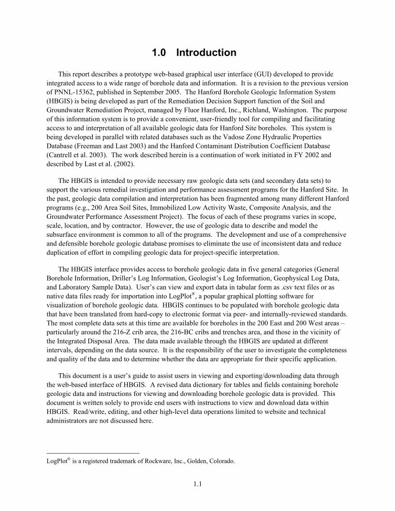
1.0 Introduction
This report describes a prototype web-based graphical user interface (GUI) developed to provide integrated access to a wide range of borehole data and information. It is a revision to the previous version of PNNL-15362, published in September 2005. The Hanford Borehole Geologic Information System (HBGIS) is being developed as part of the Remediation Decision Support function of the Soil and Groundwater Remediation Project, managed by Fluor Hanford, Inc., Richland, Washington. The purpose of this information system is to provide a convenient, user-friendly tool for compiling and facilitating access to and interpretation of all available geologic data for Hanford Site boreholes. This system is being developed in parallel with related databases such as the Vadose Zone Hydraulic Properties Database (Freeman and Last 2003) and the Hanford Contaminant Distribution Coefficient Database (Cantrell et al. 2003). The work described herein is a continuation of work initiated in FY 2002 and described by Last et al. (2002).
The HBGIS is intended to provide necessary raw geologic data sets (and secondary data sets) to support the various remedial investigation and performance assessment programs for the Hanford Site. In the past, geologic data compilation and interpretation has been fragmented among many different Hanford programs (e.g., 200 Area Soil Sites, Immobilized Low Activity Waste, Composite Analysis, and the Groundwater Performance Assessment Project). The focus of each of these programs varies in scope, scale, location, and by contractor. However, the use of geologic data to describe and model the subsurface environment is common to all of the programs. The development and use of a comprehensive and defensible borehole geologic database promises to eliminate the use of inconsistent data and reduce duplication of effort in compiling geologic data for project-specific interpretation.
The HBGIS interface provides access to borehole geologic data in five general categories (General Borehole Information, Driller’s Log Information, Geologist’s Log Information, Geophysical Log Data, and Laboratory Sample Data). User’s can view and export data in tabular form as .csv text files or as native data files ready for importation into LogPlot®, a popular graphical plotting software for visualization of borehole geologic data. HBGIS continues to be populated with borehole geologic data that have been translated from hard-copy to electronic format via peer- and internally-reviewed standards. The most complete data sets at this time are available for boreholes in the 200 East and 200 West areas – particularly around the 216-Z crib area, the 216-BC cribs and trenches area, and those in the vicinity of the Integrated Disposal Area. The data made available through the HBGIS are updated at different intervals, depending on the data source. It is the responsibility of the user to investigate the completeness and quality of the data and to determine whether the data are appropriate for their specific application.
This document is a user’s guide to assist users in viewing and exporting/downloading data through the web-based interface of HBGIS. A revised data dictionary for tables and fields containing borehole geologic data and instructions for viewing and downloading borehole geologic data is provided. This document is written solely to provide end users with instructions to view and download data within HBGIS. Read/write, editing, and other high-level data operations limited to website and technical administrators are not discussed here.
LogPlot® is a registered trademark of Rockware, Inc., Golden, Colorado.

1.2
1.1 General Terms
The definitions of general terms used in this document and the HBGIS user interface are listed below to avoid confusion:
• Borehole – A circular hole drilled into soil or rock for subsurface sampling and/or construction of a well (ASTM D4750 and Jackson 1997). A temporary borehole intended for one-time use that is immediately grouted and abandoned is generally referred to as a boring. Throughout this document and within the HBGIS interface, borehole is the preferred term rather than well, despite the fact that they are often used interchangeably.
• Borehole ID – The unique alpha-numeric number (e.g., A5481) assigned to each borehole. This field is synonymous with the Well ID field used in the Hanford Well Information System (HWIS).
• Hanford Environmental Information System (HEIS) – The official data repository for Hanford environmental data. It contains a wide variety of chemical and physical data for various sample media that include water and soil samples. Specific databases and tables in HEIS will be referenced in this report due to their relation to data stored in HBGIS. Specifically, the ‘WELL_ADM’ database in HEIS contains various tables with well information and will be discussed frequently in this report. The HBGIS interface links to tables in this database to view well information such as geographical coordinates.
• Hanford Well Information System (HWIS) – A web-based interface that provides access to well information for the Hanford Site (http://www7.rl.gov/hwisweb/). HWIS is not a database, but rather an interface to HEIS (see description above).
• Well – A permanent to semi-permanent borehole (often cased) designed for long-term repeated use.
• Well Name – The standard Hanford well number (e.g., 299-W18-1). Note that well names have been assigned to all types of boreholes (both borings and wells). However, not all borings have been assigned a well name consistent with the Hanford well number; in these cases, the well name is the same as the Borehole ID.
• Logplot – Informal term given to a one-dimensional graphical plot used to visualize borehole geologic data. Vertical changes in sedimentary, lithologic, geophysical, chemical, and other physical properties are shown using a variety of colors, textures, patterns, and textual comments. The informal term of logplot is similar but distinct from the registered trade name of a common software program, LogPlot®, used in the industry to create them. The informal term is preferred when discussing the graphical plot themselves and not the software package used to create them.

2.1
2.0 Getting Started
The gateway to geologic data accessed through the HBGIS system is the web-based access located at http://hbgis.emsl.pnl.gov/HBGIS/login.jsp. This website is the front-end portal to HBGIS and graphical user interface (GUI) for users to browse, edit (limited to administrators), and download data. It can be accessed from within and outside the Pacific Northwest National Laboratory (PNNL) firewall.
2.1 User Name and Password
First-time users will need to request a user name by contacting the website administrator, Rob Mackley ([email protected] or 509-371-7178). Click on the blue-colored “click here” link on the main web page to automatically pull up the email address to request a user name. Shortly after receiving the request, the administrator will email a response containing your user name and a temporary password, which you should change immediately after your initial login (see explanation below for changing passwords). If you have forgotten your user name or password, contact the website administrator.
Once you have a valid user name and password, you can log in to the HBGIS interface by entering them into their respective input boxes, and click on the ‘Login’ command button (Figure 2.1).
Figure 2.1. Login Screen for the HBGIS Website
2.2 User Privileges
The HBGIS user interface has different levels of user accessibility, depending on the user privilege assigned by the website administrator. Regular end users will have full access to viewing and downloading borehole data within the web interface; however, only users with high-level, read/write privileges will be able to edit and add data to the system.
2.2
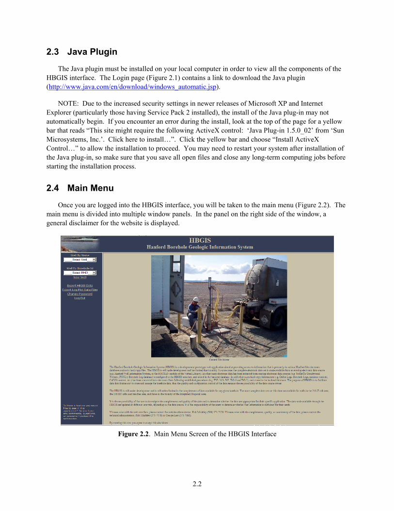
2.3 Java Plugin
The Java plugin must be installed on your local computer in order to view all the components of the HBGIS interface. The Login page (Figure 2.1) contains a link to download the Java plugin (http://www.java.com/en/download/windows_automatic.jsp).
NOTE: Due to the increased security settings in newer releases of Microsoft XP and Internet Explorer (particularly those having Service Pack 2 installed), the install of the Java plug-in may not automatically begin. If you encounter an error during the install, look at the top of the page for a yellow bar that reads “This site might require the following ActiveX control: ‘Java Plug-in 1.5.0_02’ from ‘Sun Microsystems, Inc.’. Click here to install…”. Click the yellow bar and choose “Install ActiveX Control…” to allow the installation to proceed. You may need to restart your system after installation of the Java plug-in, so make sure that you save all open files and close any long-term computing jobs before starting the installation process.
2.4 Main Menu
Once you are logged into the HBGIS interface, you will be taken to the main menu (Figure 2.2). The main menu is divided into multiple window panels. In the panel on the right side of the window, a general disclaimer for the website is displayed.
Figure 2.2. Main Menu Screen of the HBGIS Interface

2.3
The panel on the left side of the window allows users to perform the following options (Figure 2.3):
1. Select a borehole by well name
2. Or by Borehole ID
3. Export HBGIS data in tabular form as .csv text files
4. Export HBGIS data as LogPlot® .dat data files
5. Change password
6. Logout
Figure 2.3. Left-Side Panel Options on the Main Menu
2.5 Changing Your Password
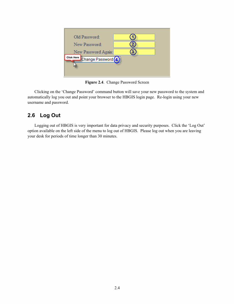
Although not the first option listed on the left-side panel of the Main Menu, changing your password may be the next thing you will want to do after logging into HBGIS for the first time. To change your password, click the ‘Change Password’ command located on the left panel of the Main Menu. This will take you to a screen shown in Figure 2.4:
1. Enter Old Password
2. Enter New Password
3. Re-confirm New Password
4. Click the ‘Change Password’ button to save your existing password
2.4
Figure 2.4. Change Password Screen
Clicking on the ‘Change Password’ command button will save your new password to the system and automatically log you out and point your browser to the HBGIS login page. Re-login using your new username and password.
2.6 Log Out
Logging out of HBGIS is very important for data privacy and security purposes. Click the ‘Log Out’ option available on the left side of the menu to log out of HBGIS. Please log out when you are leaving your desk for periods of time longer than 30 minutes.
3.1
3.0 Viewing Borehole Geologic Data
This section explains how to browse for borehole geologic data within the graphical user interface of HBGIS. The interface offers access to a variety of borehole data including driller’s logs, geologist’s logs, geophysical logs, particle-size data, bulk-rock chemistry, mineralogy, and moisture and calcium-carbonate data. (NOTE: At present, there are no bulk-rock chemistry and mineralogy data entered into the HBGIS system; however, in the future, these data will be available in HBGIS, the Virtual Library, or HEIS.)
The first step to viewing available data is to select the desired well from the Main Menu. You can select a borehole by either its well name or its Borehole ID (Figure 2.3).
3.1 Selecting by Well Name
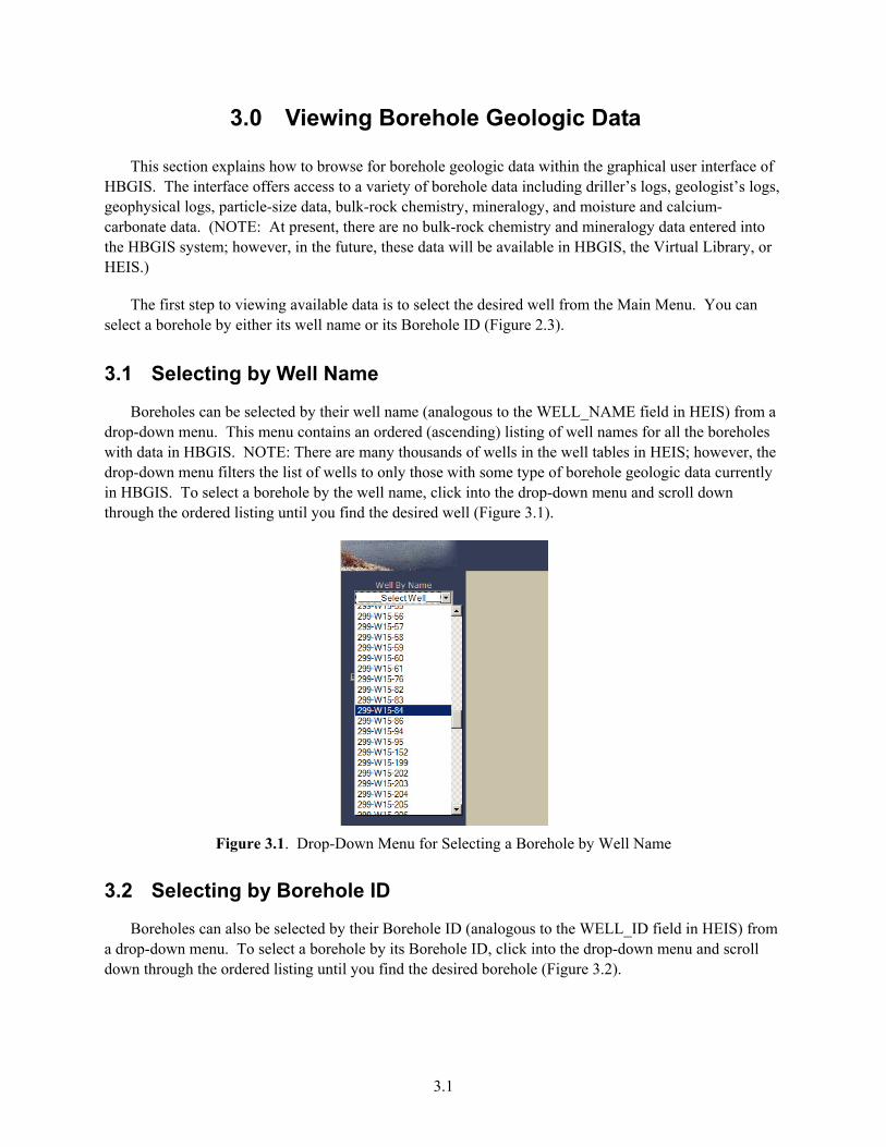
Boreholes can be selected by their well name (analogous to the WELL_NAME field in HEIS) from a drop-down menu. This menu contains an ordered (ascending) listing of well names for all the boreholes with data in HBGIS. NOTE: There are many thousands of wells in the well tables in HEIS; however, the drop-down menu filters the list of wells to only those with some type of borehole geologic data currently in HBGIS. To select a borehole by the well name, click into the drop-down menu and scroll down through the ordered listing until you find the desired well (Figure 3.1).
Figure 3.1. Drop-Down Menu for Selecting a Borehole by Well Name
3.2 Selecting by Borehole ID
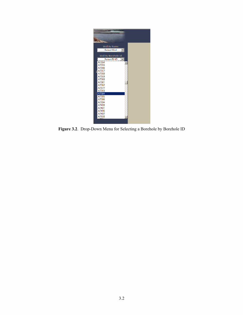
Boreholes can also be selected by their Borehole ID (analogous to the WELL_ID field in HEIS) from a drop-down menu. To select a borehole by its Borehole ID, click into the drop-down menu and scroll down through the ordered listing until you find the desired borehole (Figure 3.2).
3.2
Figure 3.2. Drop-Down Menu for Selecting a Borehole by Borehole ID
4.1
4.0 Borehole Information
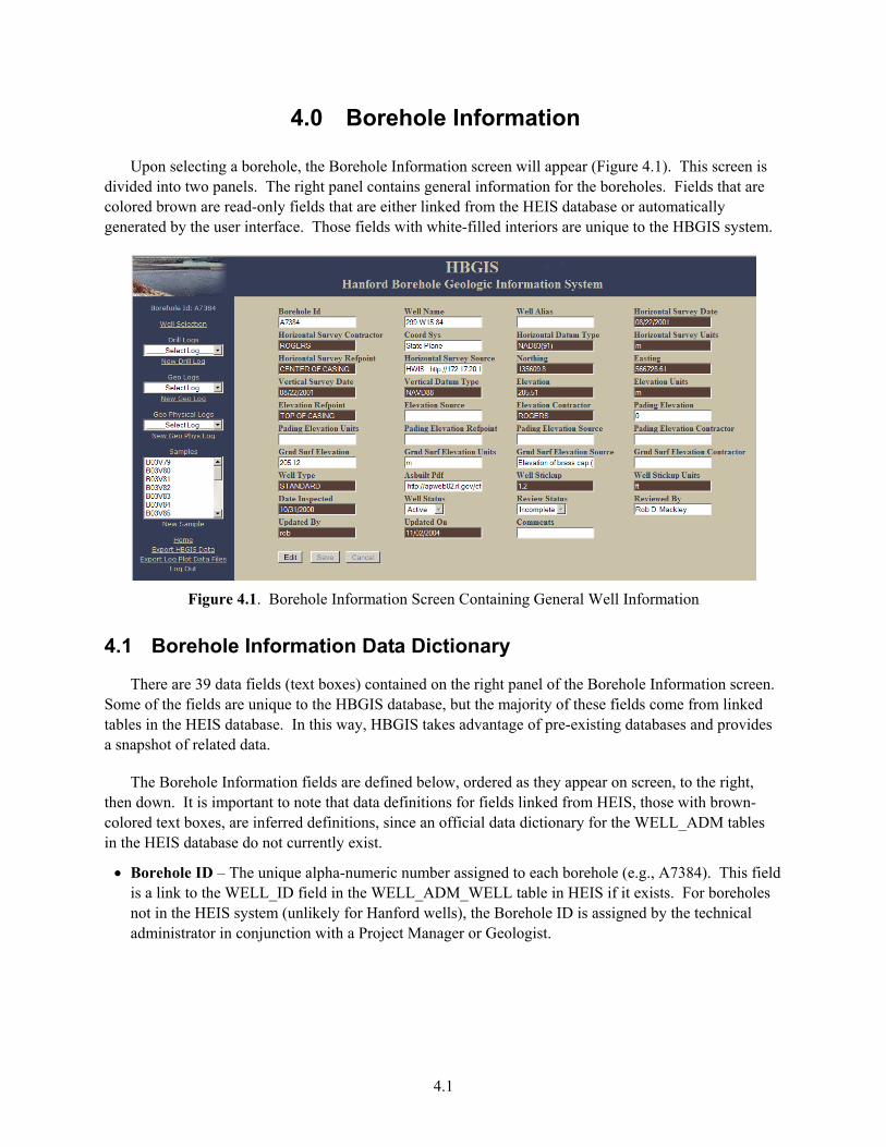
Upon selecting a borehole, the Borehole Information screen will appear (Figure 4.1). This screen is divided into two panels. The right panel contains general information for the boreholes. Fields that are colored brown are read-only fields that are either linked from the HEIS database or automatically generated by the user interface. Those fields with white-filled interiors are unique to the HBGIS system.
Figure 4.1. Borehole Information Screen Containing General Well Information
4.1 Borehole Information Data Dictionary
There are 39 data fields (text boxes) contained on the right panel of the Borehole Information screen. Some of the fields are unique to the HBGIS database, but the majority of these fields come from linked tables in the HEIS database. In this way, HBGIS takes advantage of pre-existing databases and provides a snapshot of related data.
The Borehole Information fields are defined below, ordered as they appear on screen, to the right, then down. It is important to note that data definitions for fields linked from HEIS, those with brown-colored text boxes, are inferred definitions, since an official data dictionary for the WELL_ADM tables in the HEIS database do not currently exist.
• Borehole ID – The unique alpha-numeric number assigned to each borehole (e.g., A7384). This field is a link to the WELL_ID field in the WELL_ADM_WELL table in HEIS if it exists. For boreholes not in the HEIS system (unlikely for Hanford wells), the Borehole ID is assigned by the technical administrator in conjunction with a Project Manager or Geologist.
4.2
• Well Name – The standard Hanford well number (e.g., 299-W15-84). Well names have been assigned to all types of boreholes (both borings and wells). However, not all borings have been assigned a well name consistent with the Hanford well number system; in these cases, the well name is the same as the Borehole ID. This is a link to the WELL_ADM_WELL_NAME field in HEIS if it exists. For boreholes not in HEIS (unlikely for Hanford wells), the well name is assigned by the database administrator in conjunction with a Project Manager or Geologist.
• Well Alias – An alternate identifier (e.g., old well numbers or temporary well name) taken from various sources such as logging reports.
• Horizontal Survey Date – The date, in “mm/dd/yyyy” format, that the most recent horizontal survey was conducted for the borehole. For boreholes in the HEIS database, this field is a link to the SURVEY_DATE field in the WELL_ADM_HORIZONTAL_COORD table in HEIS.
• Horizontal Survey Contractor – The name of the company or individual responsible for conducting the Horizontal Survey. For boreholes in the HEIS database, this field is a link to the SURVEY_CONTRACTOR field in the WELL_ADM_HORIZONTAL_COORD table in HEIS.
• Coordinate Sys – The name of the coordinate system used for the horizontal survey. All horizontal coordinates for boreholes from the HEIS database will have a value of “State Plane” (Washington South State Plane, FIPS 4602).
• Horizontal Datum Type – The representative ellipsoid model used for the shape of the earth, against which the horizontal survey measurements are referenced. For boreholes in the HEIS database, this field is a link to the HORIZONTAL_DATUM_TYPE field in the WELL_ADM_HORIZONTAL_COORD table in HEIS and will have a value of “NAD83(91)” (the 1991 adjustment to the North American Datum of 1983).
• Horizontal Survey Units – The measurement units the horizontal survey coordinates are expressed in. For boreholes in the HEIS database, this field is a link to the SURVEY_UNITS field in the WELL_ADM_HORIZONTAL_COORD table in HEIS and will have a value of “m” (meters).
• Horizontal Survey Refpoint – The reference point against which the horizontal survey coordinates are measured (e.g., center of casing, brass cap, x on top cover). For boreholes in the HEIS database, this field is a link to the SURVEY_POINT_DESC field in the WELL_ADM_HORIZONTAL_ COORD table in HEIS.
• Horizontal Survey Source – This is a text or hyperlink reference to the hard-copy or electronic source of the horizontal survey data.
• Northing – The Northing coordinate, usually within the Washington State Plane projection system. If the horizontal coordinates are not in the State Plane system, then this field contains the relative “north/south” coordinate. For boreholes in the HEIS database, this field is a link to the NORTHING field in the WELL_ADM_HORIZONTAL_COORD table in HEIS.
• Easting – The Easting coordinate, usually within the Washington State Plane projection system. If the horizontal coordinates are not in the State Plane system, then this field contains the relative “east/west” coordinate. For boreholes in the HEIS database, this field is a link to the EASTING field in the WELL_ADM_HORIZONTAL_COORD table in HEIS.

4.3
• Vertical Survey Date – The date, in “mm/dd/yyyy” format, that the most recent vertical survey was conducted for the borehole. For boreholes in the HEIS database, this field is a link to the SURVEY_DATE field in the WELL_ADM_WELL_ELEVATION table in HEIS.
• Vertical Datum Type – The representative ellipsoid model used for the shape of the earth against which the vertical (elevation) survey measurement is referenced. For boreholes in the HEIS database, this field is a link to the VERTICAL_DATUM_TYPE field in the WELL_ADM_WELL_ELEVATION table in HEIS and will have a value of “NAVD88” (North American Vertical Datum of 1988) or “UNKNOWN.”
• Elevation – The elevation measurement of the borehole relative to the reference point. For boreholes in the HEIS database, this field is a link to the ELEVATION field in the WELL_ADM_WELL_ELEVATION table in HEIS. Do NOT assume this is the elevation of the ground/land surface.
• Elevation Units – The measurement units associated with elevation coordinates. For boreholes in the HEIS database, this field is a link to the SURVEY_UNITS field in the WELL_ADM_WELL_ELEVATION table in HEIS and will have a value of “m” (meters).
• Elevation Refpoint – The reference point against which the elevation coordinate is measured (e.g., x on north rim, brass cap, land surface). For boreholes in the HEIS database, this field is a link to the SURVEY_POINT_DESC field in the WELL_ADM_WELL_ELEVATION table in HEIS.
• Elevation Source – This is a text or hyperlink reference to the hard-copy or electronic source of the elevation survey data.
• Elevation Contractor – The name of the company or individual responsible for conducting the elevation survey. For boreholes in the HEIS database, this field is a link to the SURVEY_CONTRACTOR field in the WELL_ADM_WELL_ELEVATION table in HEIS.
• Pad Elevation – The elevation of the concrete pad associated with the borehole.
• Pad Elevation Units – The measurement units the pading elevation is expressed in.
• Pad Elevation Source – This is a text or hyperlink reference to the hard-copy or electronic source of the pading elevation survey data.
• Pad Elevation Contractor – The name of the company or individual responsible for conducting the pading elevation survey.
• Grnd Surf Elevation – The elevation of the ground surface. This can come either from a direct survey of the ground surface or the calculated ground surface elevation based on the elevation of the top of the casing and the stickup height (ground surface elevation = top of casing elevation – stickup height). Unfortunately, most of the elevation values for boreholes stored in the HWIS database are NOT referenced to the ground surface.
• Grnd Surf Elevation Units – The measurement units associated with ground surface elevation coordinates.
• Grnd Surf Elevation Source – This is a text or hyperlink reference to the hard-copy or electronic source of the ground surface elevation.
4.4
• Grnd Surf Elevation Contractor – The name of the company or individual responsible for conducting the ground surface elevation survey.
• Well Type – This field indicates the borehole type, intended to distinguish between borings, dry wells, groundwater monitoring wells, etc. For boreholes in the HEIS database, this field is a link to the WELL_TYPE field in the WELL_ADM_WELL table in HEIS.
• Asbuilt PDF – This is a text or hyperlink reference to the electronic source of the scanned as-built document. Electronic copies (scanned images) of as-built documents are often available through the HWIS interface. Hard-copies are located in the PNNL Well Log Library in Room 2110, Sigma V Building.
• Well Stickup – The most-recent stickup height for the casing of a well; that is, the difference in height between the top of casing and ground surface. For boreholes in the HEIS database, this field is a link to the STICK_UP field in the WELL_ADM_WELL table in HEIS. For boreholes not in HEIS, it can often be found in the Asbuilt diagram or on log headers.
• Well Stickup Units – The measurement units associated with well stickup height. This is an important field since many of the stickup heights reported in geophysical logs are in feet, rather than in meters.
• Date Inspected – The date of the latest inspection of the well, in “mm/dd/yyyy” format. For boreholes in the HEIS database, this field is a link to the DATE_INSPECTED field in the WELL_ADM_LATEST_INSPECTION_VW table in HEIS.
• Well Status – The most recent status of the borehole, as defined by a Hanford well administrator. For boreholes in the HEIS database, this field is a link to the STATUS field in the WELL_ADM_WELL_ATTRIBUTES_MV table in HEIS.
• Review Status – This field denotes the review status of the data shown on the Well Information screen by HBGIS technical administrators. There are only two status options: “Complete” and “Incomplete.” To be considered “Complete,” the data must have been verified independently by a technical administrator and found to be accurate. Otherwise, the status of the Borehole Information is considered “Incomplete.” “Complete” status does not imply that the data are completely correct, only that the values in the fields match the “raw” data from the “authoritative” data sources.
• Reviewed By – The individual(s) responsible for reviewing the Borehole Information immediately following its initial entry into the HBGIS system.
• Updated By – The individual(s) responsible for making any edits or updates to the information contained in the Borehole Information fields. Updates might take place repeatedly by users with read/write privileges. This field is automatically populated each time the information is updated by the GUI based upon the name of the user logged into the HBGIS system.
• Updated On – The date, in “mm/dd/yyyy” format, any edits or updates were done to the information contained in the Borehole Information fields. Updates might take place repeatedly by users with read/write privileges. This field is automatically time stamped by GUI each time the information is updated.
• Comments – Any additional information or comments regarding the borehole that are not contained in any of the other Borehole Information fields.
5.1
5.0 Log and Sample Data Selection Panel
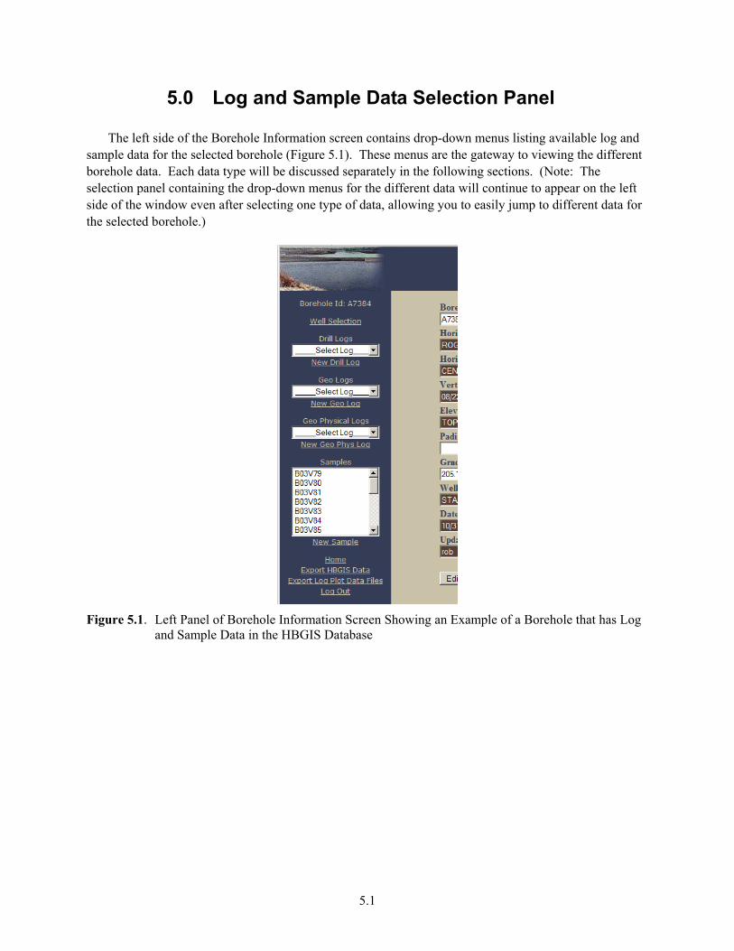
The left side of the Borehole Information screen contains drop-down menus listing available log and sample data for the selected borehole (Figure 5.1). These menus are the gateway to viewing the different borehole data. Each data type will be discussed separately in the following sections. (Note: The selection panel containing the drop-down menus for the different data will continue to appear on the left side of the window even after selecting one type of data, allowing you to easily jump to different data for the selected borehole.)
Figure 5.1. Left Panel of Borehole Information Screen Showing an Example of a Borehole that has Log
and Sample Data in the HBGIS Database

6.1
6.0 Drill Logs
The HBGIS database contains drill log data, arrays of depth-specific text strings derived from historic drilling records made by drillers (or others) during drilling. These data are considered secondary data because they are summarized from the original hard copy driller’s logs using detailed procedures to systematize the driller’s log information into a uniform set of data. Electronic copies (scanned images) of these records are often available through the HWIS interface. The quality of the drill logs and the information contained therein are highly variable, subjective, and not easily deciphered to a single interpretation. However, data entry procedures translate this qualitative information into reproducible data categories
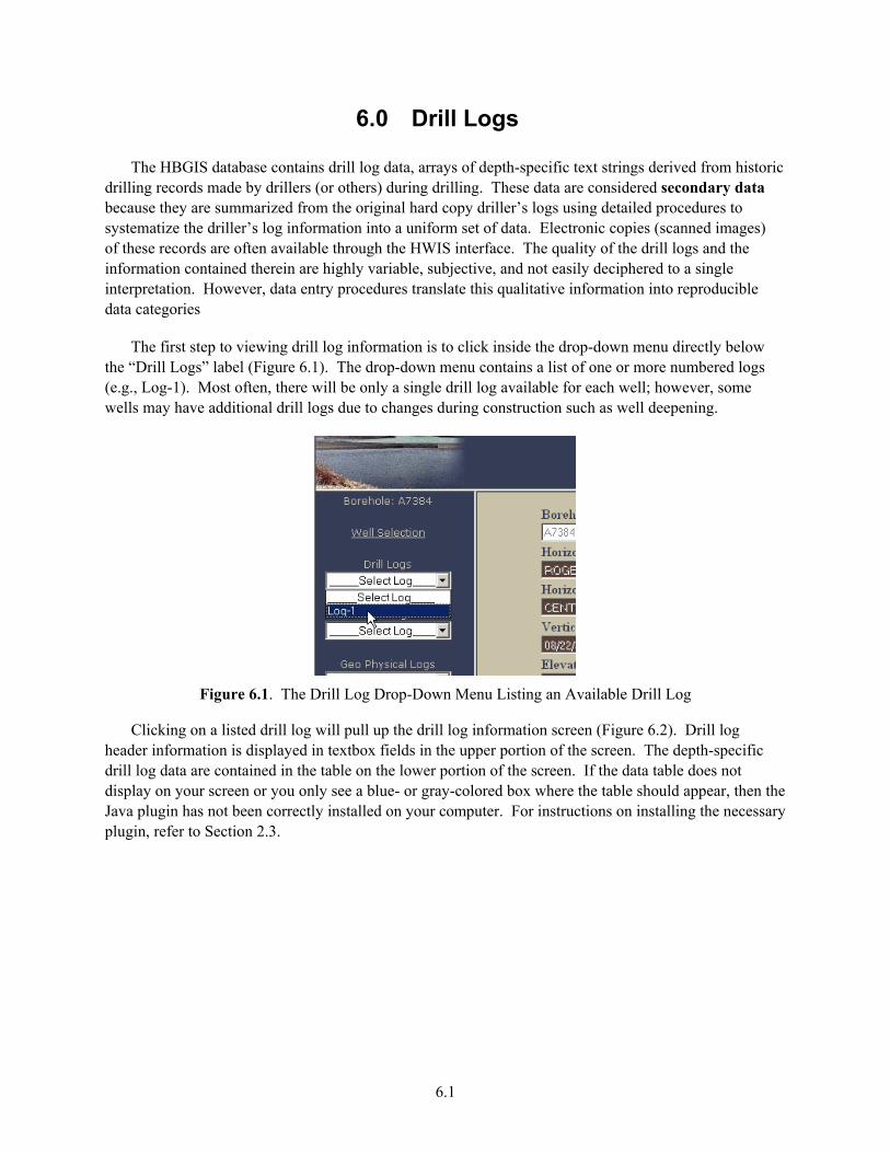
The first step to viewing drill log information is to click inside the drop-down menu directly below the “Drill Logs” label (Figure 6.1). The drop-down menu contains a list of one or more numbered logs (e.g., Log-1). Most often, there will be only a single drill log available for each well; however, some wells may have additional drill logs due to changes during construction such as well deepening.
Figure 6.1. The Drill Log Drop-Down Menu Listing an Available Drill Log
Clicking on a listed drill log will pull up the drill log information screen (Figure 6.2). Drill log header information is displayed in textbox fields in the upper portion of the screen. The depth-specific drill log data are contained in the table on the lower portion of the screen. If the data table does not display on your screen or you only see a blue- or gray-colored box where the table should appear, then the Java plugin has not been correctly installed on your computer. For instructions on installing the necessary plugin, refer to Section 2.3.
6.2
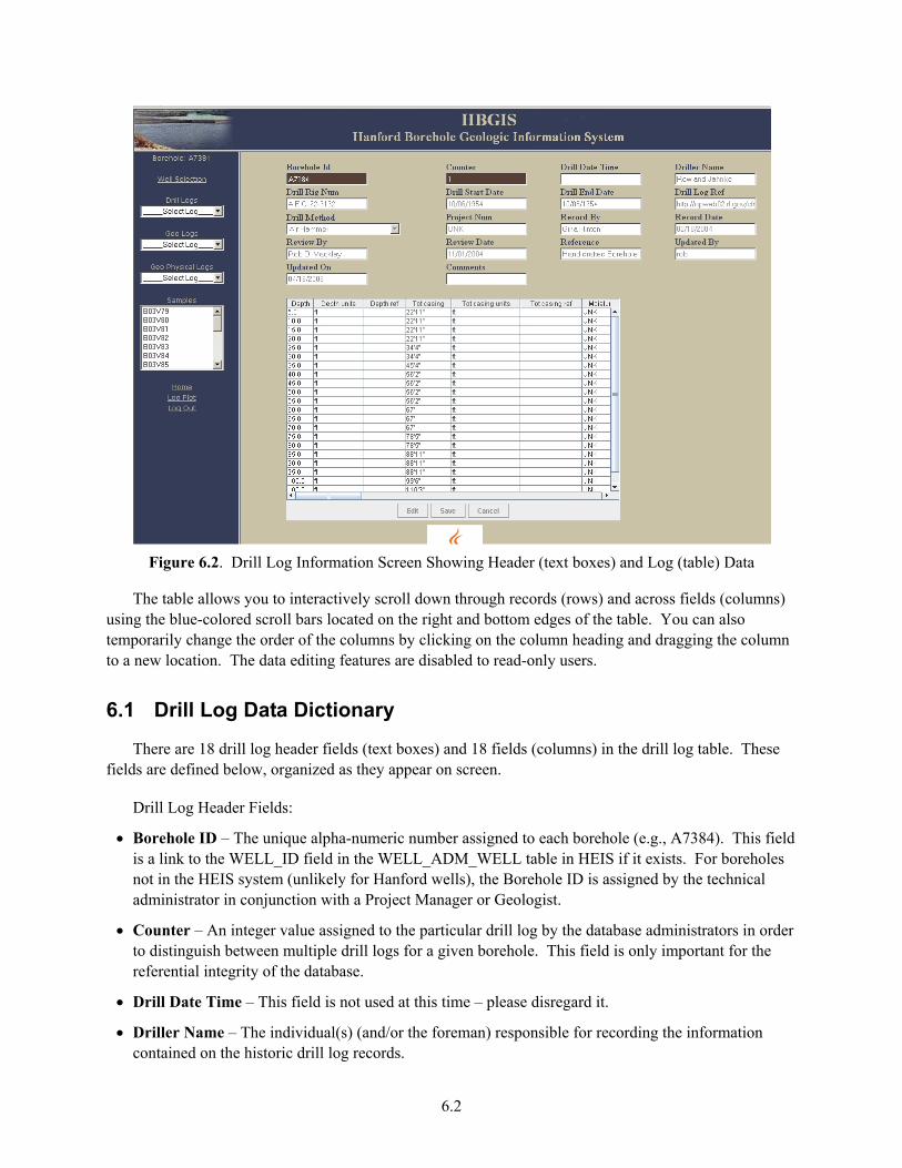
Figure 6.2. Drill Log Information Screen Showing Header (text boxes) and Log (table) Data
The table allows you to interactively scroll down through records (rows) and across fields (columns) using the blue-colored scroll bars located on the right and bottom edges of the table. You can also temporarily change the order of the columns by clicking on the column heading and dragging the column to a new location. The data editing features are disabled to read-only users.
6.1 Drill Log Data Dictionary
There are 18 drill log header fields (text boxes) and 18 fields (columns) in the drill log table. These fields are defined below, organized as they appear on screen.
Drill Log Header Fields:
• Borehole ID – The unique alpha-numeric number assigned to each borehole (e.g., A7384). This field is a link to the WELL_ID field in the WELL_ADM_WELL table in HEIS if it exists. For boreholes not in the HEIS system (unlikely for Hanford wells), the Borehole ID is assigned by the technical administrator in conjunction with a Project Manager or Geologist.
• Counter – An integer value assigned to the particular drill log by the database administrators in order to distinguish between multiple drill logs for a given borehole. This field is only important for the referential integrity of the database.
• Drill Date Time – This field is not used at this time – please disregard it.
• Driller Name – The individual(s) (and/or the foreman) responsible for recording the information contained on the historic drill log records.
6.3
• Drill Rig Num – The drill rig number or other identifier distinguishing the drill rig(s) equipment used during the drilling of the borehole.
• Drill Start Date – The date, in “mm/dd/yyyy” format, that the borehole was initially started (e.g., the date of the earliest drill log record for a given borehole).
• Drill End Date – The date, in “mm/dd/yyyy” format, that the borehole was finally completed (e.g., the date of the last drill log record for the given borehole).
• Drill Log Ref – This is a text reference or hyperlink (URL) to an electronic copy, if available, of the drill log. This is usually a link to scanned images of the original drill logs contained in HWIS.
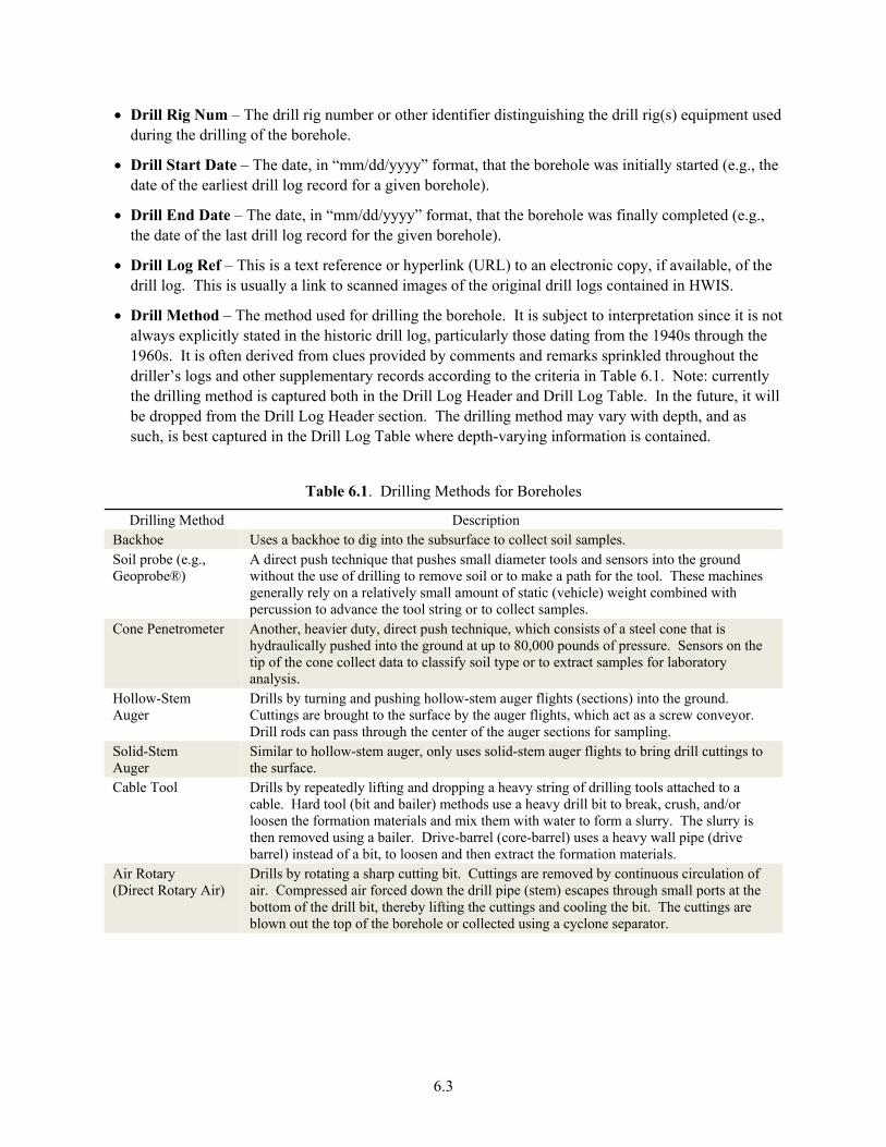
• Drill Method – The method used for drilling the borehole. It is subject to interpretation since it is not always explicitly stated in the historic drill log, particularly those dating from the 1940s through the 1960s. It is often derived from clues provided by comments and remarks sprinkled throughout the driller’s logs and other supplementary records according to the criteria in Table 6.1. Note: currently the drilling method is captured both in the Drill Log Header and Drill Log Table. In the future, it will be dropped from the Drill Log Header section. The drilling method may vary with depth, and as such, is best captured in the Drill Log Table where depth-varying information is contained.
Table 6.1. Drilling Methods for Boreholes
Drilling Method Description Backhoe Uses a backhoe to dig into the subsurface to collect soil samples. Soil probe (e.g., Geoprobe®)
A direct push technique that pushes small diameter tools and sensors into the ground without the use of drilling to remove soil or to make a path for the tool. These machines generally rely on a relatively small amount of static (vehicle) weight combined with percussion to advance the tool string or to collect samples.
Cone Penetrometer Another, heavier duty, direct push technique, which consists of a steel cone that is hydraulically pushed into the ground at up to 80,000 pounds of pressure. Sensors on the tip of the cone collect data to classify soil type or to extract samples for laboratory analysis.
Hollow-Stem Auger
Drills by turning and pushing hollow-stem auger flights (sections) into the ground. Cuttings are brought to the surface by the auger flights, which act as a screw conveyor. Drill rods can pass through the center of the auger sections for sampling.
Solid-Stem Auger
Similar to hollow-stem auger, only uses solid-stem auger flights to bring drill cuttings to the surface.
Cable Tool Drills by repeatedly lifting and dropping a heavy string of drilling tools attached to a cable. Hard tool (bit and bailer) methods use a heavy drill bit to break, crush, and/or loosen the formation materials and mix them with water to form a slurry. The slurry is then removed using a bailer. Drive-barrel (core-barrel) uses a heavy wall pipe (drive barrel) instead of a bit, to loosen and then extract the formation materials.
Air Rotary (Direct Rotary Air)
Drills by rotating a sharp cutting bit. Cuttings are removed by continuous circulation of air. Compressed air forced down the drill pipe (stem) escapes through small ports at the bottom of the drill bit, thereby lifting the cuttings and cooling the bit. The cuttings are blown out the top of the borehole or collected using a cyclone separator.
6.4
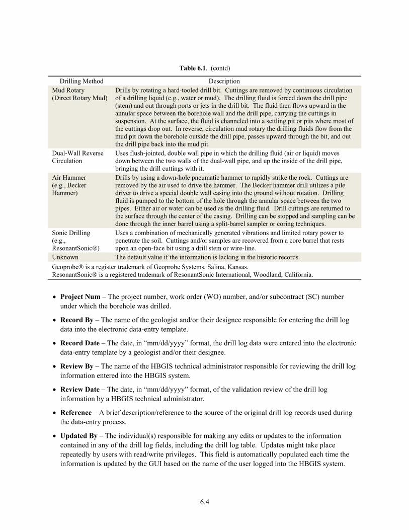
Table 6.1. (contd)
Drilling Method Description Mud Rotary (Direct Rotary Mud)
Drills by rotating a hard-tooled drill bit. Cuttings are removed by continuous circulation of a drilling liquid (e.g., water or mud). The drilling fluid is forced down the drill pipe (stem) and out through ports or jets in the drill bit. The fluid then flows upward in the annular space between the borehole wall and the drill pipe, carrying the cuttings in suspension. At the surface, the fluid is channeled into a settling pit or pits where most of the cuttings drop out. In reverse, circulation mud rotary the drilling fluids flow from the mud pit down the borehole outside the drill pipe, passes upward through the bit, and out the drill pipe back into the mud pit.
Dual-Wall Reverse Circulation
Uses flush-jointed, double wall pipe in which the drilling fluid (air or liquid) moves down between the two walls of the dual-wall pipe, and up the inside of the drill pipe, bringing the drill cuttings with it.
Air Hammer (e.g., Becker Hammer)
Drills by using a down-hole pneumatic hammer to rapidly strike the rock. Cuttings are removed by the air used to drive the hammer. The Becker hammer drill utilizes a pile driver to drive a special double wall casing into the ground without rotation. Drilling fluid is pumped to the bottom of the hole through the annular space between the two pipes. Either air or water can be used as the drilling fluid. Drill cuttings are returned to the surface through the center of the casing. Drilling can be stopped and sampling can be done through the inner barrel using a split-barrel sampler or coring techniques.
Sonic Drilling (e.g., ResonantSonic®)
Uses a combination of mechanically generated vibrations and limited rotary power to penetrate the soil. Cuttings and/or samples are recovered from a core barrel that rests upon an open-face bit using a drill stem or wire-line.
Unknown The default value if the information is lacking in the historic records. Geoprobe® is a register trademark of Geoprobe Systems, Salina, Kansas. ResonantSonic® is a registered trademark of ResonantSonic International, Woodland, California.
• Project Num – The project number, work order (WO) number, and/or subcontract (SC) number under which the borehole was drilled.
• Record By – The name of the geologist and/or their designee responsible for entering the drill log data into the electronic data-entry template.
• Record Date – The date, in “mm/dd/yyyy” format, the drill log data were entered into the electronic data-entry template by a geologist and/or their designee.
• Review By – The name of the HBGIS technical administrator responsible for reviewing the drill log information entered into the HBGIS system.
• Review Date – The date, in “mm/dd/yyyy” format, of the validation review of the drill log information by a HBGIS technical administrator.
• Reference – A brief description/reference to the source of the original drill log records used during the data-entry process.
• Updated By – The individual(s) responsible for making any edits or updates to the information contained in any of the drill log fields, including the drill log table. Updates might take place repeatedly by users with read/write privileges. This field is automatically populated each time the information is updated by the GUI based on the name of the user logged into the HBGIS system.
6.5
• Updated On – The date, in “mm/dd/yyyy” format, any edits or updates were made to the information contained in any of the drill log fields, including the drill log table. Updates might take place repeatedly by users with read/write privileges. This field is automatically time stamped by the GUI each time the information is updated.
• Comments – Any comments or information pertaining to the drill log header not contained in any other drill log header field.
• Drill Log Table Fields:
• Depth – The vertical distance between the depth reference point (usually ground surface) and the observation made by the driller.
• Depth Units – The measurement units associated with depths. With few exceptions, drill logs report depths in “feet” (ft).
• Depth Ref – The reference point against which depths are measured. Unless otherwise stated in the drill log records, the depth reference point is assumed to be the ground surface.
• Tot Casing – Total amount of casing in and over (above) the bottom of the borehole at the specific time or depth of the given observation. This represents a running total of the amount of casing at any one point in time.
• Tot Casing Units – The measurement units associated with total casing amounts. With few exceptions, total casing amounts are reported in “feet” (ft).
• Tot Casing Ref – A brief description/reference to the source of the total casing amount, since this may or may not be the same source as the rest of drill log data. This is not common, but certainly possible.
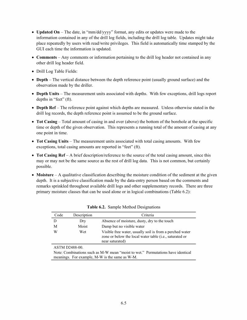
• Moisture – A qualitative classification describing the moisture condition of the sediment at the given depth. It is a subjective classification made by the data-entry person based on the comments and remarks sprinkled throughout available drill logs and other supplementary records. There are three primary moisture classes that can be used alone or in logical combinations (Table 6.2):
Table 6.2. Sample Method Designations
Code Description Criteria D Dry Absence of moisture, dusty, dry to the touch M Moist Damp but no visible water W Wet Visible free water, usually soil is from a perched water
zone or below the local water table (i.e., saturated or near saturated)
ASTM D2488-00. Note: Combinations such as M-W mean “moist to wet.” Permutations have identical meanings. For example, M-W is the same as W-M.
6.6
• Moisture Ref – A brief description/reference to the source of the information used to classify the moisture condition, since this may or may not be the same source as the rest of drill log data.
• H2O Added – The amount of water (in gallons) added to the borehole at the specific time or depth of the given observation.
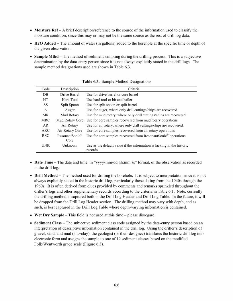
• Sample Mthd – The method of sediment sampling during the drilling process. This is a subjective determination by the data-entry person since it is not always explicitly stated in the drill logs. The sample method designations used are shown in Table 6.3.
Table 6.3. Sample Method Designations
Code Description Criteria DB Drive Barrel Use for drive barrel or core barrel HT Hard Tool Use hard tool or bit and bailer SS Split Spoon Use for split spoon or split barrel A Auger Use for auger, where only drill cuttings/chips are recovered.
MR Mud Rotary Use for mud rotary, where only drill cuttings/chips are recovered. MRC Mud Rotary Core Use for core samples recovered from mud rotary operations AR Air Rotary Use for air rotary, where only drill cuttings/chips are recovered.
ARC Air Rotary Core Use for core samples recovered from air rotary operations RSC ResonantSonic®
Core Use for core samples recovered from ResonantSonic® operations
UNK Unknown Use as the default value if the information is lacking in the historic records.
• Date Time – The date and time, in “yyyy-mm-dd hh:mm:ss” format, of the observation as recorded in the drill log.
• Drill Method – The method used for drilling the borehole. It is subject to interpretation since it is not always explicitly stated in the historic drill log, particularly those dating from the 1940s through the 1960s. It is often derived from clues provided by comments and remarks sprinkled throughout the driller’s logs and other supplementary records according to the criteria in Table 6.1. Note: currently the drilling method is captured both in the Drill Log Header and Drill Log Table. In the future, it will be dropped from the Drill Log Header section. The drilling method may vary with depth, and as such, is best captured in the Drill Log Table where depth-varying information is contained.
• Wet Dry Sample – This field is not used at this time – please disregard.
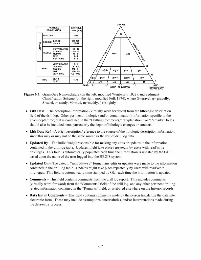
• Sediment Class – The subjective sediment class code assigned by the data-entry person based on an interpretation of descriptive information contained in the drill log. Using the driller’s description of gravel, sand, and mud (silt+clay), the geologist (or their designee) translates the historic drill log into electronic form and assigns the sample to one of 19 sediment classes based on the modified Folk/Wentworth grade scale (Figure 6.3).
6.7
PARTICLE DESIGNATION
PARTICLE DIAM. (MM)
BOULDER
COBBLE LARGE SMALL
256-128 128-64
VERY COARSE COARSE MEDIUM FINE VERY FINE
VERY COARSE COARSE MEDIUM FINE VERY FINE
PEBBLE
SAND
MUD SILT & CLAY
GR
AVE
L
64 - 32 32 - 16 16 - 8 8 - 4 4 - 2
2 - 1 1 - 1/2
1/2 - 1/4 1/4 - 1/8
1/8 - 1/16
<1/16
>256
(UNDIFERENTIATED
5
80
30
10
GRAVEL
G
SAND MUD9:1 4:1 1:1 1:4
sG msG mG
SILT AND CLAY)
PERCENT OF GRAVEL
SAND : MUD RATIO
gS (m)gS mgS gsM gM
(g)S (gm)S (g)mS (g)sM (g)M
S (m)S mS sM M
Figure 6.3. Grain-Size Nomenclature (on the left, modified Wentworth 1922), and Sediment
Classification Scheme (on the right, modified Folk 1974), where G=gravel, g= gravelly, S=sand, s= sandy, M=mud, m=muddy, ( )=slightly
• Lith Desc – The description information (virtually word for word) from the lithologic description field of the drill log. Other pertinent lithologic (and/or contamination) information specific to the given depth/time, that is contained in the “Drilling Comments,” “Explanation,” or “Remarks” fields should also be included here, particularly the depth of lithologic changes or contacts.
• Lith Desc Ref – A brief description/reference to the source of the lithologic description information, since this may or may not be the same source as the rest of drill log data.
• Updated By – The individual(s) responsible for making any edits or updates to the information contained in the drill log table. Updates might take place repeatedly by users with read/write privileges. This field is automatically populated each time the information is updated by the GUI based upon the name of the user logged into the HBGIS system.
• Updated On – The date, in “mm/dd/yyyy” format, any edits or updates were made to the information contained in the drill log table. Updates might take place repeatedly by users with read/write privileges. This field is automatically time stamped by GUI each time the information is updated.
• Comments – This field contains comments from the drill log report. This includes comments (virtually word for word) from the “Comments” field of the drill log, and any other pertinent drilling related information contained in the “Remarks” field, or scribbled elsewhere on the historic records.
• Data Entry Comments – This field contains comments made by the person translating the data into electronic form. These may include assumptions, uncertainties, and/or interpretations made during the data-entry process.

7.1
7.0 Geology Logs
The HBGIS database also contains geologist’s logs (abbreviated as “geo logs”), depth-specific text strings derived from the geologist’s logs. These are “Borehole Log” records containing sequential information on the geology and sample collection made by geologists during drilling. These are considered secondary data because they are derived from the original hard-copy records using standardized procedures for translation and systemization of borehole log information into a uniform data set.
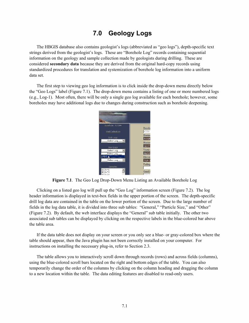
The first step to viewing geo log information is to click inside the drop-down menu directly below the “Geo Logs” label (Figure 7.1). The drop-down menu contains a listing of one or more numbered logs (e.g., Log-1). Most often, there will be only a single geo log available for each borehole; however, some boreholes may have additional logs due to changes during construction such as borehole deepening.
Figure 7.1. The Geo Log Drop-Down Menu Listing an Available Borehole Log
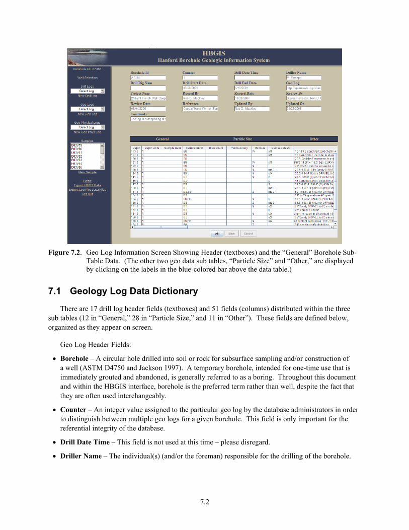
Clicking on a listed geo log will pull up the “Geo Log” information screen (Figure 7.2). The log header information is displayed in text-box fields in the upper portion of the screen. The depth-specific drill log data are contained in the table on the lower portion of the screen. Due to the large number of fields in the log data table, it is divided into three sub tables: “General,” “Particle Size,” and “Other” (Figure 7.2). By default, the web interface displays the “General” sub table initially. The other two associated sub tables can be displayed by clicking on the respective labels in the blue-colored bar above the table area.
If the data table does not display on your screen or you only see a blue- or gray-colored box where the table should appear, then the Java plugin has not been correctly installed on your computer. For instructions on installing the necessary plug-in, refer to Section 2.3.
The table allows you to interactively scroll down through records (rows) and across fields (columns), using the blue-colored scroll bars located on the right and bottom edges of the table. You can also temporarily change the order of the columns by clicking on the column heading and dragging the column to a new location within the table. The data editing features are disabled to read-only users.
7.2
Figure 7.2. Geo Log Information Screen Showing Header (textboxes) and the “General” Borehole Sub-
Table Data. (The other two geo data sub tables, “Particle Size” and “Other,” are displayed by clicking on the labels in the blue-colored bar above the data table.)
7.1 Geology Log Data Dictionary
There are 17 drill log header fields (textboxes) and 51 fields (columns) distributed within the three sub tables (12 in “General,” 28 in “Particle Size,” and 11 in “Other”). These fields are defined below, organized as they appear on screen.
Geo Log Header Fields:
• Borehole – A circular hole drilled into soil or rock for subsurface sampling and/or construction of a well (ASTM D4750 and Jackson 1997). A temporary borehole, intended for one-time use that is immediately grouted and abandoned, is generally referred to as a boring. Throughout this document and within the HBGIS interface, borehole is the preferred term rather than well, despite the fact that they are often used interchangeably.
• Counter – An integer value assigned to the particular geo log by the database administrators in order to distinguish between multiple geo logs for a given borehole. This field is only important for the referential integrity of the database.
• Drill Date Time – This field is not used at this time – please disregard.
• Driller Name – The individual(s) (and/or the foreman) responsible for the drilling of the borehole.
7.3
• Drill Rig Num – The drill rig number or other identifier distinguishing the drill rig(s) equipment used during the drilling of the borehole.
• Drill Start Date – The date, in “mm/dd/yyyy” format, that the borehole was initially started (e.g., the date of the earliest borehole log record for a given borehole).
• Drill End Date – The data, in “mm/dd/yyyy” format, that the borehole was finally completed (e.g., the date of the last borehole log record for the given borehole).
• Geo Log – This is a text reference or hyperlink (URL) to an electronic copy, if available, of the geo log record(s). This is usually a link to scanned images of the original borehole logs contained in HWIS.
• Geologist Name –The individual(s) responsible for the logging and/or interpreting the geology of the borehole during drilling. The geologist name(s) typically appear on the bottom of each page of the Borehole Logs.
• Project Num – The project number, work order (WO) number, and/or subcontract (SC) number under which the borehole was drilled.
• Record By – The name of the geologist and/or their designee responsible for entering the geo log data into the electronic data-entry template.
• Record Date – The date, in “mm/dd/yyyy” format, the geo log data were entered into the electronic data-entry template by a geologist and/or their designee.
• Review By – The name of the HBGIS technical administrator responsible for reviewing the geo log information entered into the HBGIS system.
• Review Date – The date, in “mm/dd/yyyy” format, of the validation review of the geo log information by a HBGIS technical administrator.
• Reference – A brief description/reference to the source of the original borehole log record(s) used during the data-entry process.
• Updated By – The individual(s) responsible for making any edits or updates to the information contained in any of the geo log fields, including the geo log table. Updates might take place repeatedly by users with read/write privileges. This field is automatically populated each time the information is updated by the GUI based upon the name of the user logged into the HBGIS system.
• Updated On – The date, in “mm/dd/yyyy” format, any edits or updates were made to the information contained in any of the geo log fields, including the geo log table. Updates might take place repeatedly by users with read/write privileges. This field is automatically time stamped by GUI each time the information is updated.
• Comments – Any comments or information pertaining to the geo log header not contained in any other geo log header fields.
“General” Sub-Table Fields:
• Depth – The vertical distance between the depth reference point (usually ground surface) and the observation made by the geologist.
7.4
• Depth Units – The measurement units associated with depths. With few exceptions, borehole (geologist) logs report depths in “feet” (ft).
• Sample Num – The sample number of the sediment sample taken at the discrete depth. These may or may not be Hanford Environmental Information System (HEIS) numbers.
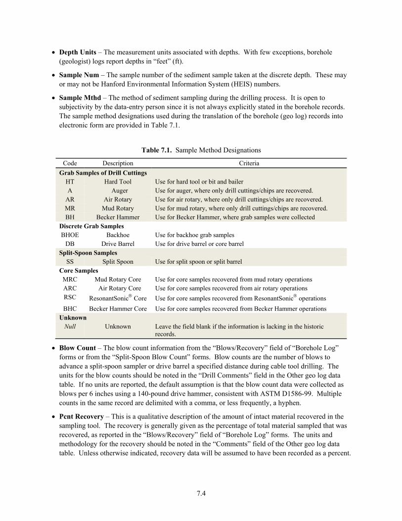
• Sample Mthd – The method of sediment sampling during the drilling process. It is open to subjectivity by the data-entry person since it is not always explicitly stated in the borehole records. The sample method designations used during the translation of the borehole (geo log) records into electronic form are provided in Table 7.1.
Table 7.1. Sample Method Designations
Code Description Criteria Grab Samples of Drill Cuttings
HT Hard Tool Use for hard tool or bit and bailer A Auger Use for auger, where only drill cuttings/chips are recovered.
AR Air Rotary Use for air rotary, where only drill cuttings/chips are recovered. MR Mud Rotary Use for mud rotary, where only drill cuttings/chips are recovered. BH Becker Hammer Use for Becker Hammer, where grab samples were collected
Discrete Grab Samples BHOE Backhoe Use for backhoe grab samples
DB Drive Barrel Use for drive barrel or core barrel Split-Spoon Samples
SS Split Spoon Use for split spoon or split barrel Core Samples
MRC Mud Rotary Core Use for core samples recovered from mud rotary operations ARC Air Rotary Core Use for core samples recovered from air rotary operations RSC ResonantSonic® Core Use for core samples recovered from ResonantSonic® operations BHC Becker Hammer Core Use for core samples recovered from Becker Hammer operations
Unknown Null Unknown Leave the field blank if the information is lacking in the historic
records.
• Blow Count – The blow count information from the “Blows/Recovery” field of “Borehole Log” forms or from the “Split-Spoon Blow Count” forms. Blow counts are the number of blows to advance a split-spoon sampler or drive barrel a specified distance during cable tool drilling. The units for the blow counts should be noted in the “Drill Comments” field in the Other geo log data table. If no units are reported, the default assumption is that the blow count data were collected as blows per 6 inches using a 140-pound drive hammer, consistent with ASTM D1586-99. Multiple counts in the same record are delimited with a comma, or less frequently, a hyphen.
• Pcnt Recovery – This is a qualitative description of the amount of intact material recovered in the sampling tool. The recovery is generally given as the percentage of total material sampled that was recovered, as reported in the “Blows/Recovery” field of “Borehole Log” forms. The units and methodology for the recovery should be noted in the “Comments” field of the Other geo log data table. Unless otherwise indicated, recovery data will be assumed to have been recorded as a percent.
7.5
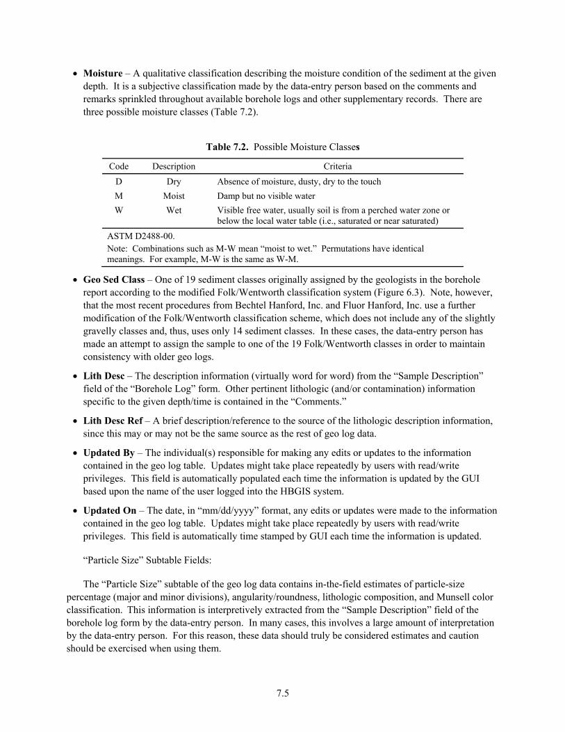
• Moisture – A qualitative classification describing the moisture condition of the sediment at the given depth. It is a subjective classification made by the data-entry person based on the comments and remarks sprinkled throughout available borehole logs and other supplementary records. There are three possible moisture classes (Table 7.2).
Table 7.2. Possible Moisture Classes
Code Description Criteria
D Dry Absence of moisture, dusty, dry to the touch M Moist Damp but no visible water W Wet Visible free water, usually soil is from a perched water zone or
below the local water table (i.e., saturated or near saturated)
ASTM D2488-00. Note: Combinations such as M-W mean “moist to wet.” Permutations have identical meanings. For example, M-W is the same as W-M.
• Geo Sed Class – One of 19 sediment classes originally assigned by the geologists in the borehole report according to the modified Folk/Wentworth classification system (Figure 6.3). Note, however, that the most recent procedures from Bechtel Hanford, Inc. and Fluor Hanford, Inc. use a further modification of the Folk/Wentworth classification scheme, which does not include any of the slightly gravelly classes and, thus, uses only 14 sediment classes. In these cases, the data-entry person has made an attempt to assign the sample to one of the 19 Folk/Wentworth classes in order to maintain consistency with older geo logs.
• Lith Desc – The description information (virtually word for word) from the “Sample Description” field of the “Borehole Log” form. Other pertinent lithologic (and/or contamination) information specific to the given depth/time is contained in the “Comments.”
• Lith Desc Ref – A brief description/reference to the source of the lithologic description information, since this may or may not be the same source as the rest of geo log data.
• Updated By – The individual(s) responsible for making any edits or updates to the information contained in the geo log table. Updates might take place repeatedly by users with read/write privileges. This field is automatically populated each time the information is updated by the GUI based upon the name of the user logged into the HBGIS system.
• Updated On – The date, in “mm/dd/yyyy” format, any edits or updates were made to the information contained in the geo log table. Updates might take place repeatedly by users with read/write privileges. This field is automatically time stamped by GUI each time the information is updated.
“Particle Size” Subtable Fields:
The “Particle Size” subtable of the geo log data contains in-the-field estimates of particle-size percentage (major and minor divisions), angularity/roundness, lithologic composition, and Munsell color classification. This information is interpretively extracted from the “Sample Description” field of the borehole log form by the data-entry person. In many cases, this involves a large amount of interpretation by the data-entry person. For this reason, these data should truly be considered estimates and caution should be exercised when using them.
7.6
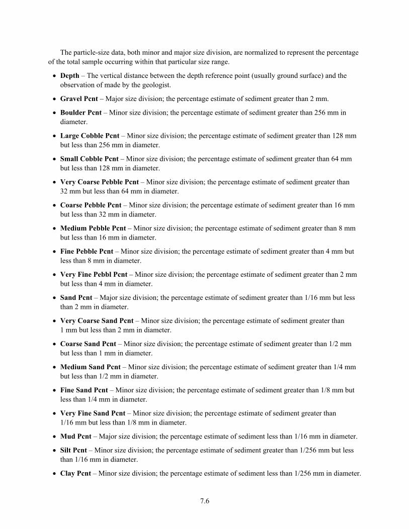
The particle-size data, both minor and major size division, are normalized to represent the percentage of the total sample occurring within that particular size range.
• Depth – The vertical distance between the depth reference point (usually ground surface) and the observation of made by the geologist.
• Gravel Pcnt – Major size division; the percentage estimate of sediment greater than 2 mm.
• Boulder Pcnt – Minor size division; the percentage estimate of sediment greater than 256 mm in diameter.
• Large Cobble Pcnt – Minor size division; the percentage estimate of sediment greater than 128 mm but less than 256 mm in diameter.
• Small Cobble Pcnt – Minor size division; the percentage estimate of sediment greater than 64 mm but less than 128 mm in diameter.
• Very Coarse Pebble Pcnt – Minor size division; the percentage estimate of sediment greater than 32 mm but less than 64 mm in diameter.
• Coarse Pebble Pcnt – Minor size division; the percentage estimate of sediment greater than 16 mm but less than 32 mm in diameter.
• Medium Pebble Pcnt – Minor size division; the percentage estimate of sediment greater than 8 mm but less than 16 mm in diameter.
• Fine Pebble Pcnt – Minor size division; the percentage estimate of sediment greater than 4 mm but less than 8 mm in diameter.
• Very Fine Pebbl Pcnt – Minor size division; the percentage estimate of sediment greater than 2 mm but less than 4 mm in diameter.
• Sand Pcnt – Major size division; the percentage estimate of sediment greater than 1/16 mm but less than 2 mm in diameter.
• Very Coarse Sand Pcnt – Minor size division; the percentage estimate of sediment greater than 1 mm but less than 2 mm in diameter.
• Coarse Sand Pcnt – Minor size division; the percentage estimate of sediment greater than 1/2 mm but less than 1 mm in diameter.
• Medium Sand Pcnt – Minor size division; the percentage estimate of sediment greater than 1/4 mm but less than 1/2 mm in diameter.
• Fine Sand Pcnt – Minor size division; the percentage estimate of sediment greater than 1/8 mm but less than 1/4 mm in diameter.
• Very Fine Sand Pcnt – Minor size division; the percentage estimate of sediment greater than 1/16 mm but less than 1/8 mm in diameter.
• Mud Pcnt – Major size division; the percentage estimate of sediment less than 1/16 mm in diameter.
• Silt Pcnt – Minor size division; the percentage estimate of sediment greater than 1/256 mm but less than 1/16 mm in diameter.
• Clay Pcnt – Minor size division; the percentage estimate of sediment less than 1/256 mm in diameter.
7.7
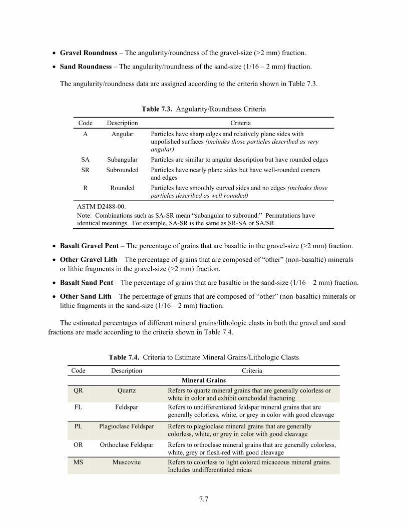
• Gravel Roundness – The angularity/roundness of the gravel-size (>2 mm) fraction.
• Sand Roundness – The angularity/roundness of the sand-size (1/16 – 2 mm) fraction.
The angularity/roundness data are assigned according to the criteria shown in Table 7.3.
Table 7.3. Angularity/Roundness Criteria
Code Description Criteria
A Angular Particles have sharp edges and relatively plane sides with unpolished surfaces (includes those particles described as very angular)
SA Subangular Particles are similar to angular description but have rounded edges SR Subrounded Particles have nearly plane sides but have well-rounded corners
and edges R Rounded Particles have smoothly curved sides and no edges (includes those
particles described as well rounded)
ASTM D2488-00. Note: Combinations such as SA-SR mean “subangular to subround.” Permutations have identical meanings. For example, SA-SR is the same as SR-SA or SA/SR.
• Basalt Gravel Pcnt – The percentage of grains that are basaltic in the gravel-size (>2 mm) fraction.
• Other Gravel Lith – The percentage of grains that are composed of “other” (non-basaltic) minerals or lithic fragments in the gravel-size (>2 mm) fraction.
• Basalt Sand Pcnt – The percentage of grains that are basaltic in the sand-size (1/16 – 2 mm) fraction.
• Other Sand Lith – The percentage of grains that are composed of “other” (non-basaltic) minerals or lithic fragments in the sand-size (1/16 – 2 mm) fraction.
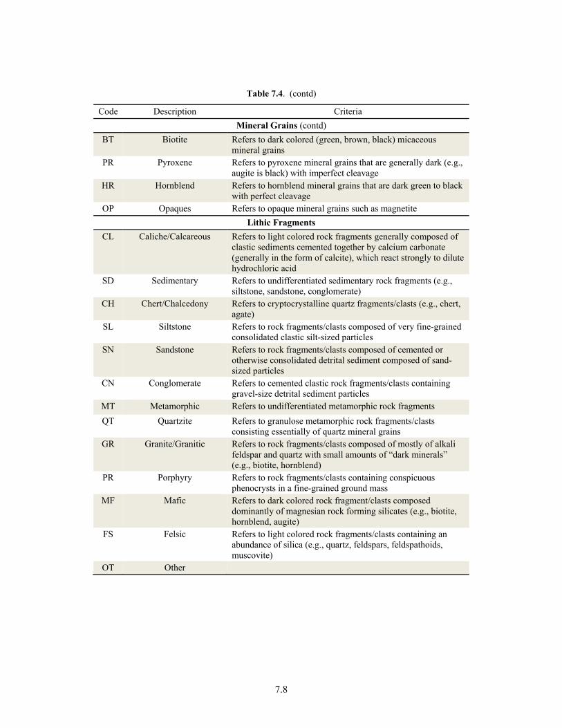
The estimated percentages of different mineral grains/lithologic clasts in both the gravel and sand fractions are made according to the criteria shown in Table 7.4.
Table 7.4. Criteria to Estimate Mineral Grains/Lithologic Clasts
Code Description Criteria Mineral Grains
QR Quartz Refers to quartz mineral grains that are generally colorless or white in color and exhibit conchoidal fracturing
FL Feldspar Refers to undifferentiated feldspar mineral grains that are generally colorless, white, or grey in color with good cleavage
PL Plagioclase Feldspar Refers to plagioclase mineral grains that are generally colorless, white, or grey in color with good cleavage
OR Orthoclase Feldspar Refers to orthoclase mineral grains that are generally colorless, white, grey or flesh-red with good cleavage
MS Muscovite Refers to colorless to light colored micaceous mineral grains. Includes undifferentiated micas
7.8
Table 7.4. (contd)
Code Description Criteria Mineral Grains (contd)
BT Biotite Refers to dark colored (green, brown, black) micaceous mineral grains
PR Pyroxene Refers to pyroxene mineral grains that are generally dark (e.g., augite is black) with imperfect cleavage
HR Hornblend Refers to hornblend mineral grains that are dark green to black with perfect cleavage
OP Opaques Refers to opaque mineral grains such as magnetite Lithic Fragments
CL Caliche/Calcareous Refers to light colored rock fragments generally composed of clastic sediments cemented together by calcium carbonate (generally in the form of calcite), which react strongly to dilute hydrochloric acid
SD Sedimentary Refers to undifferentiated sedimentary rock fragments (e.g., siltstone, sandstone, conglomerate)
CH Chert/Chalcedony Refers to cryptocrystalline quartz fragments/clasts (e.g., chert, agate)
SL Siltstone Refers to rock fragments/clasts composed of very fine-grained consolidated clastic silt-sized particles
SN Sandstone Refers to rock fragments/clasts composed of cemented or otherwise consolidated detrital sediment composed of sand-sized particles
CN Conglomerate Refers to cemented clastic rock fragments/clasts containing gravel-size detrital sediment particles
MT Metamorphic Refers to undifferentiated metamorphic rock fragments QT Quartzite Refers to granulose metamorphic rock fragments/clasts
consisting essentially of quartz mineral grains GR Granite/Granitic Refers to rock fragments/clasts composed of mostly of alkali
feldspar and quartz with small amounts of “dark minerals” (e.g., biotite, hornblend)
PR Porphyry Refers to rock fragments/clasts containing conspicuous phenocrysts in a fine-grained ground mass
MF Mafic Refers to dark colored rock fragment/clasts composed dominantly of magnesian rock forming silicates (e.g., biotite, hornblend, augite)
FS Felsic Refers to light colored rock fragments/clasts containing an abundance of silica (e.g., quartz, feldspars, feldspathoids, muscovite)
OT Other
7.9
• Field Moist Color – The Munsell color notation of a moist (as defined in the “Moisture” field of the “General” geo log subtable) sediment sample. If the moisture condition was not stated in the borehole log, then the reported color is assumed to represent field moisture conditions and is entered into this data field.
• Dry Color – The Munsell color notation of a dry (as defined for the “Moisture” field of the “General” geo log subtable) sediment sample.
• Wet Color – The Munsell color notation of a wet (as defined for the “Moisture” field of the “General” geo log subtable) sediment sample.
The Munsell color notation (in the form of hue, value, and chroma; e.g., 10YR 6/2) as taken from the “Sample Description” field of the “Borehole Log” form into one or more of the following three fields. If the color notations for both the gravel and sand/fine fractions are noted on the borehole report, then the color for the sand/fine fraction is entered by the data-entry person. If a range of color is provided (e.g., 2.5Y 5/4 to 2.5Y 5/6) only the first designation (e.g., 2.5Y 5/4) is entered. Note that if only descriptive color information (e.g., light brown or buff) is provided without a Munsell color notation, then a value of null is entered. (Future editions of the database will likely include adding a field for “qualitative” descriptions of color in addition to the Munsell color notation.)
“Other” Subtable Fields:
The “Other” subtable of the geo log data, contains miscellaneous information related to the geologist’s interpretation of the geology and drilling process for a given borehole.
• Depth – The vertical distance between the depth reference point (usually ground surface) and the observation made by the geologist.
• Depth Units – The measurement units associated with depths. With few exceptions, borehole (geologist) logs report depths in “feet” (ft).
• Tot Casing – Total amount of casing in and over (above) the bottom of the borehole at the specific time or depth of the given observation. This represents a running total of the amount of casing at any one point in time.
• Tot Casing Units – The measurement units associated with total casing amounts. With few exceptions, total casing amounts are reported in “feet” (ft).
• Tot Casing Ref – A brief description/reference to the source of the total casing amount, since this may or may not be the same source as the rest of geo log data (e.g., Field Activity Reports).
• H2O Added – The amount of water (in gallons) added to the borehole at the specific time or depth of the given observation.
• Other Remarks – Any other remarks (not drilling or lithology related) contained in the “Sample Description” or “Comments” fields of the “Borehole Log” form or taken from the Field Activity Reports Drill comments – information (virtually word for word) contained in the “Comments” field of the “Borehole Log” form.
• Drill Comments – Information (virtually word for word) contained in the “Comments” field of the “Borehole Log” forms.

7.10
• Data Entry Comments – Any key assumptions, uncertainties, and/or interpretations made by the data-entry person during the interpretation/translation of information contained in the “Borehole Log” forms.
• Updated By – The individual(s) responsible for making any edits or updates to the information contained in any of the geo log fields, including the geo log table. Updates might take place repeatedly by users with read/write privileges. This field is automatically populated each time the information is updated by the GUI based upon the name of the user logged into the HBGIS system.
• Updated On – The date, in “mm/dd/yyyy” format, any edits or updates were made to the information contained in any of the geo log fields, including the geo log table. Updates might take place repeatedly by users with read/write privileges. This field is automatically time stamped by GUI each time the information is updated.
• Comments – Any comments or information pertaining to the geo log header not contained in any other geo log header fields.
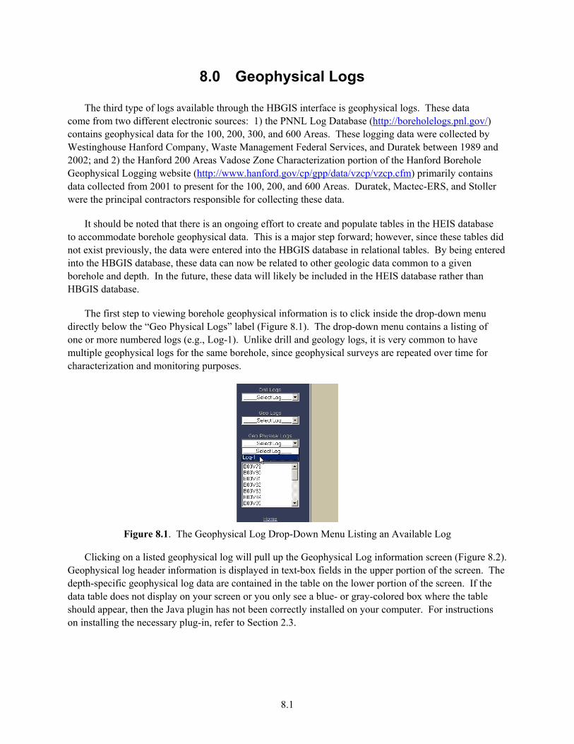
8.1
8.0 Geophysical Logs
The third type of logs available through the HBGIS interface is geophysical logs. These data come from two different electronic sources: 1) the PNNL Log Database (http://boreholelogs.pnl.gov/) contains geophysical data for the 100, 200, 300, and 600 Areas. These logging data were collected by Westinghouse Hanford Company, Waste Management Federal Services, and Duratek between 1989 and 2002; and 2) the Hanford 200 Areas Vadose Zone Characterization portion of the Hanford Borehole Geophysical Logging website (http://www.hanford.gov/cp/gpp/data/vzcp/vzcp.cfm) primarily contains data collected from 2001 to present for the 100, 200, and 600 Areas. Duratek, Mactec-ERS, and Stoller were the principal contractors responsible for collecting these data.
It should be noted that there is an ongoing effort to create and populate tables in the HEIS database to accommodate borehole geophysical data. This is a major step forward; however, since these tables did not exist previously, the data were entered into the HBGIS database in relational tables. By being entered into the HBGIS database, these data can now be related to other geologic data common to a given borehole and depth. In the future, these data will likely be included in the HEIS database rather than HBGIS database.
The first step to viewing borehole geophysical information is to click inside the drop-down menu directly below the “Geo Physical Logs” label (Figure 8.1). The drop-down menu contains a listing of one or more numbered logs (e.g., Log-1). Unlike drill and geology logs, it is very common to have multiple geophysical logs for the same borehole, since geophysical surveys are repeated over time for characterization and monitoring purposes.
Figure 8.1. The Geophysical Log Drop-Down Menu Listing an Available Log
Clicking on a listed geophysical log will pull up the Geophysical Log information screen (Figure 8.2). Geophysical log header information is displayed in text-box fields in the upper portion of the screen. The depth-specific geophysical log data are contained in the table on the lower portion of the screen. If the data table does not display on your screen or you only see a blue- or gray-colored box where the table should appear, then the Java plugin has not been correctly installed on your computer. For instructions on installing the necessary plug-in, refer to Section 2.3.
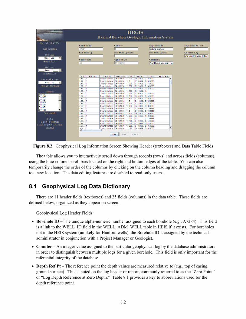
8.2
Figure 8.2. Geophysical Log Information Screen Showing Header (textboxes) and Data Table Fields
The table allows you to interactively scroll down through records (rows) and across fields (columns), using the blue-colored scroll bars located on the right and bottom edges of the table. You can also temporarily change the order of the columns by clicking on the column heading and dragging the column to a new location. The data editing features are disabled to read-only users.
8.1 Geophysical Log Data Dictionary
There are 11 header fields (textboxes) and 25 fields (columns) in the data table. These fields are defined below, organized as they appear on screen.
Geophysical Log Header Fields:
• Borehole ID – The unique alpha-numeric number assigned to each borehole (e.g., A7384). This field is a link to the WELL_ID field in the WELL_ADM_WELL table in HEIS if it exists. For boreholes not in the HEIS system (unlikely for Hanford wells), the Borehole ID is assigned by the technical administrator in conjunction with a Project Manager or Geologist.
• Counter – An integer value assigned to the particular geophysical log by the database administrators in order to distinguish between multiple logs for a given borehole. This field is only important for the referential integrity of the database.
• Depth Ref Pt – The reference point the depth values are measured relative to (e.g., top of casing, ground surface). This is noted on the log header or report, commonly referred to as the “Zero Point” or “Log Depth Reference at Zero Depth.” Table 8.1 provides a key to abbreviations used for the depth reference point.
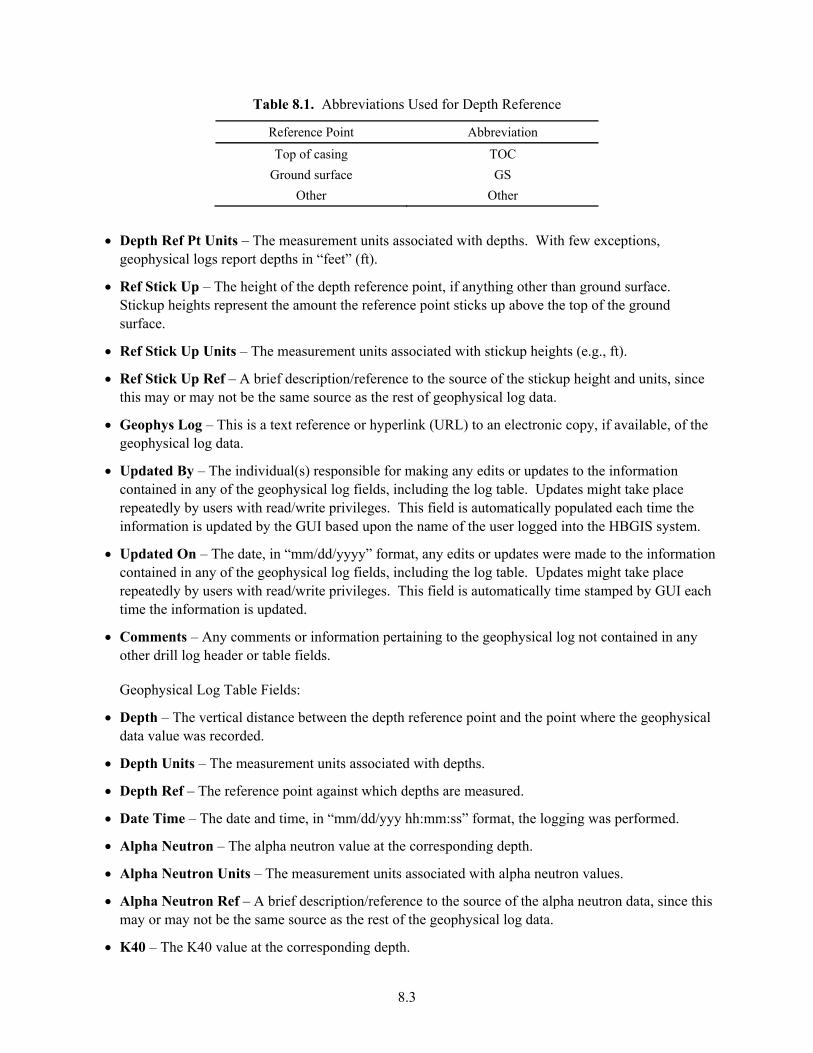
8.3
Table 8.1. Abbreviations Used for Depth Reference
Reference Point Abbreviation
Top of casing TOC Ground surface GS
Other Other
• Depth Ref Pt Units – The measurement units associated with depths. With few exceptions, geophysical logs report depths in “feet” (ft).
• Ref Stick Up – The height of the depth reference point, if anything other than ground surface. Stickup heights represent the amount the reference point sticks up above the top of the ground surface.
• Ref Stick Up Units – The measurement units associated with stickup heights (e.g., ft).
• Ref Stick Up Ref – A brief description/reference to the source of the stickup height and units, since this may or may not be the same source as the rest of geophysical log data.
• Geophys Log – This is a text reference or hyperlink (URL) to an electronic copy, if available, of the geophysical log data.
• Updated By – The individual(s) responsible for making any edits or updates to the information contained in any of the geophysical log fields, including the log table. Updates might take place repeatedly by users with read/write privileges. This field is automatically populated each time the information is updated by the GUI based upon the name of the user logged into the HBGIS system.
• Updated On – The date, in “mm/dd/yyyy” format, any edits or updates were made to the information contained in any of the geophysical log fields, including the log table. Updates might take place repeatedly by users with read/write privileges. This field is automatically time stamped by GUI each time the information is updated.
• Comments – Any comments or information pertaining to the geophysical log not contained in any other drill log header or table fields.
Geophysical Log Table Fields:
• Depth – The vertical distance between the depth reference point and the point where the geophysical data value was recorded.
• Depth Units – The measurement units associated with depths.
• Depth Ref – The reference point against which depths are measured.
• Date Time – The date and time, in “mm/dd/yyy hh:mm:ss” format, the logging was performed.
• Alpha Neutron – The alpha neutron value at the corresponding depth.
• Alpha Neutron Units – The measurement units associated with alpha neutron values.
• Alpha Neutron Ref – A brief description/reference to the source of the alpha neutron data, since this may or may not be the same source as the rest of the geophysical log data.
• K40 – The K40 value at the corresponding depth.
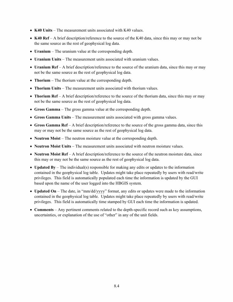
8.4
• K40 Units – The measurement units associated with K40 values.
• K40 Ref – A brief description/reference to the source of the K40 data, since this may or may not be the same source as the rest of geophysical log data.
• Uranium – The uranium value at the corresponding depth.
• Uranium Units – The measurement units associated with uranium values.
• Uranium Ref – A brief description/reference to the source of the uranium data, since this may or may not be the same source as the rest of geophysical log data.
• Thorium – The thorium value at the corresponding depth.
• Thorium Units – The measurement units associated with thorium values.
• Thorium Ref – A brief description/reference to the source of the thorium data, since this may or may not be the same source as the rest of geophysical log data.
• Gross Gamma – The gross gamma value at the corresponding depth.
• Gross Gamma Units – The measurement units associated with gross gamma values.
• Gross Gamma Ref – A brief description/reference to the source of the gross gamma data, since this may or may not be the same source as the rest of geophysical log data.
• Neutron Moist – The neutron moisture value at the corresponding depth.
• Neutron Moist Units – The measurement units associated with neutron moisture values.
• Neutron Moist Ref – A brief description/reference to the source of the neutron moisture data, since this may or may not be the same source as the rest of geophysical log data.
• Updated By – The individual(s) responsible for making any edits or updates to the information contained in the geophysical log table. Updates might take place repeatedly by users with read/write privileges. This field is automatically populated each time the information is updated by the GUI based upon the name of the user logged into the HBGIS system.
• Updated On – The date, in “mm/dd/yyyy” format, any edits or updates were made to the information contained in the geophysical log table. Updates might take place repeatedly by users with read/write privileges. This field is automatically time stamped by GUI each time the information is updated.
• Comments – Any pertinent comments related to the depth-specific record such as key assumptions, uncertainties, or explanation of the use of “other” in any of the unit fields.
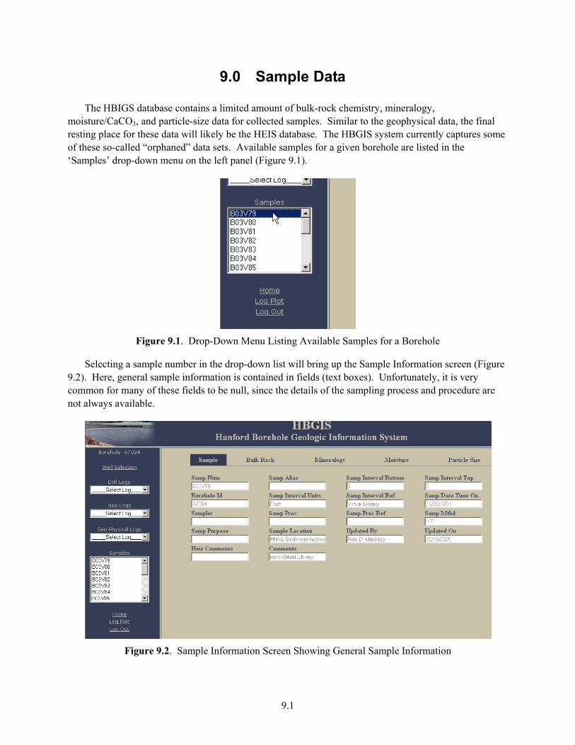
9.1
9.0 Sample Data
The HBIGS database contains a limited amount of bulk-rock chemistry, mineralogy, moisture/CaCO3, and particle-size data for collected samples. Similar to the geophysical data, the final resting place for these data will likely be the HEIS database. The HBGIS system currently captures some of these so-called “orphaned” data sets. Available samples for a given borehole are listed in the ‘Samples’ drop-down menu on the left panel (Figure 9.1).
Figure 9.1. Drop-Down Menu Listing Available Samples for a Borehole
Selecting a sample number in the drop-down list will bring up the Sample Information screen (Figure 9.2). Here, general sample information is contained in fields (text boxes). Unfortunately, it is very common for many of these fields to be null, since the details of the sampling process and procedure are not always available.
Figure 9.2. Sample Information Screen Showing General Sample Information
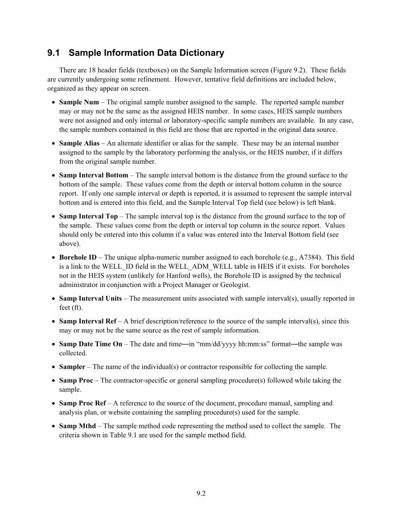
9.2
9.1 Sample Information Data Dictionary
There are 18 header fields (textboxes) on the Sample Information screen (Figure 9.2). These fields are currently undergoing some refinement. However, tentative field definitions are included below, organized as they appear on screen.
• Sample Num – The original sample number assigned to the sample. The reported sample number may or may not be the same as the assigned HEIS number. In some cases, HEIS sample numbers were not assigned and only internal or laboratory-specific sample numbers are available. In any case, the sample numbers contained in this field are those that are reported in the original data source.
• Sample Alias – An alternate identifier or alias for the sample. These may be an internal number assigned to the sample by the laboratory performing the analysis, or the HEIS number, if it differs from the original sample number.
• Samp Interval Bottom – The sample interval bottom is the distance from the ground surface to the bottom of the sample. These values come from the depth or interval bottom column in the source report. If only one sample interval or depth is reported, it is assumed to represent the sample interval bottom and is entered into this field, and the Sample Interval Top field (see below) is left blank.
• Samp Interval Top – The sample interval top is the distance from the ground surface to the top of the sample. These values come from the depth or interval top column in the source report. Values should only be entered into this column if a value was entered into the Interval Bottom field (see above).
• Borehole ID – The unique alpha-numeric number assigned to each borehole (e.g., A7384). This field is a link to the WELL_ID field in the WELL_ADM_WELL table in HEIS if it exists. For boreholes not in the HEIS system (unlikely for Hanford wells), the Borehole ID is assigned by the technical administrator in conjunction with a Project Manager or Geologist.
• Samp Interval Units – The measurement units associated with sample interval(s), usually reported in feet (ft).
• Samp Interval Ref – A brief description/reference to the source of the sample interval(s), since this may or may not be the same source as the rest of sample information.
• Samp Date Time On – The date and time—in “mm/dd/yyyy hh:mm:ss” format—the sample was collected.
• Sampler – The name of the individual(s) or contractor responsible for collecting the sample.
• Samp Proc – The contractor-specific or general sampling procedure(s) followed while taking the sample.
• Samp Proc Ref – A reference to the source of the document, procedure manual, sampling and analysis plan, or website containing the sampling procedure(s) used for the sample.
• Samp Mthd – The sample method code representing the method used to collect the sample. The criteria shown in Table 9.1 are used for the sample method field.
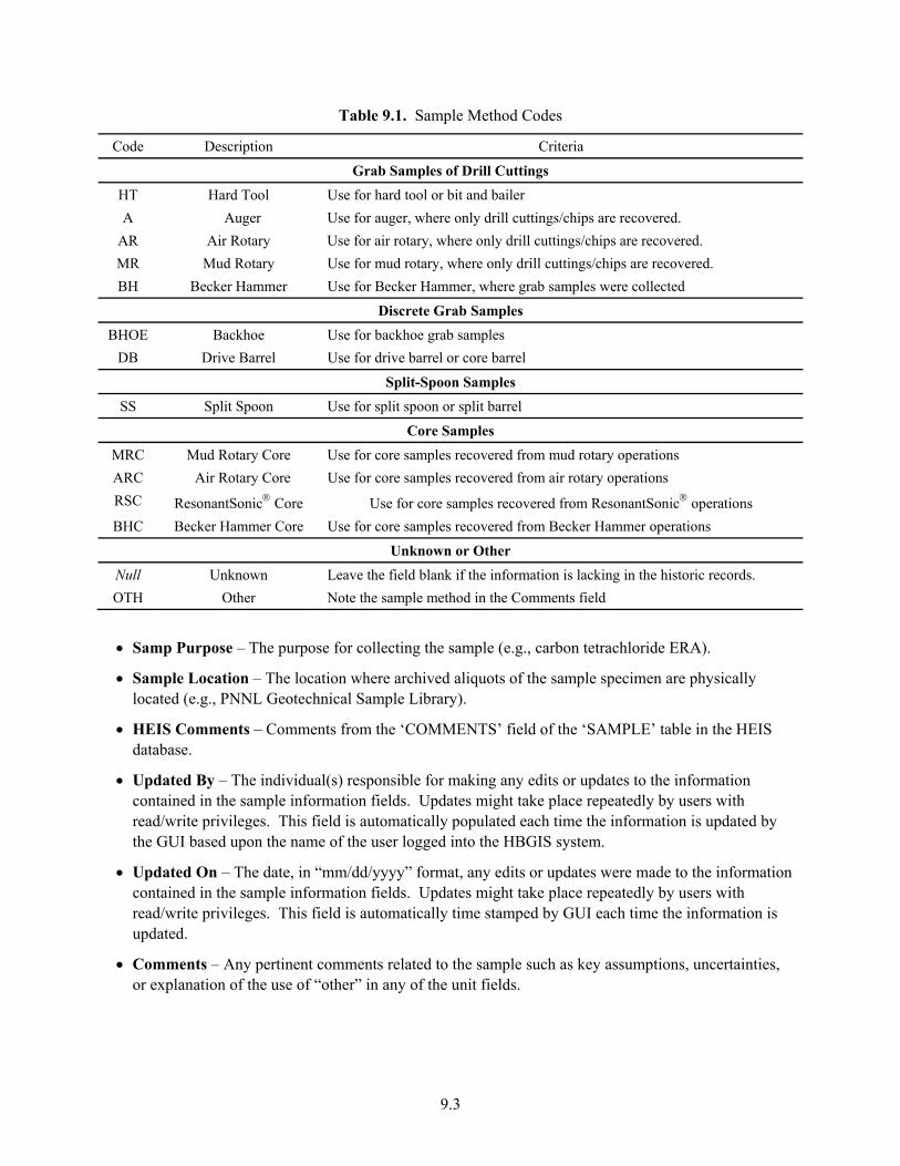
9.3
Table 9.1. Sample Method Codes
Code Description Criteria
Grab Samples of Drill Cuttings HT Hard Tool Use for hard tool or bit and bailer A Auger Use for auger, where only drill cuttings/chips are recovered.
AR Air Rotary Use for air rotary, where only drill cuttings/chips are recovered. MR Mud Rotary Use for mud rotary, where only drill cuttings/chips are recovered. BH Becker Hammer Use for Becker Hammer, where grab samples were collected
Discrete Grab Samples BHOE Backhoe Use for backhoe grab samples
DB Drive Barrel Use for drive barrel or core barrel
Split-Spoon Samples SS Split Spoon Use for split spoon or split barrel
Core Samples MRC Mud Rotary Core Use for core samples recovered from mud rotary operations ARC Air Rotary Core Use for core samples recovered from air rotary operations RSC ResonantSonic® Core Use for core samples recovered from ResonantSonic® operations BHC Becker Hammer Core Use for core samples recovered from Becker Hammer operations
Unknown or Other Null Unknown Leave the field blank if the information is lacking in the historic records. OTH Other Note the sample method in the Comments field
• Samp Purpose – The purpose for collecting the sample (e.g., carbon tetrachloride ERA).
• Sample Location – The location where archived aliquots of the sample specimen are physically located (e.g., PNNL Geotechnical Sample Library).
• HEIS Comments – Comments from the ‘COMMENTS’ field of the ‘SAMPLE’ table in the HEIS database.
• Updated By – The individual(s) responsible for making any edits or updates to the information contained in the sample information fields. Updates might take place repeatedly by users with read/write privileges. This field is automatically populated each time the information is updated by the GUI based upon the name of the user logged into the HBGIS system.
• Updated On – The date, in “mm/dd/yyyy” format, any edits or updates were made to the information contained in the sample information fields. Updates might take place repeatedly by users with read/write privileges. This field is automatically time stamped by GUI each time the information is updated.
• Comments – Any pertinent comments related to the sample such as key assumptions, uncertainties, or explanation of the use of “other” in any of the unit fields.
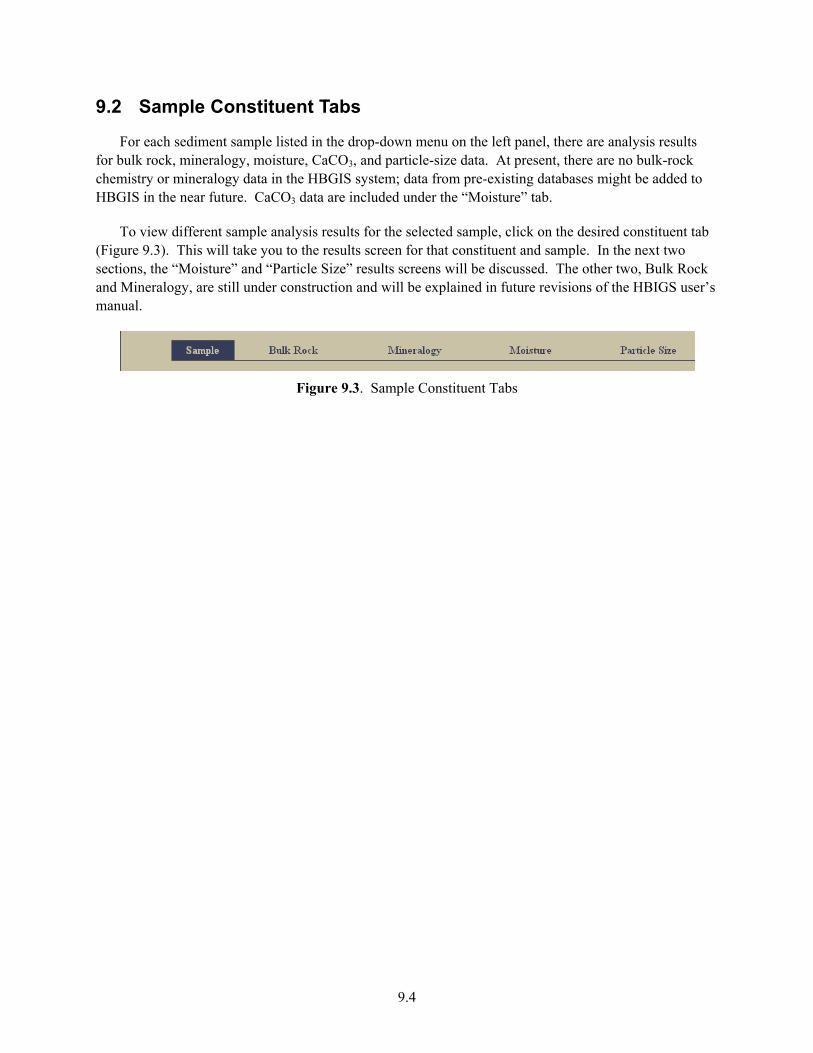
9.4
9.2 Sample Constituent Tabs
For each sediment sample listed in the drop-down menu on the left panel, there are analysis results for bulk rock, mineralogy, moisture, CaCO3, and particle-size data. At present, there are no bulk-rock chemistry or mineralogy data in the HBGIS system; data from pre-existing databases might be added to HBGIS in the near future. CaCO3 data are included under the “Moisture” tab.
To view different sample analysis results for the selected sample, click on the desired constituent tab (Figure 9.3). This will take you to the results screen for that constituent and sample. In the next two sections, the “Moisture” and “Particle Size” results screens will be discussed. The other two, Bulk Rock and Mineralogy, are still under construction and will be explained in future revisions of the HBIGS user’s manual.
Figure 9.3. Sample Constituent Tabs
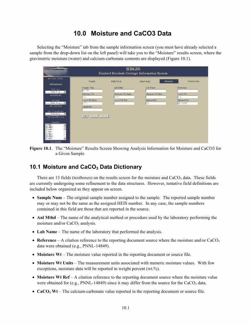
10.1
10.0 Moisture and CaCO3 Data
Selecting the “Moisture” tab from the sample information screen (you must have already selected a sample from the drop-down list on the left panel) will take you to the “Moisture” results screen, where the gravimetric moisture (water) and calcium-carbonate contents are displayed (Figure 10.1).
Figure 10.1. The “Moisture” Results Screen Showing Analysis Information for Moisture and CaCO3 for
a Given Sample
10.1 Moisture and CaCO3 Data Dictionary
There are 13 fields (textboxes) on the results screen for the moisture and CaCO3 data. These fields are currently undergoing some refinement to the data structures. However, tentative field definitions are included below organized as they appear on screen.
• Sample Num – The original sample number assigned to the sample. The reported sample number may or may not be the same as the assigned HEIS number. In any case, the sample numbers contained in this field are those that are reported in the source.
• Anl Mthd – The name of the analytical method or procedure used by the laboratory performing the moisture and/or CaCO3 analysis.
• Lab Name – The name of the laboratory that performed the analysis.
• Reference – A citation reference to the reporting document source where the moisture and/or CaCO3 data were obtained (e.g., PNNL-14849).
• Moisture Wt – The moisture value reported in the reporting document or source file.
• Moisture Wt Units – The measurement units associated with numeric moisture values. With few exceptions, moisture data will be reported in weight percent (wt.%).
• Moisture Wt Ref – A citation reference to the reporting document source where the moisture value were obtained for (e.g., PNNL-14849) since it may differ from the source for the CaCO3 data.
• CaCO3 Wt – The calcium-carbonate value reported in the reporting document or source file.
10.2
• CaCO3 Wt Units – The measurement units associated with the numeric calcium-carbonate value. With few exceptions, calcium-carbonate data will be reported in weight percent (wt.%).
• CaCO3 Wt Ref – A citation reference to the reporting document source where the moisture value were obtained for (e.g., PNNL-14849) since it may differ from the source for the moisture data.
• Updated By – The individual(s) responsible for making any edits or updates to the information contained in the results fields. Updates might take place repeatedly by users with read/write privileges. This field is automatically populated each time the information is updated by the GUI based upon the name of the user logged into the HBGIS system.
• Updated On – The date, in “mm/dd/yyyy” format, any edits or updates were made to the information contained in the results fields. Updates might take place repeatedly by users with read/write privileges. This field is automatically time stamped by GUI each time the information is updated.
• Comments – Any pertinent comments related to the sample such as key assumptions, uncertainties, or explanation of the use of “other” in any of the unit fields.
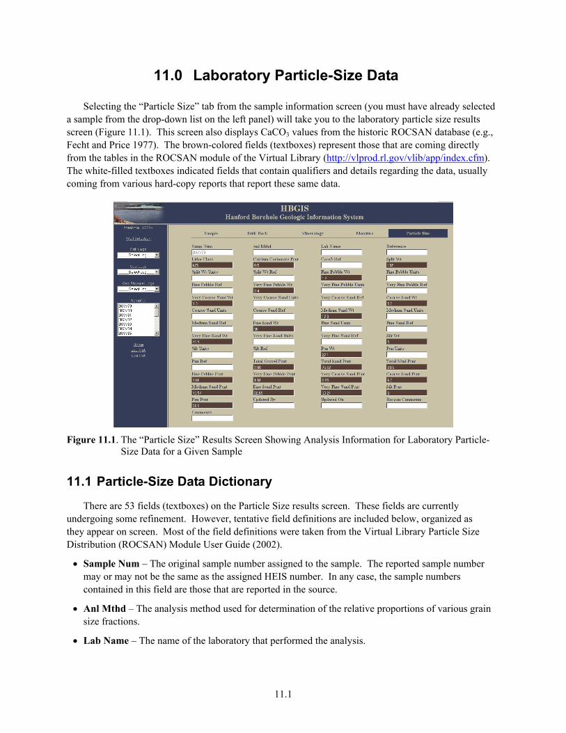
11.1
11.0 Laboratory Particle-Size Data
Selecting the “Particle Size” tab from the sample information screen (you must have already selected a sample from the drop-down list on the left panel) will take you to the laboratory particle size results screen (Figure 11.1). This screen also displays CaCO3 values from the historic ROCSAN database (e.g., Fecht and Price 1977). The brown-colored fields (textboxes) represent those that are coming directly from the tables in the ROCSAN module of the Virtual Library (http://vlprod.rl.gov/vlib/app/index.cfm). The white-filled textboxes indicated fields that contain qualifiers and details regarding the data, usually coming from various hard-copy reports that report these same data.
Figure 11.1. The “Particle Size” Results Screen Showing Analysis Information for Laboratory Particle-
Size Data for a Given Sample
11.1 Particle-Size Data Dictionary
There are 53 fields (textboxes) on the Particle Size results screen. These fields are currently undergoing some refinement. However, tentative field definitions are included below, organized as they appear on screen. Most of the field definitions were taken from the Virtual Library Particle Size Distribution (ROCSAN) Module User Guide (2002).
• Sample Num – The original sample number assigned to the sample. The reported sample number may or may not be the same as the assigned HEIS number. In any case, the sample numbers contained in this field are those that are reported in the source.
• Anl Mthd – The analysis method used for determination of the relative proportions of various grain size fractions.
• Lab Name – The name of the laboratory that performed the analysis.
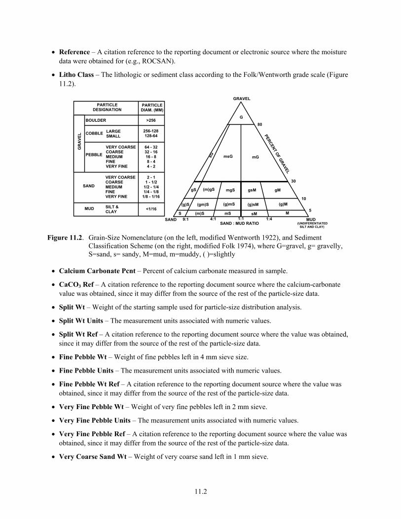
11.2
• Reference – A citation reference to the reporting document or electronic source where the moisture data were obtained for (e.g., ROCSAN).
• Litho Class – The lithologic or sediment class according to the Folk/Wentworth grade scale (Figure 11.2).
PARTICLE DESIGNATION
PARTICLE DIAM. (MM)
BOULDER
COBBLE LARGE SMALL
256-128 128-64
VERY COARSE COARSE MEDIUM FINE VERY FINE
VERY COARSE COARSE MEDIUM FINE VERY FINE
PEBBLE
SAND
MUD SILT & CLAY
GR
AVE
L
64 - 32 32 - 16 16 - 8 8 - 4 4 - 2
2 - 1 1 - 1/2
1/2 - 1/4 1/4 - 1/8
1/8 - 1/16
<1/16
>256
(UNDIFERENTIATED
5
80
30
10
GRAVEL
G
SAND MUD9:1 4:1 1:1 1:4
sG msG mG
SILT AND CLAY)
PERCENT OF GRAVEL
SAND : MUD RATIO
gS (m)gS mgS gsM gM
(g)S (gm)S (g)mS (g)sM (g)M
S (m)S mS sM M
Figure 11.2. Grain-Size Nomenclature (on the left, modified Wentworth 1922), and Sediment
Classification Scheme (on the right, modified Folk 1974), where G=gravel, g= gravelly, S=sand, s= sandy, M=mud, m=muddy, ( )=slightly
• Calcium Carbonate Pcnt – Percent of calcium carbonate measured in sample.
• CaCO3 Ref – A citation reference to the reporting document source where the calcium-carbonate value was obtained, since it may differ from the source of the rest of the particle-size data.
• Split Wt – Weight of the starting sample used for particle-size distribution analysis.
• Split Wt Units – The measurement units associated with numeric values.
• Split Wt Ref – A citation reference to the reporting document source where the value was obtained, since it may differ from the source of the rest of the particle-size data.
• Fine Pebble Wt – Weight of fine pebbles left in 4 mm sieve size.
• Fine Pebble Units – The measurement units associated with numeric values.
• Fine Pebble Wt Ref – A citation reference to the reporting document source where the value was obtained, since it may differ from the source of the rest of the particle-size data.
• Very Fine Pebble Wt – Weight of very fine pebbles left in 2 mm sieve.
• Very Fine Pebble Units – The measurement units associated with numeric values.
• Very Fine Pebble Ref – A citation reference to the reporting document source where the value was obtained, since it may differ from the source of the rest of the particle-size data.
• Very Coarse Sand Wt – Weight of very coarse sand left in 1 mm sieve.
11.3
• Very Coarse Sand Units – The measurement units associated with numeric values.
• Very Coarse Sand Ref – A citation reference to the reporting document source where the value was obtained, since it may differ from the source of the rest of the particle-size data.
• Coarse Sand Wt – Weight of coarse sand left in 0.5 mm sieve.
• Coarse Sand Units – The measurement units associated with numeric values.
• Coarse Sand Ref – A citation reference to the reporting document source where the value was obtained, since it may differ from the source of the rest of the particle-size data.
• Medium Sand Wt – Weight of medium sand left in 0.25 sieve.
• Medium Sand Units – The measurement units associated with numeric values.
• Medium Sand Ref – A citation reference to the reporting document source where the value was obtained, since it may differ from the source of the rest of the particle-size data.
• Fine Sand Wt – Weight of fine sand left in 0.125 sieve.
• Fine Sand Units – The measurement units associated with numeric values.
• Fine Sand Ref – A citation reference to the reporting document source where the value was obtained, since it may differ from the source of the rest of the particle-size data.
• Very Fine Sand Wt – Weight of very fine sand left in 0.0625 mm sieve.
• Very Fine Sand Units – The measurement units associated with numeric values.
• Very Fine Sand Ref – A citation reference to the reporting document source where the value was obtained, since it may differ from the source of the rest of the particle-size data.
• Silt Wt – Weight of silt left in 0.0375 mm sieve.
• Silt Units – The measurement units associated with numeric values.
• Silt Ref – A citation reference to the reporting document source where the value was obtained, since it may differ from the source of the rest of the particle-size data.
• Pan Wt – Weight of material left in bottom pan.
• Pan Units – The measurement units associated with numeric values.
• Pan Ref – A citation reference to the reporting document source where the value was obtained, since it may differ from the source of the rest of the particle-size data.
• Total Gravel Pcnt – Total gravel percent as calculated by the following formula: (total gravel weight/total sieve weight)*100. Note: the total sieve weight is the sum of the weights of the materials left on each sieve and in the bottom pan.
• Total Sand Pcnt – Total sand percent as calculated by the following formula: (total sand weight/ total sieve weight)*100.
• Total Mud Pcnt – Total mud percent as calculated by the following formula: (total mud weight/ total sieve weight)*100.
11.4
• Fine Pebble Pcnt – Percent of fine pebbles left in 4 mm sieve calculated by the following formula: (fine pebble weight/total sieve weight)*100.
• Very Fine Pebble Pcnt – Percent of very fine pebbles left in 2 mm sieve calculated by the following formula: (very fine pebble weight/total sieve weight)*100.
• Very Coarse Sand Pcnt – Percent of very coarse sand left in 1 mm sieve calculated by the following formula: (very coarse sand weight/total sieve weight)*100.
• Coarse Sand Pcnt – Percent of coarse sand left in 0.5 mm sieve calculated by the following formula: (coarse sand weight/total sieve weight)*100.
• Medium Sand Pcnt – Percent of medium sand left in 0.25 mm sieve calculated by the following formula: (medium sand weight/total sieve weight)*100.
• Fine Sand Pcnt – Percent of fine sand left in 0.125 mm sieve calculated by the following formula: (fine sand weight/total sieve weight)*100.
• Very Fine Sand Pcnt – Percent of very fine sand left in 0.0625 mm sieve calculated by the following formula: (very fine sand weight/total sieve weight)*100.
• Silt Pcnt – Percent of silt left in 0.0375 mm sieve calculated by the following formula: (silt weight/ total sieve weight)*100.
• Pan Pcnt – Percent of material left in bottom of pan calculated by the following formula: (pan weight/total sieve weight)*100.
• Updated By – The individual(s) responsible for making any edits or updates to the information contained in the results fields. Updates might take place repeatedly by users with read/write privileges. This field is automatically populated each time the information is updated by the GUI based upon the name of the user logged into the HBGIS system.
• Updated On – The date, in “mm/dd/yyyy format,” any edits or updates were made to the information contained in the results fields. Updates might take place repeatedly by users with read/write privileges. This field is automatically time stamped by GUI each time the information is updated.
• Rocsan Comments – Comments from the ‘Comments’ field of the ROCSAN module of the Virtual Library.
• Comments – Any pertinent comments related to the sample such as key assumptions, uncertainties, or explanations.
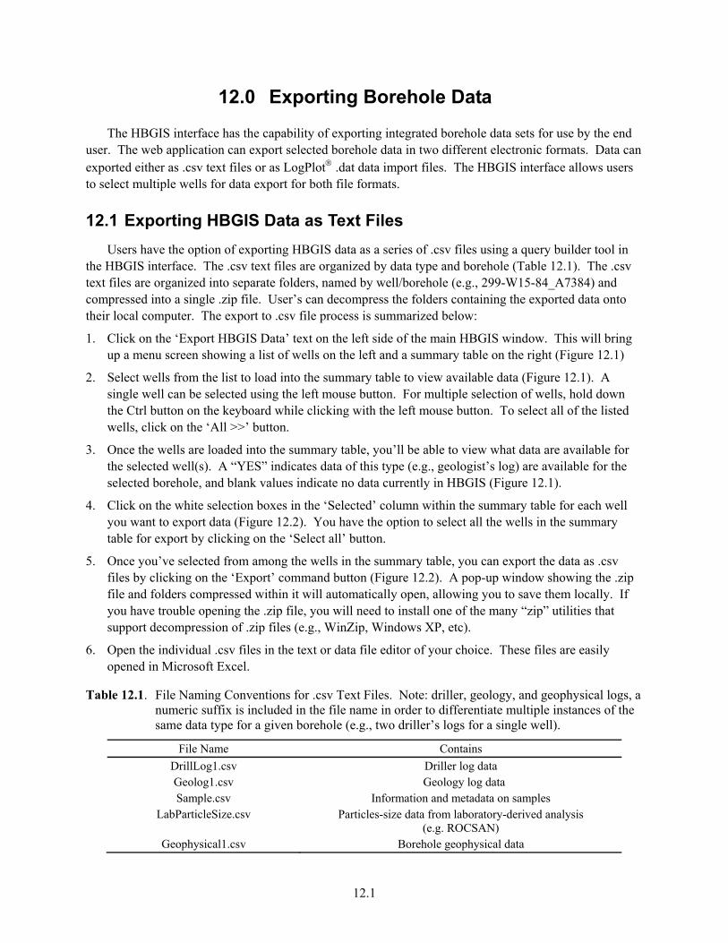
12.1
12.0 Exporting Borehole Data
The HBGIS interface has the capability of exporting integrated borehole data sets for use by the end user. The web application can export selected borehole data in two different electronic formats. Data can exported either as .csv text files or as LogPlot® .dat data import files. The HBGIS interface allows users to select multiple wells for data export for both file formats.
12.1 Exporting HBGIS Data as Text Files Users have the option of exporting HBGIS data as a series of .csv files using a query builder tool in
the HBGIS interface. The .csv text files are organized by data type and borehole (Table 12.1). The .csv text files are organized into separate folders, named by well/borehole (e.g., 299-W15-84_A7384) and compressed into a single .zip file. User’s can decompress the folders containing the exported data onto their local computer. The export to .csv file process is summarized below:
1. Click on the ‘Export HBGIS Data’ text on the left side of the main HBGIS window. This will bring up a menu screen showing a list of wells on the left and a summary table on the right (Figure 12.1)
2. Select wells from the list to load into the summary table to view available data (Figure 12.1). A single well can be selected using the left mouse button. For multiple selection of wells, hold down the Ctrl button on the keyboard while clicking with the left mouse button. To select all of the listed wells, click on the ‘All >>’ button.
3. Once the wells are loaded into the summary table, you’ll be able to view what data are available for the selected well(s). A “YES” indicates data of this type (e.g., geologist’s log) are available for the selected borehole, and blank values indicate no data currently in HBGIS (Figure 12.1).
4. Click on the white selection boxes in the ‘Selected’ column within the summary table for each well you want to export data (Figure 12.2). You have the option to select all the wells in the summary table for export by clicking on the ‘Select all’ button.
5. Once you’ve selected from among the wells in the summary table, you can export the data as .csv files by clicking on the ‘Export’ command button (Figure 12.2). A pop-up window showing the .zip file and folders compressed within it will automatically open, allowing you to save them locally. If you have trouble opening the .zip file, you will need to install one of the many “zip” utilities that support decompression of .zip files (e.g., WinZip, Windows XP, etc).
6. Open the individual .csv files in the text or data file editor of your choice. These files are easily opened in Microsoft Excel.
Table 12.1. File Naming Conventions for .csv Text Files. Note: driller, geology, and geophysical logs, a numeric suffix is included in the file name in order to differentiate multiple instances of the same data type for a given borehole (e.g., two driller’s logs for a single well).
File Name Contains DrillLog1.csv Driller log data Geolog1.csv Geology log data Sample.csv Information and metadata on samples
LabParticleSize.csv Particles-size data from laboratory-derived analysis (e.g. ROCSAN)
Geophysical1.csv Borehole geophysical data
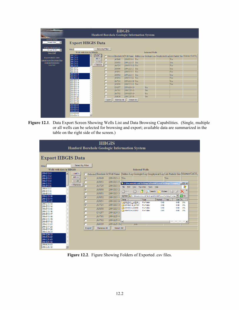
12.2
Figure 12.1. Data Export Screen Showing Wells List and Data Browsing Capabilities. (Single, multiple
or all wells can be selected for browsing and export; available data are summarized in the table on the right side of the screen.)
Figure 12.2. Figure Showing Folders of Exported .csv files.
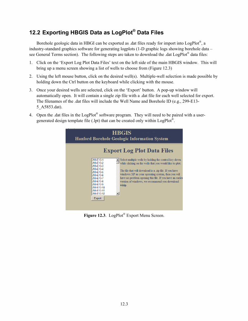
12.3
12.2 Exporting HBGIS Data as LogPlot® Data Files
Borehole geologic data in HBGI can be exported as .dat files ready for import into LogPlot®, a industry-standard graphics software for generating logplots (1-D graphic logs showing borehole data – see General Terms section). The following steps are taken to download the .dat LogPlot® data files:
1. Click on the ‘Export Log Plot Data Files’ text on the left side of the main HBGIS window. This will bring up a menu screen showing a list of wells to choose from (Figure 12.3)
2. Using the left mouse button, click on the desired well(s). Multiple-well selection is made possible by holding down the Ctrl button on the keyboard while clicking with the mouse.
3. Once your desired wells are selected, click on the ‘Export’ button. A pop-up window will automatically open. It will contain a single zip file with a .dat file for each well selected for export. The filenames of the .dat files will include the Well Name and Borehole ID (e.g., 299-E13-5_A5853.dat).
4. Open the .dat files in the LogPlot® software program. They will need to be paired with a user-generated design template file (.lpt) that can be created only within LogPlot®.
Figure 12.3. LogPlot® Export Menu Screen.


13.1
13.0 Contact Information
Please contact the website administrator, Rob Mackley (509-371-7178), regarding any questions, problems, or comments regarding the HBGIS web interface. If issues arise with the completeness, quality, or consistency of the data, please contact the technical administrators, Rob Mackley (509-371-7178) or George Last (509-371-7080).


14.1
14.0 Future Database and Website Changes
The HBGIS is an evolving prototype web interface. Many of the changes are project driven, and as such take place in an ongoing effort. As mentioned in this document, there are structural placeholders (e.g., table sand fields) and functionalities within the HBGIS database and website that have already been developed for data sets that have not been populated yet. In the future, some of these data sets may be incorporated into HBGIS or other more suitable database systems (e.g., HEIS, Virtual Library, etc). Items that have been identified in future revisions of the graphical user interface include but are not limited to:
1. Link to existing bulk-rock chemistry and mineralogy databases (currently an Excel spreadsheet)
2. Incorporate geologic contacts
3. Restructure the data structure and model of the HBGIS database to be more efficient and powerful (e.g., eliminate redundant fields, consolidate similar tables, etc)
4. Change name of “Particle Size” sub table of the geologist log data – these data are field estimates of particle size and should be named accordingly in order to differentiate them from laboratory particle-size data.
5. Create a constituent tab for CaCO3 – it is presently included as a field in the ‘Moisture’ tab and needs its own tab.
6. Add field to capture the degree of particle-size sorting described in borehole logs.
We rely heavily on you, the end-user, to help identify weaknesses and areas of improvement for the user interface. Please share your ideas and opinions with the HBGIS contacts listed in Section 13.

15.1
15.0 References
American Society for Testing and Materials (ASTM). 1987. “Standard Test Method for Penetration Test and Split-Barrel Sampling of Soils.” D1586-99, American Society for Testing and Materials, West Conshohocken, Pennsylvania.
American Society for Testing and Materials (ASTM). 1987. “Determining Subsurface Liquid Levels in a Borehole or Monitoring Well (Observation Well).” D4750-87, American Society for Testing and Materials, West Conshohocken, Pennsylvania.
American Society for Testing and Materials (ASTM). 2000. “Standard Practice for Description and Identification of Soils (Visual-Manual Procedure).” D2488-00, American Society for Testing and Materials, West Conshohocken, Pennsylvania.
Cantrell KJ, RJ Serne, and GV Last. 2003. Hanford Contaminant Distribution Coefficient Database and Users Guide. PNNL-13895, Rev. 1, Pacific Northwest National Laboratory, Richland, Washington.
Fecht KR and WH Price. 1977. Granulometric Data, 241-A Tank Farm Monitoring Well Sediments. RHO-LD-11, Rockwell Hanford Operations, Richland, Washington.
Freeman EJ and GV Last. 2003. Vadose Zone Hydraulic Property Letter Reports. WMP-17524, Rev. 0, Fluor Hanford, Inc., Richland, Washington.
Folk, RL. 1974. Petrology of Sedimentary Rocks. University of Texas, Austin, Texas.
Jackson JA (ed.). 1997. Glossary of Geology. Fourth Edition, American Geological Institute, Alexandria, Virginia.
Last GV, DG Horton, BN Bjornstad, TJ Gilmore, RD Mackley, and CE Strickland. 2003. Prototype Geologic Database and User’s Guide. CP-17090, Rev. 0. Prepared for the Groundwater Protection Project, Fluor Hanford, Richland, Washington.
RJ Serne, BN Bjornstad, DG Horton, DC Lanigan, CW Lindenmeier, MJ Lindberg, RE Clayton, VL LeGore, KN Geiszler, SR Baum, MM Valenta, IV Kutnyakov, TS Vickerman, RD Orr, and CF Brown 2004. Characterization of Vadose Zone Sediments Below the T Tank Farm: Boreholes C4104, C4105, 299-W10-196, and RCRA Borehole 299-W11-39. , PNNL-14849. Pacific Northwest National Laboratory, Richland, Washington.
Wentworth, CK. 1922. "A Scale of Grade and Class Terms for Clastic Sediments" Journal of Geology 30(5):377-92.

PNNL 15362 Rev. 1
Distribution
No. of No. of Copies Copies
Distr.1
1 DOE Office of River Protection R.W. Lober H6-60
6 DOE Richland Operations Office B.L. Charboneau A6-33
R.D. Hildebrand A6-38 J.G. Morse A6-38 K.M. Thompson A6-38 2 DOE Public Reading Room H2-53 5 CH2M HILL Hanford Group, Inc.
F.M. Mann H6-03 W.J. McMahon H6-03 D.A. Myers H6-03 C.D. Wittreich H6-03 M.I. Wood H8-44 1 Stoller R.G. McCain B2-62
1100 Jadwin Ave., Ste. 300 Richland, WA 99352 2 Fluor Federal Services
R. Khaleel E6-17 R.J. Puigh A0-26 13 Fluor Hanford, Inc.
C. Sutton E6-44 J.V. Borghese E6-44 B.H. Ford E6-44 R. Jackson E6-35
D.S. Miller E6-44 K. Moser (Vista) E6-44 L.D. Walker E6-35 W.D. Webber B6-06 G.D. Cummins B6-06 G. Kelty E6-35 V.J. Rohay E6-44 L.C. Swanson B6-06 S.N. Narbutovskih E6-44 D.G. Horton B6-06 B.A. Williams E6-44 Internal Distribution 23 PNNL
Pacific Northwest National Laboratory R.G. Riley K6-81
B.N. Bjornstad K6-81 Y.J. Bott K6-81 M.D. Freshley K9-33 T.J. Gilmore K6-96 5 G.V. Last K6-81 5 R.D. Mackley K6-96 C.J. Murray K6-81 M.L. Rockhold K9-36 P.D. Thorne K6-96 Y. Xie K6-81 D.C. Lanigan K6-75 C.H. Allwardt K6-85 J.A. Horner K6-96 K.R. Parker K6-96