internal combustion engine (part 1) - people@utm
TRANSCRIPT
SKMM2423Applied thermodynamics
Chapter 4
Internal Combustion Engine
1
Introduction
What is IC Engine?-An internal combustion engine is a thermal system that converts heat obtained from chemical energy sources (gasoline, natural gas) into mechanical work.
Where are IC Engines Used?-IC engines are used as the propulsion systems for land transportvehicles such as automobiles (cars, etc.), marine vehicles (boats, etc.)and small airplanes.
-IC engines are also used in portable electrical generators and as primemover in grass cutting machine, etc.
2
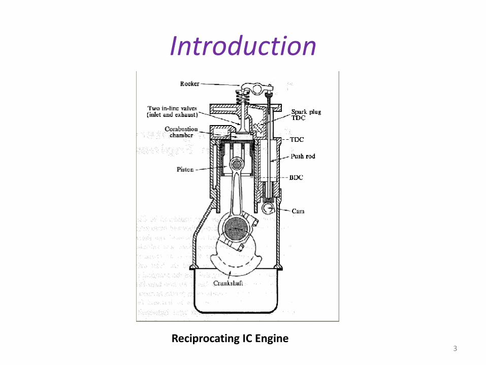
Introduction
Reciprocating IC Engine3
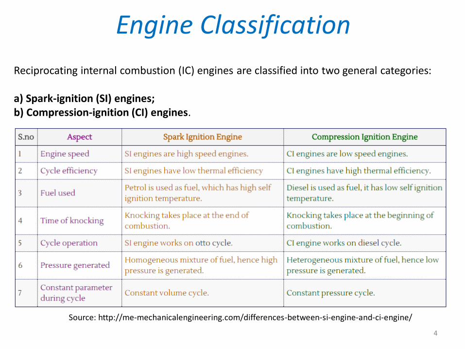
Reciprocating internal combustion (IC) engines are classified into two general categories:
a) Spark-ignition (SI) engines;b) Compression-ignition (CI) engines.
Engine Classification
Source: http://me-mechanicalengineering.com/differences-between-si-engine-and-ci-engine/
4
Description of SI Engines
About SI Engine..
• Run on liquid fuel such as gasoline or petrol, which is mixed with air.• The air-fuel mixture enters the cylinder and is compressed to a higher pressure
and temperature.• A spark from a spark-plug ignites the combustible air-fuel mixture.• It burns and combustion gases is produced.• The high pressure of the gases pushes the piston downwards, producing a
power stroke of the piston.• The crankshaft transforms the reciprocating motion into rotational motion
(rpm), which is carried by gears and drive shaft systems to the wheels, causing the vehicle to move.
5
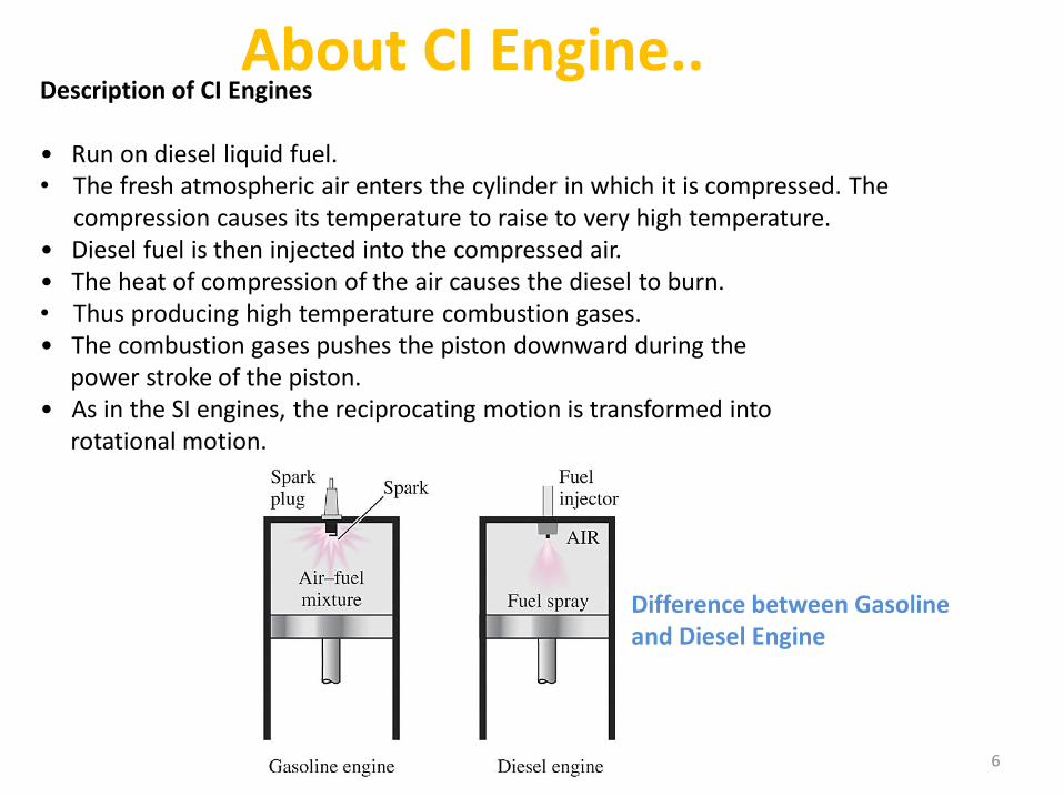
About CI Engine..Description of CI Engines
• Run on diesel liquid fuel.• The fresh atmospheric air enters the cylinder in which it is compressed. The
compression causes its temperature to raise to very high temperature.• Diesel fuel is then injected into the compressed air.• The heat of compression of the air causes the diesel to burn.• Thus producing high temperature combustion gases.• The combustion gases pushes the piston downward during the
power stroke of the piston.• As in the SI engines, the reciprocating motion is transformed into
rotational motion.
Difference between Gasoline and Diesel Engine
6
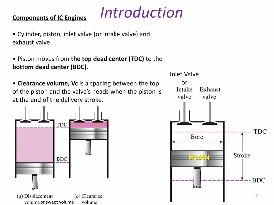
Components of IC Engines
• Cylinder, piston, inlet valve (or intake valve) and exhaust valve.
• Piston moves from the top dead center (TDC) to the bottom dead center (BDC).
• Clearance volume, Vc is a spacing between the top of the piston and the valve’s heads when the piston isat the end of the delivery stroke.
Introduction
PISTON
Inlet Valveor
or swept volume
7
IDEAL CYCLE(OTTO CYCLE and DIESEL CYCLE)
8
9
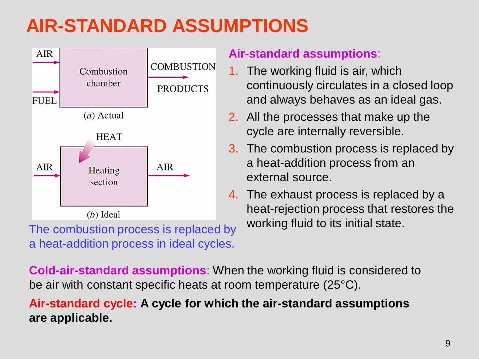
AIR-STANDARD ASSUMPTIONS
The combustion process is replaced by
a heat-addition process in ideal cycles.
Air-standard assumptions:
1. The working fluid is air, which
continuously circulates in a closed loop
and always behaves as an ideal gas.
2. All the processes that make up the
cycle are internally reversible.
3. The combustion process is replaced by
a heat-addition process from an
external source.
4. The exhaust process is replaced by a
heat-rejection process that restores the
working fluid to its initial state.
Cold-air-standard assumptions: When the working fluid is considered to
be air with constant specific heats at room temperature (25°C).
Air-standard cycle: A cycle for which the air-standard assumptions
are applicable.
10
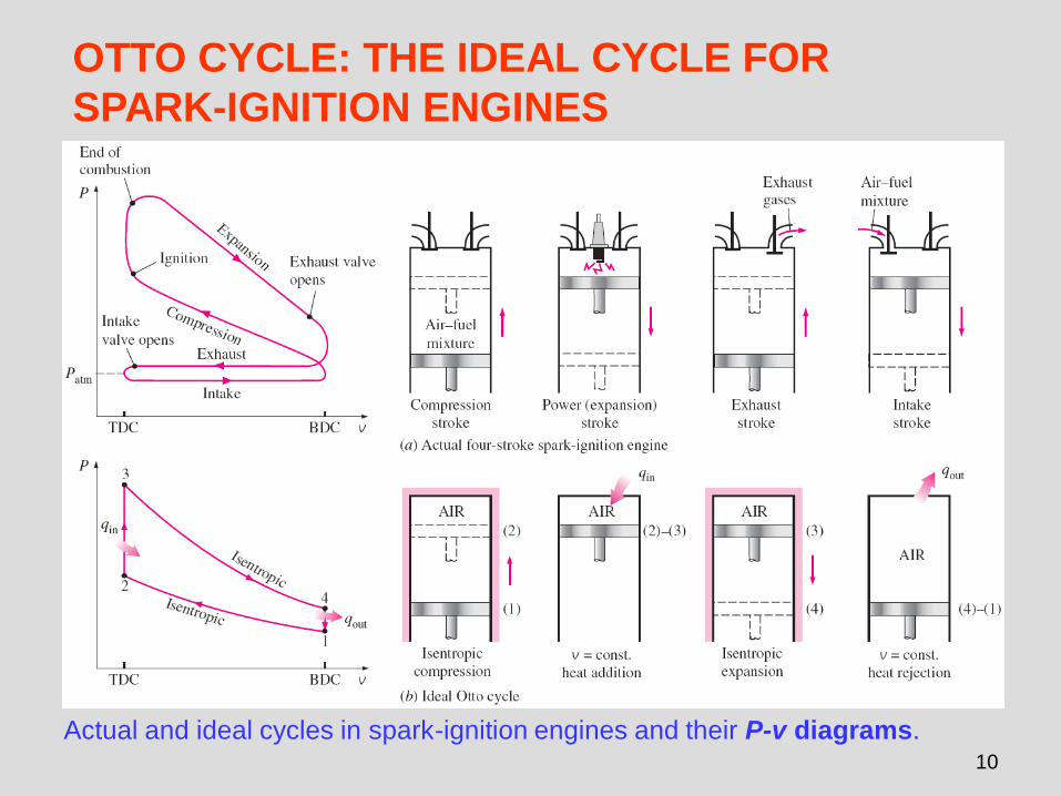
OTTO CYCLE: THE IDEAL CYCLE FOR
SPARK-IGNITION ENGINES
Actual and ideal cycles in spark-ignition engines and their P-v diagrams.
11
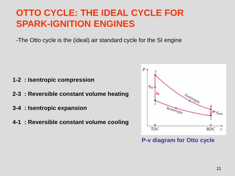
OTTO CYCLE: THE IDEAL CYCLE FOR
SPARK-IGNITION ENGINES
1-2 : Isentropic compression
2-3 : Reversible constant volume heating
3-4 : Isentropic expansion
4-1 : Reversible constant volume cooling
P-v diagram for Otto cycle
-The Otto cycle is the (ideal) air standard cycle for the SI engine
12
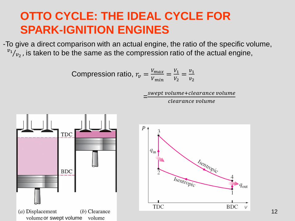
OTTO CYCLE: THE IDEAL CYCLE FOR
SPARK-IGNITION ENGINES-To give a direct comparison with an actual engine, the ratio of the specific volume,
Τ𝑣1 𝑣2 , is taken to be the same as the compression ratio of the actual engine,
Compression ratio, 𝑟𝑣 =𝑉𝑚𝑎𝑥
𝑉𝑚𝑖𝑛=
𝑉1
𝑉2=
𝑣1
𝑣2
=𝑠𝑤𝑒𝑝𝑡 𝑣𝑜𝑙𝑢𝑚𝑒+𝑐𝑙𝑒𝑎𝑟𝑎𝑛𝑐𝑒 𝑣𝑜𝑙𝑢𝑚𝑒
𝑐𝑙𝑒𝑎𝑟𝑎𝑛𝑐𝑒 𝑣𝑜𝑙𝑢𝑚𝑒
or swept volume
13
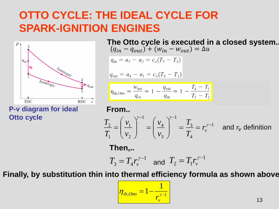
OTTO CYCLE: THE IDEAL CYCLE FOR
SPARK-IGNITION ENGINES
From..
and 𝑟𝑣 definition
Then,..
Finally, by substitution thin into thermal efficiency formula as shown above,
(𝑞𝑖𝑛 − 𝑞𝑜𝑢𝑡) + (𝑤𝑖𝑛 − 𝑤𝑜𝑢𝑡) = ∆𝑢The Otto cycle is executed in a closed system..
P-v diagram for ideal
Otto cycle1
4
3
1
3
4
1
2
1
1
2 −
−−
==
=
=
vrT
T
v
v
v
v
T
T
1
43
−= vrTT and
1
12
−= vrTT
1,
11
−−=
v
Ottothr
14
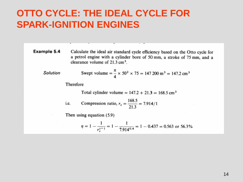
OTTO CYCLE: THE IDEAL CYCLE FOR
SPARK-IGNITION ENGINES
15
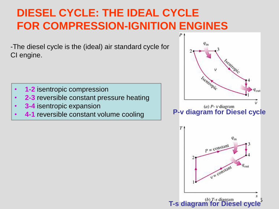
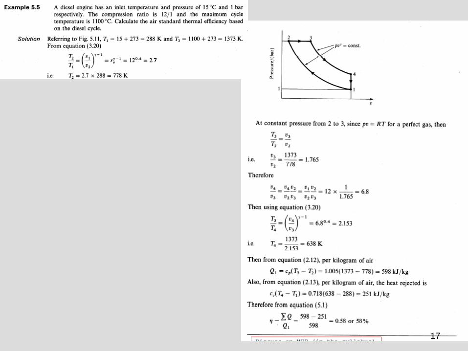
DIESEL CYCLE: THE IDEAL CYCLE
FOR COMPRESSION-IGNITION ENGINES
• 1-2 isentropic compression
• 2-3 reversible constant pressure heating
• 3-4 isentropic expansion
• 4-1 reversible constant volume cooling P-v diagram for Diesel cycle
T-s diagram for Diesel cycle
-The diesel cycle is the (ideal) air standard cycle for
CI engine.
16
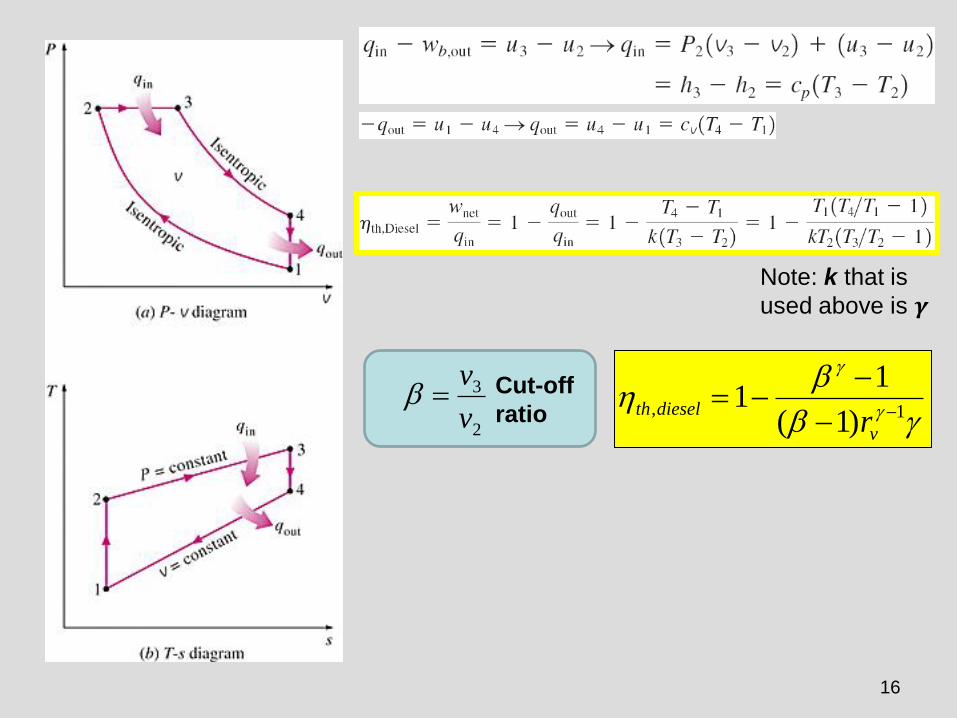
Cut-off
ratio2
3
v
v=
1,)1(
11
−−
−−=
v
dieselthr
Note: k that is
used above is 𝜸
17
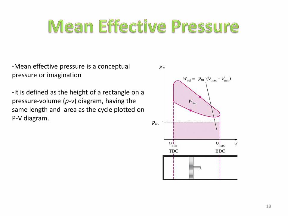
-Mean effective pressure is a conceptual pressure or imagination
-It is defined as the height of a rectangle on a pressure-volume (p-v) diagram, having the same length and area as the cycle plotted on P-V diagram.
𝑝𝑚
𝑝𝑚
18
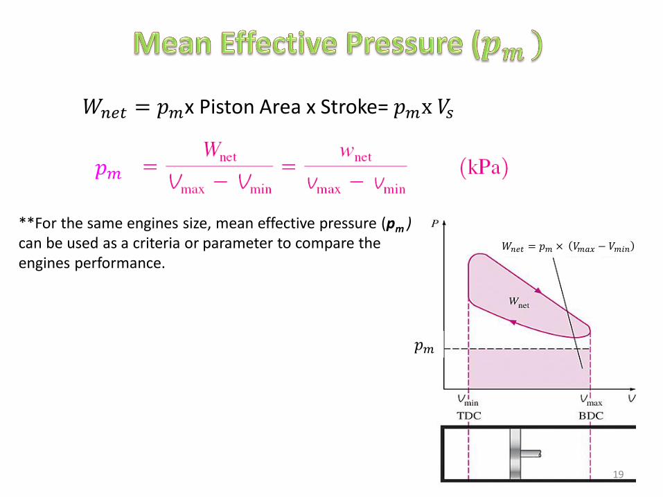
**For the same engines size, mean effective pressure (pm )can be used as a criteria or parameter to compare the engines performance.
𝑝𝑚
𝑊𝑛𝑒𝑡 = 𝑝𝑚x Piston Area x Stroke= 𝑝𝑚x 𝑉𝑠
𝑊𝑛𝑒𝑡 = 𝑝𝑚 × 𝑉𝑚𝑎𝑥 − 𝑉𝑚𝑖𝑛
𝑝𝑚
19
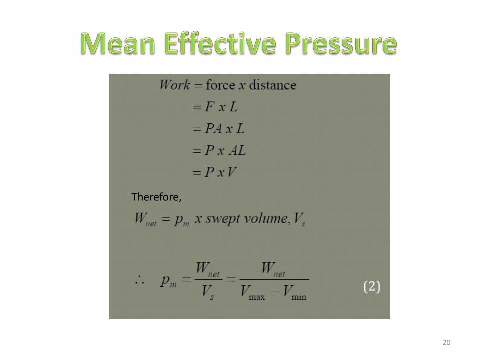
Therefore,
20
CRITERIA PERFORMANCEFOR ACTUAL CYCLE
21
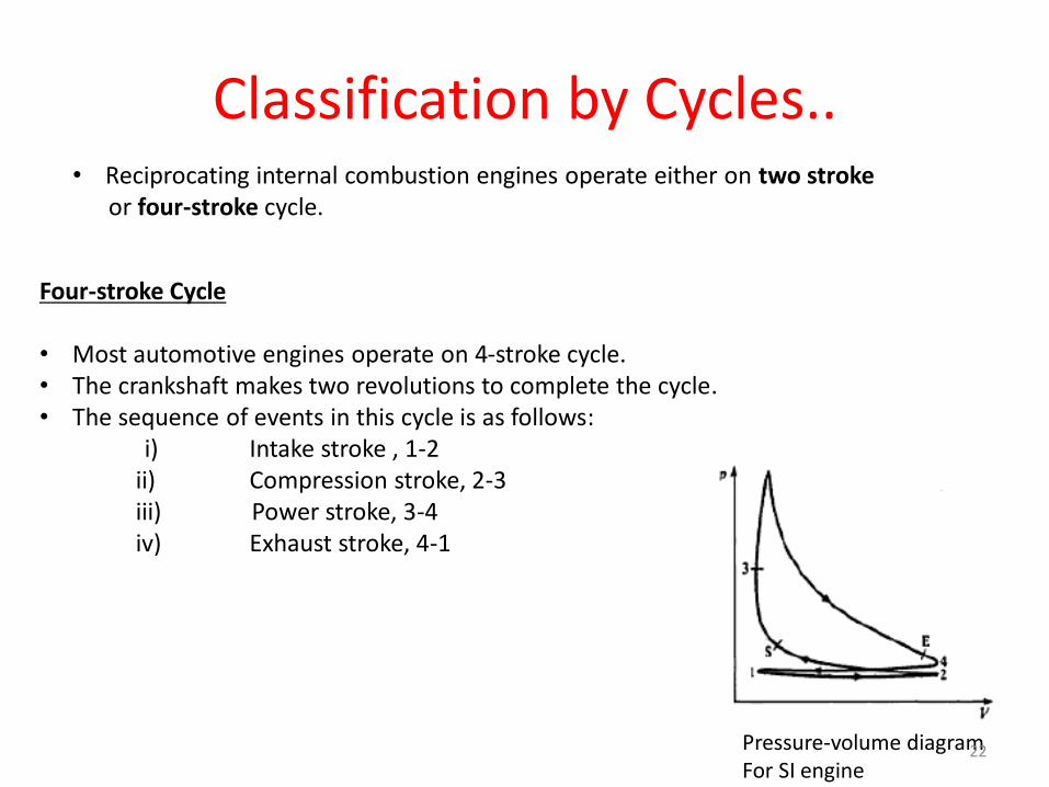
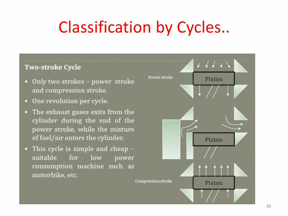
Classification by Cycles..• Reciprocating internal combustion engines operate either on two stroke
or four-stroke cycle.
Four-stroke Cycle
• Most automotive engines operate on 4-stroke cycle.• The crankshaft makes two revolutions to complete the cycle.• The sequence of events in this cycle is as follows:
i) Intake stroke , 1-2ii) Compression stroke, 2-3iii) Power stroke, 3-4iv) Exhaust stroke, 4-1
Pressure-volume diagramFor SI engine
22
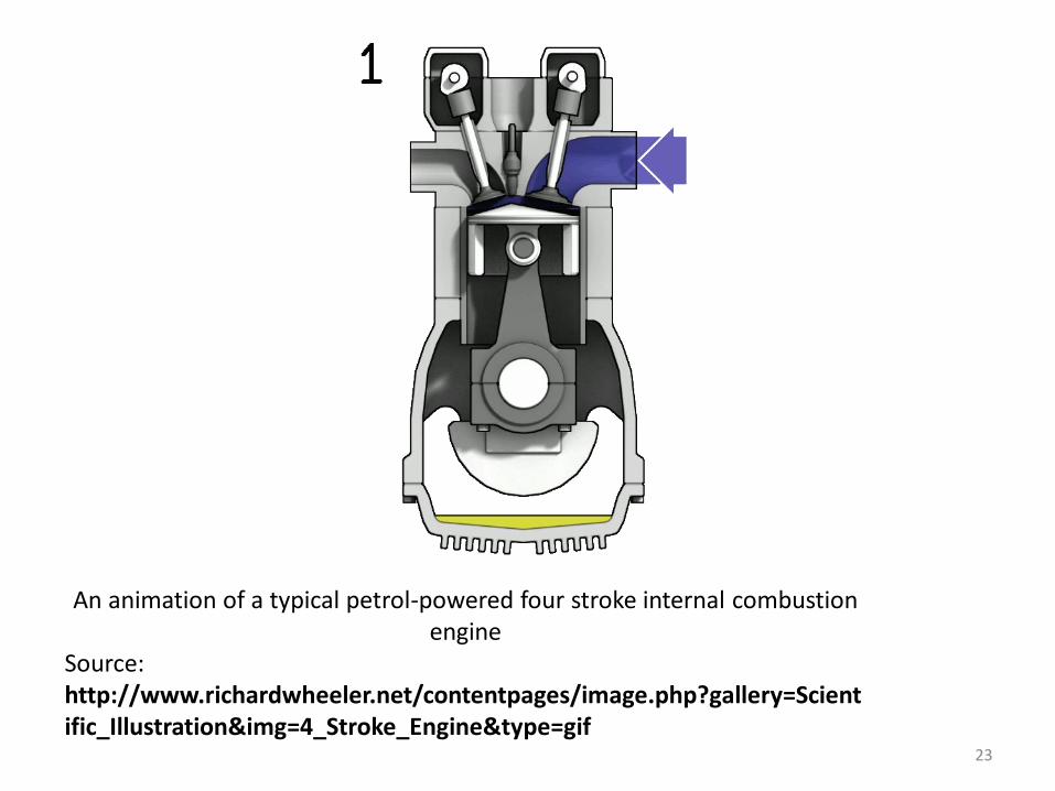
An animation of a typical petrol-powered four stroke internal combustion engine
Source: http://www.richardwheeler.net/contentpages/image.php?gallery=Scientific_Illustration&img=4_Stroke_Engine&type=gif
23
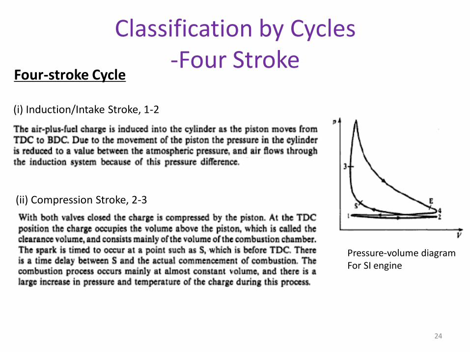
Four-stroke Cycle
(ii) Compression Stroke, 2-3
Pressure-volume diagramFor SI engine
(i) Induction/Intake Stroke, 1-2
Classification by Cycles-Four Stroke
24
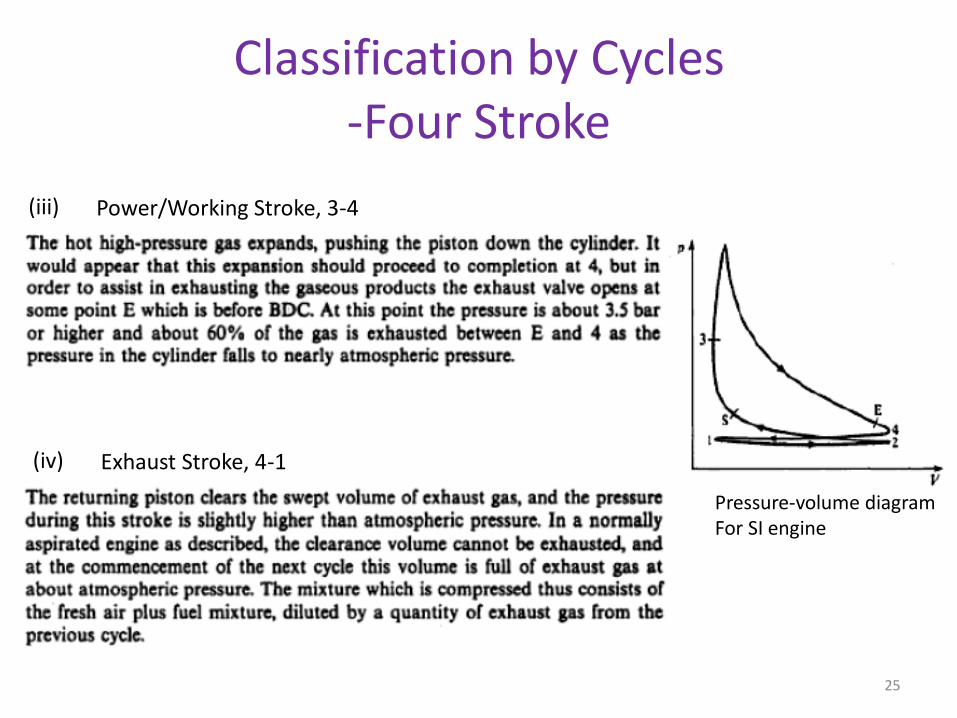
(iii) Power/Working Stroke, 3-4
(iv) Exhaust Stroke, 4-1
Pressure-volume diagramFor SI engine
Classification by Cycles-Four Stroke
25
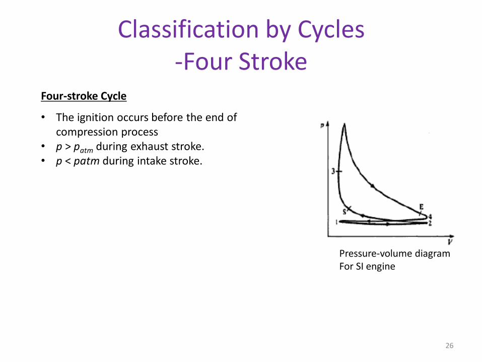
• The ignition occurs before the end of compression process
• p > patm during exhaust stroke.• p < patm during intake stroke.
Four-stroke Cycle
Pressure-volume diagramFor SI engine
Classification by Cycles-Four Stroke
26

An animation of a typical petrol-powered four stroke internal combustion engine
Source: http://www.richardwheeler.net/contentpages/image.php?gallery=Scientific_Illustration&img=4_Stroke_Engine&type=gif
27
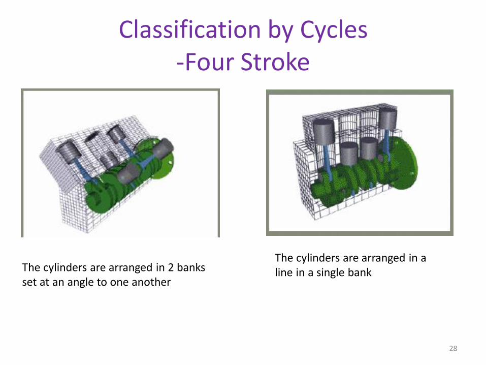
Classification by Cycles-Four Stroke
The cylinders are arranged in 2 banks set at an angle to one another
The cylinders are arranged in a line in a single bank
28
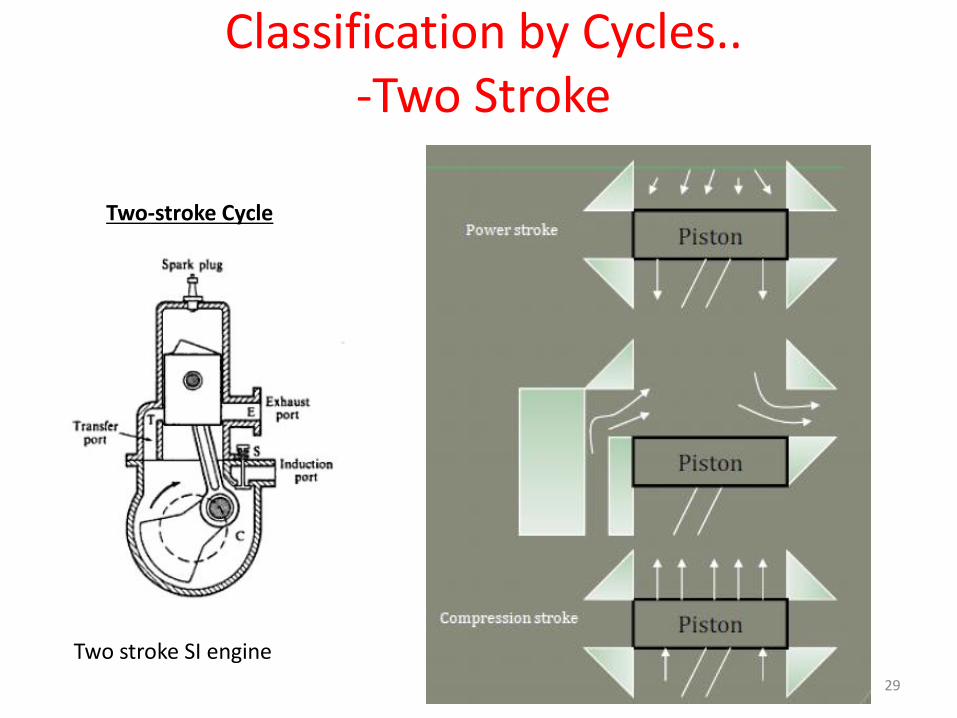
Two stroke SI engine
Two-stroke Cycle
Classification by Cycles..-Two Stroke
29
Classification by Cycles..
30
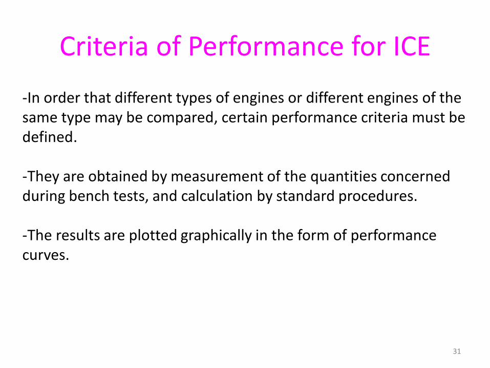
Criteria of Performance for ICE
-In order that different types of engines or different engines of the same type may be compared, certain performance criteria must be defined.
-They are obtained by measurement of the quantities concerned during bench tests, and calculation by standard procedures.
-The results are plotted graphically in the form of performance curves.
31
Criteria of Performance for ICE-Indicated Power (ip)
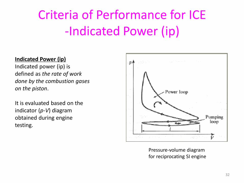
Indicated Power (ip)Indicated power (ip) isdefined as the rate of workdone by the combustion gaseson the piston.
It is evaluated based on theindicator (p-V) diagramobtained during enginetesting.
Pressure-volume diagramfor reciprocating SI engine
32
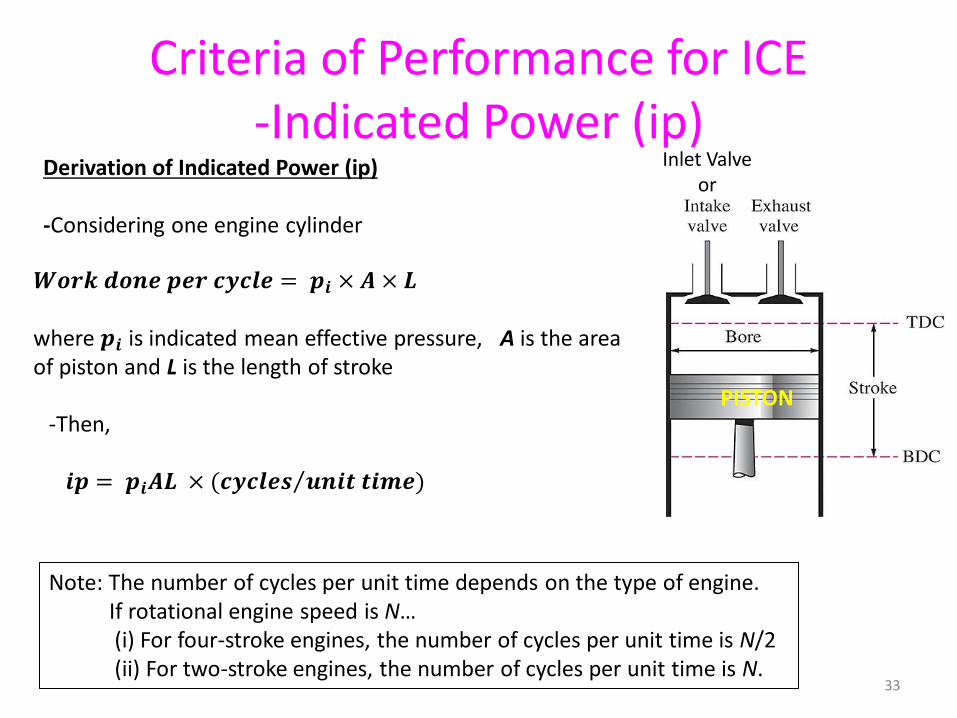
Derivation of Indicated Power (ip)
-Considering one engine cylinder
𝑾𝒐𝒓𝒌 𝒅𝒐𝒏𝒆 𝒑𝒆𝒓 𝒄𝒚𝒄𝒍𝒆 = 𝒑𝒊 × 𝑨 × 𝑳
where 𝒑𝒊 is indicated mean effective pressure, A is the area of piston and L is the length of stroke
-Then,
𝒊𝒑 = 𝒑𝒊𝑨𝑳 × ( Τ𝒄𝒚𝒄𝒍𝒆𝒔 𝒖𝒏𝒊𝒕 𝒕𝒊𝒎𝒆)
Note: The number of cycles per unit time depends on the type of engine.If rotational engine speed is N…(i) For four-stroke engines, the number of cycles per unit time is N/2 (ii) For two-stroke engines, the number of cycles per unit time is N.
Criteria of Performance for ICE-Indicated Power (ip)
PISTON
Inlet Valveor
33
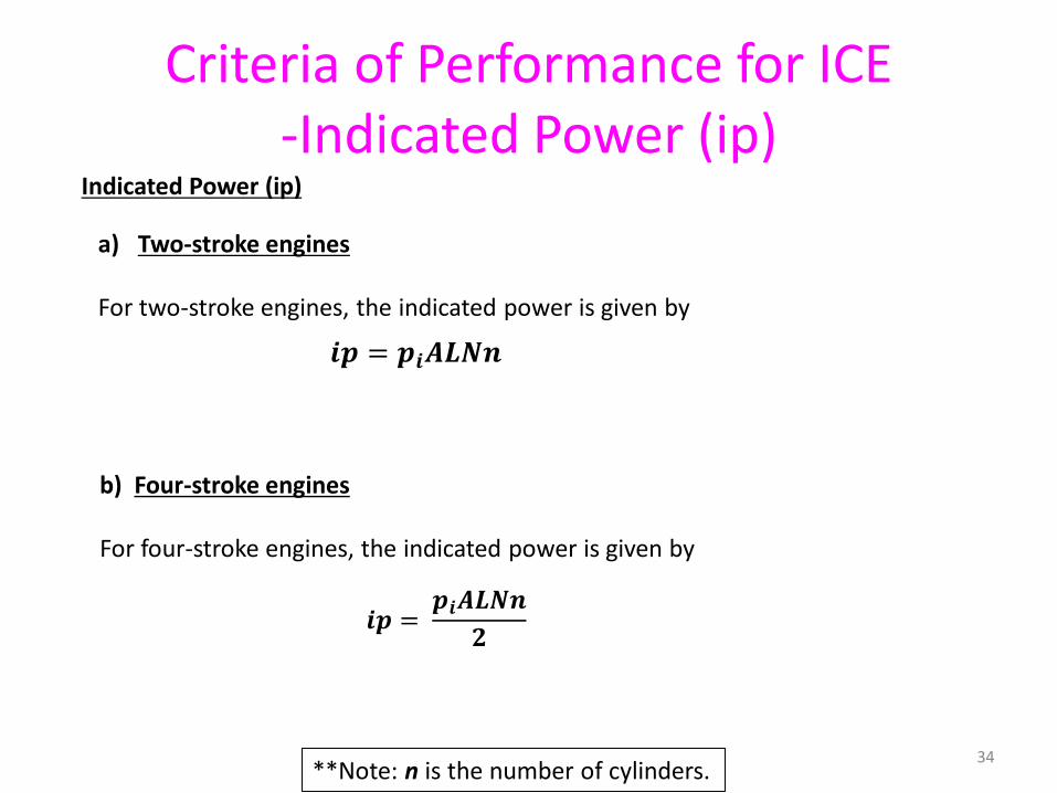
Indicated Power (ip)
𝒊𝒑 = 𝒑𝒊𝑨𝑳𝑵𝒏
a) Two-stroke engines
For two-stroke engines, the indicated power is given by
𝒊𝒑 =𝒑𝒊𝑨𝑳𝑵𝒏
𝟐
b) Four-stroke engines
For four-stroke engines, the indicated power is given by
**Note: n is the number of cylinders.
Criteria of Performance for ICE-Indicated Power (ip)
34
Indicated Power (ip)
where A = area of pistonL = length of stroke of the pistonN = rotational speed of engine n = number of cylinders𝒑𝒊=indicated mean effective pressure
Criteria of Performance for ICE-Indicated Power (ip)
-Actually, how the indicated mean effective pressure is obtained?
35
Criteria of Performance for ICE-Indicated Power (ip)
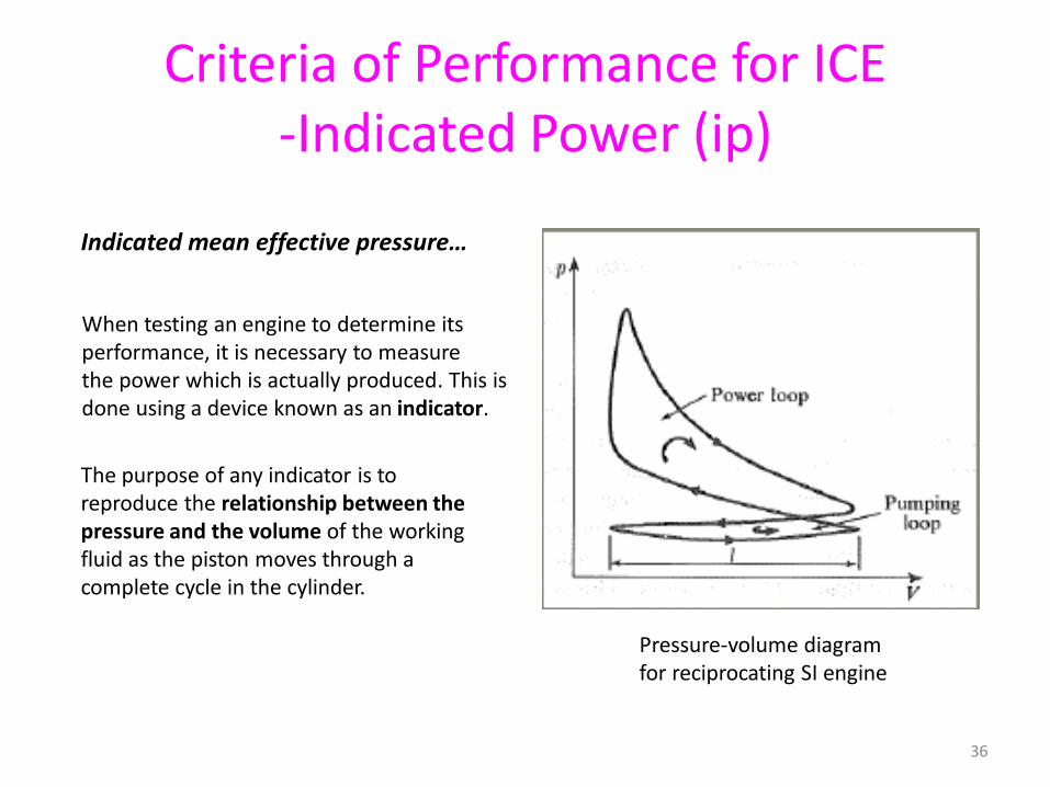
Indicated mean effective pressure…
When testing an engine to determine itsperformance, it is necessary to measurethe power which is actually produced. This isdone using a device known as an indicator.
Pressure-volume diagramfor reciprocating SI engine
The purpose of any indicator is toreproduce the relationship between thepressure and the volume of the workingfluid as the piston moves through acomplete cycle in the cylinder.
36
Criteria of Performance for ICE-Indicated Power (ip)
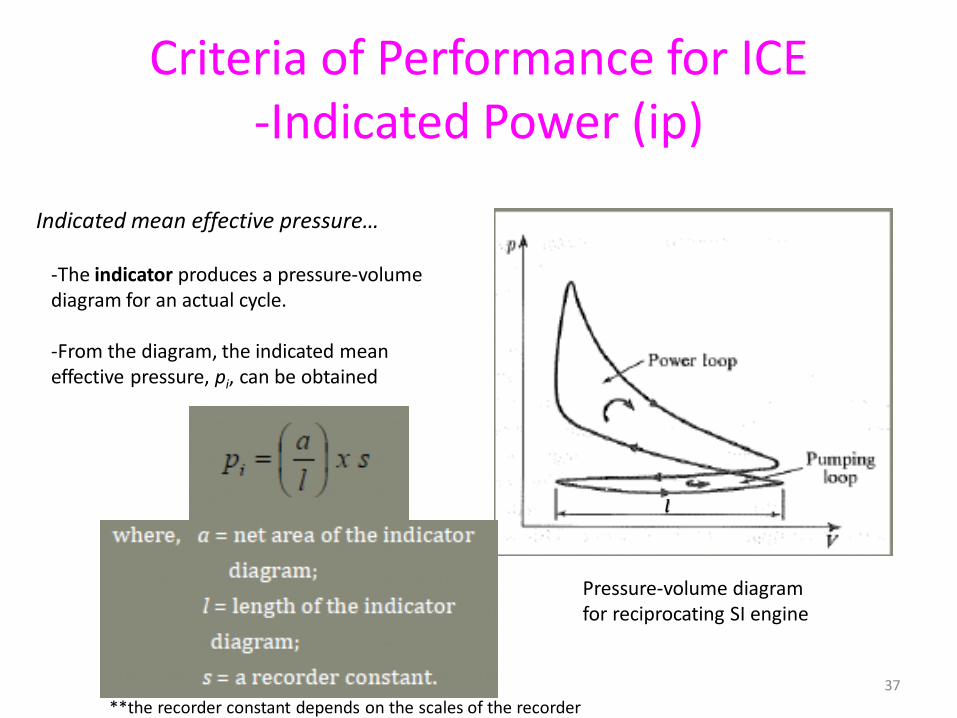
Pressure-volume diagramfor reciprocating SI engine
-The indicator produces a pressure-volumediagram for an actual cycle.
-From the diagram, the indicated meaneffective pressure, pi, can be obtained
Indicated mean effective pressure…
𝑙
**the recorder constant depends on the scales of the recorder37
Criteria of Performance for ICE-Brake Power (bp)
Brake Power (bp)
-The power measured at the output shaft of the engine is known as the brake power of the engine.
-The indicated power developed by the engine is the power available at the piston-cylinder.
-This mechanical power, in the form of linear motion of the piston, is transmitted through the connecting rod and the crankshaft, to be transformed into rotary power at the output shaft.
-However, during this process some of the power is used to overcome the frictional resistance between the moving parts.
38
Criteria of Performance for ICE-Brake Power (bp)
Brake Power (bp)
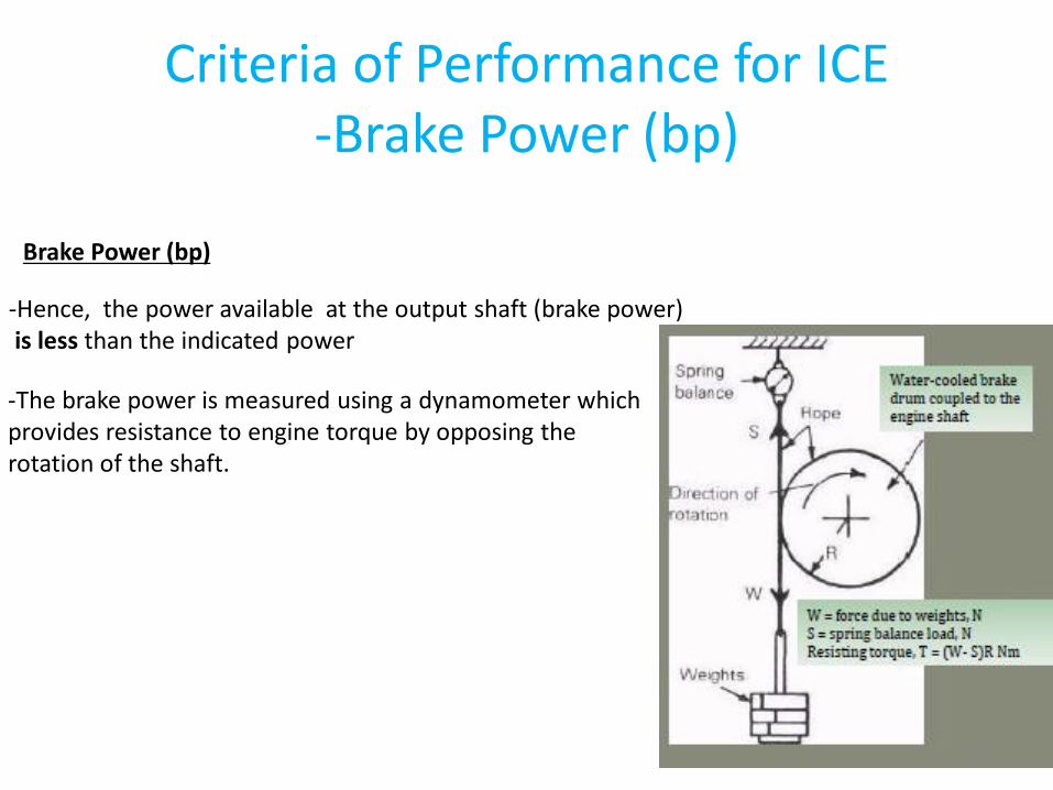
-Hence, the power available at the output shaft (brake power) is less than the indicated power
-The brake power is measured using a dynamometer which provides resistance to engine torque by opposing the rotation of the shaft.
39
Criteria of Performance for ICE-Brake Power (bp)
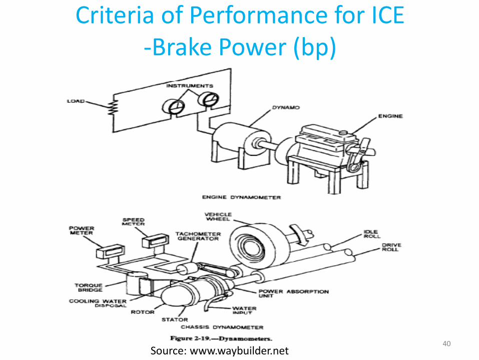
Source: www.waybuilder.net40
Criteria of Performance for ICE-Brake Power (bp)
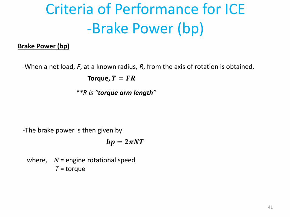
Brake Power (bp)
-When a net load, F, at a known radius, R, from the axis of rotation is obtained,
Torque, 𝑻 = 𝑭𝑹
-The brake power is then given by
𝒃𝒑 = 𝟐𝝅𝑵𝑻
where, N = engine rotational speedT = torque
**R is “torque arm length”
41
Criteria of Performance for ICE-Friction Power
Friction Power (fp)
Friction power (fp) is the amount of power needed to overcome friction resistance in many moving parts of the engine.We have,
42
Criteria of Performance for ICE-Mechanical Efficiency
Mechanical Efficiency (ηm)
-The mechanical efficiency of an IC engine is defined as
-Typical IC engines have mechanical efficiency of 80 to 90 %.
43
Criteria of Performance for ICE-Brake Mean Effective Pressure (BMEP)
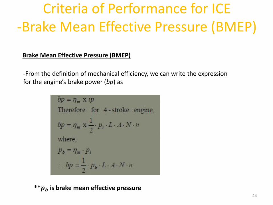
-From the definition of mechanical efficiency, we can write the expression for the engine’s brake power (bp) as
Brake Mean Effective Pressure (BMEP)
**𝒑𝒃 is brake mean effective pressure44
Criteria of Performance for ICE-Brake Mean Effective Pressure (BMEP)
45
Criteria of Performance for ICE-Brake Mean Effective Pressure (BMEP)
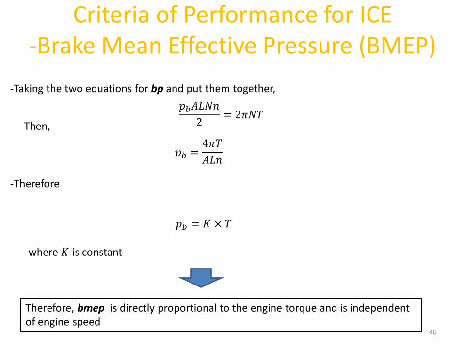
-Taking the two equations for bp and put them together,
𝑝𝑏𝐴𝐿𝑁𝑛
2= 2𝜋𝑁𝑇
-Therefore
𝑝𝑏 = 𝐾 × 𝑇
Then,
𝑝𝑏 =4𝜋𝑇
𝐴𝐿𝑛
where 𝐾 is constant
Therefore, bmep is directly proportional to the engine torque and is independent of engine speed
46
Criteria of Performance for ICE-Brake Thermal Efficiency
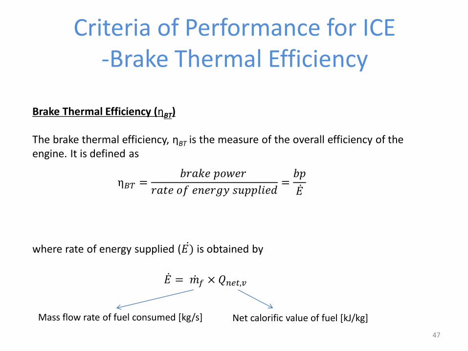
Brake Thermal Efficiency (ηBT)
The brake thermal efficiency, ηBT is the measure of the overall efficiency of the engine. It is defined as
η𝐵𝑇 =𝑏𝑟𝑎𝑘𝑒 𝑝𝑜𝑤𝑒𝑟
𝑟𝑎𝑡𝑒 𝑜𝑓 𝑒𝑛𝑒𝑟𝑔𝑦 𝑠𝑢𝑝𝑝𝑙𝑖𝑒𝑑=𝑏𝑝
ሶ𝐸
where rate of energy supplied ( ሶ𝐸) is obtained by
ሶ𝐸 = ሶ𝑚𝑓 × 𝑄𝑛𝑒𝑡,𝑣
Mass flow rate of fuel consumed [kg/s] Net calorific value of fuel [kJ/kg]
47
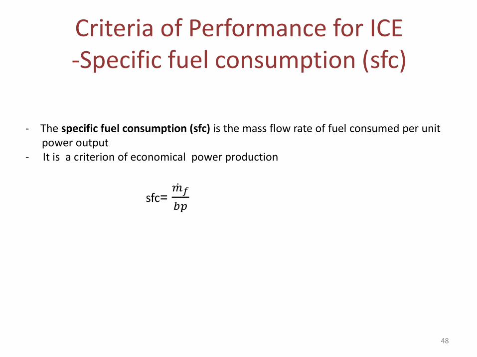
Criteria of Performance for ICE-Specific fuel consumption (sfc)
- The specific fuel consumption (sfc) is the mass flow rate of fuel consumed per unit power output
- It is a criterion of economical power production
sfc= ሶ𝑚𝑓
𝑏𝑝
48
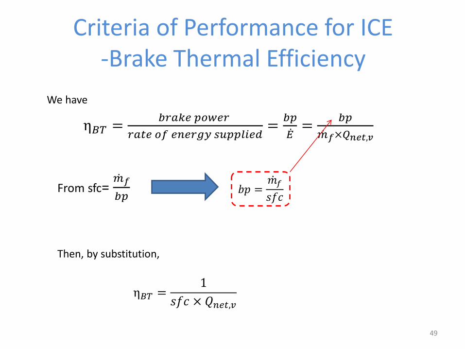
Criteria of Performance for ICE-Brake Thermal Efficiency
η𝐵𝑇 =𝑏𝑟𝑎𝑘𝑒 𝑝𝑜𝑤𝑒𝑟
𝑟𝑎𝑡𝑒 𝑜𝑓 𝑒𝑛𝑒𝑟𝑔𝑦 𝑠𝑢𝑝𝑝𝑙𝑖𝑒𝑑=
𝑏𝑝
ሶ𝐸=
𝑏𝑝
ሶ𝑚𝑓×𝑄𝑛𝑒𝑡,𝑣
From sfc= ሶ𝑚𝑓
𝑏𝑝
We have
𝑏𝑝 =ሶ𝑚𝑓
𝑠𝑓𝑐
Then, by substitution,
η𝐵𝑇 =1
𝑠𝑓𝑐 × 𝑄𝑛𝑒𝑡,𝑣
49
Criteria of Performance for ICE-Indicated Thermal Efficiency
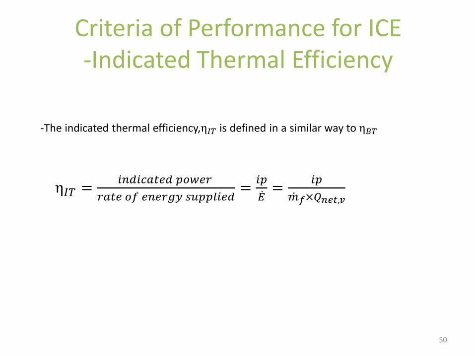
-The indicated thermal efficiency,η𝐼𝑇 is defined in a similar way to η𝐵𝑇
η𝐼𝑇 =𝑖𝑛𝑑𝑖𝑐𝑎𝑡𝑒𝑑 𝑝𝑜𝑤𝑒𝑟
𝑟𝑎𝑡𝑒 𝑜𝑓 𝑒𝑛𝑒𝑟𝑔𝑦 𝑠𝑢𝑝𝑝𝑙𝑖𝑒𝑑=
𝑖𝑝
ሶ𝐸=
𝑖𝑝
ሶ𝑚𝑓×𝑄𝑛𝑒𝑡,𝑣
50
Criteria of Performance for ICE-Indicated Thermal Efficiency
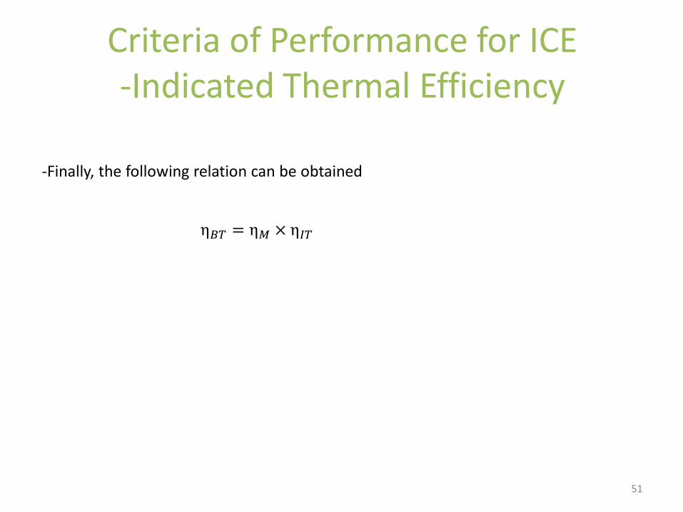
-Finally, the following relation can be obtained
η𝐵𝑇 = η𝑀 × η𝐼𝑇
51
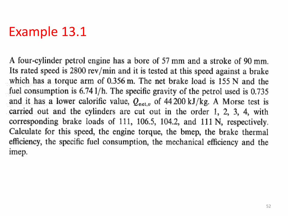
Example 13.1
52
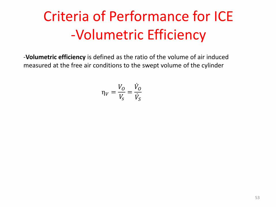
Criteria of Performance for ICE-Volumetric Efficiency
-Volumetric efficiency is defined as the ratio of the volume of air induced measured at the free air conditions to the swept volume of the cylinder
η𝑉 =𝑉𝑂𝑉𝑠
=ሶ𝑉𝑂ሶ𝑉𝑆
53
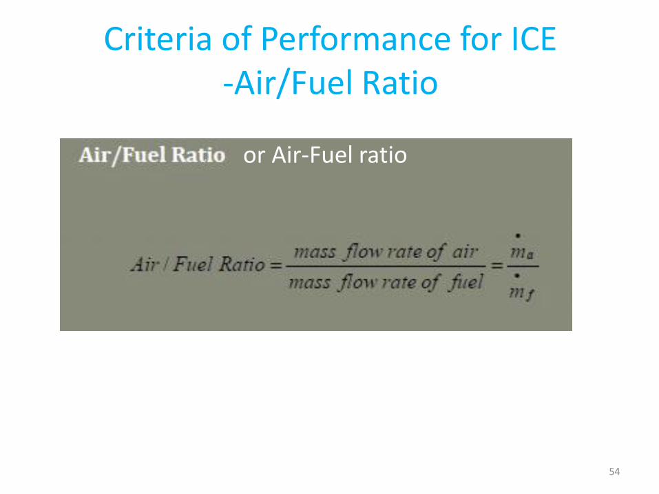
Criteria of Performance for ICE-Air/Fuel Ratio
or Air-Fuel ratio
54
THE MORSE TEST..
• Morse test is an experimental procedure for determining the engine’s indicated power without having to compute the mean effective pressure, pi of the engine.
• This indicated power is evaluated outside the cylinders. This test is only applicable to multi-cylinder engines, is carried out at constant speed (rpm).
55
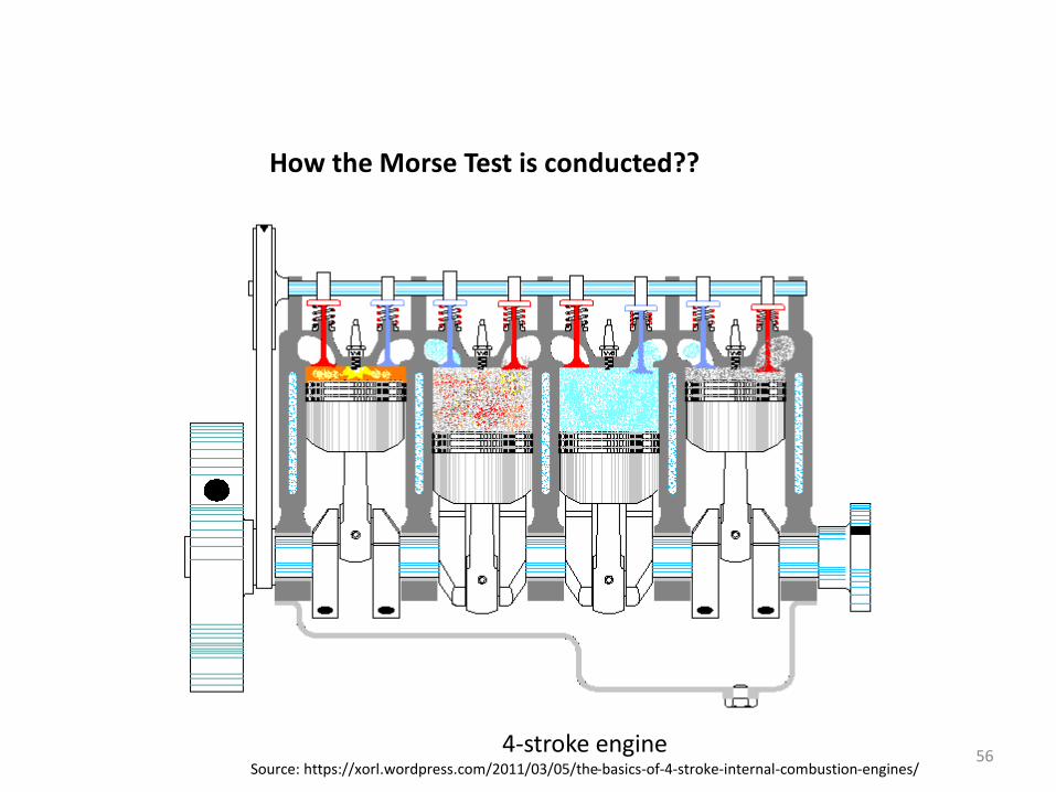
4-stroke engineSource: https://xorl.wordpress.com/2011/03/05/the-basics-of-4-stroke-internal-combustion-engines/
How the Morse Test is conducted??
56
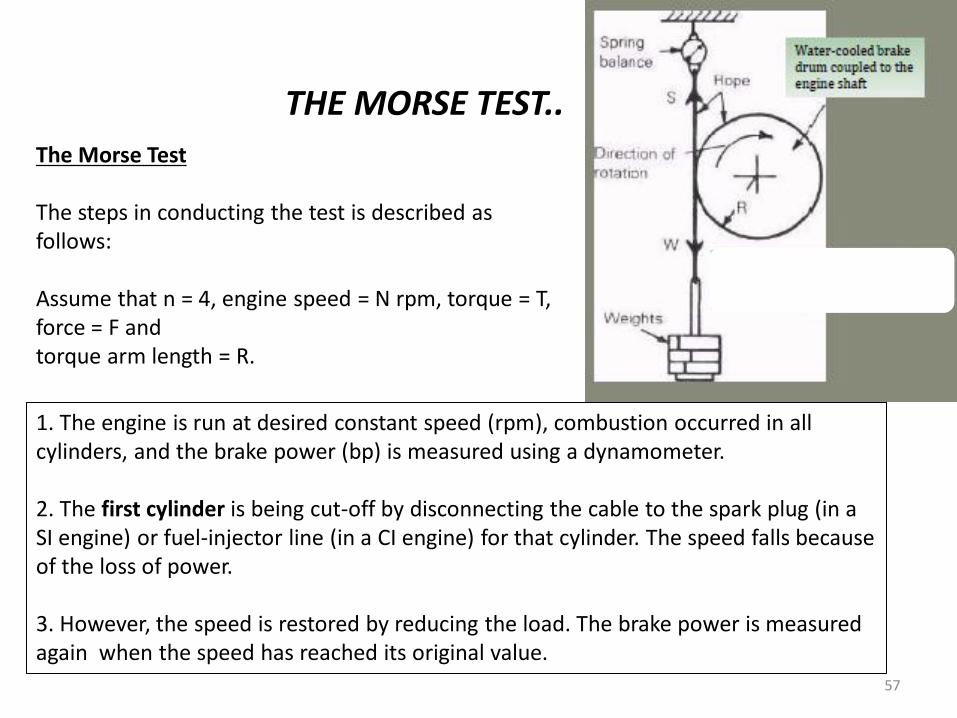
The Morse Test
The steps in conducting the test is described as follows:
Assume that n = 4, engine speed = N rpm, torque = T, force = F and torque arm length = R.
THE MORSE TEST..
1. The engine is run at desired constant speed (rpm), combustion occurred in all cylinders, and the brake power (bp) is measured using a dynamometer.
2. The first cylinder is being cut-off by disconnecting the cable to the spark plug (in a SI engine) or fuel-injector line (in a CI engine) for that cylinder. The speed falls because of the loss of power.
3. However, the speed is restored by reducing the load. The brake power is measured again when the speed has reached its original value.
57
THE MORSE TEST..
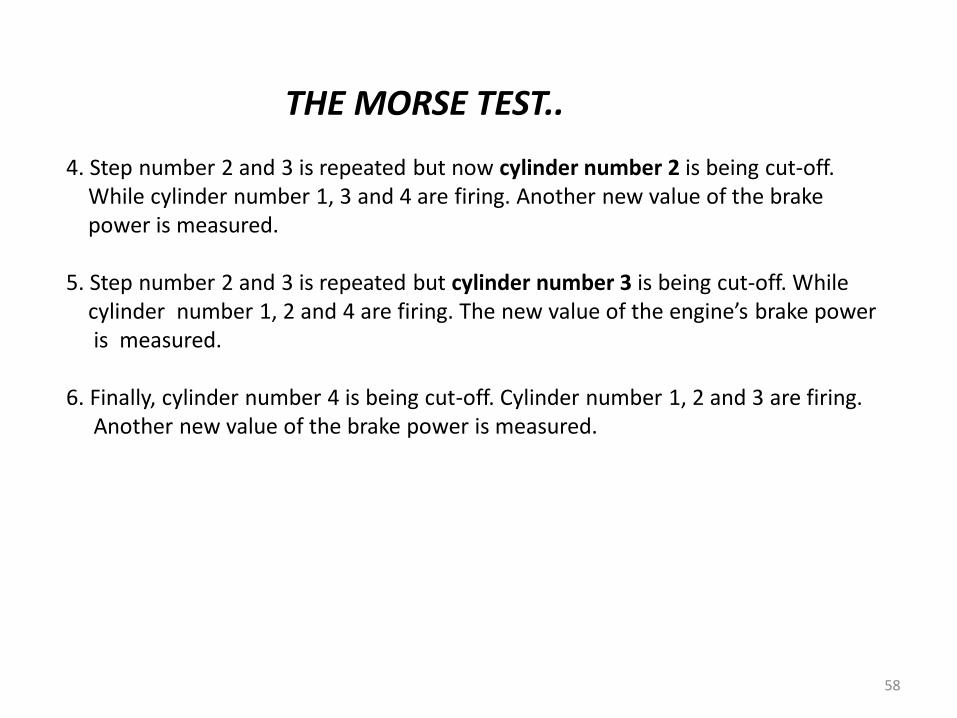
4. Step number 2 and 3 is repeated but now cylinder number 2 is being cut-off. While cylinder number 1, 3 and 4 are firing. Another new value of the brake power is measured.
5. Step number 2 and 3 is repeated but cylinder number 3 is being cut-off. While cylinder number 1, 2 and 4 are firing. The new value of the engine’s brake power is measured.
6. Finally, cylinder number 4 is being cut-off. Cylinder number 1, 2 and 3 are firing. Another new value of the brake power is measured.
58
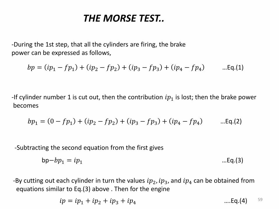
-During the 1st step, that all the cylinders are firing, the brakepower can be expressed as follows,
THE MORSE TEST..
𝑏𝑝 = 𝑖𝑝1 − 𝑓𝑝1 + 𝑖𝑝2 − 𝑓𝑝2 + 𝑖𝑝3 − 𝑓𝑝3 + 𝑖𝑝4 − 𝑓𝑝4 …Eq.(1)
-If cylinder number 1 is cut out, then the contribution 𝑖𝑝1 is lost; then the brake powerbecomes
𝑏𝑝1 = 0 − 𝑓𝑝1 + 𝑖𝑝2 − 𝑓𝑝2 + 𝑖𝑝3 − 𝑓𝑝3 + 𝑖𝑝4 − 𝑓𝑝4 …Eq.(2)
-Subtracting the second equation from the first gives
bp−𝑏𝑝1 = 𝑖𝑝1 …Eq.(3)
-By cutting out each cylinder in turn the values 𝑖𝑝2, 𝑖𝑝3, and 𝑖𝑝4 can be obtained from equations similar to Eq.(3) above . Then for the engine
𝑖𝑝 = 𝑖𝑝1 + 𝑖𝑝2 + 𝑖𝑝3 + 𝑖𝑝4 ….Eq.(4) 59
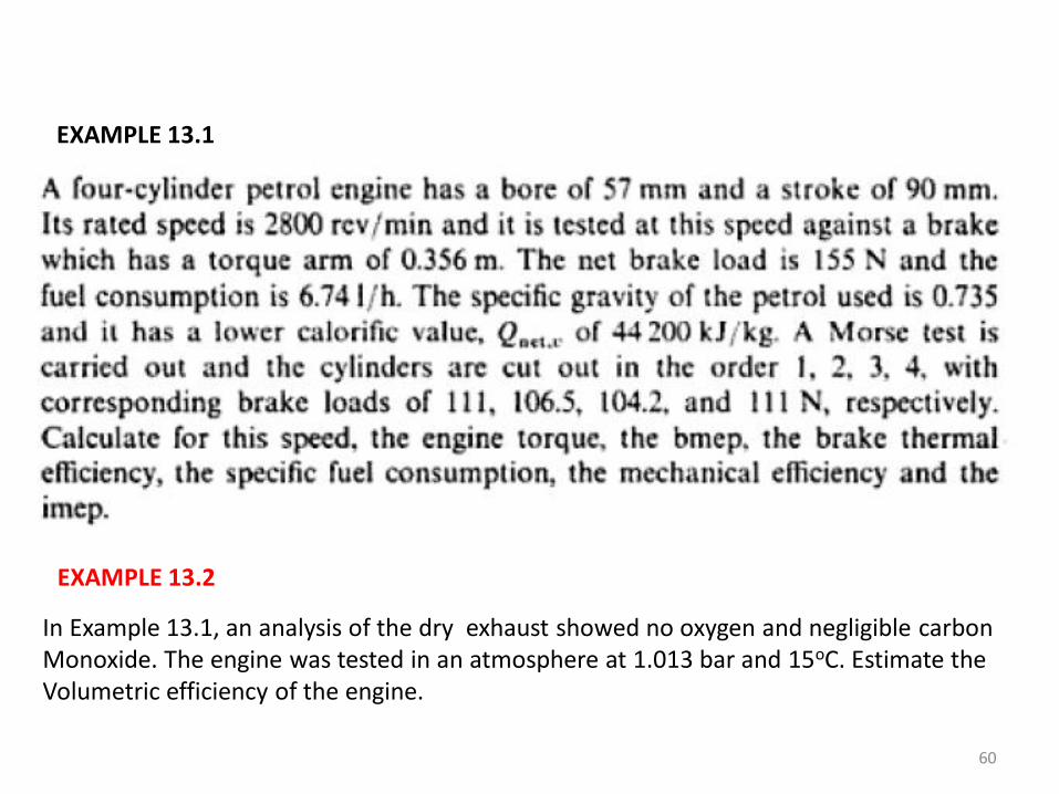
EXAMPLE 13.1
EXAMPLE 13.2
In Example 13.1, an analysis of the dry exhaust showed no oxygen and negligible carbonMonoxide. The engine was tested in an atmosphere at 1.013 bar and 15oC. Estimate the Volumetric efficiency of the engine.
60
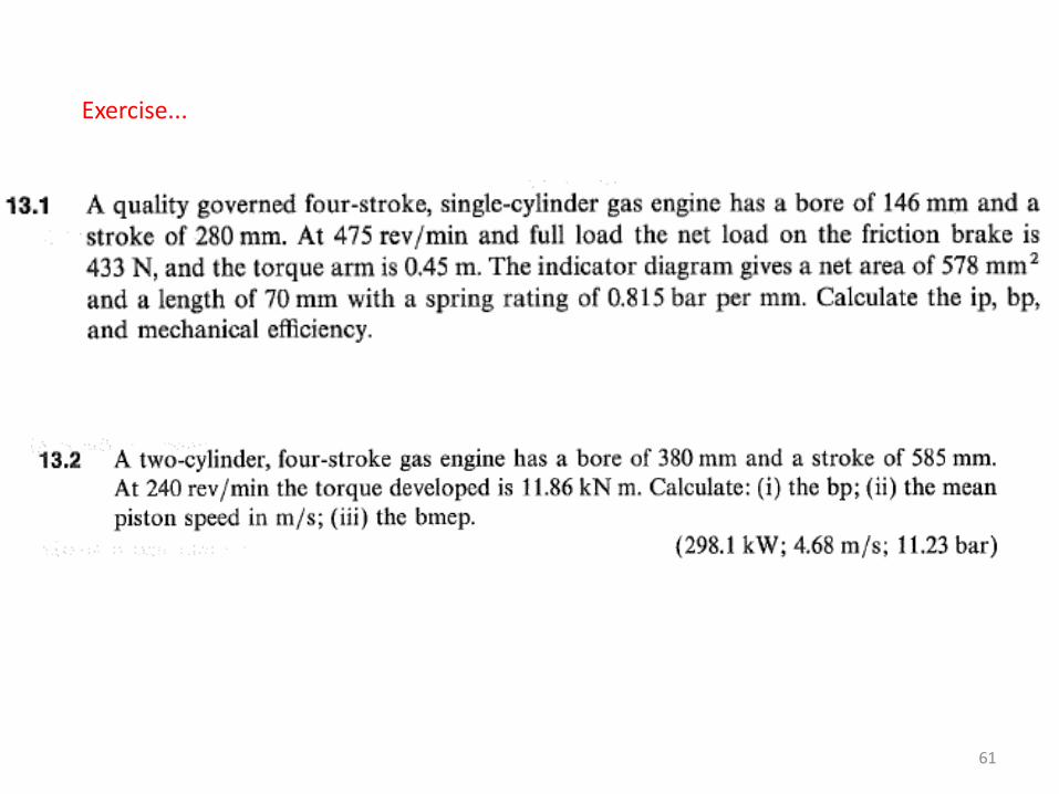
Exercise...
61
Exercise...
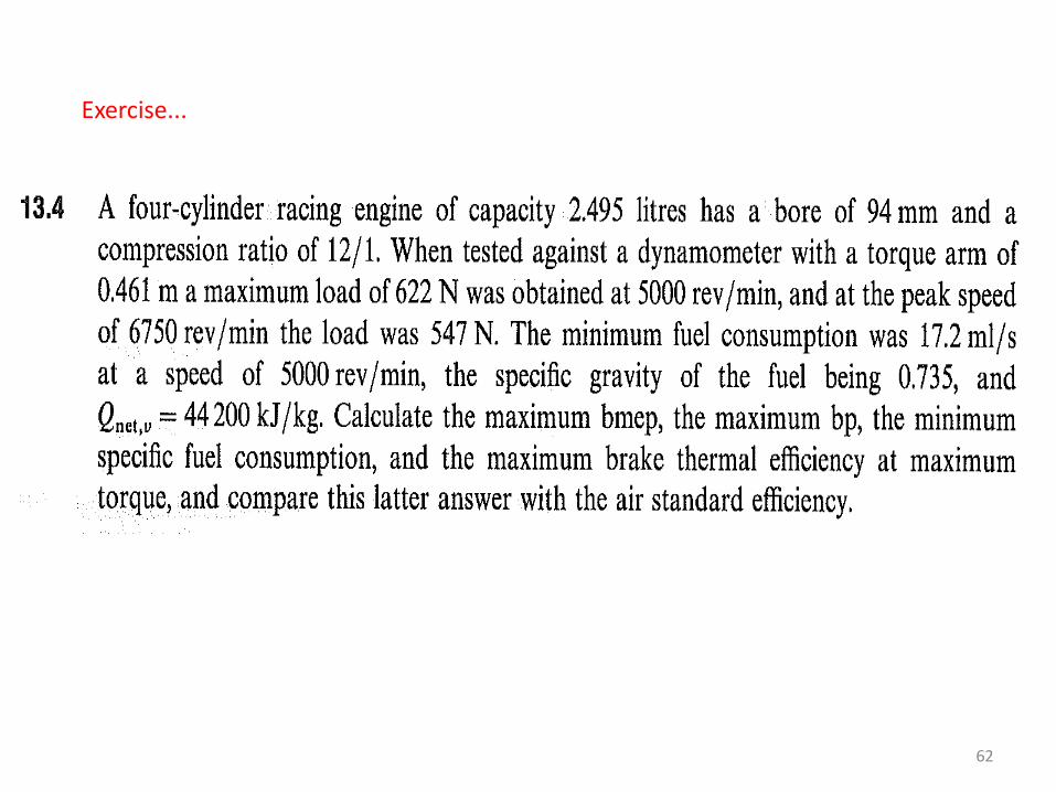
62
Exercise...
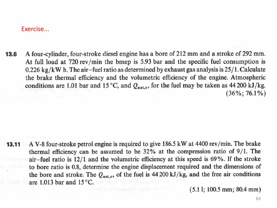
63
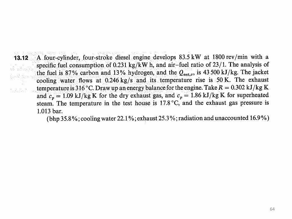
64