instruction manual - axpert-opti torque - amtech electronics
TRANSCRIPT
IMAOT-01, Rev. 1.9 NOV 2012
NOTICE
1. Read this manual thoroughly before using the Axpert-Opti torque, and store in a safe place for reference.2. Make sure that this manual is delivered to the final user.
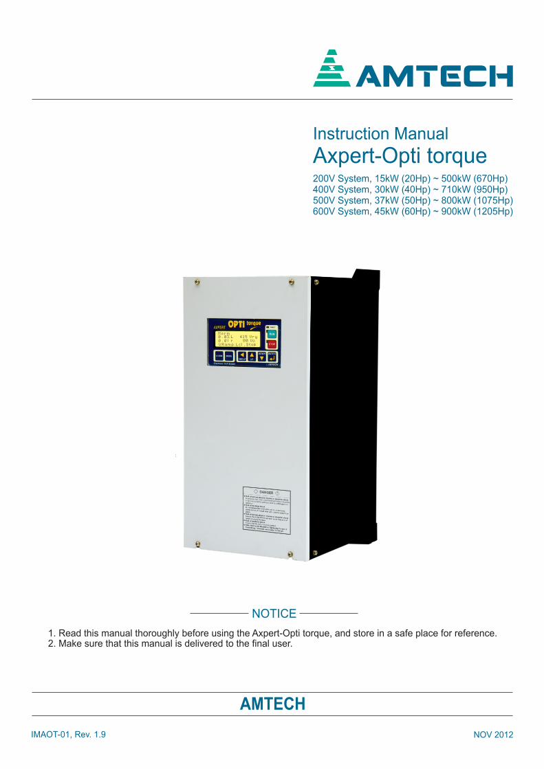
200V System, 15kW (20Hp) ~ 500kW (670Hp)400V System, 30kW (40Hp) ~ 710kW (950Hp)500V System, 37kW (50Hp) ~ 800kW (1075Hp)600V System, 45kW (60Hp) ~ 900kW (1205Hp)
Instruction Manual
Axpert-Opti torque
N o r m0 . 0 % L 4 1 5 V r y0 . 0 l r 0 0 V oV R a m p . L c l , S t o p
AMTECH
AMTECH

Amtech ii
Axpert-Opti torque Electronic Soft Starter
iii
TABLE OF CONTENTS
PREFACE
Precautions for safety
CHAPTER-1 DELIVERY, INSPECTION AND STORAGE
1.1 Delivery, inspection and storage
1.2 Details of rating nameplate and type display method
CHAPTER-2 INSTALLATION AND WIRING
2.1 Installation environment
2.2 Precautions for power supply and motor wiring
2.3 Simplified block diagram of Axpert-opti torque soft starter
2.4 Power terminal layout
2.5 Precautions for control signals wiring
CHAPTER-3 DIGITAL OPERATION PANEL (LCD KEYPAD MODULE)
3.1 Status
3.2 Modes and parameters
3.3 Parameter display & setting
CHAPTER-4 TEST OPERATION AND ADJUSTMENT
4.1 Preparation before turning power ON
4.2 Initialization of motor constants in Mode-B
4.3 Test operations
CHAPTER-5 CONTROL INPUT / OUTPUT TERMINALS
5.1 Input/output terminal functions of PCA-2005B
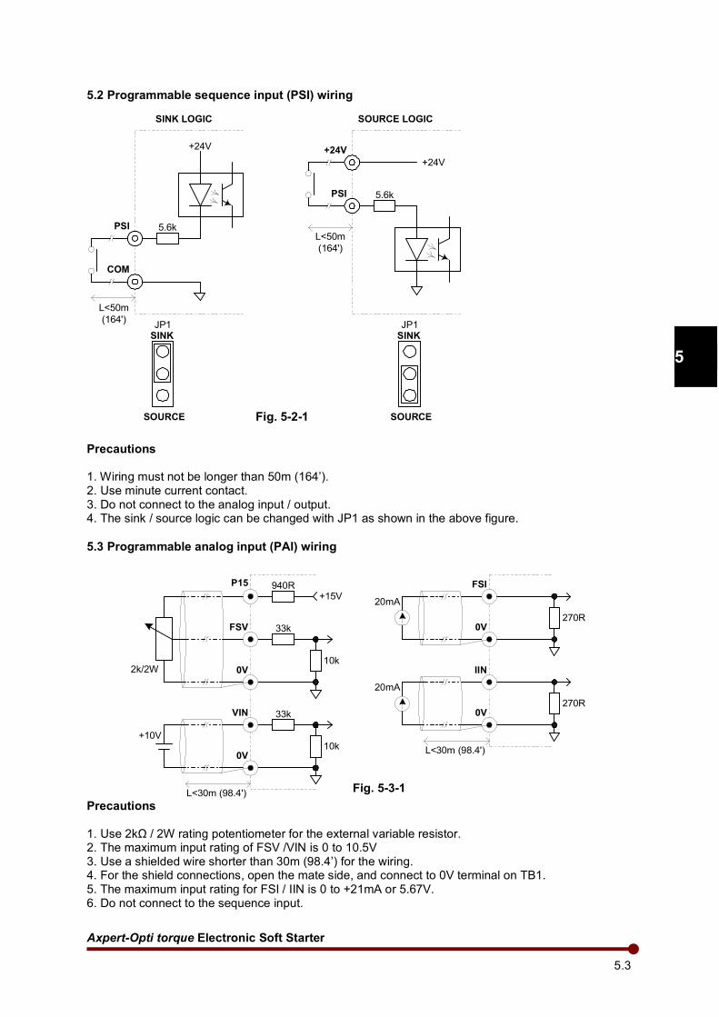
5.2 Programmable sequence input (PSI) wiring
5.3 Programmable analog input (PAI) wiring
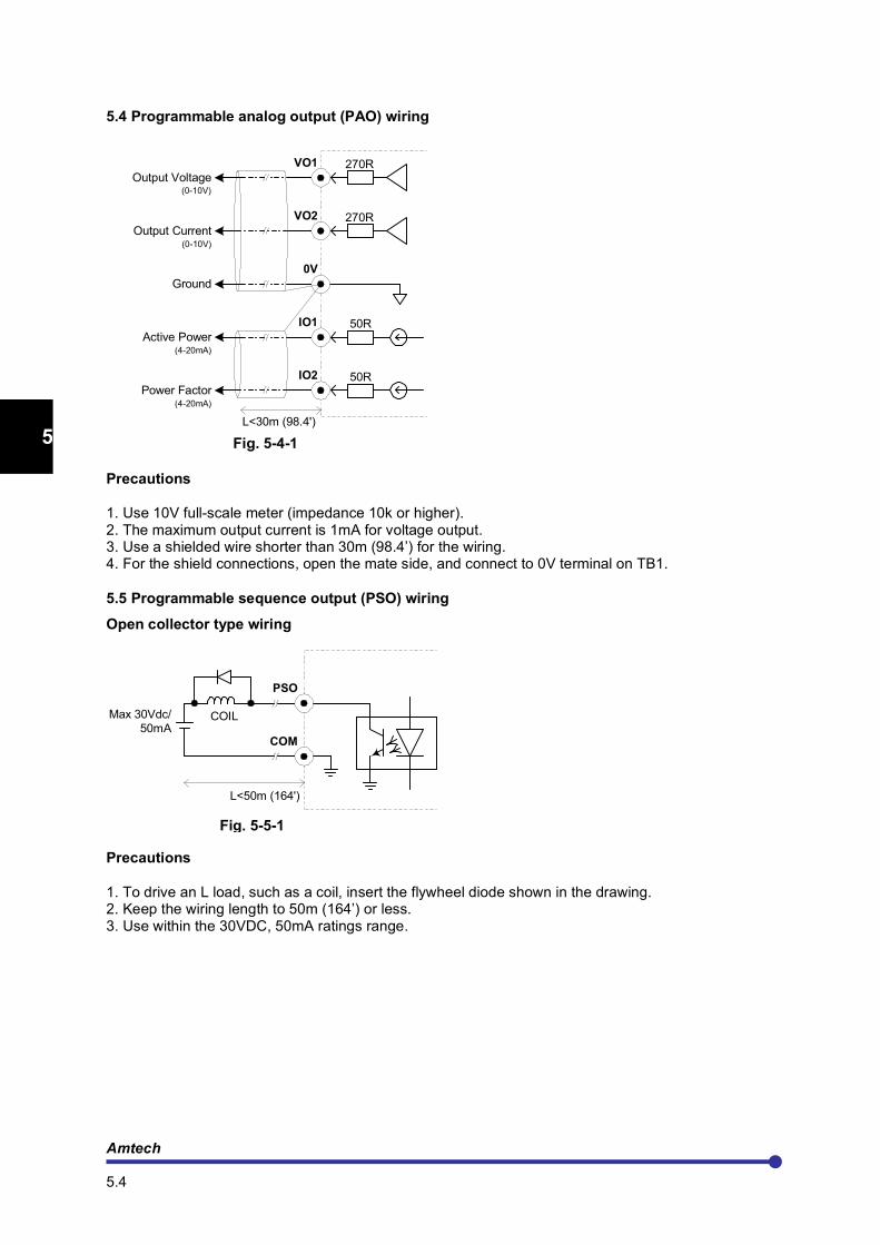
5.4 Programmable analog output (PAO) wiring
5.5 Programmable sequence output (PSO) wiring
CHAPTER-6 PARAMETER SETTINGS & FUNCTIONS
6.1 Mode-M monitor mode parameters
6.2 Mode-A parameters
6.3 Mode-B parameters
6.4 Mode-C parameters
6.5 Mode-P parameters
6.6 Function explanations
6.7 In-built PLC function explanations
CHAPTER-7 ELECTRONICS CIRCUIT BOARDS
7.1 Main control board PCA-2005B
Amtech iv
7.2 Digital operation panel
7.3 Power supply unit
7.4 RC snubber board PCA-82
7.5 MOV board PCA-77
CHAPTER-8 MAINTENANCE, INSPECTION AND PART REPLACEMENT
8.1 Inspection items
8.2 Measuring devices
CHAPTER-9 OPTIONS
9.1 Metering
9.2 Enclosure
9.3 Remote operator box
9.4 Bypass operation
CHAPTER-10 TYPICAL CONNECTION DIAGRAM
10.1 Bypass contactor connections
10.2 Inside delta connections
CHAPTER-11 SERIAL COMMUNICATION SET-UP
11.1 Connection method
11.2 Connecting the host computer & Axpert-opti torque (1-to-1)
11.3 Connecting the host computer & Axpert-opti torque (1-to-n)
11.4 Communication specifications
CHAPTER-12 UL INSTRUCTIONS
CHAPTER-13 CE INSTRUCTIONS
Appendix-A Standard specifications
Appendix-B Outline dimension
Appendix-C Fault codes
Appendix-D Trouble shooting guidelines
Appendix-E Software revision history
Axpert-Opti torque Electronic Soft Starter v
PREFACE
THANK YOU for purchasing the “AMTECH Axpert-opti torque Electronic Soft Starter”.
Axpert-opti torque Electronic Soft Starter is a modern Digital Signal Processor based highly
functional Soft Starter that is easy to use.
PLEASE READ THIS MANUAL THOROUGHLY before use, and keep the manual at hand for later reference. Also make sure that this manual is delivered to the final users.
The purpose of this Instruction Manual is to provide basic information on Installation, Start-up,
Operational and Troubleshooting for the Axpert-opti torque Electronic Soft Starter.
WARNING
ALWAYS READ THIS MANUAL THOROUGHLY BEFORE USING THE SOFT STARTER.
THIS SOFT STARTER CONTAINS HIGH VOLTAGE CIRCUITS THAT MAY BE FATAL TO HUMANS. USE EXTREME CAUTION DURING INSTALLATION. MAINTENANCE MUST BE PERFORMED BY QUALIFIED TECHNICIANS, AND ALL POWER SOURCES MUST BE DISCONNECTED BEFORE ANY MAINTENANCE. SUFFICIENT NOTICE MUST BE GIVEN TO THE GENERAL OPERATORS AND WORKERS BEFORE STARTING.
• ELECTRIC SHOCK MAY OCCUR IF THE FOLLOWING POINTS ARE NOT OBSERVED.
(1) DO NOT OPEN THE FRONT COVER WHILE THE POWER IS ON.
(2) ALWAYS GROUND THE UNIT CASE. THE GROUNDING METHOD MUST COMPLY WITH THE LAWS OF THE COUNTRY WHERE THE UNIT IS BEING INSTALLED
• THE UNIT MAY BE DESTROYED BEYOND REPAIR IF THE FOLLOWING POINTS ARE NOT OBSERVED.
(1) OPERATION WITHIN THE UNIT SPECIFICATIONS.
(2) PROPER CABLE CONNECTIONS TO INPUT/OUTPUT TERMINALS.
(3) CLEANING AND ENOUGH VENTILATION TO THE UNIT INTAKE/OUTTAKE PORTS.
(4) OBSERVATION OF CAUTIONS LISTED IN THIS INSTRUCTION MANUAL.
• THERE MAY BE SOURCES OF NOISE AROUND THIS UNIT AND MOTOR DRIVEN BY THIS UNIT. CONSIDER THE POWER SUPPLY SYSTEM, INSTALLATION PLACE AND WIRING METHOD BEFORE INSTALLATION
INSTALL THE UNIT AWAY FROM DEVICES THAT HANDLE MINUTE SIGNALS, SUCH AS MEDICAL EQUIPMENT IN PARTICULAR. ALSO SEPARATE THE DEVICES ELECTRICALLY, AND TAKE SUFFICIENT NOISE MEASURES.
• TAKE SUFFICIENT SAFETY MEASURES WHEN USING THIS UNIT FOR PASSENGER TRANSPORTATION, SUCH AS IN LIFTS (ELEVATORS).

Amtech vi
Precautions for Safety
Items to be observed to prevent physical damage or property damage and to ensure safe use of this product are noted on the product and in this instruction manual.
Please read this instruction manual and enclosed documents before starting operation to ensure correct usage. Thoroughly understand the device, safety information and precautions before starting operation. After reading, always store this manual where it can be accessed easily.
The safety precautions are ranked as "DANGER" and "CAUTION" in this instruction manual.
: When a dangerous situation may occur if handling is mistaken, leading to fatal or major injuries. : When a dangerous situation may occur if handling is mistaken, leading to medium or minor injuries, or physical damage.
Note that some items described as
CAUTION
may lead to major problems depending on the situation. In any case, important information that must be observed is described.
This instruction manual is written on the presumption that the user has an understanding of the soft starter. A qualified person must do installation, operation, maintenance and inspection of this product. Even qualified persons must undergo periodic training.
Qualified refers to satisfying the following conditions.
The person has thoroughly read and understood this instruction manual.
The person is well versed in the installation, operation, maintenance and inspection of this product, and understands the possible dangers.
The person is informed on matters related to starting, stopping, installation, locks and tag displays, and has been trained in the operation and remedies.
The person has been trained on the maintenance, inspection and repairs of this product.
The person has been trained on protective tools used to ensure safety.
KEEP SAFETY FIRST IN YOUR SYSTEM
AMTECH puts the maximum effort into making products better and more reliable, but there is always the possibility that trouble may occur with them. Trouble with soft-starter may lead to personal injury, fire or property damage. Remember to give due consideration to safety when making your system, with appropriate measures such as isolating devices, mechanical brakes, prevention against any malfunction or mishap.
CAUTION
DANGER
Axpert-Opti torque Electronic Soft Starter
1.1
1
2
3
4
5
6
7
8
9
10
11
12
13
A
CHAPTER-1: DELIVERY, INSPECTION AND STORAGE
CAUTION
Always transport the product with an appropriate method according to the products weight.
Failure to observe this could lead to injuries.
Do not place the product near inflammable items.
Failure to observe this could lead to fires.
Do not hold the product with front cover while transporting the product.
Failure to observe this could lead to injuries from dropping.
Do not let conductive materials such as screws or metal pieces and inflammable materials such as oil enter into the product.
Failure to observe this could lead to fires.
Install the product in a place that can withstand the weight of the product, and follow the instruction manual.
Failure to do so could lead to injuries from dropping.
Do not install and operate the unit that is damaged or that has missing parts.
Failure to observe this could lead to injuries.
Always observe the conditions described in the instruction manual for the installation environment.
Failure to observe this could lead to faults.
1.1 Delivery, inspection and storage
Axpert-Opti torque Electronic Soft Starter has gone through rigorous quality control tests at the factory before shipment. After receiving the unit, check for the following.
(1) Check to make sure that the package includes unit and User Manual
(2) Remove the unit from packaging, and check the details on the rating nameplate to confirm that the unit is as ordered.
(3) Confirm that the product has not been damaged during shipment.
The Axpert-Opti torque Electronic Soft Starter should be kept in the shipping carton before installation. In order to retain the warranty coverage, the unit should be stored properly when it is not to be used for an extended period of time. Some storage suggestions are:
(1) Store in a clean, dry location.
(2) Store within an ambient temperature range of -20°C (-4°F) to +60°C (140°F).
(3) If possible, store in an air-conditioned environment where the relative humidity is less than 95%, non-condensing.
(4) Do not store the unit in places where it could be exposed to corrosive gases.
(5) Do not store the unit on a shelf or on an unstable surface.
(6) If the unit is not to be used for a while (more than 2 months) after purchasing, store it in a place with no humidity or vibration in the packaged state.
(7) Always inspect the unit before using after storing for a long period.
Amtech 1.2
1
2
3
4
5
6
7
8
9
10
11
12
13
A
1.2 Details of rating nameplate and type display method
The following details are listed on the rating nameplate.
Using the above type as an example, the type is displayed as follows:
AMT - OT - 045 - 4 - 1
Axpert-opti torque Series
-2: For 3- Phase 200V series, 200Vac ~ 240Vac
-4: For 3- Phase 400V series, 380Vac ~ 480Vac
-5: For 3- Phase 500V series, 500Vac ~ 575Vac
-6: For 3- Phase 600V series, 600Vac ~ 690Vac
-030: For 30 kW Capacity
-1: For 1- Phase 115V Fan
& Control Supply
-2: For 1- Phase 230V Fan
& Control Supply-037: For 37 kW Capacity
-045: For 45 kW Capacity
-055: For 55 kW Capacity
-075: For 75 kW Capacity
-090: For 90 kW Capacity
-110: For 110 kW Capacity
-132: For 132 kW Capacity
-160: For 160 kW Capacity
-200: For 200 kW Capacity
-250: For 250 kW Capacity
-315: For 315 kW Capacity
-400: For 400 kW Capacity
-450: For 450 kW Capacity
-500: For 500 kW Capacity
-575: For 575 kW Capacity
-630: For 630 kW Capacity
-710: For 710 kW Capacity
Axpert-Opti torque Electronic Soft Starter
2.1
1
2
3
4
5
6
7
8
9
10
11
12
13
A
CHAPTER-2: INSTALLATION AND WIRING
This chapter provides the information needed to properly install and wire the unit. Make sure that the
unit is wired according to the instructions contained in this chapter. The instructions should be read and understood before the actual installation begins.
CAUTION
Install the unit and other peripheral devices on noncombustible material such as metal.
Failure to observe this could lead to fires.
Do not place the product near inflammable items.
Failure to observe this could lead to fires.
Do not let conductive materials such as screws or metal pieces and inflammable materials such as oil enter the product.
Failure to observe this could lead to fires.
Install the product in a place that can withstand the weight of the product.
Failure to do so could lead to injuries from dropping.
Do not install and operate the unit that is damaged or that is missing parts.
Failure to observe this could lead to injuries.
Always observe the conditions described in the instruction manual for the installation environment.
Failure to observe this could lead to faults.
2.1 Installation environment
Observe the following points when installing the unit.
(1) Install the unit vertically to provide proper ventilation.
(2) Make sure that the ambient temperature is –10°C (14°F) to 50°C (122°F).
(3) Avoid installation in the following environment.
• Places subject to direct sunlight
• Places with oil mist, dust or cotton lint, or subject to salty winds
• Places with corrosive gas, explosive gas or high humidity levels
• Places near vibration sources such as dollies or press machines
• Places made of in-flammable materials such as wood, or places that are not heat resistant
(4) Ensure ventilation space around the unit as shown in fig. 2-1-1
AXPERT
OPTI torque
200mm (7.87")
200mm (7.87")
50
mm
(1
.97")
50
mm
(1
.97")
Fig. 2-1-1

Amtech 2.2
1
2
3
4
5
6
7
8
9
10
11
12
13
A
2.2 Precautions for power supply and motor wiring
DANGER
Always turn the device's input power OFF before starting wiring.
Failure to do so could lead to electric shocks or fires.
Carry out grounding that complies with the standards of the country where the unit is being installed.
Failure to do so could lead to electric shocks or fires.
Wiring must always be done by a qualified electrician
Failure to observe this could lead to electric shocks or fires.
Always install the device before starting wiring.
Failure to do so could lead to electric shocks or injuries.
Use a circuit breaker such as an MCCB or fuses that match with the capacity of the unit power supply.
Failure to do so could lead to fires.
CAUTION
Do not connect an AC power supply to the output terminals (U, V, W).
Failure to observe this could lead to injuries or fires.
Confirm that the product's rated input voltage and frequency match the power supply voltage and frequency.
Failure to do so could lead to injuries or fires.
Tighten the terminal screws with the designated tightening torque.
Failure to do so could lead to fires.
Correctly connect the output (U, V, W) to motor terminals to ensure proper phase sequence.
Failure to do so could cause the motor to rotate in reverse and the machine to be damaged.
Failure to observe this could lead to reverse rotation or abnormal acceleration of the motor, and to injuries or machine damage.
Axpert-Opti torque Electronic Soft Starter
2.3
1
2
3
4
5
6
7
8
9
10
11
12
13
A
2.3 Simplified block diagram of Axpert-Opti torque soft starter
IM
3-Phase
Main Control
Board
PCA-2005B
L1
L2
L3
PE
3-Phase,
380~480Vac,
50/60Hz
Input
Note:1
U
V
W
U'V'W'
PSI-5
PSI-4
PSI-3
PSI-2
PSI-1
STOP
RUN
PSI-6
IIN
FSI
VIN
FSV
IO1
VO2
IO2
VO1
R1A
FC
R1B
FB
FA
R1C
R2A
R2B
R2C
PSO3
PSO2
PSO4
PSO1
RX
TX
CT
CT
CT
AXPERT OPTI torque
Electronic Soft Starter
Digital
Operation Panel
E
N
L1-Phase, 115/
230Vac, 50/60Hz
control supply
Fig. 2-3-1 - Simplified Block Diagram of Axpert-Opti torque Soft starter
(Note 1) Input / Output and Bypass terminals
The input terminals are L1, L2 & L3. The output terminals to the motor are U, V & W. Connect the power supply to input terminals L1, L2 & L3 only. Never connect the power supply to the U, V, and W terminals. Connect bypass contactor between L1, L2, L3 and U’, V’, W’. Input voltage range is varies according to voltage series for 200V series input voltage ranger 200VAC to 240VAC, for 400V series input voltage range 380VAC to 480VAC, for 500Vsereis input voltage range 500VAC to 575VAC and for 600V series input voltage range 600VAC to 690VAC.
(Note 2) Wire size
Use wires having the size (or larger) shown in the below table for the main circuit wiring shown in the above figure. The applicable wire size range, applicable ring terminal and tightening torque for the main circuit terminals are shown in the Table-2-3-1, for 200V Series, Table-2-3-2 for 400V Series, Table-2-3-3 for 500V Series and Table-2-3-4 for 600V Series.
Amtech 2.4
1
2
3
4
5
6
7
8
9
10
11
12
13
A
Table-2-3-1: 200V series Axpert-Opti torque (Terminal and applicable wire/bus bar for Input, Output & Bypass)
AMT-OT-
XXX-2-X
Rated Current
(A)
wire/bus bar size for Input /
Output+
wire size for Grounding
terminal
Lug ID mm
(inch) #
Lug width mm
(inch)
Terminal width (I/P,
O/P & Bypass)
mm (inch)
Hole diameter
mm (inch)
Terminal screw size
Tightening torque N*m
(lb-inch)
mm2 AWG mm
2 AWG
015 60 25 4 10 8 8.4 (0.33)
15 (0.59)
19 (0.75) 9 (0.35) M8 9 (79.7)
018 72 35 2 10 8 8.4 (0.33)
15.2 (0.60)
19 (0.75) 9 (0.35) M8 9 (79.7)
022 87 50 1 10 8 8.4 (0.33)
18.5 (0.73)
19 (0.75) 9 (0.35) M8 9 (79.7)
030 110 50 1/0 16 6 8.4
(0.33)
18.5
(0.73)
19 (0.75) 9 (0.35) M8 9 (79.7)
037 147 35 x 2p 2 x 2p 16 6 10.5 (0.41)
15.2 (0.60)
32 (1.26) 10.5 (0.41)
M10 22.5 (199)
045 175 50 x 2p 1 x 2p 16 6 10.5 (0.41)
18.5 (0.73)
32 (1.26) 10.5 (0.41)
M10 22.5 (199)
055 215 50 x 2p 1/0 x 2p 25 4 10.5 (0.41)
18.5 (0.73)
32 (1.26) 10.5 (0.41)
M10 22.5 (199)
075 245 70 x 2p 2/0 x 2p 25 4 10.5 (0.41)
21.4 (0.84)
40 (1.58) 11 (0.43)
M10 22.5 (199)
076 245 70 x 2p 2/0 x 2p 25 4 50 (1.97) 13
(0.51)
M12 31.2 (276)
090 320 120 x 2p 4/0 x 2p - 3 10.5 (0.41)
28.3 (1.11)
40 (1.58) 11 (0.43)
M10 22.5 (199)
091 320 120 x 2p 4/0 x 2p - 3 50 (1.97) 13 (0.51)
M12 31.2 (276)
110 360 40 x 10 (400)
- - 3 50 (1.97) 13 (0.51)
M12 31.2 (276)
111
132 470 40 x 10 (400)
- 50 1 50 (1.97) 13 (0.51)
M12 31.2 (276)
133
160 590 50 x 10 (500)
- 50 1 50 (1.97) 13 (0.51)
M12 31.2 (276)
161
200 720 75 x 10 (750)
- 50 1/0 50 (1.97) 13 (0.51)
M12 31.2 (276)
250 800 75 x 10 (750)
- 70 2/0 50 (1.97) 13 (0.51)
M12 31.2 (276)
315 880 100x10 (1000)
- 95 3/0 75 (2.95) 13 (0.51)
M12 31.2 (276)
400 950 100x10 (1000)
- 95 3/0 75 (2.95) 13 (0.51)
M12 31.2 (276)
450 1065 100x10 (1000)
- 95 3/0 75 (2.95) 13 (0.51)
M12 31.2 (276)
+2p = Two parallel
# - Listed ZMVV, Lugs shall be used Wire size for external control supply for cooling fan is 14 AWG (2.5 mm
2).
Axpert-Opti torque Electronic Soft Starter
2.5
1
2
3
4
5
6
7
8
9
10
11
12
13
A
Table-2-3-2: 400V series Axpert-Opti torque (Terminal and applicable wire/bus bar for Input, Output & Bypass)
AMT-OT-
XXX-4-X
Rated Current
(A)
wire/bus bar size for Input /
Output+
wire size for Grounding
terminal
Lug ID mm
(inch) #
Lug width mm
(inch)
Terminal width (I/P,
O/P & Bypass)
mm (inch)
Hole diameter
mm (inch)
Terminal screw size
Tightening torque N*m
(lb-inch)
mm2 AWG mm
2 AWG
030 60 25 4 10 8 8.4 (0.33)
15 (0.59)
19 (0.75) 9 (0.35) M8 9 (79.7)
037 72 35 2 10 8 8.4 (0.33)
15.2 (0.60)
19 (0.75) 9 (0.35) M8 9 (79.7)
045 87 50 1 10 8 8.4 (0.33)
18.5 (0.73)
19 (0.75) 9 (0.35) M8 9 (79.7)
055 110 50 1/0 16 6 8.4 (0.33)
18.5 (0.73)
19 (0.75) 9 (0.35) M8 9 (79.7)
075 147 35 x 2p 2 x 2p 16 6 10.5 (0.41)
15.2 (0.60)
32 (1.26) 10.5 (0.41)
M10 22.5 (199)
090 175 50 x 2p 1 x 2p 16 6 10.5 (0.41)
18.5 (0.73)
32 (1.26) 10.5 (0.41)
M10 22.5 (199)
110 215 50 x 2p 1/0 x 2p 25 4 10.5 (0.41)
18.5 (0.73)
32 (1.26) 10.5 (0.41)
M10 22.5 (199)
132 245 70 x 2p 2/0 x 2p 25 4 10.5 (0.41)
21.4 (0.84)
40 (1.58) 11 (0.43)
M10 22.5 (199)
133 245 70 x 2p 2/0 x 2p 25 4 50 (1.97) 13 (0.51)
M12 31.2 (276)
160 320 120 x 2p 4/0 x 2p - 3 10.5
(0.41)
28.3
(1.11)
40 (1.58) 11
(0.43)
M10 22.5 (199)
161 320 120 x 2p 4/0 x 2p - 3 50 (1.97) 13 (0.51)
M12 31.2 (276)
200 360 40 x 10 (400)
- - 3 50 (1.97) 13 (0.51)
M12 31.2 (276)
201
250 470 40 x 10 (400)
- 50 1 50 (1.97) 13 (0.51)
M12 31.2 (276)
251
315 590 50 x 10 (500)
- 50 1 50 (1.97) 13 (0.51)
M12 31.2 (276)
316
400 720 75 x 10 (750)
- 50 1/0 50 (1.97) 13 (0.51)
M12 31.2 (276)
450 800 75 x 10 (750)
- 70 2/0 50 (1.97) 13 (0.51)
M12 31.2 (276)
500 880 100x10 (1000)
- 95 3/0 75 (2.95) 13 (0.51)
M12 31.2 (276)
585 950 100x10 (1000)
- 95 3/0 75 (2.95) 13 (0.51)
M12 31.2 (276)
630 1065 100x10 (1000)
- 95 3/0 75 (2.95) 13 (0.51)
M12 31.2 (276)
+2p = Two parallel
# - Listed ZMVV, Lugs shall be used Wire size for external control supply for cooling fan is 14 AWG (2.5 mm
2).
Amtech 2.6
1
2
3
4
5
6
7
8
9
10
11
12
13
A
Table-2-3-3: 500V series Axpert-Opti torque (Terminal and applicable wire/bus bar for Input, Output & Bypass)
AMT-OT-
XXX-5-X
Rated Current
(A)
wire/bus bar size for Input /
Output+
wire size for Grounding
terminal
Lug ID mm
(inch) #
Lug width mm
(inch)
Terminal width (I/P,
O/P & Bypass)
mm (inch)
Hole diameter
mm (inch)
Terminal screw size
Tightening torque N*m
(lb-inch)
mm2 AWG mm
2 AWG
037 60 25 4 10 8 8.4 (0.33)
15 (0.59)
19 (0.75) 9 (0.35) M8 9 (79.7)
045 72 35 2 10 8 8.4 (0.33)
15.2 (0.60)
19 (0.75) 9 (0.35) M8 9 (79.7)
055 87 50 1 10 8 8.4 (0.33)
18.5 (0.73)
19 (0.75) 9 (0.35) M8 9 (79.7)
075 110 50 1/0 16 6 8.4 (0.33)
18.5 (0.73)
19 (0.75) 9 (0.35) M8 9 (79.7)
090 147 35 x 2p 2 x 2p 16 6 10.5 (0.41)
15.2 (0.60)
32 (1.26) 10.5 (0.41)
M10 22.5 (199)
110 175 50 x 2p 1 x 2p 16 6 10.5 (0.41)
18.5 (0.73)
32 (1.26) 10.5 (0.41)
M10 22.5 (199)
132 215 50 x 2p 1/0 x 2p 25 4 10.5 (0.41)
18.5 (0.73)
32 (1.26) 10.5 (0.41)
M10 22.5 (199)
160 245 70 x 2p 2/0 x 2p 25 4 10.5 (0.41)
21.4 (0.84)
40 (1.58) 11 (0.43)
M10 22.5 (199)
161 245 70 x 2p 2/0 x 2p 25 4 50 (1.97) 13 (0.51)
M12 31.2 (276)
200 320 120 x 2p 4/0 x 2p - 3 10.5
(0.41)
28.3
(1.11)
40 (1.58) 11
(0.43)
M10 22.5 (199)
201 320 120 x 2p 4/0 x 2p - 3 50 (1.97) 13 (0.51)
M12 31.2 (276)
250 360 40 x 10 (400)
- - 3 50 (1.97) 13 (0.51)
M12 31.2 (276)
251 360 40 x 10 (400)
- - 3 50 (1.97) 13 (0.51)
M12 31.2 (276)
315 470 40 x 10 (400)
- 50 1 50 (1.97) 13 (0.51)
M12 31.2 (276)
316 470 40 x 10 (400)
- 50 1 50 (1.97) 13 (0.51)
M12 31.2 (276)
400 590 50 x 10 (500)
- 50 1 50 (1.97) 13 (0.51)
M12 31.2 (276)
401 590 50 x 10 (500)
- 50 1 50 (1.97) 13 (0.51)
M12 31.2 (276)
450 720 75 x 10 (750)
- 50 1/0 50 (1.97) 13 (0.51)
M12 31.2 (276)
500 800 75 x 10 (750)
- 70 2/0 50 (1.97) 13 (0.51)
M12 31.2 (276)
585 880 100x10 (1000)
- 95 3/0 75 (2.95) 13 (0.51)
M12 31.2 (276)
630 950 100x10 (1000)
- 95 3/0 75 (2.95) 13 (0.51)
M12 31.2 (276)
710 1065 100x10 (1000)
- 95 3/0 75 (2.95) 13 (0.51)
M12 31.2 (276)
+2p = Two parallel
# - Listed ZMVV, Lugs shall be used Wire size for external control supply for cooling fan is 14 AWG (2.5 mm
2).
Axpert-Opti torque Electronic Soft Starter
2.7
1
2
3
4
5
6
7
8
9
10
11
12
13
A
Table-2-3-4: 600V series Axpert-Opti torque (Terminal and applicable wire/bus bar for Input, Output & Bypass)
AMT-OT-
XXX-6-X
Rated Current
(A)
wire/bus bar size for Input /
Output*
wire size for Grounding
terminal
Lug ID mm
(inch) #
Lug width mm
(inch)
Terminal width (I/P,
O/P & Bypass)
mm (inch)
Hole diameter
mm (inch)
Terminal screw size
Tightening torque N*m
(lb-inch)
mm2 AWG mm
2 AWG
045 60 25 4 10 8 8.4 (0.33)
15 (0.59)
19 (0.75) 9 (0.35) M8 9 (79.7)
055 72 35 2 10 8 8.4 (0.33)
15.2 (0.60)
19 (0.75) 9 (0.35) M8 9 (79.7)
075 87 50 1 10 8 8.4 (0.33)
18.5 (0.73)
19 (0.75) 9 (0.35) M8 9 (79.7)
090 110 50 1/0 16 6 8.4 (0.33)
18.5 (0.73)
19 (0.75) 9 (0.35) M8 9 (79.7)
110 147 35 x 2p 2 x 2p 16 6 10.5 (0.41)
15.2 (0.60)
32 (1.26) 10.5 (0.41)
M10 22.5 (199)
132 175 50 x 2p 1 x 2p 16 6 10.5 (0.41)
18.5 (0.73)
32 (1.26) 10.5 (0.41)
M10 22.5 (199)
160 215 50 x 2p 1/0 x 2p 25 4 10.5 (0.41)
18.5 (0.73)
32 (1.26) 10.5 (0.41)
M10 22.5 (199)
200 245 70 x 2p 2/0 x 2p 25 4 10.5 (0.41)
21.4 (0.84)
40 (1.58) 11 (0.43)
M10 22.5 (199)
201 245 70 x 2p 2/0 x 2p 25 4 50 (1.97) 13 (0.51)
M12 31.2 (276)
250 320 120 x 2p 4/0 x 2p - 3 10.5
(0.41)
28.3
(1.11)
40 (1.58) 11
(0.43)
M10 22.5 (199)
251 320 120 x 2p 4/0 x 2p - 3 50 (1.97) 13 (0.51)
M12 31.2 (276)
315 360 40 x 10 (400)
- - 3 50 (1.97) 13 (0.51)
M12 31.2 (276)
316 360 40 x 10 (400)
- - 3 50 (1.97) 13 (0.51)
M12 31.2 (276)
400 470 40 x 10 (400)
- 50 1 50 (1.97) 13 (0.51)
M12 31.2 (276)
401 470 40 x 10 (400)
- 50 1 50 (1.97) 13 (0.51)
M12 31.2 (276)
450 590 50 x 10 (500)
- 50 1 50 (1.97) 13 (0.51)
M12 31.2 (276)
451 590 50 x 10 (500)
- 50 1 50 (1.97) 13 (0.51)
M12 31.2 (276)
500 720 75 x 10 (750)
- 50 1/0 50 (1.97) 13 (0.51)
M12 31.2 (276)
585 800 75 x 10 (750)
- 70 2/0 50 (1.97) 13 (0.51)
M12 31.2 (276)
630 880 100x10 (1000)
- 95 3/0 75 (2.95) 13 (0.51)
M12 31.2 (276)
710 950 100x10 (1000)
- 95 3/0 75 (2.95) 13 (0.51)
M12 31.2 (276)
800 1065 100x10 (1000)
- 95 3/0 75 (2.95) 13 (0.51)
M12 31.2 (276)
+2p = Two parallel
# - Listed ZMVV, Lugs shall be used Wire size for external control supply for cooling fan is 14 AWG (2.5 mm
2).

Amtech 2.8
1
2
3
4
5
6
7
8
9
10
11
12
13
A
(Note 3) Noise filter
The unit will generate high harmonic electromagnetic noise, so using the following noise measures is recommended.
Insert a noise filter on the input side of the unit. Contact Amtech to select the proper noise filter. Keep the wiring length between the noise filter and unit to 500mm (19.7”) or less.
Use a shield cable for the unit and motor wiring and connect the screen to the unit’s terminal.
When using the control circuit wiring and power circuit wiring in parallel, separate the wiring by 300mm (11.8”) or more or pass each of the wiring through separate metal conduits. If the control circuit wiring and main circuit wiring intersect, make sure that they intersect at a right angle.
(Note 4) Output
Do not insert a power factor improvement capacitor on the output side of the unit. When inserting a magnetic contactor on the output side of the unit, prepare a sequence control circuit so that the magnetic contactor will not open and close when the unit is running. Directly connect only motor to the unit and do not connect through a transformer etc...without consulting Amtech.
(Note 5) Grounding
Always ground the unit according to the regulations of the country where the unit is being used to
ensure personnel safety in all circumstances, and to reduce electromagnetic emission and pickup.
Make sure that grounding conductors are adequately sized as required by safety regulations.
In European CE compliant installations and in other installations where EMC emissions must be minimized, make a 360° high frequency grounding of cable entries in order to suppress electromagnetic disturbances.
In addition, connect the cable shields to protective earth (PE) in order to meet safety regulations.
(Note 6) Surge absorber
Install a surge absorber on the magnetic contactor and relay coils installed near the unit.
Axpert-Opti torque Electronic Soft Starter
2.9
1
2
3
4
5
6
7
8
9
10
11
12
13
A
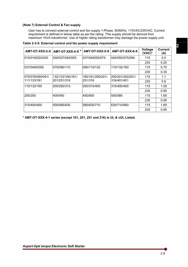
(Note 7) External Control & Fan supply
User has to connect external control and fan supply 1-Phase, 50/60Hz; 115VAC/230VAC. Current requirement is defined in below table as per the rating. This supply should be derived from maximum 1kVA transformer. Use of higher rating transformer may damage the power supply unit.
Table 2-3-5: External control and fan power supply requirement
AMT-OT-XXX-2-X AMT-OT-XXX-4-X * AMT-OT-XXX-5-X AMT-OT-XXX-6-X Voltage (VAC)*
Current (A)
015/018/022/030 030/037/045/055 037/045055/075 045/055/075/090 115 0.5
230 0.25
037/0450/055 075/090/110 090/110/132 110/132/160 115 0.70
230 0.35
075/076/090/091/ 111/133/161
132/133/160/161/ 201/251/316
160/161/200/201/ 251/316
200/201/250/251/ 316/401/451
115 1.1
230 0.6
110/132/160 200/250/315 250/315/400 315/400/450 115 1.55
230 0.95
200/250 400/450 450/500 500/585 115 1.65
230 0.95
315/400/450 500/585/630 585/630/710 630/710/800 115 1.65
230 0.95
* AMT-OT-XXX-4-1 series (except 161, 201, 251 and 316) is UL & cUL Listed.
Amtech 2.10
1
2
3
4
5
6
7
8
9
10
11
12
13
A
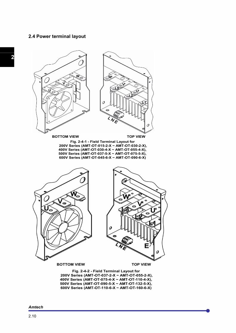
2.4 Power terminal layout
BOTTOM VIEW TOP VIEW
Fig. 2-4-1 - Field Terminal Layout for
200V Series (AMT-OT-015-2-X ~ AMT-OT-030-2-X),
400V Series (AMT-OT-030-4-X ~ AMT-OT-055-4-X),
500V Series (AMT-OT-037-5-X ~ AMT-OT-075-5-X),
600V Series (AMT-OT-045-6-X ~ AMT-OT-090-6-X)
BOTTOM VIEW TOP VIEW
Fig. 2-4-2 - Field Terminal Layout for
200V Series (AMT-OT-037-2-X ~ AMT-OT-055-2-X),
400V Series (AMT-OT-075-4-X ~ AMT-OT-110-4-X),
500V Series (AMT-OT-090-5-X ~ AMT-OT-132-5-X),
600V Series (AMT-OT-110-6-X ~ AMT-OT-160-6-X)
Axpert-Opti torque Electronic Soft Starter
2.11
1
2
3
4
5
6
7
8
9
10
11
12
13
A
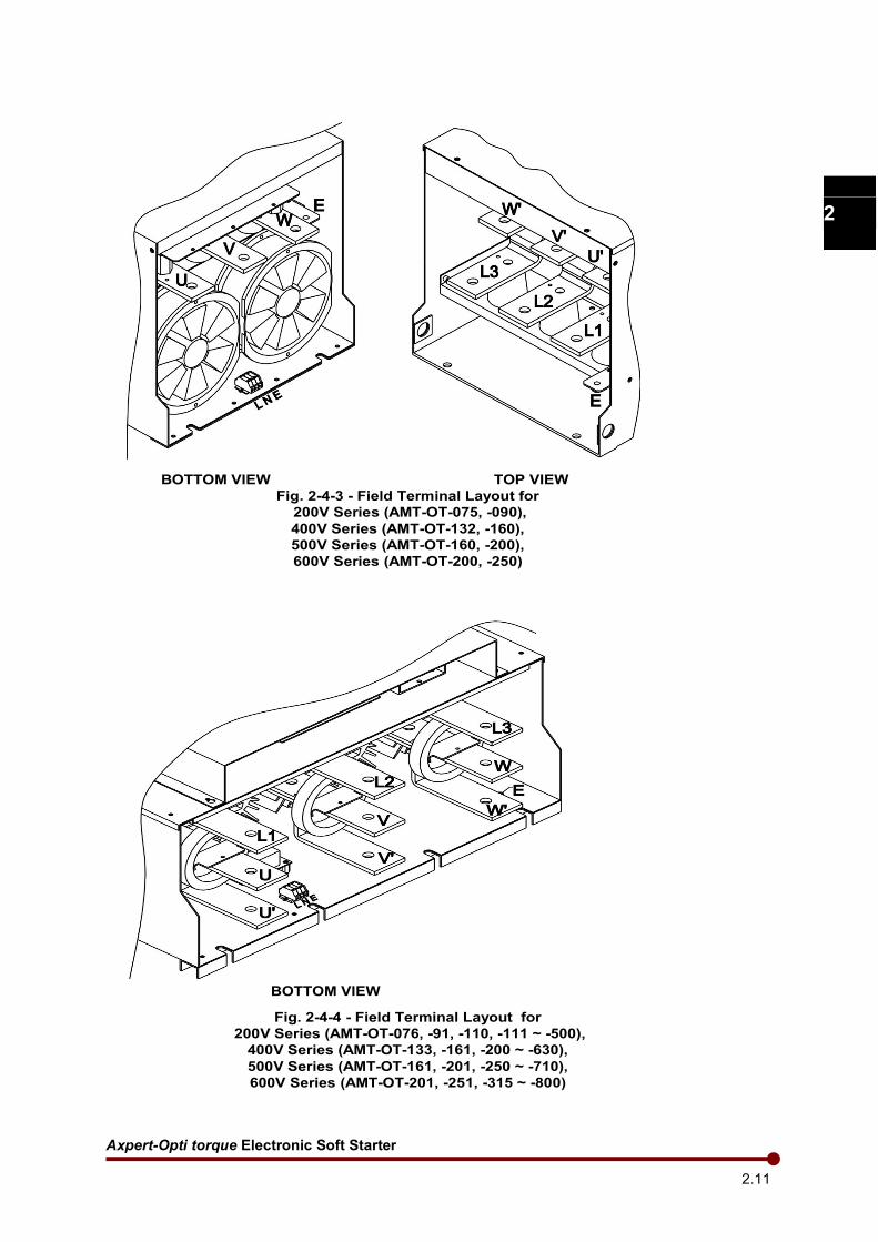
BOTTOM VIEW TOP VIEW
Fig. 2-4-3 - Field Terminal Layout for
200V Series (AMT-OT-075, -090),
400V Series (AMT-OT-132, -160),
500V Series (AMT-OT-160, -200),
600V Series (AMT-OT-200, -250)
BOTTOM VIEW
Fig. 2-4-4 - Field Terminal Layout for
200V Series (AMT-OT-076, -91, -110, -111 ~ -500),
400V Series (AMT-OT-133, -161, -200 ~ -630),
500V Series (AMT-OT-161, -201, -250 ~ -710),
600V Series (AMT-OT-201, -251, -315 ~ -800)

Amtech 2.12
1
2
3
4
5
6
7
8
9
10
11
12
13
A
2.5 Precautions for control signals wiring
When wiring (control circuit wiring) to the control terminal block, separate the main circuit wiring (terminals L1, L2, L3, U, V, W, U’, V’, W’) and the other starter wires and power wires.
Use a 0.13 (AWG26) to 0.8mm² (AWG18) wire for wiring to the control circuit. The tightening torque must be 0.6N-m (5.3lb-inch).
Use a twisted pair wire or twisted pair shield wire for wiring to the analog signal circuit such as the analog references and meters. Connect the shield wire to the 0V terminal of the unit. The wire length must be 30 meters (98.4’) or less.
The length of the sequence input/output contact wire must be 50 meters (164’) or less.
Changing the jumper position JP1 in PCA-2005B between “SINK” and “SOURCE” position respectively can change the sequence input between sink logic and source logic. Open cover designated as “Control Unit” to access this jumper.
Observe the precautions listed in " 5. Control Input/Output Terminals"
After wiring, always check the mutual wiring.
At this time do not carry out a megger check or buzzer check on the control circuit. • Are there any wire scraps or foreign matter left around the terminals? • Are any screws loose? • Is the wiring correct? • Is any terminal contacting any other terminal?
If so, take the necessary corrective measures before proceeding further.
Axpert-Opti torque Electronic Soft Starter
2.13
1
2
3
4
5
6
7
8
9
10
11
12
13
A
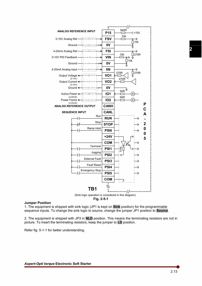
P15
FSV
0V
FSI
VIN
0V
IIN
VO1
VO2
0V
IO1
IO2
CANH
CANL
RUN
STOP
PSI6
+24V
COM
PSI1
PSI2
PSI3
PSI4
PSI5
COM
+15V940R
33k
270R33k
10k
10k
270R270R
270R
50R
50R
Run
Stop
Jogging
Emergency Stop
Fault Reset
Output Voltage
Output Current
Ground
Active Power
Power Factor
0-10V Analog Ref
Ground
0-10V PID Feedback
Ground
4-20mA Analog Ref
P
C
A
-
2
0
0
5
TB1
ANALOG REFERENCE INPUT
ANALOG REFERENCE OUTPUT
SEQUENCE INPUT
5.6
k
(0-10V)
(0-10V)
(4-20mA)
(4-20mA)
External Fault
(Sink logic operation is considered in this diagram)
4-20mA Analog input
Ramp Hold
Terminal
Fig. 2-5-1
Jumper Position 1. The equipment is shipped with sink logic (JP1 is kept on Sink position) for the programmable sequence inputs. To change the sink logic to source, change the jumper JP1 position to Source.
2. The equipment is shipped with JP3 in NLD position. This means the terminating resistors are not in picture. To insert the terminating resistors, keep the jumper to LD position. Refer fig. 5-1-1 for better understanding.
Amtech 2.14
1
2
3
4
5
6
7
8
9
10
11
12
13
A
TX
RX
COM
PB
PBN
PA
PAN
+5V
COM
RS-485 P
C
A
-
2
0
0
5
TB1
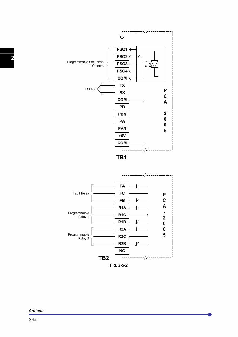
PSO1
PSO2
PSO3
PSO4
COM
R1B
R2A
R2C
R2B
P
C
A
-
2
0
0
5
TB2
FA
FC
FB
R1A
R1C
NC
Programmable
Relay 2
Programmable
Relay 1
Fault Relay
Programmable Sequence
Outputs
Fig. 2-5-2

Axpert-Opti torque Electronic Soft Starter
3.1
1
2
3
4
5
6
7
8
9
10
11
12
13
A
CHAPTER-3: DIGITAL OPERATION PANEL (LCD KEYPAD MODULE)
The configuration of the Digital Operation Panel is shown in the below picture. The structure of it is as shown below.
The Digital Operation Panel is equipped with 8-keys as shown in the above picture. The function of each key is described below.
This key is utilized to reach to the normal screen of digital operation panel from any parameter, group or mode. The normal screen displays different parameters and status. This is the screen displayed at power on.
This key when pressed passes the control to next successive modes i.e. NORM (Normal), MODE-M (Monitor), MODE-A, MODE-B, MODE-C and so on. After the end of all modes, it will carry the control again to first mode. When changing the mode, the last accessed parameter of last accessed group of successive mode will be displayed.
This key passes the control to next group in the same mode. The groups can be accessed only in the incremental direction. At last it will again come to the first group. If ‘’ENTER’’ key is pressed, this key is used to move the cursor position for parameter value change.
These keys are used to change parameter numbers & parameter value. When ENTER key is pressed, these keys are used to change the parameter value, otherwise it is used to navigate the parameters in upward / downward direction in the group.
This key is used to change and save the parameter value. When pressed first time, it will allow the user to change the parameter value using up / down keys. Once the desired value is set, it is pressed again to save the changed value. Press NORM key instead of ENTER, to discard the change.
This key is used to start the unit when the start control is through Digital Operation Panel. The key is equipped with the status indicating LED. It will glow, when the unit is running.
This key is used to stop the unit irrespective of the start control source. It is also used to reset the fault. The stop key is equipped with status indicating LED. It will glow when the
unit is off.

Amtech 3.2
1
2
3
4
5
6
7
8
9
10
11
12
13
A
The Digital Operation Panel is also equipped with the fault indicating LED. It will flash in the fault condition. It is also equipped with four lines, 80-character, 4-Line LCD display for the user-friendly parameter navigation, monitoring and setting. In the normal condition the screen will be as below.
Start Mode Start Select Soft Starter Status
T m l
L c l
S r l
User Selectable four parameters
Norm 1
Norm 2
Norm 3
Norm 4
N o r m
4 1 5 V r y 0 . 0 % L
5 0 H z 3 0 O C
V R a m p , L c l , S t o p
V R a m p
I R a m p
T R a m p
* * F a u l t *
N o r m a l R u n
S t a r t D e l y
J o g g i n g
A u t o R e s t r
C u r L i m i t
B y p a s s
M a i n s O n
E M S t po
S t o p
R a m p U p
R a m p D o w n
B r a k i n g
R a m p H o l d
Fig. 3-1 The above figure also indicates the selected start mode, start selection and the status. The four user selectable parameters can be configured using A601 ~ A604.
3.1 Status
The fourth line of the Digital Operation Panel (LCD Keypad Module) is used to display different status of the unit as shown above. More than one status can exist at one time. In this case, the status having higher priority will be displayed. The priority is as shown in the figure. Fault has the highest priority and mains on have least priority.
Axpert-Opti torque Electronic Soft Starter
3.3
1
2
3
4
5
6
7
8
9
10
11
12
13
A
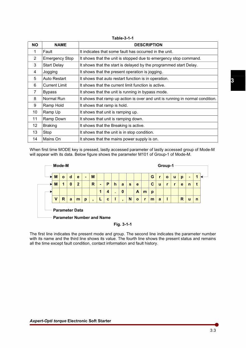
Table-3-1-1
NO NAME DESCRIPTION
1 Fault It indicates that some fault has occurred in the unit.
2 Emergency Stop It shows that the unit is stopped due to emergency stop command.
3 Start Delay It shows that the start is delayed by the programmed start Delay.
4 Jogging It shows that the present operation is jogging.
5 Auto Restart It shows that auto restart function is in operation.
6 Current Limit It shows that the current limit function is active.
7 Bypass It shows that the unit is running in bypass mode.
8 Normal Run It shows that ramp up action is over and unit is running in normal condition.
9 Ramp Hold It shows that ramp is hold.
10 Ramp Up It shows that unit is ramping up.
11 Ramp Down It shows that unit is ramping down.
12 Braking It shows that the Breaking is active.
13 Stop It shows that the unit is in stop condition.
14 Mains On It shows that the mains power supply is on.
When first time MODE key is pressed, lastly accessed parameter of lastly accessed group of Mode-M will appear with its data. Below figure shows the parameter M101 of Group-1 of Mode-M.
M o d e - M G r o u p - 1
M 1 0 2 R - P h a s e C u r r e n t
1 4 . 0 A m p
V R a m p , L c l , N o r m a l R u n
Mode-M Group-1
Parameter Number and Name
Parameter Data
Fig. 3-1-1
The first line indicates the present mode and group. The second line indicates the parameter number with its name and the third line shows its value. The fourth line shows the present status and remains all the time except fault condition, contact information and fault history.
Amtech 3.4
1
2
3
4
5
6
7
8
9
10
11
12
13
A
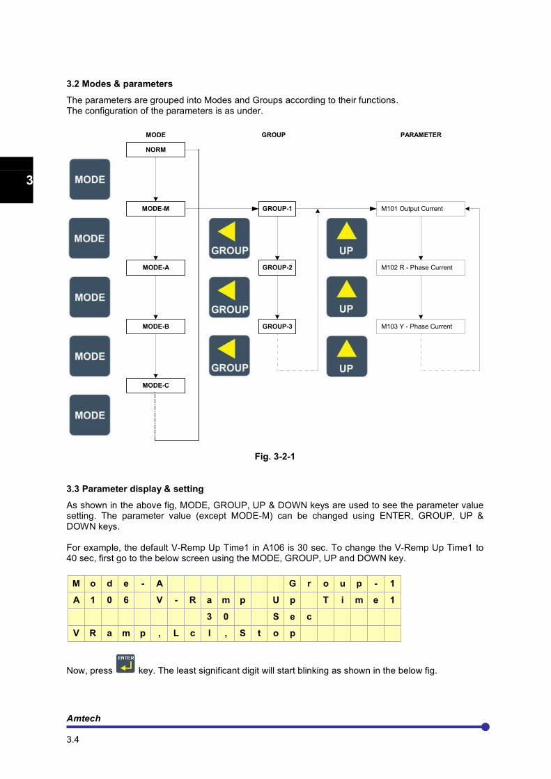
3.2 Modes & parameters
The parameters are grouped into Modes and Groups according to their functions. The configuration of the parameters is as under.
MODE
NORM
MODE-M
MODE-A
MODE-B
MODE-C
GROUP-1
GROUP-2
M101 Output Current
M102 R - Phase Current
M103 Y - Phase CurrentGROUP-3
GROUP PARAMETER
Fig. 3-2-1
3.3 Parameter display & setting
As shown in the above fig, MODE, GROUP, UP & DOWN keys are used to see the parameter value setting. The parameter value (except MODE-M) can be changed using ENTER, GROUP, UP & DOWN keys. For example, the default V-Remp Up Time1 in A106 is 30 sec. To change the V-Remp Up Time1 to 40 sec, first go to the below screen using the MODE, GROUP, UP and DOWN key.
M o d e - A G r o u p - 1
A 1 0 6 V - R a m p U p T i m e 1
3 0 S e c
V R a m p , L c l , S t o p
Now, press key. The least significant digit will start blinking as shown in the below fig.

Axpert-Opti torque Electronic Soft Starter
3.5
1
2
3
4
5
6
7
8
9
10
11
12
13
A
M o d e - A G r o u p - 1
A 1 0 6 V - R a m p U p T i m e 1
3 0 S e c
V R a m p , L c l , S t o p
The parameter value now can be set to the desired value using , or keys. When
or is pressed, the value will increment or decrement. If is pressed, the cursor position will move to the left side as shown in the below fig.
M o d e - A G r o u p - 1
A 1 0 6 V - R a m p U p T i m e 1
3 0 S e c
V R a m p , L c l , S t o p
Now, press key once. The value will be incremented by one.
M o d e - A G r o u p - 1
A 1 0 6 V - R a m p U p T i m e 1
4 0 S e c
V R a m p , L c l , S t o p
Once the desired value is set, press key to save the value. The cursor will stop blinking and the parameter value will be saved to the non-volatile memory. If you do not want to save the new value,
do not press key. Press key.
CAUTION
Do not remove or insert the display cable between PCA-2005B (Main Control Card) and PCA-2012 (Display Card) in power-energized condition.
Failure to observe this could lead to component failure and tripping of the unit.

Amtech 3.6
1
2
3
4
5
6
7
8
9
10
11
12
13
A
This page is intentionally left blank.
Axpert-Opti torque Electronic Soft Starter
4.1
1
2
3
4
5
6
7
8
9
10
11
12
13
A
CHAPTER-4: TEST OPERATION AND ADJUSTMENT
DANGER
Never touch the unit terminals while the power is ON even if the operation is stopped.
Failure to observe this could lead to electric shocks.
Selection of the restart function could lead to unexpected restarting when a fault occurs. The machine may start suddenly if the power is turned ON, if the run command is present. Do not go near the machine.
The machine may not stop according to the set Soft Stop time when a stop command is issued if the ramp down to stop function is selected and the voltage / current limit function is activated. Prepare a separate emergency stop switch in such cases.
Failure to do so could lead to injuries.
Resetting of a fault while the run signal is input could lead to restarting. Always confirm that the run signal is OFF before resetting the fault.
Failure to do so could lead to injuries.
CAUTION
The heat sink is heated to high temperatures, so never touch them.
Failure to observe this could lead to burns.
Do not block the unit’s ventilation holes.
Failure to observe this could lead to fires.
Confirm the operation of the motor as a single unit before operating the machine.
Failure to do so could lead to injuries or machine damage due to unforeseen movements.
Always prepare a safety backup device so that the machine is not placed in a hazardous situation when an error occurs in the unit.
Failure to do so could lead to injuries or machine damage or fires.
Amtech 4.2
1
2
3
4
5
6
7
8
9
10
11
12
13
A
The Axpert-Opti torque Series Electronic Soft starter has various setting items. Some of these include settings that must be made according to the power supply and motor before actually starting the operation.
The method of the basic operation is explained in this section.
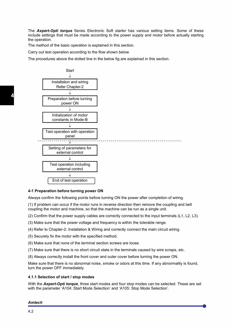
Carry out test operation according to the flow shown below
The procedures above the dotted line in the below fig are explained in this section.
Start
↓
Installation and wiring
Refer Chapter-2
↓
Preparation before turning power ON
↓
Initialization of motor constants in Mode-B
↓
Test operation with operation panel
↓
Setting of parameters for external control
↓
Test operation including external control
↓
End of test operation
4-1 Preparation before turning power ON
Always confirm the following points before turning ON the power after completion of wiring.
(1) If problem can occur if the motor runs in reverse direction then remove the coupling and belt coupling the motor and machine, so that the machine can be run as a single unit.
(2) Confirm that the power supply cables are correctly connected to the input terminals (L1, L2, L3).
(3) Make sure that the power voltage and frequency is within the tolerable range.
(4) Refer to Chapter-2: Installation & Wiring and correctly connect the main circuit wiring.
(5) Securely fix the motor with the specified method.
(6) Make sure that none of the terminal section screws are loose.
(7) Make sure that there is no short circuit state in the terminals caused by wire scraps, etc.
(8) Always correctly install the front cover and outer cover before turning the power ON.
Make sure that there is no abnormal noise, smoke or odors at this time. If any abnormality is found, turn the power OFF immediately.
4.1.1 Selection of start / stop modes
With the Axpert-Opti torque, three start modes and four stop modes can be selected. These are set with the parameter ‘A104: Start Mode Selection’ and ‘A105: Stop Mode Selection’.
Axpert-Opti torque Electronic Soft Starter
4.3
1
2
3
4
5
6
7
8
9
10
11
12
13
A
Normally, V-Ramp is used in almost 90% applications. However, where the load has to reach to the full speed within short time, I-Ramp is the preferred start mode. Where, reduction in the current peak and linear rise of speed is required, use T-Ramp mode. For the test operation, select V-Ramp Start as start mode and Coast-to-stop as stop mode.
A104: Start Mode Selection =1: V-Ramp Start =2: I-Ramp Start =3: T-Ramp Start
A105: Stop Mode Selection =1: V-Ramp Stop =2: T-Ramp Stop =3: Brake Stop =4: Coast-to-Stop
4.1.2 Selection of start control
The unit can be controlled from various places like Digital Operation Panel (Local), Terminal or from Host computer. Select appropriate start control in A101. Use Digital Operation Panel (Local) during the test operation.
A101: Start Control =1: Local =2: Terminal =3: Serial
4.1.3 Adjusting the ramp time
The ramp time needs to be adjusted according to the applications and start/ stop mode. Do not keep long ramp time when using the V-Ramp and I-Ramp start mode.
For the V-Ramp start / stop adjust the below parameters. For the test operations, you can continue with the default settings and later on change as per the application requirements. A106: V-Ramp Up Time1 A107: V-Ramp Down Time1 If using the dual ramp function, adjust A204: V-Ramp Up Time2 and A208: Ramp Down Time2 For the I-Ramp start, adjust A301: I-Ramp Up Time For T-Ramp start / stop, adjust A401: T-Ramp Up Time A406: T-Ramp Down Time
4.2 Initialization of motor constants in Mode-B
Input the motor rating parameters. Set the following parameters in Mode-B.
B101: Rated Input Voltage (V) B102: Motor Voltage (V) B103: Motor Current (A) B104: Motor Frequency (Hz) B105: Motor Speed (rpm) B106: Motor Capacity (kW) B107: Motor Poles B108: SS Connection Type
Refer Chapter-10 for the power wiring connections for inside delta connections.

Amtech 4.4
1
2
3
4
5
6
7
8
9
10
11
12
13
A
4.3 Test operations
When finished with parameter settings, test run the isolated motor, and make sure that there are no tripping.
Use Digital Operation Panel mode to test run the motor. Press “RUN” key to start the motor.
Check
- Did the motor run?
- Is the run direction correct? Check the wiring and operation if abnormal.
- Is the rotation smooth?
- Is motor direction is same as required? Press the “STOP” key and stop the motor. If the motor direction is not the desired one, interchange any two motor terminals.
This completes the test operation with the operation panel.
After this, carry out the parameter settings and adjust the load operation to match the user's application.
Axpert-Opti torque Electronic Soft Starter
5.1
1
2
3
4
5
6
7
8
9
10
11
12
13
A
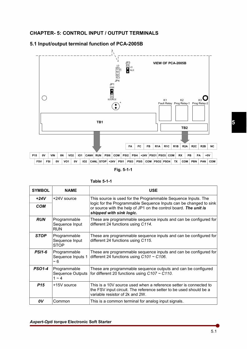
CHAPTER- 5: CONTROL INPUT / OUTPUT TERMINALS
5.1 Input/output terminal function of PCA-2005B
TB1
TB2
K1
Fault Relay
K2
Prog Relay-1
K3
Prog Relay-2
JP1SINK
+
SOURCE
JP3
LD
JP4
NLDLD
VIEW OF PCA-2005B
P15 0V VIN
FSV FSI
IIN
0V
VO2
VO1
IO1 CANH RUN PSI6 COM
0V IO2 CANL STOP +24V PSI1 PSI3 PSI5
PSI2 PSI4 +24V PSO1
COM PSO2 PSO4 TX COM PBN PAN COM
PSO3 COM RX PB PA +5V
FA FC FB R1A R1C R1B R2A R2C R2B NC
NLD
LD
Fig. 5-1-1
Table 5-1-1
SYMBOL NAME USE
+24V +24V source This source is used for the Programmable Sequence Inputs. The logic for the Programmable Sequence Inputs can be changed to sink or source with the help of JP1 on the control board. The unit is
shipped with sink logic.
COM
RUN Programmable Sequence Input RUN
These are programmable sequence inputs and can be configured for different 24 functions using C114.
STOP Programmable Sequence Input STOP
These are programmable sequence inputs and can be configured for different 24 functions using C115.
PSI1-6 Programmable Sequence Inputs 1 ~ 6
These are programmable sequence inputs and can be configured for different 24 functions using C101 ~ C106.
PSO1-4 Programmable Sequence Outputs 1 ~ 4
These are programmable sequence outputs and can be configured for different 20 functions using C107 ~ C110.
P15 +15V source This is a 10V source used when a reference setter is connected to the FSV input circuit. The reference setter to be used should be a variable resistor of 2k and 2W.
0V Common This is a common terminal for analog input signals.
Amtech 5.2
1
2
3
4
5
6
7
8
9
10
11
12
13
A
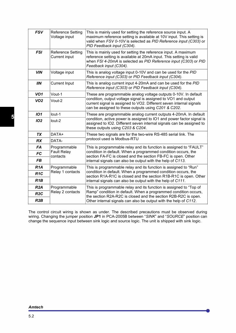
FSV Reference Setting Voltage input
This is mainly used for setting the reference source input. A maximum reference setting is available at 10V input. This setting is valid when FSV 0-10V is selected as PID Reference input (C303) or PID Feedback input (C304).
FSI Reference Setting Current input
This is mainly used for setting the reference input. A maximum reference setting is available at 20mA input. This setting is valid when FSI 4-20mA is selected as PID Reference input (C303) or PID Feedback input (C304).
VIN Voltage input This is analog voltage input 0-10V and can be used for the PID Reference input (C303) or PID Feedback input (C304).
IIN Current Input This is analog current input 4-20mA and can be used for the PID Reference input (C303) or PID Feedback input (C304).
VO1 Vout-1 These are programmable analog voltage outputs 0-10V. In default condition, output voltage signal is assigned to VO1 and output current signal is assigned to VO2. Different seven internal signals can be assigned to these outputs using C201 & C202.
VO2 Vout-2
IO1 Iout-1 These are programmable analog current outputs 4-20mA. In default condition, active power is assigned to IO1 and power factor signal is assigned to IO2. Different seven internal signals can be assigned to these outputs using C203 & C204.
IO2 Iout-2
TX DATA+ These two signals are for the two-wire RS-485 serial link. The protocol used is Modbus-RTU
RX DATA-
FA Programmable Fault Relay contacts
This is programmable relay and its function is assigned to “FAULT” condition in default. When a programmed condition occurs, the section FA-FC is closed and the section FB-FC is open. Other internal signals can also be output with the help of C113.
FC
FB
R1A Programmable Relay 1 contacts
This is programmable relay and its function is assigned to “Run” condition in default. When a programmed condition occurs, the section R1A-R1C is closed and the section R1B-R1C is open. Other internal signals can also be output with the help of C111.
R1C
R1B
R2A Programmable Relay 2 contacts
This is programmable relay and its function is assigned to “Top of Ramp” condition in default. When a programmed condition occurs, the section R2A-R2C is closed and the section R2B-R2C is open. Other internal signals can also be output with the help of C112.
R2C
R2B
The control circuit wiring is shown as under. The described precautions must be observed during wiring. Changing the jumper position JP1 in PCA-2005B between “SINK” and “SOURCE” position can change the sequence input between sink logic and source logic. The unit is shipped with sink logic.
Axpert-Opti torque Electronic Soft Starter
5.3
1
2
3
4
5
6
7
8
9
10
11
12
13
A
5.2 Programmable sequence input (PSI) wiring
Precautions 1. Wiring must not be longer than 50m (164’). 2. Use minute current contact. 3. Do not connect to the analog input / output. 4. The sink / source logic can be changed with JP1 as shown in the above figure.
5.3 Programmable analog input (PAI) wiring
FSV
P15
+15V940R
33k
10k0V2k/2W
VIN
L<30m (98.4')
33k
10k0V
FSI
270R0V
20mA
IIN
L<30m (98.4')
270R0V
20mA
+10V
Fig. 5-3-1
Precautions 1. Use 2kΩ / 2W rating potentiometer for the external variable resistor. 2. The maximum input rating of FSV /VIN is 0 to 10.5V 3. Use a shielded wire shorter than 30m (98.4’) for the wiring. 4. For the shield connections, open the mate side, and connect to 0V terminal on TB1. 5. The maximum input rating for FSI / IIN is 0 to +21mA or 5.67V. 6. Do not connect to the sequence input.
+24V
5.6k
COM
PSI
L<50m
(164')
+24V
5.6k
+24V
PSI
L<50m
(164')
SINK LOGIC SOURCE LOGIC
SINK
SOURCE
JP1
Fig. 5-2-1
SINK
SOURCE
JP1
Amtech 5.4
1
2
3
4
5
6
7
8
9
10
11
12
13
A
5.4 Programmable analog output (PAO) wiring
VO1
VO2
0V
L<30m (98.4')
IO2
Ground
270R
270R
IO1 50R
50R
Output Voltage
Output Current
Active Power
Power Factor
(0-10V)
(4-20mA)
(4-20mA)
(0-10V)
Fig. 5-4-1 Precautions 1. Use 10V full-scale meter (impedance 10k or higher). 2. The maximum output current is 1mA for voltage output. 3. Use a shielded wire shorter than 30m (98.4’) for the wiring. 4. For the shield connections, open the mate side, and connect to 0V terminal on TB1.
5.5 Programmable sequence output (PSO) wiring
Open collector type wiring
PSO
L<50m (164')
COM
COILMax 30Vdc/
50mA
Fig. 5-5-1 Precautions
1. To drive an L load, such as a coil, insert the flywheel diode shown in the drawing. 2. Keep the wiring length to 50m (164’) or less. 3. Use within the 30VDC, 50mA ratings range.
Axpert-Opti torque Electronic Soft Starter
5.5
1
2
3
4
5
6
7
8
9
10
11
12
13
A
Relay type wiring
R2C
R2A
R2B
L<50m (164')
FC
FA
FB
L<50m (164')
R1C
R1A
R1B
L<50m (164')
PROGRAMMABLE FAULT
RELAYPROGRAMMABLE RELAY1 PROGRAMMABLE RELAY2
Fig. 5-5-2 Precautions 1. Use within the rated range shown below.
Rated capacity (resistance load): 250VAC, 1A or 30VDC, 1A Maximum Voltage: 250VAC Max. Current: 1A Switching capacity: 100VA / 100W 2. The wire must be shorter than 50m (164’).

Amtech 5.6
1
2
3
4
5
6
7
8
9
10
11
12
13
A
This page is intentionally left blank
Axpert-Opti torque Electronic Soft Starter
6.1
1
2
3
4
5
6
7
8
9
10
11
12
13
A
CHAPTER- 6: PARAMETER SETTINGS & FUNCTIONS
6.1 MODE-M: Monitor Parameters
The monitor mode sequentially displays the current, voltage, etc., parameters.
No. Parameter Name Unit Res. Description
GROUP-1
M101 Output Current % 0.1 Displays the average value of three-phase output current as a % of the motor rated current.
M102 R-Phase Current Amp 0.1 It displays the current of R-Phase in ampere.
M103 Y-Phase Current Amp 0.1 It displays the current of Y-Phase in ampere.
M104 B -Phase Current Amp 0.1 It displays the current of B -Phase in ampere.
M105 Output Voltage Vac 1 It displays the Output Voltage. The display may differ from the actual output voltage.
M106 Input Voltage Vry Vac 1 It displays the Input Voltage between R & Y phase.
M107 Input Voltage Vyb Vac 1 It displays the Input Voltage between Y & B phase.
M108 Line Frequency Hz 0.1 It displays the line frequency.
M109 Active Power kW 0.1 It displays the active power in kW.
M110 Reactive Power kVR 0.1 It displays the reactive power in kVAR.
M111 Power Factor 0.01 It displays power factor of the motor.
M112 Energy Meter kWH 0.1 It displays energy consumed by the system in kWH.
M113 Energy Meter MWH 1 It displays energy consumed by the system in MWH.
GROUP-2
M201 Heat sink Temperature oC 1 Displays actual heat sink temperature of the starter.
M202 PSI-12345678 Status The ON/OFF state of programmable sequence input will display.
M203 PSO-1234567 Status The ON/OFF state of programmable sequence output will display.
M204 No Of Start 1 Display the number of start in last one hour.
M205 Total Start 1 Total number of starts after product shipment will be counted and displayed.
M206 Total Conductive Time Hrs 1 The cumulative power on time after the product shipment will be counted and displayed in hours.
M207 Total Run Time Hrs 1 The cumulative run time after product shipment will be counted and displayed in Hours.
M208 Motor Torque N-m 0.1 It displays the motor torque in N-m.
M209 PID Reference 0.1 It displays the value of currently selected PID reference in C303.
M210 PID Feedback 0.1 It displays the value of currently selected PID feedback in C304.
M211 FSV Reference % 0.1 It displays the value of analog input in % proportional to 0-10V.
M212 FSI Reference % 0.1 It displays the value of analog input in % proportional to 4-20mA.
M213 Vin Reference % 0.1 It displays the value of analog input in % proportional to 0-10V.
M214 Iin Reference % 0.1 It displays the value of analog input in % proportional to 4-20mA.
M215 Peak Current Amp 0.1 It displays the peak current drawn by the unit.
M216 Heat sink Temperature oF 1 It displays actual heat sink temperature of the starter in degree
Fahrenheit.
Amtech 6.2
1
2
3
4
5
6
7
8
9
10
11
12
13
A
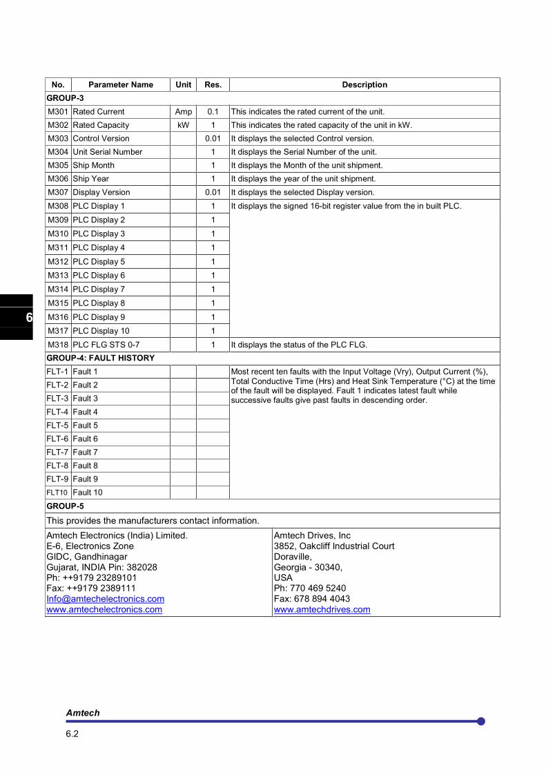
No. Parameter Name Unit Res. Description
GROUP-3
M301 Rated Current Amp 0.1 This indicates the rated current of the unit.
M302 Rated Capacity kW 1 This indicates the rated capacity of the unit in kW.
M303 Control Version 0.01 It displays the selected Control version.
M304 Unit Serial Number 1 It displays the Serial Number of the unit.
M305 Ship Month 1 It displays the Month of the unit shipment.
M306 Ship Year 1 It displays the year of the unit shipment.
M307 Display Version 0.01 It displays the selected Display version.
M308 PLC Display 1 1 It displays the signed 16-bit register value from the in built PLC.
M309 PLC Display 2 1
M310 PLC Display 3 1
M311 PLC Display 4 1
M312 PLC Display 5 1
M313 PLC Display 6 1
M314 PLC Display 7 1
M315 PLC Display 8 1
M316 PLC Display 9 1
M317 PLC Display 10 1
M318 PLC FLG STS 0-7 1 It displays the status of the PLC FLG.
GROUP-4: FAULT HISTORY
FLT-1 Fault 1 Most recent ten faults with the Input Voltage (Vry), Output Current (%),
Total Conductive Time (Hrs) and Heat Sink Temperature (°C) at the time of the fault will be displayed. Fault 1 indicates latest fault while successive faults give past faults in descending order.
FLT-2 Fault 2
FLT-3 Fault 3
FLT-4 Fault 4
FLT-5 Fault 5
FLT-6 Fault 6
FLT-7 Fault 7
FLT-8 Fault 8
FLT-9 Fault 9
FLT10 Fault 10
GROUP-5
This provides the manufacturers contact information.
Amtech Electronics (India) Limited. E-6, Electronics Zone GIDC, Gandhinagar Gujarat, INDIA Pin: 382028 Ph: ++9179 23289101 Fax: ++9179 2389111 [email protected] www.amtechelectronics.com
Amtech Drives, Inc 3852, Oakcliff Industrial Court Doraville, Georgia - 30340, USA Ph: 770 469 5240 Fax: 678 894 4043 www.amtechdrives.com
Axpert-Opti torque Electronic Soft Starter
6.3
1
2
3
4
5
6
7
8
9
10
11
12
13
A
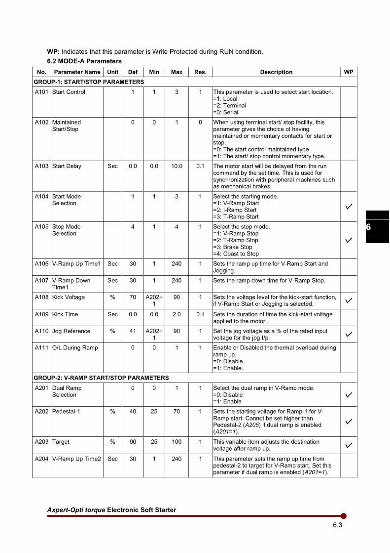
WP: Indicates that this parameter is Write Protected during RUN condition.
6.2 MODE-A Parameters
No. Parameter Name Unit Def Min Max Res. Description WP
GROUP-1: START/STOP PARAMETERS
A101 Start Control 1 1 3 1 This parameter is used to select start location. =1: Local =2: Terminal =3: Serial
A102 Maintained Start/Stop
0 0 1 0 When using terminal start/ stop facility, this parameter gives the choice of having maintained or momentary contacts for start or stop. =0: The start control maintained type =1: The start/ stop control momentary type.
A103 Start Delay Sec 0.0 0.0 10.0 0.1 The motor start will be delayed from the run command by the set time. This is used for synchronization with peripheral machines such as mechanical brakes.
A104 Start Mode Selection
1 1 3 1 Select the starting mode. =1: V-Ramp Start =2: I-Ramp Start =3: T-Ramp Start
A105 Stop Mode Selection
4 1 4 1 Select the stop mode. =1: V-Ramp Stop =2: T-Ramp Stop =3: Brake Stop =4: Coast to Stop
A106 V-Ramp Up Time1 Sec 30 1 240 1 Sets the ramp up time for V-Ramp Start and Jogging.
A107 V-Ramp Down Time1
Sec 30 1 240 1 Sets the ramp down time for V-Ramp Stop.
A108 Kick Voltage % 70 A202+1
90 1 Sets the voltage level for the kick-start function, if V-Ramp Start or Jogging is selected.
A109 Kick Time Sec 0.0 0.0 2.0 0.1 Sets the duration of time the kick-start voltage applied to the motor.
A110 Jog Reference % 41 A202+1
90 1 Set the jog voltage as a % of the rated input voltage for the jog I/p.
A111
O/L During Ramp 0 0 1 1 Enable or Disabled the thermal overload during ramp up. =0: Disable. =1: Enable.
GROUP-2: V-RAMP START/STOP PARAMETERS
A201 Dual Ramp Selection
0 0 1 1 Select the dual ramp in V-Ramp mode. =0: Disable =1: Enable
A202 Pedestal-1 % 40 25 70 1 Sets the starting voltage for Ramp-1 for V- Ramp start. Cannot be set higher than Pedestal-2 (A205) if dual ramp is enabled (A201=1).
A203 Target % 90 25 100 1 This variable item adjusts the destination voltage after ramp up.
A204 V-Ramp Up Time2 Sec 30 1 240 1 This parameter sets the ramp up time from pedestal-2 to target for V-Ramp start. Set this parameter if dual ramp is enabled (A201=1).
Amtech 6.4
1
2
3
4
5
6
7
8
9
10
11
12
13
A
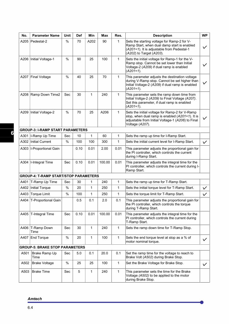
No. Parameter Name Unit Def Min Max Res. Description WP
A205 Pedestal-2 % 70 A202 90 1 Sets the starting voltage for Ramp-2 for V-Ramp Start, when dual damp start is enabled (A201=1). It is adjustable from Pedestal-1 (A202) to Target (A203).
A206 Initial Voltage-1 % 90 25 100 1 Sets the initial voltage for Ramp-1 for the V- Ramp stop. Cannot be set lower than Initial Voltage-2 (A209) if dual ramp is enabled (A201=1).
A207 Final Voltage % 40 25 70 1 This parameter adjusts the destination voltage during V-Ramp stop. Cannot be set higher than Initial Voltage-2 (A209) if dual ramp is enabled (A201=1).
A208 Ramp Down Time2 Sec 30 1 240 1 This parameter sets the ramp down time from Initial Voltge-2 (A209) to Final Voltage (A207).
Set this parameter, if dual ramp is enabled (A201=1).
A209 Initial Voltage-2 % 70 25 A206 1 Sets the initial voltage for Ramp-2 for V-Ramp stop, when dual ramp is enabled (A201=1). It is adjustable from Initial Voltage-1 (A206) to Final Voltage (A207).
GROUP-3: I-RAMP START PARAMETERS
A301 I-Ramp Up Time Sec 10 1 60 1 Sets the ramp up time for I-Ramp Start.
A302 Initial Current % 100 100 300 1 Sets the initial current level for I-Ramp Start.
A303 I-Proportional Gain 0.10 0.01 2.00 0.01 This parameter adjusts the proportional gain for the PI controller, which controls the current during I-Ramp Start.
A304 I-Integral Time Sec 0.10 0.01 100.00 0.01 This parameter adjusts the integral time for the
PI controller, which controls the current during I-Ramp Start.
GROUP-4: T-RAMP START/STOP PARAMETERS
A401 T-Ramp Up Time Sec 30 1 240 1 Sets the ramp up time for T-Ramp Start.
A402 Initial Torque % 20 1 250 1 Sets the initial torque level for T-Ramp Start.
A403 Torque Limit % 100 1 250 1 Sets the torque limit for T-Ramp Start.
A404 T-Proportional Gain 0.5 0.1 2.0 0.1 This parameter adjusts the proportional gain for the PI controller, which controls the torque during T-Ramp Start.
A405 T-Integral Time Sec 0.10 0.01 100.00 0.01 This parameter adjusts the integral time for the PI controller, which controls the current during T-Ramp Start.
A406 T-Ramp Down Time
Sec 30 1 240 1 Sets the ramp down time for T-Ramp Stop.
A407 End Torque % 20 1 100 1 Sets the end torque level at stop as a % of motor nominal torque.
GROUP-5: BRAKE STOP PARAMETERS
A501 Brake Ramp Up Time
Sec 5.0 0.1 20.0 0.1 Set the ramp time for the voltage to reach to Brake Volt (A502) during Brake Stop.
A502 Brake Voltage % 25 25 100 1 Set the Brake Voltage for Brake Stop.
A503 Brake Time Sec 5 1 240 1 This parameter sets the time for the Brake Voltage (A502) to be applied to the motor
during Brake Stop.
Axpert-Opti torque Electronic Soft Starter
6.5
1
2
3
4
5
6
7
8
9
10
11
12
13
A
No. Parameter Name Unit Def Min Max Res. Description WP
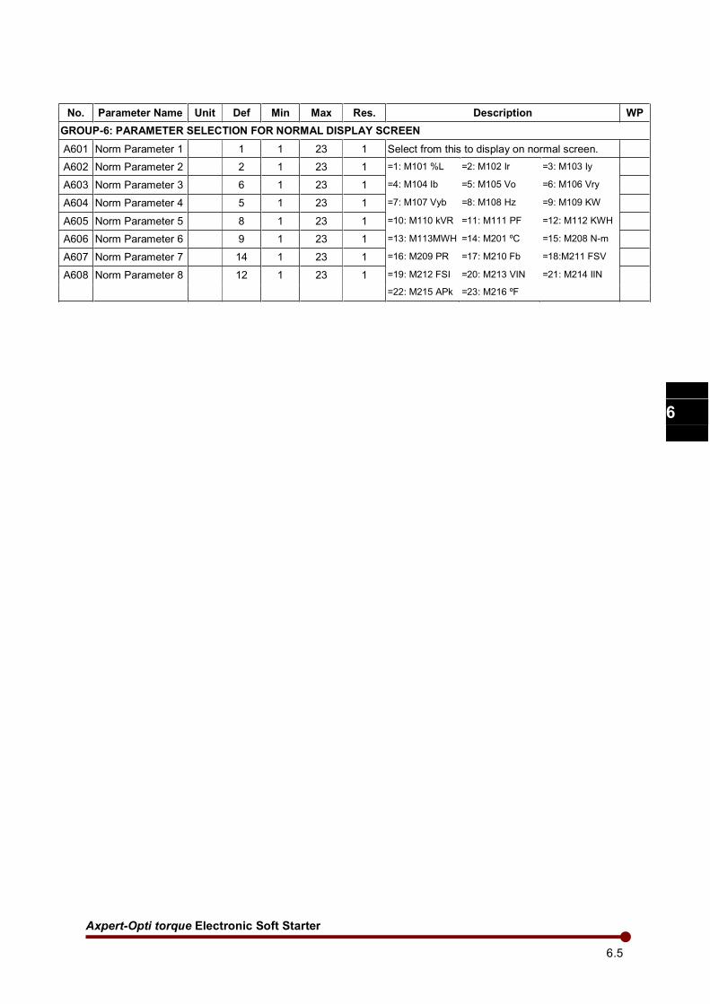
GROUP-6: PARAMETER SELECTION FOR NORMAL DISPLAY SCREEN
A601 Norm Parameter 1 1 1 23 1 Select from this to display on normal screen.
A602 Norm Parameter 2 2 1 23 1 =1: M101 %L =2: M102 Ir =3: M103 Iy
A603 Norm Parameter 3 6 1 23 1 =4: M104 Ib =5: M105 Vo =6: M106 Vry
A604 Norm Parameter 4 5 1 23 1 =7: M107 Vyb =8: M108 Hz =9: M109 KW
A605 Norm Parameter 5 8 1 23 1 =10: M110 kVR =11: M111 PF =12: M112 KWH
A606 Norm Parameter 6 9 1 23 1 =13: M113MWH =14: M201 ºC =15: M208 N-m
A607 Norm Parameter 7 14 1 23 1 =16: M209 PR =17: M210 Fb =18:M211 FSV
A608 Norm Parameter 8 12 1 23 1 =19: M212 FSI =20: M213 VIN =21: M214 IIN
=22: M215 APk =23: M216 ºF
Amtech 6.6
1
2
3
4
5
6
7
8
9
10
11
12
13
A
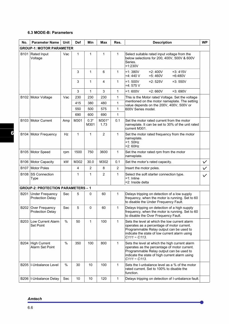
6.3 MODE-B: Parameters
No. Parameter Name Unit Def Min Max Res. Description WP
GROUP-1: MOTOR PARAMETER
B101 Rated Input Voltage
Vac 1 1 1 1 Select suitable rated input voltage from the below selections for 200, 400V, 500V & 600V Series. =1:230V
3 1 6 1 =1: 380V =2: 400V =3: 415V =4: 440 V =5: 460V =6:480V
3 1 4 1 =1: 500V =2: 525V =3: 550V =4: 575 V
3 1 3 1 =1: 600V =2: 660V =3: 690V
B102 Motor Voltage Vac 230 230 230 1 This is the Motor rated Voltage. Set the voltage mentioned on the motor nameplate. The setting value depends on the 200V, 400V, 500V or 600V Series model.
415 380 480 1
550 500 575 1
690 600 690 1
B103 Motor Current Amp M301 0.3* M301
M301* 1.73
0.1 Set the motor rated current from the motor nameplate. It can be set to 30% of the unit rated current M301.
B104 Motor Frequency Hz 1 1 2 1 Set the motor rated frequency from the motor nameplate. =1: 50Hz =2: 60Hz
B105 Motor Speed rpm 1500 750 3600 1 Set the motor rated rpm from the motor nameplate.
B106 Motor Capacity kW M302 30.0 M302 0.1 Set the motor’s rated capacity.
B107 Motor Poles 4 2 8 2 Insert the motor poles.
B108 SS Connection Type
1 1 2 1 Select the soft starter connection type. =1: Inline =2: Inside delta
GROUP-2: PROTECTION PARAMETERS – 1
B201 Under Frequency Protection Delay
Sec 5 0 60 1 Delays tripping on detection of a low supply frequency, when the motor is running. Set to 60 to disable the Under Frequency Fault.
B202 Over Frequency Protection Delay
Sec 5 0 60 1 Delays tripping on detection of a high supply frequency, when the motor is running. Set to 60 to disable the Over Frequency Fault.
B203 Low Current Alarm Set Point
% 50 1 100 1 Sets the level at which the low current alarm operates as a percentage of motor current. Programmable Relay output can be used to indicate the state of low current alarm using C111 ~ C113.
B204 High Current Alarm Set Point
% 350 100 800 1 Sets the level at which the high current alarm operates as the percentage of motor current. Programmable Relay output can be used to indicate the state of high current alarm using C111 ~ C113.
B205 I-Unbalance Level % 30 10 100 1 Sets the I-unbalance level as a % of the motor rated current. Set to 100% to disable the
function.
B206 I-Unbalance Delay Sec 10 10 120 1 Delays tripping on detection of I-unbalance fault.
Axpert-Opti torque Electronic Soft Starter
6.7
1
2
3
4
5
6
7
8
9
10
11
12
13
A
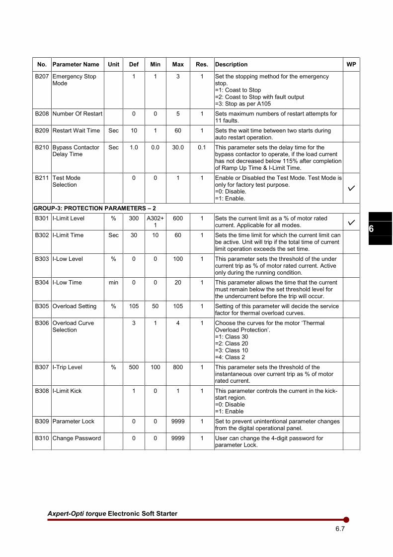
No. Parameter Name Unit Def Min Max Res. Description WP
B207 Emergency Stop Mode
1 1 3 1 Set the stopping method for the emergency stop. =1: Coast to Stop
=2: Coast to Stop with fault output =3: Stop as per A105
B208 Number Of Restart 0 0 5 1 Sets maximum numbers of restart attempts for 11 faults.
B209 Restart Wait Time Sec 10 1 60 1 Sets the wait time between two starts during auto restart operation.
B210 Bypass Contactor Delay Time
Sec 1.0 0.0 30.0 0.1 This parameter sets the delay time for the bypass contactor to operate, if the load current has not decreased below 115% after completion of Ramp Up Time & I-Limit Time.
B211 Test Mode Selection
0 0 1 1 Enable or Disabled the Test Mode. Test Mode is only for factory test purpose. =0: Disable.
=1: Enable.
GROUP-3: PROTECTION PARAMETERS – 2
B301 I-Limit Level % 300 A302+1
600 1 Sets the current limit as a % of motor rated current. Applicable for all modes.
B302 I-Limit Time Sec 30 10 60 1 Sets the time limit for which the current limit can be active. Unit will trip if the total time of current limit operation exceeds the set time.
B303 I-Low Level % 0 0 100 1 This parameter sets the threshold of the under current trip as % of motor rated current. Active only during the running condition.
B304 I-Low Time min 0 0 20 1 This parameter allows the time that the current must remain below the set threshold level for the undercurrent before the trip will occur.
B305 Overload Setting % 105 50 105 1 Setting of this parameter will decide the service factor for thermal overload curves.
B306 Overload Curve Selection
3 1 4 1 Choose the curves for the motor ‘Thermal Overload Protection’. =1: Class 30 =2: Class 20 =3: Class 10 =4: Class 2
B307 I-Trip Level % 500 100 800 1 This parameter sets the threshold of the instantaneous over current trip as % of motor rated current.
B308 I-Limit Kick 1 0 1 1 This parameter controls the current in the kick-start region. =0: Disable =1: Enable
B309 Parameter Lock 0 0 9999 1 Set to prevent unintentional parameter changes from the digital operational panel.
B310 Change Password 0 0 9999 1 User can change the 4-digit password for parameter Lock.
Amtech 6.8
1
2
3
4
5
6
7
8
9
10
11
12
13
A
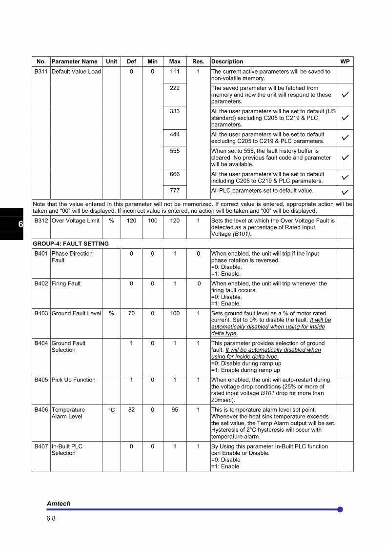
No. Parameter Name Unit Def Min Max Res. Description WP
B311 Default Value Load
0
0
111 1 The current active parameters will be saved to non-volatile memory.
222 The saved parameter will be fetched from memory and now the unit will respond to these parameters.
333 All the user parameters will be set to default (US standard) excluding C205 to C219 & PLC parameters.
444 All the user parameters will be set to default excluding C205 to C219 & PLC parameters.
555 When set to 555, the fault history buffer is cleared. No previous fault code and parameter will be available.
666 All the user parameters will be set to default including C205 to C219 & PLC parameters.
777 All PLC parameters set to default value.
Note that the value entered in this parameter will not be memorized. If correct value is entered, appropriate action will be taken and “00” will be displayed. If incorrect value is entered, no action will be taken and “00” will be displayed.
B312 Over Voltage Limit % 120 100 120 1 Sets the level at which the Over Voltage Fault is detected as a percentage of Rated Input Voltage (B101).
GROUP-4: FAULT SETTING
B401 Phase Direction Fault
0 0 1 0 When enabled, the unit will trip if the input phase rotation is reversed. =0: Disable. =1: Enable.
B402 Firing Fault 0 0 1 0 When enabled, the unit will trip whenever the firing fault occurs. =0: Disable. =1: Enable.
B403 Ground Fault Level % 70 0 100 1 Sets ground fault level as a % of motor rated current. Set to 0% to disable the fault. It will be
automatically disabled when using for inside delta type.
B404 Ground Fault Selection
1 0 1 1 This parameter provides selection of ground fault. It will be automatically disabled when using for inside delta type. =0: Disable during ramp up =1: Enable during ramp up
B405 Pick Up Function 1 0 1 1 When enabled, the unit will auto-restart during the voltage drop conditions (25% or more of rated input voltage B101 drop for more than 20msec).
B406 Temperature Alarm Level
°C 82 0 95 1 This is temperature alarm level set point. Whenever the heat sink temperature exceeds the set value, the Temp Alarm output will be set. Hysteresis of 2°C hysteresis will occur with temperature alarm.
B407 In-Built PLC Selection
0 0 1 1 By Using this parameter In-Built PLC function can Enable or Disable. =0: Disable =1: Enable
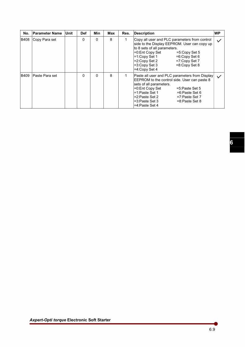
Axpert-Opti torque Electronic Soft Starter
6.9
1
2
3
4
5
6
7
8
9
10
11
12
13
A
No. Parameter Name Unit Def Min Max Res. Description WP
B408 Copy Para set 0 0 8 1 Copy all user and PLC parameters from control side to the Display EEPROM. User can copy up to 8 sets of all parameters. =0:Ent Copy Set =5:Copy Set 5 =1:Copy Set 1 =6:Copy Set 6 =2:Copy Set 2 =7:Copy Set 7 =3:Copy Set 3 =8:Copy Set 8 =4:Copy Set 4
B409 Paste Para set 0 0 8 1 Paste all user and PLC parameters from Display EEPROM to the control side. User can paste 8 sets of all parameters. =0:Ent Copy Set =5:Paste Set 5 =1:Paste Set 1 =6:Paste Set 6 =2:Paste Set 2 =7:Paste Set 7 =3:Paste Set 3 =8:Paste Set 8 =4:Paste Set 4
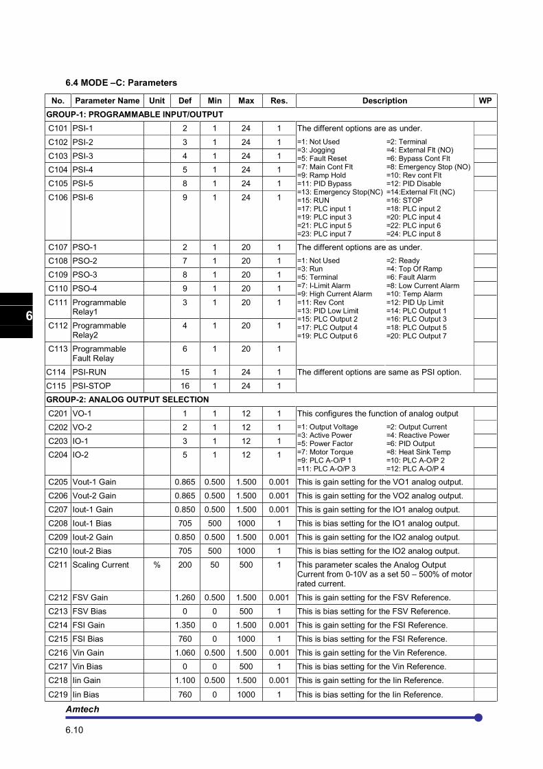
Amtech 6.10
1
2
3
4
5
6
7
8
9
10
11
12
13
A
6.4 MODE –C: Parameters
No. Parameter Name Unit Def Min Max Res. Description WP
GROUP-1: PROGRAMMABLE INPUT/OUTPUT
C101 PSI-1 2 1 24 1 The different options are as under.
C102 PSI-2 3 1 24 1 =1: Not Used =3: Jogging =5: Fault Reset =7: Main Cont Flt =9: Ramp Hold =11: PID Bypass =13: Emergency Stop(NC) =15: RUN =17: PLC input 1 =19: PLC input 3 =21: PLC input 5 =23: PLC input 7
=2: Terminal =4: External Flt (NO) =6: Bypass Cont Flt =8: Emergency Stop (NO) =10: Rev cont Flt =12: PID Disable =14:External Flt (NC) =16: STOP =18: PLC input 2 =20: PLC input 4 =22: PLC input 6 =24: PLC input 8
C103 PSI-3 4 1 24 1
C104 PSI-4 5 1 24 1
C105 PSI-5 8 1 24 1
C106 PSI-6 9 1 24 1
C107 PSO-1 2 1 20 1 The different options are as under.
C108 PSO-2 7 1 20 1 =1: Not Used =3: Run =5: Terminal =7: I-Limit Alarm =9: High Current Alarm =11: Rev Cont =13: PID Low Limit =15: PLC Output 2 =17: PLC Output 4 =19: PLC Output 6
=2: Ready =4: Top Of Ramp =6: Fault Alarm =8: Low Current Alarm =10: Temp Alarm =12: PID Up Limit =14: PLC Output 1 =16: PLC Output 3 =18: PLC Output 5 =20: PLC Output 7
C109 PSO-3 8 1 20 1
C110 PSO-4 9 1 20 1
C111 Programmable Relay1
3 1 20 1
C112 Programmable Relay2
4 1 20 1
C113 Programmable Fault Relay
6 1 20 1
C114 PSI-RUN 15 1 24 1 The different options are same as PSI option.
C115 PSI-STOP 16 1 24 1
GROUP-2: ANALOG OUTPUT SELECTION
C201 VO-1 1 1 12 1 This configures the function of analog output
C202 VO-2 2 1 12 1 =1: Output Voltage =3: Active Power =5: Power Factor =7: Motor Torque =9: PLC A-O/P 1 =11: PLC A-O/P 3
=2: Output Current =4: Reactive Power =6: PID Output =8: Heat Sink Temp =10: PLC A-O/P 2 =12: PLC A-O/P 4
C203 IO-1 3 1 12 1
C204 IO-2 5 1 12 1
C205 Vout-1 Gain 0.865 0.500 1.500 0.001 This is gain setting for the VO1 analog output.
C206 Vout-2 Gain 0.865 0.500 1.500 0.001 This is gain setting for the VO2 analog output.
C207 Iout-1 Gain 0.850 0.500 1.500 0.001 This is gain setting for the IO1 analog output.
C208 Iout-1 Bias 705 500 1000 1 This is bias setting for the IO1 analog output.
C209 Iout-2 Gain 0.850 0.500 1.500 0.001 This is gain setting for the IO2 analog output.
C210 Iout-2 Bias 705 500 1000 1 This is bias setting for the IO2 analog output.
C211 Scaling Current % 200 50 500 1 This parameter scales the Analog Output Current from 0-10V as a set 50 – 500% of motor rated current.
C212 FSV Gain 1.260 0.500 1.500 0.001 This is gain setting for the FSV Reference.
C213 FSV Bias 0 0 500 1 This is bias setting for the FSV Reference.
C214 FSI Gain 1.350 0 1.500 0.001 This is gain setting for the FSI Reference.
C215 FSI Bias 760 0 1000 1 This is bias setting for the FSI Reference.
C216 Vin Gain 1.060 0.500 1.500 0.001 This is gain setting for the Vin Reference.
C217 Vin Bias 0 0 500 1 This is bias setting for the Vin Reference.
C218 Iin Gain 1.100 0.500 1.500 0.001 This is gain setting for the Iin Reference.
C219 Iin Bias 760 0 1000 1 This is bias setting for the Iin Reference.
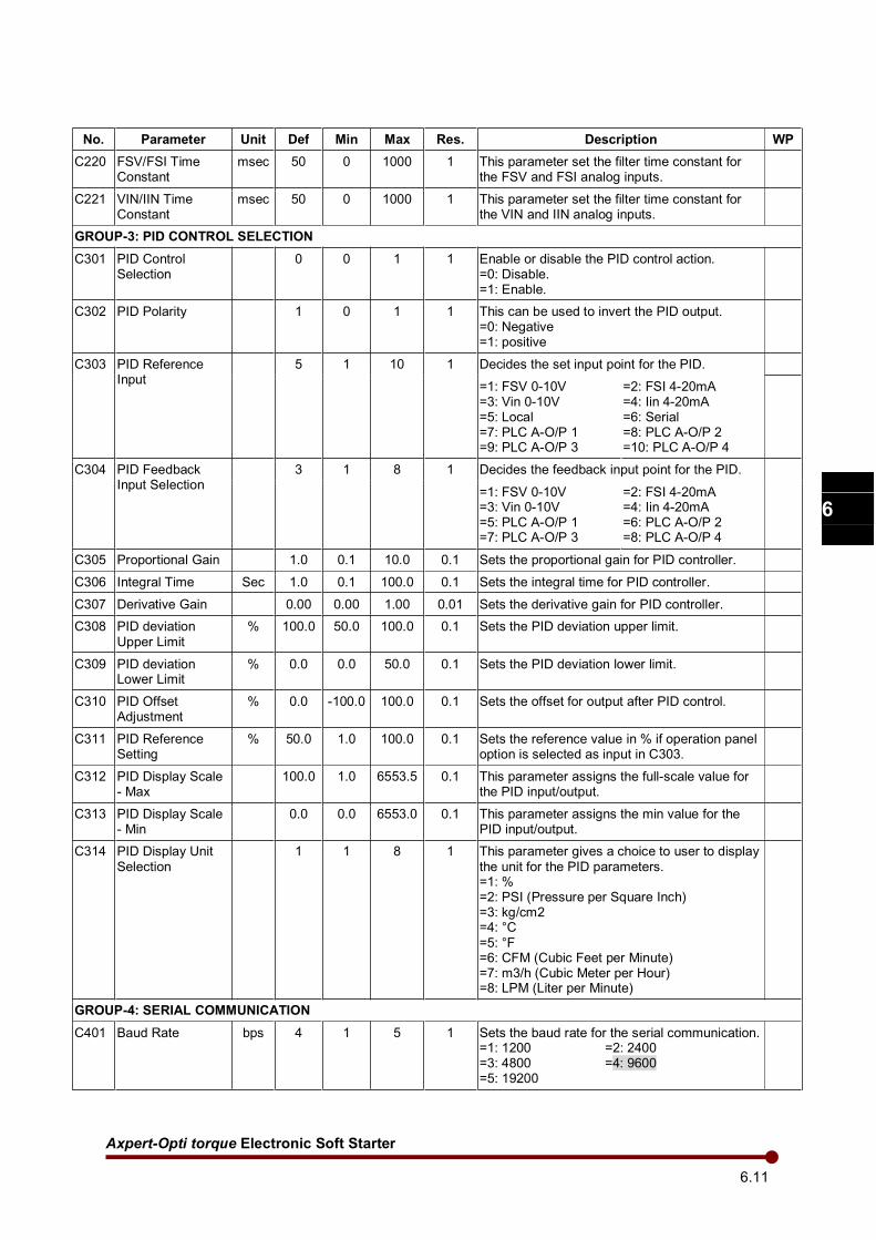
Axpert-Opti torque Electronic Soft Starter
6.11
1
2
3
4
5
6
7
8
9
10
11
12
13
A
No. Parameter Unit Def Min Max Res. Description WP
C220 FSV/FSI Time Constant
msec 50 0 1000 1 This parameter set the filter time constant for the FSV and FSI analog inputs.
C221 VIN/IIN Time Constant
msec 50 0 1000 1 This parameter set the filter time constant for the VIN and IIN analog inputs.
GROUP-3: PID CONTROL SELECTION
C301 PID Control Selection
0 0 1 1 Enable or disable the PID control action. =0: Disable. =1: Enable.
C302 PID Polarity 1 0 1 1 This can be used to invert the PID output. =0: Negative =1: positive
C303 PID Reference Input
5 1 10 1 Decides the set input point for the PID.
=1: FSV 0-10V =3: Vin 0-10V =5: Local =7: PLC A-O/P 1 =9: PLC A-O/P 3
=2: FSI 4-20mA =4: Iin 4-20mA =6: Serial =8: PLC A-O/P 2 =10: PLC A-O/P 4
C304 PID Feedback Input Selection
3 1 8 1 Decides the feedback input point for the PID.
=1: FSV 0-10V =3: Vin 0-10V =5: PLC A-O/P 1 =7: PLC A-O/P 3
=2: FSI 4-20mA =4: Iin 4-20mA =6: PLC A-O/P 2 =8: PLC A-O/P 4
C305 Proportional Gain 1.0 0.1 10.0 0.1 Sets the proportional gain for PID controller.
C306 Integral Time Sec 1.0 0.1 100.0 0.1 Sets the integral time for PID controller.
C307 Derivative Gain 0.00 0.00 1.00 0.01 Sets the derivative gain for PID controller.
C308 PID deviation
Upper Limit
% 100.0 50.0 100.0 0.1 Sets the PID deviation upper limit.
C309 PID deviation Lower Limit
% 0.0 0.0 50.0 0.1 Sets the PID deviation lower limit.
C310 PID Offset Adjustment
% 0.0 -100.0 100.0 0.1 Sets the offset for output after PID control.
C311 PID Reference Setting
% 50.0 1.0 100.0 0.1 Sets the reference value in % if operation panel option is selected as input in C303.
C312 PID Display Scale - Max
100.0 1.0 6553.5 0.1 This parameter assigns the full-scale value for the PID input/output.
C313 PID Display Scale - Min
0.0 0.0 6553.0 0.1 This parameter assigns the min value for the PID input/output.
C314 PID Display Unit
Selection
1 1 8 1 This parameter gives a choice to user to display
the unit for the PID parameters. =1: % =2: PSI (Pressure per Square Inch) =3: kg/cm2 =4: °C =5: °F =6: CFM (Cubic Feet per Minute) =7: m3/h (Cubic Meter per Hour) =8: LPM (Liter per Minute)
GROUP-4: SERIAL COMMUNICATION
C401 Baud Rate bps 4 1 5 1 Sets the baud rate for the serial communication. =1: 1200 =2: 2400 =3: 4800 =4: 9600 =5: 19200
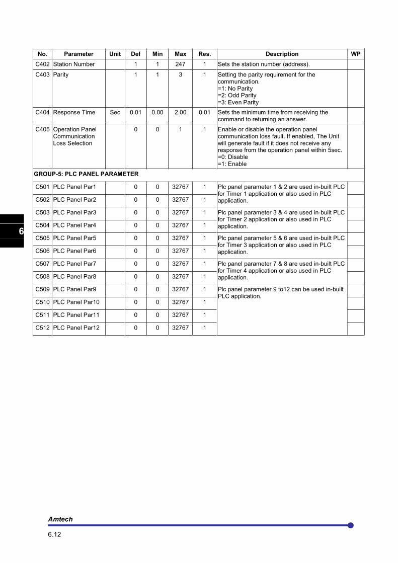
Amtech 6.12
1
2
3
4
5
6
7
8
9
10
11
12
13
A
No. Parameter Unit Def Min Max Res. Description WP
C402 Station Number 1 1 247 1 Sets the station number (address).
C403 Parity 1 1 3 1 Setting the parity requirement for the communication. =1: No Parity =2: Odd Parity
=3: Even Parity
C404 Response Time Sec 0.01 0.00 2.00 0.01 Sets the minimum time from receiving the command to returning an answer.
C405 Operation Panel Communication Loss Selection
0 0 1 1 Enable or disable the operation panel communication loss fault. If enabled, The Unit will generate fault if it does not receive any response from the operation panel within 5sec. =0: Disable =1: Enable
GROUP-5: PLC PANEL PARAMETER
C501 PLC Panel Par1 0 0 32767 1 Plc panel parameter 1 & 2 are used in-built PLC for Timer 1 application or also used in PLC application.
C502 PLC Panel Par2 0 0 32767 1
C503 PLC Panel Par3 0 0 32767 1 Plc panel parameter 3 & 4 are used in-built PLC for Timer 2 application or also used in PLC application.
C504 PLC Panel Par4 0 0 32767 1
C505 PLC Panel Par5 0 0 32767 1 Plc panel parameter 5 & 6 are used in-built PLC for Timer 3 application or also used in PLC application.
C506 PLC Panel Par6 0 0 32767 1
C507 PLC Panel Par7 0 0 32767 1 Plc panel parameter 7 & 8 are used in-built PLC for Timer 4 application or also used in PLC application.
C508 PLC Panel Par8 0 0 32767 1
C509 PLC Panel Par9 0 0 32767 1 Plc panel parameter 9 to12 can be used in-built PLC application.
C510 PLC Panel Par10 0 0 32767 1
C511 PLC Panel Par11 0 0 32767 1
C512 PLC Panel Par12 0 0 32767 1
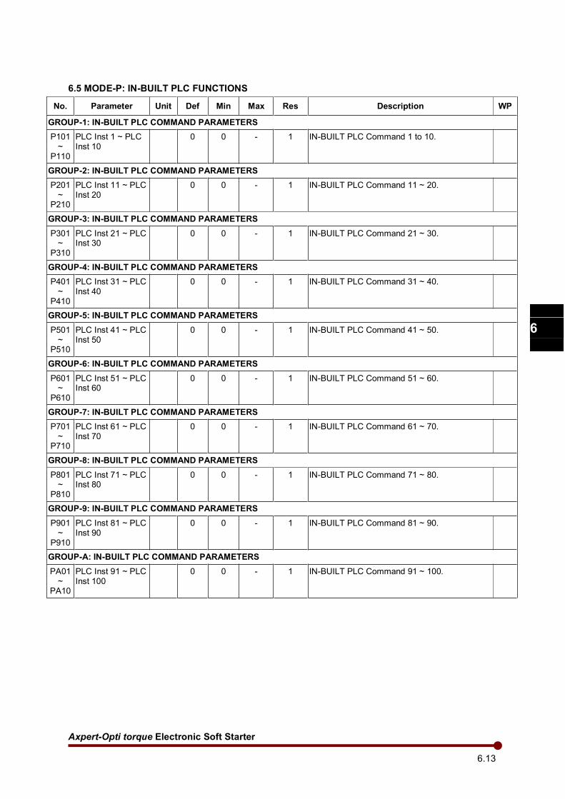
Axpert-Opti torque Electronic Soft Starter
6.13
1
2
3
4
5
6
7
8
9
10
11
12
13
A
6.5 MODE-P: IN-BUILT PLC FUNCTIONS
No. Parameter Unit Def Min Max Res Description WP
GROUP-1: IN-BUILT PLC COMMAND PARAMETERS
P101 ~
P110
PLC Inst 1 ~ PLC Inst 10
0 0 - 1 IN-BUILT PLC Command 1 to 10.
GROUP-2: IN-BUILT PLC COMMAND PARAMETERS
P201 ~
P210
PLC Inst 11 ~ PLC Inst 20
0 0 - 1 IN-BUILT PLC Command 11 ~ 20.
GROUP-3: IN-BUILT PLC COMMAND PARAMETERS
P301 ~
P310
PLC Inst 21 ~ PLC Inst 30
0 0 - 1 IN-BUILT PLC Command 21 ~ 30.
GROUP-4: IN-BUILT PLC COMMAND PARAMETERS
P401 ~
P410
PLC Inst 31 ~ PLC Inst 40
0 0 - 1 IN-BUILT PLC Command 31 ~ 40.
GROUP-5: IN-BUILT PLC COMMAND PARAMETERS
P501 ~
P510
PLC Inst 41 ~ PLC Inst 50
0 0 - 1 IN-BUILT PLC Command 41 ~ 50.
GROUP-6: IN-BUILT PLC COMMAND PARAMETERS
P601 ~
P610
PLC Inst 51 ~ PLC Inst 60
0 0 - 1 IN-BUILT PLC Command 51 ~ 60.
GROUP-7: IN-BUILT PLC COMMAND PARAMETERS
P701 ~
P710
PLC Inst 61 ~ PLC Inst 70
0 0 - 1 IN-BUILT PLC Command 61 ~ 70.
GROUP-8: IN-BUILT PLC COMMAND PARAMETERS
P801 ~
P810
PLC Inst 71 ~ PLC Inst 80
0 0 - 1 IN-BUILT PLC Command 71 ~ 80.
GROUP-9: IN-BUILT PLC COMMAND PARAMETERS
P901 ~
P910
PLC Inst 81 ~ PLC Inst 90
0 0 - 1 IN-BUILT PLC Command 81 ~ 90.
GROUP-A: IN-BUILT PLC COMMAND PARAMETERS
PA01 ~
PA10
PLC Inst 91 ~ PLC Inst 100
0 0 - 1 IN-BUILT PLC Command 91 ~ 100.
Amtech 6.14
1
2
3
4
5
6
7
8
9
10
11
12
13
A
6.6 Function explanation
GROUP-1
M101: Output Current (%)
It displays the average value of three-phase output current as a percentage of the rated motor current B103.
Output Current (%) = Output Current (M101) × 100/ Motor Current (B103)
When the unit is stop, it will display zero. When selected for the normal parameter display in A601~A608, the value will be displayed with “%L” unit.
M102: R-Phase Current (Amp)
This parameter displays the value of current in R-phase (L1) of the unit in Ampere. When selected for the normal parameter display in A601~A608, the value will be displayed with “Ir” unit.
M103: Y-Phase Current (Amp)
This parameter displays the value of current in Y-phase (L2) of the unit in Ampere. When selected for the normal parameter display in A601~A608, the value will be displayed with “Iy” unit.
M104: B-Phase Current (Amp)
This parameter displays the value of current in B-phase (L3) of the unit in Ampere. When selected for the normal parameter display in A601~A608, the value will be displayed with “Ib” unit.
Note: When soft starter is used for inside delta type connection (B108=2), parameters M102, M103 and M104 show the currents in delta branch.
M105: Output Voltage (Vac)
This parameter displays the output line-to-line voltage. This is calculated voltage based on voltage command. This may differ from actual output voltage. The actual output voltage depends on input supply voltage. When the unit is stop, it will display zero.
When selected for the normal parameter display in A601~A608, the value will be displayed with “Vo”
unit.
M106: Input Voltage Vry (Vac)
This parameter displays the actual input line-to-line voltage between R (L1) & Y (L2) phase. When selected for the normal parameter display in A601~A608, the value will be displayed with “Vry” unit.
M107: Input Voltage Vyb (Vac)
This parameter displays the actual input line-to-line voltage between Y (L2) & B (L3) phase. When selected for the normal parameter display in A601~A608, the value will be displayed with “Vyb” unit.
M108: Line Frequency (Hz)
This parameter displays the input supply frequency of the system. When selected for the normal parameter display in A601~A608, the value will be displayed with “Hz” unit.
Axpert-Opti torque Electronic Soft Starter
6.15
1
2
3
4
5
6
7
8
9
10
11
12
13
A
M109: Active Power (kW)
This parameter displays the active power drawn by the unit. This may differ from the actual active power. When the unit is stop, it will display zero. When selected for the normal parameter display in A601~A608, the value will be displayed with “kW” unit.
M110: Reactive Power (kVAR)
This parameter displays the reactive power drawn by the unit. This may differ from the actual output
power. When the unit is stop, it will display zero. When selected for the normal parameter display in
A601~A608, the value will be displayed with “kVR” unit.
M111: Power Factor
This parameter displays the power factor of the load. This value may differ from actual power factor. When the unit is stop, it will display zero. When selected for the normal parameter display in A601~A608, the value will be displayed with “PF” unit.
M112: Energy Meter (kWh)
M113: Energy Meter (MWH)
This parameter displays the total output power consumption per hour basis. This may differ from actually consumed output energy. This is stored in the non-volatile memory.
When selected for the normal parameter display screen in A601-A608, it will appear as “kWH” and “MWH” unit respectively on display screen.
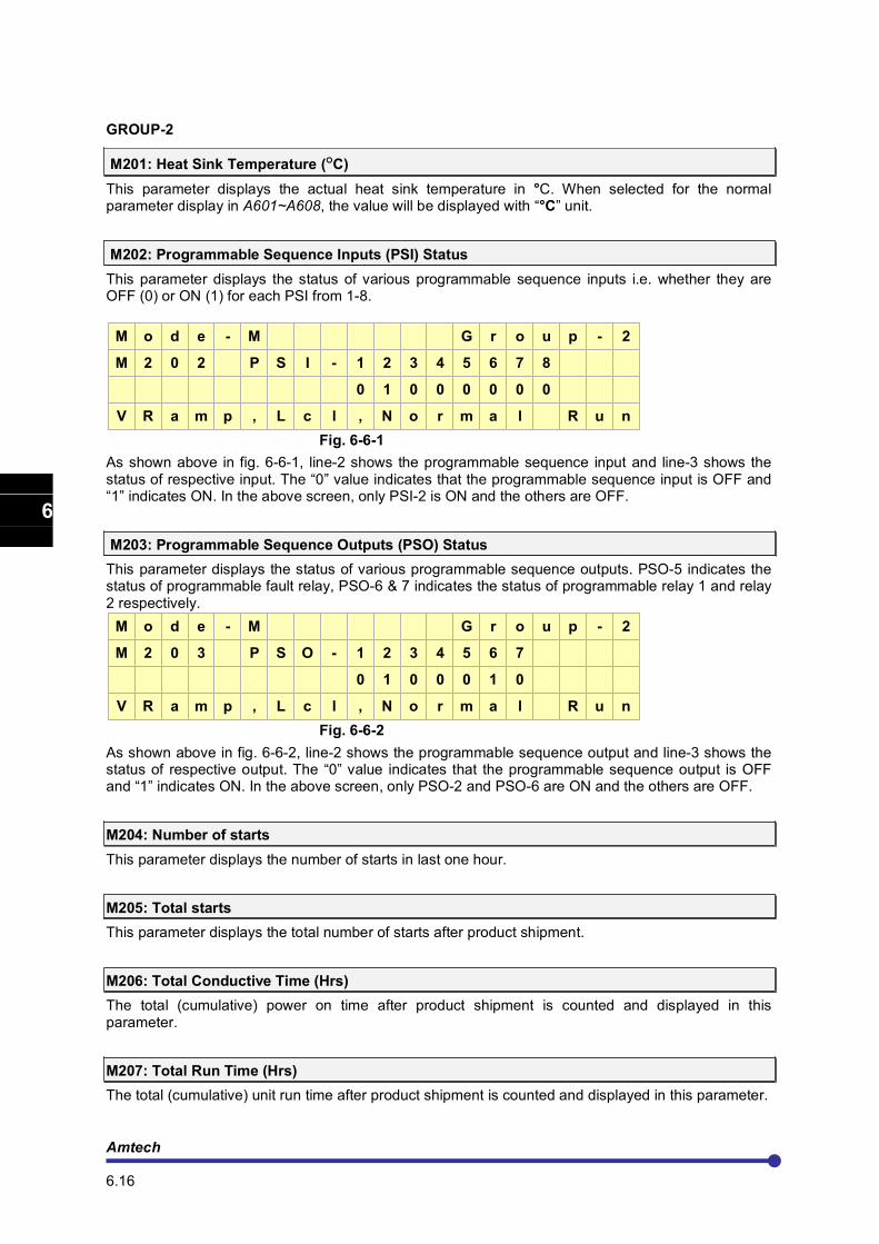
Amtech 6.16
1
2
3
4
5
6
7
8
9
10
11
12
13
A
GROUP-2
M201: Heat Sink Temperature (°C)
This parameter displays the actual heat sink temperature in °C. When selected for the normal parameter display in A601~A608, the value will be displayed with “°C” unit.
M202: Programmable Sequence Inputs (PSI) Status
This parameter displays the status of various programmable sequence inputs i.e. whether they are OFF (0) or ON (1) for each PSI from 1-8.
M o d e - M G r o u p - 2
M 2 0 2 P S I - 1 2 3 4 5 6 7 8
0 1 0 0 0 0 0 0
V R a m p , L c l , N o r m a l R u n
Fig. 6-6-1
As shown above in fig. 6-6-1, line-2 shows the programmable sequence input and line-3 shows the status of respective input. The “0” value indicates that the programmable sequence input is OFF and “1” indicates ON. In the above screen, only PSI-2 is ON and the others are OFF.
M203: Programmable Sequence Outputs (PSO) Status
This parameter displays the status of various programmable sequence outputs. PSO-5 indicates the status of programmable fault relay, PSO-6 & 7 indicates the status of programmable relay 1 and relay 2 respectively.
M o d e - M G r o u p - 2
M 2 0 3 P S O - 1 2 3 4 5 6 7
0 1 0 0 0 1 0
V R a m p , L c l , N o r m a l R u n
Fig. 6-6-2
As shown above in fig. 6-6-2, line-2 shows the programmable sequence output and line-3 shows the status of respective output. The “0” value indicates that the programmable sequence output is OFF and “1” indicates ON. In the above screen, only PSO-2 and PSO-6 are ON and the others are OFF.
M204: Number of starts
This parameter displays the number of starts in last one hour.
M205: Total starts
This parameter displays the total number of starts after product shipment.
M206: Total Conductive Time (Hrs)
The total (cumulative) power on time after product shipment is counted and displayed in this parameter.
M207: Total Run Time (Hrs)
The total (cumulative) unit run time after product shipment is counted and displayed in this parameter.
Axpert-Opti torque Electronic Soft Starter
6.17
1
2
3
4
5
6
7
8
9
10
11
12
13
A
M208: Motor Torque (N-m)
This parameter displays the motor torque in N-m. When selected for the normal parameter display in A601~A608, the value will be displayed with “N-m” unit.
M209: PID Reference
This parameter displays the value of currently selected PID reference input source in percentage. When local (Digital Operation Panel) option is selected as PID reference input source, it will display the value of C311. When selected for the normal parameter display in A601~A608, the value will be displayed with “PR” unit. Different units can be assigned to this quantity using C312.
M210: PID Feedback
This parameter displays the value of currently selected PID feedback input source in percentage. When selected for the normal parameter display in A601~A608, the value will be displayed with “Fb” unit.
M211: FSV Reference (%)
It displays the full-scale voltage in 0-100% proportional to 0-10V at FSV terminal. When selected for the normal parameter display in A601~A608, the value will be displayed with “FSV” unit.
M212: FSI Reference (%)
It displays the full-scale current in 0-100% proportional to 4-20mA at FSI terminal. When selected for the normal parameter display in A601~A608, the value will be displayed with “FSI” unit.
M213: VIN Reference (%)
It displays the full-scale voltage in 0-100% proportional to 0-10V at VIN terminal. When selected for the normal parameter display in A601~A608, the value will be displayed with “VIN” unit.
M214: IIN Reference (%)
It displays the full-scale current in 0-100% proportional to 4-20mA at IIN terminal. When selected for the normal parameter display in A601~A608, the value will be displayed with “IIN” unit.
M215: Peak Current (Amp)
This parameter displays the peak current drawn by the unit in Amp. When selected for the normal parameter display in A601~A608, the value will be displayed with “APk” unit.
M216: Heat sink Temperature (0F)
This parameter displays the actual heat sink temperature in 0F. When selected for the normal
parameter display in A601~A608, the value will be displayed with “°F” unit.
Amtech 6.18
1
2
3
4
5
6
7
8
9
10
11
12
13
A
GROUP-3
M301: Rated Current (Amp)
This parameter displays the rated current capacity of unit.
M302: Rated Capacity (kW)
This parameter displays the rated kW capacity of unit.
M303: Control Version
This parameter displays the software version of control board of the unit.
M304: Unit Serial Number
This parameter displays the serial number of the unit.
M305: Ship Month
This parameter displays the month of unit shipment.
M306: Ship Year
This parameter displays the year of unit shipment.
M307: Display Version
This parameter displays the software version of display board of the unit.
M308 to M317: PLC Display 1 ~ 10
For IN-BUILT PLC programming, there are 115 16-bit registers, 10 values of these registers can be displayed in parameter M308 to M317 and that all values will be save in EEPROM during power down. (Related PLC command is DISPLAY_REG (061)).
M318: PLC FLAG Status 0~7
For IN-BUILT PLC programming, there are 100 1-bit flags, 8 of these flag status can be display in parameter M323. (Related PLC command is DISPLAY_FLG (062)).
Axpert-Opti torque Electronic Soft Starter
6.19
1
2
3
4
5
6
7
8
9
10
11
12
13
A
GROUP-4: FAULT HISTORY
FLT-1~FLT10: Fault 1~10
This parameter displays the most recent ten faults with the values of Input Voltage (Vry), Output Current (%), Total Conductive Time (Hrs) and Heat Sink Temperature (
oC) at the time of fault
occurrence. Fault-1 indicates latest fault while successive faults gives past faults in descending order.
M o d e - M F L T - 1 G r o u p - 4
E x t e r n a l F a u l t
4 1 5 V r y 1 5 0 . 0 % L
1 2 7 5 H r s 5 0 ° C
Fig. 6-6-3
As shown in fig. 6-6-3, line-2 shows the fault code, line-3 shows the Input Voltage & Output current and line-4 shows the Total Conductive Time & heat sink temperature. If no fault is detected since shipment, line-2 displays “No previous fault” and the value of different parameters will be read as zero.
Same way FLT-2 ~ FLT10 shows the previous fault codes and parameters at the time of fault occurrence.
Amtech 6.20
1
2
3
4
5
6
7
8
9
10
11
12
13
A
MODE-A
GROUP - 1: START/STOP PARAMETERS
A101: Start Control
Select start location.
1: Local 2: Terminal 3: Serial
The unit can be started from Local (Digital Operation Panel), Terminal or Serial.
If in running condition, start control is changed from Local to Terminal, the operation will continue as per the status of the new selection. For example, present selection is Local. Now if in running condition, the selection is changed to Terminal. If RUN signal is present in terminal mode, the unit will continue running. If RUN signal is absent, the unit will stop. When the selection is changed from Terminal to any other mode (Local or Serial), unit will continue its operation as per the status of Terminal and not as per the new selection (Local or Serial).
A102: Maintained Start/Stop
When using Terminal as start control (A101=2), this parameter gives the choice of having maintained
or momentary contacts for start or stop. Here user has to select “15:RUN” option in one of PSI(C101 ~ C106, C114 and C115) for maintained and for momentary, user has to select “15:RUN” option and “16:STOP” in another PSI.
If A102=0: The start / stop control is maintained type as shown in below fig. 6-6-4.
RUN
COM
RUN
Output Voltage
Fig. 6-6-4
If A102=1: The start / stop control is momentary type as shown in below fig. 6-6-5
RUN
STOP
COM
RUN
Output Voltage
STOP
Fig. 6-6-5
A103: Start Delay (Sec)
The motor will be delayed start from the run command by the set time. This is used for synchronization with peripheral machines such as mechanical brakes. The start command can be from Digital Operation Panel (keypad), Terminal or Serial.
The start delay time is also applicable to Jog Select input.
Axpert-Opti torque Electronic Soft Starter
6.21
1
2
3
4
5
6
7
8
9
10
11
12
13
A
A104: Start Mode Selection
Select the required start mode.
A104=1: The starting mode is V-Ramp Start.
A104=2: The starting mode is I-Ramp Start.
A104=3: The starting mode is T-Ramp Start.
A105: Stop Mode Selection
Select the required stop mode.
A105=1: V-Ramp Stop
A105=2: T-Ramp Stop
A105=3: Brake Stop
A105=4: Coast to Stop
A106: V-Ramp Up Time1 (Sec)
This is applicable for V-Ramp Start and Jogging and should be adjusted as per the desired ramp up time.
It controls the ramp up time from Pedestal-1 to Target, when dual ramp (A201=0) is not selected. When A201=1, it controls the time from Pedestal-1 to Pedestal-2.
Note: Ramp up time is affected by the following condition.
1. Current limit will extend the ramp up time if motor does not reach full speed while in Current Limit mode.
2. Ramp up time will extend if Ramp Hold function is active.
Pedestal-1
(A202)
Target
(A203)
Kick Voltage
(A108)
100%
Kick Time
(A109)
Ramp up
(A106)
TIME
MOTOR
VOLTAGE
not adjustable
Fig. 6-6-6
A107: V-Ramp Down Time1 (Sec)
This is applicable for V-Ramp Stop or Jogging and should be adjusted as per the desired ramp down time.
This parameter controls the ramp down time from Initial Voltage-1(A206) to Final Voltage (A207), when dual ramp (A201=0) is not selected. When (A201=1), it controls the time from Initial Voltage-1 (A206) to Initial Voltage-2 (A209).
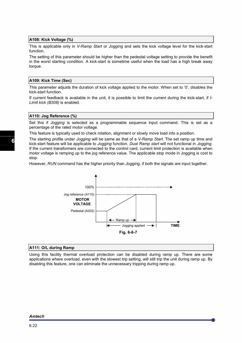
Amtech 6.22
1
2
3
4
5
6
7
8
9
10
11
12
13
A
A108: Kick Voltage (%)
This is applicable only in V-Ramp Start or Jogging and sets the kick voltage level for the kick-start function.
The setting of this parameter should be higher than the pedestal voltage setting to provide the benefit in the worst starting condition. A kick-start is sometime useful when the load has a high break away torque.
A109: Kick Time (Sec)
This parameter adjusts the duration of kick voltage applied to the motor. When set to ‘0’, disables the kick-start function.
If current feedback is available in the unit, it is possible to limit the current during the kick-start, if I-Limit kick (B308) is enabled.
A110: Jog Reference (%)
Set this if Jogging is selected as a programmable sequence input command. This is set as a percentage of the rated motor voltage.
This feature is typically used to check rotation, alignment or slowly move load into a position.
The starting profile under Jogging will be same as that of a V-Ramp Start. The set ramp up time and kick-start feature will be applicable to Jogging function. Dual Ramp start will not functional in Jogging.
If the current transformers are connected to the control card, current limit protection is available when motor voltage is ramping up to the jog reference value. The applicable stop mode in Jogging is cost to stop.
However, RUN command has the higher priority than Jogging, if both the signals are input together.
Pedestal (A202)
Ramp up
TIME
MOTOR
VOLTAGE
Jog reference (A110)
100%
Jogging applied
Fig. 6-6-7
A111: O/L during Ramp
Using this facility thermal overload protection can be disabled during ramp up. There are some applications where overload, even with the slowest trip setting, will still trip the unit during ramp up. By disabling this feature, one can eliminate the unnecessary tripping during ramp up.
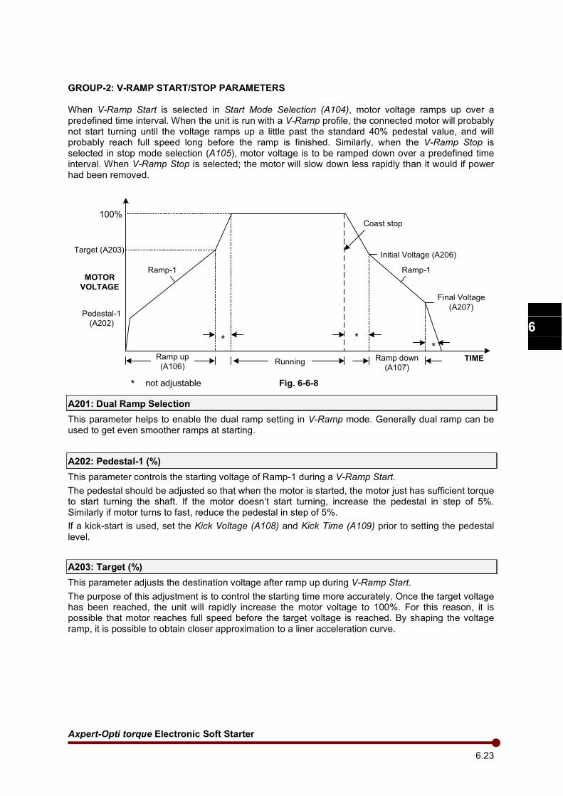
Axpert-Opti torque Electronic Soft Starter
6.23
1
2
3
4
5
6
7
8
9
10
11
12
13
A
GROUP-2: V-RAMP START/STOP PARAMETERS
When V-Ramp Start is selected in Start Mode Selection (A104), motor voltage ramps up over a predefined time interval. When the unit is run with a V-Ramp profile, the connected motor will probably not start turning until the voltage ramps up a little past the standard 40% pedestal value, and will probably reach full speed long before the ramp is finished. Similarly, when the V-Ramp Stop is selected in stop mode selection (A105), motor voltage is to be ramped down over a predefined time interval. When V-Ramp Stop is selected; the motor will slow down less rapidly than it would if power had been removed.
100%
Target (A203)
Ramp up
(A106)Running
Ramp down
(A107)
Initial Voltage (A206)
Final Voltage
(A207)
Coast stop
Pedestal-1
(A202)
MOTOR
VOLTAGE
TIME
Ramp-1 Ramp-1
* **
* not adjustable Fig. 6-6-8
A201: Dual Ramp Selection
This parameter helps to enable the dual ramp setting in V-Ramp mode. Generally dual ramp can be used to get even smoother ramps at starting.
A202: Pedestal-1 (%)
This parameter controls the starting voltage of Ramp-1 during a V-Ramp Start.
The pedestal should be adjusted so that when the motor is started, the motor just has sufficient torque to start turning the shaft. If the motor doesn’t start turning, increase the pedestal in step of 5%. Similarly if motor turns to fast, reduce the pedestal in step of 5%.
If a kick-start is used, set the Kick Voltage (A108) and Kick Time (A109) prior to setting the pedestal
level.
A203: Target (%)
This parameter adjusts the destination voltage after ramp up during V-Ramp Start.
The purpose of this adjustment is to control the starting time more accurately. Once the target voltage has been reached, the unit will rapidly increase the motor voltage to 100%. For this reason, it is possible that motor reaches full speed before the target voltage is reached. By shaping the voltage ramp, it is possible to obtain closer approximation to a liner acceleration curve.
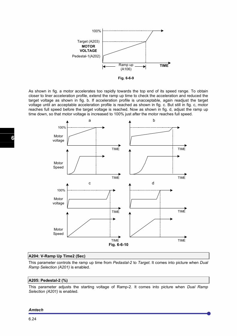
Amtech 6.24
1
2
3
4
5
6
7
8
9
10
11
12
13
A
Pedestal-1(A202)
Target (A203)
100%
Ramp up
(A106)
MOTOR
VOLTAGE
TIME
Fig. 6-6-9
As shown in fig. a motor accelerates too rapidly towards the top end of its speed range. To obtain closer to liner acceleration profile, extend the ramp up time to check the acceleration and reduced the target voltage as shown in fig. b. If acceleration profile is unacceptable, again readjust the target voltage until an acceptable acceleration profile is reached as shown in fig. c. But still in fig. c, motor reaches full speed before the target voltage is reached. Now as shown in fig. d, adjust the ramp up time down, so that motor voltage is increased to 100% just after the motor reaches full speed.
Motor
voltage
Motor
Speed
100%
Motor
voltage
Motor
Speed
100%
a b
c d
TIME TIME
TIME TIME
TIME TIME
TIMETIME
Fig. 6-6-10
A204: V-Ramp Up Time2 (Sec)
This parameter controls the ramp up time from Pedastal-2 to Target. It comes into picture when Dual Ramp Selection (A201) is enabled.
A205: Pedestal-2 (%)
This parameter adjusts the starting voltage of Ramp-2. It comes into picture when Dual Ramp Selection (A201) is enabled.
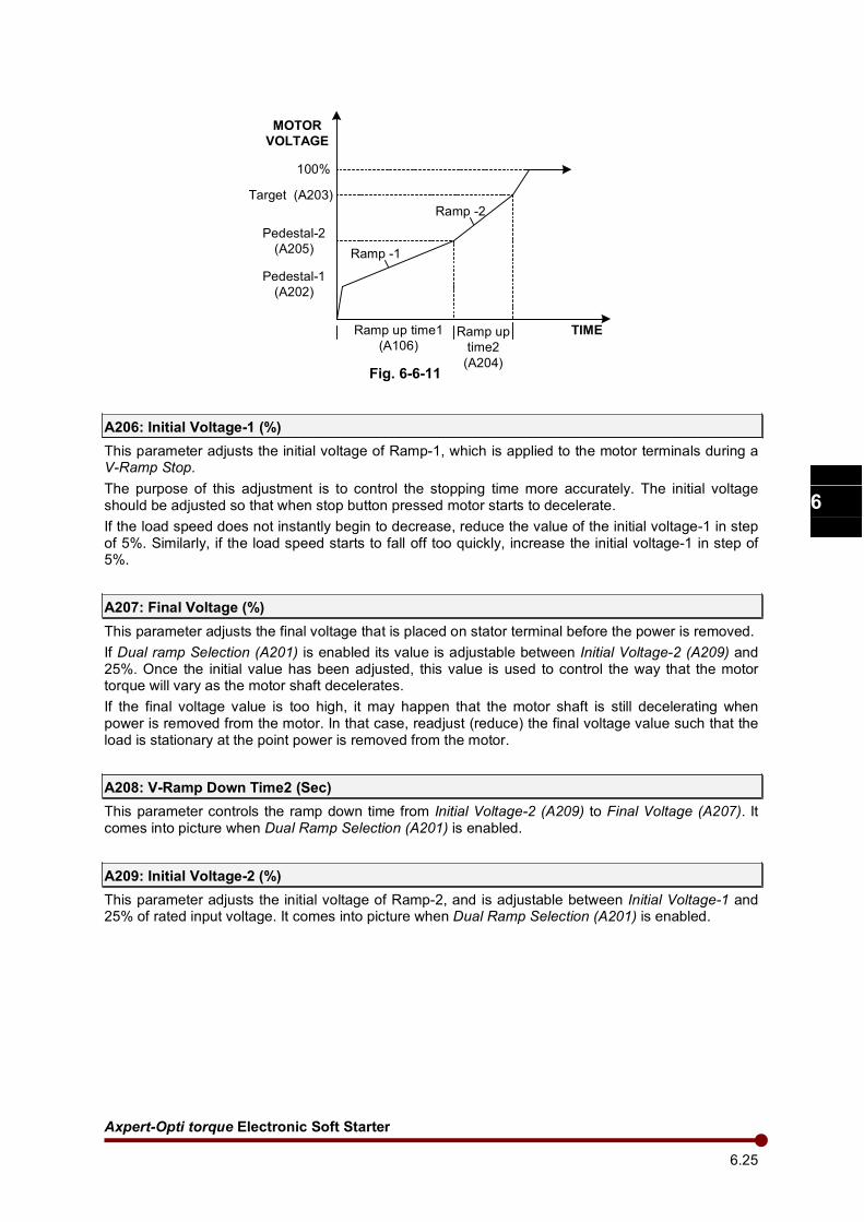
Axpert-Opti torque Electronic Soft Starter
6.25
1
2
3
4
5
6
7
8
9
10
11
12
13
A
100%
Target (A203)
Pedestal-2
(A205)
Pedestal-1
(A202)
Ramp up time1
(A106)Ramp up
time2
(A204)
TIME
MOTOR
VOLTAGE
Ramp -1
Ramp -2
Fig. 6-6-11
A206: Initial Voltage-1 (%)
This parameter adjusts the initial voltage of Ramp-1, which is applied to the motor terminals during a V-Ramp Stop.
The purpose of this adjustment is to control the stopping time more accurately. The initial voltage should be adjusted so that when stop button pressed motor starts to decelerate.
If the load speed does not instantly begin to decrease, reduce the value of the initial voltage-1 in step of 5%. Similarly, if the load speed starts to fall off too quickly, increase the initial voltage-1 in step of 5%.
A207: Final Voltage (%)
This parameter adjusts the final voltage that is placed on stator terminal before the power is removed.
If Dual ramp Selection (A201) is enabled its value is adjustable between Initial Voltage-2 (A209) and 25%. Once the initial value has been adjusted, this value is used to control the way that the motor torque will vary as the motor shaft decelerates.
If the final voltage value is too high, it may happen that the motor shaft is still decelerating when power is removed from the motor. In that case, readjust (reduce) the final voltage value such that the load is stationary at the point power is removed from the motor.
A208: V-Ramp Down Time2 (Sec)
This parameter controls the ramp down time from Initial Voltage-2 (A209) to Final Voltage (A207). It comes into picture when Dual Ramp Selection (A201) is enabled.
A209: Initial Voltage-2 (%)
This parameter adjusts the initial voltage of Ramp-2, and is adjustable between Initial Voltage-1 and 25% of rated input voltage. It comes into picture when Dual Ramp Selection (A201) is enabled.
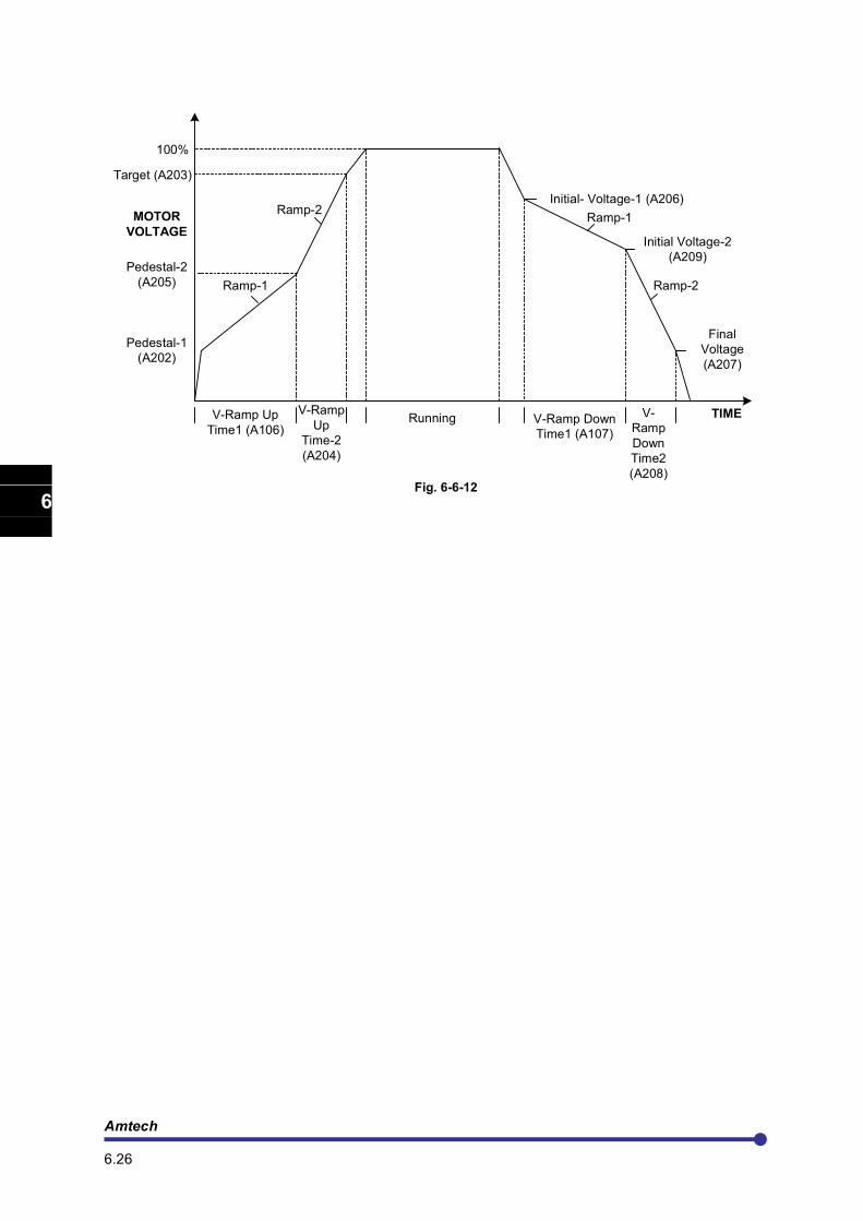
Amtech 6.26
1
2
3
4
5
6
7
8
9
10
11
12
13
A
100%
Target (A203)
Pedestal-1
(A202)
Pedestal-2
(A205)
Initial- Voltage-1 (A206)
Initial Voltage-2
(A209)
Final
Voltage
(A207)
TIME
MOTOR
VOLTAGE
V-Ramp Up
Time1 (A106)
V-Ramp
Up
Time-2
(A204)
Running V-Ramp Down
Time1 (A107)
V-
Ramp
Down
Time2
(A208)
Ramp-1
Ramp-2
Ramp-2
Ramp-1
Fig. 6-6-12
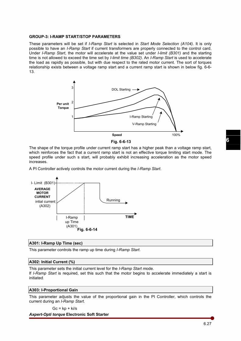
Axpert-Opti torque Electronic Soft Starter
6.27
1
2
3
4
5
6
7
8
9
10
11
12
13
A
GROUP-3: I-RAMP START/STOP PARAMETERS
These parameters will be set if I-Ramp Start is selected in Start Mode Selection (A104). It is only possible to have an I-Ramp Start if current transformers are properly connected to the control card. Under I-Ramp Start, the motor will accelerate at the value set under I-limit (B301) and the starting time is not allowed to exceed the time set by I-limit time (B302). An I-Ramp Start is used to accelerate the load as rapidly as possible, but with due respect to the rated motor current. The sort of torques relationship exists between a voltage ramp start and a current ramp start is shown in below fig. 6-6-13.
Per unit
Torque
1
2
3
Speed 100%
V-Ramp Starting
I-Ramp Starting
DOL Starting
Fig. 6-6-13
The shape of the torque profile under current ramp start has a higher peak than a voltage ramp start, which reinforces the fact that a current ramp start is not an effective torque limiting start mode. The speed profile under such s start, will probably exhibit increasing acceleration as the motor speed increases.
A PI Controller actively controls the motor current during the I-Ramp Start.
intial current
(A302)
I- Limit (B301)
I-Ramp
up Time
(A301)
TIME
AVERAGE
MOTOR
CURRENTRunning
Fig. 6-6-14
A301: I-Ramp Up Time (sec)
This parameter controls the ramp up time during I-Ramp Start.
A302: Initial Current (%)
This parameter sets the initial current level for the I-Ramp Start mode. If I-Ramp Start is required, set this such that the motor begins to accelerate immediately a start is initiated.
A303: I-Proportional Gain
This parameter adjusts the value of the proportional gain in the PI Controller, which controls the current during an I-Ramp Start.
Gc = kp + ki/s

Amtech 6.28
1
2
3
4
5
6
7
8
9
10
11
12
13
A
The above equation shows the standard PI Controller equation, where Gc = Controller gain; kp = proportional gain; ki = integral gain = kp*Ti; s = laplacian complex frequency variable.
The value entered under I-Proportional Gain (A303) is same as kp in the above equation.
A304: I-Integral Time (Sec)
This parameter adjusts the value of the integral time in the PI Controller, which controls the current during an I-Ramp Start.
The value entered under I-Integral Time (A304) is same as the Ti in the above equation.
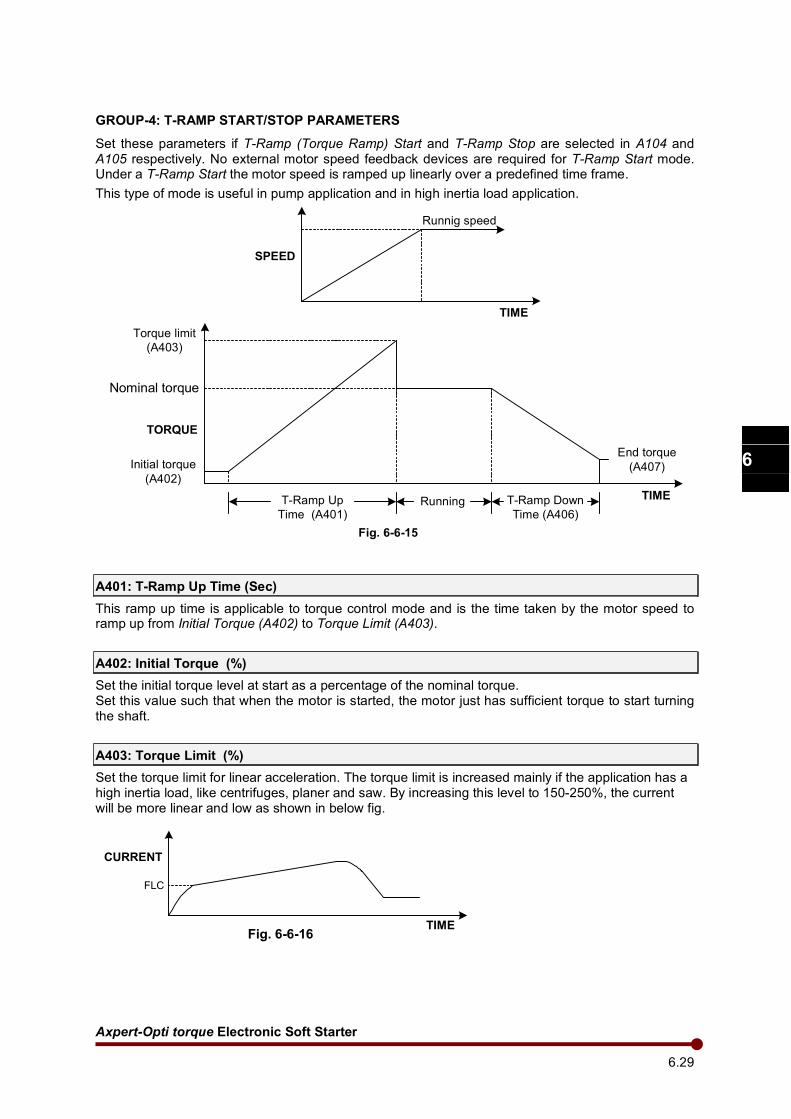
Axpert-Opti torque Electronic Soft Starter
6.29
1
2
3
4
5
6
7
8
9
10
11
12
13
A
GROUP-4: T-RAMP START/STOP PARAMETERS
Set these parameters if T-Ramp (Torque Ramp) Start and T-Ramp Stop are selected in A104 and A105 respectively. No external motor speed feedback devices are required for T-Ramp Start mode. Under a T-Ramp Start the motor speed is ramped up linearly over a predefined time frame.
This type of mode is useful in pump application and in high inertia load application.
SPEED
TIME
Runnig speed
TORQUE
Torque limit
(A403)
Initial torque
(A402)
Nominal torque
End torque
(A407)
TIMET-Ramp Up
Time (A401)
T-Ramp Down
Time (A406)Running
Fig. 6-6-15
A401: T-Ramp Up Time (Sec)
This ramp up time is applicable to torque control mode and is the time taken by the motor speed to ramp up from Initial Torque (A402) to Torque Limit (A403).
A402: Initial Torque (%)
Set the initial torque level at start as a percentage of the nominal torque. Set this value such that when the motor is started, the motor just has sufficient torque to start turning the shaft.
A403: Torque Limit (%)
Set the torque limit for linear acceleration. The torque limit is increased mainly if the application has a high inertia load, like centrifuges, planer and saw. By increasing this level to 150-250%, the current will be more linear and low as shown in below fig.
CURRENT
TIME
FLC
Fig. 6-6-16
Amtech 6.30
1
2
3
4
5
6
7
8
9
10
11
12
13
A
A404: T-Proportional Gain
This parameter adjusts the value of the proportional gain in the PI Controller, which controls the speed during a T-Ramp Start
Gc = kp + ki/s
The above equation shows the standard PI Controller equation, where Gc = Controller gain; kp = proportional gain; ki = integral gain = kp*Ti; s = laplacian complex frequency variable.
The value entered under T-Proportional Gain is same as Kp in the above equation.
A405: T-Integral Time (Sec)
This parameter adjusts the value of the integral time in the PI Controller, which controls the speed during a T-Ramp Start. The value entered under T-Integral Time is same as Ti in the above equation.
A406: T-Ramp Down Time (Sec)
This ramp down time is applicable to torque control mode and is the time taken by the unit to reduce the nominal torque to end torque. This feature is useful in pump application to prevent hydraulic shock, which may be occurred if the motor decelerates too quickly.
A407: End Torque (%)
Set the end torque level at stop as a percentage of the nominal torque. This is the threshold at which the controlled stops and the motor freewheel to stop.
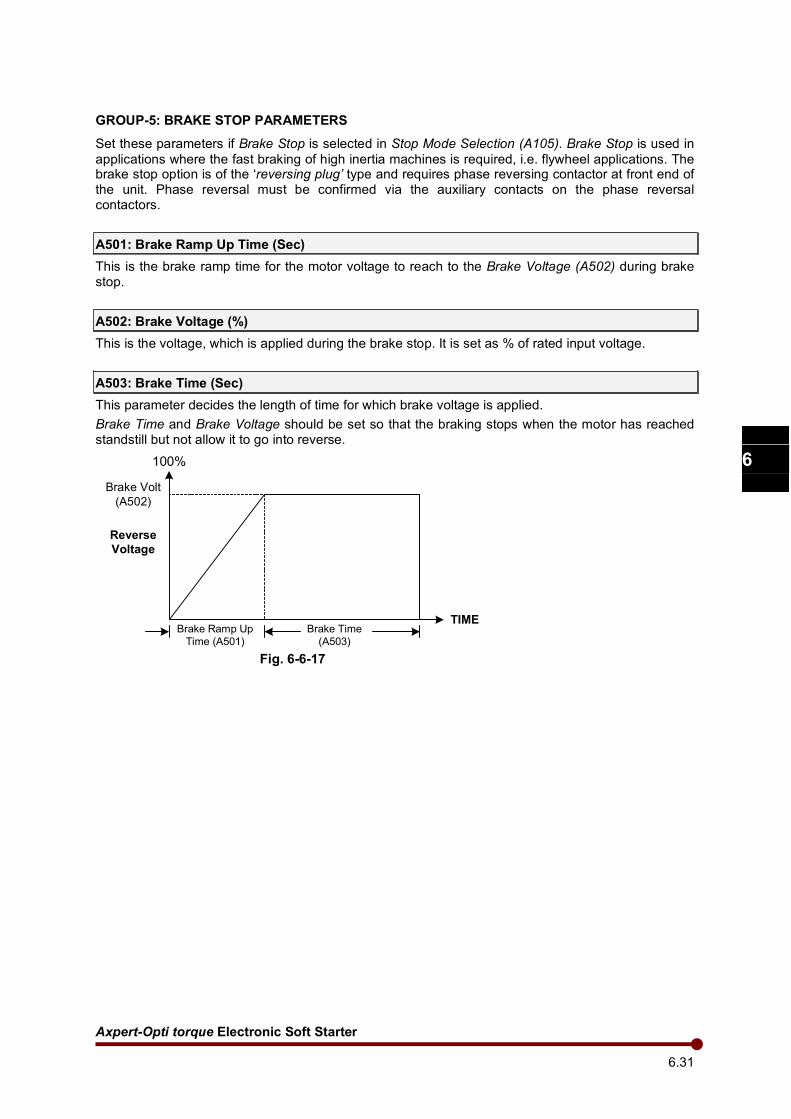
Axpert-Opti torque Electronic Soft Starter
6.31
1
2
3
4
5
6
7
8
9
10
11
12
13
A
GROUP-5: BRAKE STOP PARAMETERS
Set these parameters if Brake Stop is selected in Stop Mode Selection (A105). Brake Stop is used in
applications where the fast braking of high inertia machines is required, i.e. flywheel applications. The brake stop option is of the ‘reversing plug’ type and requires phase reversing contactor at front end of the unit. Phase reversal must be confirmed via the auxiliary contacts on the phase reversal contactors.
A501: Brake Ramp Up Time (Sec)
This is the brake ramp time for the motor voltage to reach to the Brake Voltage (A502) during brake stop.
A502: Brake Voltage (%)
This is the voltage, which is applied during the brake stop. It is set as % of rated input voltage.
A503: Brake Time (Sec)
This parameter decides the length of time for which brake voltage is applied.
Brake Time and Brake Voltage should be set so that the braking stops when the motor has reached standstill but not allow it to go into reverse.
Brake Volt
(A502)
Reverse
Voltage
Brake Ramp Up
Time (A501)
Brake Time
(A503)
100%
TIME
Fig. 6-6-17
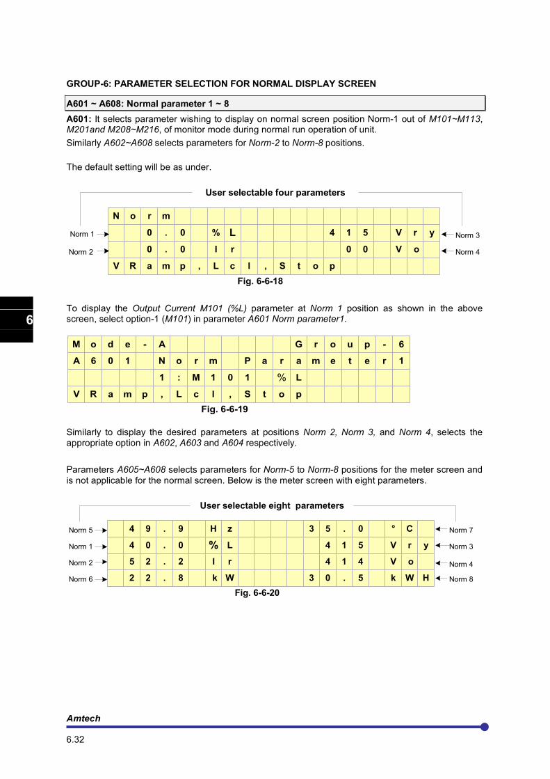
Amtech 6.32
1
2
3
4
5
6
7
8
9
10
11
12
13
A
GROUP-6: PARAMETER SELECTION FOR NORMAL DISPLAY SCREEN
A601 ~ A608: Normal parameter 1 ~ 8
A601: It selects parameter wishing to display on normal screen position Norm-1 out of M101~M113, M201and M208~M216, of monitor mode during normal run operation of unit.
Similarly A602~A608 selects parameters for Norm-2 to Norm-8 positions.
The default setting will be as under.
N o r m
0 . 0 % L 4 1 5 V r y
0 . 0 I r 0 0 V o
V R a m p , L c l , S t o p
Fig. 6-6-18
User selectable four parameters
Norm 1
Norm 2
Norm 3
Norm 4
To display the Output Current M101 (%L) parameter at Norm 1 position as shown in the above screen, select option-1 (M101) in parameter A601 Norm parameter1.
M o d e - A G r o u p - 6
A 6 0 1 N o r m P a r a m e t e r 1
1 : M 1 0 1 % L
V R a m p , L c l , S t o p
Fig. 6-6-19
Similarly to display the desired parameters at positions Norm 2, Norm 3, and Norm 4, selects the appropriate option in A602, A603 and A604 respectively.
Parameters A605~A608 selects parameters for Norm-5 to Norm-8 positions for the meter screen and
is not applicable for the normal screen. Below is the meter screen with eight parameters.
Norm 1
4 9 . 9 H z 3 5 . 0 ° C
4 0 . 0 % L 4 1 5 V r y
5 2 . 2 I r 4 1 4 V o
2 2 . 8 k W 3 0 . 5 k W H
Fig. 6-6-20
User selectable eight parameters
Norm 2
Norm 3
Norm 4
Norm 5
Norm 6
Norm 7
Norm 8
Axpert-Opti torque Electronic Soft Starter
6.33
1
2
3
4
5
6
7
8
9
10
11
12
13
A
MODE-B
GROUP-1: MOTOR PARAMETER
B101: Rated Input Voltage (Vac)
Select suitable rated input voltage for the unit. When the rated input voltage is changed, the motor voltage may change accordingly.
B102: Motor Voltage (Vac)
Enter motor nameplate voltage. This is used as reference voltage for many parameters. This is the motor terminal voltage during full load at the line frequency.
B103: Motor Current (Amp)
Enter motor rated current from the motor nameplate. This is full load motor current at line frequency. The over current and other current related protections are based on this value. This value cannot be set higher than unit rated current M301 in case of Inline configuration. However, it can be set to 1.73 times the unit rated current for Inside delta configuration.
B104: Motor Frequency (Hz)
Enter motor frequency from the motor nameplate.
B105: Motor Speed (rpm)
Enter motor speed from the motor nameplate.
B106: Motor Capacity (kW)
Enter motor rated capacity from the motor nameplate.
B107: Motor Poles
Enter number of poles from the motor nameplate.
B108: SS Connection Type
Select the soft starter connection type. The unit can be used inline. In this case, only three wires (if bypass option not used) will be coming to the unit.
When the connection is inside delta type, six wires will be coming to the unit. Refer Fig. 10-1-2 for the connection method for inside delta. In this case, the unit can be used to start the motor of the higher current rating (1.73 times) than the unit.
Amtech 6.34
1
2
3
4
5
6
7
8
9
10
11
12
13
A
GROUP-2: PROTECTION PARAMETERS – 1
B201: Under Frequency Protection Delay (Sec)
This parameter delays the tripping on detection of a low supply frequency when the motor is running, less than 45Hz for 50Hz supply and less than 55Hz for 60Hz supply.
Set to 60 to disable this function.
B202: Over Frequency Protection Delay (Sec)
This parameter delays the tripping on detection of a high supply frequency when the motor is running, greater than 55Hz for 50Hz supply and greater than 65Hz for 60Hz supply.
Set to 60 to disable this function.
B203: Low Current Alarm Set Point (%)
This parameter sets the current at which the low current alarm operates. Set as a percentage of Motor Current (B103).
Relay output can be programmed in PSO to indicate the state of low current alarm. The relay output change state when motor current is below the set point.
It sets when the Low Current Alarm is selected in PSO (Programmable Sequence Output).
Set this parameter higher than the value set in I-low Level (B303).
B204: High Current Alarm Set Point (%)
This parameter sets the current at which the high current alarm operates. Set as a percentage of Motor Current (B103).
Relay output can be programmed in PSO to indicate the state of high current alarm. The relay output change state when motor current is above the set point.
It sets when the High Current Alarm is selected in PSO (Programmable Sequence Output).
Set this parameter less than the value set in I-Trip Level (B307).
B205: I-Unbalance Level (%)
The maximum current imbalance tolerated will be the value set under the I-Unbalance Level from one
line to another.
B206: I-Unbalance Delay (Sec)
This parameter delays the tripping on detection of the imbalance current for the set time. Set 100% to disable this function.
B207: Emergency Stop Mode
Set the stopping method for the emergency stop from the following options.
1: Coast to Stop 2: Coast to Stop with fault output 3: Stop as per A105
B208: Number of Restart
This parameter decides the maximum number of attempts to restart during the fault condition.
Axpert-Opti torque Electronic Soft Starter
6.35
1
2
3
4
5
6
7
8
9
10
11
12
13
A
B209: Restart Wait Time (Sec)
Restart is function to reset the fault in the unit and start automatically to continue operation if a fault occurs. User can select these parameters to automatically restart the unit in fault condition to provide reliability and continuity of process during fault conditions.
Set to ‘0’ to disables the restart function. When a fault is detected, the unit output is shut off for the Restart Wait Time (B209). The operation panel displays the fault while the unit output is OFF. When the restart wait time elapses, a fault is reset automatically and restarts to continue the operation. When the number of such attempts exceeds the Number of Restart (B208), the faults are not reset automatically and the unit output remains OFF. At this time a fault relay is activated and the fault data will be stored in fault history. The RUN relay will also be deactivated. The number of restart times is cleared to 0 in the following cases.
1. A fault does not occur for more than 10 minutes. 2. A fault reset signal is applied from the operation panel or terminal. 3. The power supply is turned off and turned ON again.
This function is applicable to the following eleven faults. 1. Over Current Fault. 2. Under Current Fault 3. I-unbalance Fault 4. Over voltage Fault 5. Firing Fault 6. Phase Fault 7. External Fault 8. Ground Fault 9. Over Frequency Fault 10. Under Frequency Fault 11. Temperature Fault
B210: Bypass Contactor Delay Time (Sec)
This parameter sets the delay time for the bypass contactor to operate, if the load current has not decreased below 115% after completion of Ramp Up Time & I-Limit Time.
B211: Test Mode Selection
Enable or Disabled the Test Mode. Test Mode is only for factory test purpose.
=0: Disable. =1: Enable.
Amtech 6.36
1
2
3
4
5
6
7
8
9
10
11
12
13
A
GROUP-3: PROTECTION PARAMETERS – 2
B301: I-Limit Level (%)
B302: I-Limit Time (sec)
I-Limit Level sets the value of the current limit as a percentage of Motor Current (B103), and I-Limit Time (B302) sets the time in seconds, in which the I-Limit condition can exist before a trip will occur. The current limit feature is active only during the ramp up.
Whenever the motor current exceeds the I-Limit, motor voltage held constant until the current falls to an acceptable level. The current remains higher than the value set under I-Limit (B301) for a time set under I-Limit Time, the unit will trip in an overload fault. If time frame a + b exceeded the value set by I-Limit Time (B302), the unit will trip.
This feature provides adequate protection for the thyristor stack and sufficient current limiting to the motor.
100%
MOTOR
VOLTAGE
TIME
I-Limit (B301)
AVERAGE
MOTOR
CURRENT
a b
TIME
Fig. 6-6-21
B303: I-Low Level (%)
B304: I-Low Time (Sec)
I-Low Level sets the threshold of the under current trip as percentage of the Motor Current (B103), and the time for which an under current situation must exist is set by I-Low Time (B304) before tripping. By setting I-Low Level to zero will disable this function.
The under current trip facility offers an easy way of shutting the device down, when it operates for an extended period without a load. The under current trip is not active during ramp up and ramp down.
To set the under current trip, start the motor with no load, and record the current displayed by the unit. Starts it again with normal load, and set the trip point half way between these values. The unit calculates the displayed current, by averaging the current in all three phases and scaling this to an RMS value. There is no guarantee that meter used to measure the current, will operate in the same way, and therefore no guarantee that the value measured will be exactly the same as the displayed value.
Here graph shows the operating characteristics with the I-Low Level set to 50% and I-Low Time set to 3 min.
Axpert-Opti torque Electronic Soft Starter
6.37
1
2
3
4
5
6
7
8
9
10
11
12
13
A
100
75
50
25
Average Current
as a Percentage
of motor I
Trip Point
TIME(Minutes)
4 6 128 9 15
Fig. 6-6-22
B305: Overload Setting (%)
Set this parameter as % of the rated motor current. Changing of this parameter will change the tripping time of the thermal overload curves. For example, at overload setting of 105% - Class 30 curve will trip the unit in 30sec @600% of FLC where as at 52% of overload setting – Class 30 curve will trip the unit in 30sec @300% of FLC.
B306: Overload Curve Selection
Choose the Overload curves for the motor ‘Thermal Overload Protection’. 1. Class 30 2. Class 20 3. Class 10 4. Class 2
Program the appropriate class according to the characteristics of the motor and load. These trip curves are based on a common tripping point of 600% of rated motor current. For example Class-20 curve is 20-sec trip at @600% of FLC with overload setting 0f 105%.
Note: These are the cold start curve and every ‘start’ will reduced the tripping times. Curves are shown at the overload setting of 105% in Fig. 6-6-23.
Amtech 6.38
1
2
3
4
5
6
7
8
9
10
11
12
13
A
Fig. 6-6-23
B307: I-Trip Level (%)
This parameter sets to give an instantaneous over current trip as a percentage of the Motor Current (B103).
Whenever the output current exceeds the value set by I-Trip Level, the unit will trip indicating over current fault. Always set higher side to prevent the unnecessary tripping of the unit during normal operation.
I-Trip Level is entered as a percentage of the motor current, which the RMS value and the processor,
which scales the I-Trip value to a peak current and it is the peak current at which the unit will trip. For example, if I-Trip level set to 500% and Motor Current is 40A, unit will trip the instant the current
exceeds 282A, i.e. 282 = 40 * 5 * √ 2.
B308: I-Limit Kick (%)
This parameter limits the current in the kick-start region. In some applications it is necessary to limit current in kick-start region. The two main reasons for introducing current limit during the kick-start are: to protect the electrical system, and to limit the torque during the kick-start region.
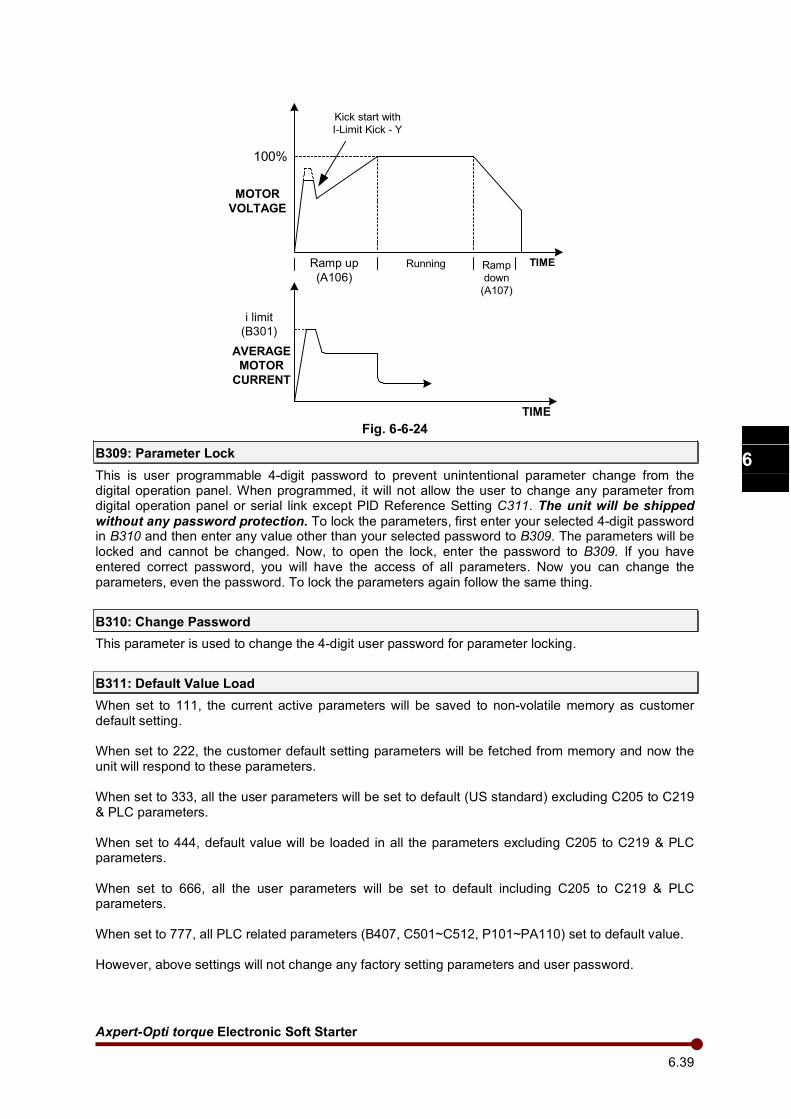
Axpert-Opti torque Electronic Soft Starter
6.39
1
2
3
4
5
6
7
8
9
10
11
12
13
A
TIME
i limit
(B301)
100%
Kick start with
I-Limit Kick - Y
Ramp up
(A106)
Running Ramp
down
(A107)
AVERAGE
MOTOR
CURRENT
MOTOR
VOLTAGE
TIME
Fig. 6-6-24
B309: Parameter Lock
This is user programmable 4-digit password to prevent unintentional parameter change from the digital operation panel. When programmed, it will not allow the user to change any parameter from digital operation panel or serial link except PID Reference Setting C311. The unit will be shipped
without any password protection. To lock the parameters, first enter your selected 4-digit password in B310 and then enter any value other than your selected password to B309. The parameters will be locked and cannot be changed. Now, to open the lock, enter the password to B309. If you have entered correct password, you will have the access of all parameters. Now you can change the parameters, even the password. To lock the parameters again follow the same thing.
B310: Change Password
This parameter is used to change the 4-digit user password for parameter locking.
B311: Default Value Load
When set to 111, the current active parameters will be saved to non-volatile memory as customer default setting. When set to 222, the customer default setting parameters will be fetched from memory and now the unit will respond to these parameters. When set to 333, all the user parameters will be set to default (US standard) excluding C205 to C219 & PLC parameters. When set to 444, default value will be loaded in all the parameters excluding C205 to C219 & PLC parameters. When set to 666, all the user parameters will be set to default including C205 to C219 & PLC parameters. When set to 777, all PLC related parameters (B407, C501~C512, P101~PA110) set to default value. However, above settings will not change any factory setting parameters and user password.

Amtech 6.40
1
2
3
4
5
6
7
8
9
10
11
12
13
A
Fault History Clear
When set to 555, the fault history buffer is cleared. No previous fault code and parameter will be available. Note that the value entered in B311 will not be memorized. If correct value is entered, appropriate action will be taken and “00” will be displayed. If incorrect value is entered, no action will be taken and “00” will be displayed.
B312: Over Voltage Limit (%)
Sets the level at which the Over Voltage Fault is detected as a percentage of Rated Input Voltage (B101).
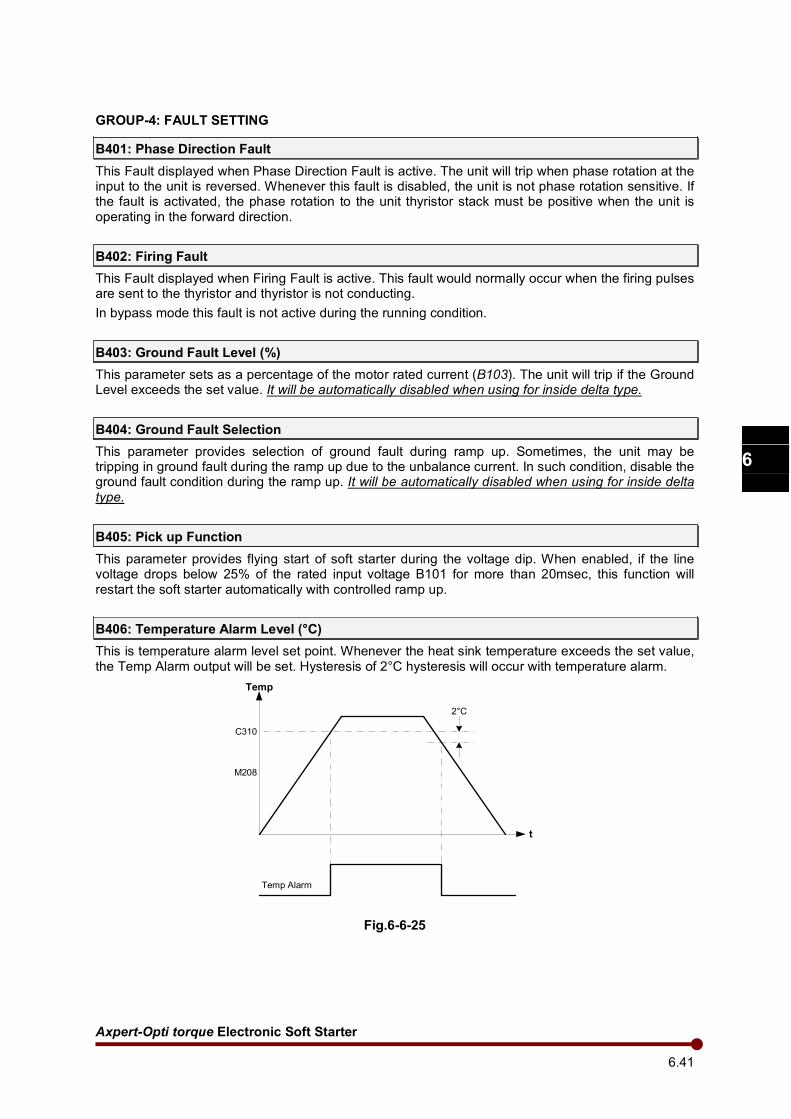
Axpert-Opti torque Electronic Soft Starter
6.41
1
2
3
4
5
6
7
8
9
10
11
12
13
A
2°C
t
Temp
C310
M208
Temp Alarm
GROUP-4: FAULT SETTING
B401: Phase Direction Fault
This Fault displayed when Phase Direction Fault is active. The unit will trip when phase rotation at the input to the unit is reversed. Whenever this fault is disabled, the unit is not phase rotation sensitive. If the fault is activated, the phase rotation to the unit thyristor stack must be positive when the unit is operating in the forward direction.
B402: Firing Fault
This Fault displayed when Firing Fault is active. This fault would normally occur when the firing pulses are sent to the thyristor and thyristor is not conducting.
In bypass mode this fault is not active during the running condition.
B403: Ground Fault Level (%)
This parameter sets as a percentage of the motor rated current (B103). The unit will trip if the Ground Level exceeds the set value. It will be automatically disabled when using for inside delta type.
B404: Ground Fault Selection
This parameter provides selection of ground fault during ramp up. Sometimes, the unit may be tripping in ground fault during the ramp up due to the unbalance current. In such condition, disable the ground fault condition during the ramp up. It will be automatically disabled when using for inside delta type.
B405: Pick up Function
This parameter provides flying start of soft starter during the voltage dip. When enabled, if the line voltage drops below 25% of the rated input voltage B101 for more than 20msec, this function will restart the soft starter automatically with controlled ramp up.
B406: Temperature Alarm Level (°C)
This is temperature alarm level set point. Whenever the heat sink temperature exceeds the set value, the Temp Alarm output will be set. Hysteresis of 2°C hysteresis will occur with temperature alarm.
Fig.6-6-25
Amtech 6.42
1
2
3
4
5
6
7
8
9
10
11
12
13
A
B407: In-Built PLC Selection
In Built PLC function can be Enable or Disable by using this parameter.
B408: Copy Para set
Copy all user and PLC parameters from control side to the Display EEPROM. User can copy up to 8 sets of all parameters. =1:Copy Set 1 =5:Copy Set 5 =2:Copy Set 2 =6:Copy Set 6 =3:Copy Set 3 =7:Copy Set 7 =4:Copy Set 4 =8:Copy Set 8
B409: Paste Para set
Paste all user and PLC parameters from Display EEPROM to the control side. User can paste 8 sets of all parameters. =1:Paste Set 1 =5:Paste Set 5 =2:Paste Set 2 =6:Paste Set 6 =3:Paste Set 3 =7:Paste Set 7 =4:Paste Set 4 =8:Paste Set 8
Axpert-Opti torque Electronic Soft Starter
6.43
1
2
3
4
5
6
7
8
9
10
11
12
13
A
MODE – C
GROUP-1: PROGRAMMABLE INPUT/OUTPUT SELECTION
C101~ C106: PSI-1 ~ PSI-6
C114 ~ C115: PSI-RUN ~ PSI-STOP
User can configure eight Programmable Sequence Inputs for different functions using parameters C101 ~ C106 and C114 ~ C115. The status of the Programmable Sequence Input can be monitored in M202. The various options are explained as under.
Table 6-6-1
OPTION NAME FUNCTION
1 Not Used Indicates that no function is selected on the PSI.
2 Terminal When this input is selected, the operation control will be switched over to terminal.
3 Jogging This is a jog command. If this signal is ON while RUN is OFF, operation then conforms to the setting of jog reference. The applicable stop mode in Jogging is cost to stop.
4 External Flt (NO) This is used for the external fault function. This is Normally Open type. When the digital input (connected to COM in case of sink logic and to +24V in case of source logic) is close, external fault occurs.
5 Fault Reset This is used for the fault reset. If RUN input is present at the time of fault reset, the unit will not start after fault reset. Issue fresh RUN command to start the unit after fault reset.
6 Bypass Cont Flt This input is used for the bypass contactor interlock. The bypass contactor closes once the thyristors are supplying full voltage to the motor.
7 Main Cont Flt This is used when main contactor is fitted to the unit. This input is used for the main contactor interlock.
8 Emergency Stop (NO)
This is used as emergency stop. This is Normally Open type. When the digital input (connected to COM in case of sink logic or to +24V in case of source logic) is close, Emergency stop occurs as per the selection in B207.
9 Ramp Hold This input allows to halt the ramp up.
10 Rev Cont Flt This input is used for reverse phase rotation contactor interlock. Select this input if brake stop is selected in A105.
11 PID Bypass This is used to bypass the PID controller. When this input is selected, the PID Reference input will be PID Output and there will not be any effect of PID controller.
12 PID Disable This is used to disable the PID controller. When this input is selected, the PID Output will remain to the last value and there will not be any effect of PID Reference or PID Feedback on the PID Output.
13 Emergency stop (NC)
This is used for emergency stop. This is Normally Close type. When the digital input (connected to COM in case of sink logic or to +24V in case of source logic) is open, Emergency stop occurs as per the selection in B207.
14 External Flt (NC) This is used for the external fault function. This is Normally Close type. When the digital input (connected to COM in case of sink logic and to +24V in case of source logic) is open, external fault occurs.
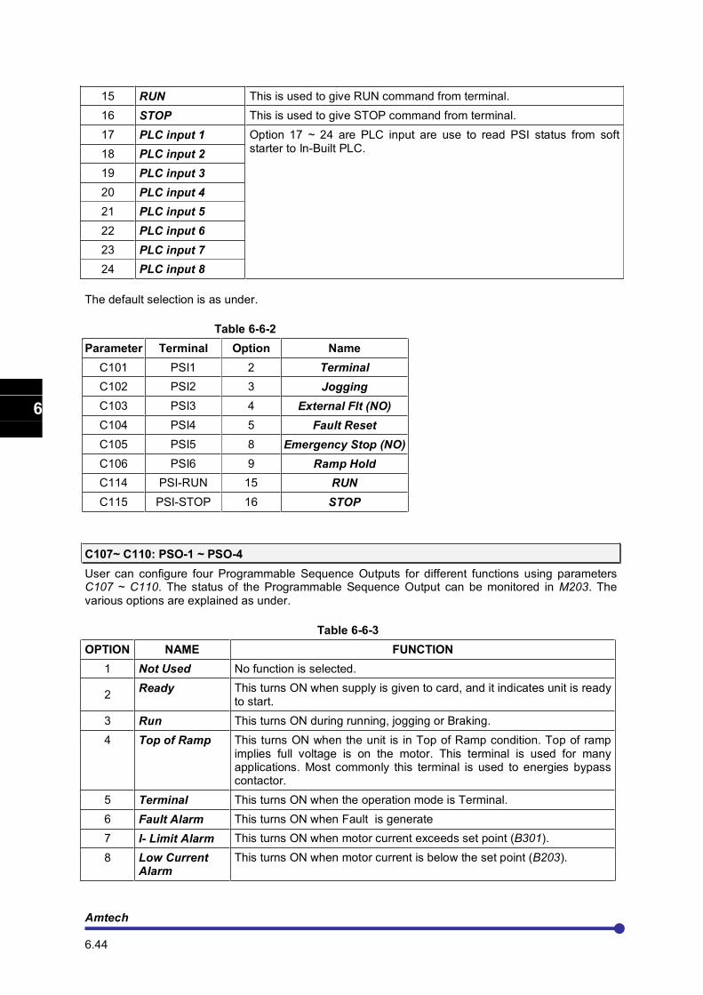
Amtech 6.44
1
2
3
4
5
6
7
8
9
10
11
12
13
A
15 RUN This is used to give RUN command from terminal.
16 STOP This is used to give STOP command from terminal.
17 PLC input 1 Option 17 ~ 24 are PLC input are use to read PSI status from soft starter to In-Built PLC.
18 PLC input 2
19 PLC input 3
20 PLC input 4
21 PLC input 5
22 PLC input 6
23 PLC input 7
24 PLC input 8
The default selection is as under.
Table 6-6-2
Parameter Terminal Option Name
C101 PSI1 2 Terminal
C102 PSI2 3 Jogging
C103 PSI3 4 External Flt (NO)
C104 PSI4 5 Fault Reset
C105 PSI5 8 Emergency Stop (NO)
C106 PSI6 9 Ramp Hold
C114 PSI-RUN 15 RUN
C115 PSI-STOP 16 STOP
C107~ C110: PSO-1 ~ PSO-4
User can configure four Programmable Sequence Outputs for different functions using parameters C107 ~ C110. The status of the Programmable Sequence Output can be monitored in M203. The various options are explained as under.
Table 6-6-3
OPTION NAME FUNCTION
1 Not Used No function is selected.
2 Ready This turns ON when supply is given to card, and it indicates unit is ready
to start.
3 Run This turns ON during running, jogging or Braking.
4 Top of Ramp This turns ON when the unit is in Top of Ramp condition. Top of ramp implies full voltage is on the motor. This terminal is used for many applications. Most commonly this terminal is used to energies bypass contactor.
5 Terminal This turns ON when the operation mode is Terminal.
6 Fault Alarm This turns ON when Fault is generate
7 I- Limit Alarm This turns ON when motor current exceeds set point (B301).
8 Low Current Alarm
This turns ON when motor current is below the set point (B203).
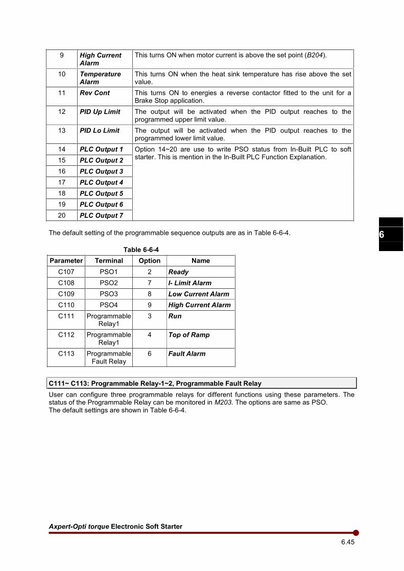
Axpert-Opti torque Electronic Soft Starter
6.45
1
2
3
4
5
6
7
8
9
10
11
12
13
A
9 High Current Alarm
This turns ON when motor current is above the set point (B204).
10 Temperature Alarm
This turns ON when the heat sink temperature has rise above the set value.
11 Rev Cont This turns ON to energies a reverse contactor fitted to the unit for a Brake Stop application.
12 PID Up Limit The output will be activated when the PID output reaches to the programmed upper limit value.
13 PID Lo Limit The output will be activated when the PID output reaches to the programmed lower limit value.
14 PLC Output 1 Option 14~20 are use to write PSO status from In-Built PLC to soft starter. This is mention in the In-Built PLC Function Explanation.
15 PLC Output 2
16 PLC Output 3
17 PLC Output 4
18 PLC Output 5
19 PLC Output 6
20 PLC Output 7
The default setting of the programmable sequence outputs are as in Table 6-6-4.
Table 6-6-4
Parameter Terminal Option Name
C107 PSO1 2 Ready
C108 PSO2 7 I- Limit Alarm
C109 PSO3 8 Low Current Alarm
C110 PSO4 9 High Current Alarm
C111 Programmable Relay1
3 Run
C112 Programmable Relay1
4 Top of Ramp
C113 Programmable Fault Relay
6 Fault Alarm
C111~ C113: Programmable Relay-1~2, Programmable Fault Relay
User can configure three programmable relays for different functions using these parameters. The status of the Programmable Relay can be monitored in M203. The options are same as PSO. The default settings are shown in Table 6-6-4.
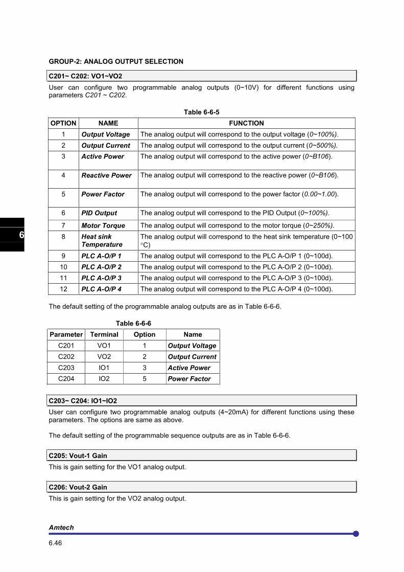
Amtech 6.46
1
2
3
4
5
6
7
8
9
10
11
12
13
A
GROUP-2: ANALOG OUTPUT SELECTION
C201~ C202: VO1~VO2
User can configure two programmable analog outputs (0~10V) for different functions using parameters C201 ~ C202.
Table 6-6-5
OPTION NAME FUNCTION
1 Output Voltage The analog output will correspond to the output voltage (0~100%).
2 Output Current The analog output will correspond to the output current (0~500%).
3 Active Power The analog output will correspond to the active power (0~B106).
4 Reactive Power The analog output will correspond to the reactive power (0~B106).
5 Power Factor The analog output will correspond to the power factor (0.00~1.00).
6 PID Output The analog output will correspond to the PID Output (0~100%).
7 Motor Torque The analog output will correspond to the motor torque (0~250%).
8 Heat sink Temperature
The analog output will correspond to the heat sink temperature (0~100
°C)
9 PLC A-O/P 1 The analog output will correspond to the PLC A-O/P 1 (0~100d).
10 PLC A-O/P 2 The analog output will correspond to the PLC A-O/P 2 (0~100d).
11 PLC A-O/P 3 The analog output will correspond to the PLC A-O/P 3 (0~100d).
12 PLC A-O/P 4 The analog output will correspond to the PLC A-O/P 4 (0~100d).
The default setting of the programmable analog outputs are as in Table 6-6-6.
Table 6-6-6
Parameter Terminal Option Name
C201 VO1 1 Output Voltage
C202 VO2 2 Output Current
C203 IO1 3 Active Power
C204 IO2 5 Power Factor
C203~ C204: IO1~IO2
User can configure two programmable analog outputs (4~20mA) for different functions using these parameters. The options are same as above. The default setting of the programmable sequence outputs are as in Table 6-6-6.
C205: Vout-1 Gain
This is gain setting for the VO1 analog output.
C206: Vout-2 Gain
This is gain setting for the VO2 analog output.
Axpert-Opti torque Electronic Soft Starter
6.47
1
2
3
4
5
6
7
8
9
10
11
12
13
A
C207: Iout-1 Gain
This is gain setting for the IO1 analog output.
C208: Iout-1 Bias
This is bias setting for the IO1 analog output.
C209: Iout-2 Gain
This is gain setting for the IO2 analog output.
C210: Iout-2 Bias
This is bias setting for the IO2 analog output.
C211: Scaling Current (%)
This parameter is allow to scales the Analog Output Current as a set value of 50 - 500% of rated motor current.
C212: FSV Gain
This is gain setting for the FSV reference.
C213: FSV Bias
This is bias setting for the FSV reference.
C214: FSI Gain
This is gain setting for the FSI reference.
C215: FSI Bias
This is bias setting for the FSI reference.
C216: Vin Gain
This is gain setting for the Vin reference.
C217: Vin Bias
This is bias setting for the Vin reference.
C218: Iin Gain
This is gain setting for the Iin reference.
C219: Iin Bias
This is bias setting for the Iin reference.
C220: FSV / FSI Time Constant (mSec)
This parameter sets the filter time constant for the FSV and FSI analog inputs.
C221: VIN / IIN Time Constant (mSec)
This parameter sets the filter time constant for the VIN and IIN analog inputs.
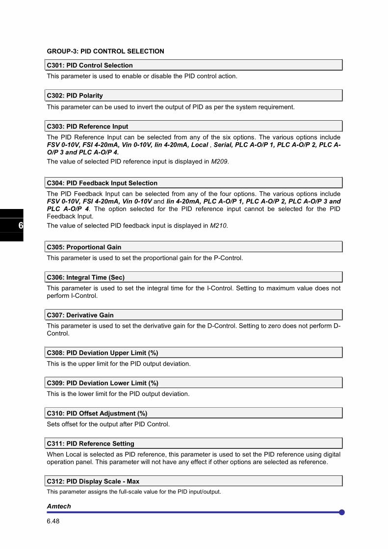
Amtech 6.48
1
2
3
4
5
6
7
8
9
10
11
12
13
A
GROUP-3: PID CONTROL SELECTION
C301: PID Control Selection
This parameter is used to enable or disable the PID control action.
C302: PID Polarity
This parameter can be used to invert the output of PID as per the system requirement.
C303: PID Reference Input
The PID Reference Input can be selected from any of the six options. The various options include FSV 0-10V, FSI 4-20mA, Vin 0-10V, Iin 4-20mA, Local , Serial, PLC A-O/P 1, PLC A-O/P 2, PLC A-O/P 3 and PLC A-O/P 4.
The value of selected PID reference input is displayed in M209.
C304: PID Feedback Input Selection
The PID Feedback Input can be selected from any of the four options. The various options include FSV 0-10V, FSI 4-20mA, Vin 0-10V and Iin 4-20mA, PLC A-O/P 1, PLC A-O/P 2, PLC A-O/P 3 and PLC A-O/P 4. The option selected for the PID reference input cannot be selected for the PID Feedback Input.
The value of selected PID feedback input is displayed in M210.
C305: Proportional Gain
This parameter is used to set the proportional gain for the P-Control.
C306: Integral Time (Sec)
This parameter is used to set the integral time for the I-Control. Setting to maximum value does not perform I-Control.
C307: Derivative Gain
This parameter is used to set the derivative gain for the D-Control. Setting to zero does not perform D-Control.
C308: PID Deviation Upper Limit (%)
This is the upper limit for the PID output deviation.
C309: PID Deviation Lower Limit (%)
This is the lower limit for the PID output deviation.
C310: PID Offset Adjustment (%)
Sets offset for the output after PID Control.
C311: PID Reference Setting
When Local is selected as PID reference, this parameter is used to set the PID reference using digital operation panel. This parameter will not have any effect if other options are selected as reference.
C312: PID Display Scale - Max
This parameter assigns the full-scale value for the PID input/output.
Axpert-Opti torque Electronic Soft Starter
6.49
1
2
3
4
5
6
7
8
9
10
11
12
13
A
C313: PID Display Scale - Min
This parameter assigns the min value for the PID input/output.
C314: PID Display Unit Selection
This parameter gives a choice to user to display the unit for the PID parameters. This can be displayed in %, PSI (Pressure per Square Inch), kg/cm2, °C, °F, LPM (Liter per Minute), CFM (Cubic Feet per Minute) and m3/h (Cubic Meter per Hour)
PID+
-
C305: Proportional Gain
C306: Integral Time
C307: Derivative Gain
C304: PID
Feedback
Input
C302
C303: PID
Reference
Input
C308: PID deviation
Upper Limit
C309: PID deviation
Lower Limit
C310: PID Offset
Adjustment
PID Output
PID Controller
+
+
M209
M210
=1
=0
C301: PID Selection
=0
=1
(PSIX = 11)
PID Bypass
Vout1C201
Vout2C202
Iout1C203
Iout2C204
Fig. 6-6-26
Amtech 6.50
1
2
3
4
5
6
7
8
9
10
11
12
13
A
GROUP-4: SERIAL COMMUNICATION
C401: Baud Rate
The unit is facilitating with serial communication between the unit and computer terminal. To control or monitor single/ multiple units from single computer terminal, serial link can be used. This parameter defines Baud rate (number of signal transition per second, it can be number of bits per second). The available options are as under. Option-4 is set as default baud rate.
1: 1200 4: 9600
2: 2400 5: 19200
3: 4800
Refer the detail manual for the ModBus protocol and other information.
C402: Station Number
This parameter defines the address of the unit when connected to the serial network. It supports the ModBus protocol. The station number can be assigned to 1 ~ 247.
C403: Parity
This parameter is used to set the parity. Parity is error-checking code to prevent from erroneous data transformation between the unit and terminal.
C404: Response Time (Sec)
Set the minimum time from receiving the command to returning an answer.
C405: Operation Panel Communication Loss Selection
Enable or disable the operation panel communication loss fault. The unit will trip if it does not receive any response from the operation panel within 5sec. Disable the fault, if operation panel is to be removed. For detail information on the ModBus protocol and register assignment, please refer “Serial Communication Guide, Version 1.0”. Note: Put jumper JP3 to “LD” position to use terminating resistors. Remove the cover designated as “Control Unit” to access this jumper on PCA-2005B.
Axpert-Opti torque Electronic Soft Starter
6.51
1
2
3
4
5
6
7
8
9
10
11
12
13
A
GROUP – 5: PLC PANEL PARAMETER
C501 ~ C502: PLC Panel Par 1 ~ 2
This PLC panel parameter 1 & 2 are used In-built PLC for Timer 1 application or can be used in Built in PLC application. Related memory location of this parameter is from 101 to 102.
C503 ~ C504: PLC Panel Par 3 ~ 4
This PLC panel parameter 3 & 4 are used In-built PLC for Timer 2 application or can be used in Built in PLC application. Related memory location from of this parameter is 103 to 104.
C505 ~ C506: PLC Panel Par 5 ~ 6
This PLC panel parameter 5 & 6 are used In-built PLC for Timer 3 application or can be used in Built in PLC application. Related memory location from of this parameter is 105 to 106.
C507 ~ C508: PLC Panel Par 7 ~ 8
This PLC panel parameter 7 & 8 are used In-built PLC for Timer 4 application or can be used in Built in PLC application. Related memory location from of this parameter is 107 to 108.
C509 ~ C512: PLC Panel Par 9 ~ 12
PLC panel parameter 9 to 12 can be input and used In-built PLC application. Related memory location of this parameter is from 109 to 112.
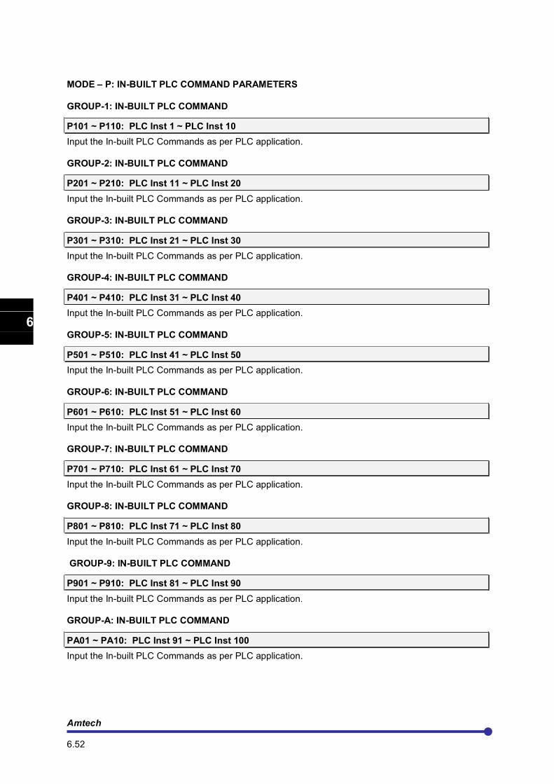
Amtech 6.52
1
2
3
4
5
6
7
8
9
10
11
12
13
A
MODE – P: IN-BUILT PLC COMMAND PARAMETERS
GROUP-1: IN-BUILT PLC COMMAND
P101 ~ P110: PLC Inst 1 ~ PLC Inst 10
Input the In-built PLC Commands as per PLC application.
GROUP-2: IN-BUILT PLC COMMAND
P201 ~ P210: PLC Inst 11 ~ PLC Inst 20
Input the In-built PLC Commands as per PLC application.
GROUP-3: IN-BUILT PLC COMMAND
P301 ~ P310: PLC Inst 21 ~ PLC Inst 30
Input the In-built PLC Commands as per PLC application.
GROUP-4: IN-BUILT PLC COMMAND
P401 ~ P410: PLC Inst 31 ~ PLC Inst 40
Input the In-built PLC Commands as per PLC application.
GROUP-5: IN-BUILT PLC COMMAND
P501 ~ P510: PLC Inst 41 ~ PLC Inst 50
Input the In-built PLC Commands as per PLC application.
GROUP-6: IN-BUILT PLC COMMAND
P601 ~ P610: PLC Inst 51 ~ PLC Inst 60
Input the In-built PLC Commands as per PLC application.
GROUP-7: IN-BUILT PLC COMMAND
P701 ~ P710: PLC Inst 61 ~ PLC Inst 70
Input the In-built PLC Commands as per PLC application.
GROUP-8: IN-BUILT PLC COMMAND
P801 ~ P810: PLC Inst 71 ~ PLC Inst 80
Input the In-built PLC Commands as per PLC application.
GROUP-9: IN-BUILT PLC COMMAND
P901 ~ P910: PLC Inst 81 ~ PLC Inst 90
Input the In-built PLC Commands as per PLC application.
GROUP-A: IN-BUILT PLC COMMAND
PA01 ~ PA10: PLC Inst 91 ~ PLC Inst 100
Input the In-built PLC Commands as per PLC application.
Axpert-Opti torque Electronic Soft Starter
6.53
1
2
3
4
5
6
7
8
9
10
11
12
13
A
6.7 In-built PLC function explanation:
In-built PLC Function is one of the important features of this product, by using which, user can make PLC related application without additional hardware. The In-built PLC function has the following features. Features:
• The In-built PLC can be used to get the same functionality of Programmable Sequence Inputs (PSI).
• It is possible to assign the signals from the In-built PLC to the Programmable Sequences Output (PSO).
• The In-built PLC can be used to get the same functionality as of programmable analog inputs.
• It is possible to assign the signals from the In-built PLC to the analog outputs.
• Bit status of PSI, PSO, Fault codes, Status codes and Control word can be read into the PLC bit memory location.
• Monitor Parameters can be read in to PLC registers (16-bit memory location).
• User can develop program by using PLC Commands based on the required application.
• PLC Commands can be input from the LCD Display. This allows changes to be made easily at the site.
• PLC Commands can be input with the standard serial interface.
• 115 registers (16-bit memory locations) and 100 Flags (1-bit memory location) for PLC operation.
• PLC program’s length up to 100 PLC Commands.
• 4 Timer Command can be set from display. The In-built PLC function-processing chart is shown in fig. 6.7.1. PLC commands are separate in each parameter and all command (P101 to PA10) execute within 20-millisecond interval.
.
Command P101
Command P104
Command P103
Command P102
Command P108
Command P109
Command P110
.
.
.
Command PA01
Command PA04
Command PA03
Command PA02
Command PA08
Command PA09
Command PA10
.
.
.
Command P201
Command P204
Command P203
Command P202
Command P908
Command P909
Command P910
.
.
Mode P, Group-1 Mode P, Group-2~ 9 Mode P, Group-A
Fig. 6-7-1 In-built PLC processing Chart
The In-built PLC function starts to read command from the Mode P Group-1 parameter (P101) and executes it one-by-one. END (000) Command indicates end of program and after this command; PLC function again executes from 1
st command (P101).
Amtech 6.54
1
2
3
4
5
6
7
8
9
10
11
12
13
A
IN-BUILT PLC BLOCK
PSI
PSO
Analog I/P
& O/P
Monitor
Parameter
In-Built PLC
Function
Main Control (Soft Starter) In-Built PLC
Fig. 6-7-2 Block Diagram Of In-built PLC function with Main Control
Fig. 6.7.2 is a block diagram of main control and In-built PLC function. All Digital Input and Output, Analog Input and output are connected with main control. Now user can program In-built PLC for his application. User can also take output of the soft starter as PLC Input and output from PLC to the soft starter as an Input. In-built PLC Function Related Parameters and Command. The In-Built PLC function related parameters are listed below.
1 In-built PLC (B407): Use this parameter to enable the In-built PLC Function.
2 In-built PLC Command (P101 to PA10):
Input the PLC commands to be executed with the In-built PLC Function in parameters P101 to PA10.
3 PLC Display Parameter (M308 to M318): In-built PLC Display
For PLC programming, there are 115 numbers of 16-bit register and 100 numbers of 1-bit flag. 10 values of signed 16-bit register can be displayed in parameter M308 to M317 and these values will be saved in EEPROM at the time of power off. (Related PLC command is DISPLAY_REG (061)) and during power of these parameters values will come in register 76 to 85, 8 different flag bit status can be display in parameter M318. (Related PLC command is DISPLAY_FLG (062)).
4 Digital Input From Soft Starter (PSI Status) to In-built PLC: Parameters C101 to C106 and C114 to C115 have 24 selectable options. In these, 17 to 24 are for PLC input options. Now to take PSI status as a PLC input, select one of the PLC input option from these parameter. Use READ_PSI (047) command in PLC program for this operation.
5 Digital Output From In-built PLC to Soft Starter (PSO Status):
Parameters C107 to C113 have 20 Selectable options. In these, 14 to 20 options are for In-Built PLC output. Now to take In-built PLC’s output as Soft Starter’s PSO output, select one of the PLC option from these parameters. Use WRITE_PSO (049) command in PLC program for this operation.
6 Digital Input From In-built PLC to Soft Starter (PSI Status): Parameters C101 to C106 and C114 to C115 have 24 selectable options. User can activate one of 1 to 16 options of these parameters, without any external digital signal on PSI by using In-built PLC. Use WRITE_PSI (048) command in PLC program for this operation.
7 Digital Output From Soft Starter (PSO Status) to In-built PLC: User can read and use status of PSO from Soft Starter for In-built PLC application. To read the PSO status In-built in PLC, use READ_PSO (046) command in PLC program.
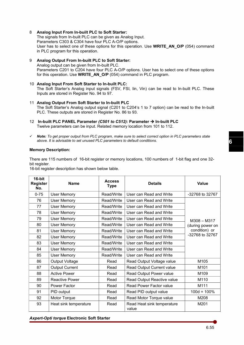
Axpert-Opti torque Electronic Soft Starter
6.55
1
2
3
4
5
6
7
8
9
10
11
12
13
A
8 Analog Input From In-built PLC to Soft Starter: The signals from In-built PLC can be given as Analog Input. Parameters C303 & C304 have four PLC A-O/P options. User has to select one of these options for this operation. Use WRITE_AN_O/P (054) command
in PLC program for this operation.
9 Analog Output From In-built PLC to Soft Starter:
Analog output can be given from In-built PLC. Parameters C201 to C204 have four PLC A-O/P options. User has to select one of these options for this operation. Use WRITE_AN_O/P (054) command in PLC program.
10 Analog Input From Soft Starter to In-built PLC: The Soft Starter’s Analog input signals (FSV, FSI, Iin, Vin) can be read to In-built PLC. These Inputs are stored in Register No. 94 to 97.
11 Analog Output From Soft Starter to In-built PLC The Soft Starter’s Analog output signal (C201 to C204‘s 1 to 7 option) can be read to the In-built PLC. These outputs are stored in Register No. 86 to 93.
12 In-built PLC PANEL Parameter (C501 to C512): Parameter In-built PLC Twelve parameters can be input. Related memory location from 101 to 112.
Note: To get proper output from PLC program, make sure to select correct option in PLC parameters state
above. It is advisable to set unused PLC parameters to default conditions.
Memory Description:
There are 115 numbers of 16-bit register or memory locations, 100 numbers of 1-bit flag and one 32-bit register. 16-bit register description has shown below table.
16-bit Register No.
Name Access Type
Details Value
0-75 User Memory Read/Write User can Read and Write -32768 to 32767
76 User Memory Read/Write User can Read and Write
M308 – M317 (during power on
condition) or -32768 to 32767
77 User Memory Read/Write User can Read and Write
78 User Memory Read/Write User can Read and Write
79 User Memory Read/Write User can Read and Write
80 User Memory Read/Write User can Read and Write
81 User Memory Read/Write User can Read and Write
82 User Memory Read/Write User can Read and Write
83 User Memory Read/Write User can Read and Write
84 User Memory Read/Write User can Read and Write
85 User Memory Read/Write User can Read and Write
86 Output Voltage Read Read Output Voltage value M105
87 Output Current Read Read Output Current value M101
88 Active Power Read Read Output Power value M109
89 Reactive Power Read Read Output Reactive value M110
90 Power Factor Read Read Power Factor value M111
91 PID output Read Read PID output value 100d = 100%
92 Motor Torque Read Read Motor Torque value M208
93 Heat sink temperature Read Read Heat sink temperature value
M201
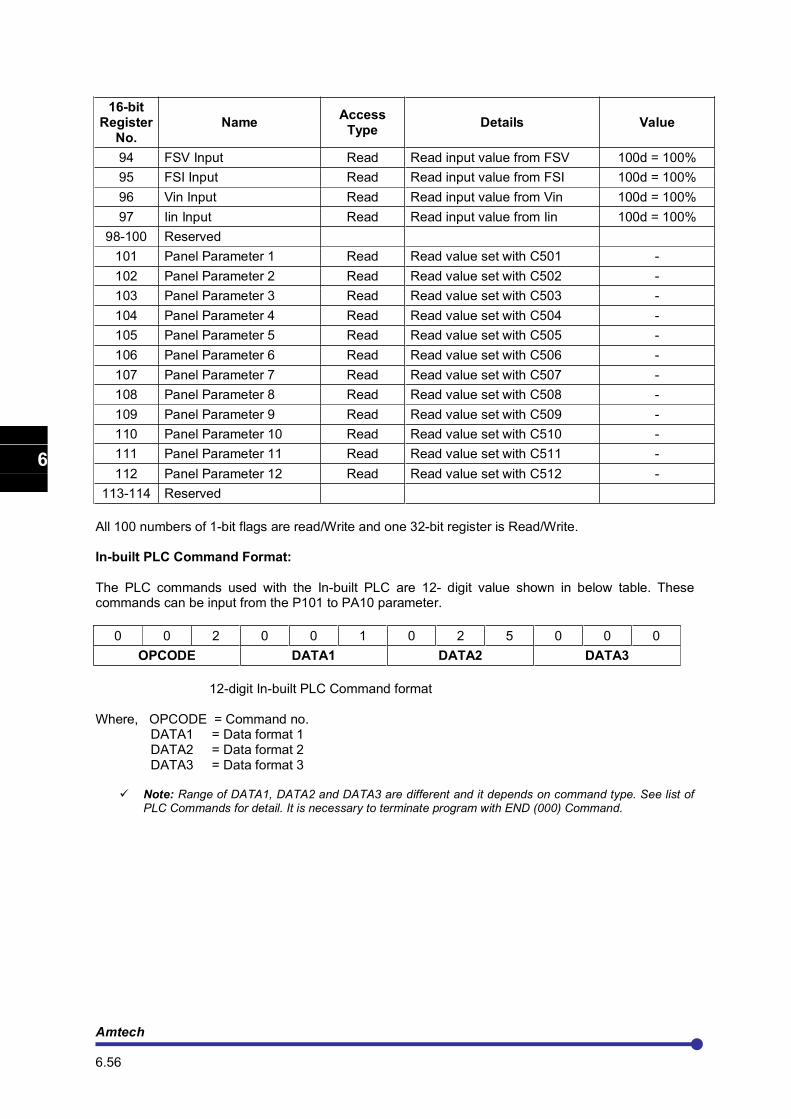
Amtech 6.56
1
2
3
4
5
6
7
8
9
10
11
12
13
A
16-bit Register No.
Name Access Type
Details Value
94 FSV Input Read Read input value from FSV 100d = 100%
95 FSI Input Read Read input value from FSI 100d = 100%
96 Vin Input Read Read input value from Vin 100d = 100%
97 Iin Input Read Read input value from Iin 100d = 100%
98-100 Reserved
101 Panel Parameter 1 Read Read value set with C501 -
102 Panel Parameter 2 Read Read value set with C502 -
103 Panel Parameter 3 Read Read value set with C503 -
104 Panel Parameter 4 Read Read value set with C504 -
105 Panel Parameter 5 Read Read value set with C505 -
106 Panel Parameter 6 Read Read value set with C506 -
107 Panel Parameter 7 Read Read value set with C507 -
108 Panel Parameter 8 Read Read value set with C508 -
109 Panel Parameter 9 Read Read value set with C509 -
110 Panel Parameter 10 Read Read value set with C510 -
111 Panel Parameter 11 Read Read value set with C511 -
112 Panel Parameter 12 Read Read value set with C512 -
113-114 Reserved
All 100 numbers of 1-bit flags are read/Write and one 32-bit register is Read/Write.
In-built PLC Command Format:
The PLC commands used with the In-built PLC are 12- digit value shown in below table. These commands can be input from the P101 to PA10 parameter.
0 0 2 0 0 1 0 2 5 0 0 0
OPCODE DATA1 DATA2 DATA3
12-digit In-built PLC Command format
Where, OPCODE = Command no. DATA1 = Data format 1 DATA2 = Data format 2 DATA3 = Data format 3
Note: Range of DATA1, DATA2 and DATA3 are different and it depends on command type. See list of PLC Commands for detail. It is necessary to terminate program with END (000) Command.
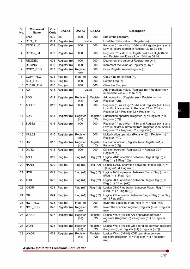
Axpert-Opti torque Electronic Soft Starter
6.57
1
2
3
4
5
6
7
8
9
10
11
12
13
A
Sr. No.
Command Name
Op-Code
DATA1 DATA2 DATA3 Description
1 END 000 000 000 000 End of the Program.
2 REG_LD 001 Register (n) Value Load the 16-bit value in Register (n).
3 REG32_LD 002 Register (n) 000 000 Register (n) as a High 16-bit and Register (n+1) as a Low 16-bit are loaded in Register 32 as 32 bits.
4 REG32_ST 003 Register (n) 000 000 Register 32 is store in Register (n) as a High 16-bit and Register (n+1) as a Low 16-bit as 32 bit.
5 REGDEC 005 Register (n) 000 000 Decrement the value of Register (n) by 1.
6 REGINC 006 Register (n) 000 000 Increment the value of Register (n) by 1.
7 COPY_REG 007 Register (n) Register (m)
000 Copy Register (m) in Register (n).
8 COPY_FLG 008 Flag (n) Flag (m) 000 Copy Flag (m) in Flag (n).
9 SET_FLG 009 Flag (n) 000 000 Set the Flag (n).
10 CLEAR_FLG 010 Flag (n) 000 000 Clear the Flag (n).
11 ADI 011 Register (n) Value Add immediate value. (Register (n) = Register (n) + Immediate Value (0 to 32767)
12 ADD 012 Register (n) Register (n1)
Register (n2)
Add operation. (Register (n) = Register (n1) + Register (n2)).
13 ADD32 013 Register (n) 000 000 Register (n) as a High 16-bit and Register (n+1) as a Low 16-bit are added to Register 32 as 32 bits. Register 32 = Register 32 + Register (n).
14 SUB 014 Register (n) Register (n1)
Register (n2)
Subtraction operator (Register (n) = Register (n1) - Register (n2)).
15 SUB32 015 Register (n) 000 000 Register (n) as a High 16-bit and Register (n+1) as a Low 16-bit are subtracted from Register32 as 32 bits. Register 32 = Register 32 - Register (n).
16 MUL32 016 Register (n) Register (m)
000 Multiplication operator (Register 32 = Register (n) * Register (m)).
17 DIV 017 Register (n) Register (n1)
Register (n2)
Division operator (Register (n) = Register (n1) / Register (n2)).
18 DIV32 018 Register (n) 000 000 Division operator (Register 32 = Register 32 / Register (n)).
19 AND 019 Flag (n) Flag (n1) Flag (n2) Logical AND operation between Flags (Flag (n) = Flag (n1) & Flag (n2))
20 NAND 020 Flag (n) Flag (n1) Flag (n2) Logical NAND operation between Flags (Flag (n) = ~(Flag (n1) & Flag (n2)))
21 NOR 021 Flag (n) Flag (n1) Flag (n2) Logical NOR operation between Flags (Flag (n) = ~ (Flag (n1) | Flag (n2)).
22 XOR 022 Flag (n) Flag (n1) Flag (n2) Logical XOR operation between Flags (Flag (n) = Flag (n1) ^ Flag (n2)).
23 XNOR 023 Flag (n) Flag (n1) Flag (n2) Logical XNOR operation between Flags (Flag (n) = ~ (Flag (n1) ^ Flag (n2))).
24 OR 024 Flag (n) Flag (n1) Flag (n2) Logical OR operation between Flags (Flag (n) = Flag (n1) | Flag (n2)).
25 NOT_FLG 025 Flag (n) Flag (m) 000 Invert the specified Flag (Flag (n) = ~Flag (m)).
26 NOT_REG 026 Register (n) Register (m)
000 Invert the specified register (Register (n) = ~Register (m))
27 WAND 027 Register (n) Register (n1)
Register (n2)
Logical Word (16-bit) AND operation between registers (Register (n) = Register (n1) & Register (n2))
28 WOR 028 Register (n) Register (n1)
Register (n2)
Logical Word (16-bit) OR operation between registers (Register (n) = Register (n1) | Register (n-2))
29 WXOR 029 Register (n) Register (n1)
Register (n2)
Logical Word (16-bit) XOR operation between registers (Register (n) = Register (n1) ^ Register (n2))
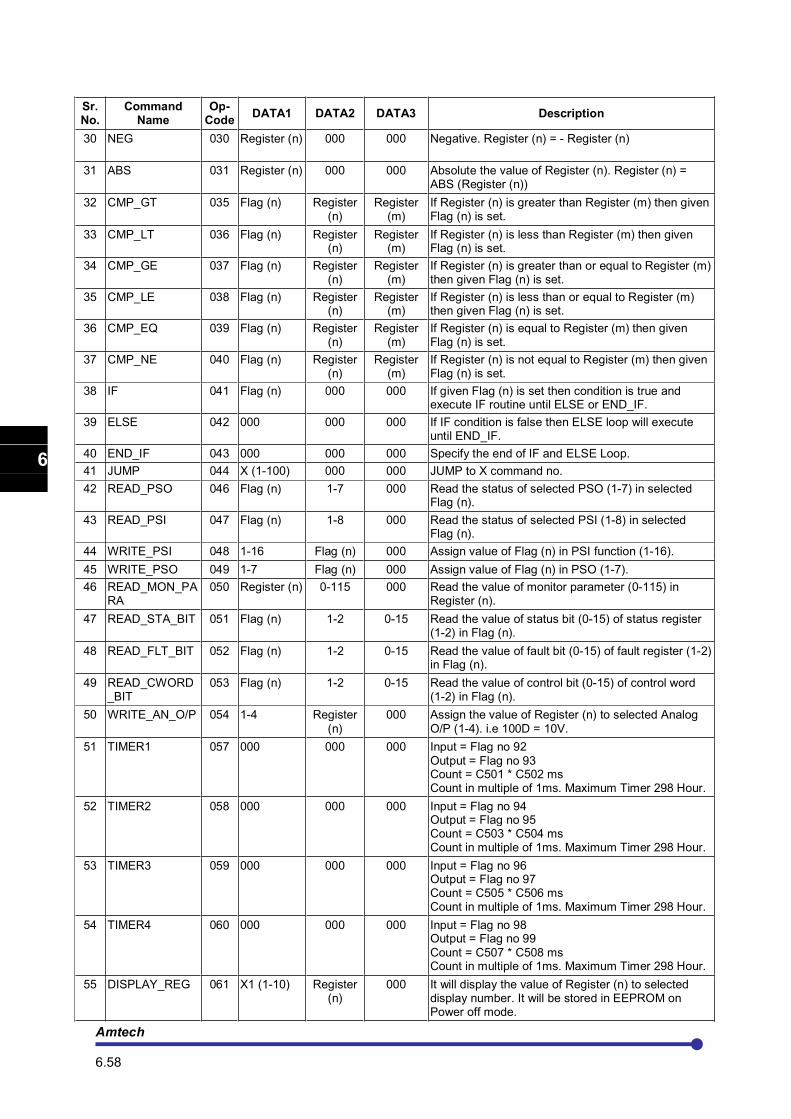
Amtech 6.58
1
2
3
4
5
6
7
8
9
10
11
12
13
A
Sr. No.
Command Name
Op-Code
DATA1 DATA2 DATA3 Description
30
NEG 030 Register (n) 000 000 Negative. Register (n) = - Register (n)
31
ABS 031
Register (n) 000 000 Absolute the value of Register (n). Register (n) = ABS (Register (n))
32 CMP_GT 035 Flag (n) Register (n)
Register (m)
If Register (n) is greater than Register (m) then given Flag (n) is set.
33 CMP_LT 036 Flag (n) Register (n)
Register (m)
If Register (n) is less than Register (m) then given Flag (n) is set.
34 CMP_GE 037 Flag (n) Register (n)
Register (m)
If Register (n) is greater than or equal to Register (m) then given Flag (n) is set.
35 CMP_LE 038 Flag (n) Register (n)
Register (m)
If Register (n) is less than or equal to Register (m) then given Flag (n) is set.
36 CMP_EQ 039 Flag (n) Register (n)
Register (m)
If Register (n) is equal to Register (m) then given Flag (n) is set.
37 CMP_NE 040 Flag (n) Register (n)
Register (m)
If Register (n) is not equal to Register (m) then given Flag (n) is set.
38 IF 041 Flag (n) 000 000 If given Flag (n) is set then condition is true and execute IF routine until ELSE or END_IF.
39 ELSE 042 000 000 000 If IF condition is false then ELSE loop will execute until END_IF.
40 END_IF 043 000 000 000 Specify the end of IF and ELSE Loop.
41 JUMP 044 X (1-100) 000 000 JUMP to X command no.
42 READ_PSO 046 Flag (n) 1-7 000 Read the status of selected PSO (1-7) in selected Flag (n).
43 READ_PSI 047 Flag (n) 1-8 000 Read the status of selected PSI (1-8) in selected Flag (n).
44 WRITE_PSI 048 1-16 Flag (n) 000 Assign value of Flag (n) in PSI function (1-16).
45 WRITE_PSO 049 1-7 Flag (n) 000 Assign value of Flag (n) in PSO (1-7).
46 READ_MON_PARA
050 Register (n) 0-115 000 Read the value of monitor parameter (0-115) in Register (n).
47 READ_STA_BIT 051 Flag (n) 1-2 0-15 Read the value of status bit (0-15) of status register (1-2) in Flag (n).
48 READ_FLT_BIT 052 Flag (n) 1-2 0-15 Read the value of fault bit (0-15) of fault register (1-2) in Flag (n).
49 READ_CWORD_BIT
053 Flag (n) 1-2 0-15 Read the value of control bit (0-15) of control word (1-2) in Flag (n).
50 WRITE_AN_O/P 054 1-4 Register (n)
000 Assign the value of Register (n) to selected Analog O/P (1-4). i.e 100D = 10V.
51 TIMER1 057 000 000 000 Input = Flag no 92 Output = Flag no 93 Count = C501 * C502 ms Count in multiple of 1ms. Maximum Timer 298 Hour.
52 TIMER2 058 000 000 000 Input = Flag no 94 Output = Flag no 95 Count = C503 * C504 ms Count in multiple of 1ms. Maximum Timer 298 Hour.
53 TIMER3 059 000 000 000 Input = Flag no 96 Output = Flag no 97 Count = C505 * C506 ms Count in multiple of 1ms. Maximum Timer 298 Hour.
54 TIMER4 060 000 000 000 Input = Flag no 98 Output = Flag no 99 Count = C507 * C508 ms Count in multiple of 1ms. Maximum Timer 298 Hour.
55 DISPLAY_REG 061 X1 (1-10) Register (n)
000 It will display the value of Register (n) to selected display number. It will be stored in EEPROM on Power off mode.
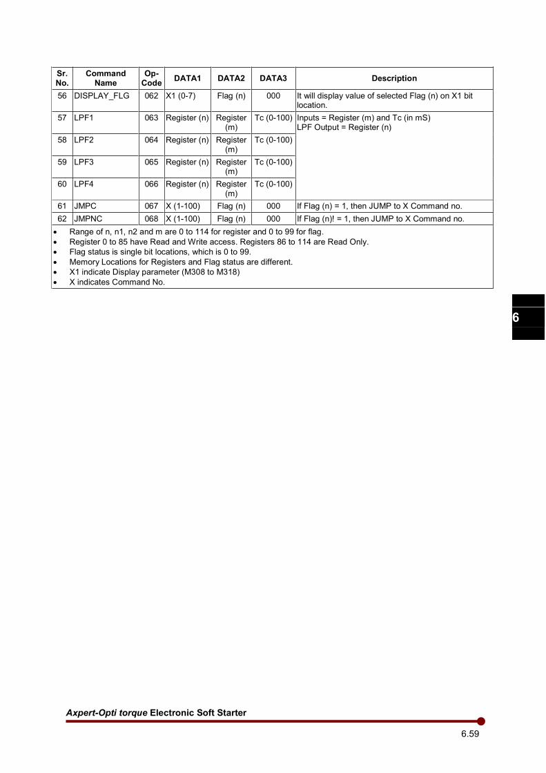
Axpert-Opti torque Electronic Soft Starter
6.59
1
2
3
4
5
6
7
8
9
10
11
12
13
A
Sr. No.
Command Name
Op-Code
DATA1 DATA2 DATA3 Description
56 DISPLAY_FLG 062 X1 (0-7) Flag (n) 000 It will display value of selected Flag (n) on X1 bit location.
57 LPF1 063 Register (n) Register (m)
Tc (0-100) Inputs = Register (m) and Tc (in mS) LPF Output = Register (n)
58 LPF2 064 Register (n) Register (m)
Tc (0-100)
59 LPF3 065 Register (n) Register (m)
Tc (0-100)
60 LPF4 066 Register (n) Register (m)
Tc (0-100)
61 JMPC 067 X (1-100) Flag (n) 000 If Flag (n) = 1, then JUMP to X Command no.
62 JMPNC 068 X (1-100) Flag (n) 000 If Flag (n)! = 1, then JUMP to X Command no.
• Range of n, n1, n2 and m are 0 to 114 for register and 0 to 99 for flag.
• Register 0 to 85 have Read and Write access. Registers 86 to 114 are Read Only.
• Flag status is single bit locations, which is 0 to 99.
• Memory Locations for Registers and Flag status are different.
• X1 indicate Display parameter (M308 to M318)
• X indicates Command No.

Amtech 6.60
1
2
3
4
5
6
7
8
9
10
11
12
13
A
In-built PLC Command Detail Description:
1. END (OPCODE 000)
This command indicates End of PLC program. Any command after this command (END) will not be executed. Input Command 000000000000 2. REG_LD (OPCODE 001) This command is used to Load 16-bit signed value into selected register. Example, REG_LD Rn 32000 Where,
Rn = Register Number (0 to 85) Input Command
001001032000 001 indicates Command OPCODE 001 indicates Register Number 1 032000 indicate 16-bit value (32000).
3. REG32_LD (OPCODE 002) This command is used to load 32-bit value into 32-bit Register. Example, REG32_LD Rn
Where, Rn = Register Number (0 to 113)
32-bit register = value of Register (n) as a high byte and the value of Register (n+1) as a low byte. Input Command
002001000000 002 Indicate Command OPCODE 001 Indicates Register Number 1 000 Not used 000 Not used
4. REG32_ST (OPCODE 003)
This command is used to store 32-bit value into Register. Example, REG32_ ST Rn
Where, Rn = Register Number (0 to 84) High byte of 32-bit value will be store into selected Rn and Low byte of 32-bit value will be stored into selected R (n+1). Input Command
003001000000 003 Indicate Command OPCODE 001 Indicates Register Number 1 000 Not used 000 Not used
5. REGDEC (OPCODE 005) This command is used to Decrement the value of selected register by one. Example, REGDEC Rn Where, Rn = Register Number (0 to 85)

Axpert-Opti torque Electronic Soft Starter
6.61
1
2
3
4
5
6
7
8
9
10
11
12
13
A
6. REGINC (OPCODE 006) This command is used to increment the value of selected register by one. Example, REGINC Rn Where, Rn = Register Number (0 to 85) 7. COPY_REG (OPCODE 007) This command is used to copy the content of one register (Rm) to another register (Rn). Example, COPY_REG Rn Rm Where, Rn = Register Number (0 to 85) Rm = Register Number (0 to 114)
8. COPY_FLG (OPCODE 008)
This command is used to copy the bit status of one Flag (Fm) to another Flag (Fn). Example, COPY_ FLG Fn Fm
Where, Fn and Fm = Flag Number (0 to 99) 9. SET_FLG (OPCODE 009) This command is used to set the bit status of selected Flag (Fn). Example, SET_FLG Fn Where, Fn = Flag Number (0 to 99) 10. CLEAR_FLG (OPCODE 010)
This command is used to clear the bit status of selected Flag (Fn). Example, CLEAR_FLG_FLG Fn Where, Fn = Flag Number (0 to 99)
11. ADI (OPCODE 011) This command is used for summation of immediate signed 16-bit value and Register. Example, ADI Rn 32000 Where, Rn = Register Number (0 to 85)
Result will be stored in Rn. (Rn = Rn + 32000). 12. ADD (OPCODE 012) This command is used for 16-bit summation operation of two registers. Example, ADD Rn Rn1 Rn2 Where, Rn = Register Number (0 to 85)
Rn1, Rn2 = Register Number (0 to 114) Result will be stored in Rn. (Rn = Rn1 + Rn2)
Amtech 6.62
1
2
3
4
5
6
7
8
9
10
11
12
13
A
13. ADD32 (OPCODE 013) This command is used for 32-bit summation. Example, ADD32 Rn Where, Rn = Register Number (0 to 113)
Register Rn as high byte and Rn+1 as low byte and it will be added to 32-bit register. Result will be stored into 32-bit Register.
14. SUB (OPCODE 014)
This command is used for 16-bit subtraction of two registers. Example, SUB Rn Rn1 Rn2 Where, Rn = Register Number (0 to 85) Rn1, Rn2 = Register Number (0 to 114)
Result will be stored in Rn. (Rn = Rn1 – Rn2) 15. SUB32 (OPCODE 015) This command is used for 32-bit Subtraction. Example, SUB32 Rn
Where, Rn = Register Number (0 to 113)
32bit Register = 32bit Register - Rn Register Rn as high byte and Rn+1 as low byte and it will be subtracted from 32-bit register. Result will be Stored into 32-bit Register.
16. MUL32 (OPCODE 016) This command is used for multiplication operation of two registers. Example, MUL32 Rn Rm
Where, Rn and Rm = Register Number (0 to 114) 32bit Register = Rn * Rm.
Result will be stored in 32-bit Register. Result should not be exceeding more then 32-bit value.
17. DIV (OPCODE 017) This command is used for division of two registers. Example, DIV Rn Rn1 Rn2 Where, Rn = Register Number (0 to 85) Rn1, Rn2 = Register Number (0 to 114)
Result will be stored in Rn. (Rn = Rn1 / Rn2).
18. DIV32 (OPCODE 018) This command is used for division of 32-bit value. Example, DIV32 Rn Where, Rn = Register Number (0 to 114)
Result will be stored in 32-bit Register. (32bit Register = 32bit Register / Rn.)
Axpert-Opti torque Electronic Soft Starter
6.63
1
2
3
4
5
6
7
8
9
10
11
12
13
A
19. AND (OPCODE 019) This command is used for logical AND operation between two bits of Flags. Example, AND Fn Fn1 Fn2 Where, Fn, Fn1 and Fn2 = Flag Number (0 to 99)
Result will be stored in Fn. (Fn = Fn1 & Fn2) 20. NAND (OPCODE 020) This command is used for logical NAND operation between two bits of Flags. Example, NAND Fn Fn1 Fn2
Where, Fn, Fn1 and Fn2 = Flag Number (0 to 99)
Result will be stored in Fn. (Fn = ~(Fn1 & Fn2)) 21. NOR (OPCODE 021) This command is used for logical NOR operation between two bit Flags. Example, NOR Fn Fn1 Fn2 Where, Fn, Fn1 and Fn2 = Flag Number (0 to 99)
Result will be stored in Fn. (Fn = ~(Fn1 | Fn2)) 22. XOR (OPCODE 022) This command is used for logical XOR operation between two bit Flags. Example, XOR Fn Fn1 Fn2 Where, Fn, Fn1 and Fn2 = Flag Number (0 to 99)
Result will be stored in Fn. (Fn = Fn1 ^ Fn2) 23. XNOR (OPCODE 023)
This command is used for logical XNOR operation between two bit Flags. Example, XNOR Fn Fn1 Fn2
Where, Fn, Fn1 and Fn2 = Flag Number (0 to 99)
Result will be stored in Fn. (Fn = ~(Fn1 ^ Fn2)) 24. OR (OPCODE 024) This command is used for logical OR operation between two bit Flags. Example, OR Fn Fn1 Fn2 Where, Fn, Fn1 and Fn2 = Flag Number (0 to 99)
Result will be stored in Fn. (Fn = Fn1 | Fn2)
25. NOT_FLG (OPCODE 025) This command is used for logical NOT operation of selected bit Flag. Example, NOT_FLG Fn Fm
Where,
Amtech 6.64
1
2
3
4
5
6
7
8
9
10
11
12
13
A
Fn and Fm = Flag Number (0 to 99) Result will be stored in Fn. (Fn = ~Fm)
26. NOT_REG (OPCODE 026)
This command is used for logical NOT operation of selected Register. Example, NOT_REG Rn Rm Where, Rn = Register Number (0 to 85) Rm = Register Number (0 to 114)
Result will be stored in Rn. (Rn = ~Rm) 27. WAND (OPCODE 027)
This command is used for 16-bit logical AND operation of selected two Registers. Example, WAND Rn Rn1 Rn2
Where, Rn = Register Number (0 to 85) Rn1, Rn2 = Register Number (0 to 114)
Result will be stored in Rn (Rn = Rn1 & Rn2). 28. WOR (OPCODE 028) This command is used for 16-bit logical OR operation of selected two Registers. Example, WOR Rn Rn1 Rn2 Where, Rn = Register Number (0 to 85) Rn1, Rn2 = Register Number (0 to 114)
Result will be stored in Rn. (Rn = Rn1 | Rn2)
29. WXOR (OPCODE 029)
This command is used for 16-bit logical XOR operation of selected two Registers. Example, WXOR Rn Rn1 Rn2 Where, Rn = Register Number (0 to 85) Rn1, Rn2 = Register Number (0 to 114)
Result will be stored in Rn. (Rn = Rn1 ^ Rn2) 30. NEG (OPCODE 030) This command is used for negative operation of selected Register. Example, NEG Rn
Where, Rn = Register Number (0 to 85)
Result will be stored in Rn. (Rn = -Rn) 31. ABS (OPCODE 031) This command is used for absolute operation of selected Register. Example, ABS Rn Where, Rn = Register Number (0 to 85)
Result will be stored in Rn. (Rn = ABS (Rn))
Axpert-Opti torque Electronic Soft Starter
6.65
1
2
3
4
5
6
7
8
9
10
11
12
13
A
Note: OPCODE no. 032 to 034 Reserved. 32. CMP_GT (OPCODE 035) This command is used for compare application. Example, CMP_GT Fn Rn Rm
Where, Rn and Rm = Register Number (0 to 114) Fn = Flag number (0 to 99)
It will compare Rn and Rm, and if Rn is greater than Rm then it will set Fn (bit status) to 1. 33. CMP_LT (OPCODE 036) This command is used for compare application. Example, CMP_LT Fn Rn Rm Where, Rn and Rm = Register Number (0 to 114) Fn = Flag number (0 to 99)
It will compare Rn and Rm, and if Rn is less than Rm then it will set Fn (bit status) to 1. 34. CMP_GE (OPCODE 037) This command is used for compare application. Example, CMP_GE Fn Rn Rm Where, Rn and Rm = Register Number (0 to 114) Fn = Flag number (0 to 99)
It will compare Rn and Rm, and if Rn is greater than and equal to Rm then it will set Fn (bit status) to 1.
35. CMP_LE (OPCODE 038)
This command is used for compare application. Example, CMP_LE Fn Rn Rm Where, Rn and Rm = Register Number (0 to 114) Fn = Flag number (0 to 99)
It will compare Rn and Rm, and if Rn is less than and equal to Rm then it will set Fn (bit status) to 1.
36. CMP_EQ (OPCODE 039)
This command is used for compare application. Example, CMP_EQ Fn Rn Rm Where, Rn and Rm = Register Number (0 to 114)
Fn = Flag number (0 to 99) It will compare Rn and Rm, and if Rn is equal to Rm then it will set Fn (bit status) to 1.
37. CMP_NE (OPCODE 040) This command is used for compare application. Example, CMP_NE Fn Rn Rm
Where,
Amtech 6.66
1
2
3
4
5
6
7
8
9
10
11
12
13
A
Rn and Rm = Register Number (0 to 114) Fn = Flag number (0 to 99) It will compare Rn and Rm, and if Rn is not equal to Rm then it will set Fn (bit status) to 1.
38. IF (OPCODE 041) This command is used for condition application. Example, IF Fn Where, Fn = Flag number (0 to 99)
If Fn is 1 then it will go into the If loop otherwise it will execute the PLC code written after ELSE command.
39. ELSE (OPCODE 042) This command is used for condition application. Example, ELSE
If IF command condition is false then it will go into the ELSE loop. Otherwise it will execute the PLC code written after END_IF command.
40. END_IF (OPCODE 043) This command indicates end of IF and ELSE condition loop. NOTE: END_IF command must be used after IF, ELSE command.
Example,
IF Fn IF Fn ……. OR ………
END_IF ELSE ……… END_IF
Note: Nested IF….ELSE…..END_IF statement is not supported.
41. JUMP (OPCODE 044)
This command is used for branch application. Example, JUMP Xn
Where, Xn = Command Number (1 to 100)
It will JUMP to selected Xn Command number and start executing from there. Note: OPCODE no. 045 Reserved. 42. READ_PSO (OPCODE 046) This command is used to read PSO status in selected Flag Number. Example, READ_PSO Fn PSOm Where, Fn = Flag number (0 to 99)
PSOm = PSO number (1 to 7) 43. READ_PSI (OPCODE 047)
This command is used to read PSI status from Inverter to In-built PLC. For this, user must have to select below PLC option in Inverter parameters C101 to C106 and C114 to C115.
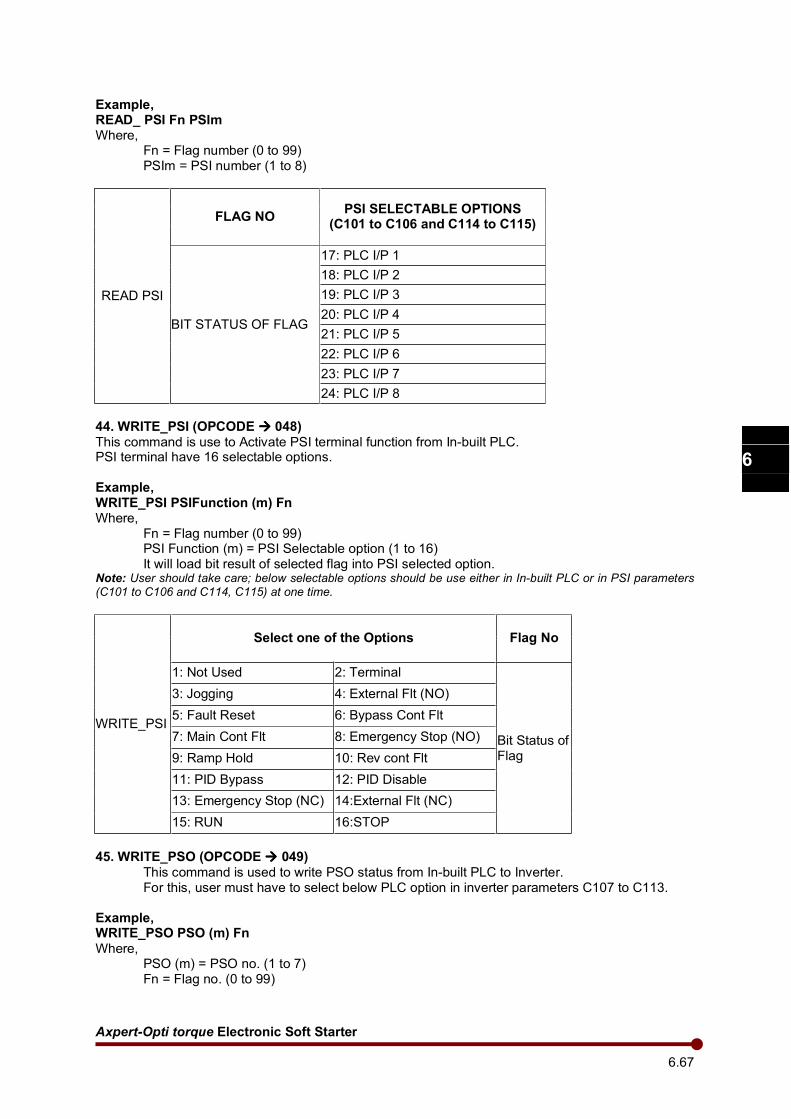
Axpert-Opti torque Electronic Soft Starter
6.67
1
2
3
4
5
6
7
8
9
10
11
12
13
A
Example, READ_ PSI Fn PSIm Where, Fn = Flag number (0 to 99)
PSIm = PSI number (1 to 8)
READ PSI
FLAG NO PSI SELECTABLE OPTIONS
(C101 to C106 and C114 to C115)
BIT STATUS OF FLAG
17: PLC I/P 1
18: PLC I/P 2
19: PLC I/P 3
20: PLC I/P 4
21: PLC I/P 5
22: PLC I/P 6
23: PLC I/P 7
24: PLC I/P 8
44. WRITE_PSI (OPCODE 048)
This command is use to Activate PSI terminal function from In-built PLC. PSI terminal have 16 selectable options.
Example, WRITE_PSI PSIFunction (m) Fn Where, Fn = Flag number (0 to 99) PSI Function (m) = PSI Selectable option (1 to 16)
It will load bit result of selected flag into PSI selected option. Note: User should take care; below selectable options should be use either in In-built PLC or in PSI parameters (C101 to C106 and C114, C115) at one time.
WRITE_PSI
Select one of the Options Flag No
1: Not Used 2: Terminal
Bit Status of Flag
3: Jogging 4: External Flt (NO)
5: Fault Reset 6: Bypass Cont Flt
7: Main Cont Flt 8: Emergency Stop (NO)
9: Ramp Hold 10: Rev cont Flt
11: PID Bypass 12: PID Disable
13: Emergency Stop (NC) 14:External Flt (NC)
15: RUN 16:STOP
45. WRITE_PSO (OPCODE 049)
This command is used to write PSO status from In-built PLC to Inverter. For this, user must have to select below PLC option in inverter parameters C107 to C113.
Example, WRITE_PSO PSO (m) Fn
Where, PSO (m) = PSO no. (1 to 7) Fn = Flag no. (0 to 99)
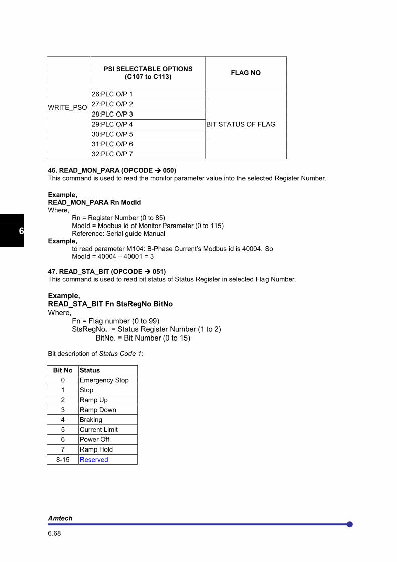
Amtech 6.68
1
2
3
4
5
6
7
8
9
10
11
12
13
A
WRITE_PSO
PSI SELECTABLE OPTIONS (C107 to C113)
FLAG NO
26:PLC O/P 1
BIT STATUS OF FLAG
27:PLC O/P 2
28:PLC O/P 3
29:PLC O/P 4
30:PLC O/P 5
31:PLC O/P 6
32:PLC O/P 7
46. READ_MON_PARA (OPCODE 050)
This command is used to read the monitor parameter value into the selected Register Number.
Example, READ_MON_PARA Rn ModId Where, Rn = Register Number (0 to 85) ModId = Modbus Id of Monitor Parameter (0 to 115) Reference: Serial guide Manual Example, to read parameter M104: B-Phase Current’s Modbus id is 40004. So
ModId = 40004 – 40001 = 3
47. READ_STA_BIT (OPCODE 051) This command is used to read bit status of Status Register in selected Flag Number.
Example, READ_STA_BIT Fn StsRegNo BitNo
Where, Fn = Flag number (0 to 99) StsRegNo. = Status Register Number (1 to 2)
BitNo. = Bit Number (0 to 15) Bit description of Status Code 1:
Bit No Status
0 Emergency Stop
1 Stop
2 Ramp Up
3 Ramp Down
4 Braking
5 Current Limit
6 Power Off
7 Ramp Hold
8-15 Reserved
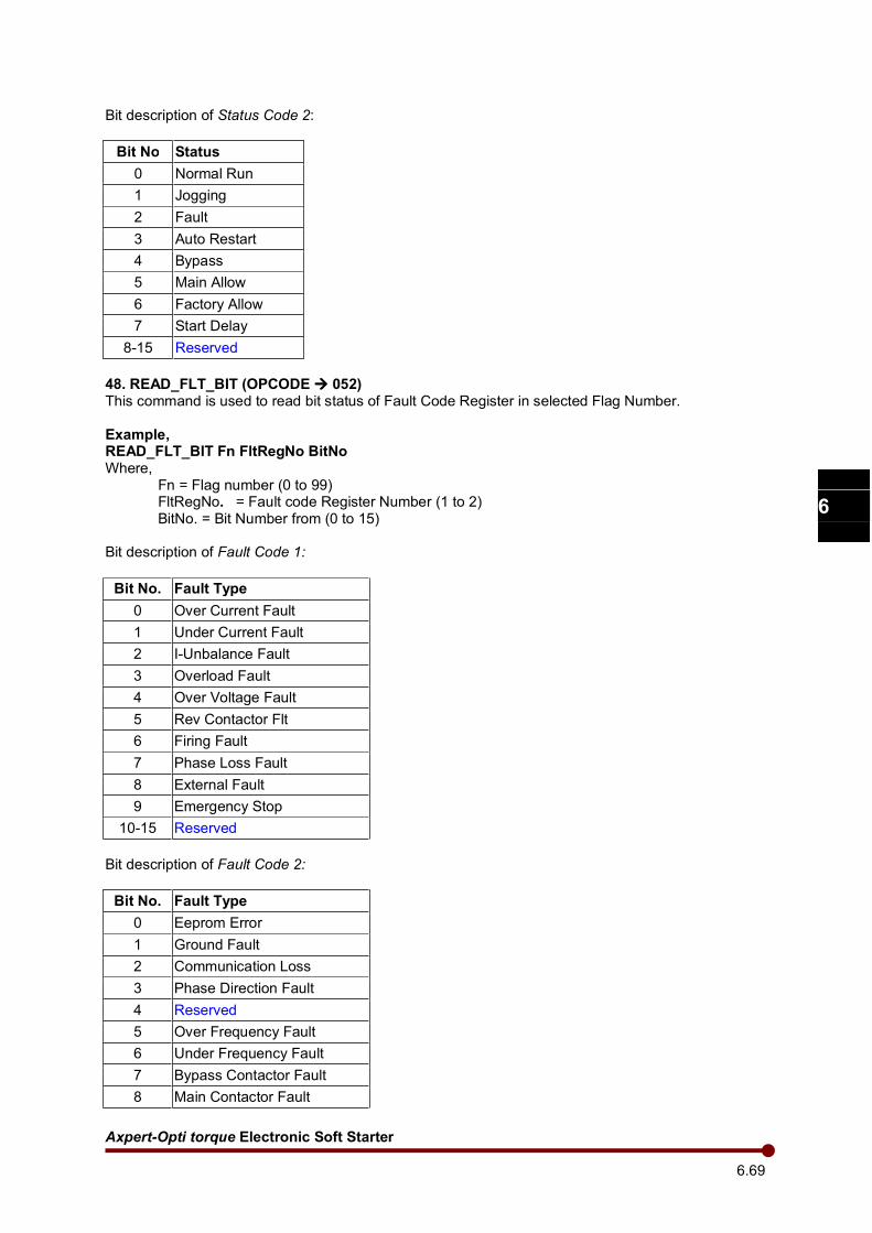
Axpert-Opti torque Electronic Soft Starter
6.69
1
2
3
4
5
6
7
8
9
10
11
12
13
A
Bit description of Status Code 2:
Bit No Status
0 Normal Run
1 Jogging
2 Fault
3 Auto Restart
4 Bypass
5 Main Allow
6 Factory Allow
7 Start Delay
8-15 Reserved
48. READ_FLT_BIT (OPCODE 052) This command is used to read bit status of Fault Code Register in selected Flag Number. Example, READ_FLT_BIT Fn FltRegNo BitNo Where, Fn = Flag number (0 to 99)
FltRegNo. = Fault code Register Number (1 to 2) BitNo. = Bit Number from (0 to 15)
Bit description of Fault Code 1:
Bit No. Fault Type
0 Over Current Fault
1 Under Current Fault
2 I-Unbalance Fault
3 Overload Fault
4 Over Voltage Fault
5 Rev Contactor Flt
6 Firing Fault
7 Phase Loss Fault
8 External Fault
9 Emergency Stop
10-15 Reserved
Bit description of Fault Code 2:
Bit No. Fault Type
0 Eeprom Error
1 Ground Fault
2 Communication Loss
3 Phase Direction Fault
4 Reserved
5 Over Frequency Fault
6 Under Frequency Fault
7 Bypass Contactor Fault
8 Main Contactor Fault
Amtech 6.70
1
2
3
4
5
6
7
8
9
10
11
12
13
A
9 Temperature Fault
10-15 Reserved
49. READ_CWORD_BIT (OPCODE 053)
This command is used to read bit status of Control Word Register in selected Flag Number. Example, READ_CWORD_BIT Fn CwordRegNo BitNo Where, Fn = Flag number (0 to 99)
CwordRegNo = Control Word Register Number (1 to 2) BitNo. = Bit Number from (0 to 15)
Bit description of Control word:
Bit No Status Description
0 Phase Direction Fault Enable or disable the phase direction fault. = 0: Disable = 1: Enable
1 Firing Fault Enable or disable the firing fault. = 0: Disable = 1: Enable
2 Pick up function Enable or disable the pick up function. = 0: Disable = 1: Enable
3 Reserved
4 Reserved
5 PID Control selection Enable or disable the PID control action. = 0: Disable = 1: Enable
6 PID Polarity This can be used to invert the PID output. = 0: Negative = 1: positive
7 Operation Panel Communication Loss selection
If enabled, SOFT STARTER will generate fault if it does not receive any response from the operation panel within 5sec. =0: Disable =1: Enable
8 Maintained/Momentary Start When using terminal start/ stop facility, this parameter gives the choice of having maintained or momentary contacts for start or stop. = 0: The start control maintained type = 1: The start/ stop control momentary type.
9 O/L During Ramp Enable or Disabled the thermal overload during ramp up. = 0: Disable. = 1: Enable.
10-15 Reserved
50. WRITE_AN_O/P (OPCODE 054) This command is used to set Analog Output or Analog Input by the use of selected Register value. Register value should be in the range of 0 to 100d. Where 0d will give 0Volt and 100d will give 10Volt.
Axpert-Opti torque Electronic Soft Starter
6.71
1
2
3
4
5
6
7
8
9
10
11
12
13
A
Example, WRITE_AN_O/P PLCAOPn Rn Where, PLCAOPn = PLC analog output number (PLCAOP1 to PLCAOP4). Rn = Register Number (0 to 114).
FOR ANALOG OPUTPUT: Analog output will come according to selection of C201 to C204. To get PLC analog output at VO1 terminal, one of the selectable options from 9:PLC A-O/P 1 to 12:PLC A-O/P 4 should be set at C201. FOR ANALOG INTPUT: Analog Input can be given to parameters C303 & C304 from In-built PLC by setting one of four PLC A-O/P options and using this command. 51. TIMER1 (OPCODE 057) This command is used to set fix timing event for required application. Example, TIMER1 1 count = 1 ms
Final count = C501 * C502. (Parameter) Flag Number 92 is Input Flag and Flag Number 93 is Output Flag for Timer1. TIMER1 is down counter. It will start after Flag number 92 is set to 1. It will only work if 92 Flag number is set otherwise it will stop counting. When TIMER1 will become zero, Flag number 93 will be set. Maximum Timer is 298 hour. 52. TIMER2 (OPCODE 058)
Final count = C503 * C504. (Parameter) Flag Number 94 is Input Flag and Flag Number 95 is Output Flag for Timer2. Same as TIMER1. 53. TIMER3 (OPCODE 059)
Final count = C505 * C506. (Parameter) Flag Number 96 is Input Flag and Flag Number 97 is Output Flag for Timer3. Same as TIMER1. 54. TIMER4 (OPCODE 060)
Final count = C507 * C508. (Parameter) Flag Number 98 is Input Flag and Flag Number 99 is Output Flag for Timer4.
Same as TIMER1. 55. DISPLAY_REG (OPCODE 061) This command is used to display the Register value on Display Panel and save it to EEPROM on Power OFF mode. Example, DISPLAY_REG X1 Rn
Where, X1 is the Display Number of Display Panel, which are 1 to 10. (M308 to M317) Rn = Register Number (0 to 114)
User can also display the value of Read only Register. 56. DISPLAY_FLG (OPCODE 062) This command is used to display the bit status of Flag Number on Display Panel and save it to EEPROM on Power OFF mode. Total 8 number of flag bit status can be shown. Example, DISPLAY_FLG Bitloc Fn
Where,
Amtech 6.72
1
2
3
4
5
6
7
8
9
10
11
12
13
A
Bitloc = bit location (0 to 7) of shown parameter on Display Panel (M318) Fn = Flag Number (0 to 99)
57. LPF1 (OPCODE 063)
This command is used for the low pass filter. Example, LPF1 Rn Rm Tc Where, Rn = Register number (0 to 85) Rm = Register number (0 to 114) Tc = Time constant. (0 to 100)
Result will be stored in Rn. 58. LPF2 (OPCODE 064) 59. LPF3 (OPCODE 065) 60. LPF4 (OPCODE 066) Same as LPF1. 61. JMPC (OPCODE 067) This command is used for conditional Branch application. Example, JMPC Xn Fn Where, Xn = Command Number (0 to 100) Fn = Flag Number (0 to 99)
If Fn (flag no) in equal to 1, then It will JUMP to selected Xn Command number and start executing from there.
62. JMPNC (OPCODE 068) This command is used for conditional Branch application. Example, JMPC Xn Fn Where, Xn = Command Number (0 to 100) Fn = Flag Number (0 to 99)
If Fn (flag no) in not equal to 1, then It will JUMP to selected Xn Command number and start executing from there.
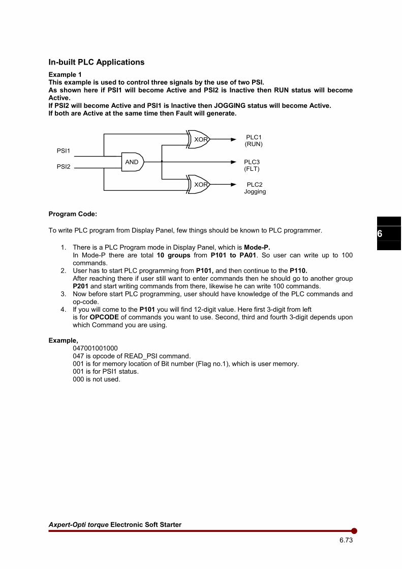
Axpert-Opti torque Electronic Soft Starter
6.73
1
2
3
4
5
6
7
8
9
10
11
12
13
A
In-built PLC Applications
Example 1 This example is used to control three signals by the use of two PSI. As shown here if PSI1 will become Active and PSI2 is Inactive then RUN status will become Active. If PSI2 will become Active and PSI1 is Inactive then JOGGING status will become Active. If both are Active at the same time then Fault will generate.
AND
XOR
XOR
PLC1(RUN)
PLC3(FLT)
PLC2Jogging
PSI1
PSI2
Program Code:
To write PLC program from Display Panel, few things should be known to PLC programmer.
1. There is a PLC Program mode in Display Panel, which is Mode-P. In Mode-P there are total 10 groups from P101 to PA01. So user can write up to 100 commands.
2. User has to start PLC programming from P101, and then continue to the P110. After reaching there if user still want to enter commands then he should go to another group P201 and start writing commands from there, likewise he can write 100 commands.
3. Now before start PLC programming, user should have knowledge of the PLC commands and op-code.
4. If you will come to the P101 you will find 12-digit value. Here first 3-digit from left is for OPCODE of commands you want to use. Second, third and fourth 3-digit depends upon which Command you are using.
Example, 047001001000 047 is opcode of READ_PSI command.
001 is for memory location of Bit number (Flag no.1), which is user memory. 001 is for PSI1 status.
000 is not used.
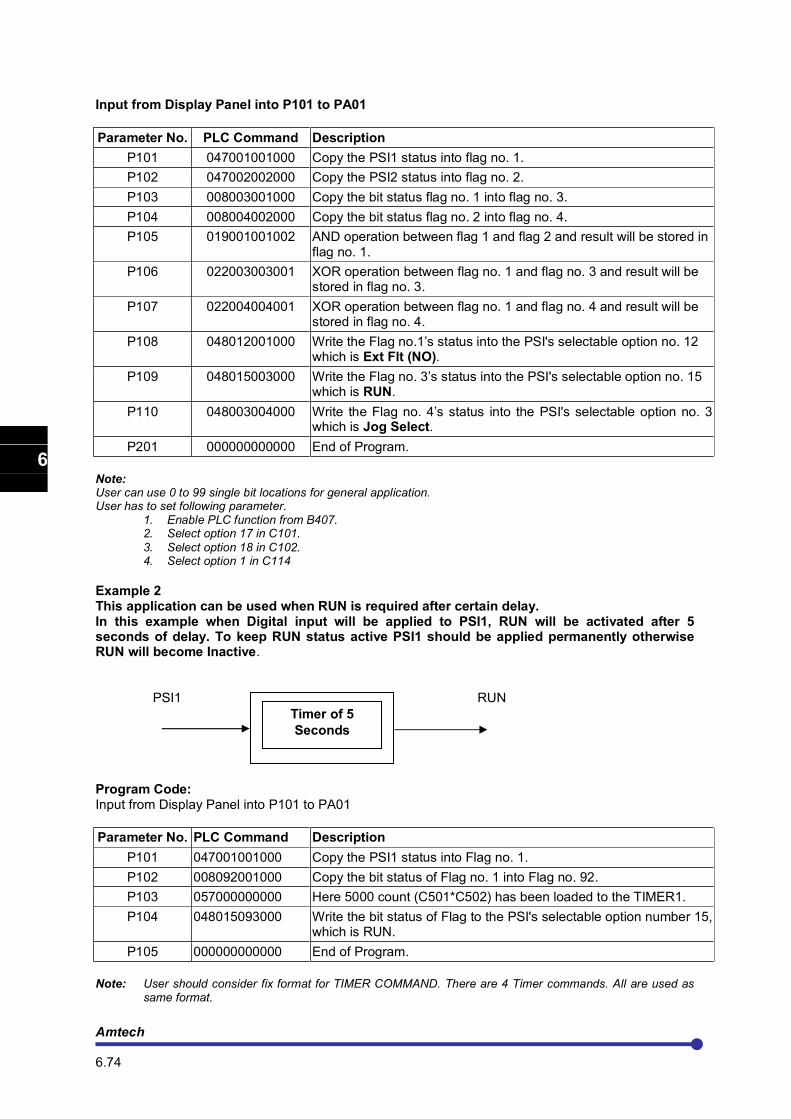
Amtech 6.74
1
2
3
4
5
6
7
8
9
10
11
12
13
A
Input from Display Panel into P101 to PA01
Parameter No. PLC Command Description
P101 047001001000 Copy the PSI1 status into flag no. 1.
P102 047002002000 Copy the PSI2 status into flag no. 2.
P103 008003001000 Copy the bit status flag no. 1 into flag no. 3.
P104 008004002000 Copy the bit status flag no. 2 into flag no. 4.
P105 019001001002 AND operation between flag 1 and flag 2 and result will be stored in flag no. 1.
P106 022003003001 XOR operation between flag no. 1 and flag no. 3 and result will be stored in flag no. 3.
P107 022004004001 XOR operation between flag no. 1 and flag no. 4 and result will be stored in flag no. 4.
P108 048012001000 Write the Flag no.1’s status into the PSI's selectable option no. 12 which is Ext Flt (NO).
P109 048015003000 Write the Flag no. 3’s status into the PSI's selectable option no. 15 which is RUN.
P110 048003004000 Write the Flag no. 4’s status into the PSI's selectable option no. 3 which is Jog Select.
P201 000000000000 End of Program.
Note: User can use 0 to 99 single bit locations for general application. User has to set following parameter.
1. Enable PLC function from B407. 2. Select option 17 in C101.
3. Select option 18 in C102. 4. Select option 1 in C114
Example 2 This application can be used when RUN is required after certain delay. In this example when Digital input will be applied to PSI1, RUN will be activated after 5 seconds of delay. To keep RUN status active PSI1 should be applied permanently otherwise RUN will become Inactive.
PSI1 RUN RUN
Program Code: Input from Display Panel into P101 to PA01
Parameter No. PLC Command Description
P101 047001001000 Copy the PSI1 status into Flag no. 1.
P102 008092001000 Copy the bit status of Flag no. 1 into Flag no. 92.
P103 057000000000 Here 5000 count (C501*C502) has been loaded to the TIMER1.
P104 048015093000 Write the bit status of Flag to the PSI's selectable option number 15, which is RUN.
P105 000000000000 End of Program.
Note: User should consider fix format for TIMER COMMAND. There are 4 Timer commands. All are used as
same format.
Timer of 5
Seconds
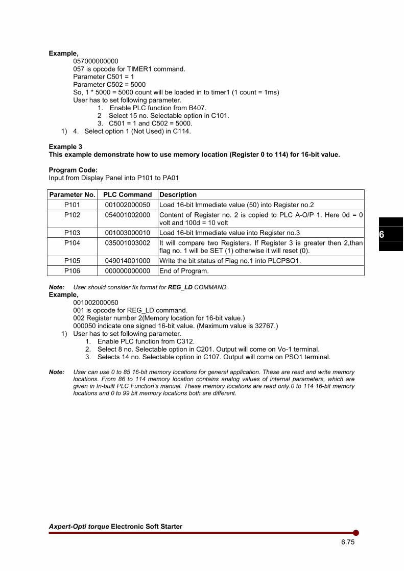
Axpert-Opti torque Electronic Soft Starter
6.75
1
2
3
4
5
6
7
8
9
10
11
12
13
A
Example, 057000000000
057 is opcode for TIMER1 command. Parameter C501 = 1
Parameter C502 = 5000 So, 1 * 5000 = 5000 count will be loaded in to timer1 (1 count = 1ms)
User has to set following parameter. 1. Enable PLC function from B407. 2 Select 15 no. Selectable option in C101. 3. C501 = 1 and C502 = 5000.
1) 4. Select option 1 (Not Used) in C114. Example 3 This example demonstrate how to use memory location (Register 0 to 114) for 16-bit value.
Program Code: Input from Display Panel into P101 to PA01
Parameter No. PLC Command Description
P101 001002000050 Load 16-bit Immediate value (50) into Register no.2
P102 054001002000 Content of Register no. 2 is copied to PLC A-O/P 1. Here 0d = 0 volt and 100d = 10 volt
P103 001003000010 Load 16-bit Immediate value into Register no.3
P104 035001003002 It will compare two Registers. If Register 3 is greater then 2,than flag no. 1 will be SET (1) otherwise it will reset (0).
P105 049014001000 Write the bit status of Flag no.1 into PLCPSO1.
P106 000000000000 End of Program.
Note: User should consider fix format for REG_LD COMMAND.
Example,
001002000050 001 is opcode for REG_LD command. 002 Register number 2(Memory location for 16-bit value.) 000050 indicate one signed 16-bit value. (Maximum value is 32767.)
1) User has to set following parameter. 1. Enable PLC function from C312. 2. Select 8 no. Selectable option in C201. Output will come on Vo-1 terminal. 3. Selects 14 no. Selectable option in C107. Output will come on PSO1 terminal.
Note: User can use 0 to 85 16-bit memory locations for general application. These are read and write memory
locations. From 86 to 114 memory location contains analog values of internal parameters, which are given in In-built PLC Function’s manual. These memory locations are read only.0 to 114 16-bit memory locations and 0 to 99 bit memory locations both are different.
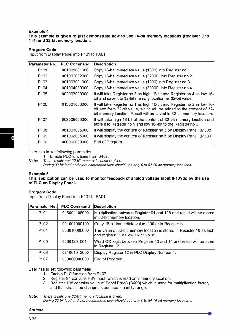
Amtech 6.76
1
2
3
4
5
6
7
8
9
10
11
12
13
A
Example 4 This example is given to just demonstrate how to use 16-bit memory locations (Register 0 to 114) and 32-bit memory location.
Program Code: Input from Display Panel into P101 to PA01
Parameter No. PLC Command Description
P101 001001001000 Copy 16-bit Immediate value (1000) into Register no.1
P102 001002032000 Copy 16-bit Immediate value (32000) into Register no.2
P103 001003001000 Copy 16-bit Immediate value (1000) into Register no.3
P104 001004030000 Copy 16-bit Immediate value (30000) into Register no.4
P105 002003000000 It will take Register no 3 as high 16-bit and Register no 4 as low 16-bit and save it to 32-bit memory location as 32-bit value.
P106 013001000000 It will take Register no 1 as high 16-bit and Register no 2 as low 16-bit and form 32-bit value, which will be added to the content of 32-bit memory location. Result will be saved to 32-bit memory location.
P107 003005000000 It will take high 16-bit of the content of 32-bit memory location and store it to Register no 5 and low 16 -bit to the Register no 6.
P108 061001005000 It will display the content of Register no 5 on Display Panel. (M308)
P109 061002006000 It will display the content of Register no 6 on Display Panel. (M309)
P110 000000000000 End of Program.
User has to set following parameter. 1. Enable PLC functions from B407. Note: There is only one 32-bit memory location is given.
During 32-bit load and store commands user should use only 0 to 84 16-bit memory locations.
Example 5 This application can be used to monitor feedback of analog voltage input 0-10Vdc by the use of PLC on Display Panel.
Program Code: Input from Display Panel into P101 to PA01
Parameter No. PLC Command Description
P101 016094108000 Multiplication between Register 94 and 108 and result will be stored in 32-bit memory location.
P102 001001000100 Copy 16-bit Immediate value (100) into Register no.1
P104 003010000000 The value of 32-bit memory location is stored in Register 10 as high and register 11 as low 16-bit value.
P105 028012010011 Word OR logic between Register 10 and 11 and result will be store in Register 12.
P106 061001012000 Display Register 12 in PLC Display Number 1.
P107 000000000000 End of Program.
User has to set following parameter.
1. Enable PLC function from B407. 2. Register 94 contains FSV input, which is read only memory location. 3. Register 108 contains value of Panel Para8 (C508) which is used for multiplication factor,
and that should be change as per input quantity range. Note: There is only one 32-bit memory location is given.
During 32-bit load and store commands user should use only 0 to 84 16-bit memory locations.
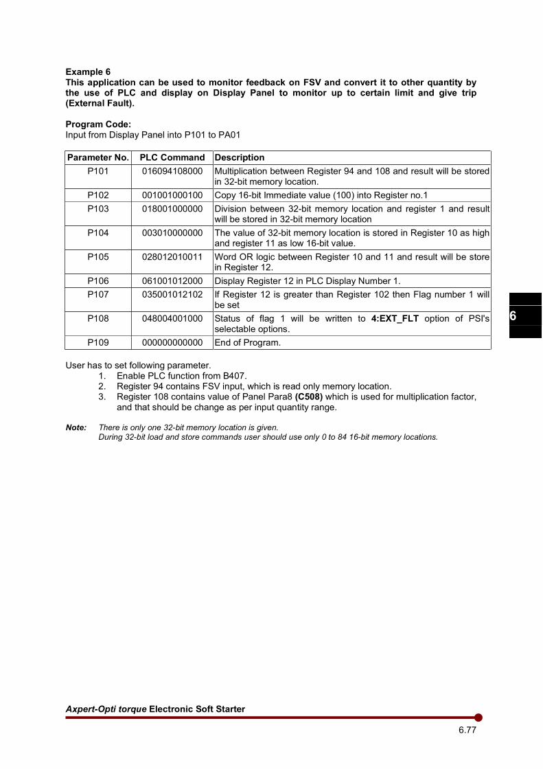
Axpert-Opti torque Electronic Soft Starter
6.77
1
2
3
4
5
6
7
8
9
10
11
12
13
A
Example 6 This application can be used to monitor feedback on FSV and convert it to other quantity by the use of PLC and display on Display Panel to monitor up to certain limit and give trip (External Fault).
Program Code: Input from Display Panel into P101 to PA01
Parameter No. PLC Command Description
P101 016094108000 Multiplication between Register 94 and 108 and result will be stored in 32-bit memory location.
P102 001001000100 Copy 16-bit Immediate value (100) into Register no.1
P103 018001000000 Division between 32-bit memory location and register 1 and result will be stored in 32-bit memory location
P104 003010000000 The value of 32-bit memory location is stored in Register 10 as high and register 11 as low 16-bit value.
P105 028012010011 Word OR logic between Register 10 and 11 and result will be store in Register 12.
P106 061001012000 Display Register 12 in PLC Display Number 1.
P107 035001012102 If Register 12 is greater than Register 102 then Flag number 1 will be set
P108 048004001000 Status of flag 1 will be written to 4:EXT_FLT option of PSI's selectable options.
P109 000000000000 End of Program.
User has to set following parameter.
1. Enable PLC function from B407. 2. Register 94 contains FSV input, which is read only memory location. 3. Register 108 contains value of Panel Para8 (C508) which is used for multiplication factor,
and that should be change as per input quantity range.
Note: There is only one 32-bit memory location is given. During 32-bit load and store commands user should use only 0 to 84 16-bit memory locations.
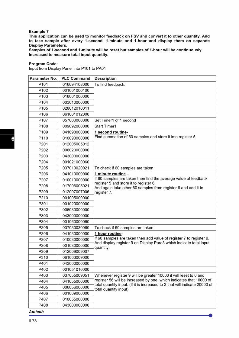
Amtech 6.78
1
2
3
4
5
6
7
8
9
10
11
12
13
A
Example 7 This application can be used to monitor feedback on FSV and convert it to other quantity. And to take sample after every 1-second, 1-minute and 1-hour and display them on separate Display Parameters. Samples of 1-second and 1-minute will be reset but samples of 1-hour will be continuously Increased to measure total input quantity.
Program Code: Input from Display Panel into P101 to PA01
Parameter No. PLC Command Description
P101 016094108000 To find feedback.
P102 001001000100
P103 018001000000
P104 003010000000
P105 028012010011
P106 061001012000
P107 057000000000 Set Timer1 of 1 second
P108 009092000000 Start Timer1
P109 041093000000 1 second routine- Find summation of 60 samples and store it into register 5 P110 010093000000
P201 012005005012
P202 006020000000
P203 043000000000
P204 001021000060
P205 037010020021 To check if 60 samples are taken
P206 041010000000 1 minute routine –
If 60 samples are taken then find the average value of feedback register 5 and store it to register 6. And again take other 60 samples from register 6 and add it to register 7.
P207 010010000000
P208 017006005021
P209 012007007006
P210 001005000000
P301 001020000000
P302 006030000000
P303 043000000000
P304 001060000060
P305 037030030060 To check if 60 samples are taken
P306 041030000000 1 hour routine- If 60 samples are taken then add value of register 7 to register 9. And display register 9 on Display Para3 which indicate total input quantity.
P307 010030000000
P308 001030000000
P309 012009009007
P310 061003009000
P401 043000000000
P402 001051010000
P403 037055009051 Whenever register 9 will be greater 10000 it will reset to 0 and register 56 will be increased by one, which indicates that 10000 of total quantity input. (If it is increased to 2 that will indicate 20000 of total quantity input)
P404 041055000000
P405 006056000000
P406 001009000000
P407 010055000000
P408 043000000000
Axpert-Opti torque Electronic Soft Starter
6.79
1
2
3
4
5
6
7
8
9
10
11
12
13
A
P409 047025001000 If PSI is given then it will reset all Registers and total quantity input.
P410 041025000000
P501 001005000000
P502 001020000000
P503 001007000000
P504 001006000000
P505 001009000000
P506 001056000000
P507 00103000000
P508 061003009000
P509 061005056000
P510 043000000000
P601 061002007000 To Display values of registers.
P602 061004009000
P603 061005056000
P604 061006020000
P605 061007030000
P606 000000000000 End of program
User has to set following parameter.
1. Enable PLC function from B407. 2. Register 94 contains FSV input, which is read only memory location. 3. Register 108 contains value of Panel Para8 (C508) which is used for multiplication factor,
and that should be change as per input quantity range. 4. Select 17 no. Selectable option in C101. 5. C501 = 10 and C502 = 100. (10*100 = 1000 count for Timer1)
Note: There is only one 32-bit memory location is given.
During 32-bit load and store commands user should use only 0 to 84 16-bit memory locations.
Example 8 This application is to demonstrate Low Pass filter command. Program Code: Input from Display Panel into P101 to PA01
Parameter No. PLC Command Description
P101 063001094030 Input is Register 94(FSV) and Time constant is 030. LPF output will be in Register 1.
P102 061001001000 Output is displayed on Display Para1.
P103 000000000000 End of program
User has to set following parameter.
1. Enable PLC function from B407. 2. Register 94 contains FSV input, which is read only memory location.

Amtech 6.80
1
2
3
4
5
6
7
8
9
10
11
12
13
A
This page is intentionally left blank.

Axpert-Opti torque Electronic Soft Starter
7.1
1
2
3
4
5
6
7
8
9
10
11
12
13
A
CHAPTER- 7: ELECTRONICS CIRCUIT BOARDS
Axpert-Opti torque Electronics Soft Starter has following electronics circuit boards.
7.1 Main control board PCA-2005B
The Control Board PCA-2005B is a multipurpose board and specifically designed to meet the high-end performance of the power electronics products like Soft Starter, AC Power Controller, and Controlled Rectifier etc… It uses 32-bit High-Performance Digital Signal Processor TMS320F2811. The control board
generates the necessary Gate pulses for Soft Starter operation. It accepts various inputs from different circuits and Digital Operation Panel (LCD Keypad Module) to generate the necessary control and gate signals. The TMS320F2811 (U1) is the heart of this board. It handles the user interfaces, core algorithm and generates Thyristor gate signals. The PCA-2005B is connected to PCA-2012, 80 - Character, 4- Line LCD Display Card with RS-485 link. PCA-2012 displays various parameters of the Soft Starter.
7.2 Digital operation panel
The unit is equipped with Digital Operation Panel (LCD Keypad Module) for the user interface. All parameters of Soft Starter can be accessed from Digital Operation Panel. The Digital Operation Panel consists of Display Board and 8-keys keypad. The display board uses 80 - Character, 4- Line Liquid Crystal Display (LCD). It has 32-bit LPC2368 ARM controller. It interfaced with main control board PCA-2005B, this becomes master and the main control boards works as slave. The master and slave communication is based on RS-485 (Modbus-RTU Protocol).
7.3 Power supply unit
This unit provides the power to all boards in the Soft Starter. The input to the power supply board is 115/230Vac. The different outputs of the power supply board are +15V/2.2A, -15V/0.5A, +5V/1A and +24V/0.5A.
7.4 RC snubber board PCA-82
This is Snubber board for the thyristor. It is a combination of R and C connected across each thyristor to protect the thyristor against the voltage transients.
7.5 MOV board PCA-77
This is connected at the input of the unit. It protects the unit against the surge / voltage transients coming in the power lines.

Amtech 7.2
1
2
3
4
5
6
7
8
9
10
11
12
13
A
This page is intentionally left blank
Axpert-Opti torque Electronic Soft Starter
8.1
1
2
3
4
5
6
7
8
9
10
11
12
13
A
CHAPTER- 8: MAINTENANCE, INSPECTION AND PART REPLACEMENT
DANGER
Maintenance, inspections and part replacement must be done by a designated person.
(Remove all metal accessories such as watches, bracelets, etc., before starting the work.)
(Always use an insulation measure tool.)
Failure to observe this could lead to electric shocks and injuries.
Always turn the power OFF before inspecting the motor or machine. A potential is applied on the motor terminal even when the motor is stopped.
Failure to do so could lead to electric shocks and injuries.
Do not use parts other than those designated for the replacement parts.
Contact your dealer for replacement parts.
Failure to observe this could lead to fires.
Never modify the product.
Failure to observe this could lead to electric shocks or injuries or product failure.
CAUTION
Vacuum the unit with a vacuum cleaner to clean it. Do not use water or organic solvents.
Failure to observe this could lead to fires or damage.
Do not megger the unit.
Failure to observe this could lead to damage to semiconductor devices.
8.1 Inspection items
The inspections must be carried out periodically according to the working environment and frequency of use. If there are any abnormalities, the cause must be inspected immediately and countermeasures taken.
Daily inspections
Table 8-1-1
Inspection item Inspection details and work
Temperature/humidity Confirm that the ambient temperature is –10 to 50°C, and that the humidity is 95% or less with no dew condensation.
Oil mist and dust Confirm that there is no oil mist or dust in the unit.
Abnormal noise and vibration
Confirm that there is no abnormal noise or vibration from the installation site or unit.
Input power source Confirm that the input voltage and frequency are within the specifications range.
Cooling fan Confirm that the cooling fan rotates normally and that no lint, etc. is stuck on it.
Indicator Confirm that all lamps on the operation panel light properly.
Amtech 8.2
1
2
3
4
5
6
7
8
9
10
11
12
13
A
Periodic Inspections
Table 8-1-2
Inspection item Inspection details and work
Appearance Check the state of dirt and dust on the vent or heat sink, and clean if necessary.
Interior Check the state of dirt and dust on the PCB and inside the equipment, and clean if necessary.
Terminal block Tighten the terminal block screws if loose.
Cooling fan Replace the fan every three years.
Insulation resistance inspection
Do not perform a megger test on the unit. When doing a megger test on the external circuit, disconnect all wires connected to the unit.
Inspection of spares
The inspection shown in above table must also be performed for spare unit that are left connected but are not used in normal operation. The operation of the unit must be checked every six months by turning the power on.
8.2 Measuring devices
As the voltage and current on the input and output sides include high harmonics, the measured value will differ according to the measuring device. When measuring with a device for commercial frequencies, measure with the following circuits and noted measuring devices.
Input voltage: Moving iron type voltmeter
Output voltage: Rectifying voltmeter
Input / output power: Electrodynamometer type wattmeter.
Axpert-Opti torque Electronic Soft Starter
9.1
1
2
3
4
5
6
7
8
9
10
11
12
13
A
CHAPTER- 9: OPTIONS
Besides the standard features available in the Axpert-Opti torque Electronic Soft Starter, which satisfies most of the industrial applications, AMTECH offers its users a spectrum of optional products designed to match their requirement. The list of optional products offered by AMTECH herewith is all developed, field tested and
commissioned at various locations in India. A brief description of the option is given. Contact AMTECH with relevant data to design one for you.
9.1 Metering
At times there may be need of monitoring the internal unit data. Optional analog or digital metering of unit operating data like various voltages, currents etc can be provided in the panel. For the unit data, which can be monitored, and the extra hardware, contacts AMTECH for details.
9.2 Enclosure
Some applications may demand enclosures, which suit the environment where the unit is to be installed. Protection against water or ingress or against some harmful ambient gas can be provided within the scope of the manufacturer. The enclosure can be modified for required degree of protection like IP54/ 55. Occasionally the shape and size of the enclosure can also be discussed for incorporating the unit in some other predefined structure. Contact AMTECH for details on Enclosure options.
9.3 Remote operator box
Remote box for operation from near the actual driven motor site can be provided for the user with optional controls and displays. We remind you here that our standard keypad control box can be taken up to 1000 feet without any problem. Contact AMTECH for details on Remote Operator Box.
9.4 Bypass operation
Some applications demand the soft starter with bypass option. All the protective feature and current monitoring functions are provided in Bypass mode. Wiring connection for the Bypass contactor is shown in Fig. 10.1.1, chapter 10. Programmable sequence output, Top of Ramp output is used to control the bypass operation. Contacts AMTECH for details.

Amtech 9.2
1
2
3
4
5
6
7
8
9
10
11
12
13
A
This page is intentionally left blank
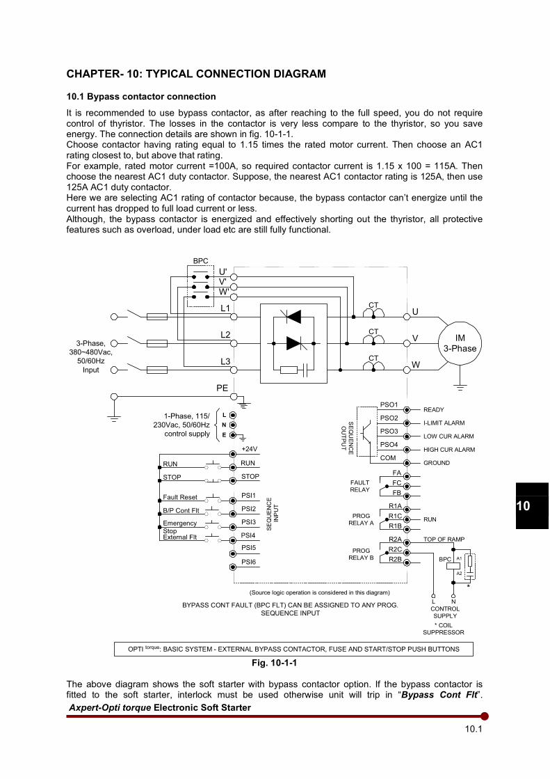
Axpert-Opti torque Electronic Soft Starter
10.1
1
2
3
4
5
6
7
8
9
10
11
12
13
A
CHAPTER- 10: TYPICAL CONNECTION DIAGRAM
10.1 Bypass contactor connection
It is recommended to use bypass contactor, as after reaching to the full speed, you do not require control of thyristor. The losses in the contactor is very less compare to the thyristor, so you save energy. The connection details are shown in fig. 10-1-1. Choose contactor having rating equal to 1.15 times the rated motor current. Then choose an AC1 rating closest to, but above that rating. For example, rated motor current =100A, so required contactor current is 1.15 x 100 = 115A. Then choose the nearest AC1 duty contactor. Suppose, the nearest AC1 contactor rating is 125A, then use 125A AC1 duty contactor. Here we are selecting AC1 rating of contactor because, the bypass contactor can’t energize until the current has dropped to full load current or less. Although, the bypass contactor is energized and effectively shorting out the thyristor, all protective features such as overload, under load etc are still fully functional.
IM
3-Phase
L1
L2
L3
PE
3-Phase,
380~480Vac,
50/60Hz
Input
U
V
W
U'V'W'
CT
CT
CT
FA
FC
FB
R1A
R1C
R1B
A1
A2
L N
BPC
R2A
R2C
R2B
SEQUENCE
INPUT
FAULT
RELAY
PROG
RELAY A
PROG
RELAY B
TOP OF RAMP
CONTROL
SUPPLY
* COIL
SUPPRESSOR
OPTI torque: BASIC SYSTEM - EXTERNAL BYPASS CONTACTOR, FUSE AND START/STOP PUSH BUTTONS
BYPASS CONT FAULT (BPC FLT) CAN BE ASSIGNED TO ANY PROG.
SEQUENCE INPUT
(Source logic operation is considered in this diagram)
+24V
RUN
STOP
PSI1
PSI2
PSI4
PSI3
PSI5
PSI6
B/P Cont Flt
READY
PSO2
PSO3
PSO1
PSO4
SEQUENCE
OUTPUT
GROUNDCOM
*
Fault Reset
Emergency
StopExternal Flt
I-LIMIT ALARM
LOW CUR ALARM
HIGH CUR ALARM
RUN
STOP
BPC
RUN
E
N
L1-Phase, 115/
230Vac, 50/60Hz
control supply
Fig. 10-1-1
The above diagram shows the soft starter with bypass contactor option. If the bypass contactor is fitted to the soft starter, interlock must be used otherwise unit will trip in “Bypass Cont Flt”.
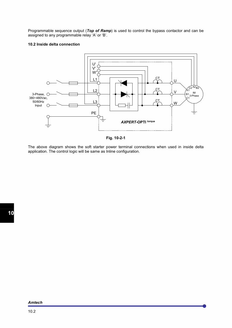
Amtech 10.2
1
2
3
4
5
6
7
8
9
10
11
12
13
A
Programmable sequence output (Top of Ramp) is used to control the bypass contactor and can be assigned to any programmable relay ‘A’ or ‘B’.
10.2 Inside delta connection
IM
3-Phase
L1
L2
L3
PE
3-Phase,
380~480Vac,
50/60Hz
Input
U
V
W
U'V'W'
CT
CT
CT
AXPERT-OPTI torque
C2 A2B2A1
B1
C1
Fig. 10-2-1 The above diagram shows the soft starter power terminal connections when used in inside delta application. The control logic will be same as Inline configuration.
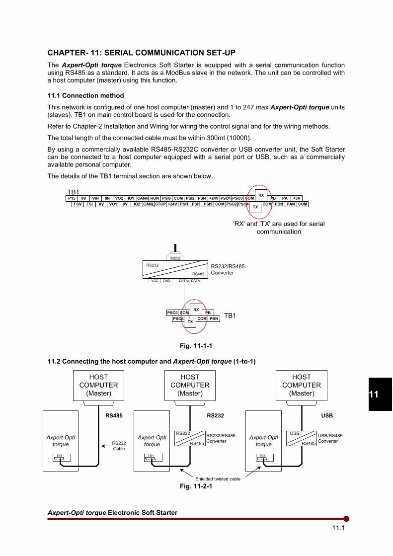
Axpert-Opti torque Electronic Soft Starter
11.1
1
2
3
4
5
6
7
8
9
10
11
12
13
A
CHAPTER- 11: SERIAL COMMUNICATION SET-UP
The Axpert-Opti torque Electronics Soft Starter is equipped with a serial communication function
using RS485 as a standard. It acts as a ModBus slave in the network. The unit can be controlled with a host computer (master) using this function.
11.1 Connection method
This network is configured of one host computer (master) and 1 to 247 max Axpert-Opti torque units (slaves). TB1 on main control board is used for the connection.
Refer to Chapter-2 Installation and Wiring for wiring the control signal and for the wiring methods.
The total length of the connected cable must be within 300mt (1000ft).
By using a commercially available RS485-RS232C converter or USB converter unit, the Soft Starter can be connected to a host computer equipped with a serial port or USB, such as a commercially available personal computer.
The details of the TB1 terminal section are shown below.
Fig. 11-1-1
11.2 Connecting the host computer and Axpert-Opti torque (1-to-1)
Fig. 11-2-1
RS232
RS485
DATA+ DATA-
RS232
VCC GND
PSO3 COMRX
PB
PSO4TX
COM PBNTB1
RS232/RS485
Converter
P15 0V VIN IIN VO2 IO1 CANH RUN PSI6 COM PSI2 PSI4 +24V PSO1 PSO3 COMRX
PB PA +5V
FSV FSI 0V VO1 0V IO2 CANL STOP +24V PSI1 PSI3 PSI5 COM PSO2 PSO4TX
COM PBN PAN COM
TB1
'RX' and 'TX' are used for serial
communication
HOST
COMPUTER
(Master)
Axpert-Opti
torque
TB1
RS232
RS485
RS232RS232/RS485
Converter
HOST
COMPUTER
(Master)
Axpert-Opti
torque
TB1
RS485
HOST
COMPUTER
(Master)
Axpert-Opti
torque
TB1
USB
RS485
USBUSB/RS485
Converter
Shielded twisted cable
RS232
Cable
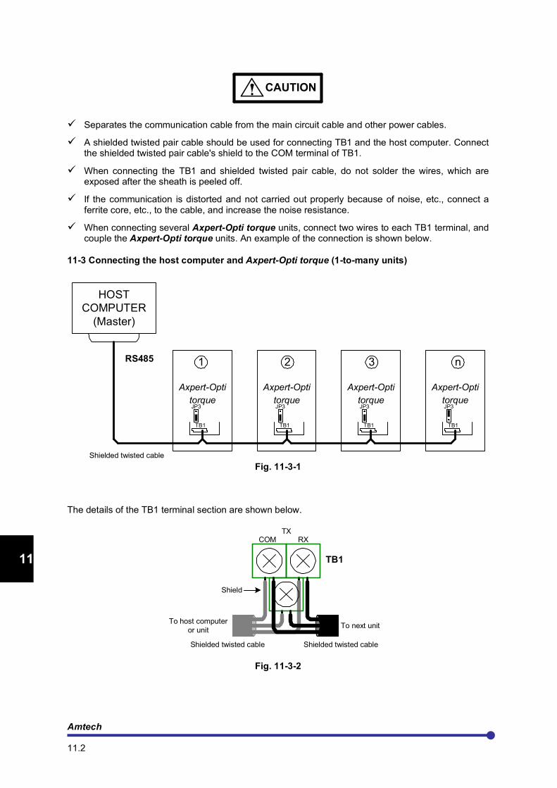
Amtech 11.2
1
2
3
4
5
6
7
8
9
10
11
12
13
A
CAUTION
Separates the communication cable from the main circuit cable and other power cables.
A shielded twisted pair cable should be used for connecting TB1 and the host computer. Connect the shielded twisted pair cable's shield to the COM terminal of TB1.
When connecting the TB1 and shielded twisted pair cable, do not solder the wires, which are exposed after the sheath is peeled off.
If the communication is distorted and not carried out properly because of noise, etc., connect a ferrite core, etc., to the cable, and increase the noise resistance.
When connecting several Axpert-Opti torque units, connect two wires to each TB1 terminal, and couple the Axpert-Opti torque units. An example of the connection is shown below.
11-3 Connecting the host computer and Axpert-Opti torque (1-to-many units)
Fig. 11-3-1 The details of the TB1 terminal section are shown below.
Fig. 11-3-2
Axpert-Opti
torque
HOST
COMPUTER
(Master)
RS485
Axpert-Opti
torque
Axpert-Opti
torque
Axpert-Opti
torque
TB1 TB1TB1TB1
JP3 JP3 JP3JP3
Shielded twisted cable
21 3 n
TB1
RXCOMTX
To host computer
or unit
Shielded twisted cable
To next unit
Shielded twisted cable
Shield
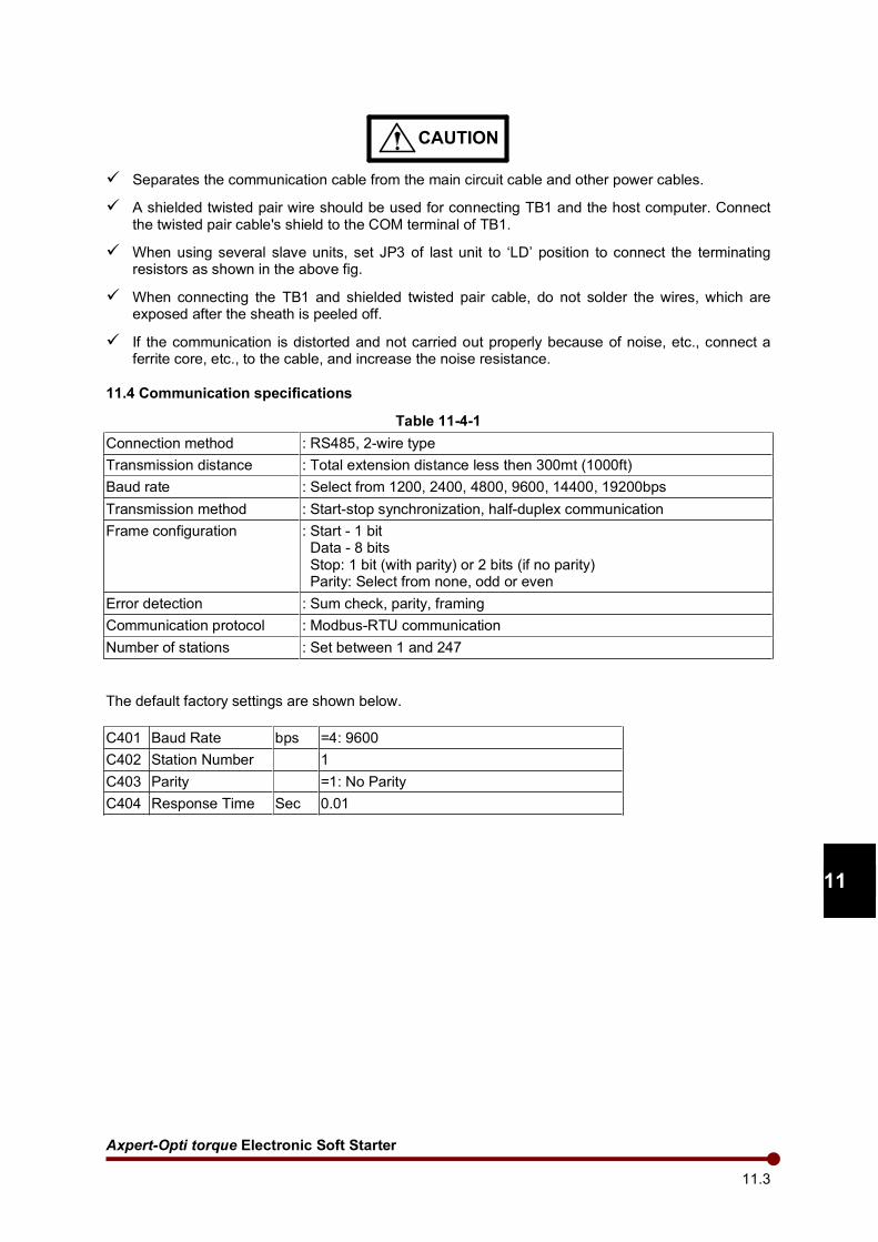
Axpert-Opti torque Electronic Soft Starter
11.3
1
2
3
4
5
6
7
8
9
10
11
12
13
A
CAUTION
Separates the communication cable from the main circuit cable and other power cables.
A shielded twisted pair wire should be used for connecting TB1 and the host computer. Connect the twisted pair cable's shield to the COM terminal of TB1.
When using several slave units, set JP3 of last unit to ‘LD’ position to connect the terminating resistors as shown in the above fig.
When connecting the TB1 and shielded twisted pair cable, do not solder the wires, which are exposed after the sheath is peeled off.
If the communication is distorted and not carried out properly because of noise, etc., connect a ferrite core, etc., to the cable, and increase the noise resistance.
11.4 Communication specifications
Table 11-4-1
Connection method : RS485, 2-wire type
Transmission distance : Total extension distance less then 300mt (1000ft)
Baud rate : Select from 1200, 2400, 4800, 9600, 14400, 19200bps
Transmission method : Start-stop synchronization, half-duplex communication
Frame configuration : Start - 1 bit Data - 8 bits Stop: 1 bit (with parity) or 2 bits (if no parity) Parity: Select from none, odd or even
Error detection : Sum check, parity, framing
Communication protocol : Modbus-RTU communication
Number of stations : Set between 1 and 247
The default factory settings are shown below.
C401 Baud Rate bps =4: 9600
C402 Station Number 1
C403 Parity =1: No Parity
C404 Response Time Sec 0.01

Amtech 11.4
1
2
3
4
5
6
7
8
9
10
11
12
13
A
This page is intentionally left blank

Axpert-Opti torque Electronic Soft Starter
12.1
1
2
3
4
5
6
7
8
9
10
11
12
13
A
CHAPTER- 12: UL INSTRUCTIONS
The Axpert-Opti torque Series Electronics Soft-Starter AMT-OT-037-4-1 to AMT-OT-630-4-1 complies with UL508 and CSA C22.2 No.14. The UL and cUL marks are indicated on the rating nameplate for UL compliant parts.
Observe the following matters when using the soft-starter as an UL/cUL Standard compatible product. (1) Use the soft-starter in an installation environment, where maximum surrounding air temperature
does not exceed 50 Degree C. (2) For the main circuit connected to the soft-starter, use a "75°C CU" "voltage rating 600V or higher"
copper wire. (3) Use the wire sizes given in Table 2-3-1 for the main circuit wiring. Use a UL/CSA Listed round
crimp terminal, which matches the wire diameter for the terminal connection. Crimp the crimp terminal with a crimping tool recommended by the maker.
(4) When wiring the circuit, tighten with the torque given in Table 2-3-1. (5) Always provide a UL Certified fuse on the input side of the soft-starter. When protected by Class
fuse as indicated below, these devices have the following short circuit rating. Table 12-1
Model AMT-OT-xxx-4-1
Fuse Rating (A rms) Fuse Class Short circuit current (A)
037 100A, 600VAC Class RK5 5000
045 100A, 600VAC Class RK5 10000
055 150A, 600VAC Class RK5 10000
075 150A, 600VAC Class RK5 10000
090 200A, 600VAC Class RK5 10000
110 300A, 600VAC Class RK5 10000
132 300A, 600VAC Class RK5 10000
160 400A, 600VAC Class RK5 18000
200 400A, 600VAC Class RK5 18000
250 600A, 600VAC Class RK5 18000
315 600A, 600VAC Class RK5 30000
400 800A, 600VAC Class L 30000
450 1000A, 600VAC Class L 30000

Amtech 12.2
1
2
3
4
5
6
7
8
9
10
11
12
13
A
500 1200A, 600VAC Class L 42000
585 1200A, 600VAC Class L 42000
630 1200A, 600VAC Class L 42000
(6) Install the soft-starter as “open type equipment". (7) The installation environment must satisfy "pollution degree 2". (8) The soft-starter has a motor overload protection function. Refer to Chapter 6, and set parameters B301 to B307 correctly. (9) Integral solid-state short circuit protection does not provide branch circuit protection. Branch circuit
protection must be provided in accordance with the National Electric Code and any additional local codes or equivalent.
Axpert-Opti torque Electronic Soft Starter
13.1
13
CHAPTER- 13: CE Marking
The Axpert-Opti torque Series Electronics Soft Starter complies with the EMC directives and Low Voltage directives. Observe the following matters when using the soft starter as an EMC directive compliant product. This Instruction details how to meet the EMC directives (89/336/EEC) with Opti-Torque and it is important to understand before installation and operation of soft starter. The soft starter is designed to meet the EMC directives and is suitable for use in the Industrial Environments. These soft starters have been tested with the power cables and control leads connected as shown in fig. 13-3-1. If these soft starters are connected with fewer control leads than those specified in fig 13-3-1, it may be possible to reduce installation costs by using ordinary cables rather than screened cables which are recommend in this manual. It is strongly advised however that a compliance test should be performed under the actual operating conditions to certify that the system complies with the relevant EMC requirements. If the soft starters are used with any of the optional cards, in such cases suitable extra measures must be provided and must certify through a test that the product, system or installation complies with the relevant EMC requirements.
WARNING
This manual represents Amtech's recommendations based on its understanding of the EMC regulations only and Amtech cannot accept responsibility for any legal problems arising from or in connection with the use of its products.
Amtech have made every effort to ensure that their products comply with the directives laid out in the certificate of conformity, which is supplied with each soft starter.
The EMC directives set out immunity requirements for the electrical soft starter (ability to work properly without being affected by external electromagnetic disturbance), in addition to the previously enforced emission requirements (electromagnetic disturbance generated by the electrical soft starter). In addition to the radiated noise directly generated from the soft starter and its connected cables, the emission requirement includes the conducted noise, which is conducted outside the soft starter through the input cables. Immunity is the ability of a soft starter to operate properly without being affected by an external disturbance. The EMC compliance is only achieved when the immunity level of soft starter exceeds its emission level under its operating environment. In addition to the immunity against a radiated and conducted disturbance, the EMC directives also require of the soft starter the immunity against static electricity discharges and fast transients.
CAUTION
A human body can easily be charged with static electricity by merely walking on carpet and with a mere touch on the soft starter, this static electricity will be discharged through it. A discharging spark can be at such a magnitude that it can damage the soft starter.
A soft starter which is installed near cables connected to a switching inductive load can often operate incorrectly due to a fast transient induced on its control leads at a switching of the inductive load.
Amtech 13.2
1
2
3
4
5
6
7
8
9
10
11
12
13
A
These are just a few examples of disturbance to which the soft starter is exposed and the soft starter is now required to operate correctly without being affected by such disturbance.
13-1 Installation environments
The Axpert-Opti torque conforms to the EN 60947-4-2: 2000 + A2:2006 With stand-alone installation of Axpert-Opti torque, it is recommended to ensure that no device or equipment is installed adjacent to the soft starter that is intended for the Residential, Commercial and Light Industrial Environments only, as interference with such equipment may occur.
13-2 Wiring & Earthing
Select the input cables from those specified in the manual.
The output cable from the soft starter must be screened or armored and the screen or armor must be connected to the earth as shown in fig. 13-3-1.
Ensure that the input and output cable are not installed in parallel to each other. Keep them apart from each other by at least 0.5 meter (20”).
Ensure that the screen of the output cable is earthed at both ends with one end connected to the earth terminal of soft starter and the other end to the motor earth.
Arrange the termination at the soft starter end inside the enclosure. If it is not possible to terminate the cables inside the enclosure then terminate them as closely to the conduit hole of soft starter as possible (preferably within 0.1 meter (4”)).
Use a 0.13mm2 (AWG 26) to 0.8mm² (AWG 18) wire for wiring to the control circuit and should be
screened if they are used for a speed setting circuitry, analogue signal circuitry for metering, or relay signal circuitry. The screen should be connected to the earth terminal of soft starter or COM terminal only (refer to Fig. 13-3-1).
Control cables should be selected in accordance with the instructions in the manual of soft starter. The control leads should be wired away from the power cables. If it is not possible, cross them at the right angle, and if they are laid down alongside each other, ensure to separate them by at least 0.5 meter (20”).
When the section, which runs along the power cables, exceeds 10 meter (33.3’), separate them further more. The control cables should not share the same conduit hole of the soft starter with the power cables. Separate analogue control leads from relay control leads.
To reduce emission and to increase immunity, ensure that no control cables are connected that is not used. Also, wire them in such manner that they are as short as possible.
Put the relay signal controller and analog speed-setting controller, analog signal meters in a metal box.
Keep the earthing cable of soft starter and motor as short as possible and is installed in accordance with the local requirements. Use low impedance earthing cables.
If the motor does not share the same earth post with the soft starter, do not connect the screen / earth cable of the soft starter’s output cable to the motor.
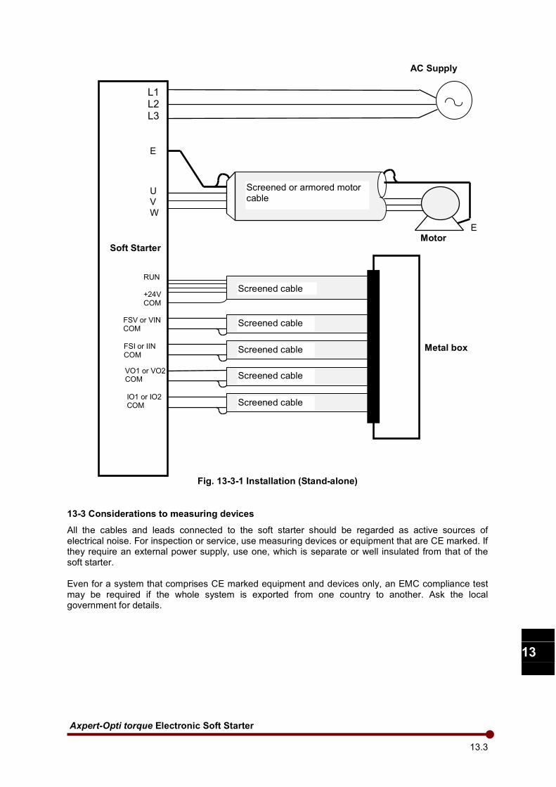
Axpert-Opti torque Electronic Soft Starter
13.3
13
Fig. 13-3-1 Installation (Stand-alone)
13-3 Considerations to measuring devices
All the cables and leads connected to the soft starter should be regarded as active sources of electrical noise. For inspection or service, use measuring devices or equipment that are CE marked. If they require an external power supply, use one, which is separate or well insulated from that of the soft starter. Even for a system that comprises CE marked equipment and devices only, an EMC compliance test may be required if the whole system is exported from one country to another. Ask the local government for details.
L1 L2 L3
E
AC Supply
Soft Starter
U V
W
Screened or armored motor cable
E Motor
Screened cable
RUN +24V COM
Screened cable FSV or VIN COM
Screened cable
Screened cable
Screened cable
FSI or IIN COM
VO1 or VO2 COM
IO1 or IO2 COM
Metal box
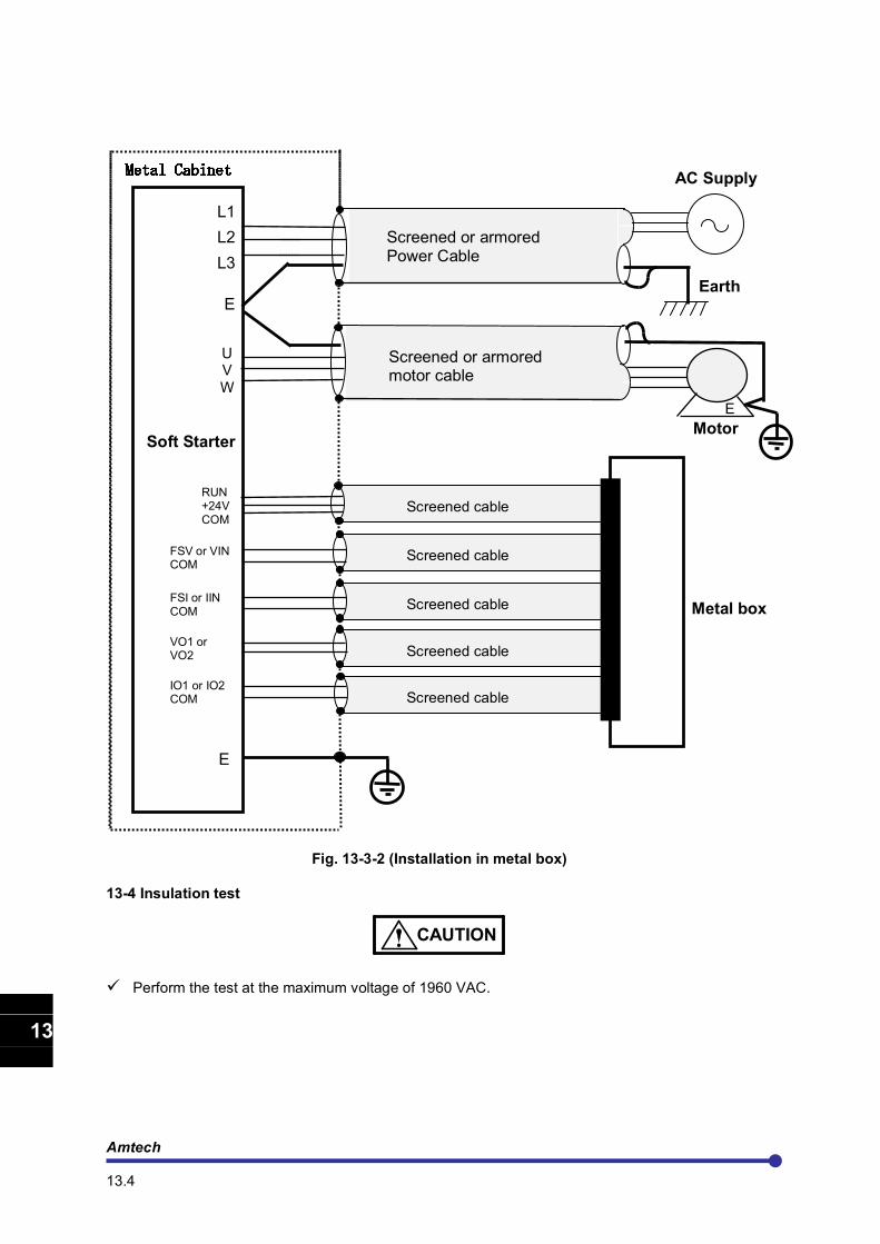
Amtech 13.4
1
2
3
4
5
6
7
8
9
10
11
12
13
A
Fig. 13-3-2 (Installation in metal box)
13-4 Insulation test
CAUTION
Perform the test at the maximum voltage of 1960 VAC.
Screened cable
Screened cable
Screened cable
Screened cable
L1
L2
L3
E
AC Supply
Soft Starter
U V
W
Screened or armored motor cable
E
Motor
Screened cable RUN +24V COM
FSV or VIN COM
Metal box
Earth
Screened or armored Power Cable
E
FSI or IIN COM
VO1 or VO2 COM IO1 or IO2 COM
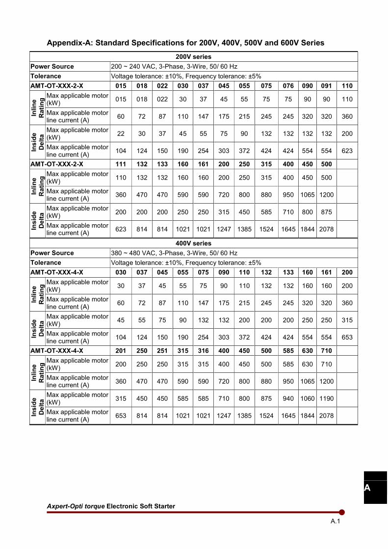
Axpert-Opti torque Electronic Soft Starter
A.1
A
Appendix-A: Standard Specifications for 200V, 400V, 500V and 600V Series
200V series
Power Source 200 ~ 240 VAC, 3-Phase, 3-Wire, 50/ 60 Hz
Tolerance Voltage tolerance: ±10%, Frequency tolerance: ±5%
AMT-OT-XXX-2-X 015 018 022 030 037 045 055 075 076 090 091 110
Inline
Rating Max applicable motor
(kW) 015 018 022 30 37 45 55 75 75 90 90 110
Max applicable motor line current (A)
60 72 87 110 147 175 215 245 245 320 320 360
Inside
Delta Max applicable motor
(kW) 22 30 37 45 55 75 90 132 132 132 132 200
Max applicable motor line current (A)
104 124 150 190 254 303 372 424 424 554 554 623
AMT-OT-XXX-2-X 111 132 133 160 161 200 250 315 400 450 500
Inline
Rating Max applicable motor
(kW) 110 132 132 160 160 200 250 315 400 450 500
Max applicable motor line current (A)
360 470 470 590 590 720 800 880 950 1065 1200
Inside
Delta Max applicable motor
(kW) 200 200 200 250 250 315 450 585 710 800 875
Max applicable motor line current (A)
623 814 814 1021 1021 1247 1385 1524 1645 1844 2078
400V series
Power Source 380 ~ 480 VAC, 3-Phase, 3-Wire, 50/ 60 Hz
Tolerance Voltage tolerance: ±10%, Frequency tolerance: ±5%
AMT-OT-XXX-4-X 030 037 045 055 075 090 110 132 133 160 161 200
Inline
Rating Max applicable motor
(kW) 30 37 45 55 75 90 110 132 132 160 160 200
Max applicable motor line current (A)
60 72 87 110 147 175 215 245 245 320 320 360
Inside
Delta Max applicable motor
(kW) 45 55 75 90 132 132 200 200 200 250 250 315
Max applicable motor line current (A)
104 124 150 190 254 303 372 424 424 554 554 653
AMT-OT-XXX-4-X 201 250 251 315 316 400 450 500 585 630 710
Inline
Rating Max applicable motor
(kW) 200 250 250 315 315 400 450 500 585 630 710
Max applicable motor line current (A)
360 470 470 590 590 720 800 880 950 1065 1200
Inside
Delta Max applicable motor
(kW) 315 450 450 585 585 710 800 875 940 1060 1190
Max applicable motor line current (A)
653 814 814 1021 1021 1247 1385 1524 1645 1844 2078
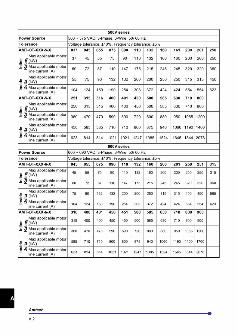
Amtech A.2
1
2
3
4
5
6
7
8
9
10
11
12
13
A
500V series
Power Source 500 ~ 575 VAC, 3-Phase, 3-Wire, 50/ 60 Hz
Tolerance Voltage tolerance: ±10%, Frequency tolerance: ±5%
AMT-OT-XXX-5-X 037 045 055 075 090 110 132 160 161 200 201 250
Inline
Rating Max applicable motor
(kW) 37 45 55 75 90 110 132 160 160 200 200 250
Max applicable motor line current (A)
60 72 87 110 147 175 215 245 245 320 320 360
Inside
Delta Max applicable motor
(kW) 55 75 90 132 132 200 200 250 250 315 315 450
Max applicable motor line current (A)
104 124 150 190 254 303 372 424 424 554 554 623
AMT-OT-XXX-5-X 251 315 316 400 401 450 500 585 630 710 800
Inline
Rating Max applicable motor
(kW) 250 315 315 400 400 450 500 585 630 710 800
Max applicable motor line current (A)
360 470 470 590 590 720 800 880 950 1065 1200
Inside
Delta Max applicable motor
(kW) 450 585 585 710 710 800 875 940 1060 1190 1400
Max applicable motor line current (A)
623 814 814 1021 1021 1247 1385 1524 1645 1844 2078
600V series
Power Source 600 ~ 690 VAC, 3-Phase, 3-Wire, 50/ 60 Hz
Tolerance Voltage tolerance: ±10%, Frequency tolerance: ±5%
AMT-OT-XXX-6-X 045 055 075 090 110 132 160 200 201 250 251 315
Inline
Rating Max applicable motor
(kW) 45 55 75 90 110 132 160 200 200 250 250 315
Max applicable motor line current (A)
60 72 87 110 147 175 215 245 245 320 320 360
Inside
Delta Max applicable motor
(kW) 75 90 132 132 200 200 250 315 315 450 450 585
Max applicable motor line current (A)
104 124 150 190 254 303 372 424 424 554 554 623
AMT-OT-XXX-6-X 316 400 401 450 451 500 585 630 710 800 900
Inline
Rating Max applicable motor
(kW) 315 400 400 450 450 500 585 630 710 800 900
Max applicable motor line current (A)
360 470 470 590 590 720 800 880 950 1065 1200
Inside
Delta Max applicable motor
(kW) 585 710 710 800 800 875 940 1060 1190 1400 1700
Max applicable motor line current (A)
623 814 814 1021 1021 1247 1385 1524 1645 1844 2078
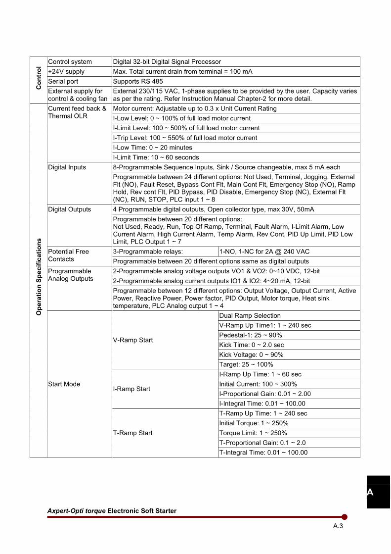
Axpert-Opti torque Electronic Soft Starter
A.3
A
Control
Control system Digital 32-bit Digital Signal Processor
+24V supply Max. Total current drain from terminal = 100 mA
Serial port Supports RS 485
External supply for control & cooling fan
External 230/115 VAC, 1-phase supplies to be provided by the user. Capacity varies as per the rating. Refer Instruction Manual Chapter-2 for more detail.
Operation Specifications
Current feed back & Thermal OLR
Motor current: Adjustable up to 0.3 x Unit Current Rating
I-Low Level: 0 ~ 100% of full load motor current
I-Limit Level: 100 ~ 500% of full load motor current
I-Trip Level: 100 ~ 550% of full load motor current
I-Low Time: 0 ~ 20 minutes
I-Limit Time: 10 ~ 60 seconds
Digital Inputs 8-Programmable Sequence Inputs, Sink / Source changeable, max 5 mA each
Programmable between 24 different options: Not Used, Terminal, Jogging, External Flt (NO), Fault Reset, Bypass Cont Flt, Main Cont Flt, Emergency Stop (NO), Ramp Hold, Rev cont Flt, PID Bypass, PID Disable, Emergency Stop (NC), External Flt (NC), RUN, STOP, PLC input 1 ~ 8
Digital Outputs 4 Programmable digital outputs, Open collector type, max 30V, 50mA
Programmable between 20 different options: Not Used, Ready, Run, Top Of Ramp, Terminal, Fault Alarm, I-Limit Alarm, Low Current Alarm, High Current Alarm, Temp Alarm, Rev Cont, PID Up Limit, PID Low Limit, PLC Output 1 ~ 7
Potential Free Contacts
3-Programmable relays: 1-NO, 1-NC for 2A @ 240 VAC
Programmable between 20 different options same as digital outputs
Programmable Analog Outputs
2-Programmable analog voltage outputs VO1 & VO2: 0~10 VDC, 12-bit
2-Programmable analog current outputs IO1 & IO2: 4~20 mA, 12-bit
Programmable between 12 different options: Output Voltage, Output Current, Active Power, Reactive Power, Power factor, PID Output, Motor torque, Heat sink temperature, PLC Analog output 1 ~ 4
Start Mode
V-Ramp Start
Dual Ramp Selection
V-Ramp Up Time1: 1 ~ 240 sec
Pedestal-1: 25 ~ 90%
Kick Time: 0 ~ 2.0 sec
Kick Voltage: 0 ~ 90%
Target: 25 ~ 100%
I-Ramp Start
I-Ramp Up Time: 1 ~ 60 sec
Initial Current: 100 ~ 300%
I-Proportional Gain: 0.01 ~ 2.00
I-Integral Time: 0.01 ~ 100.00
T-Ramp Start
T-Ramp Up Time: 1 ~ 240 sec
Initial Torque: 1 ~ 250%
Torque Limit: 1 ~ 250%
T-Proportional Gain: 0.1 ~ 2.0
T-Integral Time: 0.01 ~ 100.00
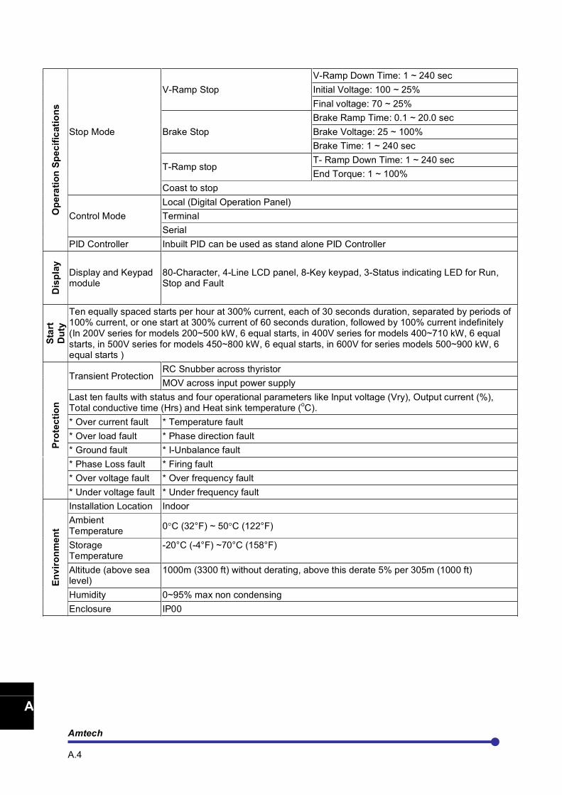
Amtech A.4
1
2
3
4
5
6
7
8
9
10
11
12
13
A
Operation Specifications
Stop Mode
V-Ramp Stop
V-Ramp Down Time: 1 ~ 240 sec
Initial Voltage: 100 ~ 25%
Final voltage: 70 ~ 25%
Brake Stop
Brake Ramp Time: 0.1 ~ 20.0 sec
Brake Voltage: 25 ~ 100%
Brake Time: 1 ~ 240 sec
T-Ramp stop T- Ramp Down Time: 1 ~ 240 sec
End Torque: 1 ~ 100%
Coast to stop
Control Mode
Local (Digital Operation Panel)
Terminal
Serial
PID Controller Inbuilt PID can be used as stand alone PID Controller
Display
Display and Keypad module
80-Character, 4-Line LCD panel, 8-Key keypad, 3-Status indicating LED for Run, Stop and Fault
Start
Duty
Ten equally spaced starts per hour at 300% current, each of 30 seconds duration, separated by periods of 100% current, or one start at 300% current of 60 seconds duration, followed by 100% current indefinitely (In 200V series for models 200~500 kW, 6 equal starts, in 400V series for models 400~710 kW, 6 equal starts, in 500V series for models 450~800 kW, 6 equal starts, in 600V for series models 500~900 kW, 6 equal starts )
Protection
Transient Protection RC Snubber across thyristor
MOV across input power supply
Last ten faults with status and four operational parameters like Input voltage (Vry), Output current (%), Total conductive time (Hrs) and Heat sink temperature (
oC).
* Over current fault * Temperature fault
* Over load fault * Phase direction fault
* Ground fault * I-Unbalance fault
* Phase Loss fault * Firing fault
* Over voltage fault * Over frequency fault
* Under voltage fault * Under frequency fault
Environment
Installation Location Indoor
Ambient Temperature
0°C (32°F) ~ 50°C (122°F)
Storage Temperature
-20°C (-4°F) ~70°C (158°F)
Altitude (above sea level)
1000m (3300 ft) without derating, above this derate 5% per 305m (1000 ft)
Humidity 0~95% max non condensing
Enclosure IP00
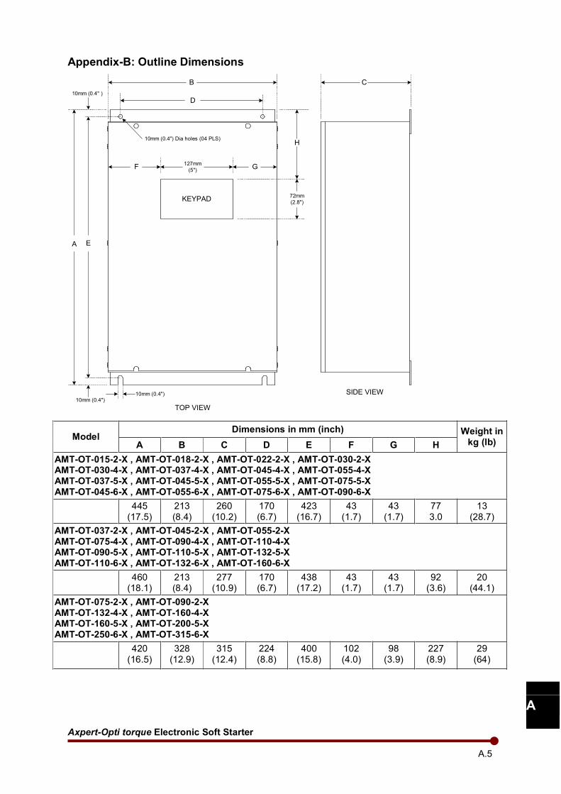
Axpert-Opti torque Electronic Soft Starter
A.5
A
Appendix-B: Outline Dimensions
A
10mm (0.4" )
127mm
(5")
72mm
(2.8")
10mm (0.4") Dia holes (04 PLS)
KEYPAD
F G
D
H
B C
E
10mm (0.4")
TOP VIEW
SIDE VIEW10mm (0.4")
Model Dimensions in mm (inch) Weight in
kg (lb) A B C D E F G H
AMT-OT-015-2-X , AMT-OT-018-2-X , AMT-OT-022-2-X , AMT-OT-030-2-X AMT-OT-030-4-X , AMT-OT-037-4-X , AMT-OT-045-4-X , AMT-OT-055-4-X AMT-OT-037-5-X , AMT-OT-045-5-X , AMT-OT-055-5-X , AMT-OT-075-5-X AMT-OT-045-6-X , AMT-OT-055-6-X , AMT-OT-075-6-X , AMT-OT-090-6-X
445 (17.5)
213 (8.4)
260 (10.2)
170 (6.7)
423 (16.7)
43 (1.7)
43 (1.7)
77 3.0
13 (28.7)
AMT-OT-037-2-X , AMT-OT-045-2-X , AMT-OT-055-2-X AMT-OT-075-4-X , AMT-OT-090-4-X , AMT-OT-110-4-X AMT-OT-090-5-X , AMT-OT-110-5-X , AMT-OT-132-5-X AMT-OT-110-6-X , AMT-OT-132-6-X , AMT-OT-160-6-X
460 (18.1)
213 (8.4)
277 (10.9)
170 (6.7)
438 (17.2)
43 (1.7)
43 (1.7)
92 (3.6)
20 (44.1)
AMT-OT-075-2-X , AMT-OT-090-2-X AMT-OT-132-4-X , AMT-OT-160-4-X AMT-OT-160-5-X , AMT-OT-200-5-X AMT-OT-250-6-X , AMT-OT-315-6-X
420 (16.5)
328 (12.9)
315 (12.4)
224 (8.8)
400 (15.8)
102 (4.0)
98 (3.9)
227 (8.9)
29 (64)
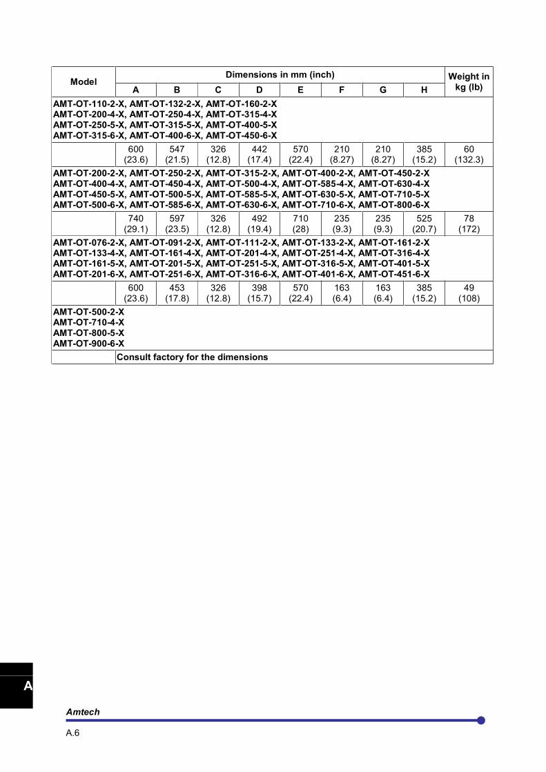
Amtech A.6
1
2
3
4
5
6
7
8
9
10
11
12
13
A
Model Dimensions in mm (inch) Weight in
kg (lb) A B C D E F G H
AMT-OT-110-2-X, AMT-OT-132-2-X, AMT-OT-160-2-X AMT-OT-200-4-X, AMT-OT-250-4-X, AMT-OT-315-4-X AMT-OT-250-5-X, AMT-OT-315-5-X, AMT-OT-400-5-X AMT-OT-315-6-X, AMT-OT-400-6-X, AMT-OT-450-6-X
600 (23.6)
547 (21.5)
326 (12.8)
442 (17.4)
570 (22.4)
210 (8.27)
210 (8.27)
385 (15.2)
60 (132.3)
AMT-OT-200-2-X, AMT-OT-250-2-X, AMT-OT-315-2-X, AMT-OT-400-2-X, AMT-OT-450-2-X AMT-OT-400-4-X, AMT-OT-450-4-X, AMT-OT-500-4-X, AMT-OT-585-4-X, AMT-OT-630-4-X AMT-OT-450-5-X, AMT-OT-500-5-X, AMT-OT-585-5-X, AMT-OT-630-5-X, AMT-OT-710-5-X AMT-OT-500-6-X, AMT-OT-585-6-X, AMT-OT-630-6-X, AMT-OT-710-6-X, AMT-OT-800-6-X
740 (29.1)
597 (23.5)
326 (12.8)
492 (19.4)
710 (28)
235 (9.3)
235 (9.3)
525 (20.7)
78 (172)
AMT-OT-076-2-X, AMT-OT-091-2-X, AMT-OT-111-2-X, AMT-OT-133-2-X, AMT-OT-161-2-X AMT-OT-133-4-X, AMT-OT-161-4-X, AMT-OT-201-4-X, AMT-OT-251-4-X, AMT-OT-316-4-X AMT-OT-161-5-X, AMT-OT-201-5-X, AMT-OT-251-5-X, AMT-OT-316-5-X, AMT-OT-401-5-X AMT-OT-201-6-X, AMT-OT-251-6-X, AMT-OT-316-6-X, AMT-OT-401-6-X, AMT-OT-451-6-X
600 (23.6)
453 (17.8)
326 (12.8)
398 (15.7)
570 (22.4)
163 (6.4)
163 (6.4)
385 (15.2)
49 (108)
AMT-OT-500-2-X AMT-OT-710-4-X AMT-OT-800-5-X AMT-OT-900-6-X
Consult factory for the dimensions

Axpert-Opti torque Electronic Soft Starter
A.7
A
Appendix-C: Fault Codes
No. Fault Name Fault Description
1 Over Current Fault This fault indicates that the unit has tripped due to excessive over current. (550% of the rated current). This fault occurs when the load current exceed the value set under I-Trip Level (B307). This fault gives the instantaneous Over Current trip. A short circuit condition on the output will also cause the unit to display this fault.
2 Under Current Fault This fault occurs when the load current falls below the set value under I-Low Level (B303) for a set time in I-Low Time (B304). This active only during the running condition.
3 I-Unbalance Fault This fault occurs when the current between any two phases differ by the value set under the I-Unbalance Level (B205) for a set time in I Unbalance Delay (B206).
4 Overload Fault The fault active whenever motor current exceeds the value set under the Over Load Setting (B305) and the unit will trip as per the selected overload curve. This fault also occurs whenever the load current exceeds the value set under I- Limit (B301) for a set time in I-Limit Time (B302).
5 Firing Fault A firing fault means that after the firing pulses are sent to the thyristor is not conducting. This would normally occur only if the thyristor has a faulty gate or if the thyristor is open circuit or, one or more thyristors are short-circuited or if the thyristor firing circuit is faulty, or one or more motor windings are open circuited.
6 Over Voltage Fault This fault occurs whenever the input voltage to the unit exceeds +20% of the value set under the Rated Input Voltage (B101). If this fault occurs, this fault is instantaneous in order to protect the unit.
7 Phase Loss Fault This fault will occur when one or more input phases are lost or the input voltage falls below the 30% of the value set under the Rated Input Voltage (B101).
8 External Fault This fault occurs if the external fault input selected at the terminal is missing. This comes from the user.
9 Emergency Stop This fault indicates that the unit has shut down due to the emergency stop command. This also comes from the user.
10 EEPROM Fault This fault indicates that the data received from the EEPROM is incorrect. After reset, it will store default values in the EEPROM memory.
11 Ground Fault This fault indicates that the unit has shut down due to ground fault. Before reset, check that any output is not shorted with the ground.
12 Communication Loss If the slave (main control unit) is not responding to the master (Digital Operation Panel), this fault will occur. It is auto reset type. If the communication resumes, this will be cleared.
13 Phase Direction Fault This fault indicates that the phase sequence at the input to the Soft Starter is reversed.
14 Over Frequency Fault This fault occurs when the line frequency exceeds the +10% of the motor frequency.
15 Under Frequency Fault This fault occurs when the line frequency below the -10% of the motor frequency.
16 Bypass Cont Fault This fault indicates that bypass contactor unable to energies when power is applied, or fails to drop out when power is removed.

Amtech A.8
1
2
3
4
5
6
7
8
9
10
11
12
13
A
17 Main Cont Fault This fault indicates that main contactor unable to energies when power is applied, or fails to drop out when power is removed. (Note: If the main contactor fault is not selected in PSI and main contactor is fitted then card will display the phase fault).
18 Reverse cont Fault This fault indicates that reverse contactor unable to energies when power is applied, or fails to drop out when power is removed.
19 Temperature Fault This fault indicates that the heatsink temperature has rise above the set value (87˚C).
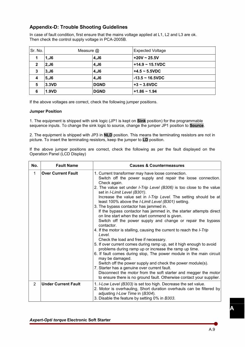
Axpert-Opti torque Electronic Soft Starter
A.9
A
Appendix-D: Trouble Shooting Guidelines
In case of fault condition, first ensure that the mains voltage applied at L1, L2 and L3 are ok. Then check the control supply voltage in PCA-2005B.
Sr. No. Measure @ Expected Voltage
1 1,J6 4,J6 +20V ~ 25.5V
2 2,J6 4,J6 +14.9 ~ 15.1VDC
3 3,J6 4,J6 +4.5 ~ 5.5VDC
4 5,J6 4,J6 -13.5 ~ 16.5VDC
5 3.3VD DGND +3 ~ 3.6VDC
6 1.9VD DGND +1.86 ~ 1.94
If the above voltages are correct, check the following jumper positions. Jumper Position
1. The equipment is shipped with sink logic (JP1 is kept on Sink position) for the programmable sequence inputs. To change the sink logic to source, change the jumper JP1 position to Source. 2. The equipment is shipped with JP3 in NLD position. This means the terminating resistors are not in picture. To insert the terminating resistors, keep the jumper to LD position. If the above jumper positions are correct, check the following as per the fault displayed on the Operation Panel (LCD Display)
No. Fault Name Causes & Countermeasures
1 Over Current Fault 1. Current transformer may have loose connection. Switch off the power supply and repair the loose connection. Check again.
2. The value set under I-Trip Level (B306) is too close to the value set in I-Limit Level (B301). Increase the value set in I-Trip Level. The setting should be at least 100% above the I-Limit Level (B301) setting.
3. The bypass contactor has jammed in. If the bypass contactor has jammed in, the starter attempts direct on line start when the start commend is given. Switch off the power supply and change or repair the bypass contactor.
4. If the motor is stalling, causing the current to reach the I-Trip Level.
Check the load and free if necessary. 5. If over current comes during ramp up, set it high enough to avoid problems during ramp up or increase the ramp up time. 6. If fault comes during stop, The power module in the main circuit
may be damaged. Switch off the power supply and check the power module(s).
7. Starter has a genuine over current fault. Disconnect the motor from the soft starter and megger the motor to ensure there is no ground fault. Otherwise contact your supplier.
2 Under Current Fault 1. I-Low Level (B303) is set too high. Decrease the set value. 2. Motor is overhauling, Short duration overhauls can be filtered by
adjusting I-Low Time in (B304). 3. Disable the feature by setting 0% in B303.
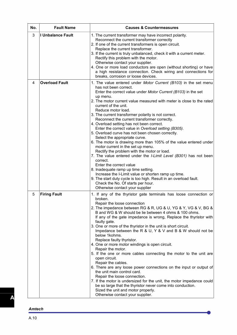
Amtech A.10
1
2
3
4
5
6
7
8
9
10
11
12
13
A
No. Fault Name Causes & Countermeasures
3 I Unbalance Fault 1. The current transformer may have incorrect polarity. Reconnect the current transformer correctly 2. If one of the current transformers is open circuit.
Replace the current transformer. 3. If the current is truly unbalanced, check it with a current meter.
Rectify this problem with the motor. Otherwise contact your supplier.
4. One or more load conductors are open (without shorting) or have a high resistance connection. Check wiring and connections for breaks, corrosion or loose devices.
4 Overload Fault 1. The value entered under Motor Current (B103) in the set menu has not been correct. Enter the correct value under Motor Current (B103) in the set
up menu. 2. The motor current value measured with meter is close to the rated
current of the unit. Reduce motor load.
3. The current transformer polarity is not correct. Reconnect the current transformer correctly.
4. Overload setting has not been correct. Enter the correct value in Overload setting (B305).
5. Overload curve has not been chosen correctly. Select the appropriate curve.
6. The motor is drawing more than 105% of the value entered under motor current in the set up menu. Rectify the problem with the motor or load.
7. The value entered under the I-Limit Level (B301) has not been correct. Enter the correct value
8. Inadequate ramp up time setting. Increase the I-Limit value or shorten ramp up time. 9. The start duty cycle is too high. Result in an overload fault. Check the No. Of starts per hour.
Otherwise contact your supplier
5 Firing Fault 1. If any of the thyristor gate terminals has loose connection or broken. Repair the loose connection
2. The impedance between RG & R, UG & U, YG & Y, VG & V, BG & B and WG & W should be lie between 4 ohms & 100 ohms. If any of the gate impedance is wrong, Replace the thyristor with faulty gate.
3. One or more of the thyristor in the unit is short circuit. Impedance between the R & U, Y & V and B & W should not be below 1kohms. Replace faulty thyristor.
4. One or more motor windings is open circuit. Repair the motor.
5. If the one or more cables connecting the motor to the unit are open circuit.
Repair the cables. 6. There are any loose power connections on the input or output of
the unit main control card. Repair the loose connection.
7. If the motor is undersized for the unit, the motor impedance could be so large that the thyristor never come into conduction. Sized the unit and motor properly. Otherwise contact your supplier.
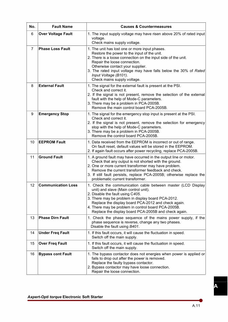
Axpert-Opti torque Electronic Soft Starter
A.11
A
No. Fault Name Causes & Countermeasures
6 Over Voltage Fault 1. The input supply voltage may have risen above 20% of rated input voltage. Check mains supply voltage.
7 Phase Loss Fault 1. The unit has lost one or more input phases. Restore the power to the input of the unit.
2. There is a loose connection on the input side of the unit. Repair the loose connection. Otherwise contact your supplier.
3. The rated input voltage may have falls below the 30% of Rated Input Voltage (B101). Check mains supply voltage.
8 External Fault 1. The signal for the external fault is present at the PSI. Check and correct it.
2. If the signal is not present, remove the selection of the external fault with the help of Mode-C parameters.
3. There may be a problem in PCA-2005B. Remove the main control board PCA-2005B.
9 Emergency Stop 1. The signal for the emergency stop input is present at the PSI. Check and correct it.
2. If the signal is not present, remove the selection for emergency stop with the help of Mode-C parameters.
3. There may be a problem in PCA-2005B. Remove the control board PCA-2005B.
10 EEPROM Fault 1. Data received from the EEPROM is incorrect or out of range. On fault reset, default values will be stored in the EEPROM.
2. If again fault occurs after power recycling, replace PCA-2005B.
11 Ground Fault 1. A ground fault may have occurred in the output line or motor. Check that any output is not shorted with the ground.
2. One or more current transformer may have problem. Remove the current transformer feedback and check.
3. If still fault persists, replace PCA-2005B; otherwise replace the problematic current transformer.
12 Communication Loss 1. Check the communication cable between master (LCD Display unit) and slave (Main control unit).
2. Disable the fault using C405. 3. There may be problem in display board PCA-2012.
Replace the display board PCA-2012 and check again. 4. There may be problem in control board PCA-2005B. Replace the display board PCA-2005B and check again.
13 Phase Dirn Fault 1. Check the phase sequence of the mains power supply, if the phase sequence is reverse, change any two phases.
Disable the fault using B401.
14 Under Freq Fault 1. If this fault occurs, it will cause the fluctuation in speed. Switch off the main supply.
15 Over Freq Fault 1. If this fault occurs, it will cause the fluctuation in speed. Switch off the main supply.
16 Bypass cont Fault 1. The bypass contactor does not energies when power is applied or fails to drop out after the power is removed. Replace the faulty bypass contactor.
2. Bypass contactor may have loose connection. Repair the loose connection.
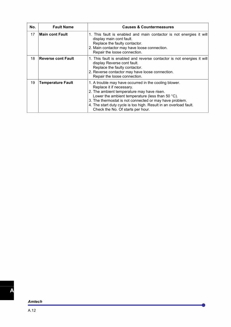
Amtech A.12
1
2
3
4
5
6
7
8
9
10
11
12
13
A
No. Fault Name Causes & Countermeasures
17 Main cont Fault 1. This fault is enabled and main contactor is not energies it will display main cont fault.
Replace the faulty contactor. 2. Main contactor may have loose connection. Repair the loose connection.
18 Reverse cont Fault 1. This fault is enabled and reverse contactor is not energies it will display Reverse cont fault.
Replace the faulty contactor. 2. Reverse contactor may have loose connection. Repair the loose connection.
19 Temperature Fault 1. A trouble may have occurred in the cooling blower. Replace it if necessary.
2. The ambient temperature may have risen. Lower the ambient temperature (less than 50 °C).
3. The thermostat is not connected or may have problem. 4. The start duty cycle is too high. Result in an overload fault. Check the No. Of starts per hour.
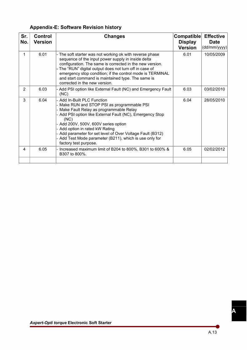
Axpert-Opti torque Electronic Soft Starter
A.13
A
Appendix-E: Software Revision history
Sr. No.
Control Version
Changes Compatible Display Version
Effective Date
(dd/mm/yyyy)
1 6.01 - The soft starter was not working ok with reverse phase sequence of the input power supply in inside delta configuration. The same is corrected in the new version.
- The “RUN” digital output does not turn off in case of emergency stop condition; if the control mode is TERMINAL and start command is maintained type. The same is corrected in the new version.
6.01 10/05/2009
2 6.03 - Add PSI option like External Fault (NC) and Emergency Fault (NC)
6.03 03/02/2010
3 6.04 - Add In-Built PLC Function - Make RUN and STOP PSI as programmable PSI - Make Fault Relay as programmable Relay - Add PSI option like External Fault (NC), Emergency Stop
(NC) - Add 200V, 500V, 600V series option - Add option in rated kW Rating - Add parameter for set level of Over Voltage Fault (B312) - Add Test Mode parameter (B211), which is use only for factory test purpose.
6.04 28/05/2010
4 6.05 - Increased maximum limit of B204 to 800%, B301 to 600% & B307 to 800%.
6.05 02/02/2012

Notes:

Notes:

Notes:

Notes:

Notes:


AMTECH