indigo™ series - manitowoc ice
TRANSCRIPT

Part Number 000014795 5/17
Indigo™ SeriesQuietQube Ice Machine
Technician’s Handbook


Safety NoticesRead these precautions to prevent personal injury:
• Read this manual thoroughly before operating, installing or performing maintenance on the equipment. Failure to follow instructions in this manual can cause property damage, injury or death.
• Routine adjustments and maintenance procedures outlined in this manual are not covered by the warranty.
• Proper installation, care and maintenance are essential for maximum performance and trouble-free operation of your equipment.
• Visit our website www.manitowocice.com for manual updates, translations, or contact information for service agents in your area.
• This equipment contains high voltage electricity and refrigerant charge. Installation and repairs are to be performed by properly trained technicians aware of the dangers of dealing with high voltage electricity and refrigerant under pressure. The technician must also be certified in proper refrigerant handling and servicing procedures. All lockout and tag out procedures must be followed when working on this equipment.
• This equipment is intended for indoor use only. Do not install or operate this equipment in outdoor areas.
• As you work on this equipment, be sure to pay close attention to the safety notices in this handbook. Disregarding the notices may lead to serious injury and/or damage to the equipment.

nWarningFollow these electrical requirements during installation of this equipment.
• All field wiring must conform to all applicable codes of the authority having jurisdiction. It is the responsibility of the end user to provide the disconnect means to satisfy local codes. Refer to rating plate for proper voltage.
• This appliance must be grounded.
• This equipment must be positioned so that the plug is accessible unless other means for disconnection from the power supply (e.g., circuit breaker or disconnect switch) is provided.
• Check all wiring connections, including factory terminals, before operation. Connections can become loose during shipment and installation.

nWarningFollow these precautions to prevent personal injury during installation of this equipment:
• Installation must comply with all applicable equipment fire and health codes with the authority having jurisdiction.
• To avoid instability the installation area must be capable of supporting the combined weight of the equipment and product. Additionally the equipment must be level side to side and front to back.
• Ice machines require a deflector when installed on an ice storage bin. Prior to using a non-OEM ice storage system with this ice machine, contact the bin manufacturer to assure their ice deflector is compatible.
• Remove all removable panels before lifting and installing and use appropriate safety equipment during installation and servicing. Two or more people are required to lift or move this appliance to prevent tipping and/or injury.
• Do not damage the refrigeration circuit when installing, maintaining or servicing the unit.
• Connect to a potable water supply only.
• This equipment contains refrigerant charge.
• Installation of the line sets must be performed by a properly trained and EPA certified refrigeration technician aware of the dangers of dealing with refrigerant charged equipment.

nWarningFollow these precautions to prevent personal injury while operating or maintaining this equipment.
• Legs or casters must be installed and the legs/casters must be screwed in completely. When casters are installed the mass of this unit will allow it to move uncontrolled on an inclined surface. These units must be tethered/secured to comply with all applicable codes. Swivel casters must be mounted on the front and rigid casters must be mounted on the rear. Lock the front casters after installation is complete.
• Some 50 Hz models may contain up to 150 grams of R290 (propane) refrigerant. R290 (propane) is flammable in concentrations of air between approximately 2.1% and 9.5% by volume (LEL lower explosion limit and UEL upper explosion limit). An ignition source at a temperature higher than 470°C is needed for a combustion to occur.
• Refer to nameplate to identify the type of refrigerant in your equipment.
• Only trained and qualified personnel aware of the dangers are allowed to work on the equipment.
• Read this manual thoroughly before operating, installing or performing maintenance on the equipment. Failure to follow instructions in this manual can cause property damage, injury or death.
• Crush/Pinch Hazard. Keep hands clear of moving components. Components can move without warning unless power is disconnected and all potential energy is removed.
• Moisture collecting on the floor will create a slippery surface. Clean up any water on the floor immediately to prevent a slip hazard.

nWarningFollow these precautions to prevent personal injury while operating or maintaining this equipment.
• Objects placed or dropped in the bin can affect human health and safety. Locate and remove any objects immediately.
• Never use sharp objects or tools to remove ice or frost.
• Do not use mechanical devices or other means to accelerate the defrosting process.
• When using cleaning fluids or chemicals, rubber gloves and eye protection (and/or face shield) must be worn.
DANGERDo not operate equipment that has been misused, abused, neglected, damaged, or altered/modified from that of original manufactured specifications. This appliance is not intended for use by persons (including children) with reduced physical, sensory or mental capabilities, or lack of experience and knowledge, unless they have been given supervision concerning use of the appliance by a person responsible for their safety. Do not allow children to play with, clean or maintain this appliance without proper supervision.

DANGERFollow these precautions to prevent personal injury during use and maintenance of this equipment:
• It is the responsibility of the equipment owner to perform a Personal Protective Equipment Hazard Assessment to ensure adequate protection during maintenance procedures.
• Do Not Store Or Use Gasoline Or Other Flammable Vapors Or Liquids In The Vicinity Of This Or Any Other Appliance. Never use flammable oil soaked cloths or combustible cleaning solutions for cleaning.
• All covers and access panels must be in place and properly secured when operating this equipment.
• Risk of fire/shock. All minimum clearances must be maintained. Do not obstruct vents or openings.
• Failure to disconnect power at the main power supply disconnect could result in serious injury or death. The power switch DOES NOT disconnect all incoming power.
• All utility connections and fixtures must be maintained in accordance with the authority having jurisdiction.
• Turn off and lockout all utilities (gas, electric, water) according to approved practices during maintenance or servicing.
• Units with two power cords must be plugged into individual branch circuits. During movement, cleaning or repair it is necessary to unplug both power cords.

Table of Contents
Part Number 000014795 5/17 9
General InformationHow to Read a Model Number . . . . . . . . . . . . . . . . 15
Head Sections . . . . . . . . . . . . . . . . . . . . . . . . . . . . . 15ICVD Condensing Units . . . . . . . . . . . . . . . . . . . . 16
Ice Cube Sizes . . . . . . . . . . . . . . . . . . . . . . . . . . . . . . . . . 16Model/Serial Number Location . . . . . . . . . . . . . . . 17Model Numbers . . . . . . . . . . . . . . . . . . . . . . . . . . . . . . . 18
QuietQube® Models . . . . . . . . . . . . . . . . . . . . . . . 18Ice Machine Warranty Information . . . . . . . . . . . . 19LuminIce® II . . . . . . . . . . . . . . . . . . . . . . . . . . . . . . . . . . . 19
InstallationStacking Two Ice Machines on a Single Storage Bin . . . . . . . . . . . . . . . . . . . . . . . . . 21Ice Deflector . . . . . . . . . . . . . . . . . . . . . . . . . . . . . . 21
Location of Ice Machine . . . . . . . . . . . . . . . . . . . . . . . 22Head Section . . . . . . . . . . . . . . . . . . . . . . . . . . . . . . 22Ice Beverage Models . . . . . . . . . . . . . . . . . . . . . . 23Location of ICVD Condensing Units . . . . . . . . 24
Clearance Requirements . . . . . . . . . . . . . . . . . . . . . . 25Ice Machine Heat of Rejection . . . . . . . . . . . . . . . . 26I1470C/I1870C/I2170C/I2176C Installation on a Manitowoc Bin . . . . . . . . . . . . . . 27Ice Machine on a Dispenser Installation . . . . . . 28Lineset Applications . . . . . . . . . . . . . . . . . . . . . . . . . . 29QuietQube® Remote Condensing Unit . . . . . . . . 30
ICVD Transformer Wiring . . . . . . . . . . . . . . . . . . . 31ICVD Interconnecting Wiring . . . . . . . . . . . . . . . 31
Additional Refrigerant Charge For 51' to 100' Line Sets . . . . . . . . . . . . . . . . . . . . . . . . . . . 32
MaintenanceCleaning and Sanitizing . . . . . . . . . . . . . . . . . . . . . . 35
General . . . . . . . . . . . . . . . . . . . . . . . . . . . . . . . . . . . 35Cleaning/Sanitizing Procedure . . . . . . . . . . . . . 37Preventative Maintenance Cleaning Procedure . . . . . . . . . . . . . . . . . . . . . . . . . . . . . . . . . 37Exterior Cleaning . . . . . . . . . . . . . . . . . . . . . . . . . . 37
Cleaning / Sanitizing Procedure . . . . . . . . . . . . . . 38

10 Part Number 000014795 5/17
Cleaning Procedure . . . . . . . . . . . . . . . . . . . . . . . 38Sanitizing Procedure . . . . . . . . . . . . . . . . . . . . . . 41Parts Removal for Cleaning/Sanitizing . . . . . . 44
Removal from Service/Winterization . . . . . . . . . 53Air-Cooled Ice Machines . . . . . . . . . . . . . . . . . . . 53
OperationControl Panel Features . . . . . . . . . . . . . . . . . . . . . . . . 55
Buttons . . . . . . . . . . . . . . . . . . . . . . . . . . . . . . . . . . . 55Display Panel . . . . . . . . . . . . . . . . . . . . . . . . . . . . . . 56
Menu Navigation Overview . . . . . . . . . . . . . . . . . . . 57Display Panel Navigation . . . . . . . . . . . . . . . . . . . . . 58Alerts and Messages . . . . . . . . . . . . . . . . . . . . . . . . . . 60Main Menu . . . . . . . . . . . . . . . . . . . . . . . . . . . . . . . . . . . . 61Machine Info Menu . . . . . . . . . . . . . . . . . . . . . . . . . . . 62Password Entry . . . . . . . . . . . . . . . . . . . . . . . . . . . . . . . 63
Reset Password To Factory Defaults . . . . . . . . 65Set-Up Menu . . . . . . . . . . . . . . . . . . . . . . . . . . . . . . . . . . 66
Language . . . . . . . . . . . . . . . . . . . . . . . . . . . . . . . . . 67Time & Date . . . . . . . . . . . . . . . . . . . . . . . . . . . . . . . 68Units . . . . . . . . . . . . . . . . . . . . . . . . . . . . . . . . . . . . . . 69Ice Clarity . . . . . . . . . . . . . . . . . . . . . . . . . . . . . . . . . 69LCD Brightness . . . . . . . . . . . . . . . . . . . . . . . . . . . . 70Password On . . . . . . . . . . . . . . . . . . . . . . . . . . . . . . 70Edit Password . . . . . . . . . . . . . . . . . . . . . . . . . . . . . 70Clean Minder . . . . . . . . . . . . . . . . . . . . . . . . . . . . . . 71IAuCS Runtime . . . . . . . . . . . . . . . . . . . . . . . . . . . . 71Air Filter . . . . . . . . . . . . . . . . . . . . . . . . . . . . . . . . . . . 72Water Filter . . . . . . . . . . . . . . . . . . . . . . . . . . . . . . . . 73LuminIce® Reminder . . . . . . . . . . . . . . . . . . . . . . . 74Ice Bin Level Sensor . . . . . . . . . . . . . . . . . . . . . . . 75Factory Defaults . . . . . . . . . . . . . . . . . . . . . . . . . . . 75
Energy Saver Menu . . . . . . . . . . . . . . . . . . . . . . . . . . . 76Ice Program . . . . . . . . . . . . . . . . . . . . . . . . . . . . . . . 77ICE Bin Level Sensor . . . . . . . . . . . . . . . . . . . . . . . 78USB Setup . . . . . . . . . . . . . . . . . . . . . . . . . . . . . . . . . 78Water Miser . . . . . . . . . . . . . . . . . . . . . . . . . . . . . . . 79Statistics . . . . . . . . . . . . . . . . . . . . . . . . . . . . . . . . . . 79
Service Menu . . . . . . . . . . . . . . . . . . . . . . . . . . . . . . . . . 80Data History . . . . . . . . . . . . . . . . . . . . . . . . . . . . . . . 82Real Time Data . . . . . . . . . . . . . . . . . . . . . . . . . . . . 83

Part Number 000014795 5/17 11
Diagnostics . . . . . . . . . . . . . . . . . . . . . . . . . . . . . . . 85Manual Harvest . . . . . . . . . . . . . . . . . . . . . . . . . . . 86Replace Control Board . . . . . . . . . . . . . . . . . . . . . 86USB Setup . . . . . . . . . . . . . . . . . . . . . . . . . . . . . . . . . 87Event Log Menu . . . . . . . . . . . . . . . . . . . . . . . . . . . 87Event Log . . . . . . . . . . . . . . . . . . . . . . . . . . . . . . . . . 88USB Flash Drive Specifications and Formatting . . . . . . . . . . . . . . . . . . . . . . . . . . . . . . . . 94Upgrading Firmware with a Flash Drive . . . . 96Exporting Data to a Flash Drive . . . . . . . . . . . . 98
Operational Checks . . . . . . . . . . . . . . . . . . . . . . . . . . 100General . . . . . . . . . . . . . . . . . . . . . . . . . . . . . . . . . . 100Ice Thickness Check . . . . . . . . . . . . . . . . . . . . . . 101
Sequence of Operation . . . . . . . . . . . . . . . . . . . . . . 103QuietQube® Models . . . . . . . . . . . . . . . . . . . . . . 103Initial Start-Up or Start-Up After Automatic Shut-Off . . . . . . . . . . . . . . . . . . . . . . . 103Freeze Sequence . . . . . . . . . . . . . . . . . . . . . . . . . 104Harvest Sequence . . . . . . . . . . . . . . . . . . . . . . . . 105Automatic Shut-Off . . . . . . . . . . . . . . . . . . . . . . . 106Restart After Automatic Shut-off . . . . . . . . . . 106Safety Timers . . . . . . . . . . . . . . . . . . . . . . . . . . . . . 109Water Assist Harvest Feature . . . . . . . . . . . . . . 110
TroubleshootingSafety Limits . . . . . . . . . . . . . . . . . . . . . . . . . . . . . . . . . 111
Safe Operation Mode . . . . . . . . . . . . . . . . . . . . . 112Ice Thaw Cycle . . . . . . . . . . . . . . . . . . . . . . . . . . . . 113Analyzing Why a Safety Limit Stopped the Ice Machine . . . . . . . . . . . . . . . . . . . . . . . . . . 114Safety Limit #1 . . . . . . . . . . . . . . . . . . . . . . . . . . . 114Safety Limit #2 . . . . . . . . . . . . . . . . . . . . . . . . . . . 116
Troubleshooting By Symptom . . . . . . . . . . . . . . . 117Reset To Factory Defaults . . . . . . . . . . . . . . . . . 118Symptom #1 Ice Machine Will Not Run . . . . 119Diagnosing a Condensing Unit That Will Not Run . . . . . . . . . . . . . . . . . . . . . . . . . 122Symptom #2 Low Production, Long Freeze Cycle . . . . . . . . . . . . . . . . . . . . . . . . . . . . . . 123Freeze Cycle Refrigeration System Operational Analysis Tables . . . . . . . . . . . . . . . 125

12 Part Number 000014795 5/17
Freeze Cycle Refrigeration System Operational Analysis Table Procedures - QuietQube® Models . . . . . . . . . . . . . . . . . . . . . . 131Symptom #3 Harvest Problems . . . . . . . . . . . 149Symptom #3 QuietQube® Models With ICVD Condensing Units . . . . . . . . . . . . . . . . . . . 150Symptom #4 QuietQube® Models With ICVD Condensing Units . . . . . . . . . . . . . . . . . . . 154
Component Check ProceduresElectrical Components . . . . . . . . . . . . . . . . . . . . . . . 157
Control Board, Display Board, Touch Pad . . 157Control Board Relay Test . . . . . . . . . . . . . . . . . . 160Programming a Replacement Board . . . . . . . 161Main Fuse . . . . . . . . . . . . . . . . . . . . . . . . . . . . . . . . 163Bin Switch . . . . . . . . . . . . . . . . . . . . . . . . . . . . . . . . 164Water Level Control Circuitry . . . . . . . . . . . . . . 167Ice Thickness Probe (Initiates Harvest) . . . . . 173High Pressure Cutout (HPCO) Control . . . . . 178Low Pressure Cutout (LPCO) Control . . . . . . 181Fan Cycle Control . . . . . . . . . . . . . . . . . . . . . . . . . 182Thermistors . . . . . . . . . . . . . . . . . . . . . . . . . . . . . . 183Harvest Assist Air Pump . . . . . . . . . . . . . . . . . . 186Compressor Electrical Diagnostics . . . . . . . . 187Diagnosing Start Components . . . . . . . . . . . . 189
Refrigeration Components . . . . . . . . . . . . . . . . . . 192Head Pressure Control Valve . . . . . . . . . . . . . . 192Suction Accumulator Operation . . . . . . . . . . 198
Recovery/Evacuation/Charging Procedures QUIETQUBE® MODELS . . . . . . . . . . . . . . . . . . . . . . . 199
Connections . . . . . . . . . . . . . . . . . . . . . . . . . . . . . 200Recovery/Evacuation Procedures . . . . . . . . . 201Charging Procedures . . . . . . . . . . . . . . . . . . . . . 202
System Contamination Clean-Up . . . . . . . . . . . . 203Determining Severity of Contamination . . . 203Cleanup Procedure . . . . . . . . . . . . . . . . . . . . . . . 205Replacing Pressure Controls Without Removing Refrigerant Charge . . . . . . . . . . . . . 208Liquid Line Filter-Driers . . . . . . . . . . . . . . . . . . . 210Suction Filter . . . . . . . . . . . . . . . . . . . . . . . . . . . . . 210

Part Number 000014795 5/17 13
Total System Refrigerant Charge QuietQube® ICVD Models . . . . . . . . . . . . . . . . . . . . 211
ChartsCycle Times/24-Hour Ice Production/ Refrigerant Pressure Charts . . . . . . . . . . . . . . . . . . 213
I0680C/ICVD0695 . . . . . . . . . . . . . . . . . . . . . . . . 214IB0690C/ICVD0695 . . . . . . . . . . . . . . . . . . . . . . . 215I0686C/ICVD0696 . . . . . . . . . . . . . . . . . . . . . . . . 216IB0696C/ICVD0696 . . . . . . . . . . . . . . . . . . . . . . . 217I0870C/ICVD0895 . . . . . . . . . . . . . . . . . . . . . . . . 218IB0890C/ICVD0895 . . . . . . . . . . . . . . . . . . . . . . . 219I0976C/ICVD0996 . . . . . . . . . . . . . . . . . . . . . . . . 220I1070C/ICVD1095 . . . . . . . . . . . . . . . . . . . . . . . . 221I1070C/ICVD1195 . . . . . . . . . . . . . . . . . . . . . . . . 222I1076C/ICVD1195 . . . . . . . . . . . . . . . . . . . . . . . . 223I1176C/ICVD1195 . . . . . . . . . . . . . . . . . . . . . . . . 224IB1090C/ICVD1195 . . . . . . . . . . . . . . . . . . . . . . . 225I1470C/ICVD1495 . . . . . . . . . . . . . . . . . . . . . . . . 226I1470C/ICVD1496 . . . . . . . . . . . . . . . . . . . . . . . . 227I1870C/ICVD1895 . . . . . . . . . . . . . . . . . . . . . . . . 228I2170C/ICVD2095 . . . . . . . . . . . . . . . . . . . . . . . . 229I2176C/ICVD2096 . . . . . . . . . . . . . . . . . . . . . . . . 230
DiagramsWiring Diagrams . . . . . . . . . . . . . . . . . . . . . . . . . . . . . 231
Wiring Diagram Legend . . . . . . . . . . . . . . . . . . 231All ICVD Models Interconnecting Wiring . . . 232I0680C/I0686C/I0870C/I0976C/I1070C/ I1176C 1&3ph . . . . . . . . . . . . . . . . . . . . . . . . . . . . 233ICVD0695/ICVD0696/ICVD895/ICVD1095/ICVD1195 1ph . . . . . . . . . . . . . . . . . . . . . . . . . . . . 234ICVD0695/ICVD0696/ICVD895/ICVD1095/ICVD1195 3ph . . . . . . . . . . . . . . . . . . . . . . . . . . . . 235IB0690C/IB0696C/IB0890C/IB1090C 1&3ph . . . . . . . . . . . . . . . . . . . . . . . . . . . . . . . . . . . 236ICVD0695/ICVD0696/ICD0895/ICVD0996/ICVD1195 1ph . . . . . . . . . . . . . . . . . . . . . . . . . . . . 237ICVD0695/ICVD0696/ICD0895/ICVD0996/ICVD1195 3ph . . . . . . . . . . . . . . . . . . . . . . . . . . . . 238I1470C/I1870C/I2170 1&3ph . . . . . . . . . . . . . . 239ICVD1495/ICVD1496/ICVD1895 1ph . . . . . . 240

14 Part Number 000014795 5/17
ICVD1495/ICVD1496/ICVD1895 3ph . . . . . . 241ICVD2095 1ph . . . . . . . . . . . . . . . . . . . . . . . . . . . . 242iCVD2095 3ph . . . . . . . . . . . . . . . . . . . . . . . . . . . . 243I2176C 1&3ph . . . . . . . . . . . . . . . . . . . . . . . . . . . . 244ICVD2096 1ph . . . . . . . . . . . . . . . . . . . . . . . . . . . . 245ICVD2096 3ph . . . . . . . . . . . . . . . . . . . . . . . . . . . . 246
Electronic Control Board . . . . . . . . . . . . . . . . . . . . . 247Refrigeration Tubing Schematics . . . . . . . . . . . . 248
Remote Condensing Unit Models . . . . . . . . . 248IB Models . . . . . . . . . . . . . . . . . . . . . . . . . . . . . . . . 249Dual Evaporator Models . . . . . . . . . . . . . . . . . . 251
Part Number 000014795 5/17 15
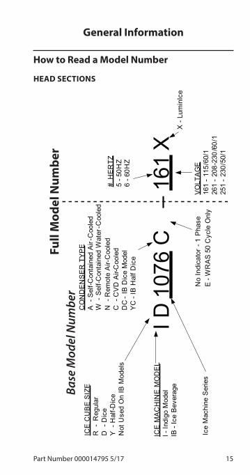
How to Read a Model Number
HEAD SECTIONS
I D 1
076
C
–16
1X
ICE
MA
CH
INE
MO
DE
LI -
Indi
go M
odel
IB -
Ice
Bev
erag
e
ICE
CU
BE
SIZ
ER
-R
egul
arD
-D
ice
Y -
Hal
f-Dic
eN
ot U
sed
On
IB M
odel
s
Ice
Mac
hine
Ser
ies
CO
ND
EN
SE
R T
YP
EA
-S
elf-C
onta
ined
Air
-Coo
led
W -
Sel
f-Con
tain
ed W
ater
-Coo
led
N -
Rem
ote
Air-
Coo
led
C -
CV
D A
ir-C
oole
dD
C -
IB D
ice
Mod
elY
C -
IB H
alf D
ice
E -
WR
AS
50
Cyc
le O
nly
No
Indi
cato
r -1
Pha
seV
OLT
AG
E16
1 -
115/
60/1
261
-20
8-23
0/6
0/1
251
-23
0/50
/1
# H
ER
TZ5
-50H
Z6
-60H
Z
X -
Lum
inIc
e
Base
Mod
el N
umbe
r
Fu
ll M
odel
Num
ber
General Information

16 Part Number 000014795 5/17
ICVD CONDENSING UNITS
ICVD 1495 3
CONDENSINGUNIT MODEL
3 PHASE
CONDENSING UNIT SERIES
Ice Cube Sizes
Regular 1-1/8” x 1-1/8” x 7/8” 2.86 x 2.86 x 2.22 cm
Dice 7/8” x 7/8” x 7/8”
2.22 x 2.22 x 2.22 cm
Half Dice 3/8” x 1-1/8” x 7/8”
0.95 x 2.86 x 2.22 cm

Part Number 000014795 5/17 17
nWarningAll Manitowoc ice machines require the ice storage system (bin, dispenser, etc.) to incorporate an ice deflector.
Prior to using a non-Manitowoc ice storage system with other Manitowoc ice machines, contact the manufacturer to assure their ice deflector is compatible with Manitowoc ice machines.
Model/Serial Number LocationThese numbers are required when requesting information from your local Manitowoc Distributor, service representative, or Manitowoc Ice, Inc. The model and serial number are listed on the OWNER WARRANTY REGISTRATION CARD. They are also listed on the MODEL/SERIAL NUMBER DECAL affixed to the front and rear of the ice machine.
The model and serial number are located in the Indigo Interface and must match the data plate for proper operation. NOTE: Only a portion of the model number is entered into the display. For example a model number listed on the data plate may show #ID1076C-161X but the display would only show #ID1076C-161. For further detail, see Control Board Replacement/Manual Setup on page 161.

18 Part Number 000014795 5/17
Model Numbers
QUIETQUBE® MODELSIce Machine Head Section ICVD® Condensing Unit
ID0682C - IY0684C IB0694YC
ICVD0695
ID0686C - IY0686C IB0696YC
ICVD0696
ID0872C - IY0874C IB0894YC
ICVD0895
ID0976C - IY0976C ICVD0996ID1072C - IY1074C ICVD1095
ICVD1195ID1076C - IY1076C ICVD1195ID1176C - IY1176C ICVD1195
IB1094YC ICVD1195ID1472C IY1474C
ICVD1496
ID1872C IY1874C
ICVD1895
ID2172C IY2174C
ICVD2095
ID2176C IY2176C
ICVD2096

Part Number 000014795 5/17 19
Ice Machine Warranty InformationFor warranty information visit:
http://www.manitowocice.com/Service/Warranty
• Warranty Verification
• Warranty Registration
• View and download a copy of the warranty Owner Warranty Registration Card
Warranty coverage begins the day the ice machine is installed.
LuminIce® IIThe LuminIce® growth inhibitor recirculates the air in the ice machine foodzone over a UV bulb. This process will inhibit the growth of common micro-organisms on all exposed foodzone surfaces.
• LuminIce® bulbs require replacement on a yearly basis.
• The control board can be set to automatically display a reminder after 12 months.
• A remote light is available for reminder indication.
NOTE: LuminIce® and LuminIce® II bulbs are not interchangeable; verify your model before ordering a replacement bulb.
Cleanup Procedure for Accidental Bulb Breakage
The cleanup procedure is identical to the procedure used to clean up compact fluorescent (CFL) or fluorescent tube lights. These lights contain a small amount of mercury sealed within a glass tube. Breaking these types of lights will release mercury and mercury vapor. The broken bulb can continue to release mercury vapor until it is cleaned up and removed.
The latest EPA procedures can be viewed on their website at www.epa.gov/cfl/cflcleanup.html.

20 Part Number 000014795 5/17
THIS PAGE INTENTIONALLY LEFT BLANK

Part Number 000014795 5/17 21
nWarningPERSONAL INJURY POTENTIAL
Remove all ice machine panels before lifting.
nWarningI1470C/I1870C/I2170C/I2176C ice machines are not approved for use on Manitowoc B570 bins.
,CautionThe ice machine head section must be protected if it will be subjected to temperatures below 32°F (0°C). Failure caused by exposure to freezing temperatures is not covered by the warranty.
Refer to “Removal from Service/Winterization” on page 53
STACKING TWO ICE MACHINES ON A SINGLE STORAGE BIN
Indigo Model ice machines cannot be stacked. However an adapter is available that allows two QuietQube® ice machines to be placed side by side on 60” bins.
ICE DEFLECTOR
An ice deflector is required for all ice machines installed on a bin and may be required by the dispenser manufacture when installed on a dispenser.
Installation

22 Part Number 000014795 5/17
Location of Ice Machine
HEAD SECTION
The location selected for the ice machine head section must meet the following criteria. If any of these criteria are not met, select another location.
• The location must be free of airborne and other contaminants.
• The air temperature must be at least 35°F (1.6°C), but must not exceed 110°F (43°C).
• Ice Making Water Inlet - Water Pressure must be at least 20 psi (1.38 bar), but must not exceed 80 psi (5.52 bar).
• The location must not be near heat-generating equipment or in direct sunlight and protected from weather.
• The ice machine must be protected if it will be subjected to temperatures below 32°F (0°C). Failure caused by exposure to freezing temperatures is not covered by the warranty. Refer to “Removal from Service/Winterization” on page 53.

Part Number 000014795 5/17 23
ICE BEVERAGE MODELS
• Ice/Beverage Ice Machines require that a proper ice level be maintained when installed on a dispenser. Ice Beverage machines ship with a ice level management sensor pre installed.
• The ice machine head is installed with the electrical inlet, water supply inlet, refrigeration tubing and water drain entering from the back of the ice machine.
• The ice machine head section contains a service loop that must remain installed between the ice machine head section and line set. Sufficient tubing length must be available to allow 180° rotation of the ice machine.
• Maintain a 3” space between the back of the ice machine and the back of the dispenser to allow room for the refrigeration line set service loop.
• The water inlet and electrical connection must contain a service loop to allow future service and maintenance access.
• The drain line must contain a union or other suitable means of disconnection at the ice machine head section.
• The location must be free of airborne and other contaminants.
• The air temperature must be at least 35°F (1.6°C), but must not exceed 110°F (43°C).
• The location must not be near heat-generating equipment or in direct sunlight.

24 Part Number 000014795 5/17
LOCATION OF ICVD CONDENSING UNITS
The location selected for the ICVD Condensing Unit must meet the following criteria. If any of these criteria are not met, select another location.
• ICVD0895/ICVD0996/ICVD1095/ICVD1495/ICVD1496/ICVD1895 Only The air temperature must be at least -20°F (-28.9°C) but must not exceed 130°F (54.4°C).
• ICVD0695/ICVD0696/ICVD1195/ICVD2095/ICVD2096 Only The air temperature must be at least -20°F (-28.9°C) but must not exceed 120°F (48.9°C).
• The location must not allow exhaust fan heat and/or grease to enter the condenser.
• The location must not obstruct airflow through or around the condensing unit. See below for clearance requirements.

Part Number 000014795 5/17 25
Clearance RequirementsI0680C - I0686C I0870C - I0976C
I1070C
Ice Machine Head Section
ICVD Condensing
UnitTop 5" (12.7 cm) *0" (0 cm)
Sides 5" (12.7 cm) *0" (0 cm)Back
Standard Connections5" (12.7 cm) 48" (122 cm)
Back Connections Out Top
3" (7.6 cm) N/A
Front *** 48" (122 cm)
I1470C - I1870C I2170C - I2176C
Ice Machine Head Section
ICVD Condensing
UnitTop 5" (12.7 cm) *0" (0 cm)
Sides 5" (12.7 cm) *0" (0 cm)Back
Standard Connections5" (12.7 cm) 48" (122 cm)
Back Connections Out Top
3" (7.6 cm) N/A
Front *** 24" (61.0 cm)
Ice Beverage Models
IB0690C - IB0890C IB1090C
Ice Machine Head Section
ICVD Condensing
UnitTop 2" (5.1 cm) *0" (0 cm)
Sides 8" (20.3 cm) *0" (0 cm)Back 5" (12.7 cm) 48" (122 cm)Front *** 48" (122 cm)
*6" (15.2 cm) is recommended for servicing*** Minimum amounts vary by installation - Access is required for cleaning/sanitizing and ice removal

26 Part Number 000014795 5/17
Ice Machine Heat of Rejection
Series Ice Machine
Heat of RejectionAir
Conditioning*Peak
I0680C - I0686C IB0690C - IB0696C
9000 13900
I0870C - I0976C IB0890C
13000 16000
I1070C 16250 18600I1176C
IB1090C20700 24500
I1470C 23500 27000I1870C 30000 35000
I2100 - I2176C 30500 35500
* BTU/Hour Because the heat of rejection varies during the ice making cycle, the figure shown is an average.

Part Number 000014795 5/17 27
I1470C/I1870C/I2170C/I2176C Installation on a Manitowoc BinDual evaporator models will not function correctly with the stock bin deflector. An ice deflector kit is required for installation and is ordered separate. Order appropriate kit (30” or 48”) for your bin.
The stock bin deflector must be removed and replaced with the correct deflector to prevent injury.
nWarningPERSONAL INJURY POTENTIAL
Do not operate any ice machine with the deflector removed.
REMOVE 1 SCREW ON EACH SIDE
REMOVE 2 SCREWS
ON EACH SIDE
RE-INSTALL TOP COVER
REMOVE DEFLECTOR

28 Part Number 000014795 5/17
A deflector must be installed on all dual evaporator models used in bin applications
2. LOCK IN PLACE WITH PIN
1. SLIDE FORWARD
Ice Machine on a Dispenser InstallationNo deflector is needed for machines that match the size of the dispenser (30" head section on a 30" dispenser) unless required by the dispenser manufacturer. Adapters are required when a smaller ice machine is going on a larger dispenser (22" machine on a 30" dispenser).
Important�Manitowoc Ice/Beverage Ice Machines require an adapter for mounting. Adapters are not included with the ice machine, dispenser or bin and must be ordered separately. When a non-Manitowoc adapter is used, verify the adapter is compatible with Manitowoc Ice/Beverage Ice Machines prior to installation.
nWarningIce Beverage ice machines, adapter plates and adapter covers must be secured to the dispenser to prevent tipping or dislodging during agitation.

Part Number 000014795 5/17 29
Lineset Applications
,CautionThe 60-month compressor warranty (including the 36-month labor replacement warranty) will not apply if the Manitowoc Ice Machine, Condenser or QuietQube® Condensing Unit were not installed according to specifications. This warranty also will not apply if the refrigeration system is modified with a condenser, heat reclaim device, or other parts or assemblies not manufactured by Manitowoc Ice.
nWarningRecovery locations vary by model. Verify you are making the correct connections for your model to prevent accidental release of high pressure refrigerant.
Important�Manitowoc remote systems are only approved and warranted as a complete new package. Warranty on the refrigeration system will be void if new equipment is connected to pre-existing (used) tubing, remote condenser, remote condensing unit or ice machine head section.

30 Part Number 000014795 5/17
QuietQube® Remote Condensing UnitQuietQube® Ice
MachineRemote Single
Circuit CondenserLine Set*
I0670C - I0680C IB0670C - IB0690C
ICVD0695
RC-26 RC-36 RC-56
I0870C - I0890C IB0870C - IB0890C
ICVD0895
I0970C ICVD0996I1070C ICVD1095
ICVD1195IB1090C ICVD1195I1470C ICVD1495 RC-25
RC-35 RC-55
I1870C ICVD1895
I2170C ICVD2095 RC-28 RC-38 RC-58
*Line SetSuction
LineLiquid
Line
Minimum Insulation Thickness
RC 26/36/56 5/8 inch (16 mm)
3/8 inch (10 mm)
1/2” (13 mm) Suction Line 1/4” (7 mm) Liquid Line
RC 25/35/55 3/4 inch (19 mm)
1/2 inch (13 mm)
1/2”(13 mm) Suction Line 1/4” (7 mm) Liquid Line
RC 28/38/58 3/4 inch (19 mm)
5/8 inch (16 mm)
1/2”(13 mm) Suction Line 1/4” (7 mm) Liquid Line

Part Number 000014795 5/17 31
ICVD TRANSFORMER WIRING
ICVD transformers leave the factory wired for a 240V supply voltage. When connecting to a 208V supply voltage, the transformer must be rewired to maintain the proper secondary voltage. Failure to correctly wire the transformer will result in premature component failure. Refer to wiring diagrams for wiring details.
Important�An incorrectly wired transformer will read a secondary voltage of 24 volts, but will not carry enough power (volt amps) to properly energize components. Correctly wired transformers normally measure in the range of 27 to 28 vac. Example - 208V primary wired for 230V will measure 24 vac, but causes overheating and contactor failure.
ICVD INTERCONNECTING WIRING
Important�Indigo QuietQube ice machines require interconnecting low voltage wiring (included with Manitowoc line sets) to energize the contactor coil and verify the LPCO & HPCO are closed. This circuit also initiates a time delay whenever the LPCO or HPCO open. Failure to properly wire the iCVD condensing unit or ice machine head section will result in a non-operational machine. Wire Specifications:18 AWG 5 Conductor, Single Strand, Plenum Rated, UL rated to 300 volts.

32 Part Number 000014795 5/17
Additional Refrigerant Charge For 51' to 100' Line Sets
Ice Machine
Condenser
Additional Amount of Refrigerant To Be
Added To Nameplate Charge
I0680C IB0690C
ICVD06951.5 lbs 680 gI0686C
IB0696CICVD0696
I0870C ICVD08954 lbs
1814 g
IB890C ICVD08952 lbs 907 g
IB0890CI0976C
ICVD09964 lbs
1814 g
I1070CICVD1095 ICVD1195
2 lbs 907 g
IB1090CIB1096C
ICVD10962 lbs 907 g
I1070CIB1094C
ICVD11952 lbs 907 g
I1470C ICVD14952 lbs 907 g
I1476C ICVD14962 lbs 907 g
I1870C ICVD18952 lbs 907 g
I2170C ICVD20954 lbs
1814 g
I2176C ICVD20964 lbs
1814 g

Part Number 000014795 5/17 33
Calculating Allowable Lineset Distance
Line Set Length
The maximum length is 100' (30.5 m).
Line Set Rise/Drop
The maximum rise is 35' (10.7 m).
The maximum drop is 15' (4.5 m).
35 FT. (10.7 M) MAXIMUM DISTANCE
35 ft. (10.7 m) Rise: The maximum distance the Condenser or Condensing Unit can be above the ice machine.
15 FT. (4.5 M) MAXIMUM DISTANCE
15 ft. (4.5 m) Drop: The maximum distance the Condenser or Condensing Unit can be below the ice machine.

34 Part Number 000014795 5/17
THIS PAGE INTENTIONALLY LEFT BLANK

Part Number 000014795 5/17 35
Cleaning and Sanitizing
GENERAL
You are responsible for maintaining the ice machine in accordance with the instructions in this manual. Maintenance procedures are not covered by the warranty.
Clean and sanitize the ice machine every six months for efficient operation. If the ice machine requires more frequent cleaning and sanitizing, consult a qualified service company to test the water quality and recommend appropriate water treatment. An extremely dirty ice machine must be taken apart for cleaning and sanitizing.
Manitowoc Ice Machine Cleaner and Sanitizer are the only products approved for use in Manitowoc ice machines.
Maintenance

36 Part Number 000014795 5/17
,CautionUse only Manitowoc approved Ice Machine Cleaner and Sanitizer for this application (Manitowoc Cleaner part number 9405463 and Manitowoc Sanitizer part number 9405653). It is a violation of Federal law to use these solutions in a manner inconsistent with their labeling. Read and understand all labels printed on bottles before use.
,CautionDo not mix Cleaner and Sanitizer solutions together. It is a violation of Federal law to use these solutions in a manner inconsistent with their labeling.
nWarningWear rubber gloves and safety goggles (and/or face shield) when handling Ice Machine Cleaner or Sanitizer.

Part Number 000014795 5/17 37
CLEANING/SANITIZING PROCEDURE
This procedure must be performed a minimum of once every six months.
• The ice machine and bin must be disassembled cleaned and sanitized.
• All ice produced during the cleaning and sanitizing procedures must be discarded.
• Removes mineral deposits from areas or surfaces that are in direct contact with water.
PREVENTATIVE MAINTENANCE CLEANING PROCEDURE
• This procedure cleans all components in the water flow path, and is used to clean the ice machine between the bi-yearly cleaning/sanitizing procedure.
EXTERIOR CLEANING
Clean the area around the ice machine as often as necessary to maintain cleanliness and efficient operation.
Wipe surfaces with a damp cloth rinsed in water to remove dust and dirt from the outside of the ice machine. If a greasy residue persists, use a damp cloth rinsed in a mild dish soap and water solution. Wipe dry with a clean, soft cloth.
The exterior panels have a clear coating that is stain resistant and easy to clean. Products containing abrasives will damage the coating and scratch the panels.
• Never use steel wool or abrasive pads for cleaning.
• Never use chlorinated, citrus based or abrasive cleaners on exterior panels and plastic trim pieces.

38 Part Number 000014795 5/17
Cleaning / Sanitizing Procedure
,CautionUse only Manitowoc approved Ice Machine Cleaner and Sanitizer for this application (Manitowoc Cleaner part number 9405463 and Manitowoc Sanitizer part number 9405653). It is a violation of Federal law to use these solutions in a manner inconsistent with their labeling. Read and understand all labels printed on bottles before use.
CLEANING PROCEDURE
,CautionDo not mix Cleaner and Sanitizer solutions together. It is a violation of Federal law to use these solutions in a manner inconsistent with their labeling.
nWarningWear rubber gloves and safety goggles (and/or face shield) when handling Ice Machine Cleaner or Sanitizer.
Ice machine cleaner is used to remove lime scale and mineral deposits. Ice machine sanitizer disinfects and removes algae and slime.
NOTE: Although not required and dependent on your installation, removing the ice machine top cover may allow easier access.

Part Number 000014795 5/17 39
Step 1 Open the front door to access the evaporator compartment. Ice must not be on the evaporator during the clean/sanitize cycle. Follow one of the methods below:
• Press the power switch at the end of a harvest cycle after ice falls from the evaporator(s).
• Press the power switch and allow the ice to melt.
,CautionNever use anything to force ice from the evaporator. Damage may result.
Step 2 Remove all ice from the bin/dispenser.
Step 3 Press the clean switch. Water will flow through the water dump valve and down the drain. Wait until the water trough refills and the display indicates add solution (approximately 1 minute), then add the proper amount of ice machine cleaner.
Model Amount of CleanerI0680C - I0686C - IB0696C I0870C - IB0890C - I0976C I1070C - I1176C - IB1090C
5 ounces (150 ml)
I1470C - I1870C - I2170C - I2176C
9 ounces (265 ml)

40 Part Number 000014795 5/17
Step 4 Wait until the clean cycle is complete (approximately 24 minutes). Then disconnect power to the ice machine (and dispenser when used).
nWarningDisconnect the electric power to the ice machine at the electric service switch box.
Step 5 Remove parts for cleaning.
Please refer to the proper parts removal for your ice machine. Continue with step 6 when the parts have been removed.
“Single Evaporator Ice Machines” on page 44
“Ice Beverage Ice Machines” on page 46
“Dual Evaporator Ice Machines” on page 48
Step 6 Mix a solution of cleaner and lukewarm water. Depending upon the amount of mineral buildup, a larger quantity of solution may be required. Use the ratio in the table below to mix enough solution to thoroughly clean all parts.
Solution Type Water Mixed WithCleaner 1 gal. (4 L) 16 oz (500 ml)
cleaner

Part Number 000014795 5/17 41
Step 7 Use 1/2 of the cleaner/water mixture to clean all components. The cleaner solution will foam when it contacts lime scale and mineral deposits; once the foaming stops use a soft-bristle nylon brush, sponge or cloth (NOT a wire brush) to carefully clean the parts. Soak parts for 5 minutes (15 - 20 minutes for heavily scaled parts). Rinse all components with clean water.
Step 8 While components are soaking, use 1/2 of the cleaner/water solution to clean all food zone surfaces of the ice machine and bin (or dispenser). Use a nylon brush or cloth to thoroughly clean the following ice machine areas:
• Side walls
• Base (area above water trough)
• Evaporator plastic parts - including top, bottom, and sides
• Bin or dispenser
Rinse all areas thoroughly with clean water.
SANITIZING PROCEDURE
Step 9 Mix a solution of sanitizer and lukewarm water.
Solution Type
Water Mixed With
Sanitizer 3 gal. (12 L) 2 oz (60 ml) sanitizer
Step 10 Use 1/2 of the sanitizer/water solution to sanitize all removed components. Use a spray bottle to liberally apply the solution to all surfaces of the removed parts or soak the removed parts in the sanitizer/water solution. Do not rinse parts after sanitizing.

42 Part Number 000014795 5/17
Step 11 Use 1/2 of the sanitizer/water solution to sanitize all food zone surfaces of the ice machine and bin (or dispenser). Use a spray bottle to liberally apply the solution. When sanitizing, pay particular attention to the following areas:
• Side walls
• Base (area above water trough)
• Evaporator plastic parts - including top, bottom and sides
• Bin or dispenser
Do not rinse the sanitized areas.
Step 12 Replace all removed components.
Step 13 Wait 20 minutes.
Step 14 Reapply power to the ice machine and preform the following keystrokes.
• Press the Clean button.
• Press the right arrow button, select clean yes button.
• Press checkmark button.
• Press the right arrow button, select auto start yes button.
• Press checkmark button.

Part Number 000014795 5/17 43
Step 15 Wait until the water trough refills and the display indicates add solution (approximately 1 minute). Add the proper amount of Manitowoc Ice Machine Sanitizer to the water trough by pouring between the water curtain and evaporator.
Model Amount of SanitizerI0680C - I0686C - IB0696C I0870C - IB0890C - I0976C
I1070C - I1176C 3 ounces (90 ml)
IB1090C 3.5 ounces (104 ml)I1470C - I1870CI2170C - I2176C
12 ounces (355 ml)
Step 16 Select Auto Ice On, press the checkmark and close and secure the front door. The ice machine will automatically start ice making after the sanitize cycle is complete (approximately 24 minutes).

44 Part Number 000014795 5/17
PARTS REMOVAL FOR CLEANING/SANITIZING
Single Evaporator Ice Machines
B
C
D E
A
OffOn / Off Mode
[ ]!
A. Remove the water curtain
• Gently flex the curtain in the center and remove it from the right side.
• Slide the left pin out.
B. Remove the water trough
• Depress tabs on right and left side of the water trough.
• Allow front of water trough to drop as you pull forward to disengage the rear pins.
C. Remove the water level probe
• Pull the water level probe straight down to disengage.
• Lower the water level probe until the wiring connector is visible.
• Disconnect the wire lead from the water level probe.
• Remove the water level probe from the ice machine.

Part Number 000014795 5/17 45
D. Remove the ice thickness probe
• Compress the hinge pin on the top of the ice thickness probe.
• Pivot the ice thickness probe to disengage one pin then the other. The ice thickness probe can be cleaned at this point without complete removal. If complete removal is desired, disconnect the ice thickness control wiring from the control board.
E. Remove the water distribution tube
NOTE: Distribution tube thumbscrews are retained to prevent loss. Loosen thumbscrews but do not pull thumbscrews out of distribution tube.
• Loosen the two outer screws (do not remove screws completely they are retained to prevent loss) and pull forward on the distribution tube to release from slip joint.
• Disassemble distribution tube by loosening the two (2) middle thumbscrews and dividing the distribution tube into two pieces.
NOTE: Proceed to step 6 on page 40.

46 Part Number 000014795 5/17
Ice Beverage Ice Machines
A
B
C
DE
A. Remove splash shield
• Grasp the top center of splash shields.
• Lift up and then out.
B. Remove ice thickness probe
• Compress the hinge pin on the top of the ice thickness probe.
• Pivot the ice thickness probe to disengage one pin then the other. The ice thickness probe can be cleaned at this point without complete removal. If complete removal is desired, disconnect the ice thickness control wiring from the control board.

Part Number 000014795 5/17 47
C. Remove the water trough
• Depress tabs on right and left side of the water trough.
• Allow front of water trough to drop as you pull forward to disengage the rear pins.
D. Remove the water level probe
• Pull the water level probe straight down to disengage.
• Lower the water level probe until the wiring connector is visible.
• Disconnect the wire lead from the water level probe.
• Remove the water level probe from the ice machine.
E. Remove the water distribution tube
NOTE: Distribution tube thumbscrews are retained to prevent loss. Loosen thumbscrews but do not pull thumbscrews out of distribution tube.
• Loosen the two outer screws (do not remove screws completely they are retained to prevent loss) and pull forward on the distribution tube to release from slip joint.
• Disassemble distribution tube by loosening the two (2) middle thumbscrews and dividing the distribution tube into two pieces
NOTE: Proceed to step 6 on page 40.

48 Part Number 000014795 5/17
Dual Evaporator Ice Machines
A
B C
D
E
F
A. Remove front splash shield
• Grasp the top of the splash shield.
• Lift up and then out.
B. Remove evaporator splash shields
• Grasp the top center of splash shields.
• Lift up and then out.
C. Remove the water trough shield
• Grasp the water trough shield in the center and the left end.
• Flex the water trough shield in the center and pull the left end forward until clear of the side wall. Repeat for the right end.
• Pull water trough shield forward to remove.

Part Number 000014795 5/17 49
D. Remove ice thickness probe
• Compress the hinge pin on the top of the ice thickness probe.
• Pivot the ice thickness probe to disengage one pin then the other. The ice thickness probe can be cleaned at this point without complete removal. If complete removal is desired, disconnect the ice thickness control wiring from the control board.
E. Remove ice dampers
• Grasp ice damper and apply pressure toward the back mounting bracket.
• Apply pressure to the front mounting bracket with thumb.
• Pull ice damper download when the front ice damper pin disengages.
F. Remove the water pump assembly
• Disconnect the vinyl distribution tube from the water pump.
• Disconnect the water pump and water level probe electrical connections.
• After the wires are disconnected, remove the two thumbscrews and lift the water pump assembly out of the ice machine.
• Remove the thumbscrews securing the water pumps (2 each pump) and remove water pumps. Do not immerse the water pump motor in cleaner or sanitizer solutions.
• Remove the water level probe from the assembly housing.
G. Remove distribution tubes
• Distribution tubes thumbscrews are retained to prevent loss. Loosen thumbscrews but do not pull thumbscrews out of distribution tube.
• Loosen the two outer screws and pull forward on the distribution tube to release from slip joint.

50 Part Number 000014795 5/17
• Disassemble distribution tube by loosening the two (2) middle thumbscrews and dividing the distribution tube into two pieces.
H. Remove the water trough
• Depress the two tabs on the top of the water trough.
• Turn left and right ice dampers down to clear water trough.
• Pull forward on the water trough to remove.
NOTE: Proceed to page 40 Step 6.

Part Number 000014795 5/17 51
Ice Thickness Probe & Water Level Probe
Clean the probes using the following procedure.
1. Mix a solution of Manitowoc ice machine cleaner and water (2 ounces of cleaner to 16 ounces of water) in a container.
2. Soak probes in container of cleaner/water solution while disassembling and cleaning water circuit components (soak probes for 10 minutes or longer).
3. Clean all probe surfaces including all plastic parts (do not use abrasives). Verify all surfaces are clean. Thoroughly rinse probes with clean water.
4. Reinstall probe, then sanitize the ice machine and bin/dispenser interior surfaces.

52 Part Number 000014795 5/17
Water Inlet Valve
The water inlet valve normally does not require removal for cleaning. Refer to “Water System Checklist” page 134, if you are troubleshooting water related problems.
1. When the ice machine is off, the water inlet valve must completely stop water flow into the machine. Watch for water flow.
When the ice machine is on, the water inlet valve must allow the proper water flow through it. Press the Power button to energize the ice machine. Watch for water flow into the ice machine. If the water flow is slow or only trickles into the ice machine, refer to water system checklist.
Water Dump Valve
The water dump valve normally does not require removal for cleaning. To determine if removal is necessary:
1. Locate the water dump valve.
2. Press the power button and stop ice making.
3. While the ice machine is in the freeze mode, check the water trough to determine if the dump valve is leaking. If there is no or little water in the water trough (during the freeze cycle) the dump valve is leaking.
A. If the dump valve is leaking, remove, disassemble and clean it.
B. If the dump valve is not leaking, do not remove it. Instead, follow the “Ice Machine Cleaning Procedure”.

Part Number 000014795 5/17 53
Removal from Service/WinterizationGeneral
Special precautions must be taken if the ice machine is to be removed from service for an extended period of time or exposed to ambient temperatures of 32°F (0°C) or below.
,CautionIf water is allowed to remain in the ice machine in freezing temperatures, severe damage to some components could result. Damage of this nature is not covered by the warranty.
Follow the applicable procedure below.
AIR-COOLED ICE MACHINES
1. Press the power button.
2. Turn off the water supply.
3. Remove the water from the water trough.
4. Disconnect and drain the incoming ice-making water line at the rear of the ice machine.
5. Energize the ice machine and wait one minute for the water inlet valve to open.
6. Blow compressed air in both the incoming water and the drain openings in the rear of the ice machine until no more water comes out of the water inlet lines or the drain.
7. Disconnect the electric power at the circuit breaker or the electric service switch.
8. Make sure water is not trapped in any of the water lines, drain lines, distribution tubes, etc.

54 Part Number 000014795 5/17
THIS PAGE INTENTIONALLY LEFT BLANK

Part Number 000014795 5/17 55
Power Button Cleaning Button
LCD Display
Navigation Arrows
Menu Button
Checkmark
Manitowoc
Control Panel FeaturesThe control panel offers a series of pressure sensitive buttons and a four-line interactive display panel.
BUTTONS
Power Button: Powers the ice machine when in the On/Off Mode. The ice machine can also be programmed to automatically power on and off in two Energy Saver modes.
Cleaning Button: Initiates a cleaning cycle. Refer to the Maintenance section for details.
Operation

56 Part Number 000014795 5/17
Menu Button: Accesses main menu structure. Moves the display from the Home Screen, where ice machine status, alerts and messages are viewed, to the Main Menu, where machine information and its event log can be accessed, machine and Energy Saver settings can be adjusted, and service issues can be addressed.
Left and Right Arrows: The Left arrow moves the display to the previous screen, allowing the user to “back out” of programming. Both the Left and Right arrows will move the cursor (underline) within a line of settings. NOTE: The Right arrow can also be used on many screens interchangeably with the checkmark to make a selection.
Up and Down Arrows: Move the highlight [brackets] up one line or down one line.
Checkmark: Makes a selection and/or moves to the next screen (or line) and is used like an “enter” button.
DISPLAY PANEL
The LCD display panel is 16 characters wide and four lines deep. During ice machine operation and cleaning cycles, the Home screen’s top three lines provide valuable status information and the fourth line shows alerts and messages. In programming, four lines of the current screen are displayed and highlights, arrows, cursor and selections inform the user of available actions.

Part Number 000014795 5/17 57
Menu Navigation Overview
Service EXIT
Main Menu
Home Screen
Alerts Messages
CleanFunction
AuCS CleanFunction
MachineInfo Set-up Energy
Saver
Password Entry(Optional)
Defaults
Defaults Exit
WhenMessagePresent
WhenAlert
Present
Menu Button Cleaning ButtonON/OFF Button Timer Initiated
Return toHome Screen
90/70 CapacityModel NumberIce Machine Head Serial NumberCondenser Serial NumberWarrantyInstall DateManufacture DateMain Software VersionDisplay Software VersionExit
LanguageTime/DateTime ConfigUnitsIce ClarityLCD BrightnessPassword OnEdit PasswordClean MinderAuCS Run TimeAir FilterWater FilterLUMINICEIce Bin SensorUSB SetupGateway SetupExit
Ice ProgramWater MiserStatisticsExit
Data HistoryReal Time DataDiagnosticsManual HarvestReplace Control BoardUSB SetupEvent LogExit
Press to select menu/sub-menu option
Navigate Menus
Press to access Main Menu
Press to access cleaning function
Press to power ON/OFF
NOTE: The ice machine will automatically set the installation date after 100 freeze/harvest cycles.

58 Part Number 000014795 5/17
Display Panel Navigation
[Time & Date >]Time Config >Units > ▼
▼
Highlights: Brackets indicate if a line on the screen is “highlighted” or actionable. Move the brackets from line to line using the Down or Up arrow. Move the brackets down from the fourth line to view more of the menu displayed.
Arrows: Two kinds of arrows give cues to additional information. “>” symbols show that another screen is available by pressing Checkmark or > while a line is highlighted. “▼” and “▲” symbols indicate the limits of the screen viewed. NOTE: Another cue to the length of a menu screen is that Exit is the last item.
07 24 1014:08Exit >

Part Number 000014795 5/17 59
Cursor: A cursor (underline) is used within lines where actual settings can be adjusted. In these screens, use the Up and Down arrows to make changes to the value underlined. Move the cursor from digit to digit using the Right and Left arrows. Use the Checkmark to move the cursor down one line. Exit and re-enter the screen to start again at the top.
[Mo/Day/Yr ( )]▼Day/Mo/Yr ( )12 Hour ( )24 Hour ( ) ▼
Selections: When parentheses ( ) appear, they indicate a selection is available by pressing Checkmark while the line is highlighted. If the choice is exclusive, selecting it with the Checkmark will uncheck another selection. That is, in the above Time Config example, selecting Day/Mo/Yr will deselect Mo/Day/Yr.

60 Part Number 000014795 5/17
Alerts and MessagesWhen messages and alerts exist, they will be highlighted and can be selected with the Left arrow. Alerts are conditions that may cause the ice machine to stop in the near future. Alerts displayed will have priority over messages.
Messages are shown on the right side and appear as an envelope - They are reminders such as clean your air condenser filter, change your water filter, etc.
OffOn / Off Mode
[ ]!
For example, if alerts are appearing in the fourth line of the display:
1. Press Checkmark. A list of alerts will appear in the display.
2. Choose the alert you wish to address by moving the highlight brackets with the Down arrow.
3. Press Checkmark again. A screen appears with a line that can be selected for clearing the alert, a line for accessing a list of possible causes and a line for accessing service information.
4. Return to the Home screen by pressing the Left arrow until it appears.

Part Number 000014795 5/17 61
Main MenuFrom the Home screen, press the Menu button to enter the Main menu, where you can choose to see machine information, make setup changes, set the Energy Saver mode, or enter the Service Menu.
Machine Info
Set-Up
Energy Saver
Factory Defaults
Service
Exit
Main Menu

62 Part Number 000014795 5/17
Machine Info MenuFrom the Main menu, ensure that Machine Info is highlighted and press the Checkmark to view a list including capacity, model number, IMH (Ice Machine Head) serial number, condenser serial number, warranty, installation date, date of manufacture and software version. Use the Down arrow to highlight an item and use the Checkmark to view the information. Press the Left arrow to return to previous screens.
Machine Info Menu
• 90/70 capacity
• Model # (Do not add numbers after model and voltage; Either 161, 261, 263 will end the model number entry).
• Ice Machine Head Serial #
• Condenser Serial #
• Warranty
• Machine
• Evaporator
• Compressor
• Install Date
• Manufacture Date
• Main Control Board Software Version
• Display Software Version

Part Number 000014795 5/17 63
Password Entry A password is not required, although a password can be turned on to prevent unauthorized control setting modification. You can use the Factory Default Password of “1234” or enter a four digit custom pin number of your choosing.
To turn on the password feature use the following procedure.
1. Press the Menu button.
2. From the Main menu, use the Down arrow to highlight setup and press the Right arrow.
3. Use the Down arrow to highlight Password ON and press the Right arrow.
4. Press the Right arrow again with Enter Passwrd highlighted and a cursor will flash.
5. Use the Up & Down arrows to enter the factory password (1, 2, 3, 4). Enter the number 1 in the flashing cursor (first digit of the factory password).
6. Press the right arrow to move to the next cell and use the Up & Down arrows to add the number 2. Repeat this process to add 3 & 4.
7. When the last number is entered press the Checkmark button to save your entry.
[ ]Exit >
Enter Passwrd ▲

64 Part Number 000014795 5/17
To enter a four digit password of your choosing use the following procedure.
1. Press the Menu button.
2. From the Main menu, use the Down arrow to highlight setup and press the Right arrow.
3. Use the Down arrow to select Edit Password and press the Right arrow.
4. Using the Up & Down arrows, enter the first digit of the factory password in the flashing icon.
5. Press the right arrow to move to the next cell and use the Up & Down arrows to add the number 2. Repeat this process to add 3 & 4.
6. When the last number is entered press the Checkmark button.
7. Follow steps 4 & 5 and enter your 4 digit password.
8. When the last number is entered press the Checkmark button to save your entry.

Part Number 000014795 5/17 65
RESET PASSWORD TO FACTORY DEFAULTS
The password can be reset to the factory defaults when required. The default factory password is 1234.
The entire setup can be reset to the factory defaults.
1. Press the Menu button.
2. From the Main menu, use the Down arrow to highlight Fact Deflts.
3. Press the Checkmark two times to reset the ice machine. The display will return to the Set-Up menu and the defaults listed below will be in effect. Refer to Set-Up Menu to adjust settings..
Setting DefaultLanguage English
Time & Date Central Time ZoneTime Configuration Mo/Day/Yr/24 Hour
Units Fahrenheit/Lbs/GallonsIce Clarity Off
LCD Brightness Level 2Password On/Off Off
Clean Minder OffAuCS RunTime Off
Air Filter OffWater Filter Auto
LuminIce® Replace Bulb NoIce Bin Sensor Off

66 Part Number 000014795 5/17
Set-Up MenuFrom the Main menu, use the Down arrow to navigate to Set-Up and press the Checkmark. Select and customize machine settings on this menu. Press the Left arrow to return to previous screens.
Set-Up Language
Time & Date
Time Configuration
Units
Ice Clarity
LCD Bright
Password On
Edit Password
Clean Minder
AuCS RunTime
Air Filter
Water Filter
LUMINICE
Ice Bin Sensor
USB Setup
Exit
Set-Up Menu

Part Number 000014795 5/17 67
LANGUAGE
1. From the Set-Up menu, use the Down arrow to highlight Language.
2. Press the Checkmark. You can choose to view the display in a language other than English, by highlighting your choice and pressing the Checkmark. Selecting one language will deselect the others.
3. When the check reflects your preference, use the Down arrow to navigate to Exit and press the Checkmark. The display will return to the Set-Up menu.

68 Part Number 000014795 5/17
TIME & DATE
When the ice machine is installed, the correct time and date needs to be set for its location.
[Mo/Day/Yr ( )]▼Day/Mo/Yr ( )12 Hour ( )24 Hour ( ) ▼
Time Configuration
1. From the Set-Up menu, use the Down arrow to highlight Time Config.
2. Press the Checkmark. On this screen, you can choose whether the date will be displayed as Mo/Day/Yr or Day/Mo/Yr by highlighting your choice and pressing the Checkmark. Selecting one will deselect the other.
3. You can also choose whether the time will be displayed as 12 Hour or 24 Hour by highlighting your choice and pressing the Checkmark. Selecting one will deselect the other.
4. When the two checks reflect your preference, use the Down arrow to navigate to Exit and press the Checkmark. The display will return to the Set-Up menu.

Part Number 000014795 5/17 69
UNITS
1. From the Set-Up menu, use the Down arrow to highlight Units.
2. Press the Checkmark. On this screen, you can choose whether the ice machine will display measurements in Celsius or Fahrenheit, kilograms or pounds, and gallons or liters by highlighting your choice of each pair and pressing the Checkmark. Selecting one of each pair will deselect the other. Make sure to navigate with the Down arrow to make all three choices.
3. When the three checks reflect your preferences, use the Down arrow to navigate to Exit and press the Checkmark. The display will return to the Set-Up menu.
ICE CLARITY
In areas with poor potable water quality, the ice machine may produce cloudier ice. Setting Ice Clarity to ON will add additional water during the freeze cycle to dilute the water that contains a high content of dissolved solids in the water trough. This feature decreases production and increases water usage. A water filter is recommended to produce the highest quality ice while maintaining the least expensive mode of operation.
1. From the Set-Up menu, use the Down arrow to highlight Ice Clarity.
2. Press the Checkmark. On this screen, you can choose to turn the ice clarity feature ON or OFF by highlighting your choice and pressing the Checkmark. Selecting one will deselect the other.
3. When the check reflects your preference, use the Down arrow to navigate to Exit and press the Checkmark. The display will return to the Set-Up menu.

70 Part Number 000014795 5/17
LCD BRIGHTNESS
Here, the brightness of the LCD display can be adjusted.
1. From the Set-Up menu, use the Down arrow to highlight LCD Bright.
2. Press the Checkmark. You will see one of four checkmarks indicating the brightness levels of the display. Level 1 is one checkmark, level 2 is two checkmarks, Level 3 is three checkmarks, etc.
3. Use the Up and Down arrows to select your preference.
4. When the checkmarks reflect your preference, press the Checkmark. The display will return to the Set-Up menu.
PASSWORD ON
A password can be added to prevent unauthorized changes to ice machine settings.
1. From the Set-Up menu, use the Down arrow to highlight Password On.
2. Enter the password and press the Checkmark.
3. Press the Left arrow to return to previous screens and to the Set-Up menu.
EDIT PASSWORD
The password can be changed on this screen.
1. From the Set-Up menu, use the Down arrow to highlight Edit Password.
2. Press the Checkmark and confirm current password.
3. Enter new password and press the Checkmark.
4. Press the Left arrow to return to previous screens and to the Set-Up menu.

Part Number 000014795 5/17 71
CLEAN MINDER
Clean Minder is a feature that displays a cleaning reminder at a set time interval.
1. From the Set-Up menu, use the Down arrow to highlight Clean Minder.
2. Press the Checkmark. On this screen, you can choose to turn the reminder ON or OFF by highlighting your choice and pressing the Checkmark. Selecting one will deselect the other.
3. You can also choose the time interval from this screen by highlighting Set Interval and pressing the Checkmark.
4. Press the Left arrow to return to previous screens and to the Set-Up menu.
IAUCS RUNTIME
Automatic Cleaning System is an optional accessory and will perform a cleaning cycle at a set time interval.
1. From the Set-Up menu, use the Down arrow to highlight AuCS RunTime.
2. Press the Checkmark. On this screen, you can choose to turn the feature ON or OFF by highlighting your choice and pressing the Checkmark. Selecting one will deselect the other.
3. You can also choose the time interval from this screen by highlighting Set Interval and pressing the Checkmark.
4. Press the Left arrow to return to previous screens and to the Set-Up menu.

72 Part Number 000014795 5/17
AIR FILTER
The ice machine has a feature that displays a clean air filter reminder at a set time interval.
1. From the Set-Up menu, use the Down arrow to highlight Air Filter.
2. Press the Checkmark. On this screen, you can choose to turn the reminder to AUTO or OFF by highlighting your choice and pressing the Checkmark. Selecting one will deselect the other.
3. You can also choose the time interval from this screen by highlighting Set Interval and pressing the Checkmark.
4. Press the Left arrow to return to previous screens and to the Set-Up menu.

Part Number 000014795 5/17 73
WATER FILTER
The ice machine has a feature that displays a replace water filter reminder at a set time interval.
1. From the Set-Up menu, use the Down arrow to highlight Water Filter.
2. Press the Checkmark. You can record the filter type on this screen by highlighting Filter Type and pressing the Checkmark.
3. After making your selection, press the Left arrow to return to the previous screen.
4. On this screen, you can also choose to turn the reminder to AUTO or OFF by highlighting your choice and pressing the Checkmark. Selecting one will deselect the other.
5. You can further choose the time interval from this screen by highlighting Set Interval and pressing the Checkmark.
6. Press the Left arrow to return to previous screens and to the Set-Up menu.

74 Part Number 000014795 5/17
LUMINICE® REMINDER
The LuminIce® growth inhibitor recirculates the air in the ice machine foodzone over a UV bulb. This process will inhibit the growth of common micro-organisms on all exposed foodzone surfaces.
The Bulb Minder is a feature that displays a reminder to change its bulb every 12 months.
1. From the Set-Up menu, use the Down arrow to highlight LuminIce® Minder.
2. Press the Checkmark. On this screen, you can choose to turn the reminder to AUTO or OFF by highlighting your choice and pressing the Checkmark. Selecting one will deselect the other.
3. When the check reflects your preference, use the Down arrow to navigate to Exit and press the Checkmark. The display will return to the Set-Up menu.

Part Number 000014795 5/17 75
ICE BIN LEVEL SENSOR
Ice bin sensor is an optional accessory that allows the ice level in the bin to be set to one of three different levels. The bin level can be set seasonally to match usage, which results in lower energy costs and fresher ice.
1. In the Energy Saver menu, ensure that Ice Program is highlighted and press checkmark.
2. Select Bin Level and press checkmark.
3. Select Settings and press checkmark.
4. On this screen you can choose to set the ice level to low, medium or high by highlighting your choice and pressing the Checkmark. Selecting one will deselect the other.
NOTE: On ice beverage models you must choose low for the control to function. The ice beverage sensor has one thermistor, while the bin level sensor has three.
5. Select - Exit, Save changes, Yes and then Done.
When the check reflects your preference, use Down to navigate to Exit and press the Checkmark. The display will return to the Set-up menu.
USB Setup
Refer to “Upgrading Firmware with a Flash Drive” and “Exporting Data to a Flash Drive” for more information on this setting.
FACTORY DEFAULTS
The entire setup can be reset to factory defaults listed on page page 65
1. From the Set-Up menu, use the Down arrow to highlight Fact Default.
2. Press the Checkmark two times to reset the ice machine. The display will return to the Set-Up menu.

76 Part Number 000014795 5/17
Energy Saver MenuFrom the Main menu, use the Down arrow to navigate to Energy Saver and press the Checkmark. Set up an energy saving ice program, enable the Water Miser and view usage statistics from this menu. Press the Left arrow to return to previous screens.
Energy Saver Ice Program
Water Miser
Statistics
Exit
Energy Saver Menu

Part Number 000014795 5/17 77
ICE PROGRAM
To save energy and water, the ice machine can be programmed to only power up during time periods that the ice will be used or when the bin level is being depleted by heavy use.
NOTE: Setting an ice program will take the ice machine out of the On/Off Mode and the Power button will be disabled.
1. In the Energy Saver menu, ensure that Ice Program is highlighted.
2. Press the Checkmark. On this screen, you can choose to turn on the time program or the bin level program by highlighting your choice and pressing the Checkmark. Selecting one will deselect the other. If one of them is selected and you wish to turn both off, highlight the choice and press Checkmark again.
3. If neither of the programs is selected, highlighting Next and pressing the Checkmark will simply return to the top of this screen. If one of the programs is selected, highlight Next and press the Checkmark to choose the times or bin levels. NOTE: For details on how to use the cursor for the time program, refer to “Display Panel Navigation” in this section.
4. Select Exit to return to previous screens and again to the Energy Saver menu.

78 Part Number 000014795 5/17
ICE BIN LEVEL SENSOR
Ice bin sensor is an optional accessory that allows the ice level in the bin to be set to one of three different levels. The bin level can be set seasonally to match usage, which results in lower energy costs and fresher ice.
1. In the Energy Saver menu, ensure that Ice Program is highlighted and press checkmark.
2. Select Bin Level and press checkmark.
3. Select Settings and press checkmark.
4. On this screen you can choose to set the ice level to low, medium or high by highlighting your choice and pressing the Checkmark. Selecting one will deselect the other.
NOTE: On ice beverage models you must choose low for the control to function. The ice beverage sensor has one thermistor, while the bin level sensor has three.
5. Select - Exit, Save changes, Yes and then Done. When the check reflects your preference, use the Down to navigate to Exit and press the Checkmark. The display will return to the Set-up menu.
USB SETUP
Refer to “Upgrading Firmware with a Flash Drive” and “Exporting Data to a Flash Drive” for more information on this setting. Flash drives must be correctly sized and formatted - 2 gigabytes or smaller, Fat 32 file system, 512 allocation units - Refer to page 95 for full specification and formatting details.

Part Number 000014795 5/17 79
WATER MISER
Water Miser is a feature that depending on water quality can reduce water usage by eliminating flush cycles.
1. From the Energy Saver menu, use the Down arrow to highlight Water Miser.
2. Press the Checkmark. On this screen, you can choose to turn the Water Miser ON or OFF by highlighting your choice and pressing the Checkmark. Selecting one will deselect the other.
3. Press the Left arrow to return to previous screens and to the Energy Saver menu.
STATISTICS
1. From the Energy Saver menu, use the Down arrow to highlight Statistics.
2. Press the Checkmark. Choose to view ice usage, or potable water and energy statistics by highlighting your choice and pressing the Checkmark.
3. Press the Left arrow to return to previous screens and to the Energy Saver menu.

80 Part Number 000014795 5/17
Service MenuFrom the Main menu, use the Down arrow to navigate to Service and press the Checkmark. This menu is intended for the use of trained service personnel. Below is an overview of the service menu. The following pages list the navigation options available by drilling into the menus with the Right arrow.
Service Data History 00000000 00000000 00000000 00000000 00000000 00000000 Lifetime Exit
RealTime Data Time & Temp Inputs Outputs Exit
Diagnostics Control Board Temp Sensors Inputs Exit
Man Harvest Hrvst Started Exit
Repl Cntl Bd Manual Setup USB Setup Exit
USB Setup USB Stick Exit
Event Log View ELog Clear ELog Exit
Exit

Part Number 000014795 5/17 81
Serv
ice
Dat
a H
isto
ryD
iagn
ostic
sR
eal T
ime
Dat
aM
anua
l H
arve
stR
epl C
nt B
dU
SB S
etup
Cur
rent
Day
Cur
rent
Day
-1
Cur
rent
Day
-2
Cur
rent
Day
-3
Cur
rent
Day
-4
Cur
rent
Day
-5
Life
time
Con
trol
B
oard
Tem
p Se
nsor
sIn
put
Tim
e &
Te
mp
Inpu
tsO
utpu
ts
Har
vest
St
arte
d
Man
ual
Setu
pU
SB S
etup
Even
t Log
Dow
nloa
d Fr
mD
ownl
oad
Cnf
Expo
rt A
LLEx
port
Set
up
View
E L
ogC
lear
E L
ogU
SB S
tick

82 Part Number 000014795 5/17
DATA HISTORY
Press the Checkmark with Data History highlighted to view a list of eight-digit dates (Current, Current + 1 ... Current + 5), along with Lifetime (be sure to use the Down arrow to reveal all the available information).
For each of the dates, use the Checkmark to view:
• Minimum Freeze Cycle
• Maximum Freeze Cycle
• Minimum Harvest Cycle
• Maximum Harvest Cycle
• Maximum Temperature Delta T3 - T4
• Delta
• T3
• T4
• Run Time
• Ice Production
• Cycle Count
• Potable Water Usage
• Clean Cycles
• Exit
For Lifetime, use the Checkmark to view:
• Install Date (Install)
• Control Board Replacement Date
• Control Board DOM (Date Of Manufacture)
• RunTime
• Cycle Count
• Potable Water Usage
• Clean Cycles
• Exit

Part Number 000014795 5/17 83
REAL TIME DATA
Press the Checkmark with Real Time Data highlighted to get readings on Time & Temp, Inputs and Outputs (be sure to use the Down arrow to reveal all the available information).
Use the Checkmark to view:
Time and Temperature
• Status Off/On - Displays stage of cycle
• Time
• T1 Thermistor Temperature
• T2 Thermistor Temperature
• T3 Thermistor Temperature
• T4 Thermistor Temperature
• T3 & T4 Delta Temperature
• 100 hz
• 120 hz
• Exit
Inputs
• Status Off/On - Displays stage of cycle
• Curtain Switch 1
• Curtain Switch 2
• LPCO Switch
• HPCO Switch
• Bin Level - Low (Optional Bin Level Probe) Status
• Bin Level - Medium (Optional Bin Level Probe) Status
• Bin Level High (Optional Bin Level Probe) Status
• Sensing Ice No/Yes
• Water Level Low No/Yes
• Water Level High No/Yes
• Exit

84 Part Number 000014795 5/17
Outputs
• Status Off/On - Displays stage of cycle
• Water Pump Off/On
• Hot Gas Valve 1 Off/On
• Hot Gas Valve 2 Off/On
• Air Pump Off/On
• Water Valve Off/On
• Dump Valve Off/On
• Compressor Control Off/On
• AuCS Relay Off/On
• Ionic Cln Off/On
• Exit

Part Number 000014795 5/17 85
DIAGNOSTICS
Press the Checkmark with Diagnostics highlighted to enter screens where you can run diagnostics on the control board, sensors and switches.
Control Board
• Self Check
• Enable Relays
• Exit
Temperature Sensors
• T1 Thermistor Temperature
• T2 Thermistor Temperature
• T3 Thermistor Temperature
• T4 Thermistor Temperature
• Exit
Inputs
• Curtain Switch 1 Closed/Open
• Curtain Switch 2 Closed/Open
• LPCO Switch Closed/Open
• HPCO Switch Closed/Open
• Bin Level - Low (Optional Bin Level Probe) Closed/Open
• Bin Level - Medium (Optional Bin Level Probe) Closed/Open
• Bin Level - High (Optional Bin Level Probe) Closed/Open
• Sensing Ice No/Yes
• Water Level Low No/Yes
• Water Level High No/Yes
• Exit

86 Part Number 000014795 5/17
MANUAL HARVEST
Press the Checkmark with Manual Harvest highlighted to initiate a manual harvest.
• Manual Harvest
• Harvest Started
• Exit
REPLACE CONTROL BOARD
Press the Checkmark with Replace Control Board highlighted to program the replacement control board. The data can copied from the defective control board (refer to “Exporting Data to a Flash Drive” on page 99), or entered manually through the Indigo interface.
• Manual Setup
• Board Install Date
• Input Model Number
NOTE: Do not add numbers after model and voltage; Either 161, 261, 263 is the end the model number entry.
• Input Serial Number
• Condenser/condensing unit serial number
• USB Setup
• Insert Drive
• Press Checkmark and wait for completion
• Exit

Part Number 000014795 5/17 87
USB SETUP
• USB Stick
• Download Firmware Insert drive and wait for completion
• Download Configuration Insert drive and wait for completion
• Export All Insert drive and wait for completion
• Export Setup Insert drive and wait for completion
• Exit
EVENT LOG MENU
From the Service menu, use the Down arrow to navigate to Event Log and press the Checkmark.
Ensure View ELog is highlighted and press the Checkmark to see the first event code, when it occurred and how many times. Use the Down arrow to view information on subsequent event codes. For more information on event codes, see “Service Menu”. Use the Left arrow to return to the Event Log menu.
To clear the event log: In the Event Log Menu, use the Down arrow to highlight Clear ELog and press the Checkmark. Press the Left arrow to return to previous screens.
Event Log View ELog
Clear ELog
Exit
Event Log Menu

88 Part Number 000014795 5/17
EVEN
T LO
G
Refe
r to
the
follo
win
g ta
ble
for E
vent
Cod
e de
scrip
tions
.
Code
Des
crip
tion
E01
Long
Fre
eze
Cycl
eE0
2Lo
ng H
arve
st C
ycle
E03
Inpu
t Pow
er L
oss
E04
Hig
h Co
nden
ser T
empe
ratu
reE0
5H
igh
Pres
sure
Con
trol
Ope
ned
E06
Spar
eE0
7St
arvi
ng T
XV S
ingl
e Ev
apor
ator
or L
ow O
n Ch
arge
E08
TXV
Faul
t Sin
gle
or D
ual C
ircui
t Eva
pora
tors
E09
Floo
ding
Eva
pora
tor F
ault
Sing
le E
vapo
rato
r, Si
ngle
Circ
uit
E10
Floo
ding
Eva
pora
tor F
ault
Dua
l TXV
, Dua
l Circ
uit
E11
Refr
iger
atio
n Fa
ult
E12
Curt
ain
Switc
h Fa
ult -
E B
oard
= O
pen
mor
e th
an 1
2 ho
urs,
G B
oard
aft
er R
evis
ion
4.01
7 =
Ope
n m
ore
than
24
hour
sE1
3Sp
are
E14
Spar
eE1
5Fa
n Cy
cle
Cont
rol F
ault
- Lo
Liqu
id L
ine
Tem
pera
ture
E16
Rem
ote
Cond
ensi
ng U
nit F
ault
(ICVD
Onl
y)E1
7Sp
are
E18
Spar
eE1
9Ic
e Th
ickn
ess
Prob
e Fa
ult

Part Number 000014795 5/17 89
Code
Des
crip
tion
E20
Wat
er S
yste
m F
ault
E21
T1 Te
mpe
ratu
re S
enso
r Iss
ueE2
2T2
Tem
pera
ture
Sen
sor I
ssue
E23
T3 Te
mpe
ratu
re S
enso
r Iss
ueE2
4T4
Tem
pera
ture
Sen
sor I
ssue
E25
Bin
Leve
l Pro
be L
ow S
enso
r Fau
ltE2
6Bi
n Le
vel P
robe
Med
ium
Sen
sor F
ault
E27
Bin
Leve
l Pro
be H
igh
Sens
or F
ault
E28
AuCS
E29
USB
Com
mun
icat
ion
Faul
tE3
0U
SB D
ownl
oad
Faul
tE3
1Sa
fe M
ode
E32
RS48
5 Co
mm
unic
atio
n Fa
ult
E33
KeyB
oard
Fau
ltE3
4D
ispl
ay F
ault
E36
Chec
k Su
m E
rror
E37
Wat
ch D
ogE3
8U
I Com
m

90 Part Number 000014795 5/17
Event Log DetailE-
Log
Dis
play
Tex
tEr
ror D
escr
iptio
nD
efin
ition
E01
Long
Fre
eze
Long
Fre
eze
6 co
nsec
utiv
e 60
Min
ute
Free
ze c
ycle
s =
shut
dow
n an
d fla
sh th
e SL
#1 li
ght o
n bo
ard
E02
Long
Har
vest
Long
Har
vest
3 co
nsec
utiv
e - 3
.5 M
inut
e H
arve
sts
logs
SL#
2 in
mem
ory,
but
runs
unt
il 50
0 lo
ng h
arve
st c
ycle
s oc
cur.
E03
Pow
er L
oss
Pow
er S
uppl
y (E
vent
Log
onl
y -
No
Aler
t)W
hen
pow
er is
inte
rrupt
ed to
the
ice
mac
hine
the
cont
rol b
oard
will
log
the
even
t in
the
ELO
G a
nd
stam
p th
e lo
ss o
f pow
er o
n po
wer
-up.
E04
Hi C
nd T
emp
or
Wtr
Cnd
Fau
lt
Air C
onde
nser
Hig
h te
mp,
or
wat
er C
onde
nser
Hig
h te
mpe
ratu
reG
Boa
rd R
ev 4
.017
- Al
ert o
nly
afte
r 10
cons
ecut
ive
trips
1).
Liqu
id L
ine
Tem
pera
ture
too
Hig
h fo
r Sel
f-con
tain
ed A
ir C
oole
d Ic
e m
achi
ne =
Air
Coo
led
C
onde
nser
Fau
lt2)
. Liq
uid
Line
Tem
pera
ture
too
Hig
h fo
r Sel
f-con
tain
ed W
ater
Coo
led
ice
mac
hine
= W
ater
Coo
led
Con
dens
er F
ault
E05
HPC
Fau
ltH
igh
Pres
sure
Cut
out (
HPC
)Th
e hi
gh p
ress
ure
cuto
ut s
witc
h (H
PCO
) ope
ned
3 tim
es in
4 h
our p
erio
d
E06
Spar
e
E07
Star
ving
TXV
Star
ving
Eva
pora
tor f
or s
ingl
e TX
V or
low
on
char
ge10
con
secu
tive
occu
rrenc
es w
here
the
Diff
eren
ce o
f the
Ave
rage
eva
pora
tor i
nlet
(T3)
and
out
let (
T4)
is g
reat
er th
an 1
2°F
in th
e la
st 1
min
ute
of th
e fre
eze
cycl
e (E
LOG
-E07
)
E08
TXV
Faul
tAi
r/Wat
er O
nly
TXV
mal
func
tion
in d
ual c
ircui
t/ si
ngle
eva
ps (T
XV F
ault)
E09
Floo
d Ev
ap 1
Floo
ding
eva
pora
tor f
or s
ingl
e ci
rcui
t sin
gle
evap
orat
or (f
lood
ing
evap
)
E10
Floo
d Ev
ap 2
Floo
ding
eva
pora
tor f
or d
ual T
XV
dual
circ
uit /
sin
gle
evap
orat
or
(Flo
odin
g Ev
ap)
Det
ail E
vent
Log
Ser
vice
Def
initi
on
10 c
onse
cutiv
e oc
curre
nces
whe
re th
e D
iffer
ence
of t
he A
vera
ge e
vapo
rato
r inl
et (T
3) a
nd o
utle
t (T4
) is
gre
ater
than
12°
F in
the
last
1 m
inut
e of
the
freez
e cy
cle
(ELO
G-E
07)
G B
oard
Rev
4.0
17 -
Even
t Log
onl
y no
ale
rt
Aver
age
com
pres
sor d
isch
arge
line
tem
pera
ture
last
6 s
econ
ds o
f Pre
chill
+50°
F (T
1) c
ompa
red
toav
erag
e of
firs
t 6 m
inut
es o
f fre
eze
cycl
e (T
2), i
s le
ss th
an 1
.05°
F
Aver
age
com
pres
sor d
isch
arge
line
tem
pera
ture
last
6 s
econ
ds o
f Pre
chill
+50°
F (T
1) c
ompa
red
toav
erag
e of
firs
t 6 m
inut
es o
f fre
eze
cycl
e (T
2), i
s le
ss th
an 1
.05°
F

Part Number 000014795 5/17 91
E11
Ref
ig F
ault
Ref
riger
atio
n Sy
stem
(Ref
rig
Faul
t)Th
e co
mpr
esso
r dis
char
ge te
mpe
ratu
re d
id n
ot in
crea
se b
y at
leas
t 10
F, a
nd th
e ev
apor
ator
te
mpe
ratu
re d
id n
ot d
ecre
ased
by
at le
ast 1
0 F
- Mea
sure
d fro
m R
efrig
erat
ion
Star
t up
or P
rech
ill un
til 2
min
utes
into
the
Free
ze c
ycle
.
E12
Cur
tain
Fau
ltC
urta
in S
witc
h op
en fo
r mor
e th
an 2
4 ho
urs
(Cur
tain
Fau
lt)Th
e ic
e m
achi
ne is
set
to ic
e m
akin
g an
d re
mai
ns in
bin
full
cond
ition
for m
ore
than
24
hour
s.Th
e cu
rtain
sw
itch
is o
pen
or c
urta
in is
off.
E13
Spar
e
E14
Spar
e
E15
Low
Liq
Tem
pLo
w a
mb
cont
rol f
ault
durri
ng lo
w
amb
If th
e liq
uid
line
tem
pera
ture
dro
ps b
elow
60
F fo
r any
per
iod
exce
edin
g co
ntin
uous
1 m
inut
e du
ring
the
the
freez
e cy
cle.
E16
Rm
t Cnd
Fau
ltR
emot
e C
onde
nser
Fau
ltIC
VD C
onde
nsin
g U
nit o
nly
If th
e liq
uid
line
tem
pera
ture
dro
ps b
elow
40
F, o
r exc
eeds
140
F fo
r mor
e th
an 1
con
tinuo
us m
inut
e du
ring
the
freez
e cy
cle.
E1
7Sp
are
E18
Spar
e
E19
ITP
Faul
tIc
e Pr
obe
(ITP)
The
mon
itore
d Fr
eque
ncie
s is
out
of t
he a
ppro
pria
te ra
nge
(Pro
be u
nplu
gged
or p
robl
em w
ith
mic
roph
one)
.
E20
WTR
Fau
ltW
ater
Sys
tem
Fau
lt
Any
of th
e fo
llow
ing:
1) S
ensi
ng h
igh
wat
er p
robe
and
not
low
wat
er p
robe
= W
ater
faul
t.2)
The
Eva
pora
tor o
utle
t tem
pera
ture
is le
ss th
an -1
0°F
6.5
to 7
.5 M
inut
es in
to fr
eeze
. 3)
The
Low
Wat
er p
robe
is s
atis
fied
at th
e en
d of
har
vest
.4)
Low
or H
igh
wat
er p
robe
sat
isfie
d at
end
of f
reez
e cy
cle.
G
Boa
rd R
ev 4
.017
- Ev
ent L
og o
nly
no a
lert
G B
oard
Rev
4.0
17 -
Even
t Log
onl
y no
ale
rt
G B
oard
Rev
4.0
17 =
24
hrs
- E B
oard
= 1
2 hr
s
G B
oard
Rev
4.0
17 -
Even
t Log
onl
y no
ale
rt
G B
oard
Rev
4.0
17 -
Even
t Log
onl
y no
ale
rt
G B
oard
Rev
4.0
17 -
Even
t Log
onl
y no
ale
rt
Air
& W
ater
-coo
led
Onl
y
E-Lo
gD
ispl
ay T
ext
Erro
r Des
crip
tion
Def
initi
onD
etai
l Eve
nt L
og S
ervi
ce D
efin
ition

92 Part Number 000014795 5/17
E21
T1 F
ault
T1 S
enso
r
Each
ther
mis
tor r
eadi
ng is
mon
itore
d co
ntin
uous
ly u
sing
six
sec
ond
aver
age
valu
es. D
urin
g Pr
e-ch
ill a
ther
mis
tor h
ad a
six
sec
ond
aver
age
ther
mis
tor v
alue
s fa
ll ou
tsid
e of
the
valid
tem
pera
ture
rang
e.E2
2T2
Fau
ltT2
Sen
sor
E23
T3 F
ault
T3 S
enso
r
E24
T4 F
ault
T4 S
enso
r
E25
Bin
Prb
Fau
ltBi
n Lo
w S
ens
Each
ther
mis
tor r
eadi
ng is
mon
itore
d co
ntin
uous
ly u
sing
six
sec
ond
aver
age
valu
es. A
th
erm
isto
r had
a s
ix s
econ
d av
erag
e va
lue
outs
ide
of th
e va
lid ra
nge
for m
ore
than
10
cont
inou
sm
inut
es
E26
Bin
Prb
Fau
ltBi
n M
ed S
ens
E27
Bin
Prb
Fau
ltBi
n H
i Sen
s
E28
AUC
SAU
CS
(Auc
s no
t Pre
sent
) (Ev
ent
Log
only
- N
o al
arm
)
Whe
n th
e AU
CS
clea
n op
tion
is s
elec
ted
from
the
men
u, th
e co
ntro
l che
cks
for t
he p
rese
nce
of th
e AU
CS
boar
d an
d if
the
AUC
S is
not
con
nect
ed it
will
sign
al a
n Ev
ent “
AUC
S”. T
his
will
be c
lear
ed
as s
oon
as th
e ha
rdw
are
is d
etec
ted.
E29
USB
CO
MM
USB
Com
m (E
vent
Log
onl
y - N
o Al
arm
)U
SB C
omm
unic
atio
n er
ror,
no
USB
driv
e in
por
t or d
efec
tive
USB
driv
e
E30
USB
DN
LDU
SB d
ownl
oad
erro
r (dl
nd) E
vent
Lo
g on
ly -
No
alar
m)
USB
Dow
nloa
d er
ror r
elat
ed to
USB
driv
e or
a d
efec
tive
USB
driv
e
E31
Safe
Mod
eSa
fe M
ode
(Eve
nt L
og o
nly
- No
alar
m)
Safe
mod
e al
low
s th
e ic
e m
achi
ne to
ope
rate
for a
per
iod
of ti
me
in th
e ev
ent o
f a W
LP o
r ITP
sens
or fa
ilure
. The
con
trolle
r allo
ws
the
mac
hine
to o
pera
te b
ased
on
his
toric
al in
form
atio
n co
llect
ed a
nd m
odel
dat
a in
form
atio
n st
ored
in th
e co
ntro
llers
mem
ory.
E-Lo
gD
ispl
ay T
ext
Erro
r Des
crip
tion
Def
initi
onD
etai
l Eve
nt L
og S
ervi
ce D
efin
ition

Part Number 000014795 5/17 93
E32
RS4
85 C
OM
MEv
ent L
og o
nly
- No
Alar
m
The
Key
boar
d is
not
plu
gged
into
the
cont
rol b
oard
or i
s fa
ulty
.
The
devi
ce p
lugg
ed in
to th
e R
S485
por
t is
not c
omm
unic
atin
g be
twee
n th
e co
ntro
l boa
r d a
nd g
atew
ay.
E33
KEY
BO
AR
DEv
ent L
og o
nly
- No
Alar
m
E34
DIS
PLA
YEv
ent L
og o
nly
- No
Alar
mTh
e Ke
y bo
ard
is n
ot p
lugg
ed in
to th
e co
ntro
l boa
rd o
r is
faul
ty.
E-Lo
gDi
splay
Text
Erro
r Des
cript
ionDe
finitio
nD
etai
l Eve
nt L
og S
ervi
ce D
efin
ition
E36
CH
ECK
SU
MER
RO
REv
ent L
og o
nly
- No
Alar
m
Proc
ess
timeo
ut, p
ossi
ble
elec
trica
l noi
se.
Dis
play
s af
ter a
pow
er lo
ss.
E37
WA
TCH
DO
GEv
ent L
og o
nly
- No
Alar
m
E38
UI C
OM
MEv
ent L
og o
nly
- No
Alar
mU
ser i
nter
face
com
mun
icat
ion
erro
r - L
oose
com
mun
icat
ion
cabl
e or
pow
er in
teru
ptio
n.

94 Part Number 000014795 5/17
USB FLASH DRIVE SPECIFICATIONS AND FORMATTINGUpdating firmware on Indigo™ model ice machines requires a properly formatted 2 GB or smaller USB flash drive. All USB flash drives must be formatted before use to remove any software programs or files currently on the flash drive.
USB Flash Drive Specifications:• USB 2 Version• 2 GB or less capacity• Fat32 File System• 512 MB File Allocation Unit
USB Flash Drive Formatting:Procedure to format a USB flash drive varies with operating system software.
Windows - Version 10 to Vista Computers:1. Insert USB flash drive; your computer may indicate:
• “Found New Hardware” follow the prompts to install the USB flash drive
• USB flash drive may auto play - Close auto play window
2. Press Windows Key and E key simultaneously to access windows explorer.
3. Right click on your USB Flash Drive.4. Left click on “Format”.5. Verify or select the settings below:
• USB flash drive capacity - 2 GB or less• File System - Fat32• Allocation Unit Size - Must be 512 MB• Volume Label is Optional - Rename if desired• Deselect “Perform A Quick Format” (no
checkmark)6. Left click on “Start” - You will receive a warning -
“Formatting will remove all data” left click “OK”. A “Format Complete” box will display when formatting is finished. Close the pop up and windows explorer.

Part Number 000014795 5/17 95
Windows XP Computers:
1. Insert USB flash drive; your computer may indicate:
• “Found New Hardware” follow the prompts to install the USB flash drive
• USB flash drive may auto launch - Close auto launch window.
2. To access Disk Management:
• Left click on the Windows Start Button
• Left click on “Run”
• Type compmgmt.msc and left click on “OK”
• Left click on “Disk Management”.
3. Verify USB flash drive capacity is 2 GB or less
4. Right click on the USB flash drive, then left click on “Format” from the drop down list.
5. Verify or select the settings below:
• Volume Label is Optional - Rename if desired
• File System - Fat32
• Allocation Unit Size must be 512 MB
• Deselect “Perform A Quick Format” (no checkmark)
6. Left click on “OK” you will receive a warning - “Formatting will remove all data” left click on “OK”, wait until formatting is complete and “status” indicates “Healthy”, then close the disk management window.

96 Part Number 000014795 5/17
UPGRADING FIRMWARE WITH A FLASH DRIVE
Important�The flash drive must be formatted before using, All files and software on the flash drive are removed during the formatting process. Refer to page 95 USB Flash Drive Specifications and Formatting.
1. Drag and drop the files from website or email onto a flash drive. Ensure that the files are not located in a folder on the flash drive.
2. Ensure that the ice machine’s power is on.
3. Press the Menu button.
4. Press the Down arrow until Service is highlighted.
5. Press the Checkmark. The Service menu will be displayed.
USB Setup USB Stick Download Frm
6. Press the Down arrow until USB Setup is highlighted.
7. Press the Checkmark. USB Stick will appear highlighted.
8. Press the Checkmark again. A submenu with Download Frm (Download Firmware) appears.
9. Ensure that Download Frm is highlighted and press the Checkmark. A display of instructions will appear.

Part Number 000014795 5/17 97
USB Connector
RT Harvest
Compressor
LT Harvest
Pump
Water
Dump
Display LightMicro LightClean LightHarvest LightSL-1 LightSL-2 Light
Fuse
Thermistors
T1
T2
T3
T4
Display
RS485
Bin LED
WaterLevelProbe
AuCS
Remote CVD
LuminIce
Transformer
Battery
Bin SwitchesBin Thermostat USB
Ice Thickness Probe Light
Water Level Probe Light
Right Bin Switch Light
Left Bin Switch Light
Dump Valve
HPC
IceThickness
Probe
Water Pump
Compressor
L1
Not Used
L2
Water Inlet Valve
Right Harvest Valve
Left Harvest ValveDump Valve
Relay Lights
VC
LPCHPC1
HPC2 CVD Contactor
Control Board
10. Follow the on-screen instructions:
A. Insert Drive (Insert the flash drive into the USB port on the ice machine’s control board.)
B. Press Check (Press the Checkmark.) Do not remove flash drive, touch display buttons or remove power while firmware is updating.
C. The display will return to the home screen in the off mode.
11. Reboot control board by removing power for 15 seconds and reapplying power.
12. Verify the new firmware version loaded by navigating to Menu/Machine information/Main Software Version and verify the firmware version number.

98 Part Number 000014795 5/17
EXPORTING DATA TO A FLASH DRIVE
Data can be copied from the control board memory to a flash drive and used to transfer setup and/or cycle data to a replacement control board or to transfer setup information to multiple ice machines. Data may also be requested by service department personnel for analysis or as an aid to troubleshooting. The data files are small and can be attached to an email.
Important�The flash drive must be formatted before using, Refer to page 95 USB Flash Drive Specifications and Formatting. All files and data are deleted during the formatting process.
1. Ensure that the ice machine’s power is on.
2. Press the Menu button.
3. Press the Down arrow until Service is highlighted.
4. Press the Checkmark. The Service menu will be displayed.
USB Setup USB Stick Export All
5. Press the Down arrow until USB Setup is highlighted.

Part Number 000014795 5/17 99
6. Press the Checkmark. USB Stick will appear highlighted.Press the Checkmark again. A submenu with Export ALL and Export Setup appears.
NOTE: If these files are already on your flash drive, the control board will save the next export as:
• Asset Data - ASDATA01.CSV
• Operating Data - OPDATA01.CSV
• Real Time Data - RTDATA01.CSV
• Ice Machine Settings - SETTIN01.CSV
Select only “Ice Machine Settings” file when multiple machines will be programmed with the same user specified settings. Select “Export All” if you are installing a replacement board.
7. Highlight Export ALL or Export Setup, depending on your requirements, and press the Checkmark. A display of instructions will appear.
8. Follow these on-screen instructions to:
A. Insert Drive (Insert the flash drive into the USB port on the ice machine’s control board.)
B. Press Check (Press the Checkmark.)
C. Wait For Comp (Wait approximately 5 to 10 minutes for the download to complete.)
D. Depending on software version either Export Complete, Success or the Home screen will appear.

100 Part Number 000014795 5/17
Operational Checks
GENERAL
Manitowoc ice machines are factory-operated and adjusted before shipment. Normally, new installations do not require any adjustment.
To ensure proper operation, always follow the Operational Checks:
• when starting the ice machine for the first time
• after a prolonged out of service period
• after cleaning and sanitizing
NOTE: Routine adjustments and maintenance procedures are not covered by the warranty.
Important�Refrigeration compressors must be operated for a minimum break in period of 24 hours before full ice production will be reached.

Part Number 000014795 5/17 101
ICE THICKNESS CHECK
After a harvest cycle, inspect the ice cubes in the ice storage bin. The ice thickness probe is factory-set to maintain the ice bridge thickness at 1/8" (3 mm).
NOTE: Make sure the water curtain or splash shield is in place when performing this check. It prevents water from splashing out of the water trough.
1. Inspect the bridge connecting the cubes. It should be about 1/8" (3 mm) thick.
2. If adjustment is necessary, turn the ice thickness probe adjustment screw clockwise to increase bridge thickness, counterclockwise to decrease bridge thickness. As a starting point place a 9/32" (7 mm) drill bit between the ice thickness probe and the evaporator. Make final adjustments to achieve a 1/8" (3 mm) thick bridge.
NOTE: Turning the adjustment 1/3 of a turn will change the ice thickness about 1/16" (1.5 mm).

102 Part Number 000014795 5/17
1/8" (3 mm) ICE BRIDGE THICKNESS
PLACE 9/32" DRILL BIT HERE TO SET INTIAL GAP
Ice Thickness Check
3. Make sure the ice thickness probe wire doesn’t restrict movement of the probe.

Part Number 000014795 5/17 103
Sequence of Operation
QUIETQUBE® MODELS
NOTE: The power button must be depressed and the water curtain/ice dampers must be in place on the evaporator before the ice machine will start.
INITIAL START-UP OR START-UP AFTER AUTOMATIC SHUT-OFF
1. Water Purge
Before the compressor starts, the water pump and water dump solenoid are energized to purge the ice machine of old water. This feature ensures that the ice making cycle starts with fresh water.
2. Refrigeration System Start-Up
Ice Machine Head Section:
The harvest valve(s), air pump(s), liquid line solenoid valve and CVD relay energize to equalize high and low side refrigeration pressure.
After 10 seconds the harvest valve(s) and air pump(s) de-energize.
ICVD Condensing Unit:
The low pressure switch closes and sends 24 volts to the control board. The control board completes the circuit through the CVD relay and sends 24 volts to the contactor coil and energizes the compressor.

104 Part Number 000014795 5/17
FREEZE SEQUENCE
3. Prechill
The compressor lowers the temperature of the evaporator(s) before the water pump is energized. The water fill valve will energize and remain on until water completes the water level probe circuit.
4. Freeze
The water pump energizes and water flows over the evaporator. After water contacts the water level probe the water fill valve de-energizes. The control board will automatically cycle the water fill valve. The valve energizes once in the pre-chill and up to twice in the freeze cycle.
The freeze cycle continues until the six minute freeze lock expires and enough ice has formed to send a signal from the ice thickness probe to the control board.

Part Number 000014795 5/17 105
HARVEST SEQUENCE
5. Water Purge
The air pump(s) and the harvest valve(s) open at the beginning of the water purge to divert refrigerant gas into the evaporator.
The water pump continues to run, and the water dump valve energizes to purge the water in the water trough.
ICVD Condensing Unit:
When the refrigerant pressure is low enough to open the fan cycling pressure control the condenser fan motor stops.
6. Harvest
The air pump(s) remain energized and the harvest valve(s) remains open. The refrigerant gas warms the evaporator causing the cubes to begin melting and slide, as a sheet, off the evaporator and into the storage bin.
Single evaporator models - The sliding sheet of cubes opens the water curtain/ice damper and bin switch.
The momentary opening and re-closing of the bin switch will terminate the harvest sequence and return to the freeze sequence (Step 3 - 4.)
Twin evaporator models - The sliding sheet of cubes opens the ice damper and bin switch. The momentary opening and re-closing of the bin switch de-energizes the harvest valve for that evaporator. When the bin switch has opened and closed the ice machine will terminate the harvest sequence and return to the freeze sequence (Step 3 - 4.)

106 Part Number 000014795 5/17
AUTOMATIC SHUT-OFF
7. Automatic Shut-Off
Ice Machine Section: Shuts off when:
• The storage bin is full at the end of a harvest sequence.
• The sheet of cubes fails to clear the water curtain and holds it open.
• Ice damper is held down.
• Bin level probe thermistor senses setpoint (when used).
After the water curtain or ice damper are held open for 30 seconds, the ice machine shuts off. The ice machine remains off for 10 minutes before it can automatically restart.
ICVD Condensing Unit: The liquid line solenoid valve closes and the condensing unit pumps down. The LPCO opens and signals the control board. The control board starts a ten minute delay period and opens the 24 VAC circuit to the contactor coil, stopping the compressor and condenser fan motor.
RESTART AFTER AUTOMATIC SHUT-OFF
The ice machine remains off until enough ice has been removed to allow the ice to fall clear of the water curtain or ice damper. As the water curtain or ice damper swings back to the operating position, the bin switch re-closes and the ice machine restarts (steps 1 - 2), provided the 10 minute delay period is complete.

Part Number 000014795 5/17 107
Sing
le &
Tw
in E
vapo
rato
r Qui
etQ
ube®
Mod
els
Ener
gize
d Pa
rts
Char
t
Ice
Mak
ing
Se
quen
ce o
f O
pera
tion
Wat
er
Pum
pH
arve
st
Valv
e(s)
Air
Pu
mps
Wat
er In
let
Valv
e
Wat
er
Dum
p Va
lve
Liqu
id L
ine
Sole
noid
Va
lve
Cont
acto
r Re
frig
erat
ion
Com
pres
sor &
Co
nden
ser F
an
Mot
or*
Leng
th o
f Ti
me
Star
t-U
p - I
niti
al o
r Aft
er
Aut
o Sh
ut O
ffO
nO
ffO
ffO
ffO
nO
ffO
ff45
Sec
onds
1.
Wat
er P
urge
2.
Refr
iger
atio
n Sy
stem
St
art-
upPr
essu
re E
qual
izat
ion
Off
On
On
Off
Off
Off
Off
5 Se
cond
sCo
mpr
esso
r Sta
rt
Off
On
On
Off
Off
On
On
5 Se
cond
sFr
eeze
Seq
uenc
e
Off
Off
Off
May
cyc
le
On/
Off
Off
On
On
Initi
al S
tart
-Up
is
120
Seco
nds
30
Sec
onds
ther
eaft
er3.
Pr
e ch
ill4.
Fr
eeze
On
Off
Off
Cycl
es O
ff th
en O
n/O
ff,
two
mor
e tim
es
Off
On
On
Unt
il Ic
e co
ntac
t with
ic
e th
ickn
ess
prob
e

108 Part Number 000014795 5/17
Sing
le &
Tw
in E
vapo
rato
r Qui
etQ
ube®
Mod
els
Ener
gize
d Pa
rts
Char
t (c
onti
nued
)
Ice
Mak
ing
Se
quen
ce o
f O
pera
tion
Wat
er
Pum
pH
arve
st
Valv
e(s)
Air
Pu
mps
Wat
er In
let
Valv
e
Wat
er
Dum
p Va
lve
Liqu
id L
ine
Sole
noid
Va
lve
Cont
acto
r Re
frig
erat
ion
Com
pres
sor &
Co
nden
ser F
an
Mot
or*
Leng
th o
f Ti
me
Har
vest
Seq
uenc
e O
nO
nO
nO
ffO
nO
nO
nFa
ctor
y-se
t at
45 S
econ
ds5.
W
ater
Pur
ge
6.
Har
vest
Off
On
On
Off
Off
On
On
Bin
switc
h
activ
atio
n
7.
Aut
omat
ic
Shut
-Off
Off
Off
Off
Off
Off
Off
Off
Unt
il 3
min
. del
ay
expi
res
& a
ll bi
n sw
itche
s re
-clo
se
* The
con
dens
er fa
n m
otor
is c
ontr
olle
d by
a fa
n cy
cle
cont
rol,
ther
efor
e it
may
cyc
le o
n/of
f.

Part Number 000014795 5/17 109
SAFETY TIMERS
The control board has the following non-adjustable safety timers:
• The ice machine is locked into the freeze cycle for 6 minutes before a harvest cycle can be initiated. This can be overridden by initiating a manual harvest. Refer to “Manual Harvest” on page 86.
• The maximum freeze time is 35 minutes at which time the control board automatically initiates a harvest sequence. Firmware 5.009 or earlier - Maximum freeze time is 60 minutes at which time the control board automatically initiates a harvest sequence.
• The maximum harvest time is 7 minutes. The control board will perform a water thaw cycle and then return the ice machine to the freeze cycle. Firmware 5.009 or earlier - The maximum harvest time is 3.5 minutes. The control board automatically initiates a freeze sequence when this time is exceeded.
• The maximum water fill is 12 minutes (16 minutes for dual evaporator models).

110 Part Number 000014795 5/17
WATER ASSIST HARVEST FEATURE
Firmware version 5.010 and higher
When the damper/curtain does not open within 3.5 minutes in the harvest cycle the following occurs:
• 3.5 minutes - The water inlet valve energizes until water touches the high water level probe.
• 4 minutes - The water pump energizes.
• 6.5 to 7 minutes - The water dump valve energizes.
Twin Evaporators firmware version 5.009 and lower
• 4 minutes into a Harvest sequence: The water fill valve will energize to fill the trough with water.
• 5 minutes into a Harvest sequence: The water pump will energize and flow water over the evaporators.
The water assist harvest continues until all bin switches have been activated, or until the 7-minute Harvest time limit is reached.

Part Number 000014795 5/17 111
Safety LimitsIn addition to standard safety controls, the control board has built in safety limit controls which protect the ice machine from major component failures.
Safety limits are stored and indicated by the control board after three cycles. The number of cycles required to stop the ice machine varies for each safety limit.
• Safety Limit 1 - If the freeze time reaches 35 minutes, the control board automatically initiates a harvest cycle. If 6 consecutive 35-minute freeze cycles occur, the ice machine stops Firmware 5.009 or lower - If the freeze time reaches 60 minutes, the control board automatically initiates a harvest cycle. If 6 consecutive 60 minute freeze cycles occur, the ice machine stops
• Safety Limit 2 - If the harvest time reaches 7 minutes, the control board will start a water thaw cycle and automatically return the ice machine to the freeze cycle. After 3 consecutive long harvest cycles the ice machine stops. Firmware 5.009 or lower - If the harvest time reaches 3.5 minutes the control board will automatically start a freeze cycle. If 500 consecutive 3.5 minutes harvest cycles occur, the ice machine stops.
• Safety Limit 2 Dual evaporator models - Firmware 5.009 or lower - If the harvest time reaches 7 minutes, the control board automatically returns the ice machine to the freeze cycle. If 500 consecutive 7 minute harvest cycles occur, the ice machine stops.
Troubleshooting

112 Part Number 000014795 5/17
SAFE OPERATION MODE
Allows the ice machine to operate up to 72 hours if the ice thickness probe (E19 fault) and/or water level probe sensors fail (E20 fault).
• When the control board starts the safe mode an alert is flashed on the LCD display to notify the end-user they have a production problem.
• The control board automatically initiates and monitors the safe mode. The control will automatically exit the safe mode if a normal signal is received from the input.
• After 72 hours the control board will enter a standby mode and turn off
NOTE: The control board needs a five cycle history to operate safe mode. If five cycles have never been successfully completed the ice machine will shut-off.
• Example - The ice machine is a new installation and the water has not been turned on. The ice machine will stop after five cycles with five long freeze cycles and five water system faults in the event log.

Part Number 000014795 5/17 113
ICE THAW CYCLE
FIRMWARE VERSION 5.010 AND HIGHER
When the damper/curtain does not open during the 7 minute harvest cycle the following ice thaw cycle occurs:
• 7 minutes - The compressor, harvest solenoid valve and dump valve de-energize. The water pump remains energized and the water inlet valve energizes until water touches the high water level probe.
• Water is circulated, dumped and refilled to the high water level probe 18 times (approximately 1 hour). Model 1200 or smaller: Circulate 165 seconds, dump 45 seconds Model 1400 and larger Circulate 240 seconds, dump 120 seconds
• At the end of the thaw cycle the ice machine will start another freeze cycle (approximately 1 - 1.75 hour).
Curtain Operation In Water Assist Harvest• Open & close damper = Continue Thaw Cycle
• Open damper 30 seconds = Full Bin Shutoff
NOTE: Use the keypad and turn the ice machine off and then on to terminate the cycle. Disconnecting and reconnecting power to end the cycle will result in the ice machine restarting in a harvest cycle.

114 Part Number 000014795 5/17
ANALYZING WHY A SAFETY LIMIT STOPPED THE ICE MACHINE
Safety limits are designed to stop the ice machine prior to major component failures, most often a minor problem or something external to the ice machine. This may be difficult to diagnose, as many external problems occur intermittently.
Example: An ice machine stops intermittently on safety limit #1 (long freeze times). The problem could be a low ambient temperature at night, a water pressure drop, the water is turned off one night a week, etc.
Refrigeration and electrical component failures will cause a safety limit trip. Eliminate all electrical components and external causes first. If it appears that the refrigeration system is causing the problem, use Manitowoc’s Freeze Cycle Refrigeration System Operational Analysis Table, along with detailed charts, checklists, and other references to determine the cause.
The following checklists are designed to assist the service technician in analysis. However, because there are many possible external problems, do not limit your diagnosis to only the items listed.
SAFETY LIMIT #1
Firmware version 5.010 and higher Freeze time exceeds 35 minutes for 6 consecutive freeze cycles.
Firmware version 5.009 and lower
Freeze time exceeds 60 minutes for 6 consecutive freeze cycles.
Possible cause list
Improper Installation
• Refer to “Installation/Visual Inspection Checklist” on page 134

Part Number 000014795 5/17 115
Water System
• Defective water level probe• Low water pressure (20 psig min.)• High water pressure (80 psig max.)• High water temperature (90°F/32.2°C max.)• Clogged water distribution tube• Dirty/defective water fill valve• Dirty/defective water dump valve• Defective water pump• Loss of water from sump areaElectrical System• Low incoming voltage• Ice thickness probe out of adjustment• Harvest cycle not initiated electrically• Contactor not energizing• Compressor electrically non-operational• Defective fan cycling control• Defective fan motorMiscellaneous• Non-Manitowoc components• Improper refrigerant charge• Defective head pressure control• Defective harvest valve• Defective compressor• TXV starving or flooding (check bulb mounting)• Non-condensable in refrigeration system• Plugged or restricted high side refrigerant lines or
component• Restricted air flow/dirty condenser fins• High inlet air temperature• Condenser discharge air recirculation

116 Part Number 000014795 5/17
SAFETY LIMIT #2
Firmware version 5.010 and higher Harvest time exceeds7 minutes for 3 consecutive harvest cycles.
Firmware version 5.009 and lowerHarvest time exceeds 3.5 minutes for 500 consecutive harvest cycles
Dual Evaporator Models - Harvest time exceeds 7 minutes for 500 consecutive harvest cycles
Possible Cause Checklist
Improper Installation• “Installation/Visual Inspection Checklist” on page
134Water System• Water area (evaporator) dirty• Dirty/defective water dump valve• Vent tube not installed on water outlet drain• Water freezing behind evaporator• Plastic extrusions and gaskets not securely mounted
to the evaporator• Clogged water distribution tubeElectrical System• Ice thickness probe out of adjustment• Bin switch closed/defective• Premature harvestRefrigeration System• Non-Manitowoc components• Improper refrigerant charge• Defective head pressure control valve • Defective harvest valve• TXV flooding (check bulb mounting)• Defective fan cycling control

Part Number 000014795 5/17 117
Troubleshooting By SymptomThe troubleshooting procedures follow flow charts. There are four symptoms, the symptom that you are experiencing will determine which flow chart to use. The flow chart asks yes and no questions to determine the problem. The flow chart will direct you to a procedure to correct the problem. QuietQube® remote condensing units use separate charts.
SYMPTOM #1
Ice Machine Stops Running Ice machine is in Ice Making cycle or Has a History of Shutting Down
• Refer to Ice Machine Stops Running Flow Chart
SYMPTOM #2
Ice Machine has a Long Freeze Cycle. Ice Formation is Thick or Thin Ice Fill on inlet or outlet of Evaporator or Low Production
Safety Limit #1 (possible)
• Refer to Freeze Cycle Refrigeration System Operational Analysis Table
SYMPTOM #3
Ice Machine Will Not Harvest - Freeze Cycle is Normal and Ice Cubes are Not Melted After Harvest
Safety Limit #2 (possible)
Refer to Refrigeration Harvest Flow Chart
SYMPTOM #4
Ice Machine Will Not Harvest - Freeze Cycle is Normal and Ice Cubes are Melted After Harvest
• Refer to Ice Meltout Flow Chart

118 Part Number 000014795 5/17
RESET TO FACTORY DEFAULTS
Before starting troubleshooting procedures, reset the control board to factory defaults to prevent misdiagnosis. Before resetting to factory defaults do one of the following:
A. Copy settings to a usb device and flash settings into the control board when diagnostics are complete.
B. Write down any customer settings so they can be re-entered when diagnostics are complete.
This procedure also resets the password to the factory default. The default factory password is 1234. To reset the ice machine to factory defaults See “Reset Password To Factory Defaults” on “Reset Password To Factory Defaults” on page 65.

Part Number 000014795 5/17 119
SYM
PTO
M #
1 IC
E M
ACH
INE
WIL
L N
OT
RUN
Mic
rolig
htfla
shin
g?Yes
No
STAR
TIs
the
disp
lay
inte
rface
ener
gize
dan
dfu
nctio
ning
?
Yes
Ref
erto
disp
lay
&co
ntro
lbo
ard
diag
nost
ics
Isth
ere
anAl
erto
rEr
rorL
ogge
d?R
efer
toAl
ert/E
rrorL
ogYe
s
No
No
No
Doe
sth
eic
em
achi
nest
art
whe
nth
ePo
wer
butto
nis
push
ed?
Yes
Are
ther
ean
ylig
hts
onor
flash
ing
onth
eco
ntro
lboa
rd?
No
Ref
erto
disp
lay
&co
ntro
lbo
ard
diag
nost
ics
Cyc
lePo
wer
toBo
ard,
are
light
sfla
shin
g?
Dis
play
light
Flas
hing
?N
o
Uni
thas
adeq
uate
grou
nd?
Inst
allG
roun
d
No
No
Yes
Yes
Yes
Yes

120 Part Number 000014795 5/17
Bin
switc
hlig
hton
?(M
ulti
evap
alll
ight
son
?)
Con
trolb
oard
fuse
isgo
od?
Yes
Yes
No
Yes
No
Inst
allt
hew
ater
curta
in/d
ampe
r.
Allw
ater
curta
ins
orda
mpe
rsin
plac
e?
Line
volta
geat
wire
s55
&56
on9
pin
cont
rol
boar
dco
nnec
tor?
Supp
lypo
wer
toth
eic
em
achi
ne
Yes
No
Yes
Rep
lace
fuse
&de
term
ine
whi
chco
mpo
nent
caus
edfu
seto
blow
Ref
erto
disp
lay
&co
ntro
lbo
ard
diag
nost
ics
No
Yes

Part Number 000014795 5/17 121
SL1
SL2
Pres
spo
wer
butto
nto
star
tice
mak
ing,
does
safe
tylim
itlig
htfla
sh?
Ism
agne
ton
the
wat
ercu
rtain
/dam
per
Yes
Rep
lace
the
wat
ercu
rtain
/dam
per.
No
Yes
Ice
mac
hine
star
ts?
No
No
Test
run
ice
mac
hine
Yes
Whi
chlig
htfla
shes
?
YesYe
s
Ref
erto
Safe
tyLi
mit
#2lo
ngha
rves
tcyc
le
Ref
erto
Safe
tyLi
mit
#1lo
ngfre
eze
cycl
e
Ref
erto
bin
switc
hdi
agno
stic
s.
Ref
erto
disp
lay
&co
ntro
lbo
ard
diag
nost
ics

122 Part Number 000014795 5/17
DIAGNOSING A CONDENSING UNIT THAT WILL NOT RUN
If the ice machine water pump is not energized, refer to “Diagnosing an Ice Machine that Will Not Run.
Also see “All ICVD Models Interconnecting wiring” on page 228
1. Verify primary voltage is supplied to ice machine condensing unit and the fuse/circuit breaker is closed.
2. Verify transformer is wired for the correct voltage:
• Primary voltage measures 197v to 219v = Red & Black wires
• Primary voltage measures 220v to 264v = Orange & Black
Important�An incorrectly wired transformer will read a secondary voltage of 24 volts, but will not carry enough power (volt amps) to properly energize components. Correctly wired transformers normally measure in the range of 27 to 28 vac. Example - 208V primary wired for 230V will measure 24 vac, but causes overheating and contactor failure.
3. Test for secondary voltage at terminals C & V - Replace transformer if not present.
4. Verify the low-pressure control is closed by testing for secondary voltage @ terminals C & LPC.
5. Verify wires are intact and ice machine is calling for cooling by testing for secondary voltage @ terminals C & HPC1.
6. Verify the high-pressure control is closed by testing for secondary voltage at the contactor coil terminals.
7. Verify the contactor contacts are closed and line voltage is present across all lines.
8. Refer to compressor diagnostics.

Part Number 000014795 5/17 123
SYMPTOM #2 LOW PRODUCTION, LONG FREEZE CYCLE
Ice Machine has a Long Freeze Cycle. Ice Formation is Thick or Thin ice fill at Inlet or Outlet of Evaporator or Low Production
How to Use the Freeze Cycle Refrigeration System Operational Analysis Table
GENERAL
These tables must be used with charts, checklists and other references to eliminate refrigeration components not listed on the tables and external items and problems which can cause good refrigeration components to appear defective.
The tables list five different defects that may affect the ice machine’s operation.
NOTE: A low-on-charge ice machine and a starving expansion valve have very similar characteristics and are listed under the same column.
NOTE: Before starting, see “Before Beginning Service” on page 131 for a few questions to ask when talking to the ice machine owner.

124 Part Number 000014795 5/17
PROCEDURE
Step 1 Complete the “Operation Analysis” column.Read down the left “Operational Analysis” column. Perform all procedures and check all information listed. Each item in this column has supporting reference material to help analyze each step.
While analyzing each item separately, you may find an “external problem” causing a good refrigerant component to appear bad. Correct problems as they are found. If the operational problem is found, it is not necessary to complete the remaining procedures.
Step 2 Enter Checkmarks (√).Each time the actual findings of an item in the “Operational Analysis” column matches the published findings on the table, enter a Checkmark.
Example: Freeze cycle suction pressure is determined to be low. Enter a Checkmark in the “low” column.
Step 3 Add the Checkmarks listed under each of the four columns. Note the column number with the highest total and proceed to “Final Analysis.”
NOTE: If two columns have matching high numbers, a procedure was not performed properly, supporting material was not analyzed correctly or the problem component is not covered by the analysis table.

Part Number 000014795 5/17 125
FREE
ZE C
YCLE
REF
RIG
ERAT
ION
SYS
TEM
OPE
RAT
ION
AL
AN
ALY
SIS
TAB
LES
I Mod
el Q
uiet
Qub
e® S
ingl
e Ex
pans
ion
Valv
eO
pera
tion
al A
naly
sis
12
34
Ice
Prod
ucti
onPu
blis
hed
24 h
our i
ce p
rodu
ctio
n___
____
____
____
_Ca
lcul
ated
(act
ual)
ice
prod
uctio
n___
____
____
____
NO
TE: T
he ic
e m
achi
ne is
ope
ratin
g pr
oper
ly if
the
ice
fill p
atte
rns
is n
orm
al a
nd ic
e pr
oduc
tion
is w
ithin
10
% o
f cha
rted
cap
acity
.Se
e “Q
uiet
Qub
e® M
odel
s - I
ce P
rodu
ctio
n Ch
eck”
on
page
132
Inst
alla
tion
and
Wat
er
Syst
emA
ll in
stal
latio
n an
d w
ater
rela
ted
prob
lem
s m
ust b
e co
rrec
ted
befo
re p
roce
edin
g w
ith c
hart
.Se
e “Q
uiet
Qub
e® M
odel
s - I
nsta
llatio
n/Vi
sual
Insp
ectio
n Ch
eckl
ist”
on
page
133
Ice
Form
atio
n Pa
tter
n Se
e “Q
uiet
Qub
e® M
odel
s -
Ice
Form
atio
n Pa
tter
n” o
n pa
ge 1
36
Ice
form
atio
n is
ex
trem
ely
thin
on
outle
t of
eva
pora
tor
-or-
N
o ic
e fo
rmat
ion
on th
e en
tire
evap
orat
or
Ice
form
atio
n no
rmal
-o
r-
Ice
form
atio
n is
ex
trem
ely
thin
on
outle
t of
eva
pora
tor
-or-
N
o ic
e fo
rmat
ion
on
entir
e ev
apor
ator
Ice
form
atio
n no
rmal
-o
r-
Ice
form
atio
n is
ex
trem
ely
thin
on
inle
t of
eva
pora
tor
-or-
N
o ic
e fo
rmat
ion
on
entir
e ev
apor
ator
Ice
form
atio
n no
rmal
-o
r-
No
ice
form
atio
n on
en
tire
evap
orat
or

126 Part Number 000014795 5/17
I Mod
el Q
uiet
Qub
e® S
ingl
e Ex
pans
ion
Valv
eO
pera
tion
al A
naly
sis
12
34
Safe
ty L
imit
s Re
fer t
o “A
naly
zing
Sa
fety
Lim
its” p
age
114
to e
limin
ate
all n
on-
refr
iger
atio
n pr
oble
ms.
Stop
s on
saf
ety
limit:
1
or 2
Stop
s on
saf
ety
limit:
1
or 2
Stop
s on
saf
ety
limit:
1
or 2
Stop
s on
saf
ety
limit:
1
Free
ze C
ycle
D
isch
arge
Pre
ssur
e __
____
__
____
__
___
___
1 m
inut
e M
iddl
e
End
in
to c
ycle
If di
scha
rge
pres
sure
is H
igh
or L
ow re
fer t
o fr
eeze
cyc
le h
igh
or lo
w d
isch
arge
pre
ssur
e pr
oble
m
chec
klis
t pag
e 13
9 &
pag
e 14
0 to
elim
inat
e pr
oble
ms
and/
or c
ompo
nent
s no
t lis
ted
on th
is ta
ble
befo
re
proc
eedi
ng.
Free
ze C
ycle
Su
ctio
n Pr
essu
re__
____
__
____
__
___
___
1 m
inut
e M
iddl
e
End
If su
ctio
n pr
essu
re is
Hig
h or
Low
refe
r to
free
ze c
ycle
hig
h or
low
suc
tion
pres
sure
pro
blem
che
cklis
t pa
ge 1
42 &
pag
e 14
3 to
elim
inat
e pr
oble
ms
and/
or c
ompo
nent
s no
t lis
ted
on th
is ta
ble
befo
re
proc
eedi
ng.
Suct
ion
pres
sure
is
Hig
hSu
ctio
n pr
essu
re is
Lo
w o
r Nor
mal
Suct
ion
pres
sure
is
Nor
mal
or H
igh
Suct
ion
pres
sure
is
Hig
h
Har
vest
Val
veAu
dibl
e re
frig
eran
t flo
w
thro
ugh
harv
est v
alve
in
Free
ze c
ycle
No
audi
ble
refr
iger
ant f
low
th
roug
h ha
rves
t val
ve in
Fr
eeze
cyc
le
No
audi
ble
refr
iger
ant f
low
th
roug
h ha
rves
t val
ve in
Fr
eeze
cyc
le
No
audi
ble
refr
iger
ant f
low
th
roug
h ha
rves
t val
ve in
Fr
eeze
cyc
le

Part Number 000014795 5/17 127
I Mod
el Q
uiet
Qub
e® S
ingl
e Ex
pans
ion
Valv
eO
pera
tion
al A
naly
sis
12
34
Suct
ion
Line
Tem
pera
ture
Att
ach
a te
mpe
ratu
re p
robe
on
the
suct
ion
line
with
-in 6
” of
the
shut
-off
valv
e ou
tlet.
Reco
rd th
e lo
w e
vent
at t
he
end
of th
e fr
eeze
cyc
le
Suct
ion
line
tem
p. a
t the
su
ctio
n sh
ut-o
ff va
lve
is g
reat
er th
an 1
0°F
(-12
.2°C
) at t
he e
nd o
f th
e fr
eeze
cyc
le
Suct
ion
line
tem
p. a
t the
su
ctio
n sh
ut-o
ff va
lve
is g
reat
er th
an 1
0°F
(-12
.2°C
) at
the
end
of
the
free
ze c
ycle
Suct
ion
line
tem
p. a
t the
su
ctio
n sh
ut-o
ff va
lve
is
less
than
10°
F (-
12.2
°C)
at th
e en
d of
the
free
ze
cycl
e
Suct
ion
line
tem
p. a
t the
su
ctio
n sh
ut-o
ff va
lve
is g
reat
er th
an 1
0°F
(-12
.2°C
) at
the
end
of
the
free
ze c
ycle
Fina
l Ana
lysi
s En
ter t
otal
num
ber o
f box
es
chec
ked
in e
ach
colu
mn.
Har
vest
Val
ve
Leak
ing
Low
On
Char
ge
-Or-
TX
V S
tarv
ing
Refr
iger
ant
Ove
rcha
rge
-O
r-
TXV
Flo
odin
g
Com
pres
sor

128 Part Number 000014795 5/17
Free
ze C
ycle
Ref
rige
rati
on S
yste
m O
pera
tion
al A
naly
sis T
able
sTw
in E
xpan
sion
Val
ve –
I147
0C/I1
870C
/I217
0C M
odel
sO
pera
tion
al A
naly
sis
12
34
Ice
Prod
ucti
onPu
blis
hed
24-h
our i
ce p
rodu
ctio
n __
____
____
Ca
lcul
ated
(act
ual)
24-h
our i
ce p
rodu
ctio
n __
____
____
N
OTE
: The
ice
mac
hine
is o
pera
ting
prop
erly
if th
e ic
e fil
l pat
tern
is n
orm
al
and
ice
prod
uctio
n is
with
in 1
0% o
f cha
rted
cap
acity
. Se
e “Q
uiet
Qub
e® M
odel
s - I
ce P
rodu
ctio
n Ch
eck”
on
page
132
Inst
alla
tion
and
Wat
er S
yste
m
All
inst
alla
tion
and
wat
er-r
elat
ed p
robl
ems
mus
t be
corr
ecte
d be
fore
pro
ceed
ing
with
cha
rt.
Ice
Form
atio
n Pa
tter
n
See
“Qui
etQ
ube®
Mod
els
- Ice
Fo
rmat
ion
Patt
ern”
on
page
136
To
p H
alf _
____
____
____
____
or
Lef
t Bo
ttom
Hal
f _
____
____
____
_ or
Rig
ht
Ice
form
atio
n is
ex
trem
ely
thin
on
out
let o
f one
ev
apor
ator
-o
r-
No
ice
form
atio
n on
top
of o
ne e
vapo
rato
r
Ice
form
atio
n
is n
orm
al
-or-
Ic
e fo
rmat
ion
is
extr
emel
y th
in o
n ou
tlet o
f one
or b
oth
evap
orat
ors
-o
r-
No
ice
form
atio
n on
one
or b
oth
evap
orat
ors
Ice
form
atio
n
is n
orm
al
-or-
Ic
e fo
rmat
ion
is
extr
emel
y th
in o
n th
e in
let o
f one
eva
pora
tor
-or-
N
o ic
e fo
rmat
ion
on
one
evap
orat
or
Ice
form
atio
n
is n
orm
al
-or-
N
o ic
e fo
rmat
ion
on
both
eva
pora
tors

Part Number 000014795 5/17 129
Twin
Exp
ansi
on V
alve
– I1
470C
/I187
0C/I2
170C
Mod
els
Ope
rati
onal
Ana
lysi
s1
23
4Sa
fety
Lim
its
Re
fer t
o “A
naly
zing
Saf
ety
Lim
its”
page
114
to
elim
inat
e al
l non
-re
frig
erat
ion
prob
lem
s.
Stop
s on
sa
fety
lim
it:
1 or
2
Stop
s on
sa
fety
lim
it:
1 or
2
Stop
s on
sa
fety
lim
it:
1 or
2
Stop
s on
sa
fety
lim
it:
1
Free
ze C
ycle
D
isch
arge
Pre
ssur
e _
____
___
___
____
_
____
__
1 m
inut
e
M
iddl
e
End
If di
scha
rge
pres
sure
is H
igh
or L
ow, r
efer
to F
reez
e cy
cle
high
or l
ow d
isch
arge
pr
essu
re p
robl
em c
heck
list p
age
142
& p
age
143
to e
limin
ate
prob
lem
s an
d/or
com
pone
nts
not
liste
d on
this
tabl
e be
fore
pro
ceed
ing.
Free
ze C
ycle
Su
ctio
n Pr
essu
re
___
____
_ _
____
__
___
____
1
min
ute
Mid
dle
En
d
If su
ctio
n pr
essu
re is
Hig
h or
Low
, ref
er to
Fre
eze
cycl
e hi
gh o
r low
suc
tion
pres
sure
pr
oble
m c
heck
list p
age
page
142
& p
age
143
to e
limin
ate
prob
lem
s an
d/or
com
pone
nts
not
liste
d on
this
tabl
e be
fore
pro
ceed
ing.
Suct
ion
pres
sure
is
Hig
hSu
ctio
n pr
essu
re is
Lo
w o
r Nor
mal
Suct
ion
pres
sure
is
Hig
h or
Nor
mal
Suct
ion
pres
sure
is
Hig
h

130 Part Number 000014795 5/17
Twin
Exp
ansi
on V
alve
– I1
470C
/I187
0C/I2
170C
Mod
els
Ope
rati
onal
Ana
lysi
s1
23
4H
arve
st V
alve
Audi
ble
refr
iger
ant f
low
th
roug
h le
ft o
r rig
ht
valv
e in
Fre
eze
cycl
e
No
audi
ble
refr
iger
ant
flow
thro
ugh
left
or
right
val
ve in
Fre
eze
cycl
e
No
audi
ble
refr
iger
ant
flow
thro
ugh
left
or
right
val
ve in
Fre
eze
cycl
e
No
audi
ble
refr
iger
ant
flow
thro
ugh
left
or
right
val
ve in
Fre
eze
cycl
eSu
ctio
n Li
ne T
empe
ratu
re
Att
ach
a te
mpe
ratu
re p
robe
on
the
suct
ion
line
with
in 6
in. o
f th
e sh
ut-o
ff va
lve
outle
t. Re
cord
th
e lo
w e
vent
at t
he e
nd o
f the
Fr
eeze
cyc
le.
Suct
ion
line
tem
pera
ture
at t
he
suct
ion
shut
-off
valv
e is
gre
ater
than
10°
F (-
12.2
°C) a
t the
end
of
the
Free
ze c
ycle
Suct
ion
line
tem
pera
ture
at t
he
suct
ion
shut
-off
valv
e is
gre
ater
than
10°
F (-
12.2
°C) a
t the
end
of
the
Free
ze c
ycle
Suct
ion
line
tem
pera
ture
at t
he
suct
ion
shut
-off
valv
e is
less
than
10°
F (-
12.2
°C) a
t the
end
of
the
Free
ze c
ycle
Suct
ion
line
tem
pera
ture
at t
he
suct
ion
shut
-off
valv
e is
gre
ater
than
10°
F (-
12.2
°C) a
t the
end
of
the
Free
ze c
ycle
Fina
l Ana
lysi
s En
ter t
otal
num
ber o
f box
es
chec
ked
in e
ach
colu
mn.
Har
vest
Val
ve
Leak
ing
Low
on
char
ge
-or-
TX
V st
arvi
ng
Refr
iger
ant O
verc
harg
e -o
r-
TXV
flood
ing
Com
pres
sor

Part Number 000014795 5/17 131
FREEZE CYCLE REFRIGERATION SYSTEM OPERATIONAL ANALYSIS TABLE PROCEDURES - QUIETQUBE® MODELS
The following is the procedures for completing each step of the Freeze Cycle Refrigeration System Operational Analysis Tables. Each procedure must be performed exactly for the table to work correctly.
Before Beginning Service
Ice machines may experience operational problems only during certain times of the day or night. A machine may function properly while it is being serviced, but malfunctions later. Information provided by the user can help the technician start in the right direction, and may be a determining factor in the final diagnosis.
Ask these questions before beginning service:
• When does the ice machine malfunction? (night, day, all the time, only during the Freeze cycle, etc.)
• When do you notice low ice production? (one day a week, every day, on weekends, etc.)
• Can you describe exactly what the ice machine seems to be doing?
• Has anyone been working on the ice machine?
• During “store shutdown,” is the circuit breaker, water supply or air temperature altered?
• Is there any reason why incoming water pressure might rise or drop substantially?

132 Part Number 000014795 5/17
Ice Production Check
The amount of ice a machine produces directly relates to the operating water and air temperatures. This means a condensing unit with a 70°F (21°C) outdoor ambient temperature and 50°F (10°C) water produces more ice than the same model condensing unit with a 90°F (32°C) outdoor ambient temperature and 70°F (21°C) water.
1. Determine the ice machine operating conditions:
Air temp entering condenser: ____°
Air temp around ice machine: ____°
Water temp entering sump trough: ____°
2. Refer to the appropriate 24-Hour Ice Production Chart (starting on page 211). Use the operating conditions determined in step 1 to find published 24-Hour Ice Production:_____
• Times are in minutes. Example: 1 min. 15 sec. converts to 1.25 min. (15 seconds ÷ 60 seconds = .25 minutes)
• Weights are in pounds. Example: 2 lb. 6 oz. converts to 2.375 lb. (6 oz. ÷ 16 oz. = .375 lb.)
3. Perform an ice production check using the formula below.
1. _________ Freeze Time
+ _________ Harvest
Time
= _________ Total Cycle
Time2. 1440 _________
Minutes in 24 Hrs.
÷ _________ Total Cycle
Time
= _________ Cycles per
Day3. _________
Weight of One Harvest
× _________ Cycles per
Day
= _________ Actual
24-Hour Production

Part Number 000014795 5/17 133
Weighing the ice is the only 100% accurate check. However, if the ice pattern is normal and the 1/8 in. thickness is maintained, the ice slab weights listed with the 24-Hour Ice Production Charts may be used.
4. Compare the results of step 3 with step 2. Ice production checks that are within 10% of the chart are considered normal. If they match closely, determine if:
• Another ice machine is required.
• More storage capacity is required.
• Relocating the existing equipment to lower the load conditions is required.
Contact the local Manitowoc Distributor for information on available options and accessories.

134 Part Number 000014795 5/17
Installation/Visual Inspection Checklist
Inadequate Clearances• Check all clearances on sides, back and top.
See “Clearance Requirements” on page 25
Ice machine is not level• Level the ice machine
Condenser is dirty• Clean the condenser
Water filtration is plugged (if used)• Install a new water filter
Water drains are not run separately and/or are not vented• Run and vent drains according to the Installation
Manual
Line set is improperly installed• Reinstall according to the Installation, Operation and
Maintenance Manual
Lineset is the incorrect size• Refer to Installation, Operation and Maintenance
Manual See “Lineset Applications” on page 29

Part Number 000014795 5/17 135
Water System Checklist
A water-related problem often causes the same symptoms as a refrigeration system component malfunction.
Water system problems must be identified and eliminated prior to replacing refrigeration components.
Water area (evaporator) is dirty• Clean as needed
Water inlet pressure not between 20 and 80 psig (1-5 Bar, 138-552 kPa).• Install water regulator or increase water pressure
Incoming water temperature is not between 35°F (2°C) and 90°F (32°C)• If too hot, check the hot water line check valves in
other store equipment
Water filtration is plugged (if used)• Install a new water filter
Water dump valve leaking during the Freeze cycle• Clean or replace dump valve as needed
Vent tube is not installed on water outlet drain• See Installation Instructions
Hoses, fittings, etc., are leaking water• Repair or replace as needed
Water fill valve is stuck open or closed• Clean or replace as needed
Water is leaking out of the sump trough area• Stop the water loss
Uneven water flow across the evaporator• Clean the ice machine
Plastic extrusions and gaskets are not secured to the evaporator• Remount/replace as needed

136 Part Number 000014795 5/17
Ice Formation Pattern
Evaporator ice formation pattern analysis is helpful in ice machine diagnostics.
Analyzing the ice formation pattern alone cannot diagnose an ice machine malfunction. However, when this analysis is used along with Manitowoc’s Freeze Cycle Refrigeration System Operational Analysis Tables, it can help diagnose an ice machine malfunction.
Any number of problems can cause improper ice formation.
Important�Keep the water curtain, splash shields and ice dampers in place while checking the ice formation pattern to ensure no water is lost.
1. Normal Ice Formation
Ice forms across the entire evaporator surface.
At the beginning of the Freeze cycle, it may appear that more ice is forming on the inlet of the evaporator than on the outlet. At the end of the Freeze cycle, ice formation at the outlet will be close to, or just a bit thinner than, ice formation at the inlet. The dimples in the cubes at the outlet of the evaporator may be more pronounced than those on the inlet. This is normal.
It is normal for ice thickness to vary up to 1/16” across the surface of the evaporator. The ice bridge thickness at the ice thickness control probe should be at least 1/8”.
The ice thickness probe must be set to maintain the ice bridge thickness at approximately 1/8 in. If ice forms uniformly across the evaporator surface, but does not reach 1/8 in. in the proper amount of time, this is still considered a normal ice fill pattern.

Part Number 000014795 5/17 137
2. Extremely Thin at Evaporator Outlet
There is no ice, or a considerable lack of ice formation, at the outlet of the evaporator.
Examples: No ice at all on the outlet half of the evaporator, but ice forms on the inlet half of the evaporator. Or, the ice at the outlet of the evaporator reaches 1/8 in. to initiate a harvest, but the inlet of the evaporator already has 1/2 in. to 1 in. of ice formation.
3. Extremely Thin at Evaporator Inlet
There is no ice, or a considerable lack of ice formation at the inlet of the evaporator. Examples: The ice at the outlet of the evaporator reaches 1/8 in. to initiate a harvest, but there is no ice formation at all on the inlet of the evaporator.
4. No Ice Formation
The ice machine operates for an extended period, but there is no ice formation at all on the evaporator.
Evaporator Tubing Routing
Routing of the tubing on the back of the evaporator determines the ice fill pattern failure mode. The evaporator outlet tubing does not exit directly at the top of the evaporator, but exits several inches below the top of the evaporator. Extremely Thin at the Evaporator Outlet will first be visible several inches below the top of the evaporator. Extremely Thin at Evaporator Inlet will first be visible at the bottom of the evaporator.
Outlet
InletThin at Inlet Thin at Outlet
ICE
ICE

138 Part Number 000014795 5/17
One Evaporator, Two TXV Models
Tubing routing for one evaporator with two TXV’s is different. The evaporator has two inlets and outlets. Fill pattern varies depending on which circuit is affected.
Extremely Thin at the Evaporator Outlet will first be visible either 1/4 or 3/4 of the way down the evaporator.
Extremely Thin at the Evaporator Inlet will show at the bottom of the evaporator or 1/2 of the way down depending on the circuit affected.
Outlet
Inlet
Thin at Inlet
Thin at Outlet
ICE
ICE
ICE
ICE
ICE
Outlet
Inlet

Part Number 000014795 5/17 139
Analyzing Discharge Pressure in the Freeze Cycle
1. Determine the ice machine operating conditions:
Air temp. entering condenser ______
Air temp. around ice machine ______
Water temp. entering sump trough ______
2. Refer to “Cycle Times/24-Hour Ice Production/Refrigerant Pressure Charts” on page 213 for ice machine being checked.
Use the operating conditions determined in step 1 to find the published normal discharge pressures.
Freeze Cycle ______
Harvest Cycle ______
3. Perform an actual discharge pressure check.
Freeze Cycle psig (kPa)
1 Minute into the Freeze CycleMiddle of Freeze CycleEnd of Freeze Cycle
4. Compare the actual discharge pressure (step 3) with the published discharge pressure (step 2).
The discharge pressure is normal when the actual pressure falls within the published pressure range for the ice machine’s operating conditions. It is normal for the discharge pressure to be higher at the beginning of the Freeze cycle (when load is greatest), then drop throughout the Freeze cycle.

140 Part Number 000014795 5/17
FREEZE CYCLE DISCHARGE PRESSURE HIGH CHECKLIST
Improper Installation• Refer to “Installation/Visual Inspection Checklist” on
page 134
Air Condenser• Dirty condenser filter
• Dirty condenser fins
• High inlet air temperature
• Condenser discharge air recirculation
• Defective “Fan Cycle Control” on page 182)
• Defective fan motor
• Defective head pressure control valve {Remote}
Other• Overcharged
• Non-condensable (air) in system
• Wrong type of refrigerant
• Non-Manitowoc components in system
• High side refrigerant lines/component restricted

Part Number 000014795 5/17 141
FREEZE CYCLE DISCHARGE PRESSURE LOW CHECKLIST
Improper Installation• Refer to “Installation/Visual Inspection Checklist” on
page 134
Condenser• Defective head pressure control valve, won’t bypass
page 192
• Defective fan cycle control, stuck closed (page 182)
Other• Undercharged
• Wrong type of refrigerant
• Non-Manitowoc components in system
• Liquid line/component restricted

142 Part Number 000014795 5/17
Analyzing Suction Pressure
The suction pressure gradually drops throughout the freeze cycle. The actual suction pressure (and drop rate) changes as the air and water temperature entering the ice machine changes. These variables also determine the freeze cycle times.
To analyze and identify the proper suction pressure drop throughout the freeze cycle, compare the published suction pressure to the published freeze cycle time.
NOTE: Analyze discharge pressure before analyzing suction pressure. High or low discharge pressure may be causing high or low suction pressure.
1. Determine the ice machine operating conditions:Air temp. entering condenser ______Air temp. around ice machine ______Water temp. entering sump trough ______
2. Refer to Operating Pressure table (starting on page 211) for ice machine being checked.
Use the operating conditions determined in step 1 to find the published normal discharge pressures.Freeze Cycle ______Harvest Cycle ______
3. Perform an actual suction pressure check.
Freeze Cycle psig (kPa)
1 Minute into the Freeze CycleMiddle of Freeze CycleEnd of Freeze Cycle
4. Compare the actual suction pressure (step 3) with the published suction pressure (step 2).
NOTE: The suction pressure is normal when the actual pressure falls within the published pressure range for the ice machine’s operating conditions. It is normal for the suction pressure to be higher at the beginning of the Freeze cycle (when load is greatest), then drop throughout the Freeze cycle.

Part Number 000014795 5/17 143
Suction Pressure High Checklist
Improper Installation• Refer to “Installation/Visual Inspection Checklist” on
page 134
Discharge Pressure• Discharge pressure is too high and is affecting suction
pressure – refer to ”Analyzing Discharge Pressure in the Freeze Cycle” on page 139
Improper Refrigerant Charge• Overcharged
• Wrong type of refrigerant
• Non condensable in system
Components• Harvest valve leaking
• TXV flooding
• Defective compressor
Other• Non-Manitowoc components in system

144 Part Number 000014795 5/17
SUCTION PRESSURE LOW CHECKLIST
Improper Installation• Refer to ”Installation/Visual Inspection Checklist” on
page 134
Discharge Pressure• Discharge pressure is too low and is affecting low side
– refer to “Analyzing Discharge Pressure in the Freeze Cycle” on page 139
Improper Refrigerant Charge• Undercharged
• Wrong type of refrigerant
Other• Non-Manitowoc components in system
• Improper water supply over evaporator – refer to “Water System Checklist” on page 135
• Restricted/plugged liquid line drier
• Restricted/plugged tubing in suction side of refrigeration system
• TXV starving
• Liquid line solenoid valve closed

Part Number 000014795 5/17 145
Harvest Valve Analysis
Symptoms of a harvest valve remaining partially open during the freeze cycle can be similar to symptoms of either an expansion valve or compressor problem. The best way to diagnose a harvest valve is by using Manitowoc’s Ice Machine Freeze Cycle Refrigeration System Operational Analysis Table.
Use the following procedures to determine if a harvest valve is remaining partially open during the freeze cycle.
QUIETQUBE® HARVEST VALVE ANALYSIS
The valve can fail in two positions:
• Valve will not open in the Harvest cycle.
• Valve remains open during the Freeze cycle.
Valve will not open in the Harvest cycle
Although the circuit board has initiated a Harvest cycle, suction and discharge pressures remain unchanged from the Freeze cycle. The ice machine will remain in the Harvest cycle for 3.5 minutes, then initiate a water thaw cycle.
Valve remains open in the Freeze cycle
Symptoms of a harvest valve remaining partially open during the Freeze cycle can be similar to symptoms of an expansion valve or compressor problem. Symptoms are dependent on the amount of leakage in the Freeze cycle.
A small amount of leakage will cause increased freeze times and an ice fill pattern that is normal.
As the amount of leakage increases, the length of the Freeze cycle increases and the amount of ice on the bottom of the evaporator decreases.
A small amount of leakage will cause an audible indication as the vapor passes through the valve. As the size of the leak increases, the audible indication becomes more apparent.

146 Part Number 000014795 5/17
Analyzing Freeze Cycle Suction Line Temperature
Suction line temperature alone cannot diagnose an ice machine. However, comparing this temperature during the freeze cycle, along with using Manitowoc’s Symptom #2 - Refrigeration System Operational Analysis Table, can help diagnose an ice machine malfunction.
The actual temperature of the suction line varies by model, and will change throughout the freeze cycle. This makes documenting the “normal” suction line temperature difficult. The key to the diagnosis is observing the compressor suction line temperature during the last three minutes of the freeze cycle.
1. Navigate to Service / Real Time Data / Time & Temp / T3 & T4 Thermistors (See page 83 Service Menu Navigation for details).
2. Monitor the suction line temperature during the last three minutes of the freeze cycle and record the low event.
3. Use this with other information gathered on the Refrigeration Component Analysis Chart to determine the ice machine malfunction.
4. Verify refrigerant amount is correct by weight when recovering refrigerant and replacing a TXV. Grossly overcharged QuietQube® ice machine in ambient temperatures below 70°F will have a suction line temperature below 10°F.

Part Number 000014795 5/17 147
Final Analysis
The column with the highest number of Checkmarks identifies the refrigeration problem.
COLUMN 1 - HARVEST VALVE LEAKING
Replace the valve as required.
COLUMN 2 - LOW CHARGE/TXV STARVING
Normally, a starving expansion valve only affects the freeze cycle pressures, not the harvest cycle pressures. A low refrigerant charge normally affects both pressures. Verify the ice machine is not low on charge before replacing an expansion valve.
1. Do not add charge to QuietQube models. The symptoms of a QuietQube condensing unit low on charge will result in a safety limit #1 in cool ambient temperatures. Check the liquid line temperature at the ice machine. The liquid line will be hot with a normal or below normal head pressure in freeze when the ice machine is low on refrigerant.
2. Find the refrigerant leak. The ice machine must operate with the nameplate charge. If the leak cannot be found, proper refrigerant procedures must still be followed Change the liquid line drier. Then, evacuate and weigh in the proper charge.
3. Verify refrigerant charge by weight when recovering to prevent misdiagnosis of the expansion valve.

148 Part Number 000014795 5/17
COLUMN 3 - TXV FLOODING OR REFRIGERANT OVERCHARGE
A loose or improperly mounted expansion valve bulb causes the expansion valve to flood. Check bulb mounting, insulation, etc., before changing the valve. Verify refrigerant amount is correct by weighing recovered refrigerant before replacing a TXV.
COLUMN 4 - COMPRESSOR
Replace the compressor. To receive warranty credit, the compressor ports must be properly sealed by crimping and soldering them closed.

Part Number 000014795 5/17 149
SYMPTOM #3 HARVEST PROBLEMS
Normal Ice Cube Melted Out Ice Cube
Definition of a harvest problem; At the end of a 3.5 minute harvest cycle (7 minutes dual evaporators) the slab(s) of ice is still contacting the evaporator. The slab of ice may or may not be removable by hand.
Harvest problems can be split into two categorizes.
• Melted sheet of cubes at the end of the harvest cycle. Ice can be removed rather easily by hand. The back of the cubes are misshapen and melted. This indicates something is on the evaporator preventing the ice slab from releasing. Follow the appropriate flow chart (in Troubleshooting) to determine the cause of the problem. A manual cleaning procedure must always be performed when this problem is encountered.
• Normal sheet of cubes at the end of the harvest cycle. Ice is difficult to remove from the evaporator by hand. Once removed the back of the cubes are square and show no signs of melting. This indicates a refrigeration problem. The source of the problem could be in the freeze or harvest cycle. Use the appropriate flow chart (in Troubleshooting) to determine the cause of the problem.

150 Part Number 000014795 5/17
SYM
PTO
M #
3 Q
UIE
TQU
BE®
MO
DEL
S W
ITH
ICV
D C
ON
DEN
SIN
G U
NIT
S
Ice
Mac
hine
Will
Not
Har
vest
- Fr
eeze
Cyc
le Is
Nor
mal
and
Ice
Cub
es A
re N
ot M
elte
d A
fter
Har
vest
STAR
TIs
the
Har
vest
Val
ve(s
)En
ergi
zed?
Ref
er to
Seq
uenc
e of
Ope
ratio
n&
Wiri
ng D
iagr
am
Not
e: A
ll pr
essu
re re
adin
gs a
reta
ken
from
the
Liqu
id &
Suc
tion
Shut
-off
Valv
es o
r acc
ess
ports
at th
e ic
e m
achi
ne h
ead
sect
ion.
Are
the
Har
vest
Pr
essu
res
norm
al?
Is th
e ic
e m
achi
nein
stal
led
corre
ctly
?C
orre
ct th
e In
stal
latio
n
YES
YES
YES
NO
NO
NO
ICE
MA
CH
INE
WIL
L N
OT
HA
RV
EST
- FR
EE
ZE
CY
CL
E N
OR
MA
L, C
UB
ES
AR
E N
OT
ME
LTE
D

Part Number 000014795 5/17 151
NO
YES
YES
YES
YES
No;
Har
vest
PSI
Nor
mal
Feel
s W
arm
to H
ot
Col
d
Feel
tem
pera
ture
of
Rec
eive
r afte
r 30
seco
nds
into
har
vest
cyc
le
Is H
ead
Pres
sure
low
&Su
ctio
n Pr
essu
re lo
w in
har
vest
?
Rep
lace
Har
vest
Va
lve
Is H
ead
Pres
sure
hig
h &
Suct
ion
Pres
sure
low
in
har
vest
?
Not
a re
frige
ratio
n pr
oble
m,
Cle
an &
Insp
ect E
vapo
rato
r

152 Part Number 000014795 5/17
Feel
tem
pera
ture
of L
iqui
d Li
neat
rear
of H
ead
Sect
ion
Feel
tem
pera
ture
of L
iqui
d Li
neat
Con
dens
ing
Uni
t
Doe
s th
e C
onde
nser
Fan
Mot
or
run
belo
w c
ut-o
ut
setp
oint
in h
arve
st?
Back
seat
Liq
uid
Line
Shu
tO
ff Va
lve
or R
epla
ce
Look
for R
estri
ctio
n,C
orre
ct L
ine
Set S
ize,
& Pr
oper
Insu
latio
n
Ref
er to
Fan
Cyc
ling
Con
trol D
iagn
ostic
s
Col
d
Col
d
Col
d
Feel
s H
ot
Feel
s H
ot
YES
NO

Part Number 000014795 5/17 153
Cha
nge
Hea
dmas
ter
NO
Feel
tem
pera
ture
of D
isch
arge
Lin
eaf
ter 3
0 se
cond
s in
to H
arve
st C
ycle
(refe
r to
Har
vest
Hea
dmas
ter D
iagn
ostic
s)
Hea
dmas
ter i
s no
t in
100
% B
ypas
s
Hea
dmas
ter i
sin
100
% B
ypas
s
Ref
riger
ant C
harg
e is
Inco
rrect
Evac
uate
Sys
tem
, Rec
harg
e &
perfo
rm P
rodu
ctio
n C
heck
Ref
er to
Sym
ptom
#2
Ref
riger
atio
n O
pera
tiona
l An
alys
is T
able
Ref
riger
ant C
harg
e is
Cor
rect
IMPO
RTA
NT
Wei
gh c
harg
e as
you
are
reco
verin
g,if
inco
rrect
eva
cuat
e &
rech
arge
,if
corre
ct th
en p
roce
ed

154 Part Number 000014795 5/17
SYM
PTO
M #
4 Q
UIE
TQU
BE®
MO
DEL
S W
ITH
ICV
D C
ON
DEN
SIN
G U
NIT
S
Ice
Mac
hine
Will
Not
Har
vest
- Fre
eze C
ycle
Is N
orm
al a
nd Ic
e Cub
es A
re M
elted
Afte
r Har
vest
Is Ic
e M
achi
ne le
vel?
NO
NO
YES
YES
YES
NO
Isw
ater
flow
ove
r th
e ev
apor
ator
in th
e ha
rves
tcyc
le?
YES
NO
Ice
rem
ains
froz
en t
oth
eev
apor
ator
atth
e en
d of
the
harv
est c
ycle
?
Lev
el I
ceM
achi
ne
Ref
er t
oD
ump
Valv
eD
iagn
ostic
s
Bac
k of
cub
es a
re m
elte
dat
end
of
harv
estc
ycle
?
STA
RT
Ref
er to
Sym
ptom
#2
Fre
eze
Cyc
le
Ope
ratio
n A
naly
sis T
able

Part Number 000014795 5/17 155
NO
YES
YES
NO
Ref
er to
Har
dC
lean
ing
Proc
edur
e
Ref
er to
Fre
eze
Cyc
le A
naly
sis
Cha
rt
Ref
er to
Har
dC
lean
ing
Proc
edur
e
NO
Dis
char
ge li
ne te
mpe
ratu
re is
norm
al a
t the
end
of t
hefre
eze
cycl
e?S8
00/S
1000
= >
140F
/60C
All o
ther
S M
odel
= >
150F
/65C
Is th
e ev
apor
ator
dirt
y or
dam
aged
?(D
ry e
vapo
rato
r firs
t the
n ch
eck)
Den
ts, l
oose
par
titio
ns o
r pl
atin
g is
sues
Are
ice
thic
knes
s, c
ycle
tim
esan
d sl
ab w
eigh
ts c
orre
ct?

156 Part Number 000014795 5/17
THIS PAGE INTENTIONALLY LEFT BLANK

Part Number 000014795 5/17 157
Electrical Components
CONTROL BOARD, DISPLAY BOARD, TOUCH PAD
FUNCTION
The control board, display board and touch pad provide user input and control the ice machine sequence of operation.
NOTE: Anytime power is supplied to wires #55 & #56 on the control board, the “Display” and “Micro” lights should flash like a heartbeat. The two green lights are located on the top right corner of the control board.
Display Diagnostics
Symptom - Micro light flashes and display light is off.
1. Disconnect both ends of the communication cable running between the control board and the back of the display module and inspect for bent or damaged pins. Reconnect after inspection.
2. Reboot ice machine by disconnecting power for a minimum of 15 seconds, reapplying power and checking micro light for normal flashing.
3. Press the power button on the display and watch the green Display light on the control board.
A. Display light flashes - Test run ice machine.
B. Display light is off - Replace communication cable first as a test, then replace display/touch pad assembly if required.
Component Check Procedures

158 Part Number 000014795 5/17
Control Board Diagnostics
1. Micro light is not flashing a heartbeat.
2. Disconnect line voltage power supply to the ice machine and wait a minimum of 15 seconds, then reapply power.
A. Micro light flashes - continue with step 3.
B. Micro light is off - Replace control board.
3. Perform the following keystrokes on the display.
• Press Menu, scroll down to Service and press right arrow
• Scroll down to Diagnostics and press right arrow
• Display reads Control Board, press right arrow
• Display reads Self Check, press right arrow to start control board test
The control board performs a self test. As the test progresses the display will show Checkmarks at the top left of the display screen. When the fifth Checkmark appears the display will show “Status Failed” or “Status Passed”.
• Status passed -The control board is functioning normally, continue with touch pad diagnostics on next page.
• Status failed - Replace control board.

Part Number 000014795 5/17 159
Touch Pad Diagnostics
Follow the control board diagnostics to “Status Passed”. Perform the following keystrokes on the display.
• Display reads Status Passed, press the right arrow
• Display reads Pass Yes, press the right arrow
• Display reads Key Pad Test, press the right arrow
4. Test the functionality of all buttons on the touch pad.
NOTE: Pushing the power button will start and stop the ice machine. Testing it last will allow the ice machine to continue running a freeze cycle.
• As you press the buttons the first letter of the corresponding word will flash indicating the push button is operating correctly
• Press the right arrow 5 times rapidly to exit.
5. Display reads Pass Yes and Pass No.
• Press left arrow 4 times to exit to home screen.

160 Part Number 000014795 5/17
CONTROL BOARD RELAY TEST
The control board can be set to energize all relays for 3.5 minutes. This allows testing to verify control board relays are closed and line voltage is available for ice machine components - Water pump, dump valve, water inlet valve, harvest valve(s), air compressor(s), contactor/compressor/fan motor - The fan cycle control must close to energize the fan motor.
1. Press power button to turn off ice machine.
2. Perform the following keystrokes on the display.
• Press Menu, scroll down to Service and press the right arrow
• Scroll down to Diagnostics, press the right arrow and select Diagnostics
• Display reads Control Board, press right arrow
• Scroll down to enbl relays and press right arrow to start control board test
3. The control board will energize all relays and the red light next to the relay. The red light indicates the relay coil is energized.
4. Test for line voltage at the individual components.
A. Line voltage is present and the component is non functional - Replace component
B. Voltage is not present at the component - Proceed to step 5
5. Refer to wiring diagram and determine wire location on the 9 pin molex connector for the component you are testing.
6. Check for line voltage at the control board 9 pin molex connector.
A. Line voltage at 9 pin connector - Repair wiring to component
B. No power at 9 pin connector - Replace control board

Part Number 000014795 5/17 161
PROGRAMMING A REPLACEMENT BOARD
Indigo™ replacement control boards require the Model number to be entered to activate the appropriate look up tables for operation and diagnostic. This can be done two different ways, USB Setup or Manual Setup.
USB Setup - Applicable when the control board is operational and has a mechanical issue such as a sticking relay. The asset data is transferred to the replacement control board from the faulty control board. Refer to page 99 “Exporting Data To A Flash Drive” before installing the replacement board.
Manual Setup - Applicable when the control board is non-operational or data from the faulty board is suspect.
Install replacement control board and reapply power.
• G series (blue) control boards will go directly to the Replacement Control Board screen and pause for input - Select either “Manual” or “USB” setup option.
• E series (beige) control boards require navigation to the Replacement Control Board (Repl Cntl Bd) screen.
1. Press the Menu button.
2. Press the Down arrow until Service is highlighted, then press the Checkmark.
3. Scroll down to Replacement Control Board and press the Checkmark.
4. Select “Manual Setup” and press the Checkmark.
Verify the date correctly auto populates.
• Yes - Go to step 5
• No - Press the right arrow to activate the cursor, then use up/down arrows to enter the correct date.

162 Part Number 000014795 5/17
5. Scroll down until brackets are in the space below “Input Model #”. Press the right arrow to activate the blinking cursor, then use the up/down arrows to select the first character in the model number. Use the right arrow to move to the next space. Add characters in this manner until the model number is complete. The model must include the dash and the last three numbers to indicate the electrical requirements (example -261, do not add any additional letters). Press the right arrow until the cursor disappears.
For example a model number listed on the data plate may show #ID1076C-161X but the display would only show #ID1076C-161.
6. Scroll down until brackets are in the space below “Input Serial#”. Press the right arrow to activate the blinking cursor, then use the up/down arrows to select the first character in the serial number. Use the right arrow to move to the next space. Add characters in this manner until the serial number is complete. Press the right arrow until the cursor disappears.
7. Scroll down and select exit, then press checkmark.
8. Reboot ice machine by disconnecting power for a minimum of 15 seconds, then reapply power.

Part Number 000014795 5/17 163
MAIN FUSE
FUNCTION
The control board fuse stops ice machine operation if electrical components fail, causing high amp draw.
SPECIFICATIONS
The main fuse is 250 Volt, 8 amp.
nWarningHigh (line) voltage is applied to the control board (terminals #55 and #56) at all times. Removing the control board fuse or pressing the On/Off button will not remove the power supplied to the control board.
CHECK PROCEDURE
1. If the bin switch light is on with the water curtain/ice dampers closed, the fuse is good.
nWarningDisconnect electrical power to the entire ice machine before proceeding.
2. Remove the fuse. Check for continuity across the fuse with an ohmmeter.
Reading ResultOpen (OL) Replace fuseClosed (O) Fuse is good

164 Part Number 000014795 5/17
BIN SWITCH
FUNCTION
Movement of the water curtain/ice dampers control bin switch operation. The bin switch has two main functions:
1. Terminating the Harvest cycle and returning the ice machine to the Freeze cycle. This occurs when the bin switch is opened and closed again within 30 seconds during the Harvest cycle.
2. Automatic ice machine shut-off. If the storage bin is full at the end of a Harvest cycle, the sheet of cubes fails to clear the water curtain/ice dampers and holds it open. After the water curtain/ice dampers are held open for 30 seconds, the ice machine shuts off. The ice machine remains off until enough ice is removed from the storage bin to allow the sheet of cubes to drop clear of the water curtain/ice dampers. As the water curtain/ice dampers swing back to the operating position, the bin switch closes and the ice machine restarts, provide the 3-minute delay has expired.
Important�The water curtain/ice dampers must be ON (bin switch closed) to start ice making.
SPECIFICATIONS
The bin switch is a magnetically operated reed switch. The magnet is attached to the lower right corner of the water curtain and both ends of ice dampers.
The bin switch is connected to a varying D.C. voltage circuit. (Voltage does not remain constant.)
NOTE: Because of a wide variation in D.C. voltage, it is not recommended that a voltmeter be used to check bin switch operation.

Part Number 000014795 5/17 165
Diagnostics
SYMPTOMS
Bin Switch Fails Open
G Model control boards or E Model control boards with firmware version Rev.2.047 or higher.
• The ice machine will not start an ice making cycle and the display indicates “Full Bin”.
• The ice machine displays “Full Bin Remove Ice” in the clean cycle.
E Control Boards with firmware versions prior to Rev.2.047
• The ice machine will not start an ice making cycle and the display indicates “Curtain Open”.
• The ice machine will run in the clean cycle.
Bin Switch Fails Closed
• When running a “Long Harvest” alert is displayed and safety limit 2 indicated.
• May be off on a safety limit 2.
• The harvest cycle continues after ice opens and closes the ice damper (harvest cycle is 3.5 minutes).

166 Part Number 000014795 5/17
DIAGNOSTICS
1. Verify bin switch, curtain/damper and curtain/damper magnet are in place.
• Press the Menu button.
• Scroll down to Service and press right arrow.
• Scroll down to Diagnostics and press right arrow
• Scroll down to Inputs and press right arrow to display curtain switch readings (Curt SW1, Curt SW2, etc).
2. Open and close the ice damper(s) repeatedly while observing the display and control board lights.
A. Curtain switch cycles open/closed and control board light energizes/de-energizes - Bin switch is operating normally
B. Curtain switch remains closed and control board light remains on - Go to step 3
C. Curtain switch remains open and control board light remains off - Go to step 3
3. Disconnect bin switch wire from control board.
4. Jumper control board bin switch wire to ground, press the power button and observe the display and control board lights.
A. Curtain switch closes, control board light energizes and ice machine starts - Replace bin switch
B. Curtain switch remains open and control board light is off - Verify procedure was correctly followed - Replace control board.

Part Number 000014795 5/17 167
WATER LEVEL CONTROL CIRCUITRY
FUNCTION
The water level probe controls the water level by sensing whether water is or is not contacting the water level probe. The water level probe has three sensing probes. Two probes are equal in length and are used to measures conductivity for diagnostics, ice clarity and water miser options. Factory default settings measure resistance from both long probes to the short probe.
SPECIFICATIONS
Freeze Cycle Water Level Setting
During the Freeze cycle, the water level probe is set to maintain the proper water level above the water pump housing. The water level is not adjustable. If the water level is incorrect, check the water level probe position. Reposition or clean the probe as necessary.
Water Inlet Valve Safety Shut-Off
In the event of a water level probe failure, this feature limits the maximum amount of time the water inlet valve can remain.
SINGLE EVAPORATOR MODELS
Regardless of the water level probe input, the control board automatically shuts off the water inlet valve if it remains on for 12.5 continuous minutes (30 seconds in prechill and two 6 minute periods in the freeze cycle).
DUAL EVAPORATOR MODELS
Regardless of the water level probe input, the control board automatically shuts off the water inlet valve if it remains on for 16.5 continuous minutes (30 seconds in prechill and two 8 minute periods in the freeze cycle).

168 Part Number 000014795 5/17
Prechill & Freeze Cycle Operation
The water inlet valve energizes and de-energizes in conjunction with the water level probe located in the water trough.
• The water inlet valve is ON when there is no water in contact with the water level probes.
• The water inlet valve turns OFF after water contacts the water level probes for 6 continuous seconds.
• The water inlet valve can cycle ON and OFF once in the prechill and up to two times in the freeze cycle.
• Maximum fill time is: Single evaporator 12.5 minutes Dual evaporator 16.5 minutes
The water inlet valve energizes in the Prechill cycle and will de-energize if water touches the high level probe (in most instances the water trough can’t fill in the prechill cycle and the water inlet valve will remain energized into the freeze cycle). The water inlet valve will remain energized until water contacts the high water probe. The water inlet valve will cycle ON, and then OFF one more time to refill the water trough. The water inlet valve is now OFF for the duration of the freeze cycle.

Part Number 000014795 5/17 169
Diagnostics
SYMPTOMS
• Water trough overfills
• Water trough will not fill
NOTE: The ice machine will initiate a premature harvest if the high water level probe circuit is complete and the low water level probe is open.
WATER TROUGH OVERFILLING DURING THE FREEZE CYCLE
Step 1 Press the power button and turn off the ice machine.
Step 2 If water continues to flow with the ice machine off, disconnect power. If water continues to flow with power disconnected verify water pressure is below 80 psig before replacing the water inlet valve. If the water stops continue with step 2.
Step 3 Check water level probe mounting and verify secure wiring connections at the probe and control board.
Step 4 Scroll to Service/Diagnostics/Inputs and press down arrow until Wtr Low and Wtr High are displayed.
• No is displayed on both Wtr low and Wtr high - The control board is not receiving a sensing water signal - Go to next step.
• Yes is displayed - The control board is receiving a sensing water signal from the low and high probes - Clean the water level probe and test run.

170 Part Number 000014795 5/17
Step 5 Disconnect the water level probe wiring harness from the control board and ohm harness and water level probe. Normal readings will show no resistance.
White
Black Red
Short Probe
Ohm water Level Probe and Wiring Harness

Part Number 000014795 5/17 171
Step 6 When all ohm tests are normal, replace the control board. When any measurement fails, disconnect the wiring harness from the water level probe and ohm the water level probe with the wiring harness removed from the circuit. Results will determine whether the wiring harness or probe will need replacement.
Empty Terminal
Short Probe
Ohm Water Level Probe

172 Part Number 000014795 5/17
WATER TROUGH WILL NOT FILL
Step 1 Verify water is supplied to the ice machine.
Step 2 Scroll to Service/Diagnostics/Inputs and press down arrow until Wtr Low and Wtr High are displayed.
A. Yes is displayed - Control board is receiving a sensing water signal. Proceed to step 3.
B. No is displayed - Control board is not receiving a sensing water signal. Proceed to Control Board Diagnostics page 156.
Step 3 Disconnect water level probe, observe LCD display text.
A. No is displayed - Clean the water level probe and test interconnecting wiring.
B. Yes is displayed - Refer to Control Board Diagnostics page 156
Step 4 Ohm probe - Refer to previous page for procedure.
WATER LEVEL PROBE CIRCUIT CHECK AT CONTROL BOARD
Wait until prechill cycle starts, then jumper water level probe connections (2 & 3) on the control board.
A. Wtr High displays yes and the water stops. Repair wire or replace water level probe.
B. Wtr High displays No and the water continues to flow. Replace control board.

Part Number 000014795 5/17 173
ICE THICKNESS PROBE (INITIATES HARVEST)
FUNCTION
The ice thickness probe senses ice on the evaporator and signals the control board to start a harvest cycle.
SPECIFICATIONS
Freeze Time Lock-In Feature
The ice machine control system incorporates a 6 minute freeze time lock-in feature. This prevents the ice machine from short cycling in and out of harvest.
Maximum Freeze Time
The maximum freeze time is 35 minutes at which time the control board automatically initiates a harvest sequence. Firmware 5.009 or earlier - Maximum freeze time is 60 minutes at which time the control board automatically initiates a harvest sequence.
Maximum Temperature
Maximum temperature for the ice thickness probe is 120°F (49°C). Do not clean probe in a dishwasher or expose to temperatures above the maximum.

174 Part Number 000014795 5/17
Ice Thickness Check
The ice thickness probe is factory-set to maintain the ice bridge thickness at 1/8 in. (3 mm).
NOTE: Make sure the water curtain/splash shields are in place when performing this check. It prevents water from splashing out of the water trough. Remove the curtain to make an adjustment, then replace immediately after the adjustment is made.
1. Inspect the bridge connecting the cubes. It should be about 1/8 in. (3 mm) thick.
2. If adjustment is necessary, turn the ice thickness probe adjustment screw clockwise to increase bridge thickness or counterclockwise to decrease bridge thickness. Set a 9/32" gap between the flat of the ice thickness probe and evaporator as a starting point. Then adjust to achieve 1/8" ice thickness.
3. Make sure the ice thickness probe wire and the bracket do not restrict movement of the probe.
PLACE 9/32" (7 mm) DRILL BIT HERE TO SET INITIAL GAP
1/8" (3 mm) ICE BRIDGE THICKNESS
ADJUSTING SCREW
Ice Thickness Adjustment

Part Number 000014795 5/17 175
Ice Machine Doesn’t Harvest Properly
ICE MACHINE CYCLES INTO HARVEST PREMATURELY
OR
ICE MACHINE DOES NOT CYCLE INTO HARVEST
Symptoms• Low ice production
• Thin or thick ice in bin
• Freeze cycles are faster or longer than published cycle times
• Large sheet of ice on evaporator
Diagnostics1. Remove all ice from the evaporator when present.
2. Press the power button and turn off the ice machine.
3. Disconnect power to the ice machine at the main disconnect.
4. Inspect the ice thickness probe for physical damage. On the face of the probe look for bulging, cracks around the nipple and deformed pivot pins or pivot pin arms.
5. Verify the ice thickness probe gap is approximately 9/32" (7 mm). See “Ice Thickness Probe (Initiates Harvest)” on page 173.
6. Make sure the ice thickness probe wire and the bracket do not restrict movement of the probe.
7. Reapply power to the ice machine at the main disconnect and confirm the ice machine is off.
8. Press the menu button, scroll down to Service, press the right arrow, scroll down to Real Time Data, press right arrow - With the brackets around Time & Temp press the right arrow - Scroll down until 100Hz & 120Hz are displayed.

176 Part Number 000014795 5/17
9. Observe the initial number range and perform a scratch test.
• Remove the water curtain or splash shield if present.
• Lift the ice thickness probe and carefully scratch the nipple on the face of the probe for at least 10 seconds.
The initial numbers displayed are constantly changing and are less than 3000.• If the numbers increase by 3000 or more above the
initial reading, begin the “Harvest Test” on page 177.
Example: Initial reading is 300 - A scratch test reading of 3300 or higher indicates a good ice thickness probe.
The initial numbers displayed do not change or initial numbers did not increase by 3000 during scratch test.• Verify the ice thickness probe connector is properly
plugged into the board (J11) and the ice thickness probe wiring is correct. If the wiring is incorrect replace the ice thickness probe.
J11 Connector On Control BoardPin 1 (+) Red Pin 2 (-) Black
Pin 3 Twisted Wire
10. Unplug the ice thickness probe and set a VOM to DC voltage scale - Measure voltage across Pin 1 (+) Red Wire and Pin 2 (-) Black Wire.
A. Voltage measures 3.25 to 3.35 VDC. Replace ice thickness probe.
B. Voltage does not measure 3.25 to 3.35 VDC. Replace the control board.

Part Number 000014795 5/17 177
Harvest Test
1. Press the power button to start an ice making cycle. Remove water curtain or splash guard when present.
2. Remove the ice thickness probe, rotate and remount with the nipple facing away from the evaporator.
3. Press the Menu button, scroll down to “Service”, press the right arrow, scroll down to “RealTimeData”, press the right arrow, scroll down to “Inputs”, press the right arrow and then scroll down to “Ice Sense”.
4. Wait until 6.5 minutes into the freeze cycle (sequence 4. Freeze). Refer to Sequence of Operation starting on page 103 for details.
5. Scratch the ice thickness probe nipple for approximately 30 seconds.
HARVEST CYCLE STARTS AND “ICE SENSE” CHANGES FROM NO TO YES
The ice thickness probe and control board are operating normally.
• Continue with harvest to remove any ice from the evaporator that may have formed during testing.
• Press the power button and turn off the ice machine.
• Remove the ice thickness probe, rotate and remount with the nipple facing the evaporator. Set the ice thickness probe gap to 9/32" (7 mm). Confirm the cable is not twisted or binding and the ice thickness probe swings freely, then re-install the water curtain.
• Perform an“Ice Thickness Check” on page 101 and test run the ice machine 2 cycles.
HARVEST CYCLE DOES NOT START
• If the control board fails to initiate a harvest cycle replace the control board and perform “Ice Thickness Check” on page 101.

178 Part Number 000014795 5/17
HIGH PRESSURE CUTOUT (HPCO) CONTROL
FUNCTION
Stops the ice machine if subjected to excessive high-side pressure. The HPCO control is normally closed, and opens on a rise in discharge pressure.
SPECIFICATIONSSpecifications
Cut-Out Cut-In450 psig ±7
(3102 kPa ±48 31 bar ±.48)300 psig ±10
(2068 kPa 20.68 bar)Automatic Reset
SYMPTOM
Opening the HPCO will cause the control board to initiate a 60 minute delay. The display counts down from 60 minutes to 0 minutes, at which point the ice machine attempts a restart. If the HPCO is closed the ice machine will continue to run. If the HPCO remains open after the 60 minute delay or reopens when the compressor starts, the ice machine will start another 60 minute delay period.
1. Machine is off and the display indicates “Delay XX min, HPCO Active”
2. Machine is running and the display has an alert triangle - Press left arrow to display “HPC Fault”.

Part Number 000014795 5/17 179
CHECK PROCEDURE
Symptom #1 Machine is off and the display indicates “Delay xx min, HPCO Active”.
1. Cycle ice machine with the on/off button.The ice machine will go to an initial start sequence if the HPCO is closed. If the HPCO is open, another 60 minute delay period starts.
• Ice Machine starts - Run the system to see if the control trips at the rated pressure. If HPCO opens at a pressure significantly lower or higher than the control setting of 450 psig replace the HPCO. If the control opens at the correct pressure find the root cause - Fan motor, dirty condenser, refrigeration system issue, etc.
• Ice Machine Does Not Start - Continue with the next step.
2. Leave all wiring connectors attached and perform testing within the 60 minute time delay period. Check for 24 volts at terminals V & C (interconnecting wiring connections) on the ice machine control board.
A. 24 volts - Proceed with next step
B. 0 Volts - Restore line voltage to condensing unit, or repair interconnecting wiring, or replace transformer in condensing unit.
3. Check for 24 volts at terminals C & HPC1.
A. 24 volts - Proceed with next step.
B. 0 volts - HPCO switch is open. Verify pressure - Below cut-in replace HPCO - Above cut-in find root cause problem.
4. Check for 24 volts at terminals C & HPC2.
A. 24 volts - Faulty relay on control board - Replace control board.
B. 0 volts - HPCO switch is open. Verify pressure - Below cut-in, replace HPCO - Above cut-in, find root cause problem.

180 Part Number 000014795 5/17
Symptom #2 Machine is running and the display has a flashing alert triangle and indicates “HPC Fault” after the left arrow is pressed
1. Navigate to the event log on the Service menu. Scroll down to HPC Fault EO5. Open the event and view when and how often HPCO Fault has occurred.
2. If this is a one time event it may be intermittent and caused by conditions around the unit changing. For example: High ambient temperature, water turned off to condenser (water cooled unit) etc.
3. Run the system to see if the control trips at the rated pressure. If HPCO opens at a pressure significantly lower than the control setting of 450 psig replace the HPCO.
4. If the control opens at the correct pressure (±10 lbs) find the root cause - Fan motor, dirty condenser, refrigeration system issue, etc.

Part Number 000014795 5/17 181
LOW PRESSURE CUTOUT (LPCO) CONTROL
FUNCTION
Signals the control board to energize and de-energize the contactor when suction pressure rises above or falls below setpoint.
The LPCO control is closed at pressures above setpoint and opens at pressures below setpoint.
SpecificationsCut-Out Cut-In
12 psig ±3 35 psig ±5
CHECK PROCEDURE
1. Navigate to LPCO input on display
• Press the Menu button.
• Scroll down to Service and press right arrow.
• Scroll down to Diagnostics and press right arrow
• Scroll down to Inputs and press right arrow to display LPCO reading
2. LPCO display indicates
A. Open = Replace Switch
B. Closed = Switch OK
3. Connect manifold gauges and verify refrigerant pressure exceeds LPCO cut-in. If pressure exceeds cut-in and the contacts are open, replace the LPCO.

182 Part Number 000014795 5/17
FAN CYCLE CONTROL
FUNCTION
Cycles the fan motor on and off to maintain proper operating discharge pressure.
The fan cycle control closes on an increase, and opens on a decrease in discharge pressure.
SPECIFICATIONSSpecifications
Model Cut-In (Close) Cut-Out (Open)ICVD0695 ICVD0696 ICVD0895 ICVD0996 ICVD1095 ICVD1195 ICVD1495 ICVD1496 ICVD1895 ICVD2095 ICVD2096
250 ±5 (1723 kPa ±.34) (17.23 bar ±.34)
200 ±5 (1517 kPa ±.34) (15.17 bar ±.34)
CHECK PROCEDURE
1. Verify fan motor windings are not open or grounded, and fan spins freely.
2. Connect manifold gauges to ice machine.
3. Hook voltmeter in parallel across the fan cycle control, leaving wires attached.
4. Refer to chart below.
FCC Setpoint: Reading Should Be:
Fan Should Be:
Above Cut-In 0 Volts RunningBelow Cut-Out Line Voltage Off

Part Number 000014795 5/17 183
THERMISTORS
FUNCTION
Thermistor resistance values change with temperature. The value supplied to the control board is used to identify temperature at the thermistor location.
SPECIFICATIONSTemperature of Thermistor Resistance
°C °F K Ohms (x 1000)-30° - -20° -22° - -4° 820.85 - 466.35-20° - -10° -4° - 14° 466.35 - 269.05-10° - 0° 14° - 32° 269.05 - 160.700° - 10° 32° - 50° 160.70 - 98.930
10° - 20° 50° - 68° 98.930 - 62.01520° - 30° 68° - 86° 62.015 - 39.69530° - 40° 86° - 104° 39.695 - 25.07040° - 50° 104° - 122° 25.070 - 17.48150° - 60° 122° - 140° 17.481 - 11.86060° - 70° 140° - 158° 11.860 - 8.190070° - 80° 158° - 176° 8.1900 - 5.753080° - 90° 176° - 194° 5.7530 - 4.1015
90° - 100° 194° - 212° 4.1015 - 2.9735100° - 110° 212° -230° 2.9735 - 2.1885110° - 120° 230° - 248° 2.1885 - 1.6290120° - 130° 248° - 266° 1.6290 - 1.2245130° - 140° 266° - 284° 1.2245 - 0.9319140° - 150° 284° - 302° 0.9319 - 0.7183150° - 160° 302° - 320° 0.7183 - 0.5624160° - 170° 320° - 338° 0.5624 - 0.4448170° - 180° 338° - 356° 0.4448 - 0.3530180° - 190° 356° - 374° 0.3530 - 0.2831190° - 200° 374° - 392° 0.2831 - 0.2273

184 Part Number 000014795 5/17
Thermistor Matrix
Eva
pora
tor
InE
vapo
rato
rO
ut fo
r 1st
circ
uit
Eva
pora
tor O
utfo
r 2nd
circ
uit
or 2
nd
Eva
pora
tor
Com
pres
sor
Dis
char
geC
onde
nser
Liqu
id L
ine
Rec
eive
rIn
let
Rec
eive
rO
utle
t
T3
T4
T2
T1
T4
T3
T2
T1
T4
T3
T2
T1
T3
T1
T2
T4
T3
T1
T2
TE
MP
ER
AT
UR
E S
EN
SO
R L
OC
AT
ION
Ice
Ma
chin
eD
esc
rip
tion
22" &
30"
1 E
vapo
rato
r with
1 C
ircui
tIM
HA
ir-C
oole
d &
Wat
er-C
oole
d
T3
T4
T2
T1
T4
30" &
48"
1 E
vapo
rato
r with
2 C
ircui
tsIM
HA
ir-C
oole
d &
Wat
er-C
oole
d
30"
1 E
vapo
rato
r with
1 C
ircui
tR
CU
Air-
Coo
led
30" &
48"
1 E
vapo
rato
r with
2 C
ircui
tsR
CU
Air-
Coo
led
Qui
etQ
ube
1 E
vapo
rato
r with
1 C
ircui
tR
CU
Air-
Coo
led
Qui
etQ
ube
1 E
vapo
rato
r with
2 C
ircui
ts o
r2
Eva
pora
tors
RC
U A
ir-C
oole
d

Part Number 000014795 5/17 185
SYMPTOM
Alert icon on the display is flashing and the alert indicates a T1, T2, T3, or T4 Fault.
CHECK PROCEDURE
• Press the Menu button.
• Scroll down to Service and press right arrow.
• Scroll down to Diagnostics and press right arrow
• Scroll down to Temp Sensors and press right arrow to display thermistor temperature readings.
NOTE: An open thermistor will display -22°F (-30°C) and a shorted thermistor displays 475°F (246°C).
Thermistor Test
1. Disconnect thermistor from control board and measure resistance.
2. Measure temperature at the thermistor.
3. Compare measured resistance/temperature readings to resistance/temperature relationship chart.
A. Within 10% of the published resistance value - Thermistor is good
B. Not within 10% of the published resistance value - Thermistor is defective.
Control Board Test
1. Disconnect thermistor from control board - The display temperature reading, dropping to -22°F (-30°C) indicates the control board is good.
2. Short thermistor pins - The display temperature reading, climbing to 475°F (246°C) indicates the control board is good.

186 Part Number 000014795 5/17
HARVEST ASSIST AIR PUMP
FUNCTION
The air pump helps break the vacuum between the sheet of ice and the evaporator which results in shorter harvest cycles.
SPECIFICATIONS
115 Volt or 230 Volt - matches the ice machine voltage.
CHECK PROCEDURE
1. The air pump is wired in parallel with the harvest valve - Verify the ice machine is in the harvest cycle and the harvest valve is energized.
2. If there is voltage at the air pump connector, use a volt ohm meter to verify there is no continuity through the motor windings then replace motor.

Part Number 000014795 5/17 187
COMPRESSOR ELECTRICAL DIAGNOSTICS
The compressor does not start or will trip repeatedly on overload.
Check Resistance (Ohm) Values
NOTE: Compressor windings can have very low ohm values. Use a properly calibrated meter.
Perform the resistance test after the compressor cools. The compressor dome should be cool enough to touch (below 120°F/49°C) to assure that the overload is closed and the resistance readings will be accurate.
SINGLE PHASE COMPRESSORS
1. Disconnect power then remove the wires from the compressor terminals.
2. The resistance values between C and S and between C and R, when added together, should equal the resistance value between S and R.
3. If the overload is open, there will be a resistance reading between S and R, and open readings between C and S and between C and R. Allow the compressor to cool, then check the readings again.
THREE PHASE COMPRESSORS
1. Disconnect power and remove the wires from the compressor terminals.
2. The resistance values between L1 and L2, between L2 and L3, and between L3 and L1 should all be equal.
3. If the overload is open, there will be open readings between L1 and L2, between L2 and L3, and between L3 and L1. Allow the compressor to cool, then check the readings again.

188 Part Number 000014795 5/17
CHECK MOTOR WINDINGS TO GROUND
Check continuity between all three terminals and the compressor shell or copper refrigeration line. Scrape metal surface to get good contact. If continuity is present, the compressor windings are grounded and the compressor should be replaced.
COMPRESSOR DRAWING LOCKED ROTOR
To determine if the compressor is seized, check the amp draw while the compressor is trying to start.
The two likely causes of this are a defective starting component or a mechanically seized compressor.
To determine which you have:
1. Install high and low side gauges.
2. Try to start the compressor.
3. Watch the pressures closely.
A. If the pressures do not move, the compressor is seized. Replace the compressor.
B. If the pressures move, the compressor is turning slowly and is not seized. Check the capacitors and relay.
COMPRESSOR DRAWING HIGH AMPS
The continuous amperage draw on start-up should not be near the maximum fuse size indicated on the serial tag.

Part Number 000014795 5/17 189
DIAGNOSING START COMPONENTS
If the compressor attempts to start, or hums and trips the overload protector, check the start components before replacing the compressor.
Capacitor
Visual evidence of capacitor failure can include a bulged terminal end or a ruptured membrane. Do not assume a capacitor is good if no visual evidence is present. A good test is to install a known good substitute capacitor. Use a capacitor tester when checking a suspect capacitor. Clip the bleed resistor off the capacitor terminals before testing.
Relay
The relay has a set of contacts that connect and disconnect the start capacitor from the compressor start winding. The contacts on the relay are normally closed (start capacitor in series with the start winding). The relay senses the voltage generated by the start winding and opens the contacts as the compressor motor starts. The contacts remain open until the compressor is de-energized.
RELAY OPERATION CHECK
1. Disconnect wires from relay terminals.
2. Verify the contacts are closed. Measure the resistance between terminals 1 and 2. No continuity indicates open contacts. Replace the relay.
3. Check the relay coil. Measure the resistance between terminals 2 and 5. No resistance indicates an open coil. Replace the relay.

190 Part Number 000014795 5/17
PTCR
The PTCR allows current to flow through the start winding at compressor startup. Current flow heats the ceramic discs in the PTCR. The electrical resistance increases with temperature and stops all except a trickle of current flow through the start winding. The small flow of current keeps the PTCR hot (260°F/127°C) and the start winding out of the circuit.
The PTCR must be cooled before attempting to start the compressor, otherwise the PTCR will heat up too quickly and stop current flow through the start winding before the compressor motor reaches full speed.
nWarningDisconnect electrical power to the entire ice machine at the building electrical disconnect box before proceeding.
NOTE: If a PTCR is dropped internal damage can occur to the ceramic PTCR discs. The ceramic disc can chip and cause arcing which leads to PTCR failure. Since there is no way to open the PTCR in order to determine if the ceramic disc is chipped or not, it must be discarded when dropped.

Part Number 000014795 5/17 191
PTCR Operation Check
1. Visually inspect the PTCR. Check for signs of physical damage.
NOTE: The PTCR case temperature may reach 210°F (100°C) while the compressor is running. This is normal. Do not change a PTCR just because it is hot.
2. Wait at least 10 minutes for the PTCR to cool to room temperature.
3. Remove the PTCR from the ice machine.
4. Measure the resistance of the PTCR as shown. The resistance reading must be between:
• Two Terminal PTCR Black = 24.5 to 45.5 ohms
• Two Terminal PTCR Blue = 21 to 39 ohms
• Three Terminal PTCR Tan = 10.5 to 19.5 ohms.
Measure Resistance At Ends
Two Terminal PTCR
Leave Jumper Wire Attached
Measure Resistance @ Center and End
Three Terminal PTCR

192 Part Number 000014795 5/17
Refrigeration Components
HEAD PRESSURE CONTROL VALVE
Manitowoc remote systems require head pressure control valves with special settings. Replace defective head pressure control valves only with “original” Manitowoc replacement parts.
Refrigerant Charge Verification
The correct amount of refrigerant (name plate charge) is required to operate correctly at all ambient conditions.
An ice machine with an overcharge or undercharge of refrigerant may function properly at higher ambient temperatures and fails at lower ambient temperatures. Symptoms of incorrect refrigerant amount are:
• Works during the day and malfunctions at night, and/or fails whenever the outdoor temperature drops.
• A safety limit is stored in control board memory.
Refrigerant loss and ambient temperature are directly related to each other. As the ambient temperature drops, more refrigerant is stored in the condenser.
When the refrigerant charge and ambient temperature create an undercharge of refrigerant in the freeze cycle, the receiver dip tube will lose its liquid seal. Without liquid refrigerant to the TXV, the ice machine fails to make a full sheet of ice in 60 minutes and a safety limit #1 results.
NOTE: When a head pressure control valve is being replaced or refrigerant charge is suspected, verify the refrigerant charge is correct by recovering the refrigerant, weighing and comparing to the nameplate amount. Refer to “Recovery/Evacuation Procedures” for recovery procedures.

Part Number 000014795 5/17 193
Freeze Cycle Operation All Models
The R404A head pressure control valve is non adjustable.
At ambient temperatures of approximately 70°F (21°C) or above, refrigerant flows through the valve from the condenser to the receiver inlet. At temperatures below this (or at higher temperatures if it is raining), the head pressure control dome’s nitrogen charge closes the condenser port and opens the bypass port from the compressor discharge line.
In this modulating mode, the valve maintains minimum head pressure by building up liquid in the condenser and bypassing discharge gas directly to the receiver.
Harvest Cycle Operation
During the Harvest cycle, the harvest valve opens and allows refrigerant from the top of the receiver tank to enter the evaporator. The refrigerants change of state (from vapor to liquid) releases the heat necessary for the Harvest cycle.
Opening the harvest valve causes a drop in discharge pressure.
The discharge pressure will drop below the condenser fan cycling control setpoint and the condenser fan motor cycles off (at ambient temperatures above 110°F (43°C) the condenser fan motor remains energized).
The warm discharge gas adds heat to the receiver in the harvest cycle. Without this additional heat the head pressure would continue to drop as liquid refrigerant boils off in the receiver.
Example: A service technician removes refrigerant vapor from a cylinder by boiling off the liquid refrigerant. A refrigeration effect is created as the refrigerant changes state from a liquid to a vapor. The cylinder cools and the refrigerant pressure drops. To maximize flow and maintain pressure the technician places the cylinder in warm water.

194 Part Number 000014795 5/17
Diagnostics
FREEZE CYCLE - QUIETQUBE® REMOTE CONDENSING UNIT
1. Determine if the coil is clean.
2. Determine the air temperature entering the condenser.
3. Determine if the head pressure is high or low in relationship to the outside temperature. (Refer to the proper “Cycle Times/24-Hour Ice Production/Refrigerant Pressure Charts” page 211).
4. Determine the temperature of the liquid line entering the receiver by feeling it. This line is normally warm; “body temperature.”
5. Using the information gathered, refer to the chart.
NOTE: A head pressure control valve that will not bypass, will function properly with condenser air temperatures of approximately 70°F (21°C) or above. When the temperature drops below 70°F (21°C), the head pressure control valve fails to bypass and the ice machine malfunctions. Lower ambient conditions can be simulated by rinsing the condenser with cool water during the freeze cycle.
Condition Probable Cause
Corrective Measure
Discharge Pressure - High Liquid Line Temperature -
Hot
Valve stuck in bypass
Replace valve
Discharge Pressure - Low Liquid Line Temperature -
Cold
Valve not bypassing
Replace valve
Discharge Pressure - Low Liquid Line Temperature -
Hot
Ice Machine Low on Charge
Refrigerant Charge
Verification

Part Number 000014795 5/17 195
Harvest Cycle
QUIETQUBE ® REMOTE CONDENSING UNIT
QuietQube® ice machines may fail in the harvest cycle when the refrigerant charge and ambient temperature create a marginal undercharge of refrigerant. The ice machine may be able to make a full sheet of ice, but fails in the harvest cycle when the receiver runs out of liquid refrigerant. A safety limit #2 will result when the ice machine is unable to harvest.
Undercharge Symptoms• Safety limit #1 or Safety limit #2 in control board
memory, a flashing triangle alert and after pressing left arrow Long Freeze or Long Harvest is displayed.
• Harvest cycle suction pressure is low.
• Harvest cycle discharge pressure is low.
• Liquid line entering receiver feels warm to hot in the freeze cycle.
Overcharge Symptoms• Safety limit #2 in control board memory, a flashing
triangle alert and after pressing left arrow Long Harvest is displayed.
• Harvest cycle discharge pressure is normal.
• Freeze cycle time, suction and discharge pressure are normal and the ice machine will not harvest. The sheet of ice cubes show little or no sign of melting when removed from the evaporator after the harvest cycle has been completed. (If the cubes are melted you have a release problem, clean the ice machine).

196 Part Number 000014795 5/17
HARVEST CYCLE DIAGNOSTICS QUIETQUBE ® REMOTE CONDENSING UNIT
The headmaster control valve diverts the compressor discharge gas to the ice machine receiver in the harvest cycle. All refrigerant flow through the condenser in the harvest cycle stops. Symptoms of a headmaster valve that will not seat 100% closed (completely bypass the condenser) in the harvest cycle are:
• Freeze cycle suction and discharge pressure are normal.
• The control board indicates safety limit #2, a flashing triangle alert and after pressing left arrow Long Harvest is displayed. The failure seems to be temperature related. Example: The ice machine may function correctly at temperatures above 32°F but fails at temperatures below 32°F.
• Harvest cycle suction pressure is low.
• Harvest cycle discharge pressure is normal or slightly low.
Procedure
1. Freeze cycle operation must be normal before diagnosing the headmaster in the harvest cycle. (Refer to Cycle Times/24 hr Ice Production/Refrigerant Pressure Chart)
2. Allow the ice machine to run a normal freeze cycle (do not initiate an early harvest cycle).
3. At the start of the harvest cycle feel the compressor discharge line and the liquid line to the ice machine receiver at the headmaster valve. The temperature of both lines will be highest at the beginning of the harvest cycle and then decrease. Compare the lines 30 seconds into the harvest cycle and then refer to Harvest Cycle Headmaster Control Valve Failure List page 195.

Part Number 000014795 5/17 197
Refrigeran
t Flow
NoFlow
Step 3 Details Grasp Here with Hands to Compare Temperatures
LIQUID LINE FROM CONDENSER
HARVEST CYCLE HEADMASTER CONTROL VALVE FAILURE LIST
Temperature of the compressor discharge line and liquid line to the ice machine receiver feel the same 30 seconds into the harvest cycle.
• The headmaster is functioning correctly.
The compressor discharge line is noticeably warmer than the liquid line to the ice machine receiver.
• Headmaster valve is not bypassing 100%. Replace headmaster valve.

198 Part Number 000014795 5/17
SUCTION ACCUMULATOR OPERATION
Liquid refrigerant collects in the suction accumulator during the harvest cycle and is removed during the freeze cycle. The liquid refrigerant is returned to the compressor through a screen and orifice in the suction accumulator J tube. Passing the liquid through the orifice causes a pressure drop; the liquid flashes to a vapor and creates a refrigeration affect. It is normal to see frost on the accumulator, suction line and compressor suction port in the freeze cycle. The suction accumulator empties within the first 5 minutes of the freeze cycle. When the refrigeration affect ends (liquid refrigerant has been removed), the suction line between the accumulator and compressor will increase in temperature. The suction line temperature increases 20 plus degrees within 2 minutes after the liquid has been removed.
1Minute
2Minutes
3Minutes
4Minutes
5Minutes
6Minutes
7Minutes
8Minutes
Temperature Increases20+ºF (18+ºC)
The time needed to remove the liquid refrigerant will vary with the ambient temperature and the length of the harvest cycle. Higher ambient temperatures = shorter harvest cycles, faster removal of liquid refrigerant from the accumulator and greater suction line temperature increases.

Part Number 000014795 5/17 199
Recovery/Evacuation/Charging Procedures QUIETQUBE® MODELSDo not purge refrigerant to the atmosphere. Capture refrigerant using recovery equipment. Follow the manufacturer’s recommendations.
Important�Manitowoc Ice assumes no responsibility for the use of contaminated refrigerant. Damage resulting from the use of contaminated refrigerant is the sole responsibility of the servicing company.
Important�Replace the liquid line drier after recovering the refrigerant and before evacuating and recharging. Use only a Manitowoc (OEM) liquid line filter-drier to prevent voiding the warranty.
nWarningRecovery/evacuation of a QuietQube® remote system requires connections at either 4 or 5 recovery points for complete system recovery/evacuation. Check valves are located in the ice machine head section and the ICVD condensing unit. Five point requires connections between the compressor and suction filter access valve, receiver access valve and the high and low side access valves on the front or rear of the ice machine. Four point is required on units that do not have a receiver service valve.
nWarningThe receiver access valve (located in the ice machine head section) must be accessed during refrigerant recovery to allow complete removal of the refrigerant charge.

200 Part Number 000014795 5/17
CONNECTIONS
Manifold gauge sets must utilize low loss fittings to comply with U.S. Government rules and regulations.
QuietQube CVD and ICVD condensing units with reciprocating compressors are manufactured with a check valve in the compressor discharge line. The check valve requires an additional connection on the condensing unit during evacuation or recovery procedures. Connection of a manifold gauge set (or a hose with core depressors on both ends) between the suction filter access port and the compressor access valve (located between the compressor and discharge line check valve) is required.
Make these connections:
Ice Machine Head Section CVD/ICVD Condensing UnitReceiver Service Valve Compressor Discharge Access
ValveLow Side Access Valve Suction Filter Access ValveHigh Side Access Valve
Connections must also be made at
two points on condensing unit
for complete refrigerant recovery.

Part Number 000014795 5/17 201
RECOVERY/EVACUATION PROCEDURES
1. Press the power button to stop the ice machine. and disconnect all power to the ice machine and condensing unit.
2. Install manifold gauges, charging scale, and recovery unit or two-stage vacuum pump.
3. Open high and low side on the manifold gauge set.
4. Perform recovery or evacuation:
A. Recovery: Operate the recovery unit as directed by the manufacturer’s instructions.
B. Pressure test the system.
C. Evacuation prior to recharging: Evacuate to 500 microns. Then allow the pump to run for an additional hour.
5. Refer to Charging Procedures.

202 Part Number 000014795 5/17
CHARGING PROCEDURES
1. The ice machine must be off.
2. Close the vacuum pump valve and the low side manifold gauge valve.
3. Open the refrigerant cylinder and add the proper refrigerant charge (shown on nameplate) into the system high side (receiver service valve and discharge line shut-off valve).
4. If the high side does not take the entire charge, close the high side on the manifold gauge set. Start the ice machine and wait until the freeze cycle starts, then add the remaining charge through valves on back of ice making head, or through valves on suction filter..
5. Disconnect the manifold gauge set from the liquid line shut-off valve.
6. Open the high and low side valves on the manifold gauge set. Any refrigerant in the lines will be pulled into the low side of the system.
7. Allow the pressures to equalize while the ice machine is in the freeze cycle.
8. Disconnect the manifold gauge set from the suction line shut-off valve.
9. Install and torque all valve caps
NOTE: Check for refrigerant leaks after all valve caps have been installed.

Part Number 000014795 5/17 203
System Contamination Clean-UpGeneral
This section describes the basic requirements for restoring contaminated systems to reliable service.
Important�Routine adjustments and maintenance procedures Manitowoc Ice assumes no responsibility for the use of contaminated refrigerant. Damage resulting from the use of contaminated refrigerant is the sole responsibility of the servicing company.
DETERMINING SEVERITY OF CONTAMINATION
System contamination is generally caused by either moisture or residue from compressor burnout entering the refrigeration system.
Inspection of the refrigerant usually provides the first indication of system contamination. Obvious moisture or an acrid odor in the refrigerant indicates contamination.
If either condition is found, or if contamination is suspected, use a Total Test Kit from Totaline or a similar diagnostic tool. These devices sample refrigerant, eliminating the need to take an oil sample. Follow the manufacturer’s directions.
If a refrigerant test kit indicates harmful levels of contamination, or if a test kit is not available, inspect the compressor oil.
1. Remove the refrigerant charge from the ice machine.
2. Remove the compressor from the system.
3. Check the odor and appearance of the oil.
4. Inspect open suction and discharge lines at the compressor for burnout deposits.
5. If no signs of contamination are present, perform an acid oil test.
Check the chart on the next page to determine the type of cleanup required.

204 Part Number 000014795 5/17
Contamination Cleanup ChartSymptoms/Findings Required Cleanup
ProcedureNo symptoms or suspicion of
contaminationNormal evacuation/
recharging procedureMoisture/Air Contamination
symptoms Refrigeration system open to atmosphere for longer than
15 minutes Refrigeration test kit and/or acid
oil test shows contamination Leak in water cooled condenser
No burnout deposits in open compressor lines
Mild contamination cleanup procedure
Mild Compressor Burnout symptoms
Oil appears clean but smells acrid Refrigeration test kit or acid oil test
shows harmful acid content No burnout deposits in open
compressor lines
Mild contamination cleanup procedure
Severe Compressor Burnout symptoms
Oil is discolored, acidic, and smells acrid
Burnout deposits found in the compressor, lines, and other
components
Severe contamination cleanup procedure

Part Number 000014795 5/17 205
CLEANUP PROCEDURE
Mild System Contamination
1. Replace any failed components.
2. If the compressor is good, change the oil.
3. Replace the liquid line drier.
NOTE: If the contamination is from moisture, use heat lamps during evacuation. Position them at the compressor, condenser and evaporator prior to evacuation. Do not position heat lamps too close to plastic components, or they may melt or warp.
Important�Dry nitrogen is recommended for this procedure. This will prevent CFC release.
4. Follow the normal evacuation procedure, except replace the evacuation step with the following:
A. Pull vacuum to 1000 microns. Break the vacuum with dry nitrogen and sweep the system. Pressurize to a minimum of 5 psig (35 kPa, .35 bar).
B. Pull vacuum to 500 microns. Break the vacuum with dry nitrogen and sweep the system. Pressurize to a minimum of 5 psig (35 kPa, .35 bar).
C. Change the vacuum pump oil.
D. Pull vacuum to 500 microns. Run the vacuum pump for 1 hour.
NOTE: You may perform a standing vacuum test to make a preliminary leak check. You should use an electronic leak detector after system charging to be sure there are no leaks.
5. Charge the system with the proper refrigerant to the nameplate charge.
6. Operate the ice machine.

206 Part Number 000014795 5/17
Severe System Contamination
1. Remove the refrigerant charge.
2. Remove the compressor and inspect the refrigeration lines. If burnout deposits are found, install a new harvest valve, replace the manifold strainer, TXV and harvest pressure regulating valve.
3. Wipe away any burnout deposits from suction and discharge lines at compressor.
4. Sweep through the open system with dry nitrogen.
Important�Refrigerant sweeps are not recommended, as they release CFCs into the atmosphere.
5. Install a new compressor and new start components.
6. Install a suction line filter-drier with acid and moisture removal capability. Place the filter drier as close to the compressor as possible.
7. Install an access valve at the inlet of the suction line drier.
8. Install a new liquid line drier (and suction filter on QuietQube® condensing units).

Part Number 000014795 5/17 207
Important�Dry nitrogen is recommended for this procedure. This will prevent CFC release.
9. Follow the normal evacuation procedure, except replace the evacuation step with the following:A. Pull vacuum to 1000 microns. Break the vacuum
with dry nitrogen and sweep the system. Pressurize to a minimum of 5 psig (35 kPa, .35 bar).
B. Change the vacuum pump oil.C. Pull vacuum to 500 microns. Break the vacuum
with dry nitrogen and sweep the system. Pressurize to a minimum of 5 psig (35 kPa, .35 bar).
D. Change the vacuum pump oil.E. Pull vacuum to 500 microns. Run the vacuum
pump for 1 hour.NOTE: You may perform a standing vacuum test to make a preliminary leak check. You should use an electronic leak detector after system charging to be sure there are no leaks.
10. Charge the system with the proper refrigerant to the nameplate charge.
11. Operate the ice machine for one hour. Then, check the pressure drop across the suction line filter-drier.A. If the pressure drop is less than 1 psig (7 kPa,
.7 bar), the filter-drier should be adequate for complete cleanup.
B. If the pressure drop exceeds 1 psig (7 kPa, .7 bar), change the suction line filter-drier and the liquid line drier. Repeat until the pressure drop is acceptable.
12. Operate the ice machine for 48-72 hours. Then remove the suction line drier and change the liquid line drier.
13. Follow normal evacuation procedures.

208 Part Number 000014795 5/17
REPLACING PRESSURE CONTROLS WITHOUT REMOVING REFRIGERANT CHARGE
This procedure reduces repair time and cost. Use it when any of the following components require replacement, and the refrigeration system is operational and leak-free.
• Fan cycle control (air cooled only)
• Water regulating valve (water cooled only)
• High pressure cut-out control
• Low Pressure cut-out control
• High side service valve
• Low side service valve
Important�This is a required in-warranty repair procedure.
1. Disconnect power to the ice machine.
2. Follow all manufacturer’s instructions supplied with the pinch-off tool. Position the pinch-off tool around the tubing as far from the pressure control as feasible. (See the figure on next page.) Clamp down on the tubing until the pinch-off is complete.
nWarningDo not unsolder a defective component. Cut it out of the system. Do not remove the pinch-off tool until the new component is securely in place.

Part Number 000014795 5/17 209
USING PINCH-OFF TOOL
3. Cut the tubing of the defective component with a small tubing cutter.
4. Solder the replacement component in place. Allow the solder joint to cool.
5. Remove the pinch-off tool.
6. Re-round the tubing. Position the flattened tubing in the proper hole in the pinch-off tool. Tighten the wing nuts until the block is tight and the tubing is rounded.
NOTE: The pressure controls will operate normally once the tubing is re-rounded. Tubing may not re-round 100%.

210 Part Number 000014795 5/17
LIQUID LINE FILTER-DRIERS
The filter-driers used on Manitowoc ice machines are manufactured to Manitowoc specifications.
A Manitowoc drier has dirt-retaining filtration, with fiberglass filters on both the inlet and outlet ends. This is very important because ice machines have a back-flushing action that takes place during every Harvest cycle.
The size of the filter-drier is important. The refrigerant charge is critical. Using an improperly sized filter-drier will cause the ice machine to be improperly charged with refrigerant.
Important�Driers are covered as a warranty part. The drier must be replaced any time the system is opened for repairs.
SUCTION FILTER
The suction filter on QuietQube® ICVD condensing units traps particulate only, and do not contain a desiccant. The filter needs replacement when:
1. The pressure drop across the drier exceeds 2 psig.
2. A compressor is replaced.
3. Refrigeration system contains contaminants.

Part Number 000014795 5/17 211
Total System Refrigerant Charge QuietQube® ICVD Models
Model Condensing Unit
Refrigerant Charge
Line Set Length
I0680C ICVD0695
10.50 lbs. 4.76kg.
0-50 ft. 0-15 m
12.00 lbs. 5.54 kg.
51-100 ft. 15-30 m
IB0690C ICVD0695
11.00 lbs 4.99 kg
0-50 ft. 0-15 m
12.50 lbs 5.67 kg
51-100 ft. 15-30 m
I0686C ICVD0696
10.50 lbs. 4.76kg.
0-50 ft. 0-15 m
12.00 lbs 5.44 kg.
51-100 ft. 15-30 m
IB0696C ICVD0696
11.00 lbs 4.99 kg
0-50 ft. 0-15 m
12.50 lbs 5.67 kg
51-100 ft. 15-30 m
I0870C ICVD0895
8.00 lbs. 3.63 kg.
0-50 ft. 0-15 m
12.00 lbs. 5.44 kg
51-100 ft. 15-30 m
IB0890CICVD0895 ICVD0996
8.00 lbs. 3.63 kg
0-50 ft. 0-15 m
10.00 lbs. 4.54 kg
51-100 ft. 15-30 m
I0976C ICVD0895
8.00 lbs. 3.63 kg.
0-50 ft. 0-15 m
10.00 lbs. 4.54 kg.
51-100 ft. 15-30 m
I1070CICVD1095 ICVD1195
10.00 lbs. 4.53 kg
0-50 ft. 0-15 m
12.00 lbs. 5.44 kg
51-100 ft. 15-30 m
I1176C ICVD1195
9.00 lbs. 4.09 kg
0-50 ft. 0-15 m
11 lbs 4.99 kg
51-100 ft. 15-30 m

212 Part Number 000014795 5/17
Model Condensing Unit
Refrigerant Charge
Line Set Length
IB1090C ICVD1195
11.50 lbs. 5.22 kg
0-50 ft. 0-15 m
13.50 lbs 6.16 kg
51-100 ft. 15-30 m
I1470CICVD1495 ICVD1496
12.50 lbs. 5.67 kg
0-50 ft. 0-15 m
14.50 lbs 6.58 kg
51-100 ft. 15-30 m
I1870C ICVD1895
15.00 lbs. 6.80 kg
0-50 ft. 0-15 m
17.00 lbs 7.71 kg
51-100 ft. 15-30 m
I2170C ICVD2095
18.00 lbs. 8.16 kg
0-50 ft. 0-15 m
22.00 lbs 9.98kg
51-100 ft. 15-30 m
I2176C ICVD2096
18.00 lbs. 8.16 kg
0-50 ft. 0-15 m
22.00 lbs 9.98kg
51-100 ft. 15-30 m
NOTE: All machines listed use R-404A refrigerant - This information is for reference only. Refer to the ice machine serial number tag to verify the system charge. Serial plate information overrides information listed on these pages.

Part Number 000014795 5/17 213
Cycle Times/24-Hour Ice Production/Refrigerant Pressure ChartsThese charts are used as guidelines to verify correct ice machine operation.
Accurate collection of data is essential to obtain the correct diagnosis.
• Production and cycle times are for dice cube - Half dice cube cycle times can be 2 - 3 minutes faster, depending on model and ambient temperature.
• Regular cube production derate is 7%.
• Ice production checks that are within 10% of the chart are considered normal. This is due to variances in water and air temperature. Actual temperatures will seldom match the chart exactly.
• Refer to “Freeze Cycle Refrigeration System Operational Analysis Tables” page 124 for the list of data that must be collected for refrigeration diagnostics.
• Zero out manifold gauge set before obtaining pressure readings to avoid misdiagnosis.
• Discharge and suction pressure are highest at the beginning of the cycle. Suction pressure will drop throughout the cycle. Verify the pressures are within the range indicated.
• Record beginning of freeze cycle suction pressure one minute after water pump energizes.
• 50 Hz dice and half dice production derate is 12%.
• 50 Hz regular cube total production derate is 14%.
Charts

214 Part Number 000014795 5/17
I0680C/ICVD0695
Remote Air-Cooled Condensing Unit ModelCharacteristics vary depending on operating conditions.
CYCLE TIMESFreeze Time + Harvest Time = Total Cycle Time
Air Temp. Entering
Condenser °F/°C
Freeze TimeHarvest
TimeWater Temperature °F/°C
50/10 70/21 90/32
-20 to 70/ -29 to 21
8.7-10.0 10.8-12.4 12.3-14.1
.75-2.590/32 10.3-11.9 11.6-13.3 12.4-14.3100/38 11.0-12.6 12.2-13.9 13.4-15.3110/43 12.0-13.8 13.4-15.3 14.9-17.0
1Times in minutes - Dice cube
24-HOUR ICE PRODUCTIONAir Temp. Entering
Condenser °F/°C
Water Temperature °F/°C
50/10 70/21 90/32
-20 to 70/ -29 to 21
650 540 480
90/32 560 505 475100/38 530 485 445110/43 490 445 405
1Based on average ice slab weight of 4.60 - 5.20 lb.
OPERATING PRESSURESAir Temp. Entering
Condenser °F/°C
Freeze Cycle Harvest CycleDischarge Pressure
psig
Suction Pressure
psig
Discharge Pressure
psig
Suction Pressure
psig-20 to 50/ -29 to 10
200-250 44-26 180-210 65-85
70/21 235-255 50-28 185-210 65-9080/27 245-275 50-28 190-210 75-10090/32 250-290 52-30 195-215 75-105
100/38 270-320 52-31 210-240 80-110110/43 300-360 60-32 215-260 85-115

Part Number 000014795 5/17 215
IB0690C/ICVD0695
Remote Air-Cooled Condensing Unit ModelCharacteristics vary depending on operating conditions.
CYCLE TIMESFreeze Time + Harvest Time = Total Cycle Time
Air Temp. Entering
Condenser °F/°C
Freeze TimeHarvest
TimeWater Temperature °F/°C
50/10 70/21 90/32
-20 to 70/ -29 to 21
9.4-10.8 10.1-11.6 11.0-12.6
.75-2.580/27 9.8-11.3 10.7-12.2 11.6-12.390/32 10.2-11.8 11.2-12.9 12.2-13.9
100/38 10.9-12.5 11.9-13.6 13.1-15.2110/43 11.7-13.5 12.9-14.9 14.3-16.3
1Times in minutes - Dice cube
24-HOUR ICE PRODUCTIONAir Temp. Entering
Condenser °F/°C
Water Temperature °F/°C
50/10 70/21 90/32
-20 to 70/ -29 to 21
610 570 530
80/27 585 545 50590/32 565 520 485
100/38 535 495 455110/43 500 460 420
1Based on average ice slab weight of 4.60 - 5.20 lb.
OPERATING PRESSURESAir Temp. Entering
Condenser °F/°C
Freeze Cycle Harvest CycleDischarge Pressure
psig
Suction Pressure
psig
Discharge Pressure
psig
Suction Pressure
psig-20 to 50/ -29 to 10
215-260 46-26 140-185 70-95
70/21 220-270 51-26 150-190 70-10080/27 225-285 56-27 155-195 80-10590/32 235-295 59-28 165-200 85-105
100/38 260-340 60-30 180-210 85-112110/43 300-385 65-34 195-230 90-120

216 Part Number 000014795 5/17
I0686C/ICVD0696
Remote Air-Cooled Condensing Unit ModelCharacteristics vary depending on operating conditions.
CYCLE TIMESFreeze Time + Harvest Time = Total Cycle Time
Air Temp. Entering
Condenser °F/°C
Freeze TimeHarvest
TimeWater Temperature °F/°C
50/10 70/21 90/32
-20 to 70/ -29 to 21
9.4-10.9 10.2-11.8 11.1-12.8
.75-2.580/27 9.9-11.4 10.9-12.5 11.7-13.590/32 10.3-11.9 11.5-13.2 12.4-14.3
100/38 11.0-12.6 12.2-13.9 13.4-15.3110/43 11.9-13.6 12.9-14.8 14.7-16.8
1Times in minutes - Dice cube
24-HOUR ICE PRODUCTIONAir Temp. Entering
Condenser °F/°C
Water Temperature °F/°C
50/10 70/21 90/32
-20 to 70/ -29 to 21
605 565 525
80/27 580 535 50090/32 560 510 475
100/38 530 485 445110/43 495 460 410
1Based on average ice slab weight of 4.60 - 5.20 lb.
OPERATING PRESSURESAir Temp. Entering
Condenser °F/°C
Freeze Cycle Harvest CycleDischarge Pressure
psig
Suction Pressure
psig
Discharge Pressure
psig
Suction Pressure
psig-20 to 50/ -29 to 10
200-250 44-26 180-210 65-85
70/21 235-255 50-28 185-210 65-9080/27 245-275 50-28 190-210 75-10090/32 250-290 52-30 195-215 75-105
100/38 270-320 52-31 210-240 80-110110/43 300-360 60-32 215-260 85-115

Part Number 000014795 5/17 217
IB0696C/ICVD0696
Remote Air-Cooled Condensing Unit ModelCharacteristics vary depending on operating conditions.
CYCLE TIMESFreeze Time + Harvest Time = Total Cycle Time
Air Temp. Entering
Condenser °F/°C
Freeze TimeHarvest
TimeWater Temperature °F/°C
50/10 70/21 90/32
-20 to 70/ -29 to 21
8.9-10.2 9.5-11.0 10.3-11.9
.75-2.580/27 9.3-10.7 10.0-11.5 10.9-12.590/32 9.6-11.1 10.4-12.0 11.4-13.0
100/38 10.2-11.8 11.1-12.8 12.2-13.9110/43 11.0-12.6 12.0-13.8 13.2-15.1
1Times in minutes - Dice cube
24-HOUR ICE PRODUCTIONAir Temp. Entering
Condenser °F/°C
Water Temperature °F/°C
50/10 70/21 90/32
-20 to 70/ -29 to 21
640 600 560
80/27 615 575 53590/32 595 555 515
100/38 565 525 485110/43 530 490 450
1Based on average ice slab weight of 4.60 - 5.20 lb.
OPERATING PRESSURESAir Temp. Entering
Condenser °F/°C
Freeze Cycle Harvest CycleDischarge Pressure
psig
Suction Pressure
psig
Discharge Pressure
psig
Suction Pressure
psig-20 to 50/ -29 to 10
215-260 46-26 140-185 70-95
70/21 220-270 51-26 150-190 70-10080/27 225-285 56-27 155-195 80-10590/32 235-295 59-28 165-200 85-105
100/38 260-340 60-30 180-210 85-112110/43 300-385 65-34 195-230 90-120

218 Part Number 000014795 5/17
I0870C/ICVD0895
Remote Air-Cooled Condensing Unit ModelCharacteristics vary depending on operating conditions.
CYCLE TIMESFreeze Time + Harvest Time = Total Cycle Time
Air Temp. Entering
Condenser °F/°C
Freeze TimeHarvest
TimeWater Temperature °F/°C
50/10 70/21 90/32
-20 to 70/ -29 to 21
11.0-12.6 12.1-13.8 13.4-15.4
.75-2.590/32 12.5-14.4 12.8-14.6 14.9-17.0100/38 13.6-15.5 14.7-16.9 15.9-18.2110/43 14.9-16.9 15.8-18.0 16.9-19.3
1Times in minutes - Dice cube
24-HOUR ICE PRODUCTIONAir Temp. Entering
Condenser °F/°C
Water Temperature °F/°C
50/10 70/21 90/32
-20 to 70/ -29 to 21
665 610 555
90/32 590 580 505100/38 550 510 475110/43 510 480 450
1Based on average ice slab weight of 5.75 - 6.50 lb.
OPERATING PRESSURESAir Temp. Entering
Condenser °F/°C
Freeze Cycle Harvest CycleDischarge Pressure
psig
Suction Pressure
psig
Discharge Pressure
psig
Suction Pressure
psig-20 to 50/ -29 to 10
200-250 50-30 170-200 65-75
70/21 250-290 55-30 180-210 75-9580/27 260-300 60-31 190-220 75-9590/32 270-310 60-33 200-230 80-100
100/38 300-380 80-34 210-250 90-110110/43 310-390 80-35 220-260 105-130

Part Number 000014795 5/17 219
IB0890C/ICVD0895
Remote Air-Cooled Condensing Unit ModelCharacteristics vary depending on operating conditions.
CYCLE TIMESFreeze Time + Harvest Time = Total Cycle Time
Air Temp. Entering
Condenser °F/°C
Freeze TimeHarvest
TimeWater Temperature °F/°C
50/10 70/21 90/32
-20 to 70/ -29 to 21
8.5-9.8 9.3-10.7 10.0-11.5
.75-2.590/32 9.5-11.0 10.8-12.4 11.4-13.1100/38 11.2-12.9 12.3-14.1 13.3-15.2110/43 13.0-14.9 14.0-16.0 14.9-17.0
1Times in minutes - Dice cube
24-HOUR ICE PRODUCTIONAir Temp. Entering
Condenser °F/°C
Water Temperature °F/°C
50/10 70/21 90/32
-20 to 70/ -29 to 21
825 770 720
90/32 750 675 640100/38 650 600 560110/43 570 535 505
1Based on average ice slab weight of 5.75 - 6.50 lb.
OPERATING PRESSURESAir Temp. Entering
Condenser °F/°C
Freeze Cycle Harvest CycleDischarge Pressure
psig
Suction Pressure
psig
Discharge Pressure
psig
Suction Pressure
psig-20 to 50/ -29 to 10
230-260 45-25 180-205 60-80
70/21 250-275 55-30 180-205 75-10580/27 260-290 60-31 185-215 80-11090/32 265-300 60-32 190-220 80-110
100/38 300-370 70-34 200-250 90-115110/43 310-385 75-35 230-260 95-115

220 Part Number 000014795 5/17
I0976C/ICVD0996
Remote Air-Cooled Condensing Unit ModelCharacteristics vary depending on operating conditions.
CYCLE TIMESFreeze Time + Harvest Time = Total Cycle Time
Air Temp. Entering
Condenser °F/°C
Freeze TimeHarvest
TimeWater Temperature °F/°C
50/10 70/21 90/32
-20 to 70/ -29 to 21
8.9-10.3 9.4-14.4 10.1-11.6
.75-2.590/32 9.8-11.3 10.4-12.0 11.2-12.9100/38 11.0-12.7 11.9-13.6 12.8-14.6110/43 12.5-14.4 13.4-15.4 14.3-16.3
1Times in minutes - Dice cube
24-HOUR ICE PRODUCTIONAir Temp. Entering
Condenser °F/°C
Water Temperature °F/°C
50/10 70/21 90/32
-20 to 70/ -29 to 21
795 760 715
90/32 730 695 650100/38 660 620 580110/43 590 555 525
1Based on average ice slab weight of 5.75 - 6.50 lb.
OPERATING PRESSURESAir Temp. Entering
Condenser °F/°C
Freeze Cycle Harvest CycleDischarge Pressure
psig
Suction Pressure
psig
Discharge Pressure
psig
Suction Pressure
psig-20 to 50/ -29 to 10
230-260 45-25 180-205 60-80
70/21 250-275 50-30 180-205 75-10580/27 260-290 55-31 185-215 80-11090/32 265-300 60-32 190-220 80-110
100/38 300-370 70-34 200-250 90-115110/43 310-385 75-35 230-260 95-115

Part Number 000014795 5/17 221
I1070C/ICVD1095
Remote Air-Cooled Condensing Unit ModelCharacteristics vary depending on operating conditions.
CYCLE TIMESFreeze Time + Harvest Time = Total Cycle Time
Air Temp. Entering
Condenser °F/°C
Freeze TimeHarvest
TimeWater Temperature °F/°C
50/10 70/21 90/32
-20 to 70/ -29 to 21
7.9-9.4 9.7-11.5 11.1-13.1
.75-2.580/27 8.4-10.0 10.2-12.1 11.6-13.790/32 8.9-10.6 10.8-12.8 12.3-14.6
100/38 9.5-11.3 11.4-13.5 13.1-15.5110/43 9.9-11.8 12.0-14.2 13.9-16.4
1Times in minutes - Dice cube
24-HOUR ICE PRODUCTIONAir Temp. Entering
Condenser °F/°C
Water Temperature °F/°C
50/10 70/21 90/32
-20 to 70/ -29 to 21
950 800 710
80/27 900 760 68090/32 860 725 645
100/38 810 690 610110/43 780 660 580
1Based on average ice slab weight of 6.2 - 7.2 lb.
OPERATING PRESSURESAir Temp. Entering
Condenser °F/°C
Freeze Cycle Harvest CycleDischarge Pressure
psig
Suction Pressure
psig
Discharge Pressure
psig
Suction Pressure
psig-20 to 50/ -29 to 10
200-250 40-30 155-180 70-85
70/21 230-255 50-30 155-180 70-9080/27 235-260 50-30 155-180 70-9590/32 240-290 55-31 155-180 85-105
100/38 275-345 60-32 160-200 90-115110/43 310-380 65-32 160-210 100-120

222 Part Number 000014795 5/17
I1070C/ICVD1195
Remote Air-Cooled Condensing Unit ModelCharacteristics vary depending on operating conditions.
CYCLE TIMESFreeze Time + Harvest Time = Total Cycle Time
Air Temp. Entering
Condenser °F/°C
Freeze TimeHarvest
TimeWater Temperature °F/°C
50/10 70/21 90/32
-20 to 70/ -29 to 21
8.7-10.3 9.3-11.1 10.4-12.3
.75-2.580/27 9.3-11.1 9.9-11.7 10.9-12.990/32 9.9-11.7 10.3-12.2 11.5-13.6
100/38 10.6-12.6 10.9-12.9 12.2-14.5110/43 11.2-12.6 11.4-13.5 13.3-15.6
1Times in minutes - Dice cube
24-HOUR ICE PRODUCTIONAir Temp. Entering
Condenser °F/°C
Water Temperature °F/°C
50/10 70/21 90/32
-20 to 70/ -29 to 21
875 825 750
80/27 825 785 72090/32 785 755 685
100/38 735 720 650110/43 705 690 605
1Based on average ice slab weight of 6.2 - 7.2 lb.
OPERATING PRESSURESAir Temp. Entering
Condenser °F/°C
Freeze Cycle Harvest CycleDischarge Pressure
psig
Suction Pressure
psig
Discharge Pressure
psig
Suction Pressure
psig-20 to 50/ -29 to 10
200-250 40-30 155-180 70-85
70/21 220-255 50-30 155-180 70-9080/27 230-260 50-30 155-180 70-9590/32 240-290 55-31 155-180 75-105
100/38 275-345 60-32 160-200 90-115110/43 310-380 65-32 160-210 100-120

Part Number 000014795 5/17 223
I1076C/ICVD1195
Remote Air-Cooled Condensing Unit ModelCharacteristics vary depending on operating conditions.
CYCLE TIMESFreeze Time + Harvest Time = Total Cycle Time
Air Temp. Entering
Condenser °F/°C
Freeze TimeHarvest
TimeWater Temperature °F/°C
50/10 70/21 90/32
-20 to 70/ -29 to 21
7.3-8.7 7.8-9.2 8.5-10.1
.75-2.580/27 7.8-9.2 8.2-9.7 8.4-10.090/32 8.2-9.7 8.6-10.3 9.5-11.3
100/38 9.7-11.5 9.9-11.8 11.3-13.3110/43 10.1-12.0 10.4-12.3 12.5-14.7
1Times in minutes - Dice cube
24-HOUR ICE PRODUCTIONAir Temp. Entering
Condenser °F/°C
Water Temperature °F/°C
50/10 70/21 90/32
-20 to 70/ -29 to 21
1015 965 890
80/27 965 925 90590/32 925 880 810
100/38 800 780 700110/43 770 750 640
1Based on average ice slab weight of 6.2 - 7.2 lb.
OPERATING PRESSURESAir Temp. Entering
Condenser °F/°C
Freeze Cycle Harvest CycleDischarge Pressure
psig
Suction Pressure
psig
Discharge Pressure
psig
Suction Pressure
psig-20 to 50/ -29 to 10
200-250 40-30 155-180 70-85
70/21 220-255 50-30 155-180 70-9080/27 230-260 50-30 155-180 70-9590/32 240-290 55-31 155-180 75-105
100/38 275-345 60-32 160-200 90-115110/43 310-380 65-32 160-210 100-120

224 Part Number 000014795 5/17
I1176C/ICVD1195
Remote Air-Cooled Condensing Unit ModelCharacteristics vary depending on operating conditions.
CYCLE TIMESFreeze Time + Harvest Time = Total Cycle Time
Air Temp. Entering
Condenser °F/°C
Freeze TimeHarvest
TimeWater Temperature °F/°C
50/10 70/21 90/32
-20 to 70/ -29 to 21
7.3-8.7 7.8-9.2 8.5-10.1
.75-2.580/27 7.8-9.2 8.2-9.7 8.4-10.090/32 8.2-9.7 8.6-10.3 9.5-11.3
100/38 9.7-11.5 9.9-11.8 11.3-13.3110/43 10.1-12.0 10.4-12.3 12.5-14.7
1Times in minutes - Dice cube
24-HOUR ICE PRODUCTIONAir Temp. Entering
Condenser °F/°C
Water Temperature °F/°C
50/10 70/21 90/32
-20 to 70/ -29 to 21
1015 965 890
80/27 965 925 90590/32 925 880 810
100/38 800 780 700110/43 770 750 640
1Based on average ice slab weight of 6.2 - 7.2 lb.
OPERATING PRESSURES
Air Temp. Entering
Condenser °F/°C
Freeze Cycle Harvest CycleDischarge Pressure
psig
Suction Pressure
psig
Discharge Pressure
psig
Suction Pressure
psig-20 to 50/ -29 to 10
200-250 40-30 155-180 70-85
70/21 220-265 50-30 155-180 70-9080/27 230-270 50-30 155-180 70-9590/32 240-290 55-31 155-180 75-105
100/38 275-335 60-32 160-200 90-115110/43 310-375 65-32 160-210 100-120

Part Number 000014795 5/17 225
IB1090C/ICVD1195
Remote Air-Cooled Condensing Unit ModelCharacteristics vary depending on operating conditions.
CYCLE TIMESFreeze Time + Harvest Time = Total Cycle Time
Air Temp. Entering
Condenser °F/°C
Freeze TimeHarvest
TimeWater Temperature °F/°C
50/10 70/21 90/32
-20 to 70/ -29 to 21
9.3-10.7 10.1-11.7 11.1-12.7
.75-2.580/27 10.1-11.7 11.1-12.7 11.8-13.690/32 10.9-12.6 12.2-14.0 12.7-14.6
100/38 12.0-13.8 12.9-14.8 13.7-15.7110/43 13.1-15.0 13.9-16.0 14.9-17.1
1Times in minutes - Dice cube
24-HOUR ICE PRODUCTIONAir Temp. Entering
Condenser °F/°C
Water Temperature °F/°C
50/10 70/21 90/32
-20 to 70/ -29 to 21
1000 930 860
80/27 930 860 81090/32 870 790 760
100/38 800 750 710110/43 740 700 660
1Based on average ice slab weight of 7.5 - 8.5 lb.
OPERATING PRESSURESAir Temp. Entering
Condenser °F/°C
Freeze Cycle Harvest CycleDischarge Pressure
psig
Suction Pressure
psig
Discharge Pressure
psig
Suction Pressure
psig-20 to 50/ -29 to 10
200-250 40-25 140-170 65-75
70/21 220-270 40-25 150-185 65-8580/27 225-275 50-26 160-190 70-9090/32 235-275 60-27 175-195 75-95
100/38 260-325 65-30 190-220 80-100110/43 300-360 70-33 200-230 90-105

226 Part Number 000014795 5/17
I1470C/ICVD1495
Remote Air-Cooled Condensing Unit ModelCharacteristics vary depending on operating conditions.
CYCLE TIMESFreeze Time + Harvest Time = Total Cycle Time
Air Temp. Entering
Condenser °F/°C
Freeze TimeHarvest
TimeWater Temperature °F/°C
50/10 70/21 90/32
-20 to 70/ -29 to 21
11.5-13.7 12.5-14.8 14.5-17.2
.75-2.580/27 13.0-15.4 14.0-16.6 16.3-19.390/32 14.1-16.7 16.1-19.1 17.5-20.7
100/38 15.0-17.8 17.3-20.4 18.7-22.1110/43 11.5-13.7 12.5-14.8 14.5-17.2
1Times in minutes - Dice cube
24-HOUR ICE PRODUCTIONAir Temp. Entering
Condenser °F/°C
Water Temperature °F/°C
50/10 70/21 90/32
-20 to 70/ -29 to 21
1330 1235 1080
90/32 1190 1115 970100/38 1110 980 910110/43 1045 920 855
1Ice slab weight of one harvest cycle = 12.0 lb. to 14.0 lb. 6.0 to 7.0 lbs per evaporator 5.44 kg to 6.35 kg (2.72 to 3.18 kg per evaporator) 230/50/1 is approximately 12% lower than 230/60/1.
OPERATING PRESSURESAir Temp. Entering
Condenser °F/°C
Freeze Cycle Harvest CycleDischarge Pressure
psig
Suction Pressure
psig
Discharge Pressure
psig
Suction Pressure
psig-20 to 50/ -29 to 10
250-235 50-36 140-165 70-95
70/21 250-235 55-38 150-170 70-9580/27 275-240 60-38 160-180 85-9590/32 300-285 65-39 170-190 90-110
100/38 350-300 70-40 180-200 95-115110/43 410-350 80-40 190-215 100-125

Part Number 000014795 5/17 227
I1470C/ICVD1496
Remote Air-Cooled Condensing Unit ModelCharacteristics vary depending on operating conditions.
CYCLE TIMESFreeze Time + Harvest Time = Total Cycle Time
Air Temp. Entering
Condenser °F/°C
Freeze TimeHarvest
TimeWater Temperature °F/°C
50/10 70/21 90/32
-20 to 70/ -29 to 21
11.3-13.4 12.3-14.6 14.2-16.8
.75-2.590/32 12.8-15.2 13.7-16.3 16.0-18.9100/38 13.8-16.3 15.8-18.7 17.1-20.2110/43 14.7-17.4 16.9-19.9 18.2-21.5
1Times in minutes - Dice cube
24-HOUR ICE PRODUCTIONAir Temp. Entering
Condenser °F/°C
Water Temperature °F/°C
50/10 70/21 90/32
-20 to 70/ -29 to 21
1350 1255 1100
90/32 1210 1135 990100/38 1130 1000 930110/43 1065 940 875
1Ice slab weight of one harvest cycle = 12.0 lb. to 14.0 lb. 6.0 to 7.0 lbs per evaporator 5.44 kg to 6.35 kg (2.72 to 3.18 kg per evaporator) 230/50/1 is approximately 12% lower than 230/60/1.
OPERATING PRESSURESAir Temp. Entering
Condenser °F/°C
Freeze Cycle Harvest CycleDischarge Pressure
psig
Suction Pressure
psig
Discharge Pressure
psig
Suction Pressure
psig-20 to 50/ -29 to 10
250-235 50-36 140-165 70-95
70/21 250-235 55-38 150-170 70-9580/27 275-240 60-38 160-180 85-9590/32 300-285 65-39 170-190 90-110
100/38 350-300 70-40 180-200 95-115110/43 410-350 80-40 190-215 100-125

228 Part Number 000014795 5/17
I1870C/ICVD1895
Remote Air-Cooled Condensing Unit ModelCharacteristics vary depending on operating conditions.
CYCLE TIMESFreeze Time + Harvest Time = Total Cycle Time
Air Temp. Entering
Condenser °F/°C
Freeze TimeHarvest
TimeWater Temperature °F/°C
50/10 70/21 90/32
-20 to 70/ -29 to 21
11.5-12.6 15.5-14.4 14.3-15.6
.75-2.580/27 13.2-14.4 14.7-16.0 16.5-18.090/32 14.3-15.5 16.4-17.8 17.7-19.3
100/38 15.4-16.8 17.7-19.3 19.3-20.9110/43 11.5-12.6 15.5-14.4 14.3-15.6
1Times in minutes - Dice cube
24-HOUR ICE PRODUCTIONAir Temp. Entering
Condenser °F/°C
Water Temperature °F/°C
50/10 70/21 90/32
-20 to 70/ -29 to 21
1715 1520 1410
90/32 1520 1375 1240100/38 1415 1250 1160110/43 1320 1160 1075
1Ice slab weight of one harvest cycle = 15.5 lb. to 16.75 lb. 7.75 - 8.38 lb per evaporator 7.0 kg to 7.6 kg (3.5 to 3.8 kg per evaporator) 230/50/1 is approximately 12% lower than 230/60/1
OPERATING PRESSURESAir Temp. Entering
Condenser °F/°C
Freeze Cycle Harvest CycleDischarge Pressure
psig
Suction Pressure
psig
Discharge Pressure
psig
Suction Pressure
psig-20 to 50/ -29 to 10
215-250 50-30 140-155 65-90
70/21 215-260 50-33 140-155 65-9080/27 240-280 50-34 145-165 65-9590/32 250-295 55-35 150-170 65-95
100/38 290-365 65-36 160-190 75-100110/43 300-380 70-37 170-200 80-110

Part Number 000014795 5/17 229
I2170C/ICVD2095
Remote Air-Cooled Condensing Unit ModelCharacteristics vary depending on operating conditions.
CYCLE TIMESFreeze Time + Harvest Time = Total Cycle Time
Air Temp. Entering
Condenser °F/°C
Freeze TimeHarvest
TimeWater Temperature °F/°C
50/10 70/21 90/32
-20 to 70/ -29 to 21
10.7-11.6 11.7-12.8 12.5-13.7
.75-2.580/27 11.0-12.1 12.5-13.7 13.4-14.690/32 12.1-13.2 12.9-14.0 14.4-15.7
100/38 12.5-13.7 14.4-15.7 15.6-17.0110/43 13.4-14.6 15.6-17.0 16.9-18.4
1Times in minutes - Dice cube
24-HOUR ICE PRODUCTIONAir Temp. Entering
Condenser °F/°C
Water Temperature °F/°C
50/10 70/21 90/32
-20 to 70/ -29 to 21
1835 1685 1590
80/27 1780 1590 149590/32 1640 1555 1400
100/38 1590 1400 1305110/43 1495 1305 1210
1Ice slab weight of one harvest cycle = 15.5 lb. to 16.75 lb. 7.75 - 8.38 lb per evaporator 7.0 kg to 7.6 kg (3.5 to 3.8 kg per evaporator) 230/50/1 is approximately 12% lower than 230/60/1
OPERATING PRESSURESAir Temp. Entering
Condenser °F/°C
Freeze Cycle Harvest CycleDischarge Pressure
psig
Suction Pressure
psig
Discharge Pressure
psig
Suction Pressure
psig-20 to 50/ -29 to 10
200-250 45-28 125-140 70-80
70/21 200-260 50-28 125-160 70-8080/27 220-275 50-28 130-180 70-9090/32 260-315 58-30 150-190 70-100
100/38 300-360 65-30 160-200 80-110110/43 320-400 70-30 170-210 90-120

230 Part Number 000014795 5/17
I2176C/ICVD2096
Remote Air-Cooled Condensing Unit ModelCharacteristics vary depending on operating conditions.
CYCLE TIMESFreeze Time + Harvest Time = Total Cycle Time
Air Temp. Entering
Condenser °F/°C
Freeze TimeHarvest
TimeWater Temperature °F/°C
50/10 70/21 90/32
-20 to 70/ -29 to 21
10.4-11.4 11.4-12.4 12.3-13.4
.75-2.580/27 11.3-12.3 12.1-13.2 13.2-14.490/32 11.6-12.6 12.4-13.5 14.2-15.4
100/38 12.8-13.9 13.9-15.1 15.3-16.6110/43 13.9-15.1 14.9-16.2 16.0-17.4
1Times in minutes - Dice cube
24-HOUR ICE PRODUCTIONAir Temp. Entering
Condenser °F/°C
Water Temperature °F/°C
50/10 70/21 90/32
-20 to 70/ -29 to 21
1920 1785 1670
80/27 1800 1690 156590/32 1760 1655 1470
100/38 1610 1500 1375110/43 1500 1405 1315
1Ice slab weight of one harvest cycle = 15.5 lb. to 16.75 lb. 7.75 - 8.38 lb per evaporator 7.0 kg to 7.6 kg (3.5 to 3.8 kg per evaporator) 230/50/1 is approximately 12% lower than 230/60/1
OPERATING PRESSURESAir Temp. Entering
Condenser °F/°C
Freeze Cycle Harvest CycleDischarge Pressure
psig
Suction Pressure
psig
Discharge Pressure
psig
Suction Pressure
psig-20 to 50/ -29 to 10
220-250 45-28 125-140 70-80
70/21 220-260 50-28 125-160 70-8080/27 220-275 50-28 130-180 70-9090/32 260-315 58-30 150-190 70-100
100/38 300-360 65-30 160-200 80-110110/43 320-400 70-30 170-210 90-120

Part Number 000014795 5/17 231
Wiring DiagramsThe following pages contain electrical wiring diagrams. Be sure you are referring to the correct diagram for the ice machine you are servicing.
nWarningAlways disconnect power before working on electrical circuitry.
Some components are wired differently on energy efficient machines. Please verify your model number (page 18) to reference the correct diagrams.
WIRING DIAGRAM LEGEND
The following symbols are used on all of the wiring diagrams:
* Internal Compressor Overload (Some models have external compressor overloads)
** Fan Motor Run Capacitor (Some models do not incorporate fan motor run capacitor)
( ) Wire Number Designation (The number is marked at each end of the wire)
—>>— Multi-Pin Connection (Electrical Box Side) —>>— (Compressor Compartment Side)
Diagrams

232 Part Number 000014795 5/17
ALL ICVD MODELS INTERCONNECTING WIRING
V C LPC
HPC
1
HPC
2
27V C
HPC
OD
etec
tion
LPC
OD
etec
tion
Ice
Mac
hine
iCVD
Rel
ay
iCVD
Con
dens
ing
Uni
t
LPC
O
HPC
O
Con
tact
or C
oil
L1 L2
Verif
y C
orre
ct ta
p is
use
d fo
r tra
nsfo
rmer
wire
s 23
0V =
Ora
nge
& bl
ack
- 208
V =
Red
& B
lack

Part Number 000014795 5/17 233
I0680C/I0686C/I0870C/I0976C/I1070C/I1176C 1&3PH
QuietQube® Ice Machine Head Section
0000
0760
5RE
V 08

234 Part Number 000014795 5/17
ICVD0695/ICVD0696/ICVD895/ICVD1095/ICVD1195 1PH
QuietQube® ICVD Condensing Unit
0000
0760
5R
EV 0
8

Part Number 000014795 5/17 235
ICVD0695/ICVD0696/ICVD895/ICVD1095/ICVD1195 3PH
QuietQube® ICVD Condensing Unit
0000
0760
5RE
V 08

236 Part Number 000014795 5/17
IB0690C/IB0696C/IB0890C/IB1090C 1&3PH
QuietQube® Ice Machine Head Section
0000
0800
9RE
V 06

Part Number 000014795 5/17 237
ICVD0695/ICVD0696/ICD0895/ICVD0996/ICVD1195 1PH
QuietQube® ICVD Condensing Unit
0000
0800
9RE
V 06

238 Part Number 000014795 5/17
ICVD0695/ICVD0696/ICD0895/ICVD0996/ICVD1195 3PH
QuietQube® ICVD Condensing Unit
0000
0800
9RE
V 06

Part Number 000014795 5/17 239
I1470C/I1870C/I2170 1&3PH
QuietQube® Ice Machine Head Section
0000
0819
7RE
V 05

240 Part Number 000014795 5/17
ICVD1495/ICVD1496/ICVD1895 1PH
QuietQube® ICVD Condensing Unit
0000
0819
7R
EV 0
5

Part Number 000014795 5/17 241
ICVD1495/ICVD1496/ICVD1895 3PH
QuietQube® ICVD Condensing Unit
0000
0819
7RE
V 05

242 Part Number 000014795 5/17
ICVD2095 1PH
QuietQube® ICVD Condensing Unit

Part Number 000014795 5/17 243
ICVD2095 3PH
QuietQube® ICVD Condensing Unit

244 Part Number 000014795 5/17
I2176C 1&3PH
QuietQube® Ice Machine Head Section
WAT
ERPU
MP
(98)
DU
MP
SOLE
NO
ID
(82)
(75)
(76)LH H
ARV.
SO
L.
(80)
(91)
WA
TE
RV
ALV
E
(60)
(61)
(92)
(21)
L2 O
R N
L1
(20)
GR
OU
ND
LIQ
UID
LIN
ESO
LEN
OID
(99)
(83)
(55)
(N)
(56)
(28)
(27)
(58)
CU
RT
AIN
SW
ITC
H
FUSE
(7A)
TR
AN
S.
ICE
THIC
KNES
SPR
OBE
WAT
ER L
EVEL
PRO
BE
HPC
SL-2
SL-1
HAR
VC
LEAN
MIC
RO
DIS
PLAY
(8)
CO
NTR
OL
BOAR
D
TO
DIS
PLA
Y
BIN
SW
ITC
H
T4 T3 T2 T1
L BI
NR
BIN
WLP
ITP
HPC
2H
PC1
LPC
C V(57)
(7)
(26)
(25)
RH
HAR
V. S
OL.
(79)
(77)
RH
AIR
CO
MP
(22)
LH A
IRC
OM
P
(62)
(82)
(80)
LH HAR
V. S
OL.
RH
HAR
V. S
OL.
(96)
(93)
(95)
(94)
0000
1051
3RE
V 02

Part Number 000014795 5/17 245
ICVD2096 1PH
QuietQube® ICVD Condensing UnitS
EE
SE
RIA
L P
LATE
FO
R V
OLT
AG
E
FAN
CY
CLE
CO
NTR
OL
FAN
MO
TOR
RU
N C
AP
AC
ITO
R
CS
R
*OV
ER
LO
AD
CO
NTA
CTO
RC
ON
TAC
TS
(49)
CO
MP
RE
SS
OR
(47
)
(85
)
L1
L2
(46
)
CO
NTA
CTO
RC
ON
TAC
TS
RR
RU
N C
AP
AC
ITO
R
SS
STA
RT
CA
PA
CIT
OR
52
1
RE
LAY
(48
)(4
4)
(45
)
(43
)
(50
)
GR
OU
ND
FAN
CY
CLE
CO
NTR
OL
FA
N M
OTO
R
RU
N C
AP
AC
ITO
R
(97)
CO
ND
EN
SIN
G U
NIT
WIT
H T
WO
FA
NS
ON
LY
CO
MP
RE
SS
OR
CR
AN
KC
AS
EH
EA
TER
WH
ER
E A
PP
LIC
AB
LE
HIG
H P
RE
SC
UTO
UT
(94
)
LOW
PR
ES
SW
ITC
H
TR
AN
SF
OR
ME
RC
ON
TAC
TOR
CO
IL
(95
)
BL
UE
PU
RP
LE
BL
AC
K
YE
LL
OW
OR
AN
GE
C
LPC
HPC2
HPC1
V
PU
RP
LE
YE
LL
OW
RE
DB
LU
EB
LU
E
BL
AC
K
(98
)
(98
)(7
5)
(96
)
(LP
C)
(LP
C)
(TR
AN
S)
TER
MIN
AL
BLO
CK
(74
)
BL
UE
BL
UE
(C)
(LP
C)
(HP
C2
)
(HP
C1
)
(V)
FUS
E
0000
1051
3RE
V 02

246 Part Number 000014795 5/17
ICVD2096 3PH
QuietQube® ICVD Condensing Unit
CO
MPR
ESSO
R C
RAN
KCAS
EH
EATE
R W
HER
E AP
PLIC
ABLE
HIG
H P
RES
CU
TOU
T
(94
)
LOW
PR
ESSW
ITC
H
TR
AN
SF
OR
ME
RC
ON
TAC
TOR
CO
IL
(95)
(BL
AC
K)
CO
NTA
CTO
RC
ON
TAC
TS
L3
CO
MPR
ESSO
R
L2L1
T2
T3
FAN
CYC
LEC
ON
TRO
L
FAN
MO
TOR
RU
N C
APAC
ITO
R
L1
SEE
SER
IAL
PLAT
E FO
R V
OLT
AGE
L2
L3
T1
(85
)
GR
OU
ND
(97)
FA
N M
OTO
R
RU
N C
APAC
ITO
R
FAN
CYC
LEC
ON
TRO
L
CO
ND
ENSI
NG
UN
ITW
ITH
TW
O F
ANS
ON
LY
BL
UE
PU
RP
LE
BLA
CK
YE
LL
OW
OR
AN
GE
C
LPC
HPC2
HPC1
V
PU
RP
LE
YE
LLO
W
RE
DB
LU
EB
LU
E
BL
AC
K
(98)
(98)
(75)
(96)
(LP
C)
(LP
C)
(TR
AN
S)
TER
MIN
AL B
LOC
K
(74)
BL
UE
BL
UE
(C)
(LP
C)
(HP
C2)
(HP
C1)
(V)
FUSE
0000
1051
3RE
V 02

Part Number 000014795 5/17 247
Electronic Control Board
RT Harvest
Compressor
LT Harvest
Pump
Water
Dump
Display LightMicro LightClean LightHarvest LightSL-1 LightSL-2 Light
Fuse
Thermistors
T1
T2
T3
T4
Display
RS485
Bin LED
WaterLevelProbe
AuCS
Remote CVD
LuminIce
Transformer
Battery
Bin SwitchesBin Thermostat USB
Ice Thickness Probe Light
Water Level Probe Light
Right Bin Switch Light
Left Bin Switch Light
Dump Valve
HPC
IceThickness
Probe
Water Pump
Compressor
L1
Not Used
L2
Water Inlet Valve
Right Harvest Valve
Left Harvest ValveDump Valve
Relay Lights
VC
LPCHPC1
HPC2 CVD Contactor

248 Part Number 000014795 5/17
Refrigeration Tubing Schematics
REMOTE CONDENSING UNIT MODELS
I0680C/I0686C/I0870C/I0976C/I1070C/I1270C
SUCTION LINE FILTER
COMPRESSOR ACCESS VALVE CHECK VALVE
CONDENSER
ACCUMULATOR
HEAD PRESSURE CONTROL VALVE
S TRAP REQUIRED
21' OR GREATER
RISE
SUCTION SHUT-OFF
VALVE
LIQUID LINE SHUT-OFF
VALVE
Ice Machine Head Section
Condensing Unit
EVAPORATOR
TXV
LLSV
DRIER
RECEIVER ACCESS VALVE
RECEIVER
CHECK VALVE
HARVEST VALVE
T3 Thermistor
T4 ThermistorHEAT EXCHANGER
T1 Thermistor
T2 Thermistor

Part Number 000014795 5/17 249
IB MODELS
IB0690C/IB0696C/IB0890C
SUCTION LINE FILTER
COMPRESSOR ACCESS VALVE CHECK VALVE
CONDENSERACCUMULATOR
HEAD PRESSURE CONTROL VALVE
S TRAP REQUIRED
21' OR GREATER
RISE
SUCTION SHUT-OFF
VALVE
LIQUID LINE SHUT-OFF
VALVE
Ice Machine Head Section
Condensing Unit
EVAPORATOR
TXV
LLSV
DRIER
RECEIVER ACCESS VALVE
RECEIVER
CHECK VALVE
HARVEST VALVE
T3 Thermistor
T4 Thermistor
HEAT EXCHANGER
T1 Thermistor
T2 Thermistor

250 Part Number 000014795 5/17
IB1090C/I1176CSUCTION
LINE FILTERCOMPRESSOR ACCESS VALVE
CHECK VALVE
CONDENSERACCUMULATOR
HEAD PRESSURE CONTROL VALVE
S TRAP REQUIRED
21' OR GREATER
RISE
SUCTION SHUT-OFF
VALVE
LIQUID LINE SHUT-OFF VALVEIce Machine Head Section
EVAPORATOR
TXV
LLSV
DRIER
RECEIVER
CHECK VALVE
HARVEST VALVE
HEAT EXCHANGER
TXV HARVEST VALVE

Part Number 000014795 5/17 251
DUAL EVAPORATOR MODELS
I1470C/I1870C
SUCTION LINE FILTER
COMPRESSOR
CHECK VALVE
CONDENSER
ACCUMULATOR
HEAD PRESSURE CONTROL
VALVE
S Trap Required 21' or Greater Rise
SUCTION SHUT-OFF
VALVE
LIQUID LINE SHUT-OFF
VALVE
EVAPORATOR
TXV
LLSV
DRIER
RECEIVER ACCESS VALVE
RECEIVER
CHECK VALVE
HARVEST VALVE
T3 Thermistor
T4 Thermistor
HEAT EXCHANGER
T1 Thermistor
T2 Thermistor
ACCESS VALVE
HARVEST VALVE
EVAPORATOR

252 Part Number 000014795 5/17
I2170CSUCTION
FILTERCOMPRESSOR
CONDENSER
ACCUMULATOR
HEAD PRESSURE CONTROL
VALVE
S Trap Required 21' or Greater Rise
SUCTION SHUT-OFF
VALVE
LIQUID LINE SHUT-OFF
VALVE
EVAPORATOR
TXV
LLSV
DRIER
RECEIVER ACCESS VALVE
RECEIVER
CHECK VALVE
HARVEST VALVE
T3 Thermistor
T4 Thermistor
HEAT EXCHANGER
T1 Thermistor
T2 Thermistor
HARVEST VALVE
EVAPORATOR

Part Number 000014795 5/17 253
I2176C
SUCTION FILTER
COMPRESSOR CONDENSERACCUMULATOR
HEAD PRESSURE CONTROL
VALVE
S Trap Required 21' or Greater Rise
SUCTION SHUT-OFF
VALVE
LIQUID LINE SHUT-OFF
VALVE
EVAPORATOR
TXV
LLSV
DRIER
RECEIVER
CHECK VALVE
HARVEST VALVE
T3 Thermistor
T4 Thermistor
HEAT EXCHANGER
T1 Thermistor
T2 Thermistor
HARVEST VALVE
EVAPORATOR
HARVEST VALVE
HARVEST VALVE
TXV TXV
TXV

254 Part Number 000014795 5/17
THIS PAGE INTENTIONALLY LEFT BLANK


MANITOWOC ICE 2110 SOUTH 26TH STREET
MANITOWOC, WI 54220
844-724-2273 WWW.MANITOWOCICE.COM
Part Number 000014795 5/17
Welbilt provides the world’s top chefs, and premier chain operators or growing
independents with industry leading equipment and solutions. Our cutting-
edge designs and lean manufacturing tactics are powered by deep knowledge,
operator insights, and culinary expertise.
All of our products are backed by KitchenCare® – our aftermarket, repair, and
parts service.
Bringing innovation to the tableWWW.WELBILT.COM
CLEVELAND
CONVOTHERM®
DELFIELD®
FITKITCHEN™
FRYMASTER®
GARLAND
KOLPAK®
LINCOLN
MANITOWOC®
MERCO®
MERRYCHEF®
MULTIPLEX®
©2017 Welbilt Inc. except where explicitly stated otherwise. All rights reserved. Continuing product improvement may necessitate change of specifications without notice.