implementation plan for liquid low-level radioactive waste
TRANSCRIPT
Implementation Plan for Liquid Low-Level Radioactive Waste Tank Systems
at Oak Ridge National Laboratory Under the Federal Facility Agreement
Oak Ridge, Tennessee
Date Issued-September 1994
Prepared by Waste Management and Remedial Action Division
Oak Ridge National Laboratory Oak Ridge, Tennessee
Prepared for U.S. Department of Energy
office of Environmental Restoration and Waste Management under budget and reporting codes EX 20, EW 20, and EW-31
MARTIN MARIETTA ENERGY SYSTEMS, INC. managing the
Oak Ridge K-25 Site Oak Ridge Y-12 Plant
Oak Ridge National Laboratory under contract DE-AC05-84OFt21400
for the

DISCLAIMER
This report was .prepared as an account of work sponsored by an agency of the United States Government. Neither the United States Government nor any agency thereof, nor any of their employees, make any warranty, express or implied, or assumes a n y legal liability or responsibility for t he accuracy, completeness, or usefulness of any information, apparatus, product, or process disclosed, or represents tha t its use would not infringe privately owned rights. Reference herein to any specific commercial product, process, or service by trade name, trademark, manufacturer, or otherwise does not necessarily constitute or imply its endorsement, recommendation, or favoring by the United States Government or any agency thereof. The views and opinions of authors expressed herein do not necessarily state or reflect those of t he United States Government or any agency thereof.
DISCLAIMER
Portions of this document may be illegible in electronic image products. Images are produced from the best available original document.
Part
DOE/OR Revision Control Index
Pag.e(s) Rev. No.
V
Date

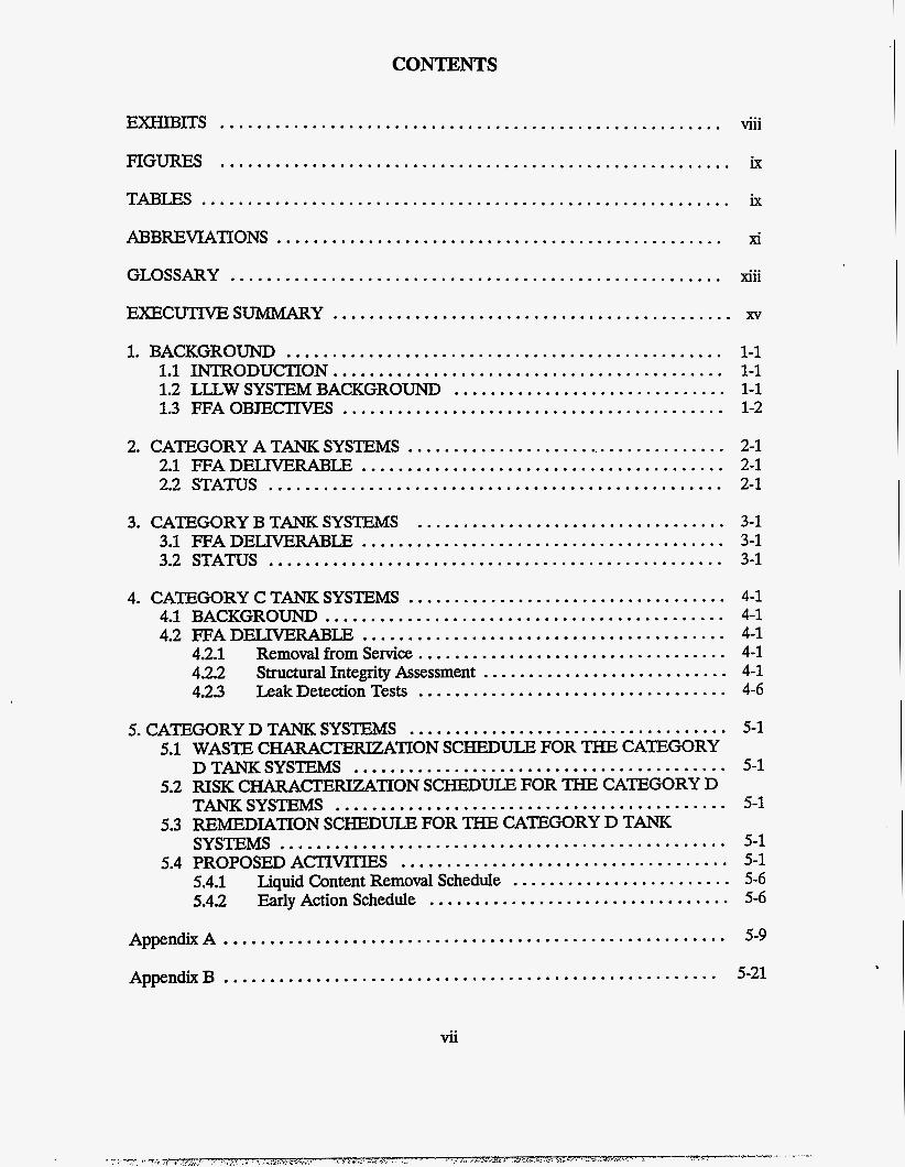
CONTENTS
EXHIBITS ....................................................... Viii
FIGURES ........................................................ ix
T A B B .......................................................... ix
GLOSSARY ...................................................... xiii
EXECUTIVESUMMARY ............................................ xv
ABBREVIATlONS ................................................. xi
1 . BACKGROUND ................................................ 1.1 INTRODUCTION ........................................... 1.3 F F A O ~ C I W E S .......................................... 1.2 LILW SYSTEM BACKGROUND ..............................
2 . CATEGORY A TANK SYSTEMS .................................... 2.1 FFA DELMRABIE ........................................ 2.2 STATUS ..................................................
3 . CATEGORY B TANK SYSTEMS .................................. 3.1 FFADELM3RABIE ........................................ 3.2 STATUS ..................................................
4 . CATEGORY C TANK SYSTEMS ................................... 4.1 BACKGROUND ............................................ 4.2 FFADELIVERAJ3LE ........................................
4.2.1 Removal from Service .................................. 4.2.2 Structural Integrity Assessment ........................... 4.23 Leak Detection Tests ..................................
5 . CATEGORY D TANK SYSTEMS ................................... 5.1 WASTE CHARACTERIZATION SCHEDULE FOR THE CATEGORY
DTANKSYSTEMS ......................................... 5.2 RISK C H A R A C T E m m O N SCHEDULE FOR THE CATEGORY D
TANKSYSTEMS ........................................... 5.3 REMEDIATION SCHEDULE FOR THE CATEGORY D TANK
SYSTEMS ................................................. 5.4 PROPOSED AcTIvrrJ[Es ....................................
5.4.1 Liquid Content Removal Schedule ........................ 5.4.2 Early Action Schedule .................................
AppendixA ....................................................... AppendixB ......................................................
vii
1-1 1-1 1-1 1-2
2-1 2-1 2-1
3-1 3-1 3-1
4-1 4-1 4-1 4-1 4-1 4-6
5-1
5-1
5-1
5-1 5-1 5-6 5-6
5-9
5-21
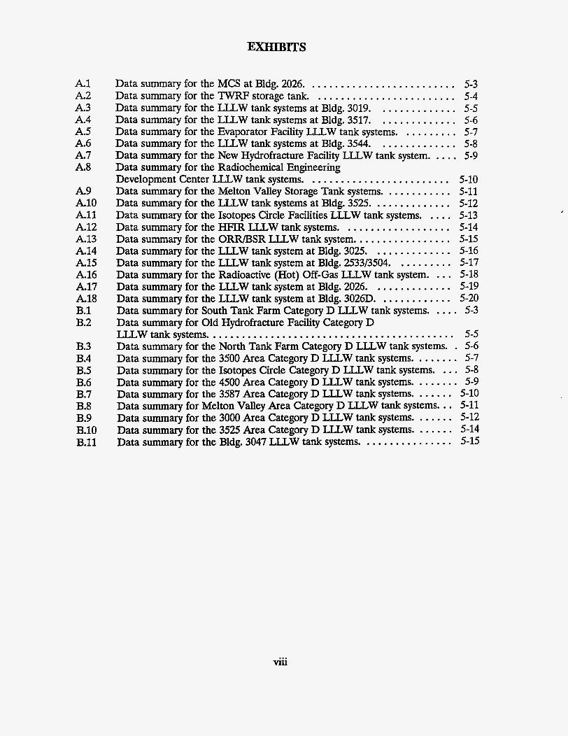
EXHIBITS
A1 A 2 A 3 A4 A5 A 6 A 7 A8
A 9 A10 All A12 A13 A14 A15 A16 A17 A18 B.l B.2
B.3 B.4 B.5 B.6 B.7 B.8 B.9 B.10 B.ll
Data summary for the MCS at Bldg . 2026 .......................... 5-3 Data summary for the TWRF storage tank. ........................ 5-4 Data summary for the LTLW tank systems at Bldg . 3019 . . . . . . . . . . . . . . 5-5 Data summary for the LLLW tank systems at Bldg . 3517 . . . . . . . . . . . . . . 5-6 Data summary for the Evaporator Facility LLLW tank systems . . . . . . . . . . 5-7 Data summary for the LLLW tank systems at Bldg . 3544 .............. 5-8 Data summary for the New Hydrofracture Facility LLLW tank system ..... 5-9 Data summary for the Radiochemical Engineering Development Center LLLW tank systems ......................... 5-10 Data summary for the Melton Valley Storage Tank systems ............ 5-11 Data summary for the LTLW tank systems at Bldg . 3525 .............. 5-12 Data summary for the Isotopes Circle Facilities LLLW tank systems . . . . . 5-13 Data summary for the HFIR LLLW tank systems ................... 5-14 Data summary for the ORR/BSR LLLW tank system ................. 5-15 Data summary for the LLLW tank system at Bldg . 3025 .............. 5-16 Data summary for the LLLW tank system at Bldg . 2533/3504 .......... 5-17 Data summary for the Radioactive (Hot) Off-Gas LLLW tank system . . . . 5-18 Data summary for the LLLW tank system at Bldg . 2026 .............. 5-19 Data summary for the LLLW tank system at Bldg . 3026D ............. 5-20 Data summary for South Tank Farm Category D LLLW tank systems . . . . . 5-3 Data summary for Old Hydrofracture Facility Category D LLLW tank systems ........................................... 5-5 Data summary for the North Tank Farm Category D LLLW tank systems . . 5-6 Data summary for the 3500 Area Category D LLLW tank systems ........ 5-7
5-8 5-9
5-10 5-11 5-12 5-14 5-15
Data summary for the Isotopes Circle Category D ILLW tank systems . . . . Data summary for the 4500 Area Category D LLLW tank systems ........ Data summary for the 3587 Area Category D LLLW tank systems ....... Data summary for Melton Valley Area Category D LLLW tank systems ... Data summary for the 3000 Area Category D ILLW tank systems ....... Data summary for the 3525 Area Category D LLLW tank systems ....... Data summary for the Bldg . 3047 LLLW tank systems ................
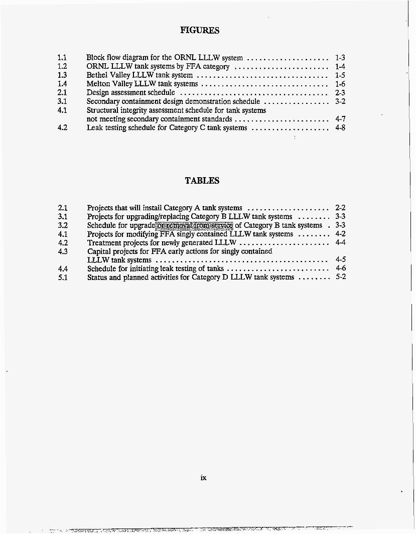
1.1 1.2 1.3 1.4 2.1 3.1 4.1
4.2
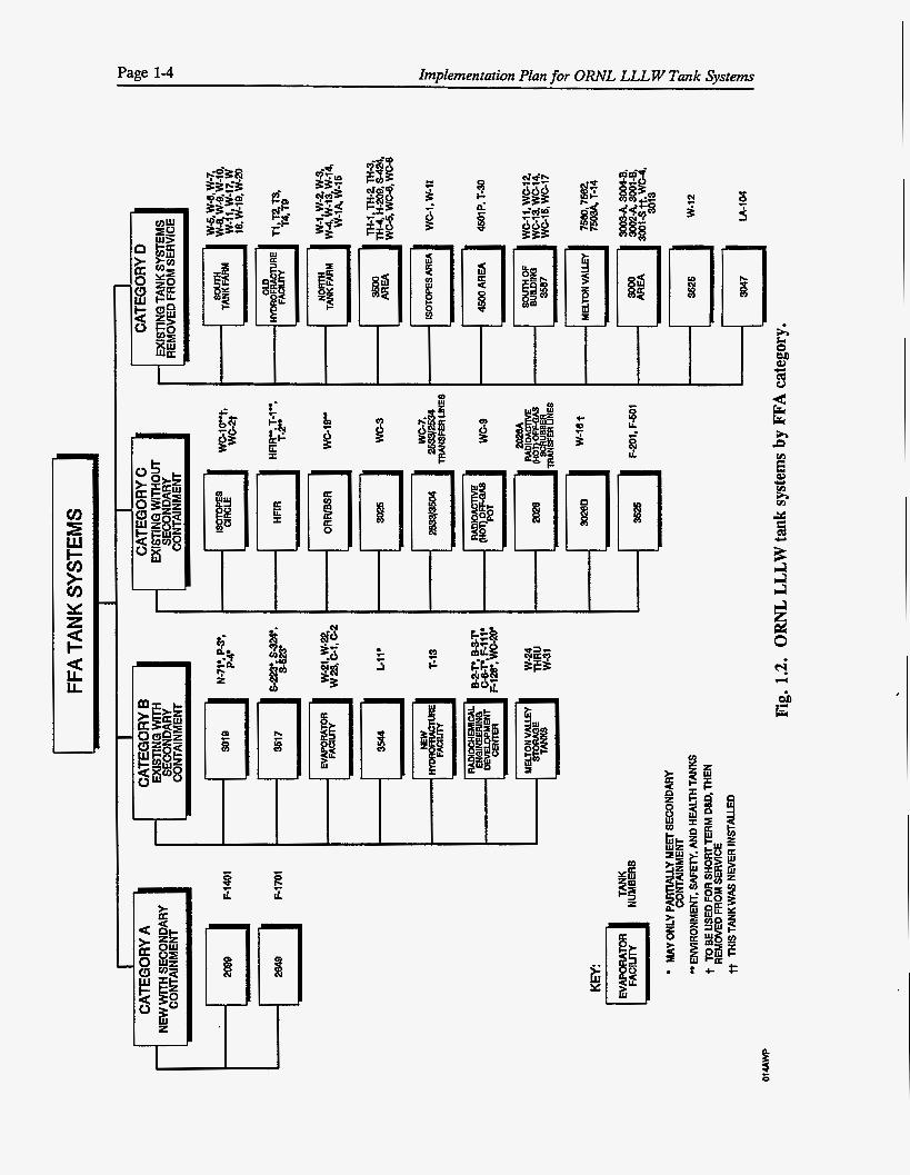
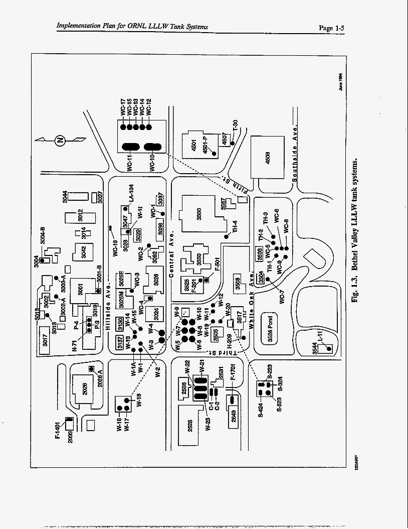
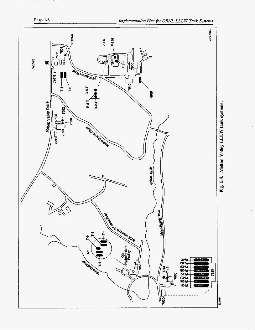
Block flow diagram for the ORNL LLLW system .................... 1-3 ORNL LLLW tank systems by FFA category ....................... 1-4 Bethel Valley LLLW tank system ................................ 1-5 Melton Valley LLLW tank systems ............................... 1-6 Design assessment schedule .................................... 2-3
3-2 Structural integrity assessment schedule for tank systems
4-7 Leak testing schedule for Category C tank systems ................... 4-8
Secondary containment design demonstration schedule ................ not meeting secondary containment standards .......................
TABLES
2.1 Projects that will install Category A tank systems .................... 2-2 3.1 Projects for upgradinglreplacing Category B LLLW tank systems ........ 3-3 3.2 Schedule for upgrad of Category B tank systems . 3-3 4.1 Projects for modifying FFA singly contained LLLW tank systems ........ 4-2 4.2 Treatment projects for newly generated LLLW ...................... 4-4 4.3 Capital projects for FFA early actions for singly contained
LLLW tank systems .......................................... 4-5 4.4 Schedule for initiating leak testing of tanks ......................... 4-6
Status and planned activities for Category D LLLW tank systems ........ 5.1 5-2
ix
. F . . . ' V I ..-5-F- $. .. . I . .<.>.A' ,:,<;i.?;:k~>%!:~y, 7. ..,...'.'...*..... .......... ?..........,........ ...... ....- . TTKg:x'' . ' ..... 5c. .. '. . . . -.a. .

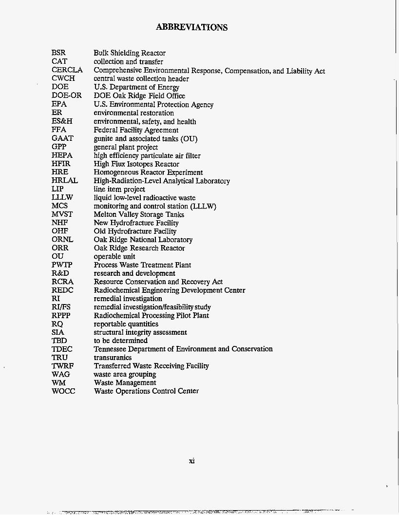
ABBREVIATIONS
BSR CAT CERCLA CWCH DOE
EPA ER ES&H FFA GAAT GPP HEPA HFIR HRE HRLAL LIP LLLW MCS MVST NHF OHF ORNL ORR ou PWTP R&D RCRA REDC RI RIPS RPPP RQ SIA TBD TDEC TRU TWRF WAG WM wocc
DOE-OR
Bulk Shielding Reactor collection and transfer Comprehensive Environmental Response, Compensation, and Liability Act central waste collection header U.S. Department of Energy DOE Oak Ridge Field Office U.S. Environmental Protection Agency environmental restoration environmental, safety, and health Federal Facility Agreement gunite and associated tanks (OU) general plant project high efficiency particulate air filter High Flux Isotopes Reactor Homogeneous Reactor Experiment High-Radiation-Level Analytical Laboratoiy line item project liquid low-level radioactive waste monitoring and control station (LLLW) Melton Valley Storage Tanks New Hydrofracture Facility Old Hydrofracture Facility Oak Ridge National Laboratory Oak Ridge Research Reactor operable unit Process Waste Treatment Plant research and development Resource Conservation and Recovery Act Radiochemical Engineering Development Center remedial investigation remedial investigatiodfeasibility study Radiochemical Processing Pilot Plant reportable quantities structural integrity assessment to be determined Tennessee Department of Environment and Conservation transuranics Transferred Waste Receiving Facility waste area grouping Waste Management Waste Operations Control Center
xi

GLOSSARY
Category A. A new or replacement tank system with secondary containment.
Category B. An existing tank system with secondary containment.
Category C. An existing tank system without secondary containment.
Category D. A tank system that has been removed from service.
Hot cell. An enclosure and its associated ancillary equipment that provides shielding, containment, and remote handling capabilities for work involving radioactive sources and materials. Ancillary equipment includes radioactive off-gas filtration and drains to the LLLW system.
LLLW tank. A stationary device, designed to contain an accumulation of LLLW. It is constructed primarily of nonearthen materials (e.g., concrete or steel) to provide structural support and containment. This tank will function as a waste storage or neutralization tank. This definition does not include tanks in which processing other than neutralization occurs or in which the entire tank contents may be recycled to a process.
Leaking. The passage of a hazardous liquid through the primary or secondary containment structure at a rate greater than or equal to the criteria established in the Leak Testing Plan for the Oak Ridge National Laboratoy Liquid Low-Level Waste System (ORNL/ER/SU b/92-SK263/1).
Raffinate. The part of a liquid remaining after its more soluble components have been extracted by a solvent.
Secondary containment tank system. For the purpose of the FFA, tank systems will be categorixd as secondarily contained if the capability exists to contain regulated substances released from the primary tank system until such wastes are detected and removed. Some ORNL LLLW tank systems may require modification of ancillary equipment and the upgrade of secondary containment to meet FFA requirements.
Tank system. A waste storage or waste treatment tank and its associated ancillary equipment and containment system. In the ORNL LLLW system, ancillary equipment includes sumps, piping, and valves to the waste tank(s) and piping and valves from the waste tank@).
1..
xlll

EXECUTIVE SUMMARY
This document summarizes the progress that has been made to date in implementing the plans and schedules for meeting the Federal Facility Agreement P A ) commitments for the Liquid Low-Level Waste (LLLW) System at Oak Ridge National Laboratory (ORNL). These commitments were initially submitted in ES/ER-17&DlY Federal Facility Agreement Plans and Schedules for Liquid Low-Level Radwactive Waste Tank Systems at Oak Ridge National Laboratory, Oak Edge, Tennessee. Information presented in this document provides a comprehensive summary to facilitate understanding of the FFA compliance program for L U W tank systems and to present plans and schedules associatedwith remediation, through the Comprehensive Environmental Response, Compensation, and Liability Act (CERCLA) process, of LLLW tank systems that have been removed from service.
ORNL has a comprehensive program underway to upgrade the LLT.,W system as necessary to meet the FFA requirements. The tank systems that are removed from service are being investigated and remediated through the CERCLAprocess. Waste and riskcharacterizations have been submitted. Additional data will be prepared and submitted to EP-EC as tanks are taken out of service and as required by the remedial investigatio4feasibility study (RIFS) process.
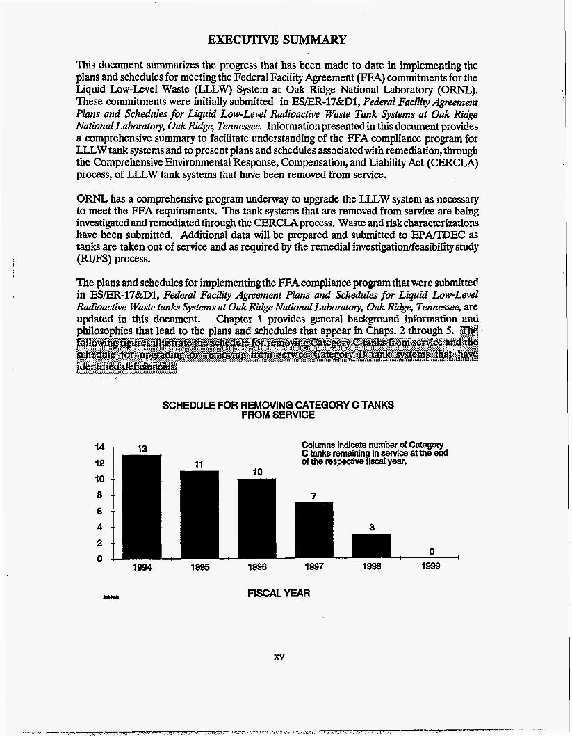
The plans and schedules for implementing the FFA compliance program that were submitted in ESER-l7&Dl, Federal Facility Agreement Plans and Schedules for Liquid Low-Level Radwactive Waste tanks Systems at Oak Ridge National Laboratory, Oak Ridge, Tennessee, are updated in this document. Chapter 1 provides general background information and
SCHEDULE FOR REMOVING CATEGORY C TANKS FROM SERVICE
14 - 12 I O - -
- -
a -.
4 - -
Columns indicate number of Category 13 Ctanksremalnin inserviceattheend
of the respectivesiscal year.
7
0 I
1994 1995 1997 1998 1W9
FISCAL YEAR ywll
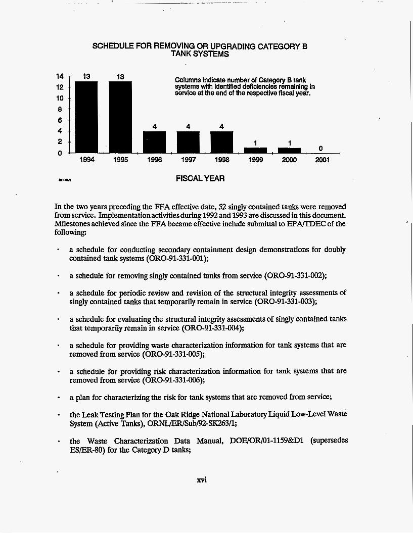
SCHEDULE FOR REMOVING OR UPGRADING CATEGORY B TANK SYSTEMS
14 T 13 13 Columns indicate number of Category B tank systems with identified deficiencies remaining in service at the end of the respedive fiscal year.
1994 1995 1996 1997 1998 1999 2Ooo 2001
FISCALYEAR
In the two years preceding the FFA effective date, 52 singly contained tanks were removed from service. Implementation activities during 1992 and 1993 are discussed in this document. Milestones achieved since the FWA became effective include submittal to EPA/TDEC of the following
- a schedule for conducting secondary containment design demonstrations for doubly contained tank systems (ORO-91-331-001);
a schedule for removing singly contained tanks from service (ORO-91-331-002);
a schedule for periodic review and revision of the structural integrity assessments of singly contained tanks that temporarily remain in service (ORO-91-331-003);
- a schedule for evaluating the structural integrity assessments of singly contained tanks that temporarily remain in service (ORO-91-331-004);
- a schedule for providing waste characterization information for tank systems that are removed from service (ORO-91-331-005);
a schedule for providing risk characterization information for tank systems that are removed from service (ORO-91331-006);
a plan for characterizing the risk for tank systems that are removed from service;
the Leak Testing Plan for the Oak Ridge National Laboratory Liquid Low-Level Waste System (Active Tanks), ORNuER/Sub/92-SIC263/1;
the Waste Characterization Data Manual, DOE/OR/01-1159&Dl (supersedes ESER-80) for the Category D tanks,
the Risk Characterization Data Manual ORNL/ER/Sub/90-W068/1 for the Category D tanks, first submittal;
the Design Demonstrations Category-B Tank Systems, DOWOR-1047;
the Detailed Leak Detection Test Plan and Schedule for the Oak Ridge National Laboratory, LLLW Active Tanks DOE/OR/Ol-l129&Dl;
Design Demonstration for the Remaining 19 Category B Tank Systems, DOE/OR/03- 1150&D1;
the Remediation Schedule for Inactive Liquid Low-Level Waste Storage Tanks at ORM, DOE/OR/Ol-l138&Dl;
the Detailed Leak Detection Test Plan and Schedule for the Oak Ridge National Laboratory LLLW Active Pipelines, DOE/OR/Ol-1167 & D1, September 1993;
the Risk Characterization Data Manual ORNUER/Sub/9O-W068/1 for the Category D tanks, final submittal; and
the Design Demonstrations for Category B Tank System Piping at Oak Ridge National Laboratory, Oak Ridge, Tennessee, DOWOR/O3-1195&Dl, February 1993.
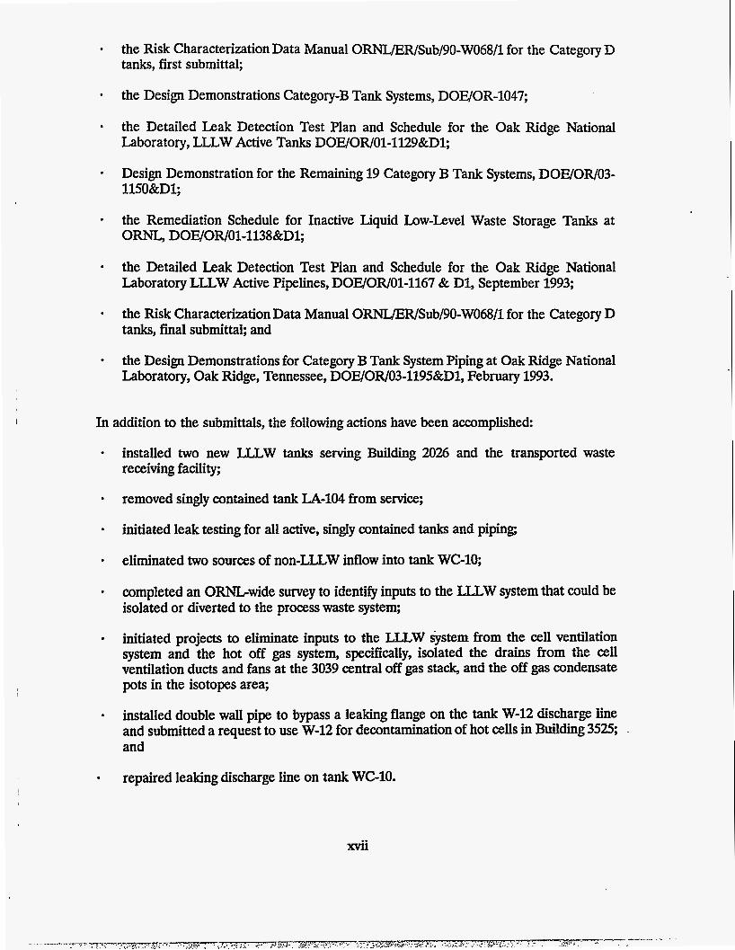
In addition to the submittals, the following actions have been accomplished
installed two new LLLW tanks serving Building 2026 and the transported waste receiving facility;
removed singly contained tank LA-104 from service;
initiated leak testing for all active, singly contained tanks and piping
eliminated two sources of non-LLLW inflow into tank WC-10;
completed an O m w i d e survey to identify inputs to the LLLW system that could be isolated or diverted to the process waste system;
initiated projects to eliminate inputs to the LLLW system from the cell ventilation system and the hot off gas system, specifically, isolated the drains from the cell ventilation ducts and fans at the 3039 central off gas stack, and the off gas condensate pots in the isotopes area;
installed double wall pipe to bypass a leaking flange on the tank W-12 discharge line and submitted a request to use W-12 for decontamination of hot cells in Building 3525, and
repaired leaking discharge line on tank WG10.
The tank systems at ORNL to which the FFA applies are listed in Fig. 1.2 of this report and in Appendix F of the FFA. Periodic changes occur in tank categories as tank systems are tested, upgraded or removed from service or for other reasons as agreed upon by the FFA signatories. Because of the time required to revise the FFA or this report, the lists in these documents may not reflect the latest approved status of some tanks. Any approved change in tank status that deviates from that shown in FFA Appendix F or this report will be supported by documentation on file in the Environmental Restoration Document Control Center and the Waste Management and Remedial Action Division Document Management Center. The FFA requirements applicable to each tank system are those for the latest approved category of that system.
Implementation Plan for O W L LLL W Tank Systems Page 1-1
1. BACKGROUND
1.1 INTRODUCTION
The Superfund Amendments and Reauthorization Act of the Comprehensive Environmental Response, Compensation, and Liability Act (CERCLA) requires a Federal Facility Agreement (FFA) for federal facilities placed on the National Priorities List. The Oak Ridge Reservation was placed on that list on December 21, 1989, and the agreement was signed in November 1991 by the Department of Energy Oak Ridge Operations Office (DOE-ORO), the U.S. Environmental Protection Agency (EPApRegion IV, and the Tennessee Department of Environment and Conservation (TDEC). The effective date of the FFA was January 1,1992. Section IX and Appendix F of the agreement impose design and operating requirements on the Oak Ridge National Laboratory (ORNL) liquid low-level radioactive waste (LLLW) tank systems and identify several plans, schedules, and assessments that must be submitted to EPAlTDEC for review or approval. The issue of EWER-l7&Dl Federal Facirity Agreement Plans and Schedules for Liquid Low-Level Radioactive Waste Tank Systems at Oak Ridge National Laboratoy, Oak Ridge, Tennessee in March 1992 transmitted to EPA/TDEC those plans and schedules that were required within 60 to 90 days of the FFA effective date. This document updates the plans, schedules, and strategy for achieving compliance with the FFA as presented in E/ER-l7&Dl and summarizes the progress that has been made to date. Chapter 1 describes the history and operation of the ORNL LLLW System and the objectives of the FFA. Chapters 2 through 5 contain the updated plans and,schedules for meeting FFA requirements. This document will continue to be periodically reassessed and refined to reflect newly developed information and progress.
1.2 LLLW SYSTEM BACKGROUND
ORNL is a multidisciplinaryresearch facility that began operation in 1943 as part of the Manhattan Project. The original mission of the laboratory was to develop a prototype graphite reactor and reprocess the reactor fuel for plutonium recovery. Subsequent to World War 11, the primary functions of ORNL were fuel reprocessing research; radioisotopes production and applicationsdevelopment; and development, testing, and operation of nuclear reactor concepts. More recently, the laboratory has increased its role in biological, environmental, energy, and materials research. As a consequence of these multidisciplinary research activities, heterogeneous wastes, including solid and liquid radioactive, hazardous, and mixed wastes, have been generated in varying amounts over time.
Since its establishment, ORNL has operated numerous facilities that generate LLLW. LLLW originates from radioactive liquid discarded into sinks and drains in research and development (R&D) laboratories and from facilities such as the Radiochemical Processing Pilot Plant (RPPP, Bldg. 3019), nuclear reactors, radioisotope production facilities, and the Process Waste Treatment Plant (PWTP)g ,,A
The LLLW system is a complex system with multiple facilities, users, and operators. The system is used for collection, neutralization, transfer, and concentration of aqueous radioactive waste solutions from generator facilities, followed by storage of the LLLW
Page 1-2 Implementation Plan for O W L LLL W Tank Systems
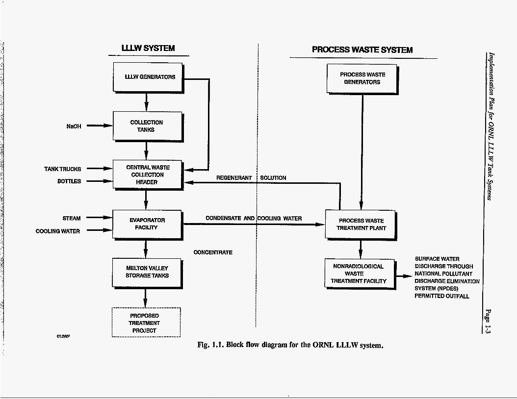
concentrate. Figure 1.1 is a block flow diagram depicting the movement of waste through the system. Waste solutions are typically accumulated at source buildings, often in collection tanks located inside the buildings, and discharged to below-grade collection tanks that receive wastes from several different source buildings. However, in many instances, LLLW is transferred directly to underground collection tanks or the central waste collection header (CWCH) from laboratory and hot-cell drains through unvalved piping.
A network of below-grade piping interconnects the various system components. Because their initial pH may be low, LLLW solutions often must be neutralized with sodium hydroxide (NaOH). The solutions are periodically transferred via the CWCH to the LLLW evaporator service tanks. From there, the solutions are sent to the LLLW evaporator facility where they are concentrated by a factor of approximately 301. The evaporator concentrate is then transferred via pipeline to the Melton Valley Storage Tanks (MVST). LLLW collection tanks are equipped with liquid-level instrumentation with high-level and low-level alarms to alert the Waste Operations Control Center (WOCC) of unusual conditions. The tanks are vented to the atmosphere through a central off-gas collection and filtration system operating at a negative pressure or through an individual tank filter system.
Most of the LLLW system was installed more than 30 years ago. The initial system and its subsequent modifications were designed to minimize radiation exposure to LLLW system users and operators. The system includes features such as unvalved, gravity-drained transfer lines to prevent waste backup into generator areas; shielded lines and tanks; and provisions for remote operations to minimize personnel exposure. As-built drawings for most of the older tank systems do not exist. Over the years, tank systems were abandoned as their integrity was breached or as programs were terminated. Some of the tanks were abandoned in place with liquid wastes and sludge left in them. As new tank systems were installed during the past 10 to 15 years, secondary containment and improved leak detection features were provided. The LLLW system is a mix of singly and doubly contained tank systems. The portions of the system that have been removed from service consist almost exclusively of tanks without secondary containment.
1.3 FTAOBJECTIVES
The objectives of the FFA are to ensure (1) that active tank systems slated to remain in service comply with the design and containment requirements specified in FFA Appendix F, Subsects. B and C; (2) that singly contained tank systems operated in the interim do not leak; and (3) that tank systems that are removed from service are evaluated and remediated through the CERCLA process. A breakdown of the LLLW tank systems by F'FA category is provided in Fig. 1.2. Figures 1.3 and 1.4 are maps showing the relative locations of LLLW tanks under the FFA in Bethel Valley and Melton Valley, respectively.
LUW SYSTEM
LUW GENERATORS v- REQENERANT
TANK TRUCKS - t CENTRALWASTE COLLECTION
BOTTLES =, HEAOER 4
* CONDENSATE AND STEAM EVAPORATOR > FACILITY COOUNQ WATER
CONCENTRATE
MELTON VALLEY STORAQETANKS
I I i TREATMENT I I
I PROJECT I
I--------------,---------!
PROCESS WASTESYSTEM
PROCESS WASTE GENERATORS
GOLUTION
PROCESS WASTE 00UNQ WATER
I NONRADIOLOQICAL 1 SURFACE WATER DISCHARGE THROUGH NATIONAL POLLUTANT DISCHARGE ELIMINATION SYSTEM (NPDES) PERMRTED OUTFALL
Fig. 1.1. Block flow diagram for the ORNL LLLW system.
Page 1 4 Implementation Plan for ORNL LLLW Tank Systems
I
t 6
Imphmentation Plan for ORNL LLLW Tmk Systems Page 1-5
I
f
Page 1-6 Implementation Plan for ORNL LLLW Tank Systems
Implementation Plan for O R E LLLW Tank Systems Page 2-1
2. CATEGORY A TANK SYSTEMS
2.1 FFA DELIVERABLE
The FFA requires DOE to prepare design assessments demonstrating that new or replacement tank systems meet the standards for design, containment, and release detection specified in FFA Appendix F, Sects. B and C. This chapter contains the schedules by which these assessments are being conducted and indicates the dates for submittal of information to E P m E C . Design assessments will be submitted to EPA and TDEC for approval at least 90 days prior to start of construction. An installation assessment will be performed at the end of the project to document changes to the system, and the assessmentwill be on file.
2.2 STATUS
Design assessments are being prepared for projects that install, upgrade, and/or replace deficient LLLW systems at ORNL. The first assessment was submitted for the general plant project FFA Compliance, Building 3019A,' which upgrades the LLLW system for Bldg. 3019A by installing a new doubly contained discharge line and a new valve box to tie the new line into the existing discharge line from the facility. The second assessment covered the upgrades to take place in the Melton Valley LLLW Collection and Transfer System line item project? This line item project installs new U L W discharge lines from the Radiochemical Engineering Development Center (REDC) and a Monitoring and Control Station (MCS) with a local collection tank, and replaces the existing U L W transfer line that runs between Melton and Bethel Valleys. Line item project Bethel Valley LLW-CAT System Upgrade installed an MCS with a local collection tank to serve buildings 2026 and an MCS equivalent in the new Transferred Waste Receiving Facility (TWRF). Phase I1 of the line item project will install an MCS to serve Bldgs. 3525 and 3025. The Bethel Valley FFA Upgrade line item project will connect Bldg. 3025 to this MCS. Line item project Melton Valley Storage Tank Capacity Increase will install new tanks to increase the storage capacity for concentrates from the central U W evaporator. The schedule for installing Category A systems is shown in Table 2.1.
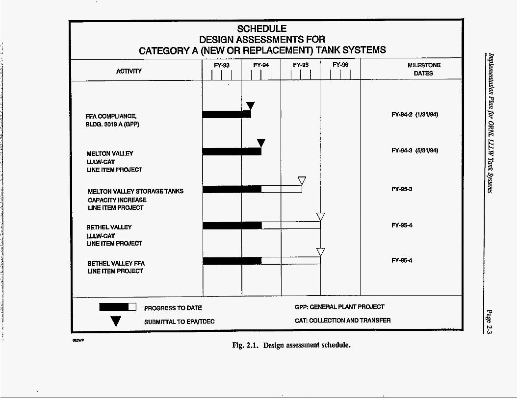
Future design assessmentswill be submitted at least 90 days prior to the start of project construction. The current schedule for submitting these documents is shown in Fig. 2.1.
- The schedules presented in this section are subject to annual renegotiation to adjust for updated information based on duration of activities or for changes in priorities and funding.
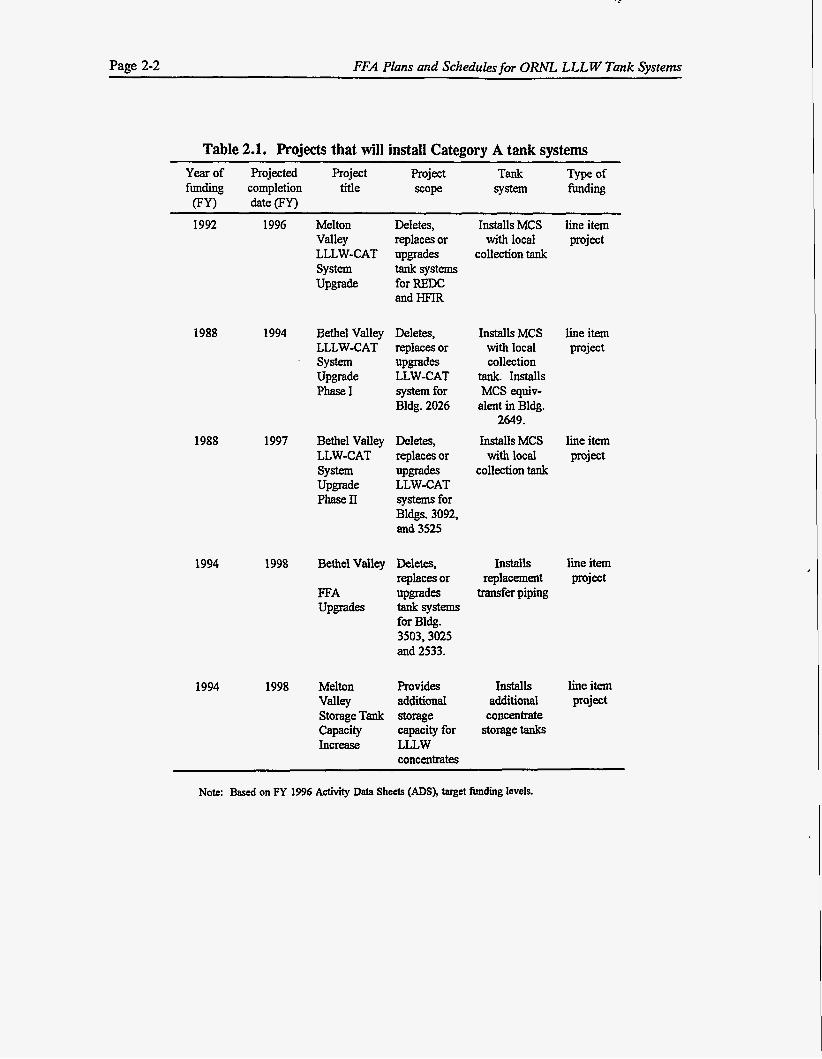
Page 2-2 FFA Plans and Schedules for ORNL LLLW Tank Systems
Table 2.1. Projects that will install Category A tank systems Yearof Projected Project Project Tank Type of funding completion title =ope system funding
(FYI date (FYI
1992 1996 Melton Deletes, Installs MCS line item Valley replaces or withlocal project LLLW-CAT upgrades collection tank system tank systems Upgrade for REX
and HFIR
1988
1988
1994
1994
1994
1997
1998
1998
Bethel Valley
system Upgrade Phase1
LLLW-CAT
Bethel Valley LLW-CAT system Upgrade PhaseII
Bethel Valley
FFA Upgrab
Melton Valley Storage Tank Capacity Increase
Deletes, replaces or upgrades
system for Bldg. 2026
Deletes, replaces or upgrab LLW-CAT systems for Bldgs. 3092, and 3525
LLW-CAT
Deletes, replaces or upgrades tanksy- for Bldg. 3503,3025 and 2533.
Provides additional storage capacity for LLLW concentrates
Installs MCS line item with local project collection
tank. Installs
alent in Bldg. 2649.
Installs MCS line item withlocal project
collection tank
MCS equiv-
Installs line item replacement project transfer piping
Installs line item additional project concentrate
storage tanks
-~
Note: Based on FY 1996 Activity Data Sheets (ADS), target funding levels.
SCHEDULE DESIGN ASSESSMENTS FOR
CATEGORY A (NEW OR REPLACEMENT) TANK SYSTEMS
FFA COMPLIANCE, BUM. SO19 A (QPP)
I I v MELTON VALLEY
LINE ITEM PROJECT LLLW-CAT
MELTON VALLEY STORAQE TANKS CAPACITY INCREASE UNE ITEM PROJECT
BRHELVALLEY
LINE ITEM PROJECT ULW-CAT
BETHEL VALLEY FFA UNE ITEM PROJECT
FY-95
27
FY-96 u
7
MILESTONE DATES
FY-962 (1/31/94)
FY-94-3 (5/31/94)
FY-95-3
FY-95Q
FY-954
m PROQRESS TO DATE v SUBMllTAL TO EPNTDEC
GPP: GENERAL PUNT PROJECT
CAT COLLECTION AND TRANSFER
mzm Fig. 2.1. Design assessment schedule.
Page 2-4 FFA Plans and Schedules for O W L LLLW Tank Systems
REFERENCES FOR CHAFI'ER 2
1. Design Assessment for Federal Facility Agreement Compliance Work, Building 3019A Liquid Low-Level Waste Tank Systems at Oak Ridge National Laboratory, Oak Ridge, Tennessee (DOE/OR/O3-1097&Dl), Ebasco, Oak Ridge, Tennessee, January 1994.
2. Design Assessment for Melton Valley Liquid Low-Level Waste Collection and Transfer System at Oak Ridge National Laboratory, Oak Ridge, Tennessee (DOE/OR/03- 1258&D1), Enserch Environmental Corp., Oak Ridge, Tennessee, May 1994.
Implementation Plan for ORNL LLLW Tank Systems Page 3-1
3. CATEGORY B TANK SYSTEMS
3.1 FFA DELIVERABLE
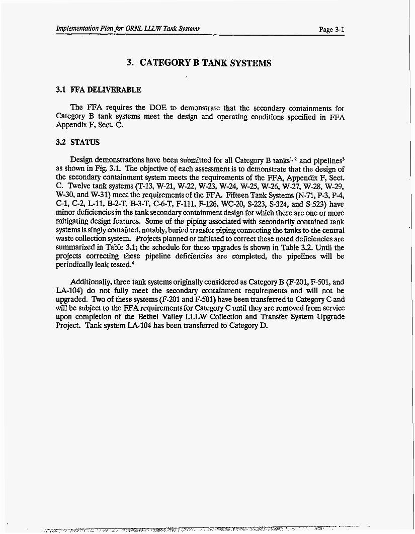
The FFA requires the DOE to demonstrate that the secondary containments for Category B tank systems meet the design and operating conditions specified in FFA Appendix F, Sect. C.
3.2 STATUS
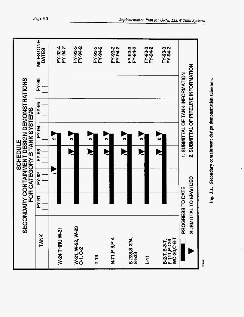
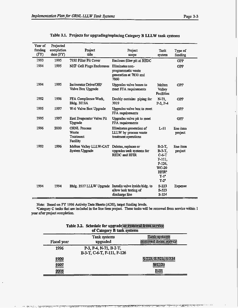
Design demonstrations have been submitted for all Category B tanks's * and pipelines3 as shown in Fig. 3.1. The objective of each assessment is to demonstrate that the design of the secondary containment system meets the requirements of the FFA, Appendix F, Sect. C. Twelve tank systems (T-13, W-21, W-22, W-23, W-24, W-25, W-26, W-27, W-28, W-29, W-30, and W-31) meet the requirements of the FFA. Fifteen Tank Systems (N-71, P-3, P-4, C-1, C-2, G11, B-2-T, B-3-T, C-6-T, F-111, F-126, WC-20, S-223, S-324, and S-523) have minor deficiencies in the tank secondary containment design for which there are one or more mitigating design features. Some of the piping associated with secondarily contained tank systems is singly contained, notably, buried transfer piping connecting the tanks to the central waste collection system. Projects planned or initiated to correct these noted deficiencies are summarized in Table 3.1; the schedule for these upgrades is shown in Table 3.2. Until the projects correcting these pipeline deficiencies are completed, the pipelines will be periodically leak tested?
Additionally, three tank systems originally considered as Category B (F-201, F-501, and LA-104) do not fully meet the secondary containment requirements and will not be upgraded. Two of these systems (F-201 and F-501) have been transferred to Category C and will be subject to the FFA requirements for Category C until they are removed from service upon completion of the Bethel Valley LLLW Collection and Transfer System Upgrade Project. Tank system LA-104 has been transferred to Category D.
Page 3-2 Implementation PIan for ORNL U W Tank Systems
I
t
implementation Plan for ORNL. LLLW Tank Systems Page 3-3
Table 3.1. Projects for upgradinglreplacing Category B LLLW tank systems
Yearof Projected funding completion Project Project Tank Typeof
(FY) hte(FY) title scope system funding 7930 Filter Pit Cover
~
1993 1995 1994 1995
Encloses filter pit at REDC GPP NHF Cell Plugs Enclosures Eliminates non-
programmatic waste generation at 7830 and 7860
GPP
1994 1995 Incinerator Drivel0H.F Valve Box Upgrade
Upgrades valve boxes to meet FFA requirements
Melton GPP
Facilities Valley
1992 1996 GPP FFA Compliance Work, Bldg. 3019A w-6 Valve Box Upgrade
Doubly contains piping for N-71, 3019 P-3, P-4
1995
1995
1996
1997
1997
2000
Upgrades valve box to meet FFA requirements Upgrades valve pit to meet FFA requirements Elites generation of LLLW by process waste treatment operations
GPP
East Evaporator Valve Pit
ORNL Process Waste Treatment Facility Melton Valley LLLW-CAT System Upgrade
Upgrade GPP
L-1 1 line item project
1992 1996 Deletes, replaces or B-2-T, lineitem upgrades tank systems for B-3-T, project REDC andHFIR C-6-T
F-111, F-126,
wc-20 HEZR' T-1' T-2'
1994 1994 Bldg. 3517 LLLW Upgrade Installs valve inside bldg. to S-223 Expense allow leak testing of S-523 discharge line S-324
Note: Based on FY 1996 Activity Data Sheets (ADS), target funding levels. 'Category C tanks that are included in the line item project. These tanks will be removed h m SerYice within 1
year after project completion.
Table 33. Schedule for upgrad@@- .......... A.X%.. ... c .A,. ....,..... # ..,. Z$&@&@V€& .................. ....A,... c .,......... Y
of Category B tank systems .... >
Fiscal vear umraded
B-3-T, C&T, F-111, F-126
Page 3-4 Implementation Plan for ORNL LLL W Tank Systems
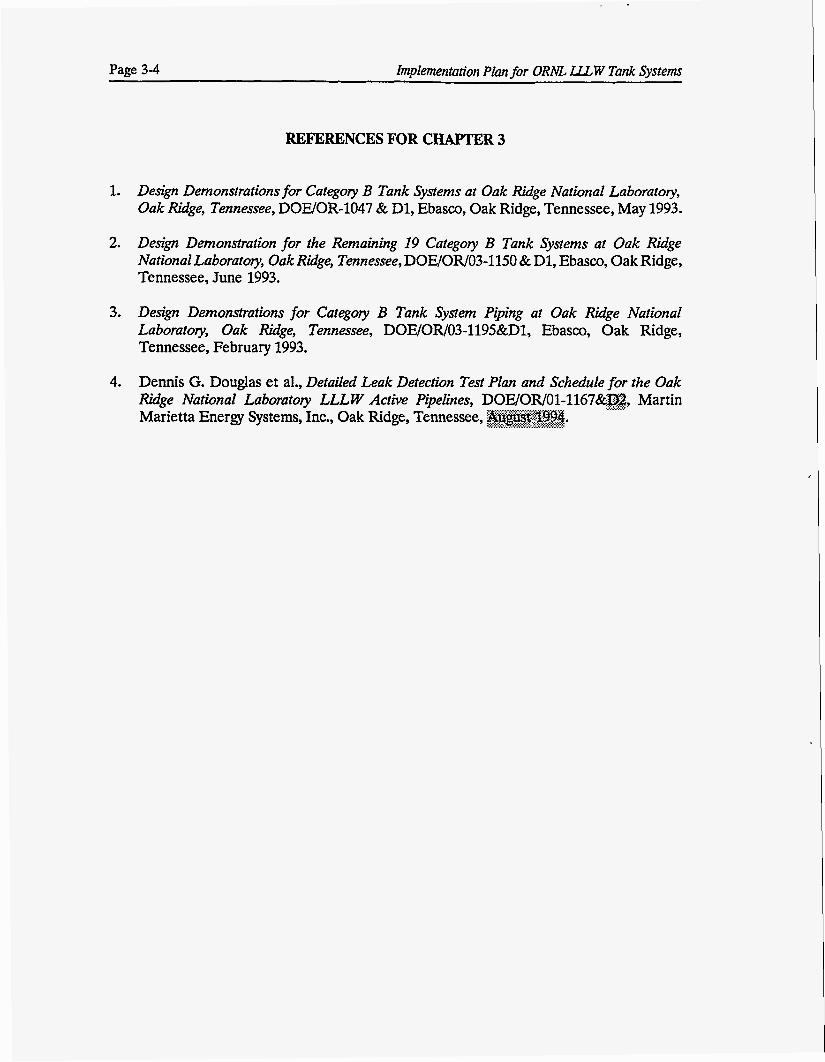
REFERENCES FOR CHAPTER 3
1.
2.
3.
4.
Design Demonstrations for Categoy B Tank Systems at Oak Ridge National Laboratory, Oak Ridge, Tennessee, DOWOR-1047 & D1, Ebasco, Oak Ridge, Tennessee, May 1993.
Design Demonstration for the Remaining 19 Categoy B Tank Systems at Oak Ridge National Laboratory, Oak Rgge, Tennessee, DOE/OR/O3-1150 & D1, Ebasco, Oak Ridge, Tennessee, June 1993.
Design Demonstrations for Category B Tank System Piping at Oak Ridge National Laboratoy, Oak Rdge, Tennessee, DOE/OR/03-1195&Dl, Ebasco, Oak Ridge, Tennessee, February 1993.
Dennis G. Douglas et al., Detailed Leak Detection Test Plan and Schedule for the Oak Ridge National Laboratory LLL W Active Pipelines, DOE/OR/01-1167&'02, ....A. . . . . ....... . . . Martin Marietta Energy Systems, Inc., Oak Ridge, Tennessee, A@&@@& ,a<.:.:.;. . .,.~~. :.:.:...:,~,:.~<.~.:.~:.
Implementation Plan for ORNL LLLW Tank Systems Page 4-1
4. CATEGORY C TANK SYSTEMS
4.1 BACKGROUND
The FFA allows tank systems that do not meet secondary containment standards to remain in service until the system can be upgraded or replaced, as long as the tank systems are not leaking and no adverse change occurs in the tank systems’baseline structural integrity data. If a tank system leaks, all programmatic inputs will be stopped, provided that complete shutdown of the tank system would not pose unacceptable environmental, health, or safety risk (e.g., reactor cooling-water treatment systems). Such systems will be repaired or replaced as soon as practicable.
4.2 FFA DELn7ERABLE
4.2.1 Removal from Service
The FFA requires DOE to remove from service any tanks that do not meet the secondary containment standards in FFA Appendix F, Subsect. C. The updated plan and schedule for removing Category C tank systems from service is shown in Table 4.1.
4.2.1.1 Status
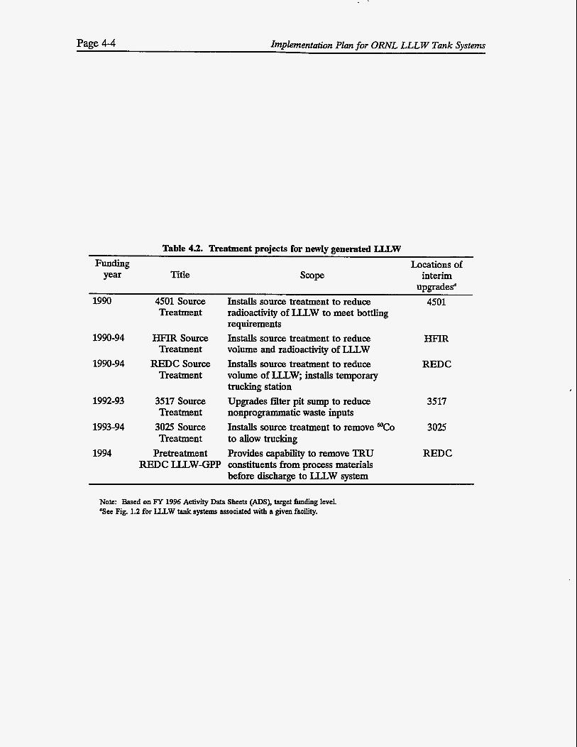
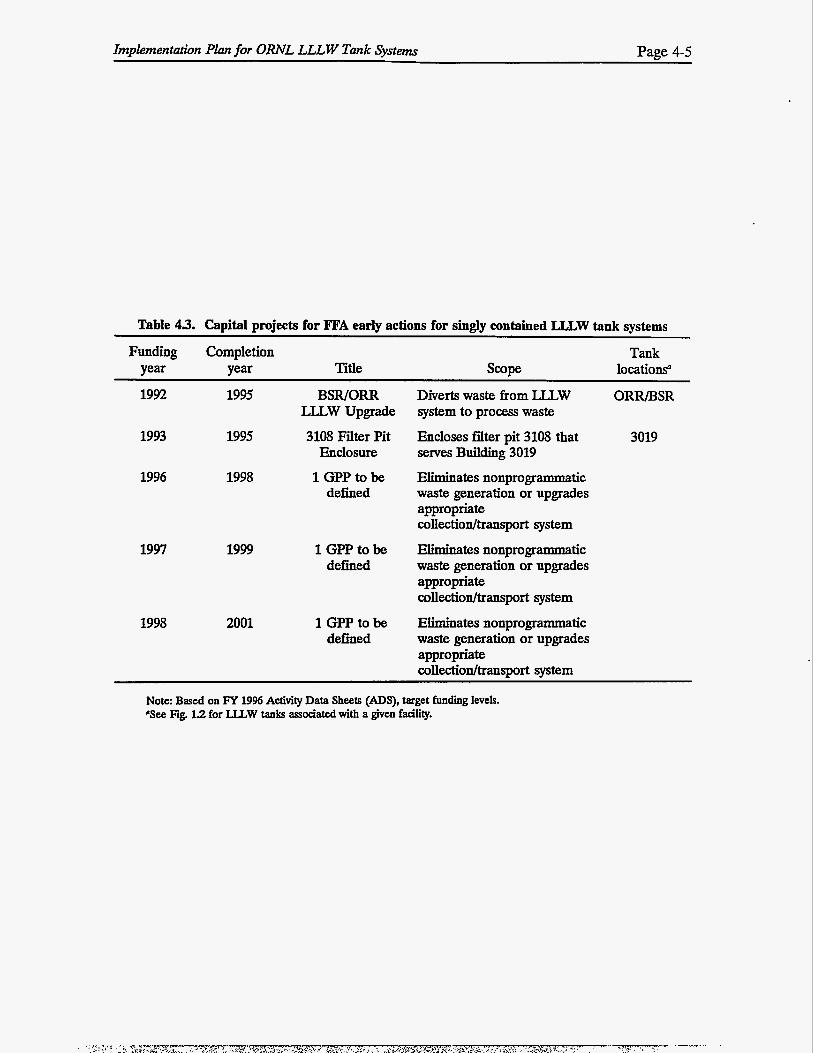
General plant projects (GPPs) and line item projects are being planned and implemented to upgrade or replace the LLLW tank systems that do not meet secondary containment and leak detection standards (Category C). The schedule for expense-funded projects for FFA early actions for singly contained LLLW tank systems is shown in Table 4.2; the schedule for capital projects is shown in Table 43.
The schedules presented in this section will continue to be subject to annual renegotiation to adjust for updated information based on duration of activities or for changes in priorities and funding.
4.2.2 Structural Integrity Assessment
The FFA requires DOE to provide information concerning the structural integrity of tank systems not meeting the secondary containment standards (Category C).
4.2.2.1 Status
The information to be submitted will follow the requirements of FFA Appendix F, Subsect. A, titled “Standards for Integrity Assessment for Tank System(s).” The structural integrity assessments (SIAs) will include tank system design data, generic descriptions of the hazardous or radioactive contents, a description of the system’s corrosion protection measures, the age of the tank system, and the results of leak tests on the tank system.
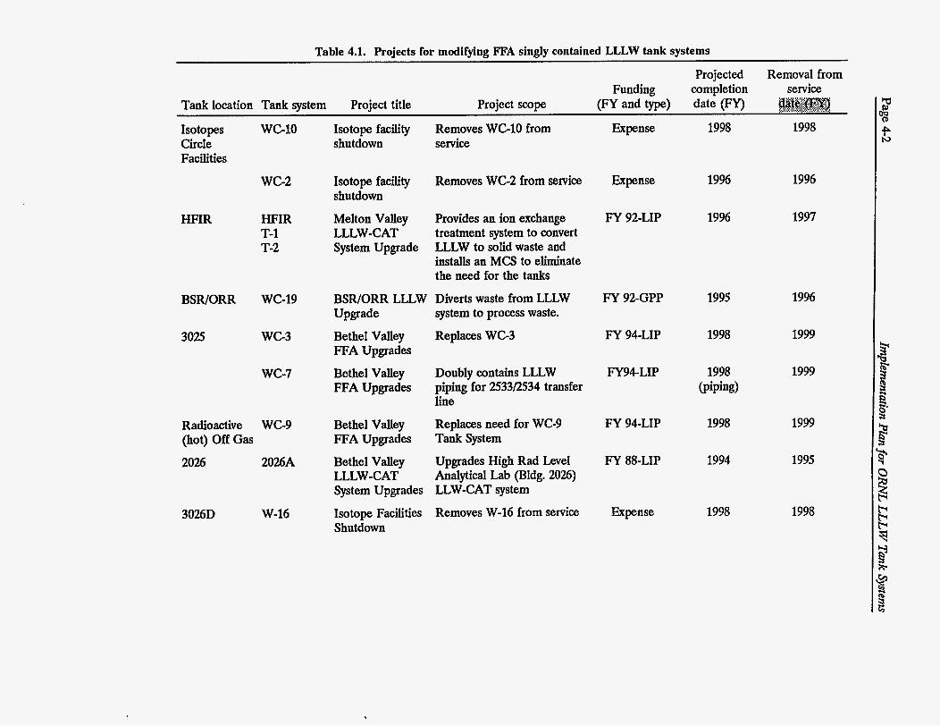
Table 4.1. Projects for modifying ITA singly contained LLLW tank systems
Projected Removal from Funding completion service
Tank location Tank system Project title Project scope (FY and type) date (Ey) &#%m ..r ....... >..m .:.:.: ......... ..
Isotopes wc-10 Isotope facility Circle shutdown Facilities
Isotope facility shutdown
Melton Valley
System Upgrade LLLW-CAT
Removes WC-10 from Expense 1998 1998 service
wc-2 Expense
FY 92-LIP
19%
19%
1996
1997
Removes WC-2 from service
Provides an ion exchange treatment system to convert LLLW to solid waste and installs an MCS to eliminate the need for the tanks
Diverts waste from LLLW system to process waste.
Replaces WC-3
HFIR HFIR T-1 T-2
BSR/ORR wc-19 BSR/ORR LLLW Upgrade
Bethel Valley FFA Upgrades
Bethel Valley FFA Upgrades
FY 92-GPP 1995 19%
3025 wc-3 FY 94-LIP 1998 1999
wc-7 Doubly contains LLLW piping for 2533f2534 transfer line
FY9CLIP 1999
Replaces need for WC-9 Tank System
FY 94-LIP 1998 1999
1995
Radioactive WC-9 (hot) Off Gas
Bethel Valley FFA Upgrades P
1994 2026 2026A Bethel Valley
System Upgrades
Isotope Facilities Shutdown
LLLW -CAT Upgrades High Rad Level Analytical Lab (Bldg. 2026) LLW-CAT system
Removes W-16 from service
FY 88-LIP
Expense 1998 1998 3026D W-16
;1 3 P
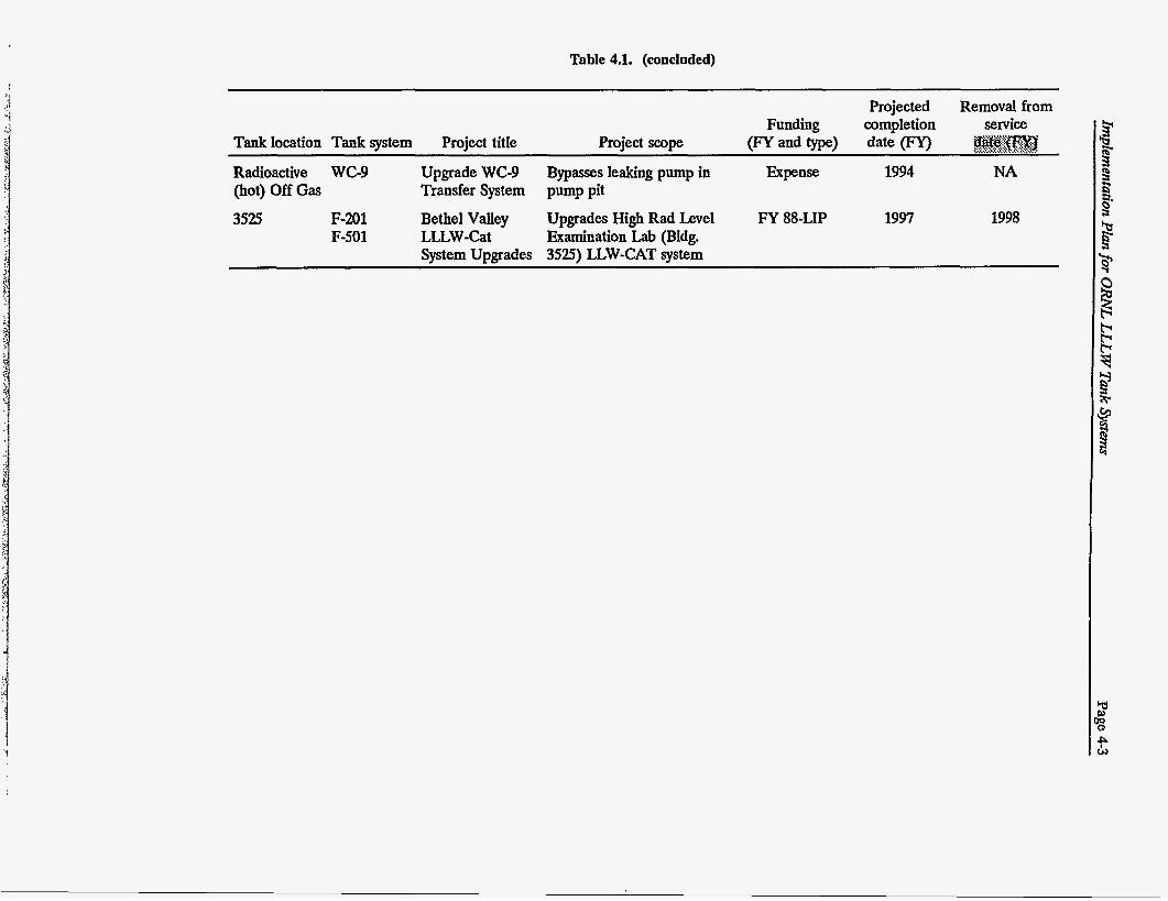
Table 4.1. (concluded)
Y
Projected Removal from Funding completion service
@#@@?yj Tank location Tank system Project title Project scope (Fy and W ) date 0 ~;~;:~~;:~~,.,~~;.:~.,.
Radioactive WC-9 Upgrade WC-9 Bypasses leaking pump in Expense 1994 NA (hot) Off Gas Transfer System pump pit
3525 F-201 Bethel Valley Upgrades High Rad Level FY 88-LIP 1997 1998 F-501 LLLW -Cat &amination Lab (Bldg.
System Upgrades 3525) LLW-CAT system
Page 4-4 Implementation Plan for O W L LLLW Tank Systems
Table 43. Treatment projects for newly generated I;LLW
Funding Locations of year Title scope interim
upgrades" 4501 Installs source treatment to reduce 1990 4501 Source
Treatment
1990-94
1990-94
1992-93
1993-94
1994
HFIR source Treatment
REDC Source Treatment
3517 Source Treatment 3025 Source Treatment
Pretreatment
radioactivity of LLLW to meet bottling requirements Installs source treatment to reduce volume and radioactivity of U W Installs source treatment to reduce volume of U W , installs temporary trucking station Upgrades filter pit sump to reduce nonprogrammatic waste inputs Installs source treatment to remove to allow trucking Provides capability to remove TRU
RFDC LLLW-GPP constituents from-process materials before discharge to LLLW system
HFIR
REDC
3517
3025
REDC
Note: Based on FY 19% Activity Data Sheets (ADS), target fimding level. 'see Fig. 1.2 for LLLW tank systems associated with a given W i .
Implementation Plan for O W L LLLW Tank Systems Page 4-5
Table 43. Capital projects for FFA early actions for singly contained J.,LL.W tank systems
Funding Completion Tank year year Title scope locations“
19% 1995 BSWORR LLLW Upgrade
1993 1995 3108 Filter Pit Enclosure
1996 1998 1 GPP to be defined
1997 1999 1 GPP to be defined
1998 2001 1 GPP to be defined
Diverts waste from LLLW ORR/BSR system to process waste
Encloses filter pit 3108 that serves Building 3019
Eliminates nonprogrammatic waste generation or upgrades appropriate collectiodtransport system
Eliminates nonprogrammatic waste generation or upgrades appropriate mllectiodtransport system
Eliminates nonprogrammatic waste generation or upgrades appropriate collection/transport system
3019
Note: Based on M 19% Activity Data Sheets ( A D S ) , target funding levels. ’See Fig. 1.2 for LLLW tanks associated with a given facility.
Page 4-6 Implementation Plan for ORNL LLLW Tank Systems
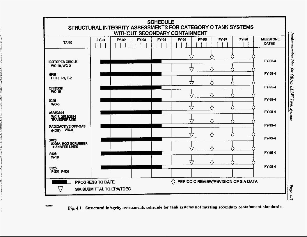
The structural integrity assessments for the tank systems not meeting secondary containment standards will be submitted in accordance with the schedule in Fig. 4.1. The schedule extension beyond the initial submittal of SIAs, as shown in Fig. 4.1, indicates the periodic review of SIAs. The results of the periodic reviews will be submitted to EPNIDEC. They will consist of the results of leak tests and notice of any change in the baseline design data provided in the SIA.
The schedules presented in this section will be subject to annual renegotiation to adjust for updated information based on duration of activities or for changes in priorities and funding.
4.23 Leak Detection Tests
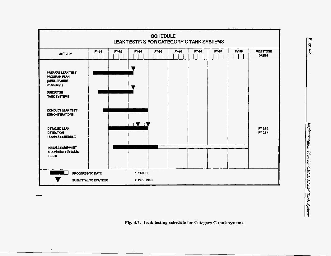
The FFA requires DOE to provide the schedule for periodic review and revision of the structural integrity assessments and to provide leak detection test results for Category C tank systems. These schedules are updated in Figs. 4.1 and 4.2 respectively.
4.23.1 Status
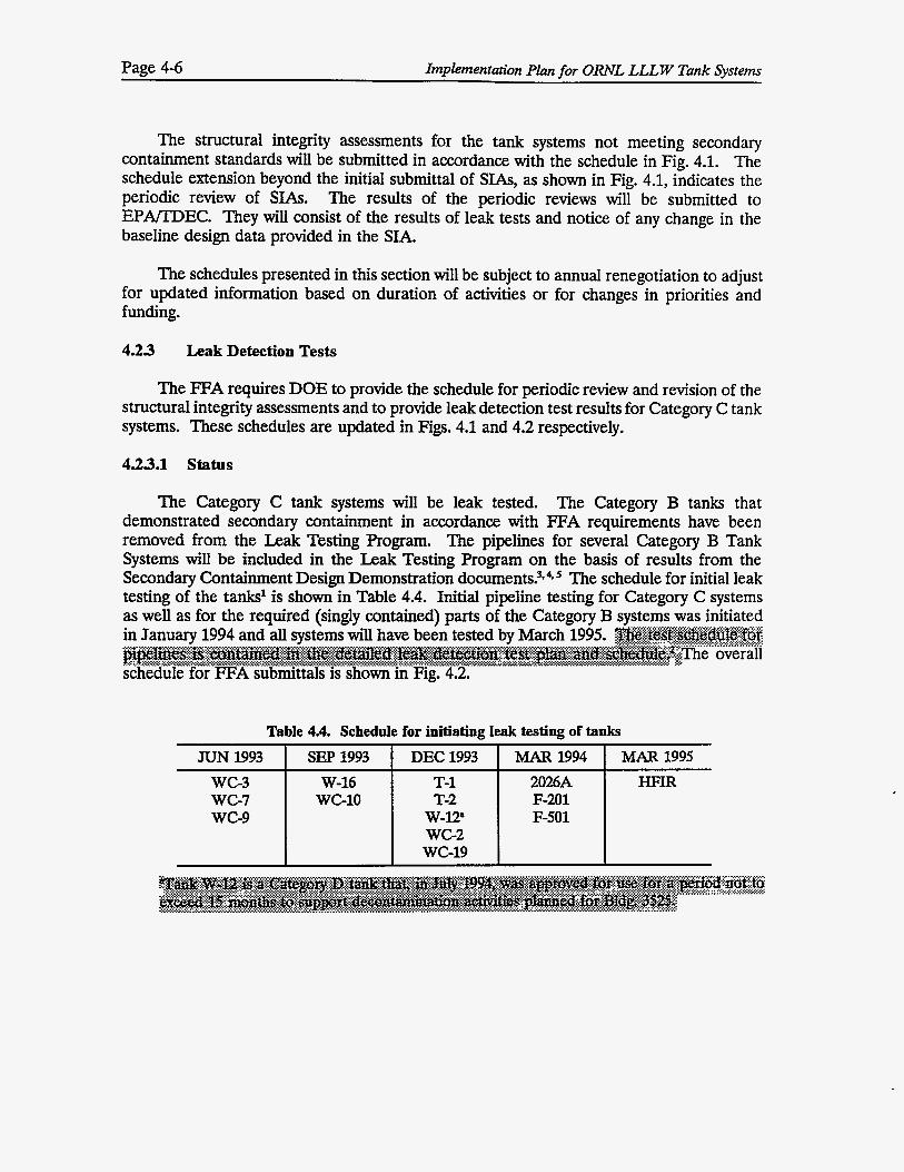
The Category C tank systems will be leak tested. The Category B tanks that demonstrated secondary containment in accordance with FFA requirements have been removed from the Leak Testing Program. The pipelines for several Category B Tank Systems will be included in the Leak Testing Program on the basis of results from the Secondary Containment Design Demonstration do~uments?*~*~ The schedule for initial leak testing of the tanks' is shown in Table 4.4. Initial pipeline testing for Category C systems as well as for the required (singly contained) parts of the Category B systems was initiated
schedule for FFA submittals is shown in Fig. 4.2.
Table 4.4. Schedule for initiating leak testing of tanks
JUN 1993 w c - 3 w c - 7 w c - 9
SEP 1993 I DEC 1993 I MAR 1994 W-16
WGlO T-1 T-2
w-12" WG2 wc-19
2026A F-201 F-501
MAR 1995 /II
SCHEDULE STRUCTURAL INTEGRITY ASSESSMENTS FOR CATEGORY C TANK SYSTEMS
TANK
ISOTOPES CIRCLE WG10, WG2
HFlR HRR, T-1, T-2
ORR/BSR WG19
3025 WC-3
2026 202BA, HOQ SCRUBBER TRANSFER UNES
3026 W-16
3525 F-201, F a 1
WITHOUT SECONDARY CONTAl N M ENT MILESTONE N-91 I FY-92 I FY-93 I FY-94 I FY-95 I FY-96 I FY-97 I FY-98 I
DATES
I I I I
FY-95-4
FY-954
FY-95-4
FY-95-4
FY-95-4
FY-95-4
FY-95-4
FY-954
FY-95-4
PROQRESS TO DATE SIA SUBMlllAL TO EPWDEC
0 PERIODIC REVIEW/REVISION OF SIA DATA
021W Fig. 4.1. Structural integrity assessments schedule for tank systems not meeting secondary containment standards.
PRIORITIZE TANKSYSTEMS
m-97
DETAILED LEAK D m c T K x l PlMS&SCHEDULE
MILESTONE DAlES
Fy-98
INSTALLEQUIPMENT & CONDUCT PERIODIC lESTs
m-92 FY-83 FY-91 m-94
PROQRESSTODATE
SUBMMALTO E P m E C
SCHEDULE LEAK TESTING FOR CATEGORY C TANK SYSTEMS
FY-93-2 FY-834
1 TANKS
2 PIPELINES
Fig. 4.2. Leak testing schedule for Category C tank systems.
Implementation Plan for ORNL LLLW Tank Systems Page 4-9
1.
2.
3.
4.
5.
REFERENCES FOR CHAPTER 4
Dennis G. Douglas and Joseph W. Maresca, Jr., Detailed Leak Detection Test Plan and Schedule for the Oak Ridge National Laboratory LLLW Active Tanks, DOE/OR/Ol- 1129&D1 ORNuER/Sub/92-SK263/&Dl, Martin Marietta Energy Systems, Inc., Oak Ridge, Tennessee, March 1993.
Dennis G. Douglas et al., Detailed Leak Detection Test Plan and Schedule for the Oak Ridge National Laboratory LLLW Active Pipelines, DOE/OR/Ol-l167&D~, <.:.:x.x, Martin Marietta Energy Systems, Inca, Oak Ridge, Tennessee &$@&f m#.
9 :<<<:.<: .....; :.:+:.:.:.::..:<.:.:. :.:.x*:<
Design Demonstrations for Category B Tank Systems at Oak Ridge National Laboratory, OakRidge, Tennessee DOE/OR-1047 & D1, Ebasco, Oak Ridge, Tennessee, May 1993.
Design Demonstration forthe Remaining 19 Category B Tank Systems at Oak Ridge National Laboratory, OakRidge Tennessee DOE/OR/03-1150 & D1, Ebasco, Oak Ridge, Tennessee, June 1993.
Design Demonstrations for Category B Tank System Piping at Oak Ridge National Laboratory, Oak Ridge, Tennessee DOE/OR/O3-1195&D1, Ebasco, Oak Ridge, Tennessee, February 1993.
Implementation Plan for ORNL LLL W Tank Systems Page 5-1
5. CATEGORY D TANK SYSTEMS
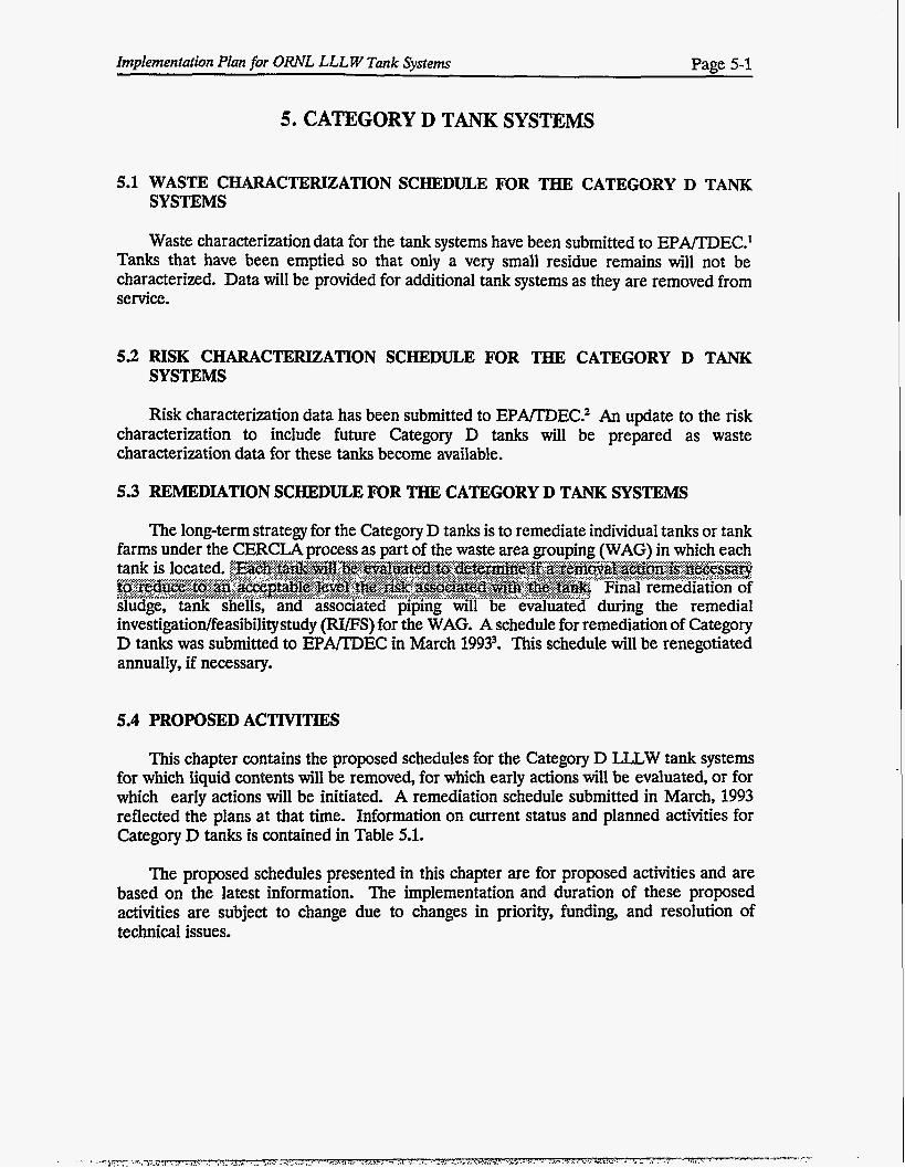
5.1 WASTE CHARACTERIZATION SCHEDULE FOR THE CATEGORY D TANK SYSTEMS
Waste characterization data for the tank systems have been submitted to EPAEDEC.' Tanks that have been emptied so that only a very small residue remains will not be characterized. Data will be provided for additional tank systems as they are removed from service.
5.2 RISK CHARACTERIZATION SCHEDULE FOR THE CATEGORY D TANK SYSTEMS
Risk characterization data has been submitted to E P m E C . 2 An update to the risk characterization to include future Category D tanks will be prepared as waste characterization data for these tanks become available.
5.3 REMEDIATION SCHEDULE FOR THE CATEGORY D TANK SYSTEMS
The long-term strategy for the Category D tanks is to remediate individual tanks or tank farms under the CERCLA process as part of the waste area grouping (WAG) in which each
sludge, tank shells, and associated piping will be evaluated during the remedial investigatiodfeasibilitystudy (RIES) for the WAG. A schedule for remediation of Category D tanks was submitted to E P D E C in March 19933. This schedule will be renegotiated annually, if necessary.
5.4 PROPOSED ACTIVITIES
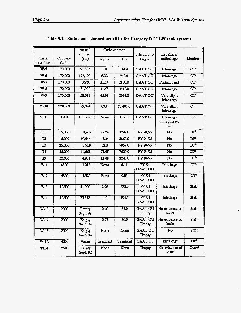
This chapter contains the proposed schedules for the Category D LLLW tank systems for which liquid contents will be removed, for which early actions will be evaluated, or for which early actions will be initiated. A remediation schedule submitted in March, 1993 reflected the plans at that time. Information on current status and planned activities for Category D tanks is contained in Table 5.1.
The proposed schedules presented in this chapter are for proposed activities and are based on the latest information. The implementation and duration of these proposed activities are subject to change due to changes in priority, funding, and resolution of technical issues.
Page 5-2 Implementation Plan for O W L LLLW Tank System
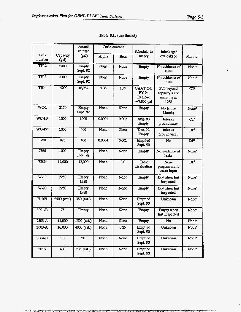
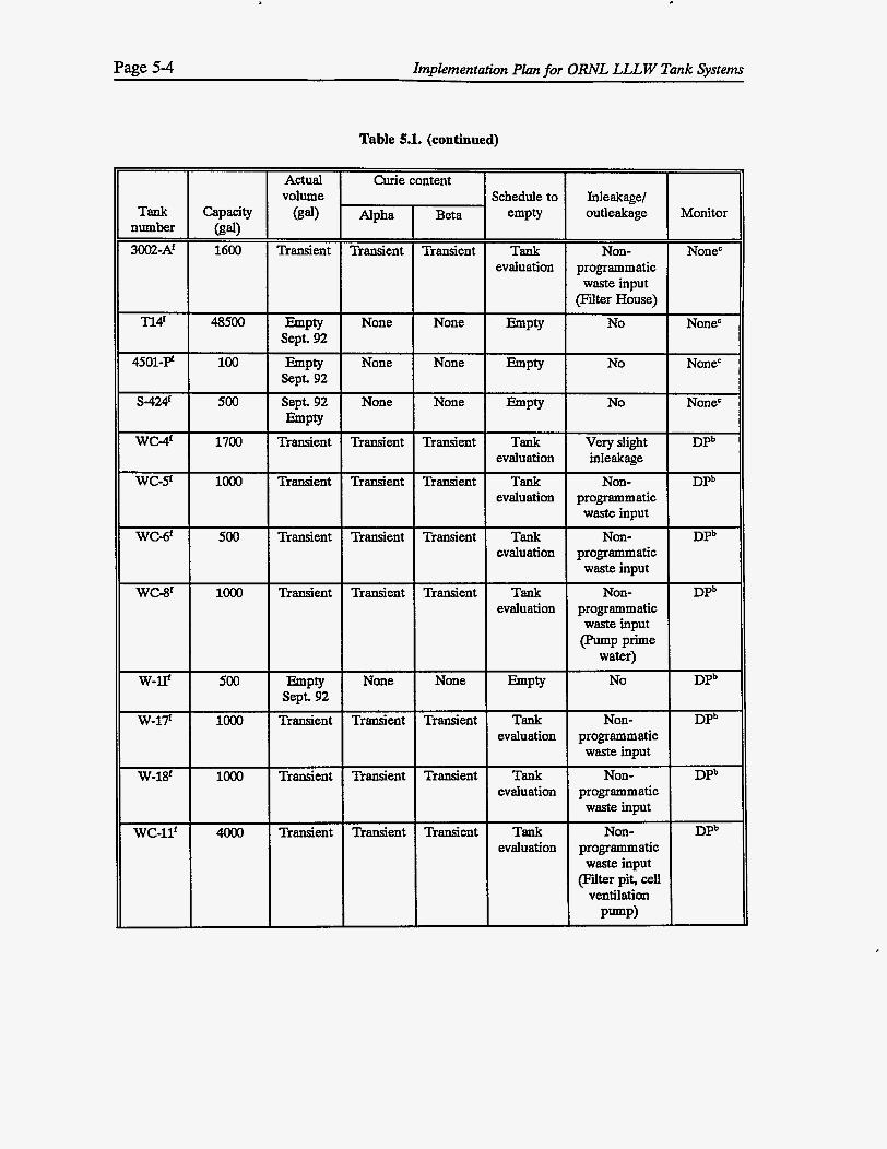
Table 5.1. Status and planned activities for Category D LLLW tank systems
Implementation Plan for O W L LLLW Tank Systems Page 5-3
Table 5.1. (continued)
w-19 2250 Empty None None Empty Drywhenlast None'
W-20 2250 Empty None None Empty Drywhenlast None'
H-209 WO(est.) 380(est.) None None Emptied Unknown None'
3001-B 75 Empty None None Empty Emptywhen None'
7503-A 11,OOO lSOO(est.) None None Empty No None' 3003-A 16,000 4OOO(est.) None 0.25 Emptied Unknown None'
3004-B 30 30 None None Emptied Unknown None'
3013 400 235(est.) None None Emptied Unknown None'
1988 inspected
1988 inspected
sept. 93
last inspected
SepL 93
Sept. 93
sept. 93
Page 5-4 Implementation Plan for ORNL LLLW Tank Systems
Table 5.1. (continued)
Actual Curie content I I I volume
Tank Capacity (gal) ' Alpha number (gal) 3W2-A' 1600 Transient Transient
Tl4f 48500 Empty None Sept. 92
Transient Tank Non- None' evaluation programmatic
waste input (Filter House)
None Empty No None'
None'
None'
Transient Tank Very slight DPb evaluation inleakage
Transient Tank Nan- DPb evaluation programmatic
waste input Transient Tank Nan- DPb
evaluation programmatic waste input
Transient Tank Non- DPb evaluation programmatic
waste input (pump Prime
water) None h P t y No DPb
Transient Tank Non- DPb evaluation programmatic
waste input Transient Tank Non- DPb
evaluation programmatic waste input
Transient Tank Non- DPb evaluation programmatic
(Fiiter pit, cell ventilation
waste input
Pump)
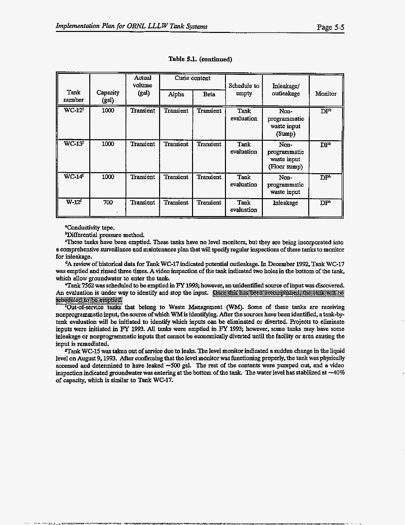
Implementation Plan for ORNL LLLW Tank Systems Page 5-5
wc-12f
WG13'
WC-14'
loo0
loo0
' loo0
T
Actual volume
(gal)
Transient
Transient
Transient
Transient
Table 5.1. (continued)
Curie
Alpha-
Transient
Transient
Transient
Transient
,ontent
Beta
Transient
Transient
Transient
Transient
Schedule to Inleakage/ outleakage Monitor
Tank Non- DPb
waste input
Tank Non- DPb
waste input
Tank Non- DPb
evaluation programmatic
(Sump)
evaluation programmatic
P o o r sump)
evaluation programmatic waste input
Tank Inleakage DPb evaluation
'Conductivity tape. Wfferential pressure method. These tanks have been emptied. These tanks have no level monitors, but they are being incorporated into
a comprehensive surveillance and maintenance plan that will specify regular inspections of these tanks to monitor for inleakage.
*A review of historical data for Tank WC-17 indicated potential outleakage. In December 1992, Tank WC-17 was emptied and rinsed three times. A video inspection of the tank indicated two holes in the bottom of the tank, which allow groundwater to enter the tank% Tank 7562 was scheduled to be emDtied in FY 1993. however. an unidentified source of inDut was discovered.
ay to identifi and stop the input.
that belong to Waste Management (WM). Some of these tanks are receiving nonprogrammatic input, the source of which WMis identifying. After the sources have been identified, atank-by- tank evaluation will be initiated to identify which inputs can be eliminated or diverted. Projects to eliminate inputs were initiated in FY 1993. AU tanks were emptied in FY 1993; however, some tanks may have some inleakage or nonprogrammatic inputs that cannot be economically diverted until the facility or area causing the input is remediated.
Tank WC-15 was taken out of service due to leaks. The level monitor indicated a sudden change in the liquid level on August 9,1993. After cwfirming that the level monitor was functioning properly, the tank was physically accessed and determined to have leaked -500 gal. The rest of the contents were pumped out, and a video inspection indicated groundwater was entering at the bottom of the tank. The water level has stabilized at -40% of capacity, which is similar to Tank WC-17.
Page 5-6
5.4.1 Liquid Content Removal Schedule
Implementation Plan for O W L LLLW Tank Systems
The liquid contents in the Old Hydrofracture (OW) Tanks (T-1, T-2, T-3, T-4, and T-9) will be removed by using the existing piping system if possible. Ifthe existing system cannot be used, a valve box will be built that will bypass the old pumps and tie into the active LLLW system. Some liquid will be left in the tanks to prevent the sludge from drying out.
Tank TH-4 will have approximately 7,000 gal of the liquid contents removed this year. This tank is already in the CERCLA process as part of the Gunite and Associated Tanks Operable Unit ( G U T OU). At present, this tank is 111 beyond its design capacity. The purpose of partially removing the liquids is to prevent the tank from overfilling and potentially releasing liquid to the environment. Since this tank is not connected to an active LLLW system, the tank will have to be emptied by trucking the liquid to the LLLW system.
Gunite tanks W-6 and W-10 will be partially emptied of liquid contents to demonstrate the ability to empty these gunite tanks as a routine operation or in an emergency situation. Because of the radioactive content of the sludge, enough liquid (-50,000 gal) should be left in each tank to provide shielding.
5.4.2 Early Action Schedule
The gunite tanks in the South Tank Fann (W-5, W-6, W-7, W-8, W-9, and W-10) will have survey markers installed on one of the manways on each tank. The elevation of these markers will be monitored for any unusual fluctuations which may give an early warning of impending dome failure.
Tanks T-30,3013,3001-B, 3004-B, and H-209 . These tanks are
meetings.
A removal action is being considered for the Thorium Tank Farm (Tanks WC-5, WC-6, WC- 8, TH-1, TH-2, and TH-3). Some of the tanks receive inleakage and have sludge in them. Owing to the cost of maintaining these tanks and the period of time before these tanks are scheduled to enter the CERCLA process, a removal may be appropriate to begin the remediation process sooner. However, before a removal action can be initiated, all non-programmatic inputs must be stopped or diverted and the risk associated with these tanks must be shown to justify the action. Other tank farms are being evaluated for removal actions as well.
Implementation Plan for ORNL LLLW Tank Systems Page 5-7 L
REFERENCES FOR CHAPTER 5
1. Waste Characterization Data for the Oak Ridge National Laboratory Inactive Liquid Low- Level Radioactive Waste Tank Systems, DOE/OWOl-l159&Dl (Supersedes ORNL&R-80), Martin Marietta Energy Systems, Inc., Oak Ridge, Tennessee, June 1993.
2. Risk Characterization Data Manual for Inactive Liquid Low-Level Waste Tank Systems at Oak Ridge National Laboratory, Oak Ridge, Tennessee, ORNL/EWSub/9O-LJ068/1, H&R Technical Associates, Inc., Oak Ridge, Tennessee, September 1992.
3. Remediation Schedule for Inactive Liquid Low-Level Waste Storage Tanks at the Oak Ridge National Laboratory, Oak Ridge, Tennessee, DOE/OR/Ol-l138&Dl, H&R Technical Associates, Inc., Oak Ridge, Tennessee, March 1993.
Appendix A
DATA SUMMARIES FOR CATEGORY A, B, AND C TANK SYSTEMS

Implementation PIan for ORhZ LLLW Tank Systems Page A-3
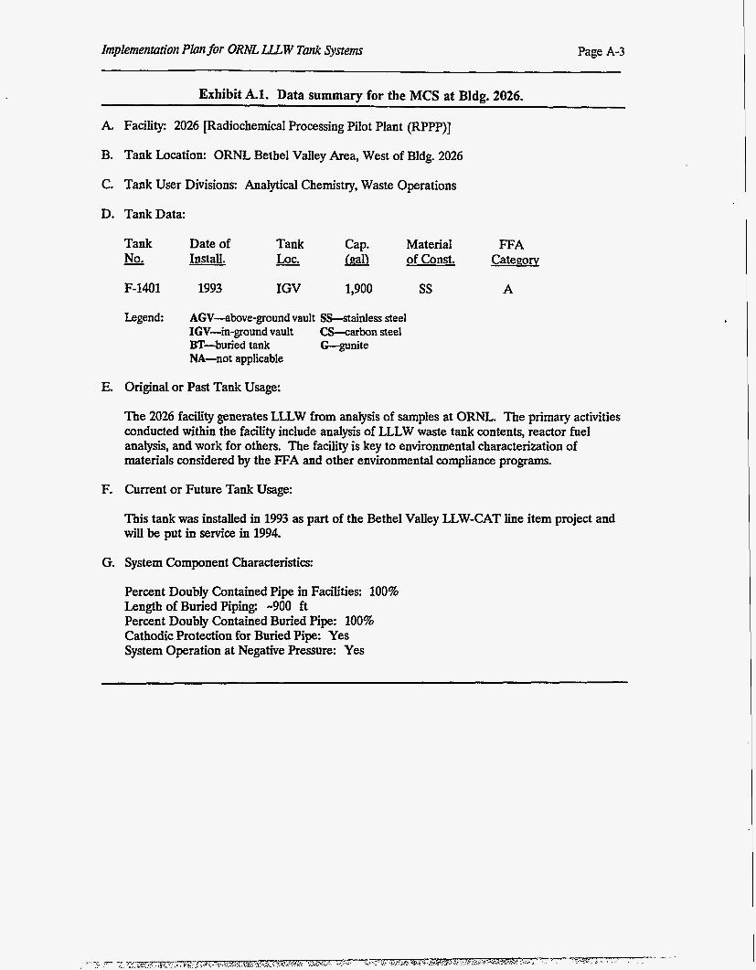
Exhibit A.l. Data summary for the MCS at Bldg. 2026.
A, Facility: 2026 [Radiochemical Processing Pilot Plant (RPPP)]
B. Tank Location: ORNL Bethel Valley Area, West of Bldg. 2026
C. Tank User Divisions: Analytical Chemistry, Waste Operations
D. TankData:
Tank - No.
F-1401
Legend:
Date of - Install.
1993
Tank - LOC.
IGV
Cap. m 1,900
Material of Const.
AGV-above-ground vault SS-stainless steel IGV-in-ground vault CS-carbon steel BT-buried tank G-gunite NA-not applicable
ss
FFA Category
A
E. Original or Past Tank Usage:
The 2026 facility generates LLLW from analysis of samples at ORNL. The primary activities conducted within the facility include analysis of LLLW waste tank contents, reactor fuel analysis, and work for others. The facility is key to environmental characterization of materials considered by the FFA and other environmental compliance programs.
F. Current or Future Tank Usage:
This tank was installed in 1993 as part of the Bethel Valley UW-CAT line item project and will be put in service in 1994.
G. System Component Characteristics:
Percent Doubly Contained Pipe in Facilities: 100% Length of Buried Piping. -900 ft Percent Doubly Contained Buried Pipe: 100% Cathodic Protection for Buried Pipe: Yes System Operation at Negative Pressure: Yes
Page A 4 Implementation Plan for ORhE LLLW Tank Systems
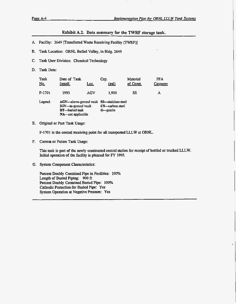
Exhibit A.2. Data summary for the TWRF storage tank.
A. Facility: 2649 [Tnnsferred Waste Receiving Facility (TWRF)]
B. Tank Location: ORNL Bethel Valley, in Bldg. 2649
C. Tank User Division: Chemical Technology
D. TankData:
E.
F.
G.
Tank - No.
Material of const.
FFA Categoxv
F-1701 ss A
Legend:
Date of Tank cap. Install. - LOC. m
1993 AGV 1,900
AGV-above-ground vault SS-stainless steel IGV-in-ground vault CS-carbon steel
NA-not applicable BT-hied tank G--gunite
Original or Past Tank Usage:
F-1701 is the central receiving point for all transported LLLW at O m .
Current or Future Tank Usage:
This tank is part of the newly constructed central station for receipt of bottled or trucked LLLW. Initial operation of the facility is planned for FY 1995.
System Component Characteristics:
Percent Doubly Contained Pipe in Facilities: 100% Length of Buried Piping: 900 ft Percent Doubly Contained Buried Pipe: 100% Cathodic Protection for Buried Pipe: Yes System Operation at Negative Pressure: Yes
Implementation Plan for ORM LLLW Tank Systems Page A-5
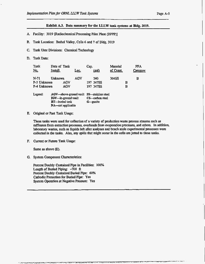
Exhibit A.3. Data summary for the LLLW tank systems at Bldg. 3019.
A. Facility: 3019 [Radiochemical Processing Pilot Plant (RPPP)]
3. Tank Location: Bethel Valley, Cells 6 and 7 of Bldg. 3019
C. Tank User Divisions: Chemical Technology
D. TankData:
Tank - No.
Date of Tank Install. Lot.
N-7 1 Unknown P-3 unknown AGV P-4 unknown AGV
AGV 240 197 347SS 197 347SS
Material of const.
304SS B B
FFA Catee;ow
B
Legend: AGV-above-ground vault Ss--stainless steel IGV-in-ground vault CS-carbon steel
NA-not applicable BT-buriedtank G--gunite
E. Original or Past Tank Usage:
These tanks were used for collection of a variety of production waste process streams such as Minates from extraction processes, overheads from evaporation processes, and others. In addition, laboratory wastes, such as liquids left after analyses and bench scale experimental processes were collected in the tanks. Also, any spills that might occur in the cells are jetted to these tanks.
F. Current or Future Tank Usage:
Same as above (E).
G. System Component Characteristics:
Percent Doubly Contained Pipe in Facilities: 100% Length of Buried Piping: -700 f t Percent Doubly Contained Buried Pipe: 60% Cathodic Protection for Buried Pipe: Yes System Operation at Negative Pressure: Yes
Page A 4 Implementation PIan for ORhE L.LL W Tank Svstems
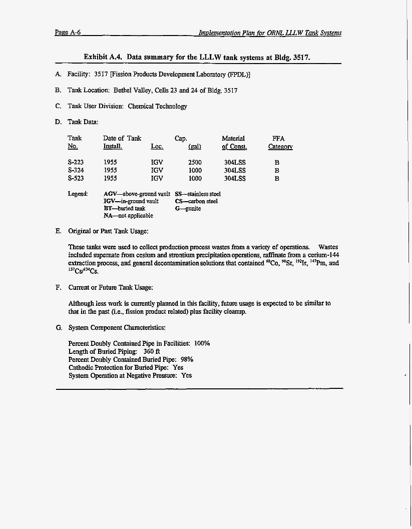
Exhibit A.4. Data summary for the LLLW tank systems at Bldg. 3517.
A. Facility: 3517 [Fission Products Development Laboratory (FPDL)]
B. Tank Location: Bethel Valley, Cells 23 and 24 of Bldg. 3517
C. Tank User Division: Chemical Technology
D. TankData:
E.
F.
G.
Tank - No.
S-223 S-324 S-523
Legend:
Date of Tank Install.
1955 1955 1955
IGV IGV IGV
QP. rn 2500 1000 1000
Material of Const.
AGV-above-ground vault SCstainless steel IGV-in-ground vault CS--carbon steel
NA-not applicable BT-bWied tank G--gunite
304LSS 304LSS 304LSS
Original or Past Tank Usage:
FFA Categow
B B B
These tanks were used to collect production process wastes from a variety of operations. Wastes included supernate from cesium and strontium precipitation operations, &inate from a cerium-144 extraction process, and general decontamination solutions that contained @Co, %Sr, 19*Ir, 147Pm, and 137cs/134cs. Current or Future Tank Usage:
Although less work is currently planned in this facility, future usage is expected to be similar to that in the past (i.e., fission product related) plus facility cleanup.
System Component Characteristics:
Percent Doubly Contained Pipe in Facilities: 100% Length of Buried Piping: 360 A Percent Doubly Contained Buried Pipe: 98% Cathodic Protection for Buried Pipe: Yes System Operation at Negative Pressure: Yes
Implementation Plan for ORNL LJLW Tank Systems Page A-7
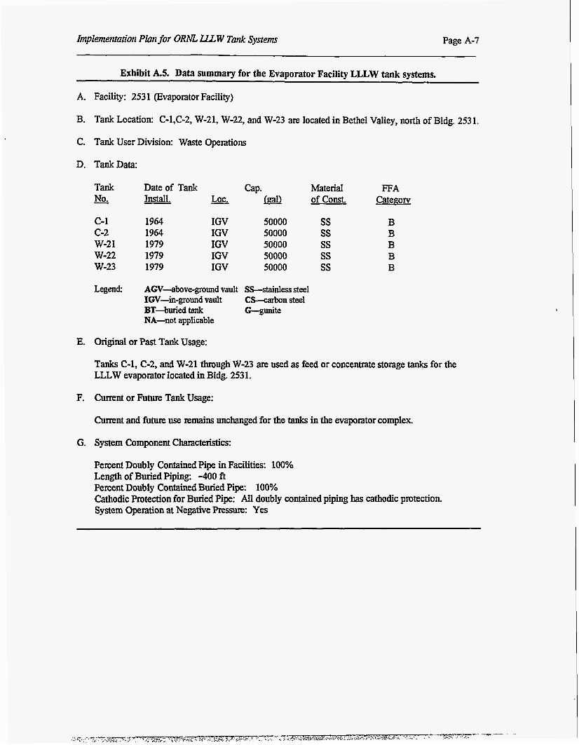
Exhibit AS. Data summary for the Evaporator Facility LLLW tank systems.
A. Facility: 253 1 (Evaporator Facility)
B. Tank Location: C-l,C-2, W-21, W-22, and W-23 are located in Bethel Valley, north of Bldg. 2531.
C. Tank User Division: Waste Operations
D. TankData:
Tank Date of Tank cap. Material FFA - No. - Install. - LOC. w of const. Category
c-1 1964 IGV 50000 ss B c-2 1964 IGV 50000 ss B w-2 1 1979 IGV 50000 ss B w-22 1979 IGV 50000 ss B W-23 1979 IGV 50000 ss B
Legend AGV-above-ground vault SS-stainless steel IGV-in-ground vault CS-carbon steel
NA-not applicable BT-buried tank G-gunite
E. Original or Past Tank Usage:
Tanks C-1, C-2, and W-21 through W-23 are used as feed or concentrate storage tanks for the LLLW evaporator located in Bldg. 253 1.
F. Cunent or Future Tank Usage:
Current and future use remains unchanged for the tanks in the evaporator complex.
G. System Component Characteristics:
Percent Doubly Contained pipe in Facilities: 100% Length of Buried Piping: -400 ft Percent Doubiy Contained Buried Pipe: 100% Cathodic Protection for Buried Pipe: All doubly contained piping has cathodic protection. System Opention at Negative Pressure: Yes
Pane A-8 Implementation Plan for ORNL LLLW Tank Systems
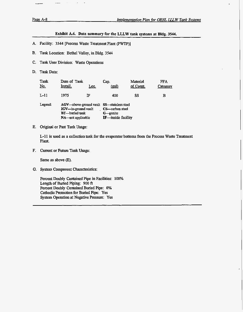
Exhibit A.6. Data summary for the LLLW tank systems at Bldg. 3544.
A. Facility: 3544 process Waste Treatment Plant (PWTP)]
B. Tank Location: Bethel Valley, in Bldg. 3544
C. Tank User Division: Waste Operations
D. TankData:
Tank - No.
L-1 1
Legend:
Date of Tank - Install.
1975
LOC. - IF 400
Material of const.
AGV-above-ground vault SS-stainless steel IGV-in-ground vault . CS-carbon steel BT-bUried tank G--wite NA-not applicable IF-inside facility
ss
FFA Categow
B
E. Original or Past Tank Usage:
L-1 1 is used as a collection tank for the evaporator bottoms from the Process Waste Treatment Plant.
F. Current or Future Tank Usage:
Same as above (E).
G. System Component Characteristics:
Percent Doubly Contained Pipe in Facilities: 100% Length of Buried Piping: 900 ft Percent Doubly Contained Buried Pipe: 0% Cathodic Protection for Buried Pipe: Yes System Operation at Negative Pressure: Yes
Implementation Plan for ORM U W Tank Systems Page A-9
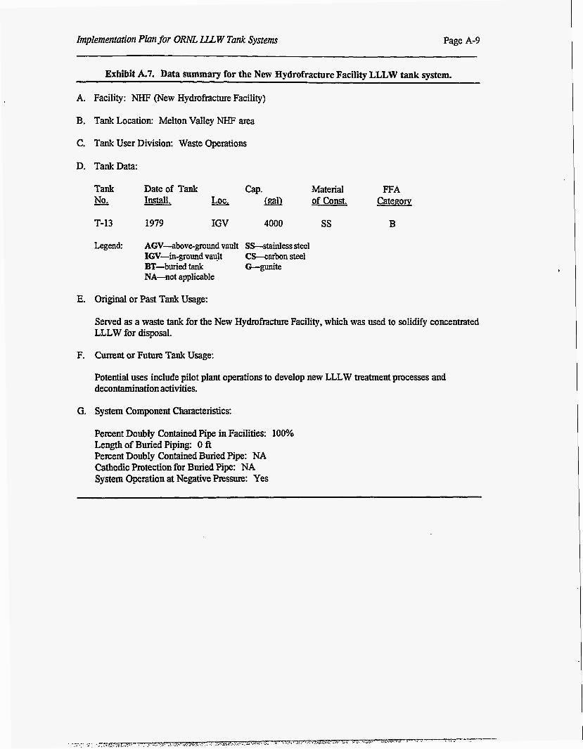
Exhibit A.7. Data summary for the New Hydrofracture Facility LLLW tank system.
A. Facility: NHF (New Hydrofracture Facility)
B. Tank Location: Melton Valley NHF area
C. Tank User Division: Waste Operations
D. TankData:
Tank Date of Tank GP. Material FFA - No. Install. rn of const. Category
T-13 1979 IGV 4000 ss B
Legend: AGV-aboveground vault SS-Stainless steel IGV-in-ground vault CS-carbon steel
NA-not applicable BT-bded tank G--gUnik
E. Original or Past Tank Usage:
Sewed as a waste tank for the New Hydrofracture Facility, which was used to solidify concentrated LLLW for disposal.
F. Current or Future Tank Usage:
Potential uses include pilot plant opexations to develop new LLLW mtment processes and decontamination activities.
G. System Component Characteristics:
Percent Doubly Contained Pipe in Facilities: 100% Length of Buried Piping: 0 ft Percent Doubly Contained Buried Pipe: NA Cathodic Protection for Buried Pipe: NA System Operation at Negative Pressure: Yes
Page A-10 Implementation Plan for ORNL LLLW Tank Systems
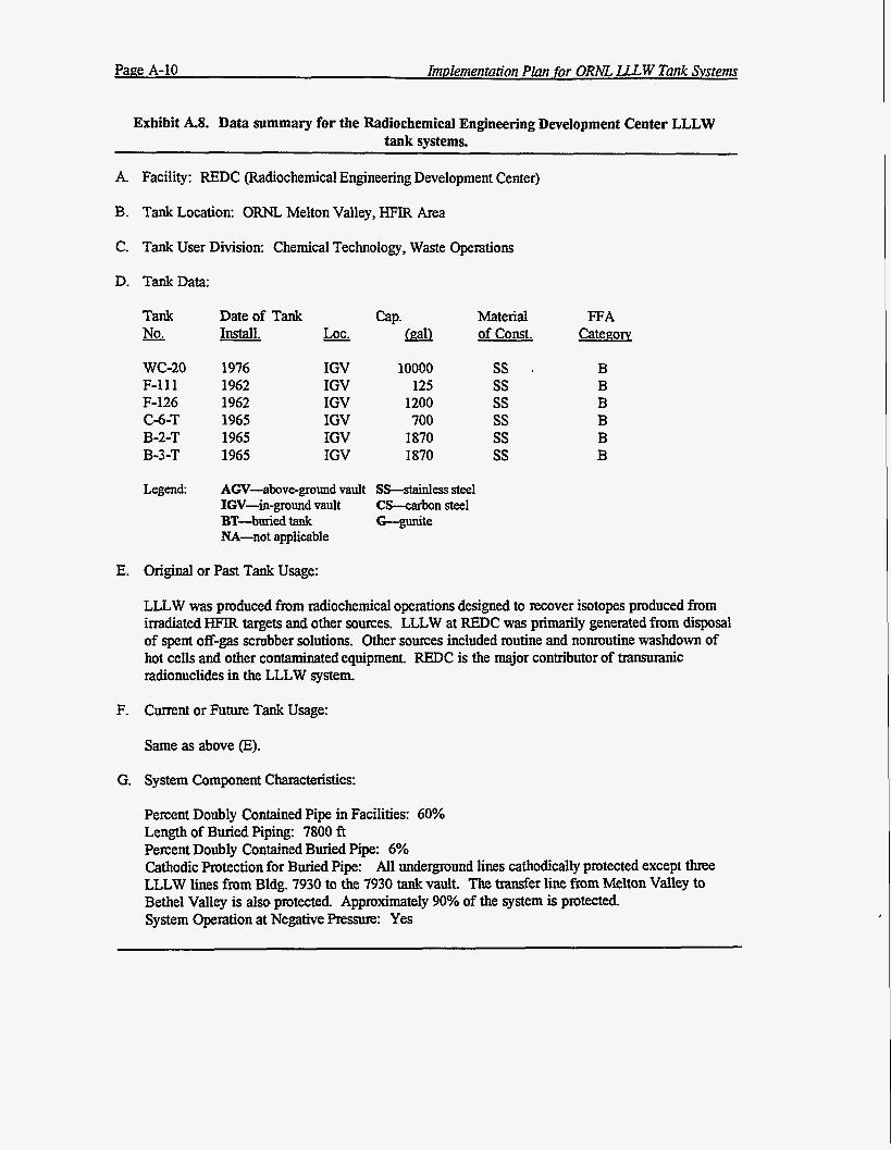
Exhibit AS. Data summary for the Radiochemical Engineering Development Center LLLW tank systems.
A. Facility: REDC (Radiochemical Engineering Development Center)
B. Tank Location: ORNL Melton Valley, HFIR Area
C. Tank User Division: Chemical Technology, Waste Operations
D. TankData:
E.
F.
G.
Tank - No.
Date of Tank QP. Install. - LOC. rn
WC-20 1976 F-111 1962 F-126 1962 C-6-T 1965 B-2-T 1965 B-3-T 1965
IGV IGV IGV IGV IGV IGV
10000 125
1200 700
1870 1870
Legend: AGV-above-ground vault sS--stainless steel IGV-in-ground vault Cfkcarbon steel
NA-not applicable BT-buried tank G%unite
Material of const.
Original or Past Tank Usage:
ss ss ss ss ss ss
FFA Categorv
LLLW was produced from radiochemical operations designed to recover isotopes produced from inadiated HFlR targets and other somes. LLLW at REDC was primarily generated from disposal of spent off-gas scrubber solutions. Other sources included routine and nomutine washdown of hot cells and other contaminated equipment. REDC is the major contributor of transUranic radionuclides in the LLLW system.
Current or Future Tank Usage:
Same as above (E).
System Component Characteristics:
Percent Doubly Contained Pipe in Facilities: 60% Length of Buried Piping: 7800 ft Percent Doubly Contained Buried Pipe: 6% Cathodic Protection for Buried Pipe: All underground lines cathodically protected except three LLLW lines from Bldg. 7930 to the 7930 tank vault. The transfer line from Melton Valley to Bethel Valley is also protected. Approximately 90% of the system is protected. System Opexation at Negative Pressure: Yes
Implementation Plan for ORNL LLL W Tank Systems Page A-11
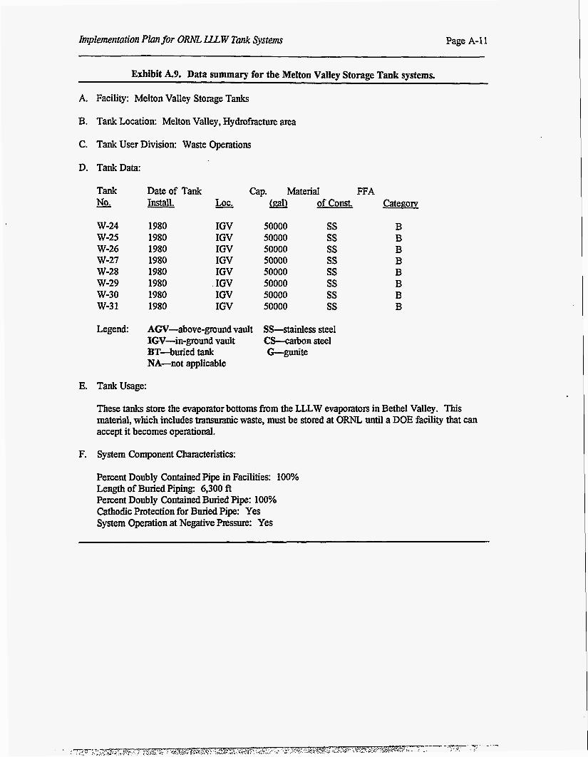
Exhibit A.9. Data summary for the Melton Valley Storage Tank systems.
A. Facility: Melton Valley Storage Tanks
B. Tank Location: Melton Valley, Hydrofracture area
C. Tank User Division: Waste Operations
D. TankData:
Tank Date of Tank Cap. Material FFA No. Install. Lot. m of const. CategoIv
W-24 W-25 W-26 W-27 W-28 W-29 W-30 w-3 1
1980 1980 1980 1980 1980 1980 1980 1980
IGV IGV IGV IGV IGV IGV IGV IGV
50000 50000 50000 50000 50000 50000 50000 50000
ss ss ss ss ss ss ss ss
Legend: AGV-above-ground vault S M n I e s s steel IGV-in-ground vault CS-carbon steel 3T-buried tank G-gunite NA-not applicable
E. Tankusage:
These tanks store the evaporator bottoms from the LLLW evaporators in Bethel Valley. This material, which includes transuraru 'c waste, must be stored at ORNL until a DOE facility that can accept it becomes operational.
F. System Component Characteristics:
Percent Doubly Contained Pipe in Facilities: 1000! Length of Buried Piping: 6,300 ft Percent Doubly Contained Buried Pipe: 100% Cathodic Protection for Buried Pipe: Yes System Operation at Negative Pressure: Yes
Page A-I2 Imvlementation Plan for ORNL LLLW Tank Systems
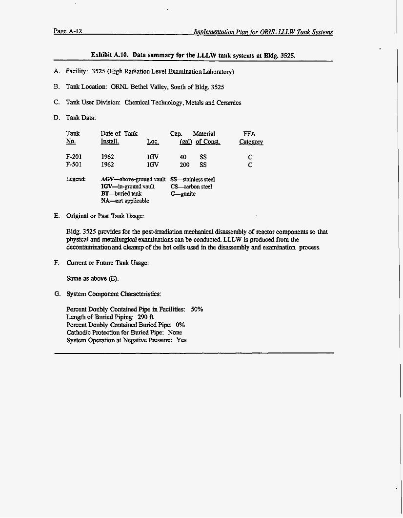
Exhibit A.10. Data summary for the LLLW tank systems at Bldg. 3525.
A. Facility: 3525 (High Radiation Level Examination Laboratory)
B. Tank Location: ORNL Bethel Valley, South of Bldg. 3525
C. Tank User Division: Chemical Technology, Metals and Ceramics
D. TankData:
E.
F.
G.
Tank &.
F-20 1 F-50 1
Legend:
Date of Tank - Install. Lot.
1962 1962
IGV IGV
Cap. Material FFA &aJ of const. CatePON
40 200
ss ss
AGV-above-ground vault SS-stainless steel IGV-in-ground vault CS-carbon steel BT-buried tank NA-not applicable
Original or Past Tank Usage:
C C
Bldg. 3525 provides for the post-irradiation mechanical disassembly of reactor components so that physical and metallurgical examinations can be conducted. LLLW is produced from the decontamination and cleanup of the hot cells used in the disassembly and examination process.
Current or Future Tank Usage:
Same as above (E).
System Component Characteristics:
Percent Doubly Contained Pipe in Facilities: 50% Length of Buried Piping: 290 A Percent Doubly Contained Buried Pipe: 0% Cathodic Protection for Buried Pipe: None System Operation at Negative Pressure: Yes
Page A-13 Implementation Plan for ORNL U W Tank Systems
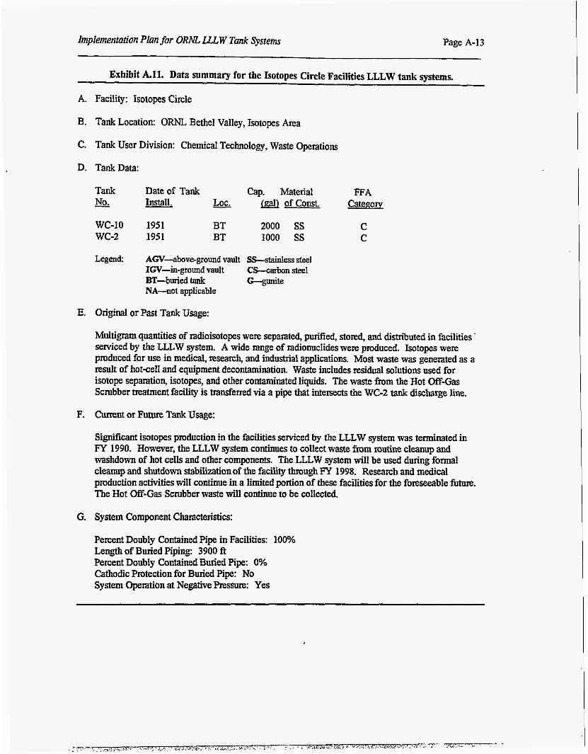
Exhibit All. Data summary for the Isotopes Circle Facilities LLLW tank systems.
A.
B.
C.
D.
E.
F.
G.
Facility: Isotopes Circle
Tank Location: ORNL Bethel Valley, Isotopes Area
Tank User Division: Chemical Technology, Waste Operations
Tank Data:
Tank Date of Tank Cap. Material FFA - No. Install. - LOC. &i& of const. Categoq
WC-10 1951 BT 2000 ss C wc-2 1951 BT 1000 ss C
Legend: AGV-above-ground vault SS-stainless steel IGV-in-ground vault CS-carbon steel
NA-not applicable BT-buriedtank W t e
Original or Past Tank Usage:
Multigram quantities of radioisotopes were separated, purified, stored, and distriiuted in facilities. serviced by the LLLW system. A wide xange of radionuclides were produced. Isotopes were produced for use in medical, research, and industrial applications. Most waste was generated as a result of hotcell and equipment decontamination. Waste includes residual solutions used for isotope separation, isotopes, and other contaminated liquids. The waste from the Hot Off-Gas Scrubber treatment facility is transferred via a pipe that intersects the WC-2 tank discharge line.
Current or Future Tank Usage:
Significant isotopes production in the facilities serviced by the LLLW system was terminated in FT 1990. However, the LLLW system continues to collect waste from mutine cleanup and washdown of hot cells and other components. The LLLW system will be used during formal cleanup and shutdown stabilizationof the facility through FY 1998. Research and medical production activities will continue in a limited portion of these facilities for the foreseeable future. The Hot Off-Gas Scrubber waste will continue to be collected.
System Component Characteristics:
Percent Doubly Contained Pipe in Facilities: 100% Length of Buried Piping: 3900 ft Percent Doubly Contained Buried Pipe: 0% Cathodic Protection for Buried Pipe: No System Operation at Negative Pressure: Yes
Pane A-14 Implementation Plan for ORAE LLL W Tank Systems
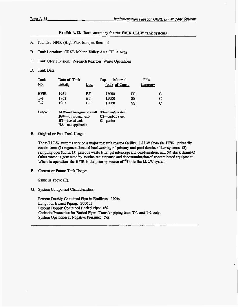
Exhibit A.12. Data summary for the HFIR LLLW tank systems.
A. Facility: HFIR (High Flux Isotopes Reactor)
B. Tank Location: ORNL Melton Valley Area, HFIR Area
C. Tank User Division: Research Reactors, Waste Operations
D. TankData:
Tank Date of Tank Cap. Material FFA No. Install. * && of const. Catenorv
HFm 1961 BT 13000 ss C T-1 1963 BT 15000 ss C T-2 1963 BT 15000 ss C
Legend: AGV-above-ground vault Ss--stainless steel IGV-in-ground vault CS-carbon steel
NA-not applicable BT-bded tank G-gunite
E. Original or Past Tank Usage:
These LLLW systems service a major research reactor facility. LLLW from the HFIR primarily results from (1) regeneration and backwashing of primary and pool demineralizer systems, (2) sampling operations, (3) gaseous waste filter pit inleakage and condensation, and (4) stack drainage. Other waste is generated by routine maintenance and decontamination of contaminated equipment. When in operation, the HFIR is the primary source of in the LLLW system.
F. Current or Future Tank Usage:
Same as above (E).
G. System Component Characteristics:
Percent Doubly Contained Pipe in Facilities: 100% Length of Buried Piping: 3000 ft Percent Doubly Contained Buried Pipe: 0% Cathodic Protection for Buried Pipe: Transfer piping from T-1 and T-2 only. System Operation at Negative Pressure: Yes
Implementation Plan for ORh?L LLLW Tank Systems Page A-15
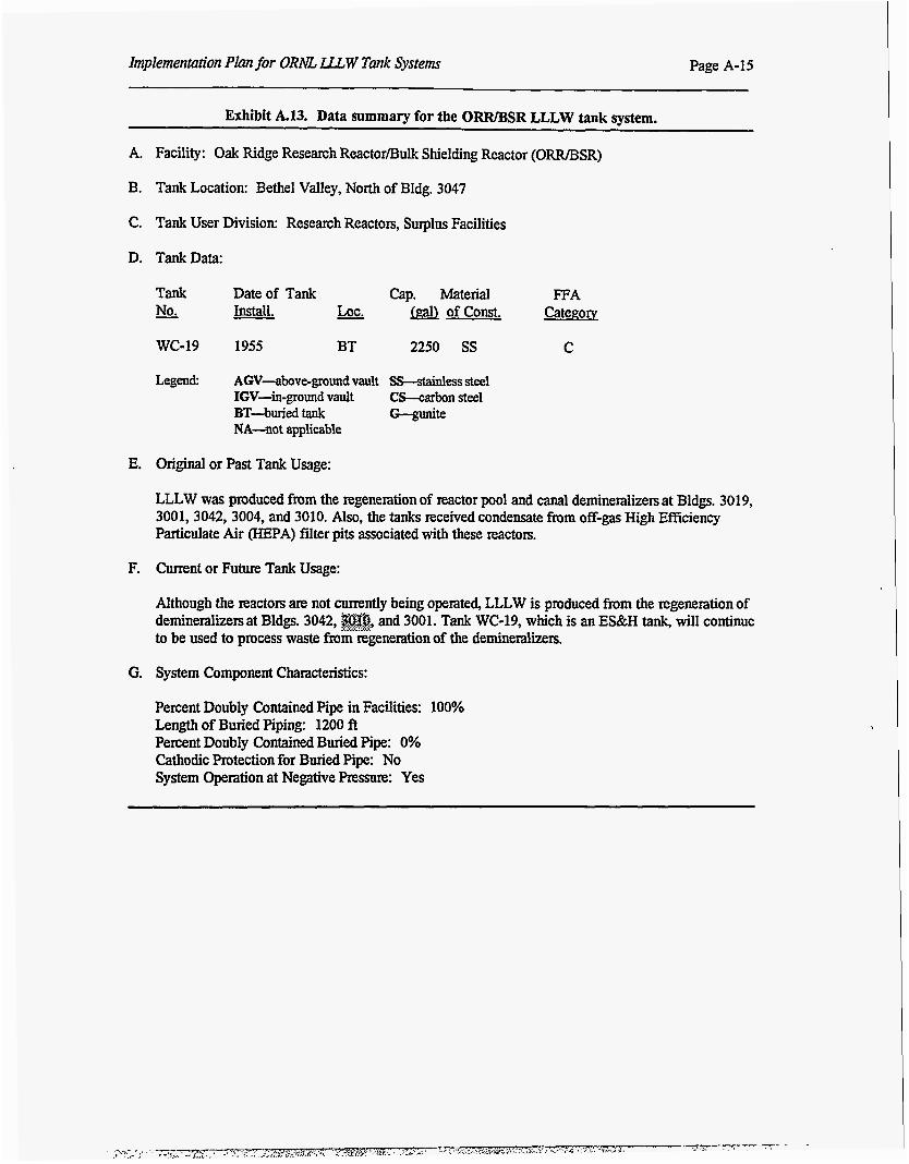
Exhibit k13. Data summary for the ORR/BSR LLLW tank system.
A. Facility: Oak Ridge Research Reactor/Bulk Shielding Reactor (ORWSSR)
B. Tank Location: Bethel Valley, North of Bldg. 3047
C. Tank User Division: Research Reactors, Suplus Facilities
D. TankData:
Tank Date of Tank Cap. Material W A No. Install. Lot. (galJ of const. CateEoN
WC-19 1955 BT 2250 SS C
Legend AGV-above-ground vault Ss-stainless steel IGV-in-ground vault CS-carbon steel
NA-not applicable BT-buried tank G--gunite
E. Original or Past Tank Usage:
LLLW was produced from the regeneration of reactor pool and canal demineralizers at Bldgs. 3019, 3001,3042,3004, and 3010. Also, the tanks received condensate from off-gas High Efficiency Particulate Air (HEPA) filter pits associated with these reactors.
F. Current or Future Tank Usage:
Although the reactors are not currently being operated, LLLW is produced from the regeneration of demineralizers at Bldgs. 3042, $@@ .,.... ,.+? and 3001. Tank WC-19, which is an ES&H tank, will continue to be used to process waste from regeneration of the deminexalizers.
G. System Component Characteristics:
Percent Doubly Contained Pipe in Facilities: 100% Length of Buried Piping: 1200 ft Percent Doubly Contained Buried Pipe: 0% Cathodic Protection for Buried Pipe: No System Operation at Negative Pressure: Yes
Page A-I6 Implementation Plan for ORNL LLL.W Tank Systems
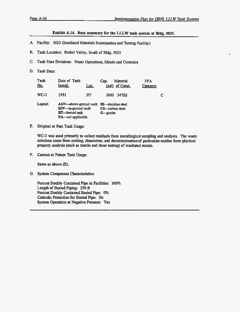
Exhibit A.14. Data summary for the LLLW tank system at Bldg. 3025.
A.
B.
C.
D.
E.
F.
G.
Facility: 3025 (Irradiated Materials Examination and Testing Facility)
Tank Location: Bethel Valley, South of Bldg. 3025
Tank User Divisions: Waste Operations, Metals and Ceramics
Tank Data:
Tank No.
wc-3
Date of Tank Install. &
1951 BT
Cap. Material &alJ of Const.
1000 347ss
Legend: AGV-above-ground vault S-ess steel IGV-in-ground vault CS-carbon steel
NA-not applicable B T - b e d tank G--gunite
Original or Past Tank Usage:
FFA Categow
C
WC-3 was used primarily to collect residuals from metallurgical sampling and analysis. The waste solutions came from etching, dissolution, and decontamination of particulate residue from physical property analysis (such as tensile and shear testing) of irradiated metals.
Current or F u e Tank Usage:
Same as above (E).
System Component Characteristics:
Percent Doubly Contained Pipe in Facilities: 100% Length of Buried Piping: 250 ft Percent Doubly Contained Buried Pipe: 0% Cathodic Protection for Buried Pipe: No System Operation at Negative Pressure: Yes
Implementation Plun for ORM, LLL W Tank Systems Page A-17
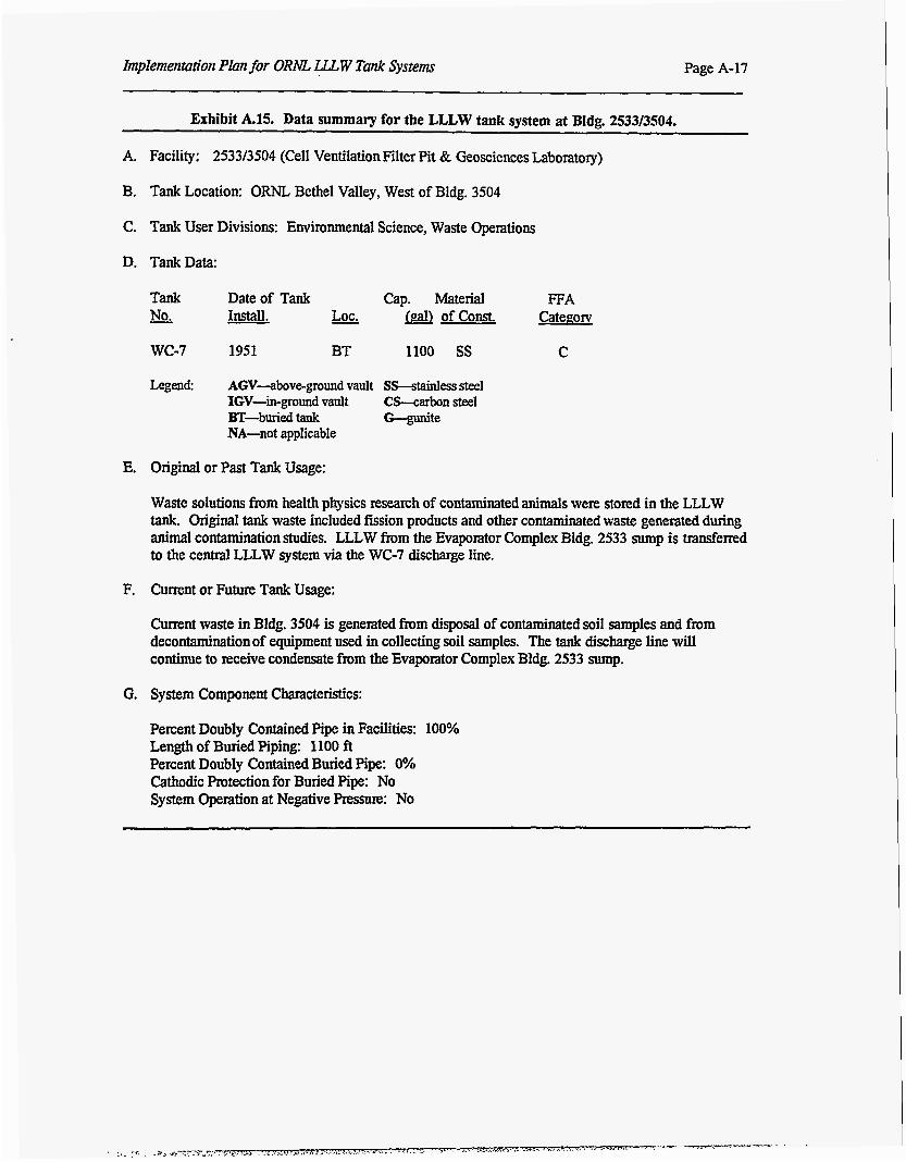
Exhibit A.15. Data summary for the LLLW tank system at Bldg. 2533/3504.
A. Facility: 253313504 (Cell Ventilation Filter Pit & Geosciences Laboratory)
B. Tank Location: ORNL Bethel Valley, West of Bldg. 3504
C. Tank User Divisions: Environmental Science, Waste Operations
D. TankData:
Tank Date of Tank Cap. Material FFA No. Install. &. &alJ of const. Categow
wc-7 1951 BT 1100 ss C
Legend AGV-above-ground vault SS-stainless steel IGV-in-ground vault C!Lcarbon steel
NA-not applicable BT-buriedtauk G--gunite
E. Original or Past Tank Usage:
Waste solutions from health physics research of contaminated animals were stored in the LLLW tank. Original tank waste included fission products and other contaminated waste generated during animal contamination studies. LLLW from the Evaporator Complex Bldg. 2533 sump is transferred to the c e d LLLW system via the WC-7 discharge line.
F. Current or Future Tank Usage:
Current waste in Bldg. 3504 is generated from disposal of contaminated soil samples and from decontamination of equipment used in collecting soil samples. The tank discharge line will continue to receive condensate from the Evaporator Complex Bldg. 2533 sump.
G. System Component Characteristics:
Percent Doubly Contained Pipe in Facilities: 100% Length of Buried Piping: 1100 ft Percent Doubly Contained Buried Pipe: 0% Cathodic Protection for Buried Pipe: No System Operation at Negative Pressure: No
Page A-18 Implementation Plan for ORhZ LLLW Tank System
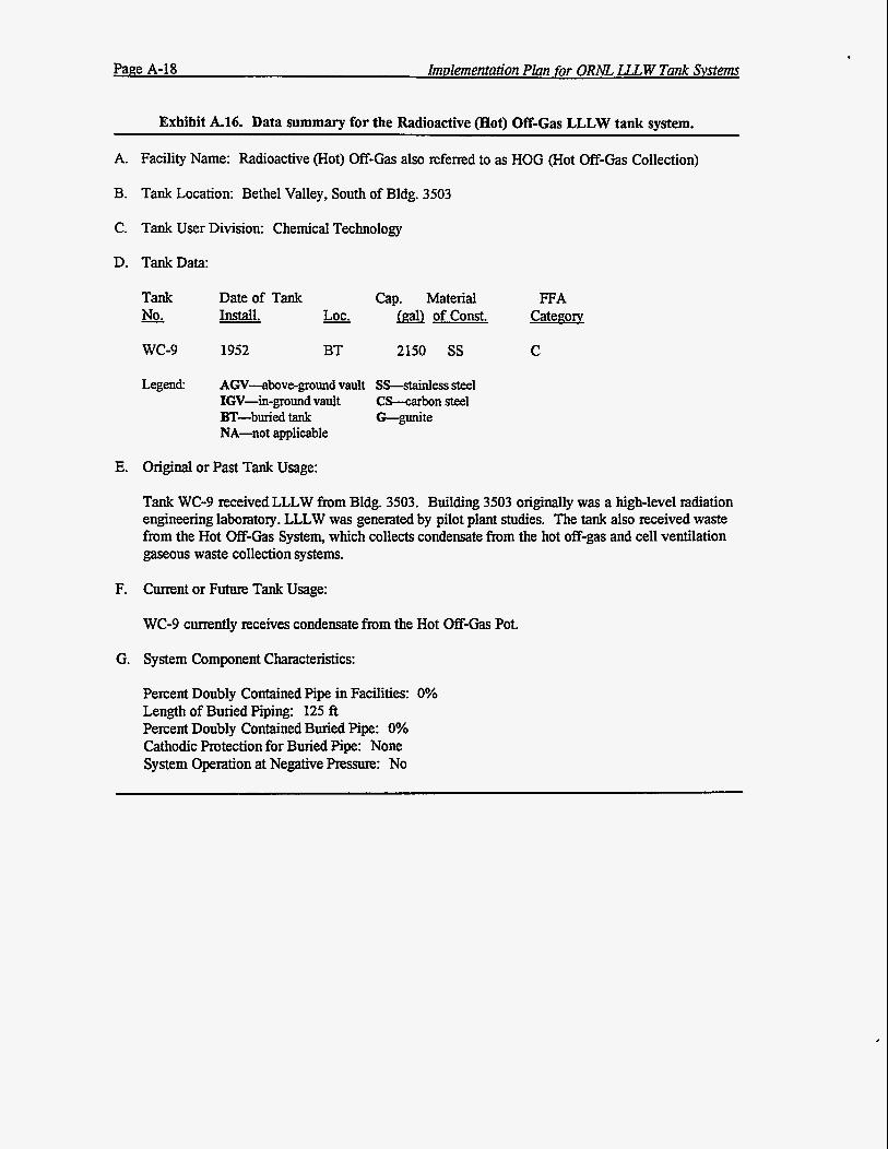
Exhibit A.16. Data summary for the Radioactive (Hot) Off-Gas LLLW tank system.
A. Facility Name: Radioactive (Hot) Off-Gas also referred to as HOG (Hot Off-Gas Collection)
B. Tank Location: Bethel Valley, South of Bldg. 3503
C. Tank User Division: Chemical Technology
D. TankData:
E.
F.
G.
Tank - No.
wc-9
Date of Tank Install. - LOC.
1952 BT
Cap. Material &aJ of const.
2150 SS
Legend: AGV-above-ground vault SS-stainless steel IGV-in-ground vault CS-wbon steel BT-buried tank G-gumte NA-not applicable
Original or Past Tank Usage:
FFA Categorv
C
Tank WC-9 received LLLW from Bldg. 3503. Building 3503 originally was a high-level radiation engineering laboratory. LLLW was generated by pilot plant studies. The tank also received waste from the Hot Off-GaS System, which collects condensate from the hot off-gas and cell ventilation gaseous waste collection systems.
Current or Future Tank Usage:
WC-9 currently receives condensate from the Hot Of€-Cias Pot.
System Component Characteristics:
Percent Doubly Contained Pipe in Facilities: 0% Length of Buried Piping: 125 ft Percent Doubly Contained Buried Pipe: 0% Cathodic Protection for Buried Pipe: None System Operation at Negative Pressure: No
Implementation Plan for ORM LLLW Tank Systems Page A-19
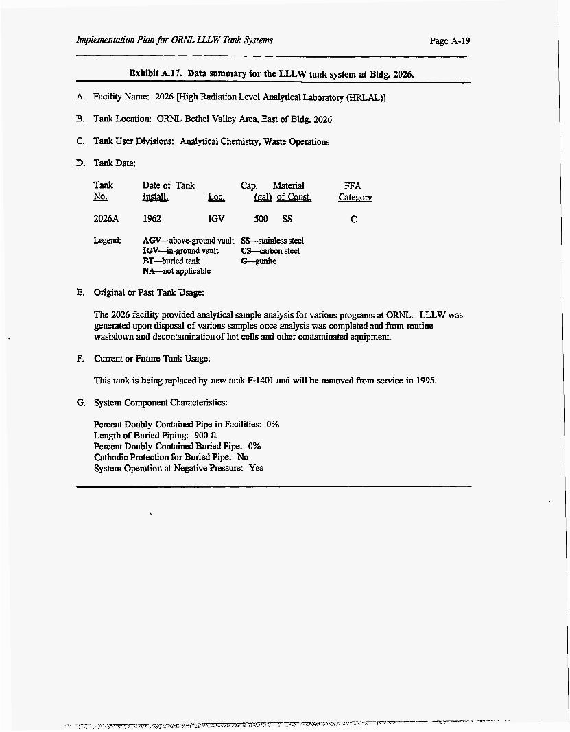
Exhibit A.17. Data summary for the LLLW tank system at Bldg. 2026.
A. Facility Name: 2026 Bigh Radiation Level Analytical Laboratory (HRLAL)]
B. Tank Location: ORNL Bethel Valley Area, East of Bldg. 2026
C. Tank User Divisions: Analytical Chemistry, Waste Operations
D. TankData:
Tank Date of Tank Cap. Material FFA - No. &alJ of const. Categoq
2026A 1962 IGV 500 SS C
Legend: AGV-above-ground vault Ss--stainless steel IGV-in-ground vault C h a r b o n steel BT-buried tank G-gunite NA-not applicable
E. Original or Past Tank Usage:
The 2026 facility provided analytical sample analysis for various programs at ORNL. LLLW was generated upon disposal of various samples once analysis was completed and from routine washdown and decontamination of hot cells and other contaminated equipment.
F. Cunent or Future Tank Usage:
This tank is being replaced by new tank F-1401 and will be removed from service in 1995.
G. System Component Characteristics:
Percent Doubly Contained Pipe in Facilities: 0% Length of Buried Piping: 900 ft Percent Doubly Contained Buried Pipe: 0% Cathodic Protection for Buried Pipe: No System Operation at Negative Pressure: Yes
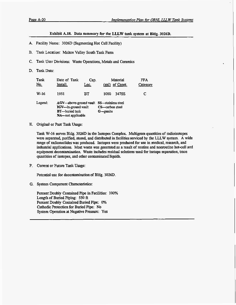
Page A-20 Imvlementation Plan for ORhE LLLW Tank Systems
Exhibit A.18. Data summary for the LLLW tank system at Bldg. 3026D.
A. Facility Name: 3026D (Segmenting Hot Cell Facility)
B. Tank Location: Melton Valley South Tank Farm
C. Tank User Divisions: Waste Operations, Metals and Ceramics
D. TankData:
Tank Date of Tank cap. Material FFA No. Install. - LOC. of const. Categoq
W-16 1951 BT 1000 3 4 7 s C
Legend: AGV-above-ground vault SPstainless steel IGV-in-ground vault C-n steel BT-buried tank G-gunite NA-not applicable
E. Original or Past Tank Usage:
Tank W-16 semes Bldg. 3026D in the Isotopes Complex. Multigram quantities of radioisotopes were separated, purified, stored, and distributed in facilities serviced by the LLLW system. A wide range of mdionuclides was produced. Isotopes were produced for use in medical, research, and industrial applications. Most waste was generated as a result of routine and nomutine hotaell and equipment decontamination. Waste includes residual solutions used for isotope separation, trace quantities of isotopes, and other contaminated liquids.
F. Current or Future Tank Usage:
Potential use for decontaminationof Bldg. 30261).
G. System Component Characteristics:
Percent Doubly Contained Pipe in Facilities: 100% Length of Buried Piping: 550 ft Percent Doubly Contained Buried Pipe: 0% Cathodic Protection for Buried Pipe: No System Opention at Negative Pressure: Yes
Appendix B
DATA SUMMARIES FOR CATEGORY D TANK SYSTEMS

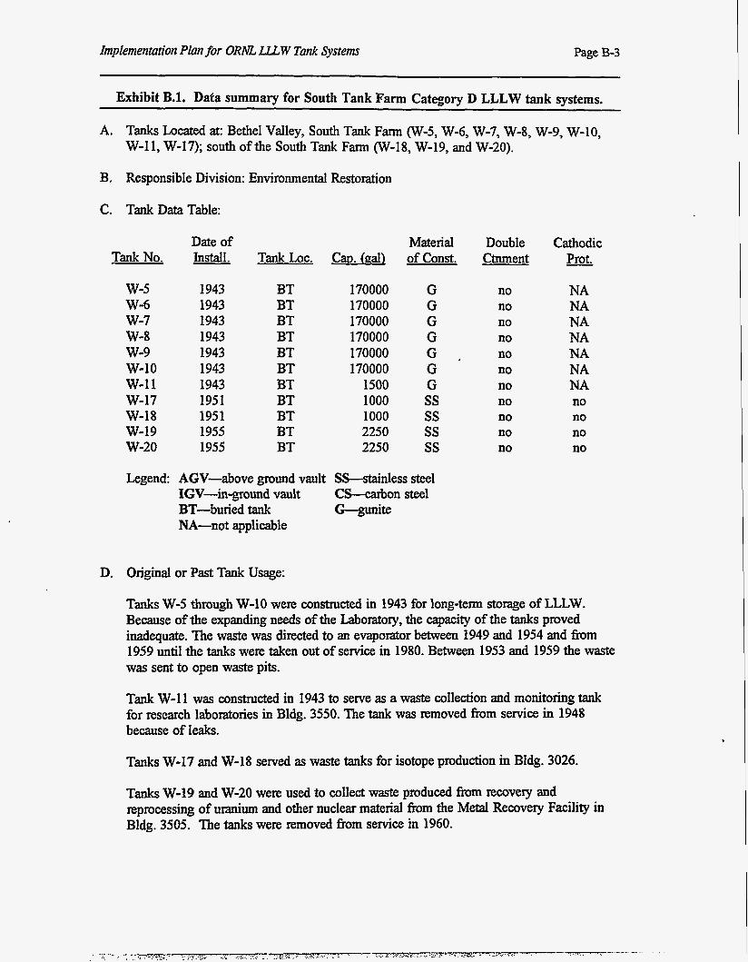
Implementation Plan for ORh?L U W Tank Systems Page B-3
Exhibit B.l. Data summary for South Tank Farm Category D LLLW tank systems.
A. Tanks Located at: Bethel Valley, South Tank Farm (W-5, W-6, W-7, W-8, W-9, W-10, W-11, W-17); south of the South Tank Farm (W-18, W-19, and W-20).
B. Responsible Division: Environmental Restoration
C. Tank DataTable:
Tank No.
w-5 W-6 w-7 W-8 w-9 w-10 w-I1 W-17 W-18 w-19 w-20
Date of Material Install. Tank Loc. Cw. (gal) ofconst.
1943 1943 1943 1943 1943 1943 1943 1951 1951 1955 1955
BT BT BT BT BT BT BT BT BT BT BT
170000 170000 170000 170000 170000 170000
1500 1000 1000 2250 2250
G G G G G . G G ss ss ss ss
Double Ctnment
no no no no no no no no no no no
Cathodic - Prot.
NA NA NA NA NA NA NA no no no no
Legend: AGV-above ground vault SS-stainless steel IGV-in-ground vault C C o n steel BT-buried tank G-gunite NA-not applicable
D. Original or Past Tank Usage:
Tanks W-5 through W-10 were constructed in 1943 for long-term storage of LLLW. Because of the expanding needs of the Laboratory, the capacity of the tanks proved inadequate. The waste was directed to an evaporator between 1949 and 1954 and from 1959 until the tanks were taken out of service in 1980. Between 1953 and 1959 the waste was sent to open waste pits.
Tank W-11 was constructed in 1943 to serve as a waste collection and monitoring tank for research laboratories in Bldg. 3550. The tank was removed from service in 1948 because of leaks.
Tanks W-17 and W-18 served as waste tanks for isotope production in Bldg. 3026.
Tanks W-19 and W-20 were used to collect waste produced from recovery and reprocessing of uranium and other nuclear material from the Metal Recovery Facility in Bldg. 3505. The tanks were removed from service in 1960.
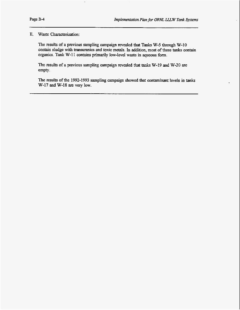
Page B-4 Implementation Plan for ORA55 U W Tank Systems
E. Waste Characterization:
The results of a previous sampling campaign revealed that Tanks W-5 through W-10 contain sludge with transuranics and toxic metals. In addition, most of these tanks contain organics. Tank W-1 1 contains primarily low-level waste in aqueous form.
The results of a previous sampling campaign revealed that tanks W-19 and W-20 are empty.
The results of the 1992-1993 sampling campaign showed that contaminant levels in tanks W-17 and W-18 are very low.
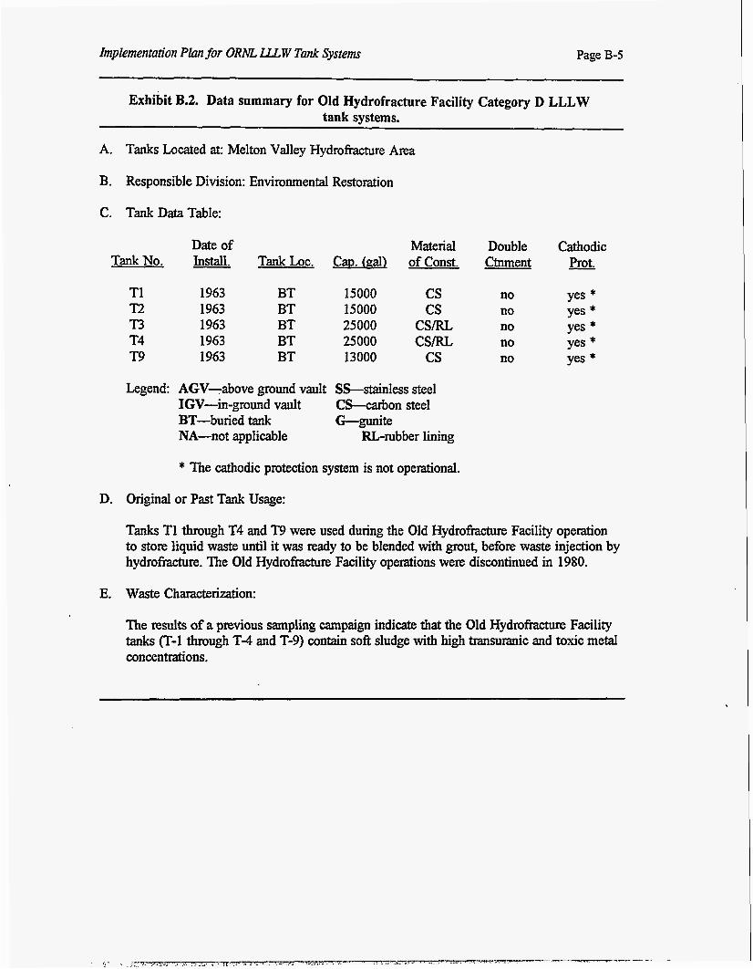
Implementation Plan for ORhK. LLLW Tank Sysiems Page B-5
Exhibit B.2. Data summary for Old Hydrofracture Facility Category D LLLW tank systems.
A. Tanks Located at: Melton Valley Hydrofracture Area
B. Responsible Division: Environmental Restoration
C. Tank DataTable:
Date of Material Double Cathodic TankNo. Install. TankLoc. C ~ D . (gal) ofconst. Ctnment - Prot.
T1 1963 BT 15000 cs no yes * T2 1963 BT 15000 cs no yes * n 1963 BT 25000 csm no yes * T4 1963 BT 25000 csm no yes * T9 1963 BT 13000 cs no yes * Legend: AGV-above ground vault SS-stainless steel
IGV-in-ground vault C-on steel BT-buried tank G-gunite NA-not applicable =-rubber lining
* The cathodic protection system is not operational.
D. Original or Past Tank Usage:
Tanks T1 through T4 and T9 were used during the Old X-3ydrofktm-e Facility operation to store liquid waste until it was ready to be blended wit& grout, before waste injection by hydrofracture. The Old Hydrofracture Facility operations were discontinued in 1980.
E. Waste Characterization:
The results of a previous sampling campaign indicate that the Old Hydrofmcture Facility tanks ("-1 through T-4 and T-9) contain soft sludge with high transuranic and toxis metal concentrations.
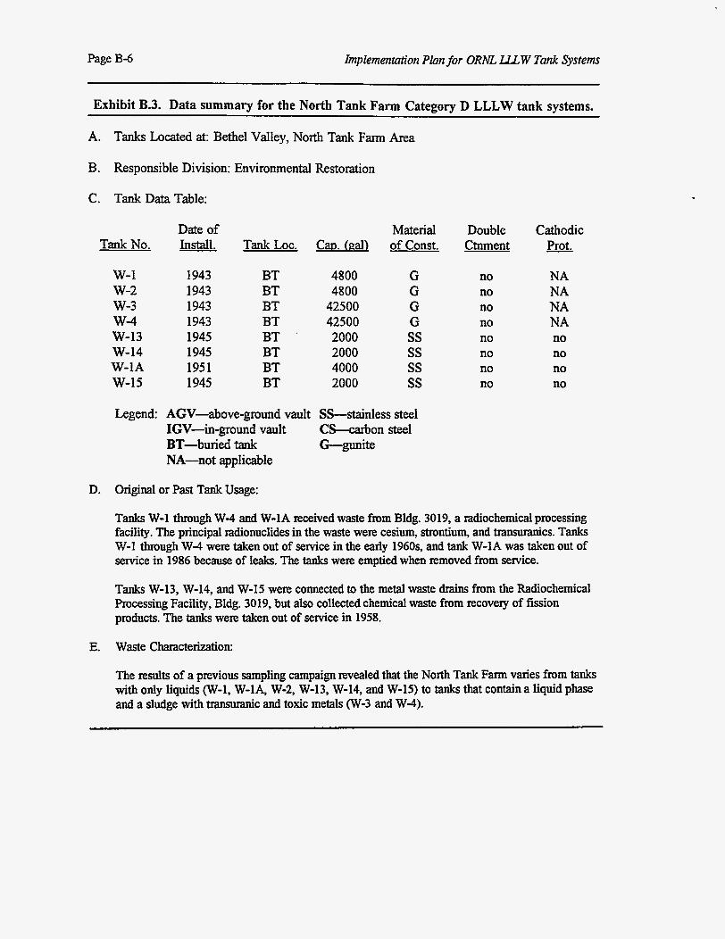
Implementation Plan for ORNL LLLW Tank Systems Page B-6
Exhibit B.3. Data summary for the North Tank Farm Category D LLLW tank systems.
A. Tanks Located at: Bethel Valley, North Tank Farm Area
B. Responsible Division: Environmental Restoration
C. Tank Data Table:
Date of TankNo. Install.
w-1 w-2 w-3 W-4 W-13 W-14 W-IA W-15
1943 1943 1943 1943 1945 1945 1951 1945
Material Double Tank Loc. Cao. (gal) of Const. Ctnment
BT BT BT BT BT BT BT BT
4800 4800
42500 42500 2000 2000 4000 2000
G G G G ss ss ss ss
no no no no no no no no
Cathodic - Prot.
NA NA NA NA no no no no
Legend: AGV-above-ground vault SS-stainless steel IGV-in-ground vault C C o n steel BT-buried tank G-mite NA-not applicable
D. Original or Past Tank Usage:
Tanks W-1 through W-4 and W-1A received waste from Bldg. 3019, a radiochemical processing facility. The principal mdionuclides in the waste were cesium, strontium, and transuranics. Tanks W-1 through W-4 were taken out of service in the early 1960s, and tank W-IA was taken out of service in 1986 because of leaks. The tanks were emptied when removed from service.
Tanks W-13, W-14, and W-15 were connected to the metal waste drains from the Radiochemical Processing Facility, Bldg. 3019, but also collected chemical waste from recovery of fission products. The tanks were taken out of service in 1958.
E. Waste Characterization:
The results of a previous sampling campaign revealed that the North Tank Farm varies from tanks with only liquids (W-1, W-IA, W-2, W-13, W-14, and W-15) to tanks that contain a liquid phase and a sludge with transuranic and toxic metals (W-3 and W-4).
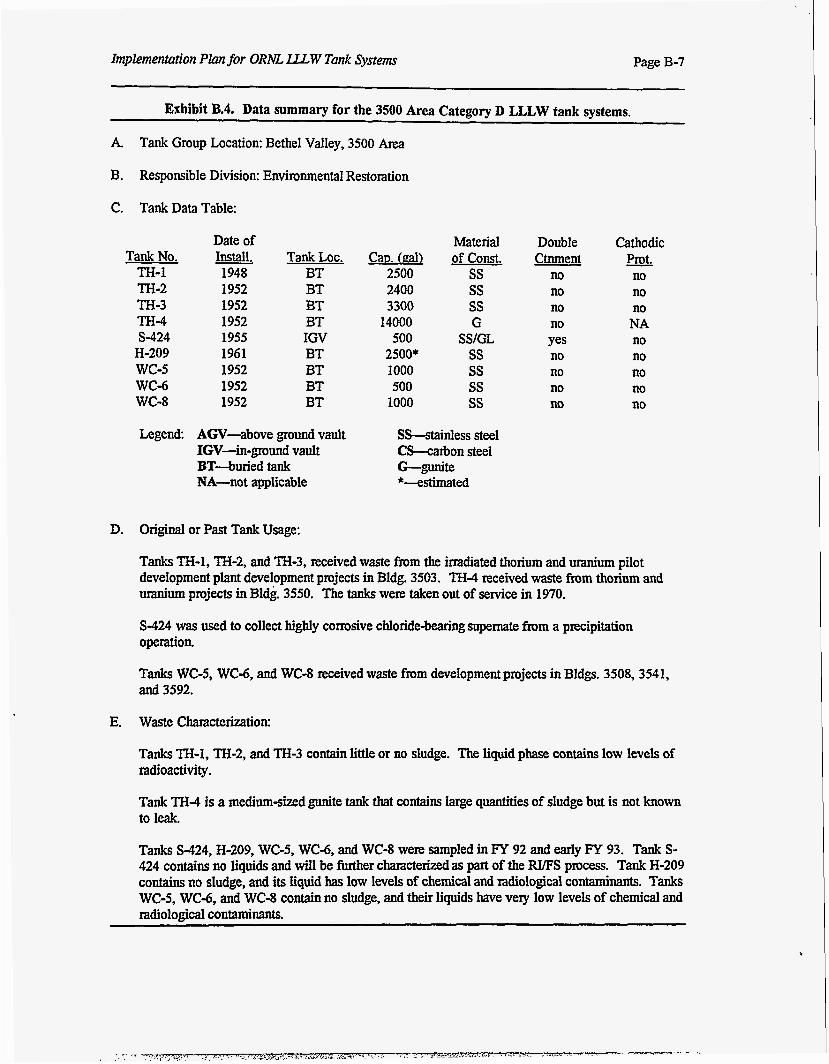
Implementation Plan for O R m LLLW Tank Systems Page B-7
Exhibit B.4. Data summary for the 3500 Area Category D LLLW tank systems.
A. Tank Group Location: Bethel Valley, 3500 Area
B. Responsible Division: Environmental Restoration
C. Tank Data Table:
Tank No. TH-1 TH-2 TH-3 TH-4 S-424
H-209 wc-5 wc-6 wc-8
Date of
1948 1952 1952 1952 1955 1961 1952 1952 1952
- Install. Tank LOC. BT BT BT BT IGV BT BT BT BT
Cap. k a l l 2500 2400 3300
14000 500
2500* 1000 500
1000
Material of const.
ss ss ss G
SS/GL ss ss ss ss
Double Ctnment
no no no no Yes no Xi0 no no
cathodic - Prot. no no no NA no no no no no
Legend: AGV-above ground vault SS-stainless steel IGV-in-pund vault CS-carbon steel BT-buried tank G-gunite NA-not applicable *-estimated
D. Original or Past Tank Usage:
Tanks TH-1, TH-2, and TH-3, received waste from the irradiated thorium and uranium pilot development plant development projects in Bldg. 3503. TH-4 received waste from thorium and uranium projects in Bldg. 3550. The tanks were taken out of service in 1970.
S-424 was used to collect highly corrosive chloride-bearing supemate from a precipitation operation.
Tanks WC-5, WC-6, and WC-8 received waste from development projects in Bldgs. 3508,3541, and 3592.
E. Waste Characterization:
Tanks TH-1, TH-2, and TH-3 contain little or no sludge. The liquid phase contains low levels of radioactivity.
Tank TH-4 is a medium-sized gunite tank that contains large quantities of sludge but is not known to leak.
Tanks S-424, H-209, WC-5, WC-6, and WC-8 were sampled in FY 92 and early FY 93. Tank S- 424 contains no liquids and will be further characterized as part of the W S process. Tank H-209 contains no sludge, and its liquid has low levels of chemical and radiological contaminants. Tanks WC-5, WC-6, and WC-8 contain no sludge, and their liquids have very low levels of chemical and radioloeical contaminants.
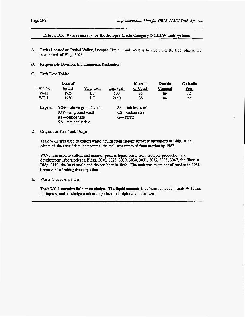
Page B-8 Implementation Plan for ORA45 LLLW Tank Systems
Exhibit B.5. Data summary for the Isotopes Circle Category D LLLW tank systems.
A. Tanks Located at: Bethel Valley, Isotopes Circle. Tank W-11 is located under the floor slab in the east airlock of Bldg. 3028.
'B. Responsible Division: Environmental Restoration
C. Tank Data Table:
Date of Material Double cathodic Tank No. Install. Tank LOC. C ~ D . (gal) of Const. Ctnment Prot.
w-11 1959 BT 500 ss no no wc-1 1950 BT 2150 ss no no
Legend: AGV-above ground vault SS-stainless steel IGV-in-ground vault CS-cahon steel BT-buried tank G-gunite NA-not applicable
D. Original or Past Tank Usage:
Tank W-11 was used to collect waste liquids from isotope recovery operations in Bldg. 3028. Although the actual date is uncertain, the tank was removed from service by 1987.
WC-1 was used to collect and monitor process liquid waste from isotopes production and development laboratories in Bldgs. 3038,3028,3029,3030,3031,3032,3033,3047, the filter in Bldg. 3110, the 3039 stack, and the scrubber in 3092. The tank was taken out of service in 1968 because of a leaking discharge line.
E. Waste Characterization:
Tank WC-1 contains little or no sludge. The liquid contents have been removed. Tank W-11 has no liquids, and its sludge contains high levels of alpha contamination
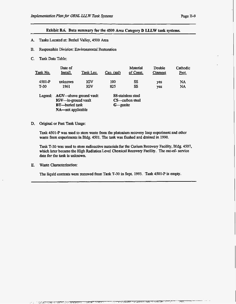
Implementation Plan for ORNL LU. W Tank Systems Page B-9
Exhibit B.6. Data summary for the 4500 Area Category D LLLW tank systems.
A. Tanks Located at: Bethel Valley, 4500 Area
B. Responsible Division: Environmental Restoration
C. Tank Data Table:
Tank No.
4501-P T-30
Date of Material Install. Tank LOC. Cap. (gal) of Const.
unknown 1961
IGV IGV
Legend AGV-above ground vault IGV-in-ground vault BT4ur ied tank NA-not applicable
100 825
ss ss
SS-stainless steel C-arbon steel G-gunite
Double Ctnment
Cathodic - Prot.
NA NA
D. Original or Past Tank Usage:
Tank 4501-P was used to store waste from the plutonium recovery loop experiment and other waste from experiments in Bldg. 4501. The tank was flushed and drained in 1990.
Tank T-30 was used to store radioactive materials for the Curium Recovery Facility, Bldg. 4507, which later became the High Radiation Level Chemical Recovery Facility. The out-of- service date for the tank is unknown.
E. Waste Characterization:
The liquid contents were removed from Tank T-30 in Sept. 1993. Tank 4501-P is empty.
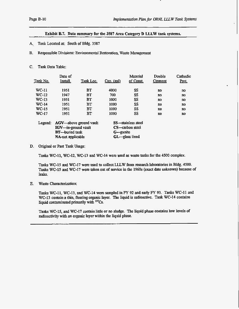
Page B-10 Implementation Plan for ORhE LLLW Tank Systems
Exhibit B.7. Data summary for the 3587 Area Category D LLLW tank systems.
A., Tank Located at: South of Bldg. 3587
B. Responsible Divisions: Environmental Restoration, Waste Management
C. Tank Data Table:
Date of Tank No. Install.
wc-11 wc-12 WC-13 WC-14 WC-15 WC-17
1951 1947 1951 1951 1951 1951
Tank LOC.
BT BT BT BT BT BT
Legend: AGV-above ground vault IGV-in-ground vault BT4uried tank NA-not applicable
4000 700 1000 1000 1000 1000
Material Double of const. Ctnment
ss ss ss ss ss ss
SS-sk.,:ss steel CS-carbon steel G-gunite GL-glass lined
no no no no no no
cathodic Prot.
no no no no no no
D. Original or Past Tank Usage:
Tanks WC-11, WC-12, WC-13 and WC-14 were used as waste tanks for the 4500 complex.
Tanks WC-15 and WC-17 were used to collect LLLW from research laboratories in Bldg. 4500. Tanks WC-15 and WC-17 were taken out of service in the 1960s (exact date unknown) because of leaks.
E. Waste Characterization:
Tanks WC-11, WC-13, and WC-14 were sampled in FY 92 and early FY 93. Tanks WC-I1 and WC-13 contain a thin, floating organic layer. The liquid is radioactive. Tank WC-14 contains liquid contaminated primarily with I3'Cs.
Tanks WC-15, and WC-17 contain little or no sludge. The liquid phase contains low levels of radioactivity with an organic layer within the liquid phase.
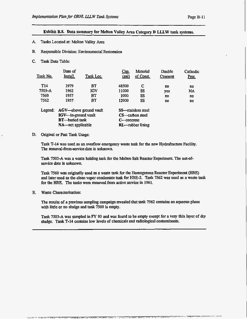
Implementation PIun for ORNL Lu, W Tank Systems Page B-1 1
~~
Exhibit B.8. Data summary for Melton Valley Area Category D LLLW tank systems.
A. Tanks Located at: Melton Valley Area
B. Responsible Division: Environmental Restomtion
C. Tank Data Table:
Tank No.
T14 7503-A 7560 7562
Legend:
Date of - Install. Tank Loc.
1979 1962 1957 1957
BT IGV BT BT
AGV-above ground vault IGV-in-ground vault BT-buried tank NA-not applicable
Cap. Material Double Cathodic of Const. Ctnment - Prot.
48500 11000 1000
12000
C ss ss ss
SS-stainless steel CS--carbon steel C-concrete &rubber lining
no Yes no no
no NA no no
D. Original or Past Tank Usage:
Tank T-14 was used as an overnow emergency waste tank for the new Hydrofracture Facility. The removal-from-service date is unknown.
Tank 7503-A was a waste holding tank for the Molten Salt Reactor Experiment. The out-of- service date is unknown.
Tank 7560 was originally used as a waste tank for the Homogenous Reactor Experiment (HRE) and later used as the clean vapor condensate tank for HRE-2. Tank 7562 was used as a waste tank for the HRE. The tanks were removed from active service in 1961.
E. Waste Characterization:
The results of a previous sampling campaign revealed that tank 7562 contains an aqueous phase with little OT no sludge and tank 7560 is empty.
Tank 7503-A was sampled in FY 93 and was found to be empty except for a very thin layer of dry sludge. Tank T-14 contains low levels of chemicals and radiological contaminants.
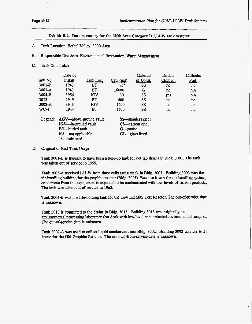
Page B-12 implementation Plan for ORNL LLLW Tank System
Exhibit B.9. Data summary for the 3000 Area Category D LLLW tank systems.
A. Tank Location: Bethel Valley, 3000 Area
B. Responsible Divisions: Environmental Restoration, Waste Management
C. Tank Data Table:
Tank No. 3001-B 3003-A 3004-B 3013 3002-A wc-4
Date of Install. 1943 1943 1956 1949 1943 1944
Material Tank LOC. Can (gal) of Const.
BT 75* ss BT 16000 G IGV 30 ss BT 400 ss IGV 1600 ss BT 1700 ss
Double cathodic Ctnment Prot.
no no no NA Yes NA no no no no no no
Legend: AGV-above ground vault IGV-in-ground vault BT-buried tank NA-not applicable *-estimated
SS-stainless steel C h a r b o n steel G-gunite GG-glass lined
D. Original or Past Tank Usage:
Tank 3001-B is thought to have been a hold-up tank for hot lab drains in Bldg. 3001. The tank was taken out of service in 1965.
Tank 3003-A received LLLW from three cells and a stack in Bldg. 3003. Building 3003 was the air-handling building for the graphite reactor (slag. 3001). Because it was the air handling system, condensate from this equipment is expected to be contaminated with low levels of fission products. The tank was taken out of service in 1965.
Tank 3004-B was a waste-holding tank for the Low Intensity Test Reactor. The out-of-service date is unknown.
Tank 3013 is connected to the dxains in Bldg. 3013. Building 3013 was originally an environmental processing laboratory that dealt with low-level contaminated environmental samples. The out-of-service date is unknown.
Tank 3002-A was used to collect liquid condensate from Bldg. 3002. Building 3002 was the filter house for the Old Graphite Reactor. The removal-from-service date is unknown.
Implementation Plan for ORNL LLCW Tank Systems Page B-13
Tank WC-4 was used as a waste tank for Bldg. 3026. Wastes were primarily generated from the Roll Up Process, which involved dissolving uranium targets and exicting isotopes. The tank was taken out of sexvice in the 1950s.
E. Waste Characterization:
Tank 300143 contains <1 in. of liquid containing low levels of chemical and radiological contaminants. Tank 3003-A contains liquid and sludge with chemical and radiological contaminants. Tank 30044% is a very small tank containing liquid with low levels of chemical and radiological contaminants. Tank 3013 contains liquid with very low chemical and radiological contamination. Tank 3002-A contains liquid and a thin sludge layer with very low levels of chemical and radiological contaminants. Tank WC-4 contains liquids with low levels of radiological and chemical contaminants.
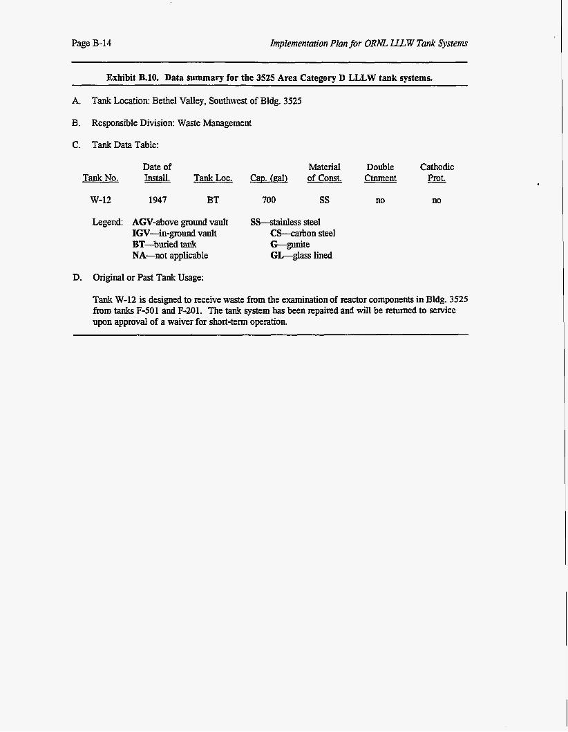
Page B-14 Implementation Plan for ORM LLLW Tank Systems
Exhibit B.lO. Data summary for the 3525 Area Category D LLLW tank systems.
A. Tank Location: Bethel Valley, Southwest of Bldg. 3525
B. Responsible Division: Waste Management
C. Tank Data Table:
Tank No.
w-12
Date of Material Double cathodic Install. Tank LOC. Cau. (gal) of Const. Ctnment Prot. - 1947 BT 700 ss no
Legend: AGV-above ground vault SS-stainless steel IGV-in-ground vault C h a r b o n steel BT-buried tank G-gunite NA-not applicable GL-glass lined
D. Original or Past Tank Usage:
no
Tank W-12 is designed to receive waste from the examination of reactor components in Bldg. 3525 from tanks F-501 and F-201. The tank system has been repaired and will be retumed to sewice upon approval of a waiver for short-term operation
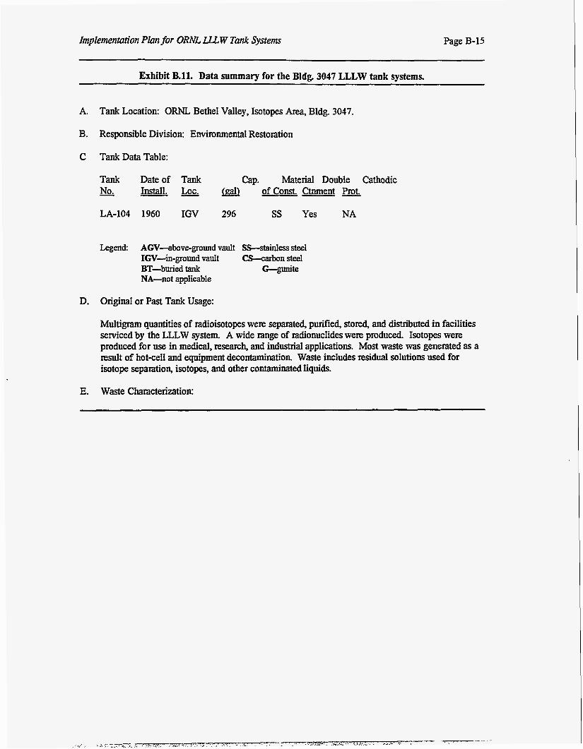
Implementation Plan for ORAE LLLW Tank System Page B-15
Exhibit B.ll. Data summary for the Bldg. 3047 LLLW tank systems.
A. Tank Location: ORNL Bethel Valley, Isotopes Area, Bldg. 3047.
B. Responsible Division: Environmental Restoration
C Tank Data Table:
Tank Date of Tank Cap. Material Double Cathodic - No. Install. Lot. of Const. Ctnment Prot.
LA-104 1960 IGV 296 SS Yes NA
Legend AGV-above-ground vault SS-stainless steel IGV-in-ground vault CS-carbon steel
NA-not applicable BT-buriedtank G-gunite
D. Original or Past Tank Usage:
Multigmm quantities of radioisotopes we= separated, p d i e d , stored, and distriiuted in facilities serviced by the LLLW system. A wide range of radionuclides were produced Isotopes were produced for use in medical, research, and industrial applications. Most waste was generated as a result of hot-cell and equipment decontamination. Waste includes residual solutions used for isotope separation, isotopes, and other contaminated liquids.
E. Waste Characterization:
DISTRIBUTION
1. M. Belvin 2 I L L Boston 3. T. W.Burwinkle 4. k D. Clay 5. C E. Devore
6-8. J. T. Ethendge 9. CEFrye
10. H.R Gaddis 11. P. J. Hakey 1 2 M.W.Kohring 13. kM.Krichinsky
14-16. D. M. Matte0
20. K k Morgan
23. B. D. Patton
17-19. T. H. Monk
21-22. P. T. Owen
24-25. M.R.Peet 26. ECPhillips 27. S. M. Robinson 28. CB.Scott 29. LILStinton 30. R J. Vedder 31. RUWham 3 2 ULWhitehead 33. P. s. wood 34. Central Research Liirary 35. Engineering Document Management Center 36. ORNL ER Document Management Center 37. Central ER Document Management Center 38. Laboratory Records Department 39. ORNL Patent Section 40. Office of Assistant Manager for Energy Research and Development, DOE Oak Ridge
Operations Office, P.O. Box 2001, Oak Ridge, TN 37831-8600 41-42 M. Singleton, H&R Technical Associates, Inc, P.O. Box 4159, Oak Ridge, TN 37831-4159
43. C Mims, DOE Oak Ridge Operations Office, P.O. Box 2001, Oak Ridge, TN 37831-8541 44. L L Radcliffe, DOE Oak Ridge Operations Office, P.O. Box 2001, Oak Ridge, TN 37831-
8541 45. L C M. Roddye, DOE Oak Ridge Operations Office, P.O. Box 2001, Oak Ridge, TN 37831-
8541 46. R C Sleeman, DOE Oak Ridge Operations Office, P.O. Box 2001, Oak Ridge, TN 37831-
8541 47. Douglas Underwood, DOE Oak Ridge Operations Office, P.O. Box 2001, Oak Ridge, TN
37831-8541 48-49. Office of Scientific and Technical Information, P.O. Box 62, Oak Ridge, TN 37831