ida8 & ateis studio user manual - penton audio usa
TRANSCRIPT

© 2012 ATEÏS
IDA8 & Ateis StudioUser Manual
Version 4

Revision History
Time Version
2012/07/23 1 Modified DNM chapter in the Product Features> Consoles and Accessories.The First Version.
2 Add Topics: Speaker lines Leakage/Short/Open. IDA8 touch panel, Master-Slave wiring. Redundancy Units hardware wiring. SPA Parallel Output setting. Configuration for CDPA,PCP and PSC. Juction Box in Consoles and Accessories.
Text Modification: Add EVAC Input Mode and Contact Output in the IDA8 system characteristics. MM Player and Message Player in Components chapter. Vox@net offline in Monitoring/Fault chapter.
2012/09/10
3 Downscale the image size for publish.Add figures: Speakon connector of IDA8SL. Telephone Line connector of RU-PDC.Modify Topic: Add quick examination for Ateis Net Broken.
2012/10/09
2012/11/29 4 Add page numbers beside links.Add Topic: Junction Box wiring. PPMAS Rear Panel.Modify Topics: DNM configuration. Hardware Wiring of RU. SPA front/rear panel. PPM AS configuration. Ateis Studio Device Management. IDA8 Fault list. PPM-IT5 LCD Panel

3Contents
3
© 2012 ATEÏS
Table of Contents
Introduction 11
................................................................................................................................... 111.1 Welcome
................................................................................................................................... 111.2 Ateis Presentation
................................................................................................................................... 131.3 EC Declaration of Conformity
Safety Declartion 14
Quick Start 15
................................................................................................................................... 153.1 for IDA8
Product Features 31
................................................................................................................................... 314.1 IDA8 Series Audio Processor
.......................................................................................................................................................... 32IDA8C 4.1.1
......................................................................................................................................................... 32Overview4.1.1.1
......................................................................................................................................................... 33Front Panel4.1.1.2
......................................................................................................................................................... 35Rear Panel4.1.1.3
......................................................................................................................................................... 37Characteristics4.1.1.4
......................................................................................................................................................... 41Peripherals4.1.1.5
......................................................................................................................................................... 423rd Party Control4.1.1.6
......................................................................................................................................................... 42LCD Menu4.1.1.7
......................................................................................................................................... 46Paging4.1.1.7
......................................................................................................................................... 46System Information4.1.1.7
......................................................................................................................................... 49System Setting4.1.1.7
.......................................................................................................................................................... 53IDA8SAB 4.1.2
......................................................................................................................................................... 53Overview4.1.2.1
......................................................................................................................................................... 54Front Panel4.1.2.2
......................................................................................................................................................... 55Rear Panel4.1.2.3
......................................................................................................................................................... 56Characteristics4.1.2.4
......................................................................................................................................................... 59Peripherals4.1.2.5
......................................................................................................................................................... 603rd Party Control4.1.2.6
.......................................................................................................................................................... 61IDA8SL 4.1.3
......................................................................................................................................................... 61Overview4.1.3.1
......................................................................................................................................................... 62Front Panel4.1.3.2
......................................................................................................................................................... 63Rear Panel4.1.3.3
......................................................................................................................................................... 65Characteristics4.1.3.4
......................................................................................................................................................... 683rd Party Control4.1.3.5
......................................................................................................................................................... 68Peripherals4.1.3.6
.......................................................................................................................................................... 70IDA8S 4.1.4
......................................................................................................................................................... 70Overview4.1.4.1
......................................................................................................................................................... 70Front Panel4.1.4.2
......................................................................................................................................................... 72Rear Panel4.1.4.3
......................................................................................................................................................... 73Characteristics4.1.4.4
......................................................................................................................................................... 763rd Party Control4.1.4.5
......................................................................................................................................................... 76Peripherals4.1.4.6
.......................................................................................................................................................... 77Network Wiring 4.1.5
.......................................................................................................................................................... 80Amplifier Configuration 4.1.6

ATEIS - IDA84
© 2012 ATEÏS
......................................................................................................................................................... 80Basic Amplifier Connection4.1.6.1
......................................................................................................................................................... 81Amplifier Backup4.1.6.2
.......................................................................................................................................................... 86Monitoring/Fault 4.1.7
......................................................................................................................................................... 87Table of Global Faults4.1.7.1
......................................................................................................................................... 88Table of System Faults4.1.7.1
................................................................................................................................... 89Flash Error4.1.7.1.1
................................................................................................................................... 89I2C Error4.1.7.1.1
................................................................................................................................... 90Net Card Error4.1.7.1.1
................................................................................................................................... 91DSP Error4.1.7.1.1
................................................................................................................................... 91Preset Table Error4.1.7.1.1
................................................................................................................................... 92No Preset Error4.1.7.1.1
................................................................................................................................... 92SPI Flash Error4.1.7.1.1
................................................................................................................................... 93Para. Table Error4.1.7.1.1
................................................................................................................................... 94Trans Error4.1.7.1.1
................................................................................................................................... 94Audio Overflow4.1.7.1.1
................................................................................................................................... 95Power Error4.1.7.1.1
................................................................................................................................... 96Reset Error4.1.7.1.1
................................................................................................................................... 96TEL Error4.1.7.1.1
................................................................................................................................... 97Main FPGA Error4.1.7.1.1
......................................................................................................................................... 97SSI Error4.1.7.1
......................................................................................................................................... 98No Para. Table.4.1.7.1
......................................................................................................................................... 98Ethernet Broken4.1.7.1
......................................................................................................................................... 99AESEBU Error4.1.7.1
......................................................................................................................................... 100User Define Error4.1.7.1
......................................................................................................................................... 100Normal/Backup Amplifier Error4.1.7.1
......................................................................................................................................... 104Line A/B Error4.1.7.1
......................................................................................................................................... 108Amplifier Line Leakage Error4.1.7.1
......................................................................................................................................... 109Evacuation Intput Error4.1.7.1
......................................................................................................................................... 111Local Ateis Net Broken4.1.7.1
......................................................................................................................................... 113Fireman Microphone Error4.1.7.1
......................................................................................................................................... 114VOX@NET Offline4.1.7.1
......................................................................................................................................... 115Redundancy Error4.1.7.1
......................................................................................................................................... 116Remote Offline4.1.7.1
......................................................................................................................................... 117Remote Fault4.1.7.1
......................................................................................................................................... 118URGP Fault4.1.7.1
......................................................................................................................................... 120File Corruption4.1.7.1
......................................................................................................................................... 121ModBus Offline4.1.7.1
......................................................................................................................................... 121AMP Rating Fault4.1.7.1
......................................................................................................................................... 122BackupAmp Used State4.1.7.1
......................................................................................................................................... 123Local AteisNet Backup Mode4.1.7.1
......................................................................................................................................... 123Bypass Mode4.1.7.1
......................................................................................................................................... 124Major User Define Fault4.1.7.1
......................................................................................................................................... 125Minor User Define Fault4.1.7.1
......................................................................................................................................... 125Modan Offline4.1.7.1
......................................................................................................................................... 126NTP Server Error4.1.7.1
......................................................................................................................................... 127Normal AMP Out of Toler4.1.7.1
......................................................................................................................................... 127Backup AMP Out of Toler4.1.7.1
......................................................................................................................................................... 128Procedure of Monitoring Setup4.1.7.2
......................................................................................................................................................... 128Zone Monitoring4.1.7.3
......................................................................................................................................................... 133Normal Amplifier Monitoring4.1.7.4
......................................................................................................................................................... 135Backup Amplifier Monitoring4.1.7.5
......................................................................................................................................................... 139Global Settings4.1.7.6
......................................................................................................................................................... 140Tone Settings4.1.7.7
......................................................................................................................................................... 141Circuit Leakage4.1.7.8

5Contents
5
© 2012 ATEÏS
......................................................................................................................................................... 142Open/Short Circuit4.1.7.9
.......................................................................................................................................................... 143Log List 4.1.8
.......................................................................................................................................................... 147Bypass Mode Paging 4.1.9
.......................................................................................................................................................... 148Contact I/O 4.1.10
......................................................................................................................................................... 148Evacuation Input4.1.10.1
......................................................................................................................................................... 149Contact Output4.1.10.2
.......................................................................................................................................................... 150Maintenance and Troubleshooting 4.1.11
................................................................................................................................... 1524.2 Consoles and Accessories
.......................................................................................................................................................... 152Redundancy Unit 4.2.1
......................................................................................................................................................... 152Overview4.2.1.1
......................................................................................................................................................... 153Hardware Wiring4.2.1.2
......................................................................................................................................................... 167Configuration4.2.1.3
......................................................................................................................................................... 171RU-Main4.2.1.4
......................................................................................................................................... 171Overview4.2.1.4
......................................................................................................................................... 171Front Panel4.2.1.4
......................................................................................................................................... 172Rear Panel4.2.1.4
......................................................................................................................................... 175Characteristics4.2.1.4
......................................................................................................................................................... 175RU-PDC4.2.1.5
......................................................................................................................................... 175Overview4.2.1.5
......................................................................................................................................... 176Front Panel4.2.1.5
......................................................................................................................................... 176Characteristics4.2.1.5
......................................................................................................................................................... 176RU-CTL4.2.1.6
......................................................................................................................................... 176Overview4.2.1.6
......................................................................................................................................... 177Front Panel4.2.1.6
......................................................................................................................................... 177Rear Panel4.2.1.6
......................................................................................................................................... 179Characteristics4.2.1.6
.......................................................................................................................................................... 179DNM 4.2.2
......................................................................................................................................................... 179Overview4.2.2.1
......................................................................................................................................................... 179Wire Connection4.2.2.2
......................................................................................................................................................... 180Installation4.2.2.3
......................................................................................................................................................... 182Characteristics4.2.2.4
......................................................................................................................................................... 183Configuration4.2.2.5
......................................................................................................................................................... 189Operation Notice4.2.2.6
......................................................................................................................................................... 189Two DNM on the Same PDC4.2.2.7
.......................................................................................................................................................... 194PPM AS 4.2.3
......................................................................................................................................................... 194Overview4.2.3.1
......................................................................................................................................................... 195Control Panel4.2.3.2
......................................................................................................................................................... 197Rear Panel4.2.3.3
......................................................................................................................................................... 198Characteristics4.2.3.4
......................................................................................................................................................... 198Configuration4.2.3.5
......................................................................................................................................................... 205Maintenance and Troubleshooting4.2.3.6
.......................................................................................................................................................... 206PSS AS 4.2.4
......................................................................................................................................................... 206Overview4.2.4.1
......................................................................................................................................................... 207Control Panel4.2.4.2
......................................................................................................................................................... 208Characteristics4.2.4.3
......................................................................................................................................................... 209Configuration4.2.4.4
......................................................................................................................................................... 216Maintenance and Troubleshooting4.2.4.5
.......................................................................................................................................................... 216URC AS 4.2.5
......................................................................................................................................................... 216Overview4.2.5.1
......................................................................................................................................................... 217Control Panel4.2.5.2
......................................................................................................................................................... 217Characteristics4.2.5.3
......................................................................................................................................................... 218Configuration4.2.5.4
.......................................................................................................................................................... 223RAC 4.2.6
......................................................................................................................................................... 223Overview4.2.6.1

ATEIS - IDA86
© 2012 ATEÏS
......................................................................................................................................................... 223Wire Connection4.2.6.2
.......................................................................................................................................................... 224URGP 4.2.7
......................................................................................................................................................... 224Overview4.2.7.1
......................................................................................................................................................... 224Front Panel4.2.7.2
......................................................................................................................................................... 225Rear Panel4.2.7.3
......................................................................................................................................................... 226Characteristics4.2.7.4
......................................................................................................................................................... 227Configuration4.2.7.5
.......................................................................................................................................................... 228CD-Touch 4.2.8
......................................................................................................................................................... 228Overview4.2.8.1
......................................................................................................................................................... 229Control Panel4.2.8.2
......................................................................................................................................................... 230Characteristics4.2.8.3
......................................................................................................................................................... 231Maintenance and Troubleshooting4.2.8.4
.......................................................................................................................................................... 232CD8 4.2.9
......................................................................................................................................................... 232Overview4.2.9.1
......................................................................................................................................................... 233Control Panel4.2.9.2
......................................................................................................................................................... 234Characteristics4.2.9.3
......................................................................................................................................................... 235Maintenance and Troubleshooting4.2.9.4
.......................................................................................................................................................... 236CD16 4.2.10
......................................................................................................................................................... 236Overview4.2.10.1
......................................................................................................................................................... 237Control Panel4.2.10.2
......................................................................................................................................................... 239Characteristics4.2.10.3
......................................................................................................................................................... 239Maintenance and Troubleshooting4.2.10.4
.......................................................................................................................................................... 240Fireman Microphone 4.2.11
......................................................................................................................................................... 240Overview4.2.11.1
......................................................................................................................................................... 240Characteristics4.2.11.2
......................................................................................................................................................... 240Configuration4.2.11.3
.......................................................................................................................................................... 242CDPM 4.2.12
......................................................................................................................................................... 242Overview4.2.12.1
......................................................................................................................................................... 243Control Panel4.2.12.2
......................................................................................................................................................... 245Characteristics4.2.12.3
......................................................................................................................................................... 246Configuration4.2.12.4
......................................................................................................................................................... 252Maintenance and Troubleshooting4.2.12.5
.......................................................................................................................................................... 253PCP 4.2.13
......................................................................................................................................................... 253Overview4.2.13.1
......................................................................................................................................................... 254Control Panel4.2.13.2
......................................................................................................................................................... 256Characteristics4.2.13.3
......................................................................................................................................................... 256Configuration4.2.13.4
......................................................................................................................................................... 262Maintenance and Troubleshooting4.2.13.5
.......................................................................................................................................................... 263PSC 4.2.14
......................................................................................................................................................... 263Overview4.2.14.1
......................................................................................................................................................... 264Control Panel4.2.14.2
......................................................................................................................................................... 265Characteristics4.2.14.3
......................................................................................................................................................... 266Configuration4.2.14.4
......................................................................................................................................................... 272Maintenance and Troubleshooting4.2.14.5
.......................................................................................................................................................... 273URC200 TPC 4.2.15
......................................................................................................................................................... 273Overview4.2.15.1
......................................................................................................................................................... 274Control Panel4.2.15.2
......................................................................................................................................................... 274Characteristic4.2.15.3
......................................................................................................................................................... 275Configuration4.2.15.4
......................................................................................................................................... 275Edit Control Items4.2.15.4
......................................................................................................................................... 280Import/Export Configuration4.2.15.4
......................................................................................................................................... 280Save/Load Configuration4.2.15.4
......................................................................................................................................... 280Reset Configuation4.2.15.4
......................................................................................................................................................... 281Device Maintenance4.2.15.5

7Contents
7
© 2012 ATEÏS
......................................................................................................................................... 281Update Firmware4.2.15.5
......................................................................................................................................... 284Protected Mode4.2.15.5
.......................................................................................................................................................... 285Junction Box 4.2.16
......................................................................................................................................................... 285Overview4.2.16.1
......................................................................................................................................................... 286Connection4.2.16.2
......................................................................................................................................................... 289RJ454.2.16.3
.......................................................................................................................................................... 291PPM-IT5 4.2.17
......................................................................................................................................................... 291Overview4.2.17.1
......................................................................................................................................................... 292Control Panel4.2.17.2
......................................................................................................................................................... 293LCD Menu4.2.17.3
......................................................................................................................................... 295Main4.2.17.3
......................................................................................................................................... 299Dial4.2.17.3
......................................................................................................................................... 300Message4.2.17.3
......................................................................................................................................... 300Setting4.2.17.3
......................................................................................................................................................... 301Characteristics4.2.17.4
......................................................................................................................................................... 302Maintenance and Troubleshooting4.2.17.5
................................................................................................................................... 3024.3 Amplifier
.......................................................................................................................................................... 302SPA 4.3.1
......................................................................................................................................................... 302Overview4.3.1.1
......................................................................................................................................................... 304Front Panel4.3.1.2
......................................................................................................................................................... 305Rear Panel4.3.1.3
......................................................................................................................................................... 306Characteristics4.3.1.4
......................................................................................................................................................... 308Parallel Output4.3.1.5
System Functionality 309
................................................................................................................................... 3095.1 Ateis Studio
.......................................................................................................................................................... 309Overiew of Ateis Studio 5.1.1
.......................................................................................................................................................... 310System Requirement 5.1.2
.......................................................................................................................................................... 311Install Ateis Studio 5.1.3
.......................................................................................................................................................... 316Windows Layout 5.1.4
.......................................................................................................................................................... 317File 5.1.5
.......................................................................................................................................................... 318Edit 5.1.6
.......................................................................................................................................................... 319View 5.1.7
.......................................................................................................................................................... 320Geometry 5.1.8
.......................................................................................................................................................... 323Component Editing 5.1.9
.......................................................................................................................................................... 331Tools 5.1.10
.......................................................................................................................................................... 334Operation 5.1.11
.......................................................................................................................................................... 335Window 5.1.12
.......................................................................................................................................................... 337Help 5.1.13
.......................................................................................................................................................... 337Component Template 5.1.14
.......................................................................................................................................................... 339Resource Manager 5.1.15
.......................................................................................................................................................... 340Object Tree 5.1.16
.......................................................................................................................................................... 340Layers 5.1.17
.......................................................................................................................................................... 341Bird's Eye 5.1.18
.......................................................................................................................................................... 342Properties 5.1.19
.......................................................................................................................................................... 343Message Library 5.1.20
.......................................................................................................................................................... 344Logo Library 5.1.21
................................................................................................................................... 3445.2 Presets
.......................................................................................................................................................... 344Overview 5.2.1
.......................................................................................................................................................... 345Master Presets 5.2.2
.......................................................................................................................................................... 347Sub-Presets 5.2.3
................................................................................................................................... 3505.3 Event Management

ATEIS - IDA88
© 2012 ATEÏS
.......................................................................................................................................................... 350Event Manager 5.3.1
.......................................................................................................................................................... 351Value Trigger Event 5.3.2
.......................................................................................................................................................... 353Value Control Event 5.3.3
.......................................................................................................................................................... 356Step Trigger Event 5.3.4
.......................................................................................................................................................... 358Step Control Event 5.3.5
.......................................................................................................................................................... 360Master Preset Change Change 5.3.6
.......................................................................................................................................................... 361Sub-Preset Change Event 5.3.7
.......................................................................................................................................................... 362Integration Paging Event 5.3.8
.......................................................................................................................................................... 362Singular Paging Event 5.3.9
................................................................................................................................... 3635.4 Device Management
.......................................................................................................................................................... 364Search and Settings 5.4.1
.......................................................................................................................................................... 365Read Version 5.4.2
.......................................................................................................................................................... 366Update Firmware 5.4.3
.......................................................................................................................................................... 370Ateis Net Deploying 5.4.4
.......................................................................................................................................................... 372Remote Plug-in 5.4.5
.......................................................................................................................................................... 375Reverse 5.4.6
.......................................................................................................................................................... 376Machine File System 5.4.7
.......................................................................................................................................................... 378Remote Update 5.4.8
.......................................................................................................................................................... 381Chime Data Store 5.4.9
.......................................................................................................................................................... 383Log 5.4.10
.......................................................................................................................................................... 384Time Setting 5.4.11
.......................................................................................................................................................... 386VR Calibration 5.4.12
.......................................................................................................................................................... 387URC Logo Store 5.4.13
.......................................................................................................................................................... 389Fault E-mail Setting 5.4.14
.......................................................................................................................................................... 393Modbus 5.4.15
.......................................................................................................................................................... 395Machine Reset 5.4.16
.......................................................................................................................................................... 396Redundancy 5.4.17
.......................................................................................................................................................... 397Ethernet Monitor 5.4.18
.......................................................................................................................................................... 398TelePhone Card Setting 5.4.19
................................................................................................................................... 3985.5 3rd Party Control
.......................................................................................................................................................... 398Ateis 3rd Party Control 5.5.1
......................................................................................................................................................... 398Overview5.5.1.1
......................................................................................................................................................... 398Assign Elements to 3rd Party Control5.5.1.2
......................................................................................................................................................... 3993rd Party Control List5.5.1.3
......................................................................................................................................................... 4003rd Party Control Command5.5.1.4
................................................................................................................................... 4005.6 User Management
.......................................................................................................................................................... 400Overview 5.6.1
.......................................................................................................................................................... 401User Levels 5.6.2
.......................................................................................................................................................... 403User Accounts 5.6.3
Components of Audio Processor 404
................................................................................................................................... 4046.1 AEC
.......................................................................................................................................................... 404Parameters 6.1.1
.......................................................................................................................................................... 406Functions 6.1.2
................................................................................................................................... 4096.2 Delay (Advanced)
................................................................................................................................... 4136.3 Delay (Basic)
................................................................................................................................... 4166.4 Dynamic
.......................................................................................................................................................... 416AGC\AGC Stereo 6.4.1
.......................................................................................................................................................... 420Auto Noise Gain (A.N.G) 6.4.2
.......................................................................................................................................................... 427Compressor\Compressor Stereo 6.4.3
.......................................................................................................................................................... 431Comp-limiter 6.4.4

9Contents
9
© 2012 ATEÏS
.......................................................................................................................................................... 434DNM 6.4.5
.......................................................................................................................................................... 438Ducker\Ducker Stereo 6.4.6
.......................................................................................................................................................... 441Expander\Expander Stereo 6.4.7
.......................................................................................................................................................... 444Gate 6.4.8
......................................................................................................................................................... 444Gate - Mono6.4.8.1
......................................................................................................................................................... 446Gate - Stereo6.4.8.2
......................................................................................................................................................... 449Gate - Voice6.4.8.3
......................................................................................................................................................... 451Gate with Sidechain6.4.8.4
.......................................................................................................................................................... 454Limiter\Limiter Stereo 6.4.9
................................................................................................................................... 4576.5 Equalizer
.......................................................................................................................................................... 457GEQ\GEQ Stereo 6.5.1
.......................................................................................................................................................... 460PEQ\PEQ Stereo 6.5.2
................................................................................................................................... 4636.6 Feedback
................................................................................................................................... 4666.7 Filter
.......................................................................................................................................................... 466All Pass Filter 6.7.1
.......................................................................................................................................................... 468Band Pass 6.7.2
.......................................................................................................................................................... 471Band Stop 6.7.3
.......................................................................................................................................................... 474Crossover/Crossover Stereo 6.7.4
.......................................................................................................................................................... 477Hi/Lo Pass 6.7.5
.......................................................................................................................................................... 479Notch Filter 6.7.6
.......................................................................................................................................................... 482Shelving Filter 6.7.7
................................................................................................................................... 4846.8 Fireman
................................................................................................................................... 4856.9 Input
.......................................................................................................................................................... 485Input 6.9.1
.......................................................................................................................................................... 488Mono Input 6.9.2
.......................................................................................................................................................... 490Stereo Input 6.9.3
.......................................................................................................................................................... 492Duplex Input 6.9.4
.......................................................................................................................................................... 494Inverter 6.9.5
................................................................................................................................... 4956.10 Level Controller
................................................................................................................................... 4976.11 Local Echo Suppressor
................................................................................................................................... 4996.12 Logic
.......................................................................................................................................................... 499AND 6.12.1
.......................................................................................................................................................... 500EVAC Board 6.12.2
.......................................................................................................................................................... 502Evacuation Input 6.12.3
.......................................................................................................................................................... 503Event 6.12.4
......................................................................................................................................................... 504Trigger6.12.4.1
.......................................................................................................................................................... 506Logic Control 6.12.5
.......................................................................................................................................................... 507Logic Meter 6.12.6
.......................................................................................................................................................... 508Logic Net Input 6.12.7
.......................................................................................................................................................... 509Logic Net Output 6.12.8
.......................................................................................................................................................... 510NOT 6.12.9
.......................................................................................................................................................... 510OR 6.12.10
.......................................................................................................................................................... 511Output 6.12.11
.......................................................................................................................................................... 512Scheduler 6.12.12
................................................................................................................................... 5166.13 Meter
.......................................................................................................................................................... 516Peak/RMS Meter 6.13.1
................................................................................................................................... 5186.14 Message
.......................................................................................................................................................... 518Message Player 6.14.1
.......................................................................................................................................................... 524MM Player 6.14.2
................................................................................................................................... 5286.15 Mixer

ATEIS - IDA810
© 2012 ATEÏS
.......................................................................................................................................................... 528AutoMixer 6.15.1
.......................................................................................................................................................... 531AutoMixer MM 6.15.2
.......................................................................................................................................................... 535Matrix 6.15.3
.......................................................................................................................................................... 537Standard 6.15.4
................................................................................................................................... 5386.16 Net Input
................................................................................................................................... 5406.17 Net Output
................................................................................................................................... 5416.18 Noise Generator
.......................................................................................................................................................... 541Pink 6.18.1
.......................................................................................................................................................... 542Tone 6.18.2
.......................................................................................................................................................... 544White 6.18.3
................................................................................................................................... 5456.19 Output
.......................................................................................................................................................... 545Output 6.19.1
.......................................................................................................................................................... 547Monitor Output 6.19.2
.......................................................................................................................................................... 549Mono Output 6.19.3
.......................................................................................................................................................... 551Stereo Output 6.19.4
.......................................................................................................................................................... 553Duplex Output 6.19.5
................................................................................................................................... 5556.20 Page Control
.......................................................................................................................................................... 555S/W Page Control 6.20.1
.......................................................................................................................................................... 557Network Paging 6.20.2
................................................................................................................................... 5686.21 RS485 Audio
.......................................................................................................................................................... 568RS485 Input 6.21.1
.......................................................................................................................................................... 570RS485 Output 6.21.2
................................................................................................................................... 5726.22 Selector
................................................................................................................................... 5736.23 Signal Monitor
................................................................................................................................... 5756.24 Telephone Card
.......................................................................................................................................................... 575TC Transmit 6.24.1
.......................................................................................................................................................... 578TC Receive 6.24.2
................................................................................................................................... 5806.25 Voxnet Control
Contact Information 582

Introduction 11
© 2012 ATEÏS
1 Introduction
1.1 Welcome
Thank you for choosing ATEÏS. We here at ATEÏS hope you will enjoy our technology as much as weenjoyed developing and building it.
This manual is intended to provide the user with the necessary understanding of our system architectureas well as guide users through the configuration process.
This manual can be updated at any time without prior notice in order to keep it up to date.
If you find errors in this manual or would like to improve on the presentation, feel free to submit mistakes,suggestions or questions by sending an email .
We hope that this Help File Manual will provide you all the information you need. However if you haveany questions, feel free to contact us.
1.2 Ateis Presentation
ATEÏS has been in the professional audio market for close to thirty years and is viewed as a leadingcompetitor in the Public Address, Voice Alarm, and Professional Audio Market in Europe, Asia, and theMiddle East.
Products
The company offers a full range of audio equipment: microphones, preamplifiers, digital processors,digital audio matrixes, loud-speaker monitoring systems, amplifiers, etc. ATEÏS designs andmanufactures leading products in the voice alarm systems market which have been certified EN60849compliant by the TÜV and UL listed.
Development
Thanks to a development team of over forty engineers and a close connection to our customer base,we are able to respond rapidly to the demands of our various vertical markets with specific solutionsand cutting edge technology. You can rest assured that our technology is always cutting edge with aview to the future.
ATEÏS Vertical Markets
Transportation (Railways, Subways, Airports)
High rise buildings
582

ATEIS - IDA812
© 2012 ATEÏS
Hotels
Restaurants
Shopping malls
Theme parks
Places of worship
Stadium
Museums
Industrial
University and campus applications

Introduction 13
© 2012 ATEÏS
1.3 EC Declaration of Conformity

ATEIS - IDA814
© 2012 ATEÏS
2 Safety Declartion
Do not expose the device to extreme temperatures, direct sunlight, humidity, or dust, which couldcause fire or electrical shock hazard.
Keep away water or other liquids from the device. Otherwise fire or electrical shock may result.
Connect the power cord only to an AC outlet of the type stated in this Owner's Manual or as markedon the unit. Otherwise fire and electrical shock hazard results.
When disconnecting the power cord from an AC outlet always grab the plug. Never pull the cord. Adamaged power cord is a potential risk of fire and electrical shock hazard.
Avoid touching power plugs with wet hands. Doing so is a potential electrical shock hazard.
Take care for correct polarity when operating the device from a DC power source. Reversed polaritymay cause damage to the unit or the batteries.
Avoid placing heavy objects on power cords. A damaged power cord is a fire and electrical shockhazard.
Do not cut, scratch, bend, twist, pull, or heat the power cord. A damaged power cord is a fire andelectrical shock hazard. Ask your ATEÏS dealer for replacement.
Turn off immediately the unit, remove the power cord from the AC outlet and consult your ATEÏS dealerin any of the following circumstances:
Smoke, odor, or noise getting out of the unit.
Foreign objects or liquids get inside the device.
The unit has been dropped or the shell is damaged.
The power cord is damaged.
If you continue using the device, fire and electrical shock may result.
Do not drop or insert metallic objects or flammable materials into the unit as this may result in fire andelectrical shock.
Do not remove the device's cover, as there are exposed parts inside carrying high voltages that maycause an electrical shock. Contact your ATEÏS dealer if internal inspection, maintenance, or repair isnecessary.
Do not try to make any modifications to the device. This is a potential fire and electrical shock hazard.
Avoid the device's ventilation slots to be blocked. Blocking the ventilation slots is a potential firehazard.

Safety Declartion 15
© 2012 ATEÏS
To prevent the unit from falling down and causing personal injury and/or property damage, avoidinstalling or mounting the unit in unstable locations.
Leave enough space above and below the unit to provide good ventilation of the device. If the airflow isnot adequate, the device will heat up inside and may cause a fire.
Operate the device in an environment with a free-air temperature of between 0 °C and 40 °C (32 °F and104 °F).
Turn off all audio equipment when making any connections to the device, and make sure to useadequate cables.
Do not use benzene, thinner, or chemicals to clean the device. Use only a soft, dry cloth.
If the device is moved from a cold place (e.g., overnight in a car) to a warmer environment,condensation may form inside the unit, which may affect performance. Allow the device to acclimatizefor about one hour before use.
3 Quick Start
3.1 for IDA8
Here is a simple demonstration showing how to configure the IDA8C and how to adjust the parametersto get a 2K tone from the connected speaker.
1. Setup device and wiring:
Speaker is connected to the Amplifier Zone Output(Zone1).
Connect the ethernet cable between the speaker, PC and IDA8C.

ATEIS - IDA816
© 2012 ATEÏS
2. Power up the device:
Power up the IDA8C and make sure the power LED is on.
3. Set the IP, Subnet mask and gateway address:
Set the IP Address, Subnet mask and Gateway address by using the menu of the IDA8C's touchpanel to match your LAN. The default factory setting of the IP address is 192.168.100.236.
You can find information of your network by typing "ipconfig" command in the cmd window:
The IP/Subnet Mask/Gateway information are displayed, see the green rectangle in the picturebelow:
Return to the IDA8C's touch panel and follow the steps below to login and change the IP/SubnetMask/Gateway:
Click the [SYSTEM SET] in the [MAIN MENU] page:

Quick Start 17
© 2012 ATEÏS
Click the [LOGIN] in the [SYSTEM SET MENU-1] page:
Click the [USER NAME] in the [LOGIN] page:
Input ID "ADMIN" which is the default user of the IDA8C, keep the password field empty and click"OK" to log in.

ATEIS - IDA818
© 2012 ATEÏS
A page appears showing the message "Login successful".
Go back to the [SYSTEM SET MENU-2] page and click the [ETHERNET].
There are three fields: [IP ADDRESS], [SUBMASK] and [GATEWAY]. Click to setup each button tofit your network. In this example, we changed the IDA8C's IP to 192.168.100.79.

Quick Start 19
© 2012 ATEÏS
You need to reboot device to apply the settings.
4. Install the Ateis Studio.
5. Run the Ateis Studio.
6. Network settings of Ateis Studio
If there are more than one network interface cards on your PC, make sure it's using the correct onewhich the IDA8C is connected to. Open the window for setting the network interface card by clickingthe main menu of the Ateis Studio "View > Device Management"

ATEIS - IDA820
© 2012 ATEÏS
There are three tabs at the right side of the window. Switch to the [Network] tab and open the drop-down list to select the correct network interface card in the NIC field. See the rectangle stroke in thepicture below.
Change the UDP port if it is conflicting with other software.
7. Search devices:
Go to [Devices] tab and press the [Search] button:

Quick Start 21
© 2012 ATEÏS
After few seconds, all the Ateis devices in the LAN will be listed in a tree structure in the [Devices]field. Find the desired IDA8 which IP is 192.168.100.79.
8. Connect to device:
Click the [Connect] link to connect to the IDA8C and open its function menu:

ATEIS - IDA822
© 2012 ATEÏS
9. Check the compatibility between the IDA8C and the Ateis Studio. Click [Read Version] in the menu.
A window [Version] opens. Press the [Read] button to see the information about the firmwareversion.
If all firmware units are compatible ( shown in black text ) with Ateis Studio, go to step 11, otherwisego to step 10 to update the firmware. The below figure shows an incompatible version of the firmwarewhich is marked in red.
10.Update firmware:
Close the [Version] window and go back to the [Device Management] window. Next, click the[Update] function:

Quick Start 23
© 2012 ATEÏS
A window [Device Select] opens. Select the IDA8 and click the [OK] button:
A file manager opens. Select the IDA8 directory and choose the .asu file for updating.

ATEIS - IDA824
© 2012 ATEÏS
The update is processing. When it's done, a window will pop-up asking to reboot the IDA8, click[Yes] to restart the device.

Quick Start 25
© 2012 ATEÏS
Check the device version using step 9 again, the version number should be in black which means it'snow compatible.
11.Create a New file:
Create a new file by clicking the button on the upper-left of the Ateis Studio as shown in the picturebelow:
12.Create an IDA8C block in the device editor window
Drag the row "IDA8C" from the [Device Management] window and drop it into the design area asshown in the picture below:

ATEIS - IDA826
© 2012 ATEÏS
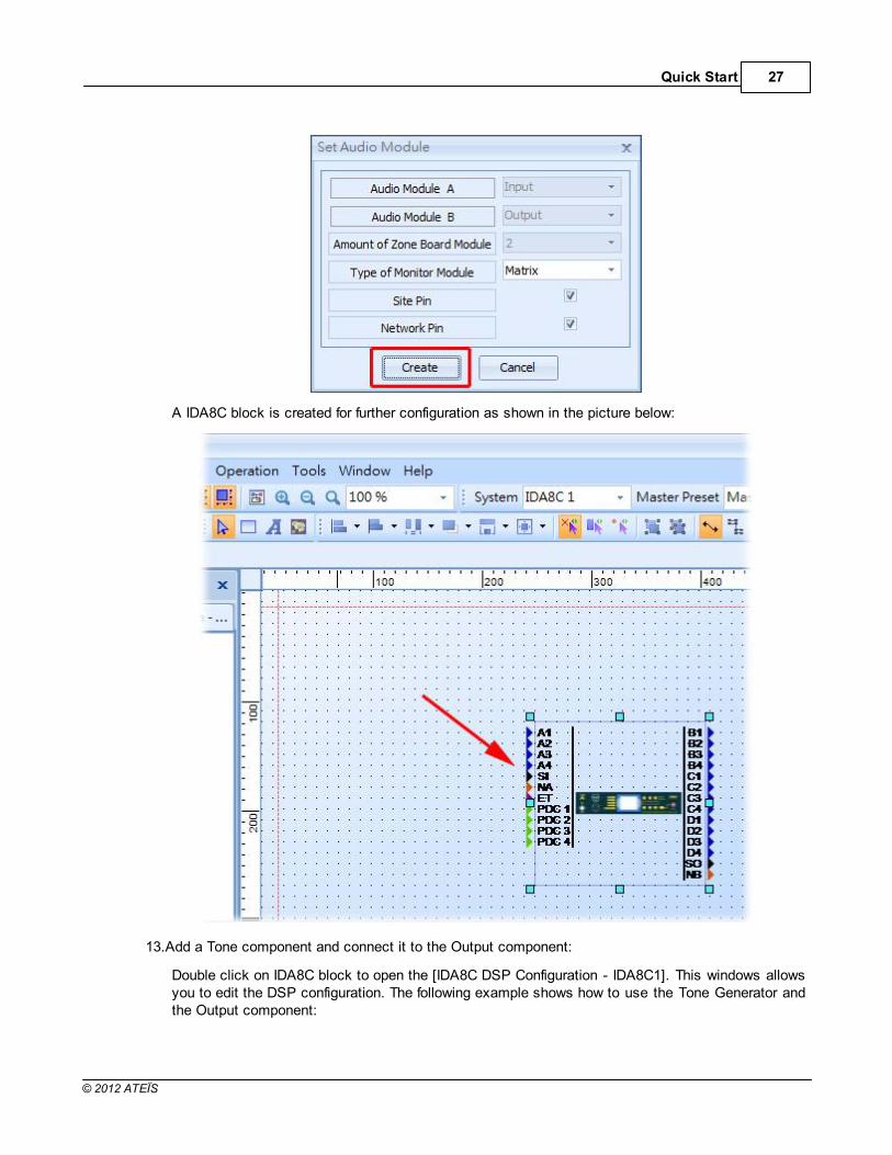
A window [Set Audio Module] opens. Click the [Create] button to continue.
Quick Start 27
© 2012 ATEÏS
A IDA8C block is created for further configuration as shown in the picture below:
13.Add a Tone component and connect it to the Output component:
Double click on IDA8C block to open the [IDA8C DSP Configuration - IDA8C1]. This windows allowsyou to edit the DSP configuration. The following example shows how to use the Tone Generator andthe Output component:

ATEIS - IDA828
© 2012 ATEÏS
14.Compile and Store:
Once the design is done, click [Compile All]. The Compiling window appears as shown in the picturebelow.

Quick Start 29
© 2012 ATEÏS
Then, click [Store All] to store your design into the IDA8. The Store window appears as shown in thepicture below.
Meanwhile, the system will ask the user to turn on the audio, click Yes.

ATEIS - IDA830
© 2012 ATEÏS
15.Adjust element:
Set the element of the Tone Generator:
Level(dB) = -10
Tone Button = On
Tone freq.(Hz) = 2.00k
Now you can see the channel 1 meter as shown in the picture below and hear a 2k tone from thespeaker connected to the Amplifier Zone Output(zone1) on the rear panel of the IDA8C.

Quick Start 31
© 2012 ATEÏS
4 Product Features
4.1 IDA8 Series Audio Processor
The IDA8 is a third generation modular system that complies with current architectural demandsrequiring IP-and/or Fiberoptics Networking to cover any complex design. IDA8 responds to PublicAddress and Voice Alarm requirements as stated in EN 54-16, ISO 7240-16 and BS 5839/8, withspecific attributes for compliance in large installations.

ATEIS - IDA832
© 2012 ATEÏS
4.1.1 IDA8C
4.1.1.1 Overview
The IDA8C Controller unit enables operators to see a detailed overview of the operational status of theentire PA system with a single push button. The IDA8C Controller unit is able to run an impedance scanof all components connected to it, covering not only the input paging consoles but including connectors,cabling, and processing blocks such as compressors and limiters, delay lines and the network andloudspeakers. It stores a reference measurement of the system as it exists in a given configuration andenvironment. This reference is subsequently stored in the system. Any alterations to this reference willbe reported and are logged in an event log file. User definable thresholds can be applied to thesereferences, allowing for customization to match circumstances.
Being EN 54-16/ISO 7240-16 and BS 5839 part 8 security systems, all components and peripherals aremonitored. All incidents are recorded into a data file which can be consulted on the controller modulemonitor display or on a PC using the ATEÏS Studio remote control software. Also, any detected fault issignalled by a general fault output contact available on the IDA8C Controller unit. A built-in loudspeakeroutput enables selective listening to all the sources and system’s 100 V output signals.

Product Features 33
© 2012 ATEÏS
Also, The IDA8 have two detection functions. Short-to-ground: Speaker line to ground detection andShort-circuit: Between speaker line.
The IDA8C Controller unit is easily configured with our PC based ATEÏS-Studio global software(Windows compatible). Software access can be password protected. Once programmed, the system willbe able to work independently(off-line) without the need of a PC to be connected.
4.1.1.2 Front Panel
Fireman Microphone Active LED:
Shows the activity of the fireman microphone, there are two states of this LED: test
Status Frequency Activity
Permanent Active, Fireman microphone is allowed to paging.
Blinking ° ° Zones are busy, fireman microphone is not allowed to paging.
Blinking ° °°° ° Pre chime is playing.
Fireman Microphone Input:
DIN Connector for fireman microphone connection.
Fireman Microphone Hook:
An U-shape hook to place fireman microphone.
Monitoring Speaker:
The IDA8C integrates a monitoring speaker in front panel. There are two functions of this speaker
Function Activity
Warning Tone A buzzer sound is generated when some faults is detected in system.
Source MonitoringMonitor audio sources of IDA8C. The source to be monitored can be selectedvia Ateis Studio software.
Note: If a fault is detected when speaker is monitoring a source, then the source monitoring will beinterrupted and play a buzzer sound for the fault.
Bypass Mode LED:
To indicate IDA8C is in bypass mode or not.
G.Fault LED:

ATEIS - IDA834
© 2012 ATEÏS
This LED lights up when a global fault is detected.
Note: Fault LED and system fault LED are exclusive. If system fault and global fault are detected atthe same time, the system only light the system fault LED.
System Fault LED:
This LED lights up when a system fault fault is detected.
Global EVAC LED:
To indicate system is in EVAC paging or not. This LED lights up if any IDA8 device over Ateis Netdo an EVAC paging.
Bypass Monitoring LED:
Shows the monitoring function is enabled or not. This LED lights up if monitoring of IDA8 is disabledby user.
Touch Screen:
3.5" Color touch panel offers a graphical interface for users to control or read the status of system.There is a multi layered menu on it to get/set parameters or change settings of device.
ESC Button:
To Navigate menu of touch screen.
OK Button:
To Navigate menu of touch screen.
Up Button:
To Navigate menu of touch screen.
Down Button:
To Navigate menu of touch screen.
Plus Button:
To Navigate menu of touch screen.
Down Button:
To Navigate menu of touch screen.
Zone EVAC LEDs:
To show the audio channel is in EVAC paging or not. Each LED corresponds to an output channel ofNetwork Paging component. For example, 1st LED is for pin M1, 2nd LED for pin M2 and so on.
Zone Fault LEDs:
To show fault status of zone. This LED lights up if one of following faults is detected:
Normal AMP Error

Product Features 35
© 2012 ATEÏS
Line A Error
Line B Error
Backup AMP Error
AMP Line Leakage Error
EVAC Reset Button:
Cancels the event triggered by EVAC button.
Power LED:
This LED lights up when IDA8C is power on.
Network LED:
Show the status of Ateis Net. This LED lights up if more than two deployed IDA8 devices in AteisNet.
EVAC Button:
To trigger an event bind with this button.
4.1.1.3 Rear Panel
Speaker Zone Outputs:
There are 8 zones for speaker & amplifier connections. Each zone consists of following connectors(from left to right):
connector of line A speaker
connector of line B speaker
connector of 100V audio coming from amplifier
The IDA8 output is exactly the same audio signal to line A and B. Two speakers can connect to onezone for redundancy purposes, one connects to line A, another connects to line B. Both speakerlines are monitored. That means if damage to a speaker is detected, a global fault "Line A/B Error"will be generated.
Backup Amplifier I/Os:

ATEIS - IDA836
© 2012 ATEÏS
Two backup amplifier connectors included 0 dB to amplifiers and 100V return from amplifiers.
Amplifier Zone Outputs:
8 Zone 0dB output to amplifiers.
Bypass Mode Input:
Contact input to engage the bypass mode paging(CMD).
Contact output to display the state of bypass mode paging(ACK).
EVAC, Fault State Outputs:
EVAC Output Contact: this contact is closed if the system is under EVAC paging.
Fault Output Contact: this contact is open if a fault is detected.
PDC(Peripherals Device Controller) Connectors:
Four RJ-45 connectors are used to connect consoles or peripheral devices such as PSS AS, URCAS and PPM AS through Junction Box.
Ethernet Connector:
RJ-45 connector to link the IDA8C on an ethernet network. The following end points arecommunicated with IDA8C through ethernet networking.
Ateis Studio software
3rd party devices
Voxnet Server
PMIP-D
VNB
PPM-IT5
TERRA Devics
Modbus Protocol
Local Ateis Net Connectors:
Optional card to build a local dedicated IDA8C-IDA8S network.
Global Ateis Net Connectors:
Optional card to build a global dedicated IDA8C network.
Configurable Audio I/Os:
Two configurable 0dB audio I/O port A and B. Each port is available to assemble an audio card.There are 4 channels on each audio I/O card.
Telephone Line Input:
A connector for a telephone signal coming from the telephone company.(optional).

Product Features 37
© 2012 ATEÏS
Telephone Connector:
A connector for external telephone connection.(optional).
Bypass Mode Outputs:
This port is used to share the bypass mode microphone signals through the IDA8C-IDA8S network(only needed when using fiber optic network).
Contact Outputs:
8 logic outputs channels are used to close/open a circuit for an external device. This contact isnormally open.
Evacuation Inputs:
9 evacuation contact inputs that allow the monitoring of external contact. They also can be used inUGA mode, trigger by a voltage polarization change.
24V DC Output:
This connector supplies a 24VDC source.
24V DC Input:
Main 24VDC power supply connector.
AC Power Socket:
Main 110~240 V 1.2A, 47~63Hz AC power input with fuse. If 24V DC and AC power inputs areconnected at the same time, IDA8C will use AC power, and switch to DC power if there is no ACpower input.
Fuse Rating: 3.15A
Zone Boards
Zone Board1
The following I/Os belong to zone board1 in IDA8C: speaker zone output ch1~ch4, backupamplifier1, amplifier zone output ch1 ~ ch4.
Zone Board2
The following I/Os are belong to zone board2 in IDA8C: speaker zone output ch5~ch8, backupamplifier2, amplifier zone output ch5 ~ ch8.
4.1.1.4 Characteristics
Case:
Dimension = 436mm (W) x 313mm (L) x 88mm (H)
Weight = 5.36Kg
Color = RAL7016
Screen:
3.5" Color touch panel

ATEIS - IDA838
© 2012 ATEÏS
Power:
Item Voltage Current Consumption Comment
AC Input 100V~240V 1.6A@100V, 0.7A@240V Frequency:47Hz~63Hz
DC Input 18V~26V, Typical 24V 2A -
DC Output 18V~26V, Typical 24V 0.5A -
AC Maximum Consumption = 45 W
Amplifier Zone Outputs:
Maximum level = 14 dB
Output Impedance = 50 Ohm
THD+N(Total Harmonic Distortion plus Noise)
Sensitivity Minimum Maximum Unit Frequency
0dBu - 0.04 % 20~20kHz@+4dBu
-12dBu - 0.06 % 20~20kHz@-2dBu
-24dBu - 0.06 % 20~20kHz@-14dBu
-40dBu - 0.06 % 20~20kHz@-30dBu
-54dBu - 0.06 % 20~20kHz@-44dBu
Bandwidth = 20Hz ~ 20kHz
EIN(Equivalent Input Noise)
Sensitivity Minimum Maximum Unit Frequency
0dBu - -81 dBu 20~20kHz@150Ω
-12dBu - -93 dBu 20~20kHz@150Ω
-24dBu - -104 dBu 20~20kHz@150Ω
-40dBu - -112 dBu 20~20kHz@150Ω
-54dBu - -115 dBu 20~20kHz@150Ω
Speaker line/Amplifier:
Maximum Power = 700W(RMS)
Maximum Power(Siren + Message) = 1000W
Monitoring Speaker:
Impedance = 8 Ohm
Maximum Power @ 1kHz = 1.6W
THD @ 1kHz = < 1%
Bandwidth @ -3dB = 100Hz ~ 12kHz
Configurable Audio Output:
Maximum level = 14 dBu
Output Impedance = 50 Ohm
THD+N(Total Harmonic Distortion plus Noise)

Product Features 39
© 2012 ATEÏS
Sensitivity Minimum Maximum Unit Frequency0dBu - 0.04 % 20~20kHz@+4dBu
-12dBu - 0.06 % 20~20kHz@-2dBu-24dBu - 0.06 % 20~20kHz@-14dBu-40dBu - 0.06 % 20~20kHz@-30dBu-54dBu - 0.06 % 20~20kHz@-44dBu
Bandwidth = 20Hz ~ 20kHz
EIN(Equivalent Input Noise)
Sensitivity Minimum Maximum Unit Frequency
0dBu - -81 dBu 20~20kHz@150Ω
-12dBu - -93 dBu 20~20kHz@150Ω
-24dBu - -104 dBu 20~20kHz@150Ω
-40dBu - -112 dBu 20~20kHz@150Ω
-54dBu - -115 dBu 20~20kHz@150Ω
Configurable Audio Input:
Sensitivity:
For each channel of a configurable audio input card, there are five levels to gain the audio signal.They are sensitivity values of 0dBu, -12dbBu, -24dBu, -40dBu and -54dBu respectively. Themeaning of sensitivity value is how large the gain is for an audio source, and to amplify thegiving minus input source to 0dBu. The figure below is an example of when the sensitivity valueis set to -54dBu, and input source is -54dBu, after the gaining circuit of the audio card you'll getthe 0dBu of output.
Maximum level = 14 dBu
Input Impedance = 10k Ohm
THD+N(Total Harmonic Distortion plus Noise)
Sensitivity Minimum Maximum Unit Frequency0dBu - 0.04 % 20~20kHz@+4dBu
-12dBu - 0.06 % 20~20kHz@-2dBu-24dBu - 0.06 % 20~20kHz@-14dBu-40dBu - 0.06 % 20~20kHz@-30dBu-54dBu - 0.06 % 20~20kHz@-44dBu

ATEIS - IDA840
© 2012 ATEÏS
Bandwidth = 20Hz ~ 20kHz
PDC:
Maximum Output Level = 10 dBu
Output Impedance = 300 Ohm
THD @ 1kHz at output < 0.02
Bandwidth @ -3dB at output = 20Hz ~ 20kHz
Noise @ 22Hz ~ 22kHz = -85dBu
Maximum Input Level = 16 dBu
Input Impedance = 11k Ohm
THD @ 1kHz at input < 0.02
Bandwidth @ -3dB at input < 20Hz ~ 22kHz
RS232 voltages = -6.5/+6.5
Evacuation Inputs(Contact Mode):
4 status: On, Off, Open and Short
Evacuation Inputs(Voltage Mode):
On Voltage:
Item Minimum Maximum Unit
High 18 72 VDC
Low - 0.5 VDC
Contact Outputs + EVAC, Fault State Outputs:
Item Minimum Maximum Unit
Voltage - 100 VDC
Current - 0.5 ADC
Contact Output Relay:

Product Features 41
© 2012 ATEÏS
Contact Output
Contact Form Maximum Unit
Carry Current 1.0 ADC
Maximum Voltage 100 VDC
Electrical Life 1 x 10 8 (Ref 10VDC, 10mA) -
Working Temperature:
0°C ~ 40°C
4.1.1.5 Peripherals
The following table shows the peripherals supported by IDA8C:
Device Connection Max. Num Function
Fireman MICFireman MIC
Input1 Paging where operator is close to the IDA8C.
PPM AS PDC 31 Remote console with paging ability.
PSS AS PDC 1Remote console for Paging and Event Triggering(Element
Control, Master/Sub Preset Control).
URC AS PDC 1Remote console for Master/Sub Preset Controlling and Element
Controlling.URGP PDC 1 Evacuation Input extension.DNM PDC 31 Auto noise gain for audio signals.
PPM-IT5 Ethernet1 ActiveOver Eth
Paging, Element Control and Master/Sub Preset Control.
URC200TPC
Ethernet Eth. Limit Parameters Control and Master/Sub Preset Control.
CD8 PDC 31Wall mounted cabinet remote paging console with 8 buttons/
zones.
CD16 PDC 31Wall mounted cabinet remote paging console with 16 buttons/
zones.

ATEIS - IDA842
© 2012 ATEÏS
Device Connection Max. Num Function
CD Touch PDC 1Wall mounted cabinet remote paging console with touch screen
and Fireman Microphone.
PCP PDC 31Wall mounted cabinet remote paging console with telephone
styled microphone.
CDPM PDC 31Wall mounted cabinet remote paging console with 24 buttons/
zones and 2 extra selectable microphone sources.
PSC PDC 31A grouped console is comprised of a pad with a monitoring
speaker, a pad with a gooseneck and 8 buttons/zones, and twopads with 8 buttons/zones.
Deskpad PDC 1A remote dialer for making telephone calls via IDA8's telephone
hardware.Deskpad
BoxPDC 1
An RF transceiver to communication between Deskpad andIDA8, use it, Deskpad can work without a physical connection.
Max. Num means you can connect one or more peripheral units through the connector by using aJunction Box. For example: On the PDC, you can connect 32 PPM AS through junction boxesand are able to assign IDs in sequence for each unit in Ateis Studio. Note: One IDA8C has 4 PDCports, and the sum of remote units is 32. Basically, fireman MIC already has one positionallocated, so this table only shows the maximum as 31.
If a large number of remote units is required , simply add more slave units for the master unit.
Eth. Limit: The maximum number of IP that can be assigned over the network.
4.1.1.6 3rd Party Control
The following table lists 3rd Party Control protocols which are IDA8C Supported.
ProtocolInterface
FunctionConnection Settings
Ateis 3rdParty
Protocol
Ethernet(UDP)UDP Port =
19761Read/Write value of parameters.Stepped adjustment for parameters.
ModbusEthernet(TCP)PDC(RS485)
TCP Port = 502PDC Port 1~ 4
Level controlPagingRead Monitoring StatusRead Evacuation StatusPlay MessageLogic I/O Control
4.1.1.7 LCD Menu
The IDA8C has a 3.5" Color touch panel which offers a graphical interface for users to control or read thestatus of system. There is a multi layered menu on it to get/set parameters or change settings of device.
Not only by the touch screen, you can also use the following buttons to get the access to somefunctions.
ESC Button: To Navigate menu of touch screen.
OK Button: To Navigate menu of touch screen.
Up Button: To Navigate menu of touch screen.

Product Features 43
© 2012 ATEÏS
Down Button: To Navigate menu of touch screen.
Plus Button: To Navigate menu of touch screen.
Down Button: To Navigate menu of touch screen.
Power on the IDA8C and the touch screen displays the IDA8C logo:
Click on [ENTER] or press the screen once to display the root menu:
Paging: Enter in the Paging function page.
System Information: Enter in the System Information.
System Setting: Enter in system setting.
Exit: Back to rest page.
Use the Up/Down buttons and OK button to move in or easily press the selection you want.
System Information:
There are 5 items under the system information.

ATEIS - IDA844
© 2012 ATEÏS
System Setting:
There are 5 pages in the system setting menu.

Product Features 45
© 2012 ATEÏS

ATEIS - IDA846
© 2012 ATEÏS
4.1.1.7.1 Paging
Here you can select the zone and paging.
After the editing of Front Panel Paging (Fireman, Message play and Music paging) in the Ateis Studioand save parameters, you can find your paging setting here. Note: Users need to compile and store theirdesign into the audio processor before save parameters.
Follow the steps to paging through the front panel.
Press the paging button (It's named in Ateis Studio as well.)
Select the zones.
Press Paging.
4.1.1.7.2 System Information
In these pages you can read information of the local IDA8C or all Master/Slave units in the system.
EVAC List:

Product Features 47
© 2012 ATEÏS
The ID(1 ,1) here means the first device in the first IDA8 system. Generally, the master unit would be(n, 1), and slave units would be in sequence. It displays like ID(n ,2), ID(n ,3).
Fault List:
Here displays the fault list, you can read this for more information.
Log List:
Here displays the log list, you can read this for more information.
86
143

ATEIS - IDA848
© 2012 ATEÏS
Temperature:
Folder CRC:
VER.: The last time of modification.
Folder name: Here displays the items in machine file system, see the picture below.

Product Features 49
© 2012 ATEÏS
CRC: The number here is between 0 to 65535, write down the unicode for check if the files aremodified or not.
4.1.1.7.3 System Setting
Login:
You need to set the accounts in Ateis Studio and store them into machine. The default user level is1, and the highest is 4.
Logout:
Logout the accounts.
Monitoring:
Here you can check the following values through the front panel.
Leakage:

ATEIS - IDA850
© 2012 ATEÏS
If the leakage value is too low, the fault list displays AMP Zone n Leakage (n=1~8).
Normal/Backup AMP Monitoring:
Here displays the info of Normal AMP monitoring
o Backup AMP: Press to check the backup amplifier.
o Reset Monitor: Stop monitoring.
Line IMP. 18/20K Tone Monitoring:
Here displays the info of 18/20K and 1K tone monitoring
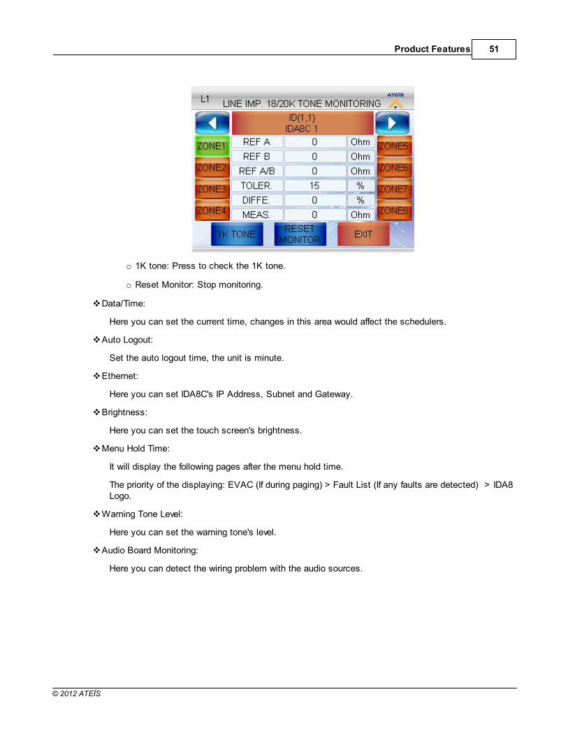
Product Features 51
© 2012 ATEÏS
o 1K tone: Press to check the 1K tone.
o Reset Monitor: Stop monitoring.
Data/Time:
Here you can set the current time, changes in this area would affect the schedulers.
Auto Logout:
Set the auto logout time, the unit is minute.
Ethernet:
Here you can set IDA8C's IP Address, Subnet and Gateway.
Brightness:
Here you can set the touch screen's brightness.
Menu Hold Time:
It will display the following pages after the menu hold time.
The priority of the displaying: EVAC (If during paging) > Fault List (If any faults are detected) > IDA8Logo.
Warning Tone Level:
Here you can set the warning tone's level.
Audio Board Monitoring:
Here you can detect the wiring problem with the audio sources.

ATEIS - IDA852
© 2012 ATEÏS
Source Status: Here displays the audio source you choose.
VOL: Adjust the volume of the speakers.
Paging Reset:
Cancel all paging in the system.
System Fault Reset:
Press to clean the system fault list, the System Fault LED will light off as well.
LED/LCD Test:
All of the LED will light up, press exit to end the test or wait for 60 seconds.
The front panel will turn into test mode, press ESC to end the test or wait for 60 seconds.

Product Features 53
© 2012 ATEÏS
4.1.2 IDA8SAB
4.1.2.1 Overview
The IDA8SAB Slave units provide audio-in and output expansion of the IDA8 Systems using a secured48-channel audio and data network over CAT5 or fiber optic. Each IDA8SAB expands the IDA8 Systemwith an additional 8 audio inputs and outputs, 2 additional security microphone consoles PSS AS andsecurity programmable switching contacts.
The Network cards that come with the unit provides a redundant 48 channels of audio and dataconnection, AteÏs- Net, between one controller and a maximum of 32 IDA8SX Slave units in one racksystem.

ATEIS - IDA854
© 2012 ATEÏS
4.1.2.2 Front Panel
System Fault LED:
This LED lights up when a system fault fault is detected.
G.Fault LED:
This LED lights up when a global fault is detected.
Bypass Mode LED:
Indicates if the IDA8C is in bypass mode.
Bypass Monitoring LED:
Shows if the monitoring function is enabled. This LED lights up if monitoring of the IDA8 is disabledby the user.
Global EVAC LED:
Indicates if the system is in EVAC paging state. This LED lights up if any IDA8 device over AteisNet is performing EVAC paging. See the topic of Network Paging Component to learn more abouthow to configure an EVAC paging.
Zone EVAC LEDs:
Shows the audio channel is in EVAC paging. Each LED corresponds to an output channel of aNetwork Paging component. For example, 1st LED is for pin M1, 2nd LED for pin M2 and so on.
Power LED:
This LED lights up when the IDA8SAB's power on.
Network LED:
Shows the status of Ateis Net. This LED lights up if there are more than two deployed IDA8 devicesin Ateis Net.
Zone Fault LEDs:
Shows fault status of a zone. This LED lights up if one of following faults is detected:
Normal AMP Error
Line A Error

Product Features 55
© 2012 ATEÏS
Line B Error
Backup AMP Error
AMP Line Leakage Error
4.1.2.3 Rear Panel
Speaker Zone Outputs:
There are 8 zones for speaker & amplifier connections. Each zone consists of following connectors(from left to right):
connector of line A speaker.
connector of line B speaker.
connector of 100V audio coming from amplifier.
The IDA8 output is exactly the same audio signal to line A and B. Two speakers can connect to onezone for redundancy purposes, one connects to line A, another connects to line B. Both speakerlines are monitored, meaning if damage to a speaker is detected, a global fault "Line A/B Error" willbe generated.
Backup Amplifier I/Os:
Two backup amplifier connectors includ 0 dB to amplifiers and 100V return from amplifiers.
Amplifier Zone Outputs:
8 Zone 0dB output to amplifiers.
Bypass Mode Outputs:
This port is used to share the bypass mode microphone signals through the IDA8C-IDA8S network(only needed when using a fiber optic network).
PDC(Peripherals Device Controller) Connectors:
Two RJ-45 connectors are used to connect consoles or peripheral devices. For example, PSS AS,URC AS, PPM AS connect to the IDA8SAB via this connector.
Local Ateis Net Connectors:

ATEIS - IDA856
© 2012 ATEÏS
Optional card to build a local dedicated IDA8C-IDA8S network.
Configurable Audio I/Os:
Two configurable 0dB audio I/O port A and B. Each port is available to assemble an audio card.There are 4 channels on each audio I/O card.
Telephone Line Input:
A connector for a telephone signal coming from telephone company.(optional).
Telephone Connector:
A connector for external telephone connection.(optional).
Contact Outputs:
8 logic output channels to close/open circuit for an external device. This contact is normally open.
Evacuation Inputs:
9 evacuation contact inputs that allow the monitoring of external contact. They also can be used inUGA mode and are triggerred by a voltage polarization change.
24V DC Output:
This connector supplies a 24VDC source.
24V DC Input:
Main 24VDC power supply connector.
AC Power Socket:
Main 110~240 V 1.2A, 47~63Hz AC power input with fuse. If 24V DC and AC power are input at thesame time, IDA8C will use AC power, and switch to DC power if there is no AC power input.
Fuse Rating: 1.6A
4.1.2.4 Characteristics
Case:
Dimension = 436mm (W) x 289mm (L) x 88mm (H)
Weight = 5Kg
Color = RAL7016
Power:
Item Voltage Current Consumption Comment
AC Input 100V~240V 1.2A@100V, 0.5A@240V Frequency:47Hz~63Hz
DC Input 18V~26V, Typical 24V 2A -
DC Output 18V~26V, Typical 24V 0.5A -
AC Maximum Consumption = 45 W
Amplifier Zone Outputs:

Product Features 57
© 2012 ATEÏS
Maximum level = 14 dB
Output Impedance = 50 Ohm
THD+N(Total Harmonic Distortion plus Noise)
Sensitivity Minimum Maximum Unit Frequency
0dBu - 0.04 % 20~20kHz@+4dBu
-12dBu - 0.06 % 20~20kHz@-2dBu
-24dBu - 0.06 % 20~20kHz@-14dBu
-40dBu - 0.06 % 20~20kHz@-30dBu
-54dBu - 0.06 % 20~20kHz@-44dBu
Bandwidth = 20Hz ~ 20kHz
EIN(Equivalent Input Noise)
Sensitivity Minimum Maximum Unit Frequency
0dBu - -81 dBu 20~20kHz@150Ω
-12dBu - -93 dBu 20~20kHz@150Ω
-24dBu - -104 dBu 20~20kHz@150Ω
-40dBu - -112 dBu 20~20kHz@150Ω
-54dBu - -115 dBu 20~20kHz@150Ω
Speaker line/Amplifier:
Maximum Power = 700W(RMS)
Maximum Power(Siren + Message) = 1000W
Configurable Audio Output:
Maximum level = 14 dBu
Output Impedance = 50 Ohm
THD+N(Total Harmonic Distortion plus Noise)
Sensitivity Minimum Maximum Unit Frequency
0dBu - 0.04 % 20~20kHz@+4dBu
-12dBu - 0.06 % 20~20kHz@-2dBu
-24dBu - 0.06 % 20~20kHz@-14dBu
-40dBu - 0.06 % 20~20kHz@-30dBu
-54dBu - 0.06 % 20~20kHz@-44dBu
Bandwidth = 20Hz ~ 20kHz
EIN(Equivalent Input Noise)
Sensitivity Minimum Maximum Unit Frequency
0dBu - -81 dBu 20~20kHz@150Ω
-12dBu - -93 dBu 20~20kHz@150Ω
-24dBu - -104 dBu 20~20kHz@150Ω
-40dBu - -112 dBu 20~20kHz@150Ω
-54dBu - -115 dBu 20~20kHz@150Ω
Configurable Audio Input:

ATEIS - IDA858
© 2012 ATEÏS
Sensitivity:
For each channel of a configurable audio input card, there are five levels to gain the audio signal.They are sensitivity values of 0dBu, -12dbBu, -24dBu, -40dBu and -54dBu respectively. Themeaning of sensitivity value is how large the gain is for an audio source, and to amplify thegiving minus input source to 0dBu. The figure below is an example of when the sensitivity valueis set to -54dBu, and input source is -54dBu, after the gaining circuit of the audio card you'll getthe 0dBu of output. For more information as reference, please see this.
Maximum level = 14 dBu
Input Impedance = 10k Ohm
THD+N(Total Harmonic Distortion plus Noise)
Sensitivity Minimum Maximum Unit Frequency
0dBu - 0.04 % 20~20kHz@+4dBu
-12dBu - 0.06 % 20~20kHz@-2dBu
-24dBu - 0.06 % 20~20kHz@-14dBu
-40dBu - 0.06 % 20~20kHz@-30dBu
-54dBu - 0.06 % 20~20kHz@-44dBu
Bandwidth = 20Hz ~ 20kHz
PDC:
Maximum Output Level = 10 dBu
Output Impedance = 300 Ohm
THD @ 1kHz at output < 0.02
Bandwidth @ -3dB at output = 20Hz ~ 20kHz
Noise @ 22Hz ~ 22kHz = -85dBu
Maximum Input Level = 16 dBu
Input Impedance = 11k Ohm
THD @ 1kHz at input < 0.02
Bandwidth @ -3dB at input < 20Hz ~ 22kHz
RS232 voltages = -6.5/+6.5
Evacuation Inputs(Contact Mode):
4 status: On, Off, Open and Short
39

Product Features 59
© 2012 ATEÏS
Evacuation Inputs(Voltage Mode):
On Voltage:
Item Minimum Maximum Unit
High 18 72 VDC
Low - 0.5 VDC
Contact Outputs + EVAC, Fault State Outputs:
Item Minimum Maximum Unit
Voltage - 100 VDC
Current - 0.5 ADC
Contact Output Relay:
Contact Output
Contact Form Maximum Unit
Carry Current 1.0 ADC
Maximum Voltage 100 VDC
Electrical Life 1 x 10 8 (Ref 10VDC, 10mA) -
Working Temperature:
0°C ~ 40°C
4.1.2.5 Peripherals
The following table shows the peripherals supported by IDA8SAB:
Device Connection Max. Num Function
Fireman MICFireman MIC
Input1 Paging where operator is close to the IDA8C.

ATEIS - IDA860
© 2012 ATEÏS
Device Connection Max. Num Function
PPM AS PDC 31 Remote console with paging ability.
PSS AS PDC 1Remote console for Paging and Event Triggering(Element
Control, Master/Sub Preset Control).
URC AS PDC 1Remote console for Master/Sub Preset Controlling and Element
Controlling.URGP PDC 1 Evacuation Input extension.DNM PDC 31 Auto noise gain for audio signals.
PPM-IT5 Ethernet1 ActiveOver Eth
Paging, Element Control and Master/Sub Preset Control.
URC200TPC
Ethernet Eth. Limit Parameters Control and Master/Sub Preset Control.
CD8 PDC 31Wall mounted cabinet remote paging console with 8 buttons/
zones.
CD16 PDC 31Wall mounted cabinet remote paging console with 16 buttons/
zones.
CD Touch PDC 1Wall mounted cabinet remote paging console with touch screen
and Fireman Microphone.
PCP PDC 31Wall mounted cabinet remote paging console with telephone
styled microphone.
CDPM PDC 31Wall mounted cabinet remote paging console with 24 buttons/
zones and 2 extra selectable microphone sources.
PSC PDC 31A grouped console is comprised of a pad with a monitoring
speaker, a pad with a gooseneck and 8 buttons/zones, and twopads with 8 buttons/zones.
Deskpad PDC 1A remote dialer for making telephone calls via IDA8's telephone
hardware.Deskpad
BoxPDC 1
An RF transceiver to communication between Deskpad andIDA8, use it, Deskpad can work without a physical connection.
Max. Num means you can connect one or more peripheral units through the connector by a usingJunction Box. For example: On the PDC, you can connect 32 PPM AS through junction boxesand are able to assign IDs in sequence for each unit in Ateis Studio. Note: One IDA8C has 4 PDCports, and the sum of remote units is 32. Basically, fireman MIC already has one positionallocated, so this table only shows the maximum as 31.
Eth. Limit: The maximum number of IP that can be assigned over the network.
4.1.2.6 3rd Party Control
The following table lists 3rd Party Control protocols which are IDA8C Supported.
ProtocolInterface
FunctionConnection Settings
Ateis 3rdParty
Protocol
Ethernet(UDP)UDP Port =
19761Read/Write value of parameters.Stepped adjustment for parameters.
Modbus PDC(RS485) PDC Port 1~ 2
Level controlPagingRead Monitoring StatusRead Evacuation StatusPlay MessageLogic I/O Control

Product Features 61
© 2012 ATEÏS
4.1.3 IDA8SL
4.1.3.1 Overview
The IDA8SL Slave units provide audio output expansion of the IDA8 Systems using a secured 48-channel audio and data network over CAT5 or fiber optic. Each IDA8SL expands the IDA8 System withan additional 4 outputs, 2 additional security microphone consoles PSS AS and security programmableswitching contacts.
The Network cards that comes with the unit provides a redundant 48 channels audio and dataconnection, AteÏs-Net, between one controller and a maximum of 32 IDA8SX Slave units in one racksystem.
The IDA8SL is used on PA/VA applications that need large amplifier power. The maximum power mayreach 1000W(RMS). The connectors for audio are Speakon style, which is mostly used in professionalaudio systems for connecting loudspeakers to amplifiers.

ATEIS - IDA862
© 2012 ATEÏS
4.1.3.2 Front Panel
System Fault LED:
This LED lights up when a system fault fault is detected.
G.Fault LED:
This LED lights up when a global fault is detected.
Bypass Mode LED:
Indicates if the IDA8C is in bypass mode.
Bypass Monitoring LED:
Shows if the monitoring function is enabled. This LED lights up if monitoring of the IDA8 is disabledby the user.
Global EVAC LED:
Indicates if the system is in EVAC paging state. This LED lights up if any IDA8 device over AteisNet is performing EVAC paging. See the topic of Network Paging Component to learn more abouthow to configure an EVAC paging.
Zone EVAC LEDs:
Shows the audio channel is in EVAC paging. Each LED corresponds to an output channel of aNetwork Paging component. For example, 1st LED is for pin M1, 2nd LED for pin M2 and so on.
Power LED:
This LED lights up when the IDA8SL's power on.
Network LED:
Shows the status of Ateis Net. This LED lights up if there are more than two deployed IDA8 devicesin Ateis Net.
Zone Fault LEDs:
Shows fault status of a zone. This LED lights up if one of following faults is detected:
Normal AMP Error
Line A Error

Product Features 63
© 2012 ATEÏS
Line B Error
Backup AMP Error
AMP Line Leakage Error
4.1.3.3 Rear Panel
Backup Amplifier Output:
This connector connects to the output of the backup amplifier for receiving the 100V audio signalpowered by the amplifier.
Bypass Mode Outputs:
This port is used to share the bypass mode microphone signals through the IDA8C-IDA8S network(only needed when using fiber optic network).
PDC (Peripherals Device Controller) Connectors:
Two RJ-45 connectors are used to connect consoles or peripheral devices. For examples, PSS AS,URC AS, PPM AS connect to the IDA8SAB via this connector.
Local Ateis Net Connectors:
The optional card for building a local dedicated IDA8C-IDA8S network.
Zone1 Speaker Line Output:
This connector is used to connect the loudspeaker of zone1, the below picture shows how toconnect the speaker.

ATEIS - IDA864
© 2012 ATEÏS
Zone1 Amplifier Output:
This connector is used to connect the output of the zone1 amplifier for receiving the 100V audiosignal powered by the amplifier.
Zone1 Amplifier Input:
This connector is used to connect the input of the zone1 amplifier for transmitting 0dB audio signalto the amplifier.
Backup Amplifier Input:
This connector is used to connect the input of the backup amplifier for transmitting 0dB audio signalto the amplifier.
Contact Outputs:
8 logic output channels to close/open circuits for an external device, this contact is normally open.
Evacuation Inputs:
9 evacuation contact inputs allow the monitoring of external contact. They also can be used in UGAmode and triggered by a voltage polarization change.
24V DC Output:
This connector supplies a 24VDC source.
24V DC Input:
Main 24VDC power supply connector.
AC Power Socket:
Main 110~240 V 1.2A, 47~63Hz AC power input with fuse. If 24V DC and AC power input at thesame time, IDA8C will use AC power, and switch to DC power if there is no AC power input.
Fuse Rating: 1.6A

Product Features 65
© 2012 ATEÏS
4.1.3.4 Characteristics
Case:
Dimension = 436mm (W) x 300mm (L) x 88mm (H)
Weight = 5Kg
Color = RAL7016
Power:
Item Voltage Current Consumption Comment
AC Input 100V~240V 1.2A@100V, 0.5A@240V Frequency:47Hz~63Hz
DC Input 18V~26V, Typical 24V 2A -
DC Output 18V~26V, Typical 24V 0.5A -
AC Maximum Consumption = 45 W
Amplifier Zone Outputs:
Maximum level = 14 dB
Output Impedance = 50 Ohm
THD+N(Total Harmonic Distortion plus Noise)
Sensitivity Minimum Maximum Unit Frequency
0dBu - 0.04 % 20~20kHz@+4dBu
-12dBu - 0.06 % 20~20kHz@-2dBu
-24dBu - 0.06 % 20~20kHz@-14dBu
-40dBu - 0.06 % 20~20kHz@-30dBu
-54dBu - 0.06 % 20~20kHz@-44dBu
Bandwidth = 20Hz ~ 20kHz
EIN(Equivalent Input Noise)
Sensitivity Minimum Maximum Unit Frequency
0dBu - -81 dBu 20~20kHz@150Ω
-12dBu - -93 dBu 20~20kHz@150Ω
-24dBu - -104 dBu 20~20kHz@150Ω
-40dBu - -112 dBu 20~20kHz@150Ω
-54dBu - -115 dBu 20~20kHz@150Ω
Speaker line/Amplifier:
Maximum Power = 100W(RMS)
Maximum Power(Siren + Message) = 1500W
Configurable Audio Output:
Maximum level = 14 dBu
Output Impedance = 50 Ohm
THD+N(Total Harmonic Distortion plus Noise)
Sensitivity Minimum Maximum Unit Frequency

ATEIS - IDA866
© 2012 ATEÏS
0dBu - 0.04 % 20~20kHz@+4dBu-12dBu - 0.06 % 20~20kHz@-2dBu-24dBu - 0.06 % 20~20kHz@-14dBu-40dBu - 0.06 % 20~20kHz@-30dBu-54dBu - 0.06 % 20~20kHz@-44dBu
Bandwidth = 20Hz ~ 20kHz
EIN(Equivalent Input Noise)
Sensitivity Minimum Maximum Unit Frequency
0dBu - -81 dBu 20~20kHz@150Ω
-12dBu - -93 dBu 20~20kHz@150Ω
-24dBu - -104 dBu 20~20kHz@150Ω
-40dBu - -112 dBu 20~20kHz@150Ω
-54dBu - -115 dBu 20~20kHz@150Ω
Configurable Audio Input:
Sensitivity:
For each channel of a configurable audio input card, there are five levels to gain the audio signal.They are sensitivity values of 0dBu, -12dbBu, -24dBu, -40dBu and -54dBu respectively. Themeaning of sensitivity value is how large the gain is for an audio source, and to amplify the givingminus input source to 0dBu. The figure below is an example of when the sensitivity value is setto -54dBu, and input source is -54dBu, after the gaining circuit of the audio card you'll get the0dBu of output. For more information as reference, please see this.
Maximum level = 14 dBu
Input Impedance = 10k Ohm
THD+N(Total Harmonic Distortion plus Noise)
Sensitivity Minimum Maximum Unit Frequency
0dBu - 0.04 % 20~20kHz@+4dBu
-12dBu - 0.06 % 20~20kHz@-2dBu
-24dBu - 0.06 % 20~20kHz@-14dBu
-40dBu - 0.06 % 20~20kHz@-30dBu
-54dBu - 0.06 % 20~20kHz@-44dBu
Bandwidth = 20Hz ~ 20kHz
PDC:
Maximum Output Level = 10 dBu
Output Impedance = 300 Ohm
THD @ 1kHz at output < 0.02
Bandwidth @ -3dB at output = 20Hz ~ 20kHz
Noise @ 22Hz ~ 22kHz = -85dBu
Maximum Input Level = 16 dBu
Input Impedance = 11k Ohm
39

Product Features 67
© 2012 ATEÏS
THD @ 1kHz at input < 0.02
Bandwidth @ -3dB at input < 20Hz ~ 22kHz
RS232 voltages = -6.5/+6.5
Evacuation Inputs(Contact Mode):
4 status: On, Off, Open and Short
Evacuation Inputs(Voltage Mode):
On Voltage:
Item Minimum Maximum Unit
High 18 72 VDC
Low - 0.5 VDC
Contact Outputs + EVAC, Fault State Outputs:
Item Minimum Maximum Unit
Voltage - 100 VDC
Current - 0.5 ADC
Contact Output Relay:

ATEIS - IDA868
© 2012 ATEÏS
Contact Output
Contact Form Maximum Unit
Carry Current 1.0 ADC
Maximum Voltage 100 VDC
Electrical Life 1 x 10 8 (Ref 10VDC, 10mA) -
Working Temperature:
0°C ~ 40°C
4.1.3.5 3rd Party Control
The following table lists 3rd Party Control protocols which are IDA8C Supported.
ProtocolInterface
FunctionConnection Settings
Ateis 3rdParty
Protocol
Ethernet(UDP)UDP Port =
19761Read/Write value of parameters.Stepped adjustment for parameters.
Modbus PDC(RS485) PDC Port 1~ 2
Level controlPagingRead Monitoring StatusRead Evacuation StatusPlay MessageLogic I/O Control
4.1.3.6 Peripherals
Following table is the peripherals supported by IDA8SL:
Device Connection Max. Num Function
Fireman MICFireman MIC 1 Paging where operator is close to the IDA8C.

Product Features 69
© 2012 ATEÏS
Device Connection Max. Num Function
InputPPM AS PDC 31 Remote console for paging ability.
PSS AS PDC 1Remote console for Paging and Event Triggering(Element
Control, Master/Sub Preset Control).
URC AS PDC 1Remote console for Master/Sub Preset Controlling and Element
Controlling.URGP PDC 1 Evacuation Input extension.DNM PDC 31 Auto noise gain for audio signals.
PPM-IT5 Ethernet1 ActiveOver Eth
Paging, Element Control and Master/Sub Preset Control.
URC200TPC
Ethernet Eth. Limit Parameters Control and Master/Sub Preset Control.
CD8 PDC 31Wall mounted cabinet remote paging console with 8 buttons/
zones.
CD16 PDC 31Wall mounted cabinet remote paging console with 16 buttons/
zones.
CD Touch PDC 1Wall mounted cabinet remote paging console with touch screen
and Fireman Microphone.
PCP PDC 31Wall mounted cabinet remote paging console with telephone
styled microphone.
CDPM PDC 31Wall mounted cabinet remote paging console with 24 buttons/
zones and 2 extra selectable microphone sources.
PSC PDC 31A grouped console is comprised of a pad with a monitoring
speaker, a pad with a gooseneck and 8 buttons/zones, and twopads with 8 buttons/zones.
Deskpad PDC 1A remote dialer for making telephone calls via IDA8's telephone
hardware.Deskpad
BoxPDC 1
An RF transceiver to communication between Deskpad andIDA8, use it, Deskpad can work without a physical connection.
Max. Num means you can connect one or more peripheral units through the connector by usingJunction Box. For example: On the PDC, you can connect 32 PPM AS through junction boxesand are able to assign IDs in sequence for each unit in Ateis Studio. Note: One IDA8C has 4 PDCports, and the sum of remote units is 32. Basically, fireman MIC already has one positionallocated, so this table only shows the maximum as 31.
Eth. Limit: The maximum numbers of IP that can be assigned over the network.

ATEIS - IDA870
© 2012 ATEÏS
4.1.4 IDA8S
4.1.4.1 Overview
The IDA8S Slave units provide audio in and output expansion of the IDA8 Systems using a secured 48-channel audio and data network over CAT5 or fiber optic. Each IDA8S expands the IDA8 System with anadditional 8 outputs, 2 additional security microphone consoles PSS AS and security programmableswitching contacts.
The Network cards that comes with the unit provides a redundant 48 channels audio and dataconnection, AteÏs-Net, between one controller and a maximum of 32 IDA8SX Slave units in one racksystem.
4.1.4.2 Front Panel

Product Features 71
© 2012 ATEÏS
System Fault LED:
This LED lights up when a system fault fault is detected.
G.Fault LED:
This LED lights up when a global fault is detected.
Bypass Mode LED:
Indicates if the IDA8C is in bypass mode.
Bypass Monitoring LED:
Shows if the monitoring function is enabled. This LED lights up if monitoring of the IDA8 is disabledby the user.
Global EVAC LED:
Indicates if the system is in EVAC paging state. This LED lights up if any IDA8 device over AteisNet is performing EVAC paging. See the topic of Network Paging Component to learn more abouthow to configure an EVAC paging.
Zone EVAC LEDs:
Shows the audio channel is in EVAC paging. Each LED corresponds to an output channel of aNetwork Paging component. For example, 1st LED is for pin M1, 2nd LED for pin M2 and so on.
Power LED:
This LED lights up when the IDA8S is power on.
Network LED:
Shows the status of the Ateis Net. This LED lights up if there are more than two deployed IDA8devices in the Ateis Net.
Zone Fault LEDs:
To show fault status of zone. This LED lights up if one of the following faults is detected:
Normal AMP Error
Line Speaker Error
Backup AMP Error
AMP Line Leakage Error

ATEIS - IDA872
© 2012 ATEÏS
4.1.4.3 Rear Panel
Speaker Zone Outputs:
There are 8 zones for speaker & amplifier connection. each zone consists of following connectors(from left to right):
connector of line speaker
connector of 100V audio coming from amplifier.
Backup Amplifier I/Os:
Two backup amplifier connectors included 0 dB to amplifiers and 100V return from amplifiers.
Amplifier Zone Outputs:
8 Zone 0dB output to amplifiers.
Bypass Mode Outputs:
This port is used to share the bypass mode microphone signals through the IDA8C-IDA8S network(only needed when using fiber optic network).
PDC(Peripherals Device Controller) Connectors:
Two RJ-45 connectors are used to connect the consoles or peripheral devices. For examples, PSSAS, URC AS, PPM AS, ... are connect to IDA8S via this connector.
Local Ateis Net Connectors:
The optional card for building a local dedicated IDA8C-IDA8S network.
Configurable Audio I/Os:
Two configurable 0dB audio I/O port A and B. Each port is available to assemble an audio card.There are 4 channels on each audio I/O card.
Contact Outputs:
8 logic output channels to close/open circuits for an external device, this contact is normally open.
Evacuation Inputs:
9 evacuation contact inputs allow the monitoring of external contact. They also can be used in UGAmode and triggered by a voltage polarization change.
24V DC Output:
This connector supplies a 24VDC source.

Product Features 73
© 2012 ATEÏS
24V DC Input:
Main 24VDC power supply connector.
4.1.4.4 Characteristics
Case:
Dimension = 436mm (W) x 285mm (L) x 44mm (H)
Weight = 4.2Kg
Color = RAL7016
Power:
Item Voltage Current Consumption Comment
DC Input 18V~26V, Typical 24V 2A -
DC Output 18V~26V, Typical 24V 0.5A -
AC Maximum Consumption = 45 W
Amplifier Zone Outputs:
Maximum level = 14 dB
Output Impedance = 50 Ohm
THD+N(Total Harmonic Distortion plus Noise)
Sensitivity Minimum Maximum Unit Frequency
0dBu - 0.04 % 20~20kHz@+4dBu
-12dBu - 0.06 % 20~20kHz@-2dBu
-24dBu - 0.06 % 20~20kHz@-14dBu
-40dBu - 0.06 % 20~20kHz@-30dBu
-54dBu - 0.06 % 20~20kHz@-44dBu
Bandwidth = 20Hz ~ 20kHz
EIN(Equivalent Input Noise)
Sensitivity Minimum Maximum Unit Frequency
0dBu - -81 dBu 20~20kHz@150Ω
-12dBu - -93 dBu 20~20kHz@150Ω
-24dBu - -104 dBu 20~20kHz@150Ω
-40dBu - -112 dBu 20~20kHz@150Ω
-54dBu - -115 dBu 20~20kHz@150Ω
Speaker line/Amplifier:
Maximum Power = 700W(RMS)
Maximum Power(Siren + Message) = 1000W
Configurable Audio Output:
Maximum level = 14 dBu
Output Impedance = 50 Ohm

ATEIS - IDA874
© 2012 ATEÏS
THD+N(Total Harmonic Distortion plus Noise)
Sensitivity Minimum Maximum Unit Frequency
0dBu - 0.04 % 20~20kHz@+4dBu
-12dBu - 0.06 % 20~20kHz@-2dBu
-24dBu - 0.06 % 20~20kHz@-14dBu
-40dBu - 0.06 % 20~20kHz@-30dBu
-54dBu - 0.06 % 20~20kHz@-44dBu
Bandwidth = 20Hz ~ 20kHz
EIN(Equivalent Input Noise)
Sensitivity Minimum Maximum Unit Frequency
0dBu - -81 dBu 20~20kHz@150Ω
-12dBu - -93 dBu 20~20kHz@150Ω
-24dBu - -104 dBu 20~20kHz@150Ω
-40dBu - -112 dBu 20~20kHz@150Ω
-54dBu - -115 dBu 20~20kHz@150Ω
Configurable Audio Input:
Sensitivity:
For each channel of a configurable audio input card, there are five levels to gain the audio signal.They are sensitivity values of 0dBu, -12dbBu, -24dBu, -40dBu and -54dBu respectively. Themeaning of sensitivity value is how large the gain is for an audio source, and to amplify the givingminus input source to 0dBu. The figure below is an example of when the sensitivity value is setto -54dBu, and input source is -54dBu, after the gaining circuit of the audio card you'll get the0dBu of output. For more information as reference, please see this.
Maximum level = 14 dBu
Input Impedance = 10k Ohm
THD+N(Total Harmonic Distortion plus Noise)
Sensitivity Minimum Maximum Unit Frequency
0dBu - 0.04 % 20~20kHz@+4dBu
-12dBu - 0.06 % 20~20kHz@-2dBu
-24dBu - 0.06 % 20~20kHz@-14dBu
-40dBu - 0.06 % 20~20kHz@-30dBu
-54dBu - 0.06 % 20~20kHz@-44dBu
Bandwidth = 20Hz ~ 20kHz
PDC:
Maximum Output Level = 10 dBu
Output Impedance = 300 Ohm
THD @ 1kHz at output < 0.02
Bandwidth @ -3dB at output = 20Hz ~ 20kHz
Noise @ 22Hz ~ 22kHz = -85dBu
39

Product Features 75
© 2012 ATEÏS
Maximum Input Level = 16 dBu
Input Impedance = 11k Ohm
THD @ 1kHz at input < 0.02
Bandwidth @ -3dB at input < 20Hz ~ 22kHz
RS232 voltages = -6.5/+6.5
Evacuation Inputs(Contact Mode):
4 status: On, Off, Open and Short
Evacuation Inputs(Voltage Mode):
On Voltage:
Item Minimum Maximum Unit
High 18 72 VDC
Low - 0.5 VDC
Contact Outputs + EVAC, Fault State Outputs:
Item Minimum Maximum Unit
Voltage - 100 VDC
Current - 0.5 ADC
Contact Output Relay:
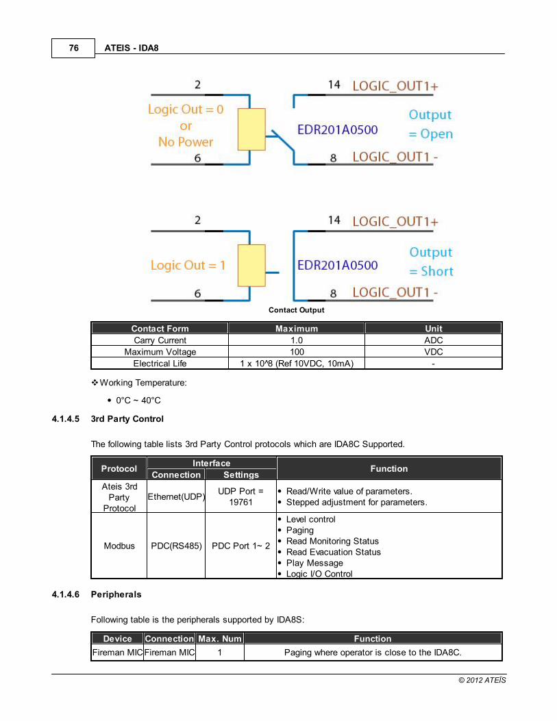
ATEIS - IDA876
© 2012 ATEÏS
Contact Output
Contact Form Maximum Unit
Carry Current 1.0 ADC
Maximum Voltage 100 VDC
Electrical Life 1 x 10 8 (Ref 10VDC, 10mA) -
Working Temperature:
0°C ~ 40°C
4.1.4.5 3rd Party Control
The following table lists 3rd Party Control protocols which are IDA8C Supported.
ProtocolInterface
FunctionConnection Settings
Ateis 3rdParty
Protocol
Ethernet(UDP)UDP Port =
19761Read/Write value of parameters.Stepped adjustment for parameters.
Modbus PDC(RS485) PDC Port 1~ 2
Level controlPagingRead Monitoring StatusRead Evacuation StatusPlay MessageLogic I/O Control
4.1.4.6 Peripherals
Following table is the peripherals supported by IDA8S:
Device Connection Max. Num Function
Fireman MICFireman MIC 1 Paging where operator is close to the IDA8C.

Product Features 77
© 2012 ATEÏS
Device Connection Max. Num Function
InputPPM AS PDC 31 Remote console for paging ability.
PSS AS PDC 1Remote console for Paging and Event Triggering(Element
Control, Master/Sub Preset Control).
URC AS PDC 1Remote console for Master/Sub Preset Controlling and Element
Controlling.URGP PDC 1 Evacuation Input extension.DNM PDC 31 Auto noise gain for audio signals.
PPM-IT5 Ethernet1 ActiveOver Eth
Paging, Element Control and Master/Sub Preset Control.
URC200TPC
Ethernet Eth. Limit Parameters Control and Master/Sub Preset Control.
CD8 PDC 31Wall mounted cabinet remote paging console with 8 buttons/
zones.
CD16 PDC 31Wall mounted cabinet remote paging console with 16 buttons/
zones.
CD Touch PDC 1Wall mounted cabinet remote paging console with touch screen
and Fireman Microphone.
PCP PDC 31Wall mounted cabinet remote paging console with telephone
styled microphone.
CDPM PDC 31Wall mounted cabinet remote paging console with 24 buttons/
zones and 2 extra selectable microphone sources.
PSC PDC 31A grouped console is comprised of a pad with a monitoring
speaker, a pad with a gooseneck and 8 buttons/zones, and twopads with 8 buttons/zones.
Deskpad PDC 1A remote dialer for making telephone calls via IDA8's telephone
hardware.Deskpad
BoxPDC 1
An RF transceiver to communication between Deskpad andIDA8, use it, Deskpad can work without a physical connection.
Max. Num means you can connect one or more peripheral units through the connector by usingJunction Box. For example: On the PDC, you can connect 32 PPM AS through junction boxesand are able to assign IDs in sequence for each unit in Ateis Studio. Note: One IDA8C has 4 PDCports, and the sum of remote units is 32. Basically, fireman MIC already has one positionallocated, so this table only shows the maximum as 31.
Eth. Limit: The maximum numbers of IP that can be assigned over the network.
4.1.5 Network Wiring
There are three cases of an Ateis Net connection:
Global Net + Local Net
Only Local Net
None
The following three diagrams show how to connect the IDA8Cs and the IDA8SABs through A, B port ofthe Global/Local Ateis Net.
1 IDA8C and 1 IDA8SAB connect through Local Ateis Net:

ATEIS - IDA878
© 2012 ATEÏS
Connection example : Local Ateis Net.
1 IDA8C and 2 IDA8SABs connect through Local Ateis Net:
Inside the IDA8 units, the packets travel around from A to B and B to A through wires.
Therefore, the second slave unit is the one connected to the IDA8C's B port of Local Net.
Connection example : Local Ateis Net.
2 IDA8C master-slave systems connect with each other through Global Ateis Net:

Product Features 79
© 2012 ATEÏS
Connection example : Global / Local Ateis Net.

ATEIS - IDA880
© 2012 ATEÏS
4.1.6 Amplifier Configuration
4.1.6.1 Basic Amplifier Connection
Basic Amplifier Connection
The IDA8 System applies a flexible amplifier setup. The figure above shows the basic setup of anamplifier with the IDA8. The figure shows the connection between amplifiers and the IDA8C. There twokinds of connections for an amplifier:
Normal Amplifiers Connection:
The connection of amplifiers for speaker zone outputs. In above figure(Basic Amplifier Connection),Z1~Z8 are typical amplifiers. Follow these wires. The audio signal starts from the amplifier zone, theoutput goes into amplifier's input, then is gained by the amplifier and then is input to the AMPOconnector of speaker line I/Os . Each channel of amplifier's zones output should connect to it'scorresponding channel of the speaker zones output AMPO connector. For example, the amplifierzone output 5 should connect to the Zone5 AMPO connector of the speaker zones output. See thebelow figure.
35

Product Features 81
© 2012 ATEÏS
Backup Amplifier Connections:
The is for the connection of amplifiers for backup. In above figure(Basic Amplifier Connection), B1,B2 are backup amplifiers. There two connectors for each backup amplifier. Trace the wiring. Theaudio signal starts from the AMP I connector, goes into the amplifier's input, then is gained by theamplifier and input to the AMP O connector. The following figure is an example of a backup amplifierconnection.
4.1.6.2 Amplifier Backup
Basic Concept:
The IDA8 system applies a flexible mechanism for amplifier backup. Before digging deeper into therules of the amplifier backup, let's first understand its basic concept. In most of cases, audio goesthrough the normal amplifier. Once the normal amplifier fails, the IDA8 will switch to the backupamplifier to ensure that the system is still functioning. Meanwhile, the technician should analyze theproblem, which in this case is, to replace the non-working amplifier with the functioning amplifier.The figure below(Audio Routing without Backup Amplifier) shows the case of audio routing using anormal amplifier. The number in the figure below is the sequence of audio path.

ATEIS - IDA882
© 2012 ATEÏS
Audio Routing without Backup Amplifier
The figure below(Audio Routing with Backup Amplifier) shows the amplifier backup in the case ofaudio routing. When an error with the normal amplifier is detected by the IDA8C, the IDA8C willchange the audio path from the normal amplifier to the backup amplifier and generate a fault to warnthe user that there was an amplifier fault detected by the system. Please correct this issue.
Audio Routing with Backup Amplifier
Share the Backup Amplifier:
In most of cases, two amplifiers should not fail at the same time. The probability of more than twoamplifiers failing is significantly low. It is not necessary to have a backup amplifier for each zone asin most cases the backup amplifiers are waiting for the normal amplifier to fail. If one of the normalamplifiers fail, one backup amplifier can take over immediately. In the meantime, the unit will quicklyswitch from the failed amplifier. During the time that the amplifier backup engages, it is rare to haveanother amplifier fail. Based on this concept, the IDA8 system provides a flexible mechanism foramplifier backup. One backup amplifier can service multiple zones. The preview figure demonstrateshow a backup amplifier works when a normal amplifier connected to Zone 2 fails. The backup

Product Features 83
© 2012 ATEÏS
amplifier can serve Zone 1 to Zone 4. The figure below shows this concept:
Share the Backup Amplifier
In the above figure, Z1~Z4 represents the normal amplifier for Z1~Z4. B1 is the backup amplifier.S1~S4 are switches used to select the path of the audio signal coming from the DSP processor.S5~S8 switches are used to select the path going to the Line A/B output. B1 can service Zone1 toZone 4 by controlling switches S1~S8. In this example, amplifier Z2 has failed. The IDA8 controls S6and S2 to change the audio path from the normal amplifier (Z2) to the backup amplifier (B1). Thebehavior of the other channels are the same as Channel 2. A backup amplifier cannot serve morethan one zone at the same time. In such limitation, for example, if amplifier Z3 fails, then there is noavailable amplifier for backup.
Advance Backup Amplifier Setup:
There are more cost effective solutions of the IDA8 backup amplifier setup. It is possible to let onebackup amplifier serve more than four zones. See the figure below. An Ateis Net system consists ofone IDA8C and two IDA8S's. There are 24 zones in the system divided into three backup amplifiergroups. For each group, there is a backup amplifier which becomes redundant if any of the normalamplifiers in the group fail. To group zones, you need to wire AMP I and AMP O between the backupamplifier connectors. Red lines show the wire connections to group zones.

ATEIS - IDA884
© 2012 ATEÏS
Advance Backup Amplifier Setup
There are three backup amplifier groups in the above figure:
Backup Group1:
Amplifier B1 serves Zone1 ~ Zone8.
Backup Group2:
Amplifier B2 serves Zone9 ~ Zone12.
Backup Group3:

Product Features 85
© 2012 ATEÏS
Amplifier B3 serves Zone 13 ~ zone24.
Software settings for the backup amplifier:
It is necessary to have software settings to make the backup amplifier function.
Numbers in the above figure show the steps to ope then backup amplifier settings window:
1. Right click mouse on IDA8C1 block in devices window, then click item [Monitor] to openwindow "Monitor(Matrix Mode) - IDA8C1".
2. Select tab [Backup Amplifier Monitor].
3. Click button [Amplifier Amount].
The figure below shows the software setup window for the backup configuration in the AdvanceBackup Amplifier Setup :

ATEIS - IDA886
© 2012 ATEÏS
The meaning of the parameters are listed below:
Amount:
Specifies the number of backup amplifiers in system. The list content of the combo box in anamplifier depends on this value. For example, if Amount = 3, then the list content should benone (zero), 1, 2, 3.
Field [Device] of Grid:
Lists devices within the same Ateis Net.
Field [Zone Board] of Grid:
Lists zone boards of the device. Zone Board1 means Zone1 to Zone4, Zone board2 meansZone5 to Zone8.
Field [Amplifier] of Grid:
Specifies the group without zones. In the above figure, IDA8S1 Zone board1(Zone1~Zone4 ofIDA8S1), IDA8S2 Zone Board1(Zone1~4 of IDA8S2), IDA8S2 Zone Board2(zone 5~8 of IDA8S2)are the same value (i.e. those zones are the same group and use the same amplifier forbackup).
4.1.7 Monitoring/Fault
For security purposes, the IDA8 is designed to monitor equipment. When an error is detected, a fault willbe generated to inform the user. The user can then change the non-working equipment quickly to makethe system function correctly again.
There are two types of faults:
System Fault:
This sort of fault is about the internal error of the IDA8C/S. In most of cases, it is a hardware failureand the board inside the device needs to be changed o repaired.
G.Fault:

Product Features 87
© 2012 ATEÏS
The G.Fault LED lights up for mostly all faults.
When a fault is generated, the following will be performed by the IDA8C/S:
Fault State Output contact open (When a major fault occurs)
Log the fault.
A warning message of the fault will be shown in the Touch Screen.
When Ateis Studio is connected to the IDA8C/S, in [Device Status] field of [Device Management]panel will show a fault. The picture below shows an example:
There is a warning tone generated by the monitoring speaker.
A text message shown in the PSS touch screen, the figure below shows an example.
4.1.7.1 Table of Global Faults
Name Description
System Fault List The faults with the System fault LED lighting up.SSI Error Audio board control has failed.
No Para. Table. The IDA8 can't find the DSP parameters.
Ethernet BrokenThe Ethernet connection fails.
(If the ethernet monitoring is enabled in ATEIS Studio)AESEBU Error The AESEBU card has failed.
User Define ErrorThis fault happens when the "Fault Define" DSP component
received a logic signal from the input.
Normal/Backup AMP Error1. Amplifier gain is too high.2. Amplifier gain is too low.
3. Amplifier fails.
Line A/B Error1. Line A/B Open, a speaker is not connected to IDA8C/S.
2. Line A/B Bad Impedance, the impedance of the speakers ischanged over the tolerance.
88
97
98
98
99
100
100
104

ATEIS - IDA888
© 2012 ATEÏS
Name Description
3. Line A/B short, a circuit outside the speaker zone outputconnector is shorted, and no sound comes out. This fault may
damage the amplifier.AMP Line Leakage Error The current between the speakers and amplifiers has a leakage.
EVAC Input ErrorThe voltage of EVAC input is not in the range (when the evacuation
input is set to "contact mode").
AteisNet BrokenThis fault happens when one or more IDA8C's or IDA8S's over Ateis
Net lose the connection. Note: Global Ateis Net Broken only for global net IDA8.
Fireman Error The fireman microphone has an error.VOX@NET Error The IDA8C/S can't communicate with the VOX@NET server.
Redundancy Error
1. It shows "Backup Device Offline" when a backup device can'tcommunicate.
2. It shows "Operation Mode Fail" for:RU device is turned off.
The incorrect wiring between the RU and the IDA8.
Remote OfflineThe peripheral devices (PSS AS/PPM AS/URC AS/...)
can't communicate with the IDA8C/S.URGP Fault The URGP device monitor is out of tolerance
Remote FaultThere is a hardware error of peripheral devices, such as the
microphone/speaker on a PSS.File Corruption The file CRC check code fails if the file monitor option is enabled.ModBus Offline The Modbus client can't communicate.
AMP Rating Fault The IDA8 gets the reference value which is too low.BackupAmp Used State A normal amplifier fails and is replaced by the backup amplifier.
Local AteisNet Backup Mode One of the local ATEIS net port has broken.
Global AteisNet Backup ModeOne of the global ATEIS net port has broken.
Note: Only for global net IDA8.
Bypass Mode
If using a redundancy unit, the IDA8 will enter the bypass modewhen a Bypass Mode fault occurs. If not, the IDA8 will enter in that
mode only when the "Bypass Input" line on the rear panel hasbroken.
Major User Define Fault The "Fault Define Security" component trigger.Minor User Define Fault The "Fault Define Security" component trigger.
Modan Offline The Modan client can't communicate.NTP Server Error All the NTP server can't communicate.
Normal AMP Out of Toler. The normal amplifier measure out of tolerance.Backup AMP Out of Toler. The backup amplifier measure out of tolerance.
4.1.7.1.1 Table of System Faults
Name Description
Flash Error An error occurred in the Nand flash inside IDA8C/S.
I2C ErrorThere is an internal error of I2C communication between micro
controllers.
Net Card ErrorThere is an error of communication between the main CPU in the
IDA8C/S and the Net card.
DSP ErrorThere is an internal error of communication between micro
controllers inside devices.
Preset Table ErrorThe structure of the configuration is not compatible with the current
firmware.
108
109
111
113
114
115
116
118
117
120
121
121
122
123
123
124
125
125
126
127
127
89
89
90
91
91

Product Features 89
© 2012 ATEÏS
Name Description
No Preset Table There is no configuration inside the device.SPI Flash Error There is an internal error of the micro controller SPI communication.
Para. Table ErrorThere is a data error in the table which stores important information
of the configuration.Trans Error There is an internal hardware error of the device.
Audio Overflow There is a DSP chip operate error. Global NT Error The global ATEIS net card fails. Note: Only for global net IDA8.Power Error The power circuit inside the device has an error.
Reset ErrorLast time the machine is unpredictably shut down, please see the
machine log.
TEL ErrorThe communication between the main controller unit and
telephones fails.Main FPGA Error There is an Internal hardware error.
4.1.7.1.1.1 Flash Error
Fault Meaning:
Nand flash inside the IDA8C/S has an error.
Fault Indication:
LED Indicator:
When this error is detected, the following LEDs will light up:
o System Fault LED on the front panel of the IDA8C/S.
o G. Fault LED on the front panel of the IDA8C/S.
Log:
Text messages display on the touch screen of the IDA8C as:
"Flash Error"
Also, the text messages display at the [Machine Fault Record] window in Ateis Studio:
A buzzing sound outputs to the monitoring speaker on the front panel of the IDA8C.
Fault Handling:
Contact your technician to repair device.
4.1.7.1.1.2 I2C Error
Fault Meaning:
There is an internal error of I2C communication between micro controllers.
Fault Indication:
92
92
93
94
94
95
96
96
97

ATEIS - IDA890
© 2012 ATEÏS
LED Indicator:
When this error is detected, the following LEDs will light up:
o System Fault LED on the front panel of the IDA8C/S.
o G. Fault LED on the front panel of the IDA8C/S.
Log:
Text messages display on the touch screen of the IDA8C as:
"I2C Error"
Also, the text messages display at the [Machine Fault Record] window in Ateis Studio:
A buzzing sound outputs to the monitoring speaker on the front panel of the IDA8C.
Fault Handling:
Contact your technician to repair device.
4.1.7.1.1.3 Net Card Error
Fault Meaning:
There is an error of communication between the main CPU in the IDA8C/S and the Net card.
Fault Indication:
LED Indicator:
When this error is detected, the following LEDs will light up:
o System Fault LED on the front panel of the IDA8C/S.
o G. Fault LED on the front panel of the IDA8C/S.
Log:
Text messages display on the touch screen of the IDA8C as:
"NetCard Error"
Also, the text messages display at the [Machine Fault Record] window in Ateis Studio:
A buzzing sound outputs to the monitoring speaker on the front panel of the IDA8C.
Fault Handling:

Product Features 91
© 2012 ATEÏS
Contact your technician to repair device.
4.1.7.1.1.4 DSP Error
Fault Meaning:
There is an internal error of communication between micro controllers inside devices.
Fault Indication:
LED Indicator:
When this error is detected, the following LEDs will light up:
o System Fault LED on the front panel of the IDA8C/S.
o G. Fault LED on the front panel of the IDA8C/S.
Log:
Text messages display on the touch screen of the IDA8C as:
"DSP Error"
Also, the text messages display at the [Machine Fault Record] window in Ateis Studio:
A buzzing sound outputs to the monitoring speaker on the front panel of the IDA8C.
Fault Handling:
Contact your technician to repair device.
4.1.7.1.1.5 Preset Table Error
Fault Meaning:
The structure of configuration is not compatible with the current firmware.
Fault Indication:
LED Indicator:
When this error is detected, the following LEDs will light up:
o System Fault LED on the front panel of the IDA8C/S.
o G. Fault LED on the front panel of the IDA8C/S.
Log:
Text messages display on the touch screen of the IDA8C as:
"Preset Table Error"
Also, the text messages display at the [Machine Fault Record] window in Ateis Studio:

ATEIS - IDA892
© 2012 ATEÏS
A buzzing sound outputs to the monitoring speaker on the front panel of the IDA8C.
Fault Handling:
1. Update the firmware with the newest version of Ateis Studio.
2. Store a configuration. If the problem is still not solved, please contact your technician.
4.1.7.1.1.6 No Preset Error
Fault Meaning:
There is no configuration inside the device.
Fault Indication:
LED Indicator:
When this error is detected, the following LEDs will light up:
o System Fault LED on the front panel of the IDA8C/S.
o G. Fault LED on the front panel of the IDA8C/S.
Log:
Text messages display on the touch screen of the IDA8C as:
"No Preset Table"
Also, the text messages display at the [Machine Fault Record] window in Ateis Studio:
A buzzing sound outputs to the monitoring speaker on the front panel of the IDA8C.
Fault Handling:
Store a configuration to the device. If the error is still not solved, please contact your technician.
4.1.7.1.1.7 SPI Flash Error
Fault Meaning:
An internal error of micro controller SPI communication.
Fault Indication:
LED Indicator:
When this error is detected, the following LEDs will light up:

Product Features 93
© 2012 ATEÏS
o System Fault LED on the front panel of the IDA8C/S.
o G. Fault LED on the front panel of the IDA8C/S.
Log:
Text messages display on the touch screen of the IDA8C as:
"SPI Flash Error"
Also, the text messages display at the [Machine Fault Record] window in Ateis Studio:
A buzzing sound output to monitoring speaker on the front panel of the IDA8C.
Fault Handling:
Contact your technician to repair device.
4.1.7.1.1.8 Para. Table Error
Fault Meaning
There is a data error in the table which stores important information of configuration.
Fault Indication
LED Indicator
When this error is detected, the following LEDs will light up:
o System Fault LED on the front panel of the IDA8C/S.
o G. Fault LED on the front panel of the IDA8C/S.
Log
Text messages display on the touch screen of the IDA8C as:
"Para. Table Error"
Also, the text messages display at the [Machine Fault Record] window in Ateis Studio:
A buzzing sound outputs to the monitoring speaker on the front panel of the IDA8C.
Fault Handling
Store a configuration to the device. If the error is still not solved, please contact your technician.

ATEIS - IDA894
© 2012 ATEÏS
4.1.7.1.1.9 Trans Error
Fault Meaning:
There is an internal hardware error of device.
Fault Indication:
LED Indicator:
When this error is detected, the following LEDs will light up:
o System Fault LED on the front panel of the IDA8C/S.
o G. Fault LED on the front panel of the IDA8C/S.
Log:
Text messages display on the touch screen of the IDA8C as:
"Trans Error"
Also, the text messages display at the [Machine Fault Record] window in Ateis Studio:
A buzzing sound outputs to the monitoring speaker on the front panel of the IDA8C.
Fault Handling:
Contact your technician to repair device.
4.1.7.1.1.10 Audio Overflow
Fault Meaning:
The output level is too high or there is a DSP chip operate error.
Fault Indication:
LED Indicator:
When this error is detected, the following LEDs will light up:
o System Fault LED on the front panel of the IDA8C/S.
o G. Fault LED on the front panel of the IDA8C/S.
Log:
Text messages display on the touch screen of the IDA8C as:
"Audio overflow"

Product Features 95
© 2012 ATEÏS
A buzzing sound outputs to the monitoring speaker on the front panel of the IDA8C.
Fault Handling:
Decrease the audio level, if still shown on front panel very often, contact your technician to repairdevice.
4.1.7.1.1.11 Power Error
Fault Meaning:
The power circuit inside device is error.
Fault Indication:
LED Indicator:
When this error is detected, the following LEDs will light up:
o System Fault LED on the front panel of the IDA8C/S.
o G. Fault LED on the front panel of the IDA8C/S.
Log:
Text messages display on the touch screen of the IDA8C as:
"Power Error"
Also, the text messages display at the [Machine Fault Record] window in Ateis Studio:
A buzzing sound outputs to the monitoring speaker on the front panel of the IDA8C.
Fault Handling:
Contact your technician to repair device.

ATEIS - IDA896
© 2012 ATEÏS
4.1.7.1.1.12 Reset Error
Fault Meaning:
Last time the machine is unpredictably shut down, please see the machine log.
Fault Indication:
LED Indicator:
When this error is detected, the following LEDs will light up:
o System Fault LED on the front panel of the IDA8C/S.
o G. Fault LED on the front panel of the IDA8C/S.
Log:
Text messages display on the touch screen of the IDA8C as:
"Reset Error"
Also, the text messages display at the [Machine Fault Record] window in Ateis Studio:
A buzzing sound outputs to the monitoring speaker on the front panel of the IDA8C.
Fault Handling:
Report the machine log to your technician.
4.1.7.1.1.13 TEL Error
Fault Meaning:
The communication between main controller unit and telephone fails.
Fault Indication:
LED Indicator:
When this error is detected, the following LEDs will light up:
o System Fault LED on the front panel of the IDA8C/S.
o G. Fault LED on the front panel of the IDA8C/S.
Log:
Text messages display on the touch screen of the IDA8C as:
"TEL Error"
Also, the text messages display at the [Machine Fault Record] window in Ateis Studio:

Product Features 97
© 2012 ATEÏS
A buzzing sound outputs to the monitoring speaker on the front panel of the IDA8C.
Fault Handling:
Contact your technician to repair device.
4.1.7.1.1.14 Main FPGA Error
Fault Meaning:
There is an internal hardware error.
Fault Indication:
LED Indicator:
When this error is detected, following LEDs will light up:
o System Fault LED on the front panel of the IDA8C/S.
o G. Fault LED on the front panel of the IDA8C/S.
Log:
Text messages display on the touch screen of the IDA8C as:
"Main FPGA Error"
Also, the text messages display at the [Machine Fault Record] window in Ateis Studio:
A buzzing sound outputs to the monitoring speaker on the front panel of the IDA8C.
Fault Handling:
Contact your technician to repair device.
4.1.7.1.2 SSI Error
Fault Meaning:
The Audio board control has failed.
Fault Indication:
LED Indicator:
When this error is detected, the following LEDs will light up:
o G. Fault LED on the front panel of the IDA8C/S.

ATEIS - IDA898
© 2012 ATEÏS
Log:
Text messages display at the touch screen of the IDA8C:
"SSI error"
Text messages display at the window [Machine Fault Record] in Ateis Studio:
A buzzing sound outputs to the monitoring speaker on the front panel of the IDA8C.
Fault Handling:
Contact your technician to repair device.
4.1.7.1.3 No Para. Table.
Fault Meaning:
The IDA8 can't find the DSP parameters.
Fault Indication:
LED Indicator:
When this error is detected, the following LEDs will light up:
o G. Fault LED on the front panel of the IDA8C/S.
Log:
Text messages display at the touch screen of the IDA8C:
"No Parameter Table"
Text messages display at the window [Machine Fault Record] in Ateis Studio:
A buzzing sound outputs to the monitoring speaker on the front panel of the IDA8C.
Fault Handling:
Restore the parameters again.
4.1.7.1.4 Ethernet Broken
Fault Meaning:
The Ethernet connection fails. (If the ethernet monitoring has been enabled in ATEIS Studio)

Product Features 99
© 2012 ATEÏS
Fault Indication:
LED Indicator:
When this error is detected, the following LEDs will light up:
o G. Fault LED on the front panel of the IDA8C/S.
Log:
Text messages display at the touch screen of the IDA8C:
"Ethernet Broken."
A buzzing sound outputs to the monitoring speaker on the front panel of the IDA8C.
Fault Handling:
Check the Ethernet cable. Once it's recovered, in the LOG page the touch screen shows:
"Ethernet Recovery."
4.1.7.1.5 AESEBU Error
Fault Meaning:
The AESEBU card has failed.
Fault Indication:
LED Indicator:
When this error is detected, the following LEDs will light up:
o G. Fault LED on the front panel of the IDA8C/S.
Log:
Text messages display at the touch screen of the IDA8C:
"AESEBU Error."
Text messages display at the window [Machine Fault Record] in Ateis Studio:

ATEIS - IDA8100
© 2012 ATEÏS
A buzzing sound outputs to the monitoring speaker on the front panel of the IDA8C.
Fault Handling:
Update the firmware again.
4.1.7.1.6 User Define Error
Fault Meaning:
A user defined error is detected by the IDA8C/S. This kind of error can be defined by using the"Fault Definer" DSP component.
Fault Indication:
LED Indicator:
When this error is detected, the following LEDs will light up:
o G. Fault LED on the front panel of IDA8C/S.
Log:
Text messages display at the touch screen of IDA8C:
"User Define Error"
"XXXXX", where XXXXX is the content defined in "Fault Definer" the DSP component field[Message].
Text messages display at the window [Machine Fault Record] in Ateis Studio:
A buzzing sound outputs to the monitoring speaker on the front panel of the IDA8C.
Fault Handling:
Defined on the configuration of the DSP component. Check the component which is the input of"Fault Definer".
4.1.7.1.7 Normal/Backup Amplifier Error
Fault Meaning:
Amplifier gain is not high enough.
Amplifier gain is too low.
Amplifier has failed.

Product Features 101
© 2012 ATEÏS
Fault Indication:
LED Indicator
When this error is detected, the following LEDs will light up:
o G. Fault LED on the front panel of the IDA8C/S.
o Zone Fault LEDs on the front panel of the IDA8C/S.
Log:
o Amplifier Gain Too High:
Text messages display at touch screen on the front panel of IDA8C:
"Normal AMP Error" or "Backup AMP Error".
"Z1 Normal AMP Too High", where "Z1" could be any other zones, and "Normal AMP"could be "Backup AMP" as well.
A text message displays at the [Machine Fault Record] window in the Ateis Studio:
o Amplifier Gain Too Low:
Text messages display at the touch screen on the front panel of the IDA8C:
"Normal AMP Error" or "Backup AMP Error".
"Z1 Normal AMP Too High", where "Z1" could be any other zones, and "Normal AMP"could be "Backup AMP" as well.
A text message displays at the [Machine Fault Record] window in the Ateis Studio:
o Amplifier Fail:
Text messages displays at touch screen on the front panel of the IDA8C:
"Normal AMP Error", or "Backup AMP Error".
"Z1 Normal AMP Too High", where "Z1" could be any other zones, and "Normal AMP"could be "Backup AMP" as well.
A text message displays at the [Machine Fault Record] window in Ateis Studio:

ATEIS - IDA8102
© 2012 ATEÏS
A buzzing sound outputs to the monitoring speaker on the front panel of the IDA8C.
Fault Handling:
Amplifier Gain Too High

Product Features 103
© 2012 ATEÏS
Amplifier Gain Too Low

ATEIS - IDA8104
© 2012 ATEÏS
Amplifier Fail
4.1.7.1.8 Line A/B Error
Fault Meaning:
This error is mainly for loudspeakers connected to the IDA8C/S's speaker zone output connectors.There are three kinds of faults:
Line A/B Open:
If the value of Measure (ohm) is greater than 4000 ohm, this fault can be recognized by IDA8C/Swhen the field of [Measure(ohm)] shows "OPEN".
Line A/B Bad Impedance:
If the value of Measure (ohm) is greater than Reference A&B (ohm) + Tolerance (%), or the valueof Measure (ohm) is less than Reference A&B (ohm) - Tolerance (%), this fault can berecognized by the IDA8C/S when the field of [Diff(%)] shows the percentage of difference.

Product Features 105
© 2012 ATEÏS
In the figure above, the difference in the percentage of Zone 4 is 78.24 which is greater than thetolerance of 15%, a Line A/B bad impedance is recognized.
Line A/B Short:
The voltage of pin +, - is monitored by the IDA8C/S. If the voltage is zero, it means there is ashort circuit outside the IDA8C/S. If this fault is detected, the internal relay of the zone will beopened to stop the audio signal output to the speaker. The user must perform a ResetMonitoring as described in the preview part of this topic in order to switch the status back (i.e.make the audio output to the speaker and enable monitoring of the short again. A string "S.C."is showed in the field [Measure(ohm)])
Fault Indication:
LED Indicator:
When this error is detected, the following LEDs will light up:
o G. Fault LED on the front panel of the IDA8C/S.
o Zone Fault LEDs on the front panel of the IDA8C/S.
Log:
o Line A/B Open:
Text messages display at the touch screen on the front panel of the IDA8C:
"Line A Error", where Line A could be Line B.
"Z1 Line A OPEN", where Z1 could be any zone, Line A could be Line B.
A text message displays at the window [Machine Fault Record] of Ateis Studio:

ATEIS - IDA8106
© 2012 ATEÏS
o Line A/B Bad Impedance:
Text messages display at the touch screen on the front panel of the IDA8C:
"Line A Error", where Line A could be Line B.
"Z1 Line A OPEN", where Z1 could be any zone, Line A could be Line B.
A text message displays at the window [Machine Fault Record] of Ateis Studio:
o Line A/B Short:
Text messages display at the touch screen on the front panel of the IDA8C:
"Line A Error", where Line A can be Line B.
"Z1 Line A SHORT-OPEN", where Z1 can be any zone, Line A can be Line B.
Text message display at window [Machine Fault Record] of Ateis Studio:
A buzzing sound outputs to the monitoring speaker on front panel of the IDA8C.
Fault Handling:

Product Features 107
© 2012 ATEÏS
Line A/B Open
Line A/B Bad Impedance

ATEIS - IDA8108
© 2012 ATEÏS
Line A/B Short
4.1.7.1.9 Amplifier Line Leakage Error
Fault Meaning:
An electricity leakage between the IDA8C/S and the speaker is detected.
An electricity leakage between the amplifier output and the IDA8C/S is detected.
Fault Indication:
LED Indicator:
When this error is detected, the following LEDs will light up:
o G. Fault LED on the front panel of the IDA8C/S.
o Zone Fault LEDs on the front panel of the IDA8C/S.
Log:
Text messages display on the touch screen of the IDA8C as follows:
"AMP Line Leakage Error".
"Z1 Line Leakage Error", where Z1 can be any zone.

Product Features 109
© 2012 ATEÏS
A text message displays at the [Machine Fault Record] window in Ateis Studio:
A buzzing sound outputs to the monitoring speaker on the front panel of the IDA8C.
Fault Handling : Amplifier Line Leakage Error
4.1.7.1.10 Evacuation Intput Error
Fault Meaning:
The voltage of EVAC input is not in the range (when the evacuation input is set to "contact mode").
Fault Indication:
LED Indicator:
When this error is detected, the following LEDs will light up:
o G. Fault LED on the front panel of the IDA8C/S.
Log:
o EVAC Input Error(OPEN)
Text messages display on the touch screen of the IDA8C:

ATEIS - IDA8110
© 2012 ATEÏS
"EVAC Input Error".
A text message displays at the [Machine Fault Record] window in Ateis Studio:
o EVAC Input Error(SHORT)
Text messages display on the touch screen of IDA8C:
"EVAC Input Error".
A text message displays at the [Machine Fault Record] window in Ateis Studio:
A buzzing sound outputs to the monitoring speaker on the front panel of the IDA8C.

Product Features 111
© 2012 ATEÏS
Fault Handling : Evacuation Intput Error
4.1.7.1.11 Local Ateis Net Broken
Fault Meaning:
The Local Ateis Net is broken, this problem may come from the wire connection between devices onthe Ateis Net or the net card on the device.
Fault Indication:
LED Indicator
When this error is detected, the following LED will light up:
o G. Fault LED on the front panel of the IDA8C/S.
Log:
Text messages display on the touch screen of IDA8C:
"Local AteisNet Broken"
A text message displays at the [Machine Fault Record] window in Ateis Studio:
A buzzing sound outputs to the monitoring speaker on the front panel of the IDA8C.

ATEIS - IDA8112
© 2012 ATEÏS
Fault Handling
Check the wire connection between all IDA8C/S on the Local Ateis Net.
If the wire connection is connected properly, the device must be checked as follow:
o For IDA8C:
Prepare a working IDA8S, establish the Ateis Net wire connection between the IDA8C andthe IDA8S. Deploy the Ateis Net using Ateis Studio.
If the fault is not solved, please check the hardware version of Ateis Net card.
A quick examination for the Ateis Net card with RJ45 connectors (NOT the fiberconnectors), see the picture below.
hardware V.105 or higher, w ith the resistors.
If your Ateis Net card doesn't have the resistors (as circled in the picture), it might causethe connection problems. Please contact your Ateis dealer to replace it with a working one.
o For each IDA8S on the Ateis Net:
Prepare a working IDA8C, establish the Ateis Net wire connection between the IDA8C andthe IDA8S. Deploy the Ateis Net using Ateis Studio and perform the examination as referredto in the preceding paragraph.

Product Features 113
© 2012 ATEÏS
If the fault is not solved, replace the Ateis Net card of the IDA8S.
Once it's recovered, the LOG will show:
"Local AteisNet Normal Mode"
4.1.7.1.12 Fireman Microphone Error
Fault Meaning:
Fireman microphone has an error.
Fault Indication:
LED Indicator:
When this error is detected, the following LEDs will light up:
o G. Fault LED on the front panel of the IDA8C/S.
Log:
o Fireman Microphone Capsule Open
Text messages display on the touch screen of IDA8C:
"Fireman Error"
"Fireman Audio Open"
A text message displays at the [Machine Fault Record] window in Ateis Studio:
o Fireman Microphone Capsule Short:
Text messages display on the touch screen of IDA8C:
"Fireman Error"
"Fireman Audio Short"
A text message displays at the [Machine Fault Record] window in Ateis Studio:
o Fireman Microphone Button Open:
Text messages display on the touch screen of IDA8C:
"Fireman Error"
"Fireman Button Open"

ATEIS - IDA8114
© 2012 ATEÏS
A text message displays at the [Machine Fault Record] window in Ateis Studio:
o Fireman Microphone Button Short:
Text messages display on the touch screen of IDA8C:
"Fireman Error"
"Fireman Button Short"
A text message displays at the [Machine Fault Record] window in Ateis Studio:
A buzzing sound outputs to the monitoring speaker on the front panel of the IDA8C.
Fault Handling:
Check the wire connection of the fireman microphone.
If the wire connection is correct but still indicate a fault, replace the fireman microphone with aworking one.
If the fireman microphone is replaced but still indicate a fault, replace the IDA8C or contact yourtechnician.
4.1.7.1.13 VOX@NET Offline
Fault Meaning:
The IDA8C/S cannot communicate with VOX@NET server.
Fault Indication:
LED Indicator:
When this error is detected, the following LEDs will light up:
o G. Fault LED on the front panel of the IDA8C/S.
Log:
Text messages display on the touch screen of IDA8C:
"Voxnet Offline"
A text message displays at the [Machine Fault Record] window in Ateis Studio:

Product Features 115
© 2012 ATEÏS
A buzzing sound output to the monitoring speaker on the front panel of the IDA8C.
Fault Handling:
Observe the link and the active LED indicator on the RJ45 connector of the PC with the VOX@NETserver installed and ethernet switch. It is an error if the link LED is not lit up or active LEC is notblinking. Possible causes are listed below:
Both the switch and PC receive an incorrect LED display behavior. Check the cable betweenthe PC & ethernet swich.
Only VOX@NET receive an LED display behavior. Check the network card of the PC. You canchange a network card to see if it is working properly.
Only switch can receive an LED display behavior. Check the switch, you can simply changeto another port to see if it is working properly.
Observe the link and active LED indicator on the RJ45 connector of the IDA8C/S and switch.Possible causes are listed below:
Both the switch and IDA8C/S receive an incorrect LED display behavior. Check the cablebetween the IDA8C/S & ethernet swich.
Only the IDA8C/S receive an incorrect LED display behavior. Check the IDA8C/S. You canreplace it with a working IDA8C/S to see if it is working properly.
Only the switch receive an incorrect LED display behavior. Check the switch. You can simplychange to another port to see if it is working properly.
4.1.7.1.14 Redundancy Error
Fault Meaning:
It shows "Backup Device Offline" when a backup device can't communicate.
It shows "Operation Mode Fail" for:
o RU device is turned off.
o The incorrect wiring between the RU and the IDA8.
Fault Indication:
LED Indicator:
When this error is detected, the following LEDs will light up:
o G. Fault LED on the front panel of the IDA8C/S.
Log:
Text messages display at the touch screen of the IDA8C:
"Redundancy Error"

ATEIS - IDA8116
© 2012 ATEÏS
"Backup Device Offline." or
"Operation Mode Fail."
Text messages display at the window [Machine Fault Record] in Ateis Studio:
A buzzing sound outputs to the monitoring speaker on the front panel of the IDA8C.
Fault Handling:
The only power supply for RU is from IDA8s. In case the 24VDC output connector and wire are notworking right, the IDA8 can detect it and show the fault list on the touch screen as following:
VS_D12V_RL Error
-12V Error
12V Error
If anyone of them shows, please check the connections or replace the device.
Note: In case of a damaged relay of RU which cannot switch the system, the Primary IDA8 wouldbecome the main system.
Once it's recovered, the LOG will show:
"RU OK: Backup Device Online."
"RU OK: Operation Mode Normal."
4.1.7.1.15 Remote Offline
Fault Meaning:
The IDA8C/S cannot communicate with peripheral devices.
Fault Indication:
LED Indicator:
When this error is detected, the following LEDs will light up:

Product Features 117
© 2012 ATEÏS
o G. Fault LED on the front panel of the IDA8C/S.
Log:
Text messages display at the touch screen of the IDA8C:
"Remote Offline"
"PPM Port:2 ID:1", where Port N is the Nth PDC port for the peripheral connection, the ID isthe unique number for each peripheral device on the PDC port.
Text messages display at the window [Machine Fault Record] in Ateis Studio:
A buzzing sound outputs to the monitoring speaker on the front panel of the IDA8C.
Fault Handling:
Replace the peripheral device with a working one. If the fault is resolved, the problem is from theperipheral device. Send the peripheral device to your technician. If the fault is not resolved, changethe IDA8C/S and contact your technician.
4.1.7.1.16 Remote Fault
Fault Meaning:
An error is detected on peripheral devices. For PPM AS or PSS AS, this fault relates to a capsulemicrophone or a speaker error.
Fault Indication:
LED Indicator
When this error is detected, the following LEDs will light up:
o G. Fault LED on the front panel of the IDA8C/S.
Log
o PPM AS / PSS AS Capsule Microphone Open:
Text messages display on the touch screen of IDA8C:
"Remote Fault"
"PSS Port:1 ID:1, Microphone Fault", where Port N is the Nth PDC port for a peripheralconnection. The ID is the unique number for each peripheral device on the PDC port.
Text messages display at the window [Machine Fault Record] in Ateis Studio:

ATEIS - IDA8118
© 2012 ATEÏS
o PPM AS / PSS AS Capsule Microphone Short:
Text messages display at the touch screen of IDA8C:
"Remote Fault"
"PSS Port:1 ID:1, Microphone Fault", where Port N is the Nth PDC port for a peripheralconnection. The ID is the unique number for each peripheral device on the PDC port.
Text messages display at the window [Machine Fault Record] in Ateis Studio:
o PPM AS / PSS Speaker Error:
Text messages display on the touch screen of IDA8C:
"Remote Fault"
"PSS Port:1 ID:1, Speaker Fault", where Port N is the Nth PDC port for a peripheralconnection. The ID is the unique number for each peripheral device on the PDC port.
Text messages display at the window [Machine Fault Record] in Ateis Studio:
A buzzing sound outputs to the monitoring speaker on the front panel of the IDA8C.
Fault Handling:
Replace peripheral device with the error with a working one and contact your technician to repair thereplaced one.
4.1.7.1.17 URGP Fault
Fault Meaning:
There is an error on the evacuation inputs or fault inputs on the URGP.
Fault Indication:
LED Indicator:
When this error is detected, the following LEDs will light up:

Product Features 119
© 2012 ATEÏS
o G. Fault LED on the front panel of the IDA8C/S.
Log:
o EVAC Input Error(Open):
Text messages display on the touch screen of theIDA8C:
"Evac Board Fault"
"Port:1 IP:1, ch1 Open", where Port N is the Nth PDC port for a peripheral connection.The IP is the unique number for each peripheral device on the PDC port, ch is thenumber of channel.
Text messages display at the window [Machine Fault Record] in Ateis Studio:
o EVAC Input Error(Short):
Text messages display on the touch screen of IDA8C:
"Evac Board Fault"
"Port:1 IP:1, ch1 Short", where Port N is the Nth PDC port for a peripheral connection.The IP is the unique number for each peripheral device on the PDC port, ch is thenumber of the channel.
Text messages display at the window [Machine Fault Record] in Ateis Studio:
A buzzing sound outputs to the monitoring speaker on the front panel of the IDA8C.

ATEIS - IDA8120
© 2012 ATEÏS
Fault Handling : URGP Fault
4.1.7.1.18 File Corruption
Fault Meaning:
The file CRC check code fails. (If the file monitoring has been enabled in ATEIS Studio.)
Fault Indication:
LED Indicator:
When this error is detected, the following LEDs will light up:
o G. Fault LED on the front panel of the IDA8C/S.
Log:
Text messages display at the touch screen of the IDA8C:
"File Corruption"
"File xxx Corruption" (where xxx = file name)
Text messages display at the window [Machine Fault Record] in Ateis Studio:
A buzzing sound outputs to the monitoring speaker on the front panel of the IDA8C.

Product Features 121
© 2012 ATEÏS
Fault Handling
Reload the file.
4.1.7.1.19 ModBus Offline
Fault Meaning:
The Modbus client can't communicate.
Fault Indication:
LED Indicator:
When this error is detected, the following LEDs will light up:
o G. Fault LED on the front panel of the IDA8C/S.
Log:
Text messages display at the touch screen of the IDA8C:
"ModBus Offline"
Text messages display at the window [Machine Fault Record] in Ateis Studio:
A buzzing sound outputs to the monitoring speaker on the front panel of the IDA8C.
Fault Handling
Check the Modbus client communication. Once it's recovered, the LOG will show:
"ModBus Online."
4.1.7.1.20 AMP Rating Fault
Fault Meaning:
The IDA8 gets the reference value which is too low.
Fault Indication:
LED Indicator:
When this error is detected, the following LEDs will light up:
o G. Fault LED on the front panel of the IDA8C/S.
Log:
Text messages display at the touch screen of the IDA8C:
"AMP Rating Fault"
"Zone n Normal AMP Rating too low"

ATEIS - IDA8122
© 2012 ATEÏS
"Zone n BackUp AMP Rating too low" (where n = 1~8)
Text messages display at the window [Machine Fault Record] in Ateis Studio:
A buzzing sound outputs to the monitoring speaker on the front panel of the IDA8C.
Fault Handling
Check the amplifier power and wiring. Once it's recovered, the LOG will show:
"Zone n Normal AMP OK"
"Zone n Backup AMP OK"
4.1.7.1.21 BackupAmp Used State
Fault Meaning:
A normal amplifier has failed and was replaced by the backup amplifier.
Fault Indication:
LED Indicator:
When this error is detected, the following LEDs will light up:
o G. Fault LED on the front panel of the IDA8C/S.
Log:
Text messages display at the touch screen of the IDA8C:
"BackupAmp Used State"
"Machine X Zone Y Use Backup Amp Z" (Where X = machine ID, Y = 1~8 and Z = 1~n).
Text messages display at the window [Machine Fault Record] in Ateis Studio:
A buzzing sound outputs to the monitoring speaker on the front panel of the IDA8C.
Fault Handling
Check the normal amplifier power and wiring.

Product Features 123
© 2012 ATEÏS
4.1.7.1.22 Local AteisNet Backup Mode
Fault Meaning:
One of the local ATEIS net port has broken.
Fault Indication:
LED Indicator:
When this error is detected, the following LEDs will light up:
o G. Fault LED on the front panel of the IDA8C/S.
Log:
Text messages display at the touch screen of the IDA8C:
"Local AteisNet Backup Mode"
Text messages display at the window [Machine Fault Record] in Ateis Studio:
A buzzing sound outputs to the monitoring speaker on the front panel of the IDA8C.
Fault Handling
Check the ATEIS Net cable.
4.1.7.1.23 Bypass Mode
Fault Meaning:
If using a redundancy unit, the IDA8 will enter in the bypass mode when a Bypass Mode faultoccurs, the following are the Bypass Mode faults:
Flash Error
I2C Error
SSI Error
SPI Flash Error
NetCard Error
DSP Error
Power Error
AESEBU Error
TEL Error
License deact
Main FPGA Error

ATEIS - IDA8124
© 2012 ATEÏS
Ethernet Broken
If not, the IDA8 will enter in that mode only when the "Bypass Input line" on the rear panel hasbroken.
Fault Indication:
LED Indicator:
When this error is detected, the following LEDs will light up:
o G. Fault LED on the front panel of the IDA8C/S.
Log:
Text messages display at the touch screen of the IDA8C:
"Bypass Mode."
Text messages display at the window [Machine Fault Record] in Ateis Studio:
A buzzing sound outputs to the monitoring speaker on the front panel of the IDA8C.
Fault Handling:
Check the fault list and the "Bypass Input line" on the rear panel.
4.1.7.1.24 Major User Define Fault
Fault Meaning:
The "Fault Define Security" component trigger.
Fault Indication:
LED Indicator:
When this error is detected, the following LEDs will light up:
o G. Fault LED on the front panel of the IDA8C/S.
Log:
Text messages display at the touch screen of the IDA8C:
"Major User Define Fault"
"Major Fault : xxx" (where xxx = user-defined word.)
Text messages display at the window [Machine Fault Record] in Ateis Studio:

Product Features 125
© 2012 ATEÏS
A buzzing sound outputs to the monitoring speaker on the front panel of the IDA8C.
Fault Handling:
Check the trigger source by Ateis Studio.
4.1.7.1.25 Minor User Define Fault
Fault Meaning:
The "Fault Define Security" component trigger.
Fault Indication:
LED Indicator:
When this error is detected, the following LEDs will light up:
o G. Fault LED on the front panel of the IDA8C/S.
Log:
Text messages display at the touch screen of the IDA8C:
"Minor User Define Fault"
"Minor Fault : xxx" (where xxx = user-defined word.)
Text messages display at the window [Machine Fault Record] in Ateis Studio:
A buzzing sound outputs to the monitoring speaker on the front panel of the IDA8C.
Fault Handling:
Check the trigger source by Ateis Studio.
4.1.7.1.26 Modan Offline
Fault Meaning:
The Modan client can't communicate.
Fault Indication:
LED Indicator:
When this error is detected, the following LEDs will light up:

ATEIS - IDA8126
© 2012 ATEÏS
o G. Fault LED on the front panel of the IDA8C/S.
Log:
Text messages display at the touch screen of the IDA8C:
"Modan Offline"
"Modan Port : n offline" (Where n = 1~65535)
Text messages display at the window [Machine Fault Record] in Ateis Studio:
A buzzing sound outputs to the monitoring speaker on the front panel of the IDA8C.
Fault Handling:
Check the modan client communication.
4.1.7.1.27 NTP Server Error
Fault Meaning:
All the NTP server can't communicate.
Fault Indication:
LED Indicator:
When this error is detected, the following LEDs will light up:
o G. Fault LED on the front panel of the IDA8C/S.
Log:
Text messages display at the touch screen of the IDA8C:
"NTP Server Error"
Text messages display at the window [Machine Fault Record] in Ateis Studio:
A buzzing sound outputs to the monitoring speaker on the front panel of the IDA8C.
Fault Handling:
Check the NTP server communication.

Product Features 127
© 2012 ATEÏS
4.1.7.1.28 Normal AMP Out of Toler
Fault Meaning:
The reference value measured from the normal amplifier is out of tolerance.
Fault Indication:
LED Indicator:
When this error is detected, the following LEDs will light up:
o G. Fault LED on the front panel of the IDA8C/S.
Log:
Text messages display at the touch screen of the IDA8C:
"Normal AMP Out of Toler"
"Zone n Normal AMP Gain Too High"
"Zone n Normal AMP Gain Too Low " (Where n = 1~8)
Text messages display at the window [Machine Fault Record] in Ateis Studio:
A buzzing sound outputs to the monitoring speaker on the front panel of the IDA8C.
Fault Handling:
Check the measured value of the normal amplifier.
4.1.7.1.29 Backup AMP Out of Toler
Fault Meaning:
The reference value measured from the backup amplifier is out of tolerance.
Fault Indication:
LED Indicator:
When this error is detected, the following LEDs will light up:
o G. Fault LED on the front panel of the IDA8C/S.
Log:
Text messages display at the touch screen of the IDA8C:
"Backup AMP Out of Toler."
"Zone n Backup AMP Gain Too High"

ATEIS - IDA8128
© 2012 ATEÏS
"Zone n Backup AMP Gain Too Low " (Where n = 1~8)
Text messages display at the window [Machine Fault Record] in Ateis Studio:
A buzzing sound outputs to the monitoring speaker on the front panel of the IDA8C.
Fault Handling:
Check the measured value of the backup amplifier.
4.1.7.2 Procedure of Monitoring Setup
The monitoring setup must be done when the hardware is completely setup. This means the IDA8C/S,amplifiers, speakers and wiring should be prepared and connected before the monitoring setup, as theIDA8C/S will get the values from the hardware's initial state for further reference. When the system isrunning and reference values are correctly achieved, the IDA8C/S continuously measures the internalstatus and compares it with referenced values to determine if there are incorrect processes of zone/amplifiers.
1. Setup hardware equipment, including an IDA8C/S, a normal amplifier, a backup amplifier, speakersand wiring between the devices,
2. Make a configuration using Ateis Studio.
3. Store the configuration, then online.
4. Set appropriate settings for your application using Ateis Studio. You can see more details on thefollowing topic Zone Monitoring , Normal Amplifier Monitoring , Backup Amplifier Monitoring .
5. Press the "get reference" button to start the monitoring for the zone you selected.
4.1.7.3 Zone Monitoring
Settings:
First, right click on the IDA8C/S block at the [Devices] window in Ateis Studio:
128 133 135

Product Features 129
© 2012 ATEÏS
When the window [Monitoring(Matrix Mode)-IDA8C/S X ] appears, select the page [Zone Settings]:
There are several fields in the grid of the page [Zone Settings] at the lower part of the window:
Zone:
Indicates a row is related to a zone.
Monitor:
Enable/Disable the zone monitoring, if the monitoring of a zone is disabled, the IDA8C/S will notdetect faults of that zone.
Backup:
This setting will notice the IDA8 if the backup amplifier services the zone correctly. For example,if the checkbox is not checked, the IDA8C/S will not switch to the backup amplifier for the zonewith the fault This results in the monitoring of the zone not working.

ATEIS - IDA8130
© 2012 ATEÏS
Mode:
There are two types:
1. 25V/70V/100V
An Audio signal through the amplifier and back to the IDA8C/S.
2. 0dB
Instead of going through the amplifier and back to the IDA8C/S, the audio will output to otherequipment and monitoring is disabled under this mode.
Tolerance(%):
Specifies the tolerance of impedance to detect a bad impedance fault. For example, if thereference is 1000 ohm and the tolerance is set to 15%, the range of good impedance will be 850~ 1150 ohm. If measured impedance value is 1300 ohm, a bad impedance fault is recognized bythe IDA8C/S.
Get Reference
When the system is constructed, the user needs to get the impedance value of the speaker forfurther reference. This value will be utilized to detect faults of zones. The rule of fault detection isdescribed in preview item "Tolerance(%)".
Reset Reference:
Resets the reference value to empty, resulting in the disabling of zone monitoring, but themeasure value is still updated.
There are buttons on the right side of the page [Zone Settings]:
Get All Reference:
Get references for all zones.
Reset All Reference:
Resets references for all zones.
Reset Monitoring:
This will tell the IDA8C/S to reset the monitoring and to initialize the state of the devices. In thecase of zone short fault, the IDA8C/S will open the internal relay to stop the output of the audiosignal to speaker. After the relay is opened, the IDA8C/S has no way to know if the circuitoutside has a short or not. Therefore, after the user repairs the circuit, the user needs to resetthe monitoring to close the relay to the output audio signal to the speaker again so that theIDA8C/S can monitor the short problem again.
Measurement:
After parameter settings are set in the grid at the lower part, the IDA8C/S starts to measure thevalue which is received from the internal circuit, and displays it on the grid at the upper part of thewindow:

Product Features 131
© 2012 ATEÏS
Below fields of the grid:
Leakage Impedance:
The impedance between the Line A/B +/- signal and ground causes the current leakage.
Reference A (ohm):
Shows the impedance value for reference received from Line A output.
Reference B (ohm):
Shows the impedance value for reference received from Line B output.
Reference A&B (ohm):
Shows the impedance value for reference received from Line A & B.
Current Amp:
Shows which amplifier is for the current zone (normal amplifier or backup amplifier).
Measure (ohm):
Shows the impedance value of Line A & B.
Diff(%):
Show the difference percentage of Measure(ohm) and Reference A&B(ohm)
Faults:

ATEIS - IDA8132
© 2012 ATEÏS
Leakage occurrence:
If the leakage impedance is lower than the leakage threshold which is defined in [Global Settings]tab, then a Leakage Occurrence fault is recognized.
If the internal values of monitoring Line A/B become abnormal, the IDA8C/S will detect andrecognize that error, then generate a global fault Line A/B Error. The error status is showed in thefield [Measure(ohm)]. There are three kinds of Line A/B Errors listed below:
Line A/B Open:
If the value of Measure (ohm) is greater than 4000 ohm, this fault can be recognized by theIDA8C/S. The field of [Measure(ohm)] shows "OPEN".
Line A/B Bad Impedance:
If the value of Measure (ohm) is greater than Reference A&B (ohm) + Tolerance (%), or value ofMeasure (ohm) is less than Reference A&B (ohm) - Tolerance (%), this fault can be recognizedby the IDA8C/S. The field of [Diff(%)] shows the percentage of difference. In the figure above, thedifference in percentage of zone 4 is 78.24 which is greater than the tolerance of 15%. A Line A/B bad impedance is then recognized.
Line A/B Short:
The voltage of pin +, - is monitored by the IDA8C/S, if the voltage is zero. This means there is ashort circuit outside the IDA8C/S. If this fault is detected, the internal relay of a zone will beopen to stop the audio signals to the speaker. The user needs to perform a Reset Monitoring asdescribed in the preview part of this topic in order to switch the status back. For example, makethe audio output to the speaker and enable the monitoring of the short again. A string "S.C." isshowed in the field [Measure(ohm)].

Product Features 133
© 2012 ATEÏS
4.1.7.4 Normal Amplifier Monitoring
Settings:
First, in Ateis Studio, right click on the IDA8C/S block in the [Devices] window:
When the window [Monitoring(Matrix Mode)-IDA8C/S X ] appears, select the page [Normal AmplifierSettings]:
Amplifier:
Indicates a row is related to a normal amplifier of a zone.
Monitor:
Enable/Disable the normal amplifier monitoring for the selected zone. If the monitoring of anormal amplifier is disabled, the IDA8C/S will not detect faults of the normal amplifiers.
Tolerance(%):

ATEIS - IDA8134
© 2012 ATEÏS
To determine the boundary of the fault detection for a selected zone. There is a fault recognizedif one of the following conditions is true:
Measure < (Full Loaded Reference x (100% - Tolerance%))
Measure > (Unloaded Reference x (100% + Tolerance%))
Get Reference:
Get the reference values of the selected zone for further fault detection. Be aware, the hardwareconfiguration(IDA8C/S, amplifiers, wiring) should be completed before getting the reference.
Reset Reference:
Clear the reference values of the selected zone to initialize the status. If the reference value iscleared, the monitoring will stop.
Measurement:
After the parameter settings are completed in the grid at the lower part, the IDA8C/S starts tomeasure the value received from the internal circuit, and displays it on the grid at the upper part ofwindow:
Unloaded Reference:
Displays the value of an unloaded reference which is the gain of an amplifier when there is noload to the zone. This value is used to determine if there is a fault of a normal amplifier.
Full Loaded Reference:
Displays the value of a full loaded reference which is the gain of an amplifier when there is a fullload to the zone. This value is used to determine if there is a fault of a normal amplifier.
Measure:

Product Features 135
© 2012 ATEÏS
Displays the value of measure, which is the gain of an amplifier.
Faults:
Amplifier Gain Too High:
If Measure > (Unloaded Reference x (100% + Tolerance%)), an Amplifier Gain Too High fault isrecognized. Once this fault occurs, perform the following:
o Make sure there is a good connection between the speaker and the IDA8C/S.
o Replace the non-working speaker with a working one.
o Check the gain of the amplifiers to see if the value has changed after getting a reference.
If all of the above actions have been checked but the amplifier still receives a fault that is toohigh, replace the amplifier.
Amplifier Gain Too Low:
If Measure < (Full Unloaded Reference x (100% - Tolerance%)), an Amplifier Gain Too Low faultis recognized. Once this fault occurs, check the following:
o Check if the signal going into the amplifier is too large. Some amplifiers have an indicator
"Overload". Check this indicator.
o Check if speaker is working or damaged.
If all of the above have been checked but the amplifier still receives a fault that is too low,change the amplifier.
If this fault generated after the speaker configuration is changed, you can perform a referenceagain to get new values for a reference.
Amplifier Fail:
Measure < (Unloaded Reference / 10), once this fault happens, check the following:
o Check if the amplifier power on.
o Check if the gain of the amplifier is set to 0. If it is, set to a suitable value.
o Check if the wires between the amplifier and the IDA8 are connected correctly.
If all the above have been checked completely but still the amplifier receives a fail fault, replacethe amplifier.
4.1.7.5 Backup Amplifier Monitoring
Settings:
First, in Ateis Studio, right click on the IDA8C/S block in [Devices] window:

ATEIS - IDA8136
© 2012 ATEÏS
When the window [Monitor(Matrix Mode) - IDA8C/S X] appears, select page [Backup AmplifierSettings]:
Amplifier:
Indicates which backup amplifier will be monitored.
Line:
Indicates which combination of the zone and the backup amplifier will be monitored.
Tolerance(%):
Determines the boundary of the fault detection for a selected zone. There is a fault recognized ifone of the following conditions is true:
Measure < (Full Loaded Reference x (100% - Tolerance%))
Measure > (Unloaded Reference x (100% + Tolerance%))

Product Features 137
© 2012 ATEÏS
Get Reference:
Gets the reference values of the selected zone for further fault detection. Be aware, the hardwareconfiguration(IDA8C/S, amplifiers, wiring) should be completed before getting the reference.
Reset Reference:
Clears reference values of the selected zone to return to the initial status. If the reference valueis cleared, monitoring will stop.
Measurement:
After the parameter settings are completed in the grid at the lower part, the IDA8C/S starts tomeasure the value received from the internal circuit and displays it on the grid at upper part ofwindow:
Unloaded Reference:
Displays the value of an unloaded reference which is the gain of an amplifier when there is noload to the zone. This value is used to determine if there is a fault of a normal amplifier.
Full Loaded Reference:
Displays the value of a fully loaded reference which is the gain of an amplifier when there is a fullload to the zone. This value is used to determine if there is a fault of a normal amplifier.
Measure:
Displays the value of measure, which is the gain of an amplifier.
Faults:
Amplifier Too High:
If Measure > (Unloaded Reference x (100% + Tolerance%)), an Amplifier Too High fault is

ATEIS - IDA8138
© 2012 ATEÏS
recognized. Once this fault occurs, perform the following:
o Make sure there is a good connection between the speaker and the IDA8C/S.
o Ensure the speaker is a working one.
o Check the gain of the amplifier, maybe the value has changed after getting the reference.
If all of the above actions have been checked but the amplifier still receives a fault that is toohigh, replace the amplifier.
Amplifier Too Low:
If Measure < (Full Unloaded Reference x (100% - Tolerance%)), an Amplifier Too Low fault isrecognized. Once this fault occurs, check the following:
o Check if the signal going into the amplifier is too large, some amplifiers have an indicator
"Overload". Check this indicator.
o Check if the speaker is working or damaged.
If all of the above have been checked but the amplifier still receives a fault that is too low,replace the amplifier.
If this fault generates after the speaker configuration is changed, you can perform a referenceagain to get new values for a reference.
Amplifier Fail:
Measure < (Unloaded Reference / 10), once this fault is happen, check the following:
o Check if the amplifier power is on.
o Check if the gain of the amplifier is set to 0. If it is, set to a suitable value.
o Check if the wires between the amplifier and IDA8 have a good connection.
If all the above have been checked completely but still the amplifier receives a fail fault, replacethe amplifier.

Product Features 139
© 2012 ATEÏS
4.1.7.6 Global Settings
There are global settings listed below:
Enable Monitor:
A check box used to enable or disable the monitor function.
Enable Leakage:
A check box used to enable or disable the leakage detect function.
Leakage Threshold(1k ohm):
A threshold value for the leakage detection. If the leakage impedance is lower than this value, thefault Leakage Occurrence is detected.
Leakage Calibration:
If the system detects a leakage fault, but the problem wasn't found in the circuit after performing apropriety check, it needs to perform a leakage calibration to confirm the monitor function is workingproperly.

ATEIS - IDA8140
© 2012 ATEÏS
4.1.7.7 Tone Settings
In the lower part of the window [Monitoring(Matrix Mode)-IDA8C/S X ], There is a page [Tone Settings] forconfiguring the tone signal which is utilized for monitoring. There are two types of settings:
Zones with 0dB:
If the audio signal from Amplifier Zone Output is not returning to the IDA8C/S for monitoring, thisallows the user to mix a tone into that signal for further detection. You can change this setting in the[Zone Settings] tab and the [Mode] field. There are parameters of settings:
Zone:
Indicates the zone number of parameters.
Mute:
Mutes the tone signal.
Level(dB):
The level of the tone signal.
Frequency(Hz):
The frequency of the tone signal.
Zones with 100V:
Frequency:
The frequency of the tone signal.
Enable 1K Tone:

Product Features 141
© 2012 ATEÏS
Enables 1K tone for monitoring. If this option is on, during the Start Time and the End Time, a1K tone signal will be sent to the amplifier for monitoring.
o Start Time:(hh:mm)
The time to start 1K tone sending.
o End Time:(hh:mm)
The time to stop 1K tone sending.
4.1.7.8 Circuit Leakage
Circuit Leakage is caused when the AMPO +/- conducting to the ground. For example, the isolation ofa speaker's wire is broken.
Leakage causes the gradual loss of voltage. Once it is detected, the IDA8C will open the relay of theleakage zone.
The following messages will display on the touch panel of the IDA8C and in the Ateis Studio. See LineA/B Error. 104

ATEIS - IDA8142
© 2012 ATEÏS
4.1.7.9 Open/Short Circuit
Open circuit
An open circuit occurs when a break exists in a complete conducting pathway.
Once the open circuit is detected, the IDA8C will open the relay. The following messages willdisplay on the touch panel of the IDA8C and in the Ateis Studio. See Line A/B Error.
Short circuit
A short circuit occurs when the electrical current running across separate wires accidentally toucheach other.
Once the short circuit is detected, the IDA8C will force open the short-circuited line to protect thecircuitry and the amplifier from the over-current damage.
If you use both the line a/b, the IDA8 keeps the working line continuous, see the picture below.
104

Product Features 143
© 2012 ATEÏS
The following messages display on the touch panel of the IDA8C and in the Ateis Studio. See LineA/B Error.
4.1.8 Log List
LOG item Description
Nand Flash ErrorNAND flash access fault for IDA8C(256MB) or IDA8S
(128MB)
I2C Z LED No ResponseI2C Z LED Driver Error
I2C Z LED Compare Error
I2C LOGICOUT POWER FAN UEVM NoResponse
I2C LOGICOUT POWER FAN UEVM Driver ErrorI2C LOGICOUT POWER FAN UEVM Compare
Error
I2C EVACU IN No ResponseI2C EVACU IN Driver Error
I2C EVACU IN Compare Error
I2C POWER DETECT No ResponseI2C POWER DETECT Driver Error
I2C POWER DETECT Compare Error
I2C TEMPERATURE No ResponseI2C TEMPERATURE Driver Error
I2C TEMPERATURE Compare Error
I2C FRP_BUTTON SLED No ResponseI2C FRP_BUTTON SLED Driver Error
I2C FRP_BUTTON SLED Compare Error
I2C FP MONITOR No ResponseI2C FP MONITOR Driver Error
I2C FP MONITOR Compare Error
I2C PCM3168 No Response
Front panel LED, fan, evac input, temperature detectand button control fails
104

ATEIS - IDA8144
© 2012 ATEÏS
LOG item Description
I2C PCM3168 Driver ErrorI2C PCM3168 Compare Error
I2C ADAPTER No ResponseI2C ADAPTER Driver Error
I2C ADAPTER Compare Error
SSI Error Audio board control has a fault
NetCard Error Local ATEIS net card fails
DSP Error DSP chip fails
Preset Table Error Configuration (.ats file) version not matching
No Preset Table Can't find a configuration
No Parameter Table Can't find a DSP parameter
Parameter Table Error DSP parameter (.ats file) version not matching
Trans Error DSP chip communication fails
Ethernet BrokenEthernet Recovery
Ethernet connection status
LVDT DetectLow voltage detected when power supply is lower than
16VDC
Global NT Error Global ATEIS net card fails
AESEBU Error AESEBU card fails
TEL Error Telephone card fails
License deact ATEIS Studio can't find the license
Main Board FPGA Code Error Main board FPGA chip fails
RU OK: Backup Device OnlineRU Error: Backup Device Offline
Backup device status in the redundancy configuration
RU OK: Operation Mode NormalRU Error: Operation Mode Fail
Operation mode status in the redundancyconfiguration
Power On Status Machine is powered
AteisNET Deploying Starts ATEIS Net deploying
Restart Machine Resets machine by ATEIS Studio
NTP Server Error All of the NTP server can't communicate
Local AteisNet BrokenLocal AteisNet Recovery
Local ATEIS net card connection status
Global AteisNet Broken Global AteisNet Recovery
Global ATEIS net card connection status
Voxnet Online Voxnet server connection status

Product Features 145
© 2012 ATEÏS
LOG item Description
Voxnet Offline
ModBus OnlineModBus Offline
Modbus client connection status
Local AteisNet Backup ModeLocal AteisNet Normal Mode
Local ATEIS net backup connection status
Global AteisNet Backup ModeGlobal AteisNet Normal Mode
Global ATEIS net backup connection status
Evac Event BeginningEvac Event Ending
Any evacuation paging beginning/ ending
Store Configuration Table StartStore Configuration Table End
Stores configuration table status
Store Configuration SuccessStore Configuration Fail
Stores configuration table results
Update StartUpdate End
Updates machine status
Update SuccessUpdate Fail
Updates machine result
Zone n Overflow(n = 1~16)
Zone overflow status
5v ErrorVS_D12V_RL Error
-12v Error12v Error48v Error
System 24v ErrorNormal 24v ErrorBackUp 24v Error
Power status
Store File StartStore File End
Stores file status
Store File SuccessStore File Fail
Stores file result
Zone n Normal AMP OK Zone n Normal AMP Fai
Zone n Normal AMP Gain Too HighZone n Normal AMP Gain Too LowZone n Normal AMP Rating too low
(where n = 1~8)
Normal amplifier status
Zone n Backup AMP OK Zone n Backup AMP Fai
Zone n Backup AMP Gain Too HighZone n Backup AMP Gain Too LowZone n Backup AMP Rating too low
(where n = 1~8)
Backups amplifier status
Zone n Line A GoodZone n Line A Open
Zone n Line A Short-OpenZone n Line A Bad Impedance
(where n = 1~8)
Speaker line A status
Zone n Line B Good Speaker line B status

ATEIS - IDA8146
© 2012 ATEÏS
LOG item Description
Zone n Line B OpenZone n Line B Short-Open
Zone n Line B Bad Impedance(where n = 1~8)
AMP Zone n No LeakageAMP Zone n Leakage
(n = 1~8)
Zone leakage status
Evac n OpenEvac n Short
(where n = 1~9)
Evacuation input monitor status
Fireman Audio Line OpenFireman Audio Line OK
Fireman Audio Line ShortFireman Button Press
Fireman Button ReleaseFireman Button OpenFireman Button Short
Fireman monitor status
xxx Port: m ID: n On linexxx Port: m ID: n Off line
(where xxx = Remote Name, m = 1~4, n =1~32)
Remote device connection status
xxx Port:m ID:n Speaker Faultxxx Port:m ID:n Microphone Fault
xxx Port:m ID:n Fireman Key Fault xxx Port:m ID:n Fireman Audio Fault
(where xxx = Remote Name, m = 1~4, n =1~32)
Remote device mic/speaker status
Bypass Mode BeginningBypass Mode Ending
Bypass mode status
Paging Start Source : n At : xxx(where n = source channel, xxx = zone number)
Paging start status
Paging Stop Source : n At : xxx(where n = source channel, xxx = zone number)
Paging stop status
Evac Board Port:m CH:n DeactiveEvac Board Port:m CH:n Active
Evac Board Port:m CH:n Line OpenEvac Board Port:m CH:n Short Circuit
(where m = 1~4, n = 1~32)
Evac board monitor status
S/WDOG RETS = xxx(where xxx = code address)
Watchdog status
Exception RETX= xxx(where xxx = code address)
Exception status
KernelPanic Code = xxx(where xxx = code address)
Kernel panic status
File xxx Corruption(where xxx = file name)
File CRC code error
mmm Audio RMS = nnn(where mmm = Fireman or PDC, nnn = RMS
value)
Audio RMS value

Product Features 147
© 2012 ATEÏS
LOG item Description
Major Fault : xxx(where xxx = user customer define word)
Major fault occurs form the "Fault Definer Security"
Minor Fault : xxx(where xxx = user customer define word)
Minor fault occurs form the "Fault Definer Security"
ZB m Zone n Reference_Full_Load-tolerance isxxx
(where m = 1~2, n = 1~8, xxx = tolerance value)
Zone full load tolerance value recording
ZB m Zone n Reference_Unload+tolerance isxxx(where m = 1~2, n = 1~8, xxx = tolerance value)
Zone unload tolerance value recording
ZB m Zone n Measure on Full_Load is xxx(where m = 1~2, n = 1~8, xxx = measure value)
Zone measure value recording
ZB m Zone n Impedance_Reference_AB-tolerance is xxx (where m = 1~2, n = 1~8, xxx =
reference value)
Zone reference value recording
ZB m Zone nImpedance_Reference_AB+tolerance is xxx
(where m = 1~2, n = 1~8, xxx = reference value)
Zone reference value recording
ZB m Zone n Impedance Measure on Line AB isxxx
(where m = 1~2, n = 1~8, xxx = reference value)
Zone reference value recording
4.1.9 Bypass Mode Paging
The IDA8C/S provides a safe mechanism for paging when the microchip inside the device is not working.This is called Bypass Mode Paging. When the system is in Bypass Mode Paging, the paging sourcethrough the normal amplifier is directed without DSP component processing, and the backup amplifiercannot work due to the micro-controller crash.
Sources of Bypass Mode Paging:
There are two source as input of bypass mode paging:
Fireman microphone:
A Fireman microphone is a microphone with a button which can be plugged into the front panelof the IDA8. When the system is under Bypass Mode Paging, press the button to start pagingand release button to end paging.
Audio coming from PDC1:
The IDA8C allows you to use the PDC1 port as the source of bypass paging. It needs a buttonto start paging. The by-pass mode input contact can connect to a button for triggering BypassMode Paging.
Note: The Fireman microphone has a higher priority than PDC1 source.
Condition of Bypass Mode Switching:
There are two ways to switch the system state to Bypass Mode Paging:
Hardware monitoring:
In IDA8 devices, there are hardware monitored mechanisms to detect a micro controller crash.The system switches to Bypass mode paging if a micro controller crash is detected.

ATEIS - IDA8148
© 2012 ATEÏS
Bypass mode input contact:
Connect the pin CMD and pin GND of the bypass-mode input to a button. This input contact cantrigger Bypass Mode Paging.
Cascade:
If the application uses multiple IDA8s and uses fiber optic as Ateis Net is transmitting media,additional wiring for Bypass Mode Paging cascade must be used. See the picture below:
4.1.10 Contact I/O
4.1.10.1 Evacuation Input
IDA8 Devices have evacuation inputs that allow the monitoring of external contacts. To configureevacuation inputs, perform the following:
Assign an element to an evacuation input control:

Product Features 149
© 2012 ATEÏS
Use Evacuation Input components.
By using the Evacuation Input component, you can control the other logic components. The logicsignal is coming from the Evacuation Input component and going to any other input pins of thelogic component as you choose. Please refer to topic Evacuation Input component.
They also can be used in the UGA mode, triggered by a voltage polarization change. To set this option,you need to use Evacuation Input component, please refer to topic Evacuation Input component.
4.1.10.2 Contact Output
In the IDA8C/S devices there are logic output channels for closing/opening a circuit of an external device.There are two ways to configure it:
Assign an element to the evacuation output control:
502
502

ATEIS - IDA8150
© 2012 ATEÏS
Use the Logic Out component.
By using the Logic Out component, you can output a signal coming from any logic component.Please refer to topic Logic Out component.
4.1.11 Maintenance and Troubleshooting
This chapter will help you diagnose and troubleshoot common problems. The maintenance of the deviceand peripherals are also explained in this section.
If none of these solutions work, please contact your Ateis dealer.
The LED indicators:
When the FAULT LED lights up
When the FAULT LED lights up, please check the Log & Faults.
When the Network LED blinks
There are two situations that may cause the Network LED's to blink.
1. The Global Ateis Net ports are connected incorrectly. Please make sure they are connectedas A to B and B to A.
2. The firmware of the IDA8S needs to be updated. Please update the firmware to the mostrecent version.
Can't search the devices in Ateis Studio:
We strongly recommend you perform the following steps after receiving the devices from the factory.This will ensure that you connect the devices successfully.
The device does not have the TFT panel to see the IP address such as a UAP G2.
511
86

Product Features 151
© 2012 ATEÏS
1. Set your PC to a static IP address as 192.168.100.XXX (where the XXX is different from thedevice's default factory setting.), and Subnet as 255.255.255.0, Gateway as 192.168.100.254.
2. Connect the device making sure its is connecting through Ethernet (See the information inAteis Studio > Device Management > Network > NIC).
3. Use Ateis Studio to search for the device.
4. If the device is still not located, check the physical wiring and the connectors.
The device has the TFT screen.
1. Find the IP address/Subnet/Gateway setting through the TFT screen then set your computer'sIP address, Subnet and Gateway to fit the device.
2. Follow the steps above.
Can't connect the device in Ateis Studio:
Below some situations which may cause connection problems:
1. The device is on a different Subnet.
Ping your device by Selecting "Run" and typing "cmd.exe" in the Run prompt.
Type the command "ping IPADDRESS" and replace "IPADDRESS" with the IP address ofthe device you want to ping.
If the pinging is successful, please see the 2nd, 3rd and 4th entries below.
If the pinging is not successful, check the route table.
o Adding an item into the table by Run > cmd.exe > typing "route add X MASK
254.254.254.254 Y", where X is the device's IP address and Y is your PC's IP address.
o Go to Ateis Studio > Device Management > Search By IP, type the device's IP and
login as the PC's Administrator.
o Repeat the Search By IP again, and the device will be added into the list.
2. There are two devices with the same IP
Please check their IP addresses through Ateis Studio and change one of them to anavailable IP address.
3. There are two devices with the same MAC address.
Only the DIVA's MAC Address is allowed to modify from the front panel. Make sure youare keeping the factory settings on all devices. Changing a device's MAC address maycause connection problems.
In changing the MAC address is required, please contact your Ateis dealer.
4. There are two devices with the same serial number.
You can see the device's serial number through Ateis Studio > Device management >search.
If there are two or more devices with the same serial number, please contact your Ateisdealer.

ATEIS - IDA8152
© 2012 ATEÏS
4.2 Consoles and Accessories
4.2.1 Redundancy Unit
4.2.1.1 Overview
PAVA systems in very highly sensitive places like nuclear power centrals, underground industrialsystems or places where people have to thrust on a 100% availability of a PAVA system, may requirefor redundancy on any part of the PAVA system. Redundancy is a very widely-spread expression thatneeds to be further specified into a required level of redundancy. In normal PAVA systems where othercommunication means are available, spare amplifiers and surveillance of essential components is morethan enough. Higher levels of redundancy may require for A/B wiring of the loudspeaker lines where lossof the A or B line or system still ensures a minimum coverage of 50% of the venue. (Such requirement isdetailed described in the BSI-5839 -part 8). But even that could not be enough in situations where thePAVA is the only and last means of communication. In this case an even higher level of redundancymay be required. At this level, not only the amplifiers have redundancy by means of active spareamplifiers, also the central equipment will have a full back-up.
This is what we call: Full-Redundancy. AteÏs RU provides this high level of redundancy. RU is a thoroughswitching device that acts as a Primary / Secondary switching device

Product Features 153
© 2012 ATEÏS
There are three types of redundancy unit:
RU-MAIN.: Switch digital audio and processing matrix like IDA8C, paging consoles and interfaces.
RU -CTL: Switch security and normal contacts IN and OUT.
RU -PDC: Switch auxiliary audio IN and OUT , two additional paging consoles and telephone line.
4.2.1.2 Hardware Wiring
Active Control
IDA8RU-Main/PDC/CTL determine active system will be primary or secondary IDA8 network by

ATEIS - IDA8154
© 2012 ATEÏS
monitor input logic contacts P_WD and S_WD, The basic philosophy is that master RU monitor thesignal coming from primary and secondary IDA8C/8Ss to decide which one can be active, and alsopass the decision to next RU through EXP_OUT port. The judgment logic is different betweenIDA8RU set to master and slave.
Ateis Net
Each IDA8C and IDA8S connect with its own Local Ateis Net. If one of the system is out of order,another one will replace .
24V DC Power Supply
From IDA8 to RU-MAIN:
IDA8: 24VDC output.
RU MAIN: Power Supply 24VDC/0.25A.
From RU-MAIN to RU-PDC/CTL:
RU-MAIN: Expansion Power Supply.
RU-PDC/CTL: Power Supply 24VDC/0.25A.
Note:
The only power supply for RU is from IDA8s. In case the 24VDC output connector and wire are notworking right, IDA8 can detect it and show the info on the TFT screen.
If there is no power supply in the system, it means both the IDA8Cs are out of order, please contactyour Ateis dealer.

Product Features 155
© 2012 ATEÏS
Note: Set RU-MAIN as M and RU-PDC/CTL as S on the back panel.
Contact Outputs

ATEIS - IDA8156
© 2012 ATEÏS
From IDA8 to RU-CTL:
IDA8: Contact outputs 1~8.
RU-CTL: Output Contacts P_1~8, S_1~8.
From RU-CTL to LED or signal output.
RU-CTL: Output Contacts 1~8.
PDC
From IDA8 to RU-MAIN:
IDA8: PDC1~4.
RU-MAIN: P_PDC1, S_PDC1.
From RU-MAIN to PPM-IT5/PSS-AS...etc
RU-MAIN: PDC1.

Product Features 157
© 2012 ATEÏS
Normal Amplifier Input + Backup Amplifier Input
Normal AMP input from IDA8 to RU-MAIN:
IDA8: AMP Inputs Zone1~8.
RU-MAIN: AMP Inputs For Zone1~8 (P_ZONE, S_ZONE).
Normal AMP input from RU-MAIN to SPA.
RU-MAIN: AMP Inputs For Zone1~8.
SPA: Balanced Input.
Backup AMP input from IDA8 to RU-MAIN:
IDA8: Backup AMP1 (AMP I).
RU-MAIN: AMP Inputs For Backup AMP1 (P_BKP1+S_BKP1).
Backup AMP input from RU-MAIN to SPA.
RU-MAIN: AMP Inputs For Backup AMP1 (BKP1).
SPA: Balanced Input.

ATEIS - IDA8158
© 2012 ATEÏS

Product Features 159
© 2012 ATEÏS
Normal Amplifier Output +Backup Amplifier Output
Normal AMP Output from IDA8 to RU-MAIN:
IDA8: Zone1~8 AMP O.
RU-MAIN: Zone1~8 (P_AMPO, S_AMP O).
Normal AMP Output from RU-MAIN to SPA.
RU-MAIN: Zone1~8 (AMP O)
SPA: Audio Output.
Backup AMP Output from IDA8 to RU-MAIN:
IDA8: Backup AMP1 (AMP O).
RU-MAIN: Backup AMP1 (P_AMPO, S_AMP O).
Backup AMP Output from RU-MAIN to SPA.
RU-MAIN: Backup AMP1 (AMP O).
SPA: Audio Output.

ATEIS - IDA8160
© 2012 ATEÏS
Speaker Zone Output

Product Features 161
© 2012 ATEÏS
From IDA8 to RU-MAIN:
IDA8: Zone1~8, Lina a, Line b.
RU-MAIN: Zone1~8, (P_LINE A, P_LINE B, S_LINE A, S_LINE B)
From RU-MAIN to Speaker:
RU-MAIN: Zone1~8, (LINE A, LINE B)
Configurable Audio I/O
Black = Outputs, Green = Inputs.
From IDA8 to RU-PDC:
IDA8: Configurable Audio I/O CH1~4.
RU-PDC: Configurable Audio I/O (P_CH_1~4, S_CH_1~4)
From RU-PDC to Speaker:

ATEIS - IDA8162
© 2012 ATEÏS
RU-PDC: Configurable Audio I/O (CH_1~4)
Telephone Lines
From IDA8 to RU-PDC:
IDA8: Line (Tel) Set.
RU-PDC: Primary (IDA8 Tel.) Secondary
From RU-PDC to Telephone line:
RU-PDC: Tel.Line 1, Tel.Line2
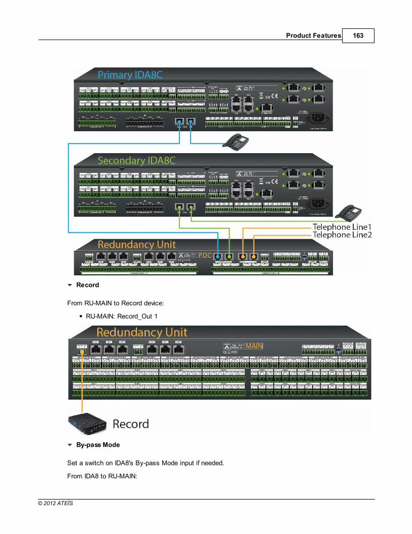
Product Features 163
© 2012 ATEÏS
Record
From RU-MAIN to Record device:
RU-MAIN: Record_Out 1
By-pass Mode
Set a switch on IDA8's By-pass Mode input if needed.
From IDA8 to RU-MAIN:

ATEIS - IDA8164
© 2012 ATEÏS
IDA8: By-pass Mode outputs.
RU-MAIN: P_WD, S_WD (Watchdog)
EVAC Inputs
From IDA8 to RU-CTL:
IDA8: EVAC Inputs CH1~9.
RU-CTL: EVAC Inputs P_1~9, S_1~9.
From RU-CTL to switch:
RU-CTL: EVAC Inputs 1~9.

Product Features 165
© 2012 ATEÏS
External Contact (usually on EVAC Inputs CH8)
From IDA8 to RU-CTL:
IDA8: EVAC Inputs CH8.
RU-CTL: EVAC Inputs P_8, S_8.
From RU-CTL to switch:
RU-CTL: EVAC Inputs 8.

ATEIS - IDA8166
© 2012 ATEÏS
Expansion Out
Set RU-MAIN as the master unit and RU-CTL/PDC as the slave unit.
From RU-MAIN to RU-CTL/PDC:
RU-MAIN: EXP_Out
RU-CTL/PDC: S_WD

Product Features 167
© 2012 ATEÏS
4.2.1.3 Configuration
The following steps show how to configure redundancy system in IDA8 system:
1. Setup H/W connection redundancy system.
2. Search primary and secondary IDA8C using Ateis Studio, and connect to them.
3. Select the IDA8C to be primary, Click button [Redundancy] on functions window.
4. Choose the system of secondary IDA8C belongs to. You can click item in combo box of redundancy
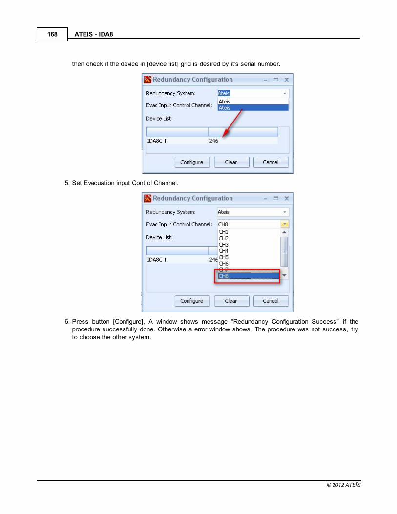
ATEIS - IDA8168
© 2012 ATEÏS
then check if the device in [device list] grid is desired by it's serial number.
5. Set Evacuation input Control Channel.
6. Press button [Configure], A window shows message "Redundancy Configuration Success" if theprocedure successfully done. Otherwise a error window shows. The procedure was not success, tryto choose the other system.

Product Features 169
© 2012 ATEÏS
7. After this setting was finished, you can see the information on devices window show the two IDA8Care redundancy for each other. The field "Redundancy Addr" now are filled with the redundant IDA8C'saddress.

ATEIS - IDA8170
© 2012 ATEÏS
8. Store one of redundancy systems, the other will store the same configuration automatically.
9. There is a window shows the information of current system if a error detected and system switchingfor redundancy

Product Features 171
© 2012 ATEÏS
4.2.1.4 RU-Main
4.2.1.4.1 Overview
RU-MAIN is a device for audio processor redundancy, the peripherals are connected with RU-MAIN notdirectly to audio processor. RU-MAIN is in charge of switching primary and secondary audio processorto active one of them. If primary audio processor is active, all signal of peripherals are redirect to primaryaudio processor by RU-MAIN.RU-MAIN monitor the status of audio processor. if primary audio processoris crash, RU-MAIN will detected and switch to secondary audio processor.
4.2.1.4.2 Front Panel
Secondary Active Indicator:

ATEIS - IDA8172
© 2012 ATEÏS
This LED light up if primary audio processor is active.
Primary Active Indicator:
This LED light up if secondary audio processor is active.
Fault Indicator:
This LED light up if the unit is set to be slave, and a short or open is detected on S. WD(SecondaryWatching Dog) port.
Note: If this indicator light up, it means there is an error of the unit, user needs to check wiring of S.WD connector or replace by a good unit.
Power Indicator:
This LED light up if this unit is power on.
4.2.1.4.3 Rear Panel
PDC Audio Output for Record:
The audio output of peripheral plugged on PDC connector.
PDC Connectors:
There are 2 sets of PDC port in RU-Main, each set consist of three connectors, allow system to doone PDC peripheral redundancy, the "N" is the number of set:
P_PDC N
Connect to one of primary audio processor's PDC connectors.
PDC N
Connect to peripheral which communicates to audio processor using PDC interface, for examplePSS AS, PPM AS.
S_PDC N
Connect to one of secondary audio processor's PDC connectors.

Product Features 173
© 2012 ATEÏS
Zone Amplifier Inputs:
There are 8 sets of Zone Amplifier Input in RU-MAIN, each set consist of three connectors, allowsystem to do one channel of zone amplifier redundancy, the "N" is the number of set:
P_ZONE N
Connect to Nth channel of primary audio processor's zone amplifier input connector.
ZONE N
Connect to Nth channel of normal amplifier's audio input connector.
S_ZONE N
Connect to Nth channel of secondary audio processor's zone amplifier input connector.
EXP_OUT(Active Control Expansion Output):
This port output logic signal to next RU devices to synchronize redundancy state which tells primaryor secondary is active.
Fault:
This port is a logic contact, which is normally closed, opened if the unit is set to be slave(refer toMaster/Slave Switch of later item), and a short or open is detected on S_WD(Secondary WatchingDog) port.
S_ACT(Secondary Active Output):
Output a logic signal to indicate secondary audio processor is active.
S_WD(Secondary Watching Dog):
RU-Main/PDC/CTL determine active system will be primary or secondary IDA8 network by monitorinput logic contacts P_WD and S_WD, The basic philosophy is that master RU monitor the signalcoming from primary and secondary audio processor to decide which one can be active, and alsopass the decision to next RU through EXP_OUT port. When RU is set to be master, it monitor bothP_WD and S_WD for choose which IDA8 network will be active, but if RU is set to slave, it onlymonitor S_WD to determine which one can be active.
P_ACT(Primary Active Output):
Output a logic signal to indicate primary audio processor is active.
P_WD(Primary Watching Dog):
RU devices monitor this logic signal for determining active audio processor, please refer to item"(S_WD)Secondary Watching Dog".
Master/Slave Switch:
A dip switch to set RU-MAIN be master or slave. The difference between master and slave pleaserefer to item "(S_WD)Secondary Watching Dog".
Expansion Power Supply:
Output 24V DC power to next RU-MAIN/PDC/CTL devices.

ATEIS - IDA8174
© 2012 ATEÏS
There are two connectors of this output:
PRI: Connect to Power Supply PRI connector next RU-MAIN/PDC/CTL.
SEC: Connect to Power Supply SEC connector next RU-MAIN/PDC/CTL.
Power Supply:
24V DC power input, which is connect to 24V DC Output of IDA8C/S.
There are two connectors of this input:
PRI: 24V DC power input from primary audio processor.
SEC: 24V DC power input from secondary audio processor.
Speaker Zone Output:
There are 8 zones for speaker connection. each zone consists of following connectors(from left toright):
P_LINEA: Connect to speaker zone output line A of primary audio processor.
P_LINEB: Connect to speaker zone output line B of primary audio processor.
LINE A: Connect to line A speaker.
LINE B: Connect ot line B speaker.
S_LINE A: Connect to speaker zone output line A of secondary audio processor.
S_LINE B: Connect to speaker zone output line B of secondary audio processor.
Zone Amplifier Output:
There are 8 zones for amplifier output connection, it receive the gained audio signal coming fromnormal amplifier, each amplifier output consist of three connectors:
P_AMPO: Connect to normal amplifier output connector of primary audio processor.
AMPO: Connect to output of normal amplifiers.
S_AMPO: Connect to normal amplifier output connector of secondary audio processor.
Backup Amplifier Output:
There are two backup amplifier outputs on RU-MAIN, each output consist of three connectors:
P_AMPO: Connect to backup amplifier output of primary audio processor.
AMPO: Connect to backup amplifier output.
S_AMPO: Connect to backup amplifier output of secondary audio processor.
Backup Amplifier Input:
There are two backupt amplifier inputs on RU-MAIN, each input consist of three connectors, where Nis the number of channel:
P_BKP N: Connect to backup amplifier input of primary audio processor.
BKP N: Connect to input of backup amplifier.

Product Features 175
© 2012 ATEÏS
S_BKP N: Connect to backup amplifier input of secondary audio processor.
4.2.1.4.4 Characteristics
Dimension = 436mm x 150mm x 88mm.
power consumption : 600mA @24Vdc
4.2.1.5 RU-PDC
4.2.1.5.1 Overview
RU-PDC is a device for audio processor redundancy, the peripherals are connected with RU-PDC notdirectly to audio processor. RU-PDC is in charge of switching primary and secondary audio processor toactive one of them. If primary audio processor is active, all signal of peripherals are redirect to primaryaudio processor by RU-PDC. RU-PDC monitor the status of the other RUs for switching active audioprocessor.

ATEIS - IDA8176
© 2012 ATEÏS
4.2.1.5.2 Front Panel
Secondary Active Indicator:
This LED light up if active system is primary audio processor.
Primary Active Indicator:
This LED light up if active system is secondary audio processor.
Fault Indicator:
This LED light up if the unit is set to be slave, and a short or open is detected on S. WD(SecondaryWatching Dog) port.
Note: If this indicator light up, it means there is an error of the unit, user needs to check wiring of S.WD connector or replace by a good unit.
Power Indicator:
This LED light up if this unit is power on.
4.2.1.5.3 Characteristics
Dimension = 436mm x 150mm x 44mm.
power consumption : 350mA @24Vdc
4.2.1.6 RU-CTL
4.2.1.6.1 Overview

Product Features 177
© 2012 ATEÏS
RU-CTL is a device for audio processor redundancy, the peripherals are connected with RU-CTL notdirectly to audio processor. RU-CTL is in charge of switching primary and secondary audio processor toactive one of them. If primary audio processor is active, all signal of peripherals are redirect to primaryaudio processor by RU-CTL. RU-CTL monitor the status of the other RUs for switching active audioprocessor.
4.2.1.6.2 Front Panel
Secondary Active Indicator:
This LED light up if active system is primary audio processor.
Primary Active Indicator:
This LED light up if active system is secondary audio processor.
Fault Indicator:
This LED light up if the unit is set to be slave, and a short or open is detected on S. WD(SecondaryWatching Dog) port.
Note: If this indicator light up, it means there is an error of the unit, user needs to check wiring of S.WD connector or replace by a good unit.
Power Indicator:
This LED light up if this unit is power on.
4.2.1.6.3 Rear Panel
Output Contacts:
There are 8 channels for output contacts, each channel consist of three connectors, where "N" isthe number of channel:
P_N: Connect to Nth output contact of primary audio processor.
N: Nth channel of output contact.
S_N: Connect to Nth output contact of secondary audio processor.

ATEIS - IDA8178
© 2012 ATEÏS
Expansion Power Supply:
Output 24V DC power to next RU-MAIN/PDC/CTL devices.
There are two connectors of this output:
PRI: Connect to Power Supply PRI connector next RU-MAIN/PDC/CTL.
SEC: Connect to Power Supply SEC connector next RU-MAIN/PDC/CTL.
Power Supply:
24V DC power input, which is connect to 24V DC Output of audio processor.
There are two connectors of this input:
PRI: 24V DC power input from primary audio processor.
SEC: 24V DC power input from secondary audio processor.
Evacuation Inputs:
There are 9 channels for evacuation input, each channel consist of three connectors, where "N" isthe number of channel:
P_N: Connect to Nth evacuation input of primary audio processor.
N: Nth channel of evacuation input.
S_N: Connect to Nth evacuation input of secondary audio processor.
Active Control Expansion Output:
This port output logic signal to next RU devices to synchronize redundancy state which tells primaryor secondary is active.
Fault:
This port is a logic contact, which is normally closed, opened if the unit is set to be slave(refer toMaster/Slave Switch of later item), and a short or open is detected on S_WD(Secondary WatchingDog) port.
S_ACT(Secondary Active Output):
Output a logic signal to indicate if secondary IDA8 network is active.
S_WD(Secondary Watching Dog):
IDA8RU-Main/PDC/CTL determine active system will be primary or secondary IDA8 network bymonitor input logic contacts P_WD and S_WD, The basic philosophy is that master RU monitor thesignal coming from primary and secondary audio processor to decide which one can be active, andalso pass the decision to next RU through EXP_OUT port. When RU is set to be master, it monitorboth P_WD and S_WD for choose which audio processor will be active, but if RU is set to slave, itonly monitor S_WD to determine which one can be active.
P_ACT(Primary Active Output):
Output a logic signal to indicate if primary audio processor is active.

Product Features 179
© 2012 ATEÏS
P_WD(Primary Watching Dog):
RU devices monitor this logic signal for determining active audio processor, please refer to item"(S_WD)Secondary Watching Dog".
Master/Slave Switch:
A dip switch to set RU-PDC be master or slave. The difference between master and slave pleaserefer to item "(S_WD)Secondary Watching Dog".
4.2.1.6.4 Characteristics
Dimension = 436mm x 150mm x 44mm.
power consumption : 200mA @24Vdc
4.2.2 DNM
4.2.2.1 Overview
The DNM assures the omnidirectional sound recording and preamplification of the surroundingbackground noise.
The 0 dB modulation is sent through the Audio Processor in order to provide the automatic gain controlfeature of the DNM component and allows the level adjustment where the DNM is implemented.
Any situation in which the volume of loudspeakers need to be adjusted automatically depending on thebackground noise. (ex: station, Airport, MRT, etc.)
4.2.2.2 Wire Connection
When the DNM is connected with a PDC port, the picture below shows how to wire. The type of cable isthe CAT5 FTP cable here.

ATEIS - IDA8180
© 2012 ATEÏS
4.2.2.3 Installation
Install the DNM device to the position in which you want the DNM to sense background noise and adjustloudspeaker volume automatically, and connect the DNM device with Audio Processor by RS485 orEthernet, besides, if the system needs to connect to a series of DNM on same RS485 port, then theuser should plug in the DNM devices one by one before connecting a series DNM to RS485 port. How toconnect is described in the "Configuration" section.
One DNM can only support one Zone(like IDA8 Zone Channel).
Generally, place the DNM in front of a loudspeaker about 1~2 meters. The distance between DNM andLoudspeaker also depends on the power of the amplifier and loudspeaker.
If it is a high-power loudspeaker (sound is louder), then the distance should be increased, and vice versa.
The examples of installation as follows:
1. One zone connects only one loudspeaker, generally, then install the DNM in front of theloudspeaker about 1~2 meters.
2. One zone connects many loudspeakers, and installed the loudspeakers by circularity and thedistance is not far between the loudspeakers, then the DNM can be set in the center ofloudspeakers (ex: A small conference room, etc.).

Product Features 181
© 2012 ATEÏS
3. One zone connects many loudspeakers, and the installation of loudspeakers are irregular but thedistance of all loudspeakers are not far, then install the DNM about 1~2 meters in the front of anyone loudspeaker.
4. In a large area, the broadcast source is same in the area, and the distance of each loudspeakeris far, maybe the ambient noise is loud in one side, but quiet in the other side. What if the DNM isinstalled around loud side? The DNM will adjust the level automatically allowing people to hear the

ATEIS - IDA8182
© 2012 ATEÏS
broadcast clearly, as all of the loudspeakers are connected from same source (same zoneoutput). Maybe the volume of broadcast is too loud for the quiet side, or on the contrary, if theDNM is installed around quiet side, the volume of broadcast is too small for the loud side. Toavoid this problem, the user can separate the area to several zones and one DNM for oneseparated zone, and all of the DNM are same input source (ex. Department store, etc.).
Note: The sound of loudspeakers from another zone can't effect each other, otherwise, the DNM willconsider the sounds from another zone as a background noise.
4.2.2.4 Characteristics
Case:
Dimension = 100mm(Φ) x 130mm(H)
Weight = 0.13 Kg
Power:

Product Features 183
© 2012 ATEÏS
Item Voltage Current Consumption CommentDC Input 18V~26V, Typical 24V 250mA -
Microphone:
Sensitivity adjustment rang ... (60 ~ 120dBA)±5dBA
THD @ 1kHz < 0.2%.
Bandwidth @ -3dB = 50Hz ~ 16kHz.
Maximum Cable Length:
600M on category 5 cable.
4.2.2.5 Configuration
1. Plug the DNM to the RS485(PDC) port of IDA8C/S (Here's the example using IDA8, the configurationis the same for other Ateis Audio Processor).
2. Search and click on the entry of IDA8C/S in the [Device Management] window:
3. Connect to the IDA8C/S.
4. Click the button [Remote Plug-In].

ATEIS - IDA8184
© 2012 ATEÏS
5. A window [Remote Plug-In] pop up. Select RS485 port number and Remote Type, and key in theseries number which can be found on the sticker attached. Click the “Plug-In” button in the window.After plug in, click the “refresh” button to read back the DNM information from the RS485 port If theinformation is same with your device, the plug-in is successful.
6. In device editing window, create a DNM and wires it to IDA8C/S's RS485 port:

Product Features 185
© 2012 ATEÏS
7. Double click the IDA8C/S to open DSP component editing window, then drag and drop to create"DNM" component. In this case, it simply input audio from "Input" component and output to "Output"component:
8. Go back to device editing window, click on the block of DNM device. A [DNM Preset] window popsup. There is a combo box to select the cooperate DSP component for the DNM device.

ATEIS - IDA8186
© 2012 ATEÏS
9. To assign the DNM component to device.
10.Store the configuration, and then online.
11.Click "DNM" component to open it's element window, press button [Calibration] to start thecalibration procedure. When it is calibrating, the red LED will light up, and the White Noise Level(dB)will be auto-tuning (sending out a low frequency tone). Note: White Noise Level(dB) is appropriate tostop around -20dB.
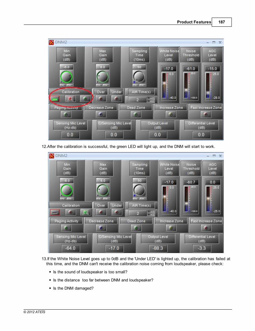
Product Features 187
© 2012 ATEÏS
12.After the calibration is successful, the green LED will light up, and the DNM will start to work.
13.If the White Noise Level goes up to 0dB and the 'Under LED' is lighted up, the calibration has failed atthis time, and the DNM can't receive the calibration noise coming from loudspeaker, please check:
Is the sound of loudspeaker is too small?
Is the distance too far between DNM and loudspeaker?
Is the DNM damaged?

ATEIS - IDA8188
© 2012 ATEÏS
14.If the White Noise Level goes down to -40dB and the over LED is lighted up, this means thecalibration has failed at this time, and the DNM received the sound too loud, please check:
Is The sound of loudspeaker is too loud?
Is the distance too close between DNM and loudspeaker?
Is the DNM damaged ?
15.After calibration finished, DNM starts to work, It increases the level of audio if there is some noisedetected by DNM.
16.To save the parameter, click the [Save parameter] in Ateis Studio.

Product Features 189
© 2012 ATEÏS
4.2.2.6 Operation Notice
Once the calibration is successful, don't adjust the level in the rear of DNM component (ex: Monitor OutC's level or amplifier gain, etc.), but the level can be adjusted which is front of the DNM component (ex:Input A level or PC output volume, etc.).
4.2.2.7 Two DNM on the Same PDC
If the system needs to use more than one DNM and connect the DNM units on the same RS485 port,the user should assign DNM units with different IDs.
1. For each DNM, choose the remote type and manually enter its SN then click "Plug-In". Note: If youlose the SN and cannot find the number sticker, connect only the one you want and click [Refresh] toshow its Serial Number.

ATEIS - IDA8190
© 2012 ATEÏS
2. After plug-in successfully. These two DNM units are listed in the grids and showing their firmwareversion.
3. In the configuration file, draw the DNM component out, and connect to RS485 port (same with realwiring). If the system has two DNM, then draw two DNM device components.(the example is twoDNM in PDC1).

Product Features 191
© 2012 ATEÏS
4. To assign the DNM component to device.

ATEIS - IDA8192
© 2012 ATEÏS
5. Draw DSP DNM component, and connect the input and output.
6. To modify the DSP component name. You can simply use property to do this.

Product Features 193
© 2012 ATEÏS
7. Go to device editing window. Double click the device DNM component to open a window, and Linkdevice DNM component with DSP DNM component.
8. Store, Online, Calibrate two DNMs by each. Please refer to preview topic "Configuration " forcalibration procedure.
183

ATEIS - IDA8194
© 2012 ATEÏS
4.2.3 PPM AS
4.2.3.1 Overview
Unidirectional Condenser Addressable Microphone, compatible with all system units, PPM AS uses anRS485 protocol over a single CAT5 cable connection, to transport both Audio and Power from the PPMAS to the system units. The PPM AS comprises of 8 zones / 8 buttons with sleek condensergooseneck microphone, and spring metal protection, providing durability and excellent aesthetics as wellas allowing up to 256 zones expansion via the additional keypad easy extension station. The buttonscan represent a single zone or a group of zones and are easily defined via the GUI of the system unitsusing a simple Matrix selection.
The unit offers “Hold” and “Busy” LED signals in addition to the zone LED’s, and these allow the easyidentification of selection / Busy signals for the user.
All buttons can be programmed with drag & drop features from the System unit GUI software and eachbutton can be programmed for Push To Talk or Latch functionality.The unidirectional condensermicrophone warrants high quality directive signal pick up from the user and hence less interference fromthe surroundings thanks to the cardioid polar pick-up pattern.
The RS485 communication protocol offers daisy chaining of up to 100 m on a CAT5 cable, and yetmakes outlets easy to connect via a standard RJ45 connectors. (The microphone compatibility listingshows the maximum number of units per System).

Product Features 195
© 2012 ATEÏS
4.2.3.2 Control Panel
Microphone:
The sleek condenser gooseneck microphone. This unidirectional condenser microphone warrantshigh quality directive signal pick up from the user and hence less interference from the surroundings.
Monitoring Speaker:
This embedded speaker to play chime when paging or monitor signal from audio processor, it needsto work with rs485 output component to get audio signal from other DSP components in audioprocessor.
Fault LED:
To display fault status of system. Following table list the states of fault:
Status Frequency Activity
Permanent There are faults in audio processor.Blinking ° ° Lost communication with audio processor.

ATEIS - IDA8196
© 2012 ATEÏS
EVAC LED:
Status Frequency Activity
Permanent System is under evacuation paging.
Blinking ° ° PPM AS does not do a "Plug-in" in Ateis Studio before using.
Note: "Remote Plug-in" makes audio processor to recognize the peripheral devices.
Power LED:
This LED light up when the PPM AS is powered on.
Hold LED:
These LEDs Indicate which keys are selected.
Event Select Key:
These buttons are used to select keys, each key may link to an event for triggering actions likepaging or adjust the value of parameters.
All/Release LED:
This indicator lights up if all keys are selected.
All/Release Button:
This button is used to select or deselect all keys.
Talk Key:
Push this key to request paging.
Talk Indicator:
This LED light up if PPM-AS is allowed to paging, on the other word, the paging request has beenacknowledged.
Note: Sometimes even the paging request is granted, zones under paging still can be occupied byother sources with higher priority. In the event of, the talk LED still lights up, you can check it frombusy LEDs.
Busy LED:
Show the status of zone:
Color Status Frequency Activity
Red Permanent Priority of the zone is lower than other sources.Green Blinking ° ° Priority of the zone is higher than other sources.
Green PermanentThe zone only desired for paging is not using by other
sources.

Product Features 197
© 2012 ATEÏS
4.2.3.3 Rear Panel
This chapter is about the adjustable volume on the PPM-AS's back panel and how to connect a keypad.
PPM Keypad(Left) and PPM-AS ( Right)
Volume Control:
Here you can use a cross-tip screwdriver to adjust the volume of the speak, Mic and chime of PPMAS.
Terminator:
The terminator switch for the last PPM, for the Master-Slave connection via junction boxes see,Consoles and Accessories > Junction Box.
Keypad connector:
The keypad connector on the PPM-AS for connecting the Keypad.
Please make sure the hardware version is matching. If connecting with the wrong hardware type,the circuit in the keypad will burn out.
HardwareType
Keypad Power Supply Comment
PPM V2 PPM-KP 3.3VDC -
PPM V3, V4 PPM-KP G2 24VDC -
PPM SP PPM-KP G2 24VDC Only for LAPG2T & UAP G2
Keypad connector:
286

ATEIS - IDA8198
© 2012 ATEÏS
The keypad connector on the keypad for connecting the PPM-AS. Every keypad is shipped with oneflexible flat cable on it.
Keypad connector:
The keypad connector on the keypad for connecting the next keypad, one PPM-AS can have 2keypads for extending the keys.
4.2.3.4 Characteristics
Case:
Dimension = 105mm (W) x 190mm (L) x 50mm (H).
Weight = 0.7Kg.
Color = RAL7035.
Goose-neck length with microphone = 300 mm
Power:
Item Voltage Current Consumption Comment
DC Input 18V~26V, Typical 24V 120mA -
Microphone Output:
Maximum level = 6dBu.
Output Impedance = 100Ohm.
THD @ 1kHz < 1%.
Bandwidth @ -3dB = 100Hz ~ 18kHz.
Front Panel Speaker:
Impedance = 4Ohm.
Maximum Power @ 1kHz = 1W.
THD @ 1kHz < 1%.
Bandwidth @ -3dB = 200Hz ~ 8kHz.
Cable length:
100m(control and power on the same cable)
900m(when power line connects to junction box).
Comes standard with Junction box (JB) and CAT5 cable (1.5)
4.2.3.5 Configuration
To make PPM AS work, it needs to edit configuration using Ateis Studio. Following sections are aboutconfiguration editing.
The example here is IDA8, the configuration is the same for ESC, LAPG2T and other Ateis AudioProcessor.

Product Features 199
© 2012 ATEÏS
Create PPM AS Object
Open or create a Ateis studio configuration file, in the [Device] design window, create audioprocessor and PPM AS object:
1. Drag IDA8C to design window to create audio processor object.
2. Drag PPM AS to design window to create PPM AS object.
3. Wiring to connect green pins between PPM AS object and audio processor.
DSP component configuration
It need to route audio from PPM AS to paging component for paging processing. See the followingexample:

ATEIS - IDA8200
© 2012 ATEÏS
Pin A~D of RS485 Input component is corresponds to PPM AS 1~4 audio plugged in PDC1~4respectively. Network Paging component process paging request coming from various sources, andto determine which source is allowed to paging to zones it desired. The zones are M1~M8 onNetwork Paging component.You need create an integration paging event to link with PPM AS, Seetopic Network Paging to learn editing paging settings.
PPM AS Manager
PPM AS Manager is an unit of the software to manage settings about PPM AS that connect toaudio processors like IDA8 series.
Click main menu of software [View > PPM AS Manager] to open PPM AS Manager:

Product Features 201
© 2012 ATEÏS
Name
The name of PPM AS object.
Rs485 Target
Indicates the connector on audio processor that PPM AS connected in the design window.
Talk Mode
To specify the behavior of key pressing for paging. There are two modes:
Push: Push and hold the key for paging request, release the key to end paging.
Lock: First push for paging request, if request is grant then start paging, push again to endpaging.
Key-Count
To specify how many keys on PPM AS.
Pre-Announcement-Enabled
Enable or disable pre-announcement chime playing.

ATEIS - IDA8202
© 2012 ATEÏS
Pre-Announcement-Name
The name of pre-announcement message.
Post-Announcement-Enabled
Enable or disable post-announcement chime playing.
Post-Announcement-Name
The name of post-announcement message.
Announcement
Open announcement message settings window:
o New
Input a name of announcement message for creating new entry in the list. Type name in the
editor and press the button right to the editor.
o Index
Index for entries in the list.
o Announcement
The name of announcement message.
o Add
Add a name of announcement message from File Selection Dialog:

Product Features 203
© 2012 ATEÏS
Path
Specify the directory to list all files with supported formats.
File List
Display files in the directory Path.
Display
Specify the display mode for file list. There are three modes: Icon/List/Detail.
Add
Move the select files to the ready list that the right side of window.
Ok
Add files in the ready list to announcement message list.
Cancel
Close window and ignore ready list.
Path
The directory name of message file belongs to.
File
The name of message file.
Remove
Remove the select message file in ready list.
Clear
Clear ready list.
o Remove
Remove a message from list.
o Clear

ATEIS - IDA8204
© 2012 ATEÏS
Clear the list.
o Close
Close the window.
PPM AS Settings
Double click the PPM AS object open the window of PPM AS Settings:
Name
The name of PPM AS.
Announcement
Open announcement message settings window, see prior section for details.
Announcement Preposition
Enable or disable pre-announcement chime playing.
Announcement Preposition Name
Select message from the announcement message list for pre-announcement chime playing.
Announcement Postposition
Enable or disable post-announcement chime playing.
Announcement Postposition Name
Select message from the announcement message list for post-announcement chime playing.
Talk Mode
Specify the behavior of key pressing when paging. See prior section for details.
Key Count
Specify how many number of keys in PPM AS.
Key Event
Bind a paging event with PPM AS for zone selection. See Network Paging component topic for

Product Features 205
© 2012 ATEÏS
more details.
Remote Plug-in
It need to do a "Remote Plug-in" to make audio processor recognize this remote devices. See thetopic Remote Plug-in for more details.
Assign to Design Objects
The device object in design window needs map to physical device, then the configuration of thedevice can be set to the physical one. Click "Name " field of device list to select correspond deviceobject. Refer to topic search and settings for more detail.
4.2.3.6 Maintenance and Troubleshooting
This chapter will help you to diagnose the common problems for troubleshooting and how to solve. Themaintenance of the device and peripherals are also told here.
If none of the solution works, please contact your Ateis dealer.
The LED indicators:
When the EVAC LED blinks
When the EVAC LED blinks, it possibly is the plug-in problem.
Please read this.
When the FAULT LED blinks
When the FAULT LED blinks, it means the paging console lose the communication with audioprocessor.
Please use the Ateis Studio to check the paging console component is added correctly, and thenstore the table into the paging console.
372

ATEIS - IDA8206
© 2012 ATEÏS
4.2.4 PSS AS
4.2.4.1 Overview
The PSS AS touch paging microphone console is a man-machine interface which allows paging call,messages broadcasting and DSP matrix parameter control. Its back-lit touch screen is designed forsimple and user-friendly operating. Various operating levels with password protection make the PSS ASa versatile device that fits well in a commercial shopping center as for an industrial high securityenvironment.
All paging parameters needed for site operating can be programmed: zones assigned to the differentbuttons, name of zones, group of zones, messages triggering, levels adjustments and pre-call chime butalso for fader control, button control or event control.
A total of twelve keys on fourteen pages allow zone or group of zones selections. Each key contains acolor changing field indicating that the zone is occupied by a different process.

Product Features 207
© 2012 ATEÏS
4.2.4.2 Control Panel
Microphone:
A 280mm flex microphone.
Power LED:
This LED light up when the PSS AS is powered on.
Fault LED:
To display fault status of system. Following table list the states of fault:
Status Frequency Activity
Permanent There are faults in audio processor.
Blinking ° ° Lost communication with audio processor.
EVAC LED:
Light up when system is under evacuation paging.
Status Frequency Activity
Permanent System is under evacuation paging.
Touch Screen:
A back-lit touch screen with 5" diagonal and 800 x 480 resolution contains 14 pages, 12 keys foreach pages can freely config to paging or adjustment parameters in audio processor.
Left Button:
No function for the moment.
Middle Button:

ATEIS - IDA8208
© 2012 ATEÏS
No function for the moment.
Right Button:
Press and hold it for a while to calibrate touch screen.
Monitoring Speaker:
This embedded speaker to play chime when paging or monitor signal from audio processor, it needsto work with rs485 output component to get audio signal from other DSP components in audioprocessor.
4.2.4.3 Characteristics
Case
Dimension = 250mm (W) x 140mm (L) x 75mm (H).
Weight = 1.1Kg.
Color = RAL7016.
Goose-neck length with microphone = 300 mm
Screen
Diagonal = 5" .
Resolution = 800 x 480.
Power
Item Voltage Current Consumption Comment
DC Input 18V~26V, Typical 24V 250mA -
Microphone Output
Maximum level = 6dBu.
Output Impedance = 100Ohm.
THD @ 1kHz < 1%.
Bandwidth @ -3dB = 100Hz ~ 18kHz.
Noise Gate Threshold = -84dBu ~ -24dBu.
Target Output Level = 0.
Max Output Level = -54dBu ~ 6dBu.
Attack Time = 8ms.
Release Time = 100ms.
Front Panel Speaker
Impedance = 4Ohm.
Maximum Power @ 1kHz = 1W.
THD @ 1kHz < 1%.

Product Features 209
© 2012 ATEÏS
Bandwidth @ -3dB = 200Hz ~ 12kHz.
Maximum Cable Length
100m on Category 5 cable
4.2.4.4 Configuration
To make PPM AS work it need to edit configuration using Ateis Studio. Following sections are aboutconfiguration editing.
Create PPM AS Object
Open or create a Ateis studio configuration file, in the [Device] design window, create audioprocessor and PSS AS object:
1. Drag audio processor to design window to create audio processor object.
2. Drag PSS AS to design window to create PPM AS object.
3. Wiring to connect green pins between PSS AS object and audio processor.
DSP component configuration
It need to route audio from PPM AS to paging component for paging processing. See the followingexample:

ATEIS - IDA8210
© 2012 ATEÏS
Pin A~D of RS485 Input component is corresponds to PPM AS 1~4 audio plugged in PDC1~4respectively. Network Paging component process paging request coming from various sources, andto determine which source is allowed to paging to zones it desired. The zones are M1~M8 onNetwork Paging component. You need create an integration paging event to link with PSS AS, seetopic Network Paging to learn editing paging settings.
PSS AS Settings
Double click PSS AS object to open settings window, There are 14 pages on the right of window,each or page is corresponds to a page on PSS AS. There are five tabs on the top of windowcontaining various settings of each. The following sections describe for each settings of tab.
PSS AS Settings-Key Tab
This page is the settings about the captions for each key and the usage selection.

Product Features 211
© 2012 ATEÏS
Key
Refer to the key on the page of PPM AS.
Comment 1/2/3
The text displayed on the key, there are three rows on it Comment 1 is the first row and so on.
Paging/Other
Check boxes for Paging and Others option are alternative. Choose one of them to determine thekey used for paging or triggering an event.
PSS AS Settings-Paging Tab
This page shows the zone combination for each key which is configured as paging.

ATEIS - IDA8212
© 2012 ATEÏS
Value
To specify which code on integration paging event is bound with the key.
All
Select all zone for the key.
Zone Selection
The grid list all zones of network paging component for all audio processors. click check boxesto select zones separately for the key.
PSS AS Settings-Trigger/Control Tab
This section mainly about settings of event linking. PSS AS with the ability of triggering event usingkey. You need to specify the link relation of key and event at design time.

Product Features 213
© 2012 ATEÏS
Event
Select the event linked to.the key.
Control Mode
Specify the control mode is Trigger or Control, see more details on topic Event Management.
State
Enter a value for the state that processed by event control procedure, each state number resultdifferent adjustment of system, see more details on topic Event Management.
Link
Open settings window of the event.
PSS AS Settings-Message Tab

ATEIS - IDA8214
© 2012 ATEÏS
This section is about setting up the message list for play on runtime in PSS AS. Before selection,you need to build chime list which settings in on the tab Setting.
Ch(Left)
The channel number for a message on local.
Local Message
The message belongs to local list, indicates this message is inside the PSS AS itself.
Ch(Right)
The channel number for a message on audio processor.
Processor Message
The message belongs to processor list, indicates this message is inside the audio processor.
It need to work with Message Player component.
PSS AS Settings-Setting Tab

Product Features 215
© 2012 ATEÏS
This section is settings about chimes.
Chime List
Open a settings window to build up list of message for selection.
Pre-announcement Enable
To enable or disable pre-announcement.
Pre-announcement Chime Selection
Select a message for pre-announcement.
Post-announcement Enable
Enable or disable post-announcement.
Post-announcement Chime Selection
Selection a message for post-announcement.
Talk Mode
There are two mode available:
Push: Push and hold the key for paging request, release the key to end paging.
Lock: First push for paging request, if request is grant then start paging, push again to endpaging.
Remote Plug-in
It need to do a "Remote Plug-in" to make audio processor recognize this remote devices. See thetopic Remote Plug-in for more details.

ATEIS - IDA8216
© 2012 ATEÏS
Assign to Design Objects
The device object in design window needs map to physical device, then the configuration of thedevice can be set to the physical one. Click "Name " field of device list to select correspond deviceobject. Refer to topic search and settings for more detail.
4.2.4.5 Maintenance and Troubleshooting
This chapter will help you to diagnose the common problems for troubleshooting and how to solve. Themaintenance of the device and peripherals are also told here.
If none of the solution works, please contact your Ateis dealer.
The LED indicators:
When the EVAC LED lights up
When the EVAC LED lights up, it means the system is under evacuation paging.
When the FAULT LED blinks
When the FAULT LED blinks, it means the paging console lose the communication with audioprocessor.
Please use the Ateis Studio to check the paging console component is added correctly, and thenstore the table into the paging console.
4.2.5 URC AS
4.2.5.1 Overview
The URC AS can be fully programmed via Ateis Studio to adjust every setting you want: volume, mute,preset, components' adjustments... URC AS connect to audio processor via RS485 cable that allow youto remote control parameters of audio processor with a long distance. A elegant OLED to displayinformation of parameters or the status. It give extreme simple and effective experience of controlinterface with only Two buttons [EXIT], [BACK] and a Knob to achieve whatever action desired. The URCAS is definitely the best choose for remote controlling with low cost consideration.

Product Features 217
© 2012 ATEÏS
4.2.5.2 Control Panel
OLED Display
Exit Button:
Back to the main menu.
Knob:
Turn: Select items or change volume.
Press: Enter in the sub menu.
Back Button:
Back to the root menu.
4.2.5.3 Characteristics
Case
Dimension = 84mm (W) x 33mm (L) x 84mm (H).
Weight = 0.08KG.
Power
Item Voltage Current Consumption Comment
DC Input 24VDC 20mA -
Maximum Cable Length
1200m on Category 5 cable

ATEIS - IDA8218
© 2012 ATEÏS
4.2.5.4 Configuration
To make URC AS work it need to edit configuration using Ateis Studio. Following sections are aboutconfiguration editing.
Create URC AS Object
Open or create a Ateis studio configuration file, in the [Device] design window, create audioprocessor and URC AS object:
1. Drag audio processor to design window to create audio processor object.
2. Drag URC AS to design window to create URC AS object.
3. Wiring to connect green pins between URC AS object and audio processor.
URC AS Settings
Double click URC AS object to open settings window.

Product Features 219
© 2012 ATEÏS
Serial Number
Serial number of the URC AS.
Name
Name of the URC AS.
Memory
Indicate memory usage of the URC AS for current settings.
URC AS Settings-About Tab
This page include settings for About function in URC AS. About is the last item of first layered menuin URC AS. Click the item to enter second layer of About function that is a list of texts that set indesign time.f
Title
The text of about title.
Item
The item No. for the text in About text list.

ATEIS - IDA8220
© 2012 ATEÏS
Text
The text in About text list.
Add
To add a text in About text list.
Delete
To remove selected text from About text list.
URC AS Settings-Global Parameters Tab
This page is settings about items in URC AS for controlling global parameters like changing master/sub presets. Users are allow to create arbitrary number of items until reach the memory limit whichdisplayed on the bottom of window.
Add
Add a item in URC AS for controlling global parameters.
Delete
To remove a item.
Item
Index of the item.
Label
Display text for the item.
Control Type
To specify which type of global parameter is going to control. Available types list below:
o Preset Selector : To change master/sub presets.
Assign Right
To specify the item is belong to first layer or protected layer.
Assigned
Indicate the number of presets are selected for change. There is an ellipsis button on the right ofgrid cell, click it to open the window for preset selection.

Product Features 221
© 2012 ATEÏS
o Check boxes for selection of master/sub presets to be linked to the item.
o Check All button to select all master/sub presets.
o Uncheck All button to de-select all master/sub presets.
o OK button to confirm settings and close window.
o Cancel to discard the modification of settings and close window.
URC AS Settings-Sub-preset and Parameters Tab
This page is settings about sub-preset and parameter control using items in URC AS.
Function Combo Box
To specify which function for controlling going to be created. The available functions list below:
o Sub-Preset Selector
To change sub-preset.
o Element Control(Range)
To control element with range type value. For example "Level" in Input component with min -90 dB and max 20 dB is a range type of element.
o Element Control(List or Button)
To control element with list or boolean type value. For example "Mute" in Input componentwith states On/Off is a button type of element.
Add
To add an item for controlling sub-presets or elements.
Delete
To remove selected items in the list.

ATEIS - IDA8222
© 2012 ATEÏS
Item
Index of the item.
Label
The display text of the item.
Control Type
The type of item. refer to prior section "Function Combo Box" for more details.
Assign Right
To specify the item is belong to first layer or protected layer.
Assigned
Indicate how many controlled target linked to the item, for example if a item controls 4 channelsof "Mute" simultaneously, the value "Assigned" will be 4.
URC AS Settings-Preset Parameters Tab
This page is settings about behavior of menu changing.
P.P. to enter First Layer
If this option is enabled, Double clicks to enter first layer menu is required.
Constant Mode
There are two picture (Logo A/Logo B)stored in an URC AS for logo. Under this mode the logo isdisplay permanently using the one selected on combo box.
Advertisement Mode
In this mode two pictures are display in turn, the time to switch picture is in the editor on theright.
Waiting Time
To specify how long will show Logo pictures when URC AS idled.
Remote Plug-in
It need to do a "Remote Plug-in" to make audio processor recognize this remote devices. See the

Product Features 223
© 2012 ATEÏS
topic Remote Plug-in for more details.
Assign to Design Objects
The device object in design window needs map to physical device, then the configuration of thedevice can be set to the physical one. Click "Name " field of device list to select correspond deviceobject. Refer to topic search and settings for more detail.
4.2.6 RAC
4.2.6.1 Overview
Allows use of analogue inputs for selecting a channel among 5 or 8 and setting the volume.
RAC5 - Wall-mounted level and 5 sources selectors
RAC8 - Wall-mounted level and 8 sources selectors
4.2.6.2 Wire Connection
The RAC is an Analogue instrument. It can be influenced by nearby power cables or 100V speaker lines.To avoid this use shielded cable to connect the device.The type of cable mostly used for this is theCAT5 FTP cable.

ATEIS - IDA8224
© 2012 ATEÏS
4.2.7 URGP
4.2.7.1 Overview
The URGP is an extension unit for the IDA8-System, LAPG2T and ECS. Each URGP provides thosesystems with 32 additional alarm inputs. Each input is monitored and can be programmed to trigger adigital audio message into a specific zone or group of zones. The URGP is linked to the System unitsthrough a RS232 /RS485 monitored serial link.
4.2.7.2 Front Panel
Evacuation LED:
Lights up in red when the Evacuation input is active or blinks while boot.
Following table lists the states of the Evac LED:
Status Frequency Activity
Continuous One of the Evacuation inputs is active.
Blinking ° ° Blinks 5 times after powered on.
Fault LED:
Displays fault status of system. the following table lists the states of the Fault LED:

Product Features 225
© 2012 ATEÏS
Status Frequency Activity
ContinuousOne of the the fault inputs is active.
One of the Evacuation inputs is Short Circuit or Line Open Blinking ° ° Blinks 5 times after powered on.
Power LED:
Lights up in green when the device is powered.
4.2.7.3 Rear Panel
24V DC Input:
Main 24VDC power supply connector.
Fault Inputs:
4 fault inputs received logic signals and used as switches. See the table and figure below:
Definition Circuit Status
NO Open Inactive
NO Short Active
NC Open Active
NC Short Inactive
Do not input the external power voltage to this connector, it might damage the device.
RS485 Connector: 8C8P RJ45 connector for RJ45 connection.

ATEIS - IDA8226
© 2012 ATEÏS
RS232 Connector
Evacuation Inputs:
32 evacuation contact inputs for expanding the channels for IDA8 system. The following table andfigure show the status of the inputs.
Mode Definition Status
Monitoring NO
Short CircuitOpen: InactiveClose: Active
Line Open
Monitoring NC
Short CircuitOpen: Active
Close: InactiveLine Open
Non-Monitoring NOOpen: InactiveClose: Active
Non-Monitoring NCOpen: Active
Close: Inactive
Do not input the external power voltage to this connector, it might damage the device.
4.2.7.4 Characteristics
Case
Dimension = 140mm (W) x 75mm (L) x 44mm (H).
Weight = 0.48KG.
Power

Product Features 227
© 2012 ATEÏS
Item Voltage Current Consumption CommentDC Input 24VDC 30mA -
Maximum Cable Length
RS485 = 600m on Category 5 cable
RS232 = 15m
Evacuation Inputs(Contact Mode)
Bias voltage:
Item Minimum Maximum Unit
Voltage - 5 VDC
Monitoring resistor = 4.7k Ohm.
Evacuation Inputs(Voltage Mode)
On Voltage:
Item Minimum Maximum UnitVoltage 18 72 VDC
4.2.7.5 Configuration
URGP needs config using Ateis Studio before working. EVAC Board is the DSP component for thedevice.
For more information, please see the topic EVAC Board. 500

ATEIS - IDA8228
© 2012 ATEÏS
4.2.8 CD-Touch
4.2.8.1 Overview
CD-Touch Wall mounted cabinet remote paging console for Ateis audio processor.
Wall-mount heavy duty remote paging console with Access level 2 protection to comply with the EN 54-16. Compatible with Ateis audio processor and communicates over a dedicated RS485 for Power, audioand DATA.
The unit comprises of 8 zones / 8 buttons with fist firemen’s microphone in a metal surface mount wall-box. It provides robust IP-30 protection.
The RS485 communication protocol offers daisy chaining of up to 300 m on a simple CAT5 cable, andyet makes outlets easy to connect via a standard RJ45 connector.
Like PSSG2, CD-TOUCH has common keys that are by default displayed in green and several onscreen indicators.
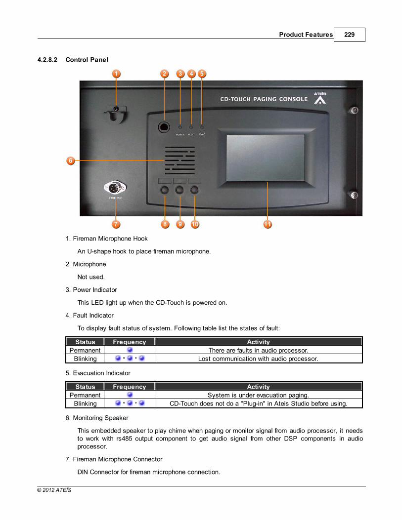
Product Features 229
© 2012 ATEÏS
4.2.8.2 Control Panel
1. Fireman Microphone Hook
An U-shape hook to place fireman microphone.
2. Microphone
Not used.
3. Power Indicator
This LED light up when the CD-Touch is powered on.
4. Fault Indicator
To display fault status of system. Following table list the states of fault:
Status Frequency Activity
Permanent There are faults in audio processor.
Blinking ° ° Lost communication with audio processor.
5. Evacuation Indicator
Status Frequency Activity
Permanent System is under evacuation paging.
Blinking ° ° CD-Touch does not do a "Plug-in" in Ateis Studio before using.
6. Monitoring Speaker
This embedded speaker to play chime when paging or monitor signal from audio processor, it needsto work with rs485 output component to get audio signal from other DSP components in audioprocessor.
7. Fireman Microphone Connector
DIN Connector for fireman microphone connection.

ATEIS - IDA8230
© 2012 ATEÏS
8. Left Button
No function for the moment.
9. Middle Button
No function for the moment.
10.Right Button
No function for the moment.
11.Touch Screen
A back-lit touch screen with 5" diagonal and 800 x 480 resolution contains 14 pages, 12 keys foreach pages can freely config to paging or adjustment parameters in audio processor.
4.2.8.3 Characteristics
Case
Dimension = 400mm (W) x 210mm (H) x 130mm (D).
Weight = 4.5Kg.
Color = RAL7035.
Screen
Diagonal = 5" .
Resolution = 800 x 480.
Power
Item Voltage Current Consumption Comment
DC Input 18V~26V, Typical 24V 250mA
Microphone Output
Maximum level = 6dBu.
Output Impedance = 100Ohm.
THD @ 1kHz < 0.5%.
Bandwidth @ -3dB = 50Hz ~ 20kHz.
Noise Gate Threshold = -84dBu ~ -24dBu.
Target Output Level = 0.
Max Output Level = -54dBu ~ 6dBu.
Attack Time = 8ms.
Release Time = 100ms.
Front Panel Speaker
Impedance = 4Ohm.
Maximum Power @ 1kHz = 1W.

Product Features 231
© 2012 ATEÏS
THD @ 1kHz < 0.5%.
Bandwidth @ -3dB = 50Hz ~ 20kHz.
Maximum Cable Length
100m on Category 5 cable
4.2.8.4 Maintenance and Troubleshooting
This chapter will help you to diagnose the common problems for troubleshooting and how to solve. Themaintenance of the device and peripherals are also told here.
If none of the solution works, please contact your Ateis dealer.
The LED indicators:
When the EVAC LED blinks
When the EVAC LED blinks, it possibly is the plug-in problem.
Please read this.
When the FAULT LED blinks
When the FAULT LED blinks, it means the paging console lose the communication with audioprocessor.
Please use the Ateis Studio to check the paging console component is added correctly, and thenstore the table into the paging console.
372

ATEIS - IDA8232
© 2012 ATEÏS
4.2.9 CD8
4.2.9.1 Overview
CD8 Wall mounted cabinet remote paging console for Ateis audio processor.
Wall-mount heavy duty remote paging console with Access level 2 protection to comply with the EN 54-16. Compatible with Ateis audio processor and communicates over a dedicated RS485 for Power, audioand DATA.
The unit comprises of 8 zones / 8 buttons with fist firemen’s microphone in a metal surface mount wall-box. It provides robust IP-30 protection. Each CD8 contains a PMM PS Master PCB with extensionkeypad and uses the same architecture as for the PPM AS series of microphone consoles. Each Ateisaudio processor like IDA8C can handle up to 31 CD8 units per 485 port in Master/Slave configuration.(Note that only the Master unit is secured, Slaves are not).
The buttons can represent a single zone or a group of zones. All buttons can be programmed with drag& drop features from the software, The PTT button can be programmed for Push To Talk or for latchingfunctionality.
The unit offers “Hold” and “Busy” LED signals in addition to the zone LED’s, and these allow the easyidentification of Selection / Busy signals for the user. In addition, to comply with EN 54-16, separatePOWER, FAULT and EVAC indicators are provided.
The RS485 communication protocol offers daisy chaining of up to 300 m on a simple CAT5 cable, andyet makes outlets easy to connect via a standard RJ45 connector.

Product Features 233
© 2012 ATEÏS
4.2.9.2 Control Panel
1. Fireman Microphone Hook
An U-shape hook to place fireman microphone.
2. LED Test Button
Test LED on control panel, after pressing this button all LEDs light up and then off.
3. Talk Indicator
This LED light up if PCP is allowed to paging, on the other word, the paging request has beenacknowledged.
Sometime after paging request is granted, zones under paging still can be occupied by othersources. In such a case, the talk led still light up, but you can check busy LED to know thesituation.
4. Busy Indicator
Show the status of zone:
Color Status Frequency Activity
Red Permanent Priority of the zone is lower than other sources.
Green Blinking ° ° Priority of the zone is higher than other sources.
Green PermanentThe zone only desired for paging is not using by other
sources.
5. Hold Indicator
These LEDs Indicate which keys are selected.
6. Monitoring Speaker

ATEIS - IDA8234
© 2012 ATEÏS
This embedded speaker to play chime when paging or monitor signal from audio processor, it needsto work with rs485 output component to get audio signal from other DSP components in audioprocessor.
7. Fireman Microphone Connector
DIN Connector for fireman microphone connection.
8. All Call Release Button
This button is used to select or deselect all keys.
9. All Call Release Indicator
This indicator lights up if all keys are selected.
10.Event Select Key
These buttons are used to select keys, each key may link to an event for triggering actions likepaging or adjust the value of parameters.
11.Power Indicator
This LED light up when the CD8 is powered on.
12.Evacuation Indicator
Light up when system is under evacuation paging.
Status Frequency Activity
Permanent System is under evacuation paging.
Blinking ° ° CD-8 does not do a "Plug-in" in Ateis Studio before using.
13.Fault Indicator
To display fault status of system. Following table list the states of fault:
Status Frequency Activity
Permanent There are faults in audio processor.Blinking ° ° Lost communication with audio processor.
4.2.9.3 Characteristics
Case
Dimension = 320mm (W) x 190mm (H) x 130mm (D).
Weight = 3.6Kg.
Color = RAL7035.
Power
Item Voltage Current Consumption Comment
DC Input 18V~26V, Typical 24V 120mA -
Microphone Output
Maximum level = 6dBu.
Output Impedance = 100Ohm.

Product Features 235
© 2012 ATEÏS
THD @ 1kHz < 1%.
Bandwidth @ -3dB = 200Hz ~ 20kHz.
Front Panel Speaker
Impedance = 8Ohm.
Maximum Power @ 1kHz = 1W.
THD @ 1kHz < 1%.
Bandwidth @ -3dB = 200Hz ~ 8kHz.
Cable length
100m(control and power on the same cable)
900m(when power line connects to junction box).
Comes standard with Junction box (JB) and CAT5 cable (1.5)
4.2.9.4 Maintenance and Troubleshooting
This chapter will help you to diagnose the common problems for troubleshooting and how to solve. Themaintenance of the device and peripherals are also told here.
If none of the solution works, please contact your Ateis dealer.
The LED indicators:
When the EVAC LED blinks
When the EVAC LED blinks, it possibly is the plug-in problem.
Please read this.
When the FAULT LED blinks
When the FAULT LED blinks, it means the paging console lose the communication with audioprocessor.
Please use the Ateis Studio to check the paging console component is added correctly, and thenstore the table into the paging console.
372

ATEIS - IDA8236
© 2012 ATEÏS
4.2.10 CD16
4.2.10.1 Overview
CD16 Wall mounted cabinet remote paging console for Ateis audio processor.
Wall-mount heavy duty remote paging console with Access level 2 protection to comply with the EN 54-16. Compatible with Ateis audio processor and communicates over a dedicated RS485 for Power, audioand DATA.
The unit comprises of 16 zones / 16 buttons with fist firemen’s microphone in a metal surface mountwall-box. It provides robust IP-30 protection. Each CD16 contains a PMM PS Master PCB withextension keypad and uses the same architecture as for the PPM AS series of microphone consoles.Each Ateis audio processor like IDA8C can handle up to 31 CD16 units per 485 port in Master/Slaveconfiguration. (Note that only the Master unit is secured, Slaves are not).
The buttons can represent a single zone or a group of zones. All buttons can be programmed with drag& drop features from the software, The PTT button can be programmed for Push To Talk or for latchingfunctionality.
The unit offers “Hold” and “Busy” LED signals in addition to the zone LED’s, and these allow the easyidentification of Selection / Busy signals for the user. In addition, to comply with EN 54-16, separatePOWER, FAULT and EVAC indicators are provided.
The RS485 communication protocol offers daisy chaining of up to 300 m on a simple CAT5 cable, andyet makes outlets easy to connect via a standard RJ45 connector.

Product Features 237
© 2012 ATEÏS
4.2.10.2 Control Panel
1. Fireman Microphone Hook
An U-shape hook to place fireman microphone.
2. Busy Indicator(1~8)
Show the status of zone:
Color Status Frequency Activity
Red Permanent Priority of the zone is lower than other sources.
Green Blinking ° ° Priority of the zone is higher than other sources.
Green PermanentThe zone only desired for paging is not using by other
sources.
3. Fault Indicator
To display fault status of system. Following table list the states of fault:
Status Frequency Activity
Permanent There are faults in audio processor.
Blinking ° ° Lost communication with audio processor.
4. Monitoring Speaker
This embedded speaker to play chime when paging or monitor signal from audio processor, it needsto work with rs485 output component to get audio signal from other DSP components in audio

ATEIS - IDA8238
© 2012 ATEÏS
processor.
5. Fireman Microphone Connector
DIN Connector for fireman microphone connection.
6. Talk Indicator
This LED light up if PCP is allowed to paging, on the other word, the paging request has beenacknowledged.
Sometime after paging request is granted, zones under paging still can be occupied by othersources. In such a case, the talk led still light up, but you can check busy LED to know thesituation.
7. LED Test Button
Test LED on control panel, after pressing this button all LEDs light up and then off.
8. Hold Indicator(1~8)
These LEDs Indicate which keys are selected.
9. All Call Release Button
This button is used to select or deselect all keys.
10.All Call Release Indicator
This indicator lights up if all keys are selected.
11.Event Select Key(1~8)
These buttons are used to select keys, each key may link to an event for triggering actions likepaging or adjust the value of parameters.
12.Busy Indicator(9~16)
Please refer to Busy Indicator(1~8).
13.Hold Indicator(9~16)
Please refer to Hold Indicator(1~8).
14.Event Select Key(9~16)
Please refer to Event Select Key(1~8).
15.Power Indicator
This LED light up when the CD8 is powered on.
16.EVAC Indicator
Light up when the system is under evacuation paging.
Status Frequency Activity
Permanent System is under evacuation paging.Blinking ° ° CD-16 does not do a "Plug-in" in Ateis Studio before using.

Product Features 239
© 2012 ATEÏS
4.2.10.3 Characteristics
Case
Dimension = 350mm (W) x 250mm (H) x 130mm (D).
Weight = 4.7Kg.
Color = RAL7016
Power
Item Voltage Current Consumption Comment
DC Input 18V~26V, Typical 24V 150mA
Microphone Output
Maximum level = 6dBu.
Output Impedance = 100Ohm.
THD @ 1kHz < 0.1%.
Bandwidth @ -3dB = 200Hz ~ 20kHz.
Front Panel Speaker
Impedance = 8Ohm.
Maximum Power @ 1kHz = 1W.
THD @ 1kHz < 1%.
Bandwidth @ -3dB = 200Hz ~ 20kHz.
Cable length
100m(control and power on the same cable)
900m(when power line connects to junction box).
Comes standard with Junction box (JB) and CAT5 cable (1.5)
4.2.10.4 Maintenance and Troubleshooting
This chapter will help you to diagnose the common problems for troubleshooting and how to solve. Themaintenance of the device and peripherals are also told here.
If none of the solution works, please contact your Ateis dealer.
The LED indicators:
When the EVAC LED blinks
When the EVAC LED blinks, it possibly is the plug-in problem.
Please read this.
When the FAULT LED blinks
When the FAULT LED blinks, it means the paging console lose the communication with audioprocessor.
372

ATEIS - IDA8240
© 2012 ATEÏS
Please use the Ateis Studio to check the paging console component is added correctly, and thenstore the table into the paging console.
4.2.11 Fireman Microphone
4.2.11.1 Overview
The Fireman Microphone SHM 1 is a small compact microphone dedicated to security calling. It is atotally monitored microphone with internal resistor network to detect four different states (Shortcut,Closed Contact, Open Contact, Absent). Firemen Microphone SHM 1 for All call, group or zone calls.
4.2.11.2 Characteristics
Case
Dimension = 62mm (W) x 45mm (L) x 102mm (H).
Weight = 0.15KG
Cable = 1.8M(spring cord)
Microphone
Bandwidth @ -3dB = 300Hz ~ 6kHz.
Impedance = 500ohm.
Sensitivity = -72dB
4.2.11.3 Configuration
Fireman microphone needs config using Ateis Studio before working. Fireman is the DSP component forthe microphone. Most of time Fireman component is working with Network Paging component, in suchsettings, fireman microphone is able to paging.

Product Features 241
© 2012 ATEÏS
See more details in topic Fireman component.

ATEIS - IDA8242
© 2012 ATEÏS
4.2.12 CDPM
4.2.12.1 Overview
CDPM Wall mounted cabinet remote paging console for Ateis audio processor.
Wall-mount heavy duty remote paging console with Access level 2 protection to comply with the EN 54-16. Compatible with Ateis audio processor and communicates over a dedicated RS485 for Power, audioand DATA.
CDPM supports 2 channels of music input. Users can press the button for music channel selection.There are two LED indicators to show which music channel is active.
The unit comprises of 24 zones / 24 buttons with fist firemen’s microphone in a metal surface mountwall-box. It provides robust IP-30 protection. Each CDPM contains two PMM PS Master PCBs withextension keypads and uses the same architecture as for the PPM AS series of microphone consoles.Each Ateis audio processor like IDA8C can handle up to 31 CDPM units per 485 port in Master/Slaveconfiguration. (Note that only the Master unit is secured, Slaves are not).
The buttons can represent a single zone or a group of zones. All buttons can be programmed with drag& drop features from the software, The PTT button can be programmed for Push To Talk or for latchingfunctionality.
The unit offers “Hold” and “Busy” LED signals in addition to the zone LED’s, and these allow the easyidentification of Selection / Busy signals for the user. In addition, to comply with EN 54-16, separatePOWER, FAULT and EVAC indicators are provided.

Product Features 243
© 2012 ATEÏS
Additional RCA connectors with selection buttons support local audio injection for commercial usage.
The RS485 communication protocol offers daisy chaining of up to 300 m on a simple CAT5 cable, andyet makes outlets easy to connect via a standard RJ45 connector.
4.2.12.2 Control Panel
1. Fireman Microphone
The Fireman Microphone SHM 1 is a small compact microphone dedicated to security calling. It is atotally monitored microphone with internal resistor network to detect four different states (Shortcut,Closed Contact, Open Contact, Absent). Firemen Microphone SHM 1 for All call, group or zonecalls.
2. Music Active Indicator
These two led to indicate which music input channel is active.
3. Music Selection Button
To select music input channel.
4. Fault Indicator
To display fault status of system. Following table list the states of fault:

ATEIS - IDA8244
© 2012 ATEÏS
Status Frequency Activity
Permanent There are faults in audio processor.Blinking ° ° Lost communication with audio processor.
5. EVAC Indicator
Light up when the system is under evacuation paging.
Status Frequency Activity
Permanent System is under evacuation paging.
Blinking ° ° CDPM does not do a "Plug-in" in Ateis Studio before using.
6. Power Indicator
This LED light up when the CD8 is powered on.
7. Monitoring Speaker
This embedded speaker to play chime when paging or monitor signal from audio processor, it needsto work with rs485 output component to get audio signal from other DSP components in audioprocessor.
8. Fireman Microphone Connector
DIN Connector for fireman microphone connection.
9. Music Input Connector
There are two music input channels of CDPM. Users can select one of them by pressing musicselection button.
10.Talk Indicator
This LED light up if PCP is allowed to paging, on the other word, the paging request has beenacknowledged.
Sometime after paging request is granted, zones under paging still can be occupied by othersources. In such a case, the talk led still light up, but you can check busy LED to know thesituation.
11.Talk Button
Press this button to request paging. There are two modes for this button: push to talk and lock.
12. All Call/Release Button
This button is used to select or deselect all keys.
13.All Call/Release Indicator
This indicator lights up if all keys are selected.
14.Busy Indicator(1~8)
Show the status of zone:
Color Status Frequency Activity
Red Permanent Priority of the zone is lower than other sources.Green Blinking ° ° Priority of the zone is higher than other sources.

Product Features 245
© 2012 ATEÏS
Color Status Frequency Activity
Green PermanentThe zone only desired for paging is not using by other
sources.
15.Hold Indicator(1~8)
These LEDs Indicate which keys are selected.
16.Event Select Key(1~8)
These buttons are used to select keys, each key may link to an event for triggering actions likepaging or adjust the value of parameters.
4.2.12.3 Characteristics
Case
Dimension = 483 mm (W) x 220 mm (H) x 68 mm (D).
Color = RAL7035.
Power
Item Voltage Current Consumption Comment
DC Input 18V~26V, Typical 24V 200mA -
Microphone Output
Maximum level = 6dBu.
Output Impedance = 100Ohm.
THD @ 1kHz < 0.1%.
Bandwidth @ -3dB = 200Hz ~ 20kHz.
Front Panel Speaker
Impedance = 8Ohm.
Maximum Power @ 1kHz = 1W.
THD @ 1kHz < 1%.
Bandwidth @ -3dB = 200Hz ~ 20kHz.MUSIC INPUT
Input Impedance = 10kOhm.
Maximum level = 12dBu
THD @ 1kHz < 0.1%.
Bandwidth @ -3dB = 20Hz ~ 20kHz.
Cable length
100m(control and power on the same cable)
900m(when power line connects to junction box).
Comes standard with Junction box (JB) and CAT5 cable (1.5)

ATEIS - IDA8246
© 2012 ATEÏS
4.2.12.4 Configuration
To make CDPM work it need to edit configuration using Ateis Studio. Following sections are aboutconfiguration editing.
The example here is IDA8, the configuration is the same for ESC, LAPG2T and other Ateis AudioProcessor.
Create CDPM Object
Open or create a Ateis studio configuration file, in the [Device] design window, create audioprocessor and CDPM object:
1. Drag IDA8C to design window to create audio processor object.
2. Drag PPM AS to design window to create CDPM object. Note: PPM AS, PCP, PSC and CDPMshare the same object.
3. Wiring to connect green pins between CDPM object and audio processor.
DSP component configuration
It need to route audio from CDPM to paging component for paging processing. See the followingexample:

Product Features 247
© 2012 ATEÏS
Pin A~D of RS485 Input component is corresponds to CDPM 1~4 audio plugged in PDC1~4respectively. Network Paging component process paging request coming from various sources, andto determine which source is allowed to paging to zones it desired. The zones are M1~M8 onNetwork Paging component.You need create an integration paging event to link with CDPM, Seetopic Network Paging to learn editing paging settings.
PPM AS Manager
PPM AS Manager is an unit of the software to manage settings about paging console that connectto audio processors like IDA8 series.
Click main menu of software [View > PPM AS Manager] to open PPM AS Manager:

ATEIS - IDA8248
© 2012 ATEÏS
Name
The name of CDPM object, click to rename.
RS485 Target
Indicates the connector on audio processor that CDPM connected in the design window.
Talk Mode
To specify the behavior of key pressing for paging. There are two modes:
Push: Push and hold the key for paging request, release the key to end paging.
Lock: First push for paging request, if request is grant then start paging, push again to endpaging.
Key-Priority
The priority of key.
Key-Count
To specify how many keys on CDPM.

Product Features 249
© 2012 ATEÏS
Pre-Announcement-Enabled
Enable or disable pre-announcement chime playing.
Pre-Announcement-Name
The name of pre-announcement message.
Post-Announcement-Enabled
Enable or disable post-announcement chime playing.
Post-Announcement-Name
The name of post-announcement message.
Announcement
Open announcement message settings window:
o New
Input a name of announcement message for creating new entry in the list. Type name in the
editor and press the button right to the editor.
o Index
Index for entries in the list.
o Announcement
The name of announcement message.
o Add
Add a name of announcement message from File Selection Dialog:

ATEIS - IDA8250
© 2012 ATEÏS
Path
Specify the directory to list all files with supported formats.
File List
Display files in the directory Path.
Display
Specify the display mode for file list. There are three modes: Icon/List/Detail.
Add
Move the select files to the ready list that the right side of window.
Ok
Add files in the ready list to announcement message list.
Cancel
Close window and ignore ready list.
Path
The directory name of message file belongs to.
File
The name of message file.
Remove
Remove the select message file in ready list.
Clear
Clear ready list.
o Remove
Remove a message from list.
o Clear

Product Features 251
© 2012 ATEÏS
Clear the list.
o Close
Close the window.
PPM AS Settings
Double click the CDPM object open the window of PPM AS Settings:
Name
The name of CDPM.
Announcement
Open announcement message settings window, see prior section for details.
Announcement Preposition
Enable or disable pre-announcement chime playing.
Announcement Preposition Name
Select message from the announcement message list for pre-announcement chime playing.
Announcement Postposition
Enable or disable post-announcement chime playing.
Announcement Postposition Name
Select message from the announcement message list for post-announcement chime playing.
Talk Mode
Specify the behavior of key pressing when paging. See prior section for details.
Key Count
Specify how many number of keys in CDPM.
Key Event
Bind a paging event with CDPM for zone selection. See Network Paging component topic for

ATEIS - IDA8252
© 2012 ATEÏS
more details.
Remote Plug-in
It need to do a "Remote Plug-in" to make audio processor recognize this remote devices. See thetopic Remote Plug-in for more details.
Assign to Design Objects
The device object in design window needs map to physical device, then the configuration of thedevice can be set to the physical one. Click "Name " field of device list to select correspond deviceobject. Refer to topic search and settings for more detail.
4.2.12.5 Maintenance and Troubleshooting
This chapter will help you to diagnose the common problems for troubleshooting and how to solve. Themaintenance of the device and peripherals are also told here.
If none of the solution works, please contact your Ateis dealer.
The LED indicators:
When the EVAC LED blinks
When the EVAC LED blinks, it possibly is the plug-in problem.
Please read this.
When the FAULT LED blinks
When the FAULT LED blinks, it means the paging console lose the communication with audioprocessor.
Please use the Ateis Studio to check the paging console component is added correctly, and thenstore the table into the paging console.
372

Product Features 253
© 2012 ATEÏS
4.2.13 PCP
4.2.13.1 Overview
Wall-mount heavy duty remote paging console with Access level 2 protection to comply with the EN 54-16. Compatible with Ateis audio processor and communicates over a dedicated RS485 for Power, audioand DATA.
The unit comprises of 16 zones / 16 buttons with fist firemen’s microphone in a metal surface mountwall-box. It provides robust IP-30 protection. Each PCP contains a PMM PS Master PCB with extensionkeypad and uses the same architecture as for the PPM AS series of microphone consoles. Each Ateisaudio processor like IDA8C can handle up to 31 PCP units per 485 port in Master/Slave configuration.(Note that only the Master unit is secured, Slaves are not).
The buttons can represent a single zone or a group of zones. All buttons can be programmed with drag& drop features from the software, The PTT button can be programmed for Push To Talk or for latchingfunctionality.
The unit offers “Hold” and “Busy” LED signals in addition to the zone LED’s, and these allow the easyidentification of Selection / Busy signals for the user. In addition, to comply with EN 54-16, separatePOWER, FAULT and EVAC indicators are provided.
The RS485 communication protocol offers daisy chaining of up to 300 m on a simple CAT5 cable, and

ATEIS - IDA8254
© 2012 ATEÏS
yet makes outlets easy to connect via a standard RJ45 connector.
4.2.13.2 Control Panel
1. A telephone styled microphone for paging.
2. Busy Indicator(1~8)
Show the status of zone:
Color Status Frequency Activity
Red Permanent Priority of the zone is lower than other sources.
Green Blinking ° ° Priority of the zone is higher than other sources.
Green PermanentThe zone only desired for paging is not using by other
sources.
3. Fault Indicator
To display fault status of system. Following table list the states of fault:

Product Features 255
© 2012 ATEÏS
Status Frequency Activity
Permanent There are faults in audio processor.Blinking ° ° Lost communication with audio processor.
4. EVAC Indicator
Light up when the system is under evacuation paging.
Status Frequency Activity
Permanent System is under evacuation paging.
Blinking ° ° PCP does not do a "Plug-in" in Ateis Studio before using.
5. Power Indicator
This LED light up when the PCP is powered on.
6. Microphone Connector
A phone jack connector for connection of telephone styled microphone.
7. Talk Button
Press this button to request paging. There are two modes for this button: push to talk and lock.
8. Talk Indicator
This LED light up if PCP is allowed to paging, on the other word, the paging request has beenacknowledged.
Note: Sometimes even the paging request is granted, zones under paging still can be occupied byother sources with higher priority. In the event of, the talk LED still lights up, you can check it frombusy LEDs.
9. Hold Indicator(1~8)
These LEDs Indicate which keys are selected.
10.All Call/Release Button
This button is used to select or deselect all keys.
11.All Call/Release Indicator
This indicator lights up if all keys are selected.
12.Event Select Key(1~8)
These buttons are used to select keys, each key may link to an event for triggering actions likepaging or adjust the value of parameters.
13.Busy Indicator(9~16)
Please refer to Busy Indicator(1~8).
14.Hold Indicator(9~16)
Please refer to Hold Indicator(1~8).
15.Event Select Key(9~16)
Please refer to Event Select Key(9~16).

ATEIS - IDA8256
© 2012 ATEÏS
4.2.13.3 Characteristics
Case
Dimension = 346 mm (W) x 220 mm (H) x 128 mm (D).
Weight = 3 Kg.
Color = RAL7035.
Power
Item Voltage Current Consumption Comment
DC Input 18V~26V, Typical 24V 150mA -
Handset Microphone Output
Maximum level = 6dBu.
Output Impedance = 100Ohm.
THD @ 1kHz < 0.1%.
Bandwidth @ -3dB = 200Hz ~ 20kHz.
Front Panel Speaker
Impedance = 8Ohm.
Maximum Power @ 1kHz = 1W.
THD @ 1kHz < 1%.
Bandwidth @ -3dB = 200Hz ~ 20kHz.
Cable length
100m(control and power on the same cable)
900m(when power line connects to junction box).
Comes standard with Junction box (JB) and CAT5 cable (1.5)
4.2.13.4 Configuration
To make PCP work it need to edit configuration using Ateis Studio. Following sections are aboutconfiguration editing.
The example here is IDA8, the configuration is the same for ESC, LAPG2T and other Ateis AudioProcessor.
Create PCP Object
Open or create a Ateis studio configuration file, in the [Device] design window, create audioprocessor and PCP object:
1. Drag IDA8C to design window to create audio processor object.
2. Drag PPM AS to design window to create PCP object. Note: PPM AS, PCP, PSC and CDPMshare the same object.
3. Wiring to connect green pins between PCP object and audio processor.

Product Features 257
© 2012 ATEÏS
DSP component configuration
It need to route audio from PCP to paging component for paging processing. See the followingexample:
Pin A~D of RS485 Input component is corresponds to PCP 1~4 audio plugged in PDC1~4respectively. Network Paging component process paging request coming from various sources, andto determine which source is allowed to paging to zones it desired. The zones are M1~M8 onNetwork Paging component.You need create an integration paging event to link with PCP, See topicNetwork Paging to learn editing paging settings.

ATEIS - IDA8258
© 2012 ATEÏS
PPM AS Manager
PPM AS Manager is an unit of the software to manage settings about paging console that connectto audio processors like IDA8 series.
Click main menu of software [View > PPM AS Manager] to open PPM AS Manager:
Name
The name of PCP object, click to rename.
RS485 Target
Indicates the connector on audio processor that PCP connected in the design window.
Talk Mode
To specify the behavior of key pressing for paging. There are two modes:
Push: Push and hold the key for paging request, release the key to end paging.
Lock: First push for paging request, if request is grant then start paging, push again to endpaging.

Product Features 259
© 2012 ATEÏS
Key-Priority
The priority of key.
Key-Count
To specify how many keys on PCP.
Pre-Announcement-Enabled
Enable or disable pre-announcement chime playing.
Pre-Announcement-Name
The name of pre-announcement message.
Post-Announcement-Enabled
Enable or disable post-announcement chime playing.
Post-Announcement-Name
The name of post-announcement message.
Announcement
Open announcement message settings window:
o New
Input a name of announcement message for creating new entry in the list. Type name in the
editor and press the button right to the editor.
o Index
Index for entries in the list.
o Announcement
The name of announcement message.
o Add
Add a name of announcement message from File Selection Dialog:

ATEIS - IDA8260
© 2012 ATEÏS
Path
Specify the directory to list all files with supported formats.
File List
Display files in the directory Path.
Display
Specify the display mode for file list. There are three modes: Icon/List/Detail.
Add
Move the select files to the ready list that the right side of window.
Ok
Add files in the ready list to announcement message list.
Cancel
Close window and ignore ready list.
Path
The directory name of message file belongs to.
File
The name of message file.
Remove
Remove the select message file in ready list.
Clear
Clear ready list.
o Remove
Remove a message from list.
o Clear

Product Features 261
© 2012 ATEÏS
Clear the list.
o Close
Close the window.
PPM AS Settings
Double click the PCP object open the window of PPM AS Settings:
Name
The name of PCP.
Announcement
Open announcement message settings window, see prior section for details.
Announcement Preposition
Enable or disable pre-announcement chime playing.
Announcement Preposition Name
Select message from the announcement message list for pre-announcement chime playing.
Announcement Postposition
Enable or disable post-announcement chime playing.
Announcement Postposition Name
Select message from the announcement message list for post-announcement chime playing.
Talk Mode
Specify the behavior of key pressing when paging. See prior section for details.
Key Count
Specify how many number of keys in PCP.
Key Event
Bind a paging event with PCP for zone selection. See Network Paging component topic for more

ATEIS - IDA8262
© 2012 ATEÏS
details.
Remote Plug-in
It need to do a "Remote Plug-in" to make audio processor recognize this remote devices. See thetopic Remote Plug-in for more details.
Assign to Design Objects
The device object in design window needs map to physical device, then the configuration of thedevice can be set to the physical one. Click "Name " field of device list to select correspond deviceobject. Refer to topic search and settings for more detail.
4.2.13.5 Maintenance and Troubleshooting
This chapter will help you to diagnose the common problems for troubleshooting and how to solve. Themaintenance of the device and peripherals are also told here.
If none of the solution works, please contact your Ateis dealer.
The LED indicators:
When the EVAC LED blinks
When the EVAC LED blinks, it possibly is the plug-in problem.
Please read this.
When the FAULT LED blinks
When the FAULT LED blinks, it means the paging console lose the communication with audioprocessor.
Please use the Ateis Studio to check the paging console component is added correctly, and thenstore the table into the paging console.
372

Product Features 263
© 2012 ATEÏS
4.2.14 PSC
4.2.14.1 Overview
Unidirectional Condenser Addressable Microphone, compatible with all system units, PSC uses anRS485 protocol over a single CAT5 cable connection, to transport both Audio and Power from the PSCto the system units. The PSC comprises of 8 zones / 8 buttons with sleek condenser gooseneckmicrophone, and spring metal protection, providing durability and excellent aesthetics as well as allowingup to 256 zones expansion via the additional keypad easy extension station. The buttons can representa single zone or a group of zones and are easily defined via the GUI of the system units using a simpleMatrix selection.
It supports an extended speaker to monitor the audio source with more power compared with the originalone.
The unit offers “Hold” and “Busy” LED signals in addition to the zone LED’s, and these allow the easyidentification of selection / Busy signals for the user.
All buttons can be programmed with drag & drop features from the System unit GUI software and eachbutton can be programmed for Push To Talk or Latch functionality.The unidirectional condensermicrophone warrants high quality directive signal pick up from the user and hence less interference fromthe surroundings thanks to the cardioid polar pick-up pattern.
The RS485 communication protocol offers daisy chaining of up to 100 m on a CAT5 cable, and yetmakes outlets easy to connect via a standard RJ45 connectors. (The microphone compatibility listingshows the maximum number of units per System).

ATEIS - IDA8264
© 2012 ATEÏS
4.2.14.2 Control Panel
Microphone:The sleek condenser gooseneck microphone. This unidirectional condenser microphone warrantshigh quality directive signal pick up from the user and hence less interference from the surroundings.
Monitoring Speaker:
This embedded speaker to play chime when paging or monitor signal from audio processor, it needsto work with RS485 output component to get audio signal from other DSP components in audioprocessor.
Busy LED:
Show the status of zone:
Color Status Frequency Activity
Red Permanent Priority of the zone is lower than other sources.
Green Blinking ° ° Priority of the zone is higher than other sources.
Green PermanentThe zone only desired for paging is not using by other
sources.
Fault LED:
To display fault status of system. Following table list the states of fault:

Product Features 265
© 2012 ATEÏS
Status Frequency Activity
Permanent There are faults in audio processor.Blinking ° ° Lost communication with audio processor.
EVAC LED:
Status Frequency Activity
Permanent System is under evacuation paging.
Blinking ° ° PSC does not do a "Plug-in" in Ateis Studio before using.
Note: "Remote Plug-in" makes audio processor to recognize the peripheral devices.
Power LED:
This LED light up when the PSC is powered on.
Event Select Key:
These buttons are used to select keys, each key may link to an event for triggering actions likepaging or adjust the value of parameters.
Talk Indicator:
This LED light up if PSC is allowed to paging, on the other word, the paging request has beenacknowledged.
Note: Sometimes even the paging request is granted, zones under paging still can be occupied byother sources with higher priority. In the event of, the talk LED still lights up, you can check it frombusy LEDs.
Talk Key:
Push this key to request paging.
Hold LED:
These LEDs Indicate which keys are selected.
All/Release Button:
This button is used to select or deselect all keys.
All/Release LED:
This indicator lights up if all keys are selected.
4.2.14.3 Characteristics
Case:
Dimension = 220mm (W) x 483mm (L) x 115.7mm (H).
Weight = 0.37 Kg.
Color = RAL7035.
Power:
Item Voltage Current Consumption Comment

ATEIS - IDA8266
© 2012 ATEÏS
DC Input 18V~26V, Typical 24V 150mA -
Microphone Output:
Maximum level = 6dBu.
Output Impedance = 100Ohm.
THD @ 1kHz < 0.1%.
Bandwidth @ -3dB = 200Hz ~ 20kHz.
Front Panel Speaker:
Impedance = 8Ohm.
Maximum Power @ 1kHz = 1W.
THD @ 1kHz < 1%.
Bandwidth @ -3dB = 200Hz ~ 20kHz.
Cable length:
100m(control and power on the same cable)
900m(when power line connects to junction box).
Comes standard with Junction box (JB) and CAT5 cable (1.5)
4.2.14.4 Configuration
To make PSC work it need to edit configuration using Ateis Studio. Following sections are aboutconfiguration editing.
The example here is IDA8, the configuration is the same for ESC, LAPG2T and other Ateis AudioProcessor.
Create PSC Object
Open or create a Ateis studio configuration file, in the [Device] design window, create audioprocessor and PSC object:
1. Drag IDA8C to design window to create audio processor object.
2. Drag PPM AS to design window to create PSC object. Note: PPM AS, PCP, PSC and CDPMshare the same object.
3. Wiring to connect green pins between PSC object and audio processor.

Product Features 267
© 2012 ATEÏS
DSP component configuration
It need to route audio from PSC to paging component for paging processing. See the followingexample:
Pin A~D of RS485 Input component is corresponds to PSC 1~4 audio plugged in PDC1~4respectively. Network Paging component process paging request coming from various sources, andto determine which source is allowed to paging to zones it desired. The zones are M1~M8 onNetwork Paging component.You need create an integration paging event to link with PSC, See topicNetwork Paging to learn editing paging settings.

ATEIS - IDA8268
© 2012 ATEÏS
PPM AS Manager
PPM AS Manager is an unit of the software to manage settings about paging console that connectto audio processors like IDA8 series.
Click main menu of software [View > PPM AS Manager] to open PPM AS Manager:
Name
The name of PSC object, click to rename.
RS485 Target
Indicates the connector on audio processor that PSC connected in the design window.
Talk Mode
To specify the behavior of key pressing for paging. There are two modes:
Push: Push and hold the key for paging request, release the key to end paging.
Lock: First push for paging request, if request is grant then start paging, push again to endpaging.

Product Features 269
© 2012 ATEÏS
Key-Priority
The priority of key.
Key-Count
To specify how many keys on PSC.
Pre-Announcement-Enabled
Enable or disable pre-announcement chime playing.
Pre-Announcement-Name
The name of pre-announcement message.
Post-Announcement-Enabled
Enable or disable post-announcement chime playing.
Post-Announcement-Name
The name of post-announcement message.
Announcement
Open announcement message settings window:
o New
Input a name of announcement message for creating new entry in the list. Type name in the
editor and press the button right to the editor.
o Index
Index for entries in the list.
o Announcement
The name of announcement message.
o Add
Add a name of announcement message from File Selection Dialog:

ATEIS - IDA8270
© 2012 ATEÏS
Path
Specify the directory to list all files with supported formats.
File List
Display files in the directory Path.
Display
Specify the display mode for file list. There are three modes: Icon/List/Detail.
Add
Move the select files to the ready list that the right side of window.
Ok
Add files in the ready list to announcement message list.
Cancel
Close window and ignore ready list.
Path
The directory name of message file belongs to.
File
The name of message file.
Remove
Remove the select message file in ready list.
Clear
Clear ready list.
o Remove
Remove a message from list.
o Clear

Product Features 271
© 2012 ATEÏS
Clear the list.
o Close
Close the window.
PPM AS Settings
Double click the PSC object open the window of PPM AS Settings:
Name
The name of PSC.
Announcement
Open announcement message settings window, see prior section for details.
Announcement Preposition
Enable or disable pre-announcement chime playing.
Announcement Preposition Name
Select message from the announcement message list for pre-announcement chime playing.
Announcement Postposition
Enable or disable post-announcement chime playing.
Announcement Postposition Name
Select message from the announcement message list for post-announcement chime playing.
Talk Mode
Specify the behavior of key pressing when paging. See prior section for details.
Key Count
Specify how many number of keys in PSC.
Key Event
Bind a paging event with PSC for zone selection. See Network Paging component topic for more

ATEIS - IDA8272
© 2012 ATEÏS
details.
Remote Plug-in
It need to do a "Remote Plug-in" to make audio processor recognize this remote devices. See thetopic Remote Plug-in for more details.
Assign to Design Objects
The device object in design window needs map to physical device, then the configuration of thedevice can be set to the physical one. Click "Name " field of device list to select correspond deviceobject. Refer to topic search and settings for more detail.
4.2.14.5 Maintenance and Troubleshooting
This chapter will help you to diagnose the common problems for troubleshooting and how to solve. Themaintenance of the device and peripherals are also told here.
If none of the solution works, please contact your Ateis dealer.
The LED indicators:
When the EVAC LED blinks
When the EVAC LED blinks, it possibly is the plug-in problem.
Please read this.
When the FAULT LED blinks
When the FAULT LED blinks, it means the paging console lose the communication with audioprocessor.
Please use the Ateis Studio to check the paging console component is added correctly, and thenstore the table into the paging console.
372

Product Features 273
© 2012 ATEÏS
4.2.15 URC200 TPC
4.2.15.1 Overview
The URC200 is an programmable remote controller (TCP/IP) for the IDA8 system, LAPG2T and ECSDSP audio matrix System. It allows users to customize the menu items for the control parameters,master/sub presets of Ateis audio processors.
The URC200 contains a color 2" TFT panel, and with the well designed user interface it gives the userthe best experience of using this control console. Two buttons and one encoders make menu controllingvery simple and easy.
The URC200 is powered over IP and easy to integrate with current demands for room controllers likelight, curtains, sound and video control. The full color display is easy to read and has a low-powerconsumption to allow for long lines and multiple devices into one system.

ATEIS - IDA8274
© 2012 ATEÏS
4.2.15.2 Control Panel
TFT Panel:
A color 2" TFT panel presents the menu system of URC 200 TPC.
IR Receiver:
It receives the control signals of handheld devices for controlling the system.
Back Button:
This button is used for going back to the upper layer of the menu.
Encoder:
Rotate this encoder for select the item of the menu.
Enter Button:
This button is used for going into to the inner layer of the menu.
4.2.15.3 Characteristic
Case:
Dimension = 140mm (W) x 108mm (L) x 34mm (H)
Weight = 0.35Kg
Color = RAL7016
Screen:

Product Features 275
© 2012 ATEÏS
Diagonal = 2"
Resolution = 176 x 220
Power:
Item Voltage Current Consumption Comment
DC Input 18V~26V, Typical 24V 50mA -
Maximum Cable Length:
100m on Category 5 cable
4.2.15.4 Configuration
This topic with sub-topics which describe configuration of URC200 TPC. This is the basic procedure tosetup URC200 TPC for controlling the system:
1. Connect URC200 TPC to ethernet switch that the targeted devices connected. The target devices areIDA8C, ECS, ...etc.
2. Set IP/Subnet Mask/Gateway in Protected Mode menu.
3. Edit Control Items, see topic Edit Control Items for more detail.
4. Save Configuration to URC200 TPC, see topic Save/Load Configuration for more detail.
4.2.15.4.1 Edit Control Items
The menu system of URC200TPC is configurable, that means users need to create items of menu forwhat they want to control. The menu system is multi-layered, it the first layer, there are three items:ECS, LAP G2, AMP indicates what device can be controlled by URC200 TPC.
Following steps is an instruction for building menus.
1. Lunch the Remote G2 software. On the left, there is a grid lists all the devices could be found by it,select the node "CR200" and click [IP settings] in [Remote Device] page.
2. It open the window [IpStringsSettingsFm]. This window lists all the URC200 TPC that ready to save orload the configuration. Click the button [CMD] to open the settings window for the first layer items inthe menu system.
284
275
280

ATEIS - IDA8276
© 2012 ATEÏS
3. Press button [Reset] to make the reset root menu to default.
4. Click the button on field [Link] for the desired menu item. It opens the CMD settings window. Pressbutton [Add] to establish an item in the menu for controlling parameter of the device.

Product Features 277
© 2012 ATEÏS
5. The default name is "Group 1", you can change it to the other string.
6. Click buttons on the field [Link] to open the command list window. Press button [Add] to create acommand string.

ATEIS - IDA8278
© 2012 ATEÏS
7. For example, I create two items: "increase" and "decrease" for controlling the audio level.
8. Clink [link] field to fill the detail settings of the command string.

Product Features 279
© 2012 ATEÏS
The fields in the grid are described below:
Type
To indicate the communication protocol used, this field is read only.
IP
The IP address of the device be controlled.
Port
The port number of the device be controlled.
Transmit
The command string for controlling the parameter of the target device. When the user selectsthe item of menu and press button [Enter] on the panel, this string will send to the target device.
Timeout
Due to the networking quality could be varied in the different environment. For some applicationswith low bandwidth or bad quality network, we can set the timeout value to a large numberbecause it may take more time to communicate with target devices. 3 seconds is the defaultvalue and it is suitable for most cases.
Success
Set this field could show "Success" when the target device informs URC200 TPC the commandstring is transferred successfully. This setting is optional, if you need it, please fill the value "060D".
Fail
Set this field could show "Fail" when the target device informs URC200 TPC the command stringis transferred failed. This setting is optional, if you need it, please fill the value "10 0D".

ATEIS - IDA8280
© 2012 ATEÏS
4.2.15.4.2 Import/Export Configuration
You can export the URC200 TPC configuration to a file or import the file to restore the configuration. Onsettings window for the first level menu, there is two buttons:
Export
By clicking this button to export configuration of URC200 TPC to a file.
Import
By clicking this button to import configuration of URC200 TPC from a file.
4.2.15.4.3 Save/Load Configuration
The configuration of URC200 TPC is edited using the software. If you want URC200 TPC to run theconfiguration, you need to save it to the device. See the below figure, you have to select the targetURC200 TPC that to be saved and then press the button [Save] to start save procedure. During the saveperiod, the field [progress] in the grid shows the percentage the save procedure done.
4.2.15.4.4 Reset Configuation
Sometimes if URC200 TPC power on with error, it needs to ignore current configuration, and reset to thedefault status. Holds on both two keys on the panel, and plugs the ethernet wire to URC200 TPC topower on. See the following demonstration.

Product Features 281
© 2012 ATEÏS
After power up, you'll the a message on the top of LCD screen: "No Preset". It means the URC200 TPCnow is forbidden to run the configuration. And then you can save another configuration for the device tomake it working.
4.2.15.5 Device Maintenance
This topic contains the knowledge about the update procedure and inner settings of devices. Forexample the IP settings.
4.2.15.5.1 Update Firmware
Please follow the steps below to update the firmware of URC200TPC:
1. Lunch software and search URC200TPC. Click page [Network]. Set the network interface card thatcommunicate with URC200TPC. After the network interface card is selected, the IP address isrefreshed automatically.

ATEIS - IDA8282
© 2012 ATEÏS
2. Click page [Remote Device]. This page lists all devices in the network. Press the button [Search] todiscovery URC200 TPCs throughout the network.
3. The result of a search is like below. In the field [Devices], devices are represented using a tree, eachleaf node of the tree is a device. The URC200 is one of them in the grid.

Product Features 283
© 2012 ATEÏS
4. There is a box [Function List] at the right side of the window. By select the entry of the grid, the itemsinside the box changes accordingly to list all the functions that the device provide. Select entry[CR200], and then click the item [Update] in the [Function List] box to open the update window.
5. Click the button [Open], use the dialog window to choose the desired firmware program for updating.
6. Select the desired URC200 TPC for updating by clicking the check box in the field [Selected]. Pressthe button [Update] to start updating procedure, which uploads the firmware program to the device'sflash memory. There are progress bars for each URC200 TPC displaying the progress of theprocedure. Once updating is finished, please press the button [Restart] to restart the device and makethe change takes effect.

ATEIS - IDA8284
© 2012 ATEÏS
4.2.15.5.2 Protected Mode
There are some internal settings of URC200 TPC. Those settings are in the protected mode menu. Toenter the protected mode, please hold both two buttons and turn the knob.
The internal settings are:
Network:
This page contains following settings:
IP Address
Sub Mask
Gateway
Basically, those values should be defined before using a URC200 TPC.

Product Features 285
© 2012 ATEÏS
Version:
This page displays the firmware version of URC200 TPC.
S. B.:
This page is comprised of two settings:
Saver Time:
The waiting time that the menu go back to root page.
Black Time:
The waiting time that the URC200 TPC enters sleep mode.
Note: The unit of the value is minute.
Reset:
If you modify the settings belong to protected mode, please execute this function to save value andtake effect.
Return:
Execute this function to go back root menu.
4.2.16 Junction Box
4.2.16.1 Overview
Easy chain-connection of IDA8 peripherals such as URC and PPM.
Key features:
5 RJ45 connectors for:
o RS-485 MAIN-IN + AUDIO OUT: Connects to the PDC port of IDA8 or connects to the
previous JB.
o RS485-SIDE: Connects to a URC.
o MASTER PPM: Connects to a Master PPM using the supplied 10 pins cable.

ATEIS - IDA8286
© 2012 ATEÏS
o SLAVE PPM: Connects to the JB for Slave PPM. Note: The Slave PPM shares the same
audio output with the Master PPM and is only used as a microphone.
o RS-485 MAIN-OUT: Connects to next JB.
2 internal screw connectors for 0 dB audio:
o AUDIO OUTPUT: Audio output from PPM microphone to audio processor.
o AUDIO INPUT: Audio input from audio processor to PPM's speaker for monitoring.
1 input for additional 24V power supply. Depending on the distance between IDA8 and PPM/URC,basically one audio processor can power 3 Junction boxes.
1 internal switch inside the plastic case for PPM Master/Slave selection, see the picture below.
1 internal switch inside the plastic case for System or Local power supply selection, see thepicture below.
LEDs:
POWER SYSTEM: Lights up when the power comes from a local power supply.
POWER LOCAL: Lights up when the power comes from Audio Processor.
READY: Lights up when the Junction Box is powered correctly.
4.2.16.2 Connection
There are two examples of audio processor and PPM wiring, learn more about the RJ-45 connector, seethis.
With one PPM:
289

Product Features 287
© 2012 ATEÏS
With several PPM and URC:
1. Only the connection between the first JB and the audio processor transmits the audio. Youhave to wire the AUDIO OUTPUT for the second and later JB, see the blue line shown in thepicture below.
2. Once using the additional power supply, switch the power selection to the correct one.
3. Connects the JB for Slave PPM using the "SLAVE PPM" port.

ATEIS - IDA8288
© 2012 ATEÏS
4. Switch the PPM Master/Slave selection correctly otherwise the PPM AS cannot be identifiedin Ateis Studio. See the picture below:

Product Features 289
© 2012 ATEÏS
4.2.16.3 RJ45
RJ45 pin out
For practically all the wiring you'll need straight CAT5 FTP OR STP cable (4 pairs):
o Pin1 = RS-485 B
o Pin2 = RS-485 A
o Pin3 = Line in -
o Pin4 = 24VDC
o Pin5= Ground
o Pin6 = Line in +
o Pin7 = Line out -
o Pin8 = Line out +

ATEIS - IDA8290
© 2012 ATEÏS
With PPM, a straight CAT5 FTP cable 5 pairs is needed (provided with PPM):
o Pin1 = Slave RS-485 A
o Pin2 = 24VDC
o Pin3 = Master RS-485
o Pin4 = Master RS-485 A
o Pin5 = Line out + ( PPM Mic)
o Pin6 = Line out - (PPM Mic)
o Pin7 = Line in + (PPM speak.)
o Pin8 = Line in (PPM speak.)
o Pin9 = Ground
o Pin10 = Slave RS-485 B

Product Features 291
© 2012 ATEÏS
4.2.17 PPM-IT5
4.2.17.1 Overview
The PPMIT5 IP paging console is a man-machine interface which allows call-paging, messagesbroadcasting. Its back-lit touch screen is designed for simple and user-friendly operating. The 3 hardwarekeys can be freely assigned by software. The PPM-IT5 Media console is a versatile device that fits wellin a commercial shopping center as for an industrial environment where paging over IP-networking bringsflexibility and easy access.
All paging parameters needed for site operating can be programmed: zones assigned to the differentbuttons, name of zones, group of zones, messages triggering or event control. A total of 168 keys over12 pages allow zone or group of zones selections. The prerecorded messages and the chime are storedinto the PPM-IT5 IP paging console.

ATEIS - IDA8292
© 2012 ATEÏS
All the settings are done through web pages with your favorite web browser. Thanks to powerful echocancellation, the PPM-IT5 delivers clear sound for full duplex talk.
PPM-IT5 is made of:
5” TFT full color paging console.
High quality gooseneck microphone.
Built in loudspeaker.
Ethernet interface including PoE (Power Over Ethernet).
24 VDC power supply (if no PoE available).
Automatic gain control on microphone input
Echo cancellation / noise reduction.
G.711, G.722, L16 audio encoding /decoding.
Half or full duplex talk.
Memory space for prerecorded messages.
POWER / FAULT / EVAC LEDs.
3 key-buttons: User definable using ATEÏS Studio GUI.
RJ 9 for optional telephone headset.
2 mini-jack plugs for optional headset.
4.2.17.2 Control Panel
Microphone:
A 280mm flex microphone.

Product Features 293
© 2012 ATEÏS
Power LED:
This LED light up when the PPM-IT5 is powered on.
Fault LED:
To display fault status of system, permanently lit if a fault state in the VACIE system has beenengaged.
EVAC LED:
Light up when system is under evacuation paging, permanently lit if a evacuation state in the VACIEsystem has been engaged.
Status Frequency Activity
Permanent System is under evacuation paging.
Left Button:
Switch between Auto detecting the Microphone and phone jack.
Middle Button:
No function for the moment.
Right Button:
No function for the moment.
Monitoring Speaker:
This embedded speaker to play chime when paging or monitor signal from audio processor, it needsto work with RS485 output component to get audio signal from other DSP components in audioprocessor.
Touch Screen:
A back-lit touch screen with 5" diagonal and 800 x 480 resolution, each buttons in pages can freelyconfig to paging or adjustment parameters in audio processor.
4.2.17.3 LCD Menu
All buttons are managed on PPM-IT5's web interface, the touch panel is for operation only.
The PPM-IT5 supports multi-language. You can change the language shown on each button and thedefault language is English.

ATEIS - IDA8294
© 2012 ATEÏS
Primary horizontal menu:
MAIN: Display the Device as button, Events as buttons and function buttons.
DIAL: For typing telephone numbers, SIP URI and so on.
MESSAGE: Messages list.
SETTING: Display the setting information.
Content area.
System status: Display the status of the device, such as a network cable is unplugged.
Operation:
SIP Call.
Paging.
Monitoring.
Play message.

Product Features 295
© 2012 ATEÏS
Back to root menu (works with Macro buttons)
Select all.
Deselect all.
Page Up/ Page Down.
4.2.17.3.1 Main
Button types:
All buttons change to lighter color while pressed.
Device Button (Blue): Displays the device name on the button. There is an indicator at the upper-left corner of a button showing its status, see the picture below:
From left to right is: Available, Off-line and Busy.
Note: In case of changing a device button names. you can use Ateis Studio to change thename of LAP, ECS and IDA8 and enter in each Terracom device's web interface to edit itsname.

ATEIS - IDA8296
© 2012 ATEÏS
Paging Group (Orange) : The Paging Group button. Press it then start paging by speaking to thegoose-neck microphone of the IT5.
Note: Pressing the orange button won't pop up for asking for permission to access. Forexample, if you press PagingGroup button, the pre-chime will play right away for the paging.
Command Button (Orange): Press to perform the Command (string) function defined on the webinterface.
Logic Out Button (Orange): Press to perform the Logic (Out) function defined edit on the webinterface.
Locked Button (Orange): Similar to Command button, but it holds the Up/Down status.
Macro Button (Green): Manages buttons like a folder. After create a Macro button, press to enterin its page. See how to create a Macro button.
SIP Call:
Call to other device (one to one):

Product Features 297
© 2012 ATEÏS
The Call from other device (one to one):

ATEIS - IDA8298
© 2012 ATEÏS
Paging to multi-user:

Product Features 299
© 2012 ATEÏS
4.2.17.3.2 Dial
BS: Backspace.
CANC: Cancel all.
CAPS: Caps lock.
After entering a number, press the phone icon " " to dial. You can re-dial the last phone number
by pressing " ".

ATEIS - IDA8300
© 2012 ATEÏS
4.2.17.3.3 Message
Play messages:
Select the audio file > Go to Main page, select devices > Press button.
The audio files are stored in the device's flash. You can check the free disk space on the web server.
Note: The format currently supported is WAV(16k 16bit only).
4.2.17.3.4 Setting

Product Features 301
© 2012 ATEÏS
Use - , + buttons to adjust the speaker volume.
4.2.17.4 Characteristics
Case
Dimension = 250mm(W) x 140mm(L) x 80mm(H)
Weight = 1.1kg
Color = RAL7016Screen
Diagonal = 5"
Resolution = 800 x 480
Power
Item Voltage Current Consumption Connect Type
PoE >19VDC 250mA RJ45
24VDC 24VDC - DC Jack
MAX Power consumption = 6W.
Microphone Length: 275 mm.
Microphone Output
Maximum level = 6dBu.
Output Impedance = 100Ohm.
THD @ 1kHz < 1%.
Bandwidth @ -3dB = 100Hz ~ 18kHz.
Noise Gate Threshold = -84dBu ~ -24dBu.
Target Output Level = 0.
Max Output Level = -54dBu ~ 6dBu.
Attack Time = 8ms.
Release Time = 100ms.
Front Panel Speaker
Impedance = 4Ohm.
Maximum Power @ 1kHz = 1W.
THD @ 1kHz < 1%.
Bandwidth @ -3dB = 200Hz ~ 12kHz.
Maximum Cable Length
100m on Category 5 cable

ATEIS - IDA8302
© 2012 ATEÏS
4.2.17.5 Maintenance and Troubleshooting
This chapter will help you to diagnose the common problems for troubleshooting and how to solve. Themaintenance of the device and peripherals are also told here.
If none of the solution works, please contact your Ateis dealer.
The LED indicators:
When the EVAC LED lights up
The LED lights up accompanied by the audio processor's evacuation paging.
When the FAULT LED blinks
When the FAULT LED lights up, it means the network is broken, please check the network connection.
4.3 Amplifier
4.3.1 SPA
4.3.1.1 Overview
The SPA (Security Power Aamplifier) is designed for perfect integration into the SINAPS system, butthanks to its flexibility, it can also be used for any Public Address application.
SPA 2060
SPA 2120

Product Features 303
© 2012 ATEÏS
SPA 2240
The SPA were specifically developed to meet the requirements of EN 60849 for safety installations.Each amplifier module is fitted with its own 220 VAC/24 VDC power supply for increased systemreliability. To avoid handling errors, the volume output is set using the potentiometer located at the backof the apparatus. In addition to standard protection via fuses, SPA amplifiers also have electronic andthermal protection to protect them from all potential hazards.
A fan provides forced cooling for the final power shelves and internal parts of the apparatus. It starts upautomatically when the temperature reaches a certain threshold, and stops when it returns to normalvalues.
Four LEDs display the status of each amplifier: AC or DC power supply, Line Overload and Temperatureoverload.
Furthermore, a three LEDs Vu-Meter indicates the presence and level of audio signal.
A surveillance circuit continuously monitors the temperature and the presence of AC and DC powersupplies for both amplifiers. In case of a problem, the overload LEDs will be switched ON and the Faultrelay will be activated.
The SPA series(SPA 2060, 2120, 2240) can be ordered with optional 115V power supply. Pleasecontact your local dealer or your regional ATEÏS branch office.
Specifications
Output power:
o SPA 2060 : 2ch X 60W
o SPA 2120 : 2ch X 120W
o SPA 2240 : 2ch X 240W
Output voltage: 8 Ω, 70 & 100 V
Power type: 24 (range 21-28) VDC and 230 VAC
Connector (electronically balanced): 3-pin XLR and 3-pin phoenix
Frequency response: +/-3 dB @ 40 Hz and 20 kHz
S/N: >90 dBA
THD: < 1% @ 1 kHz
Input range: -6 dBV to 6 dBV / 770mV

ATEIS - IDA8304
© 2012 ATEÏS
Input impedance: 22k ohm
4.3.1.2 Front Panel
VU Meter:
The VU-meter is composed of three LEDs that represent three different level thresholds: -40dB, -20dB and 0dB. When the input signal reaches those thresholds, the corresponding LED will blink.
Temp.:
If the device internal temperature exceeds 95 degrees C, the TEMP LED will light and the pre-ampwill stop working until the temperature falls below 95 degrees C. The pre-amp will come back to aworking state automatically. To avoid temperature failure, please insert an external fan to the racksystem.
Overload:
The overload LED will blink as soon as the output power exceeds the nominal value. If the OverloadLED is blinking, check that the output load is well connected and still in good condition as well aschecking the level of the input signal.
Power:
The Power LED indicates the ON/OFF status.
Power fault:
This LED indicates the main/backup power supply, the LED lights up when one of them is lost andthe system will switch to the working one as well.
Note: There is a button on the rear panel for disabling/enabling this LED indicator. It's required toenable this LED for the PAVA system.

Product Features 305
© 2012 ATEÏS
4.3.1.3 Rear Panel
Fuse Receptacles:
Two fuse receptacles are located on the left of the amplifier’s rear panel.
Power Switch:
The power switch is a two position switch. Pushing up the power switch ( I position) will power onthe device, pushing it down (O position) will off the power. When the power switch is on the Iposition, the front panel power LED will light up.
Channel 1/2 24VDC battery backup connector:
The SPA amplifier can be operated with battery backup. Use the channel 1 and channel 2 "24VDCBattery Backup" connector to do so. This 24VDC power supply can be used when no AC power isavailable. When in use, the front panel Power LED will be lit as well as the front panel DC LED.
Fault LED On/Off:
Enables/Disables the Fault Power LED indicator. In need of turning off the indicator, use a thinscrewdriver to press the retractable button.
& Channel 1/2 Outputs:
Each channel outputs a replica of the corresponding balanced audio input signal either on the XLRconnector or on the Euro-terminal block.
The following table lists the pins of XLR connector (both Female and Male):
Item Description
Pin1 Chassis ground (cable shield).
Pin2 Positive polarity terminal for balanced audio circuits (aka "hot").
Pin3 Negative polarity terminal for balanced circuits (aka "cold").
& Channel 1/2 Inputs:

ATEIS - IDA8306
© 2012 ATEÏS
For each channel, there is an XLR balanced input and a Euro-terminal block balanced input. Eachinput can be gain adjusted to suit the user’s needs. The On/Off gain switch can instantaneouslybypass the gain controller and set the channel gain amplifier to maximum.
AC Power Inlet:
The 3 pin IEC connector is located on the left of the amplifier’s rear panel. It accepts a standardmains power lead fitted with an IEC connector.
For 115 V, fuse rating:
SPA 2060: 2.5A
SPA 2120: 5A
SPA 2240: 8A
For 230 V, fuse rating:
SPA 2060: 1.25A
SPA 2120: 2.5A
SPA 2240: 5A
Channel 1/2 Audio Output:
For each amplifier channel, there is a dedicated Audio Output connector for connection of either 8Ohm speakers, 75V speakers or 100V speakers. For the 8 Ohm connection and if you are usingmore than 1 speaker, please ensure that speakers are wired in a way that the total impedance loadis between 8 Ohm and 16 Ohm. The Com point is the negative terminal and 8 Ohm, 75V and 100Vare the positive terminals.
Fault Contact:
The fault contact indicates an amplifier fault by an opening contact.
Channel 1/2 Inputs GAIN and ON/OFF switch:
The on/off switch is mainly for the parallel output and the knob is for adjusting the amplifier gain.
4.3.1.4 Characteristics
Case:
Dimension:
o SPA2060, SPA2120 = 425mm (W) x 305mm(D) x 88mm(H)
o SPA2240 = 425mm (W) x 420mm(D) x 88mm(H)
Weight :
o SPA2060 = 10.6 Kg
o SPA2120 = 12.3 Kg
o SPA2240 = 18.5 Kg
Color = RAL7016.

Product Features 307
© 2012 ATEÏS
Power:
Item Voltage Power Consumption Comment
AC Input 230V +/- 10%
SPA2120
Standby: 28W
Frequency:47Hz~63Hz
Idle: 150W
Pmax: 322W
SPA2240
Standby: 64W
Idle: 287W
Pmax: 655W
DC Output 21~28V, Typical: 24V - -
Note: Idle: Measured with 10 Volt surveillance tone on the output.
Audio:
Frequency response = 40 - 20k Hz (-3dB)
Distortion at nominal power: <1% (@ 1 kHz) @ -10dB of rated output
Signal/noise ratio: > 90 dB
Inputs/Outputs:
Power output = 100 V
Main line input = 770 mV
Input impedance = 20 KOhms
Current consumption:
Current consumption with 28 VDC supply (per channel)
Standby 1/8NominalPower(Audi
Messages)
1/4NominalPower(50%
Message,50% Siren)
1/2NominalPowerSiren
NominalPower
CurrentConsumpt
ion
SPA2060 0.19 A 1.5 A 1.8 A 2.75 A 3.2 A
SPA2120 0.25 A 2.9 A 3.9 A 5.5 A 6.4 A
SPA2240 0.30 A 5.47 A 7.5 A 10.4 A 12.3 A
Current consumption with 230 AC supply (per channel)
SPA2060 0.07 A 0.32 A 0.42 A 0.53 A 0.67 A
SPA2120 0.12 A 0.65 A 0.89 A 1.15 A 1.4 A
SPA2240 0.28 A 1.25 A 1.65 A 2.20 A 2.85 A
Working Temperature:
Operating temperature: -5 ºC to +55 ºC (+23 ºF to +131 ºF).
Storage temperature: -40 ºC to +70 ºC (-40 ºF to +158 ºF).
Relative humidity: 15% to 90%.
Air pressure: 600 to 1100 h Pa.

ATEIS - IDA8308
© 2012 ATEÏS
4.3.1.5 Parallel Output
Here we can combine 2 or more channels into one. For example, 60W x 2 Channels to be one channelwith 120W power, simply do the following:
1. Turn the input gain to "OFF" position on channel 2, but keep the channel 1 Input gain adjustable.
2. Connect channel 1 output to channel 2 input (XLR or Euroblock)
3. Parallel the output of channel 1 and channel 2 (COM to COM, 70.7V line to 70.7V line).
Please refer to the example connection below:
Using XLR connectors.
Using euroblock.

System Functionality 309
© 2012 ATEÏS
5 System Functionality
5.1 Ateis Studio
5.1.1 Overiew of Ateis Studio
Ateis Studio allows complete audio systems with a multitude of similar or different devices to beconfigured, supervised and controlled centrally from a single user interface. Ateis Studio supports all IP-based products with the Ateis product family such as IDA8, LAP, ECS. This way you can have a largeview of the system containing every device, remote device and virtual connections between them.
Ateis Studio is ready for future expansion in conjunction with new Ateis products. Ateis Studio alsooffers control and configuration for power amplifiers, microphone consoles and remote controllers suchas PSS AS, URC AS.
It supervises, controls, logs and reports. The whole system configuration can be stored and reloaded atthe push of a button (Preset), depending upon the application. Customers can design their own graphicuser interface or control panel(s) as well as program automatic sequences (Events) and create differentlevels of user groups. (Security).
Ateis Studio provides a complete set of tools and building blocks for real-time control, monitoring anddesign of an audio system or Voice Evacuation system from paging desk to loudspeaker. Detailedinformation such as signal levels, loudspeaker impedance, pre-recorded messages, amplifier conditionsand other parameters can be monitored in real-time.
A library of control and monitoring elements, (GUI) graphical user interface, is provided and includesitems such as volume control faders, various metering, high level EQ, Compression, Limiting, Auto-Gain,Noise-sensing, Mixing, quick-buttons and display elements. The behavior of these elements arecompletely configurable for customer control design.
The combination of these GUI tools allows a user to create a control surface that is effective and easy tooperate regardless of the user’s technical knowledge. Additional security is available through the use ofpassword protected layers according to the EN 54-16. Multiple users can be created within Ateis Studio,each with a unique password and access to specific layers of the GUI. This creates a control surfacethat is specific to the needs of any system designer and/or operators.

ATEIS - IDA8310
© 2012 ATEÏS
In addition you will find a comprehensive selection of tools for system design and programming using ourAteis Studio integrated software platform for all remote-controllable devices and systems.
As you can have a huge system, the software provides many functions making the navigation inside thesystem easier by using different layers of the design which are freely configurable.
After the determination of the devices included in your system, you can start designing the internalsignal paths independently for each device with all the existing features the huge component libraryoffers, simply by drag and drop and connect different audio component.
This all is done in a straight forward and clear manner, helping you to concentrate on creating state-of-the-art electro-acoustic environments.
This software allows management of all devices in the network from one computer. That means from onecomputer and in one software interface you are able to update all the devices, to modify the configurationand to store it into each device independently, and of course to check and update them.
Once the design is successfully compiled and loaded into the machine(s), you will have full access to allthe parameters in the system.
There are many controlling features starting from simple TTL I/O's over analogue voltage control toadvanced data communication. You can choose from a range of controlling devices or remotemicrophones suitable to access parameters within the whole networked system.
5.1.2 System Requirement
Ateïs Studio runs on Windows XP, Vista and Seven.
At least 1GB RAM, 2GHz processor is recommended.
Disk Space required is 100MB.
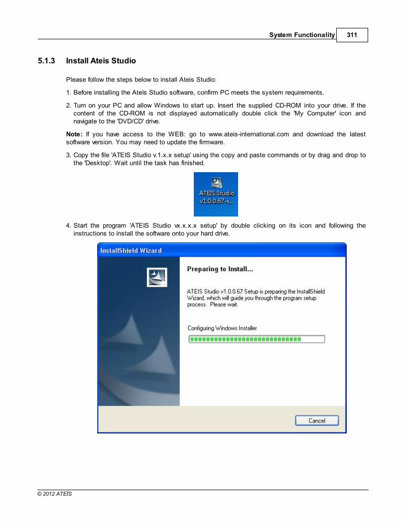
System Functionality 311
© 2012 ATEÏS
5.1.3 Install Ateis Studio
Please follow the steps below to install Ateis Studio:
1. Before installing the Ateïs Studio software, confirm PC meets the system requirements.
2. Turn on your PC and allow Windows to start up. Insert the supplied CD-ROM into your drive. If thecontent of the CD-ROM is not displayed automatically double click the 'My Computer' icon andnavigate to the 'DVD/CD' drive.
Note: If you have access to the WEB: go to www.ateis-international.com and download the latestsoftware version. You may need to update the firmware.
3. Copy the file 'ATEIS Studio v.1.x.x setup' using the copy and paste commands or by drag and drop tothe 'Desktop'. Wait until the task has finished.
4. Start the program 'ATEIS Studio vx.x.x.x setup' by double clicking on its icon and following theinstructions to install the software onto your hard drive.

ATEIS - IDA8312
© 2012 ATEÏS
Click [Next]
5. Type in a user name and your organization name if you want and click [Next]

System Functionality 313
© 2012 ATEÏS
6. By default the program software is installed under the path "C:\Program Files\ATEIS\ATEIS Studio vx.x.x.x". Change the installation path by clicking [Change...] if required, and click [Next].
7. As usual with the Installshield Wizard a window will appear showing all the information prior to theactual installation. You can enter corrections at this point by clicking [< Back]. If there are nochanges click [Next >] to execute the installation.

ATEIS - IDA8314
© 2012 ATEÏS
8. Wait until the end of the installation.
9. After all installation tasks have been finished successfully click [Finish] to exit the wizard.

System Functionality 315
© 2012 ATEÏS
10.The installation program creates a shortcut to the "ATEIS Studio v.1.x.x .exe" named "ATEIS Studiovx.x.x.x" on your "Desktop'"
Double click the icon to start the program.

ATEIS - IDA8316
© 2012 ATEÏS
5.1.4 Windows Layout
The basic windows layout should look like the figure showed above, however, the layout can be changedif you drag the dock panel(circle No.5 & 6 are examples of dock panel). Below are brief descriptions ofeach part of the area in the software which is labeled with orange circles in the above figure:
1. Title Bar:
Displays the path name of the current file.
2. Menu Bar:
Holds all the functionalities of the software (windows and tools), arranged by topic.
3. Tools Bar:
Short access to main functionalities that are hidden into the menu bar.
4. Tab Bar:
Shows the window title of all opened windows (design, components control windows) for quickaccess.
5. Dock Panel-Component Template:
A dock panel on the left side of software which contains all devices and DSP components you canuse to build up and design your system.
6. Dock Panel-Device Management:
A dock panel on bottom side of software lists information about devices and allows the user toconnect to a device for maintenance.

System Functionality 317
© 2012 ATEÏS
7. Status Bar:
Displays the status of software including the modification indication of editing file, mouse cursorposition, ... etc.
8. Working Area-DSP Components Editor
A graphical interface allowing the user to design the system, putting components which performspecific audio signal processing and wiring between components to make complete audio path frominput to output.
5.1.5 File
New :
Opens a new blank project.
Save :
Saves the current file you are currently working with.
Save As :
Opens the “Save as…” dialog box to save the current working project with a different name and/orpath.
Open :
Opens the “Open...” dialog box which allows you to select a path and open a saved file.
Recent Files:
Quick access to the last opened file.
Close :
Close the opened files.

ATEIS - IDA8318
© 2012 ATEÏS
5.1.6 Edit
Select All :
o Select all the components and wires.
Select
Select All DSP Components :
o Select all DSP components in the graphic editor.
Select All Connectors :
o Select all wires in the graphic editor.

System Functionality 319
© 2012 ATEÏS
5.1.7 View
Each item in the [View] menu can open a specific window to perform settings modification ormanagement of devices.
Main :
Opens the window of the Component Template which contains various type of devices and DSPcomponents for designing the system.
Compile :
Opens the compiler window and compiles the current configuration.
Resource :
Opens the window of Resource Manager to manage resource files in the software.
Object Tree :
Opens the window of Object Tree to see the whole structure of the configuration file.
Layers :
Opens the window of Layer Manager to manage the graphical layers for objects.
Bird's Eye :
Opens the window of Bird's Eye to have a overview of graphical objects.

ATEIS - IDA8320
© 2012 ATEÏS
Properties :
Opens the window of Properties which allows you to inspect various parameters of an object ingraphic editor.
PPM AS Manager :
Opens the window of PPM AS Manager to have a overview of all PPM AS in the configuration file.
Message Library :
Opens the window of Message Library to manage message files in the software.
3rd Party Control List :
Opens the window of 3rd Party Control List to have an overview of elements that are 3rd partycontrollable.
3rd Party Control Command :
Opens the window of 3rd Party Control Command that displays 3rd party control string of focusedelement.
Device Management :
Opens the window of Device Management that discovers the devices over network and maintenance.
Logo Library :
Opens the window of Log Library to manage Logos for Ateis devices.
User Management :
Opens the window of User Management for editing the users of configuration file.
5.1.8 Geometry
Zoom In :

System Functionality 321
© 2012 ATEÏS
Zoom in to the graphic editor.
Zoom Out :
Zoom out of the graphic editor.
Zoom Original :
Zoom to the original size of the graphic editor.
Room Ratio:
Sets the graphic editor to a specific ratio.
Ruler :
Shows or hides the ruler of the graphic editor.
Ruler Unit:
Specifies ruler unit of the graphic editor. There are three types of units:
o Inches
o Centimeters
o Pixels
Show Grid :
Shows or hides the grid of the graphic editor.
Snap to Grid :

ATEIS - IDA8322
© 2012 ATEÏS
Enables or disables moving an object by multiple pixels at a time.
Layer:
o Add Layer :
Adds a layer of the graphic editor.
o Remove Layer :
Removes a layer of the graphic editor.
o Lock Layer :
Locks a layer of the graphic editor to disable movement of any objects belonging in that layer.
o Hide Layer :
Hide a layer. All objects belonging in that layer will become invisible.
o Select Layer:
Selects a layer to be current. Any newly created object will belong to the current layer.
Bird's Eye :
Opens the window of Bird's Eye allowing you to see an overview of the graphic editor.

System Functionality 323
© 2012 ATEÏS
5.1.9 Component Editing
Position Operation
Position Operation Type
Some functions, as Alignment or Pack use a reference. Here you define what kind of referenceyou use which can be the place in the area (Normal), a component or a point.
For example when you use the "Align Left" function to align several components to the left, theleft will depend on the reference.
o Normal
In Normal mode, the reference is the place in the graphic editor.
If you select several components, and use the "Align Left" function, then the reference willbe the left side of the component at the left of the area. All the selected components will bealigned to this reference.

ATEIS - IDA8324
© 2012 ATEÏS
o Reference Component
In Reference Component mode, the reference is a component. If you select several
components, and use the "Align Left" function, the mouse cursor will change to , andwill ask you to select a component as a reference. Select a component by clicking it. The
mouse change to when it is placed on a component. All the selected components willbe aligned to this component.
In this example, we chose the AEC component as reference.
o Reference Point
In Reference Component mode, the reference is a point. If you select several components,and use the "Align Left" function, then the mouse cursor will change to a blue cross and willask you to choose exactly where the reference is located. All the selected components willbe aligned to this point.

System Functionality 325
© 2012 ATEÏS
Alignment
You can select several elements (by maintaining a left click and moving the mouse you will havea selection square) and then align all the elements. This function uses a reference whichdepends of the reference mode
Pack
You can select several elements (by maintaining a left click and moving the mouse you will havea selection square) and then pack the elements. This function uses a reference which dependson the reference mode.
Space

ATEIS - IDA8326
© 2012 ATEÏS
You can select several elements (by maintaining a left click and moving the mouse you will havea selection square) and then define the space between all the elements. It is helpful if you packthe elements first.
Z-Order
If you have elements which are under other elements, you can define each by selecting oneelement choosing if this will be to the front or to the back. Pay attention as sometimes elementscan be totally hidden with this action. For example, It is useful with background images andbuttons.
Size
These functions resize the components. You can select several components and adjust them tohave the same dimensions. All the selected components will have the size of the component onthe top left of the window.
Center

System Functionality 327
© 2012 ATEÏS
You can select several components (by maintaining a left click and moving the mouse you willhave a selection square) and then move the component to the window's middle, horizontally orvertically.
Grouping
Group
You can select several components (by maintaining a left click and moving the mouse you willhave a selection square) and then group the components in one component.
Ungroup
This function splits grouped components to a single component. It's the reverse of the Groupfunction.
Wiring Mode
Normal Line
Select Normal Line if you want to draw the wire with different angles.

ATEIS - IDA8328
© 2012 ATEÏS
Right Angle
Select Right Angle if you want to draw the wire only with right angles (90 degrees).
Auto Corner
Select Auto Corner if you want the wires to be automatically arranged to have proper corner,with separated wires and with right angles.
Signal Path Mode
Signal Path Disable
Disable the signal path highlighting function. When it's not disabled, the signal path functionallows seeing where an audio signal is sent through the design. The signal path is highlighted inred. To understand what this function is, please see the next chapters.
Signal Path Mouse Move
In this mode, by placing the mouse on a signal link, the signal link and the entire signal pathlinked will be highlighted in red.
In this example, input C1 is routed in the matrix to outputs 1 and 2. If you place the mouse onthe link of channel 1, then the signal path on outputs 1 and 2 will be displayed in red.

System Functionality 329
© 2012 ATEÏS
Signal Path Temporary
In this mode, by selecting a signal link, the signal link and the entire signal path linked will behighlighted in red. If you click in a free zone, the signal path is cancelled.
In this example, input C1 is routed in the matrix to the output 1 and 2. If you place and selectthe link of channel 1, then the signal path on outputs 1 and 2 will be displayed in red.
Signal Path Path Fixed
In this mode, by selecting a signal link, the signal link and the entire signal path linked will behighlighted in red. The signal path is fixed, to cancel it you have to click on another link orcomponent (not on a free zone).
In this example, input C1 is routed in the matrix to outputs 1 and 2. If you place and select thelink of channel 1, then the signal path on outputs 1 and 2 will be displayed in red.

ATEIS - IDA8330
© 2012 ATEÏS
Signal Path Lock
In this mode, by selecting a signal link, the signal link and the entire signal path linked will be
highlighted in red, then the mouse cursor will change into , asking you to select the linkagain, in order to lock it. The signal path is locked. To cancel it you have to select the mode
"Signal Path Disable ".
In this example, input C1 is routed in the matrix to outputs 1 and 2. If you place and select thelink of channel 1, then the signal path on outputs 1 and 2 will be displayed in red.

System Functionality 331
© 2012 ATEÏS
5.1.10 Tools
By changing the skin you can modify the global style (color and appearance) of the windows. You canchoose one of the skin in the list.
Here are examples of skins:
Office 2003 Blue

ATEIS - IDA8332
© 2012 ATEÏS
Mc Skin

System Functionality 333
© 2012 ATEÏS
London Liquid Sky

ATEIS - IDA8334
© 2012 ATEÏS
5.1.11 Operation
In this menu you will find the major operations related to system connection allowing you to compile theconfiguration design and then to store the compiled configuration into the device.
Most part of those windows have short access in the Tools bar. We are going to introduce you everyitems. To learn how to use these items please refer to the “create a project” and “how to” sections.
System Selector
The drop-down list of "System" allows the user to switch systems to the current one. All actions inthe tool bar only work on the current system. These actions include master preset changing, store,online/offline and audio enable/disable.

System Functionality 335
© 2012 ATEÏS
Master Preset Selector
The drop-down list of "Master Preset" allows the user to switch master presets.
Master Preset Settings
Opens the master preset settings window.
Sub-Preset Settings
Opens the sub-preset settings window.
Event
Opens event settings window.
Compile All
Starts the compile process. The software verifies that no major errors remain before uploading thedesign into Audio Processor.
Store All
Starts the compilation process and then uploads your design into the audio processor.
Save Parameters
Saves parameters to device's flash.
Online
Makes Ateis Studio online with the audio processors. Once online, the parameters will besynchronized including the adjustment of the parameters. When Ateis Studio is online with devices,designing configuration is not allowed.
Offline
In the offline state, you can modify the configuration file.
Audio Enable
Enables audio of Ateis devices.
Audio Disable
Disables audio of Ateis devices.
5.1.12 Window

ATEIS - IDA8336
© 2012 ATEÏS
In this topic you will find tools to re-arrange windows or find hidden opened windows.
Close
Close the opened active window.
Close All
Close all the opened windows.
UI Preset
The UI Presets are pre-defined windows positioning.
I'm Lost
By default the UI Preset "I'm Lost" is available, it allows coming back in the default standardwindows positioning.
Active Windows

System Functionality 337
© 2012 ATEÏS
In the bottom of the window menu, you will find all the opened windows of your project. By selectingof the windows in the list, the window will comes on the first displaying level.
5.1.13 Help
About:
Opens the About window.
Version:
Opens the Version window. This shows the compatible firmware version of the devices that AteisStudio supports.
5.1.14 Component Template
In the configuration file of Ateis Studio, you can create many objects to make up a system for theapplication. Each object works different jobs and you need to create it in the design window to make itwork. Component Template is a container for an object's icon that is ready to drag and drop down to thedesign windows for creating an object for configuration. The below figure shows how component templateworks with the design window:

ATEIS - IDA8338
© 2012 ATEÏS
On the left is a component template and on the right is the design window. There are three pages ofcomponent templates, You can click the icons on the bottom of the component templates to switchbetween them.
Devices Page
Lists devices which are ready for drag and drop to a device design window. Some of the objectscorrespond to physical devices and some are only symbols.
DSP Components Page
Lists DSP components which are ready for drag and drop to a DSP design window. Each of themcorresponds to a signal processing unit inside the device.
Extended Components Page
Lists symbolic components such as images and texts. All of these do not relate to physicalfunctions.
By clicking the menu [View > Main], you can open component template windows.

System Functionality 339
© 2012 ATEÏS
5.1.15 Resource Manager
Resource manager is a container for files which can be used in a device configuration. Sections listedbelow describe each part of the resource manager settings window:
Path for Resource Manager
Specify a path for searching resource files.
Browse the folder.
The ellipsis button is used to change a path.
Include file
When the path changes, this copies files from the original path to the new path.
Pages of Resource File
There are various types of files which can be managed by Ateis Studio, each one corresponds to apage in the resource manager. The files are listed below:
Update
Bitmap
Wave
G.722
AsZip
Customized Component
xml
Refresh
Search resource files in the folder specified in the resource manager path.
Add
Add a file.to the resource manager.

ATEIS - IDA8340
© 2012 ATEÏS
Delete
Remove selected files from the resource manager.
Export
Export selected files to a single resource packed file.
Import
Import files from a resource packed file.
By clicking the menu [View > Resource Manager], you can open the resource manager window.
5.1.16 Object Tree
Object tree displays the designing of objects by tree structure, making it easy to understand and accessobjects. By clicking the menu [View > Object Tree], you can open the object tree window.
5.1.17 Layers
Each design window can be separated into multiple layers. Every object in the design window belongs toa layer. By clicking menu [View > Layers], you can open the layers window.
On top of windows there is a grid to list all layers. The fields are described below:

System Functionality 341
© 2012 ATEÏS
Current
Indicates which layer is the current layer. The newly created objects will be put into the currentlayer.
Lock
Locks a selected layer. All objects belong to the locked layer cannot be edited.
Hide
Hides all objects belonging to a selected layer.
Name
The name of a layer.
Select
An ellipsis button is used to select objects of the layer.
There are four buttons on bottom of the window:
Add Layer
Adds a layer. The new layer becomes the current layer.
Remove Layer
Removes a selected layer and the components belonging to that layer.
Move up Layer
Moves up a selected layer a row.
Move down layer
Moves down a selected layer a row.
5.1.18 Bird's Eye
When the design area is huge, Bird's Eye gives an overview for the user to easily understand the layoutof the design. By clicking the menu [View > Bird's Eye], you can open the Bird's Eye window.

ATEIS - IDA8342
© 2012 ATEÏS
5.1.19 Properties
Properties window allows users to browse/edit settings of the selected objects in the design window. Byclicking menu [View > Properties], you can open the properties window.

System Functionality 343
© 2012 ATEÏS
5.1.20 Message Library
Message Library provides an easy interface to manage messages used in Ateis Studio. By clicking themenu [View > Message Library], you can open the message library window.
Path:
The working directory for message files.
Open:
Open a file browser to change the working directory.
Message File List:
A grid which lists all messages in the working directory and displays information about it.
Add:
To add a message into the working directory.
Delete
Remove a selected entry of the message list.
Close
Close Message Library window.

ATEIS - IDA8344
© 2012 ATEÏS
5.1.21 Logo Library
Logo Library is a settings windows for Logo Library management. By clicking the menu [View > LogoLibrary], you can open the Logo Library window.
At the left side of the window is the list of all Logo files.
At the right side of the window is a preview for the selected Logo file. Use button [Add] to add alogo file and use button [Delete] to remove the selected Logo file.
5.2 Presets
5.2.1 Overview
The Ateis systems includes two types of presets:
The Master preset (design preset) enables completely different designs to be restored.
The Sub-Preset (parameters preset) enables values of multiple parameters of the same design,such as levels, gains, EQ, etc. to be restored either from the PC software, the remote controllersor the control inputs.
These 'Master Presets' and 'Sub-Presets' reside in the devices memory and can be accessed in manyways: PC, Logic inputs, Third party. The maximum number of master presets and sub presets dependson machine memory size and content of each preset.

System Functionality 345
© 2012 ATEÏS
5.2.2 Master Presets
The Master Preset function allows switching between several designs on the same device. Each MasterPreset can contain different components, design paths, sub-presets, etc. The user can then switch thecomplete design simply by changing the Master Presets which is done by using the logic input contactor by third party.
Master Preset Management
This section describes how to create or remove master presets. In the tools bar, click on the ellipsisbutton next to the Master Preset combo box.
What the Presets window open, select the "Master-Presets" tab.

ATEIS - IDA8346
© 2012 ATEÏS
Master Preset Name
The name of the master preset.
Edit
By clicking the ellipsis cell in the grid you can open the DSP design window of the preset.
Sub-Preset
Open the settings window of sub-preset which belongs to the master preset.
Add
To create a new master preset.

System Functionality 347
© 2012 ATEÏS
Remove
To remove a selected master preset.
Master Preset Switching
There is only one master preset active at a time. When you're designing a system, change themaster to the preset you want to edit. At run time, change the master preset to make the Ateisdevice working on a different DSP design belong to the master preset.
Click the combo box of the Master Preset to switch master presets:
5.2.3 Sub-Presets
The Sub-Preset function allows the storing of values of different component elements (volume gain,frequency, mute, etc.) in one Sub-Preset. By loading a Sub-Preset, all of the elements associated willtake the predefined values. The Sub-Presets are different in each Master Preset and in each System(Device).
The idea is to create a Sub-Preset, define which element of which component you want to associatewith the Sub-Preset, then to the elements to their target values, and then to memorize that in the Sub-Preset.
Sub-Preset Management
At the tool bar in the main window, click on the ellipsis button next to the [Master Preset] combobox.
When the Presets window opens, select the "Sub-Presets" tab.

ATEIS - IDA8348
© 2012 ATEÏS
Master Preset Combo Box
By clicking this combo box, you can switch to the desired master preset and then edit the sub-preset settings belonging to it.
Sub-Preset
Name of the sub-preset.
Linked Elements
Open the window containing the table of elements controlled by the sub-preset. See the latersection "Table of linked elements" for more detail.
Save
Save a value of linked elements to the sub-preset. Those values are kept in the memory in thesub-preset.
Load
Load values from the storage of the sub-preset and set to linked elements.
Add
Add a sub-preset.
Remove
Remove a sub-preset.
Assign an element to be controlled by sub-presets
Right click on the element of the component you want to control, and select your sub-preset.

System Functionality 349
© 2012 ATEÏS
Table of linked elements
This table lists all elements controlled by the sub-preset. On the right there is a small panel with anembedded graphic control for adjusting the stored value in the sub-preset. Each field is described insections below.
Device
Indicates the device containing the linked element.
Component
Indicates the component containing the linked element.
Parameter
The element could be controlled by the sub-preset.
Value
Value stored in the sub-preset.
Link
To open the window containing the linked element.
Save
To save current value of elements to the sub-preset.
Load
To load value stored in the sub-preset and set to linked elements.

ATEIS - IDA8350
© 2012 ATEÏS
5.3 Event Management
5.3.1 Event Manager
There are various types of events for controlling Ateis devices. For example, to adjust the value ofelements or change presets, each event is able to link with a controller, The following lists are sourcesable to link events:
Event Trigger component
Event Value Control component
PPM AS
PSS AS
Terra Controller
Front Panel on some Ateis devices, like IDA8C
Event manager is a container to store and manage all events There is one event manager for eachmaster preset.
Open the Event manager by clicking on the tools bar:
The settings window is shown below:
Name:
The name of an event.
Type:
The type of an event. Different types of events execute different tasks when triggered.
States Count:
Some of the events are triggered with a state number. For example, to control an element likemute, you need to set State Count to 2, since mute has two states: On and Off. States count isthe number of states.
Content:
Opens the settings window belonging to the event.
Add:

System Functionality 351
© 2012 ATEÏS
Adds an event to the event manager, Some event cannot be created in this window, such as apaging event. In this case, you will need to create it in the settings windows of the NetworkPaging component.
Remove:
Removes a selected event.
5.3.2 Value Trigger Event
Description
This event is used to control the element value. It sets a value of an element by the state andtriggers the event. A value triggering an event can be linked to more than one element for controlling.
Event Creation
Click the button [Add] to create a new event. A second window will open prompting you to choosewhich kind of event is desired. Select the item [Value Trigger] on the Type combo box. Next, pressthe [OK] button.
Event Settings
After creating a value trigger event, you will need to assign an element to it. Then the assignedelement will be controllable by the event. To set up an assignment, right click on the desiredelement, click the popup menu by the sequence: [Event > Value Trigger > XXX] where XXX is the

ATEIS - IDA8352
© 2012 ATEÏS
name of the event. The following figure is an example:
Next, a window which displays brief information of the relationship between state and value:
Click the [Content] field of the event manager window to open the settings window of the event:

System Functionality 353
© 2012 ATEÏS
State Pages:
There is a page for each state in the value trigger event. To switch states, click the tab of thedesired state.
Element:
Indicates which element of the component controlled by value trigger.
Component:
Indicates which component of the device contains the previously mentioned element .
Device:
Indicates which device contains the previously mentioned component.
System:
Indicates which system contains the previously mentioned device.
Value:
Specifies the value that binds with the state. When a Value Trigger Event triggers, the sourcethat triggers the event sends a state number to the event system. Events map this state numberto a value and then sets it to the element.
Remove:
Removes the element controlled by the event.
This operation only removes the relation between the element and event and does not deletethe element.
Clear:
Removes all elements controlled by the event.
Close:
Closes the settings window.
5.3.3 Value Control Event
Description
This event is used to control the element value. It sets a value of the element by a source thattriggers the event. A value control event can link more than one element for controlling.
Event Creation

ATEIS - IDA8354
© 2012 ATEÏS
Click the [Add] button to create a new event. A second window will open prompting you to choosewhich kind of event is desired. Select the item [Value Control] on the Type combo box. Next, pressthe [OK] button.
Event Settings
After creating a value control event, you will need to assign an element to it. Then the assignedelement will be controllable by the event. To set up an assignment, right click on the desiredelement, click the popup menu by the sequence: [Event > Value Control > XXX] where XXX is thename of the event. The following figure is an example.
Click the [Content] field of the event manager window to open the settings window of the event:

System Functionality 355
© 2012 ATEÏS
On the right side of window, there is a knob to simulate the source that triggers the event. If youadjust the knob, the value of elements also changed.
Control Type:
This option determines the type of knob simulation. There are two options of Control Type:
o Value:
Knob adjust value of elements using native value.
o Percent:
Knob adjust value of elements by percentage.
Element:
Indicates which element of the component is controlled by the value trigger.
Component:
Indicates which component of the device contains the previously mentioned element.
Device:
Indicates which device contains the previously mentioned component.
System:
Indicates which system contains the previously mentioned device.
Min:
Specifies the minimum value of the simulating knob.
Max:
Specifies the maximum value of the simulating knob.
Remove:
Removes the element controlled by the event.
This operation only removes the relation between the element and event and does not deletethe element.
Clear:
Removes all elements controlled by the event.

ATEIS - IDA8356
© 2012 ATEÏS
Close:
Closes the settings window.
5.3.4 Step Trigger Event
Description:
This event is used to control the element value. It adjusts the value of the element by step when thesource triggers the event. There are multiple states in an step trigger event. Each state contains astep value.
Event Creation:
Click the [Add] button to create a new event, a second window prompts you to choose which kind ofevent is desired. Select the item [Step Trigger] on the Type combo box. Then, press the [OK]button.
Event Settings
After creating a value control event, you will need to assign an element to it. Then the assignedelement will be controllable by the event. To set up an assignment, right click on the desiredelement, click the popup menu by the sequence: [Event > Step Trigger > XXX] where XXX is thename of the event. The following figure is an example.

System Functionality 357
© 2012 ATEÏS
Next, a window shows the brief information. Select the check box at the row "All":
Click the [Content] field of the event manager window to open the settings window of the event:

ATEIS - IDA8358
© 2012 ATEÏS
State Pages
There is a page for each state in the step trigger event. To switch states, click the tab of thedesired state.
Element
Indicates which element of the component is controlled by the value trigger.
Component
Indicates which component of the device contains the previously mentioned element.
Device
Indicates which device contains the previously mentioned component.
System
Indicates which system contains the previously mentioned device.
Step Value
Specifies the step value of the state.
Modify
Enables or disables the selected element controlled by the state of event.
Remove
Removes the element controlled by the event.
This operation only removes the relation between the element and event and does not deletethe element.
5.3.5 Step Control Event
Description
This event is used to control the element value. It adjusts the value of the element by step when thesource triggers the event. The source which triggers the event sends the step value to the event foradjusting elements.
Event Creation

System Functionality 359
© 2012 ATEÏS
Click the [Add] button to create a new event. A second window opens prompting you to choosewhich kind of event is desired. Select the item [Step Control] on the Type combo box. Next, pressthe [OK] button.
Event Settings
After creating a value control event, you will need to assign an element to it. Then, the assignedelement will be controllable by the event. To set up an assignment, right click on the desiredelement, click the popup menu by the sequence: [Event > Step Control > XXX] where XXX is thename of event. The following figure is an example.
Click the [Content] field of the event manager window to open the settings window of the event:

ATEIS - IDA8360
© 2012 ATEÏS
Element:
Indicates which element of the component is controlled by the value trigger.
Component:
Indicates which component of the device contains the previously mentioned element.
Device:
Indicates which device contains the previously mentioned component.
System:
Indicates which system contains the previously mentioned device.
Remove:
Removes the element controlled by the event.
This operation only remove the relation between element and event and does not delete theelement.
5.3.6 Master Preset Change Change
Description
This event is used to change the master preset of Ateis devices. Each state can be linked to amaster preset. When a source triggers a master preset change event, it sends a state number tothe event, then changes to the master preset linked to the state.
Event Creation

System Functionality 361
© 2012 ATEÏS
Click the [Add] button to create a new event, a second window opens prompting you to choosewhich kind of event is desired. Select the item [Master Preset Change] on the Type combo box.Then, press the [OK] button.
Event Settings
Click the [Content] field of the event manager window to open the settings window of the event:
No
Indicates the state No.
Master Preset
Specifies which master preset links to the state.
Open
Opens the settings window of the master preset.
5.3.7 Sub-Preset Change Event
Description:
This event is used to change the sub-preset of Ateis devices. Each state can be linked to a sub-preset. When a source triggers a sub-preset change event, it sends a state number to the eventthen changes to the sub-preset linked to the state.
Event Creation:

ATEIS - IDA8362
© 2012 ATEÏS
Click the [Add] button to create a new event, a second window opens prompting you to choosewhich kind of event is desired. Select the item [Sub Preset Change] on the Type combo box. Next,press the [OK] button.
Event Settings:
Click the [Content] field of the event manager window to open the settings window of the event:
No:
Indicates state No.
Sub Preset:
Specifies which sub-preset link to the state.
Open:
Opens the settings window of the sub preset.
5.3.8 Integration Paging Event
This event is used to select zones of the Networking Paging component with multiple combinationsbefore paging. See the topic Network Paging for more details.
5.3.9 Singular Paging Event
This event is used to select zones of the Networking Paging component with single combinations beforepaging. See the topic Network Paging for more details.
557
557

System Functionality 363
© 2012 ATEÏS
5.4 Device Management
Device Management window helps the user to search Ateis devices in the network. You can modify thesettings by using the command on the window. Select the [Device Management] tab or open it throughthe menu [View > Device Management].
The Device Management window consists of four parts:
Device Information:
Lists the information of the device, including the following fields:
Devices:
Discovered devices are listed in a tree structure.
Type:
The type of the device.
Ateis Net:
Display Ateis Net ID by (X, Y) format, where X is the global net ID and Y is the local net ID.
Serial Number:
Serial Number of the device. Each Ateis device has a unique serial number.
Address:
Shows the IP address of the device.
Redundancy Addr:
The redundancy address of the device.
Device Status:
Show the status of devices. If there is a fault in the audio processor, this field shows "Fault".

ATEIS - IDA8364
© 2012 ATEÏS
Name:
The object of the design window that corresponds to the device. After the relation of the objectand device is created, the configuration of the object will set to the device after executing the"store" procedure.
Communication:
Shows the communication state of Ateis Studio and the device.
Device Function:
Lists all available functions of the device which will be told in each topic later.
Settings Tab:
Switches to a different tab for desired settings:
Device:
Searches and lists Ateis devices in the local area network.
Network:
Network interface card settings for communicating with Ateis devices.
RS232:
RS232 interface settings for communicating with Ateis devices.
Search Devices:
Search:
Attempts to discover the Ateis devices on the network.
Clear:
Clears the current search results and empties the grid.
Search Timeout Interval:
Determines the length of time the device will reply to the search command.
Search by IP:
If you already know the IP address of a device, you can search for it by that address.
5.4.1 Search and Settings
Search and connect to a device for further editing:
1. Before searching the Ateis devices in the LAN, the device information area is empty as shown inthe picture below.
2. Click the [Search] button under the Devices tab, the device list will appear after few seconds.

System Functionality 365
© 2012 ATEÏS
3. Select the desired device and click the "Connect" at the device function area and the connectionstarts to process. A list appears after connecting. See the picture below:
4. The red rectangle at the left shows which device has been connected and the other at the rightshows the items the user can perform such as updating a firmware, Reversing and etc.
5.4.2 Read Version
To know which version is loaded in the device and which version is available with the current Ateïs Studiosoftware:
1. Open the Device Management Window.
2. Search and Connect to the device. For step by step guide, see "Device Management > Searchand Connect ".
3. Click [Read Version] to open the Version window.
364

ATEIS - IDA8366
© 2012 ATEÏS
Click the [Read] button to get the version data from the device.
Firmware Unit:
The firmware program unit in the device.
Compatible Version:
Displays the version required by the installed software.
Current Version:
Displays the firmware version of the device.
If the version numbers in the Current Version field are marked in red which means the Firmwareneeds to be updated, please see the next chapter to perform a update.
5.4.3 Update Firmware
The purpose of updating the firmware is to match the version contained in your Ateïs Studio software andthe version contained in the hardware of your devices.
Read the version to see if there are mismatching versions. If so, update both the Ateïs Studio softwareand the audio processor firmware. To do this, follow the steps below:
1. Open the Device Management Window.

System Functionality 367
© 2012 ATEÏS
2. Search and Connect to the device which needs updating. For step by step guide, see "DeviceManagement > Search and Connect ".
3. Click [Update] to open the update window.
4. Select the desired device in the list, then click on [OK].
5. With the file browser open, search the ASU (Ateïs Studio Update) files on your PC. Next, click [Open]to start the update process.
364

ATEIS - IDA8368
© 2012 ATEÏS
The progress bar in the Update window displays the status of the update:
6. When the update is completed, a pop-up window will appear asking if you want to reboot the device,click [Yes].

System Functionality 369
© 2012 ATEÏS
7. Now your device is updated. Since the device is rebooted, it is currently unconnected. Select it andclick [Connect] again.
8. It is recommended that the firmware version be checked confirming that it is now displayed in blackwhich means the device is now ready for use.

ATEIS - IDA8370
© 2012 ATEÏS
5.4.4 Ateis Net Deploying
This function allows the user to configure the networking state of devices on Ateis Net. Connecting thephysical units together through the Ateis Net port and the identification must be assigned to each devicewhen they are set up for the first time. To do this, you need to perform the "config IP" function byfollowing the steps listed below:
1. Connecting the Ethernet to the first unit and obey the wiring rules that the Ateis Net Port is B to Aand A to B connection.
2. Open the Device Management Window.
3. Search and Connect to the device. For step by step guide, see "Device Management > Search andConnect ".
4. Select the device which will be the master unit and click [ATEIS NET Deploying] to execute theprocedure. A Machine Configuration window appears showing "Start configure IP".
364

System Functionality 371
© 2012 ATEÏS
5. The LED of Audio Processor indicates while deploying. The Data LED blinks for a while and turns tocontinuous lighting on the front panel.
6. The Machine Configuration window shows "Configure IP success"
7. Once the Deploying is done, click "Search" again. Another devices connected to the master unit willappear in the list. For example, in the picture below shows 4 LAP G2T units which are labeled afterdeploying successfully, the master unit is the (1 ,1) here and each device is assigned with anindividual IP.

ATEIS - IDA8372
© 2012 ATEÏS
5.4.5 Remote Plug-in
This function is used to register remotes to an audio processor. When the remote is for first time used,you need to perform the "Remote Plug-in" function to make the audio processor to recognize it. Followthe steps listed below:
1. Open the Device Management Window.
2. Search and Connect to the device. For step by step guide, see "Device Management > Search andConnect ".
3. Click [Remote Plug-in] to open the setting window.
ID:
364

System Functionality 373
© 2012 ATEÏS
The internal identification for each remote device.
Remote Type:
Specifies which type of remote device belong to the ID.
SN:
Inputs the serial number of the remote device which can be found on the attached sticker.
Version:
The firmware version of the remote device.
RS485 Channel:
A drop-down list located on the left bottom is used to switch RS485 channel settings.
Option of Only PSS AS:
Specifies the channel connected only with PSS AS. When it's enabled, no other remote devicesare allowed to connect to this channel.
Refresh:
Reads and refreshes the data from the audio processor.
Plug-In:
Sets the editing data to the audio processor.
4. All the remote units have been performed "plugged-in" before shipping. Click the [Refresh] button andthe device will appear in the list.

ATEIS - IDA8374
© 2012 ATEÏS
5. If you have many remotes to be plugged-in, you need to manually key in the SN for Ateis Studio toassigned the IDs.
Select the Remote Type of the remote device you are using with the selected RS485 channel.
Input SN (Serial Number) of the remote device, you can find it out on the sticker on the device.
Press the [Plug-In] button which will write the settings to the audio processor to register remotedevices.

System Functionality 375
© 2012 ATEÏS
5.4.6 Reverse
This function allows the user to reverse designs from audio processors.
1. Open the Device Management Window.
2. Search and Connect to the device. For step by step guide, see "Device Management > Search andConnect ".
3. Before perform the "Reverse", the user needs to make sure the firmware version fits, please perform"Read Version" and "Update" before revert a design.
4. Click [Reverse] to execute a reverse procedure.
5. The reverse will take a few seconds and a pop-up window appears asking the user to save the file if adesign has already existed because Ateis Studio only edit one file a time.
6. Click Yes/No and the design will be loaded completely in few seconds. Now the user can edit the
364

ATEIS - IDA8376
© 2012 ATEÏS
design.
5.4.7 Machine File System
This function allows you to manage the audio files stored in the devices.
1. Open the Device Management Window.
2. Search and Connect to the device. For step by step guide, see "Device Management > Search andConnect ".
3. Click [Machine File System] to open the setting window.
The formats of audio files supported by the IDA8 are "16K, 16bits", "24k, 16bits" and "48k, 16bits" inWAV format.
The IDA8C can save about 200MB of audio sources, and the IDA8S can save about 100MB of audiosources. Note: Please make sure the software's version is correct as it will affect the file location.
364

System Functionality 377
© 2012 ATEÏS
The left grid lists the files under the specific folder in your PC, and the right grid is for the device.
All: Select or deselect all.
Save: Stores the files into the device.
Space: Shows the storage space of the device.
Status: Shows the process is in progress, successful or has failed.
Click [...] at the upper left to open the [Resource Manager] window. See the picture below.
Refresh: Refreshs the list.
Add/Delete: Adds or deletes files. This will delete the files under the Resource folder in your PCas well.
Export: Exports the selected files into a .aszip file.

ATEIS - IDA8378
© 2012 ATEÏS
Import: Imports an Ateis Studio .zip file. Ateis Studio will automatically recognize the format andput the files under the correct folder.
There are two ways to adding files
1. Place the files under the path "C:\\Program Files\ATEIS\ATEIS STUDIO v 1.0.0.XX\resource\wave" and click [Refresh].
2. Press "Add" to open the [FileSelectDialogFm] window, find the files, than click "Add". AteisStudio will copy those files you select into its folder.
Select the source and save to the device's folders, then click ( ) to refresh. See the picture below.
Now you can Add a message player component and use the files in the device to play messages.
5.4.8 Remote Update
This function allows you to update the firmware of the remote devices connected with the AudioProcessor.
1. Open the Device Management Window.
2. Search and Connect to the device. For step by step guide, see "Device Management > Search andConnect ".
3. Once your remote device has been plugged-in, you can click the remote to open the [Remote Update]window.
364

System Functionality 379
© 2012 ATEÏS
4. You can also click the [Remote Update] to open the setting window and open the drop-down list toselect the remote type and click the [OK] button.
5. The "Comm Remote Update" window appears and lists the device you have.
Basically, the files will automatically read by Ateis Studio if they're placed under the right directory.

ATEIS - IDA8380
© 2012 ATEÏS
If not, click the [...] to browse the files for updating as shown in the picture below:
In case of adding files from other directory, click "Add" to browse the files.
6. The available files will be listed at the left part of the window, select the desired file and click the[Update] button.
7. The Updating procedure will take a few minutes and once it's done, the Updated status shows"Succeed"

System Functionality 381
© 2012 ATEÏS
5.4.9 Chime Data Store
This function allows you to store the chime into the remote devices connected with the Audio Processor.
1. Open the Device Management Window.
2. Search and Connect to the device. For step by step guide, see "Device Management > Search andConnect ".
3. Once your remote device has been plugged-in, you can click the remote to open the [Chime DataStore] window.
4. You can also click the [Chime Data Store] to open the setting window.
5. The "Chime Data Store" window appears and lists the device you have.
364

ATEIS - IDA8382
© 2012 ATEÏS
Basically, the files will automatically read by Ateis Studio if they're placed under the right directory.If not, click the [...] to browse the files for updating as shown in the picture below:
In case of adding files from other directory, click "Add" to browse the files.
The file name must be shorter than 8 letters and the sample rate required 16k (Hz).
6. The available files will be listed at the upper-left part of the window, select the desired file and click the
" " button to load files into the Remote Device.

System Functionality 383
© 2012 ATEÏS
7. The Updating procedure will take a few minutes and once it's done, the Updated status shows"Succeed"
5.4.10 Log
This function allows the user to read the log of the Audio Processor.
1. Open the Device Management Window.
2. Search and Connect to the device. For step by step guide, see "Device Management > Search andConnect ".
3. Click [Log] to open the log window.
364
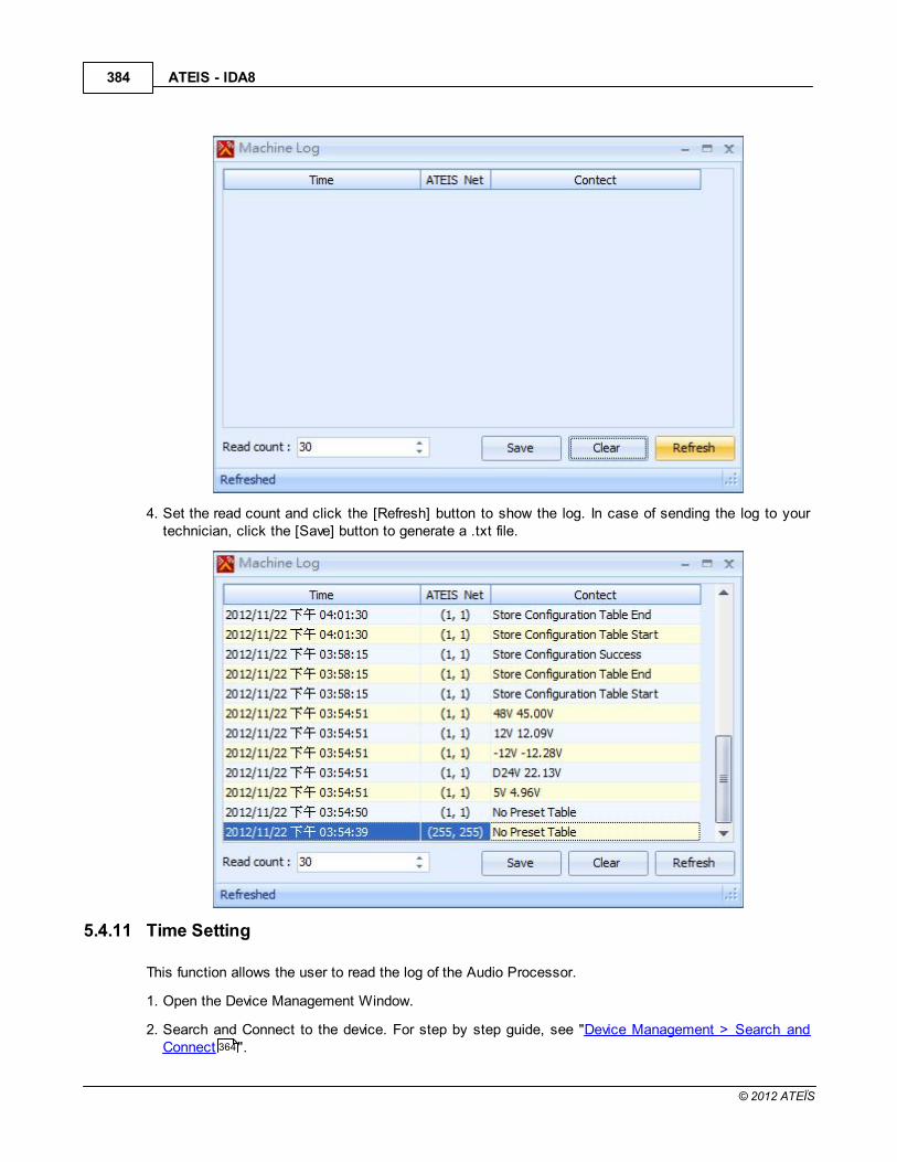
ATEIS - IDA8384
© 2012 ATEÏS
4. Set the read count and click the [Refresh] button to show the log. In case of sending the log to yourtechnician, click the [Save] button to generate a .txt file.
5.4.11 Time Setting
This function allows the user to read the log of the Audio Processor.
1. Open the Device Management Window.
2. Search and Connect to the device. For step by step guide, see "Device Management > Search andConnect ".364

System Functionality 385
© 2012 ATEÏS
3. Click [Log] to open the log window.
4. Here you can read the Time set in the device and manually adjust the time by clicking the [Read] and[Write] button. The adjustment is required in period for the component which is associated with thetime such as the scheduler. You can use the NTP server to sync the clocks on your LAN.

ATEIS - IDA8386
© 2012 ATEÏS
5. In case of using the daylight saving time, switch to the Daylight Saving tab to set.
5.4.12 VR Calibration
This function is for adjusting the RAC or the Analog inputs.
1. Open the Device Management Window.

System Functionality 387
© 2012 ATEÏS
2. Search and Connect to the device. For step by step guide, see "Device Management > Search andConnect ".
3. Click VR Calibration] to open the VR Calibration window.
4. Select the channel where the device is connected to and click the Minimum and the Maximum buttonto calibrate.
5.4.13 URC Logo Store
This function allows the user to customize the OLED displaying of URC AS.
1. Open the Device Management Window.
2. Search and Connect to the device. For step by step guide, see "Device Management > Search andConnect ".
3. Click [URC Logo Store] to open the URC Logo Store View window.
364
364

ATEIS - IDA8388
© 2012 ATEÏS
4. Follow the steps 1-4 to perform the store. You can store two images into many URC AS units a time.Once it's done the status shows "Succeed" as shown in the last picture.

System Functionality 389
© 2012 ATEÏS
5.4.14 Fault E-mail Setting
This function allows the user to receive fault reports from the IDA8 by the E-mail in the set period.
1. Open the Device Management Window.
2. Search and Connect to the device. For step by step guide, see "Device Management > Search andConnect ".
3. Click [Fault E-Mail Setting] to open the Fault E-mail Setting window.
364

ATEIS - IDA8390
© 2012 ATEÏS

System Functionality 391
© 2012 ATEÏS
Server IP: Enter the Mail Server.
Server Port:SMTP port of the Mail Server. The default value is 25.
Sender: The sender's name, the default is "[email protected]".
Authentication: Enable to set the Username and Password for avoiding receiving the spam.
Report By Time: Here you can set 5 different time a day at which the device will send the report.
Receiver: The mail can be received by multi-users, click to add more receivers.

ATEIS - IDA8392
© 2012 ATEÏS
Check the checkbox of the faults you want to receive.
4. Once the E-mail setting is done, the mail sent by the device contains two parts, one is the fault listand the other is the list of the devices which haven't reported faults. See the picture below.

System Functionality 393
© 2012 ATEÏS
5.4.15 Modbus
This function allows the user to set the Modbus message priorities and schedule Interval.
1. Open the Device Management Window.
2. Search and Connect to the device. For step by step guide, see "Device Management > Search andConnect ".
3. Click [Modbus] to open the Modbus Message Priority Setting window.
364
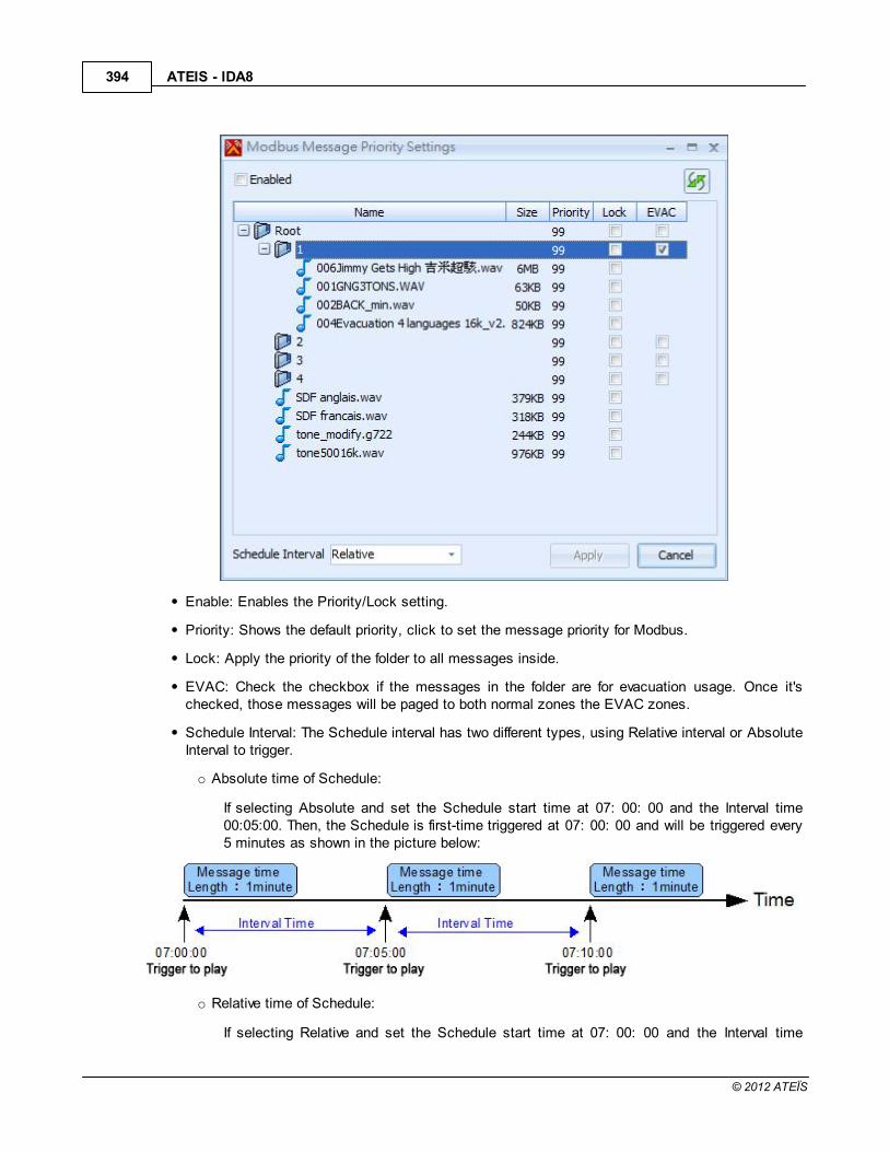
ATEIS - IDA8394
© 2012 ATEÏS
Enable: Enables the Priority/Lock setting.
Priority: Shows the default priority, click to set the message priority for Modbus.
Lock: Apply the priority of the folder to all messages inside.
EVAC: Check the checkbox if the messages in the folder are for evacuation usage. Once it'schecked, those messages will be paged to both normal zones the EVAC zones.
Schedule Interval: The Schedule interval has two different types, using Relative interval or AbsoluteInterval to trigger.
o Absolute time of Schedule:
If selecting Absolute and set the Schedule start time at 07: 00: 00 and the Interval time00:05:00. Then, the Schedule is first-time triggered at 07: 00: 00 and will be triggered every5 minutes as shown in the picture below:
o Relative time of Schedule:
If selecting Relative and set the Schedule start time at 07: 00: 00 and the Interval time
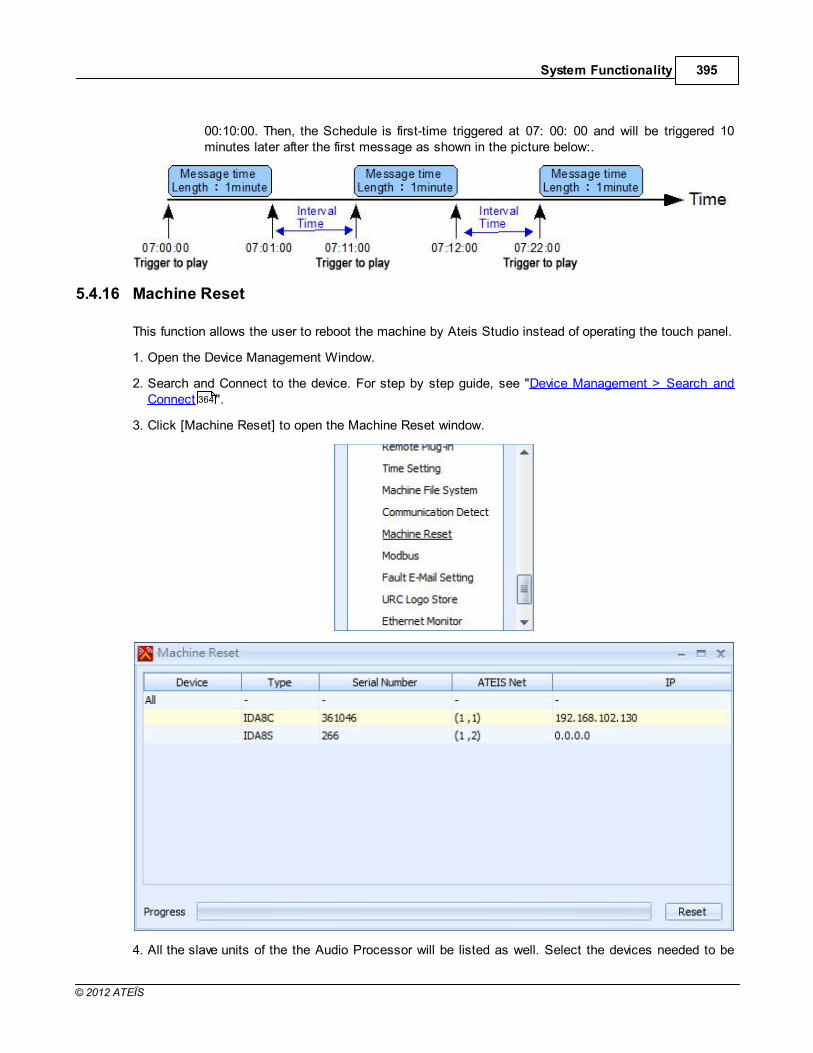
System Functionality 395
© 2012 ATEÏS
00:10:00. Then, the Schedule is first-time triggered at 07: 00: 00 and will be triggered 10minutes later after the first message as shown in the picture below:.
5.4.16 Machine Reset
This function allows the user to reboot the machine by Ateis Studio instead of operating the touch panel.
1. Open the Device Management Window.
2. Search and Connect to the device. For step by step guide, see "Device Management > Search andConnect ".
3. Click [Machine Reset] to open the Machine Reset window.
4. All the slave units of the the Audio Processor will be listed as well. Select the devices needed to be
364

ATEIS - IDA8396
© 2012 ATEÏS
rebooted and click [Reset] to reboot them.
5.4.17 Redundancy
This function allows the user to set the Redundancy system used for IDA8.
1. Open the Device Management Window.
2. Search and Connect to the device. For step by step guide, see "Device Management > Search andConnect ".
3. Click [Redundancy] to open the Redundancy Configuration window.
Redundancy System: Choose the Network the desired secondary system is in, the Device Listwill change with this item.
364

System Functionality 397
© 2012 ATEÏS
Evac Input Control Channel: The channel which is connected to the Redundancy Units.
Device List: Shows how many units in the secondary system and their Serial Numbers.
4. Once the setting is done, press the "Configure" button and you can see the Redundancy informationshows at the Device Information column as shown in the picture below. The two system becomingeach other's backup System.
5.4.18 Ethernet Monitor
This function allows the user to monitor the ethernet status.
1. Open the Device Management Window.
2. Search and Connect to the device. For step by step guide, see "Device Management > Search andConnect ".
3. Click [Ethernet Monitor] to open the Ethernet Monitor window.
4. Once enable the Ethernet Monitor, the fault message will show in the log list when the communicationis broken.
364

ATEIS - IDA8398
© 2012 ATEÏS
5.4.19 TelePhone Card Setting
This function allows the user to monitor the ethernet status.
1. Open the Device Management Window.
2. Search and Connect to the device. For step by step guide, see "Device Management > Search andConnect ".
3. Click [Ethernet Monitor] to open the Ethernet Monitor window.
Country Code: Select the Country/Area.
FSK: Here you can choose the standard for transmitting caller ID.
Password Enable: Check the checkbox to enable the password. Once it's checked, the callerneeds to enter the password for paging access.
5.5 3rd Party Control
5.5.1 Ateis 3rd Party Control
5.5.1.1 Overview
An Ateis device supplies a flexible way for controlling the parameters inside of the device. Depending onthe device, Ateis 3rd party protocol allows an external device to control an Ateis device through Ethernetor RS232.
5.5.1.2 Assign Elements to 3rd Party Control
To make an element controllable by 3rd party protocol, you need to specify that it is able to becontrolled by 3rd party devices. To activate this setting, right click the element and click on menu [3rdParty Control > Single]
364
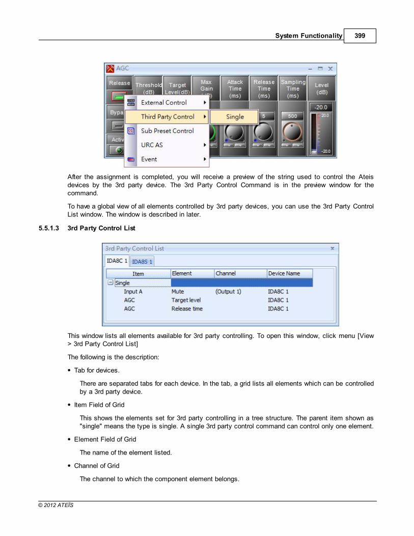
System Functionality 399
© 2012 ATEÏS
After the assignment is completed, you will receive a preview of the string used to control the Ateisdevices by the 3rd party device. The 3rd Party Control Command is in the preview window for thecommand.
To have a global view of all elements controlled by 3rd party devices, you can use the 3rd Party ControlList window. The window is described in later.
5.5.1.3 3rd Party Control List
This window lists all elements available for 3rd party controlling. To open this window, click menu [View> 3rd Party Control List]
The following is the description:
Tab for devices.
There are separated tabs for each device. In the tab, a grid lists all elements which can be controlledby a 3rd party device.
Item Field of Grid
This shows the elements set for 3rd party controlling in a tree structure. The parent item shown as"single" means the type is single. A single 3rd party control command can control only one element.
Element Field of Grid
The name of the element listed.
Channel of Grid
The channel to which the component element belongs.

ATEIS - IDA8400
© 2012 ATEÏS
Device Name of Grid
Lists the element containing the component.
5.5.1.4 3rd Party Control Command
This window shows a preview of the element that is assigned for 3rd party control. In the left part, a gridshows information of the command string for a 3rd party device to the control element. The right part is avisual object which allows the user to change its value and see the command string.
Control:
Indicates the row of command string which is for single control or multiple control.
Type:
Shows the command string which is for reading or writing parameters of Ateis devices.
Command:
There are several sub-fields in this field, STX, CP, ..., CR. Each is part of the complete commandstring.
Command Data:
The content of a command string, represented by hexadecimal.
5.6 User Management
5.6.1 Overview
User management is a critical part of maintaining a secure system. Ineffective user and privilegemanagement often leads many systems becoming compromised. Therefore, it is important that youunderstand how you can protect your device through simple and effective user account managementtechniques. Ateis Studio provides a flexible user management mechanism to ensure the security foraccessing system resources.
By clicking the menu [View > User Management], you can open the User Manager Settings window:

System Functionality 401
© 2012 ATEÏS
There are two pages in the window:
User Levels
A user level is a combination of user privileges where in a privilege is the right for executing somespecific action. There are four default user levels used by most applications which need authorityrequirement.
User Account
It allows you to create or remove users for controlling the system. For each user, you can set theuser level by choosing default or creating a new level for customized privilege combination.
On left bottom, there is a check box [Active] to enable or disable user management for the configurationfile.
5.6.2 User Levels
A user level is a combination of user privileges where in a privilege is the right for executing somespecific action. There are four default user levels used by most applications which need authorityrequirement. Click the [Level] tab to edit user levels:

ATEIS - IDA8402
© 2012 ATEÏS
On top of window, there is a grid list all user levels including four defaults. Each column represents anaction authority. Following are descriptions for each authority.
File:
Allows the opening configuration files.
User Manager:
Allows the editing of user accounts and user levels.
System(-):
Selects all authorities inside the system.
System(Connect):
Allows the right to connect to Ateis devices.
System(Store):
Allows the right to store the configuration to Ateis devices.
System(Reverse):
Allows the right to reverse configurations to Ateis Studio from devices.
System(Update):
Allows the right to update the firmware of Ateis devices.
System(Para. R/W):
Allows the right to read or write parameters in Ateis devices.
System(Online):
Allows the right to go online with Ateis devices.
Master Preset(-):
Used to select all authorities in the master preset.
Master Preset(View):
Allows the right to view the master preset configuration.
Master Preset(Edit):
Allows the right to view the editing settings belonging to master presets.
Master Preset(Control):
Allows the right to switch master presets.
On the right bottom of window, there are two buttons:
Create:
Used to create a new user level, and enable desired authorities.
Delete:
Used to remove selected user level. Please note that Administrator, Power User and User are

System Functionality 403
© 2012 ATEÏS
not allowed to remove.
5.6.3 User Accounts
Ateis devices allow the creation of multiple users for controlling a system. For each user you can specifydifferent access rights by giving a user level. By clicking the page [Accounts], you can create or removeusers.
There is a grid to list all users. The following are descriptions of each field:
User
The name of user.
Level
The level in which the user belongs.
Link
A ellipsis button to switch the page to [Levels] and focus on the level in which that user belongs.
Three buttons on the right bottom of window:
Create
Create a new user.
Delete
Remove a selected user.
Edit
Change password of a selected user.

ATEIS - IDA8404
© 2012 ATEÏS
6 Components of Audio Processor
6.1 AEC
6.1.1 Parameters
This component is used to avoid reflected signals caused by acoustic echo between microphones andspeakers, in remote conference applications.
The control window of the "AEC" module
is opened by double clicking on the icon in the DESIGN AREA and will appear like this:

Components of Audio Processor 405
© 2012 ATEÏS
AEC Parameters
Parameter Range Comment
Echo Detect led This led is lit when an echo is detected.
Signal led This led is lit when an audio signal is detected.
ERLE (dB) Echo Return Loss Enhancement.The reduction of echo indicating the quality of the AEC.
AEC Coefficient Selector:Perform,
Bypass, Hold
Function supplied for AEC controlled status which offers 3functions:
Perform: Turns on the AEC functionBypass: Turns off the AEC function
Hold: Holds the parameters of the echo coefficient

ATEIS - IDA8406
© 2012 ATEÏS
Parameter Range Comment
Reset Button Resets the echo cancellation on the channel
Far-EndVolume
Vu-meter(dB)
Audio volume of the far-end audio signal.
Near-EndVolume (dB)
Vu-meter (dB)
Audio volume of the near-end audio signal.
Near-End Level -90 to 20 (dB) Volume adjustment of the near-end audio signal
NLP Selector: Soft, Medium,Aggressive, Off
NonLinear Process.The purpose is to suppress the remaining echo
in a complex environment. It offers four functions:Off: NLP function off
Soft: weak intensity of remain echo suppression.Medium: medium intensity of remaining echo suppression.
Aggressive: aggressive intensity of remaining echosuppression.
NLP Threshold(dB)
-90 to 20 (dB) The threshold value of the Nonlinear Process.
NoiseReduction
Enable
Button Enable the noise gate
NR Threshold -90 to 20 (dB) Threshold of the noise gate
6.1.2 Functions
The AEC component provides four fully independent channels.
On the component, each channel has one input called "far-in", and one output, and one reference called"far-end". In order to send a proper signal to the other room, the far-end signal will be removed from thefar-in signal,

Components of Audio Processor 407
© 2012 ATEÏS
AEC Coefficient / Reset
On each channel you can independently activate the echo cancellation process by setting the "AECCoefficient" parameter on "Perform". It can also work without the process activating by maintainingthe AEC coefficient by choosing "Hold". Of course, you can deactivate it by choosing "Off".
The reset button is used to reset the AEC coefficient.
Volume display and control
The far-end volume and near-end volume vu-meters display the far-end and near-end volume levels

ATEIS - IDA8408
© 2012 ATEÏS
respectively.
If you want to modify the volume of a source (near-end inputs) use the "Near-End Level" knobs in theAEC component. When the system is properly adjusted, do not change the volume by using anotherparameter other than this one.
Non Linear Process (NLP)
The microphone captures the sound coming from the loudspeaker and also the speaker's voice.
If on the microphone capsule the sound pressure level of the loudspeaker sound is near to the soundpressure level of the speaker's voice, then the AEC component won't be able to recognize them. Inthis case the AEC process is stopped and the non-linear process is activated.
Choose the type of non-linear process, soft, medium, aggressive or off.
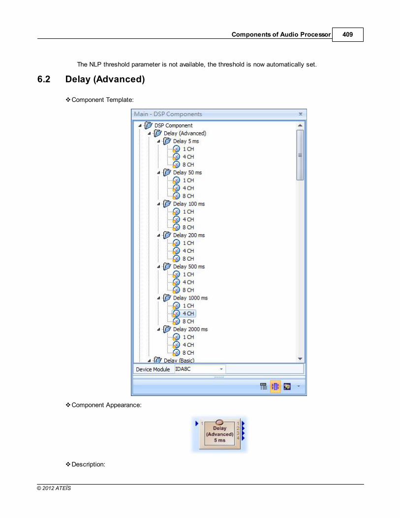
Components of Audio Processor 409
© 2012 ATEÏS
The NLP threshold parameter is not available, the threshold is now automatically set.
6.2 Delay (Advanced)
Component Template:
Component Appearance:
Description:

ATEIS - IDA8410
© 2012 ATEÏS
Delays the audio signal input to the component. The delayed component records the audio into ainternal buffer and then plays back the stored audio based on parameters set by the user. There aretwo ways to adjust the delay time for a channel. The first is by adjusting the element Delay time, thesecond is by adjusting the Element Temp and Distance to compute the delay time. Element Typecan be switched between two modes.
Control Window:
Element Properties:
Name Initial Minimum Maximum Precision Unit
Type On - - - -
Mute all Off - - - -
Bypass all Off - - - -
Mute Off - - - -
Bypass Off - - - -
Delay time 0 0 *1 *2 µs
Temp 20 -10 50 0.1 °C
Distance 0 0 *3 0.01 m
*1: The maximum value of Delay time in various type of Delay (Advanced).
Type Maximum
5ms 5000 µs
50ms 50000 µs
100ms 100000 µs
200ms 200000 µs
500ms 500000 µs
1000ms 1000000 µs
2000ms 2000000 µs
*2: The precision value of Delay time in various type of Delay (Advanced).

Components of Audio Processor 411
© 2012 ATEÏS
Type Maximum
5ms 5 µs50ms 20 µs100ms 20 µs200ms 20 µs500ms 20 µs
1000ms 20 µs2000ms 20 µs
*3: The maximum value of Distance depends on the type of Delay (Advanced)
Type Maximum
5ms 1.62 m
50ms 16.25 m
100ms 32.5 m
200ms 65 m
500ms 162.5 m
1000ms 325 m
2000ms 650 m
Element Description:
Type:
Chooses between adjusting with Time or with Distance and temperature.
Mute all:
Mutes all channels.
Bypass all:
Bypasses the audio signal of all channels. Note: This Disables the delay function.
Mute:
Mutes the channel. The output of a channel is muted if the button is on or the "Mute all" buttonis on.
Bypass
Bypasses the audio signal of the channel.
Delay time
Specifies how much time will be delayed for the audio signal of a channel.
Temp
Specifies the temperature to compute the delay time for a channel.
Distance
Specifies the Distance to compute the delay time for a channel.
Note: If a channel is muted and bypasses at the same time, the audio signal of the channel will bemuted.
Application:
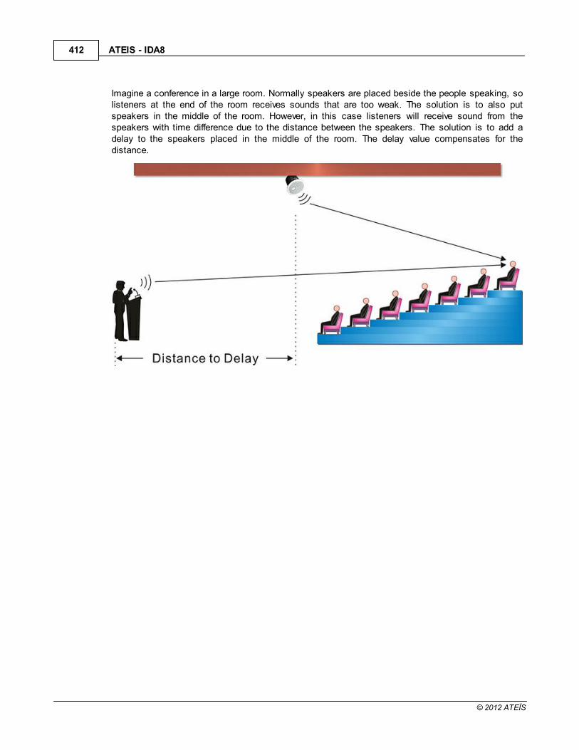
ATEIS - IDA8412
© 2012 ATEÏS
Imagine a conference in a large room. Normally speakers are placed beside the people speaking, solisteners at the end of the room receives sounds that are too weak. The solution is to also putspeakers in the middle of the room. However, in this case listeners will receive sound from thespeakers with time difference due to the distance between the speakers. The solution is to add adelay to the speakers placed in the middle of the room. The delay value compensates for thedistance.

Components of Audio Processor 413
© 2012 ATEÏS
6.3 Delay (Basic)
Component Template:
Component Appearance:
Description:
Delays the audio signal input to the component. This component is a compact version of Delay

ATEIS - IDA8414
© 2012 ATEÏS
(Advanced) that is not allowed to mute or bypass the signal of the input. There are two ways toadjust the delay time for a channel. The first is by adjusting element Delay time, the second is byadjusting the Element Temp and Distance to compute the delay time. Element Type can beswitched between two modes.
Control Window:
Element Properties:
Name Initial Minimum Maximum Precision Unit
Type On - - - -
Delay time 0 0 *1 *2 µs
Temp 20 -10 50 0.1 °C
Distance 0 0 *3 0.01 m
*1: The maximum value of Delay time in various type of Delay (Basic).
Type Maximum
5ms 5000 µs
50ms 50000 µs
100ms 100000 µs
200ms 200000 µs
500ms 500000 µs
1000ms 1000000 µs
2000ms 2000000 µs
*2: The precision value of Delay time in various type of Delay (Basic).
Type Maximum
5ms 5 µs50ms 20 µs100ms 20 µs200ms 20 µs500ms 20 µs

Components of Audio Processor 415
© 2012 ATEÏS
Type Maximum
1000ms 20 µs2000ms 20 µs
*3: The maximum value of Distance depends on the type of Delay (Basic)
Type Maximum
5ms 1.62 m
50ms 16.25 m
100ms 32.5 m
200ms 65 m
500ms 162.5 m
1000ms 325 m
2000ms 650 m
Element Description:
Type:
Chooses between adjusting with Time or with Distance and temperature.
Delay time:
Specifies how much time will be delayed for the audio signal of a channel.
Temp:
Specifies the temperate to compute the delay time for a channel.
Distance:
Specifies the Distance to compute the delay time for a channel.
Note: If a channel is muted and bypassed at the same time, the audio signal of the channel will bemuted.
Application:
Refer to Delay (Advanced) .411

ATEIS - IDA8416
© 2012 ATEÏS
6.4 Dynamic
6.4.1 AGC\AGC Stereo
Component Template:
Component Appearance:
Description:
With this Automatic Gain Control(AGC), the input signal can be increased or decreased to a targetlevel. For example, without AGC the sound emitted from an AM radio receiver would vary to theextreme extent from a weak signal to a strong one. The AGC effectively reduces the volume if thesignal is strong or raises the volume when it's weak.
You can adjust the gain of the source automatically by setting a target level. There are two types ofAGC, one is the signal channel and the second is stereo.
Control Window:

Components of Audio Processor 417
© 2012 ATEÏS
The control window of AGC Stereo is the same as the AGC's.
Element Properties:
Name Initial Minimum Maximum Precision Unit
Release On - - - -
Bypass Off - - - -
Active Off - - - -
Threshold -40.0 -60.0 0 0.1 dB
Target Level -20.0 -35.0 10 0.1 dB
Max Gain 10.0 0.0 18 0.1 dB
Attack Time 5 1 1K 1 ms
Release Time 5 1 1K 1 ms
Sampling Time 500 1 1K 1 ms
Level -20.0 -20.0 20 0.1 dB
The element properties of AGC Stereo is the same as the AGC's.
Element Description:
Release:
If the release button is on, the release time will be the Element Release Time. Otherwise, therelease time will be 10 ms.
Bypass:
Disables the AGC Function (i.e. Bypasses the audio signal from input to output).
Active:
Flashes when the gain is controlled (AGC is active).
Threshold:
Sets the threshold level above then the gain will be controlled.
Don't set the level too low otherwise it will hear unexpected sounds such as breathingsounds or ambient noise.
Target Level:
Determines which relative volume you want to target.
Max Gain:

ATEIS - IDA8418
© 2012 ATEÏS
Determines the maximum of automatic gain.
Limit the max gain to keep a natural audio dynamic.
Attack Time:
Adjusts the fade-in time to reach the target level.
A time that is too short will be uncomfortably heard with the audio peak when the speakerbegins to talk.
Release Time:
Adjusts the fade-out time of the signal when AGC is no longer working. This value is ignored ifthe “Release button” is off.
A time that is too short will be uncomfortably heard with audio slack between the speaker'swords.
Sampling Time:
Average time needed by measuring the input level.
A time that is too long will make the AGC too insensitive on short peaks.
Level:
Level of the gain that AGC increased or decreased the input signal.
Example:
For example, we want to automatically adjust the gain of a type of vocal microphone.
On the "Input A" component, the input sensitivity is set to -40dB for standard dynamic microphone.

Components of Audio Processor 419
© 2012 ATEÏS
Threshold: Set at -25dB. The level is adjusted only when the input signal is above -25dB. This is tokeep a natural dynamic.
Target level: We want a final target level at -10dB.
Maximum gain: Set at 10dB. Giving more gain will generate some uncomfortable level differences.
Release time: Set at 800(ms), enough time to avoid hard transition when the speaker talks again,after a little break.
Attack time: Set at 50(ms), enough time to avoid hard transition when the speaker begin to talks,and not too long as we want a stable level quickly (not since the middle of the sentence).
AVG time: Set at 200(ms), not too long, to detect short peaks in the speech and to beresponsive. Not too short to avoid level change too often.
You can see on the vu-meter that when the speaker talks at -18.3 dBu, the final level is around -10.5dBu:
You can see on the vu-meter that when the speaker talks at 8 dBu, the final level is around -10.6dBu:
This benefits both the presenter and audience. More comfortable hearing and speaking in largergroups.

ATEIS - IDA8420
© 2012 ATEÏS
6.4.2 Auto Noise Gain (A.N.G)
Component Template:
Component Appearance:
S.M.: Sensing Microphone input.
P.M.: Program Material input.
Description:
This component adjusts the audio levels of the Program Material (P.M.) depending on the ambientnoise. The ambient noise is measured with a sensing microphone connected to the sensingmicrophone input (S.M.). Our advice is to use the noise sensing microphone NSM (Ateïs) which canbe programmed in Ateis Studio as well.
Control Window:

Components of Audio Processor 421
© 2012 ATEÏS
Element Properties:
Name Initial Minimum Maximum Precision Unit
Min Gain -6.0 -15.0 0 0.1 dBMax Gain 6.0 0 15.0 0.1 dB
Sampling Time 50 50 60000 50 10msWhite Noise
Level-40.0 -40.0 0 0.1 dB
Noise Threshold -100.0 -100.0 20.0 0.1 dBAGC Level -15.0 -15.0 15.0 0.1 dBCalibration Off - - - -CalibrationProceeding
Off - - - -
CalibrationFinish
Off - - - -
Over Off - - - -Under Off - - - -
ResponseSpeed
Low - - - -
Paging Activity Off - - - -Decrease Zone Off - - - -
Dead Zone Off - - - -Increase Zone Off - - - -Fast Increase
ZoneOff - - - -
Sensing MicLevel
-100.0 -100 200 0.1 Hz-dB
C/Sensing MicLevel
-100.0 -100 200 0.1 dB
Output Level -100.0 -100 200 0.1 dBDifferential Level -100.0 -100 200 0.1 dB

ATEIS - IDA8422
© 2012 ATEÏS
Item list of Response Speed:
No. Name
1 Low
2 Medium
3 High
Element Description:
Min Gain:
The minimum level compensation.
Max Gain:
The maximum level compensation.
Sampling Time:
Determines the period of time between two ambient noise measurements. The less the value themore sensitivity. This means the compensation gain of paging input responds quicker toenvironment noise.
White Noise Level:
White noise is used for calibration. The level is automatically adjusted in the calibration process.
Noise Threshold:
The level of background noise measured when the calibration button is pressed.
AGC Level:
Displays the current compensation gain.
Calibration:
Starts the automatic calibration process.
Calibration Proceeding:
The red LED lights up if the calibration process is proceeding.
Calibration Finish:
The Green LED lights up if the calibration process is successful.
Over:
Indicates the calibration result:
The white noise level is over the range. A pop-up window will show what to do.
Under:
Indicates the calibration result:
The white noise level is under the range. A pop-up window will show what to do.
Response Speed:
Selects the reaction speed of the A.N.G.

Components of Audio Processor 423
© 2012 ATEÏS
It means the speed of adapting the P.M. audio level depends on the ambient noise.
Paging Activity:
Lights up when the paging is active.
Decrease Zone:
Indicates that the AGC gain is decreasing.
Dead Zone:
Indicates that the AGC is not changing.
Increase Zone:
Indicates that the AGC gain is increasing.
Fast Increase Zone:
Indicates that the AGC gain is increasing fast.
Sensing Mic Level:
Shows the input level of the sensing microphone.
C/Sensing Mic Level:
Shows the input level of the sensing microphone through the internal calibration transferfunction.
Output Level:
Shows the output level.
Differential Level:
Difference between the Output level and the C/Sensing Mic level.
Process to set the A.N.G.:
1. Connect the sensing microphone to the S.M. input, and the paging audio source to the P.M.input. The NSM sensing microphone needs an input sensitivity of 0dB (software). The max cablelength between the NSM and the audio processor is 500 meter (152 ft) with CAT-5 cable.
2. Link the output of the ANG component to an Output component where it is connected to aloudspeaker.
3. Click on the Calibrate button to start the calibration process. The system will start to estimate theacoustic transfer function between loudspeakers and microphone when the user clicks theCalibration button. It will automatically stop calibrating when the system finds a better transferfunction.
4. The calibration red LED lights up when the calibration process is running. During the process,don't move the physical installation, and don't make punctual noise. The calibration must be donein normal ambient conditions.
5. Wait until the calibration is finished. The red calibration LED light will turn off and the greencalibration LED will light up as shown in the picture below:

ATEIS - IDA8424
© 2012 ATEÏS
6. Now look at the Over/Under red LED:
If both Over/Under LEDs are OFF, it means the calibration has properly finished and the A.N.G. is ready.
If one of the Over/Under LEDs still lights up, it means the white noise level needed is out ofrange.
7. Depending on the issue, a pop-up window will show you what to do. Follow the most useful adviceand restart the calibration process until the both Over/Under LED are OFF after the calibration.
8. The system is properly set.
Even when the paging is not active, the A.N.G. is still adjusting the AGC level with the ambientnoise to be ready for paging.
Notice:
The calibration should be done in normal ambient noise. There should be no sudden loudnoise during the calibration.

Components of Audio Processor 425
© 2012 ATEÏS
Do not adjust the gain of output, amplifier or sensing microphone during or after thecalibration. You can adjust the volume of the audio source connected to the P.M. input.
Theoretically, when the calibration has finished, the AGC level will be stable around 0 dB in anenvironment of no increasing noise. However, every calibration might have a deviation. If theAGC level is not stable around 0dB, the user could adjust the gain of the output function,amplifier or sensing microphone to let the AGC level stable around 0 dB.
When the system is calibrating, clicking on the calibration button will cancel the calibration.Note: The system will use the calibration result which was last successfully calibrated.
After the calibration is successful, the paging microphone shouldn't be placed near thesensing microphone because the user's voice will also be received by the sensingmicrophone.
The AGC level is still calculating even in the inactivate mode. The level depends onbackground noise and will support a good initial gain for paging level.
Use the A.N.G.:
When the calibration green LED is lit, the system is ready. For example, the A.N.G. has detectedan ambient noise average of -12dB. We choose a medium "response speed" and a short "samplingtime" in order to adequately react quickly.
Now the A.N.G. will automatically adjust the level on the P.M. signal depending on the ambientnoise detected from the sensing microphone. The A.N.G. works when an audio signal is detected onthe P.M. input and the paging activity LED will light up.
Dead Zone:
If the sensing microphone doesn't detect more noise than during calibration, the A.N.G. works in the"Dead Zone" which means there is no need to adjust the gain. See the picture below:

ATEIS - IDA8426
© 2012 ATEÏS
As the noise level is nearer than during the calibration, the differential level is almost null. You cansee the AGC level is about 0 dB which means no compensation.
Increase Zone:
If the sensing microphone detects more noise than during calibration, the A.N.G. works in the"Increase Zone" which means that the gain must be increased to compensate for the ambient noise.See the picture below:
In this case, the noise is now louder than during calibration. The Differential level is around 4.4dB.You can see the AGC level shows 3.5dB which means the P.M. signal is increased to 3.5dB. Assoon as the AGC level reaches the level needed to compensate for the ambient noise (or the MaxGain), the A.N.G. will turn to the "Dead Zone".
Fast Increase Zone:

Components of Audio Processor 427
© 2012 ATEÏS
If the sensing microphone detects more noise than during the calibration, the A.N.G. works in the"Fast Increase Zone" which means that the gain must be quickly increased to compensate for theloud ambient noise. See the picture below:
6.4.3 Compressor\Compressor Stereo
Component Template:

ATEIS - IDA8428
© 2012 ATEÏS
Component Appearance:
Description:
A Compressor is an automatic volume control. Loud sounds over a certain threshold are reduced inlevel while quiet sounds remain untreated. In this way it reduces the dynamic range of an audiosignal. This may be done for aesthetic reasons to deal with the technical limitations of audioequipment or to improve the audibility of audio in noisy environments.
Compression reduces the level of the loud sounds, but not the quiet sounds. The level can be raisedto a point where the quiet sounds are more audible without the loud sounds being too loud.
Compressor Stereo is the same as the the Compressor component, but this works on both stereochannels. The detection is done by way of the both input signals. The same compression is appliedon the both output signals.
Control Window:
Element Properties:
Name Initial Minimum Maximum Precision Unit
Bypass Off - - - -
Soft Knee On - - - -
Compress Off - - - -
Ratio 2.0 1.1 20.0 0.1 -
Threshold 0.0 -60.0 20.0 0.1 dB
Threshold Range 10.3 0 40.0 0.1 dB
Attack Time 10 1 100 1 ms
Release Time 500 100 5000 1 ms
Gain Reduction -25.0 -25.0 0 0.1 dB
Element Description:
Bypass:
Bypasses the compressor's function.
Soft Knee:

Components of Audio Processor 429
© 2012 ATEÏS
Enables/disables the “Soft Knee” mode. This element controls whether the bend in the responsecurve is a sharp angle or has a rounded edge. A soft knee slowly increases the compressionratio as the level increases and eventually reaches the compression ratio set by the user. A softknee reduces the audible change from uncompressed to compressed, especially for higherratios where the changeover is more noticeable.
Compress:
Indicates compression.
Ratio:
Sets compression ratio.
Threshold:
Sets the threshold level above which compression begins.
Threshold Range:
Sets the range of level, in which the ratio gradually alters from 1:1 to the value set by the ratioparameter (soft knee function).
Attack Time:
Sets the time it takes to respond to the input signal. A compressor might provide a degree ofcontrol over how quickly it acts. The 'attack phase' is the period when the compressor isdecreasing gain to reach the level that is determined by the ratio.

ATEIS - IDA8430
© 2012 ATEÏS
Release Time:
Sets the time it takes to release the gain reduction. The 'release phase' is the period when thecompressor is increasing gain to the level determined by the ratio or to zero dB, once the levelhas fallen below the threshold.
Gain Reduction:
Reflects the current amount of gain reduction.
Graphical Control Window
Axis
o X: Input signal level(dB)

Components of Audio Processor 431
© 2012 ATEÏS
o Y: Output signal level(dB)
Control Points
o Blue: Adjusts Threshold.
o Red: Adjusts Threshold Range.
o Yellow: Adjusts Ratio
Application
Engineers wishing to achieve dynamic range reduction with few obvious effects might choose arelatively low threshold and low compression ratio so that the source material is being compressedvery slightly most of the time. To deliberately soften the attack of a snare drum, they might choose afast attack time and a moderately fast release time combined with a higher threshold. To accentuatethe attack of the snare, they might choose a slower attack time to avoid affecting the initialtransient.
6.4.4 Comp-limiter
Component Template
Component Appearance
Description

ATEIS - IDA8432
© 2012 ATEÏS
Comp-limiter is a combination of the Compressor and the Limiter Components.
Control Window
Element Properties
Name Initial Minimum Maximum Precision Unit
Bypass Off - - - -
Soft Knee On - - - -
Limiting (Limiter) Off - - - -
Hard Clipping (Limiter) Off - - - -
Threshold (Limiter) 0 0 20.0 0.1 dB
Release Time (Limiter) 500 100 5000 1 ms
Compress (Compressor) Off - - - -
Ratio (Compressor) 2.0 1.0 20.0 0.1 -
Threshold (Compressor) -10.0 -60.0 0 0.1 dB
Release Time (Compressor) 500 100 5000 1 ms
Attack Time (Compressor) 10 1 100 1 ms
Gain Reduction 0 -25.0 0 0.1 ms
Element Description
Bypass:
Bypasses the Comp-limiter's function.
Soft Knee:
Enables/disables the “Soft Knee” mode.
Limiting(Limiter):
Indicates limiting.

Components of Audio Processor 433
© 2012 ATEÏS
Hard Clipping(Limiter):
Enables/disables the “Hard clipping” mode.
Threshold(Limiter):
Sets the threshold level above which limiting begins.
Release Time(Limiter):
Sets the time it takes to release gain reduction.
Compress(Compressor):
Indicates compression.
Ratio(Compressor):
Sets compression ratio.
Threshold(Compressor):
Sets the threshold level above which compression begins.
Release Time(Compressor):
Sets the time it takes to release gain reduction.
Attack Time(Compressor):
Sets the time it takes to respond to the input signal.
Gain Reduction:
Reflects the current amount of gain reduction.
Graphical Control Window

ATEIS - IDA8434
© 2012 ATEÏS
Axis
o X: Input signal level (dB)
o Y: Output signal level (dB)
Control Points
o Blue: Adjusts Threshold(Compressor).
o Red: Adjusts Threshold(Limiter).
6.4.5 DNM
Component Template:
Component Appearance:
Description:
DNM component is basically the same as the A.N.G. component but it uses the DNM microphoneas the S.M input of A.N.G.
Control Window:

Components of Audio Processor 435
© 2012 ATEÏS
Element Properties:
Name Initial Minimum Maximum Precision Unit
Min Gain -6.0 -15.0 0 0.1 dBMax Gain 6.0 0 15.0 0.1 dB
Sampling Time 50 50 60000 50 10msTarget Level 10.0 15.0 15.0 0.1 dBWhite Noise
Level-40.0 -40.0 0 0.1 dB
Noise Threshold -100.0 -100.0 20.0 0.1 dBAGC Level -15.0 -15.0 15.0 0.1 dBCalibration Off - - - -CalibrationProceeding
Off - - - -
CalibrationFinish
Off - - - -
Over Off - - - -Under Off - - - -
AR Time 8000 500 10000 10 msPaging Activity Off - - - -Decrease Zone Off - - - -
Dead Zone Off - - - -Increase Zone Off - - - -Fast Increase
ZoneOff - - - -
Sensing MicLevel
-100.0 -100 200 0.1 Hz-dB
C/Sensing MicLevel
-100.0 -100 200 0.1 dB
Output Level -100.0 -100 200 0.1 dBDifferential Level -100.0 -100 200 0.1 dB

ATEIS - IDA8436
© 2012 ATEÏS
Element Description:
Min Gain:
The minimum AGC level compensation.
Max Gain:
The maximum AGC level compensation.
Sampling Time:
Determines the period of time between two ambient noise measures. The less the value themore sensitivity which means the compensation gain of paging input responds more quickly toenvironment noise.
Target Level:
Determines which relative volume you want to target.
White Noise Level:
The white noise level which is automatically adjusted by the calibration.
Noise Threshold:
The level of background noise measured when the calibration button pressed.
AGC Level:
Displays the current compensation gain.
Calibration:
Click on to start the automatic calibration process.
Calibration Proceeding:
Lights up along the calibration process.
Calibration Finish:
Green LED, light up if the calibration process is success.
Over:
Indicates the calibration result. The white noise level needed is over the range. A pop-up windowwill show you what to do.
Under:
Indicates the calibration result. The white noise level needed is under the range.A pop-upwindow will show you what to do.
AR Time:
The attack and release time.
Paging Activity:
Lights up when the paging is active while the P.M. is above the mode threshold.
Decrease Zone:

Components of Audio Processor 437
© 2012 ATEÏS
Indicates that the AGC gain is decreasing.
Dead Zone:
Indicates that the AGC is not changing.
Increase Zone:
Indicates that the AGC gain is increasing.
Fast Increase Zone:
Indicates that the AGC gain is increasing quickly.
Sensing Mic Level:
Shows the input level of the sensing microphone.
C/Sensing Mic Level:
Shows the input level of the sensing microphone through the internal calibration transferfunction.
Output Level:
Shows the output level.
Differential Level:
Difference between the Output level and the C/Sensing Mic level.

ATEIS - IDA8438
© 2012 ATEÏS
6.4.6 Ducker\Ducker Stereo
Component Template
Component Appearance:
Description:
The Ducker is a type of "sophisticated switch" which allows you to attenuate or switch off the signalarriving in input A automatically when the chosen level (in dB) is perceived in input S.
Control Window:
Element Properties:

Components of Audio Processor 439
© 2012 ATEÏS
Name Initial Minimum Maximum Precision Unit
Bypass Off - - - -Active Off - - - -Thd. -20.0 -80.0 35.0 0.1 dB
Response Time 100 10 5000 10 msAttack Time 50 10 1000 10 msHold Time 2000 10 5000 10 ms
Release Time 50 10 1000 10 msAudio Depth -50 -100 0 0.1 dBSpeech Gain 0 -60.0 20.0 0.1 dB
Element Description
Bypass:
Switches off the Ducker's operations.
Active:
Lights up when the Ducker is active while the signal has been detected on input S.
Thd.:
Threshold of detection on the input channel (S). The input channel (A) is attenuate when theinput channel (S) goes above this threshold.
To avoid the unexpected attenuation, don't set a threshold level that is too low.
Response Time:
Adjust the time between the S level's detection and the beginning of the Ducker’s operation onthe A signal.
Don't set a "response time" that is too long otherwise you won't hear the beginning of the(S) signal (as the first word of a speech).
Attack Time:
Adjusts the fade-in time of the (A) signal when the Ducker is working.
Hold Time
Adjusts the time between the end (S) level's detection and the end of the Ducker’s operation.
Set enough "Hold time" to avoid the unexpected background level during the speechesbreaks.
Release Time:
Adjusts the fade-out time of the (A) signal when the Ducker is no longer working.
Audio Depth:
Adjusts the (A) level when the Ducker is active.
Speech Gain:
Adjusts the (S) level when the Ducker is active.
Use the Ducker Component:

ATEIS - IDA8440
© 2012 ATEÏS
For example, we set a system for a speech with background music playing and the speechmaker isusing a standard dynamic microphone type SM58. When the speechmaker is talking, thebackground music must decrease its level.
The component set is shown in the picture below. The microphone is connected to channel 2 of the"Input A" component with sensitivity set as -40dB. The microphone is linked to the input (S) of theDucker.
The music player (as a CD player) is connected to channel 1 of the "Input A" component then themusic source is linked to the input (A) of the Ducker.
Elements:
Threshold:
Set as -18dB, because less would activate the attenuation causing the microphone to catchsome unexpected noise even when the speaker is not talking.
Response Time:
Set very short, because the background music must be attenuated as soon as the speaker istalking.
Attack and Release Times:
The "fade-in" and "fade-out" on the background music. Set about 1 second for hearing comfort.
Hold Time:
Set as 700(ms) which is enough to avoid the music increasing during the speech breaks.
Audio Depth:
Set as -20dB for constantly hearing the music during the speech but in a very low level(depending on the context).

Components of Audio Processor 441
© 2012 ATEÏS
6.4.7 Expander\Expander Stereo
Component Template:
Component Appearance:
Description:
An expander works in an opposite fashion than the compressor. The threshold is set and any part ofthe signal dropping below this threshold will be affected by the expander and this level will be raised.The expander therefore is like the compressor which balances out the signal to make it sound moreprofessional. The expander is able to have a signal with a bigger dynamic range.
Control Window:

ATEIS - IDA8442
© 2012 ATEÏS
Element Properties:
Name Initial Minimum Maximum Precision Unit
Bypass Off - - - -
Soft Knee On - - - -
Expand Off - - - -
Ratio 2.0 1.0 20.0 0.1 x;1
Threshold 0 -60.0 20.0 0.1 dB
ThresholdRange
20.0 0 40.0 0.1 dB
Attack Time 10 1 100 1 ms
Release Time 500 100 5000 1 ms
Gain Reduction -25.0 -25.0 0 0.1 dB
Element Description:
Bypass:
Bypasses the expander's function.
Soft Knee:
Enables/disables the “Soft Knee” mode.
Expand:
Indicates that the function is active.
Ratio:
Sets the expansion ratio.
Threshold:
Sets the threshold level above which expansion begins.
Threshold Range:
Sets the range of level, in which the ratio gradually alters from 1:1 to the value set by the ratioparameter (Soft Knee function).
Attack Time:
Sets the time it takes to respond to the input signal.

Components of Audio Processor 443
© 2012 ATEÏS
Release Time:
Adjusts the time to stop the gain reduction.
Gain Reduction:
Reflects the current amount of gain reduction.
Graphical Control Window:
Axis:
o X: Input signal level(dB)
o Y: Output signal level(dB)
Control Points:
o Red: Adjusts Ratio.
o Yellow: Adjusts Threshold Range.
o Blue: Adjusts Threshold.

ATEIS - IDA8444
© 2012 ATEÏS
6.4.8 Gate
6.4.8.1 Gate - Mono
Component Template
Component Appearance:
Description:
The Gate allows you to cut off the signal below the chosen threshold.

Components of Audio Processor 445
© 2012 ATEÏS
Control Window:
Element Properties:
Name Initial Minimum Maximum Precision Unit
Mute Off - - - -
Bypass Off - - - -
Gate On Off - - - -
Thd. -20.0 -90.0 35.0 0.1 dB
Response Time 2 2 5000 1 ms
Attack Time 5 1 1000 1 ms
Hold Time 1500 1 5000 1 ms
Release Time 5 1 1000 1 ms
Depth -50.0 -100.0 0 0.1 dB
Element Description:
Mute:
Mutes the gate's module.
Bypass:
Switches off the gate's operation.
Gate On:
Lights up when the gate is active (open).
Thd.:
Sets the threshold level above which the Gate will open.
Response Time:

ATEIS - IDA8446
© 2012 ATEÏS
Adjusts the time between the level's detection and the beginning of the Gate operation.
Attack Time:
Adjusts the fade-in time of the signal when the Gate is working.
Hold Time:
Adjusts the time between the end level's detection and the end of the Gate operation.
Release Time:
Adjusts the fade-out time of the signal when the Gate is no longer working.
Depth:
Attenuates the level when the Gate is active.
6.4.8.2 Gate - Stereo
Component Template
Component Appearance:

Components of Audio Processor 447
© 2012 ATEÏS
Description:
Simple double channel Gate.
Control Window:
Element Properties:
Name Initial Minimum Maximum Precision Unit
Mute Off - - - -
Bypass Off - - - -
Gate On Off - - - -
Left Gain 0 -35.0 35.0 0.1 dB
Right Gain 0 -35.0 35.0 0.1 dB
Thd. -20.0 -90.0 35.0 0.1 dB
Response Time 5 1 1000 1 ms
Attack Time 2 1 5000 1 ms
Hold Time 2000 1 5000 1 ms
Release Time 5 1 1000 1 ms
Left Depth -50.0 -100.0 0 0.1 dB
Right Depth -50.0 -100.0 0 0.1 dB
Element Description:
Mute:
Mutes the Gate's module.
Bypass:
Switches off the Gate's operation.
Gate On:
Lights up when the Gate is active (open).
Left Gain:
Sets the volume of the signal connected in the input L.
Right Gain:

ATEIS - IDA8448
© 2012 ATEÏS
Sets the volume of the signal connected in the input R.
Thd.:
Sets the threshold level above which the Gate will open.
Response Time:
Adjusts the time between the level's detection and the beginning of the Gate operation.
Attack Time:
Adjusts the fade-in time of the signal when the Gate is working.
Hold Time:
Adjusts the time between the end level's detection and the end of the Gate operation.
Release Time:
Adjusts the fade-out time of the signal when the Gate is no longer working.
Left Depth:
Attenuates the level when the Gate is active.
Right Depth:
Attenuates the level when the Gate is active.

Components of Audio Processor 449
© 2012 ATEÏS
6.4.8.3 Gate - Voice
Component Template:
Component Appearance:
Description:
This component is the Gate-Voice which is using an active detection algorithm specially dedicatedfor voice. The Gate is open only if a human voice is detected. For example, if you knock on a table,this noise will be stopped by Gate-Voice, but when you speak the Gate-Voice will allow the humanvoice to open the Gate. If there is a noise and a human voice present, the Gate-Voice will open andboth noise and voice will pass through.
This is NOT a noise cancellation component.
Control Window:

ATEIS - IDA8450
© 2012 ATEÏS
Element Properties:
Name Initial Minimum Maximum Precision Unit
Gate On Off - - - -
Mute Off - - - -
Bypass Off - - - -
Thd. -20.0 -90.0 35.0 0.1 dB
Hold Time 2000 10 5000 10 ms
Release Time 50 10 1000 10 ms
VoiceRecognition
Soft - - - -
Item list of Voice Recognition:
No. Name
1 Soft
2 Medium
3 Accurate
Element Description:
Gate On
Lights up when the Gate-Voice is active (open).
Mute:
Mutes the Gate-Voice's module.
Bypass:
Switches off the Gate-Voice's operation.
Thd.:
The threshold to determine and pass the input signal.
Hold Time:
Time to close the output when no more human speech is detected.
Release Time:
Adjusts the fade-out time of the signal to decrease the signal after the hold time.

Components of Audio Processor 451
© 2012 ATEÏS
Voice Recognition:
The level of sensitivity for human voice.
6.4.8.4 Gate with Sidechain
Component Template:
Component Appearance:
Description:
With this Gate, you can control a Gate on an audio channel (I) with an external Sidechain signal(S).When the Sidechain input (S) goes above the threshold, the gate is active and the signal on theInput (I) goes to the output.

ATEIS - IDA8452
© 2012 ATEÏS
Control Window:
Element Properties:
Name Initial Minimum Maximum Precision Unit
Mute Off - - - -
Bypass Off - - - -
Gate On Off - - - -
Sidechain Gain 0 -35.0 35.0 0.1 dB
Input Gain 0 -35.0 35.0 0.1 dB
Thd. -20 -90.0 35.0 0l.1 dB
Response Time 2 1 5000 1 ms
Attack Time 5 1 1000 1 ms
Hold Time 2000 1 5000 1 ms
Release Time 5 1 1000 1 ms
Depth -50.0 -100.0 0 0.1 dB
Element Description:
Mute:
Mutes the Gate's module.
Bypass:
Switches off the Gate's operation.
Gate On:
Flashes when the Gate is active (open).
Sidechain Gain

Components of Audio Processor 453
© 2012 ATEÏS
Sets the volume of the signal connected in the input S.
Input Gain:
Sets the volume of the signal connected in the input I.
Thd.:
Sets the threshold level (input S) above which the Gate will open.
Response Time:
Adjusts the time between the level's detection and the beginning of the Gate operation.
Attack Time:
Adjusts the fade-in time of the signal when the Gate is working.
Hold Time:
Adjusts the time between the end level's detection and the end of the Gate operation.
Release Time:
Adjusts the fade-out time of the signal when the Gate is no longer working.
Depth:
Attenuates the level when the Gate is active.

ATEIS - IDA8454
© 2012 ATEÏS
6.4.9 Limiter\Limiter Stereo
Component Template:
Component Appearance:
Description:
This component limits the audio level depending on a threshold.
Control Window:
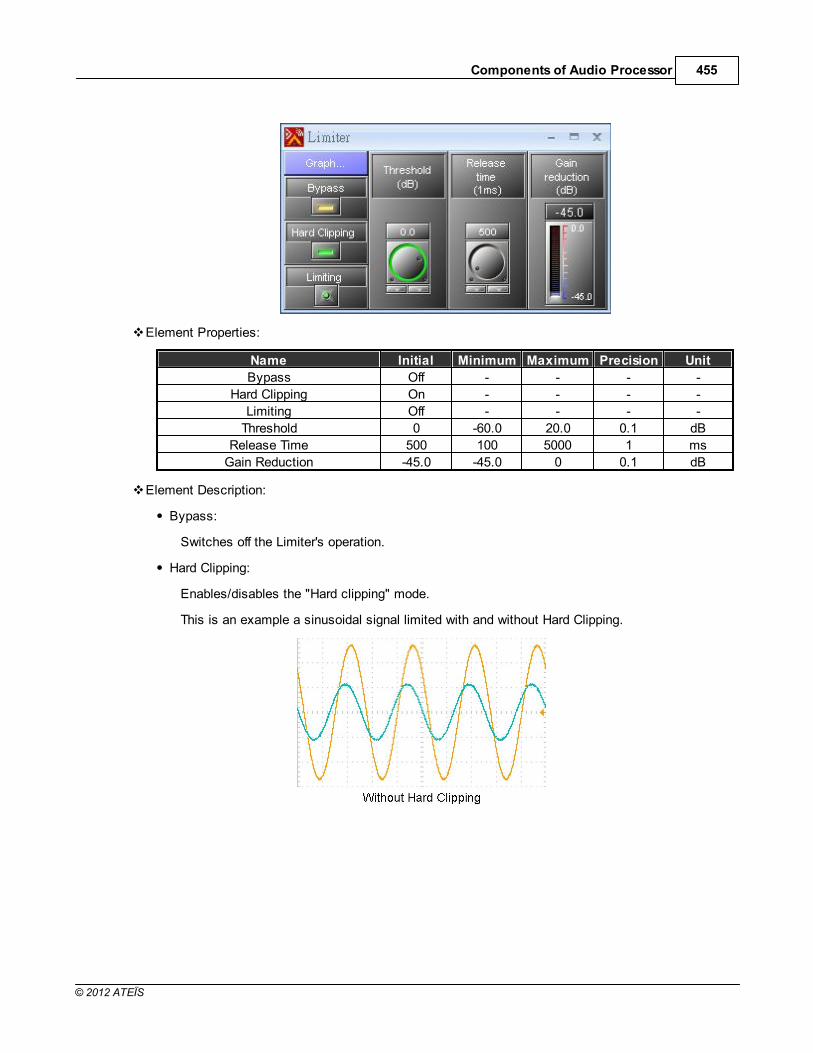
Components of Audio Processor 455
© 2012 ATEÏS
Element Properties:
Name Initial Minimum Maximum Precision Unit
Bypass Off - - - -
Hard Clipping On - - - -
Limiting Off - - - -
Threshold 0 -60.0 20.0 0.1 dB
Release Time 500 100 5000 1 ms
Gain Reduction -45.0 -45.0 0 0.1 dB
Element Description:
Bypass:
Switches off the Limiter's operation.
Hard Clipping:
Enables/disables the "Hard clipping" mode.
This is an example a sinusoidal signal limited with and without Hard Clipping.

ATEIS - IDA8456
© 2012 ATEÏS
Limiting:
Indicates the limiting.
Threshold:
Sets the threshold level above which limiting begins.
Release Time:
Sets the time it takes to release gain reduction.
Gain Reduction:
Reflects the current amount of gain reduction.
Graphical Control Window:
Axis:
o X: Input signal level(dB)

Components of Audio Processor 457
© 2012 ATEÏS
o Y: Output signal level(dB)
Control Points:
o Red: Adjusts Threshold.
6.5 Equalizer
6.5.1 GEQ\GEQ Stereo
Component Template:
Component Appearance:

ATEIS - IDA8458
© 2012 ATEÏS
Description
GEQ is the abbreviation of Graphic Equalizer. In the Graphic Equalizer the input signal is sent to abank of filters. Each filter passes the portion of the signal present in its own frequency range orband. The amplitude passed by each filter is adjusted using a slider in the control window of AteisStudio control to boost or cut frequency components passed by that filter. The vertical position ofeach slider thus indicates the gain applied at that frequency band.
The number of frequency channels (and therefore each one's bandwidth) affects the consuming DSPpower of audio processor and may be matched to the requirements of the intended application. Anequalizer for professional live sound reinforcement typically has some 25 to 31 bands for moreprecise control of feedback problems and equalization of room modes. There are three types ofGEQ, 1 Octave, 2/3 Octave and 1/3 Octave. 1/3 Octave GEQ is spoken informally as "third-octaveEQ" because the center frequency of its filters are spaced one third of an octave apart with threefilters to an octave. Equalizers with half as many filters per octave are common where there is lessprecise control and is called a 2/3-octave equalizer, and the 1 Octave GEQ is one filter to an octave.
Control Window:
Element Properties:
Name Initial Minimum Maximum Precision Unit
Bypass all Off - - - -
Bypass Off - - - -
Gain 0 -30.0 15.0 0.1 dB
Element Description:
Bypass all:
Bypasses the EQ (all the frequency bands).
Bypass:
Bypasses only the selected frequency band.
Gain:
Sets the gain of the selected frequency band.
Graphical Control Window

Components of Audio Processor 459
© 2012 ATEÏS
Axis:
o X: Frequency of output signal(Hz)
o Y: Gain of output signal(dB)
Control Points:
o Blue: Adjusts Gain.
Application
Equalizers can correct problems posed by a room's acoustics, an auditorium will generally have anuneven frequency response especially due to standing waves and acoustic dampening. Forinstance, the frequency response of a room may be analyzed using a spectrum analyzer and a pinknoise generator. Then, a graphic equalizer can be easily adjusted to compensate for the room'sacoustics. Such compensation can also be applied to tweak the sound quality of a recording studioin addition to its use in live sound reinforcement systems.

ATEIS - IDA8460
© 2012 ATEÏS
6.5.2 PEQ\PEQ Stereo
Component Template:
Component Appearance:
Description:
PEQ is the abbreviation of Parametric Equalizer. PEQs are multi-band variable equalizers whichallow users to control the three primary parameters: amplitude, center frequency and bandwidth. Theamplitude of each band can be controlled, the center frequency can be shifted, and bandwidth ("Q")

Components of Audio Processor 461
© 2012 ATEÏS
can be widened or narrowed. PEQs are capable of making much more precise adjustments to soundthan other equalizers and are commonly used in sound recording and live sound reinforcement.
Control Window:
Element Properties:
Generate Information:
Name Initial Minimum Maximum Precision Unit
Bypass all Off - - - -
Bypass Off - - - -
Bandwidth 1.00 1.00 4.00 0.01 Octive
Frequency *1 10 22000 1 Hz
Gain 0 -30.0 15.0 0.1 dB
*1: The initial value of Frequency depends on how many bands of a PEQ. These initial values areaverage distribution in range from 10 to 22000 Hz.
Element Description:
Bypass all:
Bypasses the EQ (all the frequency bands).
Bypass:
Bypasses only the selected frequency band.
Bandwidth:
Sets the width around the frequency (Q factor) of selected frequency band.
Frequency:

ATEIS - IDA8462
© 2012 ATEÏS
Sets the frequency of a band.
Gain:
Sets the gain (attenuate or increase the selected frequency).
Graphical Control Window:
Axis:
o X: Frequency of output signal(Hz)
o Y: Gain of output signal(dB)
Control Points:
o Blue: Adjusts Gain(using vertical direction) and Frequency(using horizontal direction).
o Yellow: Adjusts Bandwidth
Application
An equalizer can be used to correct or "flatten" the frequency response of speakers rather thandesigning the speaker itself to be equalized. Some speaker systems don't use separate woofers andtweeters to cover the bass and treble frequencies but rather include full-range drivers. However, thisspeaker system is sold with an active equalizer designed to correct the poor frequency balance ofthose drivers. That equalizer must go into the sound system before the amplifier so that theamplified signal is sent to the speakers. The signal has its response increased at the frequencieswhere the response of these drivers falls off, producing a high fidelity reproduction regardless. Ateisaudio processors give you the same solution without using an external equalizer, it's all done in thesoftware component PEQ.

Components of Audio Processor 463
© 2012 ATEÏS
6.6 Feedback
Component Template:
Component Appearance:
Description:
The error between the desired and the actual output is taken and given as feedback to the adaptiveprocessor for adjusting its coefficients to minimize the error. The feedback analyzes the signal,

ATEIS - IDA8464
© 2012 ATEÏS
detects feedback and attenuates the responsible frequency. There is several types of feedbackcomponents. The difference is only the bandwidth which is tuned for Music higher than speech (thebandwidth is decreasing between it). Each category has 4 different feedbacks, and it is only thenumber of filters (4, 8 12 or 16) that the feedback will use. The treatment time is increased with thenumber of filters.
Use feedback killers to detect feedback then note the frequency and replace the feedbackcomponent with an Equalizer. Then, add a simply 4 notch feedback for security.
By again storing the configuration, you will erase the captured Values (frequencies, bandwidthand gain).
Control Window:
Element Properties:
Generate Information:
Name Initial Minimum Maximum Precision Unit
Bypass Off - - - -Hold On - - - -
Manual Off - - - -Frequency 20 20 20000 1 HzBandwidth 1.00 0.01 1.50 0.01 Octive
Gain 0 -60.0 0 0.1 dBLock Off - - - -
Frequency Level 20 20 20000 1 HzBandwidth Level 0.01 0.01 1.50 0.01 Octive
Gain Level -60.0 -60.0 0 0.1 dBBypass All -60.0 - - - -Manual All Off - - - -
Hold All On - - - -Stop Detect Off - - - -
Reset All Off - - - -Lock Time 60 30 600 1 Second
Detect Level -30.0 -40.0 0 0.1 dBDepth -40.0 -60.0 0 0.1 dB

Components of Audio Processor 465
© 2012 ATEÏS
Element Description:
Bypass:
Bypasses the feedback’s module.
By clicking on the Bypass button you will erase the captured values.
Hold:
When a Larsen is detected, a frequency lock the component to hold this setting.
Manual:
Enables the Frequency, Bandwidth and Gain fader to be used manually. This will disable theautomatic detection.
Frequency:
Frequency of the notch filter for attenuating the feedback.
Bandwidth:
Bandwidth of the notch filter for attenuating the feedback.
Gain:
The attenuation of the locked frequency.
Lock:
Shows if the feedback killers channel has detected and erased the frequencies which arecausing the feedback.
Frequency Level:
Shows the locked frequency.
Bandwidth Level:
Shows the bandwidth of the notch filter locked.
Gain Level:
Shows the attenuation of the frequency locked.
Bypass All:
Bypasses all channels.
Manual All:
Activates manual settings (with Frequency, Bandwidth and gain knobs).
Lock Time:
The interval time during which the filter will be activated when a feedback is detected. After thatthe captured values will lose.
Hold All:
Holds all channels. Press the button if you don’t want to release all the detected frequency afterthe Lock time.

ATEIS - IDA8466
© 2012 ATEÏS
Stop Detect:
Stops detecting feedback.
Reset All:
Resets all coefficients.
Detect Level:
The level of feedback detection.
Depth:
The maximum reduction gain for the filter.
6.7 Filter
6.7.1 All Pass Filter
Component Template:
Component Appearance:
Description:
An All Pass Filter is a signal processing filter that passes all frequencies equally but changes thephase relationship between various frequencies. It performs this by varying its propagation delay withfrequency.
Control Window:

Components of Audio Processor 467
© 2012 ATEÏS
Element Properties:
Generate Information:
Name Initial Minimum Maximum Precision Unit
Bypass All Off - - - -
Bypass On - - - -
Bandwidth 1.00 0.01 4.00 0.01 Octive
Frequency 1000 20 20000 1 Hz
Element Description:
Bypass All:
Bypasses the component (all bands of filter's module).
Bypass:
Bypasses the processing of a selected band in a filter's module.
Bandwidth:
The transition bandwidth.
Frequency:
The frequency at which the phase shift crosses 90°.
Graphical Control Window:

ATEIS - IDA8468
© 2012 ATEÏS
Axis:
o X: Frequency of output signal(Hz)
o Y: Gain of output signal(dB)
Control Points:
o Blue: Adjusts Frequency
o Yellow: Adjusts Bandwidth
6.7.2 Band Pass
Component Template:
Component Appearance:

Components of Audio Processor 469
© 2012 ATEÏS
Description:
A Band Pass component that passes frequencies within a certain range and rejects (attenuates)frequencies outside that range.
Control Window:
Element Properties
Generate Information:
Name Initial Minimum Maximum Precision Unit
Mode Butterworth - - - -
Slope 12 dB - - - -
Bandwidth 1.00 0.01 2.00 0.01 Octave
Bypass Off - - - -
Mute Off - - - -
Level 0 -90.0 20.0 0.1 dB
Frequency 1000 10 22000 1 Hz
Item list of Mode:
No. Name
1 Butterworth
Item list of Slope:
No. Name
1 12 dB
Element Description:
Mode:

ATEIS - IDA8470
© 2012 ATEÏS
The type of filtering,
Slope:
Slopes of attenuation.
Bandwidth:
Difference between the upper and lower frequencies in a contiguous set of frequencies.
Mute:
Mutes the filter's module.
Level:
The gain of the filter's module.
Frequency:
The frequency of cut.
Graphical Control Window:
Axis:
o X: Frequency of output signal(Hz)
o Y: Level of input signal(dB)
Control Points:
o Blue: Adjusts element Frequency(Horizontal) and Level(Vertical).
o Yellow: Adjusts element Bandwidth

Components of Audio Processor 471
© 2012 ATEÏS
6.7.3 Band Stop
Component Template:
Component Appearance:
Description:
A Band Stop filter is a filter that passes most frequencies unaltered, but attenuates those in aspecific range to very low levels. It is the opposite of a band-pass filter.
Control Window:
Element Properties:

ATEIS - IDA8472
© 2012 ATEÏS
Generate Information:
Name Initial Minimum Maximum Precision Unit
Mode Butterworth - - - -
Slope 12dB - - - -
Bandwidth 1.00 0.01 2.00 0.01 Octave
Bypass Off - - - -
Mute Off - - - -
Level 0 -90.0 20.0 0.1 dB
Frequency 1000 10 22000 1 Hz
Item list of Mode:
No. Name
1 Butterworth
Item list of Band Stop:
No. Name
1 12dB
Element Description:
Mode:
The type of filtering.
Slope:
The slope of attenuation.
Bandwidth:
The difference between the upper and lower frequencies in a contiguous set of frequencies.
Bypass:
Bypasses the filter's module.
Mute:
Mutes the filter's module.
Level:
The gain of the filter's module.
Frequency:
The frequency of cut.
Graphical Control Window:

Components of Audio Processor 473
© 2012 ATEÏS
Axis:
o X: Frequency of output signal(Hz)
o Y: Level of input signal(dB)
Control Points:
o Blue: Adjust element Frequency(Horizontal) and Level(Vertical).
o Yellow: Adjust element Bandwidth

ATEIS - IDA8474
© 2012 ATEÏS
6.7.4 Crossover/Crossover Stereo
Component Template:
Component Appearance:
Description:
Crossovers split the audio signal into separate frequency bands that can be separately routed toother DSP components for those bands. A 2-way crossover consists of a low-pass and a high-passfilter. A 3-way crossover is constructed as a combination of low-pass, band-pass and high-passfilters (LPF, BPF and HPF respectively).
Control Window:

Components of Audio Processor 475
© 2012 ATEÏS
Element Properties:
Name Initial Minimum Maximum Precision Unit
Invert - - - - -
Mode - - - - -
Slope - - - - -
Mute - - - - -
Level - - - - -
Frequency *1 *1 *1 1 Hz
*1: The Initial/Minimum/Maximum values are different between types of Crossover/Crossover Stereo.
Name Initial Minimum Maximum Precision Unit
Frequency(2 Way-Low/High Band) 1000 10 22000 1 Hz
Frequency(3 Way-Low Band) 250 20 5590 1 Hz
Frequency(3 Way-Mid Band-Hi Pass) 250 26 20000 1 Hz
Frequency(3 Way-Mid Band-Low Pass) 2500 200 15874 1 Hz
Frequency(3 Way-High Band) 2500 2500 20000 1 Hz
Frequency(4 Way-Low Band) 160 20 634 1 Hz
Frequency(4 Way-Mid Low Band-HiPass)
160 20 2519 1 Hz
Frequency(4 Way-Mid Low Band-LowPass
800 202 3174 1 Hz
Frequency(4 Way-Mid Hi Band-HiPass)
800 202 3174 1 Hz
Frequency(4 Way-Mid Hi Band-LowPass)
4000 1008 20000 1 Hz
Frequency(4 Way-Hi Band) 4000 1008 20000 1 Hz
Element Description:
Invert:

ATEIS - IDA8476
© 2012 ATEÏS
Inverts the phase of the signal.
Mode:
The type of filtering.
Slope:
The slope of attenuation.
Mute:
Mutes the filter's module.
Level:
The gain of signal.
Frequency:
The frequency of cut.
Graphical Control Window:
Axis:
o X: Frequency of output signal(Hz)
o Y: Level of input signal(dB)
Control Points:
o Blue: Adjust Level and hi-pass Frequency or low-pass Frequency of mid band.
o Yellow: Adjust Level and both hi-pass Frequency and low-pass Frequency of mid band.
o Red: Adjust Level and low band or hi band.

Components of Audio Processor 477
© 2012 ATEÏS
6.7.5 Hi/Lo Pass
Component Template:
Component Appearance:
Description:
Hi/Lo Pass component passes high/low frequencies and attenuates (i.e. reduces the amplitude of)frequencies lower/higher than its cutoff frequency.
Control Window:
Element Properties:

ATEIS - IDA8478
© 2012 ATEÏS
Name Initial Minimum Maximum Precision Unit
Mode Bessel 6 dB - - - -Type Low-Pass - - - -
Bypass Off - - - -Mute Off - - - -Level 0 -90.0 20.0 0.1 dB
Frequency 80 10 22000 1 Hz
Element Description:
Mode:
The type of filtering.
Type:
Low or High pass.
Bypass:
Bypasses the filter's module.
Mute:
Mutes the filter's module.
Level:
The gain of signal.
Frequency:
The frequency of cut.
Graphical Control Window:
Axis:

Components of Audio Processor 479
© 2012 ATEÏS
o X: Frequency of output signal(Hz)
o Y: Level of input signal(dB)
Control Points:
o Red: Adjust element Frequency(Horizontal) and Level(Vertical)
6.7.6 Notch Filter
Component Template:
Component Appearance:
Description:
In signal processing, a band-stop filter or band-rejection filter is a filter that passes most frequenciesunaltered, but attenuates those in a specific range to very low levels. It is the opposite of a band-pass filter. A notch filter is a band-stop filter with a narrow stop band (high Q factor).
Control Window:

ATEIS - IDA8480
© 2012 ATEÏS
Element Properties:
Name Initial Minimum Maximum Precision Unit
Mode Butterworth - - - -
Slope 12dB - - - -
Bandwidth 1 0.01 2.00 0.01 Octave
Bypass Off - - - -
Mute Off - - - -
Level 0 -90.0 20.0 0.1 dB
Frequency 1000 10 22000 1 Hz
Element Description:
Mode:
The type of filtering.
Slope:
The slope of attenuation, the higher slope means the drop speed levels are faster.
Bandwidth:
The difference between the upper and lower cut of frequencies in a contiguous set of frequency.
Bypass:
Bypasses the filter's module.
Mute:
Mutes the filter's module.
Level:
The gain of filter's module.
Frequency:
The center frequency to be cut.
Graphical Control Window:

Components of Audio Processor 481
© 2012 ATEÏS
Axis:
o X: Frequency of output signal(Hz).
o Y: Level of input signal(dB).
Control Points:
o Blue: Adjust element Frequency(Horizontal) and Level(Vertical).
o Yellow: Adjust element Bandwidth.

ATEIS - IDA8482
© 2012 ATEÏS
6.7.7 Shelving Filter
Component Template:
Component Appearance:
Description:
Shelving Filter component implements a first order response and provides an adjustable boost or cutto frequencies above or lower than a certain point.
Control Window:
Element Properties:
Name Initial Minimum Maximum Precision Unit
Mode Low-Shelving - - - -

Components of Audio Processor 483
© 2012 ATEÏS
Name Initial Minimum Maximum Precision Unit
Bypass Off - - - -Level 0 -90.0 20.0 0.1 dB
Frequency 1000 10 22000 1 Hz
Element Description:
Mode:
The type of filtering (high pass or low pass).
Bypass:
Bypasses the filter's module.
Level:
The gain of the filter's module.
Frequency:
The frequency of cut.
Graphical Control Window:
Axis:
o X: Frequency of output signal(Hz).
o Y: Level of input signal(dB).
Control Points:
o Blue: Adjust element Frequency(Horizontal) and Level(Vertical).

ATEIS - IDA8484
© 2012 ATEÏS
6.8 Fireman
Component Template:
Component Appearance:
Description:
This component represents the Fireman Microphone with one channel audio output ready for furtherDSP processing.
Control Window:
Element Properties:
Name Initial Minimum Maximum Precision Unit
Mute Off - - - -
Level 0 -60.0 20.0 0.1 dB
Element Description:
Mute:
Mutes the audio signal.
Level:

Components of Audio Processor 485
© 2012 ATEÏS
The signal level of the Fireman component.
Paging-Event Selection:
Selects a paging event to bind with the Fireman component. To perform a paging using firemanmicrophone, it needs to have a paging event bind with the Fireman component.
Before assigning a paging event to the component, you need to create it first in settingswindow of the "Network Paging Component ".
Paging-Event Link Button:
To open the settings window of the binding paging event:
See more details in Network Paging topic.
6.9 Input
6.9.1 Input
Component Template:
Component Appearance:
557
557

ATEIS - IDA8486
© 2012 ATEÏS
Description:
This component controls the input signal's parameters and monitors it. The analog input modulesrepresent the physical analog inputs which are accessible on the rear panel of the Audio Processor.There are several separate modules for use with each of the audio board slots. Analog input andoutput modules are added automatically to the DSP window of the relevant processor by definingtheir module configuration at the time you create them and should not be altered.
Control Window:
Element Properties:
Name Initial Minimum Maximum Precision Unit
Bypass Off - - - -Mute Off - - - -
Sensitivity 0dB - - - -Phantom Power Off - - - -
RTO Off - - - -Overload Off - - - -Volume -50.0 -50.0 20.0 - dBSignal Off - - - -Level 0 -60.0 20.0 0.1 dB

Components of Audio Processor 487
© 2012 ATEÏS
Name Initial Minimum Maximum Precision Unit
Overload Thd. 0 -20.0 20.0 0.1 dB
Element Description:
Bypass:
Bypasses audio of the channel.
Mute:
Mutes the audio of the channel.
Sensitivity:
Sets the input gain of the channel to the preamplifier.
Phantom Power:
Applies 48 VDC phantom power to the channel input for use with condenser mics.
RTO:
Indicates an input channel 'Routed To Output(s)'.
Overload:
This LED lights up if the signal of an input channel is greater than the Overload Thd.
Volume:
The VU-Meter shows the channel RMS level.
Signal:
Indicates if an audio signal presents above -30 dB from the chosen 'Sensitivity'.
Level:
The Signal output level of the channel.
Overload Thd.:
A threshold value to determine the signal of a channel is overloaded or not.

ATEIS - IDA8488
© 2012 ATEÏS
6.9.2 Mono Input
Component Template:
Component Appearance:
Description:
For the AES/EBU input, the elements inside the component are very similar to the Input componentexcept without Sensitivity and Phantom Power.
Control Window:

Components of Audio Processor 489
© 2012 ATEÏS
Element Properties:
Name Initial Minimum Maximum Precision Unit
Bypass Off - - - -
Mute Off - - - -
RTO Off - - - -
Overload Off - - - -
Volume -50.0 -50.0 20.0 - dB
Signal Off - - - -
Level 0 -60.0 20.0 0.1 dB
Overload Thd. 0 -20.0 20.0 0.1 dB
Element Description:
Bypass:
Bypasses audio of the channel.
Mute:
Mutes the audio of the channel.
RTO:
Indicates an input channel 'Routed To Output(s)'.
Overload:

ATEIS - IDA8490
© 2012 ATEÏS
This LED lights up if the signal of an input channel is greater than the Overload Thd.
Volume:
The VU-Meter shows the channel RMS level.
Signal:
Indicates if an audio signal presents above -30 dB from the chosen 'Sensitivity'.
Level:
The Signal output level of the channel.
Overload Thd.:
A threshold value to determine the signal of a channel is overloaded or not.
6.9.3 Stereo Input
Component Template:
Component Appearance:
Description:
For AES/EBU input/output, the elements inside the component are very similar to Input componentexcept without Sensitivity and Phantom Power. The audio input to the channel 1 of the board goesto the component Stereo Input X channel 1 & 2 and channel 3 to Stereo Input X channel 3 & 4.
Control Window:

Components of Audio Processor 491
© 2012 ATEÏS
Element Properties:
Name Initial Minimum Maximum Precision Unit
Bypass Off - - - -
Mute Off - - - -
RTO Off - - - -
Overload Off - - - -
Volume -50.0 -50.0 20.0 - dB
Signal Off - - - -
Level 0 -60.0 20.0 0.1 dB
Overload Thd. 0 -20.0 20.0 0.1 dB
Element Description:
Bypass:
Bypasses audio of the channel.
Mute:
Mutes the audio of the channel.
RTO:
Indicates an input channel 'Routed To Output(s)'.
Overload:

ATEIS - IDA8492
© 2012 ATEÏS
This LED lights up if the signal of an input channel is greater than the Overload Thd.
Volume:
The VU-Meter shows the channel RMS level.
Signal:
Indicates if an audio signal presents above -30 dB from the chosen 'Sensitivity'.
Level:
The Signal output level of the channel.
Overload Thd.:
A threshold value to determine the signal of a channel is overloaded or not.
6.9.4 Duplex Input
Component Template:
Component Appearance:
Description:
For AES/EBU input/output, the elements inside the component are very similar to the Inputcomponent except without Sensitivity and Phantom Power. The audio input to the channel 1 of theboard goes to the component Duplex Input A channel 1 & 2, channel 2 to the Duplex Input Achannel 3 & 4, channel 3 to the Duplex Output B channel 1 & 2 and channel 4 to the Duplex OutputB channel 3 & 4.
Control Window:

Components of Audio Processor 493
© 2012 ATEÏS
Element Properties:
Name Initial Minimum Maximum Precision Unit
Bypass Off - - - -
Mute Off - - - -
RTO Off - - - -
Overload Off - - - -
Volume -50.0 -50.0 20.0 - dB
Signal Off - - - -
Level 0 -60.0 20.0 0.1 dB
Overload Thd. 0 -20.0 20.0 0.1 dB
Element Description:
Bypass:
Bypasses audio of the channel.
Mute:
Mutes the audio of the channel.
RTO:
Indicates an input channel 'Routed To Output(s)'.
Overload:

ATEIS - IDA8494
© 2012 ATEÏS
This LED lights up if the signal of an input channel is greater than the Overload Thd.
Volume:
The VU-Meter shows the channel RMS level.
Signal:
Indicates if an audio signal presents above -30 dB from the chosen 'Sensitivity'.
Level:
The Signal output level of the channel.
Overload Thd.:
A threshold value to determine the signal of a channel is overloaded or not.
6.9.5 Inverter
Component Template:
Component Appearance:
Description:
This component changes the signal phase of 90 degrees.
Control Window:

Components of Audio Processor 495
© 2012 ATEÏS
Element Properties:
Name Initial Minimum Maximum Precision Unit
Mute Off - - - -
Invert Off - - - -
Element Description:
Mute:
Mutes the inverter module.
Invert:
Activates the inverter.
6.10 Level Controller
Component Template:
Component Appearance:
Description:
This component adjusts the signal level.
Control Window:

ATEIS - IDA8496
© 2012 ATEÏS
Element Properties:
Name Initial Minimum Maximum Precision Unit
Bypass Off - - - -
Mute Off - - - -
Input Level 0 -90.0 20.0 0.1 dB
Output Level 0 -90.0 20.0 0.1 dB
Element Description:
Bypass:
Bypasses the module's function.
Mute:
Mutes the sound coming out from the component.
Input Level:
Adjusts the level of an input channel.
Output Level:
Adjusts the level of output.

Components of Audio Processor 497
© 2012 ATEÏS
6.11 Local Echo Suppressor
Component Template:
Component Appearance:
Description:
This component is designed for suppressing local Echo or feedback. It has two parts, the Pre-Processing and the Post-Processing. The Pre-Processing reduces the level above the threshold foravoiding the feedback. The Post-Processing removes the echo below a threshold which is foravoiding the residual echo.
Control Window:

ATEIS - IDA8498
© 2012 ATEÏS
Element Properties:
Name Initial Minimum Maximum Precision Unit
Bypass Off - - - -
Gain Reduction 0 -25.0 0 0.1 dB
Pre-Processing Threshold -22.0 -40.0 0 0.1 dB
Pre-Processing Attack Time 10 1 100 1 ms
Pre-Processing Release Time 500 100 5000 1 ms
Post-Processing Threshold -40.0 -40.0 -20.0 0.1 dB
Post-Processing Attack Time 10 1 100 1 ms
Post-Processing Release Time 500 100 5000 1 ms
Element Description:
Bypass:
Switches off the component operations.
Gain Reduction:
Displays the gain of the output volume.
Pre-Processing Threshold:
When the input volume is larger than the Pre-Processing Threshold, it will reduce the volume toThreshold.
Pre-Processing Attack Time:
The needed time for changing the volume from the original level to the expected level.
Pre-Processing Release Time:
The needed time for changing the volume from the expected level to the original level.

Components of Audio Processor 499
© 2012 ATEÏS
Post-Processing Threshold:
When the input volume is smaller than the Post-Processing Threshold, it will suppress theresidue echo sound.
Post-Processing Attack Time:
The needed time for changing the volume from the original level to the expected level.
Post-Processing Release Time:
The needed time for changing the volume from the expected level to the original level.
6.12 Logic
Components processing logic signal listed in this section.
6.12.1 AND
Component Template:
Component Appearance:
Description:
This component allows the logical operation "AND" that applied on a logic signal.

ATEIS - IDA8500
© 2012 ATEÏS
6.12.2 EVAC Board
Component Template:
Component Appearance:
Description:
This component corresponds to URGP peripheral devices. It extends the audio processor's logicinput channel.
Control Window:
Parameters:
Monitor:
Enables or disables the external device monitoring. If this option is enabled it needs two 4.7kOhm resisters in the external device circuit.

Components of Audio Processor 501
© 2012 ATEÏS
Type:
To specify the mode of activation. There are two choices:
o N.O.:
Normally open, close the contact to the output signal.
o N.C.:
Normally close, open the contact to the output signal.
Status:
Shows states of the external device. There are four states:
o Open:
An open circuit of external device is detected.
o Short:
A short circuit of external device is detected.
o Activate:
The logic output is active.
o Deactivate:
The logic output is deactivated.

ATEIS - IDA8502
© 2012 ATEÏS
6.12.3 Evacuation Input
Component Template:
Component Appearance:
Description:
This component corresponds to the Evacuation Input of IDA8C/S, the output logic signal will be theother logic component's input.
Control Window:

Components of Audio Processor 503
© 2012 ATEÏS
Parameters:
Monitor Mode:
There are two options:
o Voltage: The logic output of component which is triggered by a voltage polarization change.
o Contact: The logic output of component which is triggered by opening or closing the pin +/- of
the connector in the rear panel.
Response Time:
Determines how quick the system responds to the hardware status changing from Open(Lo) toClose(Hi) or from Close(Hi) to Open(Lo).
Activation:
Specifies this parameter to determine under what condition the hardware will generate 1 output.There are two choices:
o Open(Lo): The component output=1 when the contact open(contact mode) or voltage low
(voltage mode).
o Close(Hi): The component output=1 when the contact close(contact mode) or voltage hi
(voltage mode).
6.12.4 Event
The components which work with events will be listed in this section.

ATEIS - IDA8504
© 2012 ATEÏS
6.12.4.1 Trigger
Component Template:
Component Appearance:
Description:
This component links events to the logic signal. The linked events will be triggered if the input logicsignal of the component is from Low to High or from High to Low depending on the settings.
Control Window:
When dragging and dropping of the component for a DSP design, a window will show to specify theinput and output channel counts:
Double-click the component and the control window will show. There are several tabs on the top ofthe window. Each tab is for a logic input channel:

Components of Audio Processor 505
© 2012 ATEÏS
After events are linked to the component the control window lists them in grids:
Parameters:
Event Name:
Shows the name of the events linked.
Content:
Opens the event settings window.
State:
Specifies the state number for triggering an event.
Logic In:
Defines which condition will trigger the linked events.
Logic Out:
Defines output signal state after the linked event is executed. There are two cases which needto be considered: The event executed is successful or has failed. To setup this configuration youneed to select the working output signal first:

ATEIS - IDA8506
© 2012 ATEÏS
In the above figure, the logic output channel 4 and 6 are selected. For more settings, click thegrid cell [...]:
In the above figure, the settings means when the Event 1 is Failed, output 4 will be 1 and output6 will be 0, and when Event1 is successfully executed the output 4 will be 0 and the output 6 willbe 1.
6.12.5 Logic Control
Component Template:
Component Appearance:

Components of Audio Processor 507
© 2012 ATEÏS
Description:
This component allows the user to generate the logic signal using buttons in the software. For eachchannel there is an element for the control logic signal for output.
Control Window:
Elements:
On/Off:
Outputs logic signal 0 or 1.
6.12.6 Logic Meter
Component Template:
Component Appearance:
Description:
This component has LEDs to indicate the statuses of the logic signal.
Control Window:

ATEIS - IDA8508
© 2012 ATEÏS
6.12.7 Logic Net Input
Component Template:
Component Appearance:
Description:
This component transfers logic signals over Ateis Net.The logic signal goes into the "Logic Net Out"component in one device and out of the "Logic Net In" component in another device by using theAteis Net card. The signal path is one-to-many and there are 48 channels available to carry signalswhich are numbered and identified by the number. For example, a signal goes into Channel 1 ofcomponent Logic Net Out A and will go out from the component Logic Net In A channel 1.

Components of Audio Processor 509
© 2012 ATEÏS
6.12.8 Logic Net Output
Component Template:
Component Appearance:
Description:
This component transfers logic signals over Ateis Net.The logic signal goes into the "Logic Net Out"component in one device and out of the "Logic Net In" component in another device by using theAteis Net card. The signal path is one-to-many and there are 48 channels available to carry signalswhich are numbered and identified by the number. For example, a signal goes into Channel 1 ofcomponent Logic Net Out A and will go out from the component Logic Net In A channel 1.

ATEIS - IDA8510
© 2012 ATEÏS
6.12.9 NOT
Component Template:
Component Appearance:
Description:
This component performs logical NOT operation.
6.12.10 OR
Component Template:

Components of Audio Processor 511
© 2012 ATEÏS
Component Appearance:
Description:
This component performs logical OR operation.
6.12.11 Output
Component Template:
Component Appearance:
Description:
This component is corresponding to the contact outputs.
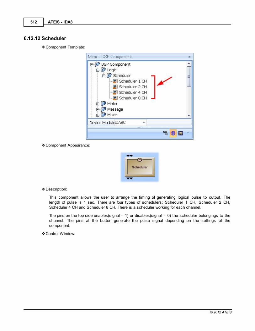
ATEIS - IDA8512
© 2012 ATEÏS
6.12.12 Scheduler
Component Template:
Component Appearance:
Description:
This component allows the user to arrange the timing of generating logical pulse to output. Thelength of pulse is 1 sec. There are four types of schedulers: Scheduler 1 CH, Scheduler 2 CH,Scheduler 4 CH and Scheduler 8 CH. There is a scheduler working for each channel.
The pins on the top side enables(signal = 1) or disables(signal = 0) the scheduler belongings to thechannel. The pins at the button generate the pulse signal depending on the settings of thecomponent.
Control Window:

Components of Audio Processor 513
© 2012 ATEÏS
Scheduler List:
At the left side of the window, a box lists all channels of the scheduler. Click it to change the focuson the scheduler. The right part of the window shows the settings of the scheduler which will beswitched to the corresponding scheduler.
General Settings:
Name:
The name of the scheduler.
Start Time:
The start time of the scheduler.
Stop Condition:

ATEIS - IDA8514
© 2012 ATEÏS
Specifies the condition to deactivate a scheduler. There are three types of stop condition:
Continue:
In this option, scheduler will never stop. Triggering mode settings are always valid.
Number of Times:
Scheduler is triggered N times using triggering mode settings where N can be set at "Numberof Times parameter".
Stop Time:
Scheduler is activated from start time to the time specified in the "Stop Time parameter".
Triggering Mode:
The triggering mode defines the rule of triggering a pulse to output.
Periodic:
The interval is the time between two triggers.
Cyclic:

Components of Audio Processor 515
© 2012 ATEÏS
The Occurrence parameter determines the cycle type of triggering. There are five typesavailable: Hourly/Daily/Weekly/Monthly/Yearly. It allows the user to define the interval betweencycles by specifying the parameter of Every N cycle unit where the cycle unit can be Hour/Day/Week/Month/Year.
The box lists the Time of Triggering. You can add or remove the triggering time in the cycle.
By Excel File
It allows the user to specify the triggering times by using an excel file. The rules are listedbelow:
Field A1 is the "Year.Month" for scheduling. Note: Refer to the format as shown in the pictureabove.
B1 ~ X1 is the field for time format, there are two choices:
o 24HR
o AM/PM
A2 ~ A 32 represents the day of a month.
For each row, B to X fields are the time to be triggered.
Exception Duration
Even through the mechanism for triggering time setup is very flexible the exceptions are still needed.At the lower part of the scheduler settings window, a block of "Exception Duration" allows the userto edit a list for the exceptions of the triggering. Each exception consists of a start time and a stoptime. During the exception time all triggering will be masked.

ATEIS - IDA8516
© 2012 ATEÏS
6.13 Meter
6.13.1 Peak/RMS Meter
Component Template:
Component Appearance:
Description:
This component displays the amplitude of the incoming audio signal. There are two approachesavailable for measuring the signal. The first one is RMS which is often used to measure complexwaveforms especially for non-repeating signals like noises. The second is Peak approach.
Control Window:

Components of Audio Processor 517
© 2012 ATEÏS
Element Properties:
Name Initial Minimum Maximum Precision Unit
Indefinite Off - - - -
Measure Type RMS - - - -
Hold Time 10 10 1000 10 ms
Volume -40.0 -40 20 0.1 dBu
Element Description:
Indefinite:
Blocks the display of level value.
Measure Type:
The type of measuring.
Hold Time:
The time the value is displayed.
Volume:
Measures the value of the signal.

ATEIS - IDA8518
© 2012 ATEÏS
6.14 Message
6.14.1 Message Player
Component Template:
Component Appearance:
Description:
This component plays the audio message files which are stored in your Ateis devices. It is able tohave multiple events binding with a message in the event list. Each event can be assigned to asource to trigger it. If there is more than one event triggered in the same message playercomponent, the event with the highest priority will play the message.
Note: The smaller value has the higher priority.
Once you drag and drop the component, you can set component pins. See the picture below.

Components of Audio Processor 519
© 2012 ATEÏS
CR Pin: Clear. This will cancel the event for triggering messages and clear all of the logicsignals.
IR Pin: Interrupt. This will interrupt the messages and not play the messages.
Pause Pin(P): Trigger P pin is used to stop/continue the messages, it will restart exactlywhere you paused.
Input Channel: The number of trigger channels.
Output Channel: The number of channels of message playing.
Control Window:
Event:
Double click the message player to open the window shown in the below picture.
Name: Left click to rename the event.
Priority: The priority of Event. No matter which one is triggered first, the Event with thehigher priority will take priority.

ATEIS - IDA8520
© 2012 ATEÏS
Messages: The total messages in this event.
Add an event by clicking "..." in the Messages column to open the window, "Message PlayEven".
Click "Add from HW" and select messages. Note: The current support audio formats are WAV(16K 16bit, 24K 16bit, 48K 16bit) and G722.
Lastly, click [OK] as shown in the picture below:
Trigger:
Click "trigger", and you can see 2 channels. That means “input channel=2” of your setting.
Open the drop down list of Event and select event and run times.
As the following settings below show, when channel 1 is triggered, the Event 1 will run 3 times.See the picture below.

Components of Audio Processor 521
© 2012 ATEÏS
Set the logic out signal:
1. Interrupt: If the IR trigger interrupts the Event 1, the logic output CH 1 will send a signal"High".
2. Normal Ending: If the Event 1 is set to end normal ending and not interrupted or cleared, thelogic output CH 2 will send a signal "High".

ATEIS - IDA8522
© 2012 ATEÏS
3. Playing: When the first message (gong.wav) is playing, logic output Ch1 will send a signal"High".
4. Idle: After playing gong.wav for 3 times, it will idle for 3 seconds before playing the nextmessage (GNG3TONS.WAV). During the idle time, the logic output Ch2 will send a signal"High".
Interrupt Enable/Disable:
Open the window of Interrupt Setting to add items.

Components of Audio Processor 523
© 2012 ATEÏS
o Interrupt Enable:
When interrupt is enabled, it means that except for the "Nth times" you set, the otherswould be interrupted. For example, only the 2nd times won't be interrupted. See the picturebelow.
o Interrupt Disable:
This different from the Interrupt Enable in that only the Nth times you set will be interrupted.

ATEIS - IDA8524
© 2012 ATEÏS
6.14.2 MM Player
Component Template:
Component Appearance:

Components of Audio Processor 525
© 2012 ATEÏS
Description:
This component plays the messages stored in the Ateis device. It allows the user to specify playingsequence of messages and makes it possible to play messages through the logic signal input of thecomponent.
Control Window:
Priority: The priority in this component depends on the list order.
Message Name: Click "..." to assemble your messages(audio files) stored in the device or PC.Note: The current support audio formats are WAV(16K 16bit, 24K 16bit, 48K 16bit) and G722.
Source type: For the time being, only the "Normal" works.
Mode: Here you can choose the mode of playing messages.
o Control: Control by the Logic signal. When it's high the message plays, and stops if the signal
is low.
o Trigger: Trigger will play your messages for "1 + the Times you set". For example, it will play
5 times if you set 4 at the last column.
Times: Set for trigger.

ATEIS - IDA8526
© 2012 ATEÏS
You can set the Message play list, in this window:
Mode:
o Logic Input: Choose Logic IN1~ IN8 to control when your message play, If you set more than
one messages on the same Logic input. As shown in the picture above, it will play thosemessages in order.
o Dynamic: Use dynamic to manage the messages. Choose Dynamic and click "..." to open
the window [Dynamic assembling message setting]. See the picture below.

Components of Audio Processor 527
© 2012 ATEÏS
Here is an example for explaining the order of play with Dynamic.
Once the Logic IN 1 is high, it will play "The"+"next class is"+"Art", then, "The"+"next classis"+"History".

ATEIS - IDA8528
© 2012 ATEÏS
6.15 Mixer
6.15.1 AutoMixer
Component Template:
Component Appearance:
Description:
This component mixes several signals to one output. The activation of the channel(s) can be donemanually or automatically by a signal and the priority.
The auto mixer adjusts the signal output level on the output node depending on the number ofactivated input channels. This function can be used in conference applications or houses ofworkshop where the unattended mixing has to be executed automatically.
A special feature of this component is the priority function which can be used for an auto-pagingapplications or implementing a voice triggered by chairman's mic in a small conference system.
Control Window:

Components of Audio Processor 529
© 2012 ATEÏS
Element Properties:
Name Initial Minimum Maximum Precision Unit
Type Manual - - - -
Last Mic. On Designated Channel 1 - - - -
Mute On - - - -
Invert Off - - - -
Solo Off - - - -
Gate On Off - - - -
Input Level 0 -90.0 20.0 0.1 dB
Manual mode On - - - -
Automatic mode priority level 1 2 3 4 -
Output Mute Off - - - -
Output Level 0 -90.0 20.0 0.1 dB
Threshold -40.0 -90.0 20.0 0.1 dB
Background Threshold 15.0 0 100.0 0.1 dB
Hold Time 5 0 10.0 0.1 Second
Attenuation Response Time 10 10 10000 1 ms
NOM Attenuation Step 0 0 6 0.1 dB
NOM Attenuation Max 0 0 100 0.1 dB
Attenuation Gain -100.0 20.0 -100.0 0.1 dB
Open Mic. Limits No limit - - - -
NOM Attenuation Mode1: (NOM-1)
*step- - - -
Element Description:
Type:
Here you can select the Manual mode or Automatic mode.

ATEIS - IDA8530
© 2012 ATEÏS
Manual mode: The user manually activates channels (the threshold and priority are ignored).
Automatic mode: Channels activated depending on the priority and threshold.
Last Mic. On Designated:
Defines which channel will stay open (Only if "Last Mic. On" is activated).
The channel will stay open even if it's muted.
Mute:
Mutes or unmutes the channel input.
Invert:
Inverts the polarity of the input channel.
Solo:
Solos the input channel. (The channel goes directly to the output).
Gate On:
Shows the activation status of the input channel.
Level:
Adjusts the level of the output channel.
Manual mode:
This item is only used in manual mode (see "Manual/Automatic") which allows manual channelactivation.
Automatic mode priority level:
Sets the priority level of the channel. The smaller the number thee higher the priority.
Output Mute:
Mutes or unmutes the module's output.
Output Level:
Sets the module's output level.
Threshold:
Sets the threshold for channel activation.
Background Threshold:
Sets how the input signal will be interpreted for opening a gate. The background level willincrease the input activation level.
Hold Time:
Sets the threshold for channel activation.
Attenuation Response Time:
Sets a pre-delay time for automatic attenuation. That means the transition time of the

Components of Audio Processor 531
© 2012 ATEÏS
attenuation when a channel is added or removed.
NOM Attenuation Step:
Sets the amount of attenuation applied each time the number of activated channels increases.
NOM Attenuation Max:
Limits the amount of attenuation applied.
Attenuation Gain:
Indicates the amount of current gain reduction.
Open Mic. Limits:
Chooses the maximum number of simultaneously activated channels.
NOM Attenuation Mode:
Choose this mode if you want a linear attenuation or a logarithmic attenuation to be morerealistic.
Eq1: (NOM-1) x step (same attenuation for each additional channel).
Eq2: log2(NOM) x step.
6.15.2 AutoMixer MM
Component Template:
Component Appearance:
Description:

ATEIS - IDA8532
© 2012 ATEÏS
This component allows mixing several signals to one output. The activation of channel(s) can bedone manually or automatically by the signal threshold and priority. The output 1 is the standardauto-mixer output like the auto-mixer component. On each input channel, you can open a mini-mixerwhich allows you to send the input signal to different outputs with different levels of mixing.
Control Window:
Element Properties:
Name Initial Minimum Maximum Precision Unit
Type Manual - - - -Last Mic. On Designated Channel 1 - - - -
Mute On - - - -Invert Off - - - -Solo Off - - - -
Gate On Off - - - -Input Level 0 -90.0 20.0 0.1 dB
Manual mode On - - - -Automatic mode priority level 1 2 3 4 -
Output Mute Off - - - -

Components of Audio Processor 533
© 2012 ATEÏS
Name Initial Minimum Maximum Precision Unit
Matrix Output Mute Off - - - -Matrix Output Level 0 -90.0 0 0.1 dB
Output Level 0 -90.0 20.0 0.1 dBThreshold -40.0 -90.0 20.0 0.1 dB
Background Threshold 15.0 0 100.0 0.1 dBHold Time 5 0 10.0 0.1 Second
Attenuation Response Time 10 10 10000 1 msNOM Attenuation Step 0 0 6 0.1 dBNOM Attenuation Max 0 0 100 0.1 dB
Attenuation Gain -100.0 20.0 -100.0 0.1 dBOpen Mic. Limits No limit - - - -
NOM Attenuation Mode 1: (NOM-1)*step - - - -
Element Description:
Type:
Here you can select the Manual mode or Automatic mode.
Manual mode: The user manually activates channels (the threshold and priority are ignored).
Automatic mode: Channels activated depend on the priority and threshold.
Last Mic. On Designated:
Defines which channel will stay open (Only if "Last Mic. On" is activated).
The channel will stay open even if it's muted.
Mute:
Mutes or unmutes the channel input.
Invert:
Inverts the polarity of the input channel.
Solo:
Solos the input channel. (the channel goes directly to the output).
Gate On:
Shows the activation status of the input channel.
Level:
Adjusts the level of the output channel.
Manual mode:
This item is only used in manual mode (see "Manual/Automatic") which allows manual channelactivation.
Automatic mode priority level:
Sets the priority level of the channel. The smaller the number the higher the priority.
Output Mute:

ATEIS - IDA8534
© 2012 ATEÏS
Mutes or unmutes the module's output.
Matrix Output Mute:
Mutes an input for the output mixing. Different than the Mute element, this element only affectsthe output channel itself.
Matrix Output Level:
The attenuation of an input for the output mixing. Different than the Mute element, this elementonly affects the output channel itself.
Output Level:
Sets the module's output level.
Threshold:
Sets the threshold for channel activation.
Background Threshold:
Sets how the input signal will be interpreted for opening a gate. The background level willincrease the input activation level.
Hold Time:
Sets the threshold for channel activation.
Attenuation Response Time:
Sets a pre-delay time for automatic attenuation. That means the transition time of theattenuation when a channel is added or removed.
NOM Attenuation Step:
Sets the amount of attenuation applied each time the number of activated channels increases.
NOM Attenuation Max:
Limits the amount of attenuation applied.
Attenuation Gain:
Indicates the amount of current gain reduction.
Open Mic. Limits:
Chooses the maximum number of simultaneously activated channels.
NOM Attenuation Mode:
Choose this mode if you want a linear attenuation or a logarithmic attenuation be be morerealistic.
Eq1: (NOM-1) x step (same attenuation for each additional channel).
Eq2: log2(NOM) x step.

Components of Audio Processor 535
© 2012 ATEÏS
6.15.3 Matrix
Component Template:
Component Appearance:
Description:
The Matrix Mixer offers two main functionalities:
Mixing: Sums signals together.
Routing: Allows the routing of source signals to external processing components.
Click the function [Output(n)] buttons under the label 'Variable Matrix' to open sub control windowsof the particular output channels.
Here you can create an individual mix of the input signals independently for the specified output. Bydefault all levels are set as 0 dB which means that all audio signals at the input are mixed with noattenuation and appear like this on every output.
Control Window

ATEIS - IDA8536
© 2012 ATEÏS
Element Properties:
Name Initial Minimum Maximum Precision Unit
Input Mute Off - - - -
Input Level 0 -60.0 20.0 0.1 dB
Output Level 0 -60.0 20.0 0.1 dB
Output Mute Off - - - -
Matrix Output Level 0 -60.0 20.0 0.1 dB
Element Description:
Input Mute:
Mutes or unmutes the channel input.
Input Level:
Mutes or unmutes the channel input.
Output Level:
Sets the master output level of the channel.
Output Mute:
Mutes or un-mutes the channel output.
Matrix Output Level:
Sets the input level on the particular output channel for mixing.

Components of Audio Processor 537
© 2012 ATEÏS
6.15.4 Standard
Component Template:
Component Appearance:
Description:
The matrix module is similar to the standard mixer. The main difference is that there is no ability tomake independent mixes for each output channel. So, the module primarily used for simple routingpurposes.
Control Window:

ATEIS - IDA8538
© 2012 ATEÏS
Element Properties:
Name Initial Minimum Maximum Precision Unit
Input Mute Off - - - -
Input Level 0 -90.0 20.0 0.1 dB
Output Mute Off - - - -
Output Level 0 -90.0 20.0 0.1 dB
Routing *1 - - - -
*1: The initial value of Routing element is on for the [Input 1:Output 1], [Input 2:Output 2], ..., [InputN:Output N], the others are all with initial value off.
Element Description:
Input Mute
Mutes or unmutes the channel input.
Input Level:
Sets the input level of the channel.
Output Mute:
Mutes or unmutes the channel output.
Output Level:
Sets the master output level of the channel.
Routing
Turns on/off the input on the particular output channel.
6.16 Net Input
Component Template:
Component Appearance:

Components of Audio Processor 539
© 2012 ATEÏS
Description:
This component transfers audio signals over Ateis Net.The signal goes into a channel of a NetOutput component and is able to retrieve from the output with the same channel or any other NetInput component (i.e. the signal path is one to many relationship). There are 48 channels available tocarry signals, they are numbered and identified by the number. For example, when a signal goesinto channel 1 of the component Net Output A you can get it from the component Net Input Achannel 1.
The following diagram shows a simple example using IDA8 devices to show the configuration of theNet Input and Net Output components.
In Device editing window, create an IDA8C and an IDA8SAB. Wires connect from NB to NA pins onthe block to create a Ateis Net system:
In the DSP design window of IDA8C, it utilizes the Net Input/Output channel 1 to transport audiosignal from Input A channel in IDA8C to Output C channel in IDA8SAB.

ATEIS - IDA8540
© 2012 ATEÏS
6.17 Net Output
Component Template:
Component Appearance:
Description:
This component transfers audio signals over Ateis Net. It must work with Net Input. Please go to thetopic Net Input for more details.538

Components of Audio Processor 541
© 2012 ATEÏS
6.18 Noise Generator
6.18.1 Pink
Component Template:
Component Appearance:
Description:
Pink noise or 1/ƒ noise is a signal or process with a frequency spectrum such as that the powerspectral density is inversely proportionate to the frequency. In pink noise, each octave carries anequal amount of noise power.
Control Window:
Element Properties:
Name Initial Minimum Maximum Precision Unit
Mute - - - - -
Level -100.0 -100.0 7.0 0.1 dB
Element Description:

ATEIS - IDA8542
© 2012 ATEÏS
Mute:
Mutes the sound coming out from the component.
Level:
The level of the pink noise.
6.18.2 Tone
Component Template:
Component Appearance:
Description:
Generates either tone (single frequency) or sweep sequence (between two fixed frequencies and in adefined interval of time).
Control Window:
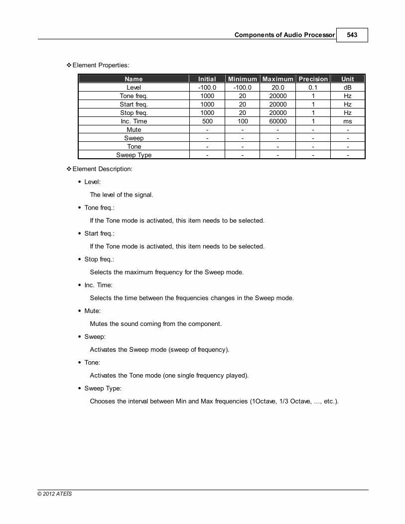
Components of Audio Processor 543
© 2012 ATEÏS
Element Properties:
Name Initial Minimum Maximum Precision Unit
Level -100.0 -100.0 20.0 0.1 dB
Tone freq. 1000 20 20000 1 Hz
Start freq. 1000 20 20000 1 Hz
Stop freq. 1000 20 20000 1 Hz
Inc. Time 500 100 60000 1 ms
Mute - - - - -
Sweep - - - - -
Tone - - - - -
Sweep Type - - - - -
Element Description:
Level:
The level of the signal.
Tone freq.:
If the Tone mode is activated, this item needs to be selected.
Start freq.:
If the Tone mode is activated, this item needs to be selected.
Stop freq.:
Selects the maximum frequency for the Sweep mode.
Inc. Time:
Selects the time between the frequencies changes in the Sweep mode.
Mute:
Mutes the sound coming from the component.
Sweep:
Activates the Sweep mode (sweep of frequency).
Tone:
Activates the Tone mode (one single frequency played).
Sweep Type:
Chooses the interval between Min and Max frequencies (1Octave, 1/3 Octave, ..., etc.).

ATEIS - IDA8544
© 2012 ATEÏS
6.18.3 White
Component Template:
Component Appearance:
Description:
This component generates a White noise. The White noise is a random signal (or process) with aflat power spectral density. In other words, the signal contains equal power within a fixed bandwidthat any center frequency.
An infinite-bandwidth, a white noise signal is purely a theoretical construction. By having power at allfrequencies, the total power of such a signal is infinite and therefore impossible to generate. Inpractice, however, a signal can be "white" with a flat spectrum over a defined frequency band.
For example, it can be used to set up the equalization for a concert or other performance in a venue.A short burst of white or pink noise is sent through the PA system and monitored from variouspoints in the venue so that the engineer can tell if the acoustics of the building naturally boost or cutany frequencies. The engineer can then adjust the overall EQ to ensure a balanced mix.
Control Window:
Element Properties:

Components of Audio Processor 545
© 2012 ATEÏS
Name Initial Minimum Maximum Precision Unit
Mute - - - - -Level -100.0 -100.0 20.0 0.1 dB
Element Description:
Mute
Mutes the sound coming from the component.
Level
The level of the white noise.
6.19 Output
6.19.1 Output
Component Template:
Component Appearance:
Description:
The analog output modules represent the physical analog outputs accessible on the rear panel ofthe device. There are several separate modules for use with each of the audio boards. Analog inputand output modules are added automatically to the DSP window of the relevant processor bydefining their module configuration at the time you create them and should not be altered.
Control Window:

ATEIS - IDA8546
© 2012 ATEÏS
Element Properties:
Name Initial Minimum Maximum Precision Unit
Overload Off - - - -
Volume -50.0 -50.0 20.0 0.1 dBu
Mute Off - - - -
Signal Off - - - -
Level 0 -60.0 20.0 0.1 dB
Overload thd. 3.0 -20.0 20.0 0.1 dB
Element Description:
Overload:
Indicates the channel level above the chosen Overload Threshold (dB).
Volume:
The meter shows the channel level.
Mute:
Mutes or unmutes the output channel, the LED lights in red while the channel is muted.
Signal:
Indicates if a channel is activated or not.

Components of Audio Processor 547
© 2012 ATEÏS
Level:
The signal output level of the module.
Overload thd.:
Sets the threshold of the overload indicator.
6.19.2 Monitor Output
Component Template:
Component Appearance:
Description:
The monitor output modules represent the amplifier zone output accessible on the rear panel of thedevice. There are 2 separate modules for use with the zone boards 1 and 2. Analog input and outputmodules are added automatically to the DSP window of the relevant processor by defining theirmodule configuration at the time you create them and should not be altered.
Control Window:

ATEIS - IDA8548
© 2012 ATEÏS
Element Properties:
Name Initial Minimum Maximum Precision Unit
Overload Off - - - -
Volume -50.0 -50.0 20.0 0.1 dBu
Mute Off - - - -
Signal Off - - - -
Level 0 -60.0 20.0 0.1 dB
Overload thd. 3.0 -20.0 20.0 0.1 dB
Element Description:
Overload:
Indicates the channel level above the chosen Overload Threshold (dB).
Volume:
The Meter shows the channel level.
Mute:
Mutes or unmutes the output channel, the LED lights in red while the channel is muted.
Signal:
Indicates a channel is activated or not.

Components of Audio Processor 549
© 2012 ATEÏS
Level:
The signal output level of the module.
Overload thd.:
Sets the threshold of the overload indicator.
6.19.3 Mono Output
Component Template
Component Appearance:
Description:
For AES/EBU output, the mono output modules represent the physical outputs accessible on therear panel of the device. There are several separate modules for use with each of the audio boards.Input and output modules are added automatically to the DSP window of the relevant processor bydefining their module configuration at the time you create them and should not be altered.
Control Window:

ATEIS - IDA8550
© 2012 ATEÏS
Element Properties:
Name Initial Minimum Maximum Precision Unit
Overload Off - - - -
Volume -50.0 -50.0 20.0 0.1 dBu
Mute Off - - - -
Signal Off - - - -
Level 0 -60.0 20.0 0.1 dB
Overload thd. 3.0 -20.0 20.0 0.1 dB
Element Description:
Overload:
Indicates the channel level above the chosen Overload Threshold (dB).
Volume:
The Meter shows the channel level.
Mute:
Mutes or unmutes the output channel, the LED lights in red while the channel is muted.
Signal:
Indicates a channel is activated or not.

Components of Audio Processor 551
© 2012 ATEÏS
Level:
The signal output level of the module.
Overload thd.:
Sets the threshold of the overload indicator.
6.19.4 Stereo Output
Component Template:
Component Appearance:
Description:
For AES/EBU output, the stereo output modules represent the outputs accessible on the rear panelof the device. There are several separate modules for use with each of the audio boards. Input andoutput modules are added automatically to the DSP window of the relevant processor by definingtheir module configuration at the time you create them and should not be altered.
Control Window:

ATEIS - IDA8552
© 2012 ATEÏS
Element Properties:
Name Initial Minimum Maximum Precision Unit
Overload Off - - - -
Volume -50.0 -50.0 20.0 0.1 dBu
Mute Off - - - -
Signal Off - - - -
Level 0 -60.0 20.0 0.1 dB
Overload thd. 3.0 -20.0 20.0 0.1 dB
Element Description:
Overload:
Indicates the channel level above the chosen Overload Threshold (dB).
Volume:
The Meter shows the channel level.
Mute:
Mutes or unmutes the output channel, the LED lights in red while the channel is muted.
Signal:
Indicates a channel is activated or not.

Components of Audio Processor 553
© 2012 ATEÏS
Level:
The signal output level of the module.
Overload thd.:
Sets the threshold of the overload indicator.
6.19.5 Duplex Output
Component Template:
Component Appearance:
Description:
For AES/EBU output, the duplex output modules represent the physical outputs accessible on therear panel of the device. There are several separate modules for use with each of the audio boards.Input and output modules are added automatically to the DSP window of the relevant processor bydefining their module configuration at the time you create them and should not be altered.
Control Window:

ATEIS - IDA8554
© 2012 ATEÏS
Element Properties:
Name Initial Minimum Maximum Precision Unit
Overload Off - - - -
Volume -50.0 -50.0 20.0 0.1 dBu
Mute Off - - - -
Signal Off - - - -
Level 0 -60.0 20.0 0.1 dB
Overload thd. 3.0 -20.0 20.0 0.1 dB
Element Description:
Overload:
Indicates the channel level above the chosen Overload Threshold (dB).
Volume:
The Meter shows the channel level.
Mute:
Mutes or unmutes the output channel, the LED lights in red while the channel is muted.
Signal:
Indicates a channel is activated or not.

Components of Audio Processor 555
© 2012 ATEÏS
Level:
The signal output level of the module.
Overload thd.:
Sets the threshold of the overload indicator.
6.20 Page Control
6.20.1 S/W Page Control
Component Template:
Component Appearance:
Description:
With this component you can activate and route the audio inputs to the outputs. This is not amixer, only one input can be routed to an output.
You cannot have two input channels mixed to an output (even if they have the same priority). In thiscase, the busy LED of the lower channel number will light up and these channels won't be routed.Each output works separately. On each one output, only the channels with the gate ON and with thehighest priority will be routed.
Control Window
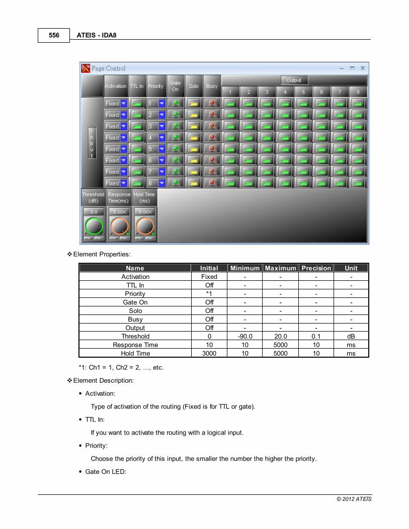
ATEIS - IDA8556
© 2012 ATEÏS
Element Properties:
Name Initial Minimum Maximum Precision Unit
Activation Fixed - - - -
TTL In Off - - - -
Priority *1 - - - -
Gate On Off - - - -
Solo Off - - - -
Busy Off - - - -
Output Off - - - -
Threshold 0 -90.0 20.0 0.1 dB
Response Time 10 10 5000 10 ms
Hold Time 3000 10 5000 10 ms
*1: Ch1 = 1, Ch2 = 2, ..., etc.
Element Description:
Activation:
Type of activation of the routing (Fixed is for TTL or gate).
TTL In:
If you want to activate the routing with a logical input.
Priority:
Choose the priority of this input, the smaller the number the higher the priority.
Gate On LED:

Components of Audio Processor 557
© 2012 ATEÏS
Lights up when the gate is activated (open).
Solo:
Only routes this input.
Busy:
Lights up if the gate of the channel is open but not able be routed to the output because theother channel with higher priority is already activated.
Note: Busy means the gate is open, but the channel is not routed.
Output:
Click on the desired button of the output where the input will be routed to.
Threshold:
Sets the threshold level above which the Gate will open automatically and route the signal.
Response Time:
Adjusts the time between the level's detection and the beginning of the Gate operation.
Hold Time:
Adjusts the time between the end level's detection and the end of the Gate operation.
6.20.2 Network Paging
Component Template:
Component Appearance:

ATEIS - IDA8558
© 2012 ATEÏS
Description:
The Network Paging component routes the input source signal to zones using priority arbitration.The pins at the left side represent the paging sources and the pins at right side are zones. The pinson top side are able to control the paging activity and the pins on the bottom output logic signals totell the status of paging activity. Each source can specify which zone wants to page. Thisperformance does not always succeed when a source is requested for paging because the zonesmay already be occupied by another source.
Network Cascading Paging:
Some applications like station PA system require a huge number of zones for paging. It needs tohave multiple Ateis audio processors connected together using Ateis Net. And for each DSPconfiguration of audio processor, there is a Network Paging component in charge of paging tasks.The following figure shows an example:
Double click the Network Paging component to open the settings window, the following sectionsdescribe the parameters of each tab
Source Type:

Components of Audio Processor 559
© 2012 ATEÏS
A source type is an identification for paging activities. If a zone is occupied by some source forpaging, it needs to know who did this paging and who is the owner of the zone. You can edit thesource type of Network Paging component by using property windows. The procedure is very simple,click Network Paging component on the DSP design window, once Network Paging component isfocused, the property windows revesl all the parameters of it. Click the field of the Source List on theproperty window to edit source types.
General Settings:

ATEIS - IDA8560
© 2012 ATEÏS
Evac:
Enable this option to set the paging source as an evacuation source. If an evacuation source isactivated on paging, An evacuation paging situation is recognized by the IDA8 system, and thedevice shows this state "LED GLOBAL EVAC" on the front panel. Also, this activity will belogged.
Modbus Type:
Set the type of information of the paging source for the 3rd party controller which uses modbusprotocol to get data from Ateis devices.
Note: This setting is only a label and won't affect the behavior of Paging Component.
Modbus Channel:
Set the channel information of the paging source for the 3rd party controller which uses modbusprotocol to get data from Ateis devices.
Note: This setting is only a label and won't affect the behavior of Paging Component.
Activation:
Click the button on the grid to open a window for further settings as shown in the picture below:

Components of Audio Processor 561
© 2012 ATEÏS
There are various modes for triggering a paging activity.
o None:
The paging request is not coming from the Network Paging component itself, If you need toperform a paging using the control console like PPM AS or PSS AS, please select thisoption.
o Permanent:
Means the paging source is always requested for paging. You can choose this option if thesource is background music and keep playing for zones.
o Modulation:
Paging request is recognized/released if the conditions on [Modulation Properties] aresatisfied.
Threshold / Attack Time:
IDA8s acknowledge a paging request of the channel when the signal level iscontinuously higher than the Threshold over Attack time.
Release Time:
IDA8s release the paging request of the channel if the signal level is continuously lowerthan the Threshold over Release time.

ATEIS - IDA8562
© 2012 ATEÏS
o Logic Signal:
A paging request of the channel is established depending on the logic signal of an input.
Basically, if a logic is from Low to High and it will request a paging. On the other hand, iffrom High to Low, it releases a paging request.
The settings allow you to put multiple channels to perform a logic operation AND/OR todetermine the paging activities.
o Modulation + Logic Signal:
Under this mode, IDA8 decides to request a paging if both the modulation and logic signalconditions are satisfied. It releases a paging request if one of the conditions is achieved.
o Paging Event:
Binds a paging event for the zone selection. Only events with a singular type are selectable.See the section "Zone and Priority" below for more details about the paging events.
Zone and Priority:
This section is about the zone section of a paging request, and to specify priority for judgment ifthere are zones conflict with another paging source which occupies it.
There are two types of paging events:
o Integration:
An integration paging event has multiple codes for zone selection. This is for each codewhich is able to assign to the key of control consoles such as PPM AS and PSS AS.
By clicking the ellipsis button, a settings window of an integration paging event appears asshown in the picture below:

Components of Audio Processor 563
© 2012 ATEÏS
Code:
A code is a zone combination so called a selection of zones. The figure above is anexample, the zone combination of the code is (Z1, Z2, and Z3) which means zone 1, 2and 3 will be selected when requesting a page.
All:
Selects all zones for the code.
Zone Selection:
Check the checkbox to specify a zone to be included in a code. The table lists all of thezones of a paging component under the same Ateis Net.
Source Type:
Specifies the source type to bind with the paging event. When a paging event is active(i.e. A paging request is acknowledged by the IDA8, you can say the zones areoccupied by the audio source bound with that paging event). This info (zone:occupiedsource) is used in some logic or procedure of paging component implementation forgiving different results for the user. See the next sections for more details about how theaudio source is also being used.
Priority:
A priority value per zone along with the code. If more than one source is attempting topage the same zone, IDA8 uses the priority value to decide which source is allowed tooccupy the zone for paging.
Note: The smaller the value the higher the priority.
Priority Visible:
A checkbox to show or hide the priority setting inside the grid.
Button All:
Set the same priority value for all zones. The grid for entering the priority value forapplying to all zones is located by the [All] button.

ATEIS - IDA8564
© 2012 ATEÏS
Button Add:
Add codes to event.
Button Remove:
Remove selected code.
o Singular
This event is similar to the integration paging event except that it only has one code.
Refreshing Condition:
This section is about the ending behavior of a paging request and the zone available condition.
Recovery:
If this option is enabled, a paging source will try to take back the zones after another sourcewhich occupied the zones has finished the paging session.
The occupied zone gives back to the active source if both options "Recovery" of theactivated source and "Release" of releasing the source are enabled.
Release:
If this option is enabled, a paging source will release the zone to other active sources afterfinishing its paging session.
Zone Available Percentage:
This is the condition to determine a paging request which can be allowed or denied. If thepercentage of available zones is greater than the number set at "Zone Available Percentage",

Components of Audio Processor 565
© 2012 ATEÏS
the paging succeeds. On the opposite side, the paging request is denied. The available zonesmeans the being-paged zones are not occupied by other sources or occupied by other sourceswith lower priority.
Chime:
Network Paging component provides the ability of chime playing before and at the end of a pagingsession. To specify the chimes bound to a source using the tab [chime] of the "Network Pagingsetting" window, click the cell on grid and the second layer window opens:
You can select the chime listed in grid table of [PC] tab or from [Device] tab. The button [Open]allows you to change the directory for browsing files.
Logic Out Trigger:

ATEIS - IDA8566
© 2012 ATEÏS
There 20 channel logic outputs for each Network Paging component. This section shows theconfiguration about it.
Start:
Generates a pulse to a specific logic out when a paging begins.
Stop:
Generates a pulse to a specific logic out when a paging stopped.
ACK:
The specific logic output stays High during the paging session.
Busy:
Checks all selected zones which are occupied by the other source with higher priority.
Fault:
The specific logic output stays High if any of the selected zones have an error.
Relay:

Components of Audio Processor 567
© 2012 ATEÏS
It is able to output a logical High to a specific output channel in condition of a zone is occupied by aspecific source. In the above figure, logic out channel 1 will stay High if zone 1 is occupied by PSSAS's source.

ATEIS - IDA8568
© 2012 ATEÏS
6.21 RS485 Audio
6.21.1 RS485 Input
Component Template:
Component Appearance:
Description:
This component controls and monitors the RS485 input signal parameters. The input componentrepresents the physical analog inputs accessible on the RS485 port of the Audio Processor. Thereare four ports (A to D) which represent different channels of the RS485 port. Some consoles likePSS AS which transfers audio signals via PDC port is the RS485 interface. To process an audiosignal with another DSP component, you need to create a RS485 Input component in the designwindow.
Control Window:

Components of Audio Processor 569
© 2012 ATEÏS
Element Properties:
Name Initial Minimum Maximum Precision Unit
Bypass Off - - - -
Mute Off - - - -
RTO Off - - - -
Overload Off - - - -
Volume -20.0 -20.0 20.0 0.1 dB
Signal Off - - - -
Level 0 -60.0 20.0 0.1 dB
Overload Thd. -20.0 -20.0 20.0 0.1 dB
Element Description:
Bypass:
Bypasses the audio of the channel.
Mute:
Mutes the audio of the channel.
RTO:
Indicates an input channel which is 'Routed To Output(s)'.
Overload:

ATEIS - IDA8570
© 2012 ATEÏS
This LED lights up if the signal of the input channel is greater than the Overload Thd.
Volume:
The VU-Meter shows the channel RMS level.
Signal:
Indicates if an audio signal presents above -30 dB from the chosen 'Sensitivity'.
Level:
The signal output level of the channel.
Overload Thd.:
A threshold value to determine if the signal of a channel is overloaded.
6.21.2 RS485 Output
Component Template:
Component Appearance:
Description:
This component controls and monitors the RS485 output signal parameters. The output componentrepresents the physical analog inputs accessible on the RS485 port of the Audio Processor. Thereare four ports (A to D) which represent different channels of the RS485 port. Some consoles likePSS AS which transfers audio signals via PDC port is the RS485 interface. To outputs an audiosignal via RS485 port, you need to create a RS485 output component in the design window.
Control Window:

Components of Audio Processor 571
© 2012 ATEÏS
Element Properties:
Name Initial Minimum Maximum Precision Unit
Overload Off - - - -
Volume -20.0 -20.0 20.0 0.1 dB
Mute Off - - - -
Signal Off - - - -
Level 0 -60.0 20.0 0.1 dB
Overload Thd. 3.0 -20.0 20.0 0.1 dB
Element Description:
Overload:
This LED lights up if the signal of the input channel is greater than the Overload Thd.
Volume:
The VU-Meter shows the channel RMS level.Mute:
Mutes the audio of the channel.
Signal:
Indicates if an audio signal presents above -30 dB from the chosen 'Sensitivity'.

ATEIS - IDA8572
© 2012 ATEÏS
Level:
The signal output level of the channel.
Overload Thd.:
A threshold value to determine if the signal of a channel is overloaded.
6.22 Selector
Component Template:
Component Appearance:
Description:
A simple selector allowing the user to select which input is routed to the single output.
Control Window:
Element Properties:
Name Initial Minimum Maximum Precision Unit
Input Select CH1 - - - -

Components of Audio Processor 573
© 2012 ATEÏS
Element Description:
Input Select:
Open the drop-down list to select the input.
6.23 Signal Monitor
Component Template:
Component Appearance:
Description:
This component detects the input signal and shows its active status. If the condition is satisfied theelement "Trigger On" will be set to On and the logic output channel will be set to High.
Control Window:

ATEIS - IDA8574
© 2012 ATEÏS
Element Properties:
Name Initial Minimum Maximum Precision Unit
Trigger On Off - - - -
Threshold -20.0 -50.0 20.0 0.1 dB
Volume -40.0 -40.0 20.0 0.1 dB
Response Time 0 0 500 10 ms
Hold Time 300 10 5000 10 ms
Element Description:
Trigger On:
Shows if the input signal is activated or not. If the input signal is continuously greater than theThreshold over the Response Time, the Trigger On value will be set to 1 and the correspondinglogic output is set to High.
Threshold:
The threshold to determine if the audio input is activated or not.
Volume:
The volume of the input signal.
Response Time:
The time to determine if an audio input is activated or not.
Hold Time:
The time to determine if an audio input is activated or not.

Components of Audio Processor 575
© 2012 ATEÏS
6.24 Telephone Card
6.24.1 TC Transmit
Component Template:
Component Appearance:
Description:
This component allows the Ateis Device to dial or receive phone calls which need to work withtelephone card hardware. The following items are definitions of pins on the component:
Pins on top side:
o Rd: Redials when the state of a signal is from low to high.
o F: Flashes, to make a 3-way calling. Active if state of signal from lo to hi.
Pins on bottom side:
o Rd: Ready status.
o S: Set status
o F: Fault status
o C: Connect status
o D: Dialing status
o Ri: Ringing status

ATEIS - IDA8576
© 2012 ATEÏS
o B: Busy status
o M: MCU status
Control Window:
Element Properties:
Name Initial Minimum Maximum Precision Unit
Dialing Off - - - -
Ringing Off - - - -
Set Off - - - -
Ready Off - - - -
Mute Off - - - -
Connect Off - - - -
Busy Off - - - -
MCU Off - - - -
Fault Off - - - -
Level 0 -15.0 12.0 0.1 dB
Delay Key None - - - -
Delay Time 2 1 7 1 Second
Element Description:
Dial:
This button has two functions:
Dial: Makes a phone call. Dials the number in Current Number field.
Accept phone call: In case of an incoming phone call, press the Dial button to accept it.
Hang up:

Components of Audio Processor 577
© 2012 ATEÏS
Hangs up the telephone.
Digit Keys:
16 Digit Keys at the left part of the control window on the panel includes numbers "0" to "9",symbols "*" and "#", letters from "A" to "D". The numbers will be shown in the "Current Number"field while dialing. Note: If pressing digit keys during a phone call, this component sends aDTMF signal to the remote.
Current Number:
Records the number dialed or displays incoming calls.
Back:
Erases the last digit of the current Number.
Last Number:
The latest number dialed.
Redial:
Redials the Last Number.
Dialing:
Indicates the telephone card is dialing.
Ringing:
Indicates an incoming call needs to be accepted.
Set:
The LED lights up if the external telephone connected to the telephone card is off the hook.
Ready:
Indicates the status of the telephone card. This LED lights up if the telephone line is ready tomake a call.
Connect:
Indicates the telephone card is making a call.
Busy:
The LED shows the remote telephone is in the busy state and is not allowed to accept anyother calls.
MCU:
Reserved for displaying the engineering status.
Fault:
Determines if there is an error on the telephone line or not.
Mute:
Mutes the transmitting audio.

ATEIS - IDA8578
© 2012 ATEÏS
Flash:
This button allows a 3-way telephone conversation. Press this button during the connection ofthe first remote phone and dial the number of the second remote telephone. Once the secondremote accepts the call, press the Flash button again.
Level:
Adjusts the level of the transmitting audio.
Delay key define:
Defines the key for delay. For some telephone systems, it will needs to dial 0 for an outside linebefore dialing the required number. Between 0 and the outside phone number, it requires a shortdelay. In this case, you can define digit "#" for a delay. The number to dial should be"0#XXXXXXXXXX" where X is the outside phone number you want to call.
Delay Time:
Sets the delay time for a delay digit.
6.24.2 TC Receive
Component Template:
Component Appearance:
Description:
This component receives a telephone call and detects if a DTMF tone output logic signal responsedto the key pressing on remote telephone. This needs to work with the telephone card hardware. Thepins at the lower part of the component outputs the DTMF status.

Components of Audio Processor 579
© 2012 ATEÏS
Control Window:
Element Properties:
Name Initial Minimum Maximum Precision Unit
Caller Mute Off - - - -
Caller Level 0 -15.0 12.0 0.1 dB
Ring Mute Off - - - -
Ring Level 0 -15.0 12.0 0.1 dB
Phone Answer Manual - - - -
Noise Suppression On - - - -
Line Echo Cancellation On - - - -
Voice Enhance On - - - -
Element Description:
Caller Mute:
Mutes the audio of a caller.
Caller Level:
Adjusts the audio level of a caller.
Ring Mute:
Mutes the ring audio.
Ring Level:
Adjusts the level of a ring.
DTMF:
If the caller presses any key on the phone after an incoming call was accepted, the telephonecard will detect and display the status on the control window and change the state of the logicoutput corresponding to the number detected.

ATEIS - IDA8580
© 2012 ATEÏS
History:
Displays the history of the DTMF numbers.
Phone Answer:
The mode of action for answering incoming calls. There are two types of modes:
o Manual:
Press the Dial button on the control window of TC Transmit for accepting calls.
o After N Rings:
The telephone accepts calls automatically after ringing N times.
Noise Suppression:
Enables or disables the noise suppression function.
Line Echo Cancellation:
Enables or disables the line echo cancellation function.
Voice Enhance:
Enables or disables the voice enhance function.
6.25 Voxnet Control
Component Template:
Component Appearance:
Description:

Components of Audio Processor 581
© 2012 ATEÏS
This component is a bridge between the Ateis device and the Voxnet device. It maps the key in theVoxnet protocol to the code in an event for paging control.
Settings Window:
There are two channels for paging with Voxnet source, each source with the following settings:
Paging Event:
Specify the paging event to bind with the Voxnet source for paging.
Key:
Represents the key of the Voxnet protocol.
Value:
Specifies the code which is mapped to the key. Each code represents a zone selectioncombined for paging.
All:
Selects all zones.
Zone Selection:
Check the checkbox inside the grid at the right side of window to select a zone for paging.

ATEIS - IDA8582
© 2012 ATEÏS
7 Contact Information
http://www.ateis.com
ATEÏS Europe BV ATEÏS Suisse SAAddress:
Sydneystraat 423047BP ROTTERDAM, NETHERLANDS
T : +31 (0)10 2088690F : +31 (0)10 2088699
Address:Chemin du Dévent
1024 Ecublens, SwitzerlandT : +41 (0) 21 881 25 10F : +41 (0) 21 881 25 09
ATEÏS France Siège ATEÏS Germany GmbH.Address :
34, avenue de l’Europe, Z.A Font Ratel 38640 CLAIX, FRANCET : 33 (0) 4 76 99 26 30F : 33 (0) 4 76 99 26 31
Address:Kirchenstrasse 11
D-82194 Gröbenzell, DeutschlandT : +49 (0)8142/305070-30F : +49 (0)8142/305070-39
ATEÏS Middle East Penton/ATEÏS USA.Address:
Light Industrial Unit 11 Dubai Silicon Oasis,
Dubai United Arab EmiratesT : +971 4 3262730F : +971 4 3262731
Address:21 Sabin St. Pawtucket, RI 02860, USA
T : 401-727-1600F : 401-727-0003
ATEÏS FAR EAST CORP. ATEÏS SE Pte Ltd.Address:
No.60, Xinghua 2nd Rd, Tanzi, Taichung 427, TaiwanT : +886-4-25333820F : +886-4-25333830
Address:Blk 5000 Ang Mo Kio Ave 5
Techplace II #02-10569870, Singapore, Singapore
T : +65 64811968F : +65 64811378
ATEÏS ChinaAddress:
Room 610, No. 255 Wubao Road,Minxing district, Shanghai, China
T : 021-54495191/92F : 021-54495193