iced'07/71 1 a conceptual design support methodology based on structural optimization...
TRANSCRIPT
ICED’07/71 1
INTERNATIONAL CONFERENCE ON ENGINEERING DESIGN, ICED’07 28 - 31 AUGUST 2007, CITE DES SCIENCES ET DE L'INDUSTRIE, PARIS, FRANCE
A CONCEPTUAL DESIGN SUPPORT METHODOLOGY BASED ON STRUCTURAL OPTIMIZATION TECHNIQUES USING FUNCTION-ORIENTED ELEMENTS Akihiro Takezawa1, Shinji Nishiwaki2, Kazuhiro Izui2, Masataka Yoshimura2, and Nozomu Kogiso3 1Department of Social and Environmental Engineering, Hiroshima University, Kagamiyama Higashi-Hiroshima, Hiroshima, 739-8527, Japan 2Department of Aeronautics and Astronautics, Kyoto University, Yoshida Honmachi Sakyo, Kyoto, 606-8501, Japan 3Department of Aerospace Engineering, Osaka Prefecture University,1-1 Gakuen-Cho, Naka-Ku, Sakai, 599-8531, Japan
ABSTRACT Enhancement of product capabilities at the conceptual design phase is an important issue when developing high performance mechanical products. Maximizing the range of conceptual and basic ideas concerning essential structural and mechanical design features improves the likelihood of successful results at the conceptual design phase, since these features directly affect fundamental product performances. This paper discusses a new design support method based on structural optimization techniques, for use at the conceptual design phase, which assists the decision-making of design engineers working to obtain innovative and high performance mechanical structures. To achieve this, a new concept of structural discrete elements is introduced, namely, "function-oriented elements", defined as structural elements that have a specific function, intentionally implemented by a design engineer in order to clarify insights concerning the achieved optimality of the optimal mechanical structures from a mechanics point of view. Finally, several numerical examples confirm the validity and utility of the proposed method, which should offer useful support to mechanical design engineers at the conceptual design phase.
Keywords: Conceptual Design, Structural Optimization, Topology Optimization, Discrete Elements, Reliability-based Optimization
1 INTRODUCTION This paper proposes a new conceptual design support method to obtain innovative designs
based on structural optimization techniques. This method aims to support the decision-making of design engineers working to obtain innovative designs and evaluate mechanical design details at the conceptual design phase of mechanical structures such as automotive bodies and machine tools.
Enhancement of product capabilities at the conceptual design phase is an important issue when developing high performance mechanical products. Maximizing the range of conceptual and basic ideas concerning essential structural and mechanical design features improves the likelihood of successful results at the conceptual design phase, since these features directly affect fundamental product performances. More meaningful conceptual design drafts can also minimize the number of modifications required at the evaluation phase that follows the detailed design phase, and can shorten the total development period.
Several conceptual support methods are described in current mechanical design literature, among them Pugh’s method (the decision-matrix method) [1], a method used for concept selection using a scoring matrix. There are also a number of other support schemes such as the analytic hierarchy process (AHP) [2], a method for formalizing decision making based on a pair comparison
ICED’07/71 2
method; the quality function deployment (QFD) method [3], which focuses on the core items of information necessary to understand the relationship between customer needs and product functions based on house of quality matrices; and TRIZ [4], a methodology identifying physical working principles for solving problems based on past inventions and patents. Application of these methodologies to actual design problems has been reported [5], [6]. However, research thus far has shown that these methods are effective for certain system design application, rather than mechanical structural design applications, since they do not deal with quantitative performance evaluations.
Structural optimization methods have the potential to manage the quantitative performance evaluations that are crucial to successful structural designs, and to rationally offer alternative improved design drafts based on structural mechanics and mathematical optimization methods. In particular, topology optimization [7] offers the greatest potential for exploring ideal and optimized structures. There are several fields in which there are applied examples of supporting methods used during the conceptual design process. For example, Shin et al. [8] used topology optimization for automotive door design, and Maute and Allen [9] used it for the conceptual design of aeroelastic structures. However, these methods have inherent difficulties that hinder their application to practical structural designs, since all rely on ordinary topology optimization methods based on continuum mechanics. In topology optimization methods based continuum mechanics, the optimal configurations are obtained as material distributions, which give little insight into the underlying reasons for achieved optimality. Thus, it appears that ordinary topology optimization methods are inherently unsuitable for supporting the decision-making of design engineers working to optimally configure assembled mechanical structures composed of frames, panels, and joints, such as automotive body and aircraft structures at the conceptual design phase.
The use of discrete structural elements [10]-[15] is one of several ways to overcome the above problem, since each discrete structural element has its particular function and provides useful information for decision making during the conceptual design process. For example, frame and panel elements, typically used as discrete structural elements, have specific structural characteristics and functions. That is, frame elements are stiff in the axial direction but compliant in the direction of bending, while panel elements are stiff in the in-plane direction but weak in the out-plane direction. Therefore, the optimal configurations obtained by using these elements are usually composed of element configurations where each element is allocated according to its particular function, and the information that these element configurations provide can clarify structural relationships and mechanical validity more easily than hexahedral finite elements, which are usually used for finite element analysis, as the effects and functions of frame and panels are emphasized. This type of information is very useful to mechanical design engineers since they can easily understand the role of each discrete structural element in the context of the optimal configuration of the structure being designed.
Note that it is important for design engineers to understand such details, since the conceptual design drafts may be modified to accommodate other specifications during the detailed design phase, and it is very difficult to carry out such modifications without this kind of useful knowledge. Furthermore, since these elements do not need detailed shape information, such as is required for analysis, optimal designs and evaluations can be made even at the conceptual design phase, where design engineers focus on the best conceptual configurations or rough outlines of design ideas.
In this paper, we first propose a new concept concerning discrete structural elements termed “function-oriented elements”, to more effectively support the conceptual design process where function-oriented elements are defined as structural elements that have a specific function, intentionally implemented by a design engineer in order to clarify insights concerning the achieved optimality of the optimal configurations from a mechanics point of view. These function-oriented elements can be fictitious, and are not expected to provide accurate quantitative physical values in the way ordinary that finite elements do through numerical analysis. Typical examples are a frame element having an intentionally simplified cross-section, and a shear panel element, both of which are formulated in this research.
Next, the proposed structural topology optimization method utilizing function-oriented elements is constructed. In the optimization formulation, the objective functions deal with the mean compliance and mean eigen-frequency (mean eigen-value), and their system reliability indexes, i.e., reliability measures that consider both the mean compliance and mean eigen-frequency. Generally, these are the most fundamental performance metrics of mechanical structures and many structural
ICED’07/71 3
optimization problems in which they are treated as design goals have been reported (e.g., stiffness problems [7],[15], vibration problems [16]-[18] and system reliability problems [19]-[21]). Finally, several numerical examples confirm the validity and utility of the proposed method, which should provide useful support to mechanical design engineers working at the conceptual design phase.
2 FORMULATIONS
2.1 Concept of Topology Optimization The optimization is performed based on topology optimization techniques [7]. The key ideas of the proposed method are the introduction of a fixed and extended design domain D that includes the original design domain Ωd, and the utilization of the following characteristic function that indicates the existence of a function-oriented element. Suppose that a fixed and extended design domain D is composed of n function-oriented elements. The existence of the i-th element is expressed by the characteristic function iχ :
1 if exists in for =1,...,
0 if does not exist in d
id
i nχΩ⎧
= ⎨ Ω⎩ (1)
An optimal structure is obtained by the existence of necessary elements in the design domain Ωd using this characteristic function. This approach is also termed the ground structure approach [10], [11], where a set of fixed nodal points and some possible connections using elements are first constructed, and an optimal configuration is then obtained by eliminating unnecessary elements in the design domain using an optimization scheme. Thus, the optimization problem can be interpreted as a combinatorial problem that includes finite discontinuities that express the existence or non-existence of elements, and it is therefore not easily treated numerically. To overcome this difficulty, Eq. (1) is relaxed to a continuous variable using the following equations, whose formulation is based on the concept of the density approach.
with 0 1pi v vχ ρ ρ≈ ≤ ≤ (2)
where ρv is a normalized design variable, and p is a penalization parameter emphasizing the influence that design variable ρv has on calculations. In order to achieve consistency between the normalized design variable and the actual design variable, p is set to 1. In cases where "exaggerated" optimal configurations are desired, which are composed of elements having higher and lower (but not intermediate) design variables, the penalization parameter can be set to 2 or 3. Using Eq. (2), the original combinatorial problem is replaced by an element distribution problem, and an optimal configuration can be obtained by eliminating unnecessary elements in the design domain using the proposed optimization scheme.
2.2 Objective Functions In this paper, the mean compliance and mean eigen-frequency (mean eigen-value), and their system reliability indexes, i.e., reliability measures considering both the mean compliance and mean eigen-frequency, are considered as the objective functions. Consider an elastic three-dimensional fixed design domain D composed of function-oriented elements, that is fixed at boundary Γu. This domain is subjected to a static load f at boundary Γf , and its displacement vector is denoted u. Body forces applied to the structure are assumed to be ignored for simplicity in the formulation. Stiffness maximization is one of the most important goals for obtaining a stable structure in the static problem at the conceptual design stage. The mean compliance l [7] defined by
Tl = f u (3)
is the measure of the stiffness at boundary Γf when load f is applied. That is, by minimizing the mean compliance l, we obtain sufficient stiffness at boundary Γf . Eigen-frequency maximization is also an important goal for obtaining a stable structure in dynamic problems. Also consider the free vibration problem of the elastic three-dimensional fixed design domain D. Non-structural masses are set in appropriate positions in order to represent non-
ICED’07/71 4
design mechanical parts attached to the design domain. Let jω and 2( )j jλ ω= be the j-th eigen-
frequency and eigen-value, respectively. The maximization of the lowest eigen-value 1λ leads the most stable structure for the dynamic problem. However, switching of the eigen-value order may occur when only the lowest eigen-value 1λ is maximized [16]. To overcome this problem, we use the following objective function, the mean eigen-value Λ , proposed by Ma et al. [16].
1
01 1 0 j
m mj
jj j j
wwΛ λ
λ λ
−
= =
⎛ ⎞⎜ ⎟= +⎜ ⎟−⎝ ⎠
∑ ∑ (4)
where jλ is a specified eigen-value, jw is a given weighting coefficient, 0 jλ is a given parameter, and
0λ is an arbitrary constant. This equation consists of multiple eigen-values, and the sum of all specified eigen-values formulated by Eq. (4) is maximized to avoid the occurrence of changes in their order. System reliability is also an important measure that needs to be evaluated at the conceptual designs, and must be maximized to obtain a stable structure that remains durable when subject to variations in a range of parameters. A variety of design optimization techniques based on reliability analysis have been proposed and such are called Reliability-Based Design Optimization (RBDO) techniques [22]. In this research, the Reliability Index Approach (RIA) [23] is used, a method that handles reliability indexes as if they were probabilistic constraint conditions. Let x be a random variable vector and Gh be the h-th limit state function representing the effect that random variables have on the mechanical structure, according to the following.
0)( <xhG : State of failure (5)
0)( =xhG : Limit state surface (6)
0)( >xhG : State of safety (7)
Furthermore we introduce ( )0)( ≤xhGP , representing the failure probability, and this can be calculated per the following equation:
( ) ∫ ∫≤
==≤0
, )()0(0)(h
hG
hGh dqFGP xxx x (8)
where hGF and ,hqx are respectively the cumulative distribution function and the joint probability
density function of the limit state function Gh. Based on the First-Order Reliability Method (FORM), the j-th target random variable xj is assumed to follow the normal distribution N(mj, σj
2) and xj is then transformed using the following equation:
j jj
j
x mU
σ−
= (9)
where Uj stands for a standard normal random variable. Using this transformation, the reliability index βh is computed by solving the following optimization problem:
Minimize ||U|| (10)
subject to:
G (U) = 0 (11)
Point U* which satisfies the optimization problem is called the Most Probable Point (MPP), and ||U*|| is equal to the reliability index βh, since βh is the distance from the MPP U* to the origin. By maximizing the reliability index βh , we obtain a structure that is sufficiently stable despite a certain amount of variation in a specified parameter. In this research, two specified parameters are considered, namely, the direction of a static load f at boundary Γf in the static problem, and the mass values of non-structural masses in the dynamic case. The above equations involve two failure modes,
ICED’07/71 5
pertaining to the mean compliance and the mean eigen-value. In cases where multiple failure modes need to be considered, the probability of the structural system’s failure is equal to the joint failure probabilities of at least two failure modes expressed as the series system. Therefore, the structural system failure probability Ps can be written as:
[ ] [ ] [ ]s l lP P F P F P F FΛ Λ= + − ∩ (12)
where Fl represents a situation where the mean compliance is larger than its upper limit, and FΛ a situation where the mean eigen-value is lower than its lower limit. P[Fl] and P[FΛ] are the Fl and FΛ occurrence probabilities which can be calculated using the corresponding reliability indexes. The term
][ ΛFFP l ∩ is the probability in which the Fl and FΛ situations occur simultaneously. Using the above equation, the system reliability index βs is computed.
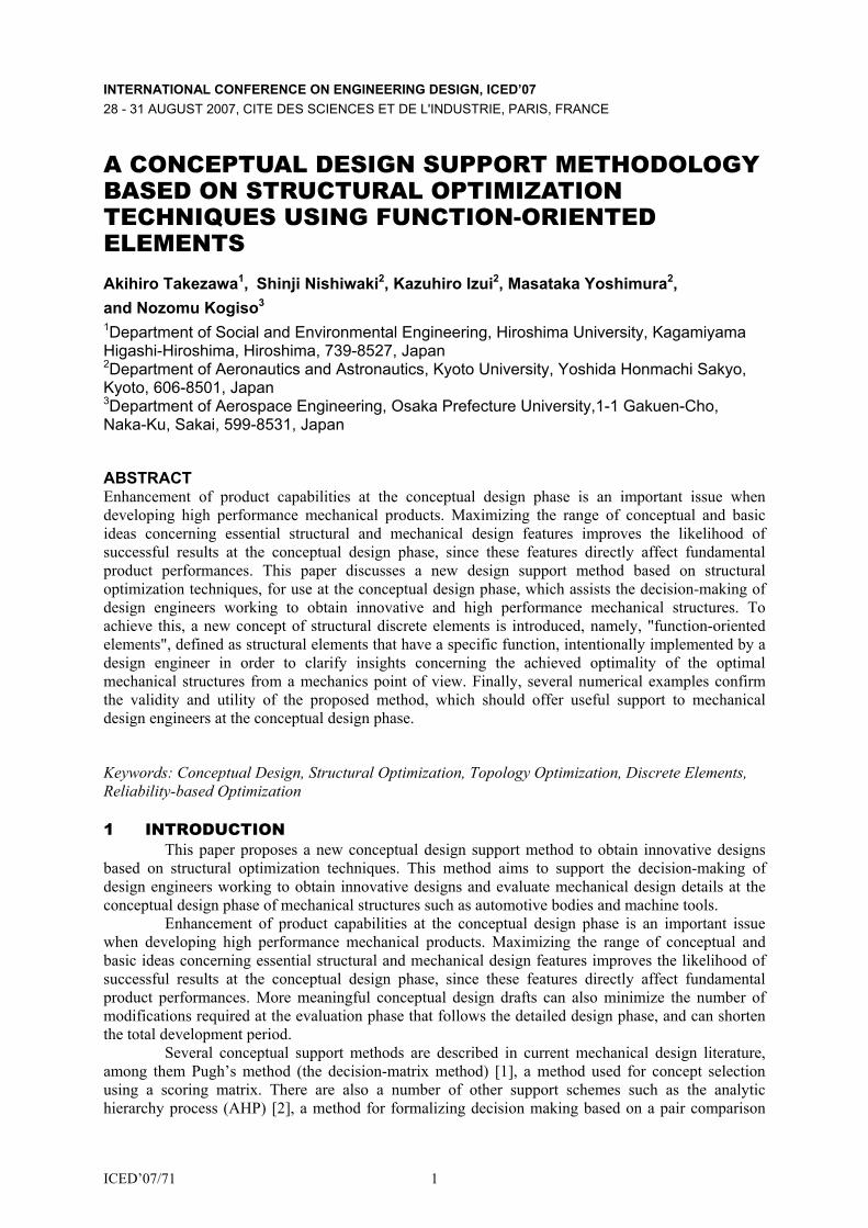
2.3 Design Variable and Element Configuration Settings In this paper, two types of function-oriented elements are considered, namely, intentionally
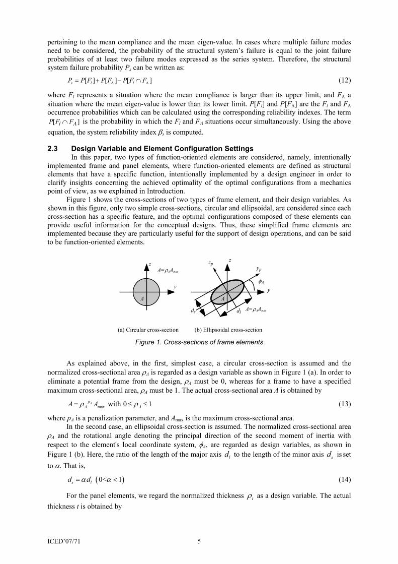
implemented frame and panel elements, where function-oriented elements are defined as structural elements that have a specific function, intentionally implemented by a design engineer in order to clarify insights concerning the achieved optimality of the optimal configurations from a mechanics point of view, as we explained in Introduction. Figure 1 shows the cross-sections of two types of frame element, and their design variables. As shown in this figure, only two simple cross-sections, circular and ellipsoidal, are considered since each cross-section has a specific feature, and the optimal configurations composed of these elements can provide useful information for the conceptual designs. Thus, these simplified frame elements are implemented because they are particularly useful for the support of design operations, and can be said to be function-oriented elements.
y
z
A
A=ρAAmax
y
z
ds dl
A
φA
A=ρAAmax
zpyp
(a) Circular cross-section (b) Ellipsoidal cross-section Figure 1. Cross-sections of frame elements
As explained above, in the first, simplest case, a circular cross-section is assumed and the normalized cross-sectional area ρA is regarded as a design variable as shown in Figure 1 (a). In order to eliminate a potential frame from the design, ρA must be 0, whereas for a frame to have a specified maximum cross-sectional area, ρA must be 1. The actual cross-sectional area A is obtained by
max with 0 1ApA AA Aρ ρ= ≤ ≤ (13)
where pA is a penalization parameter, and Amax is the maximum cross-sectional area. In the second case, an ellipsoidal cross-section is assumed. The normalized cross-sectional area ρA and the rotational angle denoting the principal direction of the second moment of inertia with respect to the element's local coordinate system, φA, are regarded as design variables, as shown in Figure 1 (b). Here, the ratio of the length of the major axis ld to the length of the minor axis sd is set to α. That is,
( ) 0< 1s ld dα α= < (14)
For the panel elements, we regard the normalized thickness tρ as a design variable. The actual thickness t is obtained by
ICED’07/71 6
max with 0 1tpt tt tρ ρ= ≤ ≤ (15)
where pt is the penalization parameter, and maxt is the maximum thickness. The stress assumed method is used to formulate panel elements, and the basic idea is based on the mixed approach. Consider a panel element that consists of four nodes (i.e. quadrilateral-like elements). In such an element, out-of-plane effects are assumed to be neglected, based on the concept of function-oriented elements, since the main role of the panels is to hold the in-plane equilibrium for the design of mechanical structures. In the stress assumed method, we can assume an independent interpolation function for the stress distribution of the displacement's shape function (see [24] for details). Therefore, design engineers can intentionally implement a specified function-oriented panel element to assist their design decisions and evaluations. Here, we assume that the stress distribution s in an element is interpolated as,
11
11 12 12
21 22 21
31 22
31
1 0 0 00 0 1 00 0 0 0 1
x
y s
xy
cc c y y cc c x x c
c cc
σστ
⎧ ⎫⎪ ⎪⎧ ⎫ +⎧ ⎫ ⎡ ⎤ ⎪ ⎪⎪ ⎪ ⎪ ⎪ ⎪ ⎪⎢ ⎥= = + = =⎨ ⎬ ⎨ ⎬ ⎨ ⎬⎢ ⎥
⎪ ⎪ ⎪ ⎪ ⎪ ⎪⎢ ⎥⎩ ⎭ ⎣ ⎦⎩ ⎭ ⎪ ⎪⎪ ⎪⎩ ⎭
s N c (16)
When only the shear stress is considered, the stress distribution s is assumed to be,
11
12
21
31 22
31
0 0 0 0 0 00 0 0 0 0 0
0 0 0 0 1
x
y s
xy
ccc
c cc
σστ
⎧ ⎫⎪ ⎪⎧ ⎫ ⎧ ⎫ ⎡ ⎤ ⎪ ⎪⎪ ⎪ ⎪ ⎪ ⎪ ⎪⎢ ⎥= = = =⎨ ⎬ ⎨ ⎬ ⎨ ⎬⎢ ⎥
⎪ ⎪ ⎪ ⎪ ⎪ ⎪⎢ ⎥⎩ ⎭ ⎣ ⎦⎩ ⎭ ⎪ ⎪⎪ ⎪⎩ ⎭
s N c (17)
We define a panel element formulated according to Eq. (16) as a normal panel element, and a panel element formulated according to Eq. (17) as a shear panel element. Note that the stress assumed method can clarify the characteristics of a panel element by choosing an intentional formulation of the stress distributions. For example, the shear stress distribution assumption in Eq. (17) provides optimal solutions that use the shear stress most efficiently. If optimal configurations obtained by normal and shear panels are nearly similar, design engineers can easily understand that the shear stress is dominant in the optimal configurations. Therefore, we can obtain information useful to an understanding of the mechanical aspect of the structure by comparing the results from using two different types of panel element.
3 NUMERICAL IMPLEMENTATIONS Based on the above objective function and design variable settings, the optimization problem is formulated as follows:
s, , , , , ,minimize , maximize or maximize
A A t A A t A A t
lρ φ ρ ρ φ ρ ρ φ ρ
βΛ (18)
subject to
( ) or and U U UB B P PV V V V V V≤ ≤ ≤ (19)
0 1, 0 1A tρ ρ≤ ≤ ≤ ≤ (20)
fKu = (21)
( ) 0 for 1,2, ,m m m Mλ ϕ− = =K M … (22)
limit state function:
)()(1 xx llG U −= (23)
2 ( ) ( ) LG y= Λ −Λx (24)
ICED’07/71 7
where V is the total volume of the design domain, UV is the upper limit of the total volume, BV is the total volume of the frame elements, U
BV is the upper limit of the frame elements volume, PV is the total volume of the panel elements, U
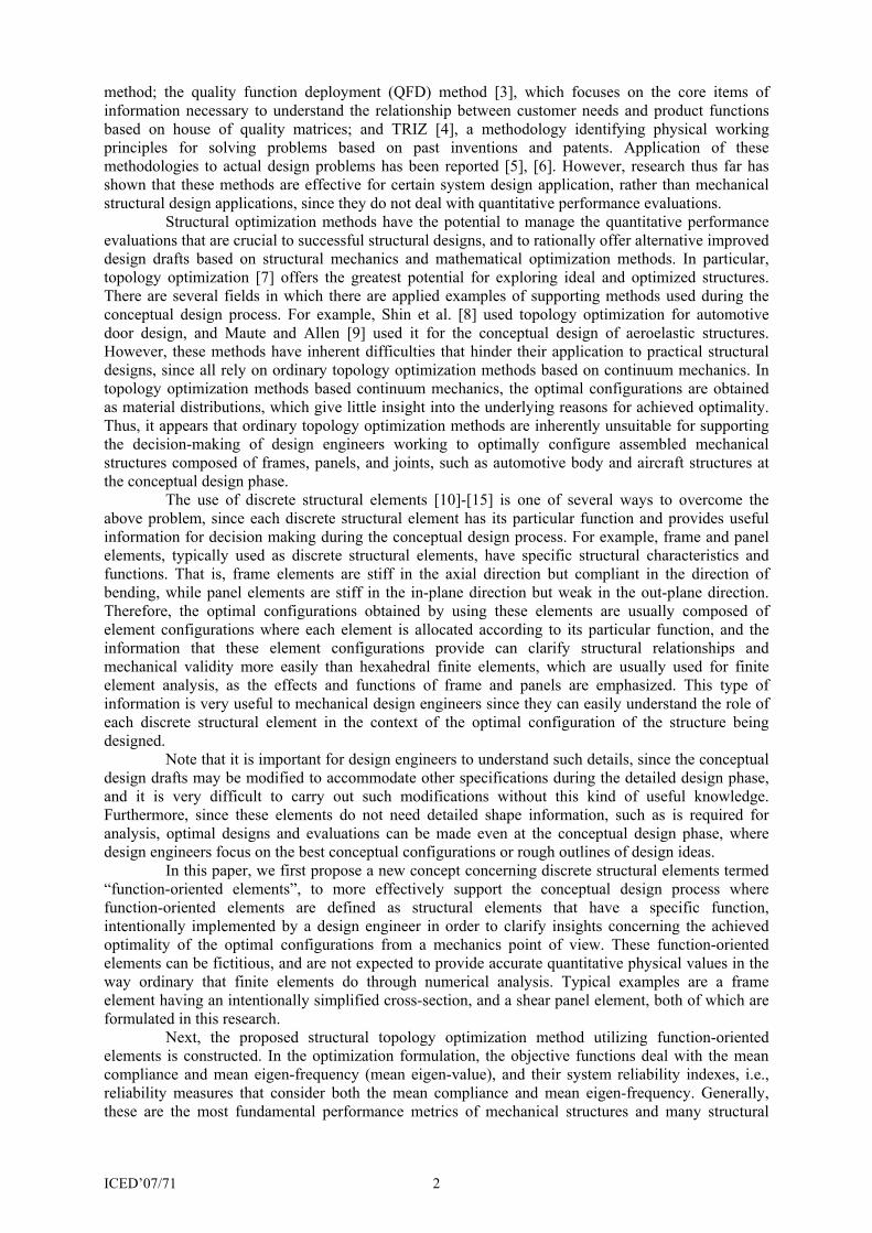
PV is the upper limit of the panel elements volume, mλ and mϕ are respectively the m-th eigen-value and eigen-mode, M is the number of eigen-values considered, Ul is the upper limit of the mean compliance value, and LΛ is the lower limit of the mean eigen-value. A flowchart of the optimization procedure is illustrated in Figure 2. As shown in figure, first, a global stiffness matrix K and a global mass matrix M are constructed. Next, the static equilibrium equation is solved to obtain the mean compliance l as well as the displacement vector u. Also, the vibration equation is solved to obtain the eigen-values jλ and the corresponding eigenvectors jφ . In
the third step, the reliability index for the mean compliance lβ , the reliability index for the mean eigen-value βΛ , and the system reliability index sβ are evaluated, if needed, where the mode reliability indexes lβ and βΛ are computed by HL-RF algorithms. In the fourth step, the objective function and the total volume of the design domain V are computed. Next, the sensitivities of the objective function as well as the total volume with respect to all design variables are calculated, if the optimization has not converged. After updating the design variables, the procedure returns to the second step.
Construct K and M matrices
Input dataInput data
Calculate sensitivities of the objective function and total volume
Convergence
Calculate the objective function and total volume
No
YesEnd
Solve static equilibrium equation and/or vibration equation
Update design variables
Calculate reliability indexes
Figure 2. Flowchart of optimization procedure
4 NUMERICAL EXAMPLES The following several numerical examples explicate the physical and structural characteristics of the optimal configurations, and confirm the utility of the proposed optimization method. In all examples, the assumed material is steel with a Young modulus, Poisson’s ratio, and mass density of 209 GPa, 0.3, and 7.85×10³ kg/m3, respectively. Penalization parameters Ap and tp are set to 1.0 in order to achieve consistency between the normalized design variable and the actual design variable. For the dynamic problem, m and 0λ are set to 3 and 0, respectively, and jw and 0 j
λ are set to 1 and 0,
respectively, in the objective function formulated according to Eq. (4).
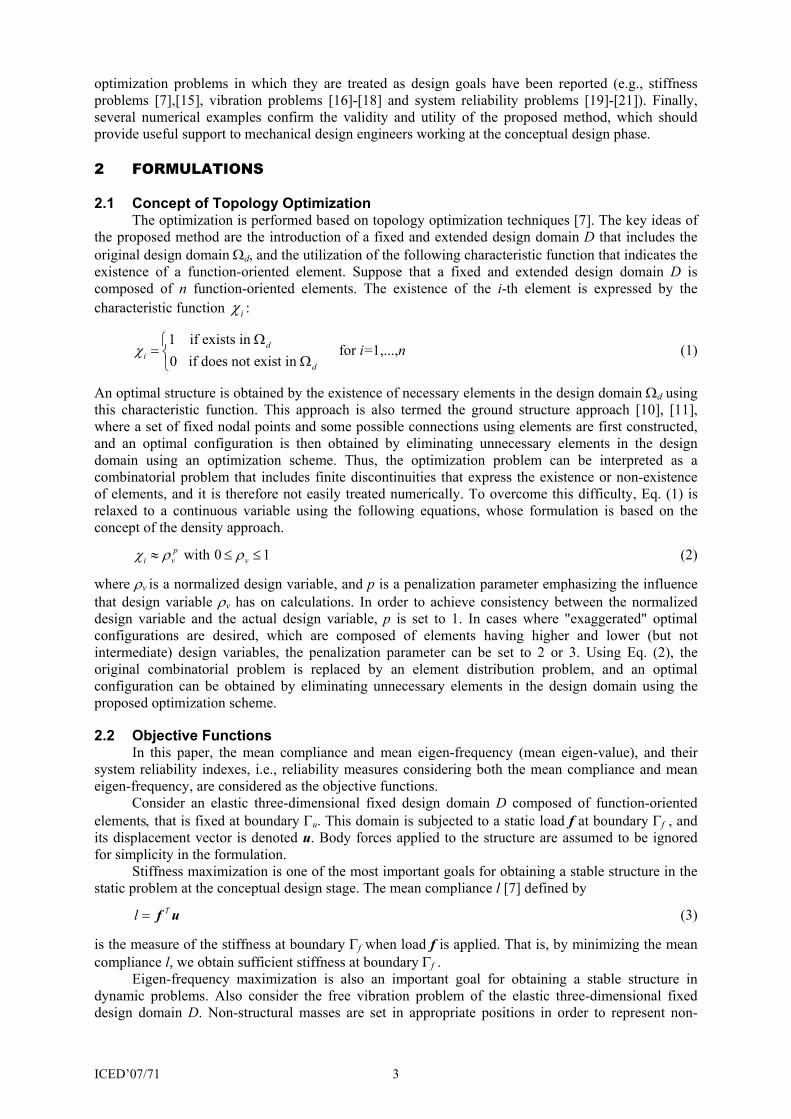
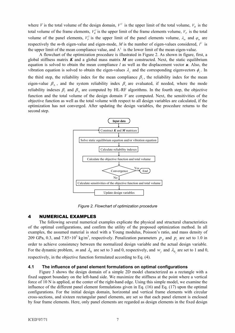
4.1 The influence of panel element formulations on optimal configurations Figure 3 shows the design domain of a simple 2D model characterized as a rectangle with a fixed support boundary on the left-hand side. We maximize the stiffness at the point where a vertical force of 10 N is applied, at the center of the right-hand edge. Using this simple model, we examine the influence of the different panel element formulations given in Eq. (16) and Eq. (17) upon the optimal configurations. For the initial design domain, horizontal and vertical frame elements with circular cross-sections, and sixteen rectangular panel elements, are set so that each panel element is enclosed by four frame elements. Here, only panel elements are regarded as design elements in the fixed design
ICED’07/71 8
domain, while the frame elements are not. In the optimization scheme, the cross-sectional area of the frame elements is set to 8 23.14 10 m−× , which corresponds to a radius of 41.0 10 m−× , a very small value used to avoid singularity of the equilibrium equation, which could occur since the panel elements do not have stiffness in the out-of-plane direction, and also to make the influence of stiffness of the frame elements negligible. The maximum thickness maxt is set to 33.0 10 m−× , and the upper limit of the total volume UV is set to 30% of the volume of the entire design domain.
Figure 3. Design domain for simple problem 1
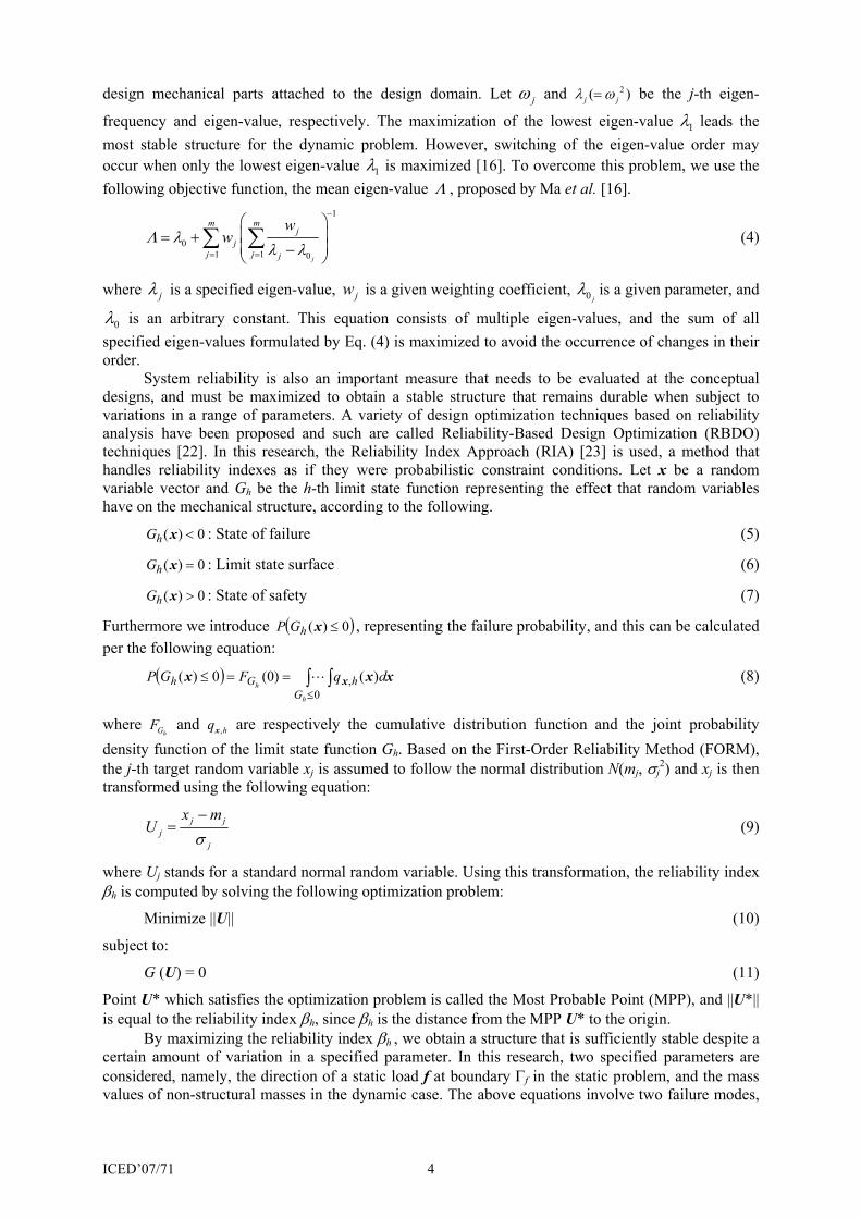
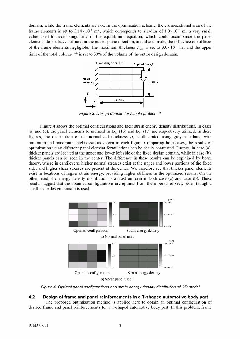
Figure 4 shows the optimal configurations and their strain energy density distributions. In cases (a) and (b), the panel elements formulated in Eq. (16) and Eq. (17) are respectively utilized. In these figures, the distribution of the normalized thickness tρ is illustrated using grayscale bars, with minimum and maximum thicknesses as shown in each figure. Comparing both cases, the results of optimization using different panel element formulations can be easily contrasted. Further, in case (a), thicker panels are located at the upper and lower left side of the fixed design domain, while in case (b), thicker panels can be seen in the center. The difference in these results can be explained by beam theory, where in cantilevers, higher normal stresses exist at the upper and lower portions of the fixed side, and higher shear stresses are present at the center. We therefore see that thicker panel elements exist in locations of higher strain energy, providing higher stiffness in the optimized results. On the other hand, the energy density distribution is almost uniform in both case (a) and case (b). These results suggest that the obtained configurations are optimal from these points of view, even though a small-scale design domain is used.
(a) Normal panel usedOptimal configuration Strain energy density
Optimal configuration Strain energy density(b) Shear panel used
Figure 4. Optimal panel configurations and strain energy density distribution of 2D model
4.2 Design of frame and panel reinforcements in a T-shaped automotive body part The proposed optimization method is applied here to obtain an optimal configuration of
desired frame and panel reinforcements for a T-shaped automotive body part. In this problem, frame
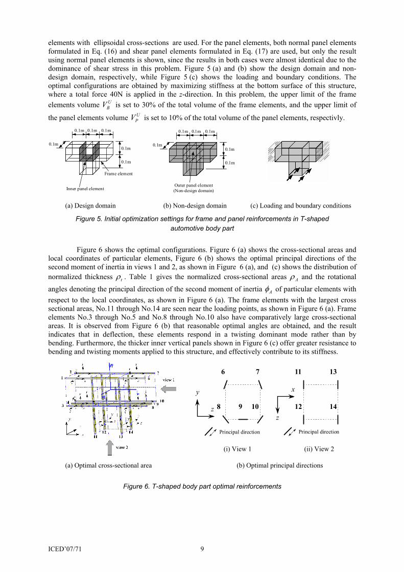
ICED’07/71 9
elements with ellipsoidal cross-sections are used. For the panel elements, both normal panel elements formulated in Eq. (16) and shear panel elements formulated in Eq. (17) are used, but only the result using normal panel elements is shown, since the results in both cases were almost identical due to the dominance of shear stress in this problem. Figure 5 (a) and (b) show the design domain and non-design domain, respectively, while Figure 5 (c) shows the loading and boundary conditions. The optimal configurations are obtained by maximizing stiffness at the bottom surface of this structure, where a total force 40N is applied in the z-direction. In this problem, the upper limit of the frame elements volume U
BV is set to 30% of the total volume of the frame elements, and the upper limit of
the panel elements volume UPV is set to 10% of the total volume of the panel elements, respectivly.
(a) Design domain (b) Non-design domain (c) Loading and boundary conditions
Figure 5. Initial optimization settings for frame and panel reinforcements in T-shaped automotive body part
Figure 6 shows the optimal configurations. Figure 6 (a) shows the cross-sectional areas and
local coordinates of particular elements, Figure 6 (b) shows the optimal principal directions of the second moment of inertia in views 1 and 2, as shown in Figure 6 (a), and (c) shows the distribution of normalized thickness tρ . Table 1 gives the normalized cross-sectional areas Aρ and the rotational angles denoting the principal direction of the second moment of inertia Aφ of particular elements with respect to the local coordinates, as shown in Figure 6 (a). The frame elements with the largest cross sectional areas, No.11 through No.14 are seen near the loading points, as shown in Figure 6 (a). Frame elements No.3 through No.5 and No.8 through No.10 also have comparatively large cross-sectional areas. It is observed from Figure 6 (b) that reasonable optimal angles are obtained, and the result indicates that in deflection, these elements respond in a twisting dominant mode rather than by bending. Furthermore, the thicker inner vertical panels shown in Figure 6 (c) offer greater resistance to bending and twisting moments applied to this structure, and effectively contribute to its stiffness.
(i) View 1 (ii) View 2
(a) Optimal cross-sectional area (b) Optimal principal directions
Figure 6. T-shaped body part optimal reinforcements
0.1m 0.1m 0.1m
0.1m0.1m
0.1m
Frame element
Inner panel element
0.1m 0.1m 0.1m
0.1m0.1m
0.1m
Outer panel element(Non-design domain)
76
8 9 10
y
z
Principal direction
1311
12 14z
x
Principal direction
ICED’07/71 10
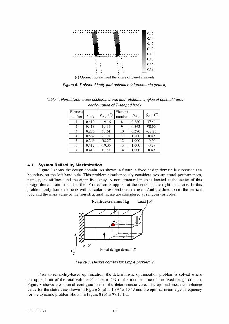
(c) Optimal normalized thickness of panel elements
Figure 6. T-shaped body part optimal reinforcements (cont'd)
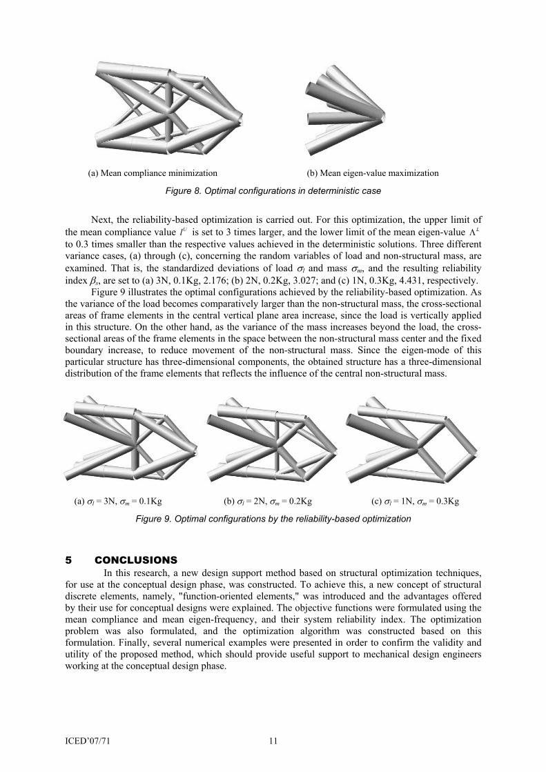
Table 1. Normalized cross-sectional areas and rotational angles of optimal frame configuration of T-shaped body
Elementnumber
Elementnumber
1 0.419 -19.16 8 0.280 37.512 0.418 19.18 9 0.563 90.003 0.270 38.24 10 0.270 -38.204 0.562 90.00 11 1.000 0.495 0.269 -38.27 12 1.000 -0.506 0.412 -19.35 13 1.000 -0.287 0.413 19.25 14 1.000 0.49
, AA iρ , AA iρ, ( )AA iφ ° , ( )
AA iφ °
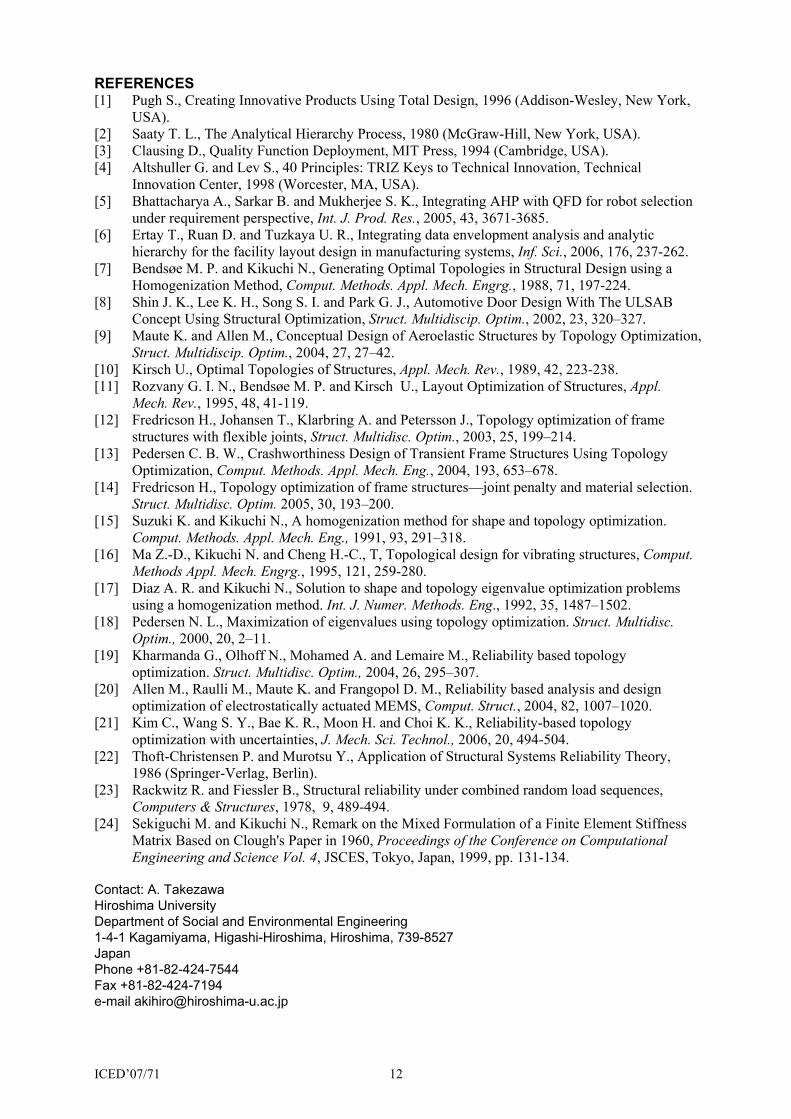
4.3 System Reliability Maximization Figure 7 shows the design domain. As shown in figure, a fixed design domain is supported at a boundary on the left-hand side. This problem simultaneously considers two structural performances, namely, the stiffness and the eigen-frequency. A non-structural mass is located at the center of this design domain, and a load in the -Y direction is applied at the center of the right-hand side. In this problem, only frame elements with circular cross-sections are used. And the direction of the vertical load and the mass value of the non-structural masse are considered as random variables.
Figure 7. Design domain for simple problem 2
Prior to reliability-based optimization, the deterministic optimization problem is solved where the upper limit of the total volume UV is set to 1% of the total volume of the fixed design domain. Figure 8 shows the optimal configurations in the deterministic case. The optimal mean compliance value for the static case shown in Figure 8 (a) is 1.897 x 10⁻⁶ J and the optimal mean eigen-frequency for the dynamic problem shown in Figure 8 (b) is 97.13 Hz.
Load 10NNonstructural mass 1kg
X
Y
Z
Load 10NNonstructural mass 1kg
X
Y
ZFixed design domain D
ICED’07/71 11
(a) Mean compliance minimization (b) Mean eigen-value maximization
Figure 8. Optimal configurations in deterministic case
Next, the reliability-based optimization is carried out. For this optimization, the upper limit of the mean compliance value Ul is set to 3 times larger, and the lower limit of the mean eigen-value LΛ to 0.3 times smaller than the respective values achieved in the deterministic solutions. Three different variance cases, (a) through (c), concerning the random variables of load and non-structural mass, are examined. That is, the standardized deviations of load σl and mass σm, and the resulting reliability index βs, are set to (a) 3N, 0.1Kg, 2.176; (b) 2N, 0.2Kg, 3.027; and (c) 1N, 0.3Kg, 4.431, respectively. Figure 9 illustrates the optimal configurations achieved by the reliability-based optimization. As the variance of the load becomes comparatively larger than the non-structural mass, the cross-sectional areas of frame elements in the central vertical plane area increase, since the load is vertically applied in this structure. On the other hand, as the variance of the mass increases beyond the load, the cross-sectional areas of the frame elements in the space between the non-structural mass center and the fixed boundary increase, to reduce movement of the non-structural mass. Since the eigen-mode of this particular structure has three-dimensional components, the obtained structure has a three-dimensional distribution of the frame elements that reflects the influence of the central non-structural mass.
(a) σl = 3N, σm = 0.1Kg (b) σl = 2N, σm = 0.2Kg (c) σl = 1N, σm = 0.3Kg
Figure 9. Optimal configurations by the reliability-based optimization
5 CONCLUSIONS In this research, a new design support method based on structural optimization techniques,
for use at the conceptual design phase, was constructed. To achieve this, a new concept of structural discrete elements, namely, "function-oriented elements," was introduced and the advantages offered by their use for conceptual designs were explained. The objective functions were formulated using the mean compliance and mean eigen-frequency, and their system reliability index. The optimization problem was also formulated, and the optimization algorithm was constructed based on this formulation. Finally, several numerical examples were presented in order to confirm the validity and utility of the proposed method, which should provide useful support to mechanical design engineers working at the conceptual design phase.
ICED’07/71 12
REFERENCES [1] Pugh S., Creating Innovative Products Using Total Design, 1996 (Addison-Wesley, New York,
USA). [2] Saaty T. L., The Analytical Hierarchy Process, 1980 (McGraw-Hill, New York, USA). [3] Clausing D., Quality Function Deployment, MIT Press, 1994 (Cambridge, USA). [4] Altshuller G. and Lev S., 40 Principles: TRIZ Keys to Technical Innovation, Technical
Innovation Center, 1998 (Worcester, MA, USA). [5] Bhattacharya A., Sarkar B. and Mukherjee S. K., Integrating AHP with QFD for robot selection
under requirement perspective, Int. J. Prod. Res., 2005, 43, 3671-3685. [6] Ertay T., Ruan D. and Tuzkaya U. R., Integrating data envelopment analysis and analytic
hierarchy for the facility layout design in manufacturing systems, Inf. Sci., 2006, 176, 237-262. [7] Bendsøe M. P. and Kikuchi N., Generating Optimal Topologies in Structural Design using a
Homogenization Method, Comput. Methods. Appl. Mech. Engrg., 1988, 71, 197-224. [8] Shin J. K., Lee K. H., Song S. I. and Park G. J., Automotive Door Design With The ULSAB
Concept Using Structural Optimization, Struct. Multidiscip. Optim., 2002, 23, 320–327. [9] Maute K. and Allen M., Conceptual Design of Aeroelastic Structures by Topology Optimization,
Struct. Multidiscip. Optim., 2004, 27, 27–42. [10] Kirsch U., Optimal Topologies of Structures, Appl. Mech. Rev., 1989, 42, 223-238. [11] Rozvany G. I. N., Bendsøe M. P. and Kirsch U., Layout Optimization of Structures, Appl.
Mech. Rev., 1995, 48, 41-119. [12] Fredricson H., Johansen T., Klarbring A. and Petersson J., Topology optimization of frame
structures with flexible joints, Struct. Multidisc. Optim., 2003, 25, 199–214. [13] Pedersen C. B. W., Crashworthiness Design of Transient Frame Structures Using Topology
Optimization, Comput. Methods. Appl. Mech. Eng., 2004, 193, 653–678. [14] Fredricson H., Topology optimization of frame structures—joint penalty and material selection.
Struct. Multidisc. Optim. 2005, 30, 193–200. [15] Suzuki K. and Kikuchi N., A homogenization method for shape and topology optimization.
Comput. Methods. Appl. Mech. Eng., 1991, 93, 291–318. [16] Ma Z.-D., Kikuchi N. and Cheng H.-C., T, Topological design for vibrating structures, Comput.
Methods Appl. Mech. Engrg., 1995, 121, 259-280. [17] Diaz A. R. and Kikuchi N., Solution to shape and topology eigenvalue optimization problems
using a homogenization method. Int. J. Numer. Methods. Eng., 1992, 35, 1487–1502. [18] Pedersen N. L., Maximization of eigenvalues using topology optimization. Struct. Multidisc.
Optim., 2000, 20, 2–11. [19] Kharmanda G., Olhoff N., Mohamed A. and Lemaire M., Reliability based topology
optimization. Struct. Multidisc. Optim., 2004, 26, 295–307. [20] Allen M., Raulli M., Maute K. and Frangopol D. M., Reliability based analysis and design
optimization of electrostatically actuated MEMS, Comput. Struct., 2004, 82, 1007–1020. [21] Kim C., Wang S. Y., Bae K. R., Moon H. and Choi K. K., Reliability-based topology
optimization with uncertainties, J. Mech. Sci. Technol., 2006, 20, 494-504. [22] Thoft-Christensen P. and Murotsu Y., Application of Structural Systems Reliability Theory,
1986 (Springer-Verlag, Berlin). [23] Rackwitz R. and Fiessler B., Structural reliability under combined random load sequences,
Computers & Structures, 1978, 9, 489-494. [24] Sekiguchi M. and Kikuchi N., Remark on the Mixed Formulation of a Finite Element Stiffness
Matrix Based on Clough's Paper in 1960, Proceedings of the Conference on Computational Engineering and Science Vol. 4, JSCES, Tokyo, Japan, 1999, pp. 131-134.
Contact: A. Takezawa Hiroshima University Department of Social and Environmental Engineering 1-4-1 Kagamiyama, Higashi-Hiroshima, Hiroshima, 739-8527 Japan Phone +81-82-424-7544 Fax +81-82-424-7194 e-mail [email protected]