hgm6100n-rm remote control module - user manual - the generator
TRANSCRIPT
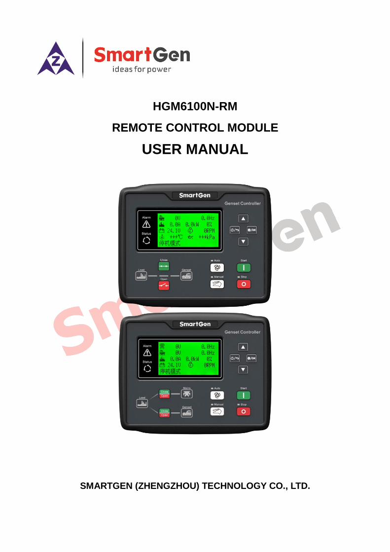
HGM6100N-RM
REMOTE CONTROL MODULE
USER MANUAL
SMARTGEN (ZHENGZHOU) TECHNOLOGY CO., LTD.
HGM6100N-RM REMOTE MONITORING MODULE USER MANUAL
HGM6100N-RM Remote Control Module 2019-08-06 Version 1.0 Page 2 of 14
CONTENT
1 OVERVIEW ................................................................................................................................ 4
2 PERFORMANCE AND CHARACTERISTICS ............................................................................ 5
3 SPECIFICATION ........................................................................................................................ 6
4 OPERATION ............................................................................................................................... 7
4.1 KEY DSCRIPTIONS ............................................................................................................. 7
4.2 CONTROLLER PANEL ......................................................................................................... 8
4.3 REMOTE CONTROL MODE OPERATION .......................................................................... 9
5 CONNECTIONS ....................................................................................................................... 10
6 TYPICAL APPLICATION .......................................................................................................... 12
7 INSTALLATION ......................................................................................................................... 13
7.1 FIXING CLIPS ..................................................................................................................... 13
7.2 OVERALL DIMENSION AND PANEL CUTOUT ................................................................. 13
8 TROUBLESHOOTING ............................................................................................................. 14
HGM6100N-RM REMOTE MONITORING MODULE USER MANUAL
HGM6100N-RM Remote Monitoring Module 2019-08-06 Version 1.0 Page 3 of 14
Chinese trademark
English trademark
SmartGen — make your generator smart
SmartGen Technology Co., Ltd.
No.28 Jinsuo Road
Zhengzhou City
Henan Province
P. R. China
Tel: 0086-(0)371-67988888/67981888
0086-(0)371-67991553/67992951
0086-(0)371-67981000(overseas)
Fax: 0086-(0)371-67992952
Web: www.smartgen.com.cn
www.smartgen.cn
Email: [email protected]
All rights reserved. No part of this publication may be reproduced in any material form (including
photocopying or storing in any medium by electronic means or other) without the written
permission of the copyright holder.
Applications for the copyright holder’s written permission to reproduce any part of this publication
should be addressed to Smartgen Technology at the address above.
Any reference to trademarked product names used within this publication is owned by their
respective companies.
SmartGen Technology reserves the right to change the contents of this document without prior
notice.
Table 1 Software Version
Date Version Content
2019-08-06 1.0 Original release
HGM6100N-RM REMOTE MONITORING MODULE USER MANUAL
HGM6100N-RM Remote Monitoring Module 2019-08-06 Version 1.0 Page 4 of 14
1 OVERVIEW
HGM6100N-RM is remote monitoring module designed for HGM6100N series genset controllers.
With RS485 port it can realize functions of remote start/stop, data measuring, and alarm display etc.
it is applicable for single remote monitoring system. It can be in the monitoring mode, realizing only
monitoring, not controlling, or it can be changed over to remote control mode by local module
transfer, monitored and controlled remotely.
HGM6100N-RM remote monitoring module uses micro-processing technique and 132 x64 LCD
display. 8 kinds of languages are optional (Simplified Chinese, English, Spanish, Russian,
Portuguese, Turkish, Polish and French) and can be changed freely. It can be widely used in all
types of automatic control system with compact structure, simple connections and high reliability.
HGM6100N-RM REMOTE MONITORING MODULE USER MANUAL
HGM6100N-RM Remote Monitoring Module 2019-08-06 Version 1.0 Page 5 of 14
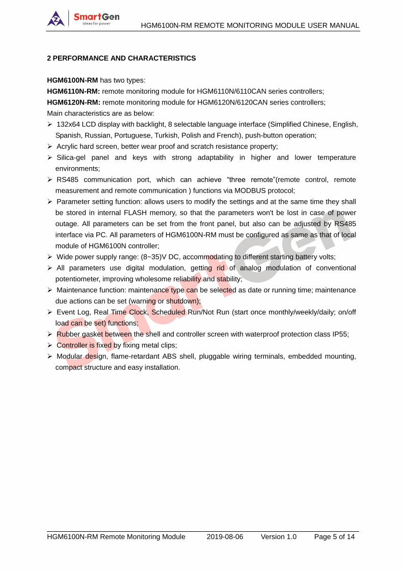
2 PERFORMANCE AND CHARACTERISTICS
HGM6100N-RM has two types:
HGM6110N-RM: remote monitoring module for HGM6110N/6110CAN series controllers;
HGM6120N-RM: remote monitoring module for HGM6120N/6120CAN series controllers;
Main characteristics are as below:
132x64 LCD display with backlight, 8 selectable language interface (Simplified Chinese, English,
Spanish, Russian, Portuguese, Turkish, Polish and French), push-button operation;
Acrylic hard screen, better wear proof and scratch resistance property;
Silica-gel panel and keys with strong adaptability in higher and lower temperature
environments;
RS485 communication port, which can achieve “three remote”(remote control, remote
measurement and remote communication ) functions via MODBUS protocol;
Parameter setting function: allows users to modify the settings and at the same time they shall
be stored in internal FLASH memory, so that the parameters won't be lost in case of power
outage. All parameters can be set from the front panel, but also can be adjusted by RS485
interface via PC. All parameters of HGM6100N-RM must be configured as same as that of local
module of HGM6100N controller;
Wide power supply range: (8~35)V DC, accommodating to different starting battery volts;
All parameters use digital modulation, getting rid of analog modulation of conventional
potentiometer, improving wholesome reliability and stability;
Maintenance function: maintenance type can be selected as date or running time; maintenance
due actions can be set (warning or shutdown);
Event Log, Real Time Clock, Scheduled Run/Not Run (start once monthly/weekly/daily; on/off
load can be set) functions;
Rubber gasket between the shell and controller screen with waterproof protection class IP55;
Controller is fixed by fixing metal clips;
Modular design, flame-retardant ABS shell, pluggable wiring terminals, embedded mounting,
compact structure and easy installation.
HGM6100N-RM REMOTE MONITORING MODULE USER MANUAL
HGM6100N-RM Remote Monitoring Module 2019-08-06 Version 1.0 Page 6 of 14
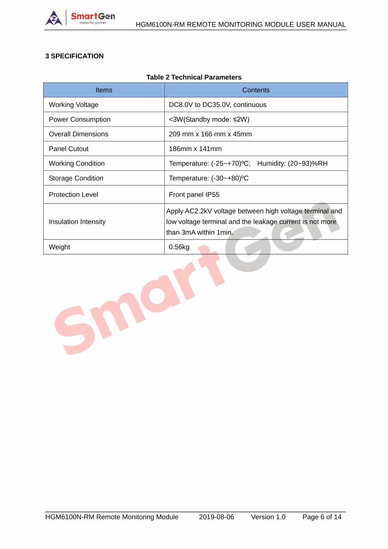
3 SPECIFICATION
Table 2 Technical Parameters
Items Contents
Working Voltage DC8.0V to DC35.0V, continuous
Power Consumption <3W(Standby mode: ≤2W)
Overall Dimensions 209 mm x 166 mm x 45mm
Panel Cutout 186mm x 141mm
Working Condition Temperature: (-25~+70)ºC; Humidity: (20~93)%RH
Storage Condition Temperature: (-30~+80)ºC
Protection Level Front panel IP55
Insulation Intensity
Apply AC2.2kV voltage between high voltage terminal and
low voltage terminal and the leakage current is not more
than 3mA within 1min.
Weight 0.56kg
HGM6100N-RM REMOTE MONITORING MODULE USER MANUAL
HGM6100N-RM Remote Monitoring Module 2019-08-06 Version 1.0 Page 7 of 14
4 OPERATION
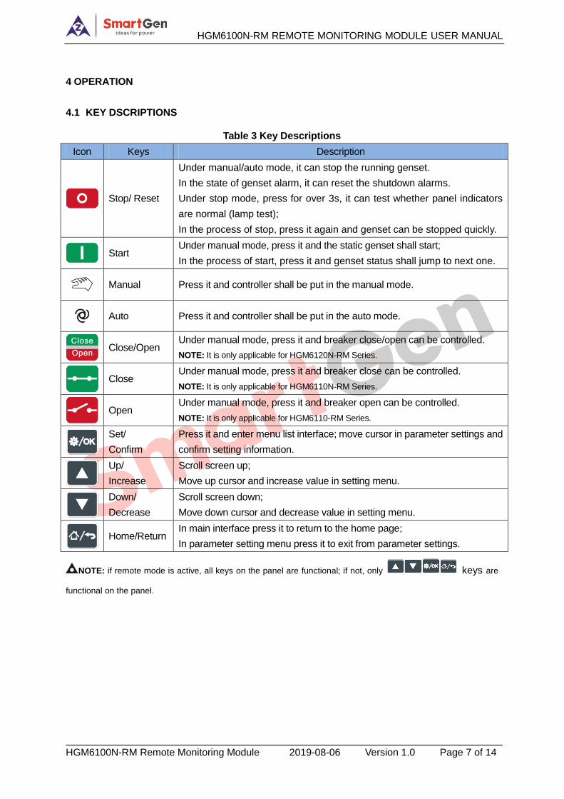
4.1 KEY DSCRIPTIONS
Table 3 Key Descriptions
Icon Keys Description
Stop/ Reset
Under manual/auto mode, it can stop the running genset.
In the state of genset alarm, it can reset the shutdown alarms.
Under stop mode, press for over 3s, it can test whether panel indicators
are normal (lamp test);
In the process of stop, press it again and genset can be stopped quickly.
Start
Under manual mode, press it and the static genset shall start;
In the process of start, press it and genset status shall jump to next one.
Manual Press it and controller shall be put in the manual mode.
Auto Press it and controller shall be put in the auto mode.
Close/Open
Under manual mode, press it and breaker close/open can be controlled.
NOTE: It is only applicable for HGM6120N-RM Series.
Close
Under manual mode, press it and breaker close can be controlled.
NOTE: It is only applicable for HGM6110N-RM Series.
Open
Under manual mode, press it and breaker open can be controlled.
NOTE: It is only applicable for HGM6110-RM Series.
Set/
Confirm
Press it and enter menu list interface; move cursor in parameter settings and
confirm setting information.
Up/
Increase
Scroll screen up;
Move up cursor and increase value in setting menu.
Down/
Decrease
Scroll screen down;
Move down cursor and decrease value in setting menu.
Home/Return
In main interface press it to return to the home page;
In parameter setting menu press it to exit from parameter settings.
NOTE: if remote mode is active, all keys on the panel are functional; if not, only keys are
functional on the panel.
HGM6100N-RM REMOTE MONITORING MODULE USER MANUAL
HGM6100N-RM Remote Monitoring Module 2019-08-06 Version 1.0 Page 8 of 14
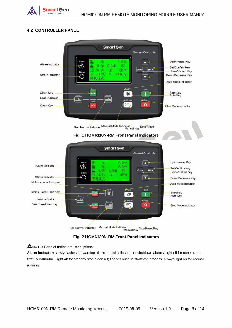
4.2 CONTROLLER PANEL
Fig. 1 HGM6110N-RM Front Panel Indicators
Fig. 2 HGM6120N-RM Front Panel Indicators
NOTE: Parts of Indicators Descriptions:
Alarm Indicator: slowly flashes for warning alarms; quickly flashes for shutdown alarms; light off for none alarms;
Status Indicator: Light off for standby status genset; flashes once in start/stop process; always light on for normal
running.
HGM6100N-RM REMOTE MONITORING MODULE USER MANUAL
HGM6100N-RM Remote Monitoring Module 2019-08-06 Version 1.0 Page 9 of 14
4.3 REMOTE CONTROL MODE OPERATION
When remote control mode input is active on local module, the 4th line of LCD displays remote mode
on both remote module and local module, which means remote control mode is active.
After remote mode is active, genset mode transfer and genset start/stop operations can be
conducted.
NOTE: if alarms occur in start/stop process, corresponding alarm information will be synchronously displayed on the
LCD of HGM6100N-RM.
HGM6100N-RM REMOTE MONITORING MODULE USER MANUAL
HGM6100N-RM Remote Monitoring Module 2019-08-06 Version 1.0 Page 10 of 14
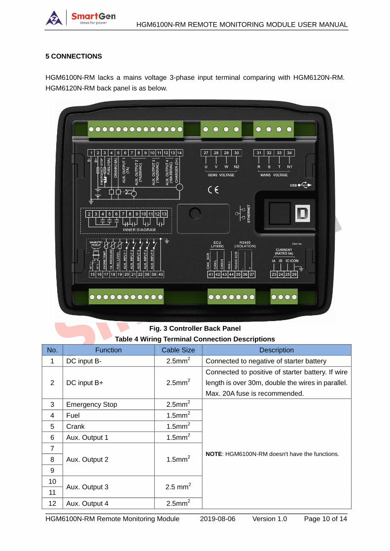
5 CONNECTIONS
HGM6100N-RM lacks a mains voltage 3-phase input terminal comparing with HGM6120N-RM.
HGM6120N-RM back panel is as below.
Fig. 3 Controller Back Panel
Table 4 Wiring Terminal Connection Descriptions
No. Function Cable Size Description
1 DC input B- 2.5mm2 Connected to negative of starter battery
2 DC input B+ 2.5mm2
Connected to positive of starter battery. If wire
length is over 30m, double the wires in parallel.
Max. 20A fuse is recommended.
3 Emergency Stop 2.5mm2
NOTE: HGM6100N-RM doesn't have the functions.
4 Fuel 1.5mm2
5 Crank 1.5mm2
6 Aux. Output 1 1.5mm2
7
Aux. Output 2 1.5mm2 8
9
10 Aux. Output 3 2.5 mm
2
11
12 Aux. Output 4 2.5mm2
HGM6100N-RM REMOTE MONITORING MODULE USER MANUAL
HGM6100N-RM Remote Monitoring Module 2019-08-06 Version 1.0 Page 11 of 14
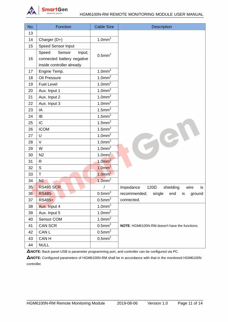
No. Function Cable Size Description
13
14 Charger (D+) 1.0mm2
15 Speed Sensor Input
0.5mm2
16
Speed Sensor Input;
connected battery negative
inside controller already
17 Engine Temp. 1.0mm2
18 Oil Pressure 1.0mm2
19 Fuel Level 1.0mm2
20 Aux. Input 1 1.0mm2
21 Aux. Input 2 1.0mm2
22 Aux. Input 3 1.0mm2
23 IA 1.5mm2
24 IB 1.5mm2
25 IC 1.5mm2
26 ICOM 1.5mm2
27 U 1.0mm2
28 V 1.0mm2
29 W 1.0mm2
30 N2 1.0mm2
31 R 1.0mm2
32 S 1.0mm2
33 T 1.0mm2
34 N1 1.0mm2
35 RS485 SCR / Impedance 120Ω shielding wire is
recommended; single end is ground
connected.
36 RS485- 0.5mm2
37 RS485+ 0.5mm2
38 Aux. Input 4 1.0mm2
NOTE: HGM6100N-RM doesn't have the functions.
39 Aux. Input 5 1.0mm2
40 Sensor COM 1.0mm2
41 CAN SCR 0.5mm2
42 CAN L 0.5mm2
43 CAN H 0.5mm2
44 NULL
NOTE: Back panel USB is parameter programming port, and controller can be configured via PC.
NOTE: Configured parameters of HGM6100N-RM shall be in accordance with that in the monitored HGM6100N
controller.
HGM6100N-RM REMOTE MONITORING MODULE USER MANUAL
HGM6100N-RM Remote Monitoring Module 2019-08-06 Version 1.0 Page 12 of 14
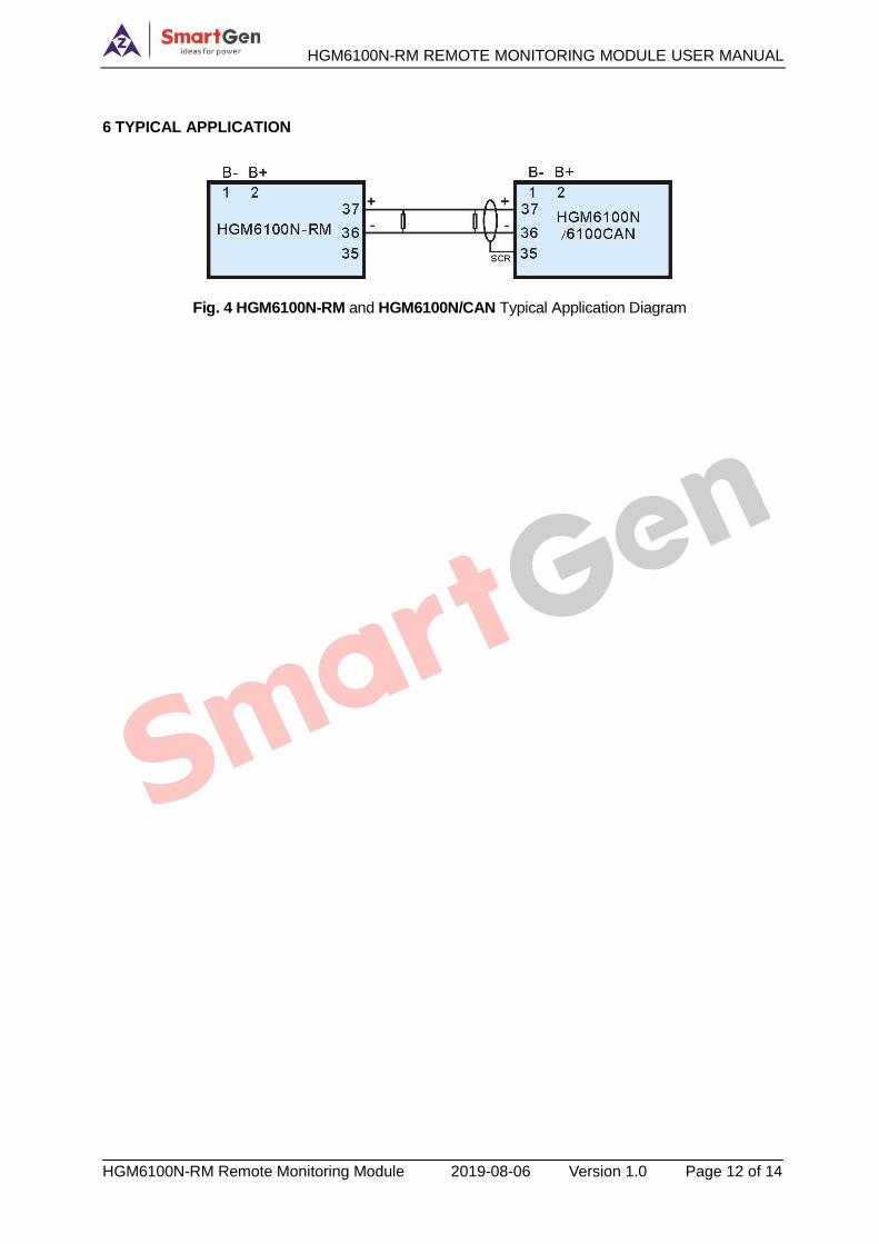
6 TYPICAL APPLICATION
Fig. 4 HGM6100N-RM and HGM6100N/CAN Typical Application Diagram
HGM6100N-RM REMOTE MONITORING MODULE USER MANUAL
HGM6100N-RM Remote Monitoring Module 2019-08-06 Version 1.0 Page 13 of 14
7 INSTALLATION
7.1 FIXING CLIPS
— Controller design is panel installation method, and it is fixed by clips.
— Withdraw the fixing clip screw (turn anticlockwise) until it reaches proper position.
— Pull the fixing clip backwards (towards the back of the module) ensuring four clips are inside
their allotted slots.
— Turn the fixing clip screws clockwise until they are fixed on controller panel.
— Care should be taken not to over tighten the screws of fixing clips.
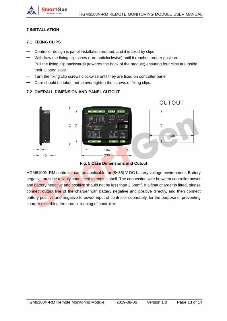
7.2 OVERALL DIMENSION AND PANEL CUTOUT
Fig. 5 Case Dimensions and Cutout
HGM6100N-RM controller can be applicable for (8~35) V DC battery voltage environment. Battery
negative must be reliably connected to engine shell. The connection wire between controller power
and battery negative and positive should not be less than 2.5mm2. If a float charger is fitted, please
connect output line of the charger with battery negative and positive directly, and then connect
battery positive and negative to power input of controller separately, for the purpose of preventing
charger disturbing the normal running of controller.
HGM6100N-RM REMOTE MONITORING MODULE USER MANUAL
HGM6100N-RM Remote Monitoring Module 2019-08-06 Version 1.0 Page 14 of 14
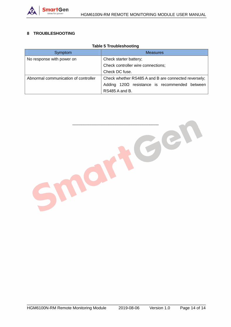
8 TROUBLESHOOTING
Table 5 Troubleshooting
Symptom Measures
No response with power on Check starter battery;
Check controller wire connections;
Check DC fuse.
Abnormal communication of controller Check whether RS485 A and B are connected reversely;
Adding 120Ω resistance is recommended between
RS485 A and B.
______________________________________