help and tutorials contents
TRANSCRIPT
Help and tutorialsADOBE® PHOTOSHOP
June 2013

Contents
What’s new 1...................................................................................................................................................What’s New in Photoshop CC 2................................................................................................................................................
Photoshop getting started tutorials 13.......................................................................................................................................................
Workspace and workflow 14............................................................................................................................Share your work on Behance | Photoshop CC 15.....................................................................................................................
Sync settings using Adobe Creative Cloud | Photoshop CC 18................................................................................................
Workspace basics 20.................................................................................................................................................................
Panels and menus 26................................................................................................................................................................
Tools 30.....................................................................................................................................................................................
Preferences 37..........................................................................................................................................................................
Presets 38..................................................................................................................................................................................
Plug-ins 41.................................................................................................................................................................................
Key shortcuts 42........................................................................................................................................................................
Productivity enhancements (JDI’s) in CS6 44...........................................................................................................................
Show or hide non-printing Extras 47..........................................................................................................................................
Position elements with snapping 48..........................................................................................................................................
Positioning with the Ruler tool 49..............................................................................................................................................
Specifying columns for an image 50..........................................................................................................................................
Rulers 51...................................................................................................................................................................................
Undo and history 52...................................................................................................................................................................
Customizing keyboard shortcuts 56...........................................................................................................................................
Default keyboard shortcuts 58...................................................................................................................................................
Grid and guides 83....................................................................................................................................................................
Run Photoshop in 32-bit mode (64-bit Mac OS only) 85...........................................................................................................
Image and color basics 86...............................................................................................................................Resizing images | CC, CS6 87..................................................................................................................................................
Image essentials 89...................................................................................................................................................................
Image size and resolution 91.....................................................................................................................................................
Acquiring images from cameras and scanners 96.....................................................................................................................
Creating, opening, and importing images 98.............................................................................................................................
Viewing images 101...................................................................................................................................................................
Add swatches from HTML CSS and SVG 105..........................................................................................................................
Merging images to HDR 106.....................................................................................................................................................
Adjusting display of 32-bit HDR images 112.............................................................................................................................
Convert an image to Bitmap mode 118.....................................................................................................................................
Customizing indexed color tables 122.......................................................................................................................................
Adding a conditional mode change to an action 123.................................................................................................................
Choosing colors in the Color and Swatches panels 124...........................................................................................................
Viewing multiple images 126.....................................................................................................................................................
About color 128..........................................................................................................................................................................
Choosing colors 131..................................................................................................................................................................
High dynamic range images 136...............................................................................................................................................
Blending modes 142..................................................................................................................................................................
Color modes 145.......................................................................................................................................................................
Converting between color modes 147.......................................................................................................................................
Customizing color pickers and swatches 151............................................................................................................................
Image information 153...............................................................................................................................................................
Understanding color management 156......................................................................................................................................
Layers 158.......................................................................................................................................................Layer basics 159........................................................................................................................................................................
Managing layers 163.................................................................................................................................................................
Selecting, grouping, and linking layers 166...............................................................................................................................
Copy CSS from layers | CC, CS6 168.......................................................................................................................................
Moving, stacking, and locking layers 169..................................................................................................................................
Nondestructive editing 171........................................................................................................................................................
Combining multiple images into a group portrait 172................................................................................................................
Masking layers 173....................................................................................................................................................................
Load selections from a layer or layer mask’s boundaries 177...................................................................................................
Masking layers with vector masks 178......................................................................................................................................
Editing layer masks 180.............................................................................................................................................................
Revealing layers with clipping masks 181.................................................................................................................................
Applying a Smart Filter 182.......................................................................................................................................................
Create Smart Objects 185.........................................................................................................................................................
Aligning layers 188....................................................................................................................................................................
Combine images with Auto-Blend Layers 190...........................................................................................................................
Knockout to reveal content from other layers 191.....................................................................................................................
Create and manage layers and groups 192..............................................................................................................................
Layer opacity and blending 194.................................................................................................................................................
Blending modes 197..................................................................................................................................................................
Layer comps 200.......................................................................................................................................................................
Layer effects and styles 202......................................................................................................................................................
Selecting 209...................................................................................................................................................Making selections 210...............................................................................................................................................................
Adjusting pixel selections 211....................................................................................................................................................
Moving, copying, and deleting selected pixels 216....................................................................................................................
Saving selections and alpha channel masks 220......................................................................................................................
Selecting with the lasso tools 223..............................................................................................................................................
Selecting with the marquee tools 226........................................................................................................................................
Selecting a color range in an image 228...................................................................................................................................
Making quick selections 230......................................................................................................................................................
Duplicate split and merge channels 232....................................................................................................................................
Creating a temporary quick mask 234.......................................................................................................................................
Channel basics 236...................................................................................................................................................................
Channel calculations 239...........................................................................................................................................................
Extract an object from its background 241................................................................................................................................
Image adjustments 243...................................................................................................................................Reduce camera shake blurring | Photoshop CC 244................................................................................................................
Adjusting image sharpness and blur | CC, CS6 248.................................................................................................................
Understanding color adjustments 253.......................................................................................................................................
Viewing histograms and pixel values 258..................................................................................................................................
High dynamic range images 263...............................................................................................................................................
Levels adjustment 269...............................................................................................................................................................
Adjust HDR exposure and toning 272.......................................................................................................................................
Adjusting image color and tone 273..........................................................................................................................................
Curves adjustment 275..............................................................................................................................................................

Adjusting hue and saturation 279..............................................................................................................................................
Convert a color image to black and white 282...........................................................................................................................
Adjust shadow and highlight detail 283.....................................................................................................................................
Adjust color and tone with Levels and Curves eyedroppers 285...............................................................................................
Quickly adjust black and white points 286.................................................................................................................................
Applying Color Balance adjustment 287....................................................................................................................................
Apply a Brightness-Contrast adjustment 289............................................................................................................................
Adjustment and fill layers 290....................................................................................................................................................
Dodge or burn image areas 293................................................................................................................................................
Applying special color effects to images 294.............................................................................................................................
Making quick tonal adjustments 296..........................................................................................................................................
Matching, replacing, and mixing colors 299...............................................................................................................................
Targeting images for press 304.................................................................................................................................................
Camera Raw 306.............................................................................................................................................Introduction to Camera Raw 307...............................................................................................................................................
Automatic perspective correction in Camera Raw | Photoshop CC 311...................................................................................
Radial Filter in Camera Raw | Photoshop CC 314....................................................................................................................
Enhanced Spot Removal Tool in Camera Raw | Photoshop CC 317........................................................................................
Make color and tonal adjustments in Camera Raw 321............................................................................................................
Correct lens distortions in Camera Raw 326.............................................................................................................................
Make local adjustments in Camera Raw 329............................................................................................................................
Sharpening and noise reduction in Camera Raw 333...............................................................................................................
Process versions in Camera Raw 335.......................................................................................................................................
Adjust color rendering for your camera in Camera Raw 336.....................................................................................................
Manage Camera Raw settings 338...........................................................................................................................................
Navigate, open, and save images in Camera Raw 342.............................................................................................................
Rotate, crop, and retouch images in Camera Raw 345.............................................................................................................
Vignette and grain effects in Camera Raw 347.........................................................................................................................
Repair and restoration 349..............................................................................................................................Content-Aware Patch and Move 350.........................................................................................................................................
Retouching and repairing images 352.......................................................................................................................................
Correcting image distortion and noise 358................................................................................................................................
Reshaping and transforming 361.....................................................................................................................Transforming objects 362..........................................................................................................................................................
Adjusting crop, rotation, and canvas 369...................................................................................................................................
Create panoramic images with Photomerge 374.......................................................................................................................
Content-aware scaling 377........................................................................................................................................................
Crop and straighten photos | CC, CS6 379...............................................................................................................................
Liquify filter 382..........................................................................................................................................................................
Free transformations of images shapes and paths 387.............................................................................................................
Vanishing Point 388...................................................................................................................................................................
Warp images shapes and paths 399.........................................................................................................................................
Drawing and painting 402................................................................................................................................Modify shapes | CC, CS6 403...................................................................................................................................................
About drawing 405.....................................................................................................................................................................
Drawing shapes 407..................................................................................................................................................................
Painting tools 411......................................................................................................................................................................
Brush presets 413......................................................................................................................................................................
Creating and modifying brushes 415.........................................................................................................................................

Erasing parts of an image 421...................................................................................................................................................
Adding dynamic elements to brushes 423.................................................................................................................................
Creating textured brushes 426..................................................................................................................................................
Editing paths 428.......................................................................................................................................................................
Painting with the Mixer Brush 435.............................................................................................................................................
Drawing or painting with a graphics tablet 437..........................................................................................................................
Painting stylized strokes with the Art History Brush 438............................................................................................................
Painting with a pattern 439........................................................................................................................................................
Managing pattern libraries and presets 440..............................................................................................................................
Creating patterns 441................................................................................................................................................................
Draw a path that snaps to defined edges 442...........................................................................................................................
Drawing with the Pen tools 443.................................................................................................................................................
Adding color to paths 448..........................................................................................................................................................
Blending modes 450..................................................................................................................................................................
Converting between paths and selection borders 453...............................................................................................................
Filling and stroking selections, layers, and paths 455...............................................................................................................
Generate a pattern using the Pattern Maker 458......................................................................................................................
Gradients 460............................................................................................................................................................................
Managing paths 464..................................................................................................................................................................
Text 466...........................................................................................................................................................Creating type 467......................................................................................................................................................................
Editing text 471..........................................................................................................................................................................
Creating type effects 475...........................................................................................................................................................
Formatting Characters 479........................................................................................................................................................
Line and character spacing 484.................................................................................................................................................
Formatting paragraphs 487.......................................................................................................................................................
Arabic and Hebrew type | CC, CS6 492....................................................................................................................................
Fonts 495...................................................................................................................................................................................
Asian type 498...........................................................................................................................................................................
Video and animation 503.................................................................................................................................Video editing | CC, CS6 504......................................................................................................................................................
Creating frame animations 506..................................................................................................................................................
Creating timeline animations 512..............................................................................................................................................
Creating images for video 517...................................................................................................................................................
Editing video and animation layers 521.....................................................................................................................................
Video and animation overview 525............................................................................................................................................
Saving and exporting video and animations 530.......................................................................................................................
Importing video files and image sequences 536........................................................................................................................
Painting frames in video layers 539...........................................................................................................................................
Previewing video and animations 541.......................................................................................................................................
Filters and effects 544.....................................................................................................................................Filter basics 545.........................................................................................................................................................................
Filter effects reference | CC, CS6 548.......................................................................................................................................
Add Lighting Effects | CC, CS6 556...........................................................................................................................................
Photographic blur gallery 559....................................................................................................................................................
Adaptive wide angle filter 562....................................................................................................................................................
Oil Paint filter 564......................................................................................................................................................................
Smudge image areas 565..........................................................................................................................................................
Add Lighting Effects (CS5) 566.................................................................................................................................................
Applying specific filters 569.......................................................................................................................................................
Layer effects and styles 572......................................................................................................................................................
Saving and exporting 579................................................................................................................................Saving images 580....................................................................................................................................................................
File formats 583.........................................................................................................................................................................
Supported file formats 589.........................................................................................................................................................
Saving files in graphics formats 591..........................................................................................................................................
Saving PDF files 594.................................................................................................................................................................
Creating web photo galleries 600..............................................................................................................................................
Digimarc copyright protection 605.............................................................................................................................................
Printing 607......................................................................................................................................................Printing from Photoshop | CC, CS6 608....................................................................................................................................
Printing with color management 611.........................................................................................................................................
Contact Sheets and PDF Presentations 613.............................................................................................................................
Duotones 614............................................................................................................................................................................
Picture packages and contact sheets 617.................................................................................................................................
Printing images to a commercial printing press 621..................................................................................................................
Printing with color management | CS5 625...............................................................................................................................
Printing from Photoshop CS5 628.............................................................................................................................................
Printing spot colors 631.............................................................................................................................................................
Automation 634................................................................................................................................................About actions and the Actions panel 635..................................................................................................................................
Creating actions 636..................................................................................................................................................................
Playing and managing actions 639............................................................................................................................................
Processing a batch of files 642..................................................................................................................................................
Scripting 646..............................................................................................................................................................................
Creating data-driven graphics 647.............................................................................................................................................
Adding conditional actions | CC, CS6 651.................................................................................................................................
Recording tools in actions | CC, CS6 652.................................................................................................................................
Adding a conditional mode change to an action 653.................................................................................................................
Web graphics 654............................................................................................................................................Copy CSS from layers | CC, CS6 655.......................................................................................................................................
Creating web photo galleries 656..............................................................................................................................................
Working with web graphics 661.................................................................................................................................................
Slicing web pages 663...............................................................................................................................................................
Modifying slice layout 666..........................................................................................................................................................
HTML options for slices 669......................................................................................................................................................
Optimizing images 671..............................................................................................................................................................
Output settings for web graphics 676........................................................................................................................................
Web graphics optimization options 678.....................................................................................................................................
3D and technical imaging 687.........................................................................................................................3D painting | CC, CS6 688........................................................................................................................................................
3D panel enhancements | Photoshop CC 692..........................................................................................................................
Essential 3D concepts and tools 694.........................................................................................................................................
3D workflow | CC, CS6 698.......................................................................................................................................................
Adjust HDR exposure and toning 701.......................................................................................................................................
3D panel settings 702................................................................................................................................................................
3D rendering and saving 712.....................................................................................................................................................
Creating 3D objects and animations 716...................................................................................................................................

3D painting | CS5 721................................................................................................................................................................
3D texture editing 723................................................................................................................................................................
Combining and converting 3D objects 726................................................................................................................................
Counting objects in an image 728.............................................................................................................................................
DICOM files 730........................................................................................................................................................................
Image Stacks 733......................................................................................................................................................................
Measurement 735......................................................................................................................................................................
Photoshop and MATLAB 740....................................................................................................................................................
Color management 742...................................................................................................................................Understanding color management 743......................................................................................................................................
Keeping colors consistent 745...................................................................................................................................................
Color settings 748......................................................................................................................................................................
Working with color profiles 751..................................................................................................................................................
Color-managing documents for online viewing 755...................................................................................................................
Color-managing documents when printing 756.........................................................................................................................
Color-managing imported images 758.......................................................................................................................................
Proofing colors 759....................................................................................................................................................................

What's new
1

What's New in Photoshop CC
To the top
Adobe® Photoshop® CC ships with several new features and enhancements that enrich your digital imaging experience. Read on for a quickintroduction to new features and links to resources offering more information.
Note: If you're upgrading from Photoshop CS5, see What's New in Photoshop CS6 for an overview of new features in Photoshop CS6 andPhotoshop 13.1 for Adobe Creative Cloud.
Reduce camera shake blurringImage resizing improvementsShare your work on BehanceSync settings using Adobe Creative Cloud 3D imagingFiltersAdobe Camera RawMultiple selection of pathsModify rectangles and rounded rectangles Support for Indic languagesSystem anti-aliasing option for type Other enhancementsProduct-level changes
Reduce camera shake blurring
New in Photoshop CC
Photoshop features an intelligent mechanism to automatically reduce image blurring caused by camera motion. If necessary, you can adjustadvanced settings to further sharpen the image. The camera shake reduction feature can reduce blurring resulting from several types of cameramotion; including linear motion, arc-shaped motion, rotational motion, and zigzag motion.
Camera shake reduction | A before/after example
Images suitable for camera shake reductionThe camera shake reduction feature works best with decently lit still camera images having low noise. The following types of still images areparticularly suitable for shake reduction:
2
To the top
Indoor or outdoor images captured using a lens with a long focal lengthIndoor images of a static scene taken with a slow shutter speed and no flash
In addition, shake reduction can help sharpen blurred text in images affected by camera motion.
For more information, see Reduce camera shake blurring.
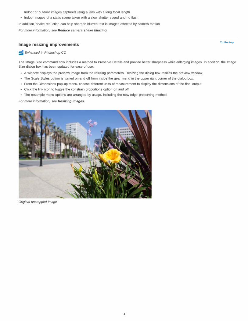
Image resizing improvements
Enhanced in Photoshop CC
The Image Size command now includes a method to Preserve Details and provide better sharpness while enlarging images. In addition, the ImageSize dialog box has been updated for ease of use:
A window displays the preview image from the resizing parameters. Resizing the dialog box resizes the preview window.The Scale Styles option is turned on and off from inside the gear menu in the upper right corner of the dialog box.From the Dimensions pop-up menu, choose different units of measurement to display the dimensions of the final output.Click the link icon to toggle the constrain proportions option on and off.The resample menu options are arranged by usage, including the new edge-preserving method.
For more information, see Resizing images.
Original uncropped image
3

To the top
Note:
Sharp resized image with details preservation
Share your work on Behance
New in Photoshop CC
You can upload your creative images as work-in-progress to Behance directly from within Photoshop. Behance is the leading online platform toshowcase and discover creative work. Using Behance, you can create a portfolio of your work and broadcast it widely and efficiently to getfeedback. You can upload fresh images as well as revisions of images you've uploaded earlier.
Behance integration with Photoshop CC is available only for the English locale.
Uploading revisions to Behance...
Share your work from within Photoshop in one of the following ways:
With a document open, select File > Share On Behance.With a document open, click the Share On Behance button ( ) in the lower-left corner of the document window.
4

Note:
To the top
To the top
Note:
You can either start a new Behance portfolio using your Adobe ID or link your existing Behance account with your Adobe ID.
For more information about Photoshop-Behance integration, see Share your work on Behance. For more information about using Behance, seethis FAQ.
You must be 13 years of age or older to sign up for Behance.
You can share images of dimensions 320 x 320 pixel or higher.
Sync settings using Adobe Creative Cloud
New in Photoshop CC
When you work on multiple computers, managing and syncing preferences across the computers can be time-consuming, complex, and prone toerror.
The new Sync Settings feature enables you to sync preferences and settings via Creative Cloud. If you use two computers, the Sync Settingsfeature makes it easy for you to keep those settings synchronized across the two computers. The syncing happens via your Adobe Creative Cloudaccount. Settings are uploaded to your Creative Cloud account and are then downloaded and applied on the other computer.
Choose Edit > Sync Settings and then select the relevant options. For more information, see Sync Settings Using Adobe Creative Cloud | CC.
3D imaging
Enhanced in Photoshop CC
Also see 3D features | Creative Cloud-only for Creative Cloud-only features added to Photoshop CS6. These features are also available inPhotoshop CC.
3D paintingPhotoshop CC features several enhancements that let you paint 3D models with finer control and greater accuracy. When you paint in the defaultLive 3D Painting mode, you can see your brush strokes update in real time in both the 3D model view and the texture view. The Live 3D Paintingmode also offers significant performance gains and minimizes distortion.
Projection Painting, the default 3D painting method in Photoshop CS5 and CS6, remains available in Photoshop CC. You can switch to this 3Dpainting method by selecting 3D > Use Projection Painting.
Besides Live 3D Painting, Photoshop CC features the following enhancements to 3D painting functionality:
When you target different texture types for painting, you can see the paint target in both the 3D model and the target texture view.You can choose to paint your 3D objects in the unlit mode. This mode ignores any lighting in your scene and wraps raw texture data of theappropriate type around your 3D objects. Painting in the unlit mode lets you paint without shading and with greater color accuracy.
Available 3D painting methodsDifferent painting methods are appropriate for different use cases. Photoshop CC provides the following 3D painting methods:
Live 3D Painting: (Default in Photoshop CC) Brush strokes made in the 3D model view or the texture view are reflected in real time in theother view. This 3D painting method offers high performance and minimum distortion.
Layer Projection Painting: (Enhanced in Photoshop CC) The Gradient tool and filters use this painting method. The Layer ProjectionPainting method involves merging a painted layer with the underlying 3D layer. During the merge operation, Photoshop automatically projects thepaint onto the appropriate target textures.
Projection Painting: (Only method in Photoshop CS6) Projection Painting is suitable for painting multiple textures simultaneously or for paintingthe seam between two textures. However, in general, it is a lower-performance painting method and may result in cracks when you’re paintingcomplex 3D objects.
Texture Painting: You can open the 2D texture and paint it directly.
For more information, see 3D painting.
5
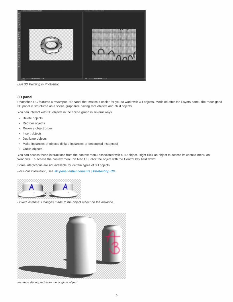
Live 3D Painting in Photoshop
3D panelPhotoshop CC features a revamped 3D panel that makes it easier for you to work with 3D objects. Modeled after the Layers panel, the redesigned3D panel is structured as a scene graph/tree having root objects and child objects.
You can interact with 3D objects in the scene graph in several ways:
Delete objectsReorder objectsReverse object orderInsert objectsDuplicate objectsMake instances of objects (linked instances or decoupled instances)Group objects
You can access these interactions from the context menu associated with a 3D object. Right click an object to access its context menu onWindows. To access the context menu on Mac OS, click the object with the Control key held down.
Some interactions are not available for certain types of 3D objects.
For more information, see 3D panel enhancements | Photoshop CC.
Linked instance: Changes made to the object reflect on the instance
Instance decoupled from the original object
6
To the topFilters
Enhanced in Photoshop CC
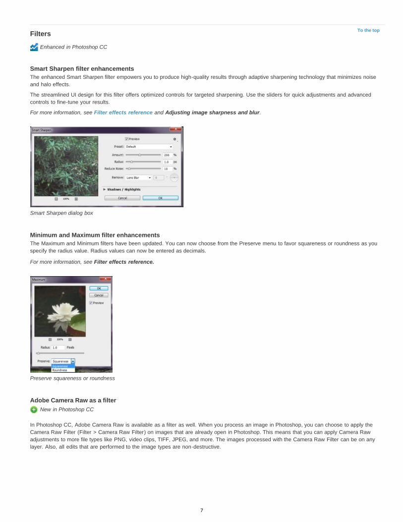
Smart Sharpen filter enhancementsThe enhanced Smart Sharpen filter empowers you to produce high-quality results through adaptive sharpening technology that minimizes noiseand halo effects.
The streamlined UI design for this filter offers optimized controls for targeted sharpening. Use the sliders for quick adjustments and advancedcontrols to fine-tune your results.
For more information, see Filter effects reference and Adjusting image sharpness and blur.
Smart Sharpen dialog box
Minimum and Maximum filter enhancementsThe Maximum and Minimum filters have been updated. You can now choose from the Preserve menu to favor squareness or roundness as youspecify the radius value. Radius values can now be entered as decimals.
For more information, see Filter effects reference.
Preserve squareness or roundness
Adobe Camera Raw as a filter New in Photoshop CC
In Photoshop CC, Adobe Camera Raw is available as a filter as well. When you process an image in Photoshop, you can choose to apply theCamera Raw Filter (Filter > Camera Raw Filter) on images that are already open in Photoshop. This means that you can apply Camera Rawadjustments to more file types like PNG, video clips, TIFF, JPEG, and more. The images processed with the Camera Raw Filter can be on anylayer. Also, all edits that are performed to the image types are non-destructive.
7
To the top
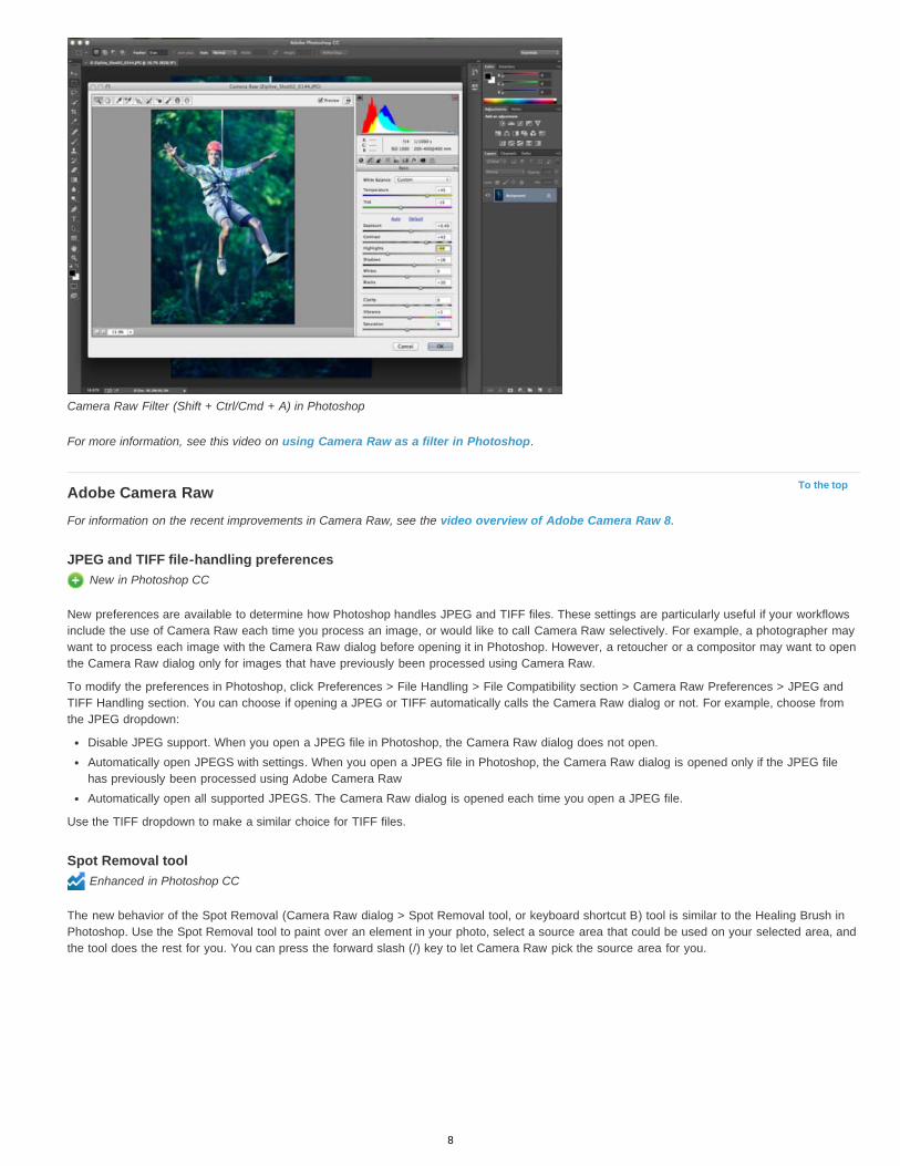
Camera Raw Filter (Shift + Ctrl/Cmd + A) in Photoshop
For more information, see this video on using Camera Raw as a filter in Photoshop.
Adobe Camera RawFor information on the recent improvements in Camera Raw, see the video overview of Adobe Camera Raw 8.
JPEG and TIFF file-handling preferences New in Photoshop CC
New preferences are available to determine how Photoshop handles JPEG and TIFF files. These settings are particularly useful if your workflowsinclude the use of Camera Raw each time you process an image, or would like to call Camera Raw selectively. For example, a photographer maywant to process each image with the Camera Raw dialog before opening it in Photoshop. However, a retoucher or a compositor may want to openthe Camera Raw dialog only for images that have previously been processed using Camera Raw.
To modify the preferences in Photoshop, click Preferences > File Handling > File Compatibility section > Camera Raw Preferences > JPEG andTIFF Handling section. You can choose if opening a JPEG or TIFF automatically calls the Camera Raw dialog or not. For example, choose fromthe JPEG dropdown:
Disable JPEG support. When you open a JPEG file in Photoshop, the Camera Raw dialog does not open.Automatically open JPEGS with settings. When you open a JPEG file in Photoshop, the Camera Raw dialog is opened only if the JPEG filehas previously been processed using Adobe Camera RawAutomatically open all supported JPEGS. The Camera Raw dialog is opened each time you open a JPEG file.
Use the TIFF dropdown to make a similar choice for TIFF files.
Spot Removal tool Enhanced in Photoshop CC
The new behavior of the Spot Removal (Camera Raw dialog > Spot Removal tool, or keyboard shortcut B) tool is similar to the Healing Brush inPhotoshop. Use the Spot Removal tool to paint over an element in your photo, select a source area that could be used on your selected area, andthe tool does the rest for you. You can press the forward slash (/) key to let Camera Raw pick the source area for you.
8

A zip-line that needs to be cleaned up (left), is identified, selected, and matched with a source area (center), and then removed (right)
While the Spot Removal tool enables you to remove visible imperfections, some flaws in the photo may not be visible in the normal view (forexample, sensor dust, or spots or blemishes on a portrait). The Visualize Spots option in the Spot Removal tool enables you to see smaller andless-visible imperfections. When you select the Visualize Spots checkbox, the image appears inverted. You can vary the contrast levels of theinverted image to see imperfections more clearly. You can then use the Spot Removal tool in this view to remove any imperfections.
For more information, see the article on the enhanced Spot Removal tool in Photoshop CC.
Radial Filter New in Photoshop CC
The new Radial Filter tool (Camera Raw dialog > Radial Filter tool, or keyboard shortcut J) enables you to define elliptical marquees, and thenapply localized corrections to these areas. The corrections can be applied within or outside the marquee areas. You can place multiple RadialFilters on an image, and apply a different set of adjustments to each Radial Filter.
The image as shot (left), and the subject brought into focus using a vignette-like effect using Radial Filters (right)
For example, a vignette-like effect has been simulated in the image above. Two overlapping Radial Filter areas were defined over the face of thesubject, one slightly larger than the other. Using the larger Radial Filter area, adjustments were made to subdue the regions behind the face. Thesecond, smaller Radial filter area was adjusted to brighten and highlight the face.
For more information, see the article on the Radial Filter tool.
Upright modes New in Photoshop CC
The Upright feature (Camera Raw dialog > Lens Correction > Manual tab) in Camera Raw enables you to automatically straighten image content.The Upright mode automatically corrects the perspective of the elements in a photograph. The feature has four settings that you can choose from:
Auto: Balanced perspective correctionsLevel: Perspective corrections are weighted toward horizontal detailsVertical: Perspective corrections are weighted toward vertical detailsFull: Combination of Level, Vertical, and Auto perspective corrections
You can apply one setting, cycle through the others, and then choose the setting that is best for your photograph.
9

To the top
To the top
To the top
Sample image before applying perspective correction (left) and after using the Auto setting in the Upright feature (right)
Also, a new slider - Aspect has been to the existing set. The Aspect slider lets you modify the aspect of the image horizontally or vertically. Slidingthe control left modifies the horizontal aspect, and sliding it right modifies the vertical aspect of the photo.
For more information, see the article on Automatic perspective correction in Camera Raw.
Multiple selection of paths
Enhanced in Photoshop CC
New enhancements in Photoshop CC let you work with multiple paths. You can apply commands to multiple paths from the Paths panel menu.Specifically users will be happy to hear they can select more than one path and delete them all at once.
You can now perform the following actions:
Shift-click to select multiple paths in the Paths panelCtrl-click (Windows) or Command-click (Mac OS) to select non-contiguous pathsDrag either the Path Selection tool and the Direct Selection tool over multiple paths to manipulate them, even if the paths are on differentlayers.Alt-drag (Windows) or Option-drag (Mac OS) a path in the Paths panel duplicates itReorder a path by dragging in the Paths panel. You can only reorder paths that are not shape, type, or vector mask paths.Delete multiple selected paths at once.
For more information, see Editing paths.
Modify rectangles and rounded rectangles
Enhanced in Photoshop CC
You can adjust dimensions, placement, and the corner radii of a rectangle or rounded rectangle shape after it has been created. Each corner canbe adjusted independently and adjustments can be simultaneously made to rectangles on multiple layers.
For more information, see Modify shapes.
Support for Indic languages
New in Photoshop CC
You can now type text in 10 Indic languages into your Photoshop documents: Bengali, Gujarati, Hindi, Kannada, Malayalam, Marathi, Oriya,Punjabi, Tamil, and Telugu.
To enable Indic language support, select Preferences > Type > Middle Eastern And South Asian. Changes take effect for the next document thatyou create.
When you enable Indic support, two additional composers are enabled in the flyout menu of the Paragraph panel:
• Single-line Composer• Every-line Composer
10

Note:
To the top
To the top
To the top
You can enable either Middle Eastern And South Asian support or East Asian support in a document.
System anti-aliasing option for type
Enhanced in Photoshop CC
The new system anti-aliasing option for type gives you a realistic preview of how your type will appear on the web. This new option closelymatches the anti-aliasing options in popular browsers for both Windows and Mac-based rendering.
Other enhancementsSignificantly improved performance for the Blur Gallery. The Blur Gallery now uses OpenCL for previews as well as the final result.Several enhancements to the preset migration functionality:
Presets are now migrated from the user library folder as well as the application presets folderActive presets are now migrated along with non-loaded presetsOnly presets for the immediate past version are migrated. For example, CS6 presets are migrated while CS5 presets are ignored from amigration standpoint.A system restart is not required after migrating presets.
Changes to Windows Open/Save dialog boxes:Changes to the ordering and placement of some controlsThe Use Lower Case option has been removed. You can change file extension upper/lower case setting in the Preferences dialog box.Warning icons and the warning text info box have been replaced with the Warning button appearing next to the Save and Cancel buttons.When you click this Warning button, Photoshop displays a message capturing the reason for the warning. If a document has no warnings,the Warning button is hidden.
The Warning button
An angle control widget for brushes is now available from the options bar as well as the context menu.The View Print Size option has been restored.The gamma value for text is now automatically set for new system options.Improved performance when you save your work to network shares on Mac OS XMetadata and ICC profiles are now included when you save a document as PNG.You can now export CSS (Cascading Style Sheet) code directly from layers or groups. Select Layer > Copy CSS.Copy CSS improvements:
Copy CSS units are now always pixel (px)
Copy CSS transparency now works in gradientsImproved placement of transformed textWidth is no longer generated for non-paragraph text
You can now select and delete multiple type stylesYou can now use the Shift key modifier while creating paths.
Product-level changesAll features in Photoshop Extended CS6 are now available in Photoshop CC. Photoshop CC does not have a separate Extended offering.The following applications are no longer installed by default with Photoshop CC:
Bridge CC; to see a list of new features, see What's New in Adobe Bridge CCExtension ManagerExtendScriptToolkitNote: To download Bridge CC, Extension Manager, or ExtendScriptToolkit; log in to Adobe Creative Cloud, navigate to Apps, and thendownload the desired application.
New system requirements for Photoshop CC:
Support for Mac OS X 10.7 (Lion) and 10.8 (Mountain Lion)
11
Twitter™ and Facebook posts are not covered under the terms of Creative Commons.
Legal Notices | Online Privacy Policy
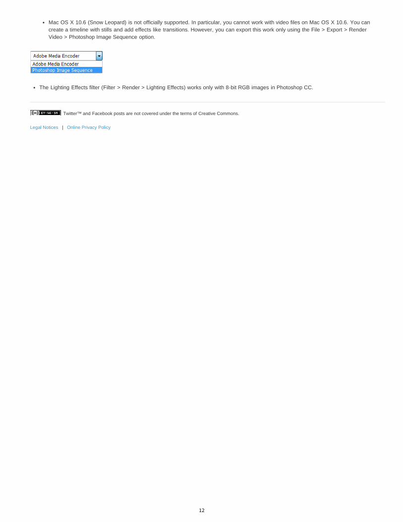
Mac OS X 10.6 (Snow Leopard) is not officially supported. In particular, you cannot work with video files on Mac OS X 10.6. You cancreate a timeline with stills and add effects like transitions. However, you can export this work only using the File > Export > RenderVideo > Photoshop Image Sequence option.
The Lighting Effects filter (Filter > Render > Lighting Effects) works only with 8-bit RGB images in Photoshop CC.
12

Photoshop getting started tutorials
Learn Photoshop CC video tutorialsAdobe TV (May. 17, 2013)video-tutorial
Video | Photoshop introductionvideo-tutorial (May. 31, 2013)
Video | Using the Camera Shake Reduction filtervideo-tutorial (May. 31, 2013)
Video | Adobe Camera Raw as a filtervideo-tutorial (May. 31, 2013)
Video | Syncing Presets in Photoshop CCvideo-tutorial (May. 31, 2013)
Video | 3D Painting - The next levelvideo-tutorial (May. 31, 2013)
13
Workspace and workflow
How to tune Photoshop for peak performanceJeff Tranberry (May. 27, 2013)article
Background-save and Auto-recoverKelby (May. 7, 2012)video-tutorialProtect precious image data.
Preset migration and sharingKelby (May. 7, 2012)video-tutorialApply common settings across workgroups.
14

Share your work on Behance | Photoshop CC
Note:
Note:
To the top
You can upload your creative images as work-in-progress to Behance directly from within Photoshop. Behance is the leading online platform toshowcase and discover creative work. Using Behance, you can create a portfolio of your work and broadcast it widely and efficiently to getfeedback.
Behance integration with Photoshop CC is available only for the English locale.
You can share your work from within Photoshop in one of the following ways:
With a document open, select File > Share On Behance.With a document open, click the Share On Behance icon ( ) in the lower-left corner of the document window.
For more information about using Behance, see the Behance Help Center.
You can share images of dimensions 320 x 320 pixel or higher.
You must be 13 years of age or older to sign up for Behance.
Share an image on Behance1. With the image open in Photoshop, select Share On Behance.2. Do one of the following:
If you don't have a Behance account, click Start Your Public Profile and create a Behance account.If you use same email address for your Behance account and your Creative Cloud membership, link the two accounts by entering yourBehance password.If you use a different email address for your Behance account and your Creative Cloud membership, fill in the details under I Have aBehance Portfolio.
3. On the Enter Information screen, specify a title and some tags for the image you're sharing. You can also post a comment to start theconversation around your work.
Specify a title and some tags for the image
4. If you have a feedback circle on Behance, you can choose to share your work just with the members of that circle.
15
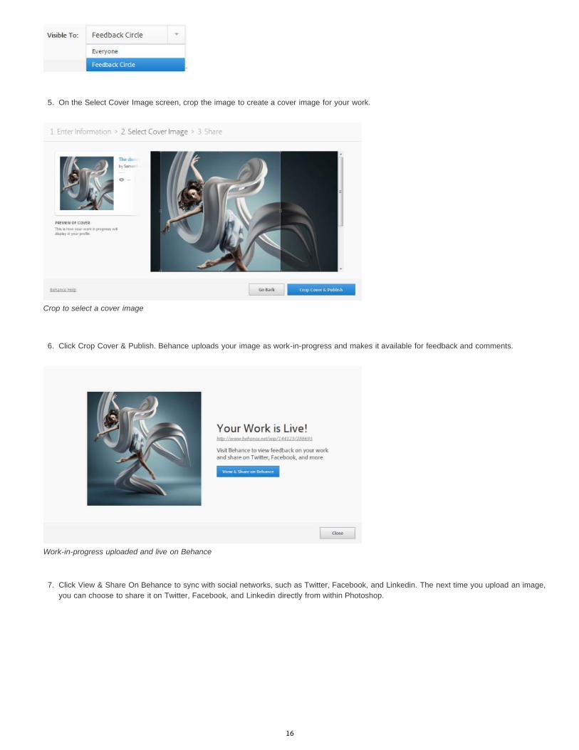
5. On the Select Cover Image screen, crop the image to create a cover image for your work.
Crop to select a cover image
6. Click Crop Cover & Publish. Behance uploads your image as work-in-progress and makes it available for feedback and comments.
Work-in-progress uploaded and live on Behance
7. Click View & Share On Behance to sync with social networks, such as Twitter, Facebook, and Linkedin. The next time you upload an image,
you can choose to share it on Twitter, Facebook, and Linkedin directly from within Photoshop.
16
Note:
To the top
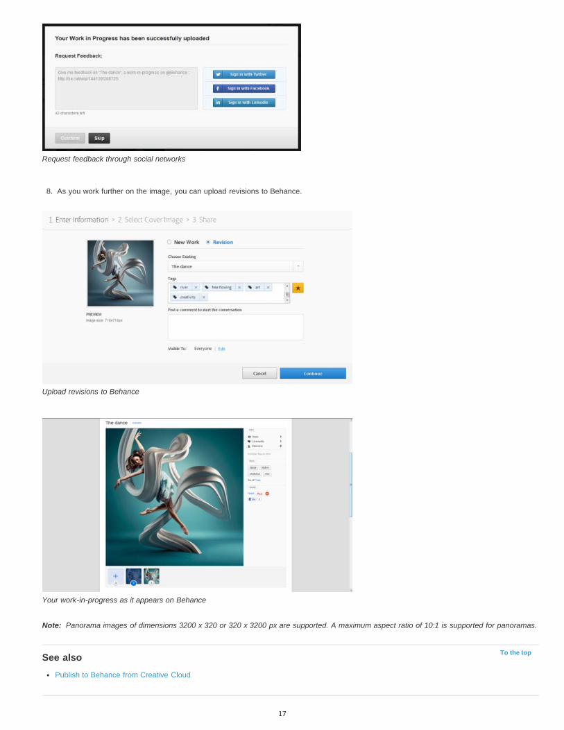
Request feedback through social networks
8. As you work further on the image, you can upload revisions to Behance.
Upload revisions to Behance
Your work-in-progress as it appears on Behance
Panorama images of dimensions 3200 x 320 or 320 x 3200 px are supported. A maximum aspect ratio of 10:1 is supported for panoramas.
See alsoPublish to Behance from Creative Cloud
17

Sync settings using Adobe Creative Cloud | Photoshop CC
To the top
To the top
Sync settingsManage Sync settingsSee also
When you work on multiple computers, managing and syncing preferences among the computers can be time-consuming, complex, and prone toerror.
The new Sync Settings feature enables you to sync preferences and settings via Creative Cloud. If you use two computers, the Sync Settingsfeature makes it easy for you to keep those settings synchronized across the computers.
The syncing happens via your Adobe Creative Cloud account. Settings are uploaded to your Creative Cloud account and then are downloadedand applied on the other computer.
You can initiate the sync manually; it does not happen automatically and it cannot be scheduled.
Sync settingsTo initiate the sync, choose one of the following:
(Windows) Edit > [your Adobe ID] > Sync Settings Now. (Mac) Photoshop > [your Adobe ID] > Sync Settings Now.
Manage Sync settingsTo change what data gets synchronized, choose one of the following:
(Windows) Edit > [your Adobe ID] > Manage Sync Settings.(Mac) Photoshop > [your Adobe ID] > Manage Sync Settings.
Alternatively, click Sync Settings in the Preferences dialog box (Edit > Preferences).
Manage Sync Settings
You can change the sync options and also choose what to do in case of conflict. Select the options to sync preferences and settings.Synchronizable preferences refer to preferences that are not dependent on computer or hardware settings.
Select the preferences to sync.Synchronizable PreferencesSwatchesCustom ShapesTool PresetsActionsStylesPatternsBrushes
18
Twitter™ and Facebook posts are not covered under the terms of Creative Commons.
Legal Notices | Online Privacy Policy
Note:
To the top
GradientsContours
When Conflicts Occur: Specify an action to take when a conflict is detected:Always AskKeep Local SettingsKeep Remote Settings
To sync your settings successfully, change the settings only from within the application. The sync settings feature does not sync any filethat is manually placed in a folder location.
See alsoCreative Cloud Help | Sync Settings with Creative Cloud
19
Workspace basics
To the top
To the top
Photoshop workspaceWorkspace overviewManage windows and panelsSave and switch workspacesHide tool tips
Photoshop workspaceThe Photoshop workspace is easy to use and includes a number of usability features:
Different brightness levels: Choose Edit > Preference (Windows) or Photoshop > Preferences (Mac OS) and select a Color Theme swatch inthe Interface section.Note: To quickly decrease brightness, press Shift + 1; to increase brightness, press Shift + 2. (On Mac OS, it’s necessary to also press theFN key.)
On-image displays: Stay informed as you use your favorite tools. On-image displays show selection dimensions, transformation angles, andmore. To change the placement of the displays, choose an option from the Show Transformation Values in the Interface preferences.
New Mini Bridge: The new Mini Bridge gallery offers easier access to images and documents. Choose Window > Extensions > Mini Bridge.
Maximized screen space: Click the button at the bottom of the toolbar to switch between Standard and Fullscreen display modes.
Workspace overviewYou create and manipulate your documents and files using various elements, such as panels, bars, and windows. Any arrangement of theseelements is called a workspace. The workspaces of the different applications in Adobe® Creative Suite® 5 share the same appearance so that youcan move between the applications easily. You can also adapt each application to the way you work by selecting from several preset workspacesor by creating one of your own.
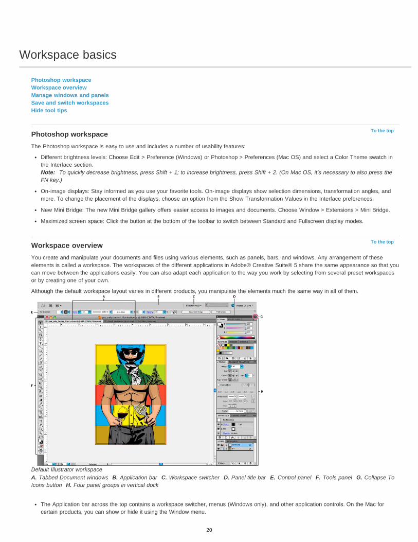
Although the default workspace layout varies in different products, you manipulate the elements much the same way in all of them.
Default Illustrator workspaceA. Tabbed Document windows B. Application bar C. Workspace switcher D. Panel title bar E. Control panel F. Tools panel G. Collapse ToIcons button H. Four panel groups in vertical dock
The Application bar across the top contains a workspace switcher, menus (Windows only), and other application controls. On the Mac forcertain products, you can show or hide it using the Window menu.
20
To the top
The Tools panel contains tools for creating and editing images, artwork, page elements, and so on. Related tools are grouped.
The Control panel displays options for the currently selected tool. In Illustrator, the Control panel displays options for the currently selectedobject. (In Adobe Photoshop® this is known as the Options bar. In Adobe Flash®, Adobe Dreamweaver®, and Adobe Fireworks® this isknown as the Property Inspector and includes properties of the currently selected element.)
The Document window displays the file you’re working on. Document windows can be tabbed and, in certain cases, grouped and docked.
Panels help you monitor and modify your work. Examples include the Timeline in Flash, the Brush panel in Illustrator, the Layers panel inAdobe Photoshop®, and the CSS Styles panel in Dreamweaver. Panels can be grouped, stacked, or docked.
The Application frame groups all the workspace elements in a single, integrated window that lets you treat the application as a single unit.When you move or resize the Application frame or any of its elements, all the elements within it respond to each other so none overlap.Panels don’t disappear when you switch applications or when you accidentally click out of the application. If you work with two or moreapplications, you can position each application side by side on the screen or on multiple monitors.
If you are using a Mac and prefer the traditional, free-form user interface, you can turn off the Application frame. In Adobe Illustrator®, forexample, select Window > Application Frame to toggle it on or off. (In Flash, the Application frame is on permanently for Mac, andDreamweaver for Mac does not use an Application frame.)
Hide or show all panels
(Illustrator, Adobe InCopy®, Adobe InDesign®, Photoshop, Fireworks)To hide or show all panels, including the Tools panel and Controlpanel, press Tab.
(Illustrator, InCopy, InDesign, Photoshop) To hide or show all panels except the Tools panel and Control panel, press Shift+Tab.
You can temporarily display hidden panels if Auto-Show Hidden Panels is selected in Interface preferences. It’s always on in Illustrator.Move the pointer to the edge of the application window (Windows®) or to the edge of the monitor (Mac OS®) and hover over the strip thatappears.
(Flash, Dreamweaver, Fireworks) To hide or show all panels, press F4.
Display panel options Click the panel menu icon in the upper-right corner of the panel.
You can open a panel menu even when the panel is minimized.
In Photoshop, you can change the font size of the text in panels and tool tips. In the Interface preferences, choose a size from the UI Font Sizemenu.
(Illustrator) Adjust panel brightness In User Interface preferences, move the Brightness slider. This control affects all panels, including the Control panel.
Reconfigure the Tools panelYou can display the tools in the Tools panel in a single column, or side by side in two columns. (This feature is not available in the Tools panel inFireworks and Flash.)
In InDesign and InCopy, you also can switch from single-column to double-column (or single-row) display by setting an option in Interfacepreferences.
Click the double arrow at the top of the Tools panel.
Manage windows and panelsYou can create a custom workspace by moving and manipulating Document windows and panels. You can also save workspaces and switchamong them. For Fireworks, renaming custom workspaces can lead to unexpected behavior.
Note: The following examples use Photoshop for demonstration purposes. The workspace behaves the same in all the products.
Rearrange, dock, or float document windowsWhen you open more than one file, the Document windows are tabbed.
To rearrange the order of tabbed Document windows, drag a window’s tab to a new location in the group.
To undock (float or untab) a Document window from a group of windows, drag the window’s tab out of the group.
Note: In Photoshop you can also choose Window > Arrange > Float in Window to float a single Document window, or Window > Arrange >Float All In Windows to float all of the Document windows at once. See tech note kb405298 for more information.Note: Dreamweaver does not support docking and undocking Document windows. Use the Document window’s Minimize button to createfloating windows (Windows), or choose Window > Tile Vertically to create side-by-side Document windows. Search “Tile Vertically” inDreamweaver Help for more information on this topic. The workflow is slightly different for Macintosh users.
21
To dock a Document window to a separate group of Document windows, drag the window into the group.
To create groups of stacked or tiled documents, drag the window to one of the drop zones along the top, bottom, or sides of another window.You can also select a layout for the group by using the Layout button on the Application bar.
Note: Some products do not support this functionality. However, your product may have Cascade and Tile commands in the Window menuto help you lay out your documents.
To switch to another document in a tabbed group when dragging a selection, drag the selection over the document’s tab for a moment.
Note: Some products do not support this functionality.
Dock and undock panelsA dock is a collection of panels or panel groups displayed together, generally in a vertical orientation. You dock and undock panels by movingthem into and out of a dock.
To dock a panel, drag it by its tab into the dock, at the top, bottom, or in between other panels.
To dock a panel group, drag it by its title bar (the solid empty bar above the tabs) into the dock.
To remove a panel or panel group, drag it out of the dock by its tab or title bar. You can drag it into another dock or make it free-floating.
Navigator panel being dragged out to new dock, indicated by blue vertical highlight
Navigator panel now in its own dock
You can prevent panels from filling all the space in a dock. Drag the bottom edge of the dock up so it no longer meets the edge of theworkspace.
Move panelsAs you move panels, you see blue highlighted drop zones, areas where you can move the panel. For example, you can move a panel up or downin a dock by dragging it to the narrow blue drop zone above or below another panel. If you drag to an area that is not a drop zone, the panel floatsfreely in the workspace.
Note: The position of the mouse (rather than the position of the panel), activates the drop zone, so if you can’t see the drop zone, try draggingthe mouse to the place where the drop zone should be.
To move a panel, drag it by its tab.
To move a panel group, drag the title bar.
22
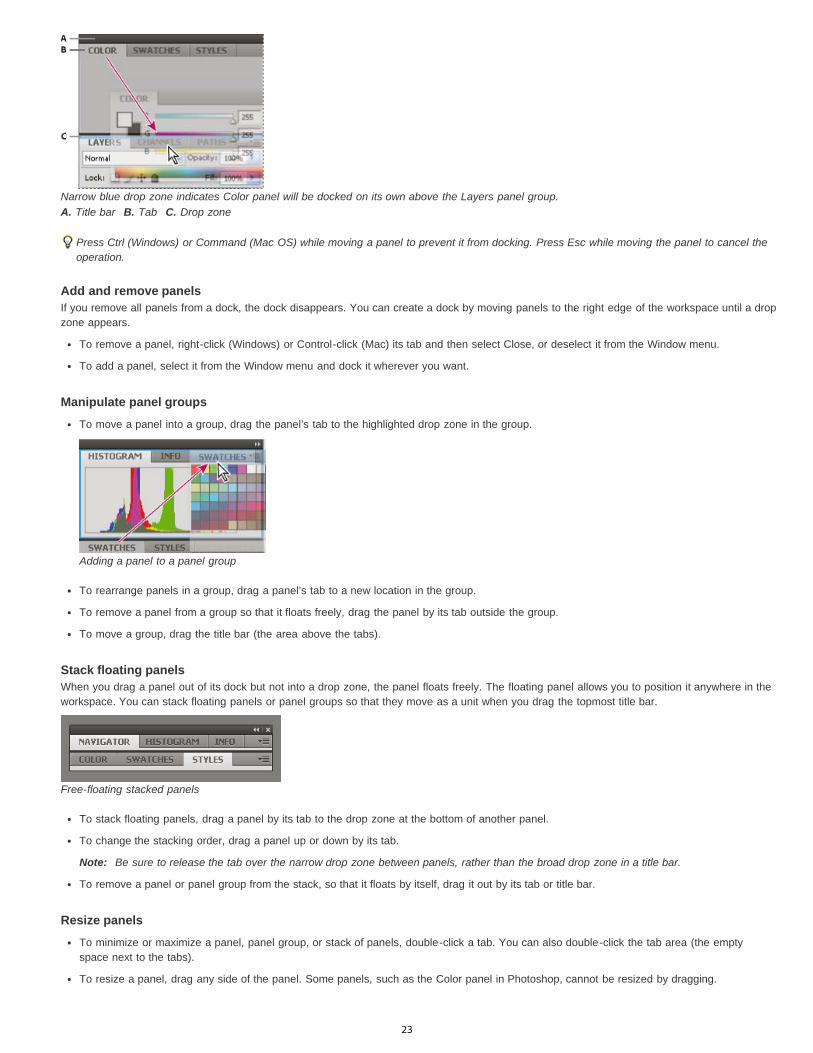
Narrow blue drop zone indicates Color panel will be docked on its own above the Layers panel group.A. Title bar B. Tab C. Drop zone
Press Ctrl (Windows) or Command (Mac OS) while moving a panel to prevent it from docking. Press Esc while moving the panel to cancel theoperation.
Add and remove panelsIf you remove all panels from a dock, the dock disappears. You can create a dock by moving panels to the right edge of the workspace until a dropzone appears.
To remove a panel, right-click (Windows) or Control-click (Mac) its tab and then select Close, or deselect it from the Window menu.
To add a panel, select it from the Window menu and dock it wherever you want.
Manipulate panel groups
To move a panel into a group, drag the panel’s tab to the highlighted drop zone in the group.
Adding a panel to a panel group
To rearrange panels in a group, drag a panel’s tab to a new location in the group.
To remove a panel from a group so that it floats freely, drag the panel by its tab outside the group.
To move a group, drag the title bar (the area above the tabs).
Stack floating panelsWhen you drag a panel out of its dock but not into a drop zone, the panel floats freely. The floating panel allows you to position it anywhere in theworkspace. You can stack floating panels or panel groups so that they move as a unit when you drag the topmost title bar.
Free-floating stacked panels
To stack floating panels, drag a panel by its tab to the drop zone at the bottom of another panel.
To change the stacking order, drag a panel up or down by its tab.
Note: Be sure to release the tab over the narrow drop zone between panels, rather than the broad drop zone in a title bar.
To remove a panel or panel group from the stack, so that it floats by itself, drag it out by its tab or title bar.
Resize panels
To minimize or maximize a panel, panel group, or stack of panels, double-click a tab. You can also double-click the tab area (the emptyspace next to the tabs).
To resize a panel, drag any side of the panel. Some panels, such as the Color panel in Photoshop, cannot be resized by dragging.
23

To the top
Collapse and expand panel iconsYou can collapse panels to icons to reduce clutter on the workspace. In some cases, panels are collapsed to icons in the default workspace.
Panels collapsed to icons
Panels expanded from icons
To collapse or expand all panel icons in a column, click the double arrow at the top of the dock.
To expand a single panel icon, click it.
To resize panel icons so that you see only the icons (and not the labels), adjust the width of the dock until the text disappears. To display theicon text again, make the dock wider.
To collapse an expanded panel back to its icon, click its tab, its icon, or the double arrow in the panel’s title bar.
In some products, if you select Auto-Collapse Icon Panels from the Interface or User Interface Options preferences, an expanded panelicon collapses automatically when you click away from it.
To add a floating panel or panel group to an icon dock, drag it in by its tab or title bar. (Panels are automatically collapsed to icons whenadded to an icon dock.)
To move a panel icon (or panel icon group), drag the icon. You can drag panel icons up and down in the dock, into other docks (where theyappear in the panel style of that dock), or outside the dock (where they appear as floating icons).
Save and switch workspacesBy saving the current size and position of panels as a named workspace, you can restore that workspace even if you move or close a panel. Thenames of saved workspaces appear in the workspace switcher in the Application bar.
Save a custom workspace
1. With the workspace in the configuration you want to save, do one of the following:
(Illustrator) Choose Window > Workspace > Save Workspace.
(Photoshop, InDesign, InCopy) Choose Window > Workspace > New Workspace.
(Dreamweaver) Choose Window > Workspace Layout > New Workspace.
(Flash) Choose New Workspace from the workspace switcher in the Application bar.
(Fireworks) Choose Save Current from the workspace switcher in the Application bar.
2. Type a name for the workspace.
3. (Photoshop, InDesign) Under Capture, select one or more options:
Panel Locations Saves the current panel locations (InDesign only).
24

To the top
Keyboard shortcuts Saves the current set of keyboard shortcuts (Photoshop only).
Menus or Menu Customization Saves the current set of menus.
Display or switch workspaces Select a workspace from the workspace switcher in the Application bar.
In Photoshop, you can assign keyboard shortcuts to each workspace to navigate among them quickly.
Delete a custom workspace
Select Manage Workspaces from the workspace switcher in the Application bar, select the workspace, and then click Delete. (The option isnot available in Fireworks.)
(Photoshop, InDesign, InCopy) Select Delete Workspace from the workspace switcher.
(Illustrator) Choose Window > Workspace > Manage Workspaces, select the workspace, and then click the Delete icon.
(Photoshop, InDesign) Choose Window > Workspace >Delete Workspace, select the workspace, and then click Delete.
Restore the default workspace
1. Select the Default or Essentials workspace from the workspace switcher in the application bar. For Fireworks, see the articlehttp://www.adobe.com/devnet/fireworks/articles/workspace_manager_panel.html.
Note: In Dreamweaver, Designer is the default workspace.2. For Fireworks (Windows), delete these folders:
Windows Vista \\Users\<username>\AppData\Roaming\Adobe\Fireworks CS4\
Windows XP \\Documents and Settings\<username>\Application Data\Adobe\Fireworks CS4
3. (Photoshop, InDesign, InCopy) Select Window > Workspace > Reset [Workspace Name].
(Photoshop) Restore a saved workspace arrangementIn Photoshop, workspaces automatically appear as you last arranged them, but you can restore the original, saved arrangement of panels.
To restore an individual workspace, choose Window > Workspace > Reset Workspace Name.
To restore all the workspaces installed with Photoshop, click Restore Default Workspaces in the Interface preferences.
To rearrange the order of workspaces in the application bar, drag them.
Hide tool tipsWhen you position the pointer over most tools and options, descriptions appear in tool tips by default. If you find tool tips visually distracting, youcan hide them.
In the Interface preferences, deselect Show Tool Tips.Note: Tool tips are not available in some dialog boxes.More Help topics
Adobe Bridge
Legal Notices | Online Privacy Policy
25

Panels and menus
To the top
To the top
Enter values in panels, dialog boxes, and the options barWorking with slidersWorking with pop-up panelsDisplay and define menus
Enter values in panels, dialog boxes, and the options bar Do any of the following:
Type a value in the text box, and press Enter (Windows) or Return (Mac OS).
Drag the slider.
Move the pointer over the title of a slider or pop-up slider. When the pointer turns to a pointing finger, drag the scrubby slider to the left orright. This feature is available only for selected sliders and pop-up sliders.
Drag the dial.
Click the arrow buttons in the panel to increase or decrease the value.
(Windows) Click the text box and then use the Up Arrow key and the Down Arrow key on the keyboard to increase or decrease the value.
Select a value from the menu associated with the text box.
Ways to enter valuesA. Menu arrow B. Scrubby slider C. Text box D. Dial E. Slider
Working with sliders
About pop-up slidersSome panels, dialog boxes, and options bars contain settings that use pop-up sliders (for example, the Opacity option in the Layers panel). Ifthere is a triangle next to the text box, you can activate the pop-up slider by clicking the triangle. Position the pointer over the triangle next to thesetting, hold down the mouse button, and drag the slider or angle radius to the desired value. Click outside the slider box or press Enter to closethe slider box. To cancel changes, press the Esc key.
To increase or decrease values in 10% increments when the pop-up slider box is open, hold down Shift and press the Up Arrow or Down Arrowkey.
Using different kinds of pop-up slidersA. Click to open pop-up slider box. B. Drag slider or angle radius.
You can also “scrub” some pop-up sliders. For example, if you hold the pointer over the word “Fill” or “Opacity” in the Layers panel, the pointerchanges to the Hand icon. Then you can move the pointer left or right to change the fill or opacity percentage.
About scrubby slidersIn some panels, dialog boxes, and options bars, you can drag scrubby sliders to change option values. Scrubby sliders are hidden until youposition the pointer over the title of sliders and pop-up sliders. When the pointer changes to a pointing finger, you drag to the left or right. Holding
26

To the top
To the top
down the Shift key while dragging accelerates the scrubbing by a factor of 10.
Hovering over the title of a slider or pop-up slider shows the scrubby slider
Working with pop-up panelsPop-up panels provide easy access to available options for brushes, swatches, gradients, styles, patterns, contours, and shapes. You cancustomize pop-up panels by renaming and deleting items and by loading, saving, and replacing libraries. You can also change the display of apop-up panel to view items by their names, as thumbnail icons, or with both names and icons.
Click a tool thumbnail in the options bar to show its pop-up panel. Click an item in the pop-up panel to select it.
Viewing the Brush pop-up panel in the options barA. Click to show the pop-up panel. B. Click to view the pop-up panel menu.
Rename or delete an item in a pop-up panel Select an item, click the triangle in the upper right corner of the pop-up panel, and choose one of the following:
Rename Tool Preset Lets you enter a new name for the item.Delete Tool Preset Deletes an item in the pop-up panel.Note: You can also delete an item in a pop-up panel by holding down Alt (Windows) or Option (Mac OS) and clicking the item.
Customize the list of items in a pop-up panel1. Click the triangle in the upper right corner of the pop-up panel to view the panel menu.2. To return to the default library, choose the Reset Tool Presets command. You can either replace the current list or add the default library to
the current list.3. To load a different library, do one of the following:
Choose the Load Tool Presets command to add a library to the current list. Then select the library file you want to use, and click Load.
Choose the Replace Tool Presets command to replace the current list with a different library. Then select the library file you want to use,and click Load.
Choose a library file (displayed at the bottom of the panel menu). Then click OK to replace the current list, or click Append to add it tothe current list.
4. To save the current list as a library for later use, choose the Save Tool Presets command. Then enter a name for the library file, and clickSave.
(Mac OS) Include the extension of the library file name so that you can easily share the libraries across operating systems. SelectAppend File Extension Always in the File Handling Preferences to append extensions to file names.
Change the display of items in a pop-up panel1. Click the triangle in the upper right corner of the pop-up panel to view the panel menu.2. Select a view option: Text Only, Small List, and Large List.
Display and define menus
27

Display context menusContext menus display commands relevant to the active tool, selection, or panel. They are distinct from the menus across the top of theworkspace.
Viewing the context menu for the Eyedropper tool
1. Position the pointer over an image or panel item.2. Right-click (Windows) or Control-click (Mac OS).
Define a set of menus1. Do one of the following:
Choose Edit > Menus.
Choose Window > Workspace > Keyboard Shortcuts & Menus and click the Menus tab.
2. In the Keyboard Shortcuts and Menus dialog box, choose a set of menus from the Set drop-down menu.3. Choose a type from the Menu For menu:
Application Menus Lets you show, hide, or add color to items in the application menus.
Panel Menus Lets you show, hide, or add color to items in panel menus.
4. Click the triangle next to a menu or panel name.5. Do one of the following:
To hide a menu item, click the Visibility button .
To show a menu item, click the empty Visibility button.
To add color to a menu item, click the color swatch (if no color is assigned, it will say None) and choose a color.
6. When you finish changing the menus, do one of the following:
To save all changes to the current set of menus, click the Save Set button . Changes to a custom set are saved. If you’re savingchanges to the Photoshop Defaults set, the Save dialog box opens. Enter a name for the new set and click Save.
To create a new set based on the current set of menus, click the Save Set As button .
Note: If you haven’t saved the current set of changes, you can click Cancel to discard all changes and close the dialog box.7. In the Save dialog box, enter a name for the set and click Save.
Choosing a color for a menu item using the Keyboard Shortcuts & Menus dialog box
Delete a set of menus1. Do one of the following:
Choose Edit > Menus.
Choose Window > Workspace > Keyboard Shortcuts & Menus and click the Menu tab.
28
2. In the Keyboard Shortcuts & Menus dialog box, choose a set of menus from the Set menu.3. Click the Delete Set icon .
Temporarily show hidden menu itemsIt’s possible to temporarily show items that you’ve hidden in a menu. After the menu closes, the items return to their hidden state.
Do one of the following:
From a menu with hidden items, choose Show All Menu Items.
Ctrl-click (Windows) or Command-click (Mac OS) a menu with hidden items.
To permanently reveal all menu items, select Window > Workspace > Essentials.
Turn menu colors on or off In Interface preferences, select or deselect Show Menu Colors.
Legal Notices | Online Privacy Policy
29
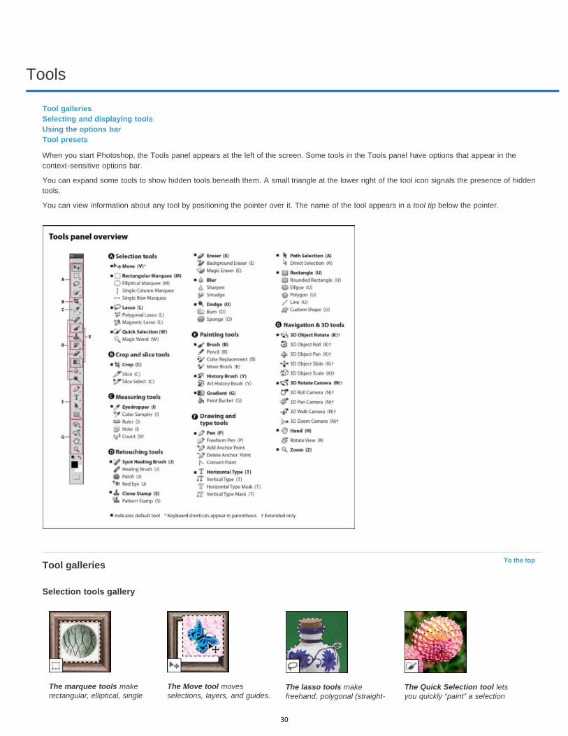
Tools
To the top
Tool galleriesSelecting and displaying toolsUsing the options barTool presets
When you start Photoshop, the Tools panel appears at the left of the screen. Some tools in the Tools panel have options that appear in thecontext-sensitive options bar.
You can expand some tools to show hidden tools beneath them. A small triangle at the lower right of the tool icon signals the presence of hiddentools.
You can view information about any tool by positioning the pointer over it. The name of the tool appears in a tool tip below the pointer.
Tool galleries
Selection tools gallery
The marquee tools makerectangular, elliptical, single
The Move tool movesselections, layers, and guides.
The lasso tools makefreehand, polygonal (straight-
The Quick Selection tool letsyou quickly “paint” a selection
30
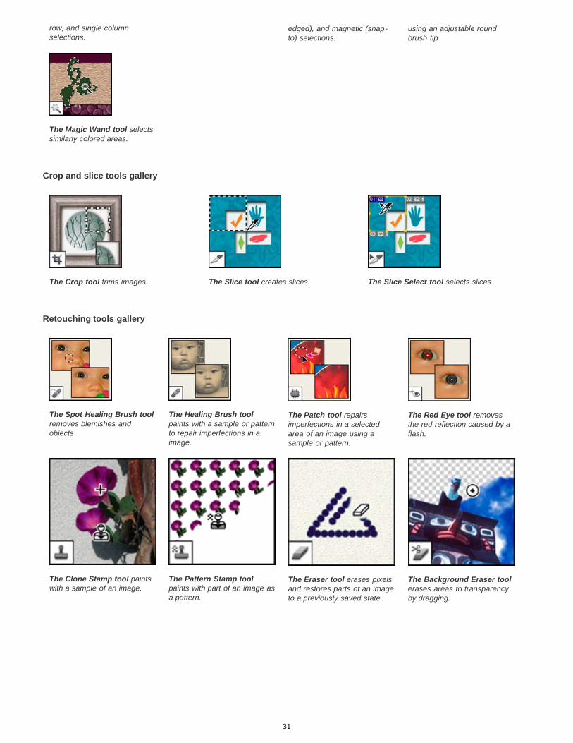
Crop and slice tools gallery
Retouching tools gallery
row, and single columnselections.
edged), and magnetic (snap-to) selections.
using an adjustable roundbrush tip
The Magic Wand tool selectssimilarly colored areas.
The Crop tool trims images. The Slice tool creates slices. The Slice Select tool selects slices.
The Spot Healing Brush toolremoves blemishes andobjects
The Healing Brush toolpaints with a sample or patternto repair imperfections in aimage.
The Patch tool repairsimperfections in a selectedarea of an image using asample or pattern.
The Red Eye tool removesthe red reflection caused by aflash.
The Clone Stamp tool paintswith a sample of an image.
The Pattern Stamp toolpaints with part of an image asa pattern.
The Eraser tool erases pixelsand restores parts of an imageto a previously saved state.
The Background Eraser toolerases areas to transparencyby dragging.
31

Painting tools gallery
Drawing and type tools gallery
The Magic Eraser tool erasessolid-colored areas totransparency with a singleclick.
The Blur tool blurs hardedges in an image.
The Sharpen tool sharpenssoft edges in an image.
The Smudge tool smudgesdata in an image.
The Dodge tool lightensareas in an image.
The Burn tool darkens areasin an image.
The Sponge tool changes thecolor saturation of an area.
The Brush tool paints brushstrokes.
The Pencil tool paints hard-edged strokes.
The Color Replacement toolreplaces a selected color witha new color.
The Mixer Brush toolSimulates realistic paintingtechniques such as blendingcanvas colors and varyingpaint wetness.
The History Brush tool paintsa copy of the selected state orsnapshot into the currentimage window.
The Art History brush toolpaints with stylized strokesthat simulate the look ofdifferent paint styles, using aselected state or snapshot.
The gradient tools createstraight-line, radial, angle,reflected, and diamond blendsbetween colors.
The Paint Bucket tool fillssimilarly colored areas with theforeground color.
32
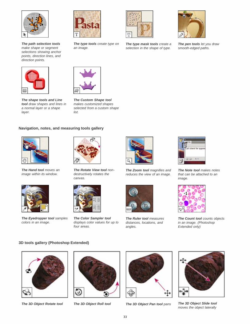
Navigation, notes, and measuring tools gallery
3D tools gallery (Photoshop Extended)
The path selection toolsmake shape or segmentselections showing anchorpoints, direction lines, anddirection points.
The type tools create type onan image.
The type mask tools create aselection in the shape of type.
The pen tools let you drawsmooth-edged paths.
The shape tools and Linetool draw shapes and lines ina normal layer or a shapelayer.
The Custom Shape toolmakes customized shapesselected from a custom shapelist.
The Hand tool moves animage within its window.
The Rotate View tool non-destructively rotates thecanvas.
The Zoom tool magnifies andreduces the view of an image.
The Note tool makes notesthat can be attached to animage.
The Eyedropper tool samplescolors in an image.
The Color Sampler tooldisplays color values for up tofour areas.
The Ruler tool measuresdistances, locations, andangles.
The Count tool counts objectsin an image. (PhotoshopExtended only)
The 3D Object Rotate tool The 3D Object Roll tool The 3D Object Pan tool pans The 3D Object Slide toolmoves the object laterally
33
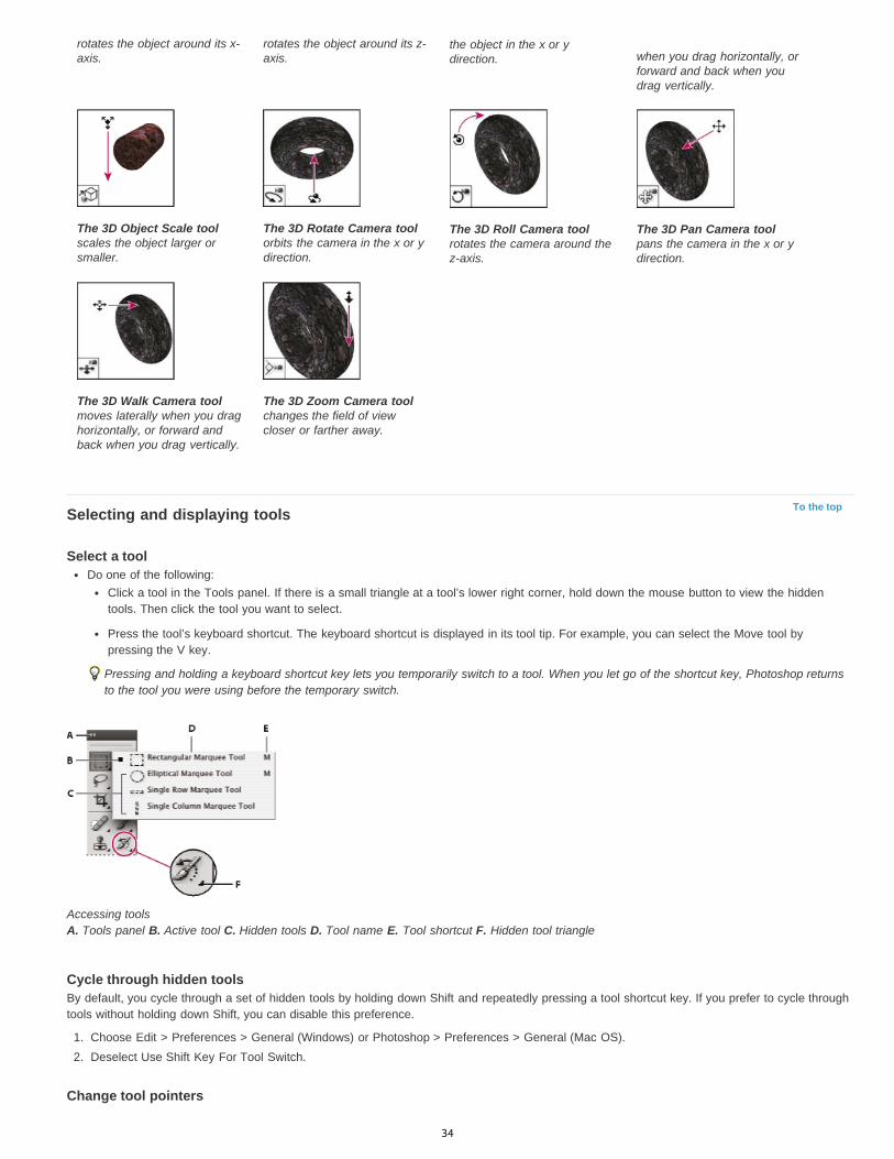
To the topSelecting and displaying tools
Select a toolDo one of the following:
Click a tool in the Tools panel. If there is a small triangle at a tool’s lower right corner, hold down the mouse button to view the hiddentools. Then click the tool you want to select.
Press the tool’s keyboard shortcut. The keyboard shortcut is displayed in its tool tip. For example, you can select the Move tool bypressing the V key.
Pressing and holding a keyboard shortcut key lets you temporarily switch to a tool. When you let go of the shortcut key, Photoshop returnsto the tool you were using before the temporary switch.
Accessing tools A. Tools panel B. Active tool C. Hidden tools D. Tool name E. Tool shortcut F. Hidden tool triangle
Cycle through hidden toolsBy default, you cycle through a set of hidden tools by holding down Shift and repeatedly pressing a tool shortcut key. If you prefer to cycle throughtools without holding down Shift, you can disable this preference.
1. Choose Edit > Preferences > General (Windows) or Photoshop > Preferences > General (Mac OS).2. Deselect Use Shift Key For Tool Switch.
Change tool pointers
rotates the object around its x-axis.
rotates the object around its z-axis.
the object in the x or ydirection. when you drag horizontally, or
forward and back when youdrag vertically.
The 3D Object Scale toolscales the object larger orsmaller.
The 3D Rotate Camera toolorbits the camera in the x or ydirection.
The 3D Roll Camera toolrotates the camera around thez-axis.
The 3D Pan Camera toolpans the camera in the x or ydirection.
The 3D Walk Camera toolmoves laterally when you draghorizontally, or forward andback when you drag vertically.
The 3D Zoom Camera toolchanges the field of viewcloser or farther away.
34

Standard
Precise
Normal Brush Tip
Full Size Brush Tip
Show Crosshair In Brush Tip
Show Only Crosshair While Painting
To the top
To the top
Each default pointer has a different hotspot, where an effect or action in the image begins. With most tools, you can switch to precise cursors,which appear as cross hairs centered around the hotspot.
In most cases, the pointer for a tool is the same as the icon for that tool; you see that pointer when you select the tool. The default pointer for themarquee tools is the cross-hair pointer ; for the text tool, the default pointer is the I-beam ; and for the painting tools the default pointer is theBrush Size icon.
1. Choose Edit > Preferences > Cursors (Windows) or choose Photoshop > Preferences > Cursors (Mac OS).2. Choose tool pointer settings under Painting Cursors or Other Cursors:
Displays pointers as tool icons.
Displays pointers as cross hairs.
The pointer outline corresponds to approximately 50% of the area that the tool will affect. This option shows the pixelsthat would be most visibly affected.
The pointer outline corresponds to nearly 100% of the area that the tool will affect, or nearly all the pixels that wouldbe affected.
Displays cross hairs in the center of the brush shape.
Improves performance with large brushes.
3. Click OK.
The Painting Cursors options control the pointers for the following tools:
Eraser, Pencil, Paintbrush, Healing Brush, Rubber Stamp, Pattern Stamp, Quick Selection, Smudge, Blur, Sharpen, Dodge, Burn, and Spongetools
The Other Cursors options control the pointers for the following tools:
Marquee, Lasso, Polygonal Lasso, Magic Wand, Crop, Slice, Patch, Eyedropper, Pen, Gradient, Line, Paint Bucket, Magnetic Lasso, MagneticPen, Freeform Pen, Measure, and Color Sampler tools
To toggle between standard and precise cursors in some tool pointers, press Caps Lock.
Visually resize or change hardness of painting cursorsYou can resize or change the hardness of a painting cursor by dragging in the image. As you drag, the painting cursor previews your changes.(Previews require OpenGL. See GPU, OpenGL support.
To resize a cursor, press Alt + right-click (Windows) or Control + Option (Mac OS), and drag left or right. To change hardness, drag up ordown.
Using the options barThe options bar appears below the menu bar at the top of the workspace. The options bar is context sensitive—it changes as you select differenttools. Some settings in the options bar (such as painting modes and opacity) are common to several tools, and some are specific to one tool.
You can move the options bar in the workspace by using the gripper bar, and you can dock it at the top or bottom of the screen. Tool tips appearwhen you position the pointer over a tool. To show or hide the options bar, choose Window > Options.
Lasso options bar A. Gripper bar B. Tool tip
To return tools to their default settings, right-click (Windows) or Control-click (Mac OS) the tool icon in the options bar, and then choose ResetTool or Reset All Tools from the context menu.
For more information on setting options for a specific tool, search for the tool’s name in Photoshop Help.
Tool presetsTool presets let you save and reuse tool settings. You can load, edit, and create libraries of tool presets using the Tool Preset picker in the options
35
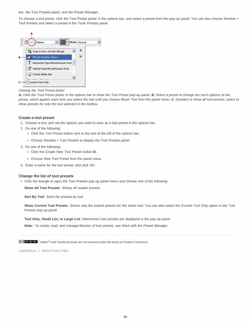
Twitter™ and Facebook posts are not covered under the terms of Creative Commons.
Legal Notices | Online Privacy Policy
Show All Tool Presets
Sort By Tool
Show Current Tool Presets
Text Only, Small List, or Large List
Note:
bar, the Tool Presets panel, and the Preset Manager.
To choose a tool preset, click the Tool Preset picker in the options bar, and select a preset from the pop-up panel. You can also choose Window >Tool Presets and select a preset in the Tools Presets panel.
Viewing the Tool Preset picker A. Click the Tool Preset picker in the options bar to show the Tool Preset pop-up panel. B. Select a preset to change the tool’s options to thepreset, which applies each time you select the tool until you choose Reset Tool from the panel menu. C. Deselect to show all tool presets; select toshow presets for only the tool selected in the toolbox.
Create a tool preset1. Choose a tool, and set the options you want to save as a tool preset in the options bar.2. Do one of the following:
Click the Tool Preset button next to the tool at the left of the options bar.
Choose Window > Tool Presets to display the Tool Presets panel.
3. Do one of the following:Click the Create New Tool Preset button .
Choose New Tool Preset from the panel menu.
4. Enter a name for the tool preset, and click OK.
Change the list of tool presetsClick the triangle to open the Tool Presets pop-up panel menu and choose one of the following:
Shows all loaded presets.
Sorts the presets by tool.
Shows only the loaded presets for the active tool. You can also select the Current Tool Only option in the ToolPresets pop-up panel.
Determines how presets are displayed in the pop-up panel.
To create, load, and manage libraries of tool presets, see Work with the Preset Manager.
36

Preferences
Twitter™ and Facebook posts are not covered under the terms of Creative Commons.
Legal Notices | Online Privacy Policy
About preferencesNumerous program settings are stored in the Adobe Photoshop Prefs file, including general display options, file-saving options, performanceoptions, cursor options, transparency options, type options, and options for plug-ins and scratch disks. Most of these options are set in thePreferences dialog box. Preference settings are saved each time you quit the application.
Unexpected behavior may indicate damaged preferences. If you suspect damage to preferences, restore preferences to their default settings.
Detailed information about specific preference settings appears in task-specific topics. For example, search Help for “Transparencypreferences” to see those settings discussed in the context of related features such as layers.
Open a preferences dialog box1. Do one of the following:
(Windows) Choose Edit > Preferences and choose the desired preference set from the submenu.
(Mac OS) Choose Photoshop > Preferences, and then choose the desired preference set from the submenu.
2. To switch to a different preference set, do one of the following:Choose the preference set from the menu at the left of the dialog box.
Click Next to display the next preference set in the list; click Prev to display the previous set.
For information on a specific preference option, search Help.
To manually restore preferences to default:
Find the preference file that you want to reset and move it to another location. When you restart Photoshop a new preference file will becreated in the original location. See Preference filenames and locations.
To restore preferences quickly using a keyboard short cut:
Press and hold Alt+Control+Shift (Windows) or Option+Command+Shift (Mac OS) as you start Photoshop. You are prompted to delete thecurrent settings. The new preferences files are created the next time you start Photoshop.
Note: Using the keyboard shortcut, preference files for custom shortcuts, workspaces, and color setings will also be reset to default.
Disable and enable warning messagesSometimes you will see messages containing warnings or prompts. You can suppress the display of these messages by selecting the Don’t ShowAgain option in the message. You can also globally redisplay all messages that have been suppressed.
1. Do one of the following:(Windows) Choose Edit > Preferences > General.
(Mac OS) Choose Photoshop > Preferences > General.
2. Click Reset All Warning Dialogs, and click OK.
37
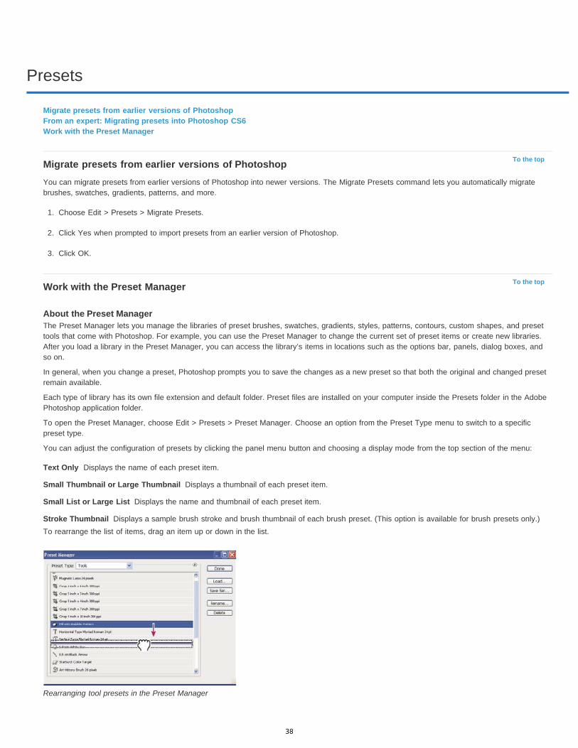
Presets
To the top
To the top
Text Only
Small Thumbnail or Large Thumbnail
Small List or Large List
Stroke Thumbnail
Migrate presets from earlier versions of PhotoshopFrom an expert: Migrating presets into Photoshop CS6Work with the Preset Manager
Migrate presets from earlier versions of PhotoshopYou can migrate presets from earlier versions of Photoshop into newer versions. The Migrate Presets command lets you automatically migratebrushes, swatches, gradients, patterns, and more.
1. Choose Edit > Presets > Migrate Presets.
2. Click Yes when prompted to import presets from an earlier version of Photoshop.
3. Click OK.
Work with the Preset Manager
About the Preset ManagerThe Preset Manager lets you manage the libraries of preset brushes, swatches, gradients, styles, patterns, contours, custom shapes, and presettools that come with Photoshop. For example, you can use the Preset Manager to change the current set of preset items or create new libraries.After you load a library in the Preset Manager, you can access the library’s items in locations such as the options bar, panels, dialog boxes, andso on.
In general, when you change a preset, Photoshop prompts you to save the changes as a new preset so that both the original and changed presetremain available.
Each type of library has its own file extension and default folder. Preset files are installed on your computer inside the Presets folder in the AdobePhotoshop application folder.
To open the Preset Manager, choose Edit > Presets > Preset Manager. Choose an option from the Preset Type menu to switch to a specificpreset type.
You can adjust the configuration of presets by clicking the panel menu button and choosing a display mode from the top section of the menu:
Displays the name of each preset item.
Displays a thumbnail of each preset item.
Displays the name and thumbnail of each preset item.
Displays a sample brush stroke and brush thumbnail of each brush preset. (This option is available for brush presets only.)To rearrange the list of items, drag an item up or down in the list.
Rearranging tool presets in the Preset Manager
38

Note:
Note:
To delete a preset in the Preset Manager, select the preset and click Delete. You can always use the Reset command to restore the defaultitems in a library.
Load a library of preset itemsDo one of the following:
Click the triangle to the right of the Preset Type pop-up menu and then choose a library file from the bottom of the panel menu. Click OKto replace the current list, or click Append to add the current list.
To add a library to the current list, click Load, select the library file you want to add, and click Load.
To replace the current list with a different library, choose Replace [Preset Type] from the panel menu. Select the library file you want touse, and click Load.
Each type of library has its own file extension and default folder.
Manage preset itemsYou can rename or delete preset items, as well as create or restore libraries of presets.
Rename preset items1. Select a preset item. Shift-click to select multiple items.2. Do one of the following:
Click Rename, and then enter a new name for the brush, swatch, and so on.
If the Preset Manager currently displays presets as thumbnails, double-click a preset, enter a new name, and click OK.
If the Preset Manager currently displays presets as a list or text only, double-click a preset, enter a new name inline, and press Enter(Windows) or Return (Mac OS).
Delete preset itemsDo one of the following:
Select a preset item, and click Delete.
Alt-click (Windows) or Option-click (Mac OS) the items you want to delete.
Create a new library of presets1. Do one of the following:
To save all the presets in the list as a library, make sure that all items are selected.
To save a subset of the current list as a library, hold down Shift, and select the items you want to save.
2. Click Save Set, choose a location for the library, enter a file name, and click Save.
You can save the library anywhere. However, if you place the library file in the appropriate Presets folder in the default preset location, thelibrary name will appear at the bottom of the panel menu after you restart Photoshop.
Restore the default library of preset itemsChoose Reset from the panel menu. You can either replace the current list or append the default library to the current list.
Default preset locations1. The default location for saving/loading/replacing presets depends on your operating system.
Windows 7 and Windows Vista: [Drive]:\Users\<user>\AppData\Roaming\Adobe\Adobe Photoshop [version_number]\Presets.
Mac: <User>/Library/Application Support/Adobe/AdobePhotoshop [version_number]/Presets.
Windows XP: [Drive]:\Document and Settings\<user>\Application Data\Adobe\AdobePhotoshop [version_number]\Presets.
2. Presets that ship with Adobe Photoshop are stored in the Photoshop program folder.
Displaying Hidden Files in WindowsThe default locations for saving/loading/replacing presets are hidden by default in Windows.
1. To display hidden files in Windows XP:
a. Go to Start > Control Panel > Folder Options.
b. In the View tab, under Hidden files and folders, select Show hidden files and folders.
39

Twitter™ and Facebook posts are not covered under the terms of Creative Commons.
Legal Notices | Online Privacy Policy
c. Click OK.
2. To display hidden files in Windows Vista:
a. Go to Start > Control Panel > Appearance and Personalization > Folder Options.
b. In the View tab, under Hidden files and folders, select Show hidden files and folders.
c. Click OK.
40
Plug-ins
Twitter™ and Facebook posts are not covered under the terms of Creative Commons.
Legal Notices | Online Privacy Policy
About plug-in modulesPlug-in modules are software programs developed by Adobe Systems and by other software developers in conjunction with Adobe Systems to addfeatures to Photoshop. A number of importing, exporting, and special-effects plug-ins come with your program. They are automatically installed infolders inside the Photoshop Plug-ins folder.
You can select an additional Plug-ins folder for compatible plug-ins stored with another application. You can also create a shortcut (Windows) or an alias (Mac OS) for a plug-in stored in another folder on your system. You can then add the shortcut or alias to the plug-ins folder and use that plug-in with Photoshop.
Once installed, plug-in modules appear as options in the Import or Export menu; as file formats in the Open, and Save As dialog boxes; or asfilters in the Filter submenus. Photoshop can accommodate a large number of plug-ins. However, if the list of installed plug-in modules becomestoo long, Photoshop may not be able to display all the plug-ins in their appropriate menus. If so, newly installed plug-ins appear in the Filter >Other submenu.
Install a plug-in moduleIn Mac OS, you cannot run Photoshop in the Classic environment. Plug-ins originally intended to work on Mac OS 9 won’t appear.
Do one of the following:To install an Adobe Systems plug-in module, use the plug-in installer, if provided. In Windows, you can also install or copy the moduleinto the appropriate Plug-ins folder in the Photoshop program folder. In Mac OS, drag a copy of the module to the appropriate Plug-Insfolder in the Photoshop program folder. Make sure that the files are uncompressed.
To install a third-party plug-in module, follow the installation instructions that came with the plug-in module. If you cannot run a third-partyplug-in, it may require a legacy Photoshop serial number.
Select an additional plug-ins folder1. Choose Edit > Preferences > Plug-ins (Windows) or choose Photoshop > Preferences > Plug-ins (Mac OS).2. Select Additional Plug-ins Folder.3. Click Choose, and select a folder or directory from the list. Make sure that you do not select a location inside the Plug-ins folder. To display
the contents of a folder, double-click the directory (Windows) or click Open (Mac OS).4. When you have highlighted the additional plug-ins folder, click OK (Windows) or Choose (Mac OS).5. Restart Photoshop for the plug-ins to take effect.
Suppress the loading of plug-insAdd a tilde ~ character at the beginning of the plug-in name, folder, or directory. That file (or all files in the folder) will be ignored by theapplication.
View information about installed plug-insDo one of the following:
(Windows) Choose Help > About Plug-in and choose a plug-in from the submenu.
(Mac OS) Choose Photoshop > About Plug-in, and then choose a plug-in from the submenu.
41

Key shortcuts
To the top
To the top
To the top
To the top
To the top
PrintBlur gallery (Field, Iris, Tilt-Shift)LiquifyCrop toolAdaptive Wide Angle
This list covers some helpful shortcuts for some Photoshop features.
PrintTo clear print settings, hold down the spacebar while selecting File > Print.
Blur gallery (Field, Iris, Tilt-Shift)H: Temporarily hide on-canvas UIM: Temporarily show blur mask
LiquifyM: Load Last MeshX: Mirror Tool
Crop tool
Adaptive Wide AngleTool shortcutsC: Constraint tool
Double-click inside crop box, or press Enter or Return Commit crop
Esc Cancel crop
X Switch crop box orientation between portrait andlandscape
I (Creative Cloud only) Front Image for Crop tool andPerspective Crop tool
Backspace or Delete Reset crop box
O Cycle overlay options
Shift + O Cycle overlay orientation for Triangle and GoldenSpiral overlays
Forward slash (/) Hide and show cropped area
Shift + drag Create new crop box
Shift + drag corner handle Constrain proportions
Control (Windows) or Command (Mac OS) Invoke Straighten tool
Control + rotate Prevent crop box from shrinking
Shift + rotate Restrict to 15-degree increments
Shift + drag image Restrict to 45-degree axes
Control + drag Temporarily disable snapping to edge
42
Twitter™ and Facebook posts are not covered under the terms of Creative Commons.
Legal Notices | Online Privacy Policy
Y: Polygon Constraint toolM: Move toolH: Hand toolZ: Zoom tool
Control shortcutsP: PreviewW: Show ConstraintE: Show MeshT: CorrectionS: ScaleF: Focal LengthR: Crop FactorA: As Shot
Hidden shortcuts not visible in interfaceL: Toggle transparent matteX: Temorary zoomE: Revert the last-added polygon corner
For more keyboard shortcutsDefault keyboard shortcuts
43

Productivity enhancements (JDI's) in CS6
Note:
To the top
To the top
To the top
To the top
To the top
To the top
To the top
Photoshop CS6 introduces over 60 productivity enhancements, also known as Just Do It (JDI) features. These small improvements addresslongtime customer requests and collectively can greatly increase your productivity.
For information about new features and enhancements in Photoshop CC, see What's New in Photoshop CC.
AutomationContact Sheet II restored as an Automate optionPDF Presentation restored as an Automate optionLayer Comps to PDF restored as a Scripts option
BrushesRecord brush strokes in actions with Allow Tool Recording option in Actions panel menu. (Because brush strokes are often unique to eachproject, be sure to disable this option after recording actions that require it.)Brightness/contrast slider for textures when paintingBrush tip cursor reflects brush pose and jitter for round and captured tipsBrush projection for static tipsColor dynamics remain consistent for each stroke by default
Note: For details about brush pose, projection, and color dynamics options, see Painting and patterns.
The heads-up display (HUD) for changing brush size and hardness can also change opacity: Press Control+Alt (Windows) orCommand+Option (Mac OS), and drag up or down. (In the General preferences, you must deselect Vary Round Brush Hardness Based onHUD Vertical Movement.)Increased maximum brush size to 5000 pixels
ChannelsEnabled Split Channels for documents with single layer (so you can split simple transparency)
Color PickerAllows pasting into hexadecimal field with # (for example, #aabbcc) or 0x (for example, 0xAABBCC)Allows shortcut hexadecimal values (for example, #123)
EyedropperAdded option to ignore adjustment layers to Sample menu in options barAdded option to sample from current layer and below to Sample menuSample size options now appear in context menu for various Eyedropper tools (black point and white point in Levels, and so forth)
File formatsReads more bit depths in TIFF filesAdds options for addressing OpenEXR transparency when opening and savingReads BIGTIFF format (TIFF files over 4 Gig)Reads common stereo image pair formats (JPS, MPO, PNS)
44
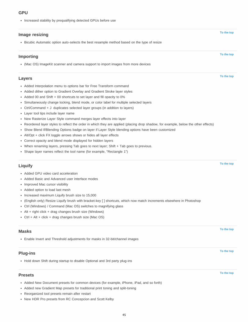
To the top
To the top
To the top
To the top
To the top
To the top
To the top
GPUIncreased stability by prequalifying detected GPUs before use
Image resizingBicubic Automatic option auto-selects the best resample method based on the type of resize
Importing(Mac OS) ImageKit scanner and camera support to import images from more devices
LayersAdded Interpolation menu to options bar for Free Transform commandAdded dither option to Gradient Overlay and Gradient Stroke layer stylesAdded 00 and Shift + 00 shortcuts to set layer and fill opacity to 0%Simultaneously change locking, blend mode, or color label for multiple selected layersCtrl/Command + J duplicates selected layer groups (in addition to layers)Layer tool tips include layer nameNew Rasterize Layer Style command merges layer effects into layerReordered layer styles to reflect the order in which they are applied (placing drop shadow, for example, below the other effects)Show Blend If/Blending Options badge on layer if Layer Style blending options have been customizedAlt/Opt + click FX toggle arrows shows or hides all layer effectsCorrect opacity and blend mode displayed for hidden layersWhen renaming layers, pressing Tab goes to next layer; Shift + Tab goes to previous.Shape layer names reflect the tool name (for example, "Rectangle 1")
LiquifyAdded GPU video card accelerationAdded Basic and Advanced user interface modesImproved Mac cursor visibilityAdded option to load last meshIncreased maximum Liquify brush size to 15,000(English only) Resize Liquify brush with bracket-key [ ] shortcuts, which now match increments elsewhere in PhotoshopCtrl (Windows) / Command (Mac OS) switches to magnifying glassAlt + right click + drag changes brush size (Windows)Ctrl + Alt + click + drag changes brush size (Mac OS)
MasksEnable Invert and Threshold adjustments for masks in 32-bit/channel images
Plug-insHold down Shift during startup to disable Optional and 3rd party plug-ins
PresetsAdded New Document presets for common devices (for example, iPhone, iPad, and so forth)Added new Gradient Map presets for traditional print toning and split-toningReorganized tool presets remain after restartNew HDR Pro presets from RC Concepcion and Scott Kelby
45

Twitter™ and Facebook posts are not covered under the terms of Creative Commons.
Legal Notices | Online Privacy Policy
To the top
To the top
To the top
To the top
To the top
To the top
To the top
PrintingAdded Edit button for description field in Print dialogAllow Print dialog and print preview window to be resizedAllow customizable preview background color in the Print dialogAllow manual repositioning of the printed area on pageHide color profiles that are inappropriate for currently selected printer when using Photoshop Manages ColorReintroduced Print Selected Area; you can modify selection in Print dialog
SavingWarning message indicates that 16-bit images cannot display their file size in the Save as JPEG dialog
SDKAdded ability to access tool name associated with the tool preset name via scriptingAdded the ability to return an array of guides in a document from the scripting SDK
SelectionsSupport for decimal feather values for Marquee tool, Lasso tool, and Mask panel (like the Feather dialog)Feather radius recalled in Make Selection from path dialog
TransformLayer thumbnail continues to show Smart Object icon when transforming a layerImproved dragging of vector curvesCan rotate 90 degrees with even x odd pixel dimension to avoid landing on a half-pixel position. (To enable this behavior, Snap Vector ToolsAnd Transforms To Pixel Grid must be selected in the General preferences.)Added File Handling > Ignore Rotation Metadata preference to disable automatic rotation of images based on file metadata
TypeAdded Type > Paste Lorem Ipsum command to quickly insert placeholder textAdded Blend Text Colors Using Gamma setting to blend text layers using a gamma setting distinct from the document color space. Toaccess this option, choose Edit > Color Settings, and click More Options at right. The default setting, 1.45, blends text more correctly thanprevious Photoshop versions, better matching other applications.
Note: When you select Blend Text Colors Using Gamma, text layers from Photoshop CS6 will look different in earlier versions of Photoshop.
User interfaceNew/Open document commands available by context-clicking document tabs (longtime Mac OS feature now on Windows too)Added "Don't show again" checkbox to Purge warningsRemoved the app bar and reduced the draggable title bar over 30%
46
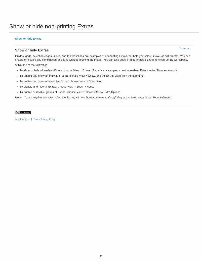
Show or hide non-printing Extras
To the top
Show or hide Extras
Show or hide ExtrasGuides, grids, selection edges, slices, and text baselines are examples of nonprinting Extras that help you select, move, or edit objects. You canenable or disable any combination of Extras without affecting the image. You can also show or hide enabled Extras to clean up the workspace.
Do one of the following:
To show or hide all enabled Extras, choose View > Extras. (A check mark appears next to enabled Extras in the Show submenu.)
To enable and show an individual Extra, choose View > Show, and select the Extra from the submenu.
To enable and show all available Extras, choose View > Show > All.
To disable and hide all Extras, choose View > Show > None.
To enable or disable groups of Extras, choose View > Show > Show Extra Options.
Note: Color samplers are affected by the Extras, All, and None commands, though they are not an option in the Show submenu.
Legal Notices | Online Privacy Policy
47
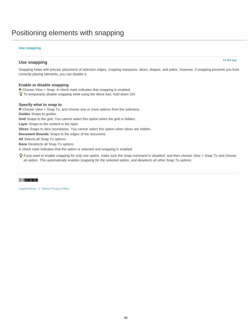
Positioning elements with snapping
To the top
Use snapping
Use snappingSnapping helps with precise placement of selection edges, cropping marquees, slices, shapes, and paths. However, if snapping prevents you fromcorrectly placing elements, you can disable it.
Enable or disable snapping Choose View > Snap. A check mark indicates that snapping is enabled.
To temporarily disable snapping while using the Move tool, hold down Ctrl.
Specify what to snap to Choose View > Snap To, and choose one or more options from the submenu:
Guides Snaps to guides.Grid Snaps to the grid. You cannot select this option when the grid is hidden.Layer Snaps to the content in the layer.Slices Snaps to slice boundaries. You cannot select this option when slices are hidden.Document Bounds Snaps to the edges of the document.All Selects all Snap To options.None Deselects all Snap To options.A check mark indicates that the option is selected and snapping is enabled.
If you want to enable snapping for only one option, make sure the Snap command is disabled, and then choose View > Snap To and choosean option. This automatically enables snapping for the selected option, and deselects all other Snap To options.
Legal Notices | Online Privacy Policy
48

Positioning with the Ruler tool
To the top
Position with the Ruler tool
Position with the Ruler tool
The Ruler tool helps you position images or elements precisely. The Ruler tool calculates the distance between any two points in theworkspace. When you measure from one point to another, a nonprinting line is drawn, and the options bar and Info panel show the followinginformation:
The starting location (X and Y)
The horizontal (W) and vertical (H) distances traveled from the x and y axes
The angle measured relative to the axis (A)
The total length traveled (D1)
The two lengths traveled (D1 and D2), when you use a protractor
All measurements except the angle are calculated in the unit of measure currently set in the Units & Rulers preference dialog box.
If your document has an existing measuring line, selecting the Ruler tool causes it to be displayed.
Measure between two points1. Select the Ruler tool . (If the Ruler isn’t visible, hold down the Eyedropper tool.)2. Drag from the starting point to the ending point. Hold down the Shift key to constrain the tool to 45° increments.3. To create a protractor from an existing measuring line, Alt-drag (Windows) or Option-drag (Mac OS) at an angle from one end of the
measuring line, or double-click the line and drag. Hold down the Shift key to constrain the tool to multiples of 45°.
Edit a measuring line1. Select the Ruler tool .2. Do one of the following:
To resize the line, drag one end of an existing measuring line.
To move the line, place the pointer on the line away from either endpoint, and drag the line.
To remove the line, place the pointer on the line away from either endpoint, and drag the line out of the image, or click Clear in the tooloptions bar.
Note: You can drag out a measure line on an image feature that should be horizontal or vertical, and then choose Image > ImageRotation > Arbitrary. The correct angle of rotation required to straighten the image is automatically entered into the Rotate Canvas dialogbox.
Legal Notices | Online Privacy Policy
49
Specifying columns for an image
To the top
Specify columns for an image
Specify columns for an imageColumns help you position images or elements precisely. The New, Image Size, and Canvas Size commands let you specify image width in termsof columns. Using columns is convenient when you plan to import an image into a page-layout program, such as Adobe InDesign®, and you wantthe image to fit exactly within a certain number of columns.
1. Choose Edit > Preferences > Units & Rulers (Windows) or Photoshop > Preferences > Units & Rulers (Mac OS).2. Enter values for Width and Gutter.3. Use the File > New command to create a new image, select Columns for the Width value, and enter the number of columns you need for
the new document. You can also resize an open image to the number of columns required by the page layout using the Image > Image Sizeor Image > Canvas Size commands.
Legal Notices | Online Privacy Policy
50

Rulers
To the top
To the top
To the top
About rulersChange a ruler’s zero originChange the unit of measurement
About rulersRulers help you position images or elements precisely. When visible, rulers appear along the top and left side of the active window. Markers in theruler display the pointer’s position when you move it. Changing the ruler origin (the (0, 0) mark on the top and left rulers) lets you measure from aspecific point on the image. The ruler origin also determines the grid’s point of origin.
To show or hide rulers, choose View > Rulers.
Change a ruler’s zero origin1. (Optional) Choose View > Snap To, then choose any combination of options from the submenu. This snaps the ruler origin to guides, slices,
or document bounds. You can also snap to the grid.2. Position the pointer over the intersection of the rulers in the upper-left corner of the window, and drag diagonally down onto the image. A set
of cross hairs appears, marking the new origin on the rulers.You can hold down Shift as you drag to make the ruler origin snap to the ruler ticks.
To reset a ruler’s origin to its default value, double-click the upper-left corner of the ruler.
Dragging to create new ruler origin
Change the unit of measurement1. Do one of the following:
Double-click a ruler.
(Windows) Choose Edit > Preferences > Units & Rulers, or right-click the ruler and then choose a new unit from the context menu.
(Mac OS) Choose Photoshop > Preferences > Units & Rulers, or Control-click the ruler and then choose a new unit from the contextmenu.
2. For Rulers, choose a unit of measurement.Note: Changing the units on the Info panel automatically changes the units on the rulers.
3. For Point/Pica Size, choose from the following options:PostScript (72 points per inch) Sets a unit size compatible for printing to a PostScript device.
Traditional Uses 72.27 points per inch, as traditionally used in printing.
4. Click OK.
51

Undo and history
To the top
To the top
To the top
To the top
To the top
To the top
Use the Undo or Redo commandsRevert to the last saved versionRestore part of an image to its previously saved versionCancel an operationReceive notification when an operation is completedUsing the History panelMake a snapshot of an imagePaint with a state or snapshot of an image
Use the Undo or Redo commandsThe Undo and Redo commands let you undo or redo operations. You can also use the History panel to undo or redo operations.
Choose Edit > Undo or Edit > Redo.If an operation can’t be undone, the command is dimmed and changes to Can’t Undo.
Revert to the last saved version Choose File > Revert.
Note: Revert is added as a history state in the History panel and can be undone.
Restore part of an image to its previously saved version Do one of the following:
Use the History Brush tool to paint with the selected state or snapshot on the History panel.
Use the Eraser tool with the Erase To History option selected.
Select the area you want to restore, and choose Edit > Fill. For Use, choose History, and click OK.
Note: To restore the image with a snapshot of the initial state of the document, choose History Options from the Panel menu and make sure thatthe Automatically Create First Snapshot option is selected.
Cancel an operation Hold down Esc until the operation in progress has stopped. In Mac OS, you can also press Command+period.
Receive notification when an operation is completedA progress bar indicates that an operation is being performed. You can interrupt the operation or have the program notify you when it has finishedthe operation.
1. Do one of the following:
(Windows) choose Edit > Preferences > General.
(Mac OS) choose Photoshop > Preferences > General.
2. Select Beep When Done.3. Click OK.
Using the History panelYou can use the History panel to jump to any recent state of the image created during the current working session. Each time you apply a changeto an image, the new state of that image is added to the panel.
For example, if you select, paint, and rotate part of an image, each of those states is listed separately in the panel. When you select one of thestates, the image reverts to how it looked when that change was first applied. You can then work from that state.
52

You can also use the History panel to delete image states and, in Photoshop, to create a document from a state or snapshot.
To display the History panel, choose Window > History, or click the History panel tab.
Photoshop History panelA. Sets the source for the history brush B. Thumbnail of a snapshot C. History state D. History state slider
Keep the following in mind when using the History panel:
Program-wide changes, such as changes to panels, color settings, actions, and preferences, are not reflected in the History panel, becausethey are not changes to a particular image.
By default, the History panel lists the previous 20 states. You can change the number of remembered states by setting a preference underPreferences > Performance. Older states are automatically deleted to free more memory for Photoshop. To keep a particular state throughoutyour work session, make a snapshot of the state.
Once you close and reopen the document, all states and snapshots from the last working session are cleared from the panel.
By default, a snapshot of the initial state of the document is displayed at the top of the panel.
States are added to the bottom of the list. That is, the oldest state is at the top of the list, the most recent one at the bottom.
Each state is listed with the name of the tool or command used to change the image.
By default, when you select a state, the states below it are dimmed. This way you can easily see which changes will be discarded if youcontinue working from the selected state.
By default, selecting a state and then changing the image eliminates all states that come after it.
If you select a state and then change the image, eliminating the states that came after, you can use the Undo command to undo the lastchange and restore the eliminated states.
By default, deleting a state deletes that state and those that came after it. If you choose the Allow Non-Linear History option, deleting a statedeletes only that state.
Revert to a previous image state Do any of the following:
Click the name of the state.
Choose Step Forward or Step Backward from the History panel menu or the Edit menu to move to the next or previous state.
Delete one or more image states Do one of the following:
Click the name of the state, and choose Delete from the History panel menu to delete that change and those that came after it.
Drag the state to the Delete icon to delete that change and those that came after it.
Choose Clear History from the panel menu to delete the list of states from the History panel, without changing the image. This option doesn’treduce the amount of memory used by Photoshop.
Hold down Alt (Windows) or Option (Mac OS), and choose Clear History from the panel menu to purge the list of states without changing theimage. If you get a message that Photoshop is low on memory, purging states is useful, because the command deletes the states from theUndo buffer and frees up memory. You can’t undo the Clear History command.
Choose Edit > Purge > Histories to purge the list of states for all open documents. You can’t undo this action.
53

To the top
Create or replace a document with an image state Do one of the following:
Drag a state or snapshot onto the Create a New Document From Current State button in the History panel. The history list for the newlycreated document contains only the Duplicate State entry.
Select a state or snapshot, and click the Create a New Document From Current State button . The history list for the newly createddocument contains only the Duplicate State entry.
Select a state or snapshot, and choose New Document from the History panel menu. The history list for the newly created documentcontains only the Duplicate State entry.
Drag a state onto an existing document.
To save one or more snapshots or image states for use in a later editing session, create a new file for each state you save, and save each in aseparate file. When you reopen your original file, plan to open the other saved files also. You can drag each file’s initial snapshot to the originalimage to access the snapshots again from the original image’s History panel.
Set history optionsYou can specify the maximum number of items to include in the History panel and set other options to customize the panel.
1. Choose History Options from the History panel menu.2. Select an option:
Automatically Create First Snapshot Automatically creates a snapshot of the initial state of the image when the document is opened.
Automatically Create New Snapshot When Saving Generates a snapshot every time you save.
Allow Non-Linear History Makes changes to a selected state without deleting the states that come after. Normally, when you select a stateand change the image, all states that come after the selected one are deleted. In this way, the History panel can display a list of the editingsteps in the order that they were made. By recording states in a nonlinear way, you can select a state, make a change to the image, anddelete just that state. The change is appended at the end of the list.
Show New Snapshot Dialog By Default Forces Photoshop to prompt you for snapshot names even when you use the buttons on thepanel.
Make Layer Visibility Changes Undoable By default, turning layer visibility on or off is not recorded as a history step and therefore can’tbe undone. Select this option to include layer visibility changes in history steps.
Set Edit History Log optionsYou may need to keep careful track of what’s been done to a file in Photoshop, either for your own records, client records, or legal purposes. TheEdit History Log helps you keep a textual history of changes made to an image. You can view the Edit History Log metadata using Adobe Bridgeor the File Info dialog box.
You can choose to export the text to an external log file, or you can store the information in the metadata of edited files. Storing many editingoperations as file metadata increases file size; such files may take longer than usual to open and save.
If you need to prove that the log file hasn’t been tampered with, keep the edit log in the file’s metadata, and then use Adobe Acrobat to digitallysign the log file.
By default, history log data about each session is saved as metadata embedded in the image file. You can specify where the history log data issaved and the level of detail contained in the history log.
1. Choose Edit > Preferences > General (Windows) or Photoshop > Preferences > General (Mac OS).2. Click the History Log preference to toggle from on to off or vice versa.3. For the Save Log Items To option, choose one of the following:
Metadata Saves the history log as metadata embedded in each file.
Text File Exports the history log to a text file. You are prompted to name the text file and choose a location in which to store it.
Both Stores metadata in the file and creates a text file.Note: If you want to save the text file in a different location or save another text file, click the Choose button, specify where to save the textfile, name the file if necessary, and click Save.
4. From the Edit Log Items menu, choose one of the following options:Sessions Only Keeps a record of each time your start or quit Photoshop and each time you open and close files (each image’s filename isincluded). Does not include any information about edits made to the file.
Concise Includes the text that appears in the History panel in addition to the Sessions information.
Detailed Includes the text that appears in the Actions panel in addition to the Concise information. If you need a complete history of allchanges made to files, choose Detailed.
54

To the top
Make a snapshot of an imageThe Snapshot command lets you make a temporary copy (or snapshot) of any state of the image. The new snapshot is added to the list ofsnapshots at the top of the History panel. Selecting a snapshot lets you work from that version of the image.
Snapshots are similar to the states listed in the History panel, but they offer additional advantages:
You can name a snapshot to make it easy to identify.
Snapshots can be stored for an entire work session.
You can compare effects easily. For example, you can take a snapshot before and after applying a filter. Then select the first snapshot, andtry the same filter with different settings. Switch between the snapshots to find the settings you like best.
With snapshots, you can recover your work easily. When you experiment with a complex technique or apply an action, take a snapshot first. Ifyou’re not satisfied with the results, you can select the snapshot to undo all the steps.
Note: Snapshots are not saved with the image—closing an image deletes its snapshots. Also, unless you select the Allow Non-LinearHistory option, selecting a snapshot and changing the image deletes all of the states currently listed in the History panel.
Create a snapshot1. Select a state and do one of the following:
To automatically create a snapshot, click the Create New Snapshot button on the History panel, or if Automatically Create NewSnapshot When Saving is selected in the history options, choose New Snapshot from the History panel menu.
To set options when creating a snapshot, choose New Snapshot from the History panel menu, or Alt-click (Windows) or Option-click(Mac OS) the Create New Snapshot button.
2. Enter the name of the Snapshot in the Name text box.3. Choose the snapshot contents from the From menu:
Full Document Makes a snapshot of all layers in the image at that state
Merged Layers Makes a snapshot that merges all layers in the image at that state
Current Layer Makes a snapshot of only the currently selected layer at that state
Work with snapshots Do one of the following:
To select a snapshot, click the name of the snapshot or drag the slider at the left of the snapshot up or down to a different snapshot.
To rename a snapshot, double-click the snapshot and enter a name.
To delete a snapshot, select the snapshot and either choose Delete from the panel menu, click the Delete icon , or drag the snapshot tothe Delete icon.
Paint with a state or snapshot of an imageThe History Brush tool lets you paint a copy of one image state or snapshot into the current image window. This tool makes a copy, or sample,of the image and then paints with it.
For example, you might make a snapshot of a change you made with a painting tool or filter (with the Full Document option selected when youcreate the snapshot). After undoing the change to the image, you could use the History Brush tool to apply the change selectively to areas of theimage. Unless you select a merged snapshot, the History Brush tool paints from a layer in the selected state to the same layer in another state.
The History Brush tool copies from one state or snapshot to another, but only at the same location. In Photoshop, you can also paint with the ArtHistory Brush tool to create special effects.
1. Select the History Brush tool .2. Do one of the following in the options bar:
Specify the opacity and blending mode.
Choose a brush and set brush options.
3. In the History panel, click the left column of the state or snapshot to be used as the source for the History Brush tool.4. Drag to paint with the History Brush tool.
Legal Notices | Online Privacy Policy
55
Customizing keyboard shortcuts
To the top
To the top
To the top
Define new keyboard shortcutsClear shortcuts from a command or toolDelete a set of shortcutsView a list of current shortcuts
Note: For detailed instructions, click the links below. To ask questions, request features, or report problems, visit feedback.photoshop.com.Photoshop lets you view a list of all shortcuts, and edit or create shortcuts. The Keyboard Shortcuts dialog box serves as a shortcut editor, andincludes all commands that support shortcuts, some of which aren’t addressed in the default shortcut set.
In addition to using keyboard shortcuts, you can access many commands using context-sensitive menus that are relevant to the active tool,selection, or panel. To display a context-sensitive menu, right-click in the document window or panel.
Define new keyboard shortcuts1. Do one of the following:
Choose Edit > Keyboard Shortcuts.
Choose Window > Workspace > Keyboard Shortcuts & Menus and click the Keyboard Shortcuts tab.
2. Choose a set of shortcuts from the Set menu at the top of the Keyboard Shortcuts & Menus dialog box.3. Choose a shortcut type from the Shortcuts For menu:
Application Menus Lets you customize keyboard shortcuts for items in the menu bar.
Panel Menus Lets you customize keyboard shortcuts for items in panel menus.
Tools Lets you customize keyboard shortcuts for tools in the toolbox.
4. In the Shortcut column of the scroll list, select the shortcut you want to modify.5. Type a new shortcut.
If the keyboard shortcut is already assigned to another command or tool in the set, an alert appears. Click Accept to assign the shortcut tothe new command or tool and erase the previously assigned shortcut. After you reassign a shortcut, you can click Undo Changes to undothe change, or click Accept and Go To Conflict to assign a new shortcut to the other command or tool.
6. When you’re finished changing shortcuts, do one of the following:
To save all changes to the current set of keyboard shortcuts, click the Save Set button . Changes to a custom set are saved. If you’resaving changes to the Photoshop Defaults set, the Save dialog box opens. Enter a name for the new set and click Save.
To create a new set based on the current set of shortcuts, click the Save Set As button . In the Save dialog box, enter a name for thenew set in the Name text box, and click Save. The new keyboard shortcut set will appear in the pop-up menu under the new name.
To discard the last saved change without closing the dialog box, click Undo.
To return a new shortcut to the default, click Use Default.
To discard all changes and exit the dialog box, click Cancel.
Note: If you haven’t saved the current set of changes, you can click Cancel to discard all changes and exit the dialog box.
Clear shortcuts from a command or tool1. Choose Edit > Keyboard Shortcuts.2. In the Keyboard Shortcuts dialog box, select the command or tool name whose shortcut you want to delete.3. Click Delete Shortcut.
Delete a set of shortcuts1. Choose Edit > Keyboard Shortcuts.2. In the Set pop-up menu, choose the shortcut set that you want to delete.3. Click the Delete icon and then click OK to exit the dialog box.
56
To the topView a list of current shortcutsTo view a list of current shortcuts, export them to an HTML file, which you can display or print with a web browser.
1. Choose Edit > Keyboard Shortcuts.
2. From the Shortcuts For menu, choose a shortcut type: Application Menus, Panel Menus, or Tools.
3. Click Summarize.
Legal Notices | Online Privacy Policy
57

Default keyboard shortcuts
To the top
Keys for selecting toolsKeys for viewing imagesKeys for Puppet WarpKeys for Refine EdgeKeys for the Filter GalleryKeys for LiquifyKeys for Vanishing PointKeys for the Camera Raw dialog boxKeys for the Black-and-White dialog boxKeys for CurvesKeys for selecting and moving objectsKeys for transforming selections, selection borders, and pathsKeys for editing pathsKeys for paintingKeys for blending modesKeys for selecting and editing textKeys for formatting typeKeys for slicing and optimizingKeys for using panelsKeys for the Actions panelKeys for adjustment layersKeys for the Animation panel in Frames modeKeys for the Animation panel in Timeline Mode (Photoshop Extended)Keys for the Brush panelKeys for the Channels panelKeys for the Clone Source panelKeys for the Color panelKeys for the History panelKeys for the Info panelKeys for the Layers panelKeys for the Layer Comps panelKeys for the Paths panelKeys for the Swatches panelKeys for 3D tools (Photoshop Extended)Keys for measurement (Photoshop Extended)Keys for DICOM files (Photoshop Extended)Keys for Extract and Pattern Maker (optional plug-ins)Function keys
Keys for selecting toolsHolding down a key temporarily activates a tool. Letting go of the key returns to the previous tool. To customize shortcuts, see Define newkeyboard shortcuts. To view keyboard shortcuts for features that were introduced in Photoshop CS6, see Key shortcuts for CS6 features.
Note: In rows with multiple tools, repeatedly press the same shortcut to toggle through the group.
Result Windows Mac OS
Cycle through tools with the same shortcutkey
Shift-press shortcut key (if Use Shift Keyfor Tool Switch preference is selected)
Shift-press shortcut key (if Use Shift Keyfor Tool Switch preference is selected)
Cycle through hidden tools Alt-click + tool (except add anchor point,delete anchor point, and convert pointtools)
Option-click + tool (except add anchorpoint, delete anchor point, and convertpoint tools)
Move tool V V
Rectangular Marquee tool M M†
58
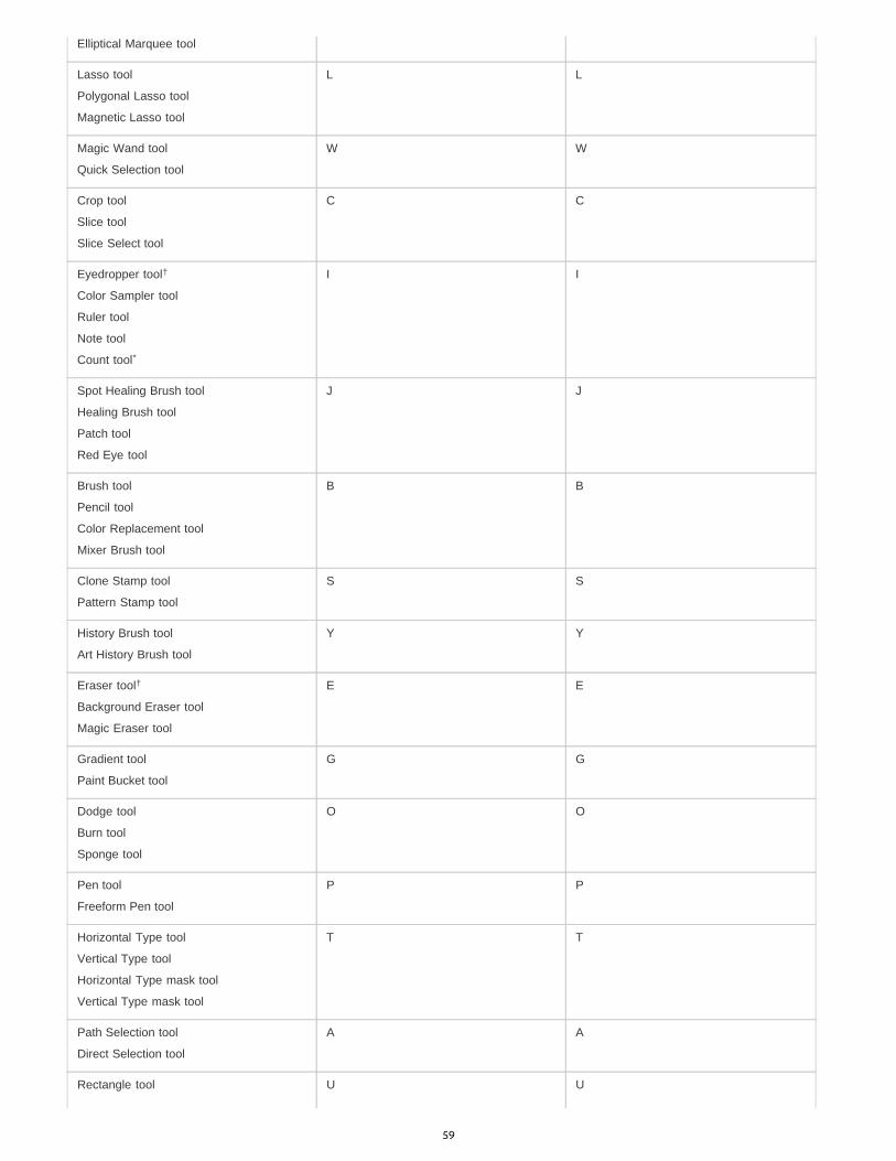
Elliptical Marquee tool
Lasso tool
Polygonal Lasso tool
Magnetic Lasso tool
L L
Magic Wand tool
Quick Selection tool
W W
Crop tool
Slice tool
Slice Select tool
C C
Eyedropper tool
Color Sampler tool
Ruler tool
Note tool
Count tool
I I
Spot Healing Brush tool
Healing Brush tool
Patch tool
Red Eye tool
J J
Brush tool
Pencil tool
Color Replacement tool
Mixer Brush tool
B B
Clone Stamp tool
Pattern Stamp tool
S S
History Brush tool
Art History Brush tool
Y Y
Eraser tool
Background Eraser tool
Magic Eraser tool
E E
Gradient tool
Paint Bucket tool
G G
Dodge tool
Burn tool
Sponge tool
O O
Pen tool
Freeform Pen tool
P P
Horizontal Type tool
Vertical Type tool
Horizontal Type mask tool
Vertical Type mask tool
T T
Path Selection tool
Direct Selection tool
A A
Rectangle tool U U
†
*
†
59
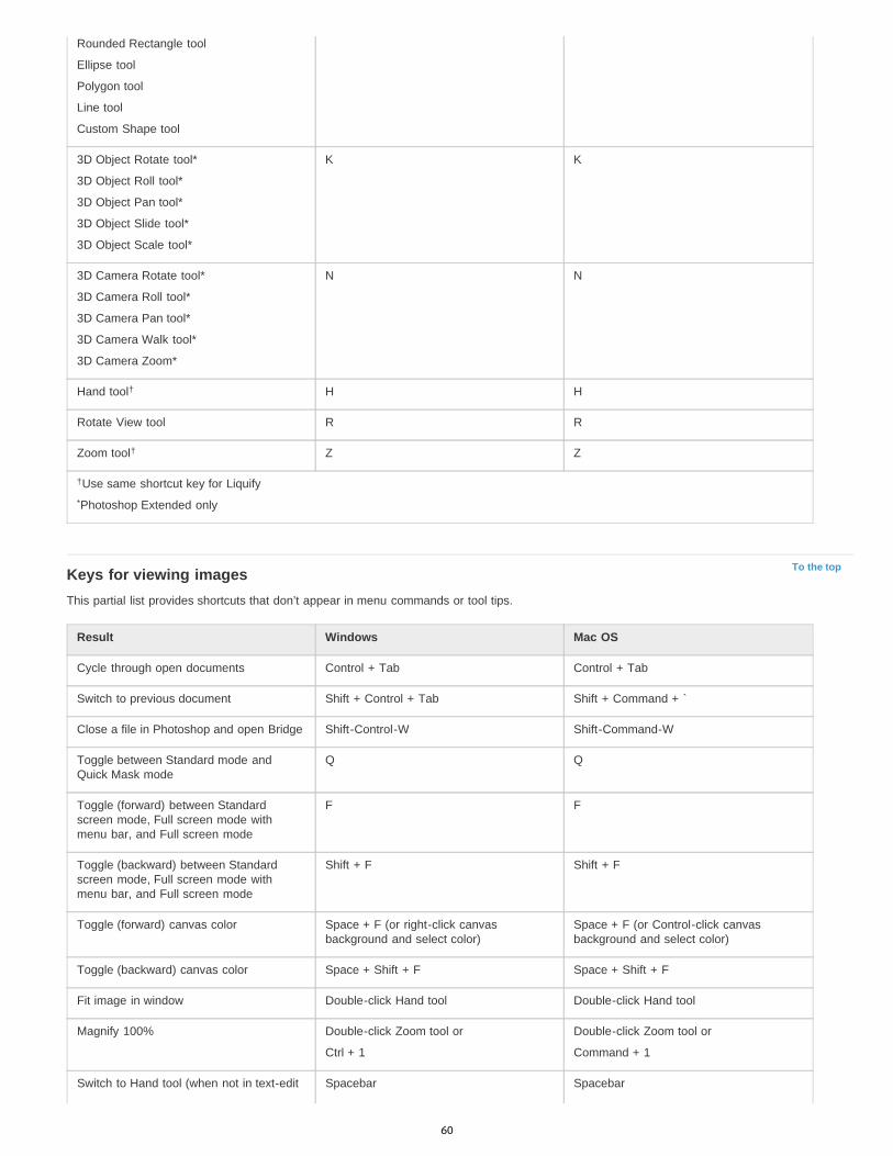
To the top
Rounded Rectangle tool
Ellipse tool
Polygon tool
Line tool
Custom Shape tool
3D Object Rotate tool*
3D Object Roll tool*
3D Object Pan tool*
3D Object Slide tool*
3D Object Scale tool*
K K
3D Camera Rotate tool*
3D Camera Roll tool*
3D Camera Pan tool*
3D Camera Walk tool*
3D Camera Zoom*
N N
Hand tool H H
Rotate View tool R R
Zoom tool Z Z
Use same shortcut key for Liquify
Photoshop Extended only
Keys for viewing imagesThis partial list provides shortcuts that don’t appear in menu commands or tool tips.
Result Windows Mac OS
Cycle through open documents Control + Tab Control + Tab
Switch to previous document Shift + Control + Tab Shift + Command + `
Close a file in Photoshop and open Bridge Shift-Control-W Shift-Command-W
Toggle between Standard mode andQuick Mask mode
Q Q
Toggle (forward) between Standardscreen mode, Full screen mode withmenu bar, and Full screen mode
F F
Toggle (backward) between Standardscreen mode, Full screen mode withmenu bar, and Full screen mode
Shift + F Shift + F
Toggle (forward) canvas color Space + F (or right-click canvasbackground and select color)
Space + F (or Control-click canvasbackground and select color)
Toggle (backward) canvas color Space + Shift + F Space + Shift + F
Fit image in window Double-click Hand tool Double-click Hand tool
Magnify 100% Double-click Zoom tool or
Ctrl + 1
Double-click Zoom tool or
Command + 1
Switch to Hand tool (when not in text-edit Spacebar Spacebar
†
†
†
*
60
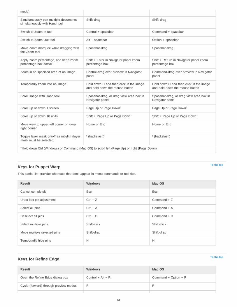
To the top
To the top
mode)
Simultaneously pan multiple documentssimultaneously with Hand tool
Shift-drag Shift-drag
Switch to Zoom In tool Control + spacebar Command + spacebar
Switch to Zoom Out tool Alt + spacebar Option + spacebar
Move Zoom marquee while dragging withthe Zoom tool
Spacebar-drag Spacebar-drag
Apply zoom percentage, and keep zoompercentage box active
Shift + Enter in Navigator panel zoompercentage box
Shift + Return in Navigator panel zoompercentage box
Zoom in on specified area of an image Control-drag over preview in Navigatorpanel
Command-drag over preview in Navigatorpanel
Temporarily zoom into an image Hold down H and then click in the imageand hold down the mouse button
Hold down H and then click in the imageand hold down the mouse button
Scroll image with Hand tool Spacebar-drag, or drag view area box inNavigator panel
Spacebar-drag, or drag view area box inNavigator panel
Scroll up or down 1 screen Page Up or Page Down Page Up or Page Down
Scroll up or down 10 units Shift + Page Up or Page Down Shift + Page Up or Page Down
Move view to upper-left corner or lowerright corner
Home or End Home or End
Toggle layer mask on/off as rubylith (layermask must be selected)
\ (backslash) \ (backslash)
Hold down Ctrl (Windows) or Command (Mac OS) to scroll left (Page Up) or right (Page Down)
Keys for Puppet WarpThis partial list provides shortcuts that don’t appear in menu commands or tool tips.
Result Windows Mac OS
Cancel completely Esc Esc
Undo last pin adjustment Ctrl + Z Command + Z
Select all pins Ctrl + A Command + A
Deselect all pins Ctrl + D Command + D
Select multiple pins Shift-click Shift-click
Move multiple selected pins Shift-drag Shift-drag
Temporarily hide pins H H
Keys for Refine Edge
Result Windows Mac OS
Open the Refine Edge dialog box Control + Alt + R Command + Option + R
Cycle (forward) through preview modes F F
† †
† †
†
61
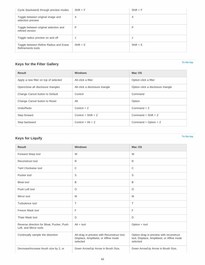
To the top
To the top
Cycle (backward) through preview modes Shift + F Shift + F
Toggle between original image andselection preview
X X
Toggle between original selection andrefined version
P P
Toggle radius preview on and off J J
Toggle between Refine Radius and EraseRefinements tools
Shift + E Shift + E
Keys for the Filter Gallery
Result Windows Mac OS
Apply a new filter on top of selected Alt-click a filter Option-click a filter
Open/close all disclosure triangles Alt-click a disclosure triangle Option-click a disclosure triangle
Change Cancel button to Default Control Command
Change Cancel button to Reset Alt Option
Undo/Redo Control + Z Command + Z
Step forward Control + Shift + Z Command + Shift + Z
Step backward Control + Alt + Z Command + Option + Z
Keys for Liquify
Result Windows Mac OS
Forward Warp tool W W
Reconstruct tool R R
Twirl Clockwise tool C C
Pucker tool S S
Bloat tool B B
Push Left tool O O
Mirror tool M M
Turbulence tool T T
Freeze Mask tool F F
Thaw Mask tool D D
Reverse direction for Bloat, Pucker, PushLeft, and Mirror tools
Alt + tool Option + tool
Continually sample the distortion Alt-drag in preview with Reconstruct tool,Displace, Amplitwist, or Affine modeselected
Option-drag in preview with reconstructtool, Displace, Amplitwist, or Affine modeselected
Decrease/increase brush size by 2, or Down Arrow/Up Arrow in Brush Size, Down Arrow/Up Arrow in Brush Size,
62
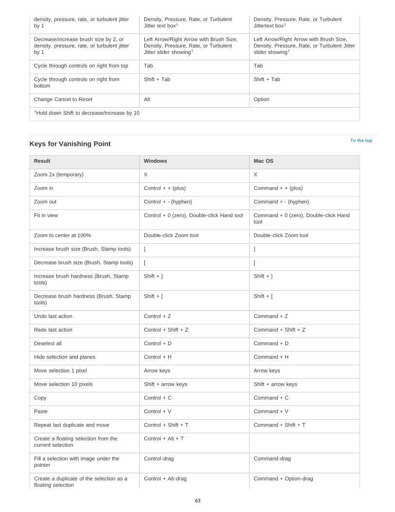
To the top
density, pressure, rate, or turbulent jitterby 1
Density, Pressure, Rate, or TurbulentJitter text box
Density, Pressure, Rate, or TurbulentJittertext box
Decrease/increase brush size by 2, ordensity, pressure, rate, or turbulent jitterby 1
Left Arrow/Right Arrow with Brush Size,Density, Pressure, Rate, or TurbulentJitter slider showing
Left Arrow/Right Arrow with Brush Size,Density, Pressure, Rate, or Turbulent Jitterslider showing
Cycle through controls on right from top Tab Tab
Cycle through controls on right frombottom
Shift + Tab Shift + Tab
Change Cancel to Reset Alt Option
Hold down Shift to decrease/increase by 10
Keys for Vanishing Point
Result Windows Mac OS
Zoom 2x (temporary) X X
Zoom in Control + + (plus) Command + + (plus)
Zoom out Control + - (hyphen) Command + - (hyphen)
Fit in view Control + 0 (zero), Double-click Hand tool Command + 0 (zero), Double-click Handtool
Zoom to center at 100% Double-click Zoom tool Double-click Zoom tool
Increase brush size (Brush, Stamp tools) ] ]
Decrease brush size (Brush, Stamp tools) [ [
Increase brush hardness (Brush, Stamptools)
Shift + ] Shift + ]
Decrease brush hardness (Brush, Stamptools)
Shift + [ Shift + [
Undo last action Control + Z Command + Z
Redo last action Control + Shift + Z Command + Shift + Z
Deselect all Control + D Command + D
Hide selection and planes Control + H Command + H
Move selection 1 pixel Arrow keys Arrow keys
Move selection 10 pixels Shift + arrow keys Shift + arrow keys
Copy Control + C Command + C
Paste Control + V Command + V
Repeat last duplicate and move Control + Shift + T Command + Shift + T
Create a floating selection from thecurrent selection
Control + Alt + T
Fill a selection with image under thepointer
Control-drag Command-drag
Create a duplicate of the selection as afloating selection
Control + Alt-drag Command + Option-drag
† †
† †
†
63

To the top
Constrain selection to a 15° rotation Alt + Shift to rotate Option + Shift to rotate
Select a plane under another selectedplane
Control-click the plane Command-click the plane
Create 90 degree plane off parent plane Control-drag Command-drag
Delete last node while creating plane Backspace Delete
Make a full canvas plane, square to thecamera
Double-click the Create Plane tool Double-click the Create Plane tool
Show/hide measurements (PhotoshopExtended only)
Control + Shift + H Command + Shift + H
Export to a DFX file (Photoshop Extendedonly)
Control + E Command + E
Export to a 3DS file (Photoshop Extendedonly)
Control + Shift + E Command + Shift + E
Keys for the Camera Raw dialog boxNote: Holding down a key temporarily activates a tool. Letting go of the key returns to the previous tool.
Result Windows Mac OS
Zoom tool Z Z
Hand tool H H
White Balance tool I I
Color Sampler tool S S
Crop tool C C
Straighten tool A A
Spot Removal tool B B
Red Eye Removal tool E E
Basic panel Ctrl+Alt+1 Command+Option+1
Tone Curve panel Ctrl+Alt+2 Command+Option+2
Detail panel Ctrl+Alt+3 Command+Option+3
HSL/Grayscale panel Ctrl+Alt+4 Command+Option+4
Split Toning panel Ctrl+Alt+5 Command+Option+5
Lens Corrections panel Ctrl+Alt+6 Command+Option+6
Camera Calibration panel Ctrl+Alt+7 Command+Option+7
Presets panel Ctrl+Alt+8 Command+Option+8 (Mac OS UniversalAccess zoom shortcut must be disabled inSystem Preferences)
Open Snapshots panel Ctrl+Alt+9 Command+Option+9
Parametric Curve Targeted Adjustmenttool
Ctrl+Alt+Shift+T Command+Option+Shift+T
64
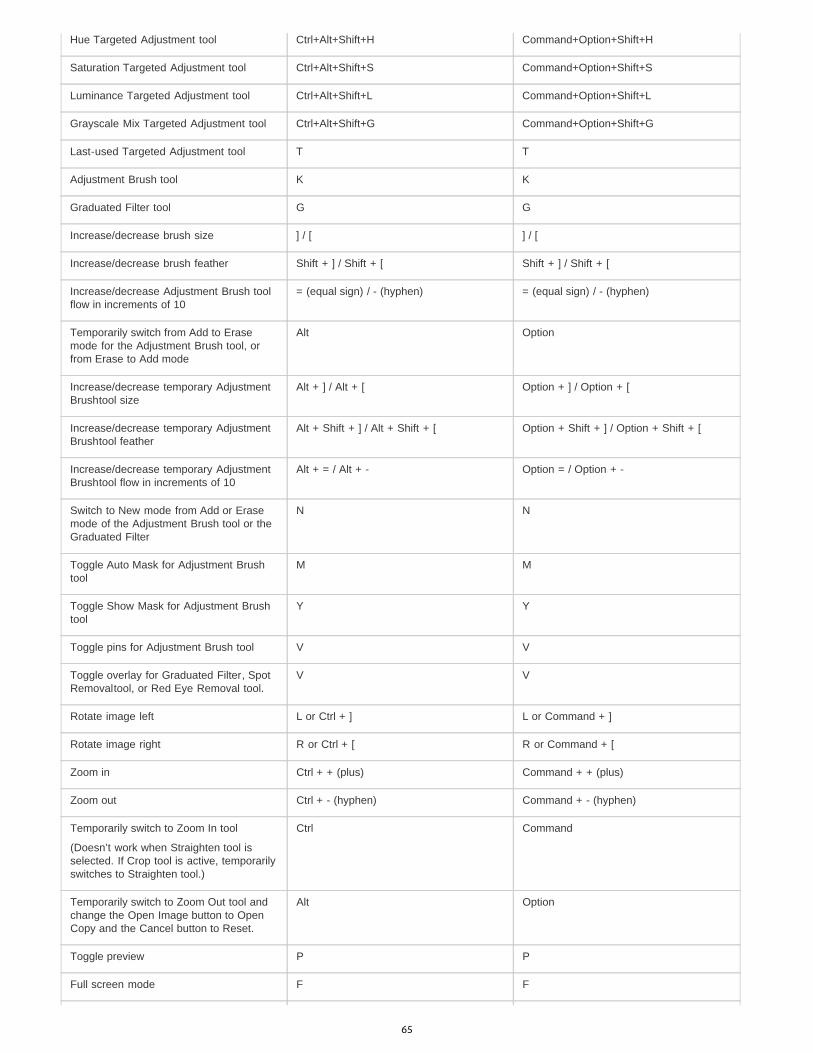
Hue Targeted Adjustment tool Ctrl+Alt+Shift+H Command+Option+Shift+H
Saturation Targeted Adjustment tool Ctrl+Alt+Shift+S Command+Option+Shift+S
Luminance Targeted Adjustment tool Ctrl+Alt+Shift+L Command+Option+Shift+L
Grayscale Mix Targeted Adjustment tool Ctrl+Alt+Shift+G Command+Option+Shift+G
Last-used Targeted Adjustment tool T T
Adjustment Brush tool K K
Graduated Filter tool G G
Increase/decrease brush size ] / [ ] / [
Increase/decrease brush feather Shift + ] / Shift + [ Shift + ] / Shift + [
Increase/decrease Adjustment Brush toolflow in increments of 10
= (equal sign) / - (hyphen) = (equal sign) / - (hyphen)
Temporarily switch from Add to Erasemode for the Adjustment Brush tool, orfrom Erase to Add mode
Alt Option
Increase/decrease temporary AdjustmentBrushtool size
Alt + ] / Alt + [ Option + ] / Option + [
Increase/decrease temporary AdjustmentBrushtool feather
Alt + Shift + ] / Alt + Shift + [ Option + Shift + ] / Option + Shift + [
Increase/decrease temporary AdjustmentBrushtool flow in increments of 10
Alt + = / Alt + - Option = / Option + -
Switch to New mode from Add or Erasemode of the Adjustment Brush tool or theGraduated Filter
N N
Toggle Auto Mask for Adjustment Brushtool
M M
Toggle Show Mask for Adjustment Brushtool
Y Y
Toggle pins for Adjustment Brush tool V V
Toggle overlay for Graduated Filter, SpotRemovaltool, or Red Eye Removal tool.
V V
Rotate image left L or Ctrl + ] L or Command + ]
Rotate image right R or Ctrl + [ R or Command + [
Zoom in Ctrl + + (plus) Command + + (plus)
Zoom out Ctrl + - (hyphen) Command + - (hyphen)
Temporarily switch to Zoom In tool
(Doesn’t work when Straighten tool isselected. If Crop tool is active, temporarilyswitches to Straighten tool.)
Ctrl Command
Temporarily switch to Zoom Out tool andchange the Open Image button to OpenCopy and the Cancel button to Reset.
Alt Option
Toggle preview P P
Full screen mode F F
65
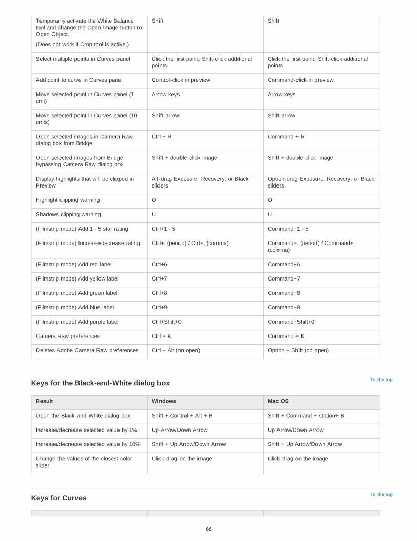
To the top
To the top
Temporarily activate the White Balancetool and change the Open Image button toOpen Object.
(Does not work if Crop tool is active.)
Shift Shift
Select multiple points in Curves panel Click the first point; Shift-click additionalpoints
Click the first point; Shift-click additionalpoints
Add point to curve in Curves panel Control-click in preview Command-click in preview
Move selected point in Curves panel (1unit)
Arrow keys Arrow keys
Move selected point in Curves panel (10units)
Shift-arrow Shift-arrow
Open selected images in Camera Rawdialog box from Bridge
Ctrl + R Command + R
Open selected images from Bridgebypassing Camera Raw dialog box
Shift + double-click image Shift + double-click image
Display highlights that will be clipped inPreview
Alt-drag Exposure, Recovery, or Blacksliders
Option-drag Exposure, Recovery, or Blacksliders
Highlight clipping warning O O
Shadows clipping warning U U
(Filmstrip mode) Add 1 - 5 star rating Ctrl+1 - 5 Command+1 - 5
(Filmstrip mode) Increase/decrease rating Ctrl+. (period) / Ctrl+, (comma) Command+. (period) / Command+,(comma)
(Filmstrip mode) Add red label Ctrl+6 Command+6
(Filmstrip mode) Add yellow label Ctrl+7 Command+7
(Filmstrip mode) Add green label Ctrl+8 Command+8
(Filmstrip mode) Add blue label Ctrl+9 Command+9
(Filmstrip mode) Add purple label Ctrl+Shift+0 Command+Shift+0
Camera Raw preferences Ctrl + K Command + K
Deletes Adobe Camera Raw preferences Ctrl + Alt (on open) Option + Shift (on open)
Keys for the Black-and-White dialog box
Result Windows Mac OS
Open the Black-and-White dialog box Shift + Control + Alt + B Shift + Command + Option+ B
Increase/decrease selected value by 1% Up Arrow/Down Arrow Up Arrow/Down Arrow
Increase/decrease selected value by 10% Shift + Up Arrow/Down Arrow Shift + Up Arrow/Down Arrow
Change the values of the closest colorslider
Click-drag on the image Click-drag on the image
Keys for Curves
66
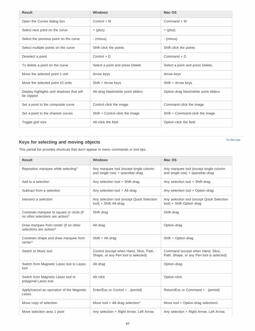
To the top
Result Windows Mac OS
Open the Curves dialog box Control + M Command + M
Select next point on the curve + (plus) + (plus)
Select the previous point on the curve - (minus) - (minus)
Select multiple points on the curve Shift-click the points Shift-click the points
Deselect a point Control + D Command + D
To delete a point on the curve Select a point and press Delete Select a point and press Delete.
Move the selected point 1 unit Arrow keys Arrow keys
Move the selected point 10 units Shift + Arrow keys Shift + Arrow keys
Display highlights and shadows that willbe clipped
Alt-drag black/white point sliders Option-drag black/white point sliders
Set a point to the composite curve Control-click the image Command-click the image
Set a point to the channel curves Shift + Control-click the image Shift + Command-click the image
Toggle grid size Alt-click the field Option-click the field
Keys for selecting and moving objectsThis partial list provides shortcuts that don’t appear in menu commands or tool tips.
Result Windows Mac OS
Reposition marquee while selecting Any marquee tool (except single columnand single row) + spacebar-drag
Any marquee tool (except single columnand single row) + spacebar-drag
Add to a selection Any selection tool + Shift-drag Any selection tool + Shift-drag
Subtract from a selection Any selection tool + Alt-drag Any selection tool + Option-drag
Intersect a selection Any selection tool (except Quick Selectiontool) + Shift-Alt-drag
Any selection tool (except Quick Selectiontool) + Shift-Option-drag
Constrain marquee to square or circle (ifno other selections are active)
Shift-drag Shift-drag
Draw marquee from center (if no otherselections are active)
Alt-drag Option-drag
Constrain shape and draw marquee fromcenter
Shift + Alt-drag Shift + Option-drag
Switch to Move tool Control (except when Hand, Slice, Path,Shape, or any Pen tool is selected)
Command (except when Hand, Slice,Path, Shape, or any Pen tool is selected)
Switch from Magnetic Lasso tool to Lassotool
Alt-drag Option-drag
Switch from Magnetic Lasso tool topolygonal Lasso tool
Alt-click Option-click
Apply/cancel an operation of the MagneticLasso
Enter/Esc or Control + . (period) Return/Esc or Command + . (period)
Move copy of selection Move tool + Alt-drag selection Move tool + Option-drag selection‡
Move selection area 1 pixel Any selection + Right Arrow, Left Arrow, Any selection + Right Arrow, Left Arrow,
‡
‡
‡
‡
‡
67
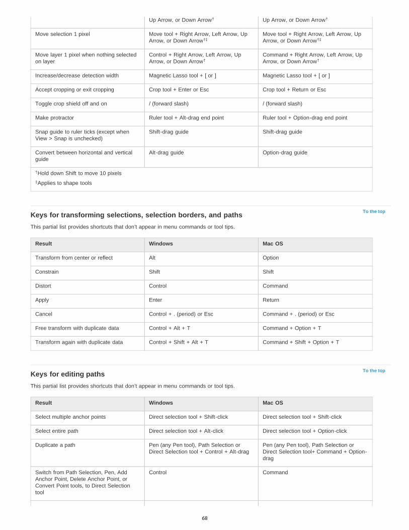
To the top
To the top
Up Arrow, or Down Arrow Up Arrow, or Down Arrow
Move selection 1 pixel Move tool + Right Arrow, Left Arrow, UpArrow, or Down Arrow
Move tool + Right Arrow, Left Arrow, UpArrow, or Down Arrow
Move layer 1 pixel when nothing selectedon layer
Control + Right Arrow, Left Arrow, UpArrow, or Down Arrow
Command + Right Arrow, Left Arrow, UpArrow, or Down Arrow
Increase/decrease detection width Magnetic Lasso tool + [ or ] Magnetic Lasso tool + [ or ]
Accept cropping or exit cropping Crop tool + Enter or Esc Crop tool + Return or Esc
Toggle crop shield off and on / (forward slash) / (forward slash)
Make protractor Ruler tool + Alt-drag end point Ruler tool + Option-drag end point
Snap guide to ruler ticks (except whenView > Snap is unchecked)
Shift-drag guide Shift-drag guide
Convert between horizontal and verticalguide
Alt-drag guide Option-drag guide
Hold down Shift to move 10 pixels
Applies to shape tools
Keys for transforming selections, selection borders, and pathsThis partial list provides shortcuts that don’t appear in menu commands or tool tips.
Result Windows Mac OS
Transform from center or reflect Alt Option
Constrain Shift Shift
Distort Control Command
Apply Enter Return
Cancel Control + . (period) or Esc Command + . (period) or Esc
Free transform with duplicate data Control + Alt + T Command + Option + T
Transform again with duplicate data Control + Shift + Alt + T Command + Shift + Option + T
Keys for editing pathsThis partial list provides shortcuts that don’t appear in menu commands or tool tips.
Result Windows Mac OS
Select multiple anchor points Direct selection tool + Shift-click Direct selection tool + Shift-click
Select entire path Direct selection tool + Alt-click Direct selection tool + Option-click
Duplicate a path Pen (any Pen tool), Path Selection orDirect Selection tool + Control + Alt-drag
Pen (any Pen tool), Path Selection orDirect Selection tool+ Command + Option-drag
Switch from Path Selection, Pen, AddAnchor Point, Delete Anchor Point, orConvert Point tools, to Direct Selectiontool
Control Command
† †
†‡ †‡
† †
†
‡
68

To the top
To the top
Switch from Pen tool or Freeform Pen toolto Convert Point tool when pointer is overanchor or direction point
Alt Option
Close path Magnetic Pen tool-double-click Magnetic Pen tool-double-click
Close path with straight-line segment Magnetic Pen tool + Alt-double-click Magnetic Pen tool + Option-double-click
Keys for paintingThis partial list provides shortcuts that don’t appear in menu commands or tool tips.
Result Windows Mac OS
Select foreground color from color picker Any painting tool + Shift + Alt + right-clickand drag
Any painting tool + Control + Option +Command and drag
Select foreground color from image withEyedropper tool
Any painting tool + Alt or any shape tool +Alt (except when Paths option is selected)
Any painting tool + Option or any shapetool + Option (except when Paths option isselected)
Select background color Eyedropper tool + Alt-click Eyedropper tool + Option-click
Color sampler tool Eyedropper tool + Shift Eyedropper tool + Shift
Deletes color sampler Color sampler tool + Alt-click Color sampler tool + Option-click
Sets opacity, tolerance, strength, orexposure for painting mode
Any painting or editing tool + number keys(e.g., 0 = 100%, 1 = 10%, 4 then 5 inquick succession = 45%) (When airbrushoption is enabled, use Shift + numberkeys)
Any painting or editing tool + number keys(e.g., 0 = 100%, 1 = 10%, 4 then 5 inquick succession = 45%) (When airbrushoption is enabled, use Shift + numberkeys)
Sets flow for painting mode Any painting or editing tool + Shift +number keys (e.g., 0 = 100%, 1 = 10%, 4then 5 in quick succession = 45%) (Whenairbrush option is enabled, omit Shift)
Any painting or editing tool + Shift +number keys (e.g., 0 = 100%, 1 = 10%, 4then 5 in quick succession = 45%) (Whenairbrush option is enabled, omit Shift)
Mixer Brush changes Mix setting Alt + Shift + number Option + Shift + number
Mixer Brush changes Wet setting Number keys Number key
Mixer Brush changes Wet and Mix to zero 00 00
Cycle through blending modes Shift + + (plus) or – (minus) Shift + + (plus) or – (minus)
Open Fill dialog box on background orstandard layer
Backspace or Shift + Backspace Delete or Shift + Delete
Fill with foreground or background color Alt + Backspace or Control + Backspace Option + Delete or Command + Delete
Fill from history Control + Alt + Backspace Command + Option + Delete
Displays Fill dialog box Shift + Backspace Shift + Delete
Lock transparent pixels on/off / (forward slash) / (forward slash)
Connects points with a straight line Any painting tool + Shift-click Any painting tool + Shift-click
Hold down Shift to preserve transparency
Keys for blending modes
Result Windows Mac OS
† †
† †
†
69
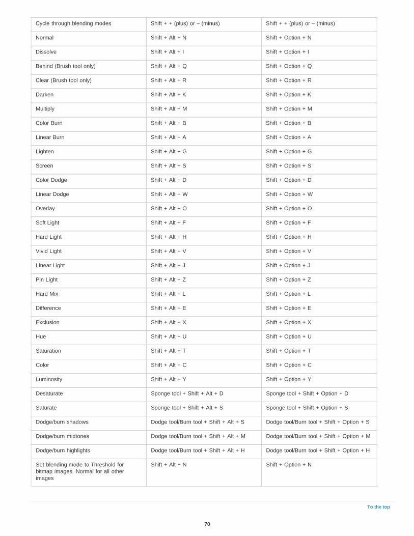
To the top
Cycle through blending modes Shift + + (plus) or – (minus) Shift + + (plus) or – (minus)
Normal Shift + Alt + N Shift + Option + N
Dissolve Shift + Alt + I Shift + Option + I
Behind (Brush tool only) Shift + Alt + Q Shift + Option + Q
Clear (Brush tool only) Shift + Alt + R Shift + Option + R
Darken Shift + Alt + K Shift + Option + K
Multiply Shift + Alt + M Shift + Option + M
Color Burn Shift + Alt + B Shift + Option + B
Linear Burn Shift + Alt + A Shift + Option + A
Lighten Shift + Alt + G Shift + Option + G
Screen Shift + Alt + S Shift + Option + S
Color Dodge Shift + Alt + D Shift + Option + D
Linear Dodge Shift + Alt + W Shift + Option + W
Overlay Shift + Alt + O Shift + Option + O
Soft Light Shift + Alt + F Shift + Option + F
Hard Light Shift + Alt + H Shift + Option + H
Vivid Light Shift + Alt + V Shift + Option + V
Linear Light Shift + Alt + J Shift + Option + J
Pin Light Shift + Alt + Z Shift + Option + Z
Hard Mix Shift + Alt + L Shift + Option + L
Difference Shift + Alt + E Shift + Option + E
Exclusion Shift + Alt + X Shift + Option + X
Hue Shift + Alt + U Shift + Option + U
Saturation Shift + Alt + T Shift + Option + T
Color Shift + Alt + C Shift + Option + C
Luminosity Shift + Alt + Y Shift + Option + Y
Desaturate Sponge tool + Shift + Alt + D Sponge tool + Shift + Option + D
Saturate Sponge tool + Shift + Alt + S Sponge tool + Shift + Option + S
Dodge/burn shadows Dodge tool/Burn tool + Shift + Alt + S Dodge tool/Burn tool + Shift + Option + S
Dodge/burn midtones Dodge tool/Burn tool + Shift + Alt + M Dodge tool/Burn tool + Shift + Option + M
Dodge/burn highlights Dodge tool/Burn tool + Shift + Alt + H Dodge tool/Burn tool + Shift + Option + H
Set blending mode to Threshold forbitmap images, Normal for all otherimages
Shift + Alt + N Shift + Option + N
70

To the top
Keys for selecting and editing textThis partial list provides shortcuts that don’t appear in menu commands or tool tips.
Result Windows Mac OS
Move type in image Control-drag type when Type layer isselected
Command-drag type when Type layer isselected
Select 1 character left/right or 1 linedown/up, or 1 word left/right
Shift + Left Arrow/Right Arrow or DownArrow/Up Arrow, or Control + Shift + LeftArrow/Right Arrow
Shift + Left Arrow/Right Arrow or DownArrow/Up Arrow, or Command + Shift +Left Arrow/Right Arrow
Select characters from insertion point tomouse click point
Shift-click Shift-click
Move 1 character left/right, 1 line down/up,or 1 word left/right
Left Arrow/Right Arrow, Down Arrow/UpArrow, or Control + Left Arrow/Right Arrow
Left Arrow/Right Arrow, Down Arrow/UpArrow, or Command + Left Arrow/RightArrow
Create a new text layer, when a text layeris selected in the Layers panel
Shift-click Shift-click
Select a word, line, paragraph, or story Double-click, triple-click, quadruple-click,or quintuple-click
Double-click, triple-click, quadruple-click,or quintuple-click
Show/Hide selection on selected type Control + H Command + H
Display the bounding box for transformingtext when editing text, or activate Movetool if cursor is inside the bounding box
Control Command
Scale text within a bounding box whenresizing the bounding box
Control-drag a bounding box handle Command-drag a bounding box handle
Move text box while creating text box Spacebar-drag Spacebar-drag
Keys for formatting typeThis partial list provides shortcuts that don’t appear in menu commands or tool tips.
Result Windows Mac OS
Align left, center, or right Horizontal Type tool + Control + Shift + L,C, or R
Horizontal Type tool + Command + Shift +L, C, or R
Align top, center, or bottom Vertical Type tool + Control + Shift + L, C,or R
Vertical Type tool + Command + Shift + L,C, or R
Choose 100% horizontal scale Control + Shift + X Command + Shift + X
Choose 100% vertical scale Control + Shift + Alt + X Command + Shift + Option + X
Choose Auto leading Control + Shift + Alt + A Command + Shift + Option + A
Choose 0 for tracking Control + Shift + Q Command + Control + Shift + Q
Justify paragraph, left aligns last line Control + Shift + J Command + Shift + J
Justify paragraph, justifies all Control + Shift + F Command + Shift + F
Toggle paragraph hyphenation on/off Control + Shift + Alt + H Command + Control + Shift + Option + H
Toggle single/every-line composer on/off Control + Shift + Alt + T Command + Shift + Option + T
Decrease or increase type size of selectedtext 2 points or pixels
Control + Shift + < or > Command + Shift + < or >† †
71
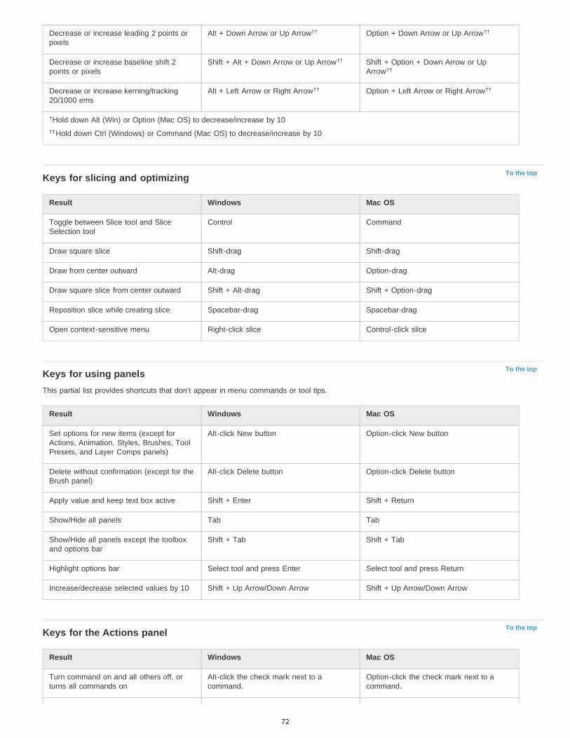
To the top
To the top
To the top
Decrease or increase leading 2 points orpixels
Alt + Down Arrow or Up Arrow Option + Down Arrow or Up Arrow
Decrease or increase baseline shift 2points or pixels
Shift + Alt + Down Arrow or Up Arrow Shift + Option + Down Arrow or UpArrow
Decrease or increase kerning/tracking20/1000 ems
Alt + Left Arrow or Right Arrow Option + Left Arrow or Right Arrow
Hold down Alt (Win) or Option (Mac OS) to decrease/increase by 10
Hold down Ctrl (Windows) or Command (Mac OS) to decrease/increase by 10
Keys for slicing and optimizing
Result Windows Mac OS
Toggle between Slice tool and SliceSelection tool
Control Command
Draw square slice Shift-drag Shift-drag
Draw from center outward Alt-drag Option-drag
Draw square slice from center outward Shift + Alt-drag Shift + Option-drag
Reposition slice while creating slice Spacebar-drag Spacebar-drag
Open context-sensitive menu Right-click slice Control-click slice
Keys for using panelsThis partial list provides shortcuts that don’t appear in menu commands or tool tips.
Result Windows Mac OS
Set options for new items (except forActions, Animation, Styles, Brushes, ToolPresets, and Layer Comps panels)
Alt-click New button Option-click New button
Delete without confirmation (except for theBrush panel)
Alt-click Delete button Option-click Delete button
Apply value and keep text box active Shift + Enter Shift + Return
Show/Hide all panels Tab Tab
Show/Hide all panels except the toolboxand options bar
Shift + Tab Shift + Tab
Highlight options bar Select tool and press Enter Select tool and press Return
Increase/decrease selected values by 10 Shift + Up Arrow/Down Arrow Shift + Up Arrow/Down Arrow
Keys for the Actions panel
Result Windows Mac OS
Turn command on and all others off, orturns all commands on
Alt-click the check mark next to acommand.
Option-click the check mark next to acommand.
†† ††
††
††
†† ††
†
††
72

To the top
To the top
To the top
Turn current modal control on and toggleall other modal controls
Alt-click Option-click
Change action or action set options Alt + double-click action or action set Option + double-click action or action set
Display Options dialog box for recordedcommand
Double-click recorded command Double-click recorded command
Play entire action Control + double-click an action Command + double-click an action
Collapse/expand all components of anaction
Alt-click the triangle Option-click the triangle
Play a command Control-click the Play button Command-click the Play button
Create new action and begin recordingwithout confirmation
Alt-click the New Action button Option-click the New Action button
Select contiguous items of the same kind Shift-click the action/command Shift-click the action/command
Select discontiguous items of the samekind
Control-click the action/command Command-click the action/command
Keys for adjustment layersIf you prefer channel shortcuts starting with Alt/Option + 1 for red, choose Edit > Keyboard Shortcuts, and select Use Legacy ChannelShortcuts. Then restart Photoshop.
Result Windows Mac OS
Choose specific channel for adjustment Alt + 3 (red), 4 (green), 5 (blue) Option + 3 (red), 4 (green), 5 (blue)
Choose composite channel for adjustment Alt + 2 Option + 2
Delete adjustment layer Delete or Backspace Delete
Define Auto options for Levels or Curves Alt-click Auto button Option-click Auto button
Keys for the Animation panel in Frames mode
Result Windows Mac OS
Select/deselect multiple contiguous frames Shift-click second frame Shift-click second frame
Select/deselect multiple discontiguousframes
Control-click multiple frames Command-click multiple frames
Paste using previous settings withoutdisplaying the dialog box
Alt + Paste Frames command from thePanel pop-up menu
Option + Paste Frames command from thePanel pop-up menu
Keys for the Animation panel in Timeline Mode (Photoshop Extended)Note: To enable all shortcuts, choose Enable Timeline Shortcut Keys from the Animation (Timeline) panel menu.
Result Windows Mac OS
Start playing the timeline or Animationpanel
Spacebar Spacebar
Switch between timecode and framenumbers (current time view)
Alt + click the current-time display in theupper-left corner of the timeline.
Option + click the current-time display inthe upper-left corner of the timeline.
73
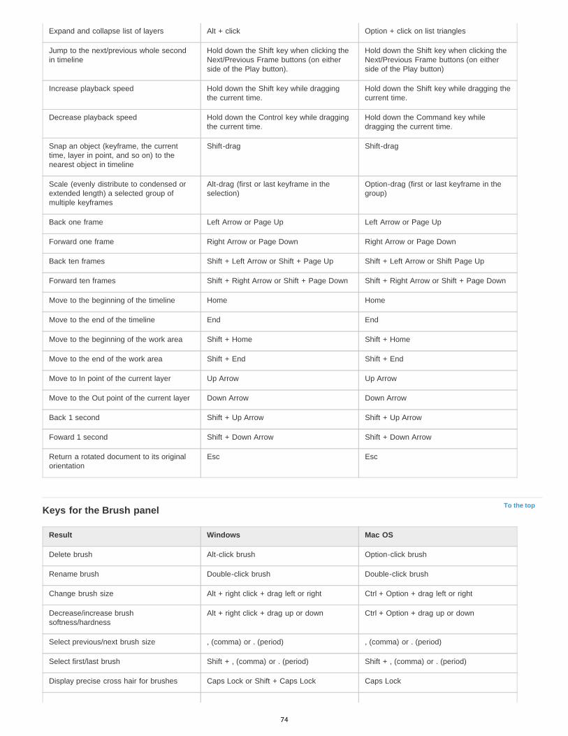
To the top
Expand and collapse list of layers Alt + click Option + click on list triangles
Jump to the next/previous whole secondin timeline
Hold down the Shift key when clicking theNext/Previous Frame buttons (on eitherside of the Play button).
Hold down the Shift key when clicking theNext/Previous Frame buttons (on eitherside of the Play button)
Increase playback speed Hold down the Shift key while draggingthe current time.
Hold down the Shift key while dragging thecurrent time.
Decrease playback speed Hold down the Control key while draggingthe current time.
Hold down the Command key whiledragging the current time.
Snap an object (keyframe, the currenttime, layer in point, and so on) to thenearest object in timeline
Shift-drag Shift-drag
Scale (evenly distribute to condensed orextended length) a selected group ofmultiple keyframes
Alt-drag (first or last keyframe in theselection)
Option-drag (first or last keyframe in thegroup)
Back one frame Left Arrow or Page Up Left Arrow or Page Up
Forward one frame Right Arrow or Page Down Right Arrow or Page Down
Back ten frames Shift + Left Arrow or Shift + Page Up Shift + Left Arrow or Shift Page Up
Forward ten frames Shift + Right Arrow or Shift + Page Down Shift + Right Arrow or Shift + Page Down
Move to the beginning of the timeline Home Home
Move to the end of the timeline End End
Move to the beginning of the work area Shift + Home Shift + Home
Move to the end of the work area Shift + End Shift + End
Move to In point of the current layer Up Arrow Up Arrow
Move to the Out point of the current layer Down Arrow Down Arrow
Back 1 second Shift + Up Arrow Shift + Up Arrow
Foward 1 second Shift + Down Arrow Shift + Down Arrow
Return a rotated document to its originalorientation
Esc Esc
Keys for the Brush panel
Result Windows Mac OS
Delete brush Alt-click brush Option-click brush
Rename brush Double-click brush Double-click brush
Change brush size Alt + right click + drag left or right Ctrl + Option + drag left or right
Decrease/increase brushsoftness/hardness
Alt + right click + drag up or down Ctrl + Option + drag up or down
Select previous/next brush size , (comma) or . (period) , (comma) or . (period)
Select first/last brush Shift + , (comma) or . (period) Shift + , (comma) or . (period)
Display precise cross hair for brushes Caps Lock or Shift + Caps Lock Caps Lock
74

To the top
To the top
To the top
Toggle airbrush option Shift + Alt + P Shift + Option + P
Keys for the Channels panelIf you prefer channel shortcuts starting with Ctrl/Command + 1 for red, choose Edit > Keyboard Shortcuts, and select Use Legacy ChannelShortcuts.
Result Windows Mac OS
Select individual channels Ctrl + 3 (red), 4 (green), 5 (blue) Command + 3 (red), 4 (green), 5 (blue)
Select composite channel Ctrl + 2 Command + 2
Load channel as selection Control-click channel thumbnail, or Alt +Ctrl + 3 (red), 4 (green), 5 (blue)
Command-click channel thumbnail, orOption + Command + 3 (red), 4 (green), 5(blue)
Add to current selection Control + Shift-click channel thumbnail. Command + Shift-click channel thumbnail
Subtract from current selection Control + Alt-click channel thumbnail Command + Option-click channelthumbnail
Intersect with current selection Control + Shift + Alt-click channelthumbnail
Command + Shift + Option-click channelthumbnail
Set options for Save Selection AsChannel button
Alt-click Save Selection As Channelbutton
Option-click Save Selection As Channelbutton
Create a new spot channel Control-click Create New Channel button Command-click Create New Channelbutton
Select/deselect multiple color-channelselection
Shift-click color channel Shift-click color channel
Select/deselect alpha channel andshow/hide as a rubylith overlay
Shift-click alpha channel Shift-click alpha channel
Display channel options Double-click alpha or spot channelthumbnail
Double-click alpha or spot channelthumbnail
Toggle composite and grayscale mask inQuick Mask mode
~ (tilde) ~ (tilde)
Keys for the Clone Source panel
Result Windows Mac OS
Show Clone Source (overlays image) Alt + Shift Opt + Shift
Nudge Clone Source Alt + Shift + arrow keys Opt + Shift + arrow keys
Rotate Clone Source Alt + Shift + < or > Opt + Shift + < or >
Scale (increase or reduce size) CloneSource
Alt + Shift + [ or ] Opt + Shift + [ or ]
Keys for the Color panel
Result Windows Mac OS
Select background color Alt-click color in color bar Option-click color in color bar
75

To the top
To the top
To the top
Display Color Bar menu Right-click color bar Control-click color bar
Cycle through color choices Shift-click color bar Shift-click color bar
Keys for the History panel
Result Windows Mac OS
Create a new snapshot Alt + New Snapshot Option + New Snapshot
Rename snapshot Double-click snapshot name Double-click snapshot name
Step forward through image states Control + Shift + Z Command + Shift + Z
Step backward through image states Control + Alt + Z Command + Option + Z
Duplicate any image state, except thecurrent state
Alt-click the image state Option-click the image state
Permanently clear history (no Undo) Alt + Clear History (in History panelpop-up menu)
Option + Clear History (in History panelpop-up menu)
Keys for the Info panel
Result Windows Mac OS
Change color readout modes Click eyedropper icon Click eyedropper icon
Change measurement units Click crosshair icon Click crosshair icon
Keys for the Layers panel
Result Windows Mac OS
Load layer transparency as a selection Control-click layer thumbnail Command-click layer thumbnail
Add to current selection Control + Shift-click layer thumbnail. Command + Shift-click layer thumbnail.
Subtract from current selection Control + Alt-click layer thumbnail. Command + Option-click layer thumbnail.
Intersect with current selection Control + Shift + Alt-click layer thumbnail. Command + Shift + Option-click layerthumbnail.
Load filter mask as a selection Control-click filter mask thumbnail Command-click filter mask thumbnail
Group layers Control + G Command + G
Ungroup layers Control + Shift + G Command-Shift + G
Create/release clipping mask Control + Alt + G Command-Option + G
Select all layers Control + Alt + A Command + Option + A
Merge visible layers Control + Shift + E Command + Shift + E
Create new empty layer with dialog box Alt-click New Layer button Option-click New Layer button
Create new layer below target layer Control-click New Layer button Command-click New Layer button
76
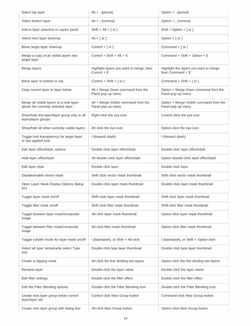
Select top layer Alt + . (period) Option + . (period)
Select bottom layer Alt + , (comma) Option + , (comma)
Add to layer selection in Layers panel Shift + Alt + [ or ] Shift + Option + [ or ]
Select next layer down/up Alt + [ or ] Option + [ or ]
Move target layer down/up Control + [ or ] Command + [ or ]
Merge a copy of all visible layers intotarget layer
Control + Shift + Alt + E Command + Shift + Option + E
Merge layers Highlight layers you want to merge, thenControl + E
Highlight the layers you want to merge,then Command + E
Move layer to bottom or top Control + Shift + [ or ] Command + Shift + [ or ]
Copy current layer to layer below Alt + Merge Down command from thePanel pop-up menu
Option + Merge Down command from thePanel pop-up menu
Merge all visible layers to a new layerabove the currently selected layer
Alt + Merge Visible command from thePanel pop-up menu
Option + Merge Visible command from thePanel pop-up menu
Show/hide this layer/layer group only or alllayers/layer groups
Right-click the eye icon Control-click the eye icon
Show/hide all other currently visible layers Alt-click the eye icon Option-click the eye icon
Toggle lock transparency for target layer,or last applied lock
/ (forward slash) / (forward slash)
Edit layer effect/style, options Double-click layer effect/style Double-click layer effect/style
Hide layer effect/style Alt-double-click layer effect/style Option-double-click layer effect/style
Edit layer style Double-click layer Double-click layer
Disable/enable vector mask Shift-click vector mask thumbnail Shift-click vector mask thumbnail
Open Layer Mask Display Options dialogbox
Double-click layer mask thumbnail Double-click layer mask thumbnail
Toggle layer mask on/off Shift-click layer mask thumbnail Shift-click layer mask thumbnail
Toggle filter mask on/off Shift-click filter mask thumbnail Shift-click filter mask thumbnail
Toggle between layer mask/compositeimage
Alt-click layer mask thumbnail Option-click layer mask thumbnail
Toggle between filter mask/compositeimage
Alt-click filter mask thumbnail Option-click filter mask thumbnail
Toggle rubylith mode for layer mask on/off \ (backslash), or Shift + Alt-click \ (backslash), or Shift + Option-click
Select all type; temporarily select Typetool
Double-click type layer thumbnail Double-click type layer thumbnail
Create a clipping mask Alt-click the line dividing two layers Option-click the line dividing two layers
Rename layer Double-click the layer name Double-click the layer name
Edit filter settings Double-click the filter effect Double-click the filter effect
Edit the Filter Blending options Double-click the Filter Blending icon Double-click the Filter Blending icon
Create new layer group below currentlayer/layer set
Control-click New Group button Command-click New Group button
Create new layer group with dialog box Alt-click New Group button Option-click New Group button
77
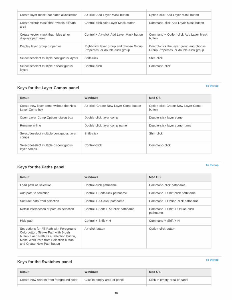
To the top
To the top
To the top
Create layer mask that hides all/selection Alt-click Add Layer Mask button Option-click Add Layer Mask button
Create vector mask that reveals all/patharea
Control-click Add Layer Mask button Command-click Add Layer Mask button
Create vector mask that hides all ordisplays path area
Control + Alt-click Add Layer Mask button Command + Option-click Add Layer Maskbutton
Display layer group properties Right-click layer group and choose GroupProperties, or double-click group
Control-click the layer group and chooseGroup Properties, or double-click group
Select/deselect multiple contiguous layers Shift-click Shift-click
Select/deselect multiple discontiguouslayers
Control-click Command-click
Keys for the Layer Comps panel
Result Windows Mac OS
Create new layer comp without the NewLayer Comp box
Alt-click Create New Layer Comp button Option-click Create New Layer Compbutton
Open Layer Comp Options dialog box Double-click layer comp Double-click layer comp
Rename in-line Double-click layer comp name Double-click layer comp name
Select/deselect multiple contiguous layercomps
Shift-click Shift-click
Select/deselect multiple discontiguouslayer comps
Control-click Command-click
Keys for the Paths panel
Result Windows Mac OS
Load path as selection Control-click pathname Command-click pathname
Add path to selection Control + Shift-click pathname Command + Shift-click pathname
Subtract path from selection Control + Alt-click pathname Command + Option-click pathname
Retain intersection of path as selection Control + Shift + Alt-click pathname Command + Shift + Option-clickpathname
Hide path Control + Shift + H Command + Shift + H
Set options for Fill Path with ForegroundColorbutton, Stroke Path with Brushbutton, Load Path as a Selection button,Make Work Path from Selection button,and Create New Path button
Alt-click button Option-click button
Keys for the Swatches panel
Result Windows Mac OS
Create new swatch from foreground color Click in empty area of panel Click in empty area of panel
78

To the top
To the top
Set swatch color as background color Control-click swatch Command-click swatch
Delete swatch Alt-click swatch Option-click swatch
Keys for 3D tools (Photoshop Extended)
Result Windows Mac OS
Enable 3D object tools K K
Enable 3D camera tools N N
Hide nearest surface Alt + Ctrl + X Option + Command + X
Show all surfaces Alt + Shift + Ctrl + X Option + Shift + Command + X
3D Object Tool Right-click (Windows) / Control-click (Mac OS)
Alt (Windows) / Option (Mac OS )
Rotate Changes to Drag tool Changes to Roll tool
Roll Changes to Slide tool Changes to Rotate tool
Drag Changes to Orbit tool Changes to Slide tool
Slide Changes to Roll tool Changes to Drag tool
Scale Scales on the Z plane Scales on the Z plane
To scale on the Y plane, hold down the Shift key.
Camera Tool Right-click (Windows) / Control-click (Mac OS)
Alt (Windows) / Option (Mac OS )
Orbit Changes to Drag tool Changes to Roll tool
Roll Changes to Slide tool Changes to Rotate tool
Pan Changes to Orbit tool Changes to Slide tool
Walk Changes to Roll tool Changes to Drag tool
Keys for measurement (Photoshop Extended)
Result Windows Mac OS
Record a measurement Shift + Control + M Shift + Command + M
Deselects all measurements Control + D Command + D
Selects all measurements Control + A Command + A
Hide/show all measurements Shift + Control + H Shift + Command + H
Removes a measurement Backspace Delete
Nudge the measurement Arrow keys Arrow keys
Nudge the measurement in increments Shift + arrow keys Shift + arrow keys
Extend/shorten selected measurement Ctrl + left/right arrow key Command + left/right arrow key
79

To the top
To the top
Extend/shorten selected measurement inincrements
Shift + Ctrl + left/right arrow key Shift +Command + left/right arrow key
Rotate selected measurement Ctrl + up/down arrow key Command + up/down arrow key
Rotate selected measurement inincrements
Shift + Ctrl + up/down arrow key Shift + Command + up/down arrow key
Keys for DICOM files (Photoshop Extended)
Result Windows Mac OS
Zoom tool Z Z
Hand tool H H
Window Level tool W W
Select all frames Control + A Command + A
Deselect all frames except the currentframe
Control + D Command + D
Navigate through frames Arrow keys Arrow keys
Keys for Extract and Pattern Maker (optional plug-ins)
Result (Extract and Pattern Maker) Windows Mac OS
Fit in window Control + 0 Command + 0
Zoom in Control + + (plus) Command + + (plus)
Zoom out Control + - (hyphen) Command + - (hyphen)
Cycle through controls on right from top Tab Tab
Cycle through controls on right frombottom
Shift + Tab Shift + Tab
Temporarily activate Hand tool Spacebar Spacebar
Change Cancel to Reset Alt Option
Result (Extract only) Windows Mac OS
Edge Highlighter tool B B
Fill tool G G
Eyedropper tool I I
Cleanup tool C C
Edge Touchup tool T T
Toggle between Edge Highlighter tool andEraser tool
Alt + Edge Highlighter/Eraser tool Option + Edge Highlighter/Eraser tool
Toggle Smart Highlighting Control with Edge Highlighter tool selected Command with Edge Highlighter toolselected
Remove current highlight Alt + Delete Option + Delete
80
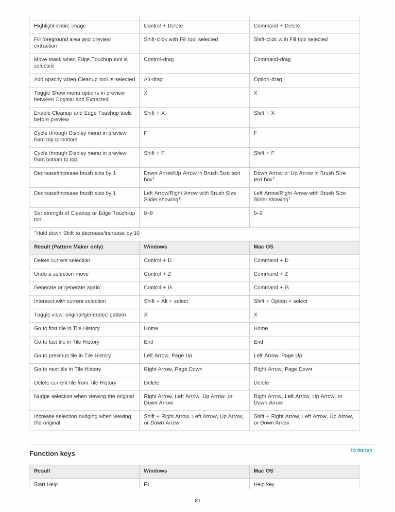
To the top
Highlight entire image Control + Delete Command + Delete
Fill foreground area and previewextraction
Shift-click with Fill tool selected Shift-click with Fill tool selected
Move mask when Edge Touchup tool isselected
Control-drag Command-drag
Add opacity when Cleanup tool is selected Alt-drag Option-drag
Toggle Show menu options in previewbetween Original and Extracted
X X
Enable Cleanup and Edge Touchup toolsbefore preview
Shift + X Shift + X
Cycle through Display menu in previewfrom top to bottom
F F
Cycle through Display menu in previewfrom bottom to top
Shift + F Shift + F
Decrease/increase brush size by 1 Down Arrow/Up Arrow in Brush Size textbox
Down Arrow or Up Arrow in Brush Sizetext box
Decrease/increase brush size by 1 Left Arrow/Right Arrow with Brush SizeSlider showing
Left Arrow/Right Arrow with Brush SizeSlider showing
Set strength of Cleanup or Edge Touch-uptool
0–9 0–9
Hold down Shift to decrease/increase by 10
Result (Pattern Maker only) Windows Mac OS
Delete current selection Control + D Command + D
Undo a selection move Control + Z Command + Z
Generate or generate again Control + G Command + G
Intersect with current selection Shift + Alt + select Shift + Option + select
Toggle view: original/generated pattern X X
Go to first tile in Tile History Home Home
Go to last tile in Tile History End End
Go to previous tile in Tile History Left Arrow, Page Up Left Arrow, Page Up
Go to next tile in Tile History Right Arrow, Page Down Right Arrow, Page Down
Delete current tile from Tile History Delete Delete
Nudge selection when viewing the original Right Arrow, Left Arrow, Up Arrow, orDown Arrow
Right Arrow, Left Arrow, Up Arrow, orDown Arrow
Increase selection nudging when viewingthe original
Shift + Right Arrow, Left Arrow, Up Arrow,or Down Arrow
Shift + Right Arrow, Left Arrow, Up Arrow,or Down Arrow
Function keys
Result Windows Mac OS
Start Help F1 Help key
† †
† †
†
81

Undo/Redo F1
Cut F2 F2
Copy F3 F3
Paste F4 F4
Show/Hide Brush panel F5 F5
Show/Hide Color panel F6 F6
Show/Hide Layers panel F7 F7
Show/Hide Info panel F8 F8
Show/Hide Actions panel F9 Option + F9
Revert F12 F12
Fill Shift + F5 Shift + F5
Feather Selection Shift + F6 Shift + F6
Inverse Selection Shift + F7 Shift + F7
Legal Notices | Online Privacy Policy
82
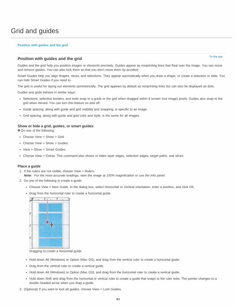
Grid and guides
To the top
Position with guides and the grid
Position with guides and the gridGuides and the grid help you position images or elements precisely. Guides appear as nonprinting lines that float over the image. You can moveand remove guides. You can also lock them so that you don’t move them by accident.
Smart Guides help you align shapes, slices, and selections. They appear automatically when you draw a shape, or create a selection or slide. Youcan hide Smart Guides if you need to.
The grid is useful for laying out elements symmetrically. The grid appears by default as nonprinting lines but can also be displayed as dots.
Guides and grids behave in similar ways:
Selections, selection borders, and tools snap to a guide or the grid when dragged within 8 screen (not image) pixels. Guides also snap to thegrid when moved. You can turn this feature on and off.
Guide spacing, along with guide and grid visibility and snapping, is specific to an image.
Grid spacing, along with guide and grid color and style, is the same for all images.
Show or hide a grid, guides, or smart guides Do one of the following:
Choose View > Show > Grid.
Choose View > Show > Guides.
View > Show > Smart Guides.
Choose View > Extras. This command also shows or hides layer edges, selection edges, target paths, and slices.
Place a guide1. If the rulers are not visible, choose View > Rulers.
Note: For the most accurate readings, view the image at 100% magnification or use the Info panel.2. Do one of the following to create a guide:
Choose View > New Guide. In the dialog box, select Horizontal or Vertical orientation, enter a position, and click OK.
Drag from the horizontal ruler to create a horizontal guide.
Dragging to create a horizontal guide
Hold down Alt (Windows) or Option (Mac OS), and drag from the vertical ruler to create a horizontal guide.
Drag from the vertical ruler to create a vertical guide.
Hold down Alt (Windows) or Option (Mac OS), and drag from the horizontal ruler to create a vertical guide.
Hold down Shift and drag from the horizontal or vertical ruler to create a guide that snaps to the ruler ticks. The pointer changes to adouble-headed arrow when you drag a guide.
3. (Optional) If you want to lock all guides, choose View > Lock Guides.
83
Move a guide1. Select the Move tool , or hold down Ctrl (Windows) or Command (Mac OS) to activate the Move tool.2. Position the pointer over the guide (the pointer turns into a double-headed arrow).3. Move the guide in any of the following ways:
Drag the guide to move it.
Change the guide from horizontal to vertical, or vice versa, by holding down Alt (Windows) or Option (Mac OS) as you click or drag theguide.
Align the guide with the ruler ticks by holding down Shift as you drag the guide. The guide snaps to the grid if the grid is visible andView > Snap To > Grid is selected.
Remove guides from the image Do one of the following:
To remove a single guide, drag the guide outside the image window.
To remove all guides, choose View > Clear Guides.
Set guide and grid preferences1. Do one of the following:
(Windows) Choose Edit > Preferences > Guides, Grid, & Slices.
(Mac OS) Choose Photoshop > Preferences > Guides, Grid, & Slices.
2. For Color, choose a color for the guides, the grid, or both. If you choose Custom, click the color box, choose a color, and click OK.3. For Style, choose a display option for guides or the grid, or both.4. For Gridline Every, enter a value for the grid spacing. For Subdivisions, enter a value by which to subdivide the grid.
If desired, change the units for this option. The Percent option creates a grid that divides the image into even sections. For example,choosing 25 for the Percent option creates an evenly divided 4-by-4 grid.
5. Click OK.
Legal Notices | Online Privacy Policy
84

Run Photoshop in 32-bit mode (64-bit Mac OS only)
In 64-bit versions of Mac OS 10.5 and later, some older, optional plug-ins are available only if Photoshop is running in 32-bit mode:
1. In the Finder, choose Go > Applications.
2. Expand the Photoshop folder. Then right-click the Photoshop application icon, and choose Get Info.
3. In the General section of the Info window, select Open In 32-bit Mode.
4. Close the Info window, and restart Photoshop.
For more information, see 64-bit operating system benefits and limitations in Photoshop.
Legal Notices | Online Privacy Policy
85

Image and color basics
86
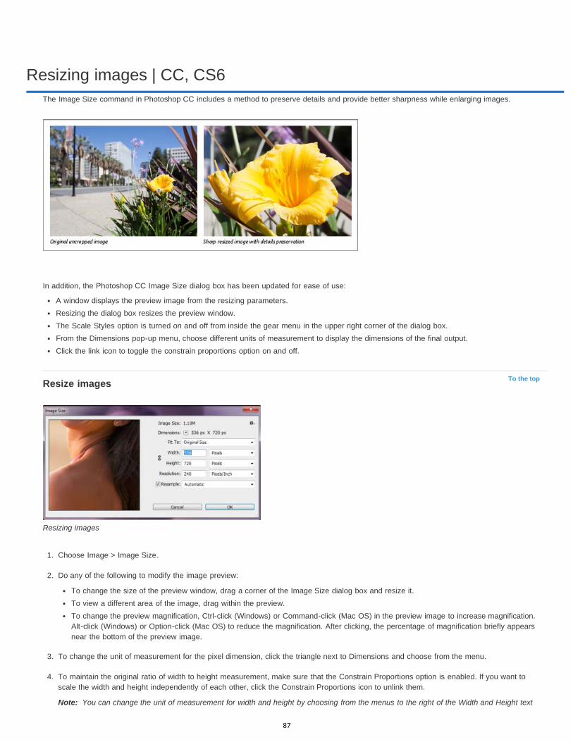
Resizing images | CC, CS6
To the top
Note:
The Image Size command in Photoshop CC includes a method to preserve details and provide better sharpness while enlarging images.
In addition, the Photoshop CC Image Size dialog box has been updated for ease of use:
A window displays the preview image from the resizing parameters.Resizing the dialog box resizes the preview window.The Scale Styles option is turned on and off from inside the gear menu in the upper right corner of the dialog box.From the Dimensions pop-up menu, choose different units of measurement to display the dimensions of the final output.Click the link icon to toggle the constrain proportions option on and off.
Resize images
Resizing images
1. Choose Image > Image Size.
2. Do any of the following to modify the image preview:
To change the size of the preview window, drag a corner of the Image Size dialog box and resize it.To view a different area of the image, drag within the preview.To change the preview magnification, Ctrl-click (Windows) or Command-click (Mac OS) in the preview image to increase magnification.Alt-click (Windows) or Option-click (Mac OS) to reduce the magnification. After clicking, the percentage of magnification briefly appearsnear the bottom of the preview image.
3. To change the unit of measurement for the pixel dimension, click the triangle next to Dimensions and choose from the menu.
4. To maintain the original ratio of width to height measurement, make sure that the Constrain Proportions option is enabled. If you want toscale the width and height independently of each other, click the Constrain Proportions icon to unlink them.
You can change the unit of measurement for width and height by choosing from the menus to the right of the Width and Height text
87
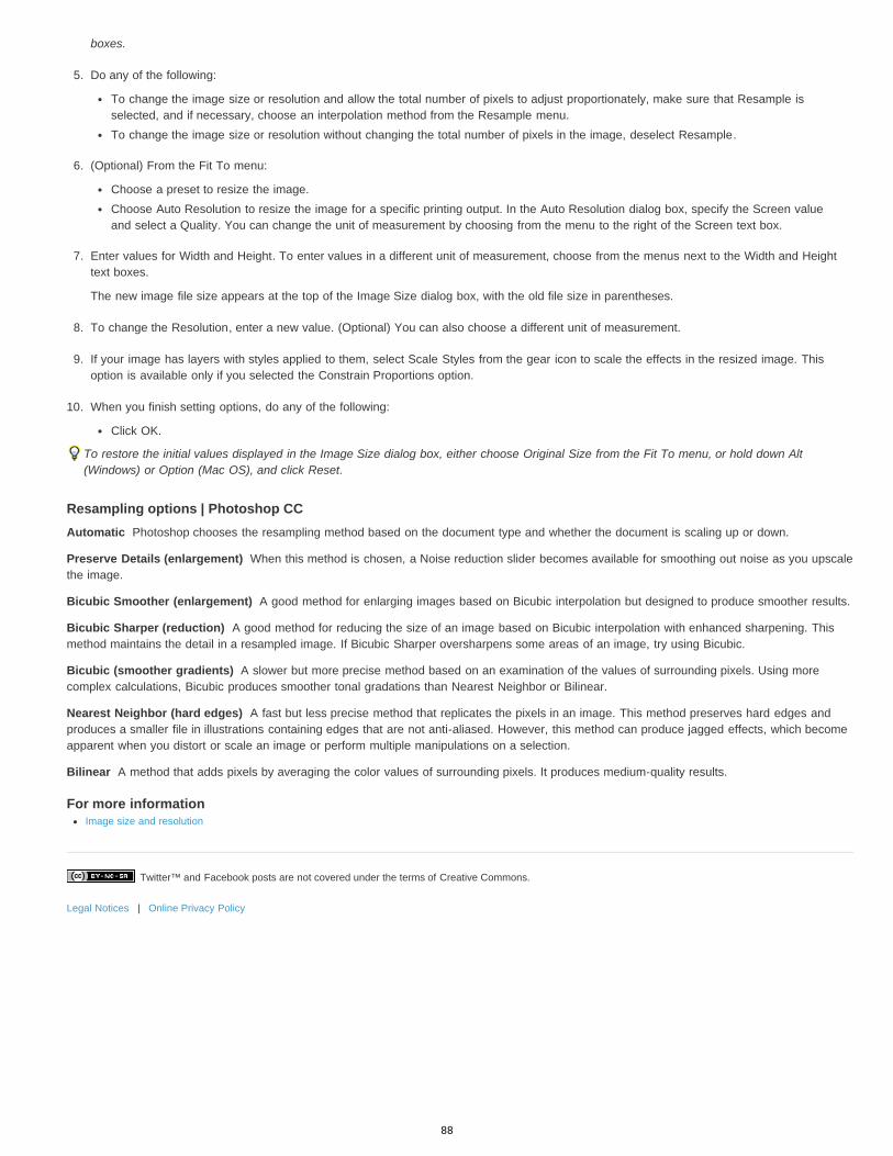
Twitter™ and Facebook posts are not covered under the terms of Creative Commons.
Legal Notices | Online Privacy Policy
Automatic
Preserve Details (enlargement)
Bicubic Smoother (enlargement)
Bicubic Sharper (reduction)
Bicubic (smoother gradients)
Nearest Neighbor (hard edges)
Bilinear
boxes.
5. Do any of the following:
To change the image size or resolution and allow the total number of pixels to adjust proportionately, make sure that Resample isselected, and if necessary, choose an interpolation method from the Resample menu.To change the image size or resolution without changing the total number of pixels in the image, deselect Resample.
6. (Optional) From the Fit To menu:
Choose a preset to resize the image. Choose Auto Resolution to resize the image for a specific printing output. In the Auto Resolution dialog box, specify the Screen valueand select a Quality. You can change the unit of measurement by choosing from the menu to the right of the Screen text box.
7. Enter values for Width and Height. To enter values in a different unit of measurement, choose from the menus next to the Width and Heighttext boxes.
The new image file size appears at the top of the Image Size dialog box, with the old file size in parentheses.
8. To change the Resolution, enter a new value. (Optional) You can also choose a different unit of measurement.
9. If your image has layers with styles applied to them, select Scale Styles from the gear icon to scale the effects in the resized image. Thisoption is available only if you selected the Constrain Proportions option.
10. When you finish setting options, do any of the following:
Click OK.
To restore the initial values displayed in the Image Size dialog box, either choose Original Size from the Fit To menu, or hold down Alt(Windows) or Option (Mac OS), and click Reset.
Resampling options | Photoshop CCPhotoshop chooses the resampling method based on the document type and whether the document is scaling up or down.
When this method is chosen, a Noise reduction slider becomes available for smoothing out noise as you upscalethe image.
A good method for enlarging images based on Bicubic interpolation but designed to produce smoother results.
A good method for reducing the size of an image based on Bicubic interpolation with enhanced sharpening. Thismethod maintains the detail in a resampled image. If Bicubic Sharper oversharpens some areas of an image, try using Bicubic.
A slower but more precise method based on an examination of the values of surrounding pixels. Using morecomplex calculations, Bicubic produces smoother tonal gradations than Nearest Neighbor or Bilinear.
A fast but less precise method that replicates the pixels in an image. This method preserves hard edges andproduces a smaller file in illustrations containing edges that are not anti-aliased. However, this method can produce jagged effects, which becomeapparent when you distort or scale an image or perform multiple manipulations on a selection.
A method that adds pixels by averaging the color values of surrounding pixels. It produces medium-quality results.
For more informationImage size and resolution
88

Image essentials
To the top
To the top
To the top
About bitmap imagesAbout vector graphicsCombining vector graphics and bitmap imagesColor channelsBit depthConvert between bit depths
Note: For detailed instructions, click the links below. To ask questions, request features, or report problems, visit feedback.photoshop.com.
About bitmap imagesBitmap images—technically called raster images—use a rectangular grid of picture elements (pixels) to represent images. Each pixel is assigned aspecific location and color value. When working with bitmap images, you edit pixels rather than objects or shapes. Bitmap images are the mostcommon electronic medium for continuous-tone images, such as photographs or digital paintings, because they can more efficiently representsubtle gradations of shades and color.
Bitmap images are resolution-dependent—that is, they contain a fixed number of pixels. As a result, they can lose detail and appear jagged if theyare scaled to high magnifications on-screen or if they are printed at a lower resolution than they were created for.
Example of a bitmap image at different levels of magnification
Bitmap images sometimes require large amounts of storage space, and often need to be compressed to keep file sizes down when used in certainCreative Suite components. For instance, you compress an image file in its original application before you import it into a layout.
Note: In Adobe Illustrator, you can create bitmap effects in your artwork using effects and graphic styles.
About vector graphicsVector graphics (sometimes called vector shapes or vector objects) are made up of lines and curves defined by mathematical objects calledvectors, which describe an image according to its geometric characteristics.
You can freely move or modify vector graphics without losing detail or clarity, because they are resolution-independent—they maintain crisp edgeswhen resized, printed to a PostScript printer, saved in a PDF file, or imported into a vector-based graphics application. As a result, vector graphicsare the best choice for artwork, such as logos, that will be used at various sizes and in various output media.
The vector objects you create using the drawing and shape tools in Adobe Creative Suite are examples of vector graphics. You can use the Copyand Paste commands to duplicate vector graphics betweenCreative Suite components.
Combining vector graphics and bitmap imagesWhen combining vector graphics and bitmap images in a document, it’s important to remember that how your artwork looks on-screen isn’t alwayshow it will look in its final medium (whether commercially printed, printed on a desktop printer, or viewed on the web). The following factorsinfluence the quality of your final artwork:
Transparency Many effects add partially transparent pixels to your artwork. When your artwork contains transparency, Photoshop performs aprocess called flattening before printing or exporting. In most cases, the default flattening process produces excellent results. However, if yourartwork contains complex, overlapping areas and you require high-resolution output, you will probably want to preview the effects of flattening.Image Resolution The number of pixels per inch (ppi) in a bitmap image. Using too low a resolution for a printed image results in pixelation—output with large, coarse-looking pixels. Using too high a resolution (pixels smaller than what the output device can produce) increases the file sizewithout increasing the quality of the printed output, and slows the printing of the artwork.Printer resolution and screen frequency The number of ink dots produced per inch (dpi) and the number of lines per inch (lpi) in a halftone
89
To the top
To the top
To the top
screen. The relationship between image resolution, printer resolution, and screen frequency determines the quality of detail in the printed image.
Color channelsEvery Photoshop image has one or more channels, each storing information about color elements in the image. The number of default colorchannels in an image depends on its color mode. By default, images in Bitmap, Grayscale, Duotone, and Indexed Color mode have one channel;RGB and Lab images have three; and CMYK images have four. You can add channels to all image types except Bitmap mode images. For moreinformation, see Color modes.
Channels in color images are actually grayscale images that represent each of the color components of an image. For example, an RGB imagehas separate channels for red, green, and blues color values.
In addition to color channels, alpha channels, can be added to an image for storing and editing selections as masks, and spot color channels canbe added to add spot color plates for printing. For more information, see Channel basics.
Bit depthBit depth specifies how much color information is available for each pixel in an image. The more bits of information per pixel, the more availablecolors and more accurate color representation. For example, an image with a bit depth of 1 has pixels with two possible values: black and white.An image with a bit depth of 8 has 2 , or 256, possible values. Grayscale mode images with a bit depth of 8 have 256 possible gray values.
RGB images are made of three color channels. An 8-bit per pixel RGB image has 256 possible values for each channel which means it has over16 million possible color values. RGB images with 8-bits per channel (bpc) are sometimes called 24-bit images (8 bits x 3 channels = 24 bits ofdata for each pixel).
In addition to 8-bpc images, Photoshop can also work with images that contain 16-bpc or 32-bpc. Images with 32-bpc are also known as highdynamic range (HDR) images.
Photoshop support for 16-bit imagesPhotoshop provides the following support for working with 16-bpc images:
Working in Grayscale, RGB Color, CMYK Color, Lab Color, and Multichannel, modes.
All tools in the toolbox, except the Art History Brush tool, can be used with 16-bpc images.
Color and tonal adjustment commands are available
You can work with layers, including adjustment layers, in 16-bpc images.
Many Photoshop filters can be used with 16-bpc images.
To take advantage of certain Photoshop features, such as some filters, you can convert a 16-bpc image to an 8-bpc image. It’s best if you doa Save As and convert a copy of the image file so the original file retains the full 16-bpc image data.
Adobe recommends Have a tutorial you would like to share?
Understanding bit depthMartin EveningLearn more with this excerpt from AdobePhotoshop for Photographers.
Convert between bit depths Do any of the following:
To convert between 8 bpc and 16 bpc, Choose Image > Mode > 16 Bits/Channel or 8 Bits/Channel.
To convert from 8 bpc or 16 bits to 32 bpc, choose Image > Mode > 32 Bits/Channel.
Legal Notices | Online Privacy Policy
8
90
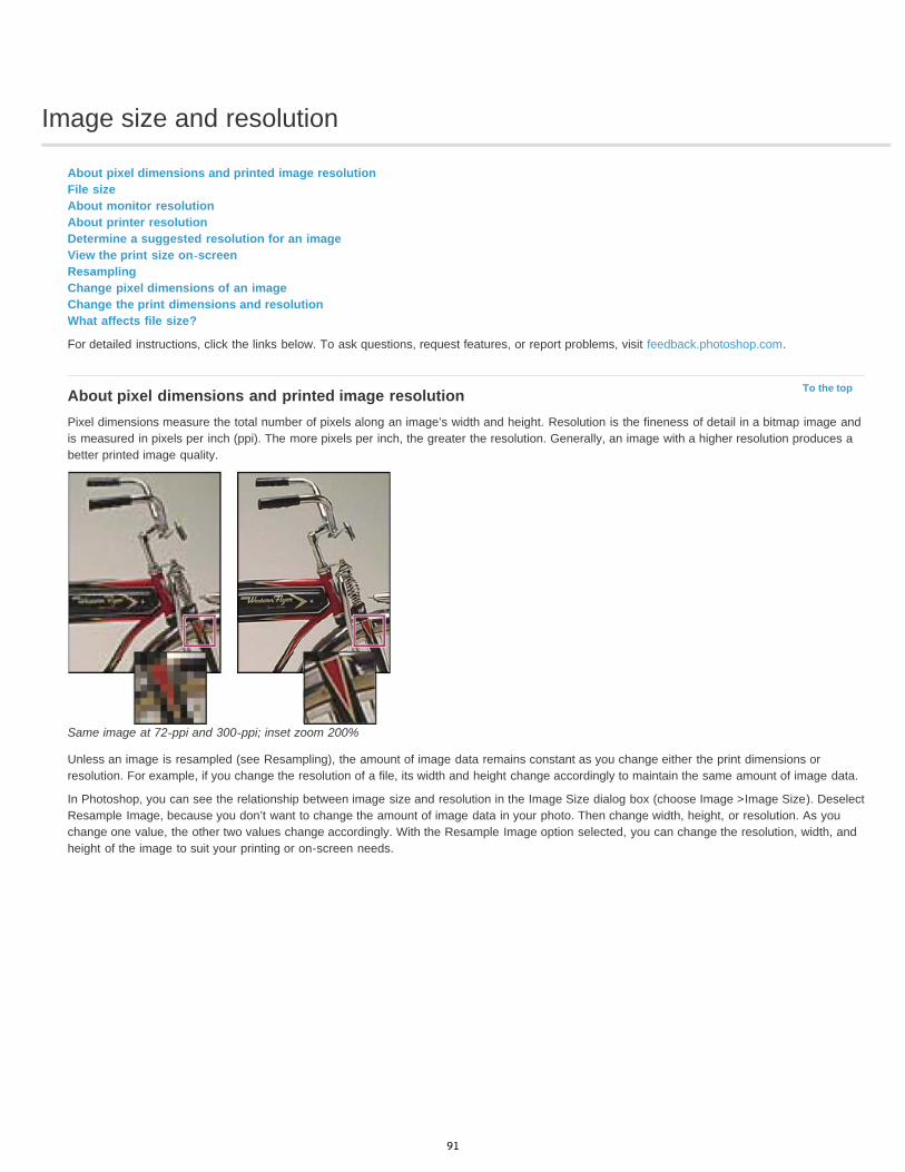
Image size and resolution
To the top
About pixel dimensions and printed image resolutionFile sizeAbout monitor resolutionAbout printer resolutionDetermine a suggested resolution for an imageView the print size on-screenResamplingChange pixel dimensions of an imageChange the print dimensions and resolutionWhat affects file size?
For detailed instructions, click the links below. To ask questions, request features, or report problems, visit feedback.photoshop.com.
About pixel dimensions and printed image resolutionPixel dimensions measure the total number of pixels along an image’s width and height. Resolution is the fineness of detail in a bitmap image andis measured in pixels per inch (ppi). The more pixels per inch, the greater the resolution. Generally, an image with a higher resolution produces abetter printed image quality.
Same image at 72-ppi and 300-ppi; inset zoom 200%
Unless an image is resampled (see Resampling), the amount of image data remains constant as you change either the print dimensions orresolution. For example, if you change the resolution of a file, its width and height change accordingly to maintain the same amount of image data.
In Photoshop, you can see the relationship between image size and resolution in the Image Size dialog box (choose Image >Image Size). DeselectResample Image, because you don’t want to change the amount of image data in your photo. Then change width, height, or resolution. As youchange one value, the other two values change accordingly. With the Resample Image option selected, you can change the resolution, width, andheight of the image to suit your printing or on-screen needs.
91
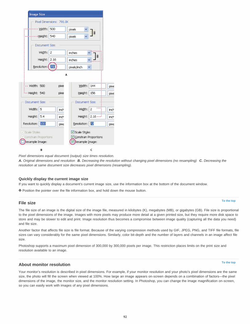
To the top
To the top
Pixel dimensions equal document (output) size times resolution.A. Original dimensions and resolution B. Decreasing the resolution without changing pixel dimensions (no resampling) C. Decreasing theresolution at same document size decreases pixel dimensions (resampling).
Quickly display the current image sizeIf you want to quickly display a document’s current image size, use the information box at the bottom of the document window.
Position the pointer over the file information box, and hold down the mouse button.
File sizeThe file size of an image is the digital size of the image file, measured in kilobytes (K), megabytes (MB), or gigabytes (GB). File size is proportionalto the pixel dimensions of the image. Images with more pixels may produce more detail at a given printed size, but they require more disk space tostore and may be slower to edit and print. Image resolution thus becomes a compromise between image quality (capturing all the data you need)and file size.
Another factor that affects file size is file format. Because of the varying compression methods used by GIF, JPEG, PNG, and TIFF file formats, filesizes can vary considerably for the same pixel dimensions. Similarly, color bit-depth and the number of layers and channels in an image affect filesize.
Photoshop supports a maximum pixel dimension of 300,000 by 300,000 pixels per image. This restriction places limits on the print size andresolution available to an image.
About monitor resolutionYour monitor’s resolution is described in pixel dimensions. For example, if your monitor resolution and your photo’s pixel dimensions are the samesize, the photo will fill the screen when viewed at 100%. How large an image appears on-screen depends on a combination of factors—the pixeldimensions of the image, the monitor size, and the monitor resolution setting. In Photoshop, you can change the image magnification on-screen,so you can easily work with images of any pixel dimensions.
92
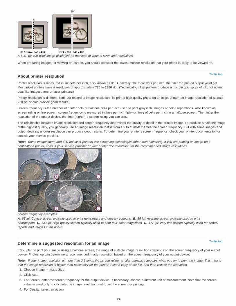
To the top
To the top
A 620- by 400-pixel image displayed on monitors of various sizes and resolutions.
When preparing images for viewing on-screen, you should consider the lowest monitor resolution that your photo is likely to be viewed on.
About printer resolutionPrinter resolution is measured in ink dots per inch, also known as dpi. Generally, the more dots per inch, the finer the printed output you’ll get.Most inkjet printers have a resolution of approximately 720 to 2880 dpi. (Technically, inkjet printers produce a microscopic spray of ink, not actualdots like imagesetters or laser printers.)
Printer resolution is different from, but related to image resolution. To print a high quality photo on an inkjet printer, an image resolution of at least220 ppi should provide good results.
Screen frequency is the number of printer dots or halftone cells per inch used to print grayscale images or color separations. Also known asscreen ruling or line screen, screen frequency is measured in lines per inch (lpi)—or lines of cells per inch in a halftone screen. The higher theresolution of the output device, the finer (higher) a screen ruling you can use.
The relationship between image resolution and screen frequency determines the quality of detail in the printed image. To produce a halftone imageof the highest quality, you generally use an image resolution that is from 1.5 to at most 2 times the screen frequency. But with some images andoutput devices, a lower resolution can produce good results. To determine your printer’s screen frequency, check your printer documentation orconsult your service provider.
Note: Some imagesetters and 600-dpi laser printers use screening technologies other than halftoning. If you are printing an image on anonhalftone printer, consult your service provider or your printer documentation for the recommended image resolutions.
Screen frequency examplesA. 65 lpi: Coarse screen typically used to print newsletters and grocery coupons B. 85 lpi: Average screen typically used to printnewspapers C. 133 lpi: High-quality screen typically used to print four-color magazines D. 177 lpi: Very fine screen typically used for annualreports and images in art books
Determine a suggested resolution for an imageIf you plan to print your image using a halftone screen, the range of suitable image resolutions depends on the screen frequency of your outputdevice. Photoshop can determine a recommended image resolution based on the screen frequency of your output device.
Note: If your image resolution is more than 2.5 times the screen ruling, an alert message appears when you try to print the image. This meansthat the image resolution is higher than necessary for the printer. Save a copy of the file, and then reduce the resolution.
1. Choose Image > Image Size.2. Click Auto.3. For Screen, enter the screen frequency for the output device. If necessary, choose a different unit of measurement. Note that the screen
value is used only to calculate the image resolution, not to set the screen for printing.4. For Quality, select an option:
93
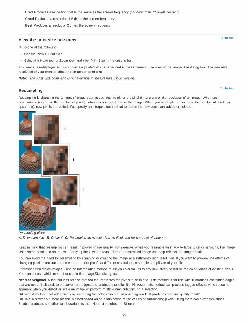
To the top
To the top
Draft Produces a resolution that is the same as the screen frequency (no lower than 72 pixels per inch).
Good Produces a resolution 1.5 times the screen frequency.
Best Produces a resolution 2 times the screen frequency.
View the print size on-screen Do one of the following:
Choose View > Print Size.
Select the Hand tool or Zoom tool, and click Print Size in the options bar.
The image is redisplayed in its approximate printed size, as specified in the Document Size area of the Image Size dialog box. The size andresolution of your monitor affect the on-screen print size.
Note: The Print Size command is not available in the Creative Cloud version.
ResamplingResampling is changing the amount of image data as you change either the pixel dimensions or the resolution of an image. When youdownsample (decrease the number of pixels), information is deleted from the image. When you resample up (increase the number of pixels, orupsample), new pixels are added. You specify an interpolation method to determine how pixels are added or deleted.
Resampling pixelsA. Downsampled B. Original C. Resampled up (selected pixels displayed for each set of images)
Keep in mind that resampling can result in poorer image quality. For example, when you resample an image to larger pixel dimensions, the imageloses some detail and sharpness. Applying the Unsharp Mask filter to a resampled image can help refocus the image details.
You can avoid the need for resampling by scanning or creating the image at a sufficiently high resolution. If you want to preview the effects ofchanging pixel dimensions on-screen or to print proofs at different resolutions, resample a duplicate of your file.
Photoshop resamples images using an interpolation method to assign color values to any new pixels based on the color values of existing pixels.You can choose which method to use in the Image Size dialog box.
Nearest Neighbor A fast but less precise method that replicates the pixels in an image. This method is for use with illustrations containing edgesthat are not anti-aliased, to preserve hard edges and produce a smaller file. However, this method can produce jagged effects, which becomeapparent when you distort or scale an image or perform multiple manipulations on a selection.Bilinear A method that adds pixels by averaging the color values of surrounding pixels. It produces medium-quality results.Bicubic A slower but more precise method based on an examination of the values of surrounding pixels. Using more complex calculations,Bicubic produces smoother tonal gradations than Nearest Neighbor or Bilinear.
94
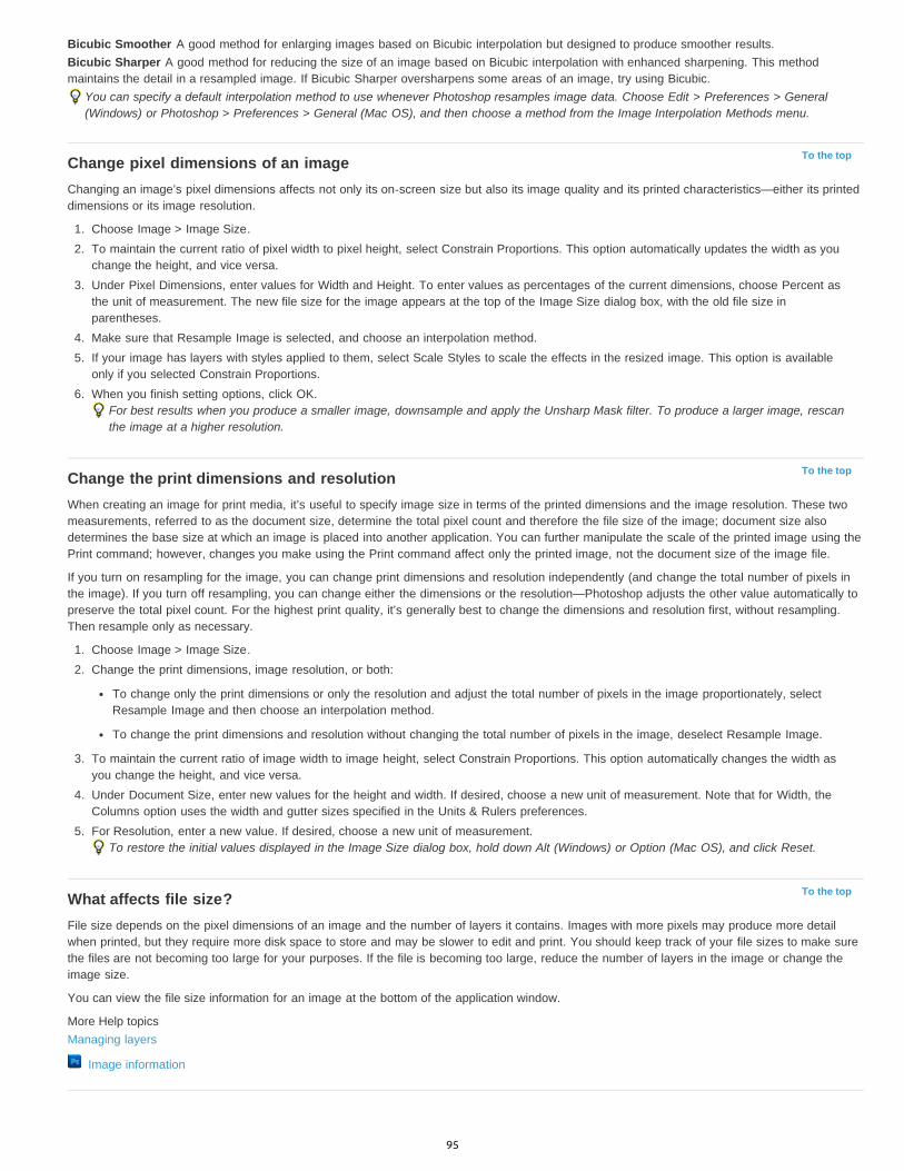
To the top
To the top
To the top
Bicubic Smoother A good method for enlarging images based on Bicubic interpolation but designed to produce smoother results.Bicubic Sharper A good method for reducing the size of an image based on Bicubic interpolation with enhanced sharpening. This methodmaintains the detail in a resampled image. If Bicubic Sharper oversharpens some areas of an image, try using Bicubic.
You can specify a default interpolation method to use whenever Photoshop resamples image data. Choose Edit > Preferences > General(Windows) or Photoshop > Preferences > General (Mac OS), and then choose a method from the Image Interpolation Methods menu.
Change pixel dimensions of an imageChanging an image’s pixel dimensions affects not only its on-screen size but also its image quality and its printed characteristics—either its printeddimensions or its image resolution.
1. Choose Image > Image Size.2. To maintain the current ratio of pixel width to pixel height, select Constrain Proportions. This option automatically updates the width as you
change the height, and vice versa.3. Under Pixel Dimensions, enter values for Width and Height. To enter values as percentages of the current dimensions, choose Percent as
the unit of measurement. The new file size for the image appears at the top of the Image Size dialog box, with the old file size inparentheses.
4. Make sure that Resample Image is selected, and choose an interpolation method.5. If your image has layers with styles applied to them, select Scale Styles to scale the effects in the resized image. This option is available
only if you selected Constrain Proportions.6. When you finish setting options, click OK.
For best results when you produce a smaller image, downsample and apply the Unsharp Mask filter. To produce a larger image, rescanthe image at a higher resolution.
Change the print dimensions and resolutionWhen creating an image for print media, it’s useful to specify image size in terms of the printed dimensions and the image resolution. These twomeasurements, referred to as the document size, determine the total pixel count and therefore the file size of the image; document size alsodetermines the base size at which an image is placed into another application. You can further manipulate the scale of the printed image using thePrint command; however, changes you make using the Print command affect only the printed image, not the document size of the image file.
If you turn on resampling for the image, you can change print dimensions and resolution independently (and change the total number of pixels inthe image). If you turn off resampling, you can change either the dimensions or the resolution—Photoshop adjusts the other value automatically topreserve the total pixel count. For the highest print quality, it’s generally best to change the dimensions and resolution first, without resampling.Then resample only as necessary.
1. Choose Image > Image Size.2. Change the print dimensions, image resolution, or both:
To change only the print dimensions or only the resolution and adjust the total number of pixels in the image proportionately, selectResample Image and then choose an interpolation method.
To change the print dimensions and resolution without changing the total number of pixels in the image, deselect Resample Image.
3. To maintain the current ratio of image width to image height, select Constrain Proportions. This option automatically changes the width asyou change the height, and vice versa.
4. Under Document Size, enter new values for the height and width. If desired, choose a new unit of measurement. Note that for Width, theColumns option uses the width and gutter sizes specified in the Units & Rulers preferences.
5. For Resolution, enter a new value. If desired, choose a new unit of measurement.To restore the initial values displayed in the Image Size dialog box, hold down Alt (Windows) or Option (Mac OS), and click Reset.
What affects file size?File size depends on the pixel dimensions of an image and the number of layers it contains. Images with more pixels may produce more detailwhen printed, but they require more disk space to store and may be slower to edit and print. You should keep track of your file sizes to make surethe files are not becoming too large for your purposes. If the file is becoming too large, reduce the number of layers in the image or change theimage size.
You can view the file size information for an image at the bottom of the application window.
More Help topicsManaging layers
Image information
95
Acquiring images from cameras and scanners
To the top
To the top
To the top
Acquiring digital images from camerasImport images from a digital camera using WIA (Windows only)Importing scanned images
Acquiring digital images from camerasYou can copy images to your computer by connecting your camera or a media card reader to your computer.
Use theGet Photos From Camera command in Adobe® Bridge® to download photos, and to organize, rename, and apply metadata to them.
If your camera or the card reader appears as a drive on your computer, copy images directly to your hard disk or into Adobe Bridge.
Use the software that came with your camera, Windows Image Acquisition (WIA), or Image Capture (Mac OS). For more information on usingWindows Image Acquisition or Image Capture, see your computer documentation.
Import images from a digital camera using WIA (Windows only)Certain digital cameras import images using Windows Image Acquisition (WIA) support. When you use WIA, Photoshop works with Windows andyour digital camera or scanner software to import images directly into Photoshop.
1. Choose File > Import > WIA Support.2. Choose a destination in which to save your image files on your computer.3. Make sure that Open Acquired Images in Photoshop is selected. If you are importing a large number of images, or if you want to edit the
images later, deselect Open Acquired Images.4. To save the imported images directly into a folder whose name is the current date, select Unique Subfolder.5. Click Start.6. Select the digital camera from which to import images.
Note: If the name of your camera does not appear in the submenu, verify that the software and drivers were properly installed and that thecamera is connected.
7. Choose the image or images you want to import:
Click the image from the list of thumbnails to import the image.
Hold down Shift and click multiple images to import them at the same time.
Click Select All to import all available images.
8. Click Get Picture to import the image.
Importing scanned imagesTo import scanned images, either open TIFF files saved from separate scanning software, or use a TWAIN or WIA interface directly in Photoshop.In either case, make sure to install the software necessary for your scanner. For installation instructions, see the documentation provided by thescanner manufacturer.
Note: Scanner drivers are supported by the scanner manufacturer, not Adobe. If you have problems with scanning, make sure that you are usingthe latest version of the scanner driver and software.
Import images from a separate scanning applicationMost scanners come with software you can run outside of Photoshop, providing identical scanning options and quality. This method avoids issuescaused by outdated TWAIN drivers. It can also improve efficiency, letting you edit images in Photoshop while scanning continues in thebackground.
1. Start the scanning software, and set options as desired. (In Mac OS, you can also use the Image Capture utility.)
2. Save scanned images in TIFF format.
3. In Photoshop, open the saved TIFF files.
Some scanner software lets you designate Photoshop as the external editor for an image after a scanning is completed.
96

Import images using a TWAIN interfaceTWAIN is a cross-platform interface for acquiring images captured by certain scanners, digital cameras, and frame grabbers.
1. Install the TWAIN software provided by the device manufacturer.2. Download the Photoshop TWAIN plug-in for Windows or Mac OS.
The plug-in supports 32-bit Windows and Mac OS. It also supports 64-bit Mac OS 10.6 if the scanner manufacturer provides 64-bit drivers.(Very few do, so most Mac OS users must run Photoshop in 32-bit mode.)
3. Choose File > Import, and select the device you want to use from the submenu.
Import images using a WIA interface (Windows only)1. Choose File > Import > WIA Support.2. Choose a destination on your computer for saving your image files.3. Click Start.4. Select Open Acquired Images In Photoshop (unless you have a large number of images to import, or if you want to edit the images at a later
time).5. Select Unique Subfolder if you want to save imported images in a folder named with the current date.6. Select the scanner that you want to use.
Note: If the name of your scanner does not appear in the submenu, verify that the software and drivers were properly installed and that thescanner is connected.
7. Choose the kind of image you want to scan: Color Picture, Grayscale Picture, or Black And White Picture or Text.To specify custom settings, select Adjust The Quality Of The Scanned Picture.
8. Click Preview. If necessary, drag the handles of the bounding box to adjust the size of the crop.9. Click Scan.
The scanned image is saved in BMP format.
More Help topics Get photos from a digital camera or card reader into Adobe Bridge
Navigate, open, and save images in Camera Raw
Legal Notices | Online Privacy Policy
97
Creating, opening, and importing images
To the top
To the top
To the top
Create an imageDuplicate an imageOpen filesOpen PDF filesOpen an EPS file
For detailed instructions, click the links below. To ask questions, request features, or report problems, visit feedback.photoshop.com.
Create an image1. Choose File > New.2. In the New dialog box, type a name for the image.3. (Optional) Choose document size from the Preset menu.
Note: To create a document with the pixel dimensions set for a specific device, click the Device Central button.4. Set the width and height by choosing a preset from the Size menu or entering values in the Width and Height text boxes.
To match the width, height, resolution, color mode, and bit depth of the new image to that of any open image, choose a filename from thebottom section of the Preset menu.
5. Set the Resolution, Color Mode, and bit depth.
If you’ve copied a selection to the clipboard, the image dimensions and resolution are automatically based on that image data.
6. Select a canvas color option:White Fills the background layer with white, the default background color.
Background Color Fills the background layer with the current background color.
Transparent Makes the first layer transparent, with no color values. The resulting document has a single, transparent layer as its contents.
7. (Optional) If necessary, click the Advanced button to display more options.8. (Optional) Under Advanced, choose a color profile, or choose Don’t Color Manage This Document. For Pixel Aspect Ratio, choose Square
unless you’re using the image for video. In that case, choose another option to use non-square pixels.9. When you finish, you can save the settings as a preset by clicking Save Preset, or you can click OK to open the new file.
Duplicate an imageYou can duplicate an entire image (including all layers, layer masks, and channels) into available memory without saving to disk.
1. Open the image you want to duplicate.2. Choose Image > Duplicate.3. Enter a name for the duplicated image.4. If you want to duplicate the image and merge the layers, select Duplicate Merged Layers Only. To preserve the layers, make sure this
option is deselected.5. Click OK.
Open filesYou can open files using the Open command and Open Recent command. You can also open files into Photoshop from Adobe Bridge or Adobe®Photoshop® Lightroom™.
When opening certain files, such as camera raw and PDF, you specify settings and options in a dialog box before the files completely open inPhotoshop.
In addition to still images, Photoshop® Extended users can open and edit 3D files, video and image sequence files. For more information, seeImporting video files and image sequences.
Note: Photoshop uses plug-in modules to open and import many file formats. If a file format does not appear in the Open dialog box or in theFile > Import submenu, you may need to install the format’s plug-in module.Sometimes Photoshop may not be able to determine the correct format for a file. This can happen, for example, because the file has beentransferred between two operating systems. Sometimes a transfer between Mac OS and Windows can cause the file format to be mislabeled.
98

To the top
In such cases, you must specify the correct format in which to open the file.
You can retain (where possible) layers, masks, transparency, compound shapes, slices, image maps, and editable type when bringing yourIllustrator art into Photoshop. In Illustrator, export the art in the Photoshop (PSD) file format. If your Illustrator art contains elements thatPhotoshop doesn’t support, the appearance of the artwork is preserved, but the layers are merged and the artwork is rasterized.
Open a file using the Open command1. Choose File > Open.2. Select the name of the file you want to open. If the file does not appear, select the option for showing all files from the Files Of Type
(Windows) or Enable (Mac OS) pop-up menu.3. Click Open. In some cases, a dialog box appears, letting you set format-specific options.
Note: If a color profile warning message appears, specify whether to use embedded profile as the working space, convert the documentcolor to working space, or reverse the embedded profile. For more information, see Color-managing imported images.
Open a recently used file Choose File > Open Recent, and select a file from the submenu.
Note: To specify the number of files listed in the Open Recent menu, change the Recent File List Contains option in the File Handlingpreferences. Choose Edit > Preferences > File Handling (Windows), or Photoshop > Preferences > File Handling (Mac OS).
Specify the file format in which to open a fileIf a file was saved with an extension that doesn’t match its true format (for example, a PSD file saved with a .gif extension), or has no extension,Photoshop may not be able to open the file. Selecting the correct format will allow Photoshop to recognize and open the file.
Do one of the following:
(Windows) Choose File > Open As, and select the file you want to open. Then choose the desired format from the Open As pop-up menu,and click Open.
(Mac OS) Choose File > Open, and choose All Documents from the Show pop-up menu. Then select the file you want to open, choose thedesired file format from the Format pop-up menu, and click Open.
Note: If the file does not open, then the chosen format may not match the file’s true format, or the file may be damaged.
Open PDF filesAdobe Portable Document Format (PDF) is a versatile file format that can represent both vector and bitmap data. It has electronic documentsearch and navigation features. PDF is the primary format for Adobe Illustrator and Adobe Acrobat.
Some PDF files contain a single image, and others contain multiple pages and images. When you open a PDF file in Photoshop, you can choosewhich pages or images to open and specify rasterization options.
You can also import PDF data using the Place command, the Paste command, and the drag-and-drop feature. The page or image is placed on aseparate layer as a Smart Object.
Note: The following procedure is only for opening generic PDF files in Photoshop. You don’t need to specify options in the Import PDF dialog box,when opening Photoshop PDF files.
1. Do one of the following:
(Photoshop) Choose File > Open.
(Bridge) Select the PDF file and choose File >Open With > Adobe Photoshop. Skip to step 3.
2. In the Open dialog box, select the name of the file, and click Open.3. Under Select in the Import PDF dialog box, select Pages or Images, depending on what elements of the PDF document you want to import.4. Click the thumbnails to select the pages or images you want to open. Shift-click to select more than one page or image. The number of
selected items appears under the preview window. If you’re importing images, skip to step 8.Note: Use the Thumbnail Size menu to adjust the thumbnail view in the preview window. The Fit Page option fits one thumbnail in thepreview window. A scroll bar appears if there are multiple items.
5. To give the new document a name, type it in the Name text box. If you’re importing more than one page or image, multiple documents openwith the base name followed by a number.
6. Under Page Options, choose from the Crop To menu to specify what part of the PDF document to include:Bounding Box Crops to the smallest rectangular region that includes all the text and graphics of the page. This option eliminatesextraneous white space and any document elements outside the Trim Box.Note: Bounding Box will not crop white space that is part of a background created by the source application.
Media Box Crops to the original size of the page.
Crop Box Crops to the clipping region (crop margins) of the PDF file.
Bleed Box Crops to the region specified in the PDF file for accommodating limitations inherent in production processes such as cutting,folding, and trimming.
99
To the top
Trim Box Crops to the region specified for the intended finished size of the page.
Art Box Crops to the region specified in the PDF file for placing the PDF data into another application.
7. Under Image Size, enter values (if necessary) for Width and Height:
To preserve the aspect ratio of the pages as they’re scaled to fit within the rectangle defined by the Width and Height values, selectConstrain Proportions.
To scale the pages exactly to the Width and Height values, deselect Constrain Proportions. Some distortion might occur when the pagesare scaled.
When more than one page is selected, the Width and Height text boxes display the maximum width and height values of the selectedpages. All pages are rendered at their original size if Constrain Proportions is selected and you don’t change the Width and Height values.Changing the values will scale all pages proportionately as they're rasterized.
8. Specify the following options under Image Size:Resolution Sets the resolution for the new document. See also About pixel dimensions and printed image resolution.
Mode Sets the color mode for the new document. See also Color modes.
Bit Depth Sets the bit depth for the new document. See also Bit depth.
The Width and Height values plus the Resolution determine the final pixel dimension of resulting document.
9. To suppress color profile warnings, select Suppress Warning.10. Click OK.
Open an EPS fileEncapsulated PostScript (EPS) can represent both vector and bitmap data and is supported by virtually all graphic, illustration, and page-layoutprograms. The Adobe application that primarily produces PostScript artwork is Adobe Illustrator. When you open an EPS file containing vector art,it is rasterized—the mathematically defined lines and curves of the vector artwork are converted into the pixels or bits of a bitmap image.
You can also bring PostScript artwork into Photoshop using the Place command, the Paste command, and the drag-and-drop feature.
1. Choose File > Open.2. Select the file you want to open, and click Open.3. Indicate the desired dimensions, resolution, and mode. To maintain the same height-to-width ratio, select Constrain Proportions.4. To minimize jagged lines at the edges of artwork, select Anti-aliased.
More Help topics Adobe Bridge
Mini Bridge
Processing images with Camera Raw
Legal Notices | Online Privacy Policy
100
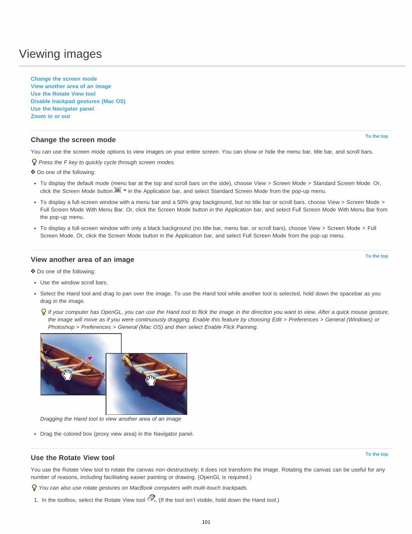
Viewing images
To the top
To the top
To the top
Change the screen modeView another area of an imageUse the Rotate View toolDisable trackpad gestures (Mac OS)Use the Navigator panelZoom in or out
Change the screen modeYou can use the screen mode options to view images on your entire screen. You can show or hide the menu bar, title bar, and scroll bars.
Press the F key to quickly cycle through screen modes.
Do one of the following:
To display the default mode (menu bar at the top and scroll bars on the side), choose View > Screen Mode > Standard Screen Mode. Or,click the Screen Mode button in the Application bar, and select Standard Screen Mode from the pop-up menu.
To display a full-screen window with a menu bar and a 50% gray background, but no title bar or scroll bars, choose View > Screen Mode >Full Screen Mode With Menu Bar. Or, click the Screen Mode button in the Application bar, and select Full Screen Mode With Menu Bar fromthe pop-up menu.
To display a full-screen window with only a black background (no title bar, menu bar, or scroll bars), choose View > Screen Mode > FullScreen Mode. Or, click the Screen Mode button in the Application bar, and select Full Screen Mode from the pop-up menu.
View another area of an image Do one of the following:
Use the window scroll bars.
Select the Hand tool and drag to pan over the image. To use the Hand tool while another tool is selected, hold down the spacebar as youdrag in the image.
If your computer has OpenGL, you can use the Hand tool to flick the image in the direction you want to view. After a quick mouse gesture,the image will move as if you were continuously dragging. Enable this feature by choosing Edit > Preferences > General (Windows) orPhotoshop > Preferences > General (Mac OS) and then select Enable Flick Panning.
Dragging the Hand tool to view another area of an image
Drag the colored box (proxy view area) in the Navigator panel.
Use the Rotate View toolYou use the Rotate View tool to rotate the canvas non-destructively; it does not transform the image. Rotating the canvas can be useful for anynumber of reasons, including facilitating easier painting or drawing. (OpenGL is required.)
You can also use rotate gestures on MacBook computers with multi-touch trackpads.
1. In the toolbox, select the Rotate View tool . (If the tool isn’t visible, hold down the Hand tool.)
101
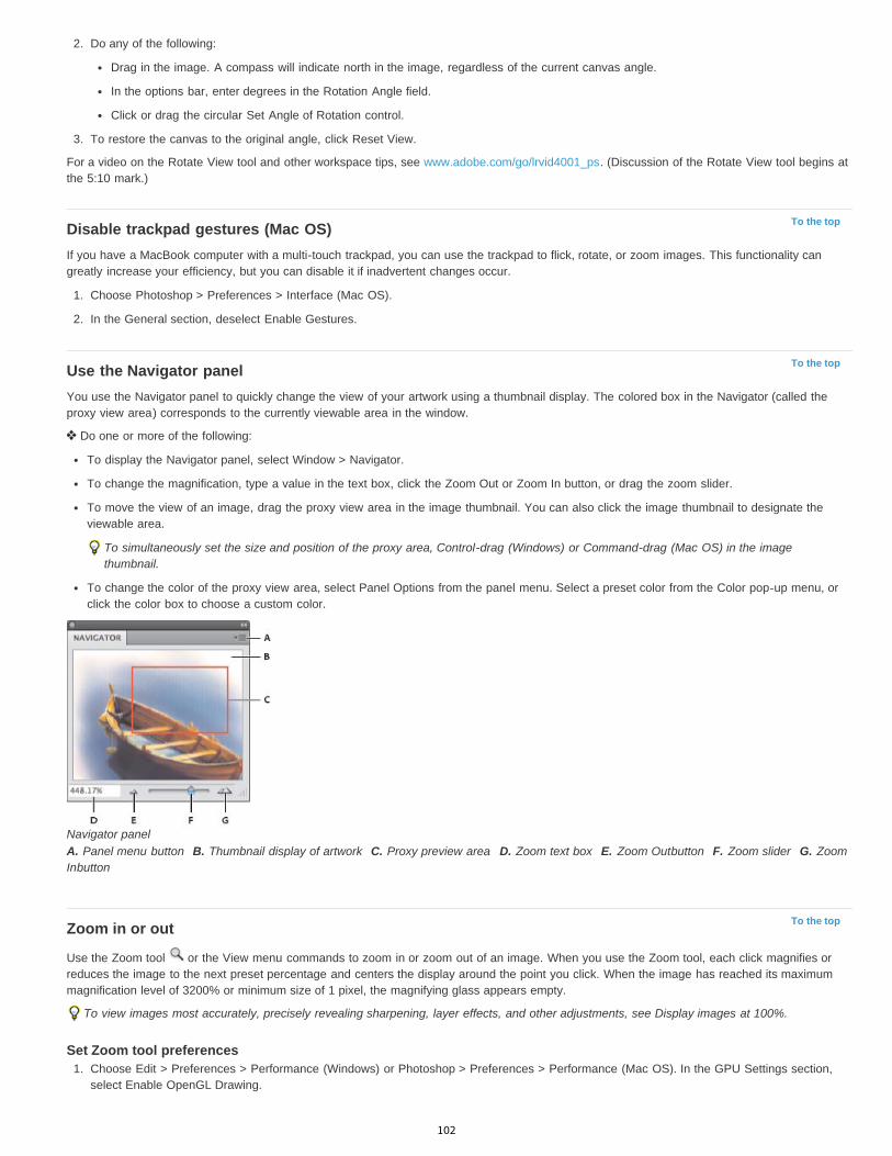
To the top
To the top
To the top
2. Do any of the following:
Drag in the image. A compass will indicate north in the image, regardless of the current canvas angle.
In the options bar, enter degrees in the Rotation Angle field.
Click or drag the circular Set Angle of Rotation control.
3. To restore the canvas to the original angle, click Reset View.
For a video on the Rotate View tool and other workspace tips, see www.adobe.com/go/lrvid4001_ps. (Discussion of the Rotate View tool begins atthe 5:10 mark.)
Disable trackpad gestures (Mac OS)If you have a MacBook computer with a multi-touch trackpad, you can use the trackpad to flick, rotate, or zoom images. This functionality cangreatly increase your efficiency, but you can disable it if inadvertent changes occur.
1. Choose Photoshop > Preferences > Interface (Mac OS).
2. In the General section, deselect Enable Gestures.
Use the Navigator panelYou use the Navigator panel to quickly change the view of your artwork using a thumbnail display. The colored box in the Navigator (called theproxy view area) corresponds to the currently viewable area in the window.
Do one or more of the following:
To display the Navigator panel, select Window > Navigator.
To change the magnification, type a value in the text box, click the Zoom Out or Zoom In button, or drag the zoom slider.
To move the view of an image, drag the proxy view area in the image thumbnail. You can also click the image thumbnail to designate theviewable area.
To simultaneously set the size and position of the proxy area, Control-drag (Windows) or Command-drag (Mac OS) in the imagethumbnail.
To change the color of the proxy view area, select Panel Options from the panel menu. Select a preset color from the Color pop-up menu, orclick the color box to choose a custom color.
Navigator panelA. Panel menu button B. Thumbnail display of artwork C. Proxy preview area D. Zoom text box E. Zoom Outbutton F. Zoom slider G. ZoomInbutton
Zoom in or out
Use the Zoom tool or the View menu commands to zoom in or zoom out of an image. When you use the Zoom tool, each click magnifies orreduces the image to the next preset percentage and centers the display around the point you click. When the image has reached its maximummagnification level of 3200% or minimum size of 1 pixel, the magnifying glass appears empty.
To view images most accurately, precisely revealing sharpening, layer effects, and other adjustments, see Display images at 100%.
Set Zoom tool preferences1. Choose Edit > Preferences > Performance (Windows) or Photoshop > Preferences > Performance (Mac OS). In the GPU Settings section,
select Enable OpenGL Drawing.
102
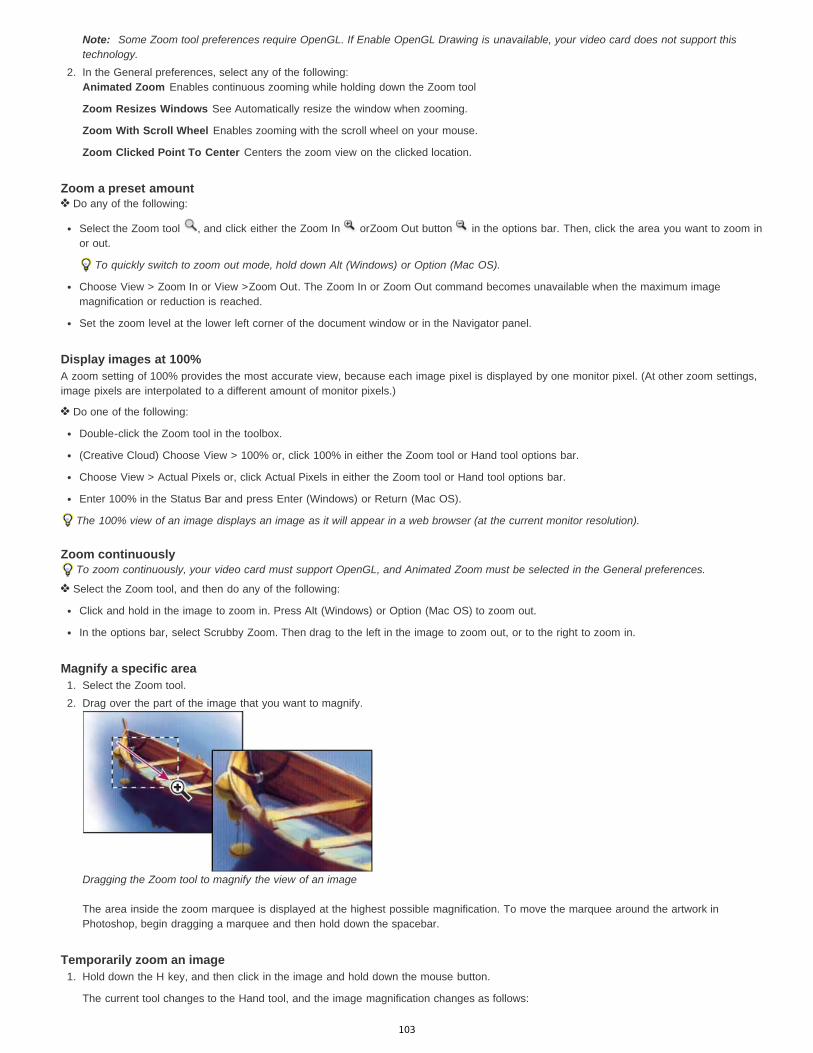
Note: Some Zoom tool preferences require OpenGL. If Enable OpenGL Drawing is unavailable, your video card does not support thistechnology.
2. In the General preferences, select any of the following:Animated Zoom Enables continuous zooming while holding down the Zoom tool
Zoom Resizes Windows See Automatically resize the window when zooming.
Zoom With Scroll Wheel Enables zooming with the scroll wheel on your mouse.
Zoom Clicked Point To Center Centers the zoom view on the clicked location.
Zoom a preset amount Do any of the following:
Select the Zoom tool , and click either the Zoom In orZoom Out button in the options bar. Then, click the area you want to zoom inor out.
To quickly switch to zoom out mode, hold down Alt (Windows) or Option (Mac OS).
Choose View > Zoom In or View >Zoom Out. The Zoom In or Zoom Out command becomes unavailable when the maximum imagemagnification or reduction is reached.
Set the zoom level at the lower left corner of the document window or in the Navigator panel.
Display images at 100%A zoom setting of 100% provides the most accurate view, because each image pixel is displayed by one monitor pixel. (At other zoom settings,image pixels are interpolated to a different amount of monitor pixels.)
Do one of the following:
Double-click the Zoom tool in the toolbox.
(Creative Cloud) Choose View > 100% or, click 100% in either the Zoom tool or Hand tool options bar.
Choose View > Actual Pixels or, click Actual Pixels in either the Zoom tool or Hand tool options bar.
Enter 100% in the Status Bar and press Enter (Windows) or Return (Mac OS).
The 100% view of an image displays an image as it will appear in a web browser (at the current monitor resolution).
Zoom continuouslyTo zoom continuously, your video card must support OpenGL, and Animated Zoom must be selected in the General preferences.
Select the Zoom tool, and then do any of the following:
Click and hold in the image to zoom in. Press Alt (Windows) or Option (Mac OS) to zoom out.
In the options bar, select Scrubby Zoom. Then drag to the left in the image to zoom out, or to the right to zoom in.
Magnify a specific area1. Select the Zoom tool.2. Drag over the part of the image that you want to magnify.
Dragging the Zoom tool to magnify the view of an image
The area inside the zoom marquee is displayed at the highest possible magnification. To move the marquee around the artwork inPhotoshop, begin dragging a marquee and then hold down the spacebar.
Temporarily zoom an image1. Hold down the H key, and then click in the image and hold down the mouse button.
The current tool changes to the Hand tool, and the image magnification changes as follows:
103
If the entire image originally fit within the document window, the image zooms in to fit the window.
If only a portion of the image was originally visible, the image zooms out. Drag the zoom marquee to magnify a different part of theimage.
2. Release the mouse button and then the H key.
The image returns to the previous magnification and tool.
Automatically resize the window when zooming With the Zoom tool active, select Resize Windows To Fit in the options bar. The window is resized when you magnify or reduce the view of the
image.When Resize Windows To Fit is deselected (the default), the window maintains a constant size regardless of the image magnification. This can behelpful when using smaller monitors or working with tiled views.
Note: To automatically resize the window when using keyboard shortcuts for zooming, choose Edit > Preferences > General (Windows) orPhotoshop > Preferences > General (Mac OS). Then select the Zoom Resizes Windows.
Fit an image to the screen Do one of the following:
Double-click the Hand tool in the toolbox.
Choose View > Fit On Screen.
Select a zoom tool or the Hand tool, and click the Fit On Screen button in the options bar.
These options scale both the zoom level and the window size to fit the available screen space.
Hide the pixel gridOver 500% magnification, the image’s pixel grid becomes visible by default. To hide the grid, do the following.
Choose View > Show, and deselect Pixel Grid.
Legal Notices | Online Privacy Policy
104
Add swatches from HTML CSS and SVG
Twitter™ and Facebook posts are not covered under the terms of Creative Commons.
Legal Notices | Online Privacy Policy
Note: This feature was introduced in the Creative Cloud release for Photoshop CS6.
You can add all colors specified in an HTML, CSS, or SVG document to the Swatches panel. If a color value is repeated in a document, only oneinstance of the color is added not duplicates. This feature recognizes the following HTML/CSS color syntax: #112233, #123, rgb(1,2,3),rgba(1,2,3,4), hsb(1,2,3), and hsba(1,2,3,4).
1. In the Swatches panel, do one of the following:
Choose Load Swatches from the panel menu.Choose Replace Swatches from the panel menu.
2. In the Load window, navigate to the HTML, CSS, or SVG file, select it, and then, click Load.
For more information, see Customizing color pickers and swatches.
105

High dynamic range images
To the top
To the top
About high dynamic range imagesTake photos for HDR imagesFeatures that support 32-bpc HDR imagesMerge images to HDRAdjust displayed dynamic range for 32-bit HDR imagesAbout the HDR Color PickerPaint on HDR images
About high dynamic range imagesThe dynamic range (ratio between dark and bright regions) in the visible world far exceeds the range of human vision and of images that aredisplayed on a monitor or printed. But whereas human eyes can adapt to very different brightness levels, most cameras and computer monitorscan reproduce only a fixed dynamic range. Photographers, motion picture artists, and others working with digital images must be selective aboutwhat’s important in a scene because they are working with a limited dynamic range.
High dynamic range (HDR) images open up a world of possibilities because they can represent the entire dynamic range of the visible world.Because all the luminance values in a real-world scene are represented proportionately and stored in an HDR image, adjusting the exposure of anHDR image is like adjusting the exposure when photographing a scene in the real world.
Merging images of different exposures to create an HDR imageA. Image with shadow detail but highlights clipped B. Image with highlight detail but shadows clipped C. HDR image containing the dynamicrange of the scene
In Photoshop, the luminance values of an HDR image are stored using a floating-point numeric representation that’s 32 bits long (32-bits-per-channel). The luminance values in an HDR image are directly related to the amount of light in a scene. By contrast, non-floating point 16- and8-bpc image files store luminance values only from black to paper white, reflecting an extremely small segment of dynamic range in the real world.
In Photoshop, the Merge To HDR Pro command lets you create HDR images by combining multiple photographs captured at different exposures.Because an HDR image contains brightness levels that far exceed the display capabilities of a standard 24-bit monitor, Photoshop lets you adjustthe HDR preview. If you need to print or use tools and filters that don’t work with HDR images, you can convert them to 16- or 8-bpc images.
Take photos for HDR imagesKeep the following tips in mind when you take photos to be combined with the Merge To HDR Pro command:
106
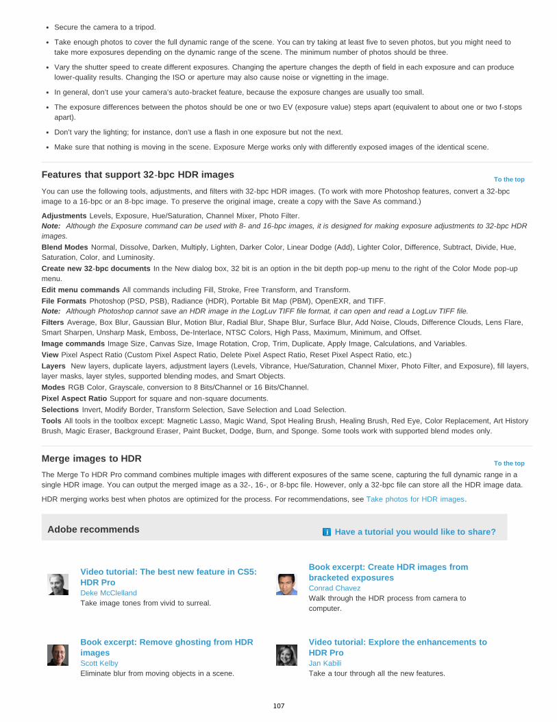
To the top
To the top
Secure the camera to a tripod.
Take enough photos to cover the full dynamic range of the scene. You can try taking at least five to seven photos, but you might need totake more exposures depending on the dynamic range of the scene. The minimum number of photos should be three.
Vary the shutter speed to create different exposures. Changing the aperture changes the depth of field in each exposure and can producelower-quality results. Changing the ISO or aperture may also cause noise or vignetting in the image.
In general, don’t use your camera’s auto-bracket feature, because the exposure changes are usually too small.
The exposure differences between the photos should be one or two EV (exposure value) steps apart (equivalent to about one or two f-stopsapart).
Don’t vary the lighting; for instance, don’t use a flash in one exposure but not the next.
Make sure that nothing is moving in the scene. Exposure Merge works only with differently exposed images of the identical scene.
Features that support 32-bpc HDR imagesYou can use the following tools, adjustments, and filters with 32-bpc HDR images. (To work with more Photoshop features, convert a 32-bpcimage to a 16-bpc or an 8-bpc image. To preserve the original image, create a copy with the Save As command.)
Adjustments Levels, Exposure, Hue/Saturation, Channel Mixer, Photo Filter.Note: Although the Exposure command can be used with 8- and 16-bpc images, it is designed for making exposure adjustments to 32-bpc HDRimages.Blend Modes Normal, Dissolve, Darken, Multiply, Lighten, Darker Color, Linear Dodge (Add), Lighter Color, Difference, Subtract, Divide, Hue,Saturation, Color, and Luminosity.Create new 32-bpc documents In the New dialog box, 32 bit is an option in the bit depth pop-up menu to the right of the Color Mode pop-upmenu.Edit menu commands All commands including Fill, Stroke, Free Transform, and Transform.File Formats Photoshop (PSD, PSB), Radiance (HDR), Portable Bit Map (PBM), OpenEXR, and TIFF.Note: Although Photoshop cannot save an HDR image in the LogLuv TIFF file format, it can open and read a LogLuv TIFF file.Filters Average, Box Blur, Gaussian Blur, Motion Blur, Radial Blur, Shape Blur, Surface Blur, Add Noise, Clouds, Difference Clouds, Lens Flare,Smart Sharpen, Unsharp Mask, Emboss, De-Interlace, NTSC Colors, High Pass, Maximum, Minimum, and Offset.Image commands Image Size, Canvas Size, Image Rotation, Crop, Trim, Duplicate, Apply Image, Calculations, and Variables.View Pixel Aspect Ratio (Custom Pixel Aspect Ratio, Delete Pixel Aspect Ratio, Reset Pixel Aspect Ratio, etc.)Layers New layers, duplicate layers, adjustment layers (Levels, Vibrance, Hue/Saturation, Channel Mixer, Photo Filter, and Exposure), fill layers,layer masks, layer styles, supported blending modes, and Smart Objects.Modes RGB Color, Grayscale, conversion to 8 Bits/Channel or 16 Bits/Channel.Pixel Aspect Ratio Support for square and non-square documents.Selections Invert, Modify Border, Transform Selection, Save Selection and Load Selection.Tools All tools in the toolbox except: Magnetic Lasso, Magic Wand, Spot Healing Brush, Healing Brush, Red Eye, Color Replacement, Art HistoryBrush, Magic Eraser, Background Eraser, Paint Bucket, Dodge, Burn, and Sponge. Some tools work with supported blend modes only.
Merge images to HDRThe Merge To HDR Pro command combines multiple images with different exposures of the same scene, capturing the full dynamic range in asingle HDR image. You can output the merged image as a 32-, 16-, or 8-bpc file. However, only a 32-bpc file can store all the HDR image data.
HDR merging works best when photos are optimized for the process. For recommendations, see Take photos for HDR images.
Adobe recommends Have a tutorial you would like to share?
Video tutorial: The best new feature in CS5:HDR ProDeke McClellandTake image tones from vivid to surreal.
Book excerpt: Create HDR images frombracketed exposuresConrad ChavezWalk through the HDR process from camera tocomputer.
Book excerpt: Remove ghosting from HDRimagesScott KelbyEliminate blur from moving objects in a scene.
Video tutorial: Explore the enhancements toHDR ProJan KabiliTake a tour through all the new features.
107

1. Do one of the following:
(Photoshop) Choose File > Automate > Merge To HDR Pro.
(Bridge) Select the images you want to use and choose Tools > Photoshop > Merge To HDR Pro. Skip to step 5.
2. In the Merge To HDR Pro dialog box, click Browse to select specific images, click Add Open Files, or choose Use > Folder. (To remove aparticular item, select it in files list, and click Remove.)
3. (Optional) Select Attempt To Automatically Align Source Images if you held the camera in your hands when you photographed the images.4. Click OK.
Note: If images lack exposure metadata, enter values in the Manually Set EV dialog box.
A second Merge To HDR Pro dialog box displays thumbnails of the source images, and a preview of the merged result.
5. To the upper right of the preview, choose a bit depth for the merged image.Choose 32 Bit if you want the merged image to store the entire dynamic range of the HDR image. 8-bit and (non-floating point) 16-bitimage files cannot store the entire range of luminance values in an HDR image.
6. To adjust the tonal range, see Options for 32-bit images or Options for 16- or 8-bit images.7. (Optional) To save your tonal settings for future use, choose Preset > Save Preset. (To later reapply the settings, choose Load Preset.)
Options for 32-bit imagesMove the slider below the histogram to adjust the white point preview of the merged image. Moving the slider adjusts the image preview only; allHDR image data remains in the merged file.
The preview adjustment is stored in the HDR file and applied whenever you open the file in Photoshop. To readjust the white point preview at anytime, choose View > 32-Bit Preview Options.
Options for 16- or 8-bit imagesHDR images contain luminance levels that far exceed the dynamic range that 16- or 8-bpc images can store. To produce an image with thedynamic range you want, adjust exposure and contrast when converting from 32-bpc to lower bit depths.
Choose one of the following tone-mapping methods:
Local Adaptation Adjusts HDR tonality by adjusting local brightness regions throughout the image.
Edge Glow Radius specifies the size of the local brightness regions. Strength specifies how far apart two pixels’ tonal values must bebefore they’re no longer part of the same brightness region.Tone and Detail Dynamic range is maximized at a Gamma setting of 1.0; lower settings emphasize midtones, while higher settingsemphasize highlights and shadows. Exposure values reflect f-stops. Drag the Detail slider to adjust sharpness and the Shadow andHighlight sliders to brighten or darken these regions.Color Vibrance adjusts the intensity of subtle colors, while minimizing clipping of highly saturated colors. Saturation adjusts the intensityof all colors from –100 (monochrome) to +100 (double saturation).Toning Curve Displays an adjustable curve over a histogram showing luminance values in the original, 32-bit HDR image. The red tickmarks along the horizontal axis are in one EV (approximately one f-stop) increments.Note: By default, the Toning Curve and Histogram limit and equalize your changes from point to point. To remove the limit and applymore extreme adjustments, select the Corner option after inserting a point on the curve. When you insert and move a second point, thecurve becomes angular.
Toning Curve and Histogram adjustment using the Corner option
A. Inserting a point and selecting the Corner option. B. Adjusting new point makes the curve angular at the point where theCorner option is used.
108
To the top
To the top
Equalize Histogram Compresses the dynamic range of the HDR image while trying to preserve some contrast. No further adjustments arenecessary; this method is automatic.Exposure and Gamma Lets you manually adjust the brightness and contrast of the HDR image. Move the Exposure slider to adjust gain and theGamma slider to adjust contrast.Highlight Compression Compresses the highlight values in the HDR image so they fall within the luminance values range of the 8- or 16-bpcimage file. No further adjustments are necessary; this method is automatic.
Compensate for moving objectsIf images have different content due to moving objects like cars, people, or foliage, select Remove Ghosts in the Merge To HDR Pro dialog box.
Photoshop displays a green outline around the thumbnail with the best tonal balance, identifying the base image. Moving objects found in otherimages are removed. (If movement occurs in very light or dark areas, click a different thumbnail where moving objects are better exposed toimprove results.)
For a tutorial on the Remove Ghosts option, see this video. (Discussion of Remove Ghosts begins at 3:00.)
Save or load camera response curvesResponse curves indicate how camera sensors interpret different levels of incoming light. By default, the Merge To HDR Pro dialog boxautomatically calculates a camera response curve based on the tonal range of images you are merging. You can save the current response curveand later apply it to another group of merged images.
In the upper-right corner of the Merge to HDR Pro dialog box, click the response curve menu , and then choose Save Response Curve. (Tolater reapply the curve, choose Load Response Curve.)
Convert from 32 bits to 16 or 8 bpcIf you originally created a 32-bit image during the Merge to HDR Pro process, you can later convert it to a 16- or 8-bit image.
1. Open a 32-bpc image in Photoshop, and choose Image > Mode > 16 Bits/Channel or 8 Bits/Channel.2. Adjust exposure and contrast to produce an image with the dynamic range you want. (See Options for 16- or 8-bit images.)3. Click OK to convert the 32-bit image.
Adjust displayed dynamic range for 32-bit HDR imagesThe dynamic range of HDR images exceeds the display capabilities of standard computer monitors. When you open an HDR image in Photoshop,it can look very dark or washed out. Photoshop lets you adjust the preview so that the monitor displays an HDR image whose highlights andshadows aren’t washed out or too dark. The preview settings are stored in the HDR image file (PSD, PSB, and TIFF only) and are appliedwhenever the file is opened in Photoshop. Preview adjustments don’t edit the HDR image file; all the HDR image information remains intact. Usethe Exposure adjustment (Image > Adjustments > Exposure) to make exposure edits to the 32-bpc HDR image.
To view 32-bit readouts in the Info panel, click the Eyedropper icon in the Info panel and choose 32-Bit from the pop-up menu.
1. Open a 32-bpc HDR image in Photoshop, and choose View > 32-Bit Preview Options.2. In the 32-bit Preview Options dialog box, choose an option from the Method menu:
Exposure And Gamma Adjusts the brightness and contrast.
Highlight Compression Compresses the highlight values in the HDR image so they fall within the luminance values range of the 8- or16-bpc image file.
3. If you chose Exposure And Gamma, move the Exposure and Gamma sliders to adjust the brightness and contrast of the image preview.4. Click OK.
You can also adjust the preview of an HDR image open in Photoshop by clicking the triangle in the status bar of the document windowand choosing 32-Bit Exposure from the pop-up menu. Move the slider to set the white point for viewing the HDR image. Double-click theslider to return to the default exposure setting. Since the adjustment is made per view, you can have the same HDR image open inmultiple windows, each with a different preview adjustment. Preview adjustments made with this method are not stored in the HDR imagefile.
About the HDR Color PickerThe HDR Color Picker allows you to accurately view and select colors for use in 32-bit HDR images. As in the regular Adobe Color Picker, youselect a color by clicking a color field and adjusting the color slider. The Intensity slider allows you to adjust the brightness of a color to match theintensity of the colors in the HDR image you’re working with. A Preview area lets you view swatches of a selected color to see how it will display atdifferent exposures and intensities.
109

HDR Color PickerA. Preview area B. Adjusted color C. Original color D. 32-bit floating point values E. Intensity slider F. Picked color G. Color slider H. Colorvalues
Display the HDR Color Picker With a 32-bpc image open, do one of the following:
In the toolbox, click the foreground or background color selection box.
In the Color panel, click the Set Foreground Coloror Set Background Color selection box.
The Color Picker is also available when features let you choose a color. For example, by clicking the color swatch in the options bar for sometools, or the eyedroppers in some color adjustment dialog boxes.
Choose colors for HDR imagesThe lower part of the HDR Color Picker functions like the regular Color Picker does with 8- or 16-bit images. Click in the color field to select acolor and move the color slider to change hues, or use the HSB or RGB fields to enter numeric values for a particular color. In the color field,brightness increases as you move from bottom to top, and saturation increases as you move from left to right.
Use the Intensity slider to adjust the brightness of the color. The color value plus the intensity value are converted to 32-bit floating point numbervalues in your HDR document.
1. Select a color by clicking in the color field and moving the color slider, or by entering HSB or RGB numeric values, as in the Adobe ColorPicker.
2. Adjust the Intensity slider to boost or reduce the color’s brightness. The new color swatch in the Preview scale at the top of the Color Pickershows the effect of increasing or decreasing stops for the selected color.
The Intensity Stops correspond inversely to exposure setting stops. If you boost the Exposure setting of the HDR image two stops, reducingthe Intensity stops by two will maintain the same color appearance as if the HDR image exposure and the color intensity were both set to 0.
If you know the exact 32-bit RGB values for the color you want, you can enter them directly in the 32-bit value RGB fields.
3. (Optional) Adjust settings for the Preview area.Preview Stop Size Sets the stop increments for each preview swatch. For example, a setting of 3 results in swatches of -9, -6, -3, +3, +6,+9. These swatches let you preview the appearance of your selected color at different exposure settings.
Relative to Document Select to adjust the preview swatches to reflect the current exposure setting for the image. For example, if thedocument exposure is set higher, the new preview swatch will be lighter than the color selected in the Color Picker’s color field, to show theeffect of the higher exposure on the selected color. If the current exposure is set to 0 (the default), checking or unchecking this option willnot change the new swatch.
4. (Optional) Click Add to Swatches to add the selected color to the Swatches panel.5. Click OK.
110
;
To the topPaint on HDR imagesYou can edit and add effects to HDR/32-bpc images using any of the following Photoshop tools: Brush, Pencil, Pen, Shape, Clone Stamp, PatternStamp, Eraser, Gradient, Blur, Sharpen, Smudge, and History Brush. You can also use the Text tool to add 32-bpc text layers to an HDR image.
When editing or painting on HDR images, you can preview your work at different exposure settings using either the 32-Bit Exposure slider in thedocument info area or the 32-Bit Preview Options dialog box (View > 32-Bit Preview Options). The HDR Color Picker also lets you preview yourselected foreground color at different intensity settings, to match different exposure settings in an HDR image.
1. Open an HDR image.2. (Optional) Set the exposure for the image. See Adjust displayed dynamic range for 32-bit HDR images.3. For the Brush or Pencil tools, click the foreground color to open the HDR Color Picker and select a color. For the Text tool, click the color
chip in the Text tool options bar to set the text color.The Preview area of the HDR Color Picker helps you select and adjust a foreground color in relation to different exposure settings in theHDR image. See About the HDR Color Picker.
To view the effects of painting at different HDR exposures, use the Window > Arrange > New Window command to open simultaneousviews of the same HDR image, then set each window to a different exposure using the Exposure slider in the document status bar area.
More Help topicsCurves overview
Adobe Color Picker overview
Adjust HDR exposure and toning
Legal Notices | Online Privacy Policy
111
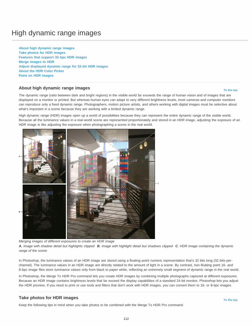
High dynamic range images
To the top
To the top
About high dynamic range imagesTake photos for HDR imagesFeatures that support 32-bpc HDR imagesMerge images to HDRAdjust displayed dynamic range for 32-bit HDR imagesAbout the HDR Color PickerPaint on HDR images
About high dynamic range imagesThe dynamic range (ratio between dark and bright regions) in the visible world far exceeds the range of human vision and of images that aredisplayed on a monitor or printed. But whereas human eyes can adapt to very different brightness levels, most cameras and computer monitorscan reproduce only a fixed dynamic range. Photographers, motion picture artists, and others working with digital images must be selective aboutwhat’s important in a scene because they are working with a limited dynamic range.
High dynamic range (HDR) images open up a world of possibilities because they can represent the entire dynamic range of the visible world.Because all the luminance values in a real-world scene are represented proportionately and stored in an HDR image, adjusting the exposure of anHDR image is like adjusting the exposure when photographing a scene in the real world.
Merging images of different exposures to create an HDR imageA. Image with shadow detail but highlights clipped B. Image with highlight detail but shadows clipped C. HDR image containing the dynamicrange of the scene
In Photoshop, the luminance values of an HDR image are stored using a floating-point numeric representation that’s 32 bits long (32-bits-per-channel). The luminance values in an HDR image are directly related to the amount of light in a scene. By contrast, non-floating point 16- and8-bpc image files store luminance values only from black to paper white, reflecting an extremely small segment of dynamic range in the real world.
In Photoshop, the Merge To HDR Pro command lets you create HDR images by combining multiple photographs captured at different exposures.Because an HDR image contains brightness levels that far exceed the display capabilities of a standard 24-bit monitor, Photoshop lets you adjustthe HDR preview. If you need to print or use tools and filters that don’t work with HDR images, you can convert them to 16- or 8-bpc images.
Take photos for HDR imagesKeep the following tips in mind when you take photos to be combined with the Merge To HDR Pro command:
112

To the top
To the top
Secure the camera to a tripod.
Take enough photos to cover the full dynamic range of the scene. You can try taking at least five to seven photos, but you might need totake more exposures depending on the dynamic range of the scene. The minimum number of photos should be three.
Vary the shutter speed to create different exposures. Changing the aperture changes the depth of field in each exposure and can producelower-quality results. Changing the ISO or aperture may also cause noise or vignetting in the image.
In general, don’t use your camera’s auto-bracket feature, because the exposure changes are usually too small.
The exposure differences between the photos should be one or two EV (exposure value) steps apart (equivalent to about one or two f-stopsapart).
Don’t vary the lighting; for instance, don’t use a flash in one exposure but not the next.
Make sure that nothing is moving in the scene. Exposure Merge works only with differently exposed images of the identical scene.
Features that support 32-bpc HDR imagesYou can use the following tools, adjustments, and filters with 32-bpc HDR images. (To work with more Photoshop features, convert a 32-bpcimage to a 16-bpc or an 8-bpc image. To preserve the original image, create a copy with the Save As command.)
Adjustments Levels, Exposure, Hue/Saturation, Channel Mixer, Photo Filter.Note: Although the Exposure command can be used with 8- and 16-bpc images, it is designed for making exposure adjustments to 32-bpc HDRimages.Blend Modes Normal, Dissolve, Darken, Multiply, Lighten, Darker Color, Linear Dodge (Add), Lighter Color, Difference, Subtract, Divide, Hue,Saturation, Color, and Luminosity.Create new 32-bpc documents In the New dialog box, 32 bit is an option in the bit depth pop-up menu to the right of the Color Mode pop-upmenu.Edit menu commands All commands including Fill, Stroke, Free Transform, and Transform.File Formats Photoshop (PSD, PSB), Radiance (HDR), Portable Bit Map (PBM), OpenEXR, and TIFF.Note: Although Photoshop cannot save an HDR image in the LogLuv TIFF file format, it can open and read a LogLuv TIFF file.Filters Average, Box Blur, Gaussian Blur, Motion Blur, Radial Blur, Shape Blur, Surface Blur, Add Noise, Clouds, Difference Clouds, Lens Flare,Smart Sharpen, Unsharp Mask, Emboss, De-Interlace, NTSC Colors, High Pass, Maximum, Minimum, and Offset.Image commands Image Size, Canvas Size, Image Rotation, Crop, Trim, Duplicate, Apply Image, Calculations, and Variables.View Pixel Aspect Ratio (Custom Pixel Aspect Ratio, Delete Pixel Aspect Ratio, Reset Pixel Aspect Ratio, etc.)Layers New layers, duplicate layers, adjustment layers (Levels, Vibrance, Hue/Saturation, Channel Mixer, Photo Filter, and Exposure), fill layers,layer masks, layer styles, supported blending modes, and Smart Objects.Modes RGB Color, Grayscale, conversion to 8 Bits/Channel or 16 Bits/Channel.Pixel Aspect Ratio Support for square and non-square documents.Selections Invert, Modify Border, Transform Selection, Save Selection and Load Selection.Tools All tools in the toolbox except: Magnetic Lasso, Magic Wand, Spot Healing Brush, Healing Brush, Red Eye, Color Replacement, Art HistoryBrush, Magic Eraser, Background Eraser, Paint Bucket, Dodge, Burn, and Sponge. Some tools work with supported blend modes only.
Merge images to HDRThe Merge To HDR Pro command combines multiple images with different exposures of the same scene, capturing the full dynamic range in asingle HDR image. You can output the merged image as a 32-, 16-, or 8-bpc file. However, only a 32-bpc file can store all the HDR image data.
HDR merging works best when photos are optimized for the process. For recommendations, see Take photos for HDR images.
Adobe recommends Have a tutorial you would like to share?
Video tutorial: The best new feature in CS5:HDR ProDeke McClellandTake image tones from vivid to surreal.
Book excerpt: Create HDR images frombracketed exposuresConrad ChavezWalk through the HDR process from camera tocomputer.
Book excerpt: Remove ghosting from HDRimagesScott KelbyEliminate blur from moving objects in a scene.
Video tutorial: Explore the enhancements toHDR ProJan KabiliTake a tour through all the new features.
113
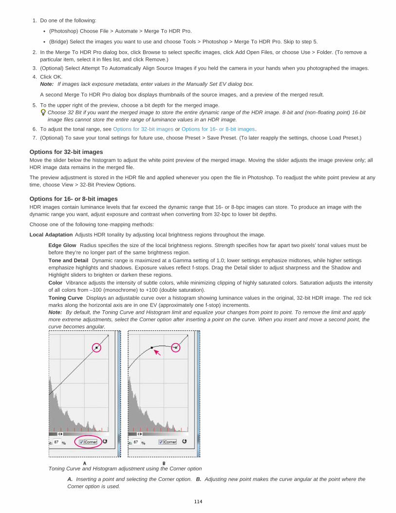
1. Do one of the following:
(Photoshop) Choose File > Automate > Merge To HDR Pro.
(Bridge) Select the images you want to use and choose Tools > Photoshop > Merge To HDR Pro. Skip to step 5.
2. In the Merge To HDR Pro dialog box, click Browse to select specific images, click Add Open Files, or choose Use > Folder. (To remove aparticular item, select it in files list, and click Remove.)
3. (Optional) Select Attempt To Automatically Align Source Images if you held the camera in your hands when you photographed the images.4. Click OK.
Note: If images lack exposure metadata, enter values in the Manually Set EV dialog box.
A second Merge To HDR Pro dialog box displays thumbnails of the source images, and a preview of the merged result.
5. To the upper right of the preview, choose a bit depth for the merged image.Choose 32 Bit if you want the merged image to store the entire dynamic range of the HDR image. 8-bit and (non-floating point) 16-bitimage files cannot store the entire range of luminance values in an HDR image.
6. To adjust the tonal range, see Options for 32-bit images or Options for 16- or 8-bit images.7. (Optional) To save your tonal settings for future use, choose Preset > Save Preset. (To later reapply the settings, choose Load Preset.)
Options for 32-bit imagesMove the slider below the histogram to adjust the white point preview of the merged image. Moving the slider adjusts the image preview only; allHDR image data remains in the merged file.
The preview adjustment is stored in the HDR file and applied whenever you open the file in Photoshop. To readjust the white point preview at anytime, choose View > 32-Bit Preview Options.
Options for 16- or 8-bit imagesHDR images contain luminance levels that far exceed the dynamic range that 16- or 8-bpc images can store. To produce an image with thedynamic range you want, adjust exposure and contrast when converting from 32-bpc to lower bit depths.
Choose one of the following tone-mapping methods:
Local Adaptation Adjusts HDR tonality by adjusting local brightness regions throughout the image.
Edge Glow Radius specifies the size of the local brightness regions. Strength specifies how far apart two pixels’ tonal values must bebefore they’re no longer part of the same brightness region.Tone and Detail Dynamic range is maximized at a Gamma setting of 1.0; lower settings emphasize midtones, while higher settingsemphasize highlights and shadows. Exposure values reflect f-stops. Drag the Detail slider to adjust sharpness and the Shadow andHighlight sliders to brighten or darken these regions.Color Vibrance adjusts the intensity of subtle colors, while minimizing clipping of highly saturated colors. Saturation adjusts the intensityof all colors from –100 (monochrome) to +100 (double saturation).Toning Curve Displays an adjustable curve over a histogram showing luminance values in the original, 32-bit HDR image. The red tickmarks along the horizontal axis are in one EV (approximately one f-stop) increments.Note: By default, the Toning Curve and Histogram limit and equalize your changes from point to point. To remove the limit and applymore extreme adjustments, select the Corner option after inserting a point on the curve. When you insert and move a second point, thecurve becomes angular.
Toning Curve and Histogram adjustment using the Corner option
A. Inserting a point and selecting the Corner option. B. Adjusting new point makes the curve angular at the point where theCorner option is used.
114

To the top
To the top
Equalize Histogram Compresses the dynamic range of the HDR image while trying to preserve some contrast. No further adjustments arenecessary; this method is automatic.Exposure and Gamma Lets you manually adjust the brightness and contrast of the HDR image. Move the Exposure slider to adjust gain and theGamma slider to adjust contrast.Highlight Compression Compresses the highlight values in the HDR image so they fall within the luminance values range of the 8- or 16-bpcimage file. No further adjustments are necessary; this method is automatic.
Compensate for moving objectsIf images have different content due to moving objects like cars, people, or foliage, select Remove Ghosts in the Merge To HDR Pro dialog box.
Photoshop displays a green outline around the thumbnail with the best tonal balance, identifying the base image. Moving objects found in otherimages are removed. (If movement occurs in very light or dark areas, click a different thumbnail where moving objects are better exposed toimprove results.)
For a tutorial on the Remove Ghosts option, see this video. (Discussion of Remove Ghosts begins at 3:00.)
Save or load camera response curvesResponse curves indicate how camera sensors interpret different levels of incoming light. By default, the Merge To HDR Pro dialog boxautomatically calculates a camera response curve based on the tonal range of images you are merging. You can save the current response curveand later apply it to another group of merged images.
In the upper-right corner of the Merge to HDR Pro dialog box, click the response curve menu , and then choose Save Response Curve. (Tolater reapply the curve, choose Load Response Curve.)
Convert from 32 bits to 16 or 8 bpcIf you originally created a 32-bit image during the Merge to HDR Pro process, you can later convert it to a 16- or 8-bit image.
1. Open a 32-bpc image in Photoshop, and choose Image > Mode > 16 Bits/Channel or 8 Bits/Channel.2. Adjust exposure and contrast to produce an image with the dynamic range you want. (See Options for 16- or 8-bit images.)3. Click OK to convert the 32-bit image.
Adjust displayed dynamic range for 32-bit HDR imagesThe dynamic range of HDR images exceeds the display capabilities of standard computer monitors. When you open an HDR image in Photoshop,it can look very dark or washed out. Photoshop lets you adjust the preview so that the monitor displays an HDR image whose highlights andshadows aren’t washed out or too dark. The preview settings are stored in the HDR image file (PSD, PSB, and TIFF only) and are appliedwhenever the file is opened in Photoshop. Preview adjustments don’t edit the HDR image file; all the HDR image information remains intact. Usethe Exposure adjustment (Image > Adjustments > Exposure) to make exposure edits to the 32-bpc HDR image.
To view 32-bit readouts in the Info panel, click the Eyedropper icon in the Info panel and choose 32-Bit from the pop-up menu.
1. Open a 32-bpc HDR image in Photoshop, and choose View > 32-Bit Preview Options.2. In the 32-bit Preview Options dialog box, choose an option from the Method menu:
Exposure And Gamma Adjusts the brightness and contrast.
Highlight Compression Compresses the highlight values in the HDR image so they fall within the luminance values range of the 8- or16-bpc image file.
3. If you chose Exposure And Gamma, move the Exposure and Gamma sliders to adjust the brightness and contrast of the image preview.4. Click OK.
You can also adjust the preview of an HDR image open in Photoshop by clicking the triangle in the status bar of the document windowand choosing 32-Bit Exposure from the pop-up menu. Move the slider to set the white point for viewing the HDR image. Double-click theslider to return to the default exposure setting. Since the adjustment is made per view, you can have the same HDR image open inmultiple windows, each with a different preview adjustment. Preview adjustments made with this method are not stored in the HDR imagefile.
About the HDR Color PickerThe HDR Color Picker allows you to accurately view and select colors for use in 32-bit HDR images. As in the regular Adobe Color Picker, youselect a color by clicking a color field and adjusting the color slider. The Intensity slider allows you to adjust the brightness of a color to match theintensity of the colors in the HDR image you’re working with. A Preview area lets you view swatches of a selected color to see how it will display atdifferent exposures and intensities.
115
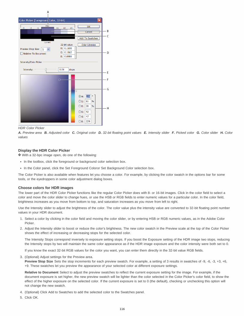
HDR Color PickerA. Preview area B. Adjusted color C. Original color D. 32-bit floating point values E. Intensity slider F. Picked color G. Color slider H. Colorvalues
Display the HDR Color Picker With a 32-bpc image open, do one of the following:
In the toolbox, click the foreground or background color selection box.
In the Color panel, click the Set Foreground Coloror Set Background Color selection box.
The Color Picker is also available when features let you choose a color. For example, by clicking the color swatch in the options bar for sometools, or the eyedroppers in some color adjustment dialog boxes.
Choose colors for HDR imagesThe lower part of the HDR Color Picker functions like the regular Color Picker does with 8- or 16-bit images. Click in the color field to select acolor and move the color slider to change hues, or use the HSB or RGB fields to enter numeric values for a particular color. In the color field,brightness increases as you move from bottom to top, and saturation increases as you move from left to right.
Use the Intensity slider to adjust the brightness of the color. The color value plus the intensity value are converted to 32-bit floating point numbervalues in your HDR document.
1. Select a color by clicking in the color field and moving the color slider, or by entering HSB or RGB numeric values, as in the Adobe ColorPicker.
2. Adjust the Intensity slider to boost or reduce the color’s brightness. The new color swatch in the Preview scale at the top of the Color Pickershows the effect of increasing or decreasing stops for the selected color.
The Intensity Stops correspond inversely to exposure setting stops. If you boost the Exposure setting of the HDR image two stops, reducingthe Intensity stops by two will maintain the same color appearance as if the HDR image exposure and the color intensity were both set to 0.
If you know the exact 32-bit RGB values for the color you want, you can enter them directly in the 32-bit value RGB fields.
3. (Optional) Adjust settings for the Preview area.Preview Stop Size Sets the stop increments for each preview swatch. For example, a setting of 3 results in swatches of -9, -6, -3, +3, +6,+9. These swatches let you preview the appearance of your selected color at different exposure settings.
Relative to Document Select to adjust the preview swatches to reflect the current exposure setting for the image. For example, if thedocument exposure is set higher, the new preview swatch will be lighter than the color selected in the Color Picker’s color field, to show theeffect of the higher exposure on the selected color. If the current exposure is set to 0 (the default), checking or unchecking this option willnot change the new swatch.
4. (Optional) Click Add to Swatches to add the selected color to the Swatches panel.5. Click OK.
116

;
To the topPaint on HDR imagesYou can edit and add effects to HDR/32-bpc images using any of the following Photoshop tools: Brush, Pencil, Pen, Shape, Clone Stamp, PatternStamp, Eraser, Gradient, Blur, Sharpen, Smudge, and History Brush. You can also use the Text tool to add 32-bpc text layers to an HDR image.
When editing or painting on HDR images, you can preview your work at different exposure settings using either the 32-Bit Exposure slider in thedocument info area or the 32-Bit Preview Options dialog box (View > 32-Bit Preview Options). The HDR Color Picker also lets you preview yourselected foreground color at different intensity settings, to match different exposure settings in an HDR image.
1. Open an HDR image.2. (Optional) Set the exposure for the image. See Adjust displayed dynamic range for 32-bit HDR images.3. For the Brush or Pencil tools, click the foreground color to open the HDR Color Picker and select a color. For the Text tool, click the color
chip in the Text tool options bar to set the text color.The Preview area of the HDR Color Picker helps you select and adjust a foreground color in relation to different exposure settings in theHDR image. See About the HDR Color Picker.
To view the effects of painting at different HDR exposures, use the Window > Arrange > New Window command to open simultaneousviews of the same HDR image, then set each window to a different exposure using the Exposure slider in the document status bar area.
More Help topicsCurves overview
Adobe Color Picker overview
Adjust HDR exposure and toning
Legal Notices | Online Privacy Policy
117
Converting between color modes
To the top
To the top
Convert an image to another color modeConvert an image to Bitmap modeConvert a color photo to Grayscale modeConvert a Bitmap mode image to Grayscale modeConvert a grayscale or RGB image to indexed color
Convert an image to another color modeYou can change an image from its original mode (source mode) to a different mode (target mode). When you choose a different color mode for animage, you permanently change the color values in the image. For example, when you convert an RGB image to CMYK mode, RGB color valuesoutside the CMYK gamut (defined by the CMYK working space setting in the Color Settings dialog box) are adjusted to fall within gamut. As aresult, some image data may be lost and can’t be recovered if you convert the image from CMYK back to RGB.
Before converting images, it’s best to do the following:
Do as much editing as possible in the original image mode (usually RGB for images from most scanners or digital cameras, or CMYK forimages from traditional drum scanners or imported from a Scitex system).
Save a backup copy before converting. Be sure to save a copy of your image that includes all layers so that you can edit the original versionof the image after the conversion.
Flatten the file before converting it. The interaction of colors between layer blending modes changes when the mode changes.Note: In most cases, you’ll want to flatten a file before converting it. However, it isn't required and, in some cases, it isn’t desirable (forexample, when the file has vector text layers).
Choose Image > Mode and the mode you want from the submenu. Modes not available for the active image appear dimmed in the menu.Images are flattened when converted to Multichannel, Bitmap, or Indexed Color mode, because these modes do not support layers.
Convert an image to Bitmap modeConverting an image to Bitmap mode reduces the image to two colors, greatly simplifying the color information in the image and reducing its filesize.
When converting a color image to Bitmap mode, first convert it to Grayscale mode. This removes the hue and saturation information from thepixels and leaves just the brightness values. However, because only a few editing options are available for Bitmap mode images, it’s usually bestto edit the image in Grayscale mode and then convert it to Bitmap mode.
Note: Images in Bitmap mode are 1 bit per channel. You must convert a 16- or 32-bits-per-channel image to 8-bit Grayscale mode beforeconverting it to Bitmap mode.
1. Do one of the following:
If the image is in color, choose Image > Mode > Grayscale. Then choose Image > Mode > Bitmap.
If the image is grayscale, choose Image > Mode > Bitmap.
2. For Output, enter a value for the output resolution of the Bitmap mode image, and choose a unit of measurement. By default, the currentimage resolution appears as both the input and the output resolutions.
3. Choose one of the following bitmap conversion methods from the Use pop-up menu:50% Threshold Converts pixels with gray values above the middle gray level (128) to white and pixels with gray values below that level toblack. The result is a very high-contrast, black-and-white representation of the image.
Pattern Dither Converts an image by organizing the gray levels into geometric configurations of black and white dots.
Diffusion Dither Converts an image by using an error-diffusion process, starting at the pixel in the upper-left corner of the image. If thepixel’s value is above middle gray (128), the pixel is changed to white—if below it, to black. Because the original pixel is rarely pure white orpure black, error is inevitably introduced. This error is transferred to surrounding pixels and diffused throughout the image, resulting in agrainy, film-like texture.
Halftone Screen Simulates the appearance of halftone dots in the converted image. Enter values in the Halftone Screen dialog box:
For Frequency, enter a value for the screen frequency, and choose a unit of measurement. Values can range from 1.000 to 999.999 forlines per inch and from 0.400 to 400.00 for lines per centimeter. You can enter decimal values. The screen frequency specifies the rulingof the halftone screen in lines per inch (lpi). The frequency depends on the paper stock and type of press used for printing. Newspaperscommonly use an 85-line screen. Magazines use higher resolution screens, such as 133-lpi and 150-lpi. Check with your print shop for
118

To the top
To the top
To the top
correct screen frequencies.
Enter a value for the screen angle in degrees from -180 to +180. The screen angle refers to the orientation of the screen. Continuous-tone and black-and-white halftone screens commonly use a 45° angle.
For Shape, choose the dot shape you want.
Important: The halftone screen becomes part of the image. If you print the image on a halftone printer, the printer will use its own halftonescreen as well as the halftone screen that is part of the image. On some printers, the result is a moiré pattern.
Custom Pattern Simulates the appearance of a custom halftone screen in the converted image. Choose a pattern that lends itself tothickness variations, typically one with a variety of gray shades.
To use this option, you first define a pattern and then screen the grayscale image to apply the texture. To cover the entire image, the patternmust be as large as the image. Otherwise, the pattern is tiled. Photoshop comes with several self-tiling patterns that can be used as halftonescreen patterns.
To prepare a black-and-white pattern for conversion, first convert the image to grayscale and then apply the Blur More filter severaltimes. This blurring technique creates thick lines tapering from dark gray to white.
Original grayscale image, and 50% Threshold conversion method
Pattern Dither conversion method, and Diffusion Dither conversion method
Convert a color photo to Grayscale mode1. Open the photo you want to convert to black-and-white.2. Choose Image > Mode > Grayscale.3. Click Discard. Photoshop converts the colors in the image to black, white, and shades of gray.
Note: The technique above minimizes file size but discards color information and can convert adjacent colors to the exact same shade ofgray. Using a Black & White adjustment layer increases file size but retains color information, letting you map colors to shades of gray.
Convert a Bitmap mode image to Grayscale modeYou can convert a Bitmap mode image to Grayscale mode in order to edit it. Keep in mind that a Bitmap mode image edited in Grayscale modemay not look the same when you convert it back to Bitmap mode. For example, suppose a pixel that is black in Bitmap mode is edited to a shadeof gray in Grayscale mode. When the image is converted back to Bitmap mode, that pixel is rendered as white if its gray value is above the middlegray value of 128.
1. Choose Image > Mode > Grayscale.2. Enter a value between 1 and 16 for the size ratio.
The size ratio is the factor for scaling down the image. For example, to reduce a grayscale image by 50%, enter 2 for the size ratio. If youenter a number greater than 1, the program averages multiple pixels in the Bitmap mode image to produce a single pixel in the grayscaleimage. This process lets you generate multiple shades of gray from an image scanned on a 1-bit scanner.
Convert a grayscale or RGB image to indexed colorConverting to indexed color reduces the number of colors in the image to at most 256—the standard number of colors supported by the GIF andPNG-8 formats and many multimedia applications. This conversion reduces file size by deleting color information from the image.
119

To convert to indexed color, you must start with an image that is 8 bits per channel and in either Grayscale or RGB mode.
1. Choose Image > Mode > Indexed Color.Note: All visible layers will be flattened; any hidden layers will be discarded.
For grayscale images, the conversion happens automatically. For RGB images, the Indexed Color dialog box appears.
2. Select Preview in the Indexed Color dialog box to display a preview of the changes.3. Specify conversion options.
Conversion options for indexed-color imagesWhen converting an RGB image to indexed color, you can specify a number of conversion options in the Indexed Color dialog box.
Palette Type A number of palette types are available for converting an image to indexed color. For the Perceptual, Selective, and Adaptiveoptions, you can choose using a local palette based on the current image’s colors. These are the available palette types:
Exact Creates a palette using the exact colors appearing in the RGB image—an option available only if the image uses 256 or fewercolors. Because the image’s palette contains all colors in the image, there is no dithering.System (Mac OS) Uses the Mac OS default 8-bit palette, which is based on a uniform sampling of RGB colors.System (Windows) Uses the Windows system’s default 8-bit palette, which is based on a uniform sampling of RGB colors.Web Uses the 216-color palette that web browsers, regardless of platform, use to display images on a monitor limited to 256 colors. Thispalette is a subset of the Mac OS 8-bit palette. Use this option to avoid browser dither when viewing images on a monitor display limited to256 colors.Uniform Creates a palette by uniformly sampling colors from the RGB color cube. For example, if Photoshop takes six evenly-spacedcolor levels each of red, green, and blue, the combination produces a uniform palette of 216 colors (6 cubed = 6 x 6 x 6 = 216). The totalnumber of colors displayed in an image corresponds to the nearest perfect cube (8, 27, 64, 125, or 216) that is less than the value in theColors text box.Local (Perceptual) Creates a custom palette by giving priority to colors for which the human eye has greater sensitivity.Local (Selective) Creates a color table similar to the Perceptual color table, but favoring broad areas of color and the preservation of webcolors. This option usually produces images with the greatest color integrity.Local (Adaptive) Creates a palette by sampling the colors from the spectrum appearing most commonly in the image. For example, anRGB image with only the colors green and blue produces a palette made primarily of greens and blues. Most images concentrate colors inparticular areas of the spectrum. To control a palette more precisely, first select a part of the image containing the colors you want toemphasize. Photoshop weights the conversion toward these colors.Master (Perceptual) Creates a custom palette by giving priority to colors for which the human eye has greater sensitivity. Applies whenyou have multiple documents open; takes all open documents into account.Master (Selective) Creates a color table similar to the Perceptual color table, but favoring broad areas of color and the preservation ofweb colors. This option usually produces images with the greatest color integrity. Applies when you have multiple documents open; takesall open documents into account.Master (Adaptive) Creates a palette by sampling the colors from the spectrum appearing most commonly in the image. For example, anRGB image with only the colors green and blue produces a palette made primarily of greens and blues. Most images concentrate colors inparticular areas of the spectrum. To control a palette more precisely, first select a part of the image containing the colors you want toemphasize. Photoshop weights the conversion toward these colors. Applies when you have multiple documents open; takes all opendocuments into account.Custom Creates a custom palette using the Color Table dialog box. Either edit the color table and save it for later use or click Load toload a previously created color table. This option also displays the current Adaptive palette, which is useful for previewing the colors mostoften used in the image.Previous Uses the custom palette from the previous conversion, making it easy to convert several images with the same custompalette.
Number Of Colors For the Uniform, Perceptual, Selective, or Adaptive palette, you can specify the exact number of colors to be displayed (up to256) by entering a value for Colors. The Colors text box controls only how the indexed color table is created. Adobe Photoshop still treats theimage as an 8-bit, 256-color image.Color Inclusion And Transparency To specify colors to be included in the indexed color table or to specify transparency in the image, choosefrom the following options:
Forced Provides options to force the inclusion of certain colors in the color table. Black And White adds a pure black and a pure white tothe color table; Primaries adds red, green, blue, cyan, magenta, yellow, black, and white; Web adds the 216 web-safe colors; and Customlets you define custom colors to add.Transparency Specifies whether to preserve transparent areas of the image during conversion. Selecting this option adds a special indexentry in the color table for transparent colors. Deselecting this option fills transparent areas with the matte color, or with white if no mattecolor is chosen.Matte Specifies the background color used to fill anti-aliased edges that lie adjacent to transparent areas of the image. WhenTransparency is selected, the matte is applied to edge areas to help blend the edges with a web background of the same color. WhenTransparency is deselected, the matte is applied to transparent areas. Choosing None for the matte creates hard-edged transparency ifTransparency is selected; otherwise, all transparent areas are filled with 100% white. The image must have transparency for the Matteoptions to be available.
120

;
Dithering Unless you’re using the Exact color table option, the color table may not contain all the colors used in the image. To simulate colors notin the color table, you can dither the colors. Dithering mixes the pixels of the available colors to simulate the missing colors. Choose a ditheroption from the menu, and enter a percentage value for the dither amount. A higher amount dithers more colors but may increase file size. Youcan choose from the following dither options:
None Does not dither colors but instead uses the color closest to the missing color. This tends to result in sharp transitions betweenshades of color in the image, creating a posterized effect.Diffusion Uses an error-diffusion method that produces a less-structured dither than the Pattern option. To protect colors in the imagethat contain entries in the color table from being dithered, select Preserve Exact Colors. This is useful for preserving fine lines and text forweb images.Pattern Uses a halftone-like square pattern to simulate any colors not in the color table.Noise Helps to reduce seam patterns along the edges of image slices. Choose this option if you plan to slice the image for placement inan HTML table.
More Help topicsCustomizing indexed color tables
Adding a conditional mode change to an action
About color working spaces
Legal Notices | Online Privacy Policy
121

Customizing indexed color tables
To the top
Customize indexed color tables
Customize indexed color tablesThe Color Table command lets you make changes to the color table of an indexed-color image. These customization features are particularlyuseful with pseudocolor images—images displaying variations in gray levels with color rather than shades of gray, often used in scientific andmedical applications. However, customizing the color table can also produce special effects with indexed-color images that have a limited numberof colors.
Note: To shift colors simply in a pseudocolor image, choose Image > Adjustments, and use the color adjustment commands in the submenu.
Edit colors and assign transparency with a color tableYou can edit colors in the color table to produce special effects, or assign transparency in the image to a single color in the table.
1. Open the indexed-color image.2. Choose Image > Mode > Color Table.3. To change a single color, click the color and choose a new color in the Color Picker.4. To change a range of colors, drag in the table to choose the range of colors you want to change. In the Color Picker, choose the first color
you want in the range and click OK. When the color picker redisplays, choose the last color you want in the range and click OK.
The colors you selected in the Color Picker are placed in the range you selected in the Color Table dialog box.
5. To assign transparency to a color, select the Eyedropper tool in the Color Table dialog box, and click the color in the table or in the image.The sampled color is replaced with transparency in the image.
6. Click OK in the Color Table dialog box to apply the new colors to the indexed-color image.
Choose a predefined color table1. Open the indexed-color image.2. Do one of the following:
Choose Image > Mode >Color Table.
Choose Image > Mode > Indexed Color. In the Indexed Color dialog box, choose Custom from the Panel pop-up menu. This opens theColor Table dialog box.
3. In the Color Table dialog box, choose a predefined table from the Table menu.Custom Creates a palette you specify.
Black Body Displays a palette based on the different colors a black body radiator emits as it is heated—from black to red, orange, yellow,and white.
Grayscale Displays a palette based on 256 levels of gray—from black to white.
Spectrum Displays a palette based on the colors produced as white light passes through a prism—from violet, blue, and green to yellow,orange, and red.
System (Mac OS) Displays the standard Mac OS 256-color system palette.
System (Windows) Displays the standard Windows 256-color system palette.
Save and load color tablesYou use the Save and Load buttons in the Color Table dialog box to save your indexed color tables for use with other Adobe Photoshop images.After you load a color table into an image, the colors in the image change to reflect the color positions they reference in the new color table.
Note: You can also load saved color tables into the Swatches panel.
Legal Notices | Online Privacy Policy
122
Adding a conditional mode change to an action
To the top
Add a conditional mode change to an action
Add a conditional mode change to an actionYou can specify conditions for a mode change so that the conversion can occur during an action, which is a series of commands appliedsequentially to a single file or a batch of files. When a mode change is part of an action, an error can occur if the file being opened is not in thesource mode specified in the action. For example, suppose one step in an action is to convert an image with a source mode of RGB to a targetmode of CMYK. Applying this action to an image in Grayscale mode, or any other source mode besides RGB, results in an error.
When you record an action, you can use the Conditional Mode Change command to specify one or more modes for the source mode and a modefor the target mode.
1. Start recording an action.2. Choose File > Automate > Conditional Mode Change.3. In the Conditional Mode Change dialog box, select one or more modes for the source mode. Use the All or None buttons to select all
possible modes or no mode.4. Choose a target mode from the Mode pop-up menu.5. Click OK. The conditional mode change appears as a new step in the Actions panel.
More Help topicsAdding conditional actions | Creative Cloud
Legal Notices | Online Privacy Policy
123
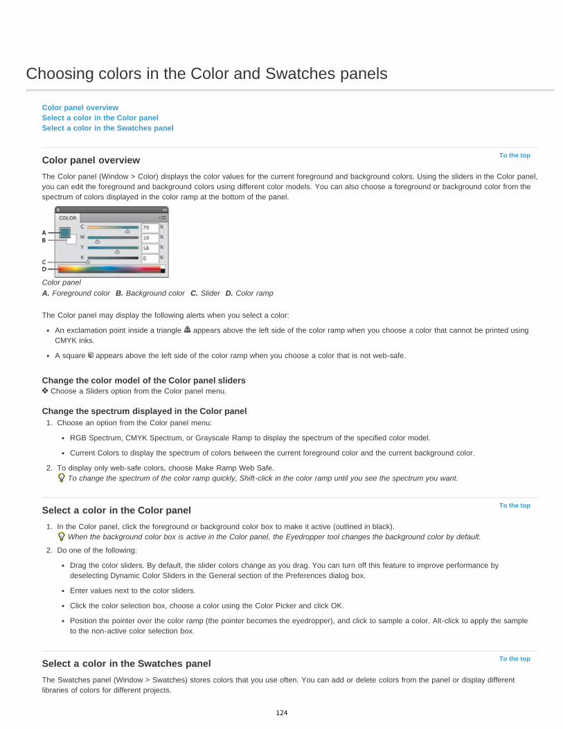
Choosing colors in the Color and Swatches panels
To the top
To the top
To the top
Color panel overviewSelect a color in the Color panelSelect a color in the Swatches panel
Color panel overviewThe Color panel (Window > Color) displays the color values for the current foreground and background colors. Using the sliders in the Color panel,you can edit the foreground and background colors using different color models. You can also choose a foreground or background color from thespectrum of colors displayed in the color ramp at the bottom of the panel.
Color panelA. Foreground color B. Background color C. Slider D. Color ramp
The Color panel may display the following alerts when you select a color:
An exclamation point inside a triangle appears above the left side of the color ramp when you choose a color that cannot be printed usingCMYK inks.
A square appears above the left side of the color ramp when you choose a color that is not web-safe.
Change the color model of the Color panel sliders Choose a Sliders option from the Color panel menu.
Change the spectrum displayed in the Color panel1. Choose an option from the Color panel menu:
RGB Spectrum, CMYK Spectrum, or Grayscale Ramp to display the spectrum of the specified color model.
Current Colors to display the spectrum of colors between the current foreground color and the current background color.
2. To display only web-safe colors, choose Make Ramp Web Safe.To change the spectrum of the color ramp quickly, Shift-click in the color ramp until you see the spectrum you want.
Select a color in the Color panel1. In the Color panel, click the foreground or background color box to make it active (outlined in black).
When the background color box is active in the Color panel, the Eyedropper tool changes the background color by default.
2. Do one of the following:
Drag the color sliders. By default, the slider colors change as you drag. You can turn off this feature to improve performance bydeselecting Dynamic Color Sliders in the General section of the Preferences dialog box.
Enter values next to the color sliders.
Click the color selection box, choose a color using the Color Picker and click OK.
Position the pointer over the color ramp (the pointer becomes the eyedropper), and click to sample a color. Alt-click to apply the sampleto the non-active color selection box.
Select a color in the Swatches panelThe Swatches panel (Window > Swatches) stores colors that you use often. You can add or delete colors from the panel or display differentlibraries of colors for different projects.
124

To choose a foreground color, click a color in the Swatches panel.To choose a background color, Ctrl-click (Windows) or Command-click (Mac OS) a color in the Swatches panel.
Note: Change how swatches are displayed by choosing an option from the Swatches panel menu.
Legal Notices | Online Privacy Policy
125
Viewing multiple images
To the top
To the top
View images in multiple windowsMatch zoom and location in multiple images
View images in multiple windowsThe document window is where your images appear. You can open multiple windows to display different images or different views of the sameone. A list of open windows appears in the Window menu. To bring an open image to the front, choose the file name from the bottom of theWindow menu. Available memory may limit the number of windows per image.
1. Choose Window > Arrange > New Window For [Image File Name].2. If you want to arrange the windows, choose Window > Arrange and then choose one of the following:
Cascade Displays undocked windows stacked and cascading from the upper-left to the lower right of the screen.
Tile Displays windows edge to edge. As you close images, the open windows are resized to fill the available space.
Float in Window Allows image to float freely.
Float All in Windows Floats all images.
Consolidate All to Tabs Shows one image in full screen and minimizes the other images to tabs.
You can use the Hand tool’s Scroll All Windows option to scroll through all open images. Select it in the options bar and drag in oneimage to scroll through all visible images.
Match zoom and location in multiple images
Match only zoom1. Open one or more images, or open one image in multiple windows.2. Choose Window > Arrange > Tile to display the images edge to edge.3. Select the Zoom tool, and then do one of the following:
Select Zoom All Windows in the options bar, and then click one of the images. The other images zoom in or out the same relativeamount.
Choose Window > Arrange > Match Zoom. Hold down the Shift key and click one of the images. The other images zoom in or out at thesame magnification.
Match only location1. Open one or more images, or open one image in multiple windows.2. Choose Window > Arrange > Tile.3. Do either of the following:
Choose Window > Arrange > Match Location.
Select the Hand tool, select Scroll All Windows in the options bar, and then drag to view another area in one of the images. (Totemporarily enable this option, hold down the Shift key while dragging with the Hand tool.)
Note: Photoshop automatically scrolls to the same relative location on the horizontal and vertical axes. You may need to manually scroll to revealthe edges of images.
Match zoom and location1. Open one or more images, or open one image in multiple windows.2. Choose Window > Arrange > Tile.3. Choose Window > Arrange > Match All.
126

Without Match All command (top), and with Match All command (bottom) selected
4. Select the Zoom tool or the Hand tool.5. Select one of the images, hold down the Shift key, and click in or drag an area of an image. The other images are magnified to the same
percentage and snap to the area you clicked.
Legal Notices | Online Privacy Policy
127
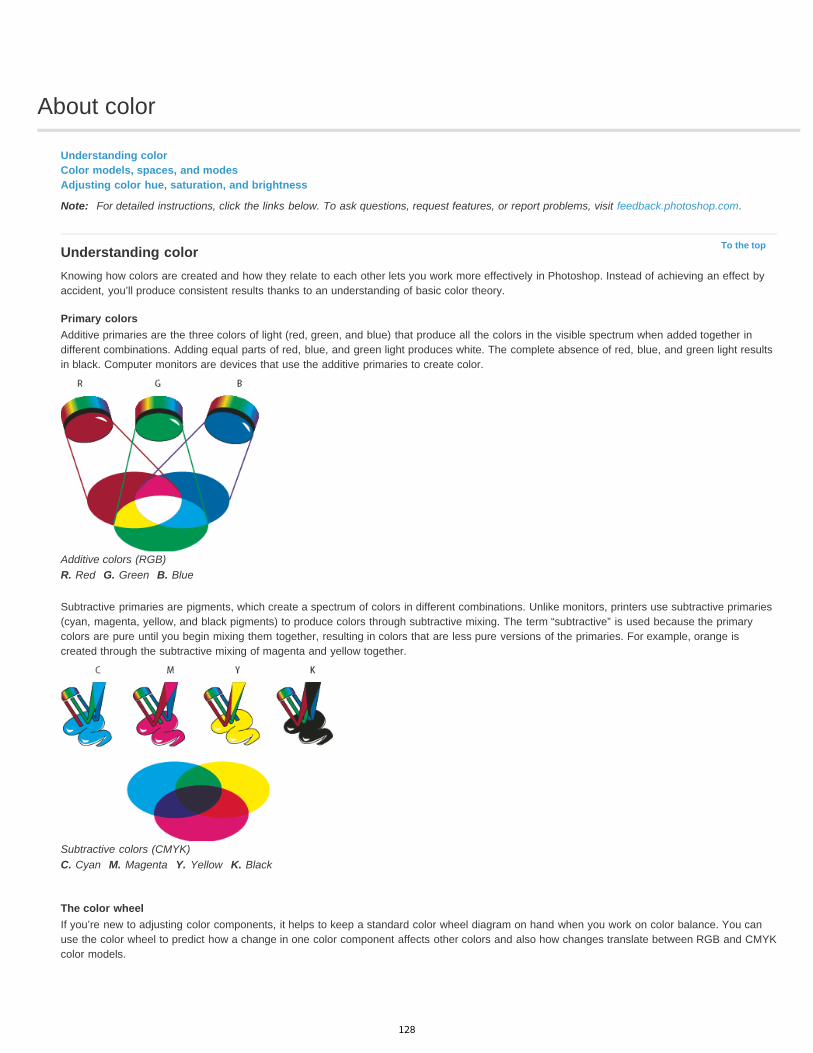
About color
To the top
Understanding colorColor models, spaces, and modesAdjusting color hue, saturation, and brightness
Note: For detailed instructions, click the links below. To ask questions, request features, or report problems, visit feedback.photoshop.com.
Understanding colorKnowing how colors are created and how they relate to each other lets you work more effectively in Photoshop. Instead of achieving an effect byaccident, you’ll produce consistent results thanks to an understanding of basic color theory.
Primary colorsAdditive primaries are the three colors of light (red, green, and blue) that produce all the colors in the visible spectrum when added together indifferent combinations. Adding equal parts of red, blue, and green light produces white. The complete absence of red, blue, and green light resultsin black. Computer monitors are devices that use the additive primaries to create color.
Additive colors (RGB)R. Red G. Green B. Blue
Subtractive primaries are pigments, which create a spectrum of colors in different combinations. Unlike monitors, printers use subtractive primaries(cyan, magenta, yellow, and black pigments) to produce colors through subtractive mixing. The term “subtractive” is used because the primarycolors are pure until you begin mixing them together, resulting in colors that are less pure versions of the primaries. For example, orange iscreated through the subtractive mixing of magenta and yellow together.
Subtractive colors (CMYK)C. Cyan M. Magenta Y. Yellow K. Black
The color wheelIf you’re new to adjusting color components, it helps to keep a standard color wheel diagram on hand when you work on color balance. You canuse the color wheel to predict how a change in one color component affects other colors and also how changes translate between RGB and CMYKcolor models.
128

To the top
To the top
Color wheelR. Red Y. Yellow G. Green C. Cyan B. Blue M. Magenta
For example, you can decrease the amount of any color in an image by increasing the amount of its opposite on the color wheel—and vice versa.Colors that lie opposite each other on the standard color wheel are known as complementary colors. Similarly, you can increase and decrease acolor by adjusting the two adjacent colors on the wheel, or even by adjusting the two colors adjacent to its opposite.
In a CMYK image, you can decrease magenta either by decreasing the amount of magenta or by increasing its complement, which is green (thecolor on the opposite side of the color wheel from magenta). In an RGB image, you can decrease magenta by removing red and blue or by addinggreen. All of these adjustments result in an overall color balance containing less magenta.
Color models, spaces, and modesA color model describes the colors we see and work with in digital images. Each color model, such as RGB, CMYK, or HSB, represents a differentmethod (usually numeric) for describing color.
A color space is a variant of a color model and has a specific gamut (range) of colors. For example, within the RGB color model are a number ofcolor spaces: Adobe RGB, sRGB, ProPhoto RGB, and so on.
Each device, like your monitor or printer, has its own color space and can only reproduce colors in its gamut. When an image moves from onedevice to another, image colors may change because each device interprets the RGB or CMYK values according to its own color space. You canuse color management when moving images to ensure that most colors are the same or similar enough so they appear consistent. See Whycolors sometimes don’t match.
In Photoshop, a document’s color mode determines which color model is used to display and print the image you’re working on. Photoshop basesits color modes on the color models that are useful for images used in publishing. You can choose from RGB (Red, Green, Blue), CMYK (Cyan,Magenta, Yellow, Black), Lab Color (based on CIE L* a* b*), and Grayscale. Photoshop also includes modes for specialized color output such asIndexed Color and Duotone. Color modes determine the number of colors, the number of channels, and the file size of an image. Choosing a colormode also determines which tools and file formats are available. See Color modes.
When you work with the colors in an image, you are adjusting numerical values in the file. It’s easy to think of a number as a color, but thesenumerical values are not absolute colors in themselves—they only have a color meaning within the color space of the device that is producing thecolor.
Adjusting color hue, saturation, and brightnessBased on the human perception of color, the HSB model describes three fundamental characteristics of color:
Hue Color reflected from or transmitted through an object. It is measured as a location on the standard color wheel, expressed as a degreebetween 0° and 360°. In common use, hue is identified by the name of the color, such as red, orange, or green.Saturation Strength or purity of the color (sometimes called chroma). Saturation represents the amount of gray in proportion to the hue, measuredas a percentage from 0% (gray) to 100% (fully saturated). On the standard color wheel, saturation increases from the center to the edge.Brightness Relative lightness or darkness of the color, usually measured as a percentage from 0% (black) to 100% (white).
129
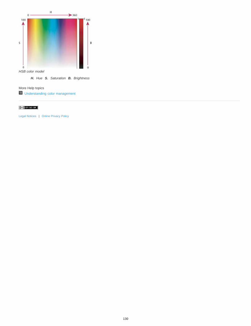
HSB color model
H. Hue S. Saturation B. Brightness
More Help topics Understanding color management
Legal Notices | Online Privacy Policy
130
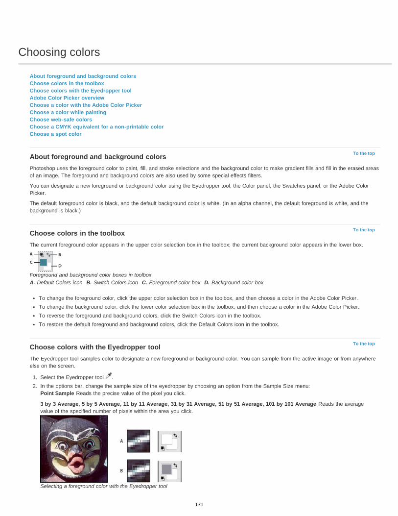
Choosing colors
To the top
To the top
To the top
About foreground and background colorsChoose colors in the toolboxChoose colors with the Eyedropper toolAdobe Color Picker overviewChoose a color with the Adobe Color PickerChoose a color while paintingChoose web-safe colorsChoose a CMYK equivalent for a non-printable colorChoose a spot color
About foreground and background colorsPhotoshop uses the foreground color to paint, fill, and stroke selections and the background color to make gradient fills and fill in the erased areasof an image. The foreground and background colors are also used by some special effects filters.
You can designate a new foreground or background color using the Eyedropper tool, the Color panel, the Swatches panel, or the Adobe ColorPicker.
The default foreground color is black, and the default background color is white. (In an alpha channel, the default foreground is white, and thebackground is black.)
Choose colors in the toolboxThe current foreground color appears in the upper color selection box in the toolbox; the current background color appears in the lower box.
Foreground and background color boxes in toolboxA. Default Colors icon B. Switch Colors icon C. Foreground color box D. Background color box
To change the foreground color, click the upper color selection box in the toolbox, and then choose a color in the Adobe Color Picker.To change the background color, click the lower color selection box in the toolbox, and then choose a color in the Adobe Color Picker.To reverse the foreground and background colors, click the Switch Colors icon in the toolbox.To restore the default foreground and background colors, click the Default Colors icon in the toolbox.
Choose colors with the Eyedropper toolThe Eyedropper tool samples color to designate a new foreground or background color. You can sample from the active image or from anywhereelse on the screen.
1. Select the Eyedropper tool .2. In the options bar, change the sample size of the eyedropper by choosing an option from the Sample Size menu:
Point Sample Reads the precise value of the pixel you click.
3 by 3 Average, 5 by 5 Average, 11 by 11 Average, 31 by 31 Average, 51 by 51 Average, 101 by 101 Average Reads the averagevalue of the specified number of pixels within the area you click.
Selecting a foreground color with the Eyedropper tool
131
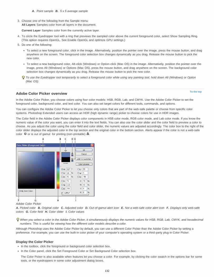
To the top
A. Point sample B. 5 x 5 average sample
3. Choose one of the following from the Sample menu:All Layers Samples color from all layers in the document.
Current Layer Samples color from the currently active layer.
4. To circle the Eyedropper tool with a ring that previews the sampled color above the current foreground color, select Show Sampling Ring.(This option requires OpenGL. See Enable OpenGL and optimize GPU settings.)
5. Do one of the following:
To select a new foreground color, click in the image. Alternatively, position the pointer over the image, press the mouse button, and draganywhere on the screen. The foreground color selection box changes dynamically as you drag. Release the mouse button to pick thenew color.
To select a new background color, Alt-click (Windows) or Option-click (Mac OS) in the image. Alternatively, position the pointer over theimage, press Alt (Windows) or Options (Mac OS), press the mouse button, and drag anywhere on the screen. The background colorselection box changes dynamically as you drag. Release the mouse button to pick the new color.
To use the Eyedropper tool temporarily to select a foreground color while using any painting tool, hold down Alt (Windows) or Option(Mac OS).
Adobe Color Picker overviewIn the Adobe Color Picker, you choose colors using four color models: HSB, RGB, Lab, and CMYK. Use the Adobe Color Picker to set theforeground color, background color, and text color. You can also set target colors for different tools, commands, and options.
You can configure the Adobe Color Picker to let you choose only colors that are part of the web-safe palette or choose from specific colorsystems. Photoshop Extended users can access an HDR (high dynamic range) picker to choose colors for use in HDR images.
The Color field in the Adobe Color Picker displays color components in HSB color mode, RGB color mode, and Lab color mode. If you know thenumeric value of the color you want, you can enter it into the text fields. You can also use the color slider and the color field to preview a color tochoose. As you adjust the color using the color field and color slider, the numeric values are adjusted accordingly. The color box to the right of thecolor slider displays the adjusted color in the top section and the original color in the bottom section. Alerts appear if the color is not a web-safecolor or is out of gamut for printing (non-printable) .
Adobe Color PickerA. Picked color B. Original color C. Adjusted color D. Out-of-gamut alert icon E. Not a web-safe color alert icon F. Displays only web-safecolors G. Color field H. Color slider I. Color values
When you select a color in the Adobe Color Picker, it simultaneously displays the numeric values for HSB, RGB, Lab, CMYK, and hexadecimalnumbers. This is useful for viewing how the different color models describe a color.
Although Photoshop uses the Adobe Color Picker by default, you can use a different Color Picker than the Adobe Color Picker by setting apreference. For example, you can use the built-in color picker of your computer’s operating system or a third-party plug-in Color Picker.
Display the Color PickerIn the toolbox, click the foreground or background color selection box.In the Color panel, click the Set Foreground Color or Set Background Color selection box.
The Color Picker is also available when features let you choose a color. For example, by clicking the color swatch in the options bar for sometools, or the eyedroppers in some color adjustment dialog boxes.
132

To the top
To the top
Choose a color with the Adobe Color PickerYou can choose a color by entering color component values in HSB, RGB, and Lab text boxes, or by using the color slider and the color field.
To choose a color with the color slider and color field, click in the color slider or move the color slider triangle to set one color component. Thenmove the circular marker or click in the color field. This sets the other two color components.
As you adjust the color using the color field and color slider, the numeric values for the different color models adjust accordingly. The rectangle tothe right of the color slider displays the new color in the top half and the original color in the bottom. Alerts appear if the color is not a web-safecolor or is out of gamut .
You can choose a color outside the Adobe Color Picker window. Moving the pointer over the document window changes it to the Eyedroppertool. You can then select a color by clicking in the image. The selected color is displayed in the Adobe Color Picker. You can move theEyedropper tool anywhere on your desktop by clicking in the image and then holding down the mouse button. You can select a color byreleasing the mouse button.
Choose a color using the HSB modelUsing the HSB color model, the hue is specified in the color field, as an angle from 0° to 360° that corresponds to a location on the color wheel.Saturation and brightness are specified as percentages. In the color field, the hue saturation increases from left to right and the brightnessincreases from the bottom to top.
1. In the Adobe Color Picker, select the H option and then enter a numeric value in the H text box or select a hue in the color slider.2. Adjust the saturation and brightness by clicking in the color field, moving the circular maker, or entering numeric values in the S and B text
boxes.3. (Optional) Select either the S option or B option to display the color’s saturation or brightness in the color field for making further
adjustments.
Choose a color using the RGB modelChoose a color by specifying its red, green, and blue components.
1. In the Adobe Color Picker, enter numeric values in the R, G, and B text boxes. Specify component values from 0 to 255 (0 is no color, and255 is the pure color).
2. To visually select a color using the color slider and color field, click either R, G, or B and then adjust the slider and color field.
The color you click appears in the color slider with 0 (none of that color) at the bottom and 255 (maximum amount of that color) at the top.The color field displays the range of the other two components, one on the horizontal axis and one on the vertical axis.
Choose a color using the Lab modelWhen choosing a color based on the Lab color model, the L value specifies the luminance of a color. The A value specifies how red or green acolor is. The B value specifies how blue or yellow a color is.
1. In the Adobe Color Picker, enter values for L (from 0 to 100), and for A and B (from -128 to +127).2. (Optional) Use the color slider or color field to adjust the color.
Choose a color using the CMYK modelYou can choose a color by specifying each component value as a percentage of cyan, magenta, yellow, and black.
In the Adobe Color Picker, enter percentage values for C, M, Y, and K, or use the color slider and color field to choose a color.
Choose a color by specifying a hexadecimal valueYou can choose a color by specifying a hexadecimal value that defines the R, G, and B components in a color. The three pairs of numbers areexpressed in values from 00 (minimum luminance) to ff (maximum luminance). For example, 000000 is black, ffffff is white, and ff0000 is red.
In the Adobe Color Picker, enter a hexadecimal value in the # text box.
Choose a color while paintingThe heads-up-display (HUD) color picker lets you quickly choose colors while painting in the document window, where image colors providehelpful context.
Note: The HUD color picker requires OpenGL. (See Enable OpenGL and optimize GPU settings.)
Choose the type of HUD color picker
1. Choose Edit > Preferences > General (Windows) or Photoshop > Preferences > General (Mac OS).
2. From the HUD Color Picker menu, choose Hue Strip to display a vertical picker or Hue Wheel to display a circular one.
133

To the top
To the top
To the top
Choose a color from the HUD color picker
1. Select a painting tool.
2. Press Shift + Alt + right-click (Windows) or Control + Option + Command (Mac OS).
3. Click in the document window to display the picker. Then drag to select a color hue and shade.
After clicking in the document window, you can release the pressed keys. Temporarily press the spacebar to maintain the selected shadewhile you select another hue, or vice versa.
Choosing color with HUD pickerA. Shade B. Hue
To instead select a color from the image, hold down Alt (Windows) or Option (Mac OS) to access the Eyedropper tool.
Choose web-safe colorsThe web-safe colors are the 216 colors used by browsers regardless of the platform. The browser changes all colors in the image to these colorswhen displaying the image on an 8-bit screen. The 216 colors are a subset of the Mac OS 8-bit color palettes. By working only with these colors,you can be sure that art you prepare for the web will not dither on a system set to display 256 colors.
Select web-safe colors in the Adobe Color Picker Select the Only Web Colors option in the lower left corner of the Adobe Color Picker. Any color you pick with this option selected is web-safe.
Change a non-web color to a web-safe colorIf you select a non-web color, an alert cube appears next to the color rectangle in the Adobe Color Picker.
Click the alert cube to select the closest web color. (If no alert cube appears, the color you chose is web-safe.)
Select a web-safe color using the Color panel1. Click the Color panel tab, or choose Window > Color to view the Color panel.2. Choose an option for selecting a web-safe color:
Choose Make Ramp Web Safe from the Color panel menu. Any color you pick with this option selected is web-safe.
Choose Web Color Sliders from the Color panel menu. By default, web color sliders snap to web-safe colors (indicated by tick marks)when you drag them. To override web-safe color selection, Alt-drag (Windows) or Option-drag (Mac OS) the sliders.
If you choose a non-web color, an alert cube appears above the color ramp on the left side of the Color panel. Click the alert cube toselect the closest web color.
Choose a CMYK equivalent for a non-printable colorSome colors in the RGB, HSB, and Lab color models cannot be printed because they are out-of-gamut and have no equivalents in the CMYKmodel. When you choose a non-printable color in either the Adobe Color Picker or the Color panel, a warning alert triangle appears. A swatchbelow the triangle displays the closest CMYK equivalent.
Note: In the Color panel, the alert triangle is not available if you are using Web Color Sliders. To choose the closest CMYK equivalent, click the alert triangle in the Color Picker dialog box or the Color panel.
Printable colors are determined by the current CMYK working space defined in the Color Settings dialog box.
Choose a spot colorThe Adobe Color Picker lets you choose colors from the PANTONE MATCHING SYSTEM®, the Trumatch® Swatching System™, the Focoltone®Colour System, the Toyo Color Finder™ 1050 system, the ANPA-Color™ system, the HKS® color system, and the DIC Color Guide.
134

To ensure that the final printed output is the color you want, consult your printer or service bureau and choose your color based on a printed colorswatch. Manufacturers recommend that you get a new swatch book each year to compensate for fading inks and other damage.
Important: Photoshop prints spot colors to CMYK (process color) plates in every image mode except Duotone. To print true spot color plates,create spot color channels.
1. Open the Adobe Color Picker, and click Color Libraries.
The Custom Colors dialog box displays the color closest to the color currently selected in the Adobe Color Picker.
2. For Book, choose a color library. See below for descriptions of the color libraries.3. Locate the color you want by entering the ink number or by dragging the triangles along the scroll bar.4. Click the desired color patch in the list.
Spot color librariesThe Adobe Color Picker supports the following color systems:
ANPA-COLOR Commonly used for newspaper applications. The ANPA-COLOR ROP Newspaper Color Ink Book contains samples of the ANPAcolors.DIC Color Guide Commonly used for printing projects in Japan. For more information, contact Dainippon Ink & Chemicals, Inc., in Tokyo, Japan.FOCOLTONE Consists of 763 CMYK colors. Focoltone colors help avoid prepress trapping and registration problems by showing the overprintsthat make up the colors. A swatch book with specifications for process and spot colors, overprint charts, and a chip book for marking up layoutsare available from Focoltone. For more information, contact Focoltone International, Ltd., in Stafford, United Kingdom.HKS swatches Used for printing projects in Europe. Each color has a specified CMYK equivalent. You can select from HKS E (for continuousstationery), HKS K (for gloss art paper), HKS N (for natural paper), and HKS Z (for newsprint). Color samplers for each scale are available. HKSProcess books and swatches have been added to the color system menu.PANTONE® Colors used for spot-color reproduction. The PANTONE MATCHING SYSTEM can render 1,114 colors. PANTONE color guides andchip books are printed on coated, uncoated, and matte paper stocks to ensure accurate visualization of the printed result and better on-presscontrol. You can print a solid PANTONE color in CMYK. To compare a solid PANTONE color to its closest process color match, use thePANTONE solid to process guide. The CMYK screen tint percentages are printed under each color. For more information, contact Pantone, Inc.,Carlstadt, NJ (www.pantone.com).TOYO Color Finder 1050 Consists of more than 1000 colors based on the most common printing inks used in Japan. The TOYO Process ColorFinder book and swatches have been added to the color system menu. The TOYO Color Finder 1050 Book contains printed samples of Toyocolors and is available from printers and graphic arts supply stores. For more information, contact Toyo Ink Manufacturing Co., Ltd., in Tokyo,Japan.TRUMATCH Provides predictable CMYK color matching with more than 2000 achievable, computer-generated colors. Trumatch colors cover thevisible spectrum of the CMYK gamut in even steps. The Trumatch Color displays up to 40 tints and shades of each hue, each originally created infour-color process and each reproducible in four colors on electronic imagesetters. In addition, four-color grays using different hues are included.For more information, contact Trumatch Inc., in New York City, New York.More Help topics
Customize color settings
Legal Notices | Online Privacy Policy
135
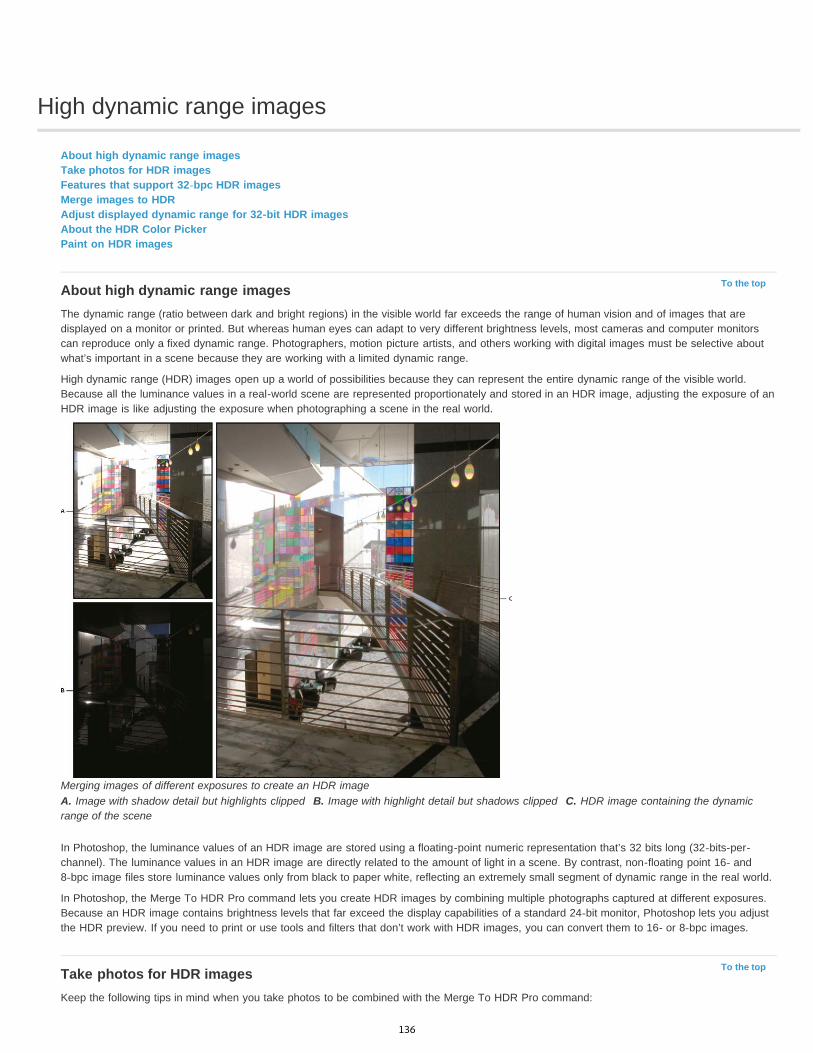
High dynamic range images
To the top
To the top
About high dynamic range imagesTake photos for HDR imagesFeatures that support 32-bpc HDR imagesMerge images to HDRAdjust displayed dynamic range for 32-bit HDR imagesAbout the HDR Color PickerPaint on HDR images
About high dynamic range imagesThe dynamic range (ratio between dark and bright regions) in the visible world far exceeds the range of human vision and of images that aredisplayed on a monitor or printed. But whereas human eyes can adapt to very different brightness levels, most cameras and computer monitorscan reproduce only a fixed dynamic range. Photographers, motion picture artists, and others working with digital images must be selective aboutwhat’s important in a scene because they are working with a limited dynamic range.
High dynamic range (HDR) images open up a world of possibilities because they can represent the entire dynamic range of the visible world.Because all the luminance values in a real-world scene are represented proportionately and stored in an HDR image, adjusting the exposure of anHDR image is like adjusting the exposure when photographing a scene in the real world.
Merging images of different exposures to create an HDR imageA. Image with shadow detail but highlights clipped B. Image with highlight detail but shadows clipped C. HDR image containing the dynamicrange of the scene
In Photoshop, the luminance values of an HDR image are stored using a floating-point numeric representation that’s 32 bits long (32-bits-per-channel). The luminance values in an HDR image are directly related to the amount of light in a scene. By contrast, non-floating point 16- and8-bpc image files store luminance values only from black to paper white, reflecting an extremely small segment of dynamic range in the real world.
In Photoshop, the Merge To HDR Pro command lets you create HDR images by combining multiple photographs captured at different exposures.Because an HDR image contains brightness levels that far exceed the display capabilities of a standard 24-bit monitor, Photoshop lets you adjustthe HDR preview. If you need to print or use tools and filters that don’t work with HDR images, you can convert them to 16- or 8-bpc images.
Take photos for HDR imagesKeep the following tips in mind when you take photos to be combined with the Merge To HDR Pro command:
136

To the top
To the top
Secure the camera to a tripod.
Take enough photos to cover the full dynamic range of the scene. You can try taking at least five to seven photos, but you might need totake more exposures depending on the dynamic range of the scene. The minimum number of photos should be three.
Vary the shutter speed to create different exposures. Changing the aperture changes the depth of field in each exposure and can producelower-quality results. Changing the ISO or aperture may also cause noise or vignetting in the image.
In general, don’t use your camera’s auto-bracket feature, because the exposure changes are usually too small.
The exposure differences between the photos should be one or two EV (exposure value) steps apart (equivalent to about one or two f-stopsapart).
Don’t vary the lighting; for instance, don’t use a flash in one exposure but not the next.
Make sure that nothing is moving in the scene. Exposure Merge works only with differently exposed images of the identical scene.
Features that support 32-bpc HDR imagesYou can use the following tools, adjustments, and filters with 32-bpc HDR images. (To work with more Photoshop features, convert a 32-bpcimage to a 16-bpc or an 8-bpc image. To preserve the original image, create a copy with the Save As command.)
Adjustments Levels, Exposure, Hue/Saturation, Channel Mixer, Photo Filter.Note: Although the Exposure command can be used with 8- and 16-bpc images, it is designed for making exposure adjustments to 32-bpc HDRimages.Blend Modes Normal, Dissolve, Darken, Multiply, Lighten, Darker Color, Linear Dodge (Add), Lighter Color, Difference, Subtract, Divide, Hue,Saturation, Color, and Luminosity.Create new 32-bpc documents In the New dialog box, 32 bit is an option in the bit depth pop-up menu to the right of the Color Mode pop-upmenu.Edit menu commands All commands including Fill, Stroke, Free Transform, and Transform.File Formats Photoshop (PSD, PSB), Radiance (HDR), Portable Bit Map (PBM), OpenEXR, and TIFF.Note: Although Photoshop cannot save an HDR image in the LogLuv TIFF file format, it can open and read a LogLuv TIFF file.Filters Average, Box Blur, Gaussian Blur, Motion Blur, Radial Blur, Shape Blur, Surface Blur, Add Noise, Clouds, Difference Clouds, Lens Flare,Smart Sharpen, Unsharp Mask, Emboss, De-Interlace, NTSC Colors, High Pass, Maximum, Minimum, and Offset.Image commands Image Size, Canvas Size, Image Rotation, Crop, Trim, Duplicate, Apply Image, Calculations, and Variables.View Pixel Aspect Ratio (Custom Pixel Aspect Ratio, Delete Pixel Aspect Ratio, Reset Pixel Aspect Ratio, etc.)Layers New layers, duplicate layers, adjustment layers (Levels, Vibrance, Hue/Saturation, Channel Mixer, Photo Filter, and Exposure), fill layers,layer masks, layer styles, supported blending modes, and Smart Objects.Modes RGB Color, Grayscale, conversion to 8 Bits/Channel or 16 Bits/Channel.Pixel Aspect Ratio Support for square and non-square documents.Selections Invert, Modify Border, Transform Selection, Save Selection and Load Selection.Tools All tools in the toolbox except: Magnetic Lasso, Magic Wand, Spot Healing Brush, Healing Brush, Red Eye, Color Replacement, Art HistoryBrush, Magic Eraser, Background Eraser, Paint Bucket, Dodge, Burn, and Sponge. Some tools work with supported blend modes only.
Merge images to HDRThe Merge To HDR Pro command combines multiple images with different exposures of the same scene, capturing the full dynamic range in asingle HDR image. You can output the merged image as a 32-, 16-, or 8-bpc file. However, only a 32-bpc file can store all the HDR image data.
HDR merging works best when photos are optimized for the process. For recommendations, see Take photos for HDR images.
Adobe recommends Have a tutorial you would like to share?
Video tutorial: The best new feature in CS5:HDR ProDeke McClellandTake image tones from vivid to surreal.
Book excerpt: Create HDR images frombracketed exposuresConrad ChavezWalk through the HDR process from camera tocomputer.
Book excerpt: Remove ghosting from HDRimagesScott KelbyEliminate blur from moving objects in a scene.
Video tutorial: Explore the enhancements toHDR ProJan KabiliTake a tour through all the new features.
137

1. Do one of the following:
(Photoshop) Choose File > Automate > Merge To HDR Pro.
(Bridge) Select the images you want to use and choose Tools > Photoshop > Merge To HDR Pro. Skip to step 5.
2. In the Merge To HDR Pro dialog box, click Browse to select specific images, click Add Open Files, or choose Use > Folder. (To remove aparticular item, select it in files list, and click Remove.)
3. (Optional) Select Attempt To Automatically Align Source Images if you held the camera in your hands when you photographed the images.4. Click OK.
Note: If images lack exposure metadata, enter values in the Manually Set EV dialog box.
A second Merge To HDR Pro dialog box displays thumbnails of the source images, and a preview of the merged result.
5. To the upper right of the preview, choose a bit depth for the merged image.Choose 32 Bit if you want the merged image to store the entire dynamic range of the HDR image. 8-bit and (non-floating point) 16-bitimage files cannot store the entire range of luminance values in an HDR image.
6. To adjust the tonal range, see Options for 32-bit images or Options for 16- or 8-bit images.7. (Optional) To save your tonal settings for future use, choose Preset > Save Preset. (To later reapply the settings, choose Load Preset.)
Options for 32-bit imagesMove the slider below the histogram to adjust the white point preview of the merged image. Moving the slider adjusts the image preview only; allHDR image data remains in the merged file.
The preview adjustment is stored in the HDR file and applied whenever you open the file in Photoshop. To readjust the white point preview at anytime, choose View > 32-Bit Preview Options.
Options for 16- or 8-bit imagesHDR images contain luminance levels that far exceed the dynamic range that 16- or 8-bpc images can store. To produce an image with thedynamic range you want, adjust exposure and contrast when converting from 32-bpc to lower bit depths.
Choose one of the following tone-mapping methods:
Local Adaptation Adjusts HDR tonality by adjusting local brightness regions throughout the image.
Edge Glow Radius specifies the size of the local brightness regions. Strength specifies how far apart two pixels’ tonal values must bebefore they’re no longer part of the same brightness region.Tone and Detail Dynamic range is maximized at a Gamma setting of 1.0; lower settings emphasize midtones, while higher settingsemphasize highlights and shadows. Exposure values reflect f-stops. Drag the Detail slider to adjust sharpness and the Shadow andHighlight sliders to brighten or darken these regions.Color Vibrance adjusts the intensity of subtle colors, while minimizing clipping of highly saturated colors. Saturation adjusts the intensityof all colors from –100 (monochrome) to +100 (double saturation).Toning Curve Displays an adjustable curve over a histogram showing luminance values in the original, 32-bit HDR image. The red tickmarks along the horizontal axis are in one EV (approximately one f-stop) increments.Note: By default, the Toning Curve and Histogram limit and equalize your changes from point to point. To remove the limit and applymore extreme adjustments, select the Corner option after inserting a point on the curve. When you insert and move a second point, thecurve becomes angular.
Toning Curve and Histogram adjustment using the Corner option
A. Inserting a point and selecting the Corner option. B. Adjusting new point makes the curve angular at the point where the
138
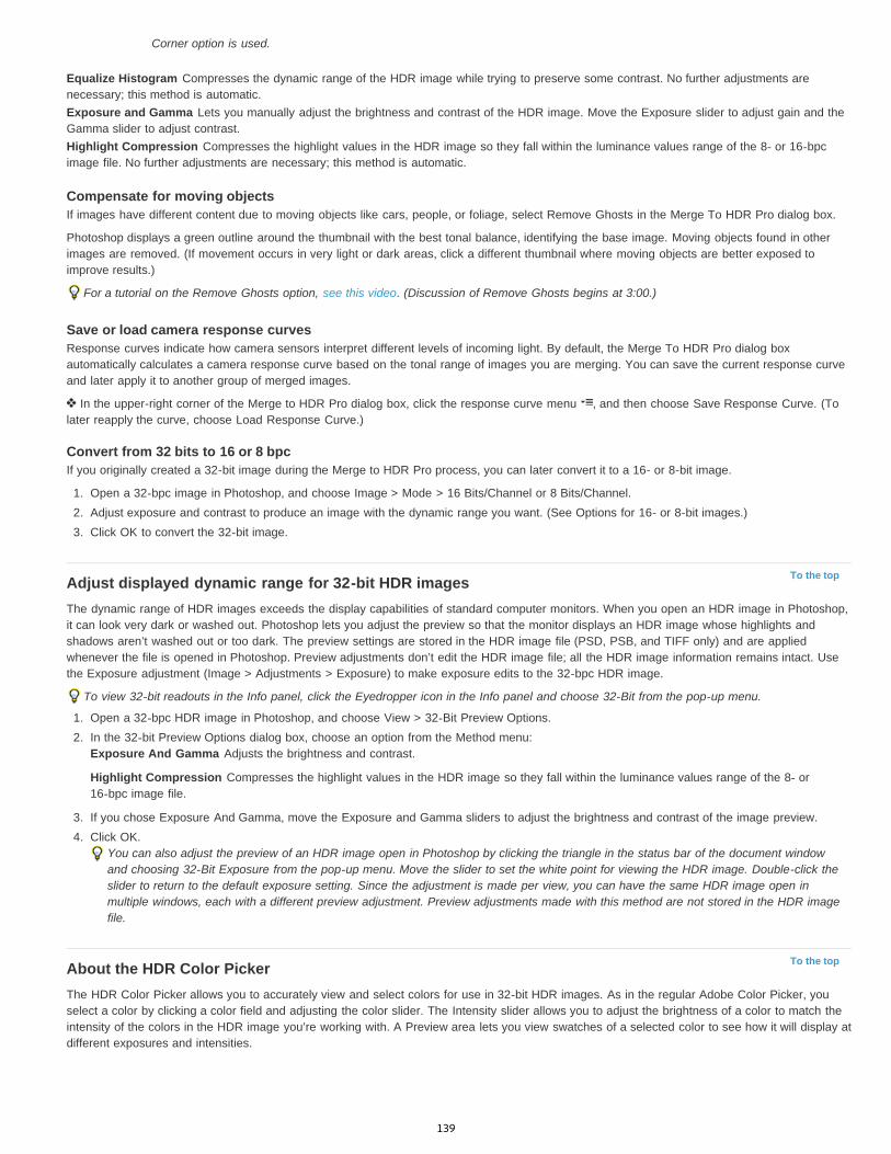
To the top
To the top
Corner option is used.
Equalize Histogram Compresses the dynamic range of the HDR image while trying to preserve some contrast. No further adjustments arenecessary; this method is automatic.Exposure and Gamma Lets you manually adjust the brightness and contrast of the HDR image. Move the Exposure slider to adjust gain and theGamma slider to adjust contrast.Highlight Compression Compresses the highlight values in the HDR image so they fall within the luminance values range of the 8- or 16-bpcimage file. No further adjustments are necessary; this method is automatic.
Compensate for moving objectsIf images have different content due to moving objects like cars, people, or foliage, select Remove Ghosts in the Merge To HDR Pro dialog box.
Photoshop displays a green outline around the thumbnail with the best tonal balance, identifying the base image. Moving objects found in otherimages are removed. (If movement occurs in very light or dark areas, click a different thumbnail where moving objects are better exposed toimprove results.)
For a tutorial on the Remove Ghosts option, see this video. (Discussion of Remove Ghosts begins at 3:00.)
Save or load camera response curvesResponse curves indicate how camera sensors interpret different levels of incoming light. By default, the Merge To HDR Pro dialog boxautomatically calculates a camera response curve based on the tonal range of images you are merging. You can save the current response curveand later apply it to another group of merged images.
In the upper-right corner of the Merge to HDR Pro dialog box, click the response curve menu , and then choose Save Response Curve. (Tolater reapply the curve, choose Load Response Curve.)
Convert from 32 bits to 16 or 8 bpcIf you originally created a 32-bit image during the Merge to HDR Pro process, you can later convert it to a 16- or 8-bit image.
1. Open a 32-bpc image in Photoshop, and choose Image > Mode > 16 Bits/Channel or 8 Bits/Channel.2. Adjust exposure and contrast to produce an image with the dynamic range you want. (See Options for 16- or 8-bit images.)3. Click OK to convert the 32-bit image.
Adjust displayed dynamic range for 32-bit HDR imagesThe dynamic range of HDR images exceeds the display capabilities of standard computer monitors. When you open an HDR image in Photoshop,it can look very dark or washed out. Photoshop lets you adjust the preview so that the monitor displays an HDR image whose highlights andshadows aren’t washed out or too dark. The preview settings are stored in the HDR image file (PSD, PSB, and TIFF only) and are appliedwhenever the file is opened in Photoshop. Preview adjustments don’t edit the HDR image file; all the HDR image information remains intact. Usethe Exposure adjustment (Image > Adjustments > Exposure) to make exposure edits to the 32-bpc HDR image.
To view 32-bit readouts in the Info panel, click the Eyedropper icon in the Info panel and choose 32-Bit from the pop-up menu.
1. Open a 32-bpc HDR image in Photoshop, and choose View > 32-Bit Preview Options.2. In the 32-bit Preview Options dialog box, choose an option from the Method menu:
Exposure And Gamma Adjusts the brightness and contrast.
Highlight Compression Compresses the highlight values in the HDR image so they fall within the luminance values range of the 8- or16-bpc image file.
3. If you chose Exposure And Gamma, move the Exposure and Gamma sliders to adjust the brightness and contrast of the image preview.4. Click OK.
You can also adjust the preview of an HDR image open in Photoshop by clicking the triangle in the status bar of the document windowand choosing 32-Bit Exposure from the pop-up menu. Move the slider to set the white point for viewing the HDR image. Double-click theslider to return to the default exposure setting. Since the adjustment is made per view, you can have the same HDR image open inmultiple windows, each with a different preview adjustment. Preview adjustments made with this method are not stored in the HDR imagefile.
About the HDR Color PickerThe HDR Color Picker allows you to accurately view and select colors for use in 32-bit HDR images. As in the regular Adobe Color Picker, youselect a color by clicking a color field and adjusting the color slider. The Intensity slider allows you to adjust the brightness of a color to match theintensity of the colors in the HDR image you’re working with. A Preview area lets you view swatches of a selected color to see how it will display atdifferent exposures and intensities.
139

HDR Color PickerA. Preview area B. Adjusted color C. Original color D. 32-bit floating point values E. Intensity slider F. Picked color G. Color slider H. Colorvalues
Display the HDR Color Picker With a 32-bpc image open, do one of the following:
In the toolbox, click the foreground or background color selection box.
In the Color panel, click the Set Foreground Coloror Set Background Color selection box.
The Color Picker is also available when features let you choose a color. For example, by clicking the color swatch in the options bar for sometools, or the eyedroppers in some color adjustment dialog boxes.
Choose colors for HDR imagesThe lower part of the HDR Color Picker functions like the regular Color Picker does with 8- or 16-bit images. Click in the color field to select acolor and move the color slider to change hues, or use the HSB or RGB fields to enter numeric values for a particular color. In the color field,brightness increases as you move from bottom to top, and saturation increases as you move from left to right.
Use the Intensity slider to adjust the brightness of the color. The color value plus the intensity value are converted to 32-bit floating point numbervalues in your HDR document.
1. Select a color by clicking in the color field and moving the color slider, or by entering HSB or RGB numeric values, as in the Adobe ColorPicker.
2. Adjust the Intensity slider to boost or reduce the color’s brightness. The new color swatch in the Preview scale at the top of the Color Pickershows the effect of increasing or decreasing stops for the selected color.
The Intensity Stops correspond inversely to exposure setting stops. If you boost the Exposure setting of the HDR image two stops, reducingthe Intensity stops by two will maintain the same color appearance as if the HDR image exposure and the color intensity were both set to 0.
If you know the exact 32-bit RGB values for the color you want, you can enter them directly in the 32-bit value RGB fields.
3. (Optional) Adjust settings for the Preview area.Preview Stop Size Sets the stop increments for each preview swatch. For example, a setting of 3 results in swatches of -9, -6, -3, +3, +6,+9. These swatches let you preview the appearance of your selected color at different exposure settings.
Relative to Document Select to adjust the preview swatches to reflect the current exposure setting for the image. For example, if thedocument exposure is set higher, the new preview swatch will be lighter than the color selected in the Color Picker’s color field, to show theeffect of the higher exposure on the selected color. If the current exposure is set to 0 (the default), checking or unchecking this option willnot change the new swatch.
4. (Optional) Click Add to Swatches to add the selected color to the Swatches panel.5. Click OK.
140

To the topPaint on HDR imagesYou can edit and add effects to HDR/32-bpc images using any of the following Photoshop tools: Brush, Pencil, Pen, Shape, Clone Stamp, PatternStamp, Eraser, Gradient, Blur, Sharpen, Smudge, and History Brush. You can also use the Text tool to add 32-bpc text layers to an HDR image.
When editing or painting on HDR images, you can preview your work at different exposure settings using either the 32-Bit Exposure slider in thedocument info area or the 32-Bit Preview Options dialog box (View > 32-Bit Preview Options). The HDR Color Picker also lets you preview yourselected foreground color at different intensity settings, to match different exposure settings in an HDR image.
1. Open an HDR image.2. (Optional) Set the exposure for the image. See Adjust displayed dynamic range for 32-bit HDR images.3. For the Brush or Pencil tools, click the foreground color to open the HDR Color Picker and select a color. For the Text tool, click the color
chip in the Text tool options bar to set the text color.The Preview area of the HDR Color Picker helps you select and adjust a foreground color in relation to different exposure settings in theHDR image. See About the HDR Color Picker.
To view the effects of painting at different HDR exposures, use the Window > Arrange > New Window command to open simultaneousviews of the same HDR image, then set each window to a different exposure using the Exposure slider in the document status bar area.
More Help topicsAdjust HDR exposure and toning
Legal Notices | Online Privacy Policy
141

Blending modes
To the top
Blending mode descriptionsBlending mode examples
The blending mode specified in the options bar controls how pixels in the image are affected by a painting or editing tool. It’s helpful to think interms of the following colors when visualizing a blending mode’s effect:
The base color is the original color in the image.
The blend color is the color being applied with the painting or editing tool.
The result color is the color resulting from the blend.
Blending mode descriptionsChoose from the Mode pop-up menu in the options bar.
Note: Only the Normal, Dissolve, Darken, Multiply, Lighten, Linear Dodge (Add), Difference, Hue, Saturation, Color, Luminosity, Lighter Color, andDarker Color blending modes are available for 32-bit images.Normal Edits or paints each pixel to make it the result color. This is the default mode. (Normal mode is called Threshold when you’re working witha bitmapped or indexed-color image.)Dissolve Edits or paints each pixel to make it the result color. However, the result color is a random replacement of the pixels with the base coloror the blend color, depending on the opacity at any pixel location.Behind Edits or paints only on the transparent part of a layer. This mode works only in layers with Lock Transparency deselected and isanalogous to painting on the back of transparent areas on a sheet of acetate.Clear Edits or paints each pixel and makes it transparent. This mode is available for the Shape tools (when fill region is selected), Paint Buckettool , Brush tool , Pencil tool , Fill command, and Stroke command. You must be in a layer with Lock Transparency deselected to use thismode.Darken Looks at the color information in each channel and selects the base or blend color—whichever is darker—as the result color. Pixelslighter than the blend color are replaced, and pixels darker than the blend color do not change.Multiply Looks at the color information in each channel and multiplies the base color by the blend color. The result color is always a darker color.Multiplying any color with black produces black. Multiplying any color with white leaves the color unchanged. When you’re painting with a colorother than black or white, successive strokes with a painting tool produce progressively darker colors. The effect is similar to drawing on the imagewith multiple marking pens.Color Burn Looks at the color information in each channel and darkens the base color to reflect the blend color by increasing the contrastbetween the two. Blending with white produces no change.Linear Burn Looks at the color information in each channel and darkens the base color to reflect the blend color by decreasing the brightness.Blending with white produces no change.Lighten Looks at the color information in each channel and selects the base or blend color—whichever is lighter—as the result color. Pixelsdarker than the blend color are replaced, and pixels lighter than the blend color do not change.Screen Looks at each channel’s color information and multiplies the inverse of the blend and base colors. The result color is always a lightercolor. Screening with black leaves the color unchanged. Screening with white produces white. The effect is similar to projecting multiplephotographic slides on top of each other.Color Dodge Looks at the color information in each channel and brightens the base color to reflect the blend color by decreasing contrastbetween the two. Blending with black produces no change.Linear Dodge (Add) Looks at the color information in each channel and brightens the base color to reflect the blend color by increasing thebrightness. Blending with black produces no change.Overlay Multiplies or screens the colors, depending on the base color. Patterns or colors overlay the existing pixels while preserving the highlightsand shadows of the base color. The base color is not replaced, but mixed with the blend color to reflect the lightness or darkness of the originalcolor.Soft Light Darkens or lightens the colors, depending on the blend color. The effect is similar to shining a diffused spotlight on the image. If theblend color (light source) is lighter than 50% gray, the image is lightened as if it were dodged. If the blend color is darker than 50% gray, theimage is darkened as if it were burned in. Painting with pure black or white produces a distinctly darker or lighter area, but does not result in pureblack or white.Hard Light Multiplies or screens the colors, depending on the blend color. The effect is similar to shining a harsh spotlight on the image. If theblend color (light source) is lighter than 50% gray, the image is lightened, as if it were screened. This is useful for adding highlights to an image. Ifthe blend color is darker than 50% gray, the image is darkened, as if it were multiplied. This is useful for adding shadows to an image. Paintingwith pure black or white results in pure black or white.Vivid Light Burns or dodges the colors by increasing or decreasing the contrast, depending on the blend color. If the blend color (light source) is
142

To the top
lighter than 50% gray, the image is lightened by decreasing the contrast. If the blend color is darker than 50% gray, the image is darkened byincreasing the contrast.Linear Light Burns or dodges the colors by decreasing or increasing the brightness, depending on the blend color. If the blend color (light source)is lighter than 50% gray, the image is lightened by increasing the brightness. If the blend color is darker than 50% gray, the image is darkened bydecreasing the brightness.Pin Light Replaces the colors, depending on the blend color. If the blend color (light source) is lighter than 50% gray, pixels darker than the blendcolor are replaced, and pixels lighter than the blend color do not change. If the blend color is darker than 50% gray, pixels lighter than the blendcolor are replaced, and pixels darker than the blend color do not change. This is useful for adding special effects to an image.Hard Mix Adds the red, green and blue channel values of the blend color to the RGB values of the base color. If the resulting sum for a channel is255 or greater, it receives a value of 255; if less than 255, a value of 0. Therefore, all blended pixels have red, green, and blue channel values ofeither 0 or 255. This changes all pixels to primary additive colors (red, green, or blue), white, or black.Note: For CMYK images, Hard Mix changes all pixels to the primary subtractive colors (cyan, yellow, or magenta), white, or black. The maximumcolor value is 100.Difference Looks at the color information in each channel and subtracts either the blend color from the base color or the base color from theblend color, depending on which has the greater brightness value. Blending with white inverts the base color values; blending with black producesno change.Exclusion Creates an effect similar to but lower in contrast than the Difference mode. Blending with white inverts the base color values. Blendingwith black produces no change.Subtract Looks at the color information in each channel and subtracts the blend color from the base color. In 8- and 16-bit images, any resultingnegative values are clipped to zero.Divide Looks at the color information in each channel and divides the blend color from the base color.Hue Creates a result color with the luminance and saturation of the base color and the hue of the blend color.Saturation Creates a result color with the luminance and hue of the base color and the saturation of the blend color. Painting with this mode in anarea with no (0) saturation (gray) causes no change.Color Creates a result color with the luminance of the base color and the hue and saturation of the blend color. This preserves the gray levels inthe image and is useful for coloring monochrome images and for tinting color images.Luminosity Creates a result color with the hue and saturation of the base color and the luminance of the blend color. This mode creates theinverse effect of Color mode.Lighter Color Compares the total of all channel values for the blend and base color and displays the higher value color. Lighter Color does notproduce a third color, which can result from the Lighten blend, because it chooses the highest channel values from both the base and blend colorto create the result color.Darker Color Compares the total of all channel values for the blend and base color and displays the lower value color. Darker Color does notproduce a third color, which can result from the Darken blend, because it chooses the lowest channel values from both the base and the blendcolor to create the result color.
Blending mode examplesThese examples show the result of painting part of the image’s face using each blending mode.
For a video on blending modes, see www.adobe.com/go/vid0012.
Original Image Normal, 100% opacity Normal, 50% opacity Dissolve, 50% opacity
Behind Clear Darken Multiply
143

Color Burn Linear Burn Lighten Screen
Color Dodge Linear Dodge (Add) Overlay Soft Light
Hard Light Vivid Light Linear Light Pin Light
Hard Mix Difference Exclusion Subtract
Divide Hue Saturation Color
Luminosity, 80% opacity Lighter Color Darker Color
Legal Notices | Online Privacy Policy
144
Color modes
To the top
To the top
To the top
To the top
RGB Color modeCMYK Color modeLab Color modeGrayscale modeBitmap modeDuotone modeIndexed Color modeMultichannel mode
RGB Color modePhotoshop RGB Color mode uses the RGB model, assigning an intensity value to each pixel. In 8-bits-per-channel images, the intensity valuesrange from 0 (black) to 255 (white) for each of the RGB (red, green, blue) components in a color image. For example, a bright red color has an Rvalue of 246, a G value of 20, and a B value of 50. When the values of all three components are equal, the result is a shade of neutral gray. Whenthe values of all components are 255, the result is pure white; when the values are 0, pure black.
RGB images use three colors, or channels, to reproduce colors on screen. In 8-bits-per-channel images, the three channels translate to 24 (8 bitsx 3 channels) bits of color information per pixel. With 24-bit images, the three channels can reproduce up to 16.7 million colors per pixel. With48-bit (16-bits-per-channel) and 96-bit (32-bits-per-channel) images, even more colors can be reproduced per pixel. In addition to being thedefault mode for new Photoshop images, the RGB model is used by computer monitors to display colors. This means that when working in colormodes other than RGB, such as CMYK, Photoshop converts the CMYK image to RGB for display on screen.
Although RGB is a standard color model, the exact range of colors represented can vary, depending on the application or display device. TheRGB Color mode in Photoshop varies according to the working space setting that you specify in the Color Settings dialog box.
CMYK Color modeIn the CMYK mode, each pixel is assigned a percentage value for each of the process inks. The lightest (highlight) colors are assigned smallpercentages of process ink colors; the darker (shadow) colors higher percentages. For example, a bright red might contain 2% cyan, 93%magenta, 90% yellow, and 0% black. In CMYK images, pure white is generated when all four components have values of 0%.
Use the CMYK mode when preparing an image to be printed using process colors. Converting an RGB image into CMYK creates a colorseparation. If you start with an RGB image, it’s best to edit first in RGB and then convert to CMYK at the end of your editing process. In RGBmode, you can use the Proof Setup commands to simulate the effects of a CMYK conversion without changing the actual image data. You canalso use CMYK mode to work directly with CMYK images scanned or imported from high-end systems.
Although CMYK is a standard color model, the exact range of colors represented can vary, depending on the press and printing conditions. TheCMYK Color mode in Photoshop varies according to the working space setting that you specify in the Color Settings dialog box.
Lab Color modeThe CIE L*a*b* color model (Lab) is based on the human perception of color. The numeric values in Lab describe all the colors that a person withnormal vision sees. Because Lab describes how a color looks rather than how much of a particular colorant is needed for a device (such as amonitor, desktop printer, or digital camera) to produce colors, Lab is considered to be a device-independent color model. Color managementsystems use Lab as a color reference to predictably transform a color from one color space to another color space.
The Lab Color mode has a lightness component (L) that can range from 0 to 100. In the Adobe Color Picker and Color panel, the a component(green-red axis) and the b component (blue-yellow axis) can range from +127 to –128.
Lab images can be saved in Photoshop, Photoshop EPS, Large Document Format (PSB), Photoshop PDF, Photoshop Raw, TIFF, Photoshop DCS1.0, or Photoshop DCS 2.0 formats. You can save 48-bit (16-bits-per-channel) Lab images in Photoshop, Large Document Format (PSB),Photoshop PDF, Photoshop Raw, or TIFF formats.
Note: The DCS 1.0 and DCS 2.0 formats convert the file to CMYK when opened.
Grayscale modeGrayscale mode uses different shades of gray in an image. In 8-bit images, there can be up to 256 shades of gray. Every pixel of a grayscaleimage has a brightness value ranging from 0 (black) to 255 (white). In 16 and 32-bit images, the number of shades in an image is much greater
145
To the top
To the top
To the top
To the top
than in 8-bit images.
Grayscale values can also be measured as percentages of black ink coverage (0% is equal to white, 100% to black).
Grayscale mode uses the range defined by the working space setting that you specify in the Color Settings dialog box.
Bitmap modeBitmap mode uses one of two color values (black or white) to represent the pixels in an image. Images in Bitmap mode are called bitmapped 1-bitimages because they have a bit depth of 1.
Duotone modeDuotone mode creates monotone, duotone (two-color), tritone (three-color), and quadtone (four-color) grayscale images using one to four custominks.
Indexed Color modeIndexed Color mode produces 8-bit image files with up to 256 colors. When converting to indexed color, Photoshop builds a color lookup table(CLUT), which stores and indexes the colors in the image. If a color in the original image does not appear in the table, the program chooses theclosest one or uses dithering to simulate the color using available colors.
Although its palette of colors is limited, indexed color can reduce file size yet maintain the visual quality needed for multimedia presentations, webpages, and the like. Limited editing is available in this mode. For extensive editing, you should convert temporarily to RGB mode. Indexed colorfiles can be saved in Photoshop, BMP, DICOM (Digital Imaging and Communications in Medicine), GIF, Photoshop EPS, Large Document Format(PSB), PCX, Photoshop PDF, Photoshop Raw, Photoshop 2.0, PICT, PNG, Targa®, or TIFF formats.
Multichannel modeMultichannel mode images contain 256 levels of gray in each channel and are useful for specialized printing. Multichannel mode images can besaved in Photoshop, Large Document Format (PSB), Photoshop 2.0, Photoshop Raw, or Photoshop DCS 2.0 formats.
These guidelines apply when converting images to Multichannel mode:
Layers are unsupported and therefore flattened.
Color channels in the original image become spot color channels in the converted image.
Converting a CMYK image to Multichannel mode creates cyan, magenta, yellow, and black spot channels.
Converting an RGB image to Multichannel mode creates cyan, magenta, and yellow spot channels.
Deleting a channel from an RGB, CMYK, or Lab image automatically converts the image to Multichannel mode, flattening layers.
To export a multichannel image, save it in Photoshop DCS 2.0 format.
Note: Indexed Color and 32-bit images cannot be converted to Multichannel mode.More Help topics
About color working spaces
Soft-proof colors
Legal Notices | Online Privacy Policy
146

Converting between color modes
To the top
To the top
Convert an image to another color modeConvert an image to Bitmap modeConvert a color photo to Grayscale modeConvert a Bitmap mode image to Grayscale modeConvert a grayscale or RGB image to indexed color
Convert an image to another color modeYou can change an image from its original mode (source mode) to a different mode (target mode). When you choose a different color mode for animage, you permanently change the color values in the image. For example, when you convert an RGB image to CMYK mode, RGB color valuesoutside the CMYK gamut (defined by the CMYK working space setting in the Color Settings dialog box) are adjusted to fall within gamut. As aresult, some image data may be lost and can’t be recovered if you convert the image from CMYK back to RGB.
Before converting images, it’s best to do the following:
Do as much editing as possible in the original image mode (usually RGB for images from most scanners or digital cameras, or CMYK forimages from traditional drum scanners or imported from a Scitex system).
Save a backup copy before converting. Be sure to save a copy of your image that includes all layers so that you can edit the original versionof the image after the conversion.
Flatten the file before converting it. The interaction of colors between layer blending modes changes when the mode changes.Note: In most cases, you’ll want to flatten a file before converting it. However, it isn't required and, in some cases, it isn’t desirable (forexample, when the file has vector text layers).
Choose Image > Mode and the mode you want from the submenu. Modes not available for the active image appear dimmed in the menu.Images are flattened when converted to Multichannel, Bitmap, or Indexed Color mode, because these modes do not support layers.
Convert an image to Bitmap modeConverting an image to Bitmap mode reduces the image to two colors, greatly simplifying the color information in the image and reducing its filesize.
When converting a color image to Bitmap mode, first convert it to Grayscale mode. This removes the hue and saturation information from thepixels and leaves just the brightness values. However, because only a few editing options are available for Bitmap mode images, it’s usually bestto edit the image in Grayscale mode and then convert it to Bitmap mode.
Note: Images in Bitmap mode are 1 bit per channel. You must convert a 16- or 32-bits-per-channel image to 8-bit Grayscale mode beforeconverting it to Bitmap mode.
1. Do one of the following:
If the image is in color, choose Image > Mode > Grayscale. Then choose Image > Mode > Bitmap.
If the image is grayscale, choose Image > Mode > Bitmap.
2. For Output, enter a value for the output resolution of the Bitmap mode image, and choose a unit of measurement. By default, the currentimage resolution appears as both the input and the output resolutions.
3. Choose one of the following bitmap conversion methods from the Use pop-up menu:50% Threshold Converts pixels with gray values above the middle gray level (128) to white and pixels with gray values below that level toblack. The result is a very high-contrast, black-and-white representation of the image.
Pattern Dither Converts an image by organizing the gray levels into geometric configurations of black and white dots.
Diffusion Dither Converts an image by using an error-diffusion process, starting at the pixel in the upper-left corner of the image. If thepixel’s value is above middle gray (128), the pixel is changed to white—if below it, to black. Because the original pixel is rarely pure white orpure black, error is inevitably introduced. This error is transferred to surrounding pixels and diffused throughout the image, resulting in agrainy, film-like texture.
Halftone Screen Simulates the appearance of halftone dots in the converted image. Enter values in the Halftone Screen dialog box:
For Frequency, enter a value for the screen frequency, and choose a unit of measurement. Values can range from 1.000 to 999.999 forlines per inch and from 0.400 to 400.00 for lines per centimeter. You can enter decimal values. The screen frequency specifies the rulingof the halftone screen in lines per inch (lpi). The frequency depends on the paper stock and type of press used for printing. Newspapers
147

To the top
To the top
To the top
commonly use an 85-line screen. Magazines use higher resolution screens, such as 133-lpi and 150-lpi. Check with your print shop forcorrect screen frequencies.
Enter a value for the screen angle in degrees from -180 to +180. The screen angle refers to the orientation of the screen. Continuous-tone and black-and-white halftone screens commonly use a 45° angle.
For Shape, choose the dot shape you want.
Important: The halftone screen becomes part of the image. If you print the image on a halftone printer, the printer will use its own halftonescreen as well as the halftone screen that is part of the image. On some printers, the result is a moiré pattern.
Custom Pattern Simulates the appearance of a custom halftone screen in the converted image. Choose a pattern that lends itself tothickness variations, typically one with a variety of gray shades.
To use this option, you first define a pattern and then screen the grayscale image to apply the texture. To cover the entire image, the patternmust be as large as the image. Otherwise, the pattern is tiled. Photoshop comes with several self-tiling patterns that can be used as halftonescreen patterns.
To prepare a black-and-white pattern for conversion, first convert the image to grayscale and then apply the Blur More filter severaltimes. This blurring technique creates thick lines tapering from dark gray to white.
Original grayscale image, and 50% Threshold conversion method
Pattern Dither conversion method, and Diffusion Dither conversion method
Convert a color photo to Grayscale mode1. Open the photo you want to convert to black-and-white.2. Choose Image > Mode > Grayscale.3. Click Discard. Photoshop converts the colors in the image to black, white, and shades of gray.
Note: The technique above minimizes file size but discards color information and can convert adjacent colors to the exact same shade ofgray. Using a Black & White adjustment layer increases file size but retains color information, letting you map colors to shades of gray.
Convert a Bitmap mode image to Grayscale modeYou can convert a Bitmap mode image to Grayscale mode in order to edit it. Keep in mind that a Bitmap mode image edited in Grayscale modemay not look the same when you convert it back to Bitmap mode. For example, suppose a pixel that is black in Bitmap mode is edited to a shadeof gray in Grayscale mode. When the image is converted back to Bitmap mode, that pixel is rendered as white if its gray value is above the middlegray value of 128.
1. Choose Image > Mode > Grayscale.2. Enter a value between 1 and 16 for the size ratio.
The size ratio is the factor for scaling down the image. For example, to reduce a grayscale image by 50%, enter 2 for the size ratio. If youenter a number greater than 1, the program averages multiple pixels in the Bitmap mode image to produce a single pixel in the grayscaleimage. This process lets you generate multiple shades of gray from an image scanned on a 1-bit scanner.
Convert a grayscale or RGB image to indexed color
148
Converting to indexed color reduces the number of colors in the image to at most 256—the standard number of colors supported by the GIF andPNG-8 formats and many multimedia applications. This conversion reduces file size by deleting color information from the image.
To convert to indexed color, you must start with an image that is 8 bits per channel and in either Grayscale or RGB mode.
1. Choose Image > Mode > Indexed Color.Note: All visible layers will be flattened; any hidden layers will be discarded.
For grayscale images, the conversion happens automatically. For RGB images, the Indexed Color dialog box appears.
2. Select Preview in the Indexed Color dialog box to display a preview of the changes.3. Specify conversion options.
Conversion options for indexed-color imagesWhen converting an RGB image to indexed color, you can specify a number of conversion options in the Indexed Color dialog box.
Palette Type A number of palette types are available for converting an image to indexed color. For the Perceptual, Selective, and Adaptiveoptions, you can choose using a local palette based on the current image’s colors. These are the available palette types:
Exact Creates a palette using the exact colors appearing in the RGB image—an option available only if the image uses 256 or fewercolors. Because the image’s palette contains all colors in the image, there is no dithering.System (Mac OS) Uses the Mac OS default 8-bit palette, which is based on a uniform sampling of RGB colors.System (Windows) Uses the Windows system’s default 8-bit palette, which is based on a uniform sampling of RGB colors.Web Uses the 216-color palette that web browsers, regardless of platform, use to display images on a monitor limited to 256 colors. Thispalette is a subset of the Mac OS 8-bit palette. Use this option to avoid browser dither when viewing images on a monitor display limited to256 colors.Uniform Creates a palette by uniformly sampling colors from the RGB color cube. For example, if Photoshop takes six evenly-spacedcolor levels each of red, green, and blue, the combination produces a uniform palette of 216 colors (6 cubed = 6 x 6 x 6 = 216). The totalnumber of colors displayed in an image corresponds to the nearest perfect cube (8, 27, 64, 125, or 216) that is less than the value in theColors text box.Local (Perceptual) Creates a custom palette by giving priority to colors for which the human eye has greater sensitivity.Local (Selective) Creates a color table similar to the Perceptual color table, but favoring broad areas of color and the preservation of webcolors. This option usually produces images with the greatest color integrity.Local (Adaptive) Creates a palette by sampling the colors from the spectrum appearing most commonly in the image. For example, anRGB image with only the colors green and blue produces a palette made primarily of greens and blues. Most images concentrate colors inparticular areas of the spectrum. To control a palette more precisely, first select a part of the image containing the colors you want toemphasize. Photoshop weights the conversion toward these colors.Master (Perceptual) Creates a custom palette by giving priority to colors for which the human eye has greater sensitivity. Applies whenyou have multiple documents open; takes all open documents into account.Master (Selective) Creates a color table similar to the Perceptual color table, but favoring broad areas of color and the preservation ofweb colors. This option usually produces images with the greatest color integrity. Applies when you have multiple documents open; takesall open documents into account.Master (Adaptive) Creates a palette by sampling the colors from the spectrum appearing most commonly in the image. For example, anRGB image with only the colors green and blue produces a palette made primarily of greens and blues. Most images concentrate colors inparticular areas of the spectrum. To control a palette more precisely, first select a part of the image containing the colors you want toemphasize. Photoshop weights the conversion toward these colors. Applies when you have multiple documents open; takes all opendocuments into account.Custom Creates a custom palette using the Color Table dialog box. Either edit the color table and save it for later use or click Load toload a previously created color table. This option also displays the current Adaptive palette, which is useful for previewing the colors mostoften used in the image.Previous Uses the custom palette from the previous conversion, making it easy to convert several images with the same custompalette.
Number Of Colors For the Uniform, Perceptual, Selective, or Adaptive palette, you can specify the exact number of colors to be displayed (up to256) by entering a value for Colors. The Colors text box controls only how the indexed color table is created. Adobe Photoshop still treats theimage as an 8-bit, 256-color image.Color Inclusion And Transparency To specify colors to be included in the indexed color table or to specify transparency in the image, choosefrom the following options:
Forced Provides options to force the inclusion of certain colors in the color table. Black And White adds a pure black and a pure white tothe color table; Primaries adds red, green, blue, cyan, magenta, yellow, black, and white; Web adds the 216 web-safe colors; and Customlets you define custom colors to add.Transparency Specifies whether to preserve transparent areas of the image during conversion. Selecting this option adds a special indexentry in the color table for transparent colors. Deselecting this option fills transparent areas with the matte color, or with white if no mattecolor is chosen.Matte Specifies the background color used to fill anti-aliased edges that lie adjacent to transparent areas of the image. WhenTransparency is selected, the matte is applied to edge areas to help blend the edges with a web background of the same color. WhenTransparency is deselected, the matte is applied to transparent areas. Choosing None for the matte creates hard-edged transparency if
149
Transparency is selected; otherwise, all transparent areas are filled with 100% white. The image must have transparency for the Matteoptions to be available.
Dithering Unless you’re using the Exact color table option, the color table may not contain all the colors used in the image. To simulate colors notin the color table, you can dither the colors. Dithering mixes the pixels of the available colors to simulate the missing colors. Choose a ditheroption from the menu, and enter a percentage value for the dither amount. A higher amount dithers more colors but may increase file size. Youcan choose from the following dither options:
None Does not dither colors but instead uses the color closest to the missing color. This tends to result in sharp transitions betweenshades of color in the image, creating a posterized effect.Diffusion Uses an error-diffusion method that produces a less-structured dither than the Pattern option. To protect colors in the imagethat contain entries in the color table from being dithered, select Preserve Exact Colors. This is useful for preserving fine lines and text forweb images.Pattern Uses a halftone-like square pattern to simulate any colors not in the color table.Noise Helps to reduce seam patterns along the edges of image slices. Choose this option if you plan to slice the image for placement inan HTML table.
More Help topics About color working spaces
Legal Notices | Online Privacy Policy
150
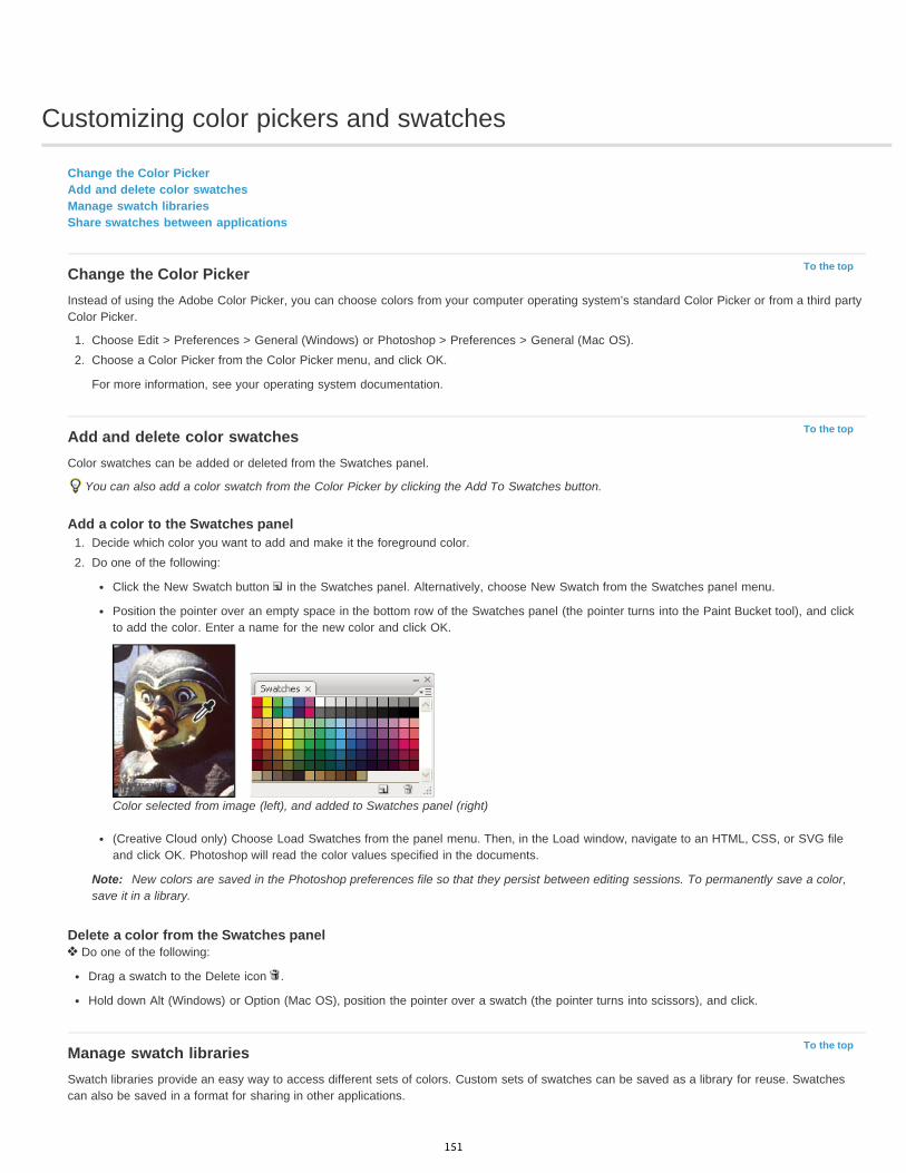
Customizing color pickers and swatches
To the top
To the top
To the top
Change the Color PickerAdd and delete color swatchesManage swatch librariesShare swatches between applications
Change the Color PickerInstead of using the Adobe Color Picker, you can choose colors from your computer operating system’s standard Color Picker or from a third partyColor Picker.
1. Choose Edit > Preferences > General (Windows) or Photoshop > Preferences > General (Mac OS).2. Choose a Color Picker from the Color Picker menu, and click OK.
For more information, see your operating system documentation.
Add and delete color swatchesColor swatches can be added or deleted from the Swatches panel.
You can also add a color swatch from the Color Picker by clicking the Add To Swatches button.
Add a color to the Swatches panel1. Decide which color you want to add and make it the foreground color.2. Do one of the following:
Click the New Swatch button in the Swatches panel. Alternatively, choose New Swatch from the Swatches panel menu.
Position the pointer over an empty space in the bottom row of the Swatches panel (the pointer turns into the Paint Bucket tool), and clickto add the color. Enter a name for the new color and click OK.
Color selected from image (left), and added to Swatches panel (right)
(Creative Cloud only) Choose Load Swatches from the panel menu. Then, in the Load window, navigate to an HTML, CSS, or SVG fileand click OK. Photoshop will read the color values specified in the documents.
Note: New colors are saved in the Photoshop preferences file so that they persist between editing sessions. To permanently save a color,save it in a library.
Delete a color from the Swatches panel Do one of the following:
Drag a swatch to the Delete icon .
Hold down Alt (Windows) or Option (Mac OS), position the pointer over a swatch (the pointer turns into scissors), and click.
Manage swatch librariesSwatch libraries provide an easy way to access different sets of colors. Custom sets of swatches can be saved as a library for reuse. Swatchescan also be saved in a format for sharing in other applications.
151
To the top
Load or replace a library of swatches Choose one of the following from the Swatches panel menu:
Load Swatches Adds a library to the current set of swatches. Select the library file you want to use, and click Load.Replace Swatches Replaces the current list with a different library. Select the library file you want to use, and click Load. Photoshop gives yourthe option of saving the current set of swatches before replacing them.Name of a color library Loads a specific color system listed in the lower part of the Swatches panel menu. You can either replace or append thecurrent set of colors with the library you’re loading.
Save a set of swatches as a library1. Choose Save Swatches from the Swatches panel menu.2. Choose a location for the swatch library, enter a file name, and click Save.
You can save the library anywhere. However, if you place the library file in the Presets/Swatches folder in the default presets location, thelibrary name will appear at the bottom of the Swatches panel menu after you restart the application.
Return to the default library of swatches Choose Reset Swatches from the Swatches panel menu. You can either replace or append the current set of colors with the default swatch
library.
Share swatches between applicationsYou can share the solid swatches you create in Photoshop, Illustrator, and InDesign by saving a swatch library for exchange. The colors appearexactly the same across applications as long as your color settings are synchronized.
1. In the Swatches panel, create the process and spot-color swatches you want to share, and remove any swatches you don’t want to share.Note: You cannot share the following types of swatches between applications: patterns, gradients, and the Registration swatch fromIllustrator or InDesign; and book color references, HSB, XYZ, duotone, monitorRGB, opacity, total ink, and webRGB swatches fromPhotoshop. These types of swatches are automatically excluded when you save swatches for exchange.
2. Select Save Swatches For Exchange from the Swatches panel menu, and save the swatch libraries in an easily accessible location.3. Load the swatch library into the Swatches panel for Photoshop, Illustrator, or InDesign.
More Help topicsAdd swatches from HTML, CSS, and SVG files | Creative Cloud
Legal Notices | Online Privacy Policy
152
Image information
To the top
Work with the Info panelDisplay file information in the document window
Work with the Info panelThe Info panel shows the color values beneath the pointer and, depending on the tool in use, gives other useful information. The Info panel alsodisplays a hint on using the selected tool, gives document status information, and can display 8-bit, 16-bit, or 32-bit values.
The Info panel displays the following information:
Depending on the option you specify, the Info panel displays 8-bit, 16-bit, or 32-bit values.
When displaying CMYK values, the Info panel displays an exclamation point next to the CMYK values if the color beneath the pointer or colorsampler is out of the printable CMYK color gamut.
When a marquee tool is being used, the Info panel displays the x and y coordinates of the pointer position and the width (W) and height (H)of the marquee as you drag.
When the Crop tool or Zoom tool is being used, the Info panel displays the width (W) and height (H) of the marquee as you drag. The panelalso shows the angle of rotation of the crop marquee.
When the Line tool, the Pen tool, or Gradient tool is being used, or when a selection is being moved, the Info panel displays the x and ycoordinates of your starting position, the change in X (DX), the change in Y (DY), the angle (A), and the length (D) as you drag.
When a two-dimensional transformation command is being used, the Info panel displays the percentage change in width (W) and height (H),the angle of rotation (A), and the angle of horizontal skew (H) or vertical skew (V).
When any color adjustment dialog box (for example, Curves) is being used, the Info panel displays before-and-after color values for thepixels beneath the pointer and beneath color samplers.
If the Show Tool Hints option is enabled, you see hints for using the tool selected in the toolbox.
Depending on the options selected, the Info panel displays status information, such as document size, document profile, documentdimensions, scratch sizes, efficiency, timing, and current tool.
Use the Info panelThe Info panel displays file information about an image and also provides feedback about the color values as you move a tool pointer over animage. Make sure the Info panel is visible in your workspace if you want to view information while dragging in the image.
1. (Optional) Do one of the following if you need to display the Info panel:
Click the Info panel tab if it’s docked with other panels.
Choose Window > Info. File information about the image is displayed at the bottom of the Info panel. You can change the informationdisplayed by clicking the triangle in the upper right corner of the panel and choosing Panel Options from the panel menu.
2. Set the options for the information you want displayed in the Info Panel by doing any of the following:
Choose Panel Options from the Info panel menu and specify options in the Info Panel Options dialog box.
Click an eyedropper icon and choose display options from the pop-up menu. You can also use the pop-up menu to specify whether theInfo panel displays 8-bit, 16-bit, or 32-bit values.
Click the cursor coordinates icon and choose a unit of measurement.
3. Select a tool.4. Move the pointer in the image, or drag in the image to use the tool. The following information may appear, depending on which tool you’re
using:Displays the numeric values for the color beneath the pointer.
Displays the x and y coordinates of the pointer.
Displays the width (W) and height (H) of a marquee or shape as you drag, or the width and height of an active selection.
Change the Info panel options1. Click the triangle in the upper right corner to open the Info panel menu and choose Panel Options.
153
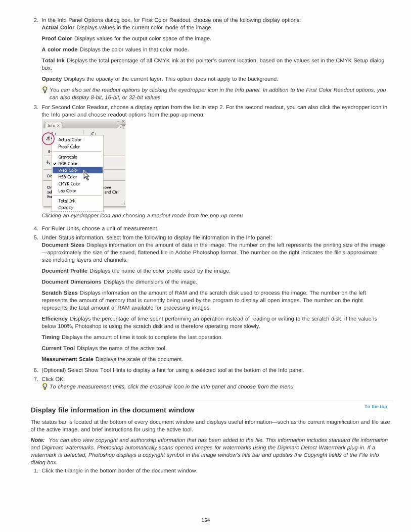
To the top
2. In the Info Panel Options dialog box, for First Color Readout, choose one of the following display options:Actual Color Displays values in the current color mode of the image.
Proof Color Displays values for the output color space of the image.
A color mode Displays the color values in that color mode.
Total Ink Displays the total percentage of all CMYK ink at the pointer’s current location, based on the values set in the CMYK Setup dialogbox.
Opacity Displays the opacity of the current layer. This option does not apply to the background.
You can also set the readout options by clicking the eyedropper icon in the Info panel. In addition to the First Color Readout options, youcan also display 8-bit, 16-bit, or 32-bit values.
3. For Second Color Readout, choose a display option from the list in step 2. For the second readout, you can also click the eyedropper icon inthe Info panel and choose readout options from the pop-up menu.
Clicking an eyedropper icon and choosing a readout mode from the pop-up menu
4. For Ruler Units, choose a unit of measurement.5. Under Status information, select from the following to display file information in the Info panel:
Document Sizes Displays information on the amount of data in the image. The number on the left represents the printing size of the image—approximately the size of the saved, flattened file in Adobe Photoshop format. The number on the right indicates the file’s approximatesize including layers and channels.
Document Profile Displays the name of the color profile used by the image.
Document Dimensions Displays the dimensions of the image.
Scratch Sizes Displays information on the amount of RAM and the scratch disk used to process the image. The number on the leftrepresents the amount of memory that is currently being used by the program to display all open images. The number on the rightrepresents the total amount of RAM available for processing images.
Efficiency Displays the percentage of time spent performing an operation instead of reading or writing to the scratch disk. If the value isbelow 100%, Photoshop is using the scratch disk and is therefore operating more slowly.
Timing Displays the amount of time it took to complete the last operation.
Current Tool Displays the name of the active tool.
Measurement Scale Displays the scale of the document.
6. (Optional) Select Show Tool Hints to display a hint for using a selected tool at the bottom of the Info panel.7. Click OK.
To change measurement units, click the crosshair icon in the Info panel and choose from the menu.
Display file information in the document windowThe status bar is located at the bottom of every document window and displays useful information—such as the current magnification and file sizeof the active image, and brief instructions for using the active tool.
Note: You can also view copyright and authorship information that has been added to the file. This information includes standard file informationand Digimarc watermarks. Photoshop automatically scans opened images for watermarks using the Digimarc Detect Watermark plug-in. If awatermark is detected, Photoshop displays a copyright symbol in the image window’s title bar and updates the Copyright fields of the File Infodialog box.
1. Click the triangle in the bottom border of the document window.
154
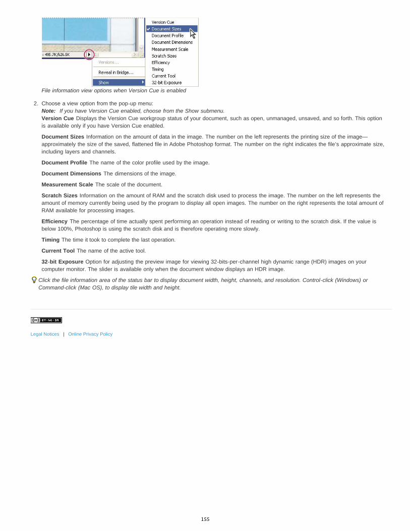
File information view options when Version Cue is enabled
2. Choose a view option from the pop-up menu:Note: If you have Version Cue enabled, choose from the Show submenu.Version Cue Displays the Version Cue workgroup status of your document, such as open, unmanaged, unsaved, and so forth. This optionis available only if you have Version Cue enabled.
Document Sizes Information on the amount of data in the image. The number on the left represents the printing size of the image—approximately the size of the saved, flattened file in Adobe Photoshop format. The number on the right indicates the file’s approximate size,including layers and channels.
Document Profile The name of the color profile used by the image.
Document Dimensions The dimensions of the image.
Measurement Scale The scale of the document.
Scratch Sizes Information on the amount of RAM and the scratch disk used to process the image. The number on the left represents theamount of memory currently being used by the program to display all open images. The number on the right represents the total amount ofRAM available for processing images.
Efficiency The percentage of time actually spent performing an operation instead of reading or writing to the scratch disk. If the value isbelow 100%, Photoshop is using the scratch disk and is therefore operating more slowly.
Timing The time it took to complete the last operation.
Current Tool The name of the active tool.
32-bit Exposure Option for adjusting the preview image for viewing 32-bits-per-channel high dynamic range (HDR) images on yourcomputer monitor. The slider is available only when the document window displays an HDR image.
Click the file information area of the status bar to display document width, height, channels, and resolution. Control-click (Windows) orCommand-click (Mac OS), to display tile width and height.
Legal Notices | Online Privacy Policy
155
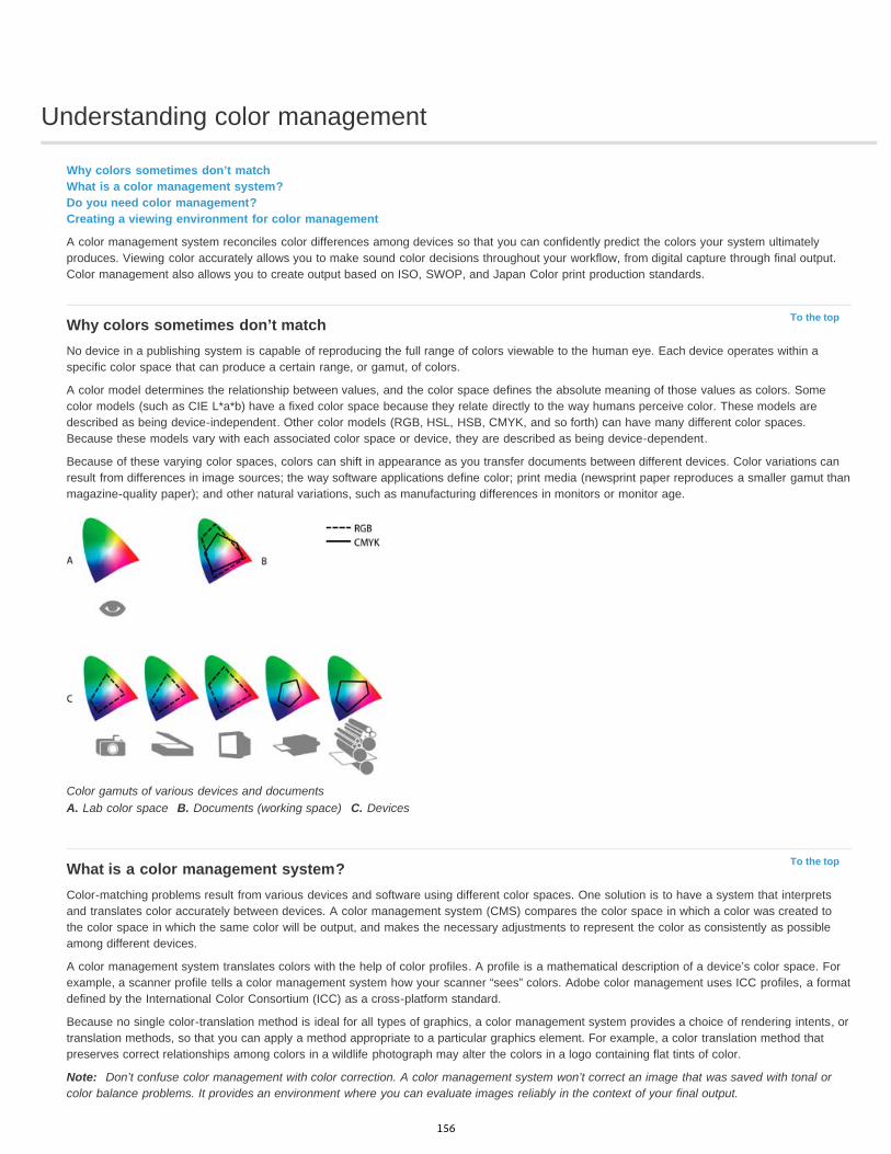
Understanding color management
To the top
To the top
Why colors sometimes don’t matchWhat is a color management system?Do you need color management?Creating a viewing environment for color management
A color management system reconciles color differences among devices so that you can confidently predict the colors your system ultimatelyproduces. Viewing color accurately allows you to make sound color decisions throughout your workflow, from digital capture through final output.Color management also allows you to create output based on ISO, SWOP, and Japan Color print production standards.
Why colors sometimes don’t matchNo device in a publishing system is capable of reproducing the full range of colors viewable to the human eye. Each device operates within aspecific color space that can produce a certain range, or gamut, of colors.
A color model determines the relationship between values, and the color space defines the absolute meaning of those values as colors. Somecolor models (such as CIE L*a*b) have a fixed color space because they relate directly to the way humans perceive color. These models aredescribed as being device-independent. Other color models (RGB, HSL, HSB, CMYK, and so forth) can have many different color spaces.Because these models vary with each associated color space or device, they are described as being device-dependent.
Because of these varying color spaces, colors can shift in appearance as you transfer documents between different devices. Color variations canresult from differences in image sources; the way software applications define color; print media (newsprint paper reproduces a smaller gamut thanmagazine-quality paper); and other natural variations, such as manufacturing differences in monitors or monitor age.
Color gamuts of various devices and documentsA. Lab color space B. Documents (working space) C. Devices
What is a color management system?Color-matching problems result from various devices and software using different color spaces. One solution is to have a system that interpretsand translates color accurately between devices. A color management system (CMS) compares the color space in which a color was created tothe color space in which the same color will be output, and makes the necessary adjustments to represent the color as consistently as possibleamong different devices.
A color management system translates colors with the help of color profiles. A profile is a mathematical description of a device’s color space. Forexample, a scanner profile tells a color management system how your scanner “sees” colors. Adobe color management uses ICC profiles, a formatdefined by the International Color Consortium (ICC) as a cross-platform standard.
Because no single color-translation method is ideal for all types of graphics, a color management system provides a choice of rendering intents, ortranslation methods, so that you can apply a method appropriate to a particular graphics element. For example, a color translation method thatpreserves correct relationships among colors in a wildlife photograph may alter the colors in a logo containing flat tints of color.
Note: Don’t confuse color management with color correction. A color management system won’t correct an image that was saved with tonal orcolor balance problems. It provides an environment where you can evaluate images reliably in the context of your final output.
156
To the top
To the top
Do you need color management?Without a color management system, your color specifications are device-dependent. You might not need color management if your productionprocess is tightly controlled for one medium only. For example, you or your print service provider can tailor CMYK images and specify color valuesfor a known, specific set of printing conditions.
The value of color management increases when you have more variables in your production process. Color management is recommended if youanticipate reusing color graphics for print and online media, using various kinds of devices within a single medium (such as different printingpresses), or if you manage multiple workstations.
You will benefit from a color management system if you need to accomplish any of the following:
Get predictable and consistent color output on multiple output devices including color separations, your desktop printer, and your monitor.Color management is especially useful for adjusting color for devices with a relatively limited gamut, such as a four-color process printingpress.
Accurately soft-proof (preview) a color document on your monitor by making it simulate a specific output device. (Soft-proofing is subject tothe limitations of monitor display, and other factors such as room lighting conditions.)
Accurately evaluate and consistently incorporate color graphics from many different sources if they also use color management, and even insome cases if they don’t.
Send color documents to different output devices and media without having to manually adjust colors in documents or original graphics. Thisis valuable when creating images that will eventually be used both in print and online.
Print color correctly to an unknown color output device; for example, you could store a document online for consistently reproducibleon-demand color printing anywhere in the world.
Creating a viewing environment for color managementYour work environment influences how you see color on your monitor and on printed output. For best results, control the colors and light in yourwork environment by doing the following:
View your documents in an environment that provides a consistent light level and color temperature. For example, the color characteristics ofsunlight change throughout the day and alter the way colors appear on your screen, so keep shades closed or work in a windowless room.To eliminate the blue-green cast from fluorescent lighting, you can install D50 (5000° Kelvin) lighting. You can also view printed documentsusing a D50 lightbox.
View your document in a room with neutral-colored walls and ceiling. A room’s color can affect the perception of both monitor color andprinted color. The best color for a viewing room is neutral gray. Also, the color of your clothing reflecting off the glass of your monitor mayaffect the appearance of colors on-screen.
Remove colorful background patterns on your monitor desktop. Busy or bright patterns surrounding a document interfere with accurate colorperception. Set your desktop to display neutral grays only.
View document proofs in the real-world conditions under which your audience will see the final piece. For example, you might want to seehow a housewares catalog looks under the incandescent light bulbs used in homes, or view an office furniture catalog under the fluorescentlighting used in offices. However, always make final color judgements under the lighting conditions specified by the legal requirements forcontract proofs in your country.
|
157
Layers
Layers 101Infinite Skills (Aug. 9, 2012)video-tutorialIntroduction to layers and the Layers panel
158
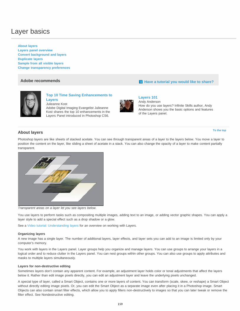
Layer basics
To the top
About layersLayers panel overviewConvert background and layersDuplicate layersSample from all visible layersChange transparency preferences
Adobe recommends Have a tutorial you would like to share?
Top 10 Time Saving Enhancements toLayersJulieanne KostAdobe Digital Imaging Evangelist JulieanneKost shares the top 10 enhancements in theLayers Panel introduced in Photoshop CS6.
Layers 101Andy AndersonHow do you use layers? Infinite Skills author, AndyAnderson shows you the basic options and featuresof the Layers panel.
About layersPhotoshop layers are like sheets of stacked acetate. You can see through transparent areas of a layer to the layers below. You move a layer toposition the content on the layer, like sliding a sheet of acetate in a stack. You can also change the opacity of a layer to make content partiallytransparent.
Transparent areas on a layer let you see layers below.
You use layers to perform tasks such as compositing multiple images, adding text to an image, or adding vector graphic shapes. You can apply alayer style to add a special effect such as a drop shadow or a glow.
See a Video tutorial: Understanding layers for an overview on working with Layers.
Organizing layersA new image has a single layer. The number of additional layers, layer effects, and layer sets you can add to an image is limited only by yourcomputer’s memory.
You work with layers in the Layers panel. Layer groups help you organize and manage layers. You can use groups to arrange your layers in alogical order and to reduce clutter in the Layers panel. You can nest groups within other groups. You can also use groups to apply attributes andmasks to multiple layers simultaneously.
Layers for non-destructive editingSometimes layers don’t contain any apparent content. For example, an adjustment layer holds color or tonal adjustments that affect the layersbelow it. Rather than edit image pixels directly, you can edit an adjustment layer and leave the underlying pixels unchanged.
A special type of layer, called a Smart Object, contains one or more layers of content. You can transform (scale, skew, or reshape) a Smart Objectwithout directly editing image pixels. Or, you can edit the Smart Object as a separate image even after placing it in a Photoshop image. SmartObjects can also contain smart filter effects, which allow you to apply filters non-destructively to images so that you can later tweak or remove thefilter effect. See Nondestructive editing.
159

To the top
To the top
Video layersYou can use video layers to add video to an image. After importing a video clip into an image as a video layer, you can mask the layer, transformit, apply layer effects, paint on individual frames, or rasterize an individual frame and convert it to a standard layer. Use the Timeline panel to playthe video within the image or to access individual frames. See Supported video and image sequence formats (Photoshop Extended).
Layers panel overviewThe Layers panel lists all layers, layer groups, and layer effects in an image. You can use the Layers panel to show and hide layers, create newlayers, and work with groups of layers. You can access additional commands and options in the Layers panel menu.
Photoshop Layers panelA. Layers panel menu B. Layer Group C. Layer D. Expand/Collapse Layer effects E. Layer effect F. Layer thumbnail
Display the Layers panel Choose Window > Layers.
Choose a command from the Layers panel menu Click the triangle in the upper right corner of the panel.
Change the size of layer thumbnails Choose Panel Options from the Layers panel menu, and select a thumbnail size.
Change thumbnail contents Choose panel Options from the Layers panel menu, and select Entire Document to display the contents of the entire document. Select Layer
Bounds to restrict the thumbnail to the object’s pixels on the layer.Turn off thumbnails to improve performance and save monitor space.
Expand and collapse groups Click the triangle to the left of a group folder. See View layers and groups within a group.
Filter layers (CC, CS6)At the top of the Layers panel, the filtering options help you find key layers in complex documents quickly. You can display a subset of layersbased on name, kind, effect, mode, attribute, or color label.
Filter layers options in the Layers panel
1. Choose a filter type from the popup menu.
2. Select or enter the filter criteria.
3. Click the toggle switch to switch layer filtering on or off.
Convert background and layersWhen you create a new image with a white background or a colored background, the bottommost image in the Layers panel is called Background.An image can have only one background layer. You cannot change the stacking order of a background layer, its blending mode, or its opacity.
160

To the top
To the top
To the top
However, you can convert a background into a regular layer, and then change any of these attributes.
When you create a new image with transparent content, the image does not have a background layer. The bottommost layer is not constrainedlike the background layer; you can move it anywhere in the Layers panel and change its opacity and blending mode.
Convert a background into a layer
1. Double-click Background in the Layers panel, or choose Layer > New > Layer From Background.
2. Set layer options. (See Create layers and groups.)
3. Click OK.
Convert a layer into a background
1. Select a layer in the Layers panel.
2. Choose Layer > New > Background From Layer.
Any transparent pixels in the layer are converted to the background color, and the layer drops to the bottom of the layer stack.
Note: You cannot create a background by giving a regular layer the name, Background—you must use the Background From Layercommand.
Duplicate layersYou can duplicate layers within an image or into another or a new image.
Duplicate a layer or group within an image
1. Select a layer or group in the Layers panel.
2. Do one of the following:
Drag the layer or group to the Create a New Layer button .
Choose Duplicate Layer or Duplicate Group from the Layers menu or the Layers panel menu. Enter a name for the layer or group, andclick OK.
Duplicate a layer or group in another image
1. Open the source and destination images.
2. From the Layers panel of the source image, select one or more layers or a layer group.
3. Do one of the following:
Drag the layer or group from the Layers panel to the destination image.
Select the Move tool , and drag from the source image to the destination image. The duplicate layer or group appears above theactive layer in the Layers panel of the destination image. Shift-drag to move the image content to the same location it occupied in thesource image (if the source and destination images have the same pixel dimensions) or to the center of the document window (if thesource and destination images have different pixel dimensions).
Choose Duplicate Layer or Duplicate Group from the Layers menu or the Layers panel menu. Choose the destination document from theDocument pop-up menu, and click OK.
Choose Select > All to select all the pixels on the layer, and choose Edit > Copy. Then choose Edit > Paste in the destination image.(This method copies only pixels, excluding layer properties such as blending mode.)
Create a new document from a layer or group
1. Select a layer or group from the Layers panel.
2. Choose Duplicate Layer or Duplicate Group from the Layers menu or the Layers panel menu.
3. Choose New from the Document pop-up menu, and click OK.
Sample from all visible layersThe default behavior of the Mixer Brush, Magic Wand, Smudge, Blur, Sharpen, Paint Bucket, Clone Stamp, and Healing Brush tools is to samplecolor only from pixels on the active layer. This means you can smudge or sample in a single layer.
To smudge or sample pixels from all visible layers with these tools, select Sample All Layers from the options bar.
Change transparency preferences
161

1. In Windows, choose Edit > Preferences > Transparency & Gamut; in Mac OS, choose Photoshop > Preferences > Transparency & Gamut.2. Choose a size and color for the transparency checkerboard, or choose None for Grid Size to hide the transparency checkerboard.3. Click OK.
Legal Notices | Online Privacy Policy
162
Managing layers
To the top
To the top
To the top
Type
Shape
Fill Content
Vector Mask
Smart Object
Video
3D (Extended only)
Layer
All Layers
Note:
To the top
Rename a layer or groupAssign a color to a layer or groupRasterize layersDelete a layer or groupExport layersMerging layers
Rename a layer or groupAs you add layers to an image, it’s helpful to give them names that reflect their content. Descriptive names make layers easy to identify in thepanel.
Do one of the following:Double-click the layer name or group name in the Layers panel, and enter a new name.
Press Alt (Windows) or Option (Mac OS), and double-click the layer (not its name or thumbnail) in the Layers panel. Enter a new namein the Name text box, and click OK.
Select a layer or group, and choose Layer Properties or Group Properties from the Layers menu or the Layers panel menu. Enter a newname in the Name text box, and click OK.
Assign a color to a layer or groupColor coding layers and groups helps you locate related layers in the Layers panel.
(CC, CS6) Right-click the layer or group and choose a color.
(CS5) Select a layer or group, choose Layer Properties or Group Properties from the Layers menu. Then choose a color from the Color pop-up menu, and click OK.
Rasterize layersYou cannot use the painting tools or filters on layers that contain vector data (such as type layers, shape layers, vector masks, or Smart Objects)and generated data (such as fill layers). However, you can rasterize these layers to convert their contents into a flat, raster image.
Select the layers you want to rasterize, choose Layer > Rasterize, and then choose an option from the submenu:
Rasterizes the type on a type layer. It does not rasterize any other vector data on the layer.
Rasterizes a shape layer.
Rasterizes the fill of a shape layer, leaving the vector mask.
Rasterizes the vector mask on a layer, turning it into a layer mask.
Converts a Smart Object into a raster layer.
Rasterizes the current video frame to an image layer.
Rasterizes the current view of 3D data into a flat raster layer.
Rasterizes all vector data on the selected layers.
Rasterizes all layers that contain vector and generated data.
To rasterize linked layers, select a linked layer, choose Layer > Select Linked Layers, and then rasterize the selected layers.
Delete a layer or group
163

To the top
To the top
Note:
Note:
Note:
Note:
Deleting layers you no longer need reduces the size of your image file.
To quickly delete empty layers, choose File > Scripts > Delete All Empty Layers.
1. Select one or more layers or groups from the Layers panel.2. Do one of the following:
To delete with a confirmation message, click the Delete icon . Alternatively, choose Layers > Delete > Layer or Delete Layer or DeleteGroup from the Layers panel menu.
To delete the layer or group without confirmation, drag it to the Delete icon , Alt-click (Windows) or Option-click (Mac OS) the Deleteicon, or press the Delete key.
To delete hidden layers, choose Layers > Delete > Hidden Layers.
To delete linked layers, select a linked layer, choose Layer > Select Linked Layers, and then delete the layers.
Export layersYou can export all layers or visible layers to separate files.
Choose File > Scripts > Export Layers To Files.
Merging layersWhen you have finalized the content of layers, you can merge them to reduce the size of your image files. When you merge layers, the data onthe top layers replaces any data it overlaps on the lower layers. The intersection of all transparent areas in the merged layers remains transparent.
You cannot use an adjustment or fill layer as the target layer for a merge.
In addition to merging layers, you can stamp them. Stamping allows you to merge the contents of more than one layer into a target layer whileleaving the other layers intact.
When you save a merged document, you cannot revert back to the unmerged state; the layers are permanently merged.
Merge two layers or groups1. Make sure that the layers and groups you want to merge are visible.2. Select the layers and groups you want to merge.3. Choose Layer > Merge Layers.
You can merge two adjacent layers or groups by selecting the top item and then choosing Layer > Merge Layers. You can merge linkedlayers by choosing Layer > Select Linked Layers, and then merging the selected layers. You can merge two 3D layers by choosing Layer > MergeLayers; they will share the same scene and the top layer will inherit the bottom layer 3D properties (the camera views must be the same for this tobe enabled).
Merge layers in a clipping mask1. Hide any layers that you do not want to merge.2. Select the base layer in the clipping mask. The base layer must be a raster layer.3. Choose Merge Clipping Mask from the Layers menu or the Layers panel menu.
For more information on clipping masks, see Mask layers with clipping masks.
Merge all visible layers and groups in an imageChoose Merge Visible from the Layers panel or the Layers panel menu. All layers showing an eye icon are merged.
A visible layer must be selected to enable the Merge Visible command.
Stamp multiple layers or linked layersWhen you stamp multiple selected layers or linked layers, Photoshop creates a new layer containing the merged content.
1. Select multiple layers.2. Press Ctrl+Alt+E (Windows) or Command+Option+E (Mac OS).
Stamp all visible layers1. Turn visibility on for the layers you want to merge.2. Press Shift+Ctrl+Alt+E (Windows) or Shift+Command+Option+E (Mac OS).
Photoshop creates a new layer containing the merged content.
164
Twitter™ and Facebook posts are not covered under the terms of Creative Commons.
Legal Notices | Online Privacy Policy
Note:
Flatten all layersFlattening reduces file size by merging all visible layers into the background and discarding hidden layers. Any transparent areas that remain arefilled with white. When you save a flattened image, you cannot revert back to the unflattened state; the layers are permanently merged.
Converting an image between some color modes flattens the file. Save a copy of your file with all layers intact if you want to edit the originalimage after the conversion.
1. Make sure that all the layers you want to keep are visible.2. Choose Layer > Flatten Image, or choose Flatten Image from the Layers panel menu.
More Help TopicsDisplay file information in the document window
165

Selecting, grouping, and linking layers
To the top
To the top
Select layersGroup and link layersShow layer edges and handles
Select layersYou can select one or more layers to work on them. For some activities, such as painting or making color and tonal adjustments, you can work ononly one layer at a time. A single selected layer is called the active layer. The name of the active layer appears in the title bar of the documentwindow.
For other activities, such as moving, aligning, transforming, or applying styles from the Styles panel, you can select and work on multiple layers ata time. You can select layers in the Layers panel or with the Move tool .
You can also link layers. Unlike multiple layers selected at the same time, linked layers stay linked when you change the selection in the Layerspanel. See Link and unlink layers.
If you don’t see the desired results when using a tool or applying a command, you may not have the correct layer selected. Check the Layerspanel to make sure that you’re working on the correct layer.
Select layers in the Layers panel Do one of the following:
Click a layer in the Layers panel.
To select multiple contiguous layers, click the first layer and then Shift-click the last layer.
To select multiple noncontiguous layers, Ctrl-click (Windows) or Command-click (Mac OS) them in the Layers panel.
Note: When selecting, Ctrl-click (Windows) or Command-click (Mac OS) the area outside the layer thumbnail. Ctrl-clicking or Command-clicking the layer thumbnail selects the nontransparent areas of the layer.
To select all layers, choose Select > All Layers.
To select all layers of a similar type (for example all type layers), select one of the layers, and choose Select > Similar Layers.
To deselect a layer, Ctrl-click (Windows) or Command-click (Mac OS) the layer.
To have no layer selected, click in the Layers panel below the background or bottom layer, or choose Select > Deselect Layers.
Select layers in the document window1. Select the Move tool .2. Do one of the following:
In the options bar, select Auto Select, then choose Layer from the drop-down menu, and click in the document on the layer you want toselect. The top layer containing pixels under the cursor is selected.
In the options bar, select Auto Select, then choose Group from the drop-down menu, and click in the document on the content you wantto select. The top group containing pixels under the cursor is selected. If you click an ungrouped layer, it becomes selected.
Right-click (Windows) or Control-click (Mac OS) in the image, and choose a layer from the context menu. The context menu lists all thelayers that contain pixels under the current pointer location.
Select a layer in a group1. Click the group in the Layers panel.2. Click the triangle to the left of the folder icon .3. Click the individual layer in the group.
Group and link layers
Group and ungroup layers
166
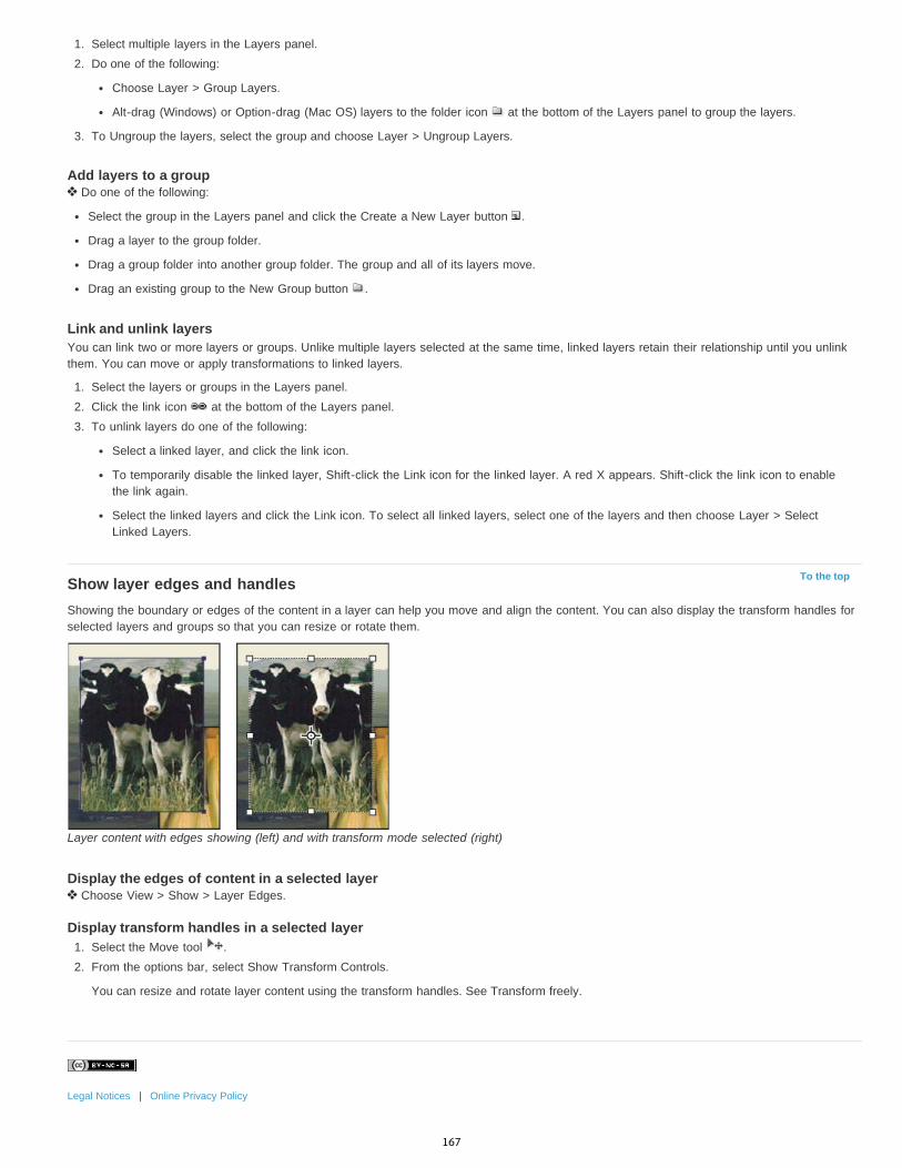
To the top
1. Select multiple layers in the Layers panel.2. Do one of the following:
Choose Layer > Group Layers.
Alt-drag (Windows) or Option-drag (Mac OS) layers to the folder icon at the bottom of the Layers panel to group the layers.
3. To Ungroup the layers, select the group and choose Layer > Ungroup Layers.
Add layers to a group Do one of the following:
Select the group in the Layers panel and click the Create a New Layer button .
Drag a layer to the group folder.
Drag a group folder into another group folder. The group and all of its layers move.
Drag an existing group to the New Group button .
Link and unlink layersYou can link two or more layers or groups. Unlike multiple layers selected at the same time, linked layers retain their relationship until you unlinkthem. You can move or apply transformations to linked layers.
1. Select the layers or groups in the Layers panel.2. Click the link icon at the bottom of the Layers panel.3. To unlink layers do one of the following:
Select a linked layer, and click the link icon.
To temporarily disable the linked layer, Shift-click the Link icon for the linked layer. A red X appears. Shift-click the link icon to enablethe link again.
Select the linked layers and click the Link icon. To select all linked layers, select one of the layers and then choose Layer > SelectLinked Layers.
Show layer edges and handlesShowing the boundary or edges of the content in a layer can help you move and align the content. You can also display the transform handles forselected layers and groups so that you can resize or rotate them.
Layer content with edges showing (left) and with transform mode selected (right)
Display the edges of content in a selected layer Choose View > Show > Layer Edges.
Display transform handles in a selected layer1. Select the Move tool .2. From the options bar, select Show Transform Controls.
You can resize and rotate layer content using the transform handles. See Transform freely.
Legal Notices | Online Privacy Policy
167
Copy CSS from layers | CC, CS6
Twitter™ and Facebook posts are not covered under the terms of Creative Commons.
Legal Notices | Online Privacy Policy
Note:
Copy CSS generates Cascading Style Sheet (CSS) properties from shape or text layers. The CSS is copied to the clipboard and can be pastedinto a style sheet. For shapes it captures values for the following:
sizepositionstroke color
fill color (including gradients)drop shadow
For text layers, Copy CSS also captures the following values:
font familyfont sizefont weight
line heightunderlinestrikethrough
superscriptsubscripttext alignment
Copying CSS from a layer group containing shapes or text creates a class for each layer as well as a Group class. The Group class represents aparent div containing child divs that correspond to the layers in the group. The top/left values for the child divs are in relation to the parent div.
The Copy CSS command does not work with Smart Objects or when selecting multiple shape/text layers that are not grouped.
1. In the Layers panel, do one of the following:
Right-click a shape/text layer or layer group and choose Copy CSS from the context menu.Select a shape/text layer or layer group and choose Copy CSS from the Layers panel menu.
2. Paste the code into your style sheet document.
For more information on creating web pages with Photoshop, see Slicing web pages.
168

Moving, stacking, and locking layers
To the top
To the top
To the top
To the top
Change the stack order of layers and groupsMove the content of layersRotate a layerLock layers
Change the stack order of layers and groups Do one of the following:
Drag the layer or group up or down in the Layers panel. Release the mouse button when the highlighted line appears where you want toplace the layer or group.
To move a layer into a group, drag a layer to the group folder . If the group is closed, the layer is placed at the bottom of the group.
Select a layer or group, choose Layer > Arrange, and choose a command from the submenu. If the selected item is in a group, the commandapplies to the stacking order within the group. If the selected item is not in a group, the command applies to the stacking order within theLayers panel.
To reverse the order of selected layers, choose Layer > Arrange > Reverse. These options appear dimmed if you do not have at least twolayers selected.
Note: By definition, the background layer is always at the bottom of the stacking order. Therefore, the Send To Back command places theselected item directly above the background layer.
Move the content of layers1. From the Layers panel, select the layers containing the objects you want to move.
2. Select the Move tool .You can select the layers that you want to move directly in the document window. In the Move tool’s options bar, select Auto Select, thechoose Layer from the drop-down menu. Shift-click to select multiple layers. Select Auto Select, then choose Group, to select the entiregroup when you select one layer in the group.
3. Do one of the following:
In the document window, drag any object onto one of the selected layers. (All objects on the layer will move together.)
Press an arrow key on the keyboard to nudge the objects by 1 pixel.
Hold down Shift and press an arrow key on the keyboard to nudge the objects by 10 pixels.
Rotate a layer1. From the Layers panel, select the layer you want to rotate.2. If anything is currently selected in the image, choose Select > Deselect.3. Choose Edit > Transform > Rotate. A box defining the boundaries of the layer (called a bounding box) appears.4. Move the pointer outside of the bounding box (the pointer becomes a curved, two-sided arrow), and then drag. Press Shift to constrain the
rotation to 15° increments.5. When you’re satisfied with the results, press Enter (Windows) or Return (Mac OS), or click the check mark in the options bar. To cancel the
rotation, press Esc, or click the Cancel Transform icon on the options bar.
Lock layersYou can lock layers fully or partially to protect their contents. For instance, you may want to lock a layer fully when you finish with it. You may wantto lock a layer partially if it has the correct transparency and styles, but you are still deciding on positioning. When a layer is locked, a lock icon appears to the right of the layer name. The lock icon is solid when the layer is fully locked and hollow when the layer is partially locked.
Lock all properties of a layer or group1. Select a layer or group.
169
2. Click the Lock All option in the Layers panel.Note: Layers in a locked group display a dimmed lock icon .
Partially lock a layer1. Select a layer.2. Click one or more lock options in the Layers panel.
Lock Transparent Pixels Confines editing to the opaque portions of the layer. This option is equivalent to the Preserve Transparencyoption in earlier versions of Photoshop.
Lock Image Pixels Prevents modification of the layer’s pixels using the painting tools.
Lock Position Prevents the layer’s pixels from being moved.Note: For type and shape layers, Lock Transparency and Lock Image are selected by default and cannot be deselected.
Apply lock options to selected layers or a group1. Select multiple layers or a group.2. Choose Lock Layers or Lock All Layers In Group from the Layers menu or the Layers panel menu.3. Select lock options, and click OK.
Legal Notices | Online Privacy Policy
170
Nondestructive editing
To the top
Techniques for nondestructive editing
Techniques for nondestructive editingNondestructive editing allows you to make changes to an image without overwriting the original image data, which remains available in case youwant to revert to it. Because nondestructive editing doesn’t remove data from an image, the image quality doesn’t degrade when you make edits.You can perform nondestructive editing in Photoshop in several ways:
Working with adjustment layers Adjustment layers apply color and tonal adjustments to an image without permanently changing pixel values.Transforming with Smart Objects Smart Objects enable nondestructive scaling, rotating, and warping.Filtering with Smart Filters Filters applied to Smart Objects become Smart Filters and allow for nondestructive filter effects.Adjusting variations, shadows, and highlights with Smart Objects Shadow/Highlight and Variations commands can be applied to a SmartObject as Smart Filters.Retouching on a separate layer Clone Stamp, Healing Brush, and Spot Healing Brush tools let you retouch non-destructively on a separatelayer. Be sure to select Sample All Layers from the options bar (select Ignore Adjustment Layers to ensure that adjustment layers won’t affect theseparate layer twice). You can discard unsatisfactory retouching, if necessary.Editing in Camera Raw Adjustments to batches of raw, JPEG, or TIFF images preserve the original image data. Camera Raw stores adjustmentsettings on a per-image basis separately from the original image files.Opening Camera Raw files as Smart Objects Before you can edit Camera Raw files in Photoshop, you must configure settings for them withCamera Raw. Once you edit a Camera Raw file in Photoshop, you can’t reconfigure Camera Raw settings without losing the changes. OpeningCamera Raw files in Photoshop as Smart Objects enables you to reconfigure Camera Raw settings at any time, even after you edit the file.Cropping non-destructively After you create a cropping rectangle with the Crop tool, select Hide from the options bar to preserve the croppedarea in a layer. Restore the cropped area anytime by choosing Image > Reveal All or by dragging the Crop tool beyond the edge of the image.The Hide option is unavailable for images that contain only a background layer.Masking Layer and vector masks are nondestructive because you can re-edit the masks without losing the pixels they hide. Filter masks let youmask out the effects of Smart Filters on Smart Object layers.More Help topics
About Camera Raw
Adjusting image color and tone
Legal Notices | Online Privacy Policy
171

Combining multiple images into a group portrait
Twitter™ and Facebook posts are not covered under the terms of Creative Commons.
Legal Notices | Online Privacy Policy
Note:
You can use the Auto-Align Layers command from the Edit menu to make a composite photo from a pair of nearly identical images that maycontain some unwanted areas. For example, one shot of a group portrait is ideal except that one of the subjects has her eyes closed. In anothershot her eyes are open. Using Auto-Align Layers and layer masking, you can combine these shots and eliminate the flaw in the final image.
1. Open the two images you want to combine.2. Create a new image (File > New) with the same dimensions as the two source images.3. In the Layers panel for each source image, select the layer that contains the image content, and drag it to the new image window. The
Layers panel for the new image now contains two new layers, one for each source image.4. In the Layers panel of the new image, arrange the new layers so the layer that contains the content you want to correct (portrait with eyes
closed) is on top of the layer that contains the correct content (portrait with eyes open).5. Select the two new layers, and choose Edit > Auto-Align Layers.6. Select Reposition Only, then click OK. Photoshop finds the common areas in each layer and aligns them so that identical areas overlap.7. Click the top layer to select only that layer.8. Add a blank layer mask to the layer:
Click Add Layer Mask in the Layers panel.
Choose Layer > Layer Mask > Reveal All.
9. Set the foreground color to black, choose a brush tip and size, and zoom in if necessary to focus on the part of the image you want tocorrect.
10. Using the brush tool, add to the layer mask by painting over the top layer. Painting with black completely masks out the top layer, whilegrayscale creates partial transparency to the layer below, and white restores the top layer. See Edit a layer mask. Continue editing the layermask until you successfully blend the two layers to create one unified image.
Make sure that the layer mask thumbnail, not the image thumbnail, is selected in the Layers panel during the masking operation.
11. To allow further editing, save the layered and masked version of the image, and make another copy that you can flatten to produce a single-layer version with a smaller file size.
More Help TopicsAbout masks and alpha channels
Applying filters video
Automatically align layers
172

Masking layers
To the top
Note:
About layer and vector masksAdd layer masksUnlinking layers and masksDisable or enable a layer maskApply or delete a layer maskSelect and display the layer mask channelChange the layer mask rubylith color or opacityAdjusting mask opacity and edges
You can add a mask to a layer and use the mask to hide portions of the layer and reveal the layers below. Masking layers is a valuablecompositing technique for combining multiple photos into a single image or for making local color and tonal corrections.
About layer and vector masksYou can use masks to hide portions of a layer and reveal portions of the layers below. You can create two types of masks:
Layer masks are resolution-dependent bitmap images that are edited with the painting or selection tools.
Vector masks are resolution independent and are created with a pen or shape tool.
Layer and vector masks are nondestructive, which means you can go back and re-edit the masks later without losing the pixels they hide.
In the Layers panel, both the layer and vector masks appear as an additional thumbnail to the right of the layer thumbnail. For the layermask, this thumbnail represents the grayscale channel that is created when you add the layer mask. The vector mask thumbnail represents apath that clips out the contents of the layer.
To create a layer or vector mask on the Background layer, first convert it to a regular layer (Layer > New > Layer from Background).
Masking layer A. Layer mask thumbnail B. Vector mask thumbnail C. Vector Mask Link icon D. Add Mask
You can edit a layer mask to add or subtract from the masked region. A layer mask is a grayscale image, so areas you paint in black are hidden,areas you paint in white are visible, and areas you paint in shades of gray appear in various levels of transparency.
Background painted with black; description card painted with gray; basket painted with white
173
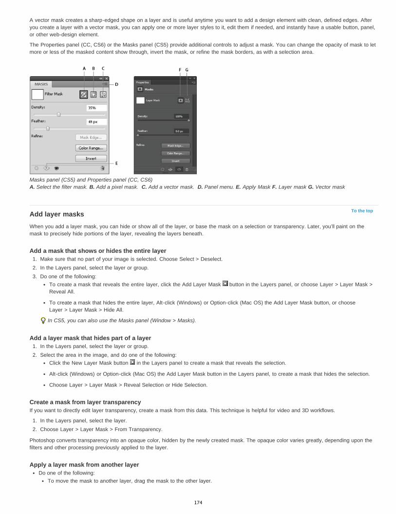
To the top
A vector mask creates a sharp-edged shape on a layer and is useful anytime you want to add a design element with clean, defined edges. Afteryou create a layer with a vector mask, you can apply one or more layer styles to it, edit them if needed, and instantly have a usable button, panel,or other web-design element.
The Properties panel (CC, CS6) or the Masks panel (CS5) provide additional controls to adjust a mask. You can change the opacity of mask to letmore or less of the masked content show through, invert the mask, or refine the mask borders, as with a selection area.
Masks panel (CS5) and Properties panel (CC, CS6) A. Select the filter mask. B. Add a pixel mask. C. Add a vector mask. D. Panel menu. E. Apply Mask F. Layer mask G. Vector mask
Add layer masksWhen you add a layer mask, you can hide or show all of the layer, or base the mask on a selection or transparency. Later, you’ll paint on themask to precisely hide portions of the layer, revealing the layers beneath.
Add a mask that shows or hides the entire layer1. Make sure that no part of your image is selected. Choose Select > Deselect.2. In the Layers panel, select the layer or group.3. Do one of the following:
To create a mask that reveals the entire layer, click the Add Layer Mask button in the Layers panel, or choose Layer > Layer Mask >Reveal All.
To create a mask that hides the entire layer, Alt-click (Windows) or Option-click (Mac OS) the Add Layer Mask button, or chooseLayer > Layer Mask > Hide All.
In CS5, you can also use the Masks panel (Window > Masks).
Add a layer mask that hides part of a layer1. In the Layers panel, select the layer or group.2. Select the area in the image, and do one of the following:
Click the New Layer Mask button in the Layers panel to create a mask that reveals the selection.
Alt-click (Windows) or Option-click (Mac OS) the Add Layer Mask button in the Layers panel, to create a mask that hides the selection.
Choose Layer > Layer Mask > Reveal Selection or Hide Selection.
Create a mask from layer transparencyIf you want to directly edit layer transparency, create a mask from this data. This technique is helpful for video and 3D workflows.
1. In the Layers panel, select the layer.2. Choose Layer > Layer Mask > From Transparency.
Photoshop converts transparency into an opaque color, hidden by the newly created mask. The opaque color varies greatly, depending upon thefilters and other processing previously applied to the layer.
Apply a layer mask from another layerDo one of the following:
To move the mask to another layer, drag the mask to the other layer.
174

To the top
To the top
To the top
Note:
To the top
To the top
To duplicate the mask, Alt-drag (Windows) or Option-drag (Mac OS) the mask to other layer.
Unlinking layers and masksBy default, a layer or group is linked to its layer mask or vector mask, as indicated by the link icon between the thumbnails in the Layers panel.The layer and its mask move together in the image when you move either one with the Move tool . Unlinking them lets you move themindependently and shift the mask’s boundaries separately from the layer.
To unlink a layer from its mask, click the link icon in the Layers panel.
To reestablish the link between a layer and its mask, click between the layer and mask path thumbnails in the Layers panel.
Disable or enable a layer maskDo one of the following:
Select the layer containing the layer mask you want to disable or enable, and click the Disable/Enable Mask button in the Propertiespanel (CC, CS6) or the Masks panel (CS5).
Shift-click the layer mask thumbnail in the Layers panel.
Select the layer containing the layer mask you want to disable or enable, and choose Layer > Layer Mask > Disable or Layer > LayerMask > Enable.
A red X appears over the mask thumbnail in the Layers panel when the mask is disabled, and the layer’s content appears without maskingeffects.
Apply or delete a layer maskYou can apply a layer mask to permanently delete the hidden portions of a layer. Layer masks are stored as alpha channels, so applying anddeleting layer masks can help reduce file size. You can also delete a layer mask without applying the changes.
1. In the Layers panel, select the layer containing the layer mask.2. In the Masks panel, click the Pixel Mask button.3. Do one of the following:
To remove the layer mask after applying it permanently to the layer, click the Apply Mask icon at the bottom of the Properties panel(CC, CS6) and Masks panel (CS5).
To remove the layer mask without applying it to the layer, click the Delete button at the bottom of the Masks panel, and then clickDelete.
You can also apply or delete layer masks using the Layer menu.
You cannot apply a layer mask permanently to a Smart Object layer when deleting the layer mask.
Select and display the layer mask channelFor easier editing of a layer mask, you can display the grayscale mask by itself or as a rubylith overlay on the layer.
In the Layers panel, do one of the following:
Alt-click (Windows) or Option-click (Mac OS) the layer mask thumbnail to view only the grayscale mask. To redisplay the layers, Alt-clickor Option-click the layer mask thumbnail. Alternatively, click the eye icon in the Properties panel (CC, CS6) or the Masks panel (CS5).
Hold down Alt+Shift (Windows) or Option+Shift (Mac OS), and click the layer mask thumbnail to view the mask on top of the layer in arubylith masking color. Hold down Alt+Shift or Option+Shift, and click the thumbnail again to turn off the color display.
Change the layer mask rubylith color or opacity1. Do one of the following:
(CS5) Double-click the layer mask thumbnail.
Double-click the layer mask channel in the Channels panel.
2. To choose a new mask color, in the Layer Mask Display Options dialog box, click the color swatch and choose a new color.3. To change the opacity, enter a value between 0% and 100%.
175

Twitter™ and Facebook posts are not covered under the terms of Creative Commons.
Legal Notices | Online Privacy Policy
To the top
Both the color and opacity settings affect only the appearance of the mask and have no effect on how underlying areas are protected. Forexample, you may want to change these settings to make the mask more easily visible against the colors in the image.
4. Click OK.
Adjusting mask opacity and edgesUse the Properties panel (CC, CS6) or the Masks panel(CS5) to adjust the opacity of a selected layer or vector mask. The Density slider controlsmask opacity. Feather lets you soften mask edges.
Additional options are specific to layer masks. The Invert option reverses masked and unmasked areas. The Mask Edge option gives you variouscontrols to modify the mask edges, such as Smooth and Contract/Expand. For information on the Color Range option, see Confine adjustmentand fill layers to specific areas.
Change mask density1. In the Layers panel, select the layer containing the mask you want to edit.
2. Do one of the following:
(CC, CS6) In the Layers panel click the Mask thumbnail. A border appears around the thumbnail.(CS5) In the Masks panel, click the Pixel Mask button or the Vector Mask button.
3. In the Properties panel (CC, CS6) or the Masks panel (CS5), drag the Density slider to adjust the mask opacity.
At 100% density, the mask is completely opaque and blocks out any underlying area of the layer. As you lower the density, more of the areaunder the mask becomes visible.
Feather mask edges1. In the Layers panel, select the layer containing the mask you want to edit.
2. Do one of the following:
(CC, CS6) In the Layers panel click the Mask thumbnail. A border appears around the thumbnail.(CS5) In the Masks panel, click the Pixel Mask button or the Vector Mask button.
3. Drag the Feather slider to apply feathering to the mask edges.
Feathering blurs the edges of the mask to create a softer transition between the masked and unmasked areas. Feathering is applied fromthe edges of the mask outward, within the range of pixels you set with the slider.
Refine mask edges1. In the Layers panel, select the layer containing the mask you want to edit.
2. Do one of the following:
(CC, CS6) In the Layers panel click the Mask thumbnail. A border appears around the thumbnail.(CS5) In the Masks panel, click the Pixel Mask button or the Vector Mask button.
3. Click Mask Edge. You can modify mask edges with the options in the Refine Mask dialog box and view the mask against differentbackgrounds. For a description of options, see Refine selection edges.
4. Click OK to close the Refine Mask dialog box and apply your changes to the layer mask.
More Help TopicsAbout masks and alpha channels
Applying filters video
176
Load selections from a layer or layer mask's boundaries
Twitter™ and Facebook posts are not covered under the terms of Creative Commons.
Legal Notices | Online Privacy Policy
Loading a layer or layer mask’s boundaries as a selectionYou can select all the non-transparent areas on a layer, or, if a layer mask exists, all the unmasked areas. Selecting these areas is useful whenyou want to select text or image content that is surrounded by or contains transparent areas, or to create a selection that excludes masked areason a layer.
1. Do one of the following:To select only the non-transparent areas on an unmasked layer, Ctrl-click (Windows) or Command-click (Mac OS) the layer thumbnail inthe Layers panel.
To select the unmasked areas on a layer that has a layer mask, Ctrl-click (Windows) or Command-click (Mac OS) the layer maskthumbnail in the Layers panel.
2. If a selection already exists, you can do any of the following:To add the pixels to an existing selection, press Ctrl+Shift (Windows) or Command+Shift (Mac OS), and click the layer thumbnail or layermask thumbnail in the Layers panel.
To subtract the pixels from an existing selection, press Ctrl+Alt (Windows) or Command+Option (Mac OS), and click the layer thumbnailor layer mask thumbnail in the Layers panel.
To load the intersection of the pixels and an existing selection, press Ctrl+Alt+Shift (Windows) or Command+Option+Shift (Mac OS),and click the layer thumbnail or layer mask thumbnail in the Layers panel.
If you want to move all the contents of a layer, use the Move tool without loading a transparency mask.
More Help TopicsAbout masks and alpha channels
Applying filters video
177
Masking layers with vector masks
Note:
Note:
Add and edit vector masksA vector mask is a resolution independent path that clips out the contents of the layer. You create vector masks with the pen or shapes tools. Formore information on working with the pen or shapes tools, see Drawing.
Add a vector mask that shows or hides the entire layer1. In the Layers panel, select the layer you want to add the vector mask to.2. Do one of the following:
To create a vector mask that reveals the entire layer, choose Layer > Vector Mask > Reveal All.
To create a vector mask that hides the entire layer, choose Layer > Vector Mask > Hide All.
Add a vector mask that shows the contents of a shape1. In the Layers panel, select the layer to which to add a vector mask.2. Select a path, or use one of the shape or Pen tools to draw a work path.
To create a path with a Shape tool, click the Paths icon in the Shape tool options bar.
3. Click the Vector Mask button in the Masks panel, or choose Layer > Vector Mask > Current Path.
Edit a vector mask1. In the Layers panel, select the layer containing the vector mask you want to edit.
2. Click the Vector Mask button in the Properties panel (CC, CS6) or Masks panel (CS5) or the thumbnail in the Paths panel. Then change theshape using the shape, pen, or Direct Selection tools. See Editing paths.
Change vector mask opacity or feather mask edges1. In the Layers panel, select the layer containing the vector mask.
2. In the Properties panel (CC, CS6) or Masks panel (CS5), click the Vector Mask button.
3. Drag the Density slider to adjust mask opacity, or the Feathering slider to feather mask edges. For more information, see Change maskopacity or refine edges.
Remove a vector mask1. In the Layers panel, select the layer containing the vector mask.2. Click the Vector Mask button in the Masks panel.
3. In the Properties panel (CC, CS6) or Masks panel (CS5), click the Delete Mask button .
Disable or enable a vector maskDo one of the following:
Select the layer containing the vector mask you want to disable or enable, and click the Disable/Enable Mask button in the Propertiespanel (CC, CS6) or Masks panel (CS5).
Shift-click the vector mask thumbnail in the Layers panel.
Select the layer containing the vector mask you want to disable or enable, and choose Layer > Vector Mask > Disable or Layer > VectorMask > Enable.
A red X appears over the mask thumbnail in the Layers panel when the mask is disabled, and the layer’s content appears without maskingeffects.
Convert a vector mask to a layer maskSelect the layer containing the vector mask you want to convert, and choose Layer > Rasterize > Vector Mask.
After you rasterize a vector mask, you can’t change it back into a vector object.
178

Twitter™ and Facebook posts are not covered under the terms of Creative Commons.
Legal Notices | Online Privacy Policy
More Help TopicsAbout masks and alpha channels
Applying filters video
179
Editing layer masks
Twitter™ and Facebook posts are not covered under the terms of Creative Commons.
Legal Notices | Online Privacy Policy
Note:
1. In the Layers panel, select the layer containing the mask you want to edit.
2. Do one of the following:
(CC, CS6) Click the Mask thumbnail in the Layers panel(CS5) Click the Pixel Mask button in the Masks panel
3. Select any of the editing or painting tools.
The foreground and background colors assume default grayscale values when the mask is active.
4. Do one of the following:To subtract from the mask and reveal the layer, paint the mask with white.
To make the layer partially visible, paint the mask with gray. Darker grays make the level more transparent, lighter grays make it moreopaque.
To add to the mask and hide the layer or group, paint the mask with black. The layers below become visible.
To edit the layer instead of the layer mask, select it by clicking its thumbnail in the Layers panel. A border appears around the layer thumbnail.
To paste a copied selection into a layer mask, Alt-click (Windows) or Option-click (Mac OS) the layer mask thumbnail in the Layers panel toselect and display the mask channel. Choose Edit > Paste, then Select > Deselect. The selection is converted to grayscale and added to themask. Click the layer thumbnail in the Layers panel to deselect the mask channel.
More Help TopicsAbout masks and alpha channels
Applying filters video
180
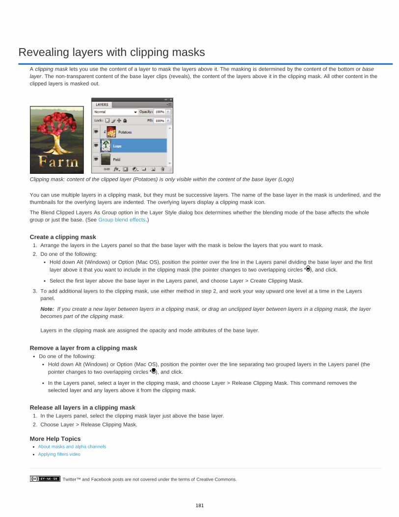
Revealing layers with clipping masks
Twitter™ and Facebook posts are not covered under the terms of Creative Commons.
Note:
A clipping mask lets you use the content of a layer to mask the layers above it. The masking is determined by the content of the bottom or baselayer. The non-transparent content of the base layer clips (reveals), the content of the layers above it in the clipping mask. All other content in theclipped layers is masked out.
Clipping mask: content of the clipped layer (Potatoes) is only visible within the content of the base layer (Logo)
You can use multiple layers in a clipping mask, but they must be successive layers. The name of the base layer in the mask is underlined, and thethumbnails for the overlying layers are indented. The overlying layers display a clipping mask icon.
The Blend Clipped Layers As Group option in the Layer Style dialog box determines whether the blending mode of the base affects the wholegroup or just the base. (See Group blend effects.)
Create a clipping mask1. Arrange the layers in the Layers panel so that the base layer with the mask is below the layers that you want to mask.2. Do one of the following:
Hold down Alt (Windows) or Option (Mac OS), position the pointer over the line in the Layers panel dividing the base layer and the firstlayer above it that you want to include in the clipping mask (the pointer changes to two overlapping circles ), and click.
Select the first layer above the base layer in the Layers panel, and choose Layer > Create Clipping Mask.
3. To add additional layers to the clipping mask, use either method in step 2, and work your way upward one level at a time in the Layerspanel.
If you create a new layer between layers in a clipping mask, or drag an unclipped layer between layers in a clipping mask, the layerbecomes part of the clipping mask.
Layers in the clipping mask are assigned the opacity and mode attributes of the base layer.
Remove a layer from a clipping maskDo one of the following:
Hold down Alt (Windows) or Option (Mac OS), position the pointer over the line separating two grouped layers in the Layers panel (thepointer changes to two overlapping circles ), and click.
In the Layers panel, select a layer in the clipping mask, and choose Layer > Release Clipping Mask. This command removes theselected layer and any layers above it from the clipping mask.
Release all layers in a clipping mask1. In the Layers panel, select the clipping mask layer just above the base layer.2. Choose Layer > Release Clipping Mask.
More Help TopicsAbout masks and alpha channels
Applying filters video
181
Applying Smart Filters
To the top
To the top
About Smart FiltersApply a Smart FilterEdit a Smart FilterHide Smart FiltersReorder, duplicate, or delete Smart FiltersMask Smart Filters
About Smart FiltersAny filter applied to a Smart Object is a Smart Filter. Smart Filters appear in the Layers panel below the Smart Object layer to which they areapplied. Because you can adjust, remove, or hide Smart Filters, they are nondestructive.
You can apply any Photoshop filter (that have been enabled to work with Smart Filters)—except for Extract, Liquify, Pattern Maker, and VanishingPoint—as a Smart Filter. In addition, you can apply the Shadow/Highlight and Variations adjustments as Smart Filters.
To work with Smart Filters, select a Smart Object layer, choose a filter, and then set filter options. After you apply a Smart Filter, you can adjust,reorder, or delete it.
To expand or collapse the view of Smart Filters, click the triangle next to the Smart Filter icon, displayed to the right of the Smart Object layer inthe Layers panel. (This technique also shows or hides Layer Style.) Or, choose Layers panel Options from the Layers panel menu, then selectExpand New Effects in the dialog box.
Use filter masks to selectively mask Smart Filter effects.
Adobe recommends Have a tutorial you would like to share?
Visual examples: Smart FiltersMartin EveningLearn more with this excerpt from AdobePhotoshop for Photographers.
Apply a Smart FilterFor a video on applying smart filters, see www.adobe.com/go/vid0004.
1. Do one of the following:
To apply a Smart Filter to an entire Smart Object layer, select the layer in the Layers panel.
To constrain the effects of the Smart Filter to a selected area of a Smart Object layer, make a selection.
To apply a Smart Filter to a regular layer, select the layer, and choose Filter > Convert For Smart Filters, and click OK.
2. Do one of the following:
Choose a filter from the Filter menu. You can choose any filter, including third-party filters that support Smart Filters, except Extract,Liquify, Pattern Maker, and Vanishing Point.
Choose Image > Adjustments > Shadow/Highlight or Image > Adjustments > Variations.
Note: If you apply one or more filters using the Filter Gallery, they appear as a group in the Layers panel named “Filter Gallery.” You canedit individual filters by double-clicking a Filter Gallery entry.
3. Set filter options and click OK.
The Smart Filter appears under the Smart Filters line in the Layers panel beneath the Smart Object layer. If you see a warning icon next to aSmart Filter in the Layers panel, the filter doesn’t support the image’s color mode or depth.
After you apply a Smart Filter, you can drag it (or an entire group of Smart Filters) onto another Smart Object layer in the Layers panel; press Alt-drag (Windows) or Option-drag (Mac OS) Smart Filters. You can’t drag Smart Filters onto regular layers.
182
To the top
To the top
To the top
To the top
Edit a Smart FilterIf a Smart Filter contains editable settings, you can edit it at any time. You can also edit blending options for Smart Filters.
Note: When you edit a Smart Filter, you can’t preview filters stacked above it. After you finish editing the Smart Filter, Photoshop again displaysthe filters stacked above it.
Edit Smart Filter settings1. Double-click the Smart Filter in the Layers panel.2. Set filter options, and click OK.
Edit Smart Filter blending optionsEditing Smart Filter blending options is similar to using the Fade command when applying a filter to a traditional layer.
1. Double-click the Edit Blending Options icon next to the Filter in the Layers panel.2. Set blending options, and click OK.
Hide Smart Filters Do one of the following:
To hide a single Smart Filter, click the eye icon next to the Smart Filter in the Layers panel. To show the Smart Filter, click in the columnagain.
To hide all Smart Filters applied to a Smart Object layer, click the eye icon next to the Smart Filters line in the Layers panel. To show theSmart Filters, click in the column again.
Reorder, duplicate, or delete Smart FiltersYou can reorder Smart Filters in the Layers panel, duplicate them, or delete Smart Filters if you no longer want to apply them to a Smart Object.
Reorder Smart Filters In the Layers panel, drag a Smart Filter up or down in the list. (Double-click Filter Gallery to reorder any gallery filters.)
Photoshop applies Smart Filters from the bottom up.
Duplicate Smart Filters In the Layers panel, Alt-drag (Windows) or Option-drag (Mac OS) the Smart Filter from one Smart Object to another, or to a new location in the
Smart Filters list.Note: To duplicate all Smart Filters, Alt-drag (Windows) or Option-drag (Mac OS) the Smart Filters icon that appears next to the Smart Objectlayer.
Delete Smart FiltersTo delete an individual Smart Filter, drag it to the Delete icon at the bottom of the Layers panel.To delete all Smart Filters applied to a Smart Object layer, select the Smart Object layer and choose Layer > Smart Filter > Clear SmartFilters.
Mask Smart FiltersWhen you apply a Smart Filter to a Smart Object, Photoshop displays an empty (white) mask thumbnail on the Smart Filters line in the Layerspanel under the Smart Object. By default, this mask shows the entire filter effect. (If you made a selection before applying the Smart Filter,Photoshop displays the appropriate mask instead of an empty mask on the Smart Filters line in the Layers panel.)
Use filter masks to selectively mask Smart Filters. When you mask Smart Filters, the masking applies to all Smart Filters—you can’t maskindividual Smart Filters.
Filter masks work much like layer masks, and you can use many of the same techniques with them. Like layer masks, filter masks are stored asalpha channels in the Channels panel, and you can load their boundaries as a selection.
Like layer masks, you can paint on a filter mask. Areas of the filter that you paint in black are hidden; areas you paint in white are visible; andareas you paint in shades of gray appear in various levels of transparency.
Use the controls in the Masks panel to change the filter mask density, add feathering to the edges of the mask, or invert the mask.
Note: By default, layer masks are linked to regular layers or Smart Object layers. When you move the layer mask or the layer using the Movetool, they move as a unit.
183

Mask Smart Filter effects1. Click the filter mask thumbnail in the Layers panel to make it active.
A border appears around the mask thumbnail.
2. Select any of the editing or painting tools.3. Do one of the following:
To hide portions of the filter, paint the mask with black.
To show portions of the filter, paint the mask with white.
To make the filter partially visible, paint the mask with gray.
You can also apply image adjustments and filters to filter masks.
Change filter mask opacity or feather mask edges1. Click the filter mask thumbnail or select the Smart Object layer in the Layers panel, and then click the Filter Mask button in the Masks panel.2. In the Masks panel, drag the Density slider to adjust the mask opacity, and the Feathering slider to apply feathering to the mask edges. See
Adjust mask opacity or edges.Note: The Mask Edge option is not available for filter masks.
Invert a filter mask Click the filter mask thumbnail in the Layers panel, then click Invert in the Masks panel.
Display only the filter mask Alt-click (Windows) or Option-click (Mac OS) the filter mask thumbnail in the Layers panel. To show the Smart Object layer, Alt-click or Option-
click the filter mask thumbnail again.
Move or copy filter masksTo move the mask to another Smart Filter Effect, drag the mask to the other Smart Filter Effect.To copy the mask, Alt-drag (Windows) or Option-drag (Mac OS) the mask to another Smart Filter Effect.
Disable a filter mask Do one of the following:
Shift-click the filter mask thumbnail in the Layers panel.
Click the filter mask thumbnail in the Layers panel, then click the Disable/Enable Mask button in the Masks panel.
Choose Layer > Smart Filter > Disable Filter Mask.
A red X appears over the filter mask thumbnail when the mask is disabled, and the Smart Filter appears without masking. To re-enable the mask,Shift-click the Smart Filter mask thumbnail again.
Delete a Smart Filter maskClick the filter mask thumbnail in the Layers panel, then click the Delete icon in the Masks panel.Drag the filter mask thumbnail in the Layers panel to the Delete icon.Select the Smart Filter Effect, and choose Layer > Smart Filters > Delete Filter Mask.
Add a filter maskIf you delete a filter mask, you can subsequently add another mask.
To add an empty mask, select the Smart Object layer, and then click the Filter Mask button in the Masks panel.To add a mask based on a selection, make a selection, and then right-click (Windows) or Control-click (Mac OS) the Smart Filters line in theLayers panel, and choose Add Filter Mask.
Legal Notices | Online Privacy Policy
184
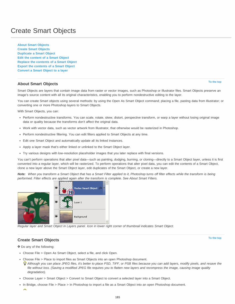
Create Smart Objects
To the top
To the top
About Smart ObjectsCreate Smart ObjectsDuplicate a Smart ObjectEdit the content of a Smart ObjectReplace the contents of a Smart ObjectExport the contents of a Smart ObjectConvert a Smart Object to a layer
About Smart ObjectsSmart Objects are layers that contain image data from raster or vector images, such as Photoshop or Illustrator files. Smart Objects preserve animage’s source content with all its original characteristics, enabling you to perform nondestructive editing to the layer.
You can create Smart objects using several methods: by using the Open As Smart Object command; placing a file, pasting data from Illustrator; orconverting one or more Photoshop layers to Smart Objects.
With Smart Objects, you can:
Perform nondestructive transforms. You can scale, rotate, skew, distort, perspective transform, or warp a layer without losing original imagedata or quality because the transforms don’t affect the original data.
Work with vector data, such as vector artwork from Illustrator, that otherwise would be rasterized in Photoshop.
Perform nondestructive filtering. You can edit filters applied to Smart Objects at any time.
Edit one Smart Object and automatically update all its linked instances.
Apply a layer mask that’s either linked or unlinked to the Smart Object layer.
Try various designs with low-resolution placeholder images that you later replace with final versions.
You can’t perform operations that alter pixel data—such as painting, dodging, burning, or cloning—directly to a Smart Object layer, unless it is firstconverted into a regular layer, which will be rasterized. To perform operations that alter pixel data, you can edit the contents of a Smart Object,clone a new layer above the Smart Object layer, edit duplicates of the Smart Object, or create a new layer.
Note: When you transform a Smart Object that has a Smart Filter applied to it, Photoshop turns off filter effects while the transform is beingperformed. Filter effects are applied again after the transform is complete. See About Smart Filters.
Regular layer and Smart Object in Layers panel. Icon in lower right corner of thumbnail indicates Smart Object.
Create Smart Objects Do any of the following:
Choose File > Open As Smart Object, select a file, and click Open.
Choose File > Place to import files as Smart Objects into an open Photoshop document.Although you can place JPEG files, it's better to place PSD, TIFF, or PSB files because you can add layers, modify pixels, and resave thefile without loss. (Saving a modified JPEG file requires you to flatten new layers and recompress the image, causing image qualitydegradation).
Choose Layer > Smart Object > Convert to Smart Object to convert a selected layer into a Smart Object.
In Bridge, choose File > Place > In Photoshop to import a file as a Smart Object into an open Photoshop document.
185
To the top
To the top
To the top
To the top
To the top
An easy way to work with camera raw files is to open them as Smart Objects. You can double-click the Smart Object layer containing theraw file at any time to adjust the Camera Raw settings.
Select one or more layers and choose Layer > Smart Objects > Convert To Smart Object. The layers are bundled into one Smart Object.
Drag PDF or Adobe Illustrator layers or objects into a Photoshop document.
Paste artwork from Illustrator into a Photoshop document, and choose Smart Object in the Paste dialog box. For the greatest flexibility,enable both PDF and AICB (No Transparency Support) in the File Handling & Clipboard section of the Preferences dialog box in AdobeIllustrator.
Duplicate a Smart Object In the Layers panel, select a Smart Object layer, and do one of the following:
To create a duplicate Smart Object that is linked to the original, choose Layer > New > Layer Via Copy, or drag the Smart Object layer tothe Create A New Layer icon at the bottom of the Layers panel. Edits you make to the original affect the copy and vice versa.
To create a duplicate Smart Object that isn’t linked to the original, choose Layer > Smart Objects > New Smart Object Via Copy. Edits youmake to the original don’t affect the copy.
A new Smart Object appears in the Layers panel with the same name as the original and “copy” as a suffix.
Edit the content of a Smart ObjectWhen you edit a Smart Object, the source content is opened in either Photoshop (if the content is raster data or a camera raw file) or Illustrator (ifthe content is vector PDF). When you save changes to the source content, the edits appear in all linked instances of the Smart Object in thePhotoshop document.
1. Select the Smart Object from the Layers panel, and do one of the following:
Choose Layer > Smart Objects > Edit Contents.
Double-click the Smart Objects thumbnail in the Layers panel.
2. Click OK to close the dialog box.3. Make edits to the source content file, then choose File > Save.
Photoshop updates the Smart Object to reflect the changes you made. (If you don’t see the changes, make the Photoshop documentcontaining the Smart Object active).
Replace the contents of a Smart ObjectYou can replace the image data in one Smart Object or multiple linked instances. This feature lets you quickly update a visual design, or replacelow-resolution placeholder images with final versions.
Note: When you replace a Smart Object, any scaling, warping, or effects that you applied to the first Smart Object are maintained.1. Select the Smart Object, and choose Layer > Smart Objects > Replace Contents.2. Navigate to the file you want to use, and click Place.3. Click OK.
The new content is placed in the Smart Object. Linked Smart Objects are also updated.
Export the contents of a Smart Object1. Select the Smart Object from the Layers panel, and choose Layer > Smart Objects > Export Contents.2. Choose a location for the contents of the Smart Object, then click Save.
Photoshop exports the Smart Object in its original placed format (JPEG, AI, TIF, PDF, or other formats). If the Smart Object was createdfrom layers, it is exported in PSB format.
Convert a Smart Object to a layerConverting a Smart Object to a regular layer rasterizes the content at the current size. Convert a Smart Object to a regular layer only if you nolonger need to edit the Smart Object data. Transforms, warps, and filters applied to a Smart Object are no longer editable after the Smart Object israsterized.
Select the Smart Object, and choose Layer > Rasterize > Smart Object.If you want to re-create the Smart Object, reselect its original layers and start from scratch. The new Smart Object won’t retain transforms you
186

applied to the original Smart Object.
Legal Notices | Online Privacy Policy
187
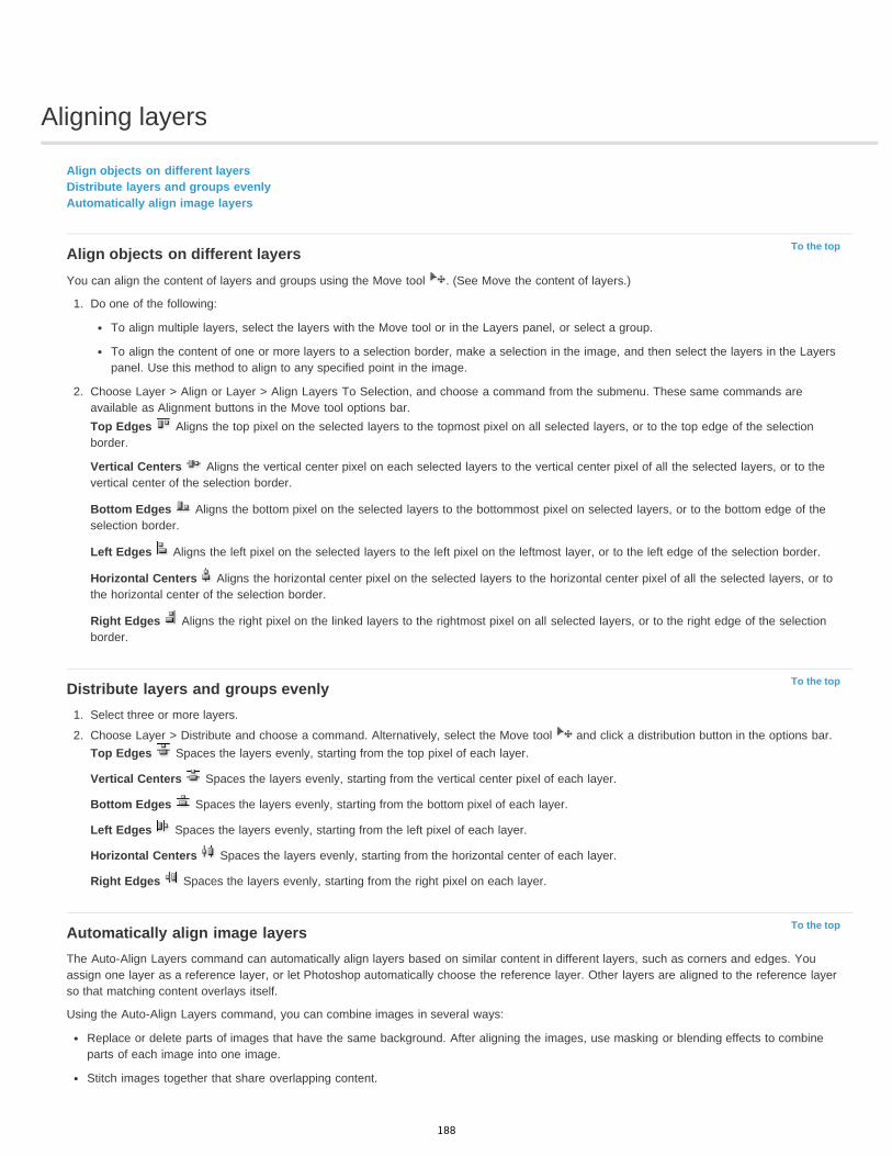
Aligning layers
To the top
To the top
To the top
Align objects on different layersDistribute layers and groups evenlyAutomatically align image layers
Align objects on different layersYou can align the content of layers and groups using the Move tool . (See Move the content of layers.)
1. Do one of the following:
To align multiple layers, select the layers with the Move tool or in the Layers panel, or select a group.
To align the content of one or more layers to a selection border, make a selection in the image, and then select the layers in the Layerspanel. Use this method to align to any specified point in the image.
2. Choose Layer > Align or Layer > Align Layers To Selection, and choose a command from the submenu. These same commands areavailable as Alignment buttons in the Move tool options bar.Top Edges Aligns the top pixel on the selected layers to the topmost pixel on all selected layers, or to the top edge of the selectionborder.
Vertical Centers Aligns the vertical center pixel on each selected layers to the vertical center pixel of all the selected layers, or to thevertical center of the selection border.
Bottom Edges Aligns the bottom pixel on the selected layers to the bottommost pixel on selected layers, or to the bottom edge of theselection border.
Left Edges Aligns the left pixel on the selected layers to the left pixel on the leftmost layer, or to the left edge of the selection border.
Horizontal Centers Aligns the horizontal center pixel on the selected layers to the horizontal center pixel of all the selected layers, or tothe horizontal center of the selection border.
Right Edges Aligns the right pixel on the linked layers to the rightmost pixel on all selected layers, or to the right edge of the selectionborder.
Distribute layers and groups evenly1. Select three or more layers.
2. Choose Layer > Distribute and choose a command. Alternatively, select the Move tool and click a distribution button in the options bar.Top Edges Spaces the layers evenly, starting from the top pixel of each layer.
Vertical Centers Spaces the layers evenly, starting from the vertical center pixel of each layer.
Bottom Edges Spaces the layers evenly, starting from the bottom pixel of each layer.
Left Edges Spaces the layers evenly, starting from the left pixel of each layer.
Horizontal Centers Spaces the layers evenly, starting from the horizontal center of each layer.
Right Edges Spaces the layers evenly, starting from the right pixel on each layer.
Automatically align image layersThe Auto-Align Layers command can automatically align layers based on similar content in different layers, such as corners and edges. Youassign one layer as a reference layer, or let Photoshop automatically choose the reference layer. Other layers are aligned to the reference layerso that matching content overlays itself.
Using the Auto-Align Layers command, you can combine images in several ways:
Replace or delete parts of images that have the same background. After aligning the images, use masking or blending effects to combineparts of each image into one image.
Stitch images together that share overlapping content.
188

For video frames shot against a static background, you can convert frames into layers, then add or delete content across multiple frames.
1. Copy or place the images you want to align into the same document.Each image will be in a separate layer. See Duplicate layers.
You can load multiple images into layers using a script. Choose File > Scripts > Load Files into Stack.
2. (Optional) In the Layers panel, create a reference layer by locking it. See Lock layers. If you do not set a reference layer, Photoshop willanalyze all the layers and select the one at the center of the final composition as the reference.
3. Select the remaining layers you want to align.
To select multiple adjacent layers from the panel, Shift-click; To select noncontiguous layers, Ctrl-Click (Windows) or Command-click(Mac OS).
Note: Do not select adjustment layers, vector layers, or Smart Objects which do not contain information needed for alignment.4. Choose Edit > Auto-Align Layers, and choose an alignment option. For stitching together multiple images that share overlapping areas—for
example, to create a panorama—use the Auto, Perspective, or Cylindrical options. To align scanned images with offset content, use theReposition Only option.Auto Photoshop analyzes the source images and applies either a Perspective or Cylindrical layout, depending on which produces a bettercomposite.
Perspective Creates a consistent composition by designating one of the source images (by default, the middle image) as the referenceimage. The other images are then transformed (repositioned, stretched, or skewed, as necessary) so that overlapping content across layersis matched.
Cylindrical Reduces the “bow-tie” distortion that can occur with the Perspective layout by displaying individual images as on an unfoldedcylinder. Overlapping content across layers is still matched. The reference image is placed at the center. Best suited for creating widepanoramas.
Spherical Aligns images with wide fields of view (vertical and horizontal). Designates one of the sources images (the middle image, bydefault) as the reference image and spherically transforms the other images so that overlapping content is matched.
Scene Collage Aligns layers and matches overlapping content, without changing the shape of the objects in the image (for example, a circlewill still be a circle).
Reposition Only Aligns the layers and matches overlapping content, but does not transform (stretch or skew) any of the source layers.
Lens Correction Automatically corrects for lens defects:
Vignette Removal Compensates for a lens defect that causes the edges, especially the corners, of an image to be darker than thecenter.
Geometric Distortion Compensates for barrel, pincushion, or fisheye distortion.Note: Geometric Distortion will try to take into account the radical distortion to improve the result of the alignment, except with fisheye lens; when fish eye metadata is detected, Geometric Distortion will align the images for fish eye
After auto-aligning, you can use Edit > Free Transform to fine tune the alignment or make tonal adjustments to even out exposure differencesbetween layers, then combine the layers into one composite image.
For a video on using Auto-Align and Auto-Blend to create a panorama and increase depth of field, see www.adobe.com/go/lrvid4120_ps.
Legal Notices | Online Privacy Policy
189

Combine images with Auto-Blend Layers
To the top
Auto blend layers
Auto blend layersUse the Auto-Blend Layers command to stitch or combine images with smooth transitions in the final composite image. Auto-Blend Layers applieslayer masks as needed to each layer to mask out over- or underexposed areas or content differences. Auto-Blend layers is only available for RGBor Grayscale images. It does not work with Smart Objects, video layers, 3D layers, or background layers.
Among the many uses of the Auto-Blend Layers command, you can blend multiple images of a scene with different areas in focus to achieve acomposite image with an extended depth of field. Similarly, you can create a composite by blending multiple images of a scene with differentilluminations. In addition to combining images of a scene, you can stitch together images into a panorama. (Although, it might be better to use thePhotomerge command to produce panoramas from multiple images.)
Auto-Blend Layers applies layer masks as needed to each layer to mask out over- or underexposed areas or content differences and create aseamless composite.
Adobe recommends Have a tutorial you would like to share?
Depth of field blendingMartin EveningLearn more with this excerpt from AdobePhotoshop for Photographers.
1. Copy or place the images you want to combine into the same document.
Each image will be in a separate layer. See Duplicate layers.
2. Select the layers you want to blend.3. (Optional) Align the layers.
You can align layers manually or by using the Auto-Align Layers command. See Automatically align image layers.
4. With the layers still selected, choose Edit > Auto-Blend Layers.5. Select the Auto-Blend Objective:
Panorama Blends overlapping layers into a panorama image.
Stack Images Blends the best details in each corresponding area. This options works best with aligned layers.Note: Stack Images lets you blend multiple images of a scene with different areas in focus or different illuminations, to achieve the bestresults of all the images (you must auto-align the images first).
6. Select Seamless Tones And Colors to adjust the color and tonality for blending.7. Click OK.
For a video on using Auto-Align and Auto-Blend to create a panorama and increase depth of field, see www.adobe.com/go/lrvid4120_ps.
Legal Notices | Online Privacy Policy
190
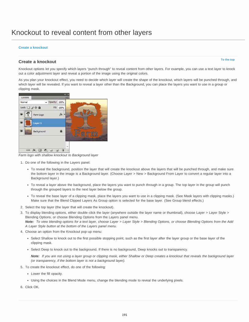
Knockout to reveal content from other layers
To the top
Create a knockout
Create a knockoutKnockout options let you specify which layers “punch through” to reveal content from other layers. For example, you can use a text layer to knockout a color adjustment layer and reveal a portion of the image using the original colors.
As you plan your knockout effect, you need to decide which layer will create the shape of the knockout, which layers will be punched through, andwhich layer will be revealed. If you want to reveal a layer other than the Background, you can place the layers you want to use in a group orclipping mask.
Farm logo with shallow knockout to Background layer
1. Do one of the following in the Layers panel:
To reveal the background, position the layer that will create the knockout above the layers that will be punched through, and make surethe bottom layer in the image is a Background layer. (Choose Layer > New > Background From Layer to convert a regular layer into aBackground layer.)
To reveal a layer above the background, place the layers you want to punch through in a group. The top layer in the group will punchthrough the grouped layers to the next layer below the group.
To reveal the base layer of a clipping mask, place the layers you want to use in a clipping mask. (See Mask layers with clipping masks.)Make sure that the Blend Clipped Layers As Group option is selected for the base layer. (See Group blend effects.)
2. Select the top layer (the layer that will create the knockout).3. To display blending options, either double-click the layer (anywhere outside the layer name or thumbnail), choose Layer > Layer Style >
Blending Options, or choose Blending Options from the Layers panel menu.Note: To view blending options for a text layer, choose Layer > Layer Style > Blending Options, or choose Blending Options from the AddA Layer Style button at the bottom of the Layers panel menu.
4. Choose an option from the Knockout pop-up menu:
Select Shallow to knock out to the first possible stopping point, such as the first layer after the layer group or the base layer of theclipping mask.
Select Deep to knock out to the background. If there is no background, Deep knocks out to transparency.
Note: If you are not using a layer group or clipping mask, either Shallow or Deep creates a knockout that reveals the background layer(or transparency, if the bottom layer is not a background layer).
5. To create the knockout effect, do one of the following:
Lower the fill opacity.
Using the choices in the Blend Mode menu, change the blending mode to reveal the underlying pixels.
6. Click OK.
191

Create and manage layers and groups
To the top
Create layers and groupsView layers and groups within a groupShow or hide a layer, group, or style
Create layers and groupsA new layer appears either above the selected layer or within the selected group in the Layers panel.
Create a new layer or group
1. Do one of the following:
To create a new layer or group using default options, click the Create a New Layer button or New Group button in the Layerspanel.
Choose Layer > New > Layer or choose Layer > New > Group.
Choose New Layer or New Group from the Layers panel menu.
Alt-click (Windows) or Option-click (Mac OS) the Create a New Layer button or New Group button in the Layers panel to display theNew Layer dialog box and set layer options.
Ctrl-click (Windows) or Command-click (Mac OS) the Create a New Layer button or New Group button in the Layers panel to add alayer below the currently selected layer.
2. Set layer options, and click OK:
Name Specifies a name for the layer or group.
Use Previous Layer to Create Clipping Mask This option is not available for groups. (See Mask layers with clipping masks.)
Color Assigns a color to the layer or group in the Layers panel.
Mode Specifies a blending mode for the layer or group. (See Blending modes.)
Opacity Specifies an opacity level for the layer or group.
Fill With Mode-Neutral Color Fills the layer with a preset, neutral color.Note: To add currently selected layers to a new group, choose Layer > Group Layers, or Shift-click the New Group button at the bottom ofthe Layers Panel.
Create a layer from an existing file
1. Drag the file icon from Windows or Mac OS onto an open image in Photoshop.
2. Move, scale, or rotate the imported image. (See Place a file in Photoshop.)
3. Press Enter or Return.
By default, Photoshop creates a Smart Object layer. To create standard layers from dragged files, deselect Place Or Drag Raster Images AsSmart Objects in the General preferences.
If the placed file is a multilayer image, a flattened version appears on the new layer. To instead copy separate layers, duplicate them inanother image. (See Duplicate layers.)
Create a layer with effects from another layer
1. Select the existing layer in the Layers panel.
2. Drag the layer to the Create a New Layer button at the bottom of the Layers panel. The newly created layer contains all the effects of theexisting one.
Convert a selection into a new layer
1. Make a selection.
2. Do one of the following:
Choose Layer > New > Layer Via Copy to copy the selection into a new layer.
192
To the top
To the top
Choose Layer > New > Layer Via Cut to cut the selection and paste it into a new layer.
Note: You must rasterize Smart Objects or shape layers to enable these commands.
View layers and groups within a group Do one of the following to open the group:
Click the triangle to the left of the folder icon .
Right-click (Windows) or Control-click (Mac OS) the triangle to the left of the folder icon and choose Open This Group.
Alt-click (Windows) or Option-click (Mac OS) the triangle to open or close a group and the groups nested within it.
Show or hide a layer, group, or style Do one of the following in the Layers panel:
Click the eye icon next to a layer, group, or layer effect to hide its content in the document window. Click in the column again to redisplaythe content. To view the eye icon for styles and effects, click the Reveal Effects In panel icon .
Choose Show Layers or Hide Layers from the Layers menu.
Alt-click (Windows) or Option-click (Mac OS) an eye icon to display only the contents of that layer or group. Photoshop remembers thevisibility states of all layers before hiding them. If you don’t change the visibility of any other layer, Alt-clicking (Windows) or Option-clicking(Mac OS) the same eye icon restores the original visibility settings.
Drag through the eye column to change the visibility of multiple items in the Layers panel.
Note: Only visible layers are printed.
Legal Notices | Online Privacy Policy
193
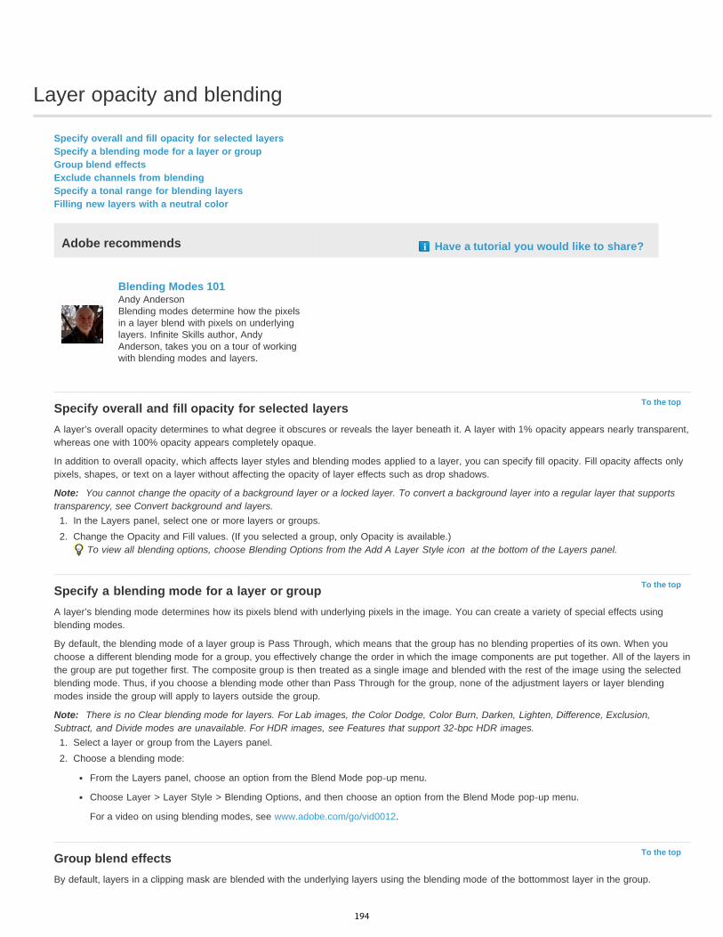
Layer opacity and blending
To the top
To the top
To the top
Specify overall and fill opacity for selected layersSpecify a blending mode for a layer or groupGroup blend effectsExclude channels from blendingSpecify a tonal range for blending layersFilling new layers with a neutral color
Adobe recommends Have a tutorial you would like to share?
Blending Modes 101Andy AndersonBlending modes determine how the pixelsin a layer blend with pixels on underlyinglayers. Infinite Skills author, AndyAnderson, takes you on a tour of workingwith blending modes and layers.
Specify overall and fill opacity for selected layersA layer’s overall opacity determines to what degree it obscures or reveals the layer beneath it. A layer with 1% opacity appears nearly transparent,whereas one with 100% opacity appears completely opaque.
In addition to overall opacity, which affects layer styles and blending modes applied to a layer, you can specify fill opacity. Fill opacity affects onlypixels, shapes, or text on a layer without affecting the opacity of layer effects such as drop shadows.
Note: You cannot change the opacity of a background layer or a locked layer. To convert a background layer into a regular layer that supportstransparency, see Convert background and layers.
1. In the Layers panel, select one or more layers or groups.2. Change the Opacity and Fill values. (If you selected a group, only Opacity is available.)
To view all blending options, choose Blending Options from the Add A Layer Style icon at the bottom of the Layers panel.
Specify a blending mode for a layer or groupA layer’s blending mode determines how its pixels blend with underlying pixels in the image. You can create a variety of special effects usingblending modes.
By default, the blending mode of a layer group is Pass Through, which means that the group has no blending properties of its own. When youchoose a different blending mode for a group, you effectively change the order in which the image components are put together. All of the layers inthe group are put together first. The composite group is then treated as a single image and blended with the rest of the image using the selectedblending mode. Thus, if you choose a blending mode other than Pass Through for the group, none of the adjustment layers or layer blendingmodes inside the group will apply to layers outside the group.
Note: There is no Clear blending mode for layers. For Lab images, the Color Dodge, Color Burn, Darken, Lighten, Difference, Exclusion,Subtract, and Divide modes are unavailable. For HDR images, see Features that support 32-bpc HDR images.
1. Select a layer or group from the Layers panel.2. Choose a blending mode:
From the Layers panel, choose an option from the Blend Mode pop-up menu.
Choose Layer > Layer Style > Blending Options, and then choose an option from the Blend Mode pop-up menu.
For a video on using blending modes, see www.adobe.com/go/vid0012.
Group blend effectsBy default, layers in a clipping mask are blended with the underlying layers using the blending mode of the bottommost layer in the group.
194
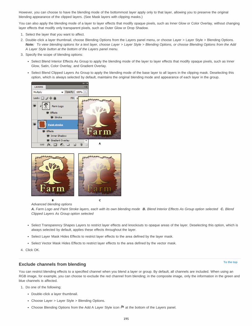
To the top
However, you can choose to have the blending mode of the bottommost layer apply only to that layer, allowing you to preserve the originalblending appearance of the clipped layers. (See Mask layers with clipping masks.)
You can also apply the blending mode of a layer to layer effects that modify opaque pixels, such as Inner Glow or Color Overlay, without changinglayer effects that modify only transparent pixels, such as Outer Glow or Drop Shadow.
1. Select the layer that you want to affect.2. Double-click a layer thumbnail, choose Blending Options from the Layers panel menu, or choose Layer > Layer Style > Blending Options.
Note: To view blending options for a text layer, choose Layer > Layer Style > Blending Options, or choose Blending Options from the AddA Layer Style button at the bottom of the Layers panel menu.
3. Specify the scope of blending options:
Select Blend Interior Effects As Group to apply the blending mode of the layer to layer effects that modify opaque pixels, such as InnerGlow, Satin, Color Overlay, and Gradient Overlay.
Select Blend Clipped Layers As Group to apply the blending mode of the base layer to all layers in the clipping mask. Deselecting thisoption, which is always selected by default, maintains the original blending mode and appearance of each layer in the group.
Advanced blending optionsA. Farm Logo and Paint Stroke layers, each with its own blending mode B. Blend Interior Effects As Group option selected C. BlendClipped Layers As Group option selected
Select Transparency Shapes Layers to restrict layer effects and knockouts to opaque areas of the layer. Deselecting this option, which isalways selected by default, applies these effects throughout the layer.
Select Layer Mask Hides Effects to restrict layer effects to the area defined by the layer mask.
Select Vector Mask Hides Effects to restrict layer effects to the area defined by the vector mask.
4. Click OK.
Exclude channels from blendingYou can restrict blending effects to a specified channel when you blend a layer or group. By default, all channels are included. When using anRGB image, for example, you can choose to exclude the red channel from blending; in the composite image, only the information in the green andblue channels is affected.
1. Do one of the following:
Double-click a layer thumbnail.
Choose Layer > Layer Style > Blending Options.
Choose Blending Options from the Add A Layer Style icon at the bottom of the Layers panel.
195
To the top
To the top
Note: To view blending options for a text layer, choose Layer > Layer Style > Blending Options, or choose Blending Options from theAdd A Layer Style button at the bottom of the Layers panel menu.
2. From the Advanced Blending area of the Layer Style dialog box, deselect any channels you do not want to include when the layer isblended.
Specify a tonal range for blending layersThe sliders in the Blending Options dialog box control which pixels from the active layer and the underlying visible layers appear in the final image.For example, you can drop dark pixels out of the active layer or force bright pixels from the underlying layers to show through. You can also definea range of partially blended pixels to produce a smooth transition between blended and unblended areas.
1. Double-click a layer thumbnail, choose Layer > Layer Style > Blending Options, or choose Add A Layer Style > Blending Options from theLayers panel menu.Note: To view blending options for a text layer, choose Layer > Layer Style > Blending Options, or choose Blending Options from the AddA Layer Style button at the bottom of the Layers panel menu.
2. In the Advanced Blending area of the Layer Style dialog box, choose an option from the Blend If pop-up menu.
Choose Gray to specify a blending range for all channels.
Select an individual color channel (for example, red, green, or blue in an RGB image) to specify blending in that channel.
3. Use the This Layer and Underlying Layer sliders to set the brightness range of the blended pixels—measured on a scale from 0 (black) to255 (white). Drag the white slider to set the high value of the range. Drag the black slider to set the low value of the range.
To define a range of partially blended pixels, hold down Alt (Windows) or Option (Mac OS), and drag one half of a slider triangle. The twovalues that appear above the divided slider indicate the partial blending range.
Keep the following guidelines in mind when specifying blending ranges:
Use the This Layer sliders to specify the range of pixels on the active layer that will blend, and therefore appear, in the final image.For example, if you drag the white slider to 235, pixels with brightness values higher than 235 will remain unblended and will be excludedfrom the final image.
Use the Underlying Layer sliders to specify the range of pixels in the underlying visible layers that will blend in the final image. Blendedpixels are combined with pixels in the active layer to produce composite pixels, whereas unblended pixels show through overlying areasof the active layer. For example, if you drag the black slider to 19, pixels with brightness values lower than 19 will remain unblended andwill show through the active layer in the final image.
Filling new layers with a neutral colorYou can’t apply certain filters (such as the Lighting Effects filter) to layers with no pixels. Selecting Fill With (Mode)-Neutral Color in the New Layerdialog box resolves this problem by first filling the layer with a preset, neutral color. This invisible, neutral color is assigned according to the layer’sblending mode. If no effect is applied, filling with a neutral color has no effect on the remaining layers. The Fill With Neutral Color option is notavailable for layers that use the Normal, Dissolve, Hard Mix, Hue, Saturation, Color, or Luminosity modes.
Legal Notices | Online Privacy Policy
196

Blending modes
To the top
Blending mode descriptionsBlending mode examples
The blending mode specified in the options bar controls how pixels in the image are affected by a painting or editing tool. It’s helpful to think interms of the following colors when visualizing a blending mode’s effect:
The base color is the original color in the image.
The blend color is the color being applied with the painting or editing tool.
The result color is the color resulting from the blend.
Blending mode descriptionsChoose from the Mode pop-up menu in the options bar.
Note: Only the Normal, Dissolve, Darken, Multiply, Lighten, Linear Dodge (Add), Difference, Hue, Saturation, Color, Luminosity, Lighter Color, andDarker Color blending modes are available for 32-bit images.Normal Edits or paints each pixel to make it the result color. This is the default mode. (Normal mode is called Threshold when you’re working witha bitmapped or indexed-color image.)Dissolve Edits or paints each pixel to make it the result color. However, the result color is a random replacement of the pixels with the base coloror the blend color, depending on the opacity at any pixel location.Behind Edits or paints only on the transparent part of a layer. This mode works only in layers with Lock Transparency deselected and isanalogous to painting on the back of transparent areas on a sheet of acetate.Clear Edits or paints each pixel and makes it transparent. This mode is available for the Shape tools (when fill region is selected), Paint Buckettool , Brush tool , Pencil tool , Fill command, and Stroke command. You must be in a layer with Lock Transparency deselected to use thismode.Darken Looks at the color information in each channel and selects the base or blend color—whichever is darker—as the result color. Pixelslighter than the blend color are replaced, and pixels darker than the blend color do not change.Multiply Looks at the color information in each channel and multiplies the base color by the blend color. The result color is always a darker color.Multiplying any color with black produces black. Multiplying any color with white leaves the color unchanged. When you’re painting with a colorother than black or white, successive strokes with a painting tool produce progressively darker colors. The effect is similar to drawing on the imagewith multiple marking pens.Color Burn Looks at the color information in each channel and darkens the base color to reflect the blend color by increasing the contrastbetween the two. Blending with white produces no change.Linear Burn Looks at the color information in each channel and darkens the base color to reflect the blend color by decreasing the brightness.Blending with white produces no change.Lighten Looks at the color information in each channel and selects the base or blend color—whichever is lighter—as the result color. Pixelsdarker than the blend color are replaced, and pixels lighter than the blend color do not change.Screen Looks at each channel’s color information and multiplies the inverse of the blend and base colors. The result color is always a lightercolor. Screening with black leaves the color unchanged. Screening with white produces white. The effect is similar to projecting multiplephotographic slides on top of each other.Color Dodge Looks at the color information in each channel and brightens the base color to reflect the blend color by decreasing contrastbetween the two. Blending with black produces no change.Linear Dodge (Add) Looks at the color information in each channel and brightens the base color to reflect the blend color by increasing thebrightness. Blending with black produces no change.Overlay Multiplies or screens the colors, depending on the base color. Patterns or colors overlay the existing pixels while preserving the highlightsand shadows of the base color. The base color is not replaced, but mixed with the blend color to reflect the lightness or darkness of the originalcolor.Soft Light Darkens or lightens the colors, depending on the blend color. The effect is similar to shining a diffused spotlight on the image. If theblend color (light source) is lighter than 50% gray, the image is lightened as if it were dodged. If the blend color is darker than 50% gray, theimage is darkened as if it were burned in. Painting with pure black or white produces a distinctly darker or lighter area, but does not result in pureblack or white.Hard Light Multiplies or screens the colors, depending on the blend color. The effect is similar to shining a harsh spotlight on the image. If theblend color (light source) is lighter than 50% gray, the image is lightened, as if it were screened. This is useful for adding highlights to an image. Ifthe blend color is darker than 50% gray, the image is darkened, as if it were multiplied. This is useful for adding shadows to an image. Paintingwith pure black or white results in pure black or white.Vivid Light Burns or dodges the colors by increasing or decreasing the contrast, depending on the blend color. If the blend color (light source) is
197

To the top
lighter than 50% gray, the image is lightened by decreasing the contrast. If the blend color is darker than 50% gray, the image is darkened byincreasing the contrast.Linear Light Burns or dodges the colors by decreasing or increasing the brightness, depending on the blend color. If the blend color (light source)is lighter than 50% gray, the image is lightened by increasing the brightness. If the blend color is darker than 50% gray, the image is darkened bydecreasing the brightness.Pin Light Replaces the colors, depending on the blend color. If the blend color (light source) is lighter than 50% gray, pixels darker than the blendcolor are replaced, and pixels lighter than the blend color do not change. If the blend color is darker than 50% gray, pixels lighter than the blendcolor are replaced, and pixels darker than the blend color do not change. This is useful for adding special effects to an image.Hard Mix Adds the red, green and blue channel values of the blend color to the RGB values of the base color. If the resulting sum for a channel is255 or greater, it receives a value of 255; if less than 255, a value of 0. Therefore, all blended pixels have red, green, and blue channel values ofeither 0 or 255. This changes all pixels to primary additive colors (red, green, or blue), white, or black.Note: For CMYK images, Hard Mix changes all pixels to the primary subtractive colors (cyan, yellow, or magenta), white, or black. The maximumcolor value is 100.Difference Looks at the color information in each channel and subtracts either the blend color from the base color or the base color from theblend color, depending on which has the greater brightness value. Blending with white inverts the base color values; blending with black producesno change.Exclusion Creates an effect similar to but lower in contrast than the Difference mode. Blending with white inverts the base color values. Blendingwith black produces no change.Subtract Looks at the color information in each channel and subtracts the blend color from the base color. In 8- and 16-bit images, any resultingnegative values are clipped to zero.Divide Looks at the color information in each channel and divides the blend color from the base color.Hue Creates a result color with the luminance and saturation of the base color and the hue of the blend color.Saturation Creates a result color with the luminance and hue of the base color and the saturation of the blend color. Painting with this mode in anarea with no (0) saturation (gray) causes no change.Color Creates a result color with the luminance of the base color and the hue and saturation of the blend color. This preserves the gray levels inthe image and is useful for coloring monochrome images and for tinting color images.Luminosity Creates a result color with the hue and saturation of the base color and the luminance of the blend color. This mode creates theinverse effect of Color mode.Lighter Color Compares the total of all channel values for the blend and base color and displays the higher value color. Lighter Color does notproduce a third color, which can result from the Lighten blend, because it chooses the highest channel values from both the base and blend colorto create the result color.Darker Color Compares the total of all channel values for the blend and base color and displays the lower value color. Darker Color does notproduce a third color, which can result from the Darken blend, because it chooses the lowest channel values from both the base and the blendcolor to create the result color.
Blending mode examplesThese examples show the result of painting part of the image’s face using each blending mode.
For a video on blending modes, see www.adobe.com/go/vid0012.
Original Image Normal, 100% opacity Normal, 50% opacity Dissolve, 50% opacity
Behind Clear Darken Multiply
198
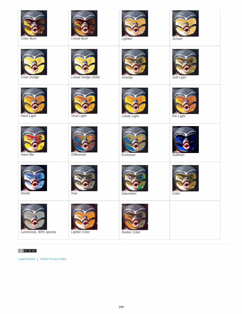
Color Burn Linear Burn Lighten Screen
Color Dodge Linear Dodge (Add) Overlay Soft Light
Hard Light Vivid Light Linear Light Pin Light
Hard Mix Difference Exclusion Subtract
Divide Hue Saturation Color
Luminosity, 80% opacity Lighter Color Darker Color
Legal Notices | Online Privacy Policy
199
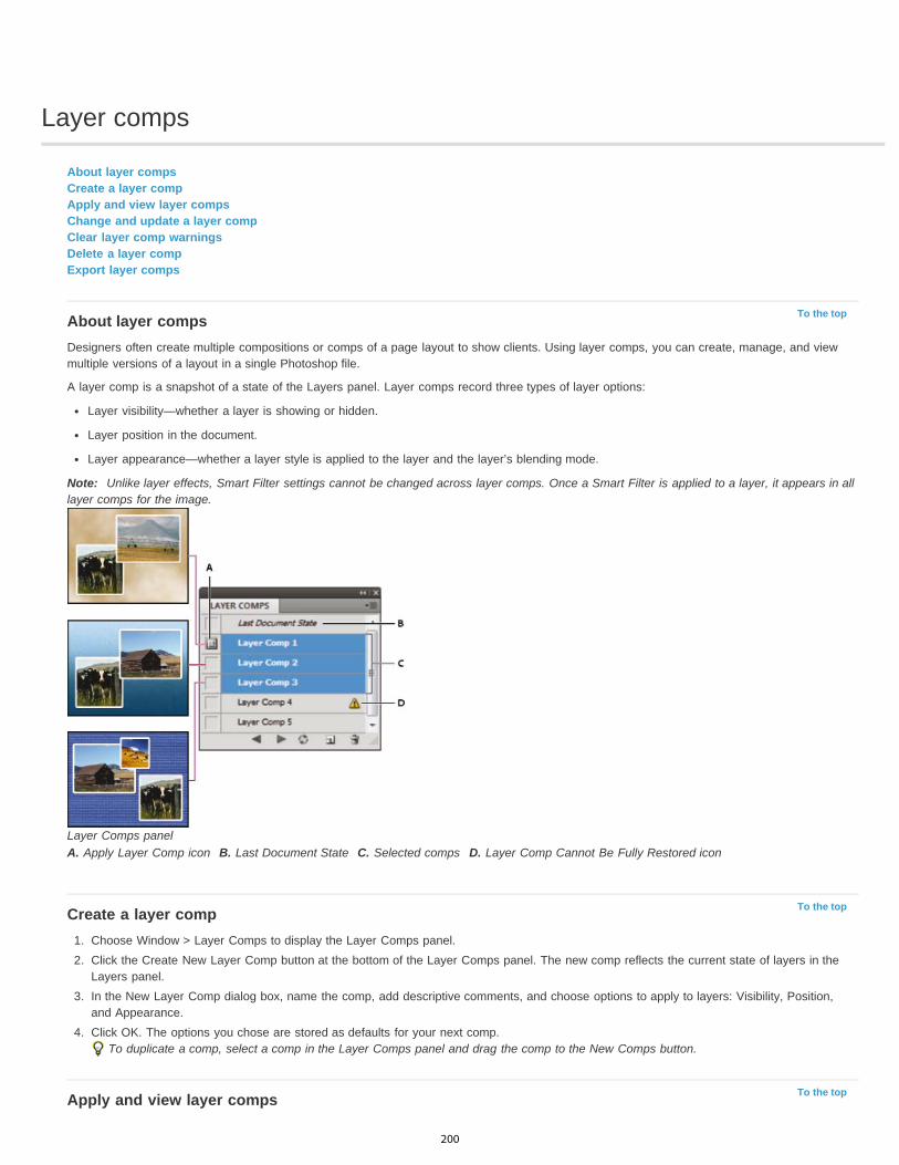
Layer comps
To the top
To the top
To the top
About layer compsCreate a layer compApply and view layer compsChange and update a layer compClear layer comp warningsDelete a layer compExport layer comps
About layer compsDesigners often create multiple compositions or comps of a page layout to show clients. Using layer comps, you can create, manage, and viewmultiple versions of a layout in a single Photoshop file.
A layer comp is a snapshot of a state of the Layers panel. Layer comps record three types of layer options:
Layer visibility—whether a layer is showing or hidden.
Layer position in the document.
Layer appearance—whether a layer style is applied to the layer and the layer’s blending mode.
Note: Unlike layer effects, Smart Filter settings cannot be changed across layer comps. Once a Smart Filter is applied to a layer, it appears in alllayer comps for the image.
Layer Comps panelA. Apply Layer Comp icon B. Last Document State C. Selected comps D. Layer Comp Cannot Be Fully Restored icon
Create a layer comp1. Choose Window > Layer Comps to display the Layer Comps panel.2. Click the Create New Layer Comp button at the bottom of the Layer Comps panel. The new comp reflects the current state of layers in the
Layers panel.3. In the New Layer Comp dialog box, name the comp, add descriptive comments, and choose options to apply to layers: Visibility, Position,
and Appearance.4. Click OK. The options you chose are stored as defaults for your next comp.
To duplicate a comp, select a comp in the Layer Comps panel and drag the comp to the New Comps button.
Apply and view layer comps
200

To the top
To the top
To the top
To the top
In the Layer Comp panel, do any of the following:
To view a layer comp, you first need to apply it. Click the Apply Layer Comp icon next to a selected comp.
To cycle through a view of all layer comps, use the Previous and Next buttons at the bottom of the panel. (To cycle through specificcomps, first select them.)
To restore the document to its state before you chose a layer comp, click the Apply Layer Comp icon next to Last Document State at thetop of the panel.
Change and update a layer compIf you change the configuration of a layer comp, you need to update it.
1. Select the layer comp in the Layer Comps panel.
2. Make changes to the layer’s visibility, position, or style. You may need to change the layer comp’s options to record these changes.
3. To change your comp options, select Layer Comp Options from the panel menu and select additional options to record layer position andstyle.
4. Click the Update Layer Comp button at the bottom of the panel.
Clear layer comp warningsCertain actions create a state where the layer comp can no longer be fully restored. This happens when you delete a layer, merge a layer, orconvert a layer to a background. In such instances, a caution icon appears next to the layer comp name.
Do one of the following:
Ignore the warning, which may result in the loss of one or more layers. Other saved parameters may be preserved.
Update the comp, which results in the loss of the previously captured parameters, but brings the comp up to date.
Click the caution icon to see the message explaining that the layer comp can’t be restored properly. Choose Clear to remove the alert iconand leave the remaining layers unchanged.
Right-click (Windows) or Control-click (Mac OS) the caution icon to see the pop-up menu that lets you choose either the Clear Layer CompWarning or the Clear All Layer Comp Warnings command.
Delete a layer comp Do one of the following:
Select the layer comp in the Layer Comps panel and click the Delete icon in the panel, or choose Delete Layer Comp from the panelmenu.
Drag it to the Delete icon in the panel.
Export layer compsYou can export layer comps to individual files.
Choose File > Scripts > Layer Comps to Files and then choose the file type and set the destination.Note: Note, you can also export to a Web Photo Gallery (WPG), but you must have the optional Web Photo Gallery plug-in installed on yourcomputer. You can find the plug-in on in the Goodies folder on your installation disc.
Legal Notices | Online Privacy Policy
201

Layer effects and styles
To the top
To the top
About layer effects and stylesApply preset stylesLayer Style dialog box overviewApply or edit a custom layer styleLayer style optionsModify layer effects with contoursSet a global lighting angle for all layersDisplay or hide layer stylesCopy layer stylesScale a layer effectRemove layer effectsConvert a layer style to image layersCreate and manage preset styles
About layer effects and stylesPhotoshop provides a variety of effects—such as shadows, glows, and bevels—that change the appearance of a layer’s contents. Layer effectsare linked to the layer contents. When you move or edit the contents of the layer, the same effects are applied to the modified contents. Forexample, if you apply a drop shadow to a text layer and then add new text, the shadow is added automatically to the new text.
A layer style is one or more effects applied to a layer or layer group. You can apply one of the preset styles provided with Photoshop or create acustom style using the Layer Style dialog box. The layer effects icon appears to the right of the layer’s name in the Layers panel. You canexpand the style in the Layers panel to view or edit the effects that compose the style.
Layers panel showing layer with multiple effects appliedA. Layer effects icon B. Click to expand and show layer effects C. Layer effects
When you save a custom style, it becomes a preset style. Preset styles appear in the Styles panel and can be applied to a layer or group with asingle click.
Apply preset stylesYou can apply preset styles from the Styles panel. The layer styles that come with Photoshop are grouped into libraries by function. For example,one library contains styles for creating web buttons; another library contains styles adding effects to text. To access these styles, you need to loadthe appropriate library. For information on loading and saving styles, see Create and manage preset styles.
Note: You cannot apply layer styles to a background, locked layer, or group.
Display the Styles panel Choose Window > Styles.
Apply a preset style to a layerNormally, applying a preset style replaces the current layer style. However, you can add the attributes of a second style to those of the currentstyle.
Do one of the following:
202
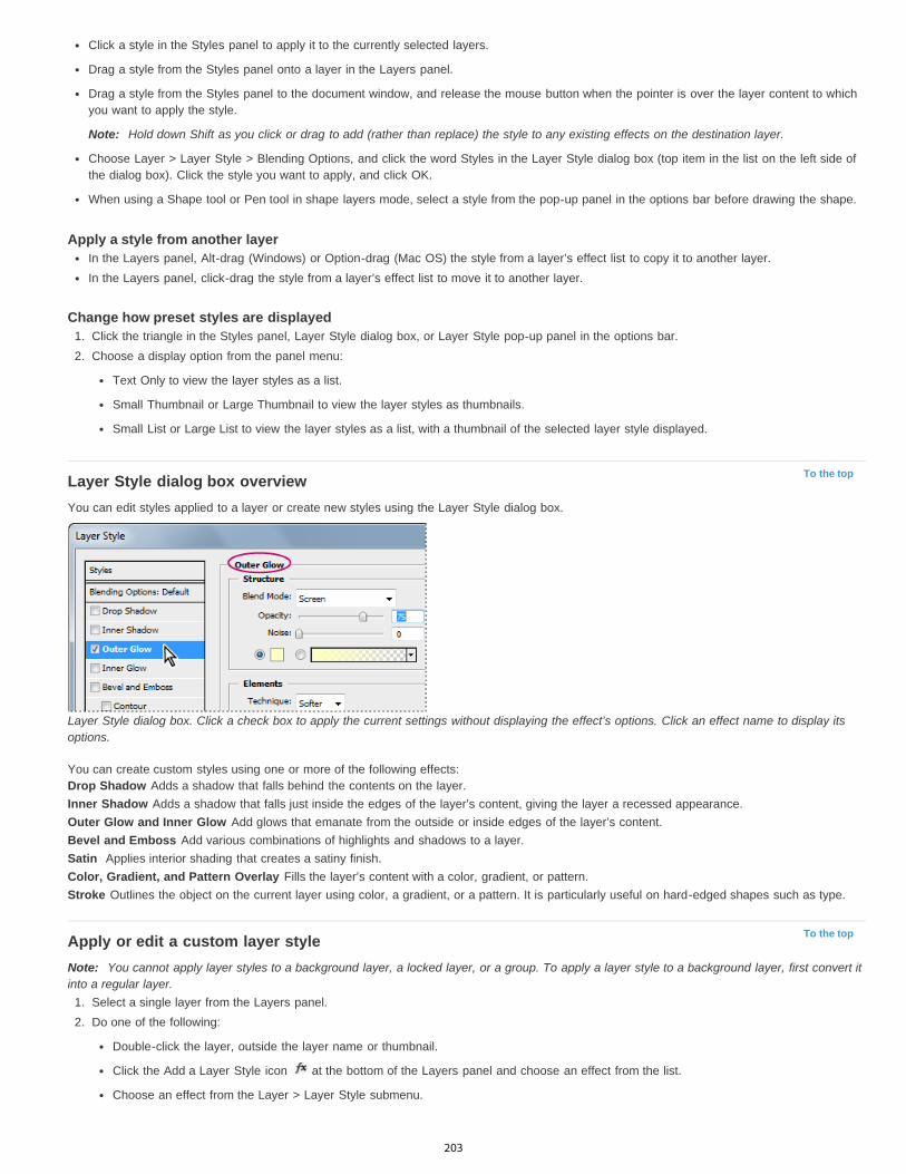
To the top
To the top
Click a style in the Styles panel to apply it to the currently selected layers.
Drag a style from the Styles panel onto a layer in the Layers panel.
Drag a style from the Styles panel to the document window, and release the mouse button when the pointer is over the layer content to whichyou want to apply the style.
Note: Hold down Shift as you click or drag to add (rather than replace) the style to any existing effects on the destination layer.
Choose Layer > Layer Style > Blending Options, and click the word Styles in the Layer Style dialog box (top item in the list on the left side ofthe dialog box). Click the style you want to apply, and click OK.
When using a Shape tool or Pen tool in shape layers mode, select a style from the pop-up panel in the options bar before drawing the shape.
Apply a style from another layerIn the Layers panel, Alt-drag (Windows) or Option-drag (Mac OS) the style from a layer’s effect list to copy it to another layer.In the Layers panel, click-drag the style from a layer’s effect list to move it to another layer.
Change how preset styles are displayed1. Click the triangle in the Styles panel, Layer Style dialog box, or Layer Style pop-up panel in the options bar.2. Choose a display option from the panel menu:
Text Only to view the layer styles as a list.
Small Thumbnail or Large Thumbnail to view the layer styles as thumbnails.
Small List or Large List to view the layer styles as a list, with a thumbnail of the selected layer style displayed.
Layer Style dialog box overviewYou can edit styles applied to a layer or create new styles using the Layer Style dialog box.
Layer Style dialog box. Click a check box to apply the current settings without displaying the effect’s options. Click an effect name to display itsoptions.
You can create custom styles using one or more of the following effects:Drop Shadow Adds a shadow that falls behind the contents on the layer.Inner Shadow Adds a shadow that falls just inside the edges of the layer’s content, giving the layer a recessed appearance.Outer Glow and Inner Glow Add glows that emanate from the outside or inside edges of the layer’s content.Bevel and Emboss Add various combinations of highlights and shadows to a layer.Satin Applies interior shading that creates a satiny finish.Color, Gradient, and Pattern Overlay Fills the layer’s content with a color, gradient, or pattern.Stroke Outlines the object on the current layer using color, a gradient, or a pattern. It is particularly useful on hard-edged shapes such as type.
Apply or edit a custom layer styleNote: You cannot apply layer styles to a background layer, a locked layer, or a group. To apply a layer style to a background layer, first convert itinto a regular layer.
1. Select a single layer from the Layers panel.2. Do one of the following:
Double-click the layer, outside the layer name or thumbnail.
Click the Add a Layer Style icon at the bottom of the Layers panel and choose an effect from the list.
Choose an effect from the Layer > Layer Style submenu.
203

To the top
To edit an existing style, double-click an effect displayed below the layer name in the Layers panel. (Click the triangle next to the Add aLayer Style icon to display the effects contained in the style.)
3. Set effect options in the Layer Style dialog box. See Layer style options.4. Add other effects to the style, if desired. In the Layer Style dialog box, click the check box to the left of the effect name to add the effect
without selecting it.You can edit multiple effects without closing the Layer Style dialog box. Click the name of an effect on the left side of the dialog box todisplay its options.
Change style defaults to custom values1. In the Layer Style dialog box, customize settings as desired.2. Click Make Default.
When you next open the dialog box, your custom defaults are automatically applied. If you adjust settings and want to return to your customdefaults, click Reset To Default.
To return to Photoshop’s original defaults, see Restore all preferences to default settings.
Layer style optionsAltitude For the Bevel and Emboss effect, sets the height of the light source. A setting of 0 is equivalent to ground level, 90 is directly above thelayer.Angle Determines the lighting angle at which the effect is applied to the layer. You can drag in the document window to adjust the angle of a DropShadow, Inner Shadow, or Satin effect.Anti-alias Blends the edge pixels of a contour or gloss contour. This option is most useful on small shadows with complicated contours.Blend Mode Determines how the layer style blends with the underlying layers, which may or may not include the active layer. For example,an inner shadow blends with the active layer because the effect is drawn on top of that layer, but a drop shadow blends only with the layersbeneath the active layer. In most cases, the default mode for each effect produces the best results. See Blending modes.Choke Shrinks the boundaries of the matte of an Inner Shadow or Inner Glow prior to blurring.Color Specifies the color of a shadow, glow, or highlight. You can click the color box and choose a color.Contour With solid-color glows, Contour allows you to create rings of transparency. With gradient-filled glows, Contour allows you to createvariations in the repetition of the gradient color and opacity. In beveling and embossing, Contour allows you to sculpt the ridges, valleys, andbumps that are shaded in the embossing process. With shadows, Contour allows you to specify the fade. For more information, see Modify layereffects with contours.Distance Specifies the offset distance for a shadow or satin effect. You can drag in the document window to adjust the offset distance.Depth Specifies the depth of a bevel. It also specifies the depth of a pattern.Use Global Light This setting allows you to set one “master” lighting angle that is then available in all the layer effects that use shading: DropShadow, Inner Shadow, and Bevel and Emboss. In any of these effects, if Use Global Light is selected and you set a lighting angle, that anglebecomes the global lighting angle. Any other effect that has Use Global Light selected automatically inherits the same angle setting. If Use GlobalLight is deselected, the lighting angle you set is “local” and applies only to that effect. You can also set the global lighting angle by choosing LayerStyle > Global Light.Gloss Contour Creates a glossy, metallic appearance. Gloss Contour is applied after shading a bevel or emboss.Gradient Specifies the gradient of a layer effect. Click the gradient to display the Gradient Editor, or click the inverted arrow and choose a gradientfrom the pop-up panel. You can edit a gradient or create a new gradient using the Gradient Editor. You can edit the color or opacity in the GradientOverlay panel the same way you edit them in the Gradient Editor. For some effects, you can specify additional gradient options. Reverse flips theorientation of the gradient, Align With Layer uses the bounding box of the layer to calculate the gradient fill, and Scale scales the application of thegradient. You can also move the center of the gradient by clicking and dragging in the image window. Style specifies the shape of the gradient.Highlight or Shadow Mode Specifies the blending mode of a bevel or emboss highlight or shadow.Jitter Varies the application of a gradient’s color and opacity.Layer Knocks Out Drop Shadow Controls the drop shadow’s visibility in a semitransparent layer.Noise Specifies the number of random elements in the opacity of a glow or shadow. Enter a value or drag the slider.Opacity Sets the opacity of the layer effect. Enter a value or drag the slider.Pattern Specifies the pattern of a layer effect. Click the pop-up panel and choose a pattern. Click the New Preset button to create a new presetpattern based on the current settings. Click Snap To Origin to make the origin of the pattern the same as the origin of the document (when LinkWith Layer is selected), or to place the origin at the upper-left corner of the layer (if Link With Layer is deselected). Select Link With Layer if youwant the pattern to move along with the layer as the layer moves. Drag the Scale slider or enter a value to specify the size of the pattern. Drag apattern to position it in the layer; reset the position by using the Snap To Origin button. The Pattern option is not available if no patterns areloaded.Position Specifies the position of a stroke effect as Outside, Inside, or Center.Range Controls which portion or range of the glow is targeted for the contour.Size Specifies the radius and size of blur or the size of the shadow.Soften Blurs the results of shading to reduce unwanted artifacts.Source Specifies the source for an inner glow. Choose Center to apply a glow that emanates from the center of the layer’s content, or Edge to
204
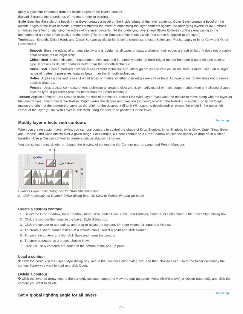
To the top
To the top
apply a glow that emanates from the inside edges of the layer’s content.Spread Expands the boundaries of the matte prior to blurring.Style Specifies the style of a bevel: Inner Bevel creates a bevel on the inside edges of the layer contents; Outer Bevel creates a bevel on theoutside edges of the layer contents; Emboss simulates the effect of embossing the layer contents against the underlying layers; Pillow Embosssimulates the effect of stamping the edges of the layer contents into the underlying layers; and Stroke Emboss confines embossing to theboundaries of a stroke effect applied to the layer. (The Stroke Emboss effect is not visible if no stroke is applied to the layer.)Technique Smooth, Chisel Hard, and Chisel Soft are available for bevel and emboss effects; Softer and Precise apply to Inner Glow and OuterGlow effects.
Smooth Blurs the edges of a matte slightly and is useful for all types of mattes, whether their edges are soft or hard. It does not preservedetailed features at larger sizes.Chisel Hard Uses a distance measurement technique and is primarily useful on hard-edged mattes from anti-aliased shapes such astype. It preserves detailed features better than the Smooth technique.Chisel Soft Uses a modified distance measurement technique and, although not as accurate as Chisel Hard, is more useful on a largerrange of mattes. It preserves features better than the Smooth technique.Softer Applies a blur and is useful on all types of mattes, whether their edges are soft or hard. At larger sizes, Softer does not preservedetailed features.Precise Uses a distance measurement technique to create a glow and is primarily useful on hard-edged mattes from anti-aliased shapessuch as type. It preserves features better than the Softer technique.
Texture Applies a texture. Use Scale to scale the size of the texture. Select Link With Layer if you want the texture to move along with the layer asthe layer moves. Invert inverts the texture. Depth varies the degree and direction (up/down) to which the texturing is applied. Snap To Originmakes the origin of the pattern the same as the origin of the document (if Link With Layer is deselected) or places the origin in the upper-leftcorner of the layer (if Link With Layer is selected). Drag the texture to position it in the layer.
Modify layer effects with contoursWhen you create custom layer styles, you can use contours to control the shape of Drop Shadow, Inner Shadow, Inner Glow, Outer Glow, Beveland Emboss, and Satin effects over a given range. For example, a Linear contour on a Drop Shadow causes the opacity to drop off in a lineartransition. Use a Custom contour to create a unique shadow transition.
You can select, reset, delete, or change the preview of contours in the Contour pop-up panel and Preset Manager.
Detail of Layer Style dialog box for Drop Shadow effectA. Click to display the Contour Editor dialog box. B. Click to display the pop-up panel.
Create a custom contour1. Select the Drop Shadow, Inner Shadow, Inner Glow, Outer Glow, Bevel and Emboss, Contour, or Satin effect in the Layer Style dialog box.2. Click the contour thumbnail in the Layer Style dialog box.3. Click the contour to add points, and drag to adjust the contour. Or enter values for Input and Output.4. To create a sharp corner instead of a smooth curve, select a point and click Corner.5. To save the contour to a file, click Save and name the contour.6. To store a contour as a preset, choose New.7. Click OK. New contours are added at the bottom of the pop-up panel.
Load a contour Click the contour in the Layer Style dialog box, and in the Contour Editor dialog box, and then choose Load. Go to the folder containing the
contour library you want to load and click Open.
Delete a contour Click the inverted arrow next to the currently selected contour to view the pop-up panel. Press Alt (Windows) or Option (Mac OS), and click the
contour you want to delete.
Set a global lighting angle for all layers
205
To the top
To the top
To the top
To the top
Using global light gives the appearance of a common light source shining on the image.
Do one of the following:
Choose Layer > Layer Style > Global Light. In the Global Light dialog box, enter a value or drag the angle radius to set the angle andaltitude, and click OK.
In the Layer Style dialog box for Drop Shadow, Inner Shadow, or Bevel, select Use Global Light. For Angle, enter a value or drag the radius,and click OK.
The global lighting applies to each layer effect that uses the global lighting angle.
Display or hide layer stylesWhen a layer has a style, an “fx” icon appears to the right of the layer’s name in the Layers panel.
Hide or show all layer styles in an image Choose Layer > Layer Style > Hide All Effects or Show All Effects.
Expand or collapse layer styles in the Layers panel Do one of the following:
Click the triangle next to the Add a Layer Style icon to expand the list of layer effects applied to that layer.
Click the triangle to collapse the layer effects.
To expand or collapse all of the layer styles applied within a group, hold down Alt (Windows) or Option (Mac OS), and click the triangle orinverted triangle for the group. The layer styles applied to all layers within the group expand or collapse correspondingly.
Copy layer stylesCopying and pasting styles is an easy way to apply the same effects to multiple layers.
Copy layer styles between layers1. From the Layers panel, select the layer containing the style you want to copy.2. Choose Layer > Layer Style > Copy Layer Style.3. Select the destination layer from the panel, and choose Layer > Layer Style > Paste Layer Style.
The pasted layer style replaces the existing layer style on the destination layer or layers.
Copy layer styles between layers by dragging Do one of the following:
In the Layers panel, Alt-drag (Windows) or Option-drag (Mac OS) a single layer effect from one layer to another to duplicate the layer effect,or drag the Effects bar from one layer to another to duplicate the layer style.
Drag one or more layer effects from the Layers panel to the image to apply the resulting layer style to the highest layer in the Layers panelthat contains pixels at the drop point.
Scale a layer effectA layer style may have been fine-tuned for a target resolution and features of a given size. Using Scale Effects allows you to scale the effects inthe layer style without scaling the object to which the layer style is applied.
1. Select the layer in the Layers panel.2. Choose Layer > Layer Style > Scale Effects.3. Enter a percentage or drag the slider.4. Select Preview to preview the changes in the image.5. Click OK.
Remove layer effectsYou can remove an individual effect from a style applied to a layer, or remove the entire style from the layer.
Remove an effect from a style
206

To the top
To the top
1. In the Layers panel, expand the layer style to see its effects.2. Drag the effect to the Delete icon .
Remove a style from a layer1. In the Layers panel, select the layer containing the style you want to remove.2. Do one of the following:
In the Layers panel, drag the Effects bar to the Delete icon .
Choose Layer > Layer Style > Clear Layer Style.
Select the layer, and then click the Clear Style button at the bottom of the Styles panel.
Convert a layer style to image layersTo customize or fine-tune the appearance of layer styles, you can convert the layer styles to regular image layers. After you convert a layer style toimage layers, you can enhance the result by painting or applying commands and filters. However, you can no longer edit the layer style on theoriginal layer, and the layer style no longer updates as you change the original image layer.
Note: The layers produced by this process may not result in artwork that exactly matches the version using layer styles. You may see an alertwhen you create the new layers.
1. In the Layers panel, select the layer containing the layer style that you want to convert.2. Choose Layer > Layer Style > Create Layers.
You can now modify and restack the new layers in the same way as regular layers. Some effects—for example, Inner Glow—convert tolayers within a clipping mask.
Create and manage preset stylesYou can create a custom style and save it as a preset, which is then available from the Styles panel. You can save preset styles in a library andload or remove them from the Styles panel as you need them.
Create a new preset style1. From the Layers panel, select the layer containing the style that you want to save as a preset.2. Do one of the following:
Click an empty area of the Styles panel.
Click the Create New Style button at the bottom of the Styles panel.
Choose New Style from the Styles panel menu.
Choose Layer > Layer Style > Blending Options, and click New Style in the Layer Style dialog box.
3. Enter a name for the preset style, set style options, and click OK.
Rename a preset style Do one of the following:
Double-click a style in the Styles panel. If the Styles panel is set to display styles as thumbnails, enter a new name in the dialog box andclick OK. Otherwise, type a new name directly in the Styles panel and press Enter (Windows) or Return (Mac OS).
Select a style in the Styles area of the Layer Style dialog box. Then choose Rename Style from the pop-up menu, enter a new name, andclick OK.
When using a shape or Pen tool, select a style from the Style pop-up panel in the options bar. Then choose Rename Style from the pop-uppanel menu.
Delete a preset style Do one of the following:
Drag a style to the Delete icon at the bottom of the Styles panel.
Press Alt (Windows) or Option (Mac OS), and click the layer style in the Styles panel.
Select a style in the Styles area of the Layer Style dialog box. (See Apply preset styles.) Then choose Delete Style from the pop-up menu.
When using a shape or Pen tool, select a style from the Layer Style pop-up panel in the options bar. Then choose Delete Style from thepop-up panel menu.
207
Save a set of preset styles as a library1. Do one of the following:
Choose Save Styles from the Styles panel menu.
Select Styles on the left side of the Layer Style dialog box. Then choose Save Styles from the pop-up menu.
When using a shape or Pen tool, click the layer style thumbnail in the options bar. Then choose Save Styles from the pop-up panelmenu.
2. Choose a location for the style library, enter a file name, and click Save.
You can save the library anywhere. However, if you place the library file in the Presets/Styles folder inside the default presets location, thelibrary name will appear at the bottom of the Styles panel menu when you restart the application.
Note: You can also use the Preset Manager to rename, delete, and save libraries of preset styles.
Load a library of preset styles1. Click the triangle in the Styles panel, Layer Style dialog box, or Layer Style pop-up panel in the options bar.2. Do one of the following:
Choose Load Styles to add a library to the current list. Then select the library file you want to use, and click Load.
Choose Replace Styles to replace the current list with a different library. Then select the library file you want to use, and click Load.
Choose a library file (displayed at the bottom of the panel menu). Then click OK to replace the current list, or click Append to append thecurrent list.
3. To return to the default library of preset styles, choose Reset Styles. You can either replace the current list or append the default library tothe current list.Note: You can also use the Preset Manager to load and reset style libraries. See About the Preset Manager.
Legal Notices | Online Privacy Policy
208

Selecting
Refine a selectionInfinite Skills (Aug. 9, 2012)video-tutorialRefine a selection or mask edge
Selecting areas of a photovideo2brain (May. 7, 2012)video-tutorialDiscover the basic building block of image editing.
209
Making selections
Twitter™ and Facebook posts are not covered under the terms of Creative Commons.
Legal Notices | Online Privacy Policy
To the top
Note:
To the top
About selecting pixelsSelect, deselect, and reselect pixels
About selecting pixelsA selection isolates one or more parts of your image. By selecting specific areas, you can edit and apply effects and filters to portions of yourimage while leaving the unselected areas untouched.
The easiest way to select pixels in your image is to use the quick selection tools. You can also select areas of a certain shape with the marqueetools or use the lasso tools to make a selection by tracing an element in your image. It's also possible to make selections based on a range ofcolors in an image. There are commands in the Select menu to select, deselect, or reselect all pixels.
In addition to pixels, vector data can be used to make selections. Use the pen or shape tools to produce precise outlines called paths. Paths canbe converted to selections.
Selections can be copied, moved, and pasted, or saved and stored in an alpha channel. Alpha channels store selections as grayscale imagescalled masks. A mask is like the inverse of a selection: it covers the unselected part of the image and protects it from any editing or manipulationsyou apply. You can convert a stored mask back into a selection by loading the alpha channel into an image.
While paths can be converted to selections, selections can also be converted to paths.
Select, deselect, and reselect pixelsIf a tool is not working as expected, you may have a hidden selection. Use the Deselect command and try the tool again.
Select all pixels on a layer within the canvas boundaries1. Select the layer in the Layers panel.2. Choose Select > All.
Deselect selectionsDo one of the following:
Choose Select > Deselect.
If you are using the Rectangle Marquee tool, the Elliptical Marquee tool, or the Lasso tool, click anywhere in the image outside theselected area.
Reselect the most recent selectionChoose Select > Reselect.
More Help TopicsConvert paths to selection borders
Saving selections and alpha channel masks
210
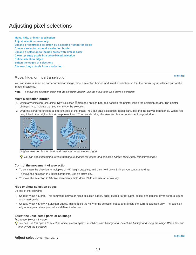
Adjusting pixel selections
To the top
To the top
Move, hide, or invert a selectionAdjust selections manuallyExpand or contract a selection by a specific number of pixelsCreate a selection around a selection borderExpand a selection to include areas with similar colorClean up stray pixels in a color-based selectionRefine selection edgesSoften the edges of selectionsRemove fringe pixels from a selection
Move, hide, or invert a selectionYou can move a selection border around an image, hide a selection border, and invert a selection so that the previously unselected part of theimage is selected.
Note: To move the selection itself, not the selection border, use the Move tool. See Move a selection.
Move a selection border1. Using any selection tool, select New Selection from the options bar, and position the pointer inside the selection border. The pointer
changes to indicate that you can move the selection.2. Drag the border to enclose a different area of the image. You can drag a selection border partly beyond the canvas boundaries. When you
drag it back, the original border reappears intact. You can also drag the selection border to another image window.
Original selection border (left), and selection border moved (right)
You can apply geometric transformations to change the shape of a selection border. (See Apply transformations.)
Control the movement of a selectionTo constrain the direction to multiples of 45°, begin dragging, and then hold down Shift as you continue to drag.To move the selection in 1-pixel increments, use an arrow key.To move the selection in 10-pixel increments, hold down Shift, and use an arrow key.
Hide or show selection edgesDo one of the following:
Choose View > Extras. This command shows or hides selection edges, grids, guides, target paths, slices, annotations, layer borders, count,and smart guide.Choose View > Show > Selection Edges. This toggles the view of the selection edges and affects the current selection only. The selectionedges reappear when you make a different selection.
Select the unselected parts of an image Choose Select > Inverse.
You can use this option to select an object placed against a solid-colored background. Select the background using the Magic Wand tool andthen invert the selection.
Adjust selections manually
211
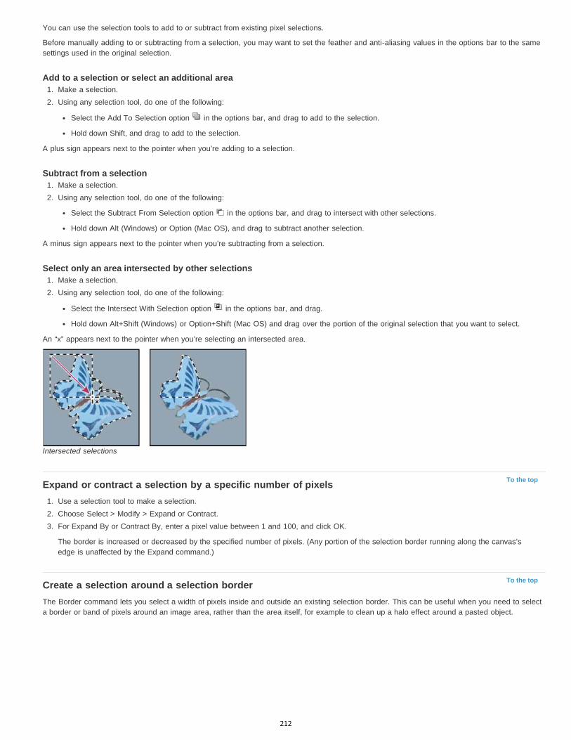
To the top
To the top
You can use the selection tools to add to or subtract from existing pixel selections.
Before manually adding to or subtracting from a selection, you may want to set the feather and anti-aliasing values in the options bar to the samesettings used in the original selection.
Add to a selection or select an additional area1. Make a selection.2. Using any selection tool, do one of the following:
Select the Add To Selection option in the options bar, and drag to add to the selection.
Hold down Shift, and drag to add to the selection.
A plus sign appears next to the pointer when you’re adding to a selection.
Subtract from a selection1. Make a selection.2. Using any selection tool, do one of the following:
Select the Subtract From Selection option in the options bar, and drag to intersect with other selections.
Hold down Alt (Windows) or Option (Mac OS), and drag to subtract another selection.
A minus sign appears next to the pointer when you’re subtracting from a selection.
Select only an area intersected by other selections1. Make a selection.2. Using any selection tool, do one of the following:
Select the Intersect With Selection option in the options bar, and drag.
Hold down Alt+Shift (Windows) or Option+Shift (Mac OS) and drag over the portion of the original selection that you want to select.
An “x” appears next to the pointer when you’re selecting an intersected area.
Intersected selections
Expand or contract a selection by a specific number of pixels1. Use a selection tool to make a selection.2. Choose Select > Modify > Expand or Contract.3. For Expand By or Contract By, enter a pixel value between 1 and 100, and click OK.
The border is increased or decreased by the specified number of pixels. (Any portion of the selection border running along the canvas’sedge is unaffected by the Expand command.)
Create a selection around a selection borderThe Border command lets you select a width of pixels inside and outside an existing selection border. This can be useful when you need to selecta border or band of pixels around an image area, rather than the area itself, for example to clean up a halo effect around a pasted object.
212

To the top
To the top
To the top
Original selection (left), and after Border command: 5 pixels (right)
1. Use a selection tool to make a selection.2. Choose Select > Modify > Border.3. Enter a value between 1 and 200 pixels for the border width of the new selection, and click OK.
The new selection frames the original selected area, and is centered on the original selection border. For example, a border width of 20pixels creates a new, soft-edged selection that extends 10 pixels inside the original selection border and 10 pixels outside it.
Expand a selection to include areas with similar colorDo one of the following:
Choose Select > Grow to include all adjacent pixels falling within the tolerance range specified in the Magic Wand options.Choose Select > Similar to include pixels throughout the image, not just adjacent ones, falling within the tolerance range.
To increase the selection in increments, choose either command more than once.
Note: You cannot use the Grow and Similar commands on Bitmap mode images or 32-bits-per-channel images.
Clean up stray pixels in a color-based selection1. Choose Select > Modify > Smooth.2. For Sample Radius, enter a pixel value between 1 and 100, and click OK.
For each pixel in the selection, Photoshop examines the pixels around it, to the distance you specify in the radius setting. If more than half ofthese surrounding pixels are selected, the pixel remains in the selection, and the unselected pixels around it are added to the selection. Ifless than half the surrounding pixels are selected, the pixel is removed from the selection. The overall effect is to reduce patchiness andsmooth sharp corners and jagged lines in the selection.
Refine selection edgesThe Refine Edge option improves the quality of selection edges, letting you extract objects with ease. You can also use Refine Edge options torefine a layer mask. (See Adjust mask opacity or edges.)
Adobe recommends Have a tutorial you'd like to share?
Video tutorial: Extracting objects inPhotoshop CS5Russell BrownExtract with speed and precision using Refine Edge.
Video tutorial: Precisely selecting portraitsDeke McClellandEasily select whispy hair to place portraits on newbackgrounds.
Video tutorial: Quickly creating refinedselectionsMartin EveningCombine the Quick Selection and edge refinementtools to maximize your efficiency.
Video tutorial: Using improved selecting andmaskingJan KabiliTake a tour through the all the enhancements toselections and masks.
1. Create a selection with any selection tool.
2. Click Refine Edge in the options bar, or choose Select > Refine Edge. Then set the following options:
View Mode From the pop-up menu, choose a mode to change how the selection is displayed. For information about each mode, hover thepointer over it until a tool tip appears. Show Original displays the original selection for comparison. Show Radius displays the selection
213

To the top
border where edge refinement occurs.
Refine Radius and Erase Refinements tools Let you precisely adjust the border area in which edge refinement occurs. To quicklytoggle from one tool to the other, press Shift+E. To change the brush size, press the bracket keys.
Brush over soft areas such as hair or fur to add fine details to the selection.
Smart Radius Automatically adjusts the radius for hard and soft edges found in the border region. Deselect this option if the border isuniformly hard- or soft-edged, or if you want to control the Radius setting and refinement brushes more precisely.
Radius Determines the size of the selection border in which edge refinement occurs. Use a small radius for sharp edges, and a large onefor softer edges.
Smooth Reduces irregular areas (“hills and valleys”) in the selection border to create a smoother outline.
Feather Blurs the transition between the selection and surrounding pixels.
Contrast When increased, soft-edged transitions along the selection border become more abrupt. Typically, the Smart Radius option andrefinement tools are more effective.
Shift Edge Moves soft-edged borders inward with negative values or outward with positive ones. Shifting these borders inward can helpremove unwanted background colors from selection edges.
Decontaminate Colors Replaces color fringes with the color of fully selected pixels nearby. The strength of color replacement isproportionate to the softness of selection edges.Important: Because this option changes pixel color, it requires output to a new layer or document. Retain the original layer so you canrevert back to it if needed. (To easily see changes in pixel color, choose Reveal Layer for the View Mode.)
Amount Changes the level of decontamination and fringe replacement.
Output To Determines whether the refined selection becomes a selection or mask on the current layer, or produces a new layer ordocument.
Soften the edges of selectionsYou can smooth the hard edges of a selection by anti-aliasing and by feathering.
Anti-aliasing Smooths the jagged edges of a selection by softening the color transition between edge pixels and background pixels. Because onlythe edge pixels change, no detail is lost. Anti-aliasing is useful when cutting, copying, and pasting selections to create composite images.Anti-aliasing is available for the Lasso tool, the Polygonal Lasso tool, the Magnetic Lasso tool, the Elliptical Marquee tool, and the Magic Wandtool. (Select a tool to display its options bar.)
Note: You must specify this option before using these tools. After a selection is made, you cannot add anti-aliasing.Feathering Blurs edges by building a transition boundary between the selection and its surrounding pixels. This blurring can cause some loss ofdetail at the edge of the selection.You can define feathering for the Marquee tools, the Lasso tool, the Polygonal Lasso tool, or the Magnetic Lasso tool as you use the tool, or youcan add feathering to an existing selection.
Note: Feathering effects become apparent only after you move, cut, copy, or fill the selection.
Adobe recommends Have a tutorial you would like to share?
Video tutorial: Flexible featheringvideo2brain - Tim GreyFor superior results, feather masks ratherthan selections.
Select pixels using anti-aliasing1. Select the Lasso tool, the Polygonal Lasso tool, the Magnetic Lasso tool, the Elliptical Marquee tool, or the Magic Wand tool.2. Select Anti-aliased in the options bar.
Define a feathered edge for a selection tool1. Select any of the lasso or marquee tools.2. Enter a Feather value in the options bar. This value defines the width of the feathered edge and can range from 0 to 250 pixels.
Define a feathered edge for an existing selection1. Choose Select > Modify > Feather.
214

To the top
2. Enter a value for the Feather Radius, and click OK.Note: A small selection made with a large feather radius may be so faint that its edges are invisible and thus not selectable. If you see themessage “No pixels are more than 50% selected,” either decrease the feather radius or increase the size of the selection. Or click OK toaccept the mask at its current setting and create a selection in which you cannot see the edges.
Selection without feathering and with feathering.A. Selection with no feather, same selection filled with pattern B. Selection with feather, same selection filled with pattern
Remove fringe pixels from a selectionWhen you move or paste an anti-aliased selection, some of the pixels surrounding the selection border are included with the selection. This canresult in a fringe or halo around the edges of the pasted selection. These Layer > Matting commands let you edit unwanted edge pixels:
Color Decontaminate replaces background colors in fringe pixels with the color of fully selected pixels nearby.
Defringe replaces the color of fringe pixels with the color of pixels farther in from the edge of the selection that lack the background color.
Remove Black Matte and Remove White Matte are useful when a selection is anti-aliased against a white or black background and you wantto paste it onto a different background. For example, anti-aliased black text on a white background has gray pixels at the edges, which arevisible against a colored background.
You can also remove fringe areas by using the Advanced Blending sliders in the Layer Styles dialog box to remove, or make transparent,areas from the layer. In this case, you would make the black or white areas transparent. Alt-click (Windows) or Option-click (Mac OS) thesliders to separate them; separating the sliders allows you to remove fringe pixels and retain a smooth edge.
Decrease fringe on a selection1. Choose Layer > Matting > Defringe.2. Enter a value in the Width box to specify the area in which to search for replacement pixels. In most cases, a distance of 1 or 2 pixels is
enough.3. Click OK.
Remove a matte from a selection Choose Layer > Matting > Remove Black Matte or Layer > Matting > Remove White Matte.
Legal Notices | Online Privacy Policy
215

Moving, copying, and deleting selected pixels
To the top
To the top
Move a selectionCopy selectionsCopy between applicationsDelete selected pixels
Move a selection1. Select the Move tool .2. Move the pointer inside the selection border, and drag the selection to a new position. If you have selected multiple areas, all move as you
drag.
Original selection (left), and after the selection is moved with the Move tool (right)
Copy selectionsYou can use the Move tool to copy selections as you drag them within or between images, or you can copy and move selections using the Copy,Copy Merged, Cut, and Paste commands. Dragging with the Move tool saves memory because the clipboard isn’t used.
When a selection or layer is pasted between images with different resolutions, the pasted data retains its pixel dimensions. This can make thepasted portion appear out of proportion to the new image. Use the Image Size command to make the source and destination images the sameresolution before copying and pasting, or use the Free Transform command to resize the pasted content.
Note: Depending on your color management settings and the color profile associated with the file (or imported data), you may be prompted tospecify how to handle color information in the file (or imported data).
Understanding the copy and paste commandsCopy Copies the selected area on the active layer.Copy Merged Makes a merged copy of all the visible layers in the selected area.Paste Pastes a copied selection into another part of the image or into another image as a new layer. If you have a selection, the Paste commandplaces the copied selection over the current selection. Without an active selection, Paste places the copied selection in the middle of the viewarea.Paste In Place If the clipboard contains pixels copied from another Photoshop document, pastes the selection into the same relative location inthe target document as it occupied in the source.Paste Into or Paste Outside Pastes a copied selection into or outside another selection in any image. The source selection is pasted onto a newlayer, and the destination selection border is converted into a layer mask.
Copy a selection1. Select the area you want to copy.2. Choose Edit > Copy, or Edit > Copy Merged.
Copy a selection while dragging1. Select the Move tool , or hold down Ctrl (Windows) or Command (Mac OS) to activate the Move tool.2. Hold down Alt (Windows) or Option (Mac OS), and drag the selection you want to copy and move.
When copying between images, drag the selection from the active image window into the destination image window. If nothing is selected,the entire active layer is copied. As you drag the selection over another image window, a border highlights the window if you can drop theselection into it.
216
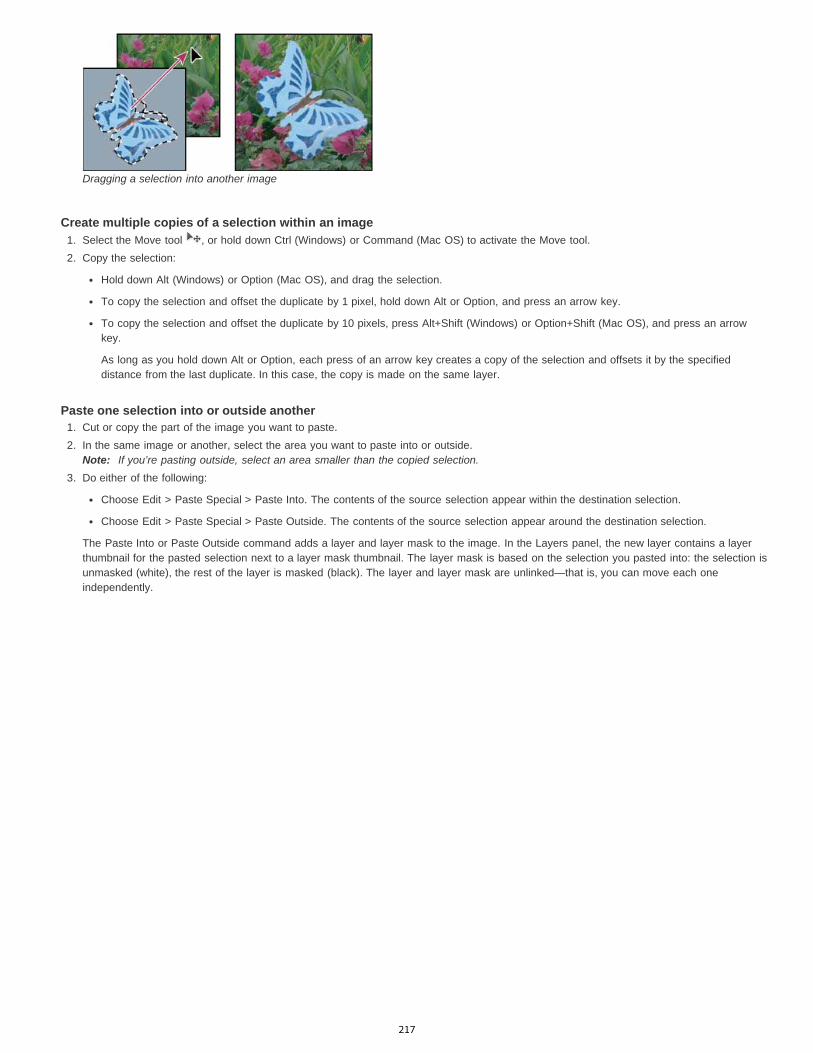
Dragging a selection into another image
Create multiple copies of a selection within an image1. Select the Move tool , or hold down Ctrl (Windows) or Command (Mac OS) to activate the Move tool.2. Copy the selection:
Hold down Alt (Windows) or Option (Mac OS), and drag the selection.
To copy the selection and offset the duplicate by 1 pixel, hold down Alt or Option, and press an arrow key.
To copy the selection and offset the duplicate by 10 pixels, press Alt+Shift (Windows) or Option+Shift (Mac OS), and press an arrowkey.
As long as you hold down Alt or Option, each press of an arrow key creates a copy of the selection and offsets it by the specifieddistance from the last duplicate. In this case, the copy is made on the same layer.
Paste one selection into or outside another1. Cut or copy the part of the image you want to paste.2. In the same image or another, select the area you want to paste into or outside.
Note: If you’re pasting outside, select an area smaller than the copied selection.3. Do either of the following:
Choose Edit > Paste Special > Paste Into. The contents of the source selection appear within the destination selection.
Choose Edit > Paste Special > Paste Outside. The contents of the source selection appear around the destination selection.
The Paste Into or Paste Outside command adds a layer and layer mask to the image. In the Layers panel, the new layer contains a layerthumbnail for the pasted selection next to a layer mask thumbnail. The layer mask is based on the selection you pasted into: the selection isunmasked (white), the rest of the layer is masked (black). The layer and layer mask are unlinked—that is, you can move each oneindependently.
217
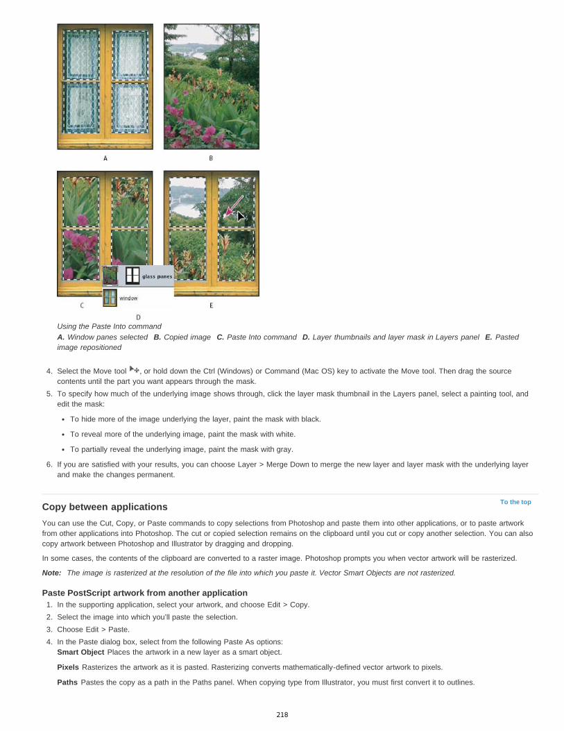
To the top
Using the Paste Into commandA. Window panes selected B. Copied image C. Paste Into command D. Layer thumbnails and layer mask in Layers panel E. Pastedimage repositioned
4. Select the Move tool , or hold down the Ctrl (Windows) or Command (Mac OS) key to activate the Move tool. Then drag the sourcecontents until the part you want appears through the mask.
5. To specify how much of the underlying image shows through, click the layer mask thumbnail in the Layers panel, select a painting tool, andedit the mask:
To hide more of the image underlying the layer, paint the mask with black.
To reveal more of the underlying image, paint the mask with white.
To partially reveal the underlying image, paint the mask with gray.
6. If you are satisfied with your results, you can choose Layer > Merge Down to merge the new layer and layer mask with the underlying layerand make the changes permanent.
Copy between applicationsYou can use the Cut, Copy, or Paste commands to copy selections from Photoshop and paste them into other applications, or to paste artworkfrom other applications into Photoshop. The cut or copied selection remains on the clipboard until you cut or copy another selection. You can alsocopy artwork between Photoshop and Illustrator by dragging and dropping.
In some cases, the contents of the clipboard are converted to a raster image. Photoshop prompts you when vector artwork will be rasterized.
Note: The image is rasterized at the resolution of the file into which you paste it. Vector Smart Objects are not rasterized.
Paste PostScript artwork from another application1. In the supporting application, select your artwork, and choose Edit > Copy.2. Select the image into which you’ll paste the selection.3. Choose Edit > Paste.4. In the Paste dialog box, select from the following Paste As options:
Smart Object Places the artwork in a new layer as a smart object.
Pixels Rasterizes the artwork as it is pasted. Rasterizing converts mathematically-defined vector artwork to pixels.
Paths Pastes the copy as a path in the Paths panel. When copying type from Illustrator, you must first convert it to outlines.
218
To the top
Shape Layer Creates a new shape layer that uses the path as a vector mask.Note: When copying artwork from Adobe Illustrator, the default clipboard preferences in Illustrator may prevent the Paste dialog box fromappearing in Photoshop. Select AICB in the File Handling and Clipboard area of the Preferences dialog box in Illustrator if you want thePaste options to appear when you paste the artwork into Photoshop.
5. If you chose Paste As Pixels in the previous step, you can choose Anti-aliased in the options bar to make a smooth transition between theedges of the selection and the surrounding pixels.Note: You can use the Matting commands if you have already merged data and are trying to reextract the rasterized data.
Save clipboard contents when you quit Photoshop1. Do one of the following:
(Windows) Choose Edit > Preferences > General.
(Mac OS) Choose Photoshop > Preferences > General.
2. Select Export Clipboard to save any Photoshop contents to the clipboard when you quit Photoshop.
Copy artwork by dragging and dropping Do one of the following:
Drag one or more Illustrator vector objects into an open image in Photoshop. This creates a vector Smart Object layer in the image. ChooseLayer > Smart Objects > Edit Content to reopen the content in Illustrator for editing.
To copy the vector object as a path in Photoshop, hold down Ctrl (Windows) or Command (Mac OS) as you drag from Illustrator.
To copy the contents of the currently selected layer in Photoshop to Illustrator, use the Move tool to drag the content from the Photoshopwindow into an open Illustrator document.
Delete selected pixels Choose Edit > Clear, or press Backspace (Windows) or Delete (Mac OS). To cut a selection to the clipboard, choose Edit > Cut.
Deleting a selection on a background layer replaces the original color with the background color. Deleting a selection on a standard layer replacesthe original color with layer transparency.
More Help topics Set up color management
Legal Notices | Online Privacy Policy
219
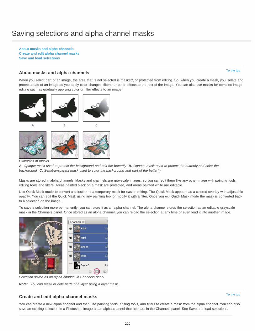
Saving selections and alpha channel masks
To the top
To the top
About masks and alpha channelsCreate and edit alpha channel masksSave and load selections
About masks and alpha channelsWhen you select part of an image, the area that is not selected is masked, or protected from editing. So, when you create a mask, you isolate andprotect areas of an image as you apply color changes, filters, or other effects to the rest of the image. You can also use masks for complex imageediting such as gradually applying color or filter effects to an image.
Examples of masksA. Opaque mask used to protect the background and edit the butterfly B. Opaque mask used to protect the butterfly and color thebackground C. Semitransparent mask used to color the background and part of the butterfly
Masks are stored in alpha channels. Masks and channels are grayscale images, so you can edit them like any other image with painting tools,editing tools and filters. Areas painted black on a mask are protected, and areas painted white are editable.
Use Quick Mask mode to convert a selection to a temporary mask for easier editing. The Quick Mask appears as a colored overlay with adjustableopacity. You can edit the Quick Mask using any painting tool or modify it with a filter. Once you exit Quick Mask mode the mask is converted backto a selection on the image.
To save a selection more permanently, you can store it as an alpha channel. The alpha channel stores the selection as an editable grayscalemask in the Channels panel. Once stored as an alpha channel, you can reload the selection at any time or even load it into another image.
Selection saved as an alpha channel in Channels panel
Note: You can mask or hide parts of a layer using a layer mask.
Create and edit alpha channel masksYou can create a new alpha channel and then use painting tools, editing tools, and filters to create a mask from the alpha channel. You can alsosave an existing selection in a Photoshop image as an alpha channel that appears in the Channels panel. See Save and load selections.
220
To the top
Adobe recommends Have a tutorial you would like to share?
Book excerpt: Using the MaskspanelConrad ChavezQuickly fine-tune masks with oneconsolidated set of options.
Create an alpha channel mask using current options1. Click the New Channel button at the bottom of the Channels panel.2. Paint on the new channel to mask out image areas.
Select areas of the image before you create the channel for the mask. Then paint on the channel to refine the mask.
Create an alpha channel mask and set options1. Alt-click (Windows) or Option-click (Mac OS) the New Channel button at the bottom of the Channels panel, or choose New Channel from
the Channels panel menu.2. Specify options in the New Channel dialog box.3. Paint on the new channel to mask out image areas.
Channel optionsTo change options for an existing channel, double-click the channel thumbnail in the Channels panel or select Channel options from the Channelspanel menu.
Options available in the New Channel and Channel Options dialog boxes:
Masked areas Sets masked areas to black (opaque) and selected areas to white (transparent). Painting with black increases the masked area;painting with white increases the selected area. When this option is selected, the Quick Mask button in the toolbox becomes a white circle on agray background .Selected Areas Sets masked areas to white (transparent) and selected areas to black (opaque). Painting with white increases the masked area;painting with black increases the selected area. When this option is selected, the Quick Mask button in the toolbox becomes a gray circle on awhite background .Spot Color Converts an alpha channel to a spot color channel. Only available for existing channels.Color Sets the color and opacity of the mask. Click the color field to change the color. The color and opacity settings affect only the appearanceof the mask and have no effect on how underlying areas are protected. Changing these settings may make the mask more easily visible againstthe colors in the image.
Paint on a channel to mask image areasWhen the new channel appears at the bottom of the Channels panel, it is the only channel visible in the image window. Click the eye icon forthe composite color channel (RGB, CMYK) to display the image with a color overlay showing the mask.
Select the brush or an editing tool and do one of the following to add or subtract from the mask created from the alpha channel:
To remove areas in the new channel, paint with white.
To add areas in the new channel, paint with black.
To add or remove areas using opacities less than 100%, set the Opacity in the options bar of the painting or editing tool and then paint withwhite or black. You can also paint with a color to achieve lower opacities.
Save and load selectionsYou can save any selection as a mask in a new or existing alpha channel and later reload the selection from the mask.
You can use a selection as a layer mask by loading the selection to make it active, then adding a new layer mask.
Save a selection to a new channel1. Select the area or areas of the image you want to isolate.2. Click the Save Selection button at the bottom of the Channels panel. A new channel appears, named according to the sequence in which
it was created.
Save a selection to a new or existing channel1. Use a selection tool to select the area or areas of the image you want to isolate.
221
2. Choose Select > Save Selection.3. Specify the following in the Save Selection dialog box, and click OK:
Document Chooses a destination image for the selection. By default, the selection is placed in a channel in your active image. You canchoose to save the selection to a channel in another open image with the same pixel dimensions or to a new image.
Channel Chooses a destination channel for the selection. By default, the selection is saved in a new channel. You can choose to save theselection to any existing channel in the selected image or to a layer mask if the image contains layers.
4. If you’re saving the selection as a new channel, type a name for the channel in the Name text box.5. If you’re saving the selection to an existing channel, select how to combine the selections:
Replace Channel Replaces the current selection in the channel.
Add to Channel Adds the selection to the current channel contents.
Subtract From Channel Deletes the selection from the channel contents.
Intersect With Channel Keeps the areas of the new selection that intersect with the channel contents.
You can select the channel from the Channels panel to see the saved selection displayed in grayscale.
Load a saved selection from the Channels panelYou can reuse a previously saved selection by loading it into an image. You can also load the selection into an image after you finish modifying analpha channel.
Do one of the following in the Channels panel:
Select the alpha channel, click the Load Selection button at the bottom of the panel, and then click the composite color channel near thetop of the panel.
Drag the channel containing the selection you want to load onto the Load Selection button.
Ctrl-click (Windows) or Command-click (Mac OS) the channel containing the selection you want to load.
To add the mask to an existing selection, press Ctrl+Shift (Windows) or Command+Shift (Mac OS), and click the channel.
To subtract the mask from an existing selection, press Ctrl+Alt (Windows) or Command+Option (Mac OS), and click the channel.
To load the intersection of the saved selection and an existing selection, press Ctrl+Alt+Shift (Windows) or Command+Option+Shift(Mac OS), and select the channel.
You can drag a selection from one open Photoshop image into another.
Load a saved selectionNote: If you are loading a saved selection from another image, make sure to open it. Also, make sure your destination image is active.
1. Choose Select > Load Selection.2. Specify the Source options in the Load Selection dialog box:
Document Chooses the source to load.
Channel Chooses the channel containing the selection you want to load.
Invert Selects the non-selected areas.
3. Select an Operation option to specify how to combine the selections if the image already has a selection:New Selection Adds the loaded selection.
Add To Selection Adds the loaded selection to any existing selections in the image.
Subtract From Selection Subtracts the loaded selection from existing selections in the image.
Intersect With Selection Saves a selection from an area intersected by the loaded selection and existing selections in the image.You can drag a selection from one open Photoshop image into another.
Legal Notices | Online Privacy Policy
222

Selecting with the lasso tools
To the top
To the top
Select with the Lasso toolSelect with the Polygonal Lasso toolSelect with the Magnetic Lasso tool
Select with the Lasso toolThe Lasso tool is useful for drawing freeform segments of a selection border.
1. Select the Lasso tool , and set feathering and anti-aliasing in the options bar. (See Soften the edges of selections.)
2. To add to, subtract from, or intersect with an existing selection, click the corresponding button in the options bar.
Selection options A. New B. Add To C. Subtract From D. Intersect With
3. Do either of the following:Drag to draw a freehand selection border.
To switch between freehand and straight-edged segments, press Alt (Windows) or Option (Mac OS), and click where segments shouldbegin and end. (To erase recently drawn straight segments, hold down the Delete key.)
4. To close the selection border, release the mouse without holding down Alt or Option.
5. (Optional) Click Refine Edge to further adjust the selection boundary. See Refine selection edges.
Select with the Polygonal Lasso toolThe Polygonal Lasso tool is useful for drawing straight-edged segments of a selection border.
1. Select the Polygonal Lasso tool , and select options.2. Specify one of the selection options in the options bar.
Selection options A. New B. Add To C. Subtract From D. Intersect With
3. (Optional) Set feathering and anti-aliasing in the options bar. See Soften the edges of selections.
4. Click in the image to set the starting point.5. Do one or more of the following:
To draw a straight segment, position the pointer where you want the first straight segment to end, and click. Continue clicking to setendpoints for subsequent segments.
To draw a straight line at a multiple of 45°, hold down Shift as you move to click the next segment.
To draw a freehand segment, hold down Alt (Windows) or Option (Mac OS), and drag. When you finish, release Alt or Option and themouse button.
To erase recently drawn straight segments, press the Delete key.
6. Close the selection border:
223

To the top
Width
Contrast
Frequency
Stylus Pressure
Position the Polygonal Lasso tool pointer over the starting point (a closed circle appears next to the pointer), and click.
If the pointer is not over the starting point, double-click the Polygonal Lasso tool pointer, or Ctrl-click (Windows) or Command-click(Mac OS).
7. (Optional) Click Refine Edge to further adjust the selection boundary. See Refine selection edges.
Select with the Magnetic Lasso tool
When you use the Magnetic Lasso tool , the border snaps to the edges of defined areas in the image. The Magnetic Lasso tool is not availablefor 32-bits-per-channel images.
The Magnetic Lasso tool is especially useful for quickly selecting objects with complex edges set against high-contrast backgrounds.
1. Select the Magnetic Lasso tool.2. Specify one of the selection options in the options bar.
Selection options A. New B. Add To C. Subtract From D. Intersect With
3. (Optional) Set feathering and anti-aliasing in the options bar. See Soften the edges of selections.
4. Set any of these options:
To specify a detection width, enter a pixel value for Width. The Magnetic Lasso tool detects edges only within the specified distancefrom the pointer.
To change the lasso pointer so that it indicates the lasso width, press the Caps Lock key. You can change the pointer while the tool isselected but not in use. Press the right bracket (]) to increase the Magnetic Lasso edge width by 1 pixel; press the left bracket ([) todecrease the width by 1 pixel.
To specify the lasso’s sensitivity to edges in the image, enter a value between 1% and 100% for Contrast. A higher value detectsonly edges that contrast sharply with their surroundings; a lower value detects lower-contrast edges.
To specify the rate at which the lasso sets fastening points, enter a value between 0 and 100 for Frequency. A higher valueanchors the selection border in place more quickly.
On an image with well-defined edges, try a higher width and higher edge contrast, and trace the border roughly. On an image with softeredges, try a lower width and lower edge contrast, and trace the border more precisely.
If you are working with a stylus tablet, select or deselect the Stylus Pressure option. When the option is selected, anincrease in stylus pressure decreases the edge width.
5. Click in the image to set the first fastening point. Fastening points anchor the selection border in place.6. Release the mouse button or keep it depressed, and then move the pointer along the edge you want to trace.
The most recent segment of the selection border remains active. As you move the pointer, the active segment snaps to the strongest edgein the image, based on the detection width set in the options bar. Periodically, the Magnetic Lasso tool adds fastening points to the selectionborder to anchor previous segments.
7. If the border doesn’t snap to the desired edge, click once to add a fastening point manually. Continue to trace the edge, and add fasteningpoints as needed.
Fastening points anchor selection border to edges
224

Twitter™ and Facebook posts are not covered under the terms of Creative Commons.
Legal Notices | Online Privacy Policy
8. To switch temporarily to the other lasso tools, do one of the following:To activate the Lasso tool, hold down Alt (Windows) or Option (Mac OS), and drag with the mouse button depressed.
To activate the Polygonal Lasso tool, hold down Alt (Windows) or Option (Mac OS), and click.
9. To erase recently drawn segments and fastening points, press the Delete key until you’ve erased the fastening points for the desiredsegment.
10. Close the selection border:To close the border with a magnetic segment, double-click, or press Enter or Return. (To manually close the border, drag over thestarting point and click.)
To close the border with a straight segment, hold down Alt (Windows) or Option (Mac OS), and double-click.
11. (Optional) Click Refine Edge to further adjust the selection boundary. See Refine selection edges.
More Help TopicsSaving selections and alpha channel masks
Convert paths to selection borders
Selection tools gallery
225

Selecting with the marquee tools
Rectangular Marquee
Elliptical Marquee
Single Row or Single Column Marquee
Normal
Fixed Ratio
Fixed Size
The marquee tools let you select rectangles, ellipses, and 1-pixel rows and columns.
1. Select a marquee tool:
Makes a rectangular selection (or a square, when used with the Shift key).
Makes an elliptical selection (or a circle, when used with the Shift key).
Defines the border as a 1-pixel-wide row or column.
2. Specify one of the selection options in the options bar.
Selection options A. New B. Add To C. Subtract From D. Intersect With
3. Specify a feathering setting in the options bar. Turn anti-aliasing on or off for the Elliptical Marquee tool. See Soften the edges of selections.
4. For the Rectangle Marquee tool or the Elliptical Marquee tool, choose a style in the options bar:
Determines marquee proportions by dragging.
Sets a height-to-width ratio. Enter values (decimal values are valid) for the aspect ratio. For example, to draw a marquee twiceas wide as it is high, enter 2 for the width and 1 for the height.
Specifies set values for the marquee’s height and width. Enter pixel values in whole numbers.
In addition to pixels (px) you can also use specific units such as inches (in) or centimeters (cm) in height and width values.
5. For aligning your selection to guides, a grid, slices, or document bounds, do one of the following to snap your selection:Choose View > Snap, or choose View > Snap To and choose a command from the submenu. The marquee selection can snap to adocument boundary or to a variety of Photoshop Extras, controlled in the Snap To submenu.
6. Do one of the following to make a selection:With the Rectangle Marquee tool or the Elliptical Marquee tool, drag over the area you want to select.
Hold down Shift as you drag to constrain the marquee to a square or circle (release the mouse button before you release Shift to keepthe selection shape constrained).
To drag a marquee from its center, hold down Alt (Windows) or Option (Mac OS) after you begin dragging.
Dragging a marquee from the corner of an image (left), and from the center of an image (right) by pressing Alt/Option as you drag
With the Single Row or Single Column Marquee tool, click near the area you want to select, and then drag the marquee to the exactlocation. If no marquee is visible, increase the magnification of your image view.
To reposition a rectangle or elliptical marquee, first drag to create the selection border, keeping the mouse button depressed. Then holddown the spacebar and continue to drag. Release the spacebar, but keep the mouse button depressed, if you need to continue adjustingthe selection border.
More Help TopicsSaving selections and alpha channel masks
Convert paths to selection borders
226

Twitter™ and Facebook posts are not covered under the terms of Creative Commons.
Legal Notices | Online Privacy Policy
Selection tools gallery
227
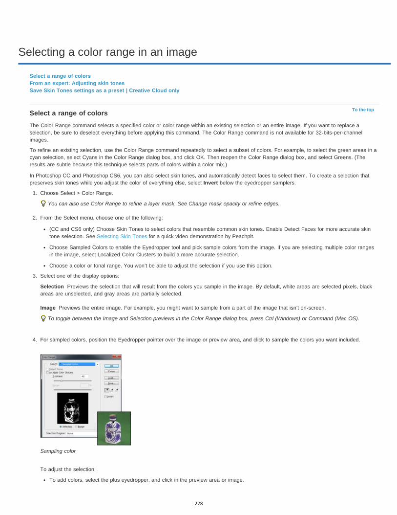
Selecting a color range in an image
To the top
Selection
Image
Select a range of colorsFrom an expert: Adjusting skin tonesSave Skin Tones settings as a preset | Creative Cloud only
Select a range of colorsThe Color Range command selects a specified color or color range within an existing selection or an entire image. If you want to replace aselection, be sure to deselect everything before applying this command. The Color Range command is not available for 32-bits-per-channelimages.
To refine an existing selection, use the Color Range command repeatedly to select a subset of colors. For example, to select the green areas in acyan selection, select Cyans in the Color Range dialog box, and click OK. Then reopen the Color Range dialog box, and select Greens. (Theresults are subtle because this technique selects parts of colors within a color mix.)
In Photoshop CC and Photoshop CS6, you can also select skin tones, and automatically detect faces to select them. To create a selection thatpreserves skin tones while you adjust the color of everything else, select Invert below the eyedropper samplers.
1. Choose Select > Color Range.
You can also use Color Range to refine a layer mask. See Change mask opacity or refine edges.
2. From the Select menu, choose one of the following:
(CC and CS6 only) Choose Skin Tones to select colors that resemble common skin tones. Enable Detect Faces for more accurate skintone selection. See Selecting Skin Tones for a quick video demonstration by Peachpit.
Choose Sampled Colors to enable the Eyedropper tool and pick sample colors from the image. If you are selecting multiple color rangesin the image, select Localized Color Clusters to build a more accurate selection.
Choose a color or tonal range. You won’t be able to adjust the selection if you use this option.
3. Select one of the display options:
Previews the selection that will result from the colors you sample in the image. By default, white areas are selected pixels, blackareas are unselected, and gray areas are partially selected.
Previews the entire image. For example, you might want to sample from a part of the image that isn’t on-screen.
To toggle between the Image and Selection previews in the Color Range dialog box, press Ctrl (Windows) or Command (Mac OS).
4. For sampled colors, position the Eyedropper pointer over the image or preview area, and click to sample the colors you want included.
Sampling color
To adjust the selection:
To add colors, select the plus eyedropper, and click in the preview area or image.
228

None
Grayscale
Black Matte
White Matte
Quick Mask
Note:
To the top
To remove colors, select the minus eyedropper, and click in the preview area or image.
To activate the plus eyedropper temporarily, hold down Shift. Hold down Alt (Windows) or Option (Mac OS) to activate the minuseyedropper.
5. Adjust the range of colors selected using the Fuzziness slider or by entering a value. The Fuzziness setting controls how wide a range ofcolors is in the selection, and increases or decreases the amount of partially selected pixels (gray areas in the selection preview). Set a lowFuzziness value to restrict the color range, a higher value to increase the range.
Increasing fuzziness expands selection
If you selected Localized Color Clusters, use the Range slider to control how far or near a color must be from the sample points to beincluded in the selection. For example, your image contains a patch of yellow flowers in both the foreground and the background, but youwant to select just the foreground flowers. Sample the colors in the foreground flowers and reduce the Range so that the similarly coloredflowers in the background are not selected.
6. To preview the selection in the image window, choose a Selection Preview option:
Shows the original image.
shows white for completely selected pixels, gray for partially selected ones, and black for unselected ones.
Shows the original image for selected pixels, and black for unselected ones. This option is good for bright images.
Shows the original image for selected pixels, and white for unselected ones. This option is good for dark images.
shows unselected areas as a rubylith overlay (or a custom color you’ve specified in the Quick Mask Options dialog box).
7. To revert to the original selection, hold down Alt (Windows) or Option (Mac OS), and click Reset.
8. To save and load color range settings, use the Save and Load buttons in the Color Range dialog box to save and reuse the current settings.
(Creative Cloud only) Skin Tones selection settings can now be saved as a preset.
If you see the message “No pixels are more than 50% selected,” the selection border will not be visible. You may have picked a colorchoice from the Select menu, such as Reds, when the image didn’t contain any red hues with high enough saturation.
Save Skin Tones settings as a preset | Creative Cloud onlyThe Color Range selections command now saves Skin Tones selections as a preset. It can also save the setting for the Detect Faces option whenSkin Tones or Sampled Colors are selected.
To save Skin Tones settings as a preset:
1. Choose Select > Color Range.
2. In the Color Range dialog box, choose Skin Tones from the Select menu.
3. For more accurate skin tone selection, select Detect Faces and then adjust the Fuzziness slider or enter a value. To help you make yourselections, make sure the display option is set to Selection and choose a Selection Preview to view your selections in the document window.
4. Click the Save button and in the Save window, type a file name for the skin tone preset and then click Save.
To load a skin tones preset:
1. In the Color Range dialog box, click the Load button.
2. In the Load window, select the preset file you want and then, click Load.
More Help TopicsSaving selections and alpha channel masks
Convert paths to selection borders
Selection tools gallery
229

Making quick selections
To the top
Sample All Layers
Auto-Enhance
To the top
Select with the Quick Selection toolSelect with the Magic Wand tool
Select with the Quick Selection tool
You can use the Quick Selection tool to quickly “paint” a selection using an adjustable round brush tip. As you drag, the selection expandsoutward and automatically finds and follows defined edges in the image.
1. Select the Quick Selection tool . (If the tool isn’t visible, hold down the Magic Wand tool .)2. In the options bar, click one of the selection options: New, Add To, or Subtract From.
New is the default option if nothing is selected. After making the initial selection, the option changes automatically to Add to.
3. To change the brush tip size, click the Brush pop-up menu in the options bar, and type in a pixel size or drag the slider. Use the Sizepop-up menu options to make the brush tip size sensitive to pen pressure or a stylus wheel.
When creating a selection, press the right bracket (]) to increase the Quick Selection tool brush tip size; press the left bracket ([) todecrease the brush tip size.
4. Choose Quick Selection options.
Creates a selection based on all layers instead of just the currently selected layer.
Reduces roughness and blockiness in the selection boundary. Auto-Enhance automatically flows the selection furthertoward image edges and applies some of the edge refinement you can apply manually in the Refine Edge dialog with the Contrast andRadius options.
5. Paint inside the part of the image you want to select.
The selection grows as you paint. If updating is slow, continue to drag to allow time to complete work on the selection. As you paint near theedges of a shape, the selection area extends to follow the contours of the shape edge.
Painting with the Quick Selection tool to extend the selection
If you stop dragging and then click or drag in a nearby area, the selection will grow to include the new area.
To subtract from a selection, click the Subtract from option in the options bar, then drag over the existing selection.
To temporarily switch between add and subtract modes, hold down the Alt (Windows) or Option (Mac) key.
To change the tool cursor, choose Edit > Preferences > Cursors > Painting Cursors (Windows) or Photoshop > Preferences > Cursors >Painting Cursors (Mac OS). Normal Brush Tip displays the standard Quick Selection cursor with a plus or minus sign to show theselection mode.
6. (Optional) Click Refine Edge to further adjust the selection boundary. See Refine selection edges.
Select with the Magic Wand toolThe Magic Wand tool lets you select a consistently colored area (for example, a red flower) without having to trace its outline. You specify theselected color range, or tolerance, relative to the original color you click.
You cannot use the Magic Wand tool on an image in Bitmap mode or on 32-bits-per-channel images.
1. Select the Magic Wand tool . (If the tool isn’t visible, access it by holding down the Quick Selection tool .)
230

Twitter™ and Facebook posts are not covered under the terms of Creative Commons.
Legal Notices | Online Privacy Policy
Tolerance
Anti-aliased
Contiguous
Sample All Layers
2. Specify one of the selection options in the options bar. The Magic Wand tool’s pointer changes depending on which option is selected.
Selection options A. New B. Add To C. Subtract From D. Intersect With
3. In the options bar, specify any of the following:
Determines the color range of selected pixels. Enter a value in pixels, ranging from 0 to 255. A low value selects the few colorsvery similar to the pixel you click. A higher value selects a broader range of colors.
Creates a smoother-edged selection.
Selects only adjacent areas using the same colors. Otherwise, all pixels in the entire image using the same colors areselected.
Selects colors using data from all the visible layers. Otherwise, the Magic Wand tool selects colors from the active layeronly.
4. In the image, click the color you want to select. If Contiguous is selected, all adjacent pixels within the tolerance range are selected.Otherwise, all pixels in the tolerance range are selected.
5. (Optional) Click Refine Edge to further adjust the selection boundary or view the selection against different backgrounds or as a mask. SeeRefine selection edges.
More Help TopicsSaving selections and alpha channel masks
Convert paths to selection borders
Selection tools gallery
231
Duplicate, split, and merge channels
To the top
To the top
To the top
Duplicate channelsSplit channels into separate imagesMerge channels
Duplicate channelsYou can copy a channel and use it in the current image or another image.
Duplicate a channelIf you are duplicating alpha channels between images, the channels must have identical pixel dimensions. You cannot duplicate a channel to aBitmap-mode image.
1. In the Channels panel, select the channel to duplicate.2. Choose Duplicate Channel from the Channels panel menu.3. Type a name for the duplicate channel.4. For Document, do one of the following:
Choose a destination. Only open images with pixel dimensions identical to the current image are available. To duplicate the channel inthe same file, select the channel’s current file.
Choose New to copy the channel to a new image, creating a multichannel image containing a single channel. Type a name for the newimage.
5. To reverse the selected and masked areas in the duplicate channel, select Invert.
Duplicate a channel in an image1. In the Channels panel, select the channel you want to duplicate.2. Drag the channel onto the Create New Channel button at the bottom of the panel.
Duplicate a channel in another image1. In the Channels panel, select the channel you want to duplicate.2. Make sure that the destination image is open.
Note: The destination image does not have to have the same pixel dimensions as the duplicated channel.3. Do one of the following:
Drag the channel from the Channels panel into the destination image window. The duplicated channel appears at the bottom of theChannels panel.
Choose Select > All, and then choose Edit > Copy. Select the channel in the destination image and choose Edit > Paste. The pastedchannel overwrites the existing channel.
Split channels into separate imagesYou can split channels of flattened images only. Splitting channels is useful when you want to retain individual channel information in a file formatthat doesn’t preserve channels.
To split channels into separate images, choose Split Channels from the Channels panel menu.The original file is closed, and the individual channels appear in separate grayscale image windows. The title bars in the new windows show theoriginal filename plus the channel. You save and edit the new images separately.
Merge channelsMultiple grayscale images can be combined as the channels of a single image. The images you want to merge must be in grayscale mode, beflattened (have no layers), have the same pixel dimensions, and be open. The number of grayscale images you have open determines the colormodes available when merging channels. For example, if you have three images open, you can merge them into an RGB image; if you have fourimages open, they can become a CMYK image.
232

If you are working with DCS files that have accidentally lost their links (and so cannot be opened, placed, or printed), open the channel files,and merge them into a CMYK image. Then re-save the file as a DCS EPS file.
1. Open the grayscale images containing the channels you want to merge, and make one of the images active.
You must have more than one image open for the Merge Channels option to be available.
2. Choose Merge Channels from the Channels panel menu.3. For Mode, choose the color mode you want to create. The number of channels appropriate for the mode appears in the Channels text box.4. If necessary, enter a number in the Channels text box.
If you enter a number that is incompatible with the selected mode, Multichannel mode is automatically selected. This creates a multichannelimage with two or more channels.
5. Click OK.6. For each channel, make sure the image you want is open. If you change your mind about the image type, click Mode to return to the Merge
Channels dialog box.7. If you are merging channels into a multichannel image, click Next, and select the remaining channels.
Note: All channels of a multichannel image are alpha channels or spot channels.8. When you have finished selecting channels, click OK.
The selected channels are merged into a new image of the specified type, and the original images are closed without any changes. Thenew image appears in an untitled window.
Note: You cannot split and recombine (merge) an image with spot color channels. The spot color channel will be added as an alphachannel.
Legal Notices | Online Privacy Policy
233
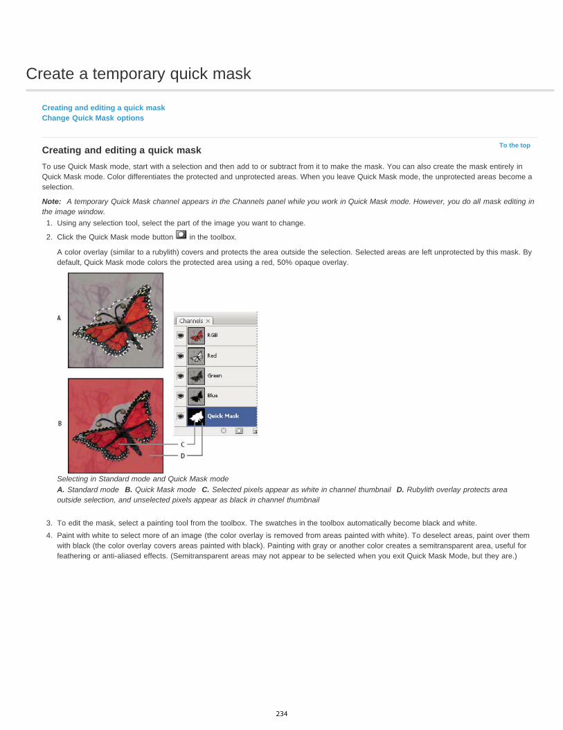
Create a temporary quick mask
To the top
Creating and editing a quick maskChange Quick Mask options
Creating and editing a quick maskTo use Quick Mask mode, start with a selection and then add to or subtract from it to make the mask. You can also create the mask entirely inQuick Mask mode. Color differentiates the protected and unprotected areas. When you leave Quick Mask mode, the unprotected areas become aselection.
Note: A temporary Quick Mask channel appears in the Channels panel while you work in Quick Mask mode. However, you do all mask editing inthe image window.
1. Using any selection tool, select the part of the image you want to change.
2. Click the Quick Mask mode button in the toolbox.
A color overlay (similar to a rubylith) covers and protects the area outside the selection. Selected areas are left unprotected by this mask. Bydefault, Quick Mask mode colors the protected area using a red, 50% opaque overlay.
Selecting in Standard mode and Quick Mask modeA. Standard mode B. Quick Mask mode C. Selected pixels appear as white in channel thumbnail D. Rubylith overlay protects areaoutside selection, and unselected pixels appear as black in channel thumbnail
3. To edit the mask, select a painting tool from the toolbox. The swatches in the toolbox automatically become black and white.4. Paint with white to select more of an image (the color overlay is removed from areas painted with white). To deselect areas, paint over them
with black (the color overlay covers areas painted with black). Painting with gray or another color creates a semitransparent area, useful forfeathering or anti-aliased effects. (Semitransparent areas may not appear to be selected when you exit Quick Mask Mode, but they are.)
234

To the top
Painting in Quick Mask modeA. Original selection and Quick Mask mode with green chosen as mask color B. Painting with white in Quick Mask mode adds to theselection C. Painting with black in Quick Mask mode subtracts from the selection
5. Click the Standard Mode button in the toolbox to turn off the quick mask and return to your original image. A selection border nowsurrounds the unprotected area of the quick mask.
If a feathered mask is converted to a selection, the boundary line runs halfway between the black pixels and the white pixels of the maskgradient. The selection boundary indicates the transition between pixels that are less than 50% selected and those that are more than 50%selected.
6. Apply the desired changes to the image. Changes affect only the selected area.7. Choose Select > Deselect to deselect the selection, or save the selection by choosing Select > Save Selection.
You can convert this temporary mask to a permanent alpha channel by switching to standard mode and choosing Select > SaveSelection.
Change Quick Mask options
1. Double-click the Quick Mask Mode button in the toolbox.2. Choose from the following display options:
Masked Areas Sets masked areas to black (opaque) and selected areas to white (transparent). Painting with black increases the maskedarea; painting with white increases the selected area. When this option is selected, the Quick Mask button in the toolbox becomes a whitecircle on a gray background .
Selected Areas Sets masked areas to white (transparent) and selected areas to black (opaque). Painting with white increases the maskedarea; painting with black increases the selected area. When this option is selected, the Quick Mask button in the toolbox becomes a graycircle on a white background .
To toggle between the Masked Areas and Selected Areas options for quick masks, Alt-click (Windows) or Option-click (Mac OS) theQuick Mask Mode button.
3. To choose a new mask color, click the color box, and choose a new color.4. To change the opacity, enter a value between 0% and 100%.
Both the color and opacity settings affect only the appearance of the mask and have no effect on how underlying areas are protected.Changing these settings may make the mask more easily visible against the colors in the image.
235
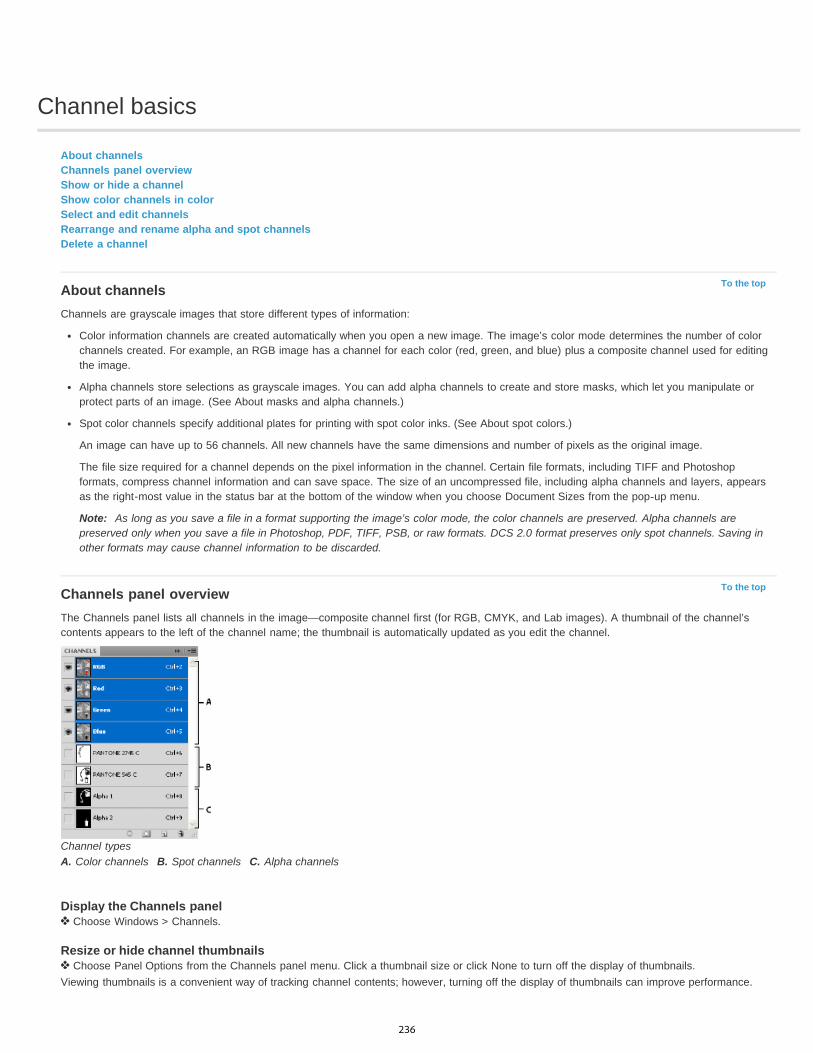
Channel basics
To the top
To the top
About channelsChannels panel overviewShow or hide a channelShow color channels in colorSelect and edit channelsRearrange and rename alpha and spot channelsDelete a channel
About channelsChannels are grayscale images that store different types of information:
Color information channels are created automatically when you open a new image. The image’s color mode determines the number of colorchannels created. For example, an RGB image has a channel for each color (red, green, and blue) plus a composite channel used for editingthe image.
Alpha channels store selections as grayscale images. You can add alpha channels to create and store masks, which let you manipulate orprotect parts of an image. (See About masks and alpha channels.)
Spot color channels specify additional plates for printing with spot color inks. (See About spot colors.)
An image can have up to 56 channels. All new channels have the same dimensions and number of pixels as the original image.
The file size required for a channel depends on the pixel information in the channel. Certain file formats, including TIFF and Photoshopformats, compress channel information and can save space. The size of an uncompressed file, including alpha channels and layers, appearsas the right-most value in the status bar at the bottom of the window when you choose Document Sizes from the pop-up menu.
Note: As long as you save a file in a format supporting the image’s color mode, the color channels are preserved. Alpha channels arepreserved only when you save a file in Photoshop, PDF, TIFF, PSB, or raw formats. DCS 2.0 format preserves only spot channels. Saving inother formats may cause channel information to be discarded.
Channels panel overviewThe Channels panel lists all channels in the image—composite channel first (for RGB, CMYK, and Lab images). A thumbnail of the channel’scontents appears to the left of the channel name; the thumbnail is automatically updated as you edit the channel.
Channel typesA. Color channels B. Spot channels C. Alpha channels
Display the Channels panel Choose Windows > Channels.
Resize or hide channel thumbnails Choose Panel Options from the Channels panel menu. Click a thumbnail size or click None to turn off the display of thumbnails.
Viewing thumbnails is a convenient way of tracking channel contents; however, turning off the display of thumbnails can improve performance.
236

To the top
To the top
To the top
To the top
To the top
Show or hide a channelYou can use the Channels panel to view any combination of channels in the document window. For example, you can view an alpha channel andthe composite channel together to see how changes made in the alpha channel relate to the entire image.
Click in the eye column next to the channel to show or hide that channel. (Click the composite channel to view all default color channels. Thecomposite channel is displayed whenever all the color channels are visible.)
To show or hide multiple channels, drag through the eye column in the Channels panel.
Show color channels in colorIndividual channels are displayed in grayscale. In RGB, CMYK, or Lab images, you can view the individual channels in color. (In Lab images, onlythe a and b channels appear in color.) If more than one channel is active, the channels always appear in color.
You can change the default to show the individual color channels in color. When a channel is visible in the image, an eye icon appears to its leftin the panel.
1. Do one of the following:
In Windows, choose Edit > Preferences > Interface.
In Mac OS, choose Photoshop > Preferences > Interface.
2. Select Show Channels in Color, and click OK.
Select and edit channelsYou can select one or more channels in the Channels panel. The names of all selected, or active, channels are highlighted.
Selecting multiple channelsA. Not visible or editable B. Visible but not selected for editing C. Selected for viewing and editing D. Selected for editing but not viewing
To select a channel, click the channel name. Shift-click to select (or deselect) multiple channels.To edit a channel, select it and then use a painting or editing tool to paint in the image. You can paint on only one channel at a time. Paintwith white to add the selected channel’s color at 100% intensity. Paint with a value of gray to add the channel’s color at a lower intensity.Paint with black to fully remove the channel’s color.
Rearrange and rename alpha and spot channelsYou can move alpha or spot channels above the default color channels only if the image is in Multichannel mode (Image > Mode > Multichannel).For information about that mode’s limitations, see Multichannel mode.
To change the order of alpha or spot channels, drag the channel up or down in the Channels panel. When a line appears in the position youwant, release the mouse button.Note: Spot colors are overprinted in the order of their appearance from top to bottom in the Channels panel.To rename an alpha or spot channel, double-click the channel’s name in the Channels panel, and enter a new name.
For more information, see Create a new spot channel.
Delete a channelYou may want to delete spot or alpha channels you no longer need before saving an image. Complex alpha channels can substantially increasethe disk space required for an image.
In Photoshop, select the channel in the Channels panel and do one of the following:
Alt-click (Windows) or Option-click (Mac OS) the Delete icon .
237

Drag the channel name in the panel to the Delete icon.
Choose Delete Channel from the Channels panel menu.
Click the Delete icon at the bottom of the panel, and then click Yes.
Note: When you delete a color channel from a file with layers, visible layers are flattened and hidden layers are discarded. This is done because removing a color channel converts the image to Multichannel mode, which does not support layers. An image isn’t flattened when you delete an alpha channel, a spot channel, or a quick mask.
Legal Notices | Online Privacy Policy
238

Channel calculations
To the top
To the top
To the top
Blending layers and channelsBlend channels with the Apply Image commandBlend channels with the Calculations commandAdd and Subtract blending modes
Blending layers and channelsYou can use the blending effects associated with layers to combine channels within and between images into new images. You can use either theApply Image command (on single and composite channels) or the Calculations command (on single channels). These commands offer twoadditional blending modes not available in the Layers panel—Add and Subtract. Although it’s possible to create new combinations of channels bycopying channels to layers in the Layers panel, you may find it quicker to use the calculation commands to blend channel information.
The calculation commands perform mathematical operations on the corresponding pixels of two channels (the pixels with identical locations in theimage) and then combine the results in a single channel. Two concepts are fundamental to understanding how the calculation commands work.
Each pixel in a channel has a brightness value. The Calculations and Apply Image commands manipulate these values to produce theresulting composite pixels.
These commands overlay the pixels in two or more channels. Thus, the images used for calculations must have the same pixel dimensions.
Blend channels with the Apply Image commandThe Apply Image command lets you blend one image’s layer and channel (the source) with a layer and channel of the active image (thedestination).
1. Open the source and destination images, and select the desired layer and channel in the destination image. The pixel dimensions of theimages must match for image names to appear in the Apply Image dialog box.Note: If the color modes of the two images differ (for example, one image is RGB and the other is CMYK), you can apply a single channel(but not the source’s composite) to the destination layer’s composite channel.
2. Choose Image > Apply Image.3. Choose the source image, layer, and channel you want to combine with the destination. To use all layers in the source image, select
Merged For Layer.4. To preview the results in the image window, select Preview.5. To use the negative of the channel contents in the calculation, select Invert.6. For Blending, choose a blending option.
For information on the Add and Subtract options, see Add and Subtract blending modes. For information on other blending options, seeBlending mode descriptions.
7. Enter an Opacity value to specify the effect’s strength.8. To apply the results only to opaque areas in the result layer, select Preserve Transparency.9. If you want to apply the blending through a mask, select Mask. Then choose the image and layer containing the mask. For Channel, you can
choose any color or alpha channel to use as the mask. You can also use a mask based on the active selection or the boundaries of thechosen layer (Transparency). Select Invert to reverse the masked and unmasked areas of the channel.
Blend channels with the Calculations commandThe Calculations command lets you blend two individual channels from one or more source images. You can then apply the results to a newimage or to a new channel or selection in the active image. You cannot apply the Calculations command to composite channels.
1. Open the source image or images.Note: If you are using more than one source image, the images must have the same pixel dimensions.
2. Choose Image > Calculations.3. To preview the results in the image window, select Preview.4. Choose the first source image, layer, and channel. To use all the layers in the source image, choose Merged For Layer.5. To use the negative of the channel contents in the calculation, select Invert. For Channel, choose Gray if you want to duplicate the effect of
converting the image to grayscale.
239
To the top
6. Choose the second source image, layer, and channel, and specify options.7. For Blending, choose a blending mode.
For information on the Add and Subtract options, see Add and Subtract blending modes. For information on other blending options, seeBlending mode descriptions.
8. Enter an Opacity value to specify the effect’s strength.9. If you want to apply the blending through a mask, select Mask. Then choose the image and layer containing the mask. For Channel, you can
choose any color or alpha channel to use as the mask. You can also use a mask based on the active selection or the boundaries of thechosen layer (Transparency). Select Invert to reverse the masked and unmasked areas of the channel.
10. For Result, specify whether to place the blending results in a new document or in a new channel or selection in the active image.
Add and Subtract blending modesThe Add and Subtract blending modes are available only for the Apply Image and Calculations commands.
AddAdds the pixel values in two channels. This is a good way to combine non-overlapping images in two channels.
Because higher pixel values represent lighter colors, adding channels with overlapping pixels lightens the image. Black areas in both channelsremain black (0 + 0 = 0). White in either channel results in white (255 + any value = 255 or greater).
Add mode divides the sum of the pixel values by the Scale amount, and then adds the Offset value to the sum. For example, to find the average ofthe pixels in two channels, add them, divide by 2, and enter no Offset value.
The Scale factor may be any number between 1.000 and 2.000. Entering a higher Scale value darkens the image.
The Offset value lets you lighten or darken the pixels in the destination channel by any brightness value between +255 and –255. Negative valuesdarken the image; positive values lighten the image.
SubtractSubtracts the pixel values in the source channel from the corresponding pixels in the target channel. As with Add mode, the result is then dividedby the Scale factor and added to the Offset value.
The Scale factor may be any number between 1.000 and 2.000. The Offset value lets you lighten or darken the pixels in the destination channelby any brightness value between +255 and –255.
Legal Notices | Online Privacy Policy
240
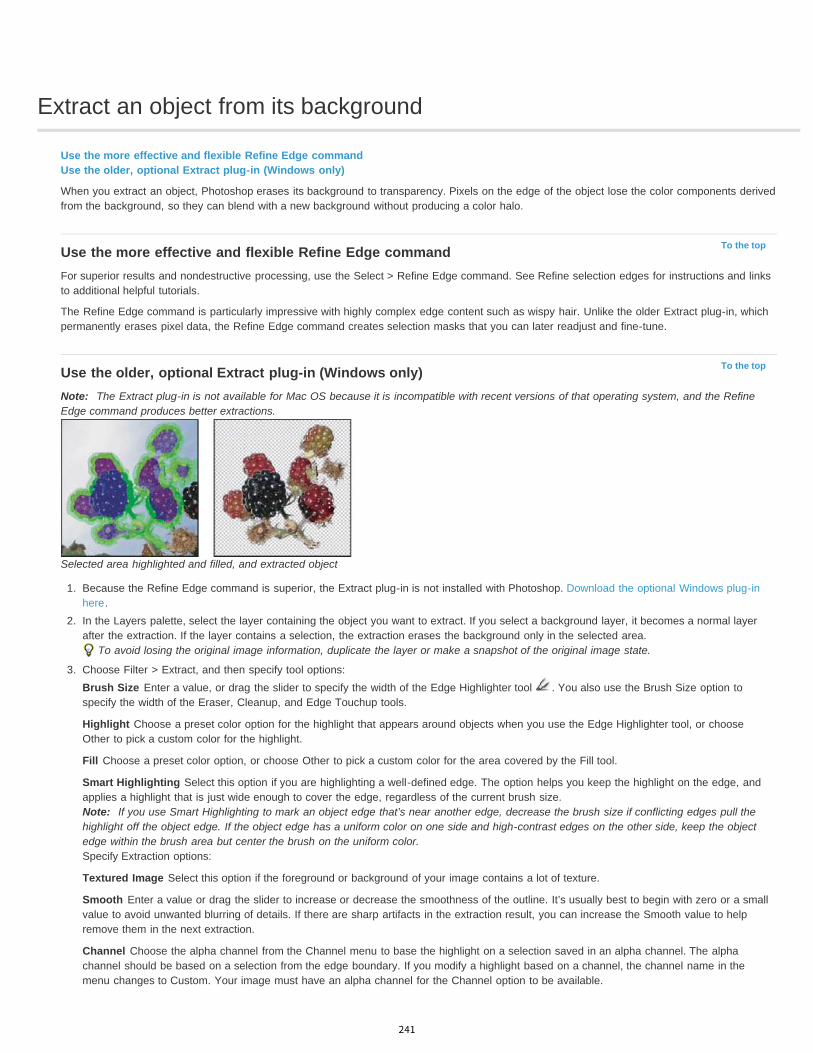
Extract an object from its background
To the top
To the top
Use the more effective and flexible Refine Edge commandUse the older, optional Extract plug-in (Windows only)
When you extract an object, Photoshop erases its background to transparency. Pixels on the edge of the object lose the color components derivedfrom the background, so they can blend with a new background without producing a color halo.
Use the more effective and flexible Refine Edge commandFor superior results and nondestructive processing, use the Select > Refine Edge command. See Refine selection edges for instructions and linksto additional helpful tutorials.
The Refine Edge command is particularly impressive with highly complex edge content such as wispy hair. Unlike the older Extract plug-in, whichpermanently erases pixel data, the Refine Edge command creates selection masks that you can later readjust and fine-tune.
Use the older, optional Extract plug-in (Windows only)Note: The Extract plug-in is not available for Mac OS because it is incompatible with recent versions of that operating system, and the RefineEdge command produces better extractions.
Selected area highlighted and filled, and extracted object
1. Because the Refine Edge command is superior, the Extract plug-in is not installed with Photoshop. Download the optional Windows plug-inhere.
2. In the Layers palette, select the layer containing the object you want to extract. If you select a background layer, it becomes a normal layerafter the extraction. If the layer contains a selection, the extraction erases the background only in the selected area.
To avoid losing the original image information, duplicate the layer or make a snapshot of the original image state.
3. Choose Filter > Extract, and then specify tool options:Brush Size Enter a value, or drag the slider to specify the width of the Edge Highlighter tool . You also use the Brush Size option tospecify the width of the Eraser, Cleanup, and Edge Touchup tools.
Highlight Choose a preset color option for the highlight that appears around objects when you use the Edge Highlighter tool, or chooseOther to pick a custom color for the highlight.
Fill Choose a preset color option, or choose Other to pick a custom color for the area covered by the Fill tool.
Smart Highlighting Select this option if you are highlighting a well-defined edge. The option helps you keep the highlight on the edge, andapplies a highlight that is just wide enough to cover the edge, regardless of the current brush size.Note: If you use Smart Highlighting to mark an object edge that’s near another edge, decrease the brush size if conflicting edges pull thehighlight off the object edge. If the object edge has a uniform color on one side and high-contrast edges on the other side, keep the objectedge within the brush area but center the brush on the uniform color.Specify Extraction options:
Textured Image Select this option if the foreground or background of your image contains a lot of texture.
Smooth Enter a value or drag the slider to increase or decrease the smoothness of the outline. It’s usually best to begin with zero or a smallvalue to avoid unwanted blurring of details. If there are sharp artifacts in the extraction result, you can increase the Smooth value to helpremove them in the next extraction.
Channel Choose the alpha channel from the Channel menu to base the highlight on a selection saved in an alpha channel. The alphachannel should be based on a selection from the edge boundary. If you modify a highlight based on a channel, the channel name in themenu changes to Custom. Your image must have an alpha channel for the Channel option to be available.
241
Force Foreground Select this option if the object is especially intricate or lacks a clear interior.
4. Select the Edge Highlighter tool , and draw to define the edge of the object you want to extract. Drag so that the highlight slightlyoverlaps both the foreground object and its background. Use a large brush to cover wispy, intricate edges where the foreground blends intothe background, as with hair or trees.
Use either the Zoom tool or the Hand tool to adjust the view as needed.
If you need to erase the highlight, select the Eraser tool , and drag it over the highlight. To erase the entire highlight, pressAlt+Backspace (Windows) or Option+Delete (Mac OS).
If the object has a well-defined interior, make sure the highlight forms a complete enclosure. You do not need to highlight areas where theobject touches the image boundaries. If the object lacks a clear interior, highlight the entire object.
Note: You can’t highlight the entire object if you’ve selected Textured Image or Force Foreground.5. Define the foreground area by doing one of the following:
If the object has a well-defined interior, select the Fill tool . Click inside the object to fill its interior. Clicking a filled area again with theFill tool removes the fill.
If you’ve selected Force Foreground, select the Eyedropper tool , and click inside the object to sample the foreground color, or click inthe Color text box and use a Color Picker to select the foreground color. This technique works best with objects that contain tones of asingle color.
6. (Optional) Click Preview to preview the extracted object. Zoom in as needed.Show Choose a menu option to switch between views of the original and the extracted image.
Display Choose a menu option to preview the extracted object against a colored matte background or a grayscale background. To display atransparent background, choose None.
7. (Optional) Improve the extraction by doing one of the following:
Choose new Highlight and Fill options and draw again with the Edge Highlighter tool. Define the foreground area once more, and thenpreview the extracted object.
Specify new Extraction settings (Smooth, Force Foreground, or Color) and then preview the extracted object.
When you are satisfied with the extraction, you can do the final touchups.
8. Touch up the extraction results by doing one of the following:
To erase background traces in the extracted area, use the Cleanup tool . The tool subtracts opacity and has a cumulative effect. Youcan also use the Cleanup tool to fill gaps in the extracted object. Hold down Alt (Windows) or Option (Mac OS) while dragging to addback opacity.
To edit the edge of the extracted object, use the Edge Touchup tool . The tool sharpens edges and has a cumulative effect. If there isno clear edge, the Edge Touchup tool adds opacity to the object or subtracts opacity from the background.
You can also clean up the image after an extraction by using the Background Eraser and History Brush tools in the toolbox.
9. Click OK to apply the final extraction. On the layer, all pixels outside the extracted object are erased to transparency.
After an extraction, you can add opacity back to the background and create other effects by choosing Edit > Fade Extract.
Legal Notices | Online Privacy Policy
242

Image adjustments
Auto color correctionsKelby (May. 7, 2012)video-tutorialOne-click corrections to common image issues.
Using adjustment layersvideo2brain (May. 7, 2012)video-tutorialChange color and tone with total flexibility.
243
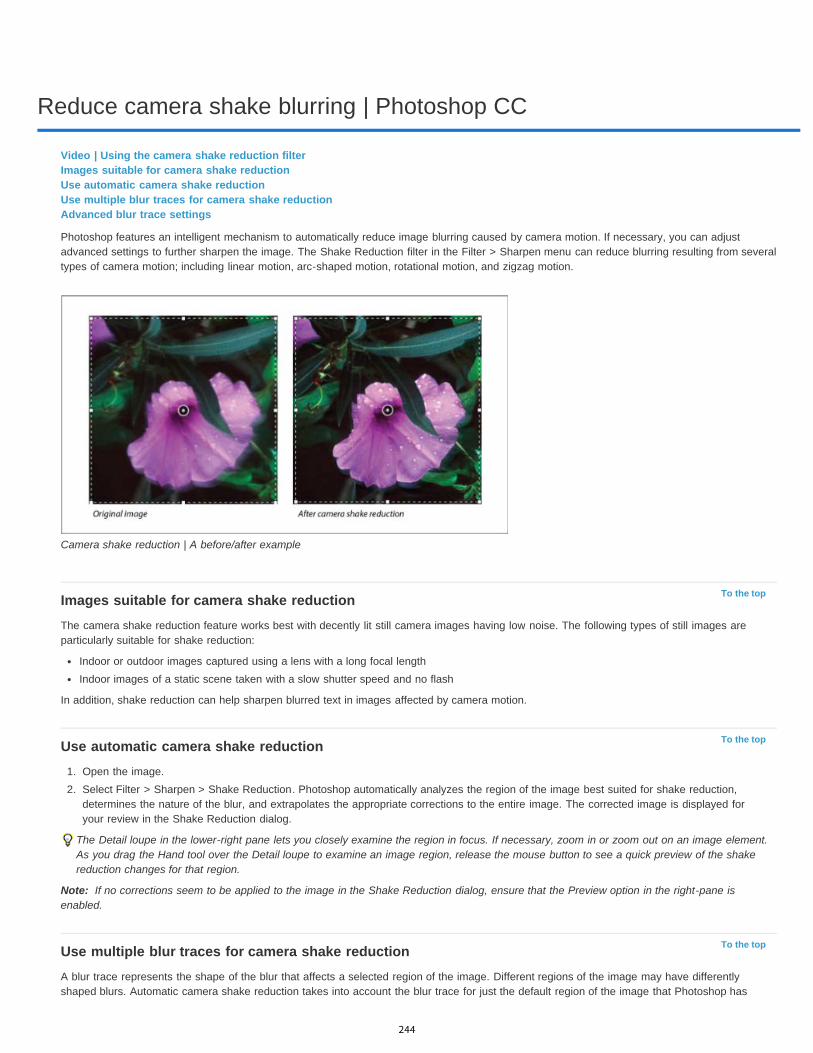
Reduce camera shake blurring | Photoshop CC
To the top
To the top
Note:
To the top
Video | Using the camera shake reduction filterImages suitable for camera shake reductionUse automatic camera shake reductionUse multiple blur traces for camera shake reductionAdvanced blur trace settings
Photoshop features an intelligent mechanism to automatically reduce image blurring caused by camera motion. If necessary, you can adjustadvanced settings to further sharpen the image. The Shake Reduction filter in the Filter > Sharpen menu can reduce blurring resulting from severaltypes of camera motion; including linear motion, arc-shaped motion, rotational motion, and zigzag motion.
Camera shake reduction | A before/after example
Images suitable for camera shake reductionThe camera shake reduction feature works best with decently lit still camera images having low noise. The following types of still images areparticularly suitable for shake reduction:
Indoor or outdoor images captured using a lens with a long focal lengthIndoor images of a static scene taken with a slow shutter speed and no flash
In addition, shake reduction can help sharpen blurred text in images affected by camera motion.
Use automatic camera shake reduction1. Open the image.2. Select Filter > Sharpen > Shake Reduction. Photoshop automatically analyzes the region of the image best suited for shake reduction,
determines the nature of the blur, and extrapolates the appropriate corrections to the entire image. The corrected image is displayed foryour review in the Shake Reduction dialog.
The Detail loupe in the lower-right pane lets you closely examine the region in focus. If necessary, zoom in or zoom out on an image element.As you drag the Hand tool over the Detail loupe to examine an image region, release the mouse button to see a quick preview of the shakereduction changes for that region.
If no corrections seem to be applied to the image in the Shake Reduction dialog, ensure that the Preview option in the right-pane isenabled.
Use multiple blur traces for camera shake reductionA blur trace represents the shape of the blur that affects a selected region of the image. Different regions of the image may have differentlyshaped blurs. Automatic camera shake reduction takes into account the blur trace for just the default region of the image that Photoshop has
244

determined as most suitable for blur estimation. To further fine-tune the image, you can have Photoshop compute and consider blur traces formultiple regions.
Available blur traces are listed in the Advanced panel of the Shake Reduction dialog. You can click a blur trace to zoom in on it.
Multiple blur traces listed in the Advanced panel
Create and modify blur tracesPhotoshop provides several ways to create and modify blur traces. For best results, create blur traces in regions of the image that have edgecontrast. For example, the region labeled A in the illustration below is better suited for blur estimation than the region labeled B.
Due to texture contrasts, A is more suitable for blur estimation than B
Resize/reposition the boundaries of the current region in focusYou can simply resize the boundaries of the region in focus to update the associated blur trace. To shift focus to a different region, simply drag thecenter pin of the region currently in focus.
Have Photoshop suggest a new region for blur estimation1. Click the Add Suggested Blur Trace icon ( ) in the Advanced panel in the right-pane. Photoshop highlights a new region of the image
suitable for blur estimation and creates its blur trace.2. Add more blur traces if necessary.
Click the trash can icon () to delete one or more selected blur traces.
Manually select a new image region1. Click the Blur Estimation Tool icon ( ) in the upper-left corner of the Shake Reduction dialog.2. Draw a selection rectangle anywhere on the image. Photoshop automatically creates a blur trace for the region you selected.3. Add more blur traces if necessary.
Modify a blur trace using the Detail loupe1. Using the Detail loupe, focus on a new image region suitable for camera shake reduction.2. Click the Enhance At Loupe Location icon ( ) to move focus in the left-pane to the region highlighted in the Detail loupe. The blur trace for
the region displayed earlier in the Detail loupe is automatically updated.
The keyboard shortcut q lets you dock/undock the Detail loupe.
245

To the top
Modify a blur trace using the Detail loupe
Preview and apply multiple blur tracesOnce you’ve added the required blur traces, you can select one or more blur traces in the Advanced panel to apply them to the image.
Preview and compare the results of two blur tracesWith the Ctrl key (Windows) or the Command key (Mac) held down, select the blur traces in the Advanced panel. Photoshop displays themultiple preview pane for the selected blur traces.
Results for two blur traces displayed side-by-side
Reuse blur tracesOnce you’ve created blur traces; you can save them, so that they can be applied to different images.
1. Select one or more blur traces.2. Select Save Blur Trace from the Advanced panel flyout menu. You can save blur traces in two formats—KNL and PNG.
When you want to reuse the saved blur traces for a different image, you can use the Load Blur Trace option in the Advanced panel flyout menu.
Saving and loading blur traces
Advanced blur trace settingsAdvanced blur trace settings help you further fine-tune camera shake reduction.
Blur trace boundsThe blur trace bound is the size of the blur in pixels as estimated by Photoshop. You can adjust this value if necessary.
Source Noise
246

Twitter™ and Facebook posts are not covered under the terms of Creative Commons.
Legal Notices | Online Privacy Policy
Photoshop automatically estimates the amount of noise in the image. If necessary, select a different value (Auto/Low/Medium/High).
SmoothingSmoothing reduces high-frequency sharpening noise. You can move the slider to a value different from the default 20%. It is recommended thatyou keep smoothing low.
Artifact SuppressionSometimes, in the course of sharpening the image, you may observe some noticeable noise artifacts. You can suppress these artifacts by settingArtifact Suppression to a higher value. 100% artifact suppression yields the original image, while 0% artifact suppression does not suppress anynoise artifacts.
Noise artifacts
247
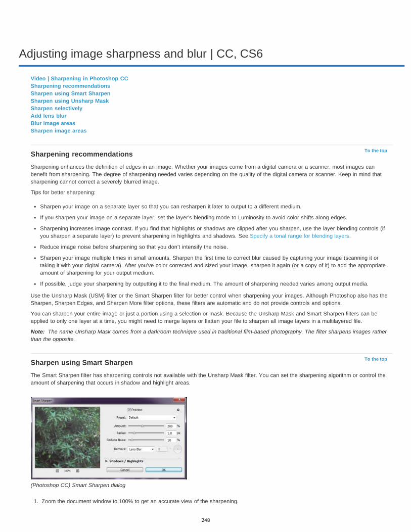
Adjusting image sharpness and blur | CC, CS6
To the top
Note:
To the top
Video | Sharpening in Photoshop CCSharpening recommendationsSharpen using Smart SharpenSharpen using Unsharp MaskSharpen selectivelyAdd lens blurBlur image areasSharpen image areas
Sharpening recommendationsSharpening enhances the definition of edges in an image. Whether your images come from a digital camera or a scanner, most images canbenefit from sharpening. The degree of sharpening needed varies depending on the quality of the digital camera or scanner. Keep in mind thatsharpening cannot correct a severely blurred image.
Tips for better sharpening:
Sharpen your image on a separate layer so that you can resharpen it later to output to a different medium.
If you sharpen your image on a separate layer, set the layer’s blending mode to Luminosity to avoid color shifts along edges.
Sharpening increases image contrast. If you find that highlights or shadows are clipped after you sharpen, use the layer blending controls (ifyou sharpen a separate layer) to prevent sharpening in highlights and shadows. See Specify a tonal range for blending layers.
Reduce image noise before sharpening so that you don’t intensify the noise.
Sharpen your image multiple times in small amounts. Sharpen the first time to correct blur caused by capturing your image (scanning it ortaking it with your digital camera). After you’ve color corrected and sized your image, sharpen it again (or a copy of it) to add the appropriateamount of sharpening for your output medium.
If possible, judge your sharpening by outputting it to the final medium. The amount of sharpening needed varies among output media.
Use the Unsharp Mask (USM) filter or the Smart Sharpen filter for better control when sharpening your images. Although Photoshop also has theSharpen, Sharpen Edges, and Sharpen More filter options, these filters are automatic and do not provide controls and options.
You can sharpen your entire image or just a portion using a selection or mask. Because the Unsharp Mask and Smart Sharpen filters can beapplied to only one layer at a time, you might need to merge layers or flatten your file to sharpen all image layers in a multilayered file.
The name Unsharp Mask comes from a darkroom technique used in traditional film-based photography. The filter sharpens images ratherthan the opposite.
Sharpen using Smart SharpenThe Smart Sharpen filter has sharpening controls not available with the Unsharp Mask filter. You can set the sharpening algorithm or control theamount of sharpening that occurs in shadow and highlight areas.
(Photoshop CC) Smart Sharpen dialog
1. Zoom the document window to 100% to get an accurate view of the sharpening.
248
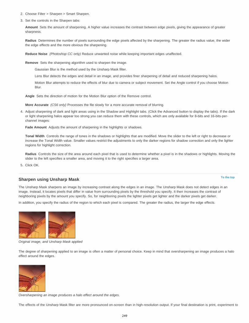
Amount
Radius
Reduce Noise
Remove
Angle
More Accurate
Fade Amount
Tonal Width
Radius
To the top
2. Choose Filter > Sharpen > Smart Sharpen.
3. Set the controls in the Sharpen tabs:
Sets the amount of sharpening. A higher value increases the contrast between edge pixels, giving the appearance of greatersharpness.
Determines the number of pixels surrounding the edge pixels affected by the sharpening. The greater the radius value, the widerthe edge effects and the more obvious the sharpening.
(Photoshop CC only) Reduce unwanted noise while keeping important edges unaffected.
Sets the sharpening algorithm used to sharpen the image.
Gaussian Blur is the method used by the Unsharp Mask filter.
Lens Blur detects the edges and detail in an image, and provides finer sharpening of detail and reduced sharpening halos.
Motion Blur attempts to reduce the effects of blur due to camera or subject movement. Set the Angle control if you choose MotionBlur.
Sets the direction of motion for the Motion Blur option of the Remove control.
(CS6 only) Processes the file slowly for a more accurate removal of blurring.
4. Adjust sharpening of dark and light areas using in the Shadow and Highlight tabs. (Click the Advanced button to display the tabs). If the darkor light sharpening halos appear too strong you can reduce them with these controls, which are only available for 8-bits and 16-bits-per-channel images:
Adjusts the amount of sharpening in the highlights or shadows.
Controls the range of tones in the shadows or highlights that are modified. Move the slider to the left or right to decrease orincrease the Tonal Width value. Smaller values restrict the adjustments to only the darker regions for shadow correction and only the lighterregions for highlight correction.
Controls the size of the area around each pixel that is used to determine whether a pixel is in the shadows or highlights. Moving theslider to the left specifies a smaller area, and moving it to the right specifies a larger area.
5. Click OK.
Sharpen using Unsharp MaskThe Unsharp Mask sharpens an image by increasing contrast along the edges in an image. The Unsharp Mask does not detect edges in animage. Instead, it locates pixels that differ in value from surrounding pixels by the threshold you specify. It then increases the contrast ofneighboring pixels by the amount you specify. So, for neighboring pixels the lighter pixels get lighter and the darker pixels get darker.
In addition, you specify the radius of the region to which each pixel is compared. The greater the radius, the larger the edge effects.
Original image, and Unsharp Mask applied
The degree of sharpening applied to an image is often a matter of personal choice. Keep in mind that oversharpening an image produces a haloeffect around the edges.
Oversharpening an image produces a halo effect around the edges.
The effects of the Unsharp Mask filter are more pronounced on-screen than in high-resolution output. If your final destination is print, experiment to
249

To the top
determine what settings work best for your image.
1. (Optional) If your image is multilayered, select the layer containing the image you want to sharpen. You can apply Unsharp Mask to only onelayer at a time, even if layers are linked or grouped. You can merge the layers before applying the Unsharp Mask filter.
2. Choose Filter > Sharpen > Unsharp Mask. Make sure the Preview option is selected.
Click the image in the preview window and hold down the mouse to see how the image looks without the sharpening. Drag in the previewwindow to see different parts of the image, and click + or – to zoom in or out.
Although there is a preview window in the Unsharp Mask dialog box, it’s best to move the dialog box so you can preview the effects of thefilter in the document window.
3. Drag the Radius slider or enter a value to determine the number of pixels surrounding the edge pixels that affect the sharpening. The greaterthe radius value, the wider the edge effects. And the wider the edge effects, the more obvious the sharpening.
The Radius value varies according to the subject matter, the size of the final reproduction, and the output method. For high-resolutionimages, a Radius value between 1 and 2 is usually recommended. A lower value sharpens only the edge pixels, whereas a higher valuesharpens a wider band of pixels. This effect is much less noticeable in print than on-screen, because a 2-pixel radius represents a smallerarea in a high-resolution printed image.
4. Drag the Amount slider or enter a value to determine how much to increase the contrast of pixels. For high-resolution printed images, anamount between 150% and 200% is usually recommended.
5. Drag the Threshold slider or enter a value to determine how different the sharpened pixels must be from the surrounding area before theyare considered edge pixels and sharpened by the filter. For instance, a threshold of 4 affects all pixels that have tonal values that differ by avalue of 4 or more, on a scale of 0 to 255. So, if adjacent pixels have tonal values of 128 and 129, they are not affected. To avoidintroducing noise or posterization (in images with flesh tones, for example), use an edge mask or try experimenting with Threshold valuesbetween 2 and 20. The default Threshold value (0) sharpens all pixels in the image.
If applying Unsharp Mask makes already bright colors appear overly saturated, choose Edit > Fade Unsharp Mask and choose Luminosity fromthe Mode menu.
Sharpen selectivelyYou can sharpen parts of your image by using a mask or a selection to prevent sharpening in certain parts of your image. For example, you canuse an edge mask with the Unsharp Mask filter on a portrait to sharpen the eyes, mouth, nose, and outline of the head, but not the texture of theskin.
Using an edge mask to apply the Unsharp Mask only to specific features in an image
Sharpen a selection1. With the image layer selected in the Layers panel, draw a selection.2. Choose Filter > Sharpen > Unsharp Mask. Adjust the options and click OK.
Only the selection is sharpened, leaving the rest of the image untouched.
Sharpen an image using an edge mask1. Create a mask to apply sharpening selectively. There are many ways to create an edge mask. Use your favorite method, or try this one:
Open the Channels panel and select the channel that displays the grayscale image with the greatest contrast in the document window.Often, this is the green or the red channel.
250
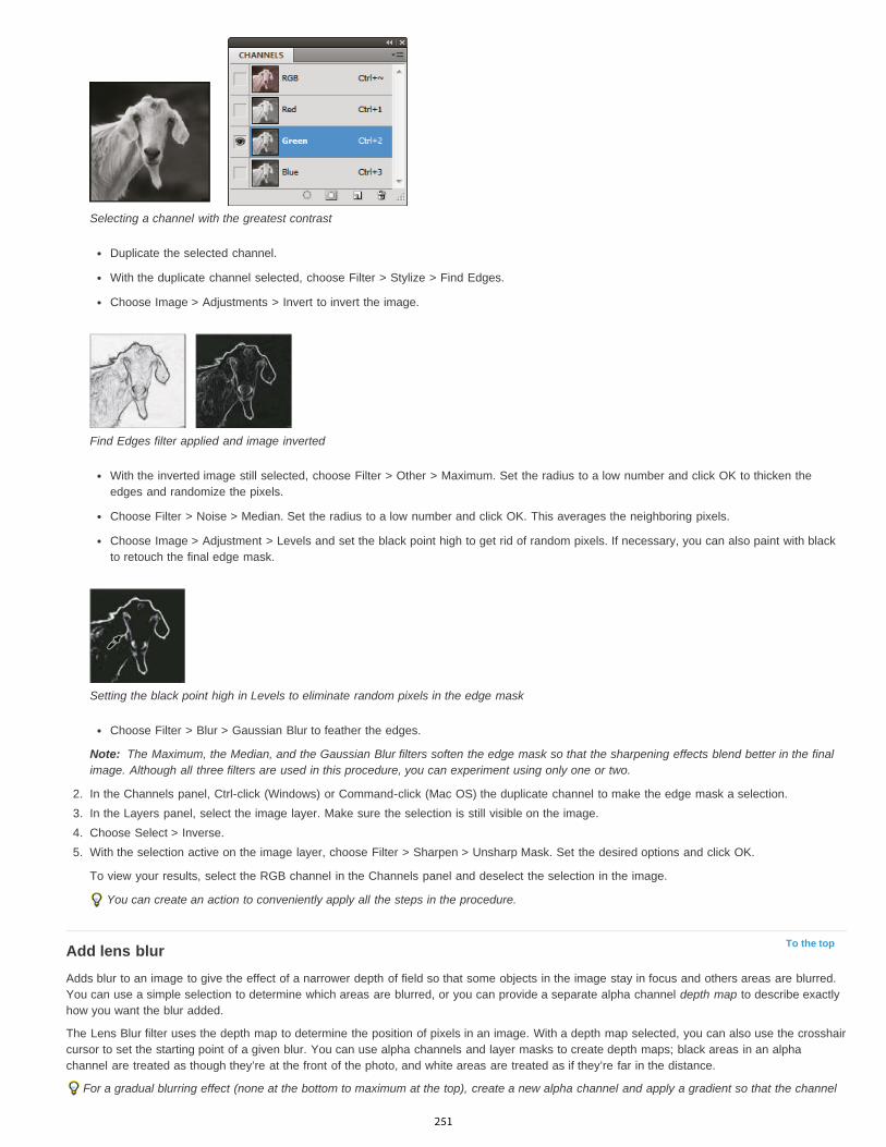
Note:
To the top
Selecting a channel with the greatest contrast
Duplicate the selected channel.
With the duplicate channel selected, choose Filter > Stylize > Find Edges.
Choose Image > Adjustments > Invert to invert the image.
Find Edges filter applied and image inverted
With the inverted image still selected, choose Filter > Other > Maximum. Set the radius to a low number and click OK to thicken theedges and randomize the pixels.
Choose Filter > Noise > Median. Set the radius to a low number and click OK. This averages the neighboring pixels.
Choose Image > Adjustment > Levels and set the black point high to get rid of random pixels. If necessary, you can also paint with blackto retouch the final edge mask.
Setting the black point high in Levels to eliminate random pixels in the edge mask
Choose Filter > Blur > Gaussian Blur to feather the edges.
The Maximum, the Median, and the Gaussian Blur filters soften the edge mask so that the sharpening effects blend better in the finalimage. Although all three filters are used in this procedure, you can experiment using only one or two.
2. In the Channels panel, Ctrl-click (Windows) or Command-click (Mac OS) the duplicate channel to make the edge mask a selection.3. In the Layers panel, select the image layer. Make sure the selection is still visible on the image.4. Choose Select > Inverse.5. With the selection active on the image layer, choose Filter > Sharpen > Unsharp Mask. Set the desired options and click OK.
To view your results, select the RGB channel in the Channels panel and deselect the selection in the image.
You can create an action to conveniently apply all the steps in the procedure.
Add lens blurAdds blur to an image to give the effect of a narrower depth of field so that some objects in the image stay in focus and others areas are blurred.You can use a simple selection to determine which areas are blurred, or you can provide a separate alpha channel depth map to describe exactlyhow you want the blur added.
The Lens Blur filter uses the depth map to determine the position of pixels in an image. With a depth map selected, you can also use the crosshaircursor to set the starting point of a given blur. You can use alpha channels and layer masks to create depth maps; black areas in an alphachannel are treated as though they’re at the front of the photo, and white areas are treated as if they’re far in the distance.
For a gradual blurring effect (none at the bottom to maximum at the top), create a new alpha channel and apply a gradient so that the channel
251

Twitter™ and Facebook posts are not covered under the terms of Creative Commons.
Legal Notices | Online Privacy Policy
To the top
To the top
is white at the top of the image and black at the bottom. Then select the Lens Blur filter and choose the alpha channel from the Source pop-upmenu. To change the direction of the gradient, select the Invert check box.
The way the blur appears depends on the iris shape you choose. The number of blades determines the iris shape. You can change blades of aniris by curving them (making them more circular) or rotating them. You can also reduce or magnify the preview by clicking the minus button or theplus button.
1. Choose Filter > Blur > Lens Blur.2. For Preview, Choose Faster to generate quicker previews. Choose More Accurate to view the final version of the image. More Accurate
previews take longer to generate.3. For Depth Map, choose a source (if you have one) from the Source pop-up menu. Drag the Blur Focal Distance slider to set the depth at
which pixels are in focus. For example, if you set focal distance to 100, pixels at 1 and at 255 are completely blurred, and pixels closer to100 are blurred less. If you click in the preview image, the Blur Focal Distance slider changes to reflect the clicked location and brings thedepth of the clicked location into focus.
4. To invert the selection or alpha channel you’re using as the depth map source, select Invert.5. Choose an iris from the Shape pop-up menu. If you wish, drag the Blade Curvature slider to smooth the edges of the iris, or drag the
Rotation slider to rotate it. To add more blur, drag the Radius slider.6. For Specular Highlight, drag the Threshold slider to select a brightness cutoff; all pixels brighter than the cutoff value are treated as specular
highlights. To increase the brightness of the highlights, drag the Brightness slider.7. To add noise to an image, choose Uniform or Gaussian. To add noise without affecting color. choose Monochromatic. Drag the Amount
slider to increase or decrease noise.
Blurring removes film grain and noise from the original image. To make the image look realistic and unretouched, you can return some ofthe removed noise to the image.
8. Click OK to apply the changes to your image.
Blur image areasThe Blur tool softens hard edges or reduces detail in an image. The more you paint over an area with the tool, the blurrier it becomes.
1. Select the Blur tool .2. Do the following in the options bar:
Choose a brush tip and set options for the blending mode and strength in the options bar.
Select Sample All Layers in the options bar to blur using data from all visible layers. Deselect this option and the tool uses data fromonly the active layer.
3. Drag over the part of the image you want to blur.
Sharpen image areasThe Sharpen tool increases contrast along edges to increase apparent sharpness. The more you paint over an area with the tool, the moresharpening increases.
1. Select the Sharpen tool . (If the tool isn’t visible, hold down the Blur tool.)2. Do the following in the options bar:
Choose a brush tip and set options for the blending mode and strength.
Select Sample All Layers to sharpen using data from all visible layers. If this is deselected, the tool uses data from only the active layer.
Select Protect Detail to enhance details and minimize pixelated artifacts. Deselect this option if you want to produce more exaggeratedsharpening effects.
3. Drag over the part of the image you want to sharpen.
252
Understanding color adjustments
To the top
To the top
Before making color and tonal adjustmentsCorrecting imagesAdjustments panel overviewColor adjustment commandsMake a color adjustmentSave adjustment settingsReapply adjustment settingsCorrecting colors in CMYK and RGBIdentify out-of-gamut colors
Before making color and tonal adjustmentsThe powerful tools in Photoshop can enhance, repair, and correct the color and tonality (lightness, darkness, and contrast) in an image. Here aresome items to consider before making color and tonal adjustments.
Work with a monitor that’s calibrated and profiled. For critical image editing, calibration and profiling are essential. Otherwise, the image yousee on your monitor looks different on other monitors or when printed.
Plan to use adjustment layers to adjust the tonal range and color balance of your image. Adjustment layers let you go back and makesuccessive tonal adjustments without discarding or permanently modifying data from the image layer. Keep in mind that using adjustmentlayers adds to the file size of the image and demands more RAM from your computer. Accessing the color and tonal commands in theAdjustments panel automatically creates adjustment layers.
If you don’t want to use adjustment layers, you can apply adjustments directly to an image layer. Remember that some image information isdiscarded, when making a color or tonal adjustment directly to an image layer.
For critical work and maximum preservation of image data, it’s best if the image you work with is 16 bits per channel (16-bit image) ratherthan 8 bits per channel (8-bit image). Data is discarded when you make tonal and color adjustments. The loss of image information is morecritical in an 8-bit image than a 16-bit image. Generally, 16-bit images have a larger file size than 8-bit images.
Duplicate or make a copy of the image file. Working on a copy of your image preserves the original in the event you want to use the image inits original state.
Remove any flaws such as dust spots, blemishes, and scratches from the image before making color and tonal adjustments.
Open the Info or Histogram panel in Expanded view. As you evaluate and correct the image, both panels display invaluable feedback on youradjustments.
You can make a selection or use a mask to confine your color and tonal adjustments to part of an image. Another way to apply color andtonal adjustments selectively is to set up your document with image components on different layers. Color and tonal adjustments are appliedto only one layer at a time. Only the image components on the targeted layer are affected.
Correcting imagesHere is the general workflow you follow when you correct the tonality and color of an image:
1. Use the histogram to check the quality and tonal range of the image.
2. Make sure that the Adjustments panel is open to access color and tonal adjustments. Click an icon to access the adjustments described inthe following steps. Applying corrections from the Adjustments panel creates an adjustment layer, which gives you more flexibility anddoesn’t discard image information. See Adjustments panel overview and About adjustment layers and fill layers.
3. Adjust the color balance to remove unwanted color casts or to correct oversaturated or undersaturated colors. See Color adjustmentcommands.
4. Adjust the tonal range, using either the Levels or Curves adjustments.
Begin tonal corrections by adjusting the values of the extreme highlight and shadow pixels in the image, setting an overall tonal range for theimage. This process is known as setting the highlights and shadows or setting the white and black points. Setting the highlights andshadows typically redistributes the midtone pixels appropriately. However, you might need to adjust your midtones manually.
253
To the top
To adjust the tonality in just shadow and highlight areas, use the Shadow/Highlight command. See Improve shadow and highlight detail.
5. (Optional) Make other color adjustments.
After you correct the overall color balance of your image, you can make optional adjustments to enhance colors or produce special effects.
6. Sharpen the edges in the image.
As one of the final steps, use the Unsharp Mask or the Smart Sharpen filter to sharpen the clarity of edges in the image. The amount ofsharpening required for an image varies according to the image quality produced by the digital camera or scanner you use. See Sharpenimages.
7. (Optional) Target the image for printer or press characteristics.
You can use options in the Levels or Curves adjustments to import highlight and shadow information into the gamut of an output device, likea desktop printer. This procedure can also be done if you are sending your image to a printing press, and know the characteristics of thepress.
Because sharpening increases the contrast of neighboring pixels, it’s possible that some pixels in critical areas might become unprintable onthe printer or press that you’re using. For this reason, it’s best to fine-tune the output settings after sharpening. For more information onadjusting the output settings, see Setting highlight and shadow target values.
Adjustments panel overviewThe tools for making color and tonal adjustments can be found in the Adjustments panel. Clicking a tool icon both selects an adjustment andautomatically creates an adjustment layer. The adjustments you make using the controls and options in the Adjustments panel createnondestructive adjustment layers. See About adjustment layers and fill layers.
In Photoshop CC and CS6, the Properties panel has a Presets menu with the adjustment presets. In Photoshop CS5, the Adjustments panel has alist of adjustment presets that apply common image corrections. Presets are available for Levels, Curves, Exposure, Hue/Saturation, Black &White, Channel Mixer, and Selective Color. Clicking a preset applies it to the image using an adjustment layer. You can always save adjustmentsettings as a preset, which is added to the presets list.
Clicking an adjustment icon or a preset displays the settings options for the specific adjustment.
For a video, see An Introduction to Adjustment Layers.
Apply a correction using the Adjustments panel
1. In the Adjustments panel, click an adjustment icon or choose an adjustment from the panel menu. In CS5, you can also click an adjustmentpreset.
2. Use the controls and options in the Properties panel (CC, CS6) or Adjustments panel (CS5) to apply the settings you want.
3. (Optional) Do any of the following:To toggle the visibility of the adjustment, click the Toggle Layer Visibility button .
To return the adjustment to its original settings, click the Reset button .
To discard an adjustment, click the Delete This Adjustment Layer button .
To expand the width of the Adjustment panel, in Photoshop CC and Photoshop CS6, drag a bottom corner of the panel. In PhotoshopCS5, click the Expand View button.
(CS5) To add another adjustment layer above the current one, click the arrow . This procedure returns the Adjustments panel to thedisplay of adjustment icons and presets list. In Photoshop CC and CS6, the adjustment icons are always visible in the Adjustmentspanel.
(CS5) To return to the current adjustments settings options from the adjustment icons and presets in the Adjustments panel, click thearrow .
Apply a correction to only the layer below
1. In the Adjustments panel, click an adjustment icon or choose an adjustment from the panel menu. In CS5, you can also click an adjustmentpreset.
2. In the the Properties panel (CC, CS6) or the Adjustments panel (CS5), click the Clip to Layer button . Click the icon again to make theadjustment apply to all layers below it in the Layers panel.
Save and apply adjustment presets
254

To the top
Adjust Levels Auto
Levels command
Curves command
Exposure command
Vibrance command
Photo Filter command
Color Balance command
Hue/Saturation command
Match Color command
Replace Color command
Selective Color command
Channel Mixer command
To the top
In Photoshop CC and Photoshop CS6, the Properties panel has a Preset menu with the adjustment presets for the tool that you clicked in theAdjustments panel. In Photoshop CS5, the Adjustments panel has a list of presets for common color and tonal adjustments. Additionally, you cansave and apply presets for Levels, Curves, Exposure, Hue/Saturation, Black & White, Channel Mixer, and Selective Color. When you save apreset, it’s added to the presets list.
To save adjustment settings as a preset, choose the Save Preset option from the Properties panel menu (CC, CS6) or the Adjustments panelmenu (CS5).(CC, CS6) To apply an adjustment preset, choose a preset from the Preset menu in the Properties panel.(CS5) To apply an adjustment preset, click the triangle to expand the list of presets for a specific adjustment and then click a preset. Alt-click(Windows) or Option-click (Mac OS) a triangle to expand all presets.
Automatically select text fields or the targeted adjustment toolIf you often change adjustment parameters using text fields or the targeted adjustment tool, maximize your efficiency by automatically selectingthese items.
From the Properties panel menu (CC, CS6) or the Adjustments panel menu (CS5), select Auto-Select Parameter or Auto-Select TargetedAdjustment Tool.
If you prefer to select text fields as needed, press Shift-Enter (Windows) or Shift-Return (Mac OS).
Color adjustment commandsYou can choose from the following color adjustment commands:
Quickly corrects the color balance in an image. Although its name implies an automatic adjustment, you can fine-tune howthe Auto Color command behaves. See Remove a color cast using Auto Color.
Adjusts color balance by setting the pixel distribution for individual color channels. See Adjust color using Levels.
Provides up to 14 control points for highlight, midtone, and shadow adjustments for individual channels. See Curves overview.
Adjusts tonality by performing calculations in a linear color space. Exposure is primarily for use in HDR images. See AdjustExposure for HDR images.
Adjusts color saturation so clipping is minimized. See Adjust color saturation using Vibrance.
Makes color adjustments by simulating the effects of using a Kodak Wratten or Fuji filter in front of a camera lens. SeeChange the color balance using the Photo Filter command.
Changes the overall mixture of colors in an image. See Apply the Color Balance adjustment.
Adjusts the hue, saturation, and lightness values of the entire image or of individual color components. See Adjusthue and saturation.
Matches the color: from one photo to another photo, from one layer to another layer, and from a selection in an image toanother selection in the same image or a different image. This command also adjusts the luminance and color range and neutralizes color casts inan image. See Match the color in different images.
Replaces specified colors in an image with new color values. See Replace the color of objects in an image.
Adjusts the amount of process colors in individual color components. See Make selective color adjustments.
Modifies a color channel and makes color adjustments not easily done with other color adjustment tools. See Mix colorchannels.
Make a color adjustmentAll Photoshop color adjustment tools work essentially the same way; they map an existing range of pixel values to a new range of values. Thedifference between the tools is the amount of control they provide. Color adjustment tools and their option settings are accessed in theAdjustments panel. For an overview of the color adjustment tools, see Color adjustment commands.
You can adjust the color in an image in different ways. The most flexible method is to use an adjustment layer. When you select a coloradjustment tool in the Adjustments panel, Photoshop automatically creates an adjustment layer. Adjustment layers let you experiment with colorand tonal adjustments without permanently modifying the pixels in the image. The color and tonal changes reside within the adjustment layer,which acts as a veil through which the underlying image layers appear.
1. If you want to make adjustments to a portion of your image, select that portion. If you make no selection, the adjustment is applied to theentire image.
2. Do one of the following:
255
Note:
To the top
To the top
To the top
Click an adjustment icon in the Adjustments panel. In CS5, you can also select an adjustment preset in the Adjustments panel.
Create an adjustment layer. See Create and confine adjustment and fill layers.
Double-click the thumbnail of an existing adjustment layer in the Layers panel.
You can also choose Image > Adjustments, and choose a command from the submenu to apply adjustments directly to the imagelayer. Keep in mind that this method discards image information.
A new adjustment layer includes a layer mask, which by default is empty (or white), meaning that your adjustment is applied to the entireimage. (If you have an active selection on the image when you add an adjustment layer, the initial layer mask masks out the unselectedarea in black.) Using the Brush tool, you can paint black areas on the mask where you don’t want the adjustment to affect the image. SeeEdit a layer mask.
3. To toggle the view of your image with and without adjustments, click the Toggle Layer Visibility icon in the Properties panel (CC, CS6) orthe Adjustments panel (CS5).
To cancel changes, click the Reset button .
Save adjustment settingsYou can save your color adjustment settings and apply them to other images. Once a setting is saved, it can be accessed in either the Presetmenu in the Properties panel (CC, CS6) or the presets list of the Adjustments panel (CS5). You can also choose the Load Preset option from anadjustment dialog box menu. If you are saving color adjustment settings using the Match Color command, see Match the color in different images.
To save a setting in the Preset menu (CC, CS6) or the Adjustments panel (CS5), choose the Save Preset option from the panel menu. Thisoption is only available for Levels, Curves, Exposure, Hue/Saturation, Black & White, Channel Mixer, and Selective Color.To save a setting in the Shadows/Highlights or Replace Color image adjustment dialog box, click Save. In the Levels, Curves, Exposure,Hue/Saturation, Black & White, Channel Mixer, or Selective Color image adjustment dialog box, choose Save Preset from the panel menu.Enter a name for the setting, then click Save.
Reapply adjustment settingsOnce an adjustment setting is saved, it’s stored as a preset and can be reapplied.
(CC, CS6) Choose an adjustment preset from the Preset menu in the Properties panel.(CS5) In the Adjustments panel, expand a set of adjustment presets and select from the menu list.In an adjustment dialog box, click Load. Locate and load the saved adjustment file. In the Curves, Black & White, Exposure, Hue/Saturation,Selective Color, Levels, or Channel Mixer dialog boxes, saved presets appear in the Presets menu. Choose Load Preset from the Presetoption to load a preset not shown on the Preset pop-up menu from a different location.
To remove default presets, navigate to the following folders, move the presets out of the folders, and restart Photoshop.
Windows: [startup drive]/Program Files/Adobe/Adobe Photoshop [version_number]/Presets/[adjustment type]/[preset name]
Mac OS: [startup drive]/Applications/Adobe Photoshop [version_number]/Presets/[adjustment type]/[preset name]
Correcting colors in CMYK and RGBAlthough you can perform all color and tonal corrections in RGB mode and most adjustments in CMYK mode, choose a mode carefully. Avoidmultiple conversions between modes, because color values are rounded and lost with each conversion. Don’t convert RGB images to CMYK modeif they are meant for on-screen display. For CMYK images that are separated and printed, do not make color corrections in RGB mode.
If you must convert your image from one mode to another, perform most of your tonal and color corrections in RGB mode. You can then useCMYK mode for fine-tuning. The advantages of working in RGB mode are:
RGB has fewer channels. As a result, your computer uses less memory.
RGB has a wider range of colors than CMYK, and more colors are likely to be preserved after adjustments.
You can soft proof colors to see an on-screen preview of how your document’s colors will look when reproduced on a particular outputdevice. See About soft-proofing colors.
You can edit an image in RGB mode in one window and view the same image in CMYK colors in another window. Choose Window > Arrange> New Window For (Filename) to open a second window. Select the Working CMYK option for Proof Setup, then choose the Proof Colorcommand to turn on the CMYK preview in one of the windows.
256

Twitter™ and Facebook posts are not covered under the terms of Creative Commons.
Legal Notices | Online Privacy Policy
To the topIdentify out-of-gamut colors
A gamut is the range of colors that a color system can display or print. A color that can be displayed in RGB could be out of gamut, and thereforeunprintable, for your CMYK setting.
In RGB mode, you can tell whether a color is out of gamut in the following ways:
In the Info panel, an exclamation point appears next to the CMYK values whenever you move the pointer over an out-of-gamut color.
In both the Color Picker and the Color panel, an alert triangle appears. When you select an out-of-gamut color, the closest CMYKequivalent is displayed. To select the CMYK equivalent, click the triangle or the color patch.
Photoshop automatically brings all colors into gamut when you convert an RGB image to CMYK. Note that some detail in the image may belost, depending on your conversion options. You can identify the out-of-gamut colors in an image or correct them manually before convertingto CMYK. You can use the Gamut Warning command to highlight out-of-gamut colors.
Find out-of-gamut colors1. Choose View > Proof Setup, then choose the proof profile on which you want to base the gamut warning.2. Choose View > Gamut Warning.
All pixels outside the gamut of the current proof profile space are highlighted in gray.
Change the gamut warning color1. Do one of the following:
(Windows) Choose Edit > Preferences > Transparency & Gamut.
(Mac OS) Choose Photoshop > Preferences > Transparency & Gamut.
2. Under Gamut Warning, click the color box to display the Color Picker. Then choose a new warning color, and click OK.
For best results, use a color that is not already present in the image.
3. Enter a value in the Opacity box, then click OK.
Use this option to reveal more or less of the underlying image through the warning color. Values can range from 1 % to 100%.
Original image, and out-of-gamut colors preview with blue selected for gamut warning color
257

Viewing histograms and pixel values
To the top
To the top
About histogramsHistogram panel overviewView the histogram for a multilayered documentPreview histogram adjustmentsRefresh the histogram displayView color values in an imageView color information while adjusting colorAdjusting color samplers
About histogramsA histogram illustrates how pixels in an image are distributed by graphing the number of pixels at each color intensity level. The histogram showsdetail in the shadows (shown in the left part of the histogram), midtones (shown in the middle), and highlights (shown in the right part) A histogramcan help you determine whether an image has enough detail to make a good correction.
The histogram also gives a quick picture of the tonal range of the image, or the image key type. A low-key image has detail concentrated in theshadows. A high-key image has detail concentrated in the highlights. And, an average-key image has detail concentrated in the midtones. Animage with full tonal range has some pixels in all areas. Identifying the tonal range helps determine appropriate tonal corrections.
How to read a histogramA. Overexposed photo B. Properly exposed photo with full tonality C. Underexposed photo
The Histogram panel offers many options for viewing tonal and color information about an image. By default, the histogram displays the tonalrange of the entire image. To display histogram data for a portion of the image, first select that portion.
You can view an image histogram as an overlay in the Curves dialog box by selecting the histogram option under Curve Display Options, andin the Curves Properties panel (CC, CS6) or the Curves Adjustment panel (CS5), or by choosing Curve Display Options from the panel menu,then Histogram.
Histogram panel overview Choose Window > Histogram or click the Histogram tab to open the Histogram panel. By default, the Histogram panel opens in Compact View
with no controls or statistics, but you can adjust the view.
Histogram panel (Expanded view)A. Channel menu B. panel menu C. Uncached Refresh button D. Cached Data Warning icon E. Statistics
258

Adjust the view of the Histogram panel Choose a view from the Histogram panel menu.
Expanded View Displays the histogram with statistics. It also displays: controls for choosing the channel represented by the histogram, viewingoptions in the Histogram panel, refreshing the histogram to display uncached data, and choosing a specific layer in a multilayered document.Compact View Displays a histogram with no controls or statistics. The histogram represents the entire image.All Channels View Displays individual histograms of the channels in addition to all the options of the Expanded View. The individual histogramsdo not include alpha channels, spot channels, or masks.
Histogram panel with all channels displayed in color and statistics hidden
View a specific channel in the histogramIf you chose the Expanded View or All Channels View of the Histogram panel, you can choose a setting from the Channel menu. Photoshopremembers the channel setting if you switch from either Expanded View or All Channels View back to Compact View.
Choose an individual channel to display a histogram of the channel, including color channels, alpha channels, and spot channels.Depending on the color mode of the image, choose RGB, CMYK, or Composite to view a composite histogram of all the channels.If the image is RGB or CMYK, choose Luminosity to display a histogram representing the luminance or intensity values of the compositechannel.If the image is RGB or CMYK, choose Colors to display a composite histogram of the individual color channels in color. This option is thedefault view for RGB and CMYK images when you first choose Expanded View or All Channels View.
In the All Channels View, choosing from the Channels menu affects only the topmost histogram in the panel.
View channel histograms in color From the Histogram panel, do one of the following:
In the All Channels View, choose Show Channels In Color from the panel menu.
In Expanded View or All Channels View, choose an individual channel from the Channel menu and choose Show Channels In Color from thepanel menu. If you switch to Compact View, the channel continues to be shown in color.
In Expanded View or All Channels View, choose Colors from the Channel menu to show a composite histogram of the channels in color. Ifyou switch to Compact View, the composite histogram continues to be shown in color.
View histogram statistics
259
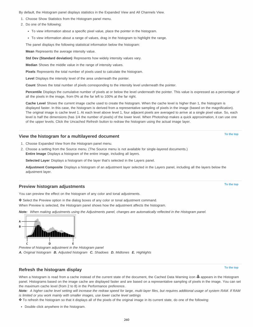
To the top
To the top
To the top
By default, the Histogram panel displays statistics in the Expanded View and All Channels View.
1. Choose Show Statistics from the Histogram panel menu.2. Do one of the following:
To view information about a specific pixel value, place the pointer in the histogram.
To view information about a range of values, drag in the histogram to highlight the range.
The panel displays the following statistical information below the histogram:
Mean Represents the average intensity value.
Std Dev (Standard deviation) Represents how widely intensity values vary.
Median Shows the middle value in the range of intensity values.
Pixels Represents the total number of pixels used to calculate the histogram.
Level Displays the intensity level of the area underneath the pointer.
Count Shows the total number of pixels corresponding to the intensity level underneath the pointer.
Percentile Displays the cumulative number of pixels at or below the level underneath the pointer. This value is expressed as a percentage ofall the pixels in the image, from 0% at the far left to 100% at the far right.
Cache Level Shows the current image cache used to create the histogram. When the cache level is higher than 1, the histogram isdisplayed faster. In this case, the histogram is derived from a representative sampling of pixels in the image (based on the magnification).The original image is cache level 1. At each level above level 1, four adjacent pixels are averaged to arrive at a single pixel value. So, eachlevel is half the dimensions (has 1/4 the number of pixels) of the lower level. When Photoshop makes a quick approximation, it can use oneof the upper levels. Click the Uncached Refresh button to redraw the histogram using the actual image layer.
View the histogram for a multilayered document1. Choose Expanded View from the Histogram panel menu.2. Choose a setting from the Source menu. (The Source menu is not available for single-layered documents.)
Entire Image Displays a histogram of the entire image, including all layers.
Selected Layer Displays a histogram of the layer that’s selected in the Layers panel.
Adjustment Composite Displays a histogram of an adjustment layer selected in the Layers panel, including all the layers below theadjustment layer.
Preview histogram adjustmentsYou can preview the effect on the histogram of any color and tonal adjustments.
Select the Preview option in the dialog boxes of any color or tonal adjustment command.When Preview is selected, the Histogram panel shows how the adjustment affects the histogram.
Note: When making adjustments using the Adjustments panel, changes are automatically reflected in the Histogram panel.
Preview of histogram adjustment in the Histogram panelA. Original histogram B. Adjusted histogram C. Shadows D. Midtones E. Highlights
Refresh the histogram displayWhen a histogram is read from a cache instead of the current state of the document, the Cached Data Warning icon appears in the Histogrampanel. Histograms based on the image cache are displayed faster and are based on a representative sampling of pixels in the image. You can setthe maximum cache level (from 2 to 8) in the Performance preference.Note: A higher cache level setting will increase the redraw speed for large, multi-layer files, but requires additional usage of system RAM. If RAMis limited or you work mainly with smaller images, use lower cache level settings
To refresh the histogram so that it displays all of the pixels of the original image in its current state, do one of the following:
Double-click anywhere in the histogram.
260
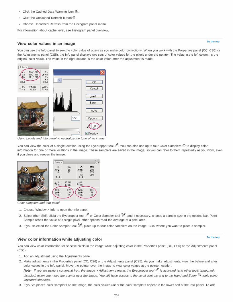
To the top
To the top
Click the Cached Data Warning icon .
Click the Uncached Refresh button .
Choose Uncached Refresh from the Histogram panel menu.
For information about cache level, see Histogram panel overview.
View color values in an imageYou can use the Info panel to see the color value of pixels as you make color corrections. When you work with the Properties panel (CC, CS6) orthe Adjustments panel (CS5), the Info panel displays two sets of color values for the pixels under the pointer. The value in the left column is theoriginal color value. The value in the right column is the color value after the adjustment is made.
Using Levels and Info panel to neutralize the tone of an image
You can view the color of a single location using the Eyedropper tool . You can also use up to four Color Samplers to display colorinformation for one or more locations in the image. These samplers are saved in the image, so you can refer to them repeatedly as you work, evenif you close and reopen the image.
Color samplers and Info panel
1. Choose Window > Info to open the Info panel.
2. Select (then Shift-click) the Eyedropper tool or Color Sampler tool , and if necessary, choose a sample size in the options bar. PointSample reads the value of a single pixel, other options read the average of a pixel area.
3. If you selected the Color Sampler tool , place up to four color samplers on the image. Click where you want to place a sampler.
View color information while adjusting colorYou can view color information for specific pixels in the image while adjusting color in the Properties panel (CC, CS6) or the Adjustments panel(CS5).
1. Add an adjustment using the Adjustments panel.2. Make adjustments in the Properties panel (CC, CS6) or the Adjustments panel (CS5). As you make adjustments, view the before and after
color values in the Info panel. Move the pointer over the image to view color values at the pointer location.Note: If you are using a command from the Image > Adjustments menu, the Eyedropper tool is activated (and other tools temporarilydisabled) when you move the pointer over the image. You still have access to the scroll controls and to the Hand and Zoom tools usingkeyboard shortcuts.
3. If you’ve placed color samplers on the image, the color values under the color samplers appear in the lower half of the Info panel. To add
261

To the top
new color samplers, select the Color Sampler tool and click in the image, or select the Eyedropper tool and Shift-click in the image.
Adjusting color samplersOnce you’ve added a color sampler, you can move or delete it, hide it, or change the color sampler information displayed in the Info panel.
Move or delete a color sampler1. Select the Color Sampler tool .2. Do one of the following:
To move a color sampler, drag the sampler to the new location.
To delete a color sampler, drag the sampler out of the document window. Alternatively, hold down Alt (Windows) or Option (Mac OS)until the pointer becomes a scissors and click the sampler.
To delete all color samplers, click Clear in the options bar.
To delete a color sampler while an adjustment dialog box is open, hold down Alt+Shift (Windows) or Option+Shift (Mac OS), and clickthe sampler.
Hide or show color samplers in an image Choose View > Extras. A check mark indicates that color samplers are visible.
Change the display of color sampler information in the Info panelTo display or hide color sampler information in the Info panel, choose Color Samplers from the panel menu. A check mark indicates that thecolor sampler information is visible.To change the color space in which a color sampler displays values, move the pointer onto the color sampler icon in the Info panel. Then,hold down the mouse button, and choose another color space from the menu.
Legal Notices | Online Privacy Policy
262

High dynamic range images
To the top
To the top
About high dynamic range imagesTake photos for HDR imagesFeatures that support 32-bpc HDR imagesMerge images to HDRAdjust displayed dynamic range for 32-bit HDR imagesAbout the HDR Color PickerPaint on HDR images
About high dynamic range imagesThe dynamic range (ratio between dark and bright regions) in the visible world far exceeds the range of human vision and of images that aredisplayed on a monitor or printed. But whereas human eyes can adapt to very different brightness levels, most cameras and computer monitorscan reproduce only a fixed dynamic range. Photographers, motion picture artists, and others working with digital images must be selective aboutwhat’s important in a scene because they are working with a limited dynamic range.
High dynamic range (HDR) images open up a world of possibilities because they can represent the entire dynamic range of the visible world.Because all the luminance values in a real-world scene are represented proportionately and stored in an HDR image, adjusting the exposure of anHDR image is like adjusting the exposure when photographing a scene in the real world.
Merging images of different exposures to create an HDR imageA. Image with shadow detail but highlights clipped B. Image with highlight detail but shadows clipped C. HDR image containing the dynamicrange of the scene
In Photoshop, the luminance values of an HDR image are stored using a floating-point numeric representation that’s 32 bits long (32-bits-per-channel). The luminance values in an HDR image are directly related to the amount of light in a scene. By contrast, non-floating point 16- and8-bpc image files store luminance values only from black to paper white, reflecting an extremely small segment of dynamic range in the real world.
In Photoshop, the Merge To HDR Pro command lets you create HDR images by combining multiple photographs captured at different exposures.Because an HDR image contains brightness levels that far exceed the display capabilities of a standard 24-bit monitor, Photoshop lets you adjustthe HDR preview. If you need to print or use tools and filters that don’t work with HDR images, you can convert them to 16- or 8-bpc images.
Take photos for HDR imagesKeep the following tips in mind when you take photos to be combined with the Merge To HDR Pro command:
263

To the top
To the top
Secure the camera to a tripod.
Take enough photos to cover the full dynamic range of the scene. You can try taking at least five to seven photos, but you might need totake more exposures depending on the dynamic range of the scene. The minimum number of photos should be three.
Vary the shutter speed to create different exposures. Changing the aperture changes the depth of field in each exposure and can producelower-quality results. Changing the ISO or aperture may also cause noise or vignetting in the image.
In general, don’t use your camera’s auto-bracket feature, because the exposure changes are usually too small.
The exposure differences between the photos should be one or two EV (exposure value) steps apart (equivalent to about one or two f-stopsapart).
Don’t vary the lighting; for instance, don’t use a flash in one exposure but not the next.
Make sure that nothing is moving in the scene. Exposure Merge works only with differently exposed images of the identical scene.
Features that support 32-bpc HDR imagesYou can use the following tools, adjustments, and filters with 32-bpc HDR images. (To work with more Photoshop features, convert a 32-bpcimage to a 16-bpc or an 8-bpc image. To preserve the original image, create a copy with the Save As command.)
Adjustments Levels, Exposure, Hue/Saturation, Channel Mixer, Photo Filter.Note: Although the Exposure command can be used with 8- and 16-bpc images, it is designed for making exposure adjustments to 32-bpc HDRimages.Blend Modes Normal, Dissolve, Darken, Multiply, Lighten, Darker Color, Linear Dodge (Add), Lighter Color, Difference, Subtract, Divide, Hue,Saturation, Color, and Luminosity.Create new 32-bpc documents In the New dialog box, 32 bit is an option in the bit depth pop-up menu to the right of the Color Mode pop-upmenu.Edit menu commands All commands including Fill, Stroke, Free Transform, and Transform.File Formats Photoshop (PSD, PSB), Radiance (HDR), Portable Bit Map (PBM), OpenEXR, and TIFF.Note: Although Photoshop cannot save an HDR image in the LogLuv TIFF file format, it can open and read a LogLuv TIFF file.Filters Average, Box Blur, Gaussian Blur, Motion Blur, Radial Blur, Shape Blur, Surface Blur, Add Noise, Clouds, Difference Clouds, Lens Flare,Smart Sharpen, Unsharp Mask, Emboss, De-Interlace, NTSC Colors, High Pass, Maximum, Minimum, and Offset.Image commands Image Size, Canvas Size, Image Rotation, Crop, Trim, Duplicate, Apply Image, Calculations, and Variables.View Pixel Aspect Ratio (Custom Pixel Aspect Ratio, Delete Pixel Aspect Ratio, Reset Pixel Aspect Ratio, etc.)Layers New layers, duplicate layers, adjustment layers (Levels, Vibrance, Hue/Saturation, Channel Mixer, Photo Filter, and Exposure), fill layers,layer masks, layer styles, supported blending modes, and Smart Objects.Modes RGB Color, Grayscale, conversion to 8 Bits/Channel or 16 Bits/Channel.Pixel Aspect Ratio Support for square and non-square documents.Selections Invert, Modify Border, Transform Selection, Save Selection and Load Selection.Tools All tools in the toolbox except: Magnetic Lasso, Magic Wand, Spot Healing Brush, Healing Brush, Red Eye, Color Replacement, Art HistoryBrush, Magic Eraser, Background Eraser, Paint Bucket, Dodge, Burn, and Sponge. Some tools work with supported blend modes only.
Merge images to HDRThe Merge To HDR Pro command combines multiple images with different exposures of the same scene, capturing the full dynamic range in asingle HDR image. You can output the merged image as a 32-, 16-, or 8-bpc file. However, only a 32-bpc file can store all the HDR image data.
HDR merging works best when photos are optimized for the process. For recommendations, see Take photos for HDR images.
Adobe recommends Have a tutorial you would like to share?
Video tutorial: The best new feature in CS5:HDR ProDeke McClellandTake image tones from vivid to surreal.
Book excerpt: Create HDR images frombracketed exposuresConrad ChavezWalk through the HDR process from camera tocomputer.
Book excerpt: Remove ghosting from HDRimagesScott KelbyEliminate blur from moving objects in a scene.
Video tutorial: Explore the enhancements toHDR ProJan KabiliTake a tour through all the new features.
264

1. Do one of the following:
(Photoshop) Choose File > Automate > Merge To HDR Pro.
(Bridge) Select the images you want to use and choose Tools > Photoshop > Merge To HDR Pro. Skip to step 5.
2. In the Merge To HDR Pro dialog box, click Browse to select specific images, click Add Open Files, or choose Use > Folder. (To remove aparticular item, select it in files list, and click Remove.)
3. (Optional) Select Attempt To Automatically Align Source Images if you held the camera in your hands when you photographed the images.4. Click OK.
Note: If images lack exposure metadata, enter values in the Manually Set EV dialog box.
A second Merge To HDR Pro dialog box displays thumbnails of the source images, and a preview of the merged result.
5. To the upper right of the preview, choose a bit depth for the merged image.Choose 32 Bit if you want the merged image to store the entire dynamic range of the HDR image. 8-bit and (non-floating point) 16-bitimage files cannot store the entire range of luminance values in an HDR image.
6. To adjust the tonal range, see Options for 32-bit images or Options for 16- or 8-bit images.7. (Optional) To save your tonal settings for future use, choose Preset > Save Preset. (To later reapply the settings, choose Load Preset.)
Options for 32-bit imagesMove the slider below the histogram to adjust the white point preview of the merged image. Moving the slider adjusts the image preview only; allHDR image data remains in the merged file.
The preview adjustment is stored in the HDR file and applied whenever you open the file in Photoshop. To readjust the white point preview at anytime, choose View > 32-Bit Preview Options.
Options for 16- or 8-bit imagesHDR images contain luminance levels that far exceed the dynamic range that 16- or 8-bpc images can store. To produce an image with thedynamic range you want, adjust exposure and contrast when converting from 32-bpc to lower bit depths.
Choose one of the following tone-mapping methods:
Local Adaptation Adjusts HDR tonality by adjusting local brightness regions throughout the image.
Edge Glow Radius specifies the size of the local brightness regions. Strength specifies how far apart two pixels’ tonal values must bebefore they’re no longer part of the same brightness region.Tone and Detail Dynamic range is maximized at a Gamma setting of 1.0; lower settings emphasize midtones, while higher settingsemphasize highlights and shadows. Exposure values reflect f-stops. Drag the Detail slider to adjust sharpness and the Shadow andHighlight sliders to brighten or darken these regions.Color Vibrance adjusts the intensity of subtle colors, while minimizing clipping of highly saturated colors. Saturation adjusts the intensityof all colors from –100 (monochrome) to +100 (double saturation).Toning Curve Displays an adjustable curve over a histogram showing luminance values in the original, 32-bit HDR image. The red tickmarks along the horizontal axis are in one EV (approximately one f-stop) increments.Note: By default, the Toning Curve and Histogram limit and equalize your changes from point to point. To remove the limit and applymore extreme adjustments, select the Corner option after inserting a point on the curve. When you insert and move a second point, thecurve becomes angular.
Toning Curve and Histogram adjustment using the Corner option
A. Inserting a point and selecting the Corner option. B. Adjusting new point makes the curve angular at the point where the
265

To the top
To the top
Corner option is used.
Equalize Histogram Compresses the dynamic range of the HDR image while trying to preserve some contrast. No further adjustments arenecessary; this method is automatic.Exposure and Gamma Lets you manually adjust the brightness and contrast of the HDR image. Move the Exposure slider to adjust gain and theGamma slider to adjust contrast.Highlight Compression Compresses the highlight values in the HDR image so they fall within the luminance values range of the 8- or 16-bpcimage file. No further adjustments are necessary; this method is automatic.
Compensate for moving objectsIf images have different content due to moving objects like cars, people, or foliage, select Remove Ghosts in the Merge To HDR Pro dialog box.
Photoshop displays a green outline around the thumbnail with the best tonal balance, identifying the base image. Moving objects found in otherimages are removed. (If movement occurs in very light or dark areas, click a different thumbnail where moving objects are better exposed toimprove results.)
For a tutorial on the Remove Ghosts option, see this video. (Discussion of Remove Ghosts begins at 3:00.)
Save or load camera response curvesResponse curves indicate how camera sensors interpret different levels of incoming light. By default, the Merge To HDR Pro dialog boxautomatically calculates a camera response curve based on the tonal range of images you are merging. You can save the current response curveand later apply it to another group of merged images.
In the upper-right corner of the Merge to HDR Pro dialog box, click the response curve menu , and then choose Save Response Curve. (Tolater reapply the curve, choose Load Response Curve.)
Convert from 32 bits to 16 or 8 bpcIf you originally created a 32-bit image during the Merge to HDR Pro process, you can later convert it to a 16- or 8-bit image.
1. Open a 32-bpc image in Photoshop, and choose Image > Mode > 16 Bits/Channel or 8 Bits/Channel.2. Adjust exposure and contrast to produce an image with the dynamic range you want. (See Options for 16- or 8-bit images.)3. Click OK to convert the 32-bit image.
Adjust displayed dynamic range for 32-bit HDR imagesThe dynamic range of HDR images exceeds the display capabilities of standard computer monitors. When you open an HDR image in Photoshop,it can look very dark or washed out. Photoshop lets you adjust the preview so that the monitor displays an HDR image whose highlights andshadows aren’t washed out or too dark. The preview settings are stored in the HDR image file (PSD, PSB, and TIFF only) and are appliedwhenever the file is opened in Photoshop. Preview adjustments don’t edit the HDR image file; all the HDR image information remains intact. Usethe Exposure adjustment (Image > Adjustments > Exposure) to make exposure edits to the 32-bpc HDR image.
To view 32-bit readouts in the Info panel, click the Eyedropper icon in the Info panel and choose 32-Bit from the pop-up menu.
1. Open a 32-bpc HDR image in Photoshop, and choose View > 32-Bit Preview Options.2. In the 32-bit Preview Options dialog box, choose an option from the Method menu:
Exposure And Gamma Adjusts the brightness and contrast.
Highlight Compression Compresses the highlight values in the HDR image so they fall within the luminance values range of the 8- or16-bpc image file.
3. If you chose Exposure And Gamma, move the Exposure and Gamma sliders to adjust the brightness and contrast of the image preview.4. Click OK.
You can also adjust the preview of an HDR image open in Photoshop by clicking the triangle in the status bar of the document windowand choosing 32-Bit Exposure from the pop-up menu. Move the slider to set the white point for viewing the HDR image. Double-click theslider to return to the default exposure setting. Since the adjustment is made per view, you can have the same HDR image open inmultiple windows, each with a different preview adjustment. Preview adjustments made with this method are not stored in the HDR imagefile.
About the HDR Color PickerThe HDR Color Picker allows you to accurately view and select colors for use in 32-bit HDR images. As in the regular Adobe Color Picker, youselect a color by clicking a color field and adjusting the color slider. The Intensity slider allows you to adjust the brightness of a color to match theintensity of the colors in the HDR image you’re working with. A Preview area lets you view swatches of a selected color to see how it will display atdifferent exposures and intensities.
266

HDR Color PickerA. Preview area B. Adjusted color C. Original color D. 32-bit floating point values E. Intensity slider F. Picked color G. Color slider H. Colorvalues
Display the HDR Color Picker With a 32-bpc image open, do one of the following:
In the toolbox, click the foreground or background color selection box.
In the Color panel, click the Set Foreground Coloror Set Background Color selection box.
The Color Picker is also available when features let you choose a color. For example, by clicking the color swatch in the options bar for sometools, or the eyedroppers in some color adjustment dialog boxes.
Choose colors for HDR imagesThe lower part of the HDR Color Picker functions like the regular Color Picker does with 8- or 16-bit images. Click in the color field to select acolor and move the color slider to change hues, or use the HSB or RGB fields to enter numeric values for a particular color. In the color field,brightness increases as you move from bottom to top, and saturation increases as you move from left to right.
Use the Intensity slider to adjust the brightness of the color. The color value plus the intensity value are converted to 32-bit floating point numbervalues in your HDR document.
1. Select a color by clicking in the color field and moving the color slider, or by entering HSB or RGB numeric values, as in the Adobe ColorPicker.
2. Adjust the Intensity slider to boost or reduce the color’s brightness. The new color swatch in the Preview scale at the top of the Color Pickershows the effect of increasing or decreasing stops for the selected color.
The Intensity Stops correspond inversely to exposure setting stops. If you boost the Exposure setting of the HDR image two stops, reducingthe Intensity stops by two will maintain the same color appearance as if the HDR image exposure and the color intensity were both set to 0.
If you know the exact 32-bit RGB values for the color you want, you can enter them directly in the 32-bit value RGB fields.
3. (Optional) Adjust settings for the Preview area.Preview Stop Size Sets the stop increments for each preview swatch. For example, a setting of 3 results in swatches of -9, -6, -3, +3, +6,+9. These swatches let you preview the appearance of your selected color at different exposure settings.
Relative to Document Select to adjust the preview swatches to reflect the current exposure setting for the image. For example, if thedocument exposure is set higher, the new preview swatch will be lighter than the color selected in the Color Picker’s color field, to show theeffect of the higher exposure on the selected color. If the current exposure is set to 0 (the default), checking or unchecking this option willnot change the new swatch.
4. (Optional) Click Add to Swatches to add the selected color to the Swatches panel.5. Click OK.
267
To the topPaint on HDR imagesYou can edit and add effects to HDR/32-bpc images using any of the following Photoshop tools: Brush, Pencil, Pen, Shape, Clone Stamp, PatternStamp, Eraser, Gradient, Blur, Sharpen, Smudge, and History Brush. You can also use the Text tool to add 32-bpc text layers to an HDR image.
When editing or painting on HDR images, you can preview your work at different exposure settings using either the 32-Bit Exposure slider in thedocument info area or the 32-Bit Preview Options dialog box (View > 32-Bit Preview Options). The HDR Color Picker also lets you preview yourselected foreground color at different intensity settings, to match different exposure settings in an HDR image.
1. Open an HDR image.2. (Optional) Set the exposure for the image. See Adjust displayed dynamic range for 32-bit HDR images.3. For the Brush or Pencil tools, click the foreground color to open the HDR Color Picker and select a color. For the Text tool, click the color
chip in the Text tool options bar to set the text color.The Preview area of the HDR Color Picker helps you select and adjust a foreground color in relation to different exposure settings in theHDR image. See About the HDR Color Picker.
To view the effects of painting at different HDR exposures, use the Window > Arrange > New Window command to open simultaneousviews of the same HDR image, then set each window to a different exposure using the Exposure slider in the document status bar area.
More Help topicsAdjust HDR exposure and toning
Legal Notices | Online Privacy Policy
268
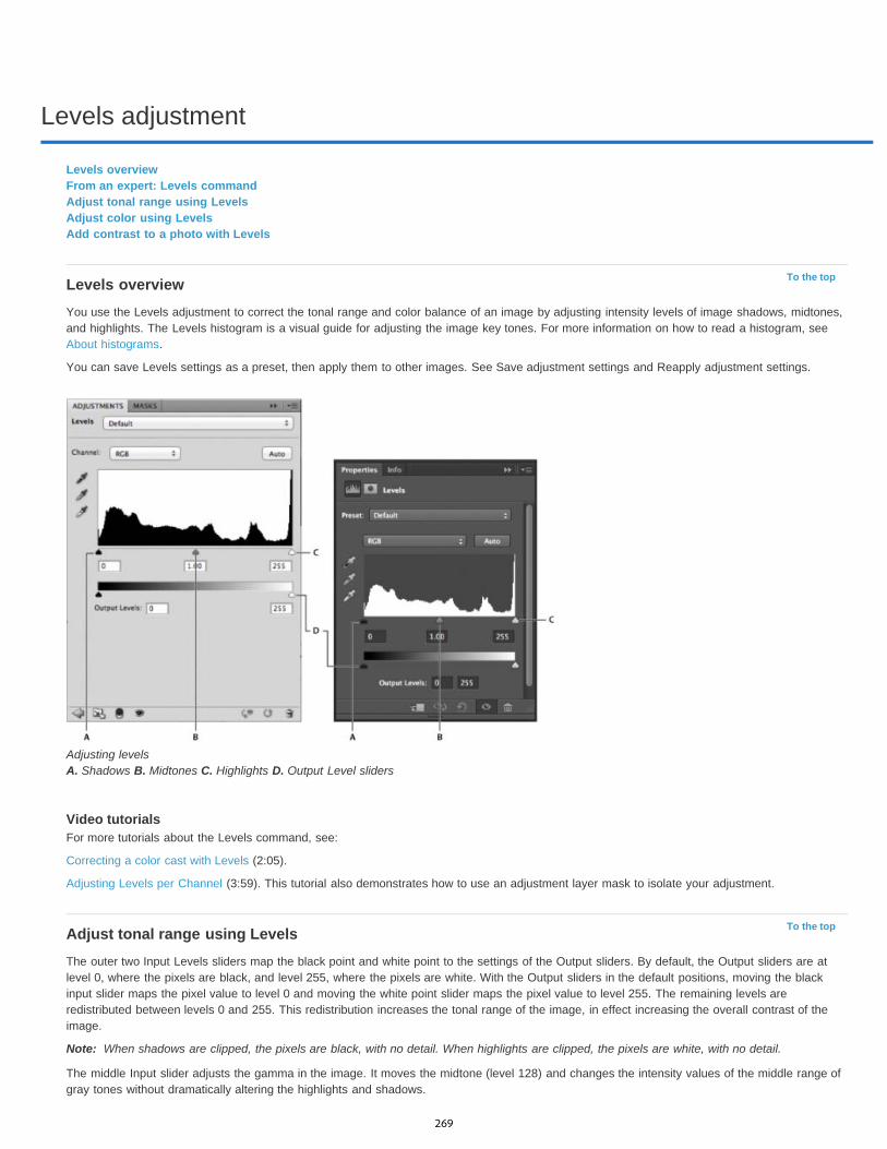
Levels adjustment
To the top
To the top
Note:
Levels overviewFrom an expert: Levels commandAdjust tonal range using LevelsAdjust color using LevelsAdd contrast to a photo with Levels
Levels overviewYou use the Levels adjustment to correct the tonal range and color balance of an image by adjusting intensity levels of image shadows, midtones,and highlights. The Levels histogram is a visual guide for adjusting the image key tones. For more information on how to read a histogram, seeAbout histograms.
You can save Levels settings as a preset, then apply them to other images. See Save adjustment settings and Reapply adjustment settings.
Adjusting levels A. Shadows B. Midtones C. Highlights D. Output Level sliders
Video tutorialsFor more tutorials about the Levels command, see:
Correcting a color cast with Levels (2:05).
Adjusting Levels per Channel (3:59). This tutorial also demonstrates how to use an adjustment layer mask to isolate your adjustment.
Adjust tonal range using LevelsThe outer two Input Levels sliders map the black point and white point to the settings of the Output sliders. By default, the Output sliders are atlevel 0, where the pixels are black, and level 255, where the pixels are white. With the Output sliders in the default positions, moving the blackinput slider maps the pixel value to level 0 and moving the white point slider maps the pixel value to level 255. The remaining levels areredistributed between levels 0 and 255. This redistribution increases the tonal range of the image, in effect increasing the overall contrast of theimage.
When shadows are clipped, the pixels are black, with no detail. When highlights are clipped, the pixels are white, with no detail.
The middle Input slider adjusts the gamma in the image. It moves the midtone (level 128) and changes the intensity values of the middle range ofgray tones without dramatically altering the highlights and shadows.
269
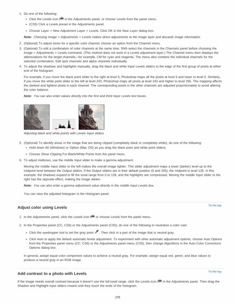
Note:
Note:
Note:
To the top
To the top
1. Do one of the following:
Click the Levels icon in the Adjustments panel, or choose Levels from the panel menu.(CS5) Click a Levels preset in the Adjustments panel.
Choose Layer > New Adjustment Layer > Levels. Click OK in the New Layer dialog box.
Choosing Image > Adjustments > Levels makes direct adjustments to the image layer and discards image information.
2. (Optional) To adjust tones for a specific color channel, choose an option from the Channel menu.3. (Optional) To edit a combination of color channels at the same time, Shift-select the channels in the Channels panel before choosing the
Image > Adjustments > Levels command. (This method does not work in a Levels adjustment layer.) The Channel menu then displays theabbreviations for the target channels—for example, CM for cyan and magenta. The menu also contains the individual channels for theselected combination. Edit spot channels and alpha channels individually.
4. To adjust the shadows and highlights manually, drag the black and white Input Levels sliders to the edge of the first group of pixels at eitherend of the histogram.
For example, if you move the black point slider to the right at level 5, Photoshop maps all the pixels at level 5 and lower to level 0. Similarly,if you move the white point slider to the left at level 243, Photoshop maps all pixels at level 243 and higher to level 255. The mapping affectsthe darkest and lightest pixels in each channel. The corresponding pixels in the other channels are adjusted proportionately to avoid alteringthe color balance.
You can also enter values directly into the first and third Input Levels text boxes.
Adjusting black and white points with Levels Input sliders
5. (Optional) To identify areas in the image that are being clipped (completely black or completely white), do one of the following:Hold down Alt (Windows) or Option (Mac OS) as you drag the black point and white point sliders.
Choose Show Clipping For Black/White Points from the panel menu.
6. To adjust midtones, use the middle Input slider to make a gamma adjustment.
Moving the middle Input slider to the left makes the overall image lighter. This slider adjustment maps a lower (darker) level up to themidpoint level between the Output sliders. If the Output sliders are in their default position (0 and 255), the midpoint is level 128. In thisexample, the shadows expand to fill the tonal range from 0 to 128, and the highlights are compressed. Moving the middle Input slider to theright has the opposite effect, making the image darker.
You can also enter a gamma adjustment value directly in the middle Input Levels box.
You can view the adjusted histogram in the Histogram panel.
Adjust color using Levels
1. In the Adjustments panel, click the Levels icon or choose Levels from the panel menu.
2. In the Properties panel (CC, CS6) or the Adjustments panel (CS5), do one of the following to neutralize a color cast:
Click the eyedropper tool to set the gray point . Then click in a part of the image that is neutral gray.
Click Auto to apply the default automatic levels adjustment. To experiment with other automatic adjustment options, choose Auto Optionsfrom the Properties panel menu (CC, CS6) or the Adjustments panel menu (CS5), then change Algorithms in the Auto Color CorrectionsOptions dialog box.
In general, assign equal color component values to achieve a neutral gray. For example, assign equal red, green, and blue values toproduce a neutral gray in an RGB image.
Add contrast to a photo with Levels
If the image needs overall contrast because it doesn’t use the full tonal range, click the Levels icon in the Adjustments panel. Then drag theShadow and Highlight input sliders inward until they touch the ends of the histogram.
270
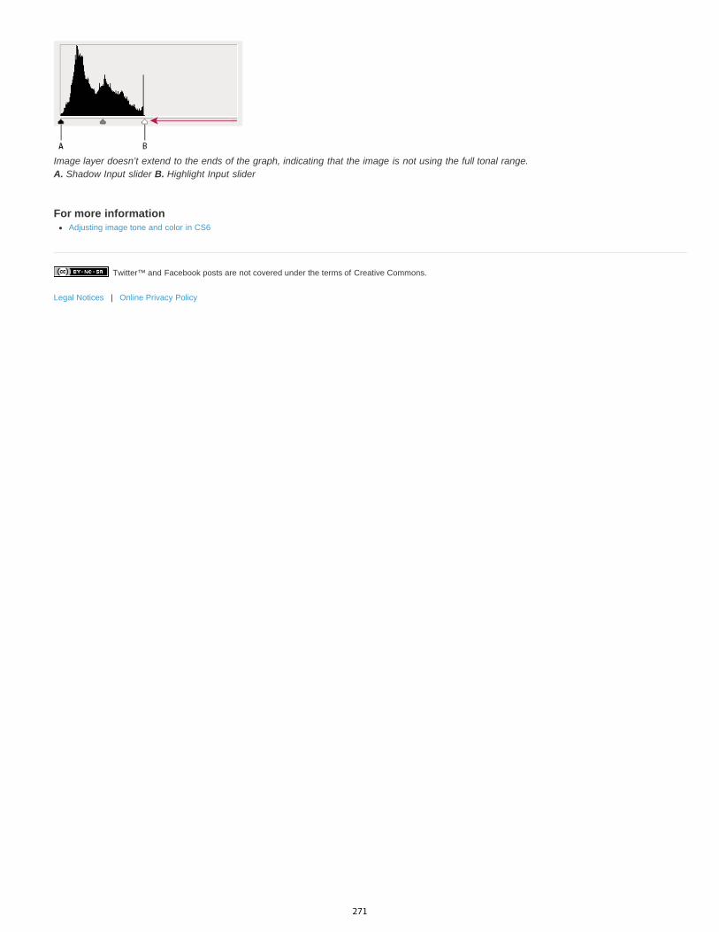
Twitter™ and Facebook posts are not covered under the terms of Creative Commons.
Legal Notices | Online Privacy Policy
Image layer doesn’t extend to the ends of the graph, indicating that the image is not using the full tonal range. A. Shadow Input slider B. Highlight Input slider
For more informationAdjusting image tone and color in CS6
271

Adjust HDR exposure and toning
Twitter™ and Facebook posts are not covered under the terms of Creative Commons.
Legal Notices | Online Privacy Policy
Note:
Note:
Exposure
Offset
Gamma
Note:
In Photoshop CS5 and Photoshop CS6, 3D functionality was part of Photoshop Extended. All features in Photoshop Extended are part ofPhotoshop CC. Photoshop CC does not have a separate Extended offering.
The Exposure and HDR Toning adjustments are primarily designed for 32-bit HDR images, but you can also apply them to 16- and 8-bit images tocreate HDR-like effects.
For a video about applying HDR effects to16- or 8-bit images, see www.adobe.com/go/lrvid5011_ps_en
Adjust HDR exposureExposure works by performing calculations in a linear color space (gamma 1.0) rather than the current color space.
1. Do one of the following:
Click the Exposure icon or an Exposure preset in the Adjustments panel.
Choose Layer > New Adjustment Layer > Exposure.
You can also choose Image > Adjustments > Exposure. But keep in mind that this method makes direct adjustments to the imagelayer and discards image information.
2. In the Adjustments panel, set any of the following options:
Adjusts the highlight end of the tonal scale with minimal effect in the extreme shadows.
With 32-bit images, you can also access the Exposure slider at the bottom of the image window.
Darkens the shadows and midtones with minimal effect on the highlights.
Adjusts the image gamma, using a simple power function. Negative values are mirrored around zero (that is, they remain negativebut still get adjusted as if they are positive).
The eyedroppers adjust the luminance values of images (unlike the Levels eyedroppers that affect all color channels).
The Set Black Point eyedropper sets the Offset, shifting the pixel you click to zero.
The Set White Point eyedropper sets the Exposure, shifting the point you click to white (1.0 for HDR images).
The Midtone eyedropper sets the Exposure, making the value you click middle gray.
Adjust HDR toningThe HDR Toning command lets you apply the full range of HDR contrast and exposure settings to individual images.
HDR toning requires flattened layers.
1. Open a 32-, 16-, or 8-bit image in RGB or Grayscale color mode.
2. Choose Image > Adjustments > HDR Toning.
For detailed information about each setting, see Options for 16- or 8-bit images. (In the HDR Toning dialog box, these options appy toimages of all bit depths.)
For more information about HDRHigh dynamic range images
272
Adjusting image color and tone
To the top
Note:
To the top
To the top
Note:
Overview of adjusting image color and toneAdjusting image color and tone with adjustment layersAdjusting image color and tone in Camera Raw
Overview of adjusting image color and toneTwo ways to adjust image tone and color are to use adjustment layers or to edit in Adobe Camera Raw. Both offer a wide range of control andflexibility, without permanently altering or damaging the original image information. The integrity of your original images is preserved. Thisnondestructive editing gives you the flexibility to make further changes, start over with a different editing approach, or undo the adjustments evenafter you've saved the edits.
With adjustment layers, you apply edits on a separate layer in the image file, leaving the original image (background layer) intact. The easiest wayto access the adjustment layer tools is clicking an icon in the Adjustments panel. You can add more than one adjustment layer for more compleximage editing. You can also use a mask to apply the adjustment to a specific part of the image. For more information, see Masking layers.
Adobe Camera Raw is a Photoshop plug-in for making color and tonal adjustments. In its editing window, there is a large preview image and theadjustment tools are laid out in the order that you would normally use them. Despite its name, Adobe Camera Raw can edit JPEGs and TIFFs inaddition to camera raw files. If you want to apply the same adjustment to multiple images, you can save the settings as a preset and apply asneeded.
Unless a specific adjustment isn't available as an adjustment layer or in Camera Raw, it is recommended that you do not use thecommands in the Image > Adjustments menu. The adjustments under the Image menu permanently alter or delete pixel information in your image.
Adjusting image color and tone with adjustment layers
1. In the Adjustments panel, click the tool icon for the adjustment you want to make:
For tonality and color, click Levels or Curves. For adjusting color, click Color Balance or Hue/Saturation.For converting a color image to black and white, click Black & White.
2. In the Properties panel, adjust the adjustment layer tool settings.
For more information on adjustment layersAdjustment and fill layers
Adjusting image color and tone in Camera Raw
1. Choose File > Open.
2. In the Open window, select one or more camera raw files, TIFFs, or JPEGs, and then choose Camera Raw from the Format menu.
3. Click Open.
4. Use the controls in Adobe Camera Raw to adjust the settings. You can use the Adjustment brush to apply edits to specific areas of theimage. For more information, see Make color and tonal adjustments in Camera Raw.
You can set preferences to always open JPEGs and TIFFs in Camera Raw.
Tip: Why You Should Set Photoshop to Open Your JPGs in Adobe Camera RAW - video tutorial by Terry White (8:07)
Enable editing of JPEGs and TIFFs in Camera Raw
1. Choose (Windows) Edit > Preferences > Camera Raw or (Mac OS) Photoshop > Preferences > Camera Raw.
2. In the JPEG and TIFF Handling section of the Camera Raw Preferences dialog box, do any of the following:
In the JPEG menu, choose Automatically Open All Supported JPEGs.
273

Twitter™ and Facebook posts are not covered under the terms of Creative Commons.
Legal Notices | Online Privacy Policy
In the TIFF menu, choose Automatically Open All Supported TIFFs from the TIFF menu.
For more information about Adobe Camera RawAdobe Camera Raw topics
Photoshop Tutorial: Open a JPEG in Camera Raw by Brodie Butler
Amazing Wonders of Adobe Camera Raw 7.0 in Photoshop CS6 by Russell Preston Brown
In addition to the two workflows described above, you can also use Smart Objects for editing layers nondestructively. Watch an Introduction tousing Smart Objects video by expert Colin Smith of the No Stupid Questions series.
274
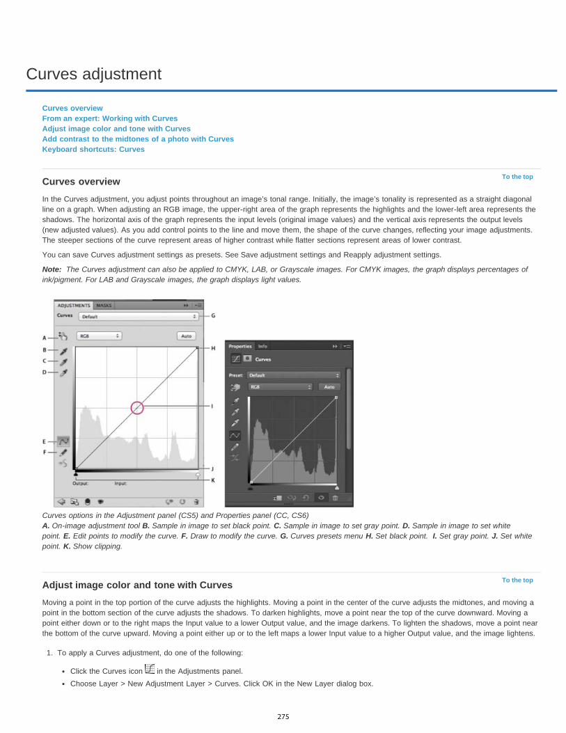
Curves adjustment
To the top
Note:
To the top
Curves overviewFrom an expert: Working with CurvesAdjust image color and tone with CurvesAdd contrast to the midtones of a photo with CurvesKeyboard shortcuts: Curves
Curves overviewIn the Curves adjustment, you adjust points throughout an image’s tonal range. Initially, the image’s tonality is represented as a straight diagonalline on a graph. When adjusting an RGB image, the upper-right area of the graph represents the highlights and the lower-left area represents theshadows. The horizontal axis of the graph represents the input levels (original image values) and the vertical axis represents the output levels(new adjusted values). As you add control points to the line and move them, the shape of the curve changes, reflecting your image adjustments.The steeper sections of the curve represent areas of higher contrast while flatter sections represent areas of lower contrast.
You can save Curves adjustment settings as presets. See Save adjustment settings and Reapply adjustment settings.
The Curves adjustment can also be applied to CMYK, LAB, or Grayscale images. For CMYK images, the graph displays percentages ofink/pigment. For LAB and Grayscale images, the graph displays light values.
Curves options in the Adjustment panel (CS5) and Properties panel (CC, CS6) A. On-image adjustment tool B. Sample in image to set black point. C. Sample in image to set gray point. D. Sample in image to set whitepoint. E. Edit points to modify the curve. F. Draw to modify the curve. G. Curves presets menu H. Set black point. I. Set gray point. J. Set whitepoint. K. Show clipping.
Adjust image color and tone with CurvesMoving a point in the top portion of the curve adjusts the highlights. Moving a point in the center of the curve adjusts the midtones, and moving apoint in the bottom section of the curve adjusts the shadows. To darken highlights, move a point near the top of the curve downward. Moving apoint either down or to the right maps the Input value to a lower Output value, and the image darkens. To lighten the shadows, move a point nearthe bottom of the curve upward. Moving a point either up or to the left maps a lower Input value to a higher Output value, and the image lightens.
1. To apply a Curves adjustment, do one of the following:
Click the Curves icon in the Adjustments panel.Choose Layer > New Adjustment Layer > Curves. Click OK in the New Layer dialog box.
275
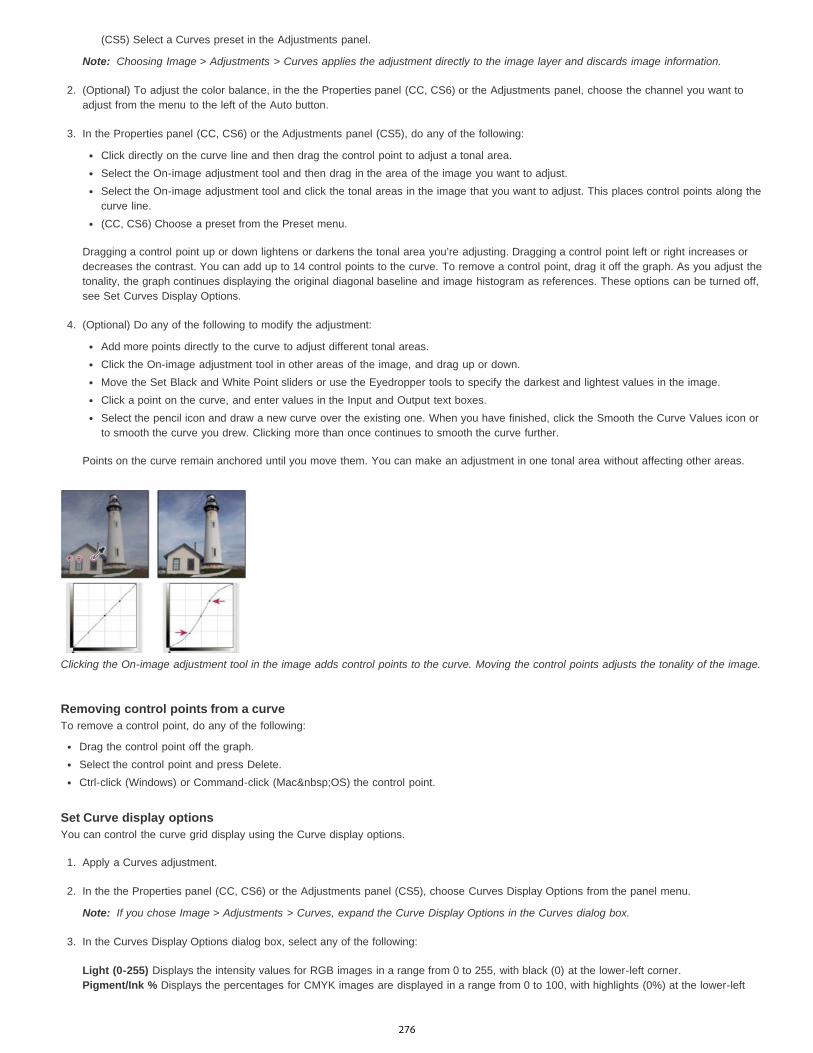
Note:
Note:
(CS5) Select a Curves preset in the Adjustments panel.
Choosing Image > Adjustments > Curves applies the adjustment directly to the image layer and discards image information.
2. (Optional) To adjust the color balance, in the the Properties panel (CC, CS6) or the Adjustments panel, choose the channel you want toadjust from the menu to the left of the Auto button.
3. In the Properties panel (CC, CS6) or the Adjustments panel (CS5), do any of the following:
Click directly on the curve line and then drag the control point to adjust a tonal area.Select the On-image adjustment tool and then drag in the area of the image you want to adjust.Select the On-image adjustment tool and click the tonal areas in the image that you want to adjust. This places control points along thecurve line.(CC, CS6) Choose a preset from the Preset menu.
Dragging a control point up or down lightens or darkens the tonal area you’re adjusting. Dragging a control point left or right increases ordecreases the contrast. You can add up to 14 control points to the curve. To remove a control point, drag it off the graph. As you adjust thetonality, the graph continues displaying the original diagonal baseline and image histogram as references. These options can be turned off,see Set Curves Display Options.
4. (Optional) Do any of the following to modify the adjustment:
Add more points directly to the curve to adjust different tonal areas.Click the On-image adjustment tool in other areas of the image, and drag up or down.Move the Set Black and White Point sliders or use the Eyedropper tools to specify the darkest and lightest values in the image.Click a point on the curve, and enter values in the Input and Output text boxes.Select the pencil icon and draw a new curve over the existing one. When you have finished, click the Smooth the Curve Values icon orto smooth the curve you drew. Clicking more than once continues to smooth the curve further.
Points on the curve remain anchored until you move them. You can make an adjustment in one tonal area without affecting other areas.
Clicking the On-image adjustment tool in the image adds control points to the curve. Moving the control points adjusts the tonality of the image.
Removing control points from a curveTo remove a control point, do any of the following:
Drag the control point off the graph.Select the control point and press Delete.Ctrl-click (Windows) or Command-click (Mac OS) the control point.
Set Curve display optionsYou can control the curve grid display using the Curve display options.
1. Apply a Curves adjustment.
2. In the the Properties panel (CC, CS6) or the Adjustments panel (CS5), choose Curves Display Options from the panel menu.
If you chose Image > Adjustments > Curves, expand the Curve Display Options in the Curves dialog box.
3. In the Curves Display Options dialog box, select any of the following:
Light (0-255) Displays the intensity values for RGB images in a range from 0 to 255, with black (0) at the lower-left corner.Pigment/Ink % Displays the percentages for CMYK images are displayed in a range from 0 to 100, with highlights (0%) at the lower-left
276
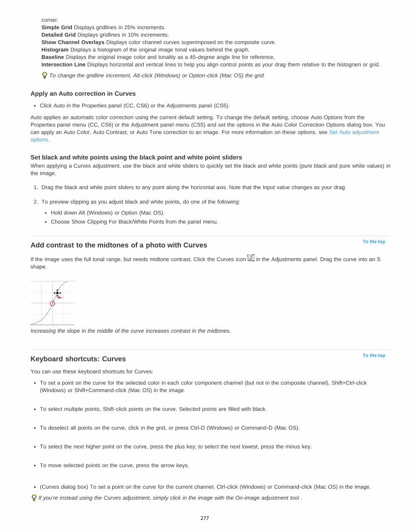
To the top
To the top
corner.Simple Grid Displays gridlines in 25% increments.Detailed Grid Displays gridlines in 10% increments.Show Channel Overlays Displays color channel curves superimposed on the composite curve.Histogram Displays a histogram of the original image tonal values behind the graph.Baseline Displays the original image color and tonality as a 45-degree angle line for reference,Intersection Line Displays horizontal and vertical lines to help you align control points as your drag them relative to the histogram or grid.
To change the gridline increment, Alt-click (Windows) or Option-click (Mac OS) the grid.
Apply an Auto correction in Curves
Click Auto in the Properties panel (CC, CS6) or the Adjustments panel (CS5).
Auto applies an automatic color correction using the current default setting. To change the default setting, choose Auto Options from theProperties panel menu (CC, CS6) or the Adjustment panel menu (CS5) and set the options in the Auto Color Correction Options dialog box. Youcan apply an Auto Color, Auto Contrast, or Auto Tone correction to an image. For more information on these options, see Set Auto adjustmentoptions.
Set black and white points using the black point and white point slidersWhen applying a Curves adjustment, use the black and white sliders to quickly set the black and white points (pure black and pure white values) inthe image.
1. Drag the black and white point sliders to any point along the horizontal axis. Note that the Input value changes as your drag.
2. To preview clipping as you adjust black and white points, do one of the following:
Hold down Alt (Windows) or Option (Mac OS).Choose Show Clipping For Black/White Points from the panel menu.
Add contrast to the midtones of a photo with Curves
If the image uses the full tonal range, but needs midtone contrast, Click the Curves icon in the Adjustments panel. Drag the curve into an Sshape.
Increasing the slope in the middle of the curve increases contrast in the midtones.
Keyboard shortcuts: CurvesYou can use these keyboard shortcuts for Curves:
To set a point on the curve for the selected color in each color component channel (but not in the composite channel), Shift+Ctrl-click(Windows) or Shift+Command-click (Mac OS) in the image.
To select multiple points, Shift-click points on the curve. Selected points are filled with black.
To deselect all points on the curve, click in the grid, or press Ctrl-D (Windows) or Command-D (Mac OS).
To select the next higher point on the curve, press the plus key; to select the next lowest, press the minus key.
To move selected points on the curve, press the arrow keys.
(Curves dialog box) To set a point on the curve for the current channel, Ctrl-click (Windows) or Command-click (Mac OS) in the image.
If you’re instead using the Curves adjustment, simply click in the image with the On-image adjustment tool .
277

Twitter™ and Facebook posts are not covered under the terms of Creative Commons.
Legal Notices | Online Privacy Policy
For more informationAdjusting image color and tone
278

Adjusting hue and saturation
To the top
Note:
Apply a Hue/Saturation adjustmentAdjust color saturation using VibranceAdjust color saturation in image areas
Hue/Saturation lets you adjust the hue, saturation, and lightness of a specific range of colors in an image or simultaneously adjust all the colors inan image. This adjustment is especially good for fine-tuning colors in a CMYK image so that they are in the gamut of an output device.
You can save Hue/Saturation settings in the Adjustments panel (CS5) or the Properties panel (CS6), and then load them for reuse in otherimages. For more information, see Save adjustment settings and Reapply adjustment settings.
For more information on image adjustments, see Adjusting image color and tone in CS6.
Apply a Hue/Saturation adjustment1. Do one of the following:
Click the Hue/Saturation icon in the Adjustments panel.(CS5) Click a Hue/Saturation preset in the Adjustments panel.
Choose Layer > New Adjustment Layer > Hue/Saturation. Click OK in the New Layer dialog box.
The two color bars in the dialog box represent the colors in their order on the color wheel. The upper color bar shows the color before theadjustment; the lower bar shows how the adjustment affects all of the hues at full saturation.
You can also choose Image > Adjustments > Hue/Saturation. But keep in mind that this method makes direct adjustments to theimage layer and discards image information.
2. In the Adjustments panel (CS5) or the Properties panel (CS6), choose from the menu to the right of the On-image adjustment tool :
Choose Master to adjust all colors at once.
Choose one of the other preset color ranges listed for the color you want to adjust. To modify the color range, see Specify the range ofcolors adjusted using Hue/Saturation.(CS6) Choose a Hue/Saturation preset from the Preset menu.
3. For Hue, enter a value or drag the slider until you are satisfied with the colors.
The values displayed in the box reflect the number of degrees of rotation around the wheel from the original color of the pixel. A positivevalue indicates clockwise rotation; a negative value, counterclockwise rotation. Values can range from -180 to +180.
Color wheel A. Saturation B. Hue
You can also select the On-image adjustment tool in the Adjustments panel (CS5) or the Properties panel (CS6), and then Ctrl-click(Windows) or Command-click (Mac OS) a color in the image. Drag left or right in the image to modify the hue value.
4. For Saturation, enter a value or drag the slider to the right to increase the saturation or to the left to decrease it.
The color shifts away from or toward the center of the color wheel. Values can range from -100 (percentage of desaturation, duller colors) to+100 (percentage of saturation increase).
You can also , select the On-image adjustment tool in the Adjustments panel (CS5) or the Properties panel (CS6), and click a color in theimage. Drag left or right in the image to decrease or increase saturation of the color range that includes the pixel you clicked.
5. For Lightness, enter a value or drag the slider to the right to increase the lightness (add white to a color) or to the left to decrease it (add
279

Note:
black to a color). Values can range from -100 (percentage of black) to +100 (percentage of white).
Click the Reset button to undo a Hue/Saturation setting in the Adjustments panel (CS5) or the Properties panel (CS6).
Specify the range of colors adjusted using Hue/Saturation
1. Apply a Hue/Saturation adjustment.
2. In the Adjustments panel (CS5) or the Properties panel (CS6), choose a color from the menu to the right of the On-image adjustment button
.
Four color wheel values (in degrees) appear in the Adjustments panel (CS5) or the Properties panel (CS6). They correspond to theadjustment sliders that appear between the color bars. The two inner vertical sliders define the color range. The two outer triangle slidersshow where the adjustments on a color range “fall off” (fall-off is a feathering or tapering of the adjustments instead of a sharply definedon/off application of the adjustments).
3. Use either the eyedropper tools or the adjustment sliders to modify the range of colors.
Click or drag in the image with the Eyedropper tool to select a color range. To expand the range, click or drag in the image with theAdd To Sample Eyedropper tool . To reduce the range of color, click or drag in the image with the Subtract From Sample Eyedroppertool . While an eyedropper tool is selected, you can also press Shift to add to the range, or Alt (Windows) or Option (Mac OS) tosubtract from it.
Drag one of the white triangle sliders to adjust the amount of color fall-off (feathering of adjustment) without affecting the range.
Drag the area between the triangle and the vertical bar to adjust the range without affecting the amount of fall-off.
Drag the center area to move the entire adjustment slider (which includes the triangles and vertical bars) to select a different color area.
Drag one of the vertical white bars to adjust the range of the color component. Moving a vertical bar from the center of the adjustmentslider and closer to a triangle increases the color range and decreases the fall-off. Moving a vertical bar closer to the center of theadjustment slider and away from a triangle decreases the color range and increases the fall-off.
Ctrl-drag (Windows) or Command-drag (Mac OS) the color bar so that a different color is in the center of the bar.
Hue/Saturation adjustment slider A. Hue slider values B. Adjusts fall-off without affecting range C. Adjusts range without affecting fall-off D. Adjusts range of color andfall-off E. Moves entire slider
If you modify the adjustment slider so that it falls into a different color range, the name in the Edit menu changes to reflect this change. Forexample, if you choose Yellow and alter its range so that it falls in the red part of the color bar, the name changes to Red 2. You can convertup to six of the individual color ranges to varieties of the same color range (for example, Red through Red 6).
By default, the range of color selected when you choose a color component is 30° wide, with 30° of fall-off on either side. Setting the fall-offtoo low can produce banding in the image.
Colorize a grayscale image or create a monotone effect
1. (Optional) If you are colorizing a grayscale image, choose Image > Mode > RGB Color to convert the image to RGB.
2. Apply a Hue/Saturation adjustment.
3. In the Adjustments panel (CS5) or the Properties panel (CS6), select the Colorize option. If the foreground color is black or white, the imageis converted to a red hue (0°). If the foreground color is not black or white, the image is converted to the hue of the current foreground color.The lightness value of each pixel does not change.
4. (Optional) Use the Hue slider to select a new color. Use the Saturation and Lightness sliders to adjust the saturation and lightness of thepixels.
280
Twitter™ and Facebook posts are not covered under the terms of Creative Commons.
Legal Notices | Online Privacy Policy
To the top
Note:
To the top
Saturate
Desaturate
Adjust color saturation using VibranceVibrance adjusts the saturation so that clipping is minimized as colors approach full saturation. This adjustment increases the saturation of less-saturated colors more than the colors that are already saturated. Vibrance also prevents skintones from becoming over saturated.
1. Do one of the following:
In the Adjustments panel, click the Vibrance icon .
Choose Layer > New Adjustment Layer > Vibrance. In the New Layer dialog box, type a name for the Vibrance adjustment layer andclick OK.
You can also choose Image > Adjustments > Vibrance. But keep in mind that this method makes direct adjustments to the imagelayer and discards image information.
2. In the Adjustments panel (CS5) or the Properties panel (CS6), drag the Vibrance slider to increase or decrease color saturation withoutclipping when colors become more saturated. Then, do one of the following:
To apply more adjustment to less saturated colors and prevent colors clipping as they reach total saturation, move the Vibrance slider tothe right.
To apply the same amount of saturation adjustment to all colors regardless of their current saturation, move the Saturation slider. Insome situations, this may produce less banding than the Saturation slider in the Hue/Saturation Adjustments panel or Hue/Saturationdialog box.
To decrease saturation, move either the Vibrance or the Saturation slider to the left.
Adjust color saturation in image areasThe Sponge tool subtly changes the color saturation of an area. When an image is in Grayscale mode, the tool increases or decreases contrast bymoving gray levels away from or toward the middle gray.
1. Select the Sponge tool .2. Choose a brush tip and set brush options in the options bar.3. In the options bar, choose the way you want to change the color from the Mode menu:
Intensifies the color’s saturation
Dilutes the color’s saturation
4. Specify the flow for the Sponge tool.5. Select the Vibrance option to minimize clipping for fully saturated or desaturated colors.6. Drag over the part of the image you want to modify.
For more informationApplying the Color Balance adjustment
281

Convert a color image to black and white
Twitter™ and Facebook posts are not covered under the terms of Creative Commons.
Legal Notices | Online Privacy Policy
Note:
Preset menu
Auto
Color Sliders
Preview
The Black & White adjustment lets you convert a color image to grayscale while maintaining full control over how individual colors are converted.You can also tint the grayscale by applying a color tone to the image, for example to create a sepia effect.
1. Do one of the following:Click the Black & White icon (CS5) or (CS6) in the Adjustments panel.(CS5) Click a Black & White preset in the Adjustments panel.
Choose Layer > New Adjustment Layer > Black & White. In the New Layer dialog box, type a name for the adjustment layer and thenclick OK.
Photoshop applies a default grayscale conversion.
You can also choose Image > Adjustments > Black & White. But keep in mind that this method makes direct adjustments to theimage layer and discards image information.
2. (Optional) In CS6, choose a Black & White preset from the Preset menu in the Properties panel.
3. In the Adjustments panel (CS5) or the Properties panel (CS6), manually adjust the conversion using the color sliders, apply an Autoconversion, or select a previously saved custom mix.
Select a predefined grayscale mix or a previously saved mix. To save a mix, choose Save Black & White Preset from thepanel menu.
Sets a grayscale mix based on the color values of the images, maximizing the distribution of gray values. The Auto mix oftenproduces excellent results, or can be used as the starting point for tweaking gray values using the color sliders.
Adjust the gray tones of specific colors in an image. Drag a slider left to darken or right to lighten the gray tones of animage’s original color.
To adjust a particular color component, select the On-image adjustment tool and then click in the image. Drag left or right to modifythe color slider for the predominant color at that location, making it darker or brighter in the image.
Click the Reset button to reset all color sliders to the default grayscale conversion.
Deselect to view the image in its original color mode.
4. To apply a color tone, select Tint. To fine-tune the tint color, click the color swatch to open the Color Picker.
For more informationAdjusting image color and tone in CS6
282

Adjust shadow and highlight detail
To the top
Note:
Note:
Note:
Amount
Note:
Tonal Width
Improve shadow and highlight detailThe Shadow/Highlight command is one method for correcting photos with silhouetted images due to strong backlighting or correcting subjects thathave been slightly washed out because they were too close to the camera flash. The adjustment can also be used for brightening areas of shadowin an otherwise well-lit image. The Shadow/Highlight command does not simply lighten or darken an image; it lightens or darkens based on thesurrounding pixels (local neighborhood) in the shadows or highlights. For this reason, there are separate controls of the shadows and thehighlights. The defaults are set to fix images with backlighting problems.
The Shadow/Highlight command also has a Midtone Contrast slider, Black Clip option, and White Clip option for adjusting the overall contrast ofthe image, and a Color Correction slider for adjusting saturation.
Keep in mind that the Shadow/Highlight command applies adjustments directly to the image and will discard image information. Fornondestructive image editing, it is recommended that you use adjustment layers or Camera Raw. See Adjustment and fill layers and Introductionto Camera Raw.
Original image, and Shadow/Highlight Correction applied
Adjust image shadows and highlights1. Choose Image > Adjustments > Shadow/Highlight.
Make sure that the Preview option is selected in the dialog box if you want the image to be updated as you make adjustments.
2. Adjust the amount of lighting correction by moving the Amount slider or entering a value in the Shadows or Highlights percentage box.Larger values provide either greater lightening of shadows or greater darkening of highlights. You can adjust both Shadows and Highlights inan image.
3. For finer control, select Show More Options to make the additional adjustments.
To increase shadow detail in an otherwise well-exposed image, try values in the 0-25% range for Shadows Amount and ShadowsTonal Width.
4. (Optional) Click the Save As Defaults button to save your current settings and make them the default settings for the Shadow/Highlightscommand. To restore the original default settings, hold down the Shift key while clicking the Save As Defaults button.
You can reuse Shadow/Highlight settings by clicking the Save button to save the current settings to a file and later using the Loadbutton to reload them. For more information on saving and loading settings, see Save adjustment settings.
5. Click OK.
Shadow/Highlight command optionsControls (separately for the highlight and shadow values in the image) how much of a correction to make.
Extreme Amount values may lead to a crossover, where what started as a highlight becomes darker than something that started as ashadow; this can make the adjusted images look ‘unnatural’.
Controls the range of tones in the shadows or highlights that are modified. Smaller values restrict the adjustments to the darkerregions for shadow correction and the lighter regions for highlight correction. Larger values increase the range of tones that are adjusted furtherinto the midtones. For example, at 100% the shadow tonal width slider affects the shadows the most, the midtones are partially affected, but thebrightest highlights are not affected. Tonal width varies from image to image. Too large a value may introduce halos around dark or light edges.The default settings attempt to reduce these artifacts. Halos may also occur when the Shadow or Highlight Amount values are too large.
Tonal Width is set to 50% by default. If you find that you are trying to lighten a dark subject but the midtones or lighter regions are changing toomuch, try reducing Shadow Tone Width toward zero so that only the darkest regions are lightened. If, however, you want to brighten themidtones as well as the shadows, increase Shadows Tonal Width toward 100%
283

Twitter™ and Facebook posts are not covered under the terms of Creative Commons.
Legal Notices | Online Privacy Policy
Radius
Brightness
Midtone Contrast
Black Clip And White Clip
Controls the size of the local neighborhood around each pixel. Neighboring pixels are used to determine whether a pixel is in the shadowsor highlights. Moving the slider to the left specifies a smaller area, and moving it to the right specifies a larger area. The optimum localneighborhood size depends on the image. It’s best to experiment with the adjustment. If the radius is too large, the adjustment tends to brighten(or darken) the whole image rather than brightening the subject only. It’s best to set the radius to roughly the size of the subjects of interest in theimage. Experiment with different Radius settings to obtain the best balance between subject contrast and differential brightening (or darkening) ofthe subject compared to the background.
Adjusts the brightness in a grayscale image. This adjustment is available only for grayscale images. Moving the Brightness slider tothe left darkens a grayscale image, and moving the slider to the right lightens a grayscale image.
Adjusts the contrast in the midtones. Move the slider to the left to reduce the contrast and to the right to increase the contrast.You can also enter a value in the Midtone Contrast box. A negative value reduces contrast, and a positive value increases contrast. Increasingmidtone contrast produces greater contrast in the midtones while tending to darken the shadows and lighten the highlights.
Specifies how greatly the shadows and highlights are clipped to the new extreme shadow (level 0) and highlight(level 255) colors in the image. Larger values produce an image with greater contrast. Be careful not to make the clipping values too large,because doing so reduces detail in the shadows or highlights (the intensity values are clipped and rendered as pure black or pure white).
For more information
284
Adjust color and tone with Levels and Curves eyedroppers
To the top
To the top
Note:
Set black and white points using the Eyedropper toolsColor correct using the eyedroppers
Set black and white points using the Eyedropper toolsKeep in mind that using the eyedroppers undoes any previous adjustment you made in Levels or Curves. If you plan to use the eyedroppers, it’sbest to use them first and then fine-tune your adjustments with the Levels sliders or Curves points.
1. Apply a Curves or Levels adjustment.
2. In the Adjustments panel (CS5) or Properties panel (CS6), do any of the following:
Double-click the Set Black Point eyedropper tool to set the black point.Double-click the Set White Point eyedropper tool to set the white point.
3. In the Adobe Color Picker, determine the values you want for the darkest and lightest tones in the image:
To set the black point value to pure black, type 0 for R, G, and B.To set the white point value to pure white, type 255 for R, G, and B.To specify a shade of gray for either the black or white point, type identical values (between 0 and 255) for R, G, and B . The lower thevalues, the darker the gray. The higher the values, the lighter the gray.
4. Do one of the following to adjust the tonal areas to the black or white points you specified in Step 2:
With the Set Black Point eyedropper, click an image area that represents the black point (area with the lowest tonal values).With the Set White Point eyedropper, click an image area that represents the white point (area with the lightest tonal values).
Color correct using the eyedroppersYou can use the eyedroppers in the Levels or Curves adjustment to correct a color cast such as an unwanted tint from an excess of color (red,green, blue, or cyan, magenta, yellow). It’s easier to color-balance an image by first identifying an area that you want to be neutral and thenremoving the color cast from that area. Depending on the image, you can use one or all three of the eyedroppers. The Set Gray Point eyedropperworks best on images that don’t require large adjustments and have easily identified neutrals.
Keep in mind that using the eyedroppers undoes any previous adjustment you made in Levels or Curves. If you plan to use the eyedroppers, it’sbest to use them first and then fine-tune your adjustments with the Levels sliders or Curves points.
The eyedropper tool that sets the gray point is used primarily for color correction and is unavailable when you work with grayscaleimages.
1. Before applying an adjustment, identify an area in the image that you want to be neutral gray. For example, a paved road.
Use a color sampler to mark a neutral area so that you can click it with an eyedropper later.
2. Click the Levels or Curves icon in the Adjustments panel.
3. In the Adjustments panel (CS5) or the Properties panel (CS6), double-click the Set Gray Point tool .
4. In the Adobe Color Picker, verify that the currently selected color has identical R, G, and B values for a neutral gray (for example,128,128,128). If necessary, type the identical values for R, G, and B. Photoshop asks whether you want to save the new target color as adefault.
5. With the Set Gray Point eyedropper tool, click the neutral area that you identified in Step 1. This should reset midtones and remove the colorcast from the image.
6. (Optional) Make final Levels or Curves adjustments in the Adjustments panel (CS5) or Properties panel (CS6).
For more informationAdjusting image color and tone in CS6
285
Quickly adjust black and white points
To the top
Adjust black and white points with the Auto option
Adjust black and white points with the Auto optionThe Auto option for Levels and Curves and the Auto Tone command automatically adjust the black point and white point in an image. This clips aportion of the shadows and highlights in each channel and maps the lightest and darkest pixels in each color channel to pure white (level 255) andpure black (level 0). The intermediate pixel values are redistributed proportionately. As a result, using the Auto option or Auto Tone increases thecontrast in an image because the pixel values are expanded. Because the Auto option and Auto Tone adjust each color channel individually, itmay remove color or introduce color casts.
The Auto option and Auto Tone give good results in certain images with an average distribution of pixel values that need a simple increase incontrast.
By default, the Auto option and the Auto Tone command clip the white and black pixels by 0.1%—that is, it ignores the first 0.1% of either extremewhen identifying the lightest and darkest pixels in the image. The default settings for the Auto option can be changed in the Auto Color CorrectionOptions dialog box.
1. Do one of the following:
Click the Levels or Curves icon in the Adjustments panel.
Choose Layer > New Adjustment Layer and choose either Levels or Curves. Click OK in the New Layer dialog box.
Note: You can choose Image > Auto Tone to apply the adjustment directly to the image layer. Keep in mind that this method discardsimage information and is automatic. You cannot adjust any of the options in the following steps.
2. In the Adjustments panel, Alt-click (Windows) or Option-click (Mac OS) the Auto button.3. Under Algorithms in the Auto Color Correction Options dialog box, select Enhance Per Channel Contrast.4. Adjust the amount of shadow and highlight values that are clipped, and adjust the target color for the midtones.5. Click OK to apply the Auto option settings.
Legal Notices | Online Privacy Policy
286
Applying the Color Balance adjustment
To the top
To the top
Apply the Color Balance adjustmentChange the color balance using the Photo Filter command
Apply the Color Balance adjustmentThe Color Balance command changes the overall mixture of colors in an image for generalized color correction.
1. Make sure that the composite channel is selected in the Channels panel. This command is available only when you’re viewing thecomposite channel.
2. Do one of the following:
Click the Color Balance icon in the Adjustments panel.
Choose Layer > New Adjustment Layer > Color Balance. Click OK in the New Layer dialog box.
Note: You can also choose Image > Adjustments > Color Balance. But keep in mind that this method makes direct adjustments to theimage layer and discards image information.
3. In the Properties panel (CC, CS6) or Adjustments panel (CS5), select Shadows, Midtones, or Highlights to select the tonal range in whichyou want to focus the changes.
4. (Optional) Select Preserve Luminosity to prevent changing the luminosity values in the image while changing the color. This option maintainsthe tonal balance in the image.
5. Drag a slider toward a color that you want to increase in the image; drag a slider away from a color that you want to decrease in the image.
The values above the color bars show the color changes for the red, green, and blue channels. (For Lab images, the values are for the Aand B channels.) Values can range from -100 to +100.
Change the color balance using the Photo Filter commandThe Photo Filter adjustment mimics the technique of placing a colored filter in front of the camera lens to adjust the color balance and colortemperature of the light transmitted through the lens and exposing the film. Photo Filter also lets you choose a color preset to apply a hueadjustment to an image. If you want to apply a custom color adjustment, the Photo Filter adjustment lets you specify a color using the Adobe ColorPicker.
1. Do one of the following:
Click the Photo Filter icon (CS5) or (CC, CS6) in the Adjustments panel.
Choose Layer > New Adjustment Layer > Photo Filter. Click OK in the New Layer dialog box.
Note: You can also choose Image > Adjustments > Photo Filter. But keep in mind that this method makes direct adjustments to the imagelayer and discards image information.
2. In the Properties panel (CC, CS6) or Adjustments panel (CS5), choose the filter color, either a custom filter or a preset. For a custom filter,select the Color option, click the color square, and use the Adobe Color Picker to specify a color for a custom color filter. For a preset filter,select the Filter option and choose one of the following presets from the Filter menu:Warming Filter (85 and LBA) and Cooling Filter (80 and LBB) Color conversion filters that tune the white balance in an image. If animage was photographed with a lower color temperature of light (yellowish), the Cooling Filter (80) makes the image colors bluer tocompensate for the lower color temperature of the ambient light. Conversely, if the photo was taken with a higher color temperature of light(bluish), the Warming Filter (85) makes the image colors warmer to compensate for the higher color temperature of the ambient light.
Warming Filter (81) and Cooling Filter (82) Use light-balancing filters for minor adjustments in the color quality of an image. The WarmingFilter (81) makes the image warmer (more yellow), and the Cooling Filter (82) makes the image cooler (bluer).
Individual Colors Apply a hue adjustment to the image depending on the color preset you choose. Your choice of color depends on howyou’re using the Photo Filter adjustment. If your photo has a color cast, you can choose a complementary color to neutralize the color cast.You can also apply colors for special color effects or enhancements. For example, the Underwater color simulates the greenish blue colorcast in underwater photos.
Make sure that Preview is selected to view the results of using a color filter. If you don’t want the image darkened by adding the color filter,be sure that the Preserve Luminosity option is selected.
3. To adjust the amount of color applied to the image, use the Density slider or enter a percentage in the Density box. A higher density resultsin a stronger color adjustment.
287

More Help topicsAdjusting image color and tone
Legal Notices | Online Privacy Policy
288
Apply a Brightness/Contrast adjustment
To the top
Apply the Brightness/Contrast adjustment
Apply the Brightness/Contrast adjustmentThe Brightness/Contrast adjustment lets you make simple adjustments to the tonal range of an image. Moving the brightness slider to the rightincreases tonal values and expands image highlights, to the left decreases values and expands shadows. The contrast slider expands or shrinksthe overall range of tonal values in the image.
In normal mode, Brightness/Contrast applies proportionate (nonlinear) adjustments to image layer, as with Levels and Curves adjustments. WhenUse Legacy is selected, Brightness/Contrast simply shifts all pixel values higher or lower when adjusting brightness. Since this can cause clippingor loss of image detail in highlight or shadow areas, using Brightness/Contrast in Legacy mode is not recommended for photographic images (butcan be useful for editing masks or scientific imagery).
Note: Use Legacy is automatically selected when editing Brightness/Contrast adjustment layers created with previous versions of Photoshop.1. Do one of the following:
Click the Brightness/Contrast icon in the Adjustments panel.
Choose Layer > New Adjustment Layer > Brightness/Contrast. Click OK in the New Layer dialog box.
Note: You can also choose Image > Adjustments > Brightness/Contrast. But keep in mind that this method makes direct adjustments to theimage layer and discards image information.
2. In the Properties panel (CC, CS6) or Adjustments panel (CS5), drag the sliders to adjust the brightness and contrast.
Dragging to the left decreases the level, and dragging to the right increases it. The number at the right of each slider reflects the brightnessor contrast value. Values can range from -150 to +150 for Brightness, -50 to +100 for Contrast.
More Help topicsAdjusting image color and tone
Legal Notices | Online Privacy Policy
289
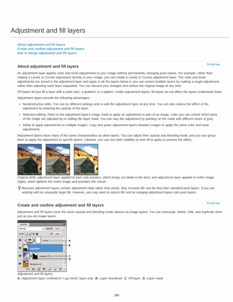
Adjustment and fill layers
To the top
To the top
About adjustment and fill layersCreate and confine adjustment and fill layersEdit or merge adjustment and fill layers
About adjustment and fill layersAn adjustment layer applies color and tonal adjustments to your image without permanently changing pixel values. For example, rather thanmaking a Levels or Curves adjustment directly to your image, you can create a Levels or Curves adjustment layer. The color and tonaladjustments are stored in the adjustment layer and apply to all the layers below it; you can correct multiple layers by making a single adjustment,rather than adjusting each layer separately. You can discard your changes and restore the original image at any time.
Fill layers let you fill a layer with a solid color, a gradient, or a pattern. Unlike adjustment layers, fill layers do not affect the layers underneath them.
Adjustment layers provide the following advantages:
Nondestructive edits. You can try different settings and re-edit the adjustment layer at any time. You can also reduce the effect of theadjustment by lowering the opacity of the layer.
Selective editing. Paint on the adjustment layer’s image mask to apply an adjustment to part of an image. Later you can control which partsof the image are adjusted by re-editing the layer mask. You can vary the adjustment by painting on the mask with different tones of gray.
Ability to apply adjustments to multiple images. Copy and paste adjustment layers between images to apply the same color and tonaladjustments.
Adjustment layers have many of the same characteristics as other layers. You can adjust their opacity and blending mode, and you can groupthem to apply the adjustment to specific layers. Likewise, you can turn their visibility on and off to apply or preview the effect.
Original (left); adjustment layer applied to barn only (center), which brings out detail in the barn; and adjustment layer applied to entire image(right), which lightens the entire image and pixelates the clouds
Because adjustment layers contain adjustment data rather than pixels, they increase file size far less than standard pixel layers. If you areworking with an unusually large file, however, you may want to reduce file size by merging adjustment layers into pixel layers.
Create and confine adjustment and fill layersAdjustment and fill layers have the same opacity and blending mode options as image layers. You can rearrange, delete, hide, and duplicate themjust as you do image layers.
Adjustment and fill layersA. Adjustment layer confined to “Log home” layer only B. Layer thumbnail C. Fill layer D. Layer mask
290
Create an adjustment layer Do one of the following:
Click the New Adjustment Layer button at the bottom of the Layers panel, and choose an adjustment layer type.
Choose Layer > New Adjustment Layer, and choose an option. Name the layer, set layer options, and click OK.
(Photoshop CS5) Click an adjustment icon or select an adjustment preset in the Adjustments panel.
To confine the effects of an adjustment layer to specific image layers, select the image layers, choose Layer > New > Group From Layers, andchange the Mode from Pass Through to any other blending mode. Then place the adjustment layer at the top of the layer group.
Create a fill layer Do one of the following:
Choose Layer > New Fill Layer, and choose an option. Name the layer, set layer options, and click OK.
Click the New Adjustment Layer button at the bottom of the Layers panel, and choose a fill layer type.Solid Color Fills the adjustment layer with the current foreground color. Use the Color Picker to select a different a fill color.
Gradient Click the gradient to display the Gradient Editor, or click the inverted arrow and choose a gradient from the pop-up panel. Setadditional options if desired. Style specifies the shape of the gradient. Angle specifies the angle at which the gradient is applied. Scalechanges the size of the gradient. Reverse flips the orientation of the gradient. Dither reduces banding by applying dithering to the gradient.Align With Layer uses the bounding box of the layer to calculate the gradient fill. You can drag in the image window to move the center of thegradient.
Pattern Click the pattern, and choose a pattern from the pop-up panel. Click Scale, and enter a value or drag the slider. Click Snap ToOrigin to make the origin of the pattern the same as the origin of the document. Select Link With Layer if you want the pattern to move alongwith the layer as the layer moves. When Link With Layer is selected, you can drag in the image to position the pattern while the Pattern Filldialog box is open.
Confine adjustment and fill layers to specific areasTo confine adjustment and fill layers to specific areas, use layer masks. By default, adjustment and fill layers automatically have layer masks,indicated by the mask icon to the right of the layer thumbnail. (To create adjustment layers without masks, deselect Add Mask by Default in theAdjustments panel menu.)
To change the shape of a mask on an existing layer, see Edit a layer mask. To create a new adjustment or fill layer with a mask of specific shape,complete one of the following procedures.
Create an adjustment or fill layer mask using a selection or path
1. In the Layers panel, select the layer to which you want to apply the adjustment or fill layer.
2. In the image, create a pixel selection, or create and select a closed path.
A selection confines the new adjustment or fill layer with a layer mask. A path confines the new adjustment or fill layer with a vector mask.
3. Create an adjustment or fill layer.
Create an adjustment layer mask using a color rangeThe Color Range feature, which is useful for creating a selection area based on sampled colors in an image, can also be used to create anadjustment layer mask. For more information, see Select a color range.
1. In the Layers panel, select the layer to which you want to apply the adjustment layer.
2. Choose Layer > New Adjustment Layer, and choose an adjustment type.
3. In the Masks panel (CS5) or the Masks section of the Properties panel (CC, CS6), click Color Range.
4. In the Color Range dialog box, choose Sampled Colors from the Select menu.
5. Select Localized Color Clusters to build a mask based on different color ranges in the image.
6. Set the display option to Selection, and Selection Preview to None.
7. Click on a color area in the image.
To sample multiple areas, hold down Shift to activate the plus eyedropper. Hold down Alt (Windows) or Option (Mac OS) to activate theminus eyedropper.
As you click on image areas, you can preview the mask in the Color Range dialog box. White areas are unmasked pixels, black areasmasked, and gray areas partially masked.
8. Use the Fuzziness slider to increase or decrease the range of colors around your sample colors that are included in the masked area. Usethe Range slider to control how far or near a color must be from the sample points to be included in the mask. After adjusting the mask,click OK to close the Color Range dialog box.
291

To the top
9. Modify the adjustment as needed in the Properties panel (CC, CS6) or Adjustments panel (CS5).
The adjustment is only applied to the unmasked (or partially masked) areas of the image. If necessary click Color Range again to makefurther adjustments to the adjustment layer mask.
Edit or merge adjustment and fill layers
Editing adjustment and fill layersYou can edit an adjustment or fill-layer setting. You can also edit the mask of an adjustment or fill layer to control the effect that the layer has onthe image. By default, all areas of an adjustment or fill layer are “unmasked” and are therefore visible. (See About layer and vector masks.)
Change adjustment and fill layer options1. Do one of the following:
Double-click the adjustment or fill-layer thumbnail in the Layers panel.
Choose Layer > Layer Content Options.
2. Make the desired changes in the Properties panel (CC, CS6) or Adjustments panel (CS5).Note: Inverted adjustment layers do not have editable settings.
Merging adjustment or fill layersYou can merge an adjustment or fill layer several ways: with the layer below it, with the layers in its own grouped layer, with other selected layers,and with all other visible layers. You cannot, however, use an adjustment or fill layer as the target layer for a merge. When you merge anadjustment or fill layer with the layer below it, the adjustments are rasterized and become permanently applied within the merged layer. You canalso rasterize a fill layer without merging it. (See Rasterize layers.)
Adjustment and fill layers whose masks contain only white values do not add significantly to the file size, so it is not necessary to merge theseadjustment layers to conserve file space.
More Help topics Make local adjustments in Camera Raw
Adjusting image color and tone
Legal Notices | Online Privacy Policy
292

Dodge or burn image areas
Twitter™ and Facebook posts are not covered under the terms of Creative Commons.
Legal Notices | Online Privacy Policy
Note:
Midtones
Shadows
Highlights
The Dodge tool and the Burn tool lighten or darken areas of the image. These tools are based on a traditional darkroom technique for regulatingexposure on specific areas of a print. Photographers hold back light to lighten an area on the print (dodging) or increase the exposure to darkenareas on a print (burning). The more you paint over an area with the Dodge or Burn tool, the lighter or darker it becomes.
Applying the Dodge tool or Burn tool to the background layer permanently alters the image information. To edit your imagesnondestructively, work on a duplicate layer. For information on duplicating layers, see Layer Basics.
1. Select the Dodge tool or the Burn tool .2. Choose a brush tip and set brush options in the options bar.3. In the options bar, select one of the following from the Range menu:
Changes the middle range of grays
Changes the dark areas
Changes the light areas
4. Specify the exposure for the Dodge tool or the Burn tool.
5. Click the airbrush button to use the brush as an airbrush. Alternatively, select the Airbrush option in the Brush panel.6. Select the Protect Tones option to minimize clipping in the shadows and highlights. This option also tries to keep colors from shifting hue.7. Drag over the part of the image you want to lighten or darken.
For more information
293
Applying special color effects to images
To the top
To the top
To the top
To the top
Desaturate colorsInvert colorsCreate a two-valued black and white imagePosterize an imageApply a gradient map to an image
Desaturate colorsThe Desaturate command converts a color image to grayscale values, but leaves the image in the same color mode. For example, it assigns equalred, green, and blue values to each pixel in an RGB image. The lightness value of each pixel does not change.
Keep in mind that the Desaturate command permanently alters the original image information in the background layer. This command has thesame effect as setting Saturation to -100 in the Hue/Saturation adjustment. For nondestructive editing, use a Hue/Saturation adjustment layer.
Note: If you are working with a multilayer image, Desaturate converts the selected layer only. Choose Image > Adjustments > Desaturate.
Invert colorsThe Invert adjustment inverts the colors in an image. You can use Invert as part of the process of making an edge mask to apply sharpening andother adjustments to selected areas of an image.
Note: Because color print film contains an orange mask in its base, the Invert adjustment cannot make accurate positive images from scannedcolor negatives. Be sure to use the proper settings for color negatives when scanning film.When you invert an image, the brightness value of each pixel in the channels is converted to the inverse value on the 256-step color-values scale.For example, a pixel in a positive image with a value of 255 is changed to 0, and a pixel with a value of 5 is changed to 250.
Do one of the following:
Click the Invert icon (CS5) or (CC, CS6) in the Adjustments panel.Choose Layer > New Adjustment Layer > Invert. Click OK in the New Layer dialog box.Note: You can also choose Image > Adjustments > Invert. But keep in mind that this method makes direct adjustments to the image layerand discards image information.
Create a two-valued black and white imageThe Threshold adjustment converts grayscale or color images to high-contrast, black-and-white images. You can specify a certain level as athreshold. All pixels lighter than the threshold are converted to white; all pixels darker are converted to black.
1. Do one of the following:
Click the Threshold icon in the Adjustments panel.
Choose Layer > New Adjustment Layer > Threshold. Click OK in the New Layer dialog box.
The Properties panel (CC, CS6) or Adjustments panel (CS5) displays a histogram of the luminance levels of the pixels in the currentselection.
Note: You can also choose Image > Adjustments > Threshold. But keep in mind that this method makes direct adjustments to the imagelayer and discards image information.
2. In the Properties panel (CC, CS6) or Adjustments panel (CS5), drag the slider below the histogram until the threshold level you wantappears. As you drag, the image changes to reflect the new threshold setting.
Posterize an imageThe Posterize adjustment lets you specify the number of tonal levels (or brightness values) for each channel in an image and then maps pixels tothe closest matching level. For example, choosing two tonal levels in an RGB image gives six colors: two for red, two for green, and two for blue.
This adjustment is useful for creating special effects, such as large, flat areas in a photograph. Its effects are most evident when you reduce thenumber of gray levels in a grayscale image, but it also produces interesting effects in color images.
294
To the top
If you want a specific number of colors in your image, convert the image to grayscale and specify the number of levels you want. Then convertthe image back to the previous color mode, and replace the various gray tones with the colors you want.
1. Do one of the following:
Click the Posterize icon in the Adjustments panel.
Choose Layer > New Adjustment Layer > Posterize.
Note: You can also choose Image > Adjustments > Posterize. But keep in mind that this method makes direct adjustments to the imagelayer and discards image information.
2. In the Properties panel (CC, CS6) or Adjustments panel (CS5), move the Levels slider or enter the number of tonal levels you want.
Apply a gradient map to an imageThe Gradient Map adjustment maps the equivalent grayscale range of an image to the colors of a specified gradient fill. If you specify a two-colorgradient fill, for example, shadows in the image are mapped to one of the endpoint colors of the gradient fill, highlights are mapped to the otherendpoint color, and midtones are mapped to the gradations in between.
1. Do one of the following:
Click the Gradient Map icon in the Adjustments panel.
Choose Layer > New Adjustment Layer > Gradient Map. Click OK in the New Layer dialog box.
Note: You can also choose Image > Adjustments > Gradient Map. But keep in mind that this method applies the adjustment directly to theimage layer and discards image information.
2. In the Properties panel (CC, CS6) or Adjustments panel (CS5), specify the gradient fill you want to use:
To choose from a list of gradient fills, click the triangle to the right of the gradient fill. Click to select the desired gradient fill, and thenclick in a blank area of the Properties panel (CC, CS6) or Adjustments panel (CS5) to dismiss the list. For information on customizing thegradient fill list, see Work with the Preset Manager.
To edit the currently-displayed gradient fill, click the gradient fill, and then modify the existing gradient fill or create a gradient fill in theGradient Editor. (See Create a smooth gradient.)
By default, the shadows, midtones, and highlights of the image are mapped respectively to the starting (left) color, midpoint, and ending(right) color of the gradient fill.
3. Select either, none, or both of the Gradient options:Dither Adds random noise to smooth the appearance of the gradient fill and reduces banding effects.
Reverse Switches the direction of the gradient fill, reversing the gradient map.
More Help topicsAdjusting hue and saturation
Legal Notices | Online Privacy Policy
295

Making quick tonal adjustments
To the top
To the top
To the top
Apply the Auto Contrast adjustmentRemove a color cast using Auto ColorSet Auto adjustment optionsUsing the Equalize commandAdjust black and white points with the Auto option
Apply the Auto Contrast adjustmentThe Auto Contrast command adjusts image contrast automatically. Because Auto Contrast does not adjust channels individually, it does notintroduce or remove color casts. It clips the shadow and highlight values in an image and then maps the remaining lightest and darkest pixels inthe image to pure white (level 255) and pure black (level 0). This makes the highlights appear lighter and shadows appear darker.
By default, when identifying the lightest and darkest pixels in an image, Auto Contrast clips the white and black pixels by 0.5%—that is, it ignoresthe first 0.5% of either extreme. You can change this default using the Auto Color Correction Options found in the Levels and the Curves dialogboxes.
Auto Contrast can improve the appearance of many photographic or continuous-tone images. It does not improve flat-color images.
1. Do one of the following:
Click the Levels or Curves icon in the Adjustments panel.
Choose Layer > New Adjustment Layer and choose either Levels or Curves. Click OK in the New Layer dialog box.
Note: You can also choose Image > Auto Contrast to apply the adjustment directly to the image layer. Keep in mind that this methoddiscards image information and its application is automatic. You cannot adjust any of the options in the following steps.
2. In the Properties panel (CC, CS6) or Adjustments panel (CS5), Alt-click (Windows) or Option-click (Mac OS) the Auto button.3. Under Algorithms in the Auto Color Correction Options dialog box, select the Enhance Monochromatic Contrast option.4. Specify the shadows and highlights that are clipped, and adjust the target color for the midtones.5. Click OK to apply Auto Contrast.
Remove a color cast using Auto ColorAuto Color adjusts the contrast and color of an image by searching the image to identify shadows, midtones, and highlights. By default, Auto Colorneutralizes the midtones using a target color of RGB 128 gray and clips the shadows and highlight pixels by 0.5%. You can change these defaultsin the Auto Color Correction Options dialog box.
1. Do one of the following:
Click the Levels or Curves icon in the Adjustments panel.
Choose Layer > New Adjustment Layer and choose either Levels or Curves. Click OK in the New Layer dialog box.
Note: You can also choose Image > Auto Color to apply the adjustment directly to the image layer. Keep in mind that this method discardsimage information and is automatic. You cannot adjust any of the options in the following steps.
2. In the Properties panel (CC, CS6) or Adjustments panel (CS5), Alt-click (Windows) or Option-click (Mac OS) the Auto button.3. Under Algorithms in the Auto Color Correction Options dialog box, select the Find Dark & Light colors option.4. Select the Snap Neutral Midtones option.5. Specify the shadows and highlights that are clipped, and adjust the target color for the midtones.6. Click OK to apply Auto Color.
Set Auto adjustment optionsThe Auto Color Correction options control the automatic tone and color corrections available in both Levels and Curves. It also controls thesettings for the Auto Tone, Auto Contrast, and Auto Color commands. The Auto Color Correction options let you specify shadow and highlightclipping percentages, and assign color values to shadows, midtones, and highlights.
You can apply the settings during a single use of the Levels or Curves adjustment, or you can save the settings as default values when applyingAuto Tone, Auto Contrast, Auto Color, and the Auto option for Levels and Curves.
296
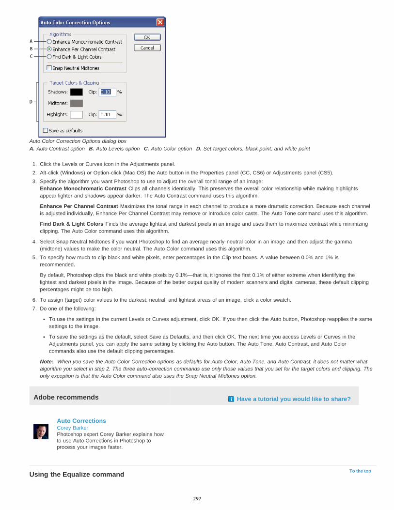
To the top
Auto Color Correction Options dialog boxA. Auto Contrast option B. Auto Levels option C. Auto Color option D. Set target colors, black point, and white point
1. Click the Levels or Curves icon in the Adjustments panel.2. Alt-click (Windows) or Option-click (Mac OS) the Auto button in the Properties panel (CC, CS6) or Adjustments panel (CS5).3. Specify the algorithm you want Photoshop to use to adjust the overall tonal range of an image:
Enhance Monochromatic Contrast Clips all channels identically. This preserves the overall color relationship while making highlightsappear lighter and shadows appear darker. The Auto Contrast command uses this algorithm.
Enhance Per Channel Contrast Maximizes the tonal range in each channel to produce a more dramatic correction. Because each channelis adjusted individually, Enhance Per Channel Contrast may remove or introduce color casts. The Auto Tone command uses this algorithm.
Find Dark & Light Colors Finds the average lightest and darkest pixels in an image and uses them to maximize contrast while minimizingclipping. The Auto Color command uses this algorithm.
4. Select Snap Neutral Midtones if you want Photoshop to find an average nearly-neutral color in an image and then adjust the gamma(midtone) values to make the color neutral. The Auto Color command uses this algorithm.
5. To specify how much to clip black and white pixels, enter percentages in the Clip text boxes. A value between 0.0% and 1% isrecommended.
By default, Photoshop clips the black and white pixels by 0.1%—that is, it ignores the first 0.1% of either extreme when identifying thelightest and darkest pixels in the image. Because of the better output quality of modern scanners and digital cameras, these default clippingpercentages might be too high.
6. To assign (target) color values to the darkest, neutral, and lightest areas of an image, click a color swatch.7. Do one of the following:
To use the settings in the current Levels or Curves adjustment, click OK. If you then click the Auto button, Photoshop reapplies the samesettings to the image.
To save the settings as the default, select Save as Defaults, and then click OK. The next time you access Levels or Curves in theAdjustments panel, you can apply the same setting by clicking the Auto button. The Auto Tone, Auto Contrast, and Auto Colorcommands also use the default clipping percentages.
Note: When you save the Auto Color Correction options as defaults for Auto Color, Auto Tone, and Auto Contrast, it does not matter whatalgorithm you select in step 2. The three auto-correction commands use only those values that you set for the target colors and clipping. Theonly exception is that the Auto Color command also uses the Snap Neutral Midtones option.
Adobe recommends Have a tutorial you would like to share?
Auto CorrectionsCorey BarkerPhotoshop expert Corey Barker explains howto use Auto Corrections in Photoshop toprocess your images faster.
Using the Equalize command
297
To the top
The Equalize command redistributes the brightness values of the pixels in an image so that they more evenly represent the entire range ofbrightness levels. Equalize remaps pixel values in the composite image so that the brightest value represents white, the darkest value representsblack, and intermediate values are evenly distributed throughout the grayscale.
You can use the Equalize command when a scanned image appears darker than the original and you want to balance the values to produce alighter image. Using Equalize together with the Histogram panel lets you see before-and-after brightness comparisons.
Keep in mind that the Equalize command applies adjustments directly to the image layer and deletes image information. For nondestructiveadjustments, use adjustment layers or edit in Adobe Camera Raw.
1. (Optional) Select an area of the image to equalize.2. Choose Image > Adjustments > Equalize.3. If you selected an area of the image, select what to equalize in the dialog box, and click OK:
Equalize Selected Area Only Evenly distributes only the pixels in the selection.
Equalize Entire Image Based On Selected Area Evenly distributes all image layers based on those in the selection.
Adjust black and white points with the Auto optionThe Auto option for Levels and Curves and the Auto Tone command automatically adjust the black point and white point in an image. This clips aportion of the shadows and highlights in each channel and maps the lightest and darkest pixels in each color channel to pure white (level 255) andpure black (level 0). The intermediate pixel values are redistributed proportionately. As a result, using the Auto option or Auto Tone increases thecontrast in an image because the pixel values are expanded. Because the Auto option and Auto Tone adjust each color channel individually, itmay remove color or introduce color casts.
The Auto option and Auto Tone give good results in certain images with an average distribution of pixel values that need a simple increase incontrast.
By default, the Auto option and the Auto Tone command clip the white and black pixels by 0.1%—that is, it ignores the first 0.1% of either extremewhen identifying the lightest and darkest pixels in the image. The default settings for the Auto option can be changed in the Auto Color CorrectionOptions dialog box.
1. Do one of the following:
Click the Levels or Curves icon in the Adjustments panel.
Choose Layer > New Adjustment Layer and choose either Levels or Curves. Click OK in the New Layer dialog box.
Note: You can choose Image > Auto Tone to apply the adjustment directly to the image layer. Keep in mind that this method discardsimage information and is automatic. You cannot adjust any of the options in the following steps.
2. In the Properties panel (CC, CS6) or Adjustments panel (CS5), Alt-click (Windows) or Option-click (Mac OS) the Auto button.3. Under Algorithms in the Auto Color Correction Options dialog box, select Enhance Per Channel Contrast.4. Adjust the amount of shadow and highlight values that are clipped, and adjust the target color for the midtones.5. Click OK to apply the Auto option settings.
More Help topicsAdjusting image color and tone
Legal Notices | Online Privacy Policy
298

Matching, replacing, and mixing colors
To the top
Matching colorsReplacing colorsMixing colors selectively
Matching colors
Match the color in different imagesThe Match Color command matches colors between multiple images, between multiple layers, or between multiple selections. It also lets youadjust the colors in an image by changing the luminance, changing the color range, and neutralizing a color cast. The Match Color commandworks only in RGB mode.
When you use the Match Color command, the pointer becomes the Eyedropper tool. Use the Eyedropper tool while adjusting the image to viewthe color pixel values in the Info panel. This panel gives you feedback about changes in color values as you use the Match Color command.See View color values in an image.
The Match Color command matches the colors in one image (the source image) with colors in another image (the target image). Match Color isuseful when you’re trying to make the colors in different photos consistent, or when certain colors (such as skin tones) in one image must matchthe colors in another image.
In addition to matching the color between two images, the Match Color command can match the color between different layers in the same image.
Match the color between two images1. (Optional) Make a selection in the source and target images.
If you don’t make a selection, then the Match Color command matches the overall image statistics between images.
2. Make the image that you want to change active, and then choose Image > Adjustments > Match Color.
If you’re applying the Match Color command to a specific layer in the target image, make sure that layer is active when you choose theMatch Color command.
3. From the Source menu in the Image Statistics area of the Match Color dialog box, choose the source image whose colors you’ll be matchingin the target image. Choose None when you don’t want to reference a different image to calculate the color adjustment. With None chosen,the target image and the source image are the same.
If necessary, use the Layer menu to choose the layer from the source image whose colors you want to match. You can also choose Mergedfrom the Layer menu to match the colors from all the layers in the source image.
4. If you made a selection in the image, do one or more of the following:
In the Destination Image area, select Ignore Selection When Applying Adjustment if you’re applying the adjustment to the entire targetimage. This option ignores the selection in the target image and applies the adjustment to the entire target image.
In the Image Statistics area, select Use Selection In Source To Calculate Colors if you made a selection in the source image and want touse the colors in the selection to compute the adjustment. Deselect this option to ignore the selection in the source image, and use thecolors from the entire source image to compute the adjustment.
In the Image Statistics area, select Use Selection In Target To Calculate Adjustment if you made a selection in the target image andwant to use the colors in the selection to calculate the adjustment. Deselect this option to ignore the selection in the target image andcompute the adjustment by using the colors of the entire target image.
5. To automatically remove a color cast in the target image, select the Neutralize option. Make sure that the Preview option is selected so thatyour image is updated as you make adjustments.
6. To increase or decrease the brightness in the target image, move the Luminance slider. Alternatively, enter a value in the Luminance box.The maximum value is 200, the minimum is 1, and the default is 100.
7. To adjust the color saturation in the target image, adjust the Color Intensity slider. Alternatively, enter a value in the Color Intensity box. Themaximum value is 200, the minimum is 1 (which produces a grayscale image), and the default is 100.
8. To control the amount of adjustment applied to the image, move the Fade slider. Moving the slider to the right reduces the adjustment.9. Click OK.
Match the color of two layers in the same image
299
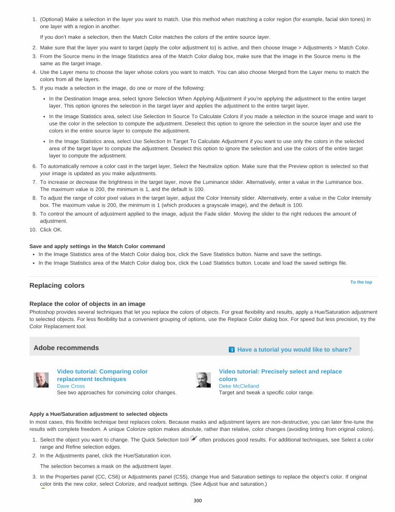
To the top
1. (Optional) Make a selection in the layer you want to match. Use this method when matching a color region (for example, facial skin tones) inone layer with a region in another.
If you don’t make a selection, then the Match Color matches the colors of the entire source layer.
2. Make sure that the layer you want to target (apply the color adjustment to) is active, and then choose Image > Adjustments > Match Color.3. From the Source menu in the Image Statistics area of the Match Color dialog box, make sure that the image in the Source menu is the
same as the target image.4. Use the Layer menu to choose the layer whose colors you want to match. You can also choose Merged from the Layer menu to match the
colors from all the layers.5. If you made a selection in the image, do one or more of the following:
In the Destination Image area, select Ignore Selection When Applying Adjustment if you’re applying the adjustment to the entire targetlayer. This option ignores the selection in the target layer and applies the adjustment to the entire target layer.
In the Image Statistics area, select Use Selection In Source To Calculate Colors if you made a selection in the source image and want touse the color in the selection to compute the adjustment. Deselect this option to ignore the selection in the source layer and use thecolors in the entire source layer to compute the adjustment.
In the Image Statistics area, select Use Selection In Target To Calculate Adjustment if you want to use only the colors in the selectedarea of the target layer to compute the adjustment. Deselect this option to ignore the selection and use the colors of the entire targetlayer to compute the adjustment.
6. To automatically remove a color cast in the target layer, Select the Neutralize option. Make sure that the Preview option is selected so thatyour image is updated as you make adjustments.
7. To increase or decrease the brightness in the target layer, move the Luminance slider. Alternatively, enter a value in the Luminance box.The maximum value is 200, the minimum is 1, and the default is 100.
8. To adjust the range of color pixel values in the target layer, adjust the Color Intensity slider. Alternatively, enter a value in the Color Intensitybox. The maximum value is 200, the minimum is 1 (which produces a grayscale image), and the default is 100.
9. To control the amount of adjustment applied to the image, adjust the Fade slider. Moving the slider to the right reduces the amount ofadjustment.
10. Click OK.
Save and apply settings in the Match Color commandIn the Image Statistics area of the Match Color dialog box, click the Save Statistics button. Name and save the settings.In the Image Statistics area of the Match Color dialog box, click the Load Statistics button. Locate and load the saved settings file.
Replacing colors
Replace the color of objects in an imagePhotoshop provides several techniques that let you replace the colors of objects. For great flexibility and results, apply a Hue/Saturation adjustmentto selected objects. For less flexibility but a convenient grouping of options, use the Replace Color dialog box. For speed but less precision, try theColor Replacement tool.
Adobe recommends Have a tutorial you would like to share?
Video tutorial: Comparing colorreplacement techniquesDave CrossSee two approaches for convincing color changes.
Video tutorial: Precisely select and replacecolorsDeke McClellandTarget and tweak a specific color range.
Apply a Hue/Saturation adjustment to selected objectsIn most cases, this flexible technique best replaces colors. Because masks and adjustment layers are non-destructive, you can later fine-tune theresults with complete freedom. A unique Colorize option makes absolute, rather than relative, color changes (avoiding tinting from original colors).
1. Select the object you want to change. The Quick Selection tool often produces good results. For additional techniques, see Select a colorrange and Refine selection edges.
2. In the Adjustments panel, click the Hue/Saturation icon.
The selection becomes a mask on the adjustment layer.
3. In the Properties panel (CC, CS6) or Adjustments panel (CS5), change Hue and Saturation settings to replace the object’s color. If originalcolor tints the new color, select Colorize, and readjust settings. (See Adjust hue and saturation.)
300
Leave the Lightness setting at zero to maintain contrast. To maintain both contrast and saturation, select the Hue blending mode for theadjustment layer.
4. If necessary, enlarge or reduce the affected area by painting on the mask with white or black. (See Edit a layer mask.)
For more information, see Adjustments panel overview.
Use the Replace Color dialog boxThe Replace Color dialog box combines tools for selecting a color range with HSL sliders for replacing that color. You can also choose thereplacement color in the Color Picker.
Replace Color lacks the Colorize option from the Hue/Saturation adjustment, which may be needed for a complete color change. You may also findthe adjustment layer technique easier for changing specific objects. However, the Replace Color command is good for global color changes—especially changing out-of-gamut colors for printing.
Adobe recommends Have a tutorial you would like to share?
Book excerpt: Using the ReplaceColor commandElaine Weinmann and Peter LourekasLearn with examples from the PhotoshopVisual QuickStart Guide.
1. Choose Image > Adjustments > Replace Color.2. (Optional) If you are selecting similar, contiguuous colors in the image, select Localized Color Clusters to build a more accurate mask.3. Select a preview option:
Selection Displays the mask in the preview box. Masked areas are black, and unmasked areas are white. Partially masked areas (areascovered with a semitransparent mask) appear as varying levels of gray according to their opacity.
Image Displays the image in the preview box. This option is useful when you are working with a magnified image or have limited screenspace.
4. To select the colors that you want to replace, use the Eyedropper tool to click in the image or in the preview box to select the areasexposed by the mask.
5. To refine the selection, do any of the following:
Shift-click or use the Add To Sample Eyedropper tool to add areas.
Alt-click (Windows), Option-click (Mac OS), or use the Subtract From Sample Eyedropper tool to remove areas.
Click the Selection Color swatch to open the Color Picker. Use the Color Picker to target the color you want replaced. As you select acolor in the Color Picker, the mask in the preview box is updated.
6. Drag the Fuzziness slider or enter a Fuzziness value to control the degree to which related colors are included in the selection.7. Specify a Replacement color by doing either of the following:
Drag the Hue, Saturation, and Lightness sliders (or enter values in the text boxes).
Double-click the Result swatch and use the Color Picker to select the replacement color.
Important: You cannot replace pure gray, black, or white with a color. However, you can change the Lightness setting. (The Hue andSaturation settings are relative to existing color, so they have no effect.)
8. (Optional) Click Save to store settings you will later load for other images.
For a video on dodging and burning with the Replace Color command, see www.adobe.com/go/lrvid4119_ps. (Discussion of Replace Colorbegins at the 5:30 mark.)
Use the Color Replacement toolThe Color Replacement tool paints over a targeted color with a replacement color. While this tool is good for quick edits, it often provesunsatisfactory, particularly with dark colors and black. If you don’t get good results after experimenting with tool options, see Apply aHue/Saturation adjustment to selected objects.
The Color Replacement tool doesn’t work in Bitmap, Indexed, or Multichannel color mode.
Adobe recommends Have a tutorial you would like to share?
301

To the top
Book excerpt: Using the ColorReplacement toolElaine Weinmann and Peter LourekasWalk through the process step by step.
1. Select the Color Replacement tool . (If the tool isn’t visible, access it by holding down the Brush tool.)2. In the options bar, choose a brush tip. Generally, you should keep the blending mode set to Color.3. For the Sampling option, choose one of the following:
Continuous Samples colors continuously as you drag.
Once Replaces the targeted color only in areas containing the color that you first click
Background Swatch Replaces only areas containing the current background color.
4. From the Limits menu, select one of the following:Discontiguous Replaces the sampled color wherever it occurs under the pointer.
Contiguous Replaces colors that are contiguous with the color immediately under the pointer
Find Edges Replaces connected areas containing the sampled color while better preserving the sharpness of shape edges.
5. For Tolerance, choose a low percentage to replace colors very similar to the pixel you click, or raise the percentage to replace a broaderrange of colors.
6. To produce a smooth edge in the corrected areas, select Anti-aliased.7. Choose a foreground color to replace the unwanted color. (See Choose colors in the toolbox.)8. Click the color you want to replace in the image.9. Drag in the image to replace the targeted color.
If the range of replaced colors is too small, increase the Tolerance setting in the options bar.
Mixing colors selectively
Make selective color adjustmentsSelective color correction is a technique used by high-end scanners and separation programs to change the amount of process colors in each ofthe primary color components in an image. You can modify the amount of a process color in any primary color selectively—without affecting theother primary colors. For example, you can use selective color correction to dramatically decrease the cyan in the green component of an imagewhile leaving the cyan in the blue component unaltered.
Even though Selective Color uses CMYK colors to correct an image, you can use it on RGB images.
1. Make sure that the composite channel is selected in the Channels panel. The Selective Color adjustment is available only when you’reviewing the composite channel.
2. Do one of the following:
Click the Selective Color icon in the Adjustments panel.
Choose Layer > New Adjustment Layer > Selective Color. Click OK in the New Layer dialog box.
(CS5) Click a Selective Color preset in the Adjustments panel.
Note: You can also choose Image > Adjustments > Selective Color. But keep in mind that this method makes direct adjustments to theimage layer and discards image information.
3. Do one of the following:
In Photoshop CC and CS6, choose the color you want to adjust from the Colors menu in the Properties panel. You can also choose aPreset that you’ve saved.
In CS5, choose the color you want to adjust from the Colors menu in the Adjustments panel.
(CC, CS6) In the Properties panel, choose a Selective Color preset from the Preset menu.
4. Select a method in the Properties panel (CC, CS6) or choose a method from the Adjustments panel menu (CS5):Relative Changes the existing amount of cyan, magenta, yellow, or black by its percentage of the total. For example, if you start with a pixelthat is 50% magenta and add 10%, 5% is added to the magenta (10% of 50% = 5%) for a total of 55% magenta. (This option cannot adjustpure specular white, which contains no color components.)
Absolute Adjusts the color in absolute values. For example, if you start with a pixel that is 50% magenta and add 10%, the magenta ink isset to a total of 60%.Note: The adjustment is based on how close a color is to one of the options in the Colors menu. For example, 50% magenta is midwaybetween white and pure magenta and receives a proportionate mix of corrections defined for the two colors.
302

5. Drag the sliders to increase or decrease the components in the selected color.
You can also save the settings you make for the Selective Color adjustment and reuse the settings on other images.
Legal Notices | Online Privacy Policy
303

Targeting images for press
To the top
To the top
To the top
Setting highlight and shadow target valuesUsing Levels to preserve highlight and shadow details for printingSet target values using the eyedroppers
Setting highlight and shadow target valuesAssigning (targeting) highlight and shadow values of an image is necessary because most output devices (usually printing presses) cannot printdetail in the blackest shadow values (near level 0) or the whitest highlight values (near level 255). Specifying the minimum shadow level andmaximum highlight level helps to bring the important shadow and highlight details within the gamut of the output device.
If you are printing an image on a desktop printer and your system is color-managed, don’t set target values. The Photoshop color managementsystem automatically makes adjustments to the image you see on the screen so that it prints properly on your profiled desktop printer.
Using Levels to preserve highlight and shadow details for printingThe Output Levels sliders let you set the shadow and highlight levels to compress the image into a range less than 0 to 255. Use this adjustmentto preserve the shadow and highlight details when an image is being printed on a press whose characteristics you know. For example, supposethere are important image details in the highlights with a value of 245, and the printing press that you’re using won’t hold a dot smaller than 5%.You can pull the highlight slider to level 242 (which is a 5% dot on the press) to shift the highlight detail from 245 to 242. Now, the highlight detailcan safely print on that press.
Generally, it is not a good idea to use the Output Levels sliders to target images with specular highlights. Your specular highlight will look grayrather than blow out to pure white. Use the highlight eyedropper for images with specular highlights.
Targeting shadows and highlights with Output Levels sliders
Set target values using the eyedroppers
1. Select the Eyedropper tool in the toolbox. You can choose 3 by 3 Average from the Sample Size menu in the Eyedropper tool options.This ensures a representative sample of an area rather than the value of a single screen pixel.
2. Click the Levels or Curves icon in the Adjustments panel.
When you select Levels or Curves, the Eyedropper tool is active outside the Properties panel (CC, CS6) or Adjustments panel (CS5).You still have access to the scroll controls, the Hand tool, and the Zoom tool through keyboard shortcuts.
3. Do one of the following to identify areas of highlights and shadows that you want to preserve in the image:
Move the pointer around the image, and look at the Info panel to find the lightest and darkest areas that you want preserved (not clippedto pure black or white). (See View color values in an image.)
Drag the pointer in the image, and look at Curves in the Properties panel (CC, CS6) or Adjustments panel (CS5) to find the lightest and
304

darkest points you want to preserve. This method does not work if the Curves adjustment is set to the CMYK composite channel.
When identifying the lightest highlight details that you want targeted to a printable (lower) value, don’t include specular highlights. Specularhighlights such as the highlight glint in jewelry or a spot of glare are meant to be the brightest points in an image. It’s desirable to clipspecular highlight pixels (pure white, no detail) so that no ink is printed on the paper.
You can also use the Threshold command to identify representative highlights and shadows before accessing Levels or Curves. (SeeCreate a two-valued black and white image.)
4. To assign highlight values to the lightest area of the image, double-click the Set White Point Eyedropper tool in the Levels or Curvesadjustment to display the Color Picker. Enter the values you want to assign to the lightest area in the image, and click OK. Then click thehighlight you identified in step 3.
If you accidentally click the wrong highlight, click the Reset button in the Adjustments panel.
Depending on the output device, you can achieve a good highlight in an average-key image using CMYK values of 5, 3, 3, and 0,respectively, when you are printing on white paper. An approximate RGB equivalent is 244, 244, 244, and an approximate grayscaleequivalent is a 4% dot. You can approximate these target values quickly by entering 96 in the Brightness (B) box under the HSB area of theColor Picker.
With a low-key image, you may want to set the highlight to a lower value to avoid too much contrast. Experiment with Brightness valuesfrom 96 through 80.
The pixel values are adjusted throughout the image proportionately to the new highlight values. Any pixels lighter than the area you clickedare clipped (adjusted to level 255, pure white). The Info panel shows the values both before and after the color adjustment.
Setting the target value for the Set White Point Eyedropper tool and then clicking a highlight to assign it the target value
5. To assign shadow values to the darkest area of the image that you want preserved, double-click the Set Black Point Eyedropper tool inthe Properties panel (CC, CS6) or Adjustments panel (CS5) to display the Color Picker. Enter the values you want to assign to the darkestarea in the image, and click OK. Then click the shadow you identified in step 3.
When you’re printing on white paper, you can usually achieve a good shadow in an average-key image using CMYK values of 65, 53, 51,and 95. An approximate RGB equivalent is 10, 10, 10, and an approximate grayscale equivalent is a 96% dot. You can approximate thesevalues quickly by entering 4 in the Brightness (B) box under the HSB area of the Color Picker.
With a high-key image, you may want to set the shadow to a higher value to maintain detail in the highlights. Experiment with Brightnessvalues from 4 through 20.
Legal Notices | Online Privacy Policy
305
Camera Raw
Camera Raw 7 plug-inKelby (May. 7, 2012)video-tutorialTap into the latest noise, color, and dynamic range controls.
Enhancing Raw imagesvideo2brain (May. 7, 2012)video-tutorialDraw upon the full range of image data.
306
Introduction to Camera Raw
To the top
To the top
About camera raw filesAbout Camera RawAbout the Digital Negative (DNG) formatProcessing images with Camera RawCamera Raw dialog box overviewWork with the Camera Raw cache in Adobe BridgeWork with Camera Raw and Lightroom
About camera raw filesA camera raw file contains unprocessed, uncompressed grayscale picture data from a digital camera’s image sensor, along with information abouthow the image was captured (metadata). Photoshop® Camera Raw software interprets the camera raw file, using information about the cameraand the image’s metadata to construct and process a color image.
Think of a camera raw file as your photo negative. You can reprocess the file at any time, achieving the results that you want by makingadjustments for white balance, tonal range, contrast, color saturation, and sharpening. When you adjust a camera raw image, the original cameraraw data is preserved. Adjustments are stored as metadata in an accompanying sidecar file, in a database, or in the file itself (in the case of DNGformat).
When you shoot JPEG files with your camera, the camera automatically processes the JPEG file to enhance and compress the image. Yougenerally have little control over how this processing occurs. Shooting camera raw images with your camera gives you greater control thanshooting JPEG images, because camera raw does not lock you into processing done by your camera. You can still edit JPEG and TIFF images inCamera Raw, but you will be editing pixels that were already processed by the camera. Camera raw files always contain the original, unprocessedpixels from the camera.
To shoot camera raw images, you must set your camera to save files in its own camera raw file format.
Note: The Photoshop Raw format (.raw) is a file format for transferring images between applications and computer platforms. Don’t confusePhotoshop raw with camera raw file formats. File extensions for camera raw files vary depending on the camera manufacturer.Digital cameras capture and store camera raw data with a linear tone response curve (gamma 1.0). Both film and the human eye have a nonlinear,logarithmic response to light (gamma greater than 2). An unprocessed camera raw image viewed as a grayscale image would seem very dark,because what appears twice as bright to the photosensor and computer seems less than twice as bright to the human eye.
For a list of supported cameras and for more information about Camera Raw, see Digital camera raw file support.
To see a list of cameras and which version of Camera Raw each camera requires, see Camera Raw plug-in | Supported cameras.
About Camera RawCamera Raw software is included as a plug-in with Adobe After Effects® and Adobe Photoshop, and also adds functionality to Adobe Bridge.Camera Raw gives each of these applications the ability to import and work with camera raw files. You can also use Camera Raw to work withJPEG and TIFF files.
Note: Camera Raw supports images up to 65,000 pixels long or wide and up to 512 megapixels. Camera Raw converts CMYK images to RGBupon opening. For a list of supported cameras, see Digital camera raw file support.You must have Photoshop or After Effects installed to open files in the Camera Raw dialog box from Adobe Bridge. However, if Photoshop or AfterEffects is not installed, you can still preview the images and see their metadata in Adobe Bridge. If another application is associated with theimage file type, it’s possible to open the file in that application from Adobe Bridge.
Using Adobe Bridge, you can apply, copy, and clear image settings, and you can see previews and metadata for camera raw files without openingthem in the Camera Raw dialog box. The preview in Adobe Bridge is a JPEG image generated using the current image settings; the preview isnot the raw camera data itself, which would appear as a very dark grayscale image.Note: A caution icon appears in the thumbnails and preview image in the Camera Raw dialog box while the preview is generated from thecamera raw image.You can modify the default settings that Camera Raw uses for a particular model of camera. For each camera model, you can also modify thedefaults for a particular ISO setting or a particular camera (by serial number). You can modify and save image settings as presets for use withother images.
When you use Camera Raw to make adjustments (including straightening and cropping) to a camera raw image, the image’s original camera rawdata is preserved. The adjustments are stored in either the Camera Raw database, as metadata embedded in the image file, or in a sidecar XMPfile (a metadata file that accompanies a camera raw file). For more information, see Specify where Camera Raw settings are stored.
307
To the top
To the top
After you process and edit a camera raw file using the Camera Raw plug-in, an icon appears in the image thumbnail in Adobe Bridge.
If you open a camera raw file in Photoshop, you can save the image in other image formats, such as PSD, JPEG, Large Document Format (PSB),TIFF, Cineon, Photoshop Raw, PNG, or PBM. From the Camera Raw dialog box in Photoshop, you can save the processed files in DigitalNegative (DNG), JPEG, TIFF, or Photoshop (PSD) formats. Although Photoshop Camera Raw software can open and edit a camera raw imagefile, it cannot save an image in a camera raw format.
As new versions of Camera Raw become available, you can update this software by installing a new version of the plug-in. You can check forupdates to Adobe software by choosing Help > Updates.
Different camera models save camera raw images in many different formats, and the data must be interpreted differently for these formats.Camera Raw includes support for many camera models, and it can interpret many camera raw formats.
If you have trouble opening Camera Raw files, see Why doesn't my version of Photoshop or Lightroom support my camera?
About the Digital Negative (DNG) formatThe Digital Negative (DNG) format is a non-proprietary, publicly documented, and widely supported format for storing raw camera data. Hardwareand software developers use DNG because it results in a flexible workflow for processing and archiving camera raw data. You may also use DNGas an intermediate format for storing images that were originally captured using a proprietary camera raw format.
Because DNG metadata is publicly documented, software readers such as Camera Raw do not need camera-specific knowledge to decode andprocess files created by a camera that supports DNG. If support for a proprietary format is discontinued, users may not be able to access imagesstored in that format, and the images may be lost forever. Because DNG is publicly documented, it is far more likely that raw images stored asDNG files will be readable by software in the distant future, making DNG a safer choice for archival storage.
Metadata for adjustments made to images stored as DNG files can be embedded in the DNG file itself instead of in a sidecar XMP file or in theCamera Raw database.
You can convert camera raw files to the DNG format by using theAdobe DNG Converter or the Camera Raw dialog box. For more information onthe DNG format and DNG Converter, see the Digital Negative (DNG) product page. To download the latest DNG Converter, go to the Adobedownloads page.
Processing images with Camera Raw
1. Copy camera raw files to your hard disk, organize them, and (optionally) convert them to DNG.Before you do any work on the images that your camera raw files represent, transfer them from the camera’s memory card, organize them, givethem useful names, and otherwise prepare them for use. Use the Get Photos From Camera command in Adobe Bridge to accomplish these tasksautomatically.
2. Open the image files in Camera Raw.You can open camera raw files in Camera Raw from Adobe Bridge, After Effects, or Photoshop. You can also open JPEG and TIFF files inCamera Raw from Adobe Bridge. (See Open images.)
For a video tutorial on importing raw images from a digital camera into Adobe Bridge CS4 or CS5 using Adobe Photo Downloader, watchDownload photos from a camera into Adobe Bridge by Lynda.com.
3. Adjust color.Color adjustments include white balance, tone, and saturation. You can make most adjustments on the Basic tab, and then use controls on theother tabs to fine-tune the results. If you want Camera Raw to analyze your image and apply approximate tonal adjustments, click Auto on theBasic tab.
To apply the settings used for the previous image, or to apply the default settings for the camera model, camera, or ISO settings, choose theappropriate command from the Camera Raw Settings menu . (See Apply saved Camera Raw settings.)
For a video tutorial on making nondestructive color adjustments to photos in Camera Raw, watch Recovering detail in raw images by RichardHarrington or Adobe Camera Raw workflow by Russell Brown.
4. Make other adjustments and image corrections.Use other tools and controls in the Camera Raw dialog box to perform such tasks as sharpening the image, reducing noise, correcting for lensdefects, and retouching.
5. (Optional) Save image settings as a preset or as default image settings.To apply the same adjustments to other images later, save the settings as a preset. To save the adjustments as the defaults to be applied to allimages from a specific camera model, a specific camera, or a specific ISO setting, save the image settings as the new Camera Raw defaults. (SeeSave, reset, and load Camera Raw settings.)
6. Set workflow options for Photoshop.Set options to specify how images are saved from Camera Raw and how Photoshop should open them. You can access the Workflow Options
308
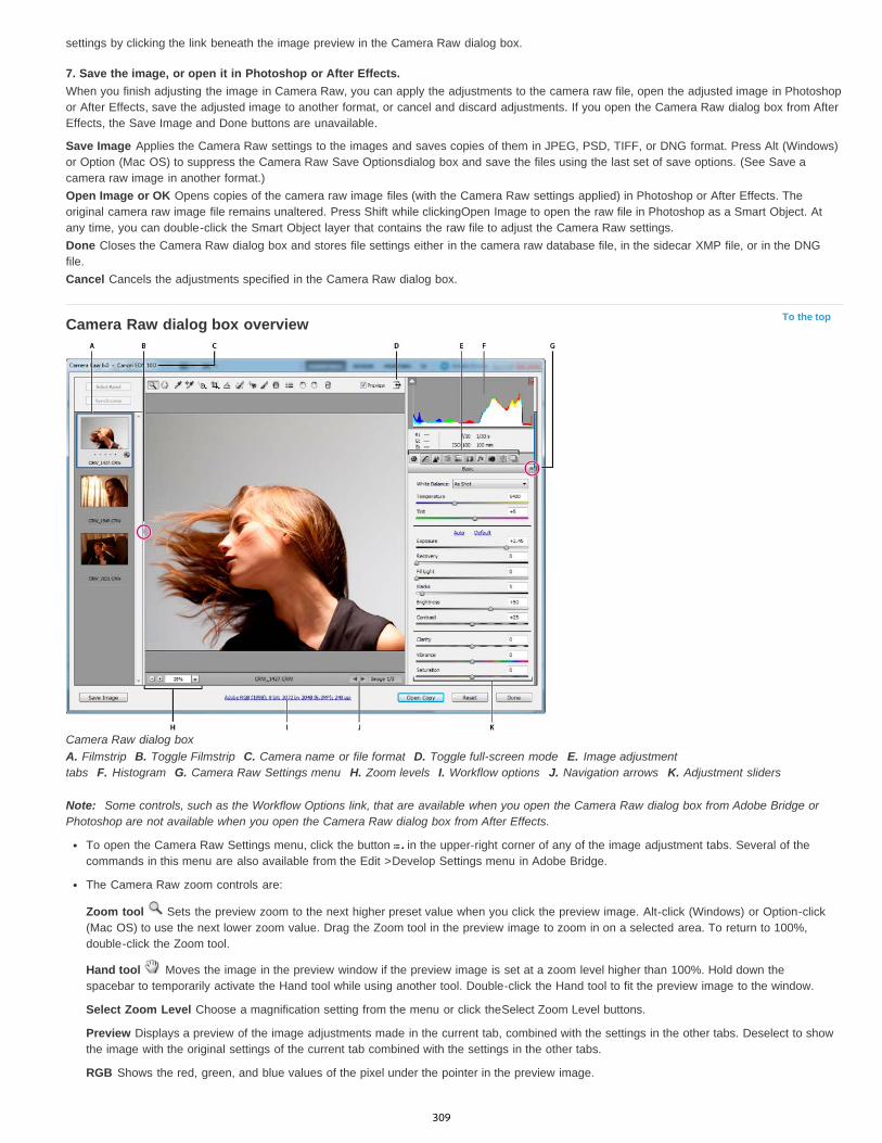
To the top
settings by clicking the link beneath the image preview in the Camera Raw dialog box.
7. Save the image, or open it in Photoshop or After Effects.When you finish adjusting the image in Camera Raw, you can apply the adjustments to the camera raw file, open the adjusted image in Photoshopor After Effects, save the adjusted image to another format, or cancel and discard adjustments. If you open the Camera Raw dialog box from AfterEffects, the Save Image and Done buttons are unavailable.
Save Image Applies the Camera Raw settings to the images and saves copies of them in JPEG, PSD, TIFF, or DNG format. Press Alt (Windows)or Option (Mac OS) to suppress the Camera Raw Save Optionsdialog box and save the files using the last set of save options. (See Save acamera raw image in another format.)Open Image or OK Opens copies of the camera raw image files (with the Camera Raw settings applied) in Photoshop or After Effects. Theoriginal camera raw image file remains unaltered. Press Shift while clickingOpen Image to open the raw file in Photoshop as a Smart Object. Atany time, you can double-click the Smart Object layer that contains the raw file to adjust the Camera Raw settings.Done Closes the Camera Raw dialog box and stores file settings either in the camera raw database file, in the sidecar XMP file, or in the DNGfile.Cancel Cancels the adjustments specified in the Camera Raw dialog box.
Camera Raw dialog box overview
Camera Raw dialog boxA. Filmstrip B. Toggle Filmstrip C. Camera name or file format D. Toggle full-screen mode E. Image adjustmenttabs F. Histogram G. Camera Raw Settings menu H. Zoom levels I. Workflow options J. Navigation arrows K. Adjustment sliders
Note: Some controls, such as the Workflow Options link, that are available when you open the Camera Raw dialog box from Adobe Bridge orPhotoshop are not available when you open the Camera Raw dialog box from After Effects.
To open the Camera Raw Settings menu, click the button in the upper-right corner of any of the image adjustment tabs. Several of thecommands in this menu are also available from the Edit >Develop Settings menu in Adobe Bridge.
The Camera Raw zoom controls are:
Zoom tool Sets the preview zoom to the next higher preset value when you click the preview image. Alt-click (Windows) or Option-click(Mac OS) to use the next lower zoom value. Drag the Zoom tool in the preview image to zoom in on a selected area. To return to 100%,double-click the Zoom tool.
Hand tool Moves the image in the preview window if the preview image is set at a zoom level higher than 100%. Hold down thespacebar to temporarily activate the Hand tool while using another tool. Double-click the Hand tool to fit the preview image to the window.
Select Zoom Level Choose a magnification setting from the menu or click theSelect Zoom Level buttons.
Preview Displays a preview of the image adjustments made in the current tab, combined with the settings in the other tabs. Deselect to showthe image with the original settings of the current tab combined with the settings in the other tabs.
RGB Shows the red, green, and blue values of the pixel under the pointer in the preview image.
309

To the top
To the top
Shadows and Highlights Displays shadow and highlight clipping using the buttons at the top of the Histogram. Clipped shadows appear inblue, and clipped highlights appear in red. Highlight clipping is shown if any one of the three RGB channels is clipped (fully saturated with nodetail). Shadow clipping is shown if all three RGB channels are clipped (black with no detail).
The Camera Raw image adjustment tabs are:
Basic Adjust white balance, color saturation, and tonality.
Tone Curve Fine-tune tonality using a Parametric curve and a Point curve.
Detail Sharpen images or reduce noise.
HSL / Grayscale Fine-tune colors using Hue, Saturation, and Luminance adjustments.
Split Toning Color monochrome images or create special effects with color images.
Lens Corrections Compensate for chromatic aberration, geometric distortions, and vignetting caused by the camera lens.
Effects Simulate film grain or apply a postcrop vignette.
Camera Calibration Apply camera profiles to raw images to correct color casts and adjust non-neutral colors to compensate for thebehavior of a camera’s image sensor.
Presets Save and apply sets of image adjustments as presets.
Snapshots Create versions of a photo that record its state at any point during the editing process.
Work with the Camera Raw cache in Adobe BridgeWhen you view camera raw files in Adobe Bridge, the thumbnails and previews use either the default settings or your adjusted settings. TheAdobe Bridge cache stores data for the file thumbnails, metadata, and file information. Caching this data shortens the loading time when youreturn to a previously viewed folder in Adobe Bridge. The Camera Raw cache speeds the opening of images in Camera Raw and rebuilds ofpreviews in Adobe Bridge when image settings change in Camera Raw.
Because caches can become very large, you may want to purge the Camera Raw cache or limit its size. You can also purge and regenerate thecache if you suspect that it is corrupted or old.
Note: The Camera Raw cache holds data for about 200 images for each gigabyte of disk storage allocated to it. By default, the Camera Rawcache is set to a maximum size of 1 GB. You can increase its limit in the Camera Raw preferences.
1. In Adobe Bridge, choose Edit >Camera Raw Preferences (Windows) or Bridge > Camera Raw Preferences (Mac OS). Or, with the CameraRaw dialog box open, click the Open Preferences Dialog button .
2. Do any of the following:
To change the cache size, enter a Maximum Size value.
To purge the camera raw cache, click the Purge Cachebutton.
To change the location of the camera raw cache, click Select Location.
Work with Camera Raw and LightroomCamera Raw and Lightroom share the same image-processing technology to ensure consistent and compatible results across applications. ForCamera Raw to view image adjustments made in the Develop module of Lightroom, metadata changes must be saved to XMP in Lightroom.
Adjustments made in Camera Raw are also displayed in the Adobe Bridge Content and Preview panels.
To view Lightroom changes in Camera Raw, and to ensure that Camera Raw adjustments can be viewed in Lightroom and Adobe Bridge, do thefollowing:
1. In Adobe Bridge, choose Edit >Camera Raw Preferences (Windows) or Bridge > Camera Raw Preferences (Mac OS). Or, with the CameraRaw dialog box open, click the Open Preferences Dialog button .
2. Choose Save Image Settings In > Sidecar “.XMP” Files, and deselect Ignore Sidecar “.XMP” Files.3. After applying adjustments to a photo in Camera Raw, save them by clicking Done or Open Image.
Note: Camera Raw reads only the current settings for the primary image in the Lightroom catalog. Adjustments made to virtual copies are notdisplayed or available in Camera Raw.
|
310
Automatic Perspective Correction in Camera Raw | Photoshop CCStraighten geometrical shapes that appear skewed because of lens distortion
Note:
To the top
Caution:
Using an incorrect lens, or camera shake can cause the perspective of photographs to be tilted or skewed. The perspective may be distorted, andis more evident in photographs containing continuous vertical lines or geometric shapes.
Adobe Camera Raw has Upright modes - four settings that can be used to automatically fix perspective. The ability to manually apply correctionscontinues to be available. After applying an Upright mode, you can adjust the image further by manually modifying the available slider-basedsettings.
It is recommended that you apply any lens correction profiles available for your camera and lens combination, before you apply one of thefour new presets. Applying the lens correction profile prepares the image to be analyzed better for distortion correction.
Manually correcting lens distortion using Upright presets
1. Do one of the following:
Open a camera raw file, or,With an image open in Photoshop, click Filter > Camera Raw Filter.
2. In the Camera Raw window, navigate to the Lens Corrections tab.
3. (Optional) In the Lens Corrections > Profile tab, select the Enable Lens Profile Corrections checkbox.
Enabling Lens profile correction based on your camera and lens combination is highly recommended, before processing the photo withthe Upright presets.
4. In Lens Corrections > Manual tab, there are four Upright modes available. Click a mode to apply the correction to the photo.
Auto Applies a balanced set of perspective corrections.
Level Applies perspective correction to ensure that the image is level.
Vertical Applies level and vertical perspective corrections.
Full Applies level, vertical, and horizontal perspective corrections on the image.
While trying out the four Upright modes, if you select or clear the Enable Lens Profile Correction checkbox (Lens Correction >Profile), click the Reanalyze link below the Upright preset buttons.
311
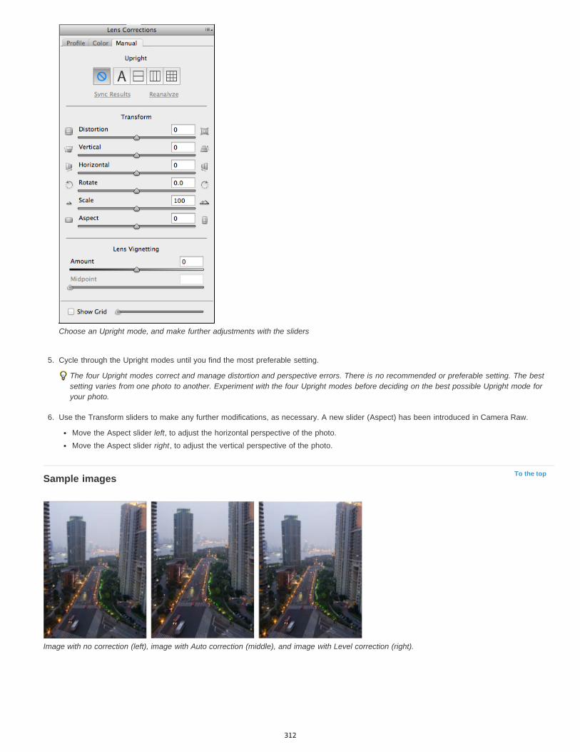
To the top
Choose an Upright mode, and make further adjustments with the sliders
5. Cycle through the Upright modes until you find the most preferable setting.
The four Upright modes correct and manage distortion and perspective errors. There is no recommended or preferable setting. The bestsetting varies from one photo to another. Experiment with the four Upright modes before deciding on the best possible Upright mode foryour photo.
6. Use the Transform sliders to make any further modifications, as necessary. A new slider (Aspect) has been introduced in Camera Raw.
Move the Aspect slider left, to adjust the horizontal perspective of the photo.Move the Aspect slider right, to adjust the vertical perspective of the photo.
Sample images
Image with no correction (left), image with Auto correction (middle), and image with Level correction (right).
312
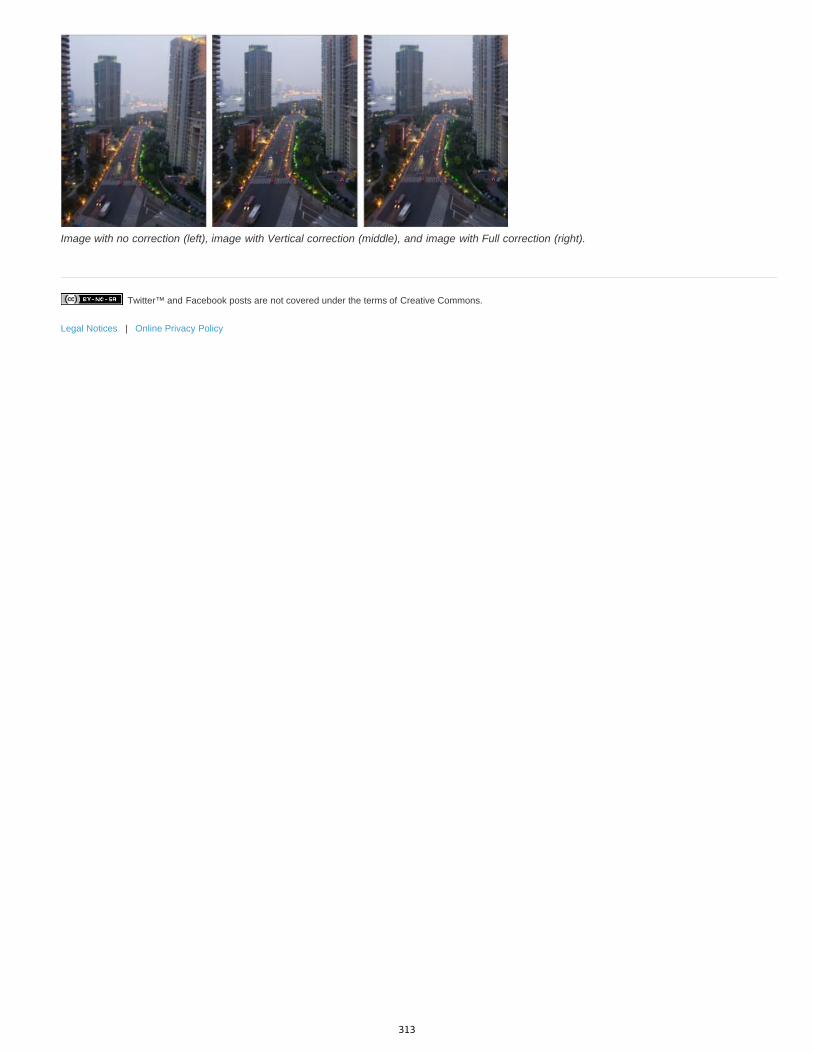
Twitter™ and Facebook posts are not covered under the terms of Creative Commons.
Legal Notices | Online Privacy Policy
Image with no correction (left), image with Vertical correction (middle), and image with Full correction (right).
313
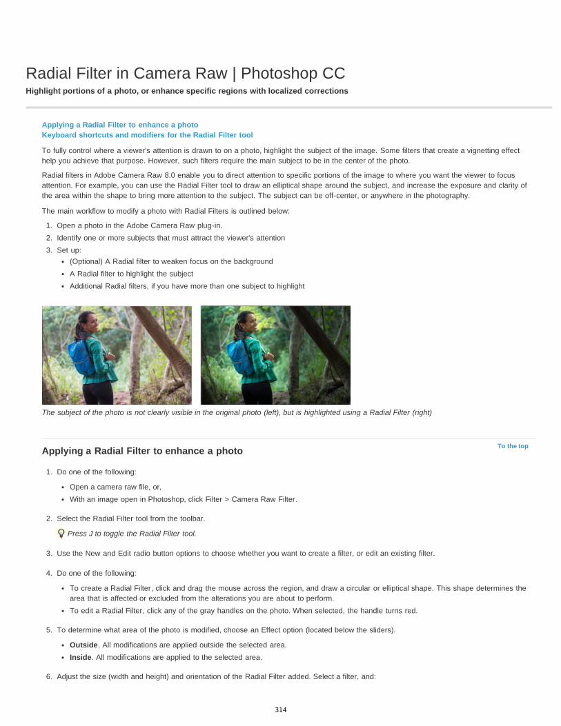
Radial Filter in Camera Raw | Photoshop CCHighlight portions of a photo, or enhance specific regions with localized corrections
To the top
Applying a Radial Filter to enhance a photoKeyboard shortcuts and modifiers for the Radial Filter tool
To fully control where a viewer's attention is drawn to on a photo, highlight the subject of the image. Some filters that create a vignetting effecthelp you achieve that purpose. However, such filters require the main subject to be in the center of the photo.
Radial filters in Adobe Camera Raw 8.0 enable you to direct attention to specific portions of the image to where you want the viewer to focusattention. For example, you can use the Radial Filter tool to draw an elliptical shape around the subject, and increase the exposure and clarity ofthe area within the shape to bring more attention to the subject. The subject can be off-center, or anywhere in the photography.
The main workflow to modify a photo with Radial Filters is outlined below:
1. Open a photo in the Adobe Camera Raw plug-in.2. Identify one or more subjects that must attract the viewer's attention3. Set up:
(Optional) A Radial filter to weaken focus on the backgroundA Radial filter to highlight the subjectAdditional Radial filters, if you have more than one subject to highlight
The subject of the photo is not clearly visible in the original photo (left), but is highlighted using a Radial Filter (right)
Applying a Radial Filter to enhance a photo
1. Do one of the following:
Open a camera raw file, or,With an image open in Photoshop, click Filter > Camera Raw Filter.
2. Select the Radial Filter tool from the toolbar.
Press J to toggle the Radial Filter tool.
3. Use the New and Edit radio button options to choose whether you want to create a filter, or edit an existing filter.
4. Do one of the following:
To create a Radial Filter, click and drag the mouse across the region, and draw a circular or elliptical shape. This shape determines thearea that is affected or excluded from the alterations you are about to perform.To edit a Radial Filter, click any of the gray handles on the photo. When selected, the handle turns red.
5. To determine what area of the photo is modified, choose an Effect option (located below the sliders).
Outside. All modifications are applied outside the selected area.Inside. All modifications are applied to the selected area.
6. Adjust the size (width and height) and orientation of the Radial Filter added. Select a filter, and:
314
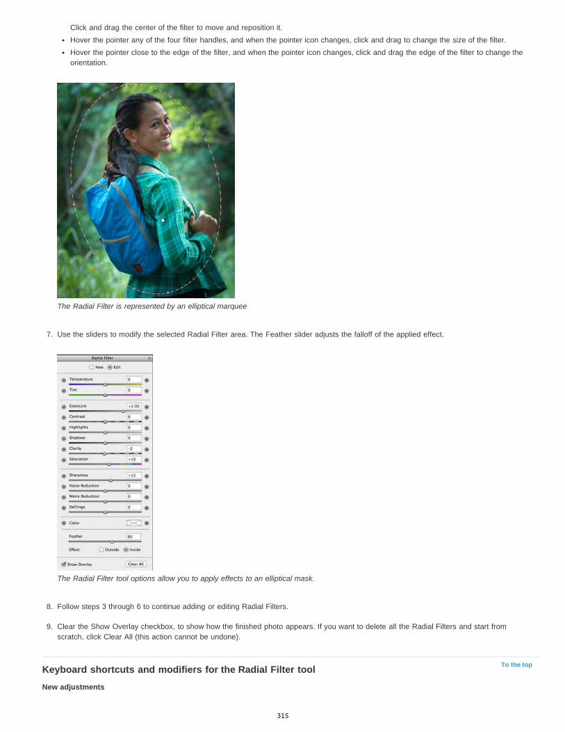
To the top
Click and drag the center of the filter to move and reposition it.Hover the pointer any of the four filter handles, and when the pointer icon changes, click and drag to change the size of the filter.Hover the pointer close to the edge of the filter, and when the pointer icon changes, click and drag the edge of the filter to change theorientation.
The Radial Filter is represented by an elliptical marquee
7. Use the sliders to modify the selected Radial Filter area. The Feather slider adjusts the falloff of the applied effect.
The Radial Filter tool options allow you to apply effects to an elliptical mask.
8. Follow steps 3 through 6 to continue adding or editing Radial Filters.
9. Clear the Show Overlay checkbox, to show how the finished photo appears. If you want to delete all the Radial Filters and start fromscratch, click Clear All (this action cannot be undone).
Keyboard shortcuts and modifiers for the Radial Filter toolNew adjustments
315
Twitter™ and Facebook posts are not covered under the terms of Creative Commons.
Legal Notices | Online Privacy Policy
Press and hold Shift + drag, to create an adjustment that is constrained to a circleWhile dragging, press and hold the spacebar to move the ellipse; release the spacebar to resume defining the shape of the new adjustment
Editing adjustments
While dragging inside an adjustment to move it, press and hold the Shift key to constrain the movement in the horizontal or vertical directionWhile dragging one of the four handles to resize an adjustment, press and hold the Shift key, to preserve the aspect ratio of the adjustmentshape.While dragging the boundary of an adjustment to rotate it, press and hold the Shift key to snap the rotation to 15-degree increments.While an adjustment is selected, press the X key to flip the effect direction (for example, from outside to inside)
Deleting adjustments
While an adjustment is selected, press the Delete key to delete the adjustmentPress Option/Alt + click an existing adjustment to delete it
Adjustments with maximum coverage
Press Command/Control and double-click on an empty area, to create an adjustment that is centered and covers the cropped image areaPress Command/Control and double-click within an existing adjustment, to expand that adjustment to cover the cropped image area
316
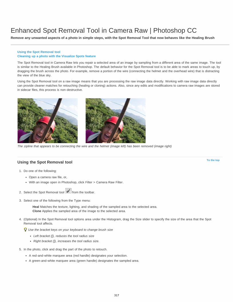
Enhanced Spot Removal Tool in Camera Raw | Photoshop CCRemove any unwanted aspects of a photo in simple steps, with the Spot Removal Tool that now behaves like the Healing Brush
To the top
Using the Spot Removal toolCleaning up a photo with the Visualize Spots feature
The Spot Removal tool in Camera Raw lets you repair a selected area of an image by sampling from a different area of the same image. The toolis similar to the Healing Brush available in Photoshop. The default behavior for the Spot Removal tool is to be able to mark areas to touch up, bydragging the brush across the photo. For example, remove a portion of the wire (connecting the helmet and the overhead wire) that is distractingthe view of the blue sky.
Using the Spot Removal tool on a raw image means that you are processing the raw image data directly. Working with raw image data directlycan provide cleaner matches for retouching (healing or cloning) actions. Also, since any edits and modifications to camera raw images are storedin sidecar files, this process is non-destructive.
The zipline that appears to be connecting the wire and the helmet (image left) has been removed (image right)
Using the Spot Removal tool
1. Do one of the following:
Open a camera raw file, or,With an image open in Photoshop, click Filter > Camera Raw Filter.
2. Select the Spot Removal tool from the toolbar.
3. Select one of the following from the Type menu:
Heal Matches the texture, lighting, and shading of the sampled area to the selected area.Clone Applies the sampled area of the image to the selected area.
4. (Optional) In the Spot Removal tool options area under the Histogram, drag the Size slider to specify the size of the area that the SpotRemoval tool affects.
Use the bracket keys on your keyboard to change brush size
Left bracket ([), reduces the tool radius sizeRight bracket (]), increases the tool radius size.
5. In the photo, click and drag the part of the photo to retouch.
A red-and-white marquee area (red handle) designates your selection.A green-and-white marquee area (green handle) designates the sampled area.
317

To the top
Identify the part of the image to heal, and then use the Spot Removal tool, to paint the area. Use the green and red handles (image right) toreposition the selected and sample areas
6. (Optional) To change the sampled area that is selected by default, do one of the following:
Automatically. Click the handle of a selected area, and press the forward slash key (/). A new area is sampled. Press the forward slashkey until you find a sample area that fits best.Manually. Use the green handle to reposition the sampled area.
When you select larger portions of an image using longer strokes, the right sample area match is not found immediately. To experimentwith various options, click the forward slash (/), and the tool auto-samples more areas for you.
7. To remove all the adjustments made using the Spot Removal tool, click Clear All.
Keyboard shortcuts and modifiersCircular spot:
Control/Command + click to create a circular spot; drag to set the source of the spot.Command/Control + Option/Alt + click to create a circular spot; drag to set the size of the spot.
Rectangular selection:
Click Option/Alt + drag to define a rectangular selection. All spots within that selection (highlighted in red) are deleted once the mouse isreleased.
Extend a selected area or spot:
Shift + click to extend an existing selected spot in "connect the dots" fashion.
Delete a selected area or spot:
Select a red or green handle, and press Delete to delete a selected adjustment.Press Option/Alt and click a handle to delete it.
Cleaning up a photo with the Visualize Spots featureWhile working on a computer screen, you may be able to identify and remove most visible spots or imperfections. However, when you print aphoto at its full resolution, the printed output may contain many imperfections that were not visible on a computer screen. These imperfectionscould be of many types - dust on a camera sensor, blemishes on a model's skin in a portrait, tiny wisps of clouds on blue skies. At full resolution,these imperfections are visually distracting.
The new Visualize Spots feature lets you search for imperfections that may not be immediately visible. When you select the Visualize Spotscheckbox (found in the options for the Spot Removal tool), the image is inverted. You can then use the Spot Removal tool in the Visualize Spotsmode, to clean up the image further.
318

The Visualize Spots checkbox is a Spot Removal tool option
1. Do one of the following:
Open a camera raw file, or,With an image open in Photoshop CC, click Filter > Camera Raw Filter.
2. Select the Spot Removal tool from the toolbar, and then select the Visualize Spots checkbox.
The image is inverted, and the outlines of the elements of the image are visible.
Below, Visualize Spots view is on, and unnecessary elements like wispy clouds (left) have been removed (right)
Above, Visualize Spots view is off, and unnecessary elements like wispy clouds (left) have been removed (right)
319

Twitter™ and Facebook posts are not covered under the terms of Creative Commons.
Legal Notices | Online Privacy Policy
3. Use the Visualize Spots slider to vary the contrast threshold of the inverted image. Move the slider to different contrast levels, to viewimperfections like sensor dust, dots, or other unwanted elements.
When the Spot Visualization checkbox is selected, to change the visualization threshold:
Increase: Press . (period)Increase (in larger steps): Press Shift + .Reduce: Press , (comma)Reduce (in larger steps): Press Shift + ,
4. Use the Spot Removal tool to clone or heal out unwanted elements in the photo. Uncheck the Visualize Spots checkbox to view the resultingimage.
5. Repeat steps 2, 3, and 4.
320
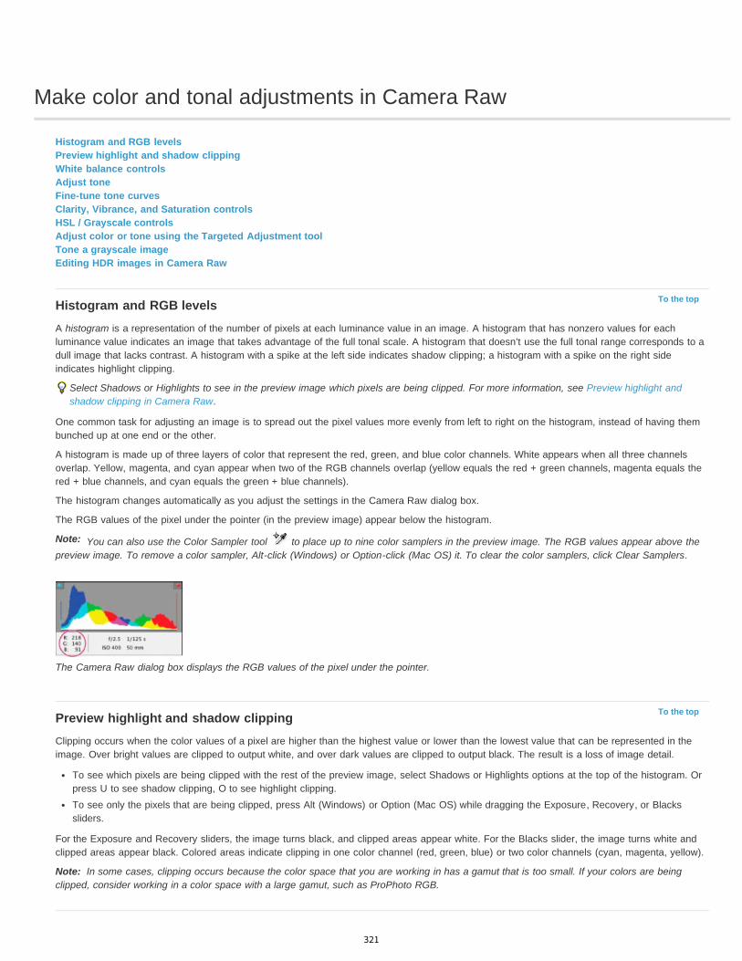
Make color and tonal adjustments in Camera Raw
To the top
Note:
To the top
Note:
Histogram and RGB levelsPreview highlight and shadow clippingWhite balance controlsAdjust toneFine-tune tone curvesClarity, Vibrance, and Saturation controlsHSL / Grayscale controlsAdjust color or tone using the Targeted Adjustment toolTone a grayscale imageEditing HDR images in Camera Raw
Histogram and RGB levelsA histogram is a representation of the number of pixels at each luminance value in an image. A histogram that has nonzero values for eachluminance value indicates an image that takes advantage of the full tonal scale. A histogram that doesn’t use the full tonal range corresponds to adull image that lacks contrast. A histogram with a spike at the left side indicates shadow clipping; a histogram with a spike on the right sideindicates highlight clipping.
Select Shadows or Highlights to see in the preview image which pixels are being clipped. For more information, see Preview highlight andshadow clipping in Camera Raw.
One common task for adjusting an image is to spread out the pixel values more evenly from left to right on the histogram, instead of having thembunched up at one end or the other.
A histogram is made up of three layers of color that represent the red, green, and blue color channels. White appears when all three channelsoverlap. Yellow, magenta, and cyan appear when two of the RGB channels overlap (yellow equals the red + green channels, magenta equals thered + blue channels, and cyan equals the green + blue channels).
The histogram changes automatically as you adjust the settings in the Camera Raw dialog box.
The RGB values of the pixel under the pointer (in the preview image) appear below the histogram.
You can also use the Color Sampler tool to place up to nine color samplers in the preview image. The RGB values appear above thepreview image. To remove a color sampler, Alt-click (Windows) or Option-click (Mac OS) it. To clear the color samplers, click Clear Samplers.
The Camera Raw dialog box displays the RGB values of the pixel under the pointer.
Preview highlight and shadow clippingClipping occurs when the color values of a pixel are higher than the highest value or lower than the lowest value that can be represented in theimage. Over bright values are clipped to output white, and over dark values are clipped to output black. The result is a loss of image detail.
To see which pixels are being clipped with the rest of the preview image, select Shadows or Highlights options at the top of the histogram. Orpress U to see shadow clipping, O to see highlight clipping.To see only the pixels that are being clipped, press Alt (Windows) or Option (Mac OS) while dragging the Exposure, Recovery, or Blackssliders.
For the Exposure and Recovery sliders, the image turns black, and clipped areas appear white. For the Blacks slider, the image turns white andclipped areas appear black. Colored areas indicate clipping in one color channel (red, green, blue) or two color channels (cyan, magenta, yellow).
In some cases, clipping occurs because the color space that you are working in has a gamut that is too small. If your colors are beingclipped, consider working in a color space with a large gamut, such as ProPhoto RGB.
321
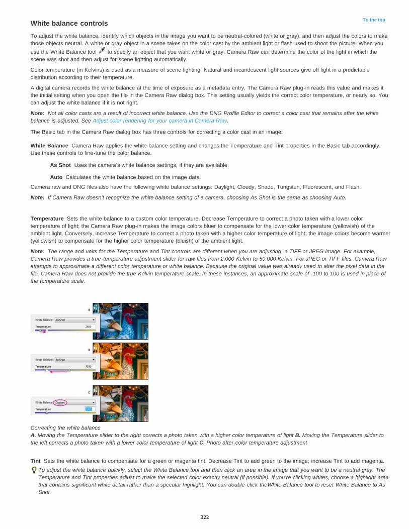
To the top
Note:
White Balance
As Shot
Auto
Note:
Temperature
Note:
Tint
White balance controlsTo adjust the white balance, identify which objects in the image you want to be neutral-colored (white or gray), and then adjust the colors to makethose objects neutral. A white or gray object in a scene takes on the color cast by the ambient light or flash used to shoot the picture. When youuse the White Balance tool to specify an object that you want white or gray, Camera Raw can determine the color of the light in which thescene was shot and then adjust for scene lighting automatically.
Color temperature (in Kelvins) is used as a measure of scene lighting. Natural and incandescent light sources give off light in a predictabledistribution according to their temperature.
A digital camera records the white balance at the time of exposure as a metadata entry. The Camera Raw plug-in reads this value and makes itthe initial setting when you open the file in the Camera Raw dialog box. This setting usually yields the correct color temperature, or nearly so. Youcan adjust the white balance if it is not right.
Not all color casts are a result of incorrect white balance. Use the DNG Profile Editor to correct a color cast that remains after the whitebalance is adjusted. See Adjust color rendering for your camera in Camera Raw.
The Basic tab in the Camera Raw dialog box has three controls for correcting a color cast in an image:
Camera Raw applies the white balance setting and changes the Temperature and Tint properties in the Basic tab accordingly.Use these controls to fine-tune the color balance.
Uses the camera’s white balance settings, if they are available.
Calculates the white balance based on the image data.
Camera raw and DNG files also have the following white balance settings: Daylight, Cloudy, Shade, Tungsten, Fluorescent, and Flash.
If Camera Raw doesn’t recognize the white balance setting of a camera, choosing As Shot is the same as choosing Auto.
Sets the white balance to a custom color temperature. Decrease Temperature to correct a photo taken with a lower colortemperature of light; the Camera Raw plug-in makes the image colors bluer to compensate for the lower color temperature (yellowish) of theambient light. Conversely, increase Temperature to correct a photo taken with a higher color temperature of light; the image colors become warmer(yellowish) to compensate for the higher color temperature (bluish) of the ambient light.
The range and units for the Temperature and Tint controls are different when you are adjusting a TIFF or JPEG image. For example,Camera Raw provides a true-temperature adjustment slider for raw files from 2,000 Kelvin to 50,000 Kelvin. For JPEG or TIFF files, Camera Rawattempts to approximate a different color temperature or white balance. Because the original value was already used to alter the pixel data in thefile, Camera Raw does not provide the true Kelvin temperature scale. In these instances, an approximate scale of -100 to 100 is used in place ofthe temperature scale.
Correcting the white balance A. Moving the Temperature slider to the right corrects a photo taken with a higher color temperature of light B. Moving the Temperature slider tothe left corrects a photo taken with a lower color temperature of light C. Photo after color temperature adjustment
Sets the white balance to compensate for a green or magenta tint. Decrease Tint to add green to the image; increase Tint to add magenta.To adjust the white balance quickly, select the White Balance tool and then click an area in the image that you want to be a neutral gray. TheTemperature and Tint properties adjust to make the selected color exactly neutral (if possible). If you’re clicking whites, choose a highlight areathat contains significant white detail rather than a specular highlight. You can double-click theWhite Balance tool to reset White Balance to AsShot.
322

To the top
Note:
Note:
Exposure (All)
Contrast (All)
Highlights (PV2012)
Shadows (PV2012)
Whites (PV2012)
Blacks (PV2012)
Blacks (PV2010 and PV2003)
Recovery (PV2010 and PV2003)
Fill Light (PV2010 and PV2003)
Brightness (PV2010 and PV2003)
Adjust toneYou adjust the image tonal scale using the tone controls in the Basic tab.
When you click Auto at the top of the tone controls section of the Basic tab, Camera Raw analyzes the image and makes automatic adjustmentsto the tone controls.
You can also apply automatic settings separately for individual tone controls. To apply an automatic adjustment to an individual tone control, suchas Exposure or Contrast, press Shift and double-click the slider. To return an individual tone control to its original value, double-click its slider.
When you adjust tone automatically, Camera Raw ignores any adjustments previously made in other tabs (such as fine-tuning of tone in the ToneCurves tab). For this reason, apply automatic tone adjustments first—if at all—to get an initial approximation of the best settings for your image. Ifyou are careful during shooting and have deliberately shot with different exposures, you probably don’t want to undo that work by applyingautomatic tone adjustments. On the other hand, you can always try clicking Auto and then undo the adjustments if you don’t like them.
Previews in Adobe® Bridge use the default image settings. If you want the default image settings to include automatic tone adjustments, selectApply Auto Tone Adjustments in the Default Image settings section of the Camera Raw preferences.
If you are comparing images based on their previews in Adobe Bridge, leave the Apply Auto Tone Adjustments preference deselected,which is the default. Otherwise, you’ll be comparing images that have already been adjusted.
As you make adjustments, keep an eye on the end points of the histogram, or use the shadow and highlight clipping previews.
While moving the tone controls sliders, hold down Alt (Windows) or Option (Mac OS) to preview where highlights or shadows are clipped.Move the slider until clipping begins, and then reverse the adjustment slightly. (For more information, see Preview highlight and shadowclipping in Camera Raw.)
To manually adjust a tone control, drag the slider, type a number in the box, or select the value in the box and press the Up or Down arrowkey.To reset a value to its default, double-click the slider control.
The tone controls that appear in the Basic panel depend on whether you are working in Process Version PV2012, PV2010, or PV2003, asnoted.
Adjusts the overall image brightness. Adjust the slider until the photo looks good and the image is the desired brightness.Exposure values are in increments equivalent to aperture values (f-stops) on a camera. An adjustment of +1.00 is similar to opening the aperture 1stop. Similarly, an adjustment of -1.00 is like closing the aperture 1 stop.
Increases or decreases image contrast, mainly affecting midtones. When you increase contrast, the middle-to-dark image areasbecome darker, and the middle-to-light image areas become lighter. The image tones are inversely affected as you decrease contrast.
Adjusts bright image areas. Drag to the left to darken highlights and recover “blown out” highlight details. Drag to the right tobrighten highlights while minimizing clipping.
Adjusts dark image areas. Drag to the left to darken shadows while minimizing clipping. Drag to the right to brighten shadowsand recover shadow details.
Adjusts white clipping. Drag to the left to reduce clipping in highlights. Drag to the right to increase highlight clipping. (Increasedclipping may be desirable for specular highlights, such as metallic surfaces.)
Adjusts black clipping. Drag to the left to increase black clipping (map more shadows to pure black). Drag to the right to reduceshadow clipping.
Specifies which image values map to black. Moving the slider to the right increases the areas that become black,sometimes creating the impression of increased image contrast. The greatest effect is in the shadows, with much less change in the midtones andhighlights.
Attempts to recover details from highlights. Camera Raw can reconstruct some details from areas in which oneor two color channels are clipped to white.
Attempts to recover details from shadows, without brightening blacks. Camera Raw can reconstruct some detailsfrom areas in which one or two color channels are clipped to black. Using Fill Light is like using the shadows portion of the Photoshop®Shadow/Highlight filter or the After Effects® Shadow/Highlight effect.
Adjusts the brightness or darkness of the image, much as the Exposure property does. However, instead ofclipping the image in the highlights or shadows, Brightness compresses the highlights and expands the shadows when you move the slider to theright. Often, the best way to use this control is to set the overall tonal scale by first setting Exposure, Recovery, and Blacks; then set Brightness.Large Brightness adjustments can affect shadow or highlight clipping, so you may want to readjust the Exposure, Recovery, or Blacks propertyafter adjusting Brightness.
Learn More: Watch the video tutorial What's New in Camera Raw by Matt Kloskowski. See also, Why You Should Set Photoshop to Open YourJPGs in Adobe Camera RAW - video tutorial by Terry White (8:07).
323
To the top
Note:
To the top
Clarity
Vibrance
Saturation
To the top
Hue
Saturation
Luminance
Grayscale Mix
To the top
Fine-tune tone curvesUse the controls in the Tone Curve tab to fine-tune images after you’ve made tone adjustments in the Basic tab. The tone curves representchanges made to the tonal scale of an image. The horizontal axis represents the original tone values of the image (input values), with black on theleft and progressively lighter values toward the right. The vertical axis represents the changed tone values (output values), with black on thebottom and progressing to white at the top.
If a point on the curve moves up, the output is a lighter tone; if it moves down, the output is a darker tone. A straight, 45-degree line indicates nochanges to the tone response curve: the original input values exactly match the output values.
Use the tone curve in the nested Parametric tab to adjust the values in specific tonal ranges in the image. The areas of the curve affected by theregion properties (Highlights, Lights, Darks, or Shadows) depend on where you set the split controls at the bottom of the graph. The middle regionproperties (Darks and Lights) mostly affect the middle region of the curve. The Highlight and Shadows properties mostly affect the ends of thetonal range.
To adjust tone curves, do any of the following:Drag the Highlights, Lights, Darks, or Shadows slider in the nested Parametric tab. You can expand or contract the curve regions that thesliders affect by dragging the region divider controls along the horizontal axis of the graph.Drag a point on the curve in the nested Point tab. As you drag the point, the Input and Output tonal values are displayed beneath thetone curve.Choose an option from the Curve menu in the nested Point tab. The setting you choose is reflected in the Point tab, but not in thesettings in the Parametric tab. Medium Contrast is the default setting.
Select the Parametric Curve Targeted Adjustment tool in the toolbar and drag in the image. The Parametric Curve TargetedAdjustment tool adjusts the Highlights, Lights, Darks, or Shadows curve region based on the values in the image where you click.
The Targeted Adjustment tool does not affect point curves.
Clarity, Vibrance, and Saturation controlsYou can change the color saturation of all colors by adjusting the Clarity, Vibrance, and Saturation controls on the Basic tab. (To adjust saturationfor a specific range of colors, use the controls on the HSL / Grayscale tab.)
Adds depth to an image by increasing local contrast, with greatest effect on the midtones. This setting is like a large-radius unsharp mask.When using this setting, it is best to zoom in to 100% or greater. To maximize the effect, increase the setting until you see halos near the edgedetails of the image and then reduce the setting slightly.
Adjusts the saturation so that clipping is minimized as colors approach full saturation. This setting changes the saturation of all lower-saturated colors with less effect on the higher-saturated colors. Vibrance also prevents skin tones from becoming oversaturated.
Adjusts the saturation of all image colors equally from -100 (monochrome) to +100 (double the saturation).
HSL / Grayscale controlsYou can use the controls in the HSL / Grayscale tab to adjust individual color ranges. For example, if a red object looks too vivid and distracting,you can decrease the Reds values in the nested Saturation tab.
The following nested tabs contain controls for adjusting a color component for a specific color range:
Changes the color. For example, you can change a blue sky (and all other blue objects) from cyan to purple.
Changes how vivid or pure the color. For example, you can change a blue sky from gray to highly saturated blue.
Changes the brightness of the color range.
If you select Convert To Grayscale, you see only one nested tab:
Use controls in this tab to specify the contribution of each color range to the grayscale version of the image.
Adjust color or tone using the Targeted Adjustment toolThe Targeted Adjustment tool allows you to make tonal and color corrections by dragging directly on a photo. Using the Targeted Adjustment tool,you can drag down on a blue sky to desaturate it, for example, or drag up on a red jacket to intensify its hue.
1. To make color adjustments with the Targeted Adjustment tool , click it in the toolbar and choose the type of correction you want to make:Hue, Saturation, Luminance, or Grayscale Mix. Then, drag in the image.
324

Twitter™ and Facebook posts are not covered under the terms of Creative Commons.
Legal Notices | Online Privacy Policy
To the top
To the top
Dragging up or right increases values; dragging down or left decreases values. Sliders for more than one color may be affected when youdrag with the Targeted Adjustment tool. Selecting the Grayscale Mix Targeted Adjustment tool converts the image to grayscale.
2. To make tone curve adjustments using the Targeted Adjustmenttool , click it in the toolbar and choose Parametric Curve. Then, drag inthe image.
The Parametric Curve Targeted Adjustment tool adjusts the Highlights, Lights, Darks, or Shadows curve region based on the values in theimage where you click.
The keyboard shortcut T toggles the last Targeted Adjustment tool you used.
Tone a grayscale imageUse the controls in the Split Toning tab to color a grayscale image. You can add one color throughout the tonal range, such as a sepiaappearance, or create a split tone result, in which a different color is applied to the shadows and the highlights. The extreme shadows andhighlights remain black and white.
You can also apply special treatments, such as a cross-processed look, to a color image.
1. Select a grayscale image. (It can be an image that you converted to grayscale by selecting Convert To Grayscale in the HSL / Grayscaletab.)
2. In the Split Toning tab, adjust the Hue and Saturation properties for the highlights and shadows. Hue sets the color of the tone; Saturationsets the magnitude of the result.
3. Adjust the Balance control to balance the influence between the Highlight and Shadow controls. Positive values increase the influence of theHighlight controls; negative values increase the influence of the Shadow controls.
Editing HDR images in Camera RawIn Camera Raw 7.1 or later, you can work with 16-, 24-, and 32-bit floating point images--often referred to as HDR (high dynamic range images).Camera Raw opens TIFF and DNG format HDR images. Make sure that the images are in process version 2012. (See Process Versions.)
You can use the Basic tab controls to edit HDR images. The Basic tab Exposure control has an expanded range when working with HDR images(+10 to -10).
When you are done editing, click Done or Open Image to open the image in Photoshop. The image opens as a 16-bit or 8-bit image, dependingon how you have the Workflow Options set.
To open an HDR image in Camera Raw:
In Bridge, select the image and choose File > Open In Camera Raw. In mini-Bridge, right-click the image (Ctlr-click on Mac) and chooseOpen With > Camera Raw.
For more information about HDR images, see High dynamic range images in Photoshop Help.
325
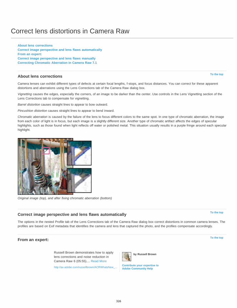
Correct lens distortions in Camera Raw
To the top
To the top
To the top
About lens correctionsCorrect image perspective and lens flaws automaticallyFrom an expert:Correct image perspective and lens flaws manuallyCorrecting Chromatic Aberration in Camera Raw 7.1
About lens correctionsCamera lenses can exhibit different types of defects at certain focal lengths, f-stops, and focus distances. You can correct for these apparentdistortions and aberrations using the Lens Corrections tab of the Camera Raw dialog box.
Vignetting causes the edges, especially the corners, of an image to be darker than the center. Use controls in the Lens Vignetting section of theLens Corrections tab to compensate for vignetting.
Barrel distortion causes straight lines to appear to bow outward.
Pincushion distortion causes straight lines to appear to bend inward.
Chromatic aberration is caused by the failure of the lens to focus different colors to the same spot. In one type of chromatic aberration, the imagefrom each color of light is in focus, but each image is a slightly different size. Another type of chromatic artifact affects the edges of specularhighlights, such as those found when light reflects off water or polished metal. This situation usually results in a purple fringe around each specularhighlight.
Original image (top), and after fixing chromatic aberration (bottom)
Correct image perspective and lens flaws automaticallyThe options in the nested Profile tab of the Lens Corrections tab of the Camera Raw dialog box correct distortions in common camera lenses. Theprofiles are based on Exif metadata that identifies the camera and lens that captured the photo, and the profiles compensate accordingly.
From an expert:
Russell Brown demonstrates how to applylens corrections and noise reduction inCamera Raw 6 (05:55).... Read More
http://av.adobe.com/russellbrown/ACRWhatsNew_...
by Russell Brown
Contribute your expertise toAdobe Community Help
326
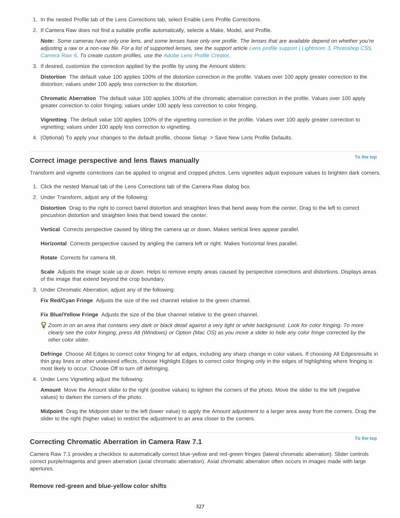
Note:
Distortion
Chromatic Aberration
Vignetting
To the top
Distortion
Vertical
Horizontal
Rotate
Scale
Fix Red/Cyan Fringe
Fix Blue/Yellow Fringe
Defringe
Amount
Midpoint
To the top
1. In the nested Profile tab of the Lens Corrections tab, select Enable Lens Profile Corrections.
2. If Camera Raw does not find a suitable profile automatically, selecte a Make, Model, and Profile.
Some cameras have only one lens, and some lenses have only one profile. The lenses that are available depend on whether you’readjusting a raw or a non-raw file. For a list of supported lenses, see the support article Lens profile support | Lightroom 3, Photoshop CS5,Camera Raw 6. To create custom profiles, use the Adobe Lens Profile Creator.
3. If desired, customize the correction applied by the profile by using the Amount sliders:
The default value 100 applies 100% of the distortion correction in the profile. Values over 100 apply greater correction to thedistortion; values under 100 apply less correction to the distortion.
The default value 100 applies 100% of the chromatic aberration correction in the profile. Values over 100 applygreater correction to color fringing; values under 100 apply less correction to color fringing.
The default value 100 applies 100% of the vignetting correction in the profile. Values over 100 apply greater correction tovignetting; values under 100 apply less correction to vignetting.
4. (Optional) To apply your changes to the default profile, choose Setup > Save New Lens Profile Defaults.
Correct image perspective and lens flaws manuallyTransform and vignette corrections can be applied to original and cropped photos. Lens vignettes adjust exposure values to brighten dark corners.
1. Click the nested Manual tab of the Lens Corrections tab of the Camera Raw dialog box.
2. Under Transform, adjust any of the following:
Drag to the right to correct barrel distortion and straighten lines that bend away from the center. Drag to the left to correctpincushion distortion and straighten lines that bend toward the center.
Corrects perspective caused by tilting the camera up or down. Makes vertical lines appear parallel.
Corrects perspective caused by angling the camera left or right. Makes horizontal lines parallel.
Corrects for camera tilt.
Adjusts the image scale up or down. Helps to remove empty areas caused by perspective corrections and distortions. Displays areasof the image that extend beyond the crop boundary.
3. Under Chromatic Aberration, adjust any of the following:
Adjusts the size of the red channel relative to the green channel.
Adjusts the size of the blue channel relative to the green channel.
Zoom in on an area that contains very dark or black detail against a very light or white background. Look for color fringing. To moreclearly see the color fringing, press Alt (Windows) or Option (Mac OS) as you move a slider to hide any color fringe corrected by theother color slider.
Choose All Edges to correct color fringing for all edges, including any sharp change in color values. If choosing All Edgesresults inthin gray lines or other undesired effects, choose Highlight Edges to correct color fringing only in the edges of highlighting where fringing ismost likely to occur. Choose Off to turn off defringing.
4. Under Lens Vignetting adjust the following:
Move the Amount slider to the right (positive values) to lighten the corners of the photo. Move the slider to the left (negativevalues) to darken the corners of the photo.
Drag the Midpoint slider to the left (lower value) to apply the Amount adjustment to a larger area away from the corners. Drag theslider to the right (higher value) to restrict the adjustment to an area closer to the corners.
Correcting Chromatic Aberration in Camera Raw 7.1Camera Raw 7.1 provides a checkbox to automatically correct blue-yellow and red-green fringes (lateral chromatic aberration). Slider controlscorrect purple/magenta and green aberration (axial chromatic aberration). Axial chromatic aberration often occurs in images made with largeapertures.
Remove red-green and blue-yellow color shifts
327

Twitter™ and Facebook posts are not covered under the terms of Creative Commons.
Legal Notices | Online Privacy Policy
Note:
In the Color tab of the Lens Correction panel, select the Remove Chromatic Aberration checkbox.
Remove global purple/magenta and green fringesIn the Color tab of the Lens Correction panel, adjust the purple and green Amount sliders. The higher the amount, the more color defringing. Takecare not apply an adjustment that affects purple or green objects in your image.
You can adjust the affected purple or green hue range using the Purple Hue and the Green Hue sliders. Drag either end-point control to expand ordecrease the range of affected colors. Drag between the end point controls to move the hue range. The minimum space between end points is tenunits. The default spacing for the green sliders is narrow to protect green/yellow image colors, like foliage.
You can protect edges of purple and green objects using the local adjustment brush.
Press the Alt/Option key as you drag any of the sliders to help visualize the adjustment. The fringe color becomes neutral as you drag to removethe color.
Remove local color fringesLocal brush and gradient adjustments remove fringes of all colors. Local defringe is available for Process Version 2012 only.
Select the brush or gradient tools and drag in the image.Adjust the Defringe slider. A plus value removes the color fringe. Minus values protect image areas from defringing that you apply globally.Minus 100 protects the area from any defringing. For example, applying a strong global purple defringe can desaturate or alter edges ofpurple objects in your image. Painting with Defringe -100 over those areas protects them and keep them at their original color.
For best results, perform any Transform lens corrections before applying local color defringe adjustments.
328
Make local adjustments in Camera Raw
To the top
To the top
Note:
Temp (PV2012)
Tint (PV2012)
Exposure (All)
Highlights (PV2012)
Shadows (PV2012)
Brightness (PV2010 and PV2003)
Contrast (All)
Saturation (All)
Clarity (All)
Sharpness (All)
Noise Reduction (PV2012)
About local adjustmentsApply local adjustments with the Adjustment Brush tool in Camera RawApply local adjustments with the Graduated Filter tool in Camera RawSave and apply local adjustment presets
About local adjustmentsThe controls in the image adjustment tabs of Camera Raw affect the color and tone of an entire photo. To adjust a specific area of a photo, like
dodging and burning, use the Adjustment Brush tool and the Graduated Filter tool in Camera Raw.
The Adjustment Brush tool lets you selectively apply Exposure, Brightness, Clarity, and other adjustments by “painting” them onto the photo.
The Graduated Filter tool lets you apply the same types of adjustments gradually across a region of a photo. You can make the region as wide oras narrow as you like.
You can apply both types of local adjustments to any photo. You can synchronize local adjustment settings across multiple selected images. Youcan also create local adjustment presets so that you can quickly reapply an effect that you use frequently.
Getting local adjustments “right” in Camera Raw takes some experimentation. The recommended workflow is to select a tool and specify itsoptions, and then apply the adjustment to the photo. Then you can go back and edit that adjustment, or apply a new one.
As with all other adjustments applied in Camera Raw, local adjustments are nondestructive. They are never permanently applied to the photo.Local adjustments are saved with an image in an XMP sidecar file or in the Camera Raw database, depending on what’s specified in Camera Rawpreferences.
Apply local adjustments with the Adjustment Brush tool in Camera Raw
1. Select the Adjustment Brush tool from the toolbar (or press K).
Camera Raw opens the Adjustment Brush tool options under the Histogram and sets the mask mode to New.
2. Choose the type of adjustment you want to make in the Adjustment Brush tool options by dragging an effects slider.
The effects that are available depend on whether you are working in Process Version 2012, 2010, or 2003, as noted. To update aphoto to PV2012, click the exclamation-point icon in the lower-right corner of the image preview.
Adjusts the color temperature of an area of the image, making it warmer or cooler. A graduated filter temperature effectcan improve images captured in mixed-lighting conditions.
Compensates for a green or magenta color cast.
Sets the overall image brightness. Applying an Exposure local correction can achieve results similar to traditional dodgingand burning.
Recovers detail in overexposed highlight areas of an image.
Recovers detail in underexposed shadow areas of an image.
Adjusts the image brightness, with a greater effect in the midtones.
Adjusts the image contrast, with a greater effect in the midtones.
Changes the vividness or purity of the color.
Adds depth to an image by increasing local contrast.
Enhances edge definition to bring out details in a photo. A negative value blurs details.
Reduces luminance noise, which can become apparent when shadow areas are opened.
329
Moiré Reduction (PV2012)
Defringe (PV2012)
Color (All)
Size
Feather
Flow
Density
Auto Mask
Show Mask
Note:
Note:
To the top
Note:
Temp (PV2012)
Removes moiré artifacts, or color aliasing.
Removes fringe colors along edges. See Remove local color fringes.
Applies a tint to the selected area. Select the hue by clicking the color sample box to the right of the effect name.
Click the Plus icons (+) or the Minus icons (-) to increase or decrease the effect by a preset amount. Click multiple times to select astronger adjustment. Double-click the slider to reset the effect to zero.
3. Specify brush options:
Specifies the diameter of the brush tip, in pixels.
Controls the hardness of the brush stroke.
Controls the rate of application of the adjustment.
Controls the amount of transparency in the stroke.
Confines brush strokes to areas of similar color.
Toggles visibility of the mask overlay in the image preview.
4. Move the Adjustment Brush tool over the image.
The cross hair indicates the application point. The solid circle indicates the brush size. The black-and-white dashed circle indicates thefeather amount.
If the Feather is set to 0, the black-and-white circle indicates the brush size. With very small feather amounts, the solid circle may notbe visible.
5. Paint with the Adjustment Brush tool in the area of the image that you want to adjust.
When you release the mouse, a pin icon appears at the application point. In the Adjustment Brush tool options, the mask mode changesto Add.
6. (Optional) Refine the adjustment by doing any of the following:Drag any of the effect sliders in the Adjustment Brush tool options to customize the effect in the image.
Press V to hide or show the pin icon.
To toggle visibility of the mask overlay, use the Show Mask option, press Y, or position the pointer over the pin icon.
To customize the color of the mask overlay, click the color swatch next to the Show Mask option. Then, choose a new color from theColor Picker.
To undo part of the adjustment, click Erase in the Adjustment Brush tool options and paint over the adjustment.
To create an eraser brush that has different characteristics from the current Adjustment Brush tool, click the Local Adjustment Settingsmenu button and choose Separate Eraser Size. Then, specify the Size, Feather, Flow, and Density you want for the eraser.
Remove the adjustment completely by selecting the pin and pressing Delete.
Press Ctrl+Z (Windows) or Command+Z (Mac OS) to undo your last adjustment.
Click Clear All at the bottom of the tool options to remove all Adjustment Brush tool adjustments and set the mask mode to New.
7. (Optional) Click New to apply an additional Adjustment Brush tool adjustment, and refine it as desired using the techniques in step 6.
When working with multiple Adjustment Brush adjustments, make sure you’re in Add mode to switch between them. Click a pin iconto select that adjustment and refine it.
Apply local adjustments with the Graduated Filter tool in Camera Raw1. Select the Graduated Filter tool from the toolbar (or press G).
Camera Raw opens the Graduated Filter tool options under the Histogram and sets the mask mode to New.
2. Choose the type of adjustment you want to make in the Graduated Filter tool options by dragging the slider for any of the following effects:
The effects that are available depend on whether you are working in Process Version 2012, 2010, or 2003, as noted. To update aphoto to PV2012, click the exclamation-point icon in the lower-right corner of the image preview.
Adjusts the color temperature of an area of the image, making it warmer or cooler. A graduated filter temperature effectcan improve images captured in mixed-lighting conditions.
330
Tint (PV2012)
Exposure (All)
Highlights (PV2012)
Shadows (PV2012)
Brightness (PV2010 and PV2003)
Contrast (All)
Saturation (All)
Clarity (All)
Sharpness (All)
Noise Reduction (PV2012)
Moiré Reduction (PV2012)
Defringe (PV 2012)
Color (All)
Note:
To the top
Note:
New Local Correction Setting
Compensates for a green or magenta color cast.
Sets the overall image brightness. Applying an Exposure graduated filter can achieve results similar to traditional dodgingand burning.
Recovers detail in overexposed highlight areas of an image.
Recovers detail in underexposed shadow areas of an image.
Adjusts the image brightness, with a greater effect in the midtones.
Adjusts the image contrast, with a greater effect in the midtones.
Changes the vividness or purity of the color.
Adds depth to an image by increasing local contrast.
Enhances edge definition to bring out details in the photo. A negative value blurs details.
Reduces luminance noise, which can become apparent when shadow areas are opened.
Removes moiré artifacts, or color aliasing.
Removes fringe color along edges. See Remove local color fringes.
Applies a tint to the selected area. Select the hue by clicking the color sample box to the right of the effect name.
Click the Plus icon (+) or the Minus icon (-) to increase or decrease the effect by a preset amount. Double-click the slider to reset theeffect to zero.
3. Drag in the photo to apply a graduated filter across a region of the photo.
The filter starts at the red dot and red dotted line, and it continues past the green dot and green dotted line.
The mask mode switches to Edit in the Graduated Filter tool options.
4. (Optional) Refine the filter by doing any of the following:Drag any of the effect sliders in the Graduated Filter tool options to customize the filter.
Toggle visibility of the guide overlays by selecting the Show Overlay option (or press V).
Drag the green or red dot to freely expand, contract, and rotate the effect.
Drag the black-and-white dotted line to shift the effect.
Position the pointer over the green-and-white or red-and-white dotted line, near the green or red dot, until a double-pointing arrowappears. Then, drag to expand or contract the effect at that end of the range.
Position the pointer over the green-and-white or red-and-white dotted line, away from the green or red dot, until a curved double-pointingarrow appears. Then, drag to rotate the effect.
Remove the filter by pressing Delete.
Press Ctrl+Z (Windows) or Command+Z (Mac OS) to undo your last adjustment.
Click Clear All at the bottom of the tool options to remove all Graduated Filter tool effects and set the mask mode to New.
5. (Optional) Click New to apply an additional Graduated Filter tool effect, and refine it as desired using the techniques in step 4.
When working with multiple Graduated Filter effects, click an overlay to select that effect and refine it.
Save and apply local adjustment presetsYou can save local adjustments as presets so that you can quickly apply the effects to other images. You create, select, and manage localadjustment presets using the Camera Raw Settings menu in the Adjustment Brush or Graduated Filter tool options. You apply local adjustment
presets using the Adjustment Brush tool or the Graduated Filter tool .
Local adjustments cannot be saved with Camera Raw image presets.
In the Adjustment Brush or Graduated Filter tool options in the Camera Raw dialog box, click the Camera Raw Settings menu button .Then, choose one of the following commands:
Saves the current local adjustment effect settings as a preset. Type a name and click OK. Saved presets
331
Twitter™ and Facebook posts are not covered under the terms of Creative Commons.
Legal Notices | Online Privacy Policy
Delete “preset name”
Rename “preset name”
Preset name
appear in the Local Adjustment Settings menu and can be applied to any image that is opened in Camera Raw.
Deletes the selected local adjustment preset.
Renames the selected local adjustment preset. Type a name and click OK.
Select a preset to apply its settings with the Adjustment Brush tool or the Graduated Filter tool.
When using local adjustment presets, keep in mind the following:
Only one local adjustment preset can be selected at a time.
When applying a local adjustment preset with the Adjustment Brush tool, you can still customize the brush options, including Size, Feather,Flow, and Density. The preset applies the effect settings at the specified brush size.
After a local adjustment preset is applied, you can refine it as desired.
The same effect settings are available for the Adjustment Brush tool and the Graduated Filter tool. As a result, local adjustment presets canbe applied using either tool, regardless of which tool was used to create the preset.
Video tutorialWhat's new in Camera Raw 7
332
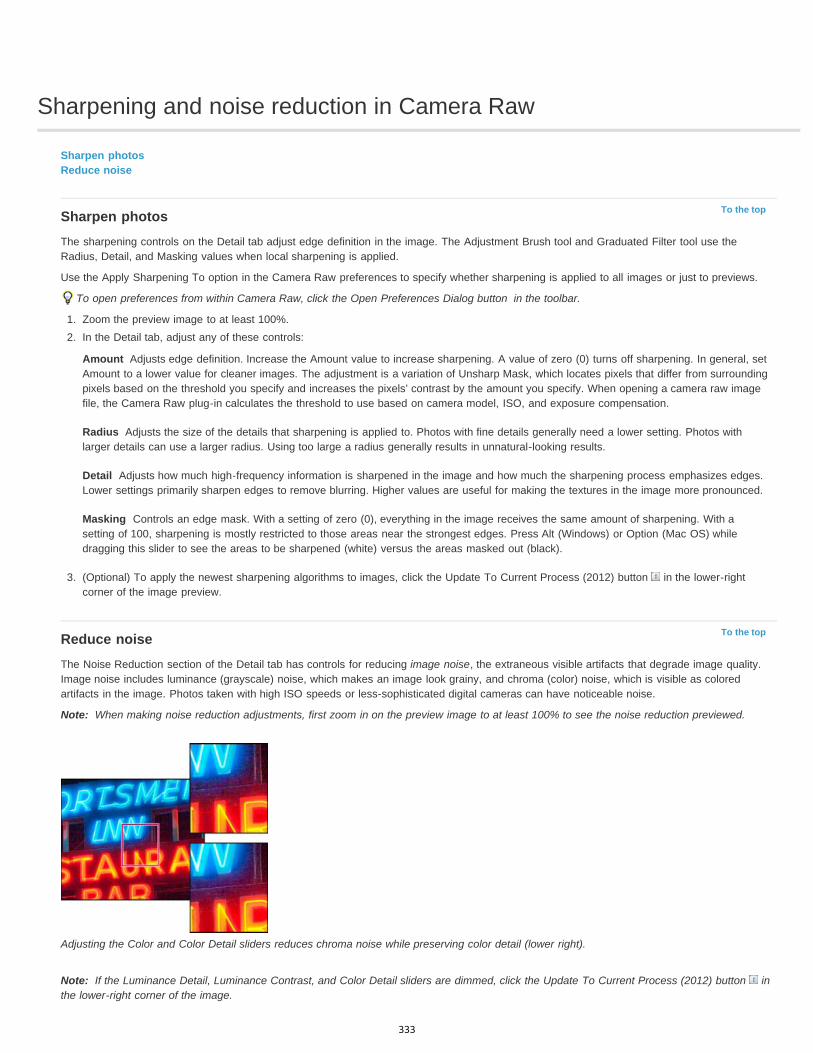
Sharpening and noise reduction in Camera Raw
To the top
Amount
Radius
Detail
Masking
To the top
Note:
Note:
Sharpen photosReduce noise
Sharpen photosThe sharpening controls on the Detail tab adjust edge definition in the image. The Adjustment Brush tool and Graduated Filter tool use theRadius, Detail, and Masking values when local sharpening is applied.
Use the Apply Sharpening To option in the Camera Raw preferences to specify whether sharpening is applied to all images or just to previews.
To open preferences from within Camera Raw, click the Open Preferences Dialog button in the toolbar.
1. Zoom the preview image to at least 100%.2. In the Detail tab, adjust any of these controls:
Adjusts edge definition. Increase the Amount value to increase sharpening. A value of zero (0) turns off sharpening. In general, setAmount to a lower value for cleaner images. The adjustment is a variation of Unsharp Mask, which locates pixels that differ from surroundingpixels based on the threshold you specify and increases the pixels’ contrast by the amount you specify. When opening a camera raw imagefile, the Camera Raw plug-in calculates the threshold to use based on camera model, ISO, and exposure compensation.
Adjusts the size of the details that sharpening is applied to. Photos with fine details generally need a lower setting. Photos withlarger details can use a larger radius. Using too large a radius generally results in unnatural-looking results.
Adjusts how much high-frequency information is sharpened in the image and how much the sharpening process emphasizes edges.Lower settings primarily sharpen edges to remove blurring. Higher values are useful for making the textures in the image more pronounced.
Controls an edge mask. With a setting of zero (0), everything in the image receives the same amount of sharpening. With asetting of 100, sharpening is mostly restricted to those areas near the strongest edges. Press Alt (Windows) or Option (Mac OS) whiledragging this slider to see the areas to be sharpened (white) versus the areas masked out (black).
3. (Optional) To apply the newest sharpening algorithms to images, click the Update To Current Process (2012) button in the lower-rightcorner of the image preview.
Reduce noiseThe Noise Reduction section of the Detail tab has controls for reducing image noise, the extraneous visible artifacts that degrade image quality.Image noise includes luminance (grayscale) noise, which makes an image look grainy, and chroma (color) noise, which is visible as coloredartifacts in the image. Photos taken with high ISO speeds or less-sophisticated digital cameras can have noticeable noise.
When making noise reduction adjustments, first zoom in on the preview image to at least 100% to see the noise reduction previewed.
Adjusting the Color and Color Detail sliders reduces chroma noise while preserving color detail (lower right).
If the Luminance Detail, Luminance Contrast, and Color Detail sliders are dimmed, click the Update To Current Process (2012) button inthe lower-right corner of the image.
333
Twitter™ and Facebook posts are not covered under the terms of Creative Commons.
Legal Notices | Online Privacy Policy
Luminance
Luminance Detail
Luminance Contrast
Color
Color Detail
Reduces luminance noise.
Controls the luminance noise threshold. Useful for noisy photos. Higher values preserve more detail but can produce noisierresults. Lower values produce cleaner results but also remove some detail.
Controls the luminance contrast. Useful for noisy photos. Higher values preserve contrast but can produce noisy blotches ormottling. Lower values produce smoother results but can also have less contrast.
Reduces color noise.
Controls the color noise threshold. Higher values protect thin, detailed color edges but can result in color specking. Lower valuesremove color speckles but can result in color bleeding.
For video tutorials about reducing noise in Camera Raw, see:
Better noise reduction in Photoshop® CS5 by Matt Kloskowski
Lens correction and noise reduction with Adobe® Camera Raw by Russell Brown
Photoshop CS5 - Camera Raw 6.0 by Justin Seeley
334
Process versions in Camera Raw
Twitter™ and Facebook posts are not covered under the terms of Creative Commons.
Legal Notices | Online Privacy Policy
Process Version 2012
Process Version 2010
Process Version 2003
The process version is the technology that Camera Raw uses to adjust and render photos. Depending on which process version you use, differentoptions and settings area available to you in the Basic tab and when you make local adjustments.
Images edited for the first time in Camera Raw 7 use process version 2012. PV2012 offers new tone controls and newtone-mapping algorithms for high-contrast images. With PV2012, you can adjust Highlights, Shadows, Whites, Blacks, Exposure, and Contrast inthe Basic panel. You can also apply local corrections for white balance (Temp and Tint), Highlights, Shadows, Noise, and Moiré.
Images edited in Camera Raw 6 used PV2010 by default. PV2010 offers improved sharpening and noise-reduction fromthe previous process version, PV2003.
The original processing engine, used by Camera Raw versions 5.x and earlier.
To take advantage of the newer processing, you can update previously edited photos to the current process version.
To update a photo to the Camera Raw 7 process (PV2012), do either of the following:
Click the Update to Current Process button (the exclamation-point icon) in the lower-right corner of the image preview.In the Camera Calibration tab, choose Process > 2012 (Current).
To apply an older process version to a photo, go to the Camera Calibration tab and choose Process > 2010 or Process > 2003.
Video tutorialWhat's new in Camera Raw 7
335
Adjust color rendering for your camera in Camera Raw
To the top
To the top
To the top
To the top
Apply a camera profileSpecify a default camera profileApply a profile to a group of imagesCreate a camera profile presetCustomize profiles using the DNG Profile Editor
For each camera model it supports, Camera Raw uses color profiles to process raw images. These profiles are produced by photographing colortargets under standardized lighting conditions and are not ICC color profiles.
ACR version These profiles are compatible with older versions of Camera Raw and Lightroom. The version corresponds to the version of CameraRaw in which the profile first appeared. ACR profiles offer consistent behavior with legacy photos.Adobe Standard Standard profiles significantly improve color rendering, especially in warm tones such as reds, yellows, and oranges, from earlierAdobe camera profiles.Camera Matching Camera Matching profiles attempt to match the camera manufacturer’s color appearance under specific settings. Use CameraMatching profiles if you prefer the color rendering offered by your camera manufacturer’s software.BothAdobe Standard and Camera Matching camera profiles are intended to serve as a starting point for further image adjustments. Therefore, usethe profiles in conjunction with the color and tone controls in the Basic, Tone Curve, HSL / Grayscale, and other image adjustment tabs.
To manually install camera profiles, place them in the following locations:
Windows XP C:\Documents and Settings\All Users\Application Data\Adobe\CameraRaw\CameraProfilesWindows Vista C:\ProgramData\Adobe\CameraRaw\CameraProfilesWindows 7 C:\ProgramData\Adobe\CameraRaw\CameraProfilesMac OS /Library/Application Support/Adobe/CameraRaw/CameraProfiles
Apply a camera profile To apply a camera profile, select it from the Camera Profile pop-up menu in the Camera Calibration tab of the Camera Raw dialog box.
The Adobe Standard profile for a camera is named Adobe Standard. Camera Matching profiles include the prefix Camera in the profile name. TheCamera Profile pop-up menu displays only profiles for your camera.
If the only profile in the Camera Profilemenu is Embedded, it means that you have selected a TIFF or JPEG image. Adobe Standard and CameraMatching profiles work only with raw images.
Note: If you have selected a raw file and Adobe Standardand Camera Matching profiles do not appear in the Camera Profilepop-up menu,download the latest Camera Raw update from the Digital camera raw file support page.
Specify a default camera profile1. Select a profile from the Camera Profilepop-up menu in the Camera Calibration tab of the Camera Raw dialog box.2. Click the Camera Raw Settings menu button and choose Save New Camera Raw Defaults from the menu.
Apply a profile to a group of images1. Select the images in the Filmstrip.2. Choose a profile from the Camera Profile pop-up menu in the Camera Calibration tab of the Camera Raw dialog box.3. Click the Synchronize button.4. In the Synchronize dialog box, choose Synchronize >Camera Calibration, and then click OK.
Create a camera profile presetIf you find yourself often applying the same profile, you can work more efficiently by creating and applying a preset.
1. Choose a profile from the Camera Profile pop-up menu in the Camera Calibration tab of the Camera Raw dialog box.2. Click the Camera Raw Settings menu button and choose Save Settings from the menu.3. In the Save Settings dialog box, choose Subset >Camera Calibration, and then click OK.4. Name your preset and click Save.
336
To the top
5. To apply the preset to a group of images, select the images and then choose Apply Preset > Preset Name from the Camera Raw Settingsmenu.
Customize profiles using the DNG Profile EditorTo improve color rendering or customize a camera profile, use the standalone DNG Profile Editor utility. For example, use the DNG Profile Editorto correct an unwanted color cast in a profile or to optimize colors for a specific application, such as studio portraits or fall foliage.
The DNG Profile Editorand documentation for it are available on Adobe Labs.
Important: Leave the Camera Calibration tab sliders set to 0 when adjusting camera profiles with the DNG Profile Editor.
|
337
Manage Camera Raw settings
To the top
To the top
To the top
Save image states as snapshotsSave, reset, and load Camera Raw settingsSpecify where Camera Raw settings are storedCopy and paste Camera Raw settingsApply saved Camera Raw settingsExport Camera Raw settings and DNG previewsSpecify Camera Raw workflow options
Save image states as snapshotsYou can record the state of an image at any time by creating a snapshot. Snapshots are stored renditions of an image that contain the completeset of edits made up until the time the snapshot is created. By creating snapshots of an image at various times during the editing process, you caneasily compare the effects of the adjustments that you make. You can also return to an earlier state if you want to use it at another time. Anotherbenefit of snapshots is that you can work from multiple versions of an image without having to duplicate the original.
Snapshots are created and managed using the Snapshots tab of the Camera Raw dialog box.
1. Click the New Snapshot button at the bottom of the Snapshots tab to create a snapshot.2. Type a name in the New Snapshot dialog box and click OK.
The snapshot appears in the Snapshots tab list.
When working with snapshots, you can do any of the following:
To rename a snapshot, right-click (Windows) or Control-click (Mac OS) it and choose Rename.
Click a snapshot to change the current image settings to those of the selected snapshot. The image preview updates accordingly.
To update, or overwrite, an existing snapshot with the current image settings, right-click (Windows) or Control-click (Mac OS) the snapshotand choose Update With Current Settings.
To undo changes made to a snapshot, click Cancel.
Important: Use caution when clicking Cancel to undo snapshot changes. All image adjustments made during the current editing session arealso lost.
To delete a snapshot, select it and click the Trash button at the bottom of the tab. Or, right-click (Windows) or Control-click (Mac OS) thesnapshot and choose Delete.
Snapshots applied in Photoshop Lightroom appear and can be edited in the Camera Raw dialog box. Similarly, snapshots created in CameraRaw appear and can be edited in Lightroom.
Save, reset, and load Camera Raw settingsYou can reuse the adjustments that you’ve made to an image. You can save all of the current Camera Raw image settings, or any subset of them,as a preset or as a new set of defaults. The default settings apply to a specific camera model, a specific camera serial number, or a specific ISOsetting, depending on the settings in the Default Image Settings section of the Camera Raw preferences.
Presets appear by name in the Presets tab, in the Edit > Develop Settings menu in Adobe Bridge, in the context menu for camera raw images inAdobe Bridge, and in the Apply Presets submenu of the Camera Raw Settings menu in the Camera Raw dialog box. Presets are not listed inthese locations if you don’t save them to the Camera Raw settings folder. However, you can use the Load Settings command to browse for andapply settings saved elsewhere.
You can save and delete presets using the buttons at the bottom of the Presets tab.
Click the Camera Raw Settings menu button and choose a command from the menu:Save Settings Saves the current settings as a preset. Choose which settings to save in the preset, and then name and save the preset.Save New Camera Raw Defaults Saves the current settings as the new default settings for other images taken with the same camera, with thesame camera model, or with the same ISO setting. Select the appropriate options in the Default Image Settings section of the Camera Rawpreferences to specify whether to associate the defaults with a specific camera’s serial number or with an ISO setting.Reset Camera Raw Defaults Restores the original default settings for the current camera, camera model, or ISO setting.Load Settings Opens the Load Raw Conversion Settings dialog box, in which you browse to the settings file, select it, and then click Load.
338
To the top
To the top
Specify where Camera Raw settings are storedChoose a preference to specify where the settings are stored. The XMP files are useful if you plan to move or store the image files and want toretain the camera raw settings. You can use the Export Settings command to copy the settings in the Camera Raw database to sidecar XMP filesor embed the settings in Digital Negative (DNG) files.
When a camera raw image file is processed with Camera Raw, the image settings are stored in one of two places: the Camera Raw database fileor a sidecar XMP file. When a DNG file is processed in Camera Raw, the settings are stored in the DNG file itself, but they can be stored in asidecar XMP file instead. Settings for TIFF and JPEG files are always stored in the file itself.
Note: When you import a sequence of camera raw files in After Effects, the settings for the first file are applied to all files in the sequence that donot have their own XMP sidecar files. After Effects does not check the Camera Raw database.You can set a preference to determine where settings are stored. When you reopen a camera raw image, all settings default to the values usedwhen the file was last opened. Image attributes (target color space profile, bit depth, pixel size, and resolution) are not stored with the settings.
1. In Adobe Bridge, choose Edit > Camera Raw Preferences (Windows) or Bridge > Camera Raw Preferences(Mac OS). Or, in the CameraRaw dialog box, click the Open Preferences Dialog button . Or, in Photoshop, choose Edit >Preferences > Camera Raw (Windows) orPhotoshop > Preferences > Camera Raw (Mac OS).
2. In the Camera Raw Preferences dialog box, choose one of the following from the Save Image Settings In menu:Camera Raw Database Stores the settings in a Camera Raw database file in the folder Document and Settings/[user name]/ApplicationData/Adobe/CameraRaw (Windows) or Users/[user name]/Library/Preferences (Mac OS). This database is indexed by file content, so theimage retains camera raw settings even if the camera raw image file is moved or renamed.
Sidecar “.XMP” Files Stores the settings in a separate file, in the same folder as the camera raw file, with the same base name and an.xmp extension. This option is useful for long-term archiving of raw files with their associated settings, and for the exchange of camera rawfiles with associated settings in multiuser workflows. These same sidecar XMP files can store IPTC (International Press TelecommunicationsCouncil) data or other metadata associated with a camera raw image file. If you open files from a read-only volume such as a CD or DVD,be sure to copy the files to your hard disk before opening them. The Camera Raw plug-in cannot write an XMP file to a read-only volumeand writes the settings to the Camera Raw database file instead. You can view XMP files in Adobe Bridge by choosing View >Show HiddenFiles.
Important: If you are using a revision control system to manage your files and are storing settings in sidecar XMP files, keep in mind thatyou must check your sidecar files in and out to change camera raw images; similarly, you must manage (e.g., rename, move, delete) XMPsidecar files together with their camera raw files. Adobe Bridge, Photoshop, After Effects, and Camera Raw take care of this filesynchronization when you work with files locally.
If you store the camera raw settings in the Camera Raw database and plan to move the files to a different location (CD, DVD, anothercomputer, and so forth), you can use the Export Settings To XMP command to export the settings to sidecar XMP files.
3. If you want to store all adjustments to DNG files in the DNG files themselves, select Ignore Sidecar “.XMP” Files in the DNG File Handlingsection of the Camera Raw Preferences dialog box.
Copy and paste Camera Raw settingsIn Adobe Bridge, you can copy and paste the Camera Raw settings from one image file to another.
1. In Adobe Bridge, select a file and choose Edit >Develop Settings > Copy Camera Raw Settings.2. Select one or more files and choose Edit >Develop Settings > Paste Camera Raw Settings.
You can also right-click (Windows) or Control-click (Mac OS) image files to copy and paste using the context menu.
3. In the Paste Camera Raw Settings dialog box, choose which settings to apply.
Apply saved Camera Raw settings1. In Adobe Bridge or in the Camera Raw dialog box, select one or more files.2. In Adobe Bridge, choose Edit > Develop Settings, or right-click a selected file. Or, in the Camera Raw dialog box, click the Camera Raw
Settings menu .3. Choose one of the following:
Image Settings Uses the settings from the selected camera raw image. This option is available only from the Camera Raw Settings menuin the Camera Raw dialog box.
Camera Raw Defaults Uses the saved default settings for a specific camera, camera model, or ISO setting.
Previous Conversion Uses the settings from the previous image of the same camera, camera model, or ISO setting.
Preset name Uses the settings (which can be a subset of all image settings) saved as a preset.
339
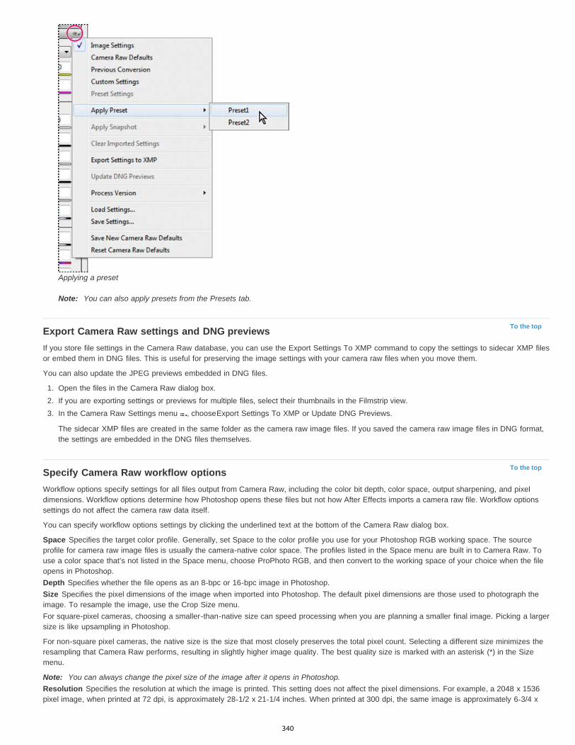
To the top
To the top
Applying a preset
Note: You can also apply presets from the Presets tab.
Export Camera Raw settings and DNG previewsIf you store file settings in the Camera Raw database, you can use the Export Settings To XMP command to copy the settings to sidecar XMP filesor embed them in DNG files. This is useful for preserving the image settings with your camera raw files when you move them.
You can also update the JPEG previews embedded in DNG files.
1. Open the files in the Camera Raw dialog box.2. If you are exporting settings or previews for multiple files, select their thumbnails in the Filmstrip view.3. In the Camera Raw Settings menu , chooseExport Settings To XMP or Update DNG Previews.
The sidecar XMP files are created in the same folder as the camera raw image files. If you saved the camera raw image files in DNG format,the settings are embedded in the DNG files themselves.
Specify Camera Raw workflow optionsWorkflow options specify settings for all files output from Camera Raw, including the color bit depth, color space, output sharpening, and pixeldimensions. Workflow options determine how Photoshop opens these files but not how After Effects imports a camera raw file. Workflow optionssettings do not affect the camera raw data itself.
You can specify workflow options settings by clicking the underlined text at the bottom of the Camera Raw dialog box.
Space Specifies the target color profile. Generally, set Space to the color profile you use for your Photoshop RGB working space. The sourceprofile for camera raw image files is usually the camera-native color space. The profiles listed in the Space menu are built in to Camera Raw. Touse a color space that’s not listed in the Space menu, choose ProPhoto RGB, and then convert to the working space of your choice when the fileopens in Photoshop.Depth Specifies whether the file opens as an 8-bpc or 16-bpc image in Photoshop.Size Specifies the pixel dimensions of the image when imported into Photoshop. The default pixel dimensions are those used to photograph theimage. To resample the image, use the Crop Size menu.For square-pixel cameras, choosing a smaller-than-native size can speed processing when you are planning a smaller final image. Picking a largersize is like upsampling in Photoshop.
For non-square pixel cameras, the native size is the size that most closely preserves the total pixel count. Selecting a different size minimizes theresampling that Camera Raw performs, resulting in slightly higher image quality. The best quality size is marked with an asterisk (*) in the Sizemenu.
Note: You can always change the pixel size of the image after it opens in Photoshop.Resolution Specifies the resolution at which the image is printed. This setting does not affect the pixel dimensions. For example, a 2048 x 1536pixel image, when printed at 72 dpi, is approximately 28-1/2 x 21-1/4 inches. When printed at 300 dpi, the same image is approximately 6-3/4 x
340

5-1/8 inches. You can also use the Image Size command to adjust resolution in Photoshop.Sharpen For Allows you to apply output sharpening for Screen, Matte Paper, or Glossy Paper. If you apply output sharpening, you can changethe Amount pop-up menu to Low or High to decrease or increase the amount of sharpening applied. In most cases, you can leave the Amount setto the default option, Standard.Open In Photoshop As Smart Objects Causes Camera Raw images to open in Photoshop as a Smart Object layer instead of a backgroundlayer when you click the Open button. To override this preference for selected images, press Shift when clicking Open.
|
341

Navigate, open, and save images in Camera Raw
To the top
To the top
Process, compare, and rate multiple imagesAutomating image processingOpen imagesSave a camera raw image in another format
Process, compare, and rate multiple imagesThe most convenient way to work with multiple camera raw images is to use the Filmstrip view in Camera Raw. Filmstrip view opens by defaultwhen you open multiple images in Camera Raw from Adobe Bridge.
Note: The Filmstrip view is not available when importing multiple images into After Effects.Images can have three states in Filmstrip pane: deselected, selected (but not active), and active (also selected). In general, adjustments areapplied to all selected images.
You can also synchronize settings to apply settings from the active image to all selected images. You can quickly apply a set of adjustments to anentire set of images—such as all shots taken under the same conditions—and then fine-tune the individual shots later, after you’ve determinedwhich you’ll use for your final output. You can synchronize both global and local adjustment settings.
To select an image, click its thumbnail. To select a range of images, Shift-click two thumbnails. To add an image to a selection, Ctrl-click(Windows) or Command-click (Mac OS) its thumbnail.To change which image is active without changing which images are selected, click a navigation arrow at the bottom of the previewpane.To apply settings from the active image to all selected images, click the Synchronize button at the top of the Filmstrip pane and choosewhich settings to synchronize.To apply a star rating, click a rating under the image thumbnail.To mark selected images for deletion, click Mark For Deletion .
A red X appears in the thumbnail of an image marked for deletion. The file is sent to the Recycle Bin (Windows) or Trash (Mac OS) whenyou close the Camera Raw dialog box. (If you decide to keep an image that you marked for deletion, select it in the Filmstrip pane and clickMark For Deletion again, before you close the Camera Raw dialog box.)
For a tutorial on synchronizing edits across multiple Camera Raw photos, see Synchronizing edits in Adobe Camera Raw byDan Moughamian.
Automating image processingYou can create an action to automate the processing of image files with Camera Raw. You can automate the editing process, and the process ofsaving the files in formats such as PSD, DNG, JPEG, Large Document Format (PSB), TIFF, and PDF. In Photoshop, you can also use the Batchcommand, the Image Processor, or the Create Droplet command to process one or more image files. The Image Processoris especially useful forsaving image files in different file formats during the same processing session.
Here are some tips for automating the processing of camera raw image files:
When you record an action, first select Image Settings from the Camera Raw Settings menu in the Camera Raw dialog box. In this way,the settings particular to each image (from the Camera Raw database or sidecar XMP files) are used to play back the action.
If you plan to use the action with the Batch command, you may want to use the Save As command and choose the file format when savingthe camera raw image.
When you use an action to open a camera raw file, the Camera Raw dialog box reflects the settings that were in effect when the action wasrecorded. You may want to create different actions for opening camera raw image files with different settings.
When using the Batch command, select Override Action “Open” Commands. Any Open commands in the action will then operate on thebatched files rather than the files specified by name in the action.Deselect Override Action “Open” Commands only if you want the action tooperate on open files or if the action uses the Open command to retrieve needed information.
When using the Batch command, select Suppress File Open Options Dialogs to prevent the display of the Camera Raw dialog box as eachcamera raw image is processed.
When using the Batch command, select Override Action “Save As” Commands if you want to use the Save As instructions from the Batchcommand instead of the Save As instructions in the action. If you select this option, the action must contain a Save As command, becausethe Batch command does not automatically save the source files. Deselect Override Action “Save As” Commands to save the files processedby the Batch command in the location specified in the Batch dialog box.
342
To the top
To the top
When creating a droplet, select Suppress File Open Options Dialogs in the Play area of the Create Droplet dialog box. This prevents thedisplay of the Camera Raw dialog box as each camera raw image is processed.
Open imagesTo process raw images in Camera Raw, select one or more camera raw files in Adobe Bridge, and then choose File > Open In Camera Rawor press Ctrl+R (Windows) or Command+R (Mac OS). When you finish making adjustments in the Camera Raw dialog box, click Done toaccept changes and close the dialog box. You can also click Open Image to open a copy of the adjusted image in Photoshop.To process JPEG or TIFF images in Camera Raw, select one or more JPEG or TIFF files in Adobe Bridge, and then choose File > Open InCamera Raw or press Ctrl+R (Windows) or Command+R (Mac OS). When you finish making adjustments in the Camera Raw dialog box,click Done to accept changes and close the dialog box. You can specify whether JPEG or TIFF images with Camera Raw settings areautomatically opened in Camera Raw in the JPEG and TIFF Handling section of the Camera Raw preferences.To import camera raw images in Photoshop, select one or more camera raw files in Adobe Bridge, and then choose File > Open With >Adobe Photoshop CS5. (You can also choose the File > Open command in Photoshop, and browse to select camera raw files.) When youfinish making adjustments in the Camera Raw dialog box, click Open Image to accept changes and open the adjusted image in Photoshop.Press Alt (Windows) or Option (Mac OS) to open a copy of the adjusted image and not save the adjustments to the original image’smetadata. Press Shift while clicking Open Image to open the image as a Smart Object in Photoshop. At any time, you can double-click theSmart Object layer that contains the raw file to adjust the Camera Raw settings.
Shift-double-click a thumbnail in Adobe Bridge to open a camera raw image in Photoshop without opening the Camera Raw dialog box.Hold down Shift while choosing File > Open to open multiple selected images.
To import camera raw images in After Effects using Adobe Bridge, select one or more camera raw files in Adobe Bridge, and then chooseFile > Open With > Adobe After Effects CS5. (You can also choose a File > Import command in After Effects and browse to select cameraraw files.) When you finish making adjustments in the Camera Raw dialog box, click OK to accept changes.To import TIFF and JPEG files into After Effects using Camera Raw, select the File > Import command in After Effects, and then select AllFiles from the Enable menu (Mac OS) or Files Of Type menu (Windows) in the After Effects Import File dialog box. Select the file to import,select Camera Raw from the Format menu, and click Open.To import Camera Raw images into After Effects as a sequence, choose File > Import in After Effects. Select the images, check the CameraRaw Sequence box, and click Open. Camera Raw settings applied to the first camera raw file upon import are applied to the remaining filesin the sequence unless an XMP sidecar file is present for any subsequent file in the sequence. In that case, the settings in the XMP file or inthe DNG file are applied to that specific frame in the sequence. All other frames use the settings that the first file in the sequence specifies.
If you have trouble opening Camera Raw files, see Why doesn't my version of Photoshop or Lightroom support my camera?
Save a camera raw image in another formatYou can save camera raw files from the Camera Raw dialog box in PSD, TIFF, JPEG, or DNG format.
When you use the Save Image command in the Camera Raw dialog box, files are placed in a queue to be processed and saved. This is useful ifyou are processing several files in the Camera Raw dialog box and saving them in the same format.
1. In the Camera Raw dialog box, click the Save Imagebutton in the lower-left corner of the dialog box.Alt-click (Windows) or Option-click (Mac OS) Save to suppress the Camera Raw Save Options dialog box when saving a file.
2. In the Save Options dialog box, specify the following options:Destination Specifies where to save the file. If necessary, click the Select Folder button and navigate to the location.
File Naming Specifies the filename using a naming convention that includes elements such as date and camera serial number. Usinginformative filenames based on a naming convention helps you keep image files organized.
3. Choose a file format from the Format menu.Digital Negative Saves a copy of the camera raw file in the DNG file format.
Compatibility Specifies the versions of Camera Raw and Lightroom that can read the file.
If you choose Custom, specify whether you want compatibility with DNG 1.1 or DNG 1.3. By default, the conversion uses losslesscompression, which means no information is lost while reducing file size. Choosing Linear (Demosaiced) stores the image data in aninterpolated format. That means other software can read the file even if that software does not have a profile for the digital camerathat captured the image.
JPEG Preview Embeds a JPEG preview in the DNG file. If you decide to embed a JPEG preview, you can choose the previewsize. If you embed JPEG previews, other applications can view the contents of the DNG file without parsing the camera raw data.
Embed Original Raw File Stores all of the original camera raw image data in the DNG file.
JPEG Saves copies of the camera raw files in JPEG (Joint Photographic Experts Group) format. To specify the amount of compression,enter a value from 0 to 12 or choose from the menu. Entering a higher value, or choosing High or Maximum, applies less compression andincreases file size and image quality. JPEG format is commonly used to display photographs and other continuous-tone images in web photogalleries, slide shows, presentations, and other online services.
343

TIFF Saves copies of the camera raw files as TIFF (Tagged-ImageFile Format) files. Specify whether to apply no compression, or LZW orZIP file compression. TIFF is a flexible bitmap image format supported by virtually all paint, image-editing, and page-layout applications.TIFF provides greater compression and compatibility with other applications than does PSD format.
Photoshop Saves copies of the camera raw files in the PSD file format. You can specify whether to preserve cropped pixel data in the PSDfile.
4. Click Save.
|
344

Rotate, crop, and retouch images in Camera Raw
To the top
To the top
To the top
To the top
To the top
Rotate imagesStraighten imagesCrop imagesRemove red-eyeRemove spots
Rotate imagesClick the Rotate Image 90° Counter Clockwise button (or press L).
Click the Rotate Image 90° Clockwise button (or press R).
Note: Using commands in the Edit menu, you can also rotate images in Adobe Bridge without opening the Camera Raw dialog box.
Straighten images1. In the Camera Raw dialog box, select the Straighten tool (or press A).2. Drag the Straighten tool in the preview image to establish what’s horizontal or vertical.
Note: The Crop tool is active immediately after you use the Straighten tool.
Crop images
1. In the Camera Raw dialog box, select the Crop tool (or press C).
To constrain the initial crop area to a specific aspect ratio, hold the mouse button down as you select the Crop tool and choose an optionfrom the menu. To apply a constraint to a previously applied crop, Ctrl-click (Mac OS) or right-click (Windows) on the crop.
2. Drag in the preview image to draw the crop area box.3. To move, scale, or rotate the crop area, drag the crop area or its handles.
Note: To cancel the crop operation, press Esc with the Crop tool active, or click and hold the Crop tool button and choose Clear Crop fromthe menu. To cancel the crop and close the Camera Raw dialog box without processing the camera raw image file, click the Cancel buttonor deselect the Crop tool and press Esc.
4. When you are satisfied with the crop, press Enter (Windows) or Return (Mac OS).
The cropped image resizes to fill the preview area, and the workflow options link under the preview area displays the updated image size anddimensions.
Remove red-eye1. Zoom the image in to at least 100%.
2. In the toolbar, select the Red Eye Removal tool (or press E).3. Drag a selection in the photo around the red eye.
Camera Raw sizes the selection to match the pupil. You can adjust the size of the selection by dragging its edges.
4. In the tool options under the Histogram, drag the Pupil Size slider to the right to increase the size of the area corrected.5. Drag the Darken slider to the right to darken the pupil area within the selection and the iris area outside the selection.
Deselect Show Overlay to turn off the selection and check your correction.
Note: Move between multiple selected red eye areas by clicking the selection.
Remove spots
The Spot Removal tool lets you repair a selected area of an image with a sample from another area.
1. Select the Spot Removal tool from the toolbar.
345
2. Select one of the following from the Type menu:Heal Matches the texture, lighting, and shading of the sampled area to the selected area.
Clone Applies the sampled area of the image to the selected area.
3. (Optional) In the tool options under the Histogram, drag the Radius slider to specify the size of the area that the Spot Removal tool affects.4. Move the Spot Removal tool into the photo and click the part of the photo to retouch. A red-and-white dashed circle appears over the
selected area. The green-and-white dashed circle designates the sampled area of the photo used to clone or heal.5. Do any of the following:
To specify the sampled area, drag inside the green-and-white circle to move it to another area of the image.
To specify the selected area being cloned or healed, drag inside the red-and-white circle.
To adjust the size of the circles, move the pointer over the edge of either circle until it changes to a double-pointing arrow, and then dragto make both circles larger or smaller.
To cancel the operation, press Backspace (Windows) or Delete (Mac OS).
Repeat this procedure for each area of the image that needs retouching. To remove all sample areas and start over, click the Clear All button inthe tool options.
|
346
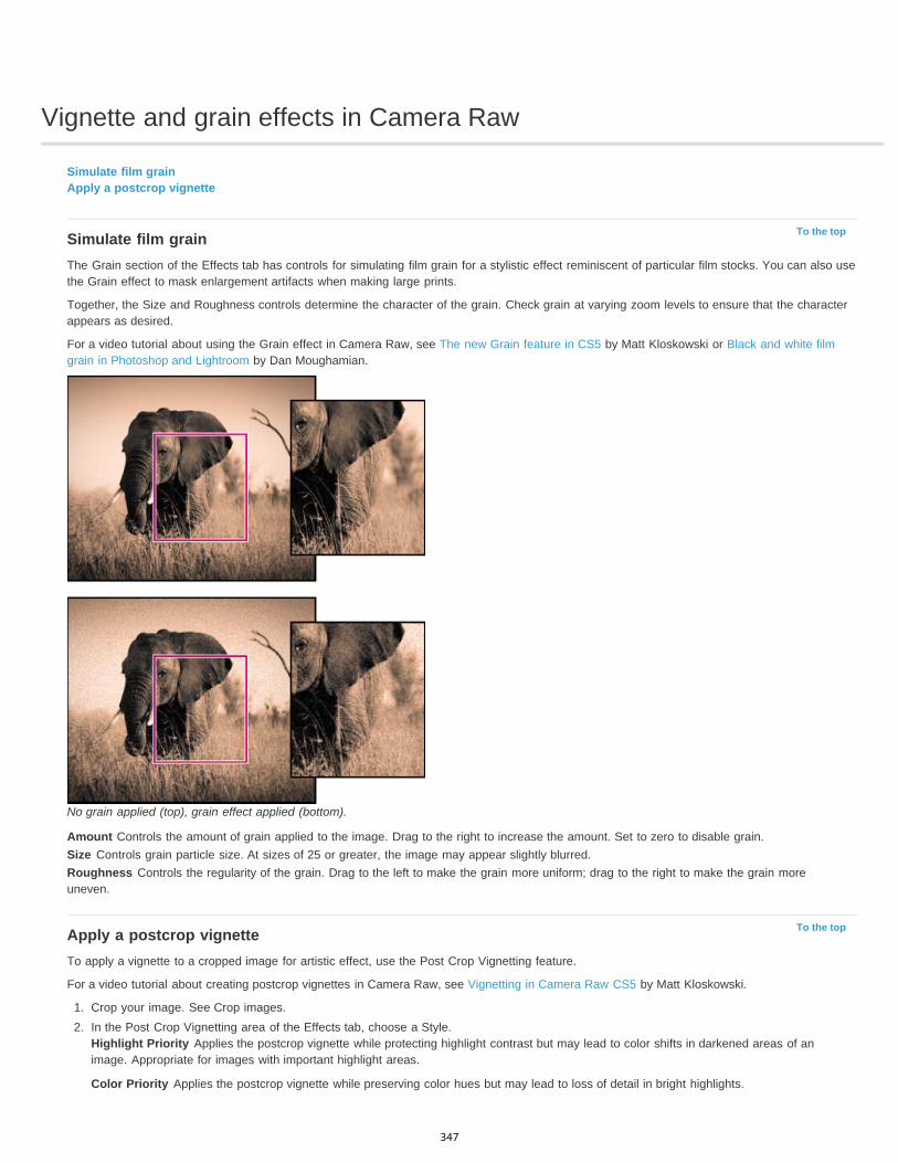
Vignette and grain effects in Camera Raw
To the top
To the top
Simulate film grainApply a postcrop vignette
Simulate film grainThe Grain section of the Effects tab has controls for simulating film grain for a stylistic effect reminiscent of particular film stocks. You can also usethe Grain effect to mask enlargement artifacts when making large prints.
Together, the Size and Roughness controls determine the character of the grain. Check grain at varying zoom levels to ensure that the characterappears as desired.
For a video tutorial about using the Grain effect in Camera Raw, see The new Grain feature in CS5 by Matt Kloskowski or Black and white filmgrain in Photoshop and Lightroom by Dan Moughamian.
No grain applied (top), grain effect applied (bottom).
Amount Controls the amount of grain applied to the image. Drag to the right to increase the amount. Set to zero to disable grain.Size Controls grain particle size. At sizes of 25 or greater, the image may appear slightly blurred.Roughness Controls the regularity of the grain. Drag to the left to make the grain more uniform; drag to the right to make the grain moreuneven.
Apply a postcrop vignetteTo apply a vignette to a cropped image for artistic effect, use the Post Crop Vignetting feature.
For a video tutorial about creating postcrop vignettes in Camera Raw, see Vignetting in Camera Raw CS5 by Matt Kloskowski.
1. Crop your image. See Crop images.2. In the Post Crop Vignetting area of the Effects tab, choose a Style.
Highlight Priority Applies the postcrop vignette while protecting highlight contrast but may lead to color shifts in darkened areas of animage. Appropriate for images with important highlight areas.
Color Priority Applies the postcrop vignette while preserving color hues but may lead to loss of detail in bright highlights.
347

Paint Overlay Applies the postcrop vignette by blending original image colors with black or white. Appropriate when a soft effect is desiredbut may reduce highlight contrast.
3. Refine the effect by adjusting any of the following sliders:Amount Positive values lighten the corners, negative values darken them.
Midpoint Higher values restrict the adjustment to the area closer to the corners, lower values apply the adjustment to a larger area awayfrom the corners.
Roundness Positive values make the effect more circular, negative values make the effect more oval.
Feather Higher values increase the softening between the effect and its surrounding pixels, lower values reduce the softening between theeffect and its surrounding pixels.
Highlights (Available for a Highlight Priority or Color Priorityeffect when Amount is a negative value) Controls the degree of highlight“punch” in bright areas of an image, such as in the glow of a streetlight or other bright light source.
|
348
Repair and restoration
Using Content-Aware PatchLynda.com (May. 7, 2012)video-tutorialSeamlessly repair imperfections.
Using Content-Aware Move and ExtendLynda.com (May. 7, 2012)video-tutorialRecompose images with these simple steps.
349
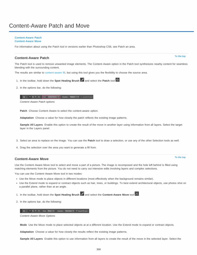
Content-Aware Patch and Move
To the top
Patch
Adaptation
Sample All Layers
To the top
Mode
Adaptation
Sample All Layers
Content-Aware PatchContent-Aware Move
For information about using the Patch tool in versions earlier than Photoshop CS6, see Patch an area.
Content-Aware PatchThe Patch tool is used to remove unwanted image elements. The Content-Aware option in the Patch tool synthesizes nearby content for seamlessblending with the surrounding content.
The results are similar to content-aware fill, but using this tool gives you the flexibility to choose the source area.
1. In the toolbar, hold down the Spot Healing Brush and select the Patch tool .
2. In the options bar, do the following:
Content-Aware Patch options
Choose Content-Aware to select the content-aware option.
Choose a value for how closely the patch reflects the existing image patterns.
Enable this option to create the result of the move in another layer using information from all layers. Select the targetlayer in the Layers panel.
3. Select an area to replace on the image. You can use the Patch tool to draw a selection, or use any of the other Selection tools as well.
4. Drag the selection over the area you want to generate a fill from.
Content-Aware MoveUse the Content-Aware Move tool to select and move a part of a picture. The image is recomposed and the hole left behind is filled usingmatching elements from the picture. You do not need to carry out intensive edits involving layers and complex selections.
You can use the Content-Aware Move tool in two modes:
Use the Move mode to place objects in different locations (most effectively when the background remains similar).Use the Extend mode to expand or contract objects such as hair, trees, or buildings. To best extend architectural objects, use photos shot ona parallel plane, rather than at an angle.
1. In the toolbar, hold down the Spot Healing Brush and select the Content-Aware Move tool .
2. In the options bar, do the following:
Content-Aware Move Options
Use the Move mode to place selected objects at at a different location. Use the Extend mode to expand or contract objects.
Choose a value for how closely the results reflect the existing image patterns.
Enable this option to use information from all layers to create the result of the move in the selected layer. Select the
350

Twitter™ and Facebook posts are not covered under the terms of Creative Commons.
Legal Notices | Online Privacy Policy
target layer in the Layers panel.
3. Select an area to move or extend. You can use the Move tool to draw a selection, or use any of the other selection tools as well.
4. Drag the selection to the area you want to place the object.
Learn moreContent-Aware Move video tutorial by Lesa Snider
Recomposing Picture Elements with Content-Aware Move and Patch Tools by Dan Moughamian
351
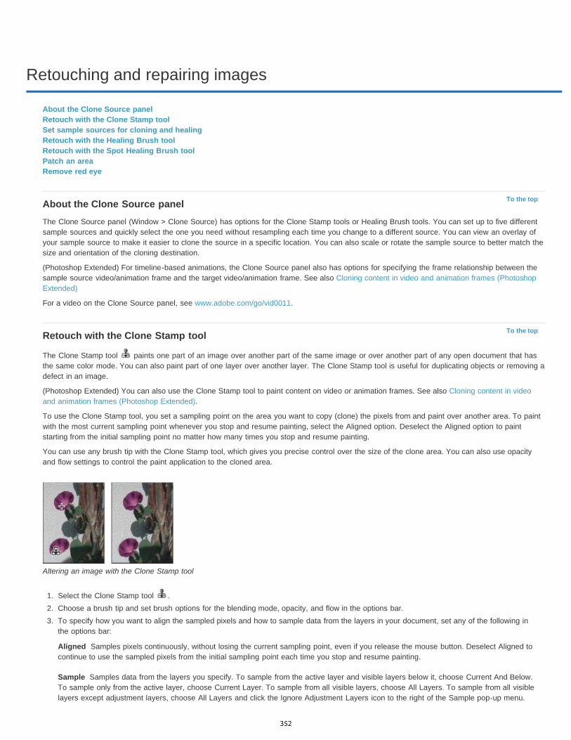
Retouching and repairing images
To the top
To the top
Aligned
Sample
About the Clone Source panelRetouch with the Clone Stamp toolSet sample sources for cloning and healingRetouch with the Healing Brush toolRetouch with the Spot Healing Brush toolPatch an areaRemove red eye
About the Clone Source panelThe Clone Source panel (Window > Clone Source) has options for the Clone Stamp tools or Healing Brush tools. You can set up to five differentsample sources and quickly select the one you need without resampling each time you change to a different source. You can view an overlay ofyour sample source to make it easier to clone the source in a specific location. You can also scale or rotate the sample source to better match thesize and orientation of the cloning destination.
(Photoshop Extended) For timeline-based animations, the Clone Source panel also has options for specifying the frame relationship between thesample source video/animation frame and the target video/animation frame. See also Cloning content in video and animation frames (PhotoshopExtended)
For a video on the Clone Source panel, see www.adobe.com/go/vid0011.
Retouch with the Clone Stamp tool
The Clone Stamp tool paints one part of an image over another part of the same image or over another part of any open document that hasthe same color mode. You can also paint part of one layer over another layer. The Clone Stamp tool is useful for duplicating objects or removing adefect in an image.
(Photoshop Extended) You can also use the Clone Stamp tool to paint content on video or animation frames. See also Cloning content in videoand animation frames (Photoshop Extended).
To use the Clone Stamp tool, you set a sampling point on the area you want to copy (clone) the pixels from and paint over another area. To paintwith the most current sampling point whenever you stop and resume painting, select the Aligned option. Deselect the Aligned option to paintstarting from the initial sampling point no matter how many times you stop and resume painting.
You can use any brush tip with the Clone Stamp tool, which gives you precise control over the size of the clone area. You can also use opacityand flow settings to control the paint application to the cloned area.
Altering an image with the Clone Stamp tool
1. Select the Clone Stamp tool .2. Choose a brush tip and set brush options for the blending mode, opacity, and flow in the options bar.3. To specify how you want to align the sampled pixels and how to sample data from the layers in your document, set any of the following in
the options bar:
Samples pixels continuously, without losing the current sampling point, even if you release the mouse button. Deselect Aligned tocontinue to use the sampled pixels from the initial sampling point each time you stop and resume painting.
Samples data from the layers you specify. To sample from the active layer and visible layers below it, choose Current And Below.To sample only from the active layer, choose Current Layer. To sample from all visible layers, choose All Layers. To sample from all visiblelayers except adjustment layers, choose All Layers and click the Ignore Adjustment Layers icon to the right of the Sample pop-up menu.
352

Note:
Note:
To the top
4. Set the sampling point by positioning the pointer in any open image and Alt-clicking (Windows) or Option-clicking (Mac OS).
Make sure you are not working on an adjustment layer. The Clone Stamp tool does not work on adjustment layers.
5. (Optional) In the Clone Source panel, click a clone source button and set an additional sampling point.
You can set up to five different sampling sources. The Clone Source panel saves the sampled sources until you close the document.
6. (Optional) Do any of the following in the Clone Source panel:To scale or rotate the source that you’re cloning, enter a value for W (width), H (height), or the rotation in degrees .
To reverse the direction of the source (good for mirroring features like eyes), click the Flip Horizontal or Flip Vertical buttons.
To show an overlay of the source that you’re cloning, select Show Overlay and specify the overlay options.
Select Clipped to clip the overlay to the brush size.
7. Drag over the area of the image you want to correct.
Set sample sources for cloning and healingUsing the Clone Stamp or Healing Brush tool, you can sample sources in the current document or any open document in Photoshop.
(Photoshop Extended) When cloning video or animation, you can set sampling points in the current frame you’re painting or sample sources in adifferent frame, even if the frame is in a different video layer or in a different open document.
You can set up to five different sampling sources at a time in the Clone Source panel. The Clone Source panel saves the sampling sources untilyou close the document.
1. (Photoshop Extended only) To clone video or animation frames, open the Animation panel (if you’re not cloning video or animation frames,skip to step 2). Select the timeline animation option and move the current-time indicator to the frame with the source you want to sample.
2. To set the sampling point, select the Clone Stamp tool and Alt-click (Windows) or Option-click (Mac OS) in any open document window.
3. (Optional) To set another sampling point, click a different Clone Source button in the Clone Source panel.
You can change the sampling source for a Clone Source button by setting a different sampling point.
Scale or rotate the sample source1. Select the Clone Stamp or Healing Brush tool and set one or more source samples.2. In the Clone Source panel, select a clone source and then do any of the following:
To scale the sample source, enter a percentage value for W (width) or H (height) or scrub W or H. The default is to constrainproportions. To adjust the dimensions independently or restore the constrain option, click the Maintain Aspect Ratio button .
To rotate the sample source, enter a degree value or scrub the Rotate The Clone Source icon .
To reset the sample source to its original size and orientation, click the Reset Transform button .
Adjust the sample source overlay optionsAdjust the sample source overlay options to see the overlay and underlying images better when painting with the Clone Stamp and Healing Brushtools.
To temporarily display the overlay while painting with the Clone Stamp tool, press Alt+Shift (Windows) or Option+Shift (Mac OS). The brushchanges temporarily to the Move Source Overlay tool. Drag to move the overlay to another location.
In the Clone Source panel, select Show Overlay and do any of the following:To hide the overlay while you apply the paint strokes, select Auto Hide.
To clip overlay to the brush size, enable the Clipped option.
To set the opacity of the overlay, enter a percentage value in the Opacity text box.
To set the appearance of the overlay, choose either the Normal, Darken, Lighten, or Difference blending mode from the pop-up menu atthe bottom of the Clone Source panel.
To invert the colors in the overlay, select Invert.
To help align identical areas in the source overlay and underlying image, set Opacity to 50%, select Invert, and deselect Clipped.Matching image areas will appear solid gray when aligned.
Specify the clone source offsetWhen using the Clone Stamp tool or Healing Brush tool, you can paint with the sampled source anywhere in the target image. The overlay optionshelp you visualize where you want to paint. However, if you paint in a specific location relative to the sampling point, you can specify the x and ypixel offset.
353
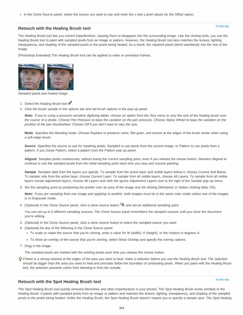
To the top
Note:
Mode
Source
Aligned
Sample
Note:
To the top
In the Clone Source panel, select the source you want to use and enter the x and y pixel values for the Offset option.
Retouch with the Healing Brush toolThe Healing Brush tool lets you correct imperfections, causing them to disappear into the surrounding image. Like the cloning tools, you use theHealing Brush tool to paint with sampled pixels from an image or pattern. However, the Healing Brush tool also matches the texture, lighting,transparency, and shading of the sampled pixels to the pixels being healed. As a result, the repaired pixels blend seamlessly into the rest of theimage.
(Photoshop Extended) The Healing Brush tool can be applied to video or animation frames.
Sampled pixels and healed image
1. Select the Healing Brush tool .2. Click the brush sample in the options bar and set brush options in the pop-up panel:
If you’re using a pressure-sensitive digitizing tablet, choose an option from the Size menu to vary the size of the healing brush overthe course of a stroke. Choose Pen Pressure to base the variation on the pen pressure. Choose Stylus Wheel to base the variation on theposition of the pen thumbwheel. Choose Off if you don’t want to vary the size.
Specifies the blending mode. Choose Replace to preserve noise, film grain, and texture at the edges of the brush stroke when usinga soft-edge brush.
Specifies the source to use for repairing pixels. Sampled to use pixels from the current image, or Pattern to use pixels from apattern. If you chose Pattern, select a pattern from the Pattern pop-up panel.
Samples pixels continuously, without losing the current sampling point, even if you release the mouse button. Deselect Aligned tocontinue to use the sampled pixels from the initial sampling point each time you stop and resume painting.
Samples data from the layers you specify. To sample from the active layer and visible layers below it, choose Current And Below.To sample only from the active layer, choose Current Layer. To sample from all visible layers, choose All Layers. To sample from all visiblelayers except adjustment layers, choose All Layers and click the Ignore Adjustment Layers icon to the right of the Sample pop-up menu.
3. Set the sampling point by positioning the pointer over an area of the image and Alt-clicking (Windows) or Option-clicking (Mac OS).
If you are sampling from one image and applying to another, both images must be in the same color mode unless one of the imagesis in Grayscale mode.
4. (Optional) In the Clone Source panel, click a clone source button and set an additional sampling point.
You can set up to 5 different sampling sources. The Clone Source panel remembers the sampled sources until you close the documentyou’re editing.
5. (Optional) In the Clone Source panel, click a clone source button to select the sampled source you want.6. (Optional) Do any of the following in the Clone Source panel:
To scale or rotate the source that you’re cloning, enter a value for W (width), H (height), or the rotation in degrees .
To show an overlay of the source that you’re cloning, select Show Overlay and specify the overlay options.
7. Drag in the image.
The sampled pixels are melded with the existing pixels each time you release the mouse button.
If there is a strong contrast at the edges of the area you want to heal, make a selection before you use the Healing Brush tool. The selectionshould be bigger than the area you want to heal and precisely follow the boundary of contrasting pixels. When you paint with the Healing Brushtool, the selection prevents colors from bleeding in from the outside.
Retouch with the Spot Healing Brush toolThe Spot Healing Brush tool quickly removes blemishes and other imperfections in your photos. The Spot Healing Brush works similarly to theHealing Brush: it paints with sampled pixels from an image or pattern and matches the texture, lighting, transparency, and shading of the sampledpixels to the pixels being healed. Unlike the Healing Brush, the Spot Healing Brush doesn’t require you to specify a sample spot. The Spot Healing
354
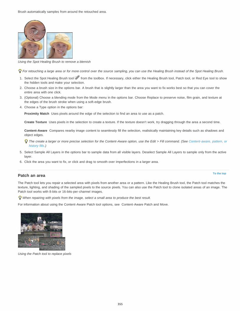
Proximity Match
Create Texture
Content-Aware
To the top
Brush automatically samples from around the retouched area.
Using the Spot Healing Brush to remove a blemish
For retouching a large area or for more control over the source sampling, you can use the Healing Brush instead of the Spot Healing Brush.
1. Select the Spot Healing Brush tool from the toolbox. If necessary, click either the Healing Brush tool, Patch tool, or Red Eye tool to showthe hidden tools and make your selection.
2. Choose a brush size in the options bar. A brush that is slightly larger than the area you want to fix works best so that you can cover theentire area with one click.
3. (Optional) Choose a blending mode from the Mode menu in the options bar. Choose Replace to preserve noise, film grain, and texture atthe edges of the brush stroke when using a soft-edge brush.
4. Choose a Type option in the options bar:
Uses pixels around the edge of the selection to find an area to use as a patch.
Uses pixels in the selection to create a texture. If the texture doesn’t work, try dragging through the area a second time.
Compares nearby image content to seamlessly fill the selection, realistically maintaining key details such as shadows andobject edges.
The create a larger or more precise selection for the Content-Aware option, use the Edit > Fill command. (See Content-aware, pattern, orhistory fills.)
5. Select Sample All Layers in the options bar to sample data from all visible layers. Deselect Sample All Layers to sample only from the activelayer.
6. Click the area you want to fix, or click and drag to smooth over imperfections in a larger area.
Patch an areaThe Patch tool lets you repair a selected area with pixels from another area or a pattern. Like the Healing Brush tool, the Patch tool matches thetexture, lighting, and shading of the sampled pixels to the source pixels. You can also use the Patch tool to clone isolated areas of an image. ThePatch tool works with 8-bits or 16-bits-per-channel images.
When repairing with pixels from the image, select a small area to produce the best result.
For information about using the Content-Aware Patch tool options, see Content-Aware Patch and Move.
Using the Patch tool to replace pixels
355
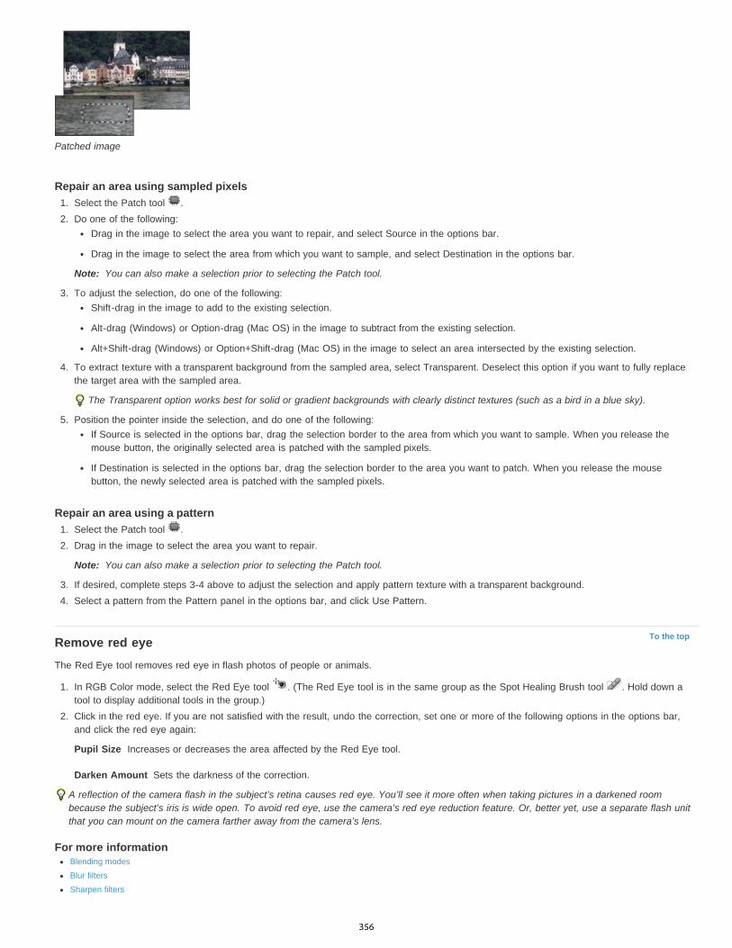
Note:
Note:
To the top
Pupil Size
Darken Amount
Patched image
Repair an area using sampled pixels1. Select the Patch tool .2. Do one of the following:
Drag in the image to select the area you want to repair, and select Source in the options bar.
Drag in the image to select the area from which you want to sample, and select Destination in the options bar.
You can also make a selection prior to selecting the Patch tool.
3. To adjust the selection, do one of the following:Shift-drag in the image to add to the existing selection.
Alt-drag (Windows) or Option-drag (Mac OS) in the image to subtract from the existing selection.
Alt+Shift-drag (Windows) or Option+Shift-drag (Mac OS) in the image to select an area intersected by the existing selection.
4. To extract texture with a transparent background from the sampled area, select Transparent. Deselect this option if you want to fully replacethe target area with the sampled area.
The Transparent option works best for solid or gradient backgrounds with clearly distinct textures (such as a bird in a blue sky).
5. Position the pointer inside the selection, and do one of the following:If Source is selected in the options bar, drag the selection border to the area from which you want to sample. When you release themouse button, the originally selected area is patched with the sampled pixels.
If Destination is selected in the options bar, drag the selection border to the area you want to patch. When you release the mousebutton, the newly selected area is patched with the sampled pixels.
Repair an area using a pattern1. Select the Patch tool .2. Drag in the image to select the area you want to repair.
You can also make a selection prior to selecting the Patch tool.
3. If desired, complete steps 3-4 above to adjust the selection and apply pattern texture with a transparent background.4. Select a pattern from the Pattern panel in the options bar, and click Use Pattern.
Remove red eyeThe Red Eye tool removes red eye in flash photos of people or animals.
1. In RGB Color mode, select the Red Eye tool . (The Red Eye tool is in the same group as the Spot Healing Brush tool . Hold down atool to display additional tools in the group.)
2. Click in the red eye. If you are not satisfied with the result, undo the correction, set one or more of the following options in the options bar,and click the red eye again:
Increases or decreases the area affected by the Red Eye tool.
Sets the darkness of the correction.
A reflection of the camera flash in the subject’s retina causes red eye. You’ll see it more often when taking pictures in a darkened roombecause the subject’s iris is wide open. To avoid red eye, use the camera’s red eye reduction feature. Or, better yet, use a separate flash unitthat you can mount on the camera farther away from the camera’s lens.
For more informationBlending modes
Blur filters
Sharpen filters
356

Twitter™ and Facebook posts are not covered under the terms of Creative Commons.
Legal Notices | Online Privacy Policy
Select a preset brush
357
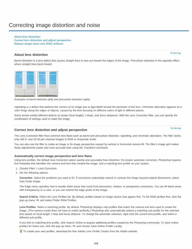
Correcting image distortion and noise
To the top
To the top
Correction
Search Criteria
Lens Profiles
About lens distortionCorrect lens distortion and adjust perspectiveReduce image noise and JPEG artifacts
About lens distortionBarrel distortion is a lens defect that causes straight lines to bow out toward the edges of the image. Pincushion distortion is the opposite effect,where straight lines bend inward.
Examples of barrel distortion (left) and pincushion distortion (right)
Vignetting is a defect that darkens the corners of an image due to light falloff around the perimeter of the lens. Chromatic aberration appears as acolor fringe along the edges of objects, caused by the lens focusing on different colors of light in different planes.
Some lenses exhibit different defects at certain focal lengths, f-stops, and focus distances. With the Lens Correction filter, you can specify thecombination of settings used to make the image.
Correct lens distortion and adjust perspectiveThe Lens Correction filter fixes common lens flaws such as barrel and pincushion distortion, vignetting, and chromatic aberration. The filter worksonly with 8- and 16-bit-per-channel images in RGB or Grayscale mode.
You can also use the filter to rotate an image or fix image perspective caused by vertical or horizontal camera tilt. The filter’s image grid makesthese adjustments easier and more accurate than using the Transform command.
Automatically correct image perspective and lens flawsUsing lens profiles, the default Auto Correction option quickly and accurately fixes distortion. For proper automatic correction, Photoshop requiresExif metadata that identifies the camera and lens that created the image, and a matching lens profile on your system.
1. Choose Filter > Lens Correction.2. Set the following options:
Select the problems you want to fix. If corrections undesirably extend or contract the image beyond original dimensions, selectAuto Scale Image.
The Edge menu specifies how to handle blank areas that result from pincushion, rotation, or perspective corrections. You can fill blank areaswith transparency or a color, or you can extend the edge pixels of the image.
Filters the Lens Profiles list. By default, profiles based on image sensor size appear first. To list RAW profiles first, click thepop-up menu , and select Prefer RAW Profiles.
Select a matching profile. By default, Photoshop displays only profiles that match the camera and lens used to create theimage. (The camera model does not have to match perfectly.) Photoshop also automatically selects a matching sub-profile for the selectedlens based on focal length, f-stop and focus distance. To change the automatic selection, right-click the current lens profile, and select adifferent sub-profile.
If you find no matching lens profile, click Search Online to acquire additional profiles created by the Photoshop community. To store onlineprofiles for future use, click the pop-up menu , and choose Save Online Profile Locally.
To create your own profiles, download the free Adobe Lens Profile Creator from the Adobe website.
358

Remove Distortion
Fix Fringe settings
Vignette Amount
Vignette Midpoint
Vertical Perspective
Horizontal Perspective
Angle
Note:
Scale
Manually correct image perspective and lens flawsYou can apply manual correction alone or use it to refine automatic lens correction.
1. Choose Filter > Lens Correction.2. In the upper-right corner of the dialog box, click the Custom tab.
3. (Optional) Choose a preset list of settings from the Settings menu. Lens Default uses settings that you previously saved for the camera,lens, focal length, f-stop, and focus distance used to create the image. Previous Conversion uses the settings used in your last lenscorrection. Any group of custom settings you saved are listed at the bottom of the menu. (See Save settings and set camera and lensdefaults.)
4. Set any of the following options to correct your image.
Corrects lens barrel or pincushion distortion. Move the slider to straighten horizontal and vertical lines that bend eitheraway from or toward the center of the image. You can also use the Remove Distortion tool to make this correction. Drag toward thecenter of the image to correct for barrel distortion and toward the edge of the image to correct for pincushion distortion. To compensate forany blank image edges that result, adjust the Edge option on the Auto Correction tab.
Compensate for fringing by adjusting the size of one color channel relative to another.
Zoom in on the image preview to get a closer view of the fringing as you make the correction.
Sets the amount of lightening or darkening along the edges of an image. Corrects images that have darkened cornerscaused by lens faults or improper lens shading.
You can also apply vignetting for a creative effect.
Specifies the width of area affected by the Amount slider. Specify a lower number to affect more of the image. Specify ahigher number to restrict the effect to the edges of the image.
Corrects image perspective caused by tilting the camera up or down. Makes vertical lines in an image parallel.
Corrects image perspective, making horizontal lines parallel.
Rotates the image to correct for camera tilt or to make adjustments after correcting perspective. You can also use the Straighten tool to make this correction. Drag along a line in the image that you want to make vertical or horizontal.
To avoid unintended scaling when adjusting perspective or angle settings, deselect Auto Scale Image on the Auto Correction tab.
Adjusts the image scale up or down. The image pixel dimensions aren’t changed. The main use is to remove blank areas of theimage caused by pincushion, rotation, or perspective corrections. Scaling up effectively results in cropping the image and interpolating up tothe original pixel dimensions.
Adjust the Lens Correction preview and gridAdjust the preview magnification and grid lines to better judge the necessary amount of correction.
To change the image preview magnification, use the Zoom tool or the zoom controls in the lower left side of the preview image.To move the image in the preview window, select the Hand tool and drag in the image preview.To use the grid, select Show Grid at the bottom of the dialog box. Use the Size control to adjust the grid spacing and the Color control tochange the color of the grid. You can move the grid to line it up with your image using the Move Grid tool .
Save settings and set camera and lens defaultsYou can save the settings in the Lens Correction dialog box to reuse with other images made with the same camera, lens, and focal length.Photoshop saves both Auto Correction settings and Custom settings for distortion, chromatic aberration, and vignetting. Perspective correctionsettings are not saved because they typically vary from one image to another.
You can save and reuse settings in two ways:
Manually save and load settings. Set options in the dialog box, and then choose Save Settings from the Settings menu . To use the savedsettings, choose them from the Settings menu. (If you save settings outside the default folder, they don’t appear in the menu; use the LoadSettings command to access them.)
359
Twitter™ and Facebook posts are not covered under the terms of Creative Commons.
Legal Notices | Online Privacy Policy
To the top
Strength
Preserve Details
Reduce Color Noise
Sharpen Details
Remove JPEG Artifacts
Set a lens default. If your image has EXIF metadata for the camera, lens, focal length, and f-stop, you can save the current settings as a lensdefault. To save the settings, click the Set Lens Default button. When you correct an image that matches the camera, lens, focal length, andf-stop, the Lens Default option becomes available in the Settings menu. This option is not available if your image doesn’t have EXIFmetadata.
Reduce image noise and JPEG artifactsImage noise appears as random extraneous pixels that aren’t part of the image detail. Noise can be caused by photographing with a high ISOsetting on a digital camera, underexposure, or shooting in a dark area with a long shutter speed. Low-end consumer cameras usually exhibit moreimage noise than high-end cameras. Scanned images may have image noise caused by the scanning sensor. Often, the film’s grain patternappears in the scanned image.
Image noise can appear in two forms: luminance (grayscale) noise, which makes an image look grainy or patchy, and color noise, which is usuallyvisible as colored artifacts in the image.
Luminance noise may be more pronounced in one channel of the image, usually the blue channel. You can adjust the noise for each channelseparately in Advanced mode. Before opening the filter, examine each channel in your image separately to see if noise is prevalent in onechannel. You preserve more image detail by correcting one channel rather than making an overall correction to all channels.
1. Choose Filter > Noise > Reduce Noise.2. Zoom in on the preview image to get a better view of image noise.3. Set options:
Controls the amount of luminance noise reduction applied to all image channels.
Preserves edges and image details such as hair or texture objects. A value of 100 preserves the most image detail, butreduces luminance noise the least. Balance the Strength and Preserve Details controls to fine-tune noise reduction.
Removes random color pixels. A higher value reduces more color noise.
Sharpens the image. Removing noise reduces image sharpness. Use the sharpening control in the dialog box or use oneof the other Photoshop sharpening filters later to restore sharpness.
Removes blocky image artifacts and halos caused by saving a image using a low JPEG quality setting.
4. If luminance noise is more prevalent in one or two color channels, click the Advanced button and then choose the color channel from theChannel menu. Use the Strength and Preserve Details controls to reduce noise in that channel.
More Help TopicsCorrect lens distortion and noise in Camera Raw
360
Reshaping and transforming
New Crop toolLynda.com (Oct. 7, 2012)video-tutorialInteractive previews help you precisely trim images down to size.
Wide-angle lens correctionKelby (Oct. 7, 2012)video-tutorialQuickly compensate for lens quirks, drawing from a detailed database.
Correcting perspectivevideo2brain (May. 7, 2012)video-tutorialFix photo angles fast.
Straightening a crooked imagevideo2brain (May. 7, 2012)video-tutorialDefine the horizon line.
361
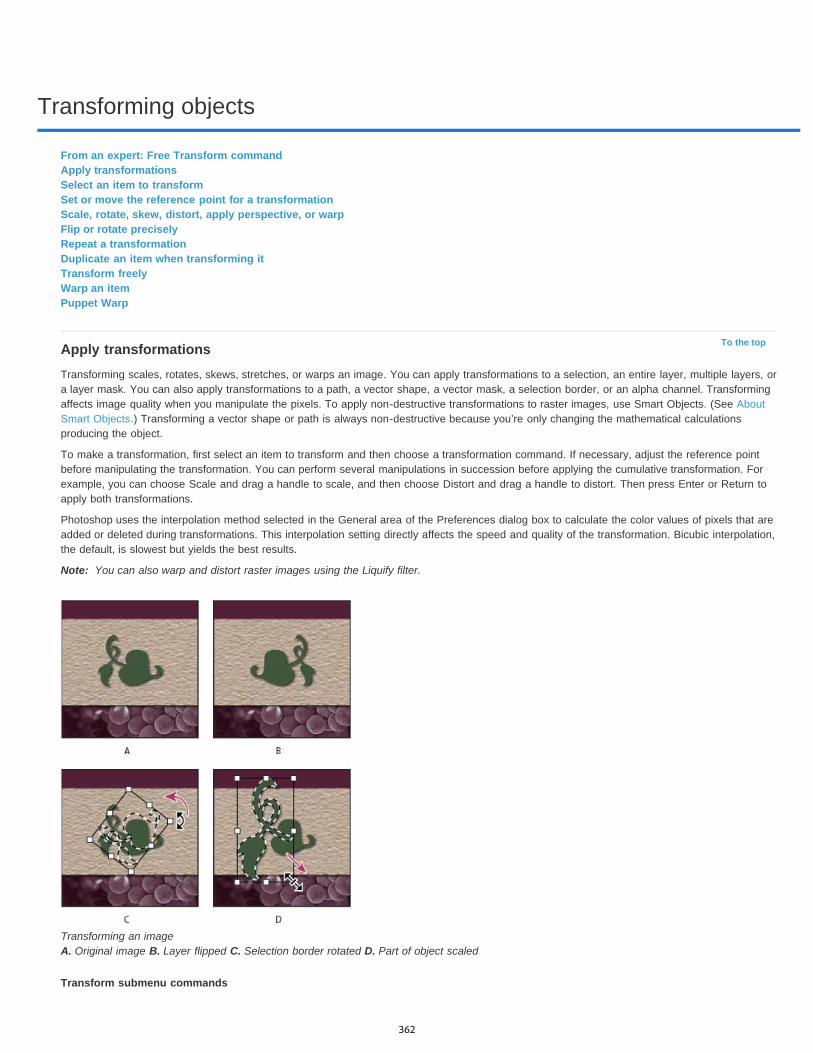
Transforming objects
To the top
Note:
From an expert: Free Transform commandApply transformationsSelect an item to transformSet or move the reference point for a transformationScale, rotate, skew, distort, apply perspective, or warpFlip or rotate preciselyRepeat a transformationDuplicate an item when transforming itTransform freelyWarp an itemPuppet Warp
Apply transformationsTransforming scales, rotates, skews, stretches, or warps an image. You can apply transformations to a selection, an entire layer, multiple layers, ora layer mask. You can also apply transformations to a path, a vector shape, a vector mask, a selection border, or an alpha channel. Transformingaffects image quality when you manipulate the pixels. To apply non-destructive transformations to raster images, use Smart Objects. (See AboutSmart Objects.) Transforming a vector shape or path is always non-destructive because you’re only changing the mathematical calculationsproducing the object.
To make a transformation, first select an item to transform and then choose a transformation command. If necessary, adjust the reference pointbefore manipulating the transformation. You can perform several manipulations in succession before applying the cumulative transformation. Forexample, you can choose Scale and drag a handle to scale, and then choose Distort and drag a handle to distort. Then press Enter or Return toapply both transformations.
Photoshop uses the interpolation method selected in the General area of the Preferences dialog box to calculate the color values of pixels that areadded or deleted during transformations. This interpolation setting directly affects the speed and quality of the transformation. Bicubic interpolation,the default, is slowest but yields the best results.
You can also warp and distort raster images using the Liquify filter.
Transforming an image A. Original image B. Layer flipped C. Selection border rotated D. Part of object scaled
Transform submenu commands
362
Scale
Rotate
Skew
Distort
Perspective
Warp
Rotate 180, Rotate 90 CW, Rotate 90 CCW
Flip
To the top
Note:
To the top
To the top
Note:
Enlarges or reduces an item relative to its reference point, the fixed point around which transformations are performed. You can scalehorizontally, vertically, or both horizontally and vertically.
Turns an item around a reference point. By default, this point is at the center of the object; however, you can move it to another location.
Slants an item vertically and horizontally.
Stretches an item in all directions.
Applies one-point perspective to an item.
Manipulates the shape of an item.
Rotates the item by the specified number of degrees, either clockwise or counterclockwise.
Flips the item vertically or horizontally.
Select an item to transformDo one of the following:
To transform an entire layer, make the layer active, and make sure nothing is selected.
You cannot transform the background layer. To transform it, first convert it to a regular layer.
To transform part of a layer, select the layer in the Layers panel, and then select part of the image on that layer.
To transform multiple layers, do either of the following in the Layers panel: link the layers together, or select multiple layers by Ctrl-clicking (Windows) or Command-clicking (Mac OS) more than one layer. In the Layers panel, you can also Shift-click to selectcontinguous layers. (See Selecting, grouping, and linking layers.)
To transform a layer mask or a vector mask, unlink the mask and select the mask thumbnail in the Layers panel.
To transform a path or vector shape, use the Path Selection tool to select the entire path or the Direct Selection tool to select part ofthe path. If you select one or more points on a path, only those path segments connected to the points are transformed. (See Select apath.)
To transform a selection border, make or load a selection. Then choose Select > Transform Selection.
To transform an alpha channel, select the channel in the Channels panel.
Set or move the reference point for a transformationAll transformations are performed around a fixed point called the reference point. By default, this point is at the center of the item you aretransforming. However, you can change the reference point or move the center point to a different location using the reference point locator in theoptions bar.
1. Choose a transformation command. A bounding box appears in the image.2. Do one of the following:
In the options bar, click a square on the reference point locator . Each square represents a point on the bounding box. For example,to move the reference point to the upper-left corner of the bounding box, click the top left square on the reference point locator.
In the transform bounding box that appears in the image, drag the reference point . The reference point can be outside the item youwant to transform.
Scale, rotate, skew, distort, apply perspective, or warp1. Select what you want to transform.2. Choose Edit > Transform > Scale, Rotate, Skew, Distort, Perspective, or Warp.
If you are transforming a shape or entire path, the Transform menu becomes the Transform Path menu. If you are transformingmultiple path segments (but not the entire path), the Transform menu becomes the Transform Points menu.
3. (Optional) In the options bar, click a square on the reference point locator .4. Do one or more of the following:
If you chose Scale, drag a handle on the bounding box. Press Shift as you drag a corner handle to scale proportionately. Whenpositioned over a handle, the pointer becomes a double arrow.
If you chose Rotate, move the pointer outside the bounding border (it becomes a curved, two-sided arrow), and then drag. Press Shift toconstrain the rotation to 15° increments.
363

Note:
To the top
Note:
To the top
To the top
To the top
Note:
If you chose Skew, drag a side handle to slant the bounding box.
If you chose Distort, drag a corner handle to stretch the bounding box.
If you chose Perspective, drag a corner handle to apply perspective to the bounding box.
If you chose Warp, choose a warp from the Warp Style pop-up menu in the options bar, or to perform a custom warp, drag the controlpoints, a line, or an area within the mesh to change the shape of the bounding box and mesh.
For all types of transformations, enter a value in the options bar. For example, to rotate an item, specify degrees in the rotation textbox.
5. (Optional) If desired, switch to a different type of transformation by selecting a command from the Edit > Transform submenu.
When you transform a bitmap image (versus a shape or path), the image becomes slightly less sharp each time you commit atransformation; therefore, performing multiple commands before applying the cumulative transformation is preferable to applying eachtransformation separately.
6. (Optional) If you want to warp the image, click the Switch Between Free Transform And Warp Mode button in the options bar.7. When you finish, do one of the following:
Press Enter (Windows) or Return (Mac OS), click the Commit button in the options bar, or double-click inside the transformationmarquee.
To cancel the transformation, press Esc or click the Cancel button in the options bar.
Flip or rotate precisely
1. Select what you want to transform.
2. Choose Edit > Transform and choose one of the following commands from the submenu:
Rotate to specify degrees in the options bar
Rotate 180° to rotate by a half-turn
Rotate 90° CW to rotate clockwise by a quarter-turn
Rotate 90° CCW to rotate counterclockwise by a quarter-turn
Flip Horizontal to flip horizontally, along the vertical axis
Flip Vertical to flip vertically, along the horizontal axis
If you are transforming a shape or entire path, the Transform command becomes the Transform Path command. If you aretransforming multiple path segments (but not the entire path), the Transform command becomes the Transform Points command.
Repeat a transformationChoose Edit > Transform > Again, Edit > Transform Path > Again, or Edit > Transform Points > Again.
Duplicate an item when transforming itHold down Alt (Windows) or Option (Mac OS) when selecting the Transform command.
Transform freelyThe Free Transform command lets you apply transformations (rotate, scale, skew, distort, and perspective) in one continuous operation. You canalso apply a warp transformation. Instead of choosing different commands, you simply hold down a key on your keyboard to switch betweentransformation types.
If you are transforming a shape or entire path, the Transform command becomes the Transform Path command. If you are transformingmultiple path segments (but not the entire path), the Transform command becomes the Transform Points command.
1. Select what you want to transform.2. Do one of the following:
Choose Edit > Free Transform.
If you are transforming a selection, pixel-based layer, or selection border, choose the Move tool . Then select Show TransformControls in the options bar.
364

Note:
To the top
If you are transforming a vector shape or path, select the Path Selection tool . Then select Show Transform Controls in the options bar.
3. Do one or more of the following:To scale by dragging, drag a handle. Press Shift as you drag a corner handle to scale proportionately.
To scale numerically, enter percentages in the Width and Height text boxes in the options bar. Click the Link icon to maintain theaspect ratio.
To rotate by dragging, move the pointer outside the bounding border (it becomes a curved, two-sided arrow), and then drag. Press Shiftto constrain the rotation to 15° increments.
To rotate numerically, enter degrees in the rotation text box in the options bar.
To distort relative to the center point of the bounding border, press Alt (Windows) or Option (Mac OS), and drag a handle.
To distort freely, press Ctrl (Windows) or Command (Mac OS), and drag a handle.
To skew, press Ctrl+Shift (Windows) or Command+Shift (Mac OS), and drag a side handle. When positioned over a side handle, thepointer becomes a white arrowhead with a small double arrow.
To skew numerically, enter degrees in the H (horizontal skew) and V (vertical skew) text boxes in the options bar.
To apply perspective, press Ctrl+Alt+Shift (Windows) or Command+Option+Shift (Mac OS), and drag a corner handle. When positionedover a corner handle, the pointer becomes a gray arrowhead.
To warp, click the Switch Between Free Transform And Warp Modes button in the options bar. Drag control points to manipulate theshape of the item or choose a warp style from the Warp pop-up menu in the options bar. After choosing from the Warp pop-up menu, asquare handle is available for adjusting the shape of the warp.
To change the reference point, click a square on the reference point locator in the options bar.
To move an item, enter values for the new location of the reference in the X (horizontal position) and Y (vertical position) text boxes inthe options bar. Click the Relative Positioning button to specify the new position in relation to the current position.
To undo the last handle adjustment, choose Edit > Undo.
4. Do one of the following:Press Enter (Windows) or Return (Mac OS), click the Commit button in the options bar, or double-click inside the transformationmarquee.
To cancel the transformation, press Esc or click the Cancel button in the options bar.
When you transform a bitmap image (versus a shape or path), the image becomes slightly less sharp each time you commit atransformation; therefore, performing multiple commands before applying the cumulative transformation is preferable to applying eachtransformation separately.
Warp an itemThe Warp command lets you drag control points to manipulate the shape of images, shapes, or paths, and so on. You can also warp using ashape in the Warp Style pop-up menu in the options bar. Shapes in the Warp Style pop-up menu are also malleable; drag their control points.
When using the control points to distort an item, choosing View > Extras shows or hides the warp mesh and control points.
Using Warp A. Selecting the shape to be warped B. Choosing a warp from the Warp Style pop-up menu in the options bar C. Result using several warp
365

Note:
To the top
options
1. Select what you want to warp.2. Do one of the following:
Choose Edit > Transform > Warp.
If you chose a different transform command or the Free Transform command, click the Switch Between Free Transform And WarpModes button in the options bar.
3. Do one or more of the following:To warp using a specific shape, choose a warp style from the Warp pop-up menu in the options bar.
Dragging a control point to warp the mesh
To the manipulate the shape, drag the control points, a segment of the bounding box or mesh, or an area within the mesh. Whenadjusting a curve, use the control point handles. This is similar to adjusting the handles in the curved segment of a vector graphic.
To undo the last handle adjustment, choose Edit > Undo.
Manipulating the shape of a warp A. Original warp mesh B. Adjusting the handles, mesh segments, and areas within the mesh
To change the orientation of a warp style that you chose from the Warp menu, click the Change The Warp Orientation button in theoptions bar.
To change the reference point, click a square on the Reference point locator in the options bar.
To specify the amount of warp using numeric values, enter the values in the Bend (set bend), X (set horizontal distortion) and Y (setvertical distortion) text boxes in the options bar. You can’t enter numeric values if you have chosen None or Custom from the Warp Stylepop-up menu.
4. Do one of the following:Press Enter (Windows) or Return (Mac OS), or click the Commit button in the options bar.
To cancel the transformation, press Esc or click the Cancel button in the options bar.
When you warp a bitmap image (versus a shape or path), the image becomes slightly less sharp each time you commit a transformation;therefore, performing multiple commands before applying the cumulative transformation is preferable to applying each transformation separately.
Puppet WarpPuppet Warp provides a visual mesh that lets you drastically distort specific image areas, while leaving other areas intact. Applications range fromsubtle image retouching (such as shaping hair) to total transformations (such as repositioning arms or legs).
In addition to image layers, you can apply Puppet Warp to layer and vector masks. To nondestructively distort images, use Smart Objects. (SeeCreate Smart Objects.)
1. In the Layers panel, select the layer or mask you want to transform.
366

Mode
Density
Expansion
Show Mesh
2. Choose Edit > Puppet Warp.
3. In the options bar, adjust the following mesh settings:
Determines the overall elasticity of the mesh.
Choose Distort for a highly elastic mesh good for warping wide-angle images or texture maps.
Determines the spacing of mesh points. More Points increases precision but requires more processing time; Fewer Points does theopposite.
Expands or contracts the outer edge of the mesh.
Deselect to show only adjustment pins, providing a clearer preview of your transformations.
To temporarily hide adjustment pins, press the H key.
4. In the image window, click to add pins to areas you want to transform and areas you want to anchor in place.
Moving a pin on the puppet mesh. Adjoining pins keep nearby areas intact.
5. To reposition or remove pins, do any of the following:
Drag pins to warp the mesh.
To reveal a mesh area you’ve overlapped with another, click the Pin Depth buttons in the options bar.
To remove selected pins, press Delete. To remove other individual pins, place the cursor directly over them, and press Alt (Windows) orOption (Mac OS); when the scissors icon appears, click.
Click the Remove All Pins button in the options bar.
To select multiple pins, Shift-click them or choose Select All Pins from the context menu.
6. To rotate the mesh around a pin, select it, and then do either of the following:
To rotate the mesh a fixed number of degrees, press Alt (Windows) or Option (Mac OS), and position the cursor near to, but not overthe pins. When a circle appears, drag to visually rotate the mesh.
The degree of rotation appears in the options bar.
To rotate the mesh automatically based on the selected Mode option, choose Auto from the Rotate menu in the options bar.
7. When your transformation is complete, press Enter or Return.
367
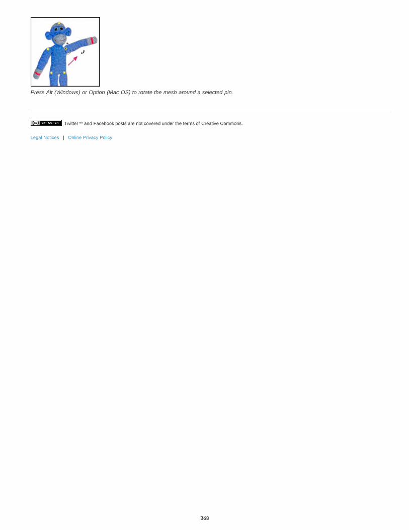
Twitter™ and Facebook posts are not covered under the terms of Creative Commons.
Legal Notices | Online Privacy Policy
Press Alt (Windows) or Option (Mac OS) to rotate the mesh around a selected pin.
368
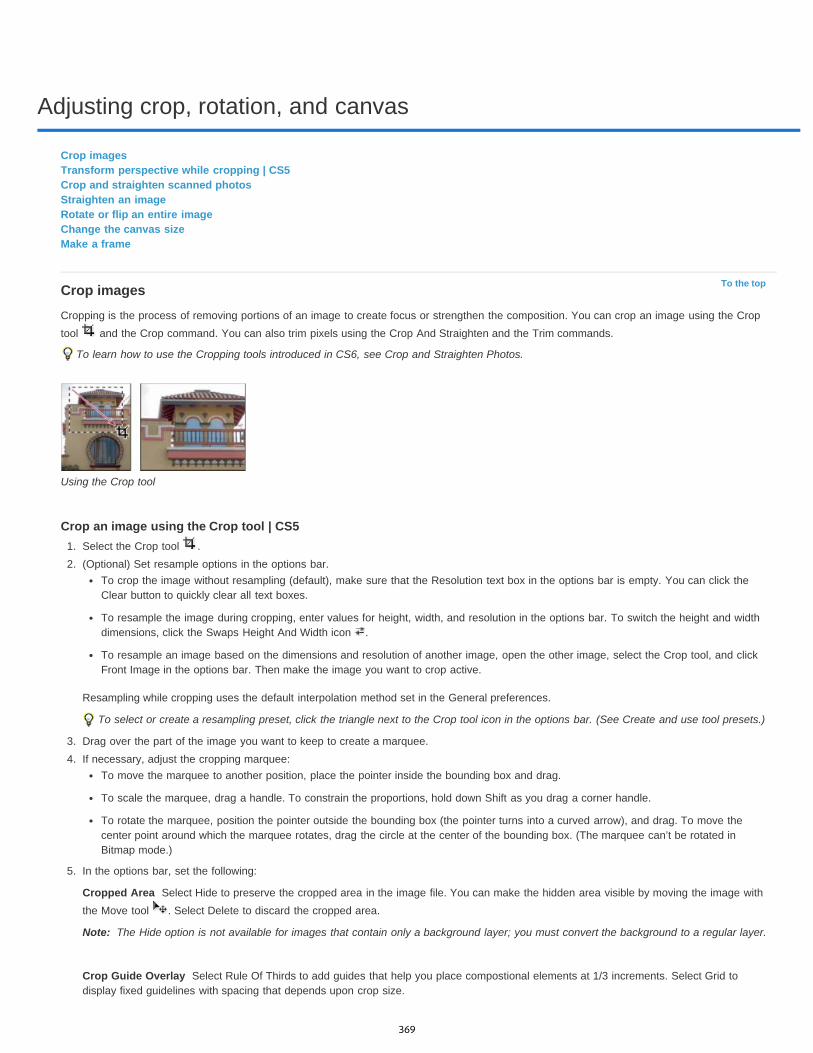
Adjusting crop, rotation, and canvas
To the top
Cropped Area
Note:
Crop Guide Overlay
Crop imagesTransform perspective while cropping | CS5Crop and straighten scanned photosStraighten an imageRotate or flip an entire imageChange the canvas sizeMake a frame
Crop imagesCropping is the process of removing portions of an image to create focus or strengthen the composition. You can crop an image using the Croptool and the Crop command. You can also trim pixels using the Crop And Straighten and the Trim commands.
To learn how to use the Cropping tools introduced in CS6, see Crop and Straighten Photos.
Using the Crop tool
Crop an image using the Crop tool | CS51. Select the Crop tool .2. (Optional) Set resample options in the options bar.
To crop the image without resampling (default), make sure that the Resolution text box in the options bar is empty. You can click theClear button to quickly clear all text boxes.
To resample the image during cropping, enter values for height, width, and resolution in the options bar. To switch the height and widthdimensions, click the Swaps Height And Width icon .
To resample an image based on the dimensions and resolution of another image, open the other image, select the Crop tool, and clickFront Image in the options bar. Then make the image you want to crop active.
Resampling while cropping uses the default interpolation method set in the General preferences.
To select or create a resampling preset, click the triangle next to the Crop tool icon in the options bar. (See Create and use tool presets.)
3. Drag over the part of the image you want to keep to create a marquee.4. If necessary, adjust the cropping marquee:
To move the marquee to another position, place the pointer inside the bounding box and drag.
To scale the marquee, drag a handle. To constrain the proportions, hold down Shift as you drag a corner handle.
To rotate the marquee, position the pointer outside the bounding box (the pointer turns into a curved arrow), and drag. To move thecenter point around which the marquee rotates, drag the circle at the center of the bounding box. (The marquee can’t be rotated inBitmap mode.)
5. In the options bar, set the following:
Select Hide to preserve the cropped area in the image file. You can make the hidden area visible by moving the image withthe Move tool . Select Delete to discard the cropped area.
The Hide option is not available for images that contain only a background layer; you must convert the background to a regular layer.
Select Rule Of Thirds to add guides that help you place compostional elements at 1/3 increments. Select Grid todisplay fixed guidelines with spacing that depends upon crop size.
369

Shield
To the top
Note:
The cropping shield shades the image area that will be deleted or hidden. When Shield is selected, you can specify color andopacity for the shield. When Shield is deselected, the area outside the cropping marquee is revealed.
6. Do one of the following:To complete the crop, press Enter (Windows) or Return (Mac OS), click the Commit button in the options bar, or double-click insidethe cropping marquee.
To cancel the cropping operation, press Esc or click the Cancel button in the options bar.
Crop an image using the Crop command1. Use a selection tool to select the part of the image you want to keep.2. Choose Image > Crop.
Crop an image using the Trim commandThe Trim command crops an image by removing unwanted image data in different ways than the Crop command. You can crop an image bytrimming surrounding transparent pixels, or background pixels of the color you specify.
1. Choose Image > Trim.2. In the Trim dialog box, select an option:
Transparent Pixels to trim away transparency at the edges of the image, leaving the smallest image containing nontransparent pixels.
Top Left Pixel Color to remove an area the color of the upper-left pixel from the image.
Bottom Right Pixel Color to remove an area the color of the lower right pixel from the image.
3. Select one or more areas of the image to trim away: Top, Bottom, Left, or Right.
Transform perspective while cropping | CS5To learn how to transform perspective in Photoshop CC and CS6, see Transform perspective while cropping.
The Crop tool has an option that lets you transform the perspective in an image. Transforming the perspective is useful when working with imagesthat contain keystone distortion. Keystone distortion occurs when an object is photographed from an angle rather than from a straight-on view. Forexample, if you take a picture of a tall building from ground level, the edges of the building appear closer to each other at the top than they do atthe bottom.
Steps to transform perspective A. Draw initial cropping marquee B. Adjust cropping marquee to match the object’s edges C. Extend the cropping bounds D. Final image
1. Select the Crop tool and set the crop mode.2. Drag the cropping marquee around an object that was rectangular in the original scene (although it doesn’t appear rectangular in the image).
You’ll use the edges of this object to define the perspective in the image. The marquee doesn’t have to be precise—you’ll adjust it later.
You must select an object that was rectangular in the original scene or Photoshop might not produce the perspective transformationyou expected.
3. Select Perspective in the options bar, and set the other options as desired.4. Move the corner handles of the cropping marquee to match the object’s edges. This defines the perspective in the image, so it is important
370
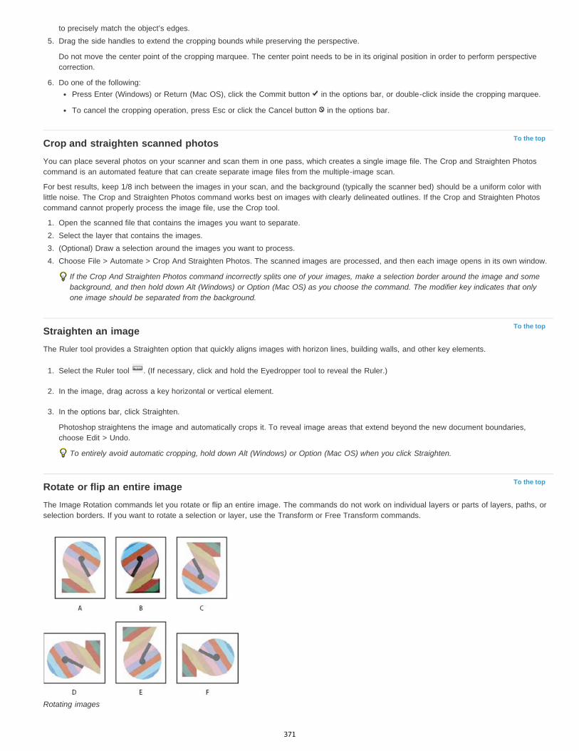
To the top
To the top
To the top
to precisely match the object’s edges.5. Drag the side handles to extend the cropping bounds while preserving the perspective.
Do not move the center point of the cropping marquee. The center point needs to be in its original position in order to perform perspectivecorrection.
6. Do one of the following:Press Enter (Windows) or Return (Mac OS), click the Commit button in the options bar, or double-click inside the cropping marquee.
To cancel the cropping operation, press Esc or click the Cancel button in the options bar.
Crop and straighten scanned photosYou can place several photos on your scanner and scan them in one pass, which creates a single image file. The Crop and Straighten Photoscommand is an automated feature that can create separate image files from the multiple-image scan.
For best results, keep 1/8 inch between the images in your scan, and the background (typically the scanner bed) should be a uniform color withlittle noise. The Crop and Straighten Photos command works best on images with clearly delineated outlines. If the Crop and Straighten Photoscommand cannot properly process the image file, use the Crop tool.
1. Open the scanned file that contains the images you want to separate.2. Select the layer that contains the images.3. (Optional) Draw a selection around the images you want to process.4. Choose File > Automate > Crop And Straighten Photos. The scanned images are processed, and then each image opens in its own window.
If the Crop And Straighten Photos command incorrectly splits one of your images, make a selection border around the image and somebackground, and then hold down Alt (Windows) or Option (Mac OS) as you choose the command. The modifier key indicates that onlyone image should be separated from the background.
Straighten an imageThe Ruler tool provides a Straighten option that quickly aligns images with horizon lines, building walls, and other key elements.
1. Select the Ruler tool . (If necessary, click and hold the Eyedropper tool to reveal the Ruler.)
2. In the image, drag across a key horizontal or vertical element.
3. In the options bar, click Straighten.
Photoshop straightens the image and automatically crops it. To reveal image areas that extend beyond the new document boundaries,choose Edit > Undo.
To entirely avoid automatic cropping, hold down Alt (Windows) or Option (Mac OS) when you click Straighten.
Rotate or flip an entire imageThe Image Rotation commands let you rotate or flip an entire image. The commands do not work on individual layers or parts of layers, paths, orselection borders. If you want to rotate a selection or layer, use the Transform or Free Transform commands.
Rotating images
371
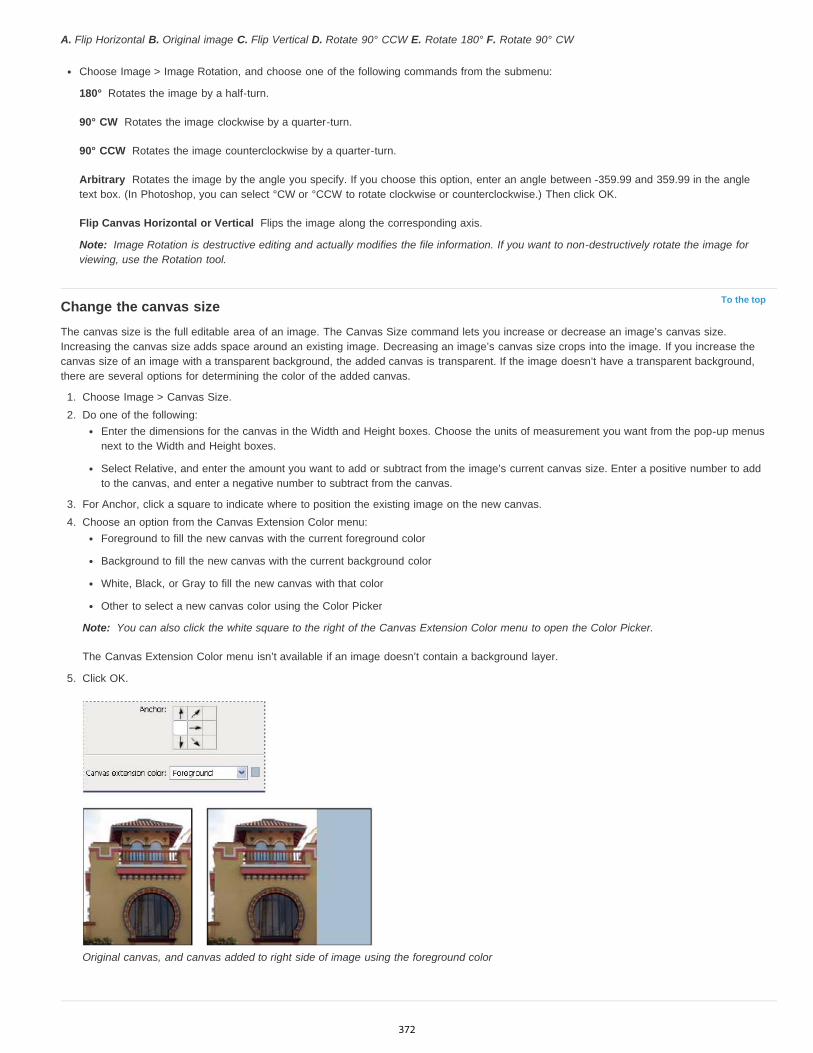
180°
90° CW
90° CCW
Arbitrary
Flip Canvas Horizontal or Vertical
Note:
To the top
Note:
A. Flip Horizontal B. Original image C. Flip Vertical D. Rotate 90° CCW E. Rotate 180° F. Rotate 90° CW
Choose Image > Image Rotation, and choose one of the following commands from the submenu:
Rotates the image by a half-turn.
Rotates the image clockwise by a quarter-turn.
Rotates the image counterclockwise by a quarter-turn.
Rotates the image by the angle you specify. If you choose this option, enter an angle between -359.99 and 359.99 in the angletext box. (In Photoshop, you can select °CW or °CCW to rotate clockwise or counterclockwise.) Then click OK.
Flips the image along the corresponding axis.
Image Rotation is destructive editing and actually modifies the file information. If you want to non-destructively rotate the image forviewing, use the Rotation tool.
Change the canvas sizeThe canvas size is the full editable area of an image. The Canvas Size command lets you increase or decrease an image’s canvas size.Increasing the canvas size adds space around an existing image. Decreasing an image’s canvas size crops into the image. If you increase thecanvas size of an image with a transparent background, the added canvas is transparent. If the image doesn’t have a transparent background,there are several options for determining the color of the added canvas.
1. Choose Image > Canvas Size.2. Do one of the following:
Enter the dimensions for the canvas in the Width and Height boxes. Choose the units of measurement you want from the pop-up menusnext to the Width and Height boxes.
Select Relative, and enter the amount you want to add or subtract from the image’s current canvas size. Enter a positive number to addto the canvas, and enter a negative number to subtract from the canvas.
3. For Anchor, click a square to indicate where to position the existing image on the new canvas.4. Choose an option from the Canvas Extension Color menu:
Foreground to fill the new canvas with the current foreground color
Background to fill the new canvas with the current background color
White, Black, or Gray to fill the new canvas with that color
Other to select a new canvas color using the Color Picker
You can also click the white square to the right of the Canvas Extension Color menu to open the Color Picker.
The Canvas Extension Color menu isn’t available if an image doesn’t contain a background layer.
5. Click OK.
Original canvas, and canvas added to right side of image using the foreground color
372
Twitter™ and Facebook posts are not covered under the terms of Creative Commons.
Legal Notices | Online Privacy Policy
To the topMake a frameYou can make a photo frame by increasing the canvas size and filling it with a color.
You can also use one of the prerecorded actions to make a styled photo frame. It’s best work on a copy of your photo.
1. Open the Actions panel. Choose Window > Actions.2. Choose Frames from the Actions panel menu.3. Choose one of the frame actions from the list.4. Click the Play Selection button.
The action plays, creating the frame around your photo.
More Help TopicsRotate, Crop, and retouch images in Camera Raw
373
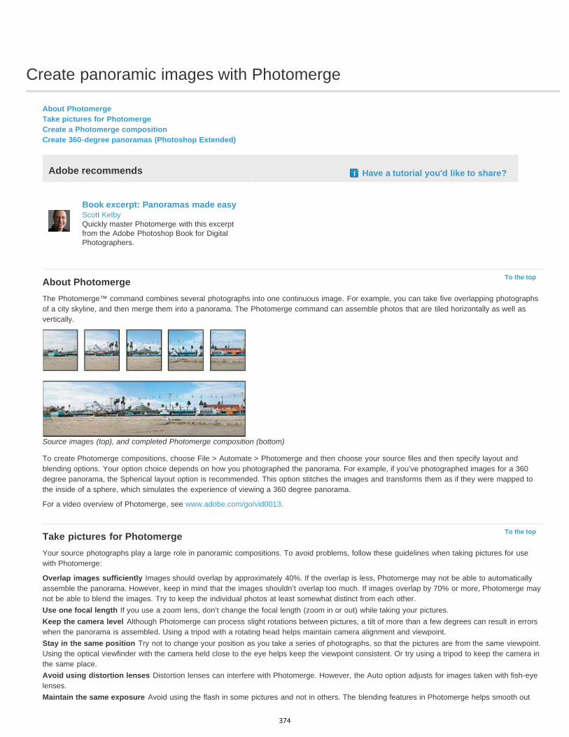
Create panoramic images with Photomerge
To the top
To the top
About PhotomergeTake pictures for PhotomergeCreate a Photomerge compositionCreate 360-degree panoramas (Photoshop Extended)
Adobe recommends Have a tutorial you'd like to share?
Book excerpt: Panoramas made easyScott KelbyQuickly master Photomerge with this excerptfrom the Adobe Photoshop Book for DigitalPhotographers.
About PhotomergeThe Photomerge™ command combines several photographs into one continuous image. For example, you can take five overlapping photographsof a city skyline, and then merge them into a panorama. The Photomerge command can assemble photos that are tiled horizontally as well asvertically.
Source images (top), and completed Photomerge composition (bottom)
To create Photomerge compositions, choose File > Automate > Photomerge and then choose your source files and then specify layout andblending options. Your option choice depends on how you photographed the panorama. For example, if you’ve photographed images for a 360degree panorama, the Spherical layout option is recommended. This option stitches the images and transforms them as if they were mapped tothe inside of a sphere, which simulates the experience of viewing a 360 degree panorama.
For a video overview of Photomerge, see www.adobe.com/go/vid0013.
Take pictures for PhotomergeYour source photographs play a large role in panoramic compositions. To avoid problems, follow these guidelines when taking pictures for usewith Photomerge:
Overlap images sufficiently Images should overlap by approximately 40%. If the overlap is less, Photomerge may not be able to automaticallyassemble the panorama. However, keep in mind that the images shouldn’t overlap too much. If images overlap by 70% or more, Photomerge maynot be able to blend the images. Try to keep the individual photos at least somewhat distinct from each other.Use one focal length If you use a zoom lens, don’t change the focal length (zoom in or out) while taking your pictures.Keep the camera level Although Photomerge can process slight rotations between pictures, a tilt of more than a few degrees can result in errorswhen the panorama is assembled. Using a tripod with a rotating head helps maintain camera alignment and viewpoint.Stay in the same position Try not to change your position as you take a series of photographs, so that the pictures are from the same viewpoint.Using the optical viewfinder with the camera held close to the eye helps keep the viewpoint consistent. Or try using a tripod to keep the camera inthe same place.Avoid using distortion lenses Distortion lenses can interfere with Photomerge. However, the Auto option adjusts for images taken with fish-eyelenses.Maintain the same exposure Avoid using the flash in some pictures and not in others. The blending features in Photomerge helps smooth out
374
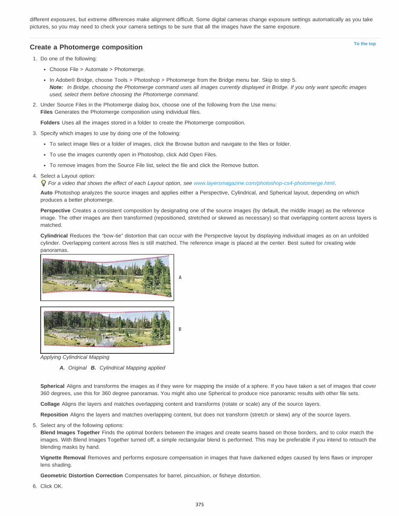
To the top
different exposures, but extreme differences make alignment difficult. Some digital cameras change exposure settings automatically as you takepictures, so you may need to check your camera settings to be sure that all the images have the same exposure.
Create a Photomerge composition1. Do one of the following:
Choose File > Automate > Photomerge.
In Adobe® Bridge, choose Tools > Photoshop > Photomerge from the Bridge menu bar. Skip to step 5.Note: In Bridge, choosing the Photomerge command uses all images currently displayed in Bridge. If you only want specific imagesused, select them before choosing the Photomerge command.
2. Under Source Files in the Photomerge dialog box, choose one of the following from the Use menu:Files Generates the Photomerge composition using individual files.
Folders Uses all the images stored in a folder to create the Photomerge composition.
3. Specify which images to use by doing one of the following:
To select image files or a folder of images, click the Browse button and navigate to the files or folder.
To use the images currently open in Photoshop, click Add Open Files.
To remove images from the Source File list, select the file and click the Remove button.
4. Select a Layout option:For a video that shows the effect of each Layout option, see www.layersmagazine.com/photoshop-cs4-photomerge.html.
Auto Photoshop analyzes the source images and applies either a Perspective, Cylindrical, and Spherical layout, depending on whichproduces a better photomerge.
Perspective Creates a consistent composition by designating one of the source images (by default, the middle image) as the referenceimage. The other images are then transformed (repositioned, stretched or skewed as necessary) so that overlapping content across layers ismatched.
Cylindrical Reduces the “bow-tie” distortion that can occur with the Perspective layout by displaying individual images as on an unfoldedcylinder. Overlapping content across files is still matched. The reference image is placed at the center. Best suited for creating widepanoramas.
Applying Cylindrical Mapping
A. Original B. Cylindrical Mapping applied
Spherical Aligns and transforms the images as if they were for mapping the inside of a sphere. If you have taken a set of images that cover360 degrees, use this for 360 degree panoramas. You might also use Spherical to produce nice panoramic results with other file sets.
Collage Aligns the layers and matches overlapping content and transforms (rotate or scale) any of the source layers.
Reposition Aligns the layers and matches overlapping content, but does not transform (stretch or skew) any of the source layers.
5. Select any of the following options:Blend Images Together Finds the optimal borders between the images and create seams based on those borders, and to color match theimages. With Blend Images Together turned off, a simple rectangular blend is performed. This may be preferable if you intend to retouch theblending masks by hand.
Vignette Removal Removes and performs exposure compensation in images that have darkened edges caused by lens flaws or improperlens shading.
Geometric Distortion Correction Compensates for barrel, pincushion, or fisheye distortion.
6. Click OK.
375

To the top
Photoshop creates one multi-layer image from the source images, adding layer masks as needed to create optimal blending where the imagesoverlap. You can edit the layer masks or add adjustment layers to further fine tune the different areas of the panorama.
To replace empty areas around image borders, use a content-aware fill. (See Content-aware, pattern, or history fills.)
Create 360-degree panoramas (Photoshop Extended)Combine Photomerge with 3D features to create a 360-degree panorama. First, you stitch together the images to create a panorama; then you usethe Spherical Panorama command to wrap the panorama so it’s continuous.
Be sure to photograph a full circle of images with sufficient overlap. Photographing with a pano head on a tripod helps produce better results.
For a video on creating a 360-degree panorama, see http://tv.adobe.com/#vi+f1577v1001.
1. Choose File > Automate > Photomerge.2. In the Photomerge dialog box, add the images you want to use.
Do not include images that cover the top (zenith) or bottom (nadir) of the scene. You’ll add these images later.
3. Select Spherical for the Layout.If you photographed with a fisheye lens, select the Auto layout and Geometric Distortion Correction. If Photoshop cannot automaticallyidentify your lens, download the free Adobe Lens Profile Creator from the Adobe website.
4. (Optional) Select Vignette Removal or Geometric Distortion for the Lens Correction.5. Click OK.
There might be transparent pixels on the edges of the panoramic image. These can prevent the final 360 panorama from wrapping correctly.You can either crop the pixels out or use the Offset filter to identify and remove the pixels.
6. Choose 3D > New Shape From Layer > Spherical Panorama.7. (Optional) Manually add the top and bottom images into the sphere. You could also paint out any remaining transparent pixels in the 3D
spherical panorama layer.
Legal Notices | Online Privacy Policy
376

Content-aware scaling
To the top
To the top
To the top
Resize images and protect contentPreserve visual content when scaling imagesSpecify content to protect when scaling
Resize images and protect contentContent-Aware Scale resizes an image without changing important visual content such as people, buildings, animals, and so forth. While normalscaling affects all pixels uniformly when resizing an image, content-aware scaling mostly affects pixels in areas that don’t have important visualcontent. Content-Aware Scale lets you upscale or downscale images to improve a composition, fit a layout, or change the orientation. If you wantto use some normal scaling when resizing your image, there is an option for specifying a ratio of content-aware scaling to normal scaling.
If you want to preserve specific areas when scaling an image, Content-Aware Scale lets you use an alpha channel to protect content duringresizing.
Content-Aware Scaling works on layers and selections. Images can be in RGB, CMYK, Lab, and Grayscale color modes as well as all bit depths.Content-Aware Scaling doesn’t work on adjustment layers, layer masks, individual channels, Smart Objects, 3D layers, Video layers, multiplelayers simultaneously, or layer groups.
A. Original image B. Scaled narrower C. Scaled narrower, using content-aware scaling
For a video on content-aware scaling, see www.adobe.com/go/lrvid4120_ps. (Discussion of this feature begins at the four-minute mark.)
Preserve visual content when scaling images1. (Optional) Choose Select > All if you’re scaling a Background layer.2. Choose Edit > Content-Aware Scale.3. Specify any of the following in the options bar:
Reference Point Location Click a square on the reference point locator to specify the fixed point around which the image is scaled.By default this point is at the center of the image.
Use Relative Positioning For Reference Point Click the button to specify the new position of the reference point in relation to its currentposition.
Reference Point Position Positions the reference point at the specific location. Enter X-axis and Y-axis pixel dimensions.
Scaling Percentage Specifies the image scaling as a percentage of the original size. Enter a percentage for the width (W) and height (H). Ifdesired, click Maintain Aspect Ratio .
Amount Specifies the ratio of content-aware scaling to normal scaling. Specify a percentage for content-aware scaling by typing in the textbox or clicking the arrow and moving the slider.
Protect Chooses an alpha channel that specifies an area to protect.
Protect Skin Tones Attempts to preserve regions that contain skin-tones.
4. Drag a handle on the bounding box to scale the image. Press Shift as you drag a corner handle to scale proportionately. When positionedover a handle, the pointer becomes a double arrow.
5. Click either Cancel Transform or Commit Transform .
Specify content to protect when scaling
377

1. Make a selection around the content you want to protect and then, in the Channels panel, click Save Selection As Channel .2. (Optional) Choose Select > All if you’re scaling a Background layer.3. Choose Edit > Content-Aware Scale.4. In the options bar, choose the alpha channel you created.5. Drag a handle on the bounding border to scale the image.
Legal Notices | Online Privacy Policy
378
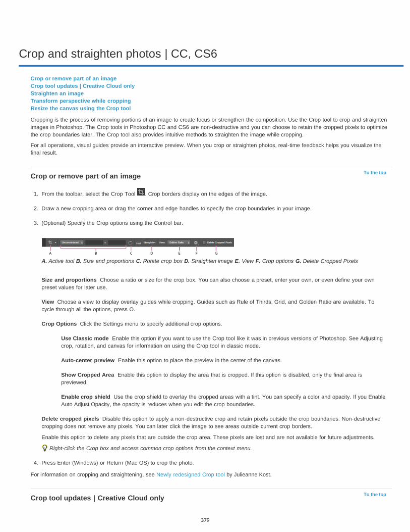
Crop and straighten photos | CC, CS6
To the top
Size and proportions
View
Crop Options
Use Classic mode
Auto-center preview
Show Cropped Area
Enable crop shield
Delete cropped pixels
To the top
Crop or remove part of an imageCrop tool updates | Creative Cloud onlyStraighten an imageTransform perspective while croppingResize the canvas using the Crop tool
Cropping is the process of removing portions of an image to create focus or strengthen the composition. Use the Crop tool to crop and straightenimages in Photoshop. The Crop tools in Photoshop CC and CS6 are non-destructive and you can choose to retain the cropped pixels to optimizethe crop boundaries later. The Crop tool also provides intuitive methods to straighten the image while cropping.
For all operations, visual guides provide an interactive preview. When you crop or straighten photos, real-time feedback helps you visualize thefinal result.
Crop or remove part of an image
1. From the toolbar, select the Crop Tool . Crop borders display on the edges of the image.
2. Draw a new cropping area or drag the corner and edge handles to specify the crop boundaries in your image.
3. (Optional) Specify the Crop options using the Control bar.
A. Active tool B. Size and proportions C. Rotate crop box D. Straighten image E. View F. Crop options G. Delete Cropped Pixels
Choose a ratio or size for the crop box. You can also choose a preset, enter your own, or even define your ownpreset values for later use.
Choose a view to display overlay guides while cropping. Guides such as Rule of Thirds, Grid, and Golden Ratio are available. Tocycle through all the options, press O.
Click the Settings menu to specify additional crop options.
Enable this option if you want to use the Crop tool like it was in previous versions of Photoshop. See Adjustingcrop, rotation, and canvas for information on using the Crop tool in classic mode.
Enable this option to place the preview in the center of the canvas.
Enable this option to display the area that is cropped. If this option is disabled, only the final area ispreviewed.
Use the crop shield to overlay the cropped areas with a tint. You can specify a color and opacity. If you EnableAuto Adjust Opacity, the opacity is reduces when you edit the crop boundaries.
Disable this option to apply a non-destructive crop and retain pixels outside the crop boundaries. Non-destructivecropping does not remove any pixels. You can later click the image to see areas outside current crop borders.
Enable this option to delete any pixels that are outside the crop area. These pixels are lost and are not available for future adjustments.
Right-click the Crop box and access common crop options from the context menu.
4. Press Enter (Windows) or Return (Mac OS) to crop the photo.
For information on cropping and straightening, see Newly redesigned Crop tool by Julieanne Kost.
Crop tool updates | Creative Cloud only
379
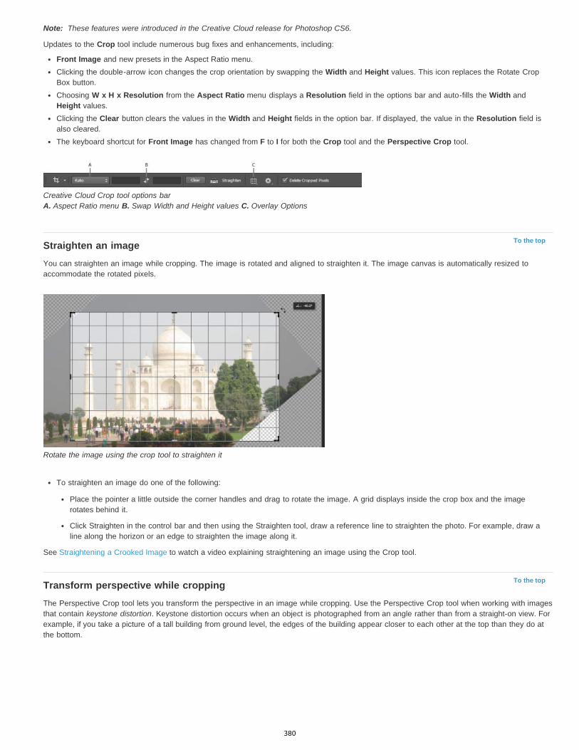
Note:
To the top
To the top
These features were introduced in the Creative Cloud release for Photoshop CS6.
Updates to the Crop tool include numerous bug fixes and enhancements, including:
Front Image and new presets in the Aspect Ratio menu.Clicking the double-arrow icon changes the crop orientation by swapping the Width and Height values. This icon replaces the Rotate CropBox button.Choosing W x H x Resolution from the Aspect Ratio menu displays a Resolution field in the options bar and auto-fills the Width andHeight values.Clicking the Clear button clears the values in the Width and Height fields in the option bar. If displayed, the value in the Resolution field isalso cleared.The keyboard shortcut for Front Image has changed from F to I for both the Crop tool and the Perspective Crop tool.
Creative Cloud Crop tool options bar A. Aspect Ratio menu B. Swap Width and Height values C. Overlay Options
Straighten an imageYou can straighten an image while cropping. The image is rotated and aligned to straighten it. The image canvas is automatically resized toaccommodate the rotated pixels.
Rotate the image using the crop tool to straighten it
To straighten an image do one of the following:
Place the pointer a little outside the corner handles and drag to rotate the image. A grid displays inside the crop box and the imagerotates behind it.
Click Straighten in the control bar and then using the Straighten tool, draw a reference line to straighten the photo. For example, draw aline along the horizon or an edge to straighten the image along it.
See Straightening a Crooked Image to watch a video explaining straightening an image using the Crop tool.
Transform perspective while croppingThe Perspective Crop tool lets you transform the perspective in an image while cropping. Use the Perspective Crop tool when working with imagesthat contain keystone distortion. Keystone distortion occurs when an object is photographed from an angle rather than from a straight-on view. Forexample, if you take a picture of a tall building from ground level, the edges of the building appear closer to each other at the top than they do atthe bottom.
380
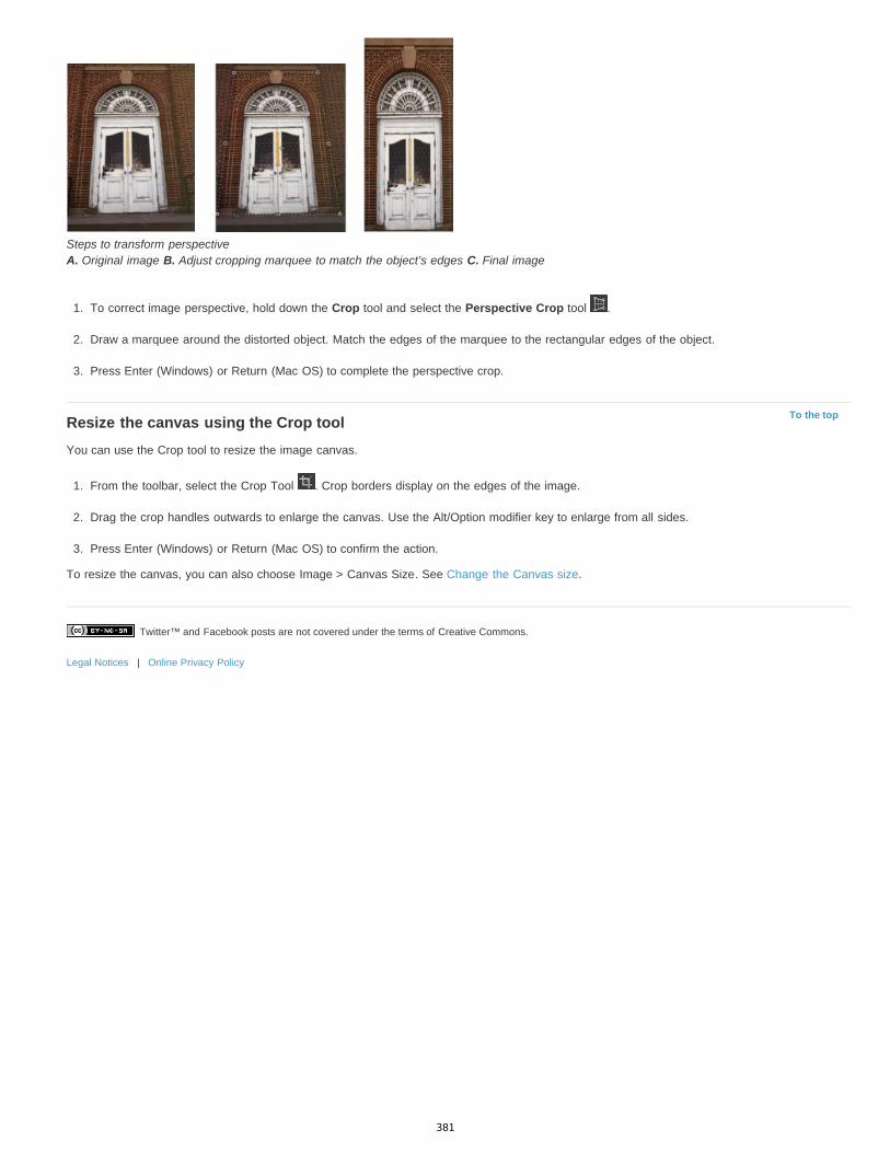
Twitter™ and Facebook posts are not covered under the terms of Creative Commons.
Legal Notices | Online Privacy Policy
To the top
Steps to transform perspective A. Original image B. Adjust cropping marquee to match the object’s edges C. Final image
1. To correct image perspective, hold down the Crop tool and select the Perspective Crop tool .
2. Draw a marquee around the distorted object. Match the edges of the marquee to the rectangular edges of the object.
3. Press Enter (Windows) or Return (Mac OS) to complete the perspective crop.
Resize the canvas using the Crop toolYou can use the Crop tool to resize the image canvas.
1. From the toolbar, select the Crop Tool . Crop borders display on the edges of the image.
2. Drag the crop handles outwards to enlarge the canvas. Use the Alt/Option modifier key to enlarge from all sides.
3. Press Enter (Windows) or Return (Mac OS) to confirm the action.
To resize the canvas, you can also choose Image > Canvas Size. See Change the Canvas size.
381
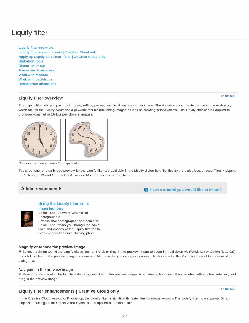
Liquify filter
To the top
To the top
Liquify filter overviewLiquify filter enhancements | Creative Cloud onlyApplying Liquify as a smart filter | Creative Cloud onlyDistortion toolsDistort an imageFreeze and thaw areasWork with meshesWork with backdropsReconstruct distortions
Liquify filter overviewThe Liquify filter lets you push, pull, rotate, reflect, pucker, and bloat any area of an image. The distortions you create can be subtle or drastic,which makes the Liquify command a powerful tool for retouching images as well as creating artistic effects. The Liquify filter can be applied to8-bits-per-channel or 16-bits per-channel images.
Distorting an image using the Liquify filter
Tools, options, and an image preview for the Liquify filter are available in the Liquify dialog box. To display the dialog box, choose Filter > Liquify.In Photoshop CC and CS6, select Advanced Mode to access more options.
Adobe recommends Have a tutorial you would like to share?
Using the Liquify filter to fiximperfectionsEddie Tapp, Software Cinema forPhotographersProfessional photographer and educator,Eddie Tapp, walks you through the basictools and options of the Liquify filter as hefixes imperfections in a clothing photo.
Magnify or reduce the preview image Select the Zoom tool in the Liquify dialog box, and click or drag in the preview image to zoom in; hold down Alt (Windows) or Option (Mac OS),
and click or drag in the preview image to zoom out. Alternatively, you can specify a magnification level in the Zoom text box at the bottom of thedialog box.
Navigate in the preview image Select the Hand tool in the Liquify dialog box, and drag in the preview image. Alternatively, hold down the spacebar with any tool selected, and
drag in the preview image.
Liquify filter enhancements | Creative Cloud onlyIn the Creative Cloud version of Photoshop, the Liquify filter is significantly faster than previous versions.The Liquify filter now supports SmartObjects, including Smart Object video layers, and is applied as a smart filter.
382
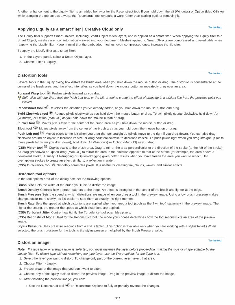
To the top
To the top
To the top
Another enhancement to the Liquify filter is an added behavior for the Reconstruct tool. If you hold down the alt (Windows) or Option (Mac OS) keywhile dragging the tool across a warp, the Reconstruct tool smooths a warp rather than scaling back or removing it.
Applying Liquify as a smart filter | Creative Cloud onlyThe Liquify filter supports Smart Objects, including Smart Object video layers, and is applied as a smart filter. When applying the Liquify filter to aSmart Object, meshes are now automatically saved into your document. Meshes applied to Smart Objects are compressed and re-editable whenreapplying the Liquify filter. Keep in mind that the embedded meshes, even compressed ones, increase the file size.
To apply the Liquify filter as a smart filter:
1. In the Layers panel, select a Smart Object layer.2. Choose Filter > Liquify.
Distortion toolsSeveral tools in the Liquify dialog box distort the brush area when you hold down the mouse button or drag. The distortion is concentrated at thecenter of the brush area, and the effect intensifies as you hold down the mouse button or repeatedly drag over an area.
Forward Warp tool Pushes pixels forward as you drag.Shift-click with the Warp tool, the Push Left tool, or the Mirror tool to create the effect of dragging in a straight line from the previous point youclicked.
Reconstruct tool Reverses the distortion you’ve already added, as you hold down the mouse button and drag.
Twirl Clockwise tool Rotates pixels clockwise as you hold down the mouse button or drag. To twirl pixels counterclockwise, hold down Alt(Windows) or Option (Mac OS) as you hold down the mouse button or drag.Pucker tool Moves pixels toward the center of the brush area as you hold down the mouse button or drag.
Bloat tool Moves pixels away from the center of the brush area as you hold down the mouse button or drag.Push Left tool Moves pixels to the left when you drag the tool straight up (pixels move to the right if you drag down). You can also dragclockwise around an object to increase its size, or drag counterclockwise to decrease its size. To push pixels right when you drag straight up (or tomove pixels left when you drag down), hold down Alt (Windows) or Option (Mac OS) as you drag.
(CS5) Mirror tool Copies pixels to the brush area. Drag to mirror the area perpendicular to the direction of the stroke (to the left of the stroke).Alt-drag (Windows) or Option-drag (Mac OS) to mirror the area in the direction opposite to that of the stroke (for example, the area above adownward stroke). Usually, Alt-dragging or Option-dragging gives better results when you have frozen the area you want to reflect. Useoverlapping strokes to create an effect similar to a reflection in water.(CS5) Turbulence tool Smoothly scrambles pixels. It is useful for creating fire, clouds, waves, and similar effects.
Distortion tool optionsIn the tool options area of the dialog box, set the following options:
Brush Size Sets the width of the brush you’ll use to distort the image.Brush Density Controls how a brush feathers at the edge. An effect is strongest in the center of the brush and lighter at the edge.Brush Pressure Sets the speed at which distortions are made when you drag a tool in the preview image. Using a low brush pressure makeschanges occur more slowly, so it’s easier to stop them at exactly the right moment.Brush Rate Sets the speed at which distortions are applied when you keep a tool (such as the Twirl tool) stationary in the preview image. Thehigher the setting, the greater the speed at which distortions are applied.(CS5) Turbulent Jitter Control how tightly the Turbulence tool scrambles pixels.(CS5) Reconstruct Mode Used for the Reconstruct tool, the mode you choose determines how the tool reconstructs an area of the previewimage.Stylus Pressure Uses pressure readings from a stylus tablet. (This option is available only when you are working with a stylus tablet.) Whenselected, the brush pressure for the tools is the stylus pressure multiplied by the Brush Pressure value.
Distort an imageNote: If a type layer or a shape layer is selected, you must rasterize the layer before proceeding, making the type or shape editable by theLiquify filter. To distort type without rasterizing the type layer, use the Warp options for the Type tool.
1. Select the layer you want to distort. To change only part of the current layer, select that area.2. Choose Filter > Liquify.3. Freeze areas of the image that you don’t want to alter.4. Choose any of the liquify tools to distort the preview image. Drag in the preview image to distort the image.5. After distorting the preview image, you can:
Use the Reconstruct tool or Reconstruct Options to fully or partially reverse the changes.
383
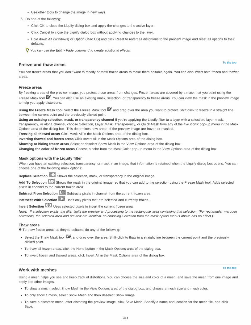
To the top
To the top
Use other tools to change the image in new ways.
6. Do one of the following:
Click OK to close the Liquify dialog box and apply the changes to the active layer.
Click Cancel to close the Liquify dialog box without applying changes to the layer.
Hold down Alt (Windows) or Option (Mac OS) and click Reset to revert all distortions to the preview image and reset all options to theirdefaults.
You can use the Edit > Fade command to create additional effects.
Freeze and thaw areasYou can freeze areas that you don’t want to modify or thaw frozen areas to make them editable again. You can also invert both frozen and thawedareas.
Freeze areasBy freezing areas of the preview image, you protect those areas from changes. Frozen areas are covered by a mask that you paint using theFreeze Mask tool . You can also use an existing mask, selection, or transparency to freeze areas. You can view the mask in the preview imageto help you apply distortions.
Using the Freeze Mask tool Select the Freeze Mask tool and drag over the area you want to protect. Shift-click to freeze in a straight linebetween the current point and the previously clicked point.Using an existing selection, mask, or transparency channel If you’re applying the Liquify filter to a layer with a selection, layer mask,transparency, or alpha channel, choose Selection, Layer Mask, Transparency, or Quick Mask from any of the five icons’ pop-up menu in the MaskOptions area of the dialog box. This determines how areas of the preview image are frozen or masked.Freezing all thawed areas Click Mask All in the Mask Options area of the dialog box.Inverting thawed and frozen areas Click Invert All in the Mask Options area of the dialog box.Showing or hiding frozen areas Select or deselect Show Mask in the View Options area of the dialog box.Changing the color of frozen areas Choose a color from the Mask Color pop-up menu in the View Options area of the dialog box.
Mask options with the Liquify filterWhen you have an existing selection, transparency, or mask in an image, that information is retained when the Liquify dialog box opens. You canchoose one of the following mask options:
Replace Selection Shows the selection, mask, or transparency in the original image.
Add To Selection Shows the mask in the original image, so that you can add to the selection using the Freeze Mask tool. Adds selectedpixels in channel to the current frozen area.
Subtract From Selection Subtracts pixels in channel from the current frozen area.
Intersect With Selection Uses only pixels that are selected and currently frozen.
Invert Selection Uses selected pixels to invert the current frozen area.Note: If a selection exists, the filter limits the preview and processing to the rectangular area containing that selection. (For rectangular marqueeselections, the selected area and preview are identical, so choosing Selection from the mask option menus above has no effect.)
Thaw areas To thaw frozen areas so they’re editable, do any of the following:
Select the Thaw Mask tool , and drag over the area. Shift-click to thaw in a straight line between the current point and the previouslyclicked point.
To thaw all frozen areas, click the None button in the Mask Options area of the dialog box.
To invert frozen and thawed areas, click Invert All in the Mask Options area of the dialog box.
Work with meshesUsing a mesh helps you see and keep track of distortions. You can choose the size and color of a mesh, and save the mesh from one image andapply it to other images.
To show a mesh, select Show Mesh in the View Options area of the dialog box, and choose a mesh size and mesh color.
To only show a mesh, select Show Mesh and then deselect Show Image.
To save a distortion mesh, after distorting the preview image, click Save Mesh. Specify a name and location for the mesh file, and clickSave.
384
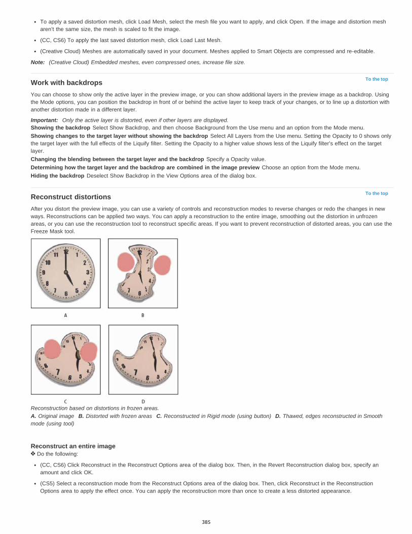
To the top
To the top
To apply a saved distortion mesh, click Load Mesh, select the mesh file you want to apply, and click Open. If the image and distortion mesharen’t the same size, the mesh is scaled to fit the image.
(CC, CS6) To apply the last saved distortion mesh, click Load Last Mesh.
(Creative Cloud) Meshes are automatically saved in your document. Meshes applied to Smart Objects are compressed and re-editable.
Note: (Creative Cloud) Embedded meshes, even compressed ones, increase file size.
Work with backdropsYou can choose to show only the active layer in the preview image, or you can show additional layers in the preview image as a backdrop. Usingthe Mode options, you can position the backdrop in front of or behind the active layer to keep track of your changes, or to line up a distortion withanother distortion made in a different layer.
Important: Only the active layer is distorted, even if other layers are displayed.Showing the backdrop Select Show Backdrop, and then choose Background from the Use menu and an option from the Mode menu.Showing changes to the target layer without showing the backdrop Select All Layers from the Use menu. Setting the Opacity to 0 shows onlythe target layer with the full effects of the Liquify filter. Setting the Opacity to a higher value shows less of the Liquify filter’s effect on the targetlayer.Changing the blending between the target layer and the backdrop Specify a Opacity value.Determining how the target layer and the backdrop are combined in the image preview Choose an option from the Mode menu.Hiding the backdrop Deselect Show Backdrop in the View Options area of the dialog box.
Reconstruct distortionsAfter you distort the preview image, you can use a variety of controls and reconstruction modes to reverse changes or redo the changes in newways. Reconstructions can be applied two ways. You can apply a reconstruction to the entire image, smoothing out the distortion in unfrozenareas, or you can use the reconstruction tool to reconstruct specific areas. If you want to prevent reconstruction of distorted areas, you can use theFreeze Mask tool.
Reconstruction based on distortions in frozen areas.A. Original image B. Distorted with frozen areas C. Reconstructed in Rigid mode (using button) D. Thawed, edges reconstructed in Smoothmode (using tool)
Reconstruct an entire image Do the following:
(CC, CS6) Click Reconstruct in the Reconstruct Options area of the dialog box. Then, in the Revert Reconstruction dialog box, specify anamount and click OK.
(CS5) Select a reconstruction mode from the Reconstruct Options area of the dialog box. Then, click Reconstruct in the ReconstructionOptions area to apply the effect once. You can apply the reconstruction more than once to create a less distorted appearance.
385
Remove all distortions Click Restore All in the Reconstruct Option area of the dialog box. This removes distortions even in frozen areas.
Reconstruct part of a distorted image1. Freeze areas you want to keep distorted.
2. Select the Reconstruct tool and specify brush options in the Tool Options area of the dialog box.3. (CS5 only) Choose an option from the Reconstruct Mode menu in the Tool Options area of the dialog box.4. Drag over the area you want to reconstruct. Pixels move more quickly at the brush center. Shift-click to reconstruct in a straight line between
the current point and the previously clicked point.
(CS5 only) Repeat distortions sampled from a starting point1. After distorting the preview image, choose one of these reconstruction modes from the Mode menu in the Tool Options area of the
dialog box.
2. Select the Reconstruct tool , and drag from a starting point in the preview image.
This creates a copy of the distortion sampled at the starting point, much as the Clone tool does when you use it to paint a copy of an area. Ifthere is no distortion, the effect is the same as using Revert mode. You can set new starting points and use the Reconstruct tool repeatedlyto create a variety of effects.
(CS 5 only) Reconstruction modesYou can choose one of the following reconstruction modes:
Revert Scales back distortions uniformly without any kind of smoothing.Rigid Maintains right angles in the pixel grid (as shown by the mesh) at the edges between frozen and unfrozen areas, sometimes producing near-discontinuities at the edges. This restores the unfrozen areas so that they approximate their original appearance. (To restore their originalappearance, use Revert reconstruction mode.)Stiff Acts like a weak magnetic field. At the edges between frozen and unfrozen areas, the unfrozen areas take on the distortions of the frozenareas. As the distance from frozen areas increases, the distortions lessen.Smooth Propagates the distortions in frozen areas throughout unfrozen areas, with smoothly continuous distortions.Loose Produces effects similar to Smooth, with even greater continuity between distortions in frozen and unfrozen areas.
To adjust the intensity of a reconstruction mode, select it from the unlabeled pop-up menu above the Mode menu. As you adjust intensity, theimage previews your changes.
(CS5 only) Additional modes for the Reconstruct toolThe Reconstruct tool has three additional modes that use the distortion at the point where you first clicked the tool (start point) to reconstruct thearea over which you use the tool. Every time you click, you set a new start point; so, if you want to extend an effect from one start point, don’trelease the mouse button until you finish using the Reconstruct tool.
Displace Reconstructs unfrozen areas to match the displacement at the start point for the reconstruction. You can use Displace to move all orpart of the preview image to a different location. If you click and gradually spiral out from the start point, you displace or move a portion of theimage to the area you brush over.Amplitwist Reconstructs unfrozen areas to match the displacement, rotation, and overall scaling that exist at the start point.Affine Reconstructs unfrozen areas to match all distortions that exist at the start point, including displacement, rotation, horizontal and verticalscaling, and skew.More Help topicsVideo on "Smart Object Support for Blur Gallery and Liquify"
Legal Notices | Online Privacy Policy
386
Free transformations of images, shapes, and paths
To the top
Transform freely
Transform freelyThe Free Transform command lets you apply transformations (rotate, scale, skew, distort, and perspective) in one continuous operation. You canalso apply a warp transformation. Instead of choosing different commands, you simply hold down a key on your keyboard to switch betweentransformation types.
Note: If you are transforming a shape or entire path, the Transform command becomes the Transform Path command. If you are transformingmultiple path segments (but not the entire path), the Transform command becomes the Transform Points command.
1. Select what you want to transform.2. Do one of the following:
Choose Edit > Free Transform.
If you are transforming a selection, pixel-based layer, or selection border, choose the Move tool . Then select Show TransformControls in the options bar.
If you are transforming a vector shape or path, select the Path Selection tool . Then select Show Transform Controls in the options bar.
3. Do one or more of the following:
To scale by dragging, drag a handle. Press Shift as you drag a corner handle to scale proportionately.
To scale numerically, enter percentages in the Width and Height text boxes in the options bar. Click the Link icon to maintain theaspect ratio.
To rotate by dragging, move the pointer outside the bounding border (it becomes a curved, two-sided arrow), and then drag. Press Shiftto constrain the rotation to 15° increments.
To rotate numerically, enter degrees in the rotation text box in the options bar.
To distort relative to the center point of the bounding border, press Alt (Windows) or Option (Mac OS), and drag a handle.
To distort freely, press Ctrl (Windows) or Command (Mac OS), and drag a handle.
To skew, press Ctrl+Shift (Windows) or Command+Shift (Mac OS), and drag a side handle. When positioned over a side handle, thepointer becomes a white arrowhead with a small double arrow.
To skew numerically, enter degrees in the H (horizontal skew) and V (vertical skew) text boxes in the options bar.
To apply perspective, press Ctrl+Alt+Shift (Windows) or Command+Option+Shift (Mac OS), and drag a corner handle. When positionedover a corner handle, the pointer becomes a gray arrowhead.
To warp, click the Switch Between Free Transform And Warp Modes button in the options bar. Drag control points to manipulate theshape of the item or choose a warp style from the Warp pop-up menu in the options bar. After choosing from the Warp pop-up menu, asquare handle is available for adjusting the shape of the warp.
To change the reference point, click a square on the reference point locator in the options bar.
To move an item, enter values for the new location of the reference in the X (horizontal position) and Y (vertical position) text boxes inthe options bar. Click the Relative Positioning button to specify the new position in relation to the current position.
To undo the last handle adjustment, choose Edit > Undo.
4. Do one of the following:
Press Enter (Windows) or Return (Mac OS), click the Commit button in the options bar, or double-click inside the transformationmarquee.
To cancel the transformation, press Esc or click the Cancel button in the options bar.
Important: When you transform a bitmap image (versus a shape or path), the image becomes slightly less sharp each time you commit atransformation; therefore, performing multiple commands before applying the cumulative transformation is preferable to applying eachtransformation separately.
387
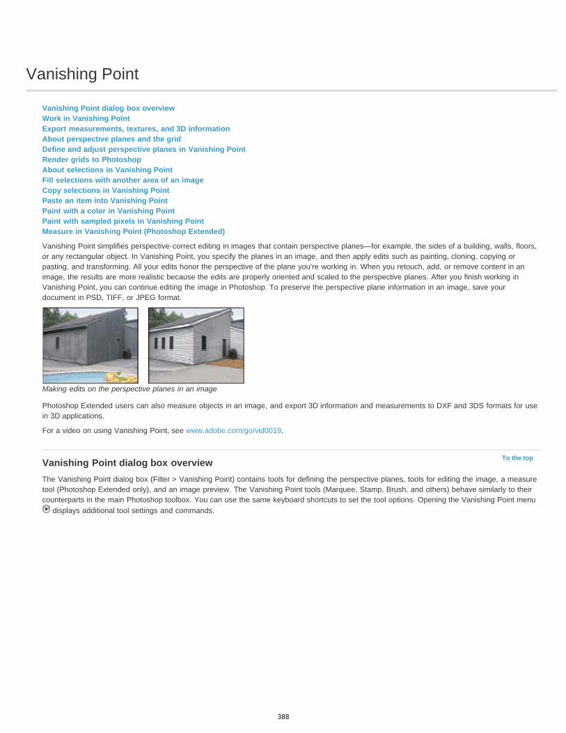
Vanishing Point
To the top
Vanishing Point dialog box overviewWork in Vanishing PointExport measurements, textures, and 3D informationAbout perspective planes and the gridDefine and adjust perspective planes in Vanishing PointRender grids to PhotoshopAbout selections in Vanishing PointFill selections with another area of an imageCopy selections in Vanishing PointPaste an item into Vanishing PointPaint with a color in Vanishing PointPaint with sampled pixels in Vanishing PointMeasure in Vanishing Point (Photoshop Extended)
Vanishing Point simplifies perspective-correct editing in images that contain perspective planes—for example, the sides of a building, walls, floors,or any rectangular object. In Vanishing Point, you specify the planes in an image, and then apply edits such as painting, cloning, copying orpasting, and transforming. All your edits honor the perspective of the plane you’re working in. When you retouch, add, or remove content in animage, the results are more realistic because the edits are properly oriented and scaled to the perspective planes. After you finish working inVanishing Point, you can continue editing the image in Photoshop. To preserve the perspective plane information in an image, save yourdocument in PSD, TIFF, or JPEG format.
Making edits on the perspective planes in an image
Photoshop Extended users can also measure objects in an image, and export 3D information and measurements to DXF and 3DS formats for usein 3D applications.
For a video on using Vanishing Point, see www.adobe.com/go/vid0019.
Vanishing Point dialog box overviewThe Vanishing Point dialog box (Filter > Vanishing Point) contains tools for defining the perspective planes, tools for editing the image, a measuretool (Photoshop Extended only), and an image preview. The Vanishing Point tools (Marquee, Stamp, Brush, and others) behave similarly to theircounterparts in the main Photoshop toolbox. You can use the same keyboard shortcuts to set the tool options. Opening the Vanishing Point menu
displays additional tool settings and commands.
388
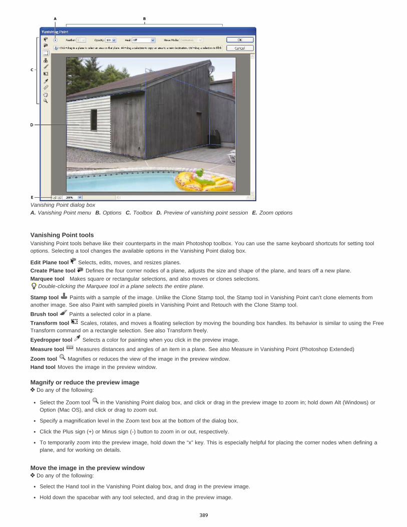
Vanishing Point dialog boxA. Vanishing Point menu B. Options C. Toolbox D. Preview of vanishing point session E. Zoom options
Vanishing Point toolsVanishing Point tools behave like their counterparts in the main Photoshop toolbox. You can use the same keyboard shortcuts for setting tooloptions. Selecting a tool changes the available options in the Vanishing Point dialog box.
Edit Plane tool Selects, edits, moves, and resizes planes.Create Plane tool Defines the four corner nodes of a plane, adjusts the size and shape of the plane, and tears off a new plane.Marquee tool Makes square or rectangular selections, and also moves or clones selections.
Double-clicking the Marquee tool in a plane selects the entire plane.
Stamp tool Paints with a sample of the image. Unlike the Clone Stamp tool, the Stamp tool in Vanishing Point can’t clone elements fromanother image. See also Paint with sampled pixels in Vanishing Point and Retouch with the Clone Stamp tool.
Brush tool Paints a selected color in a plane.Transform tool Scales, rotates, and moves a floating selection by moving the bounding box handles. Its behavior is similar to using the FreeTransform command on a rectangle selection. See also Transform freely.
Eyedropper tool Selects a color for painting when you click in the preview image.
Measure tool Measures distances and angles of an item in a plane. See also Measure in Vanishing Point (Photoshop Extended)
Zoom tool Magnifies or reduces the view of the image in the preview window.Hand tool Moves the image in the preview window.
Magnify or reduce the preview image Do any of the following:
Select the Zoom tool in the Vanishing Point dialog box, and click or drag in the preview image to zoom in; hold down Alt (Windows) orOption (Mac OS), and click or drag to zoom out.
Specify a magnification level in the Zoom text box at the bottom of the dialog box.
Click the Plus sign (+) or Minus sign (-) button to zoom in or out, respectively.
To temporarily zoom into the preview image, hold down the “x” key. This is especially helpful for placing the corner nodes when defining aplane, and for working on details.
Move the image in the preview window Do any of the following:
Select the Hand tool in the Vanishing Point dialog box, and drag in the preview image.
Hold down the spacebar with any tool selected, and drag in the preview image.
389
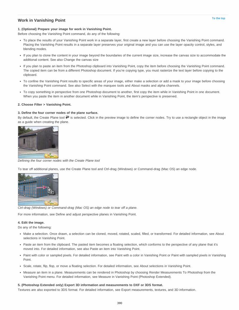
To the topWork in Vanishing Point
1. (Optional) Prepare your image for work in Vanishing Point.Before choosing the Vanishing Point command, do any of the following:
To place the results of your Vanishing Point work in a separate layer, first create a new layer before choosing the Vanishing Point command.Placing the Vanishing Point results in a separate layer preserves your original image and you can use the layer opacity control, styles, andblending modes.
If you plan to clone the content in your image beyond the boundaries of the current image size, increase the canvas size to accommodate theadditional content. See also Change the canvas size
If you plan to paste an item from the Photoshop clipboard into Vanishing Point, copy the item before choosing the Vanishing Point command.The copied item can be from a different Photoshop document. If you’re copying type, you must rasterize the text layer before copying to theclipboard.
To confine the Vanishing Point results to specific areas of your image, either make a selection or add a mask to your image before choosingthe Vanishing Point command. See also Select with the marquee tools and About masks and alpha channels.
To copy something in perspective from one Photoshop document to another, first copy the item while in Vanishing Point in one document.When you paste the item in another document while in Vanishing Point, the item’s perspective is preserved.
2. Choose Filter > Vanishing Point.
3. Define the four corner nodes of the plane surface.By default, the Create Plane tool is selected. Click in the preview image to define the corner nodes. Try to use a rectangle object in the imageas a guide when creating the plane.
Defining the four corner nodes with the Create Plane tool
To tear off additional planes, use the Create Plane tool and Ctrl-drag (Windows) or Command-drag (Mac OS) an edge node.
Ctrl-drag (Windows) or Command-drag (Mac OS) an edge node to tear off a plane.
For more information, see Define and adjust perspective planes in Vanishing Point.
4. Edit the image.Do any of the following:
Make a selection. Once drawn, a selection can be cloned, moved, rotated, scaled, filled, or transformed. For detailed information, see Aboutselections in Vanishing Point.
Paste an item from the clipboard. The pasted item becomes a floating selection, which conforms to the perspective of any plane that it’smoved into. For detailed information, see also Paste an item into Vanishing Point.
Paint with color or sampled pixels. For detailed information, see Paint with a color in Vanishing Point or Paint with sampled pixels in VanishingPoint.
Scale, rotate, flip, flop, or move a floating selection. For detailed information, see About selections in Vanishing Point.
Measure an item in a plane. Measurements can be rendered in Photoshop by choosing Render Measurements To Photoshop from theVanishing Point menu. For detailed information, see Measure in Vanishing Point (Photoshop Extended).
5. (Photoshop Extended only) Export 3D information and measurements to DXF or 3DS format.Textures are also exported to 3DS format. For detailed information, see Export measurements, textures, and 3D information.
390

To the top
To the top
To the top
6. Click OK.Grids can be rendered to Photoshop by choosing Render Grids To Photoshop from the Vanishing Point menu before you click OK. For detailedinformation, see Render grids to Photoshop.
Export measurements, textures, and 3D information3D information (planes), textures, and measurements created in Vanishing Point can be exported to a format for use in CAD, modeling, animation,and special effects applications. Exporting to DXF creates a file with 3D information and any measurements. Exported 3DS files contain renderedtextures in addition to the geometric information.
1. Open the Vanishing Point menu and choose either Export to DXF or Export To 3DS.2. In the Export DXF or Export 3DS dialog box, select a location for the saved file and click Save.
About perspective planes and the gridBefore you can make edits in Vanishing Point, you define rectangular planes that line up with the perspective in an image. The accuracy of theplane determines whether any edits or adjustments are properly scaled and oriented in your image.
After you establish the four corner nodes, the perspective plane is active and displays a bounding box and a grid. You can scale, move, orreshape to fine-tune the perspective plane. You can also change the grid size so it lines up with elements in the image. Sometimes, lining up thebounding box and grid with a texture or pattern in your image helps you accurately match the image’s perspective. Adjusting the grid size can alsomake it easier for you to count items in the image.
Besides helping to line up the perspective planes with image elements, the grid is helpful for visualizing measurements when used with theMeasure tool. An option is available to link the grid size to measurements you make with the Measure tool.
Define and adjust perspective planes in Vanishing Point1. In the Vanishing Point dialog box, select the Create Plane tool and click in the preview image to add the four corner nodes.
Try to use a rectangular object or a plane area in the image as a guide when creating the perspective plane. To help with node placement,hold down the “x” key to zoom into the preview image. As you add corner nodes, you can delete the last node if it’s not correct by pressingthe Backspace key (Windows) or Delete key (Mac OS). You can also reposition a node by dragging it.
2. Select the Edit Plane tool and do one or more of the following:
To reshape the perspective plane, drag a corner node.
To adjust the grid, enter a value in the Grid Size text box or click the down arrow and move the slider. You can also adjust the grid sizewhen the Create Plane tool is selected.
To move the plane, click inside the plane and drag.
To scale the plane, drag an edge node in a segment of the bounding box.
Dragging an edge node to increase the size of a plane to accommodate your edits
The bounding box and grid of a perspective plane is normally blue. If there’s a problem with the placement of the corner nodes, theplane is invalid, and the bounding box and grid turn either red or yellow. When your plane is invalid, move the corner nodes until thebounding box and grid are blue.
If you have overlapping planes, Ctrl-click (Windows) or Command-click (Mac OS) to cycle through the overlapping planes.
Overlapping planes
391

Create related perspective planesAfter creating a plane in Vanishing Point, you can create (tear off) additional planes that share the same perspective. Once a second plane is tornoff from the initial perspective plane, you can tear off additional planes from the second plane and so forth. You can tear off as many planes asyou want. Although new planes tear off at 90° angles, you can adjust them to any angle. This is useful for making seamless edits betweensurfaces, matching the geometry of a complex scene. For example, corner cabinets in a kitchen can be part of a continuous surface. In addition toadjusting the angles of a related perspective plane, you can always resize the plane using the Edit Plane tool.
1. Select the Create Plane tool or Edit Plane tool and Ctrl-drag (Windows) or Command-drag (Mac OS) an edge node of an existing plane’sbounding box (not a corner node).
The new plane is torn off at a 90° angle to the original plane.
Note: If a newly created plane does not properly line up with the image, select the Edit Plane tool and adjust a corner node. When youadjust one plane, a connected plane is affected. (Corner nodes are unavailable if more than two planes are connected.)
Tearing off multiple planes keeps the planes related to each other so your edits are scaled and oriented in the proper perspective.
2. (Optional) Do one of the following to change the angle of the newly torn off plane:
With either the Edit Plane tool or Create Plane tool selected, Alt-drag (Windows) or Option-drag (Mac OS) the center edge node on theside that’s opposite from the axis of rotation.
Enter a value in the Angle text box.
Move the Angle slider.
Changed plane angle.
Note: Once you create a new (child) plane from an existing (parent) plane, you can no longer adjust the angle of the parent plane.
Bounding box and grid alerts in Vanishing PointThe bounding box and grid change colors to indicate the plane’s current condition. If your plane is invalid, move a corner node until the boundingbox and grid are blue.
Blue Indicates a valid plane. Keep in mind that a valid plane doesn’t guarantee results with the proper perspective. You must make sure that thebounding box and grid accurately line up with geometric elements or a plane area in the image.Red Indicates an invalid plane. Vanishing Point cannot calculate the plane’s aspect ratio.Yellow Indicates an invalid plane. Some vanishing points of the plane cannot be resolved.Important: Although it’s possible to edit an invalid red or yellow plane, including tearing off perpendicular planes, the results will not be orientedproperly.
Show or hide the grid, active selections, and perspective plane boundaries Choose Show Edges from the Vanishing Point menu.
392
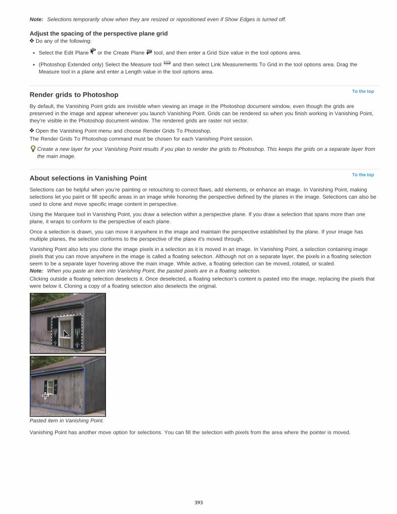
To the top
To the top
Note: Selections temporarily show when they are resized or repositioned even if Show Edges is turned off.
Adjust the spacing of the perspective plane grid Do any of the following:
Select the Edit Plane or the Create Plane tool, and then enter a Grid Size value in the tool options area.
(Photoshop Extended only) Select the Measure tool and then select Link Measurements To Grid in the tool options area. Drag theMeasure tool in a plane and enter a Length value in the tool options area.
Render grids to PhotoshopBy default, the Vanishing Point grids are invisible when viewing an image in the Photoshop document window, even though the grids arepreserved in the image and appear whenever you launch Vanishing Point. Grids can be rendered so when you finish working in Vanishing Point,they’re visible in the Photoshop document window. The rendered grids are raster not vector.
Open the Vanishing Point menu and choose Render Grids To Photoshop.The Render Grids To Photoshop command must be chosen for each Vanishing Point session.
Create a new layer for your Vanishing Point results if you plan to render the grids to Photoshop. This keeps the grids on a separate layer fromthe main image.
About selections in Vanishing PointSelections can be helpful when you’re painting or retouching to correct flaws, add elements, or enhance an image. In Vanishing Point, makingselections let you paint or fill specific areas in an image while honoring the perspective defined by the planes in the image. Selections can also beused to clone and move specific image content in perspective.
Using the Marquee tool in Vanishing Point, you draw a selection within a perspective plane. If you draw a selection that spans more than oneplane, it wraps to conform to the perspective of each plane.
Once a selection is drawn, you can move it anywhere in the image and maintain the perspective established by the plane. If your image hasmultiple planes, the selection conforms to the perspective of the plane it’s moved through.
Vanishing Point also lets you clone the image pixels in a selection as it is moved in an image. In Vanishing Point, a selection containing imagepixels that you can move anywhere in the image is called a floating selection. Although not on a separate layer, the pixels in a floating selectionseem to be a separate layer hovering above the main image. While active, a floating selection can be moved, rotated, or scaled.Note: When you paste an item into Vanishing Point, the pasted pixels are in a floating selection.Clicking outside a floating selection deselects it. Once deselected, a floating selection’s content is pasted into the image, replacing the pixels thatwere below it. Cloning a copy of a floating selection also deselects the original.
Pasted item in Vanishing Point.
Vanishing Point has another move option for selections. You can fill the selection with pixels from the area where the pointer is moved.
393
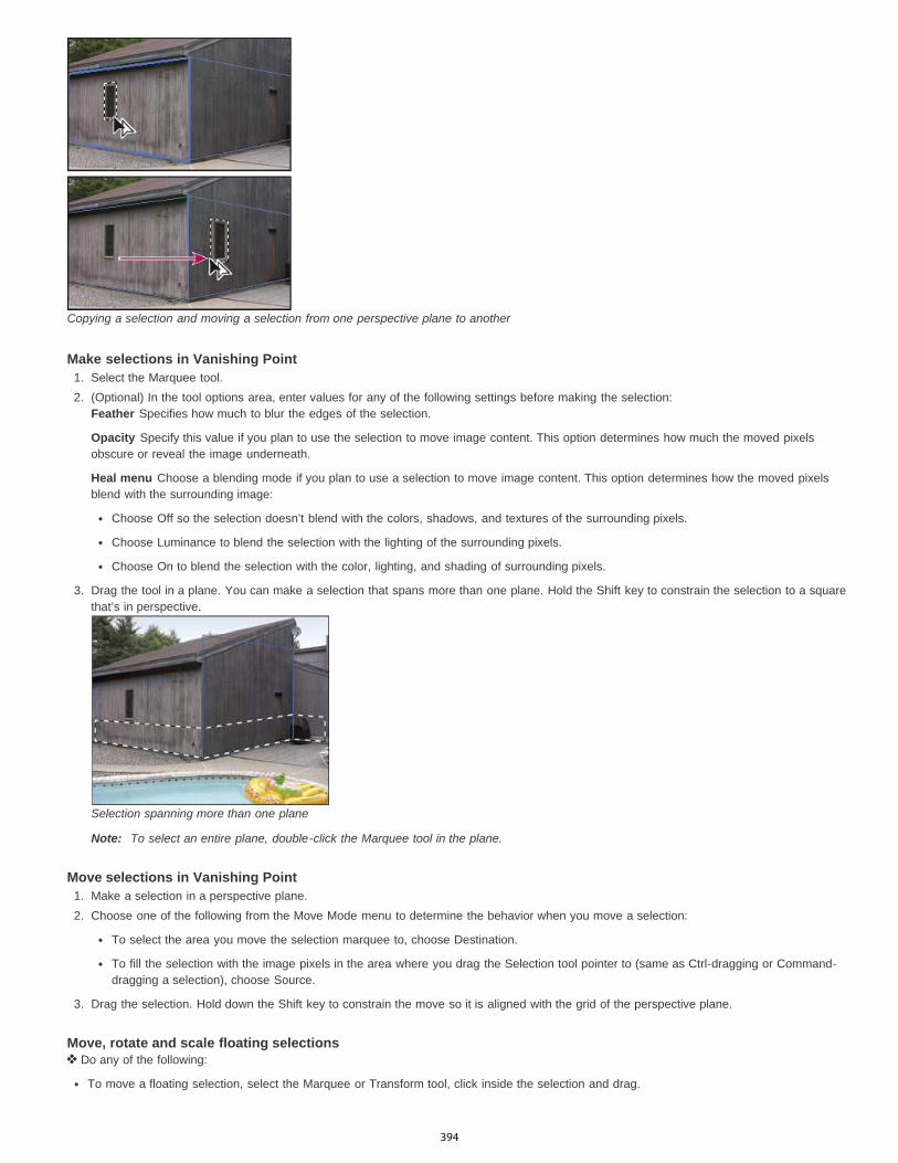
Copying a selection and moving a selection from one perspective plane to another
Make selections in Vanishing Point1. Select the Marquee tool.2. (Optional) In the tool options area, enter values for any of the following settings before making the selection:
Feather Specifies how much to blur the edges of the selection.
Opacity Specify this value if you plan to use the selection to move image content. This option determines how much the moved pixelsobscure or reveal the image underneath.
Heal menu Choose a blending mode if you plan to use a selection to move image content. This option determines how the moved pixelsblend with the surrounding image:
Choose Off so the selection doesn’t blend with the colors, shadows, and textures of the surrounding pixels.
Choose Luminance to blend the selection with the lighting of the surrounding pixels.
Choose On to blend the selection with the color, lighting, and shading of surrounding pixels.
3. Drag the tool in a plane. You can make a selection that spans more than one plane. Hold the Shift key to constrain the selection to a squarethat’s in perspective.
Selection spanning more than one plane
Note: To select an entire plane, double-click the Marquee tool in the plane.
Move selections in Vanishing Point1. Make a selection in a perspective plane.2. Choose one of the following from the Move Mode menu to determine the behavior when you move a selection:
To select the area you move the selection marquee to, choose Destination.
To fill the selection with the image pixels in the area where you drag the Selection tool pointer to (same as Ctrl-dragging or Command-dragging a selection), choose Source.
3. Drag the selection. Hold down the Shift key to constrain the move so it is aligned with the grid of the perspective plane.
Move, rotate and scale floating selections Do any of the following:
To move a floating selection, select the Marquee or Transform tool, click inside the selection and drag.
394
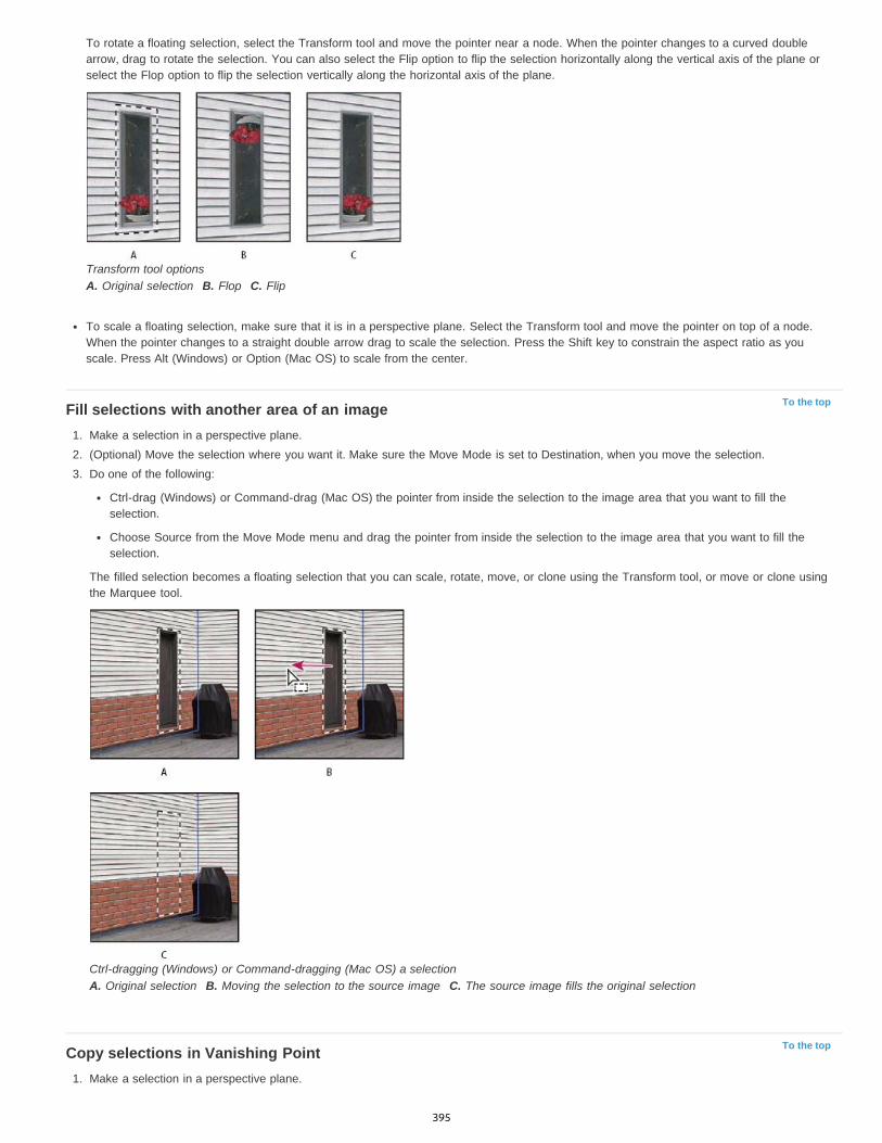
To the top
To the top
To rotate a floating selection, select the Transform tool and move the pointer near a node. When the pointer changes to a curved doublearrow, drag to rotate the selection. You can also select the Flip option to flip the selection horizontally along the vertical axis of the plane orselect the Flop option to flip the selection vertically along the horizontal axis of the plane.
Transform tool optionsA. Original selection B. Flop C. Flip
To scale a floating selection, make sure that it is in a perspective plane. Select the Transform tool and move the pointer on top of a node.When the pointer changes to a straight double arrow drag to scale the selection. Press the Shift key to constrain the aspect ratio as youscale. Press Alt (Windows) or Option (Mac OS) to scale from the center.
Fill selections with another area of an image1. Make a selection in a perspective plane.2. (Optional) Move the selection where you want it. Make sure the Move Mode is set to Destination, when you move the selection.3. Do one of the following:
Ctrl-drag (Windows) or Command-drag (Mac OS) the pointer from inside the selection to the image area that you want to fill theselection.
Choose Source from the Move Mode menu and drag the pointer from inside the selection to the image area that you want to fill theselection.
The filled selection becomes a floating selection that you can scale, rotate, move, or clone using the Transform tool, or move or clone usingthe Marquee tool.
Ctrl-dragging (Windows) or Command-dragging (Mac OS) a selectionA. Original selection B. Moving the selection to the source image C. The source image fills the original selection
Copy selections in Vanishing Point1. Make a selection in a perspective plane.
395

To the top
To the top
2. Alt-drag (Windows) or Option-drag (Mac OS) the selection with the Marquee tool to create a copy of the selection and its image pixels.
The copy becomes a floating selection, which seems to hover above the main image. You can move a floating selection, or you can selectthe Transform tool to scale or rotate the floating selection.
3. Do one of the following:
Click outside the floating selection to deselect it. The selection’s content is pasted into the image, replacing the pixels that were below it.
Click in the floating selection with either the Marquee or Transform tool and Alt-drag (Windows) or Option-drag (Mac OS) to makeanother copy. Once copied, the original floating selection is deselected and replaces the pixels that were below it.
Pressing Control+Shift+T (Windows) or Command+Shift+T (Mac OS) duplicates your last duplicating move. This is an easy way toclone content multiple times.
Paste an item into Vanishing PointYou can paste an item from the clipboard in Vanishing Point. The copied item can be from the same document or a different one. Once pasted intoVanishing Point, the item becomes a floating selection that you can scale, rotate, move or clone. When the floating selection moves into a selectedplane, it conforms to the plane’s perspective.
Pasting an item into Vanishing PointA. Copied pattern from a separate document B. Image with selection (to confine results) created in Photoshop before opening VanishingPoint C. Pasted pattern in Vanishing Point is moved into the plane and honors the selection
For convenience, it’s recommended that you create perspective planes in a previous Vanishing Point session.
1. Copy an item to the clipboard. The copied item can be from the same or different document. Keep in mind that you can paste only a raster(not vector) item.Note: If you’re copying type, you must first rasterize it. Right-click the text layer, and choose Rasterize. Then choose Select > All and copyto the clipboard.
2. (Optional) Create a new layer.3. Choose Filter > Vanishing Point.4. If necessary, create one or more planes in the image.5. Press Ctrl-V (Windows) or Command-V (Mac OS) to paste the item.
The pasted item is now a floating selection in the upper left corner of the preview image. By default, the Marquee tool is selected.
6. Use the Marquee tool to drag the pasted image to a plane.
The image conforms to the perspective of the plane.
Important: After pasting the image in Vanishing Point, do not click anywhere in the image with the Marquee tool except to drag the pastedimage to a perspective plane. Clicking anywhere else deselects the floating selection and permanently pastes the pixels into the image.
Paint with a color in Vanishing Point1. Select the Brush tool.2. Specify a brush color by doing one of the following:
Select the Eyedropper tool and click a color in the preview image.
Click the Brush Color box to open the Color Picker to select a color.
3. In the tool options area, set the Diameter (brush size), Hardness (edge smoothness), and Opacity (the degree to which painting obscures theimage below).
4. Choose a Healing mode:
To paint without blending with the color, lighting, and shading of the surrounding pixels, choose Off.
396
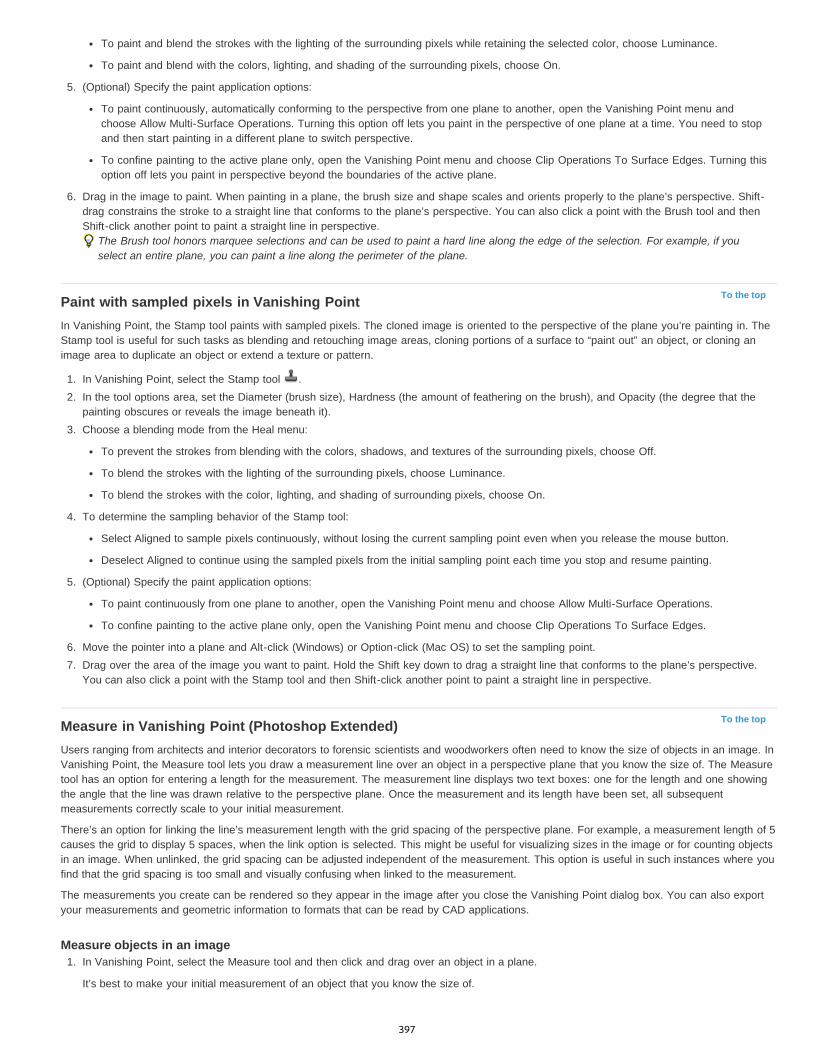
To the top
To the top
To paint and blend the strokes with the lighting of the surrounding pixels while retaining the selected color, choose Luminance.
To paint and blend with the colors, lighting, and shading of the surrounding pixels, choose On.
5. (Optional) Specify the paint application options:
To paint continuously, automatically conforming to the perspective from one plane to another, open the Vanishing Point menu andchoose Allow Multi-Surface Operations. Turning this option off lets you paint in the perspective of one plane at a time. You need to stopand then start painting in a different plane to switch perspective.
To confine painting to the active plane only, open the Vanishing Point menu and choose Clip Operations To Surface Edges. Turning thisoption off lets you paint in perspective beyond the boundaries of the active plane.
6. Drag in the image to paint. When painting in a plane, the brush size and shape scales and orients properly to the plane’s perspective. Shift-drag constrains the stroke to a straight line that conforms to the plane’s perspective. You can also click a point with the Brush tool and thenShift-click another point to paint a straight line in perspective.
The Brush tool honors marquee selections and can be used to paint a hard line along the edge of the selection. For example, if youselect an entire plane, you can paint a line along the perimeter of the plane.
Paint with sampled pixels in Vanishing PointIn Vanishing Point, the Stamp tool paints with sampled pixels. The cloned image is oriented to the perspective of the plane you’re painting in. TheStamp tool is useful for such tasks as blending and retouching image areas, cloning portions of a surface to “paint out” an object, or cloning animage area to duplicate an object or extend a texture or pattern.
1. In Vanishing Point, select the Stamp tool .2. In the tool options area, set the Diameter (brush size), Hardness (the amount of feathering on the brush), and Opacity (the degree that the
painting obscures or reveals the image beneath it).3. Choose a blending mode from the Heal menu:
To prevent the strokes from blending with the colors, shadows, and textures of the surrounding pixels, choose Off.
To blend the strokes with the lighting of the surrounding pixels, choose Luminance.
To blend the strokes with the color, lighting, and shading of surrounding pixels, choose On.
4. To determine the sampling behavior of the Stamp tool:
Select Aligned to sample pixels continuously, without losing the current sampling point even when you release the mouse button.
Deselect Aligned to continue using the sampled pixels from the initial sampling point each time you stop and resume painting.
5. (Optional) Specify the paint application options:
To paint continuously from one plane to another, open the Vanishing Point menu and choose Allow Multi-Surface Operations.
To confine painting to the active plane only, open the Vanishing Point menu and choose Clip Operations To Surface Edges.
6. Move the pointer into a plane and Alt-click (Windows) or Option-click (Mac OS) to set the sampling point.7. Drag over the area of the image you want to paint. Hold the Shift key down to drag a straight line that conforms to the plane’s perspective.
You can also click a point with the Stamp tool and then Shift-click another point to paint a straight line in perspective.
Measure in Vanishing Point (Photoshop Extended)Users ranging from architects and interior decorators to forensic scientists and woodworkers often need to know the size of objects in an image. InVanishing Point, the Measure tool lets you draw a measurement line over an object in a perspective plane that you know the size of. The Measuretool has an option for entering a length for the measurement. The measurement line displays two text boxes: one for the length and one showingthe angle that the line was drawn relative to the perspective plane. Once the measurement and its length have been set, all subsequentmeasurements correctly scale to your initial measurement.
There’s an option for linking the line’s measurement length with the grid spacing of the perspective plane. For example, a measurement length of 5causes the grid to display 5 spaces, when the link option is selected. This might be useful for visualizing sizes in the image or for counting objectsin an image. When unlinked, the grid spacing can be adjusted independent of the measurement. This option is useful in such instances where youfind that the grid spacing is too small and visually confusing when linked to the measurement.
The measurements you create can be rendered so they appear in the image after you close the Vanishing Point dialog box. You can also exportyour measurements and geometric information to formats that can be read by CAD applications.
Measure objects in an image1. In Vanishing Point, select the Measure tool and then click and drag over an object in a plane.
It’s best to make your initial measurement of an object that you know the size of.
397
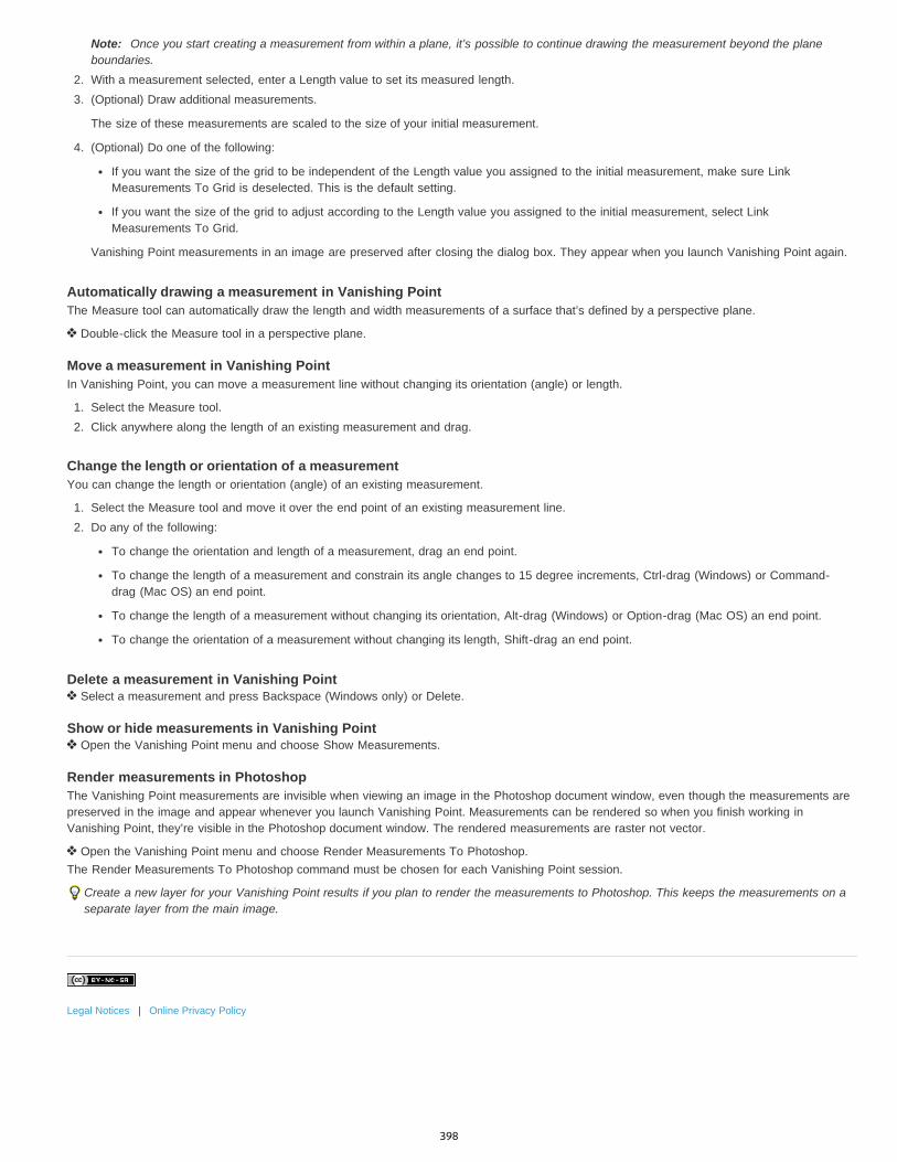
Note: Once you start creating a measurement from within a plane, it’s possible to continue drawing the measurement beyond the planeboundaries.
2. With a measurement selected, enter a Length value to set its measured length.3. (Optional) Draw additional measurements.
The size of these measurements are scaled to the size of your initial measurement.
4. (Optional) Do one of the following:
If you want the size of the grid to be independent of the Length value you assigned to the initial measurement, make sure LinkMeasurements To Grid is deselected. This is the default setting.
If you want the size of the grid to adjust according to the Length value you assigned to the initial measurement, select LinkMeasurements To Grid.
Vanishing Point measurements in an image are preserved after closing the dialog box. They appear when you launch Vanishing Point again.
Automatically drawing a measurement in Vanishing PointThe Measure tool can automatically draw the length and width measurements of a surface that’s defined by a perspective plane.
Double-click the Measure tool in a perspective plane.
Move a measurement in Vanishing PointIn Vanishing Point, you can move a measurement line without changing its orientation (angle) or length.
1. Select the Measure tool.2. Click anywhere along the length of an existing measurement and drag.
Change the length or orientation of a measurementYou can change the length or orientation (angle) of an existing measurement.
1. Select the Measure tool and move it over the end point of an existing measurement line.2. Do any of the following:
To change the orientation and length of a measurement, drag an end point.
To change the length of a measurement and constrain its angle changes to 15 degree increments, Ctrl-drag (Windows) or Command-drag (Mac OS) an end point.
To change the length of a measurement without changing its orientation, Alt-drag (Windows) or Option-drag (Mac OS) an end point.
To change the orientation of a measurement without changing its length, Shift-drag an end point.
Delete a measurement in Vanishing Point Select a measurement and press Backspace (Windows only) or Delete.
Show or hide measurements in Vanishing Point Open the Vanishing Point menu and choose Show Measurements.
Render measurements in PhotoshopThe Vanishing Point measurements are invisible when viewing an image in the Photoshop document window, even though the measurements arepreserved in the image and appear whenever you launch Vanishing Point. Measurements can be rendered so when you finish working inVanishing Point, they’re visible in the Photoshop document window. The rendered measurements are raster not vector.
Open the Vanishing Point menu and choose Render Measurements To Photoshop.The Render Measurements To Photoshop command must be chosen for each Vanishing Point session.
Create a new layer for your Vanishing Point results if you plan to render the measurements to Photoshop. This keeps the measurements on aseparate layer from the main image.
Legal Notices | Online Privacy Policy
398
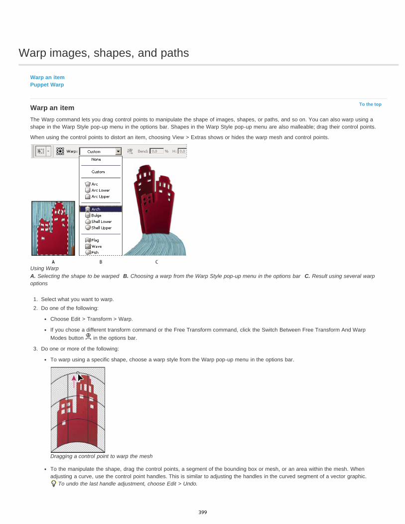
Warp images, shapes, and paths
To the top
Warp an itemPuppet Warp
Warp an itemThe Warp command lets you drag control points to manipulate the shape of images, shapes, or paths, and so on. You can also warp using ashape in the Warp Style pop-up menu in the options bar. Shapes in the Warp Style pop-up menu are also malleable; drag their control points.
When using the control points to distort an item, choosing View > Extras shows or hides the warp mesh and control points.
Using WarpA. Selecting the shape to be warped B. Choosing a warp from the Warp Style pop-up menu in the options bar C. Result using several warpoptions
1. Select what you want to warp.2. Do one of the following:
Choose Edit > Transform > Warp.
If you chose a different transform command or the Free Transform command, click the Switch Between Free Transform And WarpModes button in the options bar.
3. Do one or more of the following:
To warp using a specific shape, choose a warp style from the Warp pop-up menu in the options bar.
Dragging a control point to warp the mesh
To the manipulate the shape, drag the control points, a segment of the bounding box or mesh, or an area within the mesh. Whenadjusting a curve, use the control point handles. This is similar to adjusting the handles in the curved segment of a vector graphic.
To undo the last handle adjustment, choose Edit > Undo.
399
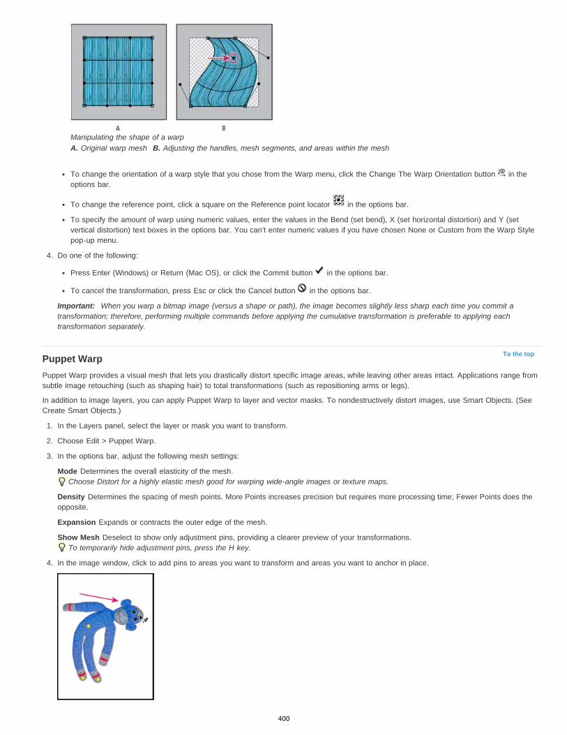
To the top
Manipulating the shape of a warpA. Original warp mesh B. Adjusting the handles, mesh segments, and areas within the mesh
To change the orientation of a warp style that you chose from the Warp menu, click the Change The Warp Orientation button in theoptions bar.
To change the reference point, click a square on the Reference point locator in the options bar.
To specify the amount of warp using numeric values, enter the values in the Bend (set bend), X (set horizontal distortion) and Y (setvertical distortion) text boxes in the options bar. You can’t enter numeric values if you have chosen None or Custom from the Warp Stylepop-up menu.
4. Do one of the following:
Press Enter (Windows) or Return (Mac OS), or click the Commit button in the options bar.
To cancel the transformation, press Esc or click the Cancel button in the options bar.
Important: When you warp a bitmap image (versus a shape or path), the image becomes slightly less sharp each time you commit atransformation; therefore, performing multiple commands before applying the cumulative transformation is preferable to applying eachtransformation separately.
Puppet WarpPuppet Warp provides a visual mesh that lets you drastically distort specific image areas, while leaving other areas intact. Applications range fromsubtle image retouching (such as shaping hair) to total transformations (such as repositioning arms or legs).
In addition to image layers, you can apply Puppet Warp to layer and vector masks. To nondestructively distort images, use Smart Objects. (SeeCreate Smart Objects.)
1. In the Layers panel, select the layer or mask you want to transform.
2. Choose Edit > Puppet Warp.
3. In the options bar, adjust the following mesh settings:
Mode Determines the overall elasticity of the mesh.Choose Distort for a highly elastic mesh good for warping wide-angle images or texture maps.
Density Determines the spacing of mesh points. More Points increases precision but requires more processing time; Fewer Points does theopposite.
Expansion Expands or contracts the outer edge of the mesh.
Show Mesh Deselect to show only adjustment pins, providing a clearer preview of your transformations.To temporarily hide adjustment pins, press the H key.
4. In the image window, click to add pins to areas you want to transform and areas you want to anchor in place.
400

Moving a pin on the puppet mesh. Adjoining pins keep nearby areas intact.
5. To reposition or remove pins, do any of the following:
Drag pins to warp the mesh.
To reveal a mesh area you’ve overlapped with another, click the Pin Depth buttons in the options bar.
To remove selected pins, press Delete. To remove other individual pins, place the cursor directly over them, and press Alt (Windows) orOption (Mac OS); when the scissors icon appears, click.
Click the Remove All Pins button in the options bar.
To select multiple pins, Shift-click them or choose Select All from the context menu.
6. To rotate the mesh around a pin, select it, and then do either of the following:
To rotate the mesh a fixed number of degrees, press Alt (Windows) or Option (Mac OS), and position the cursor near to, but not overthe pins. When a circle appears, drag to visually rotate the mesh.
The degree of rotation appears in the options bar.
To rotate the mesh automatically based on the selected Mode option, choose Auto from the Rotate menu in the options bar.
7. When your transformation is complete, press Enter or Return.
Press Alt (Windows) or Option (Mac OS) to rotate the mesh around a selected pin.
Legal Notices | Online Privacy Policy
401

Drawing and painting
Vector ShapesInfinite Skills (Oct. 7, 2012)video-tutorialDrawing shapes in CS6
New shape, type, and design toolsLynda.com (May. 7, 2012)video-tutorialGenuine vector shapes, type styles, and more.
402

Modify shapes | CC, CS6
To the top
Note:
To the top
Modify rectangles and rounded rectanglesSet shape stroke options
Modify rectangles and rounded rectanglesYou can adjust dimensions and placement of a rectangle. In Photoshop CC, you can also modify the corner radii of rounded rectangle shapes afterthey have been drawn. Each corner can be adjusted independently and adjustments can be simultaneously made to rectangles on multiple layers.
If you select multiple rectangles, the values for the top-most rectangle are displayed in the Properties panel. The values you type areapplied to all selected rectangles.
1. Use the Path Selection Tool to select one or more rectangles or rounded rectangles.
2. To change the dimensions of the rectangle, type values in the W or H text boxes in the Properties panel or options bar.
If you do not want to constrain the ratio of the width and height, click the link icon in the options bar to unlink the width and height.
3. To change the placement of the rectangle, do any of the following:
Move the contents of the layer using the Move tool.Drag the rectangle using the Path Selection tool.In the Properties panel, type the pixel coordinates into the X and Y text boxes.
4. In the Properties panel, do any of the following to modify the corner radius:
Type values in the text boxes to adjust the corner radii individually.Type a value in the Radius text box to adjust all corners to the same radius.
In the Properties panel, you can also place the pointer over a corner icon and scrub left or right to enter a radius value.
Set shape stroke options
1. Use the Path Selection tool to select the shape whose path you want to modify.
2. In the Properties panel or the tool options bar, click the Set Shape Stroke Type menu icon to open the Stroke Options panel.
3. In the Stroke Options panel, do any of the following:
Choose the type of stroke you want.Click the Align icon and choose an option to specify the position of the stroke relative to its path.Click the Caps icon and choose a cap style to specify the appearance of both ends of a path:
Butt cap Creates squared ends that abut (stop at) the endpoints.
Round cap Creates semicircular ends that extend half the stroke width beyond the endpoints.
Projecting cap Creates squared ends that extend half the stroke width beyond the endpoints. This option makes the strokeweight extend evenly in all directions around the path.
Note: Keep in mind that the caps are not visible unless the path is opened. Also, cap styles are easier to see at thicker strokeweights.
Click the Corner icon to the appearance of the stroke at corner points:
Miter join Creates pointed corners that extend beyond the endpoint when the miter’s length is within the miter limit.
Round join Creates rounded corners that extend half the stroke width beyond the endpoints.
Bevel join Creates squared corners that abut the endpoints.
Note: Like caps, miters are easier to see at thicker stroke weights.
403

Twitter™ and Facebook posts are not covered under the terms of Creative Commons.
Legal Notices | Online Privacy Policy
Save stroke settingsAfter specifying the shape stroke options in the Stroke Options panel, you can save your newly created stroke type for resue.
Click the gear icon in the upper-right corner of the Stroke Options panel and choose Save Stroke.
Copy and paste shape stroke settingsAfter specifying shape stroke options, you can apply the settings to another shape by copying and pasting.
1. Click the gear icon in the upper-right corner of the Stroke Options panel and then, choose Copy Stroke Details.
2. Select the shape you want to modify.
3. In the Properties panel or tool options bar, click the Set Shape Stroke Type menu icon to open the Stroke Options panel.
4. Click the gear icon in the upper-right corner of the Stroke Options panel and choose Paste Stroke Details.
For more informationVector Shapes tutorial
404
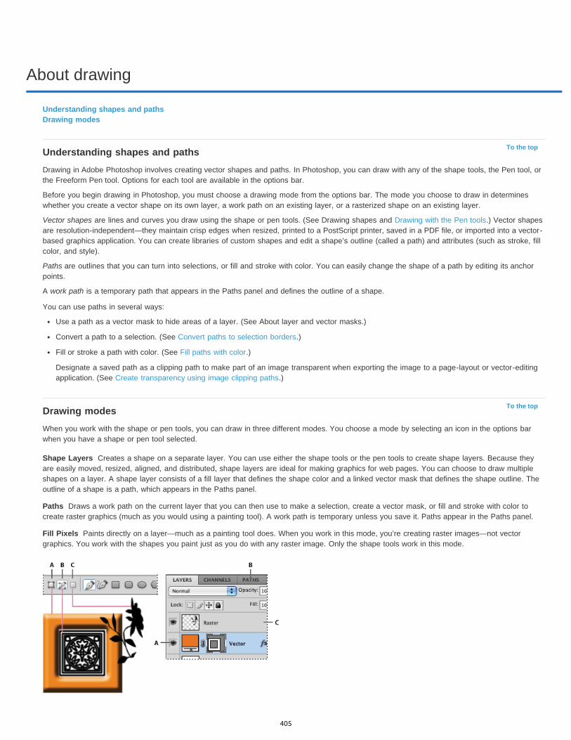
About drawing
To the top
To the top
Shape Layers
Paths
Fill Pixels
Understanding shapes and pathsDrawing modes
Understanding shapes and pathsDrawing in Adobe Photoshop involves creating vector shapes and paths. In Photoshop, you can draw with any of the shape tools, the Pen tool, orthe Freeform Pen tool. Options for each tool are available in the options bar.
Before you begin drawing in Photoshop, you must choose a drawing mode from the options bar. The mode you choose to draw in determineswhether you create a vector shape on its own layer, a work path on an existing layer, or a rasterized shape on an existing layer.
Vector shapes are lines and curves you draw using the shape or pen tools. (See Drawing shapes and Drawing with the Pen tools.) Vector shapesare resolution-independent—they maintain crisp edges when resized, printed to a PostScript printer, saved in a PDF file, or imported into a vector-based graphics application. You can create libraries of custom shapes and edit a shape’s outline (called a path) and attributes (such as stroke, fillcolor, and style).
Paths are outlines that you can turn into selections, or fill and stroke with color. You can easily change the shape of a path by editing its anchorpoints.
A work path is a temporary path that appears in the Paths panel and defines the outline of a shape.
You can use paths in several ways:
Use a path as a vector mask to hide areas of a layer. (See About layer and vector masks.)
Convert a path to a selection. (See Convert paths to selection borders.)
Fill or stroke a path with color. (See Fill paths with color.)
Designate a saved path as a clipping path to make part of an image transparent when exporting the image to a page-layout or vector-editingapplication. (See Create transparency using image clipping paths.)
Drawing modesWhen you work with the shape or pen tools, you can draw in three different modes. You choose a mode by selecting an icon in the options barwhen you have a shape or pen tool selected.
Creates a shape on a separate layer. You can use either the shape tools or the pen tools to create shape layers. Because theyare easily moved, resized, aligned, and distributed, shape layers are ideal for making graphics for web pages. You can choose to draw multipleshapes on a layer. A shape layer consists of a fill layer that defines the shape color and a linked vector mask that defines the shape outline. Theoutline of a shape is a path, which appears in the Paths panel.
Draws a work path on the current layer that you can then use to make a selection, create a vector mask, or fill and stroke with color tocreate raster graphics (much as you would using a painting tool). A work path is temporary unless you save it. Paths appear in the Paths panel.
Paints directly on a layer—much as a painting tool does. When you work in this mode, you’re creating raster images—not vectorgraphics. You work with the shapes you paint just as you do with any raster image. Only the shape tools work in this mode.
405

Twitter™ and Facebook posts are not covered under the terms of Creative Commons.
Legal Notices | Online Privacy Policy
Drawing options A. Shape Layers B. Paths C. Fill Pixels
406
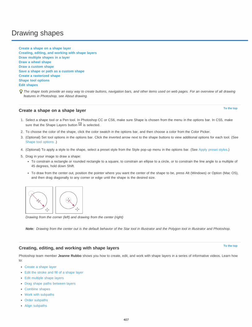
Drawing shapes
To the top
Note:
To the top
Create a shape on a shape layerCreating, editing, and working with shape layersDraw multiple shapes in a layerDraw a wheel shapeDraw a custom shapeSave a shape or path as a custom shapeCreate a rasterized shapeShape tool optionsEdit shapes
The shape tools provide an easy way to create buttons, navigation bars, and other items used on web pages. For an overview of all drawingfeatures in Photoshop, see About drawing.
Create a shape on a shape layer
1. Select a shape tool or a Pen tool. In Photoshop CC or CS6, make sure Shape is chosen from the menu in the options bar. In CS5, makesure that the Shape Layers button is selected.
2. To choose the color of the shape, click the color swatch in the options bar, and then choose a color from the Color Picker.3. (Optional) Set tool options in the options bar. Click the inverted arrow next to the shape buttons to view additional options for each tool. (See
Shape tool options .)
4. (Optional) To apply a style to the shape, select a preset style from the Style pop-up menu in the options bar. (See Apply preset styles.)
5. Drag in your image to draw a shape:To constrain a rectangle or rounded rectangle to a square, to constrain an ellipse to a circle, or to constrain the line angle to a multiple of45 degrees, hold down Shift.
To draw from the center out, position the pointer where you want the center of the shape to be, press Alt (Windows) or Option (Mac OS),and then drag diagonally to any corner or edge until the shape is the desired size.
Drawing from the corner (left) and drawing from the center (right)
Drawing from the center out is the default behavior of the Star tool in Illustrator and the Polygon tool in Illustrator and Photoshop.
Creating, editing, and working with shape layersPhotoshop team member Jeanne Rubbo shows you how to create, edit, and work with shape layers in a series of informative videos. Learn howto:
Create a shape layerEdit the stroke and fill of a shape layerEdit multiple shape layersDrag shape paths between layersCombine shapesWork with subpathsOrder subpathsAlign subpaths
407

To the top
Add To Shape Area
Subtract From Shape Area
Intersect Shape Areas
Exclude Overlapping Shape Areas
To the top
To the top
To the top
To the top
For more information, see Drawing and type tools gallery.
Draw multiple shapes in a layerYou can draw separate shapes on a layer, or use the Add, Subtract, Intersect, or Exclude options to modify the current shape on a layer.
1. Select the layer to which you want to add shapes.2. Select a drawing tool and set tool-specific options (see Shape tool options ).3. Choose one of the following in the options bar:
Adds the new area to the existing shapes or path.
Removes the overlapping area from the existing shapes or path.
Restricts the area to the intersection of the new area and the existing shapes or path.
Excludes the overlap area in the consolidated new and existing areas.
4. Draw in the image. You can easily switch between drawing tools by clicking a tool button in the options bar.
Draw a wheel shapeYou cut out a shape within an existing shape so that the layers underneath show through. This procedure shows you how to create a doughnutshape, but you can use this technique with any combination of the shape tools, including custom shapes.
1. Select the Ellipse tool in the toolbox. It may be hidden by one of the other shape tools or the Line tool .
2. In the options bar at the top of the work area, select the Shape Layer button .3. Drag in the document window to draw the shape. Hold down the Shift key while dragging to constrain the ellipse to a circle.
4. In the options bar, select the Subtract From Shape Area button .
5. Drag within the new shape to create the cutout. When you release the mouse, the image underneath the new shape shows through.
6. To reposition either shape, click the Path Selection tool in the toolbox (it may be hidden by the Direct Selection tool ), and select thepath. Drag it to its new location or use the arrow keys on the keyboard to nudge it a pixel at a time.
Shift-click to select more than one path.
Draw a custom shapeYou can draw custom shapes by using shapes from the Custom Shape pop-up panel, or save a shape or path to use as a custom shape.
1. Select the Custom Shape tool . (If the tool isn’t visible, hold down the Rectangle tool near the bottom of the toolbox.)
2. Select a shape from the Custom Shape pop-up panel in the options bar.
If you don’t find a shape you want in the panel, click the arrow in the upper right corner of the panel, and choose a different category ofshapes. When asked to replace current shapes, click either Replace to view only the shapes in the new category or Append to add to theshapes already displayed.
3. Drag in your image to draw the shape.
Save a shape or path as a custom shape1. In the Paths panel, select a path—either a vector mask for a shape layer, a work path, or a saved path.2. Choose Edit > Define Custom Shape, and enter a name for the new custom shape in the Shape Name dialog box. The new shape appears
in the Shape pop-up panel in the options bar.3. To save the new custom shape as part of a new library, select Save Shapes from the pop-up panel menu.
For more information, see Work with the Preset Manager.
Create a rasterized shapeWhen you create a rasterized shape, you’re drawing and rasterizing a shape and filling it with the foreground color. You cannot edit a rasterizedshape as a vector object. Raster shapes are created using the current foreground color.
408

Mode
Opacity
Anti-Aliased
To the top
Arrowheads Start And End
Note:
Circle
Defined Proportions
Defined Size
Fixed Size
From Center
Indent Sides By
Proportional
Radius
Sides
Smooth Corners or Smooth Indents
Snap To Pixels
Square
Unconstrained
Weight
1. Select a layer. You cannot create a rasterized shape on a vector-based layer (for example, a type layer).2. Select a shape tool, and click the Fill Pixels button in the options bar.3. Set the following options in the options bar:
Controls how the shape will affect the existing pixels in the image. (See Blending modes.)
Determines to what degree the shape will obscure or reveal the pixels beneath it. A shape with 1% opacity appears nearlytransparent, while one with 100% opacity appears completely opaque.
Smooths and blends the edge pixels with the surrounding pixels.
4. Set additional tool-specific options. See Shape tool options.
5. Draw the shape.
Shape tool optionsEach shape tool provides a unique subset of the options below. To access these options, click the arrow to the right of the row of shape buttons inthe options bar.
Accessing shape tool options in the options bar (Line options shown)
Adds arrowheads to a line. Select the Line tool and then select Start to add an arrow to the beginning of the line;select End to add an arrow to the end of the line. Select both options to add arrows to both ends. The shape options appear in the pop-up dialogbox. Enter values for Width and Length to specify the proportions of the arrowhead as a percentage of the line width (10% to 1000% for Width,and 10% to 5000% for Length). Enter a value for the concavity of the arrowhead (from –50% to +50%). The concavity value defines the amount ofcurvature on the widest part of the arrowhead, where the arrowhead meets the line.
You can also edit an arrowhead directly using the vector selection and drawing tools.
Constrains an ellipse to a circle.
Renders a custom shape based on the proportions with which it was created.
Renders a custom shape based on the size at which it was created.
Renders a rectangle, rounded rectangle, ellipse, or custom shape as a fixed shape based on the values you enter in the Width andHeight text boxes.
Renders a rectangle, rounded rectangle, ellipse, or custom shape from the center.
Renders a polygon as a star. Enter a percentage in the text box to specify the portion of the star’s radius taken up by the points.A 50% setting creates points that are half the total radius of the star; a larger value creates sharper, thinner points; a smaller value creates fullerpoints.
Renders a rectangle, rounded rectangle, or ellipse as a proportional shape based on the values you enter in the Width and Heighttext boxes.
For rounded rectangles, specifies the corner radius. For polygons, specifies the distance from the center of a polygon to the outer points.
Specifies the number of sides in a polygon.
Renders a polygon with smooth corners or indents.
Snaps edges of a rectangle or rounded rectangle to the pixel boundaries.
Constrains a rectangle or rounded rectangle to a square.
Lets you set the width and height of a rectangle, rounded rectangle, ellipse, or custom shape by dragging.
Determines width, in pixels, for the Line tool.
409

Twitter™ and Facebook posts are not covered under the terms of Creative Commons.
Legal Notices | Online Privacy Policy
To the top
To change stroke width for other shape tools, choose Layer > Layer Style > Stroke. (See Apply or edit a custom layer style.)
Edit shapesA shape is a fill layer linked to a vector mask. You can easily change the fill to a different color, a gradient, or a pattern by editing the shape’s filllayer. You can also edit the shape’s vector mask to modify the shape outline, and apply a style to the layer.
To change the color of a shape, double-click the shape layer’s thumbnail in the Layers panel, and choose a different color using the ColorPicker.To fill a shape with a pattern or gradient, select the shape layer in the Layers panel and choose Layer > Layer Style > Gradient Overlay.To change stroke width, select the shape layer in the Layers panel, and choose Layer >Layer Style > Stroke.To modify the outline of a shape, click the shape layer’s vector mask thumbnail in the Layers panel or Paths panel. Then change the shapeusing the Direct Selection and pen tools.To move a shape without changing its size or proportions, use the Move tool.
For more information, see Adjust path components and Transform freely.
410
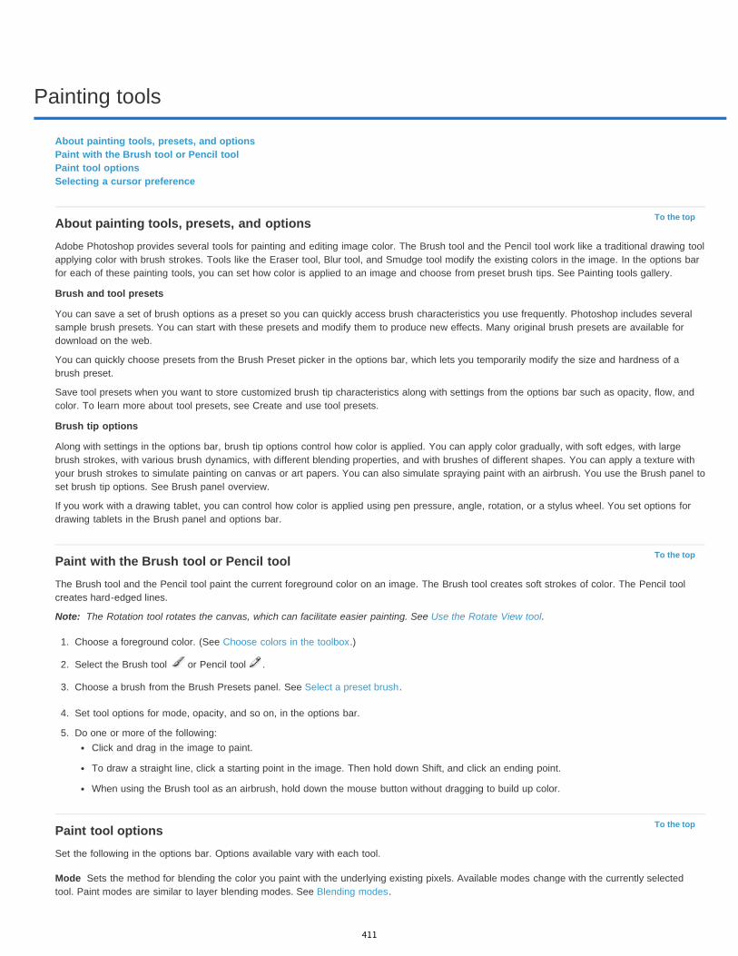
Painting tools
To the top
To the top
Note:
To the top
Mode
About painting tools, presets, and optionsPaint with the Brush tool or Pencil toolPaint tool optionsSelecting a cursor preference
About painting tools, presets, and optionsAdobe Photoshop provides several tools for painting and editing image color. The Brush tool and the Pencil tool work like a traditional drawing toolapplying color with brush strokes. Tools like the Eraser tool, Blur tool, and Smudge tool modify the existing colors in the image. In the options barfor each of these painting tools, you can set how color is applied to an image and choose from preset brush tips. See Painting tools gallery.
Brush and tool presets
You can save a set of brush options as a preset so you can quickly access brush characteristics you use frequently. Photoshop includes severalsample brush presets. You can start with these presets and modify them to produce new effects. Many original brush presets are available fordownload on the web.
You can quickly choose presets from the Brush Preset picker in the options bar, which lets you temporarily modify the size and hardness of abrush preset.
Save tool presets when you want to store customized brush tip characteristics along with settings from the options bar such as opacity, flow, andcolor. To learn more about tool presets, see Create and use tool presets.
Brush tip options
Along with settings in the options bar, brush tip options control how color is applied. You can apply color gradually, with soft edges, with largebrush strokes, with various brush dynamics, with different blending properties, and with brushes of different shapes. You can apply a texture withyour brush strokes to simulate painting on canvas or art papers. You can also simulate spraying paint with an airbrush. You use the Brush panel toset brush tip options. See Brush panel overview.
If you work with a drawing tablet, you can control how color is applied using pen pressure, angle, rotation, or a stylus wheel. You set options fordrawing tablets in the Brush panel and options bar.
Paint with the Brush tool or Pencil toolThe Brush tool and the Pencil tool paint the current foreground color on an image. The Brush tool creates soft strokes of color. The Pencil toolcreates hard-edged lines.
The Rotation tool rotates the canvas, which can facilitate easier painting. See Use the Rotate View tool.
1. Choose a foreground color. (See Choose colors in the toolbox.)
2. Select the Brush tool or Pencil tool .
3. Choose a brush from the Brush Presets panel. See Select a preset brush.
4. Set tool options for mode, opacity, and so on, in the options bar.
5. Do one or more of the following:Click and drag in the image to paint.
To draw a straight line, click a starting point in the image. Then hold down Shift, and click an ending point.
When using the Brush tool as an airbrush, hold down the mouse button without dragging to build up color.
Paint tool optionsSet the following in the options bar. Options available vary with each tool.
Sets the method for blending the color you paint with the underlying existing pixels. Available modes change with the currently selectedtool. Paint modes are similar to layer blending modes. See Blending modes.
411
Twitter™ and Facebook posts are not covered under the terms of Creative Commons.
Legal Notices | Online Privacy Policy
Opacity
Flow
Airbrush
Auto erase
Tablet pressure buttons
To the top
Sets the transparency of color you apply. As you paint over an area, the opacity does not exceed the set level no matter how many timesyou move the pointer over the area, until you release the mouse button. If you stroke over the area again, you apply additional color, equivalent tothe set opacity. Opacity of 100 percent is opaque.
Sets the rate at which color is applied as you move the pointer over an area. As you paint over an area, keeping the mouse button down,the amount of color builds up based on the flow rate, up to the opacity setting. For example, if you set the opacity to 33% and the flow to 33%,each time you move over an area, its color moves 33% toward the brush color. The total will not exceed 33% opacity unless you release themouse button and stroke over the area again.
Press a single number key to set a tool’s opacity in multiples of 10% (pressing 1 sets it to 10%; pressing 0 sets it to 100%). Press two numberkeys to set a specific opacity. To set Flow, press Shift and number keys.
Simulates painting with an airbrush. As you move the pointer over an area, paint builds up as you hold down the mouse button. Brush hardness,opacity, and flow options control how fast and how much the paint is applied. Click the button to turn on or off this option.
(Pencil tool only) Paints the background color over areas containing the foreground color. Select the foreground color you want toerase and the background color you want to change to. (See Auto Erase with the Pencil tool.)
Use stylus pressure to override opacity and size settings in the Brush panel.
Selecting a cursor preferenceThe painting tools have three possible cursors: the standard cursor (the icon from the toolbox), a cross hair , and a cursor that matches the sizeand shape of the currently selected brush tip.
1. Choose Edit > Preferences > Cursors (Windows) or Photoshop > Preferences > Cursors (Mac OS).2. Select the desired cursors in both the Painting Cursors area and the Other Cursors area. The sample cursors change to reflect your choices.
For a Brush Tip cursor, choose a size and whether to include a cross hair in the cursor.Normal Brush Tip restricts the cursor size to areas of the brush stroke that have 50% or more opacity.
Full Size Brush Tip sizes the cursor to the entire area affected by the brush stroke. For soft brushes, this produces a larger cursor sizethan the Normal setting, to include the areas of the brush stroke with lighter opacity.
To combine different types of cursors, select Show Crosshair in Brush Tip or Show Only Crosshair While Painting. Or, for the Pen and Brushtools, press the Caps Lock to toggle between the standard cursor and the cross hair.
412
Brush presets
To the top
To the top
To the top
Select a preset brushChange how preset brushes are displayedLoad, save, and manage brush presetsCreate a new preset brush
A preset brush is a saved brush tip with defined characteristics, such as size, shape, and hardness. You can save preset brushes with thecharacteristics you use often. You can also save tool presets for the Brush tool that you can select from the Tool Preset menu in the options bar.
When you change the size, shape, or hardness of a preset brush, the change is temporary. The next time you choose that preset, the brush usesits original settings. To make your changes permanent, you need to create a new preset. See Create a new preset brush.
Select a preset brush1. Select a painting or editing tool, and click the Brush pop-up menu in the options bar.2. Select a brush.
Note: You can also select a brush from the Brush panel. To view the loaded presets, click Brush Presets in the upper left of the panel.3. Change options for the preset brush.
Diameter Temporarily changes the brush size. Drag the slider or enter a value. If the brush has a dual tip, both the primary and dual brushtips are scaled.
Use Sample Size Uses the original diameter of the brush tip if the brush tip shape is based on a sample. (Not available for roundbrushes.)
Hardness (Available only for round and square brushes.) Temporarily changes the amount of anti-aliasing for the brush tool. At 100%, thebrush tool paints with the hardest brush tip, but is still anti-aliased. The Pencil always paints a hard edge that is not anti-aliased.
Change how preset brushes are displayedChoose a display option from the Brush Presets panel menu :
Text Only to view the brushes as a list.Small or Large Thumbnail to view the brushes as thumbnails.Small or Large List to view the brushes as a list with thumbnails.Stroke Thumbnail to view a sample brush stroke with each brush thumbnail.
To dynamically preview brush strokes in the Brush panel, position the pointer over a brush in the Brush Presets panel until the tool tipappears. As you move the pointer over different brushes, the preview area at the bottom of the Brush panel will display sample brushstrokes.
Load, save, and manage brush presetsYou can manage libraries of preset brushes to keep your brushes organized.
Change the displayed library of preset brushes1. To load a library of preset brushes, choose one of the following from the Brush Presets panel menu.
Load Brushes to add a library to the current list.
Replace Brushes to replace the current list with a different library.
A library file (displayed at the bottom of the panel menu). Click OK to replace the current list, or click Append to append the current list.
2. To return to the default library of preset brushes, choose Reset Brushes from the Brush Presets panel menu. You can either replace thecurrent list or append the default library to the current list.
You can also use the Preset Manager to load and reset brush libraries. For more information, see Work with the Preset Manager.
Save a set of preset brushes as a library1. Choose Save Brushes from the Brush Presets panel menu.2. Choose a location for the brush library, enter a file name, and click Save.
413

To the top
You can save the library anywhere. However, if you place the library file in the Presets/Brushes folder in the default preset location, thelibrary name will appear at the bottom of the Brush Presets panel menu after you restart Photoshop.
Rename a preset brushDo one of the following:
Select a brush in the Brush Presets panel, and choose Rename Brush from the panel menu. Enter a new name, and click OK.In the Brush panel, double-click a brush tip, enter a new name, and click OK.
Delete a preset brushIn the Brush Presets panel, do any of the following:
Alt-click (Windows) or Option-click (Mac OS) the brush you want to delete.Select a brush, and choose Delete Brush from the panel menu, or click the Delete icon .
Create a new preset brushYou can save a customized brush as a preset brush that appears in the Brush Presets panel and Preset Manager.
Note: New preset brushes are saved in a Preferences file. If this file is deleted or damaged, or if you reset brushes to the default library, the newpresets will be lost. To permanently save new preset brushes, save them in a library.
1. Customize a brush.2. Do one of the following in the Brush Presets panel:
Choose New Brush Preset from the panel menu, enter a name for the preset brush, and click OK.
Click the Create New Brush button .
Legal Notices | Online Privacy Policy
414

Creating and modifying brushes
To the top
Brush panel overviewCreate a brush tip from an imageCreate a brush and set painting optionsStandard brush tip shape optionsBristle tip shape optionsErodible tip options | CC, CS6Airbrush tip options | CC, CS6Brush pose options | CC, CS6Other brush optionsBrush scatteringClear brush options
You can create brushes that apply paint to images in a variety of ways. You select an existing preset brush, a brush tip shape, or create a uniquebrush tip from part of an image. You choose options from the Brush panel to specify how the paint is applied.
Brush panel overviewIn the Brush panel, you can select preset brushes from the Brush Presets panel, but you can also modify existing brushes and design new custombrushes. The Brush panel contains the brush tip options that determine how paint is applied to an image.
The brush stroke preview at the bottom of the panel shows how paint strokes look with the current brush options.
Brush panel with Brush Tip Shape options displayed A. Locked B. Unlocked C. Selected brush tip D. Brush settings E. Brush stroke preview F. pop-up menu G. Brush tip shapes (available whenBrush Tip Shape option is selected) H. Brush options
Display the Brush panel and brush options1. Choose Window > Brush. Or, select a painting, erasing, toning, or focus tool, and click the panel button on the left side of the options
bar.
415

To the top
Note:
To the top
Note:
To the top
Size
Use Sample Size
Flip X
2. Select an option set on the left side of the panel. The available options for the set appear on the right side of the panel.
Click the check box to the left of the option set to enable or disable the options without viewing them.
Create a brush tip from an image1. Using any selection tool, select the image area you want to use as a custom brush. The brush shape can be up to 2500 pixels by 2500
pixels in size.
When painting, you can’t adjust the hardness of sampled brushes. To create a brush with sharp edges, set Feather to zero pixels. To createa brush with soft edges, increase the Feather setting.
If you select a color image, the brush tip image is converted to grayscale. Any layer mask applied to the image doesn’t affect thedefinition of the brush tip.
2. Choose Edit > Define Brush Preset.3. Name the brush, and click OK.
Create a brush and set painting options1. Select a painting, erasing, toning, or focus tool. Then choose Window > Brush.2. In the Brush panel, select a brush tip shape, or click Brush Presets to choose an existing preset.
3. Select Brush Tip Shape on the left side of the Brush panel, and set options.
4. To set other options for the brush, see the following topics:Adding dynamic elements to brushes
Determining the scattering in a stroke
Creating textured brushes
Determine how a brush changes dynamically
Drawing or painting with a graphics tablet
5. To lock brush tip shape attributes (retaining them if you select another brush preset), click the unlock icon . To unlock the tip, click the lockicon .
6. To save the brush for use later, choose New Brush Preset from the Brush panel menu.
To save your new brush permanently or distribute it to other users, you must save the brush as part of a set of brushes. ChooseSave Brushes from the Brush Presets panel menu, and then save to a new set or overwrite an existing set. If you reset or replace thebrushes in the Brush Presets panel without saving it in a set, you could lose your new brush.
Standard brush tip shape optionsFor standard brush tips, you can set the following options in the Brush panel:
Controls the size of the brush. Enter a value in pixels or drag the slider.
Brush strokes with different diameter values
Resets the brush to its original diameter. This option is available only if the brush tip shape was created by sampling pixels inan image.
Changes the direction of a brush tip on its x axis.
416
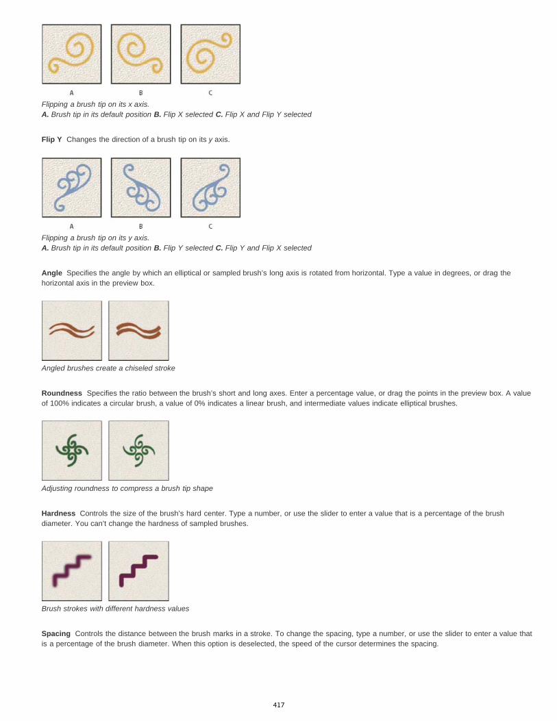
Flip Y
Angle
Roundness
Hardness
Spacing
Flipping a brush tip on its x axis. A. Brush tip in its default position B. Flip X selected C. Flip X and Flip Y selected
Changes the direction of a brush tip on its y axis.
Flipping a brush tip on its y axis. A. Brush tip in its default position B. Flip Y selected C. Flip Y and Flip X selected
Specifies the angle by which an elliptical or sampled brush’s long axis is rotated from horizontal. Type a value in degrees, or drag thehorizontal axis in the preview box.
Angled brushes create a chiseled stroke
Specifies the ratio between the brush’s short and long axes. Enter a percentage value, or drag the points in the preview box. A valueof 100% indicates a circular brush, a value of 0% indicates a linear brush, and intermediate values indicate elliptical brushes.
Adjusting roundness to compress a brush tip shape
Controls the size of the brush’s hard center. Type a number, or use the slider to enter a value that is a percentage of the brushdiameter. You can’t change the hardness of sampled brushes.
Brush strokes with different hardness values
Controls the distance between the brush marks in a stroke. To change the spacing, type a number, or use the slider to enter a value thatis a percentage of the brush diameter. When this option is deselected, the speed of the cursor determines the spacing.
417
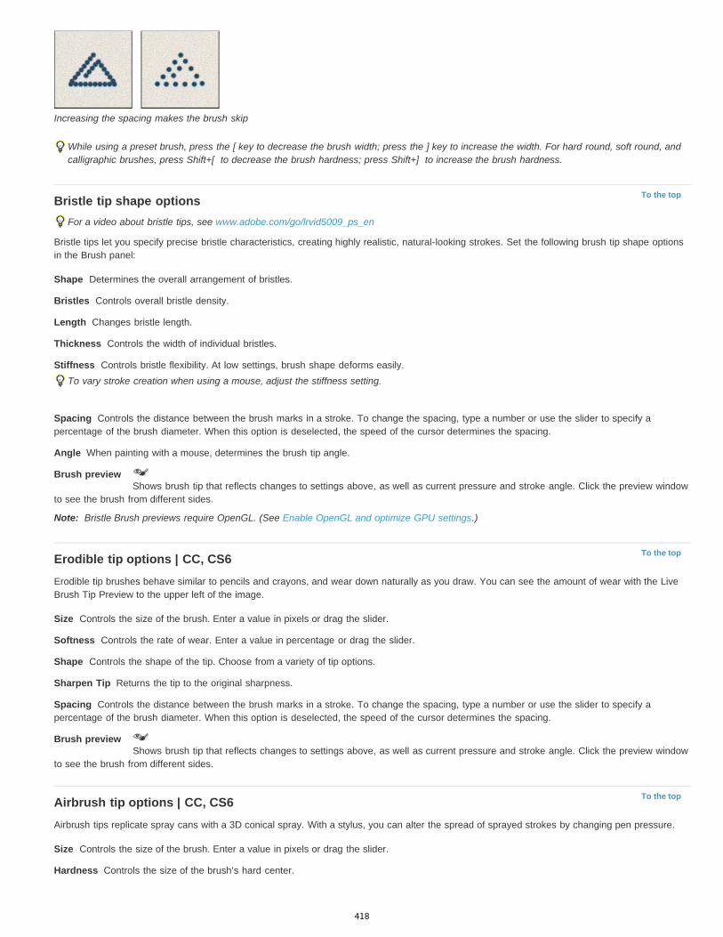
To the top
Shape
Bristles
Length
Thickness
Stiffness
Spacing
Angle
Brush preview
Note:
To the top
Size
Softness
Shape
Sharpen Tip
Spacing
Brush preview
To the top
Size
Hardness
Increasing the spacing makes the brush skip
While using a preset brush, press the [ key to decrease the brush width; press the ] key to increase the width. For hard round, soft round, andcalligraphic brushes, press Shift+[ to decrease the brush hardness; press Shift+] to increase the brush hardness.
Bristle tip shape optionsFor a video about bristle tips, see www.adobe.com/go/lrvid5009_ps_en
Bristle tips let you specify precise bristle characteristics, creating highly realistic, natural-looking strokes. Set the following brush tip shape optionsin the Brush panel:
Determines the overall arrangement of bristles.
Controls overall bristle density.
Changes bristle length.
Controls the width of individual bristles.
Controls bristle flexibility. At low settings, brush shape deforms easily.To vary stroke creation when using a mouse, adjust the stiffness setting.
Controls the distance between the brush marks in a stroke. To change the spacing, type a number or use the slider to specify apercentage of the brush diameter. When this option is deselected, the speed of the cursor determines the spacing.
When painting with a mouse, determines the brush tip angle.
Shows brush tip that reflects changes to settings above, as well as current pressure and stroke angle. Click the preview windowto see the brush from different sides.
Bristle Brush previews require OpenGL. (See Enable OpenGL and optimize GPU settings.)
Erodible tip options | CC, CS6Erodible tip brushes behave similar to pencils and crayons, and wear down naturally as you draw. You can see the amount of wear with the LiveBrush Tip Preview to the upper left of the image.
Controls the size of the brush. Enter a value in pixels or drag the slider.
Controls the rate of wear. Enter a value in percentage or drag the slider.
Controls the shape of the tip. Choose from a variety of tip options.
Returns the tip to the original sharpness.
Controls the distance between the brush marks in a stroke. To change the spacing, type a number or use the slider to specify apercentage of the brush diameter. When this option is deselected, the speed of the cursor determines the spacing.
Shows brush tip that reflects changes to settings above, as well as current pressure and stroke angle. Click the preview windowto see the brush from different sides.
Airbrush tip options | CC, CS6Airbrush tips replicate spray cans with a 3D conical spray. With a stylus, you can alter the spread of sprayed strokes by changing pen pressure.
Controls the size of the brush. Enter a value in pixels or drag the slider.
Controls the size of the brush’s hard center.
418

Distortion
Granularity
Spatter Size
Spatter Amount
Spacing
Brush preview
To the top
Tilt X
Tilt Y
Rotation
Pressure
To the top
Noise
Wet Edges
Airbrush/Build-up
Smoothing
Protect Texture
To the top
Scatter and Control
Off
Fade
Pen Pressure, Pen Tilt, Stylus Wheel, Rotation
Count
Controls the distortion to apply to the spray of paint.
Controls how grainy the paint drops look.
Controls the size of the paint droplets.
Controls the number of paint droplets.
Controls the distance between the droplets. If this option is deselected, the speed of the cursor determines the spacing.
Shows brush tip that reflects changes to settings above, as well as current pressure and stroke angle. Click the preview windowto see the brush from different sides.
Brush pose options | CC, CS6Brush pose options let you achieve stylus-like effects and let you control the angle and position of the brush.
Determines the tilt angle of the brush from left to right.
Determines the tilt angle of the brush from front to back.
Determines the rotation angle of the bristles.
Determines the pressure the brush applies on the canvas.
Enable Override options to maintain a static brush pose.
Other brush options
Adds additional randomness to individual brush tips. This option is most effective when applied to soft brush tips (brush tips that containgray values).
Causes paint to build up along the edges of the brush stroke, creating a watercolor effect.
Applies gradual tones to an image, simulating traditional airbrush techniques. The Airbrush option in the Brush panelcorresponds to the Airbrush option in the options bar.
Produces smoother curves in brush strokes. This option is most effective when you are painting quickly with a stylus; however, it mayproduce a slight lag time in stroke rendering.
Applies the same pattern and scale to all brush presets that have a texture. Select this option to simulate a consistent canvastexture when painting with multiple, textured brush tips.
Brush scatteringBrush scattering determines the number and placement of marks in a stroke.
Brush strokes without scattering (left) and with scattering (right)
Specifies how brush marks are distributed in a stroke. When Both Axes is selected, brush marks are distributed in a radialdirection. When Both Axes is deselected, brush marks are distributed perpendicular to the stroke path.To specify the maximum percentage of scattering, enter a value. To specify how you want to control the scattering variance of brush marks,choose an option from the Control pop-up menu:
Specifies no control over the scattering variance of brush marks.
Fades the scattering of brush marks from maximum scattering to no scattering in the specified number of steps.
Varies the scattering of brush marks based on the pen pressure, pen tilt, position of thepen thumbwheel, or rotation of the pen.
Specifies the number of brush marks applied at each spacing interval.
419
Twitter™ and Facebook posts are not covered under the terms of Creative Commons.
Legal Notices | Online Privacy Policy
Note:
Count Jitter and Control
Off
Fade
Pen Pressure, Pen Tilt, Stylus Wheel, Rotation
To the top
If you increase the count without increasing the spacing or scattering values, painting performance may decrease.
Specifies how the number of brush marks varies for each spacing interval. To specify the maximum percentage ofbrush marks applied at each spacing interval, enter a value. To specify how you want to control the count variance of brush marks, choose anoption from the Control pop-up menu:
Specifies no control over the count variance of brush marks.
Fades the number of brush marks from the Count value to 1 in the specified number of steps.
Varies the number of brush marks based on the pen pressure, pen tilt, position of thepen thumbwheel, or rotation of the pen.
Clear brush optionsYou can clear all options that you changed for a brush preset (except brush shape settings) at once.
Choose Clear Brush Controls from the Brush panel menu.
420
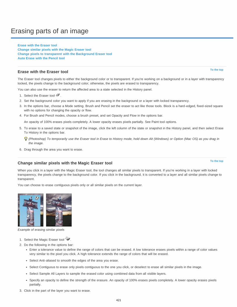
Erasing parts of an image
To the top
To the top
Erase with the Eraser toolChange similar pixels with the Magic Eraser toolChange pixels to transparent with the Background Eraser toolAuto Erase with the Pencil tool
Erase with the Eraser toolThe Eraser tool changes pixels to either the background color or to transparent. If you’re working on a background or in a layer with transparencylocked, the pixels change to the background color; otherwise, the pixels are erased to transparency.
You can also use the eraser to return the affected area to a state selected in the History panel.
1. Select the Eraser tool .2. Set the background color you want to apply if you are erasing in the background or a layer with locked transparency.3. In the options bar, choose a Mode setting. Brush and Pencil set the eraser to act like those tools. Block is a hard-edged, fixed-sized square
with no options for changing the opacity or flow.4. For Brush and Pencil modes, choose a brush preset, and set Opacity and Flow in the options bar.
An opacity of 100% erases pixels completely. A lower opacity erases pixels partially. See Paint tool options.
5. To erase to a saved state or snapshot of the image, click the left column of the state or snapshot in the History panel, and then select EraseTo History in the options bar.
(Photoshop) To temporarily use the Eraser tool in Erase to History mode, hold down Alt (Windows) or Option (Mac OS) as you drag inthe image.
6. Drag through the area you want to erase.
Change similar pixels with the Magic Eraser toolWhen you click in a layer with the Magic Eraser tool, the tool changes all similar pixels to transparent. If you’re working in a layer with lockedtransparency, the pixels change to the background color. If you click in the background, it is converted to a layer and all similar pixels change totransparent.
You can choose to erase contiguous pixels only or all similar pixels on the current layer.
Example of erasing similar pixels
1. Select the Magic Eraser tool .2. Do the following in the options bar:
Enter a tolerance value to define the range of colors that can be erased. A low tolerance erases pixels within a range of color valuesvery similar to the pixel you click. A high tolerance extends the range of colors that will be erased.
Select Anti-aliased to smooth the edges of the area you erase.
Select Contiguous to erase only pixels contiguous to the one you click, or deselect to erase all similar pixels in the image.
Select Sample All Layers to sample the erased color using combined data from all visible layers.
Specify an opacity to define the strength of the erasure. An opacity of 100% erases pixels completely. A lower opacity erases pixelspartially.
3. Click in the part of the layer you want to erase.
421
Twitter™ and Facebook posts are not covered under the terms of Creative Commons.
Legal Notices | Online Privacy Policy
To the top
Note:
To the top
Change pixels to transparent with the Background Eraser toolThe Background Eraser tool erases pixels on a layer to transparency as you drag. You can erase the background while maintaining the edges ofan object in the foreground. By specifying different sampling and tolerance options, you can control the range of the transparency and thesharpness of the boundaries.
If you want to erase the background of an object with intricate or wispy edges, use QuickSelect.
The background eraser samples the color in the center of the brush, also called the hotspot, and deletes that color wherever it appears inside thebrush. It also performs color extraction at the edges of any foreground objects, so that color halos are not visible if the foreground object is laterpasted into another image.
The background eraser overrides the lock transparency setting of a layer.
1. In the Layers panel, select the layer containing the areas you want to erase.
2. Select the Background Eraser tool . (If the tool isn’t visible, hold down the Eraser tool , and choose the Background Eraser from thepop-up menu.)
3. Click the brush sample in the options bar, and set brush options in the pop-up panel:Choose settings for the Diameter, Hardness, Spacing, Angle, and Roundness options (see Brush tip shape options).
If you’re using a pressure-sensitive digitizing tablet, choose options from the Size and Tolerance menus to vary the size and tolerance ofthe background eraser over the course of a stroke. Choose Pen Pressure to base the variation on the pen pressure. Choose StylusWheel to base the variation on the position of the pen thumbwheel. Choose Off if you don’t want to vary the size or tolerance.
4. Do the following in the options bar:Choose a Limits mode for erasing: Discontiguous to erase the sampled color wherever it occurs under the brush; Contiguous to eraseareas that contain the sampled color and are connected to one another; and Find Edges to erase connected areas containing thesampled color while better preserving the sharpness of shape edges.
For Tolerance, enter a value or drag the slider. A low tolerance limits erasure to areas that are very similar to the sampled color. A hightolerance erases a broader range of colors.
Select Protect Foreground Color to prevent the erasure of areas that match the foreground color in the toolbox.
Choose a Sampling option: Continuous to sample colors continuously as you drag; Once to erase only areas containing the color youfirst click; and Background Swatch to erase only areas containing the current background color.
5. Drag through the area you want to erase. The Background Eraser tool pointer appears as a brush shape with a cross hair indicating thetool’s hot spot .
Auto Erase with the Pencil toolThe Auto Erase option for the Pencil tool lets you paint the background color over areas containing the foreground color.
1. Specify foreground and background colors.
2. Select the Pencil tool .3. Select Auto Erase in the options bar.4. Drag over the image.
If the center of the cursor is over the foreground color when you begin dragging, the area is erased to the background color. If the center ofthe cursor is over an area that doesn’t contain the foreground color when you begin dragging, the area is painted with the foreground color.
422
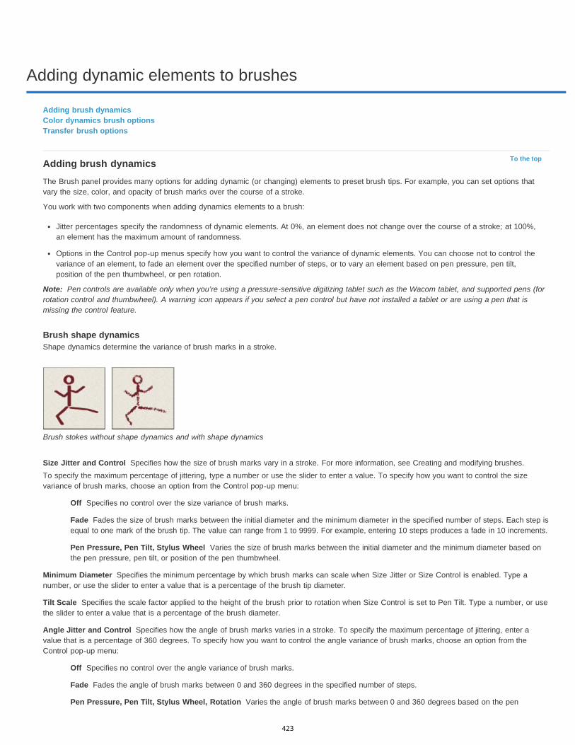
Adding dynamic elements to brushes
To the top
Note:
Size Jitter and Control
Off
Fade
Pen Pressure, Pen Tilt, Stylus Wheel
Minimum Diameter
Tilt Scale
Angle Jitter and Control
Off
Fade
Pen Pressure, Pen Tilt, Stylus Wheel, Rotation
Adding brush dynamicsColor dynamics brush optionsTransfer brush options
Adding brush dynamicsThe Brush panel provides many options for adding dynamic (or changing) elements to preset brush tips. For example, you can set options thatvary the size, color, and opacity of brush marks over the course of a stroke.
You work with two components when adding dynamics elements to a brush:
Jitter percentages specify the randomness of dynamic elements. At 0%, an element does not change over the course of a stroke; at 100%,an element has the maximum amount of randomness.
Options in the Control pop-up menus specify how you want to control the variance of dynamic elements. You can choose not to control thevariance of an element, to fade an element over the specified number of steps, or to vary an element based on pen pressure, pen tilt,position of the pen thumbwheel, or pen rotation.
Pen controls are available only when you’re using a pressure-sensitive digitizing tablet such as the Wacom tablet, and supported pens (forrotation control and thumbwheel). A warning icon appears if you select a pen control but have not installed a tablet or are using a pen that ismissing the control feature.
Brush shape dynamicsShape dynamics determine the variance of brush marks in a stroke.
Brush stokes without shape dynamics and with shape dynamics
Specifies how the size of brush marks vary in a stroke. For more information, see Creating and modifying brushes.To specify the maximum percentage of jittering, type a number or use the slider to enter a value. To specify how you want to control the sizevariance of brush marks, choose an option from the Control pop-up menu:
Specifies no control over the size variance of brush marks.
Fades the size of brush marks between the initial diameter and the minimum diameter in the specified number of steps. Each step isequal to one mark of the brush tip. The value can range from 1 to 9999. For example, entering 10 steps produces a fade in 10 increments.
Varies the size of brush marks between the initial diameter and the minimum diameter based onthe pen pressure, pen tilt, or position of the pen thumbwheel.
Specifies the minimum percentage by which brush marks can scale when Size Jitter or Size Control is enabled. Type anumber, or use the slider to enter a value that is a percentage of the brush tip diameter.
Specifies the scale factor applied to the height of the brush prior to rotation when Size Control is set to Pen Tilt. Type a number, or usethe slider to enter a value that is a percentage of the brush diameter.
Specifies how the angle of brush marks varies in a stroke. To specify the maximum percentage of jittering, enter avalue that is a percentage of 360 degrees. To specify how you want to control the angle variance of brush marks, choose an option from theControl pop-up menu:
Specifies no control over the angle variance of brush marks.
Fades the angle of brush marks between 0 and 360 degrees in the specified number of steps.
Varies the angle of brush marks between 0 and 360 degrees based on the pen
423
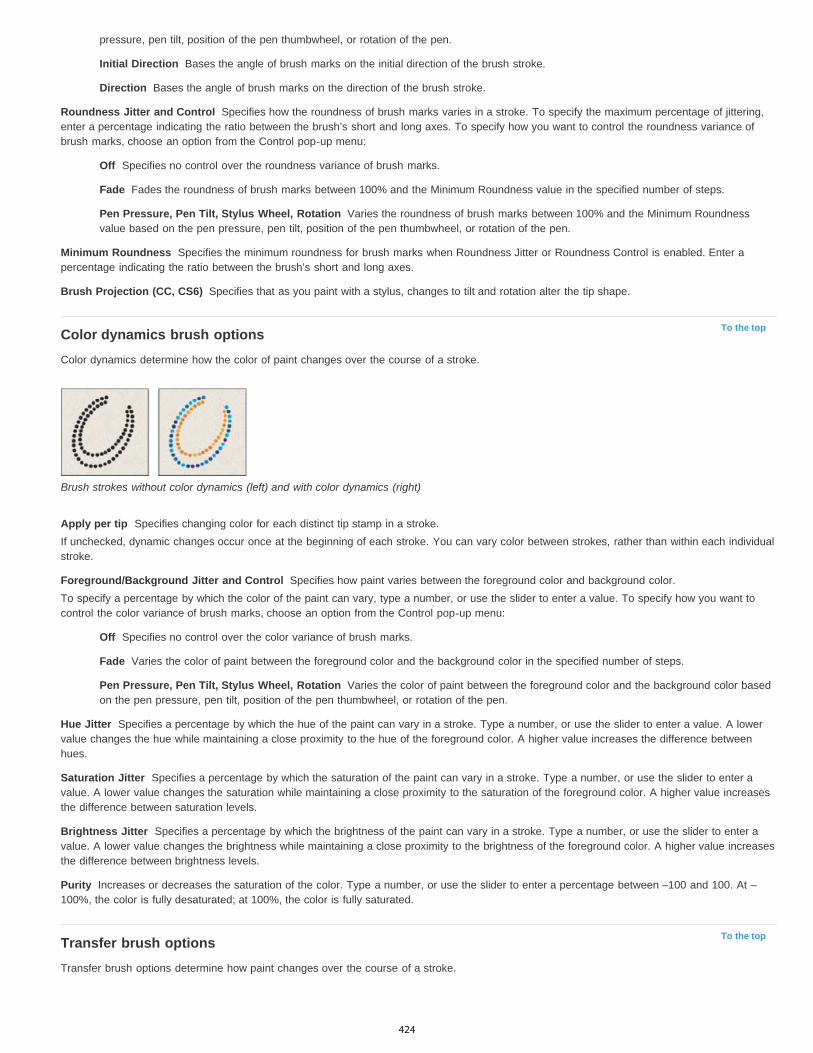
Initial Direction
Direction
Roundness Jitter and Control
Off
Fade
Pen Pressure, Pen Tilt, Stylus Wheel, Rotation
Minimum Roundness
Brush Projection (CC, CS6)
To the top
Apply per tip
Foreground/Background Jitter and Control
Off
Fade
Pen Pressure, Pen Tilt, Stylus Wheel, Rotation
Hue Jitter
Saturation Jitter
Brightness Jitter
Purity
To the top
pressure, pen tilt, position of the pen thumbwheel, or rotation of the pen.
Bases the angle of brush marks on the initial direction of the brush stroke.
Bases the angle of brush marks on the direction of the brush stroke.
Specifies how the roundness of brush marks varies in a stroke. To specify the maximum percentage of jittering,enter a percentage indicating the ratio between the brush’s short and long axes. To specify how you want to control the roundness variance ofbrush marks, choose an option from the Control pop-up menu:
Specifies no control over the roundness variance of brush marks.
Fades the roundness of brush marks between 100% and the Minimum Roundness value in the specified number of steps.
Varies the roundness of brush marks between 100% and the Minimum Roundnessvalue based on the pen pressure, pen tilt, position of the pen thumbwheel, or rotation of the pen.
Specifies the minimum roundness for brush marks when Roundness Jitter or Roundness Control is enabled. Enter apercentage indicating the ratio between the brush’s short and long axes.
Specifies that as you paint with a stylus, changes to tilt and rotation alter the tip shape.
Color dynamics brush optionsColor dynamics determine how the color of paint changes over the course of a stroke.
Brush strokes without color dynamics (left) and with color dynamics (right)
Specifies changing color for each distinct tip stamp in a stroke.If unchecked, dynamic changes occur once at the beginning of each stroke. You can vary color between strokes, rather than within each individualstroke.
Specifies how paint varies between the foreground color and background color.To specify a percentage by which the color of the paint can vary, type a number, or use the slider to enter a value. To specify how you want tocontrol the color variance of brush marks, choose an option from the Control pop-up menu:
Specifies no control over the color variance of brush marks.
Varies the color of paint between the foreground color and the background color in the specified number of steps.
Varies the color of paint between the foreground color and the background color basedon the pen pressure, pen tilt, position of the pen thumbwheel, or rotation of the pen.
Specifies a percentage by which the hue of the paint can vary in a stroke. Type a number, or use the slider to enter a value. A lowervalue changes the hue while maintaining a close proximity to the hue of the foreground color. A higher value increases the difference betweenhues.
Specifies a percentage by which the saturation of the paint can vary in a stroke. Type a number, or use the slider to enter avalue. A lower value changes the saturation while maintaining a close proximity to the saturation of the foreground color. A higher value increasesthe difference between saturation levels.
Specifies a percentage by which the brightness of the paint can vary in a stroke. Type a number, or use the slider to enter avalue. A lower value changes the brightness while maintaining a close proximity to the brightness of the foreground color. A higher value increasesthe difference between brightness levels.
Increases or decreases the saturation of the color. Type a number, or use the slider to enter a percentage between –100 and 100. At –100%, the color is fully desaturated; at 100%, the color is fully saturated.
Transfer brush optionsTransfer brush options determine how paint changes over the course of a stroke.
424

Twitter™ and Facebook posts are not covered under the terms of Creative Commons.
Legal Notices | Online Privacy Policy
Opacity Jitter and Control
Off
Fade
Pen Pressure, Pen Tilt, Stylus Wheel
Flow Jitter and Control
Off
Fade
Pen Pressure, Pen Tilt, Stylus Wheel
Brush strokes without paint dynamics (left) and with paint dynamics (right)
Specifies how the opacity of paint varies in a brush stroke, up to (but not exceeding) the opacity value specified in theoptions bar. To specify a percentage by which the opacity of the paint can vary, type a number or use the slider to enter a value. To specify howyou want to control the opacity variance of brush marks, choose an option from the Control pop-up menu:
Specifies no control over the opacity variance of brush marks.
Fades the opacity of paint from the opacity value in the options bar to 0, in the specified number of steps.
Varies the opacity of paint based on the pen pressure, pen tilt, or the position of the penthumbwheel.
Specifies how the flow of paint varies in a brush stroke, up to (but not exceeding) the flow value specified in the optionsbar.To specify a percentage by which the flow of the paint can vary, type a number or use the slider to enter a value. To specify how you want tocontrol the flow variance of brush marks, choose an option from the Control pop-up menu:
Specifies no control over the flow variance of brush marks.
Fades the flow of paint from the flow value in the options bar to 0 in the specified number of steps.
Varies the flow of paint based on the pen pressure, pen tilt, or position of the pen thumbwheel.
425

Creating textured brushes
To the top
Invert
Scale
Texture Each Tip
Mode
Depth
Minimum Depth
Depth Jitter and Control
Off
Fade
Pen Pressure, Pen Tilt, Stylus Wheel, Rotation
To the top
To the top
Textured brush optionsCopy textures between toolsDual brushes
Textured brush optionsA textured brush uses a pattern to make strokes look as if they are painted on textured canvas.
Brush strokes without texture (left) and with texture (right)
Click the pattern sample, and select a pattern from the pop-up panel. Set one or more of the following options:
Inverts the high and low points in the texture based on the tones in the pattern. When Invert is selected, the lightest areas in the patternare the low points in the texture and therefore receive the least paint; the darkest areas in the pattern are the high points in the texture andtherefore receive the most paint. When Invert is deselected, the lightest areas in the pattern receive the most paint; the darkest areas in thepattern receive the least paint.
Specifies the scale of the pattern. Type a number, or use the slider to enter a value that is a percentage of the pattern size.
Applies the selected texture individually to each brush mark in a brush stroke, rather than to the brush stroke as a whole (abrush stroke is made up of many brush marks, applied continuously as you drag the brush). You must select this option to make the Depthvariance options available.
Specifies the blending mode used to combine the brush and the pattern. (See Blending modes.)
Specifies how deeply the paint penetrates into the texture. Type a number, or use the slider to enter a value. At 100%, the low points in thetexture do not receive any paint. At 0%, all points in the texture receive the same amount of paint, therefore hiding the pattern.
Specifies the minimum depth to which paint can penetrate when Depth Control is set to Fade, Pen Pressure, Pen Tilt, or StylusWheel, and Texture Each Tip is selected.
Specifies how the depth varies when Texture Each Tip is selected. To specify the maximum percentage of jitter, enter avalue. To specify how you want to control the depth variance of brush marks, choose an option from the Control pop-up menu:
Specifies no control over the depth variance of brush marks.
Fades from the Depth Jitter percentage to the Minimum Depth percentage in the specified number of steps.
Varies the depth based on the pen pressure, pen tilt, position of the pen thumbwheel,or rotation of the pen.
Copy textures between toolsWhen you specify a texture for the current tool, you can copy the texture’s pattern and scale to all tools that support textures. For example, youcan copy the current texture pattern and scale for the Brush tool to the Pencil, Clone Stamp, Pattern Stamp, History Brush, Art History Brush,Eraser, Dodge, Burn, and Sponge tools.
Choose Copy Texture to Other Tools from the Brush panel menu.
Dual brushesA dual brush combines two tips to create brush marks. The second brush texture is applied within the brush stroke of the primary brush; only theareas where both brushstrokes intersect are painted. Set options for the primary tip in the Brush Tip Shape section of the Brush panel. Select a
426
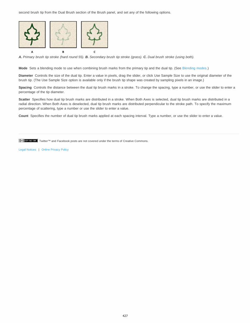
Twitter™ and Facebook posts are not covered under the terms of Creative Commons.
Legal Notices | Online Privacy Policy
Mode
Diameter
Spacing
Scatter
Count
second brush tip from the Dual Brush section of the Brush panel, and set any of the following options.
A. Primary brush tip stroke (hard round 55). B. Secondary brush tip stroke (grass). C. Dual brush stroke (using both).
Sets a blending mode to use when combining brush marks from the primary tip and the dual tip. (See Blending modes.)
Controls the size of the dual tip. Enter a value in pixels, drag the slider, or click Use Sample Size to use the original diameter of thebrush tip. (The Use Sample Size option is available only if the brush tip shape was created by sampling pixels in an image.)
Controls the distance between the dual tip brush marks in a stroke. To change the spacing, type a number, or use the slider to enter apercentage of the tip diameter.
Specifies how dual tip brush marks are distributed in a stroke. When Both Axes is selected, dual tip brush marks are distributed in aradial direction. When Both Axes is deselected, dual tip brush marks are distributed perpendicular to the stroke path. To specify the maximumpercentage of scattering, type a number or use the slider to enter a value.
Specifies the number of dual tip brush marks applied at each spacing interval. Type a number, or use the slider to enter a value.
427
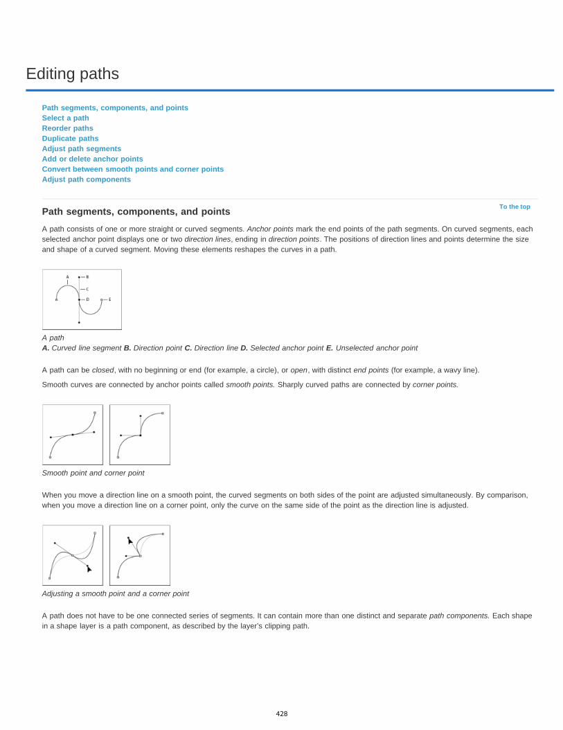
Editing paths
To the top
Path segments, components, and pointsSelect a pathReorder pathsDuplicate pathsAdjust path segmentsAdd or delete anchor pointsConvert between smooth points and corner pointsAdjust path components
Path segments, components, and pointsA path consists of one or more straight or curved segments. Anchor points mark the end points of the path segments. On curved segments, eachselected anchor point displays one or two direction lines, ending in direction points. The positions of direction lines and points determine the sizeand shape of a curved segment. Moving these elements reshapes the curves in a path.
A path A. Curved line segment B. Direction point C. Direction line D. Selected anchor point E. Unselected anchor point
A path can be closed, with no beginning or end (for example, a circle), or open, with distinct end points (for example, a wavy line).
Smooth curves are connected by anchor points called smooth points. Sharply curved paths are connected by corner points.
Smooth point and corner point
When you move a direction line on a smooth point, the curved segments on both sides of the point are adjusted simultaneously. By comparison,when you move a direction line on a corner point, only the curve on the same side of the point as the direction line is adjusted.
Adjusting a smooth point and a corner point
A path does not have to be one connected series of segments. It can contain more than one distinct and separate path components. Each shapein a shape layer is a path component, as described by the layer’s clipping path.
428

To the top
Note:
Separate path components selected
Select a pathSelecting a path component or path segment displays all of the anchor points on the selected portion, including any direction lines and directionpoints if the selected segment is curved. Direction handles appear as filled circles, selected anchor points as filled squares, and unselected anchorpoints as hollow squares.
1. Do one of the following:
To select a path component (including a shape in a shape layer), select the Path Selection tool , and click anywhere inside the pathcomponent. If a path consists of several path components, only the path component under the pointer is selected.
To select a path segment, select the Direct Selection tool , and click one of the segment’s anchor points, or drag a marquee over partof the segment.
Drag a marquee to select segments.
2. To select additional path components or segments, select the Path Selection tool or the Direct Selection tool, and then hold down Shift whileselecting additional paths or segments.
When the Direct Selection tool is selected, you can select the entire path or path component by Alt-clicking (Windows) or Option-clicking(Mac OS) inside the path. To activate the Direct Selection tool when most other tools are selected, position the pointer over an anchorpoint, and press Ctrl (Windows) or Command (Mac OS).
Select multiple paths | Photoshop CCYou can select multiple paths on the same layer or across different layers.
1. In the Path panel, do any of the following to make the paths visible:
Shift-click to select contiguous paths.Ctrl-click (Windows) or Command-click (Mac OS) to select non-contiguous paths.
2. Select the Path Selection tool or the Direct Selection tool and do any of the following:
Drag over the segments.Shift-click the paths.
3. To select additional path components or segments, select the Path Selection tool or the Direct Selection tool, and then hold down the Shiftkey while selecting additional paths or segments.
You can choose to work with paths in the isolation mode. To isolate only the layer containing a path, with the path active, double-clickusing a selection tool. You can also isolate single or multiple layers by using the Select/Isolate Layers menu item or by setting LayerFiltering to Selected.
You can exit the isolation mode in several ways, such as:
Turning off Layer FilteringSwitching Layer Filtering to something other than SelectedDouble-clicking away from a path using the path selection tools
429

To the top
To the top
To the top
Reorder pathsYou can reorder saved paths that are not Shape, Type, or Vector Mask paths in the Paths panel.
In the Path panel, drag the path to the position you want. In Photoshop CC, you can select and drag more than one path simultaneously.
Duplicate paths
1. In the Path panel, select the path you want to duplicate. In Photoshop CC, you can select more than one path.
2. Do any of the following:
Alt-drag (Windows) or Option-drag the paths.Choose Duplicate Path from the panel menu.
Adjust path segmentsYou can edit a path segment at any time, but editing existing segments is slightly different from drawing them. Keep the following tips in mindwhen editing segments:
If an anchor point connects two segments, moving that anchor point always changes both segments.
When drawing with the Pen tool, you can temporarily activate the Direct Selection tool so that you can adjust segments you’ve alreadydrawn; press Ctrl (Windows) or Command (Mac OS) while drawing.
When you initially draw a smooth point with the Pen tool, dragging the direction point changes the length of the direction line on both sides ofthe point. However, when you edit an existing smooth point with the Direct Selection tool, you change the length of the direction line only onthe side you’re dragging.
Move straight segments1. With the Direct Selection tool , select the segment you want to adjust.2. Drag the segment to its new position.
Adjust the length or angle of straight segments1. With the Direct Selection tool , select an anchor point on the segment you want to adjust.2. Drag the anchor point to the desired position. Shift-drag to constrain the adjustment to multiples of 45°.
Adjust the position or shape of curved segments1. With the Direct Selection tool ,, select a curved segment, or an anchor point on either end of the curved segment. Direction lines appear, if
any are present. (Some curved segments use just one direction line.)2. Do any of the following:
To adjust the position of the segment, drag the segment. Shift-drag to constrain the adjustment to multiples of 45°.
Click to select the curve segment. Then drag to adjust.
To adjust the shape of the segment on either side of a selected anchor point, drag the anchor point or the direction point. Shift-drag toconstrain movement to multiples of 45°.
430

Note:
Note:
To the top
Drag the anchor point, or drag the direction point.
In Photoshop CC and CS6, adjusting a path segment also adjusts the related segments, letting you intuitively transform path shapes.To only edit segments between the selected anchor points, similar to earlier Photoshop versions, select Constrain Path Dragging in theoptions bar.
You can also apply a transformation, such as scaling or rotating, to a segment or anchor point.
Delete a segment1. (Optional) If you’re creating an opening in a closed path, select the Add Anchor Point tool , and add two points where you want the cut to
occur.
2. Select the Direct Selection tool , and select the segment you want to delete.3. Press Backspace (Windows) or Delete (Mac OS) to delete the selected segment. Pressing Backspace or Delete again erases the rest of the
path.
Delete the direction line of an anchor pointUsing the Convert Anchor Point Tool, click the anchor point of the direction line.
The smooth point becomes a corner point. For more information, see Convert between smooth points and corner points .
Extend an open path1. Using the Pen tool, position the pointer over the endpoint of the open path you want to extend. The pointer changes when it’s precisely
positioned over the endpoint.2. Click the endpoint.3. Do one of the following:
To create a corner point, position the Pen tool where you want to end the new segment, and click. If you are extending a path that endsat a smooth point, the new segment will be curved by the existing direction line.
To create a smooth point, position the Pen tool where you want to end the new curved segment, and drag.
Connect two open paths1. Using the Pen tool, position the pointer over the endpoint of the open path that you want to connect to another path. The pointer changes
when it’s precisely positioned over the endpoint.2. Click the endpoint.3. Do one of the following:
To connect the path to another open path, click an endpoint on the other path. When you precisely position the Pen tool over the otherpath’s endpoint, a small merge symbol appears next to the pointer.
To connect a new path to an existing path, draw the new path near the existing path, and then move the Pen tool to the existing path’s(unselected) endpoint. Click that endpoint when you see the small merge symbol that appears next to the pointer.
Move or nudge anchor points or segments using the keyboard1. Select the anchor point or path segment.2. Click or hold down any of the arrow keys on the keyboard to move 1 pixel at a time in the direction of the arrow.
Hold down the Shift key in addition to the arrow key to move 10 pixels at a time.
Add or delete anchor pointsAdding anchor points can give you more control over a path or it can extend an open path. However, it’s a good idea not to add more points thannecessary. A path with fewer points is easier to edit, display, and print. You can reduce the complexity of a path by deleting unnecessary points.
431

Note:
To the top
Note:
The toolbox contains three tools for adding or deleting points: the Pen tool , the Add Anchor Point tool , and the Delete Anchor Point tool .
By default, the Pen tool changes to the Add Anchor Point tool as you position it over a selected path, or to the Delete Anchor Point tool as youposition it over an anchor point. You must select Auto Add/Delete in the options bar to enable the Pen tool to automatically change to the AddAnchor Point or Delete Anchor Point tool.
You can select and edit multiple paths simultaneously. You can also reshape a path while adding anchor points by clicking and dragging as youadd.
Don’t use the Delete or Backspace keys or the Edit > Cut or Edit > Clear commands to delete anchor points. These keys and commandsdelete the point and line segments that connect to that point.
Add or delete anchor points1. Select the path you want to modify.2. Select the Pen tool, the Add Anchor Point tool, or the Delete Anchor Point tool.3. To add an anchor point, position the pointer over a path segment and click. To delete an anchor point, position the pointer over an anchor
point and click.
Disable or temporarily override automatic Pen tool switchingYou can override automatic switching of the Pen tool to the Add Anchor Point tool or the Delete Anchor Point tool. This is useful when you want tostart a new path on top of an existing path.
In Photoshop, deselect Auto Add/Delete in the options bar.
Convert between smooth points and corner points1. Select the path you want to modify.2. Select the Convert Point tool, or use the Pen tool and hold down Alt (Windows) or Option (Mac OS).
To activate the Convert Point tool while the Direct Selection tool is selected, position the pointer over an anchor point, and pressCtrl+Alt (Windows) or Command+Option (Mac OS).
3. Position the Convert Point tool over the anchor point you want to convert, and do one of the following:
To convert a corner point to a smooth point, drag away from the corner point to make direction lines appear.
Dragging a direction point out of a corner point to create a smooth point
To convert a smooth point to a corner point without direction lines, click the smooth point.
Clicking a smooth point to create a corner point
To convert a corner point without direction lines to a corner point with independent direction lines, first drag a direction point out of acorner point (making it a smooth point with direction lines). Release the mouse button only (don’t release any keys you may havepressed to activate the Convert Anchor Point tool), and then drag either direction point.
To convert a smooth point to a corner point with independent direction lines, drag either direction point.
432
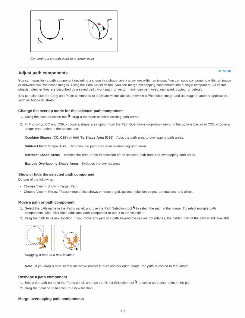
To the top
Combine Shapes (CC, CS6) or Add To Shape Area (CS5)
Subtract From Shape Area
Intersect Shape Areas
Exclude Overlapping Shape Areas
Note:
Converting a smooth point to a corner point
Adjust path componentsYou can reposition a path component (including a shape in a shape layer) anywhere within an image. You can copy components within an imageor between two Photoshop images. Using the Path Selection tool, you can merge overlapping components into a single component. All vectorobjects, whether they are described by a saved path, work path, or vector mask, can be moved, reshaped, copied, or deleted.
You can also use the Copy and Paste commands to duplicate vector objects between a Photoshop image and an image in another application,such as Adobe Illustrator.
Change the overlap mode for the selected path component1. Using the Path Selection tool , drag a marquee to select existing path areas.
2. In Photoshop CC and CS6, choose a shape area option from the Path Operations drop-down menu in the options bar, or in CS5, choose ashape area option in the options bar:
Adds the path area to overlapping path areas.
Removes the path area from overlapping path areas.
Restricts the area to the intersection of the selected path area and overlapping path areas.
Excludes the overlap area.
Show or hide the selected path componentDo one of the following:
Choose View > Show > Target Path.Choose View > Extras. This command also shows or hides a grid, guides, selection edges, annotations, and slices.
Move a path or path component1. Select the path name in the Paths panel, and use the Path Selection tool to select the path in the image. To select multiple path
components, Shift-click each additional path component to add it to the selection.2. Drag the path to its new location. If you move any part of a path beyond the canvas boundaries, the hidden part of the path is still available.
Dragging a path to a new location
If you drag a path so that the move pointer is over another open image, the path is copied to that image.
Reshape a path component1. Select the path name in the Paths panel, and use the Direct Selection tool to select an anchor point in the path.2. Drag the point or its handles to a new location.
Merge overlapping path components
433
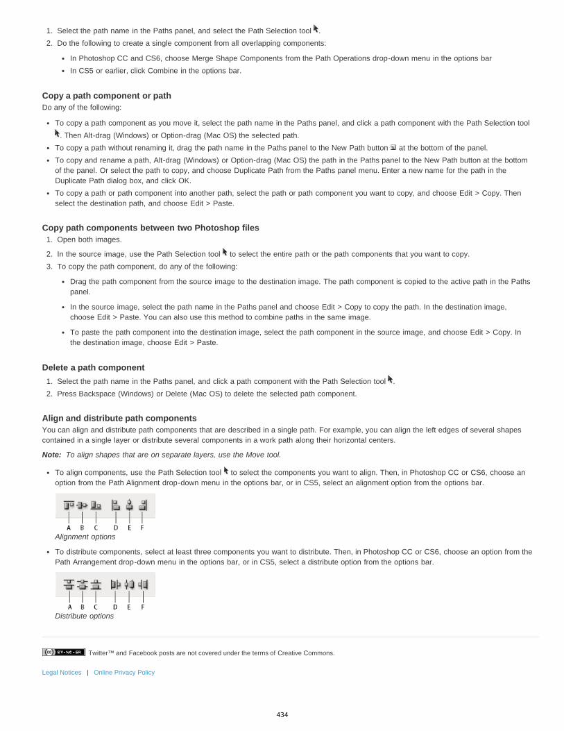
Twitter™ and Facebook posts are not covered under the terms of Creative Commons.
Legal Notices | Online Privacy Policy
Note:
1. Select the path name in the Paths panel, and select the Path Selection tool .2. Do the following to create a single component from all overlapping components:
In Photoshop CC and CS6, choose Merge Shape Components from the Path Operations drop-down menu in the options barIn CS5 or earlier, click Combine in the options bar.
Copy a path component or pathDo any of the following:
To copy a path component as you move it, select the path name in the Paths panel, and click a path component with the Path Selection tool . Then Alt-drag (Windows) or Option-drag (Mac OS) the selected path.
To copy a path without renaming it, drag the path name in the Paths panel to the New Path button at the bottom of the panel.To copy and rename a path, Alt-drag (Windows) or Option-drag (Mac OS) the path in the Paths panel to the New Path button at the bottomof the panel. Or select the path to copy, and choose Duplicate Path from the Paths panel menu. Enter a new name for the path in theDuplicate Path dialog box, and click OK.To copy a path or path component into another path, select the path or path component you want to copy, and choose Edit > Copy. Thenselect the destination path, and choose Edit > Paste.
Copy path components between two Photoshop files1. Open both images.
2. In the source image, use the Path Selection tool to select the entire path or the path components that you want to copy.3. To copy the path component, do any of the following:
Drag the path component from the source image to the destination image. The path component is copied to the active path in the Pathspanel.
In the source image, select the path name in the Paths panel and choose Edit > Copy to copy the path. In the destination image,choose Edit > Paste. You can also use this method to combine paths in the same image.
To paste the path component into the destination image, select the path component in the source image, and choose Edit > Copy. Inthe destination image, choose Edit > Paste.
Delete a path component1. Select the path name in the Paths panel, and click a path component with the Path Selection tool .2. Press Backspace (Windows) or Delete (Mac OS) to delete the selected path component.
Align and distribute path componentsYou can align and distribute path components that are described in a single path. For example, you can align the left edges of several shapescontained in a single layer or distribute several components in a work path along their horizontal centers.
To align shapes that are on separate layers, use the Move tool.
To align components, use the Path Selection tool to select the components you want to align. Then, in Photoshop CC or CS6, choose anoption from the Path Alignment drop-down menu in the options bar, or in CS5, select an alignment option from the options bar.
Alignment options
To distribute components, select at least three components you want to distribute. Then, in Photoshop CC or CS6, choose an option from thePath Arrangement drop-down menu in the options bar, or in CS5, select a distribute option from the options bar.
Distribute options
434
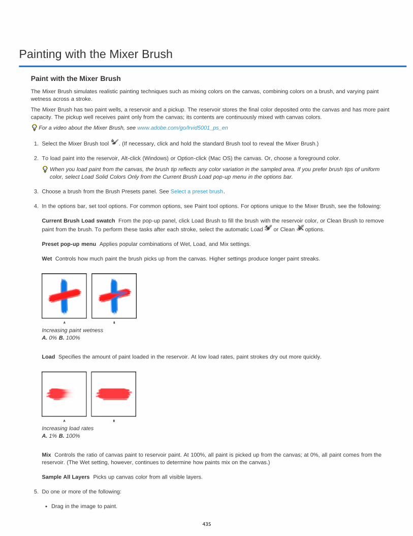
Painting with the Mixer Brush
Current Brush Load swatch
Preset pop-up menu
Wet
Load
Mix
Sample All Layers
Paint with the Mixer BrushThe Mixer Brush simulates realistic painting techniques such as mixing colors on the canvas, combining colors on a brush, and varying paintwetness across a stroke.
The Mixer Brush has two paint wells, a reservoir and a pickup. The reservoir stores the final color deposited onto the canvas and has more paintcapacity. The pickup well receives paint only from the canvas; its contents are continuously mixed with canvas colors.
For a video about the Mixer Brush, see www.adobe.com/go/lrvid5001_ps_en
1. Select the Mixer Brush tool . (If necessary, click and hold the standard Brush tool to reveal the Mixer Brush.)
2. To load paint into the reservoir, Alt-click (Windows) or Option-click (Mac OS) the canvas. Or, choose a foreground color.
When you load paint from the canvas, the brush tip reflects any color variation in the sampled area. If you prefer brush tips of uniformcolor, select Load Solid Colors Only from the Current Brush Load pop-up menu in the options bar.
3. Choose a brush from the Brush Presets panel. See Select a preset brush.
4. In the options bar, set tool options. For common options, see Paint tool options. For options unique to the Mixer Brush, see the following:
From the pop-up panel, click Load Brush to fill the brush with the reservoir color, or Clean Brush to removepaint from the brush. To perform these tasks after each stroke, select the automatic Load or Clean options.
Applies popular combinations of Wet, Load, and Mix settings.
Controls how much paint the brush picks up from the canvas. Higher settings produce longer paint streaks.
Increasing paint wetness A. 0% B. 100%
Specifies the amount of paint loaded in the reservoir. At low load rates, paint strokes dry out more quickly.
Increasing load rates A. 1% B. 100%
Controls the ratio of canvas paint to reservoir paint. At 100%, all paint is picked up from the canvas; at 0%, all paint comes from thereservoir. (The Wet setting, however, continues to determine how paints mix on the canvas.)
Picks up canvas color from all visible layers.
5. Do one or more of the following:
Drag in the image to paint.
435

Twitter™ and Facebook posts are not covered under the terms of Creative Commons.
Legal Notices | Online Privacy Policy
To draw a straight line, click a starting point in the image. Then hold down Shift, and click an ending point.
When using the Brush tool as an airbrush, hold down the mouse button without dragging to build up color.
436
Drawing or painting with a graphics tablet
Twitter™ and Facebook posts are not covered under the terms of Creative Commons.
Legal Notices | Online Privacy Policy
Note:
Change brush size and opacity with pen pressureIf you work with a graphics drawing tablet, such as the Wacom® tablet, you can control painting tools with pen pressure, angle, rotation, or thestylus wheel.
1. Select the Brush , Pencil , or other painting tool.2. In the options bar, do either of the following:
Click the Tablet Pressure Controls Size button .
Click the Tablet Pressure Controls Opacity button .
Choose Window > Brush to access additional controls that vary the angle, flow, scatter, texture depth, and roundness of the strokeaccording to pen pressure.
437
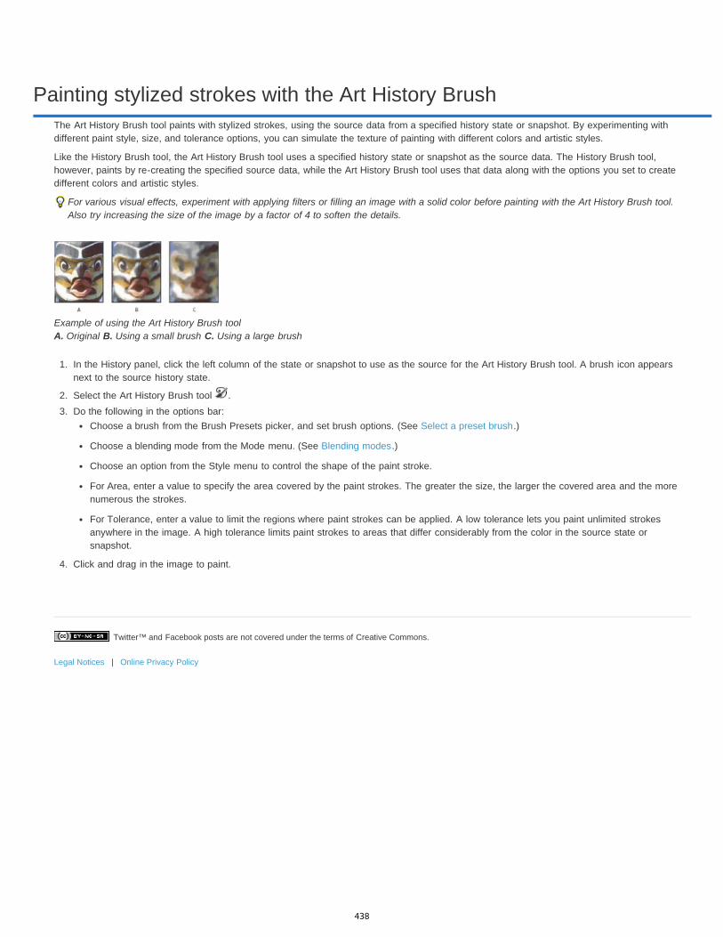
Painting stylized strokes with the Art History Brush
Twitter™ and Facebook posts are not covered under the terms of Creative Commons.
Legal Notices | Online Privacy Policy
The Art History Brush tool paints with stylized strokes, using the source data from a specified history state or snapshot. By experimenting withdifferent paint style, size, and tolerance options, you can simulate the texture of painting with different colors and artistic styles.
Like the History Brush tool, the Art History Brush tool uses a specified history state or snapshot as the source data. The History Brush tool,however, paints by re-creating the specified source data, while the Art History Brush tool uses that data along with the options you set to createdifferent colors and artistic styles.
For various visual effects, experiment with applying filters or filling an image with a solid color before painting with the Art History Brush tool.Also try increasing the size of the image by a factor of 4 to soften the details.
Example of using the Art History Brush tool A. Original B. Using a small brush C. Using a large brush
1. In the History panel, click the left column of the state or snapshot to use as the source for the Art History Brush tool. A brush icon appearsnext to the source history state.
2. Select the Art History Brush tool .3. Do the following in the options bar:
Choose a brush from the Brush Presets picker, and set brush options. (See Select a preset brush.)
Choose a blending mode from the Mode menu. (See Blending modes.)
Choose an option from the Style menu to control the shape of the paint stroke.
For Area, enter a value to specify the area covered by the paint strokes. The greater the size, the larger the covered area and the morenumerous the strokes.
For Tolerance, enter a value to limit the regions where paint strokes can be applied. A low tolerance lets you paint unlimited strokesanywhere in the image. A high tolerance limits paint strokes to areas that differ considerably from the color in the source state orsnapshot.
4. Click and drag in the image to paint.
438

Painting with a pattern
Twitter™ and Facebook posts are not covered under the terms of Creative Commons.
Legal Notices | Online Privacy Policy
To the top
Set the following in the options bar. Options available vary with each tool.
Paint with a patternThe Pattern Stamp tool paints with a pattern. You can select a pattern from the pattern libraries or create your own patterns.
1. Select the Pattern Stamp tool .
2. Choose a brush from the Brush Presets panel. See Select a preset brush.
3. Set tool options for mode, opacity, etc. in the options bar. See Paint tool options.4. Select Aligned in the options bar to maintain the pattern’s continuity with your original start point, even if you release the mouse button and
then continue painting. Deselect Aligned to restart the pattern each time you stop and start painting.5. Select a pattern from the Pattern pop-up panel in the options bar.6. If you’d like to apply the pattern with an impressionistic effect, select Impressionist.7. Drag in the image to paint it with the pattern.
439
Managing pattern libraries and presets
Twitter™ and Facebook posts are not covered under the terms of Creative Commons.
Legal Notices | Online Privacy Policy
You can keep your patterns organized in libraries that you can load or remove from pattern pop-up panels.
Load a library of patternsChoose one of the following from a Pattern pop-up panel menu:
Load Patterns to add a library to the current list. Select the library file you want to use, and click Load.Replace Patterns to replace the current list with a different library. Select the library file you want to use, and click Load.A library file (displayed at the bottom of the panel menu). Click OK to replace the current list, or click Append to append the current list.
Save a set of preset patterns as a library1. Choose Save Patterns from a Pattern pop-up panel menu.2. Choose a location for the pattern library, enter a file name, and click Save.
You can save the library anywhere. However, if you place the library file in the Presets/Patterns folder in the default location, the libraryname will appear at the bottom of the Pattern pop-up panel menus after you restart Photoshop.
Return to the default library of patternsChoose Reset Patterns from a Pattern pop-up panel menu. You can either replace the current list or append the default library to the currentlist.
If you receive a Pattern Stamp tool preset that uses an undefined pattern, or if you erase the preset you’re using by resetting or replacingthe pattern library, choose New Pattern from the Pattern pop-up panel menu to redefine the pattern.
Rename a preset pattern1. Select the pattern you want to rename, and choose Rename Pattern from the panel menu.2. Enter a new name for the pattern, and click OK.
Delete a preset patternDo one of the following:
Select the pattern you want to delete, and choose Delete Pattern from the panel menu.
Hold down Alt (Windows) or Option (Mac OS), position the pointer over a pattern (the pointer turns into scissors), and click.
The pattern is deleted only from the displayed group. To display the full library again, see Load a library of patterns.
440

Creating patterns
Twitter™ and Facebook posts are not covered under the terms of Creative Commons.
Legal Notices | Online Privacy Policy
To the top
Note:
A pattern is an image that is repeated, or tiled, when you use it to fill a layer or selection. Photoshop comes with various preset patterns.
You can create new patterns and save them in libraries for use with different tools and commands. Preset patterns are displayed in pop-up panelsin the options bar for the Paint Bucket, Pattern Stamp, Healing Brush, and Patch tools, as well as in the Layer Style dialog box. You can changehow patterns are displayed in the pop-up panels by choosing a display option from the pop-up panel menu. You can also manage pattern presetsusing the preset manager.
Define an image as a preset pattern
1. Use the Rectangle Marquee tool on any open image to select an area to use as a pattern. Feather must be set to 0 pixels. Note thatlarge images may become unwieldy.
2. Choose Edit > Define Pattern.3. Enter a name for the pattern in the Pattern Name dialog box.
If you are using a pattern from one image and applying it to another, Photoshop converts the color mode.
Photoshop comes with a set of Illustrator format files that you can use to define a preset pattern. Open the file, select any renderingoption, and then define the pattern.
441

Draw a path that snaps to defined edges
To the top
Draw using the magnetic pen options
Draw using the magnetic pen optionsThe Magnetic Pen is an option of the Freeform Pen tool that lets you draw a path that snaps to the edges of defined areas in your image. You candefine the range and sensitivity of the snapping behavior, as well as the complexity of the resulting path. The Magnetic Pen and Magnetic Lassotools share many of the same options.
1. To convert the Freeform Pen tool to the Magnetic Pen tool , select Magnetic in the options bar, or click the inverted arrow next to theshape buttons in the options bar, select Magnetic, and set the following:
For Width, enter a pixel value between 1 and 256. The Magnetic Pen detects edges only within the specified distance from the pointer.
For Contrast, enter a percentage value between 1 and 100 to specify the contrast required between pixels for that area to be consideredan edge. Use a higher value for low-contrast images.
For Frequency, enter a value between 0 and 100 to specify the rate at which the Pen sets anchor points. A higher value anchors thepath in place more quickly.
If you are working with a stylus tablet, select or deselect Pen Pressure. When this option is selected, an increase in pen pressure causesthe width to decrease.
2. Click in the image to set the first fastening point.3. To draw a freehand segment, move the pointer or drag along the edge you want to trace.
The most recent segment of the border remains active. As you move the pointer, the active segment snaps to the strongest edge in theimage, connecting the pointer to the last fastening point. Periodically, the Magnetic Pen adds fastening points to the border to anchorprevious sections.
Click to add fastening points, and continue tracing.
4. If the border doesn’t snap to the desired edge, click once to add a fastening point manually and to keep the border from moving. Continue totrace the edge and add fastening points as needed. If you make a mistake, press Delete to remove the last fastening point.
5. To dynamically modify the properties of the Magnetic Pen, do one of the following:
Alt-drag (Windows) or Option-drag (Mac OS) to draw a freehand path.
Alt-click (Windows) or Option-click (Mac OS) to draw straight segments.
Press the open square bracket key ([) to decrease the Magnetic Pen width by 1 pixel; press the close square bracket key (]) to increasethe pen width by 1 pixel.
6. Complete the path:
Press Enter (Windows) or Return (Mac OS) to end an open path.
Double-click to close the path with a magnetic segment.
Hold down Alt (Windows) or Option (Mac OS), and double-click to close the path with a straight segment.
Legal Notices | Online Privacy Policy
442

Drawing with the Pen tools
To the top
To the top
About the Pen toolsDraw straight line segments with the Pen toolDraw curves with the Pen toolFinish drawing a pathDraw with the Freeform Pen toolDraw straight lines followed by curvesDraw curves followed by straight linesDraw two curved segments connected by a cornerDraw using the magnetic pen options
About the Pen toolsPhotoshop provides multiple Pen tools. The standard Pen tool draws with the greatest precision; the Freeform Pen tool draws paths as if you weredrawing with pencil on paper, and the magnetic pen option lets you draw a path that snaps to the edges of defined areas in your image. You canuse the pen tools in conjunction with the shape tools to create complex shapes. When you use the standard Pen tool, the following options areavailable in the options bar:
Auto Add/Delete, which lets you add an anchor point when you click a line segment or delete an anchor point when you click it.
Rubber Band, which lets you preview path segments as you move the pointer between clicks. (To access this option, click the pop-up menuto the right of the Custom Shape icon.)
Before drawing with the Pen tool, you can create a new path in the Paths panel to automatically save the work path as a named path.
Adobe recommends Have a tutorial you would like to share?
Pen Tool 101Andy AndersonA comprehensive video overview on how touse the Pen Tool in Photoshop
For more information about the modes in which you can draw with the Pen tools, see Drawing modes.
Draw straight line segments with the Pen toolThe simplest path you can draw with the Pen tool is a straight line, made by clicking the Pen tool to create two anchor points. By continuing toclick, you create a path made of straight line segments connected by corner points.
Clicking Pen tool creates straight segments.
1. Select the Pen tool.2. Position the Pen tool where you want the straight segment to begin, and click to define the first anchor point (do not drag).
Note: The first segment you draw will not be visible until you click a second anchor point. (Select the Rubber Band option in Photoshop topreview path segments.) Also, if direction lines appear, you’ve accidentally dragged the Pen tool; choose Edit > Undo, and click again.
3. Click again where you want the segment to end (Shift-click to constrain the angle of the segment to a multiple of 45°).4. Continue clicking to set anchor points for additional straight segments.
443

To the top
The last anchor point you add always appears as a solid square, indicating that it is selected. Previously defined anchor points becomehollow, and deselected, as you add more anchor points.
5. Complete the path by doing one of the following:
To close the path, position the Pen tool over the first (hollow) anchor point. A small circle appears next to the Pen tool pointer when itis positioned correctly. Click or drag to close the path.
Note: To close a path in InDesign, you can also select the object and choose Object > Paths > Close Path.
To leave the path open, Ctrl-click (Windows) or Command-click (Mac OS) anywhere away from all objects.
To leave the path open, you can also select a different tool, or choose Select > Deselect in Illustrator or Edit >Deselect All in InDesign.
Draw curves with the Pen toolYou create a curve by adding an anchor point where a curve changes direction, and dragging the direction lines that shape the curve. The lengthand slope of the direction lines determine the shape of the curve.
Curves are easier to edit and your system can display and print them faster if you draw them using as few anchor points as possible. Using toomany points can also introduce unwanted bumps in a curve. Instead, draw widely spaced anchor points, and practice shaping curves by adjustingthe length and angles of the direction lines.
1. Select the Pen tool.2. Position the Pen tool where you want the curve to begin, and hold down the mouse button.
The first anchor point appears, and the Pen tool pointer changes to an arrowhead. (In Photoshop, the pointer changes only after you’vestarted dragging.)
3. Drag to set the slope of the curve segment you’re creating, and then release the mouse button.
In general, extend the direction line about one third of the distance to the next anchor point you plan to draw. (You can adjust one or bothsides of the direction line later.)
Hold down the Shift key to constrain the tool to multiples of 45°.
Drawing the first point in a curveA. Positioning Pen tool B. Starting to drag (mouse button pressed) C. Dragging to extend direction lines
4. Position the Pen tool where you want the curve segment to end, and do one of the following:
To create a C-shaped curve, drag in a direction opposite to the previous direction line. Then release the mouse button.
Drawing the second point in a curveA. Starting to drag second smooth point B. Dragging away from previous direction line, creating a C curve C. Result after releasingmouse button
To create an S-shaped curve, drag in the same direction as the previous direction line. Then release the mouse button.
444
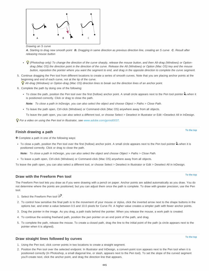
To the top
To the top
To the top
Drawing an S curveA. Starting to drag new smooth point B. Dragging in same direction as previous direction line, creating an S curve C. Result afterreleasing mouse button
(Photoshop only) To change the direction of the curve sharply, release the mouse button, and then Alt-drag (Windows) or Option-drag (Mac OS) the direction point in the direction of the curve. Release the Alt (Windows) or Option (Mac OS) key and the mousebutton, reposition the pointer where you want the segment to end, and drag in the opposite direction to complete the curve segment.
5. Continue dragging the Pen tool from different locations to create a series of smooth curves. Note that you are placing anchor points at thebeginning and end of each curve, not at the tip of the curve.
Alt-drag (Windows) or Option-drag (Mac OS) direction lines to break out the direction lines of an anchor point.
6. Complete the path by doing one of the following:
To close the path, position the Pen tool over the first (hollow) anchor point. A small circle appears next to the Pen tool pointer when itis positioned correctly. Click or drag to close the path.
Note: To close a path in InDesign, you can also select the object and choose Object > Paths > Close Path.
To leave the path open, Ctrl-click (Windows) or Command-click (Mac OS) anywhere away from all objects.
To leave the path open, you can also select a different tool, or choose Select > Deselect in Illustrator or Edit >Deselect All in InDesign.
For a video on using the Pen tool in Illustrator, see www.adobe.com/go/vid0037.
Finish drawing a path Complete a path in one of the following ways:
To close a path, position the Pen tool over the first (hollow) anchor point. A small circle appears next to the Pen tool pointer when it ispositioned correctly. Click or drag to close the path.
Note: To close a path in InDesign, you can also select the object and choose Object > Paths > Close Path.
To leave a path open, Ctrl-click (Windows) or Command-click (Mac OS) anywhere away from all objects.
To leave the path open, you can also select a different tool, or choose Select > Deselect in Illustrator or Edit > Deselect All in InDesign.
Draw with the Freeform Pen toolThe Freeform Pen tool lets you draw as if you were drawing with a pencil on paper. Anchor points are added automatically as you draw. You donot determine where the points are positioned, but you can adjust them once the path is complete. To draw with greater precision, use the Pentool.
1. Select the Freeform Pen tool .
2. To control how sensitive the final path is to the movement of your mouse or stylus, click the inverted arrow next to the shape buttons in theoptions bar, and enter a value between 0.5 and 10.0 pixels for Curve Fit. A higher value creates a simpler path with fewer anchor points.
3. Drag the pointer in the image. As you drag, a path trails behind the pointer. When you release the mouse, a work path is created.
4. To continue the existing freehand path, position the pen pointer on an end point of the path, and drag.
5. To complete the path, release the mouse. To create a closed path, drag the line to the initial point of the path (a circle appears next to thepointer when it is aligned).
Draw straight lines followed by curves1. Using the Pen tool, click corner points in two locations to create a straight segment.2. Position the Pen tool over the selected endpoint. In Illustrator and InDesign, a convert-point icon appears next to the Pen tool when it is
positioned correctly (In Photoshop, a small diagonal line, or slash, appears next to the Pen tool). To set the slope of the curved segmentyou’ll create next, click the anchor point, and drag the direction line that appears.
445

To the top
To the top
To the top
Drawing a straight segment followed by a curved segment (part 1)A. Straight segment completed B. Positioning Pen tool over endpoint (the Convert Point icon appears only in Illustrator andInDesign) C. Dragging direction point
3. Position the pen where you want the next anchor point; then click (and drag, if desired) the new anchor point to complete the curve.
Drawing a straight segment followed by a curved segment (part 2)A. Positioning Pen tool B. Dragging direction line C. New curve segment completed
Draw curves followed by straight lines1. Using the Pen tool, drag to create the first smooth point of the curved segment, and release the mouse button.2. Reposition the Pen tool where you want the curved segment to end, drag to complete the curve, and release the mouse button.3. Select the Convert Point tool from the toolbox, and then click the selected end point to convert it from a smooth point to a corner point.
Press Alt (Windows) or Option (Mac OS) to temporarily change the Pen tool to the Convert Point tool.
4. Select the Pen tool from the toolbox, position the Pen tool where you want the straight segment to end, and click to complete the straightsegment.
Draw two curved segments connected by a corner1. Using the Pen tool, drag to create the first smooth point of a curved segment.2. Reposition the Pen tool and drag to create a curve with a second smooth point; then press and hold Alt (Windows) or Option (Mac OS) and
drag the direction line toward its opposing end to set the slope of the next curve. Release the key and the mouse button.
This process converts the smooth point to a corner point by splitting the direction lines.
3. Reposition the Pen tool where you want the second curved segment to end, and drag a new smooth point to complete the second curvedsegment.
Drawing two curvesA. Dragging a new smooth point B. Pressing Alt/Option to split direction lines while dragging, and swinging direction line up C. Result afterrepositioning and dragging a third time
Draw using the magnetic pen options
446

The Magnetic Pen is an option of the Freeform Pen tool that lets you draw a path that snaps to the edges of defined areas in your image. You candefine the range and sensitivity of the snapping behavior, as well as the complexity of the resulting path. The Magnetic Pen and Magnetic Lassotools share many of the same options.
1. To convert the Freeform Pen tool to the Magnetic Pen tool , select Magnetic in the options bar, or click the inverted arrow next to theshape buttons in the options bar, select Magnetic, and set the following:
For Width, enter a pixel value between 1 and 256. The Magnetic Pen detects edges only within the specified distance from the pointer.
For Contrast, enter a percentage value between 1 and 100 to specify the contrast required between pixels for that area to be consideredan edge. Use a higher value for low-contrast images.
For Frequency, enter a value between 0 and 100 to specify the rate at which the Pen sets anchor points. A higher value anchors thepath in place more quickly.
If you are working with a stylus tablet, select or deselect Pen Pressure. When this option is selected, an increase in pen pressure causesthe width to decrease.
2. Click in the image to set the first fastening point.3. To draw a freehand segment, move the pointer or drag along the edge you want to trace.
The most recent segment of the border remains active. As you move the pointer, the active segment snaps to the strongest edge in theimage, connecting the pointer to the last fastening point. Periodically, the Magnetic Pen adds fastening points to the border to anchorprevious sections.
Click to add fastening points, and continue tracing.
4. If the border doesn’t snap to the desired edge, click once to add a fastening point manually and to keep the border from moving. Continue totrace the edge and add fastening points as needed. If you make a mistake, press Delete to remove the last fastening point.
5. To dynamically modify the properties of the Magnetic Pen, do one of the following:
Alt-drag (Windows) or Option-drag (Mac OS) to draw a freehand path.
Alt-click (Windows) or Option-click (Mac OS) to draw straight segments.
Press the open square bracket key ([) to decrease the Magnetic Pen width by 1 pixel; press the close square bracket key (]) to increasethe pen width by 1 pixel.
6. Complete the path:
Press Enter (Windows) or Return (Mac OS) to end an open path.
Double-click to close the path with a magnetic segment.
Hold down Alt (Windows) or Option (Mac OS), and double-click to close the path with a straight segment.
More Help topicsPath segments, components, and points
Legal Notices | Online Privacy Policy
447
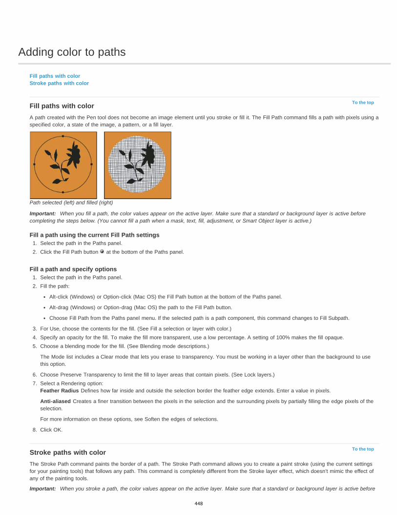
Adding color to paths
To the top
To the top
Fill paths with colorStroke paths with color
Fill paths with colorA path created with the Pen tool does not become an image element until you stroke or fill it. The Fill Path command fills a path with pixels using aspecified color, a state of the image, a pattern, or a fill layer.
Path selected (left) and filled (right)
Important: When you fill a path, the color values appear on the active layer. Make sure that a standard or background layer is active beforecompleting the steps below. (You cannot fill a path when a mask, text, fill, adjustment, or Smart Object layer is active.)
Fill a path using the current Fill Path settings1. Select the path in the Paths panel.2. Click the Fill Path button at the bottom of the Paths panel.
Fill a path and specify options1. Select the path in the Paths panel.2. Fill the path:
Alt-click (Windows) or Option-click (Mac OS) the Fill Path button at the bottom of the Paths panel.
Alt-drag (Windows) or Option-drag (Mac OS) the path to the Fill Path button.
Choose Fill Path from the Paths panel menu. If the selected path is a path component, this command changes to Fill Subpath.
3. For Use, choose the contents for the fill. (See Fill a selection or layer with color.)4. Specify an opacity for the fill. To make the fill more transparent, use a low percentage. A setting of 100% makes the fill opaque.5. Choose a blending mode for the fill. (See Blending mode descriptions.)
The Mode list includes a Clear mode that lets you erase to transparency. You must be working in a layer other than the background to usethis option.
6. Choose Preserve Transparency to limit the fill to layer areas that contain pixels. (See Lock layers.)7. Select a Rendering option:
Feather Radius Defines how far inside and outside the selection border the feather edge extends. Enter a value in pixels.
Anti-aliased Creates a finer transition between the pixels in the selection and the surrounding pixels by partially filling the edge pixels of theselection.
For more information on these options, see Soften the edges of selections.
8. Click OK.
Stroke paths with colorThe Stroke Path command paints the border of a path. The Stroke Path command allows you to create a paint stroke (using the current settingsfor your painting tools) that follows any path. This command is completely different from the Stroke layer effect, which doesn’t mimic the effect ofany of the painting tools.
Important: When you stroke a path, the color values appear on the active layer. Make sure that a standard or background layer is active before
448
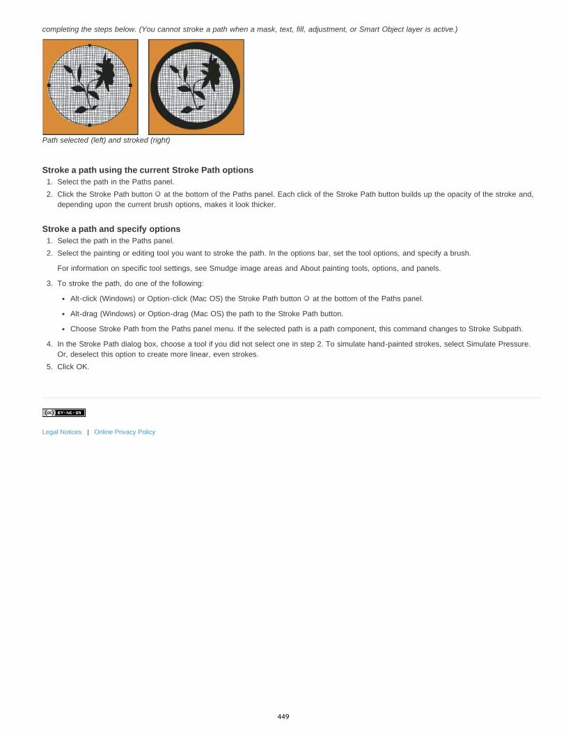
completing the steps below. (You cannot stroke a path when a mask, text, fill, adjustment, or Smart Object layer is active.)
Path selected (left) and stroked (right)
Stroke a path using the current Stroke Path options1. Select the path in the Paths panel.2. Click the Stroke Path button at the bottom of the Paths panel. Each click of the Stroke Path button builds up the opacity of the stroke and,
depending upon the current brush options, makes it look thicker.
Stroke a path and specify options1. Select the path in the Paths panel.2. Select the painting or editing tool you want to stroke the path. In the options bar, set the tool options, and specify a brush.
For information on specific tool settings, see Smudge image areas and About painting tools, options, and panels.
3. To stroke the path, do one of the following:
Alt-click (Windows) or Option-click (Mac OS) the Stroke Path button at the bottom of the Paths panel.
Alt-drag (Windows) or Option-drag (Mac OS) the path to the Stroke Path button.
Choose Stroke Path from the Paths panel menu. If the selected path is a path component, this command changes to Stroke Subpath.
4. In the Stroke Path dialog box, choose a tool if you did not select one in step 2. To simulate hand-painted strokes, select Simulate Pressure.Or, deselect this option to create more linear, even strokes.
5. Click OK.
Legal Notices | Online Privacy Policy
449
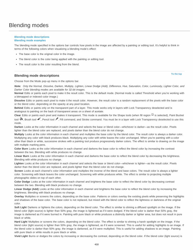
Blending modes
To the top
Blending mode descriptionsBlending mode examples
The blending mode specified in the options bar controls how pixels in the image are affected by a painting or editing tool. It’s helpful to think interms of the following colors when visualizing a blending mode’s effect:
The base color is the original color in the image.
The blend color is the color being applied with the painting or editing tool.
The result color is the color resulting from the blend.
Blending mode descriptionsChoose from the Mode pop-up menu in the options bar.
Note: Only the Normal, Dissolve, Darken, Multiply, Lighten, Linear Dodge (Add), Difference, Hue, Saturation, Color, Luminosity, Lighter Color, andDarker Color blending modes are available for 32-bit images.Normal Edits or paints each pixel to make it the result color. This is the default mode. (Normal mode is called Threshold when you’re working witha bitmapped or indexed-color image.)Dissolve Edits or paints each pixel to make it the result color. However, the result color is a random replacement of the pixels with the base coloror the blend color, depending on the opacity at any pixel location.Behind Edits or paints only on the transparent part of a layer. This mode works only in layers with Lock Transparency deselected and isanalogous to painting on the back of transparent areas on a sheet of acetate.Clear Edits or paints each pixel and makes it transparent. This mode is available for the Shape tools (when fill region is selected), Paint Buckettool , Brush tool , Pencil tool , Fill command, and Stroke command. You must be in a layer with Lock Transparency deselected to use thismode.Darken Looks at the color information in each channel and selects the base or blend color—whichever is darker—as the result color. Pixelslighter than the blend color are replaced, and pixels darker than the blend color do not change.Multiply Looks at the color information in each channel and multiplies the base color by the blend color. The result color is always a darker color.Multiplying any color with black produces black. Multiplying any color with white leaves the color unchanged. When you’re painting with a colorother than black or white, successive strokes with a painting tool produce progressively darker colors. The effect is similar to drawing on the imagewith multiple marking pens.Color Burn Looks at the color information in each channel and darkens the base color to reflect the blend color by increasing the contrastbetween the two. Blending with white produces no change.Linear Burn Looks at the color information in each channel and darkens the base color to reflect the blend color by decreasing the brightness.Blending with white produces no change.Lighten Looks at the color information in each channel and selects the base or blend color—whichever is lighter—as the result color. Pixelsdarker than the blend color are replaced, and pixels lighter than the blend color do not change.Screen Looks at each channel’s color information and multiplies the inverse of the blend and base colors. The result color is always a lightercolor. Screening with black leaves the color unchanged. Screening with white produces white. The effect is similar to projecting multiplephotographic slides on top of each other.Color Dodge Looks at the color information in each channel and brightens the base color to reflect the blend color by decreasing contrastbetween the two. Blending with black produces no change.Linear Dodge (Add) Looks at the color information in each channel and brightens the base color to reflect the blend color by increasing thebrightness. Blending with black produces no change.Overlay Multiplies or screens the colors, depending on the base color. Patterns or colors overlay the existing pixels while preserving the highlightsand shadows of the base color. The base color is not replaced, but mixed with the blend color to reflect the lightness or darkness of the originalcolor.Soft Light Darkens or lightens the colors, depending on the blend color. The effect is similar to shining a diffused spotlight on the image. If theblend color (light source) is lighter than 50% gray, the image is lightened as if it were dodged. If the blend color is darker than 50% gray, theimage is darkened as if it were burned in. Painting with pure black or white produces a distinctly darker or lighter area, but does not result in pureblack or white.Hard Light Multiplies or screens the colors, depending on the blend color. The effect is similar to shining a harsh spotlight on the image. If theblend color (light source) is lighter than 50% gray, the image is lightened, as if it were screened. This is useful for adding highlights to an image. Ifthe blend color is darker than 50% gray, the image is darkened, as if it were multiplied. This is useful for adding shadows to an image. Paintingwith pure black or white results in pure black or white.Vivid Light Burns or dodges the colors by increasing or decreasing the contrast, depending on the blend color. If the blend color (light source) is
450
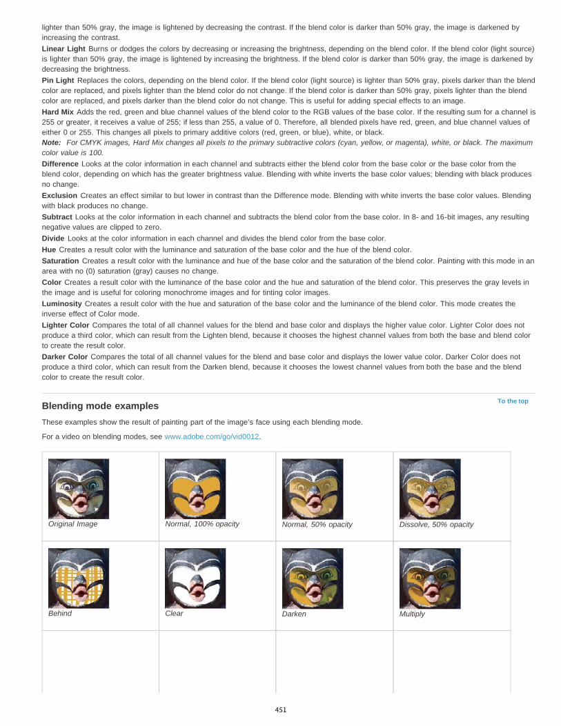
To the top
lighter than 50% gray, the image is lightened by decreasing the contrast. If the blend color is darker than 50% gray, the image is darkened byincreasing the contrast.Linear Light Burns or dodges the colors by decreasing or increasing the brightness, depending on the blend color. If the blend color (light source)is lighter than 50% gray, the image is lightened by increasing the brightness. If the blend color is darker than 50% gray, the image is darkened bydecreasing the brightness.Pin Light Replaces the colors, depending on the blend color. If the blend color (light source) is lighter than 50% gray, pixels darker than the blendcolor are replaced, and pixels lighter than the blend color do not change. If the blend color is darker than 50% gray, pixels lighter than the blendcolor are replaced, and pixels darker than the blend color do not change. This is useful for adding special effects to an image.Hard Mix Adds the red, green and blue channel values of the blend color to the RGB values of the base color. If the resulting sum for a channel is255 or greater, it receives a value of 255; if less than 255, a value of 0. Therefore, all blended pixels have red, green, and blue channel values ofeither 0 or 255. This changes all pixels to primary additive colors (red, green, or blue), white, or black.Note: For CMYK images, Hard Mix changes all pixels to the primary subtractive colors (cyan, yellow, or magenta), white, or black. The maximumcolor value is 100.Difference Looks at the color information in each channel and subtracts either the blend color from the base color or the base color from theblend color, depending on which has the greater brightness value. Blending with white inverts the base color values; blending with black producesno change.Exclusion Creates an effect similar to but lower in contrast than the Difference mode. Blending with white inverts the base color values. Blendingwith black produces no change.Subtract Looks at the color information in each channel and subtracts the blend color from the base color. In 8- and 16-bit images, any resultingnegative values are clipped to zero.Divide Looks at the color information in each channel and divides the blend color from the base color.Hue Creates a result color with the luminance and saturation of the base color and the hue of the blend color.Saturation Creates a result color with the luminance and hue of the base color and the saturation of the blend color. Painting with this mode in anarea with no (0) saturation (gray) causes no change.Color Creates a result color with the luminance of the base color and the hue and saturation of the blend color. This preserves the gray levels inthe image and is useful for coloring monochrome images and for tinting color images.Luminosity Creates a result color with the hue and saturation of the base color and the luminance of the blend color. This mode creates theinverse effect of Color mode.Lighter Color Compares the total of all channel values for the blend and base color and displays the higher value color. Lighter Color does notproduce a third color, which can result from the Lighten blend, because it chooses the highest channel values from both the base and blend colorto create the result color.Darker Color Compares the total of all channel values for the blend and base color and displays the lower value color. Darker Color does notproduce a third color, which can result from the Darken blend, because it chooses the lowest channel values from both the base and the blendcolor to create the result color.
Blending mode examplesThese examples show the result of painting part of the image’s face using each blending mode.
For a video on blending modes, see www.adobe.com/go/vid0012.
Original Image Normal, 100% opacity Normal, 50% opacity Dissolve, 50% opacity
Behind Clear Darken Multiply
451

Color Burn Linear Burn Lighten Screen
Color Dodge Linear Dodge (Add) Overlay Soft Light
Hard Light Vivid Light Linear Light Pin Light
Hard Mix Difference Exclusion Subtract
Divide Hue Saturation Color
Luminosity, 80% opacity Lighter Color Darker Color
Legal Notices | Online Privacy Policy
452

Converting between paths and selection borders
To the top
To the top
Convert paths to selection bordersConvert a selection to a path
Convert paths to selection bordersPaths provide smooth outlines that you can convert into precise selection borders. You also can convert selection borders into paths, using theDirect Selection tool for fine-tuning.
You can define any closed path as a selection border. A closed path can be added to, subtracted from, or combined with the current selection.
Convert a path to a selection border using the current settings1. Select the path in the Paths panel.2. To convert the path, do one of the following:
Click the Load Path as a Selection button at the bottom of the Paths panel.
Ctrl-click (Windows) or Command-click (Mac OS) the path thumbnail in the Paths panel.
Convert a path to a selection border and specify settings1. Select the path in the Paths panel.2. Do one of the following:
Alt-click (Windows) or Option-click (Mac OS) the Load Path As A Selection button at the bottom of the Paths panel.
Alt-drag (Windows) or Option-drag (Mac OS) the path to the Load Path As A Selection button.
Choose Make Selection from the Paths panel menu.
3. In the Make Selection dialog box, select a Rendering option:Feather Radius Defines how far inside and outside the selection border the feather edge extends. Enter a value in pixels.
Anti-aliased Creates a finer transition between the pixels in the selection and the surrounding pixels. Make sure the Feather Radius is setto 0.
For more information on these options, see Soften the edges of selections.
4. Select an Operation option:New Selection Selects only the area defined by the path.
Add To Selection Adds the area defined by the path to the original selection.
Subtract From Selection Removes the area defined by the path from the current selection.
Intersect With Selection Selects the area common to both the path and the original selection. If the path and selection do not overlap,nothing is selected.
5. Click OK.
Convert a selection to a pathAny selection made with a selection tool can be defined as a path. The Make Work Path command eliminates any feathering applied to theselection. It can also alter the shape of the selection, depending on the complexity of the path and the tolerance value you choose in the MakeWork Path dialog box.
1. Make the selection, and do one of the following:
Click the Make Work Path button at the bottom of the Paths panel to use the current tolerance setting, without opening the MakeWork Path dialog box.
Alt-click (Windows) or Option-click (Mac OS) the Make Work Path button at the bottom of the Paths panel.
Choose Make Work Path from the Paths panel menu.
2. Enter a Tolerance value or use the default value in the Make Work Path dialog box.
453

Tolerance values can range from 0.5 to 10 pixels and determine how sensitive the Make Work Path command is to slight changes in theselection shape. The higher the tolerance value, the fewer the anchor points used to draw the path and the smoother the path. If the path isused as a clipping path and you have problems printing the image, use a higher tolerance value. (See Printing image clipping paths.)
3. Click OK. The path appears at the bottom of the Paths panel.
Legal Notices | Online Privacy Policy
454

Filling and stroking selections, layers, and paths
To the top
To the top
To the top
Fill with the Paint Bucket toolFill a selection or layer with colorContent-aware, pattern, or history fillsFill the work canvasStroke a selection or layer with colorDraw a circle or square
You can fill the inside of a selection, path, or layer with a color or pattern. You can also add color to the outline of a selection or path, calledstroking.
Fill with the Paint Bucket toolThe Paint Bucket tool fills adjacent pixels that are similar in color value to the pixels you click.
Note: The Paint Bucket tool cannot be used with images in Bitmap mode.1. Choose a foreground color. (See Choose colors in the toolbox.)
2. Select the Paint Bucket tool .Note: The Paint Bucket tool is grouped with the Gradient tool in the toolbar. If you can’t find the Paint Bucket tool, click and hold theGradient tool to access it.
3. Specify whether to fill the selection with the foreground color or with a pattern.4. Specify a blending mode and opacity for the paint. (See Blending modes.)5. Enter the tolerance for the fill.
The tolerance defines how similar in color a pixel must be (to the pixel you click) to be filled. Values can range from 0 to 255. A low tolerancefills pixels within a range of color values very similar to the pixel you click. A high tolerance fills pixels within a broader range.
6. To smooth the edges of the filled selection, select Anti-aliased.7. To fill only pixels contiguous to the one you click, select Contiguous; leave Contiguous unselected to fill all similar pixels in the image.8. To fill pixels based on the merged color data from all visible layers, select All Layers.9. Click the part of the image you want to fill. All specified pixels within the specified tolerance are filled with the foreground color or pattern.
If you’re working on a layer and don’t want to fill transparent areas, make sure that the layer’s transparency is locked in the Layers panel.(See Lock layers.)
Fill a selection or layer with color1. Choose a foreground or background color. (See Choose colors in the toolbox.)2. Select the area you want to fill. To fill an entire layer, select the layer in the Layers panel.3. Choose Edit > Fill to fill the selection or layer. Or to fill a path, select the path, and choose Fill Path from the Paths panel menu.4. In the Fill dialog box, choose one of the following options for Use, or select a custom pattern:
Foreground Color, Background Color, Black, 50% Gray, or White Fills the selection with the specified color.Note: If you fill a CMYK image using the Black option, Photoshop fills all the channels with 100% black. This may result in more ink than isallowable by the printer. For best results when filling a CMYK image, use the Foreground option with the foreground color set to anappropriate black.
Color Fills with a color you select from the Color Picker.
5. Specify the blending mode and opacity for the paint. (See Blending modes.)6. If you’re working in a layer and want to fill only areas containing pixels, choose Preserve Transparency.7. Click the OK button to apply the fill.
To apply a foreground color fill only to the areas that contain pixels, press Alt+Shift+Backspace (Windows) or Option+Shift+Delete(Mac OS). This preserves the transparency of the layer. To apply a background color fill only to the areas that contain pixels, pressCtrl+Shift+Backspace (Windows) or Command+Shift+Delete (Mac OS).
Content-aware, pattern, or history fills
455

To the top
To the top
Adobe recommends Have a tutorial you would like to share?
Video tutorial: Content-aware fillChris OrwigSeamlessly replace image elements.
Scripted patternsDave CrossEasily create geometric pattern fills.
1. Select the part of the image you want to fill.2. Choose Edit > Fill.
On the Background layer, press Delete or Backspace to quickly access the Fill dialog box.
3. From the Use menu, select one of the following:Content-Aware Seamlessly fills the selection with similar image content nearby. For the best results, create a selection that extends slightlyinto the area you want to replicate. (A quick lasso or marquee selection is often sufficient.)
Content-aware fills randomly synthesize similar image content. If you don’t like your original results, choose Edit > Undo, and applyanother Content-aware fill.
Pattern Click the inverted arrow next to the pattern sample, and select a pattern from the pop-up panel. You can load additional patternsusing the pop-up panel menu. Select the name of a library of patterns, or choose Load Patterns and navigate to the folder containing thepatterns you want to use.
(CC, CS6) You can also apply one of five included Scripted Patterns to easily create a variety of geometic fill patterns. Select ScriptedPatterns at the bottom of the fill dialog box, and then choose a fill pattern from the Script pop-up menu.
Note: If Pattern is dimmed, you need to load a pattern library prior to making a selection. (See Manage pattern libraries and presets.)
History Restores the selected area to the source state or snapshot set in the History panel.
Content-aware fillA. Create selection that extends slightly into area you want to replicate B. Seamlessly replace selection with Content-Aware fill
Fill the work canvasThe work canvas surrounds the image area. You can fill the canvas with a different color that contrasts better with a given image.
Right-click the work canvas, and choose Gray, Black, or Custom. (To specify the custom color, choose Select Custom Color.)
Stroke a selection or layer with colorYou can use the Stroke command to paint a colored border around a selection, path, or layer. When you create a border this way, it becomes arasterized part of the current layer.
To create shape or layer borders that can be turned on or off like overlays and are anti-aliased to create softer-edged corners and edges, usethe Stroke layer effect instead of the Stroke command. See Layer effects and styles.
1. Choose a foreground color.2. Select the area or layer you want to stroke.3. Choose Edit > Stroke.4. In the Stroke dialog box, specify the width of the hard-edged border.5. For Location, specify whether to place the border inside, outside, or centered over the selection or layer boundaries.
Note: If the layer contents fill the entire image, a stroke applied outside the layer will not be visible.6. Specify an opacity and a blending mode. (See Blending modes.)7. If you’re working in a layer and want to stroke only areas containing pixels, select the Preserve Transparency option. (See Lock layers.)
456
To the topDraw a circle or squareYou can draw a circle or square using the elliptical or rectangular marquee tools, and then add a line (called a stroke) to the selection marquee.Stroking a selection is a quick way to add a border or frame around an object. You can stroke any selection you create with the selection tools.
1. In the Layers panel, click the New Layer button to create a new layer for the circle or square. Isolating the circle or square on its ownlayer makes it easier to work with.
2. Select the Elliptical Marquee tool or the Rectangular Marquee tool in the toolbox.3. Drag in the document window to create the shape. Hold down the Shift key while dragging to constrain the shape to a circle or square.4. Choose Edit > Stroke.5. In the Stroke dialog box, type a value for Width, and then click the color swatch to display the Adobe Color Picker.6. In the Adobe Color Picker, locate the color range you want using the triangle sliders on the color spectrum bar, and then click the desired
color in the color field. The color you select appears in the top half of the color swatch. The original color remains in the bottom half.Click OK.
7. Set the location for the stroke in relationship to the marquee by choosing Inside, Center, or Outside. Adjust the other settings as desired,and click OK. Photoshop strokes the line using the color and stroke settings you set.
Legal Notices | Online Privacy Policy
457
Generate a pattern using the Pattern MakerPattern Maker is an optional plug-in that you can download for Windows or Mac OS.
The Pattern Maker filter slices and reassembles an image to make a pattern. The Pattern Maker works in two ways:
Fills a layer or selection with a pattern. The pattern can be made of one large tile, or multiple duplicate tiles.
Creates tiles that you can save as a pattern preset and use with other images.
You can generate multiple patterns from the same sample until you find one that you like.
1. Pattern Maker is an optional plug-in. Download and install it for Windows or Mac OS.2. Run Photoshop in 32-bit mode (64-bit Mac OS only).3. Do one of the following:
Select the layer that contains the area from which you want to generate the pattern. The layer you select will be replaced by thegenerated pattern, so it’s a good idea to make a copy of the layer first.
To generate a pattern in a new layer or file, make a rectangular selection of the image you are using to generate the pattern, andchoose Edit > Copy. Then add a layer to the image, or create a new file with the dimensions you want the final image to have.
4. Choose Filter > Pattern Maker.5. Specify the source of the pattern.
Choose Use Clipboard As Sample to use the contents of the clipboard if you copied an image before you opened the Pattern Maker.
Make a selection in the preview area with the Pattern Maker’s Marquee tool . To move the selection marquee, drag it to a differentlocation.
Note: You can use the Zoom and Hand tools to navigate in the preview area. Use Alt (Windows) or Option (Mac OS) with the Zoom tool tozoom out. The magnification appears at the bottom of the dialog box.
6. Specify the tile size.
Enter pixel dimensions in the Width and Height boxes.
Click Use Image Size to generate a pattern with one tile that fills the layer.
7. Click Generate. You can press Esc to cancel the generation.
The preview area is tiled with the generated pattern.
To switch between the generated preview and the source image, choose an option from the Show menu.
To view the boundary of individual tiles, click Tile Boundaries.
To offset the tiles in the generated pattern, choose a direction from the Offset pop-up menu and specify an offset amount in the Amounttext box. The offset amount is a percentage of the tile dimension in the specified direction. The offset has no effect on saved patternpreset tiles.
8. Click Generate Again to generate additional patterns using the same options, or adjust the options and then click Generate Again.Smoothness Adjusts the sharp edges in the pattern. Increase the smoothness to reduce edges.
Sample Detail Specifies the size of pattern slices in the tile. A high value maintains more of the original detail in the pattern. A low valueuses smaller slices in the tile. Tiles take longer to generate when you use a high value.
9. Navigate through the generated tiles in the Tile History panel to select the tile that you want to use to fill the layer or to save as a patternpreset.
To move through the tiles you’ve generated, click the First Tile button, Previous Tile button, Next Tile button, or Last Tile button. Or, typethe number of the pattern preview you want to view, and press Enter (Windows) or Return (Mac OS).
To view how the tile looks as a repeating pattern in the preview area, make sure that Update Pattern Preview is selected. If tilepreviewing is slow, deselect this option, find the tile you want, and then select the option.
To delete a tile and pattern preview, navigate to the tile you want to delete, and click the Delete icon.
To save a tile as a preset pattern, navigate to the tile you want to save, and click the Save Preset Pattern button. Enter a preset name,and click OK. When you save a tile as a preset pattern, only a single tile is saved, not the full, generated pattern.
458

Tile History buttonsA. Save Preset Pattern B. First Tile C. Previous Tile D. Next Tile E. Last Tile F. Delete icon
10. When you are satisfied with a pattern preview and you have saved the tiles that you might want to use in the future, click OK to fill the layeror selection.
If you are creating preset patterns only, click Cancel to close the dialog box without filling the layer.
Legal Notices | Online Privacy Policy
459
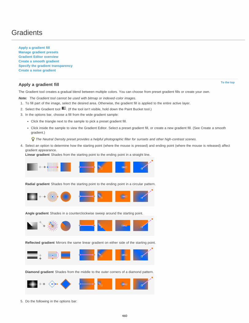
Gradients
To the top
Apply a gradient fillManage gradient presetsGradient Editor overviewCreate a smooth gradientSpecify the gradient transparencyCreate a noise gradient
Apply a gradient fillThe Gradient tool creates a gradual blend between multiple colors. You can choose from preset gradient fills or create your own.
Note: The Gradient tool cannot be used with bitmap or indexed-color images.1. To fill part of the image, select the desired area. Otherwise, the gradient fill is applied to the entire active layer.
2. Select the Gradient tool . (If the tool isn’t visible, hold down the Paint Bucket tool.)3. In the options bar, choose a fill from the wide gradient sample:
Click the triangle next to the sample to pick a preset gradient fill.
Click inside the sample to view the Gradient Editor. Select a preset gradient fill, or create a new gradient fill. (See Create a smoothgradient.)
The Neutral Density preset provides a helpful photographic filter for sunsets and other high-contrast scenes.
4. Select an option to determine how the starting point (where the mouse is pressed) and ending point (where the mouse is released) affectgradient appearance.Linear gradient Shades from the starting point to the ending point in a straight line.
Radial gradient Shades from the starting point to the ending point in a circular pattern.
Angle gradient Shades in a counterclockwise sweep around the starting point.
Reflected gradient Mirrors the same linear gradient on either side of the starting point.
Diamond gradient Shades from the middle to the outer corners of a diamond pattern.
5. Do the following in the options bar:
460
To the top
To the top
Specify a blending mode and opacity for the paint. (See Blending modes.)
To reverse the order of colors in the gradient fill, select Reverse.
To create a smoother blend with less banding, select Dither.
To use a transparency mask for the gradient fill, select Transparency. (See Specify the gradient transparency.)
6. Position the pointer in the image where you want to set the starting point of the gradient, and drag to define the ending point. To constrainthe line angle to a multiple of 45°, hold down Shift as you drag.
Manage gradient presetsGradient presets allow you to quickly apply gradients that you use often. You can manage your presets in the Gradient Picker, Presets Manager, orGradient Editor.
Save a set of preset gradients as a library1. Click Save in the Gradient Editor dialog box, or choose Save Gradients from the Gradient Picker menu in the options bar.2. Choose a location for the gradient library, enter a file name, and click Save.
You can save the library anywhere. However, if you place the library file in the Presets/Gradients folder in the default preset location, thelibrary name will appear at the bottom of the panel menu after you restart Photoshop.
Load a library of preset gradients Do one of the following in the Gradient Editor dialog box:
Click Load to add a library to the current list. Select the library file you want to use, and click Load.
Choose Replace Gradients from the panel menu to replace the current list with a different library. Select the library file you want to use, andclick Load.
Choose a library file from the bottom of the panel menu. Click OK to replace the current list, or click Append to append the current list.
Note: You can also choose Load Gradients, Replace Gradients, or choose a library of gradients from the Gradient Picker menu in the optionsbar.
Return to the default library of preset gradients Choose Reset Gradients from the panel menu. You can either replace the current list or append the default library to the current list.
Change how preset gradients are displayed Choose a display option from the panel menu:
Text Only Displays the gradients as a list.Small or Large Thumbnail Displays the gradients as thumbnails.Small or Large List Displays the gradients as a list with thumbnails.
Rename a preset gradientIf the panel is set to display gradients as thumbnails, double-click a gradient, enter a new name, and click OK.If the panel is set to display gradients as a list or text only, double-click a gradient, enter a new name inline, and press Enter (Windows) orReturn (Mac OS).
Gradient Editor overviewTo display the Gradient Editor dialog box, click the current gradient sample in the options bar. (When you hover over the gradient sample, a tooltip reading “Click to edit gradient” appears.)
The Gradient Editor dialog box lets you define a new gradient by modifying a copy of an existing gradient. You can also add intermediate colors toa gradient, creating a blend between more than two colors.
461
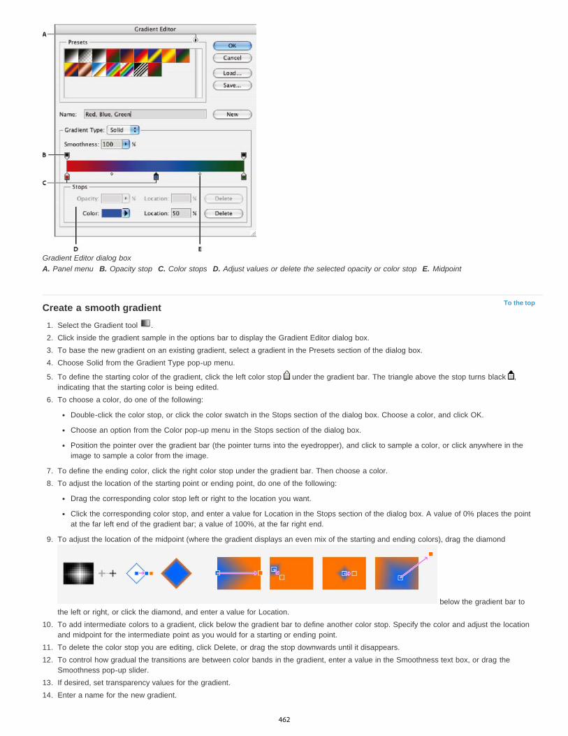
To the top
Gradient Editor dialog boxA. Panel menu B. Opacity stop C. Color stops D. Adjust values or delete the selected opacity or color stop E. Midpoint
Create a smooth gradient1. Select the Gradient tool .2. Click inside the gradient sample in the options bar to display the Gradient Editor dialog box.3. To base the new gradient on an existing gradient, select a gradient in the Presets section of the dialog box.4. Choose Solid from the Gradient Type pop-up menu.
5. To define the starting color of the gradient, click the left color stop under the gradient bar. The triangle above the stop turns black ,indicating that the starting color is being edited.
6. To choose a color, do one of the following:
Double-click the color stop, or click the color swatch in the Stops section of the dialog box. Choose a color, and click OK.
Choose an option from the Color pop-up menu in the Stops section of the dialog box.
Position the pointer over the gradient bar (the pointer turns into the eyedropper), and click to sample a color, or click anywhere in theimage to sample a color from the image.
7. To define the ending color, click the right color stop under the gradient bar. Then choose a color.8. To adjust the location of the starting point or ending point, do one of the following:
Drag the corresponding color stop left or right to the location you want.
Click the corresponding color stop, and enter a value for Location in the Stops section of the dialog box. A value of 0% places the pointat the far left end of the gradient bar; a value of 100%, at the far right end.
9. To adjust the location of the midpoint (where the gradient displays an even mix of the starting and ending colors), drag the diamond
below the gradient bar tothe left or right, or click the diamond, and enter a value for Location.
10. To add intermediate colors to a gradient, click below the gradient bar to define another color stop. Specify the color and adjust the locationand midpoint for the intermediate point as you would for a starting or ending point.
11. To delete the color stop you are editing, click Delete, or drag the stop downwards until it disappears.12. To control how gradual the transitions are between color bands in the gradient, enter a value in the Smoothness text box, or drag the
Smoothness pop-up slider.13. If desired, set transparency values for the gradient.14. Enter a name for the new gradient.
462
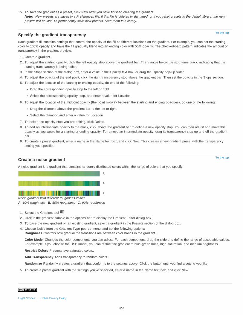
To the top
To the top
15. To save the gradient as a preset, click New after you have finished creating the gradient.Note: New presets are saved in a Preferences file. If this file is deleted or damaged, or if you reset presets to the default library, the newpresets will be lost. To permanently save new presets, save them in a library.
Specify the gradient transparencyEach gradient fill contains settings that control the opacity of the fill at different locations on the gradient. For example, you can set the startingcolor to 100% opacity and have the fill gradually blend into an ending color with 50% opacity. The checkerboard pattern indicates the amount oftransparency in the gradient preview.
1. Create a gradient.2. To adjust the starting opacity, click the left opacity stop above the gradient bar. The triangle below the stop turns black, indicating that the
starting transparency is being edited.3. In the Stops section of the dialog box, enter a value in the Opacity text box, or drag the Opacity pop-up slider.4. To adjust the opacity of the end point, click the right transparency stop above the gradient bar. Then set the opacity in the Stops section.5. To adjust the location of the starting or ending opacity, do one of the following:
Drag the corresponding opacity stop to the left or right.
Select the corresponding opacity stop, and enter a value for Location.
6. To adjust the location of the midpoint opacity (the point midway between the starting and ending opacities), do one of the following:
Drag the diamond above the gradient bar to the left or right.
Select the diamond and enter a value for Location.
7. To delete the opacity stop you are editing, click Delete.8. To add an intermediate opacity to the mask, click above the gradient bar to define a new opacity stop. You can then adjust and move this
opacity as you would for a starting or ending opacity. To remove an intermediate opacity, drag its transparency stop up and off the gradientbar.
9. To create a preset gradient, enter a name in the Name text box, and click New. This creates a new gradient preset with the transparencysetting you specified.
Create a noise gradientA noise gradient is a gradient that contains randomly distributed colors within the range of colors that you specify.
Noise gradient with different roughness values.A. 10% roughness B. 50% roughness C. 90% roughness
1. Select the Gradient tool .2. Click in the gradient sample in the options bar to display the Gradient Editor dialog box.3. To base the new gradient on an existing gradient, select a gradient in the Presets section of the dialog box.4. Choose Noise from the Gradient Type pop-up menu, and set the following options:
Roughness Controls how gradual the transitions are between color bands in the gradient.
Color Model Changes the color components you can adjust. For each component, drag the sliders to define the range of acceptable values.For example, if you choose the HSB model, you can restrict the gradient to blue-green hues, high saturation, and medium brightness.
Restrict Colors Prevents oversaturated colors.
Add Transparency Adds transparency to random colors.
Randomize Randomly creates a gradient that conforms to the settings above. Click the button until you find a setting you like.
5. To create a preset gradient with the settings you’ve specified, enter a name in the Name text box, and click New.
Legal Notices | Online Privacy Policy
463
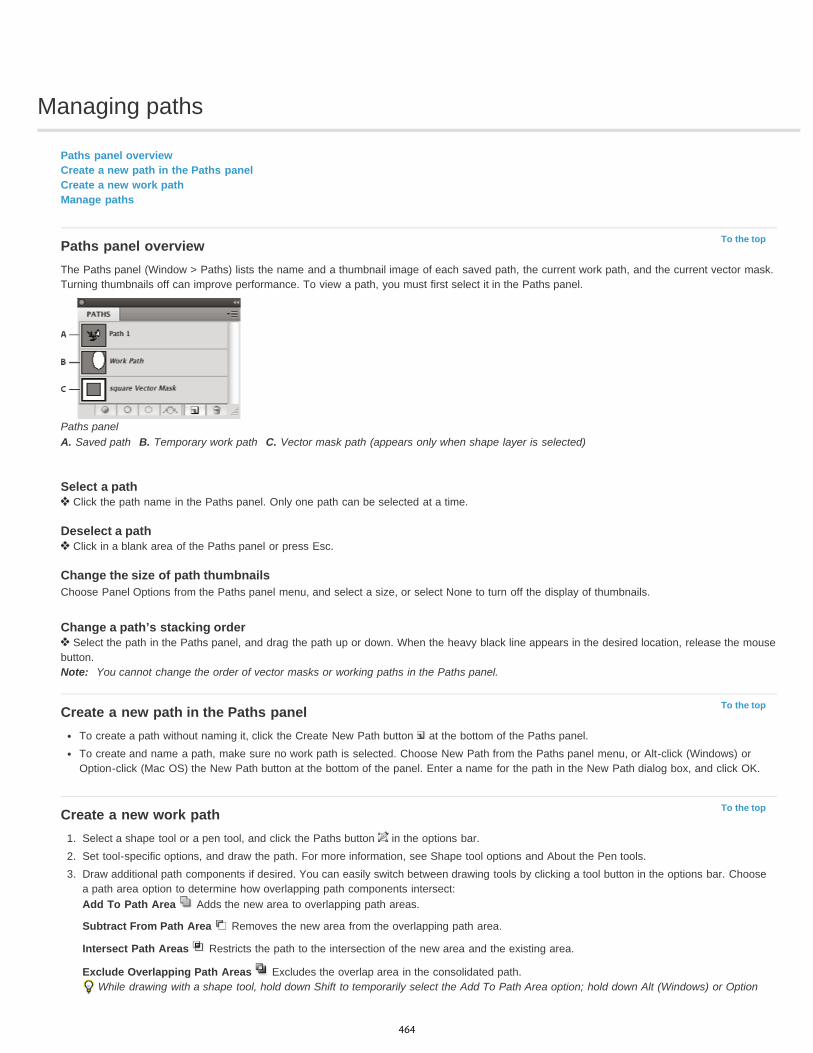
Managing paths
To the top
To the top
To the top
Paths panel overviewCreate a new path in the Paths panelCreate a new work pathManage paths
Paths panel overviewThe Paths panel (Window > Paths) lists the name and a thumbnail image of each saved path, the current work path, and the current vector mask.Turning thumbnails off can improve performance. To view a path, you must first select it in the Paths panel.
Paths panelA. Saved path B. Temporary work path C. Vector mask path (appears only when shape layer is selected)
Select a path Click the path name in the Paths panel. Only one path can be selected at a time.
Deselect a path Click in a blank area of the Paths panel or press Esc.
Change the size of path thumbnailsChoose Panel Options from the Paths panel menu, and select a size, or select None to turn off the display of thumbnails.
Change a path’s stacking order Select the path in the Paths panel, and drag the path up or down. When the heavy black line appears in the desired location, release the mouse
button.Note: You cannot change the order of vector masks or working paths in the Paths panel.
Create a new path in the Paths panelTo create a path without naming it, click the Create New Path button at the bottom of the Paths panel.To create and name a path, make sure no work path is selected. Choose New Path from the Paths panel menu, or Alt-click (Windows) orOption-click (Mac OS) the New Path button at the bottom of the panel. Enter a name for the path in the New Path dialog box, and click OK.
Create a new work path1. Select a shape tool or a pen tool, and click the Paths button in the options bar.2. Set tool-specific options, and draw the path. For more information, see Shape tool options and About the Pen tools.3. Draw additional path components if desired. You can easily switch between drawing tools by clicking a tool button in the options bar. Choose
a path area option to determine how overlapping path components intersect:Add To Path Area Adds the new area to overlapping path areas.
Subtract From Path Area Removes the new area from the overlapping path area.
Intersect Path Areas Restricts the path to the intersection of the new area and the existing area.
Exclude Overlapping Path Areas Excludes the overlap area in the consolidated path.While drawing with a shape tool, hold down Shift to temporarily select the Add To Path Area option; hold down Alt (Windows) or Option
464
To the top
(Mac OS) to temporarily select the Subtract From Path Area option.
Manage pathsWhen you use a pen or shape tool to create a work path, the new path appears as the work path in the Paths panel. The work path is temporary;you must save it to avoid losing its contents. If you deselect the work path without saving it and start drawing again, a new path will replace theexisting one.
When you use a pen or shape tool to create a new shape layer, the new path appears as a vector mask in the Paths panel. Vector masks arelinked to their parent layer; you must select the parent layer in the Layers panel in order to list the Vector mask in the Paths panel. You canremove a Vector mask from a layer and convert a Vector mask to a rasterized mask. For more information, see Add and edit vector masks.
Paths saved with an image appear when you open it again. In Windows, JPEG, JPEG 2000, DCS, EPS, PDF, and TIFF formats support paths inPhotoshop. In Mac OS, all available file formats support paths.
Note: Paths in formats other than those listed here generally don’t survive a transition from Mac OS to Windows and back to Mac OS.
Save a work pathTo save without renaming, drag the work path name to the New Path button at the bottom of the Paths panel.To save and rename, choose Save Path from the Paths panel menu, enter a new path name in the Save Path dialog box, and click OK.
Rename a saved path Double-click the path name in the Paths panel, type a new name, and press Enter (Windows) or Return (Mac OS).
Delete a path1. Click the path name in the Paths panel.2. Do one of the following:
Drag the path to the Delete icon at the bottom of the Paths panel.
Choose Delete Path from the Paths panel menu.
Click the Delete icon at the bottom of the Paths panel, and click Yes.
To delete a path without being asked to confirm, Alt-click (Windows) or Option-click (Mac OS) the Delete icon at the bottom of the Pathspanel.
Legal Notices | Online Privacy Policy
465

Text
466

Creating type
To the top
To the top
About type layersEntering typeEnter point typeEnter paragraph typePaste lorem-ipsum placeholder text (CC, CS6)Resize or transform a type bounding boxConvert between point type and paragraph type
Note: For detailed instructions, click the links below. To ask questions, request features, or report problems, visit feedback.photoshop.com.Type in Adobe Photoshop consists of vector-based type outlines—mathematically defined shapes that describe the letters, numbers, and symbolsof a typeface. Many typefaces are available in more than one format, the most common formats being Type 1 (also called PostScript fonts),TrueType, OpenType, New CID, and CID nonprotected (Japanese only).
Photoshop preserves vector-based type outlines and uses them when you scale or resize type, save a PDF or EPS file, or print the image to aPostScript printer. As a result, it’s possible to produce type with crisp, resolution-independent edges.
If you import bitmap type layers created in older versions of Photoshop or Photoshop Elements, choose Type > Update All Text Layers toconvert to vector type. (In CS5, this command is in the Layer > Type menu.)
Adobe recommends Have a tutorial you would like to share?
Type 101Andy AndersonPhotoshop is primarily an image-editingapplication, but it also handles text. InfiniteSkills author, Andy Anderson, will show youthe basics of using text the creative way.
About type layersImportant: Type layers aren’t created for images in Multichannel, Bitmap, or Indexed Color mode, because these modes don’t support layers.In these modes, type appears on the background as rasterized text.When you create type, a new type layer is added to the Layers panel. After you create a type layer, you can edit the type and apply layercommands to it.
Once you make a change to a type layer that requires it to be rasterized, however, Photoshop converts the vector-based type outlines to pixels.Rasterized type no longer has vector outlines and is uneditable as type. See Rasterize type layers.
You can make the following changes to a type layer and still edit the type:
Change the orientation of type.
Apply anti-aliasing.
Convert between point type and paragraph type.
Create a work path from type.
Apply transformation commands from the Edit menu, except for Perspective and Distort.
Note: To transform part of the type layer, you must first rasterize the type layer.
Use layer styles.
Use fill shortcuts (see Keys for painting).
Warp type to conform to a variety of shapes.
Entering typeThere are three ways to create type: at a point, inside a paragraph, and along a path.
467

To the top
To the top
Point type is a horizontal or vertical line of text that begins where you click in the image. Entering text at a point is a useful way to add a fewwords to your image.
Paragraph type uses boundaries to control the flow of characters, either horizontally or vertically. Entering text this way is useful when youwant to create one or more paragraphs, such as for a brochure.
Type entered as point type (top) and in a bounding box (bottom)
Type on a path flows along the edge of an open or a closed path. When you enter text horizontally, characters appear along the pathperpendicular to the baseline. When you enter text vertically, characters appear along the path parallel to the baseline. In either case, thetext flows in the direction in which points were added to the path.
If you enter more text that can fit within a paragraph boundary or along a path, a small box or circle containing a plus symbol (+) appears inplace of a handle in the corner of the boundary or anchor point at the end of the path.
Clicking in an image with a type tool puts the type tool in edit mode. When the tool is in edit mode, you can enter and edit characters as well asperform some other commands from the various menus; however, certain operations require that you first commit changes to the type layer. To
determine whether a type tool is in edit mode, look in the options bar—if you see the Commit button and the Cancel button , the type tool isin edit mode.
Enter point typeWhen you enter point type, each line of type is independent—the line expands or shrinks as you edit it, but it doesn’t wrap to the next line. Thetype you enter appears in a new type layer.
1. Select the Horizontal Type tool or the Vertical Type tool .2. Click in the image to set an insertion point for the type. The small line through the I-beam marks the baseline of the type (the imaginary line
on which type rests). For vertical type, the baseline marks the center axis of the characters.3. Select additional type options in the options bar, Character panel, or Paragraph panel.4. Enter the characters. To begin a new line, press Enter (Windows) or Return (Mac OS).
Note: You can also transform point type while in edit mode. Hold down the Ctrl (Windows) or Command (Mac OS) key. A bounding boxappears around the type. You can grab a handle to scale or skew the type. You can also rotate the bounding box.
5. When you finish entering or editing the type, do one of the following:
Click the Commit button in the options bar.
Press the Enter key on the numeric keypad.
Press Ctrl+Enter (Windows) or Command+Return (Mac OS).
Select any tool in the toolbox; click in the Layers, Channels, Paths, Actions, History, or Styles panel; or select any available menucommand.
Enter paragraph typeWhen you enter paragraph type, the lines of type wrap to fit the dimensions of the bounding box. You can enter multiple paragraphs and select aparagraph justification option.
You can resize the bounding box, causing the type to reflow within the adjusted rectangle. You can adjust the bounding box while you enter type orafter you create the type layer. You can also use the bounding box to rotate, scale, and skew type.
1. Select the Horizontal Type tool or the Vertical Type tool .2. Do one of the following:
Drag diagonally to define a bounding box for the type.
468

To the top
To the top
To the top
Hold down Alt (Windows) or Option (Mac OS) as you click or drag to display the Paragraph Text Size dialog box. Enter values for Widthand Height, and click OK.
3. Select additional type options in the options bar, Character panel, Paragraph panel, or Layer > Type submenu.4. Enter the characters. To begin a new paragraph, press Enter (Windows) or Return (Mac OS). If you enter more type than can fit in the
bounding box, the overflow icon appears on the bounding box.5. If desired, resize, rotate, or skew the bounding box.6. Commit the type layer by doing one of the following:
Click the Commit button in the options bar.
Press the Enter key on the numeric keypad.
Press Ctrl+Enter (Windows) or Command+Return (Mac OS).
Select any tool in the toolbox; click in the Layers, Channels, Paths, Actions, History, or Styles panel; or select any available menucommand.
The type you enter appears in a new type layer.
Paste lorem-ipsum placeholder text (CC, CS6)Lorem-ipsum placeholder text lets you quickly fill a text block for layout purposes.
1. Select a type tool, and click to insert the cursor in an existing text line or box.
2. Choose Type > Paste Lorem Ipsum.
Resize or transform a type bounding box
Display the bounding box handles of paragraph type. With the Type tool active, select the type layer in the Layers panel, and click in the textflow in the image.Note: You can transform point type while in edit mode. Hold down the Ctrl (Windows) or Command (Mac OS) key, and a bounding box appearsaround the type.
To resize the bounding box, position the pointer over a handle—the pointer turns into a double arrow —and drag. Shift-drag to maintainthe proportions of the bounding box.
To rotate the bounding box, position the pointer outside the bounding border—the pointer turns into a curved, two-sided arrow —and drag.Shift-drag to constrain the rotation to 15° increments. To change the center of rotation, Ctrl-drag (Windows) or Command-drag (Mac OS) thecenter point to a new location. The center point can be outside the bounding box.
To skew the bounding box, hold down Ctrl (Windows) or Command (Mac OS) and drag one of the middle handles. The pointer turns into anarrowhead .
Skewing type using the bounding box
To scale the type as you resize the bounding box, Ctrl-drag (Windows) or Command-drag (Mac OS) a corner handle.
To resize the bounding box from the center point, Alt-drag (Windows) or Option-drag (Mac OS) a corner handle.
Convert between point type and paragraph typeYou can convert point type to paragraph type to adjust the flow of characters within a bounding box. Alternatively, you can convert paragraph typeto point type to make each text line flow independently from the others. When you convert from paragraph type to point type, a carriage return isadded at the end of each line of type (with the exception of the last line).
1. Select the type layer in the Layers panel.2. Choose Type > Convert To Point Text or Type > Convert To Paragraph Text. (In CS5 these commands are in the Layer > Type menu.)
Note: When you convert paragraph type to point type, all characters that overflow the bounding box are deleted. To avoid losing text,
469

adjust the bounding box so that all type is visible prior to conversion.
Legal Notices | Online Privacy Policy
470

Editing text
To the top
To the top
To the top
Edit textSpecify curly or straight quotesApply anti-aliasing to a type layerCheck and correct spellingFind and replace textAssign a language for textScaling and rotating typeChange the orientation of a type layerRasterize type layers
Edit text
1. Select the Horizontal Type tool or the Vertical Type tool .2. Select the type layer in the Layers panel, or click in the text flow to automatically select a type layer.3. Position the insertion point in the text, and do one of the following:
Click to set the insertion point.
Select one or more characters you want to edit.
4. Enter text as desired.5. In the options bar, do one of the following:
Click the Commit button to apply your changes to the type layer.
Click the Cancel button or press ESC.
Specify curly or straight quotesTypographer’s quotes, often called curly quotes or smart quotes, blend in with the curves of the font. Typographer’s quotes are traditionally usedfor quotation marks and apostrophes. Straight quotes are traditionally used as abbreviations for feet and inches.
1. Choose Edit > Preferences > Type (Windows) or Photoshop > Preferences > Type (Mac OS).2. Under Type Options, select or deselect Use Smart Quotes.
Apply anti-aliasing to a type layerAnti-aliasing produces smooth-edged type by partially filling the edge pixels. As a result, the edges of the type blend into the background.
Anti-aliasing set to None (left), and Strong (right)
When creating type for display on the web, consider that anti-aliasing greatly increases the number of colors in the original image. This limits yourability to reduce the number of colors in the image and thus to reduce the size of the image file. Anti-aliasing may also cause stray colors toappear along the edges of the type. When reducing file size and limiting the number of colors are most important, it may be preferable to avoidanti-aliasing, despite the jagged edges. Also, consider using larger type than you would use for print. Larger type is easier to view on the web andgives you more freedom in deciding whether to apply anti-aliasing.
471

To the top
To the top
Note: When you use anti-aliasing, type may be rendered inconsistently at small sizes and low resolutions (such as the resolution used for webgraphics). To reduce this inconsistency, deselect the Fractional Width option in the Character panel menu.
1. Select the type layer in the Layers panel.2. Choose an option from the anti-aliasing menu in the options bar or the Character panel. Or, choose Layer > Type, and choose an option
from the submenu.None Applies no anti-aliasing
Sharp Type appears at its sharpest
Crisp Type appears somewhat sharp
Strong Type appears heavier
Smooth Type appears smoother
Check and correct spellingWhen you check the spelling in a document, Photoshop questions any words that aren’t in its dictionary. If a questioned word is spelled correctly,you can confirm its spelling by adding the word to your personal dictionary. If a questioned word is misspelled, you can correct it.
1. If necessary, in the Character panel, choose a language from the pop-up menu at the bottom of the panel. This is the dictionary Photoshopuses to check spelling.
2. (Optional) Show or unlock type layers. The Check Spelling command does not check spelling in hidden or locked layers.3. Do one of the following:
Select a type layer.
To check specific text, select the text.
To check a word, place the insertion point in the word.
4. Choose Edit > Check Spelling.5. If you selected a type layer and want to check the spelling of only that layer, deselect Check All Layers.6. As Photoshop finds unfamiliar words and other possible errors, click one of the following:
Ignore Continues the spelling check without changing the text.
Ignore All Ignores the questioned word during the rest of the spelling check.
Change Corrects a misspelling. Make sure that the correctly spelled word is in the Change To text box and click Change. If the suggestedword is not the word you want, select a different word in the Suggestions text box or enter the correct word in the Change To text box.
Change All Corrects all instances of the misspelling in the document. Make sure the correctly spelled word is in the Change To text box.
Add Stores the unrecognized word in the dictionary, so that subsequent occurrences are not flagged as misspellings.
Find and replace text1. Do one of the following:
Select the layer containing the text you want to find and replace. Place the insertion point at the beginning of the text you want to search.
Select a nontype layer if you have more than one type layer and you want to search all layers in the document.
Note: In the Layers panel, make sure the type layers you want to search are visible and unlocked. The Find And Replace Textcommand does not check spelling in hidden or locked layers.
2. Choose Edit > Find And Replace Text.3. In the Find What box, type or paste the text you want to find. To change the text, type the new text in the Change To text box.4. Select one or more options to refine your search.
Search All Layers Searches all layers in a document. This option is available when a nontype layer is selected in the Layers panel.
Forward Searches forward from an insertion point in the text. Deselect this option to search all the text in a layer, regardless of where theinsertion point is placed.
Case Sensitive Searches for a word or words that exactly match the case of the text in the Find What text box. For example, with the CaseSensitive option selected, a search for “PrePress” does not find “Prepress” or “PREPRESS.”
Whole Word Only Disregards the search text if it is embedded in a larger word. For example, if you are searching for “any” as a wholeword, “many” is disregarded.
5. Click Find Next to begin the search.6. Click one of the following buttons.
Change Replaces the found text with the revised text. To repeat the search, select Find Next.
472

To the top
To the top
Change All Searches for and replaces all occurrences of the found text.
Change/Find Replaces the found text with the revised text, and then searches for the next occurrence.
Assign a language for textPhotoshop uses language dictionaries to check hyphenation. Language dictionaries are also used to check spelling. Each dictionary containshundreds of thousands of words with standard syllable breaks. You can assign a language to an entire document or apply a language to selectedtext.
Examples of hyphenation for different languagesA. “Cactophiles” in English USA B. “Cactophiles” in English UK C. “Cactophiles” in French
1. Do one of the following:
To enter text using a specific language dictionary, choose the dictionary from the pop-up menu in the bottom left corner of the Characterpanel. Then enter the text.
To change the dictionary of existing text, select the text and choose the dictionary from the pop-up menu in the bottom left corner of theCharacter panel.
2. In the Character panel, choose the appropriate dictionary from the pop-up menu in the bottom left corner of the panel.Note: If you select text with multiple languages or if the type layer has multiple languages, the pop-up menu in the Character panel will bedimmed and it will display the word “Multiple.”
Scaling and rotating type
Adjust the scale of typeYou can specify the proportion between the height and width of the type, relative to the original width and height of the characters. Unscaledcharacters have a value of 100%. Some type families include a true expanded font, which is designed with a larger horizontal spread than the plaintype style. Scaling distorts the type, so it is generally preferable to use a font that is designed as condensed or expanded, if one is available.
1. Select the characters or type objects you want to change. If you don’t select any text, the scale applies to new text you create.
2. In the Character panel, set the Vertical Scaling option or the Horizontal Scaling option .
Rotate type Do the following:
To rotate type, select the type layer and use any rotate command or the Free Transform command. For paragraph type, you can also selectthe bounding box and use a handle to rotate the type manually.
To rotate multiple characters in vertical Asian text, use the tate-chu-yoko.
Rotate vertical type charactersWhen working with vertical type, you can rotate the direction of characters by 90°. Rotated characters appear upright; unrotated characters appearsideways (perpendicular to the type line).
473
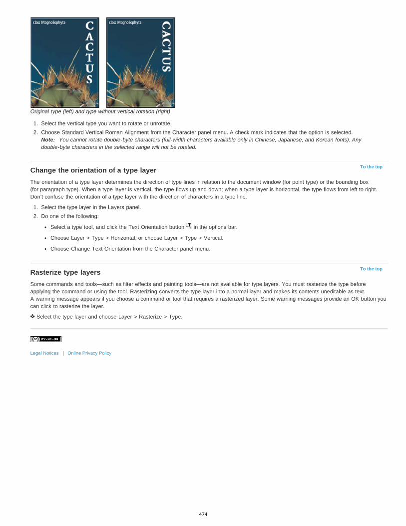
To the top
To the top
Original type (left) and type without vertical rotation (right)
1. Select the vertical type you want to rotate or unrotate.2. Choose Standard Vertical Roman Alignment from the Character panel menu. A check mark indicates that the option is selected.
Note: You cannot rotate double-byte characters (full-width characters available only in Chinese, Japanese, and Korean fonts). Anydouble-byte characters in the selected range will not be rotated.
Change the orientation of a type layerThe orientation of a type layer determines the direction of type lines in relation to the document window (for point type) or the bounding box(for paragraph type). When a type layer is vertical, the type flows up and down; when a type layer is horizontal, the type flows from left to right.Don’t confuse the orientation of a type layer with the direction of characters in a type line.
1. Select the type layer in the Layers panel.2. Do one of the following:
Select a type tool, and click the Text Orientation button in the options bar.
Choose Layer > Type > Horizontal, or choose Layer > Type > Vertical.
Choose Change Text Orientation from the Character panel menu.
Rasterize type layersSome commands and tools—such as filter effects and painting tools—are not available for type layers. You must rasterize the type beforeapplying the command or using the tool. Rasterizing converts the type layer into a normal layer and makes its contents uneditable as text.A warning message appears if you choose a command or tool that requires a rasterized layer. Some warning messages provide an OK button youcan click to rasterize the layer.
Select the type layer and choose Layer > Rasterize > Type.
Legal Notices | Online Privacy Policy
474
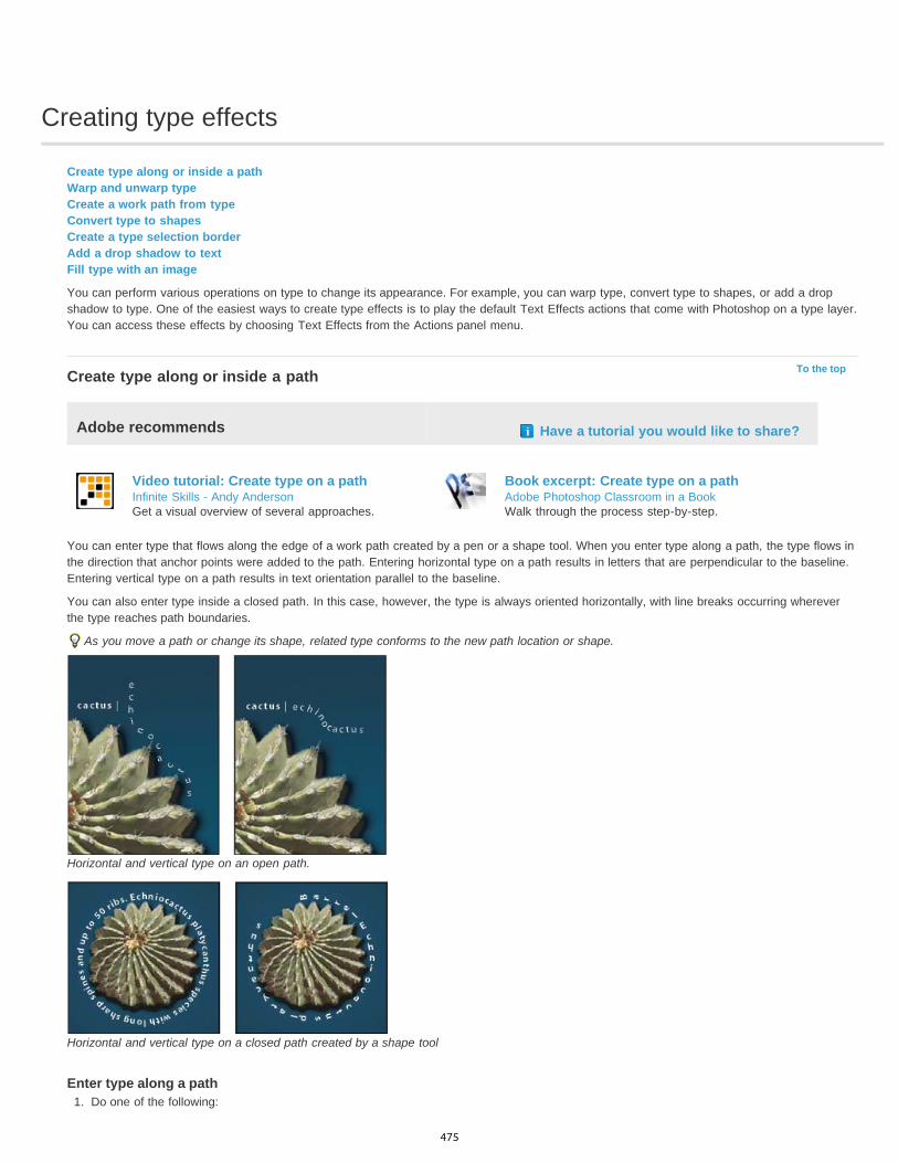
Creating type effects
To the top
Create type along or inside a pathWarp and unwarp typeCreate a work path from typeConvert type to shapesCreate a type selection borderAdd a drop shadow to textFill type with an image
You can perform various operations on type to change its appearance. For example, you can warp type, convert type to shapes, or add a dropshadow to type. One of the easiest ways to create type effects is to play the default Text Effects actions that come with Photoshop on a type layer.You can access these effects by choosing Text Effects from the Actions panel menu.
Create type along or inside a path
Adobe recommends Have a tutorial you would like to share?
Video tutorial: Create type on a pathInfinite Skills - Andy AndersonGet a visual overview of several approaches.
Book excerpt: Create type on a pathAdobe Photoshop Classroom in a BookWalk through the process step-by-step.
You can enter type that flows along the edge of a work path created by a pen or a shape tool. When you enter type along a path, the type flows inthe direction that anchor points were added to the path. Entering horizontal type on a path results in letters that are perpendicular to the baseline.Entering vertical type on a path results in text orientation parallel to the baseline.
You can also enter type inside a closed path. In this case, however, the type is always oriented horizontally, with line breaks occurring whereverthe type reaches path boundaries.
As you move a path or change its shape, related type conforms to the new path location or shape.
Horizontal and vertical type on an open path.
Horizontal and vertical type on a closed path created by a shape tool
Enter type along a path1. Do one of the following:
475
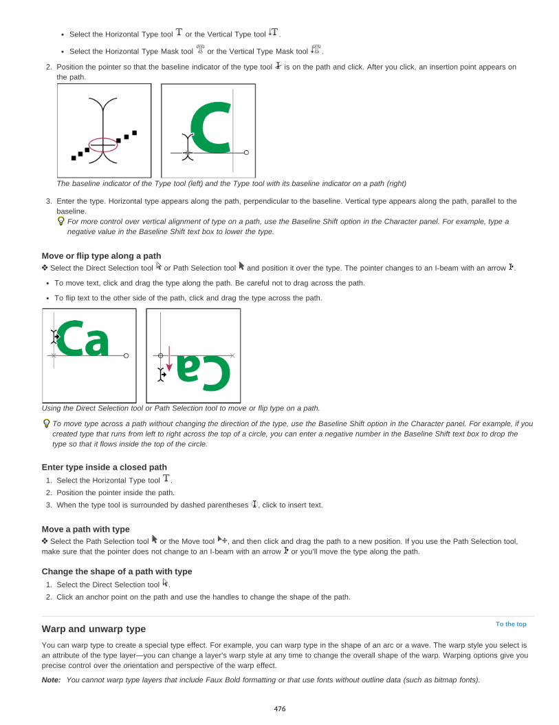
To the top
Select the Horizontal Type tool or the Vertical Type tool .
Select the Horizontal Type Mask tool or the Vertical Type Mask tool .
2. Position the pointer so that the baseline indicator of the type tool is on the path and click. After you click, an insertion point appears onthe path.
The baseline indicator of the Type tool (left) and the Type tool with its baseline indicator on a path (right)
3. Enter the type. Horizontal type appears along the path, perpendicular to the baseline. Vertical type appears along the path, parallel to thebaseline.
For more control over vertical alignment of type on a path, use the Baseline Shift option in the Character panel. For example, type anegative value in the Baseline Shift text box to lower the type.
Move or flip type along a path Select the Direct Selection tool or Path Selection tool and position it over the type. The pointer changes to an I-beam with an arrow .
To move text, click and drag the type along the path. Be careful not to drag across the path.
To flip text to the other side of the path, click and drag the type across the path.
Using the Direct Selection tool or Path Selection tool to move or flip type on a path.
To move type across a path without changing the direction of the type, use the Baseline Shift option in the Character panel. For example, if youcreated type that runs from left to right across the top of a circle, you can enter a negative number in the Baseline Shift text box to drop thetype so that it flows inside the top of the circle.
Enter type inside a closed path1. Select the Horizontal Type tool .2. Position the pointer inside the path.3. When the type tool is surrounded by dashed parentheses , click to insert text.
Move a path with type Select the Path Selection tool or the Move tool , and then click and drag the path to a new position. If you use the Path Selection tool,
make sure that the pointer does not change to an I-beam with an arrow or you’ll move the type along the path.
Change the shape of a path with type1. Select the Direct Selection tool .2. Click an anchor point on the path and use the handles to change the shape of the path.
Warp and unwarp typeYou can warp type to create a special type effect. For example, you can warp type in the shape of an arc or a wave. The warp style you select isan attribute of the type layer—you can change a layer’s warp style at any time to change the overall shape of the warp. Warping options give youprecise control over the orientation and perspective of the warp effect.
Note: You cannot warp type layers that include Faux Bold formatting or that use fonts without outline data (such as bitmap fonts).
476
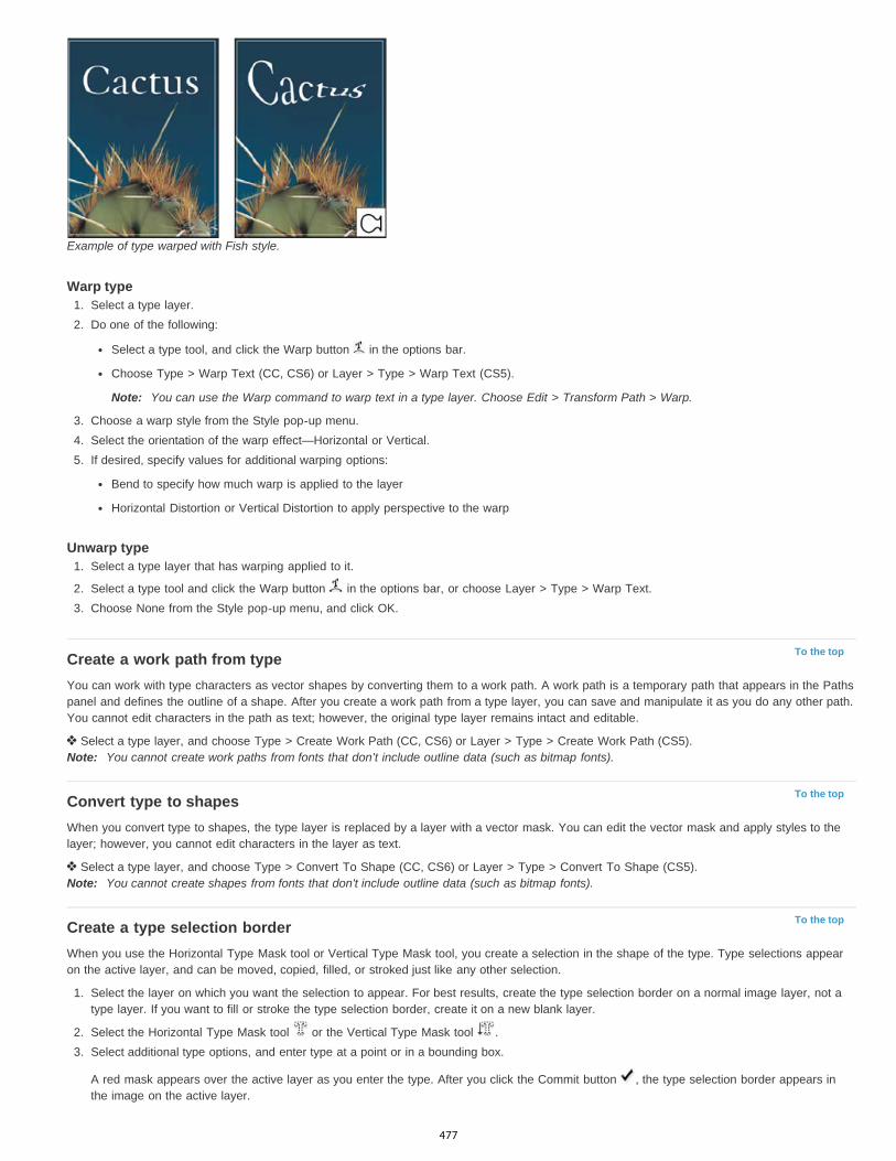
To the top
To the top
To the top
Example of type warped with Fish style.
Warp type1. Select a type layer.2. Do one of the following:
Select a type tool, and click the Warp button in the options bar.
Choose Type > Warp Text (CC, CS6) or Layer > Type > Warp Text (CS5).
Note: You can use the Warp command to warp text in a type layer. Choose Edit > Transform Path > Warp.
3. Choose a warp style from the Style pop-up menu.4. Select the orientation of the warp effect—Horizontal or Vertical.5. If desired, specify values for additional warping options:
Bend to specify how much warp is applied to the layer
Horizontal Distortion or Vertical Distortion to apply perspective to the warp
Unwarp type1. Select a type layer that has warping applied to it.
2. Select a type tool and click the Warp button in the options bar, or choose Layer > Type > Warp Text.3. Choose None from the Style pop-up menu, and click OK.
Create a work path from typeYou can work with type characters as vector shapes by converting them to a work path. A work path is a temporary path that appears in the Pathspanel and defines the outline of a shape. After you create a work path from a type layer, you can save and manipulate it as you do any other path.You cannot edit characters in the path as text; however, the original type layer remains intact and editable.
Select a type layer, and choose Type > Create Work Path (CC, CS6) or Layer > Type > Create Work Path (CS5).Note: You cannot create work paths from fonts that don’t include outline data (such as bitmap fonts).
Convert type to shapesWhen you convert type to shapes, the type layer is replaced by a layer with a vector mask. You can edit the vector mask and apply styles to thelayer; however, you cannot edit characters in the layer as text.
Select a type layer, and choose Type > Convert To Shape (CC, CS6) or Layer > Type > Convert To Shape (CS5).Note: You cannot create shapes from fonts that don't include outline data (such as bitmap fonts).
Create a type selection borderWhen you use the Horizontal Type Mask tool or Vertical Type Mask tool, you create a selection in the shape of the type. Type selections appearon the active layer, and can be moved, copied, filled, or stroked just like any other selection.
1. Select the layer on which you want the selection to appear. For best results, create the type selection border on a normal image layer, not atype layer. If you want to fill or stroke the type selection border, create it on a new blank layer.
2. Select the Horizontal Type Mask tool or the Vertical Type Mask tool .3. Select additional type options, and enter type at a point or in a bounding box.
A red mask appears over the active layer as you enter the type. After you click the Commit button , the type selection border appears inthe image on the active layer.
477

To the top
To the top
Add a drop shadow to textAdd a drop shadow to give depth to text in an image.
1. In the Layers panel, select the layer containing the text to which you want to add a drop shadow.2. Click the Layer Style button at the bottom of the Layers panel and choose Drop Shadow from the list that appears.3. If possible, position the Layer Style dialog box so that you can see the layer and its drop shadow.4. Adjust the settings to your liking. You can change various aspects of the shadow, including the way it blends with the layers below it, its
opacity (how much the underlying layers show through), the angle of the light, and its distance from the text or object.5. When you’re satisfied with the drop shadow, click OK.
To use the same drop shadow settings on another layer, Alt+drag the Drop Shadow layer in the Layers panel to the other layer. Whenyou release the mouse button, Photoshop applies the drop shadow attributes to the layer.
Fill type with an imageYou can fill type with an image by applying a clipping mask to an image layer placed above a type layer in the Layers panel.
1. Open the file containing the image you want to use inside the text.
2. Select the Horizontal Type tool or the Vertical Type tool in the toolbox.3. Click the Character tab to bring the Character panel to the front or, if the panel isn’t open, choose Window > Character.4. In the Character panel, select the font and other type attributes for the text. Large, bold, thick letters work best.5. Click an insertion point in the document window and type the desired text. When you are satisfied with the text, press Ctrl+Enter (Windows)
or Command+Return (Mac OS).6. Click the Layers tab to bring the Layers panel to the front or, if the panel isn’t open, choose Windows > Layers.7. (Optional) If the image layer is the background layer, double-click the image layer in the Layers panel to convert it from a background layer
into a regular layer.Note: Background layers are locked and prevent you from moving them in the Layers panel. It’s necessary to convert background layers toregular layers to unlock them.
8. (Optional) In the New Layer dialog box, you can rename the layer. Click OK to close the dialog box and convert the image layer.9. In the Layers panel, drag the image layer so that it is immediately above the type layer.
10. With the image layer selected, choose Layer > Create Clipping Mask. The image appears inside the text.
11. Select the Move tool , and then drag the image to adjust its placement within the text.To move the text instead of the image, select the type layer in the Layers panel and then use the Move tool to move the text.
More Help topicsPath segments, components, and points
Legal Notices | Online Privacy Policy
478

Formatting characters
To the top
Note:
To the top
Select charactersCharacter panel overviewAbout Dynamic ShortcutsSpecify type sizeChange the type colorChange the color of individual lettersUnderline or strike through textApply all caps or small capsSpecify superscript or subscript charactersCharacter styles | CC, CS6Specifying default type styles | Creative Cloud only
You can set type attributes before you enter characters or reset them to change the appearance of selected characters in a type layer.
Before you can format individual characters, select them. You can select one character, a range of characters, or all characters in a type layer.
Select characters
1. Select the Horizontal Type tool or the Vertical Type tool .2. Select the type layer in the Layers panel, or click in the text to automatically select a type layer.3. Position the insertion point in the text, and do one of the following:
Drag to select one or more characters.
Click in the text, and then Shift-click to select a range of characters.
Choose Select > All to select all the characters in the layer.
Double-click a word to select it. Triple-click a line to select it. Quadruple-click a paragraph to select it. Quintuple-click anywhere in thetext flow to select all characters in a bounding box.
To use the arrow keys to select characters, click in the text, and then hold down Shift and press the Right Arrow or Left Arrow key. Touse the keys to select words, hold down Shift+Ctrl (Windows) or Shift+Command (Mac OS) and press the Right Arrow or Left Arrow key.
4. To select all the characters in a layer without positioning the insertion point in the text flow, select the type layer in the Layers panel, andthen double-click the layer’s type icon.
Selecting and formatting characters in a type layer puts the Type tool into edit mode.
Character panel overviewThe Character panel provides options for formatting characters. Some formatting options are also available from the options bar.
You can display the Character panel by doing one of the following:
Choose Window > Character, or click the Character panel tab if the panel is visible but not active.
With a type tool selected, click the Panel button in the options bar.
To set an option in the Character panel, choose a value from the pop-up menu on the right side of the option. For options with numericvalues, you can also use the up and down arrows to set the value, or you can edit the value directly in the text box. When you edit a valuedirectly, press Enter or Return to apply a value, Shift+Enter or Shift+Return to apply a value and then highlight the value just edited, or Tabto apply a value and move to the next text box in the panel.
479
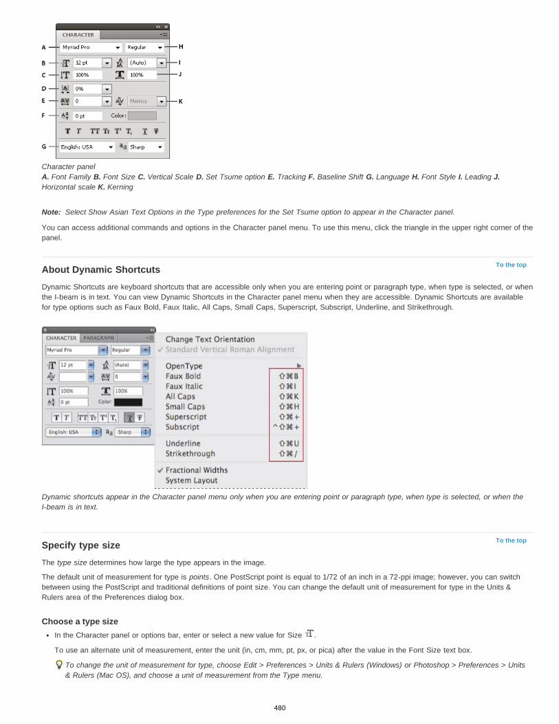
Note:
To the top
To the top
Character panel A. Font Family B. Font Size C. Vertical Scale D. Set Tsume option E. Tracking F. Baseline Shift G. Language H. Font Style I. Leading J.Horizontal scale K. Kerning
Select Show Asian Text Options in the Type preferences for the Set Tsume option to appear in the Character panel.
You can access additional commands and options in the Character panel menu. To use this menu, click the triangle in the upper right corner of thepanel.
About Dynamic ShortcutsDynamic Shortcuts are keyboard shortcuts that are accessible only when you are entering point or paragraph type, when type is selected, or whenthe I-beam is in text. You can view Dynamic Shortcuts in the Character panel menu when they are accessible. Dynamic Shortcuts are availablefor type options such as Faux Bold, Faux Italic, All Caps, Small Caps, Superscript, Subscript, Underline, and Strikethrough.
Dynamic shortcuts appear in the Character panel menu only when you are entering point or paragraph type, when type is selected, or when theI-beam is in text.
Specify type sizeThe type size determines how large the type appears in the image.
The default unit of measurement for type is points. One PostScript point is equal to 1/72 of an inch in a 72-ppi image; however, you can switchbetween using the PostScript and traditional definitions of point size. You can change the default unit of measurement for type in the Units &Rulers area of the Preferences dialog box.
Choose a type sizeIn the Character panel or options bar, enter or select a new value for Size .
To use an alternate unit of measurement, enter the unit (in, cm, mm, pt, px, or pica) after the value in the Font Size text box.
To change the unit of measurement for type, choose Edit > Preferences > Units & Rulers (Windows) or Photoshop > Preferences > Units& Rulers (Mac OS), and choose a unit of measurement from the Type menu.
480

PostScript (72 points/inch)
Traditional (72.27 points/inch)
To the top
To the top
Note:
To the top
Note:
To the top
Define the point size unit1. Choose Edit > Preferences > Units & Rulers (Windows) or Photoshop > Preferences > Units & Rulers (Mac OS).2. For Point/Pica Size, select from the following options:
Sets a unit size compatible for printing to a PostScript device.
Uses 72.27 points per inch, as traditionally used in printing.
3. Click OK.
Change the type colorThe type you enter is rendered in the current foreground color; however, you can change the color before or after you enter type. When editingexisting type layers, you can change the color of individual, selected characters or of all type in a layer.
Do one of the following:Click the Color selection box in the options bar or Character panel, and select a color using the Adobe Color Picker.
Use fill shortcuts. To fill with the foreground color, press Alt+Backspace (Windows) or Option+Delete (Mac OS); to fill with the backgroundcolor, press Ctrl+Backspace (Windows) or Command+Delete (Mac OS).
Apply an overlay layer style to the type layer to apply a color, gradient, or pattern on top of the existing color. You can’t apply an overlaylayer style selectively; it affects all characters in the type layer.
Click the foreground color selection box in the toolbox, and select a color using the Adobe Color Picker. Alternatively, click a color in theColor panel, or the Swatches panel. If you use this method to change the color of an existing type layer, you must first select characterson that layer.
Change the color of individual letters
1. Select the Horizontal Type tool .2. In the Layers panel, select the layer containing the type.3. In the document window, select the characters you want to change.4. In the options bar at the top of the work area, click the color swatch.5. In the Adobe Color Picker, locate the color range you want using the triangle sliders on the color spectrum bar, and then click the desired
color in the color field. The color you select appears in the top half of the color swatch in the Adobe Color Picker. The original color remainsin the bottom half.
6. Click OK. The new color replaces the original color in the options bar and in the selected characters.
You won’t see the new color in the characters until you deselect them or select something else.
Underline or strike through textYou can place a line under horizontal type, or to the left or right of vertical type. You can also place a line through horizontal or vertical type. Theline is always the same color as the type color.
Select the type you want to underline or strike through.To underline horizontal type, click the Underline button in the Character panel.
To apply an underline to the left or right of vertical type, choose Underline Left or Underline Right from the Character panel menu.You can apply an underline to the left or right, but not to both sides. A check mark indicates that an option is selected.
The Underline Left and Underline Right options appear in the Character panel menu only when a type layer containing vertical typeis selected. When working with vertical Asian type, you can add an underline on either side of the type line.
To apply a horizontal line through horizontal type or a vertical line through vertical type, click the Strikethrough button in the Characterpanel. You can also choose Strikethrough from the Character panel menu.
Apply all caps or small capsYou can enter or format type as uppercase characters, either all caps or small caps. When you format text as small caps, Photoshop automaticallyuses the small-cap characters designed as part of the font, if available. If the font does not include small caps, Photoshop generates faux smallcaps.
481
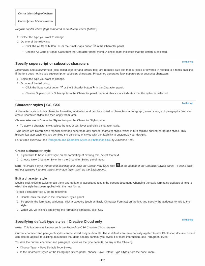
To the top
To the top
To the top
Note:
Regular capital letters (top) compared to small-cap letters (bottom)
1. Select the type you want to change.2. Do one of the following:
Click the All Caps button or the Small Caps button in the Character panel.
Choose All Caps or Small Caps from the Character panel menu. A check mark indicates that the option is selected.
Specify superscript or subscript charactersSuperscript and subscript text (also called superior and inferior text) are reduced-size text that is raised or lowered in relation to a font’s baseline.If the font does not include superscript or subscript characters, Photoshop generates faux superscript or subscript characters.
1. Select the type you want to change.2. Do one of the following:
Click the Superscript button or the Subscript button in the Character panel.
Choose Superscript or Subscript from the Character panel menu. A check mark indicates that the option is selected.
Character styles | CC, CS6A character style includes character formatting attributes, and can be applied to characters, a paragraph, even or range of paragraphs. You cancreate Character styles and then apply them later.
Choose Window > Character Styles to open the Character Styles panel.
To apply a character style, select the text or text layer and click a character style.
Type styles are hierarchical: Manual overrides supersede any applied character styles, which in turn replace applied paragraph styles. Thishierarchical approach lets you combine the efficiency of styles with the flexibility to customize your designs.
For a video overview, see Paragraph and Character Styles in Photoshop CS6 by Julieanne Kost.
Create a character style1. If you want to base a new style on the formatting of existing text, select that text.2. Choose New Character Style from the Character Styles panel menu.
Note:To create a style without first selecting text, click the Create New Style icon at the bottom of the Character Styles panel. To edit a stylewithout applying it to text, select an image layer, such as the Background.
Edit a character styleDouble-click existing styles to edit them and update all associated text in the current document. Changing the style formatting updates all text towhich the style has been applied with the new format.
To edit a character style, do the following:
1. Double-click the style in the Character Styles panel.2. To specify the formatting attributes, click a category (such as Basic Character Formats) on the left, and specify the attributes to add to the
style.3. When you’ve finished specifying the formatting attributes, click OK.
Specifying default type styles | Creative Cloud onlyThis feature was introduced in the Photoshop CS6 Creative Cloud release.
Current character and paragraph styles can be saved as type defaults. These defaults are automatically applied to new Photoshop documents andcan also be applied to existing documents that don't already contain type styles. For more information, see Paragraph styles.
To save the current character and paragraph styles as the type defaults, do any of the following:
Choose Type > Save Default Type Styles.In the Character Styles or the Paragraph Styles panel, choose Save Default Type Styles from the panel menu.
482
Twitter™ and Facebook posts are not covered under the terms of Creative Commons.
Legal Notices | Online Privacy Policy
To apply the default Character and Paragraph styles to a document:
1. Do any of the following:
Choose Type > Load Default Type Styles.In the Character Styles or the Paragraph Styles panel, choose Load Default Type Styles from the panel menu.
2. If you are loading the default type styles into a document that already has an existing type style, the Import Paragraph Styles dialog boxappears. You can choose whether or not to replace the existing type style with the default type style.
More Help TopicsLine and character spacing
Panels and menus
About layer effects and styles
Creating type
483

Line and character spacing
To the top
To the top
Set leadingKern and trackShift the baselineTurn fractional character widths off or on
Set leadingThe vertical space between lines of type is called leading (rhymes with sledding). For Roman type, leading is measured from the baseline of oneline of text to the baseline of the line above it. The baseline is the invisible line on which most letters sit. You can apply more than one leadingamount within the same paragraph; however, the largest leading value in a line of type determines the leading value for that line.
Note: When working with horizontal Asian type, you can specify how leading is measured, either from baseline to baseline or from the top of oneline to the top of the next.
Five-point type with 6-point leading (left) and with 12-point leading (right)
Set the leading1. Select the characters you want to change. If you don’t select any text, the leading applies to new text you create.2. In the Character panel, set the Leading value.
Change the default auto leading percentage1. Choose Justification from the Paragraph panel menu.2. For Auto Leading, enter a new default percentage.
Kern and trackKerning is the process of adding or subtracting space between specific pairs of characters. Tracking is the process of loosening or tightening thespacing between the characters in selected text or an entire block of text.
You can automatically kern type using metrics kerning or optical kerning. Metrics kerning (also called Auto kerning) uses kern pairs, which areincluded with most fonts. Kern pairs contain information about the spacing of specific pairs of letters. Some of these are: LA, P., To, Tr, Ta, Tu,Te, Ty, Wa, WA, We, Wo, Ya, and Yo. Metrics kerning is set as the default so that specific pairs are automatically kerned when you import or typetext.
Some fonts include robust kern-pair specifications. However, when a font includes only minimal built-in kerning or none at all, or if you use twodifferent typefaces or sizes in one or more words on a line, you may want to use the optical kerning option. Optical kerning adjusts the spacingbetween adjacent characters based on their shapes.
484

To the top
To the top
Kerning and tracking optionsA. Original text B. Text with optical kerning C. Text with manual kerning between W and a D. Text with tracking E. Cumulative kerning andtracking
You can also use manual kerning, which is ideal for adjusting the space between two letters. Tracking and manual kerning are cumulative, so youcan first adjust individual pairs of letters, and then tighten or loosen a block of text without affecting the relative kerning of the letter pairs.
When you click to place the insertion point between two letters, kerning values appear in the Character panel. Similarly, if you select a word or arange of text, the tracking values appear in the Character panel.
Tracking and kerning are both measured in 1/1000 em, a unit of measure that is relative to the current type size. In a 6-point font, 1 em equals 6points; in a 10-point font, 1 em equals 10 points. Kerning and tracking are strictly proportional to the current type size.
Note: Values for kerning and tracking affect Japanese text, but normally these options are used to adjust the aki between roman characters.
Adjust kerning Do any of the following:
To use a font’s built-in kerning information for selected characters, select Metrics for the Kerning option in the Character panel.
To automatically adjust the spacing between selected characters based on their shapes, select Optical for the Kerning option in theCharacter panel.
To adjust kerning manually, place an insertion point between two characters, and set the desired value for the Kerning option in theCharacter panel. (Note that if a range of text is selected, you can’t manually kern the text. Instead, use tracking.)
Press Alt+Left/Right Arrow (Windows) or Option+Left/Right Arrow (Mac OS) to decrease or increase the kerning between two characters.
To turn off kerning for selected characters, set the Kerning option in the Character panel to 0 (zero).
Adjust tracking1. Select the range of characters or the type object that you want to adjust.2. In the Character panel, set the Tracking option.
Shift the baselineUse Baseline Shift to move selected characters up or down relative to the baseline of the surrounding text. Shifting the baseline is especiallyuseful when you’re hand-setting fractions or adjusting the position of a picture font.
1. Select the characters or type objects you want to change. If you don’t select any text, the shift applies to new text you create.2. In the Character panel, set the Baseline Shift option. Positive values move the character’s baseline above the baseline of the rest of the line;
negative values move it below the baseline.
Type with different Baseline Shift values
Turn fractional character widths off or on
485
By default, the software uses fractional character widths between characters. This means that the spacing between characters varies, and willsometimes use only fractions of whole pixels.
In most situations, fractional character widths provide the best spacing for type appearance and readability. However, for type in small sizes (lessthan 20 points) displayed online, fractional character widths could cause type to run together or have too much extra space, making it difficult toread.
Turn off fractional widths when you want to fix type spacing in whole-pixel increments and prevent small type from running together. The fractionalcharacter width setting applies to all characters on a type layer—you cannot set the option for selected characters.
Do any of the following:
To set type spacing for the entire document in whole-pixel increments, choose System Layout from the Character panel menu.
To re-enable fractional character widths, choose Fractional Widths from the Character panel menu.
Legal Notices | Online Privacy Policy
486
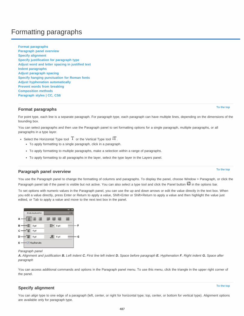
Formatting paragraphs
To the top
To the top
To the top
Format paragraphsParagraph panel overviewSpecify alignmentSpecify justification for paragraph typeAdjust word and letter spacing in justified textIndent paragraphsAdjust paragraph spacingSpecify hanging punctuation for Roman fontsAdjust hyphenation automaticallyPrevent words from breakingComposition methodsParagraph styles | CC, CS6
Format paragraphsFor point type, each line is a separate paragraph. For paragraph type, each paragraph can have multiple lines, depending on the dimensions of thebounding box.
You can select paragraphs and then use the Paragraph panel to set formatting options for a single paragraph, multiple paragraphs, or allparagraphs in a type layer.
Select the Horizontal Type tool or the Vertical Type tool .To apply formatting to a single paragraph, click in a paragraph.
To apply formatting to multiple paragraphs, make a selection within a range of paragraphs.
To apply formatting to all paragraphs in the layer, select the type layer in the Layers panel.
Paragraph panel overviewYou use the Paragraph panel to change the formatting of columns and paragraphs. To display the panel, choose Window > Paragraph, or click theParagraph panel tab if the panel is visible but not active. You can also select a type tool and click the Panel button in the options bar.
To set options with numeric values in the Paragraph panel, you can use the up and down arrows or edit the value directly in the text box. Whenyou edit a value directly, press Enter or Return to apply a value, Shift+Enter or Shift+Return to apply a value and then highlight the value justedited, or Tab to apply a value and move to the next text box in the panel.
Paragraph panel A. Alignment and justification B. Left indent C. First line left indent D. Space before paragraph E. Hyphenation F. Right indent G. Space afterparagraph
You can access additional commands and options in the Paragraph panel menu. To use this menu, click the triangle in the upper right corner ofthe panel.
Specify alignmentYou can align type to one edge of a paragraph (left, center, or right for horizontal type; top, center, or bottom for vertical type). Alignment optionsare available only for paragraph type.
487
Left Align Text
Center Text
Right Align Text
Top Align Text
Center Text
Bottom Align Text
To the top
Justify Last Left
Justify Last Centered
Justify Last Right
Justify All
Justify Last Top
Justify Last Centered
Justify Last Bottom
Justify All
Note:
To the top
1. Do one of the following:Select a type layer if you want all the paragraphs in that type layer to be affected.
Select the paragraphs you want affected.
2. In the Paragraph panel or options bar, click an alignment option.
The options for horizontal type are:
Aligns type to the left, leaving the right edge of the paragraph ragged.
Aligns type to the center, leaving both edges of the paragraph ragged.
Aligns type to right, leaving the left edge of the paragraph ragged.
The options for vertical type are:
Aligns type to the top, leaving the bottom edge of the paragraph ragged.
Aligns type to the center, leaving both the top and bottom edges of the paragraph ragged.
Aligns type to the bottom, leaving the top edge of the paragraph ragged.
Specify justification for paragraph typeText is said to be justified when it is aligned with both edges. You can choose to justify all text in a paragraph excluding the last line, or you canjustify text in a paragraph including the last line. The settings you choose for justification affect the horizontal spacing of lines and the aestheticappeal of type on a page.
Justification options are available only for paragraph type and determine word, letter, and glyph spacing. Justification settings apply only to Romancharacters; double-byte characters available in Chinese, Japanese, and Korean fonts are not affected by these settings.
1. Do one of the following:Select a type layer if you want all the paragraphs in that type layer to be affected.
Select the paragraphs you want affected.
2. In the Paragraph panel, click a justification option.
The options for horizontal type are:
Justifies all lines except the last, which is left aligned.
Justifies all lines except the last, which is center aligned.
Justifies all lines except the last, which is right aligned.
Justifies all lines including the last, which is force justified.
The options for vertical type are:
Justifies all lines except the last, which is top aligned.
Justifies all lines except the last, which is center aligned.
Justifies all lines except the last, which is bottom justified.
Justifies all lines including the last, which is force justified.
Justification (right, center, and left align, and justify all) for type on a path starts at the insertion point and ends at the end of the path.
Adjust word and letter spacing in justified textYou can precisely control how Photoshop spaces letters and words and scales characters. Adjusting spacing is especially useful with justified type,although you can also adjust spacing for unjustified type.
1. Select the paragraphs you want affected, or select a type layer if you want all the paragraphs in that type layer to be affected.2. Choose Justification from the Paragraph panel menu.
488
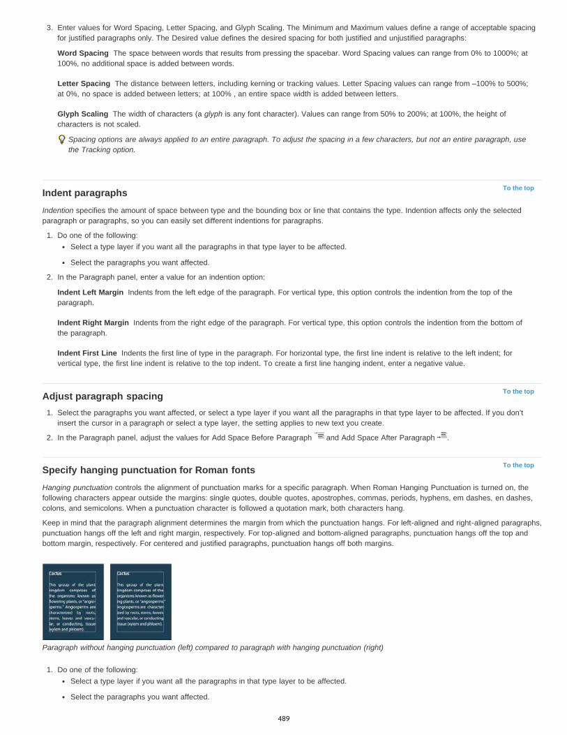
Word Spacing
Letter Spacing
Glyph Scaling
To the top
Indent Left Margin
Indent Right Margin
Indent First Line
To the top
To the top
3. Enter values for Word Spacing, Letter Spacing, and Glyph Scaling. The Minimum and Maximum values define a range of acceptable spacingfor justified paragraphs only. The Desired value defines the desired spacing for both justified and unjustified paragraphs:
The space between words that results from pressing the spacebar. Word Spacing values can range from 0% to 1000%; at100%, no additional space is added between words.
The distance between letters, including kerning or tracking values. Letter Spacing values can range from –100% to 500%;at 0%, no space is added between letters; at 100% , an entire space width is added between letters.
The width of characters (a glyph is any font character). Values can range from 50% to 200%; at 100%, the height ofcharacters is not scaled.
Spacing options are always applied to an entire paragraph. To adjust the spacing in a few characters, but not an entire paragraph, usethe Tracking option.
Indent paragraphsIndention specifies the amount of space between type and the bounding box or line that contains the type. Indention affects only the selectedparagraph or paragraphs, so you can easily set different indentions for paragraphs.
1. Do one of the following:Select a type layer if you want all the paragraphs in that type layer to be affected.
Select the paragraphs you want affected.
2. In the Paragraph panel, enter a value for an indention option:
Indents from the left edge of the paragraph. For vertical type, this option controls the indention from the top of theparagraph.
Indents from the right edge of the paragraph. For vertical type, this option controls the indention from the bottom ofthe paragraph.
Indents the first line of type in the paragraph. For horizontal type, the first line indent is relative to the left indent; forvertical type, the first line indent is relative to the top indent. To create a first line hanging indent, enter a negative value.
Adjust paragraph spacing1. Select the paragraphs you want affected, or select a type layer if you want all the paragraphs in that type layer to be affected. If you don’t
insert the cursor in a paragraph or select a type layer, the setting applies to new text you create.
2. In the Paragraph panel, adjust the values for Add Space Before Paragraph and Add Space After Paragraph .
Specify hanging punctuation for Roman fontsHanging punctuation controls the alignment of punctuation marks for a specific paragraph. When Roman Hanging Punctuation is turned on, thefollowing characters appear outside the margins: single quotes, double quotes, apostrophes, commas, periods, hyphens, em dashes, en dashes,colons, and semicolons. When a punctuation character is followed a quotation mark, both characters hang.
Keep in mind that the paragraph alignment determines the margin from which the punctuation hangs. For left-aligned and right-aligned paragraphs,punctuation hangs off the left and right margin, respectively. For top-aligned and bottom-aligned paragraphs, punctuation hangs off the top andbottom margin, respectively. For centered and justified paragraphs, punctuation hangs off both margins.
Paragraph without hanging punctuation (left) compared to paragraph with hanging punctuation (right)
1. Do one of the following:Select a type layer if you want all the paragraphs in that type layer to be affected.
Select the paragraphs you want affected.
489

Note:
To the top
Words Longer Than _ Letters
After First _ Letters And Before Last _ Letters
Hyphen Limit
Hyphenation Zone
Hyphenate Capitalized Words
Note:
To the top
Note:
To the top
2. Choose Roman Hanging Punctuation from the Paragraph panel menu. A check mark indicates that the option is selected.
Double-byte punctuation marks available in Chinese, Japanese, and Korean fonts in the selected range will not hang when you useRoman Hanging Punctuation. Instead, use either Burasagari Standard or Burasagari Strong. These items are available only if you selectShow Asian Text Options in the Type preferences.
Adjust hyphenation automaticallyThe settings you choose for hyphenation affect the horizontal spacing of lines and the aesthetic appeal of type on a page. Hyphenation optionsdetermine whether words can be hyphenated and, if so, what breaks are allowable.
1. To use automatic hyphenation, do any of the following:To turn automatic hyphenation on or off, select or deselect the Hyphenate option in the Paragraph panel.
To apply hyphenation to specific paragraphs, first select only the paragraphs that you want to affect.
To choose a hyphenation dictionary, choose a language from the Language menu at the bottom of the Character panel.
2. To specify options, choose Hyphenation from the Paragraph panel menu, and specify the following options:
Specifies the minimum number of characters for hyphenated words.
Specifies the minimum number of characters at the beginning or end of a word that can bebroken by a hyphen. For example, by specifying 3 for these values, aromatic would be hyphenated as aro- matic instead of ar- omatic oraromat- ic.
Specifies the maximum number of consecutive lines on which hyphenation may occur.
Specifies a distance from the right edge of a paragraph, demarcating a portion of the line where hyphenation is notallowed. A setting of 0 allows all hyphenation. This option applies only when you use the Adobe Single-line Composer.
Deselect to prevent capitalized words from being hyphenated.
Hyphenation settings apply only to Roman characters; double-byte characters available in Chinese, Japanese, and Korean fonts are notaffected by these settings.
Prevent words from breakingYou can prevent words from breaking at the end of lines—for example, proper names or words that could be misread when hyphenated. You canalso keep multiple words or groups of words together—for example, clusters of initials and a last name.
1. Select the characters you want to prevent from breaking.2. Choose No Break from the Character panel menu.
If you apply the No Break option to too many adjacent characters, the text may wrap in the middle of a word. However, if you applythe No Break option to more than a single line of text, none of the text will appear.
Composition methodsThe appearance of type on the page depends on a complex interaction of processes called composition. Using the word spacing, letterspacing,glyph spacing, and hyphenation options you’ve selected, Adobe applications evaluate possible line breaks and choose the one that best supportsthe specified parameters.
You can choose between two composition methods: the Adobe Every-line Composer and the Adobe Single-line Composer. Both methods evaluatepossible breaks and choose the one that best supports the hyphenation and justification options you’ve specified for a given paragraph. Thecomposition method affects only the selected paragraph or paragraphs, so you can easily set different composition methods for differentparagraphs.
Every-line Composer
The Every-line Composer considers a network of break points for a range of lines and thus can optimize earlier lines in the paragraph in order toeliminate especially unattractive breaks later on.
The Every-line Composer approaches composition by identifying possible break points, evaluating them, and assigning a weighted penalty basedon the following principles:
For left-, right-, or center-aligned text, lines that fall closer to the right side are favored and have a lower penalty.
For justified text, the highest importance is given to evenness of letter and word spacing.
490
Twitter™ and Facebook posts are not covered under the terms of Creative Commons.
Legal Notices | Online Privacy Policy
To the top
Hyphenation is avoided when possible.
Single-line Composer
The Single-line composer offers a traditional approach to composing type one line at a time. This option is useful if you want manual control overhow lines break. The Single-line Composer uses the following principles when considering a breakpoint:
Longer lines are favored over shorter lines.
In justified text, compressed or expanded word spacing is preferable to hyphenation.
In nonjustified text, hyphenation is preferable to compressed or expanded letterspacing.
If spacing must be adjusted, compression is better than expansion.
To choose one of these methods, select it from the Paragraph panel menu. To apply the method to all paragraphs, first select the typeobject; to apply the method to the current paragraph only, first insert the cursor in that paragraph.
Paragraph styles | CC, CS6A paragraph style includes both character and paragraph formatting attributes, and can be applied to a paragraph or range of paragraphs. You cancreate Paragraph styles and then apply them later.
Choose Window > Paragraph Styles to open the Paragraph Styles panel. By default, each new document contains a Basic Paragraph style thatis applied to text you type. You can edit this style, but you can’t rename or delete it. You can rename and delete styles that you create. You canalso select a different default style to apply to text.
To apply a paragraph style, select the text or text layer and click a paragraph style.
Type styles are hierarchical: Manual overrides supersede any applied character styles, which in turn replace applied paragraph styles. Thishierarchical approach lets you combine the efficiency of styles with the flexibility to customize your designs.
For a video overview, see Paragraph and Character Styles in Photoshop CS6 by Julieanne Kost.
(Creative Cloud only) You can specify character and paragraph styles as default types styles. For more information see Specifying default typestyles | Creative Cloud only.
Create a paragraph style1. If you want to base a new style on the formatting of existing text, select that text or place the insertion point in it.2. Choose New Paragraph Style from the Paragraph Styles panel menu.
Note:To create a style without first selecting text, click the Create New Style icon at the bottom of the Paragraph Styles panel. To edit a stylewithout applying it to text, select an image layer, such as the Background.
Edit a paragraph styleDouble-click existing styles to edit them and update all associated text in the current document. When you change the formatting of a style, all textto which the style has been applied will be updated with the new format.
To edit a paragraph style, do the following:
1. Double-click the style in the Paragraph style panel.2. To specify the formatting attributes, click a category (such as Basic Character Formats) on the left, and specify the attributes to add to the
style.
3. When specifying a Character Color in the Style Options dialog box, you can create a new color by double-clicking the fill or stroke box.
4. When you’ve finished specifying the formatting attributes, click OK.
More Help topicsLine and character spacing
Editing text
Specify a burasagari option
Display and set Asian type options
491
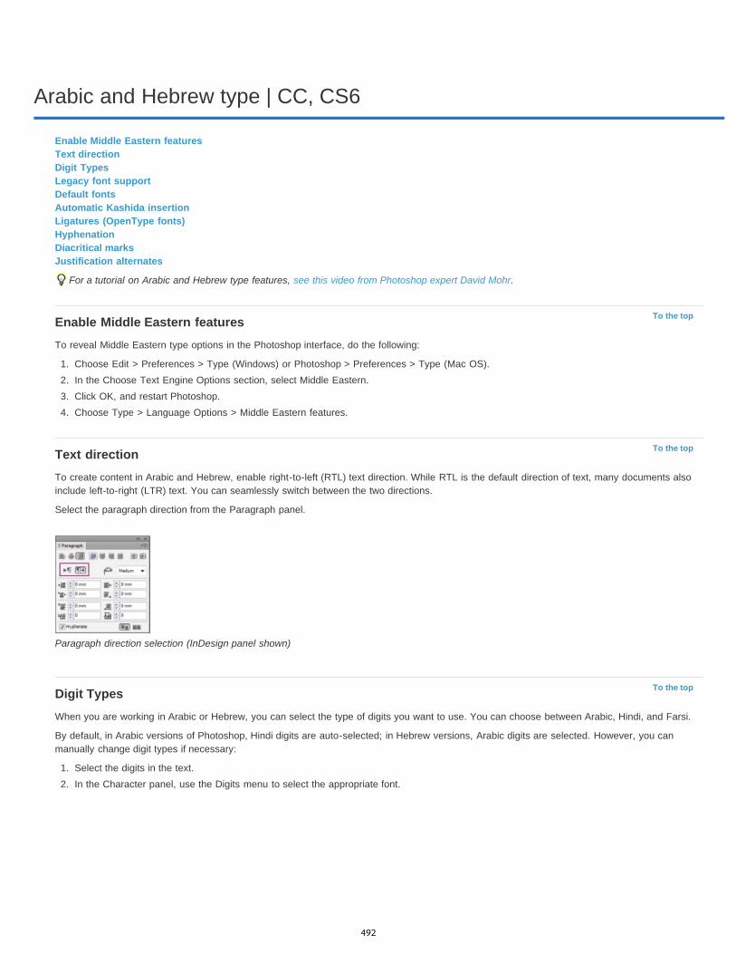
Arabic and Hebrew type | CC, CS6
To the top
To the top
To the top
Enable Middle Eastern featuresText directionDigit TypesLegacy font supportDefault fontsAutomatic Kashida insertionLigatures (OpenType fonts)HyphenationDiacritical marksJustification alternates
For a tutorial on Arabic and Hebrew type features, see this video from Photoshop expert David Mohr.
Enable Middle Eastern featuresTo reveal Middle Eastern type options in the Photoshop interface, do the following:
1. Choose Edit > Preferences > Type (Windows) or Photoshop > Preferences > Type (Mac OS).2. In the Choose Text Engine Options section, select Middle Eastern.3. Click OK, and restart Photoshop.4. Choose Type > Language Options > Middle Eastern features.
Text directionTo create content in Arabic and Hebrew, enable right-to-left (RTL) text direction. While RTL is the default direction of text, many documents alsoinclude left-to-right (LTR) text. You can seamlessly switch between the two directions.
Select the paragraph direction from the Paragraph panel.
Paragraph direction selection (InDesign panel shown)
Digit TypesWhen you are working in Arabic or Hebrew, you can select the type of digits you want to use. You can choose between Arabic, Hindi, and Farsi.
By default, in Arabic versions of Photoshop, Hindi digits are auto-selected; in Hebrew versions, Arabic digits are selected. However, you canmanually change digit types if necessary:
1. Select the digits in the text.2. In the Character panel, use the Digits menu to select the appropriate font.
492
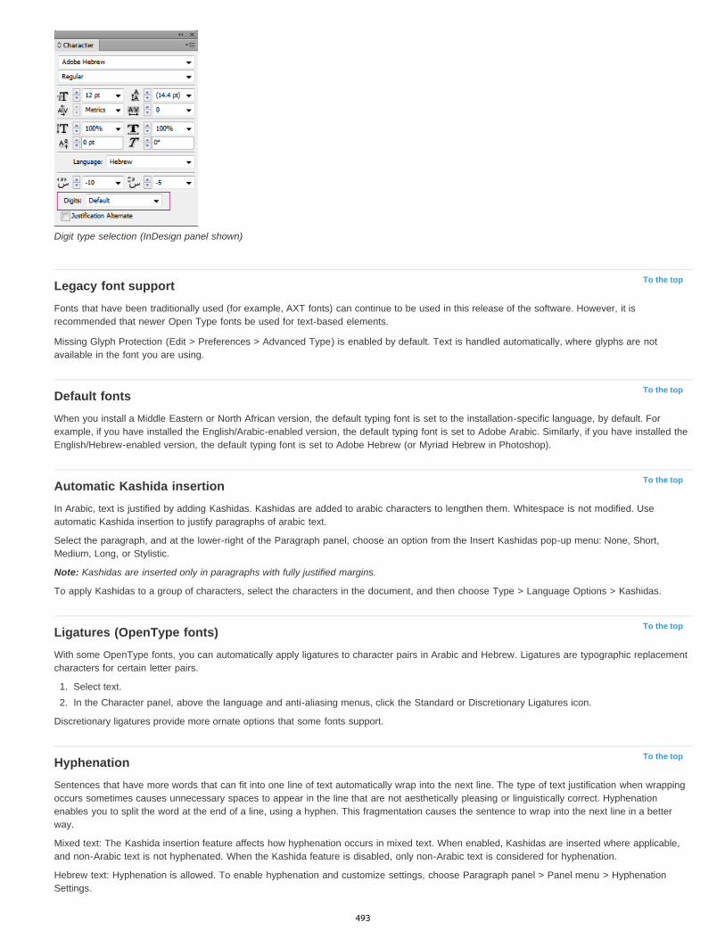
To the top
To the top
To the top
To the top
To the top
Digit type selection (InDesign panel shown)
Legacy font supportFonts that have been traditionally used (for example, AXT fonts) can continue to be used in this release of the software. However, it isrecommended that newer Open Type fonts be used for text-based elements.
Missing Glyph Protection (Edit > Preferences > Advanced Type) is enabled by default. Text is handled automatically, where glyphs are notavailable in the font you are using.
Default fontsWhen you install a Middle Eastern or North African version, the default typing font is set to the installation-specific language, by default. Forexample, if you have installed the English/Arabic-enabled version, the default typing font is set to Adobe Arabic. Similarly, if you have installed theEnglish/Hebrew-enabled version, the default typing font is set to Adobe Hebrew (or Myriad Hebrew in Photoshop).
Automatic Kashida insertionIn Arabic, text is justified by adding Kashidas. Kashidas are added to arabic characters to lengthen them. Whitespace is not modified. Useautomatic Kashida insertion to justify paragraphs of arabic text.
Select the paragraph, and at the lower-right of the Paragraph panel, choose an option from the Insert Kashidas pop-up menu: None, Short,Medium, Long, or Stylistic.
Note: Kashidas are inserted only in paragraphs with fully justified margins.
To apply Kashidas to a group of characters, select the characters in the document, and then choose Type > Language Options > Kashidas.
Ligatures (OpenType fonts)With some OpenType fonts, you can automatically apply ligatures to character pairs in Arabic and Hebrew. Ligatures are typographic replacementcharacters for certain letter pairs.
1. Select text.2. In the Character panel, above the language and anti-aliasing menus, click the Standard or Discretionary Ligatures icon.
Discretionary ligatures provide more ornate options that some fonts support.
HyphenationSentences that have more words that can fit into one line of text automatically wrap into the next line. The type of text justification when wrappingoccurs sometimes causes unnecessary spaces to appear in the line that are not aesthetically pleasing or linguistically correct. Hyphenationenables you to split the word at the end of a line, using a hyphen. This fragmentation causes the sentence to wrap into the next line in a betterway.
Mixed text: The Kashida insertion feature affects how hyphenation occurs in mixed text. When enabled, Kashidas are inserted where applicable,and non-Arabic text is not hyphenated. When the Kashida feature is disabled, only non-Arabic text is considered for hyphenation.
Hebrew text: Hyphenation is allowed. To enable hyphenation and customize settings, choose Paragraph panel > Panel menu > HyphenationSettings.
493
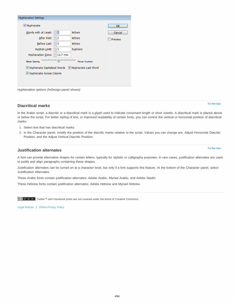
Twitter™ and Facebook posts are not covered under the terms of Creative Commons.
Legal Notices | Online Privacy Policy
To the top
To the top
Hyphenation options (InDesign panel shown)
Diacritical marksIn the Arabic script, a diacritic or a diacritical mark is a glyph used to indicate consonant length or short vowels. A diacritical mark is placed aboveor below the script. For better styling of text, or improved readability of certain fonts, you can control the vertical or horizontal position of diacriticalmarks:
1. Select text that has diacritical marks2. In the Character panel, modify the position of the diacritic marks relative to the script. Values you can change are, Adjust Horizontal Diacritic
Position, and the Adjust Vertical Diacritic Position.
Justification alternatesA font can provide alternative shapes for certain letters, typically for stylistic or calligraphy purposes. In rare cases, justification alternates are usedto justify and align paragraphs containing these shapes.
Justification alternates can be turned on at a character level, but only if a font supports this feature. At the bottom of the Character panel, selectJustification Alternates.
These Arabic fonts contain justification alternates: Adobe Arabic, Myriad Arabic, and Adobe Naskh.
These Hebrew fonts contain justification alternates: Adobe Hebrew and Myriad Hebrew.
494
Fonts
To the top
To the top
To the top
About fontsPreviewing fontsChoose a font family and styleChange the font on multiple layersAbout missing fonts and glyph protectionOpenType fontsApply OpenType features
About fontsA font is a complete set of characters—letters, numbers, and symbols—that share a common weight, width, and style, such as 10 -pt AdobeGaramond Bold.
Typefaces (often called type families or font families) are collections of fonts that share an overall appearance, and are designed to be usedtogether, such as Adobe Garamond.
A type style is a variant version of an individual font in a font family. Typically, the Roman or Plain (the actual name varies from family to family)member of a font family is the base font, which may include type styles such as regular, bold, semibold, italic, and bold italic. If a font doesn’tinclude the style you want, you can apply faux styles—simulated versions of bold, italic, superscript, subscript, all caps, and small caps styles.
Typefaces include many characters in addition to the ones you see on your keyboard. Depending on the font, these characters can includeligatures, fractions, swashes, ornaments, ordinals, titling and stylistic alternates, superior and inferior characters, old-style figures, and liningfigures. A glyph is a specific form of a character. For example, in certain fonts, the capital letter A is available in several forms, such as swash andsmall cap.
To make fonts available to Photoshop and other Adobe Creative Suite applications, install them in these system folders:
Windows Windows/FontsMac OS Library/Fonts
Previewing fontsYou can view samples of a font in the font family and font style menus in the Character panel and other areas in the application from where youcan choose fonts. The following icons are used to indicate different kinds of fonts:
OpenType
Type 1
TrueType
Multiple Master
To turn off the preview feature or change the point size of font names, do one of the following:
(CC, CS6) Choose Type > Font Preview Size, and choose an option.
(CS5) In the Type preferences, either disable Font Preview Size or choose an option from the menu.
Choose a font family and style1. Choose a font family from the Font Family menu in the Character panel or options bar. If more than one copy of a font is installed on your
computer, an abbreviation follows the font name: (T1) for Type 1 fonts, (TT) for TrueType fonts, or (OT) for OpenType fonts.
495
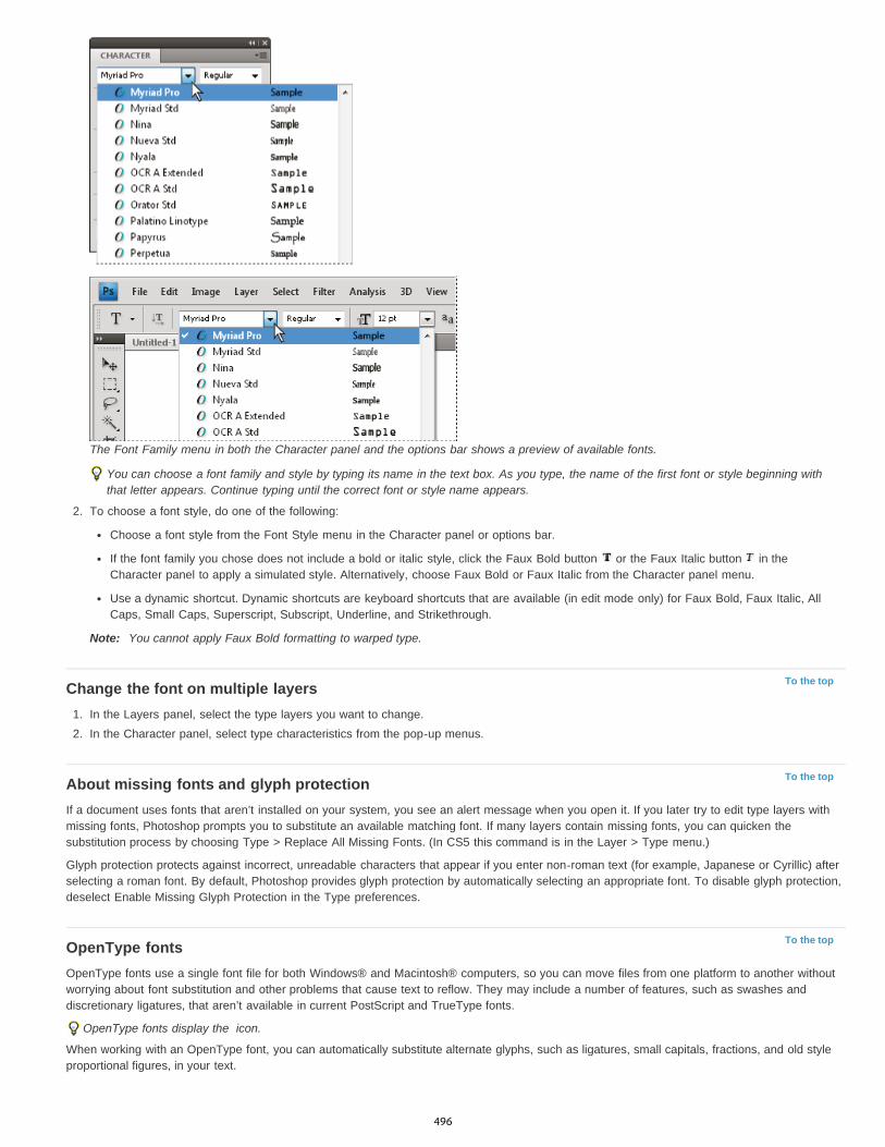
To the top
To the top
To the top
The Font Family menu in both the Character panel and the options bar shows a preview of available fonts.
You can choose a font family and style by typing its name in the text box. As you type, the name of the first font or style beginning withthat letter appears. Continue typing until the correct font or style name appears.
2. To choose a font style, do one of the following:
Choose a font style from the Font Style menu in the Character panel or options bar.
If the font family you chose does not include a bold or italic style, click the Faux Bold button or the Faux Italic button in theCharacter panel to apply a simulated style. Alternatively, choose Faux Bold or Faux Italic from the Character panel menu.
Use a dynamic shortcut. Dynamic shortcuts are keyboard shortcuts that are available (in edit mode only) for Faux Bold, Faux Italic, AllCaps, Small Caps, Superscript, Subscript, Underline, and Strikethrough.
Note: You cannot apply Faux Bold formatting to warped type.
Change the font on multiple layers1. In the Layers panel, select the type layers you want to change.2. In the Character panel, select type characteristics from the pop-up menus.
About missing fonts and glyph protectionIf a document uses fonts that aren’t installed on your system, you see an alert message when you open it. If you later try to edit type layers withmissing fonts, Photoshop prompts you to substitute an available matching font. If many layers contain missing fonts, you can quicken thesubstitution process by choosing Type > Replace All Missing Fonts. (In CS5 this command is in the Layer > Type menu.)
Glyph protection protects against incorrect, unreadable characters that appear if you enter non-roman text (for example, Japanese or Cyrillic) afterselecting a roman font. By default, Photoshop provides glyph protection by automatically selecting an appropriate font. To disable glyph protection,deselect Enable Missing Glyph Protection in the Type preferences.
OpenType fontsOpenType fonts use a single font file for both Windows® and Macintosh® computers, so you can move files from one platform to another withoutworrying about font substitution and other problems that cause text to reflow. They may include a number of features, such as swashes anddiscretionary ligatures, that aren’t available in current PostScript and TrueType fonts.
OpenType fonts display the icon.
When working with an OpenType font, you can automatically substitute alternate glyphs, such as ligatures, small capitals, fractions, and old styleproportional figures, in your text.
496

To the top
Regular (left) and OpenType (right) fontsA. Ordinals B. Discretionary ligatures C. Swashes
OpenType fonts may include an expanded character set and layout features to provide richer linguistic support and advanced typographic control.OpenType fonts from Adobe that include support for central European (CE) languages include the word “Pro,” as part of the font name inapplication font menus. OpenType fonts that don’t contain central European language support are labeled “Standard,” and have an “Std” suffix. AllOpenType fonts can also be installed and used alongside PostScript Type 1 and TrueType fonts.
For more information on OpenType fonts, see www.adobe.com/go/opentype.
Apply OpenType features1. Make sure you have an OpenType font chosen when using the Type tool. If you don’t select any text, the setting applies to new text you
create.2. From the Character panel menu, choose one of the following from the OpenType submenu:
Standard Ligatures Are typographic replacements for certain pairs of characters, such as fi, fl, ff, ffi, and ffl.
Type with the Standard Ligatures and Discretionary Ligatures options unselected and selected
Contextual Alternates Are alternative characters included in some script typefaces to provide better joining behavior. For example, whenusing Caflisch Script Pro with contextual alternatives enabled, the letter pair “bl” in the word “bloom” is joined so that it looks more likehandwriting.
Discretionary Ligatures Are typographic replacement characters for letter pairs, such as ct, st, and ft.Note: Although the characters in ligatures appear to be joined, they are fully editable and do not cause the spelling checker to flag a worderroneously.
Swash Substitutes swash glyphs, stylized letterforms with extended strokes (exaggerated flourishes).
Old Style Are numerals shorter than regular numerals, with some old style numerals descending below the type baseline.
Stylistic Alternates Formats stylized characters that create a purely aesthetic effect.
Titling Alternatives Formats characters (usually all in capitals) designed for use in large-size settings, such as titles.
Ornaments Are devices that add a personal signature to the type family and can be used as title page decoration, paragraph markers,dividers for blocks of text, or as repeated bands and borders.
Ordinals Automatically formats ordinal numbers (such as 1 and 2 ) with superscript characters. Characters such as the superscript in theSpanish words segunda and segundo (2 and 2 ) are also typeset properly.
Fractions Automatically formats fractions; numbers separated by a slash (such as 1/2) are converted to a shilling fraction (such as ).You can’t preview OpenType features, such as contextual alternates, ligatures, and glyphs in Photoshop before you apply them.However, you can preview and apply OpenType features by using the Adobe Illustrator Glyphs panel. Copy and paste your text intoAdobe Illustrator and use the Glyphs panel to preview and apply OpenType features. You can then paste the text back into Photoshop.
Legal Notices | Online Privacy Policy
st nd
a o
497
Asian type
To the top
To the top
To the top
To the top
Display and set Asian type optionsReduce spacing around Asian type charactersSpecify how leading is measured in Asian typeUse tate-chu-yokoAlign Asian characters with mojisoroeSpecify left and right underlining with Asian typeSet Asian OpenType font attributesAsian OpenType optionsChoose a mojikumi setSet kinsoku shori optionsSpecify a burasagari option
Photoshop provides several options for working with Chinese, Japanese, and Korean type. Characters in Asian fonts are often referred to asdouble-byte characters.
Note: Your operating system must support the languages in which you wish to work. Consult your system software manufacturer for moreinformation.
Display and set Asian type optionsBy default, non-Chinese, Japanese, or Korean versions of Photoshop hide options for Asian type that appear in the Character panel andParagraph panel. To view and set options for working with Chinese, Japanese, and Korean type in these versions of Photoshop, you must selectShow Asian Text Options in the Preferences dialog box. You can also control how font names are displayed—in English or in the native language.
1. Choose Edit > Preferences > Type (Windows) or Photoshop > Preferences > Type (Mac OS).2. Select from the following options:
Show Font Names In English Displays Asian font names in English.
East Asian (CC, CS6) or Show Asian Text Options (CS5) Displays Asian type options in the Character and Paragraph panels.
Reduce spacing around Asian type charactersTsume reduces the space around a character by a specified percentage value. As a result, the character itself is not stretched or squeezed.Instead, the space between the character’s bounding box and the em box is compressed. When tsume is added to a character, spacing aroundboth sides of the character is reduced by an equal percentage.
1. Select the characters you want to adjust.
2. In the Character panel, enter or select a percentage for Tsume . The greater the percentage, the tighter the compression betweencharacters. At 100% (the maximum value), there is no space between the character’s bounding box and its em box.
Specify how leading is measured in Asian type1. Select the paragraphs you want to adjust.2. Choose a leading option from the Paragraph panel menu.
Top-to-top Leading Measures the spacing between lines of type from the top of one line to the top of the next line. When you usetop-to-top leading, the first line of type in a paragraph is aligned flush with the top of the bounding box.
Bottom-to-bottom Leading For horizontal type, measures the space between lines of type from the type baseline. When you use bottom-to-bottom leading, space appears between the first line of type and the bounding box. A check mark indicates which option is selected.Note: The leading option you choose does not affect the amount of leading between lines, only how the leading is measured.
Use tate-chu-yokoTate-chu-yoko (also called kumimoji and renmoji) is a block of horizontal type laid out within vertical type lines. Using tate-chu-yoko makes iteasier to read half-width characters such as numbers, dates, and short foreign words in vertical text.
498

To the top
To the top
To the top
Numerals without tate-chu-yoko (left) compared to numerals rotated with tate-chu-yoko (right)
1. Select the characters you want to rotate.2. Choose Tate-Chu-Yoko from the Character panel menu. A check mark indicates that the option is turned on.
Note: Using tate-chu-yoko does not prevent you from editing and formatting type; you can edit and apply formatting options to rotatedcharacters just as you do to other characters.
Align Asian characters with mojisoroeMojisoroe is the alignment of characters in Asian type. When a line of text contains different sizes of characters, you can specify how to align textto the largest characters in the line: to the top, center, or bottom of the em box (right, center, and left for vertical frames), to the roman baseline, orto the top or bottom of the ICF box (right or left for vertical frames). ICF (Ideographic Character Space) is the average height and width used bythe font designer to design the ideographic characters which comprise a font.
Character alignment optionsA. Small characters aligned to the bottom B. Small characters aligned to the center C. Small characters aligned to the top
In the Character panel menu, choose an option from the Character Alignment submenu:Roman Baseline Aligns the small characters in a line to the large character.Em box Top/Right, Em box Center, or Em box Bottom/Left Aligns the small characters in a line to the specified position of the large character’sem box. In vertical text frames, Em box Top/Right aligns the text to the right of the em box, and Em box Bottom/Left aligns the text to the left of theem box.ICF Top/Right and ICF Bottom/Left Aligns the small characters in a line to the ICF specified by the large characters. In vertical text frames, ICFTop/Right aligns the text to the right of the ICF, and ICF Bottom/Left aligns the text to the left of the ICF.
Specify left and right underlining with Asian type1. Select vertical type.2. Choose either Underline Left or Underline Right from the Character panel menu.
Set Asian OpenType font attributesAsian OpenType fonts may include a number of features that aren’t available in current PostScript and TrueType fonts. It is usually best to use anyweights of KozMinPro and KozGoPro OpenType fonts. These fonts have the largest collection of glyphs of the Asian fonts produced by Adobe.
1. With the Type tool selected, do one of the following:
On an existing type layer, select the characters or type objects to which you want to apply the setting.
Click on the image to create a new type layer.
2. In the Character panel, make sure that an Asian OpenType Pro font is selected.3. From the Character panel menu, choose an OpenType option.4. Turn on the MSIME (Windows) or Kotoeri (Mac OS) input method. Do one of the following:
499
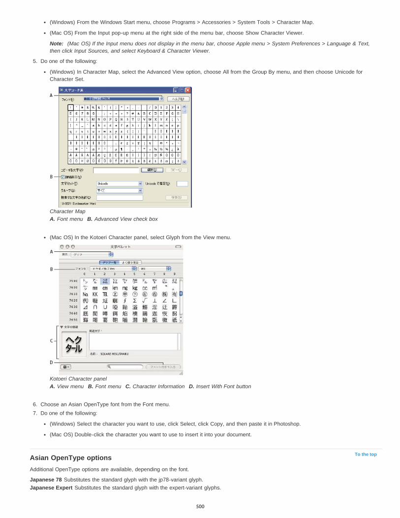
To the top
(Windows) From the Windows Start menu, choose Programs > Accessories > System Tools > Character Map.
(Mac OS) From the Input pop-up menu at the right side of the menu bar, choose Show Character Viewer.
Note: (Mac OS) If the Input menu does not display in the menu bar, choose Apple menu > System Preferences > Language & Text,then click Input Sources, and select Keyboard & Character Viewer.
5. Do one of the following:
(Windows) In Character Map, select the Advanced View option, choose All from the Group By menu, and then choose Unicode forCharacter Set.
Character MapA. Font menu B. Advanced View check box
(Mac OS) In the Kotoeri Character panel, select Glyph from the View menu.
Kotoeri Character panelA. View menu B. Font menu C. Character Information D. Insert With Font button
6. Choose an Asian OpenType font from the Font menu.7. Do one of the following:
(Windows) Select the character you want to use, click Select, click Copy, and then paste it in Photoshop.
(Mac OS) Double-click the character you want to use to insert it into your document.
Asian OpenType optionsAdditional OpenType options are available, depending on the font.
Japanese 78 Substitutes the standard glyph with the jp78-variant glyph.Japanese Expert Substitutes the standard glyph with the expert-variant glyphs.
500

To the top
To the top
Japanese Traditional Substitutes the standard glyph with the traditional-variant glyph.Proportional Metrics Substitutes the half-width and the full-width glyphs with the proportional glyph.Kana Substitutes the standard kana glyph with the horizontally optimized kana glyph for horizontal layout. However, the differences are often verysubtle.Roman Italics Substitutes the standard proportional glyph with the italic glyph.For more information, see Apply OpenType features.
Choose a mojikumi setMojikumi specifies Japanese text composition for spacing of Japanese characters, roman characters, punctuation, special characters, line start,line end, and numbers. Photoshop includes several predefined mojikumi sets based on the Japanese Industrial Standard (JIS) X 4051-1995.
In the Paragraph panel, choose an option from the Mojikumi pop-up menu:None Turns off the use of mojikumi.Mojikumi Set 1 Uses half-width spacing for punctuation.Mojikumi Set 2 Uses full-width spacing for most characters except the last character in the line.
Mojikumi Set 1, and Mojikumi Set 2
Mojikumi Set 3 Uses full-width spacing for most characters and the last character in the line.Mojikumi Set 4 Uses full-width spacing for all characters.
Mojikumi Set 3, and Mojikumi Set 4
Set kinsoku shori options
501
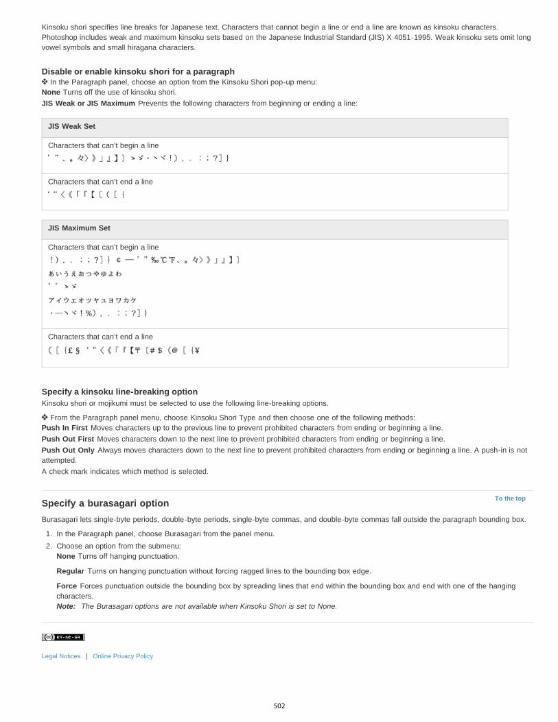
To the top
Kinsoku shori specifies line breaks for Japanese text. Characters that cannot begin a line or end a line are known as kinsoku characters.Photoshop includes weak and maximum kinsoku sets based on the Japanese Industrial Standard (JIS) X 4051-1995. Weak kinsoku sets omit longvowel symbols and small hiragana characters.
Disable or enable kinsoku shori for a paragraph In the Paragraph panel, choose an option from the Kinsoku Shori pop-up menu:
None Turns off the use of kinsoku shori.JIS Weak or JIS Maximum Prevents the following characters from beginning or ending a line:
JIS Weak Set
Characters that can’t begin a line
Characters that can’t end a line
JIS Maximum Set
Characters that can’t begin a line
Characters that can’t end a line
Specify a kinsoku line-breaking optionKinsoku shori or mojikumi must be selected to use the following line-breaking options.
From the Paragraph panel menu, choose Kinsoku Shori Type and then choose one of the following methods:Push In First Moves characters up to the previous line to prevent prohibited characters from ending or beginning a line.Push Out First Moves characters down to the next line to prevent prohibited characters from ending or beginning a line.Push Out Only Always moves characters down to the next line to prevent prohibited characters from ending or beginning a line. A push-in is notattempted.A check mark indicates which method is selected.
Specify a burasagari optionBurasagari lets single-byte periods, double-byte periods, single-byte commas, and double-byte commas fall outside the paragraph bounding box.
1. In the Paragraph panel, choose Burasagari from the panel menu.2. Choose an option from the submenu:
None Turns off hanging punctuation.
Regular Turns on hanging punctuation without forcing ragged lines to the bounding box edge.
Force Forces punctuation outside the bounding box by spreading lines that end within the bounding box and end with one of the hangingcharacters.Note: The Burasagari options are not available when Kinsoku Shori is set to None.
Legal Notices | Online Privacy Policy
502

Video and animation
Video workflowKelby (May. 7, 2012)video-tutorialIntuitive editing for video DSLRs and other sources.
503
Video editing | CC, CS6
To the top
Video | Walk through a video projectTimeline video creationApply filters to video layersApply motion effects to text, still images, and Smart ObjectsImport a wider range of file formatsExport final video with the Adobe Media Encoder
Timeline video creationThe redesigned, clip-based Timeline panel reflects video editors like Adobe Premiere, including transitions and effects that give finished videosprofessional polish.
Video tutorials:
Intuitive video Workflow: How to add video clips, trim video clips, add a music track, and render your movie for playback by your audience. By RCConception (8:18)
How to edit video in Photoshop CS6. By Matthew Gore (10:42)
Slip editing to adjust the in and out points of a video without changing the clip duration. By Meredith Payne-Stotzne (1:20)
Frame skipping and caching to improve playback performance. By MeredithPayne-Stotzne (2:07)
Fixing over exposed video footage. By Richard Harrington (1:55)
Changing clip speed: Slow and Fast Motion. By Jeff Sengstack (9:45). Infinite Skills has made several videos available from their Photoshop videocourse.
Video GroupsVideo Groups combine multiple video clips and other content such as text, images, and shapes on a single track in the Timeline.
Create a Video GroupImport a video file; it's automatically added as a new Video Group.
To create an empty group for adding content to, click a filmstrip icon on the left of the Timeline panel, and choose New Video Group fromthe pop-up menu.
Edit a Video GroupTo reposition clips, drag them in the Timeline.To change in and out points, drag clip borders in the Timeline.To move items from one group to another, drag them up or down in the Timeline or Layers panel.
To divide a selected clip and edit the resulting parts separately, position the Timeline playhead where you want to split the clip. Then clickthe Split At Playhead button in the upper-left corner of the Timeline panel.
Audio tracks and controlsSeparate audio tracks in the Timeline allow for easy editing and adjusting.
Adjust audio in clipsRight-click audio clips to mute them, adjust volume, or fade in and out.
Right-click video clips, and click the musical notes to adjust audio they contain.
Adjusting audio: Video tutorial by Richard Harrington. (3:31)
Create or delete audio tracksTo the right of audio track names in the Timeline, click the musical notes , and select either New Audio Track or Delete Track.
504

To the top
To the top
To the top
To the top
Add, duplicate, delete, or replace audio clipsTo the right of audio track names in the Timeline, click the musical notes . Then select Add Audio to place another clip on the track.
Select an audio clip in the Timeline, and click the musical notes to the right of the track name. Then select Duplicate, Delete, or ReplaceAudio Clip.
Video transitionsTransitions create professional fade and cross-fade effects. Click the transitions icon in the upper left of the Timeline panel. Then choose aduration, and drag a transition type to the start or end of clips. (Place the transition between clips to crossfade.) Drag the edges of the transitionpreview in the Timeline to precisely set in and out points.
Right-click transitions in the Timeline to replace them with another transition type or specify a precise numeric duration.
Change video clip duration and speedRight-click video clips to access Duration and Speed sliders. These controls interact; for example, a Speed of 400% limits the maximum duration toone-quarter of the original.
Apply filters to video layersTo apply filters across all frames in a video layer, first convert the layer into a Smart Object. Any subsequent filters you apply become SmartFilters, which provide total flexibility, letting you readjust filter settings at any time.
1. Select the video layer in the Timeline or Layers panel.2. Choose Layer > Smart Objects > Convert to Smart Object.3. Apply filters from the Filter menu. To later readjust settings, view the Layers panel, and double-click the filter in the Smart Filters list for the
video layer.
For more information, see Nondestructive editing.
Apply motion effects to text, still images, and Smart ObjectsRight-click text, still-image, and Smart Object clips to access pan, zoom, and rotate presets, quickly applying sophisticated animation. Drag theresulting Transform keyframes in the Timeline to fine-tune the results.
To create dramatic effects as you pan, scale, and rotate clips over time, convert your clip to a Smart Object and use Transform keyframes withthe Free Transform tool.
Video Tutorials:
Transforming Layers over time. Julieanne Kost (3:52)
Creating masks to move over time. Julieanne Kost (3:17)
How to pan and zoom video in Photoshop CS6. Julieanne Kost (18:06)
Create animations with audio. Tutorial article by Rafiq Elmansy.
Import a wider range of file formatsWith a redesigned video engine, you can import a wider range of video, audio, and image sequence files. Easily work with file types such as 3GP,3G2, AVI, DV, FLV and F4V, MPEG-1, MPEG-4, QuickTime MOV (in Windows, full support requires separate QuickTime installation).
For the complete list, see Supported file formats.
Export final video with the Adobe Media EncoderChoose File > Export > Render Video. From the first pop-up menu, select Adobe Media Encoder to choose from the following Format options:
DPX (Digital Picture Exchange) format is designed primarily for frame sequences that you plan to incorporate into professional video projectsusing an editor such as Adobe Premiere Pro.H.264 (MPEG-4) format is the most versatile, including presets for high-definition and widescreen video, and output optimized for tabletdevices or web delivery.QuickTime (MOV) format is required for export of alpha channels and uncompressed video. The Preset menu provides additionalcompression options.
505
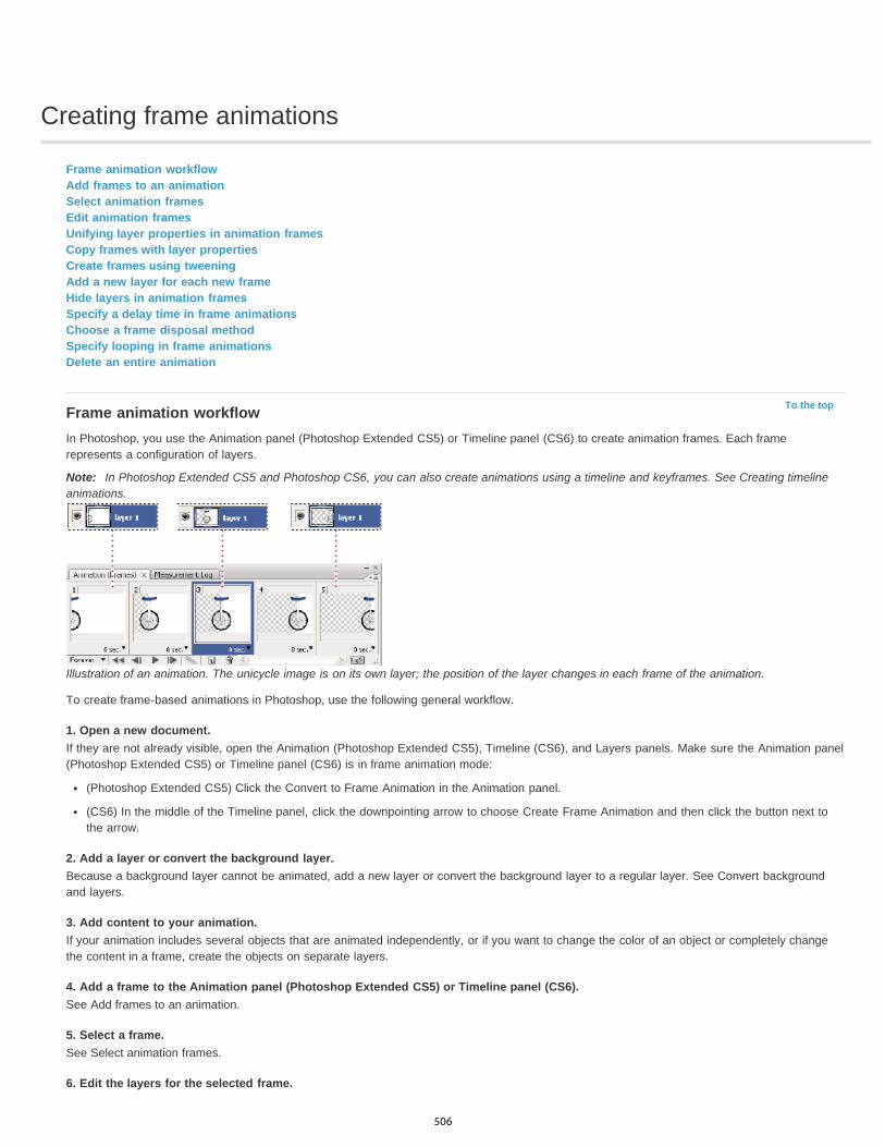
Creating frame animations
To the top
Frame animation workflowAdd frames to an animationSelect animation framesEdit animation framesUnifying layer properties in animation framesCopy frames with layer propertiesCreate frames using tweeningAdd a new layer for each new frameHide layers in animation framesSpecify a delay time in frame animationsChoose a frame disposal methodSpecify looping in frame animationsDelete an entire animation
Frame animation workflowIn Photoshop, you use the Animation panel (Photoshop Extended CS5) or Timeline panel (CS6) to create animation frames. Each framerepresents a configuration of layers.
Note: In Photoshop Extended CS5 and Photoshop CS6, you can also create animations using a timeline and keyframes. See Creating timelineanimations.
Illustration of an animation. The unicycle image is on its own layer; the position of the layer changes in each frame of the animation.
To create frame-based animations in Photoshop, use the following general workflow.
1. Open a new document.If they are not already visible, open the Animation (Photoshop Extended CS5), Timeline (CS6), and Layers panels. Make sure the Animation panel(Photoshop Extended CS5) or Timeline panel (CS6) is in frame animation mode:
(Photoshop Extended CS5) Click the Convert to Frame Animation in the Animation panel.
(CS6) In the middle of the Timeline panel, click the downpointing arrow to choose Create Frame Animation and then click the button next tothe arrow.
2. Add a layer or convert the background layer.Because a background layer cannot be animated, add a new layer or convert the background layer to a regular layer. See Convert backgroundand layers.
3. Add content to your animation.If your animation includes several objects that are animated independently, or if you want to change the color of an object or completely changethe content in a frame, create the objects on separate layers.
4. Add a frame to the Animation panel (Photoshop Extended CS5) or Timeline panel (CS6).See Add frames to an animation.
5. Select a frame.See Select animation frames.
6. Edit the layers for the selected frame.
506
To the top
To the top
Do any of the following:
Turn visibility on and off for different layers.
Change the position of objects or layers to make layer content move.
Change layer opacity to make content fade in or out.
Change the blending mode of layers.
Add a style to layers.
Photoshop provides tools for keeping characteristics of a layer the same across frames. See Unifying layer properties in animation frames.
7. Add more frames and edit layers as needed.The number of frames you can create is limited only by the amount of system memory available to Photoshop.
You can generate new frames with intermediate changes between two existing frames in the panel using the Tween command. This is a quick wayto make an object move across the screen or to fade in or out. See Create frames using tweening.
8. Set frame delay and looping options.You can assign a delay time to each frame and specify looping so that the animation runs once, a certain number of times, or continuously. SeeSpecify a delay time in frame animations and Specify looping in frame animations.
9. Preview the animation.Use the controls in the Animation panel (Photoshop Extended CS5) or Timeline panel (CS6) to play the animation as you create it. Then use theSave For Web & Devices command to preview the animation in your web browser. See Preview optimized images in a web browser.
10. Optimize the animation for efficient download.See Optimize animation frames.
11. Save the animation.There are different options for saving your frame animation:
Save as an animated GIF using the Save For Web & Devices (Photoshop Extended CS5) or Save For Web (CS6) command.
Save in Photoshop (PSD) format so you can do more work on the animation later.
Save an image sequence, QuickTime movie, or as separate files. See also Export video files or image sequences.
Add frames to an animationAdding frames is the first step in creating an animation. If you have an image open, the Animation panel (Photoshop Extended CS5) or Timelinepanel (CS6) displays the image as the first frame in a new animation. Each frame you add starts as a duplicate of the preceding frame. You thenmake changes to the frame using the Layers panel.
1. Make sure the Animation panel (Photoshop Extended CS5) or Timeline panel (CS6) is in frame animation mode.2. Click the Duplicates Selected Frames button in the Animation panel.
Select animation framesBefore you can work with a frame, you must select it as the current frame. The contents of the current frame appear in the document window.
In the Animation panel (Photoshop Extended CS5) or Timeline panel (CS6), the current frame is indicated by a narrow border (inside the shadedselection highlight) around the frame thumbnail. Selected frames are indicated by a shaded highlight around the frame thumbnails.
Select one animation frame Do one of the following in the Animation panel (Photoshop Extended CS5) or Timeline panel (CS6):
Click a frame.
Click the Selects Next Frame button to select the next frame in the series as the current frame.
Click the Selects Previous Frame button to select the previous frame in the series as the current frame.
Click the Selects First Frame button to select the first frame in the series as the current frame.
Select multiple animation frames In the Animation panel (Photoshop Extended CS5) or Timeline panel (CS6), do one of the following:
To select contiguous multiple frames, Shift-click a second frame. The second frame and all frames between the first and second are addedto the selection.
507

To the top
To the top
To the top
To select discontiguous multiple frames, Ctrl-click (Windows) or Command-click (Mac OS) additional frames to add those frames to theselection.
To select all frames, choose Select All Frames from the panel menu.
To deselect a frame in a multiframe selection, Ctrl-click (Windows) or Command-click (Mac OS) that frame.
Edit animation frames1. In the Animation panel (Photoshop Extended CS5) or Timeline panel (CS6), select one or more frames.2. Do any of the following:
To edit the content of objects in animation frames, use the Layers panel to modify the layers in the image that affect that frame.
To change the position of an object in an animation frame, select the layer containing the object in the Layers panel and drag it to a newposition.
Note: You can select and change the position of multiple frames. However, if you drag multiple discontiguous frames, the frames areplaced contiguously in the new position.
To reverse the order of animation frames, choose Reverse Frames from the panel menu.
Note: The frames you want to reverse do not have to be contiguous; you can reverse any selected frames.
To delete selected frames, select Delete Frame from the Animation panel menu or click the Delete icon , then click Yes to confirm thedeletion. You can also drag the selected frame onto the Delete icon.
Unifying layer properties in animation framesThe unify buttons (Unify Layer Position, Unify Layer Visibility, and Unify Layer Style) in the Layers panel determine how the changes you make toattributes in the active animation frame apply to the other frames in the same layer. When a unify button is selected, that attribute is changed in allthe frames in the active layer; when that button is deselected, changes apply to only the active frame.
The Propagate Frame 1 option in the Layers panel also determines how the changes you make to attributes in the first frame will apply to the otherframes in the same layer. When it is selected, you can change an attribute in the first frame, and all subsequent frames in the active layer willchange in relation to the first frame (and preserve the animation you have already created).
Unify layer properties1. In the Animation panel (Photoshop Extended CS5) or Timeline panel (CS6), change the attribute to one frame.
2. In the Layers panel, click Unify Layer Position , Unify Layer Visibility , or Unify Layer Style to have the changed attribute apply to allother frames in the active layer.
Propagate frame 11. In the Layers panel, select the Propagate Frame 1 option.2. In the Animation panel (Photoshop Extended CS5) or Timeline panel (CS6), change the attribute for the first frame.
The changed attribute is applied (in relation) to all subsequent frames in a layer.
You can also propagate frames by Shift-selecting any consecutive group of frames in the layer and changing an attribute in any of the selectedframes.
Show or hide Unify Layers buttons Choose Animation Options from the Layers panel menu, and then choose one of the following:
Automatic Displays the unify layers buttons when the Animation panel is open. In Photoshop Extended, the Animation panel must be in frameanimation mode.Always Show Displays the unify layers buttons whether the Animation panel is open or closed.Always Hide Hides the unify layers buttons whether the Animation panel is open or closed.
Copy frames with layer propertiesTo understand what happens when you copy and paste a frame, think of a frame as a duplicate version of an image with a given layerconfiguration. When you copy a frame, you copy the configurations of layers (including each layer’s visibility setting, position, and other properties).When you paste a frame, you apply that layer configuration to the destination frame.
1. Select one or more frames you want to copy in the Animation panel (Photoshop Extended CS5) or Timeline panel (CS6).2. Choose Copy Frame(s) from the panel menu.3. Select a destination frame or frames in the current animation or another animation.
508
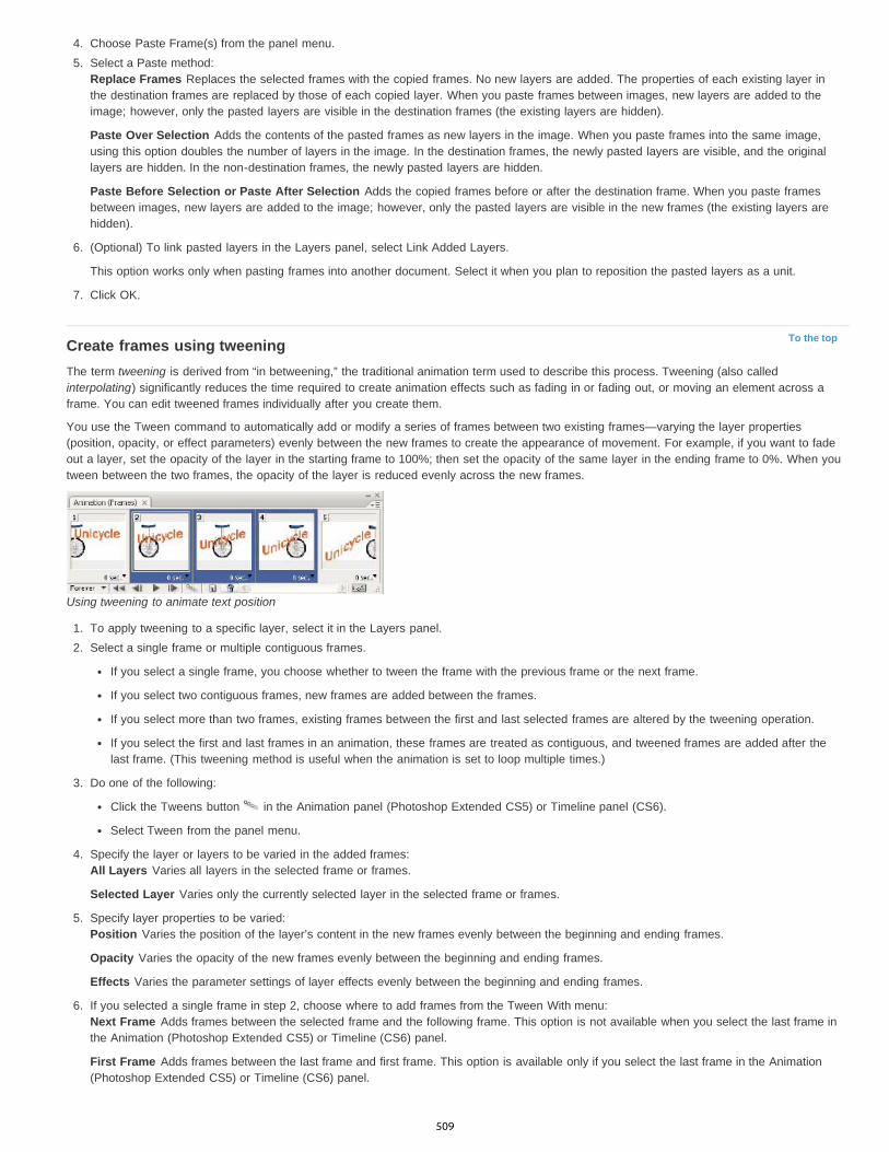
To the top
4. Choose Paste Frame(s) from the panel menu.5. Select a Paste method:
Replace Frames Replaces the selected frames with the copied frames. No new layers are added. The properties of each existing layer inthe destination frames are replaced by those of each copied layer. When you paste frames between images, new layers are added to theimage; however, only the pasted layers are visible in the destination frames (the existing layers are hidden).
Paste Over Selection Adds the contents of the pasted frames as new layers in the image. When you paste frames into the same image,using this option doubles the number of layers in the image. In the destination frames, the newly pasted layers are visible, and the originallayers are hidden. In the non-destination frames, the newly pasted layers are hidden.
Paste Before Selection or Paste After Selection Adds the copied frames before or after the destination frame. When you paste framesbetween images, new layers are added to the image; however, only the pasted layers are visible in the new frames (the existing layers arehidden).
6. (Optional) To link pasted layers in the Layers panel, select Link Added Layers.
This option works only when pasting frames into another document. Select it when you plan to reposition the pasted layers as a unit.
7. Click OK.
Create frames using tweeningThe term tweening is derived from “in betweening,” the traditional animation term used to describe this process. Tweening (also calledinterpolating) significantly reduces the time required to create animation effects such as fading in or fading out, or moving an element across aframe. You can edit tweened frames individually after you create them.
You use the Tween command to automatically add or modify a series of frames between two existing frames—varying the layer properties(position, opacity, or effect parameters) evenly between the new frames to create the appearance of movement. For example, if you want to fadeout a layer, set the opacity of the layer in the starting frame to 100%; then set the opacity of the same layer in the ending frame to 0%. When youtween between the two frames, the opacity of the layer is reduced evenly across the new frames.
Using tweening to animate text position
1. To apply tweening to a specific layer, select it in the Layers panel.2. Select a single frame or multiple contiguous frames.
If you select a single frame, you choose whether to tween the frame with the previous frame or the next frame.
If you select two contiguous frames, new frames are added between the frames.
If you select more than two frames, existing frames between the first and last selected frames are altered by the tweening operation.
If you select the first and last frames in an animation, these frames are treated as contiguous, and tweened frames are added after thelast frame. (This tweening method is useful when the animation is set to loop multiple times.)
3. Do one of the following:
Click the Tweens button in the Animation panel (Photoshop Extended CS5) or Timeline panel (CS6).
Select Tween from the panel menu.
4. Specify the layer or layers to be varied in the added frames:All Layers Varies all layers in the selected frame or frames.
Selected Layer Varies only the currently selected layer in the selected frame or frames.
5. Specify layer properties to be varied:Position Varies the position of the layer’s content in the new frames evenly between the beginning and ending frames.
Opacity Varies the opacity of the new frames evenly between the beginning and ending frames.
Effects Varies the parameter settings of layer effects evenly between the beginning and ending frames.
6. If you selected a single frame in step 2, choose where to add frames from the Tween With menu:Next Frame Adds frames between the selected frame and the following frame. This option is not available when you select the last frame inthe Animation (Photoshop Extended CS5) or Timeline (CS6) panel.
First Frame Adds frames between the last frame and first frame. This option is available only if you select the last frame in the Animation(Photoshop Extended CS5) or Timeline (CS6) panel.
509

To the top
To the top
To the top
To the top
Previous Frame Adds frames between the selected frame and the preceding frame. This option is not available when you select the firstframe in the Animation (Photoshop Extended CS5) or Timeline (CS6) panel.
Last Frame Adds frames between the first frame and last frame. This option is available only if you select the first frame in the Animation(Photoshop Extended CS5) or Timeline (CS6) panel.
7. In the Frames To Add box, enter a value, or use the Up or Down Arrow key to choose the number of frames. (This option is not available ifyou selected more than two frames.)
8. Click OK.
Add a new layer for each new frameThe Create New Layer For Each New Frame command automatically adds a new layer visible in the new frame but hidden in other frames. Thisoption saves time when you are creating an animation that requires you to add a new visual element to each frame.
Choose Create New Layer For Each New Frame from the Animation panel menu (Photoshop Extended CS5) or Timeline panel menu (CS6).A check mark indicates that the option is turned on.
Hide layers in animation framesWhen you create a new layer, it is visible in all animation frames by default.
To show new layers only in active frames, deselect New Layers Visible In All Frames from the Animation panel menu (Photoshop ExtendedCS5) or Timeline panel menu (CS6).
To hide a layer in a specific frame, select the frame, and then hide the desired layer in the Layers panel.
Specify a delay time in frame animationsYou can specify a delay—the time that a frame is displayed—for single frames or for multiple frames in an animation. Delay time is displayed inseconds. Fractions of a second are displayed as decimal values. For example, one-quarter of a second is specified as .25. If you set a delay onthe current frame, every frame you create after that will remember and apply that delay value.
1. Select one or more frames in the Animation panel (Photoshop Extended CS5) or Timeline panel (CS6).2. Click the Delay value below the selected frame to view the pop-up menu.3. Specify the delay:
Choose a value from the pop-up menu. (The last value used appears at the bottom of the menu.)
Choose Other, enter a value in the Set Frame Delay dialog box, and click OK. If you selected multiple frames, specifying a delay valuefor one frame applies the value to all frames.
Choose a frame disposal methodThe frame disposal method specifies whether to discard the current frame before displaying the next frame. You select a disposal method foranimations that include background transparency to specify whether the current frame will be visible through the transparent areas of the nextframe.
Frame disposal methodsA. Frame with background transparency with Restore To Background option B. Frame with background transparency with Do Not Disposeoption
The Disposal Method icon indicates whether the frame is set to Do Not Dispose or Dispose . (No icon appears when Disposal Method is setto Automatic.)
1. (Photoshop Extended) Make sure the Animation panel is in frame animation mode.2. Select a frame or frames for which you want to choose a disposal method.3. Right-click (Windows) or Control-click (Mac OS) the frame thumbnail to view the Disposal Method context menu.
510
To the top
To the top
4. Choose a disposal method:Automatic Determines a disposal method for the current frame automatically, discarding the current frame if the next frame contains layertransparency. For most animations, the Automatic option (default) yields the desired results.Note: To preserve frames that include transparency, select the Automatic disposal option when you are using the Redundant PixelRemoval optimization option.
Do Not Dispose Preserves the current frame as the next frame is added to the display. The current frame (and preceding frames) mayshow through transparent areas of the next frame. Use a browser to see an accurate preview of an animation using the Do Not Disposeoption.
Dispose Discards the current frame from the display before the next frame is displayed. Only a single frame is displayed at any time (andthe current frame does not appear through the transparent areas of the next frame).
Specify looping in frame animationsYou select a looping option to specify how many times the animation sequence repeats when played.
1. Click the Looping Option Selection box at the lower left corner of the Animation panel (Photoshop Extended CS5) or Timeline panel (CS6).2. Select a looping option: Once, 3 Times, Forever, or Other.3. If you selected Other, enter a value in the Set Loop Count dialog box, and click OK.
Note: Looping options can also be set in the Save For Web & Devices (Photoshop Extended CS5) or Save for Web (CS6) dialog box. Formore information, see Save For Web & Devices overview.
Delete an entire animation Select Delete Animation from the Animation panel menu (Photoshop Extended CS5) or Timeline panel menu (CS6).
Legal Notices | Online Privacy Policy
511
Creating timeline animations
To the top
Timeline animation workflowUse keyframes to animate layer propertiesCreate hand-drawn animationsInsert, delete, or duplicate blank video framesSpecify onion skin settingsOpen a multilayer animation
Timeline animation workflowTo animate layer content in timeline mode, you set keyframes in the Animation panel (Photoshop Extended CS5) or Timeline panel (CS6), as youmove the current-time indicator to a different time/frame, and then modify the position, opacity, or style of the layer content. Photoshopautomatically adds or modifies a series of frames between two existing frames—varying the layer properties (position, opacity, and styles) evenlybetween the new frames to create the appearance of movement or transformation.
For example, if you want to fade out a layer, set the opacity of the layer in the starting frame to 100% and click the Opacity stopwatch for the layer.Then move the current-time indicator to the time/frame for the ending frame and set the opacity for the same layer to 0%. Photoshop automaticallyinterpolates frames between the start and end frames, and the opacity of the layer is reduced evenly across the new frames.
In addition to letting Photoshop interpolate frames in an animation, you can also create a hand-drawn frame-by-frame animation by painting on ablank video layer.
If you want to create a SWF format animation, use Adobe Flash, Adobe After Effects, or Adobe Illustrator.
To create a timeline-based animation, use the following general workflow.
1. Create a new document.Specify the size and background contents. Make sure the pixel aspect ratio and dimensions are appropriate for the output of your animation. Thecolor mode should be RGB. Unless you have special reasons for making changes, leave the resolution at 72 pixels/inch, the bit depth at 8 bpc,and the pixel aspect ratio at square.
(Photoshop Extended CS5) Make sure the Animation panel is open. If the Animation panel is in frame animation mode, click the Convert ToTimeline Animation icon in the lower-right corner of the panel.
(CS6) Make sure the Timeline panel is open. If necessary, click the downpointing arrow in the middle of the panel, choose Create VideoTimeline from the menu, and then, click the button to the left of the arrow. If the Timeline panel is in frame animation mode, click the ConvertTo Video Timeline icon in the lower-left corner of the panel.
2. Specify the Document Timeline Settings (Photoshop Extended CS5) or Set Timeline Frame Rate (CS6) in the panelmenu.Specify the duration (Photoshop Extended CS5 only) and frame rate. See Specify timeline duration and frame rate.
3. Add a layer.Background layers cannot be animated. If you want to animate content, either convert the background layer to a normal layer or add any of thefollowing:
A new layer for adding content.
A new video layer for adding video content.
A new blank video layer for cloning content to or creating hand-drawn animations.
4. Add content to the layer.
5. (Optional) Add a layer mask.A layer mask can be used to reveal a portion of the layer’s content. You can animate the layer mask to reveal different portions of the layer’scontent over time. See Add layer masks.
6. Move the current time indicator to the time or frame where you want to set the first keyframe.See Use keyframes to animate layer properties.
7. Turn on keyframing for a layer property.Click the triangle next to the layer name. A down-pointing triangle displays the layer’s properties. Then, click the stopwatch to set the first keyframe
512
To the top
for the layer property you want to animate. You can set keyframes for more than one layer property at a time.
8. Move the current time indicator and change a layer property.Move the current-time indicator to the time or frame where the layer’s property changes. You can do one or more of the following:
Change the position of the layer to make layer content move.
Change layer opacity to make content fade in or out.
Change the position of a layer mask to reveal different parts of the layer.
Turn a layer mask on or off.
For some types of animation, such as changing the color of an object, or completely changing the content in a frame, you need additional layerswith the new content.
Note: To animate shapes, you animate the vector mask not the shape layer, using the Time-Vary stopwatch for Vector Mask Position or VectorMask Enable.
9. Add additional layers with content and edit their layer properties as needed.
10. Move or trim the layer duration bar to specify when a layer appears in an animation.See Specify when a layer appears in a video or animation and Set the timeline area to preview.
11. Preview the animation.Use the controls in the Animation panel (Photoshop Extended CS5) or Timeline panel (CS6) to play the animation as you create it. Then previewthe animation in your web browser. You can also preview the animation in the Save For Web & Devices (Photoshop Extended CS5) or Save ForWeb (CS6) dialog box. See Previewing video or timeline animations.
12. Save the animation.You can save the animation as an animated GIF using the Save For Web & Devices (Photoshop Extended CS5) or Timeline panel (CS6)command, or as an image sequence or video using the Render Video command. You can also save it in PSD format, which can be imported intoAdobe After Effects.
Use keyframes to animate layer propertiesYou can animate different layer properties, such as Position, Opacity, and Style. Each change can occur independently of, or simultaneously with,other changes. If you want to animate different objects independently, it’s best to create them on separate layers.
For a video on animating layer properties, see www.adobe.com/go/vid0024.
Here are some examples of how you can animate layer properties:
You can animate position by adding a keyframe to the Position property, then moving the current time indicator and dragging the layer in thedocument window.
You can animate a layer’s opacity by adding a keyframe to the Opacity property, then moving the current time indicator and changing thelayer’s opacity in the Layers panel.
You can animate 3D properties, such as object and camera position. (For more information, see Create 3D animations (PhotoshopExtended).)
To animate a property using keyframes, you must set at least two keyframes for that property. Otherwise, changes that you make to the layerproperty remain in effect for the duration of the layer.
Each layer property has a Time-Vary stopwatch icon that you click to begin animating. When the stopwatch is active for a specific property,Photoshop automatically sets new keyframes whenever you change the current time and the property value. When the stopwatch is inactive for aproperty, the property has no keyframes. If you type a value for a layer property while the stopwatch is inactive, the value remains in effect for theduration of the layer. If you deselect the stopwatch, you will permanently delete all of the keyframes for that property.
Choose interpolation methodInterpolation (sometimes called tweening) describes the process of filling in unknown values between two known values. In digital video and film,interpolation usually means generating new values between two keyframes. For example, to move a graphic element 50 pixels to the left in 15frames, you’d set the position of the graphic in the first and 15th frames, and mark them both as keyframes. Photoshop interpolates the framesbetween the two keyframes. Interpolation between keyframes can be used to animate movement, opacity, styles, and global lighting.
In the Animation panel (Photoshop Extended CS5) or Timeline panel (CS6), the appearance of a keyframe depends on the interpolation methodyou choose for the interval between keyframes.
Linear keyframe Evenly changes the animated property from one keyframe to another. (The one exception is the Layer Mask Position propertywhich switches between enabled and disabled states abruptly.)Hold keyframe Maintains the current property setting. This interpolation method is useful for strobe effects, or when you want layers to appearor disappear suddenly.
513
To the top
To choose the interpolation method for a keyframe, do the following:
1. In the Animation panel (Photoshop Extended CS5) or Timeline panel (CS6), select one or more keyframes.2. Do one of the following:
Right-click a selected keyframe and choose either Linear Interpolation or Hold Interpolation from the Context menu.
Open the Animation panel menu and choose either Keyframe Interpolation > Linear or Keyframe Interpolation > Hold.
Move the current-time indicator to a keyframeAfter you set the initial keyframe for a property, Photoshop displays the keyframe navigator, which you can use to move from keyframe to keyframeor to set or remove keyframes. When the keyframe navigator diamond is active (yellow), the current-time indicator lies precisely at a keyframe forthat layer property. When the keyframe navigator diamond is inactive (gray), the current-time indicator lies between keyframes. When arrowsappear on each side of the keyframe navigator box, other keyframes for that property exist on both sides of the current time.
In the Animation panel (Photoshop Extended CS5) or Timeline panel (CS6), click a keyframe navigator arrow. The arrow to the left moves thecurrent-time indicator to the previous keyframe. The arrow to the right moves the current-time indicator to the next keyframe.
Select keyframes In the Animation panel (Photoshop Extended CS5) or Timeline panel (CS6), do any of the following:
To select a keyframe, click the keyframe icon.
To select multiple keyframes, Shift-click the keyframes or drag a selection marquee around the keyframes.
To select all keyframes for a layer property, click the layer property name next to the stopwatch icon.
Move keyframes1. In the Animation panel (Photoshop Extended CS5) or Timeline panel (CS6), select one or more keyframes.2. Drag any of the selected keyframe icons to the desired time. (If you selected multiple keyframes, they move as a group and maintain the
same time spacing.)
To expand or compress the spacing of multiple keyframes, Alt-drag (Windows) or Option-drag (Mac OS) the first or last keyframe in theselection. The keyframe at the opposite end of the selection remains in place as you drag, slowing down or speeding up the animation.
Copy and paste keyframesYou can copy keyframes for a property (such as Position) to the same property in any layer. When you paste keyframes, they reflect the copiedoffset from the current-time indicator.
You can copy keyframes from only one layer at a time. When you paste keyframes into another layer, they appear in the corresponding property inthe destination layer. The earliest keyframe appears at the current time, and the other keyframes follow in relative order. The keyframes remainselected after pasting, so you can immediately move them in the timeline.
Note: You can copy and paste keyframes between more than one property at a time.1. In the Animation panel (Photoshop Extended CS5) or Timeline panel (CS6), display the layer property containing the keyframes you want to
copy.2. Select one or more keyframes.3. Right-click a selected keyframe, and choose Copy Keyframes.4. In the Animation panel containing the destination layer, move the current-time indicator to the point in time where you want the keyframes to
appear.5. Select the destination layer.6. Open the Animation panel menu and choose Paste Keyframes.
Delete keyframes In the Animation panel (Photoshop Extended CS5) or Timeline panel (CS6), select one or more keyframes and do one of the following:
Right-click (Windows) or Control-click (Mac OS) a selected keyframe, and choose Delete Keyframes from the context menu.
From the panel menu, choose Delete Keyframes.
Create hand-drawn animationsYou can add a blank video layer to your document when you want to create frame-by-frame hand-drawn animations. Adding a blank video layerabove a video layer and then adjusting the opacity of the blank video layer, allows you to see the contents of the video layer below. You can thenrotoscope the video layer content by painting or drawing on the blank video layer. See also Paint frames in video layers.
Note: If you’re animating several independent elements, create separate content on different blank video layers.1. Create a new document.
514
To the top
To the top
2. Add a blank video layer.3. Paint or add content to the layer.4. (Optional) In the Animation panel (Photoshop Extended CS5) or Timeline panel (CS6), enable the onion skin mode:
(Photoshop Extended CS5) Click the Toggle Onion Skins button to enable onion skinning.
(CS6 and Photoshop Extended CS5) Choose Enable Onion Skins from the panel menu.
5. Move the current-time indicator to the next frame.6. Paint or add content to the layer in a slightly different position from the content in the previous frame.
You can add a blank video frame, duplicate a frame, or delete a frame from the blank video layer by choosing Layer > Video Layers andthen choosing the appropriate command.
As you create more hand-drawn frames, you can either drag the current time indicator or use the playback controls to preview youranimation.
Insert, delete, or duplicate blank video framesA blank video frame can be added to or removed from a blank video layer. You can also duplicate existing (painted) frames in blank video layers.
1. In the Animation panel (Photoshop Extended CS5) or Timeline panel (CS6), select the blank video layer and then move the current-timeindicator to the desired frame.
2. Choose Layer > Video Layers and then choose one of the following:Insert Blank Frame Inserts a blank video frame in the selected blank video layer at the current time.
Delete Frame Deletes the video frame in the selected blank video layer at the current time.
Duplicate Frame Adds a copy of the video frame at the current time in the selected blank video layer.
Specify onion skin settingsOnion skin mode displays content drawn on the current frame plus content drawn on the surrounding frames. These additional frames appear atthe opacity you specify to distinguish them from the current frame. Onion skin mode is useful for drawing frame-by-frame animations because itgives you reference points for stroke positions and other edits.
Onion skin settings specify how previous and later frames appear when Onion Skins are enabled. (See Animation panel overview.)
1. Open the Animation panel menu (Photoshop Extended CS5) or Timeline panel (CS6) and choose Onion Skin Settings.2. Specify options for the following:
Onion Skin Count Specifies how many previous and forward frames are displayed. Enter the Frames Before (previous frames) and FramesAfter (forward frames) values in the text boxes.
Frame Spacing Specifies the number of frames between the displayed frames. For example, a value of 1 displays consecutive frames, anda value of 2 displays strokes that are two frames apart.
Max Opacity Sets the percentage of opacity for the frames immediately before and after the current time.
Min Opacity Sets the percentage of opacity for the last frames of the before and after sets of onion-skin frames.
Blend Mode Sets the appearance of the areas where the frames overlap.
515

To the top
Onion skinningA. Current frame with one frame after B. Current frame with both one frame before and after C. Current frame with one frame before
Open a multilayer animationYou can open animations that were saved in older versions of Photoshop as multilayer Photoshop (PSD) files. The layers are placed in theAnimation panel (Photoshop Extended CS5) or Timeline panel (CS6) in their stacking order, with the bottom layer becoming the first frame.
1. Choose File > Open, and select the Photoshop file to open.2. In the Layers panel, select the layers you want for the animation, and choose Make Frames From Layers from the Animation panel menu.
You can edit the animation, use the Save For Web & Devices (Photoshop Extended CS5) or Save For Web (CS6) command to save ananimated GIF, or use the Render Video command to save the animation as a QuickTime movie.
More Help topicsCreating animations from shape tweens
Legal Notices | Online Privacy Policy
516

Creating images for video
To the top
To the top
About creating images for videoAspect ratioCreate an image for use in videoLoad video actionsAdjust pixel aspect ratioPrepare images for use in After Effects
About creating images for videoPhotoshop can create images of various aspect ratios so that they appear properly on devices such as video monitors. You can select a specificvideo option (using the New dialog box) to compensate for scaling when the final image is incorporated into video.
Safe zonesThe Film & Video preset also creates a document with nonprinting guides that delineate the action-safe and title-safe areas of the image. Usingthe options in the Size menu, you can produce images for specific video systems—NTSC, PAL, or HDTV.
Safe zones are useful when you edit for broadcast and videotape. Most consumer TV sets use a process called overscan, which cuts off a portionof the outer edges of the picture, allowing the center of the picture to be enlarged. The amount of overscan is not consistent across TVs. Toensure that everything fits within the area that most TVs display, keep text within the title-safe margins, and all other important elements within theaction-safe margins.
Video preset file size guidesA. Action safe area (outer rectangle) B. Title safe area (inner rectangle)
Note: If you are creating content for the web or for CD, the title-safe and action-safe margins do not apply to your project because the entireimage is displayed in these media.
Preview optionsTo help you create images for video, Photoshop has a Pixel Aspect Ratio Correction viewing mode that displays images at the specified aspectratio. For more accurate previews, Photoshop also has a Video Preview command that lets you immediately preview your work on a displaydevice, such as a video monitor. To use this feature, you must have the device connected to your computer via FireWire (IEEE 1394). See alsoPreview your document on a video monitor. For more information on FireWire (IEEE 1394), see Apple’s website.
Other considerationsBoth Adobe AfterEffects and Adobe Premiere Pro support PSD files created in Photoshop. However, if you’re using other film and videoapplications, you might consider these details when you create images for use in video:
Some video-editing programs can import individual layers from a multilayer PSD file.
If the file has transparency, some video-editing programs preserve it.
If the file uses a layer mask or multiple layers, you might not have to flatten the layers, but you might want to include a flattened copy of thefile in PSD format to maximize backward compatibility.
Aspect ratio
517

To the top
Frame aspect ratio describes the ratio of width to height in the dimensions of an image. For example, DV NTSC has a frame aspect ratio of 4:3 (or4 width by 3 height) and a typical widescreen frame has a frame aspect ratio of 16:9. Some video cameras can record various frame aspect ratios.Many cameras that have a widescreen mode use the 16:9 aspect ratio. Many professional films have been shot using even wider aspect ratios.
4:3 frame aspect ratio (left), and wider 16:9 frame aspect ratio (right)
Pixel aspect ratio describes the ratio of width to height of a single pixel in a frame. Different video standards use different pixel aspect ratios. Forexample, many computer video standards define a 4:3 aspect ratio frame as 640 pixels wide by 480 pixels high, which results in square pixels.The computer video pixels in this example have a pixel aspect ratio of 1:1 (square), whereas the DV NTSC pixels have a pixel aspect ratio of 0.91(nonsquare). DV pixels, which are always rectangular, are vertically oriented in systems producing NTSC video and horizontally oriented insystems producing PAL video.
If you display rectangular pixels on a square-pixel monitor without alteration, images appear distorted; for example, circles distort into ovals.However, when displayed on a broadcast monitor, the images appear correctly proportioned because broadcast monitors use rectangular pixels.
Note: When copying or importing images into a nonsquare pixel document, Photoshop automatically converts and scales the image to the pixelaspect ratio of the document. Images imported from Adobe Illustrator are also properly scaled.
Pixel and frame aspect ratiosA. 4:3 square-pixel image displayed on 4:3 square-pixel (computer) monitor B. 4:3 square-pixel image interpreted correctly for display on 4:3 non-square pixel (TV) monitor C. 4:3 square-pixel image interpreted incorrectly for display on 4:3 non-square pixel (TV) monitor
Create an image for use in video1. Create a new document.2. From the Preset menu in the New dialog box, choose the Film & Video preset.3. Choose the size that’s appropriate for the video system on which the image will be shown.4. Click Advanced to specify a color profile and specific pixel aspect ratio.
Important: By default, nonsquare pixel documents open with Pixel Aspect Ratio Correction enabled. This setting scales the image so itappears as it would on the nonsquare-pixel output device (usually a video monitor).
5. To view the image as it would appear on a computer monitor (square pixel), choose View > Pixel Aspect Ratio Correction.
518

To the top
To the top
Circle in NTSC DV (720 x 480 pixels) document viewed on computer (square pixel) monitor with Pixel Aspect Ratio Correction turned on(top) and Pixel Aspect Ratio Correction turned off (bottom)
You can simultaneously view an image with the Pixel Aspect Ratio Correction turned on and off. With the nonsquare pixel image openand Pixel Aspect Ratio Correction enabled, choose Window > Arrange > New Window For [name of document]. With the new windowactive, choose View > Pixel Aspect Ratio Correction to turn off the correction.
6. If you have a display device, such as a video monitor, connected to your computer via FireWire, you can preview the document on thedevice:
To set output options before previewing the image, choose File > Export > Video Preview.
To view the image without setting output options, choose File > Export > Send Video Preview To Device.
When creating images for video, you can load a set of video actions (included with Photoshop) that automate certain tasks—such as scalingimages to fit video pixel dimensions and setting the pixel aspect ratio.
Load video actionsFor video images, actions automate tasks such as constraining the luminance range and saturation levels to comply with broadcast standards,resizing and converting to nonsquare pixels for use in DVD slide shows (NTSC and PAL, standard and widescreen aspect ratios), creating analpha channel from all currently visible layers, adjusting image areas (especially thin lines) that are likely to cause interlace flicker, and generatinga title-safe overlay.
1. Choose Window > Actions to display the Actions panel.2. Click the triangle in the upper right corner of the panel, and choose Video Actions from the menu.
Adjust pixel aspect ratioYou can create a custom pixel aspect ratio in existing documents, or delete or reset pixel aspect ratios previously assigned to a document.
Assign a pixel aspect ratio value to an existing document With a document open, choose View > Pixel Aspect Ratio and then choose a pixel aspect ratio that’s compatible with the video format that you’ll
be using your Photoshop file with.
Create a custom pixel aspect ratio1. With a document open, choose View > Pixel Aspect Ratio > Custom Pixel Aspect Ratio.2. In the Save Pixel Aspect Ratio dialog box, enter a value in the Factor text box, name the custom pixel aspect ratio, and click OK.
The new custom pixel aspect ratio appears in both the Pixel Aspect Ratio menu of the New dialog box and in the View > Pixel Aspect Ratiomenu.
Delete a pixel aspect ratio1. With the document open, choose View > Pixel Aspect Ratio > Delete Pixel Aspect Ratio.2. In the Delete Pixel Aspect Ratio dialog box, choose the item to delete from the Pixel Aspect Ratio menu, and click Delete.
519
To the top
Reset the pixel aspect ratios1. With the document open, choose View > Pixel Aspect Ratio > Reset Pixel Aspect Ratios.2. In the dialog box, choose one of the following:
Append Replaces the current pixel aspect ratios with the default values plus any custom pixel aspect ratios. This option is useful if youdeleted a default value and want to restore it to the menu but also want to retain any custom values.
OK Replaces the current pixel aspect ratios with the default values. Custom pixel aspect ratios are discarded.
Cancel Cancels the command.
Prepare images for use in After EffectsYou can import a Photoshop (PSD) file directly into an After Effects project with the option of preserving individual layers, layer styles, transparentareas and layer masks, and adjustment layers (preserving the individual elements for animation).
Note: For best results, work in RGB mode, which After Effects uses. After Effects CS3 and later can convert files from CMYK to RGB. AfterEffects 7 and earlier cannot.Before you export a layered Photoshop file for use in After Effects, do the following to reduce preview and rendering time and to avoid problemswith importing and updating Photoshop layers.
Organize and name layers. If you change a layer name or delete a layer in a Photoshop document after you import it into After Effects, AfterEffects won’t be able to find the renamed or deleted layer. The After Effects Project panel lists that layer as missing. (You can also grouplayers into Smart Objects. For example: If you used a set of layers to make a foreground object and a set of layers to make a background,you can group them as one Smart Object each, and easily animate one to fly in front of the other).Make sure that each layer has a unique name. Duplicate layer names can cause confusion.Choose Always from the Maximize PSD And PSB File Compatibility menu in the File Handling Preferences dialog box.Use the appropriate pixel dimension preset for video and film in the New Document dialog box.Do any required color correction, scaling, cropping, or other edits in Photoshop so that After Effects doesn’t have to do extra image-processing work. (You can also assign a color profile to the image that corresponds to the intended output type, such as Rec. 601 NTSC orRec. 709. After Effects can read embedded color profiles and interpret the image's colors accordingly. For more information on color profiles,see Working with color profiles.
More Help topics Preparing and importing Photoshop files
Legal Notices | Online Privacy Policy
520
Editing video and animation layers
To the top
To the top
To the top
Transform video layersCreate new video layersSpecify when a layer appears in a video or animationTrim or move a video layerLift work areaExtract work areaSplit video layersGroup layers in a video or animationRasterize video layers
Transform video layersYou can transform a video layer as you transform any other layer in Photoshop. However, you must convert video layers to Smart Objects beforeyou can transform them.
1. In the Timeline (CC, CS6), Animation (CS5), or Layers panel, select the video layer.
2. Do any of the following:Choose Edit > Free Transform to use handles in the document window to transform the video.
Choose Edit > Transform and choose a specific transformation from the submenu.
If the video layer is not a Smart Object, Photoshop asks you to convert it.
Create new video layersYou can create new video layers by adding a video file as a new layer or creating a blank layer.
For a video on working with video layers, see www.adobe.com/go/vid0027
Open a video fileChoose File > Open, select a video file, and click Open.
The video appears on a video layer in a new document.
Add a video file as a new video layer
1. For the active document, make sure that the Timeline (CC, CS6) or Animation (CS5) panel is displayed in timeline mode.
2. Choose Layer > Video Layers > New Video Layer From File.3. Select a video or image sequence file and click Open.
Add a blank video layer
1. For the active document, make sure that the Timeline (CC, CS6) or the Animation (CS5) panel is displayed in the timeline mode.
2. Choose Layer > Video Layers > New Blank Video Layer.
Specify when a layer appears in a video or animationYou can use various methods to specify when a layer appears in a video or animation. For example, you can trim (hide) frames at the beginning orend of a layer. This changes the layer’s start and end points in a video or animation. (The first frame to appear is called the In point, and the lastframe is called the Out point.) You can also drag the entire layer duration bar to a different portion of the timeline.
1. In the Timeline (CC, CS6) or Animation (Photoshop Extended CS5) panel, select the layer.
2. Do any of the following:To specify the In and Out points of a layer, drag the beginning and end of the layer duration bar.
521

Note:
Note:
To the top
Move Layer In Point To Current Time
Move Layer End Point To Current Time
Trim Layer Start To Current Time
Trim Layer End To Current Time
Note:
To the top
Drag the layer duration bar to the section of the timeline where you want the layer to appear.
For best results, drag the layer duration bar after the bar has been trimmed.
Layers (In timeline mode) with the layer duration bar selected to drag (Photoshop Extended CS5)
Move the current-time indicator to the frame you want as the new In or Out point, and from the panel menu, choose Trim Layer Start ToCurrent Time or Trim Layer End To Current Time.
This shortens the layer duration by hiding the frames between the current-time indicator and either the start or the end of the layer. (Re-extending the ends of the layer duration bar reveals the hidden frames.)
Use keyframes to change the layer’s opacity at specific times or frames.
To delete footage in one or more layers, use the Lift Work Area command. To delete a specific duration from all video or animatedlayers, use the Extract Work Area command.
Trim or move a video layerTo hide frames at the start or end of a video or animation layer, trim the layer. To start or end video at a different time point, move the video layer.
If you move video layers, changes become permanent when you save the file. If you trim video, however, you can restore it by re-extending theends of the layer duration bar.
1. In the Timeline (CC, CS6), Animation (CS5), or Layers panel, select the layer you want to edit.
2. Move the current-time indicator to the frame (or time) you want as the new In point or Out point.
3. From the Timeline (CC, CS6) or Animation (CS5) panel menu, choose one of the following options:
Permanently moves the start of the layer to the current-time indicator.
Permanently moves the end of the layer to the current-time indicator.
Temporarily hides section from the current-time indicator to the start of the layer.
Temporarily hides section from the current-time indicator to the end of the layer.
You can also use the Lift Work Area command to hide frames in one or more layers, or the Extract Work Area command to hide a specificduration in all layers of a video or animation.
Lift work areaA section of the footage in selected layers can be deleted, leaving a gap of the same duration as the removed section.
1. Select the layers you want to edit.
2. In the Timeline (CC, CS6) or Animation (CS5) panel, set the work area to specify the duration of the selected layers you want to omit.
3. From the panel menu, choose Lift Work Area.
522

To the top
To the top
Layers before applying the Lift Work Area command (Photoshop Extended CS5)
Layers after applying the Lift Work Area command (Photoshop Extended CS5)
Extract work areaTo delete portions of video and automatically remove the time gap, use the Extract Work Area command. The remaining content is copied to newvideo layers.
1. Select the layers you want to edit.
2. In the Timeline (CC, CS6) or Animation (CS5) panel, set the work area to specify the duration of the video or animation that you want toomit.
3. From the panel menu, choose Extract Work Area.
Split video layersA video layer can be split into two new video layers at the frame you specify.
1. Select a video layer in the Timeline (CC, CS6) or Animation (CS5) panel.
2. Move the current-time indicator to the time or frame number where you want to split the video layer.3. Click the panel menu icon , and choose Split Layer.
The selected video layer is duplicated and appears immediately above the original in the Timeline (CC, CS6) or Animation (CS5) panel. Theoriginal layer is trimmed from the start to the current time, and the duplicate layer is trimmed from the end to the current time.
Original layer before using the Split Layer command (Photoshop Extended CS5)
523
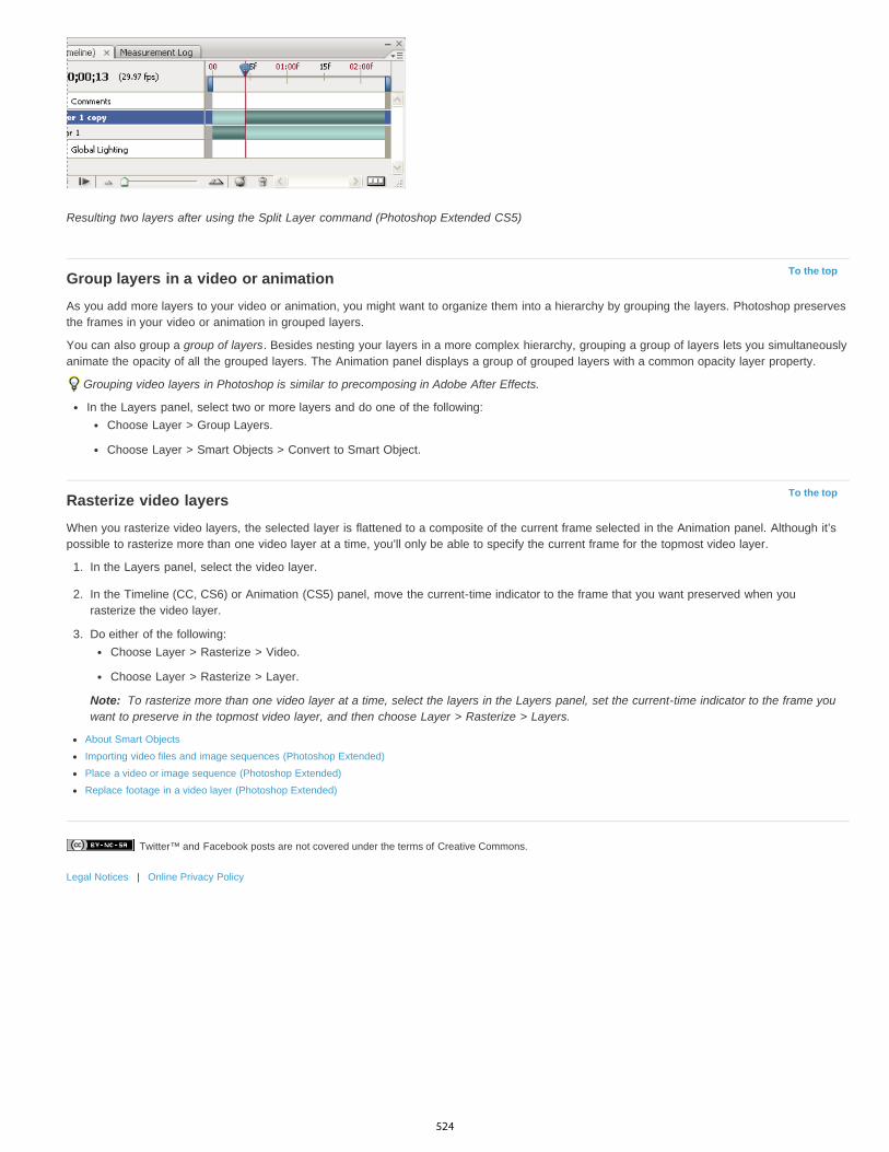
Twitter™ and Facebook posts are not covered under the terms of Creative Commons.
Legal Notices | Online Privacy Policy
To the top
To the top
Note:
Resulting two layers after using the Split Layer command (Photoshop Extended CS5)
Group layers in a video or animationAs you add more layers to your video or animation, you might want to organize them into a hierarchy by grouping the layers. Photoshop preservesthe frames in your video or animation in grouped layers.
You can also group a group of layers. Besides nesting your layers in a more complex hierarchy, grouping a group of layers lets you simultaneouslyanimate the opacity of all the grouped layers. The Animation panel displays a group of grouped layers with a common opacity layer property.
Grouping video layers in Photoshop is similar to precomposing in Adobe After Effects.
In the Layers panel, select two or more layers and do one of the following:Choose Layer > Group Layers.
Choose Layer > Smart Objects > Convert to Smart Object.
Rasterize video layersWhen you rasterize video layers, the selected layer is flattened to a composite of the current frame selected in the Animation panel. Although it’spossible to rasterize more than one video layer at a time, you’ll only be able to specify the current frame for the topmost video layer.
1. In the Layers panel, select the video layer.
2. In the Timeline (CC, CS6) or Animation (CS5) panel, move the current-time indicator to the frame that you want preserved when yourasterize the video layer.
3. Do either of the following:Choose Layer > Rasterize > Video.
Choose Layer > Rasterize > Layer.
To rasterize more than one video layer at a time, select the layers in the Layers panel, set the current-time indicator to the frame youwant to preserve in the topmost video layer, and then choose Layer > Rasterize > Layers.
About Smart Objects
Importing video files and image sequences (Photoshop Extended)
Place a video or image sequence (Photoshop Extended)
Replace footage in a video layer (Photoshop Extended)
524
Video and animation overview
Note:
To the top
Note:
Note:
Note:
To the top
About video layersSupported video and image sequence formatsAnimation panel overviewSwitch animation modesSpecify timeline duration and frame rate
For Photoshop versions earlier than Photoshop CC, some functionality discussed in this article may be available only if you have PhotoshopExtended. Photoshop CC does not have a separate Extended offering. All features in Photoshop Extended are part of Photoshop CC.
About video layersYou can use Photoshop to edit individual frames of video and image sequence files. In addition to using any Photoshop tool to edit and paint onvideo, you can also apply filters, masks, transformations, layers styles, and blending modes. After making edits, you can save the document as aPSD file (that can be played back in other Adobe applications such as Premiere Pro and After Effects or accessed as a static file in otherapplications), or you can render it as a QuickTime movie or image sequence.
For a video on working with video layers, see www.adobe.com/go/vid0027.
You can work only with the visual images in a video file, not the audio.
When you open a video file or image sequence in Photoshop, the frames are contained within a video layer. In the Layers panel, a video layer isidentified with a filmstrip icon . Video layers let you paint and clone on individual frames using the brush tools and stamp tools. Like working withregular layers, you can create selections or apply masks to restrict your edits to specific areas of a frame. You navigate through the frames usingthe timeline mode in the Animation panel (Window > Animation).
Video layers do not work when the Animation panel is in Frame mode.
You work with video layers just like regular layers by adjusting the blending mode, opacity, position, and layer style. You can also group videolayers in the Layers panel. Adjustment layers let you apply color and tonal adjustments non-destructively to the video layers.
If you prefer to make your frame edits on a separate layer, you can create a blank video layer. Blank video layers also let you create hand-drawnanimations.
A video layer references the original file, so that edits to the video layer don’t alter the original video or image sequence file. To maintainthe link to the original file, ensure that it remains in the same location relative to the PSD file. For more information, see Replace footage in a videolayer.
Supported video and image sequence formatsYou can open video files and image sequences in the following formats.
QuickTime video formats
MPEG-1 (.mpg or .mpeg)
MPEG-4 (.mp4 or .m4v)
MOV
AVI
MPEG-2 is supported if an MPEG-2 encoder is installed on your computer.
Image sequence formats
BMP
DICOM
JPEG
OpenEXR
PNG
PSD
525

To the top
Note:
Targa
TIFF
Cineon and JPEG 2000 are supported if the plug-ins are installed.
For more information on plug-ins and how to install them, see Plug-ins.
Color mode and bit depth
Video layers can contain files in the following color modes and bits per channel (bpc):
Grayscale: 8, 16, or 32 bpc
RGB: 8, 16, or 32 bpc
CMYK: 8 or 16 bpc
Lab: 8 or 16 bpc
Animation panel overviewFor a video on the Animation panel, see www.adobe.com/go/vid0023.
An animation is a sequence of images, or frames, that is displayed over time. Each frame varies slightly from the preceding frame, creating theillusion of movement or other changes when the frames are viewed in quick succession.
In the standard edition of earlier versions of Photoshop, the Animation panel (Window > Animation) appears in frame mode, showing a thumbnailof each frame in your animation. Use the tools at the bottom of the panel to navigate through the frames, set looping options, add and deleteframes, and preview the animation.
The Animation panel menu contains additional commands for editing frames or timeline durations, and for configuring the panel display. Click thepanel menu icon to view available commands.
Animation panel (frame mode) A. Selects the first frame B. Selects the previous frame C. Plays animation D. Selects the next frame E. Tweens animation frames F. Duplicatesselected frames G. Deletes selected frames H. Converts to timeline mode I. Animation panel menu
You can use the Animation panel in either frame mode or timeline mode. Timeline mode shows the frame duration and animation properties fordocument layers. Use the tools at the bottom of the panel to navigate through frames, zoom the time display in or out, toggle onion skin mode,delete keyframes, and preview the video. You can use controls on the timeline itself to adjust frame duration for a layer, set keyframes for layerproperties, and designate a section of the video as the working area.
Animation panel (timeline mode) A. Enable audio playback B. Zoom out C. Zoom slider D. Zoom in E. Toggle onion skins F. Delete keyframes G. Convert to frame animation
In timeline mode, the Animation panel displays each layer in a Photoshop document (except the background layer) and is synchronized with theLayers panel. Whenever a layer is added, deleted, renamed, grouped, duplicated, or assigned a color, the changes are updated in both panels.
When animated layers are grouped as a Smart Object, the animation information from the Animation panel is stored in the Smart Object.See also About Smart Objects.
526
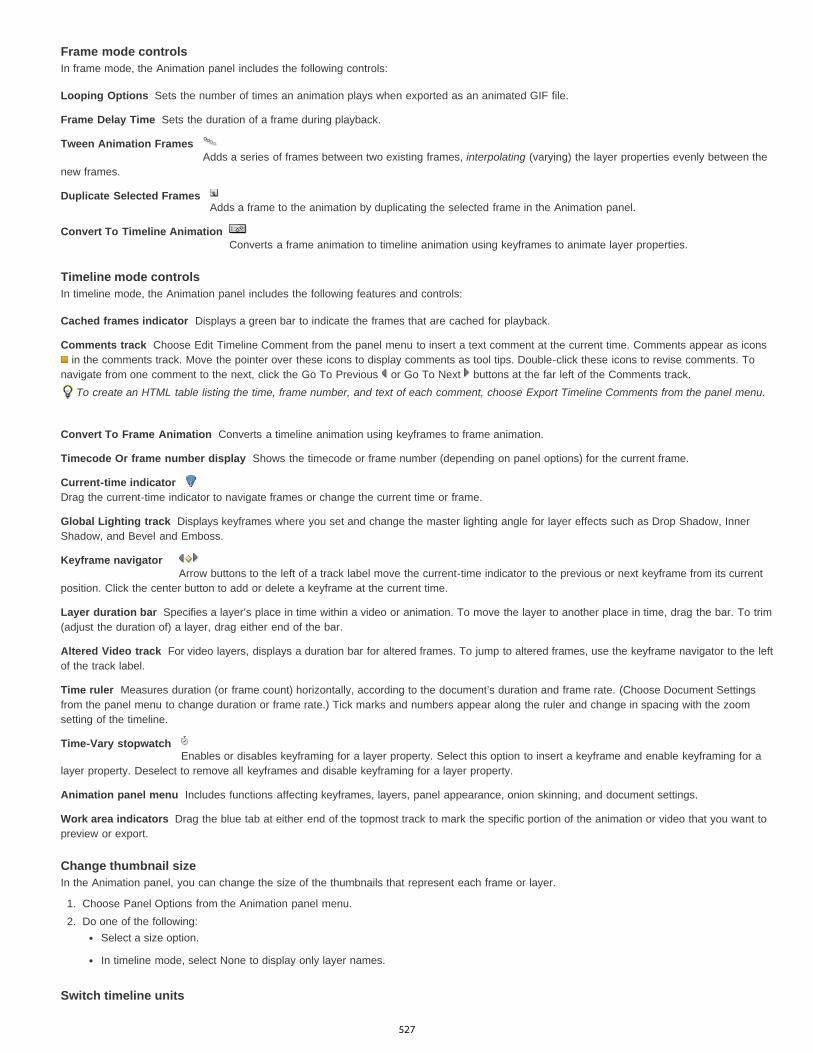
Looping Options
Frame Delay Time
Tween Animation Frames
Duplicate Selected Frames
Convert To Timeline Animation
Cached frames indicator
Comments track
Convert To Frame Animation
Timecode Or frame number display
Current-time indicator
Global Lighting track
Keyframe navigator
Layer duration bar
Altered Video track
Time ruler
Time-Vary stopwatch
Animation panel menu
Work area indicators
Frame mode controlsIn frame mode, the Animation panel includes the following controls:
Sets the number of times an animation plays when exported as an animated GIF file.
Sets the duration of a frame during playback.
Adds a series of frames between two existing frames, interpolating (varying) the layer properties evenly between thenew frames.
Adds a frame to the animation by duplicating the selected frame in the Animation panel.
Converts a frame animation to timeline animation using keyframes to animate layer properties.
Timeline mode controlsIn timeline mode, the Animation panel includes the following features and controls:
Displays a green bar to indicate the frames that are cached for playback.
Choose Edit Timeline Comment from the panel menu to insert a text comment at the current time. Comments appear as icons in the comments track. Move the pointer over these icons to display comments as tool tips. Double-click these icons to revise comments. To
navigate from one comment to the next, click the Go To Previous or Go To Next buttons at the far left of the Comments track.To create an HTML table listing the time, frame number, and text of each comment, choose Export Timeline Comments from the panel menu.
Converts a timeline animation using keyframes to frame animation.
Shows the timecode or frame number (depending on panel options) for the current frame.
Drag the current-time indicator to navigate frames or change the current time or frame.
Displays keyframes where you set and change the master lighting angle for layer effects such as Drop Shadow, InnerShadow, and Bevel and Emboss.
Arrow buttons to the left of a track label move the current-time indicator to the previous or next keyframe from its currentposition. Click the center button to add or delete a keyframe at the current time.
Specifies a layer’s place in time within a video or animation. To move the layer to another place in time, drag the bar. To trim(adjust the duration of) a layer, drag either end of the bar.
For video layers, displays a duration bar for altered frames. To jump to altered frames, use the keyframe navigator to the leftof the track label.
Measures duration (or frame count) horizontally, according to the document’s duration and frame rate. (Choose Document Settingsfrom the panel menu to change duration or frame rate.) Tick marks and numbers appear along the ruler and change in spacing with the zoomsetting of the timeline.
Enables or disables keyframing for a layer property. Select this option to insert a keyframe and enable keyframing for alayer property. Deselect to remove all keyframes and disable keyframing for a layer property.
Includes functions affecting keyframes, layers, panel appearance, onion skinning, and document settings.
Drag the blue tab at either end of the topmost track to mark the specific portion of the animation or video that you want topreview or export.
Change thumbnail sizeIn the Animation panel, you can change the size of the thumbnails that represent each frame or layer.
1. Choose Panel Options from the Animation panel menu.2. Do one of the following:
Select a size option.
In timeline mode, select None to display only layer names.
Switch timeline units
527

To the top
Note:
To the top
Note:
You can display the Animation panel timeline in either frame number or timecode units.
To select units to display, choose Panel Options from the Animation panel menu and select Frame Numbers or Timecode.To toggle between units, Alt-click (Windows) or Option-click (Mac OS) the current-time display in the upper-left corner of the timeline.
Show or hide layer properties in the timelineAs you add layers to a document, they appear as tracks in the timeline. Expand layer tracks to show layer properties that can be animated.
To show or hide layer properties, click the triangle to the left of the layer name.
Show or hide layers in the timelineAll document layers appear in the timeline by default. To show only a subset of layers, first set them as favorites.
1. In timeline mode, select one or more layers from the Animation panel, then choose Show > Set Favorite Layers in the Animation panelmenu.
2. To specify which layers are displayed, choose Show from the Animation panel menu, then select All Layers or Favorite Layers.
Navigate the timelineWith the Animation panel in timeline mode, do any of the following:
Drag the current-time indicator .
Click a number or location in the time ruler where you want to position the current-time indicator.
Drag the current-time display (in the upper-left corner of the timeline).
Double-click the current-time display and enter a frame number or time in the Set Current Time dialog box.
Use the playback controls in the Animation panel.
Choose Go To in the Animation panel menu, and then choose a timeline option.
Switch animation modesYou can use the Animation panel in either frame or timeline animation mode. Frame mode shows each separate frame, letting you set uniqueduration and layer properties for each. Timeline mode shows frames in a continuous timeline, letting you animate properties with keyframes andplay video layers.
Ideally, you should select the mode you want before starting an animation. However, it’s possible to switch animation modes in an open document,converting a frame animation to a timeline animation, or vice versa.
You may lose some interpolated keyframes when converting a timeline animation to a frame animation. The animation appearance doesn’tchange, however.
In the Animation panel, do any of the following:Click the Convert To Frame Animation icon .
Click the Convert To Timeline Animation icon .
From the Animation panel menu, choose either Convert To Frame Animation or Convert To Timeline.
Specify timeline duration and frame rateWhen you are working in timeline mode, you can specify the duration and frame rate of a document containing video or animation. Duration is theoverall time length of the video clip, from the first frame you specify to the last. Frame rate or frames per second (fps), is usually determined by thetype of output you produce: NTSC video has a frame rate of 29.97 fps; PAL video has a frame rate of 25 fps; and motion picture film has a framerate of 24 fps. Depending on the broadcast system, DVD video can have the same frame rate as NTSC video or PAL video, or a frame rate of23.976. Video intended for CD-ROM or the web typically has a frame rate of 10 to 15 fps.
When you create a new document, the default timeline duration is 10 seconds. The frame rate depends on the chosen document preset. For non-video presets (like International Paper), the default rate is 30 fps. For video presets, the rate is 25 fps for PAL and 29.97 for NTSC.
1. From the Animation panel menu, choose Document Settings.2. Enter or choose values for Duration and Frame Rate.
Reducing the duration of an existing video or animation has the effect of trimming frames (and any keyframes) from the end of thedocument.
Creating images for video
Load video actions
Adjustment and fill layers
528

Twitter™ and Facebook posts are not covered under the terms of Creative Commons.
Legal Notices | Online Privacy Policy
Set the timeline area to preview
Understanding the timeline mode video
529
Saving and exporting video and animations
Note:
To the top
To the top
Bounding Box
Redundant Pixel Removal
Note:
To the top
To the top
Video and animation export formatsOptimize animation framesFlatten frames into layersExport video files or image sequencesSpecify QuickTime Movie settings (Photoshop Extended CS5)
For Photoshop versions earlier than Photoshop CC, some functionality discussed in this article may be available only if you have PhotoshopExtended. Photoshop CC does not have a separate Extended offering. All features in Photoshop Extended are part of Photoshop CC.
Video and animation export formatsYou can save animations as GIF files for viewing on the web. Videos and animations can be saved as QuickTime movies or PSD files. If you’re notrendering your work to video, then saving the file as PSD is best because it preserves the edits and saves the file in a format that’s supported byAdobe digital video applications and many motion picture editing applications.
Optimize animation framesAfter you complete your animation, optimize it for efficient download to a web browser. You optimize an animation in two ways:
Optimize the frames to include only areas that change from frame to frame. This greatly reduces the file size of the animated GIF file.
If you are saving your animation as a GIF image, optimize it as you would any GIF image. A special dithering technique is applied toanimations to ensure that dither patterns are consistent across all frames and to prevent flickering during playback. Due to these additionaloptimization functions, more time may be required to optimize an animated GIF than to optimize a standard GIF.
When optimizing the colors in an animation, use the Adaptive, Perceptual, or Selective palette. This ensures that the colors are consistentacross frames.
1. Make sure that the Timeline panel (CC, CS6) or Animation panel (CS5) is in the frame animation mode.
2. Choose Optimize Animation from the panel menu.
3. Set the following options:
Crops each frame to the area that has changed from the preceding frame. Animation files created using this option aresmaller but are incompatible with GIF editors that do not support the option. (This option is selected by default and is recommended.)
Makes all pixels transparent in a frame that are unchanged from the preceding frame. The Transparency optionin the Optimize panel must be selected for redundant pixel removal to work. (This option is selected by default and is recommended.)
Set the frame disposal method to Automatic when using the Redundant Pixel Removal option. (See Choose a frame disposalmethod.)
4. Click OK.
Flatten frames into layersWhen you flatten frames into layers, a single layer is created for each frame in a video layer. This can be useful, for example, if you’re exportingthe individual video frames as separate image files, or if you’re planning to use the video of a static object in an image stack.
1. In the Timeline (CC, CS6), Animation (CS5), or Layers panel, select the video layer.
2. In the Timeline (CC, CS6) or Animation (CS5) panel, choose Flatten Frames Into Layers from the panel menu.
Export video files or image sequencesFor a video on image sequences, see www.adobe.com/go/vid0026
530

All Frames
Start Frame and End Frame (CC, CS6)
Work Area (CC, CS6)
In Frame and Out Frame (Photoshop Extended CS5)
Currently Selected Frames (Photoshop Extended CS5)
Note:
Alpha Channel
3D Quality (CC, CS6)
Frame Rate (Photoshop Extended CS5)
3G
FLC
Flash Video (FLV)
QuickTime Movie
AVI
DV Stream
Image Sequence
1. Choose File > Export > Render Video.2. In the Render Video dialog box, enter a name for the video or image sequence.3. Click the Select Folder button, and navigate to the location for the exported files.
To create a folder to contain your exported file, select the Create New Subfolder option and enter a name for the subfolder.
4. Do one of the following to export a view or image sequence:
(CC, CS6) Choose either Adobe Media Encoder or Photoshop Image Sequence from the menu below the Location section of the RenderVideo dialog box. Then choose a file format from the pop-up menu. If you chose Adobe Media Encoder, you have the choice of CPS,H.264, and QuickTime formats.(CS5) Under File Options, select either QuickTime Export or Image Sequence. Then choose a file format from the pop-up menu.
5. (Optional) Specify format-specific options:
(CC, CS6) Choose options from the menus below the file format menu.(CS5) Click the Settings button and set options in the Movie Settings dialog box.
6. (Optional) If you chose Image Sequence in step 4, specify the Starting and Digits numbers. (These options specify the numbering system forthe exported files.) Then do any of the following if necessary:
Choose from the Size pop-up menu to specify the pixel dimensions for the exported files.Click the Settings button and specify the format-specific options.(CC, CS6) Choose a frame rate from the Document Frame Rate menu.
7. Under Range, select one of the following options:
Renders all the frames in the Photoshop document.
Specify the sequence of frames to render.
Renders the frames selected by the work area bar in the Timeline panel.
Specify the sequence of frames to render.
Renders the frames selected by the work area bar in the Animation panel.
The available Range options depend on the file format you chose.
8. (Optional) Specify render options:
Specifies how alpha channels are rendered. (This option is available only with formats that support alpha channels, such asPSD or TIFF). Select None to ignore the alpha channel, Straight-Unmatted to include the channel, or one of the Premultiplied options to mixa matte color with the color channels.
Controls how surfaces are rendered if your project includes 3D objects. Interactive is suitable for video games andsimilar uses. Ray Traced Draft is low quality but lets the video render qucikly. Ray Traced Final is high quality but the video takes a longtime to render.
Determines how many frames are created for each second of the video or animation. TheDocument Frame Rate option reflects the rate in Photoshop. If you’re exporting to a different video standard (from NTSC to PAL, forexample), choose the appropriate rate from the pop-up menu.
9. Click Render.
QuickTime export file formats (Photoshop Extended CS5)A file format developed for third-generation mobile devices.
An animation format for playback of computer-generated animations on workstations, Windows, and Mac OS. This format is also referred toas FLI.
Adobe® Flash® Video is the Adobe format for streaming audio and video over the web and other networks. (To use thisformat, you must first install an FLV QuickTime encoder).
The Apple Computer multimedia architecture that includes a number of codecs. (To export audio, you must use this format.)
Audio Video Interleave (AVI) is a standard format for audio and video data on Windows computers.
A video format with intraframe compression that uses FireWire (IEEE 1394) interface to transfer video to nonlinear editing systems.
A sequence of still images that can reside within one folder and use the same numeric or alphabetic filename pattern (such asSequence1, Sequence2, Sequence3, and so on).
531
MPEG-4
Note:
File Format
Video
Video Format
Data Rate
Optimized For
Image Size
Preserve Aspect Ratio Using
Frame Rate
Key Frame
Video Options
Audio
Text
Streaming
Enable Streaming
Optimize For Server
Advanced
Restrict Distribution
Fragment Movie
A multimedia standard for delivering audio and video streams over a range of bandwidths.
Photoshop also supports other third-party formats such as Avid AVR codecs; however, the necessary QuickTime codecs must be installed.
Understanding QuickTime key framesIn QuickTime terminology, the term key frames refers to something different than the animation keyframes in Photoshop. In QuickTime, key framesoccur at regular intervals in the movie and are stored as complete frames. Each intermediate frame that separates them is compared to theprevious frame, and only changed data is stored. Using key frames greatly reduces movie size and greatly increases the memory required to editand render a movie. Shorter intervals between key frames enable faster seeking and reverse playback, but can significantly increase the size ofthe file.
3G export settings (Photoshop Extended CS5)For more information on 3G settings, search for 3G on the Apple Computer web site.
3GPP and 3GPP2 are standards for the creation, delivery, and playback of multimedia over third-generation high-speed wirelessnetworks. 3GPP is for GSM networks and 3GPP2 is for CDMA 2000 networks. 3GPP (Mobile MP4), 3GPP2 (EZmovie), and AMC (EZmovie) arefor specific networks. 3GPP (Mobile MP4) is for NTT DoCoMo’s i-motion 3G service. 3GPP2 (EZmovie) is for KDDI’s 3G network service. AMC(EZmovie) is for KDDI subscribers with AMC-capable phones.
Choose Video from the pop-up menu below the File Format menu and specify the following:
Selects the codec used during video export. If your source movie has only one video track and it is already compressed,you can choose Pass Through so that the video doesn't get compressed again.
Specifies the kilobits per second (kbps) during playback. A higher kbps rate usually improves movie playback quality; however,don't choose a data rate higher than the available bandwidth.
Specifies the intended delivery method if you choose H.264 from the Video Format menu, click Video Options, and selectBest Quality. This setting tells the codec how much the data rate can vary above and below the data rate you choose.
Specifies a standard for sending the file to a mobile phone. Current maintains the source material size; the resulting file maynot play on a mobile phone. Choose Custom to specify a size not listed in the menu.
Specifies an option when you’re changing the image size and the movie must be scaled to the newdimensions. Letterbox scales the source proportionally to fit into the clean aperture, adding black bars to the top and bottom or sides asnecessary. Crop centers, scales, and trims to the clean aperture.
Specifies the frames per second (fps) during playback. In most cases, your video looks better if you choose a number thatyour source fps is exactly divisible by. For example, if your source is captured at 30 fps, choose a frame rate of 10 or 15. Don't choose arate larger than that of your source material.
Specifies how frequently key frames are created in the exported video. A higher key frame rate (lower number) improvesvideo quality, but increases the file size.
If available, click the Video Options button to open the 3G Advanced Video Settings dialog box. Depending on the video,you can specify whether to add re-sync markers inside the video frames to help with packet loss recovery when streaming. With H.264video, you can also speed up the compression process (for preview purposes, for example) by choosing Faster Encode (Single-pass). Thedefault option, Best Quality (Multi-pass), allows the codec to determine how many passes are needed to compress the data for the bestquality.
All audio options are disabled because Photoshop Extended does not include audio in exported 3G files.
All text options are disabled because Photoshop Extended does not include text tracks in exported 3G files.
Choose Streaming from the pop-up menu below the File Format menu and specify the following:
Creates a file for RTSP streaming to QuickTime Player. This option creates a hint track (instructions necessary forstreaming a file).
Helps the server to process the file faster, but increases the file size.
Choose Advanced from the pop-up menu below the File Format menu and specify the following:
Specifies how many times the file can play back on the handset once downloaded. Also specifies file expirationoptions: set the file to expire in a number of days or enter a date. If your file is in Mobile MP4 or EZmovie format, you can restrictdistribution so that once the file is on a handset it can't be sent or copied elsewhere.
Enables the file to download via HTTP in small pieces so that playback can start faster and so that larger files can beplayed on the handset (only the fragment, not the entire movie, must fit on the handset at one time).
532

Color Table
Motion
Note:
Compression Type
Frame Per Second
Key Frame Every
Limit Data Rate To
Depth
Quality
Scan Mode
Aspect Ratio
Options
DV Format
Video Format
Scan Mode
Aspect Ratio
Preserve Aspect Ratio Using
Note:
FLC export settings (Photoshop Extended CS5)The following options are available in the FLC Export Settings dialog box:
Specifies the color table using the Windows system colors or Mac OS system colors in the exported movie.
Sets the playback frame rate.
Specify AVI export settings (Photoshop Extended CS5)1. In the Render Video dialog box, select QuickTime Export and then choose AVI from the pop-up menu.2. Click the Settings button.3. In the AVI Settings dialog box, make sure Video is selected.
Sound options are disabled because Photoshop Extended does not include audio in exported AVI files.
4. Under Video, click the Settings button and set the following:
Chooses the video compressor (codec) to compress your video.
Specifies the number of individual images shown every second. NTSC is generally the standard video format and is29.97 fps. PAL is a European video format that is 25 fps. The standard for film is 24 fps. QuickTime movies are sometimes created with aslower frame rate to reduce bandwidth and CPU requirements.
Movies with higher frame rates display motion better, but have larger file sizes. If you choose a frame rate that's lower than the movie'scurrent frame rate, frames are deleted. If you choose a number that's higher than the movie's current frame rate, existing frames areduplicated (not recommended, since it increases file size without improving quality). In most cases, your video will look better if you choose anumber that your source fps is exactly divisible by. For example, if your source is captured at 30 fps, choose a frame rate of 10 or 15. Don'tchoose a rate larger than that of your source material.
Specifies the key frame frequency. A higher key frame rate (lower number) improves video quality, but increases the filesize. With some compressors, an additional key frame is inserted automatically if too much of the image has changed from one frame to thenext. In general, one key frame every 5 seconds (multiply the frames per second by 5) is usually sufficient. If you are creating a file forRTSP streaming and have concerns about the reliability of the delivery network, you may want to increase key frame frequency to one keyframe every 1 or 2 seconds.
Specifies the kilobits per second (kbps) during playback. A higher kbps rate usually improves movie playback quality;however, don't choose a data rate higher than the available bandwidth.
Specifies the number of colors to include in video that you export. This menu is not available if the selected codec supports only onecolor depth.
If available, drag the slider or type a value to adjust the exported video’s picture quality and, consequently, its file size. If you areusing the same codec to capture and export, and you’ve rendered previews of a sequence, you can save rendering time by matching theexport quality setting with your original capture quality setting. Increasing quality above the original capture quality does not increase quality,but may result in longer rendering times.
Specifies whether the exported movie has fields (Interlaced) or no fields (Progressive).
Specifies a 4:3 or 16:9 aspect ratio for the exported movie.
(Intel Indeo® Video 4.4 only) Sets compression, transparency options, and access for the Intel Indeo® Video 4.4 codec.
DV Stream export settings (Photoshop Extended CS5)The following options are available in the DV Export Settings dialog box:
Specifies either the DV or DVCPRO format for your exported video.
Specifies either NTSC or PAL video broadcast standard.
Specifies whether the exported video has interlaced fields or no fields (Progressive Scan).
Specifies an aspect ratio of 4:3 or 16:9.
Specifies an option if the movie is scaled to new pixel dimensions. Letterbox scales the source proportionally to fitinto the clean aperture, adding black bars to the top and bottom or sides as necessary. Crop centers, scales, and trims to the clean aperture.
Although the DV Export Settings dialog box has Audio Format options, Photoshop Extended does not export audio in DV files.
Image sequence settings for QuickTime export (Photoshop Extended CS5)
533
Format
Frames Per Second
Insert Space Before Number
Options
Video Format
Data Rate
Optimized For
Image Size
Preserve Aspect Ratio Using
Frame Rate
Key Frame
Re-sync Markers
Restrict Profile(s) To
Encoding Mode
To the top
Note:
Settings
Filter
Typically, QuickTime is used to export video files. However, you can also select Image Sequence from the QuickTime Export pop-up menu. ClickSettings to access the following options:
Chooses a file format for the exported images.
Sets the frame rate for the image sequence.
Inserts a space between the name and generated number in the image’s filename.
If available, click the Options button and set format-specific options.For more information on the specific file formats and their options, see also Saving and exporting images and File formats.
Specify MPEG-4 export settings (Photoshop Extended)1. In the Render Video dialog box, select QuickTime Export, and choose MPEG-4 from the pop-up menu. Then click Settings.2. In the MPEG-4 Export Settings dialog box, choose MP4 or MP4 (ISMA) from the File Format menu. The MP4 (ISMA) format ensures
operability with devices made by ISMA members.3. Under Video, specify the following:
Chooses the codec to compress your video. For the highest quality at the lowest data rate (or the smallest file), H.264 isrecommended. If you need the file to play on a device that supports MPEG-4 video, choose MPEG-4 Basic or MPEG-4 Improved,depending on the target device. If your source movie’s video track is already compressed, you can choose Pass Through so that the videodoesn't get compressed again.
Specifies the kilobits per second (kbps) during playback. A higher kbps rate usually improves movie playback quality; however,don't choose a data rate higher than the available bandwidth.
Specifies how much the data rate can vary above and below the data rate you choose. This option becomes available if youchoose MP4 from the File Format menu, choose H.264 from the Video Format menu, click Video Options, and select Best Quality.
Specifies the pixel dimensions of your exported video. Current maintains the source material size. To specify a size not listed inthe Image Size menu, choose Custom.
Specifies an option if the movie needs to be scaled to the new pixel dimensions. Letterbox scales the sourceproportionally to fit into the clean aperture, adding black bars to the top and bottom or sides as necessary. Crop centers, scales, and trims tothe clean aperture. Fit Within Size adjusts to the destination size by fitting to the longest side, scaling if necessary.
Specifies the frame rate for the playback of your exported video. Usually, your video looks better if you choose a number thatis exactly divisible by the frames per second (fps) of your source. For example, if your source is captured at 30 fps, choose a frame rate of10 or 15. Don’t choose a rate greater than that of your source material.
Specifies that key frames are generated automatically or specifies how frequently key frames are created in the exported video.A higher key frame rate (lower number) improves video quality, but increases the file size.
4. (MP4 file format only) Click the Video Options button and specify the following:
(MPEG-4 Basic and MPEG-4 Improved only) Uses re-sync markers in the video bit-stream. This can help regainsynchronization due to transmission errors.
(H.264 only) Selects profiles for playing video files on a device that conforms to one or more of the standard'sprofiles.
(H.264 only) Specifies whether you want the best quality or faster encoding.
Specify QuickTime Movie settings (Photoshop Extended CS5)1. In the Render Video dialog box, select QuickTime Export and then choose QuickTime Movie from the pop-up menu.2. Click the Settings button.3. In the Movie Settings dialog box, make sure Video is selected.
Although the Movie Settings dialog box displays Sound options, you cannot adjust the current audio settings. To include audio inexported files, see Preview audio for video layers (Photoshop Extended).
4. Under Video, click the appropriate button to set the following:
Opens the Standard Video Compression Settings dialog box so you can set the video compression and accompanying options.
Opens the Choose Video Filter dialog box, where you can apply built-in QuickTime video effects.
534

Twitter™ and Facebook posts are not covered under the terms of Creative Commons.
Legal Notices | Online Privacy Policy
Size
Fast Start
Fast Start-Compressed Header
Hinted Streaming
Compression Type
Motion
Data Rate
Compressor
Note:
Dimensions
Preserve Aspect Ratio Using
Deinterlace Source Video
Opens the Export Size Settings dialog box to specify pixel dimensions for your exported video.
5. (Optional) If your movie is being delivered over the Internet, select Prepare For Internet Streaming and choose any of the following:
Sets up the movie to start playing from a web server before the movie has completely downloaded to a user’s computer harddrive.
Compresses the movie’s header losslessly and sets up the movie to start playing from a web server beforethe movie has completely downloaded to a user’s computer hard drive.
Sets up the movie to be streamed by a QuickTime Streaming Server.
QuickTime standard video compression settings (Photoshop Extended CS5)The following options are available in the Standard Video Compression Settings dialog box:
Choose the codec to apply when exporting a file.
Specify the frame rate for your video by choosing the number of frames per second (fps). Some codecs support a specific set of framerates. Increasing the frame rate may produce smoother motion (depending on the original frame rates of the source clips) but uses more diskspace. If available, specify how often the key frames are generated. (See Understanding QuickTime key frames.)
Select (if available for the selected compressor) and type a data rate to place an upper limit on the amount of video data produced bythe exported video when it is played back.
Set compressor options specific to the selected codec. Click the Option button (if available) to specify further compressor options. Ifthe Depth menu is available, choose the number of colors to include in exported video. (This menu is not available if the selected codec supportsonly one color depth.)If the Quality slider is available under Compressor, drag the slider or type a value to adjust the exported video’s picture quality and, consequently,its file size. If you are using the same codec to capture and export, and you’ve rendered previews of a sequence, you can save rendering time bymatching the export quality setting with your original capture quality setting. Increasing quality above the original capture quality does not increasequality, but may result in longer rendering times.
Compressor options are not available for the Component Video codec.
QuickTime movie size settings (Photoshop Extended CS5)The following settings are available in the Export Size Settings dialog box:
Specifies the frame size for your exported movie. If you want to specify a frame size not included in the Dimensions menu, chooseCustom and enter values for Width and Height.
Specifies an option if the movie is scaled to a new frame size. Letterbox scales the source proportionally to fit intothe clean aperture, adding black bars to the top and bottom or sides as necessary. Crop centers, scales, and trims to the clean aperture. Fit WithinDimensions adjusts to the destination size by fitting to the longest side, scaling if necessary.
Deinterlaces the two fields in each interlaced video frame.Optimizing images
Image stacks (Photoshop Extended)
Interpret video footage (Photoshop Extended)
535

Importing video files and image sequences
To the top
To the top
To the top
Open or import a video fileImport image sequencesPlace a video or image sequenceReload footage in a video layerReplace footage in a video layerInterpreting video footage
Open or import a video fileIn Photoshop CS6 and Photoshop Extended CS5, you can open a video file directly or add video to an open document. When you import video,the image frames are referenced in a video layer.
For a video on working with video layers, see www.adobe.com/go/vid0027
1. Do one of the following:
To open a video file directly, choose File > Open.
To import video into an open document, choose Layer > Video Layers > New Video Layer From File.
2. In the Open dialog box, for Files Of Type (Windows) or Enable (Mac OS), choose either All Readable Documents or QuickTime Movie.3. Select a video file and then click Open.
You can also open video directly from Bridge: select a video file and then choose File > Open With > Adobe Photoshop.
Import image sequencesIn Photoshop CS6 and Photoshop Extended CS5, when you import a folder of sequenced image files, each image becomes a frame in a videolayer.
For a video on image sequences, see www.adobe.com/go/vid0026.
1. Make sure that the image files are in one folder and are named sequentially.
The folder should contain only those images you want to use as frames. The resulting animation will be more successful if all files have thesame pixel dimensions. To order frames correctly for the animation, name the files in alphabetical or numeric order. For example,filename001, filename002, filename003, and so forth.
2. Do one of the following:
To open an image sequence directly, choose File > Open.
To import an image sequence into an open document, choose Layer > Video Layers > New Video Layer From File.
3. In the Open dialog box, navigate to the folder with image sequence files.4. Select one file, choose the Image Sequence option, and then click Open.
Note: Selecting more than one file in an image sequence disables the Image Sequence option.5. Specify the frame rate, and click OK.
Place a video or image sequenceIn Photoshop CS6 or Photoshop Extended CS5, use the Place command if you want to transform the video or image sequence as you import itinto a document. Once placed, the video frames are contained within a Smart Object. When video is contained by a Smart Object, you cannavigate through the frames using the Animation panel, and you can also apply Smart Filters.Note: You can’t paint or clone directly on video frames contained by a Smart Object. However, you can add a blank video layer above the SmartObject, and paint on the blank frames. You can also use the Clone tool with the Sample All Layers option to paint on blank frames. This lets youuse the video in the Smart Object as a cloning source.
1. With a document open choose File > Place.2. In the Place dialog box, do one of the following:
Select a video file and click Place.
Select one image sequence file, select the Image Sequence option, and then click Place.
536

To the top
To the top
To the top
Note: Make sure all the image sequence files are in one folder.
3. (Optional) Use the control points to scale, rotate, move, or warp the imported content.
4. Click the Commit Transform button in the options bar to place the file.
You can also place video directly from Adobe Bridge. Select the video file and then choose File > Place > In Photoshop.
Reload footage in a video layerIf the source file for a video layer is modified in a different application, Photoshop CS6 and Photoshop Extended CS5 generally reloads andupdates the footage, when you open the document containing the video layer referencing the changed source file. If your document is alreadyopen and the source file has been modified, use the Reload Frame command to reload and update the current frame in the Animation panel.Navigating through the video layer using the Previous/Next Frame or Play button in the Animation panel should also reload and update thefootage.
Replace footage in a video layerPhotoshop CS6 and Photoshop Extended CS 5 tries to maintain the link between the video layer and source file even if you move or rename thesource. If the link breaks for some reason, an alert icon appears on the layer in the Layers panel. To relink the video layer to the source file,use the Replace Footage command. This command can also replace the video or image sequence frames in a video layer with frames from adifferent video or image sequence source.
1. In the Animation (Photoshop Extended CS5), Timeline (CS6), or Layers panel, select the video layer that you want to relink to the source fileor to replace the content.
2. Choose Layer > Video Layers > Replace Footage.3. In the Open dialog box, select a video or image sequence file, and then click Open.
Interpreting video footage
Interpret video footageYou can specify how Photoshop CS6 or Photoshop Extended CS5 interprets the alpha channel and frame rate of the video you’ve opened orimported.
1. In the Animation (Photoshop Extended CS5), Timeline (CS6), or Layers panel, select the video layer that you want to interpret.2. Choose Layer > Video Layers > Interpret Footage.3. In the Interpret Footage dialog box, do any of the following:
To specify how the alpha channel in the video layer is interpreted, select an Alpha Channel option. The footage must have an alphachannel for this option to be available. If Premultiplied-Matte is selected, you can specify the matte color with which the channels arepremultiplied.
To specify the number of video frames played per second, enter a Frame Rate.
To color-manage the frames or images in a video layer, choose a profile from the Color Profile menu.
Alpha channel interpretation in video and image sequencesVideo and image sequences with alpha channels can be straight or premultiplied. If you’re working with video or image sequences containingalpha channels, it’s important to specify how Photoshop interprets the alpha channel to get the results you expect. When premultiplied video orimages are in a document with certain background colors, it’s possible to get undesirable ghosting or halos. You can specify a matte color so thesemi-transparent pixels blend (multiply) with the background without producing halos.
Ignore Ignores the alpha channel in the video.Straight-Unmatted Interprets the alpha channel as straight alpha transparency. If the application you used to create the video doesn’t premultiplythe color channels, select this option.Premultiplied-Matte Uses the alpha channel to determine how much of the matte color to mix with the color channels. If necessary, click the colorswatch in the Interpret Footage dialog box to specify the matte color.
537
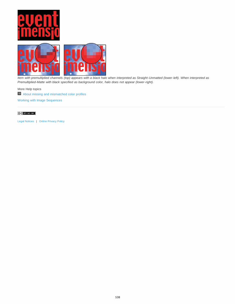
Item with premultiplied channels (top) appears with a black halo when interpreted as Straight-Unmatted (lower-left). When interpreted asPremultiplied-Matte with black specified as background color, halo does not appear (lower-right).
More Help topics About missing and mismatched color profiles
Working with Image Sequences
Legal Notices | Online Privacy Policy
538

Painting frames in video layers
To the top
To the top
Paint frames in video layersCloning content in video and animation framesRestore frames in video layersManaging color in video layers
Paint frames in video layersYou can edit or paint on individual video frames to create an animation, add content, or to remove unwanted details. In addition to using any brushtool, you can paint using the Clone Stamp, Pattern Stamp, Healing Brush, or Spot Healing Brush. You can also edit video frames using the Patchtool.
Note: Painting (or using any other tool) on video frames is often called rotoscoping; although traditionally, rotoscoping involves theframe-by-frame tracing of live action images for use in animation.
1. In the Animation (Photoshop Extended CS5), Timeline (CS6), or Layers panel, select the video layer.2. Move the current time indicator to the video frame you want to edit.3. (Optional) If you want your edits to be on a separate layer, choose Layers > Video Layers > New Blank Video Layer.4. Select the brush tool that you want to use and apply your edits to the frame.
Painting on a video layer is nondestructive. To discard the altered pixels on a specific frame or video layer, choose the Restore Frame orRestore All Frames command. To toggle on and off the visibility of altered video layers, choose the Hide Altered Video command (or clickthe eyeball next to the altered video track in the timeline).
Cloning content in video and animation framesIn Photoshop Extended CS5 or Photoshop CS6, you can use the Clone Stamp and Healing Brush tools to retouch or duplicate objects in video oranimation frames. Use the Clone Stamp to sample content from one part of a frame (the source) and paint it over another part of the same ordifferent frame (the target). You can also use a separate document as the sampling source, instead of a frame. The Healing Brush includesoptions for blending the sampled content with the target frame.
Note: You can also clone content with the Spot Healing Brush and the Patch tools. However, the Clone Stamp and the Healing Brush tools letyou store up to five samples in the Clone Source panel, and set overlay, scaling, and frame offset options.After you sample content from a frame and paint with it, and then move to another frame, the source frame changes relative to the frame youinitially sampled from. You can lock in the source frame you first sampled, or enter a frame offset value to change the source to a different frame,relative to the frame you first sampled.
For a video on cloning frames, see www.adobe.com/go/vid0025.
Clone video or animation content1. Select the Clone Stamp tool or Healing Brush tool , and then set the tool options you want.2. Do one of the following:
Select a video layer in the Layers panel, Animation panel (Photoshop Extended CS5), or Timeline panel (CS6), and then move thecurrent-time indicator to the frame you want to sample.
Open the image you want to sample.
3. Position the pointer in an open image or frame, and Alt-click (Windows) or Option-click (Mac OS) to set the sampling point.
4. To set additional sampling points, click each clone source button in the Clone Source panel.5. Select the target video layer and move the current-time indicator to the frame you want to paint.
If you want to paint on a separate layer, you can add a blank video layer. Make sure you choose the appropriate Sample option to clonecontent onto the blank video layer.
6. If you have set multiple sampling points, select the source you want to use in the Clone Source panel.7. Do any of the following in the Clone Source panel:
To scale or rotate the source that you’re cloning, enter a value for W (width) or H (height), or the rotation in degrees .
To show an overlay of the source that you’re cloning, select Show Overlay and specify the overlay options. (The Clipped option restrictsthe overlay to the brush size. Deselect this option to overlay the entire source image.)
539
To the top
To the top
To move the source overlay to an offset position, Shift + Alt-drag (Windows) or Shift + Option-drag (Mac OS). To temporarily showoverlays, deselect Show Overlay, and press Shift + Alt (Windows) or Shift + Option (Mac OS).
8. Drag over the area of the frame you want to paint.
Painting on a video layer is nondestructive. You can choose the Restore Frame or Restore All Frames command to discard the alteredpixels on a specific frame or video layer.
Change frame offset for cloning or healing In the Clone Source panel:
To always paint using the same frame you initially sampled from, select Lock Frame.
To paint using a frame relative to the frame you initially sampled from, enter the number of frames in the Frame Offset box. If the frame youwant to use is after the frame you initially sampled, enter a positive value. If the frame you want to use is before the frame you initiallysampled, enter a negative value.
Restore frames in video layersYou can discard edits made to frame video layers and blank video layers.
In the Animation panel (Photoshop Extended CS5) or Timeline panel (CS6), select a video layer and do one of the following:
To restore a specific frame, move the current-time indicator to the video frame and choose Layer > Video Layers > Restore Frame.
To restore all the frames in a video layer or blank video layer, choose Layer > Video Layers > Restore All Frames.
Managing color in video layersIn Photoshop Extended CS5 and Photoshop CS6, you can paint on video layers using tools such as the brush tool or the clone stamp tool. If nocolor profile is assigned to the video layer, these pixel edits are stored using the document file’s color space, and the video footage itself is leftunchanged. If the color space of the imported footage is different from the color space of your Photoshop document, you may need to makeadjustments. For example, a standard definition video movie may be in SDTV 601 NTSC, while the Photoshop document is in Adobe RGB. Yourfinal exported video or document might not have the colors you expect due to the color space mismatch.
Before investing a lot of time painting or editing video layers, test your complete workflow to understand your color management needs and findthe approach that works best for your workflow.
Often, you can solve a mismatch by assigning a color profile to the document that corresponds to the imported footage, and leaving the videolayer unmanaged. For example, with standard definition video, you can leave the video layer unmanaged and assign the document the SDTV(Rec. 601 NTSC) color profile. In this case, the imported frame pixels are stored directly in the video layer without color conversion.
Conversely, you can assign the document’s color profile to the video layer using the Convert Edited Frame Content option (Layers > VideoLayers > Interpret Footage). This option converts the pixel edits to the document’s color space, but does not convert the colors of the videoframes.
The Convert To Profile command (Edit > Convert To Profile) also converts all pixel edits to the document’s color space. However, using theAssign Profile command (Edit > Assign Profile) does not convert the pixel edits to a video layer. Use the Assign Profile command with care,especially when you’ve painted on or edited video frames. If the video layer has a color profile, applying the Assign Profile command to thedocument may cause a color space mismatch between the pixel edits and the imported frames.
Some combinations of video footage and document color spaces require color conversion:
A grayscale movie in an RGB, CMYK, or Lab mode document requires color conversion.
Using 8- or 16-bpc footage in a 32-bpc document requires color conversion.
More Help topics Understanding color management
Assign or remove a color profile (Illustrator, Photoshop)
Convert document colors to another profile (Photoshop)
Legal Notices | Online Privacy Policy
540
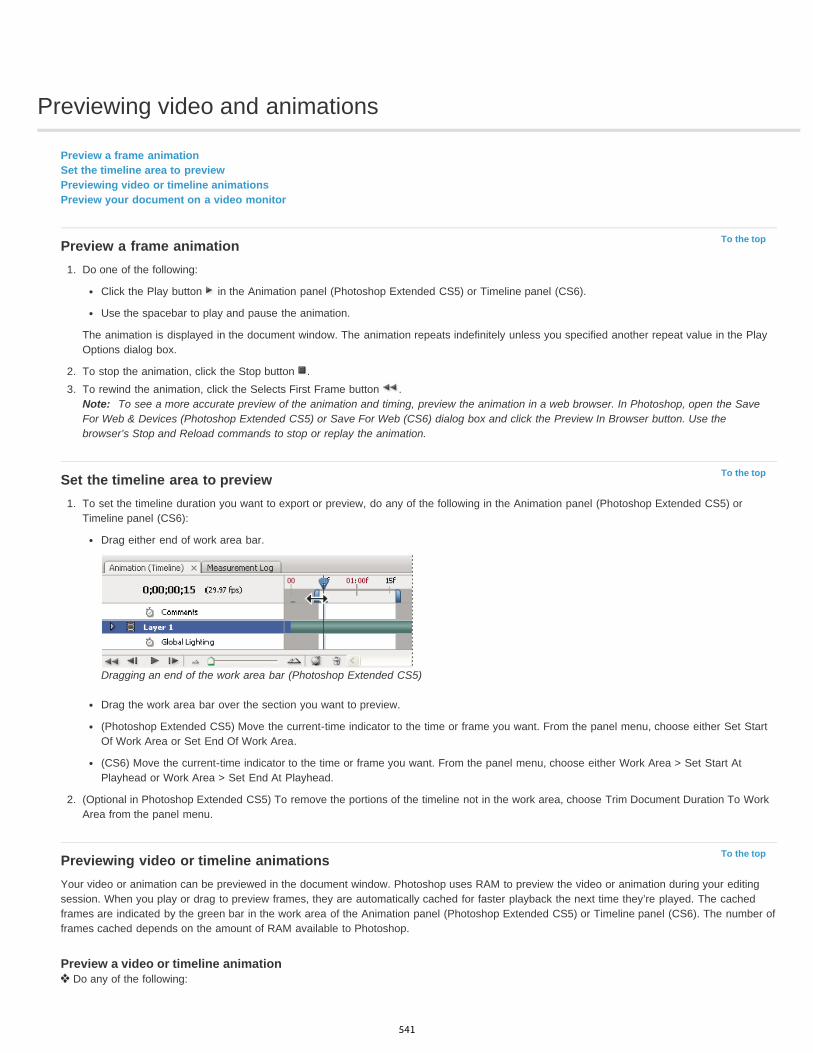
Previewing video and animations
To the top
To the top
To the top
Preview a frame animationSet the timeline area to previewPreviewing video or timeline animationsPreview your document on a video monitor
Preview a frame animation1. Do one of the following:
Click the Play button in the Animation panel (Photoshop Extended CS5) or Timeline panel (CS6).
Use the spacebar to play and pause the animation.
The animation is displayed in the document window. The animation repeats indefinitely unless you specified another repeat value in the PlayOptions dialog box.
2. To stop the animation, click the Stop button .3. To rewind the animation, click the Selects First Frame button .
Note: To see a more accurate preview of the animation and timing, preview the animation in a web browser. In Photoshop, open the SaveFor Web & Devices (Photoshop Extended CS5) or Save For Web (CS6) dialog box and click the Preview In Browser button. Use thebrowser’s Stop and Reload commands to stop or replay the animation.
Set the timeline area to preview1. To set the timeline duration you want to export or preview, do any of the following in the Animation panel (Photoshop Extended CS5) or
Timeline panel (CS6):
Drag either end of work area bar.
Dragging an end of the work area bar (Photoshop Extended CS5)
Drag the work area bar over the section you want to preview.
(Photoshop Extended CS5) Move the current-time indicator to the time or frame you want. From the panel menu, choose either Set StartOf Work Area or Set End Of Work Area.
(CS6) Move the current-time indicator to the time or frame you want. From the panel menu, choose either Work Area > Set Start AtPlayhead or Work Area > Set End At Playhead.
2. (Optional in Photoshop Extended CS5) To remove the portions of the timeline not in the work area, choose Trim Document Duration To WorkArea from the panel menu.
Previewing video or timeline animationsYour video or animation can be previewed in the document window. Photoshop uses RAM to preview the video or animation during your editingsession. When you play or drag to preview frames, they are automatically cached for faster playback the next time they’re played. The cachedframes are indicated by the green bar in the work area of the Animation panel (Photoshop Extended CS5) or Timeline panel (CS6). The number offrames cached depends on the amount of RAM available to Photoshop.
Preview a video or timeline animation Do any of the following:
541

To the top
In the timeline, drag the current-time indicator.
Use the playback buttons at the bottom of the Animation panel (Photoshop Extended CS5) or Timeline panel (CS6).
Press the spacebar to play or stop playback.
To see a more accurate preview of an animation created for the web, preview the animation in a web browser. Use the browser’s Stop andReload commands to stop or replay the animation. Open the Save For Web & Devices (Photoshop Extended CS5) or Save For Web (CS6)dialog box, and click the Preview In Browser button.
Preview audio for video layersWhen you enable audio previews for video layers, Photoshop includes the audio in files exported to QuickTime Movie format. (See Export videofiles or image sequences.)
In the Animation panel (Photoshop Extended CS5) or Timeline panel (CS6), do either of the following:
To enable or disable audio previews for a specific video layer, click the speaker icon for that layer.To enable or disable audio previews for an entire document, click the speaker icon to the right of the playback buttons at the bottom of thepanel.
Enable frame skippingPhotoshop can skip uncached frames to achieve real-time playback.
With the Animation panel (Photoshop Extended CS5) or Timeline panel (CS6) in timeline animation mode, choose Allow Frame Skipping fromthe panel menu.
Preview your document on a video monitorThe Video Preview plug-in lets you preview the current frame specified in the animation timeline (or any image open in Photoshop) throughFireWire (IEEE 1394) on a display device, such as a video monitor. You can also adjust the aspect ratio for proper display of images.
Note: On 64-bit operating systems, you must use the 32-bit version of Photoshop to access the Video Preview plug-in.The Video Preview plug-in supports RGB, grayscale, and indexed images. (The plug-in converts 16-bpc images to 8-bpc images.) The VideoPreview plug-in does not support alpha channels. Transparency is displayed as black.
Note: The Video Preview plug-in does not lock the display device. When Photoshop is in the background on your computer and anotherapplication moves into the foreground, the preview turns off and the device is unlocked so other applications can use it for preview purposes.
1. Connect a display device, such as a video monitor, to your computer via FireWire (IEEE 1394).2. With a document open in Photoshop, do one of the following:
If you don’t want to set output options for viewing your document on a device, choose File > Export > Send Video Preview To Device.You can skip the rest of the steps in this procedure.
To set output options before viewing your document on the device, choose File > Export > Video Preview.
The Video Preview dialog box opens. If your document’s pixel aspect ratio doesn’t match the aspect ratio settings of the display device, youwill see an alert.
Note: The Send Video Preview To Device command uses the previous settings in the Video Preview dialog box.3. Under Device Settings, specify options for the device that will display the image:
(Mac OS) To specify an output mode, select NTSC or PAL. If the output mode and the device do not match (for example, specifyingNTSC for the output mode and connecting to a device in PAL mode), black patches appear on previewing.
To specify the aspect ratio of the display device, choose either Standard (4:3) or Widescreen (16:9) from the Aspect Ratio menu.
Note: The Aspect Ratio setting determines which placement options are available.4. Under Image Options, choose a placement option to determine how the image appears in the display device:
Center Places the center of the image at the center of the screen, cropping the portions that fall outside the display edges of the videopreview device.
Pillarbox Displays a 4:3 image on a 16:9 display with the center of the image at the center of the screen and gray bands on the left andright sides of the image. This option is available only if you chose Widescreen (16:9) for the device aspect ratio.
Crop to 4:3 Displays a 16:9 image on a 4:3 display with the center of the image at the center of the screen and without distortion bycropping the left and right edges of the frame that fall outside the display edges of the video preview device. This option is available only ifyou chose Standard (4:3) for the device aspect ratio.
Letterbox Scales a 16:9 image to fit on a 4:3 display. Gray bands appear on the top and bottom of the image due the difference in aspectratio between the 16:9 image and the 4:3 display. This maintains the display aspect ratio without cropping or distorting the image. Thisoption is available only if you chose Standard (4:3) for the device aspect ratio.
Crop To 14:9/Letterbox Displays a widescreen image cropped to a 14:9 aspect ratio with black bands on either the top and bottom of the
542

image (when viewed on a 4:3 display) or on the left and right sides (when viewed on a 16:9 display). This maintains the display aspect ratiowithout distorting the image.
5. Choose an option from the Image Size menu to control whether the document pixels are scaled to the device display:Do Not Scale Applies no vertical scaling to the image. The image is cropped if its height is greater than that of the video display.
Scale To Fit Within Frame Increases or decreases the image height and width proportionally to fit in the video frame. With this option, a16:9 image appears on a 4:3 display as letterbox, and a 4:3 image appears on a 16:9 display as pillarbox.
6. Select the Apply Pixel Aspect Ratio To Preview check box to display the image using the document’s (nonsquare) pixel aspect ratio.Deselect this option to display the image as it appears on your computer (square pixel) monitor.
By default, the Apply Pixel Aspect Ratio To Preview check box is selected to maintain the image’s pixel aspect ratio. In general, you woulddeselect this option if the document’s pixel aspect ratio is assumed to be square and you want to view the image as it would appear on acomputer (square pixel) monitor.
7. Click OK to export the document to the device display.
More Help topics Preview optimized images in a web browser
Legal Notices | Online Privacy Policy
543
Filters and effects
Blur gallery overviewKelby (May. 7, 2012)video-tutorialQuick, creative control in a dedicated blur workspace.
Using the new three-part Blur GalleryLynda.com (May. 7, 2012)video-tutorialFocus the eye with precisely placed blurs.
544
Filter basics
To the top
To the top
Using filtersApply a filter from the Filter menuFilter Gallery overviewApply filters from the Filter GalleryBlend and fade filter effectsTips for creating special effectsImprove filter performance
Note: For detailed instructions, click the links below. To ask questions, request features, or report problems, visit feedback.photoshop.com.
Using filtersYou can use filters to clean up or retouch your photos, apply special art effects that give your image the appearance of a sketch or impressionisticpainting, or create unique transformations using distortions and lighting effects. The filters provided by Adobe appear in the Filter menu. Somefilters provided by third-party developers are available as plug-ins. Once installed, these plug-in filters appear at the bottom of the Filter menu.
Smart Filters, applied to Smart Objects, let you use filters non-destructively. Smart Filters are stored as layer effects in the Layers panel and canbe readjusted at any time, working from the original image data contained in the Smart Object. For more information on Smart Filter Effects andnondestructive editing, see Nondestructive editing.
To use a filter, choose the appropriate submenu command from the Filter menu. These guidelines can help you in choosing filters:
Filters are applied to the active, visible layer or a selection.
For 8-bits-per-channel images, most filters can be applied cumulatively through the Filter Gallery. All filters can be applied individually.
Filters cannot be applied to Bitmap-mode or indexed-color images.
Some filters work only on RGB images.
All filters can be applied to 8-bit images.
The following filters can be applied to 16-bit images: Liquify, Vanishing Point, Average Blur, Blur, Blur More, Box Blur, Gaussian Blur,Lens Blur, Motion Blur, Radial Blur, Surface Blur, Shape Blur, Lens Correction, Add Noise, Despeckle, Dust & Scratches, Median, ReduceNoise, Fibers, Clouds, Difference Clouds, Lens Flare, Sharpen, Sharpen Edges, Sharpen More, Smart Sharpen, Unsharp Mask, Emboss,Find Edges, Solarize, De-Interlace, NTSC Colors, Custom, High Pass, Maximum, Minimum, and Offset.
The following filters can be applied to 32-bit images: Average Blur, Box Blur, Gaussian Blur, Motion Blur, Radial Blur, Shape Blur, SurfaceBlur, Add Noise, Clouds, Lens Flare, Smart Sharpen, Unsharp Mask, De-Interlace, NTSC Colors, Emboss, High Pass, Maximum, Minimum,and Offset.
Some filters are processed entirely in RAM. If you don’t have enough available RAM to process a filter effect, you may get an error message.
Apply a filter from the Filter menuYou can apply a filter to the active layer, or to a Smart Object. Filters applied to a Smart Object are nondestructive and can be readjusted at anytime.
1. Do one of the following:
To apply a filter to an entire layer, make sure the layer is active or selected.
To apply a filter to an area of a layer, select that area.
To apply a filter non-destructively so you can change your filter settings later, select the Smart Object that contains the image contentyou want to filter.
2. Choose a filter from the submenus in the Filter menu.
If no dialog box appears, the filter effect is applied.
3. If a dialog box or the Filter Gallery appears, enter values or select options, and then click OK.
Applying filters to large images can be time consuming, but you can preview the effect in the filter dialog box. Drag in the preview window tocenter a specific area of the image. In some filters, you can click in the image to center it where you click. Click the + or – button under thepreview window to zoom in or out.
545

To the top
To the top
Filter Gallery overviewThe Filter Gallery provides a preview of many of the special effects filters. You can apply multiple filters, turn on or off the effect of a filter, resetoptions for a filter, and change the order in which filters are applied. When you are satisfied with the preview, you can then apply it to your image.Not all filters in the Filter menu are available in the Filter Gallery.
Filter Gallery dialog boxA. Preview B. Filter category C. Thumbnail of selected filter D. Show/Hide filter thumbnails E. Filters pop-up menu F. Options for selectedfilter G. List of filter effects to apply or arrange H. Filter effect selected but not applied I. Filter effects applied cumulatively but notselected J. Hidden filter effect
Display the Filter Gallery Choose Filter > Filter Gallery. Clicking a filter category name displays thumbnails of available filter effects.
Zoom in or out of the preview Click the + or – button under the preview area, or choose a zoom percentage.
View another area of the preview Drag in the preview area with the Hand tool
Hide filter thumbnails Click the Show/Hide button at the top of the gallery
Apply filters from the Filter GalleryFilter effects are applied in the order you select them. You can rearrange filters after you apply them by dragging a filter name to another positionin the list of applied filters. Rearranging filter effects can dramatically change the way your image looks. Click the eye icon next to a filter to hidethe effect in the preview image. You can also delete applied filters by selecting the filter and clicking the Delete Layer icon .
To save time when trying various filters, experiment by selecting a small, representative part of your image.
1. Do one of the following:
To apply a filter to an entire layer, make sure that the layer is active or selected.
To apply a filter to an area of a layer, select that area.
To apply a filter non-destructively, so you can change your filter settings later, select the Smart Object that contains the image contentthat you want to filter.
2. Choose Filter > Filter Gallery.3. Click a filter name to add the first filter. You may need to click the inverted triangle next to the filter category to see the complete list of filters.
Once added, the filter appears in the applied filter list in the lower right corner of the Filter Gallery dialog box.4. Enter values or select options for the filter you selected.5. Do any of the following:
To apply filters cumulatively, click the New Effect Layer icon , and choose an additional filter to apply. Repeat this procedure to add
546

To the top
To the top
To the top
more filters.
To rearrange applied filters, drag the filter to a new position in the applied filter list in the lower right corner of the Filter Gallery dialogbox.
To remove applied filters, select a filter in the applied filter list, and click the Delete Layer icon .
6. When you’re satisfied with the results, click OK.
Blend and fade filter effectsThe Fade command changes the opacity and blending mode of any filter, painting tool, erasing tool, or color adjustment. The Fade commandblending modes are a subset of those in the painting and editing tools options (excluding the Behind and Clear modes). Applying the Fadecommand is similar to applying the filter effect on a separate layer and then using the layer opacity and blending mode controls.
Note: The Fade command can also modify the effects of using the Liquify command and Brush Strokes filters.1. Apply a filter, painting tool, or color adjustment to an image or selection.2. Choose Edit > Fade. Select the Preview option to preview the effect.3. Drag the slider to adjust the opacity, from 0% (transparent) to 100%.4. Choose a blending mode from the Mode menu.
Note: The Color Dodge, Color Burn, Lighten, Darken, Difference, and Exclusion blending modes do not work on Lab images.5. Click OK.
Tips for creating special effectsCreating edge effects You can use various techniques to treat the edges of an effect applied to only part of an image. To leave a distinct edge,simply apply the filter. For a soft edge, feather the edge, and then apply the filter. For a transparent effect, apply the filter, and then use the Fadecommand to adjust the selection’s blending mode and opacity.Applying filters to layers You can apply filters to individual layers or to several layers in succession to build up an effect. For a filter to affect alayer, the layer must be visible and must contain pixels—for example, a neutral fill color.Applying filters to individual channels You can apply a filter to an individual channel, apply a different effect to each color channel, or apply thesame filter but with different settings.Creating backgrounds By applying effects to solid-color or grayscale shapes, you can generate a variety of backgrounds and textures. You mightthen blur these textures. Although some filters have little or no visible effect when applied to solid colors (for example, Glass), others produceinteresting effects.Combining multiple effects with masks or duplicate images Using masks to create selection areas gives you more control over transitionsfrom one effect to another. For example, you can filter the selection created with a mask.You can also use the History Brush tool to paint a filter effect onto part of the image. First, apply the filter to an entire image. Next, step back inthe History panel to the image state before the filter was applied, and set the history brush source to the filtered state by clicking in the well at theleft side of the history state. Then paint the image.
Improving image quality and consistency You can disguise faults, alter or enhance images, or create a relationship among images by applyingthe same effect to each. Use the Actions panel to record the steps you take to modify one image, and then apply this action to the other images.
Improve filter performanceSome filter effects can be memory-intensive, especially when applied to a high-resolution image.
You can do any of the following to improve performance:
Try out filters and settings on a small portion of an image.
Apply the effect to individual channels—for example, to each RGB channel—if the image is large and you’re having problems withinsufficient memory. (With some filters, effects vary if applied to the individual channel rather than the composite channel, especially if thefilter randomly modifies pixels.)
Free up memory before running the filter by using the Purge command.
Allocate more RAM to Photoshop. If necessary, exit other applications to make more memory available to Photoshop.
Try changing settings to improve the speed of memory-intensive filters, such as Lighting Effects, Cutout, Stained Glass, Chrome, Ripple,Spatter, Sprayed Strokes, and Glass filters. (For example, with the Stained Glass filter, increase cell size. With the Cutout filter, increaseEdge Simplicity, decrease Edge Fidelity, or both.)
If you plan to print to a grayscale printer, convert a copy of the image to grayscale before applying filters. However, applying a filter to a colorimage, and then converting to grayscale, may not have the same effect as applying the filter to a grayscale version of the image.
547
Filter effects reference | CC, CS6
Note:
To the top
Colored Pencil
Cutout
Dry Brush
Film Grain
Fresco
Neon Glow
Paint Daubs
Palette Knife
Plastic Wrap
Poster Edges
Rough Pastels
Smudge Stick
Sponge
Underpainting
Artistic filtersBlur filtersBrush Stroke filtersDistort filtersNoise filtersPixelate filtersRender filtersSharpen filtersSketch filtersStylize filtersTexture filtersVideo filtersOther filtersDigimarc filtersVanishing Point
Complete information on using some filters is available in other sections. Search Adobe Help for information on the sharpening, blurring,Lens Correction, Lens Blur, Noise Reduction, Liquify, and Vanishing Point filters.
Artistic filtersFilters from the Artistic submenu help you achieve painterly and artistic effects for a fine arts or commercial project. For example, use the Cutoutfilter for collages or typography. These filters replicate natural or traditional media effects. All the Artistic filters can be applied through the FilterGallery.
Draws an image using colored pencils on a solid background. Edges are retained and given a rough crosshatch appearance; thesolid background color shows through the smoother areas.
For a parchment effect, change the background color just before applying the Colored Pencil filter to a selected area.
Makes an image appear as though it were constructed from roughly cut pieces of colored paper. High-contrast images appear as if insilhouette, and colored images are built up from several layers of colored paper.
Paints the edges of the image using a dry brush technique (between oil and watercolor). The filter simplifies an image by reducing itsrange of colors to areas of common color.
Applies an even pattern to the shadow tones and midtones. A smoother, more saturated pattern is added to the lighter areas. Thisfilter is useful for eliminating banding in blends and visually unifying elements from various sources.
Paints an image in a coarse style using short, rounded, and hastily applied daubs.
Adds various types of glows to the objects in an image. This filter is useful for colorizing an image while softening its look. To select aglow color, click the glow box, and select a color from the Color Picker.
Lets you choose from various brush sizes (from 1 to 50) and types for a painterly effect. Brush types include Simple, Light Rough,Dark Rough, Wide Sharp, Wide Blurry, and Sparkle.
Reduces detail in an image to give the effect of a thinly painted canvas that reveals the texture underneath.
Coats the image in shiny plastic, accentuating the surface detail.
Reduces the number of colors in an image (posterizes it) according to the posterization option you set, and finds the edges of theimage and draws black lines on them. Large broad areas have simple shading, and fine dark detail is distributed throughout the image.
Applies strokes of pastel chalk on a textured background. In areas of bright color, the chalk appears thick with little texture; indarker areas, the chalk appears scraped off to reveal the texture.
Softens an image using short diagonal strokes to smudge or smear the darker areas. Lighter areas become brighter and losedetail.
Creates images with highly textured areas of contrasting color, simulating the effect of sponge painting.
Paints the image on a textured background, and then paints the final image over it.
548
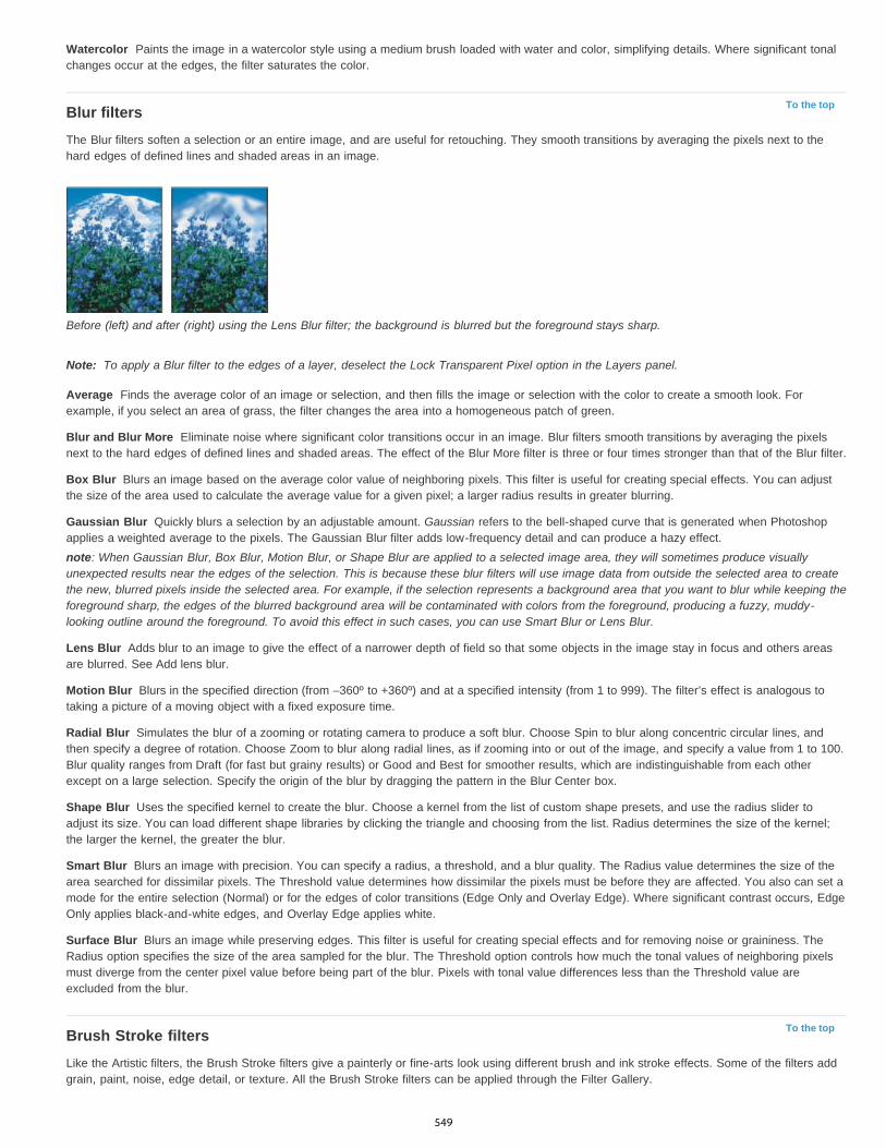
Watercolor
To the top
Note:
Average
Blur and Blur More
Box Blur
Gaussian Blur
Lens Blur
Motion Blur
Radial Blur
Shape Blur
Smart Blur
Surface Blur
To the top
Paints the image in a watercolor style using a medium brush loaded with water and color, simplifying details. Where significant tonalchanges occur at the edges, the filter saturates the color.
Blur filtersThe Blur filters soften a selection or an entire image, and are useful for retouching. They smooth transitions by averaging the pixels next to thehard edges of defined lines and shaded areas in an image.
Before (left) and after (right) using the Lens Blur filter; the background is blurred but the foreground stays sharp.
To apply a Blur filter to the edges of a layer, deselect the Lock Transparent Pixel option in the Layers panel.
Finds the average color of an image or selection, and then fills the image or selection with the color to create a smooth look. Forexample, if you select an area of grass, the filter changes the area into a homogeneous patch of green.
Eliminate noise where significant color transitions occur in an image. Blur filters smooth transitions by averaging the pixelsnext to the hard edges of defined lines and shaded areas. The effect of the Blur More filter is three or four times stronger than that of the Blur filter.
Blurs an image based on the average color value of neighboring pixels. This filter is useful for creating special effects. You can adjustthe size of the area used to calculate the average value for a given pixel; a larger radius results in greater blurring.
Quickly blurs a selection by an adjustable amount. Gaussian refers to the bell-shaped curve that is generated when Photoshopapplies a weighted average to the pixels. The Gaussian Blur filter adds low-frequency detail and can produce a hazy effect.note: When Gaussian Blur, Box Blur, Motion Blur, or Shape Blur are applied to a selected image area, they will sometimes produce visuallyunexpected results near the edges of the selection. This is because these blur filters will use image data from outside the selected area to createthe new, blurred pixels inside the selected area. For example, if the selection represents a background area that you want to blur while keeping theforeground sharp, the edges of the blurred background area will be contaminated with colors from the foreground, producing a fuzzy, muddy-looking outline around the foreground. To avoid this effect in such cases, you can use Smart Blur or Lens Blur.
Adds blur to an image to give the effect of a narrower depth of field so that some objects in the image stay in focus and others areasare blurred. See Add lens blur.
Blurs in the specified direction (from –360º to +360º) and at a specified intensity (from 1 to 999). The filter’s effect is analogous totaking a picture of a moving object with a fixed exposure time.
Simulates the blur of a zooming or rotating camera to produce a soft blur. Choose Spin to blur along concentric circular lines, andthen specify a degree of rotation. Choose Zoom to blur along radial lines, as if zooming into or out of the image, and specify a value from 1 to 100.Blur quality ranges from Draft (for fast but grainy results) or Good and Best for smoother results, which are indistinguishable from each otherexcept on a large selection. Specify the origin of the blur by dragging the pattern in the Blur Center box.
Uses the specified kernel to create the blur. Choose a kernel from the list of custom shape presets, and use the radius slider toadjust its size. You can load different shape libraries by clicking the triangle and choosing from the list. Radius determines the size of the kernel;the larger the kernel, the greater the blur.
Blurs an image with precision. You can specify a radius, a threshold, and a blur quality. The Radius value determines the size of thearea searched for dissimilar pixels. The Threshold value determines how dissimilar the pixels must be before they are affected. You also can set amode for the entire selection (Normal) or for the edges of color transitions (Edge Only and Overlay Edge). Where significant contrast occurs, EdgeOnly applies black-and-white edges, and Overlay Edge applies white.
Blurs an image while preserving edges. This filter is useful for creating special effects and for removing noise or graininess. TheRadius option specifies the size of the area sampled for the blur. The Threshold option controls how much the tonal values of neighboring pixelsmust diverge from the center pixel value before being part of the blur. Pixels with tonal value differences less than the Threshold value areexcluded from the blur.
Brush Stroke filtersLike the Artistic filters, the Brush Stroke filters give a painterly or fine-arts look using different brush and ink stroke effects. Some of the filters addgrain, paint, noise, edge detail, or texture. All the Brush Stroke filters can be applied through the Filter Gallery.
549
Accented Edges
Angled Strokes
Crosshatch
Dark Strokes
Ink Outlines
Spatter
Sprayed Strokes
Sumi-e
To the top
Diffuse Glow
Displace
Glass
Ocean Ripple
Pinch
Polar Coordinates
Ripple
Shear
Spherize
Twirl
Wave
ZigZag
To the top
Add Noise
Accentuates the edges of an image. When the edge brightness control is set to a high value, the accents resemble white chalk;when set to a low value, the accents resemble black ink.
Repaints an image using diagonal strokes, with lighter and darker areas painted in strokes going in opposite directions.
Preserves the details and features of the original image while adding texture and roughening the edges of the colored areas withsimulated pencil hatching. The Strength option (with values from 1 to 3) determines the number of hatching passes.
Paints dark areas with short, tight, dark strokes, and lighter areas with long, white strokes.
Redraws an image with fine narrow lines over the original details, in pen-and-ink style.
Replicates the effect of a spatter airbrush. Increasing the options simplifies the overall effect.
Repaints an image, using its dominant colors, with angled, sprayed strokes of color.
Paints an image in Japanese style, as if with a fully saturated brush applied to rice paper. Sumi-e creates soft, blurred edges with rich,inky blacks.
Distort filtersThe Distort filters geometrically distort an image, creating 3D or other reshaping effects. Note that these filters can be very memory-intensive. TheDiffuse Glow, Glass, and Ocean Ripple filters can be applied through the Filter Gallery.
Renders an image as though it were viewed through a soft diffusion filter. The filter adds see-through white noise, with the glowfading from the center of a selection.
Uses an image, called a displacement map, to determine how to distort a selection. For example, using a parabola-shaped displacementmap, you can create an image that appears to be printed on a cloth held up by its corners.
Makes an image appear as if it were being viewed through different types of glass. You can choose a glass effect or create your own glasssurface as a Photoshop file and apply it. You can adjust scaling, distortion, and smoothness settings. When using surface controls with a file, followthe instructions for the Displace filter.
Adds randomly spaced ripples to the surface of the image so that it appears to be underwater.
Squeezes a selection. A positive value up to 100% shifts a selection toward its center; a negative value up to – 100% shifts a selectionoutward.
Converts a selection from its rectangular to polar coordinates, and vice versa, according to a selected option. You can usethis filter to create a cylinder anamorphosis—an art form popular in the 18th century—in which the distorted image appears normal when viewed ina mirrored cylinder.
Creates an undulating pattern on a selection, like ripples on the surface of a pond. For greater control, use the Wave filter. Options includethe number and size of ripples.
Distorts an image along a curve. Specify the curve by dragging the line in the box. You can adjust any point along the curve. Click Defaultto change the curve back to a straight line. In addition, you choose how to treat undistorted areas.
Gives objects a 3D effect by wrapping a selection around a spherical shape, distorting the image and stretching it to fit the selectedcurve.
Rotates a selection more sharply in the center than at the edges. Specifying an angle produces a twirl pattern.
Works much as the Ripple filter does, but with greater control. Options include the number of wave generators, wavelength (distance fromone wave crest to the next), height of the wave, and wave type: Sine (rolling), Triangle, or Square. The Randomize option applies random values.You can also define undistorted areas.
Distorts a selection radially, depending on the radius of the pixels in your selection. The Ridges option sets the number of directionreversals of the zigzag from the center of the selection to its edge. You also specify how to displace the pixels: Pond Ripples displaces pixels tothe upper-left or lower right, Out From Center displaces pixels toward or away from the center of the selection, and Around Center rotates pixelsaround the center.
Noise filtersThe Noise filters add or remove noise, or pixels with randomly distributed color levels. This helps to blend a selection into the surrounding pixels.Noise filters can create unusual textures or remove problem areas, such as dust and scratches.
Applies random pixels to an image, simulating the effect of shooting pictures on high-speed film. You can also use the Add Noise filterto reduce banding in feathered selections or graduated fills or to give a more realistic look to heavily retouched areas. Options for noise distributioninclude Uniform and Gaussian. Uniform distributes color values of noise using random numbers between 0 and plus or minus the specified value,
550
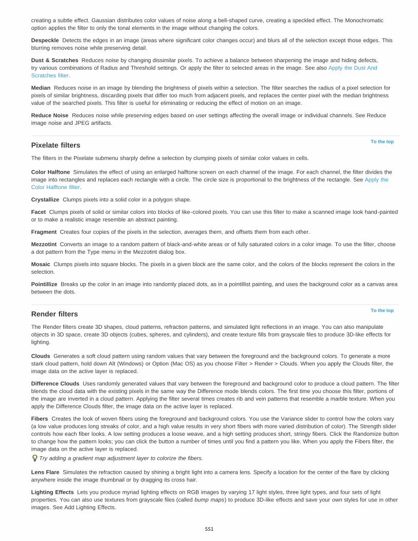
Despeckle
Dust & Scratches
Median
Reduce Noise
To the top
Color Halftone
Crystallize
Facet
Fragment
Mezzotint
Mosaic
Pointillize
To the top
Clouds
Difference Clouds
Fibers
Lens Flare
Lighting Effects
creating a subtle effect. Gaussian distributes color values of noise along a bell-shaped curve, creating a speckled effect. The Monochromaticoption applies the filter to only the tonal elements in the image without changing the colors.
Detects the edges in an image (areas where significant color changes occur) and blurs all of the selection except those edges. Thisblurring removes noise while preserving detail.
Reduces noise by changing dissimilar pixels. To achieve a balance between sharpening the image and hiding defects,try various combinations of Radius and Threshold settings. Or apply the filter to selected areas in the image. See also Apply the Dust AndScratches filter.
Reduces noise in an image by blending the brightness of pixels within a selection. The filter searches the radius of a pixel selection forpixels of similar brightness, discarding pixels that differ too much from adjacent pixels, and replaces the center pixel with the median brightnessvalue of the searched pixels. This filter is useful for eliminating or reducing the effect of motion on an image.
Reduces noise while preserving edges based on user settings affecting the overall image or individual channels. See Reduceimage noise and JPEG artifacts.
Pixelate filtersThe filters in the Pixelate submenu sharply define a selection by clumping pixels of similar color values in cells.
Simulates the effect of using an enlarged halftone screen on each channel of the image. For each channel, the filter divides theimage into rectangles and replaces each rectangle with a circle. The circle size is proportional to the brightness of the rectangle. See Apply theColor Halftone filter.
Clumps pixels into a solid color in a polygon shape.
Clumps pixels of solid or similar colors into blocks of like-colored pixels. You can use this filter to make a scanned image look hand-paintedor to make a realistic image resemble an abstract painting.
Creates four copies of the pixels in the selection, averages them, and offsets them from each other.
Converts an image to a random pattern of black-and-white areas or of fully saturated colors in a color image. To use the filter, choosea dot pattern from the Type menu in the Mezzotint dialog box.
Clumps pixels into square blocks. The pixels in a given block are the same color, and the colors of the blocks represent the colors in theselection.
Breaks up the color in an image into randomly placed dots, as in a pointillist painting, and uses the background color as a canvas areabetween the dots.
Render filtersThe Render filters create 3D shapes, cloud patterns, refraction patterns, and simulated light reflections in an image. You can also manipulateobjects in 3D space, create 3D objects (cubes, spheres, and cylinders), and create texture fills from grayscale files to produce 3D-like effects forlighting.
Generates a soft cloud pattern using random values that vary between the foreground and the background colors. To generate a morestark cloud pattern, hold down Alt (Windows) or Option (Mac OS) as you choose Filter > Render > Clouds. When you apply the Clouds filter, theimage data on the active layer is replaced.
Uses randomly generated values that vary between the foreground and background color to produce a cloud pattern. The filterblends the cloud data with the existing pixels in the same way the Difference mode blends colors. The first time you choose this filter, portions ofthe image are inverted in a cloud pattern. Applying the filter several times creates rib and vein patterns that resemble a marble texture. When youapply the Difference Clouds filter, the image data on the active layer is replaced.
Creates the look of woven fibers using the foreground and background colors. You use the Variance slider to control how the colors vary(a low value produces long streaks of color, and a high value results in very short fibers with more varied distribution of color). The Strength slidercontrols how each fiber looks. A low setting produces a loose weave, and a high setting produces short, stringy fibers. Click the Randomize buttonto change how the pattern looks; you can click the button a number of times until you find a pattern you like. When you apply the Fibers filter, theimage data on the active layer is replaced.
Try adding a gradient map adjustment layer to colorize the fibers.
Simulates the refraction caused by shining a bright light into a camera lens. Specify a location for the center of the flare by clickinganywhere inside the image thumbnail or by dragging its cross hair.
Lets you produce myriad lighting effects on RGB images by varying 17 light styles, three light types, and four sets of lightproperties. You can also use textures from grayscale files (called bump maps) to produce 3D-like effects and save your own styles for use in otherimages. See Add Lighting Effects.
551
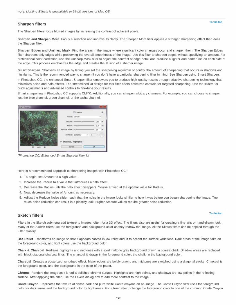
To the top
Sharpen and Sharpen More
Sharpen Edges and Unsharp Mask
Smart Sharpen
To the top
Bas Relief
Chalk & Charcoal
Charcoal
Chrome
Conté Crayon
note: Lighting Effects is unavailable in 64-bit versions of Mac OS.
Sharpen filtersThe Sharpen filters focus blurred images by increasing the contrast of adjacent pixels.
Focus a selection and improve its clarity. The Sharpen More filter applies a stronger sharpening effect than doesthe Sharpen filter.
Find the areas in the image where significant color changes occur and sharpen them. The Sharpen Edgesfilter sharpens only edges while preserving the overall smoothness of the image. Use this filter to sharpen edges without specifying an amount. Forprofessional color correction, use the Unsharp Mask filter to adjust the contrast of edge detail and produce a lighter and darker line on each side ofthe edge. This process emphasizes the edge and creates the illusion of a sharper image.
Sharpens an image by letting you set the sharpening algorithm or control the amount of sharpening that occurs in shadows andhighlights. This is the recommended way to sharpen if you don’t have a particular sharpening filter in mind. See Sharpen using Smart Sharpen.In Photoshop CC, the enhanced Smart Sharpen filter empowers you to produce high-quality results through adaptive sharpening technology thatminimizes noise and halo effects. The streamlined UI design for this filter offers optimized controls for targeted sharpening. Use the sliders forquick adjustments and advanced controls to fine-tune your results.Smart sharpening in Photoshop CC supports CMYK. Additionally, you can sharpen arbitrary channels. For example, you can choose to sharpenjust the blue channel, green channel, or the alpha channel.
(Photoshop CC) Enhanced Smart Sharpen filter UI
Here is a recommended approach to sharpening images with Photoshop CC:
1. To begin, set Amount to a high value.2. Increase the Radius to a value that introduces a halo effect.3. Decrease the Radius until the halo effect disappers. You've arrived at the optimal value for Radius.4. Now, decrease the value of Amount as necessary.5. Adjust the Reduce Noise slider, such that the noise in the image looks similar to how it was before you began sharpening the image. Too
much noise reduction can result in a plasticy look. Higher Amount values require greater noise reduction.
Sketch filtersFilters in the Sketch submenu add texture to images, often for a 3D effect. The filters also are useful for creating a fine-arts or hand-drawn look.Many of the Sketch filters use the foreground and background color as they redraw the image. All the Sketch filters can be applied through theFilter Gallery.
Transforms an image so that it appears carved in low relief and lit to accent the surface variations. Dark areas of the image take onthe foreground color, and light colors use the background color.
Redraws highlights and midtones with a solid midtone gray background drawn in coarse chalk. Shadow areas are replacedwith black diagonal charcoal lines. The charcoal is drawn in the foreground color; the chalk, in the background color.
Creates a posterized, smudged effect. Major edges are boldly drawn, and midtones are sketched using a diagonal stroke. Charcoal isthe foreground color, and the background is the color of the paper.
Renders the image as if it had a polished chrome surface. Highlights are high points, and shadows are low points in the reflectingsurface. After applying the filter, use the Levels dialog box to add more contrast to the image.
Replicates the texture of dense dark and pure white Conté crayons on an image. The Conté Crayon filter uses the foregroundcolor for dark areas and the background color for light areas. For a truer effect, change the foreground color to one of the common Conté Crayon
552

Graphic Pen
Halftone Pattern
Note Paper
Photocopy
Plaster
Reticulation
Stamp
Torn Edges
Water Paper
To the top
Diffuse
Emboss
Extrude
Find Edges
Glowing Edges
Solarize
Tiles
Trace Contour
Wind
To the top
Craquelure
Grain
Mosaic Tiles
colors (black, sepia, or sanguine) before applying the filter. For a muted effect, change the background color to white, add some of the foregroundcolor to the white background, and then apply the filter.
Uses fine, linear ink strokes to capture the details in the original image. The effect is especially striking with scanned images. Thefilter replaces color in the original image, using the foreground color for ink and the background color for paper.
Simulates the effect of a halftone screen while maintaining the continuous range of tones.
Creates an image that appears to be constructed of handmade paper. This filter simplifies images and combines the effects of theStylize > Emboss and Texture > Grain filters. Dark areas of the image appear as holes in the top layer of paper, revealing the background color.
Simulates the effect of photocopying an image. Large dark areas tend to be copied only around their edges, and midtones fall awayto either solid black or solid white.
Molds an image from 3D plaster, and then colorizes the result using the foreground and background color. Dark areas are raised, andlight areas are recessed.
Simulates the controlled shrinking and distortion of film emulsion to create an image that appears clumped in the shadows and lightlygrained in the highlights.
Simplifies the image so that it appears to be created with a rubber or wood stamp. This filter is best used with black-and-white images.
Reconstructs the image so that it appears composed of ragged, torn pieces of paper, and then colorizes the image using theforeground and background colors. This filter is particularly useful for text or high-contrast objects.
Uses blotchy daubs that appear painted onto fibrous, damp paper, causing the colors to flow and blend.
Stylize filtersThe Stylize filters produce a painted or impressionistic effect on a selection by displacing pixels and by finding and heightening contrast in animage. After using filters like Find Edges and Trace Contour that highlight edges, you can apply the Invert command to outline the edges of acolor image with colored lines or to outline the edges of a grayscale image with white lines.
Shuffles pixels in a selection to soften focus according to the selected option: Normal moves pixels randomly (ignoring color values),Darken Only replaces light pixels with darker ones, and Lighten Only replaces dark pixels with lighter ones. Anisotropic shuffles pixels in thedirection of the least change in color.
Makes a selection appear raised or stamped by converting its fill color to gray and tracing the edges with the original fill color. Optionsinclude an embossing angle (from –360° to recess the surface, to +360° to raise the surface), height, and a percentage (1% to 500%) for theamount of color within the selection. To retain color and detail when embossing, use the Fade command after applying the Emboss filter.
Gives a 3D texture to a selection or layer. See Apply the Extrude filter.
Identifies the areas of the image with significant transitions and emphasizes the edges. Like the Trace Counter filter, Find Edgesoutlines the edges of an image with dark lines against a white background and is useful for creating a border around an image.
Identifies the edges of color and adds a neon-like glow to them. This filter can be applied cumulatively.
Blends a negative and a positive image—similar to exposing a photographic print briefly to light during development.
Breaks up an image into a series of tiles, creating an offset between the selection and its original position. You can choose one of thefollowing to fill the area between the tiles: the background color, the foreground color, a reverse version of the image, or an unaltered version ofthe image, which puts the tiled version on top of the original and reveals part of the original image underneath the tiled edges.
Finds the transitions of major brightness areas and thinly outlines them for each color channel, for an effect similar to the lines ina contour map. See Apply the Trace Contour filter.
Places tiny horizontal lines in the image to create a windblown effect. Methods include Wind; Blast, for a more dramatic wind effect; andStagger, which offsets the lines in the image.
Texture filtersUse the Texture filters to simulate the appearance of depth or substance, or to add an organic look.
Paints an image onto a high-relief plaster surface, producing a fine network of cracks that follow the contours of the image. Use thisfilter to create an embossing effect with images that contain a broad range of color or grayscale values.
Adds texture to an image by simulating different kinds of grain—Regular, Soft, Sprinkles, Clumped, Contrasty, Enlarged, Stippled,Horizontal, Vertical, and Speckle, available from the Grain Type menu.
Renders the image so that it appears to be made up of small chips or tiles and adds grout between the tiles. (In contrast, thePixelate > Mosaic filter breaks up an image into blocks of different-colored pixels.)
553

Patchwork
Stained Glass
Texturizer
To the top
De-Interlace
NTSC Colors
To the top
Custom
High Pass
Maximum and Minimum
Offset
To the top
Note:
Breaks up an image into squares filled with the predominant color in that area of the image. The filter randomly reduces or increasesthe tile depth to replicate the highlights and shadows.
Repaints an image as single-colored adjacent cells outlined in the foreground color.
Applies a texture you select or create to an image.
Video filtersThe Video submenu contains the De-Interlace and NTSC Colors filters.
Smooths moving images captured on video by removing either the odd or even interlaced lines in a video image. You can choose toreplace the discarded lines by duplication or interpolation.
Restricts the gamut of colors to those acceptable for television reproduction, to prevent oversaturated colors from bleeding acrosstelevision scan lines.
Other filtersFilters in the Other submenu let you create your own filters, use filters to modify masks, offset a selection within an image, and make quick coloradjustments.
Lets you design your own filter effect. With the Custom filter, you can change the brightness values of each pixel in the image accordingto a predefined mathematical operation known as convolution. Each pixel is reassigned a value based on the values of surrounding pixels. Thisoperation is similar to the Add and Subtract calculations for channels.You can save the custom filters you create and use them with other Photoshop images. See Create a Custom filter.
Retains edge details in the specified radius where sharp color transitions occur and suppresses the rest of the image. (A radius of 0.1pixel keeps only edge pixels.) The filter removes low-frequency detail from an image and has an effect opposite to that of the Gaussian Blur filter.It is helpful to apply the High Pass filter to a continuous-tone image before using the Threshold command or converting the image to Bitmap mode.The filter is useful for extracting line art and large black-and-white areas from scanned images.
The Maximum and Minimum filters are useful for modifying masks. The Maximum filter has the effect of applying aspread (dilation)—spreading out white areas and choking in black areas. The Minimum filter has the effect of applying a choke (erosion)—shrinking white areas and spreading out the black areas. Like the Median filter, the Maximum and Minimum filters operate on selected pixels.Within a specified radius, the Maximum and Minimum filters replace the current pixel’s brightness value with the highest or lowest brightness valueof the surrounding pixels.These filters, especially with larger radii, tend to promote either corners or curves in the image contours. In Photoshop CC, you can choose fromthe Preserve menu to favor squareness or roundness as you specify the radius value.
(Photoshop CC) Preserve squareness or roundness
Moves a selection a specified horizontal or vertical amount, leaving an empty space at the selection’s original location. You can fill theempty area with the current background color, with another part of the image, or with your choice of fill if the selection is near the edge of animage.
Digimarc filtersThe Digimarc filters embed a digital watermark into an image to store copyright information.
Digimarc plug-ins require a 32-bit operating system. They are unsupported in 64-bit versions of Windows and Mac OS.
554
Twitter™ and Facebook posts are not covered under the terms of Creative Commons.
Legal Notices | Online Privacy Policy
To the topVanishing PointThe Vanishing Point feature preserves correct perspective in edits of images that contain perspective planes (for instance, the sides of a buildingor any rectangular object).
Adobe also recommendsAdding digital copyright information
Work in Vanishing Point
555
Add Lighting Effects | CC, CS6
To the top
Note:
Colorize
Exposure
Gloss
Metallic
Ambience
Texture
To the top
To the top
Point
Infinite
Apply the Lighting Effects filterFrom an Expert: Lighting Effects tutorialsLighting Effects typesAdjust a Point light in the preview windowAdjust an Infinite light in the preview windowAdjust a Spot light in the preview windowLighting Effects presetsAdd or delete a lightCreate, save, or delete a Lighting Effects presetApply a Texture channel
Apply the Lighting Effects filterThe Lighting Effects filter lets you produce myriad lighting effects on RGB images. You can also use textures from grayscale files (called bumpmaps) to produce 3D-like effects and save your own styles for use in other images.
The Lighting Effects filter works only on 8-bit RGB images in Photoshop CC. You must have a supported video card to use Lighting Effects.For more information, see this FAQ.
1. Choose Filter > Render > Lighting Effects.
2. From the Presets menu at upper left, choose a style.
3. In the preview window, select individual lights you want to adjust. Then, in the upper half of the Properties panel, do any of the following:
Choose a light type (Spot, Infinite, or Point) from the top menu.Adjust color, intensity, and hotspot size.
To duplicate a light, Alt-drag (Windows) or Option-drag (Mac OS) the light within the preview window.
4. In the lower half of the Properties panel, adjust the entire set of lights with these options:
Click to tint the overall lighting.
Controls highlight and shadow detail.
Determines how much surfaces reflects light.
Determines which is more reflective: the light or the object on which the light is cast.
Diffuses the light as if it were combined with other light in a room, such as sunlight or fluorescent light. Choose a value of 100 touse only the light source, or a value of –100 to remove the light source.
Applies a texture channel.
From an Expert: Lighting Effects tutorialsQuickly master the dedicated Lighting Effects workspace. This tutorial from Dan Moughamian gives you a step-by-step tour.
Also, see this CS6 Lighting Effects overview video by Matt Kloskowski.
Lighting Effects typesYou can choose from several lighting types:
Shines light in all directions from directly above the image—like a light bulb.
Shines light across an entire plane—like the sun.
556

Spot
To the top
To the top
To the top
To the top
2 o’clock Spotlight
Blue Omni
Circle Of Light
Crossing
Crossing Down
Default
Five Lights Down/Five Lights Up
Flashlight
Flood Light
Parallel Directional
RGB Lights
Casts an elliptical beam of light. The line in the preview window defines the light direction and angle, and the handles define the edges ofthe ellipse.
Adjust a Point light in the preview window
1. In the Properties panel, choose Point from the top menu.
2. In the preview window, adjust the light:
To move the light, drag anywhere on the canvas.
To change the spread of light (reflecting a light moving closer or farther away), drag the white section of the Intensity ring at the center.
An Intensity value of 100 is brightest, normal lighting is about 50, negative intensity takes away light, and –100 intensity produces nolight.
Adjust an Infinite light in the preview window
1. In the Properties panel, choose Infinite from the top menu.
2. Adjust the light:To change the direction, drag the handle at the end of the line.
To change brightness, drag the white section of the Intensity ring at the center of the light controls.
Adjust a Spot light in the preview window
1. At the top of the Properties panel, choose Spot.
2. In the preview window, adjust the light:
To move the light, drag within the outer ellipse.
To rotate the light, drag beyond the outer ellipse.
To change the hotspot angle, drag the edge of the interior ellipse.
To extend or shrink the ellipse, drag one of the four outer handles.
To change how much of the ellipse is filled with light, drag the white section of the Intensity ring in the center.
Lighting Effects presetsUse the Presets menu in the Lighting Effects workspace to choose from 17 light styles. You can also create your own presets by adding lights tothe Default setting. The Lighting Effects filter requires at least one light source. Only one light can be edited at a time, but all added lights are usedto create the effect.
A yellow spotlight of medium (17) intensity with a wide (91) focus.
A blue overhead omni light of full (85) intensity with no focus.
Four spotlights. White has full (100) intensity and a concentrated (8) focus. Yellow has strong intensity (88) and a concentratedfocus (3). Red has medium (50) intensity and a concentrated (0) focus. Blue has full (100) intensity and medium (25) focus.
A white spotlight of medium (35) intensity with a wide (69) focus.
Two white spotlights of medium (35) intensity with a wide (100) focus.
A white spotlight of medium intensity (35) with a wide focus (69).
Five white spotlights, down or up, of full (100) intensity with a wide (60) focus.
An omni yellow light of medium (46) intensity.
A white spotlight of medium (35) intensity with a wide (69) focus.
A directional blue light of full (98) intensity with no focus.
Red, blue, and green lights that produce a light of medium (60) intensity with a wide (96) focus.
557
Twitter™ and Facebook posts are not covered under the terms of Creative Commons.
Legal Notices | Online Privacy Policy
Soft Direct Lights
Soft Omni
Soft Spotlight
Three Down
Triple Spotlight
To the top
To the top
To the top
Two unfocused white and blue directional lights. White has a soft (20) intensity. Blue has a medium (67) intensity.
A soft omni light of medium (50) intensity.
A white spotlight of full (98) intensity with a wide (100) focus.
Three white spotlights of soft (35) intensity with a wide (96) focus.
Three spotlights of slight (35) intensity with a wide (100) focus.
Add or delete a light
In the Lighting Effects workspace, do one of the following:
At upper left, click the Lights icons to add Point, Spot, and Infinite types. Repeat as desired for a maximum of 16 lights.
In the Lights panel (at lower right by default), drag a light to the Trash icon to delete it.
Create, save, or delete a Lighting Effects preset
In the Lighting Effects dialog box, do one of the following:
To create a preset, choose Custom from the Preset menu, and click the Lights icons to add Point, Spot, and Infinite types. Repeat asdesired for a maximum of 16 lights.
To save a preset, click Save, name the style, and click OK. Saved presets include all the settings for each light and appear in the Stylemenu whenever you open the image.
To delete a preset, choose it, and then click Delete.
Apply a Texture channelIn the Lighting Effects workspace, the Texture channel lets you control lighting effects using grayscale images (called bump maps). You addbump maps to the image as alpha channels. You can add any grayscale image to your image as an alpha channel, or create an alpha channeland add texture to it. For an embossed text effect, use a channel with white text on a black background, or vice versa.
1. If necessary, add an alpha channel to your image. Do one of the following:To use a texture based on another image (for example, fabric or water), convert that image to grayscale, then drag the grayscalechannel from that image into the current image.
Drag an existing alpha channel from another image into the current image.
Create an alpha channel in your image, then add texture to it.
2. In the Lighting Effects workspace, choose a channel from the Texture menu in the Properties dialog box. (Choose either an alpha channelyou’ve added or the image’s Red, Green, or Blue channel.)
3. Drag the Height slider to vary the texture from Flat (0) to Mountainous (100).
More Help topicsCreate and edit alpha channel masks
558
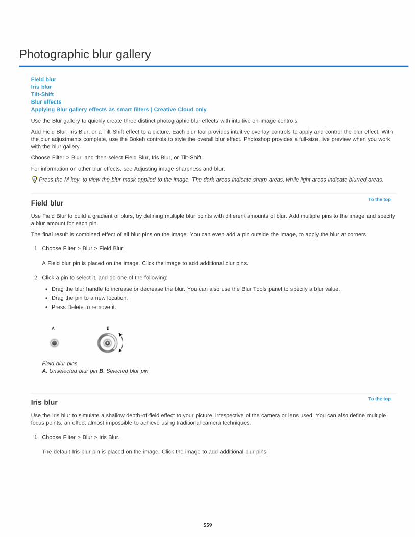
Photographic blur gallery
To the top
To the top
Field blurIris blurTilt-ShiftBlur effectsApplying Blur gallery effects as smart filters | Creative Cloud only
Use the Blur gallery to quickly create three distinct photographic blur effects with intuitive on-image controls.
Add Field Blur, Iris Blur, or a Tilt-Shift effect to a picture. Each blur tool provides intuitive overlay controls to apply and control the blur effect. Withthe blur adjustments complete, use the Bokeh controls to style the overall blur effect. Photoshop provides a full-size, live preview when you workwith the blur gallery.
Choose Filter > Blur and then select Field Blur, Iris Blur, or Tilt-Shift.
For information on other blur effects, see Adjusting image sharpness and blur.
Press the M key, to view the blur mask applied to the image. The dark areas indicate sharp areas, while light areas indicate blurred areas.
Field blurUse Field Blur to build a gradient of blurs, by defining multiple blur points with different amounts of blur. Add multiple pins to the image and specifya blur amount for each pin.
The final result is combined effect of all blur pins on the image. You can even add a pin outside the image, to apply the blur at corners.
1. Choose Filter > Blur > Field Blur.
A Field blur pin is placed on the image. Click the image to add additional blur pins.
2. Click a pin to select it, and do one of the following:
Drag the blur handle to increase or decrease the blur. You can also use the Blur Tools panel to specify a blur value.Drag the pin to a new location.Press Delete to remove it.
Field blur pins A. Unselected blur pin B. Selected blur pin
Iris blurUse the Iris blur to simulate a shallow depth-of-field effect to your picture, irrespective of the camera or lens used. You can also define multiplefocus points, an effect almost impossible to achieve using traditional camera techniques.
1. Choose Filter > Blur > Iris Blur.
The default Iris blur pin is placed on the image. Click the image to add additional blur pins.
559

To the top
To the top
Light Bokeh
Bokeh Color
Light Range
A. Sharp area B. Fade area C. Blur area
2. Drag the handles to move them to redefine the various areas.
3. Drag the blur handle to increase or decrease the blur. You can also use the Blur Tools panel to specify a blur value.
Tilt-ShiftUse the Tilt-Shift effect to simulate an image taken with a tilt-shift lens. This special effect blur defines area of sharpness, and then fades to a blurat the edges. The Tilt-Shift effect can be used to simulate photos of miniature objects.
1. Choose Filter > Blur > Tilt-Shift.
The default Tilt-Shift blur pin is placed on the image. Click the image to add additional blur pins.
A. Sharp area B. Fade area C. Blur area
2. Drag the blur handle to increase or decrease the blur. You can also use the Blur Tools panel to specify a blur value.
3. To define the different areas, do the following:
Drag the lines to move themDrag the handles and rotate
For more information on using Tilt-Shift, see this step-by-step text tutorial by Dan Moughamian.
Blur effectsYou can enhance the overall picture, by controlling the appearance of out-of-focus or blurred parts. Specify the bokeh parameters to ensure anoverall pleasing effect.
In the Blur Effects panel, specify a value for the following:
Brightens the out of focus, or blurred areas in the picture.
Adds more vivid color to lightened areas that are not blown out to white.
Determines the range of tones the settings affect.
560
Twitter™ and Facebook posts are not covered under the terms of Creative Commons.
Legal Notices | Online Privacy Policy
To the topApplying Blur gallery effects as smart filters | Creative Cloud onlyThe photographic blur effects in the Blur gallery now support Smart Objects and can be applied non-destructively as smart filters. This feature alsosupports Smart Object video layers. To apply a Blur gallery effect as a smart filter:
1. In the Layers panel, select a Smart Object layer.
2. Choose Filter > Blur, and then choose Field Blur, Iris Blur, or Tilt-Shift.
Click the following link to view a video by Photoshop Senior Product Manager, Zorana Gee, presenting the Smart Object support for the BlurGallery and Liquify.
For more information about Smart Filters, see Applying Smart Filters.
561
Adaptive wide angle filter
Focal Length
Crop Factor
Fisheye
Perspective
Panorama
Full Spherical
Auto
Scale
Focal Length
Crop Factor
As Shot
Use the Adaptive Wide Angle filter to correct lens distortions due to using wide angle lenses. You can quickly straighten lines that appear curved inpanoramas, or photos taken with fish-eye and wide angle lenses. For example, buildings seem to be leaning inwards when captured using a wide-angle lens.
The filter detects the camera and lens model and uses the lens characteristics to straighten the images. You can add multiple constraints toindicate straight lines in different parts of the picture. Using this information the Adaptive Wide Angle filter, removes the distortions.
You can also use this filter on images that do not contain camera and lens information, though it's some extra work.
If you want to edit the filter settings later, convert the layer to a smart object. Select the layer and choose Layers > Smart Objects > Convert toSmart Object.
Specify the focal length of the lens. This value is automatically populated if the lens information is detected in the photograph.
Specify a value to determine how the final image is cropped. Use this value in combination with Scale to compensate for any blankareas that are introduced while applying the filter.
1. Choose Filter > Adaptive Wide Angle.
2. Choose a correction type:
corrects extreme curvature caused by a fisheye lens.
corrects converging lines caused by angle of view and camera tilt.
corrects a Photomerge panorama.
corrects 360 degree panoramas. The panoramas must have a 2:1 aspect ratio.
detects the appropriate correction automatically.
3. Specify additional settings for filter. If the image has lens data, these values are automatically detected, and some options are not displayed.
Specify a value to scale the image. Use this value to minimize the blank areas that are introduced after applying the filter.
Specify the focal length of the lens. This value is automatically populatedif the lens information is detected in the photograph.
Specify a value to determine how the final image is cropped. Use this valuein combination with Scale to compensate for any blank areas that are introduced while applying the filter.
Enable this option to use the values as defined in the lens profile. This option is disabled if no lens information is found.
4. Define the constraints to indicate straight lines in the picture.
Do one of the following:
Choose the Constraint tool, and drag a line across a key object to straighten.
Choose the Polygon Constraint tool, and draw a polygon along the object to straighten.
The filter detects the curvature and draws a line that follows the contour of the object.
562
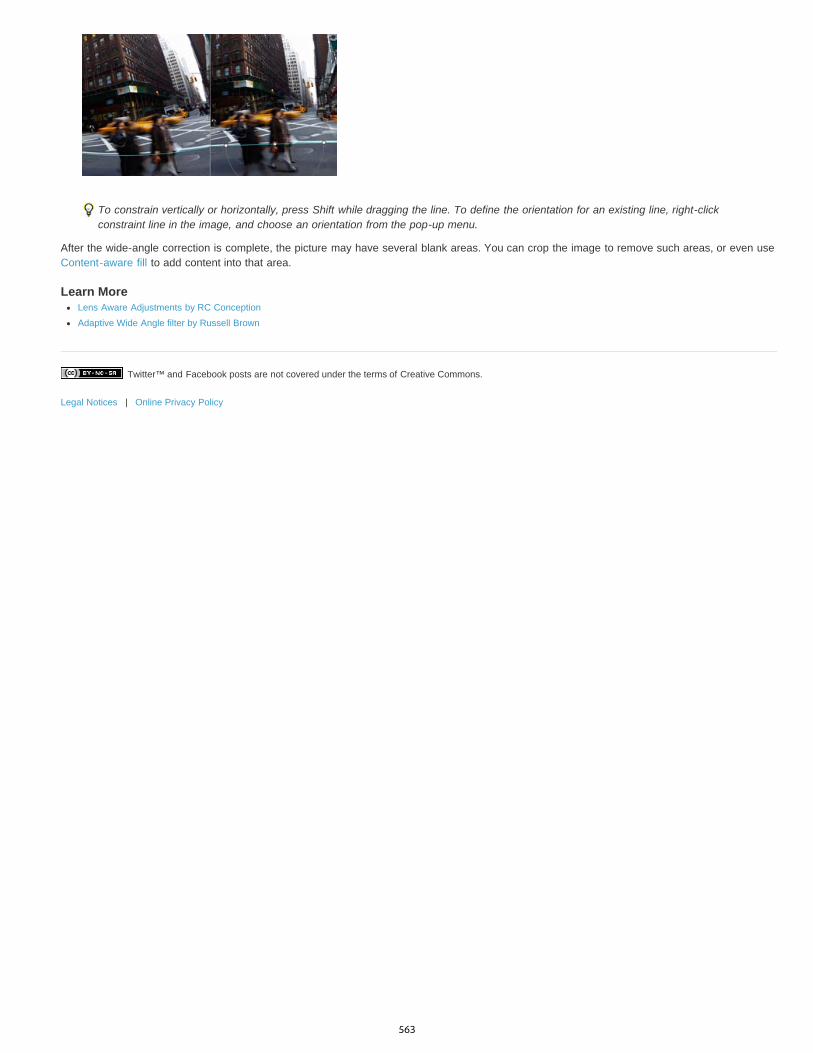
Twitter™ and Facebook posts are not covered under the terms of Creative Commons.
Legal Notices | Online Privacy Policy
To constrain vertically or horizontally, press Shift while dragging the line. To define the orientation for an existing line, right-clickconstraint line in the image, and choose an orientation from the pop-up menu.
After the wide-angle correction is complete, the picture may have several blank areas. You can crop the image to remove such areas, or even useContent-aware fill to add content into that area.
Learn MoreLens Aware Adjustments by RC Conception
Adaptive Wide Angle filter by Russell Brown
563
Oil Paint filter
Twitter™ and Facebook posts are not covered under the terms of Creative Commons.
Legal Notices | Online Privacy Policy
Use the Oil Paint filter gives an image the look of a classic painting.
1. Choose Filter > Oil Paint.2. Experiment with the Brush and Lighting options.3. Click OK to apply the filter.
If the Oil Paint filter is not working, it's possible that you don't have a supported graphics card. Or, it could mean that your graphics card driveris out-of-date. For more information, see the GPU FAQ.
564
Smudge image areas
Twitter™ and Facebook posts are not covered under the terms of Creative Commons.
Legal Notices | Online Privacy Policy
The Smudge tool simulates the effect you see when you drag a finger through wet paint. The tool picks up color where the stroke begins andpushes it in the direction you drag.
1. Select the Smudge tool .2. Choose a brush tip and options for the blending mode in the options bar.3. Select Sample All Layers in the options bar to smudge using color data from all visible layers. If this is deselected, the Smudge tool uses
colors from only the active layer.4. Select Finger Painting in the options bar to smudge using the foreground color at the beginning of each stroke. If this is deselected, the
Smudge tool uses the color under the pointer at the beginning of each stroke.5. Drag in the image to smudge the pixels.
Press Alt (Windows) or Option (Mac OS) as you drag with the Smudge tool to use the Finger Painting option.
For more informationRetouching tools gallery
565

Add Lighting Effects (CS5)
To the top
To the top
Note:
Gloss
Material
Exposure
Ambience
To the top
Run Photoshop in 32-bit mode (64-bit Mac OS only)Apply the Lighting Effects filterLighting Effects typesAdjust an Omni lightAdjust directional light using the preview windowAdjust the spotlight using the preview windowLighting Effects stylesAdd or delete a lightCreate, save, or delete a Lighting Effects styleUse the Texture Channel in the Lighting Effects
Run Photoshop in 32-bit mode (64-bit Mac OS only)In 64-bit versions of Mac OS, Lighting Effects is available only if Photoshop is running in 32-bit mode.
1. In the Finder, choose Go > Applications.
2. Expand the Photoshop folder. Then right-click the Photoshop application icon, and choose Get Info.
3. In the General section of the Info window, select Open In 32-bit Mode.
4. Close the Info window, and restart Photoshop.
For more information, see 64-bit operating system benefits and limitations in Photoshop.
Apply the Lighting Effects filterThe Lighting Effects filter lets you produce myriad lighting effects on RGB images. You can also use textures from grayscale files (called bumpmaps) to produce 3D-like effects and save your own styles for use in other images.
The Lighting Effects filter works only on RGB images.
1. Choose Filter > Render > Lighting Effects.2. For Style, choose a style.3. For Light Type, choose a type. If you’re using multiple lights, select and deselect On to turn individual lights on and off.4. To change the color of the light, click the color box in the Light Type area of the dialog box.
The Color Picker chosen in the General Preferences dialog box opens.
5. To set light properties, drag the corresponding slider for the following options:
Determines how much the surface reflects light (as on the surface of a piece of photographic paper), from Matte (low reflectance) toShiny (high reflectance).
Determines which is more reflective: the light or the object on which the light is cast. Plastic reflects the light’s color; Metallicreflects the object’s color.
Increases (positive values) or decreases (negative values) light. A value of 0 has no effect.
Diffuses the light as if it were combined with other light in a room, such as sunlight or fluorescent light. Choose a value of 100 touse only the light source, or a value of –100 to remove the light source. To change the color of the ambient light, click the color box and usethe Color Picker that appears.
To duplicate a light, Alt-drag (Windows) or Option-drag (Mac OS) the light within the preview window.
6. To use a texture fill, choose a channel for Texture Channel.
Lighting Effects types
566
Omni
Directional
Spotlight
To the top
To the top
To the top
To the top
2 o’clock Spotlight
Blue Omni
Circle Of Light
Crossing
Crossing Down
Default
You can choose from several lighting types:
Shines light in all directions from directly above the image—like a light bulb over a piece of paper.
Shines light from far away so that the light angle doesn’t change—like the sun.
Casts an elliptical beam of light. The line in the preview window defines the light direction and angle, and the handles define the edgesof the ellipse.
Adjust an Omni light1. Choose Filter > Render > Lighting Effects.2. For Light Type, choose Omni.3. Adjust the light:
To move the light, drag the center circle.
To increase or decrease the size of the light (like a light moving closer or farther away), drag one of the handles defining the edges ofthe effect.
Adjust directional light using the preview window1. Choose Filter > Render > Lighting Effects.2. For Light Type, choose Directional.3. Adjust the light:
To move the light, drag the center circle.
To change the direction of the light, drag the handle at the end of the line to rotate the light’s angle. Ctrl-drag (Windows) or Command-drag (Mac OS) to keep the light’s height (line length) constant.
To change the height of the light, drag the handle at the end of the line. Shorten the line for a bright light, and lengthen it for a lessintense one. A very short line produces pure white light; a very long one, no light. Shift-drag to keep the angle constant and change theheight of the light (line length).
Adjust the spotlight using the preview window1. Choose Filter > Render > Lighting Effects.2. For Light Type, choose Spotlight.3. Adjust the light:
To move the light, drag the center circle.
To increase the light angle, drag the handle to shorten the line. To decrease the light angle, drag to lengthen the line.
To stretch the ellipse or rotate the light, drag one of the handles. Shift-drag to keep the angle constant and change only the size of theellipse. Ctrl-drag (Windows) or Command-drag (Mac OS) to keep the size constant and change the angle or direction of the spotlight.
To set the light focus (or spotlight intensity) and control how much of an ellipse is filled with light, drag the Intensity slider: full intensity (avalue of 100) is brightest, normal intensity is about 50, negative intensity takes away light, and –100 intensity produces no light. Use theFocus slider to control how much of the ellipse is filled with light.
Lighting Effects stylesUse the Style menu in the Lighting Effects dialog box to choose from 17 light styles. You can also create your own lighting style by adding lights tothe Default setting. The Lighting Effects filter requires at least one light source. Only one light can be edited at a time, but all added lights are usedto create the effect.
A yellow spotlight of medium (17) intensity with a wide (91) focus.
A blue overhead omni light of full (85) intensity with no focus.
Four spotlights. White has full (100) intensity and a concentrated (8) focus. Yellow has strong intensity (88) and a concentratedfocus (3). Red has medium (50) intensity and a concentrated (0) focus. Blue has full (100) intensity and medium (25) focus.
A white spotlight of medium (35) intensity with a wide (69) focus.
Two white spotlights of medium (35) intensity with a wide (100) focus.
A white spotlight of medium intensity (35) with a wide focus (69).
567
Twitter™ and Facebook posts are not covered under the terms of Creative Commons.
Legal Notices | Online Privacy Policy
Five Lights Down/Five Lights Up
Flashlight
Flood Light
Parallel Directional
RGB Lights
Soft Direct Lights
Soft Omni
Soft Spotlight
Three Down
Triple Spotlight
To the top
To the top
To the top
Five white spotlights, down or up, of full (100) intensity with a wide (60) focus.
An omni yellow light of medium (46) intensity.
A white spotlight of medium (35) intensity with a wide (69) focus.
A directional blue light of full (98) intensity with no focus.
Red, blue, and green lights that produce a light of medium (60) intensity with a wide (96) focus.
Two unfocused white and blue directional lights. White has a soft (20) intensity. Blue has a medium (67) intensity.
A soft omni light of medium (50) intensity.
A white spotlight of full (98) intensity with a wide (100) focus.
Three white spotlights of soft (35) intensity with a wide (96) focus.
Three spotlights of slight (35) intensity with a wide (100) focus.
Add or delete a lightIn the Lighting Effects dialog box, do one of the following:
To add a light, drag the light icon at the bottom of the dialog box into the preview area. Repeat as desired for a maximum of 16 lights.
To delete a light, drag the light by its center circle to the Delete icon at the lower right of the preview window.
Create, save, or delete a Lighting Effects styleIn the Lighting Effects dialog box, do one of the following:
To create a style, choose Default for Style and drag the light bulb icon at the bottom of the dialog box into the preview area. Repeat asdesired for a maximum of 16 lights.
To save a style, click Save, name the style, and click OK. Saved styles include all the settings for each light and appear in the Stylemenu whenever you open the image.
To delete a style, choose a style, and then click Delete.
Use the Texture Channel in the Lighting EffectsThe Texture Channel in the Lighting Effects dialog box lets you control lighting effects using grayscale images (called bump maps) that you add toyour image as alpha channels. You can add any grayscale image to your image as an alpha channel, or create a new alpha channel and addtexture to it. For an embossed text effect, use a channel with white text on a black background, or vice versa.
1. If necessary, add an alpha channel to your image. Do one of the following:To use a texture based on another image (for example, fabric or water), convert that image to grayscale, then drag the grayscalechannel from that image into the current image.
Drag an existing alpha channel from another image into the current image.
Create an alpha channel in your image, then add texture to it.
2. In the Lighting Effects dialog box, choose a channel from the Texture Channel menu: either an alpha channel you’ve added or the image’sRed, Green, or Blue channel.
3. Select White Is High to raise the white parts of the channel from the surface. Deselect this option to raise the dark parts.4. Drag the Height slider to vary the texture from Flat (0) to Mountainous (100).
More Help TopicsCreate and edit alpha channel masks
568

Applying specific filters
To the top
To the top
To the top
To the top
Load images and textures for filtersSet texture and glass surface controlsDefining undistorted areasApply the Dust And Scratches filterApply the Displace filterApply the Color Halftone filterApply the Extrude filterApply the Trace Contour filterCreate a Custom filter
Load images and textures for filtersTo produce their effects, some filters load and use other images, such as textures and displacement maps. These filters include the Conté Crayon,Displace, Glass, Lighting Effects, Rough Pastels, Texturizer, Underpainting, and Custom filters. Not all of these filters load images or textures inthe same way.
1. Choose the filter you want from the appropriate submenu.2. In the filter’s dialog box, choose Load Texture from the Texture pop-up menu, and locate and open a texture image.
All textures must be in the Photoshop format. Most filters use only the grayscale information of a color file.
Set texture and glass surface controlsThe Rough Pastels, Underpainting, Glass, Conté Crayon, and Texturizer filters have texturizing options. These options make images appear as ifthey were painted onto textures such as canvas and brick, or viewed through surfaces such as glass blocks or frosted glass.
1. From the Filter menu, choose Artistic > Rough Pastels, Artistic > Underpainting, Distort > Glass, Sketch > Conté Crayon, or Texture >Texturizer.
2. For Texture, choose a texture type or choose Load Texture to specify a Photoshop file.3. Drag the Scaling slider to increase or reduce the size of the texture pattern.4. Drag the Relief slider (if available) to adjust the depth of the texture’s surface.5. Select Invert to reverse the shadows and highlights in the texture.6. For Light Direction (if available), indicate the direction from which the light source sheds light on the texture.
Defining undistorted areasThe Displace, Shear, and Wave filters in the Distort submenu and the Offset filter in the Other submenu let you treat areas undefined (orunprotected) by the filter in the following ways:
Wrap Around Fills the undefined space with content from the opposite edge of the image.Repeat Edge Pixels Extends the colors of pixels along the edge of the image in the direction specified. Banding may result if the edge pixels aredifferent colors.Set To Background (Offset filter only) Fills the selected area with the current background color.
Apply the Dust And Scratches filter1. Choose Filter > Noise > Dust & Scratches.2. If necessary, adjust the preview zoom ratio until the area containing noise is visible.3. Drag the Threshold slider left to 0 to turn off the value so that all pixels in the selection or image can be examined.
The Threshold value determines how dissimilar the pixels should be before they are eliminated.
Note: The Threshold slider gives greater control for values between 0 and 128—the most common range for images—than for valuesbetween 128 and 255.
4. Drag the Radius slider left or right, or enter a value in the text box from 1 to 16 pixels. The Radius value determines the size of the areasearched for dissimilar pixels.
569
To the top
To the top
To the top
To the top
Increasing the radius blurs the image. Use the smallest value that eliminates the defects.
5. Increase the threshold gradually by entering a value or by dragging the slider to the highest possible value that eliminates defects.
Apply the Displace filterThe Displace filter shifts a selection using a color value from the displacement map—0 is the maximum negative shift, 255 the maximum positiveshift, and a gray value of 128 produces no displacement. If a map has one channel, the image shifts along a diagonal defined by the horizontaland vertical scale ratios. If the map has more than one channel, the first channel controls the horizontal displacement, and the second channelcontrols the vertical displacement.
The filter creates displacement maps using a flattened file saved in Adobe Photoshop format. (Bitmap mode images are unsupported.)
1. Choose Filter > Distort > Displace.2. Enter the scale for the magnitude of the displacement.
When the horizontal and vertical scale are set to 100%, the greatest displacement is 128 pixels (because middle gray produces nodisplacement).
3. If the displacement map is not the same size as the selection, specify how the map fits the image—select Stretch To Fit to resize the map orTile to fill the selection by repeating the map in a pattern.
4. Choose Wrap Around or Repeat Edge Pixels to determine how undistorted areas of the image are treated.5. Click OK.6. Select and open the displacement map. The distortion is applied to the image.
Apply the Color Halftone filter1. Choose Filter > Pixelate > Color Halftone.2. Enter a value in pixels for the maximum radius of a halftone dot, from 4 to 127.3. Enter a screen-angle value (the angle of the dot from the true horizontal) for one or more channels:
For Grayscale images, use only channel 1.
For RGB images, use channels 1, 2, and 3, which correspond to the red, green, and blue channels.
For CMYK images, use all four channels, which correspond to the cyan, magenta, yellow, and black channels.
Click Defaults to return all the screen angles to their default values.
4. Click OK.
Apply the Extrude filter1. Choose Filter > Stylize > Extrude.2. Choose a 3D type:
Blocks creates objects with a square front face and four side faces. To fill the front face of each block with the average color of theblock, select Solid Front Faces. To fill the front face with the image, deselect Solid Front Faces.
Pyramids creates objects with four triangular sides that meet at a point.
3. Enter a value in the Size text box to determine the length of any side of the object’s base, from 2 to 255 pixels.4. Enter a value in the Depth text box to indicate how far the tallest object appears to protrude from the screen, from 1 to 255.5. Choose a depth option:
Random to give each block or pyramid an arbitrary depth.
Level-based to make each object’s depth correspond to its brightness—bright protrudes more than dark.
6. Select Mask Incomplete Blocks to hide any object extending beyond the selection.
Apply the Trace Contour filter1. Choose Filter > Stylize > Trace Contour.2. Choose an Edge option to outline areas in the selection: Lower outlines areas where the color values of pixels fall below the specified level,
and Upper outlines areas where the color values fall above.3. Enter a threshold (Level) for evaluating color values (tonal level), from 0 to 255. Experiment to see what values bring out the best detail in
the image.
570
To the top
Use the Info panel in Grayscale mode to identify a color value that you want traced. Then enter the value in the Level text box.
Create a Custom filter1. Choose Filter > Other > Custom. The Custom dialog box displays a grid of text boxes into which you can enter numeric values.2. Select the center text box, which represents the pixel being evaluated. Enter the value by which you want to multiply that pixel’s brightness
value, from –999 to +999.3. Select a text box representing an adjacent pixel. Enter the value by which you want the pixel in this position multiplied.
For example, to multiply the brightness value of the pixel to the immediate right of the current pixel by 2, enter 2 in the text box to theimmediate right of the center text box.
4. Repeat steps 2 and 3 for all pixels to be included in the operation. You don’t have to enter values in all the text boxes.5. For Scale, enter the value by which to divide the sum of the brightness values of the pixels included in the calculation.6. For Offset, enter the value to be added to the result of the scale calculation.7. Click OK. The custom filter is applied to each pixel in the image, one at a time.
Use the Save and Load buttons to save and reuse custom filters.
Legal Notices | Online Privacy Policy
571
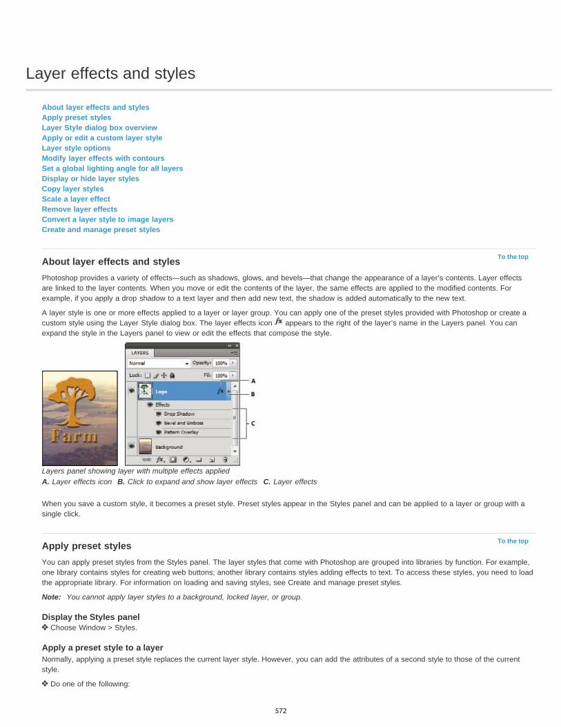
Layer effects and styles
To the top
To the top
About layer effects and stylesApply preset stylesLayer Style dialog box overviewApply or edit a custom layer styleLayer style optionsModify layer effects with contoursSet a global lighting angle for all layersDisplay or hide layer stylesCopy layer stylesScale a layer effectRemove layer effectsConvert a layer style to image layersCreate and manage preset styles
About layer effects and stylesPhotoshop provides a variety of effects—such as shadows, glows, and bevels—that change the appearance of a layer’s contents. Layer effectsare linked to the layer contents. When you move or edit the contents of the layer, the same effects are applied to the modified contents. Forexample, if you apply a drop shadow to a text layer and then add new text, the shadow is added automatically to the new text.
A layer style is one or more effects applied to a layer or layer group. You can apply one of the preset styles provided with Photoshop or create acustom style using the Layer Style dialog box. The layer effects icon appears to the right of the layer’s name in the Layers panel. You canexpand the style in the Layers panel to view or edit the effects that compose the style.
Layers panel showing layer with multiple effects appliedA. Layer effects icon B. Click to expand and show layer effects C. Layer effects
When you save a custom style, it becomes a preset style. Preset styles appear in the Styles panel and can be applied to a layer or group with asingle click.
Apply preset stylesYou can apply preset styles from the Styles panel. The layer styles that come with Photoshop are grouped into libraries by function. For example,one library contains styles for creating web buttons; another library contains styles adding effects to text. To access these styles, you need to loadthe appropriate library. For information on loading and saving styles, see Create and manage preset styles.
Note: You cannot apply layer styles to a background, locked layer, or group.
Display the Styles panel Choose Window > Styles.
Apply a preset style to a layerNormally, applying a preset style replaces the current layer style. However, you can add the attributes of a second style to those of the currentstyle.
Do one of the following:
572
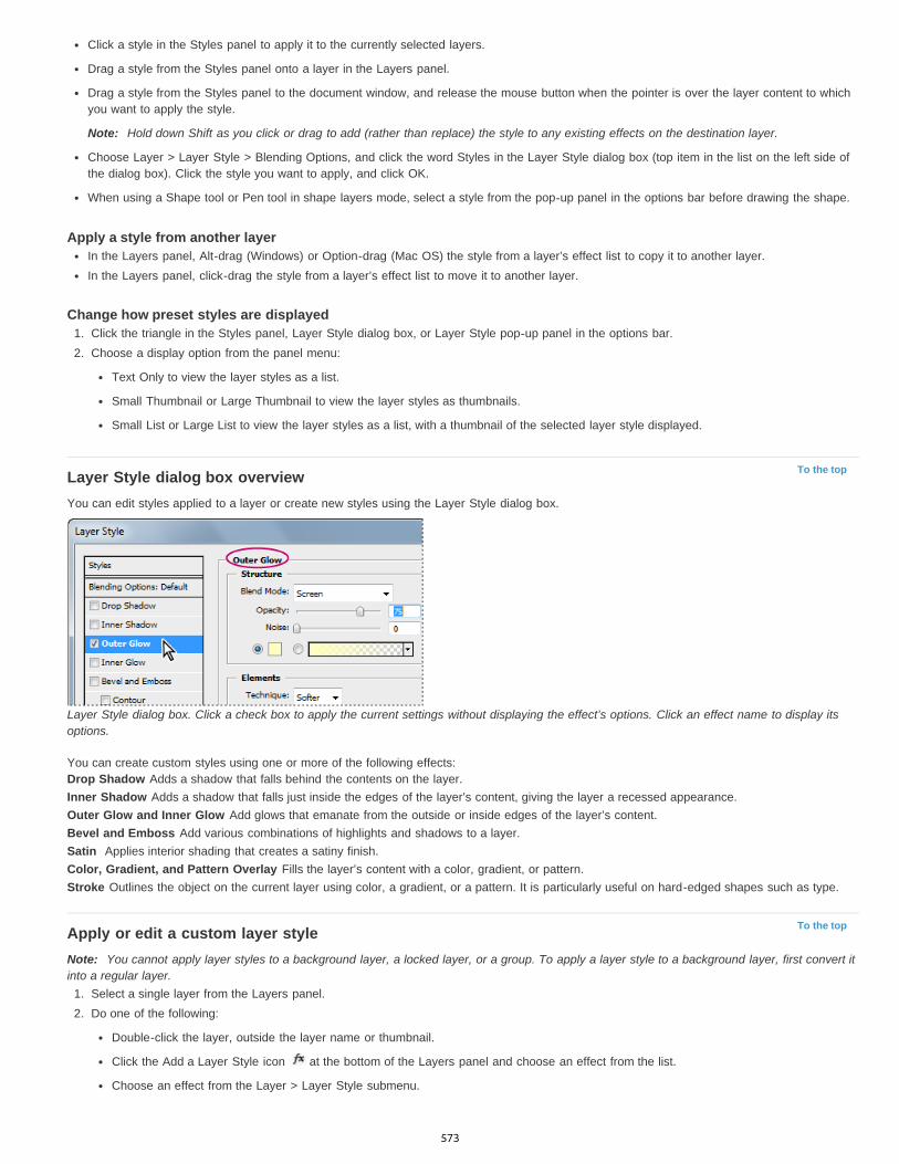
To the top
To the top
Click a style in the Styles panel to apply it to the currently selected layers.
Drag a style from the Styles panel onto a layer in the Layers panel.
Drag a style from the Styles panel to the document window, and release the mouse button when the pointer is over the layer content to whichyou want to apply the style.
Note: Hold down Shift as you click or drag to add (rather than replace) the style to any existing effects on the destination layer.
Choose Layer > Layer Style > Blending Options, and click the word Styles in the Layer Style dialog box (top item in the list on the left side ofthe dialog box). Click the style you want to apply, and click OK.
When using a Shape tool or Pen tool in shape layers mode, select a style from the pop-up panel in the options bar before drawing the shape.
Apply a style from another layerIn the Layers panel, Alt-drag (Windows) or Option-drag (Mac OS) the style from a layer’s effect list to copy it to another layer.In the Layers panel, click-drag the style from a layer’s effect list to move it to another layer.
Change how preset styles are displayed1. Click the triangle in the Styles panel, Layer Style dialog box, or Layer Style pop-up panel in the options bar.2. Choose a display option from the panel menu:
Text Only to view the layer styles as a list.
Small Thumbnail or Large Thumbnail to view the layer styles as thumbnails.
Small List or Large List to view the layer styles as a list, with a thumbnail of the selected layer style displayed.
Layer Style dialog box overviewYou can edit styles applied to a layer or create new styles using the Layer Style dialog box.
Layer Style dialog box. Click a check box to apply the current settings without displaying the effect’s options. Click an effect name to display itsoptions.
You can create custom styles using one or more of the following effects:Drop Shadow Adds a shadow that falls behind the contents on the layer.Inner Shadow Adds a shadow that falls just inside the edges of the layer’s content, giving the layer a recessed appearance.Outer Glow and Inner Glow Add glows that emanate from the outside or inside edges of the layer’s content.Bevel and Emboss Add various combinations of highlights and shadows to a layer.Satin Applies interior shading that creates a satiny finish.Color, Gradient, and Pattern Overlay Fills the layer’s content with a color, gradient, or pattern.Stroke Outlines the object on the current layer using color, a gradient, or a pattern. It is particularly useful on hard-edged shapes such as type.
Apply or edit a custom layer styleNote: You cannot apply layer styles to a background layer, a locked layer, or a group. To apply a layer style to a background layer, first convert itinto a regular layer.
1. Select a single layer from the Layers panel.2. Do one of the following:
Double-click the layer, outside the layer name or thumbnail.
Click the Add a Layer Style icon at the bottom of the Layers panel and choose an effect from the list.
Choose an effect from the Layer > Layer Style submenu.
573

To the top
To edit an existing style, double-click an effect displayed below the layer name in the Layers panel. (Click the triangle next to the Add aLayer Style icon to display the effects contained in the style.)
3. Set effect options in the Layer Style dialog box. See Layer style options.4. Add other effects to the style, if desired. In the Layer Style dialog box, click the check box to the left of the effect name to add the effect
without selecting it.You can edit multiple effects without closing the Layer Style dialog box. Click the name of an effect on the left side of the dialog box todisplay its options.
Change style defaults to custom values1. In the Layer Style dialog box, customize settings as desired.2. Click Make Default.
When you next open the dialog box, your custom defaults are automatically applied. If you adjust settings and want to return to your customdefaults, click Reset To Default.
To return to Photoshop’s original defaults, see Restore all preferences to default settings.
Layer style optionsAltitude For the Bevel and Emboss effect, sets the height of the light source. A setting of 0 is equivalent to ground level, 90 is directly above thelayer.Angle Determines the lighting angle at which the effect is applied to the layer. You can drag in the document window to adjust the angle of a DropShadow, Inner Shadow, or Satin effect.Anti-alias Blends the edge pixels of a contour or gloss contour. This option is most useful on small shadows with complicated contours.Blend Mode Determines how the layer style blends with the underlying layers, which may or may not include the active layer. For example,an inner shadow blends with the active layer because the effect is drawn on top of that layer, but a drop shadow blends only with the layersbeneath the active layer. In most cases, the default mode for each effect produces the best results. See Blending modes.Choke Shrinks the boundaries of the matte of an Inner Shadow or Inner Glow prior to blurring.Color Specifies the color of a shadow, glow, or highlight. You can click the color box and choose a color.Contour With solid-color glows, Contour allows you to create rings of transparency. With gradient-filled glows, Contour allows you to createvariations in the repetition of the gradient color and opacity. In beveling and embossing, Contour allows you to sculpt the ridges, valleys, andbumps that are shaded in the embossing process. With shadows, Contour allows you to specify the fade. For more information, see Modify layereffects with contours.Distance Specifies the offset distance for a shadow or satin effect. You can drag in the document window to adjust the offset distance.Depth Specifies the depth of a bevel. It also specifies the depth of a pattern.Use Global Light This setting allows you to set one “master” lighting angle that is then available in all the layer effects that use shading: DropShadow, Inner Shadow, and Bevel and Emboss. In any of these effects, if Use Global Light is selected and you set a lighting angle, that anglebecomes the global lighting angle. Any other effect that has Use Global Light selected automatically inherits the same angle setting. If Use GlobalLight is deselected, the lighting angle you set is “local” and applies only to that effect. You can also set the global lighting angle by choosing LayerStyle > Global Light.Gloss Contour Creates a glossy, metallic appearance. Gloss Contour is applied after shading a bevel or emboss.Gradient Specifies the gradient of a layer effect. Click the gradient to display the Gradient Editor, or click the inverted arrow and choose a gradientfrom the pop-up panel. You can edit a gradient or create a new gradient using the Gradient Editor. You can edit the color or opacity in the GradientOverlay panel the same way you edit them in the Gradient Editor. For some effects, you can specify additional gradient options. Reverse flips theorientation of the gradient, Align With Layer uses the bounding box of the layer to calculate the gradient fill, and Scale scales the application of thegradient. You can also move the center of the gradient by clicking and dragging in the image window. Style specifies the shape of the gradient.Highlight or Shadow Mode Specifies the blending mode of a bevel or emboss highlight or shadow.Jitter Varies the application of a gradient’s color and opacity.Layer Knocks Out Drop Shadow Controls the drop shadow’s visibility in a semitransparent layer.Noise Specifies the number of random elements in the opacity of a glow or shadow. Enter a value or drag the slider.Opacity Sets the opacity of the layer effect. Enter a value or drag the slider.Pattern Specifies the pattern of a layer effect. Click the pop-up panel and choose a pattern. Click the New Preset button to create a new presetpattern based on the current settings. Click Snap To Origin to make the origin of the pattern the same as the origin of the document (when LinkWith Layer is selected), or to place the origin at the upper-left corner of the layer (if Link With Layer is deselected). Select Link With Layer if youwant the pattern to move along with the layer as the layer moves. Drag the Scale slider or enter a value to specify the size of the pattern. Drag apattern to position it in the layer; reset the position by using the Snap To Origin button. The Pattern option is not available if no patterns areloaded.Position Specifies the position of a stroke effect as Outside, Inside, or Center.Range Controls which portion or range of the glow is targeted for the contour.Size Specifies the radius and size of blur or the size of the shadow.Soften Blurs the results of shading to reduce unwanted artifacts.Source Specifies the source for an inner glow. Choose Center to apply a glow that emanates from the center of the layer’s content, or Edge to
574

To the top
To the top
apply a glow that emanates from the inside edges of the layer’s content.Spread Expands the boundaries of the matte prior to blurring.Style Specifies the style of a bevel: Inner Bevel creates a bevel on the inside edges of the layer contents; Outer Bevel creates a bevel on theoutside edges of the layer contents; Emboss simulates the effect of embossing the layer contents against the underlying layers; Pillow Embosssimulates the effect of stamping the edges of the layer contents into the underlying layers; and Stroke Emboss confines embossing to theboundaries of a stroke effect applied to the layer. (The Stroke Emboss effect is not visible if no stroke is applied to the layer.)Technique Smooth, Chisel Hard, and Chisel Soft are available for bevel and emboss effects; Softer and Precise apply to Inner Glow and OuterGlow effects.
Smooth Blurs the edges of a matte slightly and is useful for all types of mattes, whether their edges are soft or hard. It does not preservedetailed features at larger sizes.Chisel Hard Uses a distance measurement technique and is primarily useful on hard-edged mattes from anti-aliased shapes such astype. It preserves detailed features better than the Smooth technique.Chisel Soft Uses a modified distance measurement technique and, although not as accurate as Chisel Hard, is more useful on a largerrange of mattes. It preserves features better than the Smooth technique.Softer Applies a blur and is useful on all types of mattes, whether their edges are soft or hard. At larger sizes, Softer does not preservedetailed features.Precise Uses a distance measurement technique to create a glow and is primarily useful on hard-edged mattes from anti-aliased shapessuch as type. It preserves features better than the Softer technique.
Texture Applies a texture. Use Scale to scale the size of the texture. Select Link With Layer if you want the texture to move along with the layer asthe layer moves. Invert inverts the texture. Depth varies the degree and direction (up/down) to which the texturing is applied. Snap To Originmakes the origin of the pattern the same as the origin of the document (if Link With Layer is deselected) or places the origin in the upper-leftcorner of the layer (if Link With Layer is selected). Drag the texture to position it in the layer.
Modify layer effects with contoursWhen you create custom layer styles, you can use contours to control the shape of Drop Shadow, Inner Shadow, Inner Glow, Outer Glow, Beveland Emboss, and Satin effects over a given range. For example, a Linear contour on a Drop Shadow causes the opacity to drop off in a lineartransition. Use a Custom contour to create a unique shadow transition.
You can select, reset, delete, or change the preview of contours in the Contour pop-up panel and Preset Manager.
Detail of Layer Style dialog box for Drop Shadow effectA. Click to display the Contour Editor dialog box. B. Click to display the pop-up panel.
Create a custom contour1. Select the Drop Shadow, Inner Shadow, Inner Glow, Outer Glow, Bevel and Emboss, Contour, or Satin effect in the Layer Style dialog box.2. Click the contour thumbnail in the Layer Style dialog box.3. Click the contour to add points, and drag to adjust the contour. Or enter values for Input and Output.4. To create a sharp corner instead of a smooth curve, select a point and click Corner.5. To save the contour to a file, click Save and name the contour.6. To store a contour as a preset, choose New.7. Click OK. New contours are added at the bottom of the pop-up panel.
Load a contour Click the contour in the Layer Style dialog box, and in the Contour Editor dialog box, and then choose Load. Go to the folder containing the
contour library you want to load and click Open.
Delete a contour Click the inverted arrow next to the currently selected contour to view the pop-up panel. Press Alt (Windows) or Option (Mac OS), and click the
contour you want to delete.
Set a global lighting angle for all layers
575

To the top
To the top
To the top
To the top
Using global light gives the appearance of a common light source shining on the image.
Do one of the following:
Choose Layer > Layer Style > Global Light. In the Global Light dialog box, enter a value or drag the angle radius to set the angle andaltitude, and click OK.
In the Layer Style dialog box for Drop Shadow, Inner Shadow, or Bevel, select Use Global Light. For Angle, enter a value or drag the radius,and click OK.
The global lighting applies to each layer effect that uses the global lighting angle.
Display or hide layer stylesWhen a layer has a style, an “fx” icon appears to the right of the layer’s name in the Layers panel.
Hide or show all layer styles in an image Choose Layer > Layer Style > Hide All Effects or Show All Effects.
Expand or collapse layer styles in the Layers panel Do one of the following:
Click the triangle next to the Add a Layer Style icon to expand the list of layer effects applied to that layer.
Click the triangle to collapse the layer effects.
To expand or collapse all of the layer styles applied within a group, hold down Alt (Windows) or Option (Mac OS), and click the triangle orinverted triangle for the group. The layer styles applied to all layers within the group expand or collapse correspondingly.
Copy layer stylesCopying and pasting styles is an easy way to apply the same effects to multiple layers.
Copy layer styles between layers1. From the Layers panel, select the layer containing the style you want to copy.2. Choose Layer > Layer Style > Copy Layer Style.3. Select the destination layer from the panel, and choose Layer > Layer Style > Paste Layer Style.
The pasted layer style replaces the existing layer style on the destination layer or layers.
Copy layer styles between layers by dragging Do one of the following:
In the Layers panel, Alt-drag (Windows) or Option-drag (Mac OS) a single layer effect from one layer to another to duplicate the layer effect,or drag the Effects bar from one layer to another to duplicate the layer style.
Drag one or more layer effects from the Layers panel to the image to apply the resulting layer style to the highest layer in the Layers panelthat contains pixels at the drop point.
Scale a layer effectA layer style may have been fine-tuned for a target resolution and features of a given size. Using Scale Effects allows you to scale the effects inthe layer style without scaling the object to which the layer style is applied.
1. Select the layer in the Layers panel.2. Choose Layer > Layer Style > Scale Effects.3. Enter a percentage or drag the slider.4. Select Preview to preview the changes in the image.5. Click OK.
Remove layer effectsYou can remove an individual effect from a style applied to a layer, or remove the entire style from the layer.
Remove an effect from a style
576

To the top
To the top
1. In the Layers panel, expand the layer style to see its effects.2. Drag the effect to the Delete icon .
Remove a style from a layer1. In the Layers panel, select the layer containing the style you want to remove.2. Do one of the following:
In the Layers panel, drag the Effects bar to the Delete icon .
Choose Layer > Layer Style > Clear Layer Style.
Select the layer, and then click the Clear Style button at the bottom of the Styles panel.
Convert a layer style to image layersTo customize or fine-tune the appearance of layer styles, you can convert the layer styles to regular image layers. After you convert a layer style toimage layers, you can enhance the result by painting or applying commands and filters. However, you can no longer edit the layer style on theoriginal layer, and the layer style no longer updates as you change the original image layer.
Note: The layers produced by this process may not result in artwork that exactly matches the version using layer styles. You may see an alertwhen you create the new layers.
1. In the Layers panel, select the layer containing the layer style that you want to convert.2. Choose Layer > Layer Style > Create Layers.
You can now modify and restack the new layers in the same way as regular layers. Some effects—for example, Inner Glow—convert tolayers within a clipping mask.
Create and manage preset stylesYou can create a custom style and save it as a preset, which is then available from the Styles panel. You can save preset styles in a library andload or remove them from the Styles panel as you need them.
Create a new preset style1. From the Layers panel, select the layer containing the style that you want to save as a preset.2. Do one of the following:
Click an empty area of the Styles panel.
Click the Create New Style button at the bottom of the Styles panel.
Choose New Style from the Styles panel menu.
Choose Layer > Layer Style > Blending Options, and click New Style in the Layer Style dialog box.
3. Enter a name for the preset style, set style options, and click OK.
Rename a preset style Do one of the following:
Double-click a style in the Styles panel. If the Styles panel is set to display styles as thumbnails, enter a new name in the dialog box andclick OK. Otherwise, type a new name directly in the Styles panel and press Enter (Windows) or Return (Mac OS).
Select a style in the Styles area of the Layer Style dialog box. Then choose Rename Style from the pop-up menu, enter a new name, andclick OK.
When using a shape or Pen tool, select a style from the Style pop-up panel in the options bar. Then choose Rename Style from the pop-uppanel menu.
Delete a preset style Do one of the following:
Drag a style to the Delete icon at the bottom of the Styles panel.
Press Alt (Windows) or Option (Mac OS), and click the layer style in the Styles panel.
Select a style in the Styles area of the Layer Style dialog box. (See Apply preset styles.) Then choose Delete Style from the pop-up menu.
When using a shape or Pen tool, select a style from the Layer Style pop-up panel in the options bar. Then choose Delete Style from thepop-up panel menu.
577

Save a set of preset styles as a library1. Do one of the following:
Choose Save Styles from the Styles panel menu.
Select Styles on the left side of the Layer Style dialog box. Then choose Save Styles from the pop-up menu.
When using a shape or Pen tool, click the layer style thumbnail in the options bar. Then choose Save Styles from the pop-up panelmenu.
2. Choose a location for the style library, enter a file name, and click Save.
You can save the library anywhere. However, if you place the library file in the Presets/Styles folder inside the default presets location, thelibrary name will appear at the bottom of the Styles panel menu when you restart the application.
Note: You can also use the Preset Manager to rename, delete, and save libraries of preset styles.
Load a library of preset styles1. Click the triangle in the Styles panel, Layer Style dialog box, or Layer Style pop-up panel in the options bar.2. Do one of the following:
Choose Load Styles to add a library to the current list. Then select the library file you want to use, and click Load.
Choose Replace Styles to replace the current list with a different library. Then select the library file you want to use, and click Load.
Choose a library file (displayed at the bottom of the panel menu). Then click OK to replace the current list, or click Append to append thecurrent list.
3. To return to the default library of preset styles, choose Reset Styles. You can either replace the current list or append the default library tothe current list.Note: You can also use the Preset Manager to load and reset style libraries. See About the Preset Manager.
Legal Notices | Online Privacy Policy
578

Saving and exporting
579
Saving images
To the top
To the top
Save a fileSet file saving preferencesSave large documentsExport layers to filesTesting Photoshop images for mobile devices with Adobe Device Central (CS5)Create mobile content with Adobe Device Central and Photoshop (CS5)
Note: For detailed instructions, click the links below. To ask questions, request features, or report problems, visit feedback.photoshop.com.
Save a fileUse the Save command to save changes to the current file or the Save As command to save changes to a different file.
Save changes to the current file Choose File > Save.
The file remains in the current format.
Save a file with a different name, location, or format1. Choose File > Save As.
Note: The Camera Raw plug-in can save camera raw image files in a different file format, such as Digital Negative (DNG).2. Choose a format from the Format menu.
Note: If you choose a format that does not support all the features of the document, a warning will appear at the bottom of the dialog box. Ifyou see this warning, it’s best to save a copy of the file in Photoshop format or in another format that supports all of the image data.
3. Specify a filename and location.4. In the Save As dialog box, select saving options.5. Click Save.
A dialog box appears for choosing options when saving in some image formats.
To copy an image without saving it to your hard disk, use the Duplicate command. To store a temporary version of the image in memory,use the History panel to create a snapshot.
File saving optionsYou can set a variety of file saving options in the Save As dialog box. The availability of options depends on the image you are saving and theselected file format.
As A Copy Saves a copy of the file while keeping the current file open on your desktop.Alpha Channels Saves alpha channel information with the image. Disabling this option removes the alpha channels from the saved image.Layers Preserves all layers in the image. If this option is disabled or unavailable, all visible layers are flattened or merged (depending on theselected format).Notes Saves notes with the image.Spot Colors Saves spot channel information with the image. Disabling this option removes spot colors from the saved image.Use Proof Setup, ICC Profile (Windows), or Embed Color Profile (Mac OS) Creates a color-managed document.Note: The following image preview and file extension options are available only if Ask When Saving is selected for the Image Previews andAppend File Extension (Mac OS) options in the File Handling Preferences dialog box.Thumbnail (Windows) Saves thumbnail data for the file.Use Lower Case Extension (Windows) Makes the file extension lowercase.Image Previews options (Mac OS) Saves thumbnail data for the file. Thumbnails appear in the Open dialog box.File Extension options (Mac OS) Specifies the format for file extensions. Select Append to add the format’s extension to a filename and UseLower Case to make the extension lowercase.
Set file saving preferences1. Do one of the following:
(Windows) Choose Edit > Preferences > File Handling.
580

To the top
To the top
To the top
(Mac OS) Choose Photoshop > Preferences > File Handling.
2. Set the following options:Image Previews Choose an option for saving image previews: Never Save to save files without previews, Always Save to save files withspecified previews, or Ask When Saving to assign previews on a file-by-file basis. In Mac OS, you can select one or more preview types.(See Mac OS image preview options.)
File Extension (Windows) Choose an option for the three-character file extensions that indicate a file’s format: Use Upper Case to appendfile extensions using uppercase characters, or Use Lower Case to append file extensions using lowercase characters.
Append File Extension (Mac OS) File extensions are necessary for files that you want to use on or transfer to a Windows system. Choosean option for appending extensions to filenames: Never to save files without file extensions, Always to append file extensions to filenames, orAsk When Saving to append file extensions on a file-by-file basis. Select Use Lower Case to append file extensions using lowercasecharacters.
Save As to Original Folder When saving, defaults to the folder images originated from. Deselect this option to instead default to the folderyou last saved in.
Save in Background (CC, CS6) Background saving lets you keep working in Photoshop after you choose a Save command. You don’t haveto wait for Photoshop to finish saving the file.
Automatically Save Recovery Information (CC, CS6) Photoshop automatically stores crash-recovery information at the interval that youspecify. If you experience a crash, Photoshop recovers your work when you restart it.
Mac OS image preview optionsIn Mac OS, you can select one or more of the following preview types (to speed the saving of files and minimize file size, select only the previewsyou need).
Icon Uses the preview as a file icon on the desktop.Full Size Saves a 72-ppi version of the file for use in applications that can open only low-resolution Photoshop images. For non-EPS files, this is aPICT preview.Macintosh Thumbnail Displays the preview in the Open dialog box.Windows Thumbnail Saves a preview that Windows systems can display.
Save large documentsPhotoshop supports documents up to 300,000 pixels in either dimension and offers three file formats for saving documents with images havingmore than 30,000 pixels in either dimension. Keep in mind that most other applications, including versions of Photoshop earlier than PhotoshopCS, cannot handle files larger than 2 GB or images exceeding 30,000 pixels in either dimension.
Choose File > Save As, and choose one of the following file formats:Large Document Format (PSB) Supports documents of any file size. All Photoshop features are preserved in PSB files (though some plug-infilters are unavailable if documents exceed 30,000 pixels in width or height). Currently, PSB files are supported only by Photoshop CS and later.Photoshop Raw Supports documents of any pixel dimension or file size, but does not support layers. Large documents saved in the PhotoshopRaw format are flattened.TIFF Supports files up to 4 GB in size. Documents larger than 4 GB cannot be saved in TIFF format.
Export layers to filesYou can export and save layers as individual files using a variety of formats, including PSD, BMP, JPEG, PDF, Targa, and TIFF. Layers arenamed automatically as they are saved. You can set options to control the generation of names.
1. Choose File > Scripts > Export Layers To Files.2. In the Export Layers To Files dialog box, under Destination, click Browse to select a destination for the exported files. By default, the
generated files are saved in the sample folder as the source file.3. Enter a name in the File Name Prefix text box to specify a common name for the files.4. Select the Visible Layers Only option if you want to export only those layers that have visibility enabled in the Layers panel. Use this option if
you don’t want all the layers exported. Turn off visibility for layers that you don’t want exported.5. Choose a file format from the File Type menu. Set options as necessary.6. Select the Include ICC Profile option if you want the working space profile embedded in the exported file. This is important for color-
managed workflows.7. Click Run.
Testing Photoshop images for mobile devices with Adobe Device Central (CS5)Device Central enables Photoshop users to preview how Photoshop files will look on a variety of mobile devices.
581
To the top
Creative professionals can create Photoshop files specifically for mobile devices and easily test the files. Users can create a document inPhotoshop based on a targeted device.
For example, a user interface designer might use Photoshop to create mock-ups. The designer can test the mock-ups on a variety of handsets,make necessary adjustments, and pass the improved mock-ups to developers.
Create mobile content with Adobe Device Central and Photoshop (CS5)1. Start Photoshop.2. Select File > New.3. Click Device Central to close the dialog box in Photoshop and open Device Central.4. Select a content type.
The Online Library list on the left is updated and shows the devices that support the content type selected.
5. Select one or more target devices from the Online Library list, and drag them to the Local Library list. Then, select a target device in theLocal Library list.
Device Central lists proposed document sizes based on the device or devices you selected (if the devices have different display sizes).Depending on the design or content you are developing, you can create a separate mobile document for each display size or try to find onesize appropriate for all devices. When choosing the second approach, you may want to use the smallest or largest suggested document sizeas a common denominator. You can even specify a custom size at the bottom of the tab.
6. Click Create.
A blank PSD file with the specified size opens in Photoshop. The new file has the following parameters set by default:
Color Mode: RGB/8bit
Resolution: 72 ppi
Color Profile: SRGB IEC61966-2.1
7. Fill the blank PSD file with content in Photoshop.8. When you finish, select File > Save For Web& Devices.9. In the Save For Web & Devices dialog box, select the desired format and change other export settings as desired.
10. Click Device Central.
A temporary file with the export settings specified is displayed in the Device Central Emulator tab. To continue testing, double-click thename of a different device in the Device Sets or Local Library list.
11. If, after previewing the file in Device Central, make changes to the file, go back to Photoshop.12. In the Photoshop Save For Web & Devices dialog box, make adjustments, such as selecting a different format or quality for export.13. To test the file again with the new export settings, click the Device Central button.14. When you are satisfied with the results, click Save in the Photoshop Save For Web & Devices dialog box.
Note: To open Device Central from Photoshop (instead of creating and testing a file), select File > Device Central.
More Help topics Save a camera raw image in another format
About Adobe Device Central
Legal Notices | Online Privacy Policy
582

File formats
To the top
To the top
Choosing a file formatAbout file compressionMaximize compatibility for PSD and PSB filesPhotoshop format (PSD)Photoshop 2.0 formatPhotoshop DCS 1.0 and 2.0 formatsPhotoshop EPS formatPhotoshop Raw formatDigital Negative format (DNG)BMP formatCineon formatDICOM formatGIFIFFJPEG formatLarge Document Format (PSB)OpenEXR formatPCXPDFPICT FilePICT ResourcePixar formatPNG formatPortable Bit Map formatRadiance formatScitex CTTargaTIFFWBMP format
Note: If a supported file format does not appear in the appropriate dialog box or submenu, you may need to install the format’s plug-in module.
Choosing a file formatGraphics file formats differ in the way they represent image data (as pixels or vectors), and support different compression techniques andPhotoshop features. To preserve all Photoshop features (layers, effects, masks, and so on), save a copy of your image in Photoshop format(PSD).
Like most file formats, PSD supports files up to 2 GB in size. For files larger than 2 GB, save in Large Document Format (PSB), Photoshop Raw(flattened image only), TIFF (up to 4 GB), or DICOM format.
The standard bit depth for images is 8 bits per channel. To achieve greater dynamic range with 16- or 32-bit images, use the following formats:
Formats for 16-bit images (require Save As command)Photoshop, Large Document Format (PSB), Cineon, DICOM, IFF, JPEG, JPEG 2000, Photoshop PDF, Photoshop Raw, PNG, Portable Bit Map,and TIFF.
Note: The Save For Web & Devices command automatically converts 16-bit images to 8-bit.
Formats for 32-bit images (require Save As command)Photoshop, Large Document Format (PSB), OpenEXR, Portable Bitmap, Radiance, and TIFF.
About file compressionMany file formats use compression to reduce the file size of bitmap images. Lossless techniques compress the file without removing image detailor color information; lossy techniques remove detail. The following are commonly used compression techniques:
RLE (Run Length Encoding) Lossless compression; supported by some common Windows file formats.LZW (Lemple-Zif-Welch) Lossless compression; supported by TIFF, PDF, GIF, and PostScript language file formats. Most useful for images with
583

To the top
To the top
To the top
To the top
To the top
large areas of single color.JPEG (Joint Photographic Experts Group) Lossy compression; supported by JPEG, TIFF, PDF, and PostScript language file formats.Recommended for continuous-tone images, such as photographs. JPEG uses lossy compression. To specify image quality, choose an option fromthe Quality menu, drag the Quality pop-up slider, or enter a value between 0 and 12 in the Quality text box. For the best printed results, choosemaximum-quality compression. JPEG files can be printed only on Level 2 (or later) PostScript printers and may not separate into individualplates.CCITT A family of lossless compression techniques for black-and-white images, supported by the PDF and PostScript language file formats.(CCITT is an abbreviation for the French spelling of International Telegraph and Telekeyed Consultive Committee.)ZIP Lossless compression; supported by PDF and TIFF file formats. Like LZW, ZIP compression is most effective for images that contain largeareas of single color.
Maximize compatibility for PSD and PSB filesIf you work with PSD and PSB files in older versions of Photoshop or applications that don’t support layers, you can add a flattened version of theimage to the saved file.
Note: If you save an image in an earlier version of Photoshop, features that version doesn’t support are discarded.1. Choose Edit > Preferences > File Handling (Windows) or Photoshop > Preferences > File Handling (Mac OS).2. From the Maximize PSD and PSB File Compatibility menu, choose any of the following:
Always Saves a composite (flattened) image along with the layers of your document.
Ask Asks whether to maximize compatibility when you save.
Never Saves only a layered image.
Choose Ask or Never if you want to significantly reduce file size.
Photoshop format (PSD)Photoshop format (PSD) is the default file format and the only format, besides the Large Document Format (PSB), that supports all Photoshopfeatures. Because of the tight integration between Adobe products, other Adobe applications, such as Adobe Illustrator, Adobe InDesign, AdobePremiere, Adobe After Effects, and Adobe GoLive, can directly import PSD files and preserve many Photoshop features. For more information, seeHelp for the specific Adobe applications.
When saving a PSD, you can set a preference to maximize file compatibility. This saves a composite version of a layered image in the file so it canbe read by other applications, including previous versions of Photoshop. It also maintains the appearance of the document, just in case futureversions of Photoshop change the behavior of some features. Including the composite also makes the image much faster to load and use inapplications other than Photoshop, and may sometimes be required to make the image readable in other applications.
16-bits-per-channel and high dynamic range 32-bits-per-channel images can be saved as PSD files.
Photoshop 2.0 format(Mac OS) You can use this format to open an image in Photoshop 2.0 or to export an image to an application supporting only Photoshop 2.0 files.Saving in Photoshop 2.0 format flattens your image and discards layer information.
Photoshop DCS 1.0 and 2.0 formatsDesktop Color Separations (DCS) format is a version of the standard EPS format that lets you save color separations of CMYK images. You canuse DCS 2.0 format to export images containing spot channels. To print DCS files, you must use a PostScript printer.
Photoshop EPS formatEncapsulated PostScript (EPS) language file format can contain both vector and bitmap graphics and is supported by virtually all graphics,illustration, and page-layout programs. EPS format is used to transfer PostScript artwork between applications. When you open an EPS filecontaining vector graphics, Photoshop rasterizes the image, converting the vector graphics to pixels.
EPS format supports Lab, CMYK, RGB, Indexed Color, Duotone, Grayscale, and Bitmap color modes, and does not support alpha channels. EPSdoes support clipping paths. Desktop Color Separations (DCS) format, a version of the standard EPS format, lets you save color separations ofCMYK images. You use DCS 2.0 format to export images containing spot channels. To print EPS files, you must use a PostScript printer.
Photoshop uses the EPS TIFF and EPS PICT formats to let you open images saved in file formats that create previews but are not supported byPhotoshop (such as QuarkXPress®). You can edit and use an opened preview image just as any other low-resolution file. An EPS PICT preview isavailable only in Mac OS.
Note: EPS TIFF format and EPS PICT format are more relevant to earlier versions of Photoshop. The current version of Photoshop includesrasterization features for opening files that include vector data.
584
To the top
To the top
To the top
To the top
To the top
To the top
To the top
Photoshop Raw formatThe Photoshop Raw format is a flexible file format for transferring images between applications and computer platforms. This format supportsCMYK, RGB, and grayscale images with alpha channels, and multichannel and Lab images without alpha channels. Documents saved in thePhotoshop Raw format can be of any pixel or file size, but they cannot contain layers.
The Photoshop Raw format consists of a stream of bytes describing the color information in the image. Each pixel is described in binary format,with 0 representing black and 255 white (for images with 16-bit channels, the white value is 65535). Photoshop designates the number of channelsneeded to describe the image, plus any additional channels in the image. You can specify the file extension (Windows), file type (Mac OS), filecreator (Mac OS), and header information.
In Mac OS, the file type is generally a four-character ID that identifies the file—for example, TEXT identifies the file as an ASCII text file. The filecreator is also generally a four-character ID. Most Mac OS applications have a unique file creator ID that is registered with the Apple ComputerDeveloper Services group.
The Header parameter specifies how many bytes of information appear in the file before actual image information begins. This value determinesthe number of zeroes inserted at the beginning of the file as placeholders. By default, there is no header (header size = 0). You can enter a headerwhen you open the file in Raw format. You can also save the file without a header and then use a file-editing program, such as HEdit (Windows)or Norton Utilities® (Mac OS), to replace the zeroes with header information.
You can save the image in an interleaved or non-interleaved format. If you choose interleaved, the color values (red, green, and blue, for example)are stored sequentially. Your choice depends on requirements of the application that will open the file.
Note: A Photoshop Raw image is not in the same file format as a camera raw image file from a digital camera. A camera raw image file is in acamera-specific proprietary format that is essentially a “digital negative,” with no filtering, white balance adjustments, or other in-cameraprocessing.
Digital Negative format (DNG)Digital Negative (DNG) is a file format that contains the raw image data from a digital camera and metadata that defines what the data means.DNG, Adobe’s publicly available, archival format for camera raw files, is designed to provide compatibility and decrease the current proliferation ofcamera raw file formats. The Camera Raw plug-in can save camera raw image data in the DNG format. For more information about the DigitalNegative (DNG) file format, visit www.adobe.com and search on the term “Digital Negative.” You’ll find comprehensive information and a link to auser forum.
BMP formatBMP is a standard Windows image format on DOS and Windows-compatible computers. BMP format supports RGB, Indexed Color, Grayscale,and Bitmap color modes. You can specify either Windows or OS/2® format and a bit depth of 8 bits/channel. For 4-bit and 8-bit images usingWindows format, you can also specify RLE compression.
BMP images are normally written bottom to top; however, you can select the Flip Row Order option to write them from top to bottom. You can alsoselect an alternate encoding method by clicking Advanced Modes. (Flip Row Order and Advanced Modes are most relevant to game programmersand others using DirectX®.)
Cineon formatDeveloped by Kodak, Cineon is a 10-bits-per-channel digital format suitable for electronic composition, manipulation, and enhancement. Using theCineon format, you can output back to film with no loss of image quality. The format is used in the Cineon Digital Film System, which transfersimages originated on film to the Cineon format and back to film.
DICOM formatThe DICOM (Digital Imaging and Communications in Medicine) format is commonly used for the transfer and storage of medical images, such asultrasounds and scans. DICOM files contain both image data and headers, which store information about the patient and the medical image. Youcan open, edit, and save DICOM files in Photoshop Extended.
GIFGraphics Interchange Format (GIF) is the file format commonly used to display indexed-color graphics and images in Hypertext Markup Language(HTML) documents over the World Wide Web and other online services. GIF is an LZW-compressed format designed to minimize file size andelectronic transfer time. GIF format preserves transparency in indexed-color images; however, it does not support alpha channels.
585
To the top
To the top
To the top
To the top
To the top
To the top
IFFIFF (Interchange File Format) is a general-purpose data storage format that can associate and store multiple types of data. IFF is portable and hasextensions that support still-picture, sound, music, video, and textual data. The IFF format includes Maya IFF and IFF (formerly Amiga IFF).
JPEG formatJoint Photographic Experts Group (JPEG) format is commonly used to display photographs and other continuous-tone images in hypertext markuplanguage (HTML) documents over the World Wide Web and other online services. JPEG format supports CMYK, RGB, and Grayscale colormodes, and does not support transparency. Unlike GIF format, JPEG retains all color information in an RGB image but compresses file size byselectively discarding data.
A JPEG image is automatically decompressed when opened. A higher level of compression results in lower image quality, and a lower level ofcompression results in better image quality. In most cases, the Maximum quality option produces a result indistinguishable from the original.
Large Document Format (PSB)The Large Document Format (PSB) supports documents up to 300,000 pixels in any dimension. All Photoshop features, such as layers, effects,and filters, are supported. (With documents larger than 30,000 pixels in width or height, some plug-in filters are unavailable.)
You can save high dynamic range, 32-bits-per-channel images as PSB files. Currently, if you save a document in PSB format, it can be openedonly in Photoshop CS or later. Other applications and earlier versions of Photoshop cannot open documents saved in PSB format.
Note: Most other applications and older versions of Photoshop cannot support documents with file sizes larger than 2 GB.
OpenEXR formatOpenEXR (EXR) is a file format used by the visual effects industry for high dynamic range images. The film format has high color fidelity and adynamic range suitable for use in motion picture production. Developed by Industrial Light and Magic, OpenEXR supports multiple lossless orlossy compression methods. An OpenEXR file supports transparency and only works with 32 bits/channel images; the file format stores the valuesas 16 bits/channel floating point.
PCXPCX format is commonly used by IBM PC-compatible computers. Most PC software supports version 5 of PCX format. A standard VGA colorpalette is used with version 3 files, which do not support custom color palettes.
PCX format supports Bitmap, Grayscale, Indexed Color, and RGB color modes, and does not support alpha channels. PCX supports the RLEcompression method. Images can have a bit depth of 1, 4, 8, or 24.
PDFPortable Document Format (PDF) is a flexible, cross-platform, cross-application file format. Based on the PostScript imaging model, PDF filesaccurately display and preserve fonts, page layouts, and both vector and bitmap graphics. In addition, PDF files can contain electronic documentsearch and navigation features such as electronic links. PDF supports 16-bits-per-channel images. Adobe Acrobat also has a Touch Up Objecttool for minor editing of images in a PDF. For more information about working with images in PDFs, see Acrobat Help.
Note: The Touch Up Object tool is mainly for last-minute revisions to images and objects. It’s best to do image editing in Photoshop beforesaving as PDF.Photoshop recognizes two types of PDF files:
Photoshop PDF files Created when Preserve Photoshop Editing Capabilities is selected in the Save Adobe PDF dialog box. Photoshop PDF filescan contain only a single image.Photoshop PDF format supports all color modes (except Multichannel) and features that are supported in standard Photoshop format. PhotoshopPDF also supports JPEG and ZIP compression, except for Bitmap-mode images, which use CCITT Group 4 compression.
Standard PDF files Created when Preserve Photoshop Editing Capabilities is deselected in the Save Adobe PDF dialog box, or by using anotherapplication such as Adobe Acrobat or Illustrator. Standard PDF files can contain multiple pages and images.When you open a standard PDF file, Photoshop rasterizes vector and text content, while preserving pixel content.
PICT FilePICT format is used in Mac OS graphics and page-layout applications as an intermediary file format for transferring images between applications.PICT format supports RGB images with a single alpha channel and Indexed Color, Grayscale, and Bitmap mode images without alpha channels.
Though Photoshop can open raster PICT files, it cannot open QuickDraw PICTs or save to PICT format.
586

To the top
To the top
To the top
To the top
To the top
To the top
To the top
To the top
PICT Resource(Mac OS) A PICT resource is a PICT file but takes a name and resource ID number. The PICT Resource format supports RGB images with asingle alpha channel, and Indexed Color, Grayscale, and Bitmap mode images without alpha channels.
You can use the Import command or the Open command to open a PICT resource. However, Photoshop cannot save to this format.
Pixar formatThe Pixar format is designed specifically for high-end graphics applications, such as those used for rendering three-dimensional images andanimation. Pixar format supports RGB and grayscale images with a single alpha channel.
PNG formatDeveloped as a patent-free alternative to GIF, Portable Network Graphics (PNG) format is used for lossless compression and for display of imageson the web. Unlike GIF, PNG supports 24-bit images and produces background transparency without jagged edges; however, some web browsersdo not support PNG images. PNG format supports RGB, Indexed Color, Grayscale, and Bitmap mode images without alpha channels. PNGpreserves transparency in grayscale and RGB images.
Portable Bit Map formatThe Portable Bit Map (PBM) file format, also known as Portable Bitmap Library and Portable Binary Map, supports monochrome bitmaps (1 bit perpixel). The format can be used for lossless data transfer because many applications support this format. You can even edit or create such fileswithin a simple text editor.
The Portable Bit Map format serves as the common language of a large family of bitmap conversion filters including Portable FloatMap (PFM),Portable Graymap (PGM), Portable Pixmap (PPM), and Portable Anymap (PNM). While the PBM file format stores monochrome bitmaps, PGMadditionally stores grayscale bitmaps, and PPM can also store color bitmaps. PNM is not a different file format in itself, but a PNM file can holdPBM, PGM, or PPM files. PFM is a floating-point image format that can be used for 32-bits-per-channel HDR files.
Radiance formatRadiance (HDR) is a 32-bits-per-channel file format used for high dynamic range images. This format was originally developed for the Radiancesystem, a professional tool for visualizing lighting in virtual environments. The file format stores the quantity of light per pixel instead of just thecolors to be displayed on-screen. The levels of luminosity accommodated by the Radiance format are far higher than the 256 levels in 8-bits-per-channel image file formats. Radiance (HDR) files are often used in 3D modeling.
Scitex CTScitex Continuous Tone (CT) format is used for high-end image processing on Scitex computers. Contact Creo to obtain utilities for transferringfiles saved in Scitex CT format to a Scitex system. Scitex CT format supports CMYK, RGB, and grayscale images and does not support alphachannels.
CMYK images saved in Scitex CT format often have extremely large file sizes. These files are generated for input using a Scitex scanner. Imagessaved in Scitex CT format are printed to film using a Scitex rasterizing unit, which produces separations using a patented Scitex halftoning system.This system produces very few moiré patterns and is often demanded in professional color work—for example, ads in magazines.
TargaThe Targa (TGA) format is designed for systems using the Truevision video board and is commonly supported by MS-DOS color applications.Targa format supports 16-bit RGB images (5 bits x 3 color channels, plus one unused bit), 24-bit RGB images (8 bits x 3 color channels), and32-bit RGB images (8 bits x 3 color channels plus a single 8-bit alpha channel). Targa format also supports indexed-color and grayscale imageswithout alpha channels. When saving an RGB image in this format, you can choose a pixel depth and select RLE encoding to compress theimage.
TIFFTagged-Image File Format (TIFF, TIF) is used to exchange files between applications and computer platforms. TIFF is a flexible bitmap imageformat supported by virtually all paint, image-editing, and page-layout applications. Also, virtually all desktop scanners can produce TIFF images.TIFF documents have a maximum file size of 4 GB. Photoshop CS and later supports large documents saved in TIFF format. However, most otherapplications and older versions of Photoshop do not support documents with file sizes greater than 2 GB.
587
To the top
TIFF format supports CMYK, RGB, Lab, Indexed Color, and Grayscale images with alpha channels and Bitmap mode images without alphachannels. Photoshop can save layers in a TIFF file; however, if you open the file in another application, only the flattened image is visible.Photoshop can also save notes, transparency, and multiresolution pyramid data in TIFF format.
In Photoshop, TIFF image files have a bit depth of 8, 16, or 32 bits per channel. You can save high dynamic range images as 32-bits-per-channelTIFF files.
WBMP formatWBMP format is the standard format for optimizing images for mobile devices, such as cell phones. WBMP supports 1-bit color, which means thatWBMP images contain only black and white pixels.
More Help topics Save a camera raw image in another format
Legal Notices | Online Privacy Policy
588

Supported file formatsAsterisks (*) indicate formats whose support was introduced in CS6.
Audio import formats
The following formats can now be opened in Photoshop Standard and Extended. (In Photoshop CS5 and prior, Extended was required.)
AAC*AIFF*M2A*M4A*MP2*MP3*
Video import formats.264*3GP, 3GPP*AVC*AVIF4V*FLV*MOV (QuickTime)MPE*MPEG-1MPEG-4MPEG-2 if a decoder is installed (for example, with an Adobe video suite)MTS*MXF*R3D*TS*VOB*
Video export formatsDPX*MOV (QuickTime)MP4
Graphic file formatsPhotoshop PSDLarge Document Format PSBBMPCineonCompuServe GIFPhotoshop DCS 1.0Photoshop DCS 2.0DICOMPhotoshop EPSIFF formatJPEGJPEG2000OpenEXRPCXPhotoshop PDFPixarPNGPortable Bit MapPhotoshop RawScitex CTTargaTIFFWireless BitmapPhotoshop 2.0 (Mac only)PICT (read only)
589
Twitter™ and Facebook posts are not covered under the terms of Creative Commons.
Legal Notices | Online Privacy Policy
PICT Resource (Mac only, can open only)Radiance
3D-related formats3D Studio (import only)DAE (Collada)Flash 3D* (export only)JPS* (JPEG Stereo)KMZ (Google Earth 4)MPO* (Multi-Picture format)U3DWavefront|OBJ
590

Saving files in graphics formats
To the top
To the top
Save in TIFF formatSave in JPEG formatSave in PNG formatSave in GIF formatSave in Photoshop EPS formatSave in Photoshop DCS formatSave in Photoshop Raw formatSave in BMP formatSave in Cineon format (16-bit images only)Save in Targa format
Save in TIFF formatTIFF is a flexible raster (bitmap) image format supported by virtually all paint, image-editing, and page-layout applications.
1. Choose File > Save As, choose TIFF from the Format menu, and click Save.2. In the TIFF Options dialog box, select the options you want, and click OK.
Bit depth (32-bit only) Specifies the bit depth (16-, 24-, or 32-bit) of the saved image.
Image Compression Specifies a method for compressing the composite image data. If you’re saving a 32-bit TIFF file, you can specify thatthe file be saved with predictor compression, but you don’t have the option to use JPEG compression. Predictor compression offersimproved compression by rearranging floating point values, and works with both LZW and ZIP compression.Note: JPEG compression is available only for opaque RGB and grayscale images that are 8-bits-per-channel and no more than 30,000pixels wide or high.
Pixel Order Writes the TIFF file with the channels data interleaved or organized by plane. Previously, Photoshop always wrote TIFF fileswith the channel order interleaved. Theoretically, the Planar order file can be read and written faster, and offers a little better compression.Both channel orders are backward compatible with earlier versions of Photoshop.
Byte Order Selects the platform on which the file can be read. This option is useful when you don’t know what program the file may beopened in. Photoshop and most recent applications can read files using either IBM PC or Macintosh byte order.
Save Image Pyramid Preserves multiresolution information. Photoshop does not provide options for opening multiresolution files; the imageopens at the highest resolution within the file. However, Adobe InDesign and some image servers provide support for opening multiresolutionformats.
Save Transparency Preserves transparency as an additional alpha channel when the file is opened in another application. Transparency isalways preserved when the file is reopened in Photoshop.
Layer Compression Specifies a method for compressing data for pixels in layers (as opposed to composite data). Many applications cannotread layer data and skip over it when opening a TIFF file. Photoshop, however, can read layer data in TIFF files. Although files that includelayer data are larger than those that don’t, saving layer data eliminates the need to save and manage a separate PSD file to hold the layerdata. Choose Discard Layers And Save A Copy if you want to flatten the image.Note: To have Photoshop prompt you before saving an image with multiple layers, select Ask Before Saving Layered TIFF Files in the FileHandling area of the Preferences dialog box.
Save in JPEG formatYou can use the Save As command to save CMYK, RGB, and grayscale images in JPEG (*.jpg) format. JPEG compresses file size by selectivelydiscarding data. You can also save an image as one or more JPEG using the Save For Web & Devices command.
JPEG supports only 8-bit images. If you save a 16-bit image to this format, Photoshop automatically lowers the bit depth.
To quickly save a medium-quality JPEG, play the Save As JPEG Medium action on the file. You can access this action by choosing Productionfrom the Actions panel menu.
1. Choose File > Save As, and choose JPEG from the Format menu.2. In the JPEG Options dialog box, select the options you want, and click OK.
Matte Offers matte color choices to simulate the appearance of background transparency in images that contain transparency.
Image Options Specifies the image quality. Choose an option from the Quality menu, drag the Quality pop-up slider, or enter a valuebetween 0 and 12 in the Quality text box.
591
To the top
To the top
To the top
Format Options Specifies the format of your JPEG file. Baseline (“Standard”) uses a format recognized by most web browsers. BaselineOptimized creates a file with optimized color and a slightly smaller file size. Progressive displays a series of increasingly detailed versions ofthe image (you specify how many) as it downloads. (Not all web browsers support optimized and Progressive JPEG images.)Note: Some applications may not be able to read a CMYK file saved in JPEG format. Likewise, if you find that a Java application can’t reada JPEG file, try saving the file without a thumbnail preview.
Save in PNG formatYou can use the Save As command to save RGB, Indexed Color, Grayscale, and Bitmap mode images in PNG format.
Note: You can also save an image as one or more PNG files using the Save For Web & Devices command.1. Choose File > Save As, and choose PNG from the Format menu.2. Select an Interlace option:
None Displays the image in a browser only when download is complete.
Interlaced Displays low-resolution versions of the image in a browser as the file downloads. Interlacing makes download time seem shorter,but it also increases file size.
3. Click OK.
Save in GIF formatYou can use the Save As command to save RGB, Indexed Color, Grayscale, or Bitmap mode images directly in CompuServe GIF (known as GIF)format. The image is automatically converted to Indexed Color mode.Note: GIF is only available when the image is 8 Bits/Channel (it only supports 8 Bit/Channel).
1. Choose File > Save As, and choose CompuServe GIF from the Format menu.2. For RGB images, the Indexed Color dialog box appears. Specify conversion options and click OK.3. Select a row order for the GIF file, and click OK:
Normal Displays the image in a browser only when download is complete.
Interlaced Displays low-resolution versions of the image in a browser as the file downloads. Interlacing makes download time seem shorter,but it also increases file size.Note: You can also save an image as one or more GIF files using the Save For Web & Devices command.
Save in Photoshop EPS formatVirtually all page-layout, word-processing, and graphics applications accept imported or placed EPS (Encapsulated PostScript) files. To print EPSfiles, you should use a PostScript printer. Non-PostScript printers will print only the screen-resolution preview.
1. Choose File > Save As, and choose Photoshop EPS from the Format menu.2. In the EPS Options dialog box, select the options you want, and click OK:
Preview Creates a low-resolution image to view in the destination application. Choose TIFF to share an EPS file between Windows andMac OS systems. An 8-bit preview is in color and a 1-bit preview is in black and white with a jagged appearance. An 8-bit preview creates alarger file size than a 1-bit preview. See also Bit depth.
Encoding Determines the way image data is delivered to a PostScript output device. Encoding options are described below.
Include Halftone Screen and Include Transfer Function Control print specifications for high-end commercial print jobs. Consult yourprinter before selecting these options.
Transparent Whites Displays white areas as transparent. This option is available only for images in Bitmap mode.
PostScript Color Management Converts file data to the printer’s color space. Do not select this option if you plan to place the image inanother color-managed document.Note: Only PostScript Level 3 printers support PostScript Color Managementfor CMYK images. To print a CMYK image using PostScriptColor Managementon a Level 2 printer, convert the image to Lab mode before saving in EPS format.
Include Vector Data Preserves any vector graphics (such as shapes and type) in the file. However, vector data in EPS and DCS files isavailable only to other applications; vector data is rasterized if you reopen the file in Photoshop. This option is only available if your filecontains vector data.
Image Interpolation Applies bicubic interpolation to smooth the low-resolution preview if printed.
Photoshop EPS encoding optionsASCII or ASCII85 Encodes if you’re printing from a Windows system, or if you’re experience printing errors or other difficulties.Binary Produces a smaller file and leaves the original data intact. However, some page-layout applications and some commercial print spoolingand network printing software may not support binary Photoshop EPS files.
592
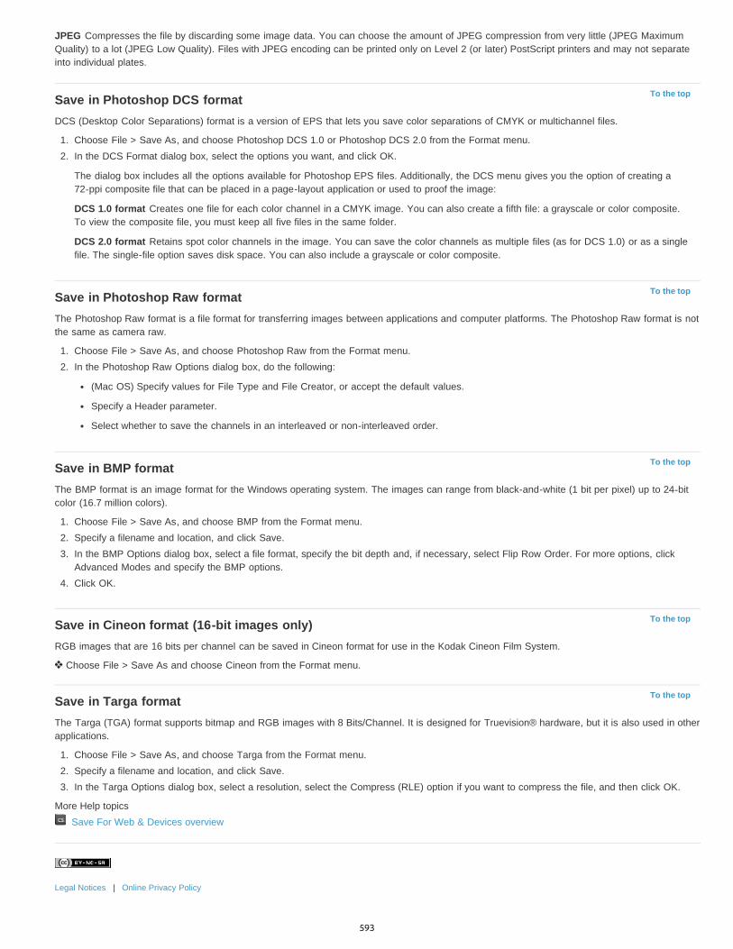
To the top
To the top
To the top
To the top
To the top
JPEG Compresses the file by discarding some image data. You can choose the amount of JPEG compression from very little (JPEG MaximumQuality) to a lot (JPEG Low Quality). Files with JPEG encoding can be printed only on Level 2 (or later) PostScript printers and may not separateinto individual plates.
Save in Photoshop DCS formatDCS (Desktop Color Separations) format is a version of EPS that lets you save color separations of CMYK or multichannel files.
1. Choose File > Save As, and choose Photoshop DCS 1.0 or Photoshop DCS 2.0 from the Format menu.2. In the DCS Format dialog box, select the options you want, and click OK.
The dialog box includes all the options available for Photoshop EPS files. Additionally, the DCS menu gives you the option of creating a72-ppi composite file that can be placed in a page-layout application or used to proof the image:
DCS 1.0 format Creates one file for each color channel in a CMYK image. You can also create a fifth file: a grayscale or color composite.To view the composite file, you must keep all five files in the same folder.
DCS 2.0 format Retains spot color channels in the image. You can save the color channels as multiple files (as for DCS 1.0) or as a singlefile. The single-file option saves disk space. You can also include a grayscale or color composite.
Save in Photoshop Raw formatThe Photoshop Raw format is a file format for transferring images between applications and computer platforms. The Photoshop Raw format is notthe same as camera raw.
1. Choose File > Save As, and choose Photoshop Raw from the Format menu.2. In the Photoshop Raw Options dialog box, do the following:
(Mac OS) Specify values for File Type and File Creator, or accept the default values.
Specify a Header parameter.
Select whether to save the channels in an interleaved or non-interleaved order.
Save in BMP formatThe BMP format is an image format for the Windows operating system. The images can range from black-and-white (1 bit per pixel) up to 24-bitcolor (16.7 million colors).
1. Choose File > Save As, and choose BMP from the Format menu.2. Specify a filename and location, and click Save.3. In the BMP Options dialog box, select a file format, specify the bit depth and, if necessary, select Flip Row Order. For more options, click
Advanced Modes and specify the BMP options.4. Click OK.
Save in Cineon format (16-bit images only)RGB images that are 16 bits per channel can be saved in Cineon format for use in the Kodak Cineon Film System.
Choose File > Save As and choose Cineon from the Format menu.
Save in Targa formatThe Targa (TGA) format supports bitmap and RGB images with 8 Bits/Channel. It is designed for Truevision® hardware, but it is also used in otherapplications.
1. Choose File > Save As, and choose Targa from the Format menu.2. Specify a filename and location, and click Save.3. In the Targa Options dialog box, select a resolution, select the Compress (RLE) option if you want to compress the file, and then click OK.
More Help topics Save For Web & Devices overview
Legal Notices | Online Privacy Policy
593

Saving PDF files
To the top
To the top
About Photoshop PDF formatSave in Photoshop PDF formatAdobe PDF presetsAbout PDF/X and PDF/A standardsPDF compatibility levelsGeneral options for Adobe PDFCompression and downsampling options for Adobe PDFColor management and PDF/X options for Adobe PDFAdding security to PDF filesSave an Adobe PDF presetLoad, edit, or delete Adobe PDF presets
About Photoshop PDF formatYou can use the Save As command to save RGB, indexed-color, CMYK, grayscale, Bitmap-mode, Lab color, and duotone images in PhotoshopPDF format. Because the Photoshop PDF document can preserve Photoshop data, such as layers, alpha channels, notes, and spot color, you canopen the document and edit the images in Photoshop CS2 or later.
You can quickly save a file as Photoshop PDF by playing the Save As Photoshop PDF action on the file. You can access this action bychoosing Production from the Actions panel menu.
For advanced users, the Photoshop PDF format offers options for making the document PDF/X compliant, which is essential, for example, whenyou send your document to a large commercial press. PDF/X (Portable Document Format Exchange) is a subset of Adobe PDF that eliminatescolor, font, and trapping variables that lead to printing problems.
You can also specify security options for restricting access to the PDF document. The 128-bit RC4 (Acrobat 6 and later) encryption has an optionfor letting users view metadata and thumbnails in a secure PDF document using Adobe Bridge.
You can save your PDF settings as a PDF preset for creating consistent Photoshop PDF files. Adobe PDF presets and settings are shared acrossAdobe Creative Suite components, including Photoshop, InDesign®, Illustrator®, GoLive®, and Acrobat®.
Save in Photoshop PDF format1. Choose File > Save As, and then choose Photoshop PDF from the Format menu. You can select a Color option if you want to embed a color
profile or use the profile specified with the Proof Setup command. You can also include layers, notes, spot color, or alpha channels. ClickSave.
2. In the Save Adobe PDF dialog box, choose an Adobe PDF preset specifying whether the Photoshop PDF file will be printed on a desktopprinter or proofer, sent to a commercial printer, distributed by e-mail, displayed on the web, and so on. For details, see Adobe PDF presets.
Choosing a preset is the easiest way to set options for your Photoshop PDF file. After you choose a preset, click Save PDF to generate yourPhotoshop PDF file. If you want to add security options or fine-tune the saving options for the PDF, follow the remaining steps in thisprocedure.
3. (Optional) Choose options from the Standard menu and the Compatibility menu to specify the PDF/X compliance and the Acrobat versioncompatibility for the PDF document. For more information, see PDF compatibility levels.
4. (Optional) Select General in the left pane of the Save Adobe PDF dialog box to set general PDF file saving options. For details of eachoption, see General options for Adobe PDF.Note: Users of Photoshop 7.0 and earlier can open a Photoshop PDF as a generic PDF with flattened layers. Choose File > Open As andthen choose Generic PDF from the Files Of Type menu (Windows), or choose File > Open and choose Generic PDF from the Format menu(Mac OS).
5. (Optional) Select Compression in the left pane of the Save Adobe PDF dialog box to specify the compression and downsampling options forthe PDF file. For more information, see Compression and downsampling options for Adobe PDF.
6. (Optional) Select Output in the left pane of the Save Adobe PDF dialog box to specify color management and PDF/X options. For moreinformation, see Color management and PDF/X options for Adobe PDF.
7. (Optional) To add security to your PDF document, select Security in the left pane of the Save Adobe PDF dialog box. Specify the passwordand permissions options for your PDF document. See also Adding security to PDF files.Note: The Encryption Level depends on the Compatibility setting of your PDF document. Choose a different Compatibility setting to specifya higher or lower Encryption Level.
8. (Optional) Select Summary in the left pane of the Save Adobe PDF dialog box. You can review the options you specified.
594
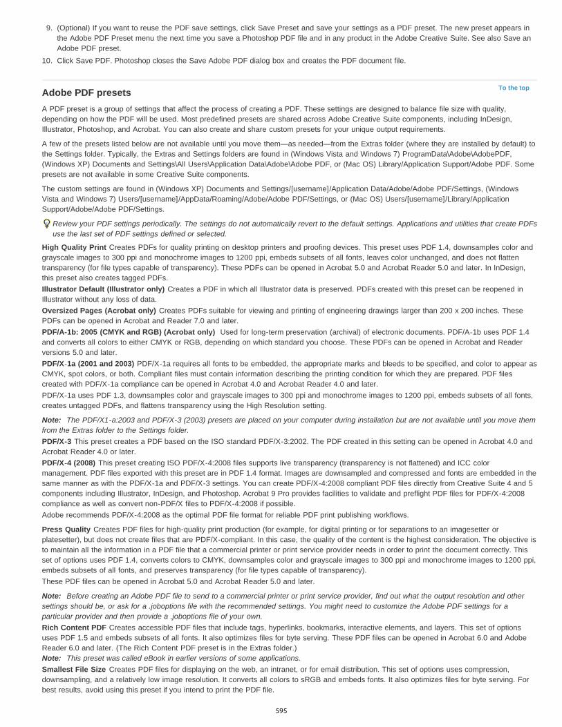
To the top
9. (Optional) If you want to reuse the PDF save settings, click Save Preset and save your settings as a PDF preset. The new preset appears inthe Adobe PDF Preset menu the next time you save a Photoshop PDF file and in any product in the Adobe Creative Suite. See also Save anAdobe PDF preset.
10. Click Save PDF. Photoshop closes the Save Adobe PDF dialog box and creates the PDF document file.
Adobe PDF presetsA PDF preset is a group of settings that affect the process of creating a PDF. These settings are designed to balance file size with quality,depending on how the PDF will be used. Most predefined presets are shared across Adobe Creative Suite components, including InDesign,Illustrator, Photoshop, and Acrobat. You can also create and share custom presets for your unique output requirements.
A few of the presets listed below are not available until you move them—as needed—from the Extras folder (where they are installed by default) tothe Settings folder. Typically, the Extras and Settings folders are found in (Windows Vista and Windows 7) ProgramData\Adobe\AdobePDF,(Windows XP) Documents and Settings\All Users\Application Data\Adobe\Adobe PDF, or (Mac OS) Library/Application Support/Adobe PDF. Somepresets are not available in some Creative Suite components.
The custom settings are found in (Windows XP) Documents and Settings/[username]/Application Data/Adobe/Adobe PDF/Settings, (WindowsVista and Windows 7) Users/[username]/AppData/Roaming/Adobe/Adobe PDF/Settings, or (Mac OS) Users/[username]/Library/ApplicationSupport/Adobe/Adobe PDF/Settings.
Review your PDF settings periodically. The settings do not automatically revert to the default settings. Applications and utilities that create PDFsuse the last set of PDF settings defined or selected.
High Quality Print Creates PDFs for quality printing on desktop printers and proofing devices. This preset uses PDF 1.4, downsamples color andgrayscale images to 300 ppi and monochrome images to 1200 ppi, embeds subsets of all fonts, leaves color unchanged, and does not flattentransparency (for file types capable of transparency). These PDFs can be opened in Acrobat 5.0 and Acrobat Reader 5.0 and later. In InDesign,this preset also creates tagged PDFs.Illustrator Default (Illustrator only) Creates a PDF in which all Illustrator data is preserved. PDFs created with this preset can be reopened inIllustrator without any loss of data.Oversized Pages (Acrobat only) Creates PDFs suitable for viewing and printing of engineering drawings larger than 200 x 200 inches. ThesePDFs can be opened in Acrobat and Reader 7.0 and later.PDF/A-1b: 2005 (CMYK and RGB) (Acrobat only) Used for long-term preservation (archival) of electronic documents. PDF/A-1b uses PDF 1.4and converts all colors to either CMYK or RGB, depending on which standard you choose. These PDFs can be opened in Acrobat and Readerversions 5.0 and later.PDF/X-1a (2001 and 2003) PDF/X-1a requires all fonts to be embedded, the appropriate marks and bleeds to be specified, and color to appear asCMYK, spot colors, or both. Compliant files must contain information describing the printing condition for which they are prepared. PDF filescreated with PDF/X-1a compliance can be opened in Acrobat 4.0 and Acrobat Reader 4.0 and later.PDF/X-1a uses PDF 1.3, downsamples color and grayscale images to 300 ppi and monochrome images to 1200 ppi, embeds subsets of all fonts,creates untagged PDFs, and flattens transparency using the High Resolution setting.
Note: The PDF/X1-a:2003 and PDF/X-3 (2003) presets are placed on your computer during installation but are not available until you move themfrom the Extras folder to the Settings folder.PDF/X-3 This preset creates a PDF based on the ISO standard PDF/X-3:2002. The PDF created in this setting can be opened in Acrobat 4.0 andAcrobat Reader 4.0 or later.PDF/X-4 (2008) This preset creating ISO PDF/X-4:2008 files supports live transparency (transparency is not flattened) and ICC colormanagement. PDF files exported with this preset are in PDF 1.4 format. Images are downsampled and compressed and fonts are embedded in thesame manner as with the PDF/X-1a and PDF/X-3 settings. You can create PDF/X-4:2008 compliant PDF files directly from Creative Suite 4 and 5components including Illustrator, InDesign, and Photoshop. Acrobat 9 Pro provides facilities to validate and preflight PDF files for PDF/X-4:2008compliance as well as convert non-PDF/X files to PDF/X-4:2008 if possible.Adobe recommends PDF/X-4:2008 as the optimal PDF file format for reliable PDF print publishing workflows.
Press Quality Creates PDF files for high-quality print production (for example, for digital printing or for separations to an imagesetter orplatesetter), but does not create files that are PDF/X-compliant. In this case, the quality of the content is the highest consideration. The objective isto maintain all the information in a PDF file that a commercial printer or print service provider needs in order to print the document correctly. Thisset of options uses PDF 1.4, converts colors to CMYK, downsamples color and grayscale images to 300 ppi and monochrome images to 1200 ppi,embeds subsets of all fonts, and preserves transparency (for file types capable of transparency).These PDF files can be opened in Acrobat 5.0 and Acrobat Reader 5.0 and later.
Note: Before creating an Adobe PDF file to send to a commercial printer or print service provider, find out what the output resolution and othersettings should be, or ask for a .joboptions file with the recommended settings. You might need to customize the Adobe PDF settings for aparticular provider and then provide a .joboptions file of your own.Rich Content PDF Creates accessible PDF files that include tags, hyperlinks, bookmarks, interactive elements, and layers. This set of optionsuses PDF 1.5 and embeds subsets of all fonts. It also optimizes files for byte serving. These PDF files can be opened in Acrobat 6.0 and AdobeReader 6.0 and later. (The Rich Content PDF preset is in the Extras folder.)Note: This preset was called eBook in earlier versions of some applications.Smallest File Size Creates PDF files for displaying on the web, an intranet, or for email distribution. This set of options uses compression,downsampling, and a relatively low image resolution. It converts all colors to sRGB and embeds fonts. It also optimizes files for byte serving. Forbest results, avoid using this preset if you intend to print the PDF file.
595
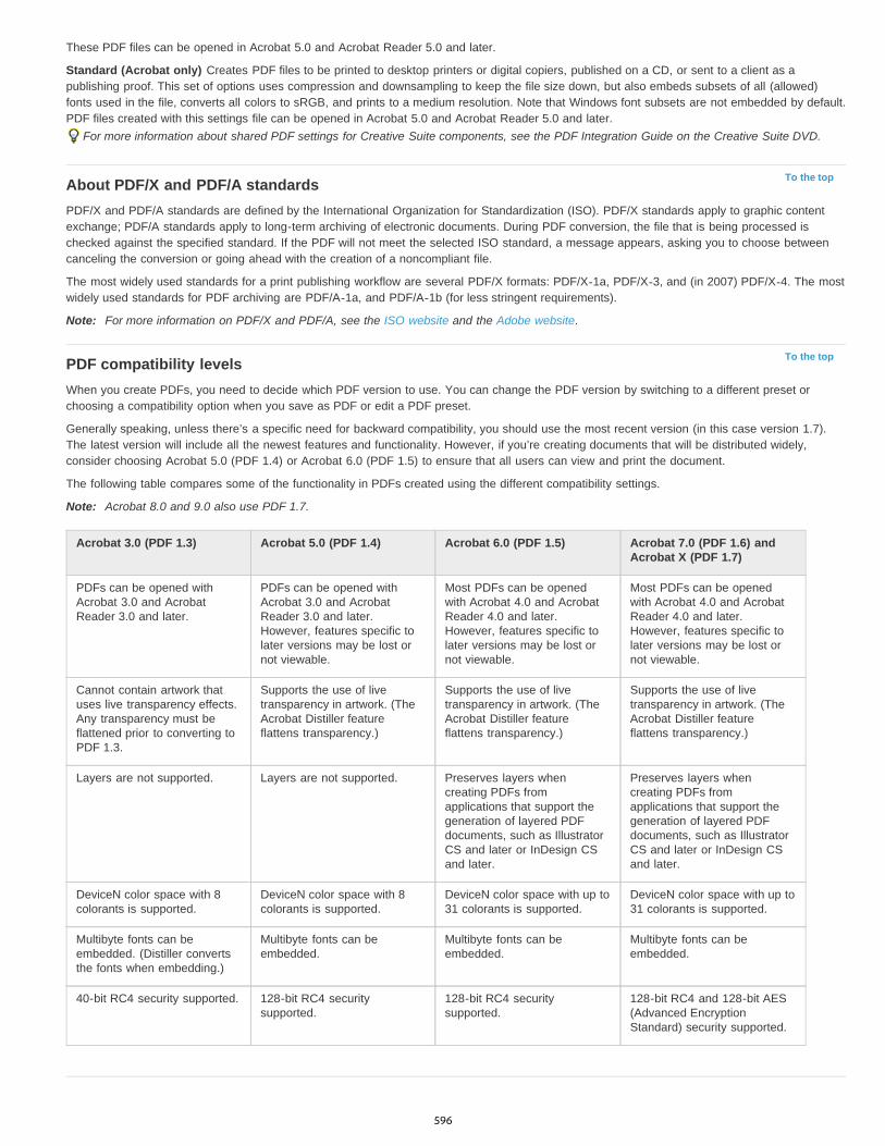
To the top
To the top
These PDF files can be opened in Acrobat 5.0 and Acrobat Reader 5.0 and later.
Standard (Acrobat only) Creates PDF files to be printed to desktop printers or digital copiers, published on a CD, or sent to a client as apublishing proof. This set of options uses compression and downsampling to keep the file size down, but also embeds subsets of all (allowed)fonts used in the file, converts all colors to sRGB, and prints to a medium resolution. Note that Windows font subsets are not embedded by default.PDF files created with this settings file can be opened in Acrobat 5.0 and Acrobat Reader 5.0 and later.
For more information about shared PDF settings for Creative Suite components, see the PDF Integration Guide on the Creative Suite DVD.
About PDF/X and PDF/A standardsPDF/X and PDF/A standards are defined by the International Organization for Standardization (ISO). PDF/X standards apply to graphic contentexchange; PDF/A standards apply to long-term archiving of electronic documents. During PDF conversion, the file that is being processed ischecked against the specified standard. If the PDF will not meet the selected ISO standard, a message appears, asking you to choose betweencanceling the conversion or going ahead with the creation of a noncompliant file.
The most widely used standards for a print publishing workflow are several PDF/X formats: PDF/X-1a, PDF/X-3, and (in 2007) PDF/X-4. The mostwidely used standards for PDF archiving are PDF/A-1a, and PDF/A-1b (for less stringent requirements).
Note: For more information on PDF/X and PDF/A, see the ISO website and the Adobe website.
PDF compatibility levelsWhen you create PDFs, you need to decide which PDF version to use. You can change the PDF version by switching to a different preset orchoosing a compatibility option when you save as PDF or edit a PDF preset.
Generally speaking, unless there’s a specific need for backward compatibility, you should use the most recent version (in this case version 1.7).The latest version will include all the newest features and functionality. However, if you’re creating documents that will be distributed widely,consider choosing Acrobat 5.0 (PDF 1.4) or Acrobat 6.0 (PDF 1.5) to ensure that all users can view and print the document.
The following table compares some of the functionality in PDFs created using the different compatibility settings.
Note: Acrobat 8.0 and 9.0 also use PDF 1.7.
Acrobat 3.0 (PDF 1.3) Acrobat 5.0 (PDF 1.4) Acrobat 6.0 (PDF 1.5) Acrobat 7.0 (PDF 1.6) andAcrobat X (PDF 1.7)
PDFs can be opened withAcrobat 3.0 and AcrobatReader 3.0 and later.
PDFs can be opened withAcrobat 3.0 and AcrobatReader 3.0 and later.However, features specific tolater versions may be lost ornot viewable.
Most PDFs can be openedwith Acrobat 4.0 and AcrobatReader 4.0 and later.However, features specific tolater versions may be lost ornot viewable.
Most PDFs can be openedwith Acrobat 4.0 and AcrobatReader 4.0 and later.However, features specific tolater versions may be lost ornot viewable.
Cannot contain artwork thatuses live transparency effects.Any transparency must beflattened prior to converting toPDF 1.3.
Supports the use of livetransparency in artwork. (TheAcrobat Distiller featureflattens transparency.)
Supports the use of livetransparency in artwork. (TheAcrobat Distiller featureflattens transparency.)
Supports the use of livetransparency in artwork. (TheAcrobat Distiller featureflattens transparency.)
Layers are not supported. Layers are not supported. Preserves layers whencreating PDFs fromapplications that support thegeneration of layered PDFdocuments, such as IllustratorCS and later or InDesign CSand later.
Preserves layers whencreating PDFs fromapplications that support thegeneration of layered PDFdocuments, such as IllustratorCS and later or InDesign CSand later.
DeviceN color space with 8colorants is supported.
DeviceN color space with 8colorants is supported.
DeviceN color space with up to31 colorants is supported.
DeviceN color space with up to31 colorants is supported.
Multibyte fonts can beembedded. (Distiller convertsthe fonts when embedding.)
Multibyte fonts can beembedded.
Multibyte fonts can beembedded.
Multibyte fonts can beembedded.
40-bit RC4 security supported. 128-bit RC4 securitysupported.
128-bit RC4 securitysupported.
128-bit RC4 and 128-bit AES(Advanced EncryptionStandard) security supported.
596
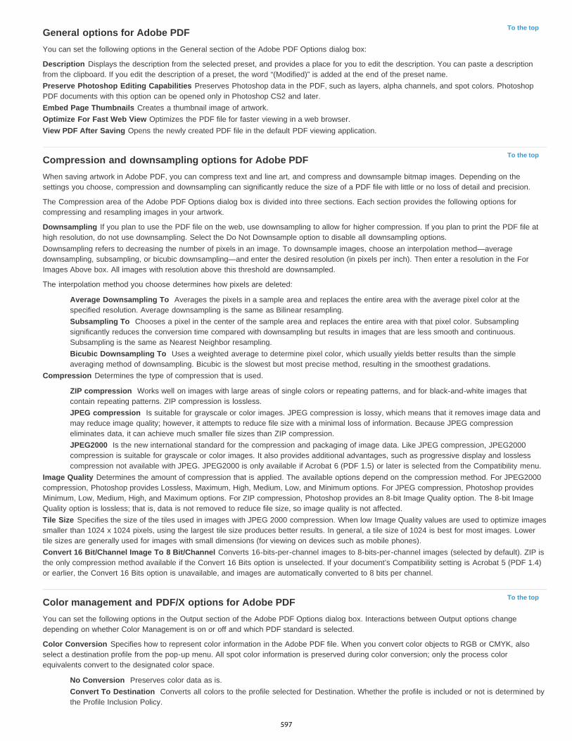
To the top
To the top
To the top
General options for Adobe PDFYou can set the following options in the General section of the Adobe PDF Options dialog box:
Description Displays the description from the selected preset, and provides a place for you to edit the description. You can paste a descriptionfrom the clipboard. If you edit the description of a preset, the word “(Modified)” is added at the end of the preset name.Preserve Photoshop Editing Capabilities Preserves Photoshop data in the PDF, such as layers, alpha channels, and spot colors. PhotoshopPDF documents with this option can be opened only in Photoshop CS2 and later.Embed Page Thumbnails Creates a thumbnail image of artwork.Optimize For Fast Web View Optimizes the PDF file for faster viewing in a web browser.View PDF After Saving Opens the newly created PDF file in the default PDF viewing application.
Compression and downsampling options for Adobe PDFWhen saving artwork in Adobe PDF, you can compress text and line art, and compress and downsample bitmap images. Depending on thesettings you choose, compression and downsampling can significantly reduce the size of a PDF file with little or no loss of detail and precision.
The Compression area of the Adobe PDF Options dialog box is divided into three sections. Each section provides the following options forcompressing and resampling images in your artwork.
Downsampling If you plan to use the PDF file on the web, use downsampling to allow for higher compression. If you plan to print the PDF file athigh resolution, do not use downsampling. Select the Do Not Downsample option to disable all downsampling options.Downsampling refers to decreasing the number of pixels in an image. To downsample images, choose an interpolation method—averagedownsampling, subsampling, or bicubic downsampling—and enter the desired resolution (in pixels per inch). Then enter a resolution in the ForImages Above box. All images with resolution above this threshold are downsampled.
The interpolation method you choose determines how pixels are deleted:
Average Downsampling To Averages the pixels in a sample area and replaces the entire area with the average pixel color at thespecified resolution. Average downsampling is the same as Bilinear resampling.Subsampling To Chooses a pixel in the center of the sample area and replaces the entire area with that pixel color. Subsamplingsignificantly reduces the conversion time compared with downsampling but results in images that are less smooth and continuous.Subsampling is the same as Nearest Neighbor resampling.Bicubic Downsampling To Uses a weighted average to determine pixel color, which usually yields better results than the simpleaveraging method of downsampling. Bicubic is the slowest but most precise method, resulting in the smoothest gradations.
Compression Determines the type of compression that is used.
ZIP compression Works well on images with large areas of single colors or repeating patterns, and for black-and-white images thatcontain repeating patterns. ZIP compression is lossless.JPEG compression Is suitable for grayscale or color images. JPEG compression is lossy, which means that it removes image data andmay reduce image quality; however, it attempts to reduce file size with a minimal loss of information. Because JPEG compressioneliminates data, it can achieve much smaller file sizes than ZIP compression.JPEG2000 Is the new international standard for the compression and packaging of image data. Like JPEG compression, JPEG2000compression is suitable for grayscale or color images. It also provides additional advantages, such as progressive display and losslesscompression not available with JPEG. JPEG2000 is only available if Acrobat 6 (PDF 1.5) or later is selected from the Compatibility menu.
Image Quality Determines the amount of compression that is applied. The available options depend on the compression method. For JPEG2000compression, Photoshop provides Lossless, Maximum, High, Medium, Low, and Minimum options. For JPEG compression, Photoshop providesMinimum, Low, Medium, High, and Maximum options. For ZIP compression, Photoshop provides an 8-bit Image Quality option. The 8-bit ImageQuality option is lossless; that is, data is not removed to reduce file size, so image quality is not affected.Tile Size Specifies the size of the tiles used in images with JPEG 2000 compression. When low Image Quality values are used to optimize imagessmaller than 1024 x 1024 pixels, using the largest tile size produces better results. In general, a tile size of 1024 is best for most images. Lowertile sizes are generally used for images with small dimensions (for viewing on devices such as mobile phones).Convert 16 Bit/Channel Image To 8 Bit/Channel Converts 16-bits-per-channel images to 8-bits-per-channel images (selected by default). ZIP isthe only compression method available if the Convert 16 Bits option is unselected. If your document’s Compatibility setting is Acrobat 5 (PDF 1.4)or earlier, the Convert 16 Bits option is unavailable, and images are automatically converted to 8 bits per channel.
Color management and PDF/X options for Adobe PDFYou can set the following options in the Output section of the Adobe PDF Options dialog box. Interactions between Output options changedepending on whether Color Management is on or off and which PDF standard is selected.
Color Conversion Specifies how to represent color information in the Adobe PDF file. When you convert color objects to RGB or CMYK, alsoselect a destination profile from the pop-up menu. All spot color information is preserved during color conversion; only the process colorequivalents convert to the designated color space.
No Conversion Preserves color data as is.Convert To Destination Converts all colors to the profile selected for Destination. Whether the profile is included or not is determined bythe Profile Inclusion Policy.
597
To the top
To the top
To the top
Destination Describes the gamut of the final RGB or CMYK output device, such as your monitor or a SWOP standard. Using this profile,Photoshop converts the document’s color information (defined by the source profile in the Working Spaces section of the Color Settings dialogbox) to the color space of the target output device.Profile Inclusion Policy Determines whether a color profile is included in the file.Output Intent Profile Name Specifies the characterized printing condition for the document. An output intent profile is required for creatingPDF/X-compliant files. This menu is available only if a PDF/X standard (or preset) is selected in the Adobe PDF Options dialog box.Output Condition Describes the intended printing condition. This entry can be useful for the intended receiver of the PDF document.Output Condition Identifier A pointer to more information on the intended printing condition. The identifier is automatically entered for printingconditions that are included in the ICC registry.Registry Name Indicates the web address for more information on the registry. The URL is automatically entered for ICC registry names.
Adding security to PDF filesWhen saving as PDF, you can add password protection and security restrictions, limiting not only who can open the file, but also who can copy orextract contents, print the document, and more.
A PDF file can require passwords to open a document (document open password) and to change security settings (permissions password). If youset any security restrictions in your file, you should set both passwords; otherwise, anyone who opens the file could remove the restrictions. If a fileis opened with a permissions password, the security restrictions are temporarily disabled.
The RC4 method of security from RSA Corporation is used to password-protect PDF files. Depending on the Compatibility setting (in the Generalcategory), the encryption level will be high or low.
Note: Adobe PDF presets don’t support passwords and security settings. If you select passwords and security settings in the Export Adobe PDFdialog box, and then click Save Preset, the passwords and security settings won’t be preserved.
Save an Adobe PDF presetAlthough the default PDF presets are based on best practices, you may discover that your workflow requires specialized PDF settings that aren’tavailable using any of the built-in presets. In this case, you can create and save your own custom presets for reuse in Photoshop or any product inthe Adobe Creative Suite.
In Photoshop, you can save the preset using the Adobe PDF Presets command or clicking the Save Preset button in the Save Adobe PDF dialogbox. Adobe PDF presets are saved as files with a .joboptions extension. This is useful, for example, if you want your vendor or printer to send youa .joboptions file with the Adobe PDF presets that work best with their workflow.
1. Do one of the following:
Choose Edit > Adobe PDF Presets.
If you’re saving a Photoshop PDF document, click the Save Preset button in the Save Adobe PDF dialog box after you specify your PDFsettings. Skip steps 2 and 3.
2. If you chose the Adobe PDF Presets command, do one of the following in the Adobe PDF Presets dialog box:
To create a new preset, click the New button in the Adobe PDF Presets dialog box. In the New PDF Preset dialog box, type a name forthe preset in the Preset text box.
To edit an existing custom preset, select the preset and click Edit. (You can’t edit the default presets.)
3. Set the PDF options.4. Save your preset by doing one of the following:
In the New PDF Preset or the Edit PDF Preset dialog box, click OK. The new preset appears in the Adobe PDF Presets list. Click Donewhen you finish creating presets.
In the Save dialog box, type a name for the preset in the File Name text box and click Save.
Adobe PDF presets are stored in the following folders:
(Windows Vista) Users/[user name]/AppData/Roaming/Adobe/Adobe PDF/Settings
(Windows XP) Documents and Settings/[user name]/Application Data/Adobe/Adobe PDF/Settings
(Mac OS) Users/[user name]/Library/Application Support/Adobe/Adobe PDF/Settings
All the Adobe PDF presets you save in these locations are available in your other Adobe Creative Suite applications.Note: To save the PDF preset in a location other than the default, click the Save As button in the Adobe PDF Presets dialog box andbrowse to the destination, or in the Save dialog box, browse to the destination and click Save.
Load, edit, or delete Adobe PDF presetsAdobe PDF presets (creation settings) are available in Photoshop and other products in the Adobe Creative Suite. From the Adobe PDF Presets
598
dialog box, you save, load, edit, or delete Adobe PDF presets.
Choose Edit > Adobe PDF Presets and do any of the following:
To save settings as a new preset, click the New button, specify settings in the New PDF Preset dialog box, and click OK.
To edit an Adobe PDF preset, select the preset in the Preset window, click the Edit button, and change settings in the Edit PDF Preset dialogbox.
Note: Although you can’t edit the Adobe PDF presets that were installed with Photoshop (the names of presets installed with Photoshop areenclosed in square brackets), you can select one of them and click the New button. In the New PDF Preset dialog box, you can modify thesettings and save them as a new preset.
To delete an Adobe PDF preset, select the preset in the Preset window and click the Delete button. You can’t delete the Adobe PDF presetsthat were installed with Photoshop.
To load an Adobe PDF preset, click the Load button, select the preset file, and click the Load button. The preset is added to the Presetswindow.
When you browse for an Adobe PDF preset to load, only files with the .joboptions extension are visible in the Load dialog box.
To close the PDF Options Preset dialog box, click the Done button.
To save a preset in a location other than the default, click the Save As button, give the preset a new name (if necessary), browse to thedestination, and click Save.
Legal Notices | Online Privacy Policy
599
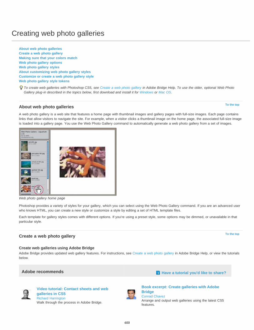
Creating web photo galleries
To the top
To the top
About web photo galleriesCreate a web photo galleryMaking sure that your colors matchWeb photo gallery optionsWeb photo gallery stylesAbout customizing web photo gallery stylesCustomize or create a web photo gallery styleWeb photo gallery style tokens
To create web galleries with Photoshop CS5, see Create a web photo gallery in Adobe Bridge Help. To use the older, optional Web PhotoGallery plug-in described in the topics below, first download and install it for Windows or Mac OS.
About web photo galleriesA web photo gallery is a web site that features a home page with thumbnail images and gallery pages with full-size images. Each page containslinks that allow visitors to navigate the site. For example, when a visitor clicks a thumbnail image on the home page, the associated full-size imageis loaded into a gallery page. You use the Web Photo Gallery command to automatically generate a web photo gallery from a set of images.
Web photo gallery home page
Photoshop provides a variety of styles for your gallery, which you can select using the Web Photo Gallery command. If you are an advanced userwho knows HTML, you can create a new style or customize a style by editing a set of HTML template files.
Each template for gallery styles comes with different options. If you’re using a preset style, some options may be dimmed, or unavailable in thatparticular style.
Create a web photo gallery
Create web galleries using Adobe BridgeAdobe Bridge provides updated web gallery features. For instructions, see Create a web photo gallery in Adobe Bridge Help, or view the tutorialsbelow.
Adobe recommends Have a tutorial you'd like to share?
Video tutorial: Contact sheets and webgalleries in CS5Richard HarringtonWalk through the process in Adobe Bridge.
Book excerpt: Create galleries with AdobeBridgeConrad ChavezArrange and output web galleries using the latest CS5features.
600

To the top
To the top
Use the older, optional Photoshop plug-in
1. Download and install the older Web Photo Gallery plug-in for Windows or Mac OS.
2. Run Photoshop in 32-bit mode (64-bit Mac OS only).
3. (Optional) Select the files or folder you want to use in Adobe Bridge.
Your images will be presented in the order in which they’re displayed in Bridge. If you’d rather use a different order, change the order inBridge.
4. Do one of the following:
In Adobe Bridge, choose Tools > Photoshop > Web Photo Gallery.
In Photoshop, choose File > Automate > Web Photo Gallery.
5. Choose a style for the gallery from the Styles pop-up menu. A preview of the home page for the chosen style appears in the dialog box.
6. (Optional) Enter an e-mail address as the contact information for the gallery.
7. Choose the source files for your gallery from the Use menu.
Selected Images From Bridge Uses images you selected before opening the Web Photo Gallery dialog box.
Folder Uses images from folders you select using the Browse (Windows) or Choose (Mac OS) buttons. Select Include All Subfolders toinclude images inside any subfolders of the selected folder.
8. Click Destination, and then select a folder in which to store the images and HTML pages for the gallery. Then click OK (Windows) orChoose (Mac OS).
9. Select formatting options for the web gallery. Choose from the Options menu to display each set of options. See Web photo gallery options.
10. Click OK. Photoshop places the following HTML and JPEG files in your destination folder:
A home page for your gallery named index.htm or index.html, depending on the Extension options. Open this file in any web browser topreview your gallery.
JPEG images inside an images subfolder.
HTML pages inside a pages subfolder.
JPEG thumbnail images inside a thumbnails subfolder.
Making sure that your colors matchIf you work with photos in a wide-gamut color working space such as ProPhoto RGB or Adobe RGB, image colors may change when viewed in aweb gallery by a browser that doesn’t read embedded color profiles. If this happens, try converting the image profiles to sRGB (which mostbrowsers use as a default) before optimizing them or including them in a Web Photo Gallery. Convert them to sRGB in one of the following ways.It is a good idea to work with a copy of the images.
To convert a single image, choose Edit >Convert To Profile and then choose sRGB. See Assign or remove a color profile (Illustrator,Photoshop).
To convert a folder of images, use the Image Processor. Choose File > Scripts > Image Processor. See Convert files with the ImageProcessor.
If you use the Image Processor, you can save the files directly to JPEG format in the size that you want them. If you do so, make sure to turnResize Images off in the Large Image options.
Web photo gallery optionsGeneral Options for file extensions, encoding, and metadata.
Extension Uses either .htm or .html as the filename extension.Use UTF 8 Encoding For URL Uses UTF-8 encoding.Add Width And Height Attributes For Images Specifies dimensions, shortening download time.Preserve All Metadata Maintains metadata info.
Banner Text options for the banner that appears on each page in the gallery. Enter text for each of these:
Site Name The name of the gallery.Photographer The name of the person or organization receiving credit for the photos in the gallery.Contact Info The contact information for the gallery, such as a telephone number or a business address.Date The date appearing on each page of the gallery. By default, Photoshop uses the current date.Font and Font Size (Available for some site styles) Options for the banner text.
601
To the top
To the top
Large Images Options for the main images that appear on each gallery page.
Add numeric links (Available for some site styles) Places a numeric sequence (starting at 1, ending with the total number of pages in thegallery) running horizontally at the top of each gallery page. Each number is a link to the respective page.Resize Images Resizes the source images for placement on the gallery pages. Choose a size from the pop-up menu or enter a size inpixels. For Constrain, choose which dimensions of the image you want to constrain during resizing. For JPEG Quality, choose an optionfrom the pop-up menu, enter a value between 0 and 12, or drag the slider. The higher the value, the better the image quality and thelarger the file.Note: Photoshop uses the default image interpolation method set in preferences. Choose Bicubic Sharper as the default for best resultswhen reducing image size.Border Size Specifies the width, in pixels, of the border around the image.Titles Use (Available for some site styles) Specifies options for displaying captions under each image. Select Filename to display thefilename, or select Description, Credits, Title, and Copyright to display description text drawn from the File Info dialog box.Font and Font Size (Available for some site styles) Specify the font and size of the caption.
Thumbnails Options for the gallery home page, including the size of the thumbnail images.
Size Specifies the thumbnail size. Choose from the pop-up menu or enter a value in pixels for the width of each thumbnail.Columns and Rows Specify the number of columns and rows in which to display thumbnails on the home page. This option doesn’tapply to galleries that use the Horizontal Frame Style or Vertical Frame Style.Border Size Specifies the width, in pixels, of the border around each thumbnail.Titles Use (Available for some site styles) Specifies options for displaying captions under each thumbnail. Select Filename to display thefilename, or select Description, Credits, Title, and Copyright to display description text drawn from the File Info dialog box.Font and Font Size (Available for some site styles) Specify the font and size of the caption.
Custom Colors Options for colors of elements in the gallery. To change the color of an element, click its color swatch and then select a new colorfrom the Adobe Color Picker. You can change the background color of each page (Background option) and of the banner (Banner option).Security Displays text over each image as a theft deterrent.
Content Specifies the text to be displayed. Select Custom Text to enter customized text. Select Filename, Description, Credits, Title,or Copyright to display text drawn from the File Info dialog box.Font, Color, and Position Specify the font, color, and alignment of the caption.Rotate Place the text on the image at an angle.
Web photo gallery stylesTo create web galleries with Photoshop CS5, see Create a web photo gallery in Adobe Bridge Help. To use the older, optional Web PhotoGallery plug-in described below, first download and install it for Windows or Mac OS.
Photoshop provides a variety of styles for your web photo gallery. If you are an advanced user who knows HTML, you can create a new style orcustomize a style by editing a set of HTML template files.
The web photo gallery styles provided by Photoshop are stored in individual folders in the following locations:
Windows Program Files/Adobe/Adobe Photoshop CS5/Presets/Web Photo Gallery.Mac OS Adobe Photoshop CS5/Presets/Web Photo Gallery.The name of each folder in this location appears as an option in the Styles menu in the Web Photo Gallery dialog box. Each folder contains thefollowing HTML template files, which Photoshop uses to generate the gallery:
Caption.htm Determines the layout of the caption that appears below each thumbnail on the home page.FrameSet.htm Determines the layout of the frame set for displaying pages.IndexPage.htm Determines the layout of the home page.SubPage.htm Determines the layout of the gallery pages with full-size images.Thumbnail.htm Determines the layout of the thumbnails that appear on the home page.Each template file contains HTML code and tokens. A token is a text string that is replaced by Photoshop when you set its corresponding option inthe Web Photo Gallery dialog box. For example, a template file may contain the following TITLE element that uses a token as its enclosed text:
<TITLE>%TITLE%</TITLE>
When Photoshop generates the gallery using this template file, it replaces the token %TITLE% with the text that you entered for Site Name in theWeb Photo Gallery dialog box.
To better understand an existing style, you can open and study its HTML template files using an HTML editor. Because only standard ASCIIcharacters are required to create HTML documents, you can open, edit, and create these documents using a plain-text editor such as Notepad(Windows) or TextEdit (Mac OS).
About customizing web photo gallery stylesYou can customize an existing web photo gallery style by editing one or more of its HTML template files. When customizing a style, you need tofollow these guidelines so that Photoshop can generate the gallery correctly:
602

To the top
To the top
The style folder must contain these files: Caption.htm, IndexPage.htm, SubPage.htm, Thumbnail.htm, and FrameSet.htm.
You can rename the style folder but not the HTML template files in the folder.
You can have an empty Caption.htm file, and place the HTML code and tokens determining the layout of the caption in the Thumbnail.htmfile.
You can replace a token in a template file with the appropriate text or HTML code, so that an option is set through the template file ratherthan through the Web Photo Gallery dialog box. For example, a template file may contain a BODY element with the following backgroundcolor attribute that uses a token as its value:
bgcolor=%BGCOLOR%
To set the background color of the page to red, you can replace the token %BGCOLOR% with “FF0000.”
You can add HTML code and tokens to the template files. All tokens must be in uppercase characters, and begin and end with the percent(%) symbol.
Customize or create a web photo gallery style1. Locate the folder that stores the existing web photo gallery styles.2. Do one of the following:
To customize a style, create a copy of the style folder, and store it in the same location as the existing style folders.
To create a new style, create a new folder for the new style, and store it in the same location as the existing style folders.
The new or customized style (named for its folder) appears in the Styles menu in the Web Photo Gallery dialog box.
3. Using an HTML editor, do one of the following:
Customize the HTML template file.
Create the necessary HTML template files and store them inside the style folder.
When creating the template files, make sure that you follow the guidelines for customization outlined in About customizing web photo gallerystyles.
Important: When customizing or creating a template for a gallery style, you should place each of the following tokens on a separate line inthe HTML file: %CURRENTINDEX%, %NEXTIMAGE%, %NEXTINDEX%, %PAGE%, %PREVIMAGE%, and %PREVINDEX%. Whengenerating specific pages of a gallery, Photoshop skips lines in a template that contain tokens that don’t apply to those pages. For example,when Photoshop generates the first gallery page, it skips any line in the template that contains the %PREVIMAGE% token, whichdetermines the link to the previous gallery page. By keeping the %PREVIMAGE% token on a separate line, you ensure that Photoshopdoesn’t ignore other tokens in the template.
Web photo gallery style tokensPhotoshop uses tokens in the HTML template files to define a default web photo gallery style. Photoshop uses these tokens to generate a gallerybased on user input in the Web Photo Gallery dialog box.
When customizing or creating a gallery style, you can add any token to any HTML template file, with the exception of %THUMBNAILS% and%THUMBNAILSROWS%, which can appear only in the IndexPage.htm file. When adding a token, keep in mind that you may also need to addHTML code to the file so that the token is used correctly.
You can use the following tokens in the HTML template files:
%ALINK% Determines the color of active links.%ALT% Determines the name of an image file.%ANCHOR% Provides the ability to return to the thumbnail of the image the user is viewing, rather than the beginning of the index. This takeseffect when the user clicks the Home button.%BANNERCOLOR% Determines the color of the banner.%BANNERFONT% Determines the font of the banner text.%BANNERFONTSIZE% Determines the font size of the banner text.%BGCOLOR% Determines the background color.%CAPTIONFONT% Determines the font of the caption below each thumbnail on the home page.%CAPTIONFONTSIZE% Determines the font size of the caption.%CAPTIONTITLE% Inserts the document title for a caption from the file information.%CHARSET% Determines the character set used on each page.%CONTACTINFO% Determines the contact information for the gallery, such as phone number and location.%CONTENT_GENRATOR% Expands to “Adobe Photoshop CS5 Web Photo Gallery.”%COPYRIGHT% Inserts the copyright information for a caption from the file information.
603

%CREDITS% Inserts the credits for a caption from the file information.%CURRENTINDEX% Determines the link for the current home page.%CURRENTINDEXANCHOR% Resides in SubPage.htm and points to the first index page.%DATE% Determines the date that appears on the banner.%EMAIL% Determines the e-mail address contact information for the gallery.%FILEINFO% Determines the image file information for a caption.%FILENAME% Determines the filename of an image. Use this for metadata that appears as HTML text.%FILENAME_URL% Determines the URL filename of an image. Use this for URL filenames only.%FIRSTPAGE% Determines the link for the first gallery page that appears in the right frame of a frame set.%FRAMEINDEX% Determines the link for the home page that appears in the left frame of a frame set.%HEADER% Determines the title of the gallery.%IMAGEBORDER% Determines the border size of the full-size image on a gallery page.%IMAGE_HEIGHT% Enables the Add Width And Height Attributes For Images check box. This allows the user to download the attributes,reducing download time.%IMAGE_HEIGHT_NUMBER% This token is replaced by a numeral (only) representing the width of the image.%IMAGEPAGE% Determines the link to a gallery page.%IMAGE_SIZE% If the Resize Images box is selected, this token contains the image pixel value used in the Large Images panel. If the box is notselected, this token contains an empty string. This is useful for JavaScript in the templates, because it can show the maximum height and widthvalues for all images for the generated site.%IMAGESRC% Determines the URL for a full-size image on a gallery page.%IMAGE_WIDTH% Enables the Add Width And Height Attributes For Images check box. This allows the user to download the attributes, reducingdownload time.%IMAGE_WIDTH_NUMBER% This token is replaced by a numeral (only) representing the width of the image.%LINK% Determines the color of links.%NEXTIMAGE% Determines the link for the next gallery page.%NEXTIMAGE _CIRCULAR% Sets the link from large preview image to next large preview image.%NEXTINDEX% Determines the link for the next home page.%NUMERICLINKS% Inserts numbered links on subpages to all large preview images.%PAGE% Determines the current page location (for example, page 1 of 3).%PHOTOGRAPHER% Determines the name of the person or organization receiving credit for the photos in the gallery.%PREVIMAGE% Determines the link for the previous gallery page.%PREVINDEX% Determines the link for the previous home page.%SUBPAGEHEADER% Determines the title of the gallery.%SUBPAGETITLE% Determines the title of the gallery.%TEXT% Determines the text color.%THUMBBORDER% Determines the size of thumbnail borders.%THUMBNAIL_HEIGHT% Enables the Add Width And Height Attributes For Images check box. This allows the user to download the attributes,reducing download time.%THUMBNAIL_HEIGHT_NUMBER% This token is replaced with a numeral (only) representing the height of the thumbnail.%THUMBNAILS% This token is replaced with thumbnails using the Thumbnail.htm file for the frame styles. You must place this token alone in asingle, nonbreaking line in the HTML file.%THUMBNAIL_SIZE% Contains the thumbnail pixel value in the Thumbnails panel. This is useful for JavaScript in the templates, as it can showthe maximum height and width values for all thumbnails for the generated site.%THUMBNAILSRC% Determines the link to a thumbnail.%THUMBNAILSROWS% This token is replaced with rows of thumbnails using the Thumbnail.htm file for the nonframe styles. You must place thistoken alone in a single, nonbreaking line in the HTML file.%THUMBNAIL_WIDTH% Enables the Add Width And Height Attributes For Images check box. This allows the user to download the attributes,reducing download time.%THUMBNAIL_WIDTH_NUMBER% This token is replaced by a numeral (only) representing the width of the thumbnail.%TITLE% Determines the title of the gallery.%VLINK% Determines the color of visited links.
Legal Notices | Online Privacy Policy
604
Digimarc copyright protection
To the top
To the top
To the top
Read a Digimarc watermarkAdding digital copyright informationBefore adding a digital watermarkEmbed a watermarkUsing the Watermark Durability settingCheck the signal strength meter
Note: Digimarc plug-ins require a 32-bit operating system. They are unsupported in 64-bit versions of Windows and Mac OS.
Read a Digimarc watermark1. Choose Filter > Digimarc > Read Watermark. If the filter finds a watermark, a dialog box displays the Digimarc ID, creator information, and
image attributes.2. Click OK, or for more information, click Web Lookup. The Digimarc website is displayed in your web browser, where contact details appear
for the given creator ID.
Adding digital copyright informationYou can add copyright information to Photoshop images and notify users that an image is copyright protected via a digital watermark that usesDigimarc ImageBridge technology. The watermark—a digital code added as noise to the image—is virtually imperceptible to the human eye. TheDigimarc watermark is durable in both digital and printed forms, surviving typical image edits and file format conversions.
Embedding a digital watermark in an image lets viewers obtain information about the creator of the image. This feature is particularly valuable toimage creators who license their work to others. Copying an image with an embedded watermark also copies the watermark and any informationassociated with it.
For more detailed information on embedding Digimarc digital watermarks, refer to the Digimarc website at www.digimarc.com.
Before adding a digital watermarkKeep in mind the following considerations before embedding a digital watermark in your image.
Color variation The image must contain some degree of variation or randomness in color to embed the digital watermark effectively andimperceptibly. The image cannot consist mostly or entirely of a single flat color.Pixel dimensions The Digimarc technology requires a minimum number of pixels to work. Digimarc recommends the following minimum pixeldimensions for the image to be watermarked:
100 pixels by 100 pixels if you don’t expect the image to be modified or compressed prior to its actual use.
256 pixels by 256 pixels if you expect the image to be cropped, rotated, compressed, or otherwise modified after watermarking.
750 pixels by 750 pixels if you expect the image to appear ultimately in printed form at 300 dpi or greater.
There is no upper limit on pixel dimensions for watermarking.
File compression In general, a Digimarc watermark will survive lossy compression methods, such as JPEG, though it is advisable to favor imagequality over file size (a JPEG compression setting of 4 or higher works best). In addition, the higher the Watermark Durability setting you choosewhen embedding the watermark, the better the chances that the digital watermark will survive compression.Workflow Digital watermarking should be one of the very last tasks you perform on an image, except for file compression.Use the following recommended workflow:
Make all necessary modifications to your image until you are satisfied with its final appearance (this includes resizing and color correction).
Embed the Digimarc watermark.
If needed, compress the image by saving it in JPEG or GIF format.
If the image is intended for printed output, perform the color separation.
Read the watermark and use the signal strength meter to verify that the image contains a watermark of sufficient strength for your purposes.
Publish the digital watermarked image.
605

To the top
To the top
To the top
Embed a watermarkTo embed a digital watermark, you must first register with Digimarc Corporation—which maintains a database of artists, designers, andphotographers and their contact information—to get a unique Digimarc ID. You can then embed the Digimarc ID in your images, along withinformation such as the copyright year or a restricted-use identifier.
1. Open the image that you want to watermark. You can embed only one digital watermark per image. The Embed Watermark filter won’twork on an image that has been previously watermarked.
If you’re working with a layered image, you should flatten the image before watermarking it; otherwise, the watermark will affect the activelayer only.
Note: You can add a digital watermark to an indexed-color image by first converting the image to RGB mode, embedding the watermark,and then converting the image back to Indexed Color mode. However, the results may be inconsistent. To make sure that the watermarkwas embedded, run the Read Watermark filter.
2. Choose Filter > Digimarc > Embed Watermark.3. If you are using the filter for the first time, click the Personalize button. Get a Digimarc ID by clicking Info to launch your web browser and
visit the Digimarc website at www.digimarc.com. Enter your PIN and ID number in the Digimarc ID text box, and click OK.
After you enter a Digimarc ID, the Personalize button becomes a Change button, allowing you to enter a new Digimarc ID.
4. Enter a copyright year, transaction ID, or image ID for the image.5. Select any of the following image attributes:
Restricted Use Limits the use of the image.
Do Not Copy Specifies that the image should not be copied.
Adult Content Labels the image contents as suitable for adults only. (Within Photoshop, this option does not limit access to adult-onlyimages, but future versions of other applications may limit their display.)
6. For Watermark Durability, drag the slider or enter a value, as described in the next section.7. Select Verify to automatically assess the watermark’s durability after it is embedded.8. Click OK.
Using the Watermark Durability settingThe default Watermark Durability setting is designed to strike a balance between watermark durability and visibility in most images. However, youcan adjust the Watermark Durability setting yourself to suit the needs of your images. Low values are less visible in an image but less durable, andmay be damaged by applying filters or by performing some image editing, printing, and scanning operations. High values are more durable butmay display some visible noise in the image.
Your setting should depend on the intended use of the image and the goals you’ve set for your watermarks. For example, it may be quiteacceptable to use a higher Watermark Durability setting with JPEG images posted on a website. The higher durability helps to ensure thepersistence of the watermark, and the increased visibility often is not noticeable with medium-resolution JPEG images. Digimarc recommendsexperimenting with various settings as part of your testing process to determine which setting works best for the majority of your images.
Check the signal strength meterThe signal strength meter helps you determine whether a watermark is durable enough to survive the intended use of the image.
Choose Filter > Digimarc > Read Watermark. The signal strength meter appears at the bottom of the dialog box. You can also display the meterautomatically by selecting Verify while embedding the watermark.The signal strength meter is available only for images containing digital watermarks that you yourself have embedded.
Digimarc recommends that you check the signal strength meter before publishing your images. For example, if you often compress watermarkedimages for inclusion in a website, check the meter before posting the images. You can also use the signal strength meter to gauge theeffectiveness of different Watermark Durability settings that you are experimenting with.
Legal Notices | Online Privacy Policy
606

Printing
607

Printing from Photoshop | CC, CS6
To the top
Types of printing
Types of images
Color separation
Quality of detail
To the top
To the top
Print One Copy
Printing basicsAbout desktop printingPrint imagesPosition and scale imagesPrint part of an imagePrint vector data
Printing basicsWhether you are printing an image to your desktop printer or sending it to a prepress facility, knowing a few basics about printing makes the printjob go more smoothly and helps ensure that the finished image appears as intended.
For many Photoshop users, printing a file means sending the image to an inkjet printer. Photoshop can send your image to avariety of devices to be printed directly onto paper or converted to a positive or negative image on film. In the latter case, you can use the film tocreate a master plate for printing by a mechanical press.
The simplest images, such as line art, use only one color in one level of gray. A more complex image, such as a photograph,has varying color tones. This type of image is known as a continuous-tone image.
Artwork intended for commercial reproduction and containing more than one color must be printed on separate master plates,one for each color. This process, called color separation, generally calls for the use of cyan, magenta, yellow, and black (CMYK) inks. InPhotoshop, you can adjust how the various plates are generated.
The detail in a printed image depends on image resolution (pixels per inch) and printer resolution (dots per inch). MostPostScript laser printers have a resolution of 600 dpi, while PostScript imagesetters have a resolution of 1200 dpi or higher. Inkjet printers producea microscopic spray of ink, not actual dots, resulting in an approximate resolution of 300 to 720 dpi.
About desktop printingUnless you work in a commercial printing company or service bureau, you probably print images to a desktop printer, such as an inkjet, dyesublimation, or laser printer, not to an imagesetter. Photoshop lets you control how your image is printed.
Monitors display images using light, whereas desktop printers reproduce images using inks, dyes, or pigments. For this reason, a desktop printercan’t reproduce all the colors displayed on a monitor. However, by incorporating certain procedures (such as a color management system) intoyour workflow, you can achieve predictable results when printing your images to a desktop printer. Keep these considerations in mind whenworking with an image you intend to print:
If your image is in RGB mode, do not convert the document to CMYK mode when printing to a desktop printer. Work entirely in RGB mode.As a rule, desktop printers are configured to accept RGB data and use internal software to convert to CMYK. If you send CMYK data, mostdesktop printers apply a conversion anyway, with unpredictable results.
If you want to preview an image as printed to any device for which you have a profile, use the Proof Colors command.
To reproduce screen colors accurately on the printed page, you must incorporate color management into your workflow. Work with a monitorthat is calibrated and characterized. Ideally, you should also create a custom profile specifically for your printer and the paper you print on,though the profile supplied with your printer can produce acceptable results.
Print imagesPhotoshop provides the following printing commands in the File menu:
Displays the Print dialog box, where you can preview the print and set options. (Customized settings are saved as new defaults when youclick Done or Print.)
Prints one copy of a file without displaying a dialog box.For maximum efficiency, you can include the Print command in actions. (Photoshop provides all print settings in one dialog box.)
Set Photoshop print options and print
608
To the top
Note:
Note:
To the top
To the top
1. Choose File > Print.
2. Select the printer, number of copies, and layout orientation.
3. In the preview area at left, visually adjust the position and scale of the image relative to the selected paper size and orientation. Or to theright, set detailed options for Position And Size, Color Management, Printing Marks, and so on.
For more details, see Position and scale images and Printing with color management from Photoshop.
In Mac OS, expand the Color Management section, and select Send 16-bit Data to produce the highest possible quality in subtlegraduated tones, such as bright skies.
4. Do one of the following:To print the image, click Print.
To close the dialog box without saving the options, click Cancel.
To preserve the options and close the dialog box, click Done.
Position and scale imagesYou can adjust the position and scale of an image using options in the Print dialog box. The shaded border at the edge of the paper representsthe margins of the selected paper; the printable area is white.
The base output size of an image is determined by the document size settings in the Image Size dialog box. Scaling an image in the Print dialogbox changes the size and resolution of the printed image only. For example, if you scale a 72-ppi image to 50% in the Print dialog box, the imagewill print at 144 ppi; however, the document size settings in the Image Size dialog box will not change. In the Print dialog box, the Print Resolutionfield at the bottom of the Position And Size section shows the print resolution at the current scaling setting.
Many third-party printer drivers provide a scaling option in the Print Settings dialog box. This scaling affects everything on the page, including thesize of all page marks, such as crop marks and captions, whereas the scaling percentage provided by the Print command affects only the size ofthe printed image (and not the size of page marks).
To avoid inaccurate scaling, specify scaling using the Print dialog box rather than the Print Settings dialog box; do not enter a scalingpercentage in both dialog boxes.
Reposition an image on the paper
Choose File > Print, and expand the Position And Size settings at right. Then do one of the following:
To center the image in the printable area, select Center Image.
To position the image numerically, deselect Center Image, and then enter values for Top and Left.
Deselect Center Image, and drag the image in the preview area.
Scale the print size of an image
Choose File > Print, and expand the Position And Size settings at right. Then do one of the following:
To fit the image within the printable area of the selected paper, click Scale To Fit Media.
To rescale the image numerically, deselect Scale To Fit Media, then enter values for Scale, Height and Width.
To achieve the desired scale, drag the bounding box around the image in the preview area.
If you get a warning that your image is larger than the printable area of the paper, click Cancel. Then choose File > Print, expand thePosition And Size settings at right, and select Scale To Fit Media.
Print part of an image1. With the Rectangle Marquee tool, select the part of the image you want to print.2. Choose File > Print, and select Print Selected Area.3. If desired, adjust the selected area by dragging the triangular handles on the perimeter of the print preview.4. Click Print.
Print vector dataIf an image includes vector graphics, such as shapes and type, Photoshop can send the vector data to a PostScript printer. When you choose to
609
Twitter™ and Facebook posts are not covered under the terms of Creative Commons.
Legal Notices | Online Privacy Policy
Note:
include vector data, Photoshop sends the printer a separate image for each type layer and each vector shape layer. These additional images areprinted on top of the base image, and clipped using their vector outline. Consequently, the edges of vector graphics print at the printer’s fullresolution, even though the content of each layer is limited to the resolution of your image file.
Some blending modes and layer effects required rasterized vector data.
1. Choose File > Print.
2. In the options box at right, scroll to the bottom, and expand PostScript Options.
3. Select Include Vector Data.
More Help TopicsImage size and resolution
About soft-proofing colors
About color profiles
610
Printing with color management
To the top
Rendering Intent
Black Point Compensation
Match Print Colors
Gamut Warning
Show Paper White
To the top
Let Photoshop determine printed colorsLet printer determine printed colorsPrint a hard proof
To better understand color management concepts and workflows, see Understanding Color Management.
Let Photoshop determine printed colorsIf you have a custom color profile for a specific printer, ink, and paper combination, letting Photoshop manage colors often produces better resultsthan letting the printer manage colors.
1. Choose File > Print.
2. Expand the Color Management section at right.
3. For Color Handling, choose Photoshop Manages Colors.4. For Printer Profile, select the profile that best matches your output device and paper type. If there are any profiles associated with the current
printer, they are placed at the top of the menu, with the default profile selected.
The more accurately the profile describes the behavior of the output device and printing conditions (such as paper type), the more accuratelythe color management system can translate the numeric values of the actual colors in a document. (See Install a color profile.)
5. (Optional) Set any of the following options:
Specifies how Photoshop converts colors to the destination color space. (See About rendering intents.)
Preserves the shadow detail in the image by simulating the full dynamic range of the output device.
6. (Optional) Below the print preview, select any of the following:
Select to view image colors in the preview area as they will actually print.
Enabled when Match Print Colors is selected. Select to highlight out-of-gamut colors in the image, as determined by theselected printer profile. A gamut is the range of colors that a color system can display or print. A color that can be displayed in RGB may beout of gamut for your current printer profile.
Sets the color white in the preview to the color of the paper in the selected printer profile. This produces a moreaccurate print preview if you're printing on off-white paper such as newsprint or art papers that are more beige than white. Since absolutewhite and black create contrast, less white in the paper will lower the overall contrast of your image. Off-white paper can also change theoverall color cast of the image, so yellows printed on beige paper may appear more brown.
7. Access the color management options for the printer driver from the Print Settings dialog box, which automatically appears after you clickPrint.
In Windows, click the Print Settings button to access the printer driver options.In Mac OS, use the pop-up menu from the Print Settings dialog box to access the printer driver options.
8. Turn off color management for the printer, so the printer profile settings won’t override your profile settings.
Every printer driver has different color management options. If it’s not clear how to turn off color management, consult your printerdocumentation.
9. Click Print.
Let printer determine printed colorsIf you don’t have a custom profile for your printer and paper type, you can let the printer driver handle the color conversion.
1. Choose File > Print.
2. Expand the Color Management section at right.
611

Twitter™ and Facebook posts are not covered under the terms of Creative Commons.
Legal Notices | Online Privacy Policy
Note:
To the top
Proof Setup
Simulate Paper Color
Simulate Black Ink
The Document Profile entry shows the profile embedded in the image.
3. For Color Handling, choose Printer Manages Colors.
4. (Optional) For Rendering Intent, specify how to convert colors to the destination color space. A summary of each option appears in theDescription area at bottom.
Many non-PostScript printer drivers ignore this option and use the Perceptual rendering intent. (For more information, see About renderingintents.)
5. Access the color management options for the printer driver from the Print Settings dialog box, which automatically appears after you clickPrint:
In Windows, click Print Settings to access the printer driver options. In Mac OS, use the pop-up menu from the Print Settings dialog box to access the printer driver options.
Every printer driver has different color management options. If it’s not clear how to turn on color management, consult your printerdocumentation.
6. Click Print.
Print a hard proofA hard proof (sometimes called a proof print or match print) is a printed simulation of your final output on a printing press. A hard proof isproduced on an output device that’s less expensive than a printing press. Some inkjet printers have the resolution necessary to produceinexpensive prints that can be used as hard proofs.
1. Choose View > Proof Setup, and select the output conditions you want to simulate. You can do this using a preset or by creating a customproof setup. See Soft-proof colors.
The view changes automatically according to the proof you choose. Choose Custom to create custom proof settings, which you must saveso you can select them in the Proof Setup menu of the Print dialog box.
2. After you select a proof, choose File > Print.
3. Expand the Color Management section at right.
4. For Color Handling, choose Photoshop Manages Colors.5. For Printer Profile, select the profile for your output device.
6. From the menu above the Proof Setup menu or Rendering Intent menu, select Hard Proofing.
The Proofing Profile entry below should match the proof setup you selected earlier.
7. (Optional) Set any of the following options.
Choose any customized proofs that exist locally on your hard drive.
Simulates what colors look like on the paper of the simulated device. Using this option produces the most accurateproof, but it is not available for all profiles.
Simulates the brightness of dark colors for the simulated device. Using this option results in more accurate proofs ofdark colors, but it is not available for all profiles.
8. Access the color management options for the printer driver from the Print Settings dialog box, which automatically appears after you clickPrint.
In Windows, click the Preferences button to access the printer driver options.In Mac OS, use the pop-up menu from the Print Settings dialog box to access the printer driver options.
9. Turn off color management for the printer so that the printer profile settings don’t override your profile settings.
Every printer driver has different color management options. If it’s not clear how to turn off color management, consult your printerdocumentation.
10. Click Print.
612

Contact Sheets and PDF Presentations
Twitter™ and Facebook posts are not covered under the terms of Creative Commons.
Legal Notices | Online Privacy Policy
To the top
To the top
Contact Sheet II and PDF Presentation plug-ins in Photoshop CS6 and Photoshop CC are 64-bit compatible for optimal performance on modernsystems.
Some procedures in this article are applicable to Adobe Bridge. Adobe Bridge is not installed by default with Photoshop CC. You can downloadBridge CC by logging in to Adobe Creative Cloud and then navigating to Apps.
Creating a contact sheet1. Do either of the following:
(Photoshop) Choose File > Automate > Contact Sheet II.(Bridge) Select a folder of images or specific image files. From the Bridge menu, choose Tools > Photoshop > Contact Sheet II. Unlessyou select specific images, the contact sheet will include all the images currently displayed in Adobe Bridge. You can select a differentimages after the Contact Sheet II dialog box opens.
2. In the Contact Sheet II dialog box, specify the images to include by choosing an option from the Use menu.
Note: If you select Bridge, all images currently in Bridge are used unless you selected images before choosing the Contact Sheet IIcommand. Images in subfolders are not included.
3. In the Document area, specify the dimensions and color data for the contact sheet. Select Flatten All Layers to create a contact sheet withall images and text on a single layer. Deselect Flatten All Layers to create a contact sheet in which each image is on a separate layer andeach caption is on a separate text layer.
4. In the Thumbnails area, specify layout options for the thumbnail previews.For Place, choose whether to arrange thumbnails across first (from left to right, then top to bottom) or down first (from top to bottom, thenleft to right).Enter the number of columns and rows that you want per contact sheet.Select Use Auto-Spacing to let Photoshop automatically space the thumbnails in the contact sheet. If you deselect Use Auto-Spacing,you can specify the vertical and horizontal space around the thumbnails.Select Rotate For Best Fit to rotate the images, regardless of their orientation, so they fit efficiently on a contact sheet.
5. Select Use Filename As Caption to label the thumbnails using their source image filenames. Use the menu to specify a caption font and fontsize.
6. Click OK.
Creating a PDF presentationThe PDF Presentation command lets you use a variety of images to create a multipage document or slide show presentation.
1. Choose File > Automate > PDF Presentation.2. In the PDF Presentation dialog box, click Browse and navigate to add files to the PDF presentation. Select Add Open Files to add files
already open in Photoshop.
Note: Drag files up or down to reorder them in the presentation. If you want a file to appear more than once, select the file and clickDuplicate.
3. Set Output and Presentation options. Then click Save.Note: PDF presentations are saved as generic PDF files, not Photoshop PDF files, and are rasterized when you reopen them in Photoshop.
613

Duotones
To the top
To the top
To the top
About duotonesConvert an image to duotoneModify the duotone curve for a given inkSpecifying overprint colorsAdjust the display of overprint colorsSaving and loading duotone settingsView the individual colors of a duotone imagePrinting duotonesExporting duotone images to other applications
About duotonesIn Photoshop, duotone refers to monotones, tritones, and quadtones as well as duotones. Monotones are grayscale images printed with a single,non-black ink. Duotones, tritones, and quadtones are grayscale images printed with two, three, and four inks. In these images, colored inks, ratherthan different shades of gray, are used to reproduce tinted grays.
Duotones increase the tonal range of a grayscale image. Although a grayscale reproduction can display up to 256 levels of gray, a printing presscan reproduce only about 50 levels of gray per ink. For this reason, a grayscale image printed with only black ink can look significantly coarserthan the same image printed with two, three, or four inks, each individual ink reproducing up to 50 levels of gray.
Sometimes duotones are printed using a black ink and a gray ink—the black for shadows and the gray for midtones and highlights. Morefrequently, duotones are printed using a colored ink for the highlight color. This technique produces an image with a slight tint and significantlyincreases the dynamic range of the image. Duotones are ideal for two-color print jobs with a spot color (such as a PANTONE Color) used foraccent.
Because duotones use different color inks to reproduce different gray levels, they are treated in Photoshop as single-channel, 8-bit, grayscaleimages. In Duotone mode, you do not have direct access to the individual image channels (as in RGB, CMYK, and Lab modes). Instead, youmanipulate the channels through the curves in the Duotone Options dialog box.
Convert an image to duotone1. Convert the image to grayscale by choosing Image > Mode > Grayscale. Only 8-bit grayscale images can be converted to duotones.2. Choose Image > Mode > Duotone.3. In the Duotone Options dialog box, select Preview to preview the image.4. For the Type option, select Monotone, Duotone, Tritone, or Quadtone.5. Click the color box (the solid square) to open the color picker, then click the Color Libraries button and select an ink book and color from the
dialog box.Note: To produce fully saturated colors, specify inks in descending order—darkest at the top, lightest at the bottom.
6. Click the curve box next to the color ink box and adjust the duotone curve for each ink color.7. Set overprint colors, if necessary.8. Click OK.
To apply a duotone effect to only part of an image, convert the duotone image to Multichannel mode—this converts the duotone curves tospot channels. You can then erase part of the spot channel for areas that you want printed as standard grayscale.
Modify the duotone curve for a given inkIn a duotone image, each ink has a separate curve that specifies how the color is distributed across the shadows and highlights. This curve mapseach grayscale value in the original image to a specific ink percentage.
1. To preview any adjustments, select the Preview option in the Duotones Options dialog box.2. Click the curve box next to the ink color box.
The default duotone curve, a straight diagonal line, indicates that the grayscale values in the original image map to an equal percentage ofink. At this setting, a 50% midtone pixel is rendered with a 50% tint of the ink, a 100% shadow is rendered in 100% color, and so on.
3. Adjust the duotone curve for each ink by dragging a point on the graph or by entering values for the different ink percentages.
In the curve graph, the horizontal axis moves from highlights (at the left) to shadows (at the right). Ink density increases as you move up
614
To the top
To the top
To the top
To the top
To the top
To the top
the vertical axis. You can specify up to 13 points on the curve. When you specify two values along the curve, Photoshop calculatesintermediate values. As you adjust the curve, values are automatically entered in the percentage text boxes.
The value you enter in the text box indicates the percentage of the ink color used to represent the grayscale value in the original image.For example, if you enter 70 in the 100% text box, a 70% tint of that ink color is used to print the 100% shadows.
4. Click Save in the Duotone Curve dialog box to save curves created with this dialog box.5. Click Load to load these curves or curves created in the Curves dialog box, including curves created using the Arbitrary Map option.
You can use the Info panel to display ink percentages when you’re working with duotone images. Set the readout mode to Actual Color todetermine what ink percentages will be applied when the image is printed. These values reflect any changes you’ve entered in the DuotoneCurve dialog box.
Specifying overprint colorsOverprint colors are two unscreened inks printed on top of each other. For example, when you print a cyan ink over a yellow ink, the resultingoverprint color is green. The order in which inks are printed, as well as variations in the inks and paper, can significantly affect the final results.
To predict how colors will look when printed, use a printed sample of the overprinted inks and adjust your screen display accordingly. Keep in mindthat this adjustment affects only how the overprint colors appear on-screen, not when printed. Before adjusting these colors, make sure to calibrateyour monitor.
Adjust the display of overprint colors1. Choose Image > Mode > Duotone.2. Click Overprint Colors. The Overprint Colors dialog box shows how the combined inks will look when printed.3. Click the color swatch of the ink combination that you want to adjust.4. Select the desired color in the Color Picker, and click OK.5. Repeat steps 3 and 4 until you are satisfied with the ink combination. Then click OK.
Saving and loading duotone settingsUse the Save button in the Duotone Options dialog box to save a set of duotone curves, ink settings, and overprint colors. Use the Load button toload a set of duotone curves, ink settings, and overprint colors. You can then apply these settings to other grayscale images.
Photoshop includes several sample sets of duotone, tritone, and quadtone curves. These sets include some commonly used curves and colors.Use these sets as starting points when you create your own combinations.
View the individual colors of a duotone imageBecause duotones are single-channel images, your adjustments to individual printing inks are displayed as part of the final composite image.In some cases, you may want to view the individual “printing plates” to see how the individual colors will separate when printed (as you can withCMYK images).
1. After specifying your ink colors, choose Image > Mode > Multichannel.
The image is converted to Multichannel mode, with each channel represented as a spot color channel. The contents of each spot channelaccurately reflect the duotone settings, but the on-screen composite preview may not be as accurate as the preview in Duotone mode.
Note: If you make any changes to the image in Multichannel mode, you can’t revert to the original duotone state (unless you can accessthe duotone state in the History panel). To adjust the distribution of ink and view its effect on the individual printing plates, make theadjustments in the Duotone Curves dialog box before converting to Multichannel mode.
2. Select the channel you want to examine in the Channels panel.3. Choose Edit > Undo Multichannel to revert to Duotone mode.
Printing duotonesWhen creating duotones, keep in mind that both the order in which the inks are printed and the screen angles you use have a significant effect onthe final output. (If needed, change the halftone screen angles on the printer’s RIP.)
You do not have to convert duotone images to CMYK to print separations—simply choose Separations from the Profile pop-up menu in the ColorManagementsection of the Print dialog box (for setting printer options). Converting to CMYK mode converts any custom colors to their CMYKequivalents.
615
Exporting duotone images to other applicationsTo export a duotone image to a page-layout application, you must first save the image in EPS or PDF format. (However, if the image contains spotchannels, convert it to Multichannel mode and save it in DCS 2.0 format.) Remember to name custom colors using the appropriate suffix so thatthe importing application can recognize them. Otherwise, the application may not print the colors correctly, or it may not print the image at all.
Legal Notices | Online Privacy Policy
616
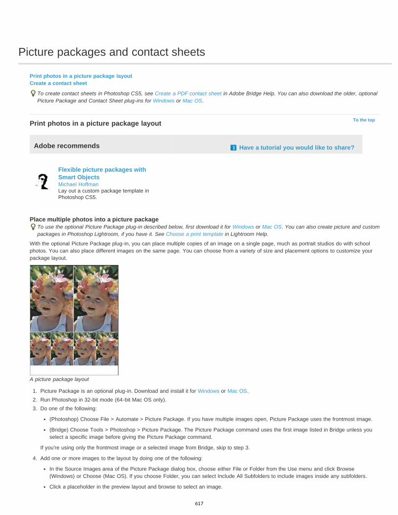
Picture packages and contact sheets
To the top
Print photos in a picture package layoutCreate a contact sheet
To create contact sheets in Photoshop CS5, see Create a PDF contact sheet in Adobe Bridge Help. You can also download the older, optionalPicture Package and Contact Sheet plug-ins for Windows or Mac OS.
Print photos in a picture package layout
Adobe recommends Have a tutorial you would like to share?
Flexible picture packages withSmart ObjectsMichael HoffmanLay out a custom package template inPhotoshop CS5.
Place multiple photos into a picture packageTo use the optional Picture Package plug-in described below, first download it for Windows or Mac OS. You can also create picture and custompackages in Photoshop Lightroom, if you have it. See Choose a print template in Lightroom Help.
With the optional Picture Package plug-in, you can place multiple copies of an image on a single page, much as portrait studios do with schoolphotos. You can also place different images on the same page. You can choose from a variety of size and placement options to customize yourpackage layout.
A picture package layout
1. Picture Package is an optional plug-in. Download and install it for Windows or Mac OS.2. Run Photoshop in 32-bit mode (64-bit Mac OS only).3. Do one of the following:
(Photoshop) Choose File > Automate > Picture Package. If you have multiple images open, Picture Package uses the frontmost image.
(Bridge) Choose Tools > Photoshop > Picture Package. The Picture Package command uses the first image listed in Bridge unless youselect a specific image before giving the Picture Package command.
If you’re using only the frontmost image or a selected image from Bridge, skip to step 3.
4. Add one or more images to the layout by doing one of the following:
In the Source Images area of the Picture Package dialog box, choose either File or Folder from the Use menu and click Browse(Windows) or Choose (Mac OS). If you choose Folder, you can select Include All Subfolders to include images inside any subfolders.
Click a placeholder in the preview layout and browse to select an image.
617
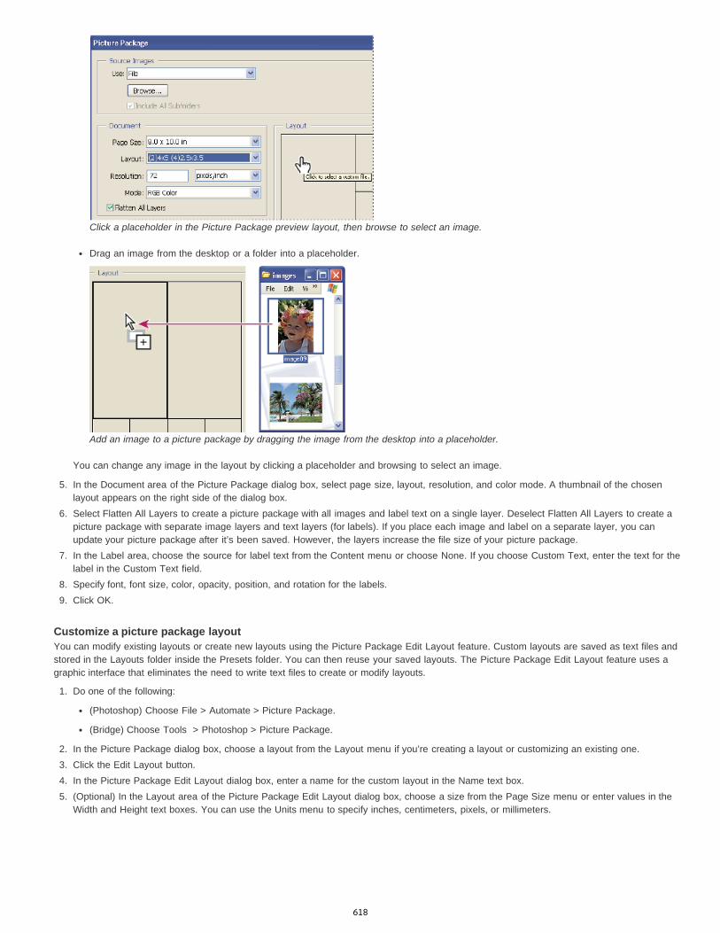
Click a placeholder in the Picture Package preview layout, then browse to select an image.
Drag an image from the desktop or a folder into a placeholder.
Add an image to a picture package by dragging the image from the desktop into a placeholder.
You can change any image in the layout by clicking a placeholder and browsing to select an image.
5. In the Document area of the Picture Package dialog box, select page size, layout, resolution, and color mode. A thumbnail of the chosenlayout appears on the right side of the dialog box.
6. Select Flatten All Layers to create a picture package with all images and label text on a single layer. Deselect Flatten All Layers to create apicture package with separate image layers and text layers (for labels). If you place each image and label on a separate layer, you canupdate your picture package after it’s been saved. However, the layers increase the file size of your picture package.
7. In the Label area, choose the source for label text from the Content menu or choose None. If you choose Custom Text, enter the text for thelabel in the Custom Text field.
8. Specify font, font size, color, opacity, position, and rotation for the labels.9. Click OK.
Customize a picture package layoutYou can modify existing layouts or create new layouts using the Picture Package Edit Layout feature. Custom layouts are saved as text files andstored in the Layouts folder inside the Presets folder. You can then reuse your saved layouts. The Picture Package Edit Layout feature uses agraphic interface that eliminates the need to write text files to create or modify layouts.
1. Do one of the following:
(Photoshop) Choose File > Automate > Picture Package.
(Bridge) Choose Tools > Photoshop > Picture Package.
2. In the Picture Package dialog box, choose a layout from the Layout menu if you’re creating a layout or customizing an existing one.3. Click the Edit Layout button.4. In the Picture Package Edit Layout dialog box, enter a name for the custom layout in the Name text box.5. (Optional) In the Layout area of the Picture Package Edit Layout dialog box, choose a size from the Page Size menu or enter values in the
Width and Height text boxes. You can use the Units menu to specify inches, centimeters, pixels, or millimeters.
618
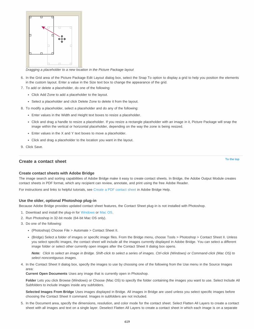
To the top
Dragging a placeholder to a new location in the Picture Package layout
6. In the Grid area of the Picture Package Edit Layout dialog box, select the Snap To option to display a grid to help you position the elementsin the custom layout. Enter a value in the Size text box to change the appearance of the grid.
7. To add or delete a placeholder, do one of the following:
Click Add Zone to add a placeholder to the layout.
Select a placeholder and click Delete Zone to delete it from the layout.
8. To modify a placeholder, select a placeholder and do any of the following:
Enter values in the Width and Height text boxes to resize a placeholder.
Click and drag a handle to resize a placeholder. If you resize a rectangle placeholder with an image in it, Picture Package will snap theimage within the vertical or horizontal placeholder, depending on the way the zone is being resized.
Enter values in the X and Y text boxes to move a placeholder.
Click and drag a placeholder to the location you want in the layout.
9. Click Save.
Create a contact sheet
Create contact sheets with Adobe BridgeThe image search and sorting capabilities of Adobe Bridge make it easy to create contact sheets. In Bridge, the Adobe Output Module createscontact sheets in PDF format, which any recipient can review, annotate, and print using the free Adobe Reader.
For instructions and links to helpful tutorials, see Create a PDF contact sheet in Adobe Bridge Help.
Use the older, optional Photoshop plug-inBecause Adobe Bridge provides updated contact sheet features, the Contact Sheet plug-in is not installed with Photoshop.
1. Download and install the plug-in for Windows or Mac OS.2. Run Photoshop in 32-bit mode (64-bit Mac OS only).3. Do one of the following:
(Photoshop) Choose File > Automate > Contact Sheet II.
(Bridge) Select a folder of images or specific image files. From the Bridge menu, choose Tools > Photoshop > Contact Sheet II. Unlessyou select specific images, the contact sheet will include all the images currently displayed in Adobe Bridge. You can select a differentimage folder or select other currently open images after the Contact Sheet II dialog box opens.
Note: Click to select an image in Bridge. Shift-click to select a series of images. Ctrl-click (Windows) or Command-click (Mac OS) toselect noncontiguous images.
4. In the Contact Sheet II dialog box, specify the images to use by choosing one of the following from the Use menu in the Source Imagesarea:Current Open Documents Uses any image that is currently open in Photoshop.
Folder Lets you click Browse (Windows) or Choose (Mac OS) to specify the folder containing the images you want to use. Select Include AllSubfolders to include images inside any subfolders.
Selected Images From Bridge Uses images displayed in Bridge. All images in Bridge are used unless you select specific images beforechoosing the Contact Sheet II command. Images in subfolders are not included.
5. In the Document area, specify the dimensions, resolution, and color mode for the contact sheet. Select Flatten All Layers to create a contactsheet with all images and text on a single layer. Deselect Flatten All Layers to create a contact sheet in which each image is on a separate
619

layer and each caption is on a separate text layer.6. In the Thumbnails area, specify layout options for the thumbnail previews.
For Place, choose whether to arrange thumbnails across first (from left to right, then top to bottom) or down first (from top to bottom,then left to right).
Enter the number of columns and rows that you want per contact sheet. The maximum dimensions for each thumbnail are displayed tothe right, along with a visual preview of the specified layout.
Select Use Auto-Spacing to let Photoshop automatically space the thumbnails in the contact sheet. If you deselect Use Auto-Spacing,you can specify the vertical and horizontal space around the thumbnails. The contact sheet preview in the dialog box is automaticallyupdated as you specify the spacing.
Select Rotate For Best Fit to rotate the images, regardless of their orientation, so they fit efficiently on a contact sheet.
When Rotate For Best Fit is deselected, thumbnails appear in their correct orientation (left). When it is selected, the pictures are rotatedto achieve the best fit (right).
7. Select Use Filename As Caption to label the thumbnails using their source image filenames. Use the menu to specify a caption font andfont size.
8. Click OK.
Legal Notices | Online Privacy Policy
620
Printing images to a commercial printing press
To the top
To the top
Preparing images for pressSet output optionsPrint separations from PhotoshopPrepare an image with spot channels for printing from another applicationCreate a color trapDetermine scan resolution for printing
Preparing images for pressFrom Photoshop, you can prepare image files for offset lithography, digital printing, gravure, and other commercial printing processes.
Generally, your workflow depends on the capabilities of the prepress facility. Before you begin a workflow for commercial printing, contact theprepress staff to learn their requirements. For example, they may not want you to convert to CMYK at any point because they may need to useprepress-specific settings. Here are some possible scenarios for preparing your image files to achieve predictable printing results:
Work entirely in RGB mode and make sure that the image file is tagged with the RGB working space profile. If your printer or prepress staffuse a color management system, they should be able to use your file’s profile to make an accurate conversion to CMYK before producing thefilm and printing plates.
Work in RGB mode until you finish editing your image. Then convert the image to CMYK mode and make any additional color and tonaladjustments. Especially check the highlights and shadows of the image. Use Levels, Curves, or Hue/Saturation adjustment layers to makecorrections. These adjustments should be very minor. Flatten the file if necessary, then send the CMYK file to the professional printer.
Place your RGB or CMYK image in Adobe InDesign or Adobe Illustrator. In general, most images printed on a commercial press are notprinted directly from Photoshop but from a page-layout program like Adobe InDesign or an illustration program like Adobe Illustrator. Formore information on importing Photoshop files into Adobe InDesign or Adobe Illustrator, see Adobe InDesign Help or the Adobe IllustratorHelp.
Here are a few issues to keep in mind when you work on an image intended for commercial printing:
If you know the characteristics of the press, you can specify the highlight and shadow output to preserve certain details.
If you use a desktop printer to preview the appearance of the final printed piece, keep in mind that a desktop printer cannot faithfully replicatethe output of a commercial printing press. A professional color proof gives a more accurate preview of the final printed piece.
If you have a profile from a commercial press, you can choose it with the Proof Setup command and then view a soft proof using the ProofColors command. Use this method to preview the final printed piece on your monitor.Note: Some printers may prefer to receive your documents in PDF format, especially if the documents need to conform to PDF/X standards.See Save in Photoshop PDF format.
Set output optionsIf you are preparing your images for commercial printing directly from Photoshop, you can select and preview a variety of page marks and otheroutput options using the Print command. Generally, these output options should be specified only by prepress professionals or peopleknowledgeable about the commercial printing process.
621
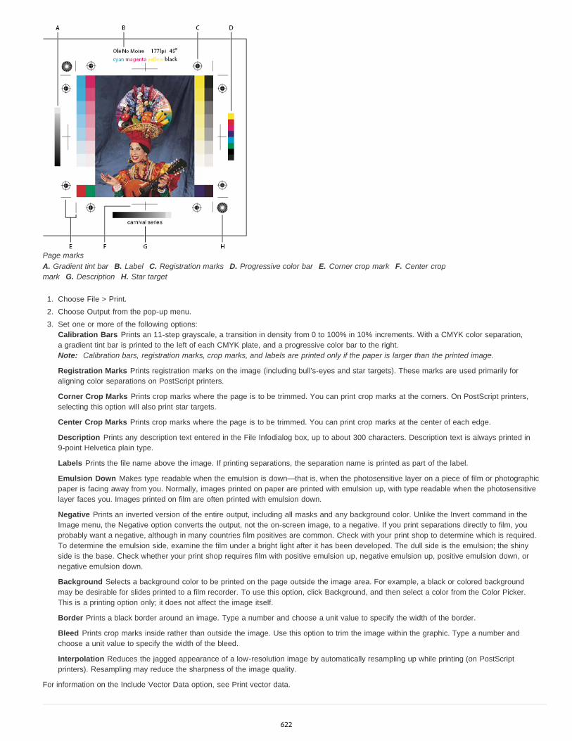
Page marksA. Gradient tint bar B. Label C. Registration marks D. Progressive color bar E. Corner crop mark F. Center cropmark G. Description H. Star target
1. Choose File > Print.2. Choose Output from the pop-up menu.3. Set one or more of the following options:
Calibration Bars Prints an 11-step grayscale, a transition in density from 0 to 100% in 10% increments. With a CMYK color separation,a gradient tint bar is printed to the left of each CMYK plate, and a progressive color bar to the right.Note: Calibration bars, registration marks, crop marks, and labels are printed only if the paper is larger than the printed image.
Registration Marks Prints registration marks on the image (including bull’s-eyes and star targets). These marks are used primarily foraligning color separations on PostScript printers.
Corner Crop Marks Prints crop marks where the page is to be trimmed. You can print crop marks at the corners. On PostScript printers,selecting this option will also print star targets.
Center Crop Marks Prints crop marks where the page is to be trimmed. You can print crop marks at the center of each edge.
Description Prints any description text entered in the File Infodialog box, up to about 300 characters. Description text is always printed in9-point Helvetica plain type.
Labels Prints the file name above the image. If printing separations, the separation name is printed as part of the label.
Emulsion Down Makes type readable when the emulsion is down—that is, when the photosensitive layer on a piece of film or photographicpaper is facing away from you. Normally, images printed on paper are printed with emulsion up, with type readable when the photosensitivelayer faces you. Images printed on film are often printed with emulsion down.
Negative Prints an inverted version of the entire output, including all masks and any background color. Unlike the Invert command in theImage menu, the Negative option converts the output, not the on-screen image, to a negative. If you print separations directly to film, youprobably want a negative, although in many countries film positives are common. Check with your print shop to determine which is required.To determine the emulsion side, examine the film under a bright light after it has been developed. The dull side is the emulsion; the shinyside is the base. Check whether your print shop requires film with positive emulsion up, negative emulsion up, positive emulsion down, ornegative emulsion down.
Background Selects a background color to be printed on the page outside the image area. For example, a black or colored backgroundmay be desirable for slides printed to a film recorder. To use this option, click Background, and then select a color from the Color Picker.This is a printing option only; it does not affect the image itself.
Border Prints a black border around an image. Type a number and choose a unit value to specify the width of the border.
Bleed Prints crop marks inside rather than outside the image. Use this option to trim the image within the graphic. Type a number andchoose a unit value to specify the width of the bleed.
Interpolation Reduces the jagged appearance of a low-resolution image by automatically resampling up while printing (on PostScriptprinters). Resampling may reduce the sharpness of the image quality.
For information on the Include Vector Data option, see Print vector data.
622
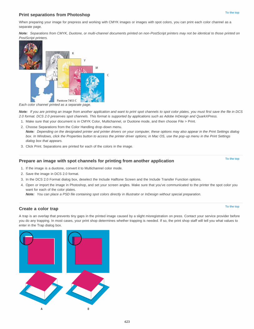
To the top
To the top
To the top
Print separations from PhotoshopWhen preparing your image for prepress and working with CMYK images or images with spot colors, you can print each color channel as aseparate page.
Note: Separations from CMYK, Duotone, or multi-channel documents printed on non-PostScript printers may not be identical to those printed onPostScript printers.
Each color channel printed as a separate page.
Note: If you are printing an image from another application and want to print spot channels to spot color plates, you must first save the file in DCS2.0 format. DCS 2.0 preserves spot channels. This format is supported by applications such as Adobe InDesign and QuarkXPress.
1. Make sure that your document is in CMYK Color, Multichannel, or Duotone mode, and then choose File > Print.2. Choose Separations from the Color Handling drop-down menu.
Note: Depending on the designated printer and printer drivers on your computer, these options may also appear in the Print Settings dialogbox. In Windows, click the Properties button to access the printer driver options; in Mac OS, use the pop-up menu in the Print Settingsdialog box that appears.
3. Click Print. Separations are printed for each of the colors in the image.
Prepare an image with spot channels for printing from another application1. If the image is a duotone, convert it to Multichannel color mode.2. Save the image in DCS 2.0 format.3. In the DCS 2.0 Format dialog box, deselect the Include Halftone Screen and the Include Transfer Function options.4. Open or import the image in Photoshop, and set your screen angles. Make sure that you’ve communicated to the printer the spot color you
want for each of the color plates.Note: You can place a PSD file containing spot colors directly in Illustrator or InDesign without special preparation.
Create a color trapA trap is an overlap that prevents tiny gaps in the printed image caused by a slight misregistration on press. Contact your service provider beforeyou do any trapping. In most cases, your print shop determines whether trapping is needed. If so, the print shop staff will tell you what values toenter in the Trap dialog box.
623
To the top
Trapping to correct misalignmentA. Misregistration with no trap B. Misregistration with trap
Trapping is intended to correct the misalignment of solid colors. In general, you don’t need traps for continuous-tone images such as photographs.Excessive trapping may produce an outline effect. These problems may not be visible on-screen and might show up only in print. Photoshop usesstandard rules for trapping:
All colors spread under black.
Lighter colors spread under darker colors.
Yellow spreads under cyan, magenta, and black.
Pure cyan and pure magenta spread under each other equally.
1. Choose Edit > Convert To Profile to view the image in the color space of the output device. See Convert document colors to another profile(Photoshop).
2. Choose Image > Trap.3. For Width, enter the trapping value provided by your print shop. Then select a unit of measurement, and click OK. Consult your print shop to
determine how much misregistration to expect.
Determine scan resolution for printingYou can use a number of techniques to determine the resolution at which to scan a photograph. If you are scanning photos to be printed, and youknow the exact size and the printing screen frequency, you can use the following techniques to determine the scanning resolution. Often it iseasiest to scan at your scanner's maximum optical resolution and then resize the image in Photoshop later.
Estimate scan resolutionYou can determine the resolution for your scan using the original and final image dimensions and the resolution of your output device. Scanresolution translates into image resolution when you open the scanned image in Photoshop.
1. Do one of the following:
For laser printers and imagesetters, multiply the printer’s screen frequency by 2. To determine your printer’s screen frequency, checkyour printer documentation or consult your service provider.
For inkjet printers, check your printer documentation for the optimal resolution. Many dye sublimation printers and devices that printdirectly onto photographic paper have an optimal resolution of 300 to 400 dpi.
2. Determine the ratio of the final image dimensions to the original image dimensions. For example, the ratio of a 6-by-9-inch final image to a2-by-3-inch original image is 3:1.
3. Multiply the result of step 1 by the result of step 2.
For example, suppose you are printing to an imagesetter with a screen frequency of 85 lpi and the ratio of the final image to the original is3:1. First multiply 85 (the screen frequency) by 2 to get 170. Then multiply 170 by 3 to get a scan resolution of 510 ppi. If you are printing toan inkjet printer with an optimal resolution of 300 dpi, multiply 300 by 3 to get a scan resolution of 900.
Note: Different color separation procedures might require different ratios of image resolution to screen frequency. It’s a good idea to checkwith your service provider or print shop before you scan the image.
Calculate the file size before scanning an imageYou can create a dummy file to predict the file size needed for the final output of your scan.
1. In Photoshop, choose File > New.2. Enter the width, height, and resolution of your final printed image. The resolution should be 1.5 to 2 times the screen frequency you will use
to print. Make sure that the mode you plan to scan in is selected. The New dialog box displays the file size.
For example, suppose you want the final image to be 4 inches wide and 5 inches high. You plan to print it with a 150-line screen using a 2:1ratio, so you set the resolution to 300. The resulting file size is 5.15 MB.
To produce the scan, enter the resulting file size in your scanner settings. Don’t worry about resolution or image dimensions. After you havescanned the image and imported it into Photoshop, use the Image Size command (with the Resample Image option deselected) to enter thecorrect width and height for the image.
More Help topics Soft-proof colors
Legal Notices | Online Privacy Policy
624

Printing with color management | CS5
To the top
Rendering Intent
Black Point Compensation
Match Print Colors
Gamut Warning
Show Paper White
Note:
To the top
Let Photoshop determine printed colorsLet printer determine printed colorsPrint a hard proof
To better understand color management concepts and workflows, see Understanding Color Management.
Let Photoshop determine printed colorsIf you have a custom color profile for a specific printer, ink, and paper combination, letting Photoshop manage colors often produces better resultsthan letting the printer manage colors.
1. Choose File > Print.2. Choose Color Management from the pop-up menu.3. For Color Handling, choose Photoshop Manages Colors.4. For Printer Profile, select the profile that best matches your output device and paper type. If there are any profiles associated with the current
printer, they are placed at the top of the menu, with the default profile selected.
The more accurately the profile describes the behavior of the output device and printing conditions (such as paper type), the more accuratelythe color management system can translate the numeric values of the actual colors in a document. (See Install a profile.)
5. (Optional) Set any of the following options.
Specifies how Photoshop converts colors to the destination color space. (See About rendering intents.)
Preserves the shadow detail in the image by simulating the full dynamic range of the output device.
Enabled when you let Photoshop manage color. Select to view image colors in the preview area as they will actuallyprint.
Enabled when Match Print Colors is selected. Select to highlight out-of-gamut colors in the image, as determined by theselected printer profile. A gamut is the range of colors that a color system can display or print. A color that can be displayed in RGB may beout of gamut for your current printer profile.
Sets the color white in the preview to the color of the paper in the selected printer profile. This produces a moreaccurate print preview if you're printing on off-white paper such as newsprint or art papers that are more beige than white. Since absolutewhite and black create contrast, less white in the paper will lower the overall contrast of your image. Off-white paper can also change theoverall color cast of the image, so yellows printed on beige paper may appear more brown.
6. Access the color management options for the printer driver from the Print Settings dialog box, which automatically appears after you clickPrint. In Windows, click the Preferences button to access the printer driver options. In Mac OS, use the pop-up menu from the Print Settingsdialog box to access the printer driver options.
7. Turn off color management for the printer, so the printer profile settings won’t override your profile settings.
Every printer driver has different color management options. If it’s not clear how to turn off color management, consult your printerdocumentation.
8. Click Print.
If you get a warning that your image is larger than the printable area of the paper, click Cancel, choose File > Print, and select the ScaleTo Fit Media box. To make changes to your paper size and layout, click Print Settings, and attempt to print the file again.
Let printer determine printed colorsIf you don’t have a custom profile for your printer and paper type, you can let the printer driver handle the color conversion.
1. Choose File > Print.2. Choose Color Management from the pop-up menu in the upper-right corner.
625
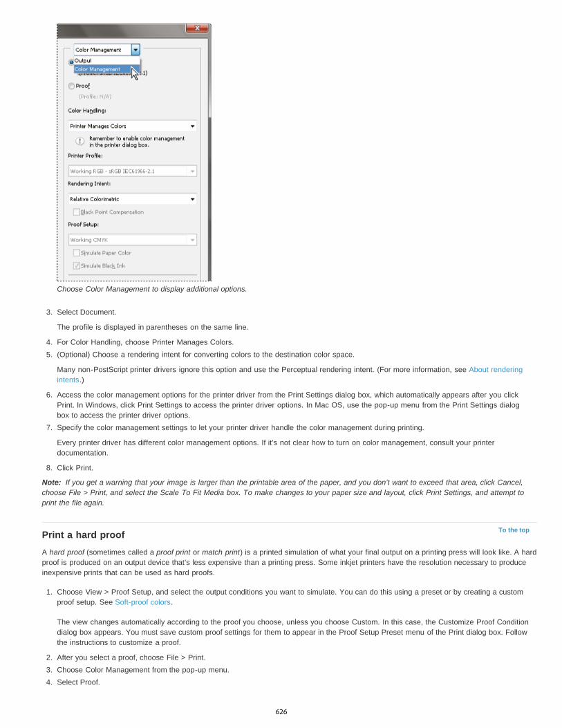
Note:
To the top
Choose Color Management to display additional options.
3. Select Document.
The profile is displayed in parentheses on the same line.
4. For Color Handling, choose Printer Manages Colors.5. (Optional) Choose a rendering intent for converting colors to the destination color space.
Many non-PostScript printer drivers ignore this option and use the Perceptual rendering intent. (For more information, see About renderingintents.)
6. Access the color management options for the printer driver from the Print Settings dialog box, which automatically appears after you clickPrint. In Windows, click Print Settings to access the printer driver options. In Mac OS, use the pop-up menu from the Print Settings dialogbox to access the printer driver options.
7. Specify the color management settings to let your printer driver handle the color management during printing.
Every printer driver has different color management options. If it’s not clear how to turn on color management, consult your printerdocumentation.
8. Click Print.
If you get a warning that your image is larger than the printable area of the paper, and you don’t want to exceed that area, click Cancel,choose File > Print, and select the Scale To Fit Media box. To make changes to your paper size and layout, click Print Settings, and attempt toprint the file again.
Print a hard proofA hard proof (sometimes called a proof print or match print) is a printed simulation of what your final output on a printing press will look like. A hardproof is produced on an output device that’s less expensive than a printing press. Some inkjet printers have the resolution necessary to produceinexpensive prints that can be used as hard proofs.
1. Choose View > Proof Setup, and select the output conditions you want to simulate. You can do this using a preset or by creating a customproof setup. See Soft-proof colors.
The view changes automatically according to the proof you choose, unless you choose Custom. In this case, the Customize Proof Conditiondialog box appears. You must save custom proof settings for them to appear in the Proof Setup Preset menu of the Print dialog box. Followthe instructions to customize a proof.
2. After you select a proof, choose File > Print.3. Choose Color Management from the pop-up menu.4. Select Proof.
626
Twitter™ and Facebook posts are not covered under the terms of Creative Commons.
Legal Notices | Online Privacy Policy
Proof Setup
Simulate Paper Color
Simulate Black Ink
Note:
The profile that appears in parentheses, should match the proof setup you selected earlier.
5. For Color Handling, choose Photoshop Manages Colors.6. For Printer Profile, select the profile for your output device.7. (Optional) Set any of the following options.
This option is available if you select Proof from the Print area. From the pop-up menu, choose any customized proofs that existlocally on your hard drive.
Simulates what colors look like on the paper of the simulated device. Using this option produces the most accurateproof, but it is not available for all profiles.
Simulates the brightness of dark colors for the simulated device. Using this option results in more accurate proofs ofdark colors, but it is not available for all profiles.
8. Access the color management options for the printer driver from the Print Settings dialog box, which automatically appears after you clickPrint. In Windows, click the Preferences button to access the printer driver options. In Mac OS, use the pop-up menu from the Print Settingsdialog box to access the printer driver options.
9. Turn off color management for the printer so that the printer profile settings don’t override your profile settings.
Every printer driver has different color management options. If it’s not clear how to turn off color management, consult your printerdocumentation.
10. Click Print.
If you get a warning that your image is larger than the printable area of the paper, click Cancel, choose File > Print, and select the ScaleTo Fit Media box. To make changes to your paper size and layout, click Print Settings, and attempt to print the file again.
627

Printing from Photoshop CS5
To the top
Types of printing
Types of images
Color separation
Quality of detail
To the top
To the top
Print One Copy
Printing basicsAbout desktop printingPrint imagesPosition and scale imagesPrint vector data
Printing basicsWhether you are printing an image to your desktop printer or sending it to a prepress facility, knowing a few basics about printing makes the printjob go more smoothly and helps ensure that the finished image appears as intended.
For many Photoshop users, printing a file means sending the image to an inkjet printer. Photoshop can send your image to avariety of devices to be printed directly onto paper or converted to a positive or negative image on film. In the latter case, you can use the film tocreate a master plate for printing by a mechanical press.
The simplest images, such as line art, use only one color in one level of gray. A more complex image, such as a photograph,has varying color tones. This type of image is known as a continuous-tone image.
Artwork intended for commercial reproduction and containing more than one color must be printed on separate master plates,one for each color. This process, called color separation, generally calls for the use of cyan, magenta, yellow, and black (CMYK) inks. InPhotoshop, you can adjust how the various plates are generated.
The detail in a printed image depends on image resolution (pixels per inch) and printer resolution (dots per inch). MostPostScript laser printers have a resolution of 600 dpi, while PostScript imagesetters have a resolution of 1200 dpi or higher. Inkjet printers producea microscopic spray of ink, not actual dots, resulting in an approximate resolution of 300 to 720 dpi.
About desktop printingUnless you work in a commercial printing company or service bureau, you probably print images to a desktop printer, such as an inkjet, dyesublimation, or laser printer, not to an imagesetter. Photoshop lets you control how your image is printed.
Monitors display images using light, whereas desktop printers reproduce images using inks, dyes, or pigments. For this reason, a desktop printercan’t reproduce all the colors displayed on a monitor. However, by incorporating certain procedures (such as a color management system) intoyour workflow, you can achieve predictable results when printing your images to a desktop printer. Keep these considerations in mind whenworking with an image you intend to print:
If your image is in RGB mode, do not convert the document to CMYK mode when printing to a desktop printer. Work entirely in RGB mode.As a rule, desktop printers are configured to accept RGB data and use internal software to convert to CMYK. If you send CMYK data, mostdesktop printers apply a conversion anyway, with unpredictable results.
If you want to preview an image as printed to any device for which you have a profile, use the Proof Colors command.
To reproduce screen colors accurately on the printed page, you must incorporate color management into your workflow. Work with a monitorthat is calibrated and characterized. Ideally, you should also create a custom profile specifically for your printer and the paper you print on,though the profile supplied with your printer can produce acceptable results.
Print imagesPhotoshop provides the following printing commands:
Displays the Print dialog box, where you can preview the print and set options. (Customized settings are saved as new defaults when youclick Done or Print.)
Prints one copy of a file without displaying a dialog box.For maximum efficiency, you can include the Print command in actions. (Photoshop provides all print settings in one dialog box.)
Set Photoshop print options and print1. Choose File > Print.
628
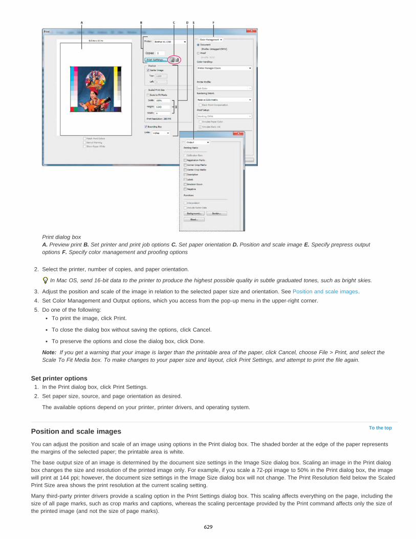
Note:
To the top
Print dialog box A. Preview print B. Set printer and print job options C. Set paper orientation D. Position and scale image E. Specify prepress outputoptions F. Specify color management and proofing options
2. Select the printer, number of copies, and paper orientation.
In Mac OS, send 16-bit data to the printer to produce the highest possible quality in subtle graduated tones, such as bright skies.
3. Adjust the position and scale of the image in relation to the selected paper size and orientation. See Position and scale images.4. Set Color Management and Output options, which you access from the pop-up menu in the upper-right corner.5. Do one of the following:
To print the image, click Print.
To close the dialog box without saving the options, click Cancel.
To preserve the options and close the dialog box, click Done.
If you get a warning that your image is larger than the printable area of the paper, click Cancel, choose File > Print, and select theScale To Fit Media box. To make changes to your paper size and layout, click Print Settings, and attempt to print the file again.
Set printer options1. In the Print dialog box, click Print Settings.2. Set paper size, source, and page orientation as desired.
The available options depend on your printer, printer drivers, and operating system.
Position and scale imagesYou can adjust the position and scale of an image using options in the Print dialog box. The shaded border at the edge of the paper representsthe margins of the selected paper; the printable area is white.
The base output size of an image is determined by the document size settings in the Image Size dialog box. Scaling an image in the Print dialogbox changes the size and resolution of the printed image only. For example, if you scale a 72-ppi image to 50% in the Print dialog box, the imagewill print at 144 ppi; however, the document size settings in the Image Size dialog box will not change. The Print Resolution field below the ScaledPrint Size area shows the print resolution at the current scaling setting.
Many third-party printer drivers provide a scaling option in the Print Settings dialog box. This scaling affects everything on the page, including thesize of all page marks, such as crop marks and captions, whereas the scaling percentage provided by the Print command affects only the size ofthe printed image (and not the size of page marks).
629

Twitter™ and Facebook posts are not covered under the terms of Creative Commons.
Legal Notices | Online Privacy Policy
Note:
To the top
Note:
Note:
The Print dialog box may not reflect accurate values for Scale, Height, and Width if you set a scaling percentage in the Print Settings dialogbox. To avoid inaccurate scaling, specify scaling using the Print dialog box rather than the Print Settings dialog box; do not enter a scalingpercentage in both dialog boxes.
Reposition an image on the paperChoose File > Print, and do one of the following:
To center the image in the printable area, select Center Image.
To position the image numerically, deselect Center Image, and then enter values for Top and Left.
Deselect Center Image, and drag the image in the preview area.
Scale the print size of an imageChoose File > Print, and do one of the following:
To fit the image within the printable area of the selected paper, click Scale To Fit Media.
To rescale the image numerically, deselect Scale To Fit Media, then enter values for Height and Width.
To achieve the desired scale, select Bounding Box, and drag a bounding box handle in the preview area.
Print vector dataIf an image includes vector graphics, such as shapes and type, Photoshop can send the vector data to a PostScript printer. When you choose toinclude vector data, Photoshop sends the printer a separate image for each type layer and each vector shape layer. These additional images areprinted on top of the base image, and clipped using their vector outline. Consequently, the edges of vector graphics print at the printer’s fullresolution, even though the content of each layer is limited to the resolution of your image file.
Some blending modes and layer effects required rasterized vector data.
1. Choose File > Print.2. Choose Output from the pop-up menu.3. Select the Include Vector Data option.4. Click Print.
If you get a warning that your image is larger than the printable area of the paper, click Cancel, choose File > Print, and select the ScaleTo Fit Media box. To make changes to your paper size and layout, click Print Settings, and attempt to print the file again.
More Help TopicsImage size and resolution
About soft-proofing colors
About color profiles
630

Printing spot colors
To the top
To the top
About spot colorsCreate a new spot channelConvert an alpha channel to a spot channelEdit a spot channel to add or remove colorChange a spot channel’s color or solidityMerge spot channelsAdjust overlapping spot colors
About spot colorsSpot colors are special premixed inks used instead of, or in addition to, the process color (CMYK) inks. Each spot color requires its own plate onthe press. (Because a varnish requires a separate plate, it is considered a spot color, too.)
If you are planning to print an image with spot colors, you need to create spot channels to store the colors. To export spot channels, save the filein DCS 2.0 format or PDF.
Note the following when working with spot colors:
For spot color graphics that have crisp edges and knock out the underlying image, consider creating the additional artwork in a page layout orillustration application.
To apply spot color as a tint throughout an image, convert the image to Duotone mode and apply the spot color to one of the duotone plates.You can use up to four spot colors, one per plate.
The names of the spot colors are printed on the separations.
Spot colors are overprinted on top of the fully composited image. Each spot color is printed in the order it appears in the Channels panel, withthe topmost channel printing as the topmost spot color.
You cannot move spot colors above a default channel in the Channels panel except in Multichannel mode.
Spot colors cannot be applied to individual layers.
Printing an image with a spot color channel to a composite color printer will print the spot color at an opacity indicated by the Solidity setting.
You can merge spot channels with color channels, splitting the spot color into its color channel components.
Create a new spot channelYou can create a new spot channel or convert an existing alpha channel to a spot channel.
1. Choose Window > Channels to display the Channels panel.2. To fill a selected area with a spot color, make or load a selection.3. Do one of the following to create a channel:
Ctrl-click (Windows) or Command-click (Mac OS) the New Channel button in the Channels panel.
Choose New Spot Channel from the Channels panel menu.
If you made a selection, that area is filled with the currently specified spot color.
4. In the New Spot Channel dialog box, click the Color box. Then in the Color Picker, click Color Libraries to choose from a custom colorsystem such as PANTONE or TOYO and choose a color. See Choose a spot color.
If you select a custom color, your print service provider can more easily provide the proper ink to reproduce the image.
5. Enter a name for the spot channel. If you choose a custom color, the channel automatically takes the name of that color.
Be sure to name spot colors so they’ll be recognized by other applications reading your file. Otherwise the file might not print.
6. For Solidity, enter a value between 0% and 100%.
This option lets you simulate on-screen the density of the printed spot color. A value of 100% simulates an ink that completely covers theinks beneath (such as a metallic ink); 0% simulates a transparent ink that completely reveals the inks beneath (such as a clear varnish). Youcan also use this option to see where an otherwise transparent spot color (such as a varnish) will appear.
631
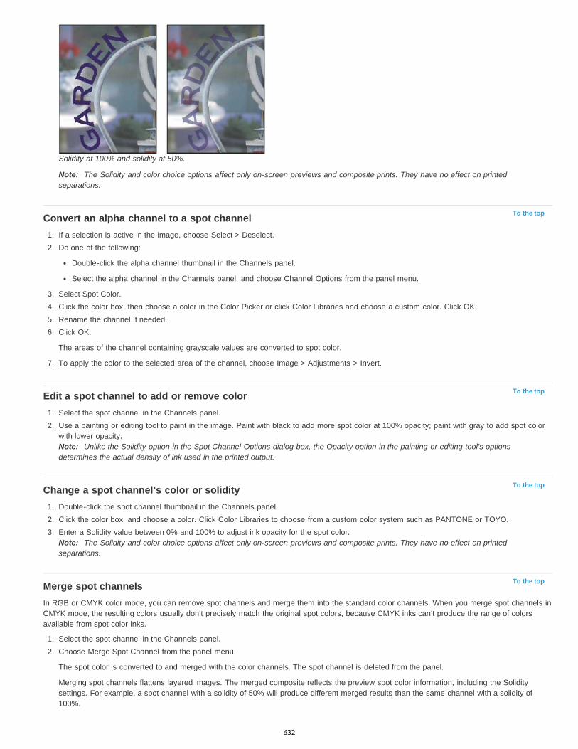
To the top
To the top
To the top
To the top
Solidity at 100% and solidity at 50%.
Note: The Solidity and color choice options affect only on-screen previews and composite prints. They have no effect on printedseparations.
Convert an alpha channel to a spot channel1. If a selection is active in the image, choose Select > Deselect.2. Do one of the following:
Double-click the alpha channel thumbnail in the Channels panel.
Select the alpha channel in the Channels panel, and choose Channel Options from the panel menu.
3. Select Spot Color.4. Click the color box, then choose a color in the Color Picker or click Color Libraries and choose a custom color. Click OK.5. Rename the channel if needed.6. Click OK.
The areas of the channel containing grayscale values are converted to spot color.
7. To apply the color to the selected area of the channel, choose Image > Adjustments > Invert.
Edit a spot channel to add or remove color1. Select the spot channel in the Channels panel.2. Use a painting or editing tool to paint in the image. Paint with black to add more spot color at 100% opacity; paint with gray to add spot color
with lower opacity.Note: Unlike the Solidity option in the Spot Channel Options dialog box, the Opacity option in the painting or editing tool’s optionsdetermines the actual density of ink used in the printed output.
Change a spot channel’s color or solidity1. Double-click the spot channel thumbnail in the Channels panel.2. Click the color box, and choose a color. Click Color Libraries to choose from a custom color system such as PANTONE or TOYO.3. Enter a Solidity value between 0% and 100% to adjust ink opacity for the spot color.
Note: The Solidity and color choice options affect only on-screen previews and composite prints. They have no effect on printedseparations.
Merge spot channelsIn RGB or CMYK color mode, you can remove spot channels and merge them into the standard color channels. When you merge spot channels inCMYK mode, the resulting colors usually don’t precisely match the original spot colors, because CMYK inks can’t produce the range of colorsavailable from spot color inks.
1. Select the spot channel in the Channels panel.2. Choose Merge Spot Channel from the panel menu.
The spot color is converted to and merged with the color channels. The spot channel is deleted from the panel.
Merging spot channels flattens layered images. The merged composite reflects the preview spot color information, including the Soliditysettings. For example, a spot channel with a solidity of 50% will produce different merged results than the same channel with a solidity of100%.
632

To the topAdjust overlapping spot colorsTo prevent overlapping spot colors from either printing over or knocking out the underlying spot color, remove one of the spot colors where theyoverlap.
Use a printed sample of the overprinted inks to adjust your screen display to help you predict how colors will look when printed.
Note: In some cases, such as when you use varnish and bump plates, you may want colors to overprint.1. In the Channels panel, select the spot channel with the color you want to print.2. Choose Select > Load Selection.
To quickly select an image in a channel, hold down Ctrl (Windows) or Command (Mac OS), and click the channel in the Channels panel.
3. For Channel, choose the spot channel from step 1, and click OK.4. To create a trap when knocking out the underlying color, choose Select > Modify > Expand or Contract, depending on whether the
overlapping spot color is darker or lighter than the spot color beneath it. In the Channels panel, select the underlying spot channel thatcontains the areas you want to knock out. Press Backspace (Windows) or Delete (Mac OS).
This method can be used to knock out areas from any channels under a spot color, such as the CMYK channels.
5. If a spot color in one channel overlaps more than one other spot color, repeat this process for each channel that contains the areas youwant removed.
Legal Notices | Online Privacy Policy
633

Automation
Batch ActionsInfinite Skills (Aug. 9, 2012)video-tutorial
634
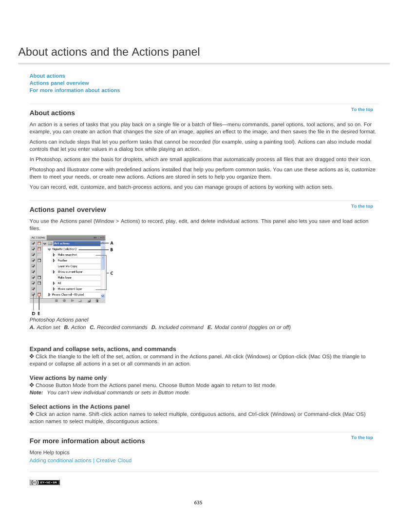
About actions and the Actions panel
To the top
To the top
To the top
About actionsActions panel overviewFor more information about actions
About actionsAn action is a series of tasks that you play back on a single file or a batch of files—menu commands, panel options, tool actions, and so on. Forexample, you can create an action that changes the size of an image, applies an effect to the image, and then saves the file in the desired format.
Actions can include steps that let you perform tasks that cannot be recorded (for example, using a painting tool). Actions can also include modalcontrols that let you enter values in a dialog box while playing an action.
In Photoshop, actions are the basis for droplets, which are small applications that automatically process all files that are dragged onto their icon.
Photoshop and Illustrator come with predefined actions installed that help you perform common tasks. You can use these actions as is, customizethem to meet your needs, or create new actions. Actions are stored in sets to help you organize them.
You can record, edit, customize, and batch-process actions, and you can manage groups of actions by working with action sets.
Actions panel overviewYou use the Actions panel (Window > Actions) to record, play, edit, and delete individual actions. This panel also lets you save and load actionfiles.
Photoshop Actions panelA. Action set B. Action C. Recorded commands D. Included command E. Modal control (toggles on or off)
Expand and collapse sets, actions, and commands Click the triangle to the left of the set, action, or command in the Actions panel. Alt-click (Windows) or Option-click (Mac OS) the triangle to
expand or collapse all actions in a set or all commands in an action.
View actions by name only Choose Button Mode from the Actions panel menu. Choose Button Mode again to return to list mode.
Note: You can’t view individual commands or sets in Button mode.
Select actions in the Actions panel Click an action name. Shift-click action names to select multiple, contiguous actions, and Ctrl-click (Windows) or Command-click (Mac OS)
action names to select multiple, discontiguous actions.
For more information about actionsMore Help topicsAdding conditional actions | Creative Cloud
635

Creating actions
To the top
To the top
Guidelines for recording actionsRecord an actionRecord a pathInsert a stopChange settings when playing an actionExclude commands from an actionInsert a non-recordable menu commandEdit and rerecord actions
Guidelines for recording actionsKeep in mind the following guidelines when recording actions:
You can record most—but not all—commands in an action.
You can record operations that you perform with the Marquee, Move, Polygon, Lasso, Magic Wand, Crop, Slice, Magic Eraser, Gradient,Paint Bucket, Type, Shape, Notes, Eyedropper, and Color Sampler tools—as well as those that you perform in the History, Swatches, Color,Paths, Channels, Layers, Styles, and Actions panels.
Results depend on file and program setting variables, such as the active layer and the foreground color. For example, a 3-pixel Gaussian blurwon’t create the same effect on a 72-ppi file as on a 144-ppi file. Nor will Color Balance work on a grayscale file.
When you record actions that include specifying settings in dialog boxes and panels, the action will reflect the settings in effect at the time ofthe recording. If you change a setting in a dialog box or panel while recording an action, the changed value is recorded.
Note: Most dialog boxes retain the settings specified at the previous use. Check carefully that those are the values you want to record.
Modal operations and tools—as well as tools that record position—use the units currently specified for the ruler. A modal operation or tool isone that requires you to press Enter or Return to apply its effect, such as transforming or cropping. Tools that record position include theMarquee, Slice, Gradient, Magic Wand, Lasso, Shape, Path, Eyedropper, and Notes tools.
If you record an action that will be played on files of different sizes, set the ruler units to percentages. As a result, the action will alwaysplay back in the same relative position in the image.
You can record the Play command listed on the Actions panel menu to cause one action to play another.
Record an actionWhen you create a new action, the commands and tools you use are added to the action until you stop recording.
To guard against mistakes, work in a copy: at the beginning of the action before applying other commands, record the File > Save A Copycommand (Illustrator) or record the File > Save As command and select As A Copy (Photoshop). Alternatively, in Photoshop you can click theNew Snapshot button on the History panel to make a snapshot of the image before recording the action.
1. Open a file.2. In the Actions panel, click the Create New Action button , or choose New Action from the Actions panel menu.3. Enter an action name, select an action set, and set additional options:
Function Key Assigns a keyboard shortcut to the action. You can choose any combination of a function key, the Ctrl key (Windows) orCommand key (Mac OS), and the Shift key (for example, Ctrl+Shift+F3), with these exceptions: In Windows, you cannot use the F1 key, norcan you use F4 or F6 with the Ctrl key.Note: If you assign an action the same shortcut that is used for a command, the shortcut will apply the action rather than the command.
Color Assigns a color for display in Button mode.
4. Click Begin Recording. The Begin Recording button in the Actions panel turns red .Important: When recording the Save As command, do not change the filename. If you enter a new filename, that new name is recordedand used each time you run the action. Before saving, if you navigate to a different folder, you can specify a different location without havingto specify a filename.
5. Perform the operations and commands you want to record.
Not all tasks in actions can be recorded directly; however, you can insert most nonrecordable tasks using commands in the Actions panelmenu.
6. To stop recording, either click the Stop Playing/Recording button, or choose Stop Recording from the Actions panel menu. (In Photoshop,
636
To the top
To the top
To the top
To the top
you can also press the Esc key.)
To resume recording in the same action, choose Start Recording from the Actions panel menu.
Record a pathThe Insert Path command lets you include a complex path (a path created with a pen tool or pasted from Adobe Illustrator) as part of an action.When the action is played back, the work path is set to the recorded path. You can insert a path when recording an action or after it has beenrecorded.
1. Do one of the following:
Start recording an action.
Select an action’s name to record a path at the end of the action.
Select a command to record a path after the command.
2. Select an existing path from the Paths panel.3. Choose Insert Path from the Actions panel menu.
If you record multiple Insert Path commands in a single action, each path replaces the previous one in the target file. To add multiple paths, recorda Save Path command using the Paths panel after recording each Insert Path command.Note: Playing actions that insert complex paths may require significant amounts of memory. If you encounter problems, increase the amount ofmemory available to Photoshop.
Insert a stopYou can include stops in an action that let you perform a task that cannot be recorded (for example, using a painting tool). After you complete thetask, click the Play button in the Actions panel to complete the action.
You can also display a short message when the action reaches the stop as a reminder of what needs to be done before continuing with the action.You can include a Continue button in the message box in case no other task needs to be done.
1. Choose where to insert the stop by doing one of the following:
Select an action’s name to insert a stop at the end of the action.
Select a command to insert a stop after the command.
2. Choose Insert Stop from the Actions panel menu.3. Type the message you want to appear.4. If you want the option to continue the action without stopping, select Allow Continue.5. Click OK.
You can insert a stop when recording an action or after it has been recorded.
Change settings when playing an actionBy default, actions are completed using the values specified when they were originally recorded. If you want to change the settings for a commandwithin an action, you can insert a modal control. A modal control pauses an action so that you can specify values in a dialog box or use a modaltool. (A modal tool requires pressing Enter or Return to apply its effect—once you press Enter or Return, the action resumes its tasks.)
A modal control is indicated by a dialog box icon to the left of a command, action, or set in the Actions panel. A red dialog box icon indicatesan action or set in which some, but not all, commands are modal. You can’t set a modal control in Button mode.
Do one of the following:
To enable a modal control for a command within an action, click the box to the left of the command name. Click again to disable the modalcontrol.
To enable or disable modal controls for all commands in an action, click the box to the left of the action name.
To enable or disable modal controls for all actions in a set, click the box to the left of the set name.
Exclude commands from an actionYou can exclude commands that you don’t want to play as part of a recorded action. You can’t exclude commands in Button mode.
1. If necessary, expand the listing of commands in the action by clicking the triangle to the left of the action name in the Actions panel.2. Do one of the following:
To exclude a single command, click to clear the check mark to the left of the command name. Click again to include the command.
637

To the top
To the top
To exclude or include all commands or actions in an action or set, click the check mark to the left of the action or set name.
To exclude or include all commands except the selected command, Alt-click (Windows) or Option-click (Mac OS) its check mark.
To indicate that some of the commands within the action are excluded, in Photoshop the check mark of the parent action turns red; inIllustrator the check mark of the parent action becomes dimmed.
Insert a non-recordable menu commandYou cannot record the painting and toning tools, tool options, View commands, and Window commands. However, you can insert many non-recordable commands into an action using the Insert Menu Item command.
You can insert a command when recording an action, or after it has been recorded. An inserted command doesn’t execute until the action isplayed, so the file remains unchanged when the command is inserted. No values for the command are recorded in the action. If the commandopens a dialog box, the dialog box appears during playback, and the action pauses until you click OK or Cancel.
Note: When you use the Insert Menu Item command to insert a command that opens a dialog box, you cannot disable the modal control in theActions panel.
1. Choose where to insert the menu item:
Select an action’s name to insert the item at the end of the action.
Select a command to insert the item at the end of the command.
2. Choose Insert Menu Item from the Actions panel menu.3. With the Insert Menu Item dialog box open, choose a command from its menu.4. Click OK.
Edit and rerecord actionsIt is easy to edit and customize actions. You can tweak the settings of any specific command within an action, add commands to an existingaction, or step through an entire action and change any or all settings.
Overwrite a single command1. In the Actions panel, double-click the command.2. Enter the new values, and click OK.
Add commands to an action1. Do one of the following:
Select the action name to insert a new command at the end of the action.
Select a command in the action to insert a command after it.
2. Click the Begin Recording button, or choose Start Recording from the Actions panel menu.3. Record the additional commands.4. When finished, click the Stop Playing/Recording button in the Actions panel or choose Stop Recording from the panel menu.
Rearrange commands within an action In the Actions panel, drag a command to its new location within the same or another action. When the highlighted line appears in the desired
position, release the mouse button.
Record an action again1. Select an action, and choose Record Again from the Actions panel menu.2. If a modal tool appears, use the tool to create a different result, and press Enter or Return, or just press Enter or Return to retain the same
settings.3. If a dialog box appears, change the settings, and click OK to record them, or click Cancel to retain the same values.
More Help topicsAdding conditional actions | Creative Cloud
Legal Notices | Online Privacy Policy
638
Playing and managing actions
To the top
To the top
To the top
Play an action on a fileSpecify playback speedManage actionsManage action sets
Play an action on a filePlaying an action executes the action’s recorded commands in the active document. (Some actions require that you make a selection beforeplaying; some can be executed on an entire file.) You can exclude specific commands from an action or play only a single command. If the actionincludes a modal control, you can specify values or use tools in a dialog box when the action pauses.
Note: In Button mode, clicking a button executes the entire action—although commands previously excluded are not executed.1. If necessary, select objects on which to play the action, or open a file.2. Do one of the following:
(Illustrator) To play a set of actions, select the set name, and click the Play button in the Actions panel, or choose Play from the panelmenu.
To play an entire single action, select the action name, and click the Play button in the Actions panel, or choose Play from the panelmenu.
If you assigned a key combination to the action, press that combination to play the action automatically.
To play only a part of an action, select the command from which you want to start playing, and click the Play button in the Actions panel,or choose Play from the panel menu.
To play a single command, select the command, and then Ctrl-click (Windows) or Command-click (Mac OS) the Play button in theActions panel. You can also press Ctrl (Windows) or Command (Mac OS), and double-click the command.
In Photoshop, to undo an action, take a snapshot in the History panel before you play an action, and then select the snapshot to undo theaction.
Specify playback speedYou can adjust an action’s playback speed or pause it to help you debug an action.
1. Choose Playback Options from the Actions panel menu.2. Specify a speed, and click OK:
Accelerated Plays the action at normal speed (the default).Note: When you play an action at accelerated speed, the screen may not update as the action executes—files may be opened, modified,saved, and closed without ever appearing on-screen, enabling the action to execute more quickly. If you want to see the files on-screen asthe action executes, specify the Step By Step speed instead.
Step By Step Completes each command and redraws the image before going on to the next command in the action.
Pause For __ Seconds Specifies the amount of time the application should pause between carrying out each command in the action.
Manage actionsManage actions in the Actions panel to keep them organized and to make available only the actions you need for a project. You can rearrange,duplicate, delete, rename, and change options for actions in the Actions panel.
Rearrange actions in the Actions panel In the Actions panel, drag the action to its new location before or after another action. When the highlighted line appears in the desired position,
release the mouse button.
Duplicate actions, commands, or sets Do one of the following:
639
To the top
Alt-drag (Windows) or Option-drag (Mac OS) the action or command to a new location in the Actions panel. When the highlighted lineappears in the desired location, release the mouse button.
Select an action or command. Then choose Duplicate from the Actions panel menu.
Drag an action or command to the Create New Action button at the bottom of the Actions panel.
You can duplicate sets with any of the same methods.
Delete actions, commands, or sets1. In the Actions panel, select the action, command, or set.2. Do any of the following:
Click the Delete icon on the Actions panel. Click OK to complete the deletion.
Alt-click (Windows) or Option-click (Mac OS) the Delete icon to delete the selection without displaying a confirmation dialog box.
Drag the selection to the Delete icon on the Actions panel to delete without displaying a confirmation dialog box.
Choose Delete from the Actions panel menu.
Delete all actions in the Actions panel Choose Clear All Actions (Photoshop) or Clear Actions (Illustrator) from the Actions panel menu.
Even after clearing all actions, the Actions panel can be restored to its default set of actions.
Rename an action or change options1. Select the action, and choose Action Options from the Actions panel menu.2. Type a new name for the action, or change the options for its set, function key combination, or button color.3. Click OK.
Double-clicking the action name in the Actions panel in Illustrator also opens the Action Options dialog box. In Photoshop, you can double-clickan action in the Actions panel and enter a new name directly in the Actions panel.
Manage action setsYou can create and organize sets of task-related actions that can be saved to disk and transferred to other computers.
Note: Any actions that you create are automatically listed in the Actions panel, but to truly save an action and not risk losing it if you delete yourpreferences file (Illustrator) or Actions panel file (Photoshop), you have to save it as part of an action set.
Save a set of actions1. Select a set.
If you want to save a single action, first create an action set and move the action to the new set.
2. Choose Save Actions from the Actions panel menu.3. Type a name for the set, choose a location, and click Save.
You can save the file anywhere. You can save only the entire contents of a set in the Actions panel, not individual actions.
Note: (Photoshop only) If you place the saved action-set file in the Presets/Actions folder, the set will appear at the bottom of the Actionspanel menu after you restart the application.
(Photoshop only) Press Ctrl+Alt (Windows) or Command+Option (Mac OS) when you choose the Save Actions command to save theactions in a text file. You can use this file to review or print the contents of an action. However, you can’t reload the text file back intoPhotoshop.
Load a set of actionsBy default, the Actions panel displays predefined actions (shipped with the application) and any actions you create. You can also load additionalactions into the Actions panel.
Do one of the following:
Choose Load Actions from the Actions panel menu. Locate and select the action set file, and then click Load (Photoshop) or Open(Illustrator).
(Photoshop only) Select an action set from the bottom of the Actions panel menu.
Photoshop action set files have the extension .atn; Illustrator action set files have the extension .aia.
Restore actions to the default set1. Choose Reset Actions from the Actions panel menu.
640

2. Click OK to replace the current actions in the Actions panel with the default set, or click Append to add the set of default actions to thecurrent actions in the Actions panel.
Organize action setsTo help you organize your actions, you can create sets of actions and save the sets to disk. You can organize sets of actions for different types ofwork—such as print publishing and online publishing—and transfer sets to other computers.
To create a new set of actions, click the Create New Set button in the Actions panel or choose New Set from the panel menu. Then enterthe name of the set, and click OK.
Note: If you plan to create a new action and group it in a new set, make sure you create the set first. Then, the new set will appear in the setpopup menu when you create your new action.
To move an action to a different set, drag the action to that set. When the highlighted line appears in the desired position, release the mousebutton.
To rename a set of actions, double-click the name of the set in the Actions panel or choose Set Options from the Actions panel menu. Thenenter the new name of the set, and click OK.
To replace all actions in the Actions panel with a new set, choose Replace Actions from the Actions panel menu. Select an actions file, andclick Load (Photoshop) or Open (Illustrator).
Important: The Replace Actions command replaces all sets of actions in the current document. Before using the command, make sure thatyou have already saved a copy of your current set of actions using the Save Actions command.
Legal Notices | Online Privacy Policy
641
Processing a batch of files
To the top
Convert files with the Image ProcessorProcess a batch of filesCreate a droplet from an actionBatch and droplet processing options
Convert files with the Image ProcessorThe Image Processor converts and processes multiple files. Unlike the Batch command, the Image Processor lets you process files without firstcreating an action. You can do any of the following in the Image Processor:
Convert a set of files to either JPEG, PSD, or TIFF format; or convert files simultaneously to all three formats.
Process a set of camera raw files using the same options.
Resize images to fit within specified pixel dimensions.
Embed a color profile or convert a set of files to sRGB and save them as JPEG images for the web.
Include copyright metadata into the converted images.
The Image Processor works with Photoshop (PSD), JPEG, and camera raw files.
1. Do any of the following:
Choose File > Scripts > Image Processor (Photoshop)
Choose Tools > Photoshop > Image Processor (Bridge)
2. Select the images you want to process. You can choose to process any open files, or select a folder of files to process.3. (Optional) Select Open First Image To Apply Settings to apply the same settings to all the images.
If you are processing a group of camera raw files taken under the same lighting conditions, you can adjust the setting in the first image toyour satisfaction and then apply the same settings to the remaining images.
Use this option with PSD or JPEG source images if the file’s color profile does not match your working profile. You can choose a colorprofile in which to convert the first image and all images in the folder.
Note: The settings you apply with the Image Processor are temporary and used only with the Image Processor. The image’s currentcamera raw settings are used to process the image, unless you change them in the Image Processor.
4. Select the location where you want to save the processed files.
If you process the same file multiple times to the same destination, each file is saved with its own file name and not overwritten.
5. Select the file types and options to save.Save As JPEG Saves images in JPEG format within a folder called JPEG in the destination folder.
Quality Sets the JPEG image quality between 0 and 12.
Resize To Fit Resizes the image to fit within the dimensions you enter in Width and Height. The image retains its original proportions.
Convert Profile To sRGB Converts the color profile to sRGB. Make sure that Include ICC Profile is selected if you want to save the profilewith the image.
Save As PSD Saves images in Photoshop format within a folder called PSD in the destination folder.
Maximize Compatibility Saves a composite version of a layered image within the target file for compatibility with applications that can't readlayered images.
Save As TIFF Saves images in TIFF format within a folder called TIFF in the destination folder.
LZW Compression Saves the TIFF file using the LZW compression scheme.
6. Set other processing options.Run Action Runs a Photoshop action. Choose the action set from the first menu and the action from the second menu. The action set mustbe loaded in the Actions panel before they appear in these menus.
Copyright Info Includes any text you enter in the IPTC copyright metadata for the file. Text you include here overwrites the copyrightmetadata in the original file.
Include ICC Profile Embeds the color profile with the saved files.
642
To the top
To the top
7. Click Run.
Before you process your images, click Save to save the current settings in the dialog box. The next time you need to process files using thisgroup of settings, click Load, and navigate to your saved Image Processor settings.
Process a batch of filesThe Batch command runs an action on a folder of files. If you have a digital camera or a scanner with a document feeder, you can also import andprocess multiple images with a single action. Your scanner or digital camera may need an acquire plug-in module that supports actions.
Note: If the third-party plug-in wasn’t written to import multiple documents at a time, it may not work during batch-processing or if used as part ofan action. Contact the plug-in’s manufacturer for further information.You can also import PDF images from Acrobat Capture or other software.
When batch-processing files, you can leave all the files open, close and save the changes to the original files, or save modified versions of thefiles to a new location (leaving the originals unchanged). If you are saving the processed files to a new location, you may want to create a newfolder for the processed files before starting the batch.
To batch-process using multiple actions, create a new action that plays all the other actions, and then batch-process using the new action.To batch-process multiple folders, create aliases within a folder to the other folders you want to process, and select the Include All Subfoldersoption.
For better batch performance, reduce the number of saved history states and deselect the Automatically Create First Snapshot option in theHistory panel.
Batch-process files1. Do one of the following:
Choose File > Automate > Batch (Photoshop)
Choose Tools > Photoshop > Batch (Bridge)
2. Specify the action you want to use to process files from the Set and Action pop-up menus. The menus display actions available in theActions panel. You may need to choose a different set or load a set in the panel if you don’t see your action.
3. Choose the files to process from the Source pop-up menu:Folder Processes files in a folder you specify. Click Choose to locate and select the folder.
Import Processes images from a digital camera, scanner, or a PDF document.
Opened Files Processes all open files.
Bridge Processes selected files in Adobe Bridge. If no files are selected, the files in the current Bridge folder are processed.
4. Set processing, saving, and file naming options. For descriptions of the Batch dialog box settings see Batch and droplet processing options.
Batch-process files in nested folders into different formats1. Process your folders as you would normally, until the Destination step.2. Choose Save And Close for the destination. You can specify options for Override Action “Save As” Commands to do the following:
If the “Save As” step in the action contains a file name, this name is overridden by the name of the document being saved; all “Save As”steps are treated as if they were recorded without a file name.
The folder you specified in the “Save As” action step is overridden by the document’s original folder.
Note: You must have a “Save As” step in the action; the Batch command does not automatically save files.
You can use this procedure, for example, to sharpen, resize, and save images as JPEGs in their original folders. You create an action thathas a sharpen step, a resize step, and then a “Save As JPEG” step. When you batch-process this action, you select Include All Subfolders,make the destination Save And Close, and select Override Action“Save As” Commands.
Create a droplet from an actionA droplet applies an action to one or more images, or a folder of images, that you drag onto the Droplet icon. You can save a droplet on thedesktop or to another location on disk.
Droplet icon
643
To the top
Actions are the basis for creating droplets—you must create the desired action in the Actions panel before creating a droplet. (See Creatingactions.)
1. Choose File > Automate > Create Droplet.2. Specify where to save the droplet. Click Choose in the Save Droplet In section of the dialog box and navigate to the location.3. Select the Action Set, and then designate which action you intend to use within the Set and Action menus. (Select the action in the Actions
panel before you open the dialog box to preselect these menus.)4. Set processing, saving, and file naming options. For descriptions of the Batch dialog box settings see Batch and droplet processing options.
Tips for cross-platform dropletsWhen creating droplets for both Windows and Mac OS, keep the following compatibility issues in mind:
After moving a droplet created in Windows to Mac OS, you must drag the droplet onto the Photoshop icon on your desktop. Photoshopupdates the droplet for use in Mac OS.
When creating a droplet in Mac OS, use the .exe extension to make droplets compatible with both Windows and Mac OS.
References to file names are not supported between operating systems. If an action step references a file or folder name (such as an Opencommand, Save As command, or adjustment command that loads its settings from a file), execution pauses and the user is prompted for afile name.
Process a file with a droplet Drag a file or folder onto the droplet icon. Photoshop starts if it is not already running.
Batch and droplet processing optionsSpecify these options in the Batch and Droplet dialog boxes.
Override Action “Open” Commands Ensures that the files you selected in the Batch command are processed, without opening the file you mayhave specified in the action's Open command. If the action contains an Open command that opens a saved file and you don't select this option,the Batch command opens and processes only the file you used to record the Open command (This occurs because the Batch command opensthe file specified by the action after each of the files in the Batch source folder is opened. Because the most recently opened file is the one namedin the action, the Batch command performs the action on that file, and none of the files in the Batch source folder are processed.)To use this option, the action must contain an Open command. Otherwise, the Batch command won't open the files you've selected for batch-processing. Selecting this option doesn't disregard everything in an Open command—only the choice of files to open.
Deselect this option if the action was recorded to operate on an open file, or if the action contains Open commands for specific files that arerequired by the action.
Include All Subfolders Processes files in subdirectories of the specified folder.Suppress Color Profile Warnings Turns off display of color policy messages.Suppress File Open Options Dialogs Hides File Open Options dialog boxes. This is useful when batching actions on camera raw image files.The default or previously specified settings will be used.Destination menu Sets where to save the processed files
None Leaves the files open without saving changes (unless the action includes a Save command).Save And Close Saves the files in their current location, overwriting the original files.Folder Saves the processed files to another location. Click Choose to specify the destination folder.
Override Action “Save As” Commands Ensures that processed files are saved to the destination folder specified in the Batch command (or totheir original folder if you chose Save and Close), with their original names or the names you specified in the File Naming section of the Batchdialog box.If you don't select this option and your action includes a Save Ascommand, your files will be saved into the folder specified by theSave Ascommand in the action, instead of the folder specified in the Batch command. In addition, if you don't select this option and the Save As commandin the action specifies a filename, the Batch command overwrites the same file (the file specified in the action) each time it processes an image.
If you want the Batch command to process files using the original filenames in the folder you specified in the Batch command, save your imagein the action. Then, when you create the batch, select Override Action "Save As" Command and specify a destination folder. If you rename theimages in the Batch command and don't select Override Action "Save As" Command, Photoshop saves your processed images twice: once withthe new name in the specified folder, and once with the original name in the folder specified by the Save As command in the action.
To use this option, the action must contain a Save As command. Otherwise, the Batch command won't save the processed files. Selecting thisoption doesn't skip everything in the Save As command—only the specified filename and folder.
Note: Some Save options aren’t available in the Batch or Create Droplet commands (such as JPEG compression or TIFF options). To use theseoptions, record a Save As step in the action that contains the desired options, and then use the Override Action “Save As” Commands option tomake sure that your files are saved where you specify in the Batch orCreate Droplet command. Photoshop disregards the specified filename andpath in the Action's Save As command, and retains the Save options using the new path and filename you specify in the Batch dialog.File Naming Specifies file naming conventions if writing files to a new folder. Select elements from the pop-up menus or enter text into the fields tobe combined into the default names for all files. The fields let you change the order and formatting of the components of the filename. You must
644
include at least one field that is unique for every file (for example, filename, serial number, or serial letter) to prevent files from overwriting eachother. Starting Serial Number specifies the starting number for any serial number fields. Serial letter fields always start with the letter “A” for thefirst file.Compatibility Makes filenames compatible with Windows, Mac OS, and UNIX operating systems.
Saving files using the Batch command options usually saves the files in the same format as the original files. To create a batch process thatsaves files in a new format, record the Save As command followed by the Close command as part of your original action. Then chooseOverride Action“Save As” Commands for the Destination when setting up the batch process.
Error menu Specifies how to handle processing errors:
Stop For Errors Suspends the process until you confirm the error message.Log Errors to File Records each error in a file without stopping the process. If errors are logged to a file, a message appears afterprocessing. To review the error file, open with a text editor after the Batch command has run.
More Help topicsImage processing video
Legal Notices | Online Privacy Policy
645

Scripting
To the top
To the top
Run a JavaScriptSet scripts and actions to run automatically
Photoshop supports external automation through scripting. In Windows, you can use scripting languages that support COM automation, such asVB Script. In Mac OS, you can use languages such as AppleScript that allow you to send Apple events. These languages are not cross-platformbut can control multiple applications such as Adobe Photoshop, Adobe Illustrator, and Microsoft Office. In Mac OS, you can also use Apple’sPhotoshop Actions for Automator to control tasks in Photoshop.
You can also use JavaScript on either platform. JavaScript support lets you write Photoshop scripts that run on either Windows or Mac OS.
Note: Refer to the scripting documentation installed in the Photoshop CS5/Scripting/Documents folder. The Scriptlistener Plug-In can be found inPhotoshop CS5/Scripting/Utilities.
Run a JavaScript Choose File > Scripts and then select the script from the list. The scripts list includes all the script files saved with a .js or .jsx extension and
saved in the Photoshop CS5/Presets/Scripts folder. To run a script saved in another location, choose File > Scripts > Browse and navigate to thescript.
Set scripts and actions to run automaticallyYou can have an event, such as opening, saving, or exporting a file in Photoshop, trigger a JavaScript or a Photoshop action. Photoshop providesseveral default events, or you can have any scriptable Photoshop event trigger the script or action. See the Photoshop CS5 Scripting Guide formore information on scriptable events.
1. Choose File > Scripts > Script Events Manager.2. Select Enable Events To Run Scripts/Actions.3. From the Photoshop Event menu, choose the event that will trigger the script or action.4. Select either Script or Action, and then choose the script or action to run when the event occurs.
Photoshop has several sample scripts you can choose. To run a different script, choose Browse and then navigate to the script. For actions,choose the action set from the first pop-up menu and an action from that set in the second menu. The action must be loaded in the Actionspanel to appear in these menus.
5. Click Add. The event and its associated script or action are listed in the dialog box.6. To disable and remove individual events, select the event in the list and click Remove. To disable all events, but keep them in the list,
deselect Enable Events To Run Scripts/Actions.
Legal Notices | Online Privacy Policy
646
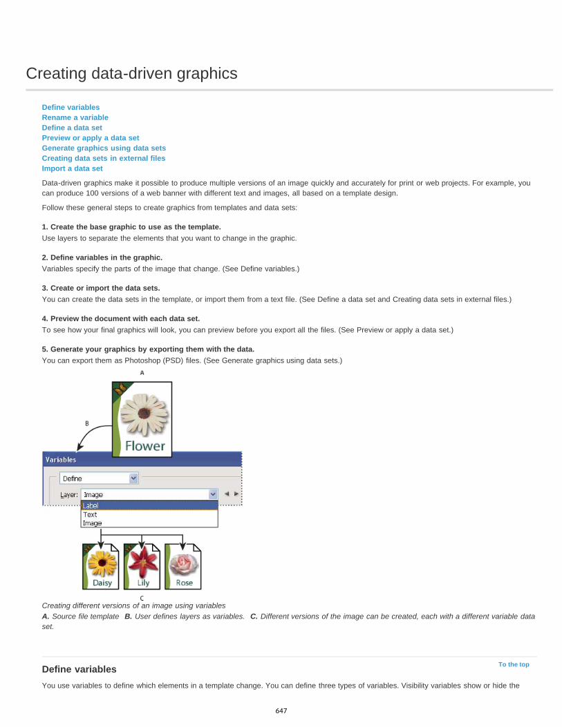
Creating data-driven graphics
To the top
Define variablesRename a variableDefine a data setPreview or apply a data setGenerate graphics using data setsCreating data sets in external filesImport a data set
Data-driven graphics make it possible to produce multiple versions of an image quickly and accurately for print or web projects. For example, youcan produce 100 versions of a web banner with different text and images, all based on a template design.
Follow these general steps to create graphics from templates and data sets:
1. Create the base graphic to use as the template.Use layers to separate the elements that you want to change in the graphic.
2. Define variables in the graphic.Variables specify the parts of the image that change. (See Define variables.)
3. Create or import the data sets.You can create the data sets in the template, or import them from a text file. (See Define a data set and Creating data sets in external files.)
4. Preview the document with each data set.To see how your final graphics will look, you can preview before you export all the files. (See Preview or apply a data set.)
5. Generate your graphics by exporting them with the data.You can export them as Photoshop (PSD) files. (See Generate graphics using data sets.)
Creating different versions of an image using variablesA. Source file template B. User defines layers as variables. C. Different versions of the image can be created, each with a different variable dataset.
Define variablesYou use variables to define which elements in a template change. You can define three types of variables. Visibility variables show or hide the
647

To the top
content of a layer. Pixel Replacement variables replace the pixels in the layer with pixels from another image file. Text Replacement variablesreplace a string of text in a type layer.
Note: GoLive recognizes all text and visibility variables, but not Pixel Replacement variables.
Two versions of an image based on the same templateA. Visibility variable B. Pixel Replacement variable C. Text Replacement variable
You cannot define variables for the Background layer.
1. Choose Image > Variables > Define.2. Select a layer from the Layer pop-up menu that contains the content you want to define as a variable.3. Select one or more types of variables:
Visibility Shows or hides the content of the layer.
Pixel Replacement Replaces the pixels in the layer with pixels from another image file.
Text Replacement Replaces a string of text in a type layer.
4. Do one of the following:
Choose Name and enter a name for the variable. Variable names must begin with a letter, underscore, or colon and cannot containspaces or special characters (except for periods, hyphens, underscores, and colons).
Choose an existing variable from the Name pop-up menu to link this layer to. Layers linked to the same variable are shown next to theName menu, along with the link icon.
5. For Pixel Replacement variables, set the following options.
Choose a method for scaling the replacement image: Fit scales the image so that it fits in the bounding box (which may leave parts ofthe bounding box empty), Fill scales the image so that it fills the bounding box entirely (which may cause the image to extend beyondthe bounding box), As Is applies no scaling to the image, and Conform scales the image non-proportionally so that it fits in the boundingbox.
Click a handle on the alignment icon to choose an alignment for placing the image inside the bounding box. (This option is notavailable for Conform.)
Select Clip To Bounding Box to clip areas of the image that do not fit in the bounding box. This option is available only when the Fill orAs Is replacement method is selected. (This option is not available for Conform.)
6. To define variables for another layer, choose a layer from the Layer pop-up menu. An asterisk appears next to the name of a layer thatcontains variables. You can use the navigation arrows to move between layers.
7. Click OK.
Rename a variable
648

To the top
To the top
To the top
To the top
1. Choose Image > Variables > Define.2. Choose the layer that contains the variable from the Layer pop-up menu.3. To rename the variable, enter a name in the Name text box. Variable names must begin with a letter, underscore, or colon and cannot
contain spaces or special characters (except for periods, hyphens, underscores, and colons).4. To remove the variable, deselect it.
Define a data setA data set is a collection of variables and associated data. You define a data set for each version of the graphic that you want to generate.
1. Do one of the following:
Choose Image > Variables > Data Sets.
If the Variables dialog box is open, choose Data Sets from the pop-up menu at the top of the dialog box, or click Next.
Note: You must define at least one variable before you can edit the default data set.
2. Click the New Data Set button .3. Select a variable from the Name pop-up menu or the list at the bottom of the dialog box.4. Edit the variable data:
For Visibility variables , select Visible to show the layer’s content or Invisible to hide the layer’s content.
For Pixel Replacement variables , click Select File and select a replacement image file. Click Do Not Replace before the data set isapplied to leave the layer in its current state.
Note: Do Not Replace does not reset the file to its original state if another replacement has been applied previously.
For Text Replacement variables , enter a text string in the Value text box.
5. Define additional data sets for each version of the graphic you want to generate.
You can edit, rename, or delete the data set later by first choosing it from the Data Set pop-up menu and editing its options. Use the arrow iconsto move between data sets. Click the Delete icon to delete a data set.
Preview or apply a data setYou can apply a data set’s contents to the base image while leaving all the variables and data sets intact. This changes the look of the PSDdocument to contain the values of the data set. You can also preview how each version of your graphic will look with each data set.
Note: Applying a data set overwrites your original document. Choose Image > Apply Data Set. Select the data set from the list and preview the image in the document window. To apply the data set, click
Apply. Click cancel if you are previewing and don’t want to change the base image.You can also apply and preview a data set in the Data Set page of the Variables dialog box.
Generate graphics using data setsAfter you define variables and one or more data sets, you can output, in batch mode, images using the data set values. You can output images asPSD files.
1. Choose File > Export > Data Sets As Files.2. Enter a base name for all files generated. You may create your own file-naming scheme if you want.3. Click the Select Folder button to select a destination directory for your files.4. Choose data sets to export.5. Click OK.
Creating data sets in external filesYou can quickly create a large number of data sets by creating an external text file that contains all the variable information and loading that fileinto a PSD document containing variables. One method is to enter your data into a text file or Microsoft Excel spreadsheet and then export it to atab or comma-separated file.
The syntax of the external text file is as follows (where each line that starts with “Variable” or “Value” is an entire line by itself in your file):
VariableName1<sep>VariableName2<sep> <sep>VariableNameN <nl> Value1-1<sep>Value2-1<sep><sep>ValueN-1<nl>
649
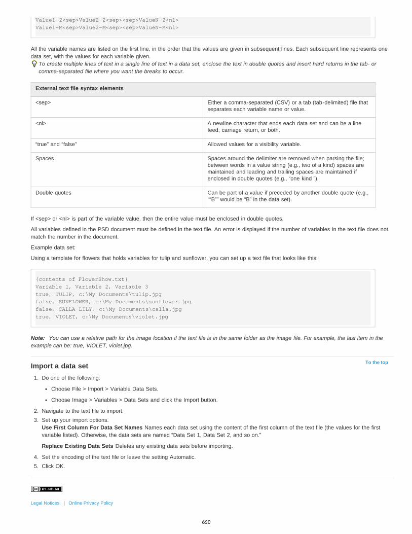
To the top
Value1-2<sep>Value2-2<sep><sep>ValueN-2<nl> Value1-M<sep>Value2-M<sep><sep>ValueN-M<nl>
All the variable names are listed on the first line, in the order that the values are given in subsequent lines. Each subsequent line represents onedata set, with the values for each variable given.
To create multiple lines of text in a single line of text in a data set, enclose the text in double quotes and insert hard returns in the tab- orcomma-separated file where you want the breaks to occur.
External text file syntax elements
<sep> Either a comma-separated (CSV) or a tab (tab-delimited) file thatseparates each variable name or value.
<nl> A newline character that ends each data set and can be a linefeed, carriage return, or both.
“true” and “false” Allowed values for a visibility variable.
Spaces Spaces around the delimiter are removed when parsing the file;between words in a value string (e.g., two of a kind) spaces aremaintained and leading and trailing spaces are maintained ifenclosed in double quotes (e.g., “one kind ”).
Double quotes Can be part of a value if preceded by another double quote (e.g.,““B”” would be “B” in the data set).
If <sep> or <nl> is part of the variable value, then the entire value must be enclosed in double quotes.
All variables defined in the PSD document must be defined in the text file. An error is displayed if the number of variables in the text file does notmatch the number in the document.
Example data set:
Using a template for flowers that holds variables for tulip and sunflower, you can set up a text file that looks like this:
{contents of FlowerShow.txt} Variable 1, Variable 2, Variable 3 true, TULIP, c:\My Documents\tulip.jpg false, SUNFLOWER, c:\My Documents\sunflower.jpg false, CALLA LILY, c:\My Documents\calla.jpg true, VIOLET, c:\My Documents\violet.jpg
Note: You can use a relative path for the image location if the text file is in the same folder as the image file. For example, the last item in theexample can be: true, VIOLET, violet.jpg.
Import a data set1. Do one of the following:
Choose File > Import > Variable Data Sets.
Choose Image > Variables > Data Sets and click the Import button.
2. Navigate to the text file to import.3. Set up your import options.
Use First Column For Data Set Names Names each data set using the content of the first column of the text file (the values for the firstvariable listed). Otherwise, the data sets are named “Data Set 1, Data Set 2, and so on.”
Replace Existing Data Sets Deletes any existing data sets before importing.
4. Set the encoding of the text file or leave the setting Automatic.5. Click OK.
Legal Notices | Online Privacy Policy
650

Adding conditional actions | CC, CS6
Twitter™ and Facebook posts are not covered under the terms of Creative Commons.
Legal Notices | Online Privacy Policy
Note:
To the top
Conditional actions let you build actions that choose what to do based on one of several different conditions. First, you choose a condition andthen, optionally specify an action that plays if the document meets the condition. Then, you optionally specify an action that plays if the documentdoes not meet the condition.
To insert a conditional action step into an action that you're recording or editing:
1. Make sure that the actions you will be referencing are in the same actions set.
2. Choose Insert Conditional from the Actions panel menu.
3. In the Conditional Action dialog box, choose a condition from the If Current menu.
4. Choose actions from the Then Play Action menu and the Else Play Action menu, and then, click OK.
You can also choose None in one of the menus, but not both. You can run an action only if a particular condition is false by choosing Noneas the Then Play Action and choosing the desired action as the Else Play Action.
For more information, see About actions and the Actions panel and Creating actions.
There is a Conditional Mode Change command to specify conditions for a color mode change step in an action. Using this command canprevent an error where a file is not in the source mode specified by the action.
Testing the opposite of what's in the conditionThere might be instances when you want to test the opposite of what's in a condition.
For example, suppose you want "Action 1" to play when when the frontmost document is non-square. You would specify the conditional: "IfCurrent Document is Square, Then Play Action None, Else Play Action "Action 1."
To test for the opposite of a particular condition, swap the "Then" and "Else" actions.
651
Recording tools in actions | CC, CS6
Twitter™ and Facebook posts are not covered under the terms of Creative Commons.
Legal Notices | Online Privacy Policy
Photoshop lets you record tools such as the brush tool in your action. To enable this feature, choose Allow Tool Recording from the Actions panelmenu.
A couple of items to keep in mind:
When recording a tool, choose your brush as part of the action or Photoshop uses the currently selected brush.If you are recording the action to play back at a different size, set Photoshop's measurement units to percentage and don’t define the brushsize as part of a brush preset.
For more information, see About actions and the Actions panel and Creating actions.
652

Adding a conditional mode change to an action
To the top
Add a conditional mode change to an action
Add a conditional mode change to an actionYou can specify conditions for a mode change so that the conversion can occur during an action, which is a series of commands appliedsequentially to a single file or a batch of files. When a mode change is part of an action, an error can occur if the file being opened is not in thesource mode specified in the action. For example, suppose one step in an action is to convert an image with a source mode of RGB to a targetmode of CMYK. Applying this action to an image in Grayscale mode, or any other source mode besides RGB, results in an error.
When you record an action, you can use the Conditional Mode Change command to specify one or more modes for the source mode and a modefor the target mode.
1. Start recording an action.2. Choose File > Automate > Conditional Mode Change.3. In the Conditional Mode Change dialog box, select one or more modes for the source mode. Use the All or None buttons to select all
possible modes or no mode.4. Choose a target mode from the Mode pop-up menu.5. Click OK. The conditional mode change appears as a new step in the Actions panel.
More Help topicsAdding conditional actions | Creative Cloud
Legal Notices | Online Privacy Policy
653

Web graphics
654
Copy CSS from layers | CC, CS6
Twitter™ and Facebook posts are not covered under the terms of Creative Commons.
Legal Notices | Online Privacy Policy
Note:
Copy CSS generates Cascading Style Sheet (CSS) properties from shape or text layers. The CSS is copied to the clipboard and can be pastedinto a style sheet. For shapes it captures values for the following:
sizepositionstroke color
fill color (including gradients)drop shadow
For text layers, Copy CSS also captures the following values:
font familyfont sizefont weight
line heightunderlinestrikethrough
superscriptsubscripttext alignment
Copying CSS from a layer group containing shapes or text creates a class for each layer as well as a Group class. The Group class represents aparent div containing child divs that correspond to the layers in the group. The top/left values for the child divs are in relation to the parent div.
The Copy CSS command does not work with Smart Objects or when selecting multiple shape/text layers that are not grouped.
1. In the Layers panel, do one of the following:
Right-click a shape/text layer or layer group and choose Copy CSS from the context menu.Select a shape/text layer or layer group and choose Copy CSS from the Layers panel menu.
2. Paste the code into your style sheet document.
For more information on creating web pages with Photoshop, see Slicing web pages.
655

Creating web photo galleries
To the top
To the top
About web photo galleriesCreate a web photo galleryMaking sure that your colors matchWeb photo gallery optionsWeb photo gallery stylesAbout customizing web photo gallery stylesCustomize or create a web photo gallery styleWeb photo gallery style tokens
To create web galleries with Photoshop CS5, see Create a web photo gallery in Adobe Bridge Help. To use the older, optional Web PhotoGallery plug-in described in the topics below, first download and install it for Windows or Mac OS.
About web photo galleriesA web photo gallery is a web site that features a home page with thumbnail images and gallery pages with full-size images. Each page containslinks that allow visitors to navigate the site. For example, when a visitor clicks a thumbnail image on the home page, the associated full-size imageis loaded into a gallery page. You use the Web Photo Gallery command to automatically generate a web photo gallery from a set of images.
Web photo gallery home page
Photoshop provides a variety of styles for your gallery, which you can select using the Web Photo Gallery command. If you are an advanced userwho knows HTML, you can create a new style or customize a style by editing a set of HTML template files.
Each template for gallery styles comes with different options. If you’re using a preset style, some options may be dimmed, or unavailable in thatparticular style.
Create a web photo gallery
Create web galleries using Adobe BridgeAdobe Bridge provides updated web gallery features. For instructions, see Create a web photo gallery in Adobe Bridge Help, or view the tutorialsbelow.
Adobe recommends Have a tutorial you'd like to share?
Video tutorial: Contact sheets and webgalleries in CS5Richard HarringtonWalk through the process in Adobe Bridge.
Book excerpt: Create galleries with AdobeBridgeConrad ChavezArrange and output web galleries using the latest CS5features.
656
To the top
To the top
Use the older, optional Photoshop plug-in
1. Download and install the older Web Photo Gallery plug-in for Windows or Mac OS.
2. Run Photoshop in 32-bit mode (64-bit Mac OS only).
3. (Optional) Select the files or folder you want to use in Adobe Bridge.
Your images will be presented in the order in which they’re displayed in Bridge. If you’d rather use a different order, change the order inBridge.
4. Do one of the following:
In Adobe Bridge, choose Tools > Photoshop > Web Photo Gallery.
In Photoshop, choose File > Automate > Web Photo Gallery.
5. Choose a style for the gallery from the Styles pop-up menu. A preview of the home page for the chosen style appears in the dialog box.
6. (Optional) Enter an e-mail address as the contact information for the gallery.
7. Choose the source files for your gallery from the Use menu.
Selected Images From Bridge Uses images you selected before opening the Web Photo Gallery dialog box.
Folder Uses images from folders you select using the Browse (Windows) or Choose (Mac OS) buttons. Select Include All Subfolders toinclude images inside any subfolders of the selected folder.
8. Click Destination, and then select a folder in which to store the images and HTML pages for the gallery. Then click OK (Windows) orChoose (Mac OS).
9. Select formatting options for the web gallery. Choose from the Options menu to display each set of options. See Web photo gallery options.
10. Click OK. Photoshop places the following HTML and JPEG files in your destination folder:
A home page for your gallery named index.htm or index.html, depending on the Extension options. Open this file in any web browser topreview your gallery.
JPEG images inside an images subfolder.
HTML pages inside a pages subfolder.
JPEG thumbnail images inside a thumbnails subfolder.
Making sure that your colors matchIf you work with photos in a wide-gamut color working space such as ProPhoto RGB or Adobe RGB, image colors may change when viewed in aweb gallery by a browser that doesn’t read embedded color profiles. If this happens, try converting the image profiles to sRGB (which mostbrowsers use as a default) before optimizing them or including them in a Web Photo Gallery. Convert them to sRGB in one of the following ways.It is a good idea to work with a copy of the images.
To convert a single image, choose Edit >Convert To Profile and then choose sRGB. See Assign or remove a color profile (Illustrator,Photoshop).
To convert a folder of images, use the Image Processor. Choose File > Scripts > Image Processor. See Convert files with the ImageProcessor.
If you use the Image Processor, you can save the files directly to JPEG format in the size that you want them. If you do so, make sure to turnResize Images off in the Large Image options.
Web photo gallery optionsGeneral Options for file extensions, encoding, and metadata.
Extension Uses either .htm or .html as the filename extension.Use UTF 8 Encoding For URL Uses UTF-8 encoding.Add Width And Height Attributes For Images Specifies dimensions, shortening download time.Preserve All Metadata Maintains metadata info.
Banner Text options for the banner that appears on each page in the gallery. Enter text for each of these:
Site Name The name of the gallery.Photographer The name of the person or organization receiving credit for the photos in the gallery.Contact Info The contact information for the gallery, such as a telephone number or a business address.Date The date appearing on each page of the gallery. By default, Photoshop uses the current date.Font and Font Size (Available for some site styles) Options for the banner text.
657

To the top
To the top
Large Images Options for the main images that appear on each gallery page.
Add numeric links (Available for some site styles) Places a numeric sequence (starting at 1, ending with the total number of pages in thegallery) running horizontally at the top of each gallery page. Each number is a link to the respective page.Resize Images Resizes the source images for placement on the gallery pages. Choose a size from the pop-up menu or enter a size inpixels. For Constrain, choose which dimensions of the image you want to constrain during resizing. For JPEG Quality, choose an optionfrom the pop-up menu, enter a value between 0 and 12, or drag the slider. The higher the value, the better the image quality and thelarger the file.Note: Photoshop uses the default image interpolation method set in preferences. Choose Bicubic Sharper as the default for best resultswhen reducing image size.Border Size Specifies the width, in pixels, of the border around the image.Titles Use (Available for some site styles) Specifies options for displaying captions under each image. Select Filename to display thefilename, or select Description, Credits, Title, and Copyright to display description text drawn from the File Info dialog box.Font and Font Size (Available for some site styles) Specify the font and size of the caption.
Thumbnails Options for the gallery home page, including the size of the thumbnail images.
Size Specifies the thumbnail size. Choose from the pop-up menu or enter a value in pixels for the width of each thumbnail.Columns and Rows Specify the number of columns and rows in which to display thumbnails on the home page. This option doesn’tapply to galleries that use the Horizontal Frame Style or Vertical Frame Style.Border Size Specifies the width, in pixels, of the border around each thumbnail.Titles Use (Available for some site styles) Specifies options for displaying captions under each thumbnail. Select Filename to display thefilename, or select Description, Credits, Title, and Copyright to display description text drawn from the File Info dialog box.Font and Font Size (Available for some site styles) Specify the font and size of the caption.
Custom Colors Options for colors of elements in the gallery. To change the color of an element, click its color swatch and then select a new colorfrom the Adobe Color Picker. You can change the background color of each page (Background option) and of the banner (Banner option).Security Displays text over each image as a theft deterrent.
Content Specifies the text to be displayed. Select Custom Text to enter customized text. Select Filename, Description, Credits, Title,or Copyright to display text drawn from the File Info dialog box.Font, Color, and Position Specify the font, color, and alignment of the caption.Rotate Place the text on the image at an angle.
Web photo gallery stylesTo create web galleries with Photoshop CS5, see Create a web photo gallery in Adobe Bridge Help. To use the older, optional Web PhotoGallery plug-in described below, first download and install it for Windows or Mac OS.
Photoshop provides a variety of styles for your web photo gallery. If you are an advanced user who knows HTML, you can create a new style orcustomize a style by editing a set of HTML template files.
The web photo gallery styles provided by Photoshop are stored in individual folders in the following locations:
Windows Program Files/Adobe/Adobe Photoshop CS5/Presets/Web Photo Gallery.Mac OS Adobe Photoshop CS5/Presets/Web Photo Gallery.The name of each folder in this location appears as an option in the Styles menu in the Web Photo Gallery dialog box. Each folder contains thefollowing HTML template files, which Photoshop uses to generate the gallery:
Caption.htm Determines the layout of the caption that appears below each thumbnail on the home page.FrameSet.htm Determines the layout of the frame set for displaying pages.IndexPage.htm Determines the layout of the home page.SubPage.htm Determines the layout of the gallery pages with full-size images.Thumbnail.htm Determines the layout of the thumbnails that appear on the home page.Each template file contains HTML code and tokens. A token is a text string that is replaced by Photoshop when you set its corresponding option inthe Web Photo Gallery dialog box. For example, a template file may contain the following TITLE element that uses a token as its enclosed text:
<TITLE>%TITLE%</TITLE>
When Photoshop generates the gallery using this template file, it replaces the token %TITLE% with the text that you entered for Site Name in theWeb Photo Gallery dialog box.
To better understand an existing style, you can open and study its HTML template files using an HTML editor. Because only standard ASCIIcharacters are required to create HTML documents, you can open, edit, and create these documents using a plain-text editor such as Notepad(Windows) or TextEdit (Mac OS).
About customizing web photo gallery stylesYou can customize an existing web photo gallery style by editing one or more of its HTML template files. When customizing a style, you need tofollow these guidelines so that Photoshop can generate the gallery correctly:
658
To the top
To the top
The style folder must contain these files: Caption.htm, IndexPage.htm, SubPage.htm, Thumbnail.htm, and FrameSet.htm.
You can rename the style folder but not the HTML template files in the folder.
You can have an empty Caption.htm file, and place the HTML code and tokens determining the layout of the caption in the Thumbnail.htmfile.
You can replace a token in a template file with the appropriate text or HTML code, so that an option is set through the template file ratherthan through the Web Photo Gallery dialog box. For example, a template file may contain a BODY element with the following backgroundcolor attribute that uses a token as its value:
bgcolor=%BGCOLOR%
To set the background color of the page to red, you can replace the token %BGCOLOR% with “FF0000.”
You can add HTML code and tokens to the template files. All tokens must be in uppercase characters, and begin and end with the percent(%) symbol.
Customize or create a web photo gallery style1. Locate the folder that stores the existing web photo gallery styles.2. Do one of the following:
To customize a style, create a copy of the style folder, and store it in the same location as the existing style folders.
To create a new style, create a new folder for the new style, and store it in the same location as the existing style folders.
The new or customized style (named for its folder) appears in the Styles menu in the Web Photo Gallery dialog box.
3. Using an HTML editor, do one of the following:
Customize the HTML template file.
Create the necessary HTML template files and store them inside the style folder.
When creating the template files, make sure that you follow the guidelines for customization outlined in About customizing web photo gallerystyles.
Important: When customizing or creating a template for a gallery style, you should place each of the following tokens on a separate line inthe HTML file: %CURRENTINDEX%, %NEXTIMAGE%, %NEXTINDEX%, %PAGE%, %PREVIMAGE%, and %PREVINDEX%. Whengenerating specific pages of a gallery, Photoshop skips lines in a template that contain tokens that don’t apply to those pages. For example,when Photoshop generates the first gallery page, it skips any line in the template that contains the %PREVIMAGE% token, whichdetermines the link to the previous gallery page. By keeping the %PREVIMAGE% token on a separate line, you ensure that Photoshopdoesn’t ignore other tokens in the template.
Web photo gallery style tokensPhotoshop uses tokens in the HTML template files to define a default web photo gallery style. Photoshop uses these tokens to generate a gallerybased on user input in the Web Photo Gallery dialog box.
When customizing or creating a gallery style, you can add any token to any HTML template file, with the exception of %THUMBNAILS% and%THUMBNAILSROWS%, which can appear only in the IndexPage.htm file. When adding a token, keep in mind that you may also need to addHTML code to the file so that the token is used correctly.
You can use the following tokens in the HTML template files:
%ALINK% Determines the color of active links.%ALT% Determines the name of an image file.%ANCHOR% Provides the ability to return to the thumbnail of the image the user is viewing, rather than the beginning of the index. This takeseffect when the user clicks the Home button.%BANNERCOLOR% Determines the color of the banner.%BANNERFONT% Determines the font of the banner text.%BANNERFONTSIZE% Determines the font size of the banner text.%BGCOLOR% Determines the background color.%CAPTIONFONT% Determines the font of the caption below each thumbnail on the home page.%CAPTIONFONTSIZE% Determines the font size of the caption.%CAPTIONTITLE% Inserts the document title for a caption from the file information.%CHARSET% Determines the character set used on each page.%CONTACTINFO% Determines the contact information for the gallery, such as phone number and location.%CONTENT_GENRATOR% Expands to “Adobe Photoshop CS5 Web Photo Gallery.”%COPYRIGHT% Inserts the copyright information for a caption from the file information.
659

%CREDITS% Inserts the credits for a caption from the file information.%CURRENTINDEX% Determines the link for the current home page.%CURRENTINDEXANCHOR% Resides in SubPage.htm and points to the first index page.%DATE% Determines the date that appears on the banner.%EMAIL% Determines the e-mail address contact information for the gallery.%FILEINFO% Determines the image file information for a caption.%FILENAME% Determines the filename of an image. Use this for metadata that appears as HTML text.%FILENAME_URL% Determines the URL filename of an image. Use this for URL filenames only.%FIRSTPAGE% Determines the link for the first gallery page that appears in the right frame of a frame set.%FRAMEINDEX% Determines the link for the home page that appears in the left frame of a frame set.%HEADER% Determines the title of the gallery.%IMAGEBORDER% Determines the border size of the full-size image on a gallery page.%IMAGE_HEIGHT% Enables the Add Width And Height Attributes For Images check box. This allows the user to download the attributes,reducing download time.%IMAGE_HEIGHT_NUMBER% This token is replaced by a numeral (only) representing the width of the image.%IMAGEPAGE% Determines the link to a gallery page.%IMAGE_SIZE% If the Resize Images box is selected, this token contains the image pixel value used in the Large Images panel. If the box is notselected, this token contains an empty string. This is useful for JavaScript in the templates, because it can show the maximum height and widthvalues for all images for the generated site.%IMAGESRC% Determines the URL for a full-size image on a gallery page.%IMAGE_WIDTH% Enables the Add Width And Height Attributes For Images check box. This allows the user to download the attributes, reducingdownload time.%IMAGE_WIDTH_NUMBER% This token is replaced by a numeral (only) representing the width of the image.%LINK% Determines the color of links.%NEXTIMAGE% Determines the link for the next gallery page.%NEXTIMAGE _CIRCULAR% Sets the link from large preview image to next large preview image.%NEXTINDEX% Determines the link for the next home page.%NUMERICLINKS% Inserts numbered links on subpages to all large preview images.%PAGE% Determines the current page location (for example, page 1 of 3).%PHOTOGRAPHER% Determines the name of the person or organization receiving credit for the photos in the gallery.%PREVIMAGE% Determines the link for the previous gallery page.%PREVINDEX% Determines the link for the previous home page.%SUBPAGEHEADER% Determines the title of the gallery.%SUBPAGETITLE% Determines the title of the gallery.%TEXT% Determines the text color.%THUMBBORDER% Determines the size of thumbnail borders.%THUMBNAIL_HEIGHT% Enables the Add Width And Height Attributes For Images check box. This allows the user to download the attributes,reducing download time.%THUMBNAIL_HEIGHT_NUMBER% This token is replaced with a numeral (only) representing the height of the thumbnail.%THUMBNAILS% This token is replaced with thumbnails using the Thumbnail.htm file for the frame styles. You must place this token alone in asingle, nonbreaking line in the HTML file.%THUMBNAIL_SIZE% Contains the thumbnail pixel value in the Thumbnails panel. This is useful for JavaScript in the templates, as it can showthe maximum height and width values for all thumbnails for the generated site.%THUMBNAILSRC% Determines the link to a thumbnail.%THUMBNAILSROWS% This token is replaced with rows of thumbnails using the Thumbnail.htm file for the nonframe styles. You must place thistoken alone in a single, nonbreaking line in the HTML file.%THUMBNAIL_WIDTH% Enables the Add Width And Height Attributes For Images check box. This allows the user to download the attributes,reducing download time.%THUMBNAIL_WIDTH_NUMBER% This token is replaced by a numeral (only) representing the width of the thumbnail.%TITLE% Determines the title of the gallery.%VLINK% Determines the color of visited links.
Legal Notices | Online Privacy Policy
660
Working with web graphics
To the top
To the top
Creating rollover imagesExport to ZoomifyWorking with hexadecimal color values
Note: For detailed instructions, click the links below. To ask questions, request features, or report problems, visit feedback.photoshop.com.The Photoshop web tools make it easy to build component pieces for your web pages or to output complete web pages in preset or customizedformats.
Use layers and slices to design web pages and web page interface elements. (See Layers and Slicing web pages.)
Use layer comps to experiment with different page compositions or to export variations of a page. (See Layer comps.)
Create rollover text or button graphics to import into Dreamweaver or Flash.
Create web animations with the Animation panel, then export them as animated GIF images or QuickTime files. See Creating frameanimations.
Use Adobe Bridge to create a web photo gallery to quickly turn a set of images into an interactive web site, using a variety of professional-looking templates.
For a video on designing web sites with Photoshop and Dreamweaver, see www.adobe.com/go/lrvid4043_dw.
Creating rollover imagesA rollover is a button or image on a web page that changes when the mouse is over it. To create a rollover, you need at least two images: aprimary image for the normal state and a secondary image for the changed state.
Photoshop provides a number of useful tools for creating rollover images:
Use layers to create primary and secondary images. Create content on one layer, then duplicate the layer and edit it to create similar contentwhile maintaining alignment between layers. When creating a rollover effect, you can change the layer’s style, visibility or position, make coloror tonal adjustments, or apply filter effects. See Duplicate layers.
You can also use layer styles to apply effects, such as color overlays, drop shadows, glow, or emboss, to the primary layer. To create arollover pair, turn the layer style on or off and save the image in each state. See Layer effects and styles.
Use preset button styles from the Styles panel to quickly create rollover buttons with normal, mouseover, and mousedown states. Draw abasic shape with the rectangle tool and apply a style, such as Beveled Normal, to automatically turn the rectangle into a button. Then copythe layer and apply other preset styles, like Beveled Mouseover, to create additional button states. Save each layer as a separate image tocreate a finished rollover button set.
Use the Save For Web & Devices dialog box to save rollover images in a web-compatible format and with an optimized file size. SeeOptimizing images.
When you save rollover images, use a naming convention to distinguish the primary (non-rollover state) image from the secondary(rollover state) image.
After creating a rollover image set in Photoshop, use Dreamweaver to place the images on a web page and automatically add the JavaScript codefor the rollover action.
For a video on designing web sites with Photoshop and Dreamweaver, see www.adobe.com/go/lrvid4043_dw.
Export to ZoomifyYou can post high-resolution images on the web that viewers can pan and zoom to see more detail. The basic-size image downloads in the sametime as an equivalent size JPEG file. Photoshop exports the JPEG files and HTML file that you can upload to your web server.
1. Choose File > Export > Zoomify and set export options.Template Sets the background and navigation for the image viewed in the browser.
Output Location Specifies the location and name of the file.
Image Tile Options Specifies the quality of the image.
Browser Options Sets the pixel width and height for the base image in the viewer’s browser.
2. Upload the HTML and image files to your web server.
661
To the top
For a video on Zoomify, see www.adobe.com/go/vid0003.
Working with hexadecimal color valuesPhotoshop can display the hexadecimal values of image colors or copy a color’s hexadecimal value for use in an HTML file.
View hexadecimal color values in the Info panel1. Choose Window > Info or click the Info panel tab to view the panel.2. Choose Panel Options from the panel menu. Under First Color Readout or Second Color Readout, choose Web Color from the Mode menu
and click OK.3. Position the pointer over the color for which you want to view hexadecimal values.
Copy a color as a hexadecimal valuePhotoshop copies colors either as an HTML COLOR attribute containing the hexadecimal value (color=#xxyyzz), or as the hexadecimal valuealone.
1. Do one of the following:
With the Eyedropper tool, move the pointer over the color that you want to copy. Right-click (Windows) or Control-click (Mac OS), andchoose Copy Color As HTML or Copy Color’s Hex Code.
Set the foreground color using the Color panel, the Swatches panel, or the Adobe Color Picker. From the Color panel menu, chooseCopy Color As HTML or Copy Color’s Hex Code.
In the Save For Web dialog box, click the color swatch or choose Matte > Other. In the Adobe Color Picker, right-click the hexadecimalvalue, and choose Copy.
2. Open the desired file in an HTML editing application, and choose Edit > Paste.
More Help topics Save For Web & Devices overview
Web graphic formats
Create a web photo gallery
Create a rollover image
Legal Notices | Online Privacy Policy
662
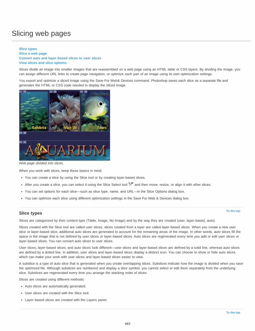
Slicing web pages
To the top
To the top
Slice typesSlice a web pageConvert auto and layer-based slices to user slicesView slices and slice options
Slices divide an image into smaller images that are reassembled on a web page using an HTML table or CSS layers. By dividing the image, youcan assign different URL links to create page navigation, or optimize each part of an image using its own optimization settings.
You export and optimize a sliced image using the Save For Web& Devices command. Photoshop saves each slice as a separate file andgenerates the HTML or CSS code needed to display the sliced image.
Web page divided into slices.
When you work with slices, keep these basics in mind:
You can create a slice by using the Slice tool or by creating layer-based slices.
After you create a slice, you can select it using the Slice Select tool and then move, resize, or align it with other slices.
You can set options for each slice—such as slice type, name, and URL—in the Slice Options dialog box.
You can optimize each slice using different optimization settings in the Save For Web & Devices dialog box.
Slice typesSlices are categorized by their content type (Table, Image, No Image) and by the way they are created (user, layer-based, auto).
Slices created with the Slice tool are called user slices; slices created from a layer are called layer-based slices. When you create a new userslice or layer-based slice, additional auto slices are generated to account for the remaining areas of the image. In other words, auto slices fill thespace in the image that is not defined by user slices or layer-based slices. Auto slices are regenerated every time you add or edit user slices orlayer-based slices. You can convert auto slices to user slices.
User slices, layer-based slices, and auto slices look different—user slices and layer-based slices are defined by a solid line, whereas auto slicesare defined by a dotted line. In addition, user slices and layer-based slices display a distinct icon. You can choose to show or hide auto slices,which can make your work with user-slices and layer-based slices easier to view.
A subslice is a type of auto slice that is generated when you create overlapping slices. Subslices indicate how the image is divided when you savethe optimized file. Although subslices are numbered and display a slice symbol, you cannot select or edit them separately from the underlyingslice. Subslices are regenerated every time you arrange the stacking order of slices.
Slices are created using different methods:
Auto slices are automatically generated.
User slices are created with the Slice tool.
Layer-based slices are created with the Layers panel.
663

To the top
To the top
Slice a web pageYou can use the slice tool to draw slice lines directly on an image, or design your graphic using layers, and then create slices based on the layers.
Create a slice with the Slice tool1. Select the Slice tool . (Press the C key to cycle through tools grouped with the Crop too.)
Any existing slices automatically appear in the document window.
2. Choose a style setting in the options bar:Normal Determines slice proportions as you drag.
Fixed Aspect Ratio Sets a height-to-width ratio. Enter whole numbers or decimals for the aspect ratio. For example, to create a slice twiceas wide as it is high, enter 2 for the width and 1 for the height.
Fixed Size Specifies the slice’s height and width. Enter pixel values in whole numbers.
3. Drag over the area where you want to create a slice. Shift-drag to constrain the slice to a square. Alt-drag (Windows) or Option-drag(Mac OS) to draw from the center. Use View > Snap To to align a new slice to a guide or another slice in the image. See Move, resize, andsnap user slices.
Create slices from guides1. Add guides to an image.2. Select the Slice tool, and click Slices From Guides in the options bar.
When you create slices from guides, any existing slices are deleted.
Create a slice from a layerA layer-based slice encompasses all the pixel data in the layer. If you move the layer or edit the layer’s content, the slice area automaticallyadjusts to include the new pixels.
A layer-based slice is updated when the source layer is modified.
Layer-based slices are less flexible than user slices; however, you can convert (“promote”) a layer-based slice to a user slice. See Convert autoand layer-based slices to user slices.
1. Select a layer in the Layers panel.2. Choose Layer > New Layer-based Slice.
Don’t use a layer-based slice when you plan to move the layer over a large area of the image during an animation, because the slicedimension may exceed a useful size.
Convert auto and layer-based slices to user slicesA layer-based slice is tied to the pixel content of a layer, so the only way to move, combine, divide, resize, and align it is to edit the layer—unlessyou convert it to a user slice.
All auto slices in an image are linked and share the same optimization settings. If you want to set different optimization settings for an auto slice,you need to promote it to a user slice.
1. Using the Slice Select tool , select one or more slices to convert.2. Click Promote in the options bar.
You can promote an auto slice in the Save For Web & Devices dialog box by unlinking it. See Work with slices in the Save For Web &Devices dialog box
View slices and slice optionsYou can view slices in Photoshop and the Save For Web & Devices dialog box. The following characteristics can help you identify and differentiate
664

between slices:
Slice lines Define the boundary of the slice. Solid lines indicate that the slice is a user slice or layer-based slice; dotted lines indicate that theslice is an auto slice.Slice colors Differentiate user slices and layer-based slices from auto slices. By default, user slices and layer-based slices have blue symbols,and auto slices have gray symbols.In addition, the Save For Web & Devices dialog box uses color adjustments to dim unselected slices. These adjustments are for display purposesonly and do not affect the color of the final image. By default, the color adjustment for auto slices is twice the amount of that for user slices.
Slice numbers Slices are numbered from left to right and top to bottom, beginning in the upper-left corner of the image. If you change thearrangement or total number of slices, slice numbers are updated to reflect the new order.Slice badges The following badges, or icons, indicate certain conditions.
User slice has Image content. User slice has No Image content. Slice is layer-based.
Show or hide slice boundaries Choose View > Show > Slices. To hide and show slices along with other items, use the Extras command. See Show or hide Extras.
Show or hide auto slices Do one of the following:
Select the Slice Select tool , and click Show Auto Slices or Hide Auto Slices in the options bar.
Choose View > Show > Slices. Auto slices appear with the rest of your slices.
Show or hide slice numbers1. Do one of the following:
In Windows, choose Edit > Preferences > Guides, Grid & Slices.
In Mac OS, choose Photoshop > Preferences > Guides, Grid & Slices.
2. Under Slices, click Show Slice Numbers.
Change the color of slice lines1. In Windows, choose Edit > Preferences > Guides, Grid & Slices; in Mac OS, choose Photoshop > Preferences > Guides, Grid & Slices.2. Under Slice Lines, choose a color from the Line Color menu.
After the color change, selected slice lines are automatically displayed in a contrasting color.
More Help topics Work with slices in the Save For Web & Devices dialog box
Legal Notices | Online Privacy Policy
665
Modifying slice layout
To the top
To the top
Select one or more slicesMove, resize, and snap user slicesDivide user slices and auto slicesDuplicate slicesCopy and paste a sliceCombine slicesChange the stacking order of slicesAlign and distribute user slicesDelete a sliceLock all slices
Select one or more slicesDo one of the following:
Select the Slice Select tool and click the slice in the image. When working with overlapping slices, click the visible section of anunderlying slice to select it.Select the Slice Select tool, and Shift-click to add slices to the selection.Select the Slice Select tool in the Save for Web & Devices dialog box, and click in an auto slice or outside the image area, and drag acrossthe slices you want to select. (Clicking in a user slice and dragging moves the slice.)Choose File > Save For Web & Devices. In the dialog box, use the Slice tool to select a slice.
When using either the Slice tool or the Slice Select tool, you can switch from one tool to the other by holding down Ctrl (Windows) orCommand (Mac OS).
Move, resize, and snap user slicesYou can move and resize user slices in Photoshop, but not in the SaveFor Web & Devices dialog box.
Move or resize a user slice1. Select one or more user slices.2. Do one of the following:
To move a slice, move the pointer inside the slice selection border, and drag the slice to a new position. Press Shift to restrict movementto a vertical, horizontal, or 45° diagonal line.
To resize a slice, grab a side or a corner handle of the slice, and drag. If you select and resize adjacent slices, common edges shared bythe slices are resized together.
Resize or move a user slice using numeric coordinates1. Select one or more user slices.2. Click the Options button in the options bar. You can also double-click a slice to show the options.3. In the Dimensions area of the Slice Options dialog box, change one or more of the following options:
X Specifies the distance in pixels between the left edge of the slice and the origin of the ruler in the document window.
Y Specifies the distance in pixels between the top edge of the slice and the origin of the ruler in the document window.Note: The default origin of the ruler is the upper-left corner of the image.
W Specifies the width of the slice.
H Specifies the height of the slice.
Snap slices to a guide, user slice, or other object1. Select the options you want from the View > Snap To submenu.2. Choose View > Snap. A check mark indicates that the option is turned on.3. Move your selected slices as desired. The slices snap to any of your chosen objects within 4 pixels.
666
To the top
To the top
To the top
To the top
Divide user slices and auto slicesUse the Divide Slice dialog box to divide slices horizontally, vertically, or both. Divided slices are always user slices, regardless of whether theoriginal is a user slice or an auto slice.
Note: You cannot divide layer-based slices.1. Select one or more slices.
2. With the Slice Select tool , click Divide in the options bar.3. Select Preview in the Divide Slice dialog box to preview the changes.4. In the Divide Slice dialog box, select one or both of the following options:
Divide Horizontally Into Divides the slice lengthwise.
Divide Vertically Into Divides the slice widthwise.
5. Define how you want to divide each selected slice:
Select and enter a value for Slices Down or Slices Across to divide each slice evenly into the specified number of slices.
Select and enter a value for Pixels Per Slice to create slices with the specified number of pixels. If the slice cannot be divided evenly bythat number of pixels, the remainder is made into another slice. For example, if you divide a slice that is 100 pixels wide into three newslices each 30 pixels wide, the remaining 10-pixel-wide area becomes a new slice.
6. Click OK.
Duplicate slicesYou can create a duplicate slice with the same dimensions and optimization settings as the original. If the original slice is a linked user slice, theduplicate is linked to the same collection of linked slices. Duplicate slices are always user slices, regardless of whether the original is a user slice,a layer-based slice, or an auto slice.
1. Select a slice or multiple slices.2. Alt-drag (Windows) or Option-drag (Mac OS) from inside the selection.
Copy and paste a sliceYou can copy and paste a selected slice within an image, into another image, or into another application such as Dreamweaver. Copying a slicecopies all layers within the bounds of the slice (not just the active layer).
1. Select one or more slices with the Slice Select tool .2. Choose Edit > Copy.
Note: A slice can’t be copied if there is an active selection in the document (a marquee pixel selection or a selected path).3. Do one of the following:
If you want to paste the slice into another image, open and display that image.
If pasting into Dreamweaver, make your Dreamweaver document the active window.
4. Choose Edit > Paste. A new layer is created when a slice is pasted into a Photoshop image.Note: A slice copied into Dreamweaver retains information about the filename and path of the original Photoshop source file. To view thisinformation in Dreamweaver, right-click (Windows) or Ctrl+click (Mac OS) the image and choose Design Notes, then locate the FilePathSrcfield on the All Info tab.
For a tutorial on copying and pasting between different applications, including Dreamweaver and Photoshop, seewww.adobe.com/go/vid0193.
Combine slicesYou can combine two or more slices into a single slice. Photoshop determines the dimensions and position of the resulting slice from the rectanglecreated by joining the outer edges of the combined slices. If the combined slices are not adjacent or have different proportions or alignments, thenewly combined slice may overlap other slices.
The combined slice takes the optimization settings of the first slice in the series of slices you select. A combined slice is always a user slice,regardless of whether the original slices include auto slices.
Note: You cannot combine layer-based slices.1. Select two or more slices.2. Right-click (Windows) or Ctrl-click (Mac OS) and choose Combine Slices.
667

To the top
To the top
To the top
To the top
Change the stacking order of slicesWhen slices overlap, the last slice you create is the top slice in the stacking order. You can change the stacking order to gain access to underlyingslices. You can specify which slice is on the top and bottom of the stack and move slices up or down in the stacking order.
Note: You cannot arrange the stacking order of auto slices.1. Select a slice or multiple slices.
2. Choose the Slice Select tool , and click a stacking order option in the options bar.
Stacking order optionsA. Bring To Front B. Bring Forward C. Send Backward D. Send To Back
Align and distribute user slicesYou can align user slices along an edge or their centers, and distribute user slices evenly along the vertical or horizontal axis. By aligning anddistributing user slices, you can eliminate unneeded auto slices and generate a smaller, more efficient HTML file.
Note: To align or distribute layer-based slices, align or distribute the contents of the layers.1. Select the user slices you want to align.
2. Choose the Slice Select tool , and select an option in the options bar.
Alignment optionsA. Top B. Vertical Centers C. Bottom D. Left E. Horizontal Centers F. Right
Distribute optionsA. Top B. Vertical Centers C. Bottom D. Left E. Horizontal Centers F. Right
Delete a sliceWhen you delete a user slice or layer-based slice, auto slices are regenerated to fill the document area.
Deleting a layer-based slice does not delete the associated layer; however, deleting the layer associated with a layer-based slice does delete thelayer-based slice.
Note: You cannot delete auto slices. If you delete all user slices and layer-based slices in an image, one auto slice covering the entire imageremains.
1. Select one or more slices.2. Choose the Slice or Slice Select tool and press the Backspace key or the Delete key.3. To delete all user slices and layer-based slices, choose View > Clear Slices.
Lock all slicesLocking slices prevents you from resizing, moving, or otherwise changing them accidentally.
Choose View > Lock Slice.More Help topics
Work with slices in the Save For Web & Devices dialog box
Legal Notices | Online Privacy Policy
668
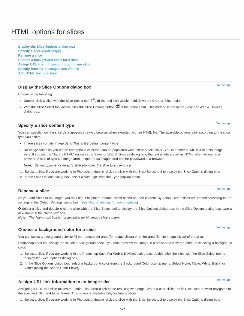
HTML options for slices
To the top
To the top
To the top
To the top
To the top
Display the Slice Options dialog boxSpecify a slice content typeRename a sliceChoose a background color for a sliceAssign URL link information to an Image sliceSpecify browser messages and Alt textAdd HTML text to a slice
Display the Slice Options dialog boxDo one of the following:
Double-click a slice with the Slice Select tool . (If the tool isn’t visible, hold down the Crop or Slice tool.)
With the Slice Select tool active, click the Slice Options button in the options bar. This method is not in the Save For Web & Devicesdialog box.
Specify a slice content typeYou can specify how the slice data appears in a web browser when exported with an HTML file. The available options vary according to the slicetype you select.
Image slices contain image data. This is the default content type.
No Image slices let you create empty table cells that can be populated with text or a solid color. You can enter HTML text in a No Imageslice. If you set the “Text is HTML” option in the Save for Web & Devices dialog box, the text is interpreted as HTML when viewed in abrowser. Slices of type No Image aren’t exported as images and can be previewed in a browser.
Note: Setting options for an auto slice promotes the slice to a user slice.
1. Select a slice. If you are working in Photoshop, double-click the slice with the Slice Select tool to display the Slice Options dialog box.2. In the Slice Options dialog box, select a slice type from the Type pop-up menu.
Rename a sliceAs you add slices to an image, you may find it helpful to rename slices based on their content. By default, user slices are named according to thesettings in the Output Settings dialog box. (See Output settings for web graphics.)
Select a slice and double-click the slice with the Slice Select tool to display the Slice Options dialog box. In the Slice Options dialog box, type anew name in the Name text box.Note: The Name text box is not available for No Image slice content.
Choose a background color for a sliceYou can select a background color to fill the transparent area (for Image slices) or entire area (for No Image slices) of the slice.
Photoshop does not display the selected background color—you must preview the image in a browser to view the effect of selecting a backgroundcolor.
1. Select a slice. If you are working in the Photoshop Save For Web & Devices dialog box, double-click the slice with the Slice Select tool todisplay the Slice Options dialog box.
2. In the Slice Options dialog box, select a background color from the Background Color pop-up menu. Select None, Matte, White, Black, orOther (using the Adobe Color Picker).
Assign URL link information to an Image sliceAssigning a URL to a slice makes the entire slice area a link in the resulting web page. When a user clicks the link, the web browser navigates tothe specified URL and target frame. This option is available only for Image slices.
1. Select a slice. If you are working in Photoshop, double-click the slice with the Slice Select tool to display the Slice Options dialog box.
669

To the top
To the top
2. In the Slice Options dialog box, enter a URL in the URL text box. You can enter a relative URL or absolute (full) URL. If you enter anabsolute URL, be sure to include the proper protocol (for example, http://www.adobe.com, not www.adobe.com). For more information onusing relative and full URLs, see an HTML reference.
3. If desired, enter the name of a target frame in the Target text box:_blank Displays the linked file in a new window, leaving the original browser window open.
_self Displays the linked file in the same frame as the original file.
_parent Displays the linked file in its own original parent frameset. Use this option if the HTML document contains frames and the currentframe is a child. The linked file appears in the current parent frame.
_top Replaces the entire browser window with the linked file, removing all current frames. The name must match a frame name previouslydefined in the HTML file for the document. When a user clicks the link, the specified file appears in the new frame.Note: For more information on frames, see an HTML reference.
Specify browser messages and Alt textYou can specify what messages appear in the browser. These options are available only for Image slices and appear only in exported HTML files.
1. Select a slice. If you are working in Photoshop, double-click the slice with the Slice Select tool to display the Slice Options dialog box.2. In the Slice Options dialog box, type the desired text.
Message Text Changes the default message in the browser’s status area for a selected slice or slices. By default, the slice’s URL, if any, isdisplayed.
Alt Tag/Alt Specifies an Alt tag for a selected slice or slices. The Alt text appears in place of the slice image in nongraphical browsers. Italso appears in place of the image while the image is downloading and as a tool tip in some browsers.
Add HTML text to a sliceWhen you choose a slice of type No Image, you can enter text to be displayed in the slice area of the resulting web page. This can be plain text ortext formatted with standard HTML tags. You can also select vertical and horizontal alignment options. For more information on specific HTMLtags, see an HTML reference.
Photoshop does not display HTML text in the document window; you must use a web browser to preview the text. Be sure to preview HTML text indifferent browsers, with different browser settings, and on different operating systems to confirm that your text is displayed correctly on the web.
Note: The amount of text in a No Image slice can affect the layout of an exported page.1. Select a slice. Double-click the slice with the Slice Select tool to display the Slice Options dialog box. You can double-click the slice in the
Save For Web & Devices dialog box to set additional formatting options.2. In the Slice Options dialog box, select No Image from the Slice Type menu.3. Type the desired text in the text box.4. (Save For Web & Devices dialog box only) If the text includes HTML formatting tags, select the Text Is HTML option. If you don’t select this
option, HTML tags are ignored and all text appears as unformatted plain text on the resulting web page.5. (SaveFor Web & Devices dialog box only) If desired, select options in the Cell Alignment section of the dialog box:
Default Uses the browser’s default for horizontal alignment.
Left Aligns the text to the left side of the slice area.
Center Aligns the text to the center of the slice area.
Right Aligns the text to the right side of the slice area.
Default Uses the browser’s default for vertical alignment.
Top Aligns the text to the top of the slice area.
Baseline Sets a common baseline for the first line of text in cells in the same row (of the resulting HTML table). Each cell in the row mustuse the Baseline option.
Middle Centers the text vertically in the slice area.
Bottom Aligns the text to the bottom of the slice area.
More Help topics Preview optimized images in a web browser
Output settings for web graphics
670
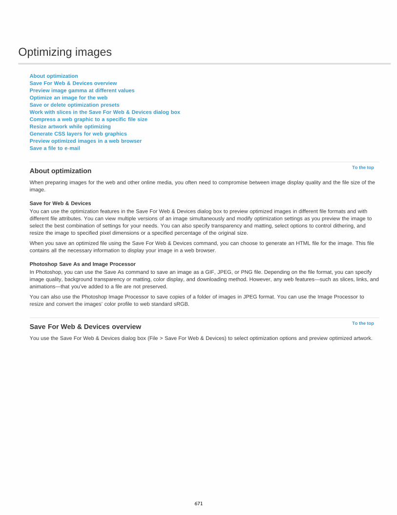
Optimizing images
To the top
To the top
About optimizationSave For Web & Devices overviewPreview image gamma at different valuesOptimize an image for the webSave or delete optimization presetsWork with slices in the Save For Web & Devices dialog boxCompress a web graphic to a specific file sizeResize artwork while optimizingGenerate CSS layers for web graphicsPreview optimized images in a web browserSave a file to e-mail
About optimizationWhen preparing images for the web and other online media, you often need to compromise between image display quality and the file size of theimage.
Save for Web & DevicesYou can use the optimization features in the Save For Web & Devices dialog box to preview optimized images in different file formats and withdifferent file attributes. You can view multiple versions of an image simultaneously and modify optimization settings as you preview the image toselect the best combination of settings for your needs. You can also specify transparency and matting, select options to control dithering, andresize the image to specified pixel dimensions or a specified percentage of the original size.
When you save an optimized file using the Save For Web & Devices command, you can choose to generate an HTML file for the image. This filecontains all the necessary information to display your image in a web browser.
Photoshop Save As and Image ProcessorIn Photoshop, you can use the Save As command to save an image as a GIF, JPEG, or PNG file. Depending on the file format, you can specifyimage quality, background transparency or matting, color display, and downloading method. However, any web features—such as slices, links, andanimations—that you’ve added to a file are not preserved.
You can also use the Photoshop Image Processor to save copies of a folder of images in JPEG format. You can use the Image Processor toresize and convert the images’ color profile to web standard sRGB.
Save For Web & Devices overviewYou use the Save For Web & Devices dialog box (File > Save For Web & Devices) to select optimization options and preview optimized artwork.
671

To the top
To the top
Save For Web & Devices dialog box (Photoshop version)A. Display options B. Toolbox C. Optimize pop-up menu D. Color Table pop-up menu E. Animation controls (Photoshop only) F. Zoom textbox G. Preview In Browser menu H. Original image I. Optimized image
Preview images in the dialog box Click a tab at the top of the image area to select a display option:
Original Displays the image with no optimization.Optimized Displays image with the current optimization settings applied.2-Up Displays two versions of the image side by side.4-Up Displays four versions of the image side by side.
Navigate in the dialog boxIf the entire artwork is not visible in the Save For Web & Devices dialog box, you can use the Hand tool to bring another area into view. Use theZoom tool to magnify or reduce the view.
Select the Hand tool (or hold down the spacebar), and drag in the view area to pan over the image.
Select the Zoom tool , and click in a view to zoom in; hold down Alt (Windows) or Option (Mac OS), and click in a view to zoom out.
You can also type a magnification percentage or choose one at the bottom of the dialog box.
View optimized image information and download timeThe annotation area below each image in the Save For Web & Devices dialog box provides optimization information. The annotation for theoriginal image shows the file name and file size. The annotation for the optimized image shows the current optimization options, the size of theoptimized file, and the estimated download time using the selected modem speed. You can choose a modem speed in the Preview pop-up menu.
Preview image gamma at different valuesThe gamma value of a computer monitor affects how light or dark an image looks in a web browser. In Photoshop, you can preview how yourimages will look on systems with different gamma values and make gamma adjustments to the image to compensate. Activating a preview optiondoes not affect final image output.
Choose one of the following options by using the Save for Web/ & Devices dialog box Preview pop-up menuMonitor Color Makes no adjustments to image gamma. Monitor Color is the default setting.Legacy Macintosh (No Color Management) Simulates the default gamma of 1.8 used by Mac OS 10.5 and earlier.Windows (No Color Management) Simulates the default gamma of 2.2 used by Windows and Mac OS 10.6 and later.Use Document Profile Adjusts the gamma to match any attached document color profile in a color-managed document.
Optimize an image for the web1. Choose File > Save For Web & Devices.
672

To the top
To the top
2. Click a tab at the top of the dialog box to select a display option: Optimized, 2-Up, or 4-Up. If you select 4-Up, click the preview you want tooptimize.
3. (Optional) If your image contains multiple slices, select one or more slices you want to optimize.4. Select a preset optimization setting from the Preset menu, or set individual optimization options. The available options change depending on
the file format you select.If you’re working in 4-Up mode, choose Repopulate Views from the Optimize menu to automatically generate lower-quality versions of theimage after you change the optimization settings.
5. Fine-tune the optimization settings until you are satisfied with the balance of image quality and file size. If your image contains multipleslices, be sure to optimize all the slices.
To restore an optimized preview to the original version, select it and then choose Original from the Preset menu.
6. If optimizing an image with an embedded color profile other than sRGB, you should convert the image’s colors to sRGB before you save theimage for use on the web. This insures that the colors you see in the optimized image will look the same in different web browsers. TheConvert to sRGB option is selected by default.
7. (Photoshop only) From the Metadata menu, choose what metadata to save with the optimized file. (Choose File > File Info to view or enterdocument metadata.) Metadata is fully supported by JPEG file format, and partially supported by GIF and PNG file formats.Note: The output metadata conforms to Metadata Working Group standards, so some JPEG metadata is stored in the EXIF and IIMformats, rather than XMP.None No metadata saved (except for the EXIF copyright notice in JPEG files). Produces the smallest file size.
Copyright Saves copyright notice, rights usage terms, copyright status, and copyright info URL.
Copyright and Contact Info Saves all copyright information, plus the following information: creator, creator job title, e-mail(s), address, city,state/province, postal code, country, telephone(s), and website(s).
All Except Camera Info Saves all metadata, except EXIF data about camera settings such as shutter speed, date and time, focal length,exposure compensation, metering pattern, and flash use.
All Saves all metadata in the file.
8. Click Save.9. In the Save Optimized As dialog box, do the following, and then click Save:
Enter a file name, and select a location for the resulting file or files.
Select a Format option to specify what kind of files you want to save: an HTML file and image files, only image files, or only an HTMLfile.
(Optional) Set output settings for HTML and image files.
If your image contains multiple slices, select an option for saving slices from the Slices menu: All Slices or Selected Slices.
To reset optimization settings to the last saved version, press Alt (Windows) or Option (Mac OS), and click Reset. To keep the samesettings the next time you open the Save For Web & Devices dialog box, press Alt/Option and click Remember.
For a video on saving files for the web in Illustrator, see www.adobe.com/go/vid0063.
Save or delete optimization presetsYou can save optimization settings as a named set and apply the settings to other images. Settings that you save appear in the Preset pop-upmenu, together with the predefined named settings. If you edit a named set or a predefined set, the Preset menu displays the term “Unnamed.”
1. Set optimization options as desired, and chooseSave Settings from the Optimize palette menu.2. Name the settings, and save them in the appropriate folder:
Photoshop (Windows XP) Document and Settings\[Username]\Application Data\Adobe\AdobePhotoshop CS5\Optimized Settings
(Windows Vista) Users\[Username]\AppData\Roaming\Adobe\Adobe Photoshop CS5\Optimized Settings
(Mac OS) Users/[Username]/Library/Preferences/AdobePhotoshop CS5 Settings/Optimized Settings
Illustrator (Windows XP) Document and Settings\[Username]\Application Data\Adobe\AdobeIllustrator CS5 Settings\[Language]\Save forWeb Settings\Optimize
(Windows Vista) Users\[Username]\AppData\Roaming\Adobe\AdobeIllustrator CS5 Settings\[Language]\Save for Web Settings\Optimize
(Mac OS) Users/[Username]/Library/ApplicationSupport/Adobe/Adobe Illustrator CS5/[Language]/Save for Web Settings/Optimize
Note: If you save the settings in a another location, they will not be available from the Preset pop-up menu.3. To delete a preset, select the preset from Preset menu, and select Delete Settings from the Optimize menu.
Work with slices in the Save For Web & Devices dialog boxIf your image contains multiple slices, you must specify the slices to be optimized. You can apply optimization settings to additional slices by
673
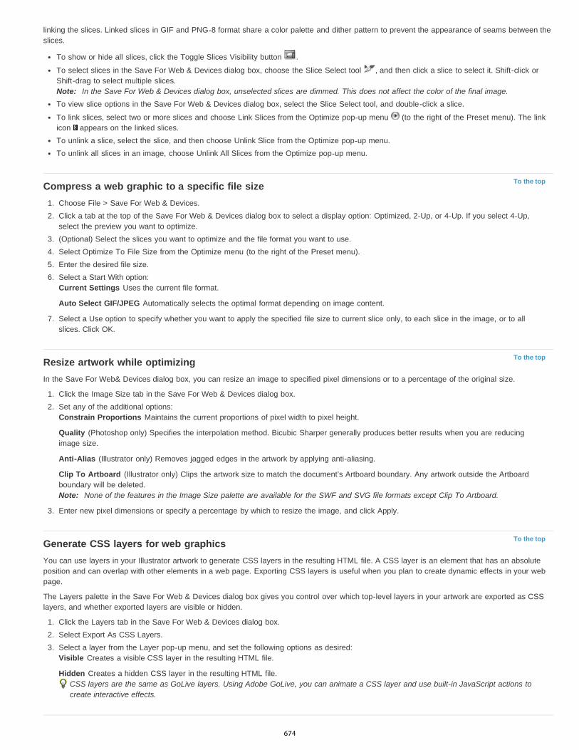
To the top
To the top
To the top
linking the slices. Linked slices in GIF and PNG-8 format share a color palette and dither pattern to prevent the appearance of seams between theslices.
To show or hide all slices, click the Toggle Slices Visibility button .
To select slices in the Save For Web & Devices dialog box, choose the Slice Select tool , and then click a slice to select it. Shift-click orShift-drag to select multiple slices.Note: In the Save For Web & Devices dialog box, unselected slices are dimmed. This does not affect the color of the final image.To view slice options in the Save For Web & Devices dialog box, select the Slice Select tool, and double-click a slice.
To link slices, select two or more slices and choose Link Slices from the Optimize pop-up menu (to the right of the Preset menu). The linkicon appears on the linked slices.To unlink a slice, select the slice, and then choose Unlink Slice from the Optimize pop-up menu.To unlink all slices in an image, choose Unlink All Slices from the Optimize pop-up menu.
Compress a web graphic to a specific file size1. Choose File > Save For Web & Devices.2. Click a tab at the top of the Save For Web & Devices dialog box to select a display option: Optimized, 2-Up, or 4-Up. If you select 4-Up,
select the preview you want to optimize.3. (Optional) Select the slices you want to optimize and the file format you want to use.4. Select Optimize To File Size from the Optimize menu (to the right of the Preset menu).5. Enter the desired file size.6. Select a Start With option:
Current Settings Uses the current file format.
Auto Select GIF/JPEG Automatically selects the optimal format depending on image content.
7. Select a Use option to specify whether you want to apply the specified file size to current slice only, to each slice in the image, or to allslices. Click OK.
Resize artwork while optimizingIn the Save For Web& Devices dialog box, you can resize an image to specified pixel dimensions or to a percentage of the original size.
1. Click the Image Size tab in the Save For Web & Devices dialog box.2. Set any of the additional options:
Constrain Proportions Maintains the current proportions of pixel width to pixel height.
Quality (Photoshop only) Specifies the interpolation method. Bicubic Sharper generally produces better results when you are reducingimage size.
Anti-Alias (Illustrator only) Removes jagged edges in the artwork by applying anti-aliasing.
Clip To Artboard (Illustrator only) Clips the artwork size to match the document’s Artboard boundary. Any artwork outside the Artboardboundary will be deleted.Note: None of the features in the Image Size palette are available for the SWF and SVG file formats except Clip To Artboard.
3. Enter new pixel dimensions or specify a percentage by which to resize the image, and click Apply.
Generate CSS layers for web graphicsYou can use layers in your Illustrator artwork to generate CSS layers in the resulting HTML file. A CSS layer is an element that has an absoluteposition and can overlap with other elements in a web page. Exporting CSS layers is useful when you plan to create dynamic effects in your webpage.
The Layers palette in the Save For Web & Devices dialog box gives you control over which top-level layers in your artwork are exported as CSSlayers, and whether exported layers are visible or hidden.
1. Click the Layers tab in the Save For Web & Devices dialog box.2. Select Export As CSS Layers.3. Select a layer from the Layer pop-up menu, and set the following options as desired:
Visible Creates a visible CSS layer in the resulting HTML file.
Hidden Creates a hidden CSS layer in the resulting HTML file.CSS layers are the same as GoLive layers. Using Adobe GoLive, you can animate a CSS layer and use built-in JavaScript actions tocreate interactive effects.
674
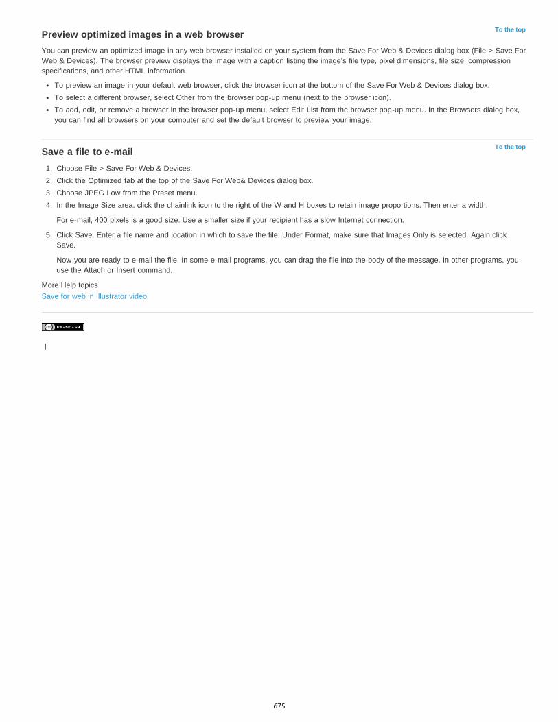
To the top
To the top
Preview optimized images in a web browserYou can preview an optimized image in any web browser installed on your system from the Save For Web & Devices dialog box (File > Save ForWeb & Devices). The browser preview displays the image with a caption listing the image’s file type, pixel dimensions, file size, compressionspecifications, and other HTML information.
To preview an image in your default web browser, click the browser icon at the bottom of the Save For Web & Devices dialog box.To select a different browser, select Other from the browser pop-up menu (next to the browser icon).To add, edit, or remove a browser in the browser pop-up menu, select Edit List from the browser pop-up menu. In the Browsers dialog box,you can find all browsers on your computer and set the default browser to preview your image.
Save a file to e-mail1. Choose File > Save For Web & Devices.2. Click the Optimized tab at the top of the Save For Web& Devices dialog box.3. Choose JPEG Low from the Preset menu.4. In the Image Size area, click the chainlink icon to the right of the W and H boxes to retain image proportions. Then enter a width.
For e-mail, 400 pixels is a good size. Use a smaller size if your recipient has a slow Internet connection.
5. Click Save. Enter a file name and location in which to save the file. Under Format, make sure that Images Only is selected. Again clickSave.
Now you are ready to e-mail the file. In some e-mail programs, you can drag the file into the body of the message. In other programs, youuse the Attach or Insert command.
More Help topicsSave for web in Illustrator video
|
675
Output settings for web graphics
To the top
To the top
To the top
Set output optionsHTML output optionsSlice output optionsBackground output settingsSaving Files output settingsInclude title and copyright information with an image
Set output optionsOutput settings control how HTML files are formatted, how files and slices are named, and how background images are handled when you savean optimized image. You set these options in the Output Settings dialog box.
You can save your output settings and apply them to other files.
1. To display the Output Settings dialog box, do one of the following:
When you save an optimized image, choose Other from the Settings pop-up menu in the Save Optimized or Save Optimized As dialogbox.
Choose Edit Output Settings from the Optimize pop-up menu (to the right of the Preset menu) in the Save For Web & Devices dialogbox.
2. (Optional) To display predefined output options, choose an option from the Settings pop-up menu.3. Edit each set of options as needed. To switch to a different set of options, choose an options set from the pop-up menu below the Settings
menu. Alternatively, click Next to display the next set in the menu list; click Prev to display the previous set.4. (Optional) To save output settings, set the options as desired, and click Save. Type a file name, choose a location for the saved file, and
click Save.
You can save the output settings anywhere. However, if you place the file in the Optimized Output Settings folder inside the Photoshopfolder or in the Save For Web Settings/Output Settingsfolder inside the Illustrator folder, the file will appear in the Settings pop-up menu.
5. (Optional) To load output settings, click Load, select a file, and click Open.
HTML output optionsYou can set the following options in the HTML set:
Output XHTML Creates web pages meeting the XHTML standard on export. Choosing Output XHTML disables other output options that mightconflict with this standard. Selecting this option automatically sets the Tags Caseand Attribute Case options.Tags Case Specifies the capitalization for tags.Attribute Case Specifies the capitalization for attributes.Indent Specifies a method for indenting lines of code: using the authoring application’s tab settings, using a specified number of spaces, or usingno indention.Line Endings Specifies a platform for line ending compatibility.Encoding Specifies a default character encoding for the web page. (This option is available only in Illustrator; Photoshop always uses UTF-8encoding.)Include Comments Adds explanatory comments to the HTML code.Always Add Alt Attribute Adds the ALT attribute to IMG elements to comply with government web accessibility standards.Always Quote Attributes Places quotation marks around all tag attributes. Placing quotation marks around attributes is required for compatibilitywith certain early browsers and for strict HTML compliance. However, always quoting attributes is not recommended. Quotation marks are usedwhen necessary to comply with most browsers if this option is deselected.Close All Tags Adds close tags for all HTML elements in the file for XHTML compliance.Include Zero Margins On Body Tag Removes default internal margins in a browser window. Adds marginwidth, marginheight, leftmargin, andtopmargin tags with values of zero to the body tag.
Slice output optionsYou can set the following options in the Slices set:
676
To the top
To the top
To the top
Generate Table Aligns slices using an HTML table rather than a cascading stylesheet.Empty Cells Specifies how empty slices are converted to table cells. Select GIF, IMG W&H to use a 1-pixel GIF with width and height valuesspecified on the IMG tag. Select GIF, TD W&H to use a 1-pixel GIF with width and height values specified on the TD tag. Select NoWrap, TDW&H to place a nonstandard NoWrap attribute on the table data and also place width and height values specified on the TD tags.TD W&H Specifies when to include width and height attributes for table data: Always, Never, or Auto (the recommended setting).Spacer Cells Specifies when to add one row and one column of empty spacer cells around the generated table: Auto (the recommended setting),Auto (Bottom), Always, Always (Bottom), or Never. For table layouts in which slice boundaries do not align, adding spacer cells can prevent thetable from breaking apart in some browsers.Generate CSS Generates a cascading stylesheet rather than an HTML table.Referenced Specifies how slice positions are referenced in the HTML file when using CSS:
By ID Positions each slice using styles that are referenced by a unique ID.Inline Includes style elements in the declaration of the block element <DIV> tag.By Class Positions each slice using classes that are referenced by a unique ID.
Default Slice Naming Choose elements from the pop-up menus or enter text into the fields to create default names for slices. Elements includethe document name, the word slice, numbers or letters designating slices or rollover states, the slice creation date, punctuation, or none.
Background output settingsYou can set the following options in the Background set of the Output Settings dialog box:
View Document As Select Image if you want the web page to display an image or a solid color as a background behind the current image. SelectBackground if you want the web page to display the optimized image as a tiled background.Background Image Enter the location of an image file, or click Choose and select an image. The file you specify will be tiled behind the optimizedimage on the web page.Color Click the Color box, and select a background color using the color picker, or select an option from the pop-up menu.
Saving Files output settingsYou set the following options in the Saving Files set of theOutput Settings dialog box:
File Naming Choose elements from the pop-up menus or enter text into the boxes to be combined into the default names for all files. Elementsinclude document name, slice name, rollover state, trigger slice, file creation date, slice number, punctuation, and file extension. Some optionsare relevant only if the file contains slices or rollover states.The text boxes let you change the order and formatting of the filename parts (for example, letting you indicate rollover state by an abbreviationinstead of the full word).
Filename Compatibility Select one or multiple options to make the filename compatible with Windows (permits longer filenames), Mac OS, andUNIX.Put Images In Folder Specifies a folder name where optimized images are saved (available only with documents containing multiple slices).Copy Background Image When Saving Preserves a background image that has been specified in the Background preferences set.
Include title and copyright information with an imageYou can add title and copyright information to a web page by entering information in the File Info dialog box. Title information appears in the webbrowser’s title bar when the image is exported with an HTML file. Copyright information is not displayed in a browser; however, it is added to theHTML file as a comment and to the image file as metadata.
1. Choose File > File Info.2. To enter a title that will appear in the web browser’s title bar, in the Description section of the File Info dialog box, enter the desired text in
the Document Title text box.3. To enter copyright information, in the Description section of the File Info dialog box, enter the desired text in the Copyright Notice text box.4. Click OK.
|
677

Web graphics optimization options
To the top
To the top
Web graphic formatsJPEG optimization optionsGIF and PNG-8 optimization optionsOptimize transparency in GIF and PNG imagesView the color table for an optimized sliceCustomize the color table for GIF and PNG-8 imagesPNG-24 optimization optionsWBMP optimization optionsSWF optimization options (Illustrator)SVG optimization options (Illustrator)
Web graphic formatsWeb graphics formats can be either bitmap (raster) or vector. The bitmap formats—GIF, JPEG, PNG, and WBMP—are resolution-dependent,meaning that a bitmap image’s dimensions, and possibly image quality, will change at different monitor resolutions. The vector formats—SVG andSWF—are resolution-independent and can be scaled up or down without losing any image quality. The vector formats can also include rasterdata. You can export from Save For Web & Devices to SVG and SWF in Adobe Illustrator only.
JPEG optimization optionsJPEG is the standard format for compressing continuous-tone images such as photographs. Optimizing an image as a JPEG format relies on lossycompression, which selectively discards data.
Note: Since image data is lost when saving a file in JPEG format, it’s a good idea to save the source file in its original format (for example,Photoshop .PSD) if you plan to edit the file further or create additional JPEG versions.
Optimization settings for JPEG (Photoshop version)A. File Format menu B. Compression Quality menu C. Optimize menu
Quality Determines the level of compression. The higher the Quality setting, the more detail the compression algorithm preserves. However, usinga high Quality setting results in a larger file size than using a low Quality setting. View the optimized image at several quality settings to determinethe best balance of quality and file size.Optimized Creates an enhanced JPEG with a slightly smaller file size. The Optimized JPEG format is recommended for maximum filecompression; however, some older browsers do not support this feature.Progressive Displays the image progressively in a web browser. The image appears as a series of overlays, enabling viewers to see a low-resolution version of the image before it downloads completely. The Progressive option requires use of the Optimized JPEG format.Note: Progressive JPEGs require more RAM for viewing and are not supported by some browsers.Blur Specifies the amount of blur to apply to the image. This option applies an effect identical to that of the Gaussian Blurfilter and allows the fileto be compressed more, resulting in a smaller file size. A setting of 0.1 to 0.5 is recommended.Embed Color Profile (Photoshop) or ICC Profile (Illustrator) Preserves color profiles in the optimized file. Some browsers use color profiles forcolor correction.Matte Specifies a fill color for pixels that were transparent in the original image. Click the Matte color swatch to select a color in the color picker, orselect an option from the Matte menu: Eyedropper Color (to use the color in the eyedropper sample box), Foreground Color, Background Color,White, Black, or Other (to use the color picker).Note: The Foreground Color and Background Color options are only available in Photoshop.Pixels that were fully transparent in the original image are filled with the selected color; pixels that were partially transparent in the original image
678
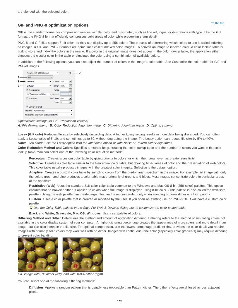
To the top
are blended with the selected color.
GIF and PNG-8 optimization optionsGIF is the standard format for compressing images with flat color and crisp detail, such as line art, logos, or illustrations with type. Like the GIFformat, the PNG-8 format efficiently compresses solid areas of color while preserving sharp detail.
PNG-8 and GIF files support 8-bit color, so they can display up to 256 colors. The process of determining which colors to use is called indexing,so images in GIF and PNG-8 formats are sometimes called indexed color images. To convert an image to indexed color, a color lookup table isbuilt to store and index the colors in the image. If a color in the original image does not appear in the color lookup table, the application eitherchooses the closest color in the table or simulates the color using a combination of available colors.
In addition to the following options, you can also adjust the number of colors in the image’s color table. See Customize the color table for GIF andPNG-8 images.
Optimization settings for GIF (Photoshop version)A. File Format menu B. Color Reduction Algorithm menu C. Dithering Algorithm menu D. Optimize menu
Lossy (GIF only) Reduces file size by selectively discarding data. A higher Lossy setting results in more data being discarded. You can oftenapply a Lossy value of 5–10, and sometimes up to 50, without degrading the image. The Lossy option can reduce file size by 5% to 40%.Note: You cannot use the Lossy option with the Interlaced option or with Noise or Pattern Dither algorithms.Color Reduction Method and Colors Specifies a method for generating the color lookup table and the number of colors you want in the colorlookup table. You can select one of the following color reduction methods:
Perceptual Creates a custom color table by giving priority to colors for which the human eye has greater sensitivity.Selective Creates a color table similar to the Perceptual color table, but favoring broad areas of color and the preservation of web colors.This color table usually produces images with the greatest color integrity. Selective is the default option.Adaptive Creates a custom color table by sampling colors from the predominant spectrum in the image. For example, an image with onlythe colors green and blue produces a color table made primarily of greens and blues. Most images concentrate colors in particular areasof the spectrum.Restrictive (Web) Uses the standard 216-color color table common to the Windows and Mac OS 8-bit (256-color) palettes. This optionensures that no browser dither is applied to colors when the image is displayed using 8-bit color. (This palette is also called the web-safepalette.) Using the web palette can create larger files, and is recommended only when avoiding browser dither is a high priority.Custom Uses a color palette that is created or modified by the user. If you open an existing GIF or PNG-8 file, it will have a custom colorpalette.
Use the Color Table palette in the Save For Web & Devices dialog box to customize the color lookup table.
Black and White, Grayscale, Mac OS, Windows Use a set palette of colors.Dithering Method and Dither Determines the method and amount of application dithering. Dithering refers to the method of simulating colors notavailable in the color display system of your computer. A higher dithering percentage creates the appearance of more colors and more detail in animage, but can also increase the file size. For optimal compression, use the lowest percentage of dither that provides the color detail you require.Images with primarily solid colors may work well with no dither. Images with continuous-tone color (especially color gradients) may require ditheringto prevent color banding.
GIF image with 0% dither (left), and with 100% dither (right)
You can select one of the following dithering methods:
Diffusion Applies a random pattern that is usually less noticeable than Pattern dither. The dither effects are diffused across adjacentpixels.
679
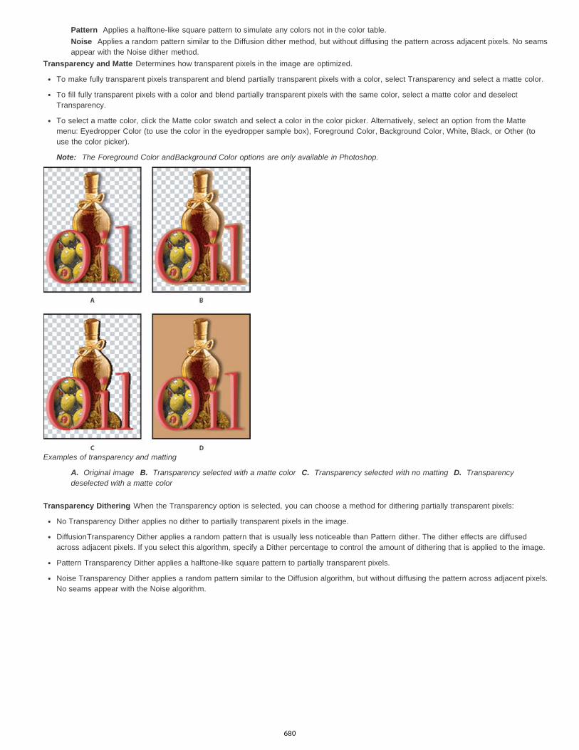
Pattern Applies a halftone-like square pattern to simulate any colors not in the color table.Noise Applies a random pattern similar to the Diffusion dither method, but without diffusing the pattern across adjacent pixels. No seamsappear with the Noise dither method.
Transparency and Matte Determines how transparent pixels in the image are optimized.
To make fully transparent pixels transparent and blend partially transparent pixels with a color, select Transparency and select a matte color.
To fill fully transparent pixels with a color and blend partially transparent pixels with the same color, select a matte color and deselectTransparency.
To select a matte color, click the Matte color swatch and select a color in the color picker. Alternatively, select an option from the Mattemenu: Eyedropper Color (to use the color in the eyedropper sample box), Foreground Color, Background Color, White, Black, or Other (touse the color picker).
Note: The Foreground Color andBackground Color options are only available in Photoshop.
Examples of transparency and matting
A. Original image B. Transparency selected with a matte color C. Transparency selected with no matting D. Transparencydeselected with a matte color
Transparency Dithering When the Transparency option is selected, you can choose a method for dithering partially transparent pixels:
No Transparency Dither applies no dither to partially transparent pixels in the image.
DiffusionTransparency Dither applies a random pattern that is usually less noticeable than Pattern dither. The dither effects are diffusedacross adjacent pixels. If you select this algorithm, specify a Dither percentage to control the amount of dithering that is applied to the image.
Pattern Transparency Dither applies a halftone-like square pattern to partially transparent pixels.
Noise Transparency Dither applies a random pattern similar to the Diffusion algorithm, but without diffusing the pattern across adjacent pixels.No seams appear with the Noise algorithm.
680
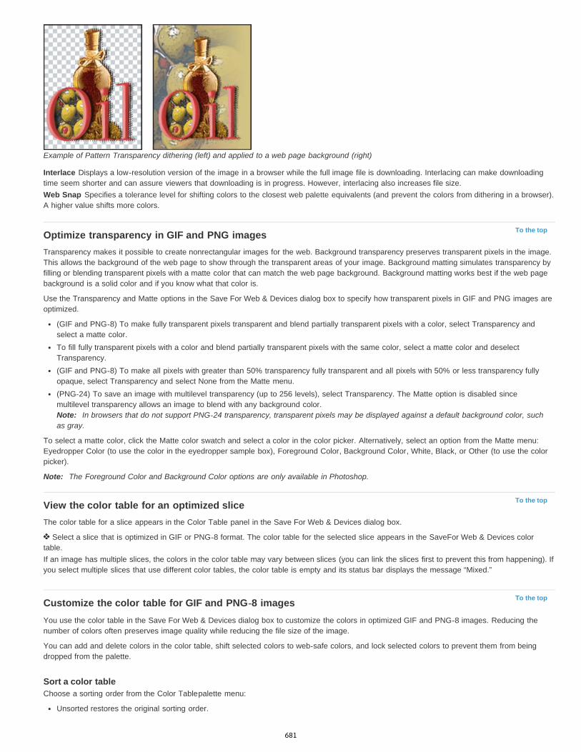
To the top
To the top
To the top
Example of Pattern Transparency dithering (left) and applied to a web page background (right)
Interlace Displays a low-resolution version of the image in a browser while the full image file is downloading. Interlacing can make downloadingtime seem shorter and can assure viewers that downloading is in progress. However, interlacing also increases file size.Web Snap Specifies a tolerance level for shifting colors to the closest web palette equivalents (and prevent the colors from dithering in a browser).A higher value shifts more colors.
Optimize transparency in GIF and PNG imagesTransparency makes it possible to create nonrectangular images for the web. Background transparency preserves transparent pixels in the image.This allows the background of the web page to show through the transparent areas of your image. Background matting simulates transparency byfilling or blending transparent pixels with a matte color that can match the web page background. Background matting works best if the web pagebackground is a solid color and if you know what that color is.
Use the Transparency and Matte options in the Save For Web & Devices dialog box to specify how transparent pixels in GIF and PNG images areoptimized.
(GIF and PNG-8) To make fully transparent pixels transparent and blend partially transparent pixels with a color, select Transparency andselect a matte color.To fill fully transparent pixels with a color and blend partially transparent pixels with the same color, select a matte color and deselectTransparency.(GIF and PNG-8) To make all pixels with greater than 50% transparency fully transparent and all pixels with 50% or less transparency fullyopaque, select Transparency and select None from the Matte menu.(PNG-24) To save an image with multilevel transparency (up to 256 levels), select Transparency. The Matte option is disabled sincemultilevel transparency allows an image to blend with any background color.Note: In browsers that do not support PNG-24 transparency, transparent pixels may be displayed against a default background color, suchas gray.
To select a matte color, click the Matte color swatch and select a color in the color picker. Alternatively, select an option from the Matte menu:Eyedropper Color (to use the color in the eyedropper sample box), Foreground Color, Background Color, White, Black, or Other (to use the colorpicker).
Note: The Foreground Color and Background Color options are only available in Photoshop.
View the color table for an optimized sliceThe color table for a slice appears in the Color Table panel in the Save For Web & Devices dialog box.
Select a slice that is optimized in GIF or PNG-8 format. The color table for the selected slice appears in the SaveFor Web & Devices colortable.If an image has multiple slices, the colors in the color table may vary between slices (you can link the slices first to prevent this from happening). Ifyou select multiple slices that use different color tables, the color table is empty and its status bar displays the message “Mixed.”
Customize the color table for GIF and PNG-8 imagesYou use the color table in the Save For Web & Devices dialog box to customize the colors in optimized GIF and PNG-8 images. Reducing thenumber of colors often preserves image quality while reducing the file size of the image.
You can add and delete colors in the color table, shift selected colors to web-safe colors, and lock selected colors to prevent them from beingdropped from the palette.
Sort a color tableChoose a sorting order from the Color Tablepalette menu:
Unsorted restores the original sorting order.
681
Sort By Hue sorts by the location of the color on the standard color wheel (expressed as a degree from 0 to 360). Neutral colors areassigned a hue of 0 and located with the reds.Sort By Luminance sorts by the lightness or brightness of a color.Sort By Popularity sorts by the colors’ frequency of occurrence in the image.
Add a new color to the color tableYou can add colors that were left out in building the color table. Adding a color to a dynamic table shifts the color in the palette closest to the newcolor. Adding a color to a fixed or Custom table adds an additional color to the palette.
1. If any colors are currently selected in the color table, choose Deselect All Colors from the Color Table palette menu to deselect them.2. Choose a color by doing one of the following:
Click the Eyedropper Color box in the SaveFor Web & Devices dialog box and choose a color from the color picker.
Select the Eyedropper tool in the Save For Web & Devices dialog box and click in the image.
3. Do one of the following:
Click the New Color button in the color table.
SelectNew Color from the Color Table palette menu.
To switch the color table to a Custom palette, hold down Ctrl (Windows) or Command (Mac OS) when you add the new color.
The new color appears in the color table with a small white square in the lower right corner, indicating that the color is locked. If the colortable is dynamic, the original color is displayed in the upper left and the new color is displayed in the lower right.
Select colors in the color tableA white border appears around selected colors in the Color Table.
To select a color, click the color in the Color Table.To select multiple colors in the color table, press Shift and click another color. All colors in the rows between the first and second selectedcolors are selected. To select a nonadjacent group of colors, press Ctrl (Windows) or Command (Mac OS) and click each color that you wantto select. The Color Table palette menu also provides commands for selecting colors.To select a color in the preview image, click in the preview with the Save For Web & Devices Eyedropper tool. Shift-click to select additionalcolors.To deselect all colors, choose Deselect All Colors from the Color Tablepalette menu.
Shift a colorYou can change a selected color in the color table to any other RGB color value. When you regenerate the optimized image, the selected colorchanges to the new color wherever it appears in the image.
1. Double-click the color in the color table to display the default color picker.2. Select a color.
The original color appears at the upper left of the color swatch and the new color at the lower right. The small square at the lower right ofthe color swatch indicates that the color is locked. If you shift to a web-safe color, a small white diamond appears at the center of theswatch.
3. To revert a shifted color to its original color, do one of the following:
Double-click the swatch for the shifted color. The original color is selected in the color picker. Click OK to restore the color.
To revert all shifted colors in a color table (including web-shifted colors), choose Unshift All Colors from the Color Tablepalette menu.
Shift colors to the closest web palette equivalentTo protect colors from dithering in a browser, you can shift the colors to their closest equivalents in the web palette. This ensures that the colorswon’t dither when displayed in browsers on either Windows or Macintosh operating systems capable of displaying only 256 colors.
1. Select one or more colors in the optimized image or color table.2. Do one of the following:
Click the Web Shift button in the Color Table palette.
Choose Shift/Unshift Selected Colors To/From Web Palette from the Color Table palette menu.The original color appears at the upperleft of the color swatch and the new color at the lower right. The small white diamond in the center of the color swatch indicates thatthe color is web-safe; the small square at the lower right of the color swatch indicates that the color is locked.
3. To set a tolerance for shifting, enter a value for Web Snap. A higher value shifts more colors.4. To revert web-shifted colors, do one of the following:
Select a web-shifted color in the color table and click the Web Shift button in the Color Table palette.
682
To revert all web-shifted colors in the color table, choose Unshift All Colors from the Color Table palette menu.
Map colors to transparencyYou can add transparency to an optimized image by mapping existing colors to transparency.
1. Select one or more colors in the optimized image or color table.2. Do one of the following:
Click the Map Transparency button in the Color Table palette.
Choose Map/Unmap Selected Colors To/From Transparent from the Color Table palette menu.
The transparency grid appears in half of each mapped color. The small square at the lower right of the color swatch indicates that thecolor is locked.
3. To revert transparency to original color, do one of the following:
Select the colors you want to revert and click the Map Transparency button or choose Map/Unmap Selected Colors To/FromTransparent from the Color Table palette menu.
To revert all transparency-mapped colors, chooseUnmap All Transparent Colors.
Lock or unlock a colorYou can lock selected colors in the color table to prevent them from being dropped when the number of colors is reduced and to prevent themfrom dithering in the application.
Note: Locking colors does not prevent them from dithering in a browser.1. Select one or more colors in the color table.2. Lock the color by doing one of the following:
Click the Lock button .
Choose Lock/Unlock Selected Colors from the Color Table palette menu.
A white square appears in the lower right corner of each locked color.
3. Unlock the color by doing one of the following:
Click the Lock button .
Choose Lock/Unlock Selected Colors from the Color Table palette menu.
The white square disappears from the color swatch.
Delete selected colorsYou can delete selected colors from the color table to decrease the image file size. When you delete a color, areas of the optimized image thatpreviously included that color are rerendered using the closest color remaining in the palette.
When you delete a color, the color table automatically changes to a Custom palette. This is because the Adaptive, Perceptual, and Selectivepalettes automatically add the deleted color back into the palette when you reoptimize the image—the Custom palette does not change when youreoptimize the image.
1. Select one or more colors in the color table.2. Delete the color by doing one of the following:
Click the Delete icon .
Choose Delete Color from the Color Table palette menu.
Save a color tableYou can save color tables from optimized images to use with other images and to load color tables created in other applications. Once you load anew color table into an image, the colors in the optimized image are changed to reflect the colors in the new color table.
1. Select Save Color Table from the Color Table palette menu.2. Name the color table and choose a location where it will be saved. By default, the color table file is given the extension .act (for Adobe Color
Table).
If you want to access the color table when selecting Optimization options for a GIF or PNG image, save the color table in the OptimizedColors folder inside the Photoshop application folder.
3. Click Save.Important: When you reload the table, all shifted colors will appear as full swatches and will be unlocked.
683
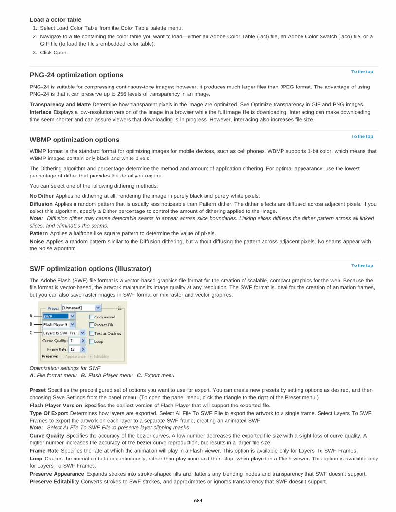
To the top
To the top
To the top
Load a color table1. Select Load Color Table from the Color Table palette menu.2. Navigate to a file containing the color table you want to load—either an Adobe Color Table (.act) file, an Adobe Color Swatch (.aco) file, or a
GIF file (to load the file’s embedded color table).3. Click Open.
PNG-24 optimization optionsPNG-24 is suitable for compressing continuous-tone images; however, it produces much larger files than JPEG format. The advantage of usingPNG-24 is that it can preserve up to 256 levels of transparency in an image.
Transparency and Matte Determine how transparent pixels in the image are optimized. See Optimize transparency in GIF and PNG images.Interlace Displays a low-resolution version of the image in a browser while the full image file is downloading. Interlacing can make downloadingtime seem shorter and can assure viewers that downloading is in progress. However, interlacing also increases file size.
WBMP optimization optionsWBMP format is the standard format for optimizing images for mobile devices, such as cell phones. WBMP supports 1-bit color, which means thatWBMP images contain only black and white pixels.
The Dithering algorithm and percentage determine the method and amount of application dithering. For optimal appearance, use the lowestpercentage of dither that provides the detail you require.
You can select one of the following dithering methods:
No Dither Applies no dithering at all, rendering the image in purely black and purely white pixels.Diffusion Applies a random pattern that is usually less noticeable than Pattern dither. The dither effects are diffused across adjacent pixels. If youselect this algorithm, specify a Dither percentage to control the amount of dithering applied to the image.Note: Diffusion dither may cause detectable seams to appear across slice boundaries. Linking slices diffuses the dither pattern across all linkedslices, and eliminates the seams.Pattern Applies a halftone-like square pattern to determine the value of pixels.Noise Applies a random pattern similar to the Diffusion dithering, but without diffusing the pattern across adjacent pixels. No seams appear withthe Noise algorithm.
SWF optimization options (Illustrator)The Adobe Flash (SWF) file format is a vector-based graphics file format for the creation of scalable, compact graphics for the web. Because thefile format is vector-based, the artwork maintains its image quality at any resolution. The SWF format is ideal for the creation of animation frames,but you can also save raster images in SWF format or mix raster and vector graphics.
Optimization settings for SWFA. File format menu B. Flash Player menu C. Export menu
Preset Specifies the preconfigured set of options you want to use for export. You can create new presets by setting options as desired, and thenchoosing Save Settings from the panel menu. (To open the panel menu, click the triangle to the right of the Preset menu.)Flash Player Version Specifies the earliest version of Flash Player that will support the exported file.Type Of Export Determines how layers are exported. Select AI File To SWF File to export the artwork to a single frame. Select Layers To SWFFrames to export the artwork on each layer to a separate SWF frame, creating an animated SWF.Note: Select AI File To SWF File to preserve layer clipping masks.Curve Quality Specifies the accuracy of the bezier curves. A low number decreases the exported file size with a slight loss of curve quality. Ahigher number increases the accuracy of the bezier curve reproduction, but results in a larger file size.Frame Rate Specifies the rate at which the animation will play in a Flash viewer. This option is available only for Layers To SWF Frames.Loop Causes the animation to loop continuously, rather than play once and then stop, when played in a Flash viewer. This option is available onlyfor Layers To SWF Frames.Preserve Appearance Expands strokes into stroke-shaped fills and flattens any blending modes and transparency that SWF doesn’t support.Preserve Editability Converts strokes to SWF strokes, and approximates or ignores transparency that SWF doesn’t support.
684

To the top
Note: SWF supports object-level opacity only.Use the Export command instead of the Save For Web & Devices command to maintain artwork’s stacking order by exporting each layer to aseparate SWF file. You can then import the exported SWF files into Adobe Flash simultaneously.
Compressed Compresses the exported file.Protect File Protects the file so that it cannot be imported by applications other than Flash.Text As Outlines Converts all text to outlines to maintain appearance. If you plan to edit the text in Flash, don’t select this option.
SVG optimization options (Illustrator)SVG is a vector format that describes images as shapes, paths, text, and filter effects. The resulting files are compact and provide high-qualitygraphics on the web, in print, and even on resource-constrained handheld devices.
Optimization settings for SVGA. File format menu B. SVG Profiles menu C. Font Subsetting menu D. Image Location menu E. CSS Properties menu F. Font Typemenu G. Encoding menu
Compressed Creates a Compressed SVG (SVGZ) file.SVG Profiles Specifies the SVG XML Document Type Definition for the exported file.
SVG 1.0 and SVG 1.1 Suitable for SVG files to be viewed on a desktop computer. SVG 1.1 is the full version of the SVG specification, ofwhich SVG Tiny1.1, SVG Tiny 1.1 Plus, SVG Tiny 1.2, and SVG Basic 1.1 are subsets.SVG Basic 1.1 Suitable for SVG files to be viewed on medium powered devices, such as handhelds. Keep in mind that not all handheldssupport the SVG Basic profile. As a result, selecting this option doesn’t guarantee that the SVG file will be viewable on all handhelds. SVGBasic doesn’t support nonrectangular clipping and some SVG filter effects.SVG Tiny 1.1 and SVG Tiny 1.1+ Suitable for SVG files to be viewed on small devices, such as mobile phones. Keep in mind that not allmobile phones support theSVG Tiny and SVG Tiny Plus profiles. As a result, selecting either of these options doesn’t guarantee that theSVG file will be viewable on all small devices.SVG Tiny 1.2 Suitable for SVG files to be viewed on a variety of devices ranging from PDAs and cellphones to laptops and desktopcomputers.SVG Tiny doesn’t support gradients, transparency, clipping, masks, symbols, or SVG filter effects. SVG Tiny Plus includes the ability todisplay gradients and transparency, but it doesn’t support clipping, masks, symbols, or SVG filter effects.
For additional information on SVG profiles, see the SVG specification on the World Wide Web Consortium (W3C) website(www.w3.org).
Decimals Determines the precision of vector data in the SVG file. You can set a value of 1 to 7 decimal places. A high value results in a larger filesize and increased image quality.Font Subsetting Controls which glyphs are embedded from the SVG file. Select None from the Subsetting menu if you can rely on the necessaryfonts being installed on end-user systems. Select Only Glyphs Used to only include glyphs for text that exists in the current artwork. The othervalues (Common English, Common English + Glyphs Used,Common Roman, Common Roman + Glyphs Used, All Glyphs) are useful when thetextual content of the SVG file is dynamic (such as server-generated text or user-interactive text).Font Type Specifies how fonts are exported.
Adobe CEF Uses font hinting for better rendering of small fonts. This font type is supported by the Adobe SVG Viewer but may not besupported by other SVG viewers.SVG Doesn’t use font hinting. This font type is supported by all SVG viewers.Convert To Outlines Converts type to vector paths. Use this option to preserve the visual appearance of type in all SVG Viewers.
Image Location Specifies whether to embed or link to images. Embedding images increases file size but ensures that rasterized images arealways available.CSS Properties Determines how CSS style attributes are saved in the SVG code. The default method, Presentation Attributes, applies propertiesat the highest point in the hierarchy, allowing the most flexibility for specific edits and transformations. The Style Attributes method creates themost readable files but may increase file size. Choose this method if the SVG code will be used in transformations—for example, transformationsusing XSLT (Extensible Stylesheet Language Transformation). The Entity References method results in faster rendering times and reduced SVGfile size. The Style Element method is used when sharing files with HTML documents. By selecting Style Element, you can then modify the SVGfile to move a style element into an external stylesheet file that is also referenced by the HTML file—however, the Style Element option also resultsin slower rendering speeds.Encoding Determines how characters are encoded in the SVG file. UTF (Unicode Transformation Format) encoding is supported by all XML
685

processors. (UTF-8 is an 8-bit format; UTF-16 is a 16-bit format.) ISO 8859-1 and UTF-16 encoding don’t preserve file metadata. Optimize For Adobe SVG Viewer Optimizes images for Adobe SVG Viewer.
|
686
3D and technical imaging
New 3D reflections and dragable shadowsLynda.com (May. 7, 2012)video-tutorialAdd realism with ease.
Streamlined 3d controlsLynda.com (May. 7, 2012)video-tutorialExpand creative possibilities into another dimension.
687

3D painting | CC, CS6
To the top
Video | 3D painting - The next levelAvailable 3D painting methodsSome tips to paint 3D modelsPaint an object in the Live 3D Painting mode | Photoshop CCSwitch to the Projection Painting mode | Photoshop CCPaint a 3D model texture | CS6Target a texture type for painting | Photoshop CCPaint in the unlit mode | Photoshop CCReveal surfaces to paint onSet the paint falloff angleIdentify paintable areas
You can use any Photoshop painting tools to paint directly on a 3D model just as you would on a 2D layer. Use selection tools to target specificmodel areas or let Photoshop identify and highlight paintable areas. 3D menu commands let you clear away areas of a model to access interior orhidden portions for painting.
When painting directly on the model, you can choose which underlying texture map to apply paint to. Typically paint is applied to the diffusetexture map, which gives a model material its color properties. You can also paint on other texture maps, such as the bump map or opacity map. Ifyou paint on an area of the model that lacks the type of texture map you’re painting on, a texture map is automatically created.
Available 3D painting methodsDifferent painting methods are appropriate for different use cases. Photoshop provides the following 3D painting methods:
Live 3D Painting: (Default in Photoshop CC) Brush strokes made in the 3D model view or the texture view are reflected in real time in the otherview. This 3D painting method offers high performance and minimum distortion.
Layer Projection Painting: The Gradient tool and filters use this painting method. The Layer Projection Painting method involves merging apainted layer with the underlying 3D layer. During the merge operation, Photoshop automatically projects the paint onto the appropriate targettextures.
Projection Painting: (Default in Photoshop Extended CS6) Projection Painting is suitable for painting multiple textures simultaneously or forpainting the seam between two textures. However, in general, it is a lower-performance painting method and may result in cracks when you’repainting complex 3D objects.
Texture Painting: You can open the 2D texture and paint it directly.
Live 3D Painting
688
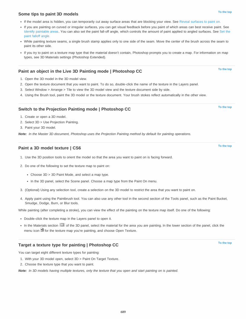
To the top
To the top
To the top
Note:
To the top
To the top
Note:
Some tips to paint 3D modelsIf the model area is hidden, you can temporarily cut away surface areas that are blocking your view. See Reveal surfaces to paint on.If you are painting on curved or irregular surfaces, you can get visual feedback before you paint of which areas can best receive paint. SeeIdentify paintable areas. You can also set the paint fall-off angle, which controls the amount of paint applied to angled surfaces. See Set thepaint falloff angle.While painting texture seams, a single brush stamp applies only to one side of the seam. Move the center of the brush across the seam topaint its other side.
If you try to paint on a texture map type that the material doesn’t contain, Photoshop prompts you to create a map. For information on maptypes, see 3D Materials settings (Photoshop Extended).
Paint an object in the Live 3D Painting mode | Photoshop CC1. Open the 3D model in the 3D model view.2. Open the texture document that you want to paint. To do so, double-click the name of the texture in the Layers panel.3. Select Window > Arrange > Tile to view the 3D model view and the texture document side by side.4. Using the Brush tool, paint the 3D model or the texture document. Your brush stokes reflect automatically in the other view.
Switch to the Projection Painting mode | Photoshop CC1. Create or open a 3D model.2. Select 3D > Use Projection Painting.3. Paint your 3D model.
In the Master 3D document, Photoshop uses the Projection Painting method by default for painting operations.
Paint a 3D model texture | CS6
1. Use the 3D position tools to orient the model so that the area you want to paint on is facing forward.
2. Do one of the following to set the texture map to paint on:
Choose 3D > 3D Paint Mode, and select a map type.
In the 3D panel, select the Scene panel. Choose a map type from the Paint On menu.
3. (Optional) Using any selection tool, create a selection on the 3D model to restrict the area that you want to paint on.
4. Apply paint using the Paintbrush tool. You can also use any other tool in the second section of the Tools panel, such as the Paint Bucket,Smudge, Dodge, Burn, or Blur tools.
While painting (after completing a stroke), you can view the effect of the painting on the texture map itself. Do one of the following:
Double-click the texture map in the Layers panel to open it.
In the Materials section of the 3D panel, select the material for the area you are painting. In the lower section of the panel, click themenu icon for the texture map you’re painting, and choose Open Texture.
Target a texture type for painting | Photoshop CCYou can target eight different texture types for painting:
1. With your 3D model open, select 3D > Paint On Target Texture.2. Choose the texture type that you want to paint.
In 3D models having multiple textures, only the texture that you open and start painting on is painted.
689

To the top
To the top
Hide Nearest Surface
Only Hide Enclosed Polygons
Invert Visible Surfaces
Reveal All Surfaces
To the top
Paint a target texture type
Paint in the unlit mode | Photoshop CCYou can choose to paint your 3D objects in the unlit mode. This mode ignores any lighting in your scene and wraps raw texture data of theappropriate type around your 3D objects. Painting in the unlit mode lets you paint without shading and with greater color accuracy.
Follow these steps:
1. In the 3D panel, select Scene.2. In the Properties panel, select Surface.3. Select Unlit Texture from the Style pop-up menu.
Reveal surfaces to paint onFor more complex models with interior or hidden areas, you can hide sections of the model for easier access to surfaces you want to paint. Forexample, to apply paint to the dashboard of a car model, you can temporarily cut away the roof or windshield, then zoom inside the car to get anunobstructed view.
1. Select an area of the model that you want to cut away, using a selection tool such as the Lasso or Marquee tool.
2. Use any of the following 3D menu commands to reveal or hide areas of the model:
hides only the first layer of model polygons within the 2D selection. To quickly peel away surface of the model, youcan use this command repeatedly while keeping the selection area active.
When hiding surfaces, rotate the model if necessaryto position surfaces so that they are perpendicular to your currentview.
When selected, the Hide Nearest Surface command only affects polygons that are fully within the selection. When
unchecked, ithides any polygons touched by the selection.
Makes currently visible surfaces invisible, and invisible surfaces visible.
Makes all hidden surfaces visible again.
Set the paint falloff angleWhen painting on a model, the paint falloff angle controls how much paint is applied to a surface as it curves away from the forward-facing view.The falloff angle is calculated based on a “normal”, or straight line projecting out from the part of the model surface that faces you. For example, ina spherical model such as a soccer ball, the falloff angle to the exact center of the ball as it faces you is 0 degrees. As the surface of the ballcurves away, the falloff angle increases, up to 90 degrees at the edges of the ball.
690

Twitter™ and Facebook posts are not covered under the terms of Creative Commons.
Legal Notices | Online Privacy Policy
To the top
A. Eye/camera angle B. Minimum angle C. Maximum angle D. Paint fade start E. Paint fade end
1. Choose 3D > 3D Paint Falloff
2. Set the minimum and maximum angle settings.
The maximum paint falloff range is 0 - 90 degrees. At 0 degrees, paint is only applied to the surface if it is facing directly forward, with nodrop-off angle. At 90 degrees, paint can follow a curved surface such as a sphere to its visible edges. At a 45 degree setting, the paintedarea is limited to the areas of the sphere that don’t curve away at more than 45 degrees.
The Minimum falloff angle sets a range within which paint gradually fades as it approaches the maximum falloff angle. For example, if themaximum falloff angle is 45, and the minimum falloff is 30, paint opacity decreases from 100 to 0 percent between 30 and 45 degrees offalloff.
Identify paintable areasIt may not be clear just from looking at a 3D model whether you can successfully paint on certain areas. Because the model view may not providea 1 to 1 correspondence with the 2D texture itself, applying paint directly to the model is different from directly painting on a 2D texture map. Whatappears to be a small brush on the model may in fact be much larger in relation to the texture, depending on the resolution of the texture, or howclose you are to the model when applying paint.
Good paintable areas are areas where you can apply paint or other adjustments to the model surface with the most consistent and predictableeffect. In other areas, paint may be undersampled or oversampled due to your angle or distance from the model surface.
Do one of the following:
Choose 3D > Select Paintable Areas. A selection marquee highlights the best areas for painting on the model.
In Scene section of the 3D panel, choose Paint Mask from the Preset menu.
In Paint Mask mode, white shows areas good for painting, blue shows areas where paint will be undersampled, and red shows areaswhere paint will be oversampled. (To paint on the model, you must change from the Paint Mask render mode to a render mode thatsupports painting, such as Solid.)
The areas selected by Select Paintable Areas, and the paintable areas shown in Paint Mask mode, are partially determined by the current PaintFalloff setting. A higher paint falloff setting increases the paintable area, a lower setting decreases the paintable area. See Set the paint falloffangle.
691

3D panel enhancements | Photoshop CC
To the top
To the top
The Photoshop 3D panel in Photoshop CC makes it easier for you to work with 3D objects. Modeled after the Layers panel, the 3D panel isstructured as a scene graph/tree having root objects and child objects.
You can interact with 3D objects in the scene graph in several ways, such as:
Delete objectsReorder objectsReverse object orderInsert objectsDuplicate objectsMake instances of objectsGroup objects
You can access these interactions from the context menu associated with a 3D object. Right-click an object to access its context menu onWindows. To access the context menu on Mac OS, click the object with the Control key held down.
Some interactions are not available for certain types of 3D objects.
Display the 3D panelSelect Window > 3D.
Basic interactions
Interaction Description How to perform... Not available for...
Delete an object Deletes the selected objectsfrom the scene graph
Drag the object to thetrashcan, orUse the Delete Objectcommand in the contextmenu
Objects under Scene,Environment, and View
Add an object Adds a mesh or a preset 3Dobject
1. Right-click the 3D object.2. From the contextual menu,
select the appropriateoption to add an object.For example, select AddPyramid.
Objects under Environmentand Current View
Reorder an objectChanges the position of theselected object within thescene graph
Drag the object to its newposition.
Objects under Scene,Environment, and CurrentView
Reverse order of objectsReverses the order of theselected objects within thescene graph
1. Select the objects.2. From the context menu,
select Reorder Objects.
Objects under Scene,Environment, and CurrentView
Duplicate an object Duplicates the currentlyselected object
1. Select an object.2. From the context menu,
select Duplicate Objects.
Objects under Scene,Environment, and CurrentView
Group objects Groups the selected objects1. Select the objects.2. From the context menu,
select Group Items.
Materials, constraints, andobjects under Scene andEnvironment
1. Select the group. Materials, constraints, and
692

Twitter™ and Facebook posts are not covered under the terms of Creative Commons.
Legal Notices | Online Privacy Policy
To the topCreate an instance of a 3D objectAn instance of a 3D object is a linked copy that reflects the changes made to the original object. If you want to modify the object and its instanceindependently, you can decouple the two.
Follow these steps to create an instance of a 3D object:
1. In the 3D panel, right-click the mesh object. For example, right-click Hat.2. From the context menu for the object, select Instance Objects. This will create an instance of the object; for example, Hat1.
By default, the instance is linked with the original object.
Linked instance: Changes made to the object reflect on the instance
Decouple an instance from the original objectWhen you decouple an instance from the original object, changes made to the original object are no longer reflected on the instance.
1. Right-click the instance in the 3D panel (for example, Hat1).2. From the contextual menu, select Bake Instance.
Instance decoupled from the original object
See also3D Scene settings
3D Mesh settings
3D Materials settings
3D Lights settings
"3D and technical imaging" in Photoshop Help
Ungroup objects Ungroups a group of objects 2. From the context menu,select Ungroup Objects.
objects under Scene andEnvironment
693
Essential 3D concepts and tools
Note:
To the top
Meshes
Note:
Materials
Lights
To the top
Understanding and displaying 3D files3D object and camera tools3D Axis
In Photoshop CS5 and CS6, 3D functionality was part of Photoshop Extended. All features in Photoshop Extended are part of PhotoshopCC. Photoshop CC does not have a separate Extended offering.
Understanding and displaying 3D filesPhotoshop lets you position and animate 3D models, edit textures and lighting, and choose from several render modes.
3D fundamentals3D files consist of the following components:
Provide the underlying structure of a 3D model. A mesh is often visualized as a wireframe, a skeletal structure built from thousands ofindividual polygons. A 3D model always has at least one mesh, and may combine multiple meshes. In Photoshop you can view meshes in avariety of render modes, and manipulate meshes independently of each other. While you can’t alter the actual polygons in a mesh, you canchange its orientation and transform it by scaling along different axes. You can also create your own 3D meshes, using pre-supplied shapes or byconverting existing 2D layers. See 3D Mesh settings.
To edit the polygon mesh of the 3D model itself, you must use a 3D authoring program.
A mesh can have one or more materials associated with it, which control the appearance of all or part of the mesh. The material in turnrelies on subcomponents called texture maps, whose cumulative effect creates the appearance of a material. The texture map itself is a 2D imagefile that creates various qualities such as color, pattern, shininess, or bumpiness. A Photoshop material can use up to nine different texture maptypes to define its overall appearance. See 3D Materials settings.
Types include Infinite, Spot, Point lights, as well as Image-based lights that wrap around a scene. You can move and adjust color andintensity of existing lights, and add new lights to your 3D scene. See 3D Lights settings.
Open a 3D filePhotoshop can open the following 3D formats: DAE (Collada), OBJ, 3DS, U3D, and KMZ (Google Earth).
Do one of the following:
To open a 3D file on its own, choose File > Open, and select the file.
To add a 3D file as a layer in an open file, choose 3D > New Layer From 3D File, and then select the 3D file. The new layer reflects thedimensions of the open file and presents the 3D model over a transparent background.
3D performance and display preferences
1. Choose Edit > Preferences > 3D (Windows) or Photoshop > Preferences 3D (Mac OS).
2. For information about options, hover the pointer over them, and read the Description section at the bottom of the dialog box.
3D object and camera toolsThe 3D object and camera tools become active when a 3D layer is selected. Use the 3D object tools to change the position or scale of a 3Dmodel; use the 3D camera tools to change the view of the scene. If your system supports OpenGL, you can also use the 3D Axis to manipulate 3Dmodels and cameras. See Using the 3D Axis.
Move, rotate, or scale a model with 3D object toolsYou can use the 3D object tools to rotate, reposition, or scale a model. While you manipulate the 3D model, the camera view remains fixed.
For tips about each 3D tool, choose Panel Options from the Info panel menu , and select Show Tool Hints. Click a tool, then move the cursorinto the image window to view tool details in the Info Panel.
694
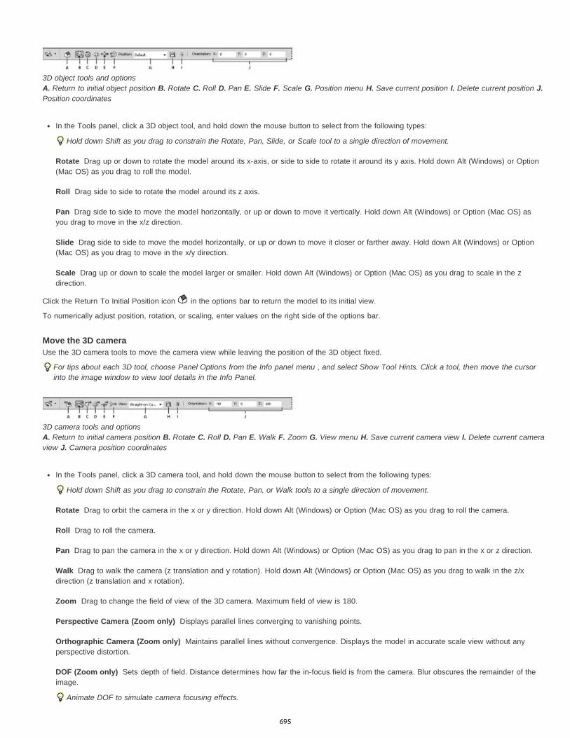
Rotate
Roll
Pan
Slide
Scale
Rotate
Roll
Pan
Walk
Zoom
Perspective Camera (Zoom only)
Orthographic Camera (Zoom only)
DOF (Zoom only)
3D object tools and options A. Return to initial object position B. Rotate C. Roll D. Pan E. Slide F. Scale G. Position menu H. Save current position I. Delete current position J.Position coordinates
In the Tools panel, click a 3D object tool, and hold down the mouse button to select from the following types:
Hold down Shift as you drag to constrain the Rotate, Pan, Slide, or Scale tool to a single direction of movement.
Drag up or down to rotate the model around its x-axis, or side to side to rotate it around its y axis. Hold down Alt (Windows) or Option(Mac OS) as you drag to roll the model.
Drag side to side to rotate the model around its z axis.
Drag side to side to move the model horizontally, or up or down to move it vertically. Hold down Alt (Windows) or Option (Mac OS) asyou drag to move in the x/z direction.
Drag side to side to move the model horizontally, or up or down to move it closer or farther away. Hold down Alt (Windows) or Option(Mac OS) as you drag to move in the x/y direction.
Drag up or down to scale the model larger or smaller. Hold down Alt (Windows) or Option (Mac OS) as you drag to scale in the zdirection.
Click the Return To Initial Position icon in the options bar to return the model to its initial view.
To numerically adjust position, rotation, or scaling, enter values on the right side of the options bar.
Move the 3D cameraUse the 3D camera tools to move the camera view while leaving the position of the 3D object fixed.
For tips about each 3D tool, choose Panel Options from the Info panel menu , and select Show Tool Hints. Click a tool, then move the cursorinto the image window to view tool details in the Info Panel.
3D camera tools and options A. Return to initial camera position B. Rotate C. Roll D. Pan E. Walk F. Zoom G. View menu H. Save current camera view I. Delete current cameraview J. Camera position coordinates
In the Tools panel, click a 3D camera tool, and hold down the mouse button to select from the following types:
Hold down Shift as you drag to constrain the Rotate, Pan, or Walk tools to a single direction of movement.
Drag to orbit the camera in the x or y direction. Hold down Alt (Windows) or Option (Mac OS) as you drag to roll the camera.
Drag to roll the camera.
Drag to pan the camera in the x or y direction. Hold down Alt (Windows) or Option (Mac OS) as you drag to pan in the x or z direction.
Drag to walk the camera (z translation and y rotation). Hold down Alt (Windows) or Option (Mac OS) as you drag to walk in the z/xdirection (z translation and x rotation).
Drag to change the field of view of the 3D camera. Maximum field of view is 180.
Displays parallel lines converging to vanishing points.
Maintains parallel lines without convergence. Displays the model in accurate scale view without anyperspective distortion.
Sets depth of field. Distance determines how far the in-focus field is from the camera. Blur obscures the remainder of theimage.
Animate DOF to simulate camera focusing effects.
695
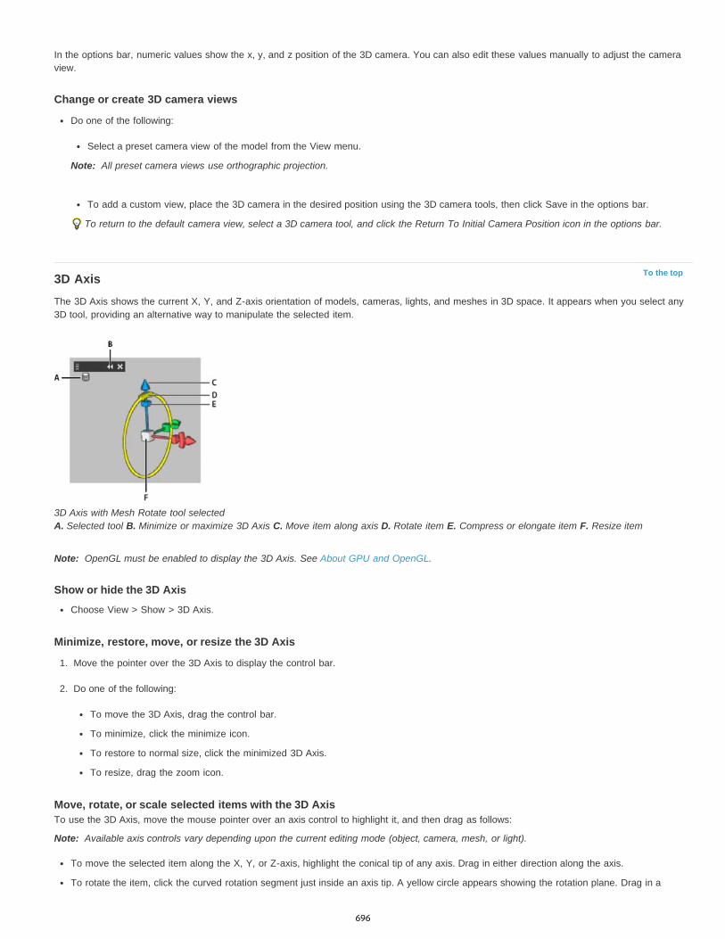
Note:
To the top
Note:
Note:
In the options bar, numeric values show the x, y, and z position of the 3D camera. You can also edit these values manually to adjust the cameraview.
Change or create 3D camera views
Do one of the following:
Select a preset camera view of the model from the View menu.
All preset camera views use orthographic projection.
To add a custom view, place the 3D camera in the desired position using the 3D camera tools, then click Save in the options bar.
To return to the default camera view, select a 3D camera tool, and click the Return To Initial Camera Position icon in the options bar.
3D AxisThe 3D Axis shows the current X, Y, and Z-axis orientation of models, cameras, lights, and meshes in 3D space. It appears when you select any3D tool, providing an alternative way to manipulate the selected item.
3D Axis with Mesh Rotate tool selected A. Selected tool B. Minimize or maximize 3D Axis C. Move item along axis D. Rotate item E. Compress or elongate item F. Resize item
OpenGL must be enabled to display the 3D Axis. See About GPU and OpenGL.
Show or hide the 3D Axis
Choose View > Show > 3D Axis.
Minimize, restore, move, or resize the 3D Axis
1. Move the pointer over the 3D Axis to display the control bar.
2. Do one of the following:
To move the 3D Axis, drag the control bar.
To minimize, click the minimize icon.
To restore to normal size, click the minimized 3D Axis.
To resize, drag the zoom icon.
Move, rotate, or scale selected items with the 3D AxisTo use the 3D Axis, move the mouse pointer over an axis control to highlight it, and then drag as follows:
Available axis controls vary depending upon the current editing mode (object, camera, mesh, or light).
To move the selected item along the X, Y, or Z-axis, highlight the conical tip of any axis. Drag in either direction along the axis.
To rotate the item, click the curved rotation segment just inside an axis tip. A yellow circle appears showing the rotation plane. Drag in a
696
Twitter™ and Facebook posts are not covered under the terms of Creative Commons.
Legal Notices | Online Privacy Policy
clockwise or counterclockwise circle around the 3D Axis center. To rotate more gradually, move the mouse further away from the center ofthe 3D Axis.
To resize the item, drag the center cube in the 3D Axis up or down.
To compress or elongate the item along an axis, drag one of the colored transform cubes either toward or away from the center cube.
To constrain movement to an object plane, move the mouse pointer into the area where two axes intersect, near the center cube. A yellowplane icon appears between two axes. Drag in any direction. You can also move the pointer over the lower part of the center cube to activatethe plane icon.
3D texture editing
697
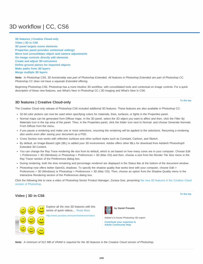
3D workflow | CC, CS6
Note:
To the top
To the top
Note:
3D features | Creative Cloud-onlyVideo | 3D in CS63D panel targets scene elementsProperties panel provides contextual settingsMove tool consolidates object and camera adjustmentsOn-image controls directly edit elementsCreate and adjust 3D extrusionsDefine ground planes for imported objectsMake paths from 3D layersMerge multiple 3D layers
In Photoshop CS6, 3D functionality was part of Photoshop Extended. All features in Photoshop Extended are part of Photoshop CC.Photoshop CC does not have a separate Extended offering.
Beginning Photoshop CS6, Photoshop has a more intuitive 3D workflow, with consolidated tools and contextual on-image controls. For a quickdescription of these new features, see What's New in Photoshop CC | 3D imaging and What's New in CS6.
3D features | Creative Cloud-onlyThe Creative Cloud-only release of Photoshop CS6 included additional 3D features. These features are also available in Photoshop CC:
32-bit color pickers can now be used when specifying colors for materials, lines, surfaces, or lights in the Properties panel.Normal maps can be generated from Diffuse maps. In the 3D panel, select the 3D object you want to affect and then, click the Filter ByMaterials icon in the top area of the panel. Then, in the Properties panel, click the folder icon next to Normal: and choose Generate NormalsFrom Diffuse from the menu.If you pause a rendering and make one or more selections, resuming the rendering will be applied to the selections. Resuming a renderingalso works even after saving your document as a PSD.Cross Section now works with reflective surfaces and other surface styles such as Constant, Cartoon, and Sketch.By default, an Image-Based Light (IBL) is added your 3D environment. Adobe offers other IBLs for download from Adobe® Photoshop®Extended 3D Content.You can change the Ray Trace rendering tile size from its default, which is set based on how many cores are in your computer. Choose Edit> Preferences > 3D (Windows) or Photoshop > Preferences > 3D (Mac OS) and then, choose a size from the Render Tile Size menu in theRay Tracer section of the Preferences dialog box.During rendering, both the time remaining and percentage rendered are displayed in the Status Bar at the bottom of the document window.Photoshop now offers better OpenGL shadows. To specify the shadow quality that works best with your computer, choose Edit >Preferences > 3D (Windows) or Photoshop > Preferences > 3D (Mac OS). Then, choose an option from the Shadow Quality menu in theInteractive Rendering section of the Preferences dialog box.
Click the following link to view a video of Photoshop Senior Product Manager, Zorana Gee, presenting the new 3D features in the Creative Cloudversion of Photoshop.
Video | 3D in CS6
A minimum of 512 MB of VRAM is required for the 3D features in the Creative Cloud version of Photoshop.
Explore all the new 3D features with thisseries of quick videos.... Read More
http://www.youtube.com/user/dramenon/videos
by Daniel Presedo
Adobe's in-house Photoshop 3D expert
Contribute your expertise toAdobe Community Help
698

To the top
To the top
To the top
To the top
To the top
3D panel targets scene elementsIn the streamlined 3D panel, select specific elements you want to edit:
1. At the top of the 3D panel, select Scene , Meshes , Materials , or Lights . 2. Select an individual element (such as Current View in the Scene section). Or select multiple elements to apply uniform properties.3. Adjust settings in the Properties panel, or drag in the document window. (If you drag a specific object or light, the 3D panel then selects that
element.)
Note: To add new lights, click the document icon at the bottom of the Scene and Lights sections. Or click the panel menu to save and loadgroups of lights as a preset.
Properties panel provides contextual settingsAfter you select individual elements in the 3D panel or document window, the Properties panel displays related settings. When you finish adjusting,click the Render icon at the bottom of the panel.
Note: Click the Coordinates icon at the top of the panel to enter precise numerical locations for objects, cameras, and lights. To quickly cyclebetween properties and coordinates, press the V key.
Environment settings include global ambient and image-based lights, and ground plane shadows and reflections.
Scene settings include render presets such as Bounding Box and Wireframe, and custom render options for cross-sections, surfaces, and points.
Camera settings include field of view (FOV), depth of field, and stereo options for anaglyph, lenticular, or side-by-side viewing.
Mesh settings let you catch and cast shadows, adjust 3D extrusions, and edit source text and paths.
Note: To hide an object, but retain its shadows for compositing with 2D images, select Invisible.
Materials settings include texture and bump map settings such as the new Roughness option.
Light settings let you choose from infinite, spot, and point types, and adjust color, intensity, and shadows.
Move tool consolidates object and camera adjustments
The Move tool lets you adjust the placement of objects and camera:
In the options bar, choose between Rotate , Roll , Drag , Slide , and Scale modes.To quickly cycle through these modes, press Shift + V.To quickly switch between camera and Environment controls, click away from 3D objects.
Note: In the document window, a gold document border indicates camera control, a blue border Environment control, a green border Scenecontrol, and no border Mesh control.
On-image controls directly edit elementsWith on-image controls, you can often edit an entire 3D scene without accessing any workspace panels. To maximize your view, press the F keyto cycle between full screen and standard screen modes.
In the document window, you can directly interact with the following elements:
Scene, Mesh, and Light settings To quickly access Scene properties in the document window, right-click the canvas away from 3D objects. Orright-click meshes and lights to access their properties.
Shadows Shift-click them, and then drag to reposition the related light.
Object bounding box controls Click an object once to activate, and then position mouse over various planes; when a plane is shaded yellow,drag to adjust the object along that axis. Or drag corners to rotate on the X or Y axis.
Create and adjust 3D extrusions3D extrusion lets you extend type, selections, closed paths, shapes, and image layers into three dimensions.
1. Select a path, shape layer, type layer, image layer, or specific pixel areas.2. Choose 3D > New 3D Extrusion From Selected Path, Layer, or Current Selection.
Note: To quickly extrude type while editing with the Type tool, click the 3D button in the options bar.
3. With the mesh selected in the 3D panel, select the Deform or Cap icons at the top of the Properties panel.
699

Twitter™ and Facebook posts are not covered under the terms of Creative Commons.
Legal Notices | Online Privacy Policy
To the top
To the top
To the top
4. Edit numerical settings in the Properties panel, or drag the interactive extrusion controls in the document window.
To edit the original path, type, or image layer, selected the related mesh in the 3D panel, and click Edit Source in the Properties panel.
Define ground planes for imported objectsQuickly create perspective planes with the Vanishing Point filter, and snap an imported object to them.
1. Select an image layer, and choose Filter > Vanishing Point.2. Using the Create Plane and Edit Plane tools, create a grid to define a ground plane. Then click OK.3. Choose 3D > New 3D Layer from File.
The imported object is placed on the ground plane you defined.
Make paths from 3D layers
Choose 3D > Make Work Path from 3D Layer to convert the current rendering into a Work Path. This command traces a path over the alphachannel of the layer.
If you render in wireframe mode and adjust the crease threshold value to eliminate some unnecessary lines, you can create a rendering that lookshand drawn when stroked with a Photoshop brush.
Merge multiple 3D layersTo improve performance and interact shadows and reflections for multiple objects, merge as many 3D layers as you need. (Previous Photoshopversions required you to merge two 3D layers at a time.)
Before merging 3D layers, use the Orthographic camera view to position meshes with maximum precision:
1. At the top of the 3D panel, click the Scene icon , and select Current View.2. In the Properties panel, select Orthographic.
700

Adjust HDR exposure and toning
Twitter™ and Facebook posts are not covered under the terms of Creative Commons.
Legal Notices | Online Privacy Policy
Note:
Note:
Exposure
Offset
Gamma
Note:
In Photoshop CS5 and Photoshop CS6, 3D functionality was part of Photoshop Extended. All features in Photoshop Extended are part ofPhotoshop CC. Photoshop CC does not have a separate Extended offering.
The Exposure and HDR Toning adjustments are primarily designed for 32-bit HDR images, but you can also apply them to 16- and 8-bit images tocreate HDR-like effects.
For a video about applying HDR effects to16- or 8-bit images, see www.adobe.com/go/lrvid5011_ps_en
Adjust HDR exposureExposure works by performing calculations in a linear color space (gamma 1.0) rather than the current color space.
1. Do one of the following:
Click the Exposure icon or an Exposure preset in the Adjustments panel.
Choose Layer > New Adjustment Layer > Exposure.
You can also choose Image > Adjustments > Exposure. But keep in mind that this method makes direct adjustments to the imagelayer and discards image information.
2. In the Adjustments panel, set any of the following options:
Adjusts the highlight end of the tonal scale with minimal effect in the extreme shadows.
With 32-bit images, you can also access the Exposure slider at the bottom of the image window.
Darkens the shadows and midtones with minimal effect on the highlights.
Adjusts the image gamma, using a simple power function. Negative values are mirrored around zero (that is, they remain negativebut still get adjusted as if they are positive).
The eyedroppers adjust the luminance values of images (unlike the Levels eyedroppers that affect all color channels).
The Set Black Point eyedropper sets the Offset, shifting the pixel you click to zero.
The Set White Point eyedropper sets the Exposure, shifting the point you click to white (1.0 for HDR images).
The Midtone eyedropper sets the Exposure, making the value you click middle gray.
Adjust HDR toningThe HDR Toning command lets you apply the full range of HDR contrast and exposure settings to individual images.
HDR toning requires flattened layers.
1. Open a 32-, 16-, or 8-bit image in RGB or Grayscale color mode.
2. Choose Image > Adjustments > HDR Toning.
For detailed information about each setting, see Options for 16- or 8-bit images. (In the HDR Toning dialog box, these options appy toimages of all bit depths.)
For more information about HDRHigh dynamic range images
701

3D panel settings
Note:
To the top
3D panel overview3D Scene settings3D Mesh settings3D Materials settings3D Lights settings
In Photoshop CS5 and Photoshop CS6, 3D functionality was part of Photoshop Extended. All features in Photoshop Extended are part ofPhotoshop CC. Photoshop CC does not have a separate Extended offering.
3D panel overviewWhen you select a 3D layer, the 3D panel shows the components of the associated 3D file. The top section of the panel lists the meshes,materials, and lights in the file. The bottom section of the panel shows settings and options for the 3D component selected in the top section.
3D panel displaying Scene options A. Display Scene, Meshes, Materials, or Lights options B. Render presets menu C. Customize render settings D. Select texture to paint on E.Cross section settings F. Toggle overlays G. Add new light H. Delete light
The buttons at the top of the 3D panel filter the components that appear in the top section. Click the Scene button to show all components, clickMaterials to see just materials, and so on.
Display the 3D panel
Do one of the following:
Choose Window > 3D.
702

Note:
Note:
To the top
Double-click the 3D layer icon in the Layers panel.
Choose Window > Workspace > Advanced 3D.
Filter the 3D options displayed
Click the Scene, Mesh, Materials, or Lights button at the top of the 3D panel.
Show or hide a 3D mesh or light
Click the eye icon next to the mesh or light entry in the top section of the 3D panel.
You cannot turn material display on or off from the 3D panel. To show or hide materials, change the visibility settings for theirassociated textures in the Layers panel. See 3D Materials settings.
Access settings for the 3D scene
1. Click the Scene button.
2. If not already selected, click the Scene entry at the top of the component list.
Access settings for a mesh, material, or light
Do one of the following:
Click the Scene button to show all scene components. Then select a mesh, material, or light in the top section.
Click the Meshes, Materials, or Lights button to temporarily display just those components. Then select a single mesh, material, or light.
Expand or collapse materials for a mesh
1. Click the Scene button.
2. Click the triangle to the left of a mesh icon.
View the ground planeThe ground plane is a grid that reflects the position of the ground relative to the 3D model.
To view the ground plane, click the Toggle icon at the bottom of the 3D panel, and select 3D Ground Plane.
The Toggle icon is enabled only if OpenGL is available on your system. See About OpenGL.
Show or hide light guides
At the bottom of the 3D panel, click the Toggle icon , and select 3D Light
Outline the selected material or mesh in the document window
At the bottom of the 3D panel, click the Toggle icon , and select 3D Selection.
When you select materials or meshes in the panel, a colored outline appears in the document window, helping you identify the current item.
To change the color of 3D overlays like material and mesh outlines, customize options in the 3D section of the Preferences dialog box.
Outlining selected items in the document window A. Materials are surrounded by a colored line B. Meshes by a bounding box
3D Scene settings
703
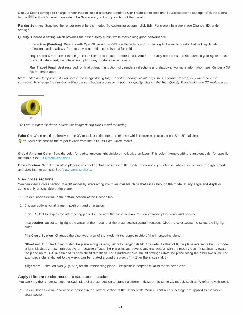
Render Settings
Quality
Interactive (Painting)
Ray Traced Draft
Ray Traced Final
Note:
Paint On
Global Ambient Color
Cross Section
Plane
Intersection
Flip Cross Section
Offset and Tilt
Alignment
Use 3D Scene settings to change render modes, select a texture to paint on, or create cross sections. To access scene settings, click the Scenebutton in the 3D panel, then select the Scene entry in the top section of the panel.
Specifies the render preset for the model. To customize options, click Edit. For more information, see Change 3D rendersettings.
Choose a setting which provides the best display quality while maintaining good performance:
Renders with OpenGL using the GPU on the video card, producing high-quality results, but lacking detailedreflections and shadows. For most systems, this option is best for editing.
Renders using the CPU on the computer motherboard, with draft-quality reflections and shadows. If your system has apowerful video card, the Interactive option may produce faster results.
Best reserved for final output, this option fully renders reflections and shadows. For more information, see Render a 3Dfile for final output.
Tiles are temporarily drawn across the image during Ray Traced rendering. To interrupt the rendering process, click the mouse orspacebar. To change the number of tiling passes, trading processing speed for quality, change the High Quality Threshold in the 3D preferences.
Tiles are temporarily drawn across the image during Ray Traced rendering.
When painting directly on the 3D model, use this menu to choose which texture map to paint on. See 3D painting.You can also choose the target texture from the 3D > 3D Paint Mode menu.
Sets the color for global ambient light visible on reflective surfaces. This color interacts with the ambient color for specificmaterials. See 3D Materials settings.
Select to create a planar cross section that can intersect the model at an angle you choose. Allows you to slice through a modeland view interior content. See View cross sections.
View cross sectionsYou can view a cross section of a 3D model by intersecting it with an invisible plane that slices through the model at any angle and displayscontent only on one side of the plane.
1. Select Cross Section in the bottom section of the Scenes tab.
2. Choose options for alignment, position, and orientation:
Select to display the intersecting plane that creates the cross section. You can choose plane color and opacity.
Select to highlight the areas of the model that the cross section plane intersects. Click the color swatch to select the highlightcolor.
Changes the displayed area of the model to the opposite side of the intersecting plane.
Use Offset to shift the plane along its axis, without changing its tilt. At a default offset of 0, the plane intersects the 3D modelat its midpoint. At maximum positive or negative offsets, the plane moves beyond any intersection with the model. Use Tilt settings to rotatethe plane up to 360 in either of its possible tilt directions. For a particular axis, the tilt settings rotate the plane along the other two axes. Forexample, a plane aligned to the y-axis can be rotated around the x-axis (Tilt 1) or the z-axis (Tilt 2).
Select an axis (x, y, or z) for the intersecting plane. The plane is perpendicular to the selected axis.
Apply different render modes to each cross sectionYou can vary the render settings for each side of a cross section to combine different views of the same 3D model, such as Wireframe with Solid.
1. Select Cross Section, and choose options in the bottom section of the Scenes tab. Your current render settings are applied to the visiblecross section.
0
704
To the top
Note:
Catch Shadows
Note:
Cast Shadows
Invisible
Shadow Opacity
To the top
2. Click Render Settings, or choose 3D > Render Settings.
3. At the top of the dialog box, click the currently unselected Cross Section button .
By default all render settings are turned off for the alternate cross section, making it appear invisible.
4. Choose render options for the alternate cross section, and click OK.
3D Mesh settingsEach mesh in the 3D model appears on a separate line in the top section of the 3D panel. Select a mesh to access mesh settings and informationin the lower section of the 3D panel.
Information includes the number of materials and textures applied to the mesh, as well as the number of vertices and faces it contains. You canalso set the following mesh display options:
To see shadows, set the lights and select Ray Traced for render quality. See 3D Scene settings.
Controls whether the selected mesh displays shadows on its surface from other meshes.
To catch shadows from the ground plane on meshes, select 3D > Ground Plane Shadow Catcher. To align these shadows with objects,select 3D > Snap Object To Ground Plane
Controls whether the selected mesh casts shadows on other mesh surfaces.
Hides the mesh, but displays any shadows on its surface.
Controls the softness of shadows cast by the selected mesh. The setting is helpful when blending 3D objects with layers below.
Show or hide a mesh
Click the eye icon next to a mesh name in the top section of the 3D panel.
Manipulate individual meshesUse the mesh position tools to move, rotate, or scale a selected mesh without moving the model as a whole. The position tools operate in thesame way as the main 3D position tools in the Tools panel. For information on each tool, see Move, rotate, or scale a 3D model.
1. Select a mesh in the top section of the 3D panel. The selected mesh is highlighted with a red box in the lower section of the panel.
2. Select and use a mesh position tool in the lower section of the panel to move the mesh.
To manipulate the entire model while an individual mesh is selected, use the 3D tools in the Tools panel.
3D Materials settingsThe top part of the 3D panel lists the materials used in the 3D file. One or multiple materials may be used to create the overall appearance of themodel. If a model contains several meshes, there may be a specific material associated with each mesh. Or a model can be built from one meshbut use different materials in different areas.
705
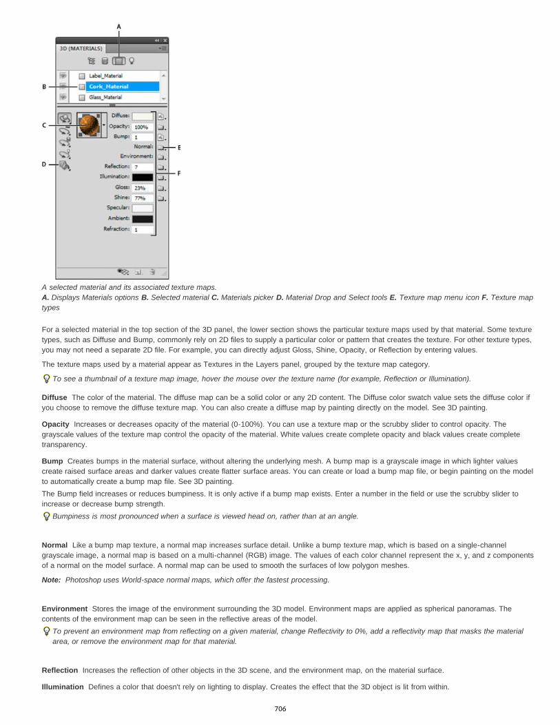
Diffuse
Opacity
Bump
Normal
Note:
Environment
Reflection
Illumination
A selected material and its associated texture maps. A. Displays Materials options B. Selected material C. Materials picker D. Material Drop and Select tools E. Texture map menu icon F. Texture maptypes
For a selected material in the top section of the 3D panel, the lower section shows the particular texture maps used by that material. Some texturetypes, such as Diffuse and Bump, commonly rely on 2D files to supply a particular color or pattern that creates the texture. For other texture types,you may not need a separate 2D file. For example, you can directly adjust Gloss, Shine, Opacity, or Reflection by entering values.
The texture maps used by a material appear as Textures in the Layers panel, grouped by the texture map category.
To see a thumbnail of a texture map image, hover the mouse over the texture name (for example, Reflection or Illumination).
The color of the material. The diffuse map can be a solid color or any 2D content. The Diffuse color swatch value sets the diffuse color ifyou choose to remove the diffuse texture map. You can also create a diffuse map by painting directly on the model. See 3D painting.
Increases or decreases opacity of the material (0-100%). You can use a texture map or the scrubby slider to control opacity. Thegrayscale values of the texture map control the opacity of the material. White values create complete opacity and black values create completetransparency.
Creates bumps in the material surface, without altering the underlying mesh. A bump map is a grayscale image in which lighter valuescreate raised surface areas and darker values create flatter surface areas. You can create or load a bump map file, or begin painting on the modelto automatically create a bump map file. See 3D painting.The Bump field increases or reduces bumpiness. It is only active if a bump map exists. Enter a number in the field or use the scrubby slider toincrease or decrease bump strength.
Bumpiness is most pronounced when a surface is viewed head on, rather than at an angle.
Like a bump map texture, a normal map increases surface detail. Unlike a bump texture map, which is based on a single-channelgrayscale image, a normal map is based on a multi-channel (RGB) image. The values of each color channel represent the x, y, and z componentsof a normal on the model surface. A normal map can be used to smooth the surfaces of low polygon meshes.
Photoshop uses World-space normal maps, which offer the fastest processing.
Stores the image of the environment surrounding the 3D model. Environment maps are applied as spherical panoramas. Thecontents of the environment map can be seen in the reflective areas of the model.
To prevent an environment map from reflecting on a given material, change Reflectivity to 0%, add a reflectivity map that masks the materialarea, or remove the environment map for that material.
Increases the reflection of other objects in the 3D scene, and the environment map, on the material surface.
Defines a color that doesn't rely on lighting to display. Creates the effect that the 3D object is lit from within.
706
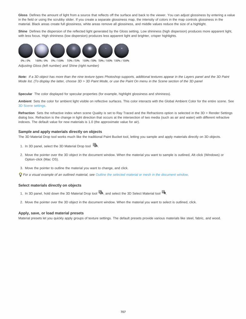
Gloss
Shine
Note:
Specular
Ambient
Refraction
Defines the amount of light from a source that reflects off the surface and back to the viewer. You can adjust glossiness by entering a valuein the field or using the scrubby slider. If you create a separate glossiness map, the intensity of colors in the map controls glossiness in thematerial. Black areas create full glossiness, white areas remove all glossiness, and middle values reduce the size of a highlight.
Defines the dispersion of the reflected light generated by the Gloss setting. Low shininess (high dispersion) produces more apparent light,with less focus. High shininess (low dispersion) produces less apparent light and brighter, crisper highlights.
Adjusting Gloss (left number) and Shine (right number)
If a 3D object has more than the nine texture types Photoshop supports, additional textures appear in the Layers panel and the 3D PaintMode list. (To display the latter, choose 3D > 3D Paint Mode, or use the Paint On menu in the Scene section of the 3D panel
The color displayed for specular properties (for example, highlight glossiness and shininess).
Sets the color for ambient light visible on reflective surfaces. This color interacts with the Global Ambient Color for the entire scene. See3D Scene settings.
Sets the refractive index when scene Quality is set to Ray Traced and the Refractions option is selected in the 3D > Render Settingsdialog box. Refraction is the change in light direction that occurs at the intersection of two media (such as air and water) with different refractiveindexes. The default value for new materials is 1.0 (the approximate value for air).
Sample and apply materials directly on objectsThe 3D Material Drop tool works much like the traditional Paint Bucket tool, letting you sample and apply materials directly on 3D objects.
1. In 3D panel, select the 3D Material Drop tool .
2. Move the pointer over the 3D object in the document window. When the material you want to sample is outlined, Alt-click (Windows) orOption-click (Mac OS).
3. Move the pointer to outline the material you want to change, and click.
For a visual example of an outlined material, see Outline the selected material or mesh in the document window.
Select materials directly on objects
1. In 3D panel, hold down the 3D Material Drop tool , and select the 3D Select Material tool .
2. Move the pointer over the 3D object in the document window. When the material you want to select is outlined, click.
Apply, save, or load material presetsMaterial presets let you quickly apply groups of texture settings. The default presets provide various materials like steel, fabric, and wood.
707
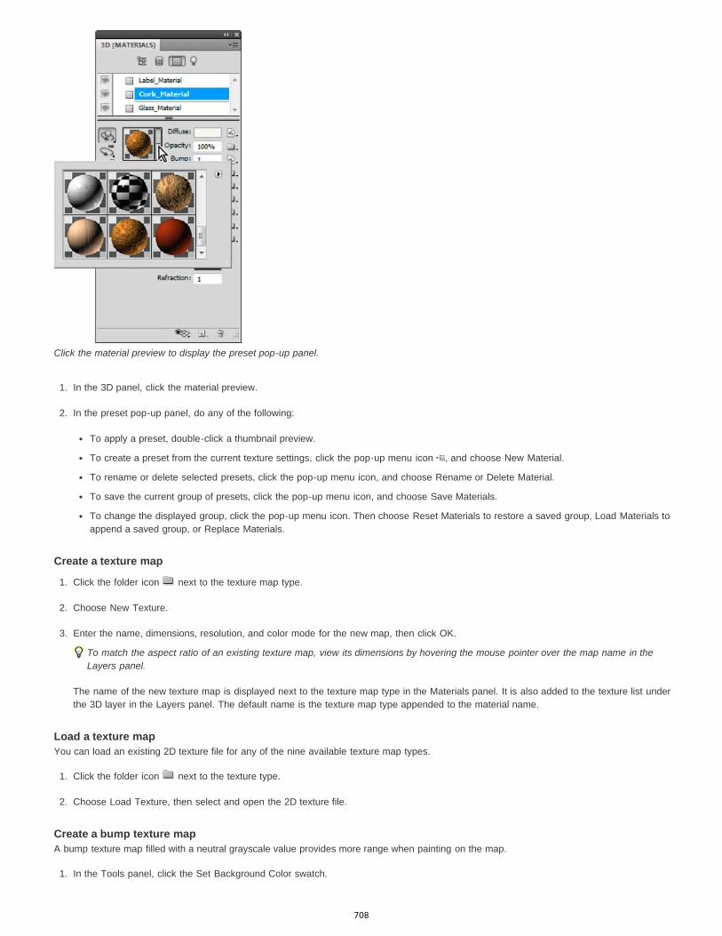
Click the material preview to display the preset pop-up panel.
1. In the 3D panel, click the material preview.
2. In the preset pop-up panel, do any of the following:
To apply a preset, double-click a thumbnail preview.
To create a preset from the current texture settings, click the pop-up menu icon , and choose New Material.
To rename or delete selected presets, click the pop-up menu icon, and choose Rename or Delete Material.
To save the current group of presets, click the pop-up menu icon, and choose Save Materials.
To change the displayed group, click the pop-up menu icon. Then choose Reset Materials to restore a saved group, Load Materials toappend a saved group, or Replace Materials.
Create a texture map
1. Click the folder icon next to the texture map type.
2. Choose New Texture.
3. Enter the name, dimensions, resolution, and color mode for the new map, then click OK.
To match the aspect ratio of an existing texture map, view its dimensions by hovering the mouse pointer over the map name in theLayers panel.
The name of the new texture map is displayed next to the texture map type in the Materials panel. It is also added to the texture list underthe 3D layer in the Layers panel. The default name is the texture map type appended to the material name.
Load a texture mapYou can load an existing 2D texture file for any of the nine available texture map types.
1. Click the folder icon next to the texture type.
2. Choose Load Texture, then select and open the 2D texture file.
Create a bump texture mapA bump texture map filled with a neutral grayscale value provides more range when painting on the map.
1. In the Tools panel, click the Set Background Color swatch.
708

Target
U and V Scale
U and V Offset
To the top
2. In the Color Picker, set brightness to 50%, and set R, G, and B values to equal values. Click OK.
3. In the 3D panel, click the folder icon next to Bump.
4. Choose New Texture.
5. Choose the following settings in the New dialog box:
For Color Mode, choose Grayscale
For Background Contents, choose Background Color.
(Optional) Set Width and Height to match the dimensions of the diffuse texture map for the material.
6. Click OK.
The bump texture map is created and added to the texture map files listed in the Materials panel. It also appears as a texture in the Layers panel.
Open a texture map for editing
Click the image icon , and choose Open Texture.
The texture map opens as a Smart Object in its own document window. After editing the texture, make the 3D model document windowactive to see updates to the model. See 3D texture editing.
Delete a texture map
1. Click the image icon next to the texture type.
2. Choose Remove Texture.
If the deleted texture is an external file, you can reload it using the Load Texture command from the texture map menu. For textures that areinternally referenced by the 3D file, choose Undo or Step Backward to restore a deleted texture.
Edit texture propertiesA texture map is applied to a particular surface area of the model, depending on its UV mapping parameters. You can adjust UV scale and offset ifnecessary to improve how the texture maps to the model.
1. Click the image icon next to the texture type.
2. Choose Edit Properties.
3. Choose a target layer and set UV Scale and Offset values. You can enter values directly or use the scrubby sliders.
Determines whether settings apply to a specific layer or the composite image.
Resize mapped textures. To create a repeating pattern, decrease the value.
Reposition mapped textures.
3D Lights settings3D lights illuminate models from different angles, adding realistic depth and shadows.
Add or delete individual lights
In the 3D panel, do either of the following:
To add a light, click the Create A New Light button , and choose the light type:
Point lights shine in all directions, like light bulbs.
Spot lights shine in a cone shape, which you can adjust.
Infinite lights shine from one directional plane, like sunlight.
Image-based lights map an illuminated image around the 3D scene.
To delete a light, select it from the list at the top of the Lights section . Then click the Delete button at the bottom of the panel.
709
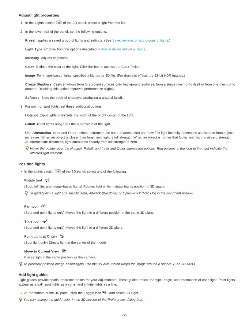
Preset
Light Type
Intensity
Color
Image
Create Shadows
Softness
Hotspot
Falloff
Use Attenuation
Rotate tool
Pan tool
Slide tool
Point Light at Origin
Move to Current View
Adjust light properties
1. In the Lights section of the 3D panel, select a light from the list.
2. In the lower half of the panel, set the following options:
applies a saved group of lights and settings. (See Save, replace, or add groups of lights.)
Choose from the options described in Add or delete individual lights.
Adjusts brightness.
Defines the color of the light. Click the box to access the Color Picker.
For image-based lights, specifies a bitmap or 3D file. (For dramatic effects, try 32-bit HDR images.)
Casts shadows from foreground surfaces onto background surfaces, from a single mesh onto itself or from one mesh ontoanother. Disabling this option improves performance slightly.
Blurs the edge of shadows, producing a gradual falloff.
3. For point or spot lights, set these additional options:
(Spot lights only) Sets the width of the bright center of the light.
(Spot lights only) Sets the outer width of the light.
Inner and Outer options determine the cone of attenuation and how fast light intensity decreases as distance from objectsincreases. When an object is closer than Inner limit, light is full strength. When an object is further that Outer limit, light is at zero strength.At intermediate distances, light attenuates linearly from full strength to zero.
Hover the pointer over the Hotspot, Falloff, and Inner and Outer attenuation options. Red outlines in the icon to the right indicate theaffected light element.
Position lights
In the Lights section of the 3D panel, select any of the following:
(Spot, infinite, and image-based lights) Rotates light while maintaining its position in 3D space.
To quickly aim a light at a specific area, Alt-click (Windows) or Option-click (Mac OS) in the document window.
(Spot and point lights only) Moves the light to a different position in the same 3D plane.
(Spot and point lights only) Moves the light to a different 3D plane.
(Spot light only) Directs light at the center of the model.
Places light in the same position as the camera.
To precisely position image-based lights, use the 3D Axis, which wraps the image around a sphere. (See 3D Axis.)
Add light guidesLight guides provide spatial reference points for your adjustments. These guides reflect the type, angle, and attenuation of each light. Point lightsappear as a ball, spot lights as a cone, and infinite lights as a line.
At the bottom of the 3D panel, click the Toggle icon , and select 3D Light.
You can change the guide color in the 3D section of the Preferences dialog box.
710

Twitter™ and Facebook posts are not covered under the terms of Creative Commons.
Legal Notices | Online Privacy Policy
Save Lights Preset
Add Lights
Replace Lights
Light Guides: A. Point light B. Spot light C. Infinite light
Save, replace, or add groups of lightsTo store groups of lights for later use, save them as a preset. To include the preset in other projects, either add to or replace the existing lights.
From the 3D panel menu , select any of the following:
Saves the current group of lights as a preset that you can reload with the following commands.
To the existing lights, adds a lights preset that you select.
Replaces the existing lights with a preset that you select.
More Help TopicsCreate UV overlays
711
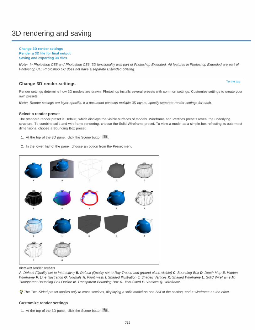
3D rendering and saving
Note:
To the top
Note:
Change 3D render settingsRender a 3D file for final outputSaving and exporting 3D files
In Photoshop CS5 and Photoshop CS6, 3D functionality was part of Photoshop Extended. All features in Photoshop Extended are part ofPhotoshop CC. Photoshop CC does not have a separate Extended offering.
Change 3D render settingsRender settings determine how 3D models are drawn. Photoshop installs several presets with common settings. Customize settings to create yourown presets.
Render settings are layer-specific. If a document contains multiple 3D layers, specify separate render settings for each.
Select a render presetThe standard render preset is Default, which displays the visible surfaces of models. Wireframe and Vertices presets reveal the underlyingstructure. To combine solid and wireframe rendering, choose the Solid Wireframe preset. To view a model as a simple box reflecting its outermostdimensions, choose a Bounding Box preset.
1. At the top of the 3D panel, click the Scene button .
2. In the lower half of the panel, choose an option from the Preset menu.
Installed render presets A. Default (Quality set to Interactive) B. Default (Quality set to Ray Traced and ground plane visible) C. Bounding Box D. Depth Map E. HiddenWireframe F. Line Illustration G. Normals H. Paint mask I. Shaded Illustration J. Shaded Vertices K. Shaded Wireframe L. Solid Wireframe M.Transparent Bounding Box Outline N. Transparent Bounding Box O. Two-Sided P. Vertices Q. Wireframe
The Two-Sided preset applies only to cross sections, displaying a solid model on one half of the section, and a wireframe on the other.
Customize render settings
1. At the top of the 3D panel, click the Scene button .
712
Face Style
Solid
Unlit Texture
Flat
Constant
Bounding Box
Normals
Depth Map
Paint Mask
Texture
Render For Final Output
Reflections, Refractions, Shadows
Remove Backfaces
Edge Style
Crease Threshold
Line Width
Remove Backfaces
Remove Hidden Lines
Vertex Style
Radius
Remove Backfaces
Remove Hidden Vertices
2. To the right of the Render Settings menu, click Edit.
3. (Optional) To see the effect of new settings as you make changes, select Preview. Or, deselect this option to slightly improve performance.
To specify unique settings for each half of a cross section, click the cross section buttons at the top of the dialog box.
4. Enable Face, Edge, Vertex, Volume, or Stereo rendering by clicking the checkboxes on the left side of the dialog box. Then adjust therelated settings below.
For information about Volume options, used primarily with DICOM images, see View the 3D volume in different render modes.
Face optionsFace options determine how model surfaces appear.
Draws surfaces using any of these methods:
Draws without shadows or reflections using the GPU on an OpenGL video card.
Draws without lighting, instead displaying only the selected Texture option. (Diffuse is selected by default.)
Applies the same surface normal for all vertices in a face, creating a faceted look.
Replaces textures with currently specified color.To adjust face, edge, or vertex color, click the Color box.
Displays boxes reflecting the outermost dimensions of each component.
Displays X, Y, and Z components for surface normals in different RGB colors.
Displays a gray model, using luminosity to reveal depth.
Displays paintable regions as white, oversampled regions in red, and undersampled regions in blue. (See Identify paintableareas.)
When Face Style is set to Unlit Texture, specifies the texture map. (See 3D Materials settings.)
For exported video animations, produces smoother shadows and realistic color bleeds from reflected objects andenvironments. This option requires more processing time, however.
Show or hide these Ray Traced rendering features.
Hides surfaces on the back of two-sided components.
Edge optionsEdge options determine how wireframe lines appear.
Reflects the Constant, Flat, Solid, and Bounding Box options described for Face Style above.
Adjusts the number of structural lines that appear in the model. A crease or line, is formed when two polygons in a modelcome together at a particular angle. If edges meet at an angle below the Crease Threshold setting (0-180), the line they form is removed. At asetting of 0, the entire wireframe is displayed.
Specifies width in pixels.
Hides edges on the back of two-sided components.
Removes lines that foreground lines overlap.
Vertex optionsVertex options adjust the appearance of vertices (intersections of polygons that make up the wireframe model).
Reflects the Constant, Flat, Solid, and Bounding Box options described for Face Style above.
Determines the pixel radius of each vertex.
Hides vertices on the back of two-sided components.
Removes vertices that foreground vertices overlap.
Stereo optionsStereo options adjust settings for images that will either be viewed with red-blue glasses or printed to objects that include a lenticular lens.
713
Stereo Type
Parallax
Lenticular Spacing
Focal Plane
To the top
Note:
To the top
Specifies Red/Blue for images viewed with colored glasses or Vertical Interlaced for lenticular prints.
Adjusts the distance between the two stereo cameras. Higher settings increase three-dimensional depth but reduce depth of field,making items ahead or behind the focal plane appear out of focus.
For vertically interlaced images, specifies how many lines per inch the lenticular lens has.
Determines the position of the focal plane relative to the center of the model’s bounding box. Enter negative values to move theplane forward, and positive values to move it backward.
Save or delete a render preset
1. At the top of the 3D panel, click the Scene button .
2. Click Render Settings.
3. Do either of the following:
To save a preset, customize settings, and click the Save button .
To delete a preset, select it from the Preset menu, and click the Delete button .
Render a 3D file for final outputWhen you’ve finished working with your 3D file, create a final render to produce the highest quality version for output to web, print, or animation.Final rendering uses ray tracing and a higher sampling rate to capture more realistic lighting and shadow effects.
Use final render mode to enhance the following effects in your 3D scene:
Image based lighting and global ambient color.
Lighting from object reflectance (color bleed).
Reduced noise in soft shadows.
A final render can be time-consuming, depending on the model, lighting, and maps in your 3D scene.
1. Make any necessary adjustments to your model, including lighting and shadow effects.
You don’t need to change Anti-Alias settings for the scene before rendering. By default, theBest setting is used.
2. At the top of the 3D panel, click the Scene button , and then click the Scene entry in the list below.
3. From the Quality menu in the lower half of the panel, select Ray Traced Final.
After the render is complete, you can flatten the 3D scene for output in anther format, composite the 3D scene with 2D content, or print directlyfrom the 3D layer.
For exported video animations, Render For Final Output is available as an option in the 3D Render Settings dialog box. See Customize rendersettings.
Saving and exporting 3D filesTo preserve the 3D content in a file, save the file in Photoshop format or another supported image format. You can also export a 3D layer as a filein a supported 3D file format.
Export a 3D layerYou can export 3D layers in all supported 3D formats: Collada DAE, Wavefront/OBJ, U3D, and Google Earth 4 KMZ. When choosing an exportformat, consider the following factors:
Texture layers are saved in all 3D file formats; however, U3D preserves only Diffuse, Environment, and Opacity texture maps.
Wavefront/OBJ format does not save camera settings, lights, or animation.
Only Collada DAE saves render settings.
To export a 3D layer, do the following:
1. Choose 3D > Export 3D layer
714
Twitter™ and Facebook posts are not covered under the terms of Creative Commons.
Legal Notices | Online Privacy Policy
2. Choose a format for exporting textures:
U3D and KMZ support JPEG or PNG as texture formats.
DAE and OBJ support all Photoshop-supported image formats for textures.
3. (Optional) If exporting to U3D format, choose an encoding option. ECMA 1 is compatible with Acrobat 7.0; ECMA 3 is compatible withAcrobat 8.0 and later and provides some mesh compression.
4. Click OK to export.
Save a 3D fileTo preserve 3D model position, lighting, render mode, and cross sections, save files with 3D layers in PSD, PSB, TIFF, or PDF format.
Choose File > Save or File > Save As, select Photoshop (PSD), Photoshop PDF, or TIFF format, and click OK.
715

Creating 3D objects and animations
Note:
To the top
Note:
Mesh tools
Repoussé Presets
Extrude
Inflate
Materials
Create 3D repoussé | CS5Create 3D objects from 2D imagesCreate 3D animations
In Photoshop CS5 and CS6, 3D functionality was part of Photoshop Extended. All features in Photoshop Extended are part of PhotoshopCC. Photoshop CC does not have a separate Extended offering.
Create 3D repoussé | CS5Beginning Photoshop CS6, the repousse feature has changed and is now called 3D Extrusion. For details, see Create and adjust 3D
Extrusions.
The term repoussé describes a metalworking technique in which object faces are shaped and patterned by hammering on the opposite side. InPhotoshop, the Repoussé command converts 2D objects into 3D meshes, which you can precisely extrude, inflate, and reposition in 3D space.
The Repoussé command works with RGB images. If you start with a grayscale image, Repoussé converts it to RGB. The Repoussé command isnot available for CMYK or Lab images.
For a video about converting from 2D to 3D with Repoussé, see www.adobe.com/go/lrvid5003_ps_en
Applying Repoussé to a pixel selection A. Increasing the depth of extrusion B. Twisting the extrusion 180° C. Inflating the front
1. Create a pixel selection, or select a text layer, layer mask, or work path.
2. Choose 3D > Repoussé, then choose the item that reflects your selection in step 1.
3. Set the following options:
Available along the upper left of the dialog box, these tools function like 3D object tools. See Move, rotate, or scale a modelwith 3D object tools and Move, rotate, or scale selected items with the 3D Axis.
Apply a predefined group of settings. To create your own preset from custom settings, click the pop-up menu , andchoose New Repoussé Preset.
To organize groups of presets, see Work with the Preset Manager.
Extends the original 2D shape in 3D space. Depth controls the length of extrusion; Scale controls the width. Select Bend for acurved extrusion, or Shear for a straight one, then set X and Y Angle to control the horizontal and vertical tilt. If desired, enter Twist indegrees.
To change the bend or shear origin, click a point on the reference icon .
Expands or collapses the middle of the front or back. Positive Angle settings expand, negative collapse. Strength controls the levelof inflation.
Apply materials such as brick or cotton either globally or to various sides of the object. (Bevel1 is the front bevel; Bevel2 theback.) For more information, see Apply, save, or load material presets.
716
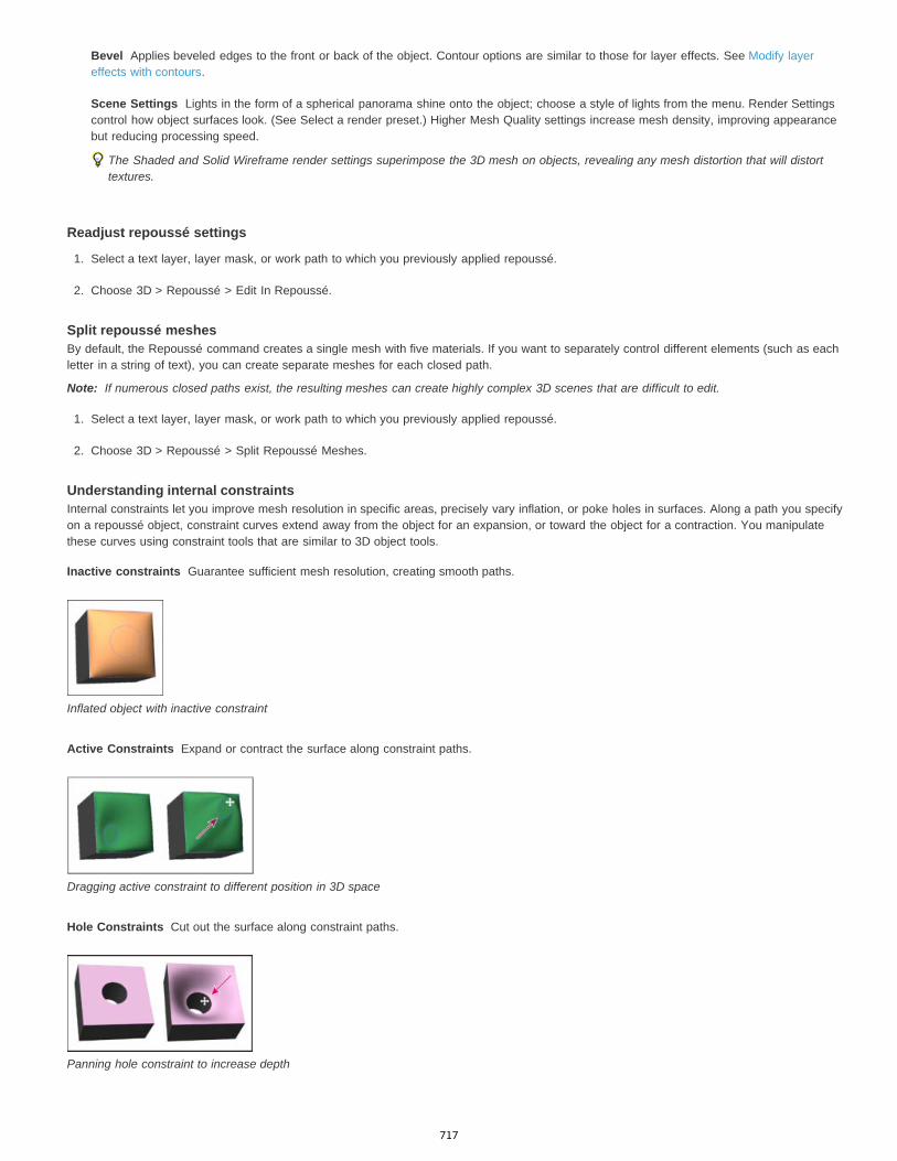
Bevel
Scene Settings
Note:
Inactive constraints
Active Constraints
Hole Constraints
Applies beveled edges to the front or back of the object. Contour options are similar to those for layer effects. See Modify layereffects with contours.
Lights in the form of a spherical panorama shine onto the object; choose a style of lights from the menu. Render Settingscontrol how object surfaces look. (See Select a render preset.) Higher Mesh Quality settings increase mesh density, improving appearancebut reducing processing speed.
The Shaded and Solid Wireframe render settings superimpose the 3D mesh on objects, revealing any mesh distortion that will distorttextures.
Readjust repoussé settings
1. Select a text layer, layer mask, or work path to which you previously applied repoussé.
2. Choose 3D > Repoussé > Edit In Repoussé.
Split repoussé meshesBy default, the Repoussé command creates a single mesh with five materials. If you want to separately control different elements (such as eachletter in a string of text), you can create separate meshes for each closed path.
If numerous closed paths exist, the resulting meshes can create highly complex 3D scenes that are difficult to edit.
1. Select a text layer, layer mask, or work path to which you previously applied repoussé.
2. Choose 3D > Repoussé > Split Repoussé Meshes.
Understanding internal constraintsInternal constraints let you improve mesh resolution in specific areas, precisely vary inflation, or poke holes in surfaces. Along a path you specifyon a repoussé object, constraint curves extend away from the object for an expansion, or toward the object for a contraction. You manipulatethese curves using constraint tools that are similar to 3D object tools.
Guarantee sufficient mesh resolution, creating smooth paths.
Inflated object with inactive constraint
Expand or contract the surface along constraint paths.
Dragging active constraint to different position in 3D space
Cut out the surface along constraint paths.
Panning hole constraint to increase depth
717

Constraint tools
Position coordinates
Side
Strength
Angle
To the top
Create internal constraints from selections, work paths, or text
1. Do one of the following:
Create a selection or path that falls entirely within the front surface of a repoussé object.
For text objects that already have internal paths, like the letter A, skip to step 3.
2. Choose 3D > Repoussé > Create Constraints From Selection or Work Path.
3. In the Repoussé dialog box, click the triangle to expand the Internal Constraints section.
4. Choose a Type option. For Active or Hole, the following options are available:
Adjust the constraint curve and function similarly to 3D object tools. See 3D object and camera tools.
If the repoussé object contains multiple internal paths (for example, both ovals in the number 8), select each path individually with theconstraint tools.
Let you precisely place constraints in 3D space.
Lets you apply uniform Strength and Angle settings to both sides, or unique settings to each.
Each constraint curve has two sides; the orientation of those sides depends on how a curve divides the surface. The Left and Right menuoptions reflect a vertical constraint. For a horizontal constraint, Left and Right mean up and down, and for a closed constraint, those optionsmean inside and outside.
Side settings A. Both creates consistent deformation. B. Left or Right allows for varied deformation.
Controls the level of inflation along the path.
Controls the direction of inflation.
Remove an internal constraint
1. Select a 3D repoussé layer that includes an internal constraint.
2. Choose 3D > Repoussé > Edit In Repoussé.
3. In the Internal Constraints section, click Delete.
To reapply a deleted constraint, click Add Selection or Add Path.
Create 3D objects from 2D imagesPhotoshop can build a variety of basic 3D objects using 2D layers as a starting point. After creating a 3D object, you can move it in 3D space,change render settings, add lighting, or merge it with other 3D layers.
Convert 2D layers into 3D postcards (planes with 3D properties). If your starting layer is a text layer, any transparency is retained.
Wrap a 2D layer around a 3D object, such as a cone, cube, or cylinder.
Create a 3D mesh from the grayscale information in a 2D image.
Simulate a metalworking technique called repoussé by extruding a 2D object in 3D space. See Create 3D repoussé.
Build a 3D volume from a multi-frame file such as a DICOM medical imaging file. Photoshop combines the individual slices of the file into a3D object that you can manipulate in 3D space and view from any angle. You can apply various 3D volume render effects to optimize thedisplay of various materials in the scan, such as bone or soft tissue. See Create a 3D volume.
For a video about creating 3D content from 2D layers, see www.adobe.com/go/lrvid4006_ps.
718
Note:
Note:
Plane
Two-Sided Plane
Cylinder
Sphere
Create a 3D postcardYou can add a 3D postcard to an existing 3D scene to create a surface that displays shadows and reflections from other objects in the scene.
1. Open a 2D image and select the layer you want to convert to a postcard.
2. Choose 3D > New 3D Postcard From Layer.
The 2D layer is converted to a 3D layer in the Layers panel. The 2D layer content is applied as a material to both sides of the postcard.
The original 2D layer appears in the Layers panel as the Diffuse texture map for the 3D postcard object. (See 3D panel overview.)
The 3D layer retains the dimensions of the original 2D image.
3. (Optional) To add the 3D postcard as a surface plane to a 3D scene, merge the new 3D layer with an existing 3D layer containing other 3Dobjects, then align it as necessary. (See Combine 3D objects.)
4. To retain the new 3D content, export the 3D layer in a 3D file format or save it in PSD format. (See Export 3D layers.)
Create 3D shapesDepending on the object type you choose, the resulting 3D model can contain one or more meshes. The Spherical Panorama option maps apanoramic image inside a 3D sphere.
1. Open a 2D image and select the layer that you want to convert to a 3D shape.
2. Choose 3D > New Shape From Layer, and select a shape from the menu. Shapes include single-mesh objects like a donut, sphere, or hat,as well as multiple mesh objects such as a cone, cube, cylinder, soda can, or wine bottle.
You can add your own custom shapes to the shape menu. Shapes are Collada (.dae) 3D model files. To add a shape, place theCollada model file in the Presets\Meshes folder inside the Photoshop program folder.
The 2D layer is converted to a 3D layer in the Layers panel.
The original 2D layer appears in the Layers panel as a Diffuse texture map. It may be used on one or more surfaces of the new 3Dobject. Other surfaces may be assigned a default diffuse texture map with a default color setting. See 3D panel overview.
3. (Optional) Use the Spherical Panorama option if you are using a panoramic image as your 2D input. This option converts a complete 360 x180 degree spherical panorama to a 3D layer. Once converted to a 3D object, you can paint areas of the panorama that are typically difficultto reach, such as the poles or areas containing straight lines. For information on creating a 2D panorama by stitching images together, seeCreate 360 degree panoramas.
4. Export the 3D layer in a 3D file format or save in PSD format to retain the new 3D content. See Export 3D layers.
Create a 3D meshThe New Mesh from Grayscale command converts a grayscale image into a depth map, which translates lightness values into a surface of varyingdepth. Lighter values create raised areas in the surface, darker values create lower areas. Photoshop then applies the depth map to one of fourpossible geometries to create a 3D model.
1. Open a 2D image and select one or more layers that you want to convert to a 3D mesh.
2. (Optional) Convert the image to grayscale mode. (Choose Image > Mode > Grayscale, or use Image > Adjustments > Black & White to fine-tune the grayscale conversion.
If you use an RGB image as input when creating a mesh, the green channel is used to generate the depth map.
3. (Optional) Make adjustments to the grayscale image if necessary to limit the range of lightness values.
4. Choose 3D > New Mesh From Grayscale, and then select a mesh option.
Applies depth map data to a planar surface.
Creates two planes reflected along a central axis and applies depth map data to both planes.
Applies depth map data outward from the center of a vertical axis.
Applies depth map data radially outward from a center point.
Photoshop creates a 3D layer containing the new mesh. It also creates Diffuse, Opacity, and Planar Depth Map texture maps for the 3D object,
719

Twitter™ and Facebook posts are not covered under the terms of Creative Commons.
Legal Notices | Online Privacy Policy
Note:
To the top
using the original grayscale or color layer.
You can reopen the Planar Depth Map as a Smart Object at any time and edit it. When you save it, the mesh is regenerated.
The Opacity texture map does not appear in the Layers panel, because that map uses the same texture file as the Diffuse map (the original2D layer). When two texture maps reference the same file, the file appears only once in the Layers panel.
Create 3D animationsUsing the Photoshop Animation timeline, you can create 3D animations that move a 3D model through space and change the way it displays overtime. You can animate any of the following properties of a 3D layer:
3D object or camera position. Use the 3D position or camera tools to move the model or 3D camera over time. Photoshop can tween framesbetween position or camera movements to create smooth motion effects.
3D render settings. Change render modes, with the ability to tween transitions between some render modes. For example, change Verticesmode gradually to Wireframe over time, to simulate the sketching-in of a model’s structure.
3D cross section. Rotate an intersecting plane to display a changing cross section over time. Change cross section settings between framesto highlight different model areas during an animation.
For high quality animations, you can render each animation frame using the Render for Final Output render setting. See Change rendering effects.
Creating timeline animations
720
3D painting
To the top
To the top
Reveal surfaces to paint onSet the paint falloff angleIdentify paintable areas
You can use any Photoshop painting tools to paint directly on a 3D model just as you would on a 2D layer. Use selection tools to target specificmodel areas or let Photoshop identify and highlight paintable areas. 3D menu commands let you clear away areas of a model to access interior orhidden portions for painting.
When painting directly on the model, you can choose which underlying texture map to apply paint to. Typically paint is applied to the diffusetexture map, which gives a model material its color properties. You can also paint on other texture maps, such as the bump map or opacity map. Ifyou paint on an area of the model that lacks the type of texture map you’re painting on, a texture map is automatically created.
1. Use the 3D position tools to orient the model so that the area you want to paint on is facing forward.
If the model area is hidden, you can temporarily cut away surface areas that are blocking your view. See Reveal surfaces to paint on.
If you are painting on curved or irregular surfaces, you can get visual feedback before you paint of which areas can best receive paint. SeeIdentify paintable areas. You can also set the paint fall-off angle, which controls the amount of paint applied to angled surfaces. See Set thepaint falloff angle.
2. Do one of the following to set the texture map to paint on:
Choose 3D > 3D Paint Mode, and select a map type.
In the 3D panel, select the Scene panel. Choose a map type from the Paint On menu.
If you try to paint on a texture map type that the material doesn’t contain, Photoshop prompts you to create a map. For information on maptypes, see 3D Materials settings (Photoshop Extended).
3. (Optional) Using any selection tool, create a selection on the 3D model to restrict the area that you want to paint on.
4. Apply paint using the Paintbrush tool. You can also use any other tool in the second section of the Tools panel, such as the Paint Bucket,Smudge, Dodge, Burn, or Blur tools.
While painting (after completing a stroke), you can view the effect of the painting on the texture map itself. Do one of the following:
Double-click the texture map in the Layers panel to open it.
In the Materials section of the 3D panel, select the material for the area you are painting. In the lower section of the panel, click themenu icon for the texture map you’re painting, and choose Open Texture.
Reveal surfaces to paint onFor more complex models with interior or hidden areas, you can hide sections of the model for easier access to surfaces you want to paint. Forexample, to apply paint to the dashboard of a car model, you can temporarily cut away the roof or windshield, then zoom inside the car to get anunobstructed view.
1. Select an area of the model that you want to cut away, using a selection tool such as the Lasso or Marquee tool.
2. Use any of the following 3D menu commands to reveal or hide areas of the model:Hide Nearest Surface hides only the first layer of model polygons within the 2D selection. To quickly peel away surfaces of the model, youcan use this command repeatedly while keeping the selection area active.
When hiding surfaces, rotate the model if necessary to position surfaces so that they are perpendicular to your current view.
Only Hide Enclosed Polygons When selected, the Hide Nearest Surface command only affects polygons that are fully within the selection.When unchecked, it hides any polygons touched by the selection.
Invert Visible Surfaces Makes currently visible surfaces invisible, and invisible surfaces visible.
Reveal All Surfaces Makes all hidden surfaces visible again.
Set the paint falloff angleWhen painting on a model, the paint falloff angle controls how much paint is applied to a surface as it curves away from the forward-facing view.The falloff angle is calculated based on a “normal”, or straight line projecting out from the part of the model surface that faces you. For example, ina spherical model such as a soccer ball, the falloff angle to the exact center of the ball as it faces you is 0 degrees. As the surface of the ball
721
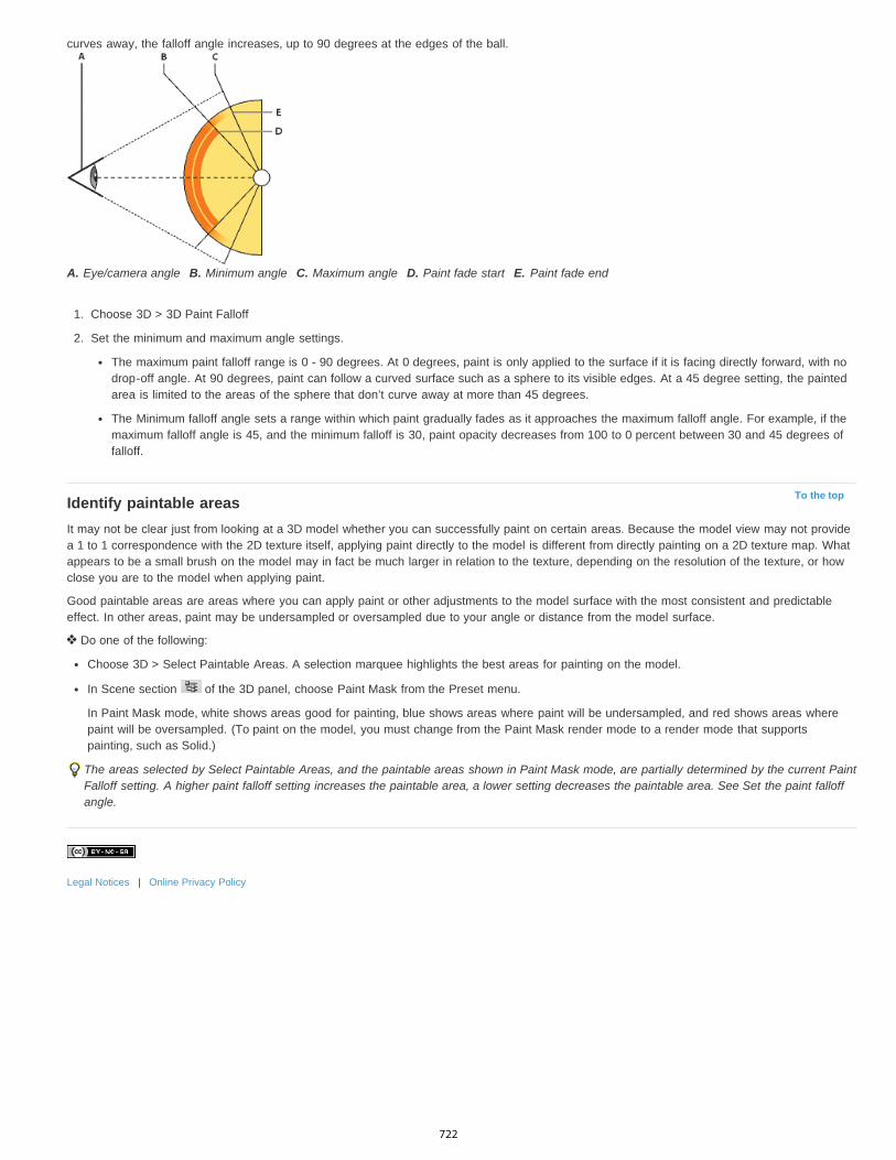
To the top
curves away, the falloff angle increases, up to 90 degrees at the edges of the ball.
A. Eye/camera angle B. Minimum angle C. Maximum angle D. Paint fade start E. Paint fade end
1. Choose 3D > 3D Paint Falloff
2. Set the minimum and maximum angle settings.
The maximum paint falloff range is 0 - 90 degrees. At 0 degrees, paint is only applied to the surface if it is facing directly forward, with nodrop-off angle. At 90 degrees, paint can follow a curved surface such as a sphere to its visible edges. At a 45 degree setting, the paintedarea is limited to the areas of the sphere that don’t curve away at more than 45 degrees.
The Minimum falloff angle sets a range within which paint gradually fades as it approaches the maximum falloff angle. For example, if themaximum falloff angle is 45, and the minimum falloff is 30, paint opacity decreases from 100 to 0 percent between 30 and 45 degrees offalloff.
Identify paintable areasIt may not be clear just from looking at a 3D model whether you can successfully paint on certain areas. Because the model view may not providea 1 to 1 correspondence with the 2D texture itself, applying paint directly to the model is different from directly painting on a 2D texture map. Whatappears to be a small brush on the model may in fact be much larger in relation to the texture, depending on the resolution of the texture, or howclose you are to the model when applying paint.
Good paintable areas are areas where you can apply paint or other adjustments to the model surface with the most consistent and predictableeffect. In other areas, paint may be undersampled or oversampled due to your angle or distance from the model surface.
Do one of the following:
Choose 3D > Select Paintable Areas. A selection marquee highlights the best areas for painting on the model.
In Scene section of the 3D panel, choose Paint Mask from the Preset menu.
In Paint Mask mode, white shows areas good for painting, blue shows areas where paint will be undersampled, and red shows areas wherepaint will be oversampled. (To paint on the model, you must change from the Paint Mask render mode to a render mode that supportspainting, such as Solid.)
The areas selected by Select Paintable Areas, and the paintable areas shown in Paint Mask mode, are partially determined by the current PaintFalloff setting. A higher paint falloff setting increases the paintable area, a lower setting decreases the paintable area. See Set the paint falloffangle.
Legal Notices | Online Privacy Policy
722
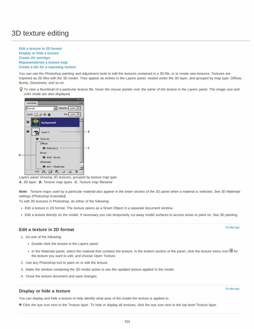
3D texture editing
To the top
To the top
Edit a texture in 2D formatDisplay or hide a textureCreate UV overlaysReparameterize a texture mapCreate a tile for a repeating texture
You can use the Photoshop painting and adjustment tools to edit the textures contained in a 3D file, or to create new textures. Textures areimported as 2D files with the 3D model. They appear as entries in the Layers panel, nested under the 3D layer, and grouped by map type: Diffuse,Bump, Glossiness, and so on.
To view a thumbnail of a particular texture file, hover the mouse pointer over the name of the texture in the Layers panel. The image size andcolor mode are also displayed.
Layers panel showing 3D textures, grouped by texture map typeA. 3D layer B. Texture map types C. Texture map filename
Note: Texture maps used by a particular material also appear in the lower section of the 3D panel when a material is selected. See 3D Materialssettings (Photoshop Extended).To edit 3D textures in Photoshop, do either of the following:
Edit a texture in 2D format. The texture opens as a Smart Object in a separate document window.
Edit a texture directly on the model. If necessary you can temporarily cut away model surfaces to access areas to paint on. See 3D painting.
Edit a texture in 2D format1. Do one of the following:
Double-click the texture in the Layers panel.
In the Materials panel, select the material that contains the texture. In the bottom section of the panel, click the texture menu icon forthe texture you want to edit, and choose Open Texture.
2. Use any Photoshop tool to paint on or edit the texture.
3. Make the window containing the 3D model active to see the updated texture applied to the model.
4. Close the texture document and save changes.
Display or hide a textureYou can display and hide a texture to help identify what area of the model the texture is applied to.
Click the eye icon next to the Texture layer. To hide or display all textures, click the eye icon next to the top-level Texture layer.
723
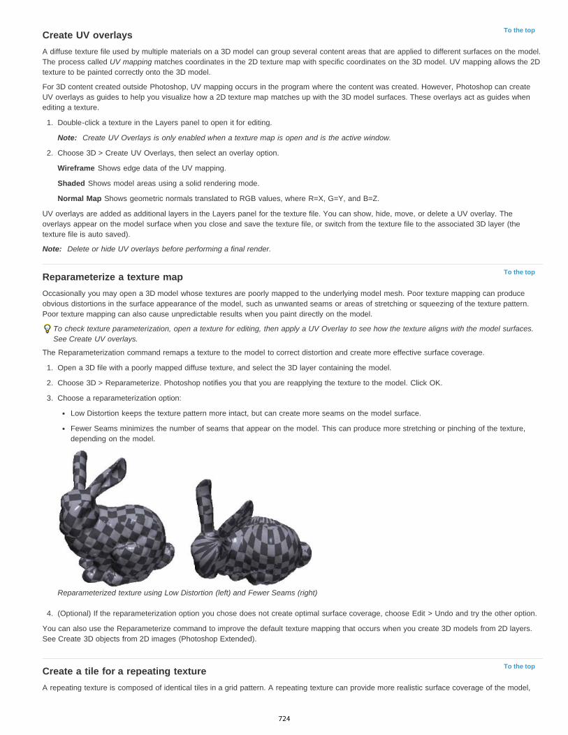
To the top
To the top
To the top
Create UV overlaysA diffuse texture file used by multiple materials on a 3D model can group several content areas that are applied to different surfaces on the model.The process called UV mapping matches coordinates in the 2D texture map with specific coordinates on the 3D model. UV mapping allows the 2Dtexture to be painted correctly onto the 3D model.
For 3D content created outside Photoshop, UV mapping occurs in the program where the content was created. However, Photoshop can createUV overlays as guides to help you visualize how a 2D texture map matches up with the 3D model surfaces. These overlays act as guides whenediting a texture.
1. Double-click a texture in the Layers panel to open it for editing.
Note: Create UV Overlays is only enabled when a texture map is open and is the active window.
2. Choose 3D > Create UV Overlays, then select an overlay option.
Wireframe Shows edge data of the UV mapping.
Shaded Shows model areas using a solid rendering mode.
Normal Map Shows geometric normals translated to RGB values, where R=X, G=Y, and B=Z.
UV overlays are added as additional layers in the Layers panel for the texture file. You can show, hide, move, or delete a UV overlay. Theoverlays appear on the model surface when you close and save the texture file, or switch from the texture file to the associated 3D layer (thetexture file is auto saved).
Note: Delete or hide UV overlays before performing a final render.
Reparameterize a texture mapOccasionally you may open a 3D model whose textures are poorly mapped to the underlying model mesh. Poor texture mapping can produceobvious distortions in the surface appearance of the model, such as unwanted seams or areas of stretching or squeezing of the texture pattern.Poor texture mapping can also cause unpredictable results when you paint directly on the model.
To check texture parameterization, open a texture for editing, then apply a UV Overlay to see how the texture aligns with the model surfaces.See Create UV overlays.
The Reparameterization command remaps a texture to the model to correct distortion and create more effective surface coverage.
1. Open a 3D file with a poorly mapped diffuse texture, and select the 3D layer containing the model.
2. Choose 3D > Reparameterize. Photoshop notifies you that you are reapplying the texture to the model. Click OK.
3. Choose a reparameterization option:
Low Distortion keeps the texture pattern more intact, but can create more seams on the model surface.
Fewer Seams minimizes the number of seams that appear on the model. This can produce more stretching or pinching of the texture,depending on the model.
Reparameterized texture using Low Distortion (left) and Fewer Seams (right)
4. (Optional) If the reparameterization option you chose does not create optimal surface coverage, choose Edit > Undo and try the other option.
You can also use the Reparameterize command to improve the default texture mapping that occurs when you create 3D models from 2D layers.See Create 3D objects from 2D images (Photoshop Extended).
Create a tile for a repeating textureA repeating texture is composed of identical tiles in a grid pattern. A repeating texture can provide more realistic surface coverage of the model,
724
use less storage, and improve rendering performance. You can convert any 2D file into a tiled painting. After previewing how multiple tiles interactin the painting, you save one tile for use as a repeating texture.
To set up a mesh for a repeating texture, use the 3D application that created the model.
1. Open a 2D file.
2. Select one or more layers in the file, then choose 3D > New Tiled Painting.
The 2D file is converted to a 3D plane containing nine identical tiles of the original content. Image dimensions remain the same.
3. Edit the tiled texture with painting tools, filters, or other techniques. (Changes you make to one tile automatically appear in the others.)
4. Save a single tile as a 2D image: In the Materials section of the 3D panel, choose Open Texture from the Diffuse menu . Then chooseFile > Save As, and specify a name, location, and format.
Unless you plan to use the original, nine-tile painting independently, close it without saving.
5. To load the tile as a repeating texture, open a 3D model file. In the Materials section of the 3D panel, choose Load Texture from the Diffusemenu, and select the file you saved above.
Legal Notices | Online Privacy Policy
725
Combining and converting 3D objects
To the top
To the top
Combine 3D objectsCombine 3D and 2D layersConvert a 3D layer to a 2D layerConvert a 3D layer to a Smart Object
Combine 3D objectsMerging 3D layers allows you to combine multiple 3D models in one scene. Once combined, each 3D model can be manipulated separately, oryou can use position and camera tools on all models simultaneously.
1. Open two document windows, each containing a 3D layer.
2. Make the source document (the file from which you are copying the 3D layer) active.
3. Select the 3D layer in the Layers panel and drag it into the window of the target document (the file which will contain the combined 3Dobjects).
The 3D layer is added as a new 3D layer in the target document. It becomes the active layer in the Layers panel of the target document.
4. In the Tools panel, select a 3D camera tool.
5. In the options bar, from the Position menu, select the layer name for the original 3D layer in the target file.
After you match the camera position of the two 3D layers, the two 3D objects appear together in the scene. Use the 3D object tools toreposition the objects before merging.
6. From the Layers panel options menu , choose Merge Down.
The two 3D layers are combined into one 3D layer. The point of origin of each model is aligned.
Note: Depending on the size of each 3D model, one model may appear partially or completely embedded in the other model after merging3D layers.
After merging two 3D models, all meshes and materials from each 3D file are contained in the target file and appear in the 3D panel. In theMeshes panel, you can select and reposition individual meshes using the 3D position tools in the panel. See 3D Mesh settings (PhotoshopExtended).
To alternate between moving all models at once and moving individual models in the layer, switch between the 3D position tools in the Toolspanel and the tools in the Meshes panel.
Combine 3D and 2D layersYou can combine 3D layers with one or more 2D layers to create composite effects. For example, you can place a model against a backgroundimage and change its position or viewing angle to match the background.
Do one of the following:
With the 2D file open, choose 3D > New Layer from 3D File, and open a 3D file.
With both a 2D file and a 3D file open, drag either the 2D or 3D layer from one file into the open document window of the other file. The layeryou add moves to the top of the Layers panel.
When working in a file with combined 2D and 3D layers, you can temporarily hide the 2D layers while working with the 3D layer. See Hide layersfor better performance.
Hide layers for better performanceIn a multi-layer document with 2D layers above a 3D layers, you can temporarily move the 3D layer to the top of the layer stack for faster screenrendering.
1. Choose 3D > Auto-Hide Layers For Performance.
2. Select a 3D Position or Camera tool.
When you hold down the mouse button with either tool, all 2D layers are temporarily hidden. When you release the mouse, all 2D layers reappear.Moving any part of the 3D Axis also hides all 2D layers.
726
To the top
To the top
Convert a 3D layer to a 2D layerConverting a 3D layer to a 2D layer rasterizes the 3D content in its current state. Convert a 3D layer to a regular layer only if you no longer want toedit the 3D model position, render mode, textures, or lights. The rasterized image retains the appearance of the 3D scene, but in a flattened 2Dformat.
Select the 3D layer in the Layers panel, and choose 3D > Rasterize.
Convert a 3D layer to a Smart ObjectConverting a 3D layer to a Smart Object allows you to retain the 3D information contained in the 3D layer. After converting, you can applytransforms or other adjustments like Smart Filters to the Smart Object. You can reopen the Smart Object layer to edit the original 3D scene. Anytransforms or adjustments applied to the Smart Object are then applied to the updated 3D content.
1. Select the 3D layer in the Layers panel.
2. From the Layers panel option menu, choose Convert to Smart Object.
3. (Optional) To reedit the 3D content, double-click the Smart Object layer in the Layers panel.
Legal Notices | Online Privacy Policy
727
Counting objects in an image (Photoshop Extended)
To the top
To the top
Manually count items in an imageAutomatic counting using a selection
You can use the Count Tool to count objects in an image. To count objects manually, you click the image with the Count tool and Photoshoptracks the number of clicks. The count number is displayed on the item and in the Count Tool options bar. Count numbers are saved when yousave a file.
Photoshop can also automatically count multiple selected areas in an image, and record the results in the Measurement Log panel. SeePerforming a measurement (Photoshop Extended).
Manually count items in an image1. Select the Count tool (located beneath the Eyedropper tool in the Tools panel).2. Choose Count tool options.
Count Group A default count group is created when you add count numbers to the image. You can create multiple count groups, each withits own name, marker and label size, and color. When you add count numbers to the image, the currently selected count group isincremented. Click the eye icon to show or hide a count group. Click the folder icon to create a count group, the Delete icon to delete acount group. Choose Rename from the Count Group menu to rename a count group.
Color To set the color for the count group, click the Color Picker.
Marker Size Enter a value from 1 to 10, or use the scrubby slider to change the value.
Label Size Enter a value from 8 to 72, or use the scrubby slider to change the value.
3. Click in the image to add a count marker and label:
To move a count marker, move the pointer over the marker or number until the cursor changes to the direction arrows, then drag. (Shift-click to constrain the drag horizontally or vertically.)
Alt-click (Windows) or Option-click (Mac OS) to remove a marker. The total count is updated.
Click Clear in the options bar to reset the count for the currently selected count group to 0.Note: Counts already recorded in the Measurement Log are not changed by clearing count numbers from the image.
4. (Optional) To change count groups, select a different group from the Count Group menu, or click the folder icon to create a count group.Subsequent clicks update the currently selected count group.
5. (Optional) To display or hide the count numbers:
Choose View > Show > Count.
Choose View > Extras, View > Show > All, or View > Show > None.
6. (Optional) Choose Analysis > Record Measurements or click Record Measurements in the Measurement Log panel to record the countnumber to the Measurement Log.Note: To record a count to the Measurement Log, you must have Count selected as a measurement data point. Choose Analysis > SelectData Points > Custom and select the Count data point in the Count Tool area.
7. (Optional) Choose File > Save to save any count numbers and count groups you’ve added to the image.
Automatic counting using a selectionUse the Photoshop automatic counting feature to count multiple selection areas in an image. Define selection areas using the Magic Wand tool orthe Color Range command.
1. Select the Magic Wand tool, or choose Select > Color Range.2. Create a selection that includes the objects in the image that you want to count. For best results, use an image with objects that contrast
well against their background.
If you are using the Magic Wand tool, increase or decrease the Tolerance option to optimize the selection of the objects you want tocount in the image. Deselect the Anti-alias and Contiguous options.
For Color Range, set Fuzziness and Selected Colors to fine-tune the selected areas in the image (see Select a color range).
3. Choose Analysis > Select Data Points > Custom.
728

4. In the Selections area, select the Count data point and click OK.5. Choose Window > Measurement Log.6. Choose Analysis > Record Measurements, or click Record Measurements in the Measurement Log. (If this option isn’t available, select a
tool other than the Count tool.)
Photoshop counts the selection areas and enters the number in the Count column in the Measurement Log.
Legal Notices | Online Privacy Policy
729
DICOM files (Photoshop Extended)
To the top
To the top
About DICOM files (Photoshop Extended)Open a DICOM file (Photoshop Extended)Create a 3D volume from DICOM frames (Photoshop Extended)Export DICOM frames as JPEG files (Photoshop Extended)DICOM metadata (Photoshop Extended)Animate DICOM files (Photoshop Extended)
About DICOM files (Photoshop Extended)For a video about DICOM files, see www.adobe.com/go/vid0028.
DICOM (an acronym for Digital Imaging and Communications in Medicine) is the most common standard for receiving medical scans. PhotoshopExtended allows you to open and work with DICOM (.dc3, .dcm, .dic, or no extension) files. DICOM files can contain multiple “slices” or frames,which represent different layers of a scan.
Photoshop reads all frames from a DICOM file and converts them to Photoshop layers. Photoshop can also place all DICOM frames in a grid onone layer, or open frames as a 3D volume which you can rotate in 3D space. Photoshop can read 8-, 10-, 12-, or 16-bit DICOM files. (Photoshopconverts 10- and 12-bit files to 16-bit files.)
Once you’ve opened a DICOM file in Photoshop, you can use any Photoshop tool to adjust, mark up, or annotate the file. For example, use theNotes tool to add a comment to the file, the Pencil tool to mark a specific area of the scan or the Dust And Scratches filter to remove dust orscratches from a scan. Use the Ruler or selection tools to make measurements of image content.Note: Any measurement scale present in a DICOM file is automatically imported with the file. If no scale is present, the default scale of 1 pixel = 1mm is added as a custom measurement scale. See Set the measurement scale (Photoshop Extended).You can save 8-bit DICOM files in any file format Photoshop supports (16-bit files must be saved as DICOM, Large Document Format, Photoshop,Photoshop PDF, Photoshop Raw, PNG, or TIFF files).Important: When you save a file as DICOM, any layer styles, adjustments, blend modes, or masks are discarded.You can also view and edit metadata for DICOM files in Bridge or in the Photoshop File Info dialog box. DICOM files support external automationthrough scripting (see Scripting).
Open a DICOM file (Photoshop Extended)Before you open a DICOM file, you can specify how DICOM frames are opened (as layers, in a grid, or as a 3D volume), and set options (in theDICOM File Import dialog box) that anonymize patient metadata and display overlays. During the import you can also perform pans, zooms, andwindow leveling.
The DICOM import dialog box also displays DICOM header information—textual information about the file, such as its dimensions, data resolution,and whether the data has been compressed.
You can import a sequence of multiple, single-frame DICOM files into a single multilayered Photoshop file, using the New Video Layer from Filecommand. See Import image sequences.
1. Choose File > Open, select a DICOM file, and click Open.2. Select the frames you want to open. Shift-click to select contiguous frames. To select noncontiguous frames, Ctrl-click (Windows) or
Command-click (Mac OS). Click Select All to select all frames.To quickly scroll through frames, use the mouse scroll wheel (Windows) or click the Right or Left Arrow buttons below the large previewarea.
3. Choose from the following options, and then click Open.Frame Import Import Frames As Layers places DICOM frames on layers. N-Up Configuration displays multiple frames in a grid (entervalues in the Rows and Columns boxes to specify height and width of grid). Import as volume opens the DICOM frames as a volume, wherethe z-distance is determined by DICOM settings and data is interpolated between the frames. You can view the volume from any angle,using a variety of rendering modes to highlight data.
DICOM Dataset Anonymize overwrites patient metadata with “anonymize.” Show Overlays displays overlays such as annotations, curves, ortext.
Windowing Select Show Windowing Options to adjust the contrast (Window Width) and brightness (Window Level) of the frame.Alternatively, you can drag the Window Level tool up or down to adjust the level, or to the right or left to adjust the width. You can alsochoose common radiology presets from the Window Preset menu (Default, Lung, Bone, or Abdomen). Select Reverse Image to invert thebrightness values of the frame.
To zoom, choose a zoom level from the Select Zoom Level menu (or click the plus and minus signs to zoom in and out). To pan, click
730

To the top
To the top
the Hand icon at the top of the dialog box and drag across the frame.
Create a 3D volume from DICOM frames (Photoshop Extended)1. Choose File > Open, select a DICOM file, and click Open.2. Select the frames you want to convert to a 3D volume. Shift-click to select contiguous frames. To select noncontiguous frames, Ctrl-click
(Windows) or Command-click (Mac OS). Click Select All to select all frames.3. In Frame Import Options, select Import as volume, then click Open.
Photoshop creates a 3D volume of the DICOM frames and places it on a 3D layer in the Layers panel. You can use Photoshop’s 3D position toolsto view the 3D volume from any angle, or change render settings to better visualize data.
The original DICOM file is preserved as a Diffuse texture layer associated with the 3D volume layer. For information on 3D textures, see 3Dtexture editing.
Double-click the texture layer to open the DICOM file as a Smart Object in its own document window. The DICOM frames appear as separatelayers in the Layers panel.
Any changes you make to individual layers are applied to the 3D volume when you close and save the Smart Object.
To save the 3D volume, you can export the 3D layer or save the file in PSD format. See Saving and exporting 3D files (Photoshop Extended).
For a video about creating a 3D volume from DICOM frames, see www.adobe.com/go/lrvid4006_ps. (Discussion of DICOM frames begins at the1:30 mark.)
View a 3D volume from different angles1. Select the 3D layer containing the DICOM volume in the Layers panel.
2. Select either the 3D Position tool or a 3D camera tool in the Tools panel.3. Use the position or camera tools in the options bar to rotate, move, or scale the 3D volume. See 3D object and camera tools (Photoshop
Extended).If OpenGL support is enabled on your system, you can also use the 3D Axis to rotate, move, or scale the 3D volume. See 3D Axis(Photoshop Extended).
View a 3D volume in different render modes1. Select the 3D layer containing the DICOM volume in the Layers panel.2. Choose Window > 3D to open the 3D panel.3. From the Preset menu in the lower section of the 3D panel, select a render mode.
Note: Render modes that use a transfer function use a Photoshop gradient to render values in the volume. The gradient color and opacityvalues are combined with the grayscale values in the volume to optimize or highlight different types of content. Transfer function rendermodes are only available for grayscale DICOM images.Enhanced Boundaries Lowers the opacity of homogeneous regions while retaining the opacity of the boundaries. It can also reduce noisein the volume.
Full Range Color Scale Transfer function that uses a full “rainbow” Photoshop color gradient.
High Range Highlights Transfer function that uses the color white for the entire value range, zero opacity for low range values, and highopacity for high range values.
Low Range Highlights Transfer function that uses the color white for the entire value range, zero opacity for high range values, and highopacity for low range values.
Maximum Intensity Projection Displays maximum values in the volume to provides a quick preview of volume structure. Does not provideany depth cues.
Red-Blue Color Scale Transfer function that uses a full red-blue color gradient.
Thin Isolines Transfer function that uses constant color, while opacity component is a function with multiple spikes, to display isovalues.
X-Ray Approximates X-ray radiation transport through an X-ray translucent medium. This effect is useful for generating an image from a CTscan that looks like an X-ray shot of the same object.
White-Black Color Scale Transfer function using a white-black color component.
4. (Optional) To create a custom render mode, click Render Settings in the 3D panel to open the 3D Render Settings dialog box. Select optionsin the Volume Styles section of the dialog. See Customize render settings.
Export DICOM frames as JPEG files (Photoshop Extended)1. Open a DICOM file and set options in the DICOM File Import dialog box (see Open a DICOM file (Photoshop Extended)).
731

To the top
To the top
2. Select frames in the DICOM File Import dialog box: Shift-click to select contiguous frames, Ctrl-click (Windows) or Command-click (Mac OS)to select noncontiguous frames, or click Select All to select all frames.
3. Enter a prefix in the Prefix box in the Export Options area.4. Click Export Presentation (JPEG), select a folder, and click Select.
The JPEG files are saved in the specified location with the prefix added to the filenames. If you selected multiple frames, Photoshopappends successive numbering to the end of each filename (for example, DICOM Frame1, DICOM Frame2, DICOM Frame3).
DICOM metadata (Photoshop Extended)You can view and edit several categories of DICOM metadata in the Photoshop File Info dialog box.Patient data Includes patient name, ID, sex, and date of birth.Study data Includes study ID, referring physician, study date and time, and study description.Series data Includes series number, modality, series date and time, and series description.Equipment data Includes the equipment institution and manufacturer.Image data Includes the transfer syntax, photometric interpretation, image width and height, bits per pixel, and frames. (These fields are noteditable.)
Animate DICOM files (Photoshop Extended)To animate DICOM slices or frames, select all DICOM layers and choose Make Frames From Layers from the Animation (Timeline) panel menu.
After creating frames in the (Animation) Timeline panel, you can save DICOM files as QuickTime movies (change grayscale DICOM files to RGB,and then render to video). You can also save frames as animated GIF files (choose File > Save for Web and Devices).
You can also use the Timeline panel to animate a 3D volume created from a DICOM file. See Creating 3D objects and animations (PhotoshopExtended).
For a video about animating DICOM files, see www.adobe.com/go/vid0028. (Discussion of animation begins at the 2:30 mark.)
Legal Notices | Online Privacy Policy
732
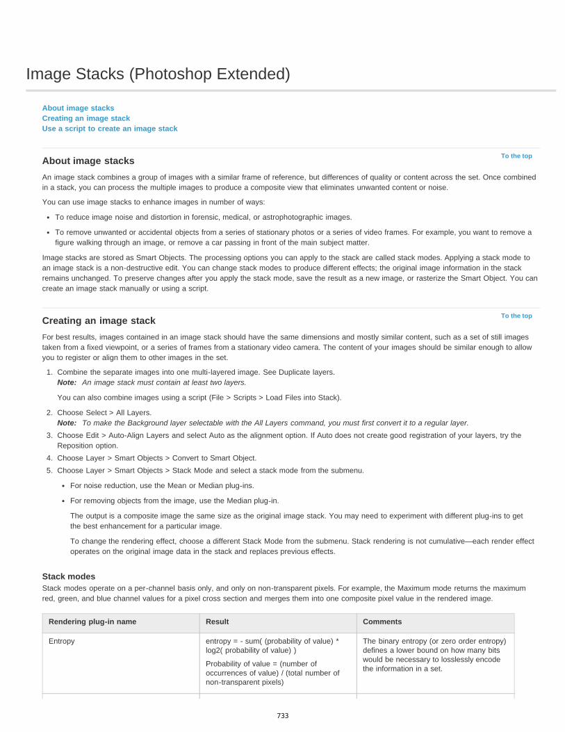
Image Stacks (Photoshop Extended)
To the top
To the top
About image stacksCreating an image stackUse a script to create an image stack
About image stacksAn image stack combines a group of images with a similar frame of reference, but differences of quality or content across the set. Once combinedin a stack, you can process the multiple images to produce a composite view that eliminates unwanted content or noise.
You can use image stacks to enhance images in number of ways:
To reduce image noise and distortion in forensic, medical, or astrophotographic images.
To remove unwanted or accidental objects from a series of stationary photos or a series of video frames. For example, you want to remove afigure walking through an image, or remove a car passing in front of the main subject matter.
Image stacks are stored as Smart Objects. The processing options you can apply to the stack are called stack modes. Applying a stack mode toan image stack is a non-destructive edit. You can change stack modes to produce different effects; the original image information in the stackremains unchanged. To preserve changes after you apply the stack mode, save the result as a new image, or rasterize the Smart Object. You cancreate an image stack manually or using a script.
Creating an image stackFor best results, images contained in an image stack should have the same dimensions and mostly similar content, such as a set of still imagestaken from a fixed viewpoint, or a series of frames from a stationary video camera. The content of your images should be similar enough to allowyou to register or align them to other images in the set.
1. Combine the separate images into one multi-layered image. See Duplicate layers.Note: An image stack must contain at least two layers.
You can also combine images using a script (File > Scripts > Load Files into Stack).
2. Choose Select > All Layers.Note: To make the Background layer selectable with the All Layers command, you must first convert it to a regular layer.
3. Choose Edit > Auto-Align Layers and select Auto as the alignment option. If Auto does not create good registration of your layers, try theReposition option.
4. Choose Layer > Smart Objects > Convert to Smart Object.5. Choose Layer > Smart Objects > Stack Mode and select a stack mode from the submenu.
For noise reduction, use the Mean or Median plug-ins.
For removing objects from the image, use the Median plug-in.
The output is a composite image the same size as the original image stack. You may need to experiment with different plug-ins to getthe best enhancement for a particular image.
To change the rendering effect, choose a different Stack Mode from the submenu. Stack rendering is not cumulative—each render effectoperates on the original image data in the stack and replaces previous effects.
Stack modesStack modes operate on a per-channel basis only, and only on non-transparent pixels. For example, the Maximum mode returns the maximumred, green, and blue channel values for a pixel cross section and merges them into one composite pixel value in the rendered image.
Rendering plug-in name Result Comments
Entropy entropy = - sum( (probability of value) *log2( probability of value) )
Probability of value = (number ofoccurrences of value) / (total number ofnon-transparent pixels)
The binary entropy (or zero order entropy)defines a lower bound on how many bitswould be necessary to losslessly encodethe information in a set.
733
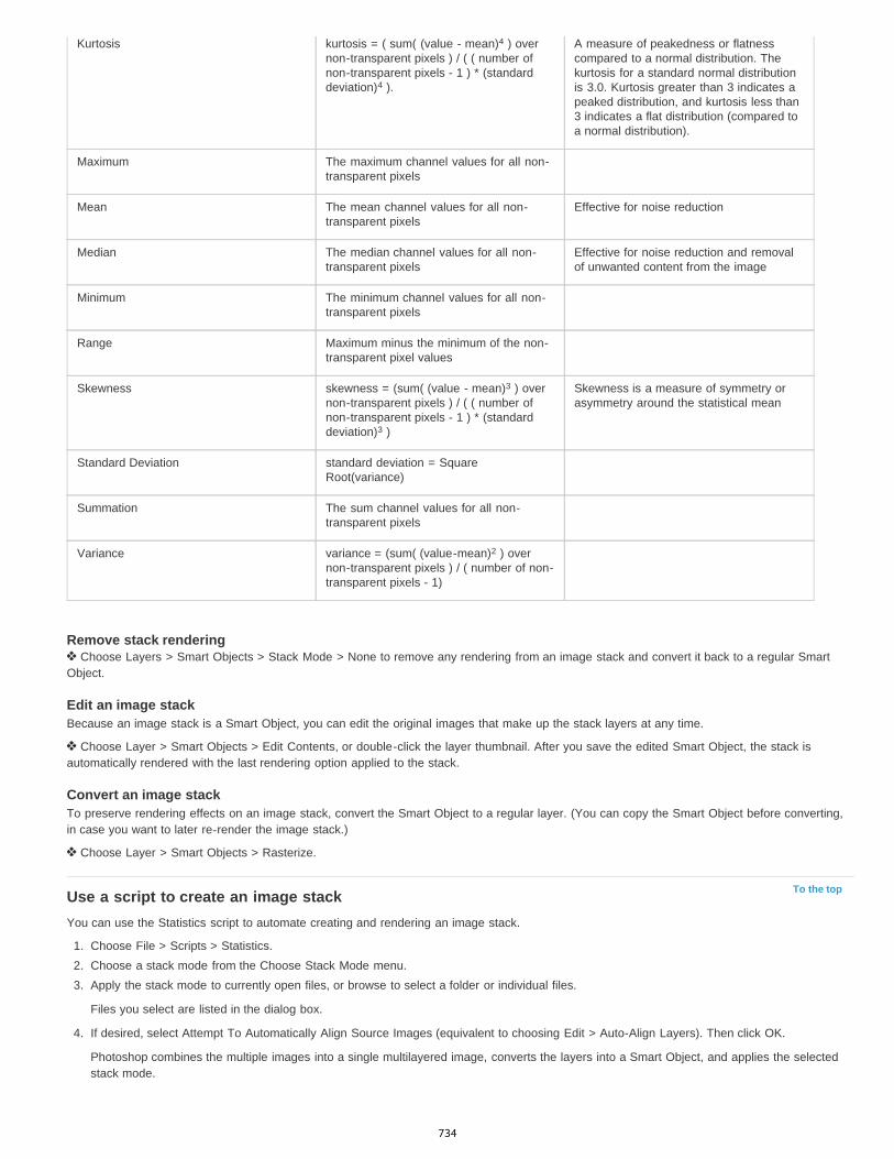
To the top
Kurtosis kurtosis = ( sum( (value - mean) ) overnon-transparent pixels ) / ( ( number ofnon-transparent pixels - 1 ) * (standarddeviation) ).
A measure of peakedness or flatnesscompared to a normal distribution. Thekurtosis for a standard normal distributionis 3.0. Kurtosis greater than 3 indicates apeaked distribution, and kurtosis less than3 indicates a flat distribution (compared toa normal distribution).
Maximum The maximum channel values for all non-transparent pixels
Mean The mean channel values for all non-transparent pixels
Effective for noise reduction
Median The median channel values for all non-transparent pixels
Effective for noise reduction and removalof unwanted content from the image
Minimum The minimum channel values for all non-transparent pixels
Range Maximum minus the minimum of the non-transparent pixel values
Skewness skewness = (sum( (value - mean) ) overnon-transparent pixels ) / ( ( number ofnon-transparent pixels - 1 ) * (standarddeviation) )
Skewness is a measure of symmetry orasymmetry around the statistical mean
Standard Deviation standard deviation = SquareRoot(variance)
Summation The sum channel values for all non-transparent pixels
Variance variance = (sum( (value-mean) ) overnon-transparent pixels ) / ( number of non-transparent pixels - 1)
Remove stack rendering Choose Layers > Smart Objects > Stack Mode > None to remove any rendering from an image stack and convert it back to a regular Smart
Object.
Edit an image stackBecause an image stack is a Smart Object, you can edit the original images that make up the stack layers at any time.
Choose Layer > Smart Objects > Edit Contents, or double-click the layer thumbnail. After you save the edited Smart Object, the stack isautomatically rendered with the last rendering option applied to the stack.
Convert an image stackTo preserve rendering effects on an image stack, convert the Smart Object to a regular layer. (You can copy the Smart Object before converting,in case you want to later re-render the image stack.)
Choose Layer > Smart Objects > Rasterize.
Use a script to create an image stackYou can use the Statistics script to automate creating and rendering an image stack.
1. Choose File > Scripts > Statistics.2. Choose a stack mode from the Choose Stack Mode menu.3. Apply the stack mode to currently open files, or browse to select a folder or individual files.
Files you select are listed in the dialog box.
4. If desired, select Attempt To Automatically Align Source Images (equivalent to choosing Edit > Auto-Align Layers). Then click OK.
Photoshop combines the multiple images into a single multilayered image, converts the layers into a Smart Object, and applies the selectedstack mode.
4
4
3
3
2
734

Measurement (Photoshop Extended)
To the top
To the top
About measurement (Photoshop Extended)Set the measurement scale (Photoshop Extended)Use scale markers (Photoshop Extended)Performing a measurement (Photoshop Extended)Use the Measurement Log (Photoshop Extended)
About measurement (Photoshop Extended)Using the Photoshop Extended Measurement feature you can measure any area defined with the Ruler tool or with a selection tool, includingirregular areas selected with the Lasso, Quick Select, or Magic Wand tools. You can also compute the height, width, area, and perimeter, or trackmeasurements of one image or multiple images. Measurement data is recorded in the Measurement Log panel. You can customize theMeasurement Log columns, sort data within columns, and export data from the log to a tab-delimited, Unicode text file.
For a video on measurement features, see www.adobe.com/go/vid0029.
Measurement scaleSetting a measurement scale sets a specified number of pixels in the image equal to a number of scale units, such as inches, millimeters, ormicrons. Once you’ve created a scale, you can measure areas and receive calculations and log results in the selected scale units. You can createmultiple measurement scale presets, although only one scale can be used in a document at a time.
Scale markersYou can place scale markers on an image to display the measurement scale. Scale markers can appear with or without a caption displayingmeasurement scale units.
Set the measurement scale (Photoshop Extended)Use the Ruler tool to set the measurement scale for a document. You can create measurement scale presets for frequently used measurementscales. Presets are added to the Analysis > Set Measurement Scale submenu. The current measurement scale for a document is checked in thesubmenu, and appears in the Info panel.Note: Measurement scale is set automatically for DICOM files. See About DICOM files (Photoshop Extended).Choose Analysis > Set Measurement Scale > Default to return to the default measurement scale, 1 pixel = 1 pixel.
Set measurement scale1. Open a document.2. Choose Analysis > Set Measurement Scale > Custom. The Ruler tool is automatically selected. Drag the tool to measure a pixel distance in
the image or enter a value in the Pixel Length text box. Your current tool setting is restored when you close the Measurement Scale dialogbox.
3. Enter the Logical Length and Logical Units that you want to set equal to the Pixel Length.
For example, if the Pixel Length is 50, and you want to set a scale of 50 pixels per micron, enter 1 for Logical Length, and microns for theLogical Units.
4. Click OK in the Measurement Scale dialog box to set the measurement scale on the document.5. Choose File > Save to save the current measurement scale setting with the document.
To display the scale in the Info panel, choose Panel Options from the panel menu , and select Measurement Scale in the StatusInformation area.
To display the measurement scale at the bottom of the document window, choose Show > Measurement Scale from the documentwindow menu.
Create a measurement scale preset1. Open a document.2. Choose Analysis > Set Measurement Scale > Custom.3. Create a measurement scale.4. Click Save Preset and name the preset.
735

To the top
To the top
5. Click OK. The preset you created is added to the Analysis > Set Measurement Scale submenu.
Delete a measurement scale preset1. Choose Analysis > Set Measurement Scale > Custom.2. Select the preset you want to delete.3. Click Delete Preset and click OK.
Use scale markers (Photoshop Extended)Measurement scale markers display the measurement scale used in your document. Set the measurement scale for a document before creating ascale marker. You can set the marker length in logical units, include a text caption indicating the length, and set the marker and caption color toblack or white.
For a video on measurement features, see www.adobe.com/go/vid0029.
Create a scale marker1. Choose Analysis > Place Scale Marker.2. In the Measurement Scale Marker dialog box, set the following options:
Length Enter a value to set the length of the scale marker. The length of the marker in pixels depends on the measurement scale that iscurrently selected for the document.
Font Choose the font for the display text.
Font Size Choose the font size for the display text.
Display Text Select this option to show the logical length and units for the scale marker.
Text position Displays caption above or below the scale marker.
Color Sets the scale marker and caption color to black or white.
3. Click OK.
The scale marker is placed in the lower left corner of the image. The marker adds a layer group to the document, containing a text layer (if theDisplay Text option is selected) and a graphic layer. You can use the Move tool to move the scale marker, or the Text tool to edit the caption orchange text size, font, or color.
Add or replace scale markersYou can place multiple scale markers in a document, or replace existing markers.
Note: Additional scale markers are placed in the same position on the image and can obscure each other, depending on their length. To view anunderlying marker, turn off the scale marker layer set.
1. Choose Analysis > Place Scale Marker.2. Click Remove or Keep.3. Enter settings for the new marker and click OK.
Delete a scale marker1. In the Layers panel, select the Measurement Scale Marker layer group for the scale marker you want to delete.2. Right-click the layer group and select Delete Group from the context menu, or click the Delete Layer button.3. Click Group and Contents.
Performing a measurement (Photoshop Extended)You can measure using the Photoshop selection tools, Ruler tool, or Count tool. Choose a measurement tool that matches the type of data youwant to record in the Measurement Log.
Create a selection area to measure values such as height, width, perimeter, area, and pixel gray values. You can measure one selection orseveral selections at once.
Draw a line with the Ruler tool to measure linear distance and angle.
Use the Count tool to count items on the image, then record the number of items. See Counting objects in an image (Photoshop Extended).
Each measurement measures one or more data points. The data points you select determine the information recorded in the Measurementlog. Data points correspond to the type of tool you’re measuring with. Area, perimeter, height, and width are available data points formeasuring selections. Length and angle are available data points for Ruler tool measurements. You can create and save sets of data pointsfor particular types of measurements to speed your workflow.
736
1. Open an existing document.2. Choose Analysis > Set Measurement Scale and choose a measurement scale preset for the document (see Set the measurement scale
(Photoshop Extended)), or choose Custom and set a custom measurement scale.
Measurements are computed and recorded in the Measurement Log using the scale units in effect when a measurement is recorded. If nomeasurement scale exists, the default scale is 1 pixel = 1 pixel.
3. (Optional) Choose Analysis > Select Data Points and do one of the following:
Choose Custom to select data points to measure.
Select an existing data point preset from the submenu.
In the Select Data Points dialog box, data points are grouped according to the measurement tool that can measure them. The Common datapoints are available for all tools. They add useful information to the Measurement Log such as the name of the file being measured, themeasurement scale, and the date/time of the measurement.
By default all data points are selected. You can select a subset of data points for a particular type of measurement, then save thecombination as a data point preset.
Note: When you measure with a particular tool, only the data points associated with that tool are displayed in the log, even if other datapoints are selected. For example, if you make a measurement with the Ruler tool, only the Ruler tool data points appear in the MeasurementLog, along with any Common data points that are selected.
4. Choose an image feature and measurement tool to match the selected data points. Do one of the following:
Create one or more selections on the image.
Choose Analysis > Ruler Tool, or click the Ruler tool in the toolbox, then use the tool to measure the length of an image area.
Choose Analysis > Count Tool, or click the Count tool in the toolbox, then count items in the image.
5. Choose Window > Measurement Log to open the Measurement Log panel.6. Choose Analysis > Record Measurements, or click Record Measurements in the Measurement Log panel.
Note: If your currently selected data points do not correspond to the current measurement tool, you are asked to select data points for thattool.
The Measurement log has columns for each data point you selected in the Measurement Data Points dialog box. Each measurement youmake enters a new row of data in the Measurement Log.
If you measure multiple selected areas on the image, one row of data is created in the log containing summary or cumulative data for allselected areas, followed by a row of data for each selection area. Each selection area is listed as a separate Feature in the Label column ofthe log and assigned a unique number.
You can repeat steps 2 through 6 for a variety of different selections in the same or multiple documents. The Document column in theMeasurement Log reflects the source of the measurement data.
Measurement Data PointsAngle Angle of orientation (±0-180) of the Ruler tool.Area Area of selection in square pixels, or in calibrated units according to the current measurement scale (such as square millimeters).Circularity 4pi(area/perimeter ). A value of 1.0 indicates a perfect circle. As the value approaches 0.0, it indicates an increasingly elongatedpolygon. Values may not be valid for very small selections.Count Varies according to the measuring tool used. Selection tool: the number of discontiguous selection areas on the image. Count tool: thenumber of counted items on the image. Ruler tool: the number of Ruler lines visible (1 or 2).Date and Time Applies a date/time stamp of when the measurement occurred.Document Identifies the document (file) measured.Gray Value This is a measurement of brightness, either from 0 to 255 (for 8-bit images), 0 to 32,768 (for 16-bit images), or 0.0 to 10 (for 32-bitimages). For all gray value-related measurements, the image is internally converted to grayscale (equivalent to choosing Image > Mode >Grayscale) using the default grayscale profile. Then the requested calculations (mean, median, minimum, maximum) are calculated for eachfeature and for the summary.Height Height of the selection (max y - min y), in units according to the current measurement scale.Histogram Generates histogram data for each channel in the image (three for RGB images, four for CMYK, and so on), recording the number ofpixels at each value from 0 to 255 (16-bit or 32-bit values are converted to 8-bit). When you export data from the Measurement Log, the numerichistogram data is exported to a CSV (comma-separated value) file. The file is placed in its own folder at the same location where themeasurement log tab-delimited text file is exported. Histogram files are assigned a unique number, starting at 0, and progressing by 1. For multipleselections measured at once, one histogram file is generated for the total selected area, plus additional histogram files for each selection.Integrated Density The sum of the values of the pixels in the selection. This is equivalent to the product of Area (in pixels) and Mean GrayValue.Label Identifies and automatically numbers each measurement as Measurement 1, Measurement 2, and so on. For multiple selections measuredsimultaneously, each selection is assigned an additional Feature label and number.Length Linear distance defined by the Ruler tool on the image, in units according to the current measurement scale.Perimeter The perimeter of the selection. For multiple selections measured at once, one measurement is generated for the total perimeter of all
2
737

To the top
selections, plus additional measurements for each selection.Scale The measurement scale of the source document (for example, 100 px = 3 miles).Scale Units Logical units of the measurement scale.Scale Factor The number of pixels assigned to the scale unit.Source Source of the measurement: Ruler tool, Count Tool, or Selection.Width Width of the selection (max x - min x), in units according to the current measurement scale.
Create a data point preset1. Choose Analysis > Select Data Points > Custom.2. Select data points to include in the preset.3. Click Save Preset and name the preset.4. Click OK. The preset is saved and is now available from the Analysis > Select Data Points submenu.
Edit a data point preset1. Choose Analysis > Select Data Points > Custom.2. Choose the preset you want to edit from the Preset menu.3. Select or deselect data points. The Preset name changes to Custom.4. Click Save Preset. Enter the original preset name to replace the existing preset, or a new name to create a new preset.
Delete a data point preset1. Choose Analysis > Select Data Points > Custom.2. Choose the preset you want to delete from the Preset menu.3. Click Delete Preset, then Yes to confirm the deletion.4. Click OK.
Use the Measurement Log (Photoshop Extended)When you measure an object, the Measurement Log panel records the measurement data. Each row in the log represents a measurement set;columns represent the data points in a measurement set.
When you measure an object, a new row appears in the Measurement Log. You can reorder columns in the log, sort data in columns, delete rowsor columns, or export data from the log to a comma-delimited text file.
For a video on measurement features, see www.adobe.com/go/vid0029.
Display the Measurement Log Do one of the following:
Choose Analysis > Record Measurements.
Choose Window > Measurement Log.
Select rows in the log Do one of the following:
Click a row in the log to select it.
To select multiple contiguous rows, click the first row and drag through additional rows, or click the first row and then Shift-click the last row.
To select noncontiguous rows, click the first row and then Ctrl-click (Windows) or Command-click (Mac) additional rows.
To select all rows, click Select All.
To deselect all rows, click Select None.
Select columns in the log Do one of the following:
Click a column header.
To select contiguous columns, click a column header and drag through additional columns, or click the first column header and then Shift-click the last column header.
To select noncontiguous columns, click the first column header and then Ctrl-click (Windows) or Command-click (Mac) additional columnheaders.
738
Reorder, resize, or sort columns in the log Do one of the following:
Drag selected columns to reorder them in the log. The column position is indicated by a double black line.
To resize a column, click the column header and then drag the separator.
To sort data in a column, click the column header to change the sort order, or right-click the header and choose Sort Ascending or SortDescending. (Rows cannot be manually reordered.)
Delete rows or columns from the log1. Select one or more rows or columns in the log.2. Do one of the following:
Choose Delete from the Measurement Log options menu.
Click the Delete icon at the top of the panel.
Right-click in a row or column header, then select Delete from the pop-up menu.
Export Measurement Log dataYou can export data from the Measurement Log into a comma-delimited text file. You can open the text file in a spreadsheet application andperform statistical or analytical calculations from the measurement data.
1. Select one or more rows of data in the log.2. Do one of the following:
Choose Export from the Measurement Log options menu.
Click the Export icon at the top of the panel.
Right-click in a row, then select Export from the pop-up menu.
3. Enter a filename and location, and click Save.
The measurements are exported to a comma-delimited, UTF-8 text file.
Legal Notices | Online Privacy Policy
739
Photoshop and MATLAB (Photoshop Extended)
To the top
To the top
To the top
About Photoshop and MATLABSet up MATLAB and PhotoshopConnect/disconnect to Photoshop from MATLABUsing MATLAB HelpMATLAB commandsCreate a document in MATLAB
About Photoshop and MATLABMATLAB is a high-level technical computing language and interactive environment for algorithm development, data visualization, data analysis,and numeric computation. With Photoshop Extended you can view MATLAB image-processing results in Photoshop, and combine MATLABcommands with Photoshop image-editing features.
Once you connect to Photoshop from MATLAB, typing commands into the MATLAB command prompt performs operations in Photoshop. You canrun MATLAB algorithms and view the results in your image in Photoshop.
Note: Communication between Photoshop and MATLAB uses the Photoshop JavaScript interface and the MATLAB library interface.
Set up MATLAB and PhotoshopInstall Photoshop and MATLAB on your computer. Once you have installed Photoshop Extended and MATLAB, you should verify the MATLABintegration.
For 64-bit systems, install the appropriate compilerTo use the Photoshop interface on a 64-bit system, a C compiler must be installed:
In Windows, install Microsoft Developer Studio.
In Mac OS, install XCode.
For more information, see the MATLAB Photoshop Read Me in the Photoshop application folder.
Note: In Windows, use 64-bit Photoshop with 64-bit MATLAB, and 32-bit Photoshop with 32-bit MATLAB.
Verify MATLAB integration1. Start Photoshop Extended and then MATLAB.2. From MATLAB, add the path Photoshop/MATLAB, including subfolders.3. At the MATLAB prompt, open the MATLAB folder, locate and open the Tests folder, and then type testall.4. Photoshop and MATLAB run a series of tests to ensure integration between the two programs and display a summary report.
(Optional) Set access to Photoshop from MATLABYou can set up a path to Photoshop Extended to allow direct access to Photoshop commands from MATLAB.
1. From MATLAB, choose File > Set Path.2. Click Add Folder and select the MATLAB folder where Photoshop Extended is installed.3. Click Save and then Close.4. From the MATLAB menu, choose File > Preferences.5. In the Preferences dialog box, click the General tree (upper-left).6. Click the Update Toolbox Path Cache button.7. Click Apply and then OK.
Connect/disconnect to Photoshop from MATLAB In MATLAB, do one of the following:
To launch or connect to Photoshop, type pslaunch, and then press Enter (Windows) or Return (Mac OS).
To disconnect from Photoshop and quit, type psquit and press Enter (Windows) or Return (Mac OS).
740
To the top
To the top
To the top
Using MATLAB HelpMATLAB’s Help system includes examples of a MATLAB/Photoshop workflow.
1. Choose Help > Full Product Family Help.
You see a Photoshop Toolbox with submenu items, including Examples for getting started. If you don’t see the Photoshop Toolbox, try thefollowing steps.
2. Click the Start Button.3. Choose Desktop Tools > View Source Files.4. Click the Refresh Start button, then Close, then retry the Help menu.
MATLAB commandsTyping commands in the MATLAB command line lets you connect and disconnect to Photoshop, and generate pixels viewable in a Photoshopdocument.
For a list of all MATLAB Photoshop commands, browse the file psfunctionscat.html, available in the MATLAB folder in the directory where youinstalled Photoshop. Enter help (command name) at the MATLAB command prompt for a fuller description of each command, including syntax,arguments, and examples.
Note: All MATLAB commands are supported for Japanese characters. MATLAB for Windows supports a Japanese language user interface onJapanese language Windows XP systems. MATLAB for Mac OS supports US English only on Japanese language Mac OS systems. For moreinformation, contact The MathWorks, Inc.
Create a document in MATLAB1. In MATLAB, enter psnewdoc.2. To specify the attributes of the new document, enter one of the following:
To create a document using the default values, enter psnewdoc(). For information on default values, see below.
To create a document with a specific width and height, enter psnewdoc(W,H). The W and H values use the current units set in the Units& Rulers option in the Photoshop Preferences dialog box. Other document attributes are set to their default values.
Note: Enter “undefined” as a string to skip input arguments. The default size for a new document is 504 x 360 pixels.
To create a document and specify attributes, enter psnewdoc(W,H,R,N,M,F,A,B,P). For information on new document attributes, seebelow.
Here is an example code for creating a document and specifying all the attributes in MATLAB:
psnewdoc(10, 10, 72, 'hi', 'cmyk', 'transparent', 2.5, 16, 'U.S. Web Coated (SWOP) v2')
New document attributes and defaultsEntering psnewdoc(W,H,R,N,M,F,A,B,P) creates a document with values for the following attributes:
W Specifies the width of the document using the current units from the Units & Rulers option in the Photoshop Preferences dialog box. The defaultwidth is 504 pixels.H Specifies the height of the document using the current units in the Units & Rulers panel in the Photoshop Preference dialog box. The defaultheight is 360.R Specifies the resolution. The default is 72 ppi.N Specifies the document name. The default is Untitled-X, where X is the index for new documents.M Specifies the color mode: RGB, CMYK, Lab, Bitmap, or Grayscale. The default is RGB.F Specifies the background contents of the new document: White,Background Color, or Transparent. The default is White.A Specifies the pixel aspect ratio. The default is 1.0 (square).B Specifies the bit depth: 1, 8, 16, or 32. The default is 8.P Specifies the color profile. The default is the working color space for the specified color mode. The working spaces are specified in thePhotoshop Color Settings dialog box.
Legal Notices | Online Privacy Policy
741

Color management
742

Understanding color management
To the top
To the top
Why colors sometimes don’t matchWhat is a color management system?Do you need color management?Creating a viewing environment for color management
A color management system reconciles color differences among devices so that you can confidently predict the colors your system ultimatelyproduces. Viewing color accurately allows you to make sound color decisions throughout your workflow, from digital capture through final output.Color management also allows you to create output based on ISO, SWOP, and Japan Color print production standards.
Why colors sometimes don’t matchNo device in a publishing system is capable of reproducing the full range of colors viewable to the human eye. Each device operates within aspecific color space that can produce a certain range, or gamut, of colors.
A color model determines the relationship between values, and the color space defines the absolute meaning of those values as colors. Somecolor models (such as CIE L*a*b) have a fixed color space because they relate directly to the way humans perceive color. These models aredescribed as being device-independent. Other color models (RGB, HSL, HSB, CMYK, and so forth) can have many different color spaces.Because these models vary with each associated color space or device, they are described as being device-dependent.
Because of these varying color spaces, colors can shift in appearance as you transfer documents between different devices. Color variations canresult from differences in image sources; the way software applications define color; print media (newsprint paper reproduces a smaller gamut thanmagazine-quality paper); and other natural variations, such as manufacturing differences in monitors or monitor age.
Color gamuts of various devices and documentsA. Lab color space B. Documents (working space) C. Devices
What is a color management system?Color-matching problems result from various devices and software using different color spaces. One solution is to have a system that interpretsand translates color accurately between devices. A color management system (CMS) compares the color space in which a color was created tothe color space in which the same color will be output, and makes the necessary adjustments to represent the color as consistently as possibleamong different devices.
A color management system translates colors with the help of color profiles. A profile is a mathematical description of a device’s color space. Forexample, a scanner profile tells a color management system how your scanner “sees” colors. Adobe color management uses ICC profiles, a formatdefined by the International Color Consortium (ICC) as a cross-platform standard.
Because no single color-translation method is ideal for all types of graphics, a color management system provides a choice of rendering intents, ortranslation methods, so that you can apply a method appropriate to a particular graphics element. For example, a color translation method thatpreserves correct relationships among colors in a wildlife photograph may alter the colors in a logo containing flat tints of color.
Note: Don’t confuse color management with color correction. A color management system won’t correct an image that was saved with tonal orcolor balance problems. It provides an environment where you can evaluate images reliably in the context of your final output.
743

To the top
To the top
Do you need color management?Without a color management system, your color specifications are device-dependent. You might not need color management if your productionprocess is tightly controlled for one medium only. For example, you or your print service provider can tailor CMYK images and specify color valuesfor a known, specific set of printing conditions.
The value of color management increases when you have more variables in your production process. Color management is recommended if youanticipate reusing color graphics for print and online media, using various kinds of devices within a single medium (such as different printingpresses), or if you manage multiple workstations.
You will benefit from a color management system if you need to accomplish any of the following:
Get predictable and consistent color output on multiple output devices including color separations, your desktop printer, and your monitor.Color management is especially useful for adjusting color for devices with a relatively limited gamut, such as a four-color process printingpress.
Accurately soft-proof (preview) a color document on your monitor by making it simulate a specific output device. (Soft-proofing is subject tothe limitations of monitor display, and other factors such as room lighting conditions.)
Accurately evaluate and consistently incorporate color graphics from many different sources if they also use color management, and even insome cases if they don’t.
Send color documents to different output devices and media without having to manually adjust colors in documents or original graphics. Thisis valuable when creating images that will eventually be used both in print and online.
Print color correctly to an unknown color output device; for example, you could store a document online for consistently reproducibleon-demand color printing anywhere in the world.
Creating a viewing environment for color managementYour work environment influences how you see color on your monitor and on printed output. For best results, control the colors and light in yourwork environment by doing the following:
View your documents in an environment that provides a consistent light level and color temperature. For example, the color characteristics ofsunlight change throughout the day and alter the way colors appear on your screen, so keep shades closed or work in a windowless room.To eliminate the blue-green cast from fluorescent lighting, you can install D50 (5000° Kelvin) lighting. You can also view printed documentsusing a D50 lightbox.
View your document in a room with neutral-colored walls and ceiling. A room’s color can affect the perception of both monitor color andprinted color. The best color for a viewing room is neutral gray. Also, the color of your clothing reflecting off the glass of your monitor mayaffect the appearance of colors on-screen.
Remove colorful background patterns on your monitor desktop. Busy or bright patterns surrounding a document interfere with accurate colorperception. Set your desktop to display neutral grays only.
View document proofs in the real-world conditions under which your audience will see the final piece. For example, you might want to seehow a housewares catalog looks under the incandescent light bulbs used in homes, or view an office furniture catalog under the fluorescentlighting used in offices. However, always make final color judgements under the lighting conditions specified by the legal requirements forcontract proofs in your country.
|
744
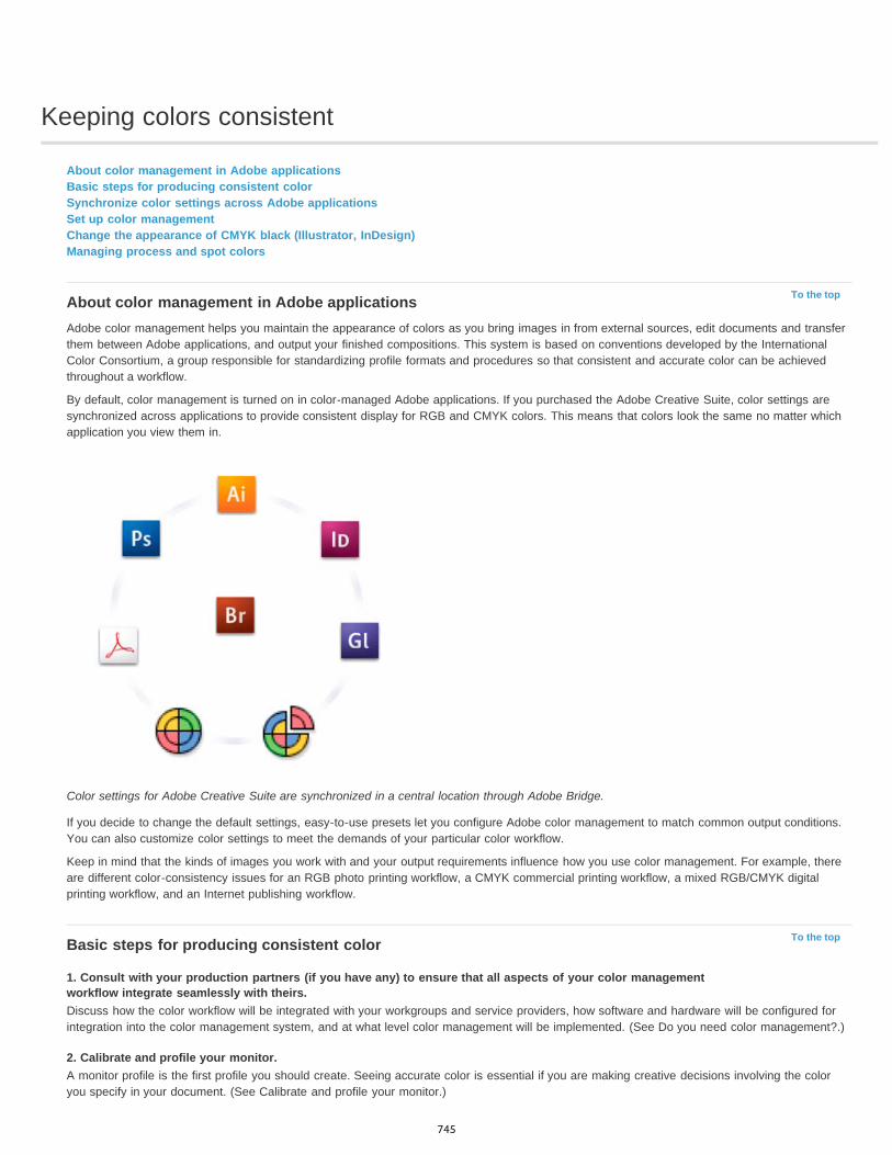
Keeping colors consistent
To the top
To the top
About color management in Adobe applicationsBasic steps for producing consistent colorSynchronize color settings across Adobe applicationsSet up color managementChange the appearance of CMYK black (Illustrator, InDesign)Managing process and spot colors
About color management in Adobe applicationsAdobe color management helps you maintain the appearance of colors as you bring images in from external sources, edit documents and transferthem between Adobe applications, and output your finished compositions. This system is based on conventions developed by the InternationalColor Consortium, a group responsible for standardizing profile formats and procedures so that consistent and accurate color can be achievedthroughout a workflow.
By default, color management is turned on in color-managed Adobe applications. If you purchased the Adobe Creative Suite, color settings aresynchronized across applications to provide consistent display for RGB and CMYK colors. This means that colors look the same no matter whichapplication you view them in.
Color settings for Adobe Creative Suite are synchronized in a central location through Adobe Bridge.
If you decide to change the default settings, easy-to-use presets let you configure Adobe color management to match common output conditions.You can also customize color settings to meet the demands of your particular color workflow.
Keep in mind that the kinds of images you work with and your output requirements influence how you use color management. For example, thereare different color-consistency issues for an RGB photo printing workflow, a CMYK commercial printing workflow, a mixed RGB/CMYK digitalprinting workflow, and an Internet publishing workflow.
Basic steps for producing consistent color
1. Consult with your production partners (if you have any) to ensure that all aspects of your color managementworkflow integrate seamlessly with theirs.Discuss how the color workflow will be integrated with your workgroups and service providers, how software and hardware will be configured forintegration into the color management system, and at what level color management will be implemented. (See Do you need color management?.)
2. Calibrate and profile your monitor.A monitor profile is the first profile you should create. Seeing accurate color is essential if you are making creative decisions involving the coloryou specify in your document. (See Calibrate and profile your monitor.)
745

To the top
To the top
To the top
3. Add color profiles to your system for any input and output devices you plan to use, such as scanners and printers.The color management system uses profiles to know how a device produces color and what the actual colors in a document are. Device profilesare often installed when a device is added to your system. You can also use third-party software and hardware to create more accurate profiles forspecific devices and conditions. If your document will be commercially printed, contact your service provider to determine the profile for the printingdevice or press condition. (See About color profilesand Install a color profile.)
4. Set up color management in Adobe applications.The default color settings are sufficient for most users. However, you can change the color settings by doing one of the following:
If you use multiple Adobe applications, use Adobe® Bridge to choose a standard color management configuration and synchronize colorsettings across applications before working with documents. (See Synchronize color settings across Adobe applications.)
If you use only one Adobe application, or if you want to customize advanced color management options, you can change color settings for aspecific application. (See Set up color management.)
5. (Optional) Preview colors using a soft proof.After you create a document, you can use a soft proof to preview how colors will look when printed or viewed on a specific device. (See Soft-proofcolors.)
Note: A soft proof alone doesn’t let you preview how overprinting will look when printed on an offset press. If you work with documents thatcontain overprinting, turn on Overprint Preview to accurately preview overprints in a soft proof. For Acrobat, the Overprint Preview option isautomatically applied.
6. Use color management when printing and saving files.Keeping the appearance of colors consistent across all of the devices in your workflow is the goal of color management. Leave color managementoptions enabled when printing documents, saving files, and preparing files for online viewing. (See Printing with color management and Color-managing documents for online viewing.)
Synchronize color settings across Adobe applicationsIf you use Adobe Creative Suite, you can use Adobe Bridge to automatically synchronize color settings across applications. This synchronizationensures that colors look the same in all color-managed Adobe applications.
If color settings are not synchronized, a warning message appears at the top of the Color Settings dialog box in each application. Adoberecommends that you synchronize color settings before you work with new or existing documents.
1. Open Bridge.
To open Bridge from a Creative Suite application, choose File > Browse. To open Bridge directly, either choose Adobe Bridge from the Startmenu (Windows) or double-click the Adobe Bridge icon (Mac OS).
2. Choose Edit > Creative SuiteColor Settings.3. Select a color setting from the list, and click Apply.
If none of the default settings meet your requirements, select Show Expanded List Of Color Setting Files to view additional settings. Toinstall a custom settings file, such as a file you received from a print service provider, click Show Saved Color Settings Files.
Set up color management1. Do one of the following:
(Illustrator, InDesign, Photoshop) Choose Edit > Color Settings.
(Acrobat) Select the Color Management category of the Preferences dialog box.
2. Select a color setting from the Settings menu, and click OK.
The setting you select determines which color working spaces are used by the application, what happens when you open and import fileswith embedded profiles, and how the color management system converts colors. To view a description of a setting, select the setting andthen position the pointer over the setting name. The description appears at the bottom of the dialog box.
Note: Acrobat color settings are a subset of those used in InDesign, Illustrator, and Photoshop.
In certain situations, such as if your service provider supplies you with a custom output profile, you may need to customize specific optionsin the Color Settings dialog box. However, customizing is recommended for advanced users only.
Note: If you work with more than one Adobe application, it is highly recommended that you synchronize your color settings acrossapplications. (See Synchronize color settings across Adobe applications.)
Change the appearance of CMYK black (Illustrator, InDesign)
746
To the top
Pure CMYK black (K=100) appears jet black (or rich black) when viewed on-screen, printed to a non-PostScript desktop printer, or exported to anRGB file format. If you prefer to see the difference between pure black and rich black as it will appear when printed on a commercial press, youcan change the Appearance Of Black preferences. These preferences do not change the color values in a document.
1. Choose Edit > Preferences > Appearance Of Black (Windows) or [application name] > Preferences > Appearance Of Black (Mac OS).2. Choose an option for On Screen:
Display All Blacks Accurately Displays pure CMYK black as dark gray. This setting allows you to see the difference between pure blackand rich black.
Display All Blacks As Rich Black Displays pure CMYK black as jet black (RGB=000). This setting makes pure black and rich black appearthe same on-screen.
3. Choose an option for Printing/Exporting:Output All Blacks Accurately When printing to a non-PostScript desktop printer or exporting to an RGB file format, outputs pure CMYKblack using the color numbers in the document. This setting allows you to see the difference between pure black and rich black.
Output All Blacks As Rich Black When printing to a non-PostScript desktop printer or exporting to an RGB file format, outputs pure CMYKblack as jet black (RGB=000). This setting makes pure black and rich black appear the same.
Managing process and spot colorsWhen color management is on, any color you apply or create within a color-managed Adobe application automatically uses a color profile thatcorresponds to the document. If you switch color modes, the color management system uses the appropriate profiles to translate the color to thenew color model you choose.
Keep in mind the following guidelines for working with process and spot colors:
Choose a CMYK working space that matches your CMYK output conditions to ensure that you can accurately define and view processcolors.
Select colors from a color library. Adobe applications come with several standard color libraries, which you can load using the Swatchespanel menu.
(Illustrator, and InDesign) Turn on Overprint Preview to get an accurate and consistent preview of spot colors.
(Acrobat, Illustrator, and InDesign) Use Lab values (the default) to display predefined spot colors (such as colors from the TOYO, PANTONE,DIC, and HKS libraries) and convert these colors to process colors. Using Lab values provides the greatest accuracy and guarantees theconsistent display of colors across Creative Suite applications. If you want the display and output of these colors to match earlier versions ofIllustrator or InDesign, use CMYK equivalent values instead. For instructions on switching between Lab values and CMYK values for spotcolors, search Illustrator or InDesign Help.
Note: Color-managing spot colors provides a close approximation of a spot color on your proofing device and monitor. However, it is difficult to exactly reproduce a spot color on a monitor or proofing device because many spot color inks exist outside the gamuts of many of those devices.
|
747

Color settings
To the top
To the top
To the top
Customize color settingsAbout color working spacesWorking space optionsAbout missing and mismatched color profilesColor management policy optionsColor conversion optionsAbout rendering intentsAdvanced controls in Photoshop
Customize color settingsFor most color-managed workflows, it is best to use a preset color setting that has been tested by Adobe Systems. Changing specific options isrecommended only if you are knowledgeable about color management and very confident about the changes you make.
After you customize options, you can save them as a preset. Saving color settings ensures that you can reuse them and share them with otherusers or applications.
To save color settings as a preset, click Save in the Color Settings dialog box. To ensure that the application displays the setting name in theColor Settings dialog box, save the file in the default location. If you save the file to a different location, you must load the file before you canselect the setting.To load a color settings preset that’s not saved in the standard location, click Load in the Color Settings dialog box, select the file you want toload, and click Open.
Note: In Acrobat, you cannot save customized color settings. To share customized color settings with Acrobat, you must create the file inInDesign, Illustrator, or Photoshop, and then save it in the default Settings folder. It will then be available in the Color Management category of thePreferences dialog box. You can also add settings manually to the default Settings folder.
About color working spacesA working space is an intermediate color space used to define and edit color in Adobe applications. Each color model has a working space profileassociated with it. You can choose working space profiles in the Color Settings dialog box.
A working space profile acts as the source profile for newly created documents that use the associated color model. For example, if Adobe RGB(1998) is the current RGB working space profile, each new RGB document that you create will use colors within the Adobe RGB (1998) gamut.Working spaces also determine the appearance of colors in untagged documents.
If you open a document embedded with a color profile that doesn’t match the working space profile, the application uses a color managementpolicy to determine how to handle the color data. In most cases, the default policy is to preserve the embedded profile.
Working space optionsTo display working space options in Photoshop, Illustrator and InDesign, choose Edit > Color Settings. In Acrobat, select the Color Managementcategory of the Preferences dialog box.
To view a description of any profile, select the profile and then position the pointer over the profile name. The description appears at the bottomof the dialog box.
RGB Determines the RGB color space of the application. In general, it’s best to choose Adobe RGB or sRGB, rather than the profile for a specificdevice (such as a monitor profile).sRGB is recommended when you prepare images for the web, because it defines the color space of the standard monitor used to view images onthe web. sRGB is also a good choice when you work with images from consumer-level digital cameras, because most of these cameras use sRGBas their default color space.
Adobe RGB is recommended when you prepare documents for print, because Adobe RGB’s gamut includes some printable colors (cyans andblues in particular) that can’t be defined using sRGB. Adobe RGB is also a good choice when working with images from professional-level digitalcameras, because most of these cameras use Adobe RGB as their default color space.
CMYK Determines the CMYK color space of the application. All CMYK working spaces are device-dependent, meaning that they are based onactual ink and paper combinations. The CMYK working spaces Adobe supplies are based on standard commercial print conditions.Gray (Photoshop) or Grayscale (Acrobat) Determines the grayscale color space of the application.Spot (Photoshop) Specifies the dot gain to use when displaying spot color channels and duotones.
748

To the top
To the top
Note: In Acrobat, you can use the color space in an embedded output intent instead of a document color space for viewing and printing. For moreinformation on output intents, see Acrobat Help.Adobe applications ship with a standard set of working space profiles that have been recommended and tested by Adobe Systems for most colormanagement workflows. By default, only these profiles appear in the working space menus. To display additional color profiles that you haveinstalled on your system, select Advanced Mode (Illustrator and InDesign) or More Options (Photoshop). A color profile must be bi-directional (thatis, contain specifications for translating both into and out of color spaces) in order to appear in the working space menus.
Note: In Photoshop, you can create custom working space profiles. However, Adobe recommends that you use a standard working space profilerather than create a custom profile. For more information, see the Photoshop support knowledgebase atwww.adobe.com/support/products/photoshop.html.
About missing and mismatched color profilesFor a newly created document, the color workflow usually operates seamlessly: Unless specified otherwise, the document uses the working spaceprofile associated with its color mode for creating and editing colors.
However, some existing documents may not use the working space profile that you have specified, and some existing documents may not becolor-managed. It is common to encounter the following exceptions to your color-managed workflow:
You might open a document or import color data (for example, by copying and pasting or dragging and dropping) from a document that is nottagged with a profile. This is often the case when you open a document created in an application that either does not support colormanagement or has color management turned off.
You might open a document or import color data from a document that is tagged with a profile different from the current working space. Thismay be the case when you open a document that was created using different color management settings, or scanned and tagged with ascanner profile.
In either case, the application uses a color management policy to decide how to handle the color data in the document.
If the profile is missing or does not match the working space, the application may display a warning message, depending on options you set in theColor Settings dialog box. Profile warnings are turned off by default, but you can turn them on to ensure the appropriate color management ofdocuments on a case-by-case basis. The warning messages vary between applications, but in general you have the following options:
(Recommended) Leave the document or imported color data as it is. For example, you can choose to use the embedded profile (if oneexists), leave the document without a color profile (if one doesn’t exist), or preserve the numbers in pasted color data.
Adjust the document or imported color data. For example, when opening a document with a missing color profile, you can choose to assignthe current working space profile or a different profile. When opening a document with a mismatched color profile, you can choose to discardthe profile or convert the colors to the current working space. When importing color data, you can choose to convert the colors to the currentworking space in order to preserve their appearance.
Color management policy optionsA color management policy determines how the application handles color data when you open a document or import an image. You can choosedifferent policies for RGB and CMYK images, and you can specify when you want warning messages to appear. To display color managementpolicy options, choose Edit > Color Settings.
To view a description of a policy, select the policy and then position the pointer over the policy name. The description appears at the bottom ofthe dialog box.
RGB, CMYK, And Gray (Gray option is available for Photoshop only.) Specifies a policy to follow when bringing colors into the current workingspace (either by opening files or importing images into the current document). Choose from the following options:
Preserve Embedded Profiles Always preserves embedded color profiles when opening files. This is the recommended option for mostworkflows because it provides consistent color management. One exception is if you’re concerned about preserving CMYK numbers, inwhich case you should select Preserve Numbers (Ignore Linked Profiles) instead.Convert To Working Space Converts colors to the current working space profile when opening files and importing images. Select thisoption if you want to force all colors to use a single profile (the current working space profile).Preserve Numbers (Ignore Linked Profiles) This option is available in InDesign and Illustrator for CMYK. Preserves color numberswhen opening files and importing images, but still allows you to use color management to view colors accurately in Adobe applications.Select this option if you want to use a safe CMYK workflow. In InDesign, you can override this policy on a per-object basis by choosingObject > Image Color Settings.Off Ignores embedded color profiles when opening files and importing images, and does not assign the working space profile to newdocuments. Select this option if you want to discard any color metadata provided by the original document creator.
Profile Mismatches: Ask When Opening Displays a message whenever you open a document tagged with a profile other than the currentworking space. You will be given the option to override the policy’s default behavior. Select this option if you want to ensure the appropriate colormanagement of documents on a case-by-case basis.Profile Mismatches: Ask When Pasting Displays a message whenever color profile mismatches occur as colors are imported into a documentthrough pasting or dragging-and-dropping. You will be given the option to override the policy’s default behavior. Select this option if you want toensure the appropriate color management of pasted colors on a case-by-case basis.
749
To the top
To the top
To the top
Missing Profiles: Ask When Opening Displays a message whenever you open an untagged document. You will be given the option to overridethe policy’s default behavior. Select this option if you want to ensure the appropriate color management of documents on a case-by-case basis.
Color conversion optionsColor conversion options let you control how the application handles the colors in a document as it moves from one color space to another.Changing these options is recommended only if you are knowledgeable about color management and very confident about the changes you make.To display conversion options, choose Edit > Color Settings, and select Advanced Mode (Illustrator and InDesign) or More Options (Photoshop). InAcrobat, select the Color Management category of the Preferences dialog box.
Engine Specifies the Color Management Module (CMM) used to map the gamut of one color space to the gamut of another. For most users, thedefault Adobe (ACE) engine fulfills all conversion needs.
To view a description of an engine or intent option, select the option and then position the pointer over the option name. The descriptionappears at the bottom of the dialog box.
Intent (Photoshop, Illustrator, InDesign) Specifies the rendering intent used to translate one color space to another. Differences betweenrendering intents are apparent only when you print a document or convert it to a different working space.Use Black Point Compensation Ensures that the shadow detail in the image is preserved by simulating the full dynamic range of the outputdevice. Select this option if you plan to use black point compensation when printing (which is recommended in most situations).Use Dither (Photoshop) Controls whether to dither colors when converting 8-bit-per-channel images between color spaces. When the Use Ditheroption is selected, Photoshop mixes colors in the destination color space to simulate a missing color that existed in the source space. Althoughdithering helps to reduce the blocky or banded appearance of an image, it may also result in larger file sizes when images are compressed for webuse.Compensate For Scene-Rendered Profiles (Photoshop) Compares video contrast when converting from scene to output profiles. This optionreflects default color management in After Effects.
About rendering intentsA rendering intent determines how a color management system handles color conversion from one color space to another. Different renderingintents use different rules to determine how the source colors are adjusted; for example, colors that fall inside the destination gamut may remainunchanged, or they may be adjusted to preserve the original range of visual relationships when translated to a smaller destination gamut. Theresult of choosing a rendering intent depends on the graphical content of documents and on the profiles used to specify color spaces. Someprofiles produce identical results for different rendering intents.
In general, it is best to use the default rendering intent for the selected color setting, which has been tested by Adobe Systems to meet industrystandards. For example, if you choose a color setting for North America or Europe, the default rendering intent is Relative Colorimetric. If youchoose a color setting for Japan, the default rendering intent is Perceptual.
You can select a rendering intent when you set color conversion options for the color management system, soft-proof colors, and print artwork:
Perceptual Aims to preserve the visual relationship between colors so it’s perceived as natural to the human eye, even though the color valuesthemselves may change. This intent is suitable for photographic images with lots of out-of-gamut colors. This is the standard rendering intent forthe Japanese printing industry.Saturation Tries to produce vivid colors in an image at the expense of color accuracy. This rendering intent is suitable for business graphics likegraphs or charts, where bright saturated colors are more important than the exact relationship between colors.Relative Colorimetric Compares the extreme highlight of the source color space to that of the destination color space and shifts all colorsaccordingly. Out-of-gamut colors are shifted to the closest reproducible color in the destination color space. Relative Colorimetric preserves moreof the original colors in an image than Perceptual. This is the standard rendering intent for printing in North America and Europe.Absolute Colorimetric Leaves colors that fall inside the destination gamut unchanged. Out-of-gamut colors are clipped. No scaling of colors todestination white point is performed. This intent aims to maintain color accuracy at the expense of preserving relationships between colors and issuitable for proofing to simulate the output of a particular device. This intent is particularly useful for previewing how paper color affects printedcolors.
Advanced controls in PhotoshopIn Photoshop you display advanced controls for managing color by choosing Edit > Color Settings and selecting More Options.
Desaturate Monitor Colors By Determines whether to desaturate colors by the specified amount when displayed on the monitor. When selected,this option can aid in visualizing the full range of color spaces with gamuts larger than that of the monitor. However, this causes a mismatchbetween the monitor display and the output. When the option is deselected, distinct colors in the image may display as a single color.Blend RGB Colors Using Gamma Controls how RGB colors blend together to produce composite data (for example, when you blend or paintlayers using Normal mode). When the option is selected, RGB colors are blended in the color space corresponding to the specified gamma. Agamma of 1.00 is considered “colorimetrically correct” and should result in the fewest edge artifacts. When the option is deselected, RGB colorsare blended directly in the document’s color space.Note: When you select Blend RGB Colors Using Gamma, layered documents will look different when displayed in other applications than they doin Photoshop.
750
Working with color profiles
To the top
About color profilesAbout monitor calibration and characterizationCalibrate and profile your monitorInstall a color profileEmbed a color profileEmbed a color profile (Acrobat)Changing the color profile for a documentAssign or remove a color profile (Illustrator, Photoshop)Assign or remove a color profile (InDesign)Convert document colors to another profile (Photoshop)Convert document colors to Multichannel, Device Link, or Abstract color profiles (Photoshop)Convert document colors to another profile (Acrobat)
About color profilesPrecise, consistent color management requires accurate ICC-compliant profiles of all of your color devices. For example, without an accuratescanner profile, a perfectly scanned image may appear incorrect in another program, simply due to any difference between the scanner and theprogram displaying the image. This misleading representation may cause you to make unnecessary, time-wasting, and potentially damaging“corrections” to an already satisfactory image. With an accurate profile, a program importing the image can correct for any device differences anddisplay a scan’s actual colors.
A color management system uses the following kinds of profiles:
Monitor profiles Describe how the monitor is currently reproducing color. This is the first profile you should create because viewing coloraccurately on your monitor allows for critical color decisions in the design process. If what you see on your monitor is not representative of theactual colors in your document, you will not be able to maintain color consistency.Input device profiles Describe what colors an input device is capable of capturing or scanning. If your digital camera offers a choice of profiles,Adobe recommends that you select Adobe RGB. Otherwise, use sRGB (which is the default for most cameras). Advanced users may alsoconsider using different profiles for different light sources. For scanner profiles, some photographers create separate profiles for each type or brandof film scanned on a scanner.Output device profiles Describe the color space of output devices like desktop printers or a printing press. The color management system usesoutput device profiles to properly map the colors in a document to the colors within the gamut of an output device’s color space. The output profileshould also take into consideration specific printing conditions, such as the type of paper and ink. For example, glossy paper is capable ofdisplaying a different range of colors than matte paper.Most printer drivers come with built-in color profiles. It’s a good idea to try these profiles before you invest in custom profiles.
Document profiles Define the specific RGB or CMYK color space of a document. By assigning, or tagging, a document with a profile, theapplication provides a definition of actual color appearances in the document. For example, R=127, G=12, B=107 is just a set of numbers thatdifferent devices will display differently. But when tagged with the Adobe RGB color space, these numbers specify an actual color or wavelength oflight–in this case, a specific color of purple.When color management is on, Adobe applications automatically assign new documents a profile based on Working Space options in the ColorSettings dialog box. Documents without assigned profiles are known as untagged and contain only raw color numbers. When working withuntagged documents, Adobe applications use the current working space profile to display and edit colors.
751
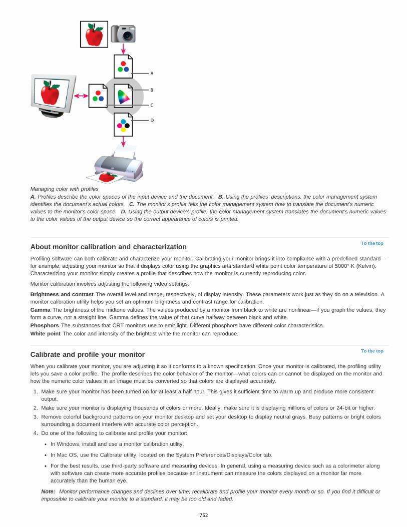
To the top
To the top
Managing color with profilesA. Profiles describe the color spaces of the input device and the document. B. Using the profiles’ descriptions, the color management systemidentifies the document’s actual colors. C. The monitor’s profile tells the color management system how to translate the document’s numericvalues to the monitor’s color space. D. Using the output device’s profile, the color management system translates the document’s numeric valuesto the color values of the output device so the correct appearance of colors is printed.
About monitor calibration and characterizationProfiling software can both calibrate and characterize your monitor. Calibrating your monitor brings it into compliance with a predefined standard—for example, adjusting your monitor so that it displays color using the graphics arts standard white point color temperature of 5000° K (Kelvin).Characterizing your monitor simply creates a profile that describes how the monitor is currently reproducing color.
Monitor calibration involves adjusting the following video settings:
Brightness and contrast The overall level and range, respectively, of display intensity. These parameters work just as they do on a television. Amonitor calibration utility helps you set an optimum brightness and contrast range for calibration.Gamma The brightness of the midtone values. The values produced by a monitor from black to white are nonlinear—if you graph the values, theyform a curve, not a straight line. Gamma defines the value of that curve halfway between black and white.Phosphors The substances that CRT monitors use to emit light. Different phosphors have different color characteristics.White point The color and intensity of the brightest white the monitor can reproduce.
Calibrate and profile your monitorWhen you calibrate your monitor, you are adjusting it so it conforms to a known specification. Once your monitor is calibrated, the profiling utilitylets you save a color profile. The profile describes the color behavior of the monitor—what colors can or cannot be displayed on the monitor andhow the numeric color values in an image must be converted so that colors are displayed accurately.
1. Make sure your monitor has been turned on for at least a half hour. This gives it sufficient time to warm up and produce more consistentoutput.
2. Make sure your monitor is displaying thousands of colors or more. Ideally, make sure it is displaying millions of colors or 24-bit or higher.3. Remove colorful background patterns on your monitor desktop and set your desktop to display neutral grays. Busy patterns or bright colors
surrounding a document interfere with accurate color perception.4. Do one of the following to calibrate and profile your monitor:
In Windows, install and use a monitor calibration utility.
In Mac OS, use the Calibrate utility, located on the System Preferences/Displays/Color tab.
For the best results, use third-party software and measuring devices. In general, using a measuring device such as a colorimeter alongwith software can create more accurate profiles because an instrument can measure the colors displayed on a monitor far moreaccurately than the human eye.
Note: Monitor performance changes and declines over time; recalibrate and profile your monitor every month or so. If you find it difficult orimpossible to calibrate your monitor to a standard, it may be too old and faded.
752

To the top
To the top
To the top
To the top
To the top
To the top
Most profiling software automatically assigns the new profile as the default monitor profile. For instructions on how to manually assign the monitorprofile, refer to the Help system for your operating system.
Install a color profileColor profiles are often installed when a device is added to your system. The accuracy of these profiles (often called generic profiles or cannedprofiles) varies from manufacturer to manufacturer. You can also obtain device profiles from your service provider, download profiles from the web,or create custom profiles using professional profiling equipment.
In Windows, right-click a profile and select Install Profile. Alternatively, copy the profiles into the WINDOWS\system32\spool\drivers\colorfolder.In Mac OS, copy profiles into the /Library/ColorSync/Profiles folder or the /Users/[username]/Library/ColorSync/Profiles folder.
After installing color profiles, be sure to restart Adobe applications.
Embed a color profileTo embed a color profile in a document you created in Illustrator, InDesign, or Photoshop, you must save or export the document in a format thatsupports ICC profiles.
1. Save or export the document in one of the following file formats: Adobe PDF, PSD (Photoshop), AI (Illustrator), INDD (InDesign), JPEG,Photoshop EPS, Large Document Format, or TIFF.
2. Select the option for embedding ICC profiles. The exact name and location of this option varies between applications. Search Adobe Helpfor additional instructions.
Embed a color profile (Acrobat)You can embed a color profile in an object or an entire PDF. Acrobat attaches the appropriate profile, as specified in the Convert Colors dialogbox, to the selected color space in the PDF. For more information, see the color conversion topics in Acrobat Help.
Changing the color profile for a documentThere are very few situations that require you to change the color profile for a document. This is because your application automatically assignsthe color profile based on the settings you select in the Color Settings dialog box. The only times you should manually change a color profile arewhen preparing a document for a different output destination or correcting a policy behavior that you no longer want implemented in the document.Changing the profile is recommended for advanced users only.
You can change the color profile for a document in the following ways:
Assign a new profile. The color numbers in the document remain the same, but the new profile may dramatically change the appearance ofthe colors as displayed on your monitor.
Remove the profile so that the document is no longer color-managed.
(Acrobat, Photoshop and InDesign) Convert the colors in the document to the color space of a different profile. The color numbers are shiftedin an effort to preserve the original color appearances.
Assign or remove a color profile (Illustrator, Photoshop)1. Choose Edit > Assign Profile.2. Select an option, and click OK:
Don’t Color Manage This Document Removes the existing profile from the document. Select this option only if you are sure that you donot want to color-manage the document. After you remove the profile from a document, the appearance of colors is defined by theapplication’s working space profiles.
Working [color model: working space] Assigns the working space profile to the document.
Profile Lets you select a different profile. The application assigns the new profile to the document without converting colors to the profilespace. This may dramatically change the appearance of the colors as displayed on your monitor.
Assign or remove a color profile (InDesign)1. Choose Edit > Assign Profiles.2. For RGB Profile and CMYK Profile, select one of the following:
Discard (Use Current Working Space) Removes the existing profile from the document. Select this option only if you are sure that you do
753

To the top
To the top
To the top
not want to color-manage the document. After you remove the profile from a document, the appearance of colors is defined by theapplication’s working space profiles, and you can no longer embed a profile in the document.
Assign Current Working Space [working space] Assigns the working space profile to the document.
Assign Profile Lets you select a different profile. The application assigns the new profile to the document without converting colors to theprofile space. This may dramatically change the appearance of the colors as displayed on your monitor.
3. Choose a rendering intent for each type of graphic in your document. For each graphic type, you can choose one of the four standardintents, or the Use Color Settings Intent, which uses the rendering intent currently specified in the Color Settings dialog box. For moreinformation on rendering intents, search in Help.
The graphic types include the following:
Solid Color Intent Sets the rendering intent for all vector art (solid areas of color) in InDesign native objects.
Default Image Intent Sets the default rendering intent for bitmap images placed in InDesign. You can still override this setting on an image-by-image basis.
After-Blending Intent Sets the rendering intent to the proofing or final color space for colors that result from transparency interactions onthe page. Use this option when your document includes transparent objects.
4. To preview the effects of the new profile assignment in the document, select Preview, and then click OK.
Convert document colors to another profile (Photoshop)1. Choose Edit > Convert To Profile.2. Under Destination Space, choose the color profile to which you want to convert the document’s colors. The document will be converted to
and tagged with this new profile.3. Under Conversion Options, specify a color management engine, a rendering intent, and black point and dither options (if available). (See
Color conversion options.)4. To flatten all layers of the document onto a single layer upon conversion, select Flatten Image.5. To preview the effects of the conversion in the document, select Preview.
Convert document colors to Multichannel, Device Link, or Abstract color profiles (Photoshop)1. Choose Edit > Convert To Profile.2. Click Advanced. The following additional ICC profile types are available under Destination Space:
Multichannel Profiles that support more than four color channels. These are useful when printing with more than four inks.
Device Link Profiles that transform from one device color space to another, without using an intermediate color space in the process. Theseare useful when specific mappings of device values (like 100% black) are required.
Abstract Profiles that enable custom image effects. Abstract profiles can have LAB/XYZ values for both input and output values, whichenables generation of a custom LUT to achieve the desired special effect.Note: Gray, RGB, LAB, and CMYK color profiles are grouped by category in Advanced view. They are combined on the Profile menu inBasic view.
3. To preview the effects of the conversion in the document, select Preview.
Convert document colors to another profile (Acrobat)You convert colors in a PDF by using Tools > Print Production > Convert Colors. For more information, see the color conversion topics in AcrobatHelp.
|
754

Color-managing documents for online viewing
To the top
To the top
To the top
Color-managing documents for online viewingColor-managing PDFs for online viewingColor-managing HTML documents for online viewing
Color-managing documents for online viewingColor management for online viewing is very different from color management for printed media. With printed media, you have far more controlover the appearance of the final document. With online media, your document will appear on a wide range of possibly uncalibrated monitors andvideo display systems, significantly limiting your control over color consistency.
When you color-manage documents that will be viewed exclusively on the web, Adobe recommends that you use the sRGB color space. sRGB isthe default working space for most Adobe color settings, but you can verify that sRGB is selected in the Color Settings dialog box (Photoshop,Illustrator, InDesign) or the Color Management preferences (Acrobat). With the working space set to sRGB, any RGB graphics you create will usesRGB as the color space.
When working with images that have an embedded color profile other than sRGB, you should convert the image’s colors to sRGB before you savethe image for use on the web. If you want the application to automatically convert the colors to sRGB when you open the image, select Convert ToWorking Space as the RGB color management policy. (Make sure that your RGB working space is set to sRGB.) In Photoshop and InDesign, youcan also manually convert the colors to sRGB using the Edit > Convert To Profile command.
Note: In InDesign, the Convert To Profile command only converts colors for native, not placed, objects in the document.
Color-managing PDFs for online viewingWhen you export PDFs, you can choose to embed profiles. PDFs with embedded profiles reproduce color consistently in Acrobat 4.0 or laterrunning under a properly configured color management system.
Keep in mind that embedding color profiles increases the size of PDFs. RGB profiles are usually small (around 3 KB); however, CMYK profiles canrange from 0.5 to 2 MB.
Color-managing HTML documents for online viewingMany web browsers do not support color management. Of the browsers that do support color management, not all instances can be consideredcolor-managed because they may be running on systems where the monitors are not calibrated. In addition, few web pages contain images withembedded profiles. If you manage a highly controlled environment, such as the intranet of a design studio, you may be able to achieve somedegree of HTML color management for images by equipping everyone with a browser that supports color management and calibrating all monitors.
You can approximate how colors will look on uncalibrated monitors by using the sRGB color space. However, because color reproduction variesamong uncalibrated monitors, you still won’t be able to anticipate the true range of potential display variations.
|
755

Color-managing documents when printing
To the top
To the top
To the top
To the top
Printing with color managementLetting the printer determine colors when printingLetting the application determine colors when printingObtaining custom profiles for desktop printersColor-managing PDFs for printing
Printing with color managementColor management options for printing let you specify how you want Adobe applications to handle the outgoing image data so the printer will printcolors consistent with what you see on your monitor. Your options for printing color-managed documents depend on the Adobe application youuse, as well as the output device you select. In general, you have the following choices for handling colors during printing:
Let the printer determine colors.
Let the application determine colors.
(InDesign) Do not use color management. In this workflow, no color conversion occurs. You may also need to turn off color management inyour printer driver. This method is useful primarily for printing test targets or generating custom profiles.
Letting the printer determine colors when printingIn this workflow, the application does the minimum color conversion required to get the document into a color space that the printer supports. Forexample, when printing CMYK or duotone images to a desktop inkjet, the application converts to RGB or Lab color, depending upon printersupport.
This method is especially convenient when printing to inkjet photo printers, because each combination of paper type, printing resolution, andadditional printing parameters (such as high-speed printing) requires a different profile. Most new inkjet photo printers come with fairly accurateprofiles built into the driver, so letting the printer select the right profile saves time and alleviates mistakes. This method is also recommended ifyou are not familiar with color management.
If you choose this method, it is very important that you set up printing options and turn on color management in your printer driver. Search Help foradditional instructions.
If you select a PostScript printer, you can take advantage of PostScript color management. PostScript color management makes it possible toperform color composite output or color separations at the raster image processor (RIP)—a process called in-RIP separations—so that a programneed only specify parameters for separation and let the device calculate the final color values. PostScript color-managed output workflows requirean output device that supports PostScript color management using PostScript Level 2 version 2017 or later, or PostScript Lanuage Level 3.
Letting the application determine colors when printingIn this workflow, the application does all the color conversion, generating color data specific to one output device. The application uses theassigned color profiles to convert colors to the output device’s gamut, and sends the resulting values to the output device. The accuracy of thismethod depends on the accuracy of the printer profile you select. Use this workflow when you have custom ICC profiles for each specific printer,ink, and paper combination.
If you choose this option, it is very important that you disable color management in your printer driver. Letting the application and the printer driversimultaneously manage colors during printing results in unpredictable color. Search Help for additional instructions.
Obtaining custom profiles for desktop printersIf the output profiles that come with your printer don’t produce satisfactory results, you obtain custom profiles in the following ways:
Purchase a profile for your type of printer and paper. This is usually the easiest and least expensive method.
Purchase a profile for your specific printer and paper. This method involves printing a profiling target on your printer and paper, and providingthat target to a company that will create a specific profile. This is more expensive than purchasing a standard profile, but can provide betterresults because it compensates for any manufacturing variations in printers.
Create your own profile using a scanner-based system. This method involves using profile-creation software and your own flatbed scanner toscan the profiling target. It can provide excellent results for matte surface papers, but not glossy papers. (Glossy papers tend to have
756
To the top
fluorescent brighteners in them that look different to a scanner than they do in room light.)
Create your own profile using a hardware profile-creation tool. This method is expensive but can provide the best results. A good hardwaretool can create an accurate profile even with glossy papers.
Tweak a profile created using one of the previous methods with profile-editing software. This software can be complex to use, but it lets youcorrect problems with a profile or simply adjust a profile to produce results more to your taste.
Color-managing PDFs for printingWhen you create Adobe PDFs for commercial printing, you can specify how color information is represented. The easiest way to do this is using aPDF/X standard; however, you can also specify color-handling options manually in the Output section of the PDF dialog box. For more informationabout PDF/X and how to create PDFs, search Help.
In general, you have the following choices for handling colors when creating PDFs:
(PDF/X-3) Does not convert colors. Use this method when creating a document that will be printed or displayed on various or unknowndevices. When you select a PDF/X-3 standard, color profiles are automatically embedded in the PDF.
(PDF/X-1a) Converts all colors to the destination CMYK color space. Use this method if you want to create a press-ready file that does notrequire any further color conversions. When you select a PDF/X-1a standard, no profiles are embedded in the PDF.
(Illustrator and InDesign) Converts colors that have embedded profiles to the destination color space, but preserves the numbers for thosecolors without embedded profiles. You can manually select this option in the Output section of the PDF dialog box. Use this method if thedocument contains CMYK images that aren’t color-managed and you want to make sure that the color numbers are preserved.
Note: All spot color information is preserved during color conversion; only the process color equivalents convert to the designated color space.
|
757
Color-managing imported images
To the top
To the top
To the top
To the top
Color-managing imported images (Illustrator, InDesign)Using a safe CMYK workflowPreparing imported graphics for color managementView or change profiles for imported bitmap images (InDesign)
Color-managing imported images (Illustrator, InDesign)How imported images are integrated into a document’s color space depends on whether or not the image has an embedded profile:
When you import an image that contains no profile, the Adobe application uses the current document profile to define the colors in the image.
When you import an image that contains an embedded profile, color policies in the Color Settings dialog box determine how the Adobeapplication handles the profile.
Using a safe CMYK workflowA safe CMYK workflow ensures that CMYK color numbers are preserved all the way to the final output device, as opposed to being converted byyour color management system. This workflow is beneficial if you want to incrementally adopt color management practices. For example, you canuse CMYK profiles to soft-proof and hard-proof documents without the possibility of unintended color conversions occurring during final output.
Illustrator and InDesign support a safe CMYK workflow by default. As a result, when you open or import a CMYK image with an embedded profile,the application ignores the profile and preserves the raw color numbers. If you want your application to adjust color numbers based on anembedded profile, change the CMYK color policy to Preserve Embedded Profiles in the Color Settings dialog box. You can easily restore the safeCMYK workflow by changing the CMYK color policy back to Preserve Numbers (Ignore Linked Profiles).
You can override safe CMYK settings when you print a document or save it to Adobe PDF. However, doing so may cause colors to bereseparated. For example, pure CMYK black objects may be reseparated as rich black. For more information on color management options forprinting and saving PDFs, search in Help.
Preparing imported graphics for color managementUse the following general guidelines to prepare graphics for being color-managed in Adobe applications:
Embed an ICC-compliant profile when you save the file. The file formats that support embedded profiles are JPEG, PDF, PSD (Photoshop),AI (Illustrator), INDD (InDesign), Photoshop EPS, Large Document Format, and TIFF.
If you plan to reuse a color graphic for multiple final output devices or media, such as for print, video, and the web, prepare the graphic usingRGB or Lab colors whenever possible. If you must save in a color model other than RGB or Lab, keep a copy of the original graphic. RGBand Lab color models represent larger color gamuts than most output devices can reproduce, retaining as much color information as possiblebefore being translated to a smaller output color gamut.
View or change profiles for imported bitmap images (InDesign)InDesign allows you to view, override, or disable profiles for imported bitmap images. This may be necessary when you are importing an imagecontaining no profile or an incorrectly embedded profile. For example, if the scanner manufacturer’s default profile was embedded but you havesince generated a custom profile, you can assign the newer profile.
1. Do one of the following:
If the graphic is already in layout, select it and choose Object > Image Color Settings.
If you’re about to import the graphic, choose File > Place, select Show Import Options, select and open the file, and then select theColor tab.
2. For Profile, choose the source profile to apply to the graphic in your document. If a profile is currently embedded, the profile name appearsat the top of the Profile menu.
3. (Optional) Choose a rendering intent, and then click OK. In most cases, it’s best to use the default rendering intent.
Note: You can also view or change profiles for objects in Acrobat.
758
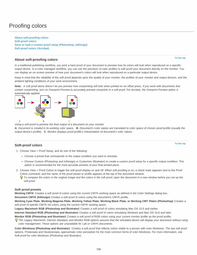
Proofing colors
To the top
To the top
About soft-proofing colorsSoft-proof colorsSave or load a custom proof setup (Photoshop, InDesign)Soft-proof colors (Acrobat)
About soft-proofing colorsIn a traditional publishing workflow, you print a hard proof of your document to preview how its colors will look when reproduced on a specificoutput device. In a color-managed workflow, you can use the precision of color profiles to soft-proof your document directly on the monitor. Youcan display an on-screen preview of how your document’s colors will look when reproduced on a particular output device.
Keep in mind that the reliability of the soft proof depends upon the quality of your monitor, the profiles of your monitor and output devices, and theambient lighting conditions of your work environment.
Note: A soft proof alone doesn’t let you preview how overprinting will look when printed on an offset press. If you work with documents thatcontain overprinting, turn on Overprint Preview to accurately preview overprints in a soft proof. For Acrobat, the Overprint Preview option isautomatically applied.
Using a soft proof to preview the final output of a document on your monitorA. Document is created in its working color space. B. Document’s color values are translated to color space of chosen proof profile (usually theoutput device’s profile). C. Monitor displays proof profile’s interpretation of document’s color values.
Soft-proof colors1. Choose View > Proof Setup, and do one of the following:
Choose a preset that corresponds to the output condition you want to simulate.
Choose Custom (Photoshop and InDesign) or Customize (Illustrator) to create a custom proof setup for a specific output condition. Thisoption is recommended for the most accurate preview of your final printed piece.
2. Choose View > Proof Colors to toggle the soft-proof display on and off. When soft proofing is on, a check mark appears next to the ProofColors command, and the name of the proof preset or profile appears at the top of the document window.
To compare the colors in the original image and the colors in the soft proof, open the document in a new window before you set up thesoft proof.
Soft-proof presetsWorking CMYK Creates a soft proof of colors using the current CMYK working space as defined in the Color Settings dialog box.Document CMYK (InDesign) Creates a soft proof of colors using the document’s CMYK profile.Working Cyan Plate, Working Magenta Plate, Working Yellow Plate, Working Black Plate, or Working CMY Plates (Photoshop) Creates asoft proof of specific CMYK ink colors using the current CMYK working space.Legacy Macintosh RGB (Photoshop and Illustrator) Creates a soft proof of colors simulating Mac OS 10.5 and earlier.Internet Standard RGB (Photoshop and Illustrator) Creates a soft proof of colors simulating Windows and Mac OS 10.6 and later.Monitor RGB (Photoshop and Illustrator) Creates a soft proof of RGB colors using your current monitor profile as the proof profile.
The Legacy Macintosh, Internet Standard, and Monitor RGB options assume that the simulated device will display your document without usingcolor management. These options are unavailable for Lab or CMYK documents.
Color Blindness (Photoshop and Illustrator) Creates a soft proof that reflects colors visible to a person with color blindness. The two soft proofoptions, Protanopia and Deuteranopia, approximate color perception for the most common forms of color blindness. For more information, seeSoft-proof for color blindness (Photoshop and Illustrator).
759
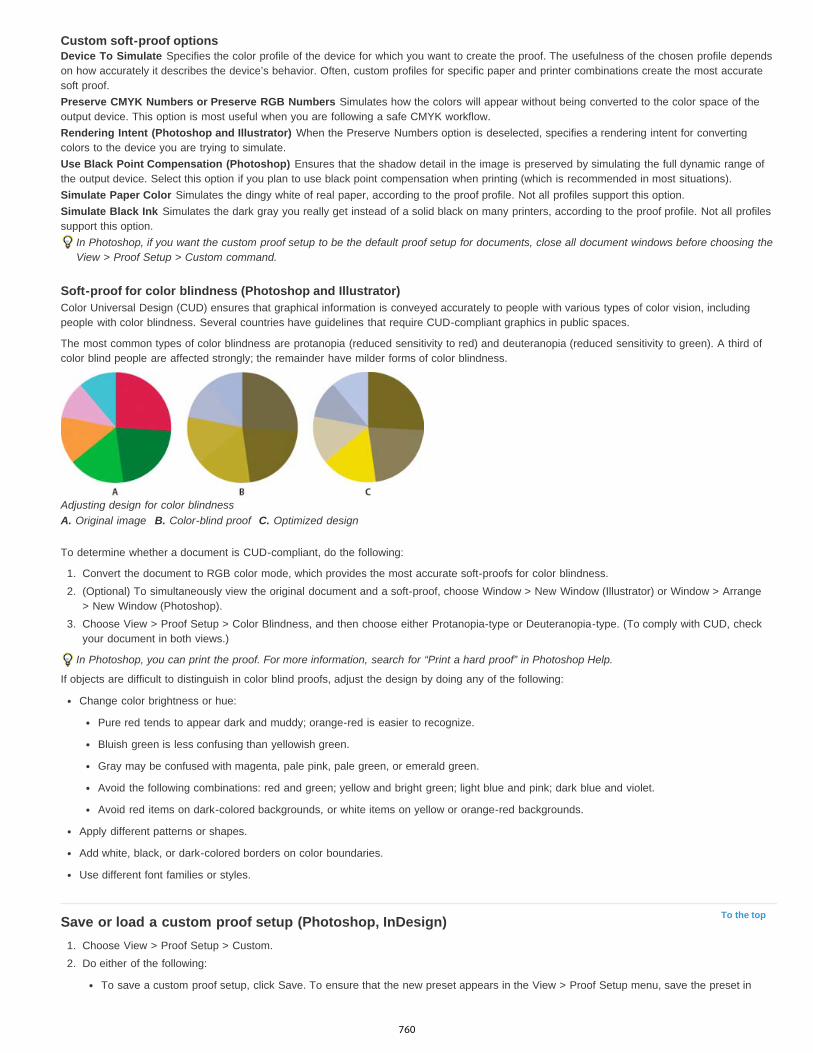
To the top
Custom soft-proof optionsDevice To Simulate Specifies the color profile of the device for which you want to create the proof. The usefulness of the chosen profile dependson how accurately it describes the device’s behavior. Often, custom profiles for specific paper and printer combinations create the most accuratesoft proof.Preserve CMYK Numbers or Preserve RGB Numbers Simulates how the colors will appear without being converted to the color space of theoutput device. This option is most useful when you are following a safe CMYK workflow.Rendering Intent (Photoshop and Illustrator) When the Preserve Numbers option is deselected, specifies a rendering intent for convertingcolors to the device you are trying to simulate.Use Black Point Compensation (Photoshop) Ensures that the shadow detail in the image is preserved by simulating the full dynamic range ofthe output device. Select this option if you plan to use black point compensation when printing (which is recommended in most situations).Simulate Paper Color Simulates the dingy white of real paper, according to the proof profile. Not all profiles support this option.Simulate Black Ink Simulates the dark gray you really get instead of a solid black on many printers, according to the proof profile. Not all profilessupport this option.
In Photoshop, if you want the custom proof setup to be the default proof setup for documents, close all document windows before choosing theView > Proof Setup > Custom command.
Soft-proof for color blindness (Photoshop and Illustrator)Color Universal Design (CUD) ensures that graphical information is conveyed accurately to people with various types of color vision, includingpeople with color blindness. Several countries have guidelines that require CUD-compliant graphics in public spaces.
The most common types of color blindness are protanopia (reduced sensitivity to red) and deuteranopia (reduced sensitivity to green). A third ofcolor blind people are affected strongly; the remainder have milder forms of color blindness.
Adjusting design for color blindnessA. Original image B. Color-blind proof C. Optimized design
To determine whether a document is CUD-compliant, do the following:
1. Convert the document to RGB color mode, which provides the most accurate soft-proofs for color blindness.2. (Optional) To simultaneously view the original document and a soft-proof, choose Window > New Window (Illustrator) or Window > Arrange
> New Window (Photoshop).3. Choose View > Proof Setup > Color Blindness, and then choose either Protanopia-type or Deuteranopia-type. (To comply with CUD, check
your document in both views.)
In Photoshop, you can print the proof. For more information, search for “Print a hard proof” in Photoshop Help.
If objects are difficult to distinguish in color blind proofs, adjust the design by doing any of the following:
Change color brightness or hue:
Pure red tends to appear dark and muddy; orange-red is easier to recognize.
Bluish green is less confusing than yellowish green.
Gray may be confused with magenta, pale pink, pale green, or emerald green.
Avoid the following combinations: red and green; yellow and bright green; light blue and pink; dark blue and violet.
Avoid red items on dark-colored backgrounds, or white items on yellow or orange-red backgrounds.
Apply different patterns or shapes.
Add white, black, or dark-colored borders on color boundaries.
Use different font families or styles.
Save or load a custom proof setup (Photoshop, InDesign)1. Choose View > Proof Setup > Custom.2. Do either of the following:
To save a custom proof setup, click Save. To ensure that the new preset appears in the View > Proof Setup menu, save the preset in
760
To the top
the default location.
To load a custom proof setup, click Load.
Soft-proof colors (Acrobat)1. Do one of the following, depending on your version of Acrobat:
(Acrobat 9) Choose Advanced > Print Production > Output Preview.
(Acrobat X) Choose Tools > Print Production > Output Preview.
2. Choose the color profile of a specific output device from the Simulation Profile menu.3. Choose a soft-proof option:
Simulate Black Ink Simulates the dark gray you really get instead of a solid black on many printers, according to the proof profile. Not allprofiles support this option.
Simulate Paper Color Simulates the dingy white of real paper, according to the proof profile. Not all profiles support this option.
|
761