grw 2016 - odtÜ electrical - electronics
TRANSCRIPT

MIDDLE EAST TECHNICAL UNIVERSITY DEPARTMENT OF ELECTRICAL AND ELECTRONICS ENGINEERING
2016 Graduate Research Workshop GRW 2016
5,6,13 May 2016

Graduate Research Workshop (GRW 2016) 5,6,13 May 2016 Department of Electrical and Electronics Engineering Middle East Technical University Ankara, Turkey Proceedings Edited by Özgür Ergül
GRW-2016 1

MIDDLE EAST TECHNICAL UNIVERSITY
DEPARTMENT OF ELECTRICAL AND ELECTRONICS ENGINEERING
2016 EEE Graduate Research Workshop GRW 2016
GRW 2016 Committee Gönül Turhan Sayan Özlem Aydın Çivi Özgür Ergül METU IEEE Student Branch Poster Evaluators Gözde Bozdağı Akar Aydın Alatan Lale Alatan Cüneyt Bazlamaçcı Çağatay Candan Tolga Çiloğlu Özlem Aydın Çivi Özgür Ergül Yeşim Serinağaoğlu Doğrusöz Aydan Erkmen Bülent Ertan Murat Göl Nevzat Güneri Gençer Nilgün Günalp Nezih Güven Fatih Kamışlı Ozan Keysan Serdar Kocaman Sencer Koç Fatih Koçer Sinan Korkan Mustafa Kuzuoğlu Haluk Külah Kemal Leblebicioğlu Umut Onguner Sevinç Figen Öktem Emre Özkan Afşar Saranlı Ece Güran Schmidt
Yalçın Tanık Emre Tuna Engin Tuncer İlkay Ulusoy Elif Vural Melek Diker Yücel METU IEEE Student Branch Presentation Evaluators Barış Bayram Ozan Keysan Fatih Koçer Sinan Korkan Umut Onguner Emre Özkan Gönül Turhan Sayan GRW-2016 Awardees GRW-2016 Best Presentations
1. Damla Alptekin 2. Gökhan K. Gültekin 3. Enis Kobal
GRW-2016 Best Poster Presentations
• Damla Alptekin • Ahmet M. Elbir • Gökhan K. Gültekin • Feza Mutlu • Enis Kobal • Oktay Sipahigil • Erdem Yanar
GRW-2016 2

MIDDLE EAST TECHNICAL UNIVERSITY DEPARTMENT OF ELECTRICAL AND ELECTRONICS ENGINEERING
2016 EEE Graduate Research Workshop GRW 2016 Final Abstract List
Ahmet Batur Controller Area Network Response Time Analysis and Scheduling for Extended Topics: Offsets, Gateways, and Validation with a Hardware Test-Bed
Ahmet M. Elbir Direction Finding for Arbitrary Array Structures in the Presence of Mutual Coupling
B. Tan Bacınoğlu Finite Horizon Energy-Efficient Scheduling with Energy Harvesting Transmitters over Fading Channels
Barışcan Karaosmanoğlu Accurate and Efficient Analysis of Plasmonic Structures Using the Multilevel Fast Multipole Algorithm
Ceren Bora Orçun Detection and Quantification of Atrial Fibrillation from Surface Electrocardiograms
Cumhur Çakmak Message Scheduling for FlexRay 3.0: Optimal and Heuristic Approaches
Damla Alptekin Dual Band PIFA Design for Biomedical Applications
Doğa Ceylan Electromagnetic Simulation and Optimization of an Electromagnetic Launcher
Elyar Ghalichi Sensitivity Analysis for Magneto-Acousto-Electrical Tomography
Enis Kobal RF MEMS Based Millimeter Wave Phased Array for Short Range Communication
Erdem Yanar Reducing False Arrhythmia Alarms in the Intensive Care Units
Feza Mutlu Design, Simulation, and Fabrication of Inkjet Antennas
Gökhan Koray Gültekin Camera Ego-Motion Based Motion Blur Compansation Robots in Legged Mobile
Göksan Eral FASST: A Low Latency, Scalable, High Throughput SDN Flow Table Hardware Architecture
Görkem Polat Quantification of Stenosis in Coronary Arteries
İlker Şahin Utilization of Sample and Hold (S/H) in the Outer Voltage Loop of Boost Type PFC Converters
GRW-2016 3

Kadir Üstün Metamaterial Absorbers in the Infrared
Mahsa Keykhali
A Study on a Low Phase Noise Charge Pump Phase-Locked Loop at 2.8 GHz
Mehmet Ertuğ Afşin A Hardware Architecture and Implementation for High Performance CAN FD (CAN with Flexible Data Rate)
Mehmet Onur Padar Classification of Human Motion Using Radar Micro-Doppler Signatures with Hidden Markov Models
Mesut Doğan Energy Based Target Detection Using the Simulated A-Scan GPR Data
Mesut Uğur Elimination of Circulating Currents Between Two Interleaved PWM Rectifiers Supplied from a Common Single-Phase AC Source
Navid Husseini MLFMA Simulations and Optimizations of Photonic Crystals for Beam Shaping
Oktay Sipahigil Estimating the Sensor Positions of a Passive Array Using Calibration Emitters with TDOA Measurements
Rasul Tarvirdilu Asl Design of a High efficiency and High Torque Density Switched Reluctance Motor to Be Used in Hybrid Electric Vehicle Applications
Reza Zeinali Design and Optimization of a High Torque Density Magnetically-Geared Generator for Direct Drive Wind Turbine Application
Saeed Ranjbar Alvar Intra Coding in HEVC with 3-tap Filters
Selim Özgen On the Solution of Data Association Problem Using Rollout Algorithms
Taha Erenler Inverse Problem of Electrocardiography; Comparison of Two Methods
Talha İnce A Study on Visual Aided Inertial Navigation
Tunç Alkanat Fast Computation of Two-Dimensional Point-Spread Functions for Photon Sieves
Yusuf Sevinç Design of Miniaturized Ku Band Narrowband Cavity Filter
GRW-2016 4
Controller Area Network Response Time Analysis and Scheduling for Extended Topics: Offsets, Gateways, and Validation with a Hardware Test-Bed
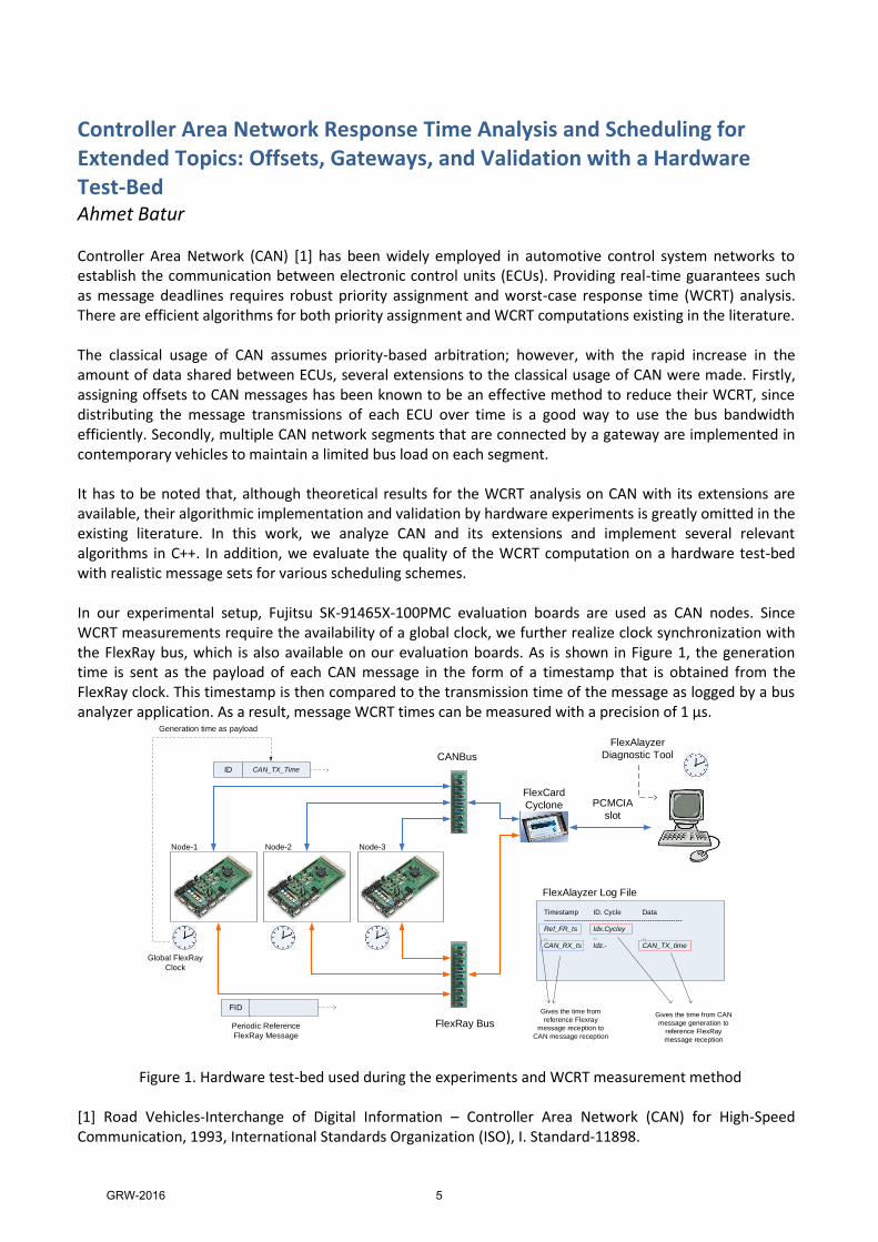
Ahmet Batur Controller Area Network (CAN) [1] has been widely employed in automotive control system networks to establish the communication between electronic control units (ECUs). Providing real-time guarantees such as message deadlines requires robust priority assignment and worst-case response time (WCRT) analysis. There are efficient algorithms for both priority assignment and WCRT computations existing in the literature. The classical usage of CAN assumes priority-based arbitration; however, with the rapid increase in the amount of data shared between ECUs, several extensions to the classical usage of CAN were made. Firstly, assigning offsets to CAN messages has been known to be an effective method to reduce their WCRT, since distributing the message transmissions of each ECU over time is a good way to use the bus bandwidth efficiently. Secondly, multiple CAN network segments that are connected by a gateway are implemented in contemporary vehicles to maintain a limited bus load on each segment. It has to be noted that, although theoretical results for the WCRT analysis on CAN with its extensions are available, their algorithmic implementation and validation by hardware experiments is greatly omitted in the existing literature. In this work, we analyze CAN and its extensions and implement several relevant algorithms in C++. In addition, we evaluate the quality of the WCRT computation on a hardware test-bed with realistic message sets for various scheduling schemes. In our experimental setup, Fujitsu SK-91465X-100PMC evaluation boards are used as CAN nodes. Since WCRT measurements require the availability of a global clock, we further realize clock synchronization with the FlexRay bus, which is also available on our evaluation boards. As is shown in Figure 1, the generation time is sent as the payload of each CAN message in the form of a timestamp that is obtained from the FlexRay clock. This timestamp is then compared to the transmission time of the message as logged by a bus analyzer application. As a result, message WCRT times can be measured with a precision of 1 µs.
Figure 1. Hardware test-bed used during the experiments and WCRT measurement method
[1] Road Vehicles-Interchange of Digital Information – Controller Area Network (CAN) for High-Speed Communication, 1993, International Standards Organization (ISO), I. Standard-11898.
CANBus
FlexRay Bus
ID CAN_TX_Time
Global FlexRay
Clock
Generation time as payload
FlexCard
Cyclone PCMCIA
slot
FlexAlayzer Log File
FlexAlayzer
Diagnostic Tool
Timestamp ID. Cycle Data
------------------------------------------------------------
Ref_FR_ts Idx.Cycley
.. .. ..
CAN_RX_ts Idz.- CAN_TX_time
FID
Periodic Reference
FlexRay Message
Node-1 Node-2 Node-3
Gives the time from CAN
message generation to
reference FlexRay
message reception
Gives the time from
reference Flexray
message reception to
CAN message reception
GRW-2016 5

Direction Finding For Arbitrary Array Structures In The Presence of Mutual Coupling
Ahmet M. Elbir Direction-of-arrival (DOA) estimation for arbitrary array structures in the presence of mutual coupling (MC) is an important problem for antenna arrays. Previous methods in the literature are usually proposed for certain array geometries and show limited performance at low SNR or for small number of snapshots. In this paper, compressed sensing is used to exploit the joint-sparsity of the array model to estimate both DOA and MC coefficients with a single snapshot for an unstructured array where the antennas are placed arbitrarily in space as shown in Fig.1. A joint-sparse recovery algorithm for a single snapshot (JSR-SS) is presented by embedding the source DOA angles and MC coefficients into a joint-sparse vector. A dictionary matrix is defined by considering the symmetricity of the MC matrix for the unstructured antenna array. The proposed method is extended to the multiple snapshots, and the joint-sparse recovery algorithm with multiple snapshots (JSR-MS) is developed. A new joint-sparsity structure, namely, joint-block-sparsity is introduced to take advantage of the structure in the composite matrix involving both DOA and MC coefficients. 1-D and 2-D DOA estimation performance of the proposed methods are provided in comparison to the conventional sparse recovery techniques, subspace methods, and the Cramer-Rao lower bound. It is shown that the proposed methods perform significantly better than the alternative methods.
Figure 1 The placement of an arbitrary array structure.
The JSR problem is laid out in a form such that the source DOA angles and MC coefficients can be recovered using convex optimization techniques. In JSR, joint-sparsity property is considered instead of sparsity used in conventional techniques and the spatial source directions and coupling coefficients are embedded into a joint-sparse vector. A new dictionary matrix is defined in accordance with the symmetricity of the MC matrix. Since the construction of the MC matrix is general, the proposed method is suitable for recovering the support set of any array structure. Once the JSR problem is solved, the source DOA angles are obtained from the support set. The recovered joint-sparse signal includes both coupling coefficients and the source directions. MC coefficients are estimated with a least square method by minimizing a cost function employing the known DOA angles. In case of multiple snapshots, a quadratic minimization problem is treated and a closed form solution is obtained.
-1 -0.8 -0.6 -0.4 -0.2 0 0.2 0.4 0.6 0.8 1-1
-0.8
-0.6
-0.4
-0.2
0
0.2
0.4
0.6
0.8
1
X [wavelength]
Y [
wavele
ngth
]
GRW-2016 6
Finite Horizon Energy-Efficient Scheduling with EnergyHarvesting Transmitters over Fading Channels
B.Tan Bacınoğlu
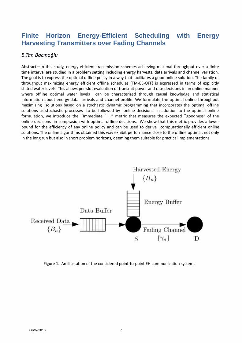
Abstract—In this study, energy-efficient transmission schemes achieving maximal throughput over a finitetime interval are studied in a problem setting including energy harvests, data arrivals and channel variation.The goal is to express the optimal offline policy in a way that facilitates a good online solution. The family ofthroughput maximizing energy efficient offline schedules (TM-EE-OFF) is expressed in terms of explicitlystated water levels. This allows per-slot evaluation of transmit power and rate decisions in an online mannerwhere offline optimal water levels can be characterized through causal knowledge and statisticalinformation about energy-data arrivals and channel profile. We formulate the optimal online throughputmaximizing solutions based on a stochastic dynamic programming that incorporates the optimal offlinesolutions as stochastic processes to be followed by online decisions. In addition to the optimal onlineformulation, we introduce the ``Immediate Fill ” metric that measures the expected ``goodness” of theonline decisions in comprasion with optimal offline decisions. We show that this metric provides a lowerbound for the efficiency of any online policy and can be used to derive computationally efficient onlinesolutions. The online algorithms obtained this way exhibit performance close to the offline optimal, not onlyin the long run but also in short problem horizons, deeming them suitable for practical implementations.
Figure 1. An illustation of the considered point-to-point EH communication system.
GRW-2016 7

Accurate and Efficient Analysis of Plasmonic StructuresUsingTheMulti levelFastMultipoleAlgorithm BarışcanKaraosmanoğluWe consider accurate full-wave solutions of plasmonic structures using the multilevel fast multipolealgorithm(MLFMA).Althoughmetalsatlowfrequenciescanbemodeledasperfectelectricconductors,theybecome penetrable at optical frequencies, where plasmonic effects dominate. In the context ofcomputationalanalysis,wearemodelingplasmonicstructuresaspenetrabledielectrics,wheretherequiredpermittivity values are obtained via the Lorentz-Drude model. Since they are homogeneous, plasmonicstructures are formulated by using surface integral equations. There have been various studies on theanalysis of dielectric and magnetic objects, leading to alternative formulations for different kinds ofproblems.Tangentialformulations,suchasthePoggio-Miller-Chang-Harrington-Wu-Tsai(PMCHWT)andthecombinedtangentialformulation(CTF),provideaccurateresultswithlow-orderdiscretization.Ontheotherhand, mixed formulations, such as the electric and magnetic current combined-field integral equation(JMCFIE), give well-conditionedmatrix equations, hence fast iterative solutions. Considering the tradeoffbetween accuracy and efficiency among surface integral equations, new formulations are further derivedandusedinourapplications.Numerical consistency of the surface integral equations is explored for plasmonic spheres with variouspermittivityvalues.Theresultsarecomparedwiththeanalyticalresults.Weobtainpromisingresultsusinganovel formulation, namely, themodified combined tangential formulation (MCTF).Wealso useMCTF foraccuratesolutionsofmorepracticalproblems,suchasplasmonicnanowires.Asanexample, in this figuretwosilvernanowiresare illuminatedat250THzwithtwodipoles.Thepowerdistribution inthevicinityofthe structure is illustrated in the figure. We observe that the electromagnetic power is efficientlytransmittedalongthenanowires.Suchanefficienttransmissionisachievedduetotheplasmoniceffects.Inaddition,weobservequitedifferentpowerresponseswhenthesameproblemisformulatedwithdifferentintegralequations.OurtestsshowthatonlyMCTFprovidesaccurateresults.Theeffectsofcrosssectionsofthe nanowires, as well as their physical and electrical dimensions, to the power distribution are alsoinvestigatedandwillbepresented.
Figure1.PowerDensity(dBW/m2)inthenear-zoneofthesystemoftwoAgnanowiresexcitedwithtwodipolesat250THz.
30
40
50
60 dBW/m
30
40
50
60 dBW/m
30
40
50
60 dBW/m2
2
2
CTF (λ/24)
JMCFIE (λ/24)
MCTF (λ/24)
GRW-2016 8

Detection and Quantification of Atrial Fibrillation from Surface Electrocardiograms
Ceren BORA ORÇUN Atrial Fibrillation (AF), one of the most frequently encountered arrhythmias, is characterized by a rapid and irregular heart beat caused by the atria quiver or irregular fibrillation. This heart disease may lead to a significant negative impact on an individual's life quality, and if left untreated, it may lead to life threatening illnesses such as stroke, or even death. Unfortunately, detection and characterization of atrial fibrillation is not straightforward since the major part of the signal recorded from the body surface contains the ventricular cardiac activity. The techniques to investigate the AF can be listed as: electrocardiogram (ECG), body surface potential mapping (BSPM), catheter based mapping. The main objective of this study is to understand the atrial electrical activity and the functionality of the heart by measuring normal sinus rhythm of the AF patients as well as the healthy adults to indicate the differences. For that purpose, we process, analyze and compare signals obtained from the clinically most widely used ECG with 12 leads as well as modified lead positions to obtain predominate atrial signals (e.g. optimized atriocardiogram - oACG). In oACG system, 9 electrodes of the standard 12-lead ECG system are replaced to the best positions: as VR, VL, VF, V1 and V4 stayed in their original positions; V2, V3, V5 and V6 have their new positions, which are determined through simulation results, in order to provide maximum independent view of atrial signals. Clinical measurements are obtained in Private Güven Hospital, Cardiology Department in Ankara, where also ethical approval and distinction between healthy individual and AF patients were obtained. In the first phase, signal pre-processing, segmentation, time and frequency domain analysis techniques are applied to determine characteristic features of a normal sinus rhythm ECG and oACG signals acquired from a healthy individual for 30 seconds long. After the pre-processing stage (removal of the 50 Hz, EMG and baseline drift noises) ECG signal is processed in the following order; detection of the R-wave and RR variability, suppression of the QRS, segmentation and characterization of the P wave (e.g.; skewness, amplitude and duration), segmentation of ST segment, characterization of the V1 and V4 waves. In the next stage, same filtering and segmentation procedures are applied to the oACG data and comparison of ECG and oACG recordings will demonstrate the similarities and differences. The norms of the oACG recordings will be set out in this study. In the future work, as well as comparison of the ECG and oACG measurements, we aim to introduce the clinically significant differences in healthy individuals and AF patients. The features obtained through signal processing, applied in this work, will be differentiated using Principal Component Analysis (PCA). Classification will be performed using Gaussian Mixture Models (GMM) or Support Vector Machines (SVM). The ultimate goal is to classify the signals in terms of the probability density function (pdf) as a percentage value. In this way, we target to ensure obtaining further information about the disease and early diagnosis of patients with AF.
GRW-2016 9
Message Scheduling for FlexRay 3.0: Optimal and Heuristic Approaches
Cumhur Çakmak The electronics used in the developing automotive industry tries to respond the increasing customer demands. In-vehicle network (IVN) designs are always being improved to keep up with safety and comfort requirements. FlexRay is a high-speed in-vehicle network protocol, which consists of 2 segments. One is the static segment (SS) which is used to transmit time-triggered messages and the other is the dynamic segment (DS) which is used to transmit event-triggered messages. The transmission timings for the FlexRay messages are defined by a schedule that is computed off-line before the network operation starts. The schedule is designed such that the messages are guaranteed to be delivered within their specified deadlines. Furthermore, it is desired to utilize the network bandwidth efficiently to accommodate possible message extensions on the same network. FlexRay is evolving over years and the most recent version of the standard proposes significant changes in the protocol which are expected to affect the schedule performance [1]. This work focuses on the SS, where the messages are periodic and where it is expected that the messages are delivered without jitter to preserve the periodicity in addition to meeting the deadlines and bandwidth efficiency. The running time of the algorithm is another metric to consider. Since the scheduling is usually done once in the factory, the running time of the algorithm may not seem very critical. However, as stated in [2], it is also possible that new messages are defined and a new schedule has to be generated later on. There are many different approaches to improve the message scheduling for SS. Most of them ignore the timing of the application layer tasks, while some of them also plan the timing requirements between individual tasks as in [3]. Some of the works propose ILP formulations to find optimal solutions, while some also consider heuristic algorithms such as Greedy heuristic and Decreasing First-Fit in [4] so that the running time is decreased. Some studies deal with the problem in two stages: packing messages into a frame first and then placing the frames into slots as in [5] and [6], while some of them assign messages directly into slots, doing the frame packing implicitly. Our work aims to deploy the previous jitter-free message scheduling methods for the FlexRay version v2.1 SS in [5] to the new version v3.0. As the new version removes certain constraints in the protocol, we expect a better performance for the resulting schedule after we apply the formulation and methods in [5] to the new version. Most of the mentioned papers do not deal with horizontal offset assignment of the messages which is introduced in the new version. We introduce a heuristic algorithm to find a horizontal offset assignment close to the optimal one, in less time. [1] FlexRayTM Protocol Specification 3.0.1 [2] Xie, Yong, et al. "Extensibility-Aware Message Scheduling Algorithm for the Static Segment of the FlexRay." Computational Science and Engineering (CSE), 2012 IEEE 15th International Conference on. IEEE, 2012. [3] A. Darbandi, S. Kwon, and M. K. Kim, “Scheduling of time triggered messages in static segment of FlexRay,” International Journal of Software Engineering and Its Applications, vol. 8, no. 6, pp. 195–208, 2014. [4] T. Schenkelaars, B. Vermeulen, and K. Goossens, “Optimal Scheduling of Switched FlexRay Networks,” in Proceedings of Design, Automation and Test in Europe (DATE), Mar. 2011. [5] K. Schmidt and E. Schmidt, “Message Scheduling for the FlexRay Protocol: The Static Segment,” IEEE Transactions on Vehicular Technology, vol. 58, no. 5, pp. 2170–2179, Jun. 2009.
[6] M. Kang, K. Park, and M.-K. Jeong, “Frame Packing for Minimizing the Bandwidth Consumption of the FlexRay Static Segment,” IEEE Transactions on Industrial Electronics, vol. 60, no. 9, pp. 4001–4008, Sep. 2013.
GRW-2016 10

Dual Band PIFA Design for Biomedical Applications
Damla Alptekin In this study, numerical and experimental analysis of a dual band (Medical Implant Communications Service-MICS; 402-405 MHz, Industrial, Scientific and Medical-ISM; 2.4-2.48 GHz) implantable antenna design for biomedical applications are presented. The proposed antenna is in the type of stacked Planar Inverted-F Antenna (PIFA) covered with a superstrate. For miniaturization, the metallic patch of the antenna is meandered and shorting-pin is used between the patch and ground plane. In addition, stacking patch structure is used to lengthen the current flow path. The antenna has a size of 2 cm x 1 cm x 3.81 mm. Numerical analysis of the implant antenna is carried out using High Frequency Structure Simulator (HFSS) software. The proposed antenna is fabricated and in vitro tested in skin phantom. It is shown that the antenna resonates at 403.5 MHz with a reflection coefficient of -23 dB, and a 10-dB bandwidth of 56 MHz, which covers the MICS band, moreover, it resonates at 2.45 GHz with a reflection coefficient of -22 dB, and a 10-dB bandwidth of 200 MHz, which covers the ISM band. The maximum simulated gain is found as -33 dBi and -13 dBi for MICS and ISM bands, respectively. Communication link measurements are performed using commercially available Microsemi-Zarlink Application Development Kit for Medical Telemetry (ZLE70102) in order to check the functioning of the proposed antenna. Designed antenna is inserted into the MICS band phantom and it is achieved to wake-up base station module at ISM band and to send data at the MICS band in 4 meter range.
GRW-2016 11
Electromagnetic Simulation and Optimization of an Electromagnetic Launcher
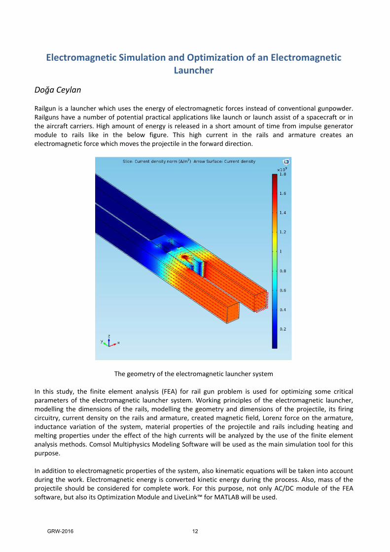
Doğa Ceylan Railgun is a launcher which uses the energy of electromagnetic forces instead of conventional gunpowder. Railguns have a number of potential practical applications like launch or launch assist of a spacecraft or in the aircraft carriers. High amount of energy is released in a short amount of time from impulse generator module to rails like in the below figure. This high current in the rails and armature creates an electromagnetic force which moves the projectile in the forward direction.
The geometry of the electromagnetic launcher system In this study, the finite element analysis (FEA) for rail gun problem is used for optimizing some critical parameters of the electromagnetic launcher system. Working principles of the electromagnetic launcher, modelling the dimensions of the rails, modelling the geometry and dimensions of the projectile, its firing circuitry, current density on the rails and armature, created magnetic field, Lorenz force on the armature, inductance variation of the system, material properties of the projectile and rails including heating and melting properties under the effect of the high currents will be analyzed by the use of the finite element analysis methods. Comsol Multiphysics Modeling Software will be used as the main simulation tool for this purpose. In addition to electromagnetic properties of the system, also kinematic equations will be taken into account during the work. Electromagnetic energy is converted kinetic energy during the process. Also, mass of the projectile should be considered for complete work. For this purpose, not only AC/DC module of the FEA software, but also its Optimization Module and LiveLink™ for MATLAB will be used.
GRW-2016 12
Sensitivity Analysis for Magneto-Acousto-Electrical Tomography
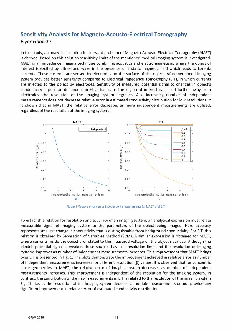
Elyar Ghalichi In this study, an analytical solution for forward problem of Magneto-Acousto-Electrical Tomography (MAET) is derived. Based on this solution sensitivity limits of the mentioned medical imaging system is investigated. MAET is an impedance imaging technique combining acoustics and electromagnetism, where the object of interest is excited by ultrasound wave in the presence of a static magnetic field which leads to Lorentz currents. These currents are sensed by electrodes on the surface of the object. Aforementioned imaging system provides better sensitivity compared to Electrical Impedance Tomography (EIT), in which currents are injected to the object by electrodes. Sensitivity of measured potential signal to changes in object’s conductivity is position dependent in EIT. That is, as the region of interest is spaced further away from electrodes, the resolution of the imaging system degrades. Also increasing number of independent measurements does not decrease relative error in estimated conductivity distribution for low resolutions. It is shown that in MAET, the relative error decreases as more independent measurements are utilized, regardless of the resolution of the imaging system.
a) b)
Figure 1 Relative error versus independent measurements for MAET and EIT
To establish a relation for resolution and accuracy of an imaging system, an analytical expression must relate measurable signal of imaging system to the parameters of the object being imaged. Here accuracy represents smallest change in conductivity that is distinguishable from background conductivity. For EIT, this relation is obtained by Separation of Variables Method (SVM). A similar expression is obtained for MAET, where currents inside the object are related to the measured voltage on the object’s surface. Although the electric potential signal is weaker, these sources have no resolution limit and the resolution of imaging systems improves as number of independent measurements increases. This improvement that MAET brings over EIT is presented in Fig. 1. The plots demonstrate the improvement achieved in relative error as number of independent measurements increases for different resolution (β) values. It is observed that for concentric circle geometries in MAET, the relative error of imaging system decreases as number of independent measurements increases. This improvement is independent of the resolution for the imaging system. In contrast, the contribution of the new measurements in EIT is related to the resolution of the imaging system Fig. 1b, i.e. as the resolution of the imaging system decreases, multiple measurements do not provide any significant improvement in relative error of estimated conductivity distribution.
GRW-2016 13

RF MEMS Based Millimeter Wave Phased Array for Short Range Communication Enis Kobal
Short range communication applications require high gain antennas to increase the signal to noise ratio or to decrease probability of bit error in analog and digital systems, respectively. High gain values can be obtained and the communication quality can be improved by using antenna arrays, especially when the array has a beam steering capability. Moreover, the channel setup is easily constructed by using an antenna array with beam steering capability compared to fixed beam array. Furthermore, moving object identification can also be achieved by using phased array antenna in short range communication systems where the relative position of the object is not known. The beam steering can be achieved by allocating phase shifters in the array feed network.
This paper presents an RF MEMS based millimeter wave phased array for short range high data rate communications. The microstrip tapered slot antenna (TSA) elements are fed by RF MEMS phase shifters to obtain beam steering capability. RF MEMS based phase shifters are chosen due to some of their advantages such as being low loss, low cost, and having high linearity. Previously, a 1 x 4 phased array antenna monolithically integrated with RF MEMS phase shifters is presented in the literature at 15 GHz. In this paper, the aim is to construct a 1 x 16 antenna array at 35 GHz using printed circuit board (PCB) technology to be integrated with RF MEMS phase shifters using wire bonding technology. The element spacing is 0.7 free space wavelength (λ0). 16 (24) elements are chosen to use a simple microstrip corporate feed network. The schematic view of the phased array structure is shown in Fig. 1. In Fig. 1, only two elements are shown where the antenna elements and RF MEMS phase shifters are built on different substrates and the connection between them are satisfied by wire bonds. 16 Ports in the array are combined using microstrip power combiner structure.
Antenna Elements
Phase Shifter Blocks
Wire bonds
Rogers 4003 substrate
Glass substrate
Port 1 Port 2 Fig. 1. Schematic view of the phased array structure.
GRW-2016 14
Reducing False Arrhythmia Alarms in the Intensive Care Units
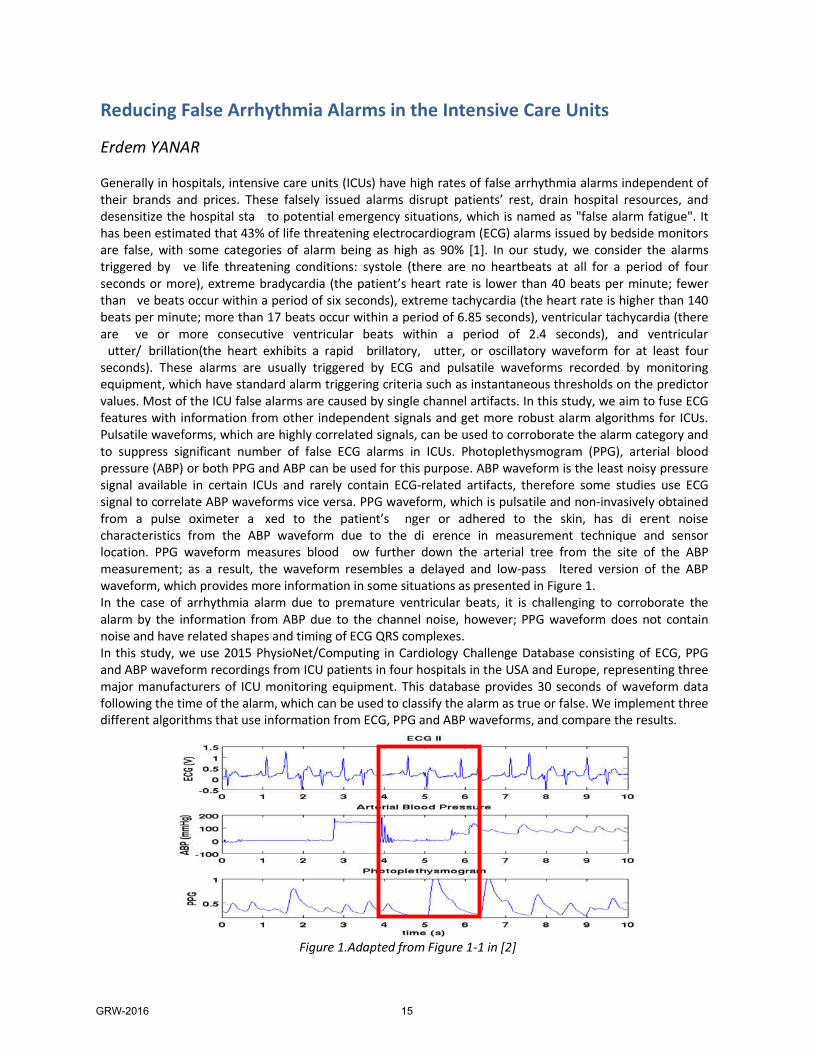
Erdem YANAR Generally in hospitals, intensive care units (ICUs) have high rates of false arrhythmia alarms independent of their brands and prices. These falsely issued alarms disrupt patients’ rest, drain hospital resources, and desensitize the hospital sta to potential emergency situations, which is named as "false alarm fatigue". It has been estimated that 43% of life threatening electrocardiogram (ECG) alarms issued by bedside monitors are false, with some categories of alarm being as high as 90% [1]. In our study, we consider the alarms triggered by ve life threatening conditions: systole (there are no heartbeats at all for a period of four seconds or more), extreme bradycardia (the patient’s heart rate is lower than 40 beats per minute; fewer than ve beats occur within a period of six seconds), extreme tachycardia (the heart rate is higher than 140 beats per minute; more than 17 beats occur within a period of 6.85 seconds), ventricular tachycardia (there are ve or more consecutive ventricular beats within a period of 2.4 seconds), and ventricular
utter/ brillation(the heart exhibits a rapid brillatory, utter, or oscillatory waveform for at least four seconds). These alarms are usually triggered by ECG and pulsatile waveforms recorded by monitoring equipment, which have standard alarm triggering criteria such as instantaneous thresholds on the predictor values. Most of the ICU false alarms are caused by single channel artifacts. In this study, we aim to fuse ECG features with information from other independent signals and get more robust alarm algorithms for ICUs. Pulsatile waveforms, which are highly correlated signals, can be used to corroborate the alarm category and to suppress significant number of false ECG alarms in ICUs. Photoplethysmogram (PPG), arterial blood pressure (ABP) or both PPG and ABP can be used for this purpose. ABP waveform is the least noisy pressure signal available in certain ICUs and rarely contain ECG-related artifacts, therefore some studies use ECG signal to correlate ABP waveforms vice versa. PPG waveform, which is pulsatile and non-invasively obtained from a pulse oximeter a xed to the patient’s nger or adhered to the skin, has di erent noise characteristics from the ABP waveform due to the di erence in measurement technique and sensor location. PPG waveform measures blood ow further down the arterial tree from the site of the ABP measurement; as a result, the waveform resembles a delayed and low-pass ltered version of the ABP waveform, which provides more information in some situations as presented in Figure 1. In the case of arrhythmia alarm due to premature ventricular beats, it is challenging to corroborate the alarm by the information from ABP due to the channel noise, however; PPG waveform does not contain noise and have related shapes and timing of ECG QRS complexes. In this study, we use 2015 PhysioNet/Computing in Cardiology Challenge Database consisting of ECG, PPG and ABP waveform recordings from ICU patients in four hospitals in the USA and Europe, representing three major manufacturers of ICU monitoring equipment. This database provides 30 seconds of waveform data following the time of the alarm, which can be used to classify the alarm as true or false. We implement three different algorithms that use information from ECG, PPG and ABP waveforms, and compare the results.
Figure 1.Adapted from Figure 1-1 in [2]
GRW-2016 15

Design, Simulation, and Fabrication of Inkjet Antennas
Feza MUTLU
Inkjet antennas, which are produced by inkjet printing on paper substrates, are investigated from
the design level to the end-product level. Antennas working in various bands are designed using a
sophisticated simulation environment based on the multilevel fast multipole algorithm. Prototypes
are produced by using silver cartridges in standard printers. Measurement and simulation results
are analyzed to obtain reliable passive tags for radio-frequency identification (RFID) applications.
This study is particularly focused on RFID applications, where the antennas have 50Ω input
impedances. RFID is an automatic identification technology that can be used to identify objects via
electromagnetic waves at radio frequencies. For this purpose, tag antennas are designed, simulated
and measured. Readers and tag antennas communicate using a radio-frequency signal. Test readers
usually operate in the range from 865 to 868 MHz that is in the UHF band for European countries.
Inkjet printing is a technology involving liquid droplets that are jetted directly onto a substrate for
patterning. In the inkjet printing mechanism, the print head has several tiny nozzles. As the paper
moves under the print head, the nozzles spray ink onto paper to constitute the letters and images.
An inkjet printer can produce copies with a high resolution. Therefore, they are popularly used in
text printing.
In this work, we use inkjet printing for producing antennas. In general terms, inkjet printing is a
direct write method and has significant differences in comparison to the conventional etching
methods. There are a lot of different processes that must be performed in the conventional etching
techniques. For example, it is necessary to get rid of unwanted, deposited parts in PCB
manufacturing methods. These processes take time and they are costly. For these reasons, inkjet
printing is an useful alternative method because of it can produce images and letters directly on
substrates without any mask and etching operation. Photograph paper is used as substrate in this
study. Paper is low-cost, environmentally-friendly, recyclable material and it can be fabricated in
mass production. These advantages highlight the inkjet printing in organic and printed electronic
market.
In this study, we demonstrate different inkjet printable antennas on low-cost paper substrates with
conductive material based on silver ink. The antennas are particularly designed for the RFID-UHF
frequency band. Conductive 25% alloyed silver ink is used for printing antennas via standard low-
cost commercial printers. After printing, a temperature curing process is applied to increase the
conductivity of silver ink traces.
Read range is an important criterion for RFID antennas. They must be matched to IC microchips
impedances conjugately for maximum power transfer from the antenna to the chip and vice-versa.
Different types antennas are designed, simulated and measured. We particularly design a novel
type of antennas, namely cage-dipole antennas, that are suitable for optimizations and inkjet
printing. Our results demonstrate favorable properties of the cage-dipole antennas for RFID
applications.
GRW-2016 16
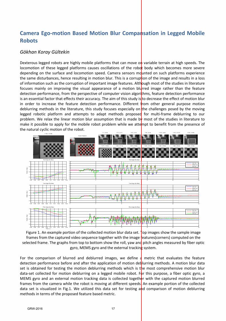
Camera Ego-motion Based Motion Blur Compansation in Legged Mobile Robots Gökhan Koray Gültekin Dexterous legged robots are highly mobile platforms that can move on variable terrain at high speeds. The locomotion of these legged platforms causes oscillations of the robot body which becomes more severe depending on the surface and locomotion speed. Camera sensors mounted on such platforms experience the same disturbances, hence resulting in motion blur. This is a corruption of the image and results in a loss of information such as the corruption of important image features. Although most of the studies in literature focuses mainly on improving the visual appearance of a motion blurred image rather than the feature detection performance, from the perspective of computer vision algorithms, feature detection performance is an essential factor that effects their accuracy. The aim of this study is to decrease the effect of motion blur in order to increase the feature detection performance. Different from other general purpose motion deblurring methods in the literature, this study focuses especially on the challenges posed by the moving legged robotic platform and attempts to adapt methods proposed for multi-frame deblurring to our problem. We relax the linear motion blur assumption that is made by most of the studies in literature to make it possible to apply for the mobile robot problem while we attempt to benefit from the presence of the natural cyclic motion of the robot.
Figure 1. An example portion of the collected motion blur data set. Top images show the sample image frames from the captured video sequence together with the image features(corners) computed on the selected frame. The graphs from top to bottom show the roll, yaw and pitch angles measured by fiber optic gyro, MEMS gyro and the external tracking system. For the comparison of blurred and deblurred images, we define a metric that evaluates the feature detection performance before and after the application of motion deblurring methods. A motion blur data set is obtained for testing the motion deblurring methods which is the most comprehensive motion blur data-set collected for motion deblurring on a legged mobile robot. For this purpose, a fiber optic gyro, a MEMS gyro and an external motion tracking data is collected together with the captured motion blurred frames from the camera while the robot is moving at different speeds. An example portion of the collected data set is visualized in Fig.1. We utilized this data set for testing and comparison of motion deblurring methods in terms of the proposed feature based metric.
f :1, t:0.0s f :31, t:2.1s f :61, t :4.3s f :91, t:6.4s f :121, t:8.6s f :151, t:10.7s f :181, t :12.9s
f :211, t:15.0s f :241, t:17.1s f :271, t :19.3s f :301, t:21.4s f :331, t:23.6s f :361, t:25.7s f :391, t :27.9s
0 5 10 15 20 25-2
-1
0
1
2
3
4Pitch Angle (No Bias)
Optic GyroMEMS GyroOptiTrack
0 5 10 15 20 25-2-10123456
Yaw Angle (No Bias)
Optic GyroMEMS GyroOptiTrack
0 5 10 15 20 25-4-3-2-101234
Roll Angle (No Bias)
Optic GyroMEMS GyroOptiTrack
13.85 13.86 13.87 13.88 13.89 13.9 13.91 13.92 13.93 13.94
-1.5-1
-0.50
0.51
1.5Pitch Angle (No Bias)
Time ( s )
Angle
( deg
)
13.85 13.86 13.87 13.88 13.89 13.9 13.91 13.92 13.93 13.94
-1.5-1
-0.50
0.51
1.5Yaw Angle (No Bias)
Angle
( deg
)
13.85 13.86 13.87 13.88 13.89 13.9 13.91 13.92 13.93 13.94
-1.5-1
-0.50
0.51
1.5Roll Angle (No Bias)
Angle
( deg
)
f :194, t:13.86sCorner Features
GRW-2016 17

FASST: A Low Latency, Scalable, High Throughput SDN Flow Table Hardware Architecture
Göksan Eral Software Defined Networking (SDN) switches lookup every packet in a flow-table of rules that are defined by packet header fields at 100s of Mpps rates. The lookup outcome is either the rule that matches the packet header or a default action if no match is found in the table. This work proposes the FASST (FAst Scalable SDN Table) hardware architecture for SDN flow tables. FASST always achieves a lower average latency compared to recent work [1,2] with a decrease of up to 98%. FASST exploits the known temporal locality in the network traffic to achieve a scalable, single chip, pure hardware architecture. The block diagram of FASST is depicted below.
Figure 1. Block diagram of FASST A Bit Vector Module (BVM) stores all rules as bit vector arrays. BVM produces partial matches between input strides and corresponding bit vector arrays. These matches are concatenated in a 2-dimensional (2D) pipeline after a multi-clock latency to obtain the final match result. The throughput is one match result/clock if the pipeline is full. BVM consumes about 25% of the power of a TCAM that stores all the rules and its resource consumption proportionally scales with the number of rules [1]. The FASST TCAM Cache (TC) only stores frequently accessed rules and produces matches with a single clock latency. The Match Monitor (MM) dynamically updates the TC with frequently matched rules, observing the rule dependency [2] for correct match results. All packets are processed by both the BVM and the TC because a packet that is not matched to a rule in the TC can match to a rule in the BVM. The result of a TC match arrives in a single clock. The same match is produced by BVM after pipeline latency. Hence, the Match Arbiter (MA) discards late duplicate match results of the BVM. We note that the order of matched packets by FASST might be different from that of the input packets. The existing network protocol stack corrects out-of-order packet deliveries at higher layers at the end hosts. Furthermore, MA can maintain the packet order in the same SDN flow (matching the same rule) at the expense of a single pipeline latency. We implement and evaluate FASST on Altera Stratix V FPGA. The BVM stores 512 rules and the RAM-based TC stores 32 rules. We achieve a high clock rate of 300 MHz, resulting in a throughput of 300Mpps for 15-tuple (356 bit) SDN packet headers. BVM and TC latencies are 80 clock cycles (266 ns) and 1 clock (3.3 ns), respectively. Hence, if TC has a hit rate of 50%, the average lookup latency drops to 135 ns. In the extreme case of all rules matching in TC, the latency is 3.3 ns. Altera’s PowerPlay Early Power Estimator Tool estimates a dynamic power consumption of 0.28 W for TC which is significantly lower than the reported TCAM power consumptions of more than 10W [1].
References [1] Y. R Qu and V.K. Prasanna, "High-Performance and Dynamically Updatable Packet Classification Engine on FPGA," IEEE Transactions on Parallel and Distributed Systems, vol. 27, no.1, pp.197-209, Jan. 2016. [2] N. Katta, O. Alipourfard, J. Rexford, D. Walker, “Infinite CacheFlow in software-defined networks,” Proc. ACM HotSDN, 2014, pp. 175-180.
GRW-2016 18

Quantification of Stenosis in Coronary Arteries
Görkem Polat Cardiovascular disease (CVD) is one of the most prevalent cause of death in the World. According to World Health Organization (WHO), 38 of 56 million global deaths in 2012 were caused by four main non-communicable diseases (NCD) which are cardiovascular diseases, cancers, diabetics, and chronic lung diseases. Among all the NCD diseases, cardiovascular diseases were the leading one with 46%. CVDs are caused due to the disorders occurring in the cardiovascular system. Today, there are many types of CVDs, among various types of CVDs Coronary Heart Disease (CHD) accounts for the largest percentage. It is caused when heart’s blood supply is blocked by plaques inside the coronary arteries. Plaques narrow the coronary arteries and reduces the blood flow to the heart muscle. This narrowing in coronary arteries is also referred to as stenosis that causes heart attack and cardiac death. It is very important to come up with a good imaging and quantification technique for early diagnosis. Quantitative coronary angiography (QCA) has been used to estimate severity of coronary artery disease. Yet, recent studies have shown that it has a modest accuracy in assessing the hemodynamic significance of intermediate lesions. Fractional flow reserve (FFR), on the other hand provides a physiologic evaluation of severity in lesion and today it is regarded as gold standard for detecting and quantifying stenosis. Many studies have shown that FFR guided percutaneous coronary intervention (PCI) has better clinical outcomes than the visual assisted medical treatment. Although there are robust data to support usage of FFR, it has a limited application in everyday clinical practice. This is mostly due to the fact that FFR measurement is costly and time consuming procedure. It is also an invasive method that cannot be applied to all patients (e.g., in patients with asthma, severe hypotension, or in patients with second-degree atrioventricular block). FFR involves advancement of the FFR guidewire to the distal vessel which may be a challenging procedure especially in side branches with complex anatomy. To overcome these issues non-invasive methodology has been proposed to allow computational assessment of FFR. Proposed method is going to generate a 3-dimensional model from 2-dimensional X-Ray images. After generating a 3-dimensional model, it will be used to estimate pressure drop on the vessel by using computational fluid dynamics techniques.
GRW-2016 19

Utilization of Sample and Hold (S/H) in the Outer Voltage Loop of Boost Type PFC Converters
İlker Şahin In PFC converters, inherent voltage ripple at the output with twice the line frequency, requires the design of the voltage control loop with a very small bandwidth (around 10 Hz) for a stable operation with low THD. However, this yields a sluggish dynamic behavior for the converter. It is a fundamental problem for power factor correction (PFC) converters therefore a considerable amount of research effort has been put to propose solutions to overcome this difficulty. In this paper, utilization of a sample and hold (S/H) circuit in the voltage loop is proposed as a means of preventing the voltage ripple entering the control loop. As a result, designs with higher bandwidth are enabled to obtain superior dynamic performance. A design methodology for voltage control loop with S/H is introduced. Practical issues such as stability and noise sensitivity are addressed. Simulation studies are carried out to validate the value of the technique and finally experimental results are provided to prove the concept. Proposed solution is verified experimentally on a 1.5 kW, average current controlled, boost type PFC converter.
Figure 1. A simplified schematic regarding PFC control. This study will provide a detailed analysis on the utilization of S/H circuitry in the voltage loop of PFC converters and show the benefit of improved dynamic performance. A systematic approach for the control loop design with S/H utilization will be addressed in the final version. Studies for a better mathematical representation of the subject and for the installation of S/H to the implemented converter are continuing and will be presented in final version.
HVOVREF
GVKMUL
HI
PWM
GC
GRW-2016 20
Metamaterial Absorbers in the Infrared
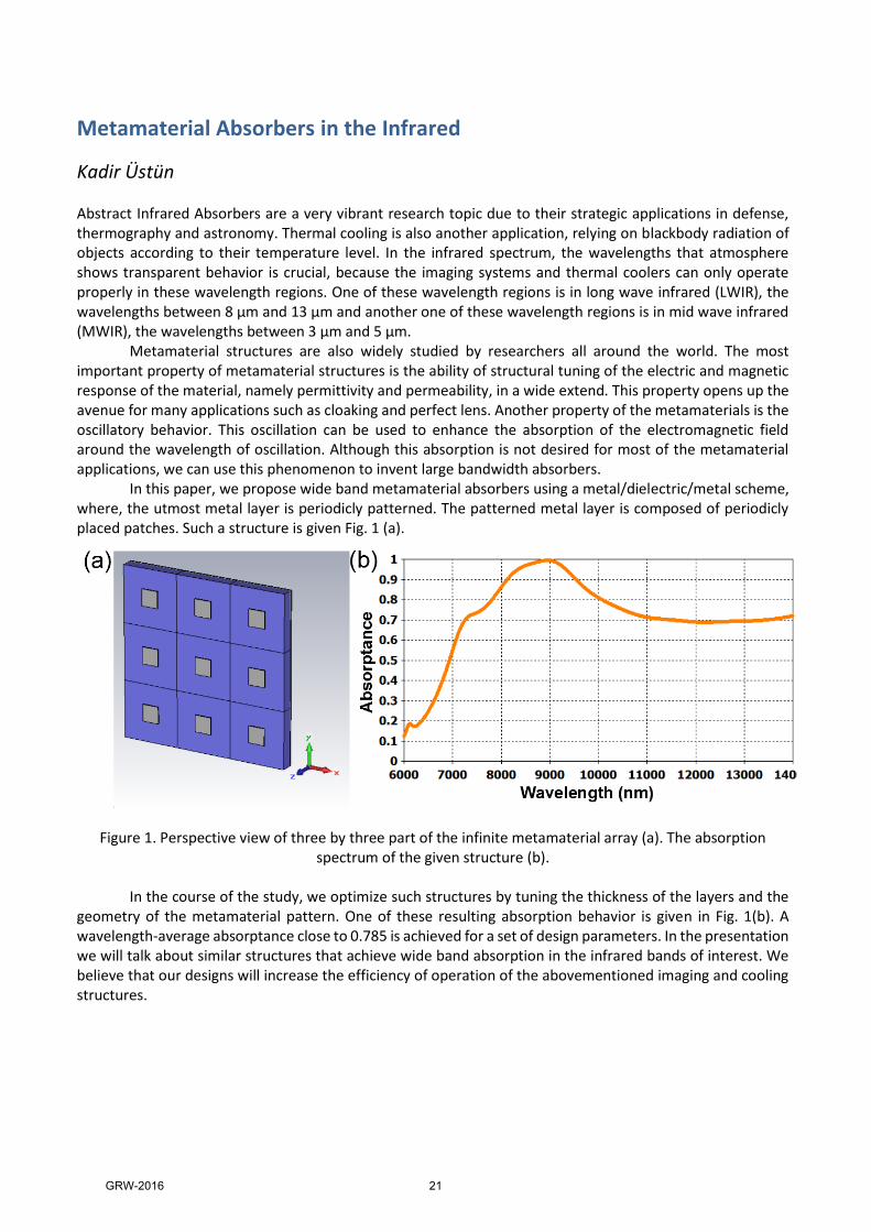
Kadir Üstün Abstract Infrared Absorbers are a very vibrant research topic due to their strategic applications in defense, thermography and astronomy. Thermal cooling is also another application, relying on blackbody radiation of objects according to their temperature level. In the infrared spectrum, the wavelengths that atmosphere shows transparent behavior is crucial, because the imaging systems and thermal coolers can only operate properly in these wavelength regions. One of these wavelength regions is in long wave infrared (LWIR), the wavelengths between 8 µm and 13 µm and another one of these wavelength regions is in mid wave infrared (MWIR), the wavelengths between 3 µm and 5 µm. Metamaterial structures are also widely studied by researchers all around the world. The most important property of metamaterial structures is the ability of structural tuning of the electric and magnetic response of the material, namely permittivity and permeability, in a wide extend. This property opens up the avenue for many applications such as cloaking and perfect lens. Another property of the metamaterials is the oscillatory behavior. This oscillation can be used to enhance the absorption of the electromagnetic field around the wavelength of oscillation. Although this absorption is not desired for most of the metamaterial applications, we can use this phenomenon to invent large bandwidth absorbers. In this paper, we propose wide band metamaterial absorbers using a metal/dielectric/metal scheme, where, the utmost metal layer is periodicly patterned. The patterned metal layer is composed of periodicly placed patches. Such a structure is given Fig. 1 (a).
In the course of the study, we optimize such structures by tuning the thickness of the layers and the geometry of the metamaterial pattern. One of these resulting absorption behavior is given in Fig. 1(b). A wavelength-average absorptance close to 0.785 is achieved for a set of design parameters. In the presentation we will talk about similar structures that achieve wide band absorption in the infrared bands of interest. We believe that our designs will increase the efficiency of operation of the abovementioned imaging and cooling structures.
Figure 1. Perspective view of three by three part of the infinite metamaterial array (a). The absorption spectrum of the given structure (b).
GRW-2016 21

A Study on a Low Phase Noise Charge Pump Phase-Locked Loop at 2.8 GHz
Mahsa Keykhali In an era dominated by the highly demanding wireless communication systems, developing small, cheap, and low power RF sub-systems is appealed. This demand has led to significant research on completely integrated transceiver systems. Frequency synthesizer makes the most challenging component of an integrated transceiver system. Implementation of frequency synthesizers are usually accomplished using a PLL and low frequency highly stable crystal oscillator. Today, the most challenging problem that Phase Locked Loop (PLL) designers face with is the design of ultra-low phase noise PLL at high frequencies. In this research, a high frequency charge-pump phase-locked loop (CPPLL) with low phase noise is studied. At the beginning stage, a gate grounding Colpitts Voltage Controlled Oscillator (VCO) using a High Electron Mobility Transistor (HEMT) is designed. The provided VCO achieved -131 dBc/Hz phase noise at 1 MHz offset with 2.6-3 GHz oscillating frequency ranges. Inserting a PLL chip around the VCO can reduce the achieved phase noise. Therefore, to investigate this phenomenon a CPPLL is simulated. The CPPLL components, namely the Phase Frequency Detector (PFD), Charge Pump (CP), and the frequency divider are investigated individually. The loop filter design is also taken into account as it plays a vital role in determining the loop bandwidth of the CPPLL. Finally, the phase noise of the implemented CPPLL is simulated. Assuming noiseless crystal oscillator, the phase noise is calculated as -120 dBc/Hz at 100 Hz offset. The phase noise is decreased successfully 90 dBc compared to the VCO phase noise (-32 dBc/Hz at 100 Hz). When the noise of the crystal oscillator is included, the phase noise at 100 Hz reached to -101 dBc/Hz. Related simulations are conducted on microwave simulation tool (ADS).
GRW-2016 22

A Hardware Architecture and Implementation for High Performance CAN FD (CAN with Flexible Data Rate)
Mehmet Ertuğ AFŞİN CAN (Controller Area Network) is currently becoming inadequate for the bandwidth needs of contemporary in-vehicle networking. To this end, CAN FD (CAN with Flexible Data Rate) is proposed in 2011 to achieve high bit rates while maintaining the compatibility with the existing CAN networks. CAN FD supports bit rates higher than 1Mbit/s and payloads higher than 8 bytes which is the maximum possible bit rate and payload for existing CAN networks. The bitrate for the arbitration phase is the same and the format is quite similar to standard CAN. The data phase of CAN FD differs in terms of bit rate, frame format and the algorithm to compute CRC (Cyclic Redundancy Check). Therefore, existing CAN bus harness and network design can easily be adapted to CAN FD. The frame format for CAN FD for standard identifier is depicted below [1].
Figure 1. CAN FD Frame Format
As the standard is fairly recent, there are not many CAN FD controllers commercially available. In this work, we implement a CAN FD Controller on Xilinx Virtex 5 FPGA. Standard CAN bus transceivers are used for the realization of the bus physical layer. Our CAN FD controller consists of a transmit engine and a receive engine. The transmit engine has a RAM based architecture, which supports buffering of the messages to be sent according to their priorities. This is an advanced property as many existing CAN controllers simply store the messages received from upper layers in a FIFO queue which disrupts the CAN message scheduling to achieve real time guarantees. Some area is allocated in the block RAM for each message priority defined by the message IDs. The memory allocation among different message priorities is configurable maintaining a total memory limit. An enhanced hardware implementation of a binary search is used to determine the first (highest-priority) message to be transmitted. The latency of finding the message with highest priority to transmit only takes 3 clock cycles for a set of 100 messages. In other words, with the advantage of the parallel processing capability of FPGAs and considering a 100MHz FPGA clock speed, it takes only 30 ns to determine the correct message to enter the bus arbitration from 100 different priority messages. The receive engine uses a FIFO (First in first out) based implementation. The messages that are not to be received are filtered using a maskable identifier filter to reduce the overhead and processing load of the application. 8 different mask and filter register sets are available for the filtering algorithm. Whenever a received message passes through any of the filters, it is placed in the FIFO. Up to 16 messages can be stored in FIFO. We provide application time configurable features such as configurable buffer numbers and buffer sizes based on priorities unlike CAN FD Controllers [2] on the market which support synthesis time configurable transmit and receive buffers. We are currently testing the developed controller in the laboratory for its correctness and performance. [1] Peter Decker, “CAN Gets Even Better, Ways to transition from classic CAN to the improved CAN FD”, Vector Informatik GmbH, April 2013, pp.2 [2] CAN 2.0B and CAN-FD Controller, CAST Inc, http://www.xilinx.com/products/intellectual-property/1-8dyf-2862.html#overview
GRW-2016 23

Classification of Human Motion Using Radar Micro-‐doppler Signatures with Hidden Markov Models Mehmet Onur Padar One of the desirable features in a ground surveillance radar is to provide information about what a detected person is doing. This would give a law enforcement organization ability to detect suspicious activities remotely and act accordingly. Previously, micro-‐doppler radar signatures from humans were shown to have the necessary features to make that distinction. Typically, micro-‐doppler signal spectrograms are used to obtain features to classify what the person is doing. However, most of these techniques treat the spectrogram as an image, and obtain features through some image processing techniques. In this work, we propose the use of hidden Markov models as an alternative method to statistically model both instantaneous and correlated long-‐term variations within the micro-‐doppler signal to classify a motion. In addition, we propose use of principle component analysis (PCA) as a data driven feature extraction approach that captures vital statistics of the input at a much reduced dimension. Experiments shows that with the proposed methods, perfect classification of four different motions can be attained when training and testing set both contains data from same people, and 90% accuracy is obtained when training and testing set has data from different people.
GRW-2016 24
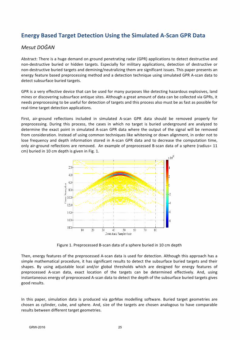
Energy Based Target Detection Using the Simulated A-‐Scan GPR Data Mesut DOĞAN Abstract: There is a huge demand on ground penetrating radar (GPR) applications to detect destructive and non-‐destructive buried or hidden targets. Especially for military applications, detection of destructive or non-‐destructive buried targets and demining/neutralizing them are significant issues. This paper presents an energy feature based preprocessing method and a detection technique using simulated GPR A-‐scan data to detect subsurface buried targets. GPR is a very effective device that can be used for many purposes like detecting hazardous explosives, land mines or discovering subsurface antique sites. Although a great amount of data can be collected via GPRs, it needs preprocessing to be useful for detection of targets and this process also must be as fast as possible for real-‐time target detection applications. First, air-‐ground reflections included in simulated A-‐scan GPR data should be removed properly for preprocessing. During this process, the cases in which no target is buried underground are analyzed to determine the exact point in simulated A-‐scan GPR data where the output of the signal will be removed from consideration. Instead of using common techniques like whitening or down alignment, in order not to lose frequency and depth information stored in A-‐scan GPR data and to decrease the computation time, only air-‐ground reflections are removed. An example of preprocessed B-‐scan data of a sphere (radius= 11 cm) buried in 10 cm depth is given in Fig. 1.
Figure 1. Preprocessed B-‐scan data of a sphere buried in 10 cm depth Then, energy features of the preprocessed A-‐scan data is used for detection. Although this approach has a simple mathematical procedure, it has significant results to detect the subsurface buried targets and their shapes. By using adjustable local and/or global thresholds which are designed for energy features of preprocessed A-‐scan data, exact location of the targets can be determined effectively. And, using instantaneous energy of preprocessed A-‐scan data to detect the depth of the subsurface buried targets gives good results. In this paper, simulation data is produced via gprMax modelling software. Buried target geometries are chosen as cylinder, cube, and sphere. And, size of the targets are chosen analogous to have comparable results between different target geometries.
GRW-2016 25
Elimination of Circulating Currents between Two Interleaved PWM Rectifiers Supplied from a Common Single-Phase AC Source
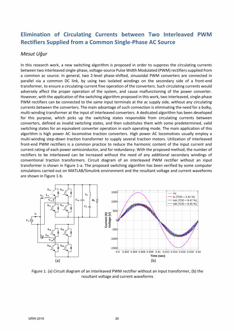
Mesut Uğur In this research work, a new switching algorithm is proposed in order to suppress the circulating currents between two interleaved single-phase, voltage-source Pulse Width Modulated (PWM) rectifiers supplied from a common ac source. In general, two 2-level phase-shifted, sinusoidal PWM converters are connected in parallel via a common DC link, by using two isolated windings on the secondary side of a front-end transformer, to ensure a circulating-current free operation of the converters. Such circulating currents would adversely affect the proper operation of the system, and cause malfunctioning of the power converter. However, with the application of the switching algorithm proposed in this work, two interleaved, single-phase PWM rectifiers can be connected to the same input terminals at the ac supply side, without any circulating currents between the converters. The main advantage of such connection is eliminating the need for a bulky, multi-winding transformer at the input of interleaved converters. A dedicated algorithm has been developed for this purpose, which picks up the switching states responsible from circulating currents between converters, defined as invalid switching states, and then substitutes them with some predetermined, valid switching states for an equivalent converter operation in each operating mode. The main application of this algorithm is high power AC locomotive traction converters. High power AC locomotives usually employ a multi-winding step-down traction transformer to supply several traction motors. Utilization of interleaved front-end PWM rectifiers is a common practice to reduce the harmonic content of the input current and current rating of each power semiconductor, and for redundancy. With the proposed method, the number of rectifiers to be interleaved can be increased without the need of any additional secondary windings of conventional traction transformers. Circuit diagram of an interleaved PWM rectifier without an input transformer is shown in Figure 1-a. The proposed switching algorithm has been verified by some computer simulations carried out on MATLAB/Simulink environment and the resultant voltage and current waveforms are shown in Figure 1-b.
Cdc
S1A
Lf
Cf
RL
S3A
S2A S4A
S1B S3B
S2B S4B
LB
LA
iS
VS
iSB
iSA
VcA
VcB
(a) (b)
Figure 1. (a) Circuit diagram of an interleaved PWM rectifier without an input transformer, (b) the resultant voltage and current waveforms
0.4 0.402 0.404 0.406 0.408 0.41 0.412 0.414 0.416 0.418 0.42
-1500
-1000
-500
0
500
1000
1500
Time (sec)
Cu
rren
t (A
)
Vo
ltag
e (
V)
Vs
Is (TDD = 2.41 %)
IsA (TDD = 8.47 %)
IsB (TDD = 8.45 %)
GRW-2016 26
MLFMA Simulations and Optimizations of Photonic Crystals for Beam Shaping
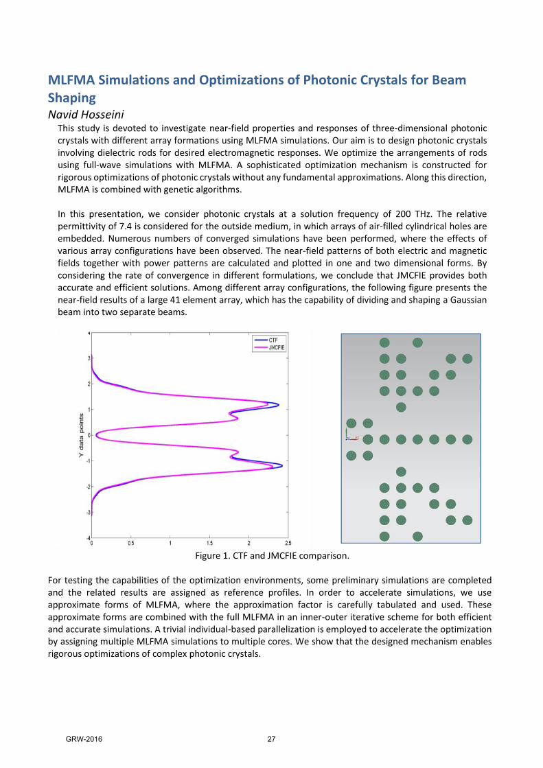
Navid Hosseini This study is devoted to investigate near-field properties and responses of three-dimensional photonic crystals with different array formations using MLFMA simulations. Our aim is to design photonic crystals involving dielectric rods for desired electromagnetic responses. We optimize the arrangements of rods using full-wave simulations with MLFMA. A sophisticated optimization mechanism is constructed for rigorous optimizations of photonic crystals without any fundamental approximations. Along this direction, MLFMA is combined with genetic algorithms. In this presentation, we consider photonic crystals at a solution frequency of 200 THz. The relative permittivity of 7.4 is considered for the outside medium, in which arrays of air-filled cylindrical holes are embedded. Numerous numbers of converged simulations have been performed, where the effects of various array configurations have been observed. The near-field patterns of both electric and magnetic fields together with power patterns are calculated and plotted in one and two dimensional forms. By considering the rate of convergence in different formulations, we conclude that JMCFIE provides both accurate and efficient solutions. Among different array configurations, the following figure presents the near-field results of a large 41 element array, which has the capability of dividing and shaping a Gaussian beam into two separate beams.
Figure 1. CTF and JMCFIE comparison.
For testing the capabilities of the optimization environments, some preliminary simulations are completed and the related results are assigned as reference profiles. In order to accelerate simulations, we use approximate forms of MLFMA, where the approximation factor is carefully tabulated and used. These approximate forms are combined with the full MLFMA in an inner-outer iterative scheme for both efficient and accurate simulations. A trivial individual-based parallelization is employed to accelerate the optimization by assigning multiple MLFMA simulations to multiple cores. We show that the designed mechanism enables rigorous optimizations of complex photonic crystals.
GRW-2016 27

Estimating the sensor positions of a passive array using calibration emitters with TDOA measurements
Oktay Sipahigil Estimating the target location using sensor arrays have various applications. The estimation accuracy depends on the precise knowledge of sensor positions, and the performance with the uncalibrated sensors are generally poor. Therefore, sensor positions should be precisely known for an accurate estimation. One way to achieve precise knowledge of sensor locations is to use calibration emitters which emit waveforms. For example, in an underwater medium with a hydrophone array, the calibration emitter may transmit acoustic signals which may be stationary as well as nonstationary for sensor position estimation. In this study, we look at self-localization of passive sensor arrays by using calibration emitters. Given a configuration of calibration emitters, we propose a practical method to estimate sensor positions using noisy data. The measurement model contains time difference of arrival (TDOA) observations. Locations of calibration emitters are known, however there are no prior information about the sensor array positions. A direct formulation of this problem leads to a nonconvex optimization problem. The nonconvex problem in general contains more than one local minima and the value of the initial condition for the solver becomes important. In order to overcome this situation, we modify the problem formulation and transform the original problem into a quadratically constrained quadratic programming (QCQP) optimization. Using a semidefinite relaxation approach of this transformed problem, we can find an approximate, but yet accurate, solution. We verify this statement by Monte-Carlo simulations. We observed, through many simulations, that the dependence to an initial condition is also eliminated.
GRW-2016 28

Design of a high efficiency and high torque density Switched Reluctance Motor to be used in Hybrid Electric Vehicle applications
Rasul Tarvirdilu Asl The concept of implementing electrical machines in automotive applications is under a rapid development and growth due to negative side effects of fossil-fueled cars, including global warming, high price and limited sources of fossil fuels. In the literature, Interior Permanent Magnet Synchronous Machines (IPMSM) are implemented in electrical vehicles. However, limited supply and high price of rare-earth magnetic materials are the main problems of using IPMSMs. Nowadays, using Switched Reluctance Motors (SRM) as a substitute for IPMSMs in hybrid electric vehicle applications is of great interest. The main advantage of using SRM is elimination of permanent magnet materials in machine structure. In addition, simple and robust structure, high rotational speeds and operation at higher temperatures are other benefits of using SRMs. In the literature, several SRMs are designed and introduced to be used in HEV applications, but lower torque density and lower efficiency of the machines are the main problems which prevent these motors to be an appropriate substitute for permanent magnet motors. In this study a new design methodology based on combination of analytical and Finite Element Method (FEM) is introduced. The proposed method has the rapidity of analytical calculations and precision of finite element method. Moreover, a novel method of core loss calculation based on actual flux variations and its harmonics is introduced in this study. The proposed SRM motor has higher torque density and efficiency in comparison with existed prototypes in the literature. The validity of calculations is investigated using 2D FEM simulations.
GRW-2016 29

Design and optimization of a high torque density magnetically-geared generator for direct drive wind turbine application
Reza Zeinali The negative effects of fossil fuels on global warming have made it important to harvest renewable energy such as wind energy. Wind-electric energy conversion technology at present appears to be advantageous from the point of view of cost also. However, there is still much that can be done on the way of maturing the existing technology. Wind turbine concept can be classified into geared drive and direct drive from drive train point of view. Direct drive systems have the advantage of higher efficiency, higher energy yield, higher reliability and low noise and maintenance cost. On the other hand, elimination of gearbox imposes some disadvantages to the system. Larger generator, larger mass and higher cost are the principal drawbacks this configuration in comparison with geared system. A high torque density generator should be utilized in direct drive concept to reduce mass and cost of the generator in this configuration. In the scientific literature, Radial Flux Permanent Magnet (RFPM) machine has been discussed as dominant design in direct drive concept. Simple and stable structure and high torque density are the advantages makes RFPM generator a suitable choice for direct drive wind turbine application. Differently, Permanent Magnet Vernier Machines (PMVMs) are also reported as concept with high torque density in the literature. Since there is magnetic gear effect inside these machine, they are suitable choice for low speed and high torque applications like direct drive wind turbine. Among various topologies of PMVM, Dual Stator Spoke Array Vernier Permanent Magnet (DSSA VPM) machine has been discussed as a magnetically-geared machine offering higher torque density and higher power factor. In this study, both RFPM generator and newly-proposed magnetically-geared Dual Stator Spoke Array Vernier Permanent Magnet (DSSA VPM) generator are designed and optimized to deliver 50 kW power at 60 rpm. The optimization results show that DSSA VPM generator has 20% mass advantage in comparison with RFPM generator.
GRW-2016 30

Intra Coding in HEVC with 3-tap Filters
Saeed Ranjbar Alvar Video Compression is performed either in lossy or lossless coding modes. Each of these modes is used for different applications. In the applications such as TV broadcast and videoconferencing that transmission bandwidth is limited, lossy coding is preferred. On the other hand, some fields such as film archiving or medical applications require an output with a perfect quality without any degradation. In these set of applications lossless coding mode is chosen. In both lossy and lossless coding modes, prediction of the current frame to be encoded plays an important role in reducing the size of the encoded frame. The aim of the prediction is to remove the spatial and temporal redundancies in the existing frames. This is achieved by the help of Intra prediction and Inter prediction. Intra prediction is performed relative to information that is contained only within the current frame and the Inter prediction utilizes the temporal processing outside of the current picture or frame. In the presentation, a novel intra coding algorithm with 3-tap filters will be discussed for lossless and lossy modes of High Efficiency Video Coding (HEVC) standard. For Lossless mode, Transform and Quantization are bypassed and the Intra prediction of the HEVC is a block based method. In the proposed algorithm, the Intra prediction is designed based on a pixel-by-pixel prediction which uses three neighboring pixels for prediction according to a two-dimensional correlation model, and the used neighbor pixels and the prediction weights change depending on intra mode. These weights are obtained in an offline or an online manner. Offline weights are obtained from a training set and the online weights are calculated adaptively during the encoding process. For the lossy scenario, it has already shown that although video compression may benefit from advanced transforms, it may also benefit from skipping the transform altogether. In case of transform skip mode, the same 2D correlation model is used to obtain the prediction but this time the obtained residual is quantized and then entropy coded. The proposed methods are implemented in the HEVC reference software. The results of the experiments show that the explored 3-tap filtering method can achieve an average 11.55% and 12.02% bitrate reduction over the default lossless intra coding in HEVC for offline and adaptive case, respectively. Additional average 3.3% bitrate reduction can be observed compared to the lossless intra coding with the well-known Sample based Angular Prediction (SAP) algorithm. In addition, results of the experiments in the lossy coding show that the proposed method can achieve up to 1% gain over the improved lossy intra coding in HEVC Format Range Extension (RExt).
GRW-2016 31
On the Solution of Data Association Problem Using Rollout Algorithms
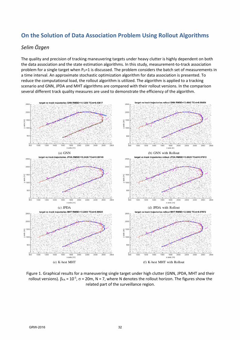
Selim Özgen The quality and precision of tracking maneuvering targets under heavy clutter is highly dependent on both the data association and the state estimation algorithms. In this study, measurement-to-track association problem for a single target when PD=1 is discussed. The problem considers the batch set of measurements in a time interval. An approximate stochastic optimization algorithm for data association is presented. To reduce the computational load, the rollout algorithm is utilized. The algorithm is applied to a tracking scenario and GNN, JPDA and MHT algorithms are compared with their rollout versions. In the comparison several different track quality measures are used to demonstrate the efficiency of the algorithm.
Figure 1. Graphical results for a maneuvering single target under high clutter (GNN, JPDA, MHT and their rollout versions). βFA = 10-5, σ = 20m, N = 7, where N denotes the rollout horizon. The figures show the
related part of the surveillance region.
GRW-2016 32

Inverse Problem of Electrocardiography; Comparison of two Methods
TAHA ERENLER Heart diseases are among the leading causes of death in the world. In clinical practice, major tool for diagnosing heart diseases is Electrocardiography (ECG). Although ECG provides significant information, it is not sufficient to diagnose many abnormalities due to its fixed and limited lead configuration. In order to extract more information on heart functioning, inverse problem of ECG could be solved. This method enables imaging of the cardiac electrical activity noninvasively, and can be defined as the estimation of cardiac electrical activity from remote body surface potential measurements. However, reconstruction of cardiac sources is not easy due to the underdetermined and ill-posed nature of the problem. There are different methods to overcome these issues, mainly regularization techniques such as Tikhonov regularization, Truncated Total Least Squares (TTLS), Least Squares QR (LSQR) factorization, Truncated Singular Value Decomposition (TSVD) and statistical approaches such as Bayesian Maximum A Posteriori (MAP) estimation and Kalman filtering. Here, we consider only Tikhonov Regularization and TSVD methods for solving the inverse ECG problem. Tikhonov regularization is widely used for solving various inverse problems. In Tikhonov regularization, the goal is to find a solution that provides a trade-off between fidelity to the measurements and a fit to some prior constraint about the solution. This trade-off is controlled by a regularization parameter, which is found using the well-known L-curve method. TSVD is another method that is widely used to solve the ill-posed inverse problems. In this method, zero or very small singular values of the forward matrix are excluded from the pseudo-inverse expression of the forward matrix, and solution is constructed using the remaining significantly large singular values. in this work, we simulate measurements at 30 dB SNR, at 64 and 192 body surface lead locations. Then, we estimate heart potentials at 490 nodes on the heart surface. Tikhonov regularization yield higher correlation coefficient and lower relative error values for both 64 lead and 192 lead configurations. Both Tikhonov regularization and TSVD provide solutions that are smooth over the surface of the heart, and they cannot capture rapid changes in the moving depolarization wavefront. Thus more robust and edge preserving techniques will be applied in our future studies.
GRW-2016 33

A Study on Visual Aided Inertial Navigation
Talha İNCE Navigation is the knowledge of a position of a body according to a reference frame. Humankind have been doing this task for centuries by using different methods like compasses, position of stars at sky, some landmarks with well know position etc. the The process of estimating the position by using a previously determined position, or fix is called as “Dead Reckoning”. This can be done using the known or estimated speed vectors over the elapsed time. The question which arises here is “Why don’t we use GPS technology for the estimation of the position?”. There are many answers to this question. One answer is accuracy of the GPS sensors. These may not be enough or may not give the full state (such as attitude) depending on the application. In some other scenarios, the usage of GPS in not possible. Hence dead reckoning using differential measurements plays an important role on navigation of mobile platforms. It is a well-known fact that usage of state estimators are mandatory for the long term navigation in order to avoid the divergent behavior of the accumulated error. Direct or Indirect Kalman filters as well as other Bayes Filter variants such as Particle Filters can be used for this purpose. These estimators can also be used for the purpose of sensor fusion. Sensor fusion concept relies on the idea of usage of information from more than one sensors to obtain better information or getting structural information between sensor data. Choice of the particular fusion method depends on the linearity of the system as well as the statistics of the noise. A popular approach in navigation research area is the fusion of IMU and camera sensor data so called “Image Aided Navigation” or “Visual Aided Inertial Navigation System (VINS)”. V.I.N.S. problem can be studied under different state estimators, system state and observation models and system configurations like stereo imaging or monocular imaging. In this study, performance of VINS will be investigated under different sensor fusion techniques, system state and observation models and configurations.
GRW-2016 34
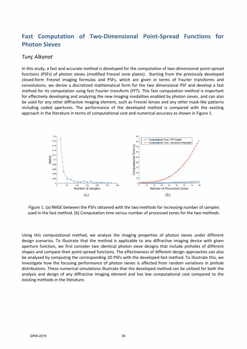
Fast Computation of Two-Dimensional Point-Spread Functions for Photon Sieves
Tunç Alkanat In this study, a fast and accurate method is developed for the computation of two-dimensional point-spread functions (PSFs) of photon sieves (modified Fresnel zone plates). Starting from the previously developed closed-form Fresnel imaging formulas and PSFs, which are given in terms of Fourier transforms and convolutions, we derive a discretized mathematical form for the two dimensional PSF and develop a fast method for its computation using fast Fourier transform (FFT). This fast computation method is important for effectively developing and analyzing the new imaging modalities enabled by photon sieves, and can also be used for any other diffractive imaging element, such as Fresnel lenses and any other mask-like patterns including coded apertures. The performance of the developed method is compared with the existing approach in the literature in terms of computational cost and numerical accuracy as shown in Figure 1.
Figure 1. (a) RMSE between the PSFs obtained with the two methods for increasing number of samples used in the fast method. (b) Computation time versus number of processed zones for the two methods.
Using this computational method, we analyze the imaging properties of photon sieves under different design scenarios. To illustrate that the method is applicable to any diffractive imaging device with given aperture function, we first consider two identical photon sieve designs that include pinholes of different shapes and compare their point-spread functions. The effectiveness of different design approaches can also be analyzed by computing the corresponding 2D PSFs with the developed fast method. To illustrate this, we investigate how the focusing performance of photon sieves is affected from random variations in pinhole distributions. These numerical simulations illustrate that the developed method can be utilized for both the analysis and design of any diffractive imaging element and has low computational cost compared to the existing methods in the literature.
GRW-2016 35

Design of Miniaturized Ku Band Narrowband Cavity Filter
Yusuf Sevinç Frequency multiplexers employed in satellite and wireless communication systems are mainly composed of channel filters and junctions connecting to filters to the common port. Waveguide filter structures are mostly preferred and employed as channel filter in multiplexer configuration due to the fact that they are of low insertion loss, high power handling capability and high quality factor. However, bulkiness and large sizes of them are troublesome in satellite-communication applications. In the scope of this study, the design procedure of narrowband and compact-sized channel filter for the contiguous-band waveguide multiplexer structure is presented. Also, it is focused on developing a framework for methodical design of the miniaturized cavity filter. In addition to the cavity filter design and miniaturization studies, it is worked on modeling discontinuities placed in the waveguide in order to obtain circuit equivalent of the cavity filter. Particularly, the design of the direct-coupled cavity filter is emphasized since it is a good candidate to meet the desired performance requirements. The direct-coupled filters are mainly composed of waveguide cavities or TEM transmission lines coupled either by shunt inductance or series capacitance. The equivalent circuit for the direct coupled waveguide filters can be obtained by modeling the discontinuities such as irises placed in the waveguide as the proper combination of the inductance and capacitance together with transmission lines. Starting from numerical calculations using empirical formulations, design procedure for direct-coupled waveguide filter is mentioned step by step and full wave EM simulations are run accordingly in this study. Moreover, circuit equivalent model for the overall filter structure is constructed after determining the circuit equivalent of the each iris by considering its width and thickness
GRW-2016 36

GRW-2016 Ödül Töreninden
GRW-2016 37

GRW-2016 38