gps based navigation and collision avoidance system using ultrasonic sensors and image processing...
TRANSCRIPT
Asher Rahman, et al International Journal of Computer and Electronics Research [Volume 3, Issue 4, August 2014]
©http://ijcer.org e- ISSN: 2278-5795 p- ISSN: 2320-9348 Page 195
GPS based Navigation and Collision Avoidance
System using Ultrasonic Sensors and Image Processing
for Autonomous Vehicle
Asher Rahman1, Muhammad Farhan Aslam
2, Hassan Ejaz
3
1,2,3Student, National University of Sciences and Technology (NUST), Karachi, Pakistan
Abstract—The purpose of this work is to design a small
electric autonomous vehicle which incorporates GPS-based
navigation and utilizes ultrasonic sensors and image processing
for collision avoidance. The deliverable product is a self-
navigating unmanned vehicle which drives to user-defined
destination coordinates which are transmitted wirelessly to the
vehicle. GPS and compass modules are used for navigation of
the vehicle while an effective collision avoidance system is also
developed. The position of obstacles are detected and collision is
avoided using image processing (via camera) for the vehicle’s
front side and ultrasonic sensors for its other three sides. AVR
microcontrollers control and interface with motors, modules
and sensors, while for image processing purposes, a Linux
based Single Board Computer (SBC) is employed. The
developed system can be used in a variety of applications
including scientific research, surveillance, and navigation to
places unsafe for humans.
Keywords: Collision, SBC, Ultrasonic, Vehicle.
I. INTRODUCTION
The modern automobile is an important innovation which
casts a direct impact on the everyday lives of humans. It has
allowed man to travel long distances in a relatively short
period of time and has undergone developments from time to
time to enhance its capabilities and improve its performance
in terms of speed, maneuverability, aesthetic look, design,
comfort and features. The development of autonomous
vehicles is a fast growing field within the modern
automobile sector. Working prototypes of autonomous
vehicles have been introduced by various research
organizations and companies, which allow vehicle to drive to
a destination without human input. Such vehicles have
numerous applications, ranging from commercial use on
roads, scientific research and monitoring of environment
which is unsafe or unreachable for humans, and for
surveillance and espionage purposes. It is essential that such
vehicles navigate to the precise user-defined destination
while taking shortest path. It is also imperative for any
autonomous vehicle to effectively avoid collision and
prevent accidents so that it performs its functions and drives
to the destination with minimum disturbance.
In this paper, we present the design and implementation of
an autonomous vehicle. GPS and compass modules keep
track of the current position and heading respectively, and
help navigate vehicle towards the destination point. The
destination point is entered by user and transmitted
wirelessly to the vehicle via a Radio Frequency (RF)
module. The second RF module i.e. the one onboard vehicle
receives these coordinates and also sends current GPS
coordinates of the vehicle after regular intervals to the user.
Alternative solutions involved using GLONASS, Galileo or
Beidou based navigation system. However, we did not prefer
those because GPS is the most popular and widely used
system and we were well acquainted with it. Furthermore,
GPS modules are widely available unlike modules of other
navigation systems. Moreover, navigation systems such as
Galileo and Beidou are in developmental phase and have
limited geographical coverage. Thus, GPS was selected
along with compass for navigation.GPS based navigation is a
tried and tested method of navigation, with extensive past
research been carried out as in [1], which assisted us in our
work.
For collision avoidance, there were several options to
choose from in terms of selection of sensor [2].These
included infrared, LIDAR [3], camera [4] and ultrasonic
sensors. Infrared sensors [5], despite being cheap, were not a
suitable choice as in daytime outdoor operations, infrared
radiation from the Sun would have also interfered with
sensors. LIDAR is an accurate, reliable and effective
collision avoidance and obstacle detection system, however,
it is an expensive, unfeasible option compared to other
solutions and thus was not chosen. Camera for the front side
was selected for performing image processing because it is
an accurate, sophisticated method of determining obstacle
position and ensures that the vehicle moves in the correct
direction to avoid collision. For this purpose, Hard Kernel
Odroid U3, a small yet sufficiently powerful quad core
single board computer was employed to perform image
processing in minimum possible time, to enable a fast
response from the collision avoidance system. Ultrasonic
sensors have been widely used to detect and avoid obstacles
in mobile robot and automobile applications [6], [7], [8].
HC-SR04 ultrasonic sensors were chosen and installed on
the left, right and rear sides of the vehicle because of their
accuracy, speed, reliability and effectiveness in detecting
distance from obstacles in addition to the fact that more
cameras for these sides would have resulted in slow,
ineffective and resource-intensive image processing on an
overburdened SBC.
Asher Rahman, et al International Journal of Computer and Electronics Research [Volume 3, Issue 4, August 2014]
©http://ijcer.org e- ISSN: 2278-5795 p- ISSN: 2320-9348 Page 196
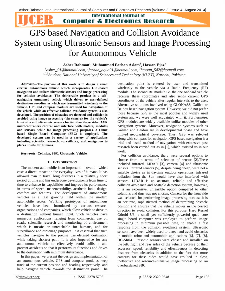
Figure 1: Six ultrasonic sensors installed on vehicle; two
sensors each on the rear, left and right sides. The shaded oval
indicates position of the mounted camera.
II. OPERATING PRINCIPLES
Operating principles of major components of the system
are described below.
A. GPS
The GPS receiver calculates its position by precisely
timing the signals sent by GPS satellites. Each satellite
continually transmits messages that include the time the
message was transmitted, and the satellite position at time of
transmission.
The receiver uses the messages it receives to determine
the transit time of each message and calculates the distance
of receiver from each satellite. Each of these distances and
satellites' locations define a sphere. The receiver is on the
surface of each of these spheres when the distances and the
satellites' locations are correct. These distances and satellites'
locations are used to compute the location of the receiver
using navigation equations. The location includes the
longitude and latitude which are the GPS coordinates of the
receiver device. We utilized RMC data format of the string
which was received from GPS module.
B. Ultrasonic Sensor
A high pulse of at least 10 µs is applied to the trigger pin
of an ultrasonic sensor HC-SR04, which initiates
transmission of eight 40 kHz ultrasonic pulses. The echo pin
of the sensor goes high when the waves are transmitted.
After the waves are reflected from a surface of an object and
reach the sensor back, the echo pin goes low. The time
period of the high echo pin is proportional to the distance
measured between sensor and object [9].Distance measured
in centimeters is calculated as in (1).
(1)
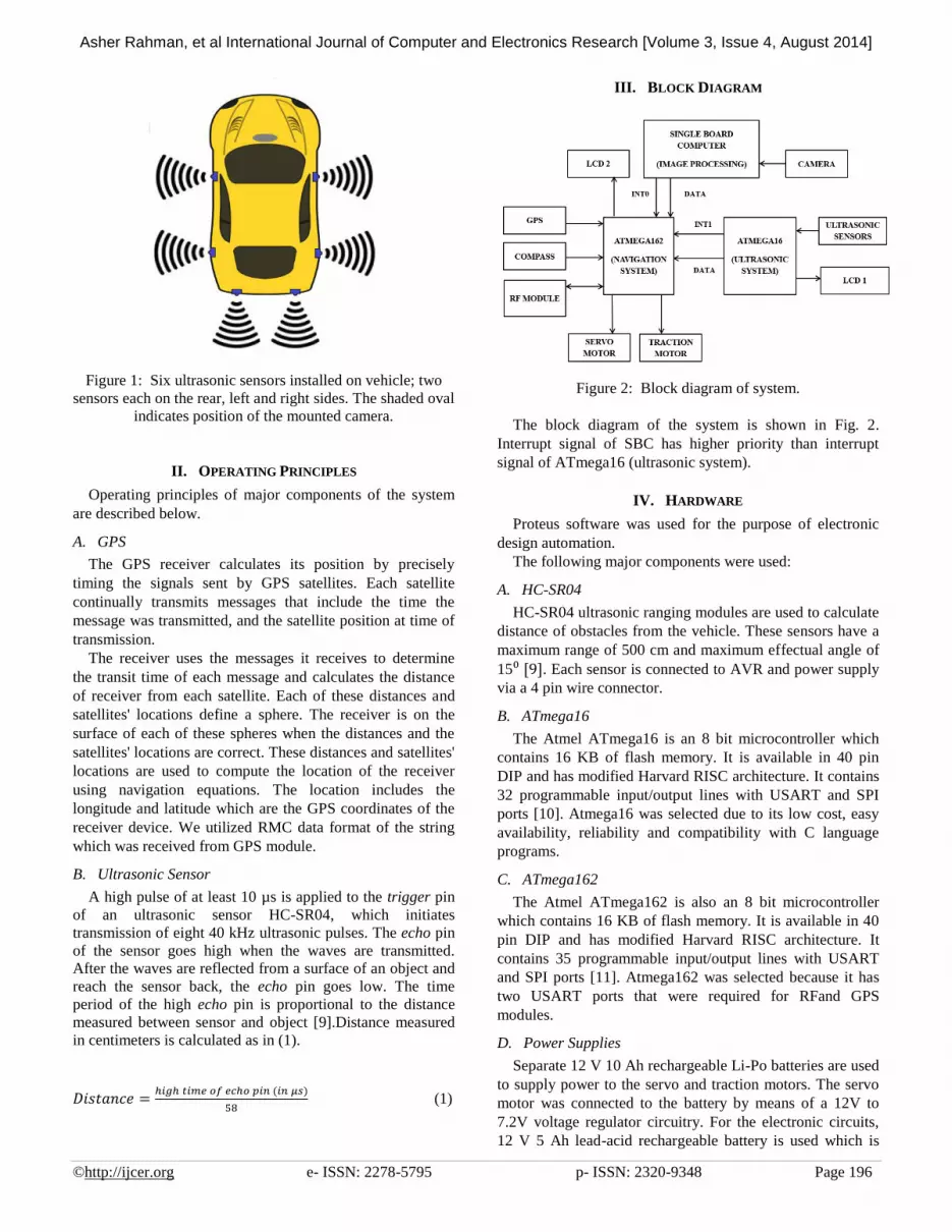
III. BLOCK DIAGRAM
Figure 2: Block diagram of system.
The block diagram of the system is shown in Fig. 2.
Interrupt signal of SBC has higher priority than interrupt
signal of ATmega16 (ultrasonic system).
IV. HARDWARE
Proteus software was used for the purpose of electronic
design automation.
The following major components were used:
A. HC-SR04
HC-SR04 ultrasonic ranging modules are used to calculate
distance of obstacles from the vehicle. These sensors have a
maximum range of 500 cm and maximum effectual angle of
15⁰ [9]. Each sensor is connected to AVR and power supply
via a 4 pin wire connector.
B. ATmega16
The Atmel ATmega16 is an 8 bit microcontroller which
contains 16 KB of flash memory. It is available in 40 pin
DIP and has modified Harvard RISC architecture. It contains
32 programmable input/output lines with USART and SPI
ports [10]. Atmega16 was selected due to its low cost, easy
availability, reliability and compatibility with C language
programs.
C. ATmega162
The Atmel ATmega162 is also an 8 bit microcontroller
which contains 16 KB of flash memory. It is available in 40
pin DIP and has modified Harvard RISC architecture. It
contains 35 programmable input/output lines with USART
and SPI ports [11]. Atmega162 was selected because it has
two USART ports that were required for RFand GPS
modules.
D. Power Supplies
Separate 12 V 10 Ah rechargeable Li-Po batteries are used
to supply power to the servo and traction motors. The servo
motor was connected to the battery by means of a 12V to
7.2V voltage regulator circuitry. For the electronic circuits,
12 V 5 Ah lead-acid rechargeable battery is used which is

Asher Rahman, et al International Journal of Computer and Electronics Research [Volume 3, Issue 4, August 2014]
©http://ijcer.org e- ISSN: 2278-5795 p- ISSN: 2320-9348 Page 197
stepped down to 5 V via 7805 voltage regulator IC.
E. SKM53 GPS module
The SkyNav SKM53 Series [12] with embedded GPS
antenna was used for receiving data from GPS satellites. It
was interfaced serially with ATmega162. The current GPS
coordinates of the module are calculated and sent to the
AVR from this module.
F. HMC6352 compass module
The Honeywell HMC6352 is a fully integrated compass
module that combines 2-axis magneto-resistive sensors with
the required analog and digital support circuits, and
algorithms for heading computation [13]. It was interfaced
via I2C port with ATmega162.To shield the compass module
from electromagnetic interference originating from motor, it
was kept in a grounded metal enclosure. The compass
calculates the current heading of the vehicle.
G. Camera
A generic USB webcam is mounted on the front side of
the vehicle and is connected to SBC for the purpose of image
processing.
H. Hard Kernel Odroid U3 SBC
Odroid U3 is a quad core ARM based SBC with a 1.7
GHz processor and 2 GB RAM [14]. Ubuntu Linux
operating system is installed and image processing is
performed on this SBC.
I. XBee Pro XSC RF module
XBee Pro XSC is long range 900 MHz RF module [15].
Two such modules are being used, one connected to the
user’s computer for transmitting destination coordinates and
the other connected to the system onboard the vehicle.
J. LCD
16x2 LCDs are used to display information. They are
interfaced to AVR microcontrollers.
K. H Bridge
An H bridge circuit based on the L298 H Bridge IC is
used to drive the traction motor. L298 IC can supply up to 4
A current in pulse width modulation (PWM), dual mode,
which is sufficient in this application [16]. An op to-coupler
electrically isolates AVR from the motor. Small fans and
heat sinks were installed to cool H Bridge and motors.
L. Motors
A 12 V DC motor was used for traction purpose while a
7.2 V digital servo motor having 40 kg/cm torque was
utilized for heading navigation.
V. SOFTWARE IMPLEMENTATION
Code design and debugging for programming AVR
microcontrollers was performed in Code Vision AVR in C
language. Eclipse CDT C/C++ was installed on Linux based
Odroid SBC for code design, debugging and programming
of the SBC using C++ language. The g++ for ARM Linux
was utilized for code compilation (arm-linux-gnueabihf-
g++). The flowcharts in Fig. 3-6 represent the software
implementation for each subsystem.
Figure 3: Navigation system.
Figure 4: Navigation system (continued).

Asher Rahman, et al International Journal of Computer and Electronics Research [Volume 3, Issue 4, August 2014]
©http://ijcer.org e- ISSN: 2278-5795 p- ISSN: 2320-9348 Page 198
Figure 5: Ultrasonic sensory system.
Figure 6: Image processing.
VI. WORKING OF NAVIGATION SYSTEM
A. Calculation of Destination Heading Angle ( )
(2)
Angle is calculated by (2).
“ulat” is latitude of destination point entered by user.
“ulong” is longitude of destination point entered by user.
“glat” is latitude of current location of vehicle.
“glong” is latitude of current location of vehicle.
“c” is current location of vehicle (center reference point).
“d” is destination point entered by user.
The destination point quadrant determines magnitude of
the destination heading angle . Angle is represented by
the curly arrows and is calculated for each case in the
following manner, as shown in Fig. 7-10.
1st Quadrant
Figure 7: 1
st quadrant
(3)
(4)
(5)
2nd
Quadrant
Figure 8: 2nd
quadrant
(6)
(7)
(8)
Asher Rahman, et al International Journal of Computer and Electronics Research [Volume 3, Issue 4, August 2014]
©http://ijcer.org e- ISSN: 2278-5795 p- ISSN: 2320-9348 Page 199
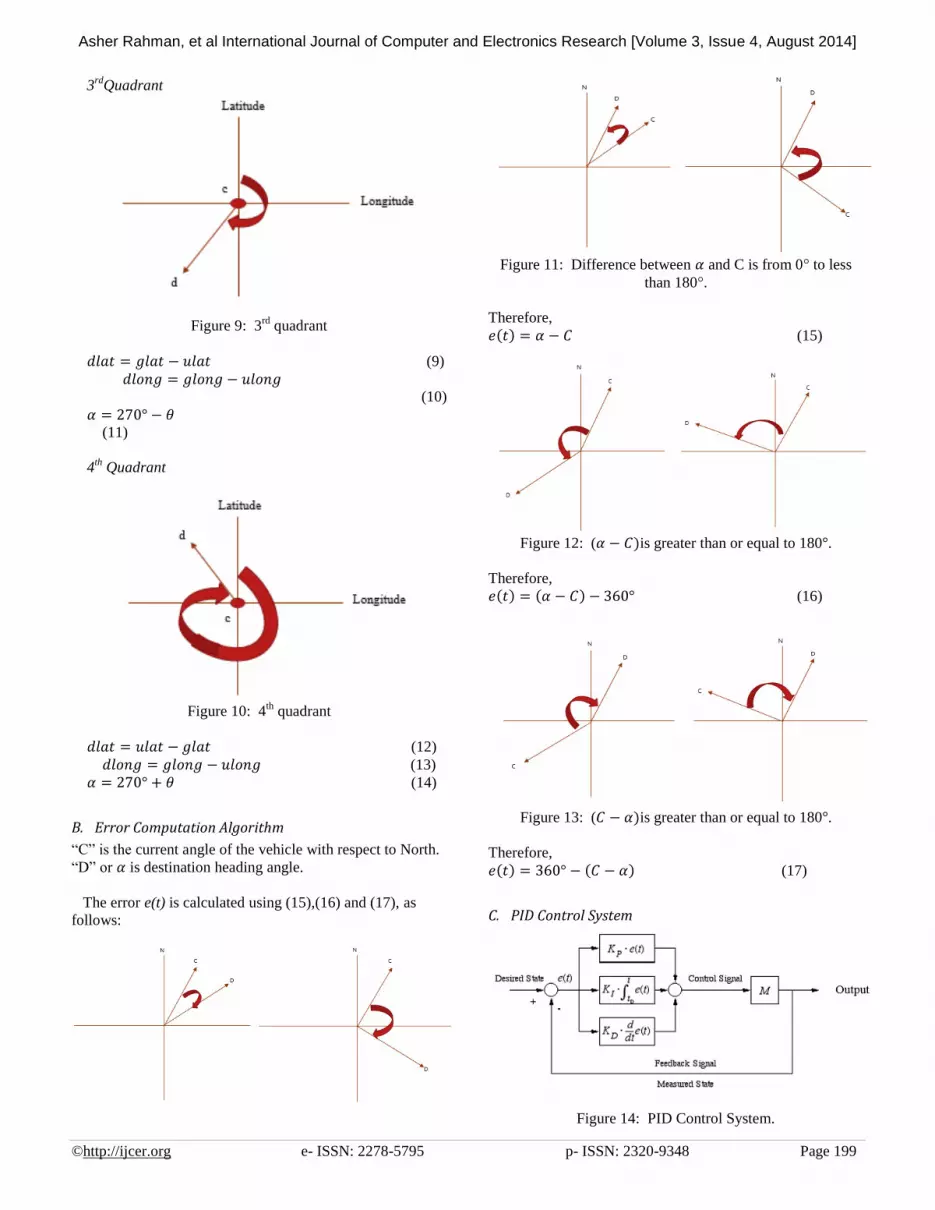
3rd
Quadrant
Figure 9: 3rd
quadrant
(9)
(10)
(11)
4th
Quadrant
Figure 10: 4
th quadrant
(12)
(13)
(14)
B. Error Computation Algorithm
“C” is the current angle of the vehicle with respect to North.
“D” or is destination heading angle.
The error e(t) is calculated using (15),(16) and (17), as
follows:
Figure 11: Difference between and C is from 0 to less
than 180 .
Therefore,
(15)
Figure 12: ( is greater than or equal to 180 .
Therefore,
(16)
Figure 13: ( is greater than or equal to 180 .
Therefore,
(17)
C. PID Control System
Figure 14: PID Control System.
Asher Rahman, et al International Journal of Computer and Electronics Research [Volume 3, Issue 4, August 2014]
©http://ijcer.org e- ISSN: 2278-5795 p- ISSN: 2320-9348 Page 200
(18)
PID control system is shown in Fig. 14. The control
system adjusts the angle of servo motor and thus controls the
heading direction of the vehicle during GPS based
navigation to steer it towards destination point. The output of
the control system is given by (18) which is the sum of
proportional (P), integral (I) and derivative (D) terms
respectively.
VII. WORKING OF ULTRASONIC SYSTEM
ATmega16 polls each ultrasonic sensor and calculates
distance values. If any distance from obstacle is less than the
predefined safe threshold value (x), then the corresponding
output pin representing that sensor is set low and interrupt is
sent to ATmega162. If distance is greater than threshold,
then corresponding output is set high.
If ATmega162 is alerted by an interrupt signal, it stops
GPS based navigation to destination point and identifies the
sensor which detected obstacle and subsequently the obstacle
position, based on data received from ATmega16. Therefore,
the path of motion of vehicle is altered correspondingly by
changing servo motor angle and reducing speed of traction
motor, and thus collision is avoided. LCD 2 displays
calculated distance values.
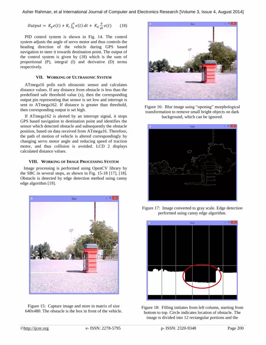
VIII. WORKING OF IMAGE PROCESSING SYSTEM
Image processing is performed using OpenCV library by
the SBC in several steps, as shown in Fig. 15-18 [17], [18].
Obstacle is detected by edge detection method using canny
edge algorithm [19].
Figure 15: Capture image and store in matrix of size
640x480. The obstacle is the box in front of the vehicle.
Figure 16: Blur image using “opening” morphological
transformation to remove small bright objects on dark
background, which can be ignored.
Figure 17: Image converted to gray scale. Edge detection
performed using canny edge algorithm.
Figure 18: Filling initiates from left column, starting from
bottom to top. Circle indicates location of obstacle. The
image is divided into 12 rectangular portions and the

Asher Rahman, et al International Journal of Computer and Electronics Research [Volume 3, Issue 4, August 2014]
©http://ijcer.org e- ISSN: 2278-5795 p- ISSN: 2320-9348 Page 201
horizontal line is 100 cm from obstacle which is the
maximum range up to which obstacles can be detected.
Number of black pixels in each portion are counted and if
they exceed the pre-defined value of 200, obstacle is
considered to be located in the associated portion(s). In such
a scenario, interrupt is sent by SBC to ATmega162. SBC
also determines direction in which vehicle is to move to
avoid collision with the detected obstacle. SBC sends data
via I/O pins to ATmega162 signaling it to head in the
appropriate direction. Therefore, ATmega162 stops GPS
based navigation, reduces vehicle speed and alters path of
motion when alerted, to avoid collision. It is important to
note that ATmega162 makes decision on altered direction of
motion based on data from both ultrasonic system and SBC.
E.g. when SBC signals ATmega162 to move in reverse
direction, the AVR also checks if obstacle is near the rear
side via data from the ultrasonic system.
IX. RESULTS
After conducting extensive tests on flat terrain, it was
observed that the vehicle navigates and accurately reaches
user-defined destination coordinates via shortest straight
path, using GPS and compass modules. Furthermore, any
nearby stationary or moving obstacles within 100cm of the
front side were detected and collision avoided with
negligible reaction time, with the help of image processing,
when the maximum speed of vehicle was 40 km/h. In the
case of ultrasonic system, the maximum range of obstacle
detection was up to 500cm, thus ensuring collision
avoidance with detected stationary and moving obstacles at
vehicle speeds in excess of 60 km/h. When the threshold
distance (x) was set as70cm, the vehicle avoided rear and
sideways collisions even at an approximate speed of 35
km/h.
X. CONCLUSION AND FUTURE SCOPE
The developed system is useful as it provides autonomous
driving ability to vehicles while at the same time avoids
collision.
However, there are a few limitations associated with this
system. Shadows and darkness can be considered as
obstacles by the image processing system due to the
boundary between dark and light color portions of image
being considered as an edge. This problematic phenomenon
can be prevented from occurring by incorporating wide beam
headlights on vehicle or navigating vehicle in well-lit areas.
Usage of vehicle on bright sunny days is also suitable.
Rough terrain or very small objects on the ground can also
be considered as obstacles therefore the vehicle should be
driven on mostly flat terrain. Another solution is to increase
blurring of image at the cost of additional processing power
required and subsequent delay in obstacle detection, in order
to ignore very small obstacles and edges on rough terrain.
Obstacles that have surface of sound absorbing material
reflect a very small amount of ultrasonic waves. This
problem can be solved by using LIDAR with the
disadvantage of high financial expenditure. Another
disadvantage is that irregular surfaces do not reflect waves
towards the sensor because the incident wave is not
perpendicular to obstacle surface causing reflection away
from the sensor [20] [21] [22].
To improve the effectiveness of the collision avoidance
system, the safe threshold value of distance for the ultrasonic
system can be increased up to 500cm. Furthermore, using a
higher resolution camera can detect very small obstacles
more easily. Using a wide angle camera can increase the
visual field of the image processing system and thus increase
its effectiveness in detecting and avoiding obstacles which
are present in front of the vehicle.
REFERENCES
[1] E. Abbott and D Powell, “Land-Vehicle Navigation Using
GPS” Proceeding IEEE, Vol. 87, No. 1, pp. 145–162, 1999.
[2] Richard W. Wall “Creating a low-cost autonomous vehicle”,
IECON 02 [Industrial Electronics Society, IEEE 2002 28th
Annual Conference of the IEEE], 5-8 Nov. 2002 pp 3112-
3116.
[3] B.Gaoand B.Coifman,“ Vehicle identification and GPS error
detection from alidar equipped probe vehicle,
”Proceedings of IEEE Intelligent Transportation
SystemsConf.ITSC’06,2006,pp.1537–1542.
[4] J.-i.Meguro,T.Murata,J.-
i.Takiguchi,Y.Amano,andT.Hashizume,“Gpsmultipathmitigatio
nforurbanareausingomnidirectionalinfraredcamera,”IEEETrans
actionsonIntelligentTransportationSystems,vol.10,no.1,pp.22–
30,2009.
[5] Lino Marques. “Mobile pneumatic robot for demining”,
Proceedings of the 2002 IEEE International Conference on
Robotics & Automation Washington, May 2002 pp 3508-
3513.
[6] Lewinger, W.A.“Obstacle Avoidance Behaviour for a
Biologically-inspired Robot Using Binaural Ultrasonic
Sensors” Proceeding of the 2006 IEEE International
Conference on Intelligent Robots and Systems, 2007. IROS
2007, October 2006 pp 6.
[7] Johan Borenstein. “Mobile Robot Navigation in Narrow Aisles
with Ultrasonic Sensors”, Proceeding on ANS 6th Topical
Meeting on Robotics and Remote Systems, February 1995
[8] Mohamad Hanif Abd Hamid, Abd Hamid Adom, Mohd Hafiz
Fazalul Rahiman, Norasmadi Abdul Rahim, Abu Hassan
Abdullah, Suffian Yusoff, Zunaidi Ibrahim, "Autonomous
Mobile Robot (AMRSBot) with GPS Navigation and
Ultrasonic Obstacle Avoidance System"
[9] Ultrasonic ranging module. ITead
Studio.[Online].Available:
ftp://imall.iteadstudio.com/Modules/IM120628012_HC_SR04/
DS_IM120628012_HC_SR04.pdf
[10] Atmel ATmega16.A t m e l
C o r p o r a t i o n .(2010).[Online].Available:
http://www.atmel.com/Images/doc2466.pdf
[11] Atmel ATmega162.A t m e l
C o r p o r a t i o n .(2013).[Online].Available:
http://www.atmel.com/Images/Atmel-2513-8-bit-AVR-
Microntroller-ATmega162_Datasheet.pdf
[12] Skylab SKM53 (2010).S k y l a b . [Online]. Available:
http://www.nooelec.com/files/SKM53_Datasheet.pdf
[13] Honeywell Digital Compass Solution HMC6352.
H o n e y w e l l (2006,Jan).[Online].Available:
https://www.sparkfun.com/datasheets/Components/HMC6352.
[14] Hard Kernel Odroid U3.HardKernel.[Online].Available:
http://hardkernel.com/main/products/prdt_info.php
[15] XBee PRO XSC.(2013). Digi.[Online].Available:
http://www.digi.com/pdf/ds_xbeeproxsc.pdf

Asher Rahman, et al International Journal of Computer and Electronics Research [Volume 3, Issue 4, August 2014]
©http://ijcer.org e- ISSN: 2278-5795 p- ISSN: 2320-9348 Page 202
[16] L298. (2000).STMicroelectronics.[Online]. Available:
https://www.sparkfun.com/datasheets/Robotics/L298_H_Bridg
e.pdf
[17] I. Culjak, D. Abram, T. Pribanic, H. Dzapo, M. Cifrek, “A
brief introduction to OpenCV”, in proceedings of the 35th
International Convention, MIPRO, 2012.
[18] M. Marengoni, D. Stringhini, “High Level Computer Vision
Using OpenCV”, in proceedings of 24th SIBGRAPI
Conference on Graphics, Patterns and Images Tutorials,
SIBGRAPI-T, 2011.
[19] X. Wang and J. Jian-Qiu, “An edge detection algorithm based
on Canny operator”. In proceedings of the 7th IEEE
International Conference on Intelligent Systems Design and
Applications (ISDA2007), pp. 623-628, 2007.
[20] J. Borenstein and Y. Koren, “Obstacle avoidance with
ultrasonic sensors”, IEEE Journal of Robotics and
Automation, vol. 4, no. 2, pp. 213-218, 1988.
[21] D. L. Jaffe, "Polaroid ultrasonic ranging sensors in robotic
applications," Robotic Age, pp. 23-30, Mar. 1985.
[22] C. Jorgensen, W. Hamel, and C. Weisbin, “Autonomous
robot navigation," BYTE, pp. 223-235, Jan. 1986.