congestion control & collision avoidance algorithm in intelligent transportation
TRANSCRIPT
International Journal of Computer Engineering and Technology (IJCET), ISSN 0976-
6367(Print), ISSN 0976 – 6375(Online) Volume 4, Issue 2, March – April (2013), © IAEME
114
CONGESTION CONTROL & COLLISION AVOIDANCE ALGORITHM
IN INTELLIGENT TRANSPORTATION SYSTEMS
Mayur V. Parulekar1, Viraj Padte
1, Dhaval Shroff
1, Akash Metawala
1, Harsh Nangalia
1
1 Research & Innovation Center, Dwarkadas J. Sanghvi College of Engineering
ABSTRACT
A highly discussed topic of today’s research in interactive systems engineering for
futuristic vehicles is inter-vehicular and vehicle to infrastructure communication using
Dedicated Short Range Communication (DSRC) Protocol. The Global Positioning System
(GPS) has further fuelled research in this area as the cruise control mode can be used to reach
destination after plugging in the destination location on the GPS. Using Model Predictive
Control (MPC) Analysis for a distributed stochastic traffic we present an open source model
architecture which could be used to auto assist the vehicle to its destination. Time slot
allocation algorithms and mathematical modeling of vehicles for lane change has been
presented based on MPC analysis. Our work is towards the development of an application for
the DSRC framework (Dedicated Short Range Communication for Inter-Vehicular
Communication) by US Department of Traffic and DARPA (Defense Advanced Research
Projects Agency) and European Commission- funded Project SAVE-U (Sensors and System
Architecture for Vulnerable road Users Protection) and is a step towards Intelligent
Transportation Systems such as Autonomous Unmanned Ground and Aerial Vehicular
systems. The application depends on recursively obtained sensor readings in a feedback loop
mode for processing and deploying a corrective action.Model Predictive approach that
exploits non-linear functions of the state and finds control inputs such as state of system,
position, acceleration, peer movement to recursively estimate and improve the quality of
resulting estimation for collision avoidance and target localization. The problem addresses is
not only restricted to localization of target but to control a formation of robots in a cluttered
indeterminist environment.
Keywords: DSRC Protocol, Model Predictive Control, Vehicular Localization
INTERNATIONAL JOURNAL OF COMPUTER ENGINEERING
& TECHNOLOGY (IJCET)
ISSN 0976 – 6367(Print) ISSN 0976 – 6375(Online) Volume 4, Issue 2, March – April (2013), pp. 114-124 © IAEME: www.iaeme.com/ijcet.asp Journal Impact Factor (2013): 6.1302 (Calculated by GISI) www.jifactor.com
IJCET
© I A E M E
International Journal of Computer Engineering and Technology (IJCET), ISSN 0976-
6367(Print), ISSN 0976 – 6375(Online) Volume 4, Issue 2, March – April (2013), © IAEME
115
I. INTRODUCTION
Despite the fact that vehicle crash at intersection accounts for more than 30% of the
vehicle crashes major research has always been carried on in forward, sideways and
backward collision detection considering the complex and stochastic nature of the traffic at
such a junction. Considering that the world today is moving towards single board computer
(SBC) in cars that can provide fast computation processing and interface with GPS to make
the driver’s job easy we look at the next few years where Internet Protocol Version 6 will be
deployed to bring at our expense 2^128 IP Addresses. So each car can be assigned a
globally unique IPv6 address which can be configured by the user with his registration ID,
SSN (social security number) number to be recognized over the world. These cars will be
devoid of judgmental or human errors as the (Controller Area Network) CAN protocol [1]
would be deployed at the SBC to receive and transmit signals displaying its state position,
velocity, acceleration to a centralized routing node which in turn would provide a return
parameter adjustment list based on similar data received from various such mobile nodes in
the network. The centralized routing node would be fit with an SBC fed from navigation
mapsto compute the routing decision, speed, lane and acceleration adjustment to avoid
intersection collision based on computational data and this would be released to the
transmitting node before the control is handed off to the next router. We model the cars on
the highway as a mobile ad-hoc network that consists of mobile hosts that communicate via
wireless and wired links. Due to mobility the topology of the network changes continuously
and wireless links breakdown and re-establish frequently. The DSRC protocol[2] and the Co-
operative Collision Avoidance Algorithm[3]are used for inter-vehicular and vehicular to
infrastructure communication using high speed data transmission rates and a large bandwidth
channel. A design of high gain directional dual band microstrip antenna[4] similar to
millimeter-wave radar transmit and receive signal to and from the routing nodes such that
they can then be given to SBC for processing and changing vehicular parameters is also
desired. Each Routing node at the intersection will be computing distance of each car in
independent lanes to decide and avoid the possibility of collision when cars have to cross an
intersection. Since the design is based on highway traffic model we require that these signals
be relayed to longer distances and hence at the backend wire line fiber optic communication
will be used to support the wireless communication between cars and road infrastructure. To
address these challenges, we propose hybrid architecture with an appropriate interplay
between centralized coordination and distributed freedom of action. The approach is built
around a core where each car has an infinite horizon contingency plan, which is updated at
each sampling instant and distributed by the cars. The layout of the proposed architecture is
discussed in section II which provides an open source parameter choice model which can be
tweaked depending on conditions in different scenarios. Further Section III deals with
Vehicular Localization using Particle Filtering, Section IV with Motion Control based on
Model Predictive Control for collision avoidance. This section also proposes Dynamic Matrix
Control algorithm which is a subset of Model Predictive Control. Section V provides details
on Congestion Control using Greedy & Leaky Bucket Algorithm. Section VI deals with
Mathematical Modeling for Lane Contention based on the model of Will & Zak and is used
to provide reference learning to a self- drive car for step input of acceleration, braking,
steering and velocity.
International Journal of Computer Engineering and Technology (IJCET), ISSN 0976-
6367(Print), ISSN 0976 – 6375(Online) Volume 4, Issue 2, March – April (2013), © IAEME
116
II. OPEN SOURCE MODEL ARCHITECTURE
Our model is based on effective collision detection and parametric correction taking
into consideration kinematics of vehicles, network latency delay and message corruption.
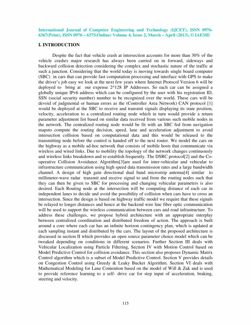
Fig. 1- Scenario of Centralized and Distributed Communication [M.Parulekar et al]
Signal or lamp post fitted with high gain directional antennas to receive beacons from
incoming and outgoing lane traffic top main routing node.
Fiber optic links relaying data i.e. IPv6 registration number, speed of the vehicle sent
from the car to routing node and in turn relaying new speed, lane change information and
next hop to data originator. Emergency on preference movement vehicles on path will be auto
assigned to lane 1 and other traffic will be shifted to the other lanes. All information will be
broadcasted in such scenario by these lamp posts.
Routing node R: Will be installed with an onboard high speed microcomputer to do distance
calculation and next route decision, time slot allocation, speed assignment and lane change
information back to the vehicles. System will be fed with GPS maps and will be told its next
hops on interfaces to guide a vehicle from any source to any destination. GPS maps with line
feed to router will be done by onboard computer on the routing node.
Vehicles will be fitted in with GPS maps and basic micro-computer which will be used to
dynamically change acceleration, lane , velocity, braking based on runtime data built by state
variable model and will be used as a beacon to relay information of its IPv6 registration plate,
destination address, speed and lane. An antenna on the registration plate of the carwill also be
used to send and receive information from lamp post required change in parameters and time
slot availability when not in cruise mode such that intersections that can be maneuvered will
have proximity sensors such that distance from the head car is always maintained i.e. it
always remains in safety set of the car ahead. MPC algorithm based controllers in the micro-
computer will be continuously updating its model. Failsafe manoeuvre will be executed
incase car behind or ahead violates safety set.
Breakdown: Confirmation if the actual vehicle on road is also required as wireless data
security can be violated. Hence an IR pair transceiver will be used with an overhead reflector
which uses a counter to relay the actual data so that integrity with wireless data is confirmed.
Every time IR cuts, counter will be incremented by one. In the event of breakdown, this lane
will have a breakdown vehicle , hence traffic will be need to be routed to the next lanes for
that distance and then redistribution of traffic need to take place.
International Journal of Computer Engineering and Technology (IJCET), ISSN 0976-
6367(Print), ISSN 0976 – 6375(Online) Volume 4, Issue 2, March – April (2013), © IAEME
117
III. VEHICULAR LOCALIZATION & TRACKING
Whenever a car is travelling on the road, it requires both longitudinal and lateral
control to avoid collision with the other vehicles. Lane detection and vehicle position
measuring are two basic intelligent-vehicle functions. The LIDAR (Light Detection &
Ranging Systems) alternative can be used to measure the lane and vehicle’s heading angle in
an indoor scenario. However, LIDAR [5] exhibits less measurement accuracy than Inertial
Navigation Systems. So the two sensor systems are combined for better result since
localization is an important functionality for navigating intelligent vehicles. However, the
data obtained from GPS and cameras is sometimes uncertain and or even momentarily
unavailable. Hence it is imperative that localization using Bayesian filtering [6, 15] be carried
out so that the range of error reduces from 3-10 meters to 2-8 cm of error. Kalman [7] and
Particle Filtering [8]have been used for tracking of vehicles where focus is more on the high
probability of certainness or belief in a specified region of operation than in other region. The
problem of GPS and vision- sensor-based localization was studied and by combining GPS
&absolute localization [9,15,17] data with data computed by a vision system provided
accurate vehicle position and orientation measurements. They transform the position and
orientation data into a global reference using a map of the environment and then estimate
localization parameters using a particle filter. This lets them manage multimodal estimations,
because the vehicle can be in the left or right lane. The best precision can supposedly reach
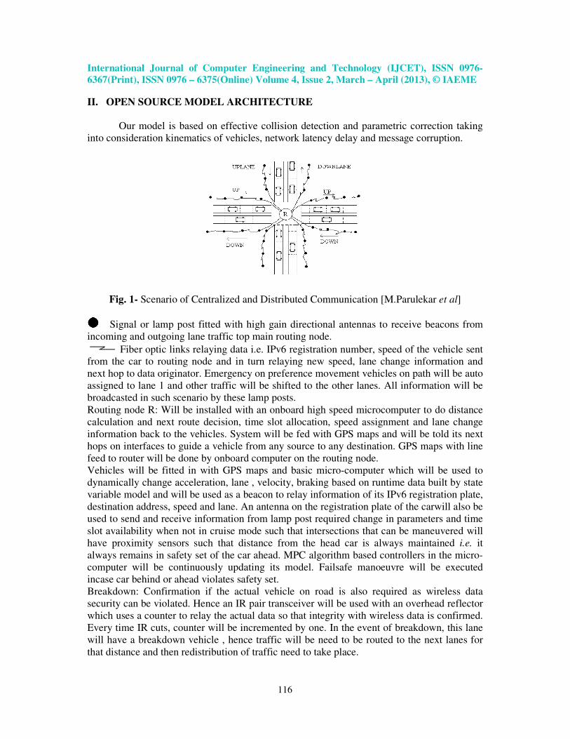
48 cm along the road axis and 8 cm along the axis normal to the road as shown in Fig.2
Fig.2 Front panel of LabVIEW with LIDAR Fig. 3 Kalman Filter for vehicular tracking
International Journal of Computer Engineering and Technology (IJCET), ISSN 0976-
6367(Print), ISSN 0976 – 6375(Online) Volume 4, Issue 2, March – April (2013), © IAEME
118
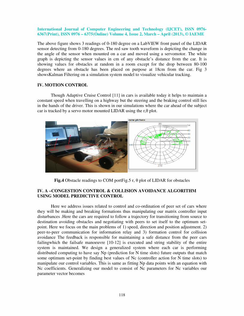
The above figure shows 3 readings of 0-180 degree on a LabVIEW front panel of the LIDAR
sensor detecting from 0-180 degrees. The red saw tooth waveform is depicting the change in
the angle of the sensor when mounted on a car and moved using a servomotor. The white
graph is depicting the sensor values in cm of any obstacle’s distance from the car. It is
showing values for obstacles at random in a room except for the drop between 80-100
degrees where an obstacle has been placed on purpose at 18cm from the car. Fig 3
showsKalman Filtering on a simulation system model to visualize vehicular tracking.
IV. MOTION CONTROL
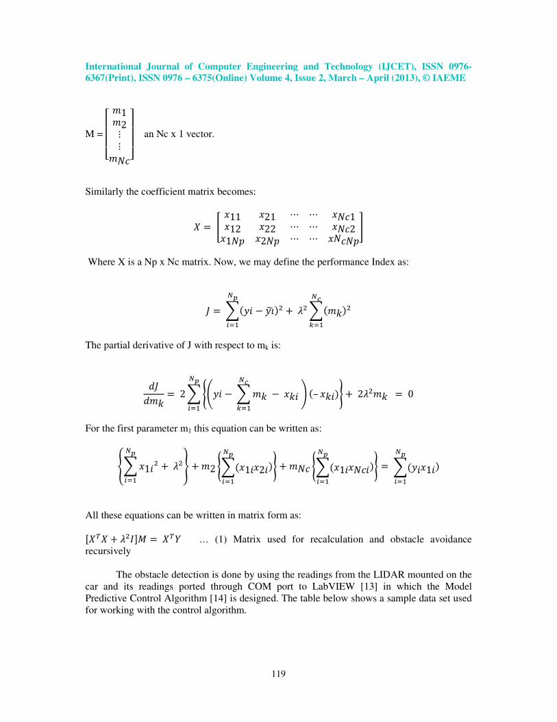
Though Adaptive Cruise Control [11] in cars is available today it helps to maintain a
constant speed when travelling on a highway but the steering and the braking control still lies
in the hands of the driver. This is shown in our simulations where the car ahead of the subject
car is tracked by a servo motor mounted LIDAR using the r,θ plot.
Fig.4 Obstacle readings to COM portFig.5 r, θ plot of LIDAR for obstacles
IV. A –CONGESTION CONTROL & COLLISION AVOIDANCE ALGORITHM
USING MODEL PREDICTIVE CONTROL
Here we address issues related to control and co-ordination of peer set of cars where
they will be making and breaking formations thus manipulating our matrix controller input
disturbances .Here the cars are required to follow a trajectory for transitioning from source to
destination avoiding obstacles and negotiating with peers to set itself to the optimum set-
point. Here we focus on the main problems of 1) speed, direction and position adjustment. 2)
peer-to-peer communication for information relay and 3) formation control for collision
avoidance The feedback is responsible for maintaining a safe distance from the peer cars
failingwhich the failsafe manoeuvre [10-12] is executed and string stability of the entire
system is maintained. We design a generalized system where each car is performing
distributed computing to have say Np (prediction for N time slots) future outputs that match
some optimum set-point by finding best values of Nc (controller action for N time slots) to
manipulate our control variables. This is same as fitting Np data points with an equation with
Nc coefficients. Generalizing our model to consist of Nc parameters for Nc variables our
parameter vector becomes
International Journal of Computer Engineering and Technology (IJCET), ISSN 0976-
6367(Print), ISSN 0976 – 6375(Online) Volume 4, Issue 2, March – April (2013), © IAEME
119
M =
����� �1�2�����
��� an Nc x 1 vector.
Similarly the coefficient matrix becomes:
� � �11 �21 � � ��1�12 �22 � � ��2�1�� �2�� � � �����
Where X is a Np x Nc matrix. Now, we may define the performance Index as:
� � ���� � ��� ��� !"# $ %����&���'
("#
The partial derivative of J with respect to mk is:
)�)�& � 2�*+�� � ��& � �&� �'("# , �– �&��./
� !"# $ 2%��& � 0
For the first parameter m1 this equation can be written as:
1��1��� !"# $ %�2 $�2 *���1��2�
� !"#
�/ $ �� *���1����� !"#
�/ � �����1�� !"#
�
All these equations can be written in matrix form as:
3 4 $ %�567 � 48 … (1) Matrix used for recalculation and obstacle avoidance
recursively
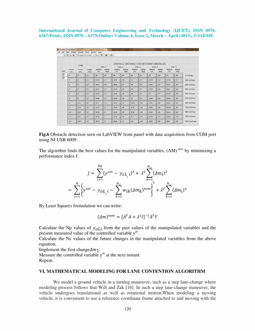
The obstacle detection is done by using the readings from the LIDAR mounted on the
car and its readings ported through COM port to LabVIEW [13] in which the Model
Predictive Control Algorithm [14] is designed. The table below shows a sample data set used
for working with the control algorithm.
International Journal of Computer Engineering and Technology (IJCET), ISSN 0976-
6367(Print), ISSN 0976 – 6375(Online) Volume 4, Issue 2, March – April (2013), © IAEME
120
Fig.6 Obstacle detection seen on LabVIEW front panel with data acquisition from COM port
using NI USB 6009
The algorithm finds the best values for the manipulated variables, (AM) new
by minimizing a
performance index J.
� � �9�:;< � �=, �?�� !"# $ %���@�����'
("#
� �*�:;< � �A=, � � �B�&�@�&�C;D�'("# /�
!"#� $ %���@���C�'
("#
By Least Squares formulation we can write:
�@��C;D � 3E4E $ %�56F#E48
Calculate the Np values of �A=� from the past values of the manipulated variables and the
present measured value of the controlled variable ym
.
Calculate the Nc values of the future changes in the manipulated variables from the above
equation.
Implement the first change@�1.
Measure the controlled variable ym
at the next instant.
Repeat.
VI. MATHEMATICAL MODELING FOR LANE CONTENTION ALGORITHM
We model a ground vehicle in a turning maneuver, such as a step lane-change where
modeling process follows that Will and Zak [16]. In such a step lane-change maneuver, the
vehicle undergoes translational as well as rotational motion.When modeling a moving
vehicle, it is convenient to use a reference coordinate frame attached to and moving with the
International Journal of Computer Engineering and Technology (IJCET), ISSN 0976-
6367(Print), ISSN 0976 – 6375(Online) Volume 4, Issue 2, March – April (2013), © IAEME
121
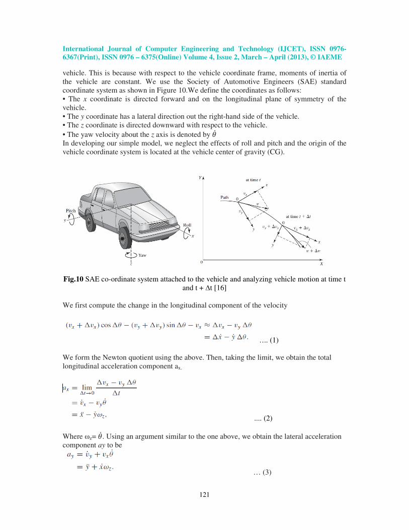
vehicle. This is because with respect to the vehicle coordinate frame, moments of inertia of
the vehicle are constant. We use the Society of Automotive Engineers (SAE) standard
coordinate system as shown in Figure 10.We define the coordinates as follows:
• The x coordinate is directed forward and on the longitudinal plane of symmetry of the
vehicle.
• The y coordinate has a lateral direction out the right-hand side of the vehicle.
• The z coordinate is directed downward with respect to the vehicle.
• The yaw velocity about the z axis is denoted by GH In developing our simple model, we neglect the effects of roll and pitch and the origin of the
vehicle coordinate system is located at the vehicle center of gravity (CG).
Fig.10 SAE co-ordinate system attached to the vehicle and analyzing vehicle motion at time t
and t + ∆t [16]
We first compute the change in the longitudinal component of the velocity
….. (1)
We form the Newton quotient using the above. Then, taking the limit, we obtain the total
longitudinal acceleration component ax.
.... (2)
Where ωz= GH . Using an argument similar to the one above, we obtain the lateral acceleration
component ay to be
… (3)
International Journal of Computer Engineering and Technology (IJCET), ISSN 0976-
6367(Print), ISSN 0976 – 6375(Online) Volume 4, Issue 2, March – April (2013), © IAEME
122
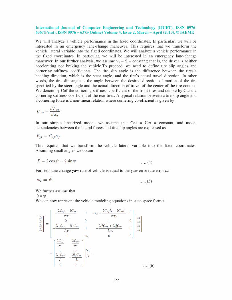
We will analyze a vehicle performance in the fixed coordinates. In particular, we will be
interested in an emergency lane-change maneuver. This requires that we transform the
vehicle lateral variable into the fixed coordinates. We will analyze a vehicle performance in
the fixed coordinates. In particular, we will be interested in an emergency lane-change
maneuver. In our further analysis, we assume vx = �H = constant; that is, the driver is neither
accelerating nor braking the vehicle.To proceed, we need to define tire slip angles and
cornering stiffness coefficients. The tire slip angle is the difference between the tires’s
heading direction, which is the steer angle, and the tire’s actual travel direction. In other
words, the tire slip angle is the angle between the desired direction of motion of the tire
specified by the steer angle and the actual direction of travel of the center of the tire contact.
We denote by Cαf the cornering stiffness coefficient of the front tires and denote by Cαr the
cornering stiffness coefficient of the rear tires. A typical relation between a tire slip angle and
a cornering force is a non-linear relation where cornering co-efficient is given by
In our simple linearized model, we assume that Cαf = Cαr = constant, and model
dependencies between the lateral forces and tire slip angles are expressed as
This requires that we transform the vehicle lateral variable into the fixed coordinates.
Assuming small angles we obtain
…. (4)
For step lane change yaw rate of vehicle is equal to the yaw error rate error i.e
….. (5)
We further assume that
θ = ψ
We can now represent the vehicle modeling equations in state space format
…. (6)
International Journal of Computer Engineering and Technology (IJCET), ISSN 0976-
6367(Print), ISSN 0976 – 6375(Online) Volume 4, Issue 2, March – April (2013), © IAEME
123
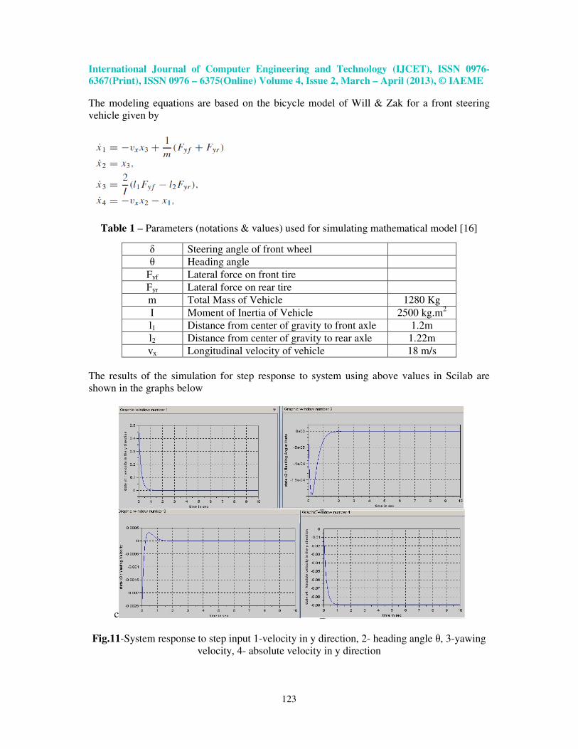
The modeling equations are based on the bicycle model of Will & Zak for a front steering
vehicle given by
Table 1 – Parameters (notations & values) used for simulating mathematical model [16]
δ Steering angle of front wheel
θ Heading angle
Fyf Lateral force on front tire
Fyr Lateral force on rear tire
m Total Mass of Vehicle 1280 Kg
I Moment of Inertia of Vehicle 2500 kg.m2
l1 Distance from center of gravity to front axle 1.2m
l2 Distance from center of gravity to rear axle 1.22m
vx Longitudinal velocity of vehicle 18 m/s
The results of the simulation for step response to system using above values in Scilab are
shown in the graphs below
c
Fig.11-System response to step input 1-velocity in y direction, 2- heading angle θ, 3-yawing
velocity, 4- absolute velocity in y direction
International Journal of Computer Engineering and Technology (IJCET), ISSN 0976-
6367(Print), ISSN 0976 – 6375(Online) Volume 4, Issue 2, March – April (2013), © IAEME
124
VII. CONCLUSIONS
The Open Source Model Architecture is discussed and a structural deployment layout
is shown. Vehicular Localization and Tracking using Bayesian Filtering methods have been
studied and implemented – Kalman Filtering. Error detection & localization using LabVIEW
is implemented. Collision Avoidance & Congestion control has been implemented. Finally
we have carried out the mathematical modeling of a vehicle for lane contention in deploying
the collision avoidance algorithm based on Model Predictive Control.
VIII. REFERENCES [1] http://www.can-cia.de, 2004. Homepage of the organization CAN in Automation (CiA).
[2]Q.Xu, “Design and Analysis of Highway Safety Communication Protocol in 5.9Ghz DSRC,”
Proc. IEEE VTC vol.57, no.4, 2003, pp. 2451
[4] M.Parulekar, Dr. A.A.Deshmukh, P.Patki, “Slot Loaded Dual band Microstrip Antenna”,
published in TechnoPath-Journal of Science Engineering and Technology (ISSN 0975-525X)
Vol. 3, Issue 2,pp 13-18 at MPSTME, NMIMS, Mumbai.
[5] Renslow, Michael, - Utilization/Integration of LIDAR in Mapping and GIS Programs –
ASPRS/ACSM Rhode Island Workshops, Providence Rhode Island, December 2000.
[6]Arulampalam, Maskell, Gordon, Clapp: A Tutorial on Particle Filters for on-line Non-linear /
Non-Gaussian Bayesian Tracking, IEEE Transactions on Signal Processing, Vol. 50, 2002
[7] R. E. Kalman, "A New Approach to Linear Filtering and Prediction Problems," Transactions
of the ASME - Journal of Basic Engineering vol. 82, pp. 35-45, 1960
[8] Chausse, F, “Vehicle localization on a digital map using particles filtering”, Intelligent
Vehicles Symposium, 2005. Proceeding, IEEE.
[9] T.Imielinski a, “GPS-Based Geographic Addressing, Routing, and Resource Discovery,”
Commun. ACM, vol. 42, no. 4 Apr. 1999.
[10] H.Kowshik, “Provable System-wide Safety in Intelligent Intersections”, IEEE transactions
on VTC, vol.60, no. 3 pp. 804-818
[11] L. Tijerina, S. Johnston, “Preliminary Studies in Haptic Display for Rear-end Collision
Avoidance System and Adaptive Criuse Control System Applications:’ Tech. Rep. DOT HS 808
(TBD), NHTSA, U.S. DOT, September 2000
[12] I.J. Cox -“An experiment in guidance and navigation of an autonomous robot vehicle”, IEEE
Transactions on Robotics and Automation 7 (2) (1991) 193–204.”
[13]www.ni.com/labview
[14] 1. B.WayneBequette, ” Non-Linear predictive Control using Multi-rate Sampling”, The
Canadian Journal of Chemical Engineering Vol.69, Issue 1,pg 136-143 Feb 1991
[15] F. Dellaert, D. Fox, W. Burgard, S. Thrun, Monte Carlo localization for mobile robots, in:
Proc. IEEE International Conference on Robotics and Automation (ICRA-99), Detroit, MI, 1999.
[16] S.Zak, “Systems & Control”, Oxford University Press, New York, 2003. ISBN 0-19-
515011-2
[17] M.Parulekar et al, “Vehicular Localization & Intelligent Transportation Systems”, 12th
International Conference on Hybrid Intelligent Systems (HIS), 2012, Pune India, ISBN: 978-1-
4673-5114-0
[18] Kaliprasad A. Mahapatro.Milinde.Rane, “A Novel Approach for Internet Congestion Control
using an Extended State Observer” International journal of Electronics and Communication
Engineering &Technology (IJECET), Volume 4, Issue 2, 2013, pp. 80 - 92, ISSN Print: 0976-
6464, ISSN Online: 0976 –6472