geometry of the intervertebral volume and vertebral endplates of the human spine
TRANSCRIPT

Geometry of the Intervertebral Volume and Vertebral Endplates
of the Human Spine
E. B. VAN DER HOUWEN,1 P. BARON,4 A. G. VELDHUIZEN,2 J. G. M. BURGERHOF,3 P. M. A. VAN OOIJEN,4
and G. J. VERKERKE1,5
1Department of Biomedical Engineering, University Medical Center Groningen, University of Groningen, A. Deusinglaan 1,9713AV Groningen, The Netherlands; 2Department of Orthopedics, University Medical Center Groningen, Universityof Groningen, Groningen, The Netherlands; 3Department of Epidemiology, University Medical Center Groningen,
University of Groningen, Groningen, The Netherlands; 4Department of Radiology, University Medical Center Groningen,University of Groningen, Groningen, The Netherlands; and 5Department of Biomechanical Engineering, University of Twente,
Enschede, The Netherlands
(Received 13 March 2009; accepted 19 October 2009; published online 30 October 2009)
Abstract—Replacement of a degenerated vertebral disc withan artificial intervertebral disc (AID) is currently possible,but poses problems, mainly in the force distribution throughthe vertebral column. Data on the intervertebral disc spacegeometry will provide a better fit of the prosthesis to thevertebrae, but current literature on vertebral disc geometry isvery scarce or not suitable. In this study, existing CT-scans of77 patients were analyzed to measure the intervertebral discand vertebral endplate geometry of the lumbar spine. Tenadjacent points on both sides of the vertebrae (S1-superior toT12-inferior) and sagittal and transverse diameters weremeasured to describe the shape of the caudal and cranialvertebral planes of the vertebrae. It was found that the largestendplate depth is located in the middle or posterior regionsof the vertebra, that there is a linear relationship betweenall inferior endplate depths and the endplate location(p< 0.0001) within the spinal column, and that the superiorendplate depth increases with age by about 0.01 mm per year(p< 0.02). The wedge angle increases from T12-L1 to L5-S1.The results allow for improvement of the fit of intervertebraldisc-prostheses to the vertebrae and optimized force trans-mission through the vertebral column.
Keywords—Intervertebral disc prosthesis, Artificial interver-
tebral disc, AID, End plate geometry, Wedge angle.
INTRODUCTION
Joint replacement for patients with knee or hipproblems is common practice in the Western World.Replacement of a degenerated vertebral disc with an
artificial intervertebral disc (AID) is currently possible,with good short-term results.
Implant migration or dislocation, however, areoften mentioned as the main post-operative problemsassociated with AID’s.10 This is especially the case forosteoporotic patients.
In designing and improving AID’s, geometrical dataon the vertebral site is required, and although literaturedata on the dimensions of the spine and individualvertebrae are available (see Table 1) more specific dataare required. Especially data on the morphology of theendplates are needed for designing AID’s with goodprosthesis-vertebra contact and consequent force dis-tribution, load sharing and a good bone ingrowthpotential. Knowledge of the volume dimensions isrequired to house the AID. To implant existing AID’s,the endplates are surgically reduced to a flat plane toaccommodate the AID, compromising the strength ofthe vertebral shell. A more elegant solution will leavethe endplates as intact as possible and have the AIDadapt or adapted to it. To the authors’ knowledge,however, data on the prevalent shape of the vertebralsurface are very scarce.
Panjabi et al.,7 Silva et al.,9 and Ritzel et al.8 usedCT or staining techniques to measure the cortexthickness on cadaver material (Table 1).
Other studies reported on general dimensions ofthe human vertebrae in which the sagittal (a) andtransverse (b) dimensions are measured from cadavers,X-ray, Computed Tomography (CT), or MagneticResonance Imaging (MRI) (Table 1).
Eijkelkamp2 measured the depth profile of theendplates using MRI and Twomey et al.12 calculatedan endplate index of concavity.
Address correspondence to E. B. van der Houwen, Department
of Biomedical Engineering, University Medical Center Groningen,
University of Groningen, A. Deusinglaan 1, 9713AV Groningen, The
Netherlands. Electronic mail: [email protected]
Annals of Biomedical Engineering, Vol. 38, No. 1, January 2010 (� 2009) pp. 33–40
DOI: 10.1007/s10439-009-9827-6
0090-6964/10/0100-0033/0 � 2009 The Author(s). This article is published with open access at Springerlink.com
33

Since data on the shape of the endplates is veryscarce or have limited accuracy, and, we believe, isessential for a proper AID design, the goal of thisstudy is to determine the endplate geometry of thelumbar region of the spine using CT scans of patientsof various age, health, and gender.
MATERIALS AND METHOD
Equipment
CT scans of the lumbar vertebrae were made with a16 detector multi-detector CT scanner (Siemens,Forchheim, Germany). Acquisition parameters wereset at 120 kV, 250 mAs, 0.75 s rotation time,16 9 .75 mm Collimation, 0.75 mm reconstructionslice thickness, 0.4 mm Reconstruction index, andB80s (sharp) reconstruction filter. All patients werescanned in supine position.
Patients
Patients that underwent a spinal thoracic orabdominal CT were retrospectively selected from thePicture Archiving and Communication System(PACS). The patients had varying spinal problems,e.g., hernias and fractures. Only intact vertebrae belowand above the problem area were measured. Patientswith implanted devices or visual evidence of osteopo-rosis resulting in visible deformations of the vertebral
body were excluded. Vertebrae with a visual axialrotation with respect to the axis of the scanner andvertebral columns with a large lateral slant were alsoexcluded. To achieve our goal of 25 measured samplesper endplate, CT scans covering the lumbar spine of 77patients (46 male, 31 female) were analyzed. The agerange was 21–86 years (mean 49.8 years).
Data Collection and Analysis
The CT-scans were visualized and analyzed usingVitrea2 software (Vital Images Inc., Minnetonka,Minnesota, US). Average intensity projections with athickness of 3.13 mm were reconstructed. A total of 10coordinates were measured on each endplate. Figure 1shows the coordinates of the superior endplate; five ofthese are in the sagittal (side) plane and five are in thefrontal plane. The arbitrarily chosen frontal planeintersects point 3 of the sagittal plane. The coordinates1, 5, 6, and 10 are the intersections of the tangent linewith the vertebral body rims. The coordinates 3 and 8both represent the middle of the endplate but weremeasured in the different viewing planes so they willnot coincide exactly.
All used nomenclature refers to the vertebral body:e.g., inferior endplates are on the caudal side andsuperior endplates are on the cranial side of the ver-tebral body. In all equations the variable locationrepresents the vertebral endplates and their rela-tive level with in the spinal column, numbered 1–11,
TABLE 1. Vertebral geometry in literature (IDH 5 Intervertebral disc height, VBH 5 Vertebral body height).
Author Method(s) Dimensions measured Summary of results
Eijkelkamp2 MRI, X-ray Sagittal diameters, IDH, wedge angle,
endplate depth
Wedge angle increases from T12-L1 to L5-S1.
Endplate depth increases from T12 to L5 and S1
is flat. Average lumbar endplate depth is 1.2 mm
(ranging from �1.1 to 3.6 mm)
Panjabi6 Cadavers Sagittal and Transverse diameters,
cortex thickness
Thickness and density of the cervical cortex
shell described
Silva9 Cadavers Cortex thickness Superior cortex thickness between 0.25 and
0.26 mm. Inferior cortex thickness between:
0.29 and 0.52 mm
Ritzel8 Cadavers Cortex thickness Mean thickness of ventral shell 0.308 mm and
of dorsal shell 0.272 mm
Nissan5 X-ray Sagittal diameters, VBH, IDH
(from which we derived wedge
angle data)
Anterior IDH increases from T12-L1 to L5-S,
respectively, from 7.8 to 10.6 mm
Tan11 Cadavers Sagittal and Transverse diameters, VBH All dimensions lower in Chinese population group
Aharinejad1 Cadavers/CT/MRI Sagittal and Transverse diameters,
VBH, IDH, marginal rim
IDH increases from L1-L2 to L5-S1, respectively,
from 8.5 to 10.3 mm
Twomey12 Cadavers VBH, IDH Increase in vertebral body concavity with age
Zhou14 CT Sagittal and Transverse diameters, VBH,
IDH
Posterior VBH decreases from L3 to L5,
respectively, 29.9 to 28.4 mm
Hall3 CT Sagittal and Transverse diameters Shape of endplate is cartoid at L4 and becomes
more elliptical toward S1
VAN DER HOUWEN et al.34

representing, respectively, S1 superior, L5 inferior, L5superior, L4 inferior, L4 superior, L3 inferior, L3superior, L2 inferior, L2 superior, L1 inferior, L1superior, and T12 inferior.
All of the 10 coordinates were measured for eachof the 12 lumbar vertebral endplates, S1-superior toT12-inferior.
Initially three reference planes were defined inoblique mode using the ‘bone viewing’ settings; asagittal plane (passing the maximum point of theanterior vertebral body and the posterior niche), afrontal plane (passing through the maximum lateralpoints of the vertebral body), and an axial (trans-verse) plane (parallel to the endplate). Note, however,that because the measurements were made inorthogonal mode, the sagittal plane of the CT scanneris not necessarily the actual mid-sagittal cross sectionof the vertebral body.
In sagittal view, a line was drawn tangent to theendplate surface of that cross section. Coordinateswere marked at equal distances and the coordinates1–5 of the projections on the end plates were stored.The edges of the vertebra were determined by themaximum drop in Hounsfield Unit (HU)-value(according to the procedure of Waarsing13) nearmanually located maximum HU-values.
The same was done in frontal view, storing thecoordinates of projected equidistant points 6–10. Abest-fit plane was defined through the rim coordinates1, 5, 6, and 10 using the least squared method.
End Plate Geometry
The endplate depths were calculated as the perpen-dicular distances from the surface coordinates to thebest-fit plane.
All 10 coordinates were measured for each of the 12lumbar vertebral endplates, S1-superior to T12-inferior(with 25 patients per endplate this yields 10 9 12 9
25 = 3000 coordinates).The distance between point 1 and 5 and point 6 and
10 determine the sagittal and transverse diameter ofthe endplate, respectively (which is different from thevertebral body dimensions, measured side to side,often mentioned in literature).
Intervertebral Disc Height
Distances between coordinates of the same numberon opposite sites of the intervertebral disc space wereused to yield the intervertebral disc height (IDH). Thepatients’ age and gender was noted.
Wedge Angle
The wedge angles were calculated for comparison toliterature and to determine if the measurement pointsreflect realistic lumbar anatomy. The wedge angle isthe angle between the planes of two adjacent endplates(Fig. 1). It was calculated using the ‘heights method’ asdescribed by Eijkelkamp.2
FIGURE 1. Nomenclature and planes of orientation.
Geometry of the Intervertebral Volume 35

The values were compared to Eijkelkamp2 and thevalues obtained by using the anterior and posteriordisc heights and the sagittal diameters of Nissan.5
Verification: Repeatability of Measurements
To determine the repeatability of both the CT andcaliper measurements, three repeated measurementswere done, by the same person, of nine differentdimensions on one pig vertebra. The average of the ninestandard deviations was used as a measure for repeat-ability. The dimensions measured were the outer supe-rior and inferior sagittal and transverse endplatediameters, the right and left vertebral body height (thedistances between, respectively, points 6–6 and 10–10on either vertebral body side), the anterior vertebralbody height (distance from point 5–5 on either vertebralbody side), the spinous process length (distance betweenthe anterior wall of the foramen to the anterior point ofthe spinous process in the transversal plane), andtransverse process width (distance between the mostlateral aspects of both transverse processes). In case ofthe measurements on the CT images, the best imageplane for each of the three repeated measurements wasestablished separately for every measurement.
Verification: Comparison of CT vs. CaliperMeasurements
To verify the accuracy of the CT-measurements, aCT scan was made of two pig vertebrae using the sameCT settings as with the human subjects. These mea-surements were verified by comparing measurementsusing a vernier caliper (Mitutoyo, Kawasaki, Japan.accuracy ±0.05 mm) on the actual explanted pig ver-tebrae. To this end, the vertebral bone was excisedusing a scalpel, with as much of the soft tissue removedas possible. For both vertebra the outer superior andinferior sagittal and transverse endplate diameters, andanterior and posterior vertebral body heights (respec-tive distance from point 5 to 5 and 1 to 1 on eithervertebral body side) were measured, giving 12 mea-surements in total.
STATISTICS
The dimensions of the different vertebrae are notentirely independent or dependent observations, sincesome of the vertebrae originate from the same indi-vidual. For this reason, the data was analyzed usingmultilevel analysis. We used the LME module fromS-Plus (TIBCO Software Inc., Palo Alto, USA) inwhich the linear mixed effects model is fit by REML(Restricted maximum likelihood). We defined a generalcovariance structure for the random effects.
The differences between the endplate depths onpoint [8] or [3] was investigated using the paired sam-ples T-test.
In all analyses, p-values below 0.02 were consideredstatistically significant.
RESULTS
All endplates appeared to be generally concave: thevariation in individual endplate depths ranged from5.3 mm located in the middle of (a deep, concave)L4inf to �1.3 mm on the anterior side of (a convex)L2sup.
Figure 2 (left column) lists all vertebrae and theirrelative depths. The smallest depth is generally locatedon the anterior side, followed by the lateral (left andright) locations. The middle or posterior locationsgenerally show the maximum depth. For T12inf andL1inf the maximum is located on the posterior side.For L3inf, L4inf, and L5inf the maximum is in themiddle. The average left and right depths are similar.There was no significant difference between the end-plate depths on point [8] or [3] (Fig. 1). There is anincrease in inferior endplate depth (in mm) from L1infto L5inf for all locations. T12inf does not follow thistrend and tends to have larger values. A linear rela-tionship between the depth and the endplate locationwithin the spinal column was found for all measuredpoints at the inferior sides only (p< 0.0001). Formeasurement point [4] a relationship between age anddepth was also found. The following equations can beused to calculate endplate depths (in mm) for differentlocations in the spinal column:
Point on endplate Depth as a function of spinal location
Right [7] Depth = 2.46 � 0.10*location
Middle [8] Depth = 3.06 � 0.14*location
Left [9] Depth = 2.36 � 0.08*location
Anterior [4] Depth = 1.56 � 0.09*location + 0.008*age
Middle [3] Depth = 3.17 � 0.15*location
Posterior [2] Depth = 2.75 � 0.09*location
In which location can be substituted with the num-ber representing the respective endplates’ locationwithin the spinal column: e.g., 2, 4, 6, 8, 10, and 12representing the vertebral inferior endplates; L5inf,L4inf, L3inf, L2inf, L1inf, and T12inf, respectively.For the superior endplate (1, 3, 5, 7, 9, 11 representingS1sup, L5sup, L4sup, L3sup, L2sup, and L1sup,respectively) the trend was less obvious: a linear rela-tionship between depth and endplate location wasfound only for the anterior and posterior points [1]and [5] (p = 0.01) and for the middle point [3] of the
VAN DER HOUWEN et al.36
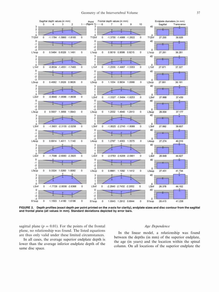
sagittal plane (p = 0.01). For the points of the frontalplane, no relationship was found. The listed equationsare thus only valid under these limited circumstances.
In all cases, the average superior endplate depth islower than the average inferior endplate depth of thesame disc space.
Age Dependence
In the linear model, a relationship was foundbetween the depths (in mm) of the superior endplate,the age (in years) and the location within the spinalcolumn. On all locations of the superior endplate the
FIGURE 2. Depth profiles (exact depth per point printed on the x-axis for clarity), endplate sizes and disc contour from the sagittaland frontal plane (all values in mm). Standard deviations depicted by error bars.
Geometry of the Intervertebral Volume 37

depth increases about 0.01 mm per year (p< 0.02).The following equations were found:
Point on endplate Depth as a function of spinal location and age
Right [7] Depth = 0.46 + 0.0006*location + 0.012*age
Middle [8] Depth = 0.88 � 0.03*location + 0.010*age
Left [9] Depth = 0.46 + 0.007*location + 0.011*age
Anterior [4] Depth = 0.35 � 0.05*location + 0.010*age
Middle [3] Depth = 0.96 � 0.05*location + 0.010*age
Posterior [2] Depth = 0.89 � 0.03*location + 0.010*age
In which location can be substituted with the num-ber representing the respective endplates’ locationwithin the spinal column: e.g., 1, 3, 5, 7, 9, and 11representing the superior vertebral endplates S1sup,L5sup, L4sup, L3sup, L2sup, and L1sup, respectively.
A significant relationship between the depth of theinferior endplate and age was not found. In the linearmodel, a relationship between depth and gender wasnot found either.
Endplate Diameters
The endplate diameters are the rim-to-rim lengths,and therefore differ from the (outside/outer) diametersoften given in literature. The sagittal diameter is aboutconstant with respect to endplate location at 27–28 mm. The transverse diameter, however, increases atthe L3/L4 level. Both diameters are on average largerfor male than female (Table 2).
Sagittal vs. Transverse Diameter
A linear regression model showed a significantrelationship between the sagittal diameter S (mm) andtransverse diameter T (mm) for 8 endplate surfaces.The following equations can be used to calculate thesagittal diameter S as a function of the transversediameter T, per given endplate:
S1sup: S = 17.583 + 0.263T (p = 0.022)
L5inf: S = 16.495 + 0.220T (p = 0.04)
L5sup: S = 24.838 + 0.0063T (p = 0.510)
L4inf: S = 19.151 + 0.222T (p = 0.08)
L4sup: S = 9.950 + 0.433T (p = 0.01)
L3inf: S = 16.207 + 0.297T (p = 0.02)
L3sup: S = 11.213 + 0.449T (p = 0.02)
L2inf: S = 17.200 + 0.286T (p = 0.07)
L2sup: S = 7.537 + 0.566T (p = 0.00)
L1inf: S = 10.993 + 0.092T (p = 0.00)
L1sup: S = 13.451 + 0.383T (p = 0.10)
T12inf: S = 15.180 + 0.323T (p = 0.018)
Wedge Angle
The wedge angle generally increases from T12 to S1(Fig. 3). One angle calculated from measurements on
L4–L5 was excluded because it was negative and morethan two standard deviations away from the mean (theunderlying measurements themselves were not ex-cluded from the results).
Verification: Repeatability Measurements
The average standard deviation of the selectedlengths was similar for both the vernier caliper(r = 0.18 mm, N = 9) measurements and the maxi-mum-gradient CT method (r = 0.22 mm, N = 9).
Verification: Comparison of CT vs. CaliperMeasurements
To verify the CT measuring method two pig verte-brae were scanned and subsequently explanted andmeasured with a vernier caliper. The mean difference(see Fig. 4) between the vernier caliper measurementsand the CT measurements was �0.18 mm (r = 0.66mm, 95% confidence interval [�1.47 mm, 1.12 mm]).
DISCUSSION
Endplate Depth
The inferior vertebral endplate has a larger depththan the superior endplate of the same disc space. Thisasymmetry is, at least from a biomechanical point ofview, difficult to explain since the pressure in the inter-vertebral disc should be the same on both adjacentendplates, thus requiring equal morphology for loaddistribution. Lee4 found the same phenomenon (Fig. 5),and so did Panjabi et al.7 for the cervical endplates.Eijkelkamp2 found generally less obvious differencesexcept for the endplates at the L5-S1 level (Fig. 5).
Furthermore, Fig. 2 shows that the depth of theinferior endplate generally increases toward the lowerlumbar region. T12inf appears to be an exception tothis trend, possibly because the depth itself is smaller,and the measurement error has a larger influence here,or because T12-L1 is a common level of vertebralinjury. Although every care was taken to avoid mea-suring on non-healthy vertebrae, fractures around thisregion may have had some influence.
Other Dependencies
In this study, the endplates’ sagittal diameter variedbetween 27.1 mm (T12inf) and 29.1 mm (L4inf); in thetransverse direction the differences are larger, with ageneral increase from thorax to lumbar. The inferiorendplate transverse diameters are mainly larger thanthe superior diameters of the same disc space, whichonly to a minor extent can be biomechanicallyaccounted for by the increase of supported body mass
VAN DER HOUWEN et al.38

toward the cranial direction along the spinal column.No gender dependencies were found for endplatedepths, from which can be concluded that to someextent, the endplate depth is independent of other ver-tebral geometry, which are body height related and thusgender related. Unfortunately, data on body weightand height was not available in the patients’ files.
Verification
According to the comparison between the mea-surements on a pig vertebra (vernier caliper) andCT-data, the sizes derived from the CT-data areaccurate.
TABLE 2. Endplate diameters for different genders.
Vertebral location
Median endplate depth (mm) Median endplate width (mm)
Females Males p-Value Mann–Whitney Females Males p-Value Mann–Whitney
T12inf 24.8 28.0 0.014 33.7 38.0 0.009
L1sup 26.6 29.0 0.031 32.7 38.7 0.000
L1inf 25.3 29.7 0.002 36.0 39.7 0.040
L2sup 27.1 28.9 0.040 33.0 38.1 0.005
L2inf 26.0 29.0 0.001 32.7 41.1 0.002
L3sup 26.3 29.7 0.003 34.7 40.2 0.000
L3inf 25.4 30.4 0.001 37.9 40.6 0.017
L4sup 26.1 28.9 0.001 37.7 42.4 0.005
L4inf 28.1 30.6 0.101 41.1 48.9 0.000
L5sup 27.7 27.6 0.803 38.1 43.9 0.020
L5inf 25.1 27.4 0.049 41.8 46.6 0.004
S1sup 28.4 29.0 0.495 38.6 41.6 0.125
FIGURE 3. Wedge angle in supine position; comparisonagainst literature, standard deviations depicted by error bars.
FIGURE 4. Bland–Altman plot: the difference in measure-ments against the average for the vernier caliper and maxi-mum-gradient CT method (N 5 12). FIGURE 5. Comparison of endplate depth (mm) against
literature,2,4,5 standard deviations depicted by error bars.
Geometry of the Intervertebral Volume 39

CONCLUSIONS
The geometry of the vertebral body endplate can bedetermined using CT-scans. The accuracy of the mea-surement method was determined by comparing CT tovernier caliper measurements of real vertebra. A largevariation in the depth profile over the endplates wasobserved from convex to concave.
The calculated wedge angle was comparable to lit-erature, which validates the measuring procedure.Other significant trends found, were increasing depthof the inferior endplates for lower lumbar levels. Thesame was also seen for the sagittal plane of the superiorendplate. The superior depth clearly increased with agefor all points measured by 0.01 mm per year. Norelation between depth and gender was found.
Information on the exact shape and geometry thevertebral endplates is important for understanding thebiomechanics and morphology of the spine. The designof orthopedic implants depends on such information.There is an ever-increasing desire to improve anddesign new orthopedic implants. The diversity in ver-tebral geometry, however, makes such a task difficult.The future may lie in custom-made implants, with forevery person a perfect fit based on a pre implantmeasurement using CT data.
ACKNOWLEDGMENTS
The authors would like to thank Ketut Purnamaand Tri Arief Sardjono for their help with spinalimaging. Special thanks to Wim Tukker of the Radi-ology Department (UMCG) for the CT-scans, and forhis useful suggestions.
OPEN ACCESS
This article is distributed under the terms ofthe Creative Commons Attribution Noncommercial
License which permits any noncommercial use, distri-bution, and reproduction in any medium, provided theoriginal author(s) and source are credited.
REFERENCES
1Aharinejad, S., et al. Morphometric analysis of vertebraeand intervertebral discs as a basis of disc replacement. Am.J. Anat. 189:69–76, 1990.2Eijkelkamp, M. F. On the Development of an ArtificialIntervertebral Disc. PhD-thesis, University of Groningen,2002.3Hall, L. T., et al. Morphology of the lumbar vertebralendplates. Spine 23(14):1517–1522, 1998.4Lee, C. K. Intervertebral Disk and Nucleus Prosthesis.Patent US2008046082, 2003.5Nissan, M., et al. Dimensions of the human lumbar ver-tebrae in the sagittal plane. J. Biomech. 19(9):743–758,1986.6Panjabi, M., et al. Human lumbar vertebrae—quantitativethree-dimensional anatomy. Spine 17(3):299–306, 1992.7Panjabi, M., et al. The cortical shell architecture of humancervical vertebral bodies. Spine 26(22):2478–2484, 2001.8Ritzel, H., et al. The thickness of human vertebral corticalbone and its changes in aging and osteoporosis: a histo-morphometric analysis of the complete spinal column fromthirty-seven autopsy specimens. J. Bone Miner. Res. 12(1):89–95, 1997.9Silva, M. J., et al. Direct and computed tomographythickness measurements of the human, lumbar vertebralshell and endplate. Bone 15(4):409–414, 1994.
10Takahata, M., et al. Bone ingrowth fixation of artificialintervertebral disc consisting of bioceramic-coated three-dimensional fabric. Spine 28:637–644, 2003.
11Tan, S. H., et al. Quantitative three-dimensional anatomyof cervical, thoracic and lumbar vertebrae of Chinese Sin-gaporeans. Eur. Spine J. 13:137–146, 2004.
12Twomey, L. T., et al. Age changes in lumbar vertebrae andintervertebral discs. Clin. Orthop. Nov(224):97–104, 1987.
13Waarsing, J. H. An improved segmentation method for invivo micro-CT imaging. J. Bone Miner. Res. 19(10):1640–1650, 2004.
14Zhou, S. H., et al. Geometrical dimensions of the lowerlumbar vertebrae—analysis of data from digitised CTimages. Eur. Spine J. 9:242–248, 2000.
VAN DER HOUWEN et al.40