geological evolution of the tyras vallis paleolacustrine system, mars
TRANSCRIPT
Geological evolution of the Tyras Vallis paleolacustrine system, Mars
Gaetano Di Achille,1 Lucia Marinangeli,1 Gian Gabriele Ori,1 Ernst Hauber,2
Klaus Gwinner,2 Dennis Reiss,2 and Gerhard Neukum3
Received 19 August 2005; revised 4 November 2005; accepted 4 January 2006; published 8 April 2006.
[1] Using the new High Resolution Stereo Camera (HRSC) data and other Martian datasets, we reconstructed the hydrological history of an unnamed complex crater in theXanthe Terra region. The crater hosted a lacustrine basin fed by a dense and centripetaldrainage system, developed along its inner rim, and by the Tyras Vallis channel. Wherethe Tyras Vallis opens into the crater, a prominent delta-like feature is visible,characterized by a central terrace and two small longitudinal scarps. This deposit has beenused as sedimentary recorder of the crater lake history and allowed assessment of theoverall hydrological evolution. Two major stands of the water level have been inferred at700 and 550 m above the crater floor, based on the correlation between the morphologyand topography of the fan and the crater floor deposits. Our reconstruction reveals acomplex sedimentary evolution of the fan, which underwent deltaic and alluvialsedimentation, as a result of the different lake water levels and Tyras Vallis supplies. Adominant erosional evolution of the fan-delta was determined by the interaction betweenthe fluvial characteristics and basin wave regime. Wave height analysis and morphologicalcomparison with terrestrial analogues support this hypothesis. The lacustrine activitycould be chronologically placed between the Late Noachian and the Hesperian. Theclimatic conditions could have allowed the recharge of the regional groundwater systemby precipitation and episodic fluvial activity. However, also heating effects of crateringcould have affected the system, rejuvenating or accelerating the recharge of thelocal aquifer.
Citation: Di Achille, G., L. Marinangeli, G. G. Ori, E. Hauber, K. Gwinner, D. Reiss, and G. Neukum (2006), Geological evolution
of the Tyras Vallis paleolacustrine system, Mars, J. Geophys. Res., 111, E04003, doi:10.1029/2005JE002561.
1. Introduction
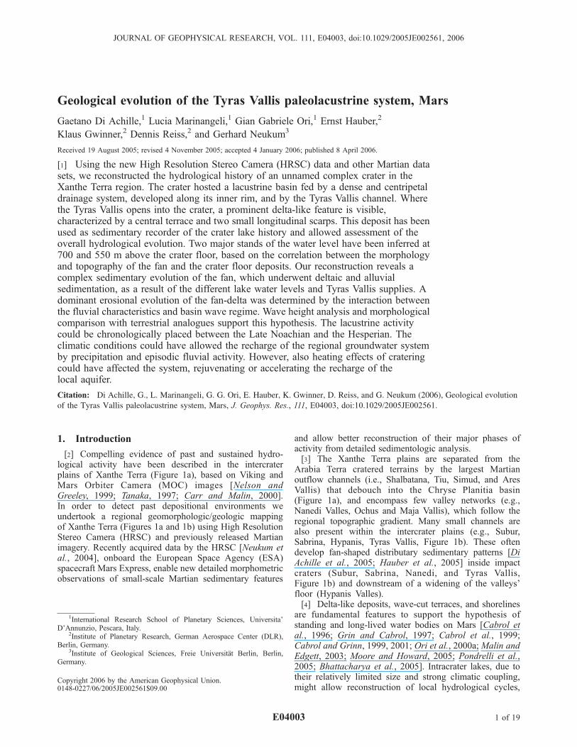
[2] Compelling evidence of past and sustained hydro-logical activity have been described in the intercraterplains of Xanthe Terra (Figure 1a), based on Viking andMars Orbiter Camera (MOC) images [Nelson andGreeley, 1999; Tanaka, 1997; Carr and Malin, 2000].In order to detect past depositional environments weundertook a regional geomorphologic/geologic mappingof Xanthe Terra (Figures 1a and 1b) using High ResolutionStereo Camera (HRSC) and previously released Martianimagery. Recently acquired data by the HRSC [Neukum etal., 2004], onboard the European Space Agency (ESA)spacecraft Mars Express, enable new detailed morphometricobservations of small-scale Martian sedimentary features
and allow better reconstruction of their major phases ofactivity from detailed sedimentologic analysis.[3] The Xanthe Terra plains are separated from the
Arabia Terra cratered terrains by the largest Martianoutflow channels (i.e., Shalbatana, Tiu, Simud, and AresVallis) that debouch into the Chryse Planitia basin(Figure 1a), and encompass few valley networks (e.g.,Nanedi Valles, Ochus and Maja Vallis), which follow theregional topographic gradient. Many small channels arealso present within the intercrater plains (e.g., Subur,Sabrina, Hypanis, Tyras Vallis, Figure 1b). These oftendevelop fan-shaped distributary sedimentary patterns [DiAchille et al., 2005; Hauber et al., 2005] inside impactcraters (Subur, Sabrina, Nanedi, and Tyras Vallis,Figure 1b) and downstream of a widening of the valleys’floor (Hypanis Valles).[4] Delta-like deposits, wave-cut terraces, and shorelines
are fundamental features to support the hypothesis ofstanding and long-lived water bodies on Mars [Cabrol etal., 1996; Grin and Cabrol, 1997; Cabrol et al., 1999;Cabrol and Grinn, 1999, 2001; Ori et al., 2000a; Malin andEdgett, 2003; Moore and Howard, 2005; Pondrelli et al.,2005; Bhattacharya et al., 2005]. Intracrater lakes, due totheir relatively limited size and strong climatic coupling,might allow reconstruction of local hydrological cycles,
JOURNAL OF GEOPHYSICAL RESEARCH, VOL. 111, E04003, doi:10.1029/2005JE002561, 2006
1International Research School of Planetary Sciences, Universita’D’Annunzio, Pescara, Italy.
2Institute of Planetary Research, German Aerospace Center (DLR),Berlin, Germany.
3Institute of Geological Sciences, Freie Universitat Berlin, Berlin,Germany.
Copyright 2006 by the American Geophysical Union.0148-0227/06/2005JE002561$09.00
E04003 1 of 19
and could help to better understand the Martian climaticevolution.[5] In this paper, we present the geological analysis of a
potential lacustrine system formed by the Tyras Vallischannel and an as yet unnamed Noachian complex crater(70 km diameter) [Scott and Tanaka, 1986], in which theformer channel flowed and formed a fan-shaped distributaryfeature (hereafter the Tyras fan). Evidence of strandlineswithin the crater provided constraints about the past pres-ence of a standing body of water with its wave relatedprocesses. High-resolution topography derived by HRSCstereo data supported the recognition of the Tyras fandeposit and its morphometric description which allowedreconstruction of the overall lacustrine depositional historyfrom the parallel analysis of the Tyras fan and crater floordeposits. Finally, wave energy estimates in fetch-limitedsettings and comparison with terrestrial analogues suggested
that Martian wind regimes could have produced enoughwave activity in order to shape the observed lacustrinemorphologies.
2. Data and Methodology
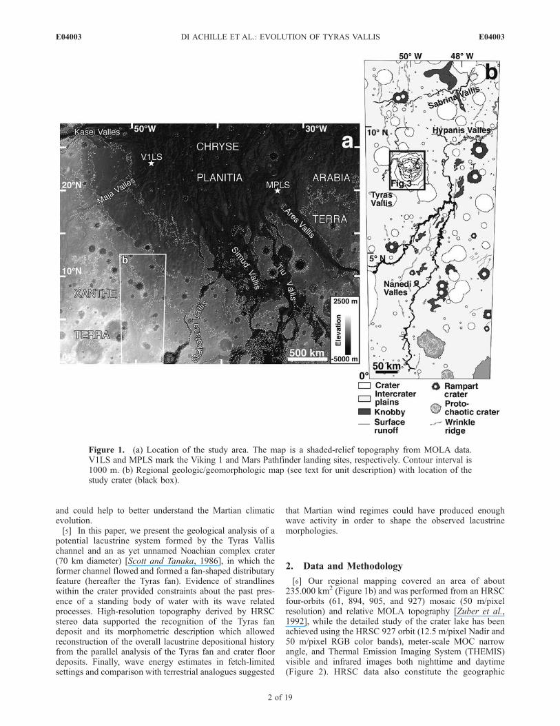
[6] Our regional mapping covered an area of about235.000 km2 (Figure 1b) and was performed from an HRSCfour-orbits (61, 894, 905, and 927) mosaic (50 m/pixelresolution) and relative MOLA topography [Zuber et al.,1992], while the detailed study of the crater lake has beenachieved using the HRSC 927 orbit (12.5 m/pixel Nadir and50 m/pixel RGB color bands), meter-scale MOC narrowangle, and Thermal Emission Imaging System (THEMIS)visible and infrared images both nighttime and daytime(Figure 2). HRSC data also constitute the geographic
Figure 1. (a) Location of the study area. The map is a shaded-relief topography from MOLA data.V1LS and MPLS mark the Viking 1 and Mars Pathfinder landing sites, respectively. Contour interval is1000 m. (b) Regional geologic/geomorphologic map (see text for unit description) with location of thestudy crater (black box).
E04003 DI ACHILLE ET AL.: EVOLUTION OF TYRAS VALLIS
2 of 19
E04003
context into which the few MOC images within the area canbe put.[7] All the images were coregistered to the MOLA (at 1/
128� degree/pixel or about 500 m/pixel) and HRSC (100 m/pixel) topography, for the regional and detailed mapping,respectively. Processed images were integrated into a Geo-graphic Information System (GIS) environment using aMercator projection and the officially adopted Mars IAU2000 reference ellipsoid [Seidelmann et al., 2002].[8] To investigate the geology of the Tyras Vallis
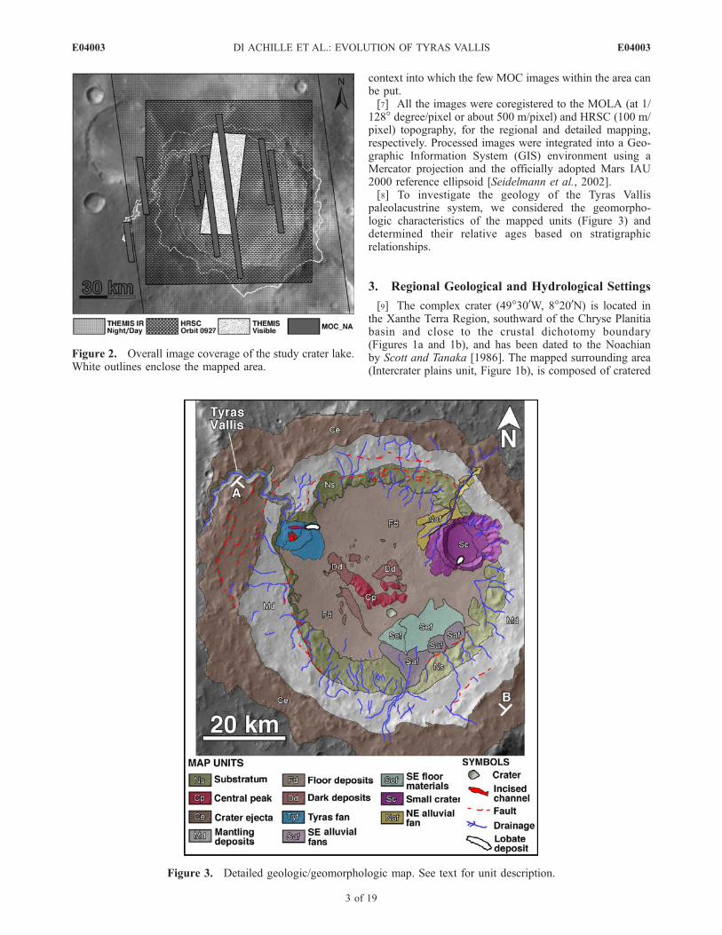
paleolacustrine system, we considered the geomorpho-logic characteristics of the mapped units (Figure 3) anddetermined their relative ages based on stratigraphicrelationships.
3. Regional Geological and Hydrological Settings
[9] The complex crater (49�300W, 8�200N) is located inthe Xanthe Terra Region, southward of the Chryse Planitiabasin and close to the crustal dichotomy boundary(Figures 1a and 1b), and has been dated to the Noachianby Scott and Tanaka [1986]. The mapped surrounding area(Intercrater plains unit, Figure 1b), is composed of cratered
Figure 2. Overall image coverage of the study crater lake.White outlines enclose the mapped area.
Figure 3. Detailed geologic/geomorphologic map. See text for unit description.
E04003 DI ACHILLE ET AL.: EVOLUTION OF TYRAS VALLIS
3 of 19
E04003
Noachian terrains and mostly corresponds to the Crateredunit (Npl1) and Subdued crater unit (Npl2) of Scott andTanaka [1986], Intercrater plains unit (Nip) of Crumpler[1997], and Cratered terrain material (Hnr) in the work ofRotto and Tanaka [1995]). The Knobby unit (Figure 1b) isenclosed in the Intercrater plains unit and consists of smalland scattered polygonal patches within the area.[10] Local hydrography is largely dominated by the two
branches of the northeast oriented Nanedi Valles network.Its main tracks meander within the intercrater plains and arejoined by tens of generally single-order tributary channels,developed along the entire length of the main channels(Figure 1b). These channels widen (up to about 5.5 km)northward until the merging point (near 7�N), located in thewestern surroundings of the investigated complex crater.
[11] The Nanedi Valles network is almost 800 km long(Figure 1b) and is subdivided into two main branches tothe South. Its age is described by Scott and Tanaka [1986]as Hesperian (Hch – Older Channel material), althoughCrumpler [1997] suggested it could be Late Noachian toHesperian (Hv – Valley unit). Rotto and Tanaka [1995]interpreted the formation of Nanedi Valles as a LateNoachian process (HNchl - Older Channels unit). Tyras,Hypanis and Sabrina Valles, (Figure 1b) do not have signif-icative tributary channels and originate from no obvioussource within the Noachian intercrater plains. Nevertheless,as in the Nanedi Valles situation, the track sinuosity andlength argue against the sapping process and headwarderosion; therefore, at least some periodic water flow shouldhave acted during the valley formation.[12] According to Carr and Malin [2000], the regional
groundwater system was probably recharged by a combi-nation of precipitation and infiltration of water duringwarmer terrestrial-like conditions; however, the authors alsodealt with the possible presence of local mechanisms ofrecharge, such as hydrothermally induced circulation drivenby volcanic heat [Gulick, 1998] or residual heat fromimpacts [Newsom, 1980].
4. Geological Analysis of Tyras Vallis System
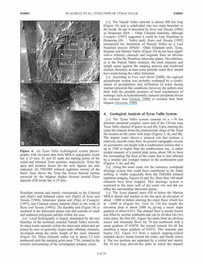
[13] The Tyras Vallis system consists of a �70 kmdiameter unnamed complex crater and of the 130 km longTyras Vallis channel (Figures 4a and 4b). Upon entering thecrater the channel forms the characteristic shape of the Tyrasfan located on the crater wall slope (Figures 3, 4a, and 4b).The impact crater shows a terraced rim that outlines arelatively smooth crater floor. Its general topography revealsan asymmetric rim height with a southeastern portion that isup to 1500 m higher than the northwestern one. A rathereroded remnant of a central peak raises about 300 m fromthe surrounding flat floor of the crater that is also affectedby a smaller and younger impact in the northeastern part(Figures 3, 4a, and 4b).[14] Along the inner crater rim the extensive centripetal
drainage system that could have contributed to the basininfilling is visible (especially from the THEMIS infrarednighttime imagery, Figures 5a and 5b). More than 140 smallchannels have been mapped. This drainage system isrestricted to the inner wall of the crater rim and did notaffect the surrounding intercrater plains.[15] The Tyras channel starts 670 m below the Martian
MOLA datum and reaches at the fan apex an elevation ofabout �2000 m before entering the crater floor, which liesat �2800 m (Figure 4a). Over its 130 km length theelevation drop is about 2000 m, giving a mean slopegradient of about 0.015. The channel floor is mostly buriedand filled by aeolian sediments and can be divided into twomain parts: the first (S1, Figure 4a) starts from no obvioussource and sinuously flows for 70 km northward with amean gradient of 0.0078; the second extends for 60 km(totalling a mean gradient of 0.013). This terminal partbegins (S2, Figure 5c) from a typical sapping-relatedrounded alcove, bends toward the crater, and finally entersit. The two portions are separated by a central and mainlyflat 10 km long alluvial-like plain in which the channel
Figure 4. (a) Tyras Vallis hydrological system physio-graphy with elevation data from MOLA topography (scalebar is 25 km). S1 and S2 mark the starting points of theinitial and terminal Tyras portions, respectively. Tyras fanapex and location boxes for the next figures are alsoindicated. (b) THEMIS infrared nighttime mosaic of thebasin. Inset shows the Tyras fan (lower thermal inertia)encircled by the brighter (higher thermal inertia) Floordeposits (Fd) (scale bar is 25 km).
E04003 DI ACHILLE ET AL.: EVOLUTION OF TYRAS VALLIS
4 of 19
E04003
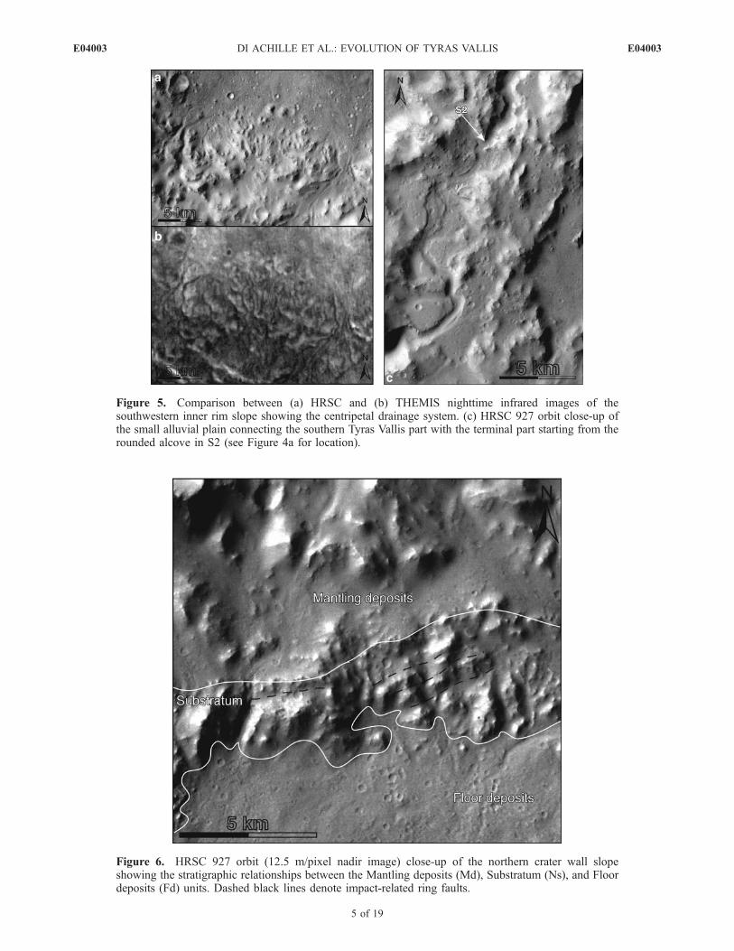
Figure 5. Comparison between (a) HRSC and (b) THEMIS nighttime infrared images of thesouthwestern inner rim slope showing the centripetal drainage system. (c) HRSC 927 orbit close-up ofthe small alluvial plain connecting the southern Tyras Vallis part with the terminal part starting from therounded alcove in S2 (see Figure 4a for location).
Figure 6. HRSC 927 orbit (12.5 m/pixel nadir image) close-up of the northern crater wall slopeshowing the stratigraphic relationships between the Mantling deposits (Md), Substratum (Ns), and Floordeposits (Fd) units. Dashed black lines denote impact-related ring faults.
E04003 DI ACHILLE ET AL.: EVOLUTION OF TYRAS VALLIS
5 of 19
E04003
appears very shallow and meandering before to reach thefinal steeper portion in S2 (Figure 5c).
4.1. Unit Description
4.1.1. Substratum (Ns)[16] This unit connects the upper terrace of the crater rim
with the smooth deposits overlapping the low-lying craterfloor and is characterized by the presence of eroded massiverocks locally tilted by faults (Figures 3 and 6). This unit isalso affected by the centripetal drainage system developedon the inner rim slope (Figure 3, 5a, and 5b).4.1.2. Central Peak (Cp)[17] The rocks of this unit (Figure 3) are highly eroded,
mostly buried and protrude from the surrounding terrains inthe central part of the crater floor.4.1.3. Crater Ejecta (Ce)[18] Coarse ejecta are close to the rim (Figure 3) and
gradually vanish into the intercrater plains. The effects ofradial ballistically emplaced secondary impacts are stillvisible in the surrounding areas up to about 130 km fromthe crater center.4.1.4. Mantling Deposits (Md)[19] These deposits are variably visible over the entire
crater terrace extending from the crater rim to the beginningof the steepest part of the crater wall slope (Figure 3). Theunit is characterized by smooth and relatively fresh finematerials draping the underlying rocks of the targeted andraised Substratum unit (Figure 6). These diffuse drapingdeposits are locally incised by the highest channels of thecentripetal drainage system affecting the crater.4.1.5. Floor Deposits (Fd)[20] This unit is characterized by a mainly gentle slope
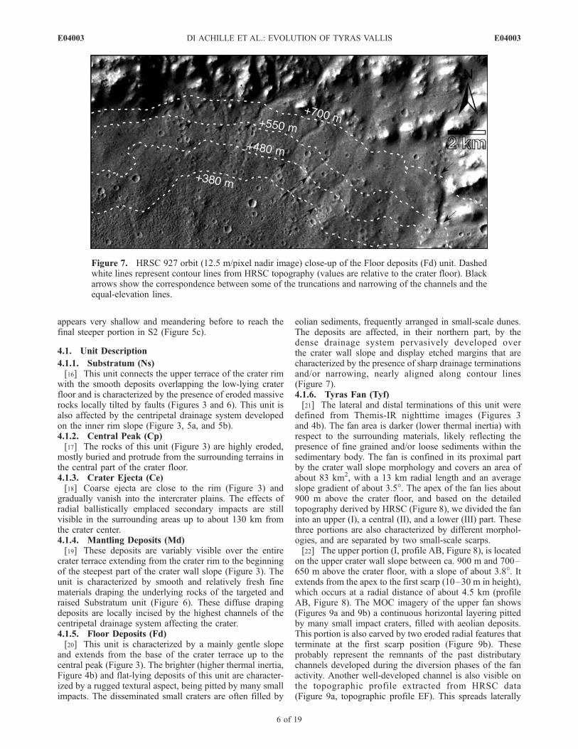
and extends from the base of the crater terrace up to thecentral peak (Figure 3). The brighter (higher thermal inertia,Figure 4b) and flat-lying deposits of this unit are character-ized by a rugged textural aspect, being pitted by many smallimpacts. The disseminated small craters are often filled by
eolian sediments, frequently arranged in small-scale dunes.The deposits are affected, in their northern part, by thedense drainage system pervasively developed overthe crater wall slope and display etched margins that arecharacterized by the presence of sharp drainage terminationsand/or narrowing, nearly aligned along contour lines(Figure 7).4.1.6. Tyras Fan (Tyf)[21] The lateral and distal terminations of this unit were
defined from Themis-IR nighttime images (Figures 3and 4b). The fan area is darker (lower thermal inertia) withrespect to the surrounding materials, likely reflecting thepresence of fine grained and/or loose sediments within thesedimentary body. The fan is confined in its proximal partby the crater wall slope morphology and covers an area ofabout 83 km2, with a 13 km radial length and an averageslope gradient of about 3.5�. The apex of the fan lies about900 m above the crater floor, and based on the detailedtopography derived by HRSC (Figure 8), we divided the faninto an upper (I), a central (II), and a lower (III) part. Thesethree portions are also characterized by different morphol-ogies, and are separated by two small-scale scarps.[22] The upper portion (I, profile AB, Figure 8), is located
on the upper crater wall slope between ca. 900 m and 700–650 m above the crater floor, with a slope of about 3.8�. Itextends from the apex to the first scarp (10–30 m in height),which occurs at a radial distance of about 4.5 km (profileAB, Figure 8). The MOC imagery of the upper fan shows(Figures 9a and 9b) a continuous horizontal layering pittedby many small impact craters, filled with aeolian deposits.This portion is also carved by two eroded radial features thatterminate at the first scarp position (Figure 9b). Theseprobably represent the remnants of the past distributarychannels developed during the diversion phases of the fanactivity. Another well-developed channel is also visible onthe topographic profile extracted from HRSC data(Figure 9a, topographic profile EF). This spreads laterally
Figure 7. HRSC 927 orbit (12.5 m/pixel nadir image) close-up of the Floor deposits (Fd) unit. Dashedwhite lines represent contour lines from HRSC topography (values are relative to the crater floor). Blackarrows show the correspondence between some of the truncations and narrowing of the channels and theequal-elevation lines.
E04003 DI ACHILLE ET AL.: EVOLUTION OF TYRAS VALLIS
6 of 19
E04003
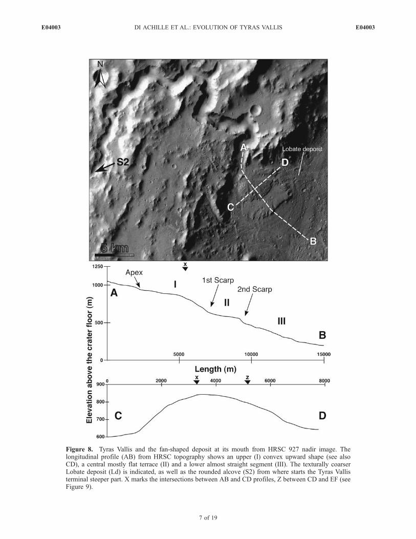
Figure 8. Tyras Vallis and the fan-shaped deposit at its mouth from HRSC 927 nadir image. Thelongitudinal profile (AB) from HRSC topography shows an upper (I) convex upward shape (see alsoCD), a central mostly flat terrace (II) and a lower almost straight segment (III). The texturally coarserLobate deposit (Ld) is indicated, as well as the rounded alcove (S2) from where starts the Tyras Vallisterminal steeper part. X marks the intersections between AB and CD profiles, Z between CD and EF (seeFigure 9).
E04003 DI ACHILLE ET AL.: EVOLUTION OF TYRAS VALLIS
7 of 19
E04003
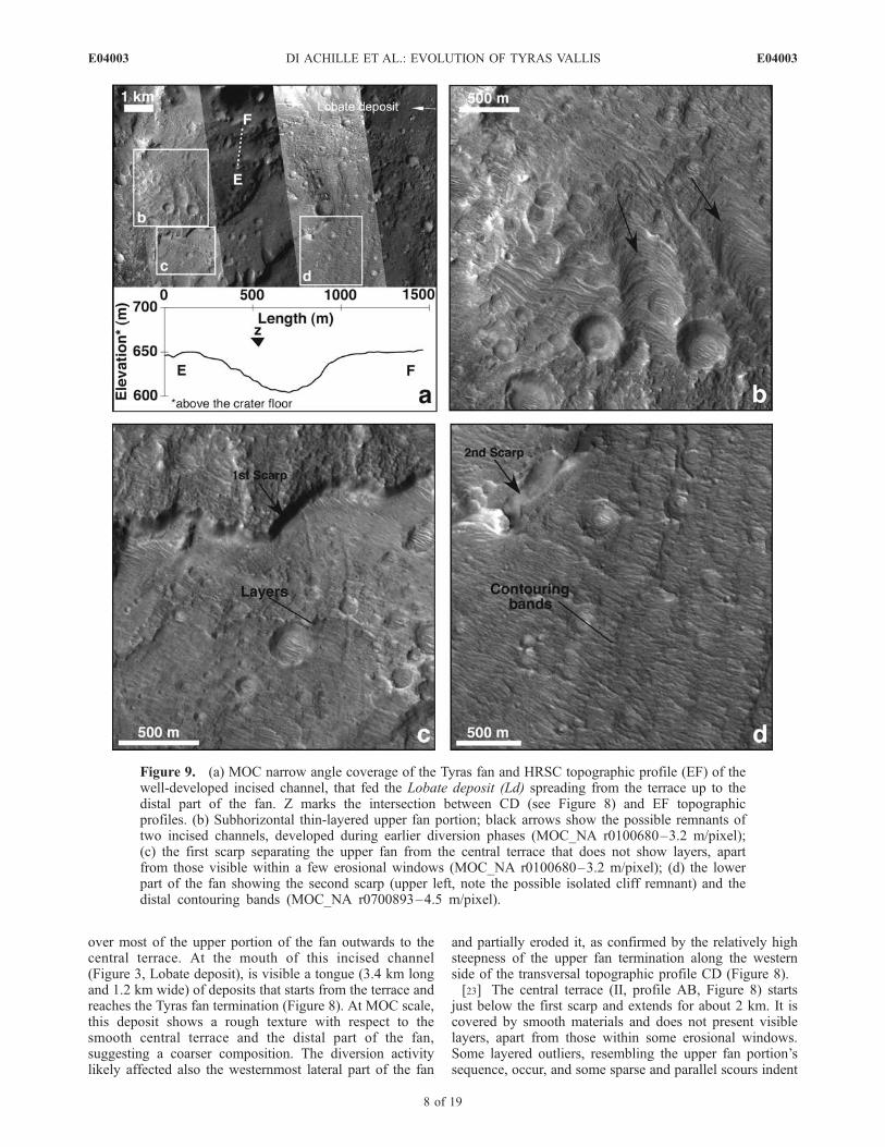
over most of the upper portion of the fan outwards to thecentral terrace. At the mouth of this incised channel(Figure 3, Lobate deposit), is visible a tongue (3.4 km longand 1.2 km wide) of deposits that starts from the terrace andreaches the Tyras fan termination (Figure 8). At MOC scale,this deposit shows a rough texture with respect to thesmooth central terrace and the distal part of the fan,suggesting a coarser composition. The diversion activitylikely affected also the westernmost lateral part of the fan
and partially eroded it, as confirmed by the relatively highsteepness of the upper fan termination along the westernside of the transversal topographic profile CD (Figure 8).[23] The central terrace (II, profile AB, Figure 8) starts
just below the first scarp and extends for about 2 km. It iscovered by smooth materials and does not present visiblelayers, apart from those within some erosional windows.Some layered outliers, resembling the upper fan portion’ssequence, occur, and some sparse and parallel scours indent
Figure 9. (a) MOC narrow angle coverage of the Tyras fan and HRSC topographic profile (EF) of thewell-developed incised channel, that fed the Lobate deposit (Ld) spreading from the terrace up to thedistal part of the fan. Z marks the intersection between CD (see Figure 8) and EF topographicprofiles. (b) Subhorizontal thin-layered upper fan portion; black arrows show the possible remnants oftwo incised channels, developed during earlier diversion phases (MOC_NA r0100680–3.2 m/pixel);(c) the first scarp separating the upper fan from the central terrace that does not show layers, apartfrom those visible within a few erosional windows (MOC_NA r0100680–3.2 m/pixel); (d) the lowerpart of the fan showing the second scarp (upper left, note the possible isolated cliff remnant) and thedistal contouring bands (MOC_NA r0700893–4.5 m/pixel).
E04003 DI ACHILLE ET AL.: EVOLUTION OF TYRAS VALLIS
8 of 19
E04003
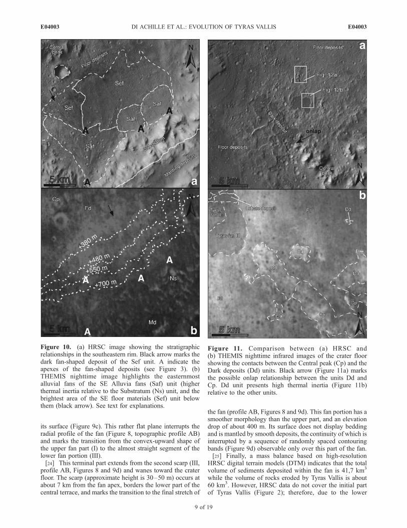
its surface (Figure 9c). This rather flat plane interrupts theradial profile of the fan (Figure 8, topographic profile AB)and marks the transition from the convex-upward shape ofthe upper fan part (I) to the almost straight segment of thelower fan portion (III).[24] This terminal part extends from the second scarp (III,
profile AB, Figures 8 and 9d) and wanes toward the craterfloor. The scarp (approximate height is 30–50 m) occurs atabout 7 km from the fan apex, borders the lower part of thecentral terrace, and marks the transition to the final stretch of
the fan (profile AB, Figures 8 and 9d). This fan portion has asmoother morphology than the upper part, and an elevationdrop of about 400 m. Its surface does not display beddingand is mantled by smooth deposits, the continuity of which isinterrupted by a sequence of randomly spaced contouringbands (Figure 9d) observable only over this part of the fan.[25] Finally, a mass balance based on high-resolution
HRSC digital terrain models (DTM) indicates that the totalvolume of sediments deposited within the fan is 41,7 km3
while the volume of rocks eroded by Tyras Vallis is about60 km3. However, HRSC data do not cover the initial partof Tyras Vallis (Figure 2); therefore, due to the lower
Figure 10. (a) HRSC image showing the stratigraphicrelationships in the southeastern rim. Black arrow marks thedark fan-shaped deposit of the Sef unit. A indicate theapexes of the fan-shaped deposits (see Figure 3). (b)THEMIS nighttime image highlights the easternmostalluvial fans of the SE Alluvia fans (Saf) unit (higherthermal inertia relative to the Substratum (Ns) unit, and thebrightest area of the SE floor materials (Sef) unit belowthem (black arrow). See text for explanations.
Figure 11. Comparison between (a) HRSC and(b) THEMIS nighttime infrared images of the crater floorshowing the contacts between the Central peak (Cp) and theDark deposits (Dd) units. Black arrow (Figure 11a) marksthe possible onlap relationship between the units Dd andCp. Dd unit presents high thermal inertia (Figure 11b)relative to the other units.
E04003 DI ACHILLE ET AL.: EVOLUTION OF TYRAS VALLIS
9 of 19
E04003
resolution of the MOLA DTM, in addition to the possiblelater infilling of the valley, the calculated volume of TyrasVallis may be underestimated.4.1.7. SE Alluvial Fans (Saf)[26] The base of the crater walls is masked in its south-
eastern part by the coalescing fan-shaped deposits of thisunit (Figures 3 and 10a). The HRSC-derived topographyshows a constant and smooth dip of these distributaryfeatures, suggesting they are alluvial fans. Themis nighttimeimages (Figure 10b) show anomalous thermal inertia differ-ences between the deposits of this unit (higher thermalinertia) and the crater walls Ns (lower thermal inertia).4.1.8. SE Floor Materials (Sef)[27] This unit is located just below the SE Alluvial fans
and was identified from the comparison between the HRSCvisible band and the infrared bands of the THEMIS night-time imagery (Figures 3, 10a, and 10b). The constitutingelements of the Sef unit have higher thermal inertia withrespect to the adjacent unit Fd and the overlying Saf unit(Figures 10a and 10b). Another part of this unit is shownlike a dark-toned triangular patch broadening toward thecrater floor (Figures 3 and 10a). The apex of this fan-likefeature corresponds to the terminal part of the biggestsouthern alluvial fan belonging to the SE Alluvial fans unit.4.1.9. Dark Deposits (Dd)[28] The floor of the crater presents small and scattered
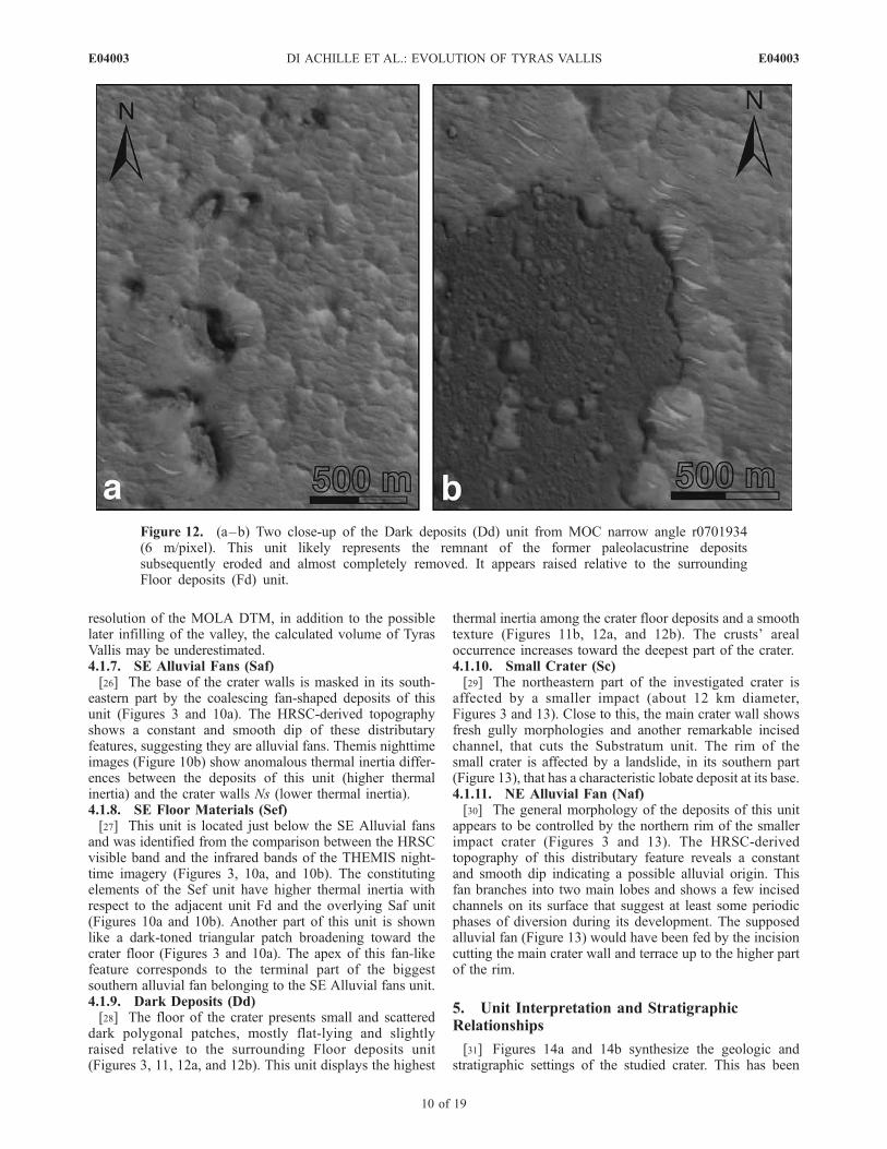
dark polygonal patches, mostly flat-lying and slightlyraised relative to the surrounding Floor deposits unit(Figures 3, 11, 12a, and 12b). This unit displays the highest
thermal inertia among the crater floor deposits and a smoothtexture (Figures 11b, 12a, and 12b). The crusts’ arealoccurrence increases toward the deepest part of the crater.4.1.10. Small Crater (Sc)[29] The northeastern part of the investigated crater is
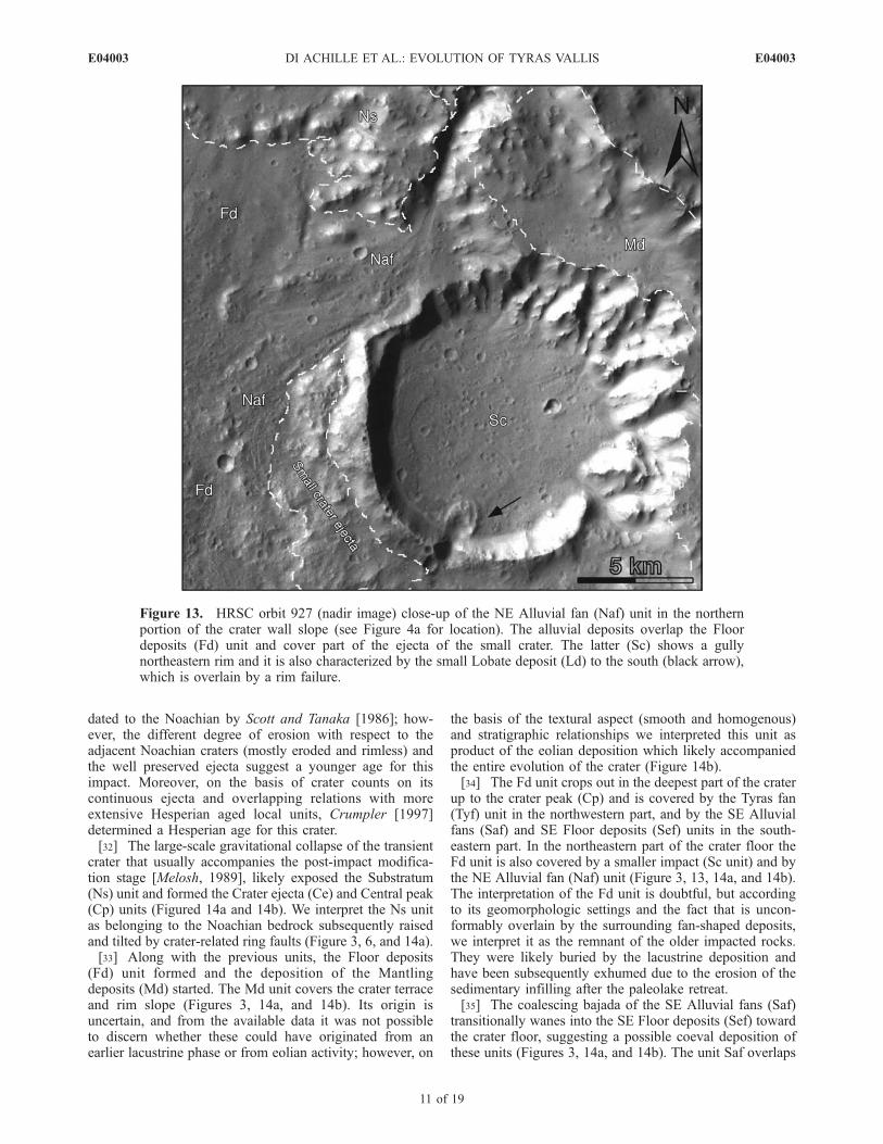
affected by a smaller impact (about 12 km diameter,Figures 3 and 13). Close to this, the main crater wall showsfresh gully morphologies and another remarkable incisedchannel, that cuts the Substratum unit. The rim of thesmall crater is affected by a landslide, in its southern part(Figure 13), that has a characteristic lobate deposit at its base.4.1.11. NE Alluvial Fan (Naf)[30] The general morphology of the deposits of this unit
appears to be controlled by the northern rim of the smallerimpact crater (Figures 3 and 13). The HRSC-derivedtopography of this distributary feature reveals a constantand smooth dip indicating a possible alluvial origin. Thisfan branches into two main lobes and shows a few incisedchannels on its surface that suggest at least some periodicphases of diversion during its development. The supposedalluvial fan (Figure 13) would have been fed by the incisioncutting the main crater wall and terrace up to the higher partof the rim.
5. Unit Interpretation and StratigraphicRelationships
[31] Figures 14a and 14b synthesize the geologic andstratigraphic settings of the studied crater. This has been
Figure 12. (a–b) Two close-up of the Dark deposits (Dd) unit from MOC narrow angle r0701934(6 m/pixel). This unit likely represents the remnant of the former paleolacustrine depositssubsequently eroded and almost completely removed. It appears raised relative to the surroundingFloor deposits (Fd) unit.
E04003 DI ACHILLE ET AL.: EVOLUTION OF TYRAS VALLIS
10 of 19
E04003
dated to the Noachian by Scott and Tanaka [1986]; how-ever, the different degree of erosion with respect to theadjacent Noachian craters (mostly eroded and rimless) andthe well preserved ejecta suggest a younger age for thisimpact. Moreover, on the basis of crater counts on itscontinuous ejecta and overlapping relations with moreextensive Hesperian aged local units, Crumpler [1997]determined a Hesperian age for this crater.[32] The large-scale gravitational collapse of the transient
crater that usually accompanies the post-impact modifica-tion stage [Melosh, 1989], likely exposed the Substratum(Ns) unit and formed the Crater ejecta (Ce) and Central peak(Cp) units (Figured 14a and 14b). We interpret the Ns unitas belonging to the Noachian bedrock subsequently raisedand tilted by crater-related ring faults (Figure 3, 6, and 14a).[33] Along with the previous units, the Floor deposits
(Fd) unit formed and the deposition of the Mantlingdeposits (Md) started. The Md unit covers the crater terraceand rim slope (Figures 3, 14a, and 14b). Its origin isuncertain, and from the available data it was not possibleto discern whether these could have originated from anearlier lacustrine phase or from eolian activity; however, on
the basis of the textural aspect (smooth and homogenous)and stratigraphic relationships we interpreted this unit asproduct of the eolian deposition which likely accompaniedthe entire evolution of the crater (Figure 14b).[34] The Fd unit crops out in the deepest part of the crater
up to the crater peak (Cp) and is covered by the Tyras fan(Tyf) unit in the northwestern part, and by the SE Alluvialfans (Saf) and SE Floor deposits (Sef) units in the south-eastern part. In the northeastern part of the crater floor theFd unit is also covered by a smaller impact (Sc unit) and bythe NE Alluvial fan (Naf) unit (Figure 3, 13, 14a, and 14b).The interpretation of the Fd unit is doubtful, but accordingto its geomorphologic settings and the fact that is uncon-formably overlain by the surrounding fan-shaped deposits,we interpret it as the remnant of the older impacted rocks.They were likely buried by the lacustrine deposition andhave been subsequently exhumed due to the erosion of thesedimentary infilling after the paleolake retreat.[35] The coalescing bajada of the SE Alluvial fans (Saf)
transitionally wanes into the SE Floor deposits (Sef) towardthe crater floor, suggesting a possible coeval deposition ofthese units (Figures 3, 14a, and 14b). The unit Saf overlaps
Figure 13. HRSC orbit 927 (nadir image) close-up of the NE Alluvial fan (Naf) unit in the northernportion of the crater wall slope (see Figure 4a for location). The alluvial deposits overlap the Floordeposits (Fd) unit and cover part of the ejecta of the small crater. The latter (Sc) shows a gullynortheastern rim and it is also characterized by the small Lobate deposit (Ld) to the south (black arrow),which is overlain by a rim failure.
E04003 DI ACHILLE ET AL.: EVOLUTION OF TYRAS VALLIS
11 of 19
E04003
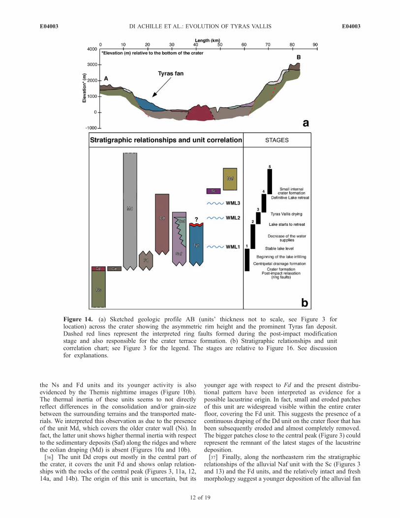
the Ns and Fd units and its younger activity is alsoevidenced by the Themis nighttime images (Figure 10b).The thermal inertia of these units seems to not directlyreflect differences in the consolidation and/or grain-sizebetween the surrounding terrains and the transported mate-rials. We interpreted this observation as due to the presenceof the unit Md, which covers the older crater wall (Ns). Infact, the latter unit shows higher thermal inertia with respectto the sedimentary deposits (Saf) along the ridges and wherethe eolian draping (Md) is absent (Figures 10a and 10b).[36] The unit Dd crops out mostly in the central part of
the crater, it covers the unit Fd and shows onlap relation-ships with the rocks of the central peak (Figures 3, 11a, 12,14a, and 14b). The origin of this unit is uncertain, but its
younger age with respect to Fd and the present distribu-tional pattern have been interpreted as evidence for apossible lacustrine origin. In fact, small and eroded patchesof this unit are widespread visible within the entire craterfloor, covering the Fd unit. This suggests the presence of acontinuous draping of the Dd unit on the crater floor that hasbeen subsequently eroded and almost completely removed.The bigger patches close to the central peak (Figure 3) couldrepresent the remnant of the latest stages of the lacustrinedeposition.[37] Finally, along the northeastern rim the stratigraphic
relationships of the alluvial Naf unit with the Sc (Figures 3and 13) and the Fd units, and the relatively intact and freshmorphology suggest a younger deposition of the alluvial fan
Figure 14. (a) Sketched geologic profile AB (units’ thickness not to scale, see Figure 3 forlocation) across the crater showing the asymmetric rim height and the prominent Tyras fan deposit.Dashed red lines represent the interpreted ring faults formed during the post-impact modificationstage and also responsible for the crater terrace formation. (b) Stratigraphic relationships and unitcorrelation chart; see Figure 3 for the legend. The stages are relative to Figure 16. See discussionfor explanations.
E04003 DI ACHILLE ET AL.: EVOLUTION OF TYRAS VALLIS
12 of 19
E04003
with respect to the small crater (Figure 14b). In fact, thedepositional feature covers the ejecta of the small crater thatalso determined the asymmetric shape of the alluvial fanNaf. The lack of evidence of transversal erosion fromtopographic observations and the well-preserved distaltermination also suggest an overall subaerial sedimentationfor this fan.
6. Wind-Generated Waves and Erosional Energy
[38] The evolution of deltaic environments is basicallydependent on the interaction between fluvial regime andsediment load on one hand, and by shape, size, bathymetry,and wave dynamics of the basin on the other. Therefore, inorder to investigate the evolution of a deltaic depositionalenvironment, the knowledge of the available wave energy isa key factor, especially considering the limited fetch size ofthe studied paleolake.[39] The generation of wind-driven surface waves on
planetary bodies and their erosional effects were investigatedduring the last years [Ori and Mosangini, 1998; Ori et al.,2000b; Ghafoor et al., 2000]. It was suggested that, owing tothe low gravitational acceleration, on moons or planetssmaller than Earth, comparable wind speeds could producetaller and slower waves. On Earth, there are two principalempirical equations for wave forecasting: the Pierson-Moskovitz (PM) [Pierson and Moskovitz, 1964], and theJoint North Sea Wave Project (JONSWAP) equations[Hasselmann et al., 1973, 1976]. The first criterionpredicts a significant wave height as function of the wind
speed (PM), while the JONSWAP considers also theinfluence of the fetch length. In this study we use theJONSWAP [Hasselmann et al., 1973] spectrum for fetch-limited settings, also according to the Coastal EngineeringResearch Center (CERC) [1984] specifications. This modelpredicts both spectral wave height and peak spectral periodthrough the following dimensionless formulae:
gTm
UA
¼ 2:857� 10�1 gF
U2A
� �1=3
ð1Þ
gHmo
U 2A
¼ 1:6� 10�3 gF
U 2A
� �1=2
; ð2Þ
where Tm (the peak spectral period) is the periodrepresentative of the higher waves, Hmo the spectral waveheight, g the gravity acceleration, F the fetch, and UA thewind stress factor, which is a corrected wind speed value at10 m above the surface. This value is given by
UA ¼ U 10=Zð Þ0:142; ð3Þ
where Z (m) is the height of the acquired wind speedmeasurement U (m/s). In deep water, Hmo is equal to thesignificant wave height [Hs = 4.0 * sqrt(Hmo)], thatapproximately corresponds to the average of the highestone third of the waves, thus inserting the Martian gravity
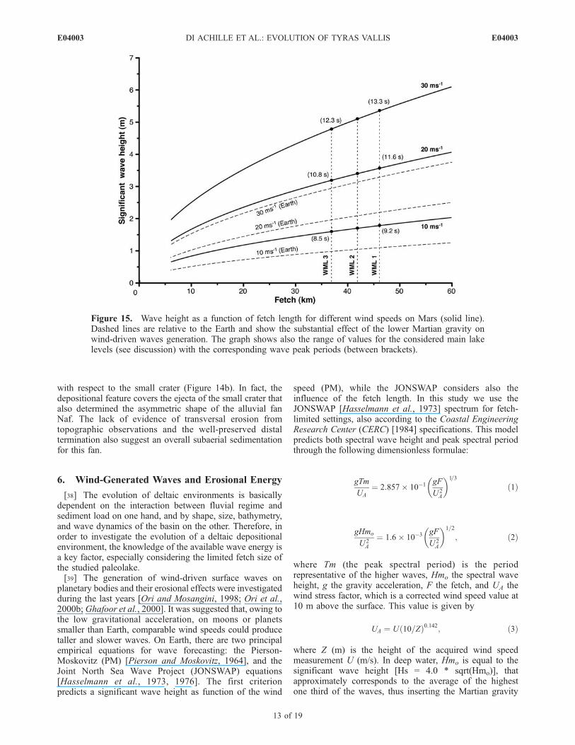
Figure 15. Wave height as a function of fetch length for different wind speeds on Mars (solid line).Dashed lines are relative to the Earth and show the substantial effect of the lower Martian gravity onwind-driven waves generation. The graph shows also the range of values for the considered main lakelevels (see discussion) with the corresponding wave peak periods (between brackets).
E04003 DI ACHILLE ET AL.: EVOLUTION OF TYRAS VALLIS
13 of 19
E04003
value (3.71 m/s) into the equations (1) and (2) andrearranging the terms, we derived the general formulae forthe Martian case:
Hs ¼ 8:31� 10�4UAF0:5 ð4Þ
Tm ¼ 1:19� 10�1 UAFð Þ1=3: ð5Þ
[40] Using the wind speeds measured at Z = 1.6 m abovethe Viking Lander sites [Hess et al., 1977], which were 2–7 m/s (summer), 5–10 m/s (fall), and 17–30 m/s (duststorm), we obtained a rough estimate of Hs (significantwave height, in meter) and Tm (period, in seconds) asfunction of F (fetch length, in meter) for Martian fetch-
limited basins (Figure 15). These estimates could give anidea of the waves activity and of the available energy forshore erosion but may be not completely reliable because a1 bar atmosphere is implicit in the equations that have beenempirically developed on Earth. However, today a windwave generation theory that is based on analytical principlesdoes not exist; therefore we can only use the available toolsto derive approximate assessments of the wave energy onMars [Kraal et al., 2003]. Moreover, we do not knowexactly the effects of different planetary conditions (mainlyatmospheric pressure) on the past Martian wind regime andwave generation processes. Further studies are necessary inorder to clarify this point and evaluate the influence of theatmospheric pressure, but, although present lower atmo-spheric density would determine a less efficient energytransfer from wind to water, in an early denser Martianatmosphere, the eolian processes and thus the wave gener-ation could have been more efficient, likely due to higherfrictional forces between blowing wind and water.
7. Discussion
7.1. Reconstruction of the Basin Evolution
[41] On the basis of stratigraphic relationships betweenthe mapped units (Figures 3, 14a, and 14b) and high-resolution topographic comparison between the Tyras fanand the overall lake shore morphology, we reconstruct thepossible evolution of the studied basin as follows.
7.1.1. Stage 1 (Crater Formation)
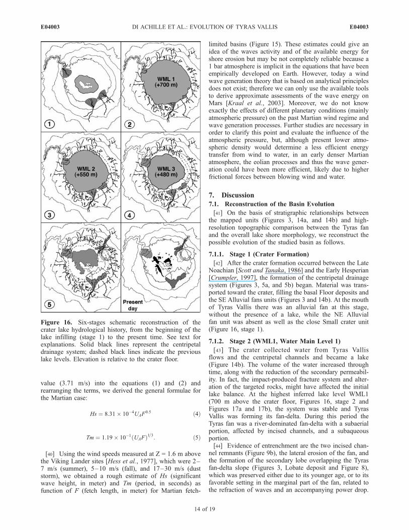
[42] After the crater formation occurred between the LateNoachian [Scott and Tanaka, 1986] and the Early Hesperian[Crumpler, 1997], the formation of the centripetal drainagesystem (Figures 3, 5a, and 5b) began. Material was trans-ported toward the crater, filling the basal Floor deposits andthe SE Alluvial fans units (Figures 3 and 14b). At the mouthof Tyras Vallis there was an alluvial fan at this stage,without the presence of a lake, while the NE Alluvialfan unit was absent as well as the close Small crater unit(Figure 16, stage 1).
7.1.2. Stage 2 (WML1, Water Main Level 1)
[43] The crater collected water from Tyras Vallisflows and the centripetal channels and became a lake(Figure 14b). The volume of the water increased throughtime, along with the reduction of the secondary permeabil-ity. In fact, the impact-produced fracture system and alter-ation of the targeted rocks, might have affected the initiallake balance. At the highest inferred lake level WML1(700 m above the crater floor, Figures 16, stage 2 andFigures 17a and 17b), the system was stable and TyrasVallis was forming its fan-delta. During this period theTyras fan was a river-dominated fan-delta with a subaerialportion, affected by incised channels, and a subaqueousportion.[44] Evidence of entrenchment are the two incised chan-
nel remnants (Figure 9b), the lateral erosion of the fan, andthe formation of the secondary lobe overlapping the Tyrasfan-delta slope (Figures 3, Lobate deposit and Figure 8),which was preserved either due to its younger age, or to itsfavorable setting in the marginal part of the fan, related tothe refraction of waves and an accompanying power drop.
Figure 16. Six-stages schematic reconstruction of thecrater lake hydrological history, from the beginning of thelake infilling (stage 1) to the present time. See text forexplanations. Solid black lines represent the centripetaldrainage system; dashed black lines indicate the previouslake levels. Elevation is relative to the crater floor.
E04003 DI ACHILLE ET AL.: EVOLUTION OF TYRAS VALLIS
14 of 19
E04003
Also the SE Alluvial fans unit was likely affected by thedeltaic sedimentation that formed the SE floor materials unit(Figure 16, stage 2).[45] At the end of this phase, subsequent to the decrease
of the Tyras Vallis water and sediments discharges
(Figures 14b), the Tyras fan became a wave-dominatedfan-delta and entered an erosional regime. The waves,which were not counteracted by the inflowing river, wereable to partially indent the fan slope and cut the terrace(Figure 16, stage 2). This variation of the fan-delta regime
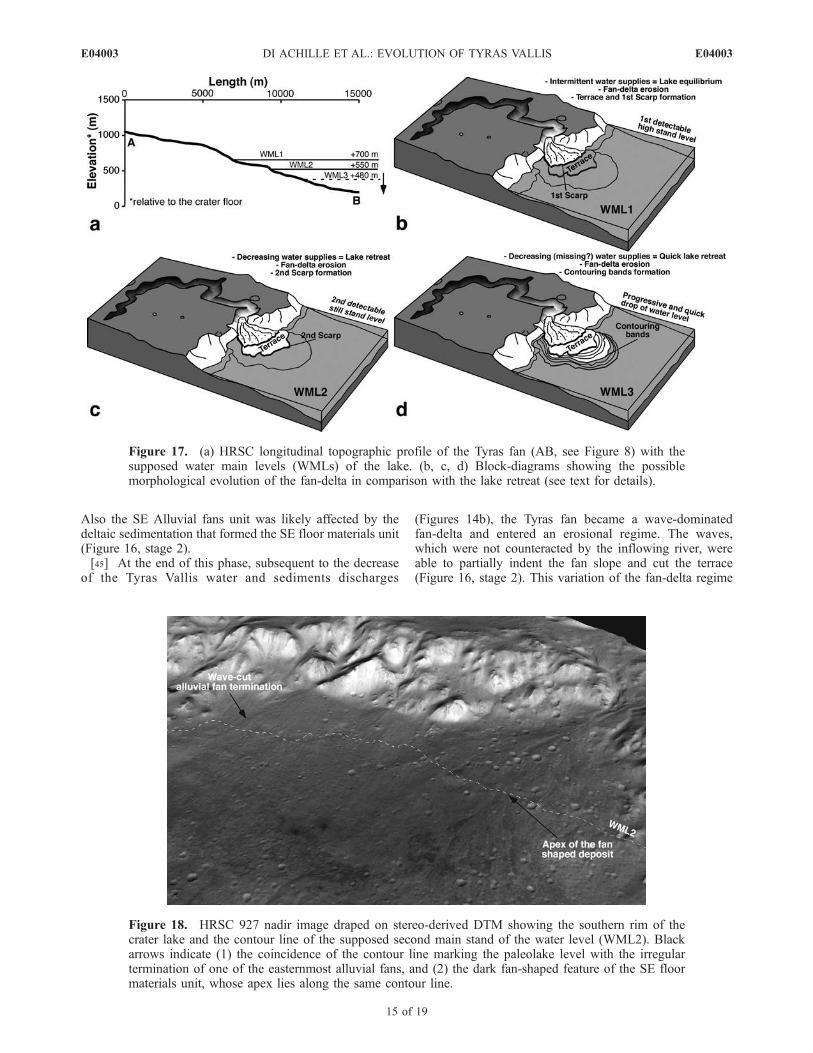
Figure 17. (a) HRSC longitudinal topographic profile of the Tyras fan (AB, see Figure 8) with thesupposed water main levels (WMLs) of the lake. (b, c, d) Block-diagrams showing the possiblemorphological evolution of the fan-delta in comparison with the lake retreat (see text for details).
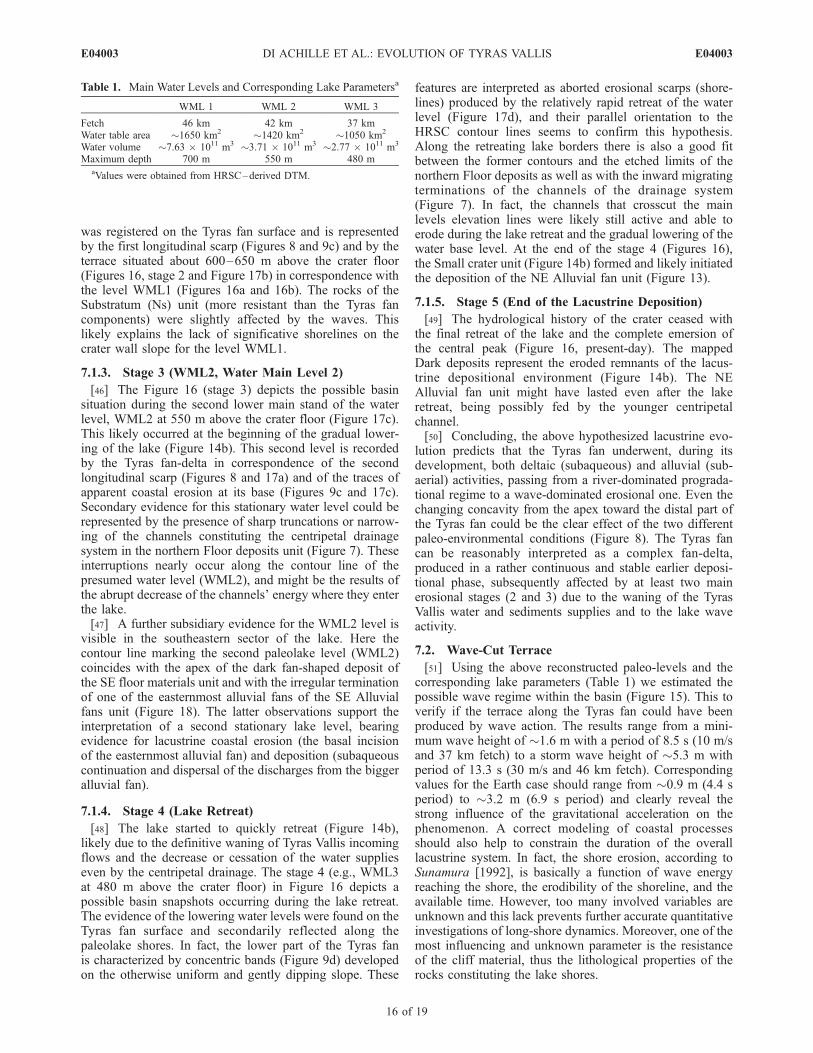
Figure 18. HRSC 927 nadir image draped on stereo-derived DTM showing the southern rim of thecrater lake and the contour line of the supposed second main stand of the water level (WML2). Blackarrows indicate (1) the coincidence of the contour line marking the paleolake level with the irregulartermination of one of the easternmost alluvial fans, and (2) the dark fan-shaped feature of the SE floormaterials unit, whose apex lies along the same contour line.
E04003 DI ACHILLE ET AL.: EVOLUTION OF TYRAS VALLIS
15 of 19
E04003
was registered on the Tyras fan surface and is representedby the first longitudinal scarp (Figures 8 and 9c) and by theterrace situated about 600–650 m above the crater floor(Figures 16, stage 2 and Figure 17b) in correspondence withthe level WML1 (Figures 16a and 16b). The rocks of theSubstratum (Ns) unit (more resistant than the Tyras fancomponents) were slightly affected by the waves. Thislikely explains the lack of significative shorelines on thecrater wall slope for the level WML1.
7.1.3. Stage 3 (WML2, Water Main Level 2)
[46] The Figure 16 (stage 3) depicts the possible basinsituation during the second lower main stand of the waterlevel, WML2 at 550 m above the crater floor (Figure 17c).This likely occurred at the beginning of the gradual lower-ing of the lake (Figure 14b). This second level is recordedby the Tyras fan-delta in correspondence of the secondlongitudinal scarp (Figures 8 and 17a) and of the traces ofapparent coastal erosion at its base (Figures 9c and 17c).Secondary evidence for this stationary water level could berepresented by the presence of sharp truncations or narrow-ing of the channels constituting the centripetal drainagesystem in the northern Floor deposits unit (Figure 7). Theseinterruptions nearly occur along the contour line of thepresumed water level (WML2), and might be the results ofthe abrupt decrease of the channels’ energy where they enterthe lake.[47] A further subsidiary evidence for the WML2 level is
visible in the southeastern sector of the lake. Here thecontour line marking the second paleolake level (WML2)coincides with the apex of the dark fan-shaped deposit ofthe SE floor materials unit and with the irregular terminationof one of the easternmost alluvial fans of the SE Alluvialfans unit (Figure 18). The latter observations support theinterpretation of a second stationary lake level, bearingevidence for lacustrine coastal erosion (the basal incisionof the easternmost alluvial fan) and deposition (subaqueouscontinuation and dispersal of the discharges from the biggeralluvial fan).
7.1.4. Stage 4 (Lake Retreat)
[48] The lake started to quickly retreat (Figure 14b),likely due to the definitive waning of Tyras Vallis incomingflows and the decrease or cessation of the water supplieseven by the centripetal drainage. The stage 4 (e.g., WML3at 480 m above the crater floor) in Figure 16 depicts apossible basin snapshots occurring during the lake retreat.The evidence of the lowering water levels were found on theTyras fan surface and secondarily reflected along thepaleolake shores. In fact, the lower part of the Tyras fanis characterized by concentric bands (Figure 9d) developedon the otherwise uniform and gently dipping slope. These
features are interpreted as aborted erosional scarps (shore-lines) produced by the relatively rapid retreat of the waterlevel (Figure 17d), and their parallel orientation to theHRSC contour lines seems to confirm this hypothesis.Along the retreating lake borders there is also a good fitbetween the former contours and the etched limits of thenorthern Floor deposits as well as with the inward migratingterminations of the channels of the drainage system(Figure 7). In fact, the channels that crosscut the mainlevels elevation lines were likely still active and able toerode during the lake retreat and the gradual lowering of thewater base level. At the end of the stage 4 (Figures 16),the Small crater unit (Figure 14b) formed and likely initiatedthe deposition of the NE Alluvial fan unit (Figure 13).
7.1.5. Stage 5 (End of the Lacustrine Deposition)
[49] The hydrological history of the crater ceased withthe final retreat of the lake and the complete emersion ofthe central peak (Figure 16, present-day). The mappedDark deposits represent the eroded remnants of the lacus-trine depositional environment (Figure 14b). The NEAlluvial fan unit might have lasted even after the lakeretreat, being possibly fed by the younger centripetalchannel.[50] Concluding, the above hypothesized lacustrine evo-
lution predicts that the Tyras fan underwent, during itsdevelopment, both deltaic (subaqueous) and alluvial (sub-aerial) activities, passing from a river-dominated prograda-tional regime to a wave-dominated erosional one. Even thechanging concavity from the apex toward the distal part ofthe Tyras fan could be the clear effect of the two differentpaleo-environmental conditions (Figure 8). The Tyras fancan be reasonably interpreted as a complex fan-delta,produced in a rather continuous and stable earlier deposi-tional phase, subsequently affected by at least two mainerosional stages (2 and 3) due to the waning of the TyrasVallis water and sediments supplies and to the lake waveactivity.
7.2. Wave-Cut Terrace
[51] Using the above reconstructed paleo-levels and thecorresponding lake parameters (Table 1) we estimated thepossible wave regime within the basin (Figure 15). This toverify if the terrace along the Tyras fan could have beenproduced by wave action. The results range from a mini-mum wave height of �1.6 m with a period of 8.5 s (10 m/sand 37 km fetch) to a storm wave height of �5.3 m withperiod of 13.3 s (30 m/s and 46 km fetch). Correspondingvalues for the Earth case should range from �0.9 m (4.4 speriod) to �3.2 m (6.9 s period) and clearly reveal thestrong influence of the gravitational acceleration on thephenomenon. A correct modeling of coastal processesshould also help to constrain the duration of the overalllacustrine system. In fact, the shore erosion, according toSunamura [1992], is basically a function of wave energyreaching the shore, the erodibility of the shoreline, and theavailable time. However, too many involved variables areunknown and this lack prevents further accurate quantitativeinvestigations of long-shore dynamics. Moreover, one of themost influencing and unknown parameter is the resistanceof the cliff material, thus the lithological properties of therocks constituting the lake shores.
Table 1. Main Water Levels and Corresponding Lake Parametersa
WML 1 WML 2 WML 3
Fetch 46 km 42 km 37 kmWater table area �1650 km2 �1420 km2 �1050 km2
Water volume �7.63 � 1011 m3 �3.71 � 1011 m3 �2.77 � 1011 m3
Maximum depth 700 m 550 m 480 maValues were obtained from HRSC–derived DTM.
E04003 DI ACHILLE ET AL.: EVOLUTION OF TYRAS VALLIS
16 of 19
E04003
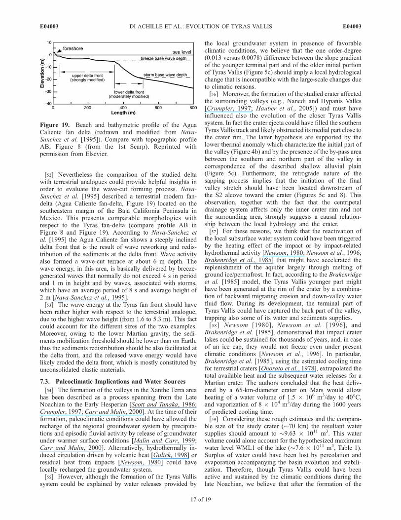
[52] Nevertheless the comparison of the studied deltawith terrestrial analogues could provide helpful insights inorder to evaluate the wave-cut forming process. Nava-Sanchez et al. [1995] described a terrestrial modern fan-delta (Agua Caliente fan-delta, Figure 19) located on thesoutheastern margin of the Baja California Peninsula inMexico. This presents comparable morphologies withrespect to the Tyras fan-delta (compare profile AB inFigure 8 and Figure 19). According to Nava-Sanchez etal. [1995] the Agua Caliente fan shows a steeply inclineddelta front that is the result of wave reworking and redis-tribution of the sediments at the delta front. Wave activityalso formed a wave-cut terrace at about 6 m depth. Thewave energy, in this area, is basically delivered by breeze-generated waves that normally do not exceed 4 s in periodand 1 m in height and by waves, associated with storms,which have an average period of 8 s and average height of2 m [Nava-Sanchez et al., 1995].[53] The wave energy at the Tyras fan front should have
been rather higher with respect to the terrestrial analogue,due to the higher wave height (from 1.6 to 5.3 m). This factcould account for the different sizes of the two examples.Moreover, owing to the lower Martian gravity, the sedi-ments mobilization threshold should be lower than on Earth,thus the sediments redistribution should be also facilitated atthe delta front, and the released wave energy would havelikely eroded the delta front, which is mostly constituted byunconsolidated clastic materials.
7.3. Paleoclimatic Implications and Water Sources
[54] The formation of the valleys in the Xanthe Terra areahas been described as a process spanning from the LateNoachian to the Early Hesperian [Scott and Tanaka, 1986;Crumpler, 1997; Carr and Malin, 2000]. At the time of theirformation, paleoclimatic conditions could have allowed therecharge of the regional groundwater system by precipita-tions and episodic fluvial activity by release of groundwaterunder warmer surface conditions [Malin and Carr, 1999;Carr and Malin, 2000]. Alternatively, hydrothermally in-duced circulation driven by volcanic heat [Gulick, 1998] orresidual heat from impacts [Newsom, 1980] could havelocally recharged the groundwater system.[55] However, although the formation of the Tyras Vallis
system could be explained by water releases provided by
the local groundwater system in presence of favorableclimatic conditions, we believe that the one order-degree(0.013 versus 0.0078) difference between the slope gradientof the younger terminal part and of the older initial portionof Tyras Vallis (Figure 5c) should imply a local hydrologicalchange that is incompatible with the large-scale changes dueto climatic reasons.[56] Moreover, the formation of the studied crater affected
the surrounding valleys (e.g., Nanedi and Hypanis Valles[Crumpler, 1997; Hauber et al., 2005]) and must haveinfluenced also the evolution of the closer Tyras Vallissystem. In fact the crater ejecta could have filled the southernTyras Vallis track and likely obstructed its medial part close tothe crater rim. The latter hypothesis are supported by thelower thermal anomaly which characterize the initial part ofthe valley (Figure 4b) and by the presence of the by-pass areabetween the southern and northern part of the valley incorrespondence of the described shallow alluvial plain(Figure 5c). Furthermore, the retrograde nature of thesapping process implies that the initiation of the finalvalley stretch should have been located downstream ofthe S2 alcove toward the crater (Figures 5c and 8). Thisobservation, together with the fact that the centripetaldrainage system affects only the inner crater rim and notthe surrounding area, strongly suggests a causal relation-ship between the local hydrology and the crater.[57] For these reasons, we think that the reactivation of
the local subsurface water system could have been triggeredby the heating effect of the impact or by impact-relatedhydrothermal activity [Newsom, 1980; Newsom et al., 1996;Brakenridge et al., 1985] that might have accelerated thereplenishment of the aquifer largely through melting ofground ice/permafrost. In fact, according to the Brakenridgeet al. [1985] model, the Tyras Vallis younger part mighthave been generated at the rim of the crater by a combina-tion of backward migrating erosion and down-valley waterfluid flow. During its development, the terminal part ofTyras Vallis could have captured the back part of the valley,trapping also some of its water and sediments supplies.[58] Newsom [1980], Newsom et al. [1996], and
Brakenridge et al. [1985], demonstrated that impact craterlakes could be sustained for thousands of years, and, in caseof an ice cap, they would not freeze even under presentclimatic conditions [Newsom et al., 1996]. In particular,Brakenridge et al. [1985], using the estimated cooling timefor terrestrial craters [Onorato et al., 1978], extrapolated thetotal available heat and the subsequent water releases for aMartian crater. The authors concluded that the heat deliv-ered by a 65-km-diameter crater on Mars would allowheating of a water volume of 1.5 � 106 m3/day to 40�C,and vaporization of 8 � 104 m3/day during the 1600 yearsof predicted cooling time.[59] Considering these rough estimates and the compara-
ble size of the study crater (�70 km) the resultant watersupplies should amount to �9.63 � 1011 m3. This watervolume could alone account for the hypothesized maximumwater level WML1 of the lake (�7.6 � 1011 m3, Table 1).Surplus of water could have been lost by percolation andevaporation accompanying the basin evolution and stabili-zation. Therefore, though Tyras Vallis could have beenactive and sustained by the climatic conditions during thelate Noachian, we believe that after the formation of the
Figure 19. Beach and bathymetric profile of the AguaCaliente fan delta (redrawn and modified from Nava-Sanchez et al. [1995]). Compare with topographic profileAB, Figure 8 (from the 1st Scarp). Reprinted withpermission from Elsevier.
E04003 DI ACHILLE ET AL.: EVOLUTION OF TYRAS VALLIS
17 of 19
E04003
crater in the Hesperian [Crumpler, 1997], the presence of animpact melt sheet and uplifted central peak may have alsosustained the lake formation for few thousands of years. Inthis alternative hypothesis the lacustrine system could havebeen independent from the recharge of the regional hydro-logic system and also relatively insensitive to climaticchanges. Other supporting evidence for the impact-relatedactivation/rejuvenation within the basin could be repre-sented by the aborted channel that fed the NE Alluvialfan unit (Figures 3 and 13). This small system could havebeen activated after the lake retreat (Figure 14b) due to thethermal effect of the internal small crater formation.
8. Conclusion
[60] The Tyras fan-delta presents the typical morpholog-ical features (e.g., fan-head incision, downslope terrace andsegmented radial profile) related to a complex depositional/erosional evolution. The longitudinal scarps, the evidentcentral terrace and the contouring bands in the distal portionof the fan, are interpreted as the products of wave erosionoccurring during the main stationary water levels of thebasin before the definitive retreat of the lake throughevaporation/sublimation and percolation into the subsurfacelayers. Wave height estimates in fetch-limited settings andcomparison with terrestrial analogues suggest that Martianwind regimes could have produced enough wave activity inorder to shape the observed lacustrine morphologies.[61] Groundwater processes likely affected the transport
capacity of Tyras Vallis and the water level changes of thepaleolake, thus determining the dominant erosional regimeof the Tyras fan. The lacustrine activity could be chrono-logically placed between the Late Noachian and the Hes-perian. During its evolution the climatic conditions couldhave allowed recharge of the regional groundwater systemby precipitations and episodic fluvial activity by release ofgroundwater. However, the crater system hydrology indi-cates a causal relationship with the impact itself, suggestingthat also the heating effects of cratering and a subsequenttemporarily high thermal gradient could have affected thesystem, rejuvenating or accelerating the recharge of theaquifer and hence the basin evolution.
[62] Acknowledgments. This manuscript was greatly improved bythe reviews of P. Allemand and an anonymous reviewer. We thank alsoG. Caprarelli for the internal review and M. Pondrelli and G. Komatsufor their fruitful comments. The DLR (German Aerospace Center) HRSC-Experiment Team, Freie Universitat Berlin, and HRSC Co-InvestigatorTeammade possible to exploit HRSC data. C. Sherwood and K. Hasselmannare also gratefully acknowledged for providing helpful material aboutmathematic handling of wind-driven waves. Figure 19 was redrawn andmodified from Nava-Sanchez et al. [1995] with kind permission fromElsevier. This research was supported by Italian Space Agency (ASI) andItalian Ministry of University and Research (MIUR).
ReferencesBhattacharya, J. P., T. H. D. Payenberg, S. C. Lang, and M. Bourke (2005),Dynamic river channels suggest a long-lived Noachian crater lake onMars, Geophys. Res. Lett., 32, L10201, doi:10.1029/2005GL022747.
Brakenridge, G. R., H. E. Newsom, and V. R. Baker (1985), Ancient hotsprings on Mars: Origins and paleoenvironmental significance of smallmartian valleys, Geology, 13, 859–862.
Cabrol, N. A., and E. A. Grin (1999), Distribution, classification, and agesof Martian impact crater lakes, Icarus, 142(1), 160–172.
Cabrol, N. A., and E. A. Grin (2001), The evolution of lacustrine environ-ments on Mars: Is Mars only hydrologically dormant?, Icarus, 149(2),291–328.
Cabrol, N. A., E. A. Grin, and G. Dawidowicz (1996), Ma’adim Vallisrevisited through new topographic data: Evidence for an ancient intraval-ley lake, Icarus, 123(2), 269–283.
Cabrol, N. A., E. A. Grin, H. E. Newsom, R. Landheim, and C. P. McKay(1999), Hydrogeologic Evolution of Gale Crater and its relevance to theexobiological exploration of Mars, Icarus, 139(2), 235–245.
Carr, M. H., and M. C. Malin (2000), Meter-scale characteristics of Martianchannels and valleys, Icarus, 146, 366–386.
Coastal Engineering Research Center (1984), Shore Protection Manual, 4thed., U.S. Army Corps of Eng., Washington, D. C.
Crumpler, L. S. (1997), Geotraverse from Xanthe Terra to Chryse planitia:Viking 1 Lander region, Mars, J. Geophys. Res., 102(E2), 4201–4218.
Di Achille, G., L. Marinangeli, G. G. Ori, E. Hauber, K. Gwinner, D. Reiss,G. Neukum, and HRSC Co-Investigator Team (2005), Geologic evolu-tion of the Tyras Vallis system, Mars, Geol. Soc. Am. Abstr. Programs,37(7), abstract 233-15.
Ghafoor, N. A.-L., J. C. Zarnecki, P. Challenor, and M. A. Srokosz (2000),Wind-driven surface waves on Titan, J. Geophys. Res., 105(E5), 12,077–12,092.
Grin, E. A., and N. A. Cabrol (1997), Limnologic analysis of Gusev craterpaleolake, Mars", Icarus, 130(2), 461–474.
Gulick, V. C. (1998), Magmatic intrusions and a hydrothermal origin forfluvial valleys on Mars, J. Geophys. Res., 103(E2), 19,365–19,388.
Hasselmann, K., et al. (1973), Measurement of wind-wave growth andswell decay during the Joint North Sea Wave Project (JONSWAP), Dtsch.Hydrogr. Z., 8(12), suppl. A, 95 pp.
Hasselmann, K., D. B. Ross, P. Muller, and W. Sell (1976), A parametricwave prediction model, J. Phys. Oceanogr., 6(2), 200–228.
Hauber, H., K. Gwinner, D. Reiss, F. Scholten, G. Michael, R. Jaumann,G. G. Ori, L. Marinangeli, G. Neukum, and HRSC Co-Investigator Team(2005), Delta-like deposits in Xanthe Terra, Mars, as seen with the HighResolution Stereo Camera (HRSC), Lunar Planet. Sci., [CD-ROM],XXXVI, abstract 1661.
Hess, S. L., M. Henry, C. B. Leovy, J. E. Tillman, and J. A. Ryan (1977),Meteorological results from the surface of Mars - Viking 1 and 2,J. Geophys. Res., 82, 4559–4574.
Kraal, E. R., E. I. Asphaug, and R. D. Lorenz (2003), Can shorelineprocesses on Mars constrain its past climate?, paper presented at SixthInternational Conference on Mars, abstract 3115, Pasadena, Calif.
Malin, M. C., and M. H. Carr (1999), Groundwater formation of martianvalleys, Nature, 397, 589–591.
Malin, M. C., and K. S. Edgett (2003), Evidence for persistent flow andaqueous sedimentation on early Mars, Science, 302, 1931–1934.
Melosh, H. J. (1989), Impact Cratering. A Geologic Process, Oxford Univ.Press, New York.
Moore, J. M., and A. D. Howard (2005), Large alluvial fans on Mars,J. Geophys. Res., 110, E04005, doi:10.1029/2004JE002352.
Nava-Sanchez, E., R. Cruz-Orozco, and D. S. Gorsline (1995), Morphologyand sedimentology of two contemporary fan deltas on the southeasternBaja California Peninsula, Mexico, Sediment. Geol., 98, 45–61.
Nelson, M. N., and R. Greeley (1999), Geology of Xanthe Terra outflowchannels and the Mars Pathfinder landing site, J. Geophys. Res., 104(E4),8653–8669.
Neukum, G., R. Jaumann, and the HRSC Co-Investigator and ExperimentTeam (2004), HRSC—The High Resolution Stereo Camera of MarsExpress, Eur. Space Agency Spec. Publ., SP-1240, 17–35.
Newsom, H. E. (1980), Hydrothermal alteration of impact melt sheets withimplications for Mars, Icarus, 44, 207–216.
Newsom, H. E., G. E. Brittelle, C. A. Hibbitts, L. J. Crossey, and A. M.Kudo (1996), Impact crater lakes on Mars, J. Geophys. Res., 101(E6),14,951–14,955.
Onorato, P. I. K., B. R. Uhlmann, and C. H. Simonds (1978), The thermalhistory of the Manicouagan impact melt sheet, Quebecs, J. Geophys.Res., 83, 2789–2798.
Ori, G. G., and C. Mosangini (1998), Complex depositional systems in Hy-draotesChaos,Mars:An example of sedimentary process interactions in theMartian hydrological cycle, J. Geophys. Res., 103(E10), 22,713–22,723.
Ori, G. G., L. Marinangeli, and A. Baliva (2000a), Terraces and Gilbert-Type Deltas in Crater Lakes in Ismenius Lacus and Memnonia (Mars),J. Geophys. Res., 105(E7), 17,629–17,642.
Ori, G. G., L. Marinangeli, A. Baliva, M. Bressan, and M. Strom (2000b),Fluid dynamics of liquids on Titan’surface, Planet. Space Sci., 46(9–10),1417–1421.
Pierson, W. J., and L. Moskovitz (1964), A proposed spectral form forfully developed wind seas based on the similarity theory of S. A.Kitaigorodskii, J. Geophys. Res., 69, 5181–5190.
Pondrelli, M., A. Baliva, S. Di Lorenzo, L. Marinangeli, and A. P. Rossi(2005), Complex evolution of paleolacustrine systems on Mars: An ex-ample from the Holden Crater, J. Geophys. Res., 110, E04016,doi:10.1029/2004JE002335.
E04003 DI ACHILLE ET AL.: EVOLUTION OF TYRAS VALLIS
18 of 19
E04003

Rotto, S., and K. L. Tanaka (1995), Geologic/geomorphic map of theChryse Planitia region of Mars, U.S. Geol. Surv. Misc. Invest. Ser.Map, I-2441.
Scott, D. H., and K. L. Tanaka (1986), Geologic map of the western equa-torial region of Mars, U.S. Geol. Surv. Misc. Invest. Ser. Map, I-1802–A.
Seidelmann, P. K., et al. (2002), Report of the IAU/IAG Working Group oncartographic coordinates and rotational elements of the planets, and sa-tellites: 2000, Celest. Mech. Dyn. Astron., 82, 83–110.
Sunamura, T. (1992), Geomorphology of Rocky Coasts, John Wiley, NewYork.
Tanaka, K. L. (1997), Sedimentary history and mass flow structures ofChryse and Acidalia Planitiae, Mars, J. Geophys. Res., 102(E2), 4131–4150.
Zuber, M. T., D. E. Smith, S. C. Solomon, D. O. Muhleman, J. W. Head,J. B. Garvin, J. B. Abshire, and J. L. Bufton (1992), The Mars Observerlaser altimeter investigation, J. Geophys. Res., 97(E5), 7781–7797.
�����������������������G. Di Achille, L. Marinangeli, and G. G. Ori, International Research
School of Planetary Sciences, Universita’ D’Annunzio, Viale Pindaro, 42,65127 Pescara, Italy. ([email protected])K. Gwinner, E. Hauber, and D. Reiss, Institute of Planetary Research,
German Aerospace Center (DLR), Rutherfordstrasse. 2, D-12489 Berlin,Germany.G. Neukum, Institute of Geological Sciences, Freie Universitat Berlin,
Malteserstrasse 74-100, D-12249 Berlin, Germany.
E04003 DI ACHILLE ET AL.: EVOLUTION OF TYRAS VALLIS
19 of 19
E04003