general-purpose and power relay group catalogue - omron
TRANSCRIPT
General-purpose Relays and Power Relays
Cat.No. X034-E1-08A
Cat.N
o.X
034-E1-08A
Gen
eral-pu
rpo
se Relays an
d P
ow
er Relays
Authorized Distributor:
Printed in Japan0604-1M (A)
Cat. No. X034-E1-08A
OMRON Corporation
In the interest of product improvement, specifications are subject to change without notice and without our obligation.
Shiokoji Horikawa, Shimogyo-ku,Kyoto, 600-8530 Japan
Industrial Automation CompanyIndustrial Devices and Components Division H.Q.Industrial Control Components DivisionTel: (81)75-344-7119/Fax: (81)75-344-7149
Electronic Components CompanyElectronic & Mechanical Components Division H.Q.C&C Power Relay DivisionTel: (81)75-344-7097/Fax: (81)75-344-7049General Purpose Relay DivisionTel: (81)75-344-7089/Fax: (81)75-344-7049

OMRON, a global - yet local - company, committed to contributing to local communities around the world
Truly global companies, like OMRON, understand that different regions around the world - like the people that inhabit them - have different needs, concerns and ambitions. To best meet these different needs, OMRON has positioned itself to better understand and respond to the local needs of its customers in five major regions: North America, Europe, Asia Pacific, China and Japan. Each region maintains independent, yet highly integrated, sales, technical support, product development, and manufacturing resources to meet the needs of local communities. We call it our Multi-Local strategy, and it is where the true value of OMRON lies. This strategy forms the foundation of OMRON's core belief in building firm roots within the communities it serves - providing employment and returning profits. It is this core belief that guides OMRON's business expansion throughout the world.
OMRON Malaysia
OMRON Indonesia
OMRON Kumamoto, Japan
OMRON Takeo, JapanDate of establishment 5 APR '73Number of employees 372 (as of JUNE '02)Models produced G7T, G2A, G2A-434, G2AK, G7L, MM, MMK, G7J, G6B4, G6D, G4Q, G9B, G7S, G9S
Date of establishment 6 APR '72Number of employees 508 (as of JULY '02)Models producedG2RS, MY, MYK, LY, G4F, G4B, Socket
Date of establishment 27 FEB '92Number of employees 1811 (as of JULY '02)Models produced MK-I/-S, LY, G7L, Socket
Date of establishment 30 JAN '73Number of employees 1125 (as of JUNE '02)Models produced Socket
Date of establishment 6 MARCH '01Number of employees 1283 (as of MAY '02)Models produced MY, Socket
OMRON ShenZhen
CONTENTS
1
Technical Information . . . . . . . . . . . . . . . . . . . . . . . . . . . . . . . . . . . . . . . 2Standards . . . . . . . . . . . . . . . . . . . . . . . . . . . . . . . . . . . . . . . . . . . . . . . . . 23Selection Guide. . . . . . . . . . . . . . . . . . . . . . . . . . . . . . . . . . . . . . . . . . . . . 41Control Panel Relays
MY New model . . . . . . . . . . . . . . . . . . . . . . . . . . . . . . . . . . . . . . . . . . . . . . . . . . 49MY . . . . . . . . . . . . . . . . . . . . . . . . . . . . . . . . . . . . . . . . . . . . . . . . . . . . . . . . . . . 62MY4H . . . . . . . . . . . . . . . . . . . . . . . . . . . . . . . . . . . . . . . . . . . . . . . . . . . . . . . . . 70MYK . . . . . . . . . . . . . . . . . . . . . . . . . . . . . . . . . . . . . . . . . . . . . . . . . . . . . . . . . . 74LY . . . . . . . . . . . . . . . . . . . . . . . . . . . . . . . . . . . . . . . . . . . . . . . . . . . . . . . . . . . 78G2RS . . . . . . . . . . . . . . . . . . . . . . . . . . . . . . . . . . . . . . . . . . . . . . . . . . . . . . . . . . 91MK-I/-S . . . . . . . . . . . . . . . . . . . . . . . . . . . . . . . . . . . . . . . . . . . . . . . . . . . . . . . . 101G7T . . . . . . . . . . . . . . . . . . . . . . . . . . . . . . . . . . . . . . . . . . . . . . . . . . . . . . . . . . . 113G2A . . . . . . . . . . . . . . . . . . . . . . . . . . . . . . . . . . . . . . . . . . . . . . . . . . . . . . . . . . . 119G2A-434 . . . . . . . . . . . . . . . . . . . . . . . . . . . . . . . . . . . . . . . . . . . . . . . . . . . . . . . 127G2AK. . . . . . . . . . . . . . . . . . . . . . . . . . . . . . . . . . . . . . . . . . . . . . . . . . . . . . . . . . 133MM . . . . . . . . . . . . . . . . . . . . . . . . . . . . . . . . . . . . . . . . . . . . . . . . . . . . . . . . . . . 139MMK . . . . . . . . . . . . . . . . . . . . . . . . . . . . . . . . . . . . . . . . . . . . . . . . . . . . . . . . . . 154
Built-in RelaysG7J . . . . . . . . . . . . . . . . . . . . . . . . . . . . . . . . . . . . . . . . . . . . . . . . . . . . . . . . . . . 166G7L . . . . . . . . . . . . . . . . . . . . . . . . . . . . . . . . . . . . . . . . . . . . . . . . . . . . . . . . . . . 175G4F . . . . . . . . . . . . . . . . . . . . . . . . . . . . . . . . . . . . . . . . . . . . . . . . . . . . . . . . . . . 188G4B . . . . . . . . . . . . . . . . . . . . . . . . . . . . . . . . . . . . . . . . . . . . . . . . . . . . . . . . . . . 192
Terminal RelaysG6D-F4B/G3DZ-F4B . . . . . . . . . . . . . . . . . . . . . . . . . . . . . . . . . . . . . . . . . . . . . 196G6B-4@@ND . . . . . . . . . . . . . . . . . . . . . . . . . . . . . . . . . . . . . . . . . . . . . . . . . . . 202
Special Purpose RelaysG4Q . . . . . . . . . . . . . . . . . . . . . . . . . . . . . . . . . . . . . . . . . . . . . . . . . . . . . . . . . . . 208G9B . . . . . . . . . . . . . . . . . . . . . . . . . . . . . . . . . . . . . . . . . . . . . . . . . . . . . . . . . . . 213
Safety RelayG7SA . . . . . . . . . . . . . . . . . . . . . . . . . . . . . . . . . . . . . . . . . . . . . . . . . . . . . . . . . . 219
Safety Relay UnitG9SA . . . . . . . . . . . . . . . . . . . . . . . . . . . . . . . . . . . . . . . . . . . . . . . . . . . . . . . . . . 225
SocketsSockets . . . . . . . . . . . . . . . . . . . . . . . . . . . . . . . . . . . . . . . . . . . . . . . . . . . . . . . . . 238
2 General-purpose Relays and Power Relays Technical Information
General-purpose Relays and Power Relays
Technical Information Classification by Basic Operating and Housing
1) Fully Sealed Relays The Fully Sealed Relay is of a simple construction, in which theRelay is placed in a plastic case. The gaps between the case and theRelay terminals, and between the terminals and terminal block(base), are sealed with epoxy resin.
(1) There is no problem if the Relay is used on a flat surface. How-ever, as much as possible, use it in an atmospheric pressure of1,013 mb ±20%.
(2) The Fully Sealed Relay can be immersed for cleaning.Note that the sealing of the case and the section filled with resinare degraded if solder flux adheres, or if heat is generated at theterminals. Due to its simple construction, the Fully Sealed Relayis not suitable for applications in an environment or installationlocation that requires a particularly high level of sealing. Forapplications in an atmosphere containing flammable or explo-sive gases, use the Hermetically Sealed Relay.
2) Latching RelaysThese Latching Relays keep residual magnetism (MYK, G2AK, etc.)
• Avoid use in places where there are a lot of magnetic particles ordust.
• Avoid using in a magnetic field (of 70 oersted or greater).
• Give sufficient consideration to the vibration and shock producedby other Relays when they close and release.
• A continuous flow of current is possible through the set and resetcoils. However, avoid applying voltage to the set coil and the resetcoil at the same time.
• Avoid use under conditions where there are many surges in thepower supply.
Classification item Representative models Features
General-purpose Relays
General-purpose Relays
The contacts of these Relays instanta-neously turn ON when the coil is ener-gized, and turn OFF when the coil is deenergized. These Relays do not have any special functions.
Fully Sealed Relays 1)
The Relay mechanism is encapsulated in a plastic case, with the terminals and terminal block sealed by epoxy resin.
Power Relays These Relays are intended to switch heavy loads.
Special-purpose Relays
Latching Relays 2)
The contacts of these Relays are mag-netically or mechanically locked in either the energized or the deenergized posi-tion until a reset signal is input. Single-winding and double-winding coils are available for applying set or reset pulse voltage.
Ratchet Relays and Stepping Relays 3)
The contacts of Ratchet Relays alter-nately turn ON and OFF, or sequentially operate, when a pulse signal is input.The contacts of Stepping Relays shift ON or OFF sequentially with each input pulse.
MY LY G2A MK-I/-SG2RS
G2A-4@
G4F G4B G7L G7J
MYK@ G2AK
G4Q G9B
Terminal
Base
Sealed with epoxy resin,etc.
Plastic case
General-purpose Relays and Power Relays Technical Information 3
• When a large number of Relays are mounted in a row, make surethat the minimum mounting intervals have been observed betweenthe various types of Relays.
• Relays are delivered in the reset condition, but we recommend thatthe reset voltage be applied before use as a starting procedure.
• When a diode is connected in the circuit, external noise and surgesmust be taken into account for the repetitive peak reverse voltageand the DC reverse voltage, and a diode with sufficient capacityused. Also, an average rectification current that is larger than thecoil current should be used.
• Excitation with self contacts may not be kept normally. Avoid use incircuits such as the ones shown in the diagrams below.
• When DC specifications are used in circuits such as the following,the latching may be lost and so a diode should be connected (asthe part marked D in the circuit diagram) or the circuit should bemodified, or a Latching Relay with built-in diode used.
Notes on Circuit
Mechanical Latching Relay (Model MMK, etc.)When installing more than one Latching Relay side by side, provide asufficient distance between two adjacent Relays for efficient heatradiation. Provide a distance of about 20 mm in the vertical directionand about 15 mm in the horizontal direction.A very slight gap is provided in the locking section of a MechanicalLatching Relay. Therefore, the resistances of this type of Relay tovibration and shock are slightly inferior to standard Latching Relays.Do not apply a voltage to the set and reset coils at the same time. Ifthis happens, the Relay will be set.
3) Basic Operation of Ratchet Relays and Stepping Relays
Note: For details, consult OMRON.
Classification by Coil RatingsExcept for a few models, two types of Relay coils are available: AC-operated and DC-operated.
Xb
XL Load
XL: Latching Relay
Xb: NC contact of Relay
Incorrect
Circuit connecting two reset coils in parallel
Circuit connecting set coil to reset coil
Circuit connecting two set coils in parallel
Circuit connecting set coil of Latching Relay in parallel with another Relay coil
Model Basic circuit Operation pattern Outline
Double-winding Latching RelaysModel MYKModel G2AKModel MKKModel MMK
In these Relays, the input pulse of the set coil causes the operating condition to be maintained magnetically or mechanically, whereas the input pulse to the reset coil side puts the Relay into the reset condi-tion.
Ratchet Relay In these Relays, the input pulse of the set coil causes the operating condition to be maintained mechanically, and similarly, the input pulse of the reset coil maintains the reset condition. The set and reset con-tacts are alternately switched ON and OFF.
Stepping Relays In these Relays, the contacts shift ON or OFF sequentially with each coil input pulse.
Load A Load B Load C Load D
Input
Coil input
Load A
Load B
Load C
Load D
Coil voltage
AC 6 V 12 V 24 V 48 V 50 V 100/110 V 110/120 V 200/220 V 220/240 V
DC 6 V 12 V 24 V 48 V --- 100/110 V 110/120 V 200/220 V 220/240 V
4 General-purpose Relays and Power Relays Technical Information
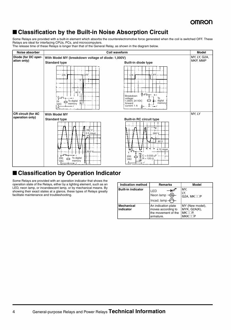
Classification by the Built-in Noise Absorption CircuitSome Relays are provided with a built-in element which absorbs the counterelectromotive force generated when the coil is switched OFF. TheseRelays are ideal for interfacing CPUs, PCs, and microcomputers.The release time of these Relays is longer than that of the General Relay, as shown in the diagram below.
Classification by Operation IndicatorSome Relays are provided with an operation indicator that shows theoperation state of the Relays, either by a lighting element, such as anLED, neon lamp, or incandescent lamp, or by mechanical means. Byshowing their exact states at a glance, these types of Relays greatlyfacilitate maintenance and troubleshooting.
Noise absorber Coil waveform Model
Diode (for DC oper-ation only)
MY, LY, G2A, MKP, MMP
CR circuit (for AC operation only)
MY, LY
D
ON OFF
140 V
ON OFF
Breakdown voltage: 1,000V, 24 VDC forward current: 1 A
To digital memory
With Model MY (breakdown voltage of diode: 1,000V)Standard type Built-in diode type
24 VDC
To digital memory
With Model MYStandard type Built-in RC circuit type
282 V2.5 msec
600 V
282 V
80 V
4.12 msec.
200 VAC
To digital memory
200 VAC
C = 0.033 µFR = 120 Ω
Indication method Remarks Model
Built-in indicator MY, LY, G2A, MK@@P
Mechanical indicator
An indication plate moves according to the movement of the armature.
MY (New model), MYK, G2A(K),MK@@P,MKK@@P
LEDNeon lamp
Incad. lamp
General-purpose Relays and Power Relays Technical Information 5
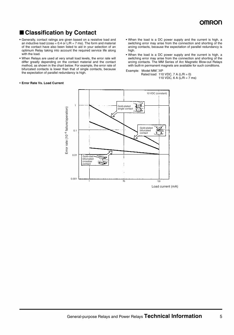
Classification by Contact• Generally, contact ratings are given based on a resistive load and
an inductive load (cosφ = 0.4 or L/R = 7 ms). The form and materialof the contact have also been listed to aid in your selection of anoptimum Relay taking into account the required service life alongwith the load.
• When Relays are used at very small load levels, the error rate willdiffer greatly depending on the contact material and the contactmethod, as shown in the chart below. For example, the error rate ofbifurcated contacts is lower than that of single contacts, becausethe expectation of parallel redundancy is high.
• When the load is a DC power supply and the current is high, aswitching error may arise from the connection and shorting of thearcing contacts, because the expectation of parallel redundancy ishigh.
• When the load is a DC power supply and the current is high, aswitching error may arise from the connection and shorting of thearcing contacts. The MM Series of Arc Magnetic Blow-out Relayswith built-in permanent magnets are available for such conditions.
Example: Model MM@XPRated load 110 VDC, 7 A (L/R = 0)
110 VDC, 6 A (L/R = 7 ms)
• Error Rate Vs. Load Current
0.001
0.01
0.1
1
Err
or r
ate
(10−6
failu
re/o
pera
tion)
Gold-plated single contact
Gold-plated bifurcated contact
Gold-clad bifurcated crossbar contact
10 VDC (constant)
Load current (mA)
6 General-purpose Relays and Power Relays Technical Information
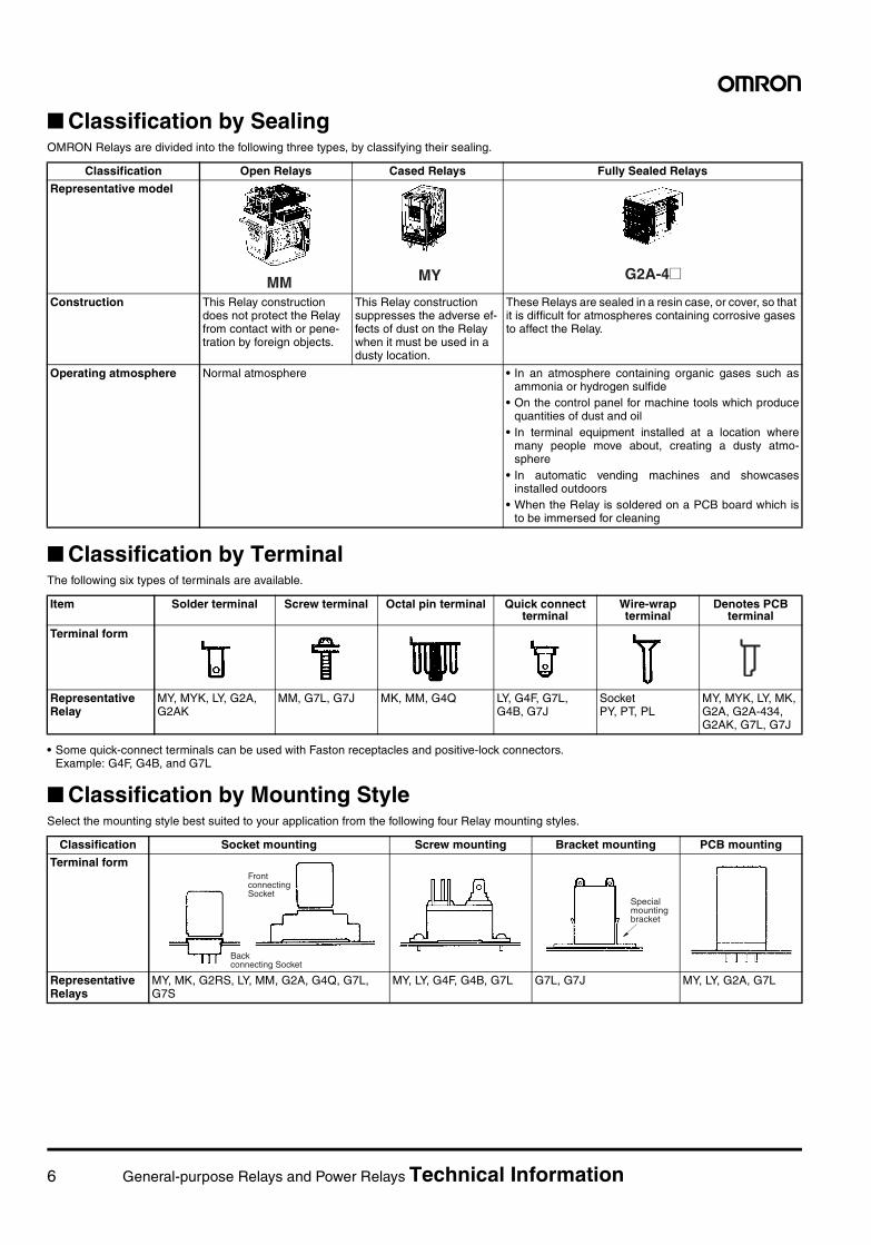
Classification by SealingOMRON Relays are divided into the following three types, by classifying their sealing.
Classification by TerminalThe following six types of terminals are available.
• Some quick-connect terminals can be used with Faston receptacles and positive-lock connectors.Example: G4F, G4B, and G7L
Classification by Mounting StyleSelect the mounting style best suited to your application from the following four Relay mounting styles.
Classification Open Relays Cased Relays Fully Sealed Relays
Representative model
Construction This Relay construction does not protect the Relay from contact with or pene-tration by foreign objects.
This Relay construction suppresses the adverse ef-fects of dust on the Relay when it must be used in a dusty location.
These Relays are sealed in a resin case, or cover, so that it is difficult for atmospheres containing corrosive gases to affect the Relay.
Operating atmosphere Normal atmosphere • In an atmosphere containing organic gases such asammonia or hydrogen sulfide
• On the control panel for machine tools which producequantities of dust and oil
• In terminal equipment installed at a location wheremany people move about, creating a dusty atmo-sphere
• In automatic vending machines and showcasesinstalled outdoors
• When the Relay is soldered on a PCB board which isto be immersed for cleaning
MM MY G2A-4@
Item Solder terminal Screw terminal Octal pin terminal Quick connectterminal
Wire-wrap terminal
Denotes PCB terminal
Terminal form
Representative Relay
MY, MYK, LY, G2A, G2AK
MM, G7L, G7J MK, MM, G4Q LY, G4F, G7L, G4B, G7J
SocketPY, PT, PL
MY, MYK, LY, MK, G2A, G2A-434, G2AK, G7L, G7J
Classification Socket mounting Screw mounting Bracket mounting PCB mounting
Terminal form
Representative Relays
MY, MK, G2RS, LY, MM, G2A, G4Q, G7L, G7S
MY, LY, G4F, G4B, G7L G7L, G7J MY, LY, G2A, G7L
Back connecting Socket
Front connecting Socket
Special mounting bracket
General-purpose Relays and Power Relays Technical Information 7
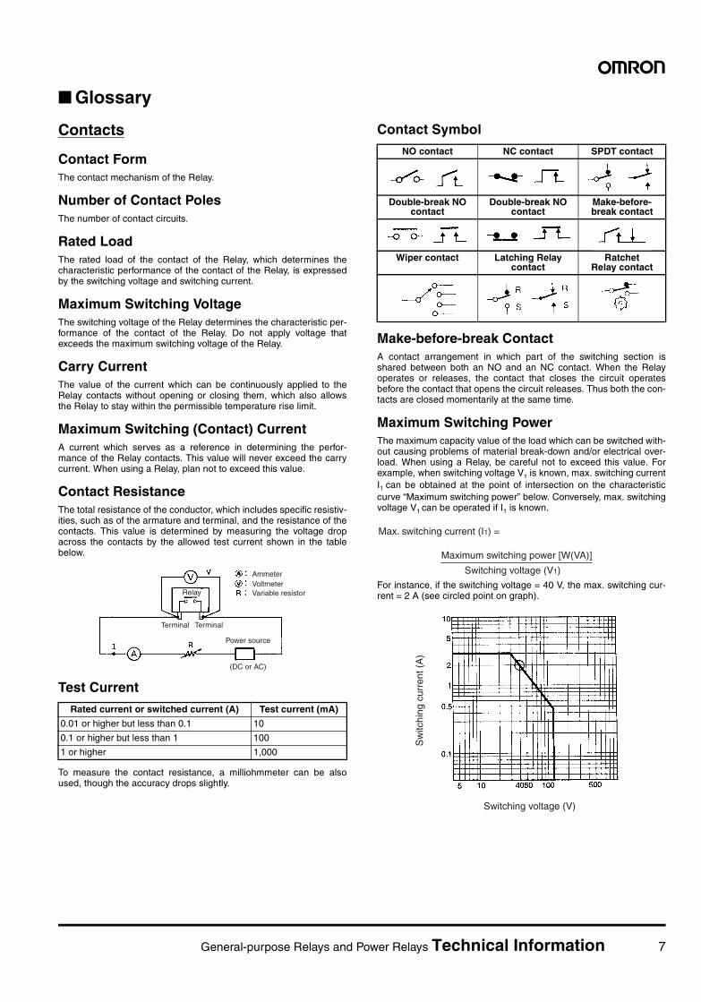
Glossary
Contacts
Contact FormThe contact mechanism of the Relay.
Number of Contact PolesThe number of contact circuits.
Rated LoadThe rated load of the contact of the Relay, which determines thecharacteristic performance of the contact of the Relay, is expressedby the switching voltage and switching current.
Maximum Switching VoltageThe switching voltage of the Relay determines the characteristic per-formance of the contact of the Relay. Do not apply voltage thatexceeds the maximum switching voltage of the Relay.
Carry CurrentThe value of the current which can be continuously applied to theRelay contacts without opening or closing them, which also allowsthe Relay to stay within the permissible temperature rise limit.
Maximum Switching (Contact) CurrentA current which serves as a reference in determining the perfor-mance of the Relay contacts. This value will never exceed the carrycurrent. When using a Relay, plan not to exceed this value.
Contact ResistanceThe total resistance of the conductor, which includes specific resistiv-ities, such as of the armature and terminal, and the resistance of thecontacts. This value is determined by measuring the voltage dropacross the contacts by the allowed test current shown in the tablebelow.
Test Current
To measure the contact resistance, a milliohmmeter can be alsoused, though the accuracy drops slightly.
Contact Symbol
Make-before-break ContactA contact arrangement in which part of the switching section isshared between both an NO and an NC contact. When the Relayoperates or releases, the contact that closes the circuit operatesbefore the contact that opens the circuit releases. Thus both the con-tacts are closed momentarily at the same time.
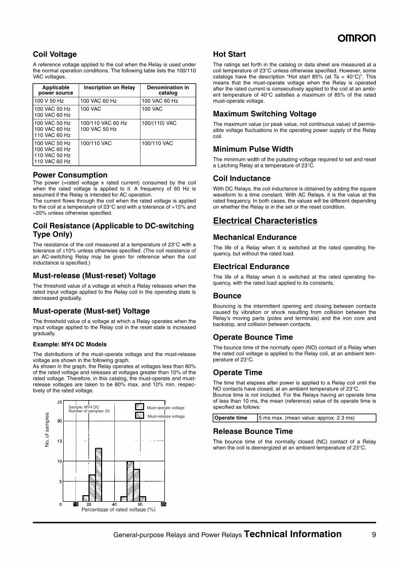
Maximum Switching PowerThe maximum capacity value of the load which can be switched with-out causing problems of material break-down and/or electrical over-load. When using a Relay, be careful not to exceed this value. Forexample, when switching voltage V1 is known, max. switching currentI1 can be obtained at the point of intersection on the characteristiccurve “Maximum switching power” below. Conversely, max. switchingvoltage V1 can be operated if I1 is known.
For instance, if the switching voltage = 40 V, the max. switching cur-rent = 2 A (see circled point on graph).
Rated current or switched current (A) Test current (mA)
0.01 or higher but less than 0.1 10
0.1 or higher but less than 1 100
1 or higher 1,000
Power source
(DC or AC)
Relay
Terminal Terminal
AmmeterVoltmeterVariable resistor
NO contact NC contact SPDT contact
Double-break NO contact
Double-break NO contact
Make-before-break contact
Wiper contact Latching Relay contact
Ratchet Relay contact
Max. switching current (I1) =
Switching voltage (V1)
Maximum switching power [W(VA)]
Switching voltage (V)
Sw
itchi
ng c
urre
nt (
A)
8 General-purpose Relays and Power Relays Technical Information
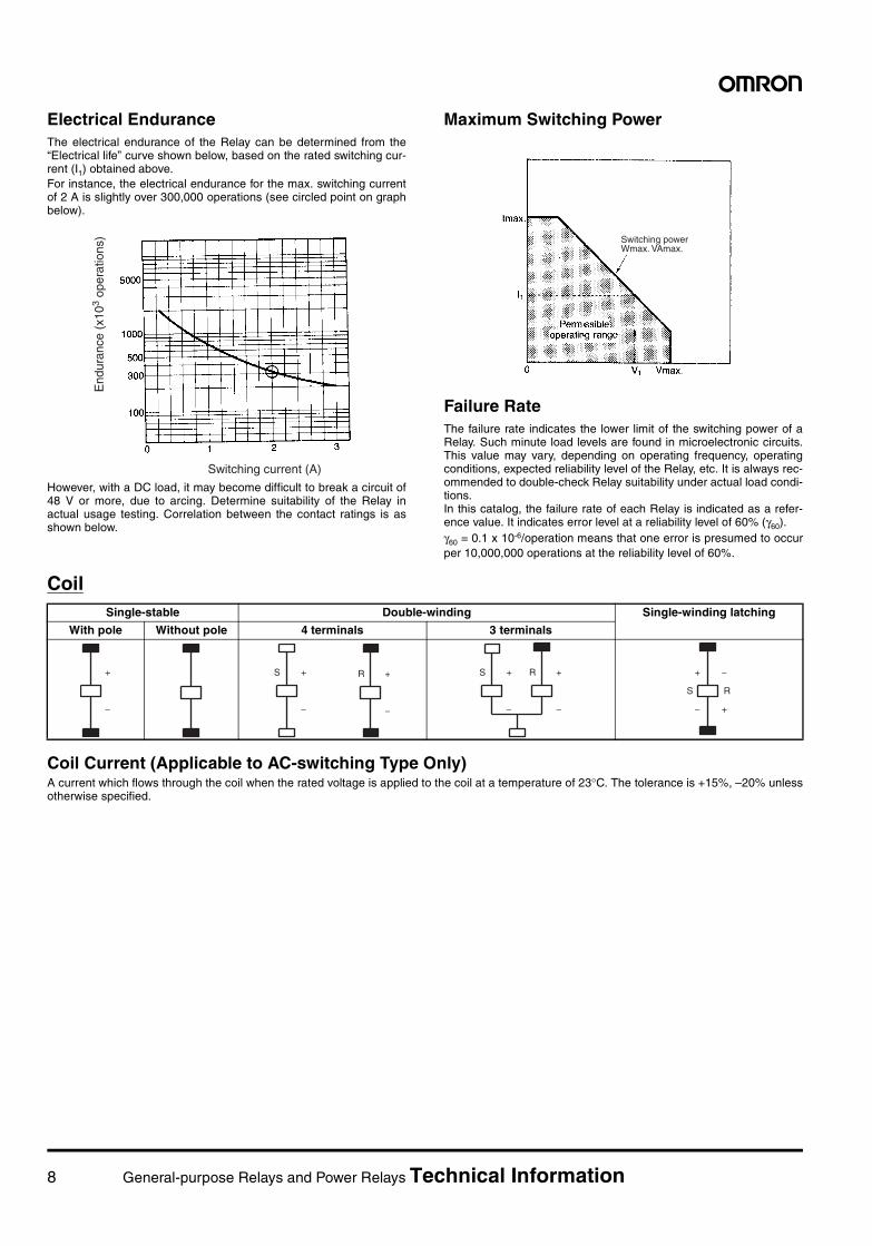
Electrical EnduranceThe electrical endurance of the Relay can be determined from the“Electrical life” curve shown below, based on the rated switching cur-rent (I1) obtained above.For instance, the electrical endurance for the max. switching currentof 2 A is slightly over 300,000 operations (see circled point on graphbelow).
However, with a DC load, it may become difficult to break a circuit of48 V or more, due to arcing. Determine suitability of the Relay inactual usage testing. Correlation between the contact ratings is asshown below.
Maximum Switching Power
Failure RateThe failure rate indicates the lower limit of the switching power of aRelay. Such minute load levels are found in microelectronic circuits.This value may vary, depending on operating frequency, operatingconditions, expected reliability level of the Relay, etc. It is always rec-ommended to double-check Relay suitability under actual load condi-tions.In this catalog, the failure rate of each Relay is indicated as a refer-ence value. It indicates error level at a reliability level of 60% (γ60).γ60 = 0.1 x 10⁻⁶/operation means that one error is presumed to occurper 10,000,000 operations at the reliability level of 60%.
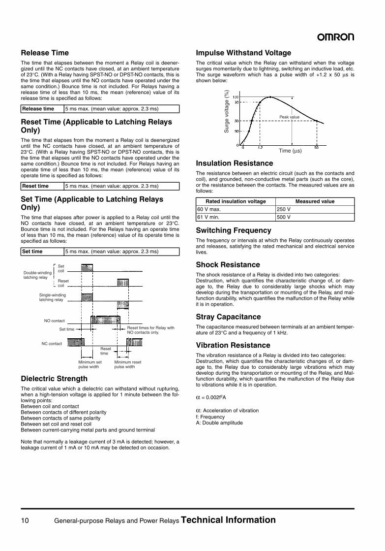
Coil
Coil Current (Applicable to AC-switching Type Only)A current which flows through the coil when the rated voltage is applied to the coil at a temperature of 23°C. The tolerance is +15%, –20% unlessotherwise specified.
Switching current (A)
End
uran
ce (
x103
oper
atio
ns) Switching power
Wmax. VAmax.
Single-stable Double-winding Single-winding latching
With pole Without pole 4 terminals 3 terminals
+
−
+
−
S +
−
R +
−
S +
−
R −
+
+
−
S R
General-purpose Relays and Power Relays Technical Information 9
Coil VoltageA reference voltage applied to the coil when the Relay is used underthe normal operation conditions. The following table lists the 100/110VAC voltages.
Power ConsumptionThe power (=rated voltage x rated current) consumed by the coilwhen the rated voltage is applied to it. A frequency of 60 Hz isassumed if the Relay is intended for AC operation.The current flows through the coil when the rated voltage is appliedto the coil at a temperature of 23°C and with a tolerance of +15% and–20% unless otherwise specified.
Coil Resistance (Applicable to DC-switching Type Only)The resistance of the coil measured at a temperature of 23°C with atolerance of ±10% unless otherwise specified. (The coil resistance ofan AC-switching Relay may be given for reference when the coilinductance is specified.)
Must-release (Must-reset) VoltageThe threshold value of a voltage at which a Relay releases when therated input voltage applied to the Relay coil in the operating state isdecreased gradually.
Must-operate (Must-set) VoltageThe threshold value of a voltage at which a Relay operates when theinput voltage applied to the Relay coil in the reset state is increasedgradually.
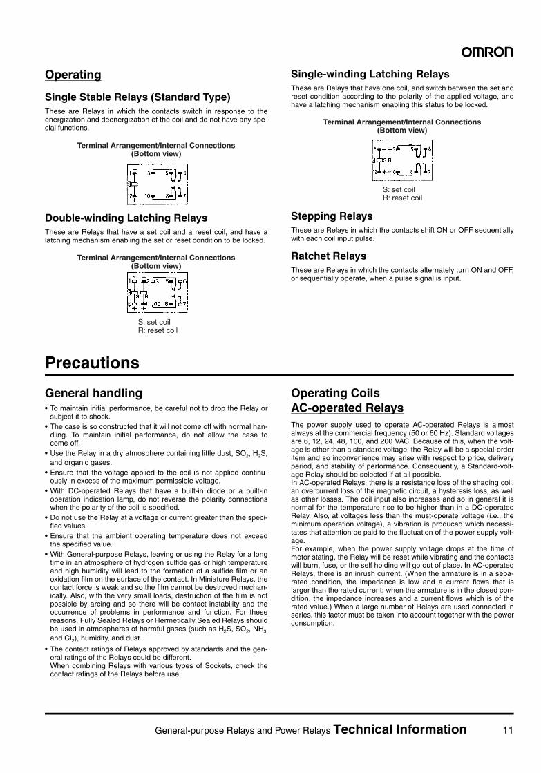
Example: MY4 DC Models
The distributions of the must-operate voltage and the must-releasevoltage are shown in the following graph.As shown in the graph, the Relay operates at voltages less than 80%of the rated voltage and releases at voltages greater than 10% of therated voltage. Therefore, in this catalog, the must-operate and must-release voltages are taken to be 80% max. and 10% min. respec-tively of the rated voltage.
Hot StartThe ratings set forth in the catalog or data sheet are measured at acoil temperature of 23°C unless otherwise specified. However, somecatalogs have the description “Hot start 85% (at Ta = 40°C)”. Thismeans that the must-operate voltage when the Relay is operatedafter the rated current is consecutively applied to the coil at an ambi-ent temperature of 40°C satisfies a maximum of 85% of the ratedmust-operate voltage.
Maximum Switching VoltageThe maximum value (or peak value, not continuous value) of permis-sible voltage fluctuations in the operating power supply of the Relaycoil.
Minimum Pulse WidthThe minimum width of the pulsating voltage required to set and reseta Latching Relay at a temperature of 23°C.
Coil InductanceWith DC Relays, the coil inductance is obtained by adding the squarewaveform to a time constant. With AC Relays, it is the value at therated frequency. In both cases, the values will be different dependingon whether the Relay is in the set or the reset condition.
Electrical Characteristics
Mechanical EnduranceThe life of a Relay when it is switched at the rated operating fre-quency, but without the rated load.
Electrical EnduranceThe life of a Relay when it is switched at the rated operating fre-quency, with the rated load applied to its constants.
BounceBouncing is the intermittent opening and closing between contactscaused by vibration or shock resulting from collision between theRelay’s moving parts (poles and terminals) and the iron core andbackstop, and collision between contacts.
Operate Bounce TimeThe bounce time of the normally open (NO) contact of a Relay whenthe rated coil voltage is applied to the Relay coil, at an ambient tem-perature of 23°C.
Operate TimeThe time that elapses after power is applied to a Relay coil until theNO contacts have closed, at an ambient temperature of 23°C. Bounce time is not included. For the Relays having an operate timeof less than 10 ms, the mean (reference) value of its operate time isspecified as follows:
Release Bounce TimeThe bounce time of the normally closed (NC) contact of a Relaywhen the coil is deenergized at an ambient temperature of 23°C.
Applicable power source
Inscription on Relay Denomination in catalog
100 V 50 Hz 100 VAC 60 Hz 100 VAC 60 Hz
100 VAC 50 Hz100 VAC 60 Hz
100 VAC 100 VAC
100 VAC 50 Hz 100 VAC 60 Hz 110 VAC 60 Hz
100/110 VAC 60 Hz100 VAC 50 Hz
100/(110) VAC
100 VAC 50 Hz 100 VAC 60 Hz 110 VAC 50 Hz 110 VAC 60 Hz
100/110 VAC 100/110 VAC
Percentage of rated voltage (%)
No.
of s
ampl
es
Sample: MY4 DCNumber of samples: 20
Must-operate voltage
Must-release voltage Operate time 5 ms max. (mean value: approx. 2.3 ms)
10 General-purpose Relays and Power Relays Technical Information
Release TimeThe time that elapses between the moment a Relay coil is deener-gized until the NC contacts have closed, at an ambient temperatureof 23°C. (With a Relay having SPST-NO or DPST-NO contacts, this isthe time that elapses until the NO contacts have operated under thesame condition.) Bounce time is not included. For Relays having arelease time of less than 10 ms, the mean (reference) value of itsrelease time is specified as follows:
Reset Time (Applicable to Latching Relays Only)The time that elapses from the moment a Relay coil is deenergizeduntil the NC contacts have closed, at an ambient temperature of23°C. (With a Relay having SPST-NO or DPST-NO contacts, this isthe time that elapses until the NO contacts have operated under thesame condition.) Bounce time is not included. For Relays having anoperate time of less than 10 ms, the mean (reference) value of itsoperate time is specified as follows:
Set Time (Applicable to Latching Relays Only)The time that elapses after power is applied to a Relay coil until theNO contacts have closed, at an ambient temperature or 23°C.Bounce time is not included. For the Relays having an operate timeof less than 10 ms, the mean (reference) value of its operate time isspecified as follows:
Dielectric StrengthThe critical value which a dielectric can withstand without rupturing,when a high-tension voltage is applied for 1 minute between the fol-lowing points:Between coil and contactBetween contacts of different polarityBetween contacts of same polarityBetween set coil and reset coilBetween current-carrying metal parts and ground terminal
Note that normally a leakage current of 3 mA is detected; however, aleakage current of 1 mA or 10 mA may be detected on occasion.
Impulse Withstand VoltageThe critical value which the Relay can withstand when the voltagesurges momentarily due to lightning, switching an inductive load, etc.The surge waveform which has a pulse width of +1.2 x 50 µs isshown below:
Insulation ResistanceThe resistance between an electric circuit (such as the contacts andcoil), and grounded, non-conductive metal parts (such as the core),or the resistance between the contacts. The measured values are asfollows:
Switching FrequencyThe frequency or intervals at which the Relay continuously operatesand releases, satisfying the rated mechanical and electrical servicelives.
Shock ResistanceThe shock resistance of a Relay is divided into two categories:Destruction, which quantifies the characteristic change of, or dam-age to, the Relay due to considerably large shocks which maydevelop during the transportation or mounting of the Relay, and mal-function durability, which quantifies the malfunction of the Relay whileit is in operation.
Stray CapacitanceThe capacitance measured between terminals at an ambient temper-ature of 23°C and a frequency of 1 kHz.
Vibration ResistanceThe vibration resistance of a Relay is divided into two categories:Destruction, which quantifies the characteristic changes of, or dam-age to, the Relay due to considerably large vibrations which maydevelop during the transportation or mounting of the Relay, and Mal-function durability, which quantifies the malfunction of the Relay dueto vibrations while it is in operation.
α = 0.002f2A
α: Acceleration of vibrationf: FrequencyA: Double amplitude
Release time 5 ms max. (mean value: approx. 2.3 ms)
Reset time 5 ms max. (mean value: approx. 2.3 ms)
Set time 5 ms max. (mean value: approx. 2.3 ms)
NO contact
Set time
NC contact
Double-winding latching relay
Set coil
Reset coil
Single-winding latching relay
Reset time
Minimum set pulse width
Minimum reset pulse width
Reset times for Relay with NO contacts only.
Rated insulation voltage Measured value
60 V max. 250 V
61 V min. 500 V
Time (µs)
Sur
ge v
olta
ge (
%)
Peak value
General-purpose Relays and Power Relays Technical Information 11
Operating
Single Stable Relays (Standard Type)These are Relays in which the contacts switch in response to theenergization and deenergization of the coil and do not have any spe-cial functions.
Double-winding Latching RelaysThese are Relays that have a set coil and a reset coil, and have alatching mechanism enabling the set or reset condition to be locked.
Single-winding Latching RelaysThese are Relays that have one coil, and switch between the set andreset condition according to the polarity of the applied voltage, andhave a latching mechanism enabling this status to be locked.
Stepping RelaysThese are Relays in which the contacts shift ON or OFF sequentiallywith each coil input pulse.
Ratchet RelaysThese are Relays in which the contacts alternately turn ON and OFF,or sequentially operate, when a pulse signal is input.
Precautions
General handling• To maintain initial performance, be careful not to drop the Relay or
subject it to shock.• The case is so constructed that it will not come off with normal han-
dling. To maintain initial performance, do not allow the case tocome off.
• Use the Relay in a dry atmosphere containing little dust, SO2, H2S,and organic gases.
• Ensure that the voltage applied to the coil is not applied continu-ously in excess of the maximum permissible voltage.
• With DC-operated Relays that have a built-in diode or a built-inoperation indication lamp, do not reverse the polarity connectionswhen the polarity of the coil is specified.
• Do not use the Relay at a voltage or current greater than the speci-fied values.
• Ensure that the ambient operating temperature does not exceedthe specified value.
• With General-purpose Relays, leaving or using the Relay for a longtime in an atmosphere of hydrogen sulfide gas or high temperatureand high humidity will lead to the formation of a sulfide film or anoxidation film on the surface of the contact. In Miniature Relays, thecontact force is weak and so the film cannot be destroyed mechan-ically. Also, with the very small loads, destruction of the film is notpossible by arcing and so there will be contact instability and theoccurrence of problems in performance and function. For thesereasons, Fully Sealed Relays or Hermetically Sealed Relays shouldbe used in atmospheres of harmful gases (such as H2S, SO2, NH3,
and CI2), humidity, and dust.
• The contact ratings of Relays approved by standards and the gen-eral ratings of the Relays could be different.When combining Relays with various types of Sockets, check thecontact ratings of the Relays before use.
Operating CoilsAC-operated RelaysThe power supply used to operate AC-operated Relays is almostalways at the commercial frequency (50 or 60 Hz). Standard voltagesare 6, 12, 24, 48, 100, and 200 VAC. Because of this, when the volt-age is other than a standard voltage, the Relay will be a special-orderitem and so inconvenience may arise with respect to price, deliveryperiod, and stability of performance. Consequently, a Standard-volt-age Relay should be selected if at all possible.In AC-operated Relays, there is a resistance loss of the shading coil,an overcurrent loss of the magnetic circuit, a hysteresis loss, as wellas other losses. The coil input also increases and so in general it isnormal for the temperature rise to be higher than in a DC-operatedRelay. Also, at voltages less than the must-operate voltage (i.e., theminimum operation voltage), a vibration is produced which necessi-tates that attention be paid to the fluctuation of the power supply volt-age.For example, when the power supply voltage drops at the time ofmotor stating, the Relay will be reset while vibrating and the contactswill burn, fuse, or the self holding will go out of place. In AC-operatedRelays, there is an inrush current. (When the armature is in a sepa-rated condition, the impedance is low and a current flows that islarger than the rated current; when the armature is in the closed con-dition, the impedance increases and a current flows which is of therated value.) When a large number of Relays are used connected inseries, this factor must be taken into account together with the powerconsumption.
Terminal Arrangement/Internal Connections (Bottom view)
Terminal Arrangement/Internal Connections (Bottom view)
S: set coil R: reset coil
Terminal Arrangement/Internal Connections (Bottom view)
S: set coilR: reset coil
12 General-purpose Relays and Power Relays Technical Information
DC-operated RelaysThe power supply used to operate DC-operated Relays may havevoltage as a standard or it may have current as a standard. Whenvoltage is the standard, the rated coil voltages include 5, 6, 12, 24,48, and 100 VDC. When current is the standard, the rated current inmA is listed in the catalog.In DC-operated Relays, when the Relay is used in an applicationwhere it is operated at some limit value, either voltage or current, thecurrent applied to the coil will gradually increase or decrease. It isimportant to note that this may delay the movement of the contactsresulting in failure to meet the specified control capacity. The coilresistance value of a DC-operated Relay may change by approxi-mately 0.4% per °C due to changes in the ambient temperature andthe heat radiated by the Relay itself. Therefore, it is important to notethat increases in temperature will be accompanied by higher must-operate and must-release voltages.
Power Supply CapacityThe fluctuation of the power supply voltage over a long period will ofcourse affect Relay operation, but momentary fluctuations will alsobe the cause of incorrect Relay operation.For example, when a large solenoid, Relay, motor, heater, or otherdevice is operated from the same power supply as the one that oper-ates the Relay, or when a large number of Relays are used, if thepower supply does not have sufficient capacity when these devicesare operated simultaneously, the voltage drop may prevent the Relayfrom operating. On the other hand, when the voltage drop is esti-mated and the voltage increased accordingly, if the voltage is appliedto the Relay when there is no voltage drop, this will cause heating ofthe coil.Provide leeway in the capacity of the power supply and keep the volt-age within the switching voltage range of the Relay.
Lower Limit Value of the Must-operate VoltageUse of Relays at high temperatures or rise of coil temperature due toa continuous flow of current through the coil will result in an increasein coil resistance which means the must-operate voltage will alsoincrease. This matter requires attention be paid to determining alower limit value of the operation power supply voltage. The followingexample and explanation should be referred to when designing thepower supply.
Note: Even though the rating is a voltage rating (as is the rating for allStandard Relays), the Relay should be thought of as being cur-rent operated.
Catalog values for model MYRated voltage: 24 VDC, coil resistance: 650 Ω, must-operate voltage:80% or less of rated voltage, at a coil temperature of 23°C.
A rated current of 36.9 mA (24 VDC/650 Ω = 36.9 mA) flows throughthis Relay, which operates at 80% or less of this value i.e., at 29.5mA or less (36.9 mA x 0.8 = 29.5 mA). When the present coil temper-ature rises by 10°C, the coil resistance will be 676 Ω (650 Ω x 1.04 =676 Ω). To have the must-operate current of 29.5 mA flow in this con-dition, it will be necessary to apply a voltage of 19.94 V (29.5 mA x676 Ω =19.94 v). This voltage (which is the must-operate voltagewhen the coil temperature is 33°C (23°C +10°C), is 83.1% (19.94/24= 83.1%) of the rated voltage which represents an increase com-pared to when the coil temperature was 23°C.
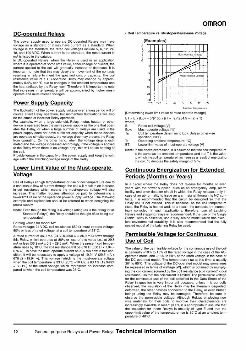
• Coil Temperature vs. Mustoperate/release Voltage
[Determining lower-limit value of must-operate voltage]
ET > E x (Epv + 5*)/100 x (T – Ta)/(234.5 + Ta) + 1where, E: Rated coil voltage [V] Epv: Must-operate voltage [%] Ta: Coil temperature determining Epv. Unless otherwise
specified, 23°C T: Operating ambient temperature [°C] ET: Lower-limit value of must-operate voltage [V]
Note: In the above expression, it is assumed that the coil temperatureis the same as the ambient temperature, and that T is the valueto which the coil temperature has risen as a result of energizingthe coil. *5 denotes the safety margin of 5 %.
Continuous Energization for Extended Periods (Months or Years)In a circuit where the Relay does not release for months or evenyears with the power supplied, such as an emergency lamp, alarmfacility, and error detector circuit in which the Relay releases only incase of an abnormality to issue an alarm signal through its NC con-tacts, it is recommended that the circuit be designed so that theRelay coil is not excited. This is because, as the coil temperaturerises, the Relay is heated and, as a result, the contacts are increas-ingly corroded. In such applications, therefore, use of LatchingRelays and stepping relays is recommended. If the use of the SingleStable Relay is essential, use a fully sealed model which has excel-lent environmental durability. It is also recommended that the fullysealed model of the Latching Relay be used.
Permissible Voltage for Continuous Use of CoilThe value of the permissible voltage for the continuous use of the coilis generally +10% to 15% of the rated voltage in the case of the AC-operated model and +15% to 20% of the rated voltage in the case ofthe DC-operated model. The temperature rise at this time is usually30° to 65°C. This voltage of the DC-operated model may sometimesbe expressed in terms of wattage [W], which is obtained by multiply-ing the coil current squared by the coil resistance (coil current2 x coilresistance), so that the coil current is limited. The permissible voltagefor the continuous use of the coil specified in the Data Sheet of theRelay in question is very important because, unless it is correctlyobserved, the insulation of the Relay may be thermally degraded,deformed, the other devices connected to the Relay, or even humanbeings using the Relay may be damaged. Therefore, be sure toobserve the permissible voltage. Although Relays employing newwire materials for their coils to improve their characteristics areincreasingly available in recent years, it is appropriate to assume thatthe insulation for these Relays is actually of type E and that theupper-limit value of the temperature rise is 80°C at an ambient tem-perature of 40°C.
Per
cent
age
(%)
Must-operate voltage
Must-release voltage
Ambient temperature
(Examples)
General-purpose Relays and Power Relays Technical Information 13
Operate TimeThe operate time of the AC-operated Relay considerably variesbecause of the phase when the switch for energizing the coil isturned ON, and, though it is expressed within a certain range, isabout half a cycle (about 10 ms) in the case of a small Relay. How-ever, if the Relay is large in size, the bounce increases, and the oper-ate time is 7 to 10 ms and the release time is 9 to 18 ms. In the caseof the DC-operated model, the greater the coil input, the shorter theoperate time. However, if the operate time is too short, the bouncetime of the NC contact may be prolonged.
Maximum VoltageDo not use a Relay in such a manner that the maximum voltagespecified in the Datasheet of the Relay is exceeded. The maximumvoltage of a Relay is determined by various factors, such as coil tem-perature rise, durability of coil insulation materials, electrical andmechanical life expectancies, and general characteristics. If the max-imum voltage is exceeded, the insulation materials may be degradedand the coil may be damaged by burning. In actual applications, how-ever, Relays are often used with their maximum voltage exceeded inorder to cope with the fluctuations in the supply voltage. In this case,observe the following points:
(1) Do not allow the coil temperature to exceed the value up towhich the spool, the coil insulation materials, and winding wirecan withstand.The temperature up to which the frequently used wiring materi-als can endure is as shown in the table below (the values in thistable are measured by the resistance method).
[Measuring coil temperature by resistance method]
t = (R2 – R1)/R1 x (234.5 + T1) + T1 [°C]where, R1: coil resistance before energization [Ω] R2: coil resistance after energization [Ω] T1: coil temperature before energization
(ambient temperature): T1 [°C] t: coil temperature after energization [°C]
(2) Confirm that there is not problem when the Relay is used in theactual application system.
Input Power Source• The power source for DC-operated Relays is in principle either a
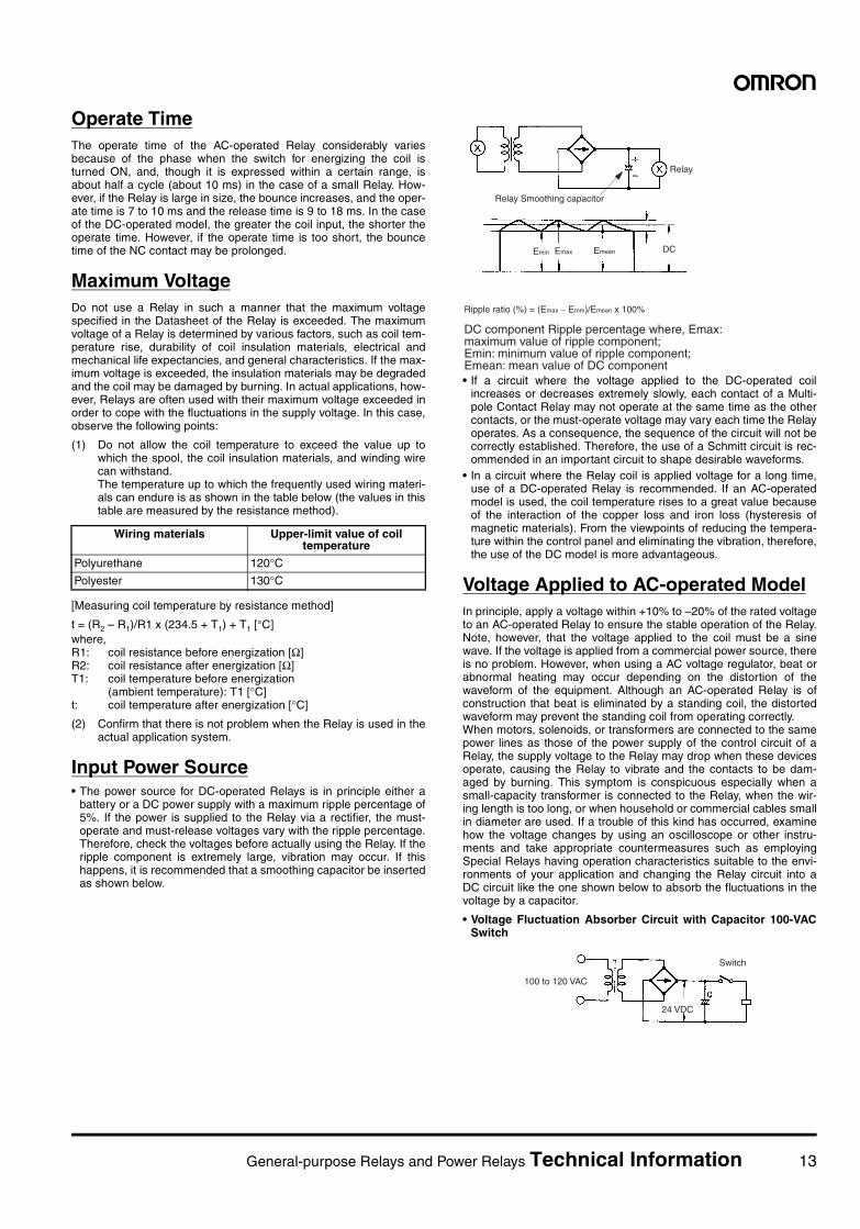
battery or a DC power supply with a maximum ripple percentage of5%. If the power is supplied to the Relay via a rectifier, the must-operate and must-release voltages vary with the ripple percentage.Therefore, check the voltages before actually using the Relay. If theripple component is extremely large, vibration may occur. If thishappens, it is recommended that a smoothing capacitor be insertedas shown below.
• If a circuit where the voltage applied to the DC-operated coilincreases or decreases extremely slowly, each contact of a Multi-pole Contact Relay may not operate at the same time as the othercontacts, or the must-operate voltage may vary each time the Relayoperates. As a consequence, the sequence of the circuit will not becorrectly established. Therefore, the use of a Schmitt circuit is rec-ommended in an important circuit to shape desirable waveforms.
• In a circuit where the Relay coil is applied voltage for a long time,use of a DC-operated Relay is recommended. If an AC-operatedmodel is used, the coil temperature rises to a great value becauseof the interaction of the copper loss and iron loss (hysteresis ofmagnetic materials). From the viewpoints of reducing the tempera-ture within the control panel and eliminating the vibration, therefore,the use of the DC model is more advantageous.
Voltage Applied to AC-operated ModelIn principle, apply a voltage within +10% to –20% of the rated voltageto an AC-operated Relay to ensure the stable operation of the Relay.Note, however, that the voltage applied to the coil must be a sinewave. If the voltage is applied from a commercial power source, thereis no problem. However, when using a AC voltage regulator, beat orabnormal heating may occur depending on the distortion of thewaveform of the equipment. Although an AC-operated Relay is ofconstruction that beat is eliminated by a standing coil, the distortedwaveform may prevent the standing coil from operating correctly.When motors, solenoids, or transformers are connected to the samepower lines as those of the power supply of the control circuit of aRelay, the supply voltage to the Relay may drop when these devicesoperate, causing the Relay to vibrate and the contacts to be dam-aged by burning. This symptom is conspicuous especially when asmall-capacity transformer is connected to the Relay, when the wir-ing length is too long, or when household or commercial cables smallin diameter are used. If a trouble of this kind has occurred, examinehow the voltage changes by using an oscilloscope or other instru-ments and take appropriate countermeasures such as employingSpecial Relays having operation characteristics suitable to the envi-ronments of your application and changing the Relay circuit into aDC circuit like the one shown below to absorb the fluctuations in thevoltage by a capacitor.
• Voltage Fluctuation Absorber Circuit with Capacitor 100-VACSwitch
Wiring materials Upper-limit value of coil temperature
Polyurethane 120°CPolyester 130°C
Relay Smoothing capacitor
Relay
DC
DC component Ripple percentage where, Emax: maximum value of ripple component; Emin: minimum value of ripple component; Emean: mean value of DC component
Ripple ratio (%) = (Emax − Emm)/Emean x 100%
Emin Emax Emean
100 to 120 VAC
Switch
24 VDC
14 General-purpose Relays and Power Relays Technical Information
CoilThe most fundamental point to be observed is to apply the rated volt-age to a Relay to make sure that the Relay accurately operates.Therefore, when using a Relay, this point must be abided by underany circumstances. Applying the rated voltage to the coil of a Relay isalso important for the reason that the coil resistance changesdepending on the type of the coil, voltage fluctuation, and tempera-ture rise. On the other hand, however, the voltage applied to the coilmust not exceed the maximum voltage specified in the Datasheet ofthe Relay; otherwise, the coil may be short-circuited and damaged byburning.
Coil Temperature RiseWhen a current flows through the coil of a Relay, heat is generatedbecause of the joule heat (copper loss) of the coil or, on alternatecurrent, of the iron loss of the magnetic materials such as iron core.Consequently, the coil temperature rises. In addition, when a currentflows through the contacts, heat is also generated from the contacts,which help the coil temperature rise further.
Temperature Rise Due to Pulse VoltageWhen a Relay is applied a pulse voltage whose ON time is 2 minutesor less, the rise in the coil temperature is independent of the ONtime, but is influenced by the ratio of the ON time to the OFF time.This temperature rise is much smaller than that when the Relay isused with continuously supplied power, and almost the same for anymodels of Relays.
Changes in Must-operate Voltage Due to Coil Temperature Rise (Hot Start)When the coil of a DC-operated Relay has been continuously ener-gized, and when the power to the Relay has been once turned OFFand then immediately back ON again, the coil resistance increasesbecause of the coil temperature rises. As a result, the must-operatevoltage slightly increases. If the Relay is used in an atmospherewhere the ambient temperature is high, the operate voltage alsoincreases. The resistance thermal coefficient of a copper wire isabout 0.4% per 1°C, and the coil resistance increases at this ratio.Therefore, to operate a Relay, a current higher than the operate cur-rent is necessary, and the current value increases with the coil resis-tance.
Surge Protection when Coil is OFFThe reverse voltage that is generated by the coil when it is OFF maycause the semiconductor to be damaged and equipment to malfunc-tion. As a countermeasure, either attach a surge suppressor to bothends of the coil or select a model with a built-in surge suppressor(e.g., MY, LY). If a surge suppressor is attached, the release time forthe Relay will be longer. Confirm operation with the circuit that willactually be used.
ContactsThe contacts are the most important constituents of a Relay. Theiroperations and characteristics are influenced by various factors suchas contact materials, applied voltage and current (especially, voltageand current waveforms on turning ON/OFF power), load type, switch-ing frequency, ambient temperature, contact construction, and thepresence or absence of the switching speed bounce phenomena.When the contacts have been adversely influenced by any of or com-bination of these factors, phenomena such as contact transfer, metaldeposition, abnormal wear, and increase in contact resistance occur.To extend the endurance of the contacts and to make sure that theyalways operate correctly, pay attention to the following points.
Voltage and Current of Contact CircuitIf a contact circuit contains induction, a considerably high counterelectromotive force (emf) is generated. The higher the voltageapplied to the contacts, the greater the energy of the counter emf,wearing the contacts. Therefore, the value of the current up to whichthe Relay makes or breaks must be appropriately controlled. If a DCvoltage is applied to the contacts, the control capacity of the Relaysignificantly drops. This is because, on DC voltage, there is no zeropoint (current zero cross point) unlike on AC voltage, and therefore, ifthe Relay has generated arc once, the arc is difficult to disappear,resulting in a long arc time. In addition, because the current flows inonly one direction, contact transfer, a phenomenon described shortly,occurs, wearing the contacts. The control capacity of a Relay is gen-erally set forth on the Data Sheet of the Relay. However, observingthis control capacity is not sufficient. Especially, in a special contactload circuit, the control capacity of the Relay must be confirmed byconducting a test with the actual load.
CurrentWhen the contacts are closed or opened, the current has a signifi-cant influence on the contacts. For example, if the load is a motor orlamp, the higher the inrush current when the contacts are closed, themore the contacts are worn and the quantity of contact transferincreases. Consequently, the contacts will fuse and cannot be sepa-rated.
Contact MaterialsIt is important to select appropriate contact materials depending onthe load current the contacts are to break or make. The followingtable lists the contact materials widely used and their features.
Energization time Temperature rise:
Continuous energization 100%
ON:OFF = 3:1 Approx. 80%
ON:OFF = 1:1 Approx. 50%
ON:OFF = 1:3 Approx. 35%
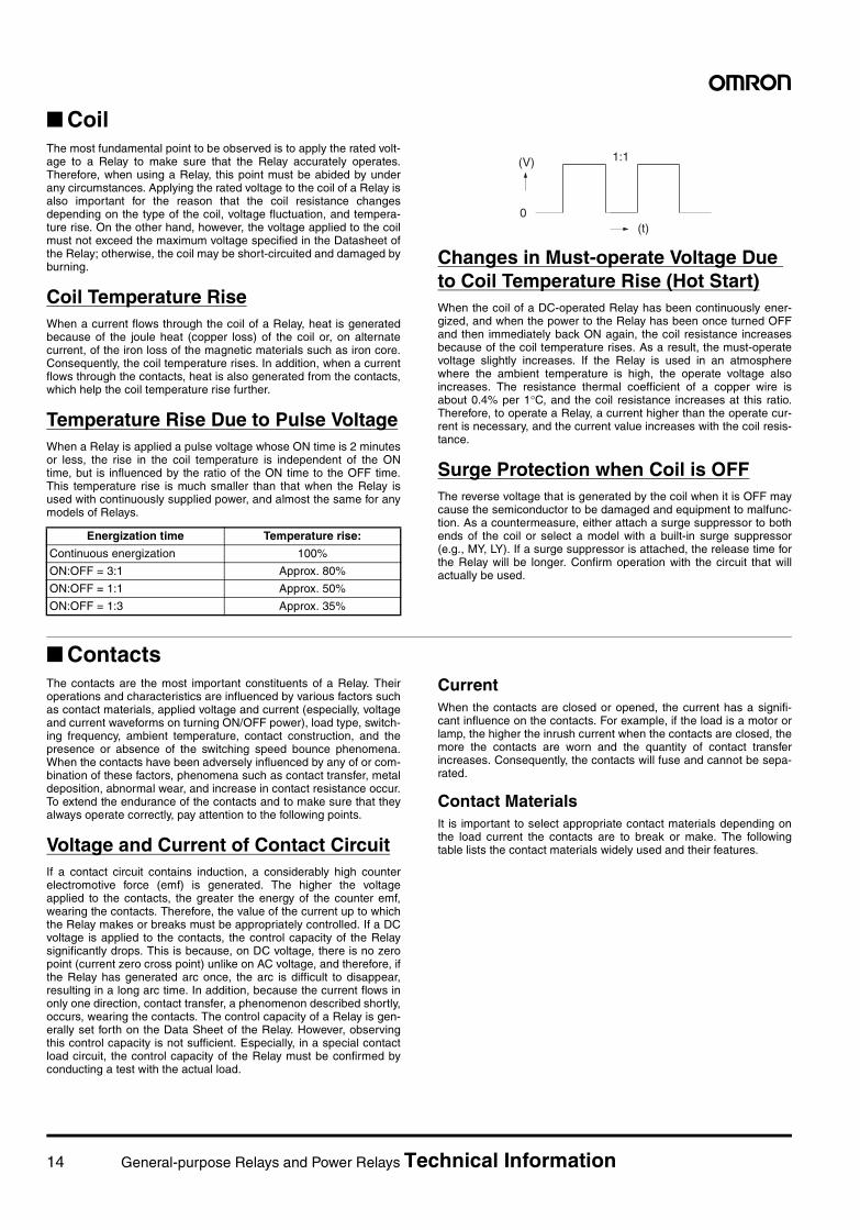
1:1
(t)0
(V)
General-purpose Relays and Power Relays Technical Information 15
Contact Materials and Their Features
Contact Protection CircuitIt is recommended to employ a contact protection circuit to increasethe service life of the Relay, to suppress noise, and to prevent gener-ation of carbide and nitric acid which otherwise will be generated atthe contacts when the Relay is opened. Unless used correctly, how-ever, the protection circuit may produce adverse effects. Anyway, therelease time of the Relay may be somewhat prolonged. The followingtable lists examples of contact protection circuits. Note that evenFully Sealed Relays, when used to break a load that may generatearc (for example, an inductive load such as a Relay coil) in highlyhumid environments, may generate nitric acid due to the NOx gener-ated by the arc and water content, which may corrode the metallicparts of the Relay, causing the Relay to malfunction. Use a surgesuppressor as the one shown in the table on the next page when theRelay is used in highly humid environments to break an arc-generat-ing circuit frequently.
P.G.S alloy (platinum, gold, silver)
AgPd (silver palladium)
Ag (silver) AgNi (silver nickle) AgSnIn (silver, tin, indium)
AgW (silver tungsten)
High resistance to cor-rosion. Mainly used in minute current circuit (Au:Ag:Pt = 69:25:6)
High resistance to cor-rosion and sulfur. In dry circuit, likely to ab-sorb organic gas and generate polymer, and thus gold-clad.
Highest conductance and thermal conduc-tance of all metals. Low contact resis-tance, but easy to cre-ate sulfide film in sulfide gas. May cause faulty contact at low voltage and current.
Rivals with Ag in terms of conductance. Excel-lent resistance to arc.
Excellent resistance to metal deposition and wear.
High hardness and melting point. Excel-lent resistance to arc, metal deposition, and transfer, but high con-tact resistance and poor environmental du-rability.
Low load current High load current
16 General-purpose Relays and Power Relays Technical Information
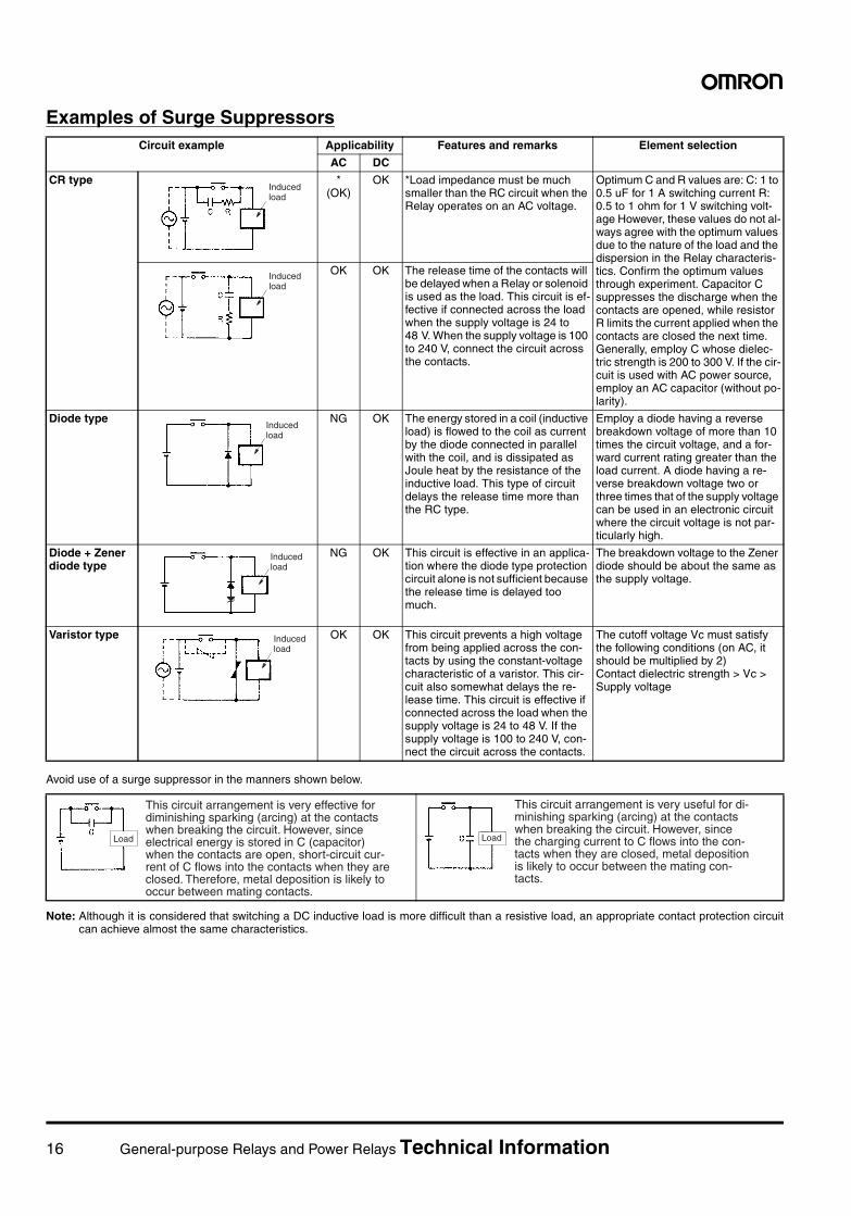
Examples of Surge Suppressors
Avoid use of a surge suppressor in the manners shown below.
Note: Although it is considered that switching a DC inductive load is more difficult than a resistive load, an appropriate contact protection circuitcan achieve almost the same characteristics.
Circuit example Applicability Features and remarks Element selection
AC DC
CR type * (OK)
OK *Load impedance must be much smaller than the RC circuit when the Relay operates on an AC voltage.
Optimum C and R values are: C: 1 to 0.5 uF for 1 A switching current R: 0.5 to 1 ohm for 1 V switching volt-age However, these values do not al-ways agree with the optimum values due to the nature of the load and the dispersion in the Relay characteris-tics. Confirm the optimum values through experiment. Capacitor C suppresses the discharge when the contacts are opened, while resistor R limits the current applied when the contacts are closed the next time. Generally, employ C whose dielec-tric strength is 200 to 300 V. If the cir-cuit is used with AC power source, employ an AC capacitor (without po-larity).
OK OK The release time of the contacts will be delayed when a Relay or solenoid is used as the load. This circuit is ef-fective if connected across the load when the supply voltage is 24 to 48 V. When the supply voltage is 100 to 240 V, connect the circuit across the contacts.
Diode type NG OK The energy stored in a coil (inductive load) is flowed to the coil as current by the diode connected in parallel with the coil, and is dissipated as Joule heat by the resistance of the inductive load. This type of circuit delays the release time more than the RC type.
Employ a diode having a reverse breakdown voltage of more than 10 times the circuit voltage, and a for-ward current rating greater than the load current. A diode having a re-verse breakdown voltage two or three times that of the supply voltage can be used in an electronic circuit where the circuit voltage is not par-ticularly high.
Diode + Zener diode type
NG OK This circuit is effective in an applica-tion where the diode type protection circuit alone is not sufficient because the release time is delayed too much.
The breakdown voltage to the Zener diode should be about the same as the supply voltage.
Varistor type OK OK This circuit prevents a high voltage from being applied across the con-tacts by using the constant-voltage characteristic of a varistor. This cir-cuit also somewhat delays the re-lease time. This circuit is effective if connected across the load when the supply voltage is 24 to 48 V. If the supply voltage is 100 to 240 V, con-nect the circuit across the contacts.
The cutoff voltage Vc must satisfy the following conditions (on AC, it should be multiplied by 2)Contact dielectric strength > Vc > Supply voltage
Induced load
Induced load
Induced load
Induced load
Induced load
This circuit arrangement is very effective for diminishing sparking (arcing) at the contacts when breaking the circuit. However, since electrical energy is stored in C (capacitor) when the contacts are open, short-circuit cur- rent of C flows into the contacts when they are closed. Therefore, metal deposition is likely to occur between mating contacts.
Load
This circuit arrangement is very useful for di- minishing sparking (arcing) at the contacts when breaking the circuit. However, since the charging current to C flows into the con- tacts when they are closed, metal deposition is likely to occur between the mating con- tacts.
Load
General-purpose Relays and Power Relays Technical Information 17
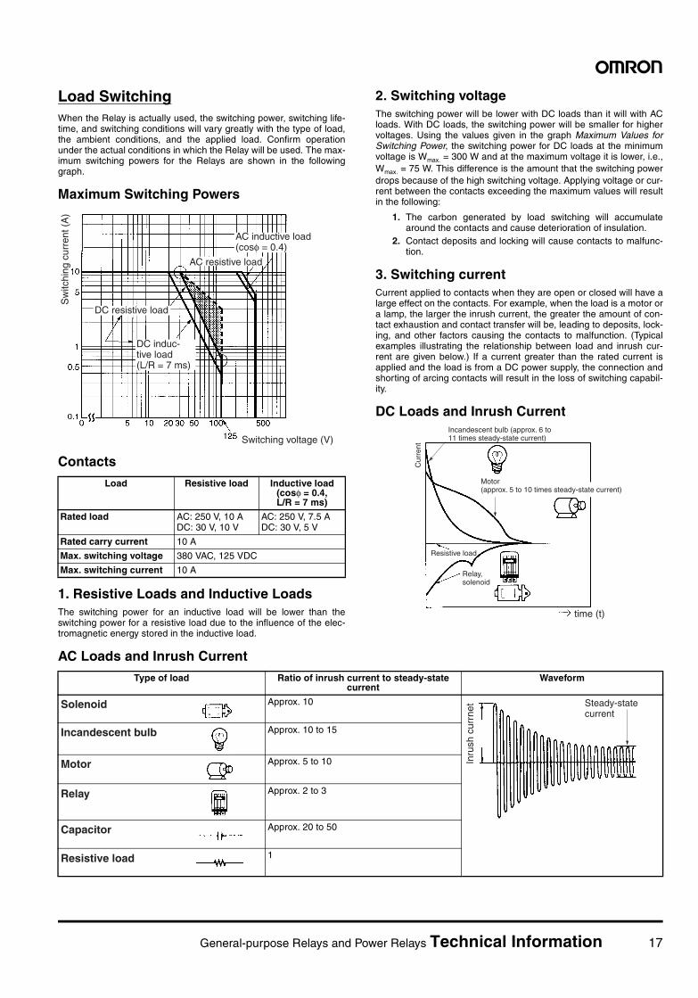
Load SwitchingWhen the Relay is actually used, the switching power, switching life-time, and switching conditions will vary greatly with the type of load,the ambient conditions, and the applied load. Confirm operationunder the actual conditions in which the Relay will be used. The max-imum switching powers for the Relays are shown in the followinggraph.
Maximum Switching Powers
Contacts
1. Resistive Loads and Inductive LoadsThe switching power for an inductive load will be lower than theswitching power for a resistive load due to the influence of the elec-tromagnetic energy stored in the inductive load.
2. Switching voltageThe switching power will be lower with DC loads than it will with ACloads. With DC loads, the switching power will be smaller for highervoltages. Using the values given in the graph Maximum Values forSwitching Power, the switching power for DC loads at the minimumvoltage is Wmax. = 300 W and at the maximum voltage it is lower, i.e.,Wmax. = 75 W. This difference is the amount that the switching powerdrops because of the high switching voltage. Applying voltage or cur-rent between the contacts exceeding the maximum values will resultin the following:
1. The carbon generated by load switching will accumulatearound the contacts and cause deterioration of insulation.
2. Contact deposits and locking will cause contacts to malfunc-tion.
3. Switching currentCurrent applied to contacts when they are open or closed will have alarge effect on the contacts. For example, when the load is a motor ora lamp, the larger the inrush current, the greater the amount of con-tact exhaustion and contact transfer will be, leading to deposits, lock-ing, and other factors causing the contacts to malfunction. (Typicalexamples illustrating the relationship between load and inrush cur-rent are given below.) If a current greater than the rated current isapplied and the load is from a DC power supply, the connection andshorting of arcing contacts will result in the loss of switching capabil-ity.
DC Loads and Inrush Current
AC Loads and Inrush Current
Load Resistive load Inductive load (cosφ = 0.4, L/R = 7 ms)
Rated load AC: 250 V, 10 ADC: 30 V, 10 V
AC: 250 V, 7.5 ADC: 30 V, 5 V
Rated carry current 10 A
Max. switching voltage 380 VAC, 125 VDC
Max. switching current 10 A
AC resistive load
Switching voltage (V)
DC resistive load
Sw
itchi
ng c
urre
nt (
A)
AC inductive load (cosφ = 0.4)
DC induc-tive load (L/R = 7 ms)
Resistive load
Cur
rent
time (t)
Incandescent bulb (approx. 6 to 11 times steady-state current)
Motor (approx. 5 to 10 times steady-state current)
Relay, solenoid
Type of load Ratio of inrush current to steady-state current
Waveform
Approx. 10
Approx. 10 to 15
Approx. 5 to 10
Approx. 2 to 3
Approx. 20 to 50
1
Solenoid
Inru
sh c
urrn
et Steady-state current
Incandescent bulb
Motor
Relay
Capacitor
Resistive load
18 General-purpose Relays and Power Relays Technical Information
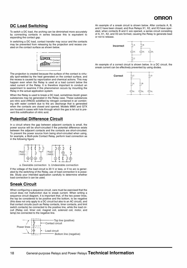
DC Load SwitchingTo switch a DC load, the arching can be diminished more accuratelyby connecting contacts in series because this is equivalent toexpanding the contact gap.
In switching a DC load, contact transfer may occur and the contactsmay be prevented from releasing by the projection and recess cre-ated on the contact surface as shown below.
The projection is created because the surface of the contact is virtu-ally spot-welded by the heat generated on the contact surface, andthe recess is caused by vaporization and chemical actions. This mayhappen even when the Relay is used at a load current below therated current of the Relay. It is therefore important to conduct anexperiment to examine if this phenomenon occurs by mounting theRelay in the actual application system.
When the Relay is used to break a DC load, sometimes bluish greensubstances may be generated in the Relay case. These substancesare nitric acid (HNO3) solidified by nitrogen contained in air combin-ing with water content due to the arc discharge that is generatedwhen the contacts are closed and opened. Models MMX and G7Xare housed in cases with hole through which the gas is let out to pre-vent this solidification of nitric acid.
Potential Difference CircuitIn a circuit where the gap between adjacent contacts is small, thepower source will be short-circuited if the potential difference existsbetween the adjacent contacts and the contacts are short-circuited.To prevent the power source from being short-circuited when using,for example, a Multi-pole Contact Relay, perform load connection asin the following figure:
If the voltage of the load circuit is 20 V or less, or if no arc is gener-ated by the switching of the Relay, use of load connection b is possi-ble. Study your intended application carefully to determine whetherload connection b can be used.
Sneak CircuitWhen configuring a sequence circuit, care must be exercised that thecircuit does not malfunction due to sneak current. When writing asequence circuit diagram, it is important that, of the two power lines,the top be considered to be positive and the bottom, to be negative(this does not only apply to a DC circuit but also to an AC circuit), andthat contact circuits (such as Relay contacts, timer contacts, and limitswitch contacts) be connected to the positive line, while the load cir-cuit (Relay coil, timer coil, magnet coil, solenoid coil, motor, andlamp) be connected to the negative line.
An example of a sneak circuit is shown below. After contacts A, B,and C have been closed, and thus Relays X1, X2, and X3 have oper-ated, when contacts B and C are opened, a series circuit consistingof A, X1, X2, and X3 are formed, causing the Relay to generate beator not to release.
An example of a correct circuit is shown below. In a DC circuit, thesneak current can be effectively prevented by using diodes.
Contact Contact
a. Desirable connection b. Undesirable connection
Power supply
Power supply
Top line (positive)
Bottom line (negative)
Power linesContact circuit
Load circuit
X1
A
C
B
X2 X3
Incorrect
X1
C
A B
D
X2 X3
Correct
General-purpose Relays and Power Relays Technical Information 19
Notes on Environment
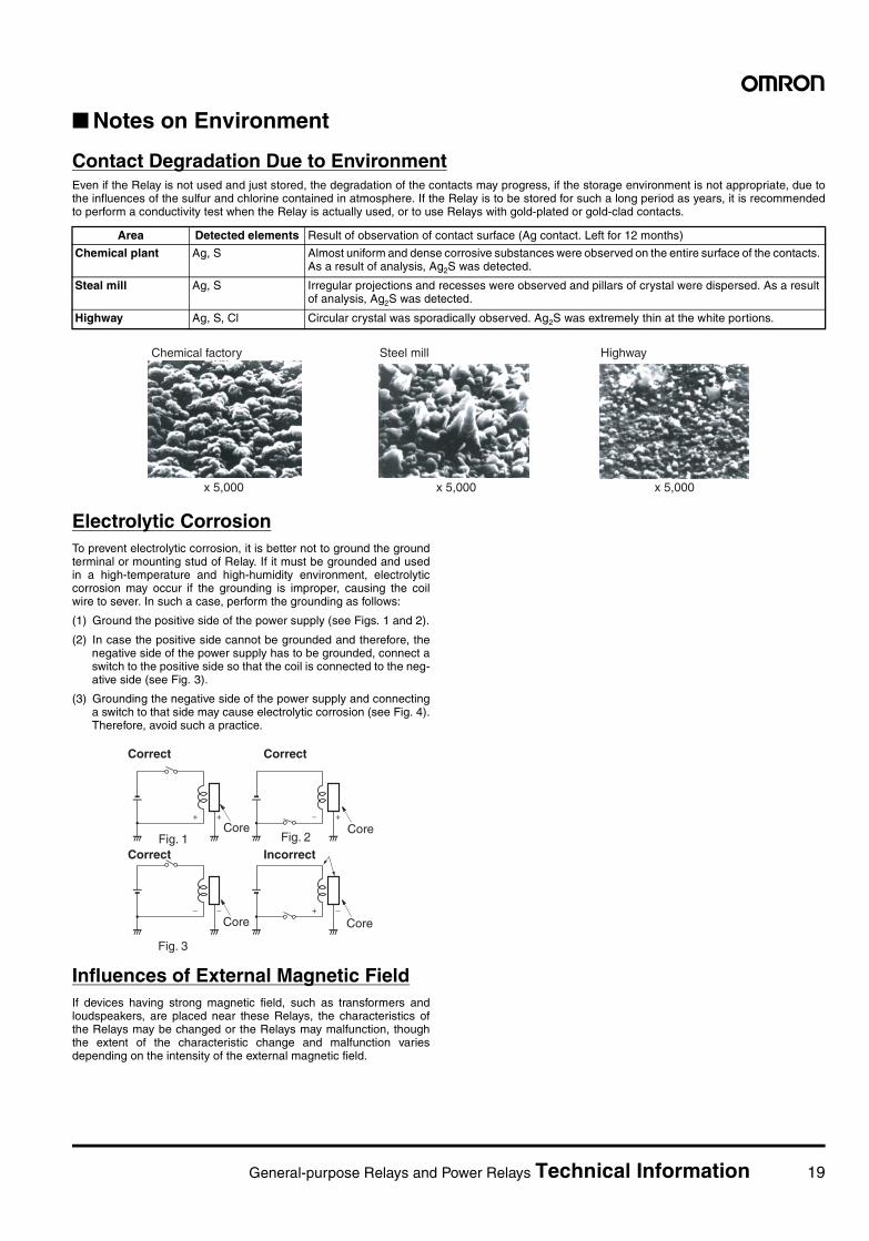
Contact Degradation Due to EnvironmentEven if the Relay is not used and just stored, the degradation of the contacts may progress, if the storage environment is not appropriate, due tothe influences of the sulfur and chlorine contained in atmosphere. If the Relay is to be stored for such a long period as years, it is recommendedto perform a conductivity test when the Relay is actually used, or to use Relays with gold-plated or gold-clad contacts.
Electrolytic CorrosionTo prevent electrolytic corrosion, it is better not to ground the groundterminal or mounting stud of Relay. If it must be grounded and usedin a high-temperature and high-humidity environment, electrolyticcorrosion may occur if the grounding is improper, causing the coilwire to sever. In such a case, perform the grounding as follows:
(1) Ground the positive side of the power supply (see Figs. 1 and 2).
(2) In case the positive side cannot be grounded and therefore, thenegative side of the power supply has to be grounded, connect aswitch to the positive side so that the coil is connected to the neg-ative side (see Fig. 3).
(3) Grounding the negative side of the power supply and connectinga switch to that side may cause electrolytic corrosion (see Fig. 4).Therefore, avoid such a practice.
Influences of External Magnetic FieldIf devices having strong magnetic field, such as transformers andloudspeakers, are placed near these Relays, the characteristics ofthe Relays may be changed or the Relays may malfunction, thoughthe extent of the characteristic change and malfunction variesdepending on the intensity of the external magnetic field.
Area Detected elements Result of observation of contact surface (Ag contact. Left for 12 months)
Chemical plant Ag, S Almost uniform and dense corrosive substances were observed on the entire surface of the contacts. As a result of analysis, Ag2S was detected.
Steal mill Ag, S Irregular projections and recesses were observed and pillars of crystal were dispersed. As a result of analysis, Ag2S was detected.
Highway Ag, S, Cl Circular crystal was sporadically observed. Ag2S was extremely thin at the white portions.
x 5,000 x 5,000 x 5,000
Chemical factory Steel mill Highway
+ +
− −
− +
+ −
Correct
IncorrectFig. 1 Fig. 2
Fig. 3
Core Core
Core Core
Correct
Correct
20 General-purpose Relays and Power Relays Technical Information
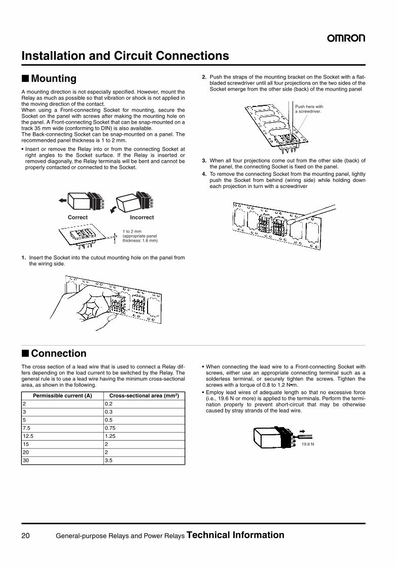
Installation and Circuit Connections
MountingA mounting direction is not especially specified. However, mount theRelay as much as possible so that vibration or shock is not applied inthe moving direction of the contact.When using a Front-connecting Socket for mounting, secure theSocket on the panel with screws after making the mounting hole onthe panel. A Front-connecting Socket that can be snap-mounted on atrack 35 mm wide (conforming to DIN) is also available.The Back-connecting Socket can be snap-mounted on a panel. Therecommended panel thickness is 1 to 2 mm.
• Insert or remove the Relay into or from the connecting Socket atright angles to the Socket surface. If the Relay is inserted orremoved diagonally, the Relay terminals will be bent and cannot beproperly contacted or connected to the Socket.
1. Insert the Socket into the cutout mounting hole on the panel fromthe wiring side.
2. Push the straps of the mounting bracket on the Socket with a flat-bladed screwdriver until all four projections on the two sides of theSocket emerge from the other side (back) of the mounting panel
3. When all four projections come out from the other side (back) ofthe panel, the connecting Socket is fixed on the panel.
4. To remove the connecting Socket from the mounting panel, lightlypush the Socket from behind (wiring side) while holding downeach projection in turn with a screwdriver
ConnectionThe cross section of a lead wire that is used to connect a Relay dif-fers depending on the load current to be switched by the Relay. Thegeneral rule is to use a lead wire having the minimum cross-sectionalarea, as shown in the following.
• When connecting the lead wire to a Front-connecting Socket withscrews, either use an appropriate connecting terminal such as asolderless terminal, or securely tighten the screws. Tighten thescrews with a torque of 0.8 to 1.2 N•m.
• Employ lead wires of adequate length so that no excessive force(i.e., 19.6 N or more) is applied to the terminals. Perform the termi-nation properly to prevent short-circuit that may be otherwisecaused by stray strands of the lead wire.
1 to 2 mm (appropriate panel thickness: 1.6 mm)
Correct Incorrect
Push here with a screwdriver.
Permissible current (A) Cross-sectional area (mm2)
2 0.2
3 0.3
5 0.5
7.5 0.75
12.5 1.25
15 2
20 2
30 3.5
19.6 N
General-purpose Relays and Power Relays Technical Information 21
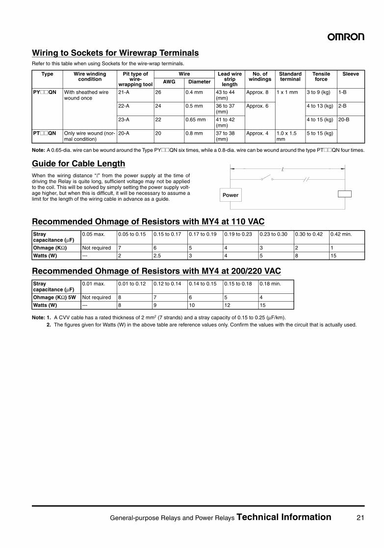
Wiring to Sockets for Wirewrap TerminalsRefer to this table when using Sockets for the wire-wrap terminals.
Note: A 0.65-dia. wire can be wound around the Type PY@@QN six times, while a 0.8-dia. wire can be wound around the type PT@@QN four times.
Guide for Cable LengthWhen the wiring distance “l” from the power supply at the time ofdriving the Relay is quite long, sufficient voltage may not be appliedto the coil. This will be solved by simply setting the power supply volt-age higher, but when this is difficult, it will be necessary to assume alimit for the length of the wiring cable in advance as a guide.
Recommended Ohmage of Resistors with MY4 at 110 VAC
Recommended Ohmage of Resistors with MY4 at 200/220 VAC
Note: 1. A CVV cable has a rated thickness of 2 mm2 (7 strands) and a stray capacity of 0.15 to 0.25 (µF/km).2. The figures given for Watts (W) in the above table are reference values only. Confirm the values with the circuit that is actually used.
Type Wire winding condition
Pit type of wire-
wrapping tool
Wire Lead wire strip
length
No. of windings
Standard terminal
Tensile force
Sleeve
AWG Diameter
PY@@QN With sheathed wire wound once
21-A 26 0.4 mm 43 to 44 (mm)
Approx. 8 1 x 1 mm 3 to 9 (kg) 1-B
22-A 24 0.5 mm 36 to 37 (mm)
Approx. 6 4 to 13 (kg) 2-B
23-A 22 0.65 mm 41 to 42 (mm)
4 to 15 (kg) 20-B
PT@@QN Only wire wound (nor-mal condition)
20-A 20 0.8 mm 37 to 38 (mm)
Approx. 4 1.0 x 1.5 mm
5 to 15 (kg)
l
Power
Stray capacitance (µF)
0.05 max. 0.05 to 0.15 0.15 to 0.17 0.17 to 0.19 0.19 to 0.23 0.23 to 0.30 0.30 to 0.42 0.42 min.
Ohmage (KΩ) Not required 7 6 5 4 3 2 1
Watts (W) --- 2 2.5 3 4 5 8 15
Stray capacitance (µF)
0.01 max. 0.01 to 0.12 0.12 to 0.14 0.14 to 0.15 0.15 to 0.18 0.18 min.
Ohmage (KΩ) 5W Not required 8 7 6 5 4
Watts (W) --- 8 9 10 12 15
22 General-purpose Relays and Power Relays Technical Information
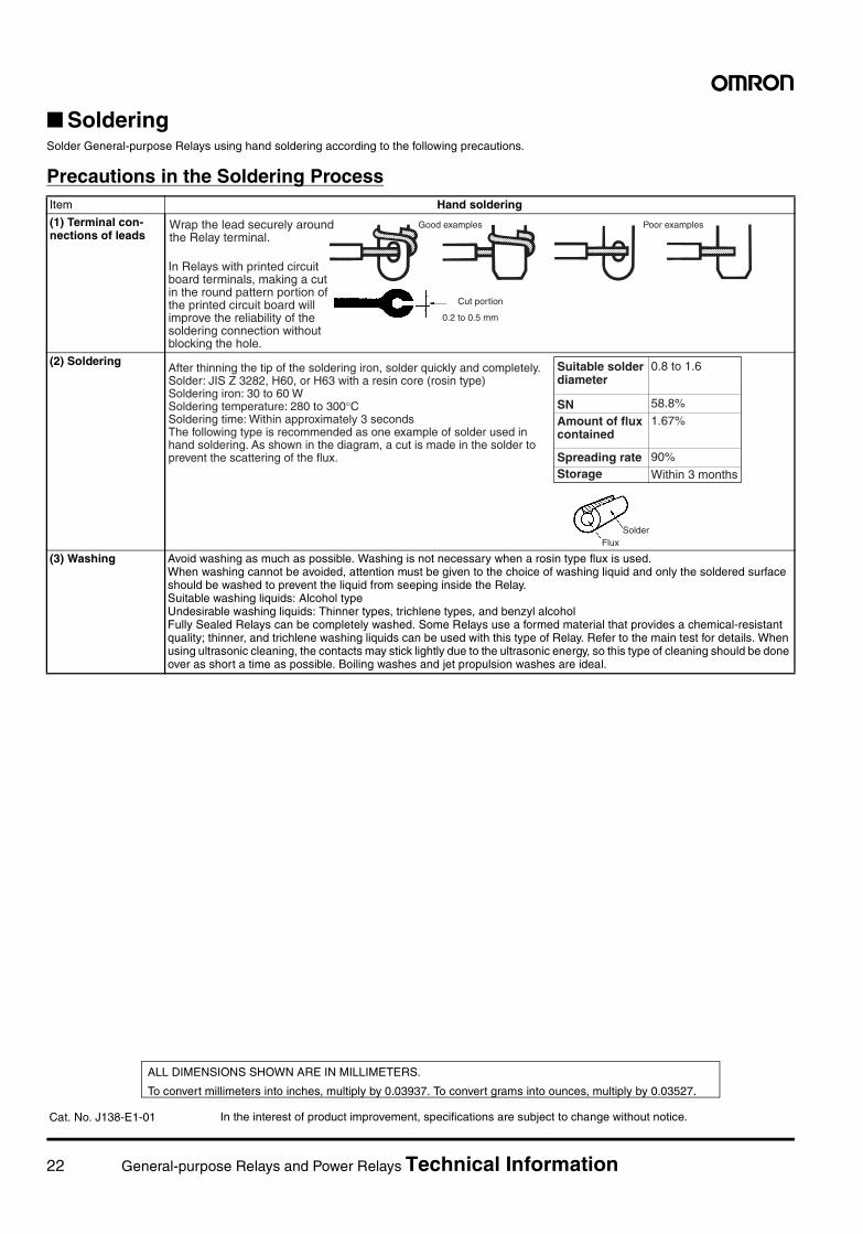
SolderingSolder General-purpose Relays using hand soldering according to the following precautions.
Precautions in the Soldering ProcessItem Hand soldering
(1) Terminal con-nections of leads
(2) Soldering
(3) Washing Avoid washing as much as possible. Washing is not necessary when a rosin type flux is used.When washing cannot be avoided, attention must be given to the choice of washing liquid and only the soldered surface should be washed to prevent the liquid from seeping inside the Relay.Suitable washing liquids: Alcohol typeUndesirable washing liquids: Thinner types, trichlene types, and benzyl alcoholFully Sealed Relays can be completely washed. Some Relays use a formed material that provides a chemical-resistant quality; thinner, and trichlene washing liquids can be used with this type of Relay. Refer to the main test for details. When using ultrasonic cleaning, the contacts may stick lightly due to the ultrasonic energy, so this type of cleaning should be done over as short a time as possible. Boiling washes and jet propulsion washes are ideal.
Cut portion
0.2 to 0.5 mm
Good examples Poor examplesWrap the lead securely around the Relay terminal.
In Relays with printed circuit board terminals, making a cut in the round pattern portion of the printed circuit board will improve the reliability of the soldering connection without blocking the hole.
After thinning the tip of the soldering iron, solder quickly and completely. Solder: JIS Z 3282, H60, or H63 with a resin core (rosin type) Soldering iron: 30 to 60 W Soldering temperature: 280 to 300°C Soldering time: Within approximately 3 seconds The following type is recommended as one example of solder used in hand soldering. As shown in the diagram, a cut is made in the solder to prevent the scattering of the flux.
SN
Spreading rateStorage
0.8 to 1.6
58.8%
1.67%
90%
Within 3 months
SolderFlux
Suitable solder diameter
Amount of flux contained
In the interest of product improvement, specifications are subject to change without notice.
ALL DIMENSIONS SHOWN ARE IN MILLIMETERS.
To convert millimeters into inches, multiply by 0.03937. To convert grams into ounces, multiply by 0.03527.
Cat. No. J138-E1-01
General-purpose Relays and Power Relays Standards 23
Standards National StandardsNote: For detailed information about applicable standards, refer to the relevant catalog.
International Standards
IEC (International Electrotechnical Commission)
The IEC is a standardization commission founded in 1908 to promote unification and coordination of in-ternational standards relating to electricity. It is headquartered in Geneva, Switzerland.
IEC standards are provided to accomplish the aim of the above. The IEC strongly recommends all themember nations of the IEC to establish domestic standards that conform with those of the IEC.
At present, there are 50 member nations in the IEC. Based on reports from member nations on the latestscience technologies in those nations, IEC standards are issued as technological standards relating toelectricity. Established international safety standards provided by various countries and accepted world-wide are based on IEC standards.
In order to simplify approval procedures for electrical devices and promote smooth international trade,there is an international scheme called CB Scheme (Certification Body Scheme), which is authorized byIEC standards. Based on the CB Scheme, safety tests on electrical devices are conducted and certificatesare issued if the devices are proved to meet IEC standards. Products issued with such certificates are ac-ceptable in 30 countries in the world.
North America
UL Standards (Underwriters Laboratories INC.)
A nonprofit organization established in 1894 by the American association of fire insurance companies.Underwriters Laboratories (abbreviated to UL hereafter) conducts approval testing on all kinds of electricalproducts. In many U.S. cities and states, UL approval is legally required on all electrical items sold.In order to obtain UL approval on an electrical product, all major internal components also require UL ap-proval.
UL offers two classifications of approvals, the listing mark and the recognition mark.
A Listing Mark constitutes a entirely approval of a product. Products display the Listing Mark shown below.
NKuR
C
UL
CSA
JO
VDE
W 9876
LR
FIMKO (SETI)
F
SEMKO
S
NEMKO
N
BSI
GL
GLDEMKO
DTÜV
E
IMQKEMA
K
SEV
+UTE
BEAB
ASTA
CCIB
CCEE
Electrical Appliance and Material Control Law of Japan
CSA recognition mark by UL
uLISTING MARK
24 General-purpose Relays and Power Relays Standards
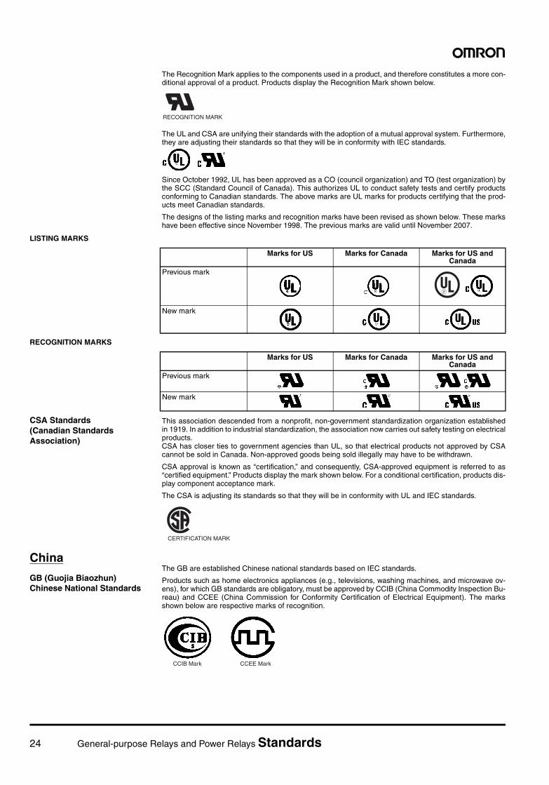
The Recognition Mark applies to the components used in a product, and therefore constitutes a more con-ditional approval of a product. Products display the Recognition Mark shown below.
The UL and CSA are unifying their standards with the adoption of a mutual approval system. Furthermore,they are adjusting their standards so that they will be in conformity with IEC standards.
Since October 1992, UL has been approved as a CO (council organization) and TO (test organization) bythe SCC (Standard Council of Canada). This authorizes UL to conduct safety tests and certify productsconforming to Canadian standards. The above marks are UL marks for products certifying that the prod-ucts meet Canadian standards.
The designs of the listing marks and recognition marks have been revised as shown below. These markshave been effective since November 1998. The previous marks are valid until November 2007.
LISTING MARKS
RECOGNITION MARKS
CSA Standards (Canadian Standards Association)
This association descended from a nonprofit, non-government standardization organization establishedin 1919. In addition to industrial standardization, the association now carries out safety testing on electricalproducts.CSA has closer ties to government agencies than UL, so that electrical products not approved by CSAcannot be sold in Canada. Non-approved goods being sold illegally may have to be withdrawn.
CSA approval is known as “certification,” and consequently, CSA-approved equipment is referred to as“certified equipment.” Products display the mark shown below. For a conditional certification, products dis-play component acceptance mark.
The CSA is adjusting its standards so that they will be in conformity with UL and IEC standards.
China
GB (Guojia Biaozhun) Chinese National Standards
The GB are established Chinese national standards based on IEC standards.
Products such as home electronics appliances (e.g., televisions, washing machines, and microwave ov-ens), for which GB standards are obligatory, must be approved by CCIB (China Commodity Inspection Bu-reau) and CCEE (China Commission for Conformity Certification of Electrical Equipment). The marksshown below are respective marks of recognition.
RRECOGNITION MARK
Marks for US Marks for Canada Marks for US and Canada
Previous mark
New mark
u
Marks for US Marks for Canada Marks for US and Canada
Previous mark
New mark
CCERTIFICATION MARK
CCIB Mark CCEE Mark
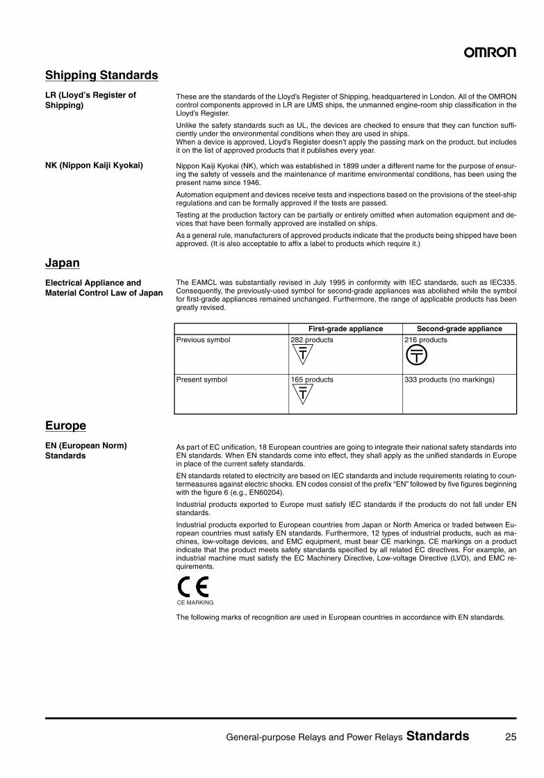
General-purpose Relays and Power Relays Standards 25
Shipping Standards
LR (Lloyd’s Register of Shipping)
These are the standards of the Lloyd’s Register of Shipping, headquartered in London. All of the OMRONcontrol components approved in LR are UMS ships, the unmanned engine-room ship classification in theLloyd’s Register.
Unlike the safety standards such as UL, the devices are checked to ensure that they can function suffi-ciently under the environmental conditions when they are used in ships.When a device is approved, Lloyd’s Register doesn’t apply the passing mark on the product, but includesit on the list of approved products that it publishes every year.
NK (Nippon Kaiji Kyokai) Nippon Kaiji Kyokai (NK), which was established in 1899 under a different name for the purpose of ensur-ing the safety of vessels and the maintenance of maritime environmental conditions, has been using thepresent name since 1946.
Automation equipment and devices receive tests and inspections based on the provisions of the steel-shipregulations and can be formally approved if the tests are passed.
Testing at the production factory can be partially or entirely omitted when automation equipment and de-vices that have been formally approved are installed on ships.
As a general rule, manufacturers of approved products indicate that the products being shipped have beenapproved. (It is also acceptable to affix a label to products which require it.)
Japan
Electrical Appliance and Material Control Law of Japan
The EAMCL was substantially revised in July 1995 in conformity with IEC standards, such as IEC335.Consequently, the previously-used symbol for second-grade appliances was abolished while the symbolfor first-grade appliances remained unchanged. Furthermore, the range of applicable products has beengreatly revised.
Europe
EN (European Norm) Standards
As part of EC unification, 18 European countries are going to integrate their national safety standards intoEN standards. When EN standards come into effect, they shall apply as the unified standards in Europein place of the current safety standards.
EN standards related to electricity are based on IEC standards and include requirements relating to coun-termeasures against electric shocks. EN codes consist of the prefix “EN” followed by five figures beginningwith the figure 6 (e.g., EN60204).
Industrial products exported to Europe must satisfy IEC standards if the products do not fall under ENstandards.
Industrial products exported to European countries from Japan or North America or traded between Eu-ropean countries must satisfy EN standards. Furthermore, 12 types of industrial products, such as ma-chines, low-voltage devices, and EMC equipment, must bear CE markings. CE markings on a productindicate that the product meets safety standards specified by all related EC directives. For example, anindustrial machine must satisfy the EC Machinery Directive, Low-voltage Directive (LVD), and EMC re-quirements.
The following marks of recognition are used in European countries in accordance with EN standards.
First-grade appliance Second-grade appliance
Previous symbol 282 products
J216 products
OPresent symbol 165 products
J333 products (no markings)
CE MARKING

26 General-purpose Relays and Power Relays Standards
VDE (Verband Deutscher Electroechnischer e.v.) in Germany
W X E
D K
F
S
+
VDE MARK MONITORING MARK TÜV Rheinland TÜV Product Service
DEMKO (Danmarks Elektriske Materielkontrol)
NEMKO (Norges Elektriske Materiellkontroll) UTE (Union Technique De Electricite)
FIMKO (Finlands Material Kontroll) IMQ (Istituto Italiano del Marchio di Qualita)
SEV (Schweizerischer Electrotechnischer Verein)
VDE (applicable to electrical appliances only)
TÜV (applicable to electrical appliances, machines, and automobiles)
KEMA (Keuring van Electrotechnische Materialen Nederland B. V.)
SEMKO (Svenska Elektriska Materielkontroll Anstalten)
ASTA (ASTA Certification Services) Britain (applicable to general products)
BEAB (British Electrotechnical Approvals Board) Britain (applicable to home electronics products)
BSI (British Standards Institution) Britain (applicable to industrial products)
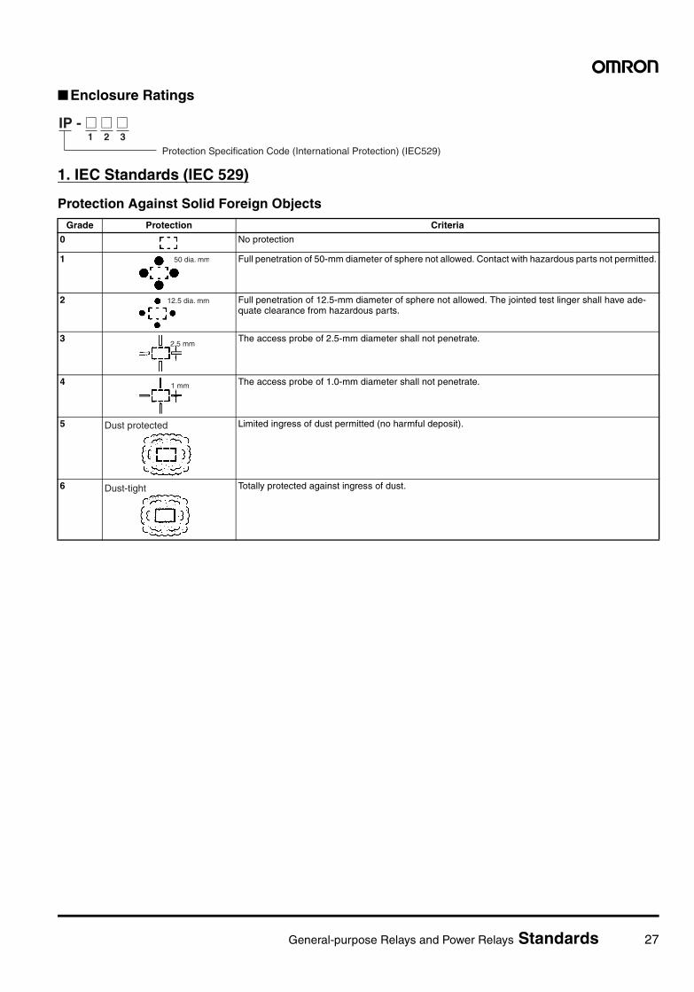
General-purpose Relays and Power Relays Standards 27
Enclosure Ratings
1. IEC Standards (IEC 529)
Protection Against Solid Foreign Objects
IP - @ @ @1 2 3
Protection Specification Code (International Protection) (IEC529)
Grade Protection Criteria
0 No protection
1 Full penetration of 50-mm diameter of sphere not allowed. Contact with hazardous parts not permitted.
2 Full penetration of 12.5-mm diameter of sphere not allowed. The jointed test linger shall have ade-quate clearance from hazardous parts.
3 The access probe of 2.5-mm diameter shall not penetrate.
4 The access probe of 1.0-mm diameter shall not penetrate.
5 Limited ingress of dust permitted (no harmful deposit).
6 Totally protected against ingress of dust.
50 dia. mm
12.5 dia. mm
2.5 mm
1 mm
Dust protected
Dust-tight
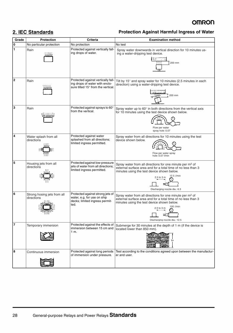
28 General-purpose Relays and Power Relays Standards
2. IEC Standards Protection Against Harmful Ingress of Water
Grade Protection Criteria Examination method
0 No particular protection No protection No test
1 Protected against vertically fall-ing drops of water.
2 Protected against vertically fall-ing drops of water with enclo-sure tilted 15° from the vertical.
3 Protected against sprays to 60° from the vertical.
4 Protected against water splashed from all directions; limited ingress permitted.
5 Protected against low-pressure jets of water from all directions; limited ingress permitted.
6 Protected against strong jets of water, e.g. for use on ship decks; limited ingress permit-ted.
7 Protected against the effects of immersion between 15 cm and 1 m.
8 Protected against long periods of immersion under pressure.
Test according to the conditions agreed upon between the manufactur-er and user.
Rain
200 mm
Spray water downwards in vertical direction for 10 minutes us-ing a water-dripping test device.
Rain
200 mm
Tilt by 15° and spray water for 10 minutes (2.5 minutes in each direction) using a water-dripping test device.
Rain Spray water up to 60° in both directions from the vertical axis for 10 minutes using the test device shown below.
Flow per water spray hole: 0.07
Water splash from all directions
Spray water from all directions for 10 minutes using the test device shown below.
Flow per water spray hole: 0.07 l/min
Housing jets from all directions
12.5 l/min2.5 to 3 m
Discharging nozzle dia.: 6.3
Spray water from all directions for one minute per m2 of external surface area and for a total time of no less than 3minutes using the test device shown below.
Strong hosing jets from all directions
100 l/min2.5 to 3 m
Discharging nozzle dia.: 12.5
Spray water from all directions for one minute per m2 of external surface area and for a total time of no less than 3 minutes using the test device shown below.
Temporary immersion Submerge for 30 minutes at the depth of 1 m (if the device is located lower than 850 mm).
Continuous immersion
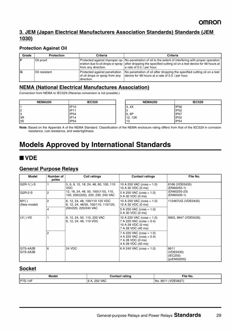
General-purpose Relays and Power Relays Standards 29
3. JEM (Japan Electrical Manufacturers Association Standards) Standards (JEM 1030)
Protection Against Oil
NEMA (National Electrical Manufactures Association)Conversion from NEMA to IEC529 (Reverse conversion is not possible.)
Note: Based on the Appendix A of the NEMA Standard. Classification of the NEMA enclosure rating differs from that of the IEC529 in corrosionresistance, rust resistance, and watertightness.
Models Approved by International Standards
VDE
General Purpose Relays
Socket
Grade Protection Criteria Criteria
F Oil proof Protected against improper op-eration due to oil drops or spray from any direction.
No penetration of oil to the extent of interfering with proper operation after dropping the specified cutting oil on a test device for 48 hours at a rate of 0.5 l per hour.
G Oil resistant Protected against penetration of oil drops or spray from any direction.
No penetration of oil after dropping the specified cutting oil on a test device for 48 hours at a rate of 0.5 l per hour.
NEMA250 IEC529
1233R3S
IP10IP11IP54IP14IP54
NEMA250 IEC529
4, 4X56, 6P12, 12K13
IP56IP52IP67IP52IP54
Model Number of poles
Coil ratings Contact ratings File No.
G2R-1( )-S 1 5, 6, 9, 12, 18, 24, 48, 60, 100, 110 VDC12, 18, 24, 48, 50, 100/(110), 110, 120, 200/(220), 220, 230, 240 VAC
10 A 250 VAC (cosφ = 1.0)10 A 30 VDC (0 ms)
6166 (VDE0435)(EN60255-1)(EN60255-23)(EN60335-1)
G2R-2-S 2 5 A 250 VAC (cosφ = 1.0)5 A 30 VDC (0 ms)
MY( ) (New model)
2 6, 12, 24, 48, 100/110 125 VDC6, 12, 24, 48/50, 100/110, 110/120, 200/220, 220/240 VAC
10 A 250 VAC (cosφ = 1.0)10 A 30 VDC (0 ms)
112467UG (VDE0435)
4 5 A 250 VAC (cosφ = 1.0)5 A 30 VDC (0 ms)
LY( )-VD 1 6, 12, 24, 50, 110, 220 VAC6, 12, 24, 48, 110 VDC
10 A 220 VAC (cosφ = 1.0)7 A 220 VAC (cosφ = 0.4)10 A 28 VDC (0 ms)7 A 28 VDC (40 ms)
9903, 9947 (VDE0435)
2 7 A 220 VAC (cosφ = 1.0)4 A 220 VAC (cosφ = 0.4)7 A 28 VDC (0 ms)4 A 28 VDC (40 ms)
G7S-4A2BG7S-3A3B
6 24 VDC 6 A 240 VAC (cosφ = 1.0) 6611 (VDE0435)(IEC255)(prEN50205)
Model Contact rating File No.
P7S-14F 6 A, 250 VAC No. 6611 (VDE0627)
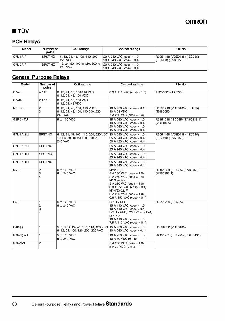
30 General-purpose Relays and Power Relays Standards
TÜV
PCB Relays
General Purpose Relays
Model Number of poles
Coil ratings Contact ratings File No.
G7L-1A-P SPST-NO 6, 12, 24, 48, 100, 110, 200, 220 VDC12, 24, 50, 100 to 120, 200 to 240 VAC
20 A 240 VAC (cosφ = 1.0)20 A 240 VAC (cosφ = 0.4)
R9051158 (VDE0435) (IEC255) (IEC950) (EN60950)
G7L-2A-P DPST-NO 20 A 240 VAC (cosφ = 1.0)20 A 240 VAC (cosφ = 0.4)
Model Number of poles
Coil ratings Contact ratings File No.
G2A-@ 4PDT 6, 12, 24, 50, 100/110 VAC6, 12, 24, 48, 100 VDC
0.3 A 110 VAC (cosφ = 1.0) T9251326 (IEC255)
G2AK-@ 2DPDT 6, 12, 24, 50, 100 VAC6, 12, 24, 48 VDC
MK-I/-S 23
6, 12, 24, 48, 100, 110 VDC6, 12, 24, 48, 100, 110 200, 220, 240 VAC
10 A 250 VAC (cosφ = 0.1)10 A 28 VDC7 A 250 VAC (cosφ = 0.4)
R9051410 (VDE0435) (IEC255) (EN60950)
G4F-( )-TU 1 5 to 100 VDC 15 A 250 VAC (cosφ = 1.0)10 A 250 VAC (cosφ = 0.4)20 A 250 VAC (cosφ = 1.0)15 A 250 VAC (cosφ = 0.4)
R9151218 (IEC255) (EN60335-1) (VDE0435)
G7L-1A-B@ SPST-NO 6, 12, 24, 48, 100, 110, 200, 220 VDC12, 24, 50, 100 to 120, 200 to 240 VAC
30 A 240 VAC (cosφ = 1.0)25 A 240 VAC (cosφ = 0.4)30 A 120 VAC (cosφ = 0.4)
R9051158 (VDE0435) (IEC255) (IEC950) (EN60950)
G7L-2A-B@ DPST-NO 25 A 240 VAC (cosφ = 1.0)25 A 240 VAC (cosφ = 0.4)
G7L-1A-T@ SPST-NO 25 A 240 VAC (cosφ = 1.0)25 A 240 VAC (cosφ = 0.4)
G7L-2A-T@ DPST-NO 25 A 240 VAC (cosφ = 1.0)25 A 240 VAC (cosφ = 0.4)
MY-@ 234
6 to 125 VDC6 to 240 VAC
MY2-02, F5 A 250 VAC (cosφ = 1.0)2 A 250 VAC (cosφ = 0.4)MY3 series3 A 250 VAC (cosφ = 1.0)0.8 A 250 VAC (cosφ = 0.4)MY4(Z)-02, F3 A 250 VAC (cosφ = 1.0)0.8 A 250 VAC (cosφ = 0.4)
R9151389 (IEC255) (EN60950) (EN60355-1)
LY-@ 1234
6 to 125 VDC6 to 240 VAC
LY1, LY1-FD15 A 110 VAC (cosφ = 1.0)10 A 110 VAC (cosφ = 0.4)LY2, LY2-FD, LY3, LY3-FD, LY4, LY4-FD10 A 110 VAC (cosφ = 1.0)7.5 A 110 VAC (cosφ = 0.4)
R9251226 (IEC255)
G4B-( ) 1 5, 6, 9, 12, 24, 48, 100, 110, 120 VDC6, 12, 24, 100, 120, 200, 220 VAC
15 A 250 VAC (cosφ = 1.0)10 A 250 VAC (cosφ = 0.4)
R9650822 (VDE0435)
G2R-1( )-S 1 5 to 110 VDC5 to 240 VAC
10 A 250 VAC (cosφ = 1.0)10 A 30 VDC (0 ms)
R9151251 (IEC 255) (VDE 0435)
G2R-2-S 2 5 A 250 VAC (cosφ = 1.0)5 A 30 VDC (0 ms)
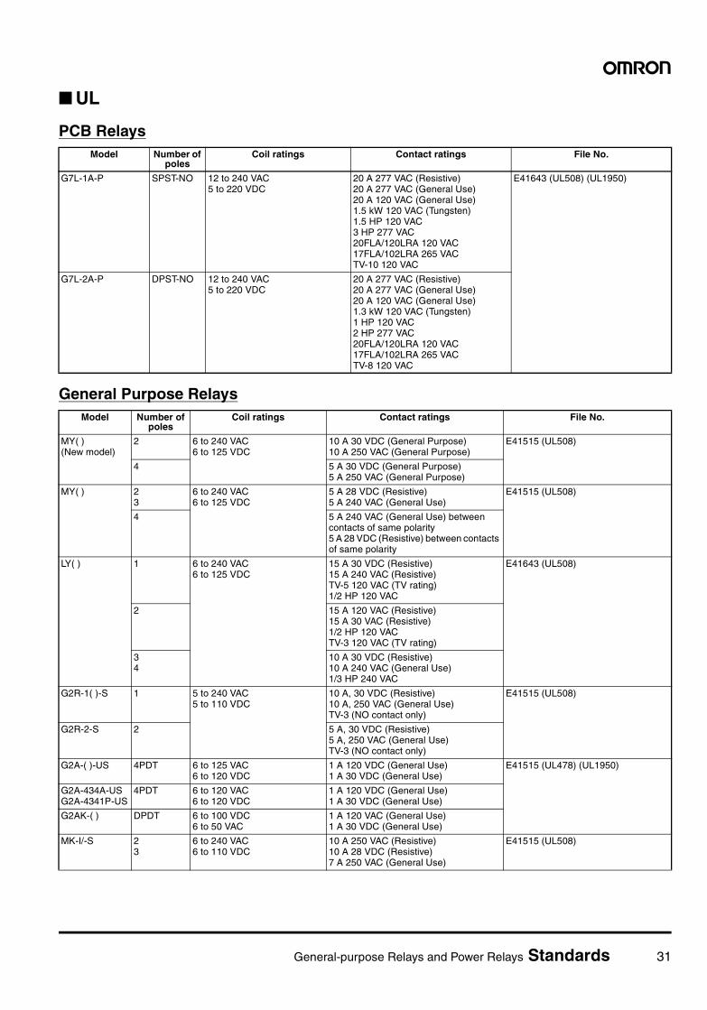
General-purpose Relays and Power Relays Standards 31
UL
PCB Relays
General Purpose Relays
Model Number of poles
Coil ratings Contact ratings File No.
G7L-1A-P SPST-NO 12 to 240 VAC5 to 220 VDC
20 A 277 VAC (Resistive)20 A 277 VAC (General Use)20 A 120 VAC (General Use)1.5 kW 120 VAC (Tungsten)1.5 HP 120 VAC3 HP 277 VAC20FLA/120LRA 120 VAC17FLA/102LRA 265 VACTV-10 120 VAC
E41643 (UL508) (UL1950)
G7L-2A-P DPST-NO 12 to 240 VAC5 to 220 VDC
20 A 277 VAC (Resistive)20 A 277 VAC (General Use)20 A 120 VAC (General Use)1.3 kW 120 VAC (Tungsten)1 HP 120 VAC2 HP 277 VAC20FLA/120LRA 120 VAC17FLA/102LRA 265 VACTV-8 120 VAC
Model Number of poles
Coil ratings Contact ratings File No.
MY( )(New model)
2 6 to 240 VAC6 to 125 VDC
10 A 30 VDC (General Purpose)10 A 250 VAC (General Purpose)
E41515 (UL508)
4 5 A 30 VDC (General Purpose)5 A 250 VAC (General Purpose)
MY( ) 23
6 to 240 VAC6 to 125 VDC
5 A 28 VDC (Resistive)5 A 240 VAC (General Use)
E41515 (UL508)
4 5 A 240 VAC (General Use) between contacts of same polarity5 A 28 VDC (Resistive) between contacts of same polarity
LY( ) 1 6 to 240 VAC6 to 125 VDC
15 A 30 VDC (Resistive)15 A 240 VAC (Resistive)TV-5 120 VAC (TV rating)1/2 HP 120 VAC
E41643 (UL508)
2 15 A 120 VAC (Resistive)15 A 30 VAC (Resistive)1/2 HP 120 VACTV-3 120 VAC (TV rating)
34
10 A 30 VDC (Resistive)10 A 240 VAC (General Use)1/3 HP 240 VAC
G2R-1( )-S 1 5 to 240 VAC5 to 110 VDC
10 A, 30 VDC (Resistive)10 A, 250 VAC (General Use)TV-3 (NO contact only)
E41515 (UL508)
G2R-2-S 2 5 A, 30 VDC (Resistive)5 A, 250 VAC (General Use)TV-3 (NO contact only)
G2A-( )-US 4PDT 6 to 125 VAC6 to 120 VDC
1 A 120 VDC (General Use)1 A 30 VDC (General Use)
E41515 (UL478) (UL1950)
G2A-434A-USG2A-4341P-US
4PDT 6 to 120 VAC6 to 120 VDC
1 A 120 VDC (General Use)1 A 30 VDC (General Use)
G2AK-( ) DPDT 6 to 100 VDC6 to 50 VAC
1 A 120 VAC (General Use)1 A 30 VDC (General Use)
MK-I/-S 23
6 to 240 VAC6 to 110 VDC
10 A 250 VAC (Resistive)10 A 28 VDC (Resistive)7 A 250 VAC (General Use)
E41515 (UL508)
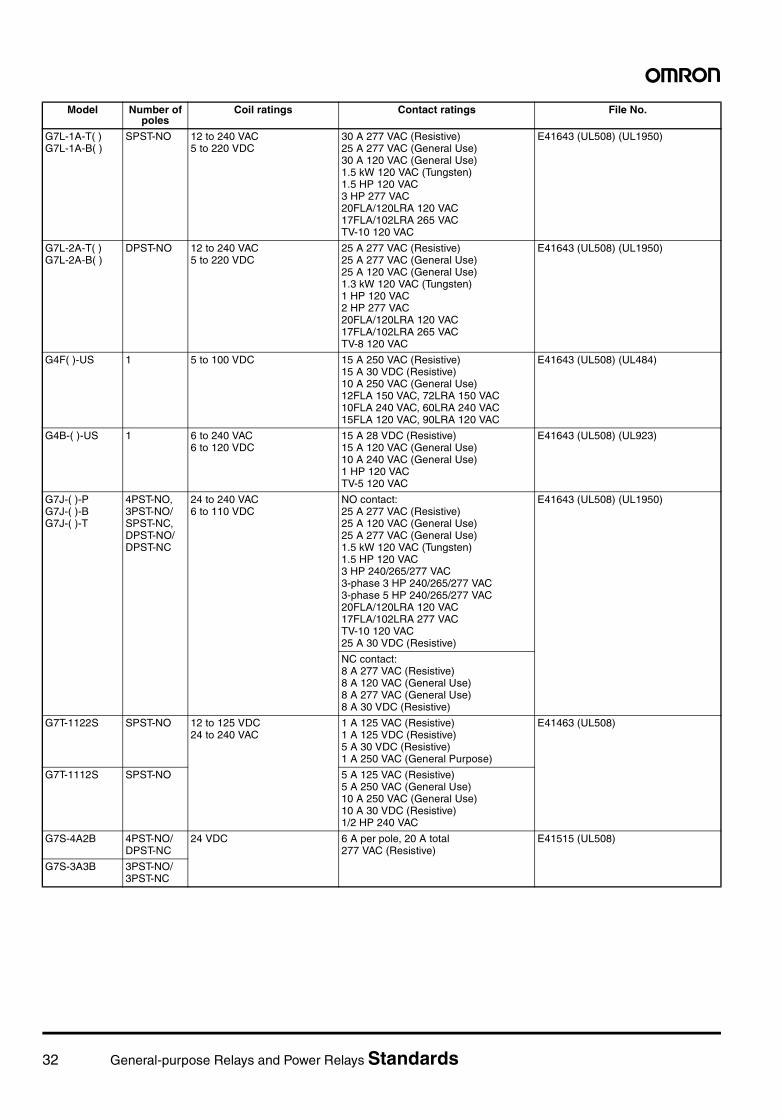
32 General-purpose Relays and Power Relays Standards
G7L-1A-T( )G7L-1A-B( )
SPST-NO 12 to 240 VAC5 to 220 VDC
30 A 277 VAC (Resistive)25 A 277 VAC (General Use)30 A 120 VAC (General Use)1.5 kW 120 VAC (Tungsten)1.5 HP 120 VAC3 HP 277 VAC20FLA/120LRA 120 VAC17FLA/102LRA 265 VACTV-10 120 VAC
E41643 (UL508) (UL1950)
G7L-2A-T( )G7L-2A-B( )
DPST-NO 12 to 240 VAC5 to 220 VDC
25 A 277 VAC (Resistive)25 A 277 VAC (General Use)25 A 120 VAC (General Use)1.3 kW 120 VAC (Tungsten)1 HP 120 VAC2 HP 277 VAC20FLA/120LRA 120 VAC17FLA/102LRA 265 VACTV-8 120 VAC
E41643 (UL508) (UL1950)
G4F( )-US 1 5 to 100 VDC 15 A 250 VAC (Resistive)15 A 30 VDC (Resistive)10 A 250 VAC (General Use)12FLA 150 VAC, 72LRA 150 VAC10FLA 240 VAC, 60LRA 240 VAC15FLA 120 VAC, 90LRA 120 VAC
E41643 (UL508) (UL484)
G4B-( )-US 1 6 to 240 VAC6 to 120 VDC
15 A 28 VDC (Resistive)15 A 120 VAC (General Use)10 A 240 VAC (General Use)1 HP 120 VACTV-5 120 VAC
E41643 (UL508) (UL923)
G7J-( )-PG7J-( )-BG7J-( )-T
4PST-NO,3PST-NO/SPST-NC,DPST-NO/DPST-NC
24 to 240 VAC6 to 110 VDC
NO contact:25 A 277 VAC (Resistive)25 A 120 VAC (General Use)25 A 277 VAC (General Use)1.5 kW 120 VAC (Tungsten)1.5 HP 120 VAC3 HP 240/265/277 VAC3-phase 3 HP 240/265/277 VAC3-phase 5 HP 240/265/277 VAC20FLA/120LRA 120 VAC17FLA/102LRA 277 VACTV-10 120 VAC25 A 30 VDC (Resistive)
E41643 (UL508) (UL1950)
NC contact:8 A 277 VAC (Resistive)8 A 120 VAC (General Use)8 A 277 VAC (General Use)8 A 30 VDC (Resistive)
G7T-1122S SPST-NO 12 to 125 VDC24 to 240 VAC
1 A 125 VAC (Resistive)1 A 125 VDC (Resistive)5 A 30 VDC (Resistive)1 A 250 VAC (General Purpose)
E41463 (UL508)
G7T-1112S SPST-NO 5 A 125 VAC (Resistive)5 A 250 VAC (General Use)10 A 250 VAC (General Use)10 A 30 VDC (Resistive)1/2 HP 240 VAC
G7S-4A2B 4PST-NO/DPST-NC
24 VDC 6 A per pole, 20 A total 277 VAC (Resistive)
E41515 (UL508)
G7S-3A3B 3PST-NO/3PST-NC
Model Number of poles
Coil ratings Contact ratings File No.
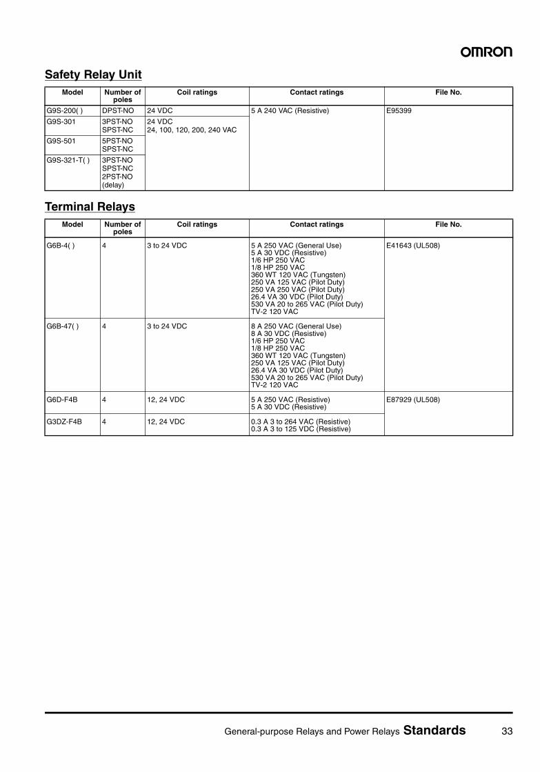
General-purpose Relays and Power Relays Standards 33
Safety Relay Unit
Terminal Relays
Model Number of poles
Coil ratings Contact ratings File No.
G9S-200( ) DPST-NO 24 VDC 5 A 240 VAC (Resistive) E95399
G9S-301 3PST-NOSPST-NC
24 VDC24, 100, 120, 200, 240 VAC
G9S-501 5PST-NOSPST-NC
G9S-321-T( ) 3PST-NOSPST-NC2PST-NO (delay)
Model Number of poles
Coil ratings Contact ratings File No.
G6B-4( ) 4 3 to 24 VDC 5 A 250 VAC (General Use)5 A 30 VDC (Resistive)1/6 HP 250 VAC1/8 HP 250 VAC360 WT 120 VAC (Tungsten)250 VA 125 VAC (Pilot Duty)250 VA 250 VAC (Pilot Duty)26.4 VA 30 VDC (Pilot Duty)530 VA 20 to 265 VAC (Pilot Duty)TV-2 120 VAC
E41643 (UL508)
G6B-47( ) 4 3 to 24 VDC 8 A 250 VAC (General Use)8 A 30 VDC (Resistive)1/6 HP 250 VAC1/8 HP 250 VAC360 WT 120 VAC (Tungsten)250 VA 125 VAC (Pilot Duty)26.4 VA 30 VDC (Pilot Duty)530 VA 20 to 265 VAC (Pilot Duty)TV-2 120 VAC
G6D-F4B 4 12, 24 VDC 5 A 250 VAC (Resistive)5 A 30 VDC (Resistive)
E87929 (UL508)
G3DZ-F4B 4 12, 24 VDC 0.3 A 3 to 264 VAC (Resistive)0.3 A 3 to 125 VDC (Resistive)
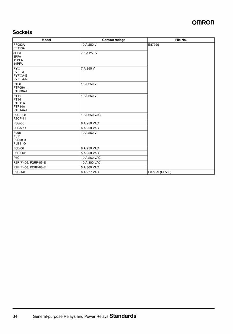
34 General-purpose Relays and Power Relays Standards
SocketsModel Contact ratings File No.
PF083APF113A
10 A 250 V E87929
8PFA8PFA111PFA14PFA
7.5 A 250 V
PY@PYF@APYF@A-EPYF@A-N
7 A 250 V
PT08PTF08APTF08A-E
15 A 250 V
PT11PT14PTF11APTF14APTF14A-E
10 A 250 V
P2CF-08P2CF-11
10 A 250 VAC
P3G-08 6 A 250 VAC
P3GA-11 6 A 250 VAC
PL08PL11PLE08-0PLE11-0
10 A 260 V
P6B-06 8 A 250 VAC
P6B-26P 5 A 250 VAC
P6C 10 A 250 VAC
P2R(F)-05, P2RF-05-E 10 A 300 VAC
P2R(F)-08, P2RF-08-E 5 A 300 VAC
P7S-14F 6 A 277 VAC E87929 (UL508)
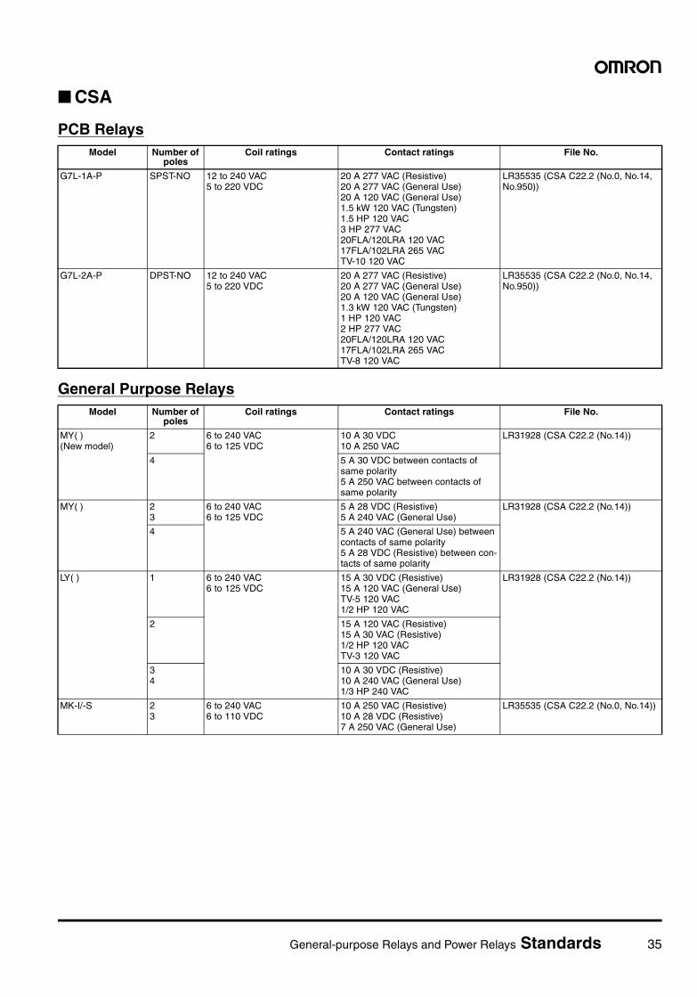
General-purpose Relays and Power Relays Standards 35
CSA
PCB Relays
General Purpose Relays
Model Number of poles
Coil ratings Contact ratings File No.
G7L-1A-P SPST-NO 12 to 240 VAC5 to 220 VDC
20 A 277 VAC (Resistive)20 A 277 VAC (General Use)20 A 120 VAC (General Use)1.5 kW 120 VAC (Tungsten)1.5 HP 120 VAC3 HP 277 VAC20FLA/120LRA 120 VAC17FLA/102LRA 265 VACTV-10 120 VAC
LR35535 (CSA C22.2 (No.0, No.14, No.950))
G7L-2A-P DPST-NO 12 to 240 VAC5 to 220 VDC
20 A 277 VAC (Resistive)20 A 277 VAC (General Use)20 A 120 VAC (General Use)1.3 kW 120 VAC (Tungsten)1 HP 120 VAC2 HP 277 VAC20FLA/120LRA 120 VAC17FLA/102LRA 265 VACTV-8 120 VAC
LR35535 (CSA C22.2 (No.0, No.14, No.950))
Model Number of poles
Coil ratings Contact ratings File No.
MY( )(New model)
2 6 to 240 VAC6 to 125 VDC
10 A 30 VDC10 A 250 VAC
LR31928 (CSA C22.2 (No.14))
4 5 A 30 VDC between contacts of same polarity5 A 250 VAC between contacts of same polarity
MY( ) 23
6 to 240 VAC6 to 125 VDC
5 A 28 VDC (Resistive)5 A 240 VAC (General Use)
LR31928 (CSA C22.2 (No.14))
4 5 A 240 VAC (General Use) between contacts of same polarity5 A 28 VDC (Resistive) between con-tacts of same polarity
LY( ) 1 6 to 240 VAC6 to 125 VDC
15 A 30 VDC (Resistive)15 A 120 VAC (General Use)TV-5 120 VAC1/2 HP 120 VAC
LR31928 (CSA C22.2 (No.14))
2 15 A 120 VAC (Resistive)15 A 30 VAC (Resistive)1/2 HP 120 VACTV-3 120 VAC
34
10 A 30 VDC (Resistive)10 A 240 VAC (General Use)1/3 HP 240 VAC
MK-I/-S 23
6 to 240 VAC6 to 110 VDC
10 A 250 VAC (Resistive)10 A 28 VDC (Resistive)7 A 250 VAC (General Use)
LR35535 (CSA C22.2 (No.0, No.14))
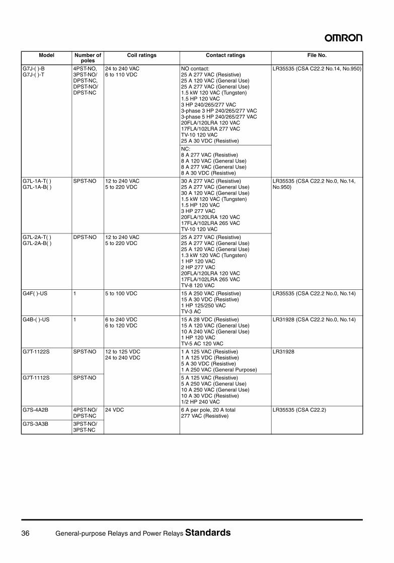
36 General-purpose Relays and Power Relays Standards
G7J-( )-BG7J-( )-T
4PST-NO,3PST-NO/DPST-NC,DPST-NO/DPST-NC
24 to 240 VAC6 to 110 VDC
NO contact:25 A 277 VAC (Resistive)25 A 120 VAC (General Use)25 A 277 VAC (General Use)1.5 kW 120 VAC (Tungsten)1.5 HP 120 VAC3 HP 240/265/277 VAC3-phase 3 HP 240/265/277 VAC3-phase 5 HP 240/265/277 VAC20FLA/120LRA 120 VAC17FLA/102LRA 277 VACTV-10 120 VAC25 A 30 VDC (Resistive)
LR35535 (CSA C22.2 No.14, No.950)
NC:8 A 277 VAC (Resistive)8 A 120 VAC (General Use)8 A 277 VAC (General Use)8 A 30 VDC (Resistive)
G7L-1A-T( )G7L-1A-B( )
SPST-NO 12 to 240 VAC5 to 220 VDC
30 A 277 VAC (Resistive)25 A 277 VAC (General Use)30 A 120 VAC (General Use)1.5 kW 120 VAC (Tungsten)1.5 HP 120 VAC3 HP 277 VAC20FLA/120LRA 120 VAC17FLA/102LRA 265 VACTV-10 120 VAC
LR35535 (CSA C22.2 No.0, No.14, No.950)
G7L-2A-T( )G7L-2A-B( )
DPST-NO 12 to 240 VAC5 to 220 VDC
25 A 277 VAC (Resistive)25 A 277 VAC (General Use)25 A 120 VAC (General Use)1.3 kW 120 VAC (Tungsten)1 HP 120 VAC2 HP 277 VAC20FLA/120LRA 120 VAC17FLA/102LRA 265 VACTV-8 120 VAC
G4F( )-US 1 5 to 100 VDC 15 A 250 VAC (Resistive)15 A 30 VDC (Resistive)1 HP 125/250 VACTV-3 AC
LR35535 (CSA C22.2 No.0, No.14)
G4B-( )-US 1 6 to 240 VDC6 to 120 VDC
15 A 28 VDC (Resistive)15 A 120 VAC (General Use)10 A 240 VAC (General Use)1 HP 120 VACTV-5 AC 120 VAC
LR31928 (CSA C22.2 No.0, No.14)
G7T-1122S SPST-NO 12 to 125 VDC24 to 240 VDC
1 A 125 VAC (Resistive)1 A 125 VDC (Resistive)5 A 30 VDC (Resistive)1 A 250 VAC (General Purpose)
LR31928
G7T-1112S SPST-NO 5 A 125 VAC (Resistive)5 A 250 VAC (General Use)10 A 250 VAC (General Use)10 A 30 VDC (Resistive)1/2 HP 240 VAC
G7S-4A2B 4PST-NO/DPST-NC
24 VDC 6 A per pole, 20 A total 277 VAC (Resistive)
LR35535 (CSA C22.2)
G7S-3A3B 3PST-NO/3PST-NC
Model Number of poles
Coil ratings Contact ratings File No.
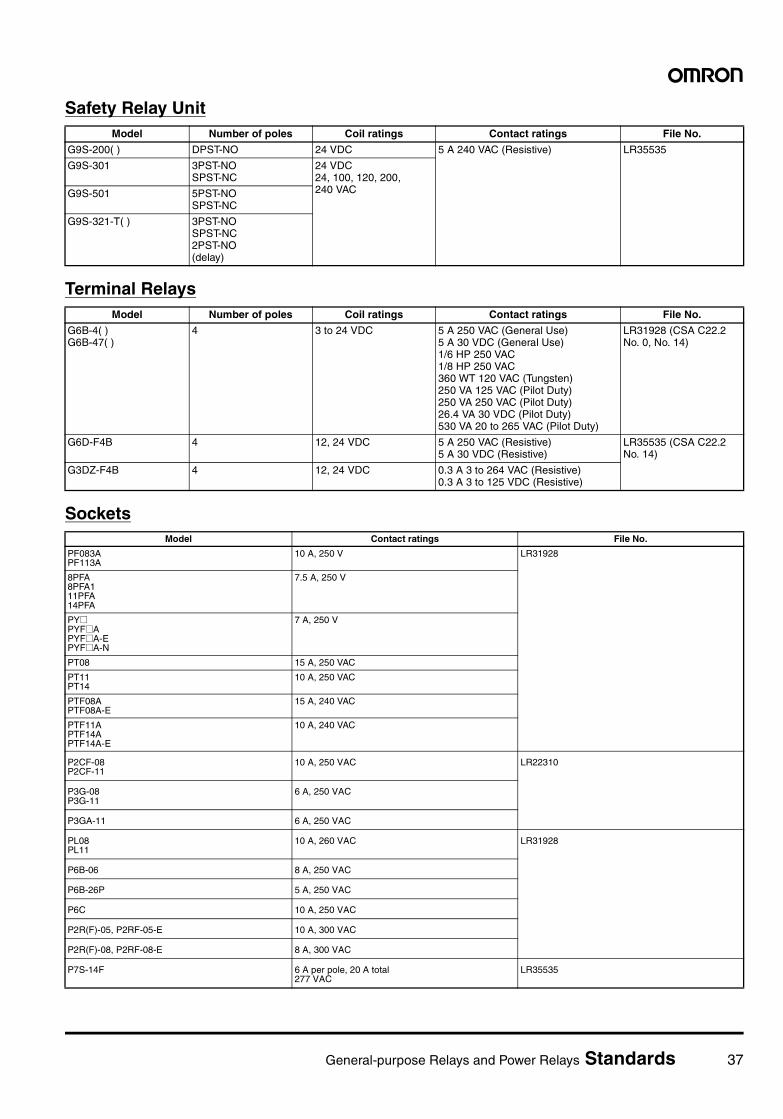
General-purpose Relays and Power Relays Standards 37
Safety Relay Unit
Terminal Relays
Sockets
Model Number of poles Coil ratings Contact ratings File No.
G9S-200( ) DPST-NO 24 VDC 5 A 240 VAC (Resistive) LR35535
G9S-301 3PST-NOSPST-NC
24 VDC24, 100, 120, 200, 240 VACG9S-501 5PST-NO
SPST-NC
G9S-321-T( ) 3PST-NOSPST-NC2PST-NO(delay)
Model Number of poles Coil ratings Contact ratings File No.
G6B-4( )G6B-47( )
4 3 to 24 VDC 5 A 250 VAC (General Use)5 A 30 VDC (General Use)1/6 HP 250 VAC1/8 HP 250 VAC360 WT 120 VAC (Tungsten)250 VA 125 VAC (Pilot Duty)250 VA 250 VAC (Pilot Duty)26.4 VA 30 VDC (Pilot Duty)530 VA 20 to 265 VAC (Pilot Duty)
LR31928 (CSA C22.2No. 0, No. 14)
G6D-F4B 4 12, 24 VDC 5 A 250 VAC (Resistive)5 A 30 VDC (Resistive)
LR35535 (CSA C22.2No. 14)
G3DZ-F4B 4 12, 24 VDC 0.3 A 3 to 264 VAC (Resistive)0.3 A 3 to 125 VDC (Resistive)
Model Contact ratings File No.
PF083APF113A
10 A, 250 V LR31928
8PFA8PFA111PFA14PFA
7.5 A, 250 V
PY@PYF@APYF@A-EPYF@A-N
7 A, 250 V
PT08 15 A, 250 VAC
PT11PT14
10 A, 250 VAC
PTF08APTF08A-E
15 A, 240 VAC
PTF11APTF14APTF14A-E
10 A, 240 VAC
P2CF-08P2CF-11
10 A, 250 VAC LR22310
P3G-08P3G-11
6 A, 250 VAC
P3GA-11 6 A, 250 VAC
PL08PL11
10 A, 260 VAC LR31928
P6B-06 8 A, 250 VAC
P6B-26P 5 A, 250 VAC
P6C 10 A, 250 VAC
P2R(F)-05, P2RF-05-E 10 A, 300 VAC
P2R(F)-08, P2RF-08-E 8 A, 300 VAC
P7S-14F 6 A per pole, 20 A total 277 VAC
LR35535
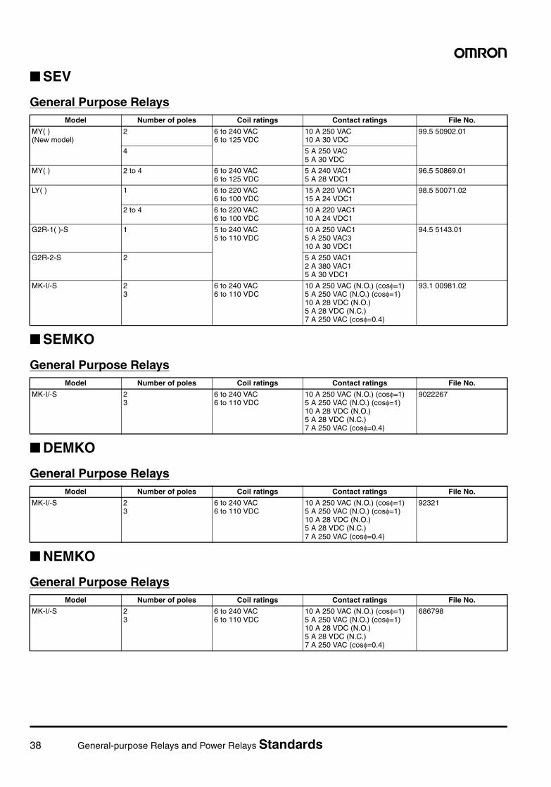
38 General-purpose Relays and Power Relays Standards
SEV
General Purpose Relays
SEMKO
General Purpose Relays
DEMKO
General Purpose Relays
NEMKO
General Purpose Relays
Model Number of poles Coil ratings Contact ratings File No.
MY( ) (New model)
2 6 to 240 VAC6 to 125 VDC
10 A 250 VAC10 A 30 VDC
99.5 50902.01
4 5 A 250 VAC5 A 30 VDC
MY( ) 2 to 4 6 to 240 VAC6 to 125 VDC
5 A 240 VAC15 A 28 VDC1
96.5 50869.01
LY( ) 1 6 to 220 VAC6 to 100 VDC
15 A 220 VAC115 A 24 VDC1
98.5 50071.02
2 to 4 6 to 220 VAC6 to 100 VDC
10 A 220 VAC110 A 24 VDC1
G2R-1( )-S 1 5 to 240 VAC5 to 110 VDC
10 A 250 VAC15 A 250 VAC310 A 30 VDC1
94.5 5143.01
G2R-2-S 2 5 A 250 VAC12 A 380 VAC15 A 30 VDC1
MK-I/-S 23
6 to 240 VAC6 to 110 VDC
10 A 250 VAC (N.O.) (cosφ=1)5 A 250 VAC (N.O.) (cosφ=1)10 A 28 VDC (N.O.)5 A 28 VDC (N.C.)7 A 250 VAC (cosφ=0.4)
93.1 00981.02
Model Number of poles Coil ratings Contact ratings File No.
MK-I/-S 23
6 to 240 VAC6 to 110 VDC
10 A 250 VAC (N.O.) (cosφ=1)5 A 250 VAC (N.O.) (cosφ=1)10 A 28 VDC (N.O.)5 A 28 VDC (N.C.)7 A 250 VAC (cosφ=0.4)
9022267
Model Number of poles Coil ratings Contact ratings File No.
MK-I/-S 23
6 to 240 VAC6 to 110 VDC
10 A 250 VAC (N.O.) (cosφ=1)5 A 250 VAC (N.O.) (cosφ=1)10 A 28 VDC (N.O.)5 A 28 VDC (N.C.)7 A 250 VAC (cosφ=0.4)
92321
Model Number of poles Coil ratings Contact ratings File No.
MK-I/-S 23
6 to 240 VAC6 to 110 VDC
10 A 250 VAC (N.O.) (cosφ=1)5 A 250 VAC (N.O.) (cosφ=1)10 A 28 VDC (N.O.)5 A 28 VDC (N.C.)7 A 250 VAC (cosφ=0.4)
686798
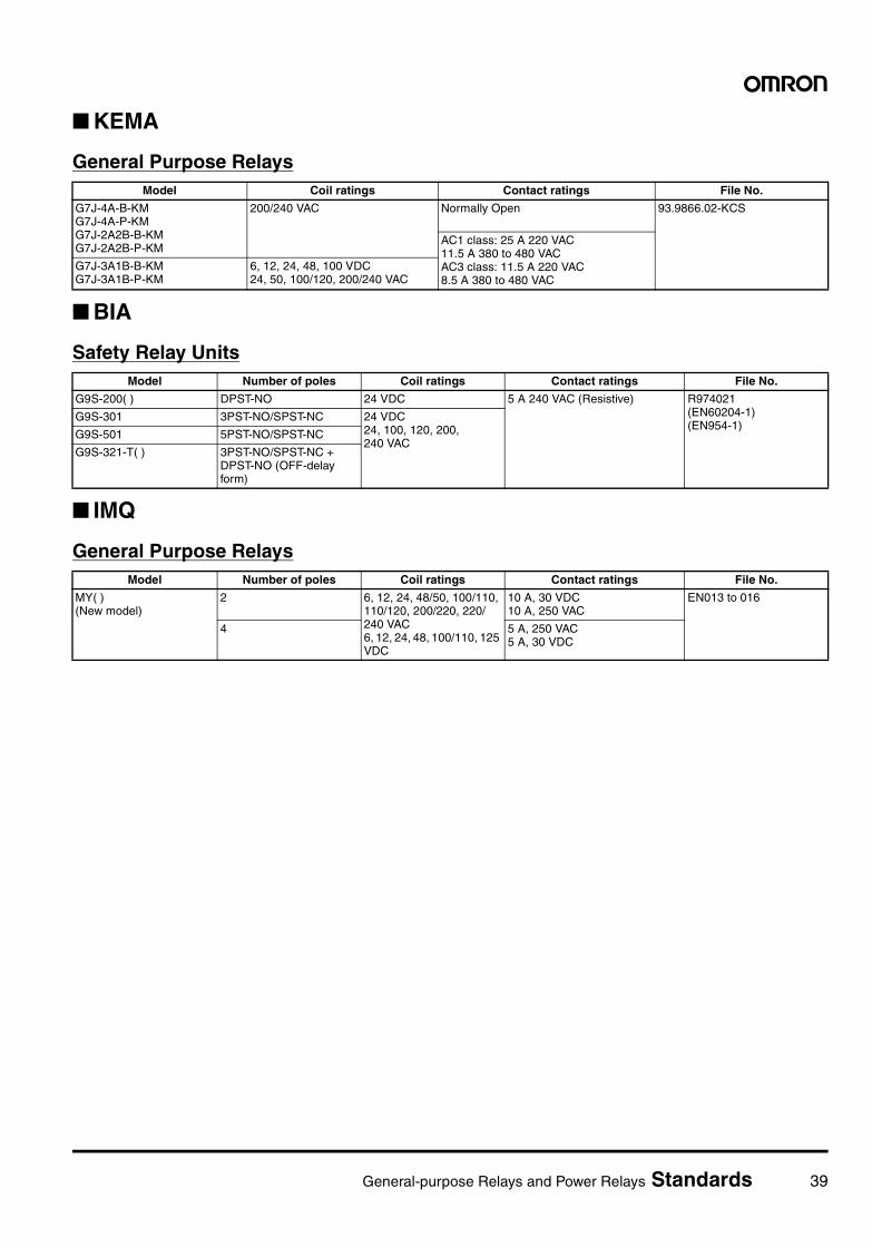
General-purpose Relays and Power Relays Standards 39
KEMA
General Purpose Relays
BIA
Safety Relay Units
IMQ
General Purpose Relays
Model Coil ratings Contact ratings File No.
G7J-4A-B-KMG7J-4A-P-KMG7J-2A2B-B-KMG7J-2A2B-P-KM
200/240 VAC Normally Open 93.9866.02-KCS
AC1 class: 25 A 220 VAC11.5 A 380 to 480 VACAC3 class: 11.5 A 220 VAC8.5 A 380 to 480 VAC
G7J-3A1B-B-KMG7J-3A1B-P-KM
6, 12, 24, 48, 100 VDC24, 50, 100/120, 200/240 VAC
Model Number of poles Coil ratings Contact ratings File No.
G9S-200( ) DPST-NO 24 VDC 5 A 240 VAC (Resistive) R974021(EN60204-1)(EN954-1)
G9S-301 3PST-NO/SPST-NC 24 VDC24, 100, 120, 200, 240 VAC
G9S-501 5PST-NO/SPST-NC
G9S-321-T( ) 3PST-NO/SPST-NC + DPST-NO (OFF-delay form)
Model Number of poles Coil ratings Contact ratings File No.
MY( )(New model)
2 6, 12, 24, 48/50, 100/110, 110/120, 200/220, 220/240 VAC6, 12, 24, 48, 100/110, 125 VDC
10 A, 30 VDC10 A, 250 VAC
EN013 to 016
4 5 A, 250 VAC5 A, 30 VDC
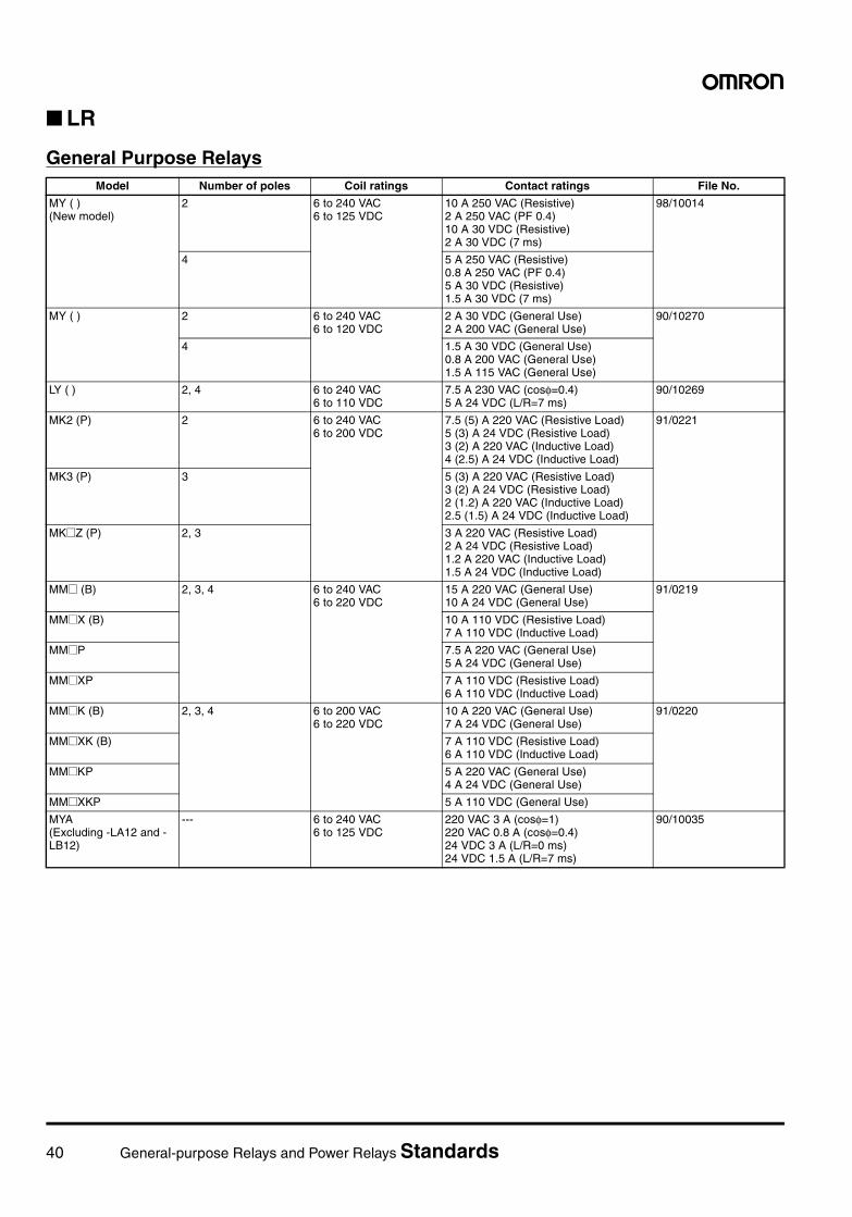
40 General-purpose Relays and Power Relays Standards
LR
General Purpose RelaysModel Number of poles Coil ratings Contact ratings File No.
MY ( ) (New model)
2 6 to 240 VAC6 to 125 VDC
10 A 250 VAC (Resistive)2 A 250 VAC (PF 0.4)10 A 30 VDC (Resistive)2 A 30 VDC (7 ms)
98/10014
4 5 A 250 VAC (Resistive)0.8 A 250 VAC (PF 0.4)5 A 30 VDC (Resistive)1.5 A 30 VDC (7 ms)
MY ( ) 2 6 to 240 VAC6 to 120 VDC
2 A 30 VDC (General Use)2 A 200 VAC (General Use)
90/10270
4 1.5 A 30 VDC (General Use)0.8 A 200 VAC (General Use)1.5 A 115 VAC (General Use)
LY ( ) 2, 4 6 to 240 VAC6 to 110 VDC
7.5 A 230 VAC (cosφ=0.4)5 A 24 VDC (L/R=7 ms)
90/10269
MK2 (P) 2 6 to 240 VAC6 to 200 VDC
7.5 (5) A 220 VAC (Resistive Load)5 (3) A 24 VDC (Resistive Load)3 (2) A 220 VAC (Inductive Load)4 (2.5) A 24 VDC (Inductive Load)
91/0221
MK3 (P) 3 5 (3) A 220 VAC (Resistive Load)3 (2) A 24 VDC (Resistive Load)2 (1.2) A 220 VAC (Inductive Load)2.5 (1.5) A 24 VDC (Inductive Load)
MK@Z (P) 2, 3 3 A 220 VAC (Resistive Load)2 A 24 VDC (Resistive Load)1.2 A 220 VAC (Inductive Load)1.5 A 24 VDC (Inductive Load)
MM@ (B) 2, 3, 4 6 to 240 VAC6 to 220 VDC
15 A 220 VAC (General Use)10 A 24 VDC (General Use)
91/0219
MM@X (B) 10 A 110 VDC (Resistive Load)7 A 110 VDC (Inductive Load)
MM@P 7.5 A 220 VAC (General Use)5 A 24 VDC (General Use)
MM@XP 7 A 110 VDC (Resistive Load)6 A 110 VDC (Inductive Load)
MM@K (B) 2, 3, 4 6 to 200 VAC6 to 220 VDC
10 A 220 VAC (General Use)7 A 24 VDC (General Use)
91/0220
MM@XK (B) 7 A 110 VDC (Resistive Load)6 A 110 VDC (Inductive Load)
MM@KP 5 A 220 VAC (General Use)4 A 24 VDC (General Use)
MM@XKP 5 A 110 VDC (General Use)
MYA(Excluding -LA12 and -LB12)
--- 6 to 240 VAC6 to 125 VDC
220 VAC 3 A (cosφ=1)220 VAC 0.8 A (cosφ=0.4)24 VDC 3 A (L/R=0 ms)24 VDC 1.5 A (L/R=7 ms)
90/10035
General-purpose Relays and Power Relays Selection Guide 41
General-purpose Relays and Power Relays
Selection Guide
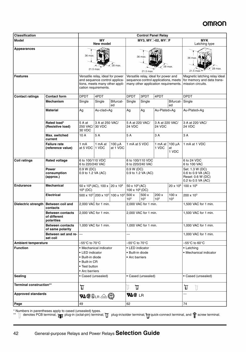
42 General-purpose Relays and Power Relays Selection Guide
Classification Control Panel Relay
Model MYNew model
MY3, MY@-02, MY@F MYKLatching type
Appearances
Features Versatile relay, ideal for power and sequence control applica-tions, meets many other appli-cation requirements.
Versatile relay, ideal for power and sequence control applications, meets many other application requirements.
Magnetic latching relay ideal for memory and data trans-mission circuits.
Contact ratings Contact form DPDT 4PDT DPDT 3PDT 4PDT DPDT
Mechanism Single Single Bifurcat-ed
Single Single Bifurcat-ed
Single
Material Ag Au-clad+Ag Ag Ag Au-Plated+Ag Au-Plated+Ag
Rated load*(Resistive load)
5 A at 250 VAC/30 VDC
3 A at 250 VAC/30 VDC
5 A at 220 VAC/24 VDC
3 A at 220 VAC/24 VDC
3 A at 220 VAC/24 VDC
Max. switched current
10 A 5 A 5 A 3 A 3 A
Failure rate (reference value)
1 mA at 5 VDC
1 mA at 1 VDC
100 µA at 1 VDC
1 mA at 5 VDC 1 mA at 1 VDC
100 µA at 1 VDC
1 mA at 1 VDC
Coil ratings Rated voltage 6 to 100/110 VDC6 to 220/240 VAC
6 to 100/110 VDC6 to 220/240 VAC
6 to 24 VDC6 to 100 VAC
Power consumption (approx.)
0.9 W (DC)0.9 to 1.2 VA (AC)
0.9 W (DC)0.9 to 1.2 VA (AC)
Set: 1.3 W (DC) 0.6 to 0.9 VA (AC)Reset: 0.6 W (DC)0.2 to 0.5 VA (AC)
Endurance Mechanical 50 x 106 (AC), 100 x 106 (DC)
20 x 106 50 x 106 (AC)100 x 106 (DC)
20 x 106 100 x 106
Electrical 500 x 103 200 x 103 100 x 103 500 x 103
500 x 103
200 x 103
100 x 103
200 x 103
Dielectric strength Between coil and contacts
2,000 VAC for 1 min. 2,000 VAC for 1 min. 1,500 VAC for 1 min.
Between contacts of different polarities
2,000 VAC for 1 min. 2,000 VAC for 1 min. 1,500 VAC for 1 min.
Between contacts of same polarity
1,000 VAC for 1 min. 1,000 VAC for 1 min. 1,000 VAC for 1 min.
Between set and re-set coil
--- --- 1,000 VAC for 1 min.
Ambient temperature –55°C to 70°C –55°C to 70°C –55°C to 60°CFunction • Mechanical indicator
• LED indicator• Built-in diode• Built-in CR• Test button• Arc barriers
• LED indicator• Built-in diode• Arc barriers
• Latching• Mechanical indicator
Sealing • Cased (unsealed) • Cased (unsealed) • Cased (unsealed)
Terminal construction**
Approved standards RC LR ---
Page 49 62 74
36 max.
28 max.21.5 max.
36 max.
28 max.
21.5 max.
36 max.
28 max.21.5 max.
RC+LRXVDE
* Numbers in parentheses apply to cased (unsealed) types.** denotes PCB terminal, plug-in (octal-pin) terminal, plug-in/solder terminal, quick-connect terminal, and screw terminal.
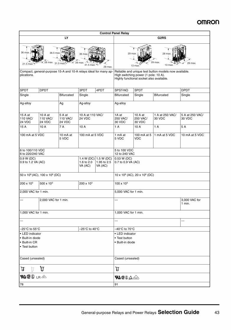
General-purpose Relays and Power Relays Selection Guide 43
Control Panel Relay
LY G2RS
Compact, general-purpose 15-A and 10-A relays ideal for many ap-plications.
Reliable and unique test button models now available. High switching power (1 pole: 10 A).Highly functional socket also available.
SPDT DPDT 3PDT 4PDT SPST-NO SPDT DPDT
Single Bifurcated Single Bifurcated Single Bifurcated Single
Ag-alloy Ag Ag-alloy Ag-alloy
15 A at 110 VAC/24 VDC
10 A at 110 VAC/24 VDC
5 A at 110 VAC/24 VDC
10 A at 110 VAC/24 VDC
1A at 250 VAC/30 VDC
10 A at 250 VAC/30 VDC
1 A at 250 VAC/30 VDC
5 A at 250 VAC/30 VDC
15 A 10 A 7 A 10 A 1 A 10 A 1 A 5 A
100 mA at 5 VDC 10 mA at 5 VDC
100 mA at 5 VDC 1 mA at 5 VDC
100 mA at 5 VDC
1 mA at 5 VDC 10 mA at 5 VDC
6 to 100/110 VDC6 to 220/240 VAC
5 to 100 VDC 12 to 240 VAC
0.9 W (DC)0.9 to 1.2 VA (AC)
1.4 W (DC)1.6 to 2.0 VA (AC)
1.5 W (DC)1.95 to 2.5 VA (AC)
0.53 W (DC)0.7 to 0.9 VA (AC)
50 x 106 (AC), 100 x 106 (DC) 10 x 106 (AC), 20 x 106 (DC)
200 x 103 500 x 103 200 x 103 100 x 103
2,000 VAC for 1 min. 5,000 VAC for 1 min.
--- 2,000 VAC for 1 min. --- 3,000 VAC for 1 min.
1,000 VAC for 1 min. 1,000 VAC for 1 min.
--- --- ---
–25°C to 55°C –25°C to 40°C –40°C to 70°C• LED indicator• Built-in diode• Built-in CR• Test button
• LED indicator• Test button• Built-in diode
Cased (unsealed) Cased (unsealed)
78 91
36 max.36 max.36.5 max.
28 max.21.5 max. 28 max.31.5 max.
41.5 max.28 max.
29 max. 28 max.
29 max.13 max.
29 max.13 max.
RC+ LR Z RC+EXVDE
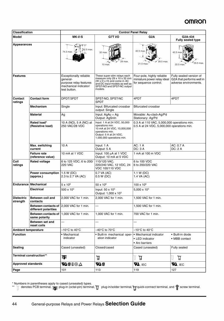
44 General-purpose Relays and Power Relays Selection Guide
Classification Control Panel Relay
Model MK-I/-S G7T I/O G2A G2A-434Fully sealed type
Appearances
Features Exceptionally reliable general-purpose relay features mechanical indicator/test button.
These super-slim relays each measure only 29 x 10 x 32 mm (W x D x H) and come in AC and DC input models as well as SPST-NO and SPST-NC output models.
Four-pole, highly reliable miniature power relay ideal for sequence control.
Fully sealed version of G2A that performs well in adverse environments.
Contact ratings
Contact form DPDT/3PDT SPST-NO, SPST-NCSPDT
4PDT 4PDT
Mechanism Single Input: Bifurcated crossbaroutput: Single
Bifurcated crossbar
Material Ag Input: AgAu + AgOutput: AgSnIn
Movable: Au-clad+Ag/PdStationary: Ag/Pd
Rated load*(Resistive load)
10 A (NO), 5 A (NC) at 250 VAC/28 VDC
Input: 1 A at 24 VDC, 50,000 operations min.10 mA at 24 VDC, 10,000,000 operations min.Output: 5 A at 24 VDC, 1,000,000 operations min.
0.3 A at 110 VAC, 5,000,000 operations min.0.5 A at 24 VDC, 5,000,000 operations min.
Max. switching current
10 A Input: 1 AOutput: 5 A
AC: 1 ADC: 3 A
AC: 0.7 ADC: 2 A
Failure rate (reference value)
10 mA at 1 VDC Input: 100 µA at 1 VDCOutput: 10 mA at 5 VDC
1 mA at 100 m VDC
Coil ratings
Rated voltage 6 to 125 VDC; 6 to 200/220 VAC
110/120 VAC, 220/240 VAC, 12 VDC, 24 VDC 100/110 VDC
6 to 100 VDC6 to 200/220 VAC
Power consumption (approx.)
1.5 W (DC)2.3 to 2.7 VA (AC)
0.7 VA (AC)0.5 W (DC)
1.1 W (DC)1.4 VA (AC)
Endurance Mechanical 5 x 10⁶ 50 x 106 100 x 106
Electrical 500 x 103 Input: 50 x 103
Output: 1,000 x 1035,000 x 103
Dielectric strength
Between coil and contacts
2,000 VAC for 1 min. 2,000 VAC for 1 min. 1,500 VAC for 1 min.
Between contacts of different polarities
2,000 VAC for 1 min. --- 1,500 VAC for 1 min.
Between contacts of same polarity
1,000 VAC for 1 min. 1,000 VAC for 1 min. 700 VAC for 1 min.
Between set and reset coils
--- --- ---
Ambient temperature –10°C to 40°C –40°C to 70°C –10°C to 40°CFunction • Mechanical
indicator• Built-in mechanical oper-
ation indicator• Mechanical indicator• LED indicator• Arc barriers
• Built-in diode• MBB contact
Sealing Cased (unsealed) Closed/cased Cased (unsealed) Fully sealed
Terminal construction**
Approved standards RC+DE RC R, IEC R, IEC
Page 101 113 119 127
74.3 max.52.5 max.
32 max.
10 max.29 max.
42.5 max.
21.5 max.28.5 max.
42.5 max.
29.5 max.22.5 max.
* Numbers in parentheses apply to cased (unsealed) types.** denotes PCB terminal, plug-in (octal-pin) terminal, plug-in/solder terminal, quick-connect terminal, and screw terminal.
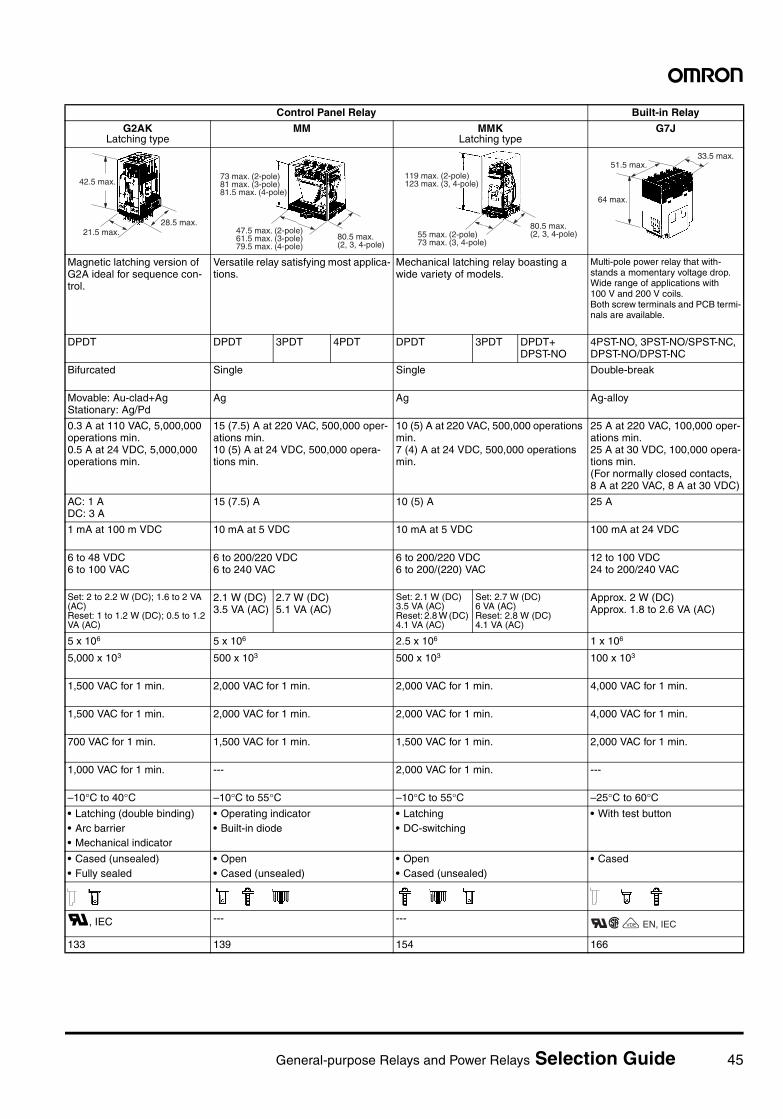
General-purpose Relays and Power Relays Selection Guide 45
Control Panel Relay Built-in Relay
G2AKLatching type
MM MMKLatching type
G7J
Magnetic latching version of G2A ideal for sequence con-trol.
Versatile relay satisfying most applica-tions.
Mechanical latching relay boasting a wide variety of models.
Multi-pole power relay that with-stands a momentary voltage drop.Wide range of applications with 100 V and 200 V coils.Both screw terminals and PCB termi-nals are available.
DPDT DPDT 3PDT 4PDT DPDT 3PDT DPDT+DPST-NO
4PST-NO, 3PST-NO/SPST-NC, DPST-NO/DPST-NC
Bifurcated Single Single Double-break
Movable: Au-clad+AgStationary: Ag/Pd
Ag Ag Ag-alloy
0.3 A at 110 VAC, 5,000,000 operations min.0.5 A at 24 VDC, 5,000,000 operations min.
15 (7.5) A at 220 VAC, 500,000 oper-ations min.10 (5) A at 24 VDC, 500,000 opera-tions min.
10 (5) A at 220 VAC, 500,000 operations min.7 (4) A at 24 VDC, 500,000 operations min.
25 A at 220 VAC, 100,000 oper-ations min.25 A at 30 VDC, 100,000 opera-tions min. (For normally closed contacts, 8 A at 220 VAC, 8 A at 30 VDC)
AC: 1 ADC: 3 A
15 (7.5) A 10 (5) A 25 A
1 mA at 100 m VDC 10 mA at 5 VDC 10 mA at 5 VDC 100 mA at 24 VDC
6 to 48 VDC6 to 100 VAC
6 to 200/220 VDC6 to 240 VAC
6 to 200/220 VDC6 to 200/(220) VAC
12 to 100 VDC24 to 200/240 VAC
Set: 2 to 2.2 W (DC); 1.6 to 2 VA (AC)Reset: 1 to 1.2 W (DC); 0.5 to 1.2 VA (AC)
2.1 W (DC)3.5 VA (AC)
2.7 W (DC)5.1 VA (AC)
Set: 2.1 W (DC) 3.5 VA (AC) Reset: 2.8 W (DC) 4.1 VA (AC)
Set: 2.7 W (DC) 6 VA (AC) Reset: 2.8 W (DC) 4.1 VA (AC)
Approx. 2 W (DC)Approx. 1.8 to 2.6 VA (AC)
5 x 10⁶ 5 x 10⁶ 2.5 x 10⁶ 1 x 10⁶
5,000 x 103 500 x 103 500 x 103 100 x 103
1,500 VAC for 1 min. 2,000 VAC for 1 min. 2,000 VAC for 1 min. 4,000 VAC for 1 min.
1,500 VAC for 1 min. 2,000 VAC for 1 min. 2,000 VAC for 1 min. 4,000 VAC for 1 min.
700 VAC for 1 min. 1,500 VAC for 1 min. 1,500 VAC for 1 min. 2,000 VAC for 1 min.
1,000 VAC for 1 min. --- 2,000 VAC for 1 min. ---
–10°C to 40°C –10°C to 55°C –10°C to 55°C –25°C to 60°C• Latching (double binding)• Arc barrier• Mechanical indicator
• Operating indicator• Built-in diode
• Latching• DC-switching
• With test button
• Cased (unsealed)• Fully sealed
• Open• Cased (unsealed)
• Open• Cased (unsealed)
• Cased
R, IEC --- ---
133 139 154 166
42.5 max.
21.5 max.28.5 max.
73 max. (2-pole) 81 max. (3-pole) 81.5 max. (4-pole)
47.5 max. (2-pole)61.5 max. (3-pole)79.5 max. (4-pole)
80.5 max. (2, 3, 4-pole)
119 max. (2-pole)123 max. (3, 4-pole)
55 max. (2-pole)73 max. (3, 4-pole)
80.5 max. (2, 3, 4-pole)
64 max.
51.5 max.33.5 max.
EN, IECRCXVDE
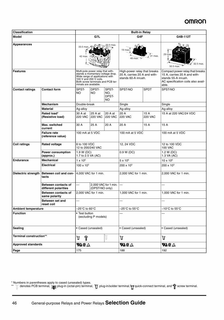
46 General-purpose Relays and Power Relays Selection Guide
Classification Built-in Relay
Model G7L G4F G4B-112T
Appearances
Features Multi-pole power relay that with-stands a momentary voltage drop.Wide range of applications with 100 V and 200 V coils.Both screw terminals and PCB ter-minals are available.
High-power relay that breaks 20 A, carries 20 A and with-stands 60-A inrush.
Compact power relay that breaks 15 A, carries 20 A and with-stands 55-A inrush.AC specification coils also avail-able.
Contact ratings Contact form SPST-NO
DPST-NO
SPST-NO, DPST-NO
SPST-NO SPDT SPST-NO
Mechanism Double-break Single Single
Material Ag-alloy Ag-alloy Ag-alloy
Rated load*(Resistive load)
30 A at 220 VAC
25 A at 220 VAC
20 A at 220 VAC
20 A220 VAC
15 A220 VAC
15 A at 220 VAC/24 VDC
Max. switched current
30 A 25 A 20 A 20 A 15 A 15 A
Failure rate (reference value)
100 mA at 5 VDC 100 mA at 5 VDC 100 mA at 5 VDC
Coil ratings Rated voltage 6 to 100 VDC 12 to 200/240 VAC
12, 24 VDC 12 to 100 VDC 100 VAC
Power consumption (approx.)
1.9 W (DC)1.7 to 2.5 VA (AC)
0.9 W (DC) 1.2 W (DC)1.3 VA (AC)
Endurance Mechanical 1 x 10⁶ 5 x 10⁶ 10 x 106
Electrical 100 x 103 200 x 103 200 x 103
Dielectric strength Between coil and con-tacts
4,000 VAC for 1 min. 2,000 VAC for 1 min. 2,000 VAC for 1 min.
Between contacts of different polarities
--- 2,000 VAC for 1 min. (DPST-NO only)
--- ---
Between contacts of same polarity
2,000 VAC for 1 min. 1,000 VAC for 1 min. 1,000 VAC for 1 min.
Between set and reset coil
--- --- ---
Ambient temperature –25°C to 60°C –25°C to 55°C –10°C to 55°CFunction • Test button
(excluding P models)--- ---
Sealing • Cased (unsealed) • Cased (unsealed) • Cased (unsealed)
Terminal construction**
Approved standards RCE RCE RCEPage 175 188 192
42 max.
33.5 max.52.5 max.
19 max.
48 max.31 max.
29 max.
50.5 max.32.5 max.
* Numbers in parentheses apply to cased (unsealed) types.** denotes PCB terminal, plug-in (octal-pin) terminal, plug-in/solder terminal, quick-connect terminal, and screw terminal.
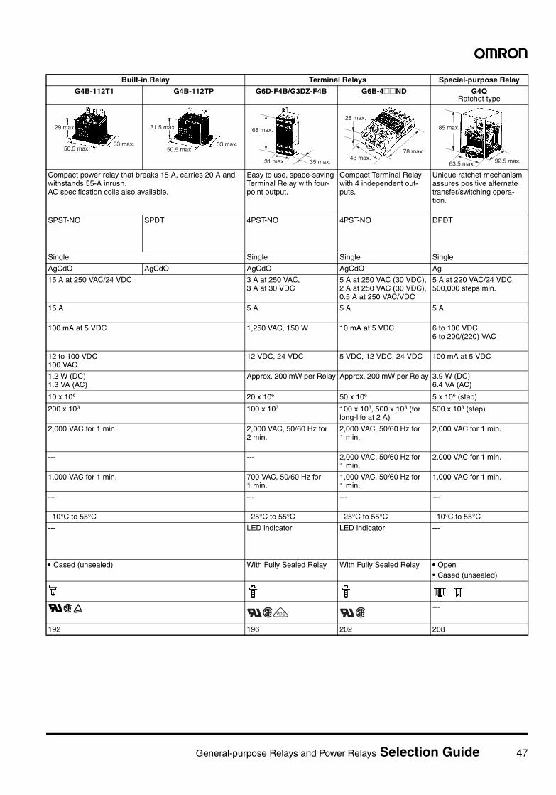
General-purpose Relays and Power Relays Selection Guide 47
Built-in Relay Terminal Relays Special-purpose Relay
G4B-112T1 G4B-112TP G6D-F4B/G3DZ-F4B G6B-4@@ND G4QRatchet type
Compact power relay that breaks 15 A, carries 20 A and withstands 55-A inrush.AC specification coils also available.
Easy to use, space-saving Terminal Relay with four-point output.
Compact Terminal Relay with 4 independent out-puts.
Unique ratchet mechanism assures positive alternate transfer/switching opera-tion.
SPST-NO SPDT 4PST-NO 4PST-NO DPDT
Single Single Single Single
AgCdO AgCdO AgCdO AgCdO Ag
15 A at 250 VAC/24 VDC 3 A at 250 VAC, 3 A at 30 VDC
5 A at 250 VAC (30 VDC), 2 A at 250 VAC (30 VDC), 0.5 A at 250 VAC/VDC
5 A at 220 VAC/24 VDC, 500,000 steps min.
15 A 5 A 5 A 5 A
100 mA at 5 VDC 1,250 VAC, 150 W 10 mA at 5 VDC 6 to 100 VDC 6 to 200/(220) VAC
12 to 100 VDC100 VAC
12 VDC, 24 VDC 5 VDC, 12 VDC, 24 VDC 100 mA at 5 VDC
1.2 W (DC)1.3 VA (AC)
Approx. 200 mW per Relay Approx. 200 mW per Relay 3.9 W (DC)6.4 VA (AC)
10 x 106 20 x 106 50 x 106 5 x 10⁶ (step)
200 x 103 100 x 103 100 x 103, 500 x 103 (for long-life at 2 A)
500 x 103 (step)
2,000 VAC for 1 min. 2,000 VAC, 50/60 Hz for 2 min.
2,000 VAC, 50/60 Hz for 1 min.
2,000 VAC for 1 min.
--- --- 2,000 VAC, 50/60 Hz for 1 min.
2,000 VAC for 1 min.
1,000 VAC for 1 min. 700 VAC, 50/60 Hz for 1 min.
1,000 VAC, 50/60 Hz for 1 min.
1,000 VAC for 1 min.
--- --- --- ---
–10°C to 55°C –25°C to 55°C –25°C to 55°C –10°C to 55°C--- LED indicator LED indicator ---
• Cased (unsealed) With Fully Sealed Relay With Fully Sealed Relay • Open• Cased (unsealed)
RCE ---
192 196 202 208
29 max.
33 max.50.5 max.
31.5 max.
33 max.50.5 max.
68 max.
31 max. 35 max.
28 max.
78 max.43 max.
85 max.
63.5 max. 92.5 max.
RCXVDE RC
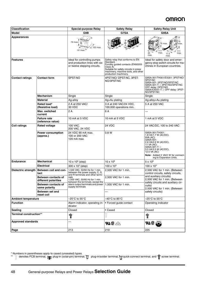
48 General-purpose Relays and Power Relays Selection Guide
Classification Special-purpose Relay Safety Relay Safety Relay Unit
Model G9B G7SA G9SA
Appearances
Features Ideal for controlling pumps and production lines with six or twelve stepping circuits.
Safety relay that conforms to EN Standard.Forcibly guided contacts (EN50205 Class A)Suitable for safety circuits in press machinery, machine tools, and other production machinery.
Ideal for safety door and emer-gency stop switch circuits for ma-chines in European countries.
Contact ratings Contact form SPST-NO 4PST-NO/ DPST-NC, 3PST-NO/3PST-NC
G9SA-301/TH301/EX301: 3PST-NO/SPST-NCG9SA-501: 5PST-NO/SPST-NCG9SA-321-T@: 3PST-NO/SPST-NCOFF delay: DPST-NOG9SA-EX031-T@: OFF delay: 3PST-NO/SPST-NC
Mechanism Single Single Single
Material Ag-alloy Ag+Au plating Ag-alloy+Au plating
Rated load*(Resistive load)
2 A at 250 VAC/30 VDC
3 A at 240 VAC/24 VDC, 100,000 operations min.
5 A at 250 VAC
Max. switched current
2 A 6 A ---
Failure rate (reference value)
10 mA at 5 VDC 10 mA at 5 VDC 1 mA at 5 VDC
Coil ratings Rated voltage 100 VAC, 200 VAC, 24 VDC
24 VDC 24 VAC/DC, 100 to 240 VAC
Power consumption (approx.)
24 VDC 90 mA max.100 or 200 VAC 120 mA max.
0.8 W G9SA-301/TH301: 1.8 VA/1.7 W (AC/DC).9VA (AC)G9SA-501: 2.8 VA/2.6 W (AC/DC), 11 VA (AC)G9SA-321-T@: 3.5 VA/3.3 W (AC/DC), 12.5 VA (AC)Note: Added 2 VA/2 W for connect-
ing to Expansion Units.
Endurance Mechanical 10 x 106 (step) 10 x 106 5 x 10⁶
Electrical 300 x 103 (step) 100 x 103 100 x 103
Dielectric strength Between coil and con-tact
1,500 VAC, 50/60 Hz for 1 min. between the power supply, C, S, and R terminals and other termi-nals1,500 VAC, 50/60 Hz for 1 min. between the terminals, except the alarm output terminals and power supply terminals
2,500 VAC for 1 min. 2,500 VAC for 1 min. (Between control circuits, safety circuits, and auxiliary circuits)2,500 VAC for 1 min. (Between safety circuits and auxiliary cir-cuits)2,500 VAC for 1 min. (Between safety circuits)
Between contacts of different polarities
2,500 VAC for 1 min.
Between contacts of same polarity
1,500 VAC for 1 min.
Between set and reset coil
---
Ambient temperature –25°C to 55°C –40°C to 85°C –25°C to 55°CFunction Alarm indicator, operating in-
dicator• Forced guide contact Operating indicator
Sealing Closed • Cased Closed
Terminal construction**
Approved standards ---
Page 213 219 225
76 max.
91 max.100 max.
76 max.
45 max.
111 max. 17.5
max.
111 max.
76 max.
RCXVDE RC
* Numbers in parentheses apply to cased (unsealed) types.** denotes PCB terminal, plug-in (octal-pin) terminal, plug-in/solder terminal, quick-connect terminal, and screw terminal.
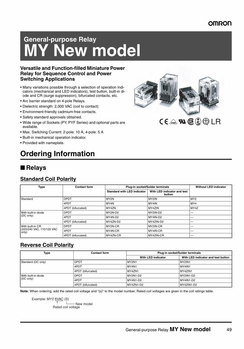
General-purpose Relay MY New model 49
General-purpose Relay
MY New modelVersatile and Function-filled Miniature Power Relay for Sequence Control and Power Switching Applications
• Many variations possible through a selection of operation indi-cators (mechanical and LED indicators), test button, built-in di-ode and CR (surge suppression), bifurcated contacts, etc.
• Arc barrier standard on 4-pole Relays.• Dielectric strength: 2,000 VAC (coil to contact)
• Environment-friendly cadmium-free contacts.• Safety standard approvals obtained.• Wide range of Sockets (PY, PYF Series) and optional parts are
available.• Max. Switching Current: 2-pole: 10 A, 4-pole: 5 A• Built-in mechanical operation indicator.
• Provided with nameplate.
LR
Ordering Information
Relays
Standard Coil Polarity
Reverse Coil Polarity
Note: When ordering, add the rated coil voltage and “(s)” to the model number. Rated coil voltages are given in the coil ratings table.
Type Contact form Plug-in socket/Solder terminals Without LED indicator
Standard with LED indicator With LED indicator and test button
Standard DPDT MY2N MY2IN MY2
4PDT MY4N MY4IN MY4
4PDT (bifurcated) MY4ZN MY4ZIN MY4Z
With built-in diode (DC only)
DPDT MY2N-D2 MY2IN-D2 ---
4PDT MY4N-D2 MY4IN-D2 ---
4PDT (bifurcated) MY4ZN-D2 MY4ZIN-D2 ---
With built-in CR (220/240 VAC, 110/120 VAC only)
DPDT MY2N-CR MY2IN-CR ---
4PDT MY4N-CR MY4IN-CR ---
4PDT (bifurcated) MY4ZN-CR MY4ZIN-CR ---
Type Contact form Plug-in socket/Solder terminals
With LED indicator With LED indicator and test button
Standard (DC only) DPDT MY2N1 MY2IN1
4PDT MY4N1 MY4IN1
4PDT (bifurcated) MY4ZN1 MY4ZIN1
With built-in diode (DC only)
DPDT MY2N1-D2 MY2IN1-D2
4PDT MY4N1-D2 MY4IN1-D2
4PDT (bifurcated) MY4ZN1-D2 MY4ZIN1-D2
Example: MY2 6VAC (S)
Rated coil voltageNew model
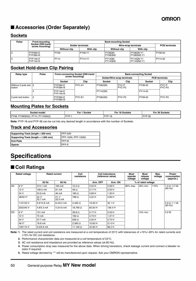
50 General-purpose Relay MY New model
Accessories (Order Separately)
Sockets
Socket Hold-down Clip Pairing
Mounting Plates for Sockets
Note: PYP-18 and PYP-36 can be cut into any desired length in accordance with the number of Sockets.
Track and Accessories
Specifications
Coil Ratings
Note: 1. The rated current and coil resistance are measured at a coil temperature of 23°C with tolerances of +15%/–20% for rated currents and±15% for DC coil resistance.
2. Performance characteristic data are measured at a coil temperature of 23°C.3. AC coil resistance and impedance are provided as reference values (at 60 Hz).4. Power consumption drop was measured for the above data. When driving transistors, check leakage current and connect a bleeder re-
sistor if required.5. Rated voltage denoted by “*” will be manufactured upon request. Ask your OMRON representative.
Poles Front-mounting Socket (DIN-track/screw mounting)
Back-mounting Socket
Solder terminals Wire-wrap terminals PCB terminals
Without clip With clip Without clip With clip
2 PYF08A-EPYF08A-N
PY08 PY08-Y1 PY08QNPY08QN2
PY08QN-Y1PY08QN2-Y1
PY08-02
4 PYF14A-EPYF14A-N
PY14 PY14-Y1 PY14QNPY14QN2
PY14QN-Y1PY14QN2-Y1
PY14-02
Relay type Poles Front-connecting Socket (DIN-track/screw mounting)
Back-connecting Socket
Solder/Wire-wrap terminals PCB terminals
Socket Clip Socket Clip Socket Clip
Without 2-pole test button
2 PYF08A-EPYF08A-N
PYC-A1 PY08(QN) PYC-PPYC-P2
PY08-02 PYC-PPYC-P2
4 PYF14A-EPYF14A-N
PY14(QN) PY14-02
2-pole test button 2 PYF08A-EPYF08A-N
PYC-E1 PY08(QN) PYC-P2 PY08-02 PYC-P2
Socket model For 1 Socket For 18 Sockets For 36 Sockets
PY08, PY08QN(2), PY14, PY14QN(2) PYP-1 PYP-18 PYP-36
Supporting Track (length = 500 mm) PFP-50N
Supporting Track (length = 1,000 mm) PFP-100N, PFP-100N2
End Plate PFP-M
Spacer PFP-S
Rated voltage Rated current Coil resistance
Coil inductance (reference value)
Must operate voltage
Must release voltage
Max. voltage
Power consumption
(approx.)
50 Hz 60 Hz Arm. OFF Arm. ON % of rated voltage
AC 6 V* 214.1 mA 183 mA 12.2 Ω 0.04 H 0.08 H 80% max. 30% min. 110% 1.0 to 1.2 VA (60 Hz)12 V 106.5 mA 91 mA 46 Ω 0.17 H 0.33 H
24 V 53.8 mA 46 mA 180 Ω 0.69 H 1.30 H
48/50 V* 24.7/25.7 mA
21.1/22.0 mA
788 Ω 3.22 H 5.66 H
110/120 V 9.9/10.8 mA 8.4/9.2 mA 4,430 Ω 19.20 H 32.1 H 0.9 to 1.1 VA (60 Hz)
220/240 V 4.8/5.3 mA 4.2/4.6 mA 18,790 Ω 83.50 H 136.4 H
DC 6 V* 151 mA 39.8 Ω 0.17 H 0.33 H 10% min. 0.9 W
12 V 75 mA 160 Ω 0.73 H 1.37 H
24 V 37.7 mA 636 Ω 3.20 H 5.72 H
48 V* 18.8 mA 2,560 Ω 10.60 H 21.0 H
100/110 V 9.0/9.9 mA 11,100 Ω 45.60 H 86.2 H
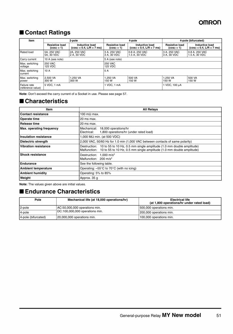
General-purpose Relay MY New model 51
Contact Ratings
Note: Don’t exceed the carry current of a Socket in use. Please see page 57.
Characteristics
Note: The values given above are initial values.
Endurance Characteristics
Item 2-pole 4-pole 4-pole (bifurcated)
Resistive load (cosφ = 1)
Inductive load (cosφ = 0.4, L/R = 7 ms)
Resistive load (cosφ = 1)
Inductive load (cosφ = 0.4, L/R = 7 ms)
Resistive load (cosφ = 1)
Inductive load (cosφ = 0.4, L/R = 7 ms)
Rated load 5A, 250 VAC5A, 30 VDC
2A, 250 VAC2 A, 30 VDC
3 A, 250 VAC3 A, 30 VDC
0.8 A, 250 VAC1.5 A, 30 VDC
3 A, 250 VAC3 A, 30 VDC
0.8 A, 250 VAC1.5 A, 30 VDC
Carry current 10 A (see note) 5 A (see note)
Max. switching voltage
250 VAC125 VDC
250 VAC125 VDC
Max. switching current
10 A 5 A
Max. switching power
2,500 VA300 W
1,250 VA300 W
1,250 VA150 W
500 VA150 W
1,250 VA150 W
500 VA150 W
Failure rate (reference value)
5 VDC, 1 mA 1 VDC, 1 mA 1 VDC, 100 µA
Item All Relays
Contact resistance 100 mΩ max.
Operate time 20 ms max.
Release time 20 ms max.
Max. operating frequency Mechanical: 18,000 operations/hrElectrical: 1,800 operations/hr (under rated load)
Insulation resistance 1,000 MΩ min. (at 500 VDC)
Dielectric strength 2,000 VAC, 50/60 Hz for 1.0 min (1,000 VAC between contacts of same polarity)
Vibration resistance Destruction: 10 to 55 to 10 Hz, 0.5 mm single amplitude (1.0 mm double amplitude)Malfunction: 10 to 55 to 10 Hz, 0.5 mm single amplitude (1.0 mm double amplitude)
Shock resistance Destruction: 1,000 m/s2
Malfunction: 200 m/s2
Endurance See the following table.
Ambient temperature Operating: –55°C to 70°C (with no icing)
Ambient humidity Operating: 5% to 85%
Weight Approx. 35 g
Pole Mechanical life (at 18,000 operations/hr) Electrical life (at 1,800 operations/hr under rated load)
2-pole AC:50,000,000 operations min.DC:100,000,000 operations min.
500,000 operations min.
4-pole 200,000 operations min.
4-pole (bifurcated) 20,000,000 operations min. 100,000 operations min.
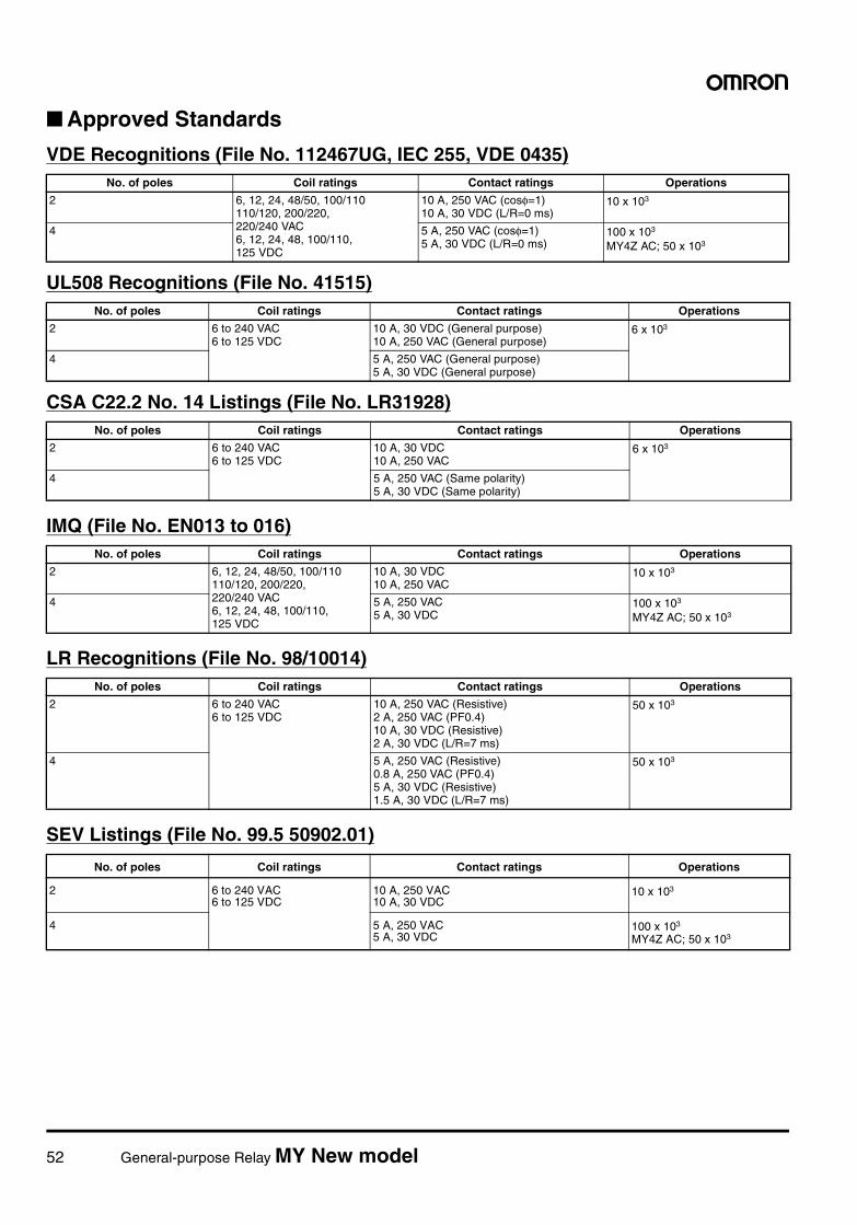
52 General-purpose Relay MY New model
Approved Standards
VDE Recognitions (File No. 112467UG, IEC 255, VDE 0435)
UL508 Recognitions (File No. 41515)
CSA C22.2 No. 14 Listings (File No. LR31928)
IMQ (File No. EN013 to 016)
LR Recognitions (File No. 98/10014)
SEV Listings (File No. 99.5 50902.01)
No. of poles Coil ratings Contact ratings Operations
2 6, 12, 24, 48/50, 100/110110/120, 200/220, 220/240 VAC6, 12, 24, 48, 100/110, 125 VDC
10 A, 250 VAC (cosφ=1)10 A, 30 VDC (L/R=0 ms)
10 x 103
4 5 A, 250 VAC (cosφ=1)5 A, 30 VDC (L/R=0 ms)
100 x 103
MY4Z AC; 50 x 103
No. of poles Coil ratings Contact ratings Operations
2 6 to 240 VAC6 to 125 VDC
10 A, 30 VDC (General purpose)10 A, 250 VAC (General purpose)
6 x 10³
4 5 A, 250 VAC (General purpose)5 A, 30 VDC (General purpose)
No. of poles Coil ratings Contact ratings Operations
2 6 to 240 VAC6 to 125 VDC
10 A, 30 VDC10 A, 250 VAC
6 x 10³
4 5 A, 250 VAC (Same polarity)5 A, 30 VDC (Same polarity)
No. of poles Coil ratings Contact ratings Operations
2 6, 12, 24, 48/50, 100/110110/120, 200/220, 220/240 VAC6, 12, 24, 48, 100/110, 125 VDC
10 A, 30 VDC10 A, 250 VAC
10 x 103
4 5 A, 250 VAC5 A, 30 VDC
100 x 103
MY4Z AC; 50 x 103
No. of poles Coil ratings Contact ratings Operations
2 6 to 240 VAC6 to 125 VDC
10 A, 250 VAC (Resistive)2 A, 250 VAC (PF0.4)10 A, 30 VDC (Resistive)2 A, 30 VDC (L/R=7 ms)
50 x 103
4 5 A, 250 VAC (Resistive)0.8 A, 250 VAC (PF0.4)5 A, 30 VDC (Resistive)1.5 A, 30 VDC (L/R=7 ms)
50 x 103
No. of poles Coil ratings Contact ratings Operations
2 6 to 240 VAC6 to 125 VDC
10 A, 250 VAC10 A, 30 VDC
10 x 103
4 5 A, 250 VAC5 A, 30 VDC
100 x 103
MY4Z AC; 50 x 103
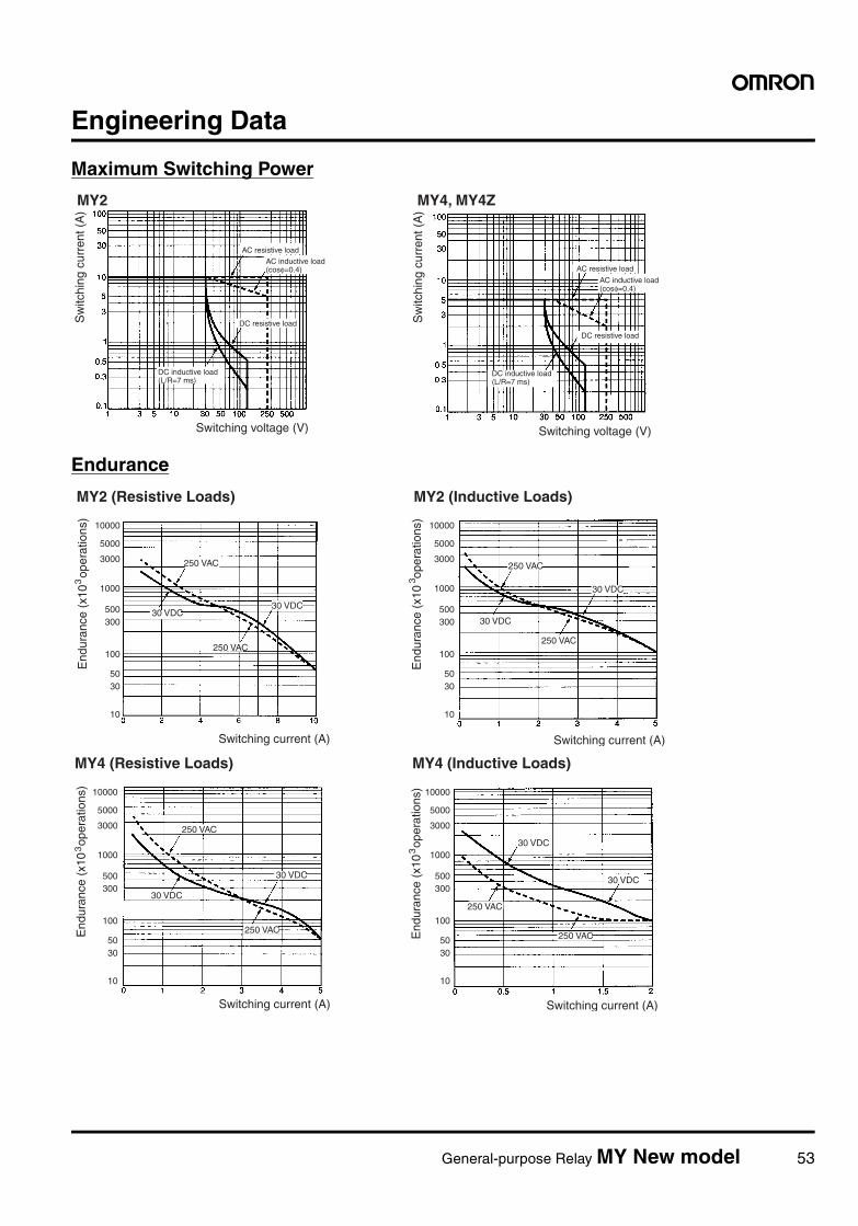
General-purpose Relay MY New model 53
Engineering Data
Maximum Switching Power
Endurance
MY2 MY4, MY4Z
Sw
itchi
ng c
urre
nt (
A)
AC resistive load
DC resistive load
AC resistive load
DC resistive load
Sw
itchi
ng c
urre
nt (
A)
Switching voltage (V) Switching voltage (V)
AC inductive load (cosφ=0.4)
DC inductive load (L/R=7 ms)
AC inductive load (cosφ=0.4)
DC inductive load (L/R=7 ms)
10000
5000
3000
1000
500300
100
5030
10
10000
5000
3000
1000
500300
100
5030
10
MY2 (Resistive Loads) MY2 (Inductive Loads)
End
uran
ce (
x10
ope
ratio
ns)
3
Switching current (A)
250 VAC
30 VDC30 VDC
250 VAC
End
uran
ce (
x10
ope
ratio
ns)
3
Switching current (A)
30 VDC
250 VAC
250 VAC
30 VDC
10000
5000
3000
1000
500300
100
5030
10
10000
5000
3000
1000
500300
100
5030
10
MY4 (Resistive Loads) MY4 (Inductive Loads)
End
uran
ce (
x10
ope
ratio
ns)
3
Switching current (A)
250 VAC
30 VDC
30 VDC
250 VAC End
uran
ce (
x10
ope
ratio
ns)
3
Switching current (A)
30 VDC
250 VAC
250 VAC
30 VDC
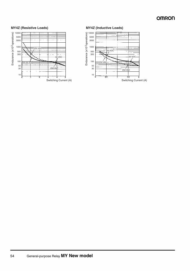
54 General-purpose Relay MY New model
10000
5000
3000
1000
500300
100
5030
10
10000
5000
3000
1000
500300
100
5030
10
MY4Z (Resistive Loads) MY4Z (Inductive Loads)
End
uran
ce (
x10
ope
ratio
ns)
3
Switching Current (A)
250 VAC
30 VDC
250 VAC
30 VDC
250 VAC
250 VAC
30 VDC
30 VDC
End
uran
ce (
x10
ope
ratio
ns)
3
Switching Current (A)
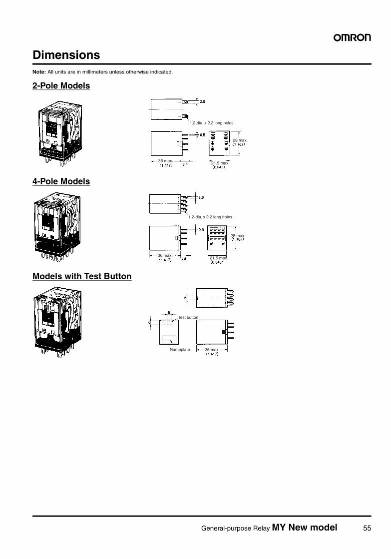
General-purpose Relay MY New model 55
DimensionsNote: All units are in millimeters unless otherwise indicated.
2-Pole Models
4-Pole Models
Models with Test Button
1.2-dia. x 2.2 long holes
36 max.
28 max.
21.5 max.
1.2-dia. x 2.2 long holes
36 max.21.5 max.
28 max.
36 max.
Test button
Nameplate
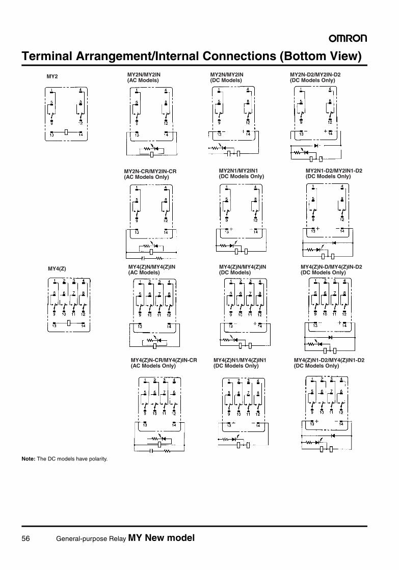
56 General-purpose Relay MY New model
Terminal Arrangement/Internal Connections (Bottom View)
Note: The DC models have polarity.
MY2 MY2N/MY2IN (AC Models)
MY2N/MY2IN (DC Models)
MY2N-D2/MY2IN-D2 (DC Models Only)
MY2N-CR/MY2IN-CR (AC Models Only)
MY2N1/MY2IN1 (DC Models Only)
MY2N1-D2/MY2IN1-D2 (DC Models Only)
MY4(Z) MY4(Z)N/MY4(Z)IN (AC Models)
MY4(Z)N/MY4(Z)IN (DC Models)
MY4(Z)N-D/MY4(Z)IN-D2 (DC Models Only)
MY4(Z)N-CR/MY4(Z)IN-CR (AC Models Only)
MY4(Z)N1/MY4(Z)IN1 (DC Models Only)
MY4(Z)N1-D2/MY4(Z)IN1-D2 (DC Models Only)
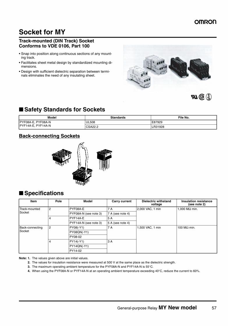
General-purpose Relay MY New model 57
Socket for MYTrack-mounted (DIN Track) Socket Conforms to VDE 0106, Part 100
• Snap into position along continuous sections of any mount-ing track.
• Facilitates sheet metal design by standardized mounting di-mensions.
• Design with sufficient dielectric separation between termi-nals eliminates the need of any insulating sheet.
Safety Standards for Sockets
Back-connecting Sockets
Specifications
Note: 1. The values given above are initial values.2. The values for insulation resistance were measured at 500 V at the same place as the dielectric strength.3. The maximum operating ambient temperature for the PYF08A-N and PYF14A-N is 55°C. 4. When using the PYF08A-N or PYF14A-N at an operating ambient temperature exceeding 40°C, reduce the current to 60%.
Model Standards File No.
PYF08A-E, PYF08A-NPYF14A-E, PYF14A-N
UL508 E87929
CSA22.2 LR31928
Item Pole Model Carry current Dielectric withstand voltage
Insulation resistance (see note 2)
Track-mounted Socket
2 PYF08A-E 7 A 2,000 VAC, 1 min 1,000 MΩ min.
PYF08A-N (see note 3) 7 A (see note 4)
4 PYF14A-E 5 A
PYF14A-N (see note 3) 5 A (see note 4)
Back-connecting Socket
2 PY08(-Y1) 7 A 1,500 VAC, 1 min 100 MΩ min.
PY08QN(-Y1)
PY08-02
4 PY14(-Y1) 3 A
PY14QN(-Y1)
PY14-02
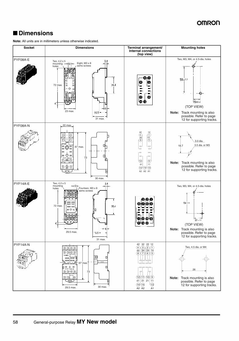
58 General-purpose Relay MY New model
DimensionsNote: All units are in millimeters unless otherwise indicated.
Socket Dimensions Terminal arrangement/Internal connections
(top view)
Mounting holes
PYF08A-E
31 max.
23 max.
72 max.
Two, 4.2 x 5 mounting holes
Eight, M3 x 8 sems screws
(TOP VIEW)
Two, M3, M4, or 4.5-dia. holes
Note: Track mounting is also possible. Refer to page 12 for supporting tracks.
PYF08A-N
4
42
8
44
1
12
5
14
41
12
A2
14
11
9
A1
13
A2
14
PYF-08A-N 73
22 max.
67 max.
30 max.
442
1
8 5
12 9
14 14 13
44
12
14
41 11
A2 A2 A1
18.7
3.0 dia.
3.5 dia. or M3
Note: Track mounting is also possible. Refer to page 12 for supporting tracks.
PYF14A-E
31 max.
29.5 max.
72 max.
Two, 4.2 x 5 mounting holes Fourteen, M3 x 8
sems screws
(TOP VIEW)
Two, M3, M4, or 4.5-dia. holes
Note: Track mounting is also possible. Refer to page 12 for supporting tracks.
PYF14A-N4
42
3
32
2
22
1
12
8
44
7
34
6
24
5
14
41
12
31
11
21
10
11
9
A1
13
A2
14
A2
14
PYF-14A-N
73
30 max.
67 max.
29.5 max.
4 3 2 1
8 7 6 5
12 11 10 9
14 14 13
42 32 22 12
44 34 24 14
41 31 21 11
A2 A2 A1
26
Two, 4.5 dia. or M4
Note: Track mounting is also possible. Refer to page 12 for supporting tracks.
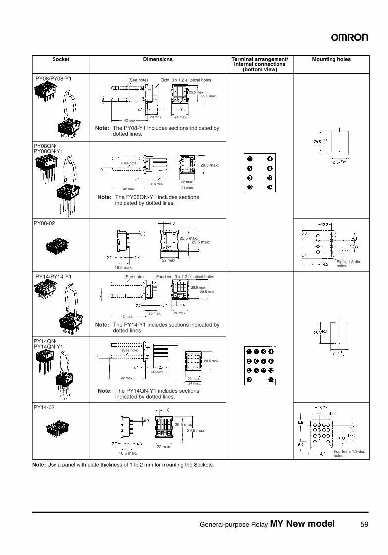
General-purpose Relay MY New model 59
Note: Use a panel with plate thickness of 1 to 2 mm for mounting the Sockets.
Socket Dimensions Terminal arrangement/Internal connections
(bottom view)
Mounting holes
PY08/PY08-Y1 (See note) Eight, 3 x 1.2 elliptical holes
25.5 max.29.5 max.
24 max.42 max.
Note: The PY08-Y1 includes sections indicated by dotted lines.
20 max.
PY08QN/PY08QN-Y1
(See note) 29.5 max.
22 max.
24 max.41.5 max.
42 max.
Note: The PY08QN-Y1 includes sections indicated by dotted lines.
PY08-02
16.5 max.
22 max.
25.5 max.29.5 max.
Eight, 1.3-dia. holes
PY14/PY14-Y1 (See note) Fourteen, 3 x 1.2 elliptical holes
25.5 max.29.5 max.
24 max.42 max.
Note: The PY14-Y1 includes sections indicated by dotted lines.
20 max.
PY14QN/PY14QN-Y1
(See note)
29.5 max.
22 max.24 max.
41.5 max.
42 max.
Note: The PY14QN-Y1 includes sections indicated by dotted lines.
PY14-02
16.5 max.
22 max.
25.5 max.29.5 max.
Fourteen, 1.3-dia. holes
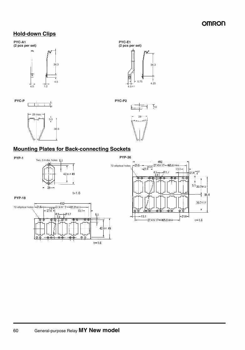
60 General-purpose Relay MY New model
Hold-down Clips
Mounting Plates for Back-connecting Sockets
4.5
1.2
36.3
4.5
36.3
5.754.25
4.5±0.1
5
3.3
38.5
10
28
PYC-P PYC-P2
29 max.
PYC-A1 (2 pcs per set)
PYC-E1 (2 pcs per set)
PYP-1 PYP-36
PYP-18t=1.6
Two, 3.4-dia. holes
72 elliptical holes
72 elliptical holes
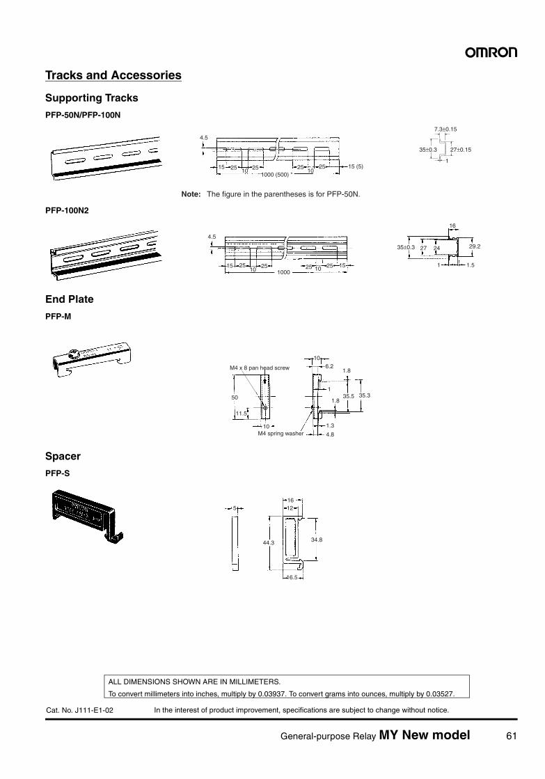
In the interest of product improvement, specifications are subject to change without notice.
ALL DIMENSIONS SHOWN ARE IN MILLIMETERS.
To convert millimeters into inches, multiply by 0.03937. To convert grams into ounces, multiply by 0.03527.
Cat. No. J111-E1-02
General-purpose Relay MY New model 61
Tracks and Accessories
Supporting Tracks
PFP-50N/PFP-100N
PFP-100N2
End Plate
PFP-M
Spacer
PFP-S
4.5
15 25 251025
1000 (500) *25
1015 (5)
1
35±0.3
7.3±0.15
27±0.15
Note: The figure in the parentheses is for PFP-50N.
29.2
1.5
27 24
16
1
4.5
15 25 2510 25
10002510 15
35±0.3
50
11.5
10
106.2
1.8
135.5 35.3
1.8
1.3
4.8
M4 x 8 pan head screw
M4 spring washer
51612
44.3
16.5
34.8
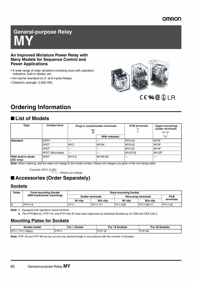
62 General-purpose Relay MY
General-purpose Relay
MYAn Improved Miniature Power Relay with Many Models for Sequence Control and Power Applications
• A wide range of relay variations including ones with operation indicators, built-in diodes, etc.
• Arc barrier standard on 3- and 4-pole Relays.• Dielectric strength: 2,000 VAC.
LR
Ordering Information
List of Models
Note: When ordering, add the rated coil voltage to the model number. Rated coil voltages are given in the coil ratings table.
Accessories (Order Separately)
Sockets
Note: 1. Equipped with operation check terminal.2. The PYF08A(-E), PYF11A, and PYF14A(-E) have been approved as individual Sockets by UL 508 and CSA C22.2.
Mounting Plates for Sockets
Note: PYP-18 and PYP-36 can be cut into any desired length in accordance with the number of Sockets.
Type Contact form
With indicator
Standard DPDT --- --- MY2-02 MY2F
3PDT MY3 MY3N MY3-02 MY3F
4PDT --- --- MY4-02 MY4F
4PDT (bifurcated) --- --- MY4Z-02 MY4ZF
With built-in diode(DC only)
3PDT MY3-D MY3N-D2 --- ---
Plug-in socket/solder terminals PCB terminals Upper-mounting/ solder terminals
Rated coil voltage Example: MY3, 6 VAC
Poles Front-mounting Socket (DIN-track/screw mounting)
Back-mounting Socket
Solder terminals Wire-wrap terminals PCB terminalsW/ clip W/o clip W/ clip W/o clip
3 PYF11A PY11 PY11-Y1 PY11QN PY11QN-Y1 PY11-02
Socket model For 1 Socket For 18 Sockets For 36 Sockets
PY11, PY11QN(2) PYP-1 PYP-18 PYP-36
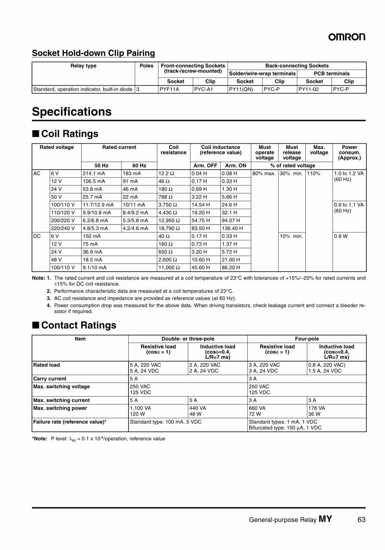
General-purpose Relay MY 63
Socket Hold-down Clip Pairing
Specifications
Coil Ratings
Note: 1. The rated current and coil resistance are measured at a coil temperature of 23°C with tolerances of +15%/–20% for rated currents and±15% for DC coil resistance.
2. Performance characteristic data are measured at a coil temperatures of 23°C.3. AC coil resistance and impedance are provided as reference values (at 60 Hz).4. Power consumption drop was measured for the above data. When driving transistors, check leakage current and connect a bleeder re-
sistor if required.
Contact Ratings
*Note: P level: λ60 = 0.1 x 10⁻⁶/operation, reference value
Relay type Poles Front-connecting Sockets(track-/screw-mounted)
Back-connecting Sockets
Solder/wire-wrap terminals PCB terminals
Socket Clip Socket Clip Socket Clip
Standard, operation indicator, built-in diode 3 PYF11A PYC-A1 PY11(QN) PYC-P PY11-02 PYC-P
Rated voltage Rated current Coil resistance
Coil inductance (reference value)
Must operate voltage
Must release voltage
Max. voltage
Power consum. (Approx.)
50 Hz 60 Hz Arm. OFF Arm. ON % of rated voltage
AC 6 V 214.1 mA 183 mA 12.2 Ω 0.04 H 0.08 H 80% max. 30% min. 110% 1.0 to 1.2 VA (60 Hz)12 V 106.5 mA 91 mA 46 Ω 0.17 H 0.33 H
24 V 53.8 mA 46 mA 180 Ω 0.69 H 1.30 H
50 V 25.7 mA 22 mA 788 Ω 3.22 H 5.66 H
100/110 V 11.7/12.9 mA 10/11 mA 3,750 Ω 14.54 H 24.6 H 0.9 to 1.1 VA (60 Hz)110/120 V 9.9/10.8 mA 8.4/9.2 mA 4,430 Ω 19.20 H 32.1 H
200/220 V 6.2/6.8 mA 5.3/5.8 mA 12,950 Ω 54.75 H 94.07 H
220/240 V 4.8/5.3 mA 4.2/4.6 mA 18,790 Ω 83.50 H 136.40 H
DC 6 V 150 mA 40 Ω 0.17 H 0.33 H 10% min. 0.9 W
12 V 75 mA 160 Ω 0.73 H 1.37 H
24 V 36.9 mA 650 Ω 3.20 H 5.72 H
48 V 18.5 mA 2,600 Ω 10.60 H 21.00 H
100/110 V 9.1/10 mA 11,000 Ω 45.60 H 86.20 H
Item Double- or three-pole Four-pole
Resistive load (cosφ = 1)
Inductive load (cosφ=0.4, L/R=7 ms)
Resistive load (cosφ = 1)
Inductive load (cosφ=0.4, L/R=7 ms)
Rated load 5 A, 220 VAC5 A, 24 VDC
2 A, 220 VAC2 A, 24 VDC
3 A, 220 VAC3 A, 24 VDC
0.8 A, 220 VAC)1.5 A, 24 VDC
Carry current 5 A 3 A
Max. switching voltage 250 VAC125 VDC
250 VAC125 VDC
Max. switching current 5 A 5 A 3 A 3 A
Max. switching power 1,100 VA120 W
440 VA48 W
660 VA72 W
176 VA36 W
Failure rate (reference value)* Standard type: 100 mA, 5 VDC Standard types: 1 mA, 1 VDC Bifurcated type: 100 µA, 1 VDC
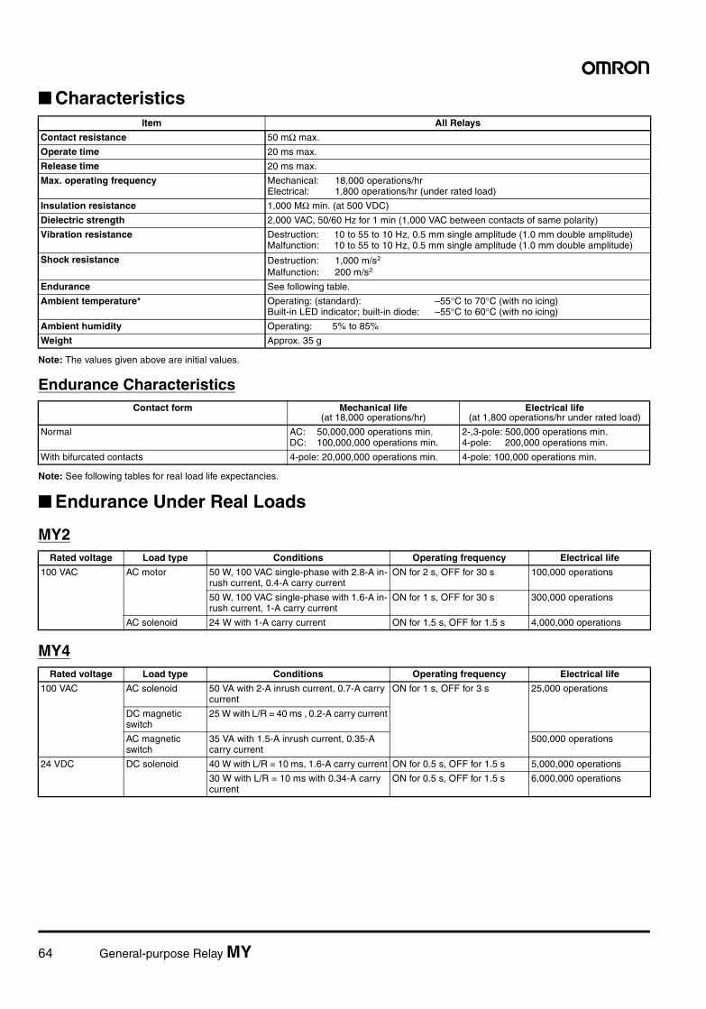
64 General-purpose Relay MY
Characteristics
Note: The values given above are initial values.
Endurance Characteristics
Note: See following tables for real load life expectancies.
Endurance Under Real Loads
MY2
MY4
Item All Relays
Contact resistance 50 mΩ max.
Operate time 20 ms max.
Release time 20 ms max.
Max. operating frequency Mechanical: 18,000 operations/hrElectrical: 1,800 operations/hr (under rated load)
Insulation resistance 1,000 MΩ min. (at 500 VDC)
Dielectric strength 2,000 VAC, 50/60 Hz for 1 min (1,000 VAC between contacts of same polarity)
Vibration resistance Destruction: 10 to 55 to 10 Hz, 0.5 mm single amplitude (1.0 mm double amplitude)Malfunction: 10 to 55 to 10 Hz, 0.5 mm single amplitude (1.0 mm double amplitude)
Shock resistance Destruction: 1,000 m/s2
Malfunction: 200 m/s2
Endurance See following table.
Ambient temperature* Operating: (standard): –55°C to 70°C (with no icing)Built-in LED indicator; built-in diode: –55°C to 60°C (with no icing)
Ambient humidity Operating: 5% to 85%
Weight Approx. 35 g
Contact form Mechanical life (at 18,000 operations/hr)
Electrical life (at 1,800 operations/hr under rated load)
Normal AC: 50,000,000 operations min. DC: 100,000,000 operations min.
2-,3-pole: 500,000 operations min.4-pole: 200,000 operations min.
With bifurcated contacts 4-pole: 20,000,000 operations min. 4-pole: 100,000 operations min.
Rated voltage Load type Conditions Operating frequency Electrical life
100 VAC AC motor 50 W, 100 VAC single-phase with 2.8-A in-rush current, 0.4-A carry current
ON for 2 s, OFF for 30 s 100,000 operations
50 W, 100 VAC single-phase with 1.6-A in-rush current, 1-A carry current
ON for 1 s, OFF for 30 s 300,000 operations
AC solenoid 24 W with 1-A carry current ON for 1.5 s, OFF for 1.5 s 4,000,000 operations
Rated voltage Load type Conditions Operating frequency Electrical life
100 VAC AC solenoid 50 VA with 2-A inrush current, 0.7-A carry current
ON for 1 s, OFF for 3 s 25,000 operations
DC magnetic switch
25 W with L/R = 40 ms , 0.2-A carry current
AC magnetic switch
35 VA with 1.5-A inrush current, 0.35-A carry current
500,000 operations
24 VDC DC solenoid 40 W with L/R = 10 ms, 1.6-A carry current ON for 0.5 s, OFF for 1.5 s 5,000,000 operations
30 W with L/R = 10 ms with 0.34-A carry current
ON for 0.5 s, OFF for 1.5 s 6,000,000 operations
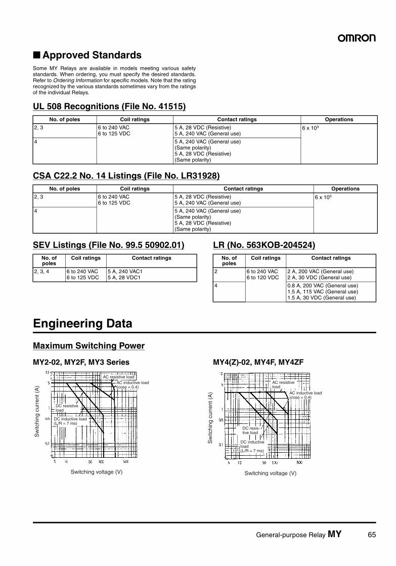
General-purpose Relay MY 65
Approved StandardsSome MY Relays are available in models meeting various safetystandards. When ordering, you must specify the desired standards.Refer to Ordering Information for specific models. Note that the ratingrecognized by the various standards sometimes vary from the ratingsof the individual Relays.
UL 508 Recognitions (File No. 41515)
CSA C22.2 No. 14 Listings (File No. LR31928)
SEV Listings (File No. 99.5 50902.01) LR (No. 563KOB-204524)
Engineering Data
Maximum Switching Power
MY2-02, MY2F, MY3 Series MY4(Z)-02, MY4F, MY4ZF
No. of poles Coil ratings Contact ratings Operations
2, 3 6 to 240 VAC6 to 125 VDC
5 A, 28 VDC (Resistive)5 A, 240 VAC (General use)
6 x 10³
4 5 A, 240 VAC (General use)(Same polarity)5 A, 28 VDC (Resistive)(Same polarity)
No. of poles Coil ratings Contact ratings Operations
2, 3 6 to 240 VAC6 to 125 VDC
5 A, 28 VDC (Resistive)5 A, 240 VAC (General use)
6 x 10³
4 5 A, 240 VAC (General use)(Same polarity)5 A, 28 VDC (Resistive)(Same polarity)
No. of poles
Coil ratings Contact ratings
2, 3, 4 6 to 240 VAC6 to 125 VDC
5 A, 240 VAC15 A, 28 VDC1
No. of poles
Coil ratings Contact ratings
2 6 to 240 VAC6 to 120 VDC
2 A, 200 VAC (General use)2 A, 30 VDC (General use)
4 0.8 A, 200 VAC (General use)1.5 A, 115 VAC (General use)1.5 A, 30 VDC (General use)
Switching voltage (V)
Sw
itchi
ng c
urre
nt (
A)
AC resistive load
Switching voltage (V)
Sw
itchi
ng c
urre
nt (
A)
AC inductive load (cosφ = 0.4)
DC resistive load
DC inductive load (L/R = 7 ms)
AC inductive load (cosφ = 0.4)
DC inductive load (L/R = 7 ms)
AC resistive load
DC resis-tive load
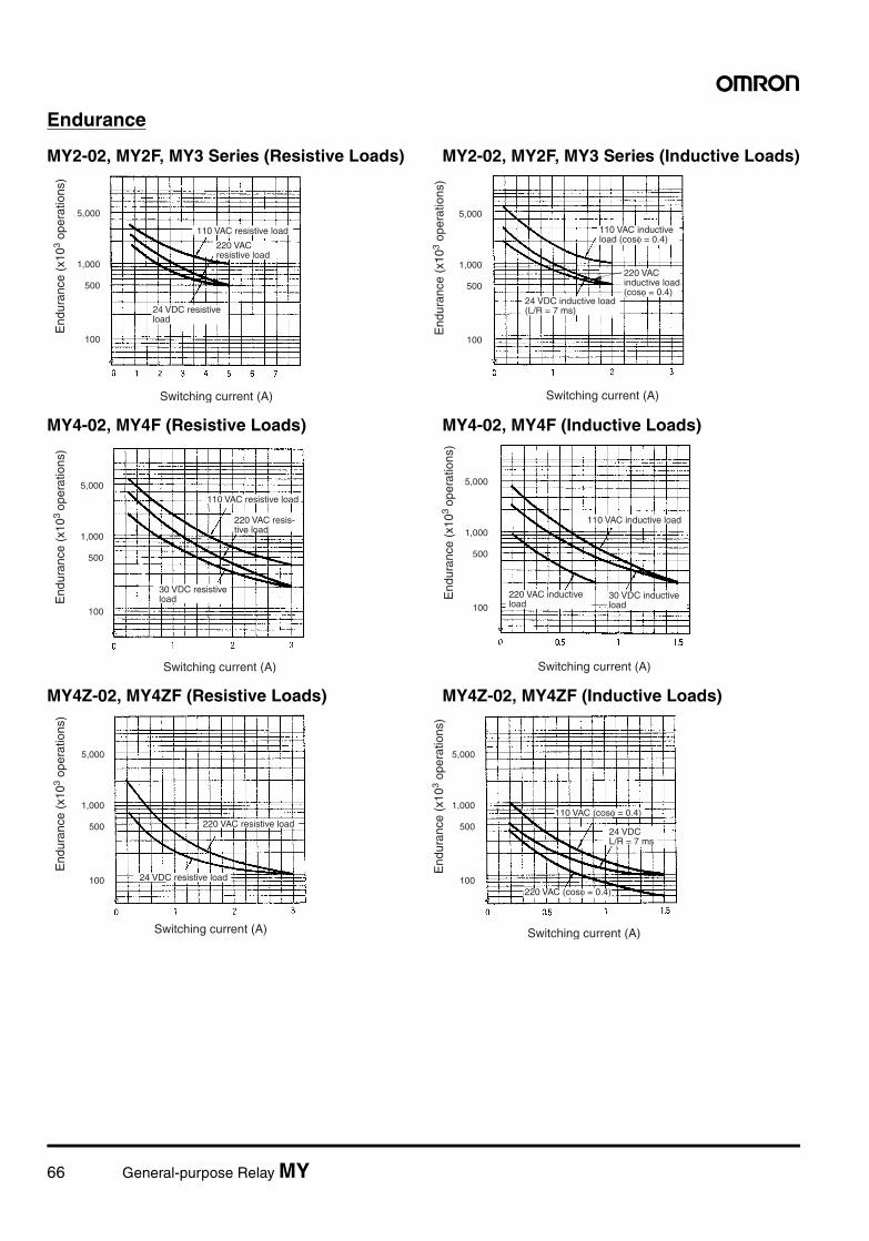
66 General-purpose Relay MY
Endurance
MY2-02, MY2F, MY3 Series (Resistive Loads) MY2-02, MY2F, MY3 Series (Inductive Loads)
MY4-02, MY4F (Resistive Loads) MY4-02, MY4F (Inductive Loads)
MY4Z-02, MY4ZF (Resistive Loads) MY4Z-02, MY4ZF (Inductive Loads)
1,000
500
100
5,000
1,000
500
100
5,000
Switching current (A)Switching current (A)
110 VAC resistive load
End
uran
ce (
x103
oper
atio
ns)
End
uran
ce (
x103
oper
atio
ns)
220 VAC resistive load
24 VDC resistive load
110 VAC inductive load (cosφ = 0.4)
220 VAC inductive load (cosφ = 0.4)
24 VDC inductive load (L/R = 7 ms)
1,000
500
100
5,000
1,000
500
100
5,000
Switching current (A)Switching current (A)
110 VAC resistive load
110 VAC inductive load
End
uran
ce (
x103
oper
atio
ns)
End
uran
ce (
x103
oper
atio
ns)
220 VAC resis-tive load
30 VDC resistive load 30 VDC inductive
load220 VAC inductive load
1,000
500
100
5,000
1,000
500
100
5,000
Switching current (A)Switching current (A)
220 VAC resistive load
24 VDC resistive load
110 VAC (cosφ = 0.4)
220 VAC (cosφ = 0.4)
End
uran
ce (
x103
oper
atio
ns)
End
uran
ce (
x103
oper
atio
ns)
24 VDC L/R = 7 ms
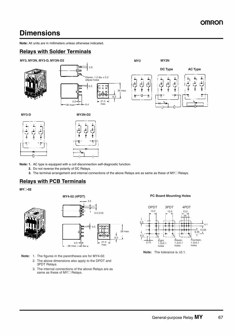
General-purpose Relay MY 67
DimensionsNote: All units are in millimeters unless otherwise indicated.
Relays with Solder Terminals
Note: 1. AC type is equipped with a coil disconnection self-diagnostic function.2. Do not reverse the polarity of DC Relays.3. The terminal arrangement and internal connections of the above Relays are as same as these of MY@ Relays.
Relays with PCB TerminalsMY@-02
MY3, MY3N, MY3-D, MY3N-D2
2.6
0.56.4
6.3
MY3NMY3
0.5
28 max.
DC Type AC Type
Eleven, 1.2 dia. x 2.2 ellipse holes
36 max.21.5 max.
MY3N-D2MY3-D
MY4-02 (4PDT)3.5
3.3 (2.6)
0.5
0.54
6.3
DPDT 3PDT 4PDT13.2 13.2 13.2
4.3
6.3
44
4.1
12.656.35
3.75
1
36 max.
28 max.
Note: 1. The figures in the parentheses are for MY4-02.
PC Board Mounting Holes
Eight, 1.3±0.1 holes
Eleven, 1.3±0.1 holes
Fourteen, 1.3±0.1 holes
Note: The tolerance is ±0.1.
2. The above dimensions also apply to the DPDT and 3PDT Relays. 3. The internal connections of the above Relays are as same as these of MY@ Relays.
21.5 max.
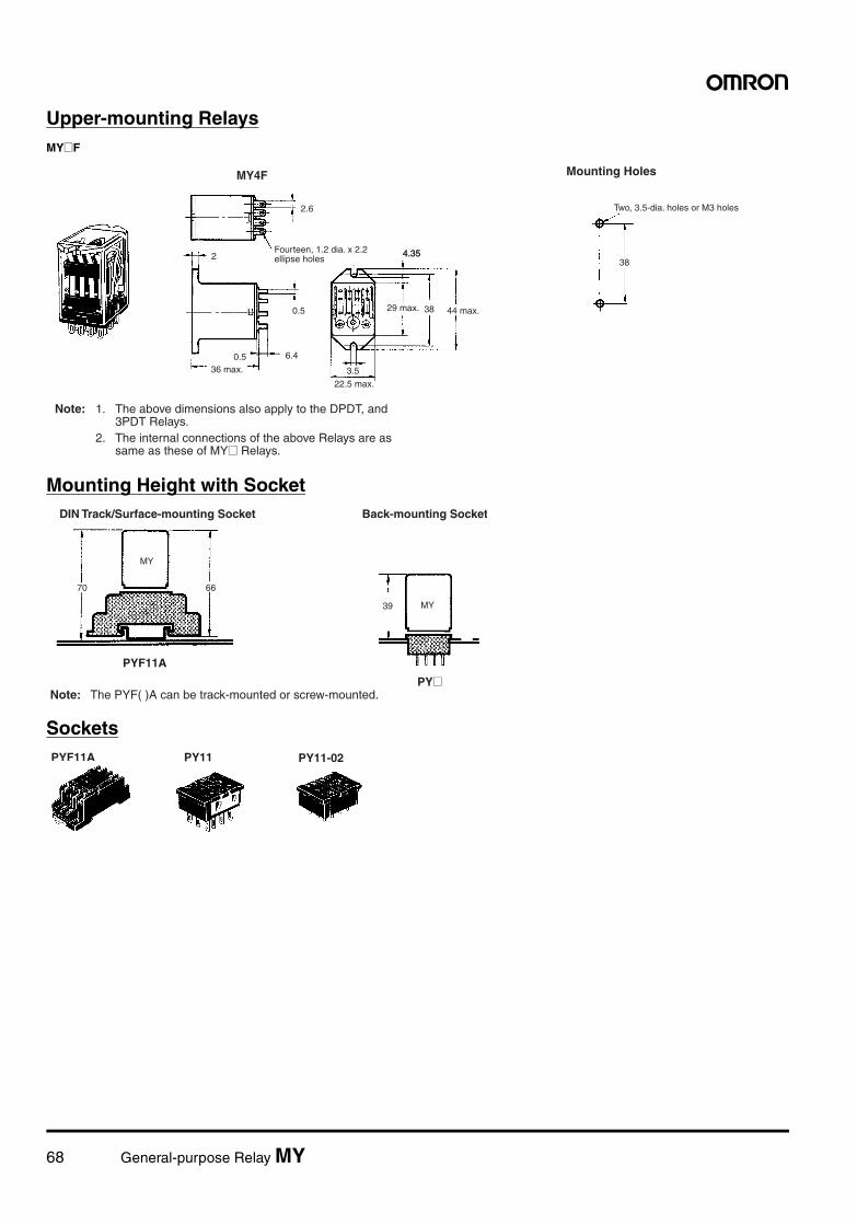
68 General-purpose Relay MY
Upper-mounting RelaysMY@F
Mounting Height with Socket
Sockets
MY4F
2.6
0.5
6.40.5
2 4.35
38
3.5
38
36 max.
4.35
29 max. 44 max.
22.5 max.
Note: 1. The above dimensions also apply to the DPDT, and 3PDT Relays. 2. The internal connections of the above Relays are as same as these of MY@ Relays.
Mounting Holes
Two, 3.5-dia. holes or M3 holes
Fourteen, 1.2 dia. x 2.2 ellipse holes
70 66
MY
39 MY
PYF11A
PY@
DIN Track/Surface-mounting Socket Back-mounting Socket
Note: The PYF( )A can be track-mounted or screw-mounted.
PY11-02PYF11A PY11
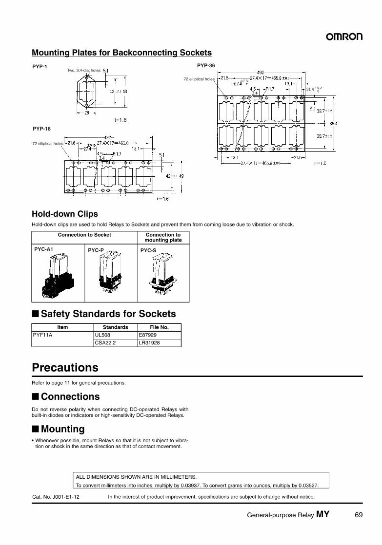
In the interest of product improvement, specifications are subject to change without notice.
ALL DIMENSIONS SHOWN ARE IN MILLIMETERS.
To convert millimeters into inches, multiply by 0.03937. To convert grams into ounces, multiply by 0.03527.
Cat. No. J001-E1-12
General-purpose Relay MY 69
Mounting Plates for Backconnecting Sockets
Hold-down ClipsHold-down clips are used to hold Relays to Sockets and prevent them from coming loose due to vibration or shock.
Safety Standards for Sockets
PrecautionsRefer to page 11 for general precautions.
ConnectionsDo not reverse polarity when connecting DC-operated Relays withbuilt-in diodes or indicators or high-sensitivity DC-operated Relays.
Mounting• Whenever possible, mount Relays so that it is not subject to vibra-
tion or shock in the same direction as that of contact movement.
PYP-1 PYP-36
PYP-18
t=1.6
Two, 3.4-dia. holes
72 elliptical holes
72 elliptical holes
Connection to Socket Connection to mounting plate
PYC-A1 PYC-P PYC-S
Item Standards File No.
PYF11A UL508 E87929
CSA22.2 LR31928
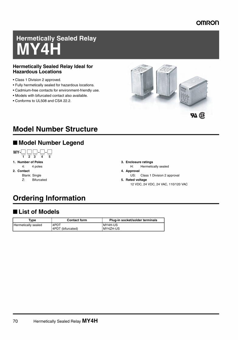
70 Hermetically Sealed Relay MY4H
Hermetically Sealed Relay
MY4HHermetically Sealed Relay Ideal for Hazardous Locations
• Class 1 Division 2 approved.• Fully hermetically sealed for hazardous locations.• Cadmium-free contacts for environment-friendly use.
• Models with bifurcated contact also available.• Conforms to UL508 and CSA 22.2.
Model Number Structure
Model Number Legend
1. Number of Poles4: 4 poles
2. ContactBlank: SingleZ: Bifurcated
3. Enclosure ratingsH: Hermetically sealed
4. ApprovalUS: Class 1 Division 2 approval
5. Rated voltage12 VDC, 24 VDC, 24 VAC, 110/120 VAC
Ordering Information
List of Models
MY- - -1 2 3 4 5
Type Contact form Plug-in socket/solder terminals
Hermetically sealed 4PDT4PDT (bifurcated)
MY4H-USMY4ZH-US
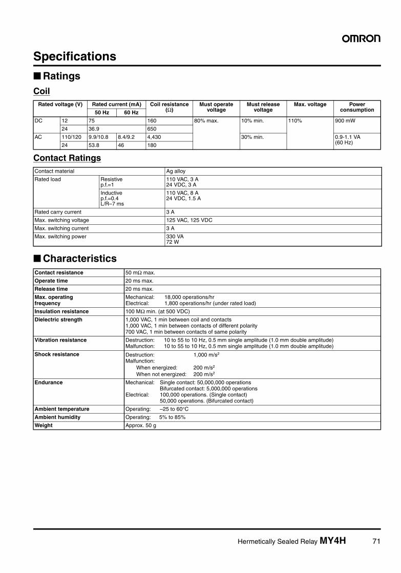
Hermetically Sealed Relay MY4H 71
Specifications
RatingsCoil
Contact Ratings
Characteristics
Rated voltage (V) Rated current (mA) Coil resistance (Ω)
Must operate voltage
Must release voltage
Max. voltage Power consumption50 Hz 60 Hz
DC 12 75 160 80% max. 10% min. 110% 900 mW
24 36.9 650
AC 110/120 9.9/10.8 8.4/9.2 4,430 30% min. 0.9-1.1 VA (60 Hz)24 53.8 46 180
Contact material Ag alloy
Rated load Resistive p.f.=1
110 VAC, 3 A24 VDC, 3 A
Inductive p.f.=0.4L/R–7 ms
110 VAC, 8 A24 VDC, 1.5 A
Rated carry current 3 A
Max. switching voltage 125 VAC, 125 VDC
Max. switching current 3 A
Max. switching power 330 VA72 W
Contact resistance 50 mΩ max.
Operate time 20 ms max.
Release time 20 ms max.
Max. operating frequency
Mechanical: 18,000 operations/hrElectrical: 1,800 operations/hr (under rated load)
Insulation resistance 100 MΩ min. (at 500 VDC)
Dielectric strength 1,000 VAC, 1 min between coil and contacts1,000 VAC, 1 min between contacts of different polarity700 VAC, 1 min between contacts of same polarity
Vibration resistance Destruction: 10 to 55 to 10 Hz, 0.5 mm single amplitude (1.0 mm double amplitude)Malfunction: 10 to 55 to 10 Hz, 0.5 mm single amplitude (1.0 mm double amplitude)
Shock resistance Destruction: 1,000 m/s2
Malfunction:When energized: 200 m/s2
When not energized: 200 m/s2
Endurance Mechanical: Single contact: 50,000,000 operationsBifurcated contact: 5,000,000 operations
Electrical: 100,000 operations. (Single contact)50,000 operations. (Bifurcated contact)
Ambient temperature Operating: –25 to 60°CAmbient humidity Operating: 5% to 85%
Weight Approx. 50 g
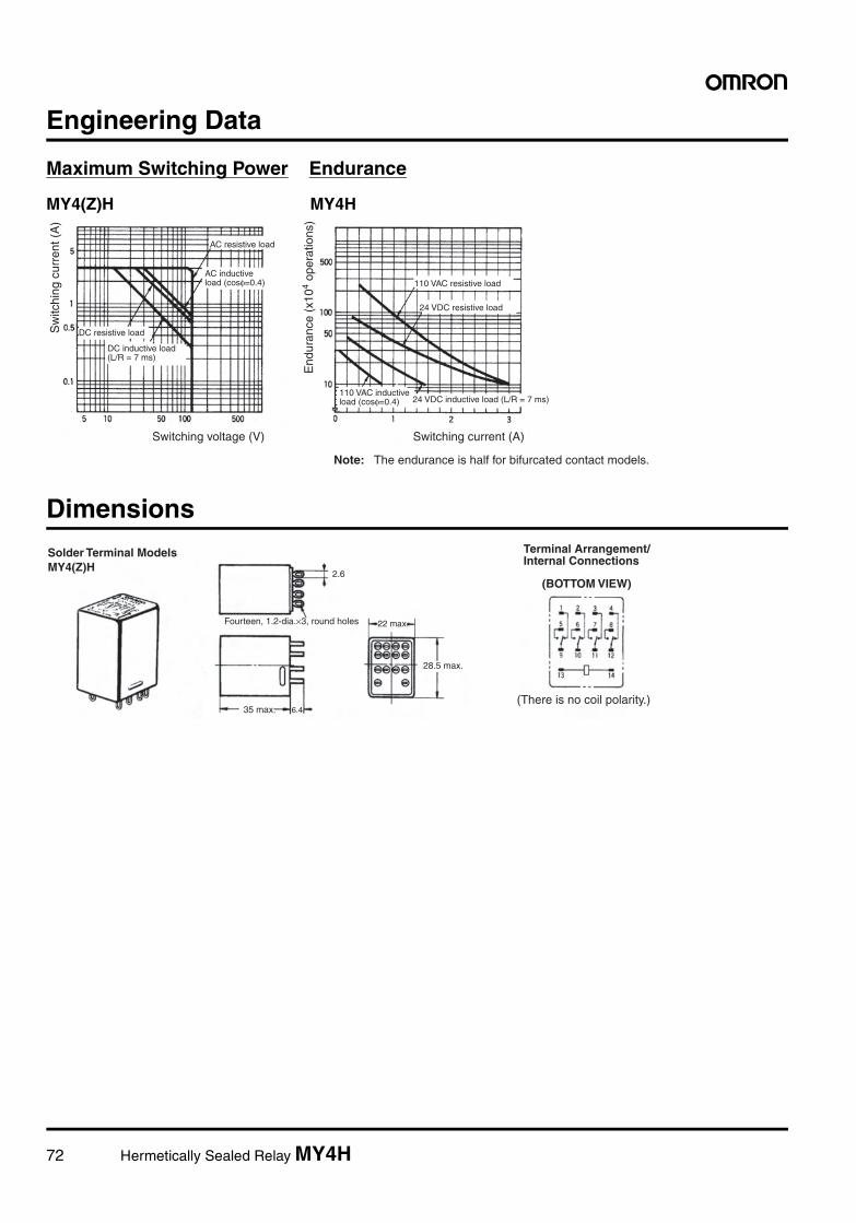
72 Hermetically Sealed Relay MY4H
Engineering Data
Maximum Switching Power Endurance
MY4(Z)H MY4H
Dimensions
DC resistive load
AC resistive load
Switching voltage (V)
110 VAC resistive load
24 VDC resistive load
Switching current (A)
Note: The endurance is half for bifurcated contact models.
Sw
itchi
ng c
urre
nt (
A)
End
uran
ce (
x104
oper
atio
ns)
24 VDC inductive load (L/R = 7 ms)
DC inductive load (L/R = 7 ms)
AC inductive load (cosφ=0.4)
110 VAC inductive load (cosφ=0.4)
MY4(Z)H2.6
6.4
Fourteen, 1.2-dia.×3, round holes
Solder Terminal Models
35 max.
28.5 max.
22 max.
(There is no coil polarity.)
(BOTTOM VIEW)
Terminal Arrangement/ Internal Connections
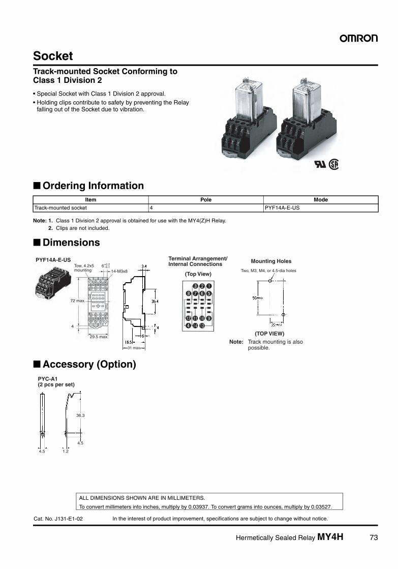
In the interest of product improvement, specifications are subject to change without notice.
ALL DIMENSIONS SHOWN ARE IN MILLIMETERS.
To convert millimeters into inches, multiply by 0.03937. To convert grams into ounces, multiply by 0.03527.
Cat. No. J131-E1-02
Hermetically Sealed Relay MY4H 73
SocketTrack-mounted Socket Conforming to Class 1 Division 2
• Special Socket with Class 1 Division 2 approval.• Holding clips contribute to safety by preventing the Relay
falling out of the Socket due to vibration.
Ordering Information
Note: 1. Class 1 Division 2 approval is obtained for use with the MY4(Z)H Relay.2. Clips are not included.
Dimensions
Accessory (Option)
Item Pole Mode
Track-mounted socket 4 PYF14A-E-US
14-M3x8
4
6−0.1+0.2
PYF14A-E-US
72 max.
29.5 max.Note: Track mounting is also possible.
(TOP VIEW)
Two, M3, M4, or 4.5-dia holes
31 max.
(Top View)
Mounting HolesTow, 4.2x5 mounting
Terminal Arrangement/ Internal Connections
36.3
4.5
4.5 1.2
PYC-A1 (2 pcs per set)
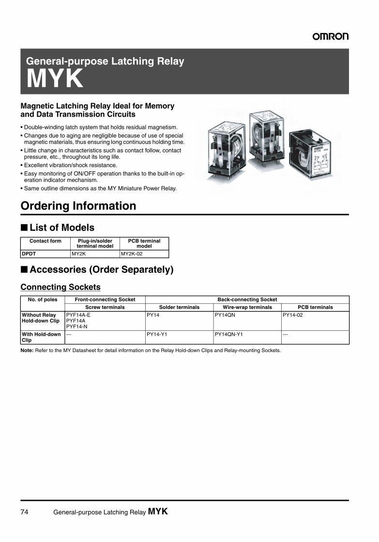
74 General-purpose Latching Relay MYK
General-purpose Latching Relay
MYKKMagnetic Latching Relay Ideal for Memory and Data Transmission Circuits
• Double-winding latch system that holds residual magnetism.• Changes due to aging are negligible because of use of special
magnetic materials, thus ensuring long continuous holding time.
• Little change in characteristics such as contact follow, contact pressure, etc., throughout its long life.
• Excellent vibration/shock resistance.
• Easy monitoring of ON/OFF operation thanks to the built-in op-eration indicator mechanism.
• Same outline dimensions as the MY Miniature Power Relay.
Ordering Information
List of Models
Accessories (Order Separately)
Connecting Sockets
Note: Refer to the MY Datasheet for detail information on the Relay Hold-down Clips and Relay-mounting Sockets.
Contact form Plug-in/solder terminal model
PCB terminal model
DPDT MY2K MY2K-02
No. of poles Front-connecting Socket Back-connecting Socket
Screw terminals Solder terminals Wire-wrap terminals PCB terminals
Without Relay Hold-down Clip
PYF14A-EPYF14APYF14-N
PY14 PY14QN PY14-02
With Hold-down Clip
--- PY14-Y1 PY14QN-Y1 ---
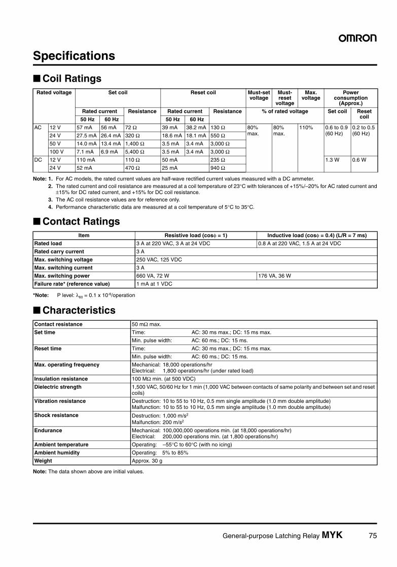
General-purpose Latching Relay MYK 75
Specifications
Coil Ratings
Note: 1. For AC models, the rated current values are half-wave rectified current values measured with a DC ammeter.2. The rated current and coil resistance are measured at a coil temperature of 23°C with tolerances of +15%/–20% for AC rated current and
±15% for DC rated current, and +15% for DC coil resistance.3. The AC coil resistance values are for reference only.4. Performance characteristic data are measured at a coil temperature of 5°C to 35°C.
Contact Ratings
*Note: P level: λ60 = 0.1 x 10⁻⁶/operation
Characteristics
Note: The data shown above are initial values.
Rated voltage Set coil Reset coil Must-set voltage
Must-reset
voltage
Max. voltage
Power consumption
(Approx.)
Rated current Resistance Rated current Resistance % of rated voltage Set coil Reset coil50 Hz 60 Hz 50 Hz 60 Hz
AC 12 V 57 mA 56 mA 72 Ω 39 mA 38.2 mA 130 Ω 80% max.
80% max.
110% 0.6 to 0.9 (60 Hz)
0.2 to 0.5 (60 Hz) 24 V 27.5 mA 26.4 mA 320 Ω 18.6 mA 18.1 mA 550 Ω
50 V 14.0 mA 13.4 mA 1,400 Ω 3.5 mA 3.4 mA 3,000 Ω100 V 7.1 mA 6.9 mA 5,400 Ω 3.5 mA 3.4 mA 3,000 Ω
DC 12 V 110 mA 110 Ω 50 mA 235 Ω 1.3 W 0.6 W
24 V 52 mA 470 Ω 25 mA 940 Ω
Item Resistive load (cosφ = 1) Inductive load (cosφ = 0.4) (L/R = 7 ms)
Rated load 3 A at 220 VAC, 3 A at 24 VDC 0.8 A at 220 VAC, 1.5 A at 24 VDC
Rated carry current 3 A
Max. switching voltage 250 VAC, 125 VDC
Max. switching current 3 A
Max. switching power 660 VA, 72 W 176 VA, 36 W
Failure rate* (reference value) 1 mA at 1 VDC
Contact resistance 50 mΩ max.
Set time Time: AC: 30 ms max.; DC: 15 ms max.
Min. pulse width: AC: 60 ms.; DC: 15 ms.
Reset time Time: AC: 30 ms max.; DC: 15 ms max.
Min. pulse width: AC: 60 ms.; DC: 15 ms.
Max. operating frequency Mechanical: 18,000 operations/hrElectrical: 1,800 operations/hr (under rated load)
Insulation resistance 100 MΩ min. (at 500 VDC)
Dielectric strength 1,500 VAC, 50/60 Hz for 1 min (1,000 VAC between contacts of same polarity and between set and reset coils)
Vibration resistance Destruction: 10 to 55 to 10 Hz, 0.5 mm single amplitude (1.0 mm double amplitude)Malfunction: 10 to 55 to 10 Hz, 0.5 mm single amplitude (1.0 mm double amplitude)
Shock resistance Destruction: 1,000 m/s2
Malfunction: 200 m/s2
Endurance Mechanical: 100,000,000 operations min. (at 18,000 operations/hr)Electrical: 200,000 operations min. (at 1,800 operations/hr)
Ambient temperature Operating: –55°C to 60°C (with no icing)
Ambient humidity Operating: 5% to 85%
Weight Approx. 30 g
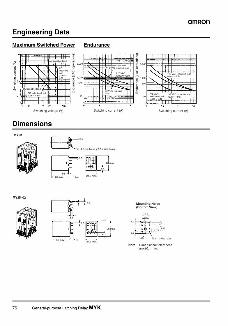
76 General-purpose Latching Relay MYK
Engineering Data
Maximum Switched Power Endurance
Dimensions
10
500
1,000
5,000
10
500
1,000
5,000
Switching voltage (V)
Sw
itchi
ng c
urre
nt (
A) AC resistive load
DC resistive load
End
uran
ce (
x103
oper
atio
ns)
110 VAC resistive load
Switching current (A) Switching current (A)
End
uran
ce (
x103
oper
atio
ns)
110 VAC inductive load (cosφ = 0.4)
30 VDC inductive load (L/R = 7 ms)
220 VAC inductive load (cosφ = 0.4)
220 VAC resistive load
30 VDC resistive loadDC inductive load
(L/R = 7 ms)
AC inductive load (cosφ = 0.4)
MY2K
MY2K-02
2.6
0.5
0.56.4
6.3
2.6
3.5
0.5
4
6.3
3.75
6.3
4.3
13.2
4.1
12.656.35
4.4
Mounting Holes(Bottom View)
Note: Dimensional tolerances are ±0.1 mm.
Ten, 1.2-dia. holes x 2.2 elliptic holes
36 max. 21.5 max.
28 max.
36 max.21.5 max.
28 max.
Ten, 1.3-dia. holes
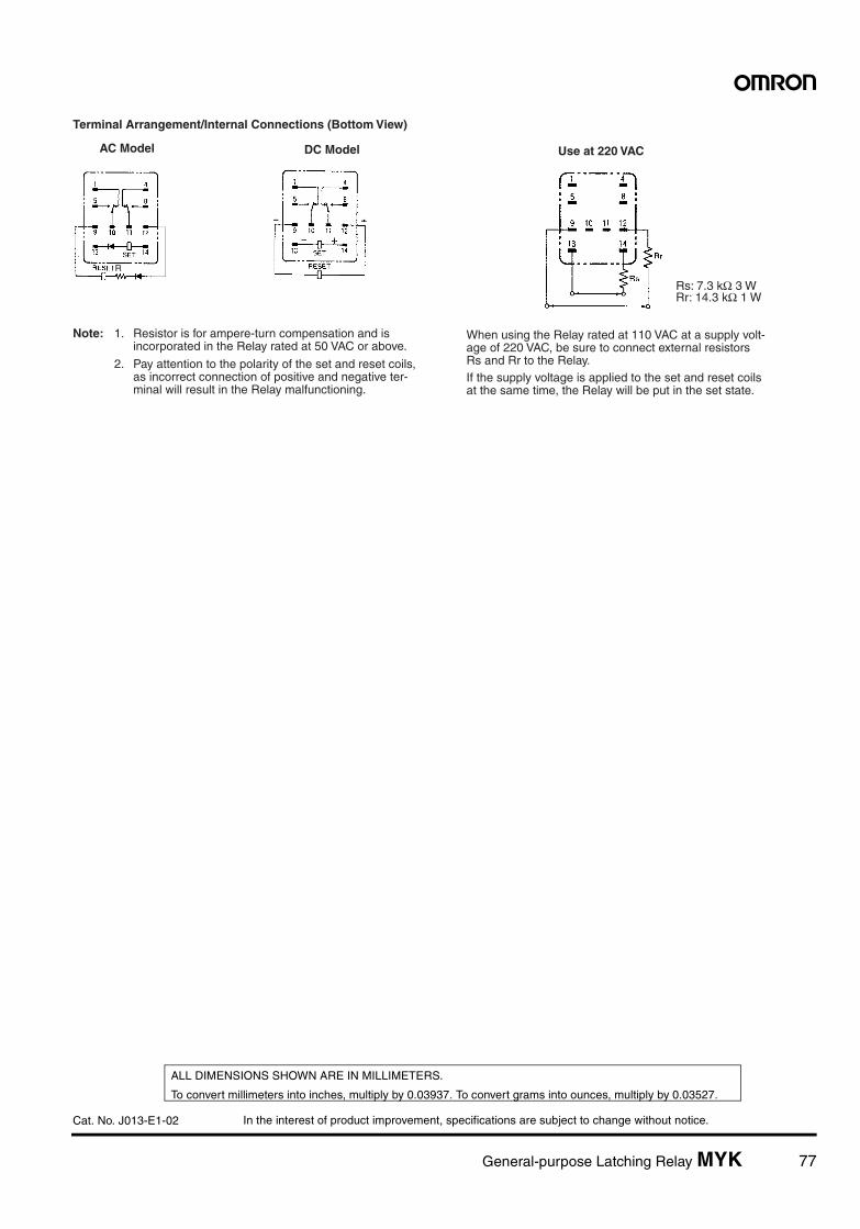
In the interest of product improvement, specifications are subject to change without notice.
ALL DIMENSIONS SHOWN ARE IN MILLIMETERS.
To convert millimeters into inches, multiply by 0.03937. To convert grams into ounces, multiply by 0.03527.
Cat. No. J013-E1-02
General-purpose Latching Relay MYK 77
R
Terminal Arrangement/Internal Connections (Bottom View)
Note: 1. Resistor is for ampere-turn compensation and is incorporated in the Relay rated at 50 VAC or above.
2. Pay attention to the polarity of the set and reset coils, as incorrect connection of positive and negative ter- minal will result in the Relay malfunctioning.
AC Model DC Model
When using the Relay rated at 110 VAC at a supply volt-age of 220 VAC, be sure to connect external resistors Rs and Rr to the Relay.If the supply voltage is applied to the set and reset coils at the same time, the Relay will be put in the set state.
Use at 220 VAC
Rs: 7.3 kΩ 3 WRr: 14.3 kΩ 1 W
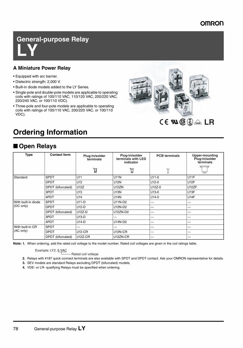
78 General-purpose Relay LY
General-purpose Relay
LYA Miniature Power Relay
• Equipped with arc barrier.
• Dielectric strength: 2,000 V.• Built-in diode models added to the LY Series.• Single-pole and double-pole models are applicable to operating
coils with ratings of 100/110 VAC, 110/120 VAC, 200/220 VAC, 220/240 VAC, or 100/110 VDC).
• Three-pole and four-pole models are applicable to operating coils with ratings of 100/110 VAC, 200/220 VAC, or 100/110 VDC).
LROrdering Information
Open Relays
Note: 1. When ordering, add the rated coil voltage to the model number. Rated coil voltages are given in the coil ratings table.
2. Relays with #187 quick connect terminals are also available with SPDT and DPDT contact. Ask your OMRON representative for details.3. SEV models are standard Relays excluding DPDT (bifurcated) models.4. VDE- or LR- qualifying Relays must be specified when ordering.
Type Contact form
Standard SPDT LY1 LY1N LY1-0 LY1F
DPDT LY2 LY2N LY2-0 LY2F
DPDT (bifurcated) LY2Z LY2ZN LY2Z-0 LY2ZF
3PDT LY3 LY3N LY3-0 LY3F
4PDT LY4 LY4N LY4-0 LY4F
With built-in diode(DC only)
SPDT LY1-D LY1N-D2 --- ---
DPDT LY2-D LY2N-D2 --- ---
DPDT (bifurcated) LY2Z-D LY2ZN-D2 --- ---
3PDT LY3-D --- --- ---
4PDT LY4-D LY4N-D2 --- ---
With built-in CR(AC only)
SPDT --- --- --- ---
DPDT LY2-CR LY2N-CR --- ---
DPDT (bifurcated) LY2Z-CR LY2ZN-CR --- ---
Plug-in/solder terminals
Plug-in/solder terminals with LED
indicator
PCB terminals Upper-mounting Plug-in/solder
terminals
Rated coil voltage Example: LY2, 6 VAC
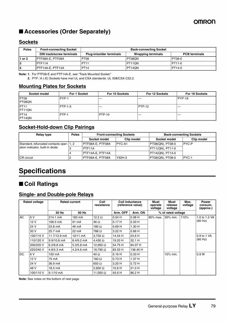
General-purpose Relay LY 79
Accessories (Order Separately)
Sockets
Note: 1. For PTF08-E and PTF14A-E, see “Track Mounted Socket.”2. PTF@A (-E) Sockets have met UL and CSA standards: UL 508/CSA C22.2.
Mounting Plates for Sockets
Socket-Hold-down Clip Pairings
Specifications
Coil Ratings
Single- and Double-pole Relays
Note: See notes on the bottom of next page.
Poles Front-connecting Socket Back-connecting Socket
DIN track/screw terminals Plug-in/solder terminals Wrapping terminals PCB terminals
1 or 2 PTF08A-E, PTF08A PT08 PT08QN PT08-0
3 PTF11A PT11 PT11QN PT11-0
4 PTF14A-E, PTF14A PT14 PT14QN PT14-0
Socket model For 1 Socket For 10 Sockets For 12 Sockets For 18 Sockets
PT08PT08QN
PYP-1 --- --- PYP-18
PT11PT11QN
PTP-1-3 --- PTP-12 ---
PT14PT14QN
PTP-1 PTP-10 --- ---
Relay type Poles Front-connecting Sockets Back-connecting Sockets
Socket model Clip model Socket model Clip model
Standard, bifurcated contacts oper-ation indicator, built-in diode
1, 2 PTF08A-E, PTF08A PYC-A1 PT08(QN), PT08-0 PYC-P
3 PTF11A PT11(QN), PT11-0
4 PTF14A-E, PTF14A PT14(QN), PT14-0
CR circuit 2 PTF08A-E, PTF08A Y92H-3 PT08(QN), PT08-0 PYC-1
Rated voltage Rated current Coil resistance
Coil inductance (reference value)
Must operate voltage
Must release voltage
Max. voltage
Power consum.(approx.)
50 Hz 60 Hz Arm. OFF Arm. ON % of rated voltage
AC 6 V 214.1 mA 183 mA 12.2 Ω 0.04 H 0.08 H 80% max. 30% min. 110% 1.0 to 1.2 VA (60 Hz)12 V 106.5 mA 91 mA 46 Ω 0.17 H 0.33 H
24 V 53.8 mA 46 mA 180 Ω 0.69 H 1.30 H
50 V 25.7 mA 22 mA 788 Ω 3.22 H 5.66 H
100/110 V 11.7/12.9 mA 10/11 mA 3,750 Ω 14.54 H 24.6 H 0.9 to 1 VA (60 Hz)110/120 V 9.9/10.8 mA 8.4/9.2 mA 4,430 Ω 19.20 H 32.1 H
200/220 V 6.2/6.8 mA 5.3/5.8 mA 12,950 Ω 54.75 H 94.07 H
220/240 V 4.8/5.3 mA 4.2/4.6 mA 18,790 Ω 83.50 H 136.40 H
DC 6 V 150 mA 40 Ω 0.16 H 0.33 H 10% min. 0.9 W
12 V 75 mA 160 Ω 0.73 H 1.37 H
24 V 36.9 mA 650 Ω 3.20 H 5.72 H
48 V 18.5 mA 2,600 Ω 10.6 H 21.0 H
100/110 V 9.1/10 mA 11,000 Ω 45.6 H 86.2 H
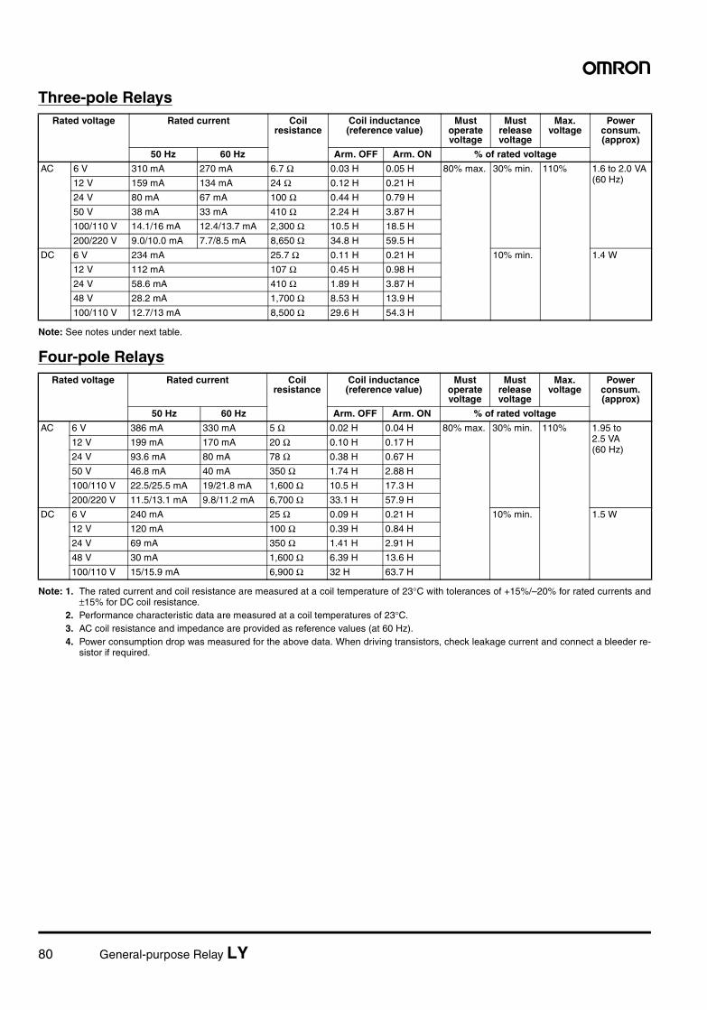
80 General-purpose Relay LY
Three-pole Relays
Note: See notes under next table.
Four-pole Relays
Note: 1. The rated current and coil resistance are measured at a coil temperature of 23°C with tolerances of +15%/–20% for rated currents and±15% for DC coil resistance.
2. Performance characteristic data are measured at a coil temperatures of 23°C.3. AC coil resistance and impedance are provided as reference values (at 60 Hz).4. Power consumption drop was measured for the above data. When driving transistors, check leakage current and connect a bleeder re-
sistor if required.
Rated voltage Rated current Coil resistance
Coil inductance (reference value)
Must operate voltage
Must release voltage
Max. voltage
Power consum. (approx)
50 Hz 60 Hz Arm. OFF Arm. ON % of rated voltage
AC 6 V 310 mA 270 mA 6.7 Ω 0.03 H 0.05 H 80% max. 30% min. 110% 1.6 to 2.0 VA (60 Hz)12 V 159 mA 134 mA 24 Ω 0.12 H 0.21 H
24 V 80 mA 67 mA 100 Ω 0.44 H 0.79 H
50 V 38 mA 33 mA 410 Ω 2.24 H 3.87 H
100/110 V 14.1/16 mA 12.4/13.7 mA 2,300 Ω 10.5 H 18.5 H
200/220 V 9.0/10.0 mA 7.7/8.5 mA 8,650 Ω 34.8 H 59.5 H
DC 6 V 234 mA 25.7 Ω 0.11 H 0.21 H 10% min. 1.4 W
12 V 112 mA 107 Ω 0.45 H 0.98 H
24 V 58.6 mA 410 Ω 1.89 H 3.87 H
48 V 28.2 mA 1,700 Ω 8.53 H 13.9 H
100/110 V 12.7/13 mA 8,500 Ω 29.6 H 54.3 H
Rated voltage Rated current Coil resistance
Coil inductance (reference value)
Must operate voltage
Must release voltage
Max. voltage
Power consum. (approx)
50 Hz 60 Hz Arm. OFF Arm. ON % of rated voltage
AC 6 V 386 mA 330 mA 5 Ω 0.02 H 0.04 H 80% max. 30% min. 110% 1.95 to 2.5 VA (60 Hz)
12 V 199 mA 170 mA 20 Ω 0.10 H 0.17 H
24 V 93.6 mA 80 mA 78 Ω 0.38 H 0.67 H
50 V 46.8 mA 40 mA 350 Ω 1.74 H 2.88 H
100/110 V 22.5/25.5 mA 19/21.8 mA 1,600 Ω 10.5 H 17.3 H
200/220 V 11.5/13.1 mA 9.8/11.2 mA 6,700 Ω 33.1 H 57.9 H
DC 6 V 240 mA 25 Ω 0.09 H 0.21 H 10% min. 1.5 W
12 V 120 mA 100 Ω 0.39 H 0.84 H
24 V 69 mA 350 Ω 1.41 H 2.91 H
48 V 30 mA 1,600 Ω 6.39 H 13.6 H
100/110 V 15/15.9 mA 6,900 Ω 32 H 63.7 H
General-purpose Relay LY 81
Contact Ratings
*Note: P level: λ60 = 0.1 x 10⁻⁶/operation, reference value
Characteristics
Note: 1. The values given above are initial values.2. The upper limit of 40°C for some Relays is because of the relationship between diode junction temperature and the element used.
Relay Single contact Bifurcated contacts
1-pole 2-, 3- or 4-pole 2-pole
Load Resistive load (cosφ = 1)
Inductive load (cosφ=0.4, L/R=7 ms)
Resistive load (cosφ = 1)
Inductive load (cosφ=0.4, L/R=7 ms)
Resistive load (cosφ = 1)
Inductive load (cosφ=0.4, L/R=7 ms)
Rated load 110 VAC 15 A24 VDC 15 A
110 VAC 10 A24 VDC 7 A
110 VAC 10 A24 VDC 10 A
110 VAC 7.5 A24 VDC 5 A
110 VAC 5A24 VDC 5 A
110 VAC 4 A24 VDC 4A
Rated carry current
15 A 10 A 7 A
Max. switching voltage
250 VAC125 VDC
250 VAC125 VDC
250 VAC125 VDC
Max. switching current
15 A 10 A 7 A
Max. switching power
1,700 VA360 W
1,100 VA170 W
1,100 VA240 W
825 VA120 W
550 VA120 W
440 VA100 W
Failure rate (reference value)*
100 mA, 5 VDC 100 mA, 5 VDC 10 mA, 5 VDC
Item All except Relays with bifurcated contacts Relays with bifurcated contacts
Contact resistance 50 mΩ max.
Operate time 25 ms max.
Release time 25 ms max.
Max. operating frequency Mechanical: 18,000 operations/hrElectrical: 1,800 operations/hr (under rated load)
Insulation resistance 100 MΩ min. (at 500 VDC)
Dielectric strength 1,000 VAC, 50/60 Hz for 1 min between contacts of same polarity2,000 VAC, 50/60 Hz for 1 min between contacts of different polarity
Vibration resistance Destruction: 10 to 55 to 10 Hz, 0.5 mm single amplitude (1.0 mm double amplitude)Malfunction: 10 to 55 to 10 Hz, 0.5 mm single amplitude (1.0 mm double amplitude)
Shock resistance Destruction: 1,000 m/s2
Malfunction: 200 m/s2
Endurance Mechanical: AC: 50,000,000 operations min. (at 18,000 operations/hr)DC: 1,00,000,000 operations min. (at 18,000 operations/hr)
Electrical: Single-, three-, and four-pole: 200,000 operations min. (at 1,800 operations/hr under rated load)Double-pole: 500,000 operations min. (at 1,800 operations/hr under rated load)
Ambient temperature* Operating: Single- and double-pole standard, bifurcated-contact Relays: –25°C to 55°C (with no icing) (–25°C to 70°C if carry current is 4 A or less)All other Relays: –25°C to 40°C (with no icing) (–25°C to 55°C if carry current is 4 A or less)
Ambient humidity Operating: 5% to 85%
Weight Single- and double-pole: approx. 40 g, three-pole: approx. 50 g, four-pole: approx. 70 g
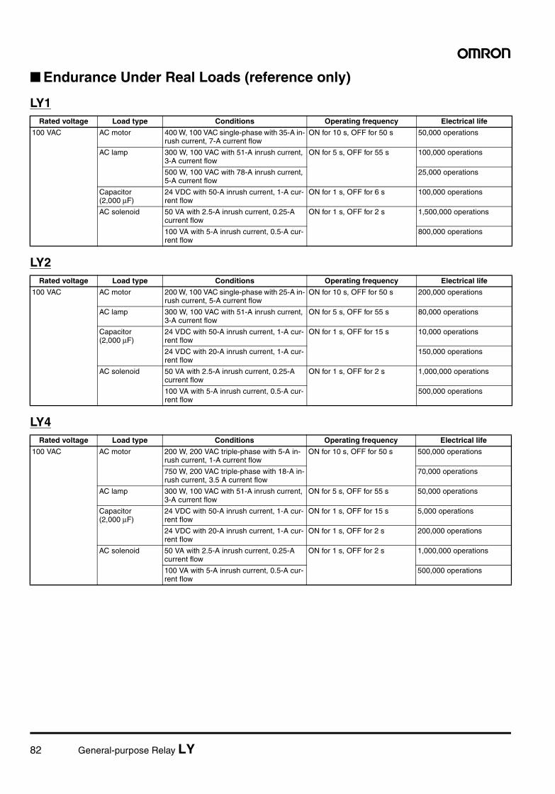
82 General-purpose Relay LY
Endurance Under Real Loads (reference only)
LY1
LY2
LY4
Rated voltage Load type Conditions Operating frequency Electrical life
100 VAC AC motor 400 W, 100 VAC single-phase with 35-A in-rush current, 7-A current flow
ON for 10 s, OFF for 50 s 50,000 operations
AC lamp 300 W, 100 VAC with 51-A inrush current, 3-A current flow
ON for 5 s, OFF for 55 s 100,000 operations
500 W, 100 VAC with 78-A inrush current, 5-A current flow
25,000 operations
Capacitor(2,000 µF)
24 VDC with 50-A inrush current, 1-A cur-rent flow
ON for 1 s, OFF for 6 s 100,000 operations
AC solenoid 50 VA with 2.5-A inrush current, 0.25-A current flow
ON for 1 s, OFF for 2 s 1,500,000 operations
100 VA with 5-A inrush current, 0.5-A cur-rent flow
800,000 operations
Rated voltage Load type Conditions Operating frequency Electrical life
100 VAC AC motor 200 W, 100 VAC single-phase with 25-A in-rush current, 5-A current flow
ON for 10 s, OFF for 50 s 200,000 operations
AC lamp 300 W, 100 VAC with 51-A inrush current, 3-A current flow
ON for 5 s, OFF for 55 s 80,000 operations
Capacitor(2,000 µF)
24 VDC with 50-A inrush current, 1-A cur-rent flow
ON for 1 s, OFF for 15 s 10,000 operations
24 VDC with 20-A inrush current, 1-A cur-rent flow
150,000 operations
AC solenoid 50 VA with 2.5-A inrush current, 0.25-A current flow
ON for 1 s, OFF for 2 s 1,000,000 operations
100 VA with 5-A inrush current, 0.5-A cur-rent flow
500,000 operations
Rated voltage Load type Conditions Operating frequency Electrical life
100 VAC AC motor 200 W, 200 VAC triple-phase with 5-A in-rush current, 1-A current flow
ON for 10 s, OFF for 50 s 500,000 operations
750 W, 200 VAC triple-phase with 18-A in-rush current, 3.5 A current flow
70,000 operations
AC lamp 300 W, 100 VAC with 51-A inrush current, 3-A current flow
ON for 5 s, OFF for 55 s 50,000 operations
Capacitor(2,000 µF)
24 VDC with 50-A inrush current, 1-A cur-rent flow
ON for 1 s, OFF for 15 s 5,000 operations
24 VDC with 20-A inrush current, 1-A cur-rent flow
ON for 1 s, OFF for 2 s 200,000 operations
AC solenoid 50 VA with 2.5-A inrush current, 0.25-A current flow
ON for 1 s, OFF for 2 s 1,000,000 operations
100 VA with 5-A inrush current, 0.5-A cur-rent flow
500,000 operations
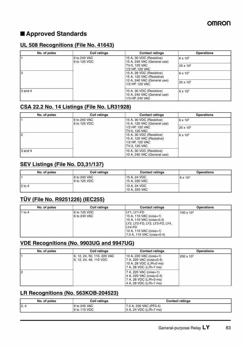
General-purpose Relay LY 83
Approved Standards
UL 508 Recognitions (File No. 41643)
CSA 22.2 No. 14 Listings (File No. LR31928)
SEV Listings (File No. D3,31/137)
TÜV (File No. R9251226) (IEC255)
VDE Recognitions (No. 9903UG and 9947UG)
LR Recognitions (No. 563KOB-204523)
No. of poles Coil ratings Contact ratings Operations
1 6 to 240 VAC6 to 125 VDC
15 A, 30 VDC (Resistive)15 A, 240 VAC (General use)TV-5, 120 VAC1/2 HP, 120 VAC
6 x 10³
25 x 103
2 15 A, 28 VDC (Resistive)15 A, 120 VAC (Resistive)12 A, 240 VAC (General use)1/2 HP, 120 VAC
6 x 10³
25 x 103
3 and 4 10 A, 30 VDC (Resistive)10 A, 240 VAC (General use)1/3 HP, 240 VAC
6 x 10³
No. of poles Coil ratings Contact ratings Operations
1 6 to 240 VAC6 to 125 VDC
15 A, 30 VDC (Resistive)15 A, 120 VAC (General use)1/2 HP, 120 VACTV-5, 120 VAC
6 x 10³
25 x 103
2 15 A, 30 VDC (Resistive)15 A, 120 VAC (Resistive)1/2 HP, 120 VACTV-3, 120 VAC
6 x 10³
3 and 4 10 A, 30 VDC (Resistive)10 A, 240 VAC (General use)
No. of poles Coil ratings Contact ratings Operations
1 6 to 240 VAC6 to 125 VDC
15 A, 24 VDC15 A, 220 VAC
6 x 10³
2 to 4 10 A, 24 VDC10 A, 220 VAC
No. of poles Coil ratings Contact ratings Operations
1 to 4 6 to 125 VDC6 to 240 VAC
LY1, LY1-FD15 A, 110 VAC (cosφ=1)10 A, 110 VAC (cosφ=0.4)LY2, LY2-FD, LY3, LY3-FD, LY4, LY4-FD10 A, 110 VAC (cosφ=1)7.5 A, 110 VAC (cosφ=0.4)
100 x 103
No. of poles Coil ratings Contact ratings Operations
1 6, 12, 24, 50, 110, 220 VAC6, 12, 24, 48, 110 VDC
10 A, 220 VAC (cosφ=1)7 A, 220 VAC (cosφ=0.4)10 A, 28 VDC (L/R=0 ms)7 A, 28 VDC (L/R=7 ms)
200 x 103
2 7 A, 220 VAC (cosφ=1) 4 A, 220 VAC (cosφ=0.4)7 A, 28 VDC (L/R=0 ms)4 A, 28 VDC (L/R=7 ms)
No. of poles Coil ratings Contact ratings
2, 4 6 to 240 VAC6 to 110 VDC
7.5 A, 230 VAC (PF0.4)5 A, 24 VDC (L/R=7 ms)
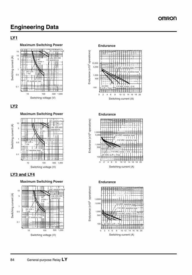
84 General-purpose Relay LY
Engineering Data
LY1
LY2
LY3 and LY4
15
10
5
1
0.5
0.1
10 100 500 1,000
10,000
5,000
1,000
100
0 2 4 6 8 10 12 14 16 18 20
500
Maximum Switching Power
Switching voltage (V) Switching current (A)
Endurance
Sw
itchi
ng c
urre
nt (
A)
AC resistive load
DC resistive load
110 VAC resistive load
24 VDC resistive load
110 VAC (cosφ = 0.4)
End
uran
ce (
x103
oper
atio
ns)
24 VDC (L/R = 7ms)
Life: 200,000 operationsAC
(cosφ = 0.4)
DC L/R = 7 ms
10
5
1
0.5
0.1
10 100 500 1,000 0 2 4 6 8 10 12 14 16 18 20
1,0000
1,000
100
500
5,000
Maximum Switching Power
Switching voltage (V)
Endurance
Switching current (A)
AC resistive load
DC resistive load
24 VDC resistive load
110 VAC resistive load
110 VAC (cosφ = 0.4)
24 VDC (L/R = 7ms)
End
uran
ce (
x103
oper
atio
ns)
Sw
itchi
ng c
urre
nt (
A)
Life: 500,000 operationsAC
(cosφ = 0.4)
DC L/R = 7 ms
10
5
1
0.5
0.1
10 100 0 2 4 6 8 10 12 14 16 18 20500 1,000
1,0000
1,000
100
500
5,000
Maximum Switching Power
Switching voltage (V)
Endurance
Switching current (A)
AC resistive load
DC resistive load
24 VDC resistive load
110 VAC resistive load
110 VAC (cosφ = 0.4)
24 VDC (L/R = 7ms)
End
uran
ce (
x103
ope
ratio
ns)
Sw
itchi
ng c
urre
nt (
A)
DC L/R = 7 ms
AC (cosφ = 0.4)
Life: 200,000 operations
General-purpose Relay LY 85
LY2Z
DimensionsNote: All units are in millimeters unless otherwise indicated.
Relays with Solder/Plug-in Terminals
Note: The DC models have polarity.
10
5
1
0.5
10 100 500 1,00050
10,000
5,000
1,000
500
0 2 4 6 8 10
100
0
Maximum Switching Power
Switching voltage (V) Switching current (A)
Endurance
Sw
itchi
ng c
urre
nt (
A) AC resistive load
DC resistive load
Life: 500,000 operations
24 VDC resistive load
110 VAC resistive load
110 VAC (cosφ = 0.4)
24 VDC (L/R = 7ms)End
uran
ce (
x103
oper
atio
ns)
DC L/R = 7 ms
AC (cosφ = 0.4)
0.5
5
3
6.4
LY1 LY1-D LY1N
LY1N-D2
LY1 LY1N (-D2) LY1-D
Eight, 2-dia. holes
36 max.
28 max.
Terminal Arrangement/Internal Connections (Bottom View)
DC Model AC Model
21.5 max.
86 General-purpose Relay LY
Note: The DC models have polarity.
Note: The DC models have polarity.
0.5
5
3
6.4
LY2(Z) LY2(Z)-D
LY2(Z)N LY2(Z)N-D2
LY2 LY2Z LY2-D LY2Z-D LY2N LY2ZN LY2N-D2 LY2ZN-D2
Eight, 3-dia. holes
36 max.
28 max.
DC Model AC Model
21.5 max.
Terminal Arrangement/Internal Connections (Bottom View)
0.5
5
36.4
LY3 LY3-D LY3N
LY3Z LY3N LY3-D
Eleven, 3-dia. holes
28 max.
31.5 max.
Terminal Arrangement/Internal Connections (Bottom View)
DC Model AC Model
36.5 max.
General-purpose Relay LY 87
Note: The DC models have polarity.
Relays with PCB Terminals
0.5
5
3
6.4
LY4 LY4-D
LY4N LY4N-D2
LY4 LY4N LY4-D LY4N-D2
36 max.
28 max.
41.5 max.
DC Model AC Model
Terminal Arrangement/Internal Connections (Bottom View)
Fourteen, 3-dia. holes
0.5
LY2(Z)-CR LY2(Z)N-CR
5
3
6.4
LY2-CR LY2Z-CR LY2N-CR LY2ZN-CR
28 max.
53 max.
Model: LY2N-CR
CR ElementC: 0.033 µFR: 120 Ω
Eight, 3-dia. holes
21.5 max.
Terminal Arrangement/Internal Connections (Bottom View)
0.5
2
1
5.75
4.1
5.5
14.210
14.210 10 10 10 10 10
3.4 3.4 5.3 5.3
4.6
13.157.15
LY1-0 LY3-0 LY2-0 LY4-0
4.5 (see note 2)36 max.
28 max.
Note: 1. The above model is the LY2-0. 2. This figure is 6.4 for the LY1-0
Note: 1. The tolerance for the above figures is 0.1 mm. 2. Besides the terminals, some part of the LY1-0 car- ries current. Due attention should be paid when mounting the LY1-0 to a double-sided PC board.
PC Board Holes (Bottom View)
21.5 max.
Five, 2.5-dia. holes
Eight, 2.5-dia. holes
Eleven, 2.5-dia. holes
Fourteen, 2.5-dia. holes
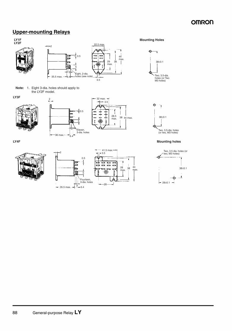
88 General-purpose Relay LY
Upper-mounting Relays
2
0.5
5
3
6.43.5
38 38±0.1
LY1F LY2F
35.5 max.
22.5 max.
Mounting Holes
Note: 1. Eight 3-dia. holes should apply to the LY2F model.
Two, 3.5-dia. holes (or Two M3 holes)
44 max.
29 max.
Eight, 2-dia. holes (see note)
LY3F
0.5
5
3
6.4
3.5
38 38±0.1
2
36 max.
32 max.
44 max.
Two, 3.5-dia. holes (or two, M3 holes)
28.5 max.
Eleven, 3-dia. holes
LY4F
2
0.5
5
36.4
3.5
28
38
28±0.1
38±0.1
35.5 max.
Mounting holes
41.5 max. Two, 3.5 dia. holes (or two, M3 holes)
44 max.
28 max.
Fourteen, 3-dia. holes
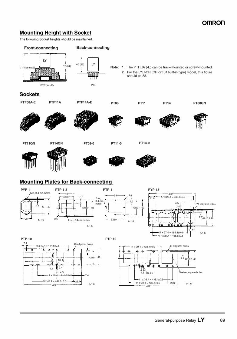
General-purpose Relay LY 89
Mounting Height with SocketThe following Socket heights should be maintained.
Sockets
Mounting Plates for Back-connecting
LY
67 (84)
PTF@A (-E)
40 (57) LY
PT@
Front-connecting
71 (see note)
Back-connecting
Note: 1. The PTF@A (-E) can be track-mounted or screw-mounted.
2. For the LY@-CR (CR circuit built-in type) model, this figure should be 88.
PTF08A-E PT14
PT14QN PT14-0
PTF14A-EPTF11A PT08 PT11 PT08QN
PT11QN PT08-0 PT11-0
PTP-1-3 PTP-1 PYP-18
PTP-10 PTP-12
PYP-1
t=1.6
t=1.6
t=1.6
t=1.6
t=1.6 t=1.6
R5
7.7
42±0.1 49
52±0.1
5949
42±0.1 7.7
42±0.1 49
R5
7.7
42±0.1 49
9 x 49.4 = 444.6±0.6
9 x 49.4 = 444.6±0.6
492
R1.7
3.4
4.5
1.1
7.4
23.7
7.4
7.7 42±0.1 49
11 x 39.4 = 433.4±0.6492
29.3
3.4
4.5 R2.25
28
5.1 42 49
492
21.6
21.6
4.53.4
R1.7
7.742±0.1 49
11 x 39.4 = 433.4±0.6
11 x 39.4 = 433.4±0.6
17 x 27.4 = 465.8±0.617 x 27.4 = 465.8±0.6
17 x 27.4 = 465.8±0.6
9 x 49.4 = 444.6±0.6
Two, 3.4-dia. holes
Four, 3.4-dia. holes
72 elliptical holes
Twelve, square holes
48 elliptical holes40 elliptical holes
Four, 3.4-dia. holes

90 General-purpose Relay LY
In the interest of product improvement, specifications are subject to change without notice.
ALL DIMENSIONS SHOWN ARE IN MILLIMETERS.
To convert millimeters into inches, multiply by 0.03937. To convert grams into ounces, multiply by 0.03527.
Cat. No. J002-E1-10
Hold-down ClipsHold-down clips are used to hold Relays to Sockets and prevent them from coming loose due to vibration or shock.
PrecautionsRefer to page 11 for general precautions.
ConnectionsDo not reverse polarity when connecting DC-operated Relays withbuilt-in diodes or indicators.
Used with Socket Used with Socket mounting plate
For CR circuit built-in Relay
PYC-A1 PYC-P PYC-S Y92H-3 PYC-1
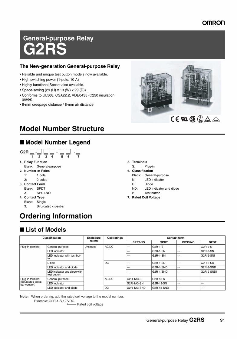
General-purpose Relay G2RS 91
General-purpose Relay
G2RSThe New-generation General-purpose Relay
• Reliable and unique test button models now available.
• High switching power (1-pole: 10 A)• Highly functional Socket also available.• Space-saving (29 (H) x 13 (W) x 29 (D))
• Conforms to UL508, CSA22.2, VDE0435 (C250 insulation grade).
• 8-mm creepage distance / 8-mm air distance
Model Number Structure
Model Number Legend
1. Relay FunctionBlank: General-purpose
2. Number of Poles1: 1 pole2: 2 poles
3. Contact FormBlank: SPDTA: SPST-NO
4. Contact TypeBlank: Single3: Bifurcated crossbar
5. TerminalsS: Plug-in
6. ClassificationBlank: General-purposeN: LED indicatorD: DiodeND: LED indicator and diodeI: Test button
7. Rated Coil Voltage
Ordering Information
List of Models
G2R - - - 1 2 3 4 5 6 7
Classification Enclosure rating
Coil ratings Contact form
SPST-NO SPDT DPST-NO DPDT
Plug-in terminal General-purpose Unsealed AC/DC --- G2R-1-S --- G2R-2-S
LED indicator --- G2R-1-SN --- G2R-2-SN
LED indicator with test but-ton
--- G2R-1-SNI --- G2R-2-SNI
Diode DC --- G2R-1-SD --- G2R-2-SD
LED indicator and diode --- G2R-1-SND --- G2R-2-SND
LED indicator and diode with test button
--- G2R-1-SNDI --- G2R-2-SNDI
Plug-in terminal (Bifurcated cross-bar contact)
General-purpose AC/DC G2R-1A3-S G2R-13-S --- ---
LED indicator G2R-1A3-SN G2R-13-SN --- ---
LED indicator and diode DC G2R-1A3-SND G2R-13-SND --- ---
Rated coil voltage
Note: When ordering, add the rated coil voltage to the model number.Example: G2R-1-S 12 VDC
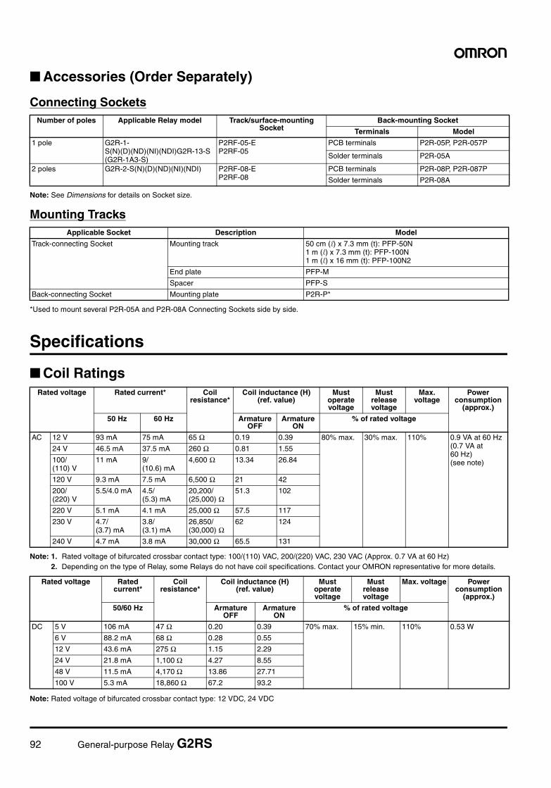
92 General-purpose Relay G2RS
Accessories (Order Separately)
Connecting Sockets
Note: See Dimensions for details on Socket size.
Mounting Tracks
*Used to mount several P2R-05A and P2R-08A Connecting Sockets side by side.
Specifications
Coil Ratings
Note: 1. Rated voltage of bifurcated crossbar contact type: 100/(110) VAC, 200/(220) VAC, 230 VAC (Approx. 0.7 VA at 60 Hz)2. Depending on the type of Relay, some Relays do not have coil specifications. Contact your OMRON representative for more details.
Note: Rated voltage of bifurcated crossbar contact type: 12 VDC, 24 VDC
Number of poles Applicable Relay model Track/surface-mounting Socket
Back-mounting Socket
Terminals Model
1 pole G2R-1-S(N)(D)(ND)(NI)(NDI)G2R-13-S (G2R-1A3-S)
P2RF-05-EP2RF-05
PCB terminals P2R-05P, P2R-057P
Solder terminals P2R-05A
2 poles G2R-2-S(N)(D)(ND)(NI)(NDI) P2RF-08-EP2RF-08
PCB terminals P2R-08P, P2R-087P
Solder terminals P2R-08A
Applicable Socket Description Model
Track-connecting Socket Mounting track 50 cm (l) x 7.3 mm (t): PFP-50N1 m (l) x 7.3 mm (t): PFP-100N1 m (l) x 16 mm (t): PFP-100N2
End plate PFP-M
Spacer PFP-S
Back-connecting Socket Mounting plate P2R-P*
Rated voltage Rated current* Coil resistance*
Coil inductance (H) (ref. value)
Must operate voltage
Must release voltage
Max. voltage
Power consumption
(approx.)
50 Hz 60 Hz Armature OFF
Armature ON
% of rated voltage
AC 12 V 93 mA 75 mA 65 Ω 0.19 0.39 80% max. 30% max. 110% 0.9 VA at 60 Hz (0.7 VA at 60 Hz) (see note)
24 V 46.5 mA 37.5 mA 260 Ω 0.81 1.55
100/(110) V
11 mA 9/(10.6) mA
4,600 Ω 13.34 26.84
120 V 9.3 mA 7.5 mA 6,500 Ω 21 42
200/(220) V
5.5/4.0 mA 4.5/(5.3) mA
20,200/(25,000) Ω
51.3 102
220 V 5.1 mA 4.1 mA 25,000 Ω 57.5 117
230 V 4.7/(3.7) mA
3.8/(3.1) mA
26,850/(30,000) Ω
62 124
240 V 4.7 mA 3.8 mA 30,000 Ω 65.5 131
Rated voltage Rated current*
Coil resistance*
Coil inductance (H) (ref. value)
Must operate voltage
Must release voltage
Max. voltage Power consumption
(approx.)
50/60 Hz Armature OFF
Armature ON
% of rated voltage
DC 5 V 106 mA 47 Ω 0.20 0.39 70% max. 15% min. 110% 0.53 W
6 V 88.2 mA 68 Ω 0.28 0.55
12 V 43.6 mA 275 Ω 1.15 2.29
24 V 21.8 mA 1,100 Ω 4.27 8.55
48 V 11.5 mA 4,170 Ω 13.86 27.71
100 V 5.3 mA 18,860 Ω 67.2 93.2
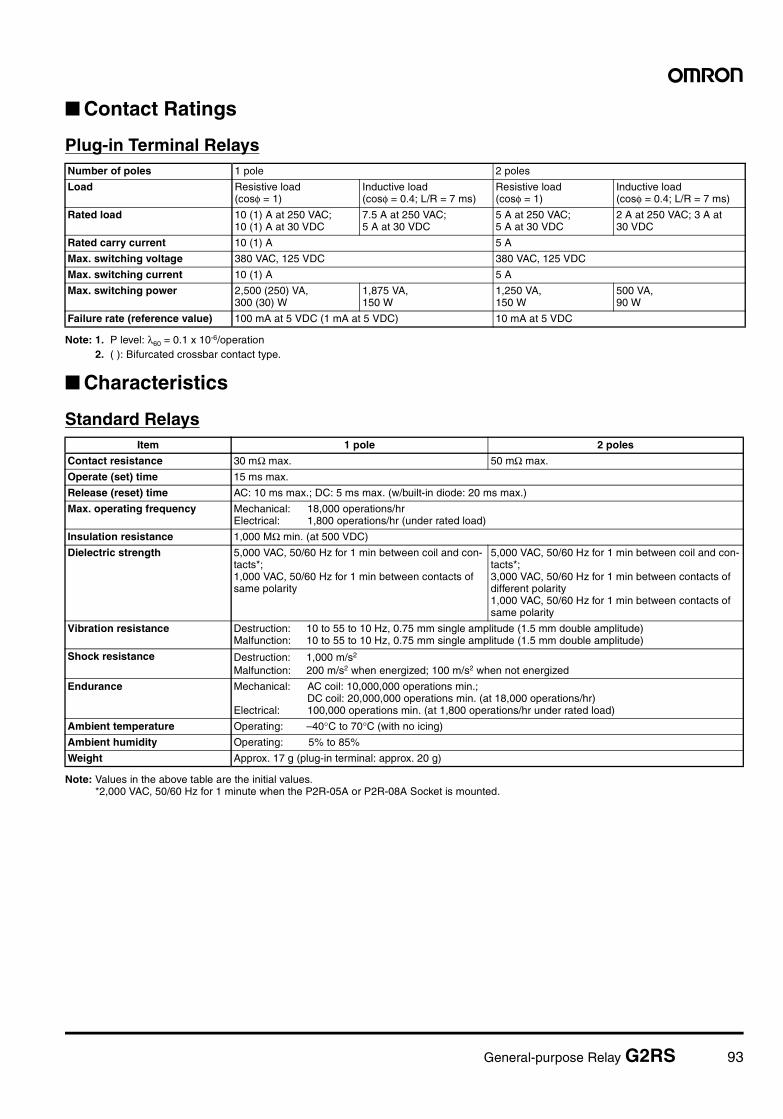
General-purpose Relay G2RS 93
Contact Ratings
Plug-in Terminal Relays
Note: 1. P level: λ60 = 0.1 x 10⁻⁶/operation2. ( ): Bifurcated crossbar contact type.
Characteristics
Standard Relays
Note: Values in the above table are the initial values.*2,000 VAC, 50/60 Hz for 1 minute when the P2R-05A or P2R-08A Socket is mounted.
Number of poles 1 pole 2 poles
Load Resistive load(cosφ = 1)
Inductive load(cosφ = 0.4; L/R = 7 ms)
Resistive load(cosφ = 1)
Inductive load(cosφ = 0.4; L/R = 7 ms)
Rated load 10 (1) A at 250 VAC;10 (1) A at 30 VDC
7.5 A at 250 VAC;5 A at 30 VDC
5 A at 250 VAC;5 A at 30 VDC
2 A at 250 VAC; 3 A at 30 VDC
Rated carry current 10 (1) A 5 A
Max. switching voltage 380 VAC, 125 VDC 380 VAC, 125 VDC
Max. switching current 10 (1) A 5 A
Max. switching power 2,500 (250) VA,300 (30) W
1,875 VA, 150 W
1,250 VA, 150 W
500 VA, 90 W
Failure rate (reference value) 100 mA at 5 VDC (1 mA at 5 VDC) 10 mA at 5 VDC
Item 1 pole 2 poles
Contact resistance 30 mΩ max. 50 mΩ max.
Operate (set) time 15 ms max.
Release (reset) time AC: 10 ms max.; DC: 5 ms max. (w/built-in diode: 20 ms max.)
Max. operating frequency Mechanical: 18,000 operations/hrElectrical: 1,800 operations/hr (under rated load)
Insulation resistance 1,000 MΩ min. (at 500 VDC)
Dielectric strength 5,000 VAC, 50/60 Hz for 1 min between coil and con-tacts*;1,000 VAC, 50/60 Hz for 1 min between contacts of same polarity
5,000 VAC, 50/60 Hz for 1 min between coil and con-tacts*;3,000 VAC, 50/60 Hz for 1 min between contacts of different polarity1,000 VAC, 50/60 Hz for 1 min between contacts of same polarity
Vibration resistance Destruction: 10 to 55 to 10 Hz, 0.75 mm single amplitude (1.5 mm double amplitude)Malfunction: 10 to 55 to 10 Hz, 0.75 mm single amplitude (1.5 mm double amplitude)
Shock resistance Destruction: 1,000 m/s2
Malfunction: 200 m/s2 when energized; 100 m/s2 when not energized
Endurance Mechanical: AC coil: 10,000,000 operations min.; DC coil: 20,000,000 operations min. (at 18,000 operations/hr)
Electrical: 100,000 operations min. (at 1,800 operations/hr under rated load)
Ambient temperature Operating: –40°C to 70°C (with no icing)
Ambient humidity Operating: 5% to 85%
Weight Approx. 17 g (plug-in terminal: approx. 20 g)
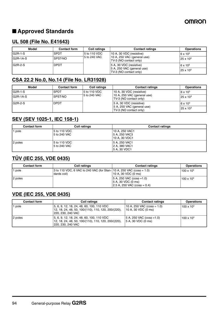
94 General-purpose Relay G2RS
Approved Standards
UL 508 (File No. E41643)
CSA 22.2 No.0, No.14 (File No. LR31928)
SEV (SEV 1025-1, IEC 158-1)
TÜV (IEC 255, VDE 0435)
VDE (IEC 255, VDE 0435)
Model Contact form Coil ratings Contact ratings Operations
G2R-1-S SPDT 5 to 110 VDC5 to 240 VAC
10 A, 30 VDC (resistive)10 A, 250 VAC (general use)TV-3 (NO contact only)
6 x 10³
G2R-1A-S SPST-NO 25 x 103
G2R-2-S DPDT 5 A, 30 VDC (resistive)5 A, 250 VAC (general use)TV-3 (NO contact only)
6 x 10³
25 x 103
Model Contact form Coil ratings Contact ratings Operations
G2R-1-S SPDT 5 to 110 VDC5 to 240 VAC
10 A, 30 VDC (resistive)10 A, 250 VAC (general use)TV-3 (NO contact only)
6 x 10³
G2R-1A-S SPST-NO 25 x 103
G2R-2-S DPDT 5 A, 30 VDC (resistive)5 A, 250 VAC (general use) TV-3 (NO contact only)
6 x 10³
25 x 103
Contact form Coil ratings Contact ratings
1 pole 5 to 110 VDC5 to 240 VAC
10 A, 250 VAC15 A, 250 VAC310 A, 30 VDC1
2 poles 5 to 110 VDC 5 to 240 VAC
5 A, 250 VAC12 A, 380 VAC15 A, 30 VDC1
Contact form Coil ratings Contact ratings Operations
1 pole 3 to 110 VDC, 6 VAC to 240 VAC (for Stan-dards coil)
10 A, 250 VAC (cosφ = 1.0)10 A, 30 VDC (0 ms)
100 x 103
2 poles 5 A, 250 VAC (cosφ =1.0)5 A, 30 VDC (0 ms)2.5 A, 250 VAC (cosφ = 0.4)
100 x 103
Contact form Coil ratings Contact ratings Operations
1 pole 5, 6, 9, 12, 18, 24, 48, 60, 100, 110 VDC12, 18, 24, 48, 50, 100/(110), 110, 120, 200/(220), 220, 230, 240 VAC
10 A, 250 VAC (cosφ = 1.0)10 A, 30 VDC (0 ms)
100 x 103
2 poles 5, 6, 9, 12, 18, 24, 48, 60, 100, 110 VDC12, 18, 24, 48, 50, 100/(110), 110, 120, 200/(220), 220, 230, 240 VAC
5 A, 250 VAC (cosφ =1.0)5 A, 30 VDC (0 ms)
100 x 103
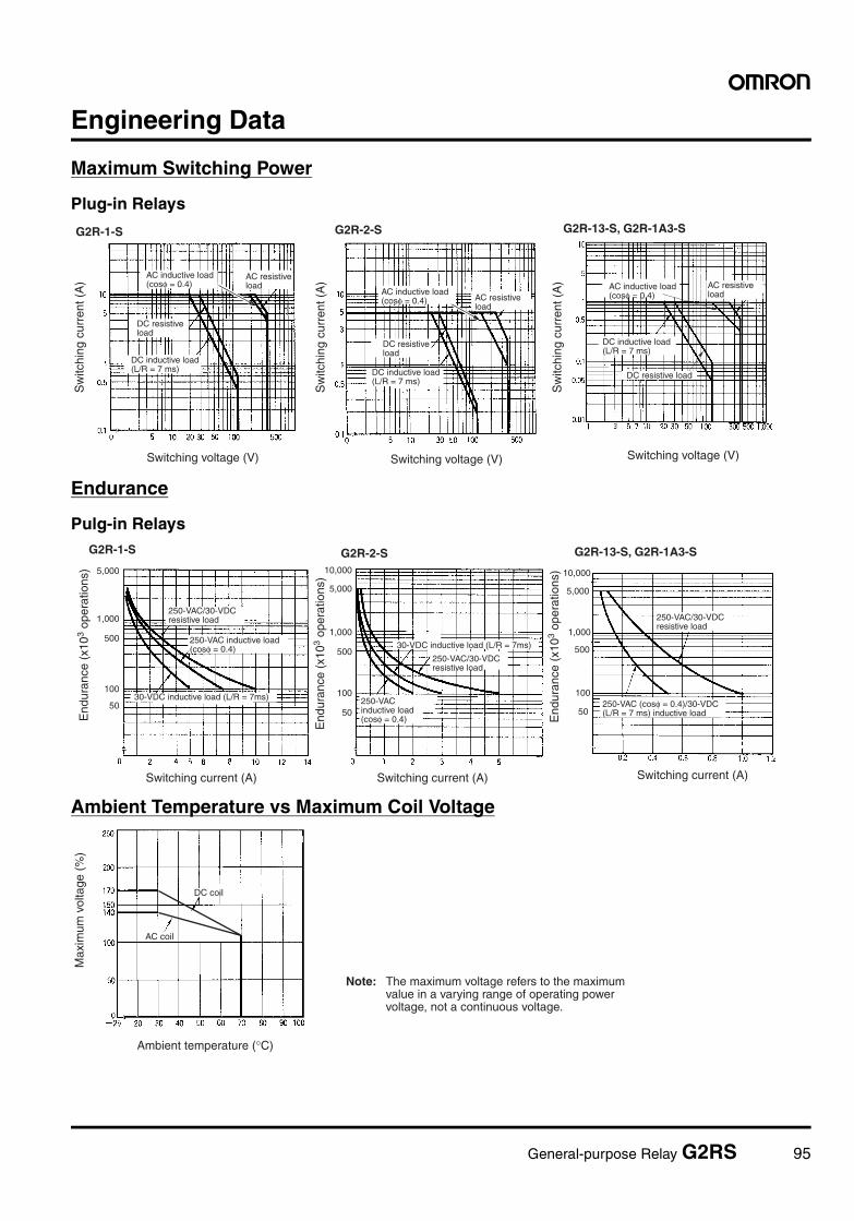
General-purpose Relay G2RS 95
Engineering Data
Maximum Switching Power
Plug-in Relays
Endurance
Pulg-in Relays
Ambient Temperature vs Maximum Coil Voltage
DC resistive load
G2R-1-S
Sw
itchi
ng c
urre
nt (
A)
Switching voltage (V)
G2R-2-S
Switching voltage (V) Switching voltage (V)
G2R-13-S, G2R-1A3-S
Sw
itchi
ng c
urre
nt (
A)
Sw
itchi
ng c
urre
nt (
A) AC inductive load
(cosφ = 0.4)AC resistive load
DC inductive load (L/R = 7 ms)
AC inductive load (cosφ = 0.4) AC resistive
load
DC resistive load
DC inductive load (L/R = 7 ms)
AC inductive load (cosφ = 0.4)
AC resistive load
DC resistive load
DC inductive load (L/R = 7 ms)
10,000
5,000
1,000
500
100
50
5,000
1,000
500
100
50
5,000
1,000
500
100
50
10,000
G2R-1-S
End
uran
ce (
x103
oper
atio
ns)
Switching current (A)
G2R-2-S
Switching current (A)
30-VDC inductive load (L/R = 7ms)
30-VDC inductive load (L/R = 7ms)
End
uran
ce (
x103
oper
atio
ns)
Switching current (A)
End
uran
ce (
x103
oper
atio
ns)
G2R-13-S, G2R-1A3-S
250-VAC/30-VDC resistive load
250-VAC inductive load (cosφ = 0.4)
250-VAC/30-VDC resistive load
250-VAC inductive load (cosφ = 0.4)
250-VAC/30-VDC resistive load
250-VAC (cosφ = 0.4)/30-VDC (L/R = 7 ms) inductive load
Ambient temperature (°C)
Note: The maximum voltage refers to the maximum value in a varying range of operating power voltage, not a continuous voltage.
Max
imum
vol
tage
(%
)
DC coil
AC coil
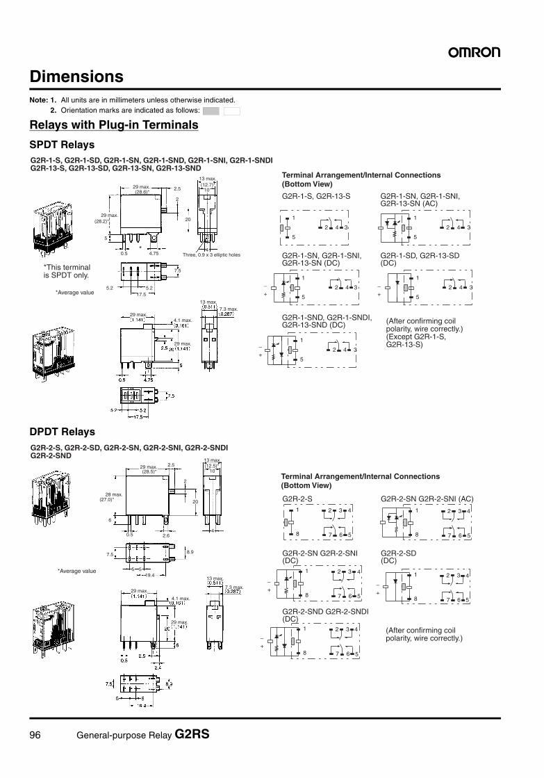
96 General-purpose Relay G2RS
DimensionsNote: 1. All units are in millimeters unless otherwise indicated.
2. Orientation marks are indicated as follows:
Relays with Plug-in Terminals
SPDT Relays
DPDT Relays
G2R-1-S, G2R-13-S G2R-1-SN, G2R-1-SNI, G2R-13-SN (AC)
G2R-1-SN, G2R-1-SNI, G2R-13-SN (DC)
G2R-1-SD, G2R-13-SD (DC)
G2R-1-SND, G2R-1-SNDI, G2R-13-SND (DC)
2.5
2
5
20
0.5 4.75
10
4
7.5
5.2 5.217.5
1
5
4 32
1
5
4 32
1
5
4 32+−
1
5
4 32+−
1
5
4 32+−
*
(28.6)*
(12.7)*
(28.2)*
G2R-1-S, G2R-1-SD, G2R-1-SN, G2R-1-SND, G2R-1-SNI, G2R-1-SNDI G2R-13-S, G2R-13-SD, G2R-13-SN, G2R-13-SND
29 max.
29 max.
13 max.
Three, 0.9 x 3 elliptic holes
*Average value
29 max.4.1 max.
13 max.
7.3 max.
29 max.
(After confirming coil polarity, wire correctly.) (Except G2R-1-S, G2R-13-S)
*This terminal is SPDT only.
Terminal Arrangement/Internal Connections (Bottom View)
G2R-2-S G2R-2-SN G2R-2-SNI (AC)
G2R-2-SN G2R-2-SNI (DC)
G2R-2-SD (DC)
G2R-2-SND G2R-2-SNDI (DC)
2.5
6
2
20
0.5 2.6
10
4
7.5
5 519.4
8.9
1
8 6 57
3 421
8 6 57
3 42
+−
1
8 6 57
3 42
+−
1
8 6 57
3 42
+−
1
8 6 57
3 42
(28.5)*
(27.0)*
(12.5)*
G2R-2-S, G2R-2-SD, G2R-2-SN, G2R-2-SNI, G2R-2-SNDI G2R-2-SND
29 max.
28 max.
13 max.
*Average value
29 max.
4.1 max.
13 max.
7.3 max.
29 max.
(After confirming coil polarity, wire correctly.)
Terminal Arrangement/Internal Connections (Bottom View)
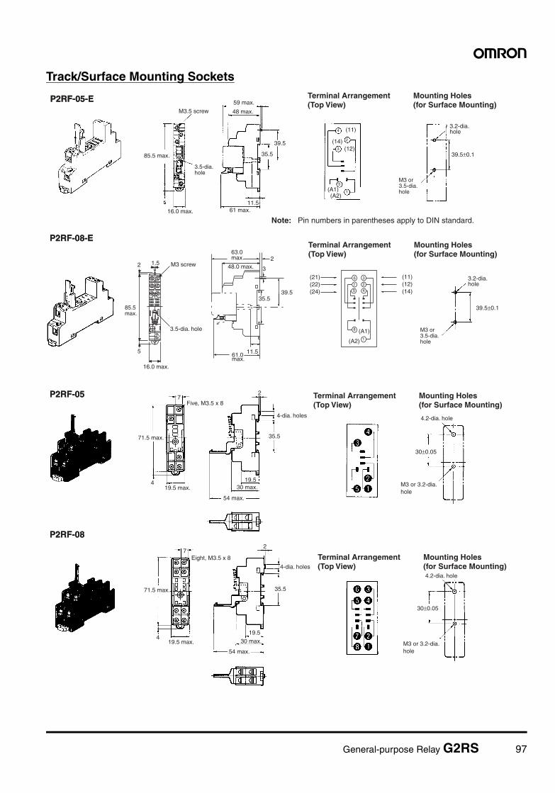
General-purpose Relay G2RS 97
Track/Surface Mounting Sockets
39.5±0.1
P2RF-05
P2RF-08
7
4
2
35.5
19.5
30±0.05
7
4
2
35.5
19.5
30±0.05
P2RF-05-E
39.5
35.5
11.5
(11)
(12)(14)
(A1)(A2)
1
2
3
4
5
39.5±0.1
2 1.5
5
2
3
39.535.5
11.5
P2RF-08-E
8
6 3
7 2
5 4
(A1)
(A2)
(21)(22)(24)
(11)(12)(14)
1
3.2-dia. hole
P2RF-05
P2RF-08
Five, M3.5 x 8
19.5 max.
4-dia. holes
30 max.
54 max.
4.2-dia. hole
71.5 max.
19.5 max.
Eight, M3.5 x 8
4-dia. holes
30 max.
54 max.
4.2-dia. hole
P2RF-05-E
3.2-dia. hole
M3.5 screw
85.5 max.
16.0 max.
59 max.
48 max.
Note: Pin numbers in parentheses apply to DIN standard.61 max.
M3 screw
3.5-dia. hole
16.0 max.
63.0 max.
48.0 max.
61.0 max.
P2RF-08-E
Terminal Arrangement (Top View)
Mounting Holes (for Surface Mounting)
Terminal Arrangement (Top View)
Mounting Holes (for Surface Mounting)
M3 or 3.5-dia. hole
M3 or 3.5-dia. hole
3.5-dia. hole
85.5 max.
M3 or 3.2-dia. hole
M3 or 3.2-dia. hole
Terminal Arrangement (Top View)
Mounting Holes (for Surface Mounting)
Terminal Arrangement (Top View)
Mounting Holes (for Surface Mounting)
71.5 max.
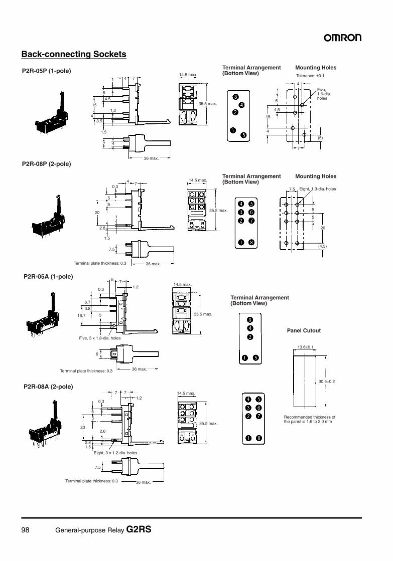
98 General-purpose Relay G2RS
Back-connecting Sockets
1 4 7
6
4.5
15
43.5
1.2
1.5
7 4
4
6
4.5
15
4
7
47
0.3
5
5
201
2.8
1.5
7.5
7.5
5
5
20
(4.3)
(5)
P2R-05P (1-pole)14.5 max.
35.5 max.
Tolerance: ±0.1
Mounting Holes
P2R-08P (2-pole)
36 max.Terminal plate thickness: 0.3
14.5 max.
35.5 max.
Eight, 1.3-dia. holes
36 max.
Terminal Arrangement (Bottom View)
Mounting HolesTerminal Arrangement (Bottom View)
Five, 1.6-dia. holes
75
1.20.3
6.7
3.8
16.7 5
6
71.2
0.3
5
7
5
20
2.8
2.6
7.5
13.6±0.1
30.5±0.2
1.5
P2R-05A (1-pole)
Panel Cutout
P2R-08A (2-pole)
Five, 3 x 1.8-dia. holes
36 max.Terminal plate thickness: 0.3
14.5 max.
35.5 max.
36 max.Terminal plate thickness: 0.3
14.5 max.
35.5 max.
Eight, 3 x 1.2-dia. holes
Terminal Arrangement (Bottom View)
Recommended thickness of the panel is 1.6 to 2.0 mm
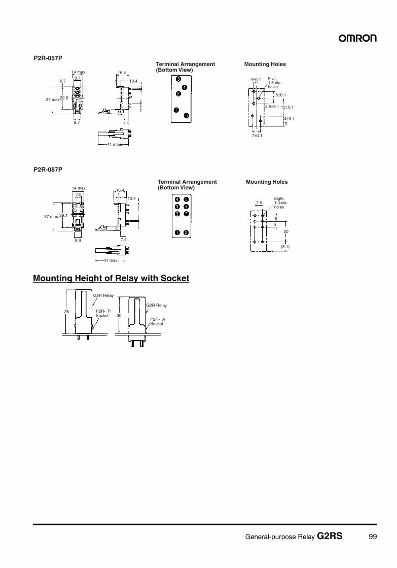
General-purpose Relay G2RS 99
Mounting Height of Relay with Socket
P2R-057P
P2R-087P
4.5±0.1 15±0.1
4±0.15
4±0.1
6±0.1
7±0.1
7.5
55
20
(8.1)
29.6
0.7
8.9
8.7
8.7
16.4
10.41
7.4
29.1
7.516.41
10.4
7.4
14 max.
37 max.
41 max.
14 max.
37 max.
41 max.
Mounting HolesTerminal Arrangement (Bottom View)
Mounting HolesTerminal Arrangement (Bottom View)
Eight, 1.3-dia. holes
Five, 1.6-dia. holes
3630
G2R Relay
G2R RelayP2R-_P Socket
P2R-_A Socket
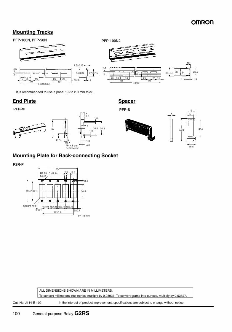
100 General-purpose Relay G2RS
In the interest of product improvement, specifications are subject to change without notice.
ALL DIMENSIONS SHOWN ARE IN MILLIMETERS.
To convert millimeters into inches, multiply by 0.03937. To convert grams into ounces, multiply by 0.03527.
Cat. No. J114-E1-02
Mounting Tracks
End Plate Spacer
Mounting Plate for Back-connecting Socket
PFP-100N, PFP-50N PFP-100N2
4.5
15 25 25 25 2510 10
1,000 (500)
7.3±0.15
35±0.3 27±0.15
1
4.5
15 25 25 25 25 1510 10
1,000
35±0.3 27 24
16
29.2
1 1.515 (5)
It is recommended to use a panel 1.6 to 2.0 mm thick.
PFP-M PFP-S
50
11.5
106.2
1.8
135.5 35.3
1.8
1.3
4.8
5
1612
44.3 34.8
10
16.5M4 x 8 pan head screw
P2R-P90
4.5 13.6
3.4
30.549 42±0.1
9±0.118±0.15 18±0.1518±0.15 18±0.15
9±0.172±0.2
Square hole
t = 1.6 mm
R2.25 10 elliptic holes
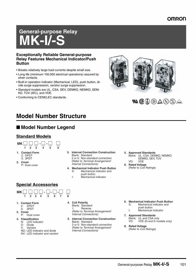
General-purpose Relay MK-I/-S 101
General-purpose Relay
MK-I/-SExceptionally Reliable General-purpose Relay Features Mechanical Indicator/Push Button
• Breaks relatively large load currents despite small size.• Long life (minimum 100,000 electrical operations) assured by
silver contacts.• Built-in operation indicator (Mechanical, LED), push button, di-
ode surge suppression, varistor surge suppression.
• Standard models are UL, CSA, SEV, DEMKO, NEMKO, SEM-KO, TÜV (IEC), and VDE.
• Conforming to CENELEC standards.
Model Number Structure
Model Number Legend
Standard Models
Special Accessories
1 2 3 4 5 6
1. Contact Form 2: DPDT 3: 3PDT2. Cover P: Dust cover
3. Internal Connection Construction Blank: Standard 2 or 5: Non-standard connection (Refer to Terminal Arrangement/ Internal Connections)
4. Mechanical Indicator Push Button S: Mechanical indicator and push button I: Mechanical indicator
5. Approved Standards Blank: UL, CSA, DEMKO, NEMKO SEMKO, SEV, TÜV VD: VDE6. Rated Voltage (Refer to Coil Ratings)
MK - -
1 2 3 4 5 6 7 8
1. Contact Form 2: DPDT 3: 3PDT2. Cover P: Dust cover
3. Classification N: LED indicator D: Diode V: Varistor ND: LED indicator and diode NV: LED indicator and varistor
4. Coil Polarity Blank: Standard 1: Reverse (Refer to Terminal Arrangement/ Internal Connections)
5. Internal Connection Construction Blank: Standard 2 or 5: Non-standard connection (Refer to Terminal Arrangement/ Internal Connections)
6. Mechanical Indicator Push Button S: Mechanical indicator and push button I: Mechanical indicator
7. Approved Standards Blank: UL and CSA only VD: VDE (N and D models only)
8. Rated Voltage (Refer to Coil Ratings)
MK - - -
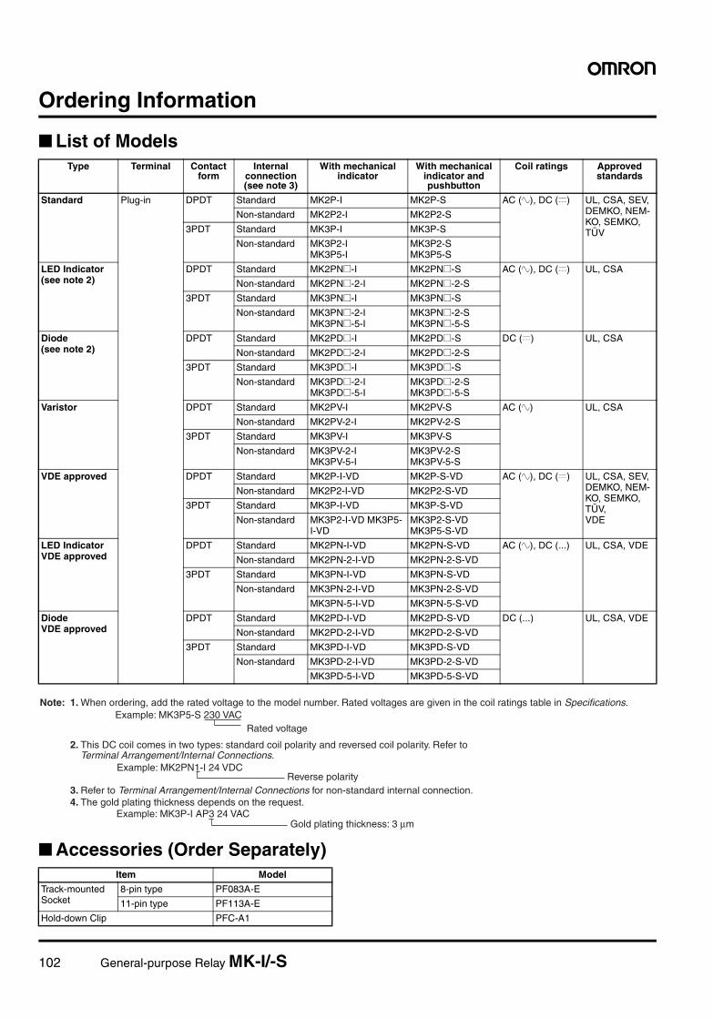
102 General-purpose Relay MK-I/-S
Ordering Information
List of Models
Accessories (Order Separately)
Type Terminal Contact form
Internal connection (see note 3)
With mechanical indicator
With mechanical indicator and pushbutton
Coil ratings Approved standards
Standard Plug-in DPDT Standard MK2P-I MK2P-S AC (~), DC (=) UL, CSA, SEV, DEMKO, NEM-KO, SEMKO, TÜV
Non-standard MK2P2-I MK2P2-S
3PDT Standard MK3P-I MK3P-S
Non-standard MK3P2-IMK3P5-I
MK3P2-SMK3P5-S
LED Indicator (see note 2)
DPDT Standard MK2PN@-I MK2PN@-S AC (~), DC (=) UL, CSA
Non-standard MK2PN@-2-I MK2PN@-2-S
3PDT Standard MK3PN@-I MK3PN@-S
Non-standard MK3PN@-2-I MK3PN@-5-I
MK3PN@-2-S MK3PN@-5-S
Diode (see note 2)
DPDT Standard MK2PD@-I MK2PD@-S DC (=) UL, CSA
Non-standard MK2PD@-2-I MK2PD@-2-S
3PDT Standard MK3PD@-I MK3PD@-S
Non-standard MK3PD@-2-I MK3PD@-5-I
MK3PD@-2-S MK3PD@-5-S
Varistor DPDT Standard MK2PV-I MK2PV-S AC (~) UL, CSA
Non-standard MK2PV-2-I MK2PV-2-S
3PDT Standard MK3PV-I MK3PV-S
Non-standard MK3PV-2-I MK3PV-5-I
MK3PV-2-S MK3PV-5-S
VDE approved DPDT Standard MK2P-I-VD MK2P-S-VD AC (~), DC (=) UL, CSA, SEV, DEMKO, NEM-KO, SEMKO, TÜV,VDE
Non-standard MK2P2-I-VD MK2P2-S-VD
3PDT Standard MK3P-I-VD MK3P-S-VD
Non-standard MK3P2-I-VD MK3P5-I-VD
MK3P2-S-VD MK3P5-S-VD
LED IndicatorVDE approved
DPDT Standard MK2PN-I-VD MK2PN-S-VD AC (~), DC (...) UL, CSA, VDE
Non-standard MK2PN-2-I-VD MK2PN-2-S-VD
3PDT Standard MK3PN-I-VD MK3PN-S-VD
Non-standard MK3PN-2-I-VD MK3PN-2-S-VD
MK3PN-5-I-VD MK3PN-5-S-VD
DiodeVDE approved
DPDT Standard MK2PD-I-VD MK2PD-S-VD DC (...) UL, CSA, VDE
Non-standard MK2PD-2-I-VD MK2PD-2-S-VD
3PDT Standard MK3PD-I-VD MK3PD-S-VD
Non-standard MK3PD-2-I-VD MK3PD-2-S-VD
MK3PD-5-I-VD MK3PD-5-S-VD
Item Model
Track-mounted Socket
8-pin type PF083A-E
11-pin type PF113A-E
Hold-down Clip PFC-A1
Rated voltage
Note: 1. When ordering, add the rated voltage to the model number. Rated voltages are given in the coil ratings table in Specifications. Example: MK3P5-S 230 VAC
2. This DC coil comes in two types: standard coil polarity and reversed coil polarity. Refer to Terminal Arrangement/Internal Connections.
Example: MK2PN1-I 24 VDC
3. Refer to Terminal Arrangement/Internal Connections for non-standard internal connection. 4. The gold plating thickness depends on the request.
Example: MK3P-I AP3 24 VAC
Reverse polarity
Gold plating thickness: 3 µm
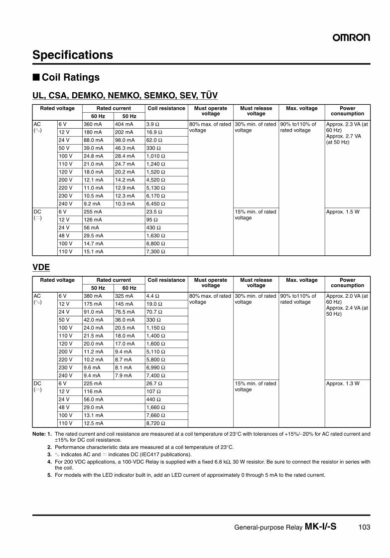
General-purpose Relay MK-I/-S 103
Specifications
Coil Ratings
UL, CSA, DEMKO, NEMKO, SEMKO, SEV, TÜV
VDE
Note: 1. The rated current and coil resistance are measured at a coil temperature of 23°C with tolerances of +15%/−20% for AC rated current and±15% for DC coil resistance.
2. Performance characteristic data are measured at a coil temperature of 23°C.3. ~ indicates AC and = indicates DC (IEC417 publications).4. For 200 VDC applications, a 100-VDC Relay is supplied with a fixed 6.8 kΩ, 30 W resistor. Be sure to connect the resistor in series with
the coil.5. For models with the LED indicator built in, add an LED current of approximately 0 through 5 mA to the rated current.
Rated voltage Rated current Coil resistance Must operate voltage
Must release voltage
Max. voltage Power consumption60 Hz 50 Hz
AC (~)
6 V 360 mA 404 mA 3.9 Ω 80% max. of rated voltage
30% min. of rated voltage
90% to110% of rated voltage
Approx. 2.3 VA (at 60 Hz)Approx. 2.7 VA(at 50 Hz)
12 V 180 mA 202 mA 16.9 Ω24 V 88.0 mA 98.0 mA 62.0 Ω50 V 39.0 mA 46.3 mA 330 Ω100 V 24.8 mA 28.4 mA 1,010 Ω110 V 21.0 mA 24.7 mA 1,240 Ω120 V 18.0 mA 20.2 mA 1,520 Ω200 V 12.1 mA 14.2 mA 4,520 Ω220 V 11.0 mA 12.9 mA 5,130 Ω230 V 10.5 mA 12.3 mA 6,170 Ω240 V 9.2 mA 10.3 mA 6,450 Ω
DC (=)
6 V 255 mA 23.5 Ω 15% min. of rated voltage
Approx. 1.5 W
12 V 126 mA 95 Ω24 V 56 mA 430 Ω48 V 29.5 mA 1,630 Ω100 V 14.7 mA 6,800 Ω110 V 15.1 mA 7,300 Ω
Rated voltage Rated current Coil resistance Must operate voltage
Must release voltage
Max. voltage Power consumption50 Hz 60 Hz
AC (~)
6 V 380 mA 325 mA 4.4 Ω 80% max. of rated voltage
30% min. of rated voltage
90% to110% of rated voltage
Approx. 2.0 VA (at 60 Hz)Approx. 2.4 VA (at 50 Hz)
12 V 175 mA 145 mA 19.0 Ω24 V 91.0 mA 76.5 mA 70.7 Ω50 V 42.0 mA 36.0 mA 330 Ω100 V 24.0 mA 20.5 mA 1,150 Ω110 V 21.5 mA 18.0 mA 1,400 Ω120 V 20.0 mA 17.0 mA 1,600 Ω200 V 11.2 mA 9.4 mA 5,110 Ω220 V 10.2 mA 8.7 mA 5,800 Ω230 V 9.6 mA 8.1 mA 6,990 Ω240 V 9.4 mA 7.9 mA 7,400 Ω
DC (=)
6 V 225 mA 26.7 Ω 15% min. of rated voltage
Approx. 1.3 W
12 V 116 mA 107 Ω24 V 56.0 mA 440 Ω48 V 29.0 mA 1,660 Ω100 V 13.1 mA 7,660 Ω110 V 12.5 mA 8,720 Ω
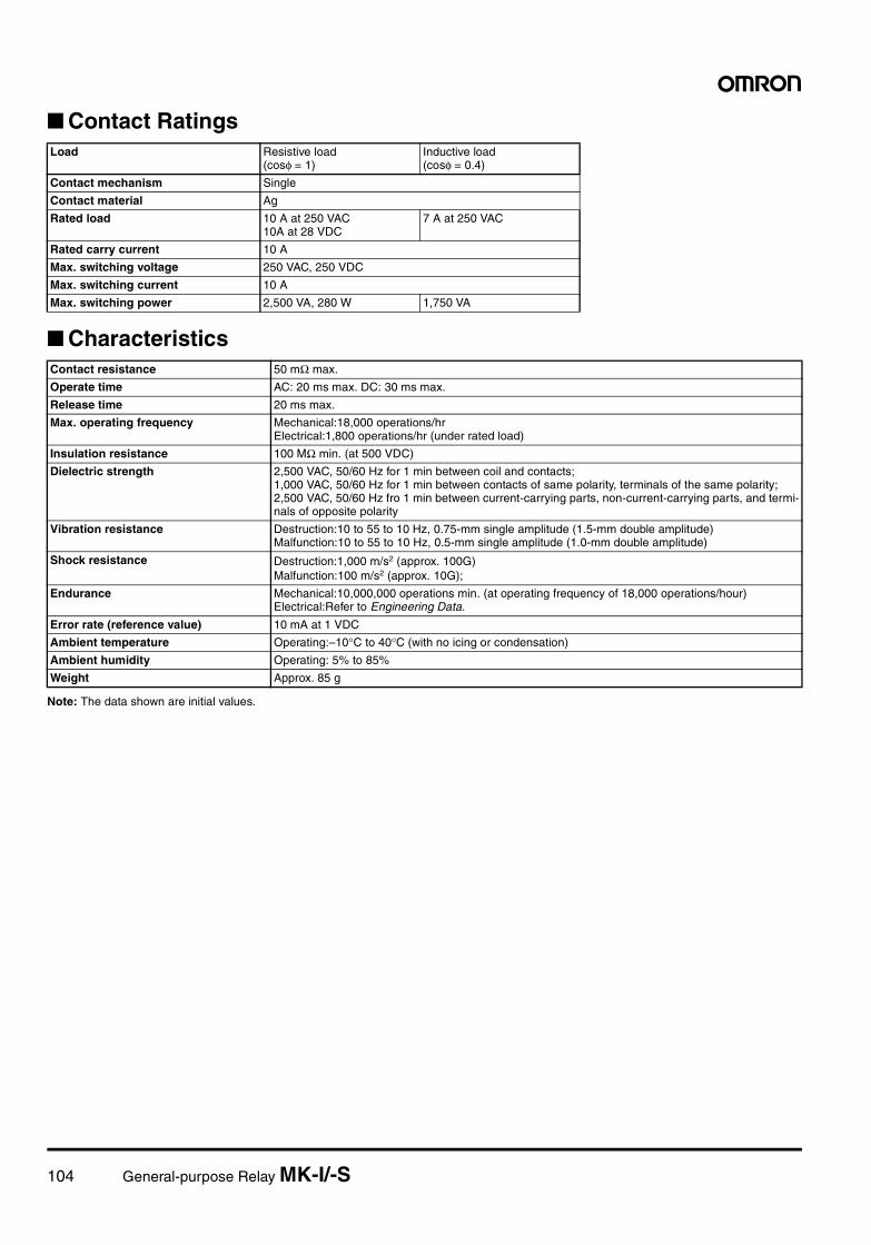
104 General-purpose Relay MK-I/-S
Contact Ratings
Characteristics
Note: The data shown are initial values.
Load Resistive load(cosφ = 1)
Inductive load(cosφ = 0.4)
Contact mechanism Single
Contact material Ag
Rated load 10 A at 250 VAC10A at 28 VDC
7 A at 250 VAC
Rated carry current 10 A
Max. switching voltage 250 VAC, 250 VDC
Max. switching current 10 A
Max. switching power 2,500 VA, 280 W 1,750 VA
Contact resistance 50 mΩ max.
Operate time AC: 20 ms max. DC: 30 ms max.
Release time 20 ms max.
Max. operating frequency Mechanical:18,000 operations/hrElectrical:1,800 operations/hr (under rated load)
Insulation resistance 100 MΩ min. (at 500 VDC)
Dielectric strength 2,500 VAC, 50/60 Hz for 1 min between coil and contacts;1,000 VAC, 50/60 Hz for 1 min between contacts of same polarity, terminals of the same polarity;2,500 VAC, 50/60 Hz fro 1 min between current-carrying parts, non-current-carrying parts, and termi-nals of opposite polarity
Vibration resistance Destruction:10 to 55 to 10 Hz, 0.75-mm single amplitude (1.5-mm double amplitude)Malfunction:10 to 55 to 10 Hz, 0.5-mm single amplitude (1.0-mm double amplitude)
Shock resistance Destruction:1,000 m/s2 (approx. 100G)Malfunction:100 m/s2 (approx. 10G);
Endurance Mechanical:10,000,000 operations min. (at operating frequency of 18,000 operations/hour)Electrical:Refer to Engineering Data.
Error rate (reference value) 10 mA at 1 VDC
Ambient temperature Operating:–10°C to 40°C (with no icing or condensation)
Ambient humidity Operating: 5% to 85%
Weight Approx. 85 g
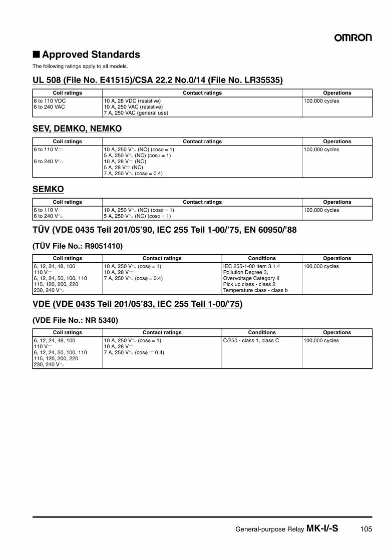
General-purpose Relay MK-I/-S 105
Approved StandardsThe following ratings apply to all models.
UL 508 (File No. E41515)/CSA 22.2 No.0/14 (File No. LR35535)
SEV, DEMKO, NEMKO
SEMKO
TÜV (VDE 0435 Teil 201/05’90, IEC 255 Teil 1-00/’75, EN 60950/’88
(TÜV File No.: R9051410)
VDE (VDE 0435 Teil 201/05’83, IEC 255 Teil 1-00/’75)
(VDE File No.: NR 5340)
Coil ratings Contact ratings Operations
6 to 110 VDC6 to 240 VAC
10 A, 28 VDC (resistive)10 A, 250 VAC (resistive)7 A, 250 VAC (general use)
100,000 cycles
Coil ratings Contact ratings Operations
6 to 110 V=
6 to 240 V~
10 A, 250 V~ (NO) (cosφ = 1)5 A, 250 V~ (NC) (cosφ = 1)10 A, 28 V= (NO)5 A, 28 V= (NC)7 A, 250 V~ (cosφ = 0.4)
100,000 cycles
Coil ratings Contact ratings Operations
6 to 110 V=6 to 240 V~
10 A, 250 V~ (NO) (cosφ = 1)5 A, 250 V~ (NC) (cosφ = 1)
100,000 cycles
Coil ratings Contact ratings Conditions Operations
6, 12, 24, 48, 100110 V=6, 12, 24, 50, 100, 110115, 120, 200, 220230, 240 V~
10 A, 250 V~ (cosφ = 1) 10 A, 28 V=7 A, 250 V~ (cosφ = 0.4)
IEC 255-1-00 Item 3.1.4Pollution Degree 3,Overvoltage Category IIPick up class - class 2Temperature class - class b
100,000 cycles
Coil ratings Contact ratings Conditions Operations
6, 12, 24, 48, 100110 V=6, 12, 24, 50, 100, 110115, 120, 200, 220230, 240 V~
10 A, 250 V~ (cosφ = 1)10 A, 28 V=7 A, 250 V~ (cosφ = 0.4)
C/250 - class 1, class C 100,000 cycles
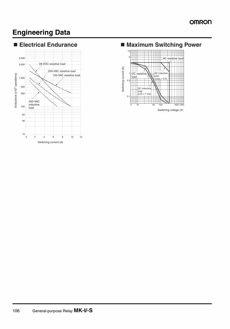
106 General-purpose Relay MK-I/-S
Engineering Data
30
50
100
300
500
1,000
3,000
5,000
0 2 4 6 8 10 1210
5 5010 100 5001,000
5
10
1
0.5
0.1
28-VDC resistive load
250-VAC resistive load
120-VAC resistive load
Electrical Endurance
AC resistive load
Maximum Switching Power
End
uran
ce (
x103 o
pera
tions
)
Sw
itchi
ng c
urre
nt (
A)
Switching current (A)
Switching voltage (V)
250-VAC inductive load
DC resistive load
AC inductive load (cosϕ = 0.4)
DC inductive load (L/R = 7 ms)
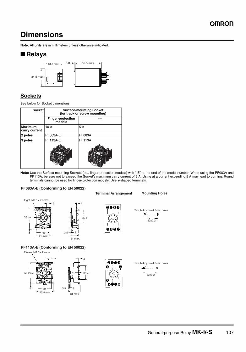
General-purpose Relay MK-I/-S 107
DimensionsNote: All units are in millimeters unless otherwise indicated.
Relays
SocketsSee below for Socket dimensions.
Note: Use the Surface-mounting Sockets (i.e., finger-protection models) with “-E” at the end of the model number. When using the PF083A andPF113A, be sure not to exceed the Socket’s maximum carry current of 5 A. Using at a current exceeding 5 A may lead to burning. Roundterminals cannot be used for finger-protection models. Use Y-shaped terminals.
0.834.5 max. 52.5 max.
34.5 max.
Socket Surface-mounting Socket(for track or screw mounting)
Finger-protection models
---
Maximum carry current
10 A 5 A
2 poles PF083A-E PF083A
3 poles PF113A-E PF113A
7
33
4
35.4
23.5
7
34
4
35.4
23.5
33±0.2
33±0.2
4
PF083A-E (Conforming to EN 50022)Mounting HolesTerminal Arrangement
PF113A-E (Conforming to EN 50022)
52 max.
Eight, M3.5 x 7 sems
41 max.21 max.
Two, M4 or two 4.5-dia. holes
Two, M4 or two 4.5-dia. holes
Eleven, M3.5 x 7 sems
52 max.
42.8 max.31 max.
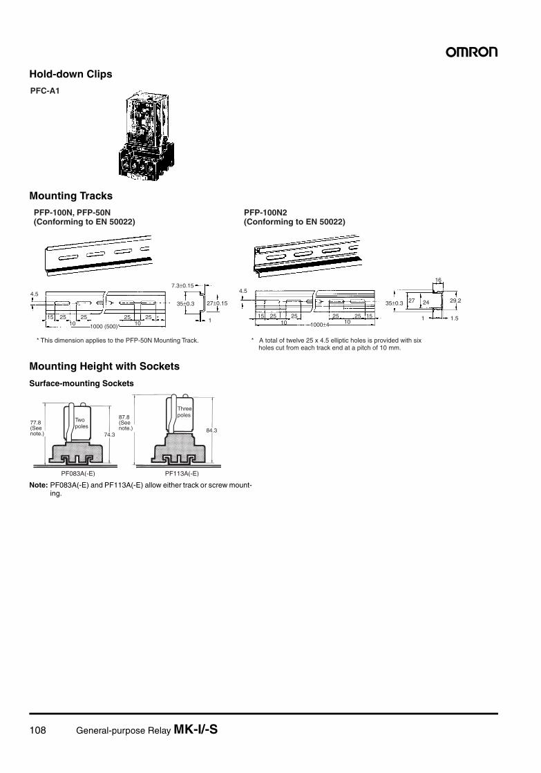
108 General-purpose Relay MK-I/-S
Hold-down Clips
Mounting Tracks
Mounting Height with Sockets
Surface-mounting Sockets
Note: PF083A(-E) and PF113A(-E) allow either track or screw mount-ing.
PFC-A1
4.5
15 25 25 25 25 *10 101000 (500)*
7.3±0.15
35±0.3 27±0.15
1
4.5
15 25 25 25 25 1510 101000±4
35±0.3 27 24
16
29.2
1 1.5
* This dimension applies to the PFP-50N Mounting Track. * A total of twelve 25 x 4.5 elliptic holes is provided with six holes cut from each track end at a pitch of 10 mm.
PFP-100N, PFP-50N (Conforming to EN 50022)
PFP-100N2 (Conforming to EN 50022)
74.384.3
PF083A(-E) PF113A(-E)
77.8 (See note.)
87.8 (See note.)
Two poles
Three poles
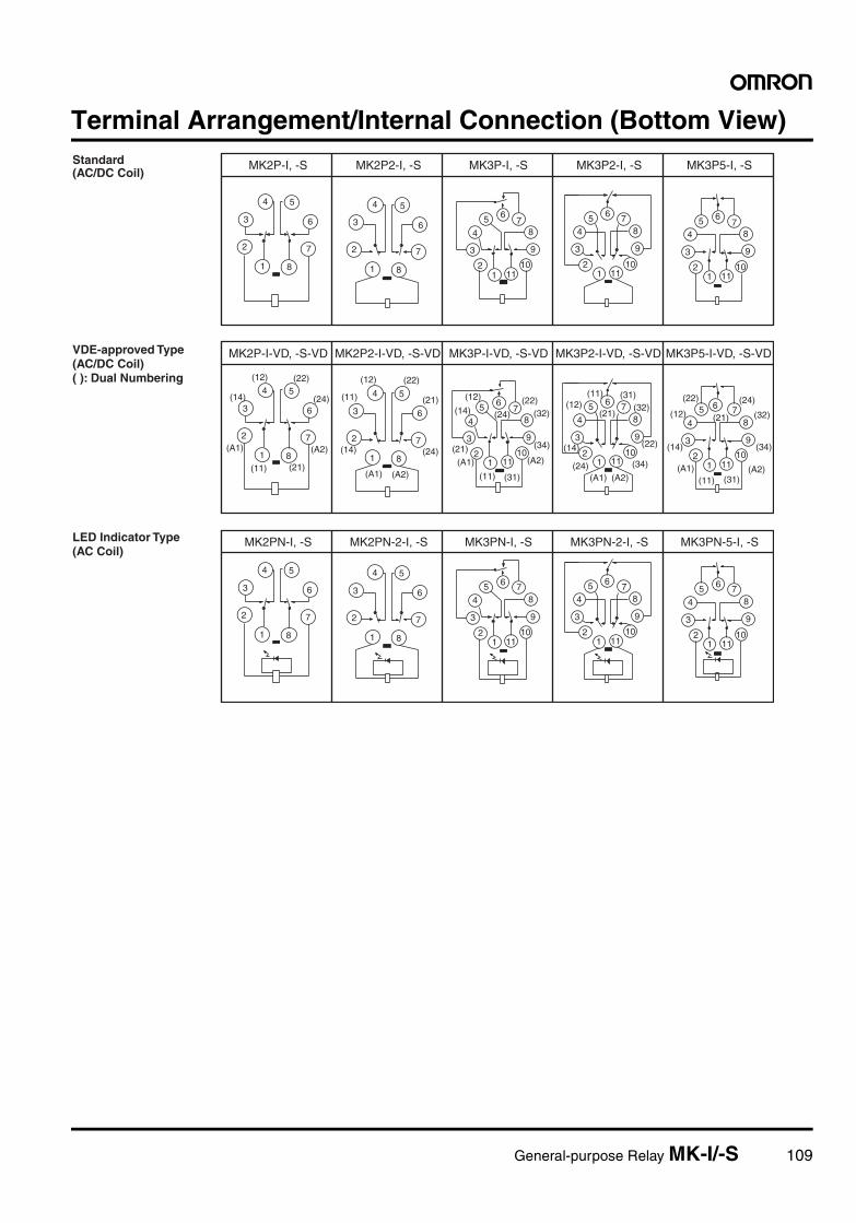
General-purpose Relay MK-I/-S 109
Terminal Arrangement/Internal Connection (Bottom View)
4
3
2
1 8
7
6
5 4
3
2
1 8
7
6
5
12
3
4
5 67
8
9
1011 1
2
3
4
5 6 78
9
1011 1
2
3
4
5 67
8
9
1011
4
3
2
1 8
7
6
5 4
3
2
1 8
7
6
5
12
3
4
5 67
8
9
1011 1
2
3
4
5 6 78
9
1011 1
2
3
4
5 6 78
9
1011
(12) (22)
(14) (24)
(A1) (A2)
(11) (21)
(12) (22)
(11) (21)
(14) (24)
(A1) (A2)
(12) (22)(14) (32)
(21) (34)
(11) (31)
(24)
(A1) (A2)
(11) (31)(12) (32)
(14) (22)
(A1) (A2)
(21)
(24) (34)
(22) (24)
(12) (32)
(14) (34)
(11) (31)
(21)
(A1) (A2)
12
3
4
5 67
8
9
10111
2
3
4
5 6 78
9
1011
4
3
2
1 8
7
6
54
3
2
1 8
7
6
5
12
3
4
5 6 78
9
1011
MK2P-I, -S MK2P2-I, -S MK3P-I, -S MK3P2-I, -S MK3P5-I, -S
MK2P-I-VD, -S-VD MK2P2-I-VD, -S-VD MK3P-I-VD, -S-VD MK3P2-I-VD, -S-VD MK3P5-I-VD, -S-VD
MK2PN-I, -S MK2PN-2-I, -S MK3PN-I, -S MK3PN-2-I, -S MK3PN-5-I, -S
Standard (AC/DC Coil)
VDE-approved Type (AC/DC Coil) ( ): Dual Numbering
LED Indicator Type (AC Coil)
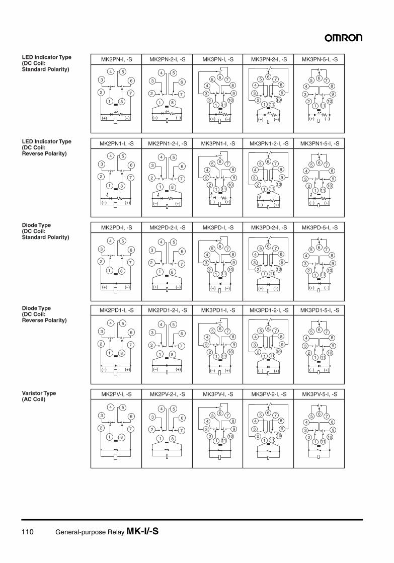
110 General-purpose Relay MK-I/-S
4
3
2
1 8
7
6
5
(+) (−)
4
3
2
1 8
7
6
5
(+) (−)
12
3
4
5 6 78
9
1011
(+) (−)
12
3
4
5 6 78
9
1011
(+) (−)
12
3
4
5 6 78
9
1011
(+) (−)
4
3
2
1 8
7
6
5
(−)(+)
4
3
2
1 8
7
6
5
(+) (−)
12
3
4
5 67
8
9
1011
(+) (−)
12
3
4
5 6 78
9
1011
(+) (−)
12
3
4
5 6 78
9
1011
(+) (−)
4
3
2
1 8
7
6
5
(+)(−)
4
3
2
1 8
7
6
5
(−) (+)
12
3
4
5 6 78
9
1011
(−) (+)
12
3
4
5 6 78
9
1011
(−) (+)
12
3
4
5 6 78
9
1011
(−) (+)
MK2PN-I, -S MK2PN-2-I, -S MK3PN-I, -S MK3PN-2-I, -S MK3PN-5-I, -S
MK2PD-I, -S MK2PD-2-I, -S MK3PD-I, -S MK3PD-2-I, -S MK3PD-5-I, -S
MK2PN1-I, -S MK2PN1-2-I, -S MK3PN1-I, -S MK3PN1-2-I, -S MK3PN1-5-I, -S
LED Indicator Type (DC Coil: Standard Polarity)
LED Indicator Type (DC Coil: Reverse Polarity)
Diode Type (DC Coil: Standard Polarity)
4
3
2
1 8
7
6
5
(−) (+)
4
3
2
1 8
7
6
5
(−) (+)
12
3
4
5 6 78
9
1011
(−) (+)
12
3
4
5 6 78
9
1011
(−) (+)
12
3
4
5 6 78
9
1011
(−) (+)
4
3
2
1 8
7
6
5 4
3
2
1 8
7
6
5
12
3
4
5 6 78
9
1011 1
2
3
4
5 6 78
9
1011 1
2
3
4
5 6 78
9
1011
MK2PD1-I, -S MK2PD1-2-I, -S MK3PD1-I, -S MK3PD1-2-I, -S MK3PD1-5-I, -S
MK2PV-I, -S MK2PV-2-I, -S MK3PV-I, -S MK3PV-2-I, -S MK3PV-5-I, -S
Diode Type (DC Coil: Reverse Polarity)
Varistor Type (AC Coil)
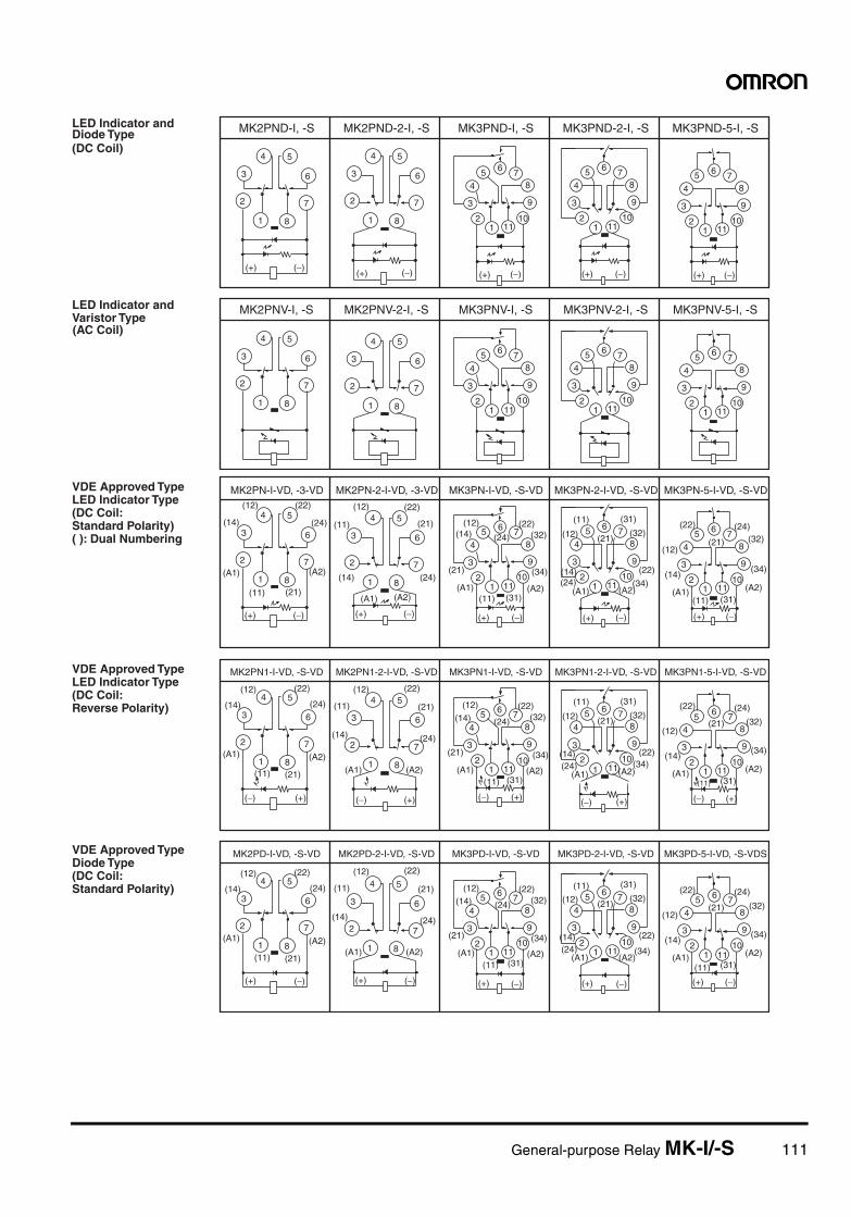
General-purpose Relay MK-I/-S 111
4
3
2
1 8
7
6
5
(+) (−)
4
3
2
1 8
7
6
5
(+) (−)
12
3
4
5 6 78
9
1011
(+) (−)
12
3
4
5 6 78
9
1011
(+) (−)
4
3
2
1 8
7
6
5 4
3
2
1 8
7
6
5
12
3
4
5 6 78
9
1011 1
2
3
4
5 6 78
9
1011 1
2
3
4
5 6 78
9
1011
12
3
4
5 6 78
9
1011
(+) (−)
MK2PND-I, -S MK2PND-2-I, -S MK3PND-I, -S MK3PND-2-I, -S MK3PND-5-I, -S
MK2PNV-I, -S MK2PNV-2-I, -S MK3PNV-I, -S MK3PNV-2-I, -S MK3PNV-5-I, -S
LED Indicator and Diode Type (DC Coil)
LED Indicator and Varistor Type (AC Coil)
4
3
2
1 8
7
6
5
(+) (−)
4
3
2
1 8
7
6
5
(+) (−)
12
3
4
5 6 78
9
1011
(+) (−)
12
3
4
5 6 78
9
1011
(+) (−)
12
3
4
5 6 78
9
1011
(+) (−)
4
3
2
1 8
7
6
5
(−)(+)
4
3
2
1 8
7
6
5
(+) (−)
12
3
4
5 6 78
9
1011
(+) (−)
12
3
4
5 6 78
9
1011
(+) (−)
12
3
4
5 6 78
9
1011
(+) (−)
4
3
2
1 8
7
6
5
(+)(−)
4
3
2
1 8
7
6
5
(−) (+)
12
3
4
5 6 78
9
1011
(−) (+)
12
3
4
5 6 78
9
1011
(−) (+)
12
3
45
6 78
9
1011
(−) (+)
(14)
(A1)
(11) (21)
(A2)
(24)
(12) (22)
(14)
(A1)
(11) (21)
(A2)
(24)
(12) (22)
(12)(14)
(21)
(A1)(11)
(22)
(24) (32)
(34)
(A2)(31)
(31)
(32)
(22)
(34)(A2)(A1)
(24)(14)
(12)
(11)
(21)
(22)
(21)
(24)(32)
(34)
(A2)(31)(11)
(A1)
(14)
(12)
(12) (22)
(14)
(A1)
(11) (21)
(A2)
(24)
(14)
(A1)
(11) (21)
(A2)
(24)
(12) (22)
(12)(14)
(21)
(A1)(11)
(22)
(24) (32)
(34)
(A2)(31)
(31)
(32)
(22)(34)
(A2)(24)(14)
(12)
(11)
(21)
(22)
(21)
(24)
(32)
(34)
(A2)(31)(11)
(A1)
(14)
(12)
(A1)
(12) (22)
(14)
(A1)
(11) (21)
(A2)
(24)
(14)
(A1)
(11) (21)
(A2)
(24)
(12) (22)
(12)(14)
(21)
(A1)(11)
(22)
(24) (32)
(34)
(A2)(31)
(31)
(32)
(22)
(34)(A2)
(24)(14)
(12)
(11)
(21)
(A1)
(22)
(21)
(24)
(32)
(34)
(A2)(31)(11)
(A1)
(14)
(12)
MK2PN-I-VD, -3-VD MK2PN-2-I-VD, -3-VD MK3PN-I-VD, -S-VD MK3PN-2-I-VD, -S-VD MK3PN-5-I-VD, -S-VD
MK2PD-I-VD, -S-VD MK2PD-2-I-VD, -S-VD MK3PD-I-VD, -S-VD MK3PD-2-I-VD, -S-VD MK3PD-5-I-VD, -S-VDS
MK2PN1-I-VD, -S-VD MK2PN1-2-I-VD, -S-VD MK3PN1-I-VD, -S-VD MK3PN1-2-I-VD, -S-VD MK3PN1-5-I-VD, -S-VD
VDE Approved Type LED Indicator Type (DC Coil: Standard Polarity) ( ): Dual Numbering
VDE Approved Type LED Indicator Type (DC Coil: Reverse Polarity)
VDE Approved Type Diode Type (DC Coil: Standard Polarity)
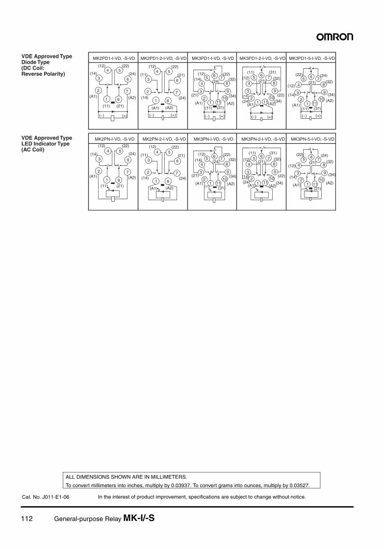
112 General-purpose Relay MK-I/-S
4
3
2
1 8
7
6
5
(−) (+)
4
3
2
1 8
7
6
5
(−) (+)
12
3
4
5 6 78
9
1011
(−) (+)
12
3
4
5 6 78
9
1011
(−) (+)
12
3
4
5 6 78
9
1011
(−) (+)
12
3
4
5 6 78
9
10111
2
3
4
5 6 78
9
1011
4
3
2
1 8
7
6
54
3
2
1 8
7
6
5
12
3
4
5 6 78
9
1011
(14)
(A1)
(11) (21)
(A2)
(24)
(12) (22)
(14)
(A1)
(11) (21)
(A2)
(24)
(12) (22)
(12)(14)
(21)
(A1)(11)
(22)
(24) (32)
(34)
(A2)(31)
(31)
(32)
(22)
(34)(A2)(A1)
(24)(14)
(12)(11)
(21)
(22)
(21)
(24)
(32)
(34)
(A2)
(31)(11)(A1)
(14)
(12)
(14)
(A1)
(11) (21)
(A2)
(24)
(12) (22)
(14)
(A1)
(11) (21)
(A2)
(24)
(12) (22)
(12)(14)
(21)
(A1)(11)
(22)
(24) (32)
(34)
(A2)(31)
(31)
(32)
(22)
(34)(A2)(A1)
(24)(14)
(12)
(11)
(21)
(22)
(21)
(24)
(32)
(34)
(A2)(31)(11)
(A1)
(14)
(12)
MK2PD1-I-VD, -S-VD MK2PD1-2-I-VD, -S-VD MK3PD1-I-VD, -S-VD MK3PD1-2-I-VD, -S-VD MK3PD1-5-I-VD, -S-VD
MK2PN-I-VD, -S-VD MK2PN-2-I-VD, -S-VD MK3PN-I-VD, -S-VD MK3PN-2-I-VD, -S-VD MK3PN-5-I-VD, -S-VD
VDE Approved Type Diode Type (DC Coil: Reverse Polarity)
VDE Approved Type LED Indicator Type (AC Coil)
In the interest of product improvement, specifications are subject to change without notice.
ALL DIMENSIONS SHOWN ARE IN MILLIMETERS.
To convert millimeters into inches, multiply by 0.03937. To convert grams into ounces, multiply by 0.03527.
Cat. No. J011-E1-06
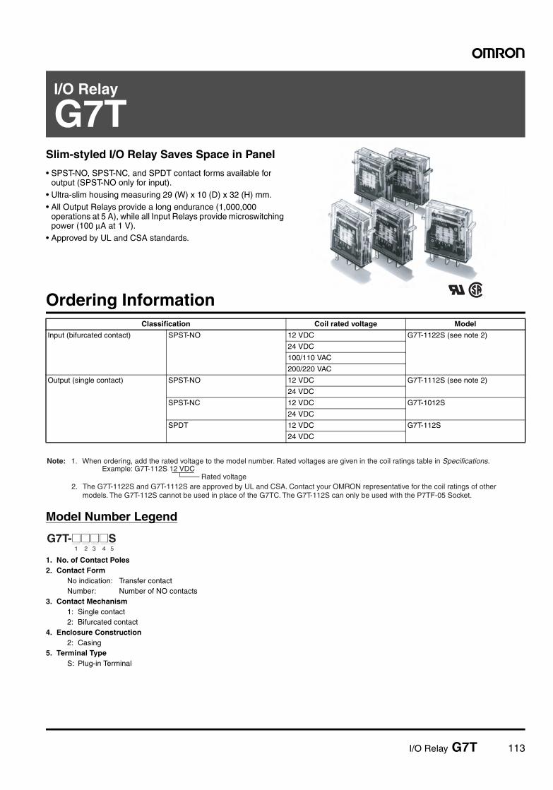
I/O Relay G7T 113
I/O Relay
G7TSlim-styled I/O Relay Saves Space in Panel
• SPST-NO, SPST-NC, and SPDT contact forms available for output (SPST-NO only for input).
• Ultra-slim housing measuring 29 (W) x 10 (D) x 32 (H) mm.• All Output Relays provide a long endurance (1,000,000
operations at 5 A), while all Input Relays provide microswitching power (100 µA at 1 V).
• Approved by UL and CSA standards.
Ordering Information
Model Number Legend
1. No. of Contact Poles2. Contact Form
No indication: Transfer contactNumber: Number of NO contacts
3. Contact Mechanism1: Single contact2: Bifurcated contact
4. Enclosure Construction2: Casing
5. Terminal TypeS: Plug-in Terminal
Classification Coil rated voltage Model
Input (bifurcated contact) SPST-NO 12 VDC G7T-1122S (see note 2)
24 VDC
100/110 VAC
200/220 VAC
Output (single contact) SPST-NO 12 VDC G7T-1112S (see note 2)
24 VDC
SPST-NC 12 VDC G7T-1012S
24 VDC
SPDT 12 VDC G7T-112S
24 VDC
Rated voltage
Note: 1. When ordering, add the rated voltage to the model number. Rated voltages are given in the coil ratings table in Specifications. Example: G7T-112S 12 VDC
2. The G7T-1122S and G7T-1112S are approved by UL and CSA. Contact your OMRON representative for the coil ratings of other models. The G7T-112S cannot be used in place of the G7TC. The G7T-112S can only be used with the P7TF-05 Socket.
G7T-@@@@S1 2 3 4 5
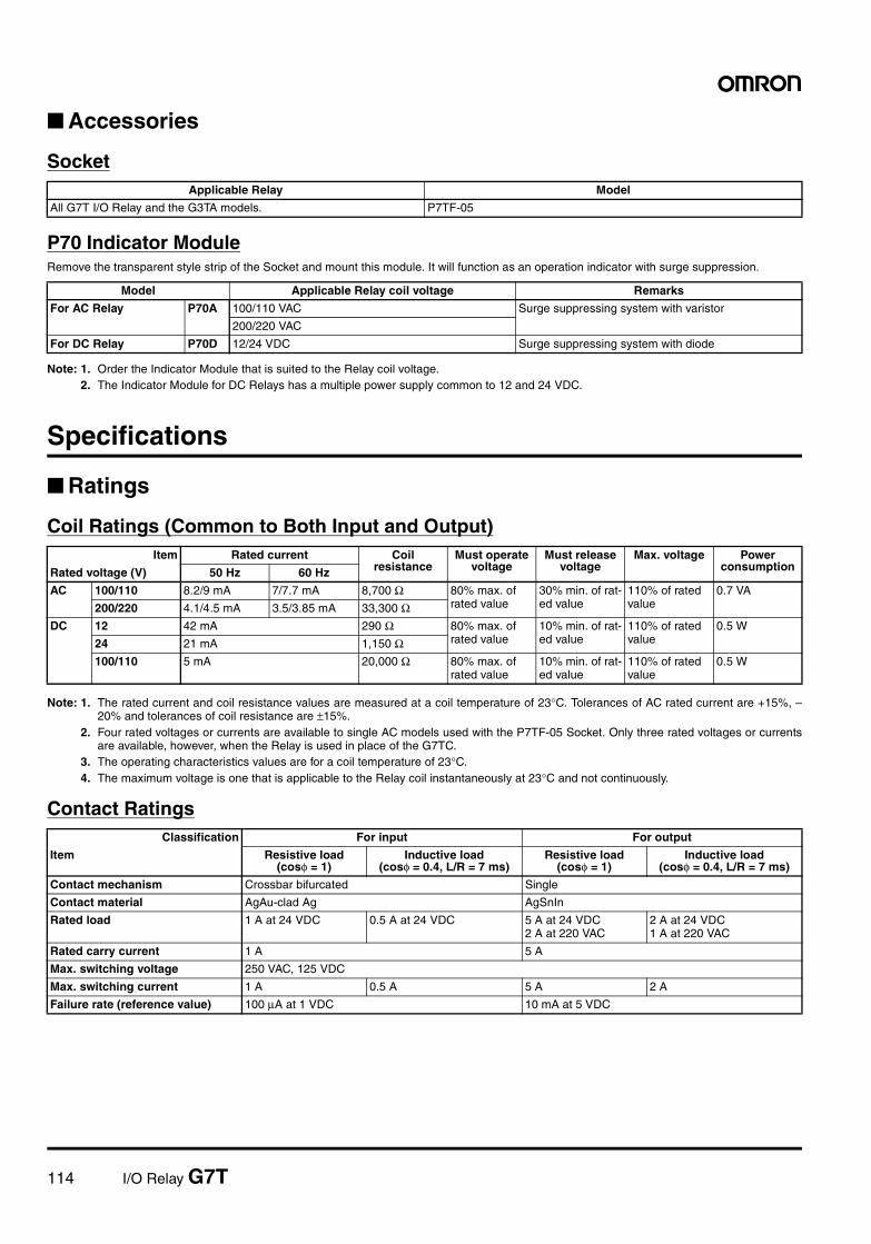
114 I/O Relay G7T
Accessories
Socket
P70 Indicator ModuleRemove the transparent style strip of the Socket and mount this module. It will function as an operation indicator with surge suppression.
Note: 1. Order the Indicator Module that is suited to the Relay coil voltage.2. The Indicator Module for DC Relays has a multiple power supply common to 12 and 24 VDC.
Specifications
Ratings
Coil Ratings (Common to Both Input and Output)
Note: 1. The rated current and coil resistance values are measured at a coil temperature of 23°C. Tolerances of AC rated current are +15%, –20% and tolerances of coil resistance are ±15%.
2. Four rated voltages or currents are available to single AC models used with the P7TF-05 Socket. Only three rated voltages or currentsare available, however, when the Relay is used in place of the G7TC.
3. The operating characteristics values are for a coil temperature of 23°C.4. The maximum voltage is one that is applicable to the Relay coil instantaneously at 23°C and not continuously.
Contact Ratings
Applicable Relay Model
All G7T I/O Relay and the G3TA models. P7TF-05
Model Applicable Relay coil voltage Remarks
For AC Relay P70A 100/110 VAC Surge suppressing system with varistor
200/220 VAC
For DC Relay P70D 12/24 VDC Surge suppressing system with diode
Item Rated current Coil resistance
Must operate voltage
Must release voltage
Max. voltage Power consumptionRated voltage (V) 50 Hz 60 Hz
AC 100/110 8.2/9 mA 7/7.7 mA 8,700 Ω 80% max. of rated value
30% min. of rat-ed value
110% of rated value
0.7 VA
200/220 4.1/4.5 mA 3.5/3.85 mA 33,300 ΩDC 12 42 mA 290 Ω 80% max. of
rated value10% min. of rat-ed value
110% of rated value
0.5 W
24 21 mA 1,150 Ω100/110 5 mA 20,000 Ω 80% max. of
rated value10% min. of rat-ed value
110% of rated value
0.5 W
Classification For input For output
Item Resistive load (cosφ = 1)
Inductive load (cosφ = 0.4, L/R = 7 ms)
Resistive load (cosφ = 1)
Inductive load (cosφ = 0.4, L/R = 7 ms)
Contact mechanism Crossbar bifurcated Single
Contact material AgAu-clad Ag AgSnIn
Rated load 1 A at 24 VDC 0.5 A at 24 VDC 5 A at 24 VDC2 A at 220 VAC
2 A at 24 VDC1 A at 220 VAC
Rated carry current 1 A 5 A
Max. switching voltage 250 VAC, 125 VDC
Max. switching current 1 A 0.5 A 5 A 2 A
Failure rate (reference value) 100 µA at 1 VDC 10 mA at 5 VDC
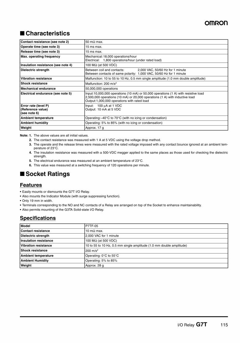
I/O Relay G7T 115
Characteristics
Note: 1. The above values are all initial values.2. The contact resistance was measured with 1 A at 5 VDC using the voltage drop method.3. The operate and the release times were measured with the rated voltage imposed with any contact bounce ignored at an ambient tem-
perature of 23°C.4. The insulation resistance was measured with a 500-VDC megger applied to the same places as those used for checking the dielectric
strength.5. The electrical endurance was measured at an ambient temperature of 23°C.6. This value was measured at a switching frequency of 120 operations per minute.
Socket Ratings
Features• Easily mounts or dismounts the G7T I/O Relay.• Also mounts the Indicator Module (with surge suppressing function).• Only 19 mm in width.• Terminals corresponding to the NO and NC contacts of a Relay are arranged on top of the Socket to enhance maintainability.• Also permits mounting of the G3TA Solid-state I/O Relay.
Specifications
Contact resistance (see note 2) 50 mΩ max.
Operate time (see note 3) 15 ms max.
Release time (see note 3) 15 ms max.
Max. operating frequency Mechanical:18,000 operations/hourElectrical: 1,800 operations/hour (under rated load)
Insulation resistance (see note 4) 100 MΩ (at 500 VDC)
Dielectric strength Between coil and contacts: 2,000 VAC, 50/60 Hz for 1 minuteBetween contacts of same polarity: 1,000 VAC, 50/60 Hz for 1 minute
Vibration resistance Malfunction: 10 to 55 to 10 Hz, 0.5 mm single amplitude (1.0 mm double amplitude)
Shock resistance Malfunction: 200 m/s2
Mechanical endurance 50,000,000 operations
Electrical endurance (see note 5) Input:10,000,000 operations (10 mA) or 50,000 operations (1 A) with resistive load2,500,000 operations (10 mA) or 20,000 operations (1 A) with inductive loadOutput:1,000,000 operations with rated load
Error rate (level P)(Reference value)(see note 6)
Input: 100 µA at 1 VDCOutput: 10 mA at 5 VDC
Ambient temperature Operating:–40°C to 70°C (with no icing or condensation)
Ambient humidity Operating: 5% to 85% (with no icing or condensation)
Weight Approx. 17 g
Model P7TF-05
Contact resistance 10 mΩ max.
Dielectric strength 2,000 VAC for 1 minute
Insulation resistance 100 MΩ (at 500 VDC)
Vibration resistance 10 to 55 to 10 Hz, 0.5 mm single amplitude (1.0 mm double amplitude)
Shock resistance 200 m/s2
Ambient temperature Operating: 0°C to 55°CAmbient Humidity Operating: 5% to 85%
Weight Approx. 28 g
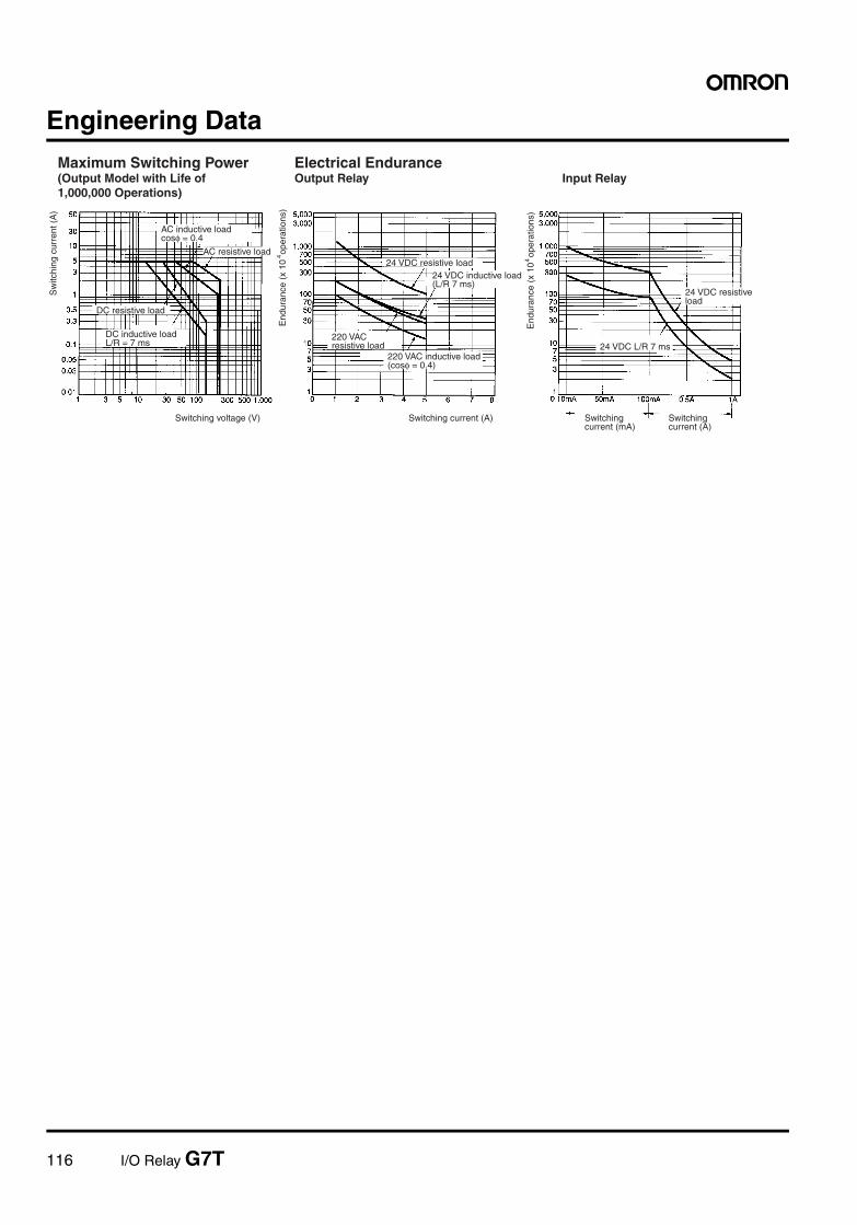
116 I/O Relay G7T
Engineering DataMaximum Switching Power(Output Model with Life of 1,000,000 Operations)
Electrical EnduranceOutput Relay Input Relay
AC inductive loadcosφ = 0.4
AC resistive load
DC resistive load
DC inductive loadL/R = 7 ms
24 VDC resistive load
End
uran
ce (
x 10
ope
ratio
n s)
424 VDC inductive load (L/R 7 ms)
220 VAC resistive load
220 VAC inductive load (cosφ = 0.4)
End
uran
ce (
x 10
ope
r atio
ns)
4
24 VDC resistive load
24 VDC L/R 7 ms
Switching current (A) Switching current (mA)
Switching current (A)
Sw
itchi
ng c
urre
nt (
A)
Switching voltage (V)
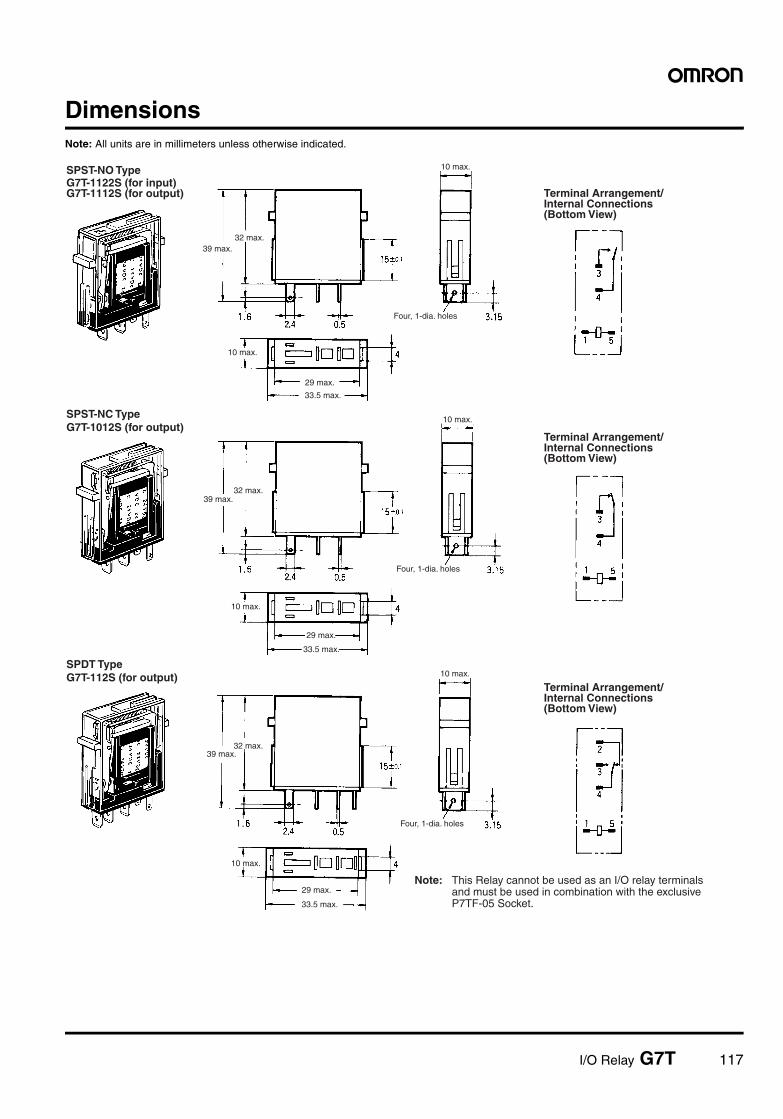
I/O Relay G7T 117
DimensionsNote: All units are in millimeters unless otherwise indicated.
SPST-NO TypeG7T-1122S (for input)G7T-1112S (for output)
32 max.39 max.
10 max.
29 max.
33.5 max.
10 max.
Four, 1-dia. holes
Terminal Arrangement/ Internal Connections (Bottom View)
SPST-NC TypeG7T-1012S (for output)
32 max.39 max.
10 max.
29 max.
33.5 max.
10 max.
Four, 1-dia. holes
Terminal Arrangement/ Internal Connections (Bottom View)
SPDT TypeG7T-112S (for output)
32 max.39 max.
10 max.
10 max.
Four, 1-dia. holes
Terminal Arrangement/ Internal Connections (Bottom View)
Note: This Relay cannot be used as an I/O relay terminals and must be used in combination with the exclusive P7TF-05 Socket.33.5 max.
29 max.
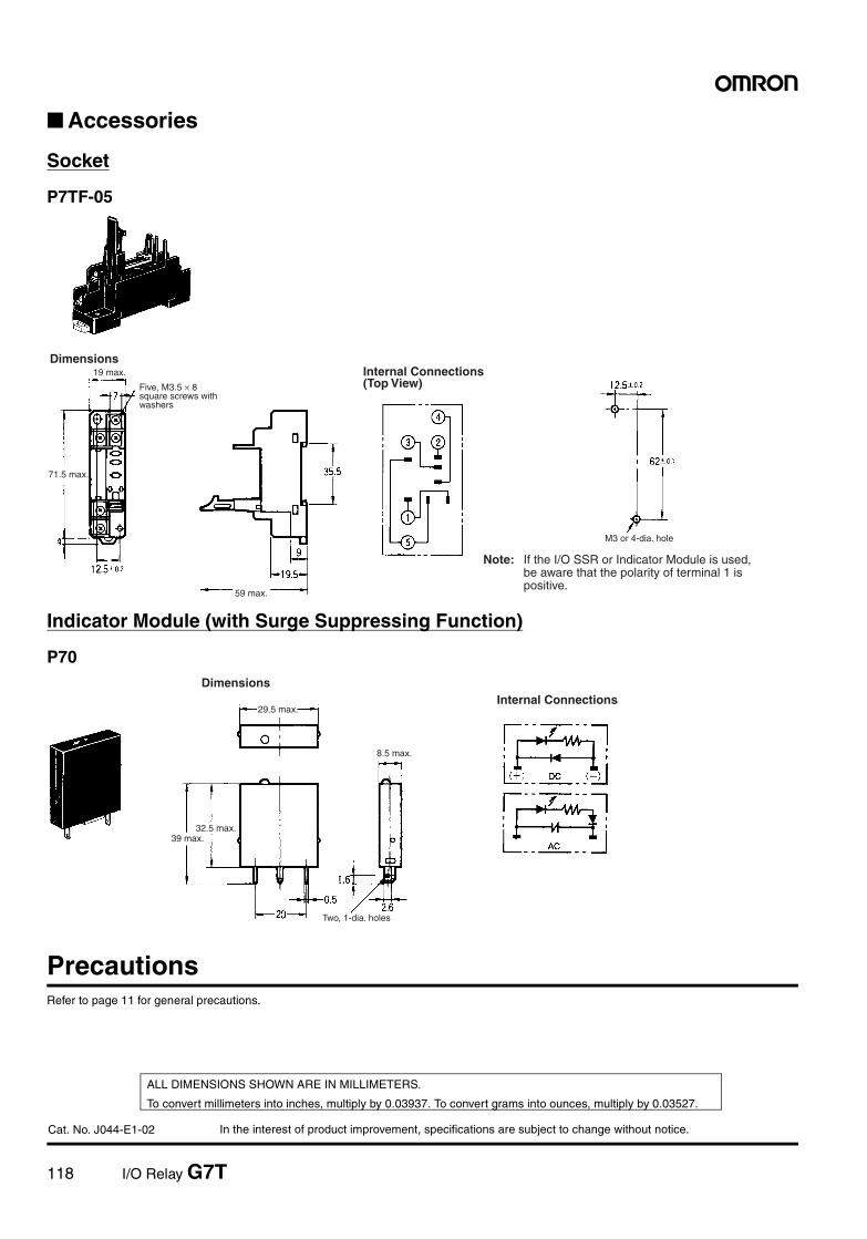
118 I/O Relay G7T
In the interest of product improvement, specifications are subject to change without notice.
ALL DIMENSIONS SHOWN ARE IN MILLIMETERS.
To convert millimeters into inches, multiply by 0.03937. To convert grams into ounces, multiply by 0.03527.
Cat. No. J044-E1-02
Accessories
Socket
P7TF-05
Indicator Module (with Surge Suppressing Function)
P70
PrecautionsRefer to page 11 for general precautions.
DimensionsInternal Connections (Top View)
Note: If the I/O SSR or Indicator Module is used, be aware that the polarity of terminal 1 is positive.
19 max.
71.5 max.
59 max.
Five, M3.5 × 8 square screws with washers
M3 or 4-dia. hole
DimensionsInternal Connections
29.5 max.
32.5 max.
8.5 max.
39 max.
Two, 1-dia. holes
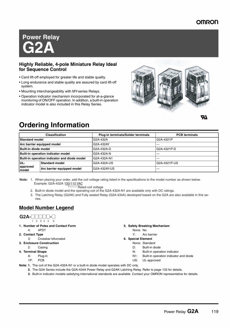
Power Relay G2A 119
Power Relay
G2AHighly Reliable, 4-pole Miniature Relay Ideal for Sequence Control
• Card lift-off employed for greater life and stable quality.• Long endurance and stable quality are assured by card lift-off
system.
• Mounting interchangeability with MY-series Relays.• Operation indicator mechanism incorporated for at-a-glance
monitoring of ON/OFF operation. In addition, a built-in operation indicator model is also included in this Relay Series.
Ordering Information
Model Number Legend
1. Number of Poles and Contact Form4: 4PDT
2. Contact Type3: Crossbar bifurcated
3. Enclosure Construction2: Casing
4. Terminal ShapeA: Plug-in1P: PCB
5. Safety Breaking MechanismNone: NoY: Arc barrier
6. Special ElementNone: StandardD: Built-in diodeN: Built-in operation indicatorN1: Built-in operation indicator and diodeUS: UL-approved
Note: 1. The coil of the G2A-432A-N1 or a built-in diode model operates with DC only.2. The G2A Series include the G2A-434A Power Relay and G2AK Latching Relay. Refer to page 133 for details.3. Built-in indicator models satisfying international standards are available. Contact your OMRON representative for details.
Classification Plug-in terminals/Solder terminals PCB terminals
Standard model G2A-432A G2A-4321P
Arc barrier equipped model G2A-432AY ---
Built-in diode model G2A-432A-D G2A-4321P-D
Built-in operation indicator model G2A-432A-N ---
Built-in operation indicator and diode model G2A-432A-N1 ---
UL-approved model
Standard model G2A-432A-US G2A-4321P-US
Arc barrier equipped model G2A-432AY-US ---
Rated coil voltage
Note: 1. When placing your order, add the coil voltage rating listed in the specifications to the model number as shown below.Example: G2A-432A 100/110 VAC
2. Built-in diode model and the operating coil of the G2A-432A-N1 are available only with DC ratings. 3. The Latching Relay (G2AK) and Fully sealed Relay (G2A-434A) developed based on the G2A are also available in this se- ries.
G2A-@@@@@-@1 2 3 4 5 6
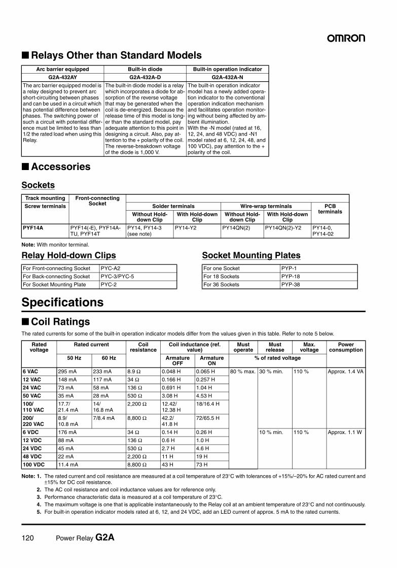
120 Power Relay G2A
Relays Other than Standard Models
Accessories
Sockets
Note: With monitor terminal.
Relay Hold-down Clips Socket Mounting Plates
Specifications
Coil RatingsThe rated currents for some of the built-in operation indicator models differ from the values given in this table. Refer to note 5 below.
Note: 1. The rated current and coil resistance are measured at a coil temperature of 23°C with tolerances of +15%/–20% for AC rated current and±15% for DC coil resistance.
2. The AC coil resistance and coil inductance values are for reference only.3. Performance characteristic data is measured at a coil temperature of 23°C.4. The maximum voltage is one that is applicable instantaneously to the Relay coil at an ambient temperature of 23°C and not continuously.5. For built-in operation indicator models rated at 6, 12, and 24 VDC, add an LED current of approx. 5 mA to the rated currents.
Arc barrier equipped Built-in diode Built-in operation indicator
G2A-432AY G2A-432A-D G2A-432A-N
The arc barrier equipped model is a relay designed to prevent arc short-circuiting between phases and can be used in a circuit which has potential difference between phases. The switching power of such a circuit with potential differ-ence must be limited to less than 1/2 the rated load when using this Relay.
The built-in diode model is a relay which incorporates a diode for ab-sorption of the reverse voltage that may be generated when the coil is de-energized. Because the release time of this model is long-er than the standard model, pay adequate attention to this point in designing a circuit. Also, pay at-tention to the + polarity of the coil. The reverse-breakdown voltage of the diode is 1,000 V.
The built-in operation indicator model has a newly added opera-tion indicator to the conventional operation indication mechanism and facilitates operation monitor-ing without being affected by am-bient illumination.With the -N model (rated at 16, 12, 24, and 48 VDC) and -N1 model rated at 6, 12, 24, 48, and 100 VDC), pay attention to the + polarity of the coil.
Track mounting Front-connecting SocketScrew terminals Solder terminals Wire-wrap terminals PCB
terminalsWithout Hold-down Clip
With Hold-down Clip
Without Hold-down Clip
With Hold-down Clip
PYF14A PYF14(-E), PYF14A-TU, PYF14T
PY14, PY14-3 (see note)
PY14-Y2 PY14QN(2) PY14QN(2)-Y2 PY14-0, PY14-02
For Front-connecting Socket PYC-A2
For Back-connecting Socket PYC-3/PYC-5
For Socket Mounting Plate PYC-2
For one Socket PYP-1
For 18 Sockets PYP-18
For 36 Sockets PYP-38
Rated voltage
Rated current Coil resistance
Coil inductance (ref. value)
Must operate
Must release
Max. voltage
Power consumption
50 Hz 60 Hz Armature OFF
Armature ON
% of rated voltage
6 VAC 295 mA 233 mA 8.9 Ω 0.048 H 0.065 H 80 % max. 30 % min. 110 % Approx. 1.4 VA
12 VAC 148 mA 117 mA 34 Ω 0.166 H 0.257 H
24 VAC 73 mA 58 mA 136 Ω 0.691 H 1.04 H
50 VAC 35 mA 28 mA 530 Ω 3.08 H 4.53 H
100/ 110 VAC
17.7/21.4 mA
14/16.8 mA
2,200 Ω 12.42/12.38 H
18/16.4 H
200/ 220 VAC
8.9/10.8 mA
7/8.4 mA 8,800 Ω 42.2/41.8 H
72/65.5 H
6 VDC 176 mA 34 Ω 0.14 H 0.26 H 10 % min. 110 % Approx. 1.1 W
12 VDC 88 mA 136 Ω 0.6 H 1.0 H
24 VDC 45 mA 530 Ω 2.7 H 4.6 H
48 VDC 22 mA 2,200 Ω 11 H 19 H
100 VDC 11.4 mA 8,800 Ω 43 H 73 H
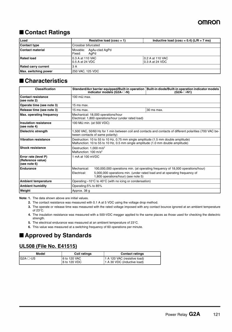
Power Relay G2A 121
Contact Ratings
Characteristics
Note: 1. The data shown above are initial values.2. The contact resistance was measured with 0.1 A at 5 VDC using the voltage drop method.3. The operate or release time was measured with the rated voltage imposed with any contact bounce ignored at an ambient temperature
of 23°C.4. The insulation resistance was measured with a 500-VDC megger applied to the same places as those used for checking the dielectric
strength.5. The electrical endurance was measured at an ambient temperature of 23°C.6. This value was measured at a switching frequency of 60 operations per minute.
Approved by Standards
UL508 (File No. E41515)
Load Resistive load (cosφ = 1) Inductive load (cosφ = 0.4) (L/R = 7 ms)
Contact type Crossbar bifurcated
Contact material Movable: AgAu-clad AgPdFixed: AgPd
Rated load 0.3 A at 110 VAC0.5 A at 24 VDC
0.2 A at 110 VAC0.3 A at 24 VDC
Rated carry current 3 A
Max. switching power 250 VAC, 125 VDC
Classification Standard/Acr barrier equipped/Built-in operation indicator models (G2A-@-N)
Built-in diode/Built-in operation indicator models (G2A-@-N1)
Contact resistance(see note 2)
100 mΩ max.
Operate time (see note 3) 15 ms max.
Release time (see note 3) 15 ms max. 30 ms max.
Max. operating frequency Mechanical: 18,000 operations/hourElectrical: 1,800 operations/hour (under rated load)
Insulation resistance(see note 4)
100 MΩ min. (at 500 VDC)
Dielectric strength 1,500 VAC, 50/60 Hz for 1 min between coil and contacts and contacts of different polarities (700 VAC be-tween contacts of same polarity)
Vibration resistance Destruction: 10 to 55 to 10 Hz, 0.75 mm single amplitude (1.5 mm double amplitude)Malfunction: 10 to 55 to 10 Hz, 0.5 mm single amplitude (1.0 mm double amplitude)
Shock resistance Destruction: 1,000 m/s2
Malfunction: 100 m/s2
Error rate (level P)(Reference value)(see note 6)
1 mA at 100 mVDC
Endurance Mechanical: 100,000,000 operations min. (at operating frequency of 18,000 operations/hour)Electrical: 5,000,000 operations min. (under rated load and at operating frequency of
1,800 operations/hour) (see note 5)
Ambient temperature Operating:–10°C to 40°C (with no icing or condensation)
Ambient humidity Operating:5% to 85%
Weight Approx. 38 g
Model Coil ratings Contact ratings
G2A-@-US 6 to 120 VAC6 to 120 VDC
1 A 120 VAC (resistive load)1 A 30 VDC (inductive load)
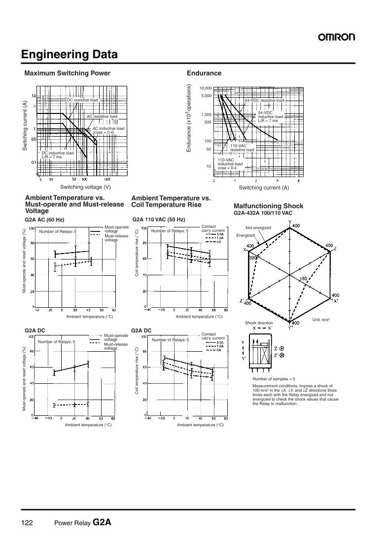
122 Power Relay G2A
Engineering DataMaximum Switching Power Endurance
Sw
itchi
ng c
urre
nt (
A)
Switching voltage (V) Switching current (A)
DC resistive load
AC resistive load
DC inductive loadL/R = 7 ms
24-VDC resistive load
24-VDCinductive loadL/R = 7 ms
110-VACresistive load
110-VAC inductive loadcosφ = 0.4
AC inductive load(cosφ = 0.4)
10
50
100
500
1,000
5,000
10,000
End
uran
ce (
x10
ope
ratio
ns)
3
Ambient Temperature vs. Must-operate and Must-release VoltageG2A AC (60 Hz)
Mus
t-op
erat
e an
d re
set v
olta
ge (
%)
Number of Relays: 5Must-operate voltageMust-release voltage
Ambient temperature (°C)
G2A DC
Mus
t-op
erat
e an
d re
set v
olta
ge (
%)
Number of Relays: 5
Must-operate voltageMust-release voltage
Ambient temperature (°C)
Ambient Temperature vs. Coil Temperature Rise
G2A 110 VAC (50 Hz)
Coi
l tem
pera
ture
ris
e (
C)
Contact carry currentNumber of Relays: 5
Ambient temperature (°C)
G2A DC
Coi
l tem
pera
ture
ris
e (
C)
°
Contact carry currentNumber of Relays: 5
Ambient temperature (°C)
Malfunctioning ShockG2A-432A 100/110 VAC
Not energized
Energized
Shock directionUnit: m/s2
Number of samples = 5
Measurement conditions: Impose a shock of 100 m/s2 in the ±X, ±Y, and ±Z directions three times each with the Relay energized and not energized to check the shock values that cause the Relay to malfunction.
°
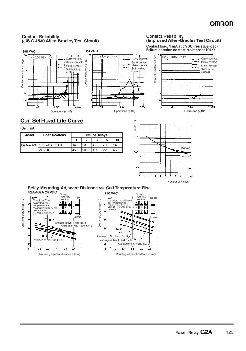
Power Relay G2A 123
Coil Self-load Life Curve(Unit: mA)
Contact Reliability (JIS C 4530 Allen-Bradley Test Circuit)
Con
tact
res
ista
nce
(m
)Ω
Carry contactBreak contactMake contactSelf-holding contact
Operations (x 104)
24 VDC
Con
tact
res
ista
nce
(m
)Ω
Carry contactBreak contactMake contactSelf-holding contact
Operations (x 104)
Contact Reliability(Improved Allen-Bradley Test Circuit)Contact load: 1 mA at 5 VDC (resistive load)Failure criterion contact resistance: 100 Ω
Con
tact
res
ista
nce
(m
)Ω
Carry contactBreak contactMake contactSelf-holding contact
Operations (x 104)
λ60 = 0.00153 × 10⁻⁶
100 VAC
λ60 = 0.00153 × 10⁻⁶ λ60 = 0.00153 × 10⁻⁶
Model Specifications No. of Relays
1 2 3 5 10
G2A-432A 100 VAC, 60 Hz 14 28 42 70 140
24 VDC 45 90 135 225 450
Life
(x1
0 )4
Number of Relays
100 VAC
24 VDC
Relay Mounting Adjacent Distance vs. Coil Temperature RiseG2A-432A 24 VDC
Coi
l tem
pera
ture
ris
e (
C)
° Condition: The saturated coil temperature is measured with rated coil voltage (24 VDC) imposed.
Relay mounting position
Upper
Lower
Average of No. 1 and No. 3Average of No. 4. and No. 6
Average of No. 7 and No. 9
Mounting adjacent distance l (mm)
Coi
l tem
pera
ture
ris
e (
C)
Condition: The saturated coil temperature is measured with rated voltage (110 VAC) at 60 Hz imposed.
Relay mounting position
Average of No. 1 and No. 3
Average of No. 4. and No. 6Average of No. 7 and No. 9
Mounting adjacent distance l (mm)
Upper
Lower
110 VAC
°
124 Power Relay G2A
Accessories (Order Separately)
Connecting Sockets
Note: 1. The PYF@A-TU is a high-humidity relay with nickel-plated rustproof terminal screws that are the same as the PYF@A in size.2. The PYF14T is slightly different from the PYF14A(-TU) in shape and size.3. The PYF@A-E is a finger-protection model, for which round terminals are not available. Use fork-shaped terminals or equivalent ones
instead.
Relay Hold-down Clips
Note: When using a Relay Hold-down Clip for the built-in operation indicator model, use of the PYC-A2 or PYC-5, which allows easy viewing ofthe indicator, is recommended.
Front-connecting Socket
Back-connecting Socket
DIN track/screw mounting
Solder terminals Wire-wrap terminals PCB terminals
PYF14A(-E)PYF14A-TUPYF14T
PY14PY14-Y3
PY14-Y2 (with Relay Hold-down Clip)
PY14QN(2) PY14QN(2)-Y2 (with Relay Hold-down Clip)
PY14-0 PY14-02
PY14-3 Back-connecting Socket (with check terminals for operation monitoring)
Check terminal for operation monitoringBuilt-in operation monitoring lamp possible
Panel Cutout815628
38.5
29 (7.7)
0.334.5±0.4
2-dia. holeThree, 1.2-dia. holes
Shorting lead
78+0.3−0
36+0.3−0
77.5+0−0.4
Relay Mounting Height with SocketWith Front-connecting Socket With Back-connecting Socket
Note: PYF14A can be used for both DIN track mounting and screw mounting.
7376.5
45.5G2A G2A
PYF14A
PY14 Socket
For Front-connecting Socket For Back-connecting Socket For Socket mounting plate
PYC-A2 PYC-3 PYC-5 PYC-2
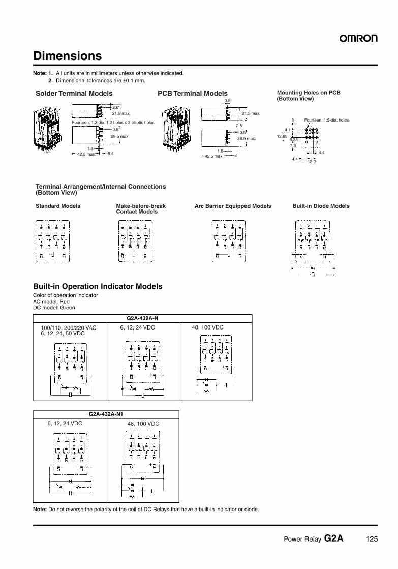
Power Relay G2A 125
DimensionsNote: 1. All units are in millimeters unless otherwise indicated.
2. Dimensional tolerances are ±0.1 mm.
Built-in Operation Indicator ModelsColor of operation indicatorAC model: RedDC model: Green
Note: Do not reverse the polarity of the coil of DC Relays that have a built-in indicator or diode.
G2A-432A-N
Solder Terminal Models PCB Terminal Models Mounting Holes on PCB(Bottom View)
Terminal Arrangement/Internal Connections(Bottom View)
Standard Models Make-before-break Contact Models
Arc Barrier Equipped Models Built-in Diode Models
5
4.1
12.65
4.4
Fourteen, 1.5-dia. holes
4.4
13.2
6.35
7.3
0.5
21.5 max.
28.5 max.
1.842.5 max. 4
0.5
12.621.5 max.
0.5
28.5 max.
Fourteen, 1.2-dia. 1.2 holes x 3 elliptic holes
1.842.5 max. 5.4
2.6
100/110, 200/220 VAC 6, 12, 24, 50 VDC
6, 12, 24 VDC 48, 100 VDC
G2A-432A-N1
6, 12, 24 VDC 48, 100 VDC
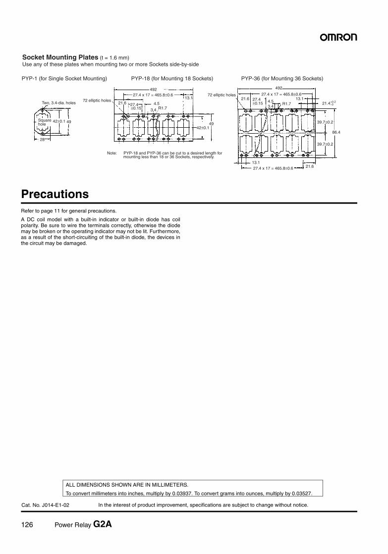
126 Power Relay G2A
In the interest of product improvement, specifications are subject to change without notice.
ALL DIMENSIONS SHOWN ARE IN MILLIMETERS.
To convert millimeters into inches, multiply by 0.03937. To convert grams into ounces, multiply by 0.03527.
Cat. No. J014-E1-02
PrecautionsRefer to page 11 for general precautions.
A DC coil model with a built-in indicator or built-in diode has coilpolarity. Be sure to wire the terminals correctly, otherwise the diodemay be broken or the operating indicator may not be lit. Furthermore,as a result of the short-circuiting of the built-in diode, the devices inthe circuit may be damaged.
Socket Mounting Plates (t = 1.6 mm)Use any of these plates when mounting two or more Sockets side-by-side
PYP-1 (for Single Socket Mounting) PYP-18 (for Mounting 18 Sockets) PYP-36 (for Mounting 36 Sockets)
Note: PYP-18 and PYP-36 can be cut to a desired length for mounting less than 18 or 36 Sockets, respectively.
49
Two, 3.4-dia. holes
28
Square hole
492
72 elliptic holes21.6 4.5
3.4
13.1
49
27.4 x 17 = 465.8±0.6
±0.15
42±0.1
42±0.1
492
72 elliptic holes21.6
4.53.4
13.1R1.7
86.4
21.613.1
27.4 x 17 = 465.8±0.627.4±0.15
39.7±0.2
39.7±0.2
21.4+0.2−0
R1.727.4
27.4 x 17 = 465.8±0.6
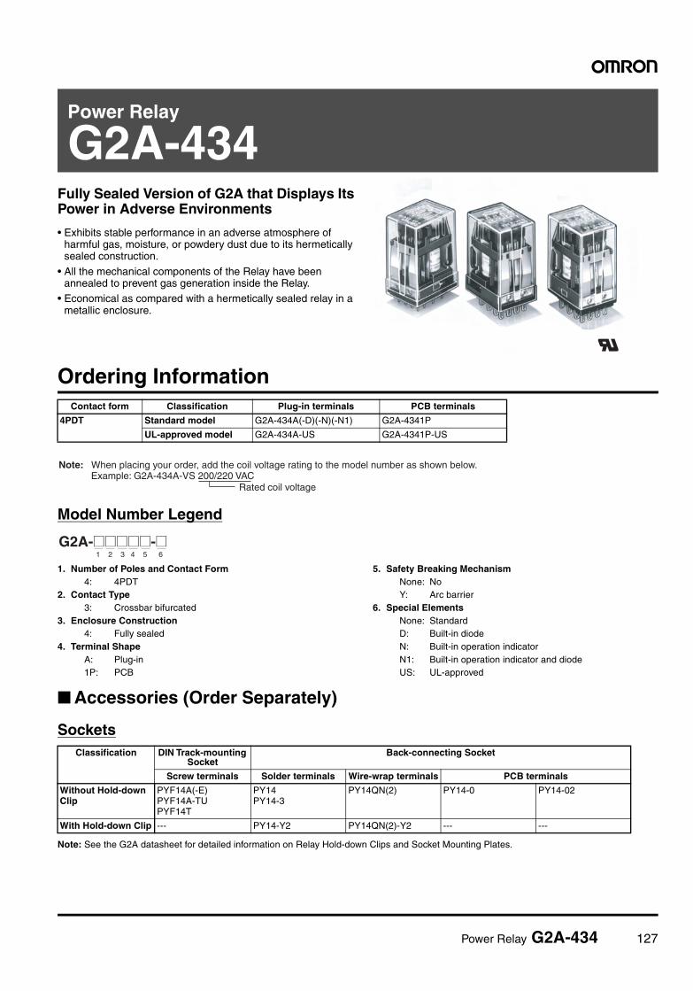
Power Relay G2A-434 127
Power Relay
G2A-434Fully Sealed Version of G2A that Displays Its Power in Adverse Environments
• Exhibits stable performance in an adverse atmosphere of harmful gas, moisture, or powdery dust due to its hermetically sealed construction.
• All the mechanical components of the Relay have been annealed to prevent gas generation inside the Relay.
• Economical as compared with a hermetically sealed relay in a metallic enclosure.
Ordering Information
Model Number Legend
1. Number of Poles and Contact Form4: 4PDT
2. Contact Type3: Crossbar bifurcated
3. Enclosure Construction4: Fully sealed
4. Terminal ShapeA: Plug-in 1P: PCB
5. Safety Breaking MechanismNone: NoY: Arc barrier
6. Special ElementsNone: StandardD: Built-in diodeN: Built-in operation indicatorN1: Built-in operation indicator and diodeUS: UL-approved
Accessories (Order Separately)
Sockets
Note: See the G2A datasheet for detailed information on Relay Hold-down Clips and Socket Mounting Plates.
Contact form Classification Plug-in terminals PCB terminals
4PDT Standard model G2A-434A(-D)(-N)(-N1) G2A-4341P
UL-approved model G2A-434A-US G2A-4341P-US
Rated coil voltage
Note: When placing your order, add the coil voltage rating to the model number as shown below.Example: G2A-434A-VS 200/220 VAC
G2A-@@@@@-@1 2 3 4 5 6
Classification DIN Track-mounting Socket
Back-connecting Socket
Screw terminals Solder terminals Wire-wrap terminals PCB terminals
Without Hold-down Clip
PYF14A(-E)PYF14A-TUPYF14T
PY14PY14-3
PY14QN(2) PY14-0 PY14-02
With Hold-down Clip --- PY14-Y2 PY14QN(2)-Y2 --- ---
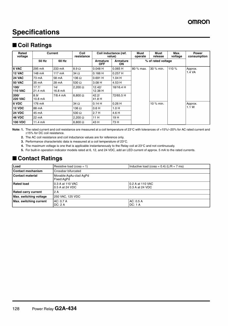
128 Power Relay G2A-434
Specifications
Coil Ratings
Note: 1. The rated current and coil resistance are measured at a coil temperature of 23°C with tolerances of +15%/–20% for AC rated current and±15% for DC coil resistance.
2. The AC coil resistance and coil inductance values are for reference only.3. Performance characteristic data is measured at a coil temperature of 23°C.4. The maximum voltage is one that is applicable instantaneously to the Relay coil at 23°C and not continuously.5. For built-in operation indicator models rated at 6, 12, and 24 VDC, add an LED current of approx. 5 mA to the rated currents.
Contact Ratings
Rated voltage
Current Coil resistance
Coil inductance (ref. value)
Must operate
Must release
Max. voltage
Power consumption
50 Hz 60 Hz Armature OFF
Armature ON
% of rated voltage
6 VAC 295 mA 233 mA 8.9 Ω 0.048 H 0.065 H 80 % max. 30 % min. 110 % Approx. 1.4 VA12 VAC 148 mA 117 mA 34 Ω 0.166 H 0.257 H
24 VAC 73 mA 58 mA 136 Ω 0.691 H 1.04 H
50 VAC 35 mA 28 mA 530 Ω 3.08 H 4.53 H
100/ 110 VAC
17.7/21.4 mA
14/16.8 mA
2,200 Ω 12.42/12.38 H
18/16.4 H
200/ 220 VAC
8.9/10.8 mA
7/8.4 mA 8,800 Ω 42.2/41.8 H
72/65.5 H
6 VDC 176 mA 34 Ω 0.14 H 0.26 H 10 % min. Approx.1.1 W12 VDC 88 mA 136 Ω 0.6 H 1.0 H
24 VDC 45 mA 530 Ω 2.7 H 4.6 H
48 VDC 22 mA 2,200 Ω 11 H 19 H
100 VDC 11.4 mA 8,800 Ω 43 H 73 H
Load Resistive load (cosφ = 1) Inductive load (cosφ = 0.4) (L/R = 7 ms)
Contact mechanism Crossbar bifurcated
Contact material Movable:AgAu-clad AgPdFixed:AgPd
Rated load 0.3 A at 110 VAC0.5 A at 24 VDC
0.2 A at 110 VAC0.3 A at 24 VDC
Rated carry current 2 A
Max. switching voltage 250 VAC, 125 VDC
Max. switching current AC: 0.7 ADC: 2 A
AC: 0.5 ADC: 1 A
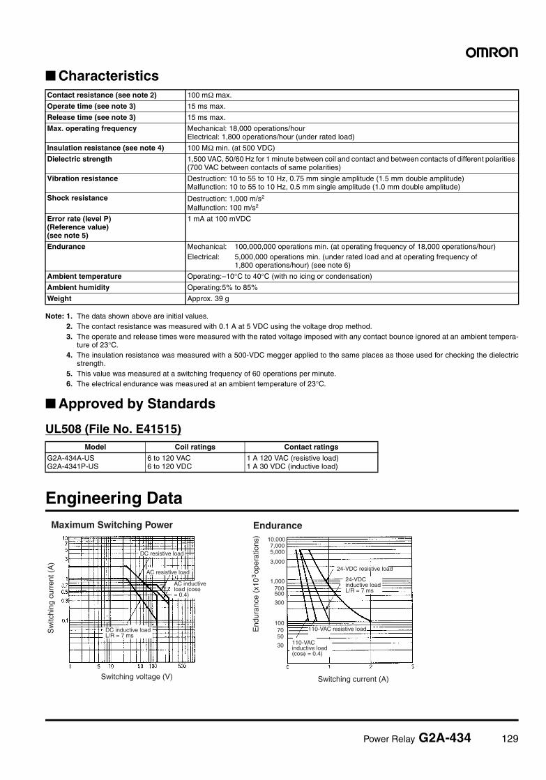
Power Relay G2A-434 129
Characteristics
Note: 1. The data shown above are initial values.2. The contact resistance was measured with 0.1 A at 5 VDC using the voltage drop method.3. The operate and release times were measured with the rated voltage imposed with any contact bounce ignored at an ambient tempera-
ture of 23°C.4. The insulation resistance was measured with a 500-VDC megger applied to the same places as those used for checking the dielectric
strength.5. This value was measured at a switching frequency of 60 operations per minute.6. The electrical endurance was measured at an ambient temperature of 23°C.
Approved by Standards
UL508 (File No. E41515)
Engineering Data
Contact resistance (see note 2) 100 mΩ max.
Operate time (see note 3) 15 ms max.
Release time (see note 3) 15 ms max.
Max. operating frequency Mechanical: 18,000 operations/hourElectrical: 1,800 operations/hour (under rated load)
Insulation resistance (see note 4) 100 MΩ min. (at 500 VDC)
Dielectric strength 1,500 VAC, 50/60 Hz for 1 minute between coil and contact and between contacts of different polarities (700 VAC between contacts of same polarities)
Vibration resistance Destruction: 10 to 55 to 10 Hz, 0.75 mm single amplitude (1.5 mm double amplitude)Malfunction: 10 to 55 to 10 Hz, 0.5 mm single amplitude (1.0 mm double amplitude)
Shock resistance Destruction: 1,000 m/s2
Malfunction: 100 m/s2
Error rate (level P)(Reference value)(see note 5)
1 mA at 100 mVDC
Endurance Mechanical: 100,000,000 operations min. (at operating frequency of 18,000 operations/hour)Electrical: 5,000,000 operations min. (under rated load and at operating frequency of
1,800 operations/hour) (see note 6)
Ambient temperature Operating:–10°C to 40°C (with no icing or condensation)
Ambient humidity Operating:5% to 85%
Weight Approx. 39 g
Model Coil ratings Contact ratings
G2A-434A-USG2A-4341P-US
6 to 120 VAC6 to 120 VDC
1 A 120 VAC (resistive load)1 A 30 VDC (inductive load)
Maximum Switching Power Endurance
Sw
itchi
ng c
urre
nt (
A)
Switching voltage (V) Switching current (A)
DC resistive load
AC resistive load
AC inductiveload (cosφ = 0.4)
DC inductive loadL/R = 7 ms
24-VDC resistive load
24-VDC inductive loadL/R = 7 ms
110-VAC resistive load
110-VAC inductive load(cosφ = 0.4)
30
5070
100
300
500700
1,000
3,000
5,0007,000
10,000
End
uran
ce (
x10
ope
ratio
ns)
3
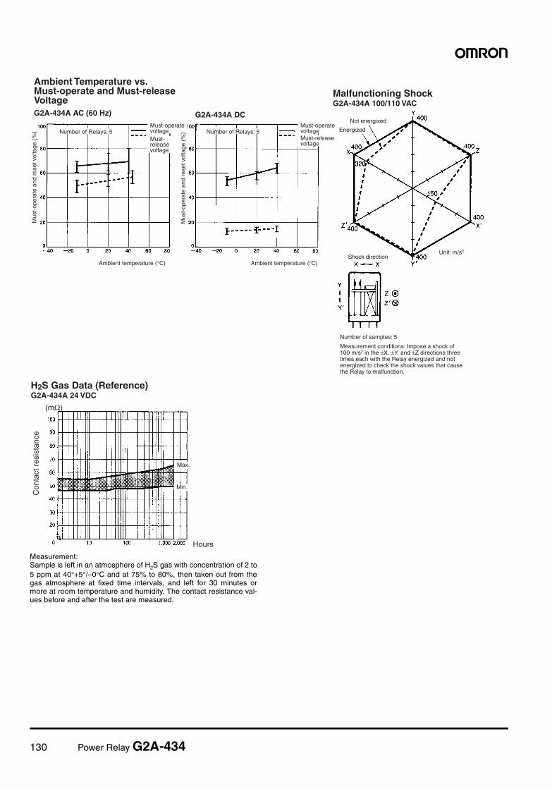
130 Power Relay G2A-434
Measurement:Sample is left in an atmosphere of H2S gas with concentration of 2 to5 ppm at 40°+5°/–0°C and at 75% to 80%, then taken out from thegas atmosphere at fixed time intervals, and left for 30 minutes ormore at room temperature and humidity. The contact resistance val-ues before and after the test are measured.
Ambient Temperature vs. Must-operate and Must-release VoltageG2A-434A AC (60 Hz) G2A-434A DC
Mus
t-op
erat
e an
d re
set v
olta
ge (
%) Number of Relays: 5
Must-operate voltageMust-release voltage
Ambient temperature (°C)
Mus
t-op
erat
e an
d re
set v
olta
ge (
%) Number of Relays: 5
Must-operate voltageMust-release voltage
Ambient temperature (°C)
Malfunctioning ShockG2A-434A 100/110 VAC
Number of samples: 5
Measurement conditions: Impose a shock of 100 m/s2 in the ±X, ±Y, and ±Z directions three times each with the Relay energized and not energized to check the shock values that cause the Relay to malfunction.
Not energized
Energized
Shock directionUnit: m/s2
H2S Gas Data (Reference)G2A-434A 24 VDC
(mΩ)
Con
tact
res
ista
nce
Hours
Max.
Min.
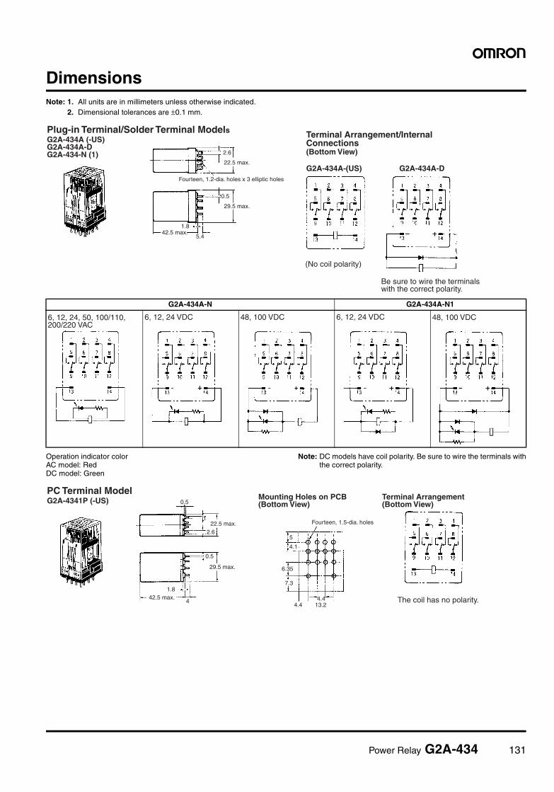
Power Relay G2A-434 131
DimensionsNote: 1. All units are in millimeters unless otherwise indicated.
2. Dimensional tolerances are ±0.1 mm.
Operation indicator colorAC model: RedDC model: Green
Note: DC models have coil polarity. Be sure to wire the terminals withthe correct polarity.
G2A-434A-N G2A-434A-N1
Plug-in Terminal/Solder Terminal ModelsG2A-434A (-US)G2A-434A-DG2A-434-N (1) 2.6
22.5 max.
Fourteen, 1.2-dia. holes x 3 elliptic holes
0.5
29.5 max.
42.5 max.1.8
5.4
Terminal Arrangement/Internal Connections(Bottom View)
G2A-434A-(US) G2A-434A-D
Be sure to wire the terminals with the correct polarity.
(No coil polarity)
6, 12, 24, 50, 100/110, 200/220 VAC
6, 12, 24 VDC 48, 100 VDC 6, 12, 24 VDC 48, 100 VDC
PC Terminal ModelG2A-4341P (-US) 0.5
2.6
1.842.5 max.
4
0.5
1
Mounting Holes on PCB(Bottom View)
Fourteen, 1.5-dia. holes
5
4.1
6.35
7.3
4.44.4 13.2
Terminal Arrangement(Bottom View)
The coil has no polarity.
22.5 max.
29.5 max.
132 Power Relay G2A-434
In the interest of product improvement, specifications are subject to change without notice.
ALL DIMENSIONS SHOWN ARE IN MILLIMETERS.
To convert millimeters into inches, multiply by 0.03937. To convert grams into ounces, multiply by 0.03527.
Cat. No. J118-E1-02
PrecautionsRefer to page 11 for general precautions.
DC models with a built-in indicator or built-in diode have coil polarity.Be sure to wire the terminals with the correct polarity.
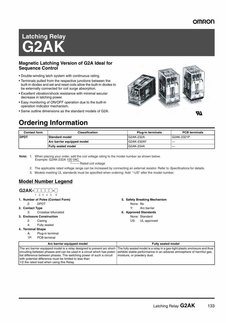
Latching Relay G2AK 133
Latching Relay
G2AKMagnetic Latching Version of G2A Ideal for Sequence Control
• Double-winding latch system with continuous rating.• Terminals pulled from the respective junctions between the
built-in diodes and set and reset coils allow the built-in diodes to be externally connected for coil surge absorption.
• Excellent vibration/shock resistance with minimal secular decrease in latching power.
• Easy monitoring of ON/OFF operation due to the built-in operation indicator mechanism.
• Same outline dimensions as the standard models of G2A.
Ordering Information
Model Number Legend
1. Number of Poles (Contact Form)2: DPDT
2. Contact Type3: Crossbar bifurcated
3. Enclosure Construction2: Casing4: Fully sealed
4. Terminal ShapeA: Plug-in terminal1P: PCB terminal
5. Safety Breaking MechanismNone: NoY: Arc barrier
6. Approved StandardsNone: StandardUS: UL-approved
Contact form Classification Plug-in terminals PCB terminals
DPDT Standard model G2AK-232A G2AK-2321P
Arc barrier equipped model G2AK-232AY ---
Fully sealed model G2AK-234A ---
Rated coil voltage
Note: 1. When placing your order, add the coil voltage rating to the model number as shown below.Example: G2AK-232A 100 VAC
2. The applicable rated voltage range can be increased by connecting an external resistor. Refer to Specifications for details. 3. Models meeting UL standards must be specified when ordering. Add "-US" after the model number.
G2AK-@@@@@-@1 2 3 4 5 6
Arc barrier equipped model Fully sealed model
The arc barrier equipped model is a relay designed to prevent arc short-circuiting between phases and can be used in a circuit which has poten-tial difference between phases. The switching power of such a circuit with potential difference must be limited to less than 1/2 the rated load when using this Relay.
The fully sealed model is a relay in a gas-tight plastic enclosure and thus exhibits stable performance in an adverse atmosphere of harmful gas, moisture, or powdery dust.
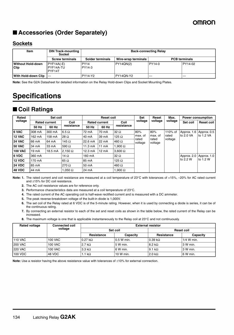
134 Latching Relay G2AK
Accessories (Order Separately)
Sockets
Note: See the G2A Datasheet for detailed information on the Relay Hold-down Clips and Socket Mounting Plates.
Specifications
Coil Ratings
Note: 1. The rated current and coil resistance are measured at a coil temperature of 23°C with tolerances of +15%, –20% for AC rated currentand ±15% for DC coil resistance.
2. The AC coil resistance values are for reference only.3. Performance characteristics data are measured at a coil temperature of 23°C.4. The rated current of the AC operating coil is half-wave rectified current and is measured with a DC ammeter.5. The peak reverse-breakdown voltage of the built-in diode is 1,000V.6. The set coil of the Relay rated at 6 VDC is of the 5-minute rating. However, when it is used by connecting a diode is series, it can be of
the continuous rating.7. By connecting an external resistor to each of the set and reset coils as shown in the table below, the rated current of the Relay can be
increased.8. The maximum voltage is one that is applicable instantaneously to the Relay coil at 23°C and not continuously.
Note: Use a resistor having the above resistance value with tolerances of ±10% for external connection.
Item DIN Track-mounting Socket
Back-connecting Relay
Screw terminals Solder terminals Wire-wrap terminals PCB terminals
Without Hold-down Clip
PYF14A(-E)PYF14A-TUPYF14T
PY14PY14-3
PY14QN(2) PY14-0 PY14-02
With Hold-down Clip --- PY14-Y2 PY14QN-Y2 --- ---
Rated voltage
Set coil Reset coil Set voltage
Reset voltage
Max. voltage
Power consumption
Rated current Coil resistance
Rated current Coil resistance
Set coil Reset coil
50 Hz 60 Hz 50 Hz 60 Hz
6 VAC 308 mA 300 mA 6.5 Ω 72 mA 70 mA 32 Ω 80% max. of rated voltage
80% max. of rated voltage
110% of rated voltage
Approx. 1.6 to 2.0 VA
Approx. 0.5 to 1.2 VA12 VAC 162 mA 158 mA 28 Ω 40 mA 39 mA 125 Ω
24 VAC 66 mA 64 mA 145 Ω 22.6 mA 22 mA 460 Ω50 VAC 34 mA 33 mA 590 Ω 11.3 mA 11 mA 1,900 Ω100 VAC 19 mA 18.5 mA 2,150 Ω 12.3 mA 12 mA 3,600 Ω6 VDC 360 mA 14 Ω 160 mA 32 Ω Approx. 2.0
to 2.2 WApprox. 1.0 to 1.2 W12 VDC 170 mA 65 Ω 85 mA 125 Ω
24 VDC 85 mA 270 Ω 50 mA 460 Ω48 VDC 44 mA 1,050 Ω 24 mA 1,900 Ω
Rated voltage Connected coil voltage
External resistor
Set coil Reset coil
Resistance Capacity Resistance Capacity
110 VAC 100 VAC 0.27 kΩ 0.5 W min. 0.39 kΩ 1/4 W min.
200 VAC 100 VAC 2.7 kΩ 5 W min. 8.2 kΩ 3 W min.
220 VAC 100 VAC 3.3 kΩ 6 W min. 9.1 kΩ 3 W min.
100 VDC 48 VDC 1.1 kΩ 10 W min. 2.0 kΩ 6 W min.
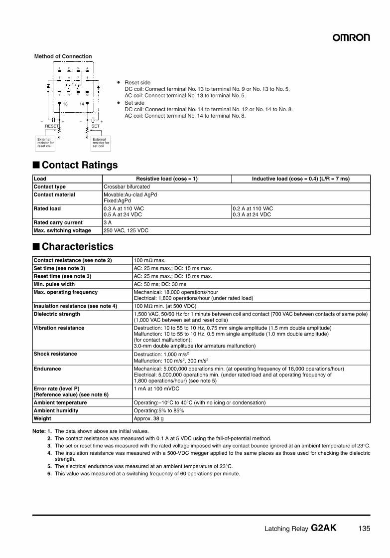
Latching Relay G2AK 135
Contact Ratings
Characteristics
Note: 1. The data shown above are initial values.2. The contact resistance was measured with 0.1 A at 5 VDC using the fall-of-potential method.3. The set or reset time was measured with the rated voltage imposed with any contact bounce ignored at an ambient temperature of 23°C.4. The insulation resistance was measured with a 500-VDC megger applied to the same places as those used for checking the dielectric
strength.5. The electrical endurance was measured at an ambient temperature of 23°C.6. This value was measured at a switching frequency of 60 operations per minute.
Load Resistive load (cosφ = 1) Inductive load (cosφ = 0.4) (L/R = 7 ms)
Contact type Crossbar bifurcated
Contact material Movable:Au-clad AgPdFixed:AgPd
Rated load 0.3 A at 110 VAC0.5 A at 24 VDC
0.2 A at 110 VAC0.3 A at 24 VDC
Rated carry current 3 A
Max. switching voltage 250 VAC, 125 VDC
Contact resistance (see note 2) 100 mΩ max.
Set time (see note 3) AC: 25 ms max.; DC: 15 ms max.
Reset time (see note 3) AC: 25 ms max.; DC: 15 ms max.
Min. pulse width AC: 50 ms; DC: 30 ms
Max. operating frequency Mechanical: 18,000 operations/hourElectrical: 1,800 operations/hour (under rated load)
Insulation resistance (see note 4) 100 MΩ min. (at 500 VDC)
Dielectric strength 1,500 VAC, 50/60 Hz for 1 minute between coil and contact (700 VAC between contacts of same pole) (1,000 VAC between set and reset coils)
Vibration resistance Destruction: 10 to 55 to 10 Hz, 0.75 mm single amplitude (1.5 mm double amplitude)Malfunction: 10 to 55 to 10 Hz, 0.5 mm single amplitude (1.0 mm double amplitude)(for contact malfunction);3.0-mm double amplitude (for armature malfunction)
Shock resistance Destruction: 1,000 m/s2
Malfunction: 100 m/s2, 300 m/s2
Endurance Mechanical: 5,000,000 operations min. (at operating frequency of 18,000 operations/hour)Electrical: 5,000,000 operations min. (under rated load and at operating frequency of 1,800 operations/hour) (see note 5)
Error rate (level P)(Reference value) (see note 6)
1 mA at 100 mVDC
Ambient temperature Operating:–10°C to 40°C (with no icing or condensation)
Ambient humidity Operating:5% to 85%
Weight Approx. 38 g
Method of Connection
• Reset side DC coil: Connect terminal No. 13 to terminal No. 9 or No. 13 to No. 5. AC coil: Connect terminal No. 13 to terminal No. 5.• Set side DC coil: Connect terminal No. 14 to terminal No. 12 or No. 14 to No. 8. AC coil: Connect terminal No. 14 to terminal No. 8.
RESET SET
External resistor for reset coil
External resistor for set coil
13 14
− + − +
9 10 11 12
1 2 3 4
5 6 7 8
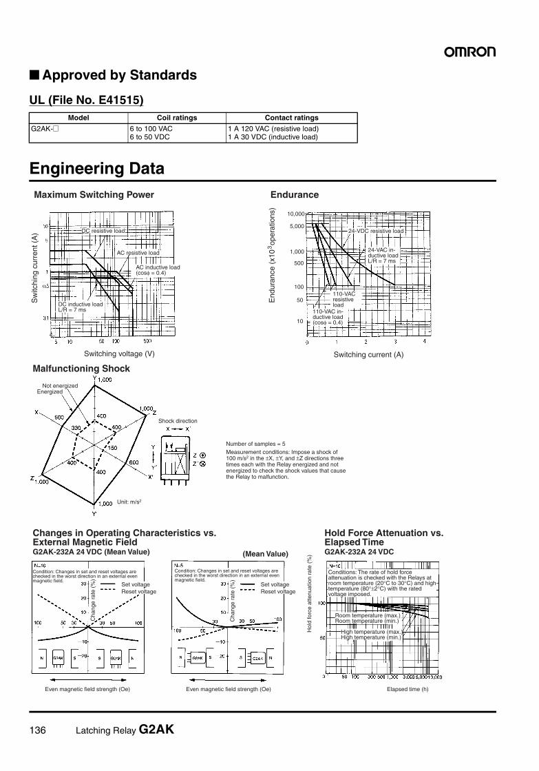
136 Latching Relay G2AK
Approved by Standards
UL (File No. E41515)
Engineering Data
Model Coil ratings Contact ratings
G2AK-@ 6 to 100 VAC6 to 50 VDC
1 A 120 VAC (resistive load)1 A 30 VDC (inductive load)
Maximum Switching Power Endurance
Sw
itchi
ng c
urre
nt (
A)
Switching voltage (V) Switching current (A)
DC resistive load
AC resistive load
AC inductive load(cosφ = 0.4)
DC inductive loadL/R = 7 ms
24-VDC resistive load
24-VAC in-ductive loadL/R = 7 ms
110-VAC resistive load
110-VAC in-ductive load(cosφ = 0.4)10
50
100
500
1,000
5,000
10,000
End
uran
ce (
x10
ope
ratio
ns)
3
Malfunctioning Shock
Not energizedEnergized
Shock direction
Unit: m/s2
Number of samples = 5Measurement conditions: Impose a shock of 100 m/s2 in the ±X, ±Y, and ±Z directions three times each with the Relay energized and not energized to check the shock values that cause the Relay to malfunction.
Changes in Operating Characteristics vs. External Magnetic FieldG2AK-232A 24 VDC (Mean Value)
Condition: Changes in set and reset voltages are checked in the worst direction in an external even magnetic field.
Set voltageReset voltage
Cha
nge
rate
(%
)
Even magnetic field strength (Oe)
(Mean Value)
Condition: Changes in set and reset voltages are checked in the worst direction in an external even magnetic field.
Set voltageReset voltage
Cha
nge
rate
(%
)
Even magnetic field strength (Oe)
Hold Force Attenuation vs. Elapsed TimeG2AK-232A 24 VDC
Hol
d fo
rce
atte
nuat
ion
rate
(%
)
Conditions: The rate of hold force attenuation is checked with the Relays at room temperature (20°C to 30°C) and high temperature (80°±2°C) with the rated voltage imposed.
Room temperature (max.)Room temperature (min.)
High temperature (max.)High temperature (min.)
Elapsed time (h)
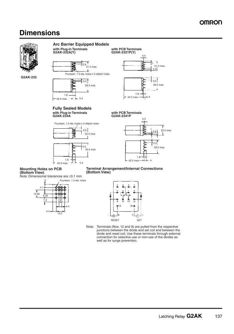
Latching Relay G2AK 137
Dimensions
with Plug-in TerminalsG2AK-232A(Y)
with PCB TerminalsG2AK-2321P(Y)
with Plug-in TerminalsG2AK-234A
with PCB TerminalsG2AK-2341P
2.621.5 max.
Fourteen, 1.2-dia. holes x 3 elliptic holes
0.5
28.5 max.
42.5 max. 5.41.8
21.5 max.
0.5
1
2.6
0.5
28.5 max.
1.842.5 max. 4
1.842.5 max. 5.4
Fourteen, 1.2-dia. holes x 3 elliptic holes
22.5 max.
29.5 max.0.5
2.6
0.5
12.6
42.5 max.1.8
4
29.5 max.
0.5
22.5 max.
Arc Barrier Equipped Models
Fully Sealed Models
G2AK-232
Mounting Holes on PCB(Bottom View)Note: Dimensional tolerances are ±0.1 mm
Terminal Arrangement/Internal Connections(Bottom View)
5
4.1
12.656.35
7.3
4.413.2
4.4
Fourteen, 1.5-dia. holes
RESET SET
Note: Terminals (Nos. 12 and 9) are pulled from the respective junctions between the diode and set coil and between the diode and reset coil. Use these terminals through external connection for selective use or non-use of the diodes as well as for surge prevention.
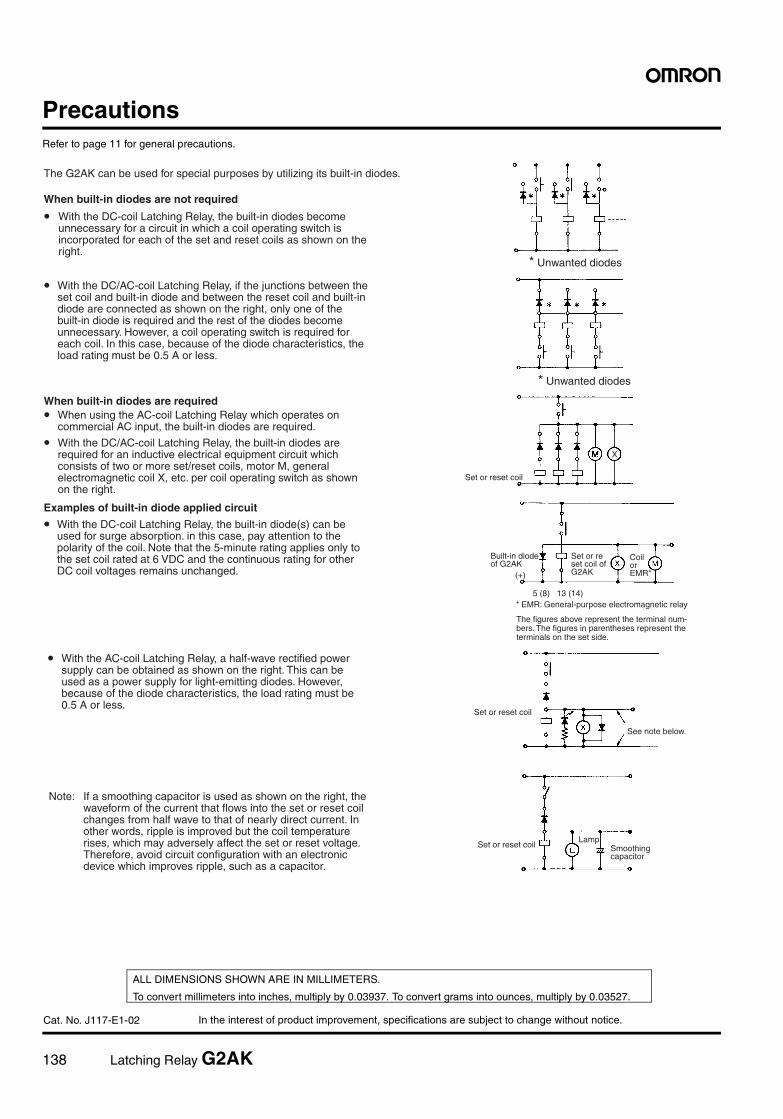
138 Latching Relay G2AK
In the interest of product improvement, specifications are subject to change without notice.
ALL DIMENSIONS SHOWN ARE IN MILLIMETERS.
To convert millimeters into inches, multiply by 0.03937. To convert grams into ounces, multiply by 0.03527.
Cat. No. J117-E1-02
PrecautionsRefer to page 11 for general precautions.
The G2AK can be used for special purposes by utilizing its built-in diodes.
When built-in diodes are not required
• With the DC-coil Latching Relay, the built-in diodes become unnecessary for a circuit in which a coil operating switch is incorporated for each of the set and reset coils as shown on the right.
* Unwanted diodes
* Unwanted diodes
• With the DC/AC-coil Latching Relay, if the junctions between the set coil and built-in diode and between the reset coil and built-in diode are connected as shown on the right, only one of the built-in diode is required and the rest of the diodes become unnecessary. However, a coil operating switch is required for each coil. In this case, because of the diode characteristics, the load rating must be 0.5 A or less.
Set or reset coil
When built-in diodes are required• When using the AC-coil Latching Relay which operates on commercial AC input, the built-in diodes are required.
• With the DC/AC-coil Latching Relay, the built-in diodes are required for an inductive electrical equipment circuit which consists of two or more set/reset coils, motor M, general electromagnetic coil X, etc. per coil operating switch as shown on the right.
X
Examples of built-in diode applied circuit
• With the DC-coil Latching Relay, the built-in diode(s) can be used for surge absorption. in this case, pay attention to the polarity of the coil. Note that the 5-minute rating applies only to the set coil rated at 6 VDC and the continuous rating for other DC coil voltages remains unchanged.
Built-in diode of G2AK
(+)
Set or reset coil of G2AK
Coil or EMR*
* EMR: General-purpose electromagnetic relay5 (8) 13 (14)
The figures above represent the terminal num- bers. The figures in parentheses represent the terminals on the set side.
Note: If a smoothing capacitor is used as shown on the right, the waveform of the current that flows into the set or reset coil changes from half wave to that of nearly direct current. In other words, ripple is improved but the coil temperature rises, which may adversely affect the set or reset voltage. Therefore, avoid circuit configuration with an electronic device which improves ripple, such as a capacitor.
Set or reset coil
Set or reset coilLamp
Smoothing capacitor
• With the AC-coil Latching Relay, a half-wave rectified power supply can be obtained as shown on the right. This can be used as a power supply for light-emitting diodes. However, because of the diode characteristics, the load rating must be 0.5 A or less.
See note below.
Power Relay MM 139
Power Relay
MMStable Contact Reliability and Long Life
• Easy to mount, wire, and use.
• A large selection of models including various contact forms, DC-switching models, and open models.
• Mechanical life: 5,000,000 operations; electrical life (under rated load): 500,000 operations.
• Models also available with built-in diodes and for use as auxiliary power relays.
Ordering InformationType Contact form Open structure Cased
Solder terminals Screw terminals Plug-in (octal pins) terminals
Standard DPDT MM2 MM2B MM2P
3PDT MM3 MM3B MM3P
4PDT MM4 MM4B MM4P
DC-switching DPDT MM2X MM2XB MM2XP
3PDT MM3X MM3XB MM3XP
4PDT MM4X MM4XB MM4XP
With built-in diode DPDT --- --- MM2P-D
4PDT --- --- MM4P-D
DC-switching with built-in diode DPDT --- --- MM2XP-D
4PDT --- --- MM4XP-D
With operation indicator DPDT --- --- MM2PN
3PDT --- --- MM3PN
4PDT --- --- MM4PN
DC-switching with operation indicator DPDT --- --- MM2XPN
3PDT --- --- MM3XPN
4PDT --- --- MM4XPN
Conforming to auxiliary power relay speci-fications
4PDT --- --- MM4P-JD
--- --- MM4XP-JD

140 Power Relay MM
Models Conforming to Auxiliary Power Relay SpecificationsThe MM4P-JD and MM4XP-JD satisfy the ratings of auxiliary relays provided in JEC-2500 (1987) standards for power protective relays specifiedby the Japan Electromechanical Commission. Furthermore, the MM4P-JD and MM4XP-JD satisfy the ratings of multi-contact relays provided inJEC-174D (1979) standards for power auxiliary relays.
These models work at operation level B specified by JEC-174D (1979) standards and the hot start of the relays is possible after the coils radiateheat.
In accordance with JEC-2500 (1987) standards, the coil of each model withstands a 130% DC load or 115% AC load.
Model Number Legend
1. Contact Form2: DPDT3: 3PDT4: 4PDT
2. Type (See Note)None: StandardX: DC-switching
3. Terminal ShapeNone: SolderB: ScrewP: Plug-in
4. Operation IndicatorNone: Not providedN: Provided
5. Built-in DiodeNone: Not providedD: Provided
Note: The suffix “JD” indicates models conforming to auxiliary powerrelay specifications.
Accessories (Order Separately)
Mounting Brackets
Sockets
Rated coil voltage
Note: 1. When ordering, add the rated coil voltage to the model number. Rated coil voltages are given in the coil ratings table.Example: MM2, 6 VAC
2. Latching Relays based on the MM Series are also available. Refer to the MMK. 3. Models with built-in varistors (AC operation) are also available in addition to those with built-in diodes. Ask your OMRON repre- sentative for details.
MM@@@@-@1 2 3 4 5
Mounting Bracket (S bracket) R99-03MM
Relay model DIN Track/Front-connecting Socket(screw terminals)
Back-connecting Socket(solder terminals)
MM2(X)P(-D) 8PFA PL08
MM3P
MM3XP, MM4(X)P(-D) 14PFA PL15
MM4(X)P-JD 14PFA ---
11PFA PL11
Power Relay MM 141
Specifications
Coil Ratings
Open Coils (with Solder or Screw Terminals)
Note: 1. The rated current and coil resistance are measured at a coil temperature of 23°C with tolerances of +15%/–20% for AC rated current and±15% for DC coil resistance.
2. The AC coil resistance values are reference values.3. Performance characteristic data are measured at a coil temperature of 23°C.4. The maximum voltage is one that is applicable instantaneously to the Relay coil at an ambient temperature of 23°C and not continuously.
Covered Coils (Plug-in Terminals)The rated current may vary if the Relay has a built-in operating indicator (see note 4).
Note: 1. The rated current and coil resistance are measured at a coil temperature of 23°C with tolerances of +15%/–20% for AC rated current and±15% for DC coil resistance.
2. The AC coil resistance and coil inductance values are for reference only.3. Performance characteristic data are measured at a coil temperature of 23°C.4. The maximum voltage is one that is applicable instantaneously to the Relay coil at an ambient temperature of 23°C and not continuously.5. The rated current of a model with a built-in LED indicator at 6, 12, 24, or 50 VAC or 6, 12, 24, or 48 VDC increases by approximately 10
mA due to the current consumption of the LED. The rated current of a model with a built-in neon lamp indicator at 100 (110) or 200 (220)VAC or 100/110 or 200/220 VDC increases by approximately 0.2 mA due to the current consumption of the neon lamp.
Rated voltage (V)
Rated current (mA) Coil resistance (Ω) Must-operate voltage
Must-release voltage
Max. voltage
Power consumption (VA or
W)DP 3P or 4P DP 3P or 4P
50 Hz 60 Hz 50 Hz 60 Hz % of rated voltage Initial Rated
AC 6 790 655 1,120 950 1.1 0.5 80% max. 30% min. (60 Hz)25% min. (50 Hz)
110% Approxi-mately 4.1 (DP)Approxi-mately 6.3 (3P or 4P)
Approxi-mately 3.9 (DP)Approxi-mately 5.7 (3P or 4P)
12 395 325 560 480 4.7 2.0
24 195 160 280 240 19 8.5
50 94 78 134 114 82 36
100/(110) 47 39/45 67 57/66 340 150
200/(220) 23.5 19.5/ 22.5 33.5 28.5/33 1,540 620
DC 6 340 450 17.5 13.4 70% max. 10% min. Approximately 2.1 (DP)Approximately 2.7 (3P or 4P)
12 176 220 68 54
24 87 94 275 255
48 41 52 1,180 930
100/110 17/19 22/24.5 5,750 4,500
200/220 8.6/9.5 11/12 23,200 18,000
Rated voltage (V)
Rated current (mA) Coil resistance (Ω)
Coil inductance (H) Must-operate voltage
Must-release voltage
Max. voltage
Power consumption
(VA or W)DP 3P or 4P DP 3P or 4P
DP 3P or 4P
50 Hz 60 Hz 50 Hz 60 Hz Contact release
Contact operate
Contact release
Contact operate
% of rated voltage Initial Rated
AC 6 690 590 975 850 1.1 0.5 0.02 0.02 0.01 0.03 80% max.
30% min. (60 Hz)25% min. (50 Hz)
110% Ap-prox. 4.1 VA (DP)Ap-prox. 6.3 VA (3P or 4P)
Ap-prox. 3.5 VA (DP)Ap-prox. 5.1 VA (3P or 4P)
12 345 295 490 430 4.7 2.0 0.07 0.01 0.04 0.07
24 170 145 245 210 19 8.5 0.28 0.41 0.18 0.28
50 82 70 117 102 82 36 1.2 1.7 0.75 1.2
100/(110) 41 35/40 58.5 51/58 340 150 4.8 6.7 3 4.5
200/(220) 20.5 17.5/ 20
29 25.5/ 29
1,540 620 20 25.6 12 19
DC 6 340 450 17.5 13.4 0.2 0.36 0.23 0.35 70% max.
10% min.
Approx. 2.1 W (DP)Approx. 2.7 W (3P or 4P)
12 176 220 68 54 0.74 1.0 0.87 1.4
24 87 94 275 255 4.2 5.8 5.6 9.2
48 41 52 1,180 930 20.4 26 27.3 45.5
100/110 17/19 22/24.5 5,750 4,500 81.6 92.5 61.4 96.5
200/220 8.6/9.5 11/12 23,200 18,000 340 380 158 250
142 Power Relay MM
Coils (Conforming to Auxiliary Power Relay Specifications)
Note: 1. The rated current and coil resistance are measured at a coil temperature of 23°C with tolerances of +15%/–20% for AC rated current and±15% for DC coil resistance.
2. The AC coil resistance and coil inductance values are for reference only.3. Performance characteristic data are measured at a coil temperature of 23°C.4. The maximum voltage is one that is applicable instantaneously to the Relay coil at 23°C and not continuously.
Contact Ratings
Standard Relays
DC-switching Relays/Built-in Diode Relays
Note: 1. When switching DC inductive loads at 125 V or more, an unstable region exists for a contact current of between 0.5 and 2.5 A. The Relaywill not turn OFF in this region. Use a contact current of 0.5 A or less when switching 125 VDC or more.
2. If L/R exceeds 7 ms when switching DC inductive loads, an arc-breaking time of up to 50 ms must be considered in application and thecircuit must be designed to ensure that an arc-breaking time of 50 ms is not exceeded.
Rated voltage (V)
Rated current (mA) Coil resistanc
e (Ω)
Coil inductance (H) Must-operate voltage
Must-release voltage
Max. voltage
Operation level (JEC-174D)
Power consumption (VA or
W)
50 Hz 60 Hz Contact release
Contact operate
% of rated voltage Initial Rated
AC 24 245 210 8.5 0.18 0.28 80% max. 30% min. (60 Hz)25% min. (50 Hz)
110% BHot start after coil heated
Approx. 6.3 VA
Approx. 5.1 VA50 117 102 36 0.75 1.2
100/(110) 58.5 51/58 150 3 4.5
110 53 46 182 3.6 5.5
115 51 44 210 4 6.2
200/(220) 29 25.5/29 620 12 19
220 26.5 23 780 15 21
DC 24 94 255 5.6 9.2 70% max. 10% min. Approx. 2.7 W
48 52 930 27.3 45.5
100/110 22/24.5 4,500 61.4 96.5
125 22 5,800 90 130
200/220 11/12 18,000 158 250
Item Open Relays Covered Relays
MM2(B), MM3(B), MM4(B) MM2P(N, D), MM3P(N), MM4P(N, D)
Resistive load (cosφ = 1)
Inductive load (cosφ=0.4, L/R=7 ms)
Resistive load (cosφ = 1)
Inductive load (cosφ=0.4, L/R=7 ms)
Contact type Single
Contact material Ag
Rated load 15 A at 220 VAC10 A at 24 VDC
7.5 A at 220 VAC5 A at 24 VDC
Rated carry current 15 A 7.5 A
Max. switching voltage 250 VAC, 250 VDC 250 VAC, 250 VDC
Max. switching current 15 A 7.5 A
Item Open Relays Covered Relays
MM2X(B), MM3X(B), MM4X(B) MM2XP(-D), MM3XP, MM4XP(-D)
Resistive load (cosφ = 1)
Inductive load (L/R=7 ms)
Resistive load (cosφ = 1)
Inductive load (L/R=7 ms)
Contact type Single
Contact material Ag
Rated load 10 A at 110 VDC 7 A at 110 VDC 7 A at 110 VDC 6 A at 110 VDC
Rated carry current 15 A 7.5 A
Max. switching voltage 250 VDC 250 VDC
Max. switching current 15 A 7.5 A
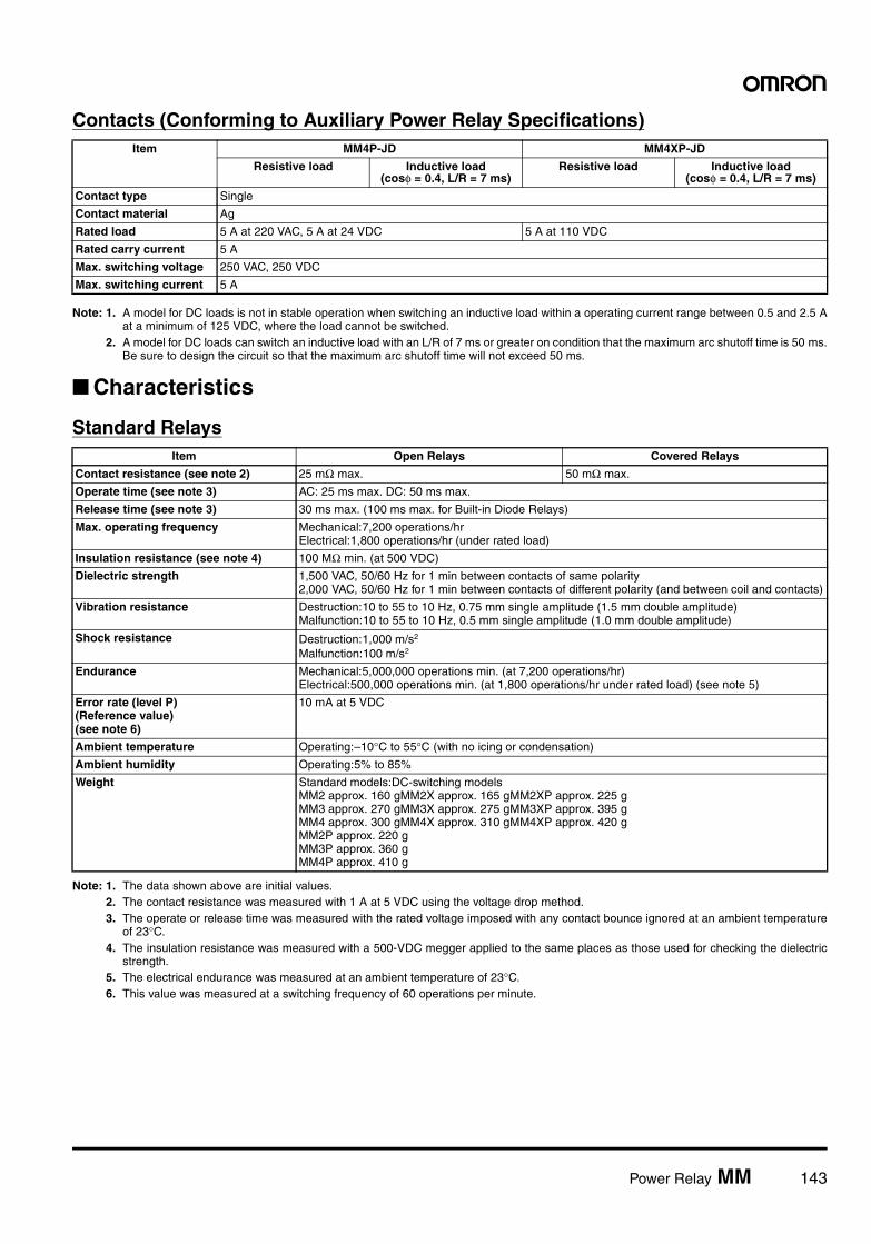
Power Relay MM 143
Contacts (Conforming to Auxiliary Power Relay Specifications)
Note: 1. A model for DC loads is not in stable operation when switching an inductive load within a operating current range between 0.5 and 2.5 Aat a minimum of 125 VDC, where the load cannot be switched.
2. A model for DC loads can switch an inductive load with an L/R of 7 ms or greater on condition that the maximum arc shutoff time is 50 ms.Be sure to design the circuit so that the maximum arc shutoff time will not exceed 50 ms.
Characteristics
Standard Relays
Note: 1. The data shown above are initial values.2. The contact resistance was measured with 1 A at 5 VDC using the voltage drop method.3. The operate or release time was measured with the rated voltage imposed with any contact bounce ignored at an ambient temperature
of 23°C.4. The insulation resistance was measured with a 500-VDC megger applied to the same places as those used for checking the dielectric
strength.5. The electrical endurance was measured at an ambient temperature of 23°C.6. This value was measured at a switching frequency of 60 operations per minute.
Item MM4P-JD MM4XP-JD
Resistive load Inductive load(cosφ = 0.4, L/R = 7 ms)
Resistive load Inductive load(cosφ = 0.4, L/R = 7 ms)
Contact type Single
Contact material Ag
Rated load 5 A at 220 VAC, 5 A at 24 VDC 5 A at 110 VDC
Rated carry current 5 A
Max. switching voltage 250 VAC, 250 VDC
Max. switching current 5 A
Item Open Relays Covered Relays
Contact resistance (see note 2) 25 mΩ max. 50 mΩ max.
Operate time (see note 3) AC: 25 ms max. DC: 50 ms max.
Release time (see note 3) 30 ms max. (100 ms max. for Built-in Diode Relays)
Max. operating frequency Mechanical:7,200 operations/hrElectrical:1,800 operations/hr (under rated load)
Insulation resistance (see note 4) 100 MΩ min. (at 500 VDC)
Dielectric strength 1,500 VAC, 50/60 Hz for 1 min between contacts of same polarity2,000 VAC, 50/60 Hz for 1 min between contacts of different polarity (and between coil and contacts)
Vibration resistance Destruction:10 to 55 to 10 Hz, 0.75 mm single amplitude (1.5 mm double amplitude)Malfunction:10 to 55 to 10 Hz, 0.5 mm single amplitude (1.0 mm double amplitude)
Shock resistance Destruction:1,000 m/s2
Malfunction:100 m/s2
Endurance Mechanical:5,000,000 operations min. (at 7,200 operations/hr)Electrical:500,000 operations min. (at 1,800 operations/hr under rated load) (see note 5)
Error rate (level P)(Reference value)(see note 6)
10 mA at 5 VDC
Ambient temperature Operating:–10°C to 55°C (with no icing or condensation)
Ambient humidity Operating:5% to 85%
Weight Standard models:DC-switching modelsMM2 approx. 160 gMM2X approx. 165 gMM2XP approx. 225 gMM3 approx. 270 gMM3X approx. 275 gMM3XP approx. 395 gMM4 approx. 300 gMM4X approx. 310 gMM4XP approx. 420 gMM2P approx. 220 gMM3P approx. 360 gMM4P approx. 410 g
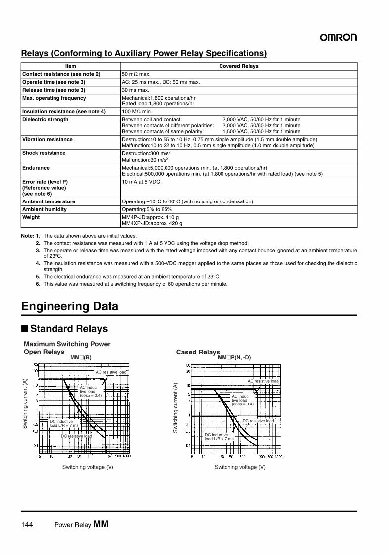
144 Power Relay MM
Relays (Conforming to Auxiliary Power Relay Specifications)
Note: 1. The data shown above are initial values.2. The contact resistance was measured with 1 A at 5 VDC using the voltage drop method.3. The operate or release time was measured with the rated voltage imposed with any contact bounce ignored at an ambient temperature
of 23°C.4. The insulation resistance was measured with a 500-VDC megger applied to the same places as those used for checking the dielectric
strength.5. The electrical endurance was measured at an ambient temperature of 23°C.6. This value was measured at a switching frequency of 60 operations per minute.
Engineering Data
Standard Relays
Item Covered Relays
Contact resistance (see note 2) 50 mΩ max.
Operate time (see note 3) AC: 25 ms max., DC: 50 ms max.
Release time (see note 3) 30 ms max.
Max. operating frequency Mechanical:1,800 operations/hrRated load:1,800 operations/hr
Insulation resistance (see note 4) 100 MΩ min.
Dielectric strength Between coil and contact: 2,000 VAC, 50/60 Hz for 1 minuteBetween contacts of different polarities: 2,000 VAC, 50/60 Hz for 1 minuteBetween contacts of same polarity: 1,500 VAC, 50/60 Hz for 1 minute
Vibration resistance Destruction:10 to 55 to 10 Hz, 0.75 mm single amplitude (1.5 mm double amplitude)Malfunction:10 to 22 to 10 Hz, 0.5 mm single amplitude (1.0 mm double amplitude)
Shock resistance Destruction:300 m/s2
Malfunction:30 m/s2
Endurance Mechanical:5,000,000 operations min. (at 1,800 operations/hr)Electrical:500,000 operations min. (at 1,800 operations/hr with rated load) (see note 5)
Error rate (level P)(Reference value)(see note 6)
10 mA at 5 VDC
Ambient temperature Operating:–10°C to 40°C (with no icing or condensation)
Ambient humidity Operating:5% to 85%
Weight MM4P-JD:approx. 410 gMM4XP-JD:approx. 420 g
Maximum Switching PowerOpen Relays
Switching voltage (V)
Cased Relays
Sw
itchi
ng c
urre
nt (
A)
Switching voltage (V)
AC resistive load
AC inductive load(cosφ = 0.4)
DC inductive load L/R = 7 ms
DC resistive load
AC resistive load
AC inductive load(cosφ = 0.4)
DC resistive load
DC inductive load L/R = 7 ms
MM@(B) MM@P(N, -D)
Sw
itchi
ng c
urre
nt (
A)
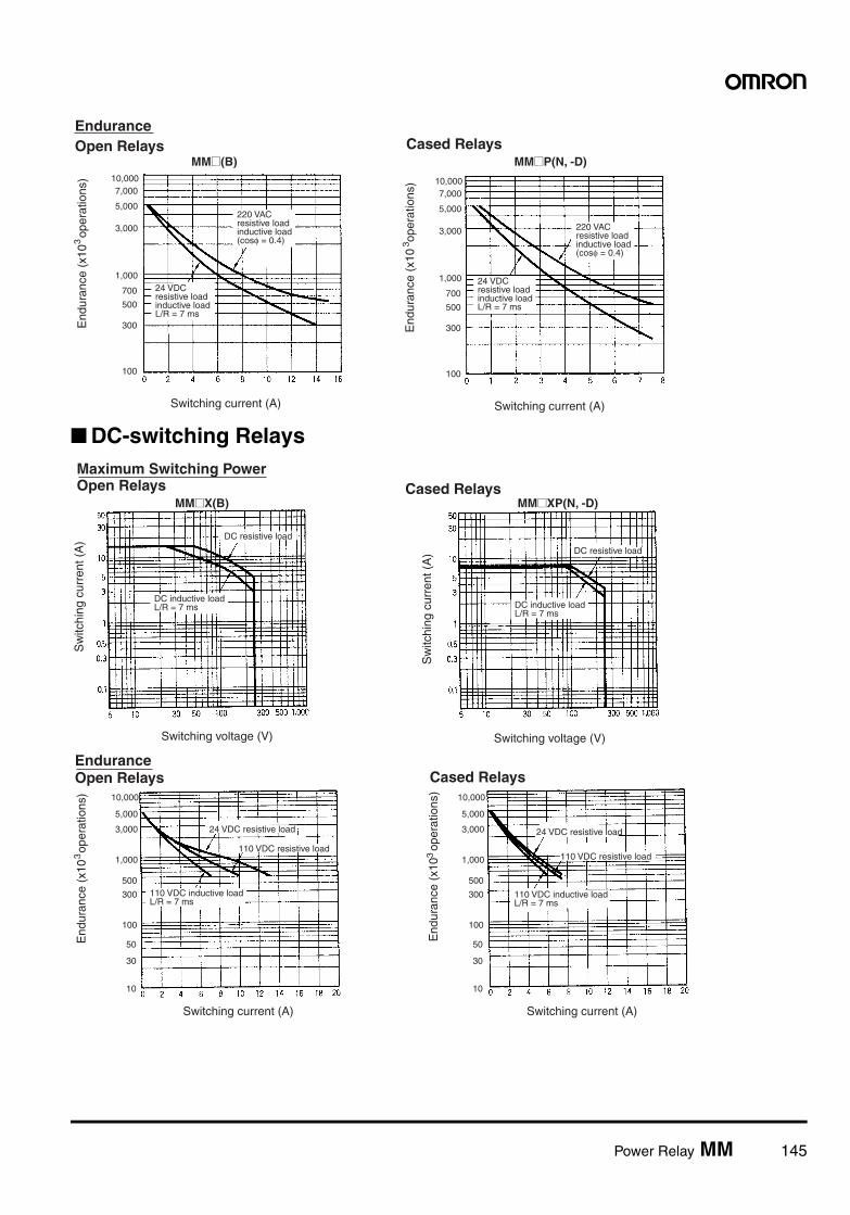
Power Relay MM 145
DC-switching Relays
EnduranceOpen Relays Cased Relays
Switching current (A)Switching current (A)
220 VACresistive loadinductive load (cosφ = 0.4)
24 VDCresistive loadinductive load L/R = 7 ms
220 VACresistive loadinductive load (cosφ = 0.4)
24 VDCresistive loadinductive load L/R = 7 ms
100
300
500
700
1,000
3,000
5,000
7,00010,000
100
300
500
700
1,000
3,000
5,000
7,00010,000
End
uran
ce (
x10
ope
ratio
ns)
3
End
uran
ce (
x10
ope
ratio
ns)
3
MM@(B) MM@P(N, -D)
Maximum Switching PowerOpen Relays
Switching voltage (V)
Cased Relays
Sw
itchi
ng c
urre
nt (
A)
Switching voltage (V)
DC resistive load
DC inductive load L/R = 7 ms
DC resistive load
DC inductive load L/R = 7 ms
MM@X(B) MM@XP(N, -D)
Sw
itchi
ng c
urre
nt (
A)
EnduranceOpen Relays Cased Relays
Switching current (A)Switching current (A)
24 VDC resistive load
110 VDC resistive load
110 VDC inductive load L/R = 7 ms
24 VDC resistive load
110 VDC resistive load
110 VDC inductive load L/R = 7 ms
10
30
50
100
300
500
1,000
3,000
5,000
10,000
10
30
50
100
300
500
1,000
3,000
5,000
10,000
End
uran
ce (
x10
ope
ratio
ns)
3
End
uran
ce (
x10
ope
ratio
ns)
3
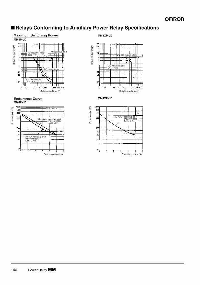
146 Power Relay MM
Relays Conforming to Auxiliary Power Relay SpecificationsMaximum Switching PowerMM4P-JD
MM4XP-JD
Endurance CurveMM4P-JD
MM4XP-JD
Sw
itchi
ng c
urre
nt (
A)
AC resistive loadAC inductive loadcosφ = 0.4
DC resistive load
DC inductive loadL/R = 7 ms
Switching voltage (V)
DC resistive load
DC inductive loadL/R = 7 ms
Switching voltage (V)
End
uran
ce (
x 10
)4
24 VDC resistive loadInductive loadL/R = 7 ms
Switching current (A)
End
uran
ce (
x 10
)4
110 VDC: resistive load inductive load L/R = 7 ms
Switching current (A)
Sw
itchi
ng c
urre
nt (
A)
220 VAC: resistive load inductive load cosφ = 0.4
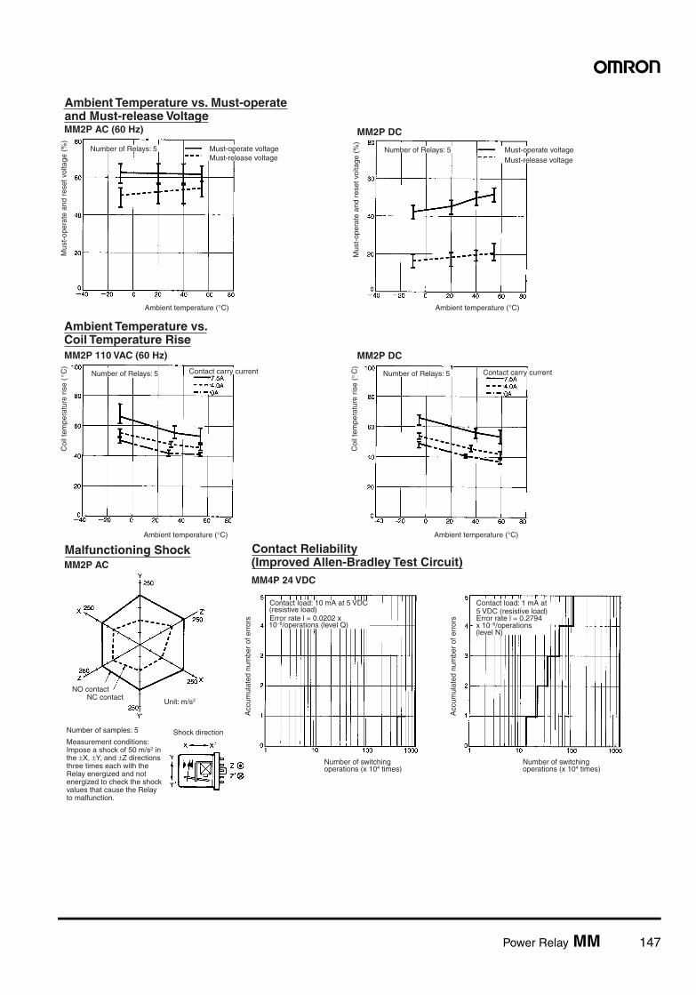
Power Relay MM 147
Ambient Temperature vs. Must-operate and Must-release VoltageMM2P AC (60 Hz) MM2P DC
Ambient Temperature vs. Coil Temperature RiseMM2P 110 VAC (60 Hz) MM2P DC
Malfunctioning ShockMM2P AC
Contact Reliability(Improved Allen-Bradley Test Circuit)MM4P 24 VDC
Mus
t-op
erat
e an
d re
set v
olta
ge (
%)
Number of Relays: 5
Ambient temperature (°C)
Mus
t-op
erat
e an
d re
set v
olta
ge (
%)
Number of Relays: 5 Must-operate voltageMust-release voltage
Ambient temperature (°C)
Number of Relays: 5
Coi
l tem
pera
ture
ris
e (
C)
° Contact carry current
Ambient temperature (°C)
Coi
l tem
pera
ture
ris
e (
C)
Number of Relays: 5
Ambient temperature (°C)
Contact carry current
NO contactNC contact
Unit: m/s2
Number of samples: 5
Measurement conditions: Impose a shock of 50 m/s2 in the ±X, ±Y, and ±Z directions three times each with the Relay energized and not energized to check the shock values that cause the Relay to malfunction.
Shock direction
Contact load: 10 mA at 5 VDC (resistive load)Error rate l = 0.0202 x 10⁻⁶/operations (level Q)
Number of switching operations (x 104 times)
Contact load: 1 mA at 5 VDC (resistive load)Error rate l = 0.2794 x 10⁻⁶/operations (level N)
Number of switching operations (x 104 times)
Acc
umul
ated
num
ber
of e
rror
s
Acc
umul
ated
num
ber
of e
rror
s
°
Must-operate voltageMust-release voltage
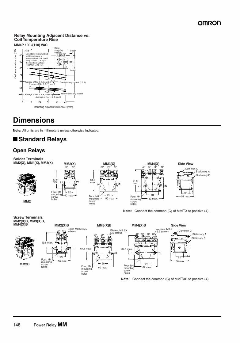
148 Power Relay MM
DimensionsNote: All units are in millimeters unless otherwise indicated.
Standard Relays
Open Relays
Relay Mounting Adjacent Distance vs. Coil Temperature RiseMM4P 100 /(110) VAC
Coi
l tem
pera
ture
ris
e (
C)
°
Condition: The saturated coil temperature is measured with the rated carry current (7.5 A) at the rated coil voltage (100 VAC at 50 Hz).
Relay mounting position
Upper
Lower
Average of No. 2, 4, 6, and 8Average of No. 1, 3, 7, and 9
Contact carry current (7.5 A)
No contact carry current
Mounting adjacent distance l (mm)
Average of No. 2, 4, 6, and 8Average of No. 1, 3, 7, and 9
Four, M4 mounting screw holes
Solder TerminalsMM2(X), MM4(X), MM3(X) MM2(X)
2240 max.
53.5 max.
MM3(X)
61.5 max.
2850 max.
Four, M4 mounting screw holes
MM4(X)
61.5 max.
3463 max.
Four, M4 mounting screw holes
Side View
1322
51 max.
Common CStationary AStationary B
MM2
Note: Connect the common (C) of MM@X to positive (+).
3P 2P2P 1P 1P 3P 2P 1P4P
Four, M4 mounting screw holes
Four, M4 mounting screw holes
Screw Terminals MM2(X)B, MM3(X)B, MM4(X)B
59.5 max.
MM2(X)B
22
55 max.
Eight, M3.5 x 5.5 screws
MM3(X)B
67.5 max.
28
60 max.
Eleven, M3.5 x 5.5 screws
67.5 max.
3467 max.
Side View
18.522
56 max.MM2B
MM4(X)BFourteen, M3.5 x 5.5 screws Common C
Stationary A
Stationary B
Note: Connect the common (C) of MM@XB to positive (+).
3P 2P
2P 1P
1P 3P 2P 1P4P
Four, M4 mounting screw holes
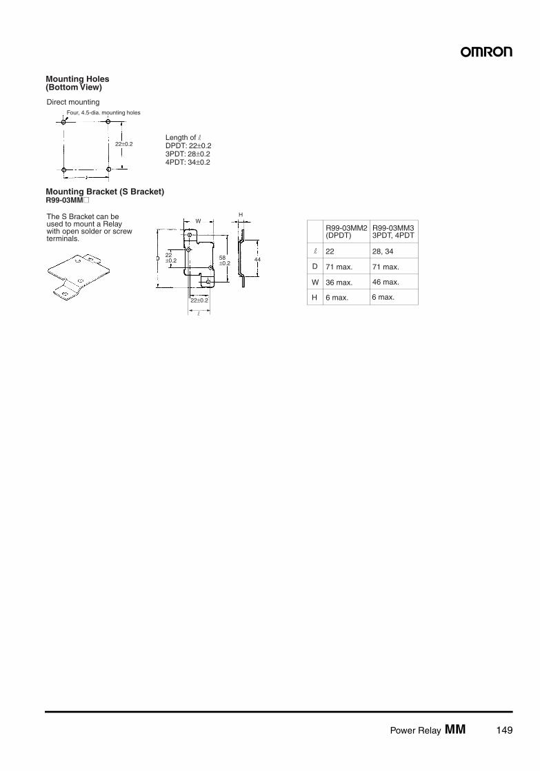
Power Relay MM 149
Mounting Holes(Bottom View)
Direct mountingFour, 4.5-dia. mounting holes
22±0.2Length of l DPDT: 22±0.2 3PDT: 28±0.2 4PDT: 34±0.2
22±0.2
Mounting Bracket (S Bracket) R99-03MM@
The S Bracket can be used to mount a Relay with open solder or screw terminals.
W
22 ±0.2 58
±0.244
H
D
W
H
R99-03MM2(DPDT)
22
71 max.
36 max.
6 max.
R99-03MM33PDT, 4PDT
28, 34
71 max.
46 max.
6 max.
l
l
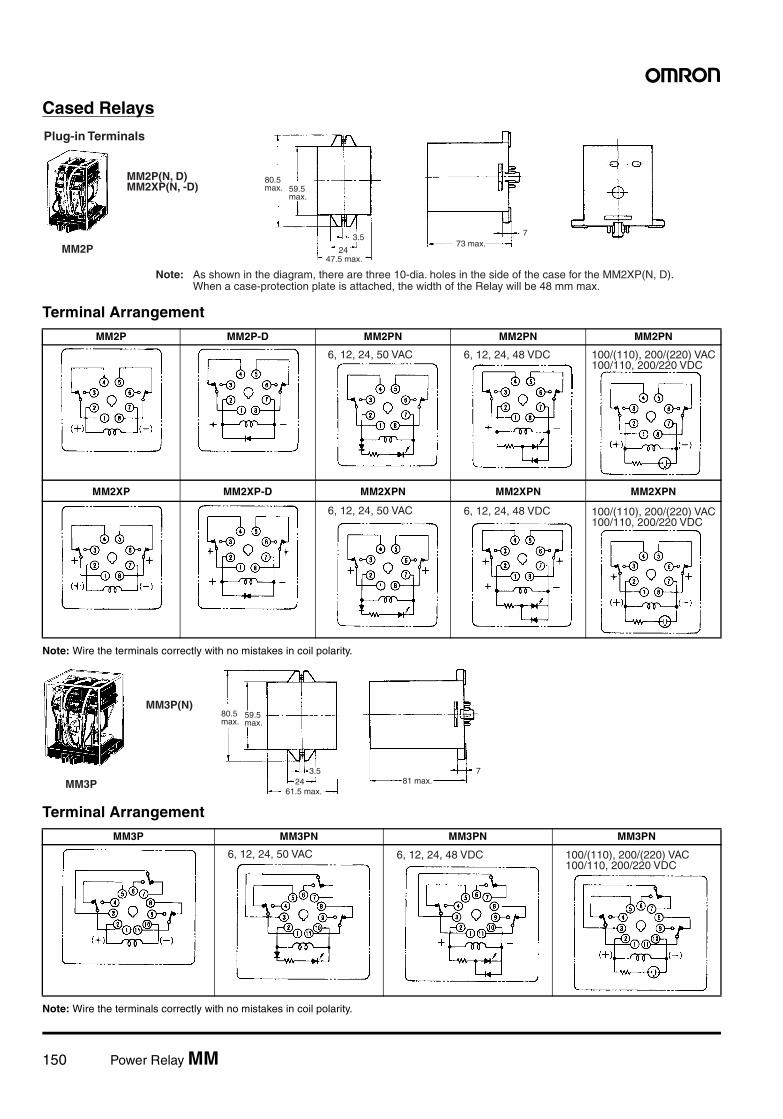
150 Power Relay MM
Cased Relays
Terminal Arrangement
Note: Wire the terminals correctly with no mistakes in coil polarity.
Terminal Arrangement
Note: Wire the terminals correctly with no mistakes in coil polarity.
Plug-in Terminals
80.5 max. 59.5
max.
3.5
24
773 max.
47.5 max.
MM2P(N, D)MM2XP(N, -D)
MM2P
Note: As shown in the diagram, there are three 10-dia. holes in the side of the case for the MM2XP(N, D). When a case-protection plate is attached, the width of the Relay will be 48 mm max.
MM2P MM2P-D MM2PN MM2PN MM2PN
MM2XP MM2XP-D MM2XPN MM2XPN MM2XPN
6, 12, 24, 50 VAC 6, 12, 24, 48 VDC 100/(110), 200/(220) VAC100/110, 200/220 VDC
6, 12, 24, 50 VAC 6, 12, 24, 48 VDC 100/(110), 200/(220) VAC100/110, 200/220 VDC
MM3P
80.5 max.
59.5 max.
3.524
61.5 max.
781 max.
MM3P(N)
MM3P MM3PN MM3PN MM3PN
6, 12, 24, 50 VAC 6, 12, 24, 48 VDC 100/(110), 200/(220) VAC100/110, 200/220 VDC
Power Relay MM 151
Terminal Arrangement
Note: Wire the terminals correctly with no mistakes in coil polarity.
MM4P
80.5max. 59.5
max.
3.524
79.5 max.
81.5 max.7
MM3PXP(N)MM4P(N, -D)MM4XP(N, -D)
Note: As shown in the diagram, there are three 10-dia. holes in the side of the case for MM@XP(N, D). When a case-protection plate is attached, the width of the Relay will be 80 mm max.
MM3XP MM3XPN MM3XPN MM3XPN
MM4P MM4P-D MM4PN MM4PN MM4PN
MM4XP MM4XP-D MM4XPN MM4XPN MM4XPN
6, 12, 24, 50 VAC 6, 12, 24, 48 VDC 100/(110), 200/(220) VAC100/110, 200/220 VDC
6, 12, 24, 50 VAC 6, 12, 24, 48 VDC 100/(110), 200/(220) VAC100/110, 200/220 VDC
6, 12, 24, 50 VAC 6, 12, 24, 48 VDC 100/(110), 200/(220) VAC100/110, 200/220 VDC
152 Power Relay MM
Relays with Operation IndicatorsDimensions are the same as those for standard Relays except that there are three 10-mm holes in the case as shown below.
Accessories
SocketsRelay model DIN Track/Front-connecting Socket
(screw terminals)Back-connecting Socket
(solder terminals)
MM2(X)P(-D) 8PFA PL08
MM3P
MM3XP, MM4(X)P(-D) 14PFA PL15
MM4(X)P-JD 14PFA ---
MM4P-JD
70.5 max.59.5 max.
79.5 max.81.5 max.
Terminal Arrangement
MM4XP-JD
70.5 max.
59.5 max.
81.5 max.Note: Make sure that all common connections are the same in polarity. The markings of the common connections on the casing all show "+" but the polarity of the com- mon connections can be either all nega- tive or all positive.
80 max.
11PFA PL11
In the interest of product improvement, specifications are subject to change without notice.
ALL DIMENSIONS SHOWN ARE IN MILLIMETERS.
To convert millimeters into inches, multiply by 0.03937. To convert grams into ounces, multiply by 0.03527.
Cat. No. J031-E1-08
Power Relay MM 153
Mounting Height of Relay with Connecting Socket
PrecautionsRefer to page 11 for general precautions.
Connection• Use proper crimp terminals or 1.2- to 2-dia. single-conductor wire
to connect screw terminals.• Connect loads to DC-switching Relays so that arcs from adjacent
terminals will not strike each other. E.g., connect all common termi-nals to the same polarity.
• Screw Terminal Model:Do not bend the coil terminals, otherwise the coil wire may be dis-connected. Make sure that the tightening torque applied to eachterminal is 1.27 N • m and the insertion force is 49 N for 10 s.
• Do not reverse polarity when connecting open DC-switchingRelays, including 3- and 4-pole models.
Installation• Do not install the Relays where iron dust can adhere to the con-
tacts or coil. Such dust can prevent the armature from movingfreely and inhibit proper electrical contact.
• Relays can generate arcs externally. Either install the Relay in alocation where a nearby object will not burn or use a coveredRelay.
• DC-switching Relays contain a permanent magnet in the insulationbase. Do not place a magnet or magnetic object near this base.Doing so will reduce the power of the permanent magnet, thusreducing Relay capacity.
• Insert PL Back-mounting Sockets from the back of the panel.• Separate Relays from each other by at least 20 mm when mount-
ing multiple Relays together.• Relays should be mounted with the armature facing down.
WiringWhen connecting a load to the contact terminals of a model for DCloads, consider the polarity of the contact terminals so that the gen-erated arcs on the adjacent poles will not collide. If the common con-nections of the Relay are all positive or all negative, no arc collisionwill occur.
MMXPThe MMXP has a hole in the Relay case to allow gas to escape. Donot use this Relay in locations subject to excessive dust.
Contact LoadsThe contact load should be greater than the power consumption ofthe coil. If it is less than this power consumption or if the Relay isoperated very infrequently, the contact can change chemically thuscausing unstable operation.
SolderingWhen soldering solder terminals, do not let flux or other foreign mat-ter adhere to contacts or do not let the coil terminals become bent.Also, solder as quickly as possible because excessive heat maydamage the coil.
StorageA model for DC loads incorporates a permanent magnetic for arcsuppression. Keep floppy disks away from the Relay, otherwise thedata on the floppy disk may be damaged.
Operating EnvironmentDo not use the Relay in places with flammable gas, otherwise anexplosion may result due to an arc generated from the Relay
DIN Track Mounting
MM2(X)P
8PFA
95.5
PL08
MM2(X)P92
11PFA
MM3P113 109.5
14PFA
MM3XPMM4(X)MM4(X)P-JD
113.5 110
Back Mounting
78
PL11
MM3P86
PL15
MM3XPMM4(X)P86.5
154 Latching Relay MMK
Latching Relay
MMKMechanically Latching Relays Based on the MM Power Relay
• Low power consumption due to mechanical latch for economic operation.
• Relays with mixed coil specifications can be produced (e.g., AC set coil and DC reset coil).
• Operational response fast enough to enable pulse signal power applications.
• Ambient operating temperature: –10°C to 55°C.
Ordering Information
Models Conforming to Auxiliary Power Relay SpecificationsThe MM4KP-JD and MM4XKP-JD satisfy the ratings of auxiliary relays provided in JEC-2500 (1987) standards for power protective relays specifiedby the Japan Electromechanical Commission. Furthermore, the MM4KP-JD and MM4XKP-JD satisfy the ratings of multi-contact relays providedin JEC-174D (1979) standards for power auxiliary relays.
These models work at operation level A specified by JEC-174D (1979) standards and the hot start of the relays is possible after the coils radiateheat.
In accordance with JEC-2500 (1987) standards, the coil of each model withstands a 130% DC load or 115% AC load.
Model Number Legend
1. Contact Form2: DPDT3: 3PDT4: 4PDT (open structure type)/
DPDT+DPST-NO (cased type)2. Type (see note)
None: StandardX: DC-switching
3. Terminal ShapeNone: SolderB: ScrewP: Plug-in
Note: The suffix “JD” indicates models conforming to auxiliary powerrelay specifications.
Type Contact form Open structure Cased
Solder terminals Screw terminals Plug-in (octal pins) terminals
Standard DPDT MM2K MM2KB MM2KP
3PDT MM3K MM3KB MM3KP
4PDT MM4K MM4KB ---
DPDT+DPST-NO --- --- MM4KP
DC-switching DPDT MM2XK MM2XKB MM2XKP
3PDT MM3XK MM3XKB MM3XKP
4PDT MM4XK MM4XKB ---
DPDT+DPST-NO --- --- MM4XKP
Conforming to auxiliary power relay specifications
DPDT+DPST-NO --- --- MM4KP-JDMM4XKP-JD
Rated coil voltage
Note: When ordering, add the rated coil voltage to the model number. Rated coil voltages are given in the coil ratings table. Example: MM2K, 6 VAC
MM@@K@1 2 3
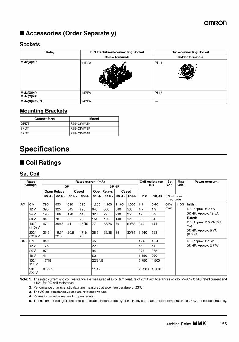
Latching Relay MMK 155
Accessories (Order Separately)
Sockets
Mounting Brackets
Specifications
Coil Ratings
Set Coil
Note: 1. The rated current and coil resistance are measured at a coil temperature of 23°C with tolerances of +15%/–20% for AC rated current and±15% for DC coil resistance.
2. Performance characteristic data are measured at a coil temperature of 23°C.3. The AC coil resistance values are reference values.4. Values in parentheses are for open relays.5. The maximum voltage is one that is applicable instantaneously to the Relay coil at an ambient temperature of 23°C and not continuously.
Relay DIN Track/Front-connecting Socket Back-connecting Socket
Screw terminals Solder terminals
MM2(X)KP
MM3(X)KPMM4(X)KP
14PFA PL15
MM4(X)KP-JD 14PFA ---
11PFA PL11
Contact form Model
DPDT R99-03MM2K
3PDT R99-03MM3K
4PDT R99-03MM4K
Rated voltage
Rated current (mA) Coil resistance (Ω)
Set volt.
Max volt.
Power consum.
DP 3P, 4P
Open Relays Cased Open Relays Cased
50 Hz 60 Hz 50 Hz 60 Hz 50 Hz 60 Hz 50 Hz 60 Hz DP 3P, 4P % of rated voltage
AC 6 V 790 655 690 590 1,285 1,100 1,165 1,000 1.1 0.46 80% max.
110% Initial: DP: Approx. 6.2 VA3P, 4P: Approx. 12 VARated:DP: Approx. 3.5 VA (3.9 VA)3P, 4P: Approx. 6 VA (6.6 VA)
12 V 395 325 345 295 640 550 580 500 4.7 1.9
24 V 195 160 170 145 320 275 290 250 19 8.2
50 V 94 78 82 70 154 132 140 120 82 34
100/ (110) V
47 39/45 41 35/40 77 66/76 70 60/68 340 141
200/ (220) V
23.5 19.5/22.5
20.5 17.5/20
38.5 33/38 35 30/34 1,540 563
DC 6 V 340 450 17.5 13.4 DP: Approx. 2.1 W3P, 4P: Approx. 2.7 W12 V 176 220 68 54
24 V 87 94 275 255
48 V 41 52 1,180 930
100/110 V
17/19 22/24.5 5,750 4,500
200/220 V
8.6/9.5 11/12 23,200 18,000
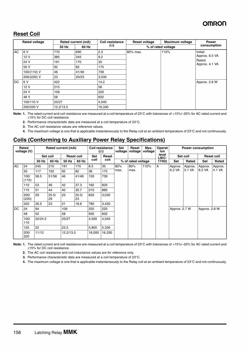
156 Latching Relay MMK
Reset Coil
Note: 1. The rated current and coil resistance are measured at a coil temperature of 23°C with tolerances of +15%/–20% for AC rated current and±15% for DC coil resistance.
2. Performance characteristic data are measured at a coil temperature of 23°C.3. The AC coil resistance values are reference values.4. The maximum voltage is one that is applicable instantaneously to the Relay coil at an ambient temperature of 23°C and not continuously.
Coils (Conforming to Auxiliary Power Relay Specifications)
Note: 1. The rated current and coil resistance are measured at a coil temperature of 23°C with tolerances of +15%/–20% for AC rated current and±15% for DC coil resistance.
2. The AC coil resistance and coil inductance values are for reference only.3. Performance characteristic data are measured at a coil temperature of 23°C.4. The maximum voltage is one that is applicable instantaneously to the Relay coil at an ambient temperature of 23°C and not continuously.
Rated voltage Rated current (mA) Coil resistance (Ω)
Reset voltage Maximum voltage Power consumption50 Hz 60 Hz % of rated voltage
AC 6 V 770 690 2.3 80% max. 110% Initial: Approx. 6.5 VARated:Approx. 4.1 VA
12 V 385 345 9.2
24 V 191 170 35
50 V 92 82 175
100/(110) V 46 41/46 739
200/(220) V 23 20/23 3,030
DC 6 V 422 14.2 Approx. 2.8 W
12 V 215 56
24 V 109 220
48 V 58 832
100/110 V 25/27 4,040
200/220 V 12.2/13.5 16,330
Rated voltage (V)
Rated current (mA) Coil resistance (Ω)
Set voltage
Reset voltage
Max. voltage
Operation
level (JEC-174D)
Power consumption
Set coil Reset coil Set coil
Reset coil
Set coil Reset coil
50 Hz 60 Hz 50 Hz 60 Hz % of rated voltage Set Rated Set Rated
AC 24 245 210 191 170 8.5 35 80% max.
80% max.
110% A Approx. 6.3 VA
Approx. 5.1 VA
Approx. 6.5 VA
Approx. 4.1 VA50 117 102 92 82 36 175
100/ (110)
58.5 51/58 46 41/46 150 739
110 53 46 42 37.3 182 835
115 51 44 40 35.7 210 885
200/ (220)
29 25.5/ 29
23 20.5/ 23
620 3,030
220 26.5 23 21 18.6 780 3,420
DC 24 94 109 255 220 Approx. 2.7 W Approx. 2.8 W
48 52 58 930 832
100/ 110
22/24.5 25/27 4,500 4,040
125 22 23.5 5,800 5,330
200/ 220
11/12 12.2/13.5 18,000 16,330
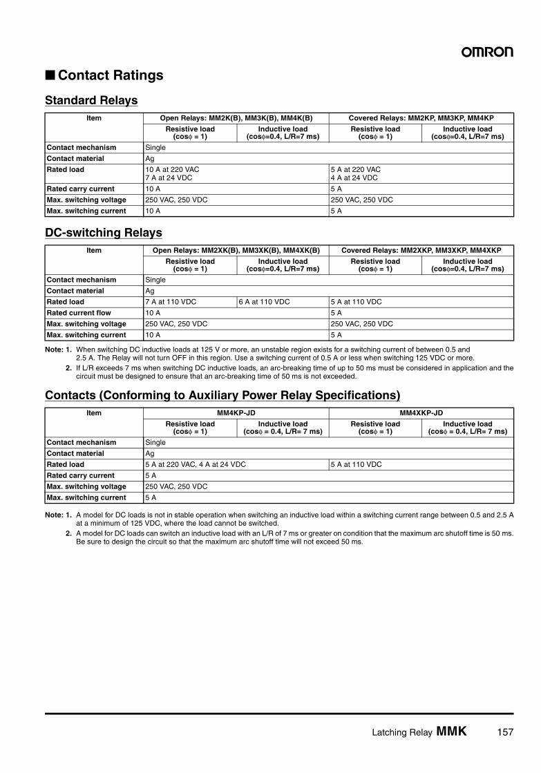
Latching Relay MMK 157
Contact Ratings
Standard Relays
DC-switching Relays
Note: 1. When switching DC inductive loads at 125 V or more, an unstable region exists for a switching current of between 0.5 and 2.5 A. The Relay will not turn OFF in this region. Use a switching current of 0.5 A or less when switching 125 VDC or more.
2. If L/R exceeds 7 ms when switching DC inductive loads, an arc-breaking time of up to 50 ms must be considered in application and thecircuit must be designed to ensure that an arc-breaking time of 50 ms is not exceeded.
Contacts (Conforming to Auxiliary Power Relay Specifications)
Note: 1. A model for DC loads is not in stable operation when switching an inductive load within a switching current range between 0.5 and 2.5 Aat a minimum of 125 VDC, where the load cannot be switched.
2. A model for DC loads can switch an inductive load with an L/R of 7 ms or greater on condition that the maximum arc shutoff time is 50 ms.Be sure to design the circuit so that the maximum arc shutoff time will not exceed 50 ms.
Item Open Relays: MM2K(B), MM3K(B), MM4K(B) Covered Relays: MM2KP, MM3KP, MM4KP
Resistive load (cosφ = 1)
Inductive load (cosφ=0.4, L/R=7 ms)
Resistive load (cosφ = 1)
Inductive load (cosφ=0.4, L/R=7 ms)
Contact mechanism Single
Contact material Ag
Rated load 10 A at 220 VAC7 A at 24 VDC
5 A at 220 VAC 4 A at 24 VDC
Rated carry current 10 A 5 A
Max. switching voltage 250 VAC, 250 VDC 250 VAC, 250 VDC
Max. switching current 10 A 5 A
Item Open Relays: MM2XK(B), MM3XK(B), MM4XK(B) Covered Relays: MM2XKP, MM3XKP, MM4XKP
Resistive load (cosφ = 1)
Inductive load (cosφ=0.4, L/R=7 ms)
Resistive load (cosφ = 1)
Inductive load (cosφ=0.4, L/R=7 ms)
Contact mechanism Single
Contact material Ag
Rated load 7 A at 110 VDC 6 A at 110 VDC 5 A at 110 VDC
Rated current flow 10 A 5 A
Max. switching voltage 250 VAC, 250 VDC 250 VAC, 250 VDC
Max. switching current 10 A 5 A
Item MM4KP-JD MM4XKP-JD
Resistive load (cosφ = 1)
Inductive load(cosφ = 0.4, L/R= 7 ms)
Resistive load (cosφ = 1)
Inductive load(cosφ = 0.4, L/R= 7 ms)
Contact mechanism Single
Contact material Ag
Rated load 5 A at 220 VAC, 4 A at 24 VDC 5 A at 110 VDC
Rated carry current 5 A
Max. switching voltage 250 VAC, 250 VDC
Max. switching current 5 A
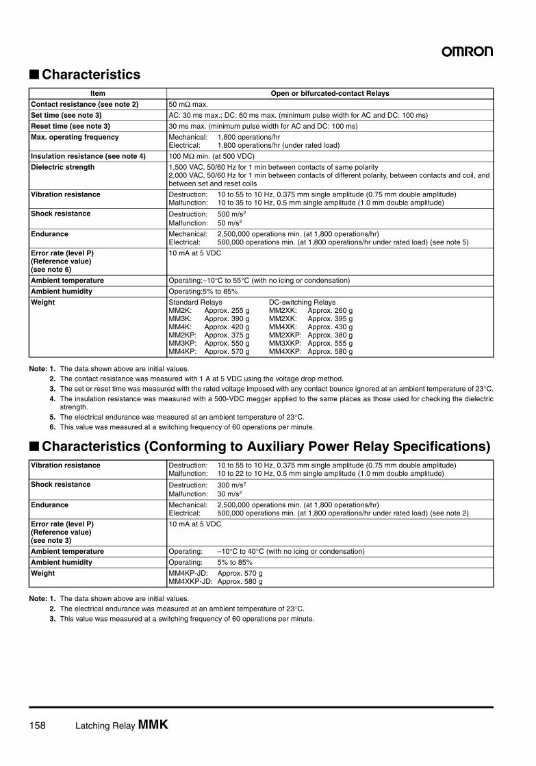
158 Latching Relay MMK
Characteristics
Note: 1. The data shown above are initial values.2. The contact resistance was measured with 1 A at 5 VDC using the voltage drop method.3. The set or reset time was measured with the rated voltage imposed with any contact bounce ignored at an ambient temperature of 23°C.4. The insulation resistance was measured with a 500-VDC megger applied to the same places as those used for checking the dielectric
strength.5. The electrical endurance was measured at an ambient temperature of 23°C.6. This value was measured at a switching frequency of 60 operations per minute.
Characteristics (Conforming to Auxiliary Power Relay Specifications)
Note: 1. The data shown above are initial values.2. The electrical endurance was measured at an ambient temperature of 23°C.3. This value was measured at a switching frequency of 60 operations per minute.
Item Open or bifurcated-contact Relays
Contact resistance (see note 2) 50 mΩ max.
Set time (see note 3) AC: 30 ms max.; DC: 60 ms max. (minimum pulse width for AC and DC: 100 ms)
Reset time (see note 3) 30 ms max. (minimum pulse width for AC and DC: 100 ms)
Max. operating frequency Mechanical: 1,800 operations/hrElectrical: 1,800 operations/hr (under rated load)
Insulation resistance (see note 4) 100 MΩ min. (at 500 VDC)
Dielectric strength 1,500 VAC, 50/60 Hz for 1 min between contacts of same polarity2,000 VAC, 50/60 Hz for 1 min between contacts of different polarity, between contacts and coil, and between set and reset coils
Vibration resistance Destruction: 10 to 55 to 10 Hz, 0.375 mm single amplitude (0.75 mm double amplitude)Malfunction: 10 to 35 to 10 Hz, 0.5 mm single amplitude (1.0 mm double amplitude)
Shock resistance Destruction: 500 m/s2
Malfunction: 50 m/s2
Endurance Mechanical: 2,500,000 operations min. (at 1,800 operations/hr)Electrical: 500,000 operations min. (at 1,800 operations/hr under rated load) (see note 5)
Error rate (level P)(Reference value)(see note 6)
10 mA at 5 VDC
Ambient temperature Operating:–10°C to 55°C (with no icing or condensation)
Ambient humidity Operating:5% to 85%
Weight Standard Relays DC-switching RelaysMM2K: Approx. 255 g MM2XK: Approx. 260 gMM3K: Approx. 390 g MM2XK: Approx. 395 gMM4K: Approx. 420 g MM4XK: Approx. 430 gMM2KP: Approx. 375 g MM2XKP: Approx. 380 gMM3KP: Approx. 550 g MM3XKP: Approx. 555 gMM4KP: Approx. 570 g MM4XKP: Approx. 580 g
Vibration resistance Destruction: 10 to 55 to 10 Hz, 0.375 mm single amplitude (0.75 mm double amplitude)Malfunction: 10 to 22 to 10 Hz, 0.5 mm single amplitude (1.0 mm double amplitude)
Shock resistance Destruction: 300 m/s2
Malfunction: 30 m/s2
Endurance Mechanical: 2,500,000 operations min. (at 1,800 operations/hr)Electrical: 500,000 operations min. (at 1,800 operations/hr under rated load) (see note 2)
Error rate (level P)(Reference value)(see note 3)
10 mA at 5 VDC
Ambient temperature Operating: –10°C to 40°C (with no icing or condensation)
Ambient humidity Operating: 5% to 85%
Weight MM4KP-JD: Approx. 570 gMM4XKP-JD: Approx. 580 g
Latching Relay MMK 159
Engineering Data
Standard Relays
DC-switching Relays
Maximum Switching PowerOpen Relays
Switching voltage (V)
Cased Relays
Sw
itchi
ng c
urre
nt (
A)
Sw
itchi
ng c
urre
nt (
A)AC resistive load
DC resistive load
DC inductive load (L/R = 7 ms)
AC inductive load(cosφ = 0.4)
Switching current (A)
AC resistive load
AC inductive load(cosφ = 0.4)
DC resistive load
DC inductive load (L/R = 7 ms)
MM@K(B) MM@KP
EnduranceOpen Relays Cased Relays
Switching current (A)
220 VAC resistive loadInductive load(cosφ = 0.4)
24 VDC resistive loadInductive load L/R = 7 ms
Switching current (A)
220 VAC resistive loadInductive load(cosφ = 0.4)
24 VDC resistive loadInductive load L/R = 7 ms
10,000
1,000
500
300
5,000
3,000
End
uran
ce (
x10
ope
ratio
ns)
3
End
uran
ce (
x10
ope
ratio
ns)
3
10,000
1,000
500
300
5,000
3,000
MM@K(B) MM@KP
Maximum Switching PowerOpen Relays
Switching voltage (V)
Cased Relays
Switching voltage (V)
DC inductive loadL/R=7 ms
DC resistive load
DC inductive loadL/R=7 ms
DC resistive load
MM@XK(B) MM@XKP
Sw
itchi
ng c
urre
nt (
A)
Sw
itchi
ng c
urre
nt (
A)
160 Latching Relay MMK
Relays Conforming to Auxiliary Power Relay Specifications
EnduranceOpen Relays
Cased Relays
Switching current (A)Switching current (A)
110 VDC resistive load
110 VDC inductive load(L/R 7 ms)
110 VDC resistive load Inductive loadL/R=7 ms
End
uran
ce (
x10
ope
ratio
ns)
3
10,000
1,000
500
300
5,000
3,000
End
uran
ce (
x10
ope
ratio
ns)
3
10,000
1,000
500
300
5,000
3,000
MM@XK(B) MM@XKP
Maximum Switching PowerMM4KP-JD MMX4KP-JD
Endurance CurveMM4KP-JD MM4XKP-JD
AC resistive loadAC inductive loadcosφ = 0.4
DC resistive load
DC inductive loadL/R = 7 ms
Switching voltage (V)
DC resistive load
DC inductive load L/R = 7 ms
Switching voltage (V)
End
uran
ce (
x 10
)4
220 VAC resistive loadInductive loadcosφ = 0.4
24 VDC resistive load Inductive loadL/R = 7 ms
Switching current (A)
End
uran
ce (
x 10
)4
110 VDC resistive load Inductive loadL/R = 7 ms
Switching current (A)
Sw
itchi
ng c
urre
nt (
A)
Sw
itchi
ng c
urre
nt (
A)
Latching Relay MMK 161
Ambient Temperature vs. Set and Reset VoltageMM4KP AC (60 Hz)
Ambient Temperature vs. Coil Temperature RiseMM4KP 110 VAC (60 Hz)
Malfunctioning Shock
MM4(X)KP
MM4KP DC MM4KP DC
Mus
t-op
erat
e an
d re
set v
olta
ge (
%)
Number of Relays: 5 Set voltageReset voltage
Ambient temperature (°C)
Coi
l tem
pera
ture
ris
e (
C)
° Number of Relays: 5
Contact carry currentSet coilReset coil
Ambient temperature (°C)
Reset60 min.
60 min. 60 min.
60 min.
60 min.
60 min.
Unit: m/s2
Number of samples: 3
Measurement conditions: Impose a shock of 50 m/s2 in the ±X, ±Y, and ±Z directions three times each with the Relay energized and not energized to check the shock values that cause the Relay to malfunction.
Mus
t-op
erat
e an
d re
set v
olta
ge (
%)
Number of Relays: 5 Set voltageReset voltage
Ambient temperature (°C)
Coi
l tem
pera
ture
ris
e (
C)
Number of Relays: 5
Contact carry currentSet coilReset coil
Ambient temperature (°C)
Shock direction
°
162 Latching Relay MMK
DimensionsNote: All units are in millimeters unless otherwise indicated.
Open Relays with Solder Terminals
Open Relays with Screw Terminals
86 max.
44 max.28±0.2
50 max.
94 max.
29±0.234
±0.2
MM2(X)K, MM3(X)K, MM4(X)K
MM2(X)K MM3(X)K
94 max.
63 max.
MM4(X)K
MM2K
15 max.
Two, M4 mounting holes
58.5 max.
Side View
2P 1P 3P 1P2P 4P 2P3P 1P Common C
Stationary A
Stationary B
Set coil
Reset coil
Note: Connect the common (C) of MM@XK to positive (+).
±0.222
22±0.2
MM2(X)KB, MM3(X)KB, MM4(X)KB
MM2KB
92 max.
Ten, M3.5 x 5.5 terminal screws
60 max.
MM2(X)KB
Thirteen,M3.5 x 5.5 terminal screws
101 max.
28±0.2
MM3(X)KB
Sixteen, M3.5 x 5.5 terminal screws
68 max.
34±0.2
101 max.
MM4(X)KB
15 max.
Two, M4 mounting holes
58.5 max.
29±0.2
Side View
60 max.
2P 1P 2P 1P3P 2P 1P3P4P Common C
Station-ary AStation-ary BSet coil
Reset coil
Note: Connect the common (C) of MM@XKB to positive (+).
Mounting Holes (Direct Mounting)Note: The tolerance is ±0.2.
Two, 4.5-dia. mounting holes
29±0.2Dimensions of : l2-pole: 22±0.2 mm3-pole: 28±0.2 mm4-pole: 34±0.2 mm
l
Mounting Bracket (S Bracket)R99-03MM ( )K
The S Bracket can be used to mount a Relay with open solder or screw terminals.
W H
29±0.2 60±0.2 50D
l
Item R99-03MM2K (DPDT)
R99-03MM3K (3PDT)
R99-03MM4K (4PDT)
l 22±0.2 28±0.2 34±0.2
D 71 max. 71 max. 71 max.
W 33 max. 39 max. 45 max.
H 6 max. 6 max. 6 max.
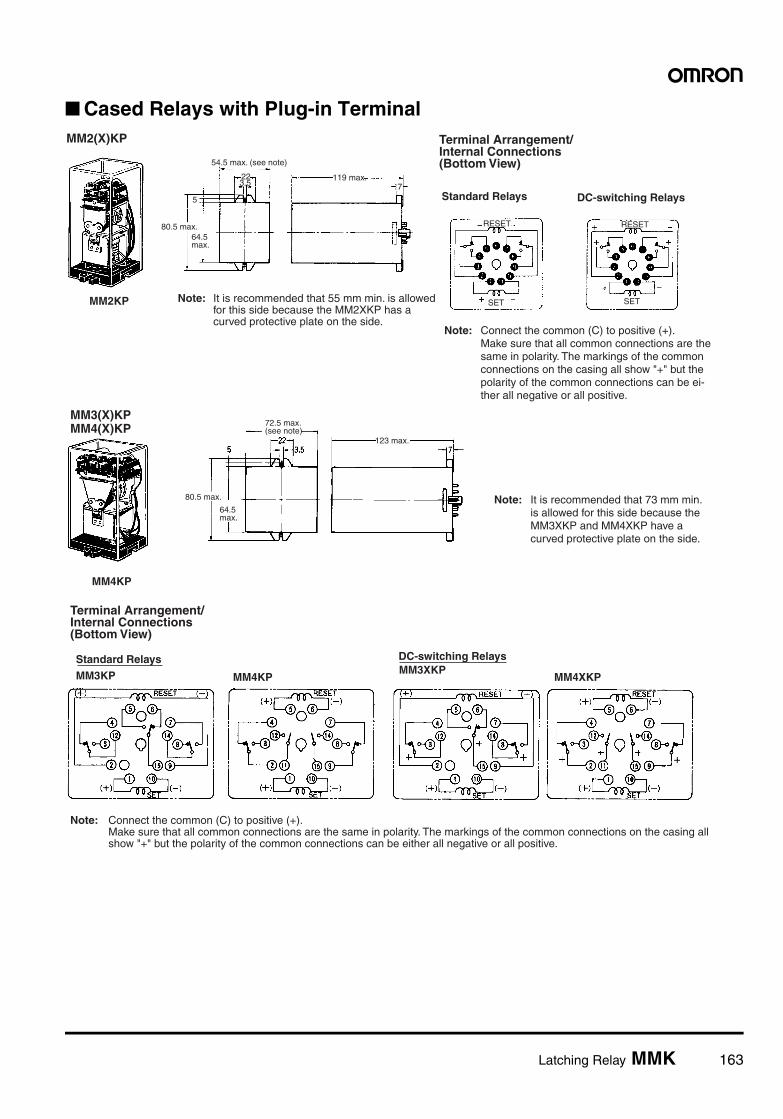
Latching Relay MMK 163
Cased Relays with Plug-in Terminal
80.5 max.
Terminal Arrangement/Internal Connections (Bottom View)
Note: Connect the common (C) to positive (+). Make sure that all common connections are the same in polarity. The markings of the common connections on the casing all show "+" but the polarity of the common connections can be ei- ther all negative or all positive.
Standard Relays DC-switching Relays
MM2(X)KP
22
54.5 max. (see note)
119 max.
64.5 max.
3.5 7
MM2KP
5
RESET
SET
RESET
SETNote: It is recommended that 55 mm min. is allowed for this side because the MM2XKP has a curved protective plate on the side.
80.5 max.
Terminal Arrangement/Internal Connections (Bottom View)
Note: Connect the common (C) to positive (+). Make sure that all common connections are the same in polarity. The markings of the common connections on the casing all show "+" but the polarity of the common connections can be either all negative or all positive.
Standard Relays
MM3KP
DC-switching RelaysMM3XKP
MM3(X)KPMM4(X)KP 72.5 max.
(see note)123 max.
64.5 max.
MM4KP
MM4KP MM4XKP
Note: It is recommended that 73 mm min. is allowed for this side because the MM3XKP and MM4XKP have a curved protective plate on the side.
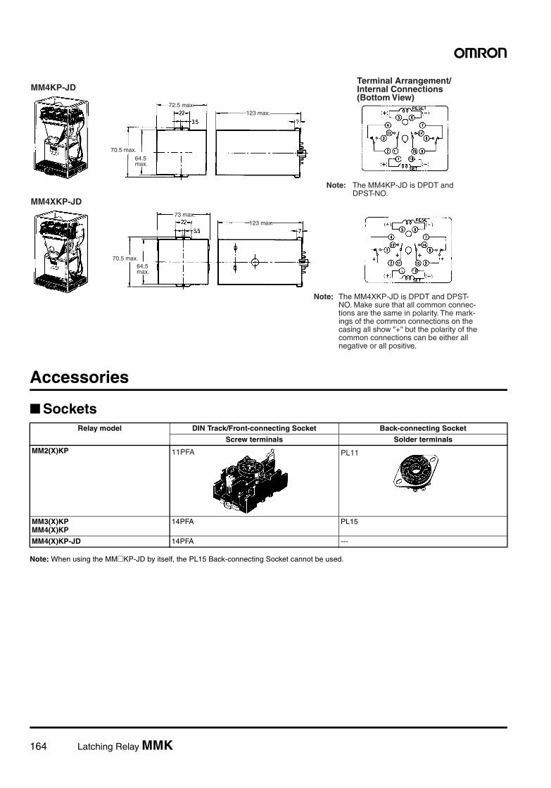
164 Latching Relay MMK
Accessories
Sockets
Note: When using the MM@KP-JD by itself, the PL15 Back-connecting Socket cannot be used.
Relay model DIN Track/Front-connecting Socket Back-connecting Socket
Screw terminals Solder terminals
MM2(X)KP
MM3(X)KPMM4(X)KP
14PFA PL15
MM4(X)KP-JD 14PFA ---
MM4KP-JD
70.5 max.
72.5 max.123 max.
64.5 max.
Terminal Arrangement/Internal Connections (Bottom View)
Note: The MM4KP-JD is DPDT and DPST-NO.
MM4XKP-JD
70.5 max.
73 max.123 max.
64.5 max.
Note: The MM4XKP-JD is DPDT and DPST- NO. Make sure that all common connec- tions are the same in polarity. The mark- ings of the common connections on the casing all show "+" but the polarity of the common connections can be either all negative or all positive.
11PFA PL11
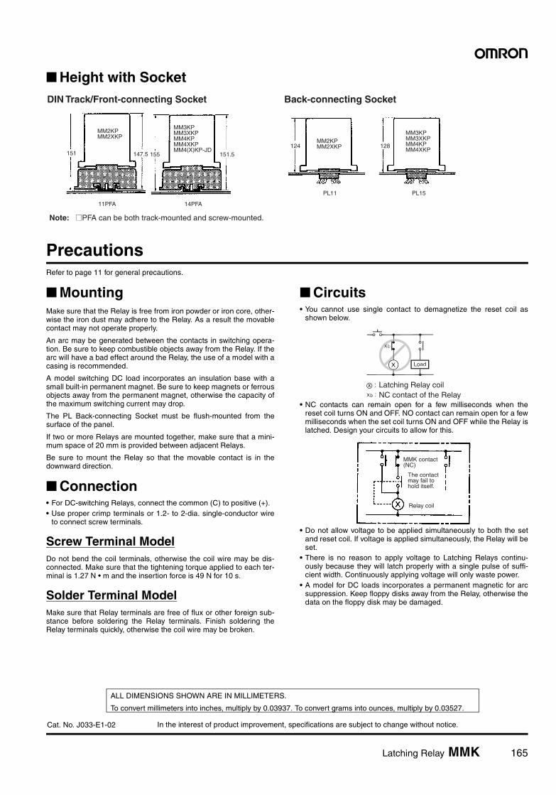
In the interest of product improvement, specifications are subject to change without notice.
ALL DIMENSIONS SHOWN ARE IN MILLIMETERS.
To convert millimeters into inches, multiply by 0.03937. To convert grams into ounces, multiply by 0.03527.
Cat. No. J033-E1-02
Latching Relay MMK 165
Height with Socket
PrecautionsRefer to page 11 for general precautions.
MountingMake sure that the Relay is free from iron powder or iron core, other-wise the iron dust may adhere to the Relay. As a result the movablecontact may not operate properly.
An arc may be generated between the contacts in switching opera-tion. Be sure to keep combustible objects away from the Relay. If thearc will have a bad effect around the Relay, the use of a model with acasing is recommended.
A model switching DC load incorporates an insulation base with asmall built-in permanent magnet. Be sure to keep magnets or ferrousobjects away from the permanent magnet, otherwise the capacity ofthe maximum switching current may drop.
The PL Back-connecting Socket must be flush-mounted from thesurface of the panel.
If two or more Relays are mounted together, make sure that a mini-mum space of 20 mm is provided between adjacent Relays.
Be sure to mount the Relay so that the movable contact is in thedownward direction.
Connection• For DC-switching Relays, connect the common (C) to positive (+).• Use proper crimp terminals or 1.2- to 2-dia. single-conductor wire
to connect screw terminals.
Screw Terminal ModelDo not bend the coil terminals, otherwise the coil wire may be dis-connected. Make sure that the tightening torque applied to each ter-minal is 1.27 N • m and the insertion force is 49 N for 10 s.
Solder Terminal ModelMake sure that Relay terminals are free of flux or other foreign sub-stance before soldering the Relay terminals. Finish soldering theRelay terminals quickly, otherwise the coil wire may be broken.
Circuits• You cannot use single contact to demagnetize the reset coil as
shown below.
• NC contacts can remain open for a few milliseconds when thereset coil turns ON and OFF. NO contact can remain open for a fewmilliseconds when the set coil turns ON and OFF while the Relay islatched. Design your circuits to allow for this.
• Do not allow voltage to be applied simultaneously to both the setand reset coil. If voltage is applied simultaneously, the Relay will beset.
• There is no reason to apply voltage to Latching Relays continu-ously because they will latch properly with a single pulse of suffi-cient width. Continuously applying voltage will only waste power.
• A model for DC loads incorporates a permanent magnetic for arcsuppression. Keep floppy disks away from the Relay, otherwise thedata on the floppy disk may be damaged.
MM3KP MM3XKP MM4KP MM4XKPMM4(X)KP-JD
151.5
MM2KP MM2XKP
151
11PFA 14PFA
155147.5
DIN Track/Front-connecting Socket Back-connecting Socket
PL11 PL15
124 128MM2KP MM2XKP
MM3KP MM3XKP MM4KP MM4XKP
Note: @PFA can be both track-mounted and screw-mounted.
Latching Relay coilNC contact of the Relay
Load
MMK contact (NC)
The contact may fail to hold itself.
Relay coil
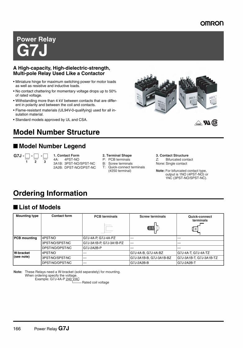
166 Power Relay G7J
Power Relay
G7JA High-capacity, High-dielectric-strength, Multi-pole Relay Used Like a Contactor
• Miniature hinge for maximum switching power for motor loads as well as resistive and inductive loads.
• No contact chattering for momentary voltage drops up to 50% of rated voltage.
• Withstanding more than 4 kV between contacts that are differ-ent in polarity and between the coil and contacts.
• Flame-resistant materials (UL94V-0-qualifying) used for all in-sulation material.
• Standard models approved by UL and CSA.
Model Number Structure
Model Number Legend
Ordering Information
List of Models
1 2 3
G7J - - - 1. Contact Form 4A: 4PST-NO 3A1B: 3PST-NO/SPST-NC 2A2B: DPST-NO/DPST-NC
2. Terminal Shape P: PCB terminals B: Screw terminals T: Quick-connect terminals (#250 terminal)
3. Contact Structure Z: Bifurcated contact None: Single contact
Note: For bifurcated contact type, output is 1NO (4PST-NO) or 1NC (3PST-NO/SPST-NC).
Mounting type Contact form
PCB mounting 4PST-NO G7J-4A-P, G7J-4A-PZ --- ---
3PST-NO/SPST-NC G7J-3A1B-P, G7J-3A1B-PZ --- ---
DPST-NO/DPST-NC G7J-2A2B-P --- ---
W-bracket(see note)
4PST-NO --- G7J-4A-B, G7J-4A-BZ G7J-4A-T, G7J-4A-TZ
3PST-NO/SPST-NC --- G7J-3A1B-B, G7J-3A1B-BZ G7J-3A1B-T, G7J-3A1B-TZ
DPST-NO/DPST-NC --- G7J-2A2B-B G7J-2A2B-T
PCB terminals Screw terminals Quick-connect terminals
Note: These Relays need a W-bracket (sold separately) for mounting. When ordering specify the voltage.
Example: G7J-4A-P 240 VACRated coil voltage
Power Relay G7J 167
PCB Terminals
PCB Terminals (Bifurcated Contact)
W-bracket Screw Terminals
Screw Terminals (Bifurcated Contact)
Tab Terminals
Tab Terminals (Bifurcated Contact)
Consult your OMRON representative for details on models not men-tioned in this document.
Accessories (Order Separately)
Application Examples• Compressors for air conditioners and heater switching controllers.• Switching controllers for power tools or motors.• Lamp controls, motor drivers, and power supply switching control-
lers in copy machines, facsimile machines, and other office equip-ment.
• Power controllers for packers or food processing equipment.• Power controllers for inverters.
Contact form Rated voltage (V) Model
4PST-NO 24, 50, 100 to 120, 200 to 240 VAC
G7J-4A-P
12, 24, 48, 100 VDC
3PST-NO/SPST-NC
24, 50, 100 to 120, 200 to 240 VAC
G7J-3A1B-P
12, 24, 48, 100 VDC
DPST-NO/DPST-NC
24, 50, 100 to 120, 200 to 240 VAC
G7J-2A2B-P
12, 24, 48, 100 VDC
Contact form Rated voltage (V) Model
4PST-NO 200 to 240 VAC 24 VDC
G7J-4A-PZ
3PST-NO/SPST-NC
12, 24 VDC G7J-3A1B-PZ
Contact form Rated voltage (V) Model
4PST-NO 24, 50, 100 to 120, 200 to 240 VAC
G7J-4A-B
12, 24, 48, 100 VDC
3PST-NO/SPST-NC
24, 50, 100 to 120, 200 to 240 VAC
G7J-3A1B-B
12, 24, 48, 100 VDC
DPST-NO/DPST-NC
24, 50, 100 to 120, 200 to 240 VAC
G7J-2A2B-B
12, 24, 48, 100 VDC
Contact form Rated voltage (V) Model
3PST-NO/SPST-NC
200 to 240 VAC G7J-3A1B-BZ
6, 12, 24, 48, 100 VDC
Contact form Rated voltage (V) Model
4PST-NO 24, 50, 100 to 120, 200 to 240 VAC
G7J-4A-T
12, 24, 48, 100 VDC
3PST-NO/SPST-NC
24, 50, 100 to 120, 200 to 240 VAC
G7J-3A1B-T
12, 24, 48, 100 VDC
DPST-NO/DPST-NC
24, 50, 100 to 120, 200 to 240 VAC
G7J-2A2B-T
12, 24, 48, 100 VDC
Contact form Rated voltage (V) Model
4PST-NO 200 to 240 VAC G7J-4A-TZ
Name Model Applicable Relay
W-bracket R99-04 for G5F G7J-4A-BG7J-3A1B-BG7J-2A2B-BG7J-4A-TG7J-3A1B-TG7J-2A2B-T
168 Power Relay G7J
Specifications
Coil Ratings
Note: 1. The rated current and coil resistance are measured at a coil temperature of 23°C with tolerances of +15%/–20% for AC rated current and±15% for DC coil resistance. (The values given for AC rated current apply at 50 Hz or 60 Hz.)
2. Performance characteristic data are measured at a coil temperature of 23°C.3. The maximum voltage is one that is applicable to the Relay coil at 23°C.
Contact Ratings
Note: The values in parentheses indicate values for a bifurcated contact.
Characteristics
Rated voltage Rated current Coil resistance Must-operate voltage
Must-release voltage
Max. voltage Power consumption
AC 24 VAC 75 mA --- 75% max. of rated voltage
15% min. of rated voltage
110% of rated voltage
Approx. 1.8 to 2.6 VA50 VAC 36 mA ---
100 to 120 VAC 18 to 21.6 mA ---
200 to 240 VAC 9 to 10.8 mA ---
DC 6 VDC 333 mA 18 Ω 10% min. of rated voltage
Approx. 2.0 W
12 VDC 167 mA 72 Ω24 VDC 83 mA 288 Ω48 VDC 42 mA 1,150 Ω100 VDC 20 mA 5,000 Ω
Item Resistive load (cos φ = 1) Inductive load (cosφ = 0.4) Resistive load
Contact mechanism Double break
Contact material Ag alloy
Rated load NO: 25 A at 220 VAC (24 A at 230 VAC)NC: 8 A at 220 VAC (7.5 A at 230 VAC)
NO: 25 A at 30 VDCNC: 8 A at 30 VDC
Rated carry current NO: 25 A (1 A)NC: 8 A (1 A)
Max. switching voltage 250 VAC 125 VDC
Max. switching current NO: 25 A (1 A)NC: 8 A (1 A)
Contact resistance (see note 2) 50 mΩ max.
Operate time (see note 3) 50 ms max.
Release time (see note 3) 50 ms max.
Max. operating frequency Mechanical: 1,800 operations/hrElectrical: 1,800 operations/hr
Insulation resistance (see note 4) 1,000 MΩ min. (at 500 VDC)
Dielectric strength 4,000 VAC, 50/60 Hz for 1 min between coil and contacts4,000 VAC, 50/60 Hz for 1 min between contacts of different polarity2,000 VAC, 50/60 Hz for 1 min between contacts of same polarity
Impulse withstand voltage 10,000 V between coil and contact (with 1.2 x 50 µs impulse wave)
Vibration resistance Destruction: 10 to 55 to 10 Hz, 0.75-mm single amplitude (1.5-mm double amplitude)Malfunction: NO:10 to 55 to 10 Hz, 0.75-mm single amplitude (1.5-mm double amplitude)
NC:10 to 26 to 10 Hz, 0.75-mm single amplitude (1.5-mm double amplitude)
Shock resistance Destruction: 1,000 m/s2
Malfunction: NO:100 m/s2
NC:20 m/s2
Endurance Mechanical: 1,000,000 operations min. (at 1,800 operations/hr)Electrical: 100,000 operations min. (at 1,800 operations/hr) (see note 5)
Error rate (see note 6) 100 mA at 24 VDC (bifurcated contact: 24 VDC 10 mA)
Ambient temperature Operating: –25°C to 60°C (with no icing or condensation)
Ambient humidity Operating: 5% to 85%
Weight PCB terminal: approx. 140 gScrew terminal: approx. 165 gQuick-connect terminal:approx. 140 g
Power Relay G7J 169
Note: 1. The above values are all initial values.2. The contact resistance was measured with 1 A at 5 VDC using the voltage drop method.3. The operate and the release times were measured with the rated voltage imposed with any contact bounce ignored at an ambient tem-
perature of 23°C.4. The insulation resistance was measured with a 500-VDC megger applied to the same places as those used for checking the dielectric
strength.5. The electrical endurance was measured at an ambient temperature of 23°C.6. This value was measured at a switching frequency of 60 operations per minute.
Approved StandardsThe G7J satisfies the following international standards. Approval for some international markings and symbols are still pending, however, and in-formation on them will be added when they are approved.
UL (File No. E41643)CSA (File No. LR35535)
Note: *These ratings are bifurcated contact ratings.
ReferenceUL approval: UL508 for industrial control devices
UL1950 for information processing equipment including business machines
CSA approval: CSA C22.2 No. 14 for industrial control devicesCSA C22.2 No. 950 for information processing equipment including business machines
VDE (File No. 5381UG)
Note: Add the suffix “-KM” to the model number when ordering.
*These ratings are bifurcated contact ratings.
ReferenceVDE approval: EN60255-1-00: 1997
EN60255-23: 1996
Coil ratings Contact ratings Number of test operations
24 to 265 VAC6 to 110 VDC
NO contact 25 A 277 VAC, Resistive 30,000
25 A 120 VAC, General Use
25 A 277 VAC, General Use
25 A 240 VAC, General Use 100,000
1.5 kW 120 VAC, Tungsten 6,000
1.5 hp 120 VAC
3 hp 240/265/277 VAC
3-phase 3 hp 240/265/277 VAC 30,000
3-phase 5 hp 240/265/277 VAC
20FLA/120LRA 120 VAC
17FLA/102LRA 277 VAC
TV-10 120 VAC 25,000
25 A 30 VDC, Resistive 30,000
*1 A 277 VAC, General Use 6,000
NC contact 8 A 277 VAC, Resistive 30,000
8 A 120 VAC, General Use
8 A 277 VAC, General Use
8 A 30 VDC, Resistive
*1 A 277 VAC, General Use 6,000
Model Coil ratings Contact ratings
NO contact NC contact
G7J-4A-B(P) (T) (Z)G7J-2A2B(P) (T)G7J-3A1B-B(P) (T) (Z)
6, 12, 24, 48, 100 VDC24, 50, 100 to 120, 200 to 240 VAC
25 A 240 VAC cosφ = 0.425 A 240 VAC cosφ = 125 A 30 VDC L/R ≥ 1*1 A 240 VAC cosφ = 0.4
8 A 240 VAC cosφ = 0.48 A 240 VAC cosφ = 18 A 30 VDC L/R ≥ 1*1 A 240 VAC cosφ = 0.4
170 Power Relay G7J
KEMA (File No. 2001291.02)
Note: Add the suffix “-KM” to the model number when ordering.
*This rating is the bifurcated contact rating.
ReferenceKEMA approval: EN60947-4-1 for contacts
IEC947-4-1 for contacts
Engineering Data
Model Coil ratings Contact ratings
NO contact
G7J-4A-B(P) (T) (Z)G7J-2A2B(P) (T)
200 to 240 VAC Class AC1: 25 A at 220 VAC11.5 A at 380 to 480 VACClass AC3: 11.5 A at 220 VAC and 8.5 A at 380 to 480 VAC*Class AC1: 1 A at 220 VAC
G7J-3A1B-B(P) (T) (Z) 6, 12, 24, 48, 100 VDC24, 50, 100 to 120, 200 to 240 VAC
50
70
300
5,000
3,000
1,000
700
500
100
300
Maximum Switching Power
Switching voltage (V) Switching current (A)
220 VAC (NC contact)
220 VAC (NO contact)
Endurance
Sw
itchi
ng c
urre
nt (
A)
End
uran
ce (
x103
oper
atio
ns)
AC resistive load(cosφ = 1)AC inductive load(cosφ = 0.4)(NC contact)
DC resistive load (NO contact)
DC resistive load (NC contact)
AC resistive load(cosφ = 1)AC inductive load(cosφ = 0.4)(NO contact)
Malfunctioning ShockG7J-2A2B
Terminals upwards
Button downwardsA1 downwards
Button upwards
Shock direction
Not energizedEnergized
A2 downwards
Terminals downwardsUnit: m/s2
Number of samples: 5Measurement conditions: Increase and decrease the specified shock gradually imposed in ±X, ±Y, and ±Z directions three times each with the Relay energized and not energized to check the shock values that cause the Relay to malfunction.Criteria: There must not be any contact separation for 1 ms or greater with a shock of 100 m/s2 imposed when the coil is energized or with a shock of 20 m/s2 when the coil is not energized.
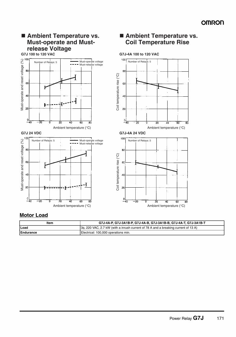
Power Relay G7J 171
Motor Load
Ambient Temperature vs. Must-operate and Must-release Voltage
Ambient Temperature vs. Coil Temperature Rise
Number of Relays: 5
Number of Relays: 5
Must-operate voltageMust-release voltage
Must-operate voltageMust-release voltage
Number of Relays: 5
Number of Relays: 5
Ambient temperature (°C)
Ambient temperature (°C)
Ambient temperature (°C)
Ambient temperature (°C)
Mus
t-op
erat
e an
d re
set v
olta
ge (
%)
Mus
t-op
erat
e an
d re
set v
olta
ge (
%)
Coi
l tem
pera
ture
ris
e (°
C)
Coi
l tem
pera
ture
ris
e (°
C)
G7J 100 to 120 VAC
G7J 24 VDC
G7J-4A 100 to 120 VAC
G7J-4A 24 VDC
Item G7J-4A-P, G7J-3A1B-P, G7J-4A-B, G7J-3A1B-B, G7J-4A-T, G7J-3A1B-T
Load 3φ, 220 VAC, 2.7 kW (with a inrush current of 78 A and a breaking current of 13 A)
Endurance Electrical: 100,000 operations min.
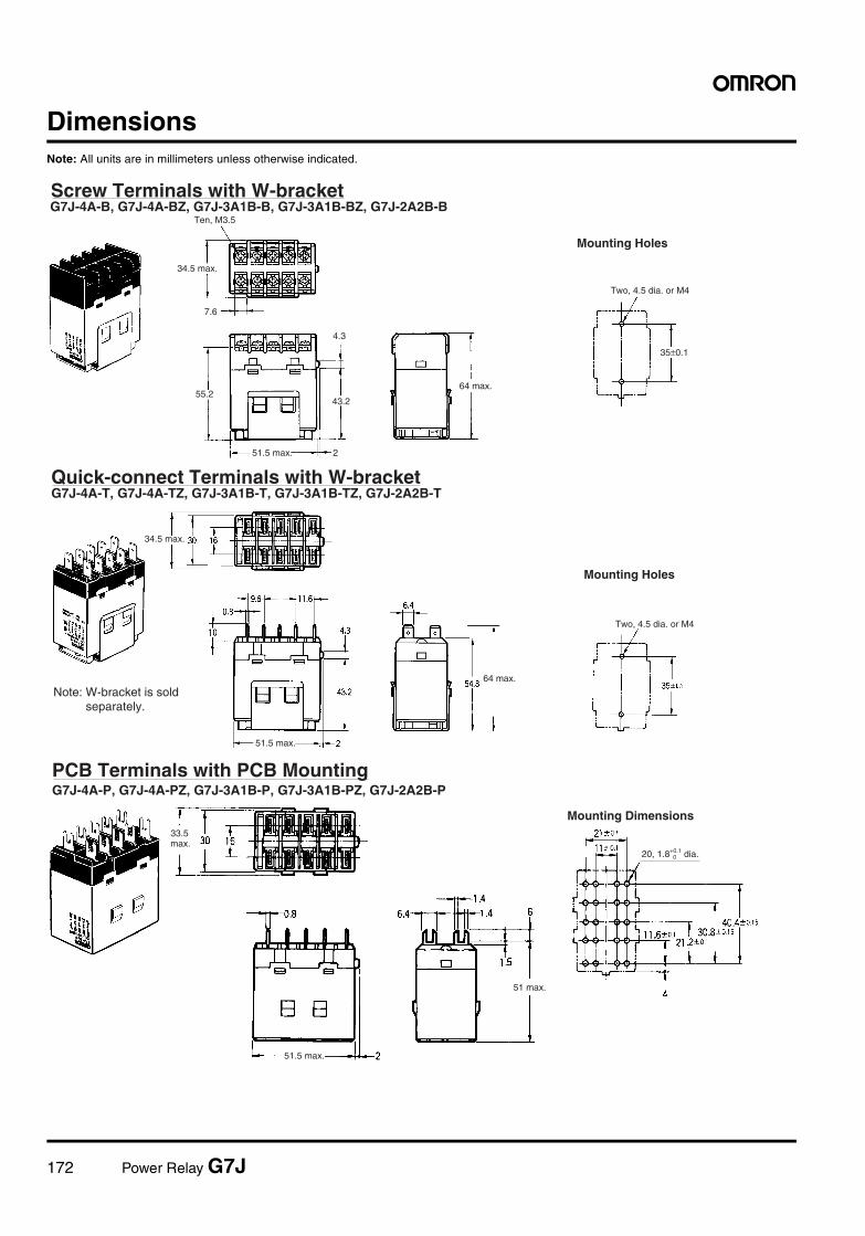
172 Power Relay G7J
DimensionsNote: All units are in millimeters unless otherwise indicated.
35±0.1
7.6
55.2
4.3
2
43.2
Screw Terminals with W-bracket
Mounting Holes
G7J-4A-B, G7J-4A-BZ, G7J-3A1B-B, G7J-3A1B-BZ, G7J-2A2B-BTen, M3.5
34.5 max.
51.5 max.
64 max.
Two, 4.5 dia. or M4
Quick-connect Terminals with W-bracketG7J-4A-T, G7J-4A-TZ, G7J-3A1B-T, G7J-3A1B-TZ, G7J-2A2B-T
34.5 max.
51.5 max.
64 max.
Two, 4.5 dia. or M4
Note: W-bracket is sold separately.
Mounting Holes
PCB Terminals with PCB Mounting
Mounting Dimensions
G7J-4A-P, G7J-4A-PZ, G7J-3A1B-P, G7J-3A1B-PZ, G7J-2A2B-P
33.5 max.
51.5 max.
51 max.
20, 1.8+0.1 dia.0
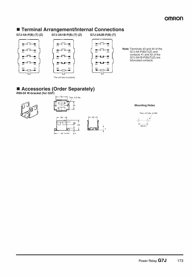
Power Relay G7J 173
35±0.1
24
44 4.4
30
7
929
35
14
24
34
44
A2 A1 A2 A1 A2 A1
43 42 41 42 41
33 34 33 32 31
23 24 23 24 23
13 14 13 14 13
28
Terminal Arrangement/Internal Connections
Accessories (Order Separately)R99-04 W-bracket (for G5F)
G7J-4A-P(B) (T) (Z) G7J-3A1B-P(B) (T) (Z) G7J-2A2B-P(B) (T)
The coil has no polarity.
Two, 4.5 dia.
Note: Terminals 43 and 44 of the G7J-4A-P(B)(T)(Z) and contacts 41 and 42 of the G7J-3A1B-P(B)(T)(Z) are bifurcated contacts.
Mounting Holes
Two, 4.5 dia. or M4
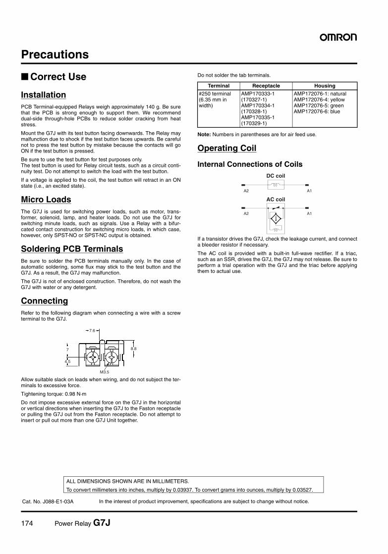
174 Power Relay G7J
Precautions
Correct Use
InstallationPCB Terminal-equipped Relays weigh approximately 140 g. Be surethat the PCB is strong enough to support them. We recommenddual-side through-hole PCBs to reduce solder cracking from heatstress.
Mount the G7J with its test button facing downwards. The Relay maymalfunction due to shock if the test button faces upwards. Be carefulnot to press the test button by mistake because the contacts will goON if the test button is pressed.
Be sure to use the test button for test purposes only.The test button is used for Relay circuit tests, such as a circuit conti-nuity test. Do not attempt to switch the load with the test button.
If a voltage is applied to the coil, the test button will retract in an ONstate (i.e., an excited state).
Micro LoadsThe G7J is used for switching power loads, such as motor, trans-former, solenoid, lamp, and heater loads. Do not use the G7J forswitching minute loads, such as signals. Use a Relay with a bifur-cated contact construction for switching micro loads, in which case,however, only SPST-NO or SPST-NC output is obtained.
Soldering PCB TerminalsBe sure to solder the PCB terminals manually only. In the case ofautomatic soldering, some flux may stick to the test button and theG7J. As a result, the G7J may malfunction.
The G7J is not of enclosed construction. Therefore, do not wash theG7J with water or any detergent.
ConnectingRefer to the following diagram when connecting a wire with a screwterminal to the G7J.
Allow suitable slack on leads when wiring, and do not subject the ter-minals to excessive force.
Tightening torque: 0.98 N·m
Do not impose excessive external force on the G7J in the horizontalor vertical directions when inserting the G7J to the Faston receptacleor pulling the G7J out from the Faston receptacle. Do not attempt toinsert or pull out more than one G7J Unit together.
Do not solder the tab terminals.
Note: Numbers in parentheses are for air feed use.
Operating Coil
Internal Connections of Coils
If a transistor drives the G7J, check the leakage current, and connecta bleeder resistor if necessary.
The AC coil is provided with a built-in full-wave rectifier. If a triac,such as an SSR, drives the G7J, the G7J may not release. Be sure toperform a trial operation with the G7J and the triac before applyingthem to actual use.
7.6
7
4.5
8.8
M3.5
Terminal Receptacle Housing
#250 terminal (6.35 mm in width)
AMP170333-1 (170327-1)AMP170334-1 (170328-1)AMP170335-1 (170329-1)
AMP172076-1: naturalAMP172076-4: yellowAMP172076-5: greenAMP172076-6: blue
A2 A1
A1A2
DC coil
AC coil
In the interest of product improvement, specifications are subject to change without notice.
ALL DIMENSIONS SHOWN ARE IN MILLIMETERS.
To convert millimeters into inches, multiply by 0.03937. To convert grams into ounces, multiply by 0.03527.
Cat. No. J088-E1-03A
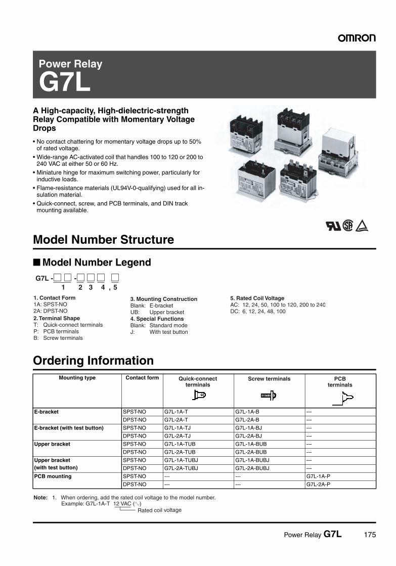
Power Relay G7L 175
Power Relay
G7LA High-capacity, High-dielectric-strength Relay Compatible with Momentary Voltage Drops
• No contact chattering for momentary voltage drops up to 50% of rated voltage.
• Wide-range AC-activated coil that handles 100 to 120 or 200 to 240 VAC at either 50 or 60 Hz.
• Miniature hinge for maximum switching power, particularly for inductive loads.
• Flame-resistance materials (UL94V-0-qualifying) used for all in-sulation material.
• Quick-connect, screw, and PCB terminals, and DIN track mounting available.
RCEModel Number Structure
Model Number Legend
Ordering InformationMounting type Contact form
E-bracket SPST-NO G7L-1A-T G7L-1A-B ---
DPST-NO G7L-2A-T G7L-2A-B ---
E-bracket (with test button) SPST-NO G7L-1A-TJ G7L-1A-BJ ---
DPST-NO G7L-2A-TJ G7L-2A-BJ ---
Upper bracket SPST-NO G7L-1A-TUB G7L-1A-BUB ---
DPST-NO G7L-2A-TUB G7L-2A-BUB ---
Upper bracket(with test button)
SPST-NO G7L-1A-TUBJ G7L-1A-BUBJ ---
DPST-NO G7L-2A-TUBJ G7L-2A-BUBJ ---
PCB mounting SPST-NO --- --- G7L-1A-P
DPST-NO --- --- G7L-2A-P
1 2 3 4 , 5G7L - -
1. Contact Form 1A: SPST-NO 2A: DPST-NO2. Terminal Shape T: Quick-connect terminals P: PCB terminals B: Screw terminals
3. Mounting Construction Blank: E-bracket UB: Upper bracket4. Special Functions Blank: Standard mode J: With test button
5. Rated Coil Voltage AC: 12, 24, 50, 100 to 120, 200 to 240DC: 6, 12, 24, 48, 100
Quick-connect terminals
Screw terminals PCB terminals
Rated coil voltage
Note: 1. When ordering, add the rated coil voltage to the model number. Example: G7L-1A-T 12 VAC (~)
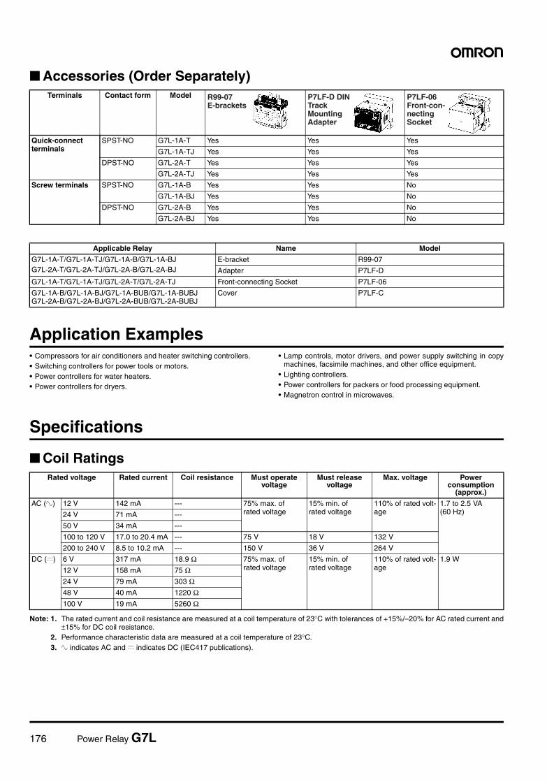
176 Power Relay G7L
Accessories (Order Separately)
Application Examples• Compressors for air conditioners and heater switching controllers.• Switching controllers for power tools or motors.• Power controllers for water heaters.• Power controllers for dryers.
• Lamp controls, motor drivers, and power supply switching in copymachines, facsimile machines, and other office equipment.
• Lighting controllers.• Power controllers for packers or food processing equipment.• Magnetron control in microwaves.
Specifications
Coil Ratings
Note: 1. The rated current and coil resistance are measured at a coil temperature of 23°C with tolerances of +15%/–20% for AC rated current and±15% for DC coil resistance.
2. Performance characteristic data are measured at a coil temperature of 23°C.3. ~ indicates AC and = indicates DC (IEC417 publications).
Terminals Contact form Model
Quick-connect terminals
SPST-NO G7L-1A-T Yes Yes Yes
G7L-1A-TJ Yes Yes Yes
DPST-NO G7L-2A-T Yes Yes Yes
G7L-2A-TJ Yes Yes Yes
Screw terminals SPST-NO G7L-1A-B Yes Yes No
G7L-1A-BJ Yes Yes No
DPST-NO G7L-2A-B Yes Yes No
G7L-2A-BJ Yes Yes No
Applicable Relay Name Model
G7L-1A-T/G7L-1A-TJ/G7L-1A-B/G7L-1A-BJG7L-2A-T/G7L-2A-TJ/G7L-2A-B/G7L-2A-BJ
E-bracket R99-07
Adapter P7LF-D
G7L-1A-T/G7L-1A-TJ/G7L-2A-T/G7L-2A-TJ Front-connecting Socket P7LF-06
G7L-1A-B/G7L-1A-BJ/G7L-1A-BUB/G7L-1A-BUBJG7L-2A-B/G7L-2A-BJ/G7L-2A-BUB/G7L-2A-BUBJ
Cover P7LF-C
R99-07 E-brackets
P7LF-D DIN Track Mounting Adapter
P7LF-06 Front-con-necting Socket
Rated voltage Rated current Coil resistance Must operate voltage
Must release voltage
Max. voltage Power consumption
(approx.)
AC (~) 12 V 142 mA --- 75% max. of rated voltage
15% min. of rated voltage
110% of rated volt-age
1.7 to 2.5 VA (60 Hz)24 V 71 mA ---
50 V 34 mA ---
100 to 120 V 17.0 to 20.4 mA --- 75 V 18 V 132 V
200 to 240 V 8.5 to 10.2 mA --- 150 V 36 V 264 V
DC (=) 6 V 317 mA 18.9 Ω 75% max. of rated voltage
15% min. of rated voltage
110% of rated volt-age
1.9 W
12 V 158 mA 75 Ω24 V 79 mA 303 Ω48 V 40 mA 1220 Ω100 V 19 mA 5260 Ω
Power Relay G7L 177
Contact Ratings
*Note: P level: λ60 = 0.1 x 10⁻⁶/operation
Characteristics
Note: The values given above are initial values.
Model G7L-1A-T@/G7L-1A-B@ G7L-2A-T@/G7L-2A-B@ G7L-1A-P/G7L-2A-P
Resistive load (cosφ = 1)
Inductive load (cosφ = 0.4)
Resistive load (cosφ = 1)
Inductive load (cosφ = 0.4)
Resistive load (cosφ = 1)
Inductive load (cosφ = 0.4)
Rated load 30 A, 220 VAC (~) 25 A, 220 VAC (~) 25 A, 220 VAC (~) 20 A, 220 VAC (~)
Rated carry current 30 A 25 A 20 A
Max. switching voltage
250 VAC (~)
Max. switching current
30 A 25 A 20 A
Max. switching power
6,600 VAC (~) 5,500 VAC (~) 5,500 VAC (~) 4,400 VAC (~)
Failure rate* (reference value)
100 mA, 5 VDC (=)
Contact resistance 50 mΩ max.
Operate time 30 ms max.
Release time 30 ms max.
Max. operating frequency Mechanical:1,800 operations/hrElectrical:1,800 operations/hr (under rated load)
Insulation resistance 1,000 MΩ min. (at 500 VDC)
Dielectric strength 4,000 VAC min., 50/60 Hz for 1 min between coil and contacts2,000 VAC, 50/60 Hz for 1 min between contacts of same polarity2,000 VAC, 50/60 Hz for 1 min between contacts of different polarity (DPST-NO model)
Impulse withstand voltage 10,000 V between coil and contact (with 1.2 x 50 µs impulse wave)
Vibration resistance Destruction:10 to 55 to 10 Hz, 0.75 mm single amplitude (1.5 mm double amplitude)Malfunction:10 to 55 to 10 Hz, 0.75 mm single amplitude (1.5 mm double amplitude)
Shock resistance Destruction:1,000 m/s2
Malfunction:100 m/s2
Endurance Mechanical:1,000,000 operations min. (at 1,800 operations/hr)Electrical:100,000 operations min. (at 1,800 operations/hr under rated load)
Ambient temperature Operating: –25°C to 60°C (with no icing)
Ambient humidity Operating: 5% to 85%
Weight Quick-connect terminal models:approx. 90 gPCB terminal models:approx. 100 gScrew terminal models: approx. 120 g
178 Power Relay G7L
Approved by Standards
UL 508, 1950 Recognitions (File No. E41643)CSA 22.2 No.14 Listings (File No.LR35535)
TÜV: File No. R9051158 (VDE 0435, IEC 255, IEC 950, EN60950)
Model Contact form Coil ratings Contact ratings Operations
G7L-1A-T@G7L-1A-B@
SPST-NO 12 to 240 VAC5 to 220 VDC
30 A, 277 VAC (RES)25 A, 277 VAC (GEN)30 A, 120 VAC (GEN)
100 x 103
(CSA; 30 x 103)
1.5 kW, 120 VAC (T)1.5 HP, 120 VAC
6 x 10³
3 HP, 277 VAC 100 x 103
(CSA; 6 x 10³)
20 FLA/120 LRA, 120 VAC17 FLA/102 LRA, 265 VAC
30 x 103
TV-10, 120 VAC 25 x 103
G7L-2A-T@G7L-2A-B@
DPST-NO 25 A, 277 VAC (RES)25 A, 277 VAC (GEN)25 A, 120 VAC (GEN)
100 x 103
(CSA; 30 x 103)
1.3 kW, 120 VAC (T)1 HP, 120 VAC
6 x 10³
2 HP, 277 VAC 100 x 103
20 FLA/120 LRA, 120 VAC17 FLA/102 LRA, 265 VAC
30 x 103
TV-8, 120 VAC 25 x 103
G7L-1A-P SPST-NO 20 A, 277 VAC (RES)20 A, 277 VAC (GEN)20 A, 120 VAC (GEN)
100 x 103
1.5 kW, 120 VAC (T)1.5 HP, 120 VAC
6 x 10³
3 HP, 277 VAC 100 x 103
(CSA; 6 x 10³)
20 FLA/120 LRA, 120 VAC17 FLA/102 LRA, 265 VAC
30 x 103
TV-10, 120 VAC 25 x 103
G7L-2A-P DPST-NO 20 A, 277 VAC (RES)20 A, 277 VAC (GEN)20 A, 120 VAC (GEN)
100 x 103
(CSA; 30 x 103)
1.3 kW, 120 VAC (T)1 HP, 120 VAC
6 x 10³
2 HP, 277 VAC 100 x 103
20 FLA/120 LRA, 120 VAC17 FLA/102 LRA, 265 VAC
30 x 103
TV-8, 120 VAC 25 x 103
Model Contact Form Coil ratings Contact ratings Operations
G7L-1A-B@ SPST-NO 6, 12, 24, 48, 100, 110, 200, 220 VDC12, 24, 50, 100 to 120, 200 to 240 VAC
30 A, 240 VAC (cosφ=1.0)25 A, 240 VAC (cosφ=0.4)30 A, 120 VAC (cosφ=0.4)
100 x 103
G7L-2A-B@ DPST-NO 25 A, 240 VAC (cosφ=1.0)25 A, 240 VAC (cosφ=0.4)
G7L-1A-T@ SPST-NO 25 A, 240 VAC (cosφ=1.0)25 A, 240 VAC (cosφ=0.4)
G7L-2A-T@ DPST-NO 25 A, 240 VAC (cosφ=1.0)25 A, 240 VAC (cosφ=0.4)
G7L-1A-P SPST-NO 20 A, 240 VAC (cosφ=1.0)20 A, 240 VAC (cosφ=0.4)
G7L-2A-P DPST-NO 20 A, 240 VAC (cosφ=1.0)20 A, 240 VAC (cosφ=0.4)
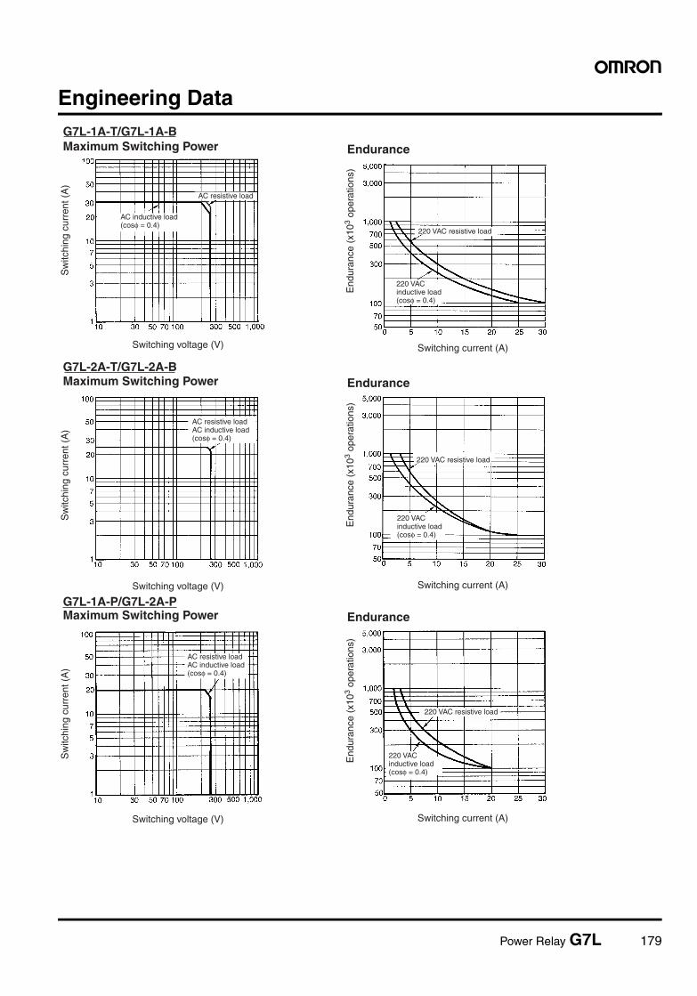
Power Relay G7L 179
Engineering DataG7L-1A-T/G7L-1A-BMaximum Switching Power
Switching voltage (V) Switching current (A)
Endurance
Sw
itchi
ng c
urre
nt (
A)
AC resistive load
220 VAC resistive load
End
uran
ce (
x103
oper
atio
ns)
220 VAC inductive load (cosφ = 0.4)
AC inductive load (cosφ = 0.4)
G7L-2A-T/G7L-2A-BMaximum Switching Power
Switching voltage (V)
Endurance
Switching current (A)
G7L-1A-P/G7L-2A-PMaximum Switching Power
Switching voltage (V)
Endurance
Switching current (A)
Sw
itchi
ng c
urre
nt (
A)
Sw
itchi
ng c
urre
nt (
A)
220 VAC resistive load
220 VAC resistive load
End
uran
ce (
x103
oper
atio
ns)
End
uran
ce (
x103
oper
atio
ns)
AC resistive load AC inductive load (cosφ = 0.4)
220 VAC inductive load (cosφ = 0.4)
220 VAC inductive load (cosφ = 0.4)
AC resistive load AC inductive load (cosφ = 0.4)
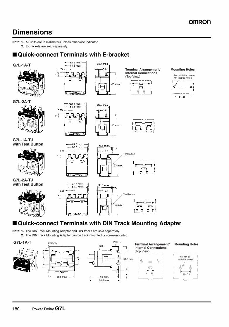
180 Power Relay G7L
DimensionsNote: 1. All units are in millimeters unless otherwise indicated.
2. E-brackets are sold separately.
Quick-connect Terminals with E-bracket
Quick-connect Terminals with DIN Track Mounting AdapterNote: 1. The DIN Track Mounting Adapter and DIN tracks are sold separately.
2. The DIN Track Mounting Adapter can be track-mounted or screw-mounted.
G7L-1A-T
G7L-2A-T
Mounting Holes
Two, 4.5-dia. hole or M4 tapped holes
Terminal Arrangement/ Internal Connections (Top View)
Test button
Test button
G7L-1A-TJ with Test Button
G7L-2A-TJ with Test Button
5
0 1
4 6 40±0.1
PFP-@N
55.5 max. 63 max.
66.5 max.
51.5 max.
G7L
P7LF-DG7L-1A-T Mounting Holes
Two, M4 or 4.5-dia. holes
Terminal Arrangement/ Internal Connections (Top View)
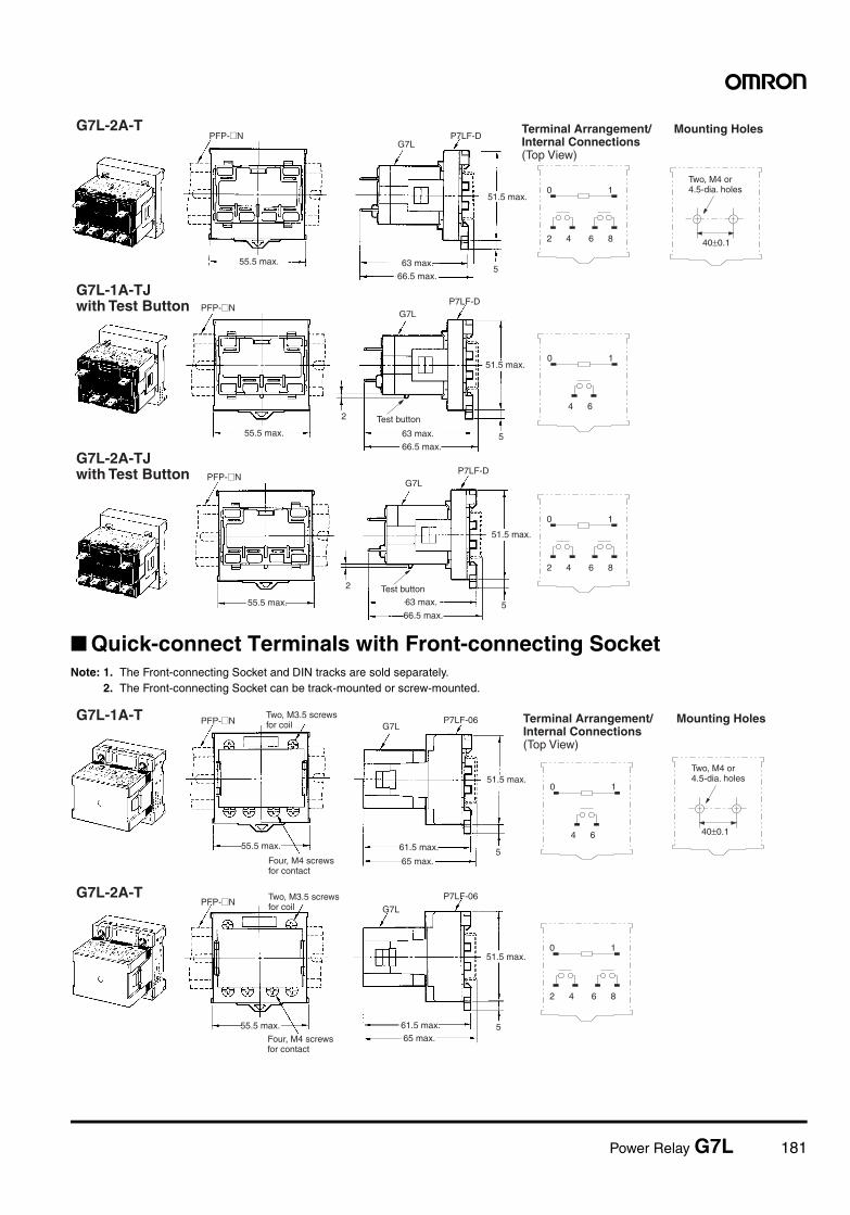
Power Relay G7L 181
Quick-connect Terminals with Front-connecting SocketNote: 1. The Front-connecting Socket and DIN tracks are sold separately.
2. The Front-connecting Socket can be track-mounted or screw-mounted.
5
2
5
2
5
0 1
2 4 6 8 40±0.1
0 1
4 6
0 1
2 4 6 8
55.5 max. 63 max.
66.5 max.
51.5 max.
PFP-@NG7L
P7LF-D
PFP-@N
55.5 max. 63 max.
66.5 max.
51.5 max.
G7LP7LF-D
55.5 max. 63 max.
66.5 max.
51.5 max.
PFP-@NG7L
P7LF-D
G7L-2A-T Mounting Holes
Test button
Test button
G7L-1A-TJ with Test Button
G7L-2A-TJ with Test Button
Terminal Arrangement/ Internal Connections (Top View)
Two, M4 or 4.5-dia. holes
5
5
40±0.1
0 1
4 6
0 1
2 4 6 8
65 max.
61.5 max.
51.5 max.
G7LP7LF-06
55.5 max.
PFP-@N
65 max.61.5 max.
51.5 max.
G7L
P7LF-06PFP-@N
G7L-1A-T Mounting Holes
G7L-2A-T
Two, M4 or 4.5-dia. holes
Terminal Arrangement/ Internal Connections (Top View)
Two, M3.5 screws for coil
Four, M4 screws for contact
Two, M3.5 screws for coil
Four, M4 screws for contact
55.5 max.
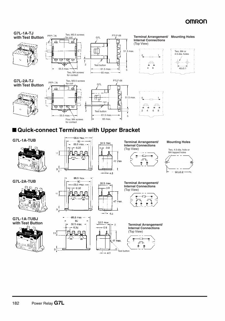
182 Power Relay G7L
Quick-connect Terminals with Upper Bracket
5
2
5
2
40±0.1
0 1
4 6
0 1
2 4 6 8
55.5 max.
65 max.
61.5 max.
51.5 max.
PFP-@NG7L
P7LF-06
55.5 max.
65 max.
61.5 max.
51.5 max.
PFP-@NG7L
P7LF-06
Mounting Holes
Test button
Test button
G7L-1A-TJ with Test Button
G7L-2A-TJ with Test Button
Two, M3.5 screws for coil
Two, M4 screws for contact
Two, M3.5 screws for coil
Four, M4 screws for contact
Terminal Arrangement/ Internal Connections (Top View)
Two, M4 or 4.5-dia. holes
G7L-1A-TUB
G7L-2A-TUB
Mounting HolesTerminal Arrangement/ Internal Connections (Top View) Two, 4.5-dia. hole or
M4 tapped holes
Terminal Arrangement/ Internal Connections (Top View)
Test button
G7L-1A-TUBJ with Test Button Terminal Arrangement/
Internal Connections (Top View)
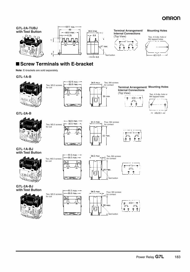
Power Relay G7L 183
Screw Terminals with E-bracketNote: E-brackets are sold separately.
Mounting Holes
Test button
G7L-2A-TUBJ with Test Button Terminal Arrangement/
Internal Connections (Top View) Two, 4.5-dia. hole or
M4 tapped holes
Two, M3.5 screws for coil
G7L-1A-B
G7L-2A-B
Mounting Holes
Test button
Test button
Four, M4 screws for contactTwo, M3.5 screws
for coil
G7L-2A-BJ with Test Button
G7L-1A-BJ with Test Button
Two, M4 screws for contact
Four, M4 screws for contactTwo, M3.5 screws
for coil
Two, M3.5 screws for coil
Two, M4 screws for contact
Terminal Arrangement/ Internal Connections (Top View) Two, 4.5-dia. hole or
M4 tapped holes
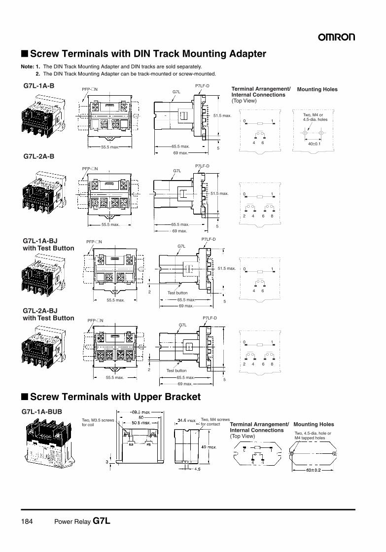
184 Power Relay G7L
Screw Terminals with DIN Track Mounting AdapterNote: 1. The DIN Track Mounting Adapter and DIN tracks are sold separately.
2. The DIN Track Mounting Adapter can be track-mounted or screw-mounted.
Screw Terminals with Upper Bracket
5
5
40±0.1
0 1
4 6
0 1
2 4 6 8
55.5 max.69 max.
65.5 max.
51.5 max.
PFP-@NG7L
P7LF-D
55.5 max.
69 max.
65.5 max.
51.5 max.
PFP-@N G7LP7LF-D
G7L-1A-B
G7L-2A-B
Mounting Holes
Two, M4 or 4.5-dia. holes
Terminal Arrangement/ Internal Connections (Top View)
5
2
5
2
0 1
4 6
0 1
2 4 6 8
55.5 max.69 max.
65.5 max.
51.5 max.
PFP-@NG7L
P7LF-D
55.5 max.
69 max.
65.5 max.
PFP-@NG7L
P7LF-D
Test button
Test button
G7L-1A-BJ with Test Button
G7L-2A-BJ with Test Button
G7L-1A-BUB
Mounting Holes
Two, 4.5-dia. hole or M4 tapped holes
Terminal Arrangement/ Internal Connections (Top View)
Two, M4 screws for contact
Two, M3.5 screws for coil
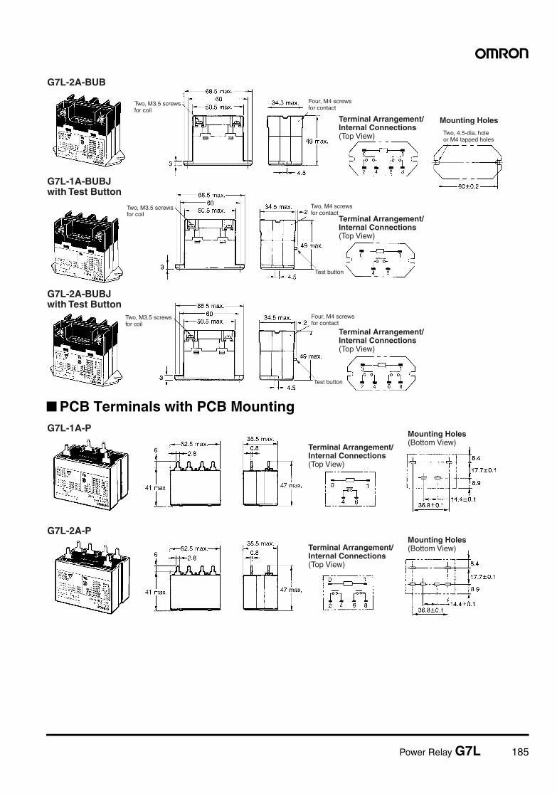
Power Relay G7L 185
PCB Terminals with PCB Mounting
G7L-2A-BUB
Mounting Holes
Test button
Test button
Terminal Arrangement/ Internal Connections (Top View)
Four, M4 screws for contact
Two, M3.5 screws for coil
G7L-2A-BUBJ with Test Button
G7L-1A-BUBJ with Test Button
Two, M3.5 screws for coil
Two, M4 screws for contact
Terminal Arrangement/ Internal Connections (Top View)
Two, 4.5-dia. hole or M4 tapped holes
Terminal Arrangement/ Internal Connections (Top View)
Four, M4 screws for contact
Two, M3.5 screws for coil
G7L-1A-P
G7L-2A-P
Terminal Arrangement/ Internal Connections (Top View)
Mounting Holes (Bottom View)
Terminal Arrangement/ Internal Connections (Top View)
Mounting Holes (Bottom View)
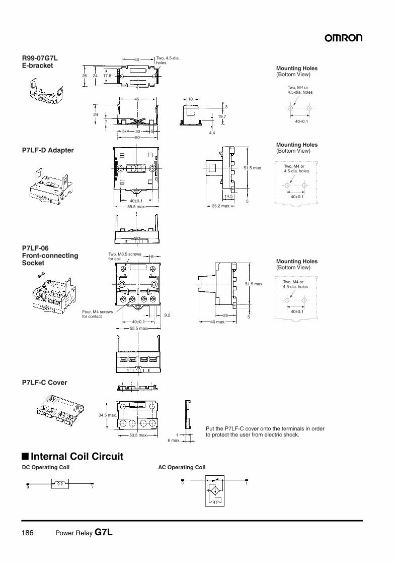
186 Power Relay G7L
Internal Coil Circuit
26 24 17.8
40
46
30
24
7
50
5 5
10
19.7
4.4
3
514.5
40±0.1
25
40±0.159.2
8
1
40+0.1
40+0.1
40±0.1
35.2 max.55.5 max.
51.5 max.
55.5 max.
46 max.
51.5 max.
34.5 max.
50.5 max.6 max.
P7LF-D Adapter
P7LF-C Cover
Mounting Holes (Bottom View)
Two, M4 or 4.5-dia. holes
Mounting Holes (Bottom View)
Two, M4 or 4.5-dia. holes
Two, 4.5-dia. holes
R99-07G7L E-bracket
P7LF-06 Front-connecting Socket
Two, M3.5 screws for coil
Four, M4 screws for contact
Mounting Holes (Bottom View)
Two, M4 or 4.5-dia. holes
Put the P7LF-C cover onto the terminals in order to protect the user from electric shock.
DC Operating Coil AC Operating Coil
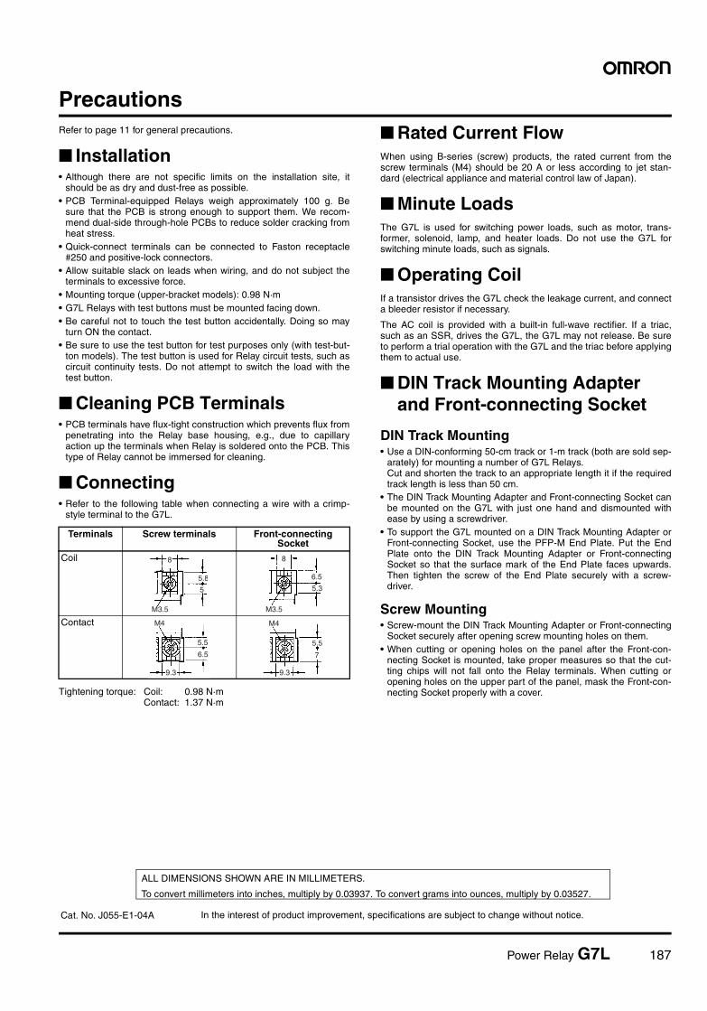
Power Relay G7L 187
PrecautionsRefer to page 11 for general precautions.
Installation• Although there are not specific limits on the installation site, it
should be as dry and dust-free as possible.• PCB Terminal-equipped Relays weigh approximately 100 g. Be
sure that the PCB is strong enough to support them. We recom-mend dual-side through-hole PCBs to reduce solder cracking fromheat stress.
• Quick-connect terminals can be connected to Faston receptacle#250 and positive-lock connectors.
• Allow suitable slack on leads when wiring, and do not subject theterminals to excessive force.
• Mounting torque (upper-bracket models): 0.98 N·m• G7L Relays with test buttons must be mounted facing down.• Be careful not to touch the test button accidentally. Doing so may
turn ON the contact.• Be sure to use the test button for test purposes only (with test-but-
ton models). The test button is used for Relay circuit tests, such ascircuit continuity tests. Do not attempt to switch the load with thetest button.
Cleaning PCB Terminals• PCB terminals have flux-tight construction which prevents flux from
penetrating into the Relay base housing, e.g., due to capillaryaction up the terminals when Relay is soldered onto the PCB. Thistype of Relay cannot be immersed for cleaning.
Connecting• Refer to the following table when connecting a wire with a crimp-
style terminal to the G7L.
Tightening torque: Coil: 0.98 N·mContact: 1.37 N·m
Rated Current FlowWhen using B-series (screw) products, the rated current from thescrew terminals (M4) should be 20 A or less according to jet stan-dard (electrical appliance and material control law of Japan).
Minute LoadsThe G7L is used for switching power loads, such as motor, trans-former, solenoid, lamp, and heater loads. Do not use the G7L forswitching minute loads, such as signals.
Operating CoilIf a transistor drives the G7L check the leakage current, and connecta bleeder resistor if necessary.
The AC coil is provided with a built-in full-wave rectifier. If a triac,such as an SSR, drives the G7L, the G7L may not release. Be sureto perform a trial operation with the G7L and the triac before applyingthem to actual use.
DIN Track Mounting Adapter and Front-connecting Socket
DIN Track Mounting• Use a DIN-conforming 50-cm track or 1-m track (both are sold sep-
arately) for mounting a number of G7L Relays.Cut and shorten the track to an appropriate length it if the requiredtrack length is less than 50 cm.
• The DIN Track Mounting Adapter and Front-connecting Socket canbe mounted on the G7L with just one hand and dismounted withease by using a screwdriver.
• To support the G7L mounted on a DIN Track Mounting Adapter orFront-connecting Socket, use the PFP-M End Plate. Put the EndPlate onto the DIN Track Mounting Adapter or Front-connectingSocket so that the surface mark of the End Plate faces upwards.Then tighten the screw of the End Plate securely with a screw-driver.
Screw Mounting• Screw-mount the DIN Track Mounting Adapter or Front-connecting
Socket securely after opening screw mounting holes on them.• When cutting or opening holes on the panel after the Front-con-
necting Socket is mounted, take proper measures so that the cut-ting chips will not fall onto the Relay terminals. When cutting oropening holes on the upper part of the panel, mask the Front-con-necting Socket properly with a cover.
Terminals Screw terminals Front-connecting Socket
Coil
Contact
8
5.8
5
M3.5
8
6.5
5.3
M3.5
5.5
6.5
9.3
M4
7
5.5
9.3
M4
In the interest of product improvement, specifications are subject to change without notice.
ALL DIMENSIONS SHOWN ARE IN MILLIMETERS.
To convert millimeters into inches, multiply by 0.03937. To convert grams into ounces, multiply by 0.03527.
Cat. No. J055-E1-04A
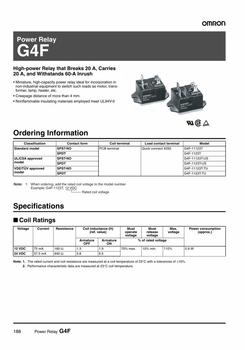
188 Power Relay G4F
Power Relay
G4FHigh-power Relay that Breaks 20 A, Carries 20 A, and Withstands 60-A Inrush
• Miniature, high-capacity power relay ideal for incorporation in non-industrial equipment to switch such loads as motor, trans-former, lamp, heater, etc.
• Creepage distance of more than 4 mm.• Nonflammable insulating materials employed meet UL94V-0
Ordering Information
Specifications
Coil Ratings
Note: 1. The rated current and coil resistance are measured at a coil temperature of 23°C with a tolerances of ±10%.2. Performance characteristic data are measured at 23°C coil temperature.
Classification Contact form Coil terminal Load contact terminal Model
Standard model SPST-NO PCB terminal Quick connect #250 G4F-11123T
SPDT G4F-1123T
UL/CSA approved model
SPST-NO G4F-11123T-US
SPDT G4F-1123T-US
VDE/TÜV approved model
SPST-NO G4F-11123T-TU
SPDT G4F-1123T-TU
Voltage
Current Resistance Coil inductance (H)(ref. value)
Must operate voltage
Must release voltage
Max. voltage
Power consumption (approx.)
Armature OFF
Armature ON
% of rated voltage
12 VDC 75 mA 160 Ω 1.3 1.9 70% max. 10% min. 110% 0.9 W
24 VDC 37.5 mA 640 Ω 5.8 9.5
Rated coil voltage
Note: 1. When ordering, add the rated coil voltage to the model number Example: G4F-1123T, 12 VDC
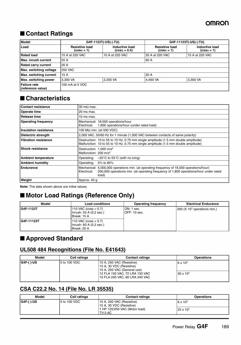
Power Relay G4F 189
Contact Ratings
Characteristics
Note: The data shown above are initial values.
Motor Load Ratings (Reference Only)
Approved Standard
UL508 484 Recognitions (File No. E41643)
CSA C22.2 No. 14 (File No. LR 35535)
Model G4F-1123T(-US) (-TU) G4F-11123T(-US) (-TU)
Load Resistive load(cosφ = 1)
Inductive load(cosφ = 0.4)
Resistive load(cosφ = 1)
Inductive load(cosφ = 1)
Rated load 15 A at 220 VAC 10 A at 220 VAC 20 A at 220 VAC 15 A at 220 VAC
Max. inrush current 55 A 60 A
Rated carry current 20 A
Max. switching voltage 250 VAC
Max. switching current 15 A 20 A
Max. switching power 3,300 VA 2,200 VA 4,400 VA 3,300 VA
Failure rate (reference value)
100 mA at 5 VDC
Contact resistance 30 mΩ max.
Operate time 20 ms max.
Release time 10 ms max.
Operating frequency Mechanical: 18,000 operations/hourElectrical: 1,800 operations/hour (under rated load)
Insulation resistance 100 MΩ min. (at 500 VDC)
Dielectric strength 2,000 VAC, 50/60 Hz for 1 minute (1,000 VAC between contacts of same polarity)
Vibration resistance Destruction: 10 to 55 to 10 Hz, 0.75 mm single amplitude (1.5 mm double amplitude)Malfunction: 10 to 55 to 10 Hz, 0.75 mm single amplitude (1.5 mm double amplitude)
Shock resistance Destruction: 1,000 m/s2
Malfunction: 200 m/s2
Ambient temperature Operating: –25°C to 55°C (with no icing)
Ambient humidity Operating: 5% to 85%
Endurance Mechanical: 5,000,000 operations min. (at operating frequency of 18,000 operations/hour)Electrical: 200,000 operations min. (at operating frequency of 1,800 operations/hour under rated
load)
Weight Approx. 40 g
Model Load conditions Operating frequency Electrical Endurance
G4F-1123T 110 VAC (cosφ = 0.7)Inrush: 55 A (0.2 sec.)Break: 15 A
ON: 1 sec.OFF: 10 sec.
200 (X 103 operations min.)
G4F-11123T 110 VAC (cosφ = 0.7)Inrush: 60 A (0.2 sec.)Break: 20 A
Model Coil ratings Contact ratings Operations
G4F-( )-US 5 to 100 VDC 15 A, 250 VAC (Resistive)15 A, 30 VDC (Resistive)10 A, 250 VAC (General use)12 FLA 150 VAC, 72 LRA 150 VAC10 FLA 240 VAC, 60 LRA 240 VAC
6 x 10³
30 x 103
Model Coil ratings Contact ratings Operations
G4F-( )-US 5 to 100 VDC 15 A, 250 VAC (Resistive)15 A, 30 VDC (Resistive)1 HP 125/250 VAC (Motor load)TV-3 AC
6 x 10³
25 x 103
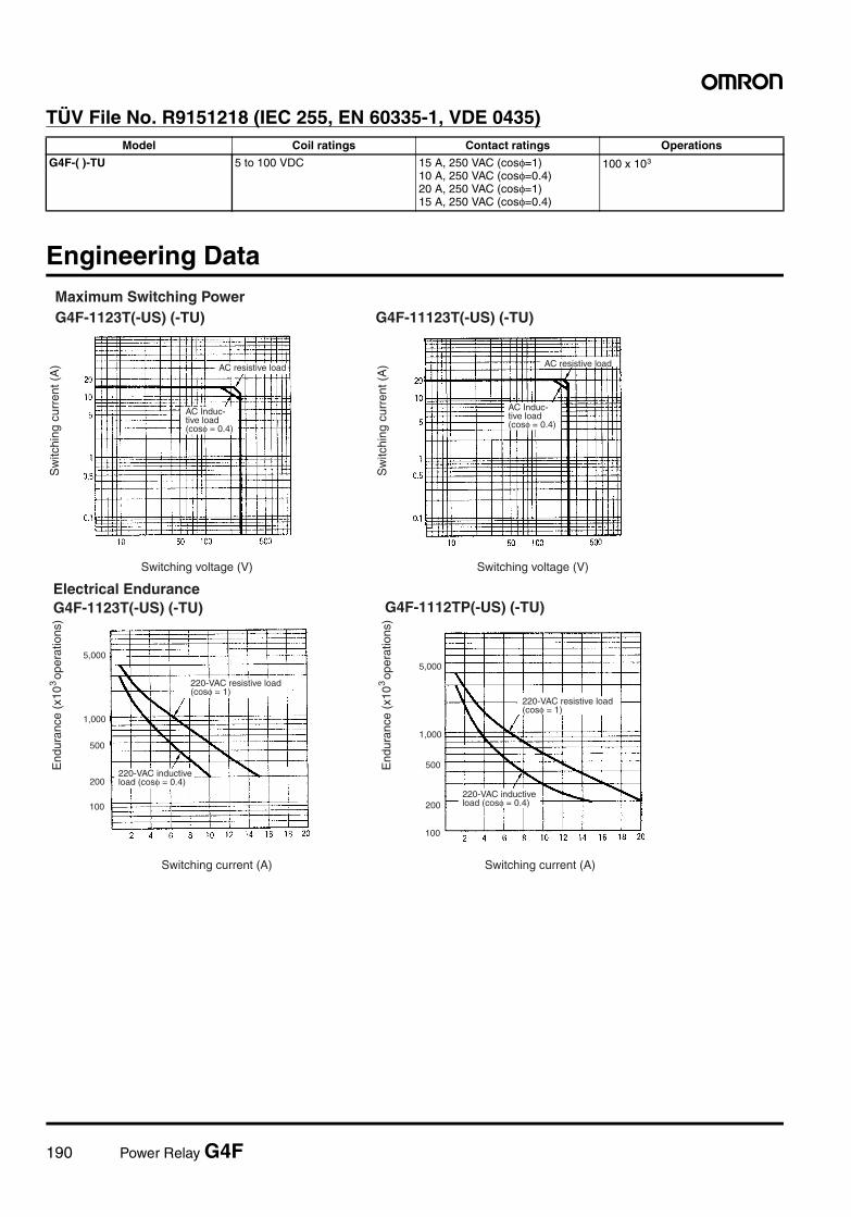
190 Power Relay G4F
TÜV File No. R9151218 (IEC 255, EN 60335-1, VDE 0435)
Engineering Data
Model Coil ratings Contact ratings Operations
G4F-( )-TU 5 to 100 VDC 15 A, 250 VAC (cosφ=1)10 A, 250 VAC (cosφ=0.4)20 A, 250 VAC (cosφ=1)15 A, 250 VAC (cosφ=0.4)
100 x 103
Maximum Switching PowerG4F-1123T(-US) (-TU)
Switching voltage (V)
AC resistive load
AC Induc-tive load(cosφ = 0.4)
G4F-11123T(-US) (-TU)
AC resistive load
AC Induc-tive load(cosφ = 0.4)
Switching voltage (V)
Sw
itchi
ng c
urre
nt (
A)
Sw
itchi
ng c
urre
nt (
A)
G4F-1112TP(-US) (-TU)
220-VAC inductive load (cosφ = 0.4)
Electrical EnduranceG4F-1123T(-US) (-TU)
Switching current (A)
220-VAC resistive load(cosφ = 1)
220-VAC inductive load (cosφ = 0.4)
100
200
500
1,000
End
uran
ce (
x10
ope
ratio
ns)
3
5,000
End
uran
ce (
x10
ope
ratio
ns)
3
100
200
500
1,000
5,000
220-VAC resistive load(cosφ = 1)
Switching current (A)
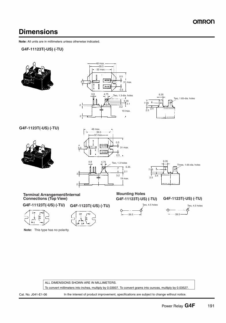
In the interest of product improvement, specifications are subject to change without notice.
ALL DIMENSIONS SHOWN ARE IN MILLIMETERS.
To convert millimeters into inches, multiply by 0.03937. To convert grams into ounces, multiply by 0.03527.
Cat. No. J041-E1-06
Power Relay G4F 191
DimensionsNote: All units are in millimeters unless otherwise indicated.
6.35
G4F-11123T(-US) (-TU)
Terminal Arrangement/Internal Connections (Top View)
Mounting Holes
G4F-1123T(-US) (-TU)
G4F-11123T(-US) (-TU) G4F-1123T(-US) (-TU)
G4F-11123T(-US) (-TU) G4F-1123T(-US) (-TU)
7.95
2.53.4
6.35
Two, 1.65-dia. holes
48 max.39.5
32 max.
4.5
0.5
31 max.
0.5
0.8 4.75 Two, 1.3-dia. holes
2.13.2
19 max.
Two, 4.5 holes
39.5
48 max.39.5
32 max.
4.5
0.5
0.5
31 max.
0.8 4.75 Two, 1.3 holes
6.35
2.1
19 max.3.2
2
2
Two, 4.5 holes
39.5
7.95
6.35
Three, 1.65-dia. holes
2.53.4
2
2
Note: This type has no polarity.
3
4
2
1
3
4
2
15
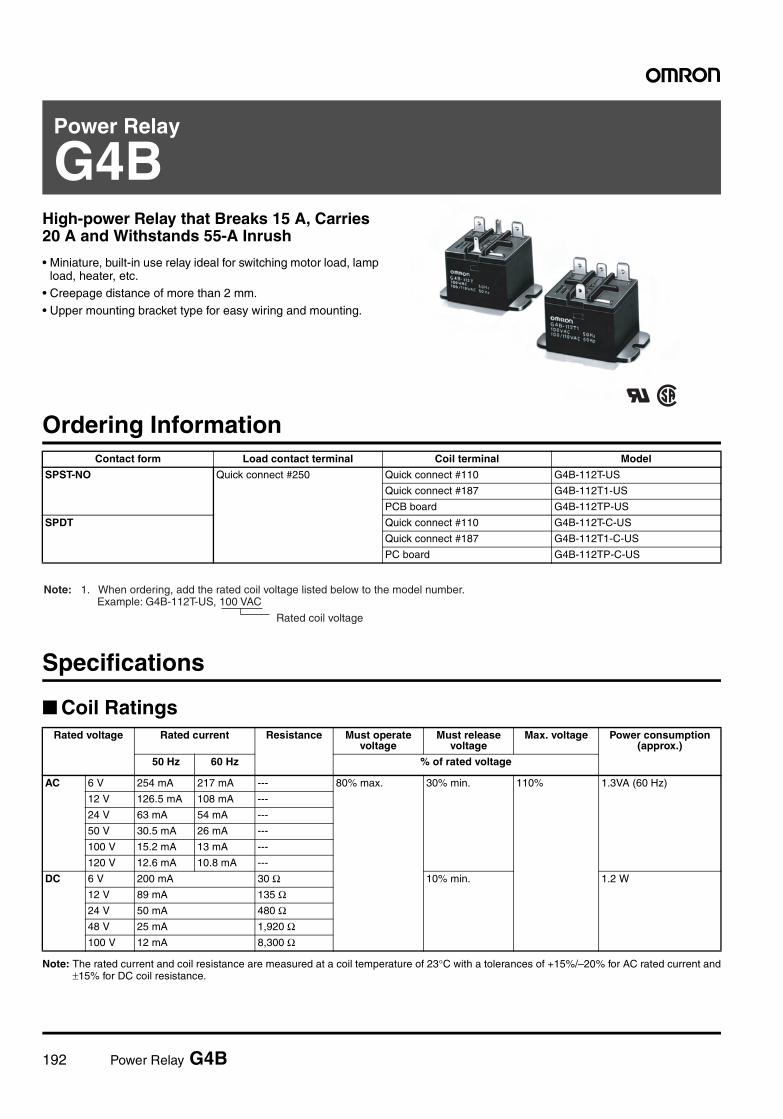
192 Power Relay G4B
Power Relay
G4BHigh-power Relay that Breaks 15 A, Carries 20 A and Withstands 55-A Inrush
• Miniature, built-in use relay ideal for switching motor load, lamp load, heater, etc.
• Creepage distance of more than 2 mm.
• Upper mounting bracket type for easy wiring and mounting.
Ordering Information
Specifications
Coil Ratings
Note: The rated current and coil resistance are measured at a coil temperature of 23°C with a tolerances of +15%/–20% for AC rated current and±15% for DC coil resistance.
Contact form Load contact terminal Coil terminal Model
SPST-NO Quick connect #250 Quick connect #110 G4B-112T-US
Quick connect #187 G4B-112T1-US
PCB board G4B-112TP-US
SPDT Quick connect #110 G4B-112T-C-US
Quick connect #187 G4B-112T1-C-US
PC board G4B-112TP-C-US
Rated coil voltage
Note: 1. When ordering, add the rated coil voltage listed below to the model number. Example: G4B-112T-US, 100 VAC
Rated voltage
Rated current Resistance
Must operate voltage
Must release voltage
Max. voltage Power consumption (approx.)
50 Hz 60 Hz % of rated voltage
AC 6 V 254 mA 217 mA --- 80% max. 30% min. 110% 1.3VA (60 Hz)
12 V 126.5 mA 108 mA ---
24 V 63 mA 54 mA ---
50 V 30.5 mA 26 mA ---
100 V 15.2 mA 13 mA ---
120 V 12.6 mA 10.8 mA ---
DC 6 V 200 mA 30 Ω 10% min. 1.2 W
12 V 89 mA 135 Ω24 V 50 mA 480 Ω48 V 25 mA 1,920 Ω100 V 12 mA 8,300 Ω
Power Relay G4B 193
Contact Ratings
Characteristics
Note: The data shown above are initial values.
Actual Load Ratings (Reference Only)
Note: The data shown above are based on the test for G4B-112T1.
Approved StandardUL508 923 Recognitions (File No. E41643)
CSA C22.2 No. 14 (File No. LR31928)
TÜV (File No. R9650822, VDE0435)
Load Resistive load(cosφ = 1)
Inductive load(cosφ = 0.4)(L/R = 7ms)
Rated load 15 A at 220 VAC15 A at 24 VDC
10 A at 220 VAC7 A at 24 VDC
Rated carry current 20 A
Max. switching voltage 250 VAC 125 VDC
Max. switching current 15 A
Max. switching power 3,300 VA 360 W 2,200 VA 168 W
Failure rate (reference value) 100 mA at 5 VDC
Contact resistance 30 mΩ max.
Operate time 20 ms max.
Release time 20 ms max.
Operating frequency Mechanical: 18,000 operations/hourElectrical: 1,800 operations/hour (under rated load)
Insulation resistance 100 MΩ min. (at 500 VDC)
Dielectric strength 2,000 VAC, 50/60 Hz for 1 minute (1,000 VAC between noncontinuous contacts)
Vibration resistance Destruction: 10 to 55 to 10 Hz, 0.75 mm single amplitude (1.5 mm double amplitude)Malfunction: 10 to 55 to 10 Hz, 0.75 mm single amplitude (1.5 mm double amplitude)
Shock resistance Mechanical: 1,000 m/s2
Malfunction: 200 m/s2
Ambient temperature Operating: –10°C to 55°C (with no icing)
Ambient humidity Operating: 5% to 85%
Endurance Mechanical: 10,000,000 operations min. (at operating frequency of 18,000 operations/hour)Electrical: 200,000 operations min. (at operating frequency of 1,800 operations/hour under rated
load)
Weight Approx. 44 g
Type of Load Conditions Endurance
AC motor 100 VAC (cosφ=1) 600 WInrush: 55 ASteady state: 15 A
100,000 operations min.
Model Coil ratings Contact ratings Operations
G4B-( )-US 6 to 240 VAC6 to 120 VDC
15 A, 28 VDC (Resistive)15 A, 120 VAC (General use)10 A, 240 VAC (General use)1 HP, 120 VAC
6 x 10³
TV-5, 120 VAC 25 x 103
Model Coil ratings Contact ratings Operations
G4B-( )-US 6 to 240 VAC6 to 120 VDC
15 A, 28 VDC (Resistive)15 A, 120 VAC (General use)10 A, 240 VAC (General use) 1 HP, 120 VAC
6 x 10³
TV-5, 120 VAC 25 x 103
Model Coil ratings Contact ratings Operations
G4B-( ) 5, 6, 9, 12, 24, 48, 100, 110, 120 VDC6, 12, 24, 100, 120, 200, 220 VAC
15 A, 250 VAC (cosφ=1.0)10 A, 250 VAC (cosφ=0.4)
200 x 103
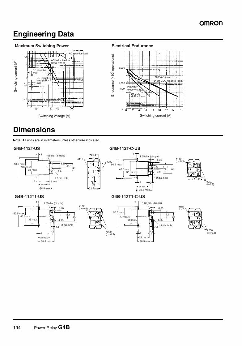
194 Power Relay G4B
Engineering Data
DimensionsNote: All units are in millimeters unless otherwise indicated.
Maximum Switching Power Electrical Endurance
Switching current (A)Switching voltage (V)
AC resistive load
DC resistive load
DC inductive load (L/R = 7 ms)
24 VDC resistive load
24 VDC(L/R = 7 ms)
AC Inductive load (cosφ = 0.4)
Sw
itchi
ng c
urre
nt (
A)
End
uran
ce (
x10
ope
ratio
ns)
30
500
1,000
5,000
220 VAC (cosφ = 1)
220 VAC (cosφ = 0.4)
G4B-112T-C-USG4B-112T-US
#110(t = 0.5)
50.5 max.43.5±0.15
36 max.
1.65 dia. (dimple)
6.3511.1
222.8
1.2 dia. hole92
29 max.
38.5 max.
#110
25.4
#250
4.529
32.5±0.5
1
50.5 max.
43.5±0.15
36 max.
1.65 dia. (dimple)1
6.35
11.122
2.8
1.2 dia. hole
92
29 max.
38.5 max.
4
1.6
#250(t=0.8)
#187(t = 0.5)
G4B-112T1-US G4B-112T1-C-US
#187(t = 0.5)
#250(t = 0.5)
50.5 max.43.5±0.15
36 max.
1.65 dia. (dimple)
6.35
11.122
92
29 max.
38.5 max.
1
1.3 dia. hole
4.75
4
7.4
3.2
1.65 dia. (dimple)
4 6.35
#250(t = 0.8)
50.5 max.
43.5±0.15
36 max.
11.122
92
29 max.
38.5 max.
1.3 dia. hole
4.75
7.4
3.2
1
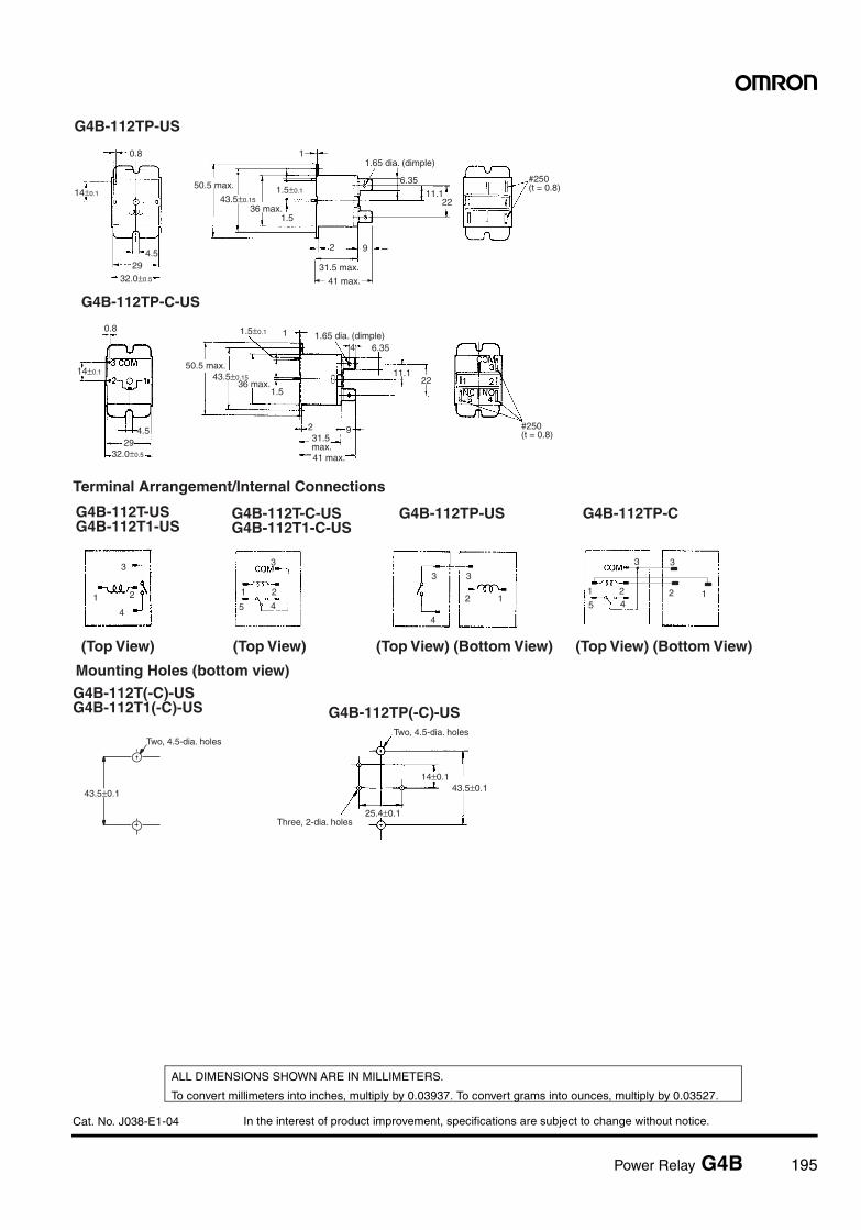
In the interest of product improvement, specifications are subject to change without notice.
ALL DIMENSIONS SHOWN ARE IN MILLIMETERS.
To convert millimeters into inches, multiply by 0.03937. To convert grams into ounces, multiply by 0.03527.
Cat. No. J038-E1-04
Power Relay G4B 195
G4B-112TP-US
#250(t = 0.8)
41 max.
14±0.1
0.8
4.529
32.0±0.5
50.5 max.
43.5±0.1536 max.
1.5
1.5±0.1
1.65 dia. (dimple)
6.35
11.122
31.5 max.
2 9
1
G4B-112TP-C-US
#250(t = 0.8)
41 max.
14±0.1
0.8
4.529
32.0±0.5
50.5 max.43.5±0.15
36 max.1.5
1.5±0.1 1.65 dia. (dimple)6.35
11.122
31.5 max.
2 9
4
1
Terminal Arrangement/Internal Connections
G4B-112T-USG4B-112T1-US
G4B-112T-C-USG4B-112T1-C-US
G4B-112TP-US G4B-112TP-C
(Top View) (Bottom View)(Top View) (Top View) (Top View) (Bottom View)
3
1
4
2 1 2
45
3
3 3
2 1
4
3 3
2 145
21
Mounting Holes (bottom view)
G4B-112T(-C)-USG4B-112T1(-C)-US G4B-112TP(-C)-US
Two, 4.5-dia. holes
Three, 2-dia. holes
43.5±0.1
Two, 4.5-dia. holes
14±0.143.5±0.1
25.4±0.1
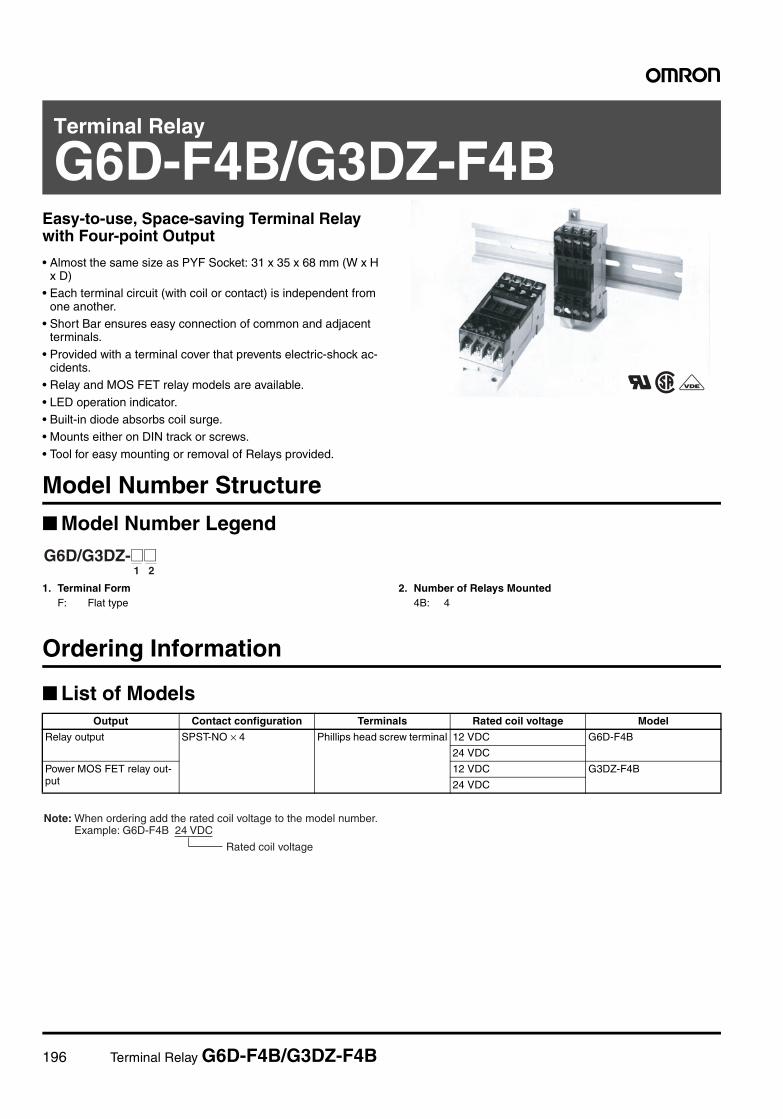
196 Terminal Relay G6D-F4B/G3DZ-F4B
Terminal Relay
G6D-F4B/G3DZ-F4BZ-F4BEasy-to-use, Space-saving Terminal Relay with Four-point Output
• Almost the same size as PYF Socket: 31 x 35 x 68 mm (W x H x D)
• Each terminal circuit (with coil or contact) is independent from one another.
• Short Bar ensures easy connection of common and adjacent terminals.
• Provided with a terminal cover that prevents electric-shock ac-cidents.
• Relay and MOS FET relay models are available.
• LED operation indicator.• Built-in diode absorbs coil surge.• Mounts either on DIN track or screws.
• Tool for easy mounting or removal of Relays provided.
Model Number Structure
Model Number Legend
1. Terminal FormF: Flat type
2. Number of Relays Mounted4B: 4
Ordering Information
List of Models
1 2G6D/G3DZ-@@
Output Contact configuration Terminals Rated coil voltage Model
Relay output SPST-NO × 4 Phillips head screw terminal 12 VDC G6D-F4B
24 VDC
Power MOS FET relay out-put
12 VDC G3DZ-F4B
24 VDC
Rated coil voltage
Note: When ordering add the rated coil voltage to the model number. Example: G6D-F4B 24 VDC
Terminal Relay G6D-F4B/G3DZ-F4B 197
Specifications
Ratings
Coil Ratings (per G6D Relay)
Note: 1. The must operate voltage is 75% or less of the rated voltage if the Relay is mounted upside down.2. Rated current and coil resistance were measured at a coil temperature of 23°C with a tolerance of ±10%.3. Operating characteristics were measured at a coil temperature of 23°C.4. The maximum allowable voltage is the maximum value of the allowable voltage range for the relay coil operating power supply. There is
no continuous allowance.5. The rated current includes the terminal’s LED current.
Contact Ratings (per G6D Relay)
Note: This value is for a switching frequency of 120 times per minute.
Power MOS FET Relay Specifications
Input (per G3DZ Power MOS FET Relay)
Note: The rated current includes the terminal’s LED current.
Output (per G3DZ Power MOS FET Relay)
Rated voltage Rated current Coil resistance Must operate voltage
Must release voltage
Max. voltage Power consumption
12 VDC 18.7 mA 720 Ω 70% max. (see note 1)
10% min. 130% Approx. 200 mW
24 VDC 10.5 mA 2,880 Ω
Item Resistive load (cosφ = 1)
Rated load 3 A at 250 VAC, 3 A at 30 VDC
Rated carry current 5 A
Max. switching voltage 250 VAC, 30 VDC
Max. switching current 5 A
Max. permissible capacity (reference value) 1,250 VA, 150 W
Error rate (reference value) (see note) 5 VDC, 10 mA
Rated voltage Operating voltage Must operate voltage level
Must release voltage level
Input impedance Rated current
12 VDC 9.6 to 14.4 VDC 9.6 VDC max. 1 VDC min. 2 kΩ±20% 8.0 mA±20%
24 VDC 19.2 to 28.8 VDC 19.2 VDC max. 4 kΩ±20% 8.2 mA±20%
Load voltage Load current Inrush current
3 to 264 VAC3 to 125 VDC
100 µ to 0.3 A 6 A (10 ms)
198 Terminal Relay G6D-F4B/G3DZ-F4B
Characteristics
Note: 1. The above values are initial values.2. Measurement condition: 1 A at 5 VDC3. Ambient temperature condition: 23°C
Item G6D-F4B
Relay output
Contact resistance (see note 2) 100 mΩ max.
Must operate time (see note 3) 10 ms max.
Release time (see note 3) 10 ms max.
Insulation resistance 1,000 MΩ min. (at 500 VDC)
Dielectric strength 2,000 VAC, 50/60 Hz for 1 min between coil and contacts.
1,500 VAC, 50/60 Hz for 1 min between contacts of different polarity
750 VAC, 50/60 Hz for 1 min between contacts of same polarity
Impulse withstand voltage (between coil and contacts)
4,000 V (1.2 × 50 µs)
Vibration resistance Destruction: 10 to 55 to 10 Hz, 0.75 mm single amplitude (1.5 mm double amplitude)Malfunction: 10 to 55 to 10 Hz, 0.75 mm single amplitude (1.5 mm double amplitude)
Shock resistance Destruction: 500 m/s2
Malfunction: 100 m/s2
Endurance Mechanical: 20,000,000 operations min. (at 18,000 operations/hr)Electrical: 100,000 operations min. (3 A at 250 VAC, resistive load)
100,000 operations min. (3 A at 30 VDC, resistive load) (at 1,800 operations /hr)
Ambient temperature Operating: –25°C to 55°C (with no icing)
Ambient humidity Operating: 45% to 85%
Weight Approx. 65 g
Item G3DZ-F4B
Power MOS FET relay output
Must operate time 10 ms max.
Release time 15 ms max.
Output ON-resistance 2.4 Ω max.
Leakage current at OFF state 10 µA max. (at 125 VDC)
Insulation resistance 100 MΩ min. (at 500 VDC)
Dielectric strength 2,000 VAC, 50/60 Hz for 1 min between input and output terminals
1,500 VAC, 50/60 Hz for 1 min between contacts of different polarity
Vibration resistance Destruction: 10 to 55 to 10 Hz, 0.75 mm single amplitude (1.5 mm double amplitude)
Shock resistance Destruction: 500 m/s2
Ambient temperature Operating: –25°C to 55°C (with no icing)
Ambient humidity Operating: 45% to 85%
Weight Approx. 65 g
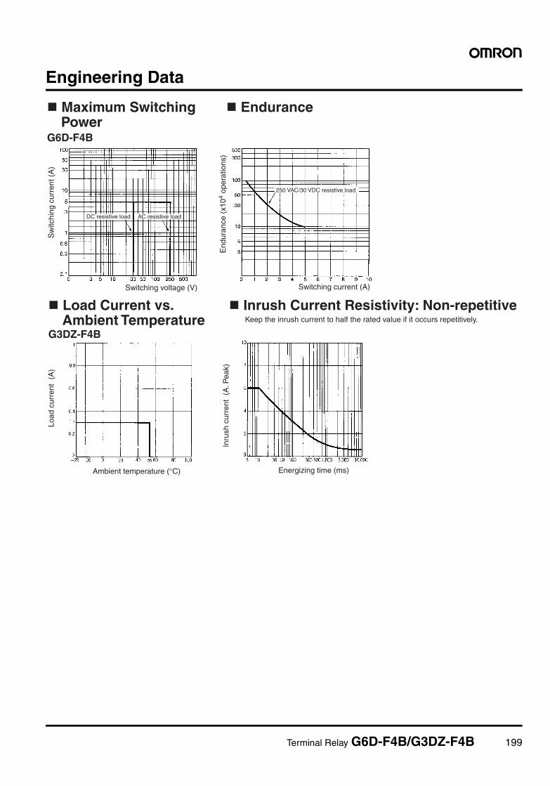
Terminal Relay G6D-F4B/G3DZ-F4B 199
Engineering Data
Endurance
Sw
itchi
ng c
urre
nt (
A)
End
uran
ce (
x104
oper
atio
ns)
Switching voltage (V) Switching current (A)
DC resistive load AC resistive load
250 VAC/30 VDC resistive load
Maximum Switching Power
G6D-F4B
Inrush Current Resistivity: Non-repetitive
Load
cur
rent
(A
)
Inru
sh c
urre
nt (
A. P
eak)
Ambient temperature (°C) Energizing time (ms)
Load Current vs. Ambient Temperature
G3DZ-F4BKeep the inrush current to half the rated value if it occurs repetitively.
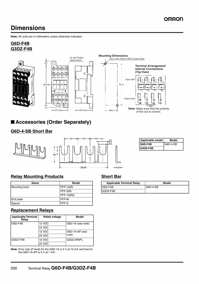
200 Terminal Relay G6D-F4B/G3DZ-F4B
DimensionsNote: All units are in millimeters unless otherwise indicated.
G6D-F4BG3DZ-F4B
Accessories (Order Separately)
G6D-4-SB Short Bar
Relay Mounting Products
Replacement Relays
Note: Error rate (P level) for the G6D-1A is 5 V at 10 mA and that forthe G6D-1A-AP is 5 V at 1 mA.
Short Bar
Mounting DimensionsTwo, 4 dia. holes or M3.5 screw holes
Input side
68 max.
31 max. 35 max.
Output side
16, M3 Phillips head screws
Terminal Arrangement/ Internal Connections (Top View)
Note: Make sure that the polarity of the coil is correct.
Applicable model Model
G6D-F4B G6D-4-SB
G3DZ-F4B
Name Model
Mounting track PFP-100N
PFP-50N
PFP-100N2
End plate PFP-M
Spacer PFP-S
Applicable Terminal Relay
Rated voltage Model
G6D-F4B 12 VDC G6D-1A (see note)
24 VDC
12 VDC G6D-1A-AP (see note)24 VDC
G3DZ-F4B 12 VDC G3DZ-2R6PL
24 VDC
Applicable Terminal Relay Model
G6D-F4B G6D-4-SB
G3DZ-F4B
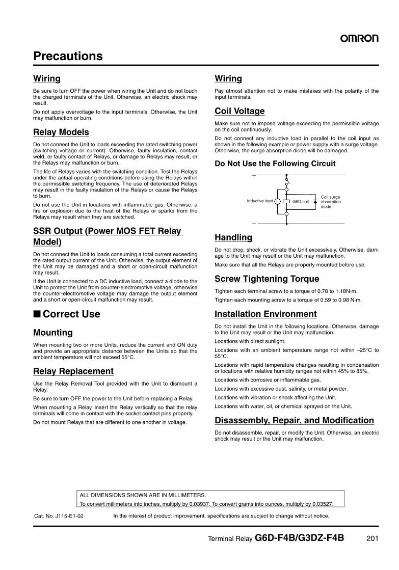
Terminal Relay G6D-F4B/G3DZ-F4B 201
Precautions
WiringBe sure to turn OFF the power when wiring the Unit and do not touchthe charged terminals of the Unit. Otherwise, an electric shock mayresult.
Do not apply overvoltage to the input terminals. Otherwise, the Unitmay malfunction or burn.
Relay ModelsDo not connect the Unit to loads exceeding the rated switching power(switching voltage or current). Otherwise, faulty insulation, contactweld, or faulty contact of Relays, or damage to Relays may result, orthe Relays may malfunction or burn.
The life of Relays varies with the switching condition. Test the Relaysunder the actual operating conditions before using the Relays withinthe permissible switching frequency. The use of deteriorated Relaysmay result in the faulty insulation of the Relays or cause the Relaysto burn.
Do not use the Unit in locations with inflammable gas. Otherwise, afire or explosion due to the heat of the Relays or sparks from theRelays may result when they are switched.
SSR Output (Power MOS FET Relay Model)Do not connect the Unit to loads consuming a total current exceedingthe rated output current of the Unit. Otherwise, the output element ofthe Unit may be damaged and a short or open-circuit malfunctionmay result.
If the Unit is connected to a DC inductive load, connect a diode to theUnit to protect the Unit from counter-electromotive voltage, otherwisethe counter-electromotive voltage may damage the output elementand a short or open-circuit malfunction may result.
Correct Use
MountingWhen mounting two or more Units, reduce the current and ON dutyand provide an appropriate distance between the Units so that theambient temperature will not exceed 55°C.
Relay ReplacementUse the Relay Removal Tool provided with the Unit to dismount aRelay.
Be sure to turn OFF the power to the Unit before replacing a Relay.
When mounting a Relay, insert the Relay vertically so that the relayterminals will come in contact with the socket contact pins properly.
Do not mount Relays that are different to one another in voltage.
WiringPay utmost attention not to make mistakes with the polarity of theinput terminals.
Coil VoltageMake sure not to impose voltage exceeding the permissible voltageon the coil continuously.
Do not connect any inductive load in parallel to the coil input asshown in the following example or power supply with a surge voltage.Otherwise, the surge absorption diode will be damaged.
Do Not Use the Following Circuit
HandlingDo not drop, shock, or vibrate the Unit excessively. Otherwise, dam-age to the Unit may result or the Unit may malfunction.
Make sure that all the Relays are properly mounted before use.
Screw Tightening TorqueTighten each terminal screw to a torque of 0.78 to 1.18N·m.
Tighten each mounting screw to a torque of 0.59 to 0.98 N·m.
Installation EnvironmentDo not install the Unit in the following locations. Otherwise, damageto the Unit may result or the Unit may malfunction.
Locations with direct sunlight.
Locations with an ambient temperature range not within –25°C to55°C.
Locations with rapid temperature changes resulting in condensationor locations with relative humidity ranges not within 45% to 85%.
Locations with corrosive or inflammable gas.
Locations with excessive dust, salinity, or metal powder.
Locations with vibration or shock affecting the Unit.
Locations with water, oil, or chemical sprayed on the Unit.
Disassembly, Repair, and ModificationDo not disassemble, repair, or modify the Unit. Otherwise, an electricshock may result or the Unit may malfunction.
Inductive load G6D coilCoil surge absorption diode
In the interest of product improvement, specifications are subject to change without notice.
ALL DIMENSIONS SHOWN ARE IN MILLIMETERS.
To convert millimeters into inches, multiply by 0.03937. To convert grams into ounces, multiply by 0.03527.
Cat. No. J115-E1-02
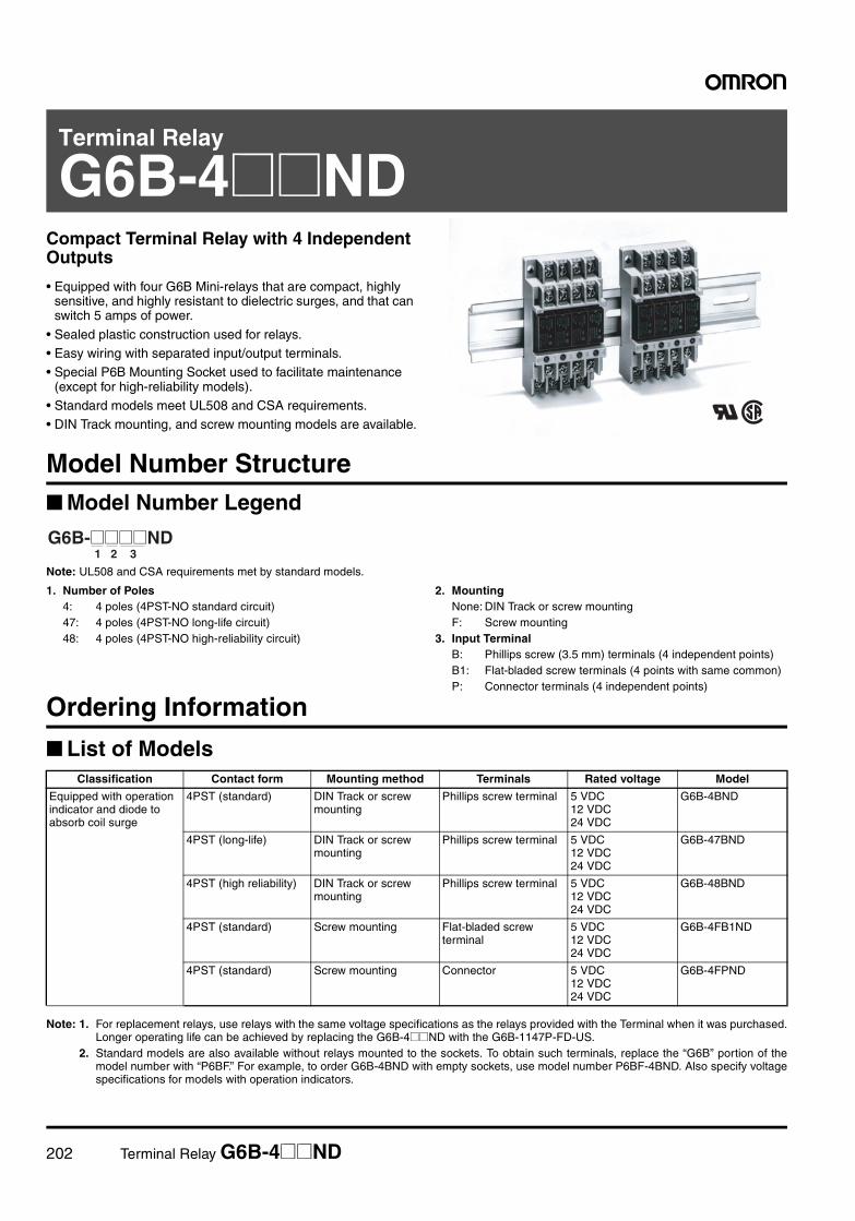
202 Terminal Relay G6B-4@@ND
Terminal Relay
G6B-4@@NDCompact Terminal Relay with 4 Independent Outputs
• Equipped with four G6B Mini-relays that are compact, highly sensitive, and highly resistant to dielectric surges, and that can switch 5 amps of power.
• Sealed plastic construction used for relays.• Easy wiring with separated input/output terminals.• Special P6B Mounting Socket used to facilitate maintenance
(except for high-reliability models).• Standard models meet UL508 and CSA requirements.• DIN Track mounting, and screw mounting models are available.
Model Number Structure Model Number Legend
Note: UL508 and CSA requirements met by standard models.
1. Number of Poles4: 4 poles (4PST-NO standard circuit)47: 4 poles (4PST-NO long-life circuit)48: 4 poles (4PST-NO high-reliability circuit)
2. MountingNone: DIN Track or screw mountingF: Screw mounting
3. Input TerminalB: Phillips screw (3.5 mm) terminals (4 independent points)B1: Flat-bladed screw terminals (4 points with same common)P: Connector terminals (4 independent points)
Ordering Information
List of Models
Note: 1. For replacement relays, use relays with the same voltage specifications as the relays provided with the Terminal when it was purchased.Longer operating life can be achieved by replacing the G6B-4@@ND with the G6B-1147P-FD-US.
2. Standard models are also available without relays mounted to the sockets. To obtain such terminals, replace the “G6B” portion of themodel number with “P6BF.” For example, to order G6B-4BND with empty sockets, use model number P6BF-4BND. Also specify voltagespecifications for models with operation indicators.
1 2 3G6B-@@@@ND
Classification Contact form Mounting method Terminals Rated voltage Model
Equipped with operation indicator and diode to absorb coil surge
4PST (standard) DIN Track or screw mounting
Phillips screw terminal 5 VDC12 VDC24 VDC
G6B-4BND
4PST (long-life) DIN Track or screw mounting
Phillips screw terminal 5 VDC12 VDC24 VDC
G6B-47BND
4PST (high reliability) DIN Track or screw mounting
Phillips screw terminal 5 VDC12 VDC24 VDC
G6B-48BND
4PST (standard) Screw mounting Flat-bladed screw terminal
5 VDC12 VDC24 VDC
G6B-4FB1ND
4PST (standard) Screw mounting Connector 5 VDC12 VDC24 VDC
G6B-4FPND
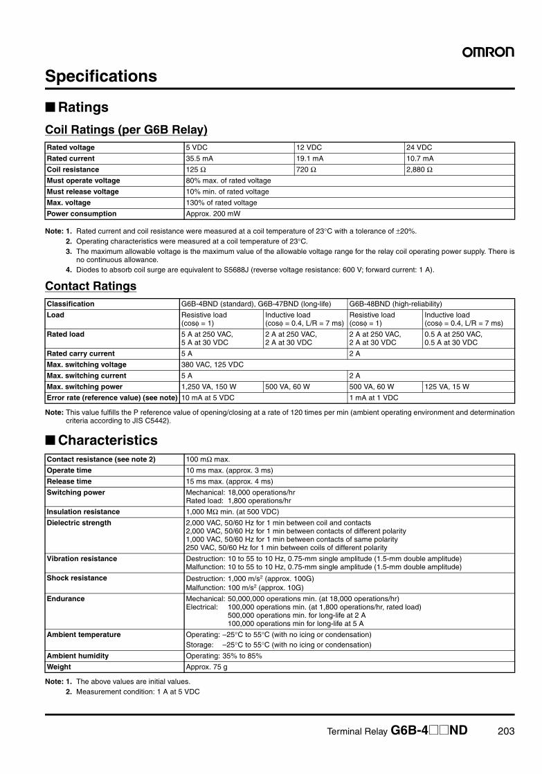
Terminal Relay G6B-4@@ND 203
Specifications
Ratings
Coil Ratings (per G6B Relay)
Note: 1. Rated current and coil resistance were measured at a coil temperature of 23°C with a tolerance of ±20%.2. Operating characteristics were measured at a coil temperature of 23°C.3. The maximum allowable voltage is the maximum value of the allowable voltage range for the relay coil operating power supply. There is
no continuous allowance.4. Diodes to absorb coil surge are equivalent to S5688J (reverse voltage resistance: 600 V; forward current: 1 A).
Contact Ratings
Note: This value fulfills the P reference value of opening/closing at a rate of 120 times per min (ambient operating environment and determinationcriteria according to JIS C5442).
Characteristics
Note: 1. The above values are initial values.2. Measurement condition: 1 A at 5 VDC
Rated voltage 5 VDC 12 VDC 24 VDC
Rated current 35.5 mA 19.1 mA 10.7 mA
Coil resistance 125 Ω 720 Ω 2,880 ΩMust operate voltage 80% max. of rated voltage
Must release voltage 10% min. of rated voltage
Max. voltage 130% of rated voltage
Power consumption Approx. 200 mW
Classification G6B-4BND (standard), G6B-47BND (long-life) G6B-48BND (high-reliability)
Load Resistive load (cosφ = 1)
Inductive load (cosφ = 0.4, L/R = 7 ms)
Resistive load (cosφ = 1)
Inductive load (cosφ = 0.4, L/R = 7 ms)
Rated load 5 A at 250 VAC, 5 A at 30 VDC
2 A at 250 VAC, 2 A at 30 VDC
2 A at 250 VAC, 2 A at 30 VDC
0.5 A at 250 VAC, 0.5 A at 30 VDC
Rated carry current 5 A 2 A
Max. switching voltage 380 VAC, 125 VDC
Max. switching current 5 A 2 A
Max. switching power 1,250 VA, 150 W 500 VA, 60 W 500 VA, 60 W 125 VA, 15 W
Error rate (reference value) (see note) 10 mA at 5 VDC 1 mA at 1 VDC
Contact resistance (see note 2) 100 mΩ max.
Operate time 10 ms max. (approx. 3 ms)
Release time 15 ms max. (approx. 4 ms)
Switching power Mechanical: 18,000 operations/hrRated load: 1,800 operations/hr
Insulation resistance 1,000 MΩ min. (at 500 VDC)
Dielectric strength 2,000 VAC, 50/60 Hz for 1 min between coil and contacts2,000 VAC, 50/60 Hz for 1 min between contacts of different polarity1,000 VAC, 50/60 Hz for 1 min between contacts of same polarity250 VAC, 50/60 Hz for 1 min between coils of different polarity
Vibration resistance Destruction: 10 to 55 to 10 Hz, 0.75-mm single amplitude (1.5-mm double amplitude)Malfunction: 10 to 55 to 10 Hz, 0.75-mm single amplitude (1.5-mm double amplitude)
Shock resistance Destruction: 1,000 m/s2 (approx. 100G)Malfunction: 100 m/s2 (approx. 10G)
Endurance Mechanical: 50,000,000 operations min. (at 18,000 operations/hr)Electrical: 100,000 operations min. (at 1,800 operations/hr, rated load)
500,000 operations min. for long-life at 2 A100,000 operations min for long-life at 5 A
Ambient temperature Operating: –25°C to 55°C (with no icing or condensation)Storage: –25°C to 55°C (with no icing or condensation)
Ambient humidity Operating: 35% to 85%
Weight Approx. 75 g
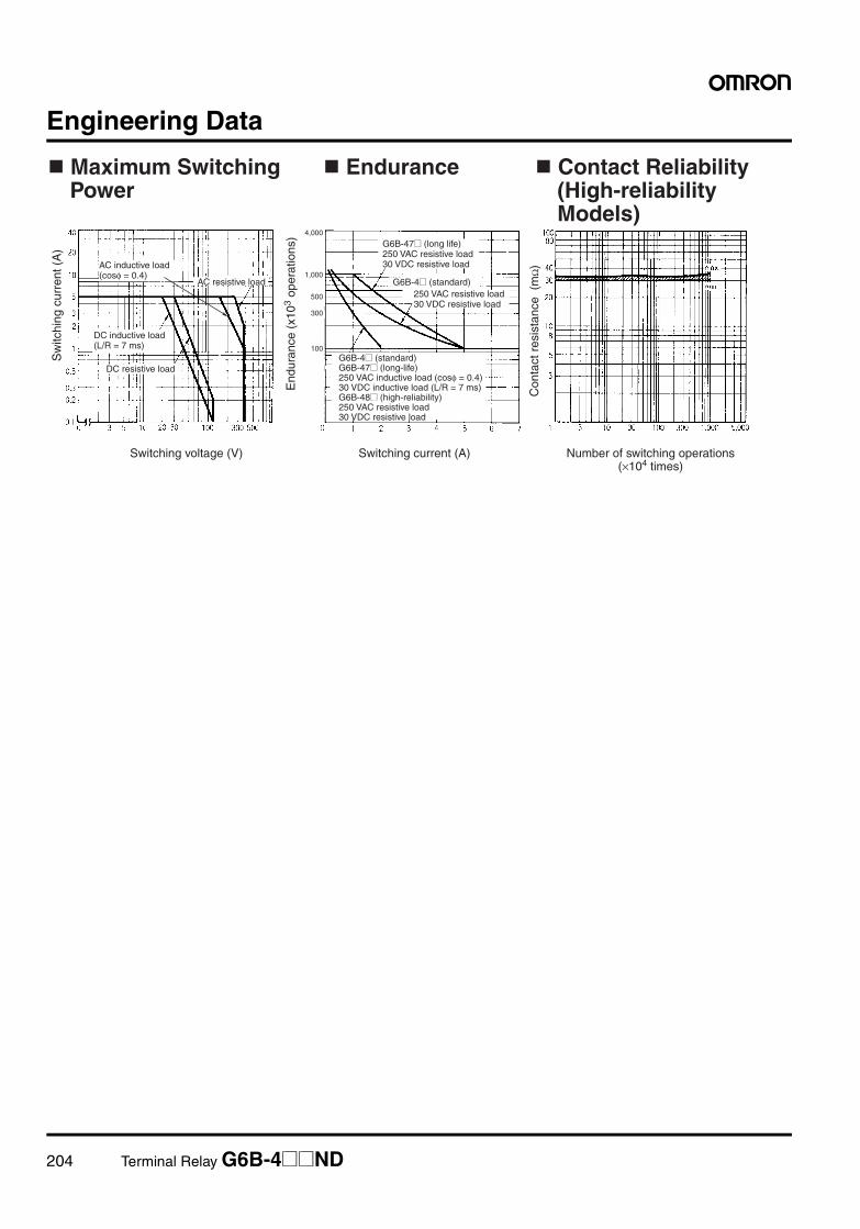
204 Terminal Relay G6B-4@@ND
Engineering Data
4,000
1,000
500
300
100
Endurance
Sw
itchi
ng c
urre
nt (
A)
End
uran
ce (
x103
oper
atio
ns)
Switching voltage (V) Switching current (A)
Con
tact
res
ista
nce
(m
Ω)
AC resistive load
DC resistive load
G6B-4@ (standard)
Contact Reliability (High-reliability Models)
AC inductive load (cosφ = 0.4)
DC inductive load (L/R = 7 ms)
G6B-47@ (long life) 250 VAC resistive load 30 VDC resistive load
250 VAC resistive load 30 VDC resistive load
G6B-4@ (standard) G6B-47@ (long-life) 250 VAC inductive load (cosφ = 0.4) 30 VDC inductive load (L/R = 7 ms) G6B-48@ (high-reliability) 250 VAC resistive load 30 VDC resistive load
Maximum Switching Power
Number of switching operations (×104 times)
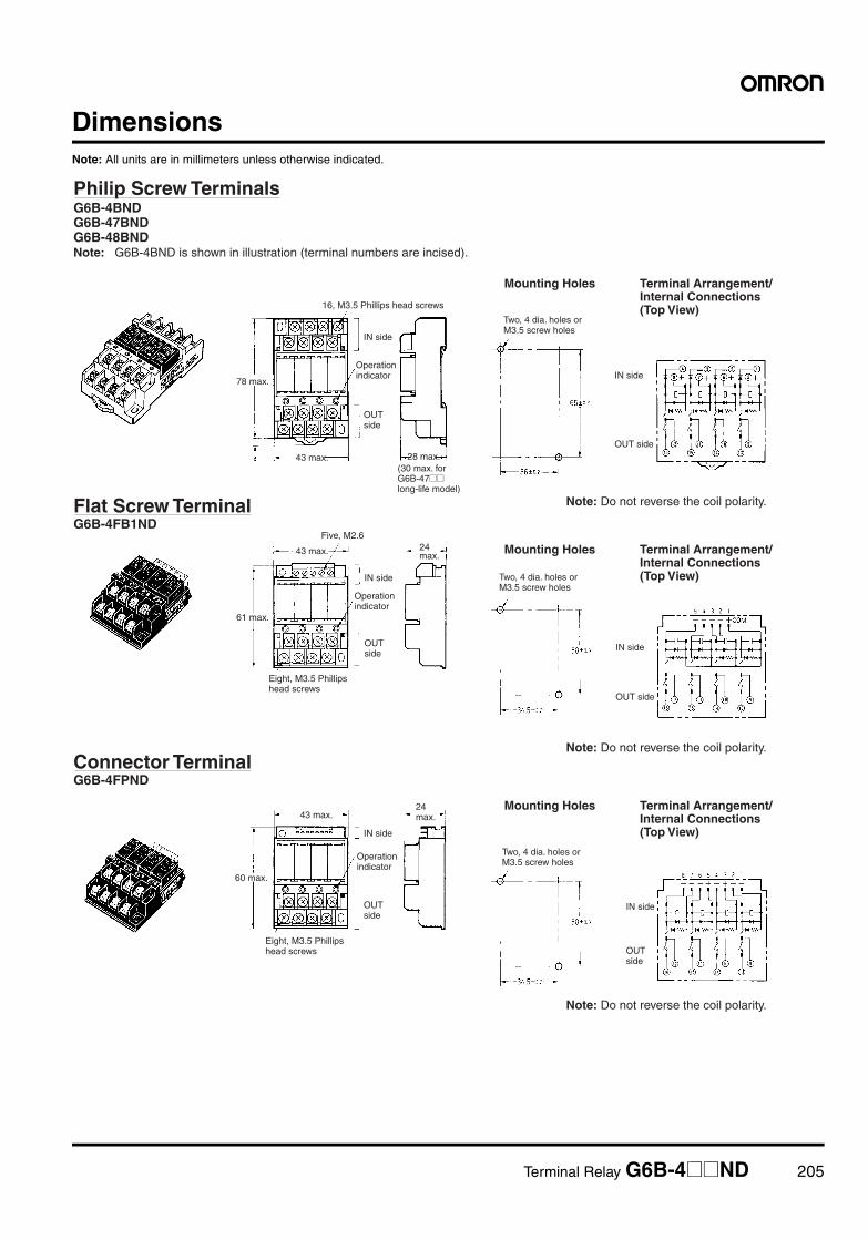
Terminal Relay G6B-4@@ND 205
DimensionsNote: All units are in millimeters unless otherwise indicated.
Philip Screw Terminals
Note: G6B-4BND is shown in illustration (terminal numbers are incised).
Mounting Holes
Flat Screw TerminalG6B-4FB1ND
Mounting Holes
Connector TerminalG6B-4FPND
Mounting Holes
Note: Do not reverse the coil polarity.
16, M3.5 Phillips head screws
IN side
43 max. 28 max.
78 max.IN side
OUT side
IN side
43 max.
61 max.
24 max.
Five, M2.6
IN side
OUT side
IN side
43 max.
60 max.
IN side
Note: Do not reverse the coil polarity.
Note: Do not reverse the coil polarity.
G6B-4BND G6B-47BND G6B-48BND
Operation indicator
OUT side
(30 max. for G6B-47@@ long-life model)
Terminal Arrangement/ Internal Connections (Top View)
Operation indicator
OUT side
Eight, M3.5 Phillips head screws
Terminal Arrangement/ Internal Connections (Top View)
Terminal Arrangement/ Internal Connections (Top View)
Eight, M3.5 Phillips head screws
Operation indicator
OUT side
24 max.
OUT side
Two, 4 dia. holes or M3.5 screw holes
Two, 4 dia. holes or M3.5 screw holes
Two, 4 dia. holes or M3.5 screw holes
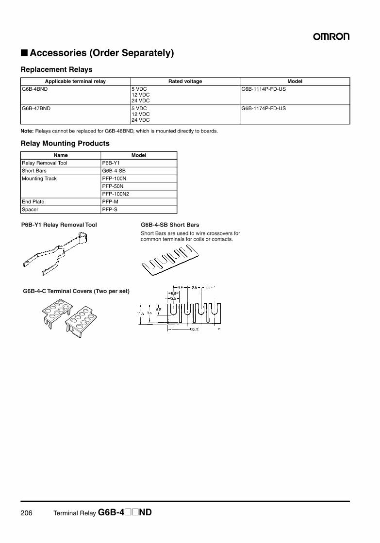
206 Terminal Relay G6B-4@@ND
Accessories (Order Separately)
Replacement Relays
Note: Relays cannot be replaced for G6B-48BND, which is mounted directly to boards.
Relay Mounting Products
Applicable terminal relay Rated voltage Model
G6B-4BND 5 VDC12 VDC24 VDC
G6B-1114P-FD-US
G6B-47BND 5 VDC12 VDC24 VDC
G6B-1174P-FD-US
Name Model
Relay Removal Tool P6B-Y1
Short Bars G6B-4-SB
Mounting Track PFP-100N
PFP-50N
PFP-100N2
End Plate PFP-M
Spacer PFP-S
P6B-Y1 Relay Removal Tool G6B-4-SB Short BarsShort Bars are used to wire crossovers for common terminals for coils or contacts.
G6B-4-C Terminal Covers (Two per set)
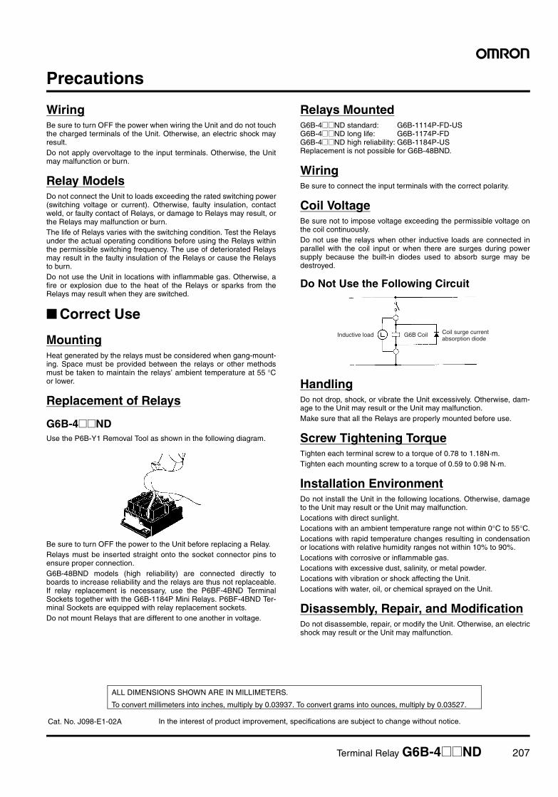
Terminal Relay G6B-4@@ND 207
Precautions
WiringBe sure to turn OFF the power when wiring the Unit and do not touchthe charged terminals of the Unit. Otherwise, an electric shock mayresult.Do not apply overvoltage to the input terminals. Otherwise, the Unitmay malfunction or burn.
Relay ModelsDo not connect the Unit to loads exceeding the rated switching power(switching voltage or current). Otherwise, faulty insulation, contactweld, or faulty contact of Relays, or damage to Relays may result, orthe Relays may malfunction or burn.The life of Relays varies with the switching condition. Test the Relaysunder the actual operating conditions before using the Relays withinthe permissible switching frequency. The use of deteriorated Relaysmay result in the faulty insulation of the Relays or cause the Relaysto burn.Do not use the Unit in locations with inflammable gas. Otherwise, afire or explosion due to the heat of the Relays or sparks from theRelays may result when they are switched.
Correct Use
MountingHeat generated by the relays must be considered when gang-mount-ing. Space must be provided between the relays or other methodsmust be taken to maintain the relays’ ambient temperature at 55 °Cor lower.
Replacement of Relays
G6B-4@@NDUse the P6B-Y1 Removal Tool as shown in the following diagram.
Be sure to turn OFF the power to the Unit before replacing a Relay.Relays must be inserted straight onto the socket connector pins toensure proper connection.G6B-48BND models (high reliability) are connected directly toboards to increase reliability and the relays are thus not replaceable.If relay replacement is necessary, use the P6BF-4BND TerminalSockets together with the G6B-1184P Mini Relays. P6BF-4BND Ter-minal Sockets are equipped with relay replacement sockets.Do not mount Relays that are different to one another in voltage.
Relays MountedG6B-4@@ND standard: G6B-1114P-FD-US G6B-4@@ND long life: G6B-1174P-FD G6B-4@@ND high reliability: G6B-1184P-US Replacement is not possible for G6B-48BND.
WiringBe sure to connect the input terminals with the correct polarity.
Coil VoltageBe sure not to impose voltage exceeding the permissible voltage onthe coil continuously.Do not use the relays when other inductive loads are connected inparallel with the coil input or when there are surges during powersupply because the built-in diodes used to absorb surge may bedestroyed.
Do Not Use the Following Circuit
HandlingDo not drop, shock, or vibrate the Unit excessively. Otherwise, dam-age to the Unit may result or the Unit may malfunction.Make sure that all the Relays are properly mounted before use.
Screw Tightening TorqueTighten each terminal screw to a torque of 0.78 to 1.18N·m.Tighten each mounting screw to a torque of 0.59 to 0.98 N·m.
Installation EnvironmentDo not install the Unit in the following locations. Otherwise, damageto the Unit may result or the Unit may malfunction.Locations with direct sunlight.Locations with an ambient temperature range not within 0°C to 55°C.Locations with rapid temperature changes resulting in condensationor locations with relative humidity ranges not within 10% to 90%.Locations with corrosive or inflammable gas.Locations with excessive dust, salinity, or metal powder.Locations with vibration or shock affecting the Unit.Locations with water, oil, or chemical sprayed on the Unit.
Disassembly, Repair, and ModificationDo not disassemble, repair, or modify the Unit. Otherwise, an electricshock may result or the Unit may malfunction.
Inductive load G6B Coil Coil surge current absorption diode
In the interest of product improvement, specifications are subject to change without notice.
ALL DIMENSIONS SHOWN ARE IN MILLIMETERS.
To convert millimeters into inches, multiply by 0.03937. To convert grams into ounces, multiply by 0.03527.
Cat. No. J098-E1-02A
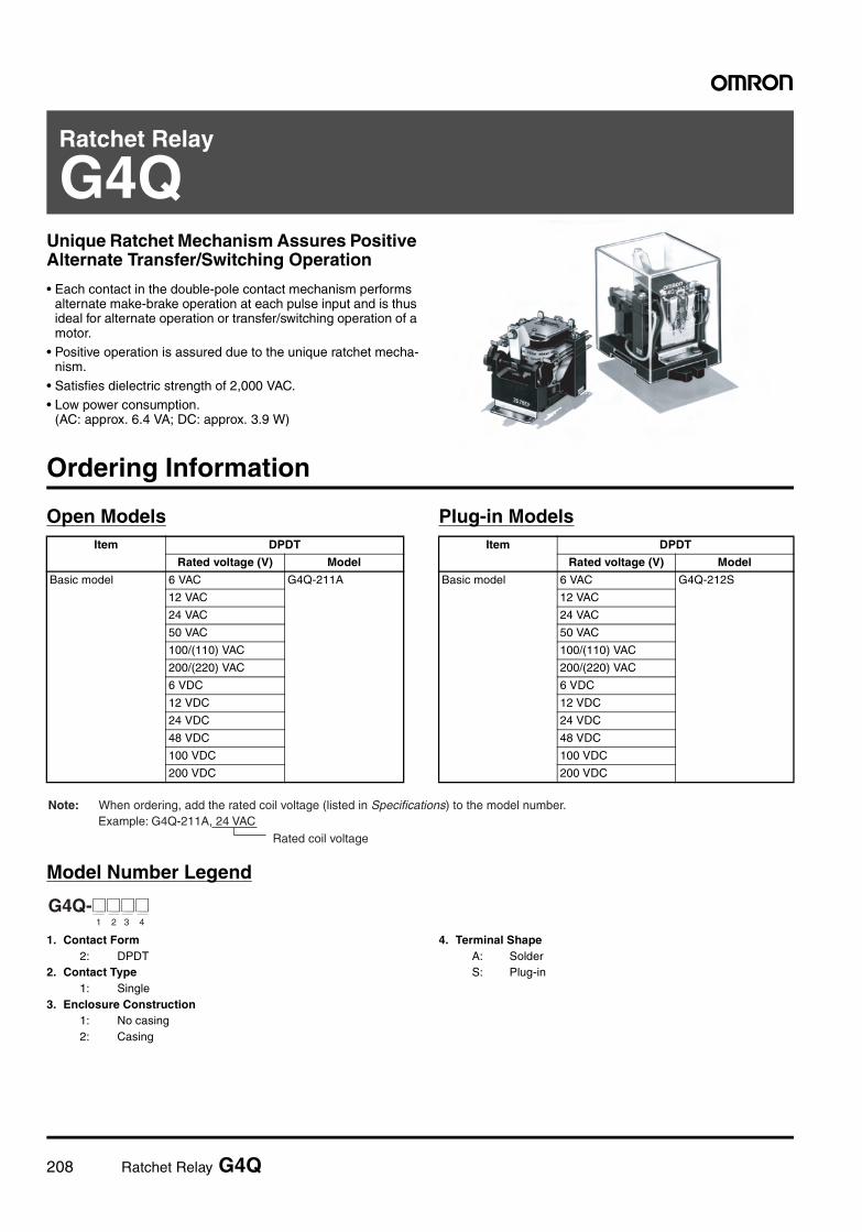
208 Ratchet Relay G4Q
Ratchet Relay
G4QUnique Ratchet Mechanism Assures Positive Alternate Transfer/Switching Operation
• Each contact in the double-pole contact mechanism performs alternate make-brake operation at each pulse input and is thus ideal for alternate operation or transfer/switching operation of a motor.
• Positive operation is assured due to the unique ratchet mecha-nism.
• Satisfies dielectric strength of 2,000 VAC.• Low power consumption.
(AC: approx. 6.4 VA; DC: approx. 3.9 W)
Ordering Information
Open Models Plug-in Models
Model Number Legend
1. Contact Form2: DPDT
2. Contact Type1: Single
3. Enclosure Construction1: No casing2: Casing
4. Terminal ShapeA: SolderS: Plug-in
Item DPDT
Rated voltage (V) Model
Basic model 6 VAC G4Q-211A
12 VAC
24 VAC
50 VAC
100/(110) VAC
200/(220) VAC
6 VDC
12 VDC
24 VDC
48 VDC
100 VDC
200 VDC
Item DPDT
Rated voltage (V) Model
Basic model 6 VAC G4Q-212S
12 VAC
24 VAC
50 VAC
100/(110) VAC
200/(220) VAC
6 VDC
12 VDC
24 VDC
48 VDC
100 VDC
200 VDC
Rated coil voltage
Note: When ordering, add the rated coil voltage (listed in Specifications) to the model number. Example: G4Q-211A, 24 VAC
G4Q-@@@@1 2 3 4
Ratchet Relay G4Q 209
Accessories (Order Separately)
Specifications
Coil Ratings
Note: 1. The rated current and coil resistance are measured at a coil temperature of 23°C with tolerances of +15%/–20% for AC rated current and±15% for DC coil resistance.
2. The AC coil resistance values are for reference only.3. Performance characteristic data is measured at a coil temperature of 23°C.4. The maximum voltage is one that is applicable instantaneously to the Relay coil at an ambient temperature of 23°C and not continuously.5. The AC power consumption is measured at 60 Hz.
Contact Ratings
DIN track/Front-connecting Socket Back-connecting Socket
Screw terminal Solder terminal
8PFA1 PL08
Item Current (mA) Resistance (Ω) Must operate Must release Max. voltage Power consumption
Rated voltage (V) 50 Hz 60 Hz % of rated voltage Initial Rated
AC 6 1,233 1,067 0.54 80 % max. 10 % min. 110 % max. Approx. 13.5 VA
Approx. 6.4 VA12 614 531 2.24
24 307 266 8.7
50 148 128 42.7
100/(110)
74 64/73.5 160
200/(220)
37 32/36.8 671
Item Current (mA) Resistance (Ω) Must operate Must release Max. voltage Power consumption
Rated voltage (V) 50 Hz 60 Hz % of rated voltage
DC 6 640 9.4 5 % min. Approx. 3.9 W
12 320 37.5
24 155 155
48 80 600
100 39 2,580
200 19.2 10,400
Load Resistive load(cosφ = 1)
Inductive load(cosφ = 0.4)(L/R = 7 ms)
Contact mechanism Single
Contact material Silver alloy
Rated load 5 A at 220 VAC, 5 A at 24 VDC 3 A at 220 VAC, 4 A at 24 VDC
Rated carry current 5 A
Max. switching voltage 250 VAC, 250 VDC
Max. switching current 5 A
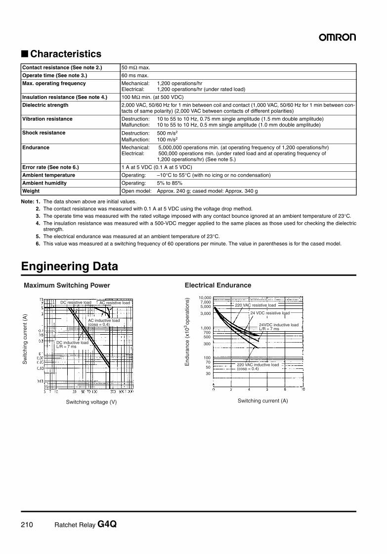
210 Ratchet Relay G4Q
Characteristics
Note: 1. The data shown above are initial values.2. The contact resistance was measured with 0.1 A at 5 VDC using the voltage drop method.3. The operate time was measured with the rated voltage imposed with any contact bounce ignored at an ambient temperature of 23°C.4. The insulation resistance was measured with a 500-VDC megger applied to the same places as those used for checking the dielectric
strength.5. The electrical endurance was measured at an ambient temperature of 23°C.6. This value was measured at a switching frequency of 60 operations per minute. The value in parentheses is for the cased model.
Engineering Data
Contact resistance (See note 2.) 50 mΩ max.
Operate time (See note 3.) 60 ms max.
Max. operating frequency Mechanical: 1,200 operations/hrElectrical: 1,200 operations/hr (under rated load)
Insulation resistance (See note 4.) 100 MΩ min. (at 500 VDC)
Dielectric strength 2,000 VAC, 50/60 Hz for 1 min between coil and contact (1,000 VAC, 50/60 Hz for 1 min between con-tacts of same polarity) (2,000 VAC between contacts of different polarities)
Vibration resistance Destruction: 10 to 55 to 10 Hz, 0.75 mm single amplitude (1.5 mm double amplitude)Malfunction: 10 to 55 to 10 Hz, 0.5 mm single amplitude (1.0 mm double amplitude)
Shock resistance Destruction: 500 m/s2
Malfunction: 100 m/s2
Endurance Mechanical: 5,000,000 operations min. (at operating frequency of 1,200 operations/hr)Electrical: 500,000 operations min. (under rated load and at operating frequency of
1,200 operations/hr) (See note 5.)
Error rate (See note 6.) 1 A at 5 VDC (0.1 A at 5 VDC)
Ambient temperature Operating: –10°C to 55°C (with no icing or no condensation)
Ambient humidity Operating: 5% to 85%
Weight Open model: Approx. 240 g; cased model: Approx. 340 g
Maximum Switching Power
DC resistive load AC resistive load
AC inductive load (cosφ = 0.4)
DC inductive loadL/R = 7 ms
Switching current (A)Switching voltage (V)
220 VAC resistive load
24 VDC resistive load
24VDC inductive loadL/R = 7 ms
220 VAC inductive load(cosφ = 0.4)
Electrical Endurance
Sw
itchi
ng c
urre
nt (
A)
End
uran
ce (
x10
ope
ratio
ns)
3
100
300
500700
1,000
3,000
5,0007,000
10,000
7050
30
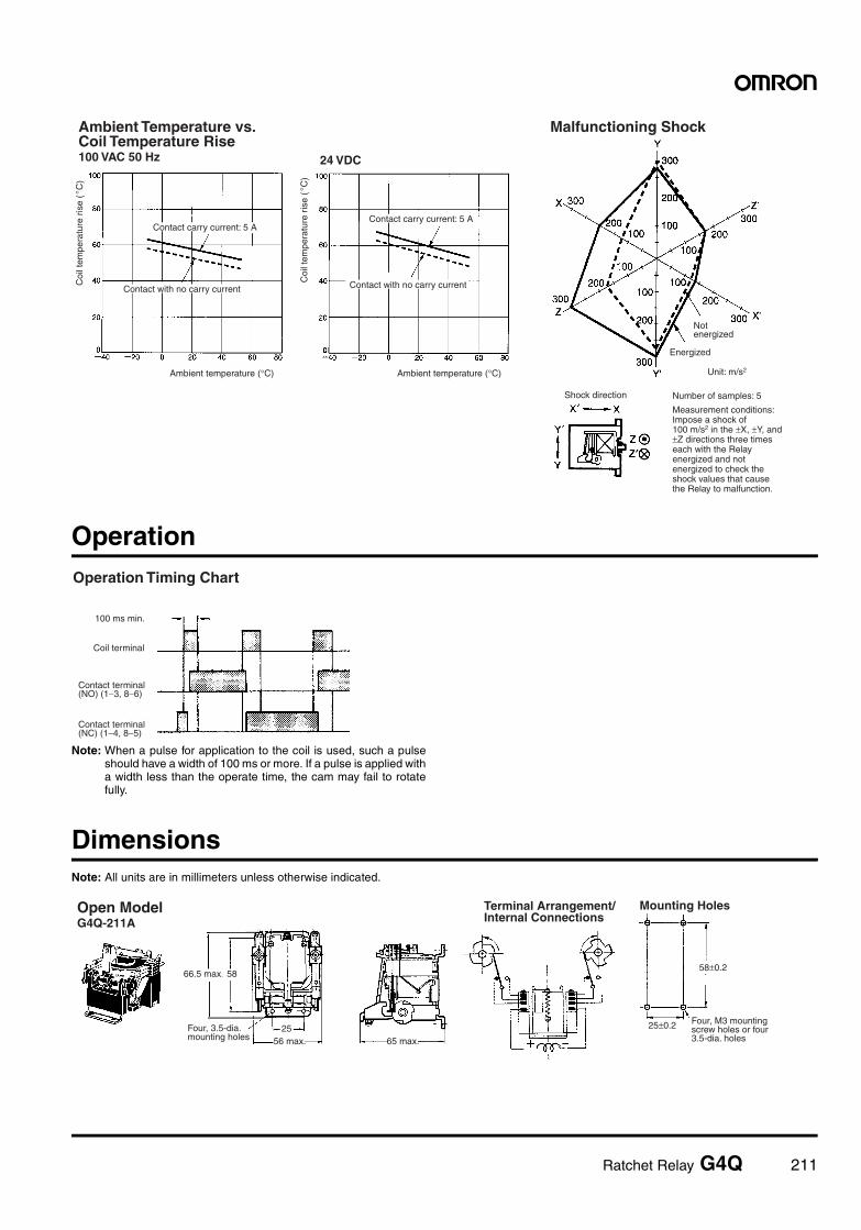
Ratchet Relay G4Q 211
Operation
Note: When a pulse for application to the coil is used, such a pulseshould have a width of 100 ms or more. If a pulse is applied witha width less than the operate time, the cam may fail to rotatefully.
DimensionsNote: All units are in millimeters unless otherwise indicated.
Ambient Temperature vs. Coil Temperature Rise100 VAC 50 Hz
Coi
l tem
pera
ture
ris
e (
C)
°
Contact carry current: 5 A
Contact with no carry current
Ambient temperature (°C)
24 VDC
Coi
l tem
pera
ture
ris
e (
C)
Contact carry current: 5 A
Contact with no carry current
Ambient temperature (°C)
Malfunctioning Shock
Not energized
Energized
Unit: m/s2
Number of samples: 5
Measurement conditions: Impose a shock of 100 m/s2 in the ±X, ±Y, and ±Z directions three times each with the Relay energized and not energized to check the shock values that cause the Relay to malfunction.
Shock direction
°
100 ms min.
Contact terminal(NO) (1−3, 8−6)
Contact terminal(NC) (1−4, 8−5)
Coil terminal
Operation Timing Chart
66.5 max. 58
Four, 3.5-dia. mounting holes
2556 max. 65 max.
Four, M3 mounting screw holes or four 3.5-dia. holes
Open ModelG4Q-211A
Terminal Arrangement/Internal Connections
Mounting Holes
58±0.2
25±0.2
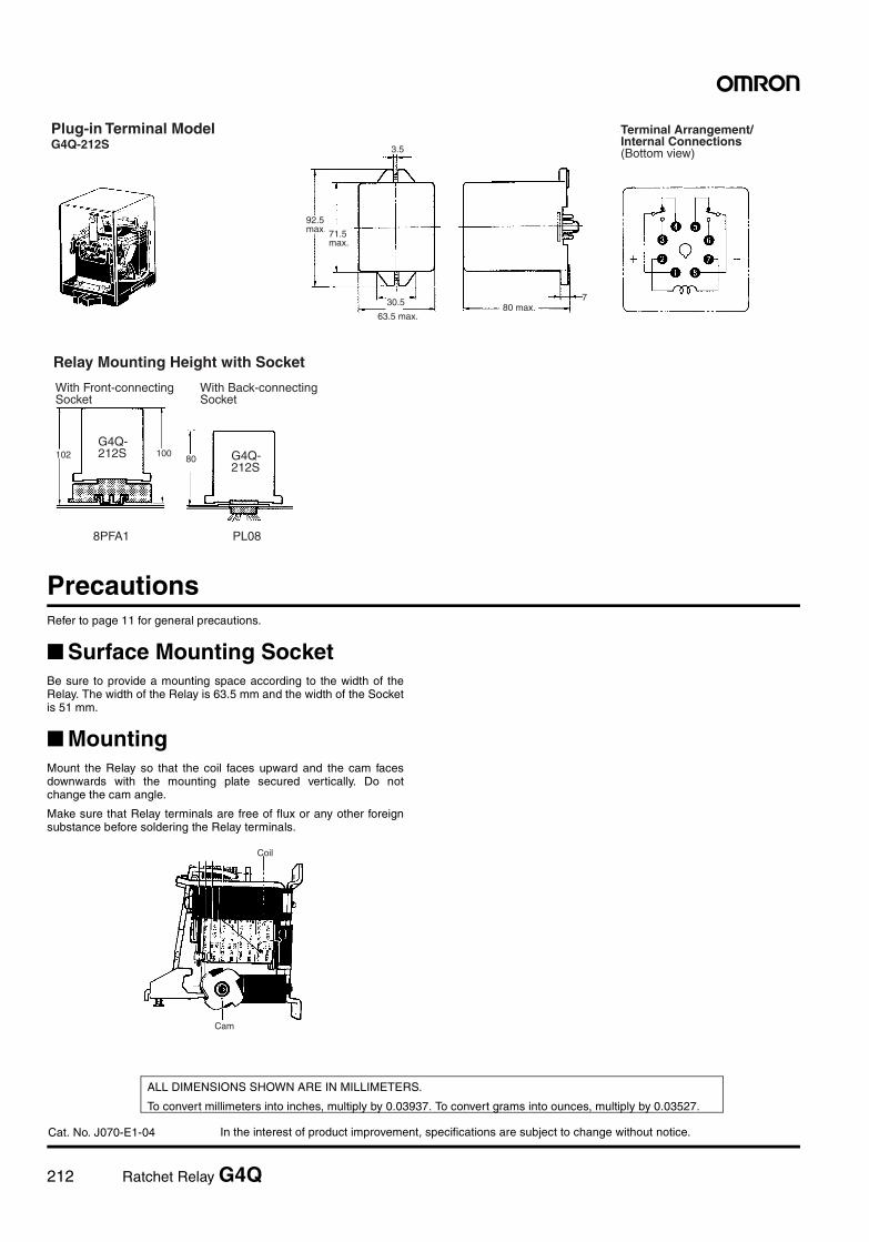
212 Ratchet Relay G4Q
In the interest of product improvement, specifications are subject to change without notice.
ALL DIMENSIONS SHOWN ARE IN MILLIMETERS.
To convert millimeters into inches, multiply by 0.03937. To convert grams into ounces, multiply by 0.03527.
Cat. No. J070-E1-04
PrecautionsRefer to page 11 for general precautions.
Surface Mounting SocketBe sure to provide a mounting space according to the width of theRelay. The width of the Relay is 63.5 mm and the width of the Socketis 51 mm.
MountingMount the Relay so that the coil faces upward and the cam facesdownwards with the mounting plate secured vertically. Do notchange the cam angle.
Make sure that Relay terminals are free of flux or any other foreignsubstance before soldering the Relay terminals.
92.5 max. 71.5
max.
30.5
63.5 max.80 max.
Plug-in Terminal ModelG4Q-212S
Terminal Arrangement/Internal Connections(Bottom view)3.5
7
102 10080
Relay Mounting Height with Socket
With Front-connecting Socket
With Back-connecting Socket
G4Q-212S G4Q-
212S
8PFA1 PL08
Coil
Cam
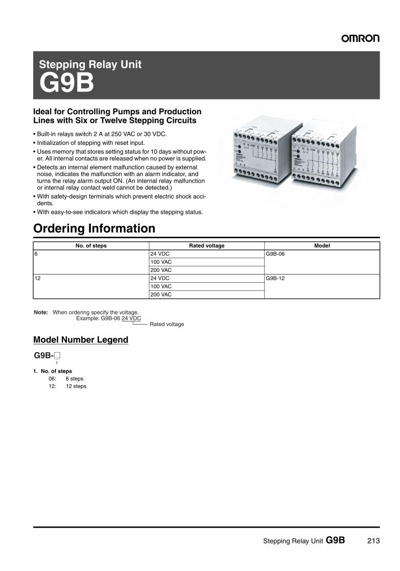
Stepping Relay Unit G9B 213
Stepping Relay Unit
G9BIdeal for Controlling Pumps and Production Lines with Six or Twelve Stepping Circuits
• Built-in relays switch 2 A at 250 VAC or 30 VDC.• Initialization of stepping with reset input.• Uses memory that stores setting status for 10 days without pow-
er. All internal contacts are released when no power is supplied.• Detects an internal element malfunction caused by external
noise, indicates the malfunction with an alarm indicator, and turns the relay alarm output ON. (An internal relay malfunction or internal relay contact weld cannot be detected.)
• With safety-design terminals which prevent electric shock acci-dents.
• With easy-to-see indicators which display the stepping status.
Ordering Information
Model Number Legend
1. No. of steps06: 6 steps12: 12 steps
No. of steps Rated voltage Model
6 24 VDC G9B-06
100 VAC
200 VAC
12 24 VDC G9B-12
100 VAC
200 VAC
Rated voltage
Note: When ordering specify the voltage. Example: G9B-06 24 VDC
G9B-@1
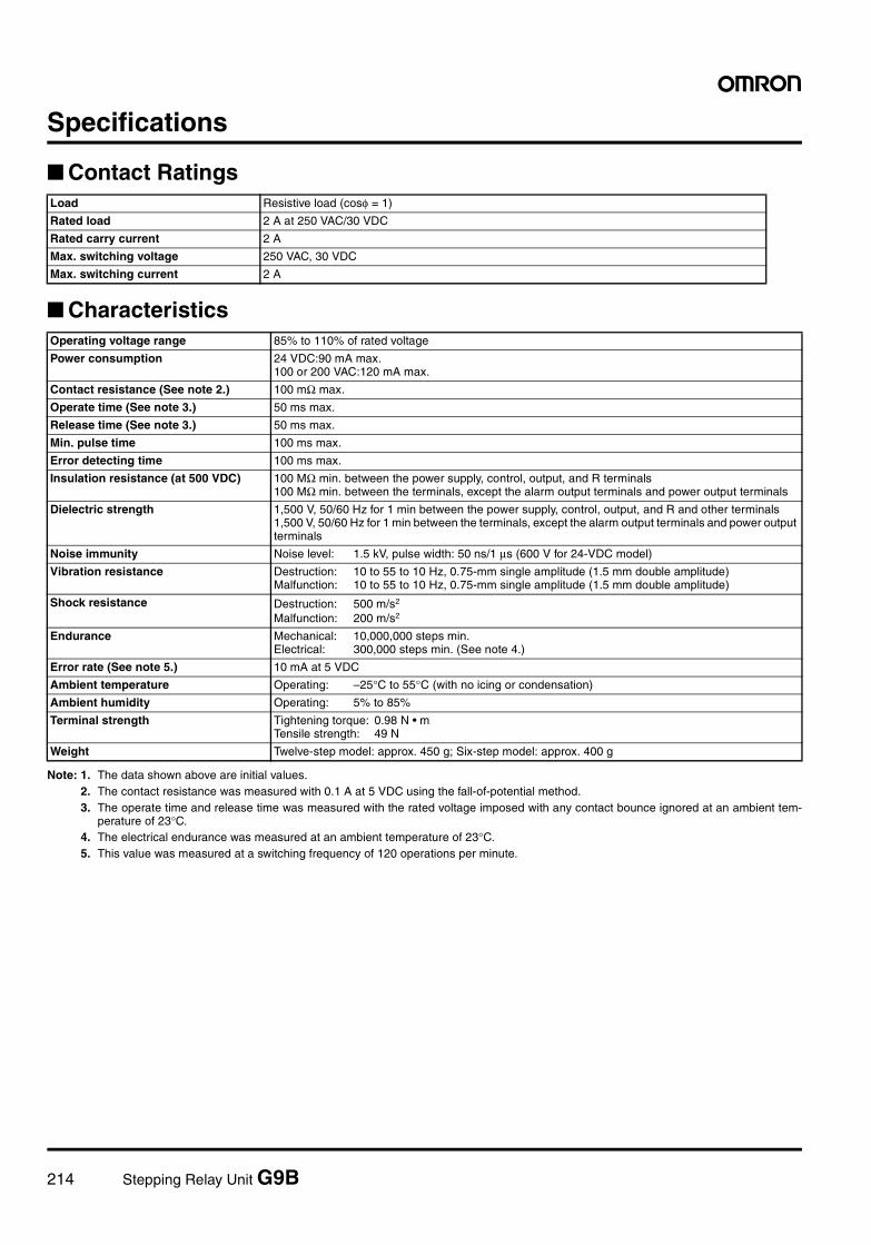
214 Stepping Relay Unit G9B
Specifications
Contact Ratings
Characteristics
Note: 1. The data shown above are initial values.2. The contact resistance was measured with 0.1 A at 5 VDC using the fall-of-potential method.3. The operate time and release time was measured with the rated voltage imposed with any contact bounce ignored at an ambient tem-
perature of 23°C.4. The electrical endurance was measured at an ambient temperature of 23°C.5. This value was measured at a switching frequency of 120 operations per minute.
Load Resistive load (cosφ = 1)
Rated load 2 A at 250 VAC/30 VDC
Rated carry current 2 A
Max. switching voltage 250 VAC, 30 VDC
Max. switching current 2 A
Operating voltage range 85% to 110% of rated voltage
Power consumption 24 VDC:90 mA max.100 or 200 VAC:120 mA max.
Contact resistance (See note 2.) 100 mΩ max.
Operate time (See note 3.) 50 ms max.
Release time (See note 3.) 50 ms max.
Min. pulse time 100 ms max.
Error detecting time 100 ms max.
Insulation resistance (at 500 VDC) 100 MΩ min. between the power supply, control, output, and R terminals100 MΩ min. between the terminals, except the alarm output terminals and power output terminals
Dielectric strength 1,500 V, 50/60 Hz for 1 min between the power supply, control, output, and R and other terminals1,500 V, 50/60 Hz for 1 min between the terminals, except the alarm output terminals and power output terminals
Noise immunity Noise level: 1.5 kV, pulse width: 50 ns/1 µs (600 V for 24-VDC model)
Vibration resistance Destruction: 10 to 55 to 10 Hz, 0.75-mm single amplitude (1.5 mm double amplitude)Malfunction: 10 to 55 to 10 Hz, 0.75-mm single amplitude (1.5 mm double amplitude)
Shock resistance Destruction: 500 m/s2
Malfunction: 200 m/s2
Endurance Mechanical: 10,000,000 steps min.Electrical: 300,000 steps min. (See note 4.)
Error rate (See note 5.) 10 mA at 5 VDC
Ambient temperature Operating: –25°C to 55°C (with no icing or condensation)
Ambient humidity Operating: 5% to 85%
Terminal strength Tightening torque: 0.98 N • mTensile strength: 49 N
Weight Twelve-step model: approx. 450 g; Six-step model: approx. 400 g
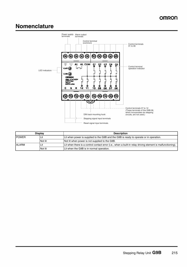
Stepping Relay Unit G9B 215
Nomenclature
LED indicators
Power supply terminals
Alarm output terminals
Control terminal (common) Control terminals
01 to 06
Control terminal operation indicator
Control terminals 07 to 12 (These terminals of the G9B-06, which incorporates six stepping circuits, are not used.)DIN track mounting hook
Stepping signal input terminals
Reset signal input terminals.
Display Description
POWER Lit Lit when power is supplied to the G9B and the G9B is ready to operate or in operation.
Not lit Not lit when power is not supplied to the G9B.
ALARM Lit Lit when there is a control contact error (i.e., when a built-in relay driving element is malfunctioning).
Not lit Lit when the G9B is in normal operation.
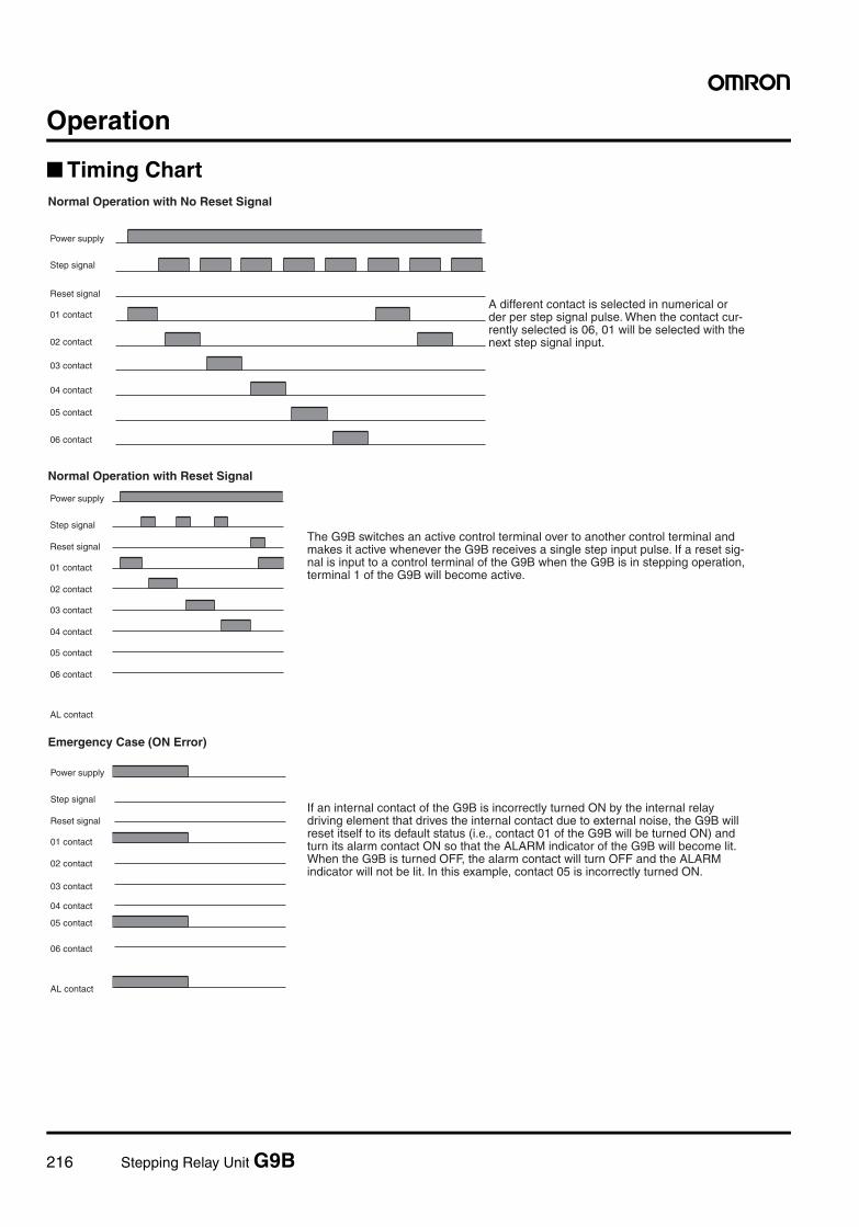
216 Stepping Relay Unit G9B
Operation
Timing Chart
Normal Operation with Reset Signal
Emergency Case (ON Error)
Power supply
Step signal
Reset signal
01 contact
02 contact
03 contact
04 contact
05 contact
06 contact
AL contact
Power supply
Step signal
Reset signal
01 contact
02 contact
03 contact
04 contact
05 contact
06 contact
AL contact
The G9B switches an active control terminal over to another control terminal and makes it active whenever the G9B receives a single step input pulse. If a reset sig- nal is input to a control terminal of the G9B when the G9B is in stepping operation, terminal 1 of the G9B will become active.
If an internal contact of the G9B is incorrectly turned ON by the internal relay driving element that drives the internal contact due to external noise, the G9B will reset itself to its default status (i.e., contact 01 of the G9B will be turned ON) and turn its alarm contact ON so that the ALARM indicator of the G9B will become lit. When the G9B is turned OFF, the alarm contact will turn OFF and the ALARM indicator will not be lit. In this example, contact 05 is incorrectly turned ON.
Normal Operation with No Reset Signal
Power supply
Step signal
Reset signal
01 contact
02 contact
03 contact
04 contact
05 contact
06 contact
A different contact is selected in numerical order per step signal pulse. When the contact cur- rently selected is 06, 01 will be selected with the next step signal input.
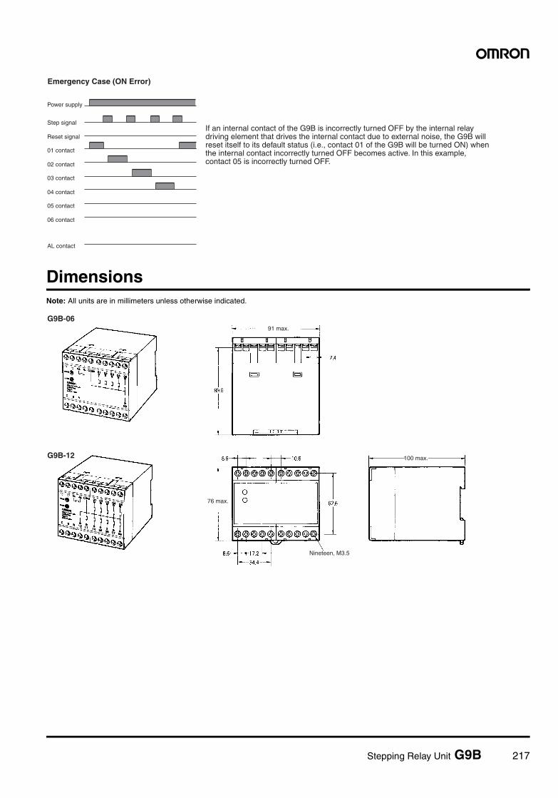
Stepping Relay Unit G9B 217
DimensionsNote: All units are in millimeters unless otherwise indicated.
Power supply
Step signal
Reset signal
01 contact
02 contact
03 contact
04 contact
05 contact
06 contact
AL contact
Emergency Case (ON Error)
If an internal contact of the G9B is incorrectly turned OFF by the internal relay driving element that drives the internal contact due to external noise, the G9B will reset itself to its default status (i.e., contact 01 of the G9B will be turned ON) when the internal contact incorrectly turned OFF becomes active. In this example, contact 05 is incorrectly turned OFF.
91 max.
100 max.
76 max.
Nineteen, M3.5
G9B-06
G9B-12
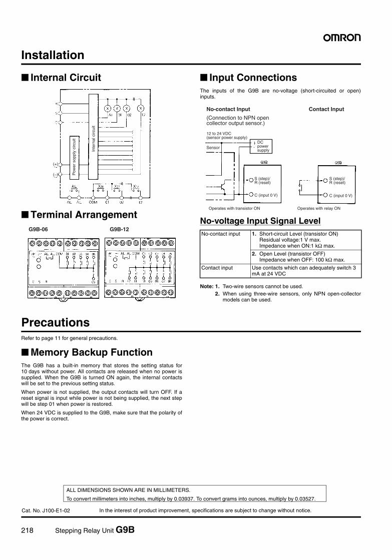
218 Stepping Relay Unit G9B
In the interest of product improvement, specifications are subject to change without notice.
ALL DIMENSIONS SHOWN ARE IN MILLIMETERS.
To convert millimeters into inches, multiply by 0.03937. To convert grams into ounces, multiply by 0.03527.
Cat. No. J100-E1-02
Installation
Internal Circuit
Terminal Arrangement
Input ConnectionsThe inputs of the G9B are no-voltage (short-circuited or open)inputs.
No-voltage Input Signal Level
Note: 1. Two-wire sensors cannot be used.2. When using three-wire sensors, only NPN open-collector
models can be used.
PrecautionsRefer to page 11 for general precautions.
Memory Backup FunctionThe G9B has a built-in memory that stores the setting status for10 days without power. All contacts are released when no power issupplied. When the G9B is turned ON again, the internal contactswill be set to the previous setting status.
When power is not supplied, the output contacts will turn OFF. If areset signal is input while power is not being supplied, the next stepwill be step 01 when power is restored.
When 24 VDC is supplied to the G9B, make sure that the polarity ofthe power is correct.
Pow
er s
oppl
y ci
rcui
t
Inte
rnal
circ
uit
(+)
(−)
G9B-06 G9B-12No-contact input 1. Short-circuit Level (transistor ON)
Residual voltage:1 V max.Impedance when ON:1 kΩ max.
2. Open Level (transistor OFF)Impedance when OFF: 100 kΩ max.
Contact input Use contacts which can adequately switch 3 mA at 24 VDC
12 to 24 VDC (sensor power supply)
SensorDC power supply
S (step)/R (reset)
C (input 0 V)
Operates with transistor ON Operates with relay ON
S (step)/R (reset)
C (input 0 V)
No-contact Input
(Connection to NPN open collector output sensor.)
Contact Input
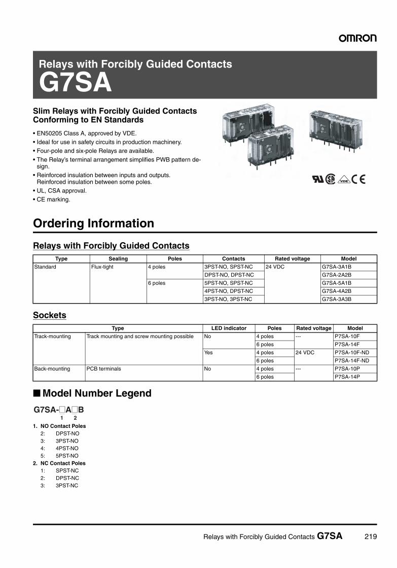
Relays with Forcibly Guided Contacts G7SA 219
Relays with Forcibly Guided Contacts
G7SASlim Relays with Forcibly Guided Contacts Conforming to EN Standards
• EN50205 Class A, approved by VDE.• Ideal for use in safety circuits in production machinery.• Four-pole and six-pole Relays are available.
• The Relay’s terminal arrangement simplifies PWB pattern de-sign.
• Reinforced insulation between inputs and outputs. Reinforced insulation between some poles.
• UL, CSA approval.• CE marking.
Ordering Information
Relays with Forcibly Guided Contacts
Sockets
Model Number Legend
1. NO Contact Poles2: DPST-NO3: 3PST-NO4: 4PST-NO5: 5PST-NO
2. NC Contact Poles1: SPST-NC2: DPST-NC3: 3PST-NC
Type Sealing Poles Contacts Rated voltage Model
Standard Flux-tight 4 poles 3PST-NO, SPST-NC 24 VDC G7SA-3A1B
DPST-NO, DPST-NC G7SA-2A2B
6 poles 5PST-NO, SPST-NC G7SA-5A1B
4PST-NO, DPST-NC G7SA-4A2B
3PST-NO, 3PST-NC G7SA-3A3B
Type LED indicator Poles Rated voltage Model
Track-mounting Track mounting and screw mounting possible No 4 poles --- P7SA-10F
6 poles P7SA-14F
Yes 4 poles 24 VDC P7SA-10F-ND
6 poles P7SA-14F-ND
Back-mounting PCB terminals No 4 poles --- P7SA-10P
6 poles P7SA-14P
1 2G7SA-@A@B
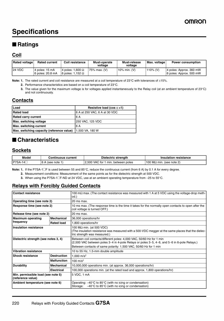
220 Relays with Forcibly Guided Contacts G7SA
Specifications
Ratings
Coil
Note: 1. The rated current and coil resistance are measured at a coil temperature of 23°C with tolerances of ±15%.2. Performance characteristics are based on a coil temperature of 23°C.3. The value given for the maximum voltage is for voltages applied instantaneously to the Relay coil (at an ambient temperature of 23°C)
and not continuously.
Contacts
Characteristics
Sockets
Note: 1. If the P7SA-1@F is used between 55 and 85°C, reduce the continuous current (from 6 A) by 0.1 A for every degree.2. Measurement conditions: Measurement of the same points as for the dielectric strength at 500 VDC.3. When using the P7SA-1@F-ND at 24 VDC, use at an ambient operating temperature from −25 to 55°C.
Relays with Forcibly Guided Contacts
Rated voltage Rated current Coil resistance Must-operate voltage
Must-release voltage
Max. voltage Power consumption
24 VDC 4 poles: 15 mA6 poles: 20.8 mA
4 poles: 1,600 Ω6 poles: 1,152 Ω
75% max. (V) 10% min. (V) 110% (V) 4 poles: Approx. 360 mW6 poles: Approx. 500 mW
Load Resistive load (cos φ =1)
Rated load 6 A at 250 VAC, 6 A at 30 VDC
Rated carry current 6 A
Max. switching voltage 250 VAC, 125 VDC
Max. switching current 6 A
Max. switching capacity (reference value) 1,500 VA, 180 W
Model Continuous current Dielectric strength Insulation resistance
P7SA-14@ 6 A (see note 1) 2,500 VAC for 1 min. between poles 100 MΩ min. (see note 2)
Contact resistance 100 mΩ max. (The contact resistance was measured with 1 A at 5 VDC using the voltage-drop meth-od.)
Operating time (see note 2) 20 ms max.
Response time (see note 2) 10 ms max. (The response time is the time it takes for the normally open contacts to open after the coil voltage is turned OFF.)
Release time (see note 2) 20 ms max.
Maximum operating frequency
Mechanical 36,000 operations/hr
Rated load 1,800 operations/hr
Insulation resistance 100 MΩ min. (at 500 VDC)(The insulation resistance was measured with a 500-VDC megger at the same places that the dielec-tric strength was measured.)
Dielectric strength (see notes 3, 4) Between coil contacts/different poles: 4,000 VAC, 50/60 Hz for 1 min(2,500 VAC between poles 3−4 in 4-pole Relays or poles 3−5, 4−6, and 5−6 in 6-pole Relays.)Between contacts of same polarity: 1,500 VAC, 50/60 Hz for 1 min
Vibration resistance 10 to 55 Hz, 1.5-mm double amplitude
Shock resistance Destruction 1,000 m/s2
Malfunction 100 m/s2
Durability Mechanical 10,000,000 operations min. (at approx. 36,000 operations/hr)
Electrical 100,000 operations min. (at the rated load and approx. 1,800 operations/hr)
Min. permissible load (see note 5) (reference value)
5 VDC, 1 mA
Ambient temperature (see note 6) Operating: −40°C to 85°C (with no icing or condensation)Storage: −40°C to 85°C (with no icing or condensation)
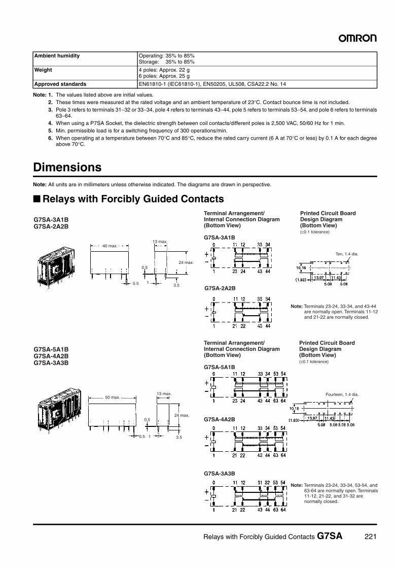
Relays with Forcibly Guided Contacts G7SA 221
Note: 1. The values listed above are initial values.2. These times were measured at the rated voltage and an ambient temperature of 23°C. Contact bounce time is not included.3. Pole 3 refers to terminals 31−32 or 33−34, pole 4 refers to terminals 43−44, pole 5 refers to terminals 53−54, and pole 6 refers to terminals
63−64.4. When using a P7SA Socket, the dielectric strength between coil contacts/different poles is 2,500 VAC, 50/60 Hz for 1 min.5. Min. permissible load is for a switching frequency of 300 operations/min.6. When operating at a temperature between 70°C and 85°C, reduce the rated carry current (6 A at 70°C or less) by 0.1 A for each degree
above 70°C.
DimensionsNote: All units are in millimeters unless otherwise indicated. The diagrams are drawn in perspective.
Relays with Forcibly Guided Contacts
Ambient humidity Operating: 35% to 85%Storage: 35% to 85%
Weight 4 poles: Approx. 22 g6 poles: Approx. 25 g
Approved standards EN61810-1 (IEC61810-1), EN50205, UL508, CSA22.2 No. 14
0.5
0.5
3.51
0.5
0.5
3.51
G7SA-2A2B
G7SA-4A2B
G7SA-3A3B
40 max.13 max.
24 max.
Ten, 1.4 dia.
50 max.13 max.
24 max.
Fourteen, 1.4 dia.
(±0.1 tolerance)
(±0.1 tolerance)
G7SA-3A1B G7SA-2A2B
G7SA-5A1B G7SA-4A2B G7SA-3A3B
Terminal Arrangement/ Internal Connection Diagram (Bottom View)
G7SA-3A1B
Printed Circuit Board Design Diagram (Bottom View)
Note: Terminals 23-24, 33-34, and 43-44 are normally open. Terminals 11-12 and 21-22 are normally closed.
Terminal Arrangement/ Internal Connection Diagram (Bottom View)
G7SA-5A1B
Printed Circuit Board Design Diagram (Bottom View)
Note: Terminals 23-24, 33-34, 53-54, and 63-64 are normally open. Terminals 11-12, 21-22, and 31-32 are normally closed.
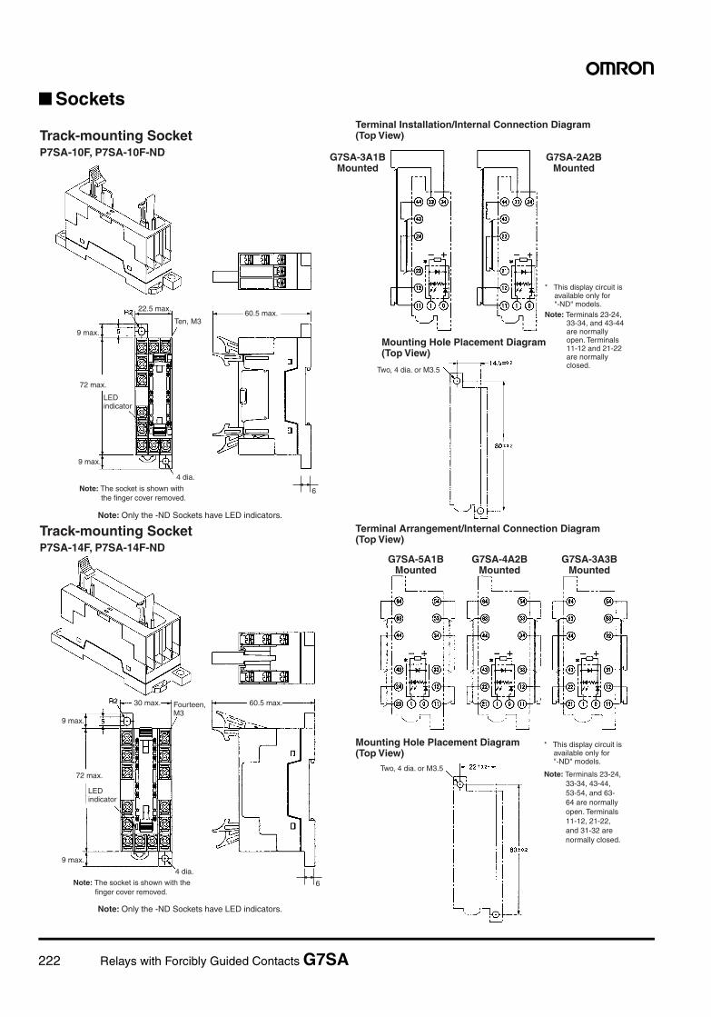
222 Relays with Forcibly Guided Contacts G7SA
Sockets
6
6
Track-mounting SocketP7SA-10F, P7SA-10F-ND
Two, 4 dia. or M3.5
4 dia.
22.5 max.60.5 max.
9 max.
72 max.
9 max.
Track-mounting SocketP7SA-14F, P7SA-14F-ND
4 dia.
30 max. 60.5 max.
9 max.
72 max.
9 max.
Two, 4 dia. or M3.5
Note: Only the -ND Sockets have LED indicators.
Note: Only the -ND Sockets have LED indicators.
Ten, M3
LED indicator
Note: The socket is shown with the finger cover removed.
Terminal Installation/Internal Connection Diagram (Top View)
G7SA-3A1B Mounted
G7SA-2A2B Mounted
* This display circuit is available only for "-ND" models.
Note: Terminals 23-24, 33-34, and 43-44 are normally open. Terminals 11-12 and 21-22 are normally closed.
Mounting Hole Placement Diagram (Top View)
LED indicator
Fourteen, M3
Note: The socket is shown with the finger cover removed.
Terminal Arrangement/Internal Connection Diagram (Top View)
G7SA-5A1B Mounted
G7SA-4A2B Mounted
G7SA-3A3B Mounted
Mounting Hole Placement Diagram (Top View)
* This display circuit is available only for "-ND" models.
Note: Terminals 23-24, 33-34, 43-44, 53-54, and 63-64 are normally open. Terminals 11-12, 21-22, and 31-32 are normally closed.
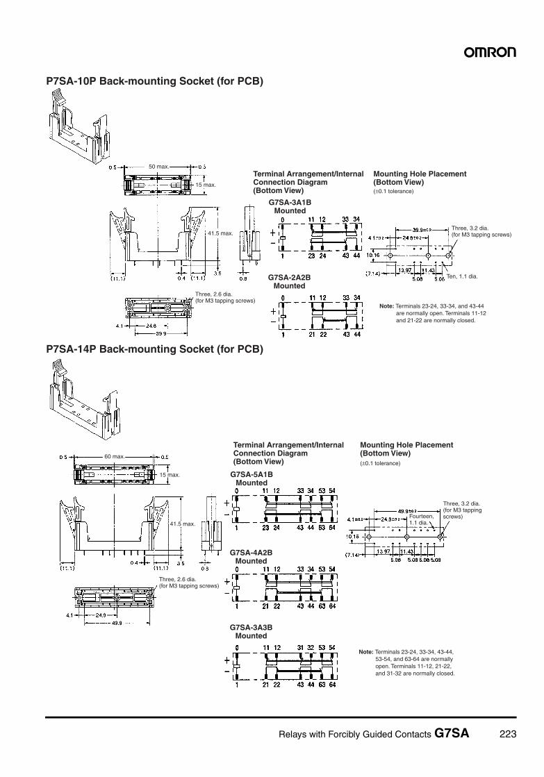
Relays with Forcibly Guided Contacts G7SA 223
P7SA-10P Back-mounting Socket (for PCB)
50 max.
41.5 max.
Ten, 1.1 dia.
15 max.(±0.1 tolerance)
Three, 2.6 dia. (for M3 tapping screws)
Terminal Arrangement/Internal Connection Diagram (Bottom View)
Mounting Hole Placement (Bottom View)
G7SA-3A1B Mounted
G7SA-2A2B Mounted
Three, 3.2 dia. (for M3 tapping screws)
Note: Terminals 23-24, 33-34, and 43-44 are normally open. Terminals 11-12 and 21-22 are normally closed.
P7SA-14P Back-mounting Socket (for PCB)
60 max.
41.5 max.
15 max.
(±0.1 tolerance)
Three, 2.6 dia. (for M3 tapping screws)
Terminal Arrangement/Internal Connection Diagram (Bottom View)
Mounting Hole Placement (Bottom View)
G7SA-5A1B Mounted
G7SA-4A2B Mounted
G7SA-3A3B Mounted
Note: Terminals 23-24, 33-34, 43-44, 53-54, and 63-64 are normally open. Terminals 11-12, 21-22, and 31-32 are normally closed.
Fourteen, 1.1 dia.
Three, 3.2 dia. (for M3 tapping screws)
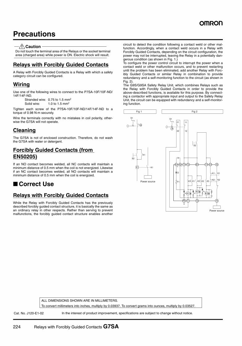
224 Relays with Forcibly Guided Contacts G7SA
Precautions
!CautionDo not touch the terminal area of the Relays or the socket terminalarea (charged area) while power is ON. Electric shock will result.
Relays with Forcibly Guided ContactsA Relay with Forcibly Guided Contacts is a Relay with which a safetycategory circuit can be configured.
WiringUse one of the following wires to connect to the P7SA-10F/10F-ND/14F/14F-ND.
Stranded wire: 0.75 to 1.5 mm2
Solid wire: 1.0 to 1.5 mm2
Tighten each screw of the P7SA-10F/10F-ND/14F/14F-ND to atorque of 0.98 N·m securely.
Wire the terminals correctly with no mistakes in coil polarity, other-wise the G7SA will not operate.
CleaningThe G7SA is not of enclosed construction. Therefore, do not washthe G7SA with water or detergent.
Forcibly Guided Contacts (from EN50205)If an NO contact becomes welded, all NC contacts will maintain aminimum distance of 0.5 mm when the coil is not energized. Likewiseif an NC contact becomes welded, all NO contacts will maintain aminimum distance of 0.5 mm when the coil is energized.
Correct Use
Relays with Forcibly Guided ContactsWhile the Relay with Forcibly Guided Contacts has the previouslydescribed forcibly guided contact structure, it is basically the same asan ordinary relay in other respects. Rather than serving to preventmalfunctions, the forcibly guided contact structure enables another
circuit to detect the condition following a contact weld or other mal-function. Accordingly, when a contact weld occurs in a Relay withForcibly Guided Contacts, depending on the circuit configuration, thepower may not be interrupted, leaving the Relay in a potentially dan-gerous condition (as shown in Fig. 1.) To configure the power control circuit to interrupt the power when acontact weld or other malfunction occurs, and to prevent restartinguntil the problem has been eliminated, add another Relay with Forc-ibly Guided Contacts or similar Relay in combination to provideredundancy and a self-monitoring function to the circuit (as shown inFig. 2).The G9S/G9SA Safety Relay Unit, which combines Relays such asthe Relay with Forcibly Guided Contacts in order to provide theabove-described functions, is available for this purpose. By connect-ing a contactor with appropriate input and output to the Safety RelayUnit, the circuit can be equipped with redundancy and a self-monitor-ing function.
K1
S1
S2
K1
K1
S1
11
12
21
22
S2
K1K2
K3
+ −
D
F1 K3 K1
K1 K1
K3 K2K2 K2
K3
A1 A2 T11 T12 Y1 X1 13B1
PE T21 T22 14
Fig 1 Fig 2
Power source
Power source
In the interest of product improvement, specifications are subject to change without notice.
ALL DIMENSIONS SHOWN ARE IN MILLIMETERS.
To convert millimeters into inches, multiply by 0.03937. To convert grams into ounces, multiply by 0.03527.
Cat. No. J120-E1-02
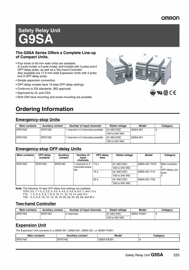
Safety Relay Unit G9SA 225
Safety Relay Unit
G9SAThe G9SA Series Offers a Complete Line-up of Compact Units.
• Four kinds of 45-mm wide Units are available: A 3-pole model, a 5-pole model, and models with 3 poles and 2 OFF-delay poles, as well as a Two-hand Controller.Also available are 17.5-mm wide Expansion Units with 3 poles and 3 OFF-delay poles.
• Simple expansion connection.
• OFF-delay models have 15-step OFF-delay settings.• Conforms to EN standards. (BG approval)• Approved by UL and CSA.
• Both DIN track mounting and screw mounting are possible.
Ordering Information
Emergency-stop Units
Emergency-stop OFF-delay Units
Note: The following 15-step OFF-delay time settings are available:T075: 0.5, 1, 1.5, 2, 2.5, 3, 3.5, 4, 4.5, 5, 5.5, 6, 6.5, 7, and 7.5 sT15: 1, 2, 3, 4, 5, 6, 7, 8, 9, 10, 11, 12, 13, 14, and 15 sT30: 2, 4, 6, 8, 10, 12, 14, 16, 18, 20, 22, 24, 26, 28, and 30 s
Two-hand Controller
Expansion UnitThe Expansion Unit connects to a G9SA-301, G9SA-501, G9SA-321, or G9SA-TH301.
Main contacts Auxiliary contact Number of input channels Rated voltage Model Category
3PST-NO SPST-NC 1 channel or 2 channels possible 24 VAC/VDC G9SA-301 4
100 to 240 VAC
5PST-NO SPST-NC 1 channel or 2 channels possible 24 VAC/VDC G9SA-501
100 to 240 VAC
Main contacts OFF-delay contacts
Auxiliary contact
Number of input
channels
OFF-delay time
Rated voltage Model Category
3PST-NO DPST-NO SPST-NC 1 channel or 2 channels possi-ble
7.5 s 24 VAC/VDC G9SA-321-T075 Main contacts:4OFF-delay con-tacts:3
100 to 240 VAC
15 s 24 VAC/VDC G9SA-321-T15
100 to 240 VAC
30 s 24 VAC/VDC G9SA-321-T30
100 to 240 VAC
Main contacts Auxiliary contact Number of input channels Rated voltage Model Category
3PST-NO SPST-NC 2 channels 24 VAC/VDC G9SA-TH301 4
100 to 240 VAC
Main contacts Auxiliary contact Model Category
3PST-NO SPST-NC G9SA-EX301 4
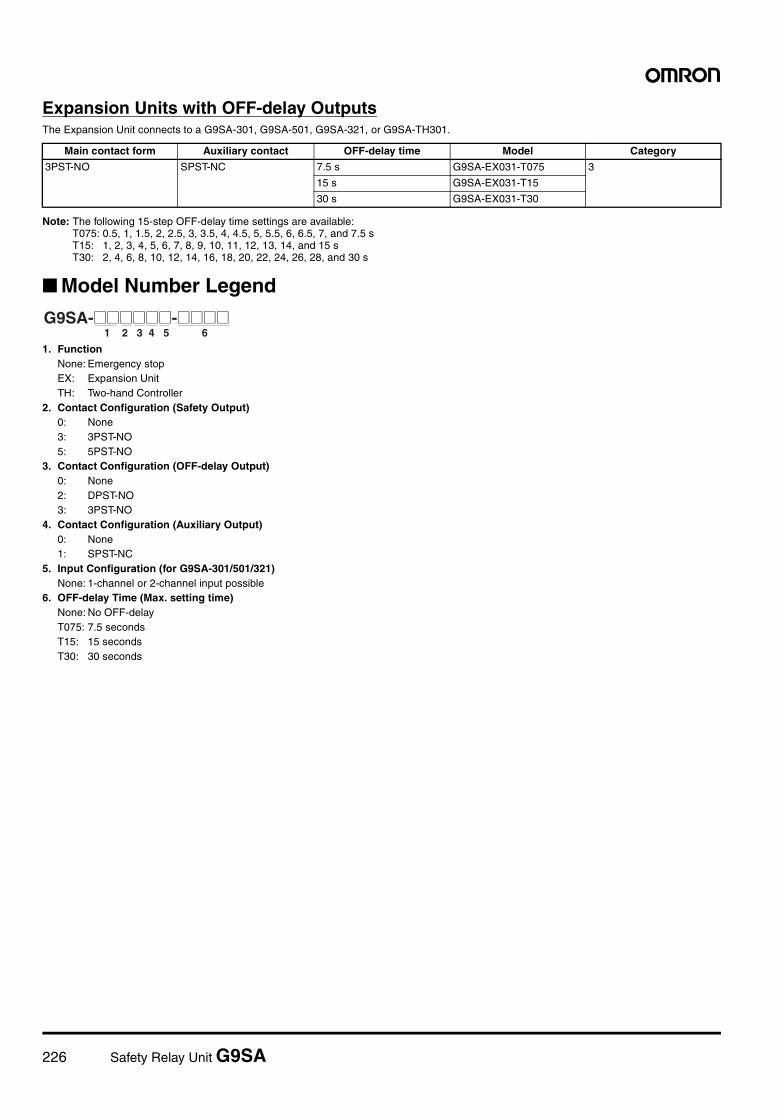
226 Safety Relay Unit G9SA
Expansion Units with OFF-delay OutputsThe Expansion Unit connects to a G9SA-301, G9SA-501, G9SA-321, or G9SA-TH301.
Note: The following 15-step OFF-delay time settings are available:T075: 0.5, 1, 1.5, 2, 2.5, 3, 3.5, 4, 4.5, 5, 5.5, 6, 6.5, 7, and 7.5 sT15: 1, 2, 3, 4, 5, 6, 7, 8, 9, 10, 11, 12, 13, 14, and 15 sT30: 2, 4, 6, 8, 10, 12, 14, 16, 18, 20, 22, 24, 26, 28, and 30 s
Model Number Legend
1. FunctionNone: Emergency stopEX: Expansion UnitTH: Two-hand Controller
2. Contact Configuration (Safety Output)0: None3: 3PST-NO5: 5PST-NO
3. Contact Configuration (OFF-delay Output)0: None2: DPST-NO3: 3PST-NO
4. Contact Configuration (Auxiliary Output)0: None1: SPST-NC
5. Input Configuration (for G9SA-301/501/321)None: 1-channel or 2-channel input possible
6. OFF-delay Time (Max. setting time)None: No OFF-delayT075: 7.5 secondsT15: 15 secondsT30: 30 seconds
Main contact form Auxiliary contact OFF-delay time Model Category
3PST-NO SPST-NC 7.5 s G9SA-EX031-T075 3
15 s G9SA-EX031-T15
30 s G9SA-EX031-T30
1 2 3 4 5 6G9SA-@@@@@@-@@@@
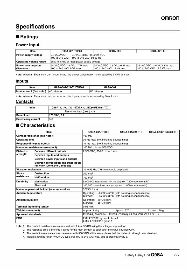
Safety Relay Unit G9SA 227
Specifications
Ratings
Power Input
Note: When an Expansion Unit is connected, the power consumption is increased by 2 VA/2 W max.
Inputs
Note: When an Expansion Unit is connected, the input current is increased by 30 mA max.
Contacts
Characteristics
Note: 1. The contact resistance was measured with 1 A at 5 VDC using the voltage-drop method.2. The response time is the time it takes for the main contact to open after the input is turned OFF.3. The insulation resistance was measured with 500 VDC at the same places that the dielectric strength was checked.4. Weight shown is for 24-VAC/VDC type. For 100 to 240-VAC type, add approximately 20 g.
Item G9SA-301/TH301 G9SA-501 G9SA-321-T@Power supply voltage 24 VAC/VDC: 24 VAC, 50/60 Hz, or 24 VDC
100 to 240 VAC: 100 to 240 VAC, 50/60 Hz
Operating voltage range 85% to 110% of rated power supply voltage
Power consumption(See note.)
24 VAC/VDC: 1.8 VA/1.7 W max.100 to 240 VAC: 9 VA max.
24 VAC/VDC: 2.8 VA/2.6 W max.100 to 240 VAC: 11 VA max.
24 VAC/VDC: 3.5 VA/3.3 W max.100 to 240 VAC: 12.5 VA max.
Item G9SA-301/321-T@/TH301 G9SA-501
Input current (See note.) 40 mA max. 60 mA max.
Item G9SA-301/501/321-T@/TH301/EX301/EX031-T@Resistive load (cos φ =1)
Rated load 250 VAC, 5 A
Rated carry current 5 A
Item G9SA-301/TH301 G9SA-501/321-T@ G9SA-EX301/EX031-T@Contact resistance (see note 1) 100 mΩOperating time 30 ms max. (not including bounce time)
Response time (see note 2) 10 ms max. (not including bounce time)
Insulation resistance (see note 3) 100 MΩ min. (at 500 VDC)
Dielectric strength
Between different outputs 2,500 VAC, 50/60 Hz for 1 min
Between inputs and outputs
Between power inputs and outputs
Between power inputs and other inputs (only for 100 to 240-V models)
Vibration resistance 10 to 55 Hz, 0.75-mm double amplitude
Shock resistance
Destruction 300 m/s2
Malfunction 100 m/s2
Durability Mechanical 5,000,000 operations min. (at approx. 7,200 operations/hr)
Electrical 100,000 operations min. (at approx. 1,800 operations/hr)
Minimum permissible load (reference value) 5 VDC, 1 mA
Ambient temperature Operating: −25°C to 55°C (with no icing or condensation)Storage: −25°C to 85°C (with no icing or condensation)
Ambient humidity Operating: 35% to 85%Storage: 35% to 85%
Terminal tightening torque 0.98 N·m
Weight (see note 4) Approx. 210 g Approx. 270 g Approx. 130 g
Approved standards EN954-1, EN60204-1, EN574 (-TH301), UL508, CSA C22.2 No. 14
EMC EMI: EN55011 group 1 class AEMS: EN50082-2 group 1
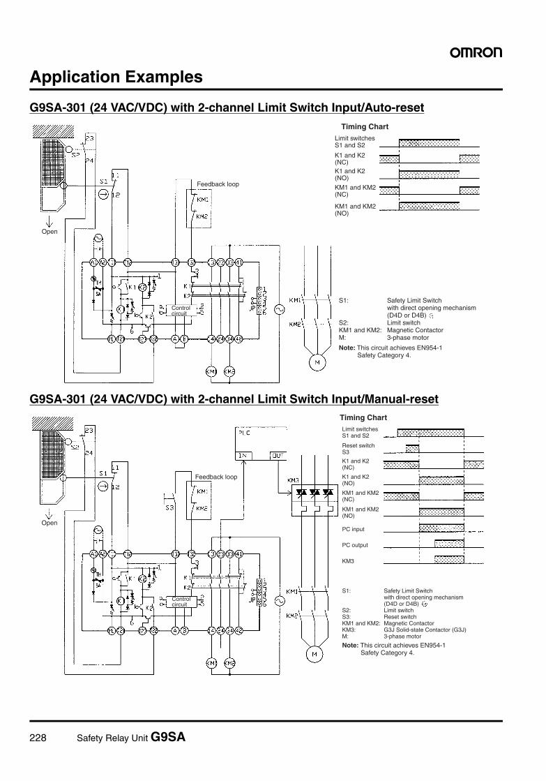
228 Safety Relay Unit G9SA
Application Examples
G9SA-301 (24 VAC/VDC) with 2-channel Limit Switch Input/Auto-reset
G9SA-301 (24 VAC/VDC) with 2-channel Limit Switch Input/Manual-reset
Feedback loop
Timing Chart
Open
Control circuit
Limit switches S1 and S2
K1 and K2 (NC)K1 and K2 (NO)
KM1 and KM2 (NC)
KM1 and KM2 (NO)
S1: Safety Limit Switch with direct opening mechanism (D4D or D4B)
S2: Limit switchKM1 and KM2: Magnetic ContactorM: 3-phase motor
Note: This circuit achieves EN954-1 Safety Category 4.
Feedback loop
Timing Chart
PC input
PC output
KM3
Open
Control circuit
Limit switches S1 and S2
Reset switch S3
K1 and K2 (NC)
K1 and K2 (NO)
KM1 and KM2 (NC)
KM1 and KM2 (NO)
S1: Safety Limit Switch with direct opening mechanism (D4D or D4B)
S2: Limit switchS3: Reset switchKM1 and KM2: Magnetic ContactorKM3: G3J Solid-state Contactor (G3J)M: 3-phase motor
Note: This circuit achieves EN954-1 Safety Category 4.
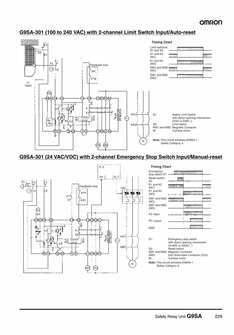
Safety Relay Unit G9SA 229
G9SA-301 (100 to 240 VAC) with 2-channel Limit Switch Input/Auto-reset
G9SA-301 (24 VAC/VDC) with 2-channel Emergency Stop Switch Input/Manual-reset
Feedback loop
Timing Chart
Open
Control circuit
Limit switches S1 and S2K1 and K2 (NC)K1 and K2 (NO)KM1 and KM2 (NC)
KM1 and KM2 (NO)
S1: Safety Limit Switch with direct opening mechanism (D4D or D4B)
S2: Limit switchKM1 and KM2: Magnetic ContactorM: 3-phase motor
Note: This circuit achieves EN954-1 Safety Category 4.
Feedback loop
Timing Chart
PC input
PC output
KM3
Control circuit
Emergency stop switch S1Reset switch S2K1 and K2 (NC)K1 and K2 (NO)
KM1 and KM2 (NC)KM1 and KM2 (NO)
S1: Emergency stop switch with direct opening mechanism (A165E or A22E)
S2: Reset switchKM1 and KM2: Magnetic ContactorKM3: G3J Solid-state Contactor (G3J)M: 3-phase motor
Note: This circuit achieves EN954-1 Safety Category 4.
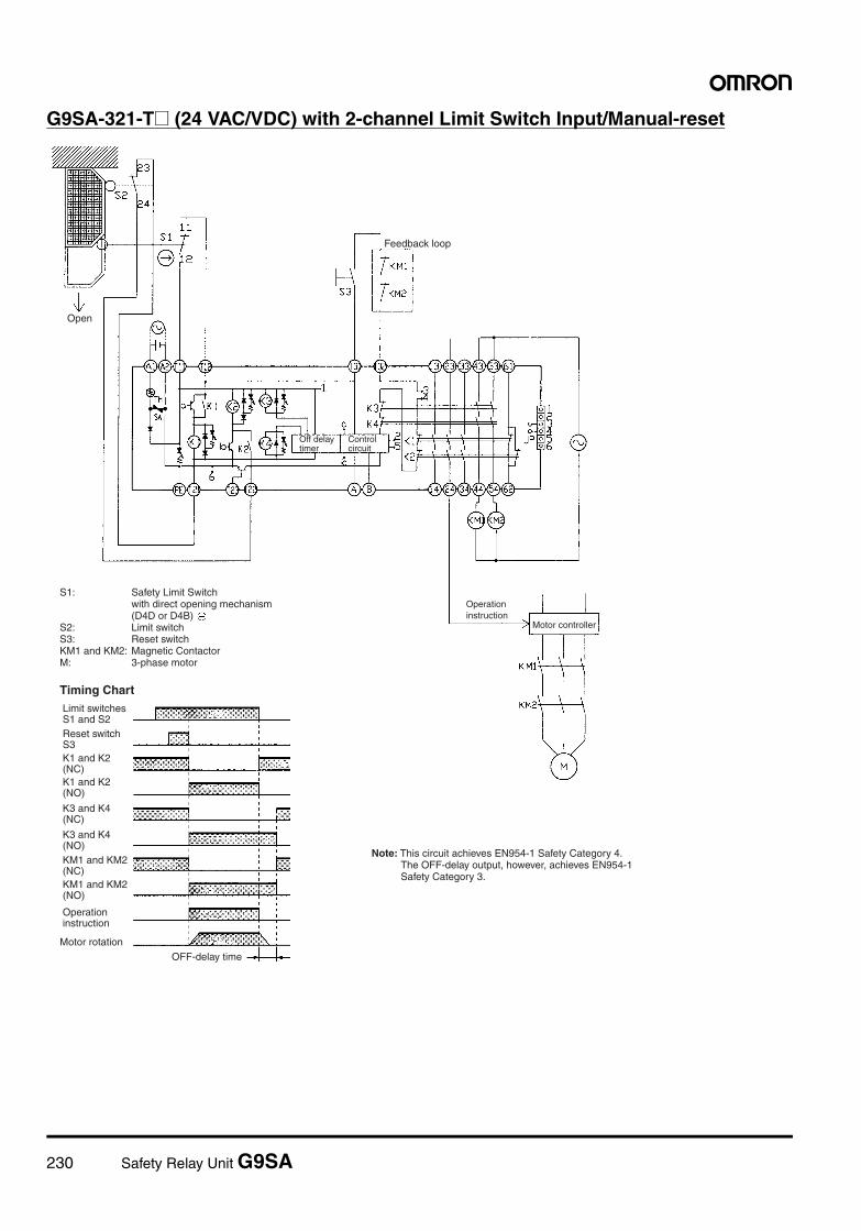
230 Safety Relay Unit G9SA
G9SA-321-T@ (24 VAC/VDC) with 2-channel Limit Switch Input/Manual-reset
Feedback loop
Motor controller
Timing Chart
Motor rotationOFF-delay time
Open
Off delay timer
Control circuit
Operation instruction
S1: Safety Limit Switch with direct opening mechanism (D4D or D4B)
S2: Limit switchS3: Reset switchKM1 and KM2: Magnetic ContactorM: 3-phase motor
Limit switches S1 and S2Reset switch S3K1 and K2 (NC)K1 and K2 (NO)
K3 and K4 (NC)
K3 and K4 (NO)KM1 and KM2 (NC)KM1 and KM2 (NO)
Operation instruction
Note: This circuit achieves EN954-1 Safety Category 4. The OFF-delay output, however, achieves EN954-1 Safety Category 3.
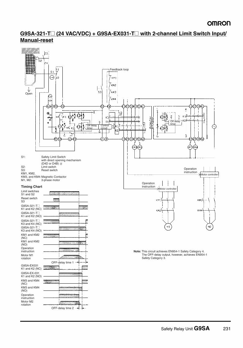
Safety Relay Unit G9SA 231
G9SA-321-T@ (24 VAC/VDC) + G9SA-EX031-T@ with 2-channel Limit Switch Input/Manual-reset
Feedback loop
Motor controllerTiming Chart
OFF-delay time 1
OFF-delay time 2
Open
Motor controller
Off delay timer
Control circuit
Off delay timer
Operation instruction
Operation instruction
S1: Safety Limit Switch with direct opening mechanism (D4D or D4B)
S2: Limit switchS3: Reset switchKM1, KM2, KM3, and KM4: Magnetic ContactorM1, M2: 3-phase motor
Limit switches S1 and S2Reset switch S3
G9SA-321-T@ K1 and K2 (NC)G9SA-321-T@ K1 and K2 (NO)
G9SA-321-T@ K3 and K4 (NC)G9SA-321-T@ K3 and K4 (NO)
KM1 and KM2 (NC)KM1 and KM2 (NO)Operation instructionMotor M1 rotation
G9SA-EX031 K1 and K2 (NC)
G9SA-EX-031 K1 and K2 (NO)
KM3 and KM4 (NC)KM3 and KM4 (NO)
Operation instructionMotor M2 rotation
Note: This circuit achieves EN954-1 Safety Category 4. The OFF-delay output, however, achieves EN954-1 Safety Category 3.
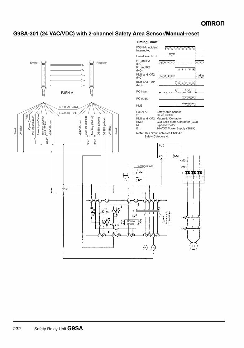
232 Safety Relay Unit G9SA
G9SA-301 (24 VAC/VDC) with 2-channel Safety Area Sensor/Manual-reset
KM3
E1
Feedback loop
Reset switch S1
Timing Chart
PC input
PC output
Emitter Receiver
F3SN-A
KM3
Ope
n
Ope
n
Control circuit
F3SN-A Incident Interrupted
K1 and K2 (NC)K1 and K2 (NO)KM1 and KM2 (NC)
KM1 and KM2 (NO)
F3SN-A: Safety area sensorS1: Reset switchKM1 and KM2: Magnetic ContactorKM3: G3J Solid-state Contactor (G3J)M: 3-phase motorE1: 24-VDC Power Supply (S82K)
Note: This circuit achieves EN954-1 Safety Category 4.
Shi
eld
0V (
Blu
e)
OS
SD
2 (W
hite
)
OS
SD
1 (G
reen
)
Aux
iliar
y (Y
ello
w)
ED
M in
put (
Red
)
+24
V (
Bro
wn)
+24
V (
Bro
wn)
Ope
n
Inte
rlock
sel
ectio
n in
put (
Whi
te)
Res
et in
put (
Yello
w)
Test
inpu
t (G
reen
)O
pen
(Red
)
0V (
Blu
e)
Shi
eld
RS-485(A) (Gray)
RS-485(B) (Pink)
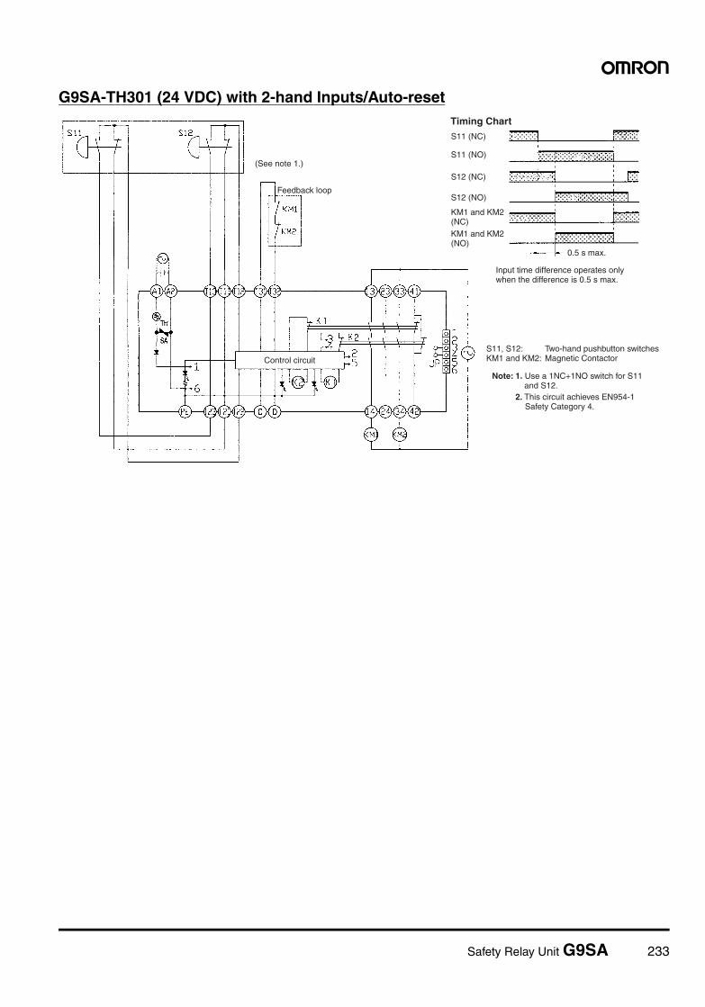
Safety Relay Unit G9SA 233
G9SA-TH301 (24 VDC) with 2-hand Inputs/Auto-reset
Feedback loop
S11 (NC)
S11 (NO)
Timing Chart
S12 (NC)
S12 (NO)
0.5 s max.
Control circuit
KM1 and KM2 (NC)KM1 and KM2 (NO)
Input time difference operates only when the difference is 0.5 s max.
S11, S12: Two-hand pushbutton switchesKM1 and KM2: Magnetic Contactor
Note: 1. Use a 1NC+1NO switch for S11 and S12.
2. This circuit achieves EN954-1 Safety Category 4.
(See note 1.)

234 Safety Relay Unit G9SA
G9SA-501 (24 VAC/VDC) and G9SA-EX301 with 2-channel Limit Switch Input/Manual-reset
Feedback loop
Timing Chart
Open
Note: This circuit achieves EN954-1 Safety Category 4.
Control circuit
S1: Safety Limit Switch with direct opening mechanism (D4D or D4B)
S2: Limit switchS3: Reset switchKM1 and KM2: Magnetic ContactorM: 3-phase motor
Limit switches S1 and S2
Reset switch S3G9SA-501 K1, K2, K3 and K4 (NC)G9SA-501 K1, K2, K3, and K4 (NO)G9SA-EX301 K1 and K2 (NC)G9SA-EX301 K1 and K2 (NO)
KM1 and KM2 (NC)
KM1 and KM2 (NO)
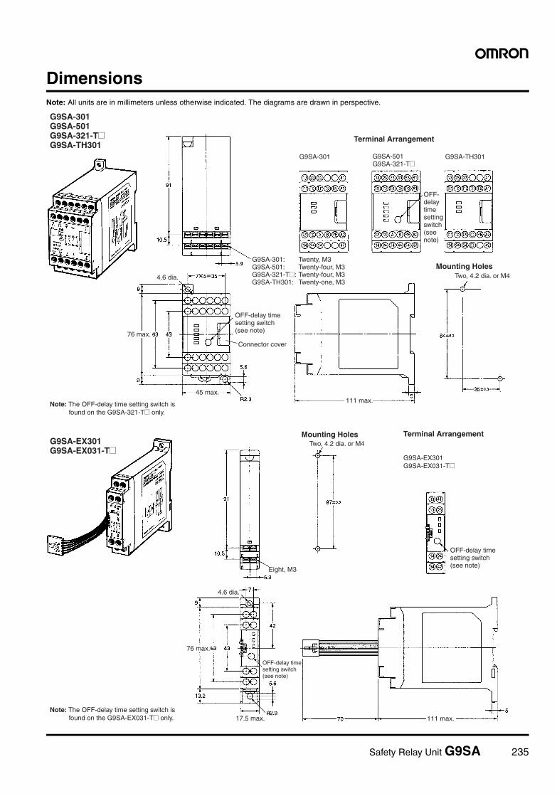
Safety Relay Unit G9SA 235
DimensionsNote: All units are in millimeters unless otherwise indicated. The diagrams are drawn in perspective.
C
D
Terminal Arrangement
G9SA-301 G9SA-TH301
Mounting HolesTwo, 4.2 dia. or M4
Terminal ArrangementMounting HolesTwo, 4.2 dia. or M4
4.6 dia.
45 max.
76 max.
111 max.
4.6 dia.
111 max.
76 max.
17.5 max.
Connector cover
Eight, M3
G9SA-301 G9SA-501 G9SA-321-T@ G9SA-TH301
G9SA-EX301 G9SA-EX031-T@
G9SA-301: Twenty, M3G9SA-501: Twenty-four, M3G9SA-321-T@: Twenty-four, M3G9SA-TH301: Twenty-one, M3
OFF-delay time setting switch (see note)
Note: The OFF-delay time setting switch is found on the G9SA-321-T@ only.
G9SA-501 G9SA-321-T@
OFF-delay time setting switch (see note)
OFF-delay time setting switch (see note)
Note: The OFF-delay time setting switch is found on the G9SA-EX031-T@ only.
G9SA-EX301 G9SA-EX031-T@
OFF-delay time setting switch (see note)
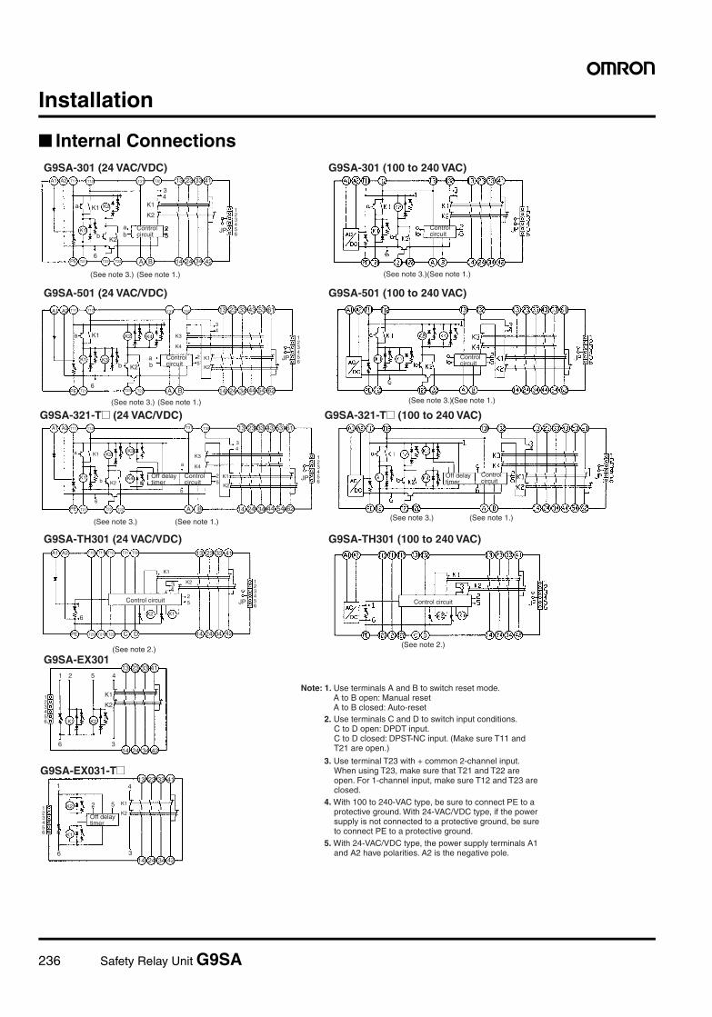
236 Safety Relay Unit G9SA
Installation
Internal Connections
A1 A2 T11 T12 T31 T32 13 23 33 41
123456
K1
K1
K2
25
a
6
bab
K2
34
K1
K2
1
JP
PE T21 T23 T22 A B 14 24 34 42
13 23 33 43 53 61T31 T32A1 A2 T11 T12
K2
K1
K3
K4K2b
K1a
6
a
bK2
K125
K3
K4
34
123456
JP
PE T21 T23 T22 A B 14 24 34 44 54 62
13 23 33 411 2 5 4
K1
K2
3614 24 34 42
K1 K2
123456
A1 A2 T11 T12
K1a K2 K4
1
K3
K4
34
25
K2
K1
14 24 34 44 54 62A BPE T21 T23 T226
b K2K3K1 a
b
123456
JP
T31 T32 13 23 33 43 53 61
A1 A2 T11 T12 T31 T32T13 13 23 33 41
123456
JP
14 24 34 42
K1K2
1
6
25
K234
K1
PE T23 T21 T22 C D
2 5 K1
K2
41
6 3
K2
K1
123456
13 23 33 41
14 24 34 42
G9SA-301 (24 VAC/VDC)
G9SA-501 (24 VAC/VDC)
G9SA-321-T@ (24 VAC/VDC)
G9SA-TH301 (24 VAC/VDC)
G9SA-EX301
G9SA-EX031-T@
25
Control circuit
G9SA-301 (100 to 240 VAC)
G9SA-501 (100 to 240 VAC)
G9SA-321-T@ (100 to 240 VAC)
G9SA-TH301 (100 to 240 VAC)
(See note 3.) (See note 1.)
(See note 3.) (See note 1.)
(See note 3.) (See note 1.)
(See note 2.)
(See note 3.)(See note 1.)
(See note 3.)(See note 1.)
(See note 3.) (See note 1.)
Control circuit
(See note 2.)
Control circuit
Control circuit
Control circuit
Control circuit
Off delay timer
Control circuit
Off delay timer
Control circuit
Off delay timer
Note: 1. Use terminals A and B to switch reset mode. A to B open: Manual reset A to B closed: Auto-reset
2. Use terminals C and D to switch input conditions. C to D open: DPDT input. C to D closed: DPST-NC input. (Make sure T11 and T21 are open.)
3. Use terminal T23 with + common 2-channel input. When using T23, make sure that T21 and T22 are open. For 1-channel input, make sure T12 and T23 are closed.
4. With 100 to 240-VAC type, be sure to connect PE to a protective ground. With 24-VAC/VDC type, if the power supply is not connected to a protective ground, be sure to connect PE to a protective ground.
5. With 24-VAC/VDC type, the power supply terminals A1 and A2 have polarities. A2 is the negative pole.
Safety Relay Unit G9SA 237
Precautions
!CautionDo not touch the terminal area of the Relays or the socket terminalarea (charged area) while power is ON. Electric shock will result.
WiringTurn OFF the G9SA before wiring the G9SA. Do not touch the termi-nals of the G9SA while the power is turned ON, because the termi-nals are charged and may cause an electric shock.
Use the following to wire the G9SA.Stranded wire: 0.75 to 1.5 mm2
Solid wire: 1.0 to 1.5 mm2
Tighten each screw to a torque of 0.78 to 1.18 N·m, or the G9SAmay malfunction or generate heat.
External inputs connected to T11 and T12 or T21 and T22 of theG9SA-301 must be no-voltage contact inputs.
PE is a ground terminal.
When a machine is grounded at the positive, the PE terminal shouldnot be grounded.
Mounting Expansion UnitsTurn OFF the G9SA before connecting the Expansion Unit.
When an Expansion Unit is being used, remove the connector coverfrom the G9SA Safety Relay Unit (G9SA-301, G9SA-501, G9SA-321@, or G9SA-TH301) and insert the connector of the ExpansionUnit’s connector cable.
Applicable Safety Category (EN954-1)G9SA-series Relays meet the requirements of Safety Category 4 ofthe EN954-1 standards when they are used as shown in the exam-ples provided by OMRON. The Relays may not meet the standardsin some operating conditions. The OFF-delay output of modelsG9SA-321-T@ and EX031-T@, however, conform to Safety Category3.
The applicable safety category is determined from the whole safetycontrol system. Make sure that the whole safety control systemmeets EN954-1 requirements.
Mounting Multiple UnitsWhen mounting multiple Units close to each other, the rated currentwill be 3 A. Do not apply a current higher than 3 A.
Connecting InputsIf using multiple G9SA models, inputs cannot be made using thesame switch. This is also true for other input terminals.
Earth ShortA positive thermistor is built into the G9SA circuits, so you can detectearth short breakdowns and breakdown shorts between channel 1and channel 2. If the short breakdown is canceled, reset is auto-matic.
G9SA G9SA
In the interest of product improvement, specifications are subject to change without notice.
ALL DIMENSIONS SHOWN ARE IN MILLIMETERS.
To convert millimeters into inches, multiply by 0.03937. To convert grams into ounces, multiply by 0.03527.
Cat. No. J121-E1-03

238 General-purpose Relays and Power Relays Sockets
General-purpose Relays and Power Relays
Sockets
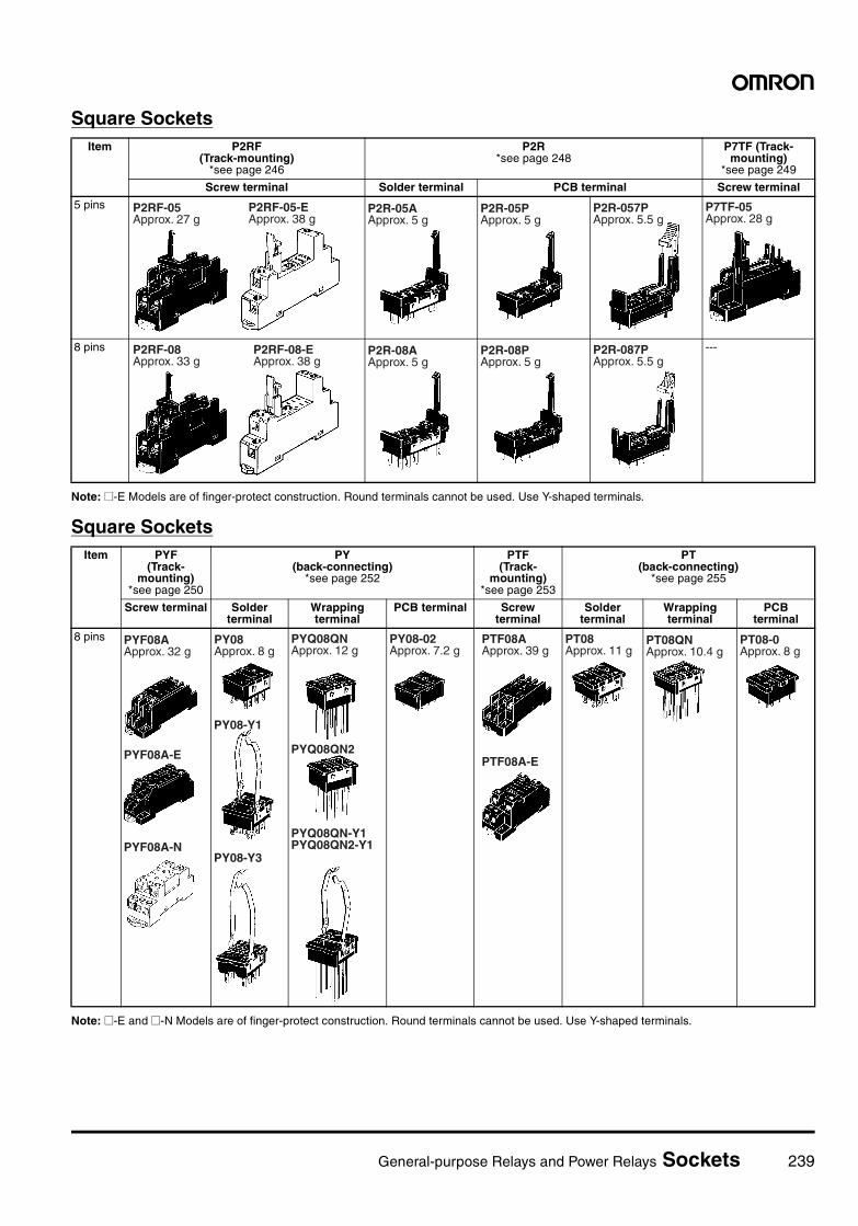
General-purpose Relays and Power Relays Sockets 239
Square Sockets
Note: @-E Models are of finger-protect construction. Round terminals cannot be used. Use Y-shaped terminals.
Square Sockets
Note: @-E and @-N Models are of finger-protect construction. Round terminals cannot be used. Use Y-shaped terminals.
Item P2RF (Track-mounting)
*see page 246
P2R *see page 248
P7TF (Track-mounting)
*see page 249
Screw terminal Solder terminal PCB terminal Screw terminal
5 pins
8 pins ---
P2RF-05Approx. 27 g
P2RF-05-EApprox. 38 g
P2R-05AApprox. 5 g
P2R-05PApprox. 5 g
P2R-057PApprox. 5.5 g
P7TF-05Approx. 28 g
P2RF-08Approx. 33 g
P2RF-08-EApprox. 38 g
P2R-08AApprox. 5 g
P2R-08PApprox. 5 g
P2R-087PApprox. 5.5 g
Item PYF (Track-
mounting) *see page 250
PY (back-connecting)
*see page 252
PTF (Track-
mounting) *see page 253
PT (back-connecting)
*see page 255
Screw terminal Solder terminal
Wrapping terminal
PCB terminal Screw terminal
Solder terminal
Wrapping terminal
PCB terminal
8 pins PYF08AApprox. 32 g
PYF08A-E
PYF08A-N
PY08Approx. 8 g
PY08-Y1
PY08-Y3
PYQ08QNApprox. 12 g
PYQ08QN-Y1 PYQ08QN2-Y1
PYQ08QN2
PY08-02Approx. 7.2 g
PTF08AApprox. 39 g
PTF08A-E
PT08Approx. 11 g
PT08QNApprox. 10.4 g
PT08-0Approx. 8 g
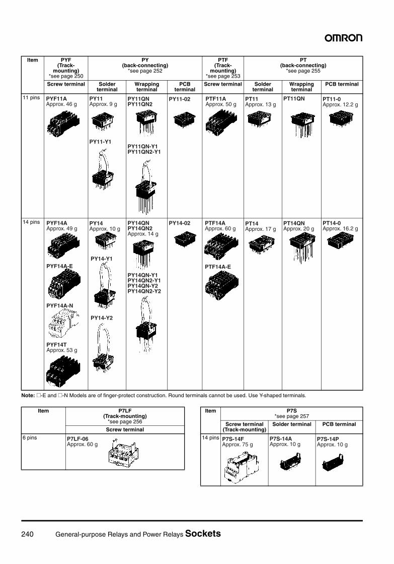
240 General-purpose Relays and Power Relays Sockets
Note: @-E and @-N Models are of finger-protect construction. Round terminals cannot be used. Use Y-shaped terminals.
Item PYF (Track-
mounting) *see page 250
PY (back-connecting)
*see page 252
PTF (Track-
mounting) *see page 253
PT (back-connecting)
*see page 255
Screw terminal Solder terminal
Wrapping terminal
PCB terminal
Screw terminal Solder terminal
Wrapping terminal
PCB terminal
11 pins
14 pins
PYF11AApprox. 46 g
PY11Approx. 9 g
PY11-Y1
PY11QNPY11QN2
PY11QN-Y1PY11QN2-Y1
PY11-02 PTF11AApprox. 50 g
PT11Approx. 13 g
PT11QN PT11-0Approx. 12.2 g
PYF14AApprox. 49 g
PYF14A-E
PYF14TApprox. 53 g
PYF14A-N
PY14Approx. 10 g
PY14-Y1
PY14-Y2
PY14QNPY14QN2Approx. 14 g
PY14QN-Y1PY14QN2-Y1PY14QN-Y2PY14QN2-Y2
PY14-02 PTF14AApprox. 60 g
PTF14A-E
PT14Approx. 17 g
PT14QNApprox. 20 g
PT14-0Approx. 16.2 g
Item P7LF (Track-mounting)
*see page 256
Screw terminal
6 pins P7LF-06Approx. 60 g
Item P7S*see page 257
Screw terminal (Track-mounting)
Solder terminal PCB terminal
14 pins P7S-14FApprox. 75 g
P7S-14AApprox. 10 g
P7S-14PApprox. 10 g
General-purpose Relays and Power Relays Sockets 241
Round Sockets
Note: This model succeeds the P3G-11 for which production was stopped in March 1991.
Item PF (Track-
mounting) *see page 258
P2CF (Track-
mounting)
PFA (Track-
mounting)
P3G (Track-
mounting)
PL (back-connecting) *see page 261
Solder terminal
Wrapping terminal
PCB terminal
8 pins
11 pins
14 pins --- --- --- --- ---
20 pins --- --- --- --- ---
PF083AApprox. 34 g
PF083A-E
PF085AApprox. 40 g
P2CF-08Approx. 55 g
8PFAApprox. 57 g
8PFA1Approx. 66 g
P3G-08Approx. 40 g
PL08Approx. 14 g
PL08-QApprox. 15 g
PLE08-0Approx. 10.6 g
PF113AApprox. 47 g
PF113A-E
P2CF-11Approx. 70 g
11PFAApprox. 74 g
P3GA-11(see note)Approx. 47 g
PL11Approx. 15 g
PL11-QApprox. 18.5 g
PLE11-0Approx. 10.8 g
14PFAApprox. 104 g
PL15Approx. 28 g
PF202Approx. 170 g
PL20Approx. 17 g
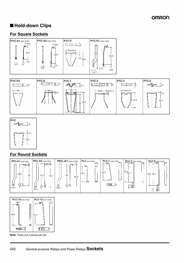
242 General-purpose Relays and Power Relays Sockets
Hold-down Clips
For Square Sockets
For Round Sockets
Note: There are 2 pieces per set.
5 max.PYC-A1 (see note)
36.3
4.51.24.5
5 max.
PYC-A2 (see note)
42.8
4.51.24.5
29 max.
PYC-P
36.53.3
5
PYC-E1 (see note)
36.3
5.754.25
4.5+0.1
PYC-P2
10
28
PYC-S
282.5
8PYC-1
9.4
28
5258.2
Approx. 3
PYC-2
28.8
8
PYC-35
29.5
44.5
PYC-5
10
3.7
41.7
PYC10
3.7
34.5
6
60.862
4.6
4.5
PFC-A1 (see note)
6
73.3 74.5
4.6
4.5
PEC-A6 (see note)
6
9495.2
4.5
4.6
PEC-A7 (see note)
56.6
7.6PLC (see note)
56.3
8
PLC-1 (see note)
69.265.7
9
8
PLC-7 (see note)
90.2 86.7
9
8
PLC-8 (see note)
66.2
5
6
PLC-10 (see note)
64.3
8
PLC-12 (see note)
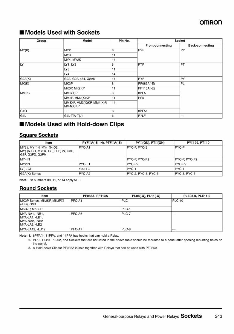
General-purpose Relays and Power Relays Sockets 243
Models Used with Sockets
Models Used with Hold-down Clips
Square Sockets
Note: Pin numbers 08, 11, or 14 apply to @.
Round Sockets
Note: 1. 8PFA(I), 11PFA, and 14PFA has hooks that can hold a Relay.2. PL15, PL20, PF202, and Sockets that are not listed in the above table should be mounted to a panel after opening mounting holes on
the panel.3. A Hold-down Clip for PF085A is sold together with Relays that can be used with PF085A.
Group Model Pin No. Socket
Front-connecting Back-connecting
MY(K) MY2 8 PYF PY
MY3 11
MY4, MY2K 14
LY LY1, LY2 8 PTF PT
LY3 11
LY4 14
G2A(K) G2A, G2A-434, G2AK 14 PYF PY
MK(K) MK2P 8 PF083A(-E) PL
MK3P, MK2KP 11 PF113A(-E)
MM(K) MM2(X)P 8 8PFA
MM3P, MM2(X)KP 11 PFA
MM3XP, MM3(X)KP, MM4(X)P, MM4(X)KP
14
G4Q --- 8 8PFA1
G7L G7L-@A-T(J) 6 P7LF ---
Item PYF@A(-E, -N), PTF@A(-E) PY@(QN), PT@(QN) PY@-02, PT@-0
MY( ), MY( )N, MY( )N-D2, MY( )N-CR, MY2K, LY( ), LY( )N, G3H, G3F, G3FD, G3FM
PYC-A1 PYC-P, PYC-S PYC-P
MY4IN PYC-P, PYC-P2 PYC-P, PYC-P2
MY2IN PYC-E1 PYC-P2 PYC-P2
LY( )-CR Y92H-3 PYC-1 PYC-1
G2A(K) Series PYC-A2 PYC-2, PYC-3, PYC-5 PYC-3, PYC-5
Item PF083A, PF113A PL08(-Q), PL11(-Q) PLE08-0, PLE11-0
MK2P Series, MK2KP, MK3P@(-US), G3B
PFC-A1 PLC PLC-10
MK3ZP, MK3LP PLC-1
MYA-NA1, -NB1, MYA-LA1, -LB1, MYA-NA2, -NB2MYA-LA2, -LB2
PFC-A6 PLC-7 ---
MYA-LA12, -LB12 PFC-A7 PLC-8 ---
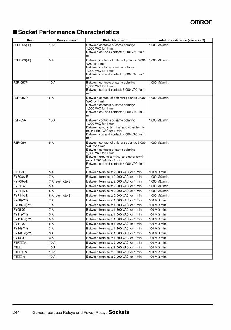
244 General-purpose Relays and Power Relays Sockets
Socket Performance CharacteristicsItem Carry current Dielectric strength Insulation resistance (see note 2)
P2RF-05(-E) 10 A Between contacts of same polarity: 1,000 VAC for 1 minBetween coil and contact: 4,000 VAC for 1 min
1,000 MΩ min.
P2RF-08(-E) 5 A Between contact of different polarity: 3,000 VAC for 1 minBetween contacts of same polarity: 1,000 VAC for 1 minBetween coil and contact: 4,000 VAC for 1 min
1,000 MΩ min.
P2R-057P 10 A Between contacts of same polarity: 1,000 VAC for 1 minBetween coil and contact: 5,000 VAC for 1 min
1,000 MΩ min.
P2R-087P 5 A Between contact of different polarity: 3,000 VAC for 1 minBetween contacts of same polarity: 1,000 VAC for 1 minBetween coil and contact: 5,000 VAC for 1 min
1,000 MΩ min.
P2R-05A 10 A Between contacts of same polarity: 1,000 VAC for 1 minBetween ground terminal and other termi-nals: 1,500 VAC for 1 minBetween coil and contact: 4,000 VAC for 1 min
1,000 MΩ min.
P2R-08A 5 A Between contact of different polarity: 3,000 VAC for 1 minBetween contacts of same polarity: 1,000 VAC for 1 minBetween ground terminal and other termi-nals: 1,500 VAC for 1 minBetween coil and contact: 4,000 VAC for 1 min
1,000 MΩ min.
P7TF-05 5 A Between terminals: 2,000 VAC for 1 min 100 MΩ min.
PYF08A-E 7 A Between terminals: 2,000 VAC for 1 min 1,000 MΩ min.
PYF08A-N 7 A (see note 3) Between terminals: 2,000 VAC for 1 min 1,000 MΩ min.
PYF11A 5 A Between terminals: 2,000 VAC for 1 min 1,000 MΩ min.
PYF14A-E 5 A Between terminals: 2,000 VAC for 1 min 1,000 MΩ min.
PYF14A-N 5 A (see note 3) Between terminals: 2,000 VAC for 1 min 1,000 MΩ min.
PY08(-Y1) 7 A Between terminals: 1,500 VAC for 1 min 100 MΩ min.
PY08QN(-Y1) 7 A Between terminals: 1,500 VAC for 1 min 100 MΩ min.
PY08-02 7 A Between terminals: 1,500 VAC for 1 min 100 MΩ min.
PY11(-Y1) 5 A Between terminals: 1,500 VAC for 1 min 100 MΩ min.
PY11QN(-Y1) 5 A Between terminals: 1,500 VAC for 1 min 100 MΩ min.
PY11-02 5 A Between terminals: 1,500 VAC for 1 min 100 MΩ min.
PY14(-Y1) 3 A Between terminals: 1,500 VAC for 1 min 100 MΩ min.
PY14QN(-Y1) 3 A Between terminals: 1,500 VAC for 1 min 100 MΩ min.
PY14-02 3 A Between terminals: 1,500 VAC for 1 min 100 MΩ min.
PTF@@A 10 A Between terminals: 2,000 VAC for 1 min 100 MΩ min.
PT@@ 10 A Between terminals: 2,000 VAC for 1 min 100 MΩ min.
PT@@QN 10 A Between terminals: 2,000 VAC for 1 min 100 MΩ min.
PT@@-0 10 A Between terminals: 2,000 VAC for 1 min 100 MΩ min.
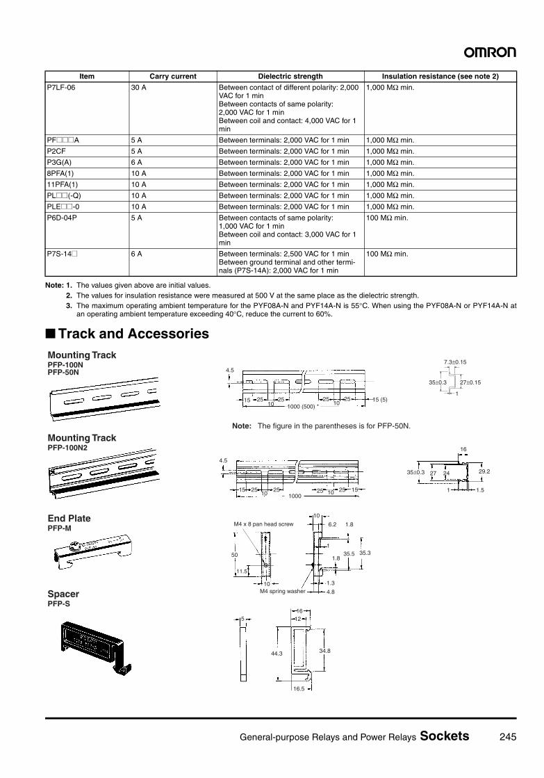
General-purpose Relays and Power Relays Sockets 245
Note: 1. The values given above are initial values.2. The values for insulation resistance were measured at 500 V at the same place as the dielectric strength.3. The maximum operating ambient temperature for the PYF08A-N and PYF14A-N is 55°C. When using the PYF08A-N or PYF14A-N at
an operating ambient temperature exceeding 40°C, reduce the current to 60%.
Track and Accessories
P7LF-06 30 A Between contact of different polarity: 2,000 VAC for 1 minBetween contacts of same polarity: 2,000 VAC for 1 minBetween coil and contact: 4,000 VAC for 1 min
1,000 MΩ min.
PF@@@A 5 A Between terminals: 2,000 VAC for 1 min 1,000 MΩ min.
P2CF 5 A Between terminals: 2,000 VAC for 1 min 1,000 MΩ min.
P3G(A) 6 A Between terminals: 2,000 VAC for 1 min 1,000 MΩ min.
8PFA(1) 10 A Between terminals: 2,000 VAC for 1 min 1,000 MΩ min.
11PFA(1) 10 A Between terminals: 2,000 VAC for 1 min 1,000 MΩ min.
PL@@(-Q) 10 A Between terminals: 2,000 VAC for 1 min 1,000 MΩ min.
PLE@@-0 10 A Between terminals: 2,000 VAC for 1 min 1,000 MΩ min.
P6D-04P 5 A Between contacts of same polarity: 1,000 VAC for 1 minBetween coil and contact: 3,000 VAC for 1 min
100 MΩ min.
P7S-14@ 6 A Between terminals: 2,500 VAC for 1 minBetween ground terminal and other termi-nals (P7S-14A): 2,000 VAC for 1 min
100 MΩ min.
Item Carry current Dielectric strength Insulation resistance (see note 2)
4.5
15 25 2510 25
10002510 15
29.2
1.5
27 24
16
1
35±0.3
M4 x 8 pan head screw
M4 spring washer
50
11.5
10
10
6.2
1.8
135.5
1.8
1.3
4.8
516
12
44.3
16.5
4.5
15 25 2510
251000 (500) *
2510
15 (5)1
Mounting TrackPFP-100NPFP-50N
Note: The figure in the parentheses is for PFP-50N.
35±0.3
7.3±0.15
27±0.15
Mounting TrackPFP-100N2
End PlatePFP-M
SpacerPFP-S
35.3
34.8
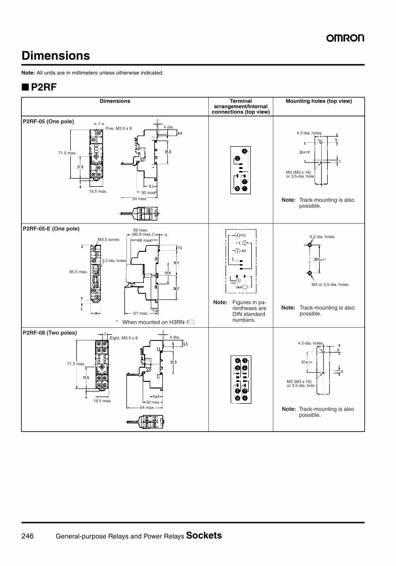
246 General-purpose Relays and Power Relays Sockets
DimensionsNote: All units are in millimeters unless otherwise indicated.
P2RFDimensions Terminal
arrangement/Internal connections (top view)
Mounting holes (top view)
P2RF-05 (One pole)Five, M3.5 x 8
71.5 max.
19.5 max.
54 max.30 max.
4 dia.4.2-dia. holes
M3 (M3 x 16) or 3.5-dia. hole
Note: Track-mounting is also possible.
9
P2RF-05-E (One pole)
M3.5 screw
85.5 max.
3.5-dia. holes
59 max.
48 max.
* When mounted on H3RN-1@.
61 max.
(80.9 max.)*
Note: Figures in pa- rentheses are DIN standard numbers.
Note: Track-mounting is also possible.
M3 or 3.5-dia. holes
3.2-dia. holes
P2RF-08 (Two poles)
71.5 max.
19.5 max. 30 max.54 max.
4 dia.Eight, M3.5 x 8
Note: Track-mounting is also possible.
4.2-dia. holes
M3 (M3 x 16) or 3.5-dia. hole
9
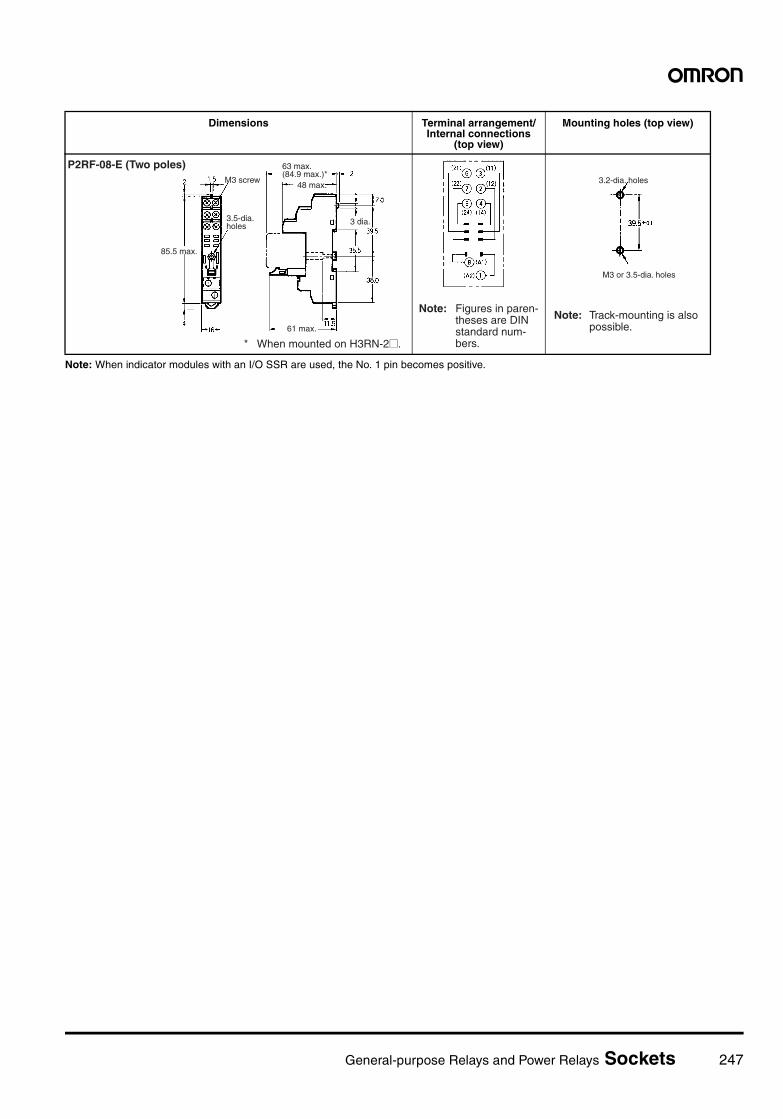
General-purpose Relays and Power Relays Sockets 247
Note: When indicator modules with an I/O SSR are used, the No. 1 pin becomes positive.
Dimensions Terminal arrangement/Internal connections
(top view)
Mounting holes (top view)
P2RF-08-E (Two poles)M3 screw
3.5-dia. holes
85.5 max.
61 max.
63 max. (84.9 max.)*
48 max.
3 dia.
* When mounted on H3RN-2@.
Note: Figures in paren- theses are DIN standard num- bers.
Note: Track-mounting is also possible.
M3 or 3.5-dia. holes
3.2-dia. holes
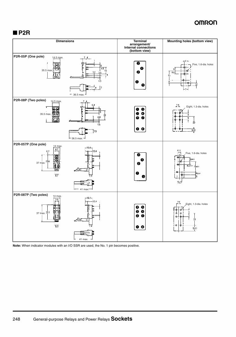
248 General-purpose Relays and Power Relays Sockets
P2R
Note: When indicator modules with an I/O SSR are used, the No. 1 pin becomes positive.
Dimensions Terminal arrangement/
Internal connections (bottom view)
Mounting holes (bottom view)
14.5 max.
35.5 max.
36.5 max.
P2R-05P (One pole)
Five, 1.6-dia. holes
14.5 max.
35.5 max.
36.5 max.
P2R-08P (Two poles)
Eight, 1.3-dia. holes
P2R-057P (One pole)14 max.
37 max.
41 max.
Five, 1.6-dia. holes
P2R-087P (Two poles)
37 max.
14 max.
41 max.
Eight, 1.3-dia. holes
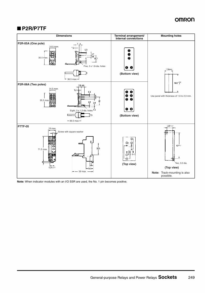
General-purpose Relays and Power Relays Sockets 249
P2R/P7TF
Note: When indicator modules with an I/O SSR are used, the No. 1 pin becomes positive.
Dimensions Terminal arrangement/Internal connections
Mounting holes
P2R-05A (One pole)14.5 max.
35.5 max.
Five, 3 x 1.8-dia. holes
36.5 max.
(Bottom view)
Use panel with thickness of 1.6 to 2.0 mm.
P2R-08A (Two poles)14.5 max.
35.5 max.
Eight, 3 x 1.2-dia. holes
36.5 max.
(Bottom view)
P7TF-0519 max.
71.5 max.
Screw with square washer
59 max.
(Top view)
(−)(+)
Two, 3.0 dia.
(Top view)
Note: Track-mounting is also possible.
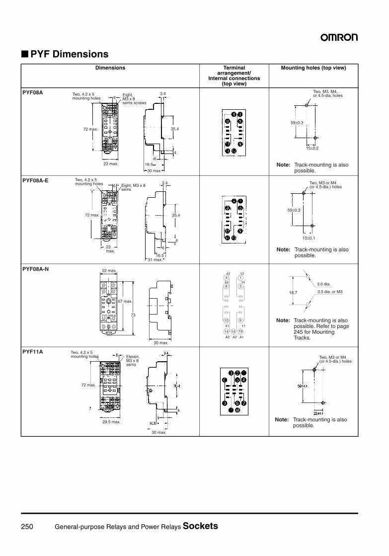
250 General-purpose Relays and Power Relays Sockets
PYF DimensionsDimensions Terminal
arrangement/Internal connections
(top view)
Mounting holes (top view)
Eight,M3 x 8sems screws
PYF08A Two, 4.2 x 5mounting holes 6
72 max.
23 max.
3.4
4
616.5
35.4
30 max.
Two, M3, M4, or 4.5-dia. holes
15±0.2
59±0.3
Note: Track-mounting is also possible.
Two, 4.2 x 5 mounting holes 6 Eight, M3 x 8
sems
72 max.
23 max.
3.4
35.4
4
6
16.531 max.
PYF08A-E Two, M3 or M4(or 4.5-dia.) holes
59±0.3
15±0.1
Note: Track-mounting is also possible.
4
42
8
44
1
12
5
14
41
12
A2
14
11
9
A1
13
A2
14
22 max.
67 max.
PYF-08A-N
30 max.
73
PYF08A-N442
1
8 5
12 9
14 14 13
44
12
14
41 11
A2 A2 A1
18.7
3.0 dia.
3.5 dia. or M3
Note: Track-mounting is also possible. Refer to page 245 for Mounting Tracks.
PYF11A Two, 4.2 x 5 mounting holes Eleven,
M3 x 8 sems
72 max.
29.5 max.
30 max.
Two, M3 or M4(or 4.5-dia.) holes
Note: Track-mounting is also possible.
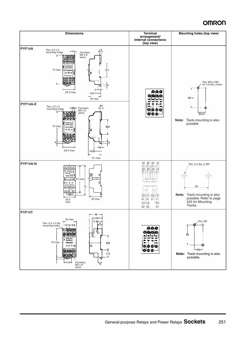
General-purpose Relays and Power Relays Sockets 251
Dimensions Terminal arrangement/
Internal connections (top view)
Mounting holes (top view)
PYF14A Two, 4.2 x 5 mounting holes Fourteen,
M3 x 8 sems
72 max.
29.5 max.
30 max.
3 2 1
8 7 6 5
10 91112
4
8
1314
Two, M3 or M4(or 4.5-dia.) holes
Note: Track-mounting is also possible.
PYF14A-ETwo, 4.2 x 5 mounting holes Fourteen,
M3 x 8 sems
29.5 max.
31 max.
72 max.
30 max.
4
42
3
32
2
22
1
12
8
44
7
34
6
24
5
14
41
12
31
11
21
10
11
9
A1
13
A2
14
A2
14
67 max.
PYF-14A-N
29.5 max.
73
PYF14A-N4 3 2 1
8 7 6 5
12 11 10 9
14 14 13
42 32 22 12
44 34 24 14
41 31 21 11
A2 A2 A1
26
Two, 4.5 dia. or M4
Note: Track-mounting is also possible. Refer to page 245 for Mounting Tracks.
PYF14T
Two, 4.2 x 5 dia. mounting holes
Fourteen, M3 x 8 sems
33 max.
70 max.
3 2 1
8 7 6 5
10 91112
4 1314Note: Track-mounting is also possible.
Two, M4
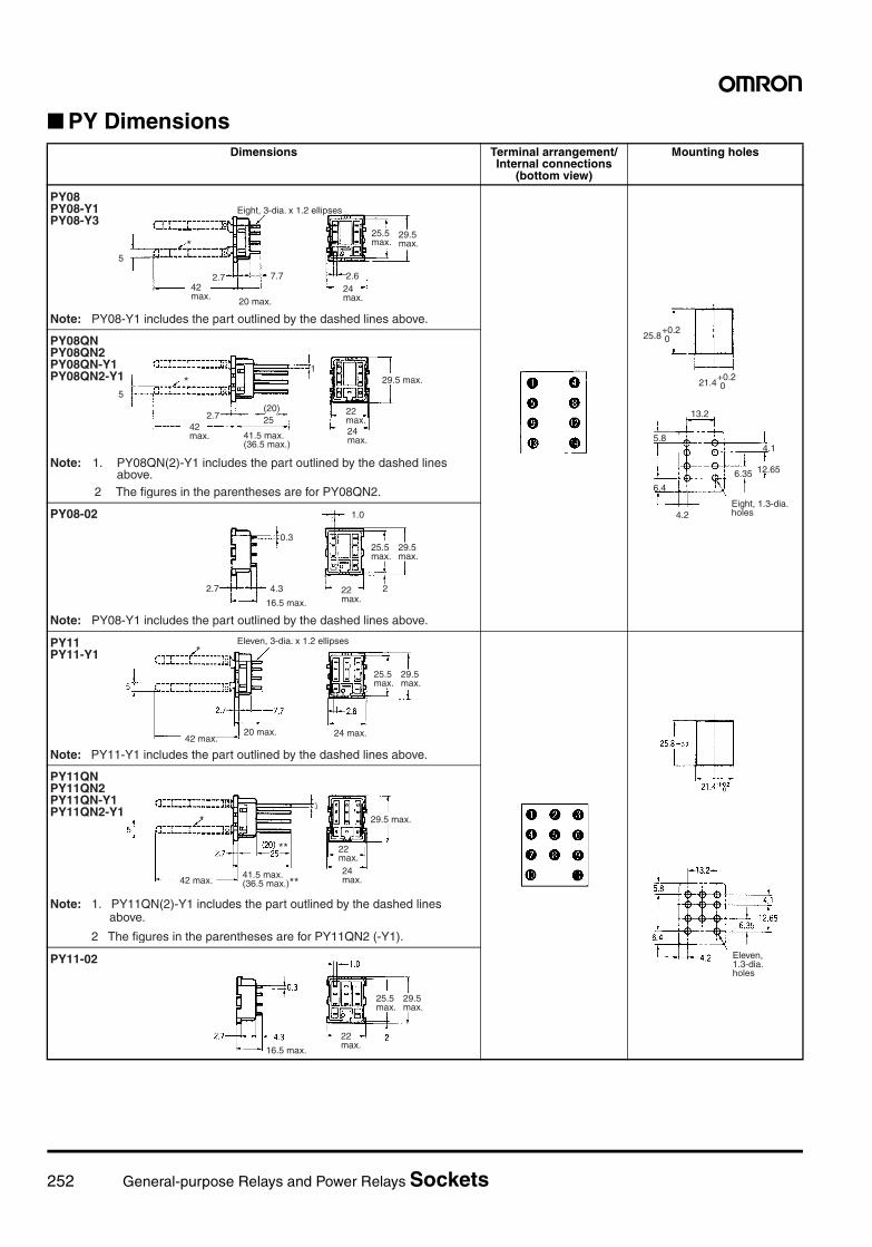
252 General-purpose Relays and Power Relays Sockets
PY DimensionsDimensions Terminal arrangement/
Internal connections (bottom view)
Mounting holes
PY08PY08-Y1PY08-Y3
Eight, 3-dia. x 1.2 ellipses
*
2.7 7.742 max. 20 max.
25.5 max.
29.5 max.
2.624 max.
Note: PY08-Y1 includes the part outlined by the dashed lines above.
5
+0.2 0
13.2
5.8
+0.2 0
6.4
25.8
4.1
21.4
12.656.35
Eight, 1.3-dia. holes4.2
PY08QNPY08QN2PY08QN-Y1PY08QN2-Y1 *
5
2.742 max.
(20)25
41.5 max.(36.5 max.)
29.5 max.
22 max.24 max.
1
Note: 1. PY08QN(2)-Y1 includes the part outlined by the dashed lines above.
2 The figures in the parentheses are for PY08QN2.
PY08-02
0.3
2.7 4.3
16.5 max.
1.0
25.5 max.
29.5 max.
222 max.
Note: PY08-Y1 includes the part outlined by the dashed lines above.
PY11PY11-Y1
Eleven, 3-dia. x 1.2 ellipses
Note: PY11-Y1 includes the part outlined by the dashed lines above.
25.5 max.
29.5 max.
24 max.20 max.42 max.
*
Eleven, 1.3-dia. holes
PY11QNPY11QN2PY11QN-Y1PY11QN2-Y1
*
42 max.41.5 max.(36.5 max.)**
29.5 max.
22 max.24 max.
Note: 1. PY11QN(2)-Y1 includes the part outlined by the dashed lines above.
2 The figures in the parentheses are for PY11QN2 (-Y1).
**
PY11-02
16.5 max.
25.5 max.
29.5 max.
22 max.
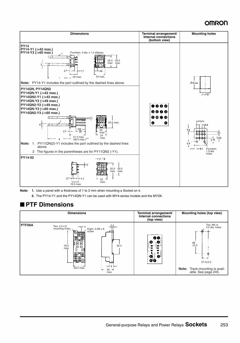
General-purpose Relays and Power Relays Sockets 253
Note: 1. Use a panel with a thickness of 1 to 2 mm when mounting a Socket on it.
2. The PY14-Y1 and the PY14QN-Y1 can be used with MY4-series models and the MY2K.
PTF Dimensions
Dimensions Terminal arrangement/Internal connections
(bottom view)
Mounting holes
PY14PY14-Y1 (l=42 max.)PY14-Y3 (l=60 max.) Fourteen, 3-dia. x 1.2 ellipses
Note: PY14-Y1 includes the part outlined by the dashed lines above.
25.5 max.
29.5 max.
24 max.20 max.
*
l
Fourteen, 1.3-dia. holes
PY14QN, PY14QN2 PY14QN-Y1 (l=42 max.) PY14QN2-Y1 (l=42 max.) PY14QN-Y2 (l=49 max.) PY14QN2-Y2 (l=49 max.) PY14QN-Y3 (l=60 max.) PY14QN2-Y3 (l=60 max.)
*
41.5 max.(36.5 max.)**
29.5 max.
22 max.24 max.
Note: 1. PY11QN(2)-Y1 includes the part outlined by the dashed lines above.
2 The figures in the parentheses are for PY11QN2 (-Y1).
**
PY14-02
16.5 max.
25.5 max.
29.5 max.
22 max.
Dimensions Terminal arrangement/Internal connections
(top view)
Mounting holes (top view)
PTF08A Two, 4.5 x 6 mounting holes Eight, 3.5M x 8
screw
78.5 max.
28.5 max.
35.4
830 max.
73.4 Two, M4 or
4.5-dia. holes
Note: Track-mounting is avail-able. See page 245.
68±0.3
27.5±0.2
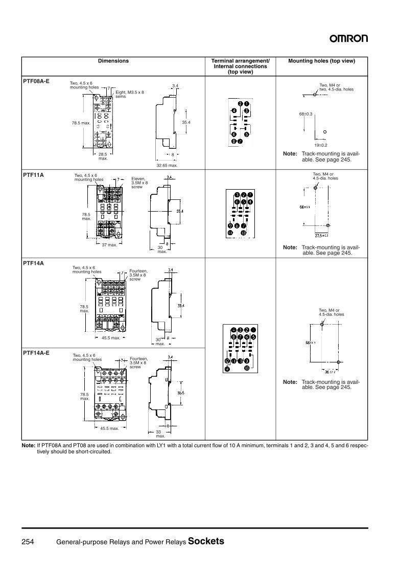
254 General-purpose Relays and Power Relays Sockets
Note: If PTF08A and PT08 are used in combination with LY1 with a total current flow of 10 A minimum, terminals 1 and 2, 3 and 4, 5 and 6 respec-tively should be short-circuited.
Dimensions Terminal arrangement/Internal connections
(top view)
Mounting holes (top view)
Two, 4.5 x 6 mounting holes 7
Eight, M3.5 x 8 sems
78.5 max.
28.5 max.
3.4
35.4
8
32.65 max.
PTF08A-ETwo, M4 ortwo, 4.5-dia. holes
68±0.3
19±0.2
Note: Track-mounting is avail-able. See page 245.
PTF11A Two, 4.5 x 6 mounting holes Eleven,
3.5M x 8 screw
78.5 max.
37 max.30 max.
Two, M4 or 4.5-dia. holes
Note: Track-mounting is avail-able. See page 245.
PTF14ATwo, 4.5 x 6 mounting holes Fourteen,
3.5M x 8 screw
78.5 max.
45.5 max. 30 max.
Two, M4 or 4.5-dia. holes
Note: Track-mounting is avail-able. See page 245.
PTF14A-E Two, 4.5 x 6 mounting holes Fourteen,
3.5M x 8 screw
78.5 max.
45.5 max.33 max.
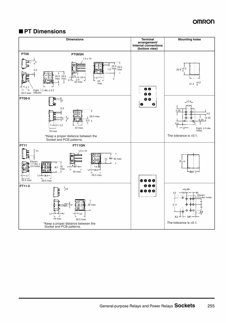
General-purpose Relays and Power Relays Sockets 255
PT DimensionsDimensions Terminal
arrangement/Internal connections
(bottom view)
Mounting holes
2.7
25.5 max.
29.5 max.
PT08
5
0.3
Eight, 1.7-dia. x 3.5 ellipses
PT08QN1.5 x 10
2.7
920 1.5
24 max.
1.025.5 max.
29.5 max.
2.535 max.
20.5 max.
2
+0.2 025.8
+0.2 021.4
PT08-02
0.3
2 5*
1 4.3
18 max.22 max.
6.5
29.5 max.
*Keep a proper distance between the Socket and PCB patterns.
10
5.35
6.5
15.6
4.6
12.456.45
3 Eight, 2.5-dia. holes
The tolerance is ±0.1.
PT11 PT11QN
32 max.
29.5 max.
Eleven, 1.7-dia. x 3.5 holes
35 max.
20.5 max.
32 max.
29.5 max.
1.5 x 10
PT11-0
18 max. 29.5 max.
32 max.
*Keep a proper distance between the Socket and PCB patterns.
5*
Eleven, 2.5-dia. holes
The tolerance is ±0.1.
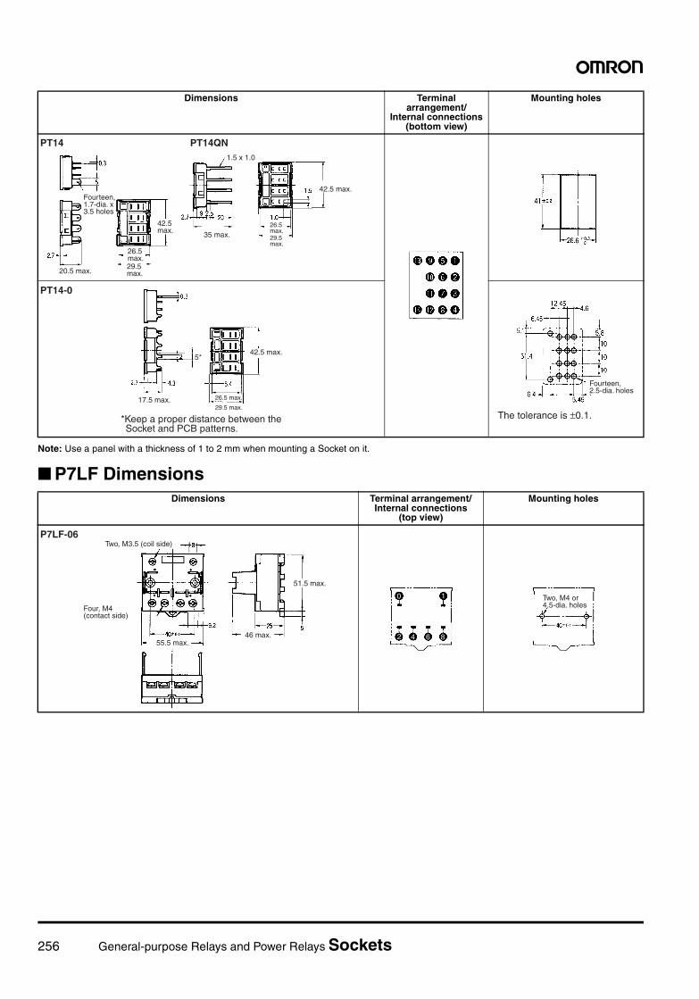
256 General-purpose Relays and Power Relays Sockets
Note: Use a panel with a thickness of 1 to 2 mm when mounting a Socket on it.
P7LF Dimensions
Dimensions Terminal arrangement/
Internal connections (bottom view)
Mounting holes
PT14QNPT14
42.5 max.
Fourteen, 1.7-dia. x 3.5 holes
35 max.
20.5 max.
1.5 x 1.0
26.5 max.29.5 max.
42.5 max.
26.5 max.29.5 max.
PT14-0
17.5 max.
42.5 max.
*Keep a proper distance between the Socket and PCB patterns.
26.5 max.
29.5 max.
5*
Fourteen, 2.5-dia. holes
The tolerance is ±0.1.
Dimensions Terminal arrangement/Internal connections
(top view)
Mounting holes
P7LF-06Two, M3.5 (coil side)
Four, M4 (contact side)
51.5 max.
55.5 max.46 max.
0 1
2 4 6 8
Two, M4 or 4.5-dia. holes
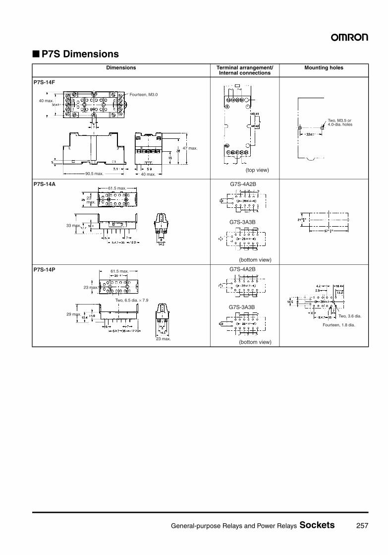
General-purpose Relays and Power Relays Sockets 257
P7S DimensionsDimensions Terminal arrangement/
Internal connectionsMounting holes
P7S-14F
40 max.
Fourteen, M3.0
47 max.
90.5 max. 40 max.(top view)
Two, M3.5 or 4.0-dia. holes
P7S-14A61.5 max.
33 max.
23 max.
G7S-4A2B
G7S-3A3B
(bottom view)
P7S-14P 61.5 max.
29 max.
23 max.
Two, 6.5 dia. × 7.9
23 max.
G7S-4A2B
G7S-3A3B
(bottom view)
Two, 3.6 dia.
Fourteen, 1.8 dia.
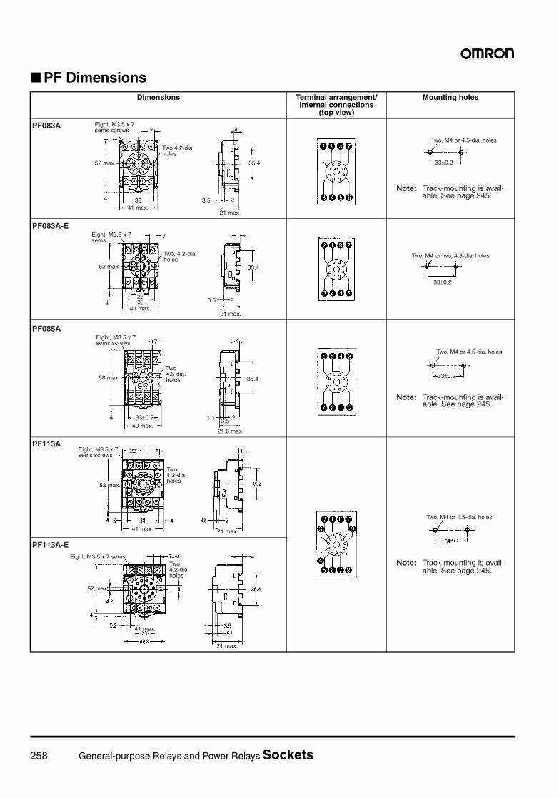
258 General-purpose Relays and Power Relays Sockets
PF DimensionsDimensions Terminal arrangement/
Internal connections (top view)
Mounting holes
PF083A Eight, M3.5 x 7sems screws
52 max.
4 3341 max.
7
Two 4.2-dia.holes
4
35.4
2
21 max.
3.5
Note: Track-mounting is avail-able. See page 245.
Two, M4 or 4.5-dia. holes
33±0.2
PF083A-EEight, M3.5 x 7 sems
7
Two, 4.2-dia. holes
4
52 max.
2333
41 max.
4
35.4
3.5 2
21 max.
Two, M4 or two, 4.5-dia. holes
33±0.2
PF085A
Eight, M3.5 x 7sems screws
58 max.
4
7
Two4.5-dia.holes
33±0.2
4
35.4
23.5
21.6 max.
1.140 max.
Note: Track-mounting is avail-able. See page 245.
Two, M4 or 4.5-dia. holes
33±0.2
PF113AEight, M3.5 x 7sems screws
52 max.
Two 4.2-dia.holes
21 max.41 max.
Note: Track-mounting is avail-able. See page 245.
Two, M4 or 4.5-dia. holes
PF113A-EEight, M3.5 x 7 sems
Two, 4.2-dia. holes
52 max.
41 max.
21 max.
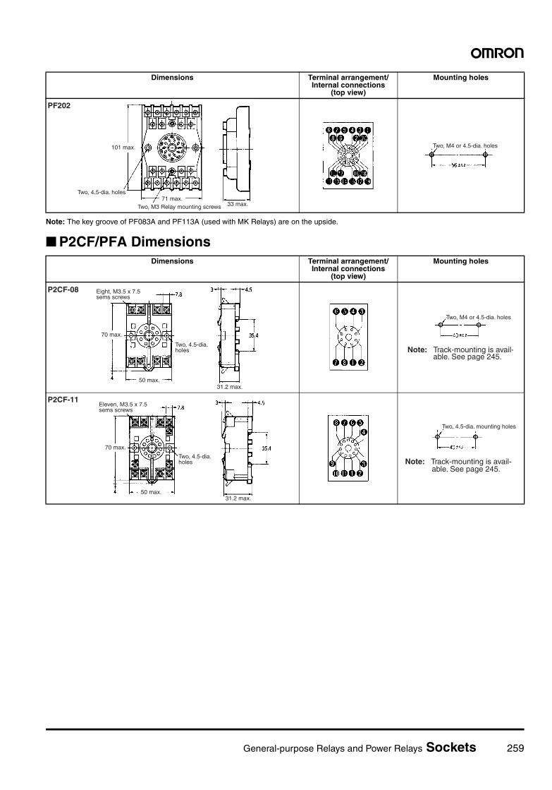
General-purpose Relays and Power Relays Sockets 259
Note: The key groove of PF083A and PF113A (used with MK Relays) are on the upside.
P2CF/PFA Dimensions
Dimensions Terminal arrangement/Internal connections
(top view)
Mounting holes
PF202
101 max.
Two, 4.5-dia. holes
Two, M3 Relay mounting screws 33 max.71 max.
Two, M4 or 4.5-dia. holes
Dimensions Terminal arrangement/Internal connections
(top view)
Mounting holes
P2CF-08 Eight, M3.5 x 7.5sems screws
70 max.
Two, 4.5-dia.holes
31.2 max.50 max.
Note: Track-mounting is avail-able. See page 245.
Two, M4 or 4.5-dia. holes
P2CF-11Eleven, M3.5 x 7.5sems screws
70 max.
Two, 4.5-dia.holes
31.2 max.50 max.
Two, 4.5-dia. mounting holes
Note: Track-mounting is avail-able. See page 245.
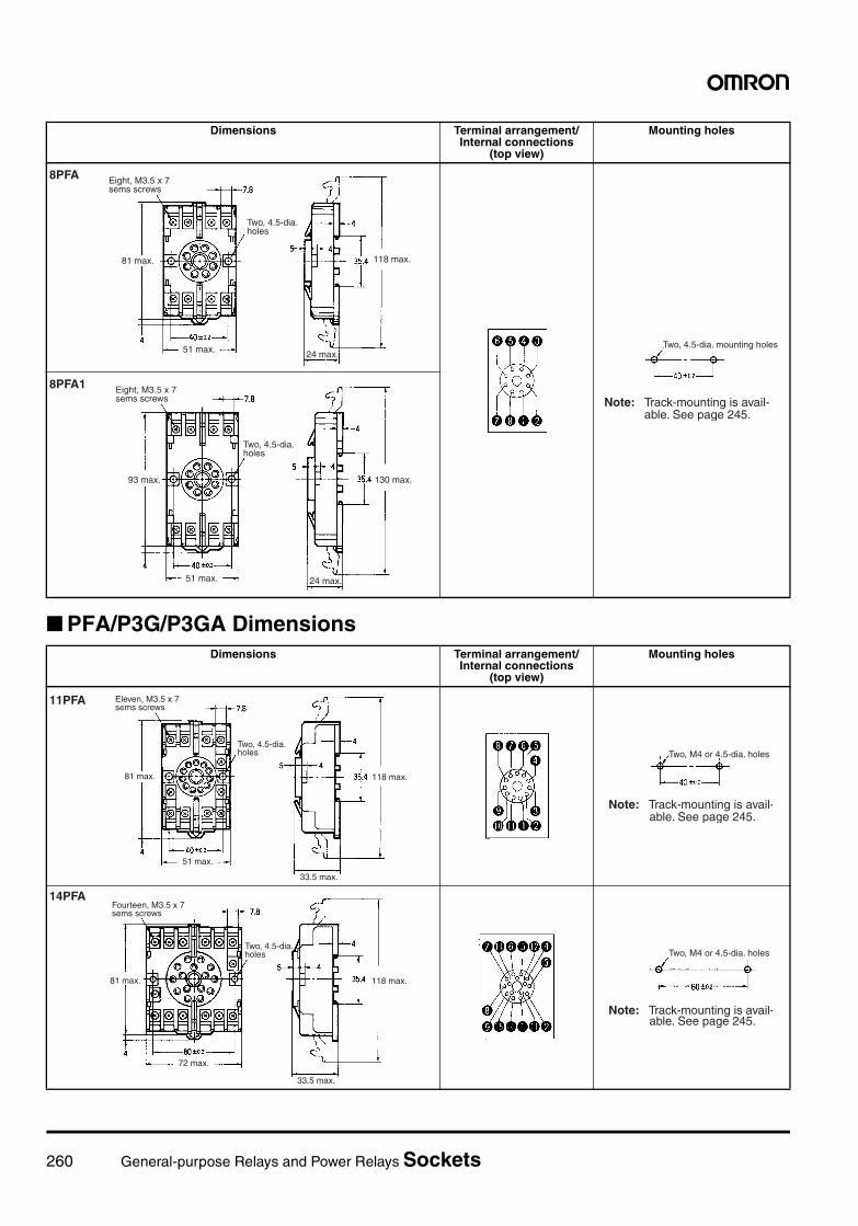
260 General-purpose Relays and Power Relays Sockets
PFA/P3G/P3GA Dimensions
Dimensions Terminal arrangement/Internal connections
(top view)
Mounting holes
8PFA Eight, M3.5 x 7sems screws
81 max.
Two, 4.5-dia.holes
24 max.
118 max.
51 max. Two, 4.5-dia. mounting holes
Note: Track-mounting is avail-able. See page 245.
8PFA1 Eight, M3.5 x 7sems screws
93 max.
Two, 4.5-dia.holes
24 max.
130 max.
51 max.
Dimensions Terminal arrangement/Internal connections
(top view)
Mounting holes
11PFA Eleven, M3.5 x 7sems screws
81 max.
Two, 4.5-dia.holes
33.5 max.
118 max.
51 max.
Note: Track-mounting is avail-able. See page 245.
Two, M4 or 4.5-dia. holes
14PFAFourteen, M3.5 x 7sems screws
81 max.
Two, 4.5-dia.holes
33.5 max.
118 max.
72 max.
Note: Track-mounting is avail-able. See page 245.
Two, M4 or 4.5-dia. holes
General-purpose Relays and Power Relays Sockets 261
PL Dimensions
Note: When mounting, pay due attention to the direction of the key groove of applicable Relays.
Dimensions Terminal arrangement/Internal connections
(top view)
Mounting holes
---
---
P3G-08 27 dia.
P3GA-11 27 dia.
Dimensions Terminal arrangement/
Internal connections (bottom view)
Mounting holes
PL083.5
51 max. 40
35 max.
4 1
30 dia.
16
35 max.
0.6t x 1.3
74 or 8640±0.3
Two, 3.5-dia. or two, M3 Relay-mounting holes
Two, 3.5-dia. or two, M3 Socket-mounting holes
31-dia. hole
PL08-Q
50.5 max. 40
3.5
35 max.
4 1
30 dia.
Two, 2-dia. holes
Approx. 20.5
3.972
Two, 3.5-dia. or two, M3 Relay-mounting holes
Two, 3.5-dia. or two, M3 Socket-mounting holes
31-dia. hole 40±0.3
19
PLE08-0
29 dia.±0.3
14 50.3t
21.5 max.
Two, 3.5-dia. Hold-down Clip-mounting holes
40±0.3
27.7±0.5
Eight, 2.5-dia. holes
262 General-purpose Relays and Power Relays Sockets
PL DimensionsDimensions Terminal arrangement/
Internal connections (bottom view)
Mounting holes
PL11
51 max.
Approx. 20.5 max.
Two, 2-dia. holes
30 dia.
35 max.
Two, 3.5-dia. or two, M3-mounting holes for applicable models
Two, 3.5-dia. or two, M3 Socket-mounting holes
31-dia. hole
L=40 mmMK3P, MK2KP, MK3ZP, MK3LPL=74 mmMM3P, MM2(X)KP
PL11-Q
51 max.
35 max. 35 max.
PLE11-0
29±0.1 dia.
22 max.
Eleven, 2.5-dia. holes
Two, 3.5-dia. Hold-down Clip-mounting holes
L= Distance between mounting holes required for MK
Eleven, 2.5-dia. holes
MK3PMK2KP
PL15
66 max.
22 max.
Two, 2-dia. holes
41 max.
45 max.
Two, 3.5-dia. or two, M3-mounting holes for applicable models
Two, 3.5-dia. or two, M3 Socket-mounting holes
42-dia. hole
MK3XP, MM4(X)P, MM3(X)KP, MM4(X)KP
PL20
46.5 max.
36.5 max. 23 max.
Two, 2-dia. holes
Two, 3.5-dia. holes
31 max.
Two, 4.5-dia. Relay-mounting holes
Two, Socket-mounting holes
33-dia. hole Note: Mounting hole
preparation not required for LDNP.