fuel fired steam boiler - installation, operation and
TRANSCRIPT
This manual must be available to the boiler operator at all times. VMP-IOMM-2018-2
INSTALLATION, OPERATION AND MAINTENANCE MANUAL
VMP (vertical multi-port)Fuel Fired Steam Boiler
VMP-IOMM-2018-2
Fulton Ltd
Page II
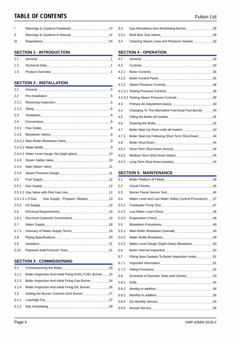
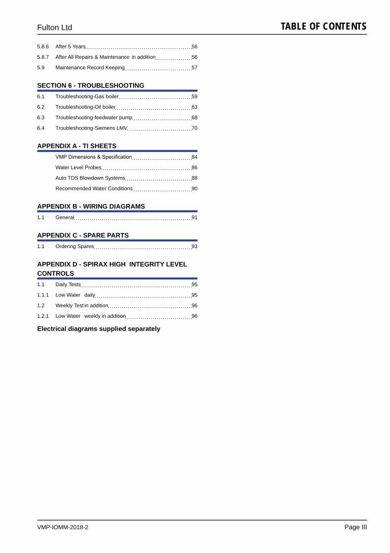
TABLE OF CONTENTS
I Warnings & Cautions Explained IV
II Warnings & Cautions In Manual IV
III Regulations VII
SECTION 1 - INTRODUCTION1.1 General 1
1.2 Technical Data 1
1.3 Product Overview 1
SECTION 2 - INSTALLATION2.1 General 5
2.2 Pre-Installation 5
2.2.1 Receiving Inspection 5
2.2.2 Siting 6
2.3 Ventilation 6
2.4 Connections 8
2.4.1 Flue Outlet 8
2.4.2 Blowdown Valves 8
2.4.2.1 Main Boiler Blowdown Valve 9
2.4.2.2 Water Bottle 9
2.4.2.3 Water Level Gauge Set (sight glass) 10
2.4.3 Steam Safety Valve 10
2.4.4 Main Steam Valve 11
2.4.5 Steam Pressure Gauge 11
2.5 Fuel Supply 12
2.5.1 Gas Supply 12
2.5.1.2 Gas Valve with Pilot Gas Line 12
2.5.1.3 L.P.Gas Gas Supply - Propane / Butane 13
2.5.2 Oil Supply 14
2.6 Electrical Requirements 15
2.6.1 Electrical Customer Connections 15
2.7 Water Supply 18
2.7.1 Glossary of Water Supply Terms 19
2.8 PipingSpecifications 20
2.9 Insulation 21
2.10 Pipework leak/Pressure Tests 21
SECTION 3 - COMMISSIONING3.1 Commissioning the Boiler 23
3.1.1 Boiler Inspection And Initial Firing-DUAL FUEL Burner 24
3.1.2 Boiler Inspection And Initial Firing-Gas Burner 24
3.1.4 Boiler Inspection And Initial Firing-OIL Burner 26
3.2 Setting the Burner Controls-GAS Burner 27
3.2.1 Low/High Fire 27
3.2.2 fully modulating 28
3.3 Gas Monoblocs-Non Modulating Burner 28
3.3.1 Multi Bloc Gas Valves 29
3.4 Cleaning Steam Lines and Pressure Vessels 32
SECTION 4 - OPERATION4.1 General 33
4.2 Controls 33
4.2.1 Boiler Controls 34
4.2.2 Boiler Control Panel 35
4.2.3 Steam Pressure Controls 38
4.2.3.1 Setting Pressure Controls 39
4.2.3.2 Testing Steam Pressure Controls 39
4.3 Primary Air Adjustment (auto) 40
4.4 Changing To The Alternative Fuel-Dual Fuel Burner 40
4.5 Filling the Boiler-all models 41
4.6 Draining the Boiler 42
4.7 Boiler Start-Up (from cold)-all models 43
4.7.1 Boiler Start-Up Following Short Term Shut-Down 44
4.8 Boiler Shut-Down 44
4.8.1 Short Term Shut-Down (hours) 44
4.8.2 Medium Term Shut-Down (days) 44
4.8.3 Long Term Shut-Down (weeks) 44
SECTION 5 - MAINTENANCE5.1 Boiler Platform (if Fitted) 45
5.2 Visual Checks 45
5.3 Burner Flame Sensor Test 46
5.4 Water Level and Low Water Safety Control Procedures 47
5.4.1 Feedwater Pump Test 47
5.4.2 Low Water Level Check 48
5.4.3 Evaporation Check 48
5.5 Blowdown Procedures 49
5.5.1 Main Boiler Blowdown (manual) 49
5.5.2 Water Bottle Blowdown 49
5.5.3 Water Level Gauge (Sight Glass) Blowdown 50
5.6 Boiler Internal Inspection 50
5.7 Fitting New Gaskets To Boiler Inspection Holes 51
5.7.1 Important Information 51
5.7.2 Fitting Procedure 52
5.8 Schedule of Operator Tests and Checks 53
5.8.1 Daily 54
5.8.2 Weekly-in addition 54
5.8.3 Monthly-in addition 55
5.8.4 Six Monthly Service 55
5.8.5 Annual Service 56
VMP-IOMM-2018-2
Fulton Ltd
Page III
TABLE OF CONTENTS
Electrical diagrams supplied separately
5.8.6 After 5 Years 56
5.8.7 After All Repairs & Maintenance in addition 56
5.9 Maintenance Record Keeping 57
SECTION 6 - TROUBLESHOOTING6.1 Troubleshooting-Gas boiler 59
6.2 Troubleshooting-Oil boiler 63
6.3 Troubleshooting-feedwater pump 68
6.4 Troubleshooting-Siemens LMV 70
APPENDIX A - TI SHEETS VMPDimensions&Specification 84
Water Level Probes 86
Auto TDS Blowdown Systems 88
Recommended Water Conditions 90
APPENDIX B - WIRING DIAGRAMS1.1 General 91
APPENDIX C - SPARE PARTS1.1 Ordering Spares 93
APPENDIX D - SPIRAX HIGH INTEGRITY LEVEL CONTROLS1.1 Daily Tests 95
1.1.1 Low Water daily 95
1.2 Weekly Test in addition 96
1.2.1 Low Water weekly in addition 96
VMP-IOMM-2018-2
Fulton Ltd
Page IV
SAFETY PRECAUTIONS
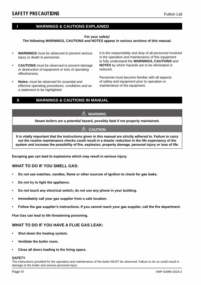
SAFETYThe instructions provided for the operation and maintenance of the boiler MUST be observed. Failure to do so could result in damage to the boiler and serious personal injury.
For your safety!The following WARNINGS, CAUTIONS and NOTES appear in various sections of this manual.
• WARNINGS must be observed to prevent serious injury or death to personnel.
• CAUTIONS must be observed to prevent damage or destruction of equipment or loss of operating effectiveness.
• Notes: must be observed for essential and effective operating procedures, conditions and as a statement to be highlighted.
It is the responsibility and duty of all personnel involved in the operation and maintenance of this equipment to fully understand the WARNINGS, CAUTIONS and NOTES by which hazards are to be eliminated or reduced.
Personnel must become familiar with all aspects of safety and equipment prior to operation or maintenance of the equipment.
WARNING
Steam boilers are a potential hazard, possibly fatal if not properly maintained.
CAUTION
It is vitally important that the instructions given in this manual are strictly adhered to. Failure to carry out the routine maintenance checks could result in a drastic reduction in the life expectancy of the
systemandincreasethepossibilityoffire,explosion,propertydamage,personalinjuryorlossoflife.
!
!
I WARNINGS & CAUTIONS EXPLAINED
II WARNINGS & CAUTIONS IN MANUAL
Escapinggascanleadtoexplosionswhichmayresultinseriousinjury.
WHAT TO DO IF YOU SMELL GAS:
• Donotusematches,candles,flameorothersourcesofignitiontocheckforgasleaks.
• Do not try to light the appliance.
• Do not touch any electrical switch; do not use any phone in your building.
• Immediately call your gas supplier from a safe location.
• Followthegassupplier’sinstructions.Ifyoucannotreachyourgassupplier,callthefiredepartment.
Flue Gas can lead to life threatening poisoning.
WHAT TO DO IF YOU HAVE A FLUE GAS LEAK:
• Shut down the heating system.
• Ventilate the boiler room.
• Close all doors leading to the living space.
VMP-IOMM-2018-2
Fulton Ltd
Page V
SAFETY PRECAUTIONS
WARNINGDo not try to do repairs or any other maintenance work you do not understand. Obtain a service manual from Fulton Ltd or call a Fulton service engineer.
It is the responsibility of the installer to ensure all parts suppliedwiththeboilerarefittedinacorrectandsafemanner.
Understand the electrical circuit before connecting or disconnecting an electrical component. A wrong connection can cause injury and or damage.
A defective boiler can injure you or others. Do not operate a boiler which is defective or has missing parts. Make sure that all maintenance procedures are completed before using the boiler.
Do not change the boiler fuel without consulting the boiler manufacturer.
LIFTING EQUIPMENTMake sure that lifting equipment complies with all local regulations and is suitable for the job. You can be injured if you use faulty lifting equipment. Make sure the lifting equipment is in good condition.
Operating the boiler beyond its design limits can damage the boiler, it can also be dangerous. Do not operate the boiler outside its limits. Do not try to upgrade the boiler performance by unapproved modifications.
Non-approvedmodificationscancauseinjuryanddamage. Contact your Fulton dealer before modifying the boiler.
Onlyqualifiedpersonsshouldbeallowedtooperate and maintain the boiler and its equipment.
The installation of gas appliances including the fluesystemshouldonlybecarriedoutbyGasSaferegistered engineers.
Steam boilers have high temperature surfaces, that if touched may cause serious burns. Only competent and qualifiedpersonnelshouldworkonorinthelocalityof a steam boiler and ancillary equipment. Always ensuretheworkingareaandfloorareclearofpotentialhazards, work slowly and methodically.DoNOTstoreinflammablematerialsneartheboiler.
The importance of correct boiler water and feedwater cannot be over emphasised, see the relevant section in this manual.
! WARNINGDANGER FROM INCOMPLETE COMBUSTIONThe importance of correct burner adjustment to achieve lowemissions,safe,cleanandefficientcombustionis paramount. Poor combustion, where unburnt gas forms carbon monoxide is both a health hazard, and the potential risk to the boiler from overheating, caused byre-burningoftheunburntgasinthesecondaryfluepasses.
Prior to the commencement of any work requiring the removal of cover plates and the opening of control panel box, the electrical supply to the boiler must be isolated.
Boilers should always be drained through an approved blowdown vessel.
This boiler is equipped with an ignition device, which automatically lights the burner. Do not try to light the burner by hand.
Label all wires prior to disconnection when servicing controls. Wiring errors can cause improper and dangerous operation.
Never attempt to operate equipment that has failed to pass all the safety checks.
Follow proper lockout procedures for the electrical, gas and water connections.
If any “Manual Reset” limit device trips, DO NOT reset without determining and correcting the cause. (Manual ResetLimitsmayinclude:flamesafeguard,highorlowgas pressure, high temperature limit, high pressure limit.)
Never tamper with low water (liquid level) cut-off sensors or circuitry.
Before commissioning the equipment, verify with authorized personnel that gas lines have been purged.
Check daily that the equipment area is free and clear ofanycombustiblematerials,includingflammablevapours & liquids.
Donotstoreorusegasolineorotherflammablevapours and liquids or corrosive materials in the vicinity of this or any other appliances. Cements for plastic pipe should be kept away from all sources of ignition.Proper ventilation should be maintained to reduce the hazard and to minimize breathing of cement vapours.
No shut-off of any kind shall be placed between the safety relief valve and the equipment or in the discharge pipe between such valve and the atmosphere. Doing so can cause an accidental explosion from overpressure.
!
VMP-IOMM-2018-2
Fulton Ltd
Page VI
SAFETY PRECAUTIONS
WARNINGThe discharge from the safety relief valve shall be so arranged that there will be no danger of scalding personnel or damage to equipment. Provisions should be made to properly drain safety relief valve discharge piping.
Fluids under pressure may cause injury to personnel or damage to equipment when released. Be sure to shut offallincomingandoutgoingfluidshut-offvalvesandcarefully decrease all trapped pressures to zero before performing any maintenance.
Do not attempt to start the equipment for any testing priortofillingandpurgingthevessel.Adryfirewillseriously damage the equipment and may result in property damage or personnel injury and is not covered bywarranty.Incaseofadryfiringevent,shutoffthe fuel supply and allow the vessel to cool to room temperaturebeforefluidisreintroducedtothepressurevessel.Theboilershouldbeinspectedbyaqualifiedindividual prior to commissioning the unit.
When opening any drains on the equipment or piping system, steps should be taken to avoid scalding/burningofpersonnelduetohotfluids.Wheneverpossible, the system should be cooled prior to opening any drains.
Hot surfaces (over 49 °C) should be insulated or shielded for safety. See Installation section.
Should overheating occur or the gas supply fails to shut off, manually shut off the gas supply external to the equipment.
Improper installation or maintenance of gauge glass and connections can cause immediate or delayed breakage resulting in bodily injury and/or property damage. Only properly trained personnel should install and maintain gauge glass connections. Wear safety glasses during installation. Be sure all parts are free of chips and debris.
!
CAUTIONObey all laws and local regulations which affect you and your boiler.
LOW FEEDWATER TEMPERATURELow feedwater temperature can result in thermal shock to the boiler pressure vessel. Return the maximum amount of condensate and if necessary preheat the feedwater. If in doubt consult Fulton Ltd.
!
CAUTIONWATER SOFTENER and CHEMICAL TREATMENTThe chemicals required to operate the water softeners and chemical treatment plants CAN BE SUPPLIED by Fulton Ltd.It is the responsibility of the operator to ensure adequate supplies of chemical are available at all times (including commissioning). Costly repairs could be required should the plant operate without chemicals or the wrong dosage of chemicals.
HYDRAULIC TEST - RISK OF BRITTLE FRACTUREHydraulic testing requires specialist equipment and is normally only required by engineering surveyors / inspectors. In order to ensure the material/ pressure vessel does not suffer from brittle fracture, hydraulic testing should not be carried out below 7 °C.
The stack arrangement and draft conditions should be in accordance with the information in this manual for proper performance of the equipment.
Some soap used for leak testing is corrosive to certain types of metals. Clean all piping thoroughly after completing the leak check.
A temperature exceeding 49 °C* in the boiler room may cause premature failure of electrical components. Provisions should be made to maintain an ambient temperature of 49 °C* or less (the panel box interior should not exceed 52 °C*.*Pumps, Programmable Logic Controllers (PLC) or ModSync panels may require lower ambient temperatures or additional cooling.
Particulate matter or chemicals (example:perchlorethylene, chlorine, or halogenated compounds) in the combustion air supply to the boiler will cause damage or failure to the burner and is not covered under warranty. High-risk situations for particulate matter to be in the air include construction and maintenance activities.
Forallsystemscontainingboilersorunfiredsteamgenerators, the water chemistry in the boiler must be kept within the limits outlined in this manual. Failure to do so may cause premature pressure vessel failure and poor steam quality and will void the warranty.
Do not run the pump dry. Irreparable damage to the seal can result. Prime the pump in accordance with the manufacturer’s instructions. Never operate the pump with a closed discharge valve.
Shouldyoususpectthattheboilersfluepassagewayshave become blocked, contact your authorized Fulton representative.
!
VMP-IOMM-2018-2
Fulton Ltd
Page VII
SAFETY PRECAUTIONS
The Pressure System Safety Regulations 2000
Fulton boilers fall within the scope of the Pressure Systems Examination Scheme.Regular inspections are therefore required by a competent person.The scope of the examination and the actual intervals between examinations is at the discretion of the competent person.It is the responsibility of the user to provide a written scheme of examination for those parts of the system in which a defect may give rise to danger.Instructions in this manual are provided for the safe operation and maintenance of the boiler and do not cover periodic statutory inspections.
For further information contact:
(a) SAFed SAFETY ASSESSMENT FEDERATION Limited. Nutmeg House, 60 Gainsford Street, Butlers Wharf, London, SE1 2NY.
(b) HealthandSafetyExecutivelocaloffice.
(c) Your Competent Person.
CAUTION
In case of emergencyThis boiler has been designed and constructed to meet all of the essential requirements of the applicable European Directives and subject to proper maintenance should not give occasion to any hazardous conditions.
If such a condition should occur during commissioning or during subsequent operation of this product, whatever the cause, then the fuel supply to the boiler should be isolated immediately, until the fault has been
investigatedbyacompetentpersonandrectified.
!
III REGULATIONS
Observe the following when working on this system:
• Workongasequipmentmustonlybecarriedoutbyaqualifiedgasengineer.
• Workonelectricalequipmentmustonlybecarriedoutbyaqualifiedelectrician.
• All legal instructions regarding the prevention of accidents,
• All legal instructions regarding environmental protection,
• The Code of Practice of relevant trade associations,
• AllcurrentsafetyregulationsasdefinedbyDIN,EN,DVGW,TRGI,TRF,VDEandalllocallyapplicablestandards,
• Gas Safety (Installation & Use) Regulations
- The appropriate Building Regulation either the Building regulations, the Building Regulation (Scotland) or Building Regulations (Northern Ireland),
- The Water Fittings Regulation or Water Bylaws in Scotland,
- The current I.E.T. Wiring Regulations.

VMP-IOMM-2018-2
Fulton Ltd
Page VIII
VMP-IOMM-2018-2
Fulton Ltd
Page 1
INTRODUCTION - 1
SECTION 1 - INTRODUCTION
1.1 GENERAL
1.2 TECHNICAL DATA
ForafullspecificationrefertoAppendixA-TI-128-VMPDimensions&Specification.
1.3 PRODUCT OVERVIEW
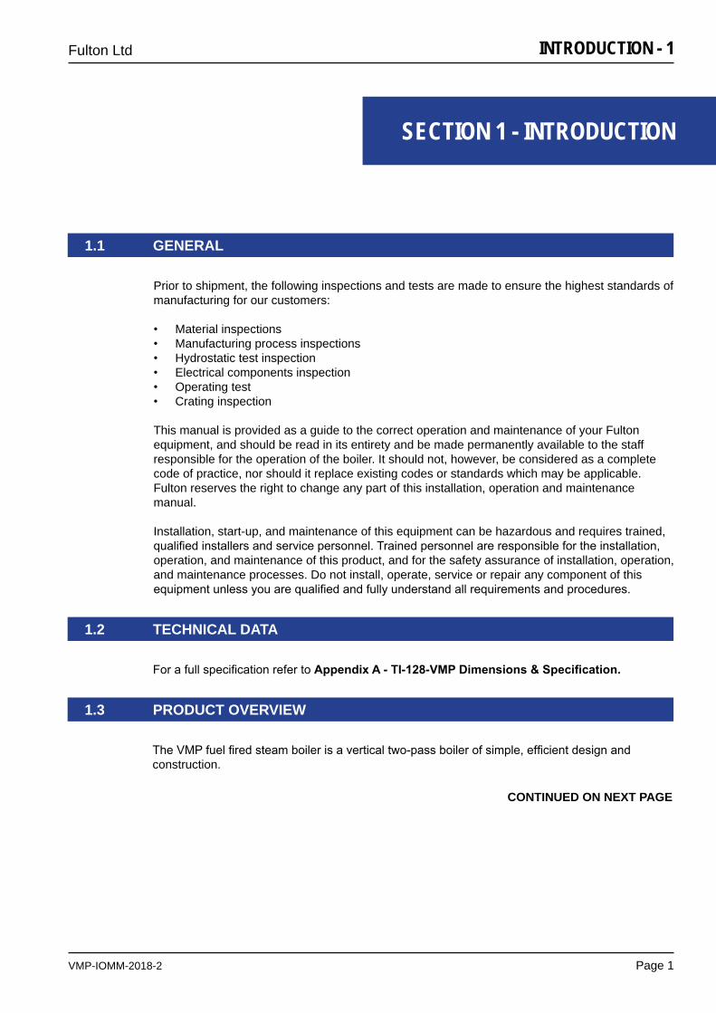
TheVMPfuelfiredsteamboilerisaverticaltwo-passboilerofsimple,efficientdesignandconstruction.
CONTINUED ON NEXT PAGE
Prior to shipment, the following inspections and tests are made to ensure the highest standards of manufacturing for our customers:
• Material inspections• Manufacturing process inspections• Hydrostatic test inspection• Electrical components inspection• Operating test• Crating inspection
This manual is provided as a guide to the correct operation and maintenance of your Fulton equipment, and should be read in its entirety and be made permanently available to the staff responsible for the operation of the boiler. It should not, however, be considered as a complete code of practice, nor should it replace existing codes or standards which may be applicable. Fulton reserves the right to change any part of this installation, operation and maintenance manual.
Installation, start-up, and maintenance of this equipment can be hazardous and requires trained, qualifiedinstallersandservicepersonnel.Trainedpersonnelareresponsiblefortheinstallation,operation, and maintenance of this product, and for the safety assurance of installation, operation, and maintenance processes. Do not install, operate, service or repair any component of this equipmentunlessyouarequalifiedandfullyunderstandallrequirementsandprocedures.
VMP-IOMM-2018-2
Fulton Ltd
Page 2
INTRODUCTION - 1
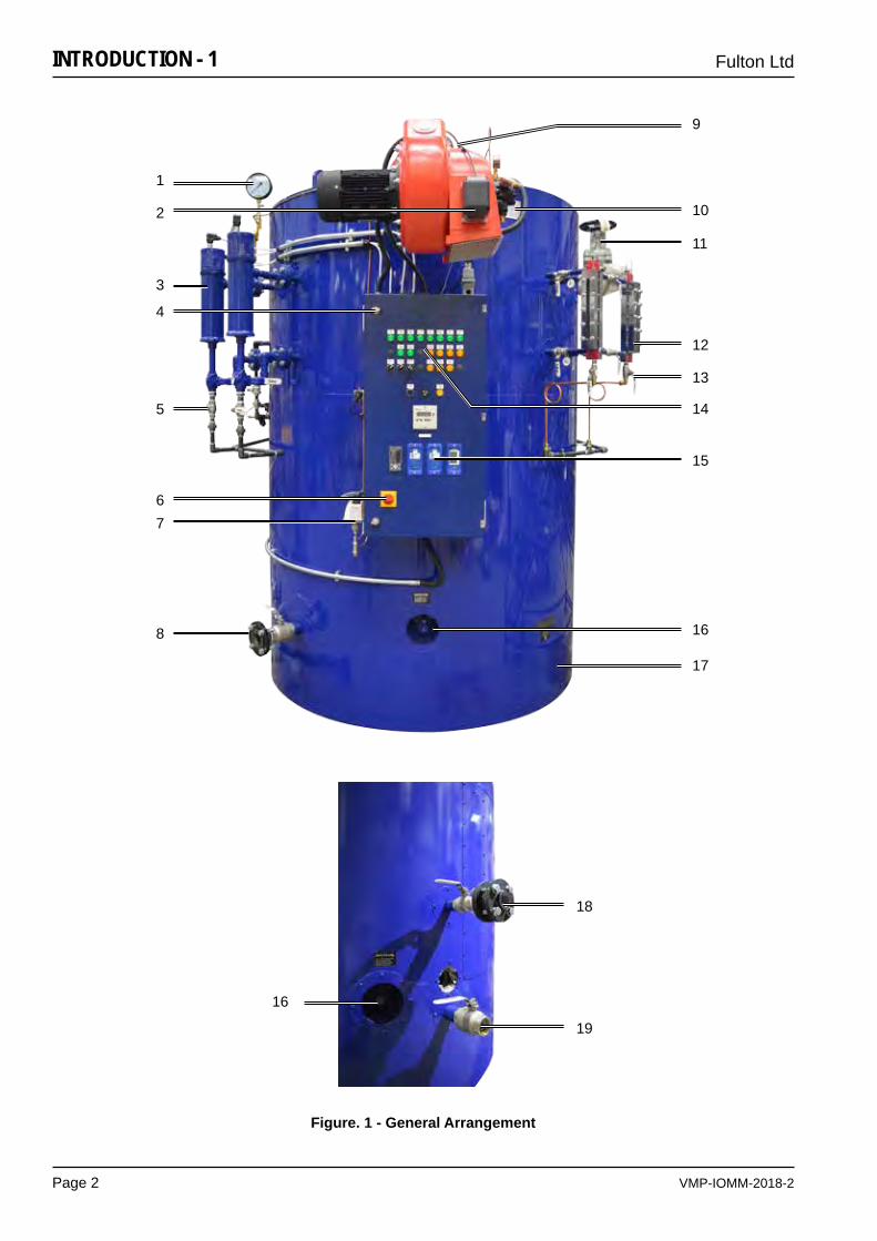
Figure. 1 - General Arrangement
13
14
18
19
2
4
5
12
11
15
1
3
7
9
10
8 16
17
6
16
VMP-IOMM-2018-2
Fulton Ltd
Page 3
INTRODUCTION - 1
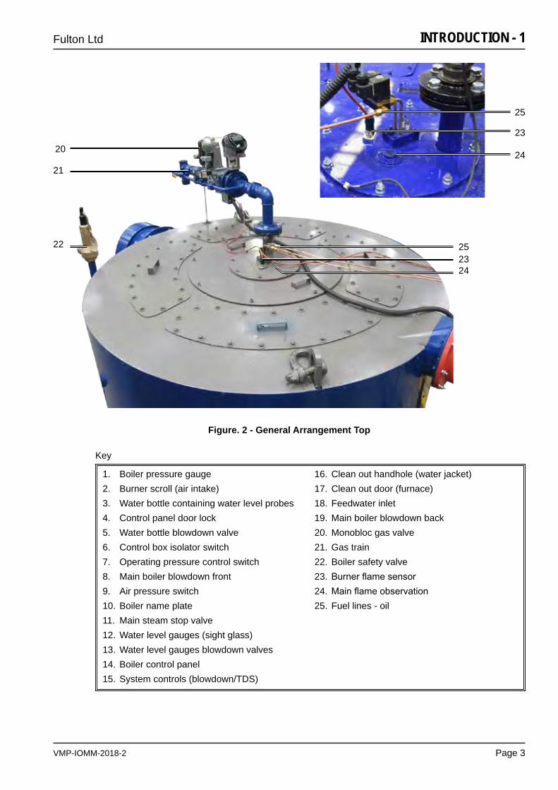
Figure. 2 - General Arrangement Top
1. Boiler pressure gauge2. Burner scroll (air intake)3. Water bottle containing water level probes4. Control panel door lock5. Water bottle blowdown valve6. Control box isolator switch7. Operating pressure control switch8. Main boiler blowdown front9. Air pressure switch10. Boiler name plate11. Main steam stop valve12. Water level gauges (sight glass)13. Water level gauges blowdown valves14. Boiler control panel15. System controls (blowdown/TDS)
16. Clean out handhole (water jacket)17. Clean out door (furnace)18. Feedwater inlet19. Main boiler blowdown back20. Monobloc gas valve21. Gas train22. Boiler safety valve23. Burnerflamesensor24. Mainflameobservation25. Fuel lines - oil
Key
20
21
2423
22 25
24
23
25
VMP-IOMM-2018-2
Fulton Ltd
Page 4
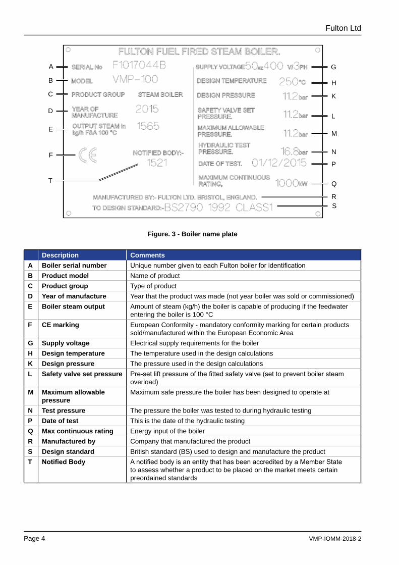
Description CommentsA Boiler serial number UniquenumbergiventoeachFultonboilerforidentificationB Product model Name of productC Product group Type of productD Year of manufacture Year that the product was made (not year boiler was sold or commissioned)E Boiler steam output Amount of steam (kg/h) the boiler is capable of producing if the feedwater
entering the boiler is 100 °CF CE marking European Conformity - mandatory conformity marking for certain products
sold/manufactured within the European Economic AreaG Supply voltage Electrical supply requirements for the boilerH Design temperature The temperature used in the design calculationsK Design pressure The pressure used in the design calculationsL Safety valve set pressure Pre-setliftpressureofthefittedsafetyvalve(settopreventboilersteam
overload)M Maximum allowable
pressureMaximum safe pressure the boiler has been designed to operate at
N Test pressure The pressure the boiler was tested to during hydraulic testingP Date of test This is the date of the hydraulic testingQ Max continuous rating Energy input of the boilerR Manufactured by Company that manufactured the productS Design standard British standard (BS) used to design and manufacture the productT NotifiedBody AnotifiedbodyisanentitythathasbeenaccreditedbyaMemberState
to assess whether a product to be placed on the market meets certain preordained standards
A
B
C
D
E
F
G
H
K
L
M
N
P
Q
RS
T
Figure. 3 - Boiler name plate
VMP-IOMM-2018-2
Fulton Ltd
Page 5
INSTALLATION - 2
SECTION 2 - INSTALLATION
Prior to delivery of the boiler, consideration should be given to the following:(Planning regulations may call for more consents than those listed below, always check with your Local Planning Authority).
A. Local Planning consents where appropriate.
B. Consideration given to access for delivery and positioning of the boiler.
C. Preparation of a suitable base, which must be able to support the total weight of the system under operating conditions.
The locations of services to the site required for the system, under operating conditions.
D. Electricity supply, check the loading required/available.
E. Drainage system, check the suitability of the drainage system.
F. Local regulations for discharge into existing drains.
G. Suitable access for delivery and off-loading.
H. Safe access to the plant when installation is complete.
2.1 GENERAL
TheinstallationofaVMPfuelfiredsteamboilershouldbecarriedoutbycompetentpersonnelinaccordance with all relevant safety regulations. It is the responsibility of the installer to ensure that these regulations are complied with.
The requirements and instructions contained in this section generally relate to the boilers being installed to operate on natural/manufactured gas. Where the boiler is to operate on L.P. Gas, special reference should be made to Section 2.10.1 - Gas Supply, and Section 2.10.1.3 L.P. Gas.
2.2 PRE-INSTALLATION
The customer should examine the equipment for any damage. It is the responsibility of the installer toensureallpartssuppliedwiththeequipmentarefittedinacorrectandsafemanner.
2.2.1 RECEIVING INSPECTION
VMP-IOMM-2018-2
Fulton Ltd
Page 6
INSTALLATION - 2
2.3 VENTILATION
2.2.2 SITING
(Reference should be made to Utilisation Procedures as stated in IGE/UP/10 Part 1 Communication 1676, and in particular to Section 5, Location of Appliances).
Theboilerhouseshouldbesufficientlysizedtoalloweasyandsafeaccesstoallpartsoftheboiler for operational and maintenance purposes.
Reference should be made to AppendixA-TI-128-VMPDimensions&Specificationto ascertain the relevant dimensions and weights, special note should be taken of the required vertical clearance required for maintenance.
WARNING
Maintenance on the burner assembly requires the area directly above and to one side of the boiler must not be obstructed with pipework or equipment which would interfere with the removal of the complete
burner unit. Care should be taken on installation of the boiler to ensure this area remains clear of obstructions.
!
Theflooringmustbelevel,laidinanon-combustiblematerialandbeofsufficientstrengthtosupport the boiler.
Adequatefresh,cleanairisnecessaryforsafeandefficientcombustion,andshouldbeprovidedat high and low level in accordance with BS 6644 1991 and IGE/UP/10 Part 1 Communication 1676.
It is essential that only fresh air be allowed to enter the combustion air system. Foreign substances in the combustion system can create hazardous conditions. Particulate matter like lint, combustible volatiles, dust, smog or chemicals (example, perchlorethlylene, halogenated compounds) in the combustion air supply to the equipment will cause damage or failure of the burner and is not covered under warranty.
Eliminate potential for high risk situations for particulate matter to be in the air supply (e.g., as the result of construction or maintenance activities). If foreign substances can enter the air stream, the combustion air inlet must be piped to an outside location. Failure to do so will void the warranty.
Ventilation requirements for LPG. Low level vents should be located as low as reasonably practicalwithin250mmofthefloorlevel.Highlevelshouldbelocatedashighasreasonablypractical.
Note: Ensure that there is adequate ventilation in the boiler room. Lack of ventilation will create a high temperature and cause control lockout. There is a minimum ventilation requirement to supply the air for combustion.Note: Do not keep exhaust fans running with windows, doors and vents closed, this will interfere with the necessary boiler draught.Note: Do not store chemicals such as perclorethylene in the boiler house, the fumes may damage the boiler and flue and cause the burner to lock out on flame failure.Note: see Appendix A - TI-128-VMP Dimensions & Specification for low and high level values.
WARNING
Failure to provide required and safe access to the equipment could impede commissioning and maintenance. Service technicians are instructed not to commence commissioning if hazardous conditions exist.
!
VMP-IOMM-2018-2
Fulton Ltd
Page 7
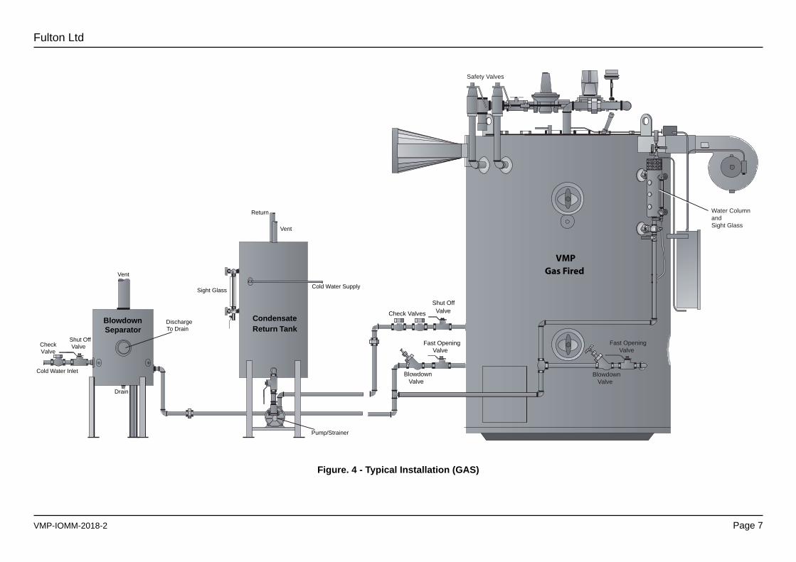
Figure. 4 - Typical Installation (GAS)
VMP Gas Fired
Shut Off Valve Check Valves
Fast OpeningValve
BlowdownValve
Safety Valves
Water Column andSight Glass
Fast OpeningValve
BlowdownValve
TYPICAL BOILER INSTALLATION(Design and Layout will change with Boiler Specification)
Vent
Cold Water Supply Sight Glass
Vent
Condensate Return Tank
DischargeTo Drain
Blowdown Separator
Shut OffValve
Cold Water Inlet
Drain
Pump/Strainer
VMP Gas Fired
Shut Off Valve Check Valves
Union Fast Opening Valve
Blowdown Valve
Safety Valves
Water Column and Sight Glass
Fast Opening Valve
Blowdown Valve
CheckValve
Return
VMP-IOMM-2018-2
Fulton Ltd
Page 8
INSTALLATION - 2
Theheightandtypeoffluewillbesubjecttolocalplanningregulationsandapprovals.
The following information is only intended to provide assistance for the installation of a simple flue.Wheremulti-boilerfluesordifficultiesareexperienced,specialistadviceshouldbeobtained.
Thefluediametermustbethesameorlargerthantheflueflangeprovidedwiththeboilerandtheoutlet should be at least 1 metre higher than the nearest ridge to avoid down draughts. Where a chimneycowlisfitted,careshouldbetakentoensurethatthedistancebetweenthelowestpointofthecowlandthetopoftheflueis1.5xthediameteroftheflueandthatitisoftheterminalcone type.
Note: If the flue layout is such that it may produce an excessive up-draught, a draught stabiliser may be required.
Note: Avoid fitting 90° elbows whenever possible, if unavoidable compensate by increasing the flue diameter.
Note: Ensure all flue pipes from the boiler to the main flue have a rising pitch.
2.4.2 BLOWDOWN VALVES
There are six blowdown valves on the boiler, two main boiler blowdown valves at the bottom of the boiler, two water bottle blowdown valves and two water level gauge (sight glass) blowdown valves.
All of these valves must be connected to a blowdown receptacle of approved design. Regulations exist covering such items and care must be taken to ensure compliance with these regulations.
If in doubt regarding blowdown arrangements, consult Fulton Ltd or Health and Safety Executive Guidance Note PM60 which covers blowdown tanks and associated pipework installation.
WARNING
Never discharge blowdown from the boiler directly to a drain. Where a high level of blowdown or automatic blowdownsystemsareinstalled,seriousconsiderationshouldbegiventofittingaBlowdownAfterCooling
System.
!
2.4.1 FLUE OUTLET
2.4 CONNECTIONS
CAUTION
Concentration levels of only a few ppm of chlorine containing compounds in combustion air can produceseriouscorrosionoftheflueoverlongperiodsoftime.Highchlorinecontainingcompounds
such as carbon tetrachloride or perchloroethylene would be prime suspects.
!
WARNING
To maintain a reasonable temperature in the equipment area and ensure safety to personnel, the section of the chimney duct within the building should be insulated.
!
VMP-IOMM-2018-2
Fulton Ltd
Page 9
INSTALLATION - 2
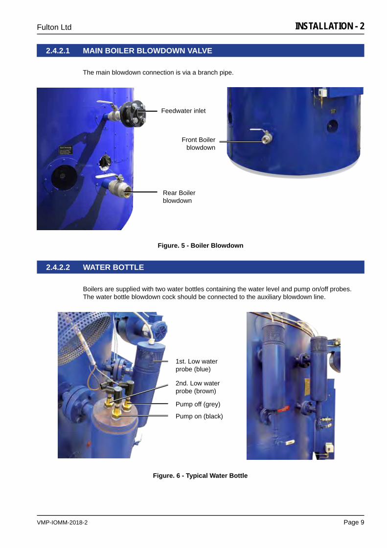
2.4.2.2 WATER BOTTLE
Boilers are supplied with two water bottles containing the water level and pump on/off probes. The water bottle blowdown cock should be connected to the auxiliary blowdown line.
1st. Low water probe (blue)
Pump off (grey)
Pump on (black)
2nd. Low water probe (brown)
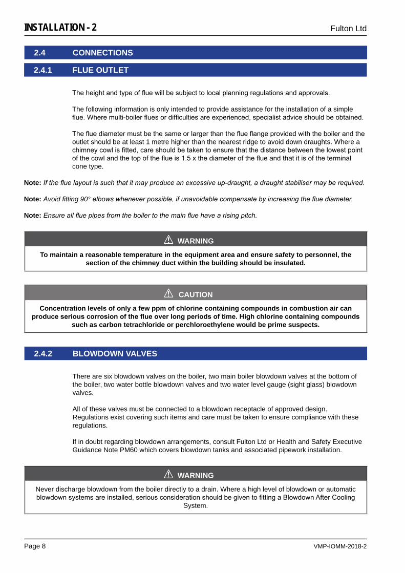
2.4.2.1 MAIN BOILER BLOWDOWN VALVE
The main blowdown connection is via a branch pipe.
Figure. 5 - Boiler Blowdown
Feedwater inlet
Rear Boiler blowdown
Front Boiler blowdown
Figure. 6 - Typical Water Bottle
VMP-IOMM-2018-2
Fulton Ltd
Page 10
INSTALLATION - 2
2.4.2.3 WATER LEVEL GAUGE SET (SIGHT GLASS)
Boilers are normally supplied with two complete water level gauge sets (sight glasses). The water level gauge blowdown cock should be connected to the auxiliary blowdown line from the water bottle blowdown valve by 3/8 in. soft copper tubing.
2.4.3 STEAM SAFETY VALVE
WARNING
Factoryfittedsafetyvalvesarepre-settoprotecttheboileronlyandmustnotbeusedtoprotectanyother items not capable of accepting boiler pressure.
!
WARNING
Improper installation or maintenance of the water level gauge assembly can cause immediate or delayedbreakageresultinginbodilyinjuryand/orpropertydamage.
!
Safetyvalvesarefactoryfittedandpre-set,theyMUSTNOTbeadjusted.Thedischargeoutletshould be piped to a safe discharge point and the piping so arranged that any condensate trapped in the pipework will drain away from the valve.
Note: It is recommended that the safety valve discharge pipework is installed to the requirements of BSEN 13480-1:2012
a) The lift pressure is indicated on the safety valve (donotadjust).
b) Thesafetyvalvefittedtotheboilerisdesignedtopreventtheboilerexceedingitsdesignpressure.
c) Any system connected to the boiler not capable of accepting boiler pressure must be protected by a separate safety valve set to the required pressure.
d) Ensure pipes and connections are clean and free of any foreign material.
e) Do not install using a pipe wrench. Use the appropriately sized wrench on the bonnet nut.
f) Install the valve vertically with no unnecessary intervening piping between the boiler and the valve.
g) Do not cap or plug the weep hole on the side of the safety valve.
h) A discharge pipe shall be of a pipe size equal to, or greater than, the outlet of the safety valve.
i) Minimizedischargepipingfittingsandoverallpipingruntoavoidoverpressurizationofthepiping, limiting safety valve discharge volume.
j) Do not support discharge piping with the safety valve. Discharge piping must be supported adequately by appropriate means.
k) Terminate the discharge pipe directly to atmosphere. Discharge pipe must not contain a shut off valve of any sort.
l) Adrainpipeistobefittedtothelowestpointofthedischargepipework.Pipesizetobenogreater than 10 mm.
VMP-IOMM-2018-2
Fulton Ltd
Page 11
INSTALLATION - 2
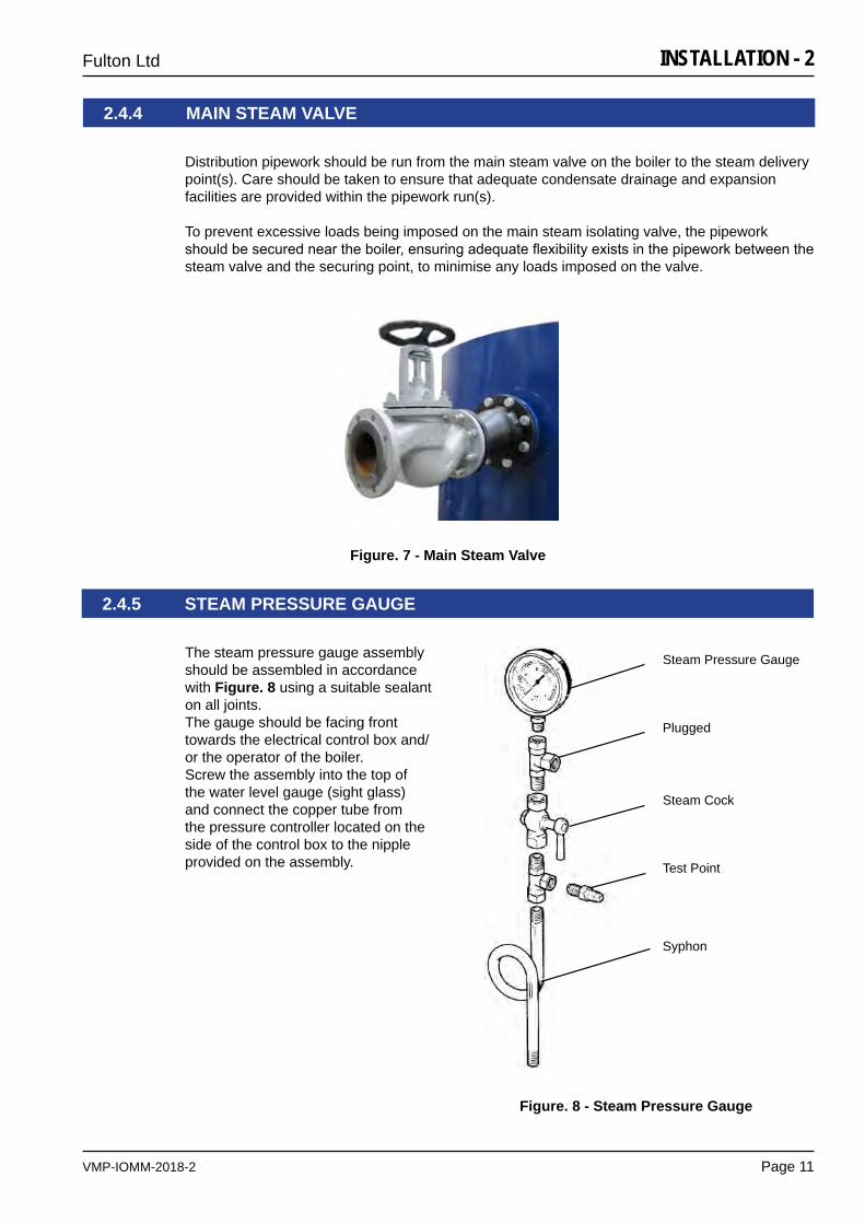
2.4.5 STEAM PRESSURE GAUGE
The steam pressure gauge assembly should be assembled in accordance with Figure. 8 using a suitable sealant on all joints. The gauge should be facing front towards the electrical control box and/or the operator of the boiler. Screw the assembly into the top of the water level gauge (sight glass) and connect the copper tube from the pressure controller located on the side of the control box to the nipple provided on the assembly. Test Point
Steam Pressure Gauge
Steam Cock
Syphon
Plugged
Figure. 8 - Steam Pressure Gauge
Distribution pipework should be run from the main steam valve on the boiler to the steam delivery point(s). Care should be taken to ensure that adequate condensate drainage and expansion facilities are provided within the pipework run(s).
To prevent excessive loads being imposed on the main steam isolating valve, the pipework shouldbesecuredneartheboiler,ensuringadequateflexibilityexistsinthepipeworkbetweenthesteam valve and the securing point, to minimise any loads imposed on the valve.
2.4.4 MAIN STEAM VALVE
Figure. 7 - Main Steam Valve
VMP-IOMM-2018-2
Fulton Ltd
Page 12
INSTALLATION - 2
2.5 FUEL SUPPLY
WARNING
Do not change the boiler fuel without consulting the boiler manufacturer.
!
2.5.1 GAS SUPPLY
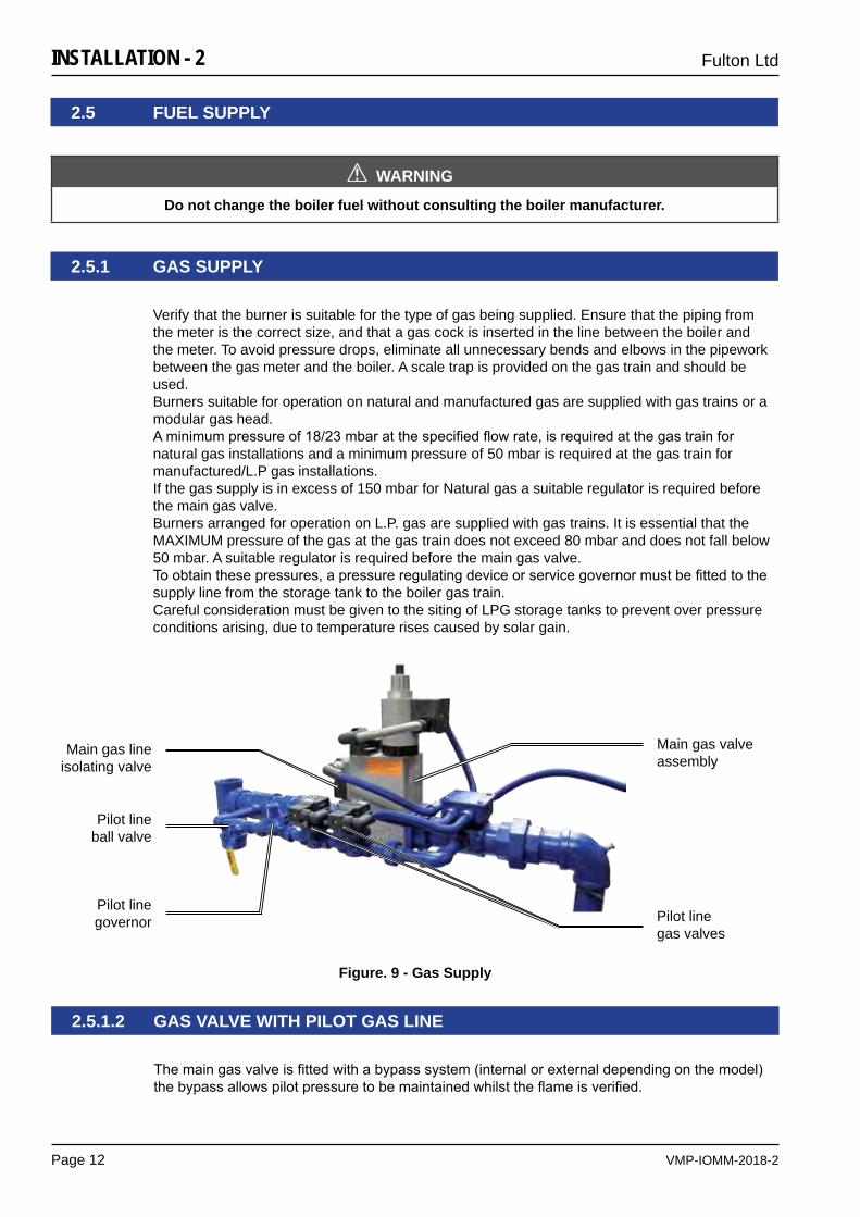
Verify that the burner is suitable for the type of gas being supplied. Ensure that the piping from the meter is the correct size, and that a gas cock is inserted in the line between the boiler and the meter. To avoid pressure drops, eliminate all unnecessary bends and elbows in the pipework between the gas meter and the boiler. A scale trap is provided on the gas train and should be used.Burners suitable for operation on natural and manufactured gas are supplied with gas trains or a modular gas head. Aminimumpressureof18/23mbaratthespecifiedflowrate,isrequiredatthegastrainfornatural gas installations and a minimum pressure of 50 mbar is required at the gas train for manufactured/L.P gas installations.If the gas supply is in excess of 150 mbar for Natural gas a suitable regulator is required before the main gas valve.Burners arranged for operation on L.P. gas are supplied with gas trains. It is essential that the MAXIMUM pressure of the gas at the gas train does not exceed 80 mbar and does not fall below 50 mbar. A suitable regulator is required before the main gas valve.Toobtainthesepressures,apressureregulatingdeviceorservicegovernormustbefittedtothesupply line from the storage tank to the boiler gas train.Careful consideration must be given to the siting of LPG storage tanks to prevent over pressure conditions arising, due to temperature rises caused by solar gain.
Themaingasvalveisfittedwithabypasssystem(internalorexternaldependingonthemodel)thebypassallowspilotpressuretobemaintainedwhilsttheflameisverified.
2.5.1.2 GAS VALVE WITH PILOT GAS LINE
Figure. 9 - Gas Supply
Main gas valve assembly
Main gas line isolating valve
Pilot line ball valve
Pilot line governor Pilot line
gas valves
VMP-IOMM-2018-2
Fulton Ltd
Page 13
INSTALLATION - 2
2.5.1.3 L.P.GAS GASSuPPLy-PrOPANE/BuTANE
LPG Boilers should be installed to the requirements of IGE/UP/10 March 2001 and only by experiencedengineersfamiliarwithLPGfiring.AnL.P.gasboilerissimilarindesigntoanaturalgas boiler, the main differences are important and must be taken into account when installing the boiler and ordering spare parts.
WheninstallinganL.P.gasboiler,thefeedfromthebulktanksupplymustbefittedwithasupplygovernor which is set to reduce the supply feed pressure to the boiler governor to between 50 mbar (min.) and 80 mbar (max.).
For PROPANE: Theboilergovernormustbeadjustedtogiveafiringpressureof25mbaratthe test point provided at the elbow on the gas train.
For BUTANE: Theboilergovernormustbeadjustedtogiveafiringpressureof20mbaratthetest point provided at the elbow on the gas train.
Gas Pressure Alarm Indicator LightFor L.P.G. applications the inlet pressure switch is used to protect the system from over pressure and should be set at 100 mbar.
Further information
Firing LPG fuels in a Fulton Vertical boiler is relatively straightforward, however the nature of the fuelmakesitdifficulttoensurethatthecorrectgasflowrateisachievedwhencommissioningandservicing the burner.
LPG is stored as a liquid at high pressure, which is vaporised as the pressure reduces through the pressure regulator at the discharge from the tank. The storage tank pressure regulators typically reduce the pressure down to 150 - 500 mbar, which is too high for the inlet to the gas control valve on the Fulton burner. An intermediate or Service Governor is therefore required to reduce the pressure further to below 80 mbar.
The siting of the LPG storage tank can be crucial particularly in environments where high ambient temperatures may be experienced. The effect of world wide temperature changes such as caused bysolargain,canresultinsignificantLPGsupplypressurechangeovera24hourperiod.
The consequences of temperature and pressure changes, is to vary the density of the gas suchthataccurate,consistent,andmeaningfulmeasurementofthegasflowrateisdifficult.Calibrating,gasflowmeterstoanydegreeofpracticalaccuracyisextremelydifficult.AtbestanLPGgasmetergivesanapproximationofthegasflowrate,howevertheinstallationofameterisessential.
Wherenometeringisavailabletheonlyavailablecriteriatoassesstheflowrateistheburnerinlet gas supply pressure at the test nipple on the last elbow prior to the gas entering the burner. This pressure would normally be established during works testing after manufacture, however LPGfiringisnotpossibleattheFultonBoilerWorksBristolfactory,forbothpracticalandsafetyreasons.
ThefiguresgivenintheOperationandMaintenanceInstructions,arecalculatedfiguresbasedonpublisheddatafortheSpecificGravityofstandardPropaneandButaneat15.6°C.Inpracticetemperature,pressureandgasconstituentsvariations,aresuchthatthecalculatedfigureshouldonly be used as a guide.
LPGfuelsgenerallyproducehigherflametemperatures(Butanebeingthehighest)whichmakesitvitalthattheburnersarenotoverfired,orareoperatedwithanysignificantlevelsofCarbonMonoxide (CO) in the exhaust gas, which could lead to overheating of the boiler pressure vessel.
VMP-IOMM-2018-2
Fulton Ltd
Page 14
INSTALLATION - 2
2.5.2 OIL SUPPLY
Note: It is advisable for dual fuel burners, that the offline fuel is manually isolated with a proof of closure microswitch that is interlocked with the online control circuit.e.g. gas supply proof of closure interlocked with the oil burner control circuit. Oil supply proof of closure interlocked with the gas burner control circuit.
ThegoldenrulewithLPGfuelsisthereforewhenindoubt,underfire,ensuringthatthereisadequate adjustment remaining on the air inlet damper for additional air, and that the exhaust gas analysis readings are 0 - 10 ppm of CO maximum, with CO2 in the range 9.0 - 10.0 % maximum.
IMPORTANT
DonotattempttosetupanLPGfiredburnerwithoutafluegasanalyser.
!
The positioning of the oil storage tank will be dependent on site conditions and local regulations. The burner fuel pump is of the bypass type requiring the installation of feed and return lines between the oil storage tank and the boiler. These lines should be in tubing of a minimum bore of 10 mm - 15 mm. Afirevalve,stopvalveandcheckvalvesshouldbeinsertedintheoilfeedline.Toavoidblockagesinthefuelpumpandburnernozzle,ametalcartridgeoilfiltershouldbefitted.Fibrouscartridgefiltersarenotrecommended.Thefinalconnectionsbetweenthefuelpumpandthefeedandreturnlinesshouldbemadewith theflexiblefuellinessupplied.Iftheoilstoragetankispositionedhigherthantheboiler,anon-returnvalveshouldbefittedtothereturnline.To overcome suction problems at the fuel pump, all vertical lifts in the feed pipe should be made as close to the boiler as possible. The burner fuel pump pressure is pre-set at the factory and should not require adjustment.
VMP-IOMM-2018-2
Fulton Ltd
Page 15
INSTALLATION - 2
2.6 ELECTRICAL REQUIREMENTS
CAUTION
Anyelectricalworkshouldbeundertakenbyaqualifiedelectriciantocurrentlocalregulations.
!
An individual wiring diagram for the boiler is located on the inside cover of the control box. Make sure the information on the electrical drawing corresponds to your voltage and frequency. Check the supply voltage and make sure that there is no over-or under-voltage exceeding 10% of the nominal value.
Whenreferringtotheelectricalspecificationoftheboiler,thereferencenumberlocatedontherear inside wall of the control box and the wiring diagram number should be quoted.
Unlessotherwisespecified,thealarmssuppliedwillbemainsvoltagemodels.Unlessotherwisespecifiedallmodelsaresuppliedwithburnermotorsandfeedwaterpumpmotorsarrangedforoperation on a three phase supply.
Awall-mounted,fuseddisconnectsizedfortheunitmustbeprovidedandfittedbytheclient/contractor, if disconnect is not supplied on the panel.
Connect power to the terminal strip as supplied on the inside of the panel box.
Note: Single skid systems are generally shipped completely pre-wired.
Note: The power ratings and requirements are given in Appendix A - TI-128-VMP Series Dimensions & Specification.
Note: It is advisable for dual fuel burners, that the offline fuel is manually isolated with a proof of closure microswitch that is interlocked with the online control circuit.e.g. gas supply proof of closure interlocked with the oil burner control circuit. Oil supply proof of closure interlocked with the gas burner control circuit.
WARNING
Assure all electrical connections are powered down prior to attempting replacement or service of electrical components or connections of the equipment.
!
2.6.1 ELECTRICAL CUSTOMER CONNECTIONS
Feed PumpBoiler feedwater pump to maintain water level in boiler.
Gas BoosterTo boost the gas supply to boiler if mains pressure is not adequate.
Gas/OilIndicatorA volt free contact is provided to give remote indication of which fuel the boiler is running on for dual fuel boilers.
Oil Valve InterlockProvision for an oil valve contact to prevent an oil supply to boiler when running on gas. Not supplied by Fulton.If not used terminals must be linked.
VMP-IOMM-2018-2
Fulton Ltd
Page 16
INSTALLATION - 2
Remote Stop.TheRemoteStopoptionallowsthecustomertofitaremotestoppushbutton/contact.Anopencontact will stop the boiler. It should be wired between terminals 13 & 15 as shown. If a Remote Alarmpanelisfitted,wiretheremotestopbetweenterminals13&14.
Note: A factory fitted link must be removed to use this option (Contact Rating 230V 4A Min.).
Common Alarm Contact.A Common Alarm Volt Free Contact is provided for giving a Remote Common Alarm signal or connecting to a site BMS system. (Contact Rating 230V 5A).
Pump Interrupt.APumpInterruptoptionallowsthecustomertofitaremoteswitchtointerrupttheboilerfeedwaterpump.Switchshouldbeanopencontacttointerruptthepumpoperation.Afactoryfittedlink must be removed to use this option.
Bottom Blowdown Valve.Connect the Bottom Blowdown valve as shown. A controller in the control panel will then allow automatic bottom blowdown to occur on a time basis. The contact gives feed back to the controller that blowdown valve has opened and closed as required. (Valve supply Max. rating 250V 3A resistive, 250V 1A inductive. Valve switch contact rating 230V 10A Max.).
TDS Solenoid Valve.Connect the TDS Solenoid valve as shown. A controller in the control panel will then allow automatic TDS blowdown to occur as required by monitoring the TDS in the boiler. (Valve supply Max. rating 250V 3A resistive, 250V 1A inductive).
Blowdown Alarm.The blow down alarm is triggered if a high TDS value is measured or if bottom blowdown is triggeredbutthevalvecontactdoesnotopenwithinaspecifiedtimeindicatingavalvefailure.(Max. rating 250V 3A resistive, 250V 1A inductive).
Fan Dilution Pressure Switch.Depending on the installation, a Flue dilution system and/or a plant room ventilation system mayberequired.Thesearesafetyfeaturestopreventahighcontaminationoffluegassesinthesystem.Pressureswitchesarefittedwithinthesystemstoensurethattherequiredfansarerunning,hencedilutingthefluegasses.Ifthefansfail,apressureswitchwilloperatetostoptheboilerandpreventfurthercontaminationoccurring.Afactoryfittedlinkmustberemovedtousethis option (230V).
Remote Alarm Panel.Aremotealarmpaneltosuit1,2or3boilerscanbefittedinamannedgatehouse.Thepanelwillgive an indication of a boiler alarm being triggered and also has the ability to remotely stop the individual boilers.
Water softener.A water softener can be powered from the boiler control panel. (230V, 2A Max.).
Feed Tank Level Control.A Feed tank level control panel can be powered from the boiler control panel. It controls the level offeedwaterinthefeedwatertankiffitted.(230V,2AMax.).
Feed Line Chemical Dosing.A Feed line chemical dosing unit can be powered from the boiler control panel. (230V, 2A Max.).
VMP-IOMM-2018-2
Fulton Ltd
Page 17
INSTALLATION - 2
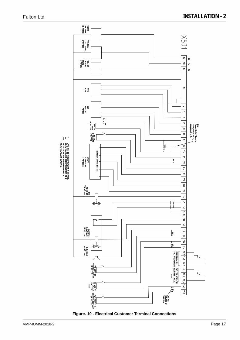
Figure. 10 - Electrical Customer Terminal Connections
VMP-IOMM-2018-2
Fulton Ltd
Page 18
INSTALLATION - 2
2.7 WATER SUPPLY
CAUTION
WATER SOFTENER and CHEMICAL TREATMENTThe chemicals required to operate the water softeners and chemical treatment plants
CAN BE SUPPLIED by Fulton. It is the responsibility of the operator to ensure adequate supplies of chemical are available at all times (including commissioning). Costly repairs could be required
should the plant operate without chemicals or the wrong dosage of chemicals.
!
The Fulton Warranty does not cover damage or failure that can be attributed to excessive corrosion, scale or fouling.
The quality of the water used in the boiler will affect the life and performance of the boiler. Feedwater contains solids and dissolved gases, these may promote encrustations of scale; foaming, priming, surging; corrosion and pitting; or caustic embrittlement. To prevent this happening it is strongly recommended that a reputable water treatment concern is consulted prior to commissioning the boiler.
Note: See Appendix A - TI-139-Recommended Water Conditions.
Connect the feedwater pump discharge to the check valve inlet with 25 mm bore pipe (this may be reduced to 15 mm, where the discharge pipework is shorter than 4 m in total. The pump suction pipework must remain at 25 mm minimum diameter and be as short as possible). Install the stop valve supplied between the boiler and the check valve. The check valve must be positioned so that it is below the internal water level of the boiler, and should be installed at least 1 m after the feedwater pump. The reason for this placement position is that the check valve is designed to have water on both sides to enable it to function correctly.
It is essential to protect the feedwater pump from damage by foreign matter, a strainer should thereforebefittedinthepumpsuction pipework.
Care should be taken to ensure the pipework is properly aligned and not placing any strain upon the feedwater pump.
Note: The boiler feedwater pump may contain an inhibitor and this should be flushed from the pump prior to fitting the pump to the boiler.Failure to do so may result in water bounce or foaming due to the inhibitor forming a seal in the boiler.
Note: If the boiler is to be operated with little or no condensate return, consideration should be given to pre-heating the feedwater. If in doubt consult Fulton Ltd.
VMP-IOMM-2018-2
Fulton Ltd
Page 19
INSTALLATION - 2
2.7.1 GLOSSARY OF WATER SUPPLY TERMS
Dissolved Oxygen: Oxygen that is dissolved in the feedwater will cause the steel in the boiler and the feedwater system to be attacked by the water in a manner described as “pitting”. The pits that are produced can vary from tiny depressions to holes large enough to penetrate the boiler metal and are usually covered with tubercles of iron oxide. Once pitting starts, it may be extremely hard to arrest. Pitting can proceed at a surprisingly rapid rate and can occur not only in the boiler proper, but also in pre-boiler equipment such as economizers, feedwater tanks, and feedwater lines.
Suspended Solids: Suspended solids are the undissolved matter in water, including dirt, silt, vegetation, iron oxides, and any other insoluble matter.Normally suspended solids are expressed in terms of turbidity. Suspended solids may also deposit in lowvelocityareasandcreatefouling.Inlinefilters,orvarious types of pretreatment can be used to lower the suspended solids level. Periodic blowdowns will eliminate suspended solids.
Alkalinity: Alkalinity is the capacity of a water to neutralize acids. Common water alkalinities consist of bicarbonate, carbonates, hydroxide, phosphate, and silicate. These alkalinities, especially bicarbonates and carbonates, break down to form carbon dioxide in steam, which is a major factor in the corrosion on condensate lines. High alkalinity also causes foaming and carry over in boilers. Both foaming and carry over cause erratic boiler operation. The reason for the high alkalinity should be determined. It may result from lack ofsufficientblowoff.Thesourceofalkalinitymaybedue to an overdose of alkaline internal water treatment chemical.
pH: pH is a measure of the degree of acid or base of solution.ApHrangeof8.5-10.5willhavelittleinfluenceon the corrosion rate of carbon steel. A low pH can result in corrosion of metals, while a high pH can result in scale formation or caustic embrittlement. In order to control boilers and equipment used for the external treatment of make-up water, it is essential that reliable pH measurements be made. RO/DI water will have a pH of 6.0 - 6.5 and will require neutralization if used in a carbon steel vessel. It is critical that the boiler pH be alkaline (8.5-10.5) whenever water is in the boiler.
Chlorides: If chloride levels are high enough to cause severe corrosion, they can be controlled by limiting the cycles of concentration and increasing boiler blowdowns. Corrosion from chlorides can also be controlled by increasing the amount of corrosion inhibitor, or changing to a more effective inhibitor.
Oil: Oil is not a natural constituent of boiler water; still it can frequently enter a system through leaks in a condenser or other heat exchanger. Oil can also enter a system through the lubrication of steam driven reciprocating equipment. Whatever the source, the presence of oil in boiler water is undesirable. Oil can act as a binder to form scale. In high heat-transfer areas oil can carbonize and further contribute to the formation of scale and low pH. Foaming is one indication of oil in boiler water. Its presence can also beconfirmedbyfirstshakingabottlecontainingboiler water. If oil is present foam will result. Often oil in boiler water will originate in the condensate. This contaminated condensate should be directed to the sewer until the source of the oil is determined and corrective steps taken.
Iron (oxides): Iron in any of its oxide or complex forms is undesirable in boiler water. Iron in its various forms can originate in the raw water makeup, condensate return water, or form directly in the boiler as a result of corrosion. It can concentrate in the boiler and it tends to collect in stagnant areas.
Water Hardness: Water hardness is the measure of calcium and magnesium content as calcium carbonate equivalents. Water hardness is a primary source of scale in boiler equipment. Hardness is removed by softening.Periodically, the ion exchange resin bed requires regenerationbyflushingthroughwithabrinesolutionfollowed by rising with fresh water. The interval between regeneration is dependent upon the raw water hardnessandflowrate.
In all cases the water hardness should be tested periodically and prior to starting the generator to ensureefficientoperationofthesoftener.Unsoftenedwater should not be allowed to enter the steam generatorunlesssufficientscaleinhibitorchemicalisused.
Feedwater: Feedwater is the combination of fresh makeup and returning condensate that is pumped to the boiler.
Condensate: Condensate is condensed steam that is normally low in dissolved solids. Hence, it does not contribute to the dissolved solid content of the feedwater. In addition, condensate is very expensive to waste. It’s been chemically treated, heated, pumped, converted to steam, and condensed.
VMP-IOMM-2018-2
Fulton Ltd
Page 20
INSTALLATION - 2
Dissolved Solids: Dissolved solids are salts in the water that stay in solution. They are invisible to the naked eye. As the boiler generates steam, dissolved solids will concentrate. If the concentration becomes too high, they will precipitate, form a suspended solid, and concentrate in the vessel. Daily boiler blowdown is recommended to help prevent the formation of deposits. Consult Blowdown procedure in the DailyMaintenance Schedule section of this manual.
Chemical Dosing: In addition to softening the feedwater, it is also important to consider other factors such as dissolved oxygen and acidity. Depending on the results of an analysis, it may be necessary to inject appropriate amounts of corrective chemical into the feedwater system. This is usually achieved by means of a chemical compound solution and variable output metering pump mounted at the storage vessel. It is important that the chemicals and quantities are correct and it is advisable to contact a water treatment company to arrange a feedwater analysis.
2.8 PIPING SPECIFICATIONS
For piping the basic considerations are: the design temperature, the pressure retained by the pipe,thefluidinthepipe,theloadresultingfromthermalexpansionorcontraction,impactorshock loads imparted (such as water hammer, external loads, wind loads and vibration from equipment).
Adhere to the following:
1. The arrangement of the piping and its appurtenances must take into consideration the location of other structures and equipment adjacent to the piping. The potential for freezing interference and/or damage as a result of expansion, contraction, vibration, or other movements must be factored.
2. Valvesareusedinpipingsystemstostopandstarttheflowoffluids,toregulateflow,topreventbackflow,andtorelieveexcessivepressurebuild-upinthepiping.Considerationshould be given to the appropriate location and orientation of valves necessary for safe operation and isolation of the piping.
3. All piping and piping components used should be suitable for the design temperatures, pressureandfluidusedinthesystem.
4. During the installation, ensure that no dirt, water, or residue from welding is left in the system.
5. Expansion joints or properly designed and sited loops should be provided to accommodate thermal expansion. Thermal expansion should be calculated using the maximum possible utilizationfluidtemperature,regardlessofwhetherthepipeconsideredisinthefeedorreturncircuit. Steel pipe will expand approximately 1 mm per meter over 100 °C rise.
6. Supports and anchors must be provided for all pipes, as necessary, to prevent undue stresses from being placed on equipment, including pumps, valves, and the boiler. Supports and anchors which will not interfere with thermal expansion should be chosen. The equipment should never be used or considered as an anchor.No additional loads should be applied to any factory connection.
7. Gasketsmustbeusedtomakeallflangedconnections.Gasketmaterialmustbesuitableforusewiththepressure,temperaturesandfluidsinthesystem.Ensurethatallboltsaretightened evenly and to the torque recommended values provided by the gasket manufacturer.
8. High point bleeds/air vents are to be installed at all high points in the system piping.
9. All pipes should be installed with a pitch to facilitate draining and venting.
VMP-IOMM-2018-2
Fulton Ltd
Page 21
INSTALLATION - 2
2.9 INSULATION
WARNING
After the appropriate system tests have been satisfactorily completed, all hot pipework and vessels must be adequately insulated with material suited to the temperature and application to prevent both
heatlossandpersonnelinjury.
!
Note: It is recommended that for inspection and maintenance, pumps, flanges, valves and fittings be left uninsulated but suitably shielded for safety.
Adhere to the following:
1. Return tanks, surge tanks and deaerators should be insulated. Insulation should be chosen withcaresuchthatthefluidinthetanksdoesnotexceedthemaximumoperatingtemperatureof the pump.
2. Blowdown vessels should not be insulated.
3. Equipment should be insulated with material suitable for the application and temperatures expected.
2.10 PIPEwOrkLEAk/PrESSurETESTS
Upon completion of the installation, adhere to the following for system piping testing:
1. Perform a pneumatic test not exceeding 15 psig.
2. Perform leak spray tests at all welds and joints to ensure that the system is free from leaks.

VMP-IOMM-2018-2
Fulton Ltd
Page 22
VMP-IOMM-2018-2
Fulton Ltd
Page 23
COMMISSIONING - 3
SECTION 3 - COMMISSIONING
3.1 COMMISSIONING THE BOILER
It is essential that the commissioning procedures listed below are carried out by a Fulton service engineer who will have the necessary experience and testing equipment to ensure that the installationisnotonlycorrect,butisoperatingsafelyandatoptimumefficiency.
Flue CommissioningPriortoinitialfiringoftheboiler,thefluemustbecheckedforleaks.This is done by BOTH of the following methods:
a) Visual InspectionCheckjointsbetweenallfluesectionsforqualityofseals.Wherethefluepassesthroughthestructureofthebuildinguseyourjudgementastotheintegrityofthissectionoftheflue.
b) Smoke TestWiththefluecapped,thedrainstabiliserpipe(iffitted)blankedandasmokegeneratorinsertedintotheflue,thereshouldbenosmokevisiblefromtheflue.
If either of these tests fail or at any time during boiler operation, there is doubt about the integrity oftheflue,shutdowntheboilerandcontactFultonLtdimmediately.
Note: Flues that are designed to operate with positive pressure should be tested to the latest regulations.
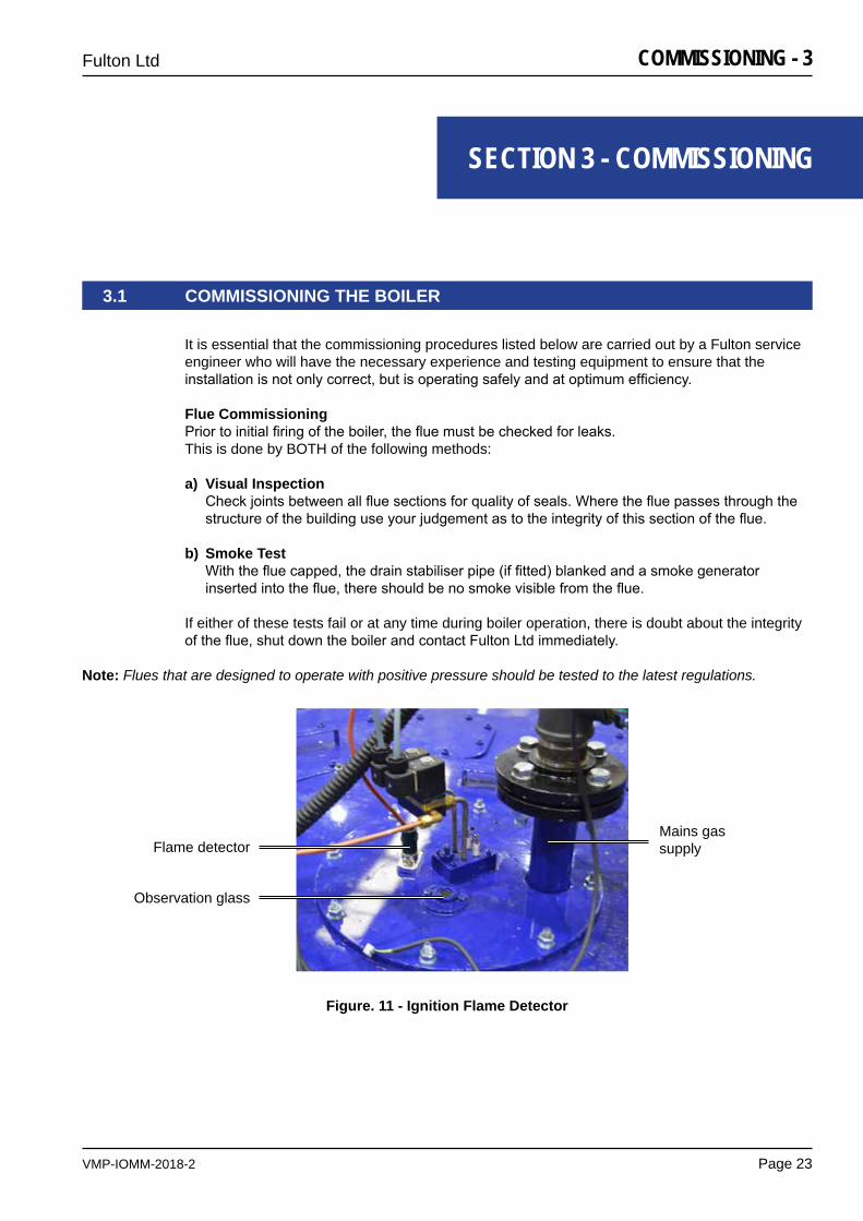
Figure. 11 - Ignition Flame Detector
Flame detectorMains gas supply
Observation glass
VMP-IOMM-2018-2
Fulton Ltd
Page 24
COMMISSIONING - 3
3.1.1 BOILER INSPECTION AND INITIAL FIRING DUAL FUEL BURNER
Dual fuel boilers that use a common burner assembly and have a switch change over from one fuel to another, have to be commissioned on the basis of a primary fuel (usually gas), with the secondary fuel as a back-up.
The secondary fuel then has to be commissioned using the air settings for the primary fuel. In practice this means adjusting the fuel input of the secondary fuel to achieve acceptable combustion.As more air is required for oil combustion the consequences are that when oil is the secondary fuel there will be a small reduction in the fuel input rate.
3.1.2 BOILER INSPECTION AND INITIAL FIRING GAS BURNER
1. Ensure that the boiler has been washed out after installation. It is advisable to conduct a water analysis before operating the boiler. Examine the probes in the water bottle and the boiler shell and record their lengths. Replace any damaged probes.
2. Remove the burner and check the electrodes have not been damaged and that their settings arecorrect.Iftheburnerisfittedwithaflamedetector,removeitandcheckfordamage.
3. Check that the burner is the correct type for use with the gas being supplied.
4. Replace the burner and reconnect the gas connection, ensuring these connections are tight. Reconnecttheignitionleadsandreplacetheflamedetector.
5. Ensure that all wiring connections are correct and that all terminal screws are tight.
6. Abarometrictypedraughtstabiliser,iffittedintheflue,shouldbesetforadraughtof - 0.025 mbar to - 0.05 mbar of water bottle pressure with the burner off.
7. Open all the valves in the feedwater line. Close the isolating valve on the discharge side of the feedwater pump. Remove the priming plugfromthepumpheadandslowlyfillthepumpwithwater.Replacetheprimingplugandtighten securely.
8. Check the correct rotation of the feedwater pump on the motor fan cover.Start the feedwater pump and check the direction of rotation.Vent the pump by means of the vent valve in the pump head. At the same time, open the discharge isolating valve a little. Continue to vent the pump. At the same time, open the discharge isolating valve a little more.Close the vent valve when a steady stream of water runs out of it.Completely open the discharge isolating valve.Thebypassvalvelocatedinthedrainplugmaybeopenedduringthefillingprocedure,closethe bypass when the operation is stable.
DO NOT ALLOW THE PUMP TO RUN DRY.
CONTINUED ON NEXT PAGE
VMP-IOMM-2018-2
Fulton Ltd
Page 25
COMMISSIONING - 3
WARNING
Gaspurgingbyqualifiedpersonsonly.
!
9. Open all the valves in the water feed line. Switchonthefeedwaterpumpmotorandfilltheboiler(seeSection 4.5 - Filling the boiler). The operation of the pump controls should be checked by using the boiler blowdown valve (located at the rear of the boiler). When the water level gauge (sight glass) is reading two thirds full, the pump will stop.
10. Open the boiler blowdown valve and slowly drain the boiler. When the water level falls below the PUMP ON probe, the pump should start. If the pump does not start, check the probe connections.
11. Close the boiler blowdown valve.
12. After purging the gas lines of air, start the burner as detailed in Section 3.6 - Boiler Start-Up. For models with an external pilot gas line, see Section 3.2 - Setting the burner controls.
13. Aftertheburnerhasbeenfiringforapproximatelyfiveminutes,adjustthegasandmainaircontrol gate located on the burner scroll, to obtain a clean combustion. Measure the levels of CO2 CO and O2 in the exhaust gas and record the results. See typical combustion values given in Appendix A - TI 128.
14. Observetheflamethroughtheobservationglassandadjusttheprimary/secondaryaircontrollocatedontheburner,sothattheflamecanbeseenpassingdowntheblasttube.
15. Check the operation of the low water safety controls (see Section 5.4.2 - Low Water Level Check).
16. Adjust the steam pressure control to suit the boiler application (see Section 4.2.3 - Steam Pressure Controls). It should be borne in mind that boilers are designed to operate most efficientlyattheirmaximumoperatingpressure.Whenboilersaretobeoperatedbelowapressureof80psi(5.5bar)considerationshouldbegiventothefittingofapressurereducingset.
VMP-IOMM-2018-2
Fulton Ltd
Page 26
COMMISSIONING - 3
3.1.4 BOILER INSPECTION AND INITIAL FIRING OIL BURNER
Note: Always place the highest value nozzle (engraved on the side of the nozzle) into the low fire oil supply port in the manifold.
1. Ensure that the boiler has been washed out after installation. It is advisable to conduct a water analysis before operating the boiler. Examine the probes in the water bottle and the boiler shell and record their lengths. Replace any damaged probes.
2. Remove the burner and check the electrodes have not been damaged and that their settings arecorrect.Iftheburnerisfittedwithaflamedetector,removeitandcheckfordamage.
3. Replace the burner and reconnect the copper oil line(s) to the oil nozzle assembly (and gas connection on Dual Fuel burners), ensuring these connections are tight. Reconnect the ignitionleadsandreplacetheflamedetector.
4. (DUAL FUEL ONLY) Ensure that the gas supply isolation valve is closed. Check that the oil supply valve is open.
5. Checktherotationoftheoilpumpmotor.Ensurethattheoilsupplyflowandreturnvalvesareopen. Bleed the oil pump.
6. Ensure all wiring connections are correct and that all terminal screws are tight.
7. Abarometrictypedraughtstabiliser,iffittedintheflue,shouldbesetforadraughtof - 0.025 mbar to - 0.05 mbar of water bottle pressure with the burner off.
8. Open all the valves in the feedwater line. Close the isolating valve on the discharge side of the feedwater pump. Remove the priming plugfromthepumpheadandslowlyfillthepumpwithwater.Replacetheprimingplugandtighten securely.
9. Check the correct rotation of the feedwater pump on the motor fan cover. Start the feedwater pump and check the direction of rotation.
DO NOT ALLOW THE PUMP TO RUN DRY.
10. Open all the valves in the water feed line. Switchonthefeedwaterpumpmotorandfilltheboiler(seeSection 4.5 - Filling the boiler). The operation of the pump controls should be checked by using the boiler blowdown valve (located at the rear of the boiler). When the water level gauge (sight glass) is reading two thirds full, the pump will stop.
11. Open the boiler blowdown valve and slowly drain the boiler. When the water level falls below the PUMP ON probe, the pump should start. If the pump does not start, check the probe connections.
12. Close the boiler blowdown valve.
13. Fit oil pressure gauge to oil pump to verify oil pressure.
14. Start the burner as detailed in Section 3.5 - Starting the burner. Allow time for the fuel pump to prime itself.
CONTINUED ON NEXT PAGE
VMP-IOMM-2018-2
Fulton Ltd
Page 27
COMMISSIONING - 3
15. Aftertheburnerhasbeenfiringforapproximatelyfiveminutes,adjustthemainaircontrolgatelocated on the burner scroll, to obtain a clean combustion.See typical combustion values given in Appendix A - TI 128.
16. Observetheflamethroughtheobservationglassandadjusttheprimary/secondaryaircontrollocatedontheburner,sothattheflamecanbeseenpassingdowntheblasttube.
17. Check the operation of the low water safety controls (see Section 5.4.2 - Low Water Level Check).
18. Adjust the steam pressure control to suit the boiler application (see Section 4.2.3 - Steam Pressure Controls). It should be borne in mind that boilers are designed to operate most efficientlyattheirmaximumoperatingpressure.Whenboilersaretobeoperatedbelowapressureof80psi(5.5bar)considerationshouldbegiventothefittingofapressurereducingset.
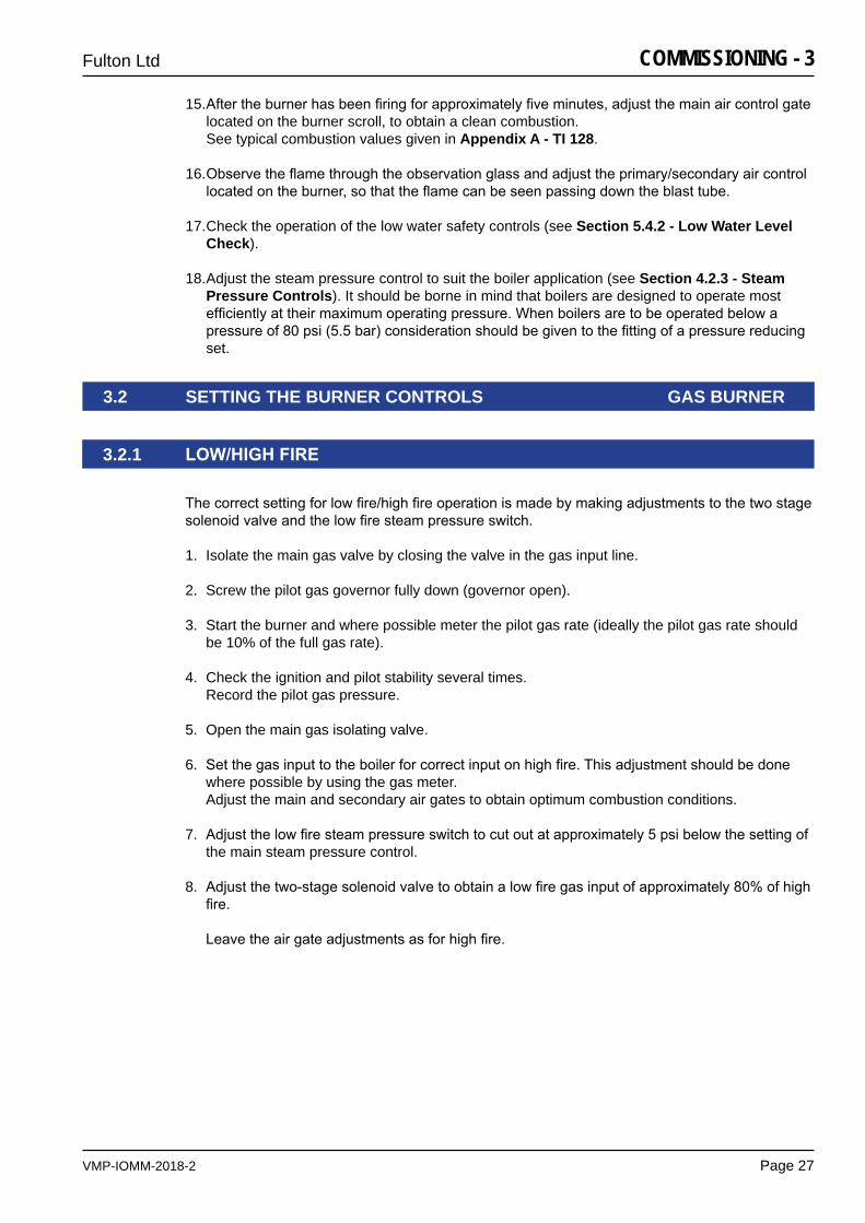
3.2.1 LOw/HIGHFIrE
Thecorrectsettingforlowfire/highfireoperationismadebymakingadjustmentstothetwostagesolenoidvalveandthelowfiresteampressureswitch.
1. Isolate the main gas valve by closing the valve in the gas input line.
2. Screw the pilot gas governor fully down (governor open).
3. Start the burner and where possible meter the pilot gas rate (ideally the pilot gas rate should be 10% of the full gas rate).
4. Check the ignition and pilot stability several times. Record the pilot gas pressure.
5. Open the main gas isolating valve.
6. Setthegasinputtotheboilerforcorrectinputonhighfire.Thisadjustmentshouldbedonewhere possible by using the gas meter. Adjust the main and secondary air gates to obtain optimum combustion conditions.
7. Adjustthelowfiresteampressureswitchtocutoutatapproximately5psibelowthesettingofthe main steam pressure control.
8. Adjustthetwo-stagesolenoidvalvetoobtainalowfiregasinputofapproximately80%ofhighfire.
Leavetheairgateadjustmentsasforhighfire.
3.2 SETTING THE BURNER CONTROLS GAS BURNER
VMP-IOMM-2018-2
Fulton Ltd
Page 28
COMMISSIONING - 3
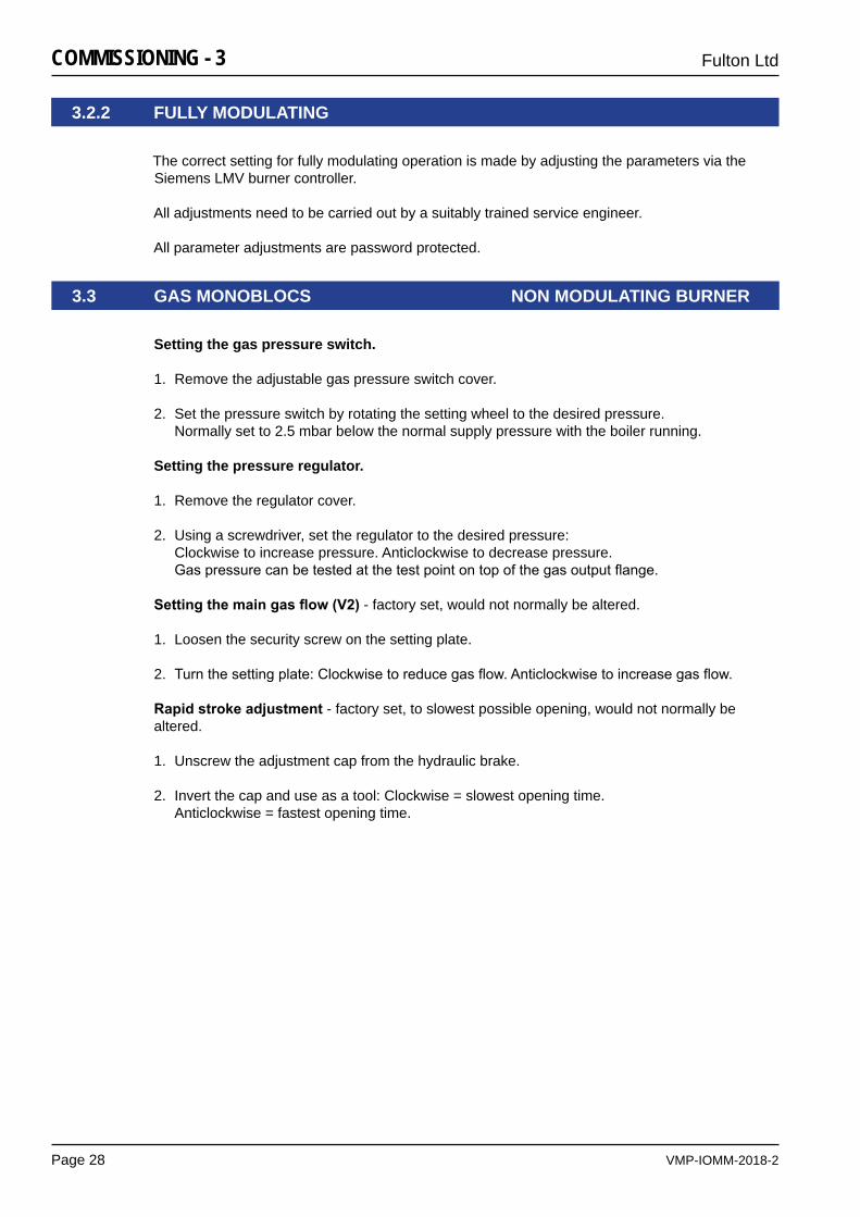
3.2.2 FULLY MODULATING
The correct setting for fully modulating operation is made by adjusting the parameters via the Siemens LMV burner controller.
All adjustments need to be carried out by a suitably trained service engineer.
All parameter adjustments are password protected.
Setting the gas pressure switch.
1. Remove the adjustable gas pressure switch cover.
2. Set the pressure switch by rotating the setting wheel to the desired pressure.Normally set to 2.5 mbar below the normal supply pressure with the boiler running.
Setting the pressure regulator.
1. Remove the regulator cover.
2. Using a screwdriver, set the regulator to the desired pressure:Clockwise to increase pressure. Anticlockwise to decrease pressure.Gaspressurecanbetestedatthetestpointontopofthegasoutputflange.
Settingthemaingasflow(V2)- factory set, would not normally be altered.
1. Loosen the security screw on the setting plate.
2. Turnthesettingplate:Clockwisetoreducegasflow.Anticlockwisetoincreasegasflow.
rapidstrokeadjustment - factory set, to slowest possible opening, would not normally be altered.
1. Unscrew the adjustment cap from the hydraulic brake.
2. Invert the cap and use as a tool: Clockwise = slowest opening time.Anticlockwise = fastest opening time.
3.3 GAS MONOBLOCS NON MODULATING BURNER
VMP-IOMM-2018-2
Fulton Ltd
Page 29
COMMISSIONING - 3
Gas valveGas
governorGas
actuator
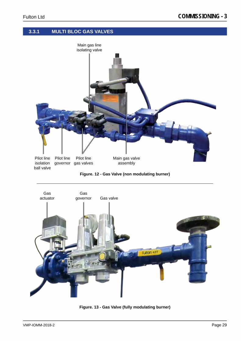
Figure. 12 - Gas Valve (non modulating burner)
Figure. 13 - Gas Valve (fully modulating burner)
3.3.1 MULTI BLOC GAS VALVES
Main gas valve assembly
Main gas line isolating valve
Pilot line isolation ball valve
Pilot line governor
Pilot line gas valves
VMP-IOMM-2018-2
Fulton Ltd
Page 30
COMMISSIONING - 3
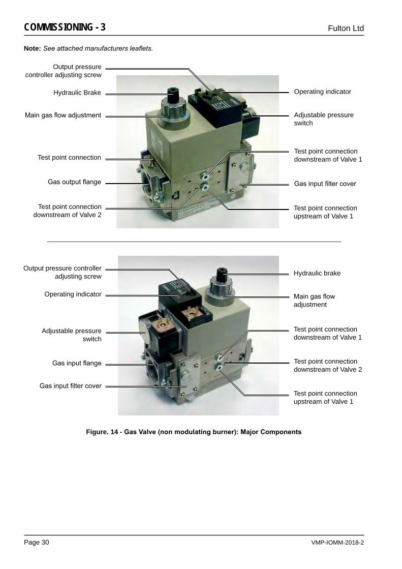
Figure. 14 - GasValve(nonmodulatingburner):MajorComponents
Note: See attached manufacturers leaflets.
Hydraulic Brake
Maingasflowadjustment
Test point connection
Gasoutputflange
Test point connection downstream of Valve 2
Test point connection upstream of Valve 1
Gasinputfiltercover
Test point connection downstream of Valve 1
Adjustable pressure switch
Operating indicator
Output pressure controller adjusting screw
Output pressure controller adjusting screw Hydraulic brake
Adjustable pressure switch
Operating indicator
Test point connection downstream of Valve 1
GasinputfiltercoverTest point connection upstream of Valve 1
Gasinputflange Test point connection downstream of Valve 2
Maingasflowadjustment
VMP-IOMM-2018-2
Fulton Ltd
Page 31
COMMISSIONING - 3
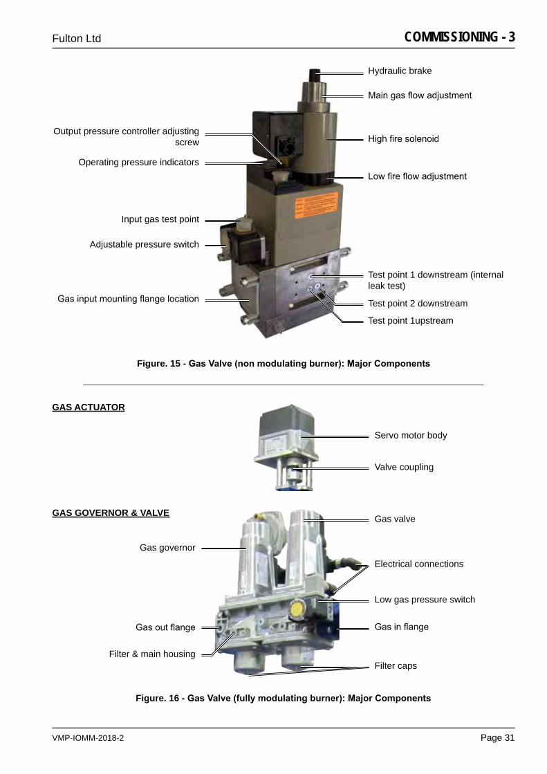
Gasinputmountingflangelocation
Adjustable pressure switch
Input gas test point
Hydraulic brake
Maingasflowadjustment
Highfiresolenoid
Lowfireflowadjustment
Test point 1 downstream (internal leak test)
Test point 2 downstream
Test point 1upstream
Output pressure controller adjusting screw
Operating pressure indicators
Figure. 15 - GasValve(nonmodulatingburner):MajorComponents
GAS ACTUATOR
GAS GOVERNOR & VALVE
Servo motor body
Valve coupling
Gas governor
Filter capsFilter & main housing
Gasoutflange
Gas valve
Electrical connections
Low gas pressure switch
Gasinflange
Figure. 16 - GasValve(fullymodulatingburner):MajorComponents
VMP-IOMM-2018-2
Fulton Ltd
Page 32
COMMISSIONING - 3
3.4 CLEANING STEAM LINES AND PRESSURE VESSELS
Duringthefirstweekofboileroperation,cleanalloilanddirtfromtheboiler,thesteamlineandcondensate return line.
1. Disconnect the condensate return pipe adjacent to the condensate return tank.
2. Directthereturnstoafloordrainorothersafedischargepointandmakesafe.
3. Leaveinthispositionforoneweektoallowallimpuritiestoflushthrough.
4. Drain the boiler completely each day.
5. Aftertheweekiscompleted,drainandflushthecondensatereturntank,removingallinstallation sediment. Reconnect the condensate return pipe to the condensate return tank.
VMP-IOMM-2018-2
Fulton Ltd
Page 33
OPERATION - 4
SECTION 4 - OPERATION
CAUTION
The following instructions are given for the guidance of the operator in the use of the Fulton steam boiler. No responsibility can be accepted by Fulton Ltd if these instructions are ignored.
!
4.1 GENERAL
The following instructions are given for the guidance of the operator in the use of the VMP fuel firedsteamboilerandtoprovideadequateinformationtoensurethatwhentheboilerisputintouse it will be done safely and without risk to health. Where original equipment service manuals are supplied, they must be read and understood in conjunction with this manual. All warnings and cautions must be observed.
4.2 CONTROLS
ThefollowingbriefdescriptionofthecontrolsusedontheVMPseriesfuelfiredsteamboilerisintended to provide the operator with a basic understanding of the operating principles, which is essentialforthecontinuedefficientoperationoftheboiler.

VMP-IOMM-2018-2
Fulton Ltd
Page 34
OPERATION - 4
4.2.1 BOILER CONTROLS
Note: All the limiters are of the ‘fail-safe’ type and are wired in series; failure of any one will automatically shut down the boiler.
Low Water Limiters, Feedwater Pump Relay and High Water Level RelayThese limiters and relays operate in conjunction with probes suspended in the boiler and water bottle to automatically maintain the level of water in the boiler and to cut off the burner should the water level fall to an unsafe level.
Steam Pressure ControlsThe steam pressure controls vary depending on the type of boiler control utilised. The controls are located on the side of the control panel box and are connected to the steam pressure gauge assembly by copper tube. An operating pressure switch controls the on/off cycle of the burner, shutting the burner off when maximum operating pressure is reached and switching it on when thesteampressurefalls.AHigh/Lowpressureswitchmaybefittedwhichswitchestheburnerbetweenahighflameandalowflamewhichallowstheburnertocontinuouslyrunratherthanswitching it on & off. An operating pressure transducer replaces the operating pressure switch for a modulating control.
Note: A set-back pressure controller is fitted when multi-boilers are fitted with a sequence control.
Burner ProgrammerThis is the main control in the panel box. The programmer in conjunction with a sensing device ‘supervises’theignitionsequence,provestheflameissatisfactoryandfinally‘monitors’theestablishedflame.Shouldanyfaultoccur,eitherduringtheignitionsequenceorduringnormalrunning, the programmer will immediately go to ‘lockout’ and the Multi-bloc gas valve will be closed.
Air Pressure SwitchMounted on the burner scroll, this switch is operated by the pressure of air entering the burner throughthethroatofthescroll.Lackofair,orinsufficientpressure,willpreventtheswitchcompleting the circuit thus preventing the burner from operating.
Gas Head AssemblyConsists of a Multi-bloc incorporating an integral governor, pressure switch and gas valves or for larger boilers in addition to the internal components, an external pilot line with its own gas solenoidvalvesandgovernor.Forboilersfittedwithfullymodulatingburners,agasactuatorisfittedtothegastrain.
Fuel Pump (OIL) Mounted on the burner scroll and driven by the burner motor, the fuel pump delivers oil to the burner nozzles at the correct pressure to allow complete atomisation and therefore combustion.
Note: Boilers fitted on skid systems and in plantrooms are interlocked with the feedwater and condensate return tank, after switching the boiler on at the boiler control box isolator switch, the reset button on the tank control box must be reset. This reset must also be selected after any electrical outage.
VMP-IOMM-2018-2
Fulton Ltd
Page 35
OPERATION - 4
4.2.2 BOILER CONTROL PANEL
Indicatorlightsarefittedtothecontrolpanelasanadditionalaidtotheoperator.The meaning and operating sequence of these lights is as follows:
CAUTION
The power on light is derived from a single phase. It is possible that with the control phase down or a defective bulb the other phases could be live. Always isolate the supply before investigating any fault.
!
CONTINUED ON NEXT PAGE
Power OnIndicates that power is being supplied to the control panel box.
PumpOFF/ONThis switch isolates the feedwater pump and must be switched ON before switching on the Boiler OFF/ON switch. This functions as a pump interrupt switch.
BoilerOFF/ONThis switch isolates the burner and must be switched ON to initiate burner start-up.
Low Water Limiter 1This light will energise when the boiler water is below low limiter 1. The light will illuminate, a continuous alarm will sound and the burner will go to lockout. Once the water in the boiler has been restored to a safe operating level, pressing the Common Alarm Reset button will reset the controls and allow the burner start sequence to initiate.
Low Water Limiter 2This light will energise when the boiler water is below low limiter 2. The light will illuminate, a continuous alarm will sound and the burner will go to lockout. Once the water in the boiler has been restored to a safe operating level, pressing the Common Alarm Reset button will reset the controls and allow the burner start sequence to initiate.
High Water LevelIndicates high water level in the boiler, isolates the feedwater pump and sounds an alarm.Once the water in the boiler has been returned to a safe operating level, the light will go out and normal control is resumed.
High Steam PressureThis light indicates when the boiler pressure exceeds the maximum allowable pressure. The high pressure controller can be reset using the switch on top of the controller.
IgnitionIndicates that the ignition transformer has been energised. This light will only be illuminated for approximately 5 - 10 seconds during the ignition sequence.
Low Gas Pressure This light will illuminate whenever the gas is off, or below minimum inlet pressure required by the European Standard for gas burners EN676. This switch is factory set and should not be adjusted after the boiler has been commissioned.
Main GasThis light illuminates when the Multi-bloc gas valve is energised.
Pilot GasThis light indicates the gas valves in the pilot line are energised.
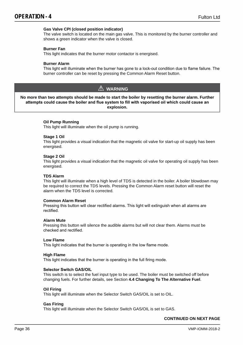
VMP-IOMM-2018-2
Fulton Ltd
Page 36
OPERATION - 4
Gas Valve CPI (closed position indicator)The valve switch is located on the main gas valve. This is monitored by the burner controller and shows a green indicator when the valve is closed.
Burner FanThis light indicates that the burner motor contactor is energised.
Burner AlarmThislightwillilluminatewhentheburnerhasgonetoalock-outconditionduetoflamefailure.Theburner controller can be reset by pressing the Common Alarm Reset button.
WARNING
No more than two attempts should be made to start the boiler by resetting the burner alarm. Further attemptscouldcausetheboilerandfluesystemtofillwithvaporisedoilwhichcouldcausean
explosion.
!
Oil Pump RunningThis light will illuminate when the oil pump is running.
Stage 1 OilThis light provides a visual indication that the magnetic oil valve for start-up oil supply has been energised.
Stage 2 OilThis light provides a visual indication that the magnetic oil valve for operating oil supply has been energised.
TDS AlarmThis light will illuminate when a high level of TDS is detected in the boiler. A boiler blowdown may be required to correct the TDS levels. Pressing the Common Alarm reset button will reset the alarm when the TDS level is corrected.
Common Alarm ResetPressingthisbuttonwillclearrectifiedalarms.Thislightwillextinguishwhenallalarmsarerectified.
Alarm MutePressing this button will silence the audible alarms but will not clear them. Alarms must be checkedandrectified.
Low FlameThislightindicatesthattheburnerisoperatinginthelowflamemode.
High FlameThislightindicatesthattheburnerisoperatinginthefullfiringmode.
SelectorSwitchGAS/OILThis switch is to select the fuel input type to be used. The boiler must be switched off before changing fuels. For further details, see Section 4.4 Changing To The Alternative Fuel.
Oil FiringThis light will illuminate when the Selector Switch GAS/OIL is set to OIL.
Gas FiringThis light will illuminate when the Selector Switch GAS/OIL is set to GAS.
CONTINUED ON NEXT PAGE
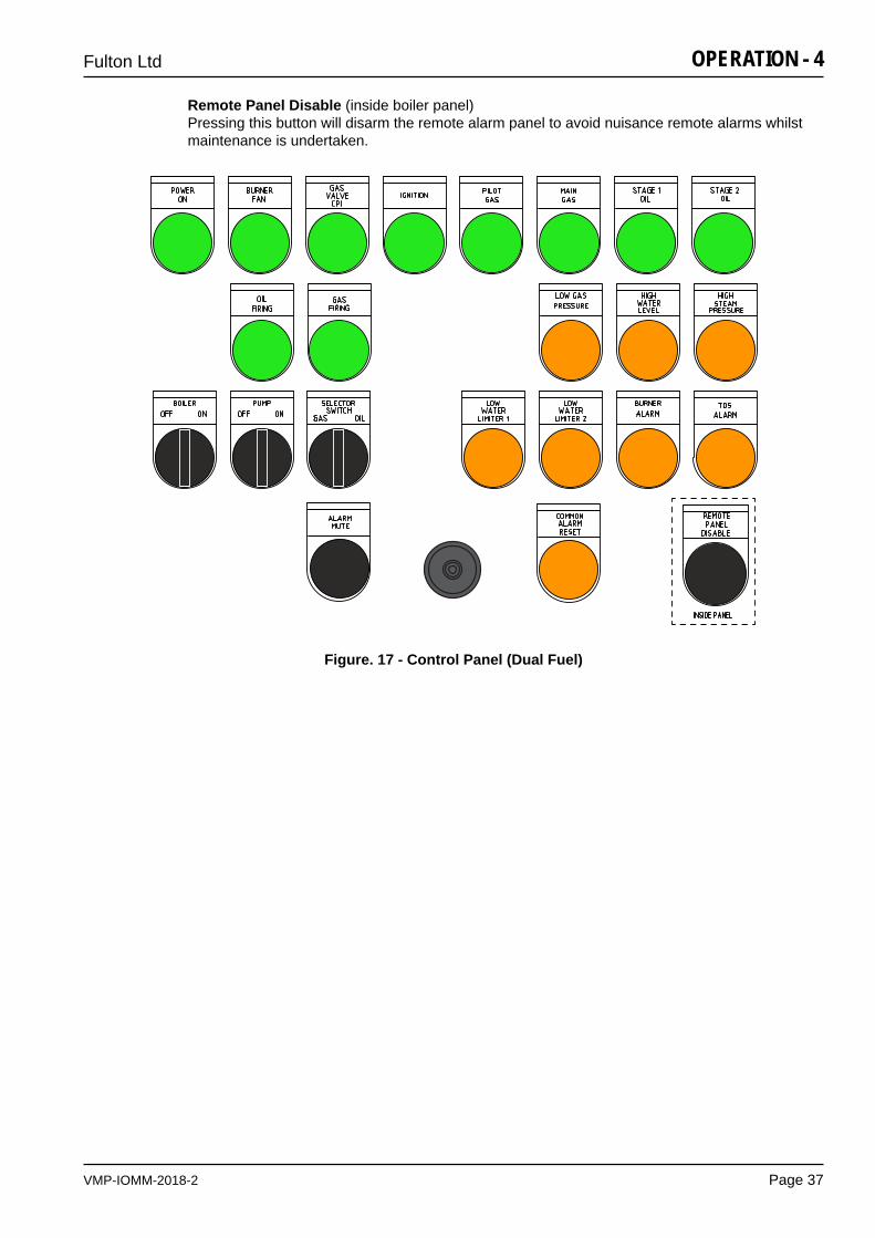
VMP-IOMM-2018-2
Fulton Ltd
Page 37
OPERATION - 4
Remote Panel Disable (inside boiler panel)Pressing this button will disarm the remote alarm panel to avoid nuisance remote alarms whilst maintenance is undertaken.
Figure. 17 - Control Panel (Dual Fuel)
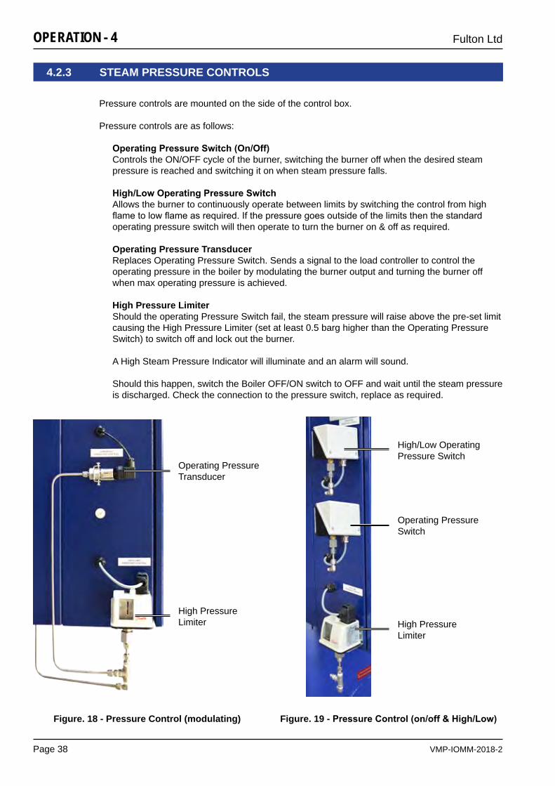
VMP-IOMM-2018-2
Fulton Ltd
Page 38
OPERATION - 4
4.2.3 STEAM PRESSURE CONTROLS
Pressure controls are mounted on the side of the control box.
Pressure controls are as follows:
OperatingPressureSwitch(On/Off) Controls the ON/OFF cycle of the burner, switching the burner off when the desired steam pressure is reached and switching it on when steam pressure falls.
High/LowOperatingPressureSwitchAllows the burner to continuously operate between limits by switching the control from high flametolowflameasrequired.Ifthepressuregoesoutsideofthelimitsthenthestandardoperating pressure switch will then operate to turn the burner on & off as required.
Operating Pressure TransducerReplaces Operating Pressure Switch. Sends a signal to the load controller to control the operating pressure in the boiler by modulating the burner output and turning the burner off when max operating pressure is achieved.
High Pressure Limiter Should the operating Pressure Switch fail, the steam pressure will raise above the pre-set limit causing the High Pressure Limiter (set at least 0.5 barg higher than the Operating Pressure Switch) to switch off and lock out the burner.
A High Steam Pressure Indicator will illuminate and an alarm will sound.
Should this happen, switch the Boiler OFF/ON switch to OFF and wait until the steam pressure is discharged. Check the connection to the pressure switch, replace as required.
Figure. 18 - Pressure Control (modulating) Figure. 19 - PressureControl(on/off&High/Low)
Operating Pressure Transducer
High Pressure Limiter
Operating Pressure Switch
High Pressure Limiter
High/Low Operating Pressure Switch
VMP-IOMM-2018-2
Fulton Ltd
Page 39
OPERATION - 4
4.2.3.1 SETTING PRESSURE CONTROLS
4.2.3.2 TESTING STEAM PRESSURE CONTROLS
Ifthepressurecontrolisfittedwithadifferentialscale:
1. Set the main scale pressure to the maximum pressure required (system pressure). Do not exceed the boiler operating pressure.
2. Setthedifferentialscaletoit’sminimumpressure.Ifthepressurecontrolhasafixeddifferential, i.e. no adjustable differential scale, set the main scale to the maximum pressure required.
whenmultipleboilersarefittedwithasequencecontrol:
1. Set the main scale and differential scale as above.
2. Set the setback pressure control to the required set back pressure (see Appendix D).
1. Start the boiler.
2. SHUT the main steam valve.
3. Set the Operating Pressure switch to its maximum.
4. Set the High Pressure Limiter to 0.5 barg below the safety valve setting.
5. Allow the steam pressure to rise until the high limit pressure switch trips. On the steam pressure gauge, check that the pressure is not less than 0.5 barg below the safety valve lift pressure.
If the pressure is incorrect, repeat steps 2, 4 and 5.
6. OPEN the main steam valve slowly to lower the steam pressure.
7. Reset the operating pressure switch to the required working pressure and the high/low pressure switch to 0.3 barg - 0.5 barg below the operating pressure switch setting.
8. SHUT the main steam valve.
9. Reset the high pressure limiter and allow the steam pressure to rise until the high/low pressure switchreducestheburnertolowfire,andthentheburnershutsdownundertheOperatingPressure switch.
10. Readjust if necessary to achieve the required settings.
Note: The requirement for a difference between the operating and high pressure limiter is to prevent unnecessary high steam pressure faults tripping the burner at no load conditions. The residual heat in the furnace, the flue pipes and the door refractory is capable of raising steam pressure slightly, causing the high pressure limiter to trip out.
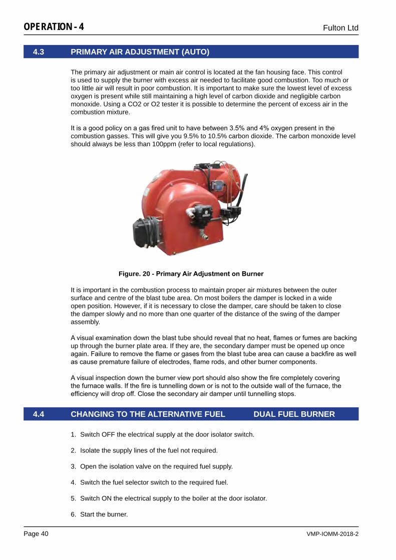
VMP-IOMM-2018-2
Fulton Ltd
Page 40
OPERATION - 4
It is important in the combustion process to maintain proper air mixtures between the outer surface and centre of the blast tube area. On most boilers the damper is locked in a wide open position. However, if it is necessary to close the damper, care should be taken to close the damper slowly and no more than one quarter of the distance of the swing of the damper assembly.
Avisualexaminationdowntheblasttubeshouldrevealthatnoheat,flamesorfumesarebackingup through the burner plate area. If they are, the secondary damper must be opened up once again.Failuretoremovetheflameorgasesfromtheblasttubeareacancauseabackfireaswellascauseprematurefailureofelectrodes,flamerods,andotherburnercomponents.
Avisualinspectiondowntheburnerviewportshouldalsoshowthefirecompletelycoveringthefurnacewalls.Ifthefireistunnellingdownorisnottotheoutsidewallofthefurnace,theefficiencywilldropoff.Closethesecondaryairdamperuntiltunnellingstops.
The primary air adjustment or main air control is located at the fan housing face. This control is used to supply the burner with excess air needed to facilitate good combustion. Too much or too little air will result in poor combustion. It is important to make sure the lowest level of excess oxygen is present while still maintaining a high level of carbon dioxide and negligible carbon monoxide. Using a CO2 or O2 tester it is possible to determine the percent of excess air in the combustion mixture.
Itisagoodpolicyonagasfiredunittohavebetween3.5%and4%oxygenpresentinthecombustion gasses. This will give you 9.5% to 10.5% carbon dioxide. The carbon monoxide level should always be less than 100ppm (refer to local regulations).
4.3 PRIMARY AIR ADjUSTMENT (AUTO)
Figure. 20 - PrimaryAirAdjustmentonBurner
1. Switch OFF the electrical supply at the door isolator switch.
2. Isolate the supply lines of the fuel not required.
3. Open the isolation valve on the required fuel supply.
4. Switch the fuel selector switch to the required fuel.
5. Switch ON the electrical supply to the boiler at the door isolator.
6. Start the burner.
4.4 CHANGING TO THE ALTERNATIVE FUEL DUAL FUEL BURNER
VMP-IOMM-2018-2
Fulton Ltd
Page 41
OPERATION - 4
4.5 FILLING THE BOILER ALL MODELS
1. The door isolator should be in the OFF position.
2. Ensure the Boiler and Pump Switches are in the OFF position.
3. Ensure the following valves are OPEN:
a) Main steam stop valve.
b) Steam pressure gauge isolating valve.
c) All valves in the feedwater line.
d) Water level gauge (sight glass) isolating valves.
4. Ensure the following valves are SHUT:
a) Main blowdown valve.
b) Water level gauge blowdown valves.
c) Water bottle blowdown valves
5. Select the fuel to be used, ensure that the valves in the selected fuel line(s) are open, and the alternative fuel lines are closed (see Section 4.4 - Changing To The Alternative Fuel).
CAUTION
The feed pump seals are water cooled. The pump must never be allowed to run whilst dry, irreparable damage may result.
Ensure the pump is fully primed before energising the motor.
!
6. Vent the pump.
7. Turn the door isolator to the ON position.
8. Turn the Pump switch to the ON position.
9. Thefeedwaterpumpshouldstart(checkthepumpdirectionofrotation)andfilltheboilertothecorrect working level and then automatically switch OFF.
Note: If the boiler water level is below its correct level, the feedwater pump will operate. When the water reaches the correct level (two thirds up the water level gauge), the pump will stop. If the water level is above the top of the level gauge, drain off until the level is in the middle of the water level gauge (sight glass).
Note: It may be necessary to vent the feedwater pump by bleeding air from the plug mounted in the top casting below the pump motor to pump body connection.
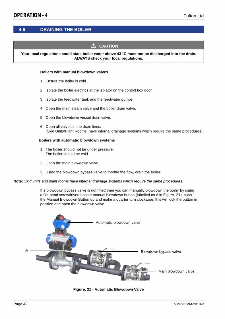
VMP-IOMM-2018-2
Fulton Ltd
Page 42
OPERATION - 4
4.6 DRAINING THE BOILER
CAUTION
Your local regulations could state boiler water above 43 °C must not be discharged into the drain. ALWAYS check your local regulations.
!
Figure. 21 - Automatic Blowdown Valve
Boilers with manual blowdown valves
1. Ensure the boiler is cold.
2. Isolate the boiler electrics at the isolator on the control box door.
3. Isolate the feedwater tank and the feedwater pumps.
4. Open the main steam valve and the boiler drain valve.
5. Open the blowdown vessel drain valve.
6. Open all valves in the drain lines. (Skid Units/Plant Rooms, have internal drainage systems which require the same procedures).
Boilers with automatic blowdown systems
1. The boiler should not be under pressure. The boiler should be cold.
2. Open the main blowdown valve.
3. Usingtheblowdownbypassvalvetothrottletheflow,draintheboiler.
Note: Skid units and plant rooms have internal drainage systems which require the same procedures.
Ifablowdownbypassvalveisnotfittedthenyoucanmanuallyblowdowntheboilerbyusing aflat-headscrewdriver.Locatemanualblowdownbutton(labelledasAinFigure.21),pushthe Manual Blowdown Button up and make a quarter turn clockwise, this will lock the button in position and open the blowdown valve.
A
Main blowdown valve
Automatic blowdown valve
Blowdown bypass valve
VMP-IOMM-2018-2
Fulton Ltd
Page 43
OPERATION - 4
4.7 BOILER START-UP (FROM COLD) ALL MODELS
CAUTION
The system should be raised to temperature slowly to allow for expansion and to avoid thermal shock and water hammer.
!
1. Fill the boiler (see Section 4.5 - Filling The Boiler).
2. Ensure the main steam isolating valve is SHUT.
3. Open all the valves in the gas train/oil supply. It is assumed that the fuel supply lines have been purged prior to attempting to start the boiler/burner.
CAUTION
Failure to open the oil supply line will damage the oil pump.A pump damaged under these circumstances will not be replaced by warranty.
!
4. (DUAL FUEL ONLY) CLOSE alternative fuel supply valves with the proof of closure microswitch.
5. Switch the Pump and Boiler switches to the ON position.
The Low Water audible alarm will sound, the Low Water Limiter lights will illuminate.
6. Press the Common Alarm Reset button for two seconds maximum. The alarms will stop, and the alarm lights will extinguish.
Reset high pressure switch.
The burner start sequence will commence.
7. Afteramaximumoftwominutestheburnershouldbefiring,andtheMainGaslightshouldilluminate.
8. When the boiler has achieved the required (set) pressure, the main steam isolating valve should be slowly opened allowing steam to enter the system distribution pipework.This can be achieved by one of two methods:
a) Partially open the main steam valve and allow the system to heat up slowly (minimum 15 minutes) before fully opening the main steam valve.
b) Open the main steam valve when starting the boiler, allowing the boiler and system to heat up together.
Note: This can lead to water logging of the steam lines until full pressure is achieved.If fitted, TDS Panel Mounted Controllers (BC3150) must be reset after any break in electrical supply to the unit.
Note: Before leaving the boiler unattended, the daily operating tests (see Section 5.8.1) should be carried out to check the functions of all the safety interlocks.
VMP-IOMM-2018-2
Fulton Ltd
Page 44
OPERATION - 4
4.8.3 LONG TERM SHUT-DOWN (WEEKS)
4.8 BOILER SHUT-DOWN
4.8.1 SHORT TERM SHUT-DOWN (HOURS)
4.7.1 BOILER START-UP FOLLOWING SHORT TERM SHUT-DOWN
4.8.2 MEDIUM TERM SHUT-DOWN (DAYS)
To store the boiler in a corrosion-free situation there are two practical solutions:
1. Fullyfloodtheboilertoexcludeasmuchairaspossible.
2. Drain the boiler completely. Remove all hand holes. Open all gas/oil side access doors.
Additionally you could introduce a form of convection heating to the gas/oil and water side. A very effective solution is to install a small heater.
If the boiler has been shut-down short term (see Section 4.8.1 - Short Term Shut-Down), the large thermal mass in the boiler will maintain the internal temperature to a point that the boiler canbesimplyswitchedon(preferablyonlowfire)andthenlefttoreachworkingtemperature/pressure.
Switch Boiler switch to OFF on the boiler control panel switch. Theburnerwillstopfiring,post-purgeandthenstop.
1. Shut the main steam valve.
2. Leave Pump switch ON.
3. Switch Boiler switch OFF.
4. Shut off fuel supply.
Note: Ensure the boiler water treatment levels for dissolved oxygen are within the specified limits.
VMP-IOMM-2018-2
Fulton Ltd
Page 45
MAINTENANCE - 5
CAUTION
It is vitally important that the instructions given in this manual are strictly adhered to.Failure to carry out the daily, weekly, monthly and six monthly checks could result in a drastic
reduction in the life expectancy of the boiler.
!
SECTION 5 - MAINTENANCE
Tests should be carried out by a competent person trained to perform such tests. If any test shows that the equipment is not operating correctly, the fault should be investigated and corrected before the boiler is used.
Anyrectificationorrepairsshouldbecarriedoutbytrained,competentservicepersonnel.
Platforms are designed to allow easy maintenance access to the components at the top of the boiler (i.e. the water level probes, main steam valve, vent and safety valves).
It is the responsibility of the user to ensure that a site risk assessment is carried out for the safe use of the ladders and working at height on the platform.
5.1 BOILER PLATFORM (IF FITTED)
5.2 VISUAL CHECKS
Inspectthesteamandfeedwaterpipework,valvesandfittingsforsignsofleakage.Ifleaksaresuspected, shut-down and evacuate the system to atmospheric pressure before attempting any repairs.
Note: Ensure that the water level is maintained during the pressure build-up. If any part of the equipment is not operating correctly, the fault should be investigated before the boiler is used. Ensure that all blowdown pipework is safe and discharged to a blowdown receptacle.
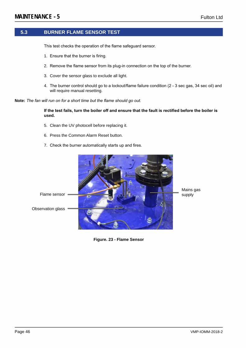
VMP-IOMM-2018-2
Fulton Ltd
Page 46
MAINTENANCE - 5
5.3 BURNER FLAME SENSOR TEST
Figure. 23 - Flame Sensor
Thistestcheckstheoperationoftheflamesafeguardsensor.
1. Ensurethattheburnerisfiring.
2. Removetheflamesensorfromitsplug-inconnectiononthetopoftheburner.
3. Cover the sensor glass to exclude all light.
4. Theburnercontrolshouldgotoalockout/flamefailurecondition(2-3secgas,34secoil)andwill require manual resetting.
Note: The fan will run on for a short time but the flame should go out.
Ifthetestfails,turntheboileroffandensurethatthefaultisrectifiedbeforetheboilerisused.
5. Clean the UV photocell before replacing it.
6. Press the Common Alarm Reset button.
7. Checktheburnerautomaticallystartsupandfires.
Flame sensorMains gas supply
Observation glass
VMP-IOMM-2018-2
Fulton Ltd
Page 47
MAINTENANCE - 5
5.4 WATER LEVEL AND LOW WATER SAFETY CONTROL PROCEDURES
The following procedures ensure the correct functioning of the water level controls and the low water safety controls.
5.4.1 FEEDWATER PUMP TEST
a) Iftheboilerisnotfiringandnotundersteampressure,lowerthewaterlevelusingthemain blowdown valve:
If the pump is running:
1. Observe the water level in the water level gauge (sight glass).
2. Verify that the pump continues to run until the Pump Off level is reached and then switches off.
If the pump is not running:
1. Check that the water level in the water level gauge is between Pump On and Pump Off levels.
2. Lower the water level by opening the main boiler blowdown valve.
3. Verify that the pump starts to run when the water level reaches the Pump On level.
4. Close the main boiler blowdown valve.
5. Continue to observe the water level in the water level gauge and verify that the pump continues to run until the Pump Off level is reached and then switches off.
b) Iftheboilerisfiringandunderload,lowerthewaterlevelbyevaporation,observinga
pump cycle:
If the pump is running:
1. Observe the water level in the water level gauge.
2. Verify that the pump continues to run until the Pump Off level is reached and then switches off.
If the pump is not running:
1. Check that the water level in the water level gauge is between Pump On and Pump Off levels.
2. The water level will lower through natural evaporation.
3. Verify that the pump starts to run when the water level reaches the Pump On level.
4. Continue to observe the water level in the water level gauge and verify that the pump continues to run until the Pump Off level is reached and then switches off.
VMP-IOMM-2018-2
Fulton Ltd
Page 48
MAINTENANCE - 5
5.4.2 LOW WATER LEVEL CHECK
5.4.3 EVAPORATION CHECK
This check may be required by your insurance inspector as part of the annual inspection.
To perform the evaporation check, follow the procedure in Section 4.4.2 - Low Water Level check allowing water to lower by natural evaporation and not by manual blowdown.
1. Ensurethattheboilerisfiring,thefeedwaterpumpisnotrunningandthatthewaterlevelis between Pump On and Pump Off.
2. Switch the Pump switch to the OFF position.
3. Allow the water level to lower by natural evaporation below the Low Water level. Do not allow the water level to drop below the bottom of the water level gauge (sight glass).
4. Check:
a) Low Water limiter lights illuminate
b) Low Water audible alarm sounds
c) Burnerstopsfiring
d) Feedwater pump does not start
Ifthetestfails,turntheboileroffandensurethatthefaultisrectifiedbeforetheboilerisused.
5. Switch the pump switch to the ON position.
6. Check:
a) Feedwaterpumpstartsandrefillstheboiler
b) Water level rises above the Low Water level
c) Burner does not start
d) Low Water audible alarm continues to sound
7. Press the Common Alarm Reset switch for 2 seconds maximum
8. Check:
a) Low Water Limiter lights extinguish
b) Low Water audible alarm silences
c) Burnerautomaticfiresequencestarts
9. Verify that the pump continues to run until the Pump Off level is reached and then switches off.
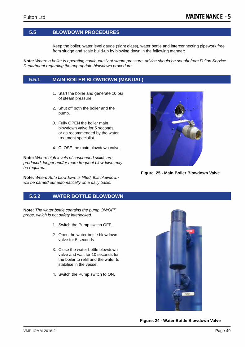
VMP-IOMM-2018-2
Fulton Ltd
Page 49
MAINTENANCE - 5
5.5.1 MAIN BOILER BLOWDOWN (MANUAL)
5.5.2 WATER BOTTLE BLOWDOWN
Note: The water bottle contains the pump ON/OFF probe, which is not safety interlocked.
1. Switch the Pump switch OFF.
2. Open the water bottle blowdown valve for 5 seconds.
3. Close the water bottle blowdown valve and wait for 10 seconds for theboilertorefillandthewaterto stabilise in the vessel.
4. Switch the Pump switch to ON.
Figure. 24 - Water Bottle Blowdown Valve
5.5 BLOWDOWN PROCEDURES
Keep the boiler, water level gauge (sight glass), water bottle and interconnecting pipework free from sludge and scale build-up by blowing down in the following manner:
Note: Where a boiler is operating continuously at steam pressure, advice should be sought from Fulton Service Department regarding the appropriate blowdown procedure.
1. Start the boiler and generate 10 psi of steam pressure.
2. Shut off both the boiler and the pump.
3. Fully OPEN the boiler main blowdown valve for 5 seconds, or as recommended by the water treatment specialist.
4. CLOSE the main blowdown valve.
Note: Where high levels of suspended solids are produced, longer and/or more frequent blowdown may be required.
Note: Where Auto blowdown is fitted, this blowdown will be carried out automatically on a daily basis.
Figure. 25 - Main Boiler Blowdown Valve
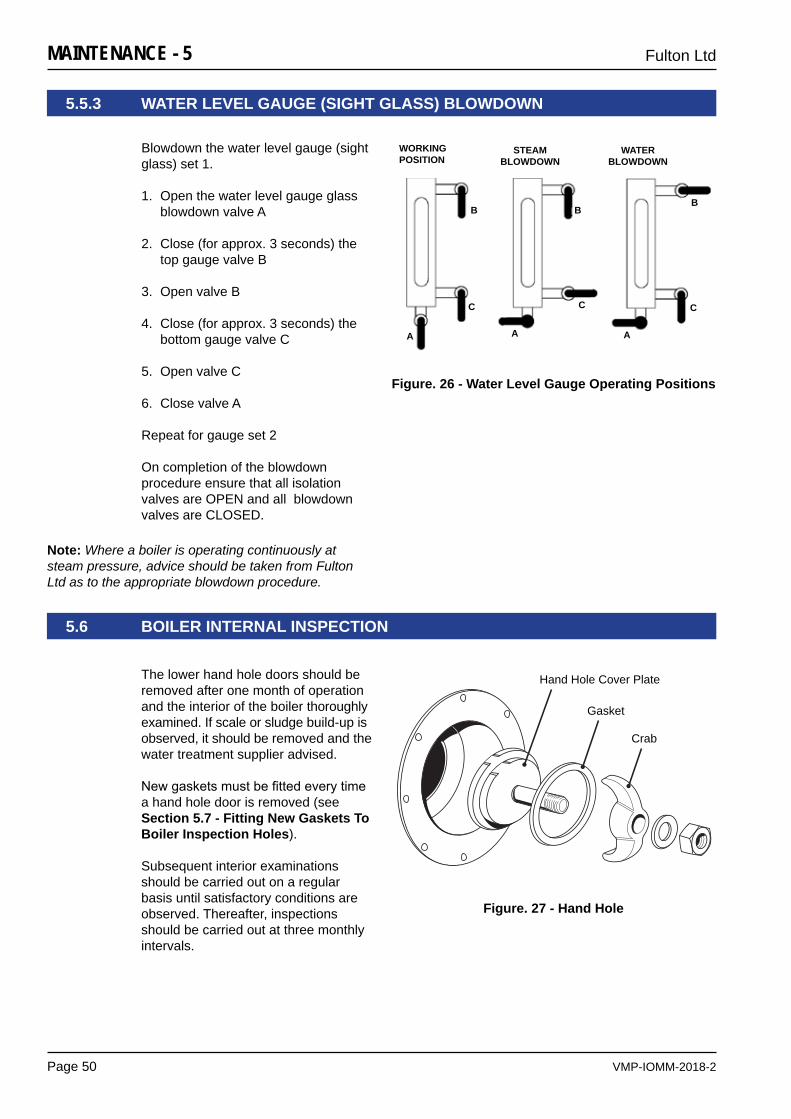
VMP-IOMM-2018-2
Fulton Ltd
Page 50
MAINTENANCE - 5
5.5.3 WATER LEVEL GAUGE (SIGHT GLASS) BLOWDOWN
Blowdown the water level gauge (sight glass) set 1.
1. Open the water level gauge glass blowdown valve A
2. Close (for approx. 3 seconds) the top gauge valve B
3. Open valve B
4. Close (for approx. 3 seconds) the bottom gauge valve C
5. Open valve C
6. Close valve A
Repeat for gauge set 2
On completion of the blowdown procedure ensure that all isolation valves are OPEN and all blowdown valves are CLOSED.
Note: Where a boiler is operating continuously at steam pressure, advice should be taken from Fulton Ltd as to the appropriate blowdown procedure.
WORKINGPOSITION
STEAMBLOWDOWN
WATERBLOWDOWN
AAA
BBB
CCC
Operating Positions
Figure. 26 - Water Level Gauge Operating Positions
5.6 BOILER INTERNAL INSPECTION
The lower hand hole doors should be removed after one month of operation and the interior of the boiler thoroughly examined. If scale or sludge build-up is observed, it should be removed and the water treatment supplier advised.
Newgasketsmustbefittedeverytimea hand hole door is removed (see Section 5.7 - Fitting New Gaskets To Boiler Inspection Holes).
Subsequent interior examinations should be carried out on a regular basis until satisfactory conditions are observed. Thereafter, inspections should be carried out at three monthly intervals.
Hand Hole Cover Plate
Gasket
Crab
Figure. 27 - Hand Hole
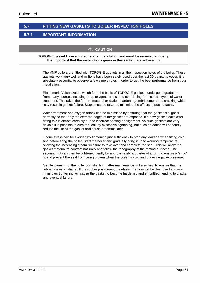
VMP-IOMM-2018-2
Fulton Ltd
Page 51
MAINTENANCE - 5
5.7 FITTING NEW GASKETS TO BOILER INSPECTION HOLES
5.7.1 IMPORTANT INFORMATION
TheVMPboilersarefittedwithTOPOG-Egasketsinalltheinspectionholesoftheboiler.Thesegaskets work very well and millions have been safely used over the last 30 years, however, it is absolutely essential to observe a few simple rules in order to get the best performance from your installation.
Elastomeric Vulcanizates, which form the basis of TOPOG-E gaskets, undergo degradation from many sources including heat, oxygen, stress, and overdosing from certain types of water treatment. This takes the form of material oxidation, hardening/embrittlement and cracking which may result in gasket failure. Steps must be taken to minimise the effects of such attacks.
Water treatment and oxygen attack can be minimised by ensuring that the gasket is aligned correctly so that only the extreme edges of the gasket are exposed. If a new gasket leaks after fittingthisisalmostcertainlyduetoincorrectseatingoralignment.Assuchgasketsareveryflexibleitispossibletocuretheleakbyexcessivetightening,butsuchanactionwillseriouslyreduce the life of the gasket and cause problems later. Unduestresscanbeavoidedbytighteningjustsufficientlytostopanyleakagewhenfittingcoldandbeforefiringtheboiler.Starttheboilerandgraduallybringituptoworkingtemperature,allowing the increasing steam pressure to take over and complete the seal. This will allow the gasket material to contract naturally and follow the topography of the mating surfaces. The securing nut can then be tightened gently by approximately a quarter of a turn, to ensure a ‘snug’ fitandpreventthesealfrombeingbrokenwhentheboileriscoldandundernegativepressure. Gentlewarmingoftheboileroninitialfiringaftermaintenancewillalsohelptoensurethattherubber ‘cures to shape’. If the rubber post-cures, the elastic memory will be destroyed and any initial over tightening will cause the gasket to become hardened and embrittled, leading to cracks and eventual failure.
CAUTION
TOPOG-Egaskethaveafinitelifeafterinstallationandmustberenewedannually.It is important that the instructions given in this section are adhered to.
!
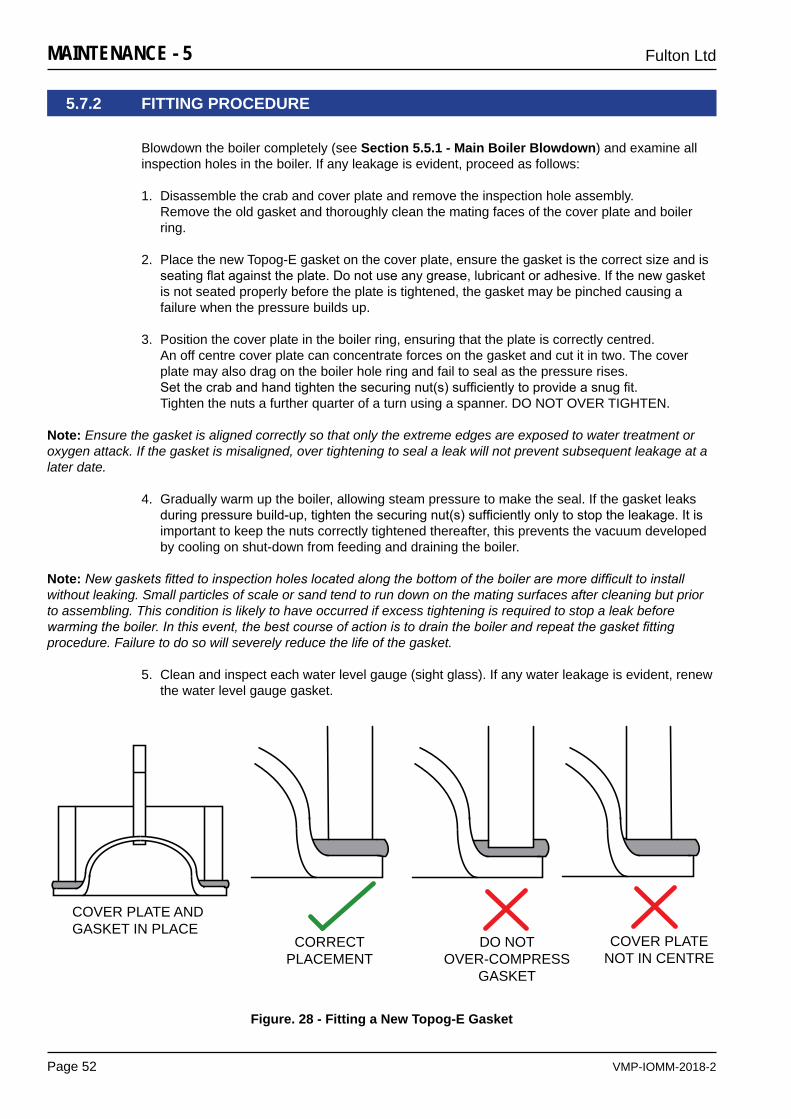
VMP-IOMM-2018-2
Fulton Ltd
Page 52
MAINTENANCE - 5
5.7.2 FITTING PROCEDURE
Blowdown the boiler completely (see Section 5.5.1 - Main Boiler Blowdown) and examine all inspection holes in the boiler. If any leakage is evident, proceed as follows:
1. Disassemble the crab and cover plate and remove the inspection hole assembly. Remove the old gasket and thoroughly clean the mating faces of the cover plate and boiler ring.
2. Place the new Topog-E gasket on the cover plate, ensure the gasket is the correct size and is seatingflatagainsttheplate.Donotuseanygrease,lubricantoradhesive.Ifthenewgasketis not seated properly before the plate is tightened, the gasket may be pinched causing a failure when the pressure builds up.
3. Position the cover plate in the boiler ring, ensuring that the plate is correctly centred. An off centre cover plate can concentrate forces on the gasket and cut it in two. The cover plate may also drag on the boiler hole ring and fail to seal as the pressure rises. Setthecrabandhandtightenthesecuringnut(s)sufficientlytoprovideasnugfit. Tighten the nuts a further quarter of a turn using a spanner. DO NOT OVER TIGHTEN.
Note: Ensure the gasket is aligned correctly so that only the extreme edges are exposed to water treatment or oxygen attack. If the gasket is misaligned, over tightening to seal a leak will not prevent subsequent leakage at a later date.
4. Gradually warm up the boiler, allowing steam pressure to make the seal. If the gasket leaks duringpressurebuild-up,tightenthesecuringnut(s)sufficientlyonlytostoptheleakage.Itisimportant to keep the nuts correctly tightened thereafter, this prevents the vacuum developed by cooling on shut-down from feeding and draining the boiler.
Note: New gaskets fitted to inspection holes located along the bottom of the boiler are more difficult to install without leaking. Small particles of scale or sand tend to run down on the mating surfaces after cleaning but prior to assembling. This condition is likely to have occurred if excess tightening is required to stop a leak before warming the boiler. In this event, the best course of action is to drain the boiler and repeat the gasket fitting procedure. Failure to do so will severely reduce the life of the gasket.
5. Clean and inspect each water level gauge (sight glass). If any water leakage is evident, renew
the water level gauge gasket.
COVER PLATE ANDGASKET IN PLACE
CORRECTPLACEMENT
DO NOT OVER-COMPRESS
GASKET
COVER PLATENOT IN CENTRE
Figure. 28 - Fitting a New Topog-E Gasket
VMP-IOMM-2018-2
Fulton Ltd
Page 53
MAINTENANCE - 5
WARNING
Prior to the commencement of any work requiring the removal of cover plates and the opening of the control panel box, the electrical supply to the boiler must be isolated.
Ensure any residual pressure within the boiler is completely vented before working on the pressure vessel.
!
CAUTION
It is essential that regular checks are made to ensure that scale build-up is not taking place within the boiler. Such checks will ensure that water treatment being applied to the boiler feedwater is effective.
Makesurethatliftingequipmentcomplieswithalllocalregulationsandissuitableforthejob.youcanbeinjuredifyouusefaultyliftingequipment.Make sure the lifting equipment is in good condition.
!
IMPORTANT
If any fault is found during these procedures, shut-down the boiler immediately and consult Fulton Ltd.
!
5.8 SCHEDULE OF OPERATOR TESTS AND CHECKS
The following schedule is the advice of Fulton Ltd. The frequency of tests and checks may vary accordingtositeriskassessmentand/orspecificrequirementsofthecountry/territorythattheboiler is installed in. Failure to maintain the boiler adequately may void the Fulton guarantee.
Maintenance on gas related parts of a boiler must be carried out by competent, trained personnel who are GAS SAFE/ACS registered, and who have the necessary equipment to check combustion.
If any fault is found during these operations, contact your Fulton representative.
The following procedures are designed to prevent the build-up of scale, silt or sludge in the bottom of the boiler, water level gauge (sight glass) and water bottle pipework. Personnel involved in doing this work must have received the appropriate training in all aspects of maintenance and safety procedures.
In addition to these procedures, the advice of a water treatment specialist should be sought and followed.
VMP-IOMM-2018-2
Fulton Ltd
Page 54
MAINTENANCE - 5
5.8.1 DAILY
5.8.2 WEEKLY IN ADDITION
WARNING
Ensurethefittingsaroundthesteamsafetyvalve(s)aresecure.The safety valve will be very hot, do not operate the safety valve without protection.
!
WARNING
Allsteampipework,valvesandfittingswillbeveryhot.
!
1. Visually inspect for signs of leakage:
a) Steam and feedwater pipework.
b) Valvesandfittings.
c) Hand holes If leakage is evident, the gasket needs replacing.
If leaks are suspected, shut down and evacuate the system to atmospheric pressure before attempting to repair the leaks.
2. Low Water Level Check (see Section 5.4.2).
Note: Where high integrity level controls are fitted, please refer to Appendix D Spirax High Integrity Level Controls.
3. Blowdown the Boiler (see Section 5.5.1).
Note: If the boiler is being operated automatically on a time clock, the blowdown may be done once during the working day and once at the end of the day when generating 10 psig or less, providing this is sufficient to control the TDS level within limits.
4. Blowdown the Water Bottles (see Section 5.5.2).
5. Blowdown the Water Level Gauges (sight glass), (see Section 5.5.3).
6. Ensure that the pipe from the safety valve outlet is not damaged and that it continues to a safe blowdown point.
7. Feedwater Pump Test (see Section 5.4.1).
8. Burner Flame Sensor Test (see Section 5.3).
9. Evaporation Check (see Section 5.4.3).
VMP-IOMM-2018-2
Fulton Ltd
Page 55
MAINTENANCE - 5
10. Visually inspect the internal water space (see Section 5.6).
11. Clean the water level gauges (sight glasses). If any leakage is evident, the gasket needs replacing (see Section 5.7).
12. Cleananywatertrapsandstrainersfittedinthefeedwaterline. Check feedwater and boiler water quality against the values given in Appendix A - TI-139-Recommended Water Conditions.
Note: Use only genuine Fulton replacement parts.
WARNING
Ensure the main electrical supply is isolated before starting work.
!
5.8.3 MONTHLY IN ADDITION
5.8.4 SIX MONTHLY SERVICE
The boiler must be drained and isolated before the following maintenance procedures are carried out (see Section 4.6 - Draining the Boiler).
1. Visually inspect feedwater pipe into the boiler. Ensure the pipe is not blocked, clean as required.
2. Clean the ignition electrode.
3. Cleanoutthefluepasses.
4. Apply a small quantity of oil to the bearings of the burner motor and the feedwater pump motor.
5. Clean the burner scroll fan.
6. Remove components from threaded stub pipes, clean and inspect.
7. Rod through top connections of the water level gauge and water bottle.
8. Drainandflushthefeedwatertank.Cleananyfiltersinthetank,inthefeedwaterlineorinthefeedwater pump.
9. Clean the water level probes.
10. Testtheflueusingthefollowingprocedures:• Visual Inspection• Smoke Test
11. Check the burner combustion.
12. Checktheconditionofthegasvalvefilter(iffitted),renewasrequired.
WARNING
Maintenance on gas related parts of a boiler must be carried out by competent, trained personnel who are GAS SAFE/ACS registered, and who have the necessary equipment to check combustion.
!
VMP-IOMM-2018-2
Fulton Ltd
Page 56
MAINTENANCE - 5
5.8.7 AFTER ALL REPAIRS & MAINTENANCE IN ADDITION
1. Complete all safety checks in the daily and weekly maintenance section.
2. Fire the boiler and perform combustion safety checks.
3. Analyse combustion throughout the range and verify proper operation of safety devices.
5.8.5 ANNUAL SERVICE
The boiler must be drained and isolated before the following maintenance procedures are carried out (see Section 4.6 - Draining the Boiler).
1. Inspect the pilot assembly.
2. Cleanandexaminefluewaysandremoveloosescalefrominsideshell.
3. Examine refractory brick.
4. Check all panel wiring connections for conditions and tightness.
5. Refillboilerwithwater,checkingforleaks.
6. Test for gas safety.
7. Checkoilpressureorgasflowrateandcombustionparameters.
Re-commissioning.
8. Refillboilerandre-commissionburner–checkallfunctionaloperationsofburnerandboilerincludingwatersafetychecksandflamefailureprocedures.Operateboilertoworkingpressure and check safety valves for operation and settings.
9. Inspect and clean blowdown separator if part of installation.
5.8.6 AFTER 5 YEARS
10. Fulton Ltd recommend replacement of all threaded stub pipes on the boiler OR to your inspectors satisfaction.
WARNING
Maintenance on gas related parts of a boiler must be carried out by competent, trained personnel who are GAS SAFE/ACS registered, and who have the necessary equipment to check combustion.
!
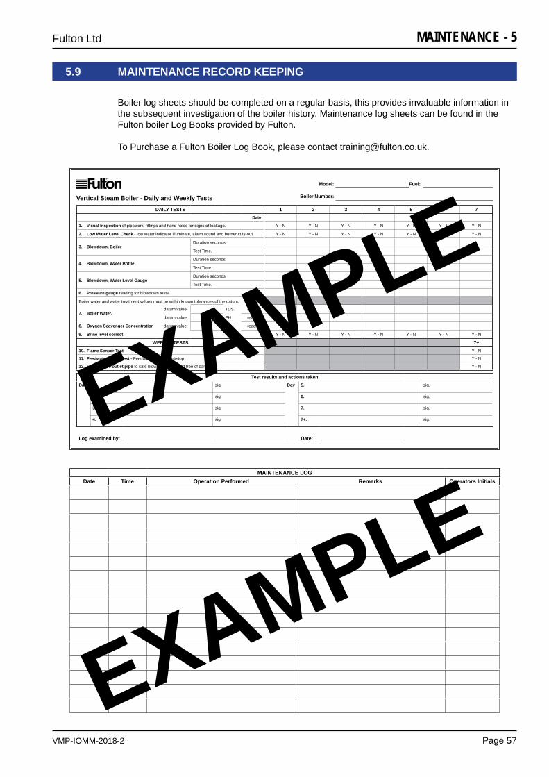
VMP-IOMM-2018-2
Fulton Ltd
Page 57
MAINTENANCE - 5
DAILY TESTS 1 2 3 4 5 6 7Date
1. Visual Inspectionofpipework,fittingsandhandholesforsignsofleakage. Y - N Y - N Y - N Y - N Y - N Y - N Y - N
2. Low Water Level Check - low water indicator illuminate, alarm sound and burner cuts-out. Y - N Y - N Y - N Y - N Y - N Y - N Y - N
3. Blowdown, BoilerDuration seconds.
Test Time.
4. Blowdown, Water BottleDuration seconds.
Test Time.
5. Blowdown, Water Level GaugeDuration seconds.
Test Time.
6. Pressure gauge reading for blowdown tests.
Boiler water and water treatment values must be within known tolerances of the datum.
7. Boiler Water.datum value. TDS. reading
datum value. PH reading
8. Oxygen Scavenger Concentration datum value. reading
9. Brine level correct Y - N Y - N Y - N Y - N Y - N Y - N Y - N
WEEKLY TESTS 7+10. Flame Sensor Test Y - N
11. Feedwater Pump Test - Feedwater pump, start/stop Y - N
12. Safety valve outlet pipe to safe blowdown point and free of damage Y - N
Test results and actions takenDay 1. sig. Day 5. sig.
2. sig. 6. sig.
3. sig. 7. sig.
4. sig. 7+. sig.
Log examined by: Date:
Vertical Steam Boiler - Daily and Weekly Tests
Model: Fuel:
Boiler Number:
MAINTENANCE LOGDate Time Operation Performed Remarks Operators Initials
5.9 MAINTENANCE RECORD KEEPING
Boiler log sheets should be completed on a regular basis, this provides invaluable information in the subsequent investigation of the boiler history. Maintenance log sheets can be found in theFulton boiler Log Books provided by Fulton.
To Purchase a Fulton Boiler Log Book, please contact [email protected].
EXAMPLE
EXAMPLE

VMP-IOMM-2018-2
Fulton Ltd
Page 58
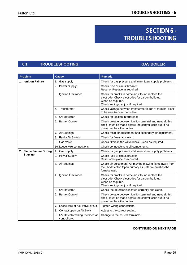
VMP-IOMM-2018-2
Fulton Ltd
Page 59
TROUBLESHOOTING - 6
SECTION 6 - TROUBLESHOOTING
6.1 TROUBLESHOOTING GAS BOILER
Problem Cause Remedy
1. Ignition Failure 1. Gas supply Check for gas pressure and intermittent supply problems.2. Power Supply Check fuse or circuit breaker.
Reset or Replace as required.3. Ignition Electrodes Check for cracks in porcelain,if found replace the
electrode. Check electrodes for carbon build-up.Clean as required. Check settings, adjust if required.
4. Transformer Check voltage between transformer leads at terminal block to be sure transformer is live.
5. UV Detector Check for ignition interference. 6. Burner Control Check voltage between ignition terminal and neutral, this
check must be made before the control locks out. If no power, replace the control.
7. Air Settings Check main air adjustment and secondary air adjustment.8. Faulty Air Switch Check for faulty air switch.9. Gas Valve Checkfiltersinthevalveblock.Cleanasrequired.10. Loose wire connections Check connections to all components.
2. Flame Failure During Start-up
1. Gas supply Check for gas pressure and intermittent supply problems.2. Power Supply Check fuse or circuit breaker.
Reset or Replace as required.3. Air Settings Checkairadjustment.Airmaybeblowingflameawayfrom
theUVdetector.Openprimaryairuntilfirebrushesthefurnace wall.
4. Ignition Electrodes Check for cracks in porcelain,if found replace the electrode. Check electrodes for carbon build-up.Clean as required. Check settings, adjust if required.
5. UV Detector Check the detector is located correctly and clean.6. Burner Control Check voltage between ignition terminal and neutral, this
check must be made before the control locks out. If no power, replace the control.
7. Loose wire at fuel valve circuit. Tighten wiring connections.8. Contact open on Air Switch Adjust to the correct setting.9. UV Detector wiring reversed at
control box.Change to the correct terminals.
CONTINUED ON NEXT PAGE
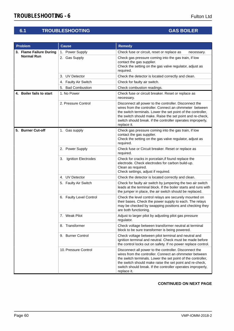
VMP-IOMM-2018-2
Fulton Ltd
Page 60
TROUBLESHOOTING - 6
CONTINUED ON NEXT PAGE
Problem Cause Remedy3. Flame Failure During
Normal Run1. Power Supply Check fuse or circuit, reset or replace as necessary.2. Gas Supply Check gas pressure coming into the gas train, if low
contact the gas supplier. Check the setting on the gas valve regulator, adjust as required.
3. UV Detector Check the detector is located correctly and clean.4. Faulty Air Switch Check for faulty air switch.5. Bad Combustion Check combustion readings.
4. Boiler fails to start 1. No Power Check fuse or circuit breaker. Reset or replace as necessary.
2. Pressure Control Disconnect all power to the controller. Disconnect the wires from the controller. Connect an ohmmeter between the switch terminals. Lower the set point of the controller, the switch should make. Raise the set point and re-check, switch should break. if the controller operates improperly, replace it.
5. Burner Cut-off 1. Gas supply Check gas pressure coming into the gas train, if low contact the gas supplier. Check the setting on the gas valve regulator, adjust as required.
2. Power Supply Check fuse or Circuit breaker. Reset or replace as required.
3. Ignition Electrodes Check for cracks in porcelain,if found replace the electrode. Check electrodes for carbon build-up.Clean as required. Check settings, adjust if required.
4. UV Detector Check the detector is located correctly and clean.5. Faulty Air Switch Check for faulty air switch by jumpering the two air switch
leads at the terminal block. If the boiler starts and runs with the jumper in place, the air switch should be replaced.
6. Faulty Level Control Check the level control relays are securely mounted on their bases. Check the power supply to each. The relays may be checked by swapping positions and checking they are both functioning.
7. Weak Pilot Adjust to larger pilot by adjusting pilot gas pressure regulator.
8. Transformer Check voltage between transformer neutral at terminal block to be sure transformer is being powered.
9. Burner Control Check voltage between pilot terminal and neutral and ignition terminal and neutral. Check must be made before the control locks out on safety. If no power replace control.
10. Pressure Control Disconnect all power to the controller. Disconnect the wires from the controller. Connect an ohmmeter between the switch terminals. Lower the set point of the controller, the switch should make raise the set point and re-check, switch should break. If the controller operates improperly, replace it.
6.1 TROUBLESHOOTING GAS BOILER
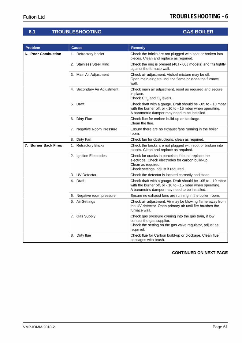
VMP-IOMM-2018-2
Fulton Ltd
Page 61
TROUBLESHOOTING - 6
Problem Cause Remedy6. Poor Combustion 1. Refractory bricks Check the bricks are not plugged with soot or broken into
pieces. Clean and replace as required. 2. Stainless Steel Ring Checktheringispresent(40J-60Jmodels)andfitstightly
against the furnace wall.3. Main Air Adjustment Check air adjustment. Air/fuel mixture may be off.
Openmainairgateuntiltheflamebrushesthefurnacewall.
4. Secondary Air Adjustment Check main air adjustment, reset as required and secure in place. Check CO2 and O2 levels.
5. Draft Check draft with a gauge. Draft should be -.05 to -.10 mbar with the burner off, or -.10 to -.15 mbar when operating.A barometric damper may need to be installed.
6. Dirty Flue Checkflueforcarbonbuild-uporblockage.Cleantheflue.
7. Negative Room Pressure Ensure there are no exhaust fans running in the boiler room.
8. Dirty Fan Check fan for obstructions, clean as required.7. Burner Back Fires 1. Refractory Bricks Check the bricks are not plugged with soot or broken into
pieces. Clean and replace as required. 2. Ignition Electrodes Check for cracks in porcelain,if found replace the
electrode. Check electrodes for carbon build-up.Clean as required. Check settings, adjust if required.
3. UV Detector Check the detector is located correctly and clean.4. Draft Check draft with a gauge. Draft should be -.05 to -.10 mbar
with the burner off, or -.10 to -.15 mbar when operating.A barometric damper may need to be installed.
5. Negative room pressure Ensure no exhaust fans are running in the boiler room. 6. Air Settings Checkairadjustment.Airmaybeblowingflameawayfrom
theUVdetector.Openprimaryairuntilfirebrushesthefurnace wall.
7. Gas Supply Check gas pressure coming into the gas train, if low contact the gas supplier.Check the setting on the gas valve regulator, adjust as required.
8. Dirtyflue CheckflueforCarbonbuild-uporblockage.Cleanfluepassages with brush.
6.1 TROUBLESHOOTING GAS BOILER
CONTINUED ON NEXT PAGE
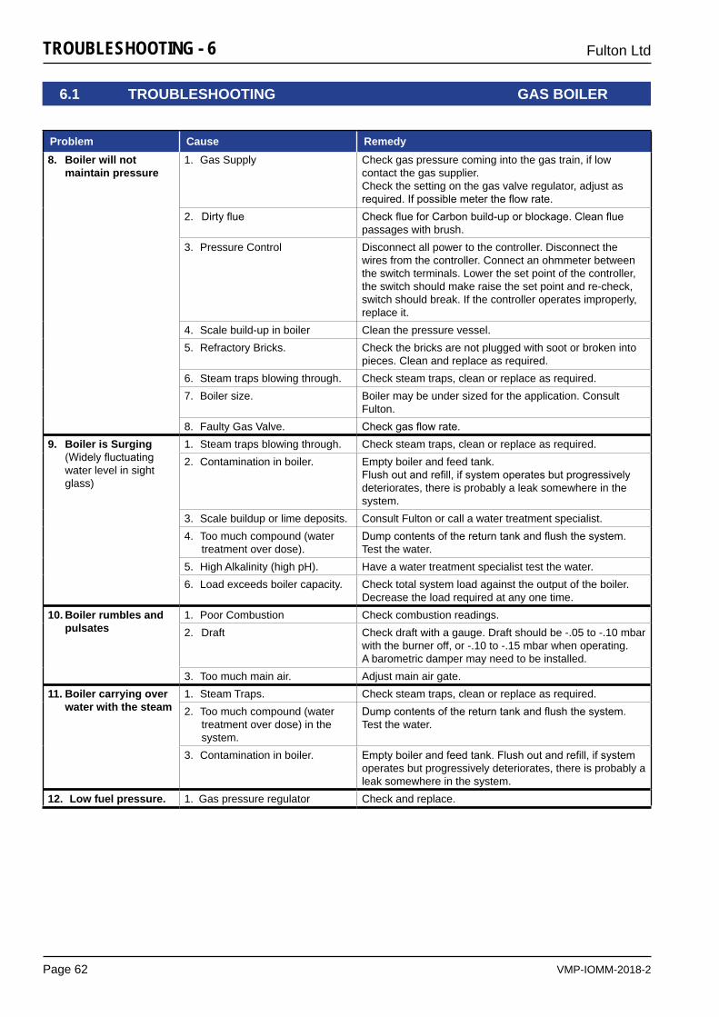
VMP-IOMM-2018-2
Fulton Ltd
Page 62
TROUBLESHOOTING - 6
Problem Cause Remedy8. Boiler will not
maintain pressure1. Gas Supply Check gas pressure coming into the gas train, if low
contact the gas supplier.Check the setting on the gas valve regulator, adjust as required.Ifpossiblemetertheflowrate.
2. Dirtyflue CheckflueforCarbonbuild-uporblockage.Cleanfluepassages with brush.
3. Pressure Control Disconnect all power to the controller. Disconnect the wires from the controller. Connect an ohmmeter between the switch terminals. Lower the set point of the controller, the switch should make raise the set point and re-check, switch should break. If the controller operates improperly, replace it.
4. Scale build-up in boiler Clean the pressure vessel.5. Refractory Bricks. Check the bricks are not plugged with soot or broken into
pieces. Clean and replace as required. 6. Steam traps blowing through. Check steam traps, clean or replace as required.7. Boiler size. Boiler may be under sized for the application. Consult
Fulton.8. Faulty Gas Valve. Checkgasflowrate.
9. Boiler is Surging (Widelyfluctuatingwater level in sight glass)
1. Steam traps blowing through. Check steam traps, clean or replace as required.2. Contamination in boiler. Empty boiler and feed tank.
Flushoutandrefill,ifsystemoperatesbutprogressivelydeteriorates, there is probably a leak somewhere in the system.
3. Scale buildup or lime deposits. Consult Fulton or call a water treatment specialist.4. Too much compound (water
treatment over dose).Dumpcontentsofthereturntankandflushthesystem.Test the water.
5. High Alkalinity (high pH). Have a water treatment specialist test the water.6. Load exceeds boiler capacity. Check total system load against the output of the boiler.
Decrease the load required at any one time.10. Boiler rumbles and
pulsates1. Poor Combustion Check combustion readings.2. Draft Check draft with a gauge. Draft should be -.05 to -.10 mbar
with the burner off, or -.10 to -.15 mbar when operating.A barometric damper may need to be installed.
3. Too much main air. Adjust main air gate.11. Boiler carrying over
water with the steam1. Steam Traps. Check steam traps, clean or replace as required.2. Too much compound (water
treatment over dose) in the system.
Dumpcontentsofthereturntankandflushthesystem.Test the water.
3. Contamination in boiler. Emptyboilerandfeedtank.Flushoutandrefill,ifsystemoperates but progressively deteriorates, there is probably a leak somewhere in the system.
12. Low fuel pressure. 1. Gas pressure regulator Check and replace.
6.1 TROUBLESHOOTING GAS BOILER
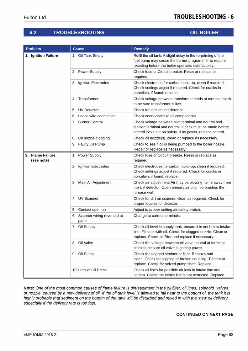
VMP-IOMM-2018-2
Fulton Ltd
Page 63
TROUBLESHOOTING - 6
Note: One of the most common causes of flame failure is dirt/sediment in the oil filter, oil lines, solenoid valves or nozzle, caused by a new delivery of oil. If the oil tank level is allowed to fall near to the bottom of the tank it is highly probable that sediment on the bottom of the tank will be disturbed and mixed in with the new oil delivery, especially if the delivery rate is too fast.
6.2 TROUBLESHOOTING OIL BOILER
CONTINUED ON NEXT PAGE
Problem Cause Remedy
1. Ignition Failure 1. Oil Tank Empty Refilltheoiltank.Aslightdelayinthere-primingofthefuel pump may cause the burner programmer to require resetting before the boiler operates satisfactorily.
2. Power Supply Check fuse or Circuit breaker. Reset or replace as required.
3. Ignition Electrodes Check electrodes for carbon build-up, clean if required. Check settings adjust if required. Check for cracks in porcelain, if found, replace.
4. Transformer Check voltage between transformer leads at terminal block to be sure transformer is live.
5. UV Detector Check for ignition interference. 6. Loose wire connection Check connections to all components. 7. Burner Control Check voltage between pilot terminal and neutral and
ignition terminal and neutral. Check must be made before control locks out on safety. If no power, replace control.
8. Oil nozzle clogging Check oil nozzle(s), clean or replace as necessary.9. Faulty Oil Pump Check to see if oil is being pumped to the boiler nozzle.
Repair or replace as necessary. 2. Flame Failure
(see note)1. Power Supply Check fuse or Circuit breaker. Reset or replace as
required. 2. Ignition Electrodes Check electrodes for carbon build-up, clean if required.
Check settings adjust if required. Check for cracks in porcelain, if found, replace.
3. Main Air Adjustment Checkairadjustment.AirmaybeblowingflameawayfromtheUVdetector.Openprimaryairuntilfirebrushesthefurnace wall.
4. UV Scanner Check for dirt on scanner, clean as required. Check for proper location of detector.
5. Contact open on Adjust to proper setting air safety switch.6. Scanner wiring reversed at
panelChange to correct terminals.
7. Oil Supply Check oil level in supply tank, ensure it is not below intake line. Fill tank with oil. Check for clogged nozzle. Clean or replace.Checkoilfilterandreplaceifnecessary.
8. Oil Valve Check the voltage between oil valve neutral at terminal block to be sure oil valve is getting power.
9. Oil Pump Checkforcloggedstrainerorfilter.Removeandclean. Check for slipping or broken coupling. Tighten or replace. Check for seized pump shaft. Replace.
10. Loss of Oil Prime Check all lines for possible air leak in intake line and tighten. Check the intake line is not restricted. Replace.
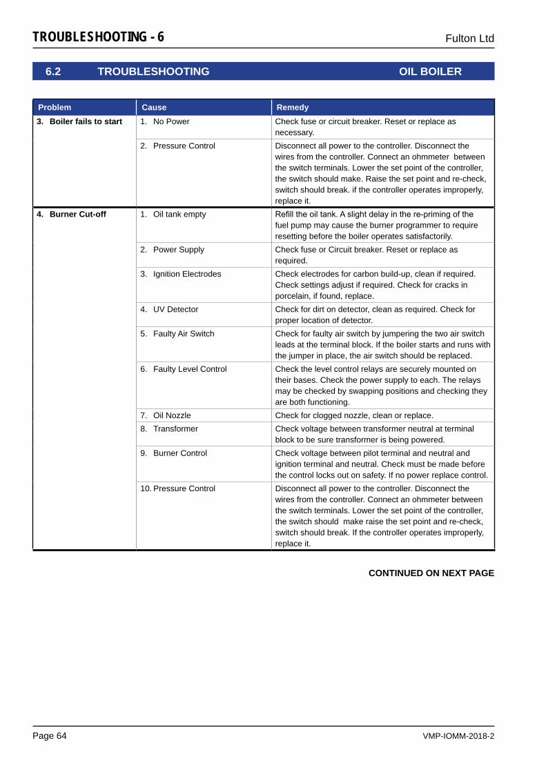
VMP-IOMM-2018-2
Fulton Ltd
Page 64
TROUBLESHOOTING - 6
CONTINUED ON NEXT PAGE
Problem Cause Remedy3. Boiler fails to start 1. No Power Check fuse or circuit breaker. Reset or replace as
necessary. 2. Pressure Control Disconnect all power to the controller. Disconnect the
wires from the controller. Connect an ohmmeter between the switch terminals. Lower the set point of the controller, the switch should make. Raise the set point and re-check, switch should break. if the controller operates improperly, replace it.
4. Burner Cut-off 1. Oil tank empty Refilltheoiltank.Aslightdelayinthere-primingofthefuel pump may cause the burner programmer to require resetting before the boiler operates satisfactorily.
2. Power Supply Check fuse or Circuit breaker. Reset or replace as required.
3. Ignition Electrodes Check electrodes for carbon build-up, clean if required. Check settings adjust if required. Check for cracks in porcelain, if found, replace.
4. UV Detector Check for dirt on detector, clean as required. Check for proper location of detector.
5. Faulty Air Switch Check for faulty air switch by jumpering the two air switch leads at the terminal block. If the boiler starts and runs with the jumper in place, the air switch should be replaced.
6. Faulty Level Control Check the level control relays are securely mounted on their bases. Check the power supply to each. The relays may be checked by swapping positions and checking they are both functioning.
7. Oil Nozzle Check for clogged nozzle, clean or replace. 8. Transformer Check voltage between transformer neutral at terminal
block to be sure transformer is being powered. 9. Burner Control Check voltage between pilot terminal and neutral and
ignition terminal and neutral. Check must be made before the control locks out on safety. If no power replace control.
10. Pressure Control Disconnect all power to the controller. Disconnect the wires from the controller. Connect an ohmmeter between the switch terminals. Lower the set point of the controller, the switch should make raise the set point and re-check, switch should break. If the controller operates improperly, replace it.
6.2 TROUBLESHOOTING OIL BOILER
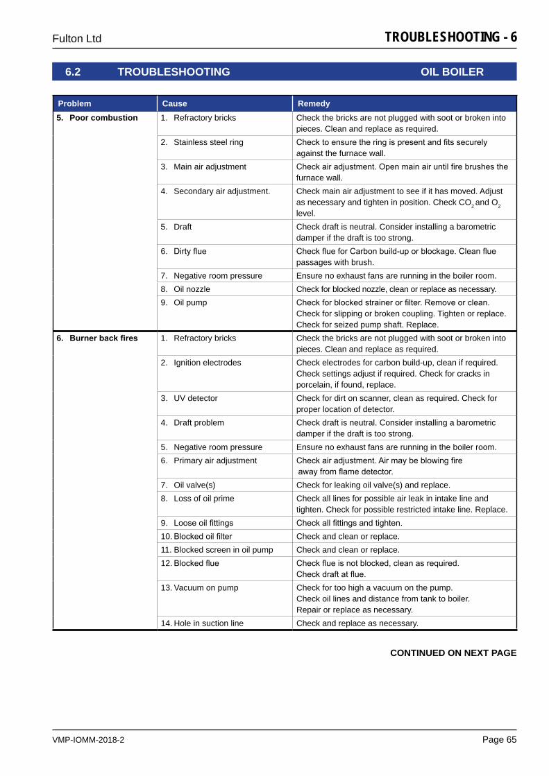
VMP-IOMM-2018-2
Fulton Ltd
Page 65
TROUBLESHOOTING - 6
6.2 TROUBLESHOOTING OIL BOILER
CONTINUED ON NEXT PAGE
Problem Cause Remedy5. Poor combustion 1. Refractory bricks Check the bricks are not plugged with soot or broken into
pieces. Clean and replace as required. 2. Stainless steel ring Checktoensuretheringispresentandfitssecurely
against the furnace wall. 3. Main air adjustment Checkairadjustment.Openmainairuntilfirebrushesthe
furnace wall. 4. Secondary air adjustment. Check main air adjustment to see if it has moved. Adjust
as necessary and tighten in position. Check CO2 and O2 level.
5. Draft Check draft is neutral. Consider installing a barometric damper if the draft is too strong.
6. Dirtyflue CheckflueforCarbonbuild-uporblockage.Cleanfluepassages with brush.
7. Negative room pressure Ensure no exhaust fans are running in the boiler room. 8. Oil nozzle Check for blocked nozzle, clean or replace as necessary. 9. Oil pump Checkforblockedstrainerorfilter.Removeorclean.
Check for slipping or broken coupling. Tighten or replace. Check for seized pump shaft. Replace.
6. Burnerbackfires 1. Refractory bricks Check the bricks are not plugged with soot or broken into pieces. Clean and replace as required.
2. Ignition electrodes Check electrodes for carbon build-up, clean if required. Check settings adjust if required. Check for cracks in porcelain, if found, replace.
3. UV detector Check for dirt on scanner, clean as required. Check for proper location of detector.
4. Draft problem Check draft is neutral. Consider installing a barometric damper if the draft is too strong.
5. Negative room pressure Ensure no exhaust fans are running in the boiler room. 6. Primary air adjustment Checkairadjustment.Airmaybeblowingfire
awayfromflamedetector.7. Oil valve(s) Check for leaking oil valve(s) and replace. 8. Loss of oil prime Check all lines for possible air leak in intake line and
tighten. Check for possible restricted intake line. Replace. 9. Looseoilfittings Checkallfittingsandtighten.10. Blockedoilfilter Check and clean or replace. 11. Blocked screen in oil pump Check and clean or replace. 12. Blockedflue Checkflueisnotblocked,cleanasrequired.
Checkdraftatflue.13. Vacuum on pump Check for too high a vacuum on the pump.
Check oil lines and distance from tank to boiler. Repair or replace as necessary.
14. Hole in suction line Check and replace as necessary.
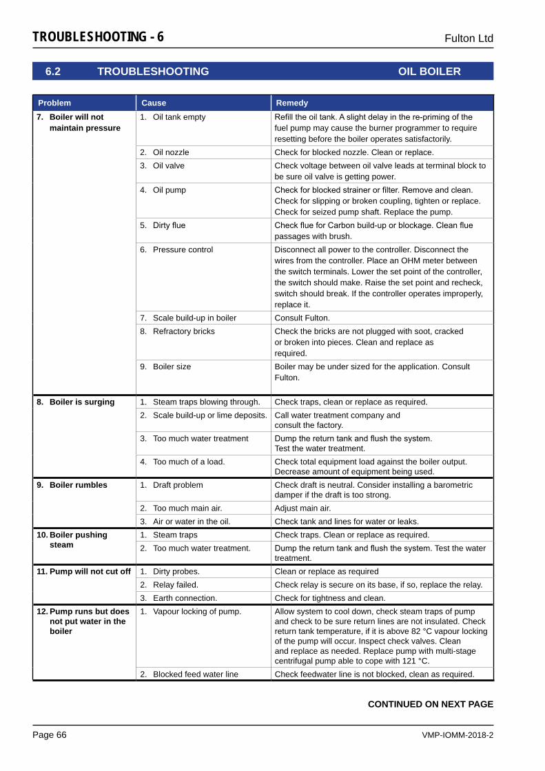
VMP-IOMM-2018-2
Fulton Ltd
Page 66
TROUBLESHOOTING - 6
6.2 TROUBLESHOOTING OIL BOILER
CONTINUED ON NEXT PAGE
Problem Cause Remedy7. Boiler will not
maintain pressure1. Oil tank empty Refilltheoiltank.Aslightdelayinthere-primingofthe
fuel pump may cause the burner programmer to require resetting before the boiler operates satisfactorily.
2. Oil nozzle Check for blocked nozzle. Clean or replace.3. Oil valve Check voltage between oil valve leads at terminal block to
be sure oil valve is getting power. 4. Oil pump Checkforblockedstrainerorfilter.Removeandclean.
Check for slipping or broken coupling, tighten or replace. Check for seized pump shaft. Replace the pump.
5. Dirtyflue CheckflueforCarbonbuild-uporblockage.Cleanfluepassages with brush.
6. Pressure control Disconnect all power to the controller. Disconnect the wires from the controller. Place an OHM meter between the switch terminals. Lower the set point of the controller, the switch should make. Raise the set point and recheck, switch should break. If the controller operates improperly, replace it.
7. Scale build-up in boiler Consult Fulton. 8. Refractory bricks Check the bricks are not plugged with soot, cracked
or broken into pieces. Clean and replace as required.
9. Boiler size Boiler may be under sized for the application. Consult Fulton.
8. Boiler is surging 1. Steam traps blowing through. Check traps, clean or replace as required.2. Scale build-up or lime deposits. Call water treatment company and
consult the factory.3. Too much water treatment Dumpthereturntankandflushthesystem.
Test the water treatment. 4. Too much of a load. Check total equipment load against the boiler output.
Decrease amount of equipment being used.9. Boiler rumbles 1. Draft problem Check draft is neutral. Consider installing a barometric
damper if the draft is too strong. 2. Too much main air. Adjust main air.3. Air or water in the oil. Check tank and lines for water or leaks.
10. Boiler pushing steam
1. Steam traps Check traps. Clean or replace as required.2. Too much water treatment. Dumpthereturntankandflushthesystem.Test the water
treatment. 11. Pump will not cut off 1. Dirty probes. Clean or replace as required
2. Relay failed. Check relay is secure on its base, if so, replace the relay. 3. Earth connection. Check for tightness and clean.
12. Pump runs but does not put water in the boiler
1. Vapour locking of pump. Allow system to cool down, check steam traps of pump and check to be sure return lines are not insulated. Check return tank temperature, if it is above 82 °C vapour locking of the pump will occur. Inspect check valves. Clean and replace as needed. Replace pump with multi-stage centrifugal pump able to cope with 121 °C.
2. Blocked feed water line Check feedwater line is not blocked, clean as required.
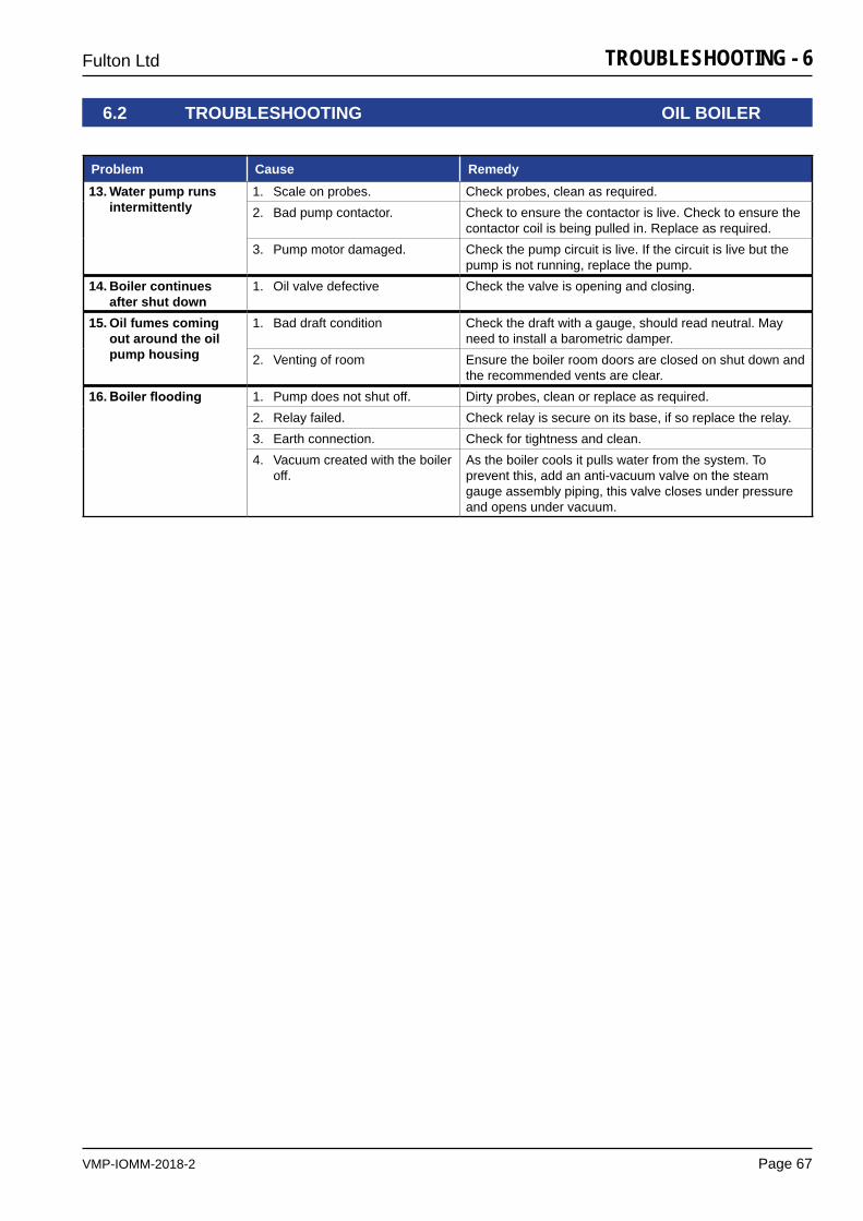
VMP-IOMM-2018-2
Fulton Ltd
Page 67
TROUBLESHOOTING - 6
6.2 TROUBLESHOOTING OIL BOILER
Problem Cause Remedy13. Water pump runs
intermittently1. Scale on probes. Check probes, clean as required. 2. Bad pump contactor. Check to ensure the contactor is live. Check to ensure the
contactor coil is being pulled in. Replace as required. 3. Pump motor damaged. Check the pump circuit is live. If the circuit is live but the
pump is not running, replace the pump.14. Boiler continues
after shut down1. Oil valve defective Check the valve is opening and closing.
15. Oil fumes coming out around the oil pump housing
1. Bad draft condition Check the draft with a gauge, should read neutral. May need to install a barometric damper.
2. Venting of room Ensure the boiler room doors are closed on shut down and the recommended vents are clear.
16. Boilerflooding 1. Pump does not shut off. Dirty probes, clean or replace as required. 2. Relay failed. Check relay is secure on its base, if so replace the relay.3. Earth connection. Check for tightness and clean.4. Vacuum created with the boiler
off. As the boiler cools it pulls water from the system. To prevent this, add an anti-vacuum valve on the steam gauge assembly piping, this valve closes under pressure and opens under vacuum.
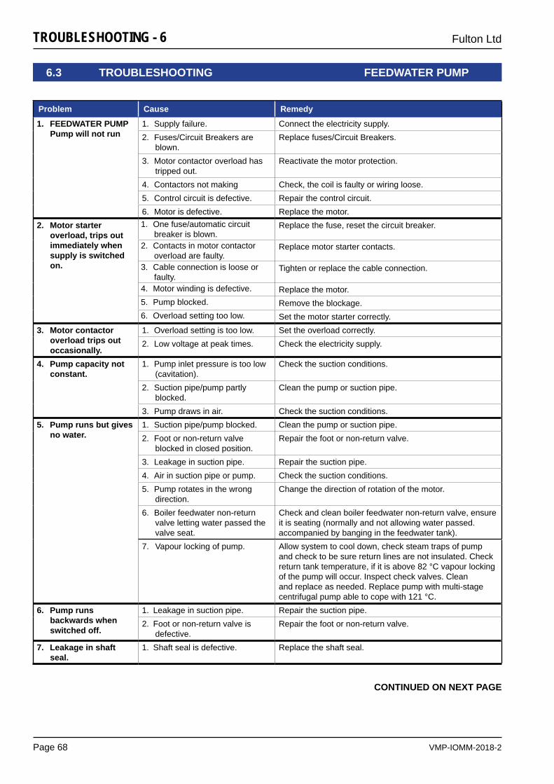
VMP-IOMM-2018-2
Fulton Ltd
Page 68
TROUBLESHOOTING - 6
6.3 TROUBLESHOOTING FEEDWATER PUMP
CONTINUED ON NEXT PAGE
Problem Cause Remedy
1. FEEDWATER PUMP Pump will not run
1. Supply failure. Connect the electricity supply.2. Fuses/Circuit Breakers are
blown.Replace fuses/Circuit Breakers.
3. Motor contactor overload has tripped out.
Reactivate the motor protection.
4. Contactors not making Check, the coil is faulty or wiring loose.5. Control circuit is defective. Repair the control circuit.6. Motor is defective. Replace the motor.
2. Motor starter overload, trips out immediately when supply is switched on.
1. One fuse/automatic circuit breaker is blown.
Replace the fuse, reset the circuit breaker.
2. Contacts in motor contactor overload are faulty.
Replace motor starter contacts.
3. Cable connection is loose or faulty.
Tighten or replace the cable connection.
4. Motor winding is defective. Replace the motor.5. Pump blocked. Remove the blockage.6. Overload setting too low. Set the motor starter correctly.
3. Motor contactor overload trips out occasionally.
1. Overload setting is too low. Set the overload correctly.2. Low voltage at peak times. Check the electricity supply.
4. Pump capacity not constant.
1. Pump inlet pressure is too low (cavitation).
Check the suction conditions.
2. Suction pipe/pump partly blocked.
Clean the pump or suction pipe.
3. Pump draws in air. Check the suction conditions.5. Pump runs but gives
no water. 1. Suction pipe/pump blocked. Clean the pump or suction pipe.2. Foot or non-return valve
blocked in closed position.Repair the foot or non-return valve.
3. Leakage in suction pipe. Repair the suction pipe.4. Air in suction pipe or pump. Check the suction conditions.5. Pump rotates in the wrong
direction. Change the direction of rotation of the motor.
6. Boiler feedwater non-return valve letting water passed the valve seat.
Check and clean boiler feedwater non-return valve, ensure it is seating (normally and not allowing water passed. accompanied by banging in the feedwater tank).
7. Vapour locking of pump. Allow system to cool down, check steam traps of pump and check to be sure return lines are not insulated. Check return tank temperature, if it is above 82 °C vapour locking of the pump will occur. Inspect check valves. Clean and replace as needed. Replace pump with multi-stage centrifugal pump able to cope with 121 °C.
6. Pump runs backwards when switched off.
1. Leakage in suction pipe. Repair the suction pipe.2. Foot or non-return valve is
defective. Repair the foot or non-return valve.
7. Leakage in shaft seal.
1. Shaft seal is defective. Replace the shaft seal.
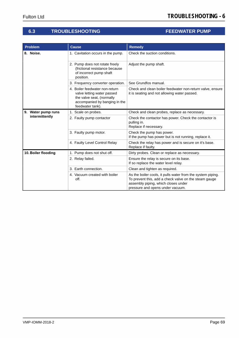
VMP-IOMM-2018-2
Fulton Ltd
Page 69
TROUBLESHOOTING - 6
6.3 TROUBLESHOOTING FEEDWATER PUMP
Problem Cause Remedy8. Noise. 1. Cavitation occurs in the pump. Check the suction conditions.
2. Pump does not rotate freely (frictional resistance because of incorrect pump shaft position.
Adjust the pump shaft.
3. Frequency converter operation. See Grundfos manual.4. Boiler feedwater non-return
valve letting water passed the valve seat, (normally accompanied by banging in the feedwater tank).
Check and clean boiler feedwater non-return valve, ensure it is seating and not allowing water passed.
9. Water pump runs intermittently
1. Scale on probes. Check and clean probes, replace as necessary.2. Faulty pump contactor Check the contactor has power. Check the contactor is
pulling in.Replace if necessary.
3. Faulty pump motor. Check the pump has power.If the pump has power but is not running, replace it.
4. Faulty Level Control Relay Check the relay has power and is secure on it’s base. Replace if faulty.
10. Boilerflooding 1. Pump does not shut off. Dirty probes. Clean or replace as necessary.2. Relay failed. Ensure the relay is secure on its base.
If so replace the water level relay.3. Earth connection. Clean and tighten as required.4. Vacuum created with boiler
off. As the boiler cools, it pulls water from the system piping. To prevent this, add a check valve on the steam gauge assembly piping, which closes underpressure and opens under vacuum.

VMP-IOMM-2018-2
Fulton Ltd
Page 70
TROUBLESHOOTING - 6
6.4 TROUBLESHOOTING SIEMENS LMV
237/
254
Build
ing
Tech
nolo
gies
Div
isio
n Ba
sic
docu
men
tatio
n LM
V26.
.. C
C1P
7547
en
30
Erro
r cod
e lis
t 20
.04.
2016
30
Erro
r cod
e lis
t Er
ror c
ode
Dia
gnos
tic c
ode
Mea
ning
for t
he L
MV2
6...
syst
em
Rem
edy
no C
omm
No
com
mun
icat
ion
betw
een
LMV2
6...
basi
c un
it an
d A
ZL2.
.. C
heck
wiri
ng fo
r lin
e in
terr
uptio
n/lo
ose
cont
act
2 #
No
flam
e at
the
end
of s
afet
y tim
e (T
SA)
1 N
o fla
me
at th
e en
d of
saf
ety
time
1 (T
SA
1)
2 N
o fla
me
at th
e en
d of
saf
ety
time
2 (T
SA
2)
3
# A
ir pr
essu
re fa
ilure
0
Air
pres
sure
off
1 A
ir pr
essu
re o
n
2
Eva
luat
ion
of a
ir pr
essu
re
Cor
rect
the
setti
ng o
f par
amet
er 2
35 o
r 335
(D
eact
ivat
ion
of th
e ai
r pre
ssur
e ch
eck
in o
pera
tion
only
allo
wed
in p
neum
atic
ope
ratio
n!)
4
Air
pres
sure
on
– pr
even
tion
of s
tartu
p
20
A
ir pr
essu
re, c
ombu
stio
n pr
essu
re –
sta
rt pr
even
tion
68
Air
pres
sure
, PO
C –
sta
rt pr
even
tion
84
Air
pres
sure
, com
bust
ion
pres
sure
, PO
C –
sta
rt pr
even
tion
4
# Ex
tran
eous
ligh
t
0
Ext
rane
ous
light
dur
ing
star
tup
1 E
xtra
neou
s lig
ht d
urin
g sh
utdo
wn
2 E
xtra
neou
s lig
ht d
urin
g st
artu
p –
prev
entio
n of
sta
rtup
6 E
xtra
neou
s lig
ht d
urin
g st
artu
p, a
ir pr
essu
re –
sta
rt pr
even
tion
18
Ext
rane
ous
light
dur
ing
star
tup,
com
bust
ion
pres
sure
– s
tart
prev
entio
n
24
E
xtra
neou
s lig
ht d
urin
g st
artu
p, a
ir pr
essu
re, c
ombu
stio
n pr
essu
re –
st
art p
reve
ntio
n
66
E
xtra
neou
s lig
ht d
urin
g st
artu
p, P
OC
– s
tart
prev
entio
n
70
E
xtra
neou
s lig
ht d
urin
g st
artu
p, a
ir pr
essu
re, P
OC
– s
tart
prev
entio
n
82
E
xtra
neou
s lig
ht d
urin
g st
artu
p, c
ombu
stio
n pr
essu
re, P
OC
– s
tart
prev
entio
n
86
E
xtra
neou
s lig
ht d
urin
g st
artu
p, a
ir pr
essu
re, c
ombu
stio
n pr
essu
re,
PO
C –
sta
rt pr
even
tion
7 #
Loss
of f
lam
e
0
Loss
of f
lam
e
3.
..255
Lo
ss o
f fla
me
due
to T
ÜV
test
(los
s-of
-flam
e te
st)
Dia
gnos
tics
corr
espo
nds
to th
e pe
riod
of ti
me
from
shu
tdow
n of
fuel
val
ves
to th
e de
tect
ion
of
loss
of f
lam
e (r
esol
utio
n 0.
2 s
Val
ue 5
= 1
s)
12
# Va
lve
prov
ing
0
Fuel
val
ve 1
(V1)
leak
ing
(fuel
val
ve 2
with
val
ve p
rovi
ng v
ia X
5-01
)
For v
alve
pro
ving
via
X5-
01 (g
as p
ress
ure
switc
h-m
in)
- Che
ck to
see
if th
e va
lve
on th
e bu
rner
sid
e is
leak
ing
- Che
ck to
see
if th
e pr
essu
re s
witc
h fo
r the
val
ve p
rovi
ng is
clo
sed
whe
n ga
s pr
essu
re is
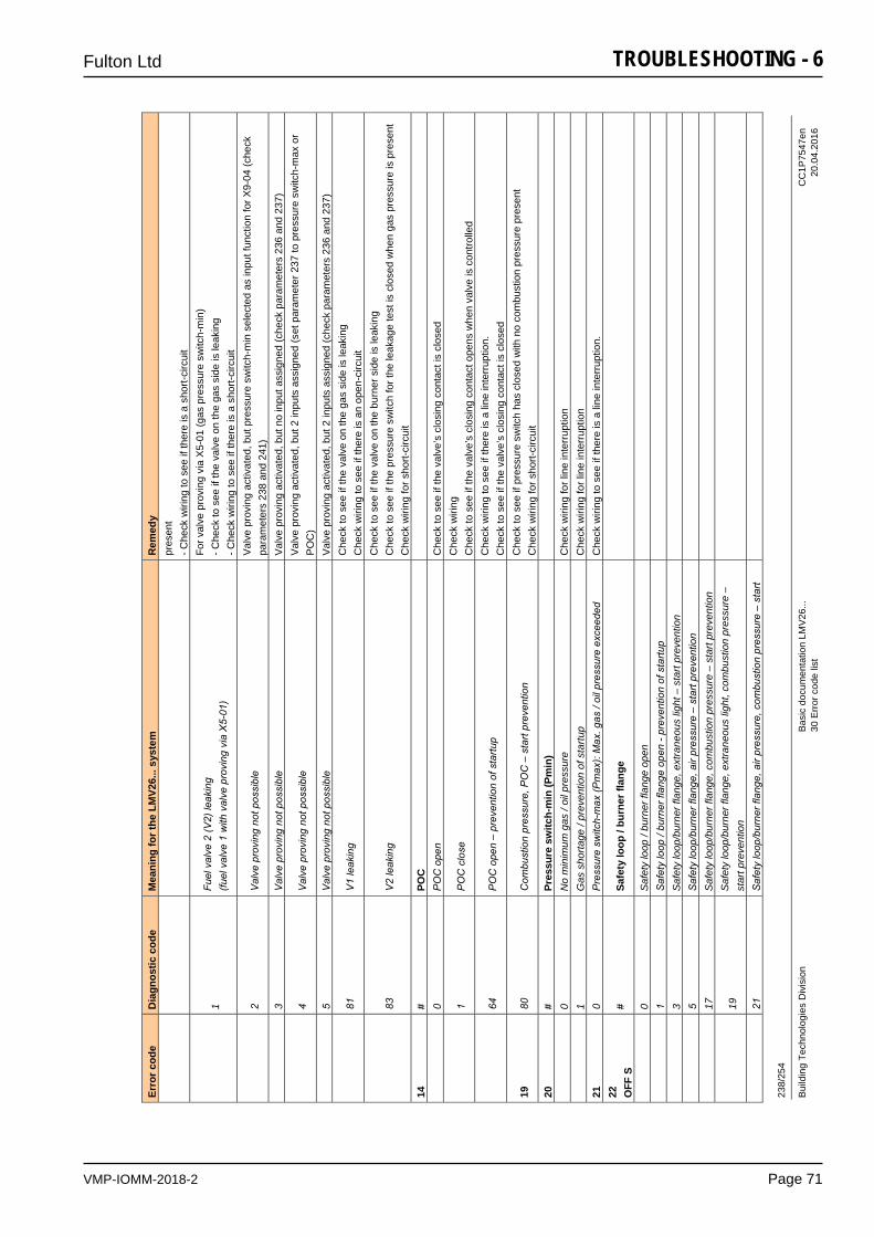
VMP-IOMM-2018-2
Fulton Ltd
Page 71
TROUBLESHOOTING - 6 23
8/25
4
Build
ing
Tech
nolo
gies
Div
isio
n Ba
sic
docu
men
tatio
n LM
V26.
.. C
C1P
7547
en
30
Erro
r cod
e lis
t 20
.04.
2016
Erro
r cod
e D
iagn
ostic
cod
e M
eani
ng fo
r the
LM
V26.
.. sy
stem
R
emed
y pr
esen
t - C
heck
wiri
ng to
see
if th
ere
is a
sho
rt-ci
rcui
t
1
Fuel
val
ve 2
(V2)
leak
ing
(fuel
val
ve 1
with
val
ve p
rovi
ng v
ia X
5-01
)
For v
alve
pro
ving
via
X5-
01 (g
as p
ress
ure
switc
h-m
in)
- Che
ck to
see
if th
e va
lve
on th
e ga
s si
de is
leak
ing
- Che
ck w
iring
to s
ee if
ther
e is
a s
hort-
circ
uit
2
Val
ve p
rovi
ng n
ot p
ossi
ble
Val
ve p
rovi
ng a
ctiv
ated
, but
pre
ssur
e sw
itch-
min
sel
ecte
d as
inpu
t fun
ctio
n fo
r X9-
04 (c
heck
pa
ram
eter
s 23
8 an
d 24
1)
3
Val
ve p
rovi
ng n
ot p
ossi
ble
Val
ve p
rovi
ng a
ctiv
ated
, but
no
inpu
t ass
igne
d (c
heck
par
amet
ers
236
and
237)
4
Val
ve p
rovi
ng n
ot p
ossi
ble
Val
ve p
rovi
ng a
ctiv
ated
, but
2 in
puts
ass
igne
d (s
et p
aram
eter
237
to p
ress
ure
switc
h-m
ax o
r P
OC
)
5 V
alve
pro
ving
not
pos
sibl
e V
alve
pro
ving
act
ivat
ed, b
ut 2
inpu
ts a
ssig
ned
(che
ck p
aram
eter
s 23
6 an
d 23
7)
81
V
1 le
akin
g C
heck
to s
ee if
the
valv
e on
the
gas
side
is le
akin
g C
heck
wiri
ng to
see
if th
ere
is a
n op
en-c
ircui
t
83
V
2 le
akin
g C
heck
to s
ee if
the
valv
e on
the
burn
er s
ide
is le
akin
g C
heck
to s
ee if
the
pres
sure
sw
itch
for t
he le
akag
e te
st is
clo
sed
whe
n ga
s pr
essu
re is
pre
sent
C
heck
wiri
ng fo
r sho
rt-ci
rcui
t 14
#
POC
0
PO
C o
pen
Che
ck to
see
if th
e va
lve’
s cl
osin
g co
ntac
t is
clos
ed
1
PO
C c
lose
C
heck
wiri
ng
Che
ck to
see
if th
e va
lve’
s cl
osin
g co
ntac
t ope
ns w
hen
valv
e is
con
trolle
d
64
P
OC
ope
n –
prev
entio
n of
sta
rtup
Che
ck w
iring
to s
ee if
ther
e is
a li
ne in
terr
uptio
n.
Che
ck to
see
if th
e va
lve’
s cl
osin
g co
ntac
t is
clos
ed
19
80
Com
bust
ion
pres
sure
, PO
C –
sta
rt pr
even
tion
Che
ck to
see
if p
ress
ure
switc
h ha
s cl
osed
with
no
com
bust
ion
pres
sure
pre
sent
C
heck
wiri
ng fo
r sho
rt-ci
rcui
t 20
#
Pres
sure
sw
itch-
min
(Pm
in)
0 N
o m
inim
um g
as /
oil p
ress
ure
Che
ck w
iring
for l
ine
inte
rrup
tion
1
Gas
sho
rtage
/ pr
even
tion
of s
tartu
p C
heck
wiri
ng fo
r lin
e in
terr
uptio
n 21
0
Pre
ssur
e sw
itch-
max
(Pm
ax):
Max
. gas
/ oi
l pre
ssur
e ex
ceed
edC
heck
wiri
ng to
see
if th
ere
is a
line
inte
rrup
tion.
22
O
FF S
#
Safe
ty lo
op /
burn
er fl
ange
0
Saf
ety
loop
/ bu
rner
flan
ge o
pen
1 S
afet
y lo
op /
burn
er fl
ange
ope
n - p
reve
ntio
n of
sta
rtup
3 S
afet
y lo
op/b
urne
r fla
nge,
ext
rane
ous
light
– s
tart
prev
entio
n
5
Saf
ety
loop
/bur
ner f
lang
e, a
ir pr
essu
re –
sta
rt pr
even
tion
17
Saf
ety
loop
/bur
ner f
lang
e, c
ombu
stio
n pr
essu
re –
sta
rt pr
even
tion
19
S
afet
y lo
op/b
urne
r fla
nge,
ext
rane
ous
light
, com
bust
ion
pres
sure
–
star
t pre
vent
ion
21
S
afet
y lo
op/b
urne
r fla
nge,
air
pres
sure
, com
bust
ion
pres
sure
– s
tart
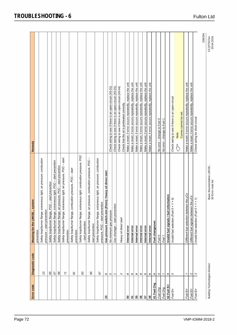
VMP-IOMM-2018-2
Fulton Ltd
Page 72
TROUBLESHOOTING - 6
239/
254
Build
ing
Tech
nolo
gies
Div
isio
n Ba
sic
docu
men
tatio
n LM
V26.
.. C
C1P
7547
en
30
Erro
r cod
e lis
t 20
.04.
2016
Erro
r cod
e D
iagn
ostic
cod
e M
eani
ng fo
r the
LM
V26.
.. sy
stem
R
emed
y pr
even
tion
23
S
afet
y lo
op/b
urne
r fla
nge,
ext
rane
ous
light
, air
pres
sure
, com
bust
ion
pres
sure
– s
tart
prev
entio
n
65
S
afet
y lo
op/b
urne
r fla
nge,
PO
C –
sta
rt pr
even
tion
67
Saf
ety
loop
/bur
ner f
lang
e, e
xtra
neou
s lig
ht, P
OC
– s
tart
prev
entio
n
69
S
afet
y lo
op/b
urne
r fla
nge,
air
pres
sure
, PO
C –
sta
rt pr
even
tion
71
S
afet
y lo
op/b
urne
r fla
nge,
ext
rane
ous
light
, air
pres
sure
, PO
C –
sta
rt pr
even
tion
81
S
afet
y lo
op/b
urne
r fla
nge,
com
bust
ion
pres
sure
, PO
C –
sta
rt pr
even
tion
83
S
afet
y lo
op/b
urne
r fla
nge,
ext
rane
ous
light
, com
bust
ion
pres
sure
, PO
C
– st
art p
reve
ntio
n
85
S
afet
y lo
op/b
urne
r fla
nge,
air
pres
sure
, com
bust
ion
pres
sure
, PO
C –
st
art p
reve
ntio
n
87
S
afet
y lo
op/b
urne
r fla
nge,
ext
rane
ous
light
, air
pres
sure
, com
bust
ion
pres
sure
, PO
C –
sta
rt pr
even
tion
23
# G
as p
ress
ure
switc
h-m
in (P
min
) / h
eavy
oil
dire
ct s
tart
0
No
min
imum
gas
pre
ssur
e C
heck
wiri
ng to
see
if th
ere
is a
n op
en-c
ircui
t(X
5-01
)
1 G
as s
horta
ge –
sta
rt pr
even
tion
Che
ck w
iring
to s
ee if
ther
e is
an
open
-circ
uit(
X5-
01)
2
Hea
vy o
il di
rect
sta
rt C
heck
wiri
ng to
see
if th
ere
is a
n op
en-c
ircui
t (X
9-04
) C
heck
that
the
oil i
s pr
ehea
ted
corr
ectly
50
#
Inte
rnal
err
or
Mak
e a
rese
t; if
erro
r occ
urs
repe
ated
ly, r
epla
ce th
e un
it 51
#
Inte
rnal
err
or
Mak
e a
rese
t; if
erro
r occ
urs
repe
ated
ly, r
epla
ce th
e un
it 55
#
Inte
rnal
err
or
Mak
e a
rese
t; if
erro
r occ
urs
repe
ated
ly, r
epla
ce th
e un
it 56
#
Inte
rnal
err
or
Mak
e a
rese
t; if
erro
r occ
urs
repe
ated
ly, r
epla
ce th
e un
it 57
#
Inte
rnal
err
or
Mak
e a
rese
t; if
erro
r occ
urs
repe
ated
ly, r
epla
ce th
e un
it 58
#
Inte
rnal
err
or
Mak
e a
rese
t; if
erro
r occ
urs
repe
ated
ly, r
epla
ce th
e un
it 61
Fue
l Chg
#
Fuel
cha
ngeo
ver
Fu
el C
hg
0 Fu
el 0
N
o er
ror -
cha
nge
to F
uel 0
Fu
el C
hg
1 Fu
el 1
N
o er
ror -
cha
nge
to F
uel 1
62
Fue
l Err
#
Inva
lid fu
el s
igna
ls /
fuel
info
rmat
ion
Fu
el E
rr
0 In
valid
fuel
sel
ectio
n (F
uel 0
+ 1
= 0
) C
heck
wiri
ng to
see
if th
ere
is a
n op
en-c
ircui
t
N
ote
Cur
ves
cann
ot b
e se
t.
Fuel
Err
1
Diff
eren
t fue
l sel
ectio
n be
twee
n th
e µC
s M
ake
a re
set;
if er
ror o
ccur
s re
peat
edly
, rep
lace
the
unit
Fuel
Err
2
Diff
eren
t fue
l sig
nals
bet
wee
n th
e µC
s M
ake
a re
set;
if er
ror o
ccur
s re
peat
edly
, rep
lace
the
unit
Fuel
Err
3
Inva
lid fu
el s
elec
tion
(Fue
l 0 +
1 =
1)
Che
ck w
iring
for s
hort-
circ
uit
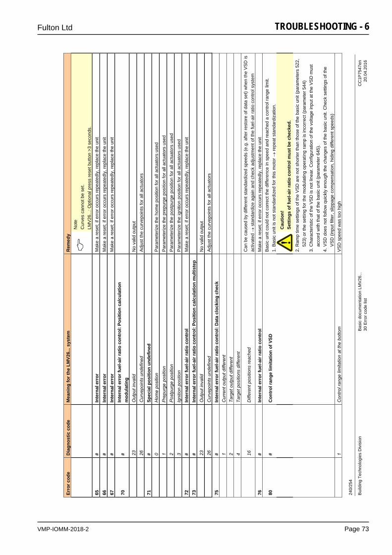
VMP-IOMM-2018-2
Fulton Ltd
Page 73
TROUBLESHOOTING - 6 24
0/25
4
Build
ing
Tech
nolo
gies
Div
isio
n Ba
sic
docu
men
tatio
n LM
V26.
.. C
C1P
7547
en
30
Erro
r cod
e lis
t 20
.04.
2016
Erro
r cod
e D
iagn
ostic
cod
e M
eani
ng fo
r the
LM
V26.
.. sy
stem
R
emed
y
Not
e C
urve
s ca
nnot
be
set.
LMV
26...
: Opt
iona
l pre
ss re
set b
utto
n >3
sec
onds
. 65
#
Inte
rnal
err
or
Mak
e a
rese
t; if
erro
r occ
urs
repe
ated
ly, r
epla
ce th
e un
it 66
#
Inte
rnal
err
or
Mak
e a
rese
t; if
erro
r occ
urs
repe
ated
ly, r
epla
ce th
e un
it 67
#
Inte
rnal
err
or
Mak
e a
rese
t; if
erro
r occ
urs
repe
ated
ly, r
epla
ce th
e un
it
70
# In
tern
al e
rror
fuel
-air
ratio
con
trol
: Pos
ition
cal
cula
tion
mod
ulat
ing
23
O
utpu
t inv
alid
N
o va
lid o
utpu
t
26
Cur
vepo
ints
und
efin
ed
Adj
ust t
he c
urve
poin
ts fo
r all
actu
ator
s 71
#
Spec
ial p
ositi
on u
ndef
ined
0
Hom
e po
sitio
n P
aram
eter
ize
the
hom
e po
sitio
n fo
r all
actu
ator
s us
ed
1
Pre
purg
e po
sitio
n P
aram
eter
ize
the
prep
urge
pos
ition
for a
ll ac
tuat
ors
used
2 P
ostp
urge
pos
ition
P
aram
eter
ize
the
post
purg
e po
sitio
n fo
r all
actu
ator
s us
ed
3
Igni
tion
posi
tion
Par
amet
eriz
e th
e ig
nitio
n po
sitio
n fo
r all
actu
ator
s us
ed
72
# In
tern
al e
rror
fuel
-air
ratio
con
trol
M
ake
a re
set;
if er
ror o
ccur
s re
peat
edly
, rep
lace
the
unit
73
# In
tern
al e
rror
fuel
-air
ratio
con
trol
: Pos
ition
cal
cula
tion
mul
tiste
p
23
O
utpu
t inv
alid
N
o va
lid o
utpu
t
26
Cur
vepo
ints
und
efin
ed
Adj
ust t
he c
urve
poin
ts fo
r all
actu
ator
s 75
#
Inte
rnal
err
or fu
el-a
ir ra
tio c
ontr
ol: D
ata
cloc
king
che
ck
1 C
urre
nt o
utpu
t diff
eren
t
2
Targ
et o
utpu
t diff
eren
t
4
Targ
et p
ositi
ons
diffe
rent
16
D
iffer
ent p
ositi
ons
reac
hed
Can
be
caus
ed b
y di
ffere
nt s
tand
ardi
zed
spee
ds (e
.g. a
fter r
esto
re o
f dat
a se
t) w
hen
the
VS
D is
ac
tivat
ed
sta
ndar
dize
aga
in a
nd c
heck
adj
ustm
ent o
f the
fuel
-air
ratio
con
trol s
yste
m
76
# In
tern
al e
rror
fuel
-air
ratio
con
trol
M
ake
a re
set;
if er
ror o
ccur
s re
peat
edly
, rep
lace
the
unit
80
# C
ontr
ol ra
nge
limita
tion
of V
SD
Bas
ic u
nit c
ould
not
cor
rect
the
diffe
renc
e in
spe
ed a
nd re
ache
d a
cont
rol r
ange
lim
it.
1. B
asic
uni
t is
not s
tand
ardi
zed
for t
his
mot
or
repe
at s
tand
ardi
zatio
n.
C
autio
n!
Setti
ngs
of fu
el-a
ir ra
tio c
ontr
ol m
ust b
e ch
ecke
d.
2. R
amp
time
setti
ngs
of th
e V
SD
are
not
sho
rter t
han
thos
e of
the
basi
c un
it (p
aram
eter
s 52
2,
5
23) o
r the
set
ting
for t
he m
odul
atin
g op
erat
ing
ram
p is
inco
rrec
t (pa
ram
eter
544
) 3.
Cha
ract
eris
tic o
f the
VS
D is
not
line
ar. C
onfig
urat
ion
of th
e vo
ltage
inpu
t at t
he V
SD
mus
t
acc
ord
with
that
of t
he b
asic
uni
t (pa
ram
eter
645
). 4.
VS
D d
oes
not f
ollo
w q
uick
ly e
noug
h th
e ch
ange
s of
the
basi
c un
it. C
heck
set
tings
of t
he
V
SD
(inp
ut fi
lter,
slip
page
com
pens
atio
n, h
idin
g di
ffere
nt s
peed
s)
1
Con
trol r
ange
lim
itatio
n at
the
botto
m
VS
D s
peed
was
too
high
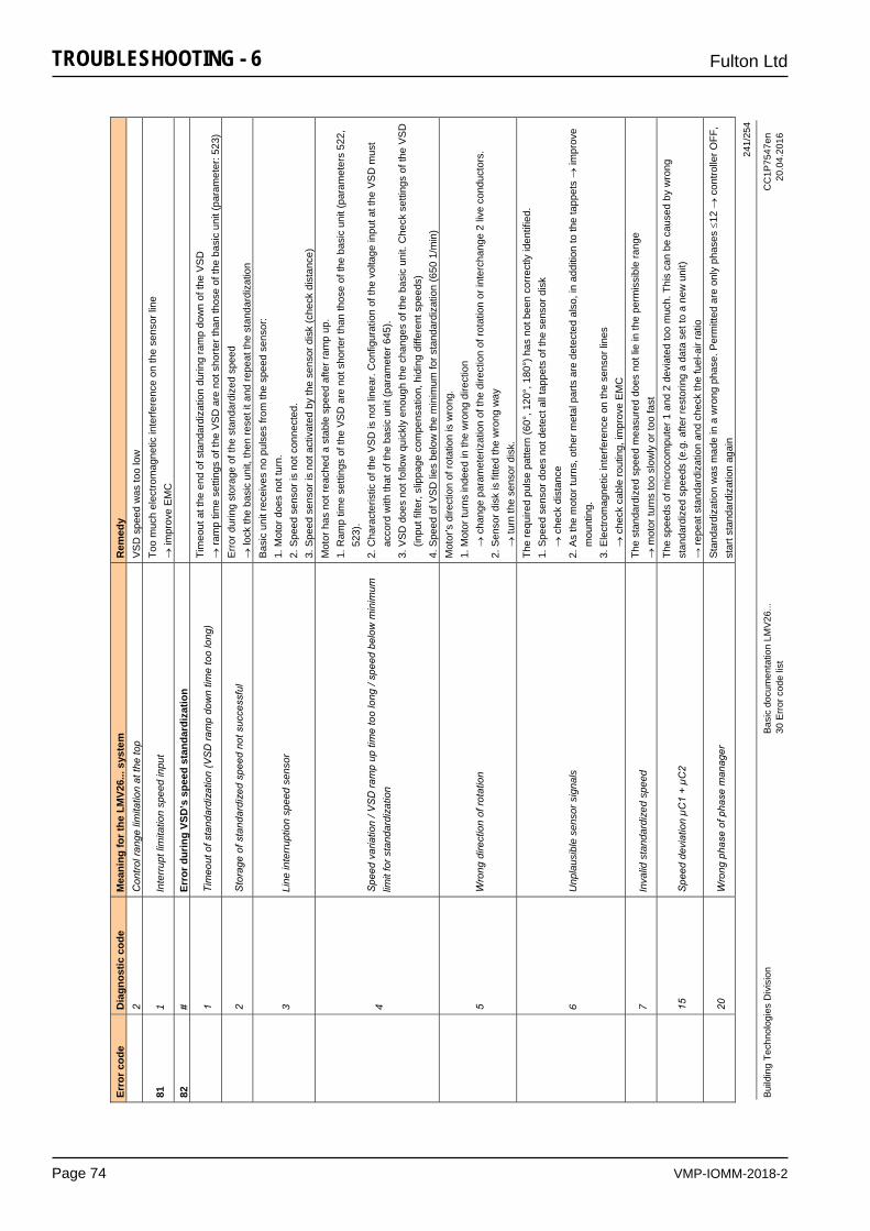
VMP-IOMM-2018-2
Fulton Ltd
Page 74
TROUBLESHOOTING - 6
241/
254
Build
ing
Tech
nolo
gies
Div
isio
n Ba
sic
docu
men
tatio
n LM
V26.
.. C
C1P
7547
en
30
Erro
r cod
e lis
t 20
.04.
2016
Erro
r cod
e D
iagn
ostic
cod
e M
eani
ng fo
r the
LM
V26.
.. sy
stem
R
emed
y
2 C
ontro
l ran
ge li
mita
tion
at th
e to
p V
SD
spe
ed w
as to
o lo
w
81
1 In
terr
upt l
imita
tion
spee
d in
put
Too
muc
h el
ectro
mag
netic
inte
rfere
nce
on th
e se
nsor
line
impr
ove
EM
C
82
# Er
ror d
urin
g VS
D’s
spe
ed s
tand
ardi
zatio
n
1
Tim
eout
of s
tand
ardi
zatio
n (V
SD
ram
p do
wn
time
too
long
) Ti
meo
ut a
t the
end
of s
tand
ardi
zatio
n du
ring
ram
p do
wn
of th
e V
SD
ram
p tim
e se
tting
s of
the
VS
D a
re n
ot s
horte
r tha
n th
ose
of th
e ba
sic
unit
(par
amet
er: 5
23)
2
Sto
rage
of s
tand
ardi
zed
spee
d no
t suc
cess
ful
Err
or d
urin
g st
orag
e of
the
stan
dard
ized
spe
ed
lo
ck th
e ba
sic
unit,
then
rese
t it a
nd re
peat
the
stan
dard
izat
ion
3
Line
inte
rrup
tion
spee
d se
nsor
Bas
ic u
nit r
ecei
ves
no p
ulse
s fro
m th
e sp
eed
sens
or:
1. M
otor
doe
s no
t tur
n.
2. S
peed
sen
sor i
s no
t con
nect
ed.
3. S
peed
sen
sor i
s no
t act
ivat
ed b
y th
e se
nsor
dis
k (c
heck
dis
tanc
e)
4
Spe
ed v
aria
tion
/ VS
D ra
mp
up ti
me
too
long
/ sp
eed
belo
w m
inim
um
limit
for s
tand
ardi
zatio
n
Mot
or h
as n
ot re
ache
d a
stab
le s
peed
afte
r ram
p up
. 1.
Ram
p tim
e se
tting
s of
the
VS
D a
re n
ot s
horte
r tha
n th
ose
of th
e ba
sic
unit
(par
amet
ers
522,
523
). 2.
Cha
ract
eris
tic o
f the
VS
D is
not
line
ar. C
onfig
urat
ion
of th
e vo
ltage
inpu
t at t
he V
SD
mus
t
acc
ord
with
that
of t
he b
asic
uni
t (pa
ram
eter
645
). 3.
VS
D d
oes
not f
ollo
w q
uick
ly e
noug
h th
e ch
ange
s of
the
basi
c un
it. C
heck
set
tings
of t
he V
SD
(inp
ut fi
lter,
slip
page
com
pens
atio
n, h
idin
g di
ffere
nt s
peed
s)
4. S
peed
of V
SD
lies
bel
ow th
e m
inim
um fo
r sta
ndar
diza
tion
(650
1/m
in)
5
Wro
ng d
irect
ion
of ro
tatio
n
Mot
or’s
dire
ctio
n of
rota
tion
is w
rong
. 1.
Mot
or tu
rns
inde
ed in
the
wro
ng d
irect
ion
cha
nge
para
met
eriz
atio
n of
the
dire
ctio
n of
rota
tion
or in
terc
hang
e 2
live
cond
ucto
rs.
2. S
enso
r dis
k is
fitte
d th
e w
rong
way
tu
rn th
e se
nsor
dis
k.
6
Unp
laus
ible
sen
sor s
igna
ls
The
requ
ired
puls
e pa
ttern
(60°
, 120
°, 1
80°)
has
not
bee
n co
rrec
tly id
entif
ied.
1.
Spe
ed s
enso
r doe
s no
t det
ect a
ll ta
ppet
s of
the
sens
or d
isk
che
ck d
ista
nce
2. A
s th
e m
otor
turn
s, o
ther
met
al p
arts
are
det
ecte
d al
so, i
n ad
ditio
n to
the
tapp
ets
impr
ove
m
ount
ing.
3.
Ele
ctro
mag
netic
inte
rfere
nce
on th
e se
nsor
line
s
c
heck
cab
le ro
utin
g, im
prov
e E
MC
7
Inva
lid s
tand
ardi
zed
spee
d Th
e st
anda
rdiz
ed s
peed
mea
sure
d do
es n
ot li
e in
the
perm
issi
ble
rang
e
mot
or tu
rns
too
slow
ly o
r too
fast
15
S
peed
dev
iatio
n µC
1 +
µC2
The
spee
ds o
f mic
roco
mpu
ter 1
and
2 d
evia
ted
too
muc
h. T
his
can
be c
ause
d by
wro
ng
stan
dard
ized
spe
eds
(e.g
. afte
r res
torin
g a
data
set
to a
new
uni
t)
→ re
peat
sta
ndar
diza
tion
and
chec
k th
e fu
el-a
ir ra
tio
20
W
rong
pha
se o
f pha
se m
anag
er
Sta
ndar
diza
tion
was
mad
e in
a w
rong
pha
se. P
erm
itted
are
onl
y ph
ases
12
c
ontro
ller O
FF,
star
t sta
ndar
diza
tion
agai
n
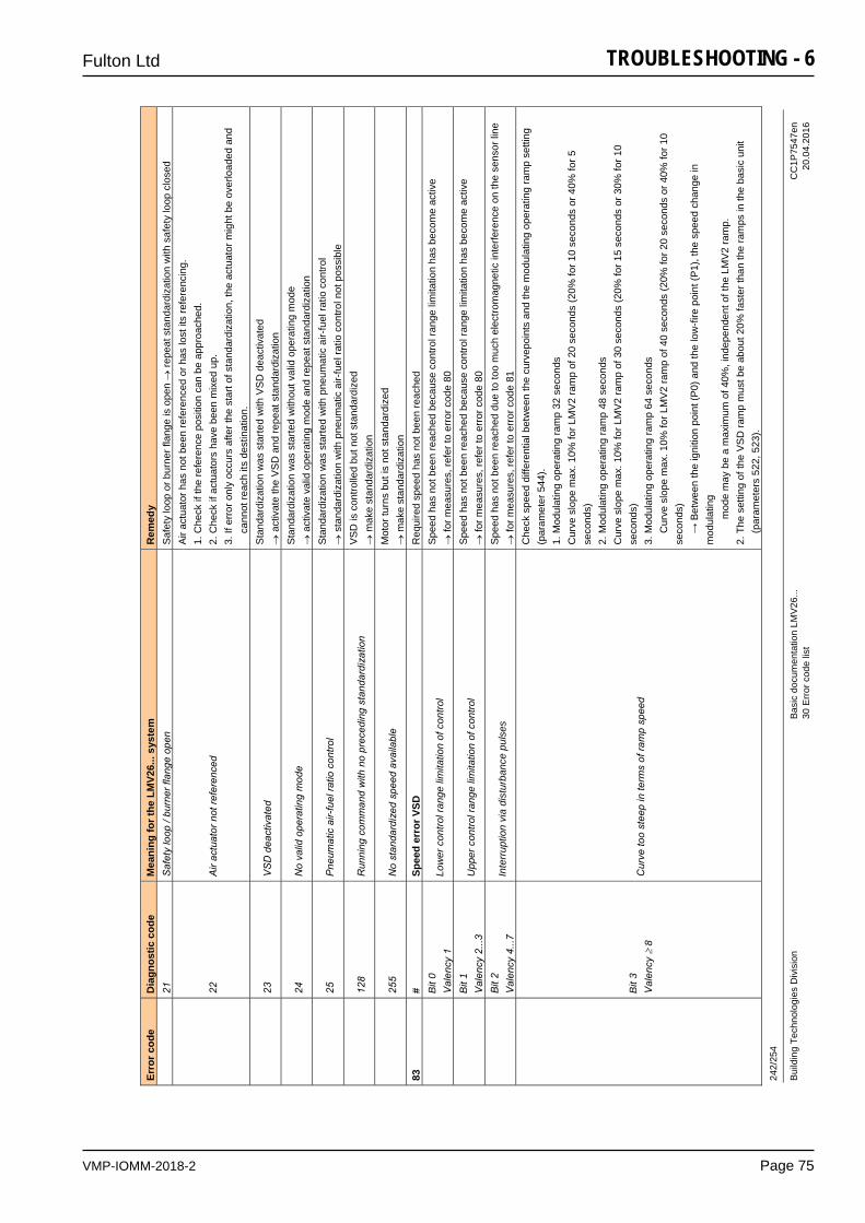
VMP-IOMM-2018-2
Fulton Ltd
Page 75
TROUBLESHOOTING - 6 24
2/25
4
Build
ing
Tech
nolo
gies
Div
isio
n Ba
sic
docu
men
tatio
n LM
V26.
.. C
C1P
7547
en
30
Erro
r cod
e lis
t 20
.04.
2016
Erro
r cod
e D
iagn
ostic
cod
e M
eani
ng fo
r the
LM
V26.
.. sy
stem
R
emed
y
21
Saf
ety
loop
/ bu
rner
flan
ge o
pen
Saf
ety
loop
or b
urne
r fla
nge
is o
pen
repe
at s
tand
ardi
zatio
n w
ith s
afet
y lo
op c
lose
d
22
A
ir ac
tuat
or n
ot re
fere
nced
Air
actu
ator
has
not
bee
n re
fere
nced
or h
as lo
st it
s re
fere
ncin
g.
1. C
heck
if th
e re
fere
nce
posi
tion
can
be a
ppro
ache
d.
2. C
heck
if a
ctua
tors
hav
e be
en m
ixed
up.
3.
If e
rror
onl
y oc
curs
afte
r the
sta
rt of
sta
ndar
diza
tion,
the
actu
ator
mig
ht b
e ov
erlo
aded
and
can
not r
each
its
dest
inat
ion.
23
V
SD
dea
ctiv
ated
S
tand
ardi
zatio
n w
as s
tarte
d w
ith V
SD
dea
ctiv
ated
act
ivat
e th
e V
SD
and
repe
at s
tand
ardi
zatio
n
24
N
o va
lid o
pera
ting
mod
e S
tand
ardi
zatio
n w
as s
tarte
d w
ithou
t val
id o
pera
ting
mod
e
act
ivat
e va
lid o
pera
ting
mod
e an
d re
peat
sta
ndar
diza
tion
25
P
neum
atic
air-
fuel
ratio
con
trol
Sta
ndar
diza
tion
was
sta
rted
with
pne
umat
ic a
ir-fu
el ra
tio c
ontro
l
sta
ndar
diza
tion
with
pne
umat
ic a
ir-fu
el ra
tio c
ontro
l not
pos
sibl
e
12
8 R
unni
ng c
omm
and
with
no
prec
edin
g st
anda
rdiz
atio
n V
SD
is c
ontro
lled
but n
ot s
tand
ardi
zed
mak
e st
anda
rdiz
atio
n
25
5 N
o st
anda
rdiz
ed s
peed
ava
ilabl
e M
otor
turn
s bu
t is
not s
tand
ardi
zed
mak
e st
anda
rdiz
atio
n 83
#
Spee
d er
ror V
SD
Req
uire
d sp
eed
has
not b
een
reac
hed
Bit
0 V
alen
cy 1
Lo
wer
con
trol r
ange
lim
itatio
n of
con
trol
Spe
ed h
as n
ot b
een
reac
hed
beca
use
cont
rol r
ange
lim
itatio
n ha
s be
com
e ac
tive
fo
r mea
sure
s, re
fer t
o er
ror c
ode
80
Bit
1 V
alen
cy 2
...3
Upp
er c
ontro
l ran
ge li
mita
tion
of c
ontro
l S
peed
has
not
bee
n re
ache
d be
caus
e co
ntro
l ran
ge li
mita
tion
has
beco
me
activ
e
for m
easu
res,
refe
r to
erro
r cod
e 80
B
it 2
Val
ency
4...
7 In
terr
uptio
n vi
a di
stur
banc
e pu
lses
S
peed
has
not
bee
n re
ache
d du
e to
too
muc
h el
ectro
mag
netic
inte
rfere
nce
on th
e se
nsor
line
for m
easu
res,
refe
r to
erro
r cod
e 81
Bit
3 V
alen
cy
8 C
urve
too
stee
p in
term
s of
ram
p sp
eed
Che
ck s
peed
diff
eren
tial b
etw
een
the
curv
epoi
nts
and
the
mod
ulat
ing
oper
atin
g ra
mp
setti
ng
(par
amet
er 5
44).
1. M
odul
atin
g op
erat
ing
ram
p 32
sec
onds
C
urve
slo
pe m
ax. 1
0% fo
r LM
V2
ram
p of
20
seco
nds
(20%
for 1
0 se
cond
s or
40%
for 5
se
cond
s)
2. M
odul
atin
g op
erat
ing
ram
p 48
sec
onds
C
urve
slo
pe m
ax. 1
0% fo
r LM
V2
ram
p of
30
seco
nds
(20%
for 1
5 se
cond
s or
30%
for 1
0 se
cond
s)
3. M
odul
atin
g op
erat
ing
ram
p 64
sec
onds
C
urve
slo
pe m
ax. 1
0% fo
r LM
V2
ram
p of
40
seco
nds
(20%
for 2
0 se
cond
s or
40%
for 1
0 se
cond
s)
→
Bet
wee
n th
e ig
nitio
n po
int (
P0)
and
the
low
-fire
poi
nt (P
1), t
he s
peed
cha
nge
in
mod
ulat
ing
m
ode
may
be
a m
axim
um o
f 40%
, ind
epen
dent
of t
he L
MV
2 ra
mp.
2.
The
set
ting
of th
e V
SD
ram
p m
ust b
e ab
out 2
0% fa
ster
than
the
ram
ps in
the
basi
c un
it
(p
aram
eter
s 52
2, 5
23).
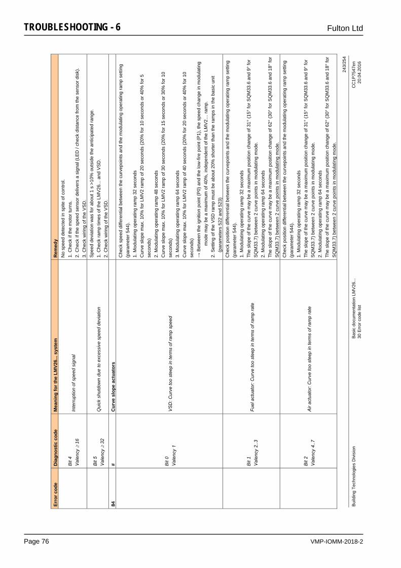
VMP-IOMM-2018-2
Fulton Ltd
Page 76
TROUBLESHOOTING - 6
243/
254
Build
ing
Tech
nolo
gies
Div
isio
n Ba
sic
docu
men
tatio
n LM
V26.
.. C
C1P
7547
en
30
Erro
r cod
e lis
t 20
.04.
2016
Erro
r cod
e D
iagn
ostic
cod
e M
eani
ng fo
r the
LM
V26.
.. sy
stem
R
emed
y
Bit
4 V
alen
cy
16
Inte
rrup
tion
of s
peed
sig
nal
No
spee
d de
tect
ed in
spi
te o
f con
trol.
1. C
heck
if th
e m
otor
turn
s.
2. C
heck
if th
e sp
eed
sens
or d
eliv
ers
a si
gnal
(LE
D /
chec
k di
stan
ce fr
om th
e se
nsor
dis
k).
3. C
heck
wiri
ng o
f the
VS
D.
Bit
5 V
alen
cy
32
Qui
ck s
hutd
own
due
to e
xces
sive
spe
ed d
evia
tion
Spe
ed d
evia
tion
was
for a
bout
1 s
>10
% o
utsi
de th
e an
ticip
ated
rang
e.
1. C
heck
ram
p tim
es o
f the
LM
V26
... a
nd V
SD
. 2.
Che
ck w
iring
of t
he V
SD
. 84
#
Cur
ve s
lope
act
uato
rs
B
it 0
Val
ency
1
VS
D: C
urve
too
stee
p in
term
s of
ram
p sp
eed
Che
ck s
peed
diff
eren
tial b
etw
een
the
curv
epoi
nts
and
the
mod
ulat
ing
oper
atin
g ra
mp
setti
ng
(par
amet
er 5
44).
1. M
odul
atin
g op
erat
ing
ram
p 32
sec
onds
C
urve
slo
pe m
ax. 1
0% fo
r LM
V2
ram
p of
20
seco
nds
(20%
for 1
0 se
cond
s or
40%
for 5
se
cond
s)
2. M
odul
atin
g op
erat
ing
ram
p 48
sec
onds
C
urve
slo
pe m
ax. 1
0% fo
r LM
V2
ram
p of
30
seco
nds
(20%
for 1
5 se
cond
s or
30%
for 1
0 se
cond
s)
3. M
odul
atin
g op
erat
ing
ram
p 64
sec
onds
C
urve
slo
pe m
ax. 1
0% fo
r LM
V2
ram
p of
40
seco
nds
(20%
for 2
0 se
cond
s or
40%
for 1
0 se
cond
s)
→ B
etw
een
the
igni
tion
poin
t (P
0) a
nd th
e lo
w-fi
re p
oint
(P1)
, the
spe
ed c
hang
e in
mod
ulat
ing
mod
e m
ay b
e a
max
imum
of 4
0%, i
ndep
ende
nt o
f the
LM
V2…
ram
p.
2. S
ettin
g of
the
VS
D ra
mp
mus
t be
abou
t 20%
sho
rter t
han
the
ram
ps in
the
basi
c un
it
(p
aram
eter
s 52
2 an
d 52
3)
B
it 1
Val
ency
2..3
Fu
el a
ctua
tor:
Cur
ve to
o st
eep
in te
rms
of ra
mp
rate
Che
ck p
ositi
on d
iffer
entia
l bet
wee
n th
e cu
rvep
oint
s an
d th
e m
odul
atin
g op
erat
ing
ram
p se
tting
(p
aram
eter
544
). 1.
Mod
ulat
ing
oper
atin
g ra
mp
32 s
econ
ds
The
slop
e of
the
curv
e m
ay b
e a
max
imum
pos
ition
cha
nge
of 3
1° (1
5° fo
r SQ
M33
.6 a
nd 9
° fo
r S
QM
33.7
) bet
wee
n 2
curv
e po
ints
in m
odul
atin
g m
ode.
2.
Mod
ulat
ing
oper
atin
g ra
mp
64 s
econ
ds
The
slop
e of
the
curv
e m
ay b
e a
max
imum
pos
ition
cha
nge
of 6
2° (3
0° fo
r SQ
M33
.6 a
nd 1
8° fo
r S
QM
33.7
) bet
wee
n 2
curv
e po
ints
in m
odul
atin
g m
ode.
B
it 2
Val
ency
4..7
A
ir ac
tuat
or: C
urve
too
stee
p in
term
s of
ram
p ra
te
Che
ck p
ositi
on d
iffer
entia
l bet
wee
n th
e cu
rvep
oint
s an
d th
e m
odul
atin
g op
erat
ing
ram
p se
tting
(p
aram
eter
544
). 1.
Mod
ulat
ing
oper
atin
g ra
mp
32 s
econ
ds
The
slop
e of
the
curv
e m
ay b
e a
max
imum
pos
ition
cha
nge
of 3
1° (1
5° fo
r SQ
M33
.6 a
nd 9
° fo
r S
QM
33.7
) bet
wee
n 2
curv
e po
ints
in m
odul
atin
g m
ode.
2.
Mod
ulat
ing
oper
atin
g ra
mp
64 s
econ
ds
The
slop
e of
the
curv
e m
ay b
e a
max
imum
pos
ition
cha
nge
of 6
2° (3
0° fo
r SQ
M33
.6 a
nd 1
8° fo
r S
QM
33.7
) bet
wee
n 2
curv
e po
ints
in m
odul
atin
g m
ode.
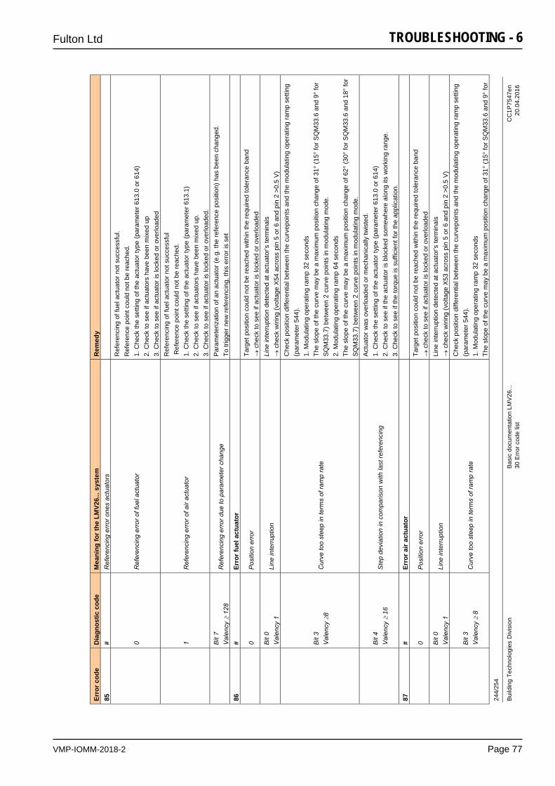
VMP-IOMM-2018-2
Fulton Ltd
Page 77
TROUBLESHOOTING - 6 24
4/25
4
Build
ing
Tech
nolo
gies
Div
isio
n Ba
sic
docu
men
tatio
n LM
V26.
.. C
C1P
7547
en
30
Erro
r cod
e lis
t 20
.04.
2016
Erro
r cod
e D
iagn
ostic
cod
e M
eani
ng fo
r the
LM
V26.
.. sy
stem
R
emed
y 85
#
Ref
eren
cing
err
or o
nes
actu
ator
s
0
Ref
eren
cing
err
or o
f fue
l act
uato
r
Ref
eren
cing
of f
uel a
ctua
tor n
ot s
ucce
ssfu
l. R
efer
ence
poi
nt c
ould
not
be
reac
hed.
1.
Che
ck th
e se
tting
of t
he a
ctua
tor t
ype
(par
amet
er 6
13.0
or 6
14)
2. C
heck
to s
ee if
act
uato
rs h
ave
been
mix
ed u
p 3.
Che
ck to
see
if a
ctua
tor i
s lo
cked
or o
verlo
aded
1
Ref
eren
cing
err
or o
f air
actu
ator
Ref
eren
cing
of f
uel a
ctua
tor n
ot s
ucce
ssfu
l R
efer
ence
poi
nt c
ould
not
be
reac
hed.
1.
Che
ck th
e se
tting
of t
he a
ctua
tor t
ype
(par
amet
er 6
13.1
) 2.
Che
ck to
see
if a
ctua
tors
hav
e be
en m
ixed
up.
3.
Che
ck to
see
if a
ctua
tor i
s lo
cked
or o
verlo
aded
. B
it 7
Val
ency
12
8 R
efer
enci
ng e
rror
due
to p
aram
eter
cha
nge
Par
amet
eriz
atio
n of
an
actu
ator
(e.g
. the
refe
renc
e po
sitio
n) h
as b
een
chan
ged.
To
trig
ger n
ew re
fere
ncin
g, th
is e
rror
is s
et
86
# Er
ror f
uel a
ctua
tor
0
Pos
ition
err
or
Targ
et p
ositi
on c
ould
not
be
reac
hed
with
in th
e re
quire
d to
lera
nce
band
che
ck to
see
if a
ctua
tor i
s lo
cked
or o
verlo
aded
B
it 0
Val
ency
1
Line
inte
rrup
tion
Line
inte
rrup
tion
dete
cted
at a
ctua
tor’s
term
inal
s
che
ck w
iring
(vol
tage
X54
acr
oss
pin
5 or
6 a
nd p
in 2
>0.
5 V
)
Bit
3 V
alen
cy8
Cur
ve to
o st
eep
in te
rms
of ra
mp
rate
Che
ck p
ositi
on d
iffer
entia
l bet
wee
n th
e cu
rvep
oint
s an
d th
e m
odul
atin
g op
erat
ing
ram
p se
tting
(p
aram
eter
544
). 1.
Mod
ulat
ing
oper
atin
g ra
mp
32 s
econ
ds
The
slop
e of
the
curv
e m
ay b
e a
max
imum
pos
ition
cha
nge
of 3
1° (1
5° fo
r SQ
M33
.6 a
nd 9
° fo
r S
QM
33.7
) bet
wee
n 2
curv
e po
ints
in m
odul
atin
g m
ode.
2.
Mod
ulat
ing
oper
atin
g ra
mp
64 s
econ
ds
The
slop
e of
the
curv
e m
ay b
e a
max
imum
pos
ition
cha
nge
of 6
2° (3
0° fo
r SQ
M33
.6 a
nd 1
8° fo
r S
QM
33.7
) bet
wee
n 2
curv
e po
ints
in m
odul
atin
g m
ode.
Bit
4 V
alen
cy
16
Ste
p de
viat
ion
in c
ompa
rison
with
last
refe
renc
ing
Act
uato
r was
ove
rload
ed o
r mec
hani
cally
twis
ted.
1.
Che
ck th
e se
tting
of t
he a
ctua
tor t
ype
(par
amet
er 6
13.0
or 6
14)
2. C
heck
to s
ee if
the
actu
ator
is b
lock
ed s
omew
here
alo
ng it
s w
orki
ng ra
nge.
3.
Che
ck to
see
if th
e to
rque
is s
uffic
ient
for t
he a
pplic
atio
n.
87
# Er
ror a
ir ac
tuat
or
0
Pos
ition
err
or
Targ
et p
ositi
on c
ould
not
be
reac
hed
with
in th
e re
quire
d to
lera
nce
band
che
ck to
see
if a
ctua
tor i
s lo
cked
or o
verlo
aded
B
it 0
Val
ency
1
Line
inte
rrup
tion
Line
inte
rrup
tion
dete
cted
at a
ctua
tor’s
term
inal
s
che
ck w
iring
(vol
tage
X53
acr
oss
pin
5 or
6 a
nd p
in 2
>0.
5 V
)
Bit
3 V
alen
cy
8 C
urve
too
stee
p in
term
s of
ram
p ra
te
Che
ck p
ositi
on d
iffer
entia
l bet
wee
n th
e cu
rvep
oint
s an
d th
e m
odul
atin
g op
erat
ing
ram
p se
tting
(p
aram
eter
544
). 1.
Mod
ulat
ing
oper
atin
g ra
mp
32 s
econ
ds
The
slop
e of
the
curv
e m
ay b
e a
max
imum
pos
ition
cha
nge
of 3
1° (1
5° fo
r SQ
M33
.6 a
nd 9
° fo
r
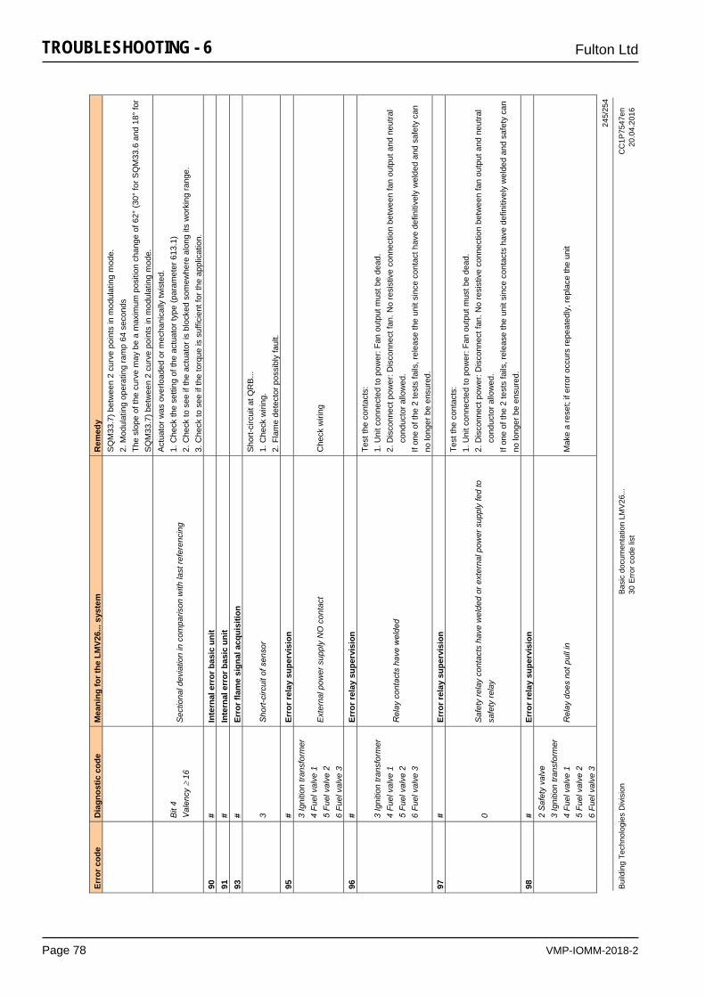
VMP-IOMM-2018-2
Fulton Ltd
Page 78
TROUBLESHOOTING - 6
245/
254
Build
ing
Tech
nolo
gies
Div
isio
n Ba
sic
docu
men
tatio
n LM
V26.
.. C
C1P
7547
en
30
Erro
r cod
e lis
t 20
.04.
2016
Erro
r cod
e D
iagn
ostic
cod
e M
eani
ng fo
r the
LM
V26.
.. sy
stem
R
emed
y S
QM
33.7
) bet
wee
n 2
curv
e po
ints
in m
odul
atin
g m
ode.
2.
Mod
ulat
ing
oper
atin
g ra
mp
64 s
econ
ds
The
slop
e of
the
curv
e m
ay b
e a
max
imum
pos
ition
cha
nge
of 6
2° (3
0° fo
r SQ
M33
.6 a
nd 1
8° fo
r S
QM
33.7
) bet
wee
n 2
curv
e po
ints
in m
odul
atin
g m
ode.
Bit
4 V
alen
cy
16
Sec
tiona
l dev
iatio
n in
com
paris
on w
ith la
st re
fere
ncin
g
Act
uato
r was
ove
rload
ed o
r mec
hani
cally
twis
ted.
1.
Che
ck th
e se
tting
of t
he a
ctua
tor t
ype
(par
amet
er 6
13.1
) 2.
Che
ck to
see
if th
e ac
tuat
or is
blo
cked
som
ewhe
re a
long
its
wor
king
rang
e.
3. C
heck
to s
ee if
the
torq
ue is
suf
ficie
nt fo
r the
app
licat
ion.
90
#
Inte
rnal
err
or b
asic
uni
t
91
# In
tern
al e
rror
bas
ic u
nit
93
#
Erro
r fla
me
sign
al a
cqui
sitio
n
3
Sho
rt-ci
rcui
t of s
enso
r S
hort-
circ
uit a
t QR
B...
1.
Che
ck w
iring
. 2.
Fla
me
dete
ctor
pos
sibl
y fa
ult.
95
# Er
ror r
elay
sup
ervi
sion
3 Ig
nitio
n tra
nsfo
rmer
4
Fuel
val
ve 1
5
Fuel
val
ve 2
6
Fuel
val
ve 3
Ext
erna
l pow
er s
uppl
y N
O c
onta
ct
Che
ck w
iring
96
# Er
ror r
elay
sup
ervi
sion
3 Ig
nitio
n tra
nsfo
rmer
4
Fuel
val
ve 1
5
Fuel
val
ve 2
6
Fuel
val
ve 3
Rel
ay c
onta
cts
have
wel
ded
Test
the
cont
acts
: 1.
Uni
t con
nect
ed to
pow
er: F
an o
utpu
t mus
t be
dead
. 2.
Dis
conn
ect p
ower
: Dis
conn
ect f
an. N
o re
sist
ive
conn
ectio
n be
twee
n fa
n ou
tput
and
neu
tral
c
ondu
ctor
allo
wed
. If
one
of th
e 2
test
s fa
ils, r
elea
se th
e un
it si
nce
cont
act h
ave
defin
itive
ly w
elde
d an
d sa
fety
can
no
long
er b
e en
sure
d.
97
# Er
ror r
elay
sup
ervi
sion
0
Saf
ety
rela
y co
ntac
ts h
ave
wel
ded
or e
xter
nal p
ower
sup
ply
fed
to
safe
ty re
lay
Test
the
cont
acts
: 1.
Uni
t con
nect
ed to
pow
er: F
an o
utpu
t mus
t be
dead
. 2.
Dis
conn
ect p
ower
: Dis
conn
ect f
an. N
o re
sist
ive
conn
ectio
n be
twee
n fa
n ou
tput
and
neu
tral
c
ondu
ctor
allo
wed
. If
one
of th
e 2
test
s fa
ils, r
elea
se th
e un
it si
nce
cont
acts
hav
e de
finiti
vely
wel
ded
and
safe
ty c
an
no lo
nger
be
ensu
red.
98
#
Erro
r rel
ay s
uper
visi
on
2
Saf
ety
valv
e 3
Igni
tion
trans
form
er
4 Fu
el v
alve
1
5 Fu
el v
alve
2
6 Fu
el v
alve
3
Rel
ay d
oes
not p
ull i
n M
ake
a re
set;
if er
ror o
ccur
s re
peat
edly
, rep
lace
the
unit
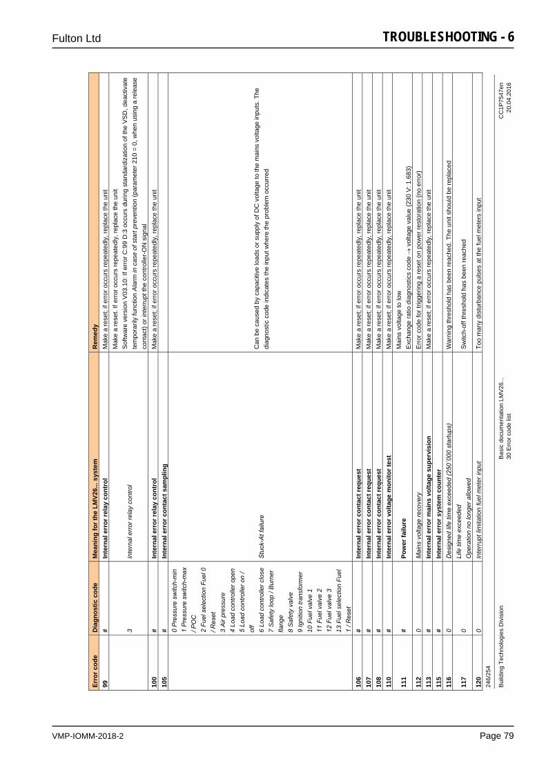
VMP-IOMM-2018-2
Fulton Ltd
Page 79
TROUBLESHOOTING - 6 24
6/25
4
Build
ing
Tech
nolo
gies
Div
isio
n Ba
sic
docu
men
tatio
n LM
V26.
.. C
C1P
7547
en
30
Erro
r cod
e lis
t 20
.04.
2016
Erro
r cod
e D
iagn
ostic
cod
e M
eani
ng fo
r the
LM
V26.
.. sy
stem
R
emed
y 99
#
Inte
rnal
err
or re
lay
cont
rol
Mak
e a
rese
t; if
erro
r occ
urs
repe
ated
ly, r
epla
ce th
e un
it
3
Inte
rnal
err
or re
lay
cont
rol
Mak
e a
rese
t. If
erro
r occ
urs
repe
ated
ly, r
epla
ce th
e un
it S
oftw
are
vers
ion
V03
.10:
If e
rror
C:9
9 D
:3 o
ccur
s du
ring
stan
dard
izat
ion
of th
e V
SD
, dea
ctiv
ate
tem
pora
rily
func
tion
Ala
rm in
cas
e of
sta
rt pr
even
tion
(par
amet
er 2
10 =
0, w
hen
usin
g a
rele
ase
cont
act)
or in
terr
upt t
he c
ontro
ller-
ON
sig
nal
100
# In
tern
al e
rror
rela
y co
ntro
l M
ake
a re
set;
if er
ror o
ccur
s re
peat
edly
, rep
lace
the
unit
105
# In
tern
al e
rror
con
tact
sam
plin
g
0 P
ress
ure
switc
h-m
in
1 P
ress
ure
switc
h-m
ax
/ PO
C
2 Fu
el s
elec
tion
Fuel
0
/ Res
et
3 A
ir pr
essu
re
4 Lo
ad c
ontro
ller o
pen
5 Lo
ad c
ontro
ller o
n /
off
6 Lo
ad c
ontro
ller c
lose
7
Saf
ety
loop
/ B
urne
r fla
nge
8 S
afet
y va
lve
9 Ig
nitio
n tra
nsfo
rmer
10
Fue
l val
ve 1
11
Fue
l val
ve 2
12
Fue
l val
ve 3
13
Fue
l sel
ectio
n Fu
el
1 / R
eset
Stu
ck-A
t fai
lure
C
an b
e ca
used
by
capa
citiv
e lo
ads
or s
uppl
y of
DC
vol
tage
to th
e m
ains
vol
tage
inpu
ts. T
he
diag
nost
ic c
ode
indi
cate
s th
e in
put w
here
the
prob
lem
occ
urre
d
106
# In
tern
al e
rror
con
tact
requ
est
Mak
e a
rese
t; if
erro
r occ
urs
repe
ated
ly, r
epla
ce th
e un
it 10
7 #
Inte
rnal
err
or c
onta
ct re
ques
t M
ake
a re
set;
if er
ror o
ccur
s re
peat
edly
, rep
lace
the
unit
108
# In
tern
al e
rror
con
tact
requ
est
Mak
e a
rese
t; if
erro
r occ
urs
repe
ated
ly, r
epla
ce th
e un
it 11
0 #
Inte
rnal
err
or v
olta
ge m
onito
r tes
t M
ake
a re
set;
if er
ror o
ccur
s re
peat
edly
, rep
lace
the
unit
111
# Po
wer
failu
re
Mai
ns v
olta
ge to
low
E
xcha
nge
ratio
dia
gnos
tics
code
v
olta
ge v
alue
(230
V: 1
.683
) 11
2 0
Mai
ns v
olta
ge re
cove
ry
Erro
r cod
e fo
r trig
gerin
g a
rese
t on
pow
er re
stor
atio
n (n
o er
ror)
11
3 #
Inte
rnal
err
or m
ains
vol
tage
sup
ervi
sion
M
ake
a re
set;
if er
ror o
ccur
s re
peat
edly
, rep
lace
the
unit
115
# In
tern
al e
rror
sys
tem
cou
nter
116
0 D
esig
ned
life
time
exce
eded
(250
´000
sta
rtups
) W
arni
ng th
resh
old
has
been
reac
hed.
The
uni
t sho
uld
be re
plac
ed
117
0Li
fe ti
me
exce
eded
O
pera
tion
no lo
nger
allo
wed
S
witc
h-of
f thr
esho
ld h
as b
een
reac
hed
120
0 In
terr
upt l
imita
tion
fuel
met
er in
put
Too
man
y di
stur
banc
e pu
lses
at t
he fu
el m
eter
s in
put

VMP-IOMM-2018-2
Fulton Ltd
Page 80
TROUBLESHOOTING - 6
247/
254
Build
ing
Tech
nolo
gies
Div
isio
n Ba
sic
docu
men
tatio
n LM
V26.
.. C
C1P
7547
en
30
Erro
r cod
e lis
t 20
.04.
2016
Erro
r cod
e D
iagn
ostic
cod
e M
eani
ng fo
r the
LM
V26.
.. sy
stem
R
emed
y
Impr
ove
EM
C
121
# In
tern
al e
rror
EEP
RO
M a
cces
s M
ake
a re
set,
repe
at la
st p
aram
eter
izat
ion
/ che
ck. R
esto
re th
e pa
ram
eter
set
, if e
rror
occ
urs
repe
ated
ly, r
epla
ce th
e un
it
122
# In
tern
al e
rror
EEP
RO
M a
cces
s M
ake
a re
set,
repe
at la
st p
aram
eter
izat
ion
/ che
ck. R
esto
re th
e pa
ram
eter
set
, if e
rror
occ
urs
repe
ated
ly, r
epla
ce th
e un
it
123
# In
tern
al e
rror
EEP
RO
M a
cces
s M
ake
a re
set,
repe
at la
st p
aram
eter
izat
ion
/ che
ck. R
esto
re th
e pa
ram
eter
set
, if e
rror
occ
urs
repe
ated
ly, r
epla
ce th
e un
it
124
# In
tern
al e
rror
EEP
RO
M a
cces
s M
ake
a re
set,
repe
at la
st p
aram
eter
izat
ion
/ che
ck. R
esto
re th
e pa
ram
eter
set
, if e
rror
occ
urs
repe
ated
ly, r
epla
ce th
e un
it 12
5 #
Inte
rnal
err
or E
EPR
OM
read
acc
ess
Mak
e a
rese
t, re
peat
last
par
amet
eriz
atio
n / c
heck
. If e
rror
occ
urs
repe
ated
ly, r
epla
ce th
e un
it 12
6 #
Inte
rnal
err
or E
EPR
OM
writ
e ac
cess
M
ake
a re
set,
repe
at la
st p
aram
eter
izat
ion
/ che
ck. I
f err
or o
ccur
s re
peat
edly
, rep
lace
the
unit
127
# In
tern
al e
rror
EEP
RO
M a
cces
s M
ake
a re
set,
repe
at la
st p
aram
eter
izat
ion
/ che
ck. R
esto
re th
e pa
ram
eter
set
, if e
rror
occ
urs
repe
ated
ly, r
epla
ce th
e un
it 12
8 0
Inte
rnal
err
or E
EP
RO
M a
cces
s - s
ynch
roni
zatio
n du
ring
initi
aliz
atio
n M
ake
a re
set;
if er
ror o
ccur
s re
peat
edly
, rep
lace
the
unit
129
# In
tern
al e
rror
EEP
RO
M a
cces
s –
com
man
d sy
nchr
oniz
atio
n M
ake
a re
set,
repe
at la
st p
aram
eter
izat
ion
/ che
ck. I
f err
or o
ccur
s re
peat
edly
, rep
lace
the
unit
130
# In
tern
al e
rror
EEP
RO
M a
cces
s - t
imeo
ut
Mak
e a
rese
t, re
peat
last
par
amet
eriz
atio
n / c
heck
. If e
rror
occ
urs
repe
ated
ly, r
epla
ce th
e un
it 13
1 #
Inte
rnal
err
or E
EPR
OM
acc
ess
- pag
e on
abo
rt
Mak
e a
rese
t, re
peat
last
par
amet
eriz
atio
n / c
heck
. If e
rror
occ
urs
repe
ated
ly, r
epla
ce th
e un
it 13
2 #
Inte
rnal
err
or E
EPR
OM
regi
ster
initi
aliz
atio
n M
ake
a re
set;
if er
ror o
ccur
s re
peat
edly
, rep
lace
the
unit
133
# In
tern
al e
rror
EEP
RO
M a
cces
s –
Req
uest
syn
chro
niza
tion
Mak
e a
rese
t, re
peat
last
par
amet
eriz
atio
n / c
heck
. If e
rror
occ
urs
repe
ated
ly, r
epla
ce th
e un
it 13
4 #
Inte
rnal
err
or E
EPR
OM
acc
ess
– R
eque
st s
ynch
roni
zatio
n M
ake
a re
set,
repe
at la
st p
aram
eter
izat
ion
/ che
ck. I
f err
or o
ccur
s re
peat
edly
, rep
lace
the
unit
135
# In
tern
al e
rror
EEP
RO
M a
cces
s –
Req
uest
syn
chro
niza
tion
Mak
e a
rese
t, re
peat
last
par
amet
eriz
atio
n / c
heck
. If e
rror
occ
urs
repe
ated
ly, r
epla
ce th
e un
it
136
1 R
esto
re s
tarte
d R
esto
re o
f a b
acku
p ha
s be
en s
tarte
d (n
o er
ror)
N
ew d
evic
es re
quire
rese
tting
follo
win
g re
stor
e!
fo
r fur
ther
dia
gnos
tic c
odes
for e
rror
cod
e 13
6, re
fer t
o er
ror c
ode
137
For m
easu
res,
refe
r to
erro
r cod
e 13
7
137
# In
tern
al e
rror
– b
acku
p / r
esto
re
157
(-99
) R
esto
re –
ok,
but
bac
kup
< da
ta s
et o
f cur
rent
sys
tem
R
esto
re s
ucce
ssfu
l, bu
t bac
kup
data
reco
rd is
sm
alle
r tha
n in
the
curr
ent s
yste
m
23
9 (-
17)
Bac
kup
– st
orag
e of
bac
kup
in A
ZL2.
.. fa
ulty
R
eset
and
repe
at b
acku
p
240
(-16
) R
esto
re –
no
back
up in
AZL
2...
No
back
up s
tore
d in
AZL
2...
24
1 (-
15)
Res
tore
– a
borti
on d
ue to
uns
uita
ble
prod
uct n
o. (A
SN
) B
acku
p ha
s an
uns
uita
ble
prod
uct n
o. (A
SN
) and
mus
t not
be
rest
ored
242
(-14
) B
acku
p –
back
up m
ade
is in
cons
iste
nt
Bac
kup
is fa
ulty
and
can
not b
e tra
nsfe
rred
bac
k
243
(-13
) B
acku
p –
data
com
paris
on b
etw
een
µCs
faul
ty
Res
et a
nd re
peat
bac
kup
24
4 (-
12)
Bac
kup
data
are
inco
mpa
tible
B
acku
p da
ta a
re in
com
patib
le w
ith th
e cu
rrent
sof
twar
e ve
rsio
n, re
stor
e no
t pos
sibl
e
245
(-11
) A
cces
s er
ror t
o pa
ram
eter
Res
tore
_Com
plet
e R
eset
and
repe
at b
acku
p
246
(-10
) R
esto
re –
tim
eout
whe
n st
orin
g in
EE
PR
OM
R
eset
and
repe
at b
acku
p
247
(-9)
D
ata
rece
ived
are
inco
nsis
tent
B
acku
p da
ta re
cord
inva
lid, r
esto
re n
ot p
ossi
ble
24
8 (-
8)
Res
tore
can
not a
t pre
sent
be
mad
e R
eset
and
repe
at b
acku
p
249
(-7)
R
esto
re –
abo
rtion
due
to u
nsui
tabl
e bu
rner
iden
tific
atio
n B
acku
p ha
s an
uns
uita
ble
burn
er id
entif
icat
ion
and
mus
t not
be
trans
ferr
ed to
the
unit
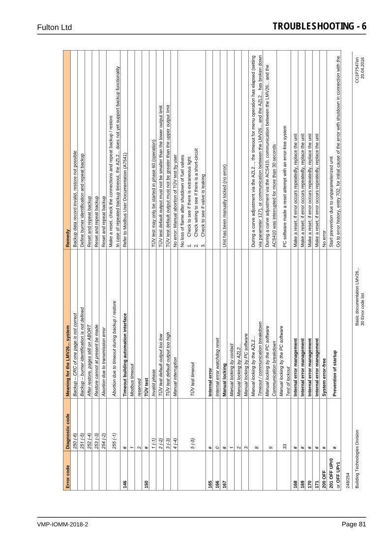
VMP-IOMM-2018-2
Fulton Ltd
Page 81
TROUBLESHOOTING - 6 24
8/25
4
Build
ing
Tech
nolo
gies
Div
isio
n Ba
sic
docu
men
tatio
n LM
V26.
.. C
C1P
7547
en
30
Erro
r cod
e lis
t 20
.04.
2016
Erro
r cod
e D
iagn
ostic
cod
e M
eani
ng fo
r the
LM
V26.
.. sy
stem
R
emed
y
250
(-6)
B
acku
p –
CR
C o
f one
pag
e is
not
cor
rect
B
acku
p da
ta re
cord
inva
lid, r
esto
re n
ot p
ossi
ble
25
1 (-
5)
Bac
kup
– bu
rner
iden
tific
atio
n is
not
def
ined
D
efin
e bu
rner
iden
tific
atio
n an
d re
peat
bac
kup
25
2 (-
4)
Afte
r res
tore
, pag
es s
till o
n A
BO
RT
Res
et a
nd re
peat
bac
kup
25
3 (-
3)
Res
tore
can
not a
t pre
sent
be
mad
e R
eset
and
repe
at b
acku
p
254
(-2)
A
borti
on d
ue to
tran
smis
sion
err
or
Res
et a
nd re
peat
bac
kup
25
5 (-
1)
Abo
rtion
due
to ti
meo
ut d
urin
g ba
ckup
/ re
stor
e M
ake
a re
set,
chec
k th
e co
nnec
tions
and
repe
at b
acku
p / r
esto
re
In c
ase
of re
peat
ed b
acku
p tim
eout
, the
AZL
2...
does
not
yet
sup
port
back
up fu
nctio
nalit
y 14
6 #
Tim
eout
bui
ldin
g au
tom
atio
n in
terf
ace
Ref
er to
Mod
bus
Use
r Doc
umen
tatio
n (A
7541
)
1 M
odbu
s tim
eout
2
rese
rved
150
# TÜ
V te
st
1 (-
1)
Inva
lid p
hase
TÜ
V te
st m
ay o
nly
be s
tarte
d in
pha
se 6
0 (o
pera
tion)
2 (-
2)
TÜV
test
def
ault
outp
ut to
o lo
w
TÜV
test
def
ault
outp
ut m
ust n
ot b
e sm
alle
r tha
n th
e lo
wer
out
put l
imit
3
(-3)
TÜ
V te
st d
efau
lt ou
tput
too
high
TÜ
V te
st d
efau
lt ou
tput
mus
t not
be
grea
ter t
han
the
uppe
r out
put l
imit
4
(-4)
M
anua
l int
erru
ptio
n N
o er
ror:
Man
ual a
borti
on o
f TÜ
V te
st b
y us
er
5
(-5)
TÜ
V te
st ti
meo
ut
No
loss
of f
lam
e af
ter s
hutd
own
of fu
el v
alve
s 1.
C
heck
to s
ee if
ther
e is
ext
rane
ous
light
2.
C
heck
wiri
ng to
see
if th
ere
is a
sho
rt-ci
rcui
t 3.
C
heck
to s
ee if
val
ve is
leak
ing
165
# In
tern
al e
rror
166
0 In
tern
al e
rror
wat
chdo
g re
set
16
7 #
Man
ual l
ocki
ng
Uni
t has
bee
n m
anua
lly lo
cked
(no
erro
r)
1
Man
ual l
ocki
ng b
y co
ntac
t
2
Man
ual l
ocki
ng b
y A
ZL2.
..
3
Man
ual l
ocki
ng b
y P
C s
oftw
are
8
Man
ual l
ocki
ng b
y th
e A
ZL2.
.. Ti
meo
ut /
com
mun
icat
ion
brea
kdow
n D
urin
g a
curv
e ad
just
men
t via
the
AZL
2...,
the
timeo
ut fo
r men
u op
erat
ion
has
elap
sed
(set
ting
via
para
met
er 1
27),
or c
omm
unic
atio
n be
twee
n th
e LM
V26
... a
nd th
e A
ZL2.
.. ha
s br
oken
dow
n
9
Man
ual l
ocki
ng b
y th
e P
C s
oftw
are
Com
mun
icat
ion
brea
kdow
n D
urin
g a
curv
e ad
just
men
t via
the
AC
S41
0, c
omm
unic
atio
n be
twee
n th
e LM
V26
... a
nd th
e A
CS
410
was
inte
rrup
ted
for m
ore
than
30
seco
nds
33
M
anua
l loc
king
by
the
PC
sof
twar
e Te
st o
f loc
kout
P
C s
oftw
are
mad
e a
rese
t atte
mpt
with
an
erro
r-fre
e sy
stem
168
# In
tern
al e
rror
man
agem
ent
Mak
e a
rese
t; if
erro
r occ
urs
repe
ated
ly, r
epla
ce th
e un
it 16
9 #
Inte
rnal
err
or m
anag
emen
t M
ake
a re
set;
if er
ror o
ccur
s re
peat
edly
, rep
lace
the
unit
170
# In
tern
al e
rror
man
agem
ent
Mak
e a
rese
t; if
erro
r occ
urs
repe
ated
ly, r
epla
ce th
e un
it 17
1 #
Inte
rnal
err
or m
anag
emen
t M
ake
a re
set;
if er
ror o
ccur
s re
peat
edly
, rep
lace
the
unit
200
OFF
#
Syst
em e
rror
-free
N
o er
ror
201
OFF
UPr
0 or
OFF
UPr
1 #
Prev
entio
n of
sta
rtup
S
tart
prev
entio
n du
e to
unp
aram
eter
ized
uni
t G
o to
err
or h
isto
ry, e
ntry
702
, for
initi
al c
ause
of t
he e
rror
with
shu
tdow
n in
con
nect
ion
with
the
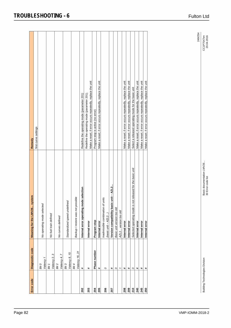
VMP-IOMM-2018-2
Fulton Ltd
Page 82
TROUBLESHOOTING - 6
249/
254
Build
ing
Tech
nolo
gies
Div
isio
n Ba
sic
docu
men
tatio
n LM
V26.
.. C
C1P
7547
en
30
Erro
r cod
e lis
t 20
.04.
2016
Erro
r cod
e D
iagn
ostic
cod
e M
eani
ng fo
r the
LM
V26.
.. sy
stem
R
emed
y fir
st c
urve
set
tings
B
it 0
Val
ency
1
No
oper
atin
g m
ode
sele
cted
Bit
1 V
alen
cy 2
..3
No
fuel
trai
n de
fined
Bit
2 V
alen
cy 4
..7
No
curv
es d
efin
ed
Bit
3 V
alen
cy 8
..15
Sta
ndar
dize
d sp
eed
unde
fined
Bit
4 V
alen
cy 1
6..3
1 B
acku
p / r
esto
re w
as n
ot p
ossi
ble
202
# In
tern
al e
rror
ope
ratin
g m
ode
sele
ctio
n R
edef
ine
the
oper
atin
g m
ode
(par
amet
er 2
01)
203
# In
tern
al e
rror
R
edef
ine
the
oper
atin
g m
ode
(par
amet
er 2
01).
Mak
e a
rese
t; if
erro
r occ
urs
repe
ated
ly, r
epla
ce th
e un
it 20
4 Ph
ase
num
ber
Prog
ram
sto
p P
rogr
am s
top
is a
ctiv
e (n
o er
ror)
20
5 #
Inte
rnal
err
or
Mak
e a
rese
t; if
erro
r occ
urs
repe
ated
ly, r
epla
ce th
e un
it
206
0In
adm
issi
ble
com
bina
tion
of u
nits
(b
asic
uni
t – A
ZL2.
..)
207
# Ve
rsio
n co
mpa
tibili
ty b
asic
uni
t – A
ZL2.
..
0
Bas
ic u
nit v
ersi
on to
o ol
d
1
AZL
2...
vers
ion
too
old
20
8 #
Inte
rnal
err
or
Mak
e a
rese
t; if
erro
r occ
urs
repe
ated
ly, r
epla
ce th
e un
it 20
9 #
Inte
rnal
err
or
Mak
e a
rese
t; if
erro
r occ
urs
repe
ated
ly, r
epla
ce th
e un
it 21
0 0
Sel
ecte
d op
erat
ing
mod
e is
not
rele
ased
for t
he b
asic
uni
t S
elec
t a re
leas
ed o
pera
ting
mod
e fo
r the
bas
ic u
nit
240
# In
tern
al e
rror
M
ake
a re
set;
if er
ror o
ccur
s re
peat
edly
, rep
lace
the
unit
245
# In
tern
al e
rror
M
ake
a re
set;
if er
ror o
ccur
s re
peat
edly
, rep
lace
the
unit
250
# In
tern
al e
rror
M
ake
a re
set;
if er
ror o
ccur
s re
peat
edly
, rep
lace
the
unit
VMP-IOMM-2018-2
Fulton Ltd
Page 83
APPENDIX - A
APPENDIX A - TI SHEETS
The Fulton boiler manual refers to a number of Fulton TI sheets. These TI sheets can be found in this Appendix.
Note: The TI sheets in this appendix can be updated/replaced without revising the manuals issue number. To check you have the most up to date TI sheet, please check the downloads section on the Fulton website (www.fulton.co.uk/support/downloads) or consult Fulton Ltd.
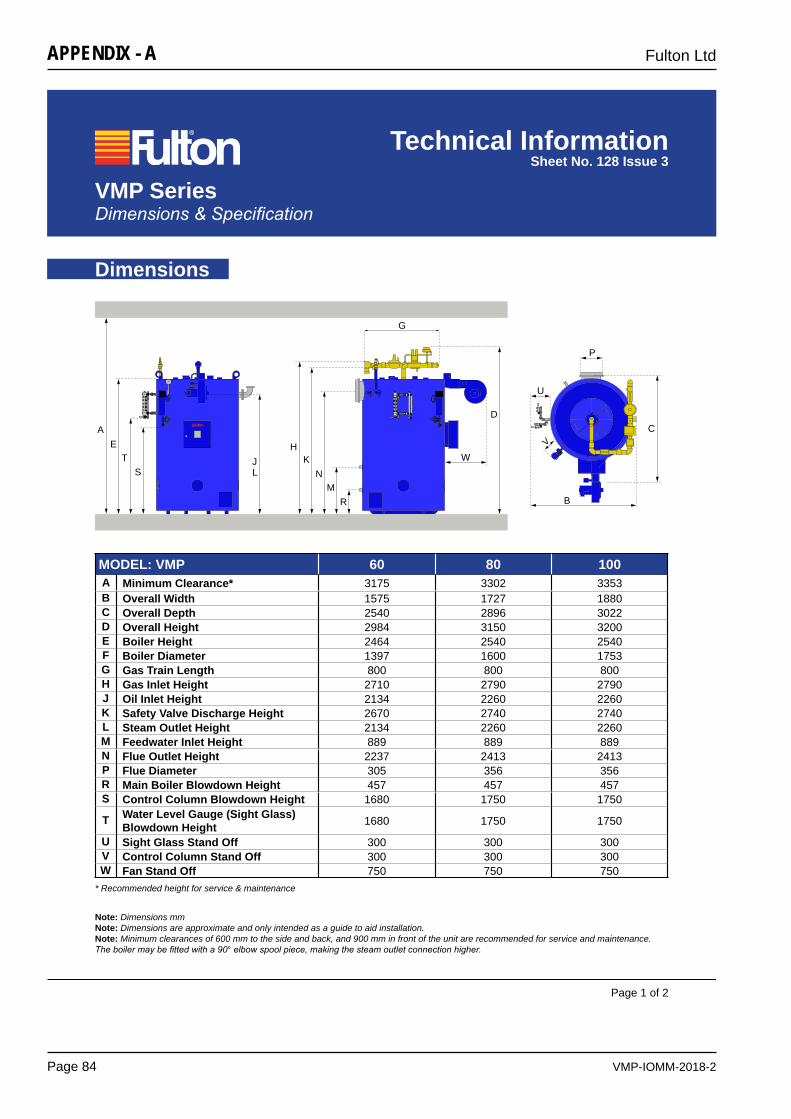
VMP-IOMM-2018-2
Fulton Ltd
Page 84
APPENDIX - A
VMP Series Dimensions & Specification
Technical InformationSheet No. 128 Issue 3
Dimensions
Page 1 of 2
AE
TS L
KN
MR
G
W
D
U
V
B
C
P
JH
* Recommended height for service & maintenance
Note: Dimensions mmNote: Dimensions are approximate and only intended as a guide to aid installation.Note: Minimum clearances of 600 mm to the side and back, and 900 mm in front of the unit are recommended for service and maintenance.The boiler may be fitted with a 90° elbow spool piece, making the steam outlet connection higher.
MODEL: VMP 60 80 100A Minimum Clearance* 3175 3302 3353B Overall Width 1575 1727 1880C Overall Depth 2540 2896 3022D Overall Height 2984 3150 3200E Boiler Height 2464 2540 2540F Boiler Diameter 1397 1600 1753G Gas Train Length 800 800 800H Gas Inlet Height 2710 2790 2790J Oil Inlet Height 2134 2260 2260K Safety Valve Discharge Height 2670 2740 2740L Steam Outlet Height 2134 2260 2260M Feedwater Inlet Height 889 889 889N Flue Outlet Height 2237 2413 2413P Flue Diameter 305 356 356R Main Boiler Blowdown Height 457 457 457S Control Column Blowdown Height 1680 1750 1750
T Water Level Gauge (Sight Glass) Blowdown Height 1680 1750 1750
U Sight Glass Stand Off 300 300 300V Control Column Stand Off 300 300 300W Fan Stand Off 750 750 750
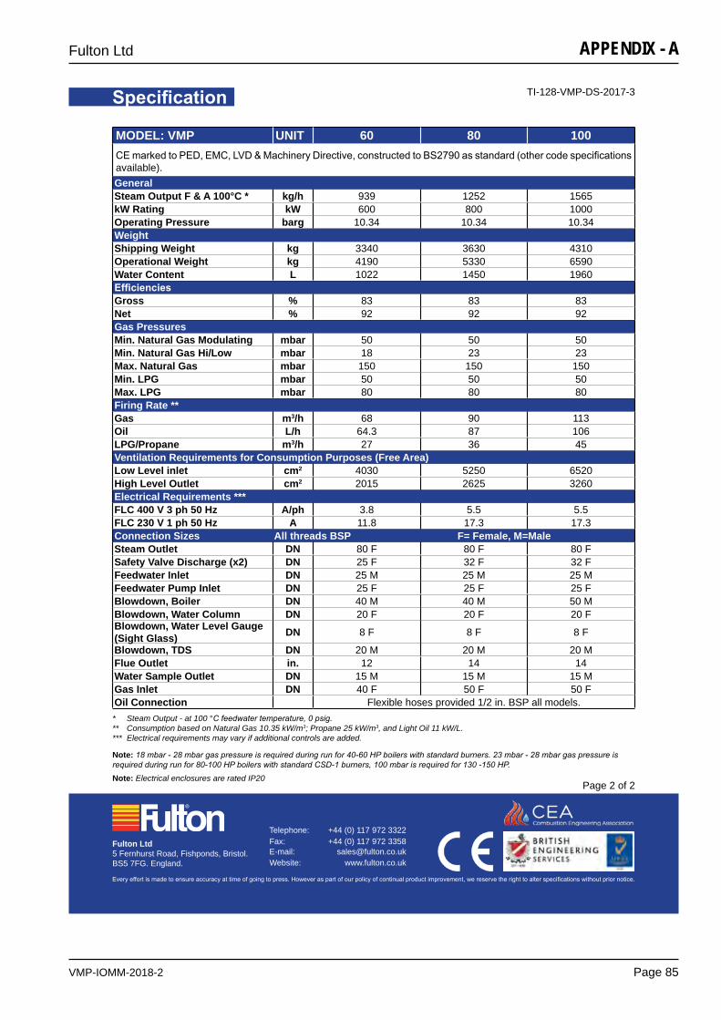
VMP-IOMM-2018-2
Fulton Ltd
Page 85
APPENDIX - A
Specification TI-128-VMP-DS-2017-3
Page 2 of 2
Every effort is made to ensure accuracy at time of going to press. However as part of our policy of continual product improvement, we reserve the right to alter specifications without prior notice.
Telephone: +44 (0) 117 972 3322 Fax: +44 (0) 117 972 3358 E-mail: [email protected] Website: www.fulton.co.uk
Fulton Ltd5 Fernhurst Road, Fishponds, Bristol.BS5 7FG. England.
MODEL: VMP UNIT 60 80 100CE marked to PED, EMC, LVD & Machinery Directive, constructed to BS2790 as standard (other code specifications available).GeneralSteam Output F & A 100°C * kg/h 939 1252 1565kW Rating kW 600 800 1000Operating Pressure barg 10.34 10.34 10.34WeightShipping Weight kg 3340 3630 4310Operational Weight kg 4190 5330 6590Water Content L 1022 1450 1960EfficienciesGross % 83 83 83Net % 92 92 92Gas PressuresMin. Natural Gas Modulating mbar 50 50 50Min. Natural Gas Hi/Low mbar 18 23 23Max. Natural Gas mbar 150 150 150Min. LPG mbar 50 50 50Max. LPG mbar 80 80 80Firing Rate **Gas m3/h 68 90 113Oil L/h 64.3 87 106LPG/Propane m3/h 27 36 45Ventilation Requirements for Consumption Purposes (Free Area)Low Level inlet cm2 4030 5250 6520High Level Outlet cm2 2015 2625 3260Electrical Requirements ***FLC 400 V 3 ph 50 Hz A/ph 3.8 5.5 5.5FLC 230 V 1 ph 50 Hz A 11.8 17.3 17.3Connection Sizes All threads BSP F= Female, M=MaleSteam Outlet DN 80 F 80 F 80 FSafety Valve Discharge (x2) DN 25 F 32 F 32 FFeedwater Inlet DN 25 M 25 M 25 MFeedwater Pump Inlet DN 25 F 25 F 25 FBlowdown, Boiler DN 40 M 40 M 50 MBlowdown, Water Column DN 20 F 20 F 20 FBlowdown, Water Level Gauge (Sight Glass) DN 8 F 8 F 8 F
Blowdown, TDS DN 20 M 20 M 20 MFlue Outlet in. 12 14 14Water Sample Outlet DN 15 M 15 M 15 MGas Inlet DN 40 F 50 F 50 FOil Connection Flexible hoses provided 1/2 in. BSP all models.* Steam Output - at 100 °C feedwater temperature, 0 psig. ** Consumption based on Natural Gas 10.35 kW/m3; Propane 25 kW/m3, and Light Oil 11 kW/L. *** Electrical requirements may vary if additional controls are added.
Note: 18 mbar - 28 mbar gas pressure is required during run for 40-60 HP boilers with standard burners. 23 mbar - 28 mbar gas pressure is required during run for 80-100 HP boilers with standard CSD-1 burners, 100 mbar is required for 130 -150 HP.Note: Electrical enclosures are rated IP20
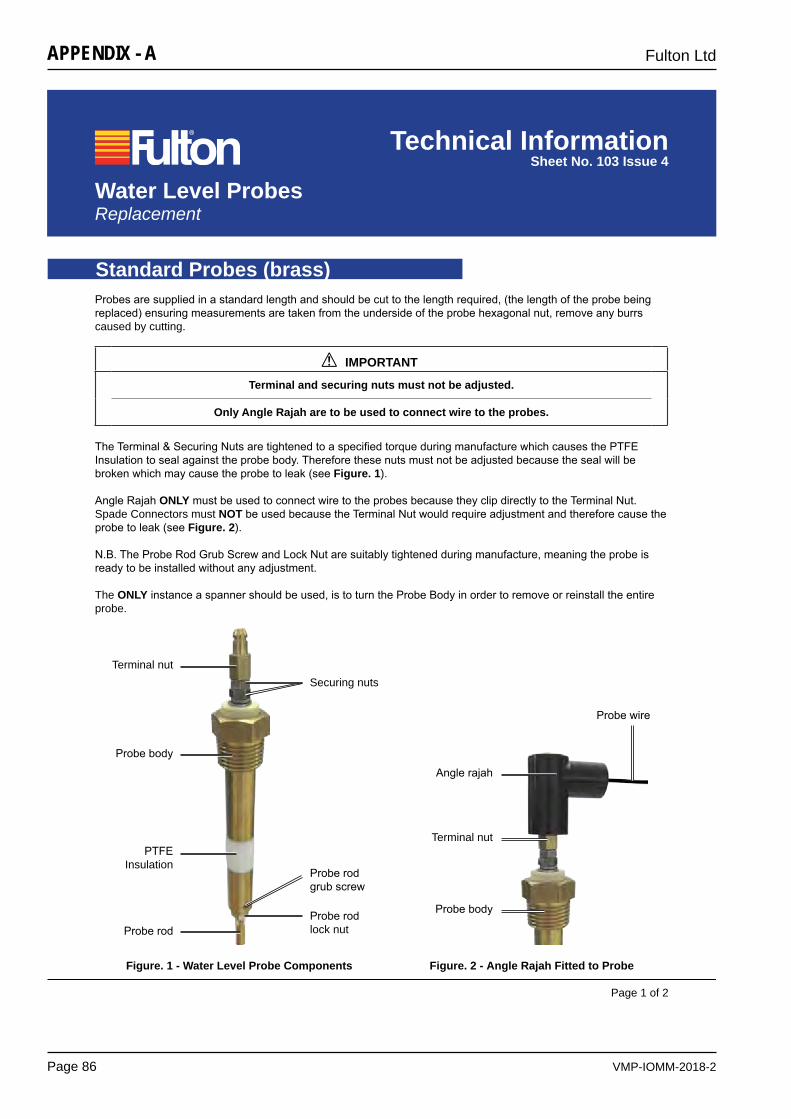
VMP-IOMM-2018-2
Fulton Ltd
Page 86
APPENDIX - A
Water Level Probes Replacement
Technical InformationSheet No. 103 Issue 4
Page 1 of 2
Standard Probes (brass)
The Terminal & Securing Nuts are tightened to a specified torque during manufacture which causes the PTFE Insulation to seal against the probe body. Therefore these nuts must not be adjusted because the seal will be broken which may cause the probe to leak (see Figure. 1).
Angle Rajah ONLY must be used to connect wire to the probes because they clip directly to the Terminal Nut. Spade Connectors must NOT be used because the Terminal Nut would require adjustment and therefore cause the probe to leak (see Figure. 2).
N.B. The Probe Rod Grub Screw and Lock Nut are suitably tightened during manufacture, meaning the probe is ready to be installed without any adjustment.
The ONLY instance a spanner should be used, is to turn the Probe Body in order to remove or reinstall the entire probe.
IMPORTANT
Terminal and securing nuts must not be adjusted.
Only Angle Rajah are to be used to connect wire to the probes.
!
Terminal nut
Probe body
Probe rod
Securing nuts
PTFEInsulation
Probe rodgrub screw
Probe rodlock nut
Terminal nut
Angle rajah
Probe body
Probe wire
Probes are supplied in a standard length and should be cut to the length required, (the length of the probe being replaced) ensuring measurements are taken from the underside of the probe hexagonal nut, remove any burrs caused by cutting.
Figure. 1 - Water Level Probe Components Figure. 2 - Angle Rajah Fitted to Probe
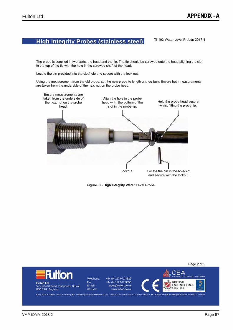
VMP-IOMM-2018-2
Fulton Ltd
Page 87
APPENDIX - A
High Integrity Probes (stainless steel) TI-103-Water Level Probes-2017-4
Page 2 of 2
Every effort is made to ensure accuracy at time of going to press. However as part of our policy of continual product improvement, we reserve the right to alter specifications without prior notice.
Telephone: +44 (0) 117 972 3322 Fax: +44 (0) 117 972 3358 E-mail: [email protected] Website: www.fulton.co.uk
Fulton Ltd5 Fernhurst Road, Fishponds, Bristol.BS5 7FG. England.
The probe is supplied in two parts, the head and the tip. The tip should be screwed onto the head aligning the slot in the top of the tip with the hole in the screwed shaft of the head.
Locate the pin provided into the slot/hole and secure with the lock nut.
Using the measurement from the old probe, cut the new probe to length and de-burr. Ensure both measurements are taken from the underside of the hex. nut on the probe head.
Figure. 3 - High Integrity Water Level Probe
Ensure measurements are taken from the underside of the hex. nut on the probe
head.
Align the hole in the probe head with the bottom of the
slot in the probe tip. Hold the probe head secure whilst fitting the probe tip.
Locknut Locate the pin in the hole/slot and secure with the locknut.
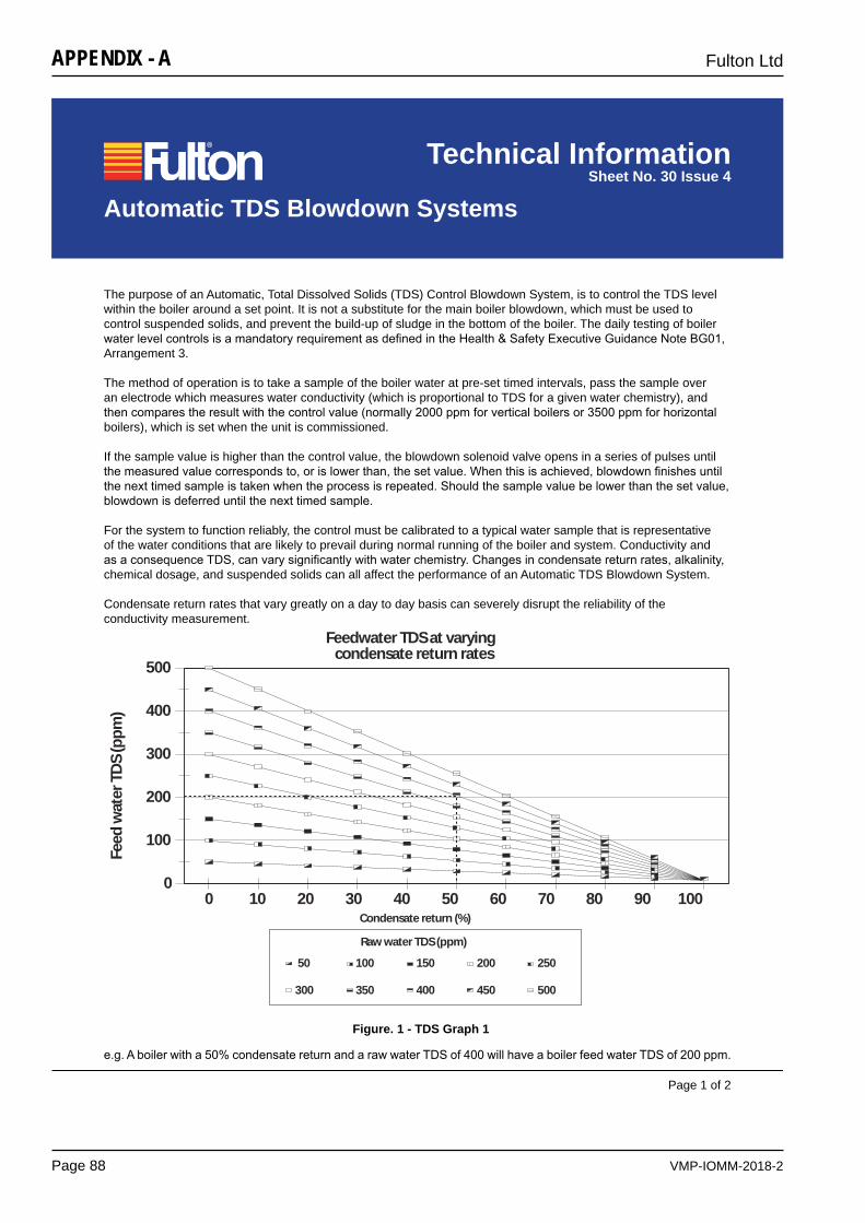
VMP-IOMM-2018-2
Fulton Ltd
Page 88
APPENDIX - A
Technical InformationSheet No. 30 Issue 4
Page 1 of 2
Automatic TDS Blowdown Systems
The purpose of an Automatic, Total Dissolved Solids (TDS) Control Blowdown System, is to control the TDS level within the boiler around a set point. It is not a substitute for the main boiler blowdown, which must be used to control suspended solids, and prevent the build-up of sludge in the bottom of the boiler. The daily testing of boiler water level controls is a mandatory requirement as defined in the Health & Safety Executive Guidance Note BG01, Arrangement 3.
The method of operation is to take a sample of the boiler water at pre-set timed intervals, pass the sample over an electrode which measures water conductivity (which is proportional to TDS for a given water chemistry), and then compares the result with the control value (normally 2000 ppm for vertical boilers or 3500 ppm for horizontal boilers), which is set when the unit is commissioned.
If the sample value is higher than the control value, the blowdown solenoid valve opens in a series of pulses until the measured value corresponds to, or is lower than, the set value. When this is achieved, blowdown finishes until the next timed sample is taken when the process is repeated. Should the sample value be lower than the set value, blowdown is deferred until the next timed sample.
For the system to function reliably, the control must be calibrated to a typical water sample that is representative of the water conditions that are likely to prevail during normal running of the boiler and system. Conductivity and as a consequence TDS, can vary significantly with water chemistry. Changes in condensate return rates, alkalinity, chemical dosage, and suspended solids can all affect the performance of an Automatic TDS Blowdown System.
Condensate return rates that vary greatly on a day to day basis can severely disrupt the reliability of the conductivity measurement.
500
400
300
200
100
00 10 20 30 40 50 60 70 80 90 100
Feedwater TDS at varying condensate return rates
Condensate return (%)
Raw water TDS (ppm)
50
300
100
350
150
400
200
450
250
500
Feed
wat
er T
DS
(ppm
)
e.g. A boiler with a 50% condensate return and a raw water TDS of 400 will have a boiler feed water TDS of 200 ppm.
Figure. 1 - TDS Graph 1
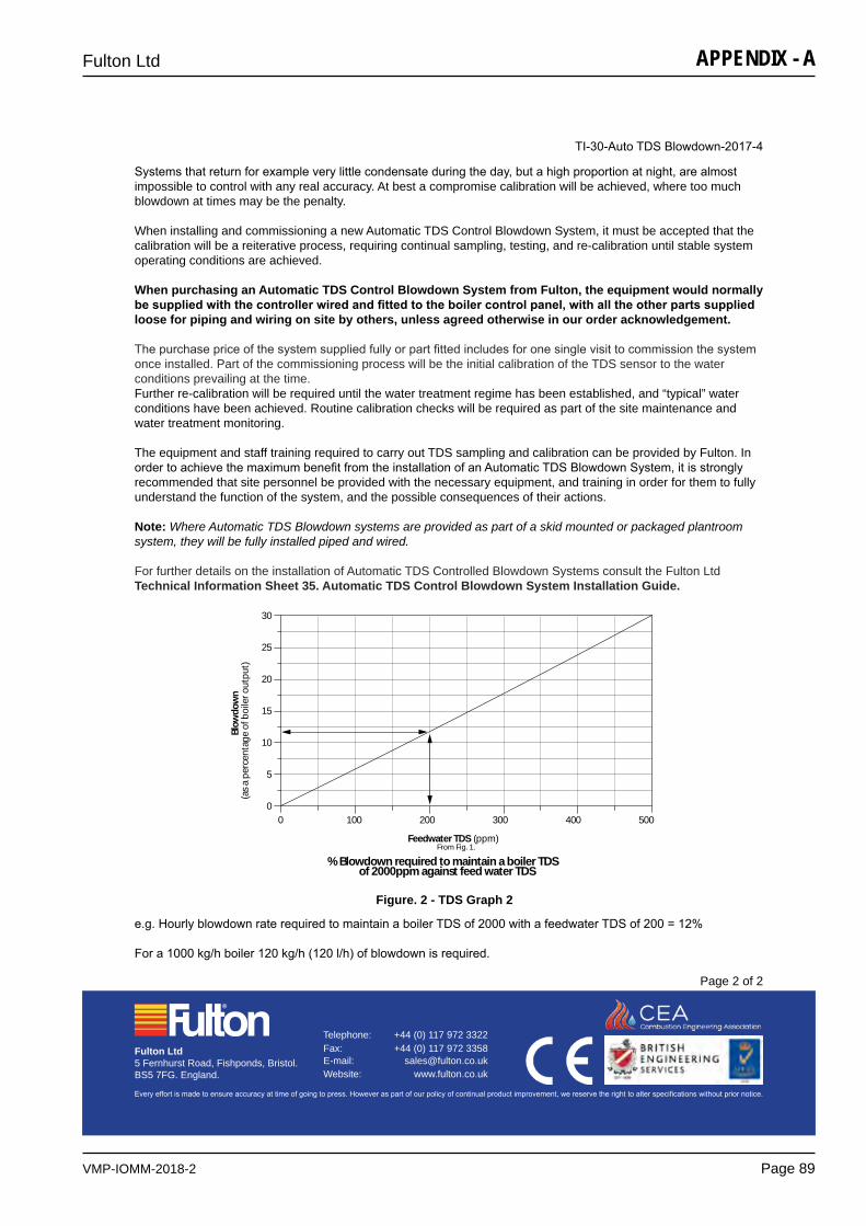
VMP-IOMM-2018-2
Fulton Ltd
Page 89
APPENDIX - A
TI-30-Auto TDS Blowdown-2017-4
Page 2 of 2
Every effort is made to ensure accuracy at time of going to press. However as part of our policy of continual product improvement, we reserve the right to alter specifications without prior notice.
Telephone: +44 (0) 117 972 3322 Fax: +44 (0) 117 972 3358 E-mail: [email protected] Website: www.fulton.co.uk
Fulton Ltd5 Fernhurst Road, Fishponds, Bristol.BS5 7FG. England.
e.g. Hourly blowdown rate required to maintain a boiler TDS of 2000 with a feedwater TDS of 200 = 12%
For a 1000 kg/h boiler 120 kg/h (120 l/h) of blowdown is required.
Figure. 2 - TDS Graph 2
30
25
20
15
10
5
00 100 200 300 400 500
% Blowdown required to maintain a boiler TDS of 2000ppm against feed water TDS
Feedwater TDS (ppm)From Fig. 1.
Blow
dow
n(a
s a
perc
enta
ge o
f boi
ler o
utpu
t)
Systems that return for example very little condensate during the day, but a high proportion at night, are almost impossible to control with any real accuracy. At best a compromise calibration will be achieved, where too much blowdown at times may be the penalty.
When installing and commissioning a new Automatic TDS Control Blowdown System, it must be accepted that the calibration will be a reiterative process, requiring continual sampling, testing, and re-calibration until stable system operating conditions are achieved.
When purchasing an Automatic TDS Control Blowdown System from Fulton, the equipment would normally be supplied with the controller wired and fitted to the boiler control panel, with all the other parts supplied loose for piping and wiring on site by others, unless agreed otherwise in our order acknowledgement.
The purchase price of the system supplied fully or part fitted includes for one single visit to commission the system once installed. Part of the commissioning process will be the initial calibration of the TDS sensor to the water conditions prevailing at the time. Further re-calibration will be required until the water treatment regime has been established, and “typical” water conditions have been achieved. Routine calibration checks will be required as part of the site maintenance and water treatment monitoring.
The equipment and staff training required to carry out TDS sampling and calibration can be provided by Fulton. In order to achieve the maximum benefit from the installation of an Automatic TDS Blowdown System, it is strongly recommended that site personnel be provided with the necessary equipment, and training in order for them to fully understand the function of the system, and the possible consequences of their actions.
Note: Where Automatic TDS Blowdown systems are provided as part of a skid mounted or packaged plantroom system, they will be fully installed piped and wired.
For further details on the installation of Automatic TDS Controlled Blowdown Systems consult the Fulton Ltd Technical Information Sheet 35. Automatic TDS Control Blowdown System Installation Guide.
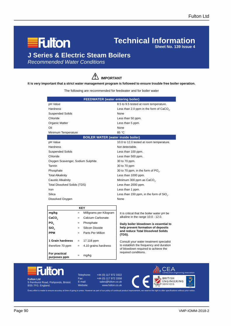
VMP-IOMM-2018-2
Fulton Ltd
Page 90
J Series & Electric Steam Boilers Recommended Water Conditions
Technical InformationSheet No. 139 Issue 4
Every effort is made to ensure accuracy at time of going to press. However as part of our policy of continual product improvement, we reserve the right to alter specifications without prior notice.
Telephone: +44 (0) 117 972 3322 Fax: +44 (0) 117 972 3358 E-mail: [email protected] Website: www.fulton.co.uk
Fulton Ltd5 Fernhurst Road, Fishponds, Bristol.BS5 7FG. England.
IMPORTANTIt is very important that a strict water management program is followed to ensure trouble free boiler operation.
The following are recommended for feedwater and for boiler water
FEEDWATER (water entering boiler)pH Value 8.5 to 9.5 tested at room temperature.Hardness Less than 2.0 ppm in the form of CaCO3.Suspended Solids NoneChloride Less than 50 ppm.Organic Matter Less than 5 ppm.Oil NoneMinimum Temperature 85 °C
BOILER WATER (water inside boiler)pH Value 10.0 to 12.0 tested at room temperature.Hardness Not detectable.Suspended Solids Less than 100 ppm.Chloride Less than 500 ppm.Oxygen Scavenger, Sodium Sulphite 30 to 70 ppm.Tannin 30 to 70 ppmPhosphate 30 to 70 ppm, in the form of PO4.Total Alkalinity Less than 1000 ppm.Caustic Alkalinity Minimum 300 ppm as CaCO3.Total Dissolved Solids (TDS) Less than 2000 ppm.Iron Less than 1 ppm.Silica Less than 150 ppm, in the form of SiO2.Dissolved Oxygen None
!
KEYmg/kg = Milligrams per Kilogram
CaCO3 = Calcium Carbonate
PO4 = Phosphate
SiO2 = Silicon Dioxide
PPM = Parts Per Million
1 Grain hardness = 17.118 ppm
therefore 70 ppm = 4.10 grains hardness
For practical purposes ppm = mg/kg
It is critical that the boiler water pH be alkaline in the range 10.0 - 12.0.
Daily boiler blowdown is essential to help prevent formation of deposits and reduce Total Dissolved Solids (TDS).
Consult your water treatment specialist to establish the frequency and duration of blowdown required to achieve the required conditions.
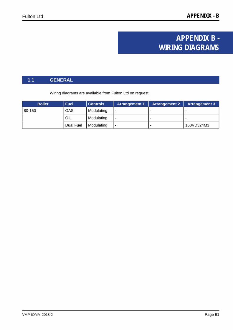
VMP-IOMM-2018-2
Fulton Ltd
Page 91
APPENDIX - B
1.1 GENERAL
APPENDIX B - WIRING DIAGRAMS
Wiring diagrams are available from Fulton Ltd on request.
Boiler Fuel Controls Arrangement 1 Arrangement 2 Arrangement 380-150 GAS Modulating - - -
OIL Modulating - - -
Dual Fuel Modulating - - 150VD324M3

VMP-IOMM-2018-2
Fulton Ltd
Page 92
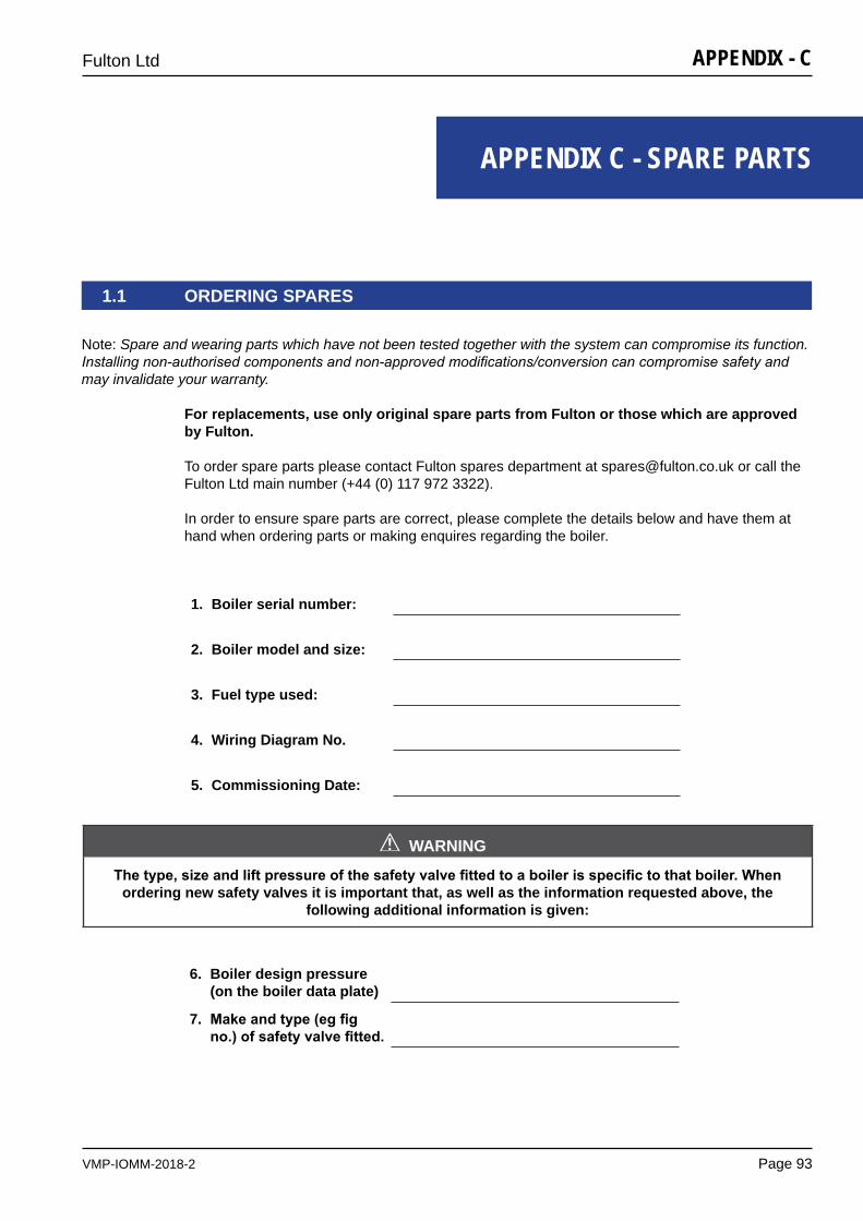
VMP-IOMM-2018-2
Fulton Ltd
Page 93
APPENDIX - C
APPENDIX C - SPARE PARTS
1.1 ORDERING SPARES
WARNING
Thetype,sizeandliftpressureofthesafetyvalvefittedtoaboilerisspecifictothatboiler.whenordering new safety valves it is important that, as well as the information requested above, the
following additional information is given:
!
1. Boiler serial number:
2. Boiler model and size:
3. Fuel type used:
4. Wiring Diagram No.
5. Commissioning Date:
6. Boiler design pressure (on the boiler data plate)
7. Makeandtype(egfigno.)ofsafetyvalvefitted.
Note: Spare and wearing parts which have not been tested together with the system can compromise its function. Installing non-authorised components and non-approved modifications/conversion can compromise safety and may invalidate your warranty.
For replacements, use only original spare parts from Fulton or those which are approved by Fulton.
To order spare parts please contact Fulton spares department at [email protected] or call the Fulton Ltd main number (+44 (0) 117 972 3322).
In order to ensure spare parts are correct, please complete the details below and have them at hand when ordering parts or making enquires regarding the boiler.

VMP-IOMM-2018-2
Fulton Ltd
Page 94
APPENDIX - C

VMP-IOMM-2018-2
Fulton Ltd
Page 95
APPENDIX - D
APPENDIX D - SPIRAX HIGH INTEGRITY LEVEL CONTROLS
CONTINUED ON NEXT PAGE
1.1 DAILY TESTS
ThedailytestingofboilerwaterlevelcontrolsisamandatoryrequirementasdefinedintheHealth& Safety Executive Guidance Note BG01, Arrangements 2 and 3.Thelevelofsupervisionisdependentuponthetypeoflevelcontrols(limiters)fitted.Boilersfittedwithselfmonitoringhighintegritycontrols(limiters)shouldbetesteddailybyaqualifiedboilerattendant,butmaybesupervisedduringthesilenthoursandweekendsbya competent person trained to respond to an alarm.
Daily testing of the controls is required which can be by simulation, with a weekly test by interrupting the feedwater pump and lowering the water by evaporation.
1.1.1 LOW WATER DAILY
withtheburnerfiring:
1. Press and hold the Low Water test button for 5 - 6 seconds, the Low Water alarm sounds, Low Water indicator lamp and Low Water Reset switch illuminates, and the burner shuts down.
2. Release the test button.
3. After approximately 17 seconds the Low Water Relay will reset.
4. To cancel the Low Water level alarm and light, depress the Low Water Reset switch.
The burner will restart.
VMP-IOMM-2018-2
Fulton Ltd
Page 96
APPENDIX - D
1.2 WEEKLY TEST IN ADDITION
1.2.1 LOW WATER WEEKLY IN ADDITION
withtheburnerfiring:
1. Switch the Pump switch to the Pump OFF position.
2. By evaporation, lower the water level in the boiler until the Low Water alarm sounds, the Low Water Reset buttons illuminate, and the burner shuts down.
3. Switch the Pump switch to the ON position.
4. The pump will start and restore the water level to the normal position and switch off.
5. After approximately 17 seconds from restoring the Low Water level the Low Water Relay can be reset.
6. To cancel the Low Water Level alarm and light, press the Low Water Reset button.
The burner will restart.
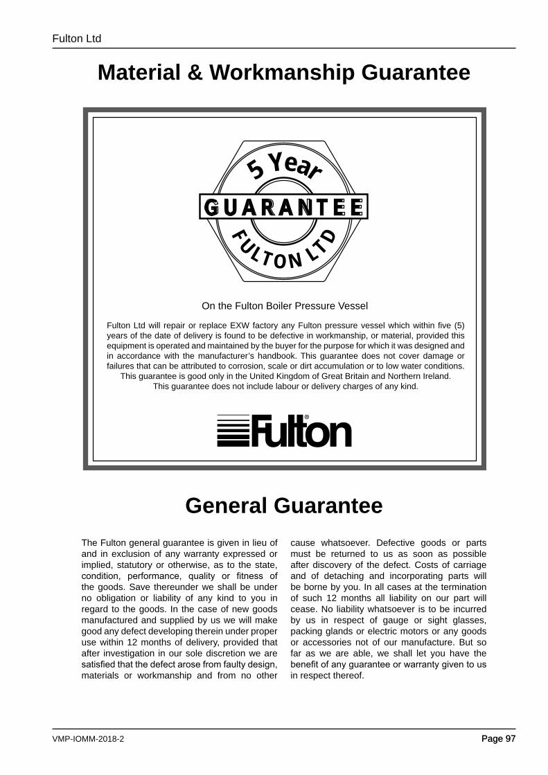
VMP-IOMM-2018-2
Fulton Ltd
Page 97Page 97
Material & Workmanship Guarantee
General GuaranteeThe Fulton general guarantee is given in lieu of and in exclusion of any warranty expressed or implied, statutory or otherwise, as to the state, condition, performance, quality or fitness ofthe goods. Save thereunder we shall be under no obligation or liability of any kind to you in regard to the goods. In the case of new goods manufactured and supplied by us we will make good any defect developing therein under proper use within 12 months of delivery, provided that after investigation in our sole discretion we are satisfiedthatthedefectarosefromfaultydesign,materials or workmanship and from no other
cause whatsoever. Defective goods or parts must be returned to us as soon as possible after discovery of the defect. Costs of carriage and of detaching and incorporating parts will be borne by you. In all cases at the termination of such 12 months all liability on our part will cease. No liability whatsoever is to be incurred by us in respect of gauge or sight glasses, packing glands or electric motors or any goods or accessories not of our manufacture. But so far as we are able, we shall let you have the benefitofanyguaranteeorwarrantygiventousin respect thereof.
On the Fulton Boiler Pressure Vessel
Fulton Ltd will repair or replace EXW factory any Fulton pressure vessel which within five (5) years of the date of delivery is found to be defective in workmanship, or material, provided this equipment is operated and maintained by the buyer for the purpose for which it was designed and in accordance with the manufacturer’s handbook. This guarantee does not cover damage or failures that can be attributed to corrosion, scale or dirt accumulation or to low water conditions.
This guarantee is good only in the United Kingdom of Great Britain and Northern Ireland. This guarantee does not include labour or delivery charges of any kind.
FU LT O N LT D
5 YearG U A R A N T E E

www.fulton.co.uk
VMP-IOMM-2018-2
Fulton Ltd5 Fernhurst RoadFishpondsBristol BS5 7FGEngland
Telephone: +44 (0) 117 972 3322Fax: +44 (0) 117 972 3358Email: [email protected] BS EN ISO 9001:2015 Company Registration 855790 England