frr_owner_manual.pdf - isuzu vietnam
TRANSCRIPT
The following symbols are also used in this manual.• V : Market-/type-specific equipment (Your vehicle may not have the equipment
with this symbol.)• M/T : Manual transmission vehicle• A/T : Automatic transmission vehicle• SA : Vehicle equipped with the Smoother system• AHB : Vehicle equipped with the air-over hydraulic brake system• FAB : Vehicle equipped with the full-air brake system
Symbols Used in This Manual
DANGER
Failure to follow these instructions identified by this symbol could result in death or serious injury to you and/or other people.
WARNING
Failure to follow these instructions identified by this symbol could result in a fire inside your vehicle in addition to death or serious injury to you and/or other people.
CAUTIONFailure to follow these instructions identified by this symbol could result in injuries or an accident.
ADVICEFailure to follow these instructions identified by this symbol could cause malfunction or damage to your vehicle.
NOTEThis symbol identifies information that you need to know.This symbol also identifies information that would be useful for operating the vehicle.
4608498_sec00_PICTORIAL INDEX.in1 14608498_sec00_PICTORIAL INDEX.in1 1 2015/11/02 13:52:072015/11/02 13:52:07
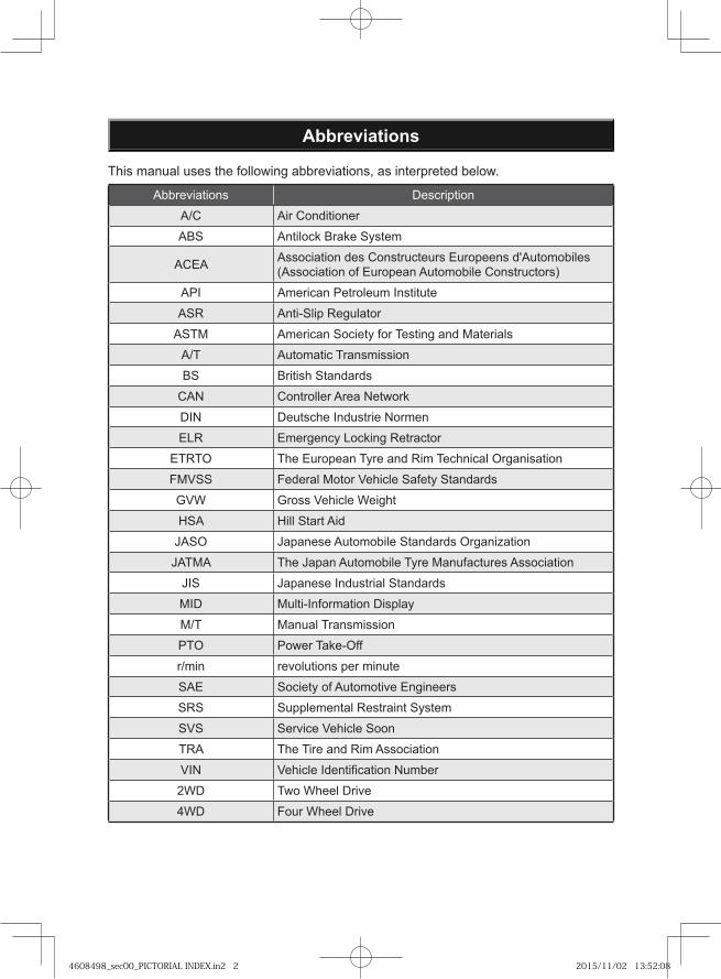
Abbreviations
This manual uses the following abbreviations, as interpreted below.
Abbreviations Description
A/C Air Conditioner
ABS Antilock Brake System
ACEA Association des Constructeurs Europeens d'Automobiles (Association of European Automobile Constructors)
API American Petroleum Institute
ASR Anti-Slip Regulator
ASTM American Society for Testing and Materials
A/T Automatic Transmission
BS British Standards
CAN Controller Area Network
DIN Deutsche Industrie Normen
ELR Emergency Locking Retractor
ETRTO The European Tyre and Rim Technical Organisation
FMVSS Federal Motor Vehicle Safety Standards
GVW Gross Vehicle Weight
HSA Hill Start Aid
JASO Japanese Automobile Standards Organization
JATMA The Japan Automobile Tyre Manufactures Association
JIS Japanese Industrial Standards
MID Multi-Information Display
M/T Manual Transmission
PTO Power Take-Off
r/min revolutions per minute
SAE Society of Automotive Engineers
SRS Supplemental Restraint System
SVS Service Vehicle Soon
TRA The Tire and Rim Association
VIN Vehicle Identification Number
2WD Two Wheel Drive
4WD Four Wheel Drive
4608498_sec00_PICTORIAL INDEX.in2 24608498_sec00_PICTORIAL INDEX.in2 2 2015/11/02 13:52:082015/11/02 13:52:08
HOW TO USE THIS MANUAL AND HOW TO FIND A SPECIFIC TOPIC
● HOW TO USE THIS MANUAL 0-2
● HOW TO FIND A SPECIFIC TOPIC 0-3
● CHAPTERS IN THIS MANUAL 0-5
● PICTORIAL INDEX 0-6
● WARNING/INDICATOR LIGHT INDEX 0-15
● WARNING/CAUTION LABELS 0-21
0
4608498_sec00_PICTORIAL INDEX.in0-1 0-14608498_sec00_PICTORIAL INDEX.in0-1 0-1 2015/11/02 13:52:092015/11/02 13:52:09
0-2
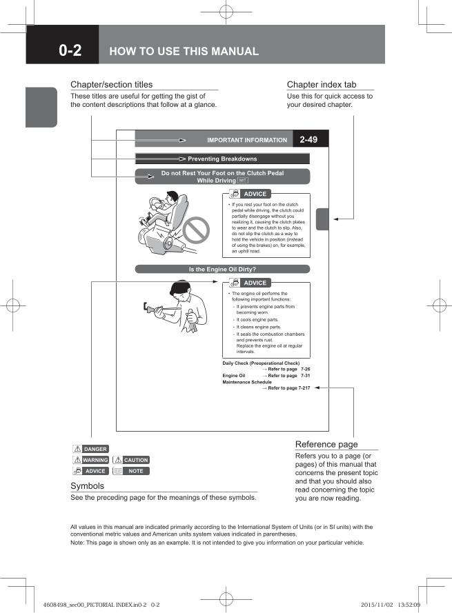
2-49IMPORTANT INFORMATION
Daily Check (Preoperational Check) → Refer to page 7-26
Engine Oil → Refer to page 7-31Maintenance Schedule
→ Refer to page 7-217
Is the Engine Oil Dirty?
ADVICEThe engine oil performs the following important functions:
It prevents engine parts from becoming worn.It cools engine parts.It cleans engine parts.It seals the combustion chambers and prevents rust.Replace the engine oil at regular intervals.
•
-
---
Preventing Breakdowns
ADVICEIf you rest your foot on the clutch pedal while driving, the clutch could partially disengage without you realizing it, causing the clutch plates to wear and the clutch to slip. Also,do not slip the clutch as a way to hold the vehicle in position (instead of using the brakes) on, for example,an uphill road.
•
Do not Rest Your Foot on the Clutch Pedal While Driving M/T
SymbolsSee the preceding page for the meanings of these symbols.
Reference page
ADVICE
WARNING
NOTE
CAUTION
DANGER
Note: This page is shown only as an example. It is not intended to give you information on your particular vehicle.
Refers you to a page (or pages) of this manual that concerns the present topic and that you should also read concerning the topic you are now reading.
All values in this manual are indicated primarily according to the International System of Units (or in SI units) with the conventional metric values and American units system values indicated in parentheses.
Chapter/section titles Chapter index tabUse this for quick access to your desired chapter.
These titles are useful for getting the gist of the content descriptions that follow at a glance.
HOW TO USE THIS MANUAL
4608498_sec00_PICTORIAL INDEX.in0-2 0-24608498_sec00_PICTORIAL INDEX.in0-2 0-2 2015/11/02 13:52:092015/11/02 13:52:09
0-3
Use chapter/section titles as keys Page 0-5
Search for the page describing the specific topic by using the general table of contents under CHAPTERS IN THIS MANUAL, the CHAPTER INDEX, and/or the TABLE OF CONTENTS on the first page of each chapter.
Use the pictorial indexes Pages 0-6 to 0-14
PICTORIAL INDEXIf you don't know the name of the switch or other device for which you need information, locate the page describing it by using the pictorial indexes.
Use device names as keys Pages 10-1 to 10-4
INDEXIf you know the name of the switch or other device for which you need information, locate the page describing it by using the Index at the end of this manual.
Use the Warning/Indicator Light Index
Pages 0-15 to 0-20WARNING/INDICATOR LIGHT INDEXIf a warning or indicator light is illuminated, you can use the WARNING/INDICATOR LIGHT INDEX to f ind the page that provides information on the light.
If you have a problem with your vehicle
Pages 8-2 to 8-80IN CASE OF EMERGENCY
HOW TO FIND A SPECIFIC TOPIC
4608498_sec00_PICTORIAL INDEX.in0-3 0-34608498_sec00_PICTORIAL INDEX.in0-3 0-3 2015/11/02 13:52:092015/11/02 13:52:09
0-4
4608498_sec00_PICTORIAL INDEX.in0-4 0-44608498_sec00_PICTORIAL INDEX.in0-4 0-4 2015/11/02 13:52:092015/11/02 13:52:09
0-5
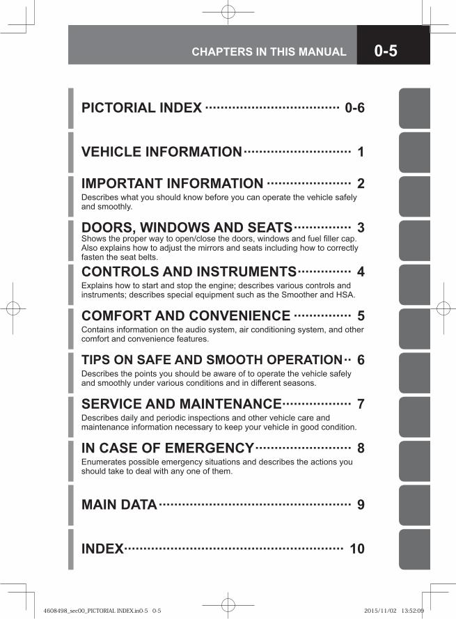
VEHICLE INFORMATION ···························· 1
IMPORTANT INFORMATION ······················ 2Describes what you should know before you can operate the vehicle safely and smoothly.
DOORS, WINDOWS AND SEATS ··············· 3Shows the proper way to open/close the doors, windows and fuel filler cap. Also explains how to adjust the mirrors and seats including how to correctly fasten the seat belts.
CONTROLS AND INSTRUMENTS ·············· 4Explains how to start and stop the engine; describes various controls and instruments; describes special equipment such as the Smoother and HSA.
COMFORT AND CONVENIENCE ··············· 5Contains information on the audio system, air conditioning system, and other comfort and convenience features.
TIPS ON SAFE AND SMOOTH OPERATION ·· 6Describes the points you should be aware of to operate the vehicle safely and smoothly under various conditions and in different seasons.
SERVICE AND MAINTENANCE ·················· 7Describes daily and periodic inspections and other vehicle care and maintenance information necessary to keep your vehicle in good condition.
MAIN DATA ·················································· 9
INDEX························································· 10
PICTORIAL INDEX ··································· 0-6
IN CASE OF EMERGENCY ························· 8Enumerates possible emergency situations and describes the actions you should take to deal with any one of them.
CHAPTERS IN THIS MANUAL
4608498_sec00_PICTORIAL INDEX.in0-5 0-54608498_sec00_PICTORIAL INDEX.in0-5 0-5 2015/11/02 13:52:092015/11/02 13:52:09
0-6 PICTORIAL INDEX
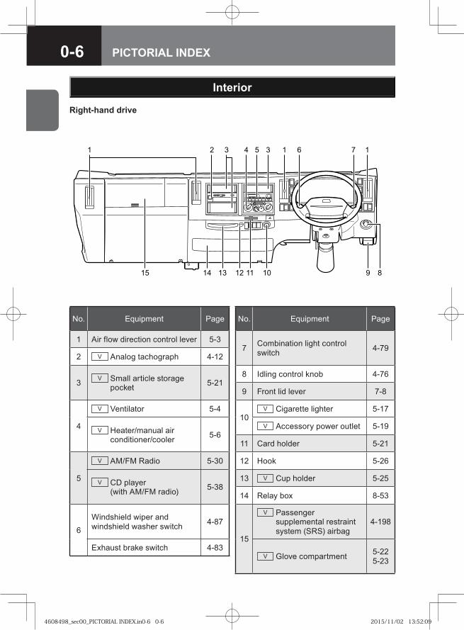
Interior
� �� � � � �
� �� �� ��� �� � �
No. Equipment Page
1 Air flow direction control lever 5-3
2 V Analog tachograph 4-12
3 V Small article storage pocket 5-21
4
V Ventilator 5-4
V Heater/manual air conditioner/cooler 5-6
5
V AM/FM Radio 5-30
V CD player (with AM/FM radio) 5-38
6Windshield wiper and windshield washer switch 4-87
Exhaust brake switch 4-83
No. Equipment Page
7 Combination light control switch 4-79
8 Idling control knob 4-76
9 Front lid lever 7-8
10V Cigarette lighter 5-17
V Accessory power outlet 5-19
11 Card holder 5-21
12 Hook 5-26
13 V Cup holder 5-25
14 Relay box 8-53
15
V Passenger supplemental restraint system (SRS) airbag
4-198
V Glove compartment 5-225-23
Right-hand drive
4608498_sec00_PICTORIAL INDEX.in0-6 0-64608498_sec00_PICTORIAL INDEX.in0-6 0-6 2015/11/02 13:52:092015/11/02 13:52:09
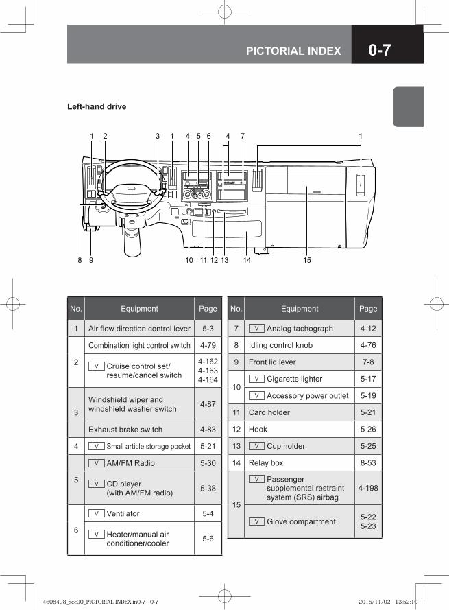
0-7PICTORIAL INDEX
�� ���� �
���� �� ������
No. Equipment Page
1 Air flow direction control lever 5-3
2
Combination light control switch 4-79
V Cruise control set/resume/cancel switch
4-1624-1634-164
3
Windshield wiper and windshield washer switch 4-87
Exhaust brake switch 4-83
4 V Small article storage pocket 5-21
5
V AM/FM Radio 5-30
V CD player (with AM/FM radio) 5-38
6
V Ventilator 5-4
V Heater/manual air conditioner/cooler 5-6
No. Equipment Page
7 V Analog tachograph 4-12
8 Idling control knob 4-76
9 Front lid lever 7-8
10V Cigarette lighter 5-17
V Accessory power outlet 5-19
11 Card holder 5-21
12 Hook 5-26
13 V Cup holder 5-25
14 Relay box 8-53
15
V Passenger supplemental restraint system (SRS) airbag
4-198
V Glove compartment 5-225-23
Left-hand drive
4608498_sec00_PICTORIAL INDEX.in0-7 0-74608498_sec00_PICTORIAL INDEX.in0-7 0-7 2015/11/02 13:52:102015/11/02 13:52:10
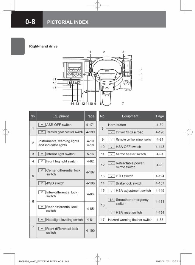
0-8 PICTORIAL INDEX
�
������
��
��
� �
�
�
�
����
No. Equipment Page
1V ASR OFF switch 4-171
V Transfer gear control switch 4-189
2 Instruments, warning lights and indicator lights
4-104-18
3 V Interior light switch 5-16
4 V Front fog light switch 4-82
5
V Center differential lock switch 4-187
V 4WD switch 4-186
6
V Inter-differential lock switch 4-86
V Rear differential lock switch 4-85
7
V Headlight leveling switch 4-81
V Front differential lock switch 4-190
No. Equipment Page
8Horn button 4-89
V Driver SRS airbag 4-198
9 V Remote control mirror switch 4-91
10 V HSA OFF switch 4-148
11 V Mirror heater switch 4-91
12 V Retractable power mirror switch 4-90
13 V PTO switch 4-194
14 V Brake lock switch 4-157
15 V HSA adjustment switch 4-149
16
SA Smoother emergency switch 4-131
V HSA reset switch 4-154
17 Hazard warning flasher switch 4-83
Right-hand drive
4608498_sec00_PICTORIAL INDEX.in0-8 0-84608498_sec00_PICTORIAL INDEX.in0-8 0-8 2015/11/02 13:52:112015/11/02 13:52:11
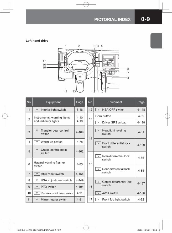
0-9PICTORIAL INDEX
Left-hand drive
6
17
14
78
12 9101113
21 3 4 5
1615
No. Equipment Page
1 V Interior light switch 5-16
2 Instruments, warning lights and indicator lights
4-104-18
3 V Transfer gear control switch 4-189
4 V Warm-up switch 4-78
5 V Cruise control main switch 4-162
6 Hazard warning flasher switch 4-83
7 V HSA reset switch 4-154
8 V HSA adjustment switch 4-149
9 V PTO switch 4-194
10 V Remote control mirror switch 4-91
11 V Mirror heater switch 4-91
No. Equipment Page
12 V HSA OFF switch 4-148
13Horn button 4-89
V Driver SRS airbag 4-198
14
V Headlight leveling switch 4-81
V Front differential lock switch 4-190
15
V Inter-differential lock switch 4-86
V Rear differential lock switch 4-85
16
V Center differential lock switch 4-187
V 4WD switch 4-186
17 V Front fog light switch 4-82
4608498_sec00_PICTORIAL INDEX.in0-9 0-94608498_sec00_PICTORIAL INDEX.in0-9 0-9 2015/11/02 13:52:132015/11/02 13:52:13
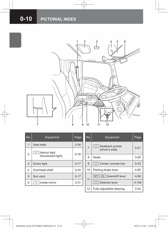
0-10 PICTORIAL INDEX
� � �
�� ���
�
���
No. Equipment Page
1 Seat belts 3-34
2 V Interior light (fluorescent light) 5-16
3 Dome light 5-17
4 Overhead shelf 5-24
5 Sun visor 5-17
6 V Inside mirror 3-31
No. Equipment Page
7 V Seatback pocket (driver's side) 5-21
8 Seats 3-20
9 V Center console box 5-23
10 Parking brake lever 4-95
11M/T SA Gearshift lever 4-99
V Selector lever 4-104
12 Fully adjustable steering 3-30
4608498_sec00_PICTORIAL INDEX.in0-10 0-104608498_sec00_PICTORIAL INDEX.in0-10 0-10 2015/11/02 13:52:152015/11/02 13:52:15
0-11PICTORIAL INDEX
1
75,6
32
4
1
8
1
75,6
32
4
8
1
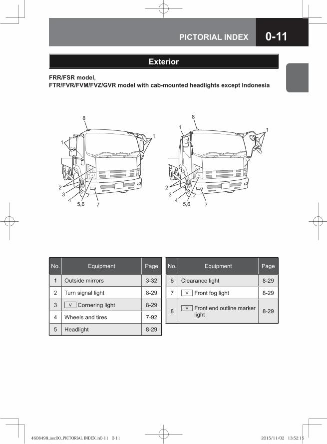
No. Equipment Page
1 Outside mirrors 3-32
2 Turn signal light 8-29
3 V Cornering light 8-29
4 Wheels and tires 7-92
5 Headlight 8-29
No. Equipment Page
6 Clearance light 8-29
7 V Front fog light 8-29
8 V Front end outline marker light 8-29
Exterior
FRR/FSR model, FTR/FVR/FVM/FVZ/GVR model with cab-mounted headlights except Indonesia
4608498_sec00_PICTORIAL INDEX.in0-11 0-114608498_sec00_PICTORIAL INDEX.in0-11 0-11 2015/11/02 13:52:152015/11/02 13:52:15
0-12 PICTORIAL INDEX
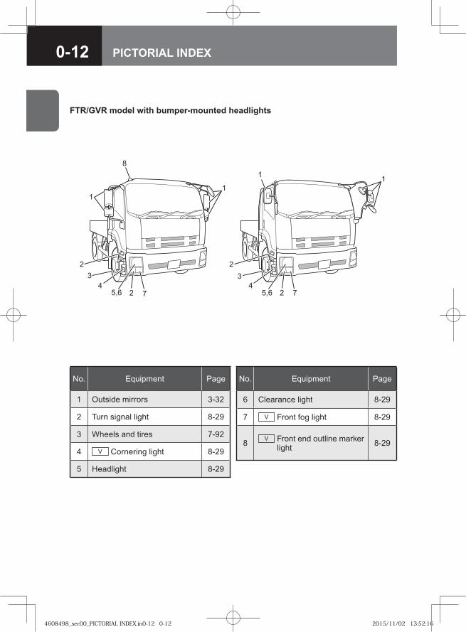
FTR/GVR model with bumper-mounted headlights
234
5,6 2 7
8
11
1
234
5,6 2 7
1
No. Equipment Page
1 Outside mirrors 3-32
2 Turn signal light 8-29
3 Wheels and tires 7-92
4 V Cornering light 8-29
5 Headlight 8-29
No. Equipment Page
6 Clearance light 8-29
7 V Front fog light 8-29
8 V Front end outline marker light 8-29
4608498_sec00_PICTORIAL INDEX.in0-12 0-124608498_sec00_PICTORIAL INDEX.in0-12 0-12 2015/11/02 13:52:162015/11/02 13:52:16
0-13PICTORIAL INDEX
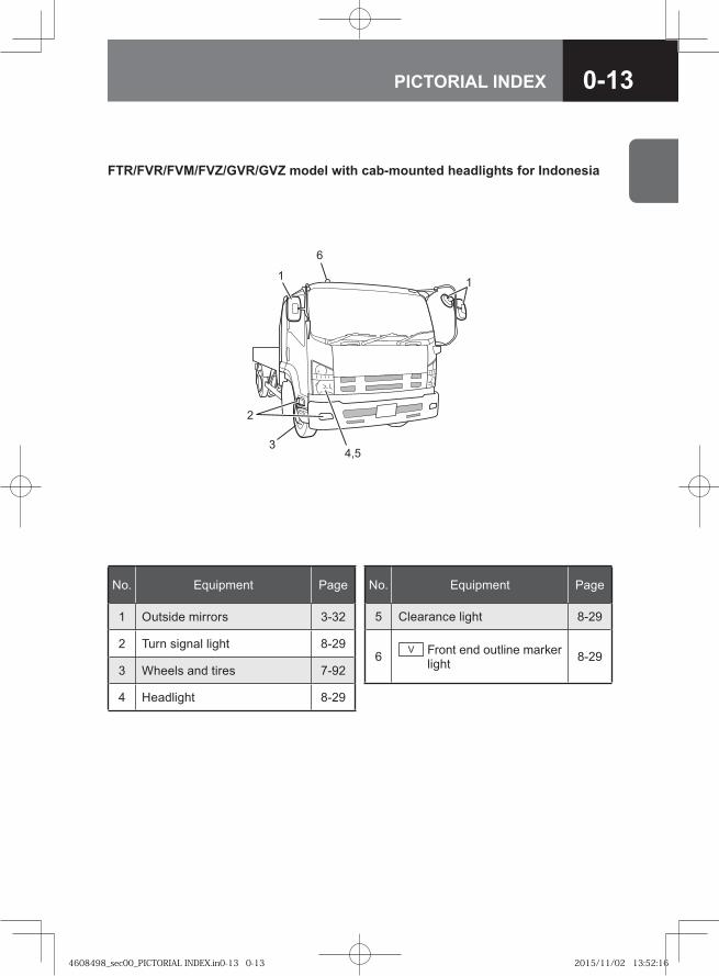
No. Equipment Page
1 Outside mirrors 3-32
2 Turn signal light 8-29
3 Wheels and tires 7-92
4 Headlight 8-29
No. Equipment Page
5 Clearance light 8-29
6 V Front end outline marker light 8-29
1
4,5
2
3
1
6
FTR/FVR/FVM/FVZ/GVR/GVZ model with cab-mounted headlights for Indonesia
4608498_sec00_PICTORIAL INDEX.in0-13 0-134608498_sec00_PICTORIAL INDEX.in0-13 0-13 2015/11/02 13:52:162015/11/02 13:52:16
0-14 PICTORIAL INDEX
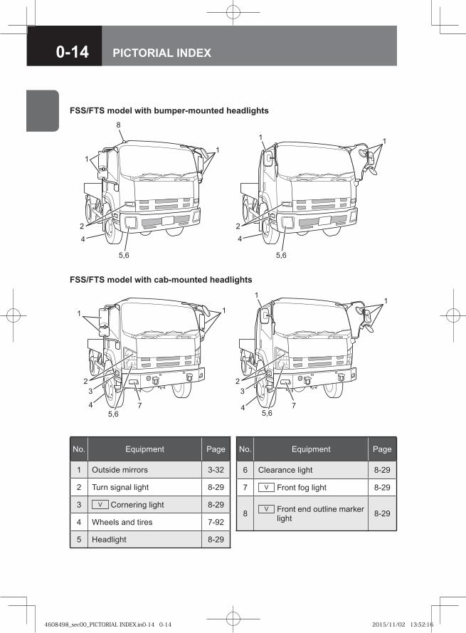
No. Equipment Page
1 Outside mirrors 3-32
2 Turn signal light 8-29
3 V Cornering light 8-29
4 Wheels and tires 7-92
5 Headlight 8-29
No. Equipment Page
6 Clearance light 8-29
7 V Front fog light 8-29
8 V Front end outline marker light 8-29
FSS/FTS model with bumper-mounted headlights
1
4
5,6
4
5,6
8
1
22
1
1
FSS/FTS model with cab-mounted headlights
11
775,65,6
3322
44
1 1
4608498_sec00_PICTORIAL INDEX.in0-14 0-144608498_sec00_PICTORIAL INDEX.in0-14 0-14 2015/11/02 13:52:162015/11/02 13:52:16
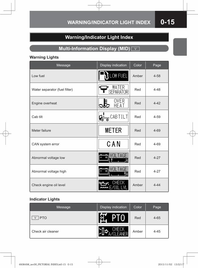
0-15WARNING/INDICATOR LIGHT INDEX
Warning/Indicator Light Index
Warning Lights
Message Display indication Color Page
Low fuel Amber 4-58
Water separator (fuel filter) Red 4-48
Engine overheat Red 4-42
Cab tilt Red 4-59
Meter failure Red 4-69
CAN system error Red 4-69
Abnormal voltage low Red 4-27
Abnormal voltage high Red 4-27
Check engine oil level Amber 4-44
Indicator Lights
Message Display indication Color Page
V PTO Red 4-65
Check air cleaner Amber 4-45
Multi-Information Display (MID) V
4608498_sec00_PICTORIAL INDEX.in0-15 0-154608498_sec00_PICTORIAL INDEX.in0-15 0-15 2015/11/02 13:52:172015/11/02 13:52:17
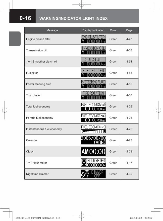
0-16 WARNING/INDICATOR LIGHT INDEX
Message Display indication Color Page
Engine oil and filter Green 4-43
Transmission oil Green 4-53
SA Smoother clutch oil Green 4-54
Fuel filter Green 4-55
Power steering fluid Green 4-56
Tire rotation Green 4-57
Total fuel economy Green 4-26
Per trip fuel economy Green 4-26
Instantaneous fuel economy Green 4-26
Calendar Green 4-28
Clock Green 4-29
V Hour meter Green 4-17
Nighttime dimmer Green 4-30
4608498_sec00_PICTORIAL INDEX.in0-16 0-164608498_sec00_PICTORIAL INDEX.in0-16 0-16 2015/11/02 13:52:182015/11/02 13:52:18
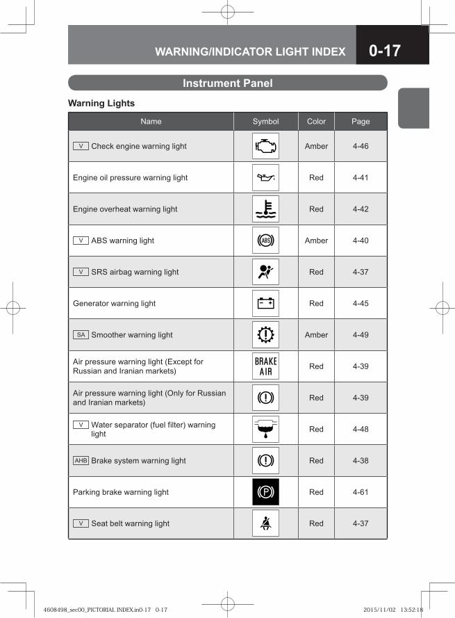
0-17WARNING/INDICATOR LIGHT INDEX
Name Symbol Color Page
V Check engine warning light Amber 4-46
Engine oil pressure warning light Red 4-41
Engine overheat warning light Red 4-42
V ABS warning light Amber 4-40
V SRS airbag warning light Red 4-37
Generator warning light Red 4-45
SA Smoother warning light Amber 4-49
Air pressure warning light (Except for Russian and Iranian markets) Red 4-39
Air pressure warning light (Only for Russian and Iranian markets) Red 4-39
V Water separator (fuel filter) warning light Red 4-48
AHB Brake system warning light Red 4-38
Parking brake warning light Red 4-61
V Seat belt warning light Red 4-37
Warning Lights
Instrument Panel
4608498_sec00_PICTORIAL INDEX.in0-17 0-174608498_sec00_PICTORIAL INDEX.in0-17 0-17 2015/11/02 13:52:182015/11/02 13:52:18
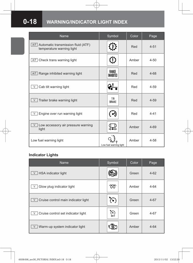
0-18 WARNING/INDICATOR LIGHT INDEX
Name Symbol Color Page
A/T Automatic transmission fluid (ATF) temperature warning light Red 4-51
A/T Check trans warning light Amber 4-50
A/T Range inhibited warning light Red 4-68
V Cab tilt warning light Red 4-59
V Trailer brake warning light Red 4-59
V Engine over run warning light Red 4-41
V Low accessory air pressure warning light Amber 4-69
Low fuel warning light� � ���� ������� �����
Amber 4-58
Name Symbol Color Page
V HSA indicator light Green 4-62
V Glow plug indicator light Amber 4-64
V Cruise control main indicator light Green 4-67
V Cruise control set indicator light Green 4-67
V Warm-up system indicator light Amber 4-64
Indicator Lights
4608498_sec00_PICTORIAL INDEX.in0-18 0-184608498_sec00_PICTORIAL INDEX.in0-18 0-18 2015/11/02 13:52:202015/11/02 13:52:20
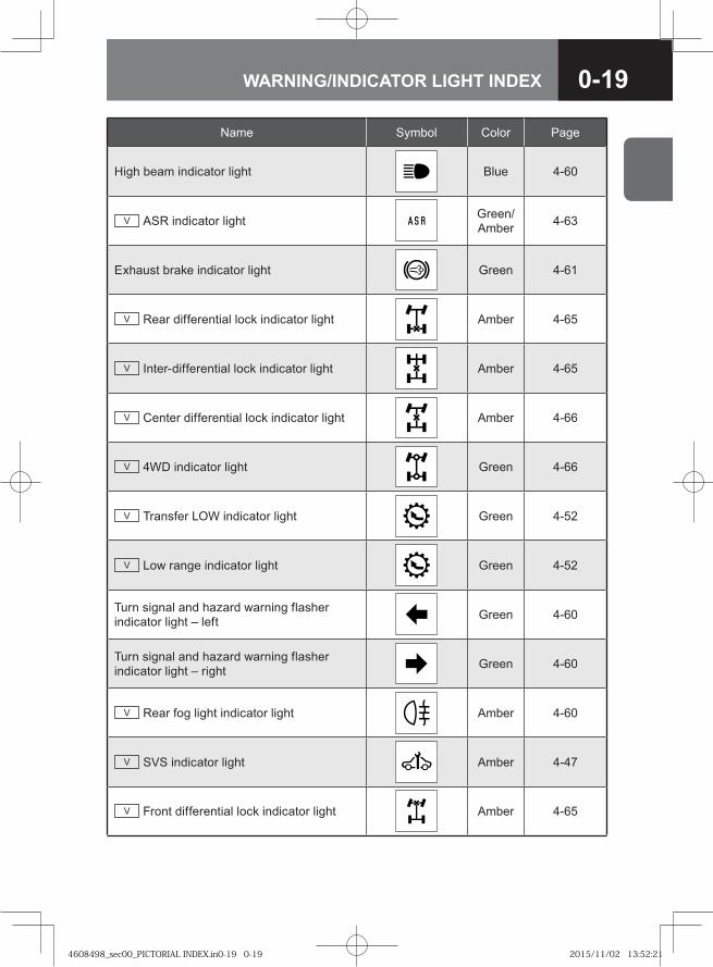
0-19WARNING/INDICATOR LIGHT INDEX
Name Symbol Color Page
High beam indicator light Blue 4-60
V ASR indicator light Green/Amber 4-63
Exhaust brake indicator light Green 4-61
V Rear differential lock indicator light Amber 4-65
V Inter-differential lock indicator light Amber 4-65
V Center differential lock indicator light Amber 4-66
V 4WD indicator light Green 4-66
V Transfer LOW indicator light Green 4-52
V Low range indicator light Green 4-52
Turn signal and hazard warning flasher indicator light – left Green 4-60
Turn signal and hazard warning flasher indicator light – right Green 4-60
V Rear fog light indicator light Amber 4-60
V SVS indicator light Amber 4-47
V Front differential lock indicator light Amber 4-65
4608498_sec00_PICTORIAL INDEX.in0-19 0-194608498_sec00_PICTORIAL INDEX.in0-19 0-19 2015/11/02 13:52:212015/11/02 13:52:21
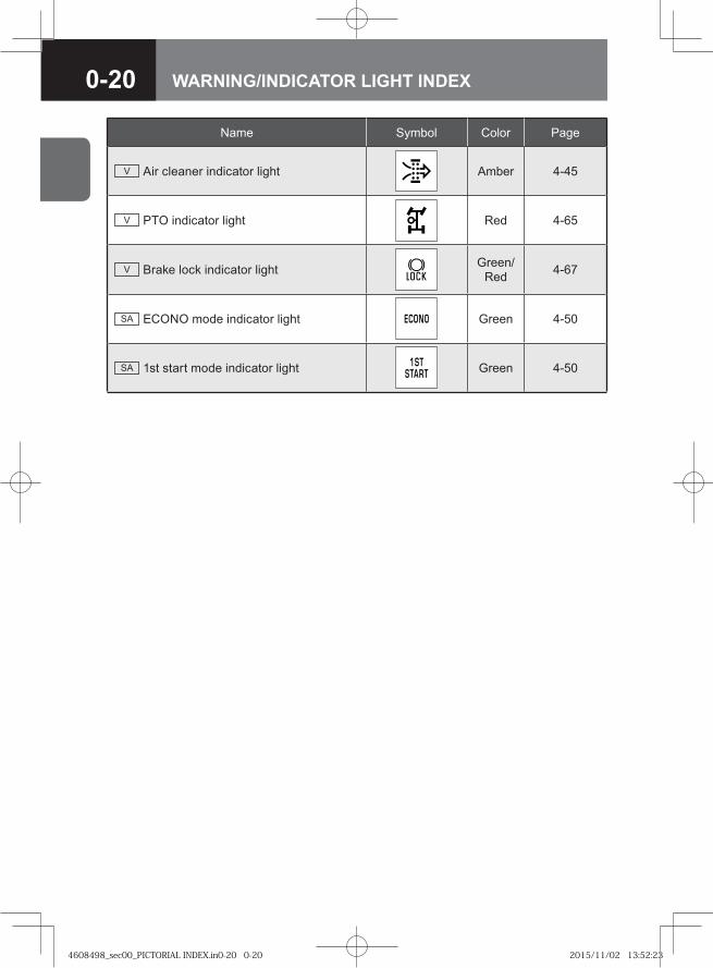
0-20 WARNING/INDICATOR LIGHT INDEX
Name Symbol Color Page
V Air cleaner indicator light Amber 4-45
V PTO indicator light Red 4-65
V Brake lock indicator light Green/Red 4-67
SA ECONO mode indicator light Green 4-50
SA 1st start mode indicator light Green 4-50
4608498_sec00_PICTORIAL INDEX.in0-20 0-204608498_sec00_PICTORIAL INDEX.in0-20 0-20 2015/11/02 13:52:232015/11/02 13:52:23
0-21WARNING/CAUTION LABELS
• The warning/caution labels in your vehicle indicate very important instructions and information that you should respect to ensure safe and proper use of the vehicle. Be sure to read them before using the vehicle.
• If any of these labels are peeling or illegible due to wear or scratches, please contact your Isuzu Dealer for a replacement.
• These warning/caution labels only concern the vehicle, not any additional installation. If your vehicle is equipped with a special body, check the instruction manual from the body manufacturer for warning/caution labels, if any.
• Some examples of warning/caution labels are indicated on the following pages, but there are many others not shown. Also, the contents of these labels may vary from model to model.
• The warning/caution labels indicated may be located differently in your vehicle.
Warning/Caution Labels in Your Vehicle
4608498_sec00_PICTORIAL INDEX.in0-21 0-214608498_sec00_PICTORIAL INDEX.in0-21 0-21 2015/11/02 13:52:232015/11/02 13:52:23
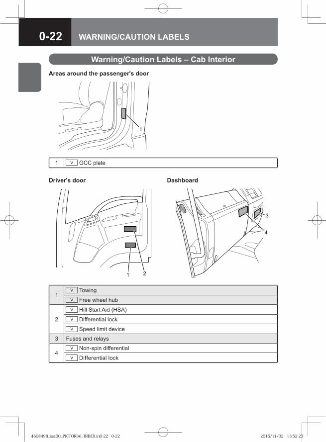
0-22 WARNING/CAUTION LABELS
1V TowingV Free wheel hub
2
V Hill Start Aid (HSA)V Differential lockV Speed limit device
3 Fuses and relays
4V Non-spin differentialV Differential lock
Warning/Caution Labels – Cab Interior
1 V GCC plate
Areas around the passenger's door
Driver's door Dashboard
�
�
�
4608498_sec00_PICTORIAL INDEX.in0-22 0-224608498_sec00_PICTORIAL INDEX.in0-22 0-22 2015/11/02 13:52:232015/11/02 13:52:23
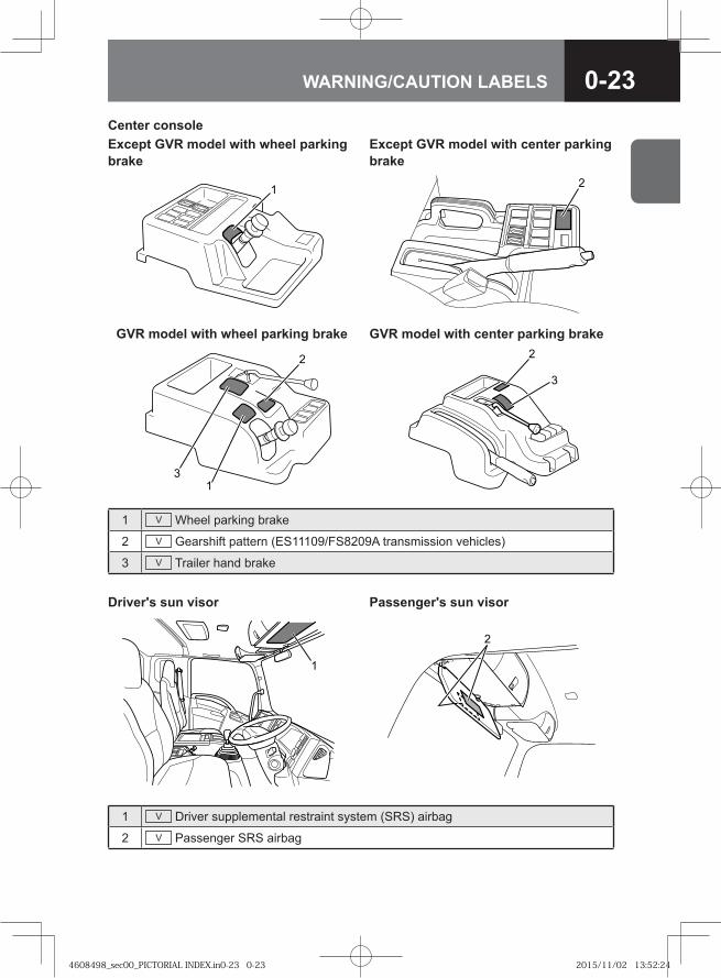
0-23WARNING/CAUTION LABELS
1 V Wheel parking brake
2 V Gearshift pattern (ES11109/FS8209A transmission vehicles)
3 V Trailer hand brake
1 V Driver supplemental restraint system (SRS) airbag
2 V Passenger SRS airbag
Center consoleExcept GVR model with wheel parking brake
Except GVR model with center parking brake
�
GVR model with wheel parking brake GVR model with center parking brake
�
�
�
Driver's sun visor Passenger's sun visor
�
4608498_sec00_PICTORIAL INDEX.in0-23 0-234608498_sec00_PICTORIAL INDEX.in0-23 0-23 2015/11/02 13:52:242015/11/02 13:52:24
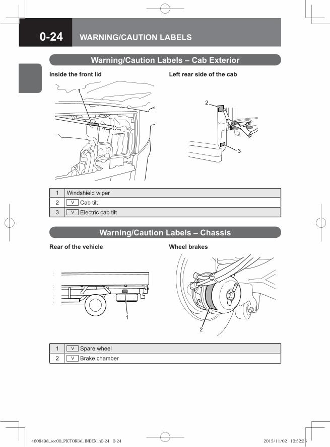
0-24 WARNING/CAUTION LABELS
Warning/Caution Labels – Cab Exterior
1 V Spare wheel
2 V Brake chamber
1 Windshield wiper
2 V Cab tilt
3 V Electric cab tilt
Warning/Caution Labels – ChassisRear of the vehicle Wheel brakes
�
Inside the front lid Left rear side of the cab
�
4608498_sec00_PICTORIAL INDEX.in0-24 0-244608498_sec00_PICTORIAL INDEX.in0-24 0-24 2015/11/02 13:52:252015/11/02 13:52:25
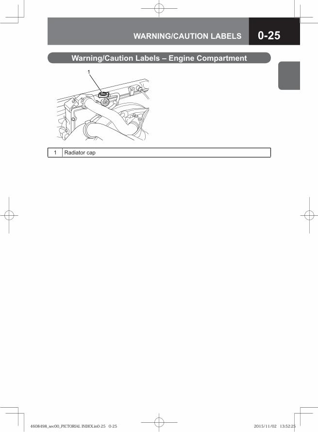
0-25WARNING/CAUTION LABELS
Warning/Caution Labels – Engine Compartment
1 Radiator cap
1
4608498_sec00_PICTORIAL INDEX.in0-25 0-254608498_sec00_PICTORIAL INDEX.in0-25 0-25 2015/11/02 13:52:252015/11/02 13:52:25
0-26 WARNING/CAUTION LABELS
4608498_sec00_PICTORIAL INDEX.in0-26 0-264608498_sec00_PICTORIAL INDEX.in0-26 0-26 2015/11/02 13:52:252015/11/02 13:52:25
● Vehicle Identification Number (VIN) and Engine Numbers 1-2
1VEHICLE INFORMATION
4608498_sec01_VEHICLE INFORMATIO1-1 1-14608498_sec01_VEHICLE INFORMATIO1-1 1-1 2015/11/02 13:54:032015/11/02 13:54:03
1-2 VEHICLE INFORMATION
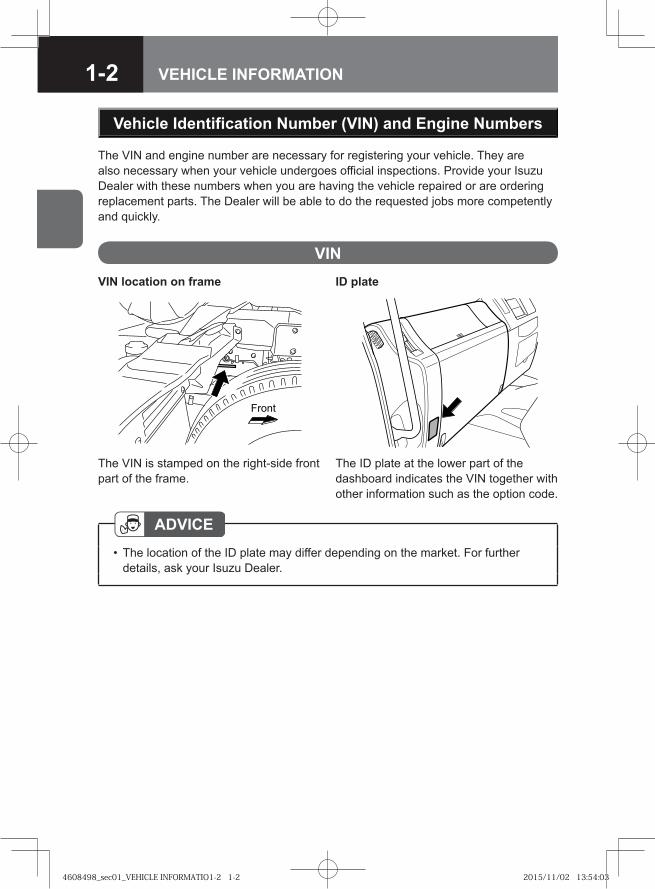
The VIN and engine number are necessary for registering your vehicle. They are also necessary when your vehicle undergoes official inspections. Provide your Isuzu Dealer with these numbers when you are having the vehicle repaired or are ordering replacement parts. The Dealer will be able to do the requested jobs more competently and quickly.
Vehicle Identification Number (VIN) and Engine Numbers
VIN
ADVICEThe location of the ID plate may differ depending on the market. For further details, ask your Isuzu Dealer.
•
VIN location on frame ID plate
��� �
The VIN is stamped on the right-side front part of the frame.
The ID plate at the lower part of the dashboard indicates the VIN together with other information such as the option code.
4608498_sec01_VEHICLE INFORMATIO1-2 1-24608498_sec01_VEHICLE INFORMATIO1-2 1-2 2015/11/02 13:54:032015/11/02 13:54:03
1-3VEHICLE INFORMATION
� � � � � � � � � � � � �
�� ���
Section Description
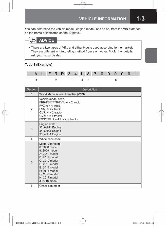
1 World Manufacturer Identifier (WMI)
2
Vehicle model codeFRR/FSR/FTR/FVR: 4 × 2 truckFVZ: 6 × 4 truckFVM: 6 × 2 truckGVR: 4 × 2 tractorGVZ: 6 × 4 tractorFSS/FTS: 4 × 4 truck or tractor
3
Engine code33: 6HH1 Engine34: 6HK1 Engine90: 4HK1 Engine
4 Wheelbase code
5
Model year code8: 2008 model9: 2009 modelA: 2010 modelB: 2011 modelC: 2012 modelD: 2013 modelE: 2014 modelF: 2015 modelG: 2016 modelH: 2017 modelJ: 2018 model
6 Chassis number
You can determine the vehicle model, engine model, and so on, from the VIN stamped on the frame or indicated on the ID plate.
ADVICEThere are two types of VIN, and either type is used according to the market. They are different in interpreting method from each other. For further details, ask your Isuzu Dealer.
•
Type 1 (Example)
4608498_sec01_VEHICLE INFORMATIO1-3 1-34608498_sec01_VEHICLE INFORMATIO1-3 1-3 2015/11/02 13:54:032015/11/02 13:54:03
1-4 VEHICLE INFORMATION
� � � � � � � � � � �
��
�
����
�
� �
No. Description
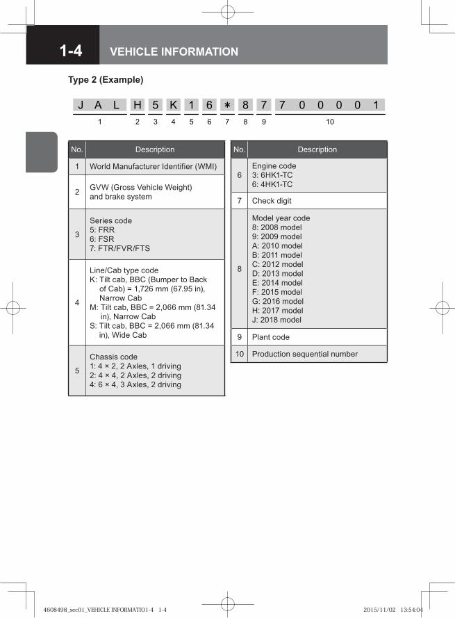
1 World Manufacturer Identifier (WMI)
2 GVW (Gross Vehicle Weight) and brake system
3
Series code5: FRR6: FSR7: FTR/FVR/FTS
4
Line/Cab type codeK: Tilt cab, BBC (Bumper to Back
of Cab) = 1,726 mm (67.95 in), Narrow Cab
M: Tilt cab, BBC = 2,066 mm (81.34 in), Narrow Cab
S: Tilt cab, BBC = 2,066 mm (81.34 in), Wide Cab
5
Chassis code1: 4 × 2, 2 Axles, 1 driving2: 4 × 4, 2 Axles, 2 driving4: 6 × 4, 3 Axles, 2 driving
No. Description
6Engine code3: 6HK1-TC6: 4HK1-TC
7 Check digit
8
Model year code8: 2008 model9: 2009 modelA: 2010 modelB: 2011 modelC: 2012 modelD: 2013 modelE: 2014 modelF: 2015 modelG: 2016 modelH: 2017 modelJ: 2018 model
9 Plant code
10 Production sequential number
Type 2 (Example)
4608498_sec01_VEHICLE INFORMATIO1-4 1-44608498_sec01_VEHICLE INFORMATIO1-4 1-4 2015/11/02 13:54:042015/11/02 13:54:04
1-5VEHICLE INFORMATION
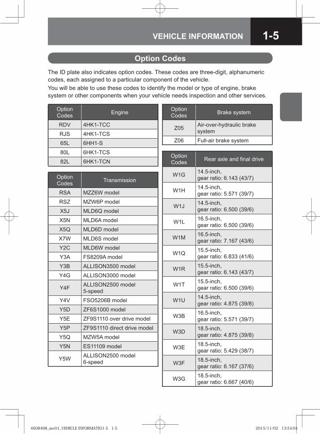
The ID plate also indicates option codes. These codes are three-digit, alphanumeric codes, each assigned to a particular component of the vehicle.You will be able to use these codes to identify the model or type of engine, brake system or other components when your vehicle needs inspection and other services.
Option Codes
Option Codes Engine
RDV 4HK1-TCC
RJS 4HK1-TCS
65L 6HH1-S
80L 6HK1-TCS
82L 6HK1-TCN
Option Codes Transmission
RSA MZZ6W model
RSZ MZW6P model
X5J MLD6Q model
X5N MLD6A model
X5Q MLD6D model
X7W MLD6S model
Y2C MLD6W model
Y3A FS8209A model
Y3B ALLISON3500 model
Y4G ALLISON3000 model
Y4F ALLISON2500 model 5-speed
Y4V FSO5206B model
Y5D ZF6S1000 model
Y5E ZF9S1110 over drive model
Y5P ZF9S1110 direct drive model
Y5Q MZW5A model
Y5N ES11109 model
Y5W ALLISON2500 model 6-speed
Option Codes Brake system
Z05 Air-over-hydraulic brake system
Z06 Full-air brake system
Option Codes Rear axle and final drive
W1G 14.5-inch, gear ratio: 6.143 (43/7)
W1H 14.5-inch, gear ratio: 5.571 (39/7)
W1J 14.5-inch, gear ratio: 6.500 (39/6)
W1L 16.5-inch, gear ratio: 6.500 (39/6)
W1M 16.5-inch, gear ratio: 7.167 (43/6)
W1Q 15.5-inch, gear ratio: 6.833 (41/6)
W1R 15.5-inch, gear ratio: 6.143 (43/7)
W1T 15.5-inch, gear ratio: 6.500 (39/6)
W1U 14.5-inch, gear ratio: 4.875 (39/8)
W3B 16.5-inch, gear ratio: 5.571 (39/7)
W3D 18.5-inch, gear ratio: 4.875 (39/8)
W3E 18.5-inch, gear ratio: 5.429 (38/7)
W3F 18.5-inch, gear ratio: 6.167 (37/6)
W3G 18.5-inch, gear ratio: 6.667 (40/6)
4608498_sec01_VEHICLE INFORMATIO1-5 1-54608498_sec01_VEHICLE INFORMATIO1-5 1-5 2015/11/02 13:54:042015/11/02 13:54:04
1-6 VEHICLE INFORMATION
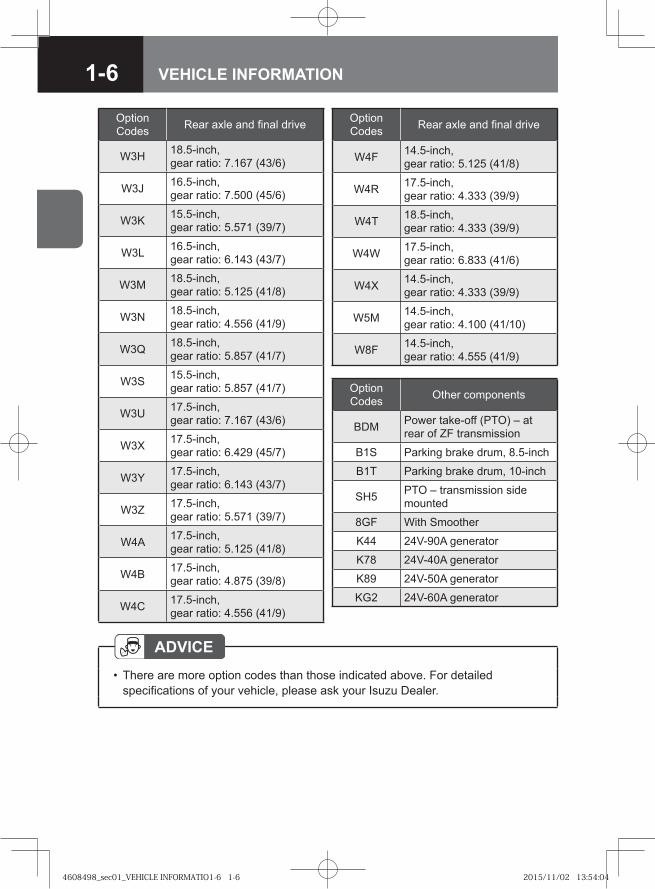
Option Codes Rear axle and final drive
W3H 18.5-inch, gear ratio: 7.167 (43/6)
W3J 16.5-inch, gear ratio: 7.500 (45/6)
W3K 15.5-inch, gear ratio: 5.571 (39/7)
W3L 16.5-inch, gear ratio: 6.143 (43/7)
W3M 18.5-inch, gear ratio: 5.125 (41/8)
W3N 18.5-inch, gear ratio: 4.556 (41/9)
W3Q 18.5-inch, gear ratio: 5.857 (41/7)
W3S 15.5-inch, gear ratio: 5.857 (41/7)
W3U 17.5-inch, gear ratio: 7.167 (43/6)
W3X 17.5-inch, gear ratio: 6.429 (45/7)
W3Y 17.5-inch, gear ratio: 6.143 (43/7)
W3Z 17.5-inch, gear ratio: 5.571 (39/7)
W4A 17.5-inch, gear ratio: 5.125 (41/8)
W4B 17.5-inch, gear ratio: 4.875 (39/8)
W4C 17.5-inch,gear ratio: 4.556 (41/9)
Option Codes Rear axle and final drive
W4F 14.5-inch, gear ratio: 5.125 (41/8)
W4R 17.5-inch,gear ratio: 4.333 (39/9)
W4T 18.5-inch, gear ratio: 4.333 (39/9)
W4W 17.5-inch, gear ratio: 6.833 (41/6)
W4X 14.5-inch, gear ratio: 4.333 (39/9)
W5M 14.5-inch, gear ratio: 4.100 (41/10)
W8F 14.5-inch, gear ratio: 4.555 (41/9)
Option Codes Other components
BDM Power take-off (PTO) – at rear of ZF transmission
B1S Parking brake drum, 8.5-inch
B1T Parking brake drum, 10-inch
SH5 PTO – transmission side mounted
8GF With Smoother
K44 24V-90A generator
K78 24V-40A generator
K89 24V-50A generator
KG2 24V-60A generator
ADVICEThere are more option codes than those indicated above. For detailed specifications of your vehicle, please ask your Isuzu Dealer.
•
4608498_sec01_VEHICLE INFORMATIO1-6 1-64608498_sec01_VEHICLE INFORMATIO1-6 1-6 2015/11/02 13:54:042015/11/02 13:54:04
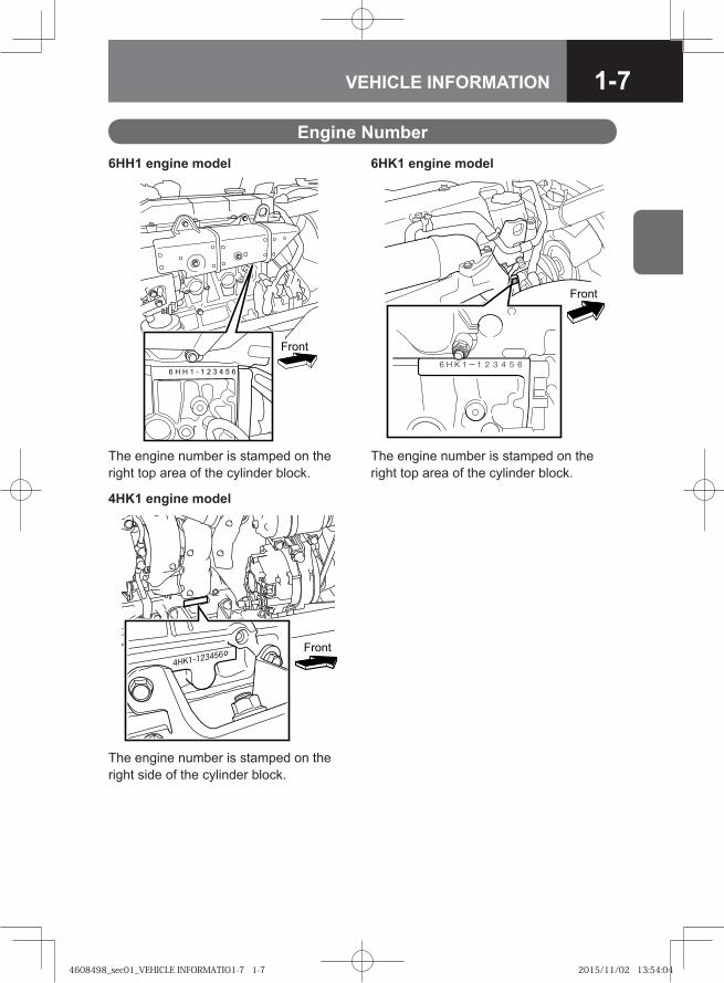
1-7VEHICLE INFORMATION
Engine Number6HH1 engine model 6HK1 engine model
���
���
The engine number is stamped on the right top area of the cylinder block.
The engine number is stamped on the right top area of the cylinder block.
4HK1 engine model
��� �
The engine number is stamped on the right side of the cylinder block.
4608498_sec01_VEHICLE INFORMATIO1-7 1-74608498_sec01_VEHICLE INFORMATIO1-7 1-7 2015/11/02 13:54:042015/11/02 13:54:04
1-8 VEHICLE INFORMATION
4608498_sec01_VEHICLE INFORMATIO1-8 1-84608498_sec01_VEHICLE INFORMATIO1-8 1-8 2015/11/02 13:54:042015/11/02 13:54:04
● Before Driving 2-2
● Carrying Children 2-15
● Driving 2-17
● ZF9S1110 Manual Transmission Model V 2-30
● ES11109/FS8209A Manual Transmission Model V 2-31
● Smoother Model SA 2-31
● Automatic Transmission Model A/T 2-35
● Four Wheel Drive (4WD) Model V 2-36
● Stopping and Parking 2-38
● Staying Safe 2-44
● Preventing Breakdowns 2-49
● When to Visit an Isuzu Dealer 2-51
● Speed Limit Device V 2-54
● Seat Belt with Pretensioner and Supplemental Restraint System (SRS) Airbag System V
2-55
● Vehicle Data Collection 2-57
● Statement of Compliance with ECE R13 2-57
This chapter contains information and cautions that you should observe for safe and comfortable vehicle operation. Be sure to read it before using the vehicle.
2IMPORTANT INFORMATION
4608498_sec02_IMPORTANT INFORMAT2-1 2-14608498_sec02_IMPORTANT INFORMAT2-1 2-1 2015/11/04 9:53:232015/11/04 9:53:23
2-2 IMPORTANT INFORMATION
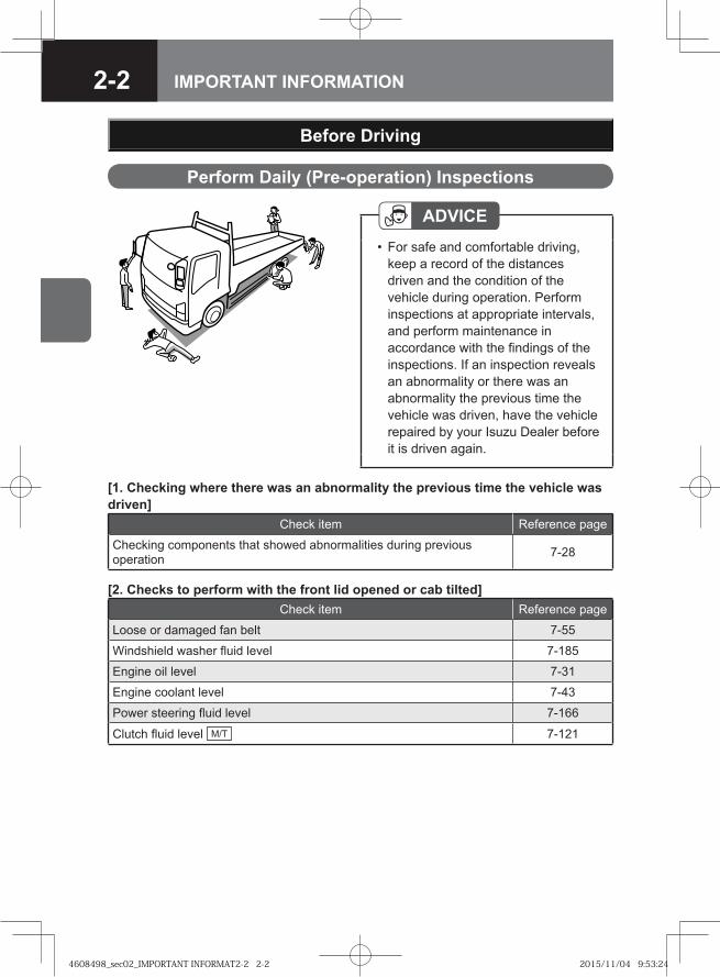
Perform Daily (Pre-operation) Inspections
Before Driving
ADVICEFor safe and comfortable driving, keep a record of the distances driven and the condition of the vehicle during operation. Perform inspections at appropriate intervals, and perform maintenance in accordance with the findings of the inspections. If an inspection reveals an abnormality or there was an abnormality the previous time the vehicle was driven, have the vehicle repaired by your Isuzu Dealer before it is driven again.
•
[1. Checking where there was an abnormality the previous time the vehicle was driven]
Check item Reference page
Checking components that showed abnormalities during previous operation 7-28
[2. Checks to perform with the front lid opened or cab tilted]Check item Reference page
Loose or damaged fan belt 7-55
Windshield washer fluid level 7-185
Engine oil level 7-31
Engine coolant level 7-43
Power steering fluid level 7-166
Clutch fluid level M/T 7-121
4608498_sec02_IMPORTANT INFORMAT2-2 2-24608498_sec02_IMPORTANT INFORMAT2-2 2-2 2015/11/04 9:53:242015/11/04 9:53:24
2-3IMPORTANT INFORMATION
[3. Checks to perform in the driver's seat]Check item Reference page
Operation of meters, gauges and warning/indicator lights 4-10, 4-18
Engine start ability, abnormal noise and color of exhaust emissions 7-30
Brake pedal free play 7-83
Exhaust sound from brake valve 7-83
Increase in air pressure 7-80
Parking brake lever stroke 7-84
Windshield washer fluid spray condition and windshield wiper effectiveness 7-185, 7-186
Steering position and free play 3-30, 7-170
Operation of horn and turn signal lights 4-80, 4-89
Fuel level 4-16
Operation of door locks 3-9, 3-10, 3-11
Water separator (fuel filter) warning light 4-48
[4. Checks to perform during a walk around the vehicle]Check item Reference page
Illumination, flashing or stained or damaged lights 7-189
Battery fluid level 7-196
Brake fluid level AHB 7-76
Condensation in air tank (draining water) 7-119
Leaf spring damage ―
Leakage of oil, engine coolant, fuel, brake fluid or power steering fluid ―
[5. Checking wheels and tires]Check item Reference page
Air pressure 7-92
Cracks and other damage 7-95
Abnormal wear 7-95
Tread depth 7-95
Disc wheel mounting condition 7-96
[6. Checks to perform while driving the vehicle]Check item Reference page
Brake effectiveness 7-83
Checking the engine at low speeds and during acceleration 7-30
Clutch system function M/T 7-124
4608498_sec02_IMPORTANT INFORMAT2-3 2-34608498_sec02_IMPORTANT INFORMAT2-3 2-3 2015/11/04 9:53:262015/11/04 9:53:26
2-4 IMPORTANT INFORMATION
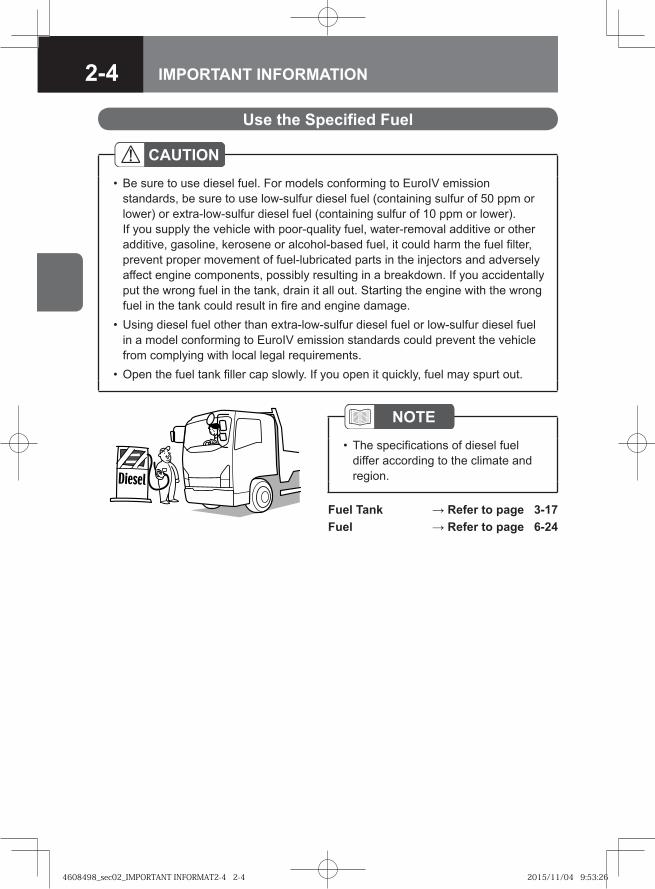
Use the Specified Fuel
CAUTIONBe sure to use diesel fuel. For models conforming to EuroIV emission standards, be sure to use low-sulfur diesel fuel (containing sulfur of 50 ppm or lower) or extra-low-sulfur diesel fuel (containing sulfur of 10 ppm or lower). If you supply the vehicle with poor-quality fuel, water-removal additive or other additive, gasoline, kerosene or alcohol-based fuel, it could harm the fuel filter, prevent proper movement of fuel-lubricated parts in the injectors and adversely affect engine components, possibly resulting in a breakdown. If you accidentally put the wrong fuel in the tank, drain it all out. Starting the engine with the wrong fuel in the tank could result in fire and engine damage.Using diesel fuel other than extra-low-sulfur diesel fuel or low-sulfur diesel fuel in a model conforming to EuroIV emission standards could prevent the vehicle from complying with local legal requirements.Open the fuel tank filler cap slowly. If you open it quickly, fuel may spurt out.
•
•
•
NOTEThe specifications of diesel fuel differ according to the climate and region.
•
Fuel Tank → Refer to page 3-17Fuel → Refer to page 6-24
4608498_sec02_IMPORTANT INFORMAT2-4 2-44608498_sec02_IMPORTANT INFORMAT2-4 2-4 2015/11/04 9:53:262015/11/04 9:53:26
2-5IMPORTANT INFORMATION
Using Self-service Filling Stations
WARNING
[Be sure to obey the following instructions when refueling the vehicle]Stop the engine and close the vehicle's doors and windows.Keep cigarettes and other flames away from the vehicle. Before opening the fuel tank filler cap, touch a metallic object to discharge static electricity from your body. If you have static charge on your body while refueling the vehicle, a spark caused by its discharge could ignite the fuel, resulting in burns.When filling, place the nozzle deeply into the fuel tank. If you try to fill more fuel by pulling out the nozzle from the fuel tank, the fuel may spill out, thus causing danger. All parts of the refueling procedure (from opening the fuel tank filler cap to completing the refueling and closing the fuel tank filler cap) must be performed by the same person. Other people may be carrying static electricity. Do not allow them to approach the fuel filler. The person performing the refueling procedure must not return to the seat in the cab part-way through the procedure. He/she could pick up another charge of static electricity by doing so. Do not use any fuel tank filler cap that is not an Isuzu genuine part. Obey all cautions posted in filling stations.
•••
•
•
••
CAUTION[Caution when refueling the vehicle]
Be careful not to inhale fuel vapor when refueling the vehicle.•
Fuel Tank → Refer to page 3-17
4608498_sec02_IMPORTANT INFORMAT2-5 2-54608498_sec02_IMPORTANT INFORMAT2-5 2-5 2015/11/04 9:53:262015/11/04 9:53:26
2-6 IMPORTANT INFORMATION
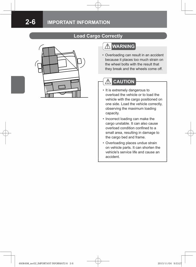
Load Cargo Correctly
CAUTIONIt is extremely dangerous to overload the vehicle or to load the vehicle with the cargo positioned on one side. Load the vehicle correctly, observing the maximum loading capacity. Incorrect loading can make the cargo unstable. It can also cause overload condition confined to a small area, resulting in damage to the cargo bed and frame.Overloading places undue strain on vehicle parts. It can shorten the vehicle's service life and cause an accident.
•
•
•
WARNING
Overloading can result in an accident because it places too much strain on the wheel bolts with the result that they break and the wheels come off.
•
4608498_sec02_IMPORTANT INFORMAT2-6 2-64608498_sec02_IMPORTANT INFORMAT2-6 2-6 2015/11/04 9:53:272015/11/04 9:53:27
2-7IMPORTANT INFORMATION
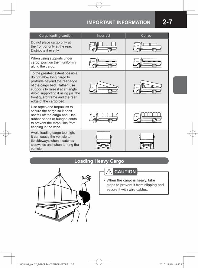
CAUTIONWhen the cargo is heavy, take steps to prevent it from slipping and secure it with wire cables.
•
Loading Heavy Cargo
Cargo loading caution Incorrect Correct
Do not place cargo only at the front or only at the rear. Distribute it evenly.
When using supports under cargo, position them uniformly along the cargo.
To the greatest extent possible, do not allow long cargo to protrude beyond the rear edge of the cargo bed. Rather, use supports to raise it at an angle. Avoid supporting it using just the front guard frame and the rear edge of the cargo bed.
Use ropes and tarpaulins to secure the cargo so it does not fall off the cargo bed. Use rubber bands or bungee cords to prevent the tarpaulins from flapping in the wind.
Avoid loading cargo too high. It can cause the vehicle to tip sideways when it catches sidewinds and when turning the vehicle.
4608498_sec02_IMPORTANT INFORMAT2-7 2-74608498_sec02_IMPORTANT INFORMAT2-7 2-7 2015/11/04 9:53:272015/11/04 9:53:27
2-8 IMPORTANT INFORMATION
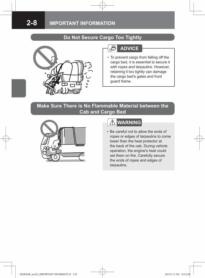
Do Not Secure Cargo Too Tightly
Make Sure There is No Flammable Material between the Cab and Cargo Bed
WARNING
Be careful not to allow the ends of ropes or edges of tarpaulins to come lower than the heat protector at the back of the cab. During vehicle operation, the engine's heat could set them on fire. Carefully secure the ends of ropes and edges of tarpaulins.
•
ADVICETo prevent cargo from falling off the cargo bed, it is essential to secure it with ropes and tarpaulins. However, retaining it too tightly can damage the cargo bed's gates and front guard frame.
•
4608498_sec02_IMPORTANT INFORMAT2-8 2-84608498_sec02_IMPORTANT INFORMAT2-8 2-8 2015/11/04 9:53:302015/11/04 9:53:30
2-9IMPORTANT INFORMATION
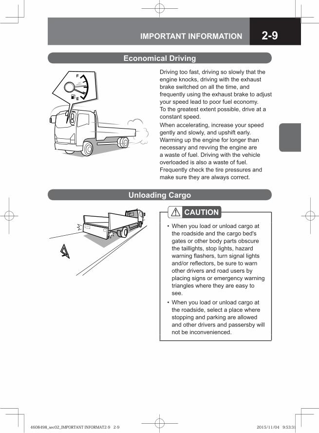
Economical DrivingDriving too fast, driving so slowly that the engine knocks, driving with the exhaust brake switched on all the time, and frequently using the exhaust brake to adjust your speed lead to poor fuel economy. To the greatest extent possible, drive at a constant speed. When accelerating, increase your speed gently and slowly, and upshift early. Warming up the engine for longer than necessary and revving the engine are a waste of fuel. Driving with the vehicle overloaded is also a waste of fuel. Frequently check the tire pressures and make sure they are always correct.
Unloading Cargo
CAUTIONWhen you load or unload cargo at the roadside and the cargo bed's gates or other body parts obscure the taillights, stop lights, hazard warning flashers, turn signal lights and/or reflectors, be sure to warn other drivers and road users by placing signs or emergency warning triangles where they are easy to see.When you load or unload cargo at the roadside, select a place where stopping and parking are allowed and other drivers and passersby will not be inconvenienced.
•
•
4608498_sec02_IMPORTANT INFORMAT2-9 2-94608498_sec02_IMPORTANT INFORMAT2-9 2-9 2015/11/04 9:53:312015/11/04 9:53:31
2-10 IMPORTANT INFORMATION
���
Keep the Floor around the Driver's Seat Clean and Tidy
WARNING
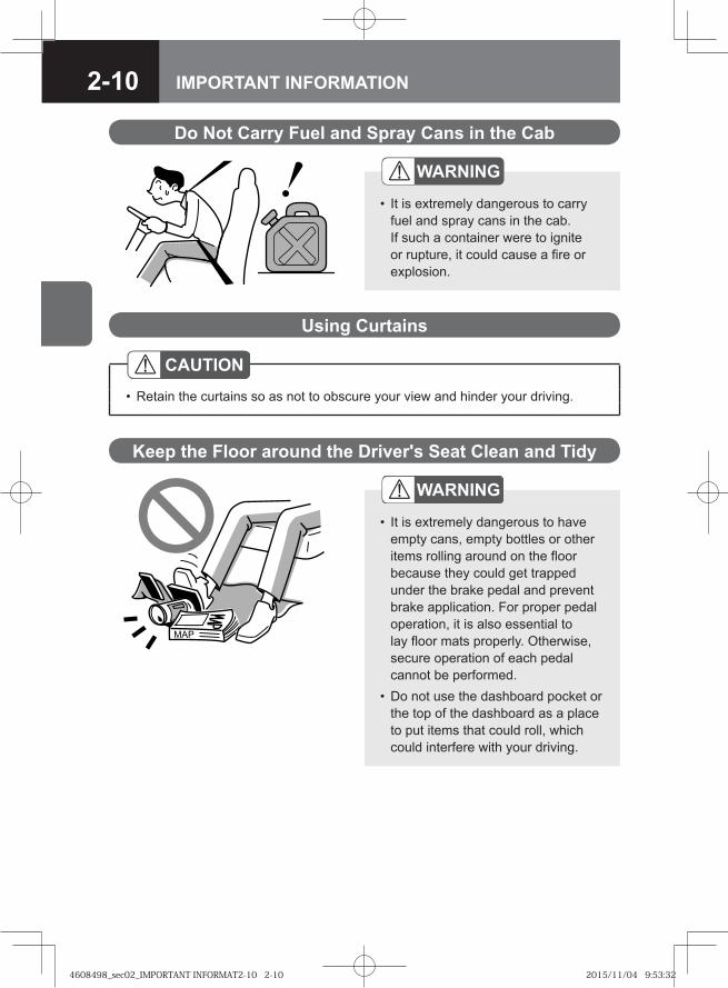
It is extremely dangerous to have empty cans, empty bottles or other items rolling around on the floor because they could get trapped under the brake pedal and prevent brake application. For proper pedal operation, it is also essential to lay floor mats properly. Otherwise, secure operation of each pedal cannot be performed. Do not use the dashboard pocket or the top of the dashboard as a place to put items that could roll, which could interfere with your driving.
•
•
Do Not Carry Fuel and Spray Cans in the Cab
WARNING
It is extremely dangerous to carry fuel and spray cans in the cab. If such a container were to ignite or rupture, it could cause a fire or explosion.
•
Using Curtains
CAUTIONRetain the curtains so as not to obscure your view and hinder your driving.•
4608498_sec02_IMPORTANT INFORMAT2-10 2-104608498_sec02_IMPORTANT INFORMAT2-10 2-10 2015/11/04 9:53:322015/11/04 9:53:32
2-11IMPORTANT INFORMATION
Seats → Refer to page 3-20Seat Belts → Refer to page 3-34Mirrors → Refer to page 3-31
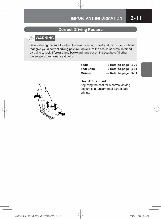
Seat AdjustmentAdjusting the seat for a correct driving posture is a fundamental part of safe driving.
Correct Driving Posture
WARNING
Before driving, be sure to adjust the seat, steering wheel and mirrors to positions that give you a correct driving posture. Make sure the seat is securely retained by trying to rock it forward and backward, and put on the seat belt. All other passengers must wear seat belts.
•
4608498_sec02_IMPORTANT INFORMAT2-11 2-114608498_sec02_IMPORTANT INFORMAT2-11 2-11 2015/11/04 9:53:322015/11/04 9:53:32
2-12 IMPORTANT INFORMATION
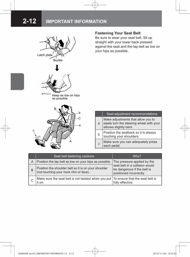
Fastening Your Seat BeltBe sure to wear your seat belt. Sit up straight with your lower back pressed against the seat and the lap belt as low on your hips as possible.
�� �� ��� �
������
���� �� ��� �� ������ ��������
Seat adjustment recommendations
aMake adjustments that allow you to easily turn the steering wheel with your elbows slightly bent.
b Position the seatback so it is always touching your shoulders.
c Make sure you can adequately press each pedal.
Seat belt fastening cautions Why?
A Position the lap belt as low on your hips as possible. The pressure applied by the seat belt in a collision would be dangerous if the belt is positioned incorrectly.
B Position the shoulder belt so it is on your shoulder (not touching your neck chin or face).
C Make sure the seat belt is not twisted when you put it on.
To ensure that the seat belt is fully effective.
�
�
�
�
�
4608498_sec02_IMPORTANT INFORMAT2-12 2-124608498_sec02_IMPORTANT INFORMAT2-12 2-12 2015/11/04 9:53:332015/11/04 9:53:33
2-13IMPORTANT INFORMATION
WARNING
Be sure to adjust the seat before driving. Achieve the correct driving posture, gently rock the seat to make sure it is locked in place, and put on your seat belt before you start driving. In addition to the driver, all other passengers must wear seat belts. For a child who is so small that the seat belt touches his/her face or does not rest across his/her hips, use a child seat or other suitable restraint, not the seat belt. Using the seat belt could be dangerous.
•
•
Carrying Children → Refer to page 2-15
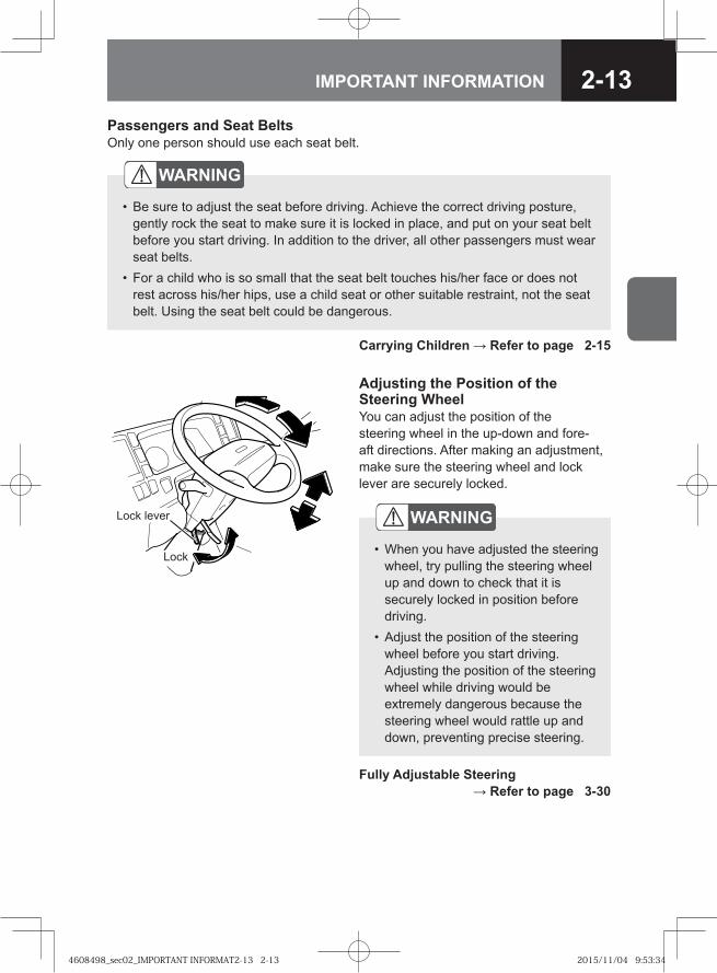
Adjusting the Position of the Steering WheelYou can adjust the position of the steering wheel in the up-down and fore-aft directions. After making an adjustment, make sure the steering wheel and lock lever are securely locked.
Lock lever
Lock
WARNING
When you have adjusted the steering wheel, try pulling the steering wheel up and down to check that it is securely locked in position before driving.Adjust the position of the steering wheel before you start driving. Adjusting the position of the steering wheel while driving would be extremely dangerous because the steering wheel would rattle up and down, preventing precise steering.
•
•
Fully Adjustable Steering → Refer to page 3-30
Passengers and Seat BeltsOnly one person should use each seat belt.
4608498_sec02_IMPORTANT INFORMAT2-13 2-134608498_sec02_IMPORTANT INFORMAT2-13 2-13 2015/11/04 9:53:342015/11/04 9:53:34

2-14 IMPORTANT INFORMATION
��� ���� ���� �������
��� ���� �������
Carrying an Expectant Mother or a Person Who is Ill
WARNING
An expectant mother or a person who is ill riding in the vehicle must also wear a seat belt. In light of the risk that the seat belt will apply pressure to the abdomen, chest and shoulders in the event of a collision, however, an expectant mother or a person who is ill should get advice from a physician beforehand.
An expectant mother should use a three-point seat belt. An expectant mother should position the lap belt snugly as low as possible on the hips (not across the abdomen). Also, she should fasten the shoulder belt so it rests on her chest, not on her abdomen. Unless the seat belt is correctly worn, it may dig into the abdomen in the event of hard braking or a collision, harming not only the expectant mother but also the unborn child, putting them both in danger of serious injuries or death.
•
-
-
-
Seat Belts → Refer to page 3-34
4608498_sec02_IMPORTANT INFORMAT2-14 2-144608498_sec02_IMPORTANT INFORMAT2-14 2-14 2015/11/04 9:53:352015/11/04 9:53:35
2-15IMPORTANT INFORMATION
Carrying Children
Using Seat Belts with Children
WARNING
The vehicle's seat belts are designed for adults. If a seat belt touches a child's neck or chin, or does not rest across his/her hips, use a baby seat, child seat or junior seat. If the seat belt were used as it is, it could apply intense pressure to the child's abdomen in the event of a collision. A small child who is not able to sit up by him/herself must be placed in a child seat. Do not fit a baby seat, child seat or junior seat on the center seat. It could hinder your driving. If the vehicle has a passenger airbag, do not fit a baby seat, child seat or junior seat facing rearward. If the baby seat, child seat or junior seat were facing rearward, the impact on the child seat during deployment of the passenger airbag could inflict life-threatening injuries on the child.
•
•
•
NOTEThe appropriate type of baby seat, child seat or junior seat and the proper installation for it depend upon the weight and height of the child. It may not be possible to correctly fit certain child seats depending on their shapes. Be sure to use a child seat that is suitable for the vehicle. * For detailed instructions, see the instruction manual supplied with the baby
seat, child seat or junior seat.
•
Seat Belts → Refer to page 3-34
4608498_sec02_IMPORTANT INFORMAT2-15 2-154608498_sec02_IMPORTANT INFORMAT2-15 2-15 2015/11/04 9:53:352015/11/04 9:53:35
2-16 IMPORTANT INFORMATION
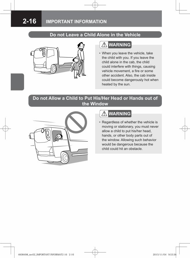
Do not Allow a Child to Put His/Her Head or Hands out of the Window
WARNING
Regardless of whether the vehicle is moving or stationary, you must never allow a child to put his/her head, hands, or other body parts out of the window. Allowing such behavior would be dangerous because the child could hit an obstacle.
•
Do not Leave a Child Alone in the Vehicle
WARNING
When you leave the vehicle, take the child with you. If you leave the child alone in the cab, the child could interfere with things, causing vehicle movement, a fire or some other accident. Also, the cab inside could become dangerously hot when heated by the sun.
•
4608498_sec02_IMPORTANT INFORMAT2-16 2-164608498_sec02_IMPORTANT INFORMAT2-16 2-16 2015/11/04 9:53:362015/11/04 9:53:36
2-17IMPORTANT INFORMATION
Opening and Closing Doors → Refer to page 3-9
Power Windows V → Refer to page 3-15
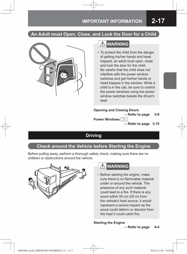
An Adult must Open, Close, and Lock the Door for a Child
WARNING
To protect the child from the danger of getting his/her hands and head trapped, an adult must open, close and lock the door for the child. Be careful that the child does not interfere with the power window switches and get his/her hands or head trapped in the window. While a child is in the cab, be sure to control the power windows using the power window switches beside the driver's seat.
•
Before pulling away, perform a thorough safety check, making sure there are no children or obstructions around the vehicle.
Driving
Check around the Vehicle before Starting the Engine
WARNING
Before starting the engine, make sure there is no flammable material under or around the vehicle. The presence of any such material could lead to a fire. If there is any wood within 50 cm (20 in) from the vehicle's heat source, it would represent a severe hazard as the wood could deform or discolor from the heat it could catch fire.
•
Starting the Engine → Refer to page 4-4
4608498_sec02_IMPORTANT INFORMAT2-17 2-174608498_sec02_IMPORTANT INFORMAT2-17 2-17 2015/11/04 9:53:362015/11/04 9:53:36
2-18 IMPORTANT INFORMATION
WARNING
Exhaust emissions contain carbon monoxide, which is colorless, odorless and poisonous. If you inhale exhaust emissions, you may suffer carbon monoxide poisoning. Do not keep the engine running for any length of time in a place that is poorly ventilated. It is particularly dangerous to run the engine in a garage or other indoor place that could easily fill with exhaust gases because you could suffer carbon monoxide poisoning. Inspect the exhaust pipe from time to time. If you notice any abnormality (for example, a damaged joint, or a hole or crack caused by corrosion), have checks and maintenance performed by the nearest Isuzu Dealer. Continuing to use the vehicle without having the defect repaired would be dangerous because exhaust gases could get into the cab and cause carbon monoxide poisoning. If exhaust gases get into the cab, completely open all of the windows and place the inside/outside air selector of the heater or air conditioner to outside air. Promptly have checks and maintenance performed by the nearest Isuzu Dealer. Continuing to use the vehicle without having the defect repaired would be dangerous because exhaust gases could get into the cab and cause carbon monoxide poisoning.
•
•
•
•
Be Careful about Exhaust Emissions
4608498_sec02_IMPORTANT INFORMAT2-18 2-184608498_sec02_IMPORTANT INFORMAT2-18 2-18 2015/11/04 9:53:372015/11/04 9:53:37
2-19IMPORTANT INFORMATION
Starting the Engine
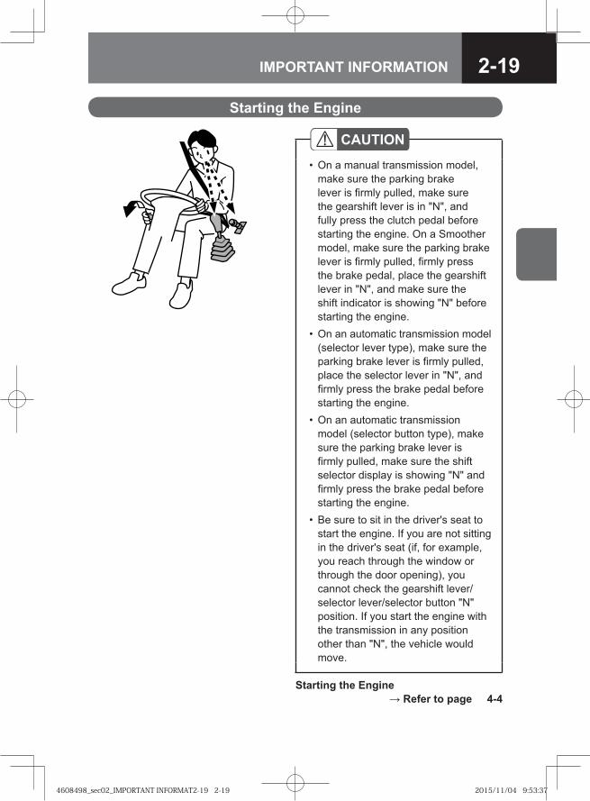
CAUTIONOn a manual transmission model, make sure the parking brake lever is firmly pulled, make sure the gearshift lever is in "N", and fully press the clutch pedal before starting the engine. On a Smoother model, make sure the parking brake lever is firmly pulled, firmly press the brake pedal, place the gearshift lever in "N", and make sure the shift indicator is showing "N" before starting the engine. On an automatic transmission model (selector lever type), make sure the parking brake lever is firmly pulled, place the selector lever in "N", and firmly press the brake pedal before starting the engine.On an automatic transmission model (selector button type), make sure the parking brake lever is firmly pulled, make sure the shift selector display is showing "N" and firmly press the brake pedal before starting the engine. Be sure to sit in the driver's seat to start the engine. If you are not sitting in the driver's seat (if, for example, you reach through the window or through the door opening), you cannot check the gearshift lever/selector lever/selector button "N" position. If you start the engine with the transmission in any position other than "N", the vehicle would move.
•
•
•
•
Starting the Engine → Refer to page 4-4
4608498_sec02_IMPORTANT INFORMAT2-19 2-194608498_sec02_IMPORTANT INFORMAT2-19 2-19 2015/11/04 9:53:372015/11/04 9:53:37
2-20 IMPORTANT INFORMATION
If the Vehicle Has Not Been Driven for a Long Period
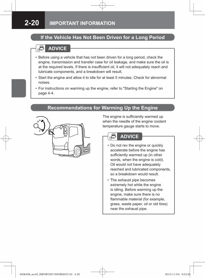
Recommendations for Warming Up the EngineThe engine is sufficiently warmed up when the needle of the engine coolant temperature gauge starts to move.
ADVICEDo not rev the engine or quickly accelerate before the engine has sufficiently warmed up (in other words, when the engine is cold). Oil would not have adequately reached and lubricated components, so a breakdown would result.The exhaust pipe becomes extremely hot while the engine is idling. Before warming up the engine, make sure there is no flammable material (for example, grass, waste paper, oil or old tires) near the exhaust pipe.
•
•
ADVICEBefore using a vehicle that has not been driven for a long period, check the engine, transmission and transfer case for oil leakage, and make sure the oil is at the required levels. If there is insufficient oil, it will not adequately reach and lubricate components, and a breakdown will result. Start the engine and allow it to idle for at least 5 minutes. Check for abnormal noises. For instructions on warming up the engine, refer to "Starting the Engine" on page 4-4.
•
•
•
4608498_sec02_IMPORTANT INFORMAT2-20 2-204608498_sec02_IMPORTANT INFORMAT2-20 2-20 2015/11/04 9:53:382015/11/04 9:53:38
2-21IMPORTANT INFORMATION
WARNING
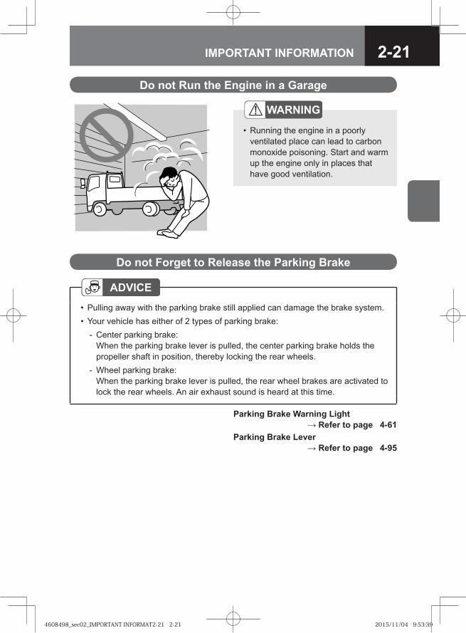
Running the engine in a poorly ventilated place can lead to carbon monoxide poisoning. Start and warm up the engine only in places that have good ventilation.
•
Do not Run the Engine in a Garage
Parking Brake Warning Light → Refer to page 4-61
Parking Brake Lever → Refer to page 4-95
Do not Forget to Release the Parking Brake
ADVICEPulling away with the parking brake still applied can damage the brake system.Your vehicle has either of 2 types of parking brake:
Center parking brake:When the parking brake lever is pulled, the center parking brake holds the propeller shaft in position, thereby locking the rear wheels.Wheel parking brake: When the parking brake lever is pulled, the rear wheel brakes are activated to lock the rear wheels. An air exhaust sound is heard at this time.
••
-
-
4608498_sec02_IMPORTANT INFORMAT2-21 2-214608498_sec02_IMPORTANT INFORMAT2-21 2-21 2015/11/04 9:53:392015/11/04 9:53:39
2-22 IMPORTANT INFORMATION
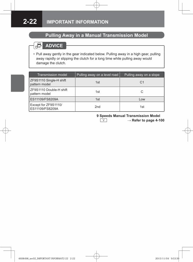
Pulling Away in a Manual Transmission Model
ADVICEPull away gently in the gear indicated below. Pulling away in a high gear, pulling away rapidly or slipping the clutch for a long time while pulling away would damage the clutch.
•
Transmission model Pulling away on a level road Pulling away on a slope
ZF9S1110 Single-H shift pattern model 1st C1
ZF9S1110 Double-H shift pattern model 1st C
ES11109/FS8209A 1st Low
Except for ZF9S1110/ES11109/FS8209A 2nd 1st
9 Speeds Manual Transmission Model V → Refer to page 4-100
4608498_sec02_IMPORTANT INFORMAT2-22 2-224608498_sec02_IMPORTANT INFORMAT2-22 2-22 2015/11/04 9:53:392015/11/04 9:53:39
2-23IMPORTANT INFORMATION
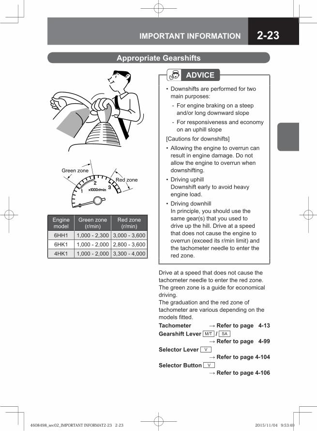
Appropriate Gearshifts
ADVICEDownshifts are performed for two main purposes:
For engine braking on a steep and/or long downward slopeFor responsiveness and economy on an uphill slope
[Cautions for downshifts]Allowing the engine to overrun can result in engine damage. Do not allow the engine to overrun when downshifting. Driving uphillDownshift early to avoid heavy engine load.Driving downhillIn principle, you should use the same gear(s) that you used to drive up the hill. Drive at a speed that does not cause the engine to overrun (exceed its r/min limit) and the tachometer needle to enter the red zone.
•
-
-
•
•
•
Drive at a speed that does not cause the tachometer needle to enter the red zone. The green zone is a guide for economical driving. The graduation and the red zone of tachometer are various depending on the models fitted.Tachometer → Refer to page 4-13Gearshift Lever M/T / SA
→ Refer to page 4-99Selector Lever V
→ Refer to page 4-104Selector Button V
→ Refer to page 4-106
� � ���
�� � ���
Engine model
Green zone (r/min)
Red zone (r/min)
6HH1 1,000 - 2,300 3,000 - 3,600
6HK1 1,000 - 2,000 2,800 - 3,600
4HK1 1,000 - 2,000 3,300 - 4,000
4608498_sec02_IMPORTANT INFORMAT2-23 2-234608498_sec02_IMPORTANT INFORMAT2-23 2-23 2015/11/04 9:53:402015/11/04 9:53:40
2-24 IMPORTANT INFORMATION
�� �
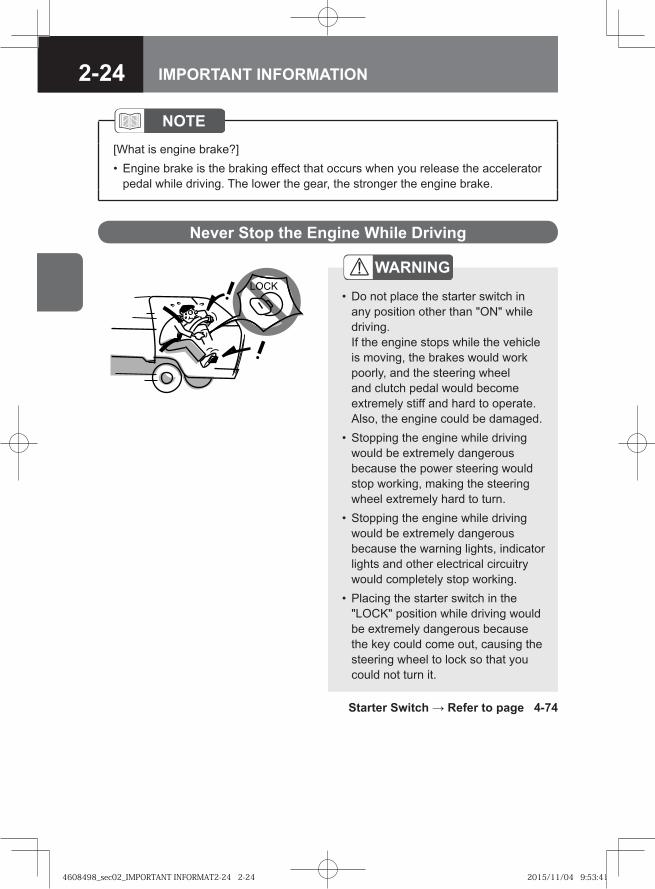
Never Stop the Engine While Driving
WARNING
Do not place the starter switch in any position other than "ON" while driving. If the engine stops while the vehicle is moving, the brakes would work poorly, and the steering wheel and clutch pedal would become extremely stiff and hard to operate. Also, the engine could be damaged. Stopping the engine while driving would be extremely dangerous because the power steering would stop working, making the steering wheel extremely hard to turn.Stopping the engine while driving would be extremely dangerous because the warning lights, indicator lights and other electrical circuitry would completely stop working.Placing the starter switch in the "LOCK" position while driving would be extremely dangerous because the key could come out, causing the steering wheel to lock so that you could not turn it.
•
•
•
•
Starter Switch → Refer to page 4-74
NOTE[What is engine brake?]
Engine brake is the braking effect that occurs when you release the accelerator pedal while driving. The lower the gear, the stronger the engine brake.
•
4608498_sec02_IMPORTANT INFORMAT2-24 2-244608498_sec02_IMPORTANT INFORMAT2-24 2-24 2015/11/04 9:53:412015/11/04 9:53:41
2-25IMPORTANT INFORMATION
CAUTIONIt is not possible to hold a person's body in position on the bed. Using the bed while the vehicle is moving would be dangerous because the occupant of the bed could be thrown out of the bed in the event of a collision or hard braking.
•
Do not Use the Bed While the Vehicle is Moving
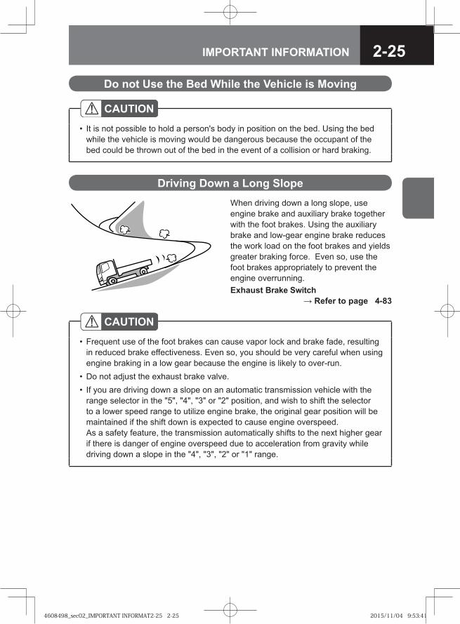
When driving down a long slope, use engine brake and auxiliary brake together with the foot brakes. Using the auxiliary brake and low-gear engine brake reduces the work load on the foot brakes and yields greater braking force. Even so, use the foot brakes appropriately to prevent the engine overrunning.Exhaust Brake Switch
→ Refer to page 4-83
Driving Down a Long Slope
CAUTIONFrequent use of the foot brakes can cause vapor lock and brake fade, resulting in reduced brake effectiveness. Even so, you should be very careful when using engine braking in a low gear because the engine is likely to over-run. Do not adjust the exhaust brake valve.If you are driving down a slope on an automatic transmission vehicle with the range selector in the "5", "4", "3" or "2" position, and wish to shift the selector to a lower speed range to utilize engine brake, the original gear position will be maintained if the shift down is expected to cause engine overspeed.As a safety feature, the transmission automatically shifts to the next higher gear if there is danger of engine overspeed due to acceleration from gravity while driving down a slope in the "4", "3", "2" or "1" range.
•
••
4608498_sec02_IMPORTANT INFORMAT2-25 2-254608498_sec02_IMPORTANT INFORMAT2-25 2-25 2015/11/04 9:53:412015/11/04 9:53:41
2-26 IMPORTANT INFORMATION
NOTE[What is engine brake?]
Engine brake is the braking effect that occurs when you release the accelerator pedal while driving. The lower the gear, the stronger the engine brake. On an automatic transmission vehicle, engine brake is most effective when the lockup clutch is engaged connecting the engine directly to the powertrain.
[What is the exhaust brake?]The exhaust brake is a system that closes the exhaust pipe and uses the force of the exhaust emissions to enhance the effectiveness of engine brake.
[What is brake fade?]Frequent use of the brakes can cause the brakes to overheat so that the frictional force of the friction surface decreases and the brakes become less effective than normal. This phenomenon is called brake fade.
[What is vapor lock?]If the brakes overheat due to frequent use, the heat can cause the brake fluid to boil so that air bubbles are created in the brake hoses. Pressing the brake pedal simply compresses the air bubbles; pressure is not transmitted to the wheel cylinders, so the brakes' effectiveness sharply deteriorates. This phenomenon is called vapor lock.
[What is an engine overrun?]An engine overrun is an engine-speed increase that causes the tachometer needle to enter the red zone.
•
•
•
•
•
4608498_sec02_IMPORTANT INFORMAT2-26 2-264608498_sec02_IMPORTANT INFORMAT2-26 2-26 2015/11/04 9:53:422015/11/04 9:53:42
2-27IMPORTANT INFORMATION
Driving in Bad Weather (Rain, Icy Roads, Snowy Roads, etc.)
ADVICEThere is a risk of hydroplaning, particularly where water tends to collect on the road surface. Drive at speeds that allow you to stay in complete control.If you cannot avoid driving on a flooded road, first check the depth of the water and then drive through the water at a slow, constant speed. There is a risk that water will get into the engine's cylinders and cause engine damage (water hammering). Keep your speed down, and drive with great care.
•
•
NOTE[What is hydroplaning?]
If a vehicle is driven at high speed on a road that is covered with water, a layer of water can form between the tires and road surface, causing the tires to lose their grip and slide across the water. This phenomenon is called hydroplaning. It is dangerous because it makes the steering wheel and brakes useless.
•
CAUTIONIn bad weather, visibility is reduced and slippery road surfaces increase stopping distances. Drive more slowly than you would in good weather. Also, avoid sharp turns of the steering wheel and hard braking. Use engine brakes together with the foot brakes to decelerate. Using the exhaust brake on a slippery road surface could cause the tires to slip.
•
4608498_sec02_IMPORTANT INFORMAT2-27 2-274608498_sec02_IMPORTANT INFORMAT2-27 2-27 2015/11/04 9:53:422015/11/04 9:53:42
2-28 IMPORTANT INFORMATION
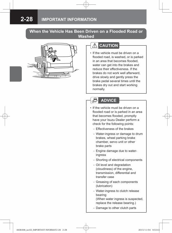
CAUTIONIf the vehicle must be driven on a flooded road, is washed, or is parked in an area that becomes flooded, water can get into the brakes and reduce their effectiveness. If the brakes do not work well afterward, drive slowly and gently press the brake pedal several times until the brakes dry out and start working normally.
•
ADVICEIf the vehicle must be driven on a flooded road or is parked in an area that becomes flooded, promptly have your Isuzu Dealer perform a check for the following points:
Effectiveness of the brakesWater-ingress or damage to drum brakes, wheel parking brake chamber, servo unit or other brake partsEngine damage due to water-ingressShorting of electrical componentsOil level and degradation (cloudiness) of the engine, transmission, differential and transfer caseGreasing of each components (lubrication)Water-ingress to clutch release bearing (When water ingress is suspected, replace the release bearing.)Damage to other clutch parts
•
--
-
--
-
-
-
When the Vehicle Has Been Driven on a Flooded Road or Washed
4608498_sec02_IMPORTANT INFORMAT2-28 2-284608498_sec02_IMPORTANT INFORMAT2-28 2-28 2015/11/04 9:53:432015/11/04 9:53:43
2-29IMPORTANT INFORMATION
Spare Tire V → Refer to page 7-117Handling the Jacks
→ Refer to page 7-180Changing a Tire (JIS 6-Bolt or 8-Bolt
Wheels) V → Refer to page 7-101Changing a Tire (ISO 10-Bolt
Wheels) V → Refer to page 7-110
Sidewinds
ADVICEIf the vehicle catches a sidewind and drifts sideways, firmly grip the steering wheel, decelerate to a speed that allows you to stay completely in control and make a directional correction. The vehicle may catch strong sidewinds in the following situations:
emerging from a tunnel; driving over a bridge, driving on an embankment or driving through a cuttingbeing overtaken by a large truck or busovertaking a large truck or bus
•
••
Dealing with a Blowout or Flat Tire While Driving
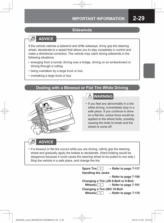
ADVICEIf a blowout or flat tire occurs while you are driving, calmly grip the steering wheel and gradually apply the brakes to decelerate. (Hard braking would be dangerous because it could cause the steering wheel to be pulled to one side.) Stop the vehicle in a safe place, and change the tire.
•
WARNING
If you feel any abnormality in a tire while driving, immediately stop in a safe place. If you continue to drive on a flat tire, undue force would be applied to the wheel bolts, possibly causing the bolts to break and the wheel to come off.
•
4608498_sec02_IMPORTANT INFORMAT2-29 2-294608498_sec02_IMPORTANT INFORMAT2-29 2-29 2015/11/04 9:53:432015/11/04 9:53:43
2-30 IMPORTANT INFORMATION
If the Underside of the Vehicle Receives a Hard Bump
ADVICEIf the underside of the vehicle receives a hard bump, stop in a safe place where the vehicle will not obstruct traffic and check for air leakage, brake fluid leakage, fuel leakage and component damage. If any part of the vehicle is damaged or broken, promptly have the vehicle inspected and repaired by the nearest Isuzu Dealer.
•
How to Read the Instruments (Instruments Layout) → Refer to page 4-10
Warning and Indicator Lights Layout → Refer to page 4-18
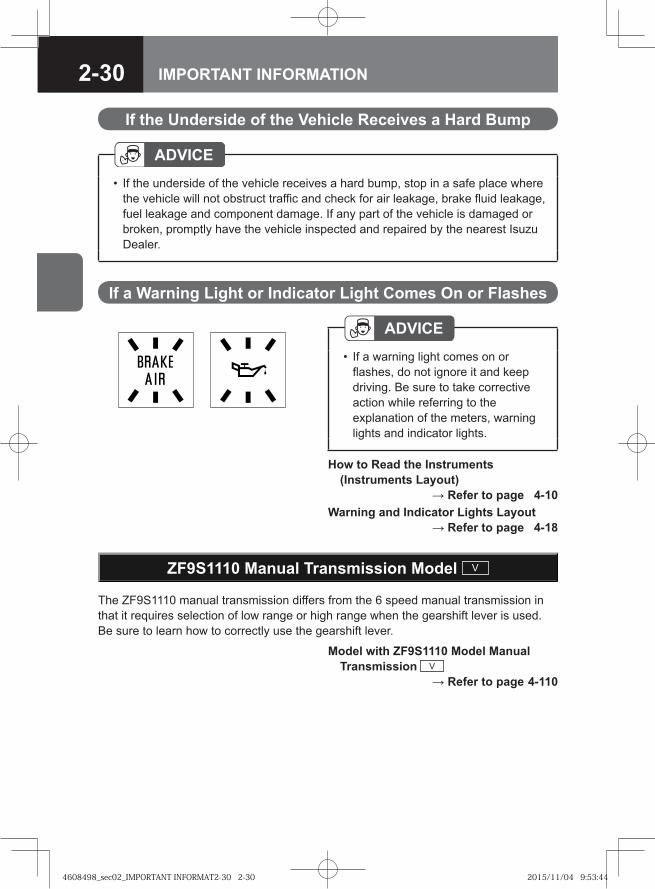
ADVICEIf a warning light comes on or flashes, do not ignore it and keep driving. Be sure to take corrective action while referring to the explanation of the meters, warning lights and indicator lights.
•
If a Warning Light or Indicator Light Comes On or Flashes
ZF9S1110 Manual Transmission Model V
The ZF9S1110 manual transmission differs from the 6 speed manual transmission in that it requires selection of low range or high range when the gearshift lever is used. Be sure to learn how to correctly use the gearshift lever.
Model with ZF9S1110 Model Manual Transmission V → Refer to page 4-110
4608498_sec02_IMPORTANT INFORMAT2-30 2-304608498_sec02_IMPORTANT INFORMAT2-30 2-30 2015/11/04 9:53:442015/11/04 9:53:44
2-31IMPORTANT INFORMATION
ES11109/FS8209A Manual Transmission Model V
The ES11109 or FS8209A manual transmission differs from the 6 speed manual transmission in that it requires selection of low range or high range when the gearshift lever is used. Be sure to learn how to correctly use the gearshift lever.
Model with ES11109/FS8209A Model Manual Transmission V → Refer to page 4-114
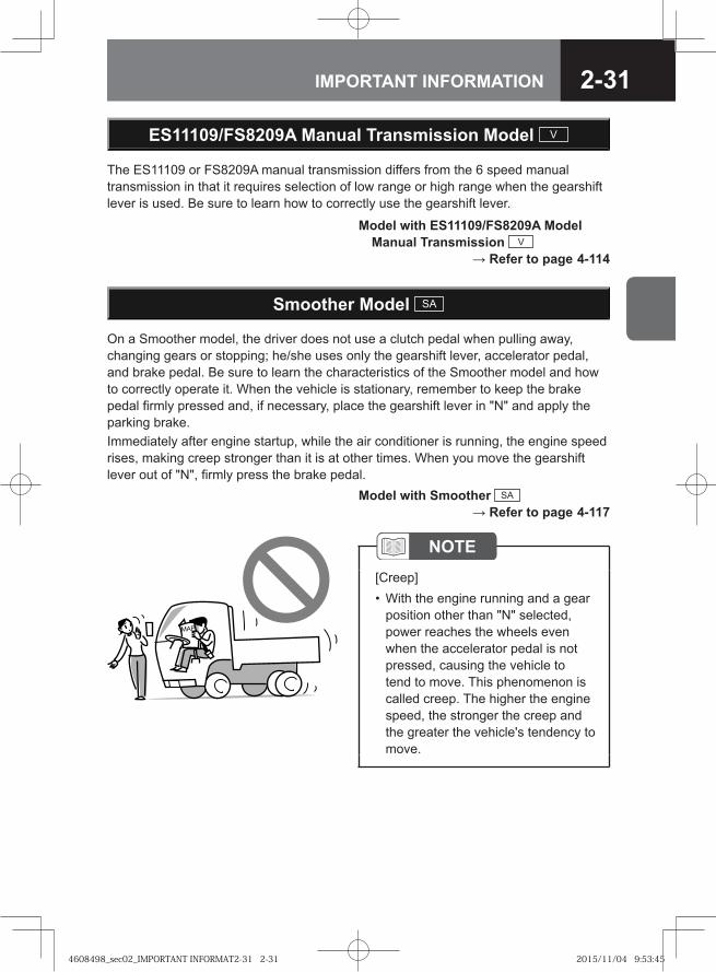
On a Smoother model, the driver does not use a clutch pedal when pulling away, changing gears or stopping; he/she uses only the gearshift lever, accelerator pedal, and brake pedal. Be sure to learn the characteristics of the Smoother model and how to correctly operate it. When the vehicle is stationary, remember to keep the brake pedal firmly pressed and, if necessary, place the gearshift lever in "N" and apply the parking brake. Immediately after engine startup, while the air conditioner is running, the engine speed rises, making creep stronger than it is at other times. When you move the gearshift lever out of "N", firmly press the brake pedal.
Smoother Model SA
Model with Smoother SA → Refer to page 4-117
���
NOTE[Creep]
With the engine running and a gear position other than "N" selected, power reaches the wheels even when the accelerator pedal is not pressed, causing the vehicle to tend to move. This phenomenon is called creep. The higher the engine speed, the stronger the creep and the greater the vehicle's tendency to move.
•
4608498_sec02_IMPORTANT INFORMAT2-31 2-314608498_sec02_IMPORTANT INFORMAT2-31 2-31 2015/11/04 9:53:452015/11/04 9:53:45
2-32 IMPORTANT INFORMATION
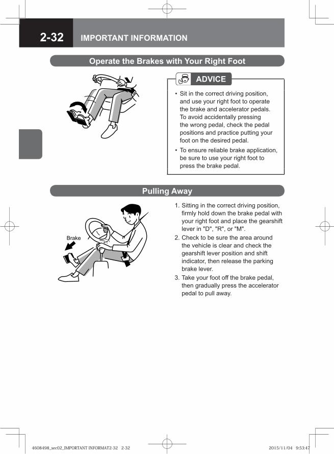
1. Sitting in the correct driving position, firmly hold down the brake pedal with your right foot and place the gearshift lever in "D", "R", or "M".
2. Check to be sure the area around the vehicle is clear and check the gearshift lever position and shift indicator, then release the parking brake lever.
3. Take your foot off the brake pedal, then gradually press the accelerator pedal to pull away.
� ���
Operate the Brakes with Your Right Foot
ADVICESit in the correct driving position, and use your right foot to operate the brake and accelerator pedals. To avoid accidentally pressing the wrong pedal, check the pedal positions and practice putting your foot on the desired pedal.To ensure reliable brake application, be sure to use your right foot to press the brake pedal.
•
•
Pulling Away
4608498_sec02_IMPORTANT INFORMAT2-32 2-324608498_sec02_IMPORTANT INFORMAT2-32 2-32 2015/11/04 9:53:472015/11/04 9:53:47
2-33IMPORTANT INFORMATION
WARNING
When you move the gearshift lever to a position other than "N", creep will cause the vehicle to move. When pulling away, be sure to keep the brake pedal pressed as you operate the gearshift lever.Do not hold down the accelerator pedal while operating the gearshift lever. The vehicle would abruptly start moving, possibly causing an accident.Immediately after engine startup, while the air conditioner is running, the engine speed automatically rises, making creep stronger than it is at other times. Keep the brake pedal firmly pressed.
•
•
•
ADVICE[Essential points for safety]
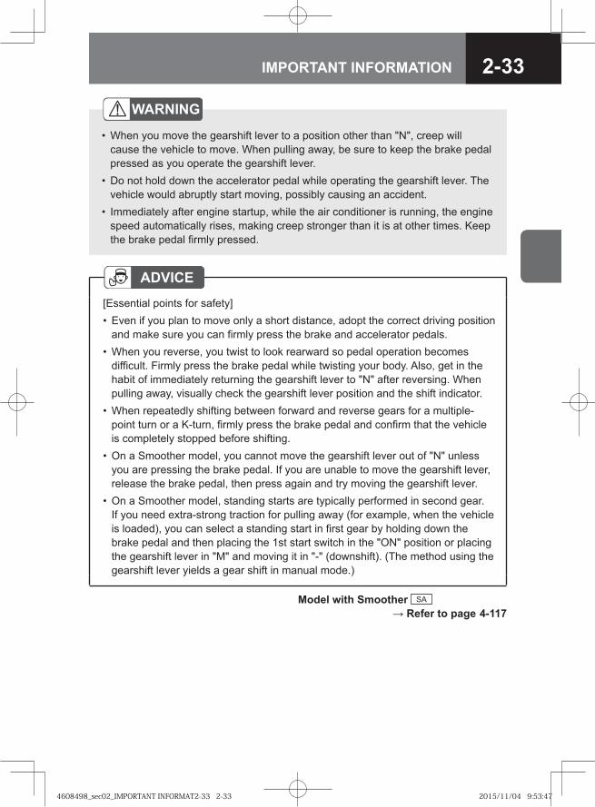
Even if you plan to move only a short distance, adopt the correct driving position and make sure you can firmly press the brake and accelerator pedals.When you reverse, you twist to look rearward so pedal operation becomes difficult. Firmly press the brake pedal while twisting your body. Also, get in the habit of immediately returning the gearshift lever to "N" after reversing. When pulling away, visually check the gearshift lever position and the shift indicator.When repeatedly shifting between forward and reverse gears for a multiple-point turn or a K-turn, firmly press the brake pedal and confirm that the vehicle is completely stopped before shifting.On a Smoother model, you cannot move the gearshift lever out of "N" unless you are pressing the brake pedal. If you are unable to move the gearshift lever, release the brake pedal, then press again and try moving the gearshift lever.On a Smoother model, standing starts are typically performed in second gear. If you need extra-strong traction for pulling away (for example, when the vehicle is loaded), you can select a standing start in first gear by holding down the brake pedal and then placing the 1st start switch in the "ON" position or placing the gearshift lever in "M" and moving it in "-" (downshift). (The method using the gearshift lever yields a gear shift in manual mode.)
•
•
•
•
•
Model with Smoother SA → Refer to page 4-117
4608498_sec02_IMPORTANT INFORMAT2-33 2-334608498_sec02_IMPORTANT INFORMAT2-33 2-33 2015/11/04 9:53:472015/11/04 9:53:47
2-34 IMPORTANT INFORMATION
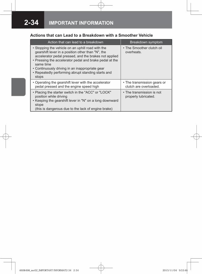
Actions that can Lead to a Breakdown with a Smoother VehicleAction that can lead to a breakdown Breakdown symptom
Stopping the vehicle on an uphill road with the gearshift lever in a position other than "N", the accelerator pedal pressed, and the brakes not appliedPressing the accelerator pedal and brake pedal at the same timeContinuously driving in an inappropriate gearRepeatedly performing abrupt standing starts and stops
•
•
••
The Smoother clutch oil overheats.
•
Operating the gearshift lever with the accelerator pedal pressed and the engine speed high
• The transmission gears or clutch are overloaded.
•
Placing the starter switch in the "ACC" or "LOCK" position while drivingKeeping the gearshift lever in "N" on a long downward slope (this is dangerous due to the lack of engine brake)
•
•
The transmission is not properly lubricated.
•
4608498_sec02_IMPORTANT INFORMAT2-34 2-344608498_sec02_IMPORTANT INFORMAT2-34 2-34 2015/11/04 9:53:482015/11/04 9:53:48
2-35IMPORTANT INFORMATION
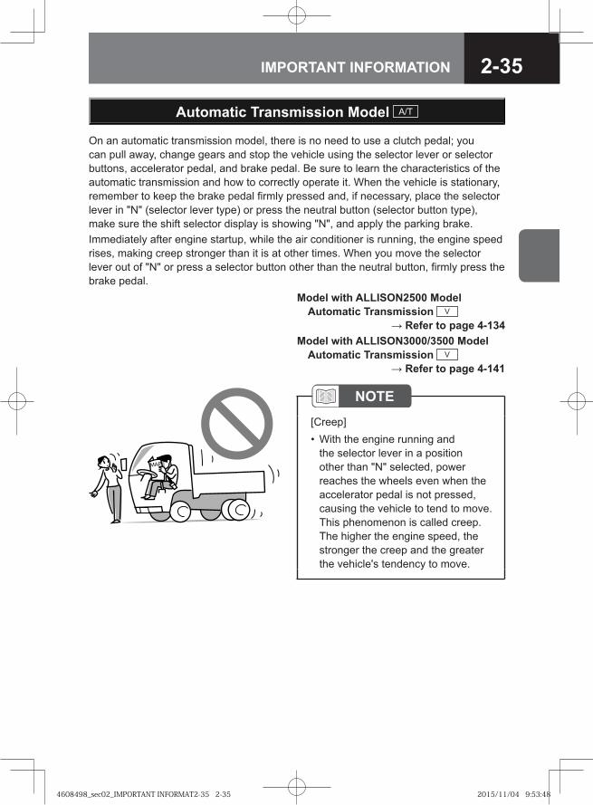
On an automatic transmission model, there is no need to use a clutch pedal; you can pull away, change gears and stop the vehicle using the selector lever or selector buttons, accelerator pedal, and brake pedal. Be sure to learn the characteristics of the automatic transmission and how to correctly operate it. When the vehicle is stationary, remember to keep the brake pedal firmly pressed and, if necessary, place the selector lever in "N" (selector lever type) or press the neutral button (selector button type), make sure the shift selector display is showing "N", and apply the parking brake.Immediately after engine startup, while the air conditioner is running, the engine speed rises, making creep stronger than it is at other times. When you move the selector lever out of "N" or press a selector button other than the neutral button, firmly press the brake pedal.
���
Automatic Transmission Model A/T
NOTE[Creep]
With the engine running and the selector lever in a position other than "N" selected, power reaches the wheels even when the accelerator pedal is not pressed, causing the vehicle to tend to move. This phenomenon is called creep. The higher the engine speed, the stronger the creep and the greater the vehicle's tendency to move.
•
Model with ALLISON2500 Model Automatic Transmission V → Refer to page 4-134
Model with ALLISON3000/3500 Model Automatic Transmission V → Refer to page 4-141
4608498_sec02_IMPORTANT INFORMAT2-35 2-354608498_sec02_IMPORTANT INFORMAT2-35 2-35 2015/11/04 9:53:482015/11/04 9:53:48
2-36 IMPORTANT INFORMATION
Four-wheel drive does not make it possible to drive a vehicle absolutely everywhere. Exercise caution when using the accelerator pedal, steering wheel and brake pedal. Concentrate on driving safely, paying attention to the condition and slope angle of the road surface.
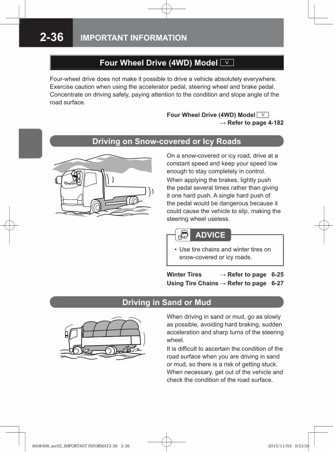
On a snow-covered or icy road, drive at a constant speed and keep your speed low enough to stay completely in control.When applying the brakes, lightly push the pedal several times rather than giving it one hard push. A single hard push of the pedal would be dangerous because it could cause the vehicle to slip, making the steering wheel useless.
Winter Tires → Refer to page 6-25Using Tire Chains → Refer to page 6-27
Four Wheel Drive (4WD) Model V
Driving on Snow-covered or Icy Roads
ADVICEUse tire chains and winter tires on snow-covered or icy roads.
•
Four Wheel Drive (4WD) Model V → Refer to page 4-182
When driving in sand or mud, go as slowly as possible, avoiding hard braking, sudden acceleration and sharp turns of the steering wheel. It is difficult to ascertain the condition of the road surface when you are driving in sand or mud, so there is a risk of getting stuck. When necessary, get out of the vehicle and check the condition of the road surface.
Driving in Sand or Mud
4608498_sec02_IMPORTANT INFORMAT2-36 2-364608498_sec02_IMPORTANT INFORMAT2-36 2-36 2015/11/04 9:53:502015/11/04 9:53:50
2-37IMPORTANT INFORMATION
NOTEWhen you cannot avoid driving through deep mud, using tire chains is an effective way to avoid getting stuck.
•
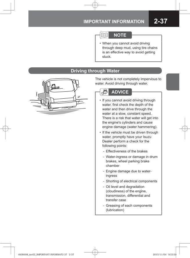
Driving through WaterThe vehicle is not completely impervious to water. Avoid driving through water.
ADVICEIf you cannot avoid driving through water, first check the depth of the water and then drive through the water at a slow, constant speed. There is a risk that water will get into the engine's cylinders and cause engine damage (water hammering).If the vehicle must be driven through water, promptly have your Isuzu Dealer perform a check for the following points:
Effectiveness of the brakesWater-ingress or damage in drum brakes, wheel parking brake chamberEngine damage due to water-ingressShorting of electrical componentsOil level and degradation (cloudiness) of the engine, transmission, differential and transfer caseGreasing of each components (lubrication)
•
•
--
-
--
-
4608498_sec02_IMPORTANT INFORMAT2-37 2-374608498_sec02_IMPORTANT INFORMAT2-37 2-37 2015/11/04 9:53:502015/11/04 9:53:50
2-38 IMPORTANT INFORMATION
Applying the Parking Brake
Stopping and Parking
Parking
ADVICEChoose a flat place where stopping and parking are permitted and where the vehicle will not obstruct traffic. Firmly apply the parking brake and make sure the vehicle does not move.Avoid parking for long periods with cargo on the vehicle.Remove all dirt from the vehicle's light lenses and reflectors to ensure that the vehicle can be seen from other vehicles.
•
••
Parking Brake Lever → Refer to page 4-95
CAUTIONExcept in an emergency, do not apply the parking brake until the vehicle has come to a complete stop. Applying the parking brake before the vehicle has stopped can cause the tires to lock or the vehicle to spin, possibly causing an accident.
•
4608498_sec02_IMPORTANT INFORMAT2-38 2-384608498_sec02_IMPORTANT INFORMAT2-38 2-38 2015/11/04 9:53:512015/11/04 9:53:51
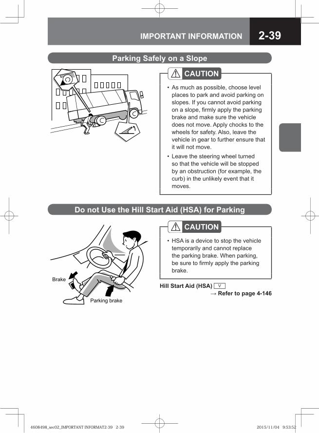
2-39IMPORTANT INFORMATION
Hill Start Aid (HSA) V → Refer to page 4-146
�� �
��� ��� ��� �
Do not Use the Hill Start Aid (HSA) for Parking
CAUTIONHSA is a device to stop the vehicle temporarily and cannot replace the parking brake. When parking, be sure to firmly apply the parking brake.
•
Parking Safely on a Slope
CAUTIONAs much as possible, choose level places to park and avoid parking on slopes. If you cannot avoid parking on a slope, firmly apply the parking brake and make sure the vehicle does not move. Apply chocks to the wheels for safety. Also, leave the vehicle in gear to further ensure that it will not move.Leave the steering wheel turned so that the vehicle will be stopped by an obstruction (for example, the curb) in the unlikely event that it moves.
•
•
4608498_sec02_IMPORTANT INFORMAT2-39 2-394608498_sec02_IMPORTANT INFORMAT2-39 2-39 2015/11/04 9:53:522015/11/04 9:53:52
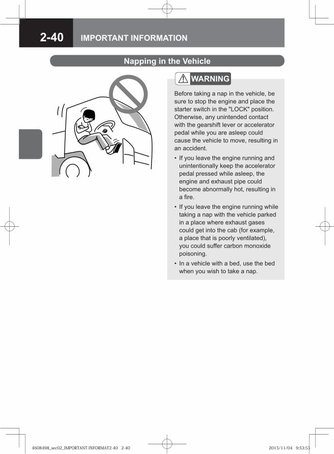
2-40 IMPORTANT INFORMATION
Napping in the Vehicle
WARNING
Before taking a nap in the vehicle, be sure to stop the engine and place the starter switch in the "LOCK" position. Otherwise, any unintended contact with the gearshift lever or accelerator pedal while you are asleep could cause the vehicle to move, resulting in an accident.
If you leave the engine running and unintentionally keep the accelerator pedal pressed while asleep, the engine and exhaust pipe could become abnormally hot, resulting in a fire.If you leave the engine running while taking a nap with the vehicle parked in a place where exhaust gases could get into the cab (for example, a place that is poorly ventilated), you could suffer carbon monoxide poisoning.In a vehicle with a bed, use the bed when you wish to take a nap.
•
•
•
4608498_sec02_IMPORTANT INFORMAT2-40 2-404608498_sec02_IMPORTANT INFORMAT2-40 2-40 2015/11/04 9:53:532015/11/04 9:53:53
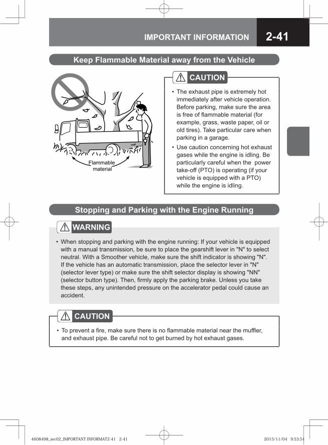
2-41IMPORTANT INFORMATION
Flammable material
Keep Flammable Material away from the Vehicle
Stopping and Parking with the Engine Running
WARNING
When stopping and parking with the engine running: If your vehicle is equipped with a manual transmission, be sure to place the gearshift lever in "N" to select neutral. With a Smoother vehicle, make sure the shift indicator is showing "N". If the vehicle has an automatic transmission, place the selector lever in "N" (selector lever type) or make sure the shift selector display is showing "NN" (selector button type). Then, firmly apply the parking brake. Unless you take these steps, any unintended pressure on the accelerator pedal could cause an accident.
•
CAUTIONTo prevent a fire, make sure there is no flammable material near the muffler, and exhaust pipe. Be careful not to get burned by hot exhaust gases.
•
CAUTIONThe exhaust pipe is extremely hot immediately after vehicle operation. Before parking, make sure the area is free of flammable material (for example, grass, waste paper, oil or old tires). Take particular care when parking in a garage.Use caution concerning hot exhaust gases while the engine is idling. Be particularly careful when the power take-off (PTO) is operating (if your vehicle is equipped with a PTO) while the engine is idling.
•
•
4608498_sec02_IMPORTANT INFORMAT2-41 2-414608498_sec02_IMPORTANT INFORMAT2-41 2-41 2015/11/04 9:53:542015/11/04 9:53:54
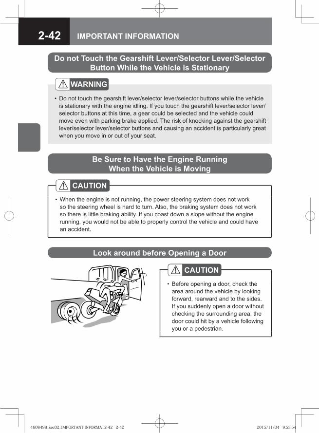
2-42 IMPORTANT INFORMATION
Do not Touch the Gearshift Lever/Selector Lever/Selector Button While the Vehicle is Stationary
WARNING
Do not touch the gearshift lever/selector lever/selector buttons while the vehicle is stationary with the engine idling. If you touch the gearshift lever/selector lever/selector buttons at this time, a gear could be selected and the vehicle could move even with parking brake applied. The risk of knocking against the gearshift lever/selector lever/selector buttons and causing an accident is particularly great when you move in or out of your seat.
•
CAUTIONWhen the engine is not running, the power steering system does not work so the steering wheel is hard to turn. Also, the braking system does not work so there is little braking ability. If you coast down a slope without the engine running, you would not be able to properly control the vehicle and could have an accident.
•
Be Sure to Have the Engine Running When the Vehicle is Moving
Look around before Opening a Door
CAUTIONBefore opening a door, check the area around the vehicle by looking forward, rearward and to the sides. If you suddenly open a door without checking the surrounding area, the door could hit by a vehicle following you or a pedestrian.
•
4608498_sec02_IMPORTANT INFORMAT2-42 2-424608498_sec02_IMPORTANT INFORMAT2-42 2-42 2015/11/04 9:53:542015/11/04 9:53:54
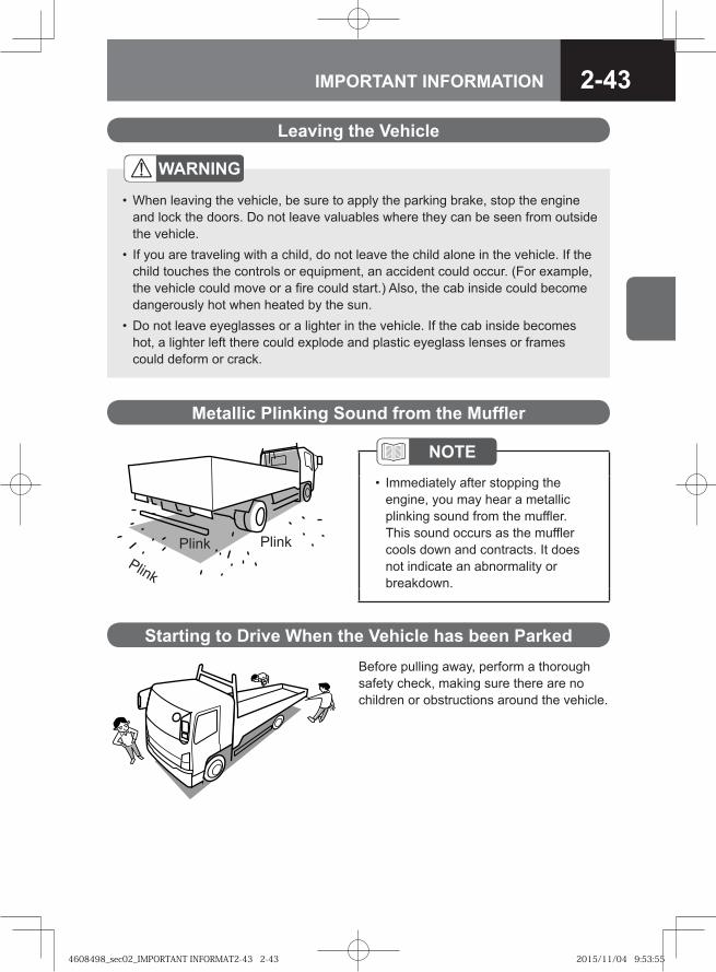
2-43IMPORTANT INFORMATION
Leaving the Vehicle
Plink
Plink Plink
Metallic Plinking Sound from the Muffler
NOTEImmediately after stopping the engine, you may hear a metallic plinking sound from the muffler. This sound occurs as the muffler cools down and contracts. It does not indicate an abnormality or breakdown.
•
Before pulling away, perform a thorough safety check, making sure there are no children or obstructions around the vehicle.
Starting to Drive When the Vehicle has been Parked
WARNING
When leaving the vehicle, be sure to apply the parking brake, stop the engine and lock the doors. Do not leave valuables where they can be seen from outside the vehicle.If you are traveling with a child, do not leave the child alone in the vehicle. If the child touches the controls or equipment, an accident could occur. (For example, the vehicle could move or a fire could start.) Also, the cab inside could become dangerously hot when heated by the sun. Do not leave eyeglasses or a lighter in the vehicle. If the cab inside becomes hot, a lighter left there could explode and plastic eyeglass lenses or frames could deform or crack.
•
•
•
4608498_sec02_IMPORTANT INFORMAT2-43 2-434608498_sec02_IMPORTANT INFORMAT2-43 2-43 2015/11/04 9:53:552015/11/04 9:53:55
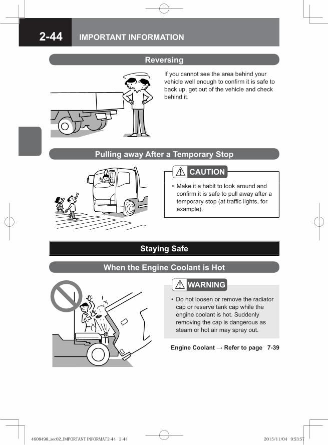
2-44 IMPORTANT INFORMATION
If you cannot see the area behind your vehicle well enough to confirm it is safe to back up, get out of the vehicle and check behind it.
Reversing
Pulling away After a Temporary Stop
CAUTIONMake it a habit to look around and confirm it is safe to pull away after a temporary stop (at traffic lights, for example).
•
Engine Coolant → Refer to page 7-39
Staying Safe
When the Engine Coolant is Hot
WARNING
Do not loosen or remove the radiator cap or reserve tank cap while the engine coolant is hot. Suddenly removing the cap is dangerous as steam or hot air may spray out.
•
4608498_sec02_IMPORTANT INFORMAT2-44 2-444608498_sec02_IMPORTANT INFORMAT2-44 2-44 2015/11/04 9:53:572015/11/04 9:53:57
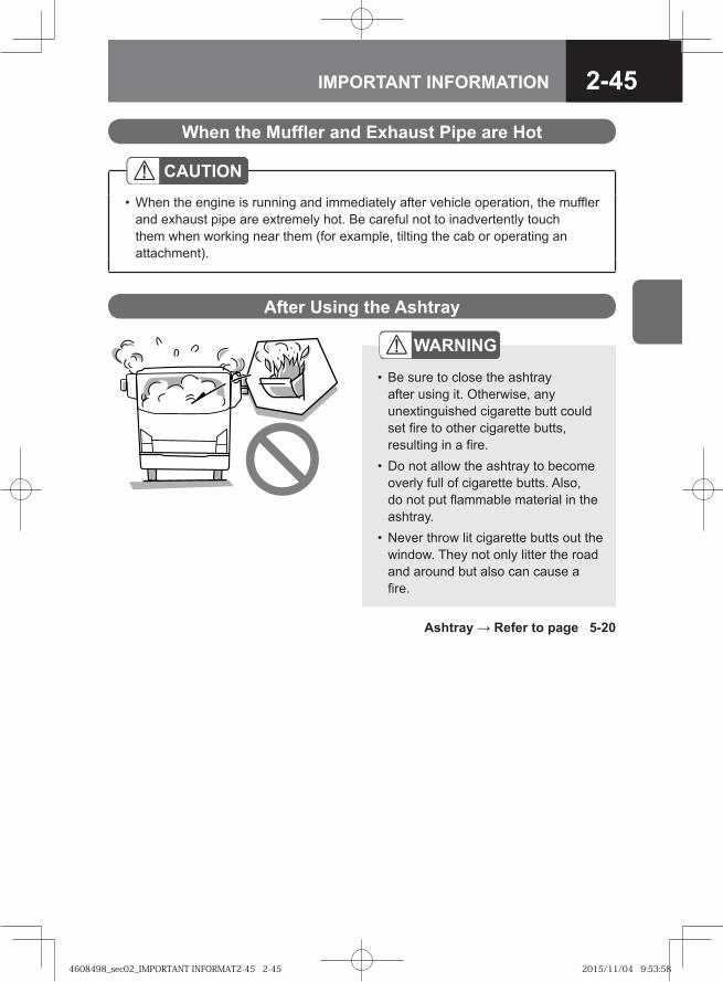
2-45IMPORTANT INFORMATION
After Using the Ashtray
WARNING
Be sure to close the ashtray after using it. Otherwise, any unextinguished cigarette butt could set fire to other cigarette butts, resulting in a fire.Do not allow the ashtray to become overly full of cigarette butts. Also, do not put flammable material in the ashtray.Never throw lit cigarette butts out the window. They not only litter the road and around but also can cause a fire.
•
•
•
Ashtray → Refer to page 5-20
When the Muffler and Exhaust Pipe are Hot
CAUTIONWhen the engine is running and immediately after vehicle operation, the muffler and exhaust pipe are extremely hot. Be careful not to inadvertently touch them when working near them (for example, tilting the cab or operating an attachment).
•
4608498_sec02_IMPORTANT INFORMAT2-45 2-454608498_sec02_IMPORTANT INFORMAT2-45 2-45 2015/11/04 9:53:582015/11/04 9:53:58
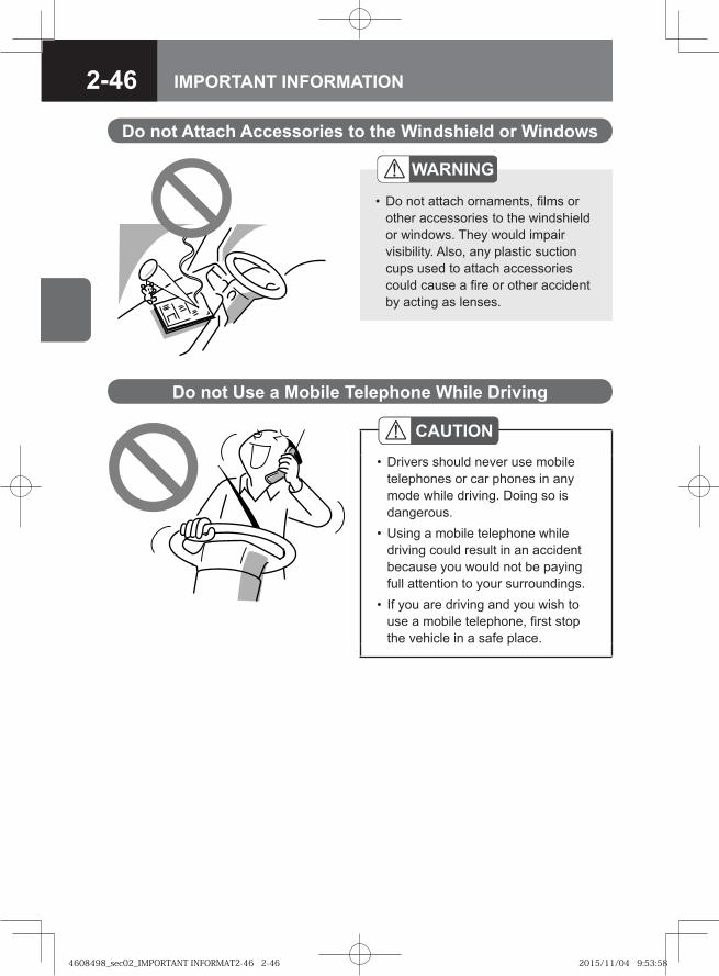
2-46 IMPORTANT INFORMATION
Do not Attach Accessories to the Windshield or Windows
WARNING
Do not attach ornaments, films or other accessories to the windshield or windows. They would impair visibility. Also, any plastic suction cups used to attach accessories could cause a fire or other accident by acting as lenses.
•
Do not Use a Mobile Telephone While Driving
CAUTIONDrivers should never use mobile telephones or car phones in any mode while driving. Doing so is dangerous.Using a mobile telephone while driving could result in an accident because you would not be paying full attention to your surroundings.If you are driving and you wish to use a mobile telephone, first stop the vehicle in a safe place.
•
•
•
4608498_sec02_IMPORTANT INFORMAT2-46 2-464608498_sec02_IMPORTANT INFORMAT2-46 2-46 2015/11/04 9:53:582015/11/04 9:53:58
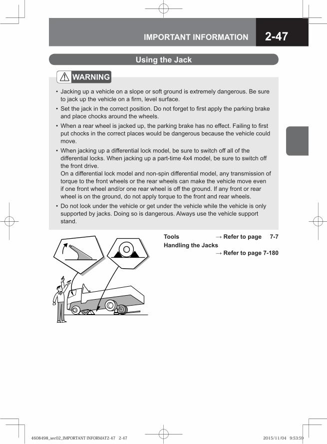
2-47IMPORTANT INFORMATION
Tools → Refer to page 7-7Handling the Jacks
→ Refer to page 7-180
Using the Jack
WARNING
Jacking up a vehicle on a slope or soft ground is extremely dangerous. Be sure to jack up the vehicle on a firm, level surface.Set the jack in the correct position. Do not forget to first apply the parking brake and place chocks around the wheels.When a rear wheel is jacked up, the parking brake has no effect. Failing to first put chocks in the correct places would be dangerous because the vehicle could move.When jacking up a differential lock model, be sure to switch off all of the differential locks. When jacking up a part-time 4x4 model, be sure to switch off the front drive. On a differential lock model and non-spin differential model, any transmission of torque to the front wheels or the rear wheels can make the vehicle move even if one front wheel and/or one rear wheel is off the ground. If any front or rear wheel is on the ground, do not apply torque to the front and rear wheels.Do not look under the vehicle or get under the vehicle while the vehicle is only supported by jacks. Doing so is dangerous. Always use the vehicle support stand.
•
•
•
•
•
4608498_sec02_IMPORTANT INFORMAT2-47 2-474608498_sec02_IMPORTANT INFORMAT2-47 2-47 2015/11/04 9:53:592015/11/04 9:53:59
2-48 IMPORTANT INFORMATION
If the Battery Goes Flat
When the Battery Goes Flat → Refer to page 8-11
CAUTIONDo not try to start the engine by pushing or towing the vehicle. You could damage the engine.
•
4608498_sec02_IMPORTANT INFORMAT2-48 2-484608498_sec02_IMPORTANT INFORMAT2-48 2-48 2015/11/04 9:54:002015/11/04 9:54:00
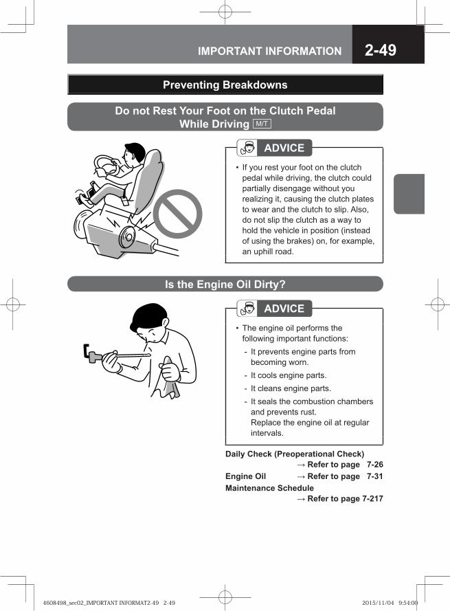
2-49IMPORTANT INFORMATION
Daily Check (Preoperational Check) → Refer to page 7-26
Engine Oil → Refer to page 7-31Maintenance Schedule
→ Refer to page 7-217
Is the Engine Oil Dirty?
ADVICEThe engine oil performs the following important functions:
It prevents engine parts from becoming worn.It cools engine parts.It cleans engine parts.It seals the combustion chambers and prevents rust.Replace the engine oil at regular intervals.
•
-
---
Preventing Breakdowns
ADVICEIf you rest your foot on the clutch pedal while driving, the clutch could partially disengage without you realizing it, causing the clutch plates to wear and the clutch to slip. Also, do not slip the clutch as a way to hold the vehicle in position (instead of using the brakes) on, for example, an uphill road.
•
Do not Rest Your Foot on the Clutch Pedal While Driving M/T
4608498_sec02_IMPORTANT INFORMAT2-49 2-494608498_sec02_IMPORTANT INFORMAT2-49 2-49 2015/11/04 9:54:002015/11/04 9:54:00
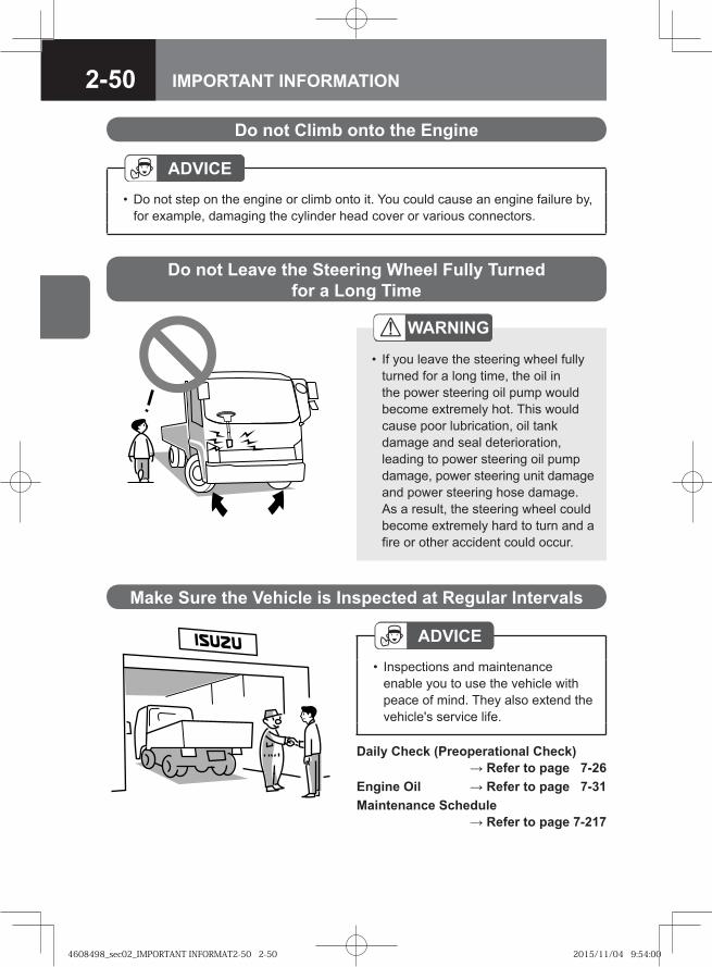
2-50 IMPORTANT INFORMATION
Do not Climb onto the Engine
ADVICEDo not step on the engine or climb onto it. You could cause an engine failure by, for example, damaging the cylinder head cover or various connectors.
•
Do not Leave the Steering Wheel Fully Turned for a Long Time
WARNING
If you leave the steering wheel fully turned for a long time, the oil in the power steering oil pump would become extremely hot. This would cause poor lubrication, oil tank damage and seal deterioration, leading to power steering oil pump damage, power steering unit damage and power steering hose damage. As a result, the steering wheel could become extremely hard to turn and a fire or other accident could occur.
•
Daily Check (Preoperational Check) → Refer to page 7-26
Engine Oil → Refer to page 7-31Maintenance Schedule
→ Refer to page 7-217
Make Sure the Vehicle is Inspected at Regular Intervals
ADVICEInspections and maintenance enable you to use the vehicle with peace of mind. They also extend the vehicle's service life.
•
4608498_sec02_IMPORTANT INFORMAT2-50 2-504608498_sec02_IMPORTANT INFORMAT2-50 2-50 2015/11/04 9:54:002015/11/04 9:54:00
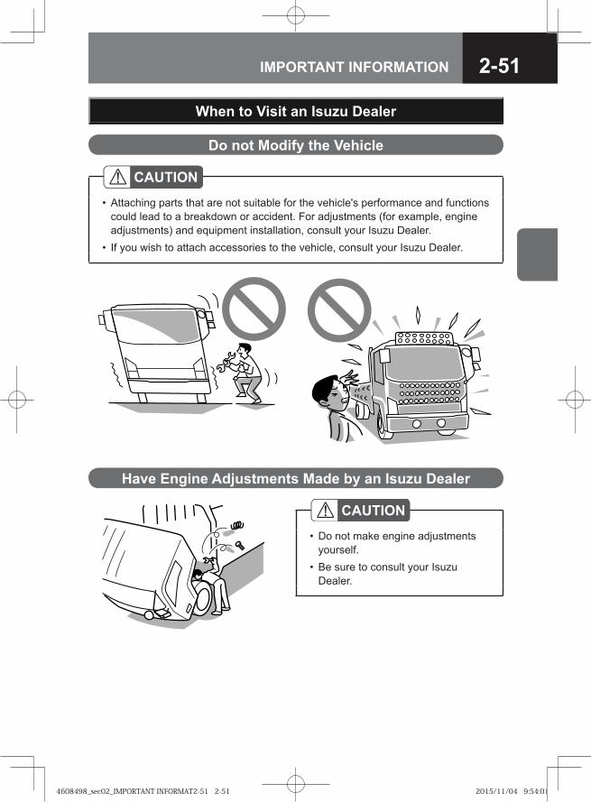
2-51IMPORTANT INFORMATION
When to Visit an Isuzu Dealer
Do not Modify the Vehicle
CAUTIONAttaching parts that are not suitable for the vehicle's performance and functions could lead to a breakdown or accident. For adjustments (for example, engine adjustments) and equipment installation, consult your Isuzu Dealer.If you wish to attach accessories to the vehicle, consult your Isuzu Dealer.
•
•
Have Engine Adjustments Made by an Isuzu Dealer
CAUTIONDo not make engine adjustments yourself.Be sure to consult your Isuzu Dealer.
•
•
4608498_sec02_IMPORTANT INFORMAT2-51 2-514608498_sec02_IMPORTANT INFORMAT2-51 2-51 2015/11/04 9:54:012015/11/04 9:54:01
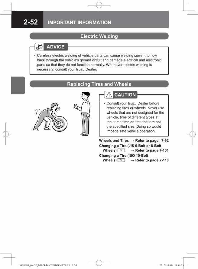
2-52 IMPORTANT INFORMATION
Wheels and Tires → Refer to page 7-92Changing a Tire (JIS 6-Bolt or 8-Bolt
Wheels) V → Refer to page 7-101Changing a Tire (ISO 10-Bolt
Wheels) V → Refer to page 7-110
Replacing Tires and Wheels
CAUTIONConsult your Isuzu Dealer before replacing tires or wheels. Never use wheels that are not designed for the vehicle, tires of different types at the same time or tires that are not the specified size. Doing so would impede safe vehicle operation.
•
Electric Welding
ADVICECareless electric welding of vehicle parts can cause welding current to flow back through the vehicle's ground circuit and damage electrical and electronic parts so that they do not function normally. Whenever electric welding is necessary, consult your Isuzu Dealer.
•
4608498_sec02_IMPORTANT INFORMAT2-52 2-524608498_sec02_IMPORTANT INFORMAT2-52 2-52 2015/11/04 9:54:032015/11/04 9:54:03
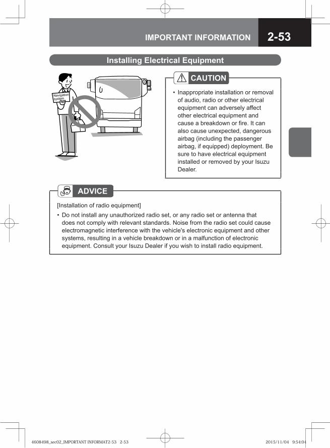
2-53IMPORTANT INFORMATION
�� �������
������
Installing Electrical Equipment
CAUTIONInappropriate installation or removal of audio, radio or other electrical equipment can adversely affect other electrical equipment and cause a breakdown or fire. It can also cause unexpected, dangerous airbag (including the passenger airbag, if equipped) deployment. Be sure to have electrical equipment installed or removed by your Isuzu Dealer.
•
ADVICE[Installation of radio equipment]
Do not install any unauthorized radio set, or any radio set or antenna that does not comply with relevant standards. Noise from the radio set could cause electromagnetic interference with the vehicle's electronic equipment and other systems, resulting in a vehicle breakdown or in a malfunction of electronic equipment. Consult your Isuzu Dealer if you wish to install radio equipment.
•
4608498_sec02_IMPORTANT INFORMAT2-53 2-534608498_sec02_IMPORTANT INFORMAT2-53 2-53 2015/11/04 9:54:042015/11/04 9:54:04
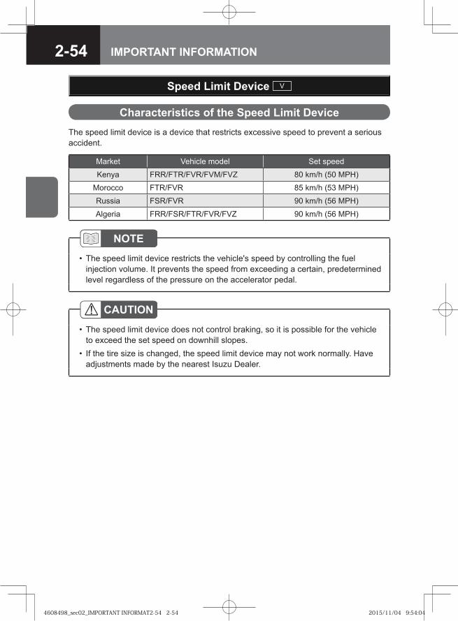
2-54 IMPORTANT INFORMATION
The speed limit device is a device that restricts excessive speed to prevent a serious accident.
Characteristics of the Speed Limit Device
CAUTIONThe speed limit device does not control braking, so it is possible for the vehicle to exceed the set speed on downhill slopes.If the tire size is changed, the speed limit device may not work normally. Have adjustments made by the nearest Isuzu Dealer.
•
•
NOTEThe speed limit device restricts the vehicle's speed by controlling the fuel injection volume. It prevents the speed from exceeding a certain, predetermined level regardless of the pressure on the accelerator pedal.
•
Market Vehicle model Set speed
Kenya FRR/FTR/FVR/FVM/FVZ 80 km/h (50 MPH)
Morocco FTR/FVR 85 km/h (53 MPH)
Russia FSR/FVR 90 km/h (56 MPH)
Algeria FRR/FSR/FTR/FVR/FVZ 90 km/h (56 MPH)
Speed Limit Device V
4608498_sec02_IMPORTANT INFORMAT2-54 2-544608498_sec02_IMPORTANT INFORMAT2-54 2-54 2015/11/04 9:54:042015/11/04 9:54:04
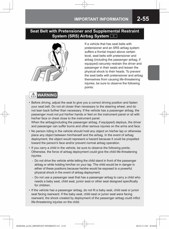
2-55IMPORTANT INFORMATION
If a vehicle that has seat belts with pretensioner and an SRS airbag system suffers a frontal impact above certain level, seat belts with pretensioner and airbag (including the passenger airbag, if equipped) securely restrain the driver and passenger in their seats and lessen the physical shock to their heads. To prevent the seat belts with pretensioner and airbag themselves from causing life-threatening injuries, be sure to observe the following points:
WARNING
Before driving, adjust the seat to give you a correct driving position and fasten your seat belt. Do not sit closer than necessary to the steering wheel, and do not lean back further than necessary. If the vehicle has a passenger airbag, the passenger must not put his/her hands or feet on the instrument panel or sit with his/her face or chest close to the instrument panel.When the airbag(including the passenger airbag, if equipped) deploys, the driver and passenger can suffer burns and other serious injuries on the arms and face.No person riding in the vehicle should hold any object on his/her lap or otherwise place any object between him/herself and the airbag. In the event of airbag deployment, the object would represent a hazard because it could be propelled toward the person's face and/or prevent normal airbag operation.If you carry a child in the vehicle, be sure to observe the following points. Otherwise, the force of airbag deployment could give the child life-threatening injuries.
Do not drive the vehicle while letting the child stand in front of the passenger airbag or while holding him/her on your lap. The child would be in danger in either of these positions because he/she would be exposed to a powerful physical shock in the event of airbag deployment.Do not use a passenger seat that has a passenger airbag to carry a child who needs a baby seat, child seat, junior seat or other seat designed specifically for children.
If the vehicle has a passenger airbag, do not fit a baby seat, child seat or junior seat facing rearward. If the baby seat, child seat or junior seat were facing rearward, the shock created by deployment of the passenger airbag could inflict life-threatening injuries on the child.
•
•
•
-
-
•
Seat Belt with Pretensioner and Supplemental Restraint System (SRS) Airbag System V
4608498_sec02_IMPORTANT INFORMAT2-55 2-554608498_sec02_IMPORTANT INFORMAT2-55 2-55 2015/11/04 9:54:042015/11/04 9:54:04
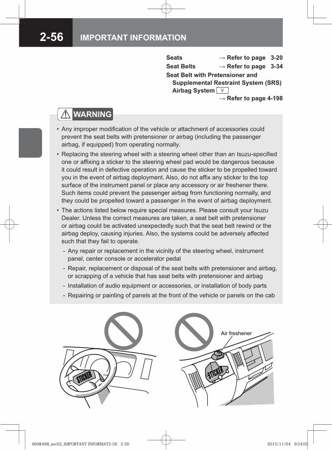
2-56 IMPORTANT INFORMATION
Seats → Refer to page 3-20Seat Belts → Refer to page 3-34Seat Belt with Pretensioner and
Supplemental Restraint System (SRS) Airbag System V → Refer to page 4-198
�� � ������
WARNING
Any improper modification of the vehicle or attachment of accessories could prevent the seat belts with pretensioner or airbag (including the passenger airbag, if equipped) from operating normally.Replacing the steering wheel with a steering wheel other than an Isuzu-specified one or affixing a sticker to the steering wheel pad would be dangerous because it could result in defective operation and cause the sticker to be propelled toward you in the event of airbag deployment. Also, do not affix any sticker to the top surface of the instrument panel or place any accessory or air freshener there. Such items could prevent the passenger airbag from functioning normally, and they could be propelled toward a passenger in the event of airbag deployment.The actions listed below require special measures. Please consult your Isuzu Dealer. Unless the correct measures are taken, a seat belt with pretensioner or airbag could be activated unexpectedly such that the seat belt rewind or the airbag deploy, causing injuries. Also, the systems could be adversely affected such that they fail to operate.
Any repair or replacement in the vicinity of the steering wheel, instrument panel, center console or accelerator pedalRepair, replacement or disposal of the seat belts with pretensioner and airbag, or scrapping of a vehicle that has seat belts with pretensioner and airbagInstallation of audio equipment or accessories, or installation of body partsRepairing or painting of panels at the front of the vehicle or panels on the cab
•
•
•
-
-
--
4608498_sec02_IMPORTANT INFORMAT2-56 2-564608498_sec02_IMPORTANT INFORMAT2-56 2-56 2015/11/04 9:54:052015/11/04 9:54:05
2-57IMPORTANT INFORMATION
Vehicle Data Collection
Your vehicle, like other modern motor vehicles, has a number of sophisticated computer systems that monitor and control several aspects of the vehicle's performance. Your vehicle uses on-board vehicle computers to monitor emission control components, to optimize fuel economy, to monitor conditions for airbag deployment and to help the driver control the vehicle in difficult driving situations. Some of the information may be stored during the regular operations to facilitate repair of detected malfunctions. Isuzu may download and retrieve stored information for the purpose of diagnosing, servicing, and repairing your motor vehicle or further improvement to future Isuzu motor vehicles.
Statement of Compliance with ECE R13
Information required by European brake regulation ECE R13 is disclosed on the following website. URL: http://www.isuzu.co.jp/world/index.htmlTo see details of the information on the website, click "Customer Information".Click "Isuzu Brake Wear Check Procedure (ECE R13 regulation)" then enter your vehicle identification number (VIN).
4608498_sec02_IMPORTANT INFORMAT2-57 2-574608498_sec02_IMPORTANT INFORMAT2-57 2-57 2015/11/04 9:54:052015/11/04 9:54:05
2-58 IMPORTANT INFORMATION
4608498_sec02_IMPORTANT INFORMAT2-58 2-584608498_sec02_IMPORTANT INFORMAT2-58 2-58 2015/11/04 9:54:062015/11/04 9:54:06
● Key 3-2
● Key with Immobilizer Transponder Chip V 3-3
● Keyless Entry System V 3-4
● Opening and Closing Doors 3-9
● Getting In and Out of the Vehicle 3-13
● Power Windows V 3-15
● Manually Operated Windows V 3-16
● Fuel Tank 3-17
● Seats 3-20
● Fully Adjustable Steering 3-30
● Mirrors 3-31
● Seat Belts 3-34
3DOORS, WINDOWS AND SEATS
4608498_sec03_DOORS, WINDOWS AND3-1 3-14608498_sec03_DOORS, WINDOWS AND3-1 3-1 2015/11/02 13:55:372015/11/02 13:55:37
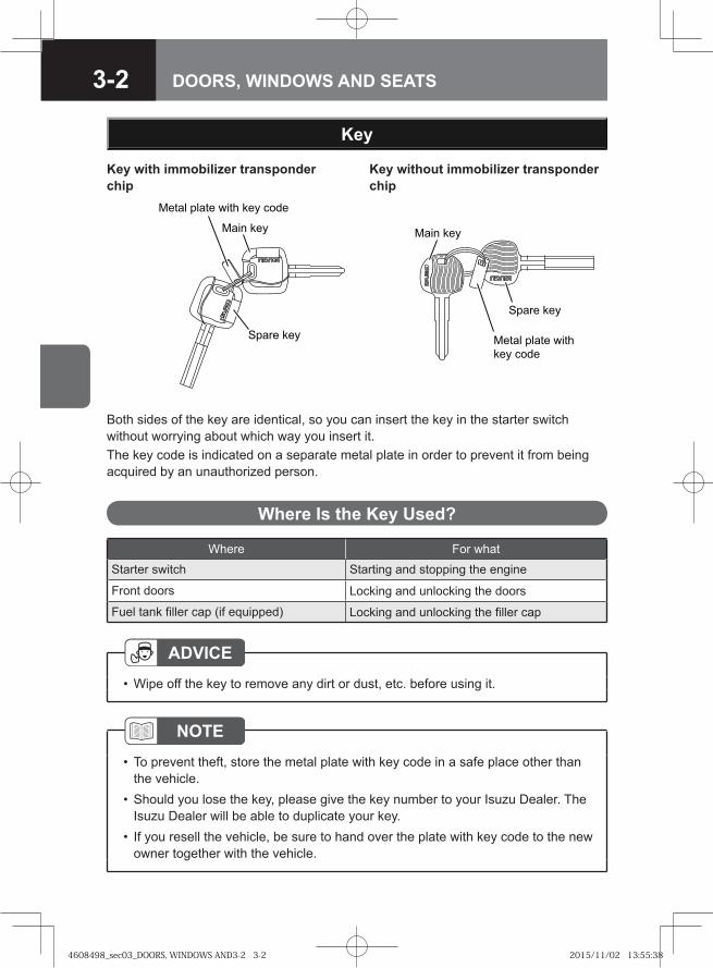
3-2 DOORS, WINDOWS AND SEATS
Where For whatStarter switch Starting and stopping the engine
Front doors Locking and unlocking the doors
Fuel tank filler cap (if equipped) Locking and unlocking the filler cap
Where Is the Key Used?
NOTETo prevent theft, store the metal plate with key code in a safe place other than the vehicle.Should you lose the key, please give the key number to your Isuzu Dealer. The Isuzu Dealer will be able to duplicate your key.If you resell the vehicle, be sure to hand over the plate with key code to the new owner together with the vehicle.
•
•
•
Key
Both sides of the key are identical, so you can insert the key in the starter switch without worrying about which way you insert it.The key code is indicated on a separate metal plate in order to prevent it from being acquired by an unauthorized person.
��� � �� �� ���� ��� ����
� �� ���
�� �� ��� ��� � �� ����
�� ���
���� ��
���� ��
Key with immobilizer transponder chip
Key without immobilizer transponder chip
ADVICEWipe off the key to remove any dirt or dust, etc. before using it.•
4608498_sec03_DOORS, WINDOWS AND3-2 3-24608498_sec03_DOORS, WINDOWS AND3-2 3-2 2015/11/02 13:55:382015/11/02 13:55:38
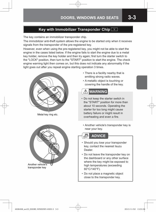
3-3DOORS, WINDOWS AND SEATS
Key with Immobilizer Transponder Chip V
The key contains an immobilizer transponder chip.The immobilizer anti-theft system allows the engine to be started only when it receives signals from the transponder of the pre-registered key.However, even when using the pre-registered key, you might not be able to start the engine in the cases listed below. If the engine fails to start the engine due to a metal key holder, remove the key holder and then try again; first turn the starter switch to the "LOCK" position, then turn to the "START" position to start the engine. The check engine warning light then comes on, but this does not indicate any abnormality if the light goes out after you repeat engine starting operation 3 times.
• There is a facility nearby that is emitting strong radio waves.
• A metallic object is touching or covering the handle of the key.
• Another vehicle's transponder key is near your key.
ADVICEShould you lose your transponder key, contact the nearest Isuzu Dealer.Do not leave the transponder key on the dashboard or any other surface where the key might be exposed to high temperatures (exceeding 60°C/140°F).Do not place a magnetic object close to the transponder key.
•
•
•
WARNING
Do not keep the starter switch in the "START" position for more than about 10 seconds. Operating the starter for too long might cause battery failure or might result in overheating and even a fire.
•
�� �� ��� ���� � ��
�� ��� ���������
���������� ���
4608498_sec03_DOORS, WINDOWS AND3-3 3-34608498_sec03_DOORS, WINDOWS AND3-3 3-3 2015/11/02 13:55:382015/11/02 13:55:38
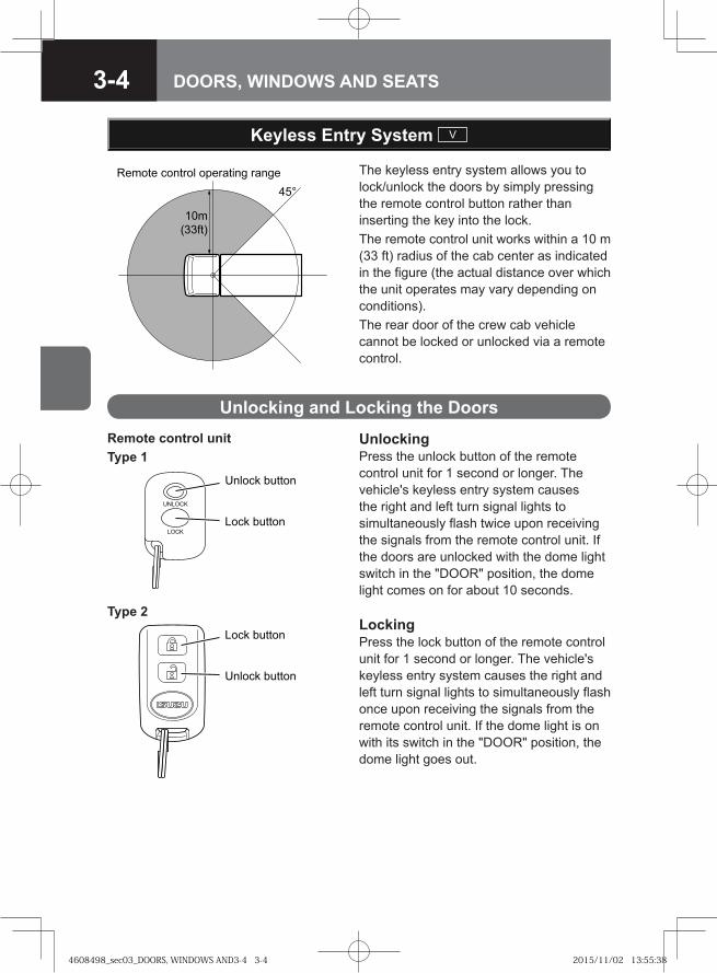
3-4 DOORS, WINDOWS AND SEATS
Keyless Entry System V
��
��� ��
��
������ ������� ��������� ����� The keyless entry system allows you to lock/unlock the doors by simply pressing the remote control button rather than inserting the key into the lock.The remote control unit works within a 10 m (33 ft) radius of the cab center as indicated in the figure (the actual distance over which the unit operates may vary depending on conditions).The rear door of the crew cab vehicle cannot be locked or unlocked via a remote control.
Unlocking and Locking the Doors
UnlockingPress the unlock button of the remote control unit for 1 second or longer. The vehicle's keyless entry system causes the right and left turn signal lights to simultaneously flash twice upon receiving the signals from the remote control unit. If the doors are unlocked with the dome light switch in the "DOOR" position, the dome light comes on for about 10 seconds.
�� � ������
���� � ������
Remote control unitType 1
��� �� ���� �
� �� ���� �
Type 2LockingPress the lock button of the remote control unit for 1 second or longer. The vehicle's keyless entry system causes the right and left turn signal lights to simultaneously flash once upon receiving the signals from the remote control unit. If the dome light is on with its switch in the "DOOR" position, the dome light goes out.
4608498_sec03_DOORS, WINDOWS AND3-4 3-44608498_sec03_DOORS, WINDOWS AND3-4 3-4 2015/11/02 13:55:382015/11/02 13:55:38
3-5DOORS, WINDOWS AND SEATS
ADVICEShould you lose the remote control unit, please contact your Isuzu Dealer.After locking the doors using the remote control unit, be sure to check that they are locked by pulling the door handles.Avoid getting water on the remote control unit, dropping it, hitting it against another object, or stepping on it; otherwise, the remote control unit could malfunction.Do not leave the remote control unit on the dashboard or any other surface where the unit might be exposed to high temperatures (exceeding 60°C/140°F). Doing so may result in shorter battery life or malfunction of the remote control unit.Repeatedly locking and unlocking the doors using the remote control unit 10 or more times in succession will trigger the protection circuit in the system, preventing the unit from working. If this happens, wait for a while. The system will then work normally.If the keyless entry system fails to operate normally, lock and unlock the doors using the key and have the system inspected by your Isuzu Dealer.
••
•
•
•
•
NOTEThe lock or unlock buttons on the remote control unit must be fully pressed for more than 1 second to work.If you do not open any doors within about 30 seconds after pressing the unlock button to unlock the doors, the automatic locking function of the system will lock the doors again to prevent theft.In areas near a TV tower, electric power plant, radio station, etc. or under any conditions involving strong electrical disturbances, the remote control unit operating range might change or the keyless entry system might not work.The keyless entry system does not operate in the following cases:
The starter switch is in the "ON" position.The key is inserted in the starter switch.One of the doors is open.
•
•
•
•---
4608498_sec03_DOORS, WINDOWS AND3-5 3-54608498_sec03_DOORS, WINDOWS AND3-5 3-5 2015/11/02 13:55:392015/11/02 13:55:39
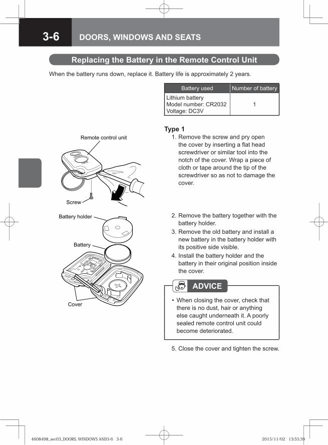
3-6 DOORS, WINDOWS AND SEATS
Replacing the Battery in the Remote Control Unit
ADVICEWhen closing the cover, check that there is no dust, hair or anything else caught underneath it. A poorly sealed remote control unit could become deteriorated.
•
When the battery runs down, replace it. Battery life is approximately 2 years.
Type 1 1. Remove the screw and pry open
the cover by inserting a flat head screwdriver or similar tool into the notch of the cover. Wrap a piece of cloth or tape around the tip of the screwdriver so as not to damage the cover.
�� ��
������ ���� �� ����
�� ���
�� ��� ������
�����
2. Remove the battery together with the battery holder.
3. Remove the old battery and install a new battery in the battery holder with its positive side visible.
4. Install the battery holder and the battery in their original position inside the cover.
5. Close the cover and tighten the screw.
Battery used Number of battery
Lithium batteryModel number: CR2032Voltage: DC3V
1
4608498_sec03_DOORS, WINDOWS AND3-6 3-64608498_sec03_DOORS, WINDOWS AND3-6 3-6 2015/11/02 13:55:392015/11/02 13:55:39
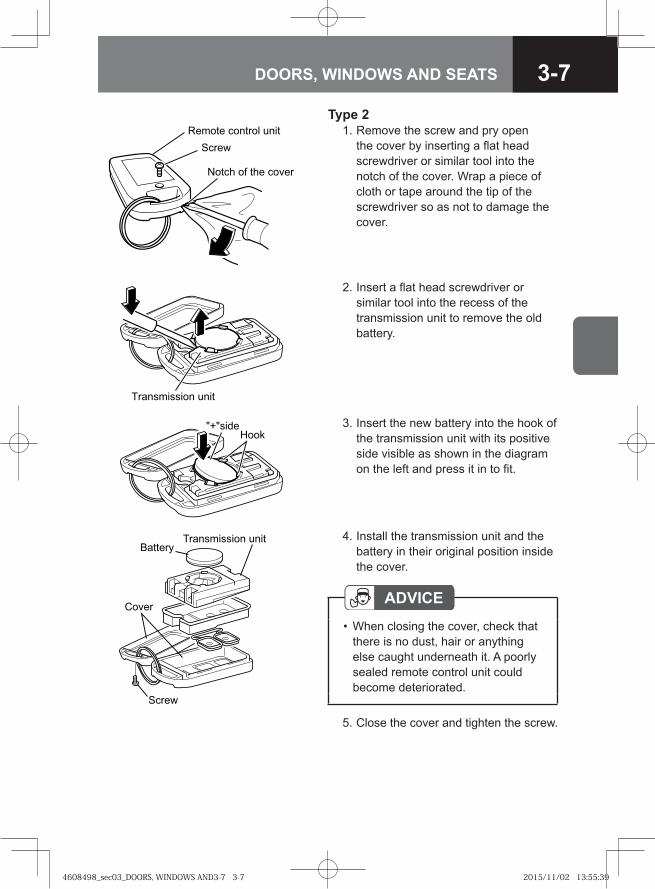
3-7DOORS, WINDOWS AND SEATS
Type 2 1. Remove the screw and pry open
the cover by inserting a flat head screwdriver or similar tool into the notch of the cover. Wrap a piece of cloth or tape around the tip of the screwdriver so as not to damage the cover.
� ��� ������� ����
��� �
����� �� �� ��� �
�� ��������� ����
2. Insert a flat head screwdriver or similar tool into the recess of the transmission unit to remove the old battery.
��� �������
3. Insert the new battery into the hook of the transmission unit with its positive side visible as shown in the diagram on the left and press it in to fit.
� ���
�����
���������� � �����������
4. Install the transmission unit and the battery in their original position inside the cover.
ADVICEWhen closing the cover, check that there is no dust, hair or anything else caught underneath it. A poorly sealed remote control unit could become deteriorated.
•
5. Close the cover and tighten the screw.
4608498_sec03_DOORS, WINDOWS AND3-7 3-74608498_sec03_DOORS, WINDOWS AND3-7 3-7 2015/11/02 13:55:392015/11/02 13:55:39
3-8 DOORS, WINDOWS AND SEATS
NOTEThe battery life varies depending on how the remote control unit is used.The battery has reached its end of life when the remote control unit works intermittently or does not work at all. Replace the battery as soon as this happens.
••
CAUTIONWhen changing the battery, use only a battery of the same type as the original battery, or an equivalent. Otherwise, there is a risk of explosion.Do not place the battery in direct sunlight, or near a fire or other sources of heat.Be sure to install the battery with the "+" and "-" sides correctly oriented. Incorrect installation will result in leakage of chemicals from inside the battery or other operational problems.
•
•
•
NOTEPlease comply with the collection system available in your country for the disposal of old batteries. In addition, take special care to prevent any danger to children.
•
4608498_sec03_DOORS, WINDOWS AND3-8 3-84608498_sec03_DOORS, WINDOWS AND3-8 3-8 2015/11/02 13:55:402015/11/02 13:55:40
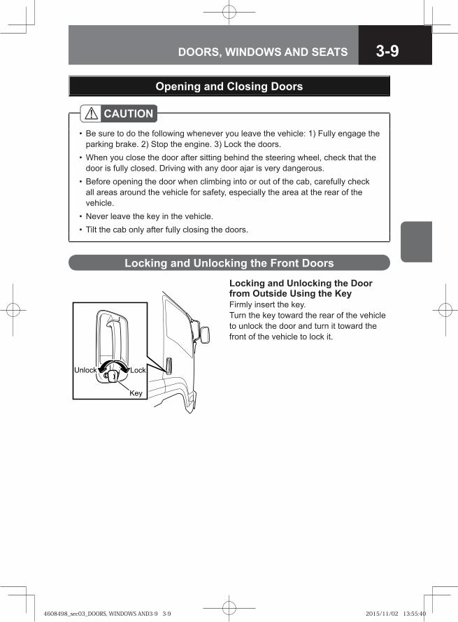
3-9DOORS, WINDOWS AND SEATS
CAUTIONBe sure to do the following whenever you leave the vehicle: 1) Fully engage the parking brake. 2) Stop the engine. 3) Lock the doors.When you close the door after sitting behind the steering wheel, check that the door is fully closed. Driving with any door ajar is very dangerous.Before opening the door when climbing into or out of the cab, carefully check all areas around the vehicle for safety, especially the area at the rear of the vehicle.Never leave the key in the vehicle.Tilt the cab only after fully closing the doors.
•
•
•
••
Opening and Closing Doors
Locking and Unlocking the Door from Outside Using the KeyFirmly insert the key. Turn the key toward the rear of the vehicle to unlock the door and turn it toward the front of the vehicle to lock it.
��� �� � ��
���
Locking and Unlocking the Front Doors
4608498_sec03_DOORS, WINDOWS AND3-9 3-94608498_sec03_DOORS, WINDOWS AND3-9 3-9 2015/11/02 13:55:402015/11/02 13:55:40
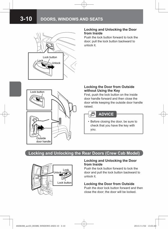
3-10 DOORS, WINDOWS AND SEATS
Locking the Door from Outside without Using the KeyFirst, push the lock button on the inside door handle forward and then close the door while keeping the outside door handle raised.
Locking and Unlocking the Door from InsidePush the lock button forward to lock the door; pull the lock button backward to unlock it.
Lock button
Outside door handle
�� � ������
���� ��� �
ADVICEBefore closing the door, be sure to check that you have the key with you.
•
Locking and Unlocking the Door from InsidePush the lock button forward to lock the door and pull the lock button backward to unlock it.
Locking the Door from OutsidePush the door lock button forward and then close the door; the door will be locked.
Locking and Unlocking the Rear Doors (Crew Cab Model)
Lock button
LockUnlock
4608498_sec03_DOORS, WINDOWS AND3-10 3-104608498_sec03_DOORS, WINDOWS AND3-10 3-10 2015/11/02 13:55:402015/11/02 13:55:40
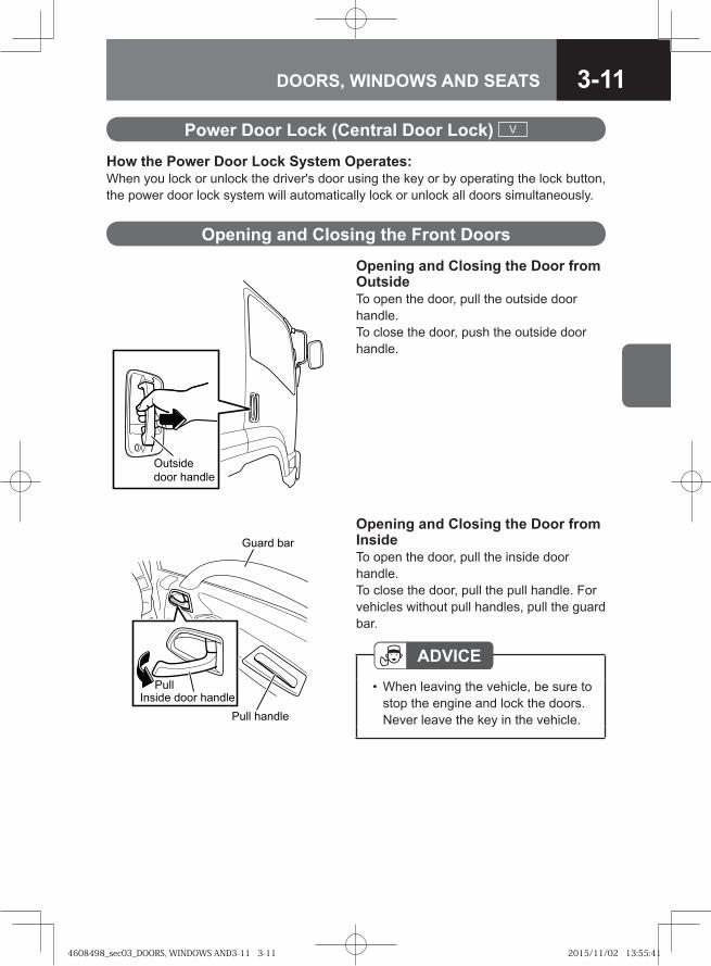
3-11DOORS, WINDOWS AND SEATS
Opening and Closing the Door from InsideTo open the door, pull the inside door handle. To close the door, pull the pull handle. For vehicles without pull handles, pull the guard bar.
ADVICEWhen leaving the vehicle, be sure to stop the engine and lock the doors. Never leave the key in the vehicle.
•
Opening and Closing the Front Doors
Opening and Closing the Door from OutsideTo open the door, pull the outside door handle. To close the door, push the outside door handle.
�� ����
���� ������
How the Power Door Lock System Operates:When you lock or unlock the driver's door using the key or by operating the lock button, the power door lock system will automatically lock or unlock all doors simultaneously.
Power Door Lock (Central Door Lock) V
��
������ ���� ���� �
�� ���� �
����� ���
4608498_sec03_DOORS, WINDOWS AND3-11 3-114608498_sec03_DOORS, WINDOWS AND3-11 3-11 2015/11/02 13:55:412015/11/02 13:55:41
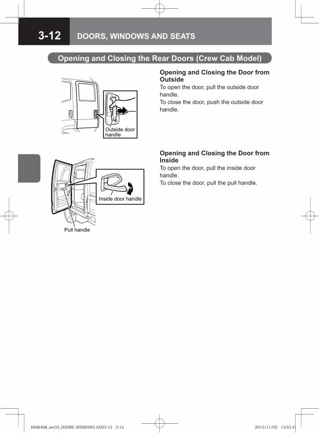
3-12 DOORS, WINDOWS AND SEATS
Opening and Closing the Door from OutsideTo open the door, pull the outside door handle. To close the door, push the outside door handle.
Opening and Closing the Rear Doors (Crew Cab Model)
Outside door handle
Opening and Closing the Door from InsideTo open the door, pull the inside door handle. To close the door, pull the pull handle.
Inside door handle
Pull handle
4608498_sec03_DOORS, WINDOWS AND3-12 3-124608498_sec03_DOORS, WINDOWS AND3-12 3-12 2015/11/02 13:55:412015/11/02 13:55:41
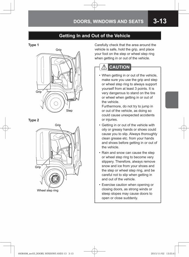
3-13DOORS, WINDOWS AND SEATS
Getting In and Out of the Vehicle
Carefully check that the area around the vehicle is safe, hold the grip, and place your foot on the step or wheel step ring when getting in or out of the vehicle.
CAUTIONWhen getting in or out of the vehicle, make sure you use the grip and step or wheel step ring to always support yourself from at least 3 points. It is very dangerous to stand on the tire or wheel when getting in or out of the vehicle. Furthermore, do not try to jump in or out of the vehicle, as doing so could cause unexpected accidents or injuries. Getting in or out of the vehicle with oily or greasy hands or shoes could cause you to slip. Always thoroughly clean grease etc. from your hands and shoes before getting in or out of the vehicle.Rain and snow can cause the step or wheel step ring to become very slippery. Therefore, always remove snow and ice from your shoes and the step or wheel step ring, and be careful not to slip when getting in and out of the vehicle. Exercise caution when opening or closing doors, as strong winds or steep slopes may cause doors to open or close suddenly.
•
•
•
•
Grip
Grip
Step
� ��
� ��
����� ���� ���
Type 1
Type 2
4608498_sec03_DOORS, WINDOWS AND3-13 3-134608498_sec03_DOORS, WINDOWS AND3-13 3-13 2015/11/02 13:55:412015/11/02 13:55:41
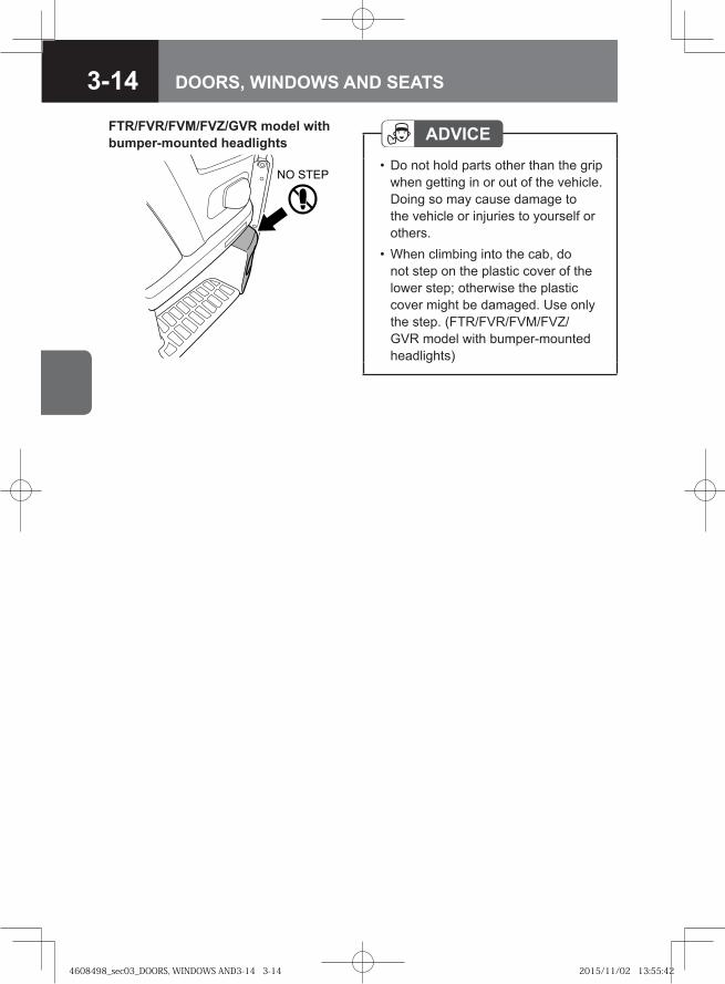
3-14 DOORS, WINDOWS AND SEATS
FTR/FVR/FVM/FVZ/GVR model with bumper-mounted headlights
� ����
ADVICEDo not hold parts other than the grip when getting in or out of the vehicle. Doing so may cause damage to the vehicle or injuries to yourself or others.When climbing into the cab, do not step on the plastic cover of the lower step; otherwise the plastic cover might be damaged. Use only the step. (FTR/FVR/FVM/FVZ/GVR model with bumper-mounted headlights)
•
•
4608498_sec03_DOORS, WINDOWS AND3-14 3-144608498_sec03_DOORS, WINDOWS AND3-14 3-14 2015/11/02 13:55:422015/11/02 13:55:42
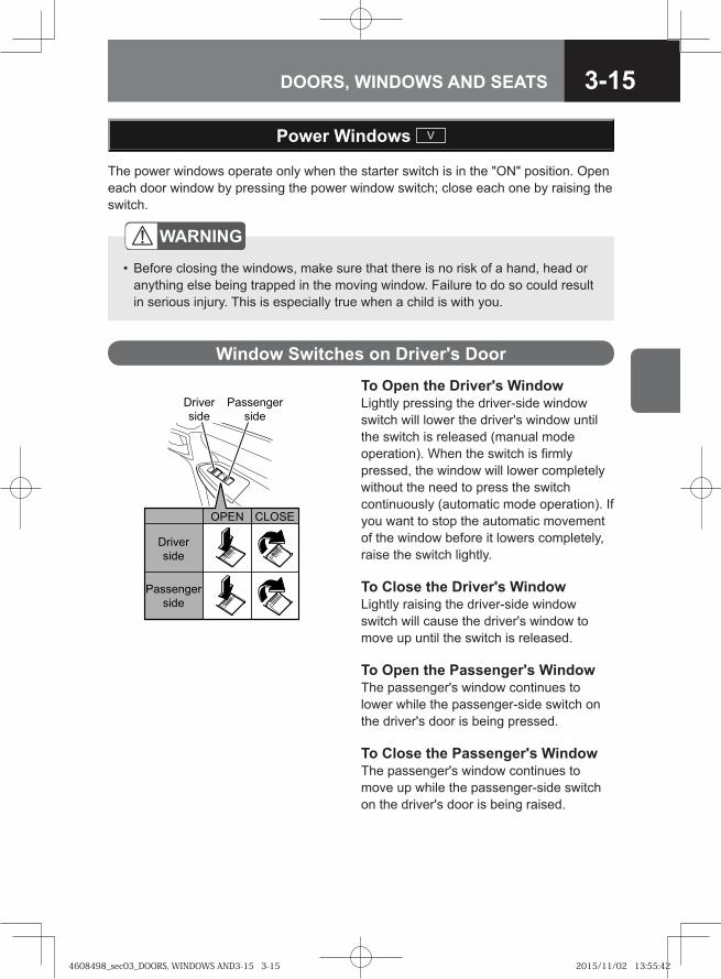
3-15DOORS, WINDOWS AND SEATS
The power windows operate only when the starter switch is in the "ON" position. Open each door window by pressing the power window switch; close each one by raising the switch.
To Open the Driver's WindowLightly pressing the driver-side window switch will lower the driver's window until the switch is released (manual mode operation). When the switch is firmly pressed, the window will lower completely without the need to press the switch continuously (automatic mode operation). If you want to stop the automatic movement of the window before it lowers completely, raise the switch lightly.
To Close the Driver's WindowLightly raising the driver-side window switch will cause the driver's window to move up until the switch is released.
To Open the Passenger's WindowThe passenger's window continues to lower while the passenger-side switch on the driver's door is being pressed.
To Close the Passenger's WindowThe passenger's window continues to move up while the passenger-side switch on the driver's door is being raised.
�� � ����
���������
����
������
����
���������
����
������
����
Power Windows V
Window Switches on Driver's Door
WARNING
Before closing the windows, make sure that there is no risk of a hand, head or anything else being trapped in the moving window. Failure to do so could result in serious injury. This is especially true when a child is with you.
•
4608498_sec03_DOORS, WINDOWS AND3-15 3-154608498_sec03_DOORS, WINDOWS AND3-15 3-15 2015/11/02 13:55:422015/11/02 13:55:42
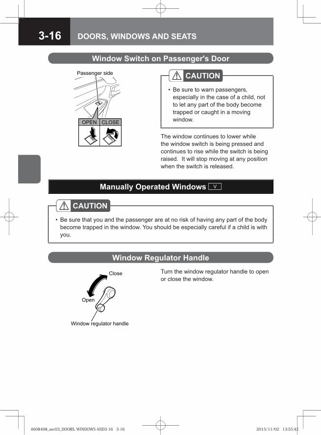
3-16 DOORS, WINDOWS AND SEATS
The window continues to lower while the window switch is being pressed and continues to rise while the switch is being raised. It will stop moving at any position when the switch is released.
Window Switch on Passenger's Door
CAUTIONBe sure to warn passengers, especially in the case of a child, not to let any part of the body become trapped or caught in a moving window.
•
�� ����
��������� ����
Turn the window regulator handle to open or close the window.
Manually Operated Windows V
Window Regulator Handle
CAUTIONBe sure that you and the passenger are at no risk of having any part of the body become trapped in the window. You should be especially careful if a child is with you.
•
�� �
����
������ � ������� �����
4608498_sec03_DOORS, WINDOWS AND3-16 3-164608498_sec03_DOORS, WINDOWS AND3-16 3-16 2015/11/02 13:55:422015/11/02 13:55:42
3-17DOORS, WINDOWS AND SEATS
Fuel Tank
WARNING
Be sure to place the starter switch in the "ACC" or "LOCK" position to shut down the engine before refueling the vehicle. Refueling while the engine is running could cause a fire in your vehicle.When refueling, never smoke or place any ignition source nearby. There is a risk of fire.After refueling, make sure that the fuel tank filler cap is tightly closed.
•
•
•
CAUTIONBe sure to use diesel fuel. For models conforming to EuroIV emission standards, be sure to use low-sulfur diesel fuel (containing sulfur of 50 ppm or lower) or extra-low-sulfur diesel fuel (containing sulfur of 10 ppm or lower). Avoid using the following: a low-quality fuel; any types of fuel additive including water remover; gasoline; kerosene; alcohol fuels; and a mixture of any of these with a permitted diesel fuel. Using such fuel will result in damage to the fuel filter, poor lubrication of injectors, and adversely affected engine components, likely causing vehicle malfunction. Should you refuel the vehicle with the wrong fuel, drain it completely before refueling the vehicle with the correct fuel. Starting the engine without replacing the wrong fuel is dangerous as it can cause damage to the engine and even a fire. Using diesel fuel other than extra-low-sulfur diesel fuel or low-sulfur diesel fuel in a model conforming to EuroIV emission standards could prevent the vehicle from complying with local legal requirements.Be sure to slowly open the fuel tank filler cap. If the cap is opened quickly, fuel may jet out from the filler port.
•
•
•
Using Self-service Filling Stations → Refer to page 2-5
4608498_sec03_DOORS, WINDOWS AND3-17 3-174608498_sec03_DOORS, WINDOWS AND3-17 3-17 2015/11/02 13:55:432015/11/02 13:55:43
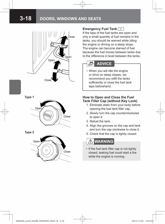
3-18 DOORS, WINDOWS AND SEATS
��
�����
How to Open and Close the Fuel Tank Filler Cap (without Key Lock) 1. Eliminate static from your body before
opening the fuel tank filler cap. 2. Slowly turn the cap counterclockwise
to open it. 3. Refuel the tank. 4. Align the grooves on the cap and tank
and turn the cap clockwise to close it. 5. Check that the cap is tightly closed.
WARNING
If the fuel tank filler cap is not tightly closed, leaking fuel could start a fire while the engine is running.
•
Emergency Fuel Tank V
If the taps of the fuel tanks are open and only a small quantity of fuel remains in the tanks, you should be warned while idling the engine or driving on a steep slope. The engine can become starved of fuel because the fuel moves between tanks due to the difference in level between the tanks.
ADVICEWhen you will idle the engine or drive on steep slopes, we recommend you refill the tanks sufficiently or close the fuel tank taps beforehand.
•
�� �
�� �
����
����
�� �
����
Type 1
Type 2
4608498_sec03_DOORS, WINDOWS AND3-18 3-184608498_sec03_DOORS, WINDOWS AND3-18 3-18 2015/11/02 13:55:432015/11/02 13:55:43
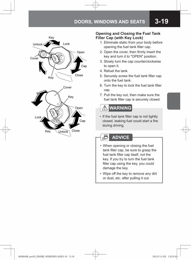
3-19DOORS, WINDOWS AND SEATS
Opening and Closing the Fuel Tank Filler Cap (with Key Lock) 1. Eliminate static from your body before
opening the fuel tank filler cap. 2. Open the cover, then firmly insert the
key and turn it to "OPEN" position. 3. Slowly turn the cap counterclockwise
to open it. 4. Refuel the tank. 5. Securely screw the fuel tank filler cap
onto the fuel tank. 6. Turn the key to lock the fuel tank filler
cap. 7. Pull the key out, then make sure the
fuel tank filler cap is securely closed.
WARNING
If the fuel tank filler cap is not tightly closed, leaking fuel could start a fire during driving.
•
��
��
� ��
����
���
�� ��
��� ��
� ���
ADVICEWhen opening or closing the fuel tank filler cap, be sure to grasp the fuel tank filler cap itself, not the key. If you try to turn the fuel tank filler cap using the key, you could damage the key.Wipe off the key to remove any dirt or dust, etc. after pulling it out.
•
•
��
��
����
����
���
�����������
�����
4608498_sec03_DOORS, WINDOWS AND3-19 3-194608498_sec03_DOORS, WINDOWS AND3-19 3-19 2015/11/02 13:55:442015/11/02 13:55:44
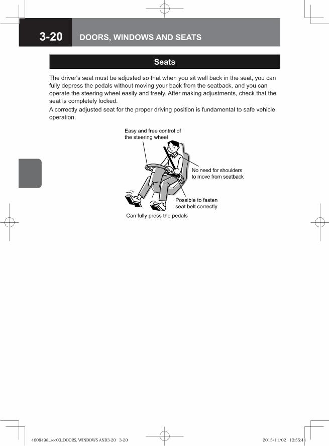
3-20 DOORS, WINDOWS AND SEATS
The driver's seat must be adjusted so that when you sit well back in the seat, you can fully depress the pedals without moving your back from the seatback, and you can operate the steering wheel easily and freely. After making adjustments, check that the seat is completely locked.A correctly adjusted seat for the proper driving position is fundamental to safe vehicle operation.
Seats
Easy and free control of the steering wheel
No need for shoulders to move from seatback
Possible to fasten seat belt correctly
Can fully press the pedals
4608498_sec03_DOORS, WINDOWS AND3-20 3-204608498_sec03_DOORS, WINDOWS AND3-20 3-20 2015/11/02 13:55:442015/11/02 13:55:44
3-21DOORS, WINDOWS AND SEATS
WARNING
Use caution when adjusting the seat, as failure to do so could cause injury. Never allow children to adjust their seats themselves; an adult should adjust the seat for occupants who are children.Adjust the seat only before you start driving. Adjusting the seat while the vehicle is in motion must be avoided not only because the unlocked seat will move back and forth unstably, preventing you from taking the correct position, but might also cause you to lose control of the vehicle, possibly resulting in an accident.Try to move the seat without unlatching it after making adjustments to check that it is completely locked. A loosely locked seat may move unexpectedly and your position might then become unstable; this could lead to an accident. Take the vehicle to your Isuzu Dealer for service if you find that your seat adjusters do not latch. In addition, the seat belt will not operate properly if the seatback is not completely locked.Driving with the seat excessively reclined could be very dangerous in the event of a collision or sudden stop. Raise the seatback, and apply the seat belt correctly while sitting straight in the seat.Do not place a cushion or similar object between your back and the seatback. Doing so not only affects the stability of your driving position but also prevents the seat belt from working effectively in the event of a collision.Do not place any objects under the seat. If there are any objects under the seat, the seat could be locked in an improper position.Before making adjustments, check that the seat rails are free of anything that could obstruct the locking of the seat. Be careful that your hand or foot does not become trapped in the seat or rails when adjusting the seat.When adjusting the seat, be careful that the seat does not hit passengers or objects. Doing so could cause injury to passengers, or damage objects.Make sure not to hit passengers or luggage when adjusting your seat.
••
•
•
•
•
•
•
•
•
4608498_sec03_DOORS, WINDOWS AND3-21 3-214608498_sec03_DOORS, WINDOWS AND3-21 3-21 2015/11/02 13:55:442015/11/02 13:55:44
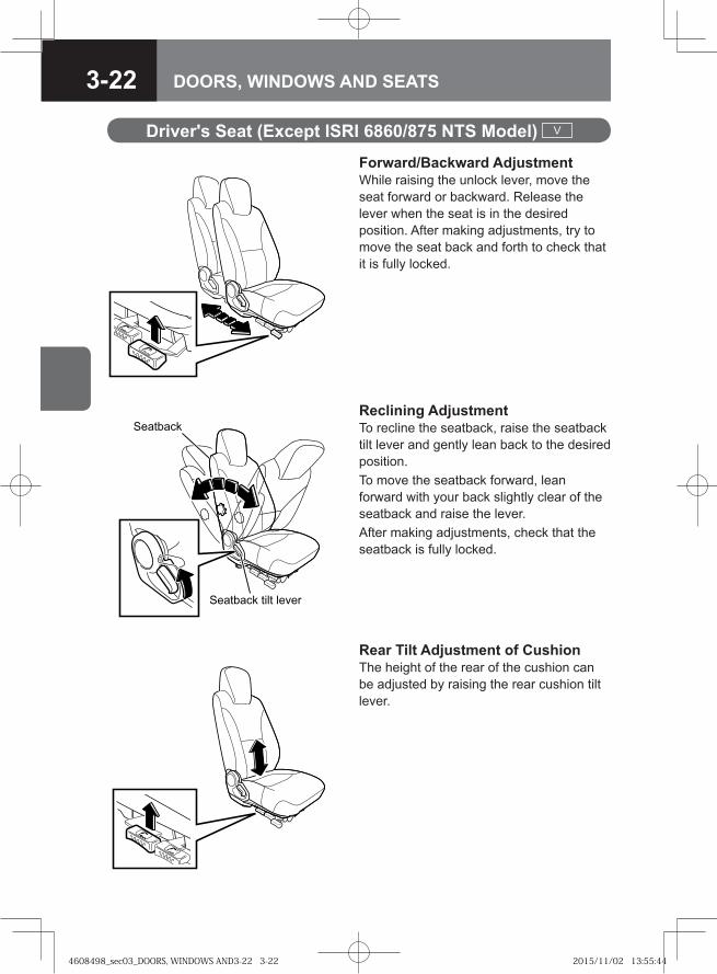
3-22 DOORS, WINDOWS AND SEATS
Forward/Backward AdjustmentWhile raising the unlock lever, move the seat forward or backward. Release the lever when the seat is in the desired position. After making adjustments, try to move the seat back and forth to check that it is fully locked.
Driver's Seat (Except ISRI 6860/875 NTS Model) V
Reclining AdjustmentTo recline the seatback, raise the seatback tilt lever and gently lean back to the desired position.To move the seatback forward, lean forward with your back slightly clear of the seatback and raise the lever.After making adjustments, check that the seatback is fully locked.
Rear Tilt Adjustment of CushionThe height of the rear of the cushion can be adjusted by raising the rear cushion tilt lever.
��� ����
��� ���� �� �����
4608498_sec03_DOORS, WINDOWS AND3-22 3-224608498_sec03_DOORS, WINDOWS AND3-22 3-22 2015/11/02 13:55:442015/11/02 13:55:44
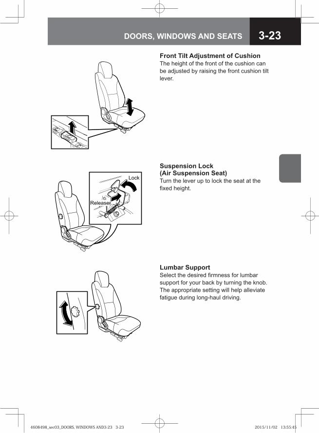
3-23DOORS, WINDOWS AND SEATS
Front Tilt Adjustment of CushionThe height of the front of the cushion can be adjusted by raising the front cushion tilt lever.
Suspension Lock(Air Suspension Seat)Turn the lever up to lock the seat at the fixed height.
�� �
�������
Lumbar SupportSelect the desired firmness for lumbar support for your back by turning the knob. The appropriate setting will help alleviate fatigue during long-haul driving.
4608498_sec03_DOORS, WINDOWS AND3-23 3-234608498_sec03_DOORS, WINDOWS AND3-23 3-23 2015/11/02 13:55:452015/11/02 13:55:45
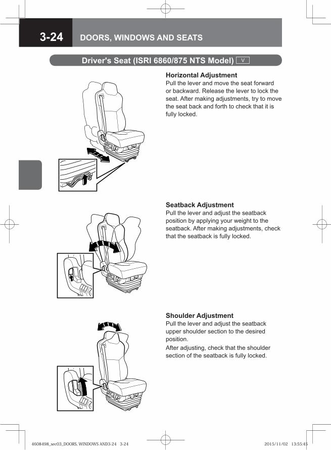
3-24 DOORS, WINDOWS AND SEATS
Horizontal AdjustmentPull the lever and move the seat forward or backward. Release the lever to lock the seat. After making adjustments, try to move the seat back and forth to check that it is fully locked.
Driver's Seat (ISRI 6860/875 NTS Model) V
Seatback AdjustmentPull the lever and adjust the seatback position by applying your weight to the seatback. After making adjustments, check that the seatback is fully locked.
Shoulder AdjustmentPull the lever and adjust the seatback upper shoulder section to the desired position.After adjusting, check that the shoulder section of the seatback is fully locked.
4608498_sec03_DOORS, WINDOWS AND3-24 3-244608498_sec03_DOORS, WINDOWS AND3-24 3-24 2015/11/02 13:55:452015/11/02 13:55:45
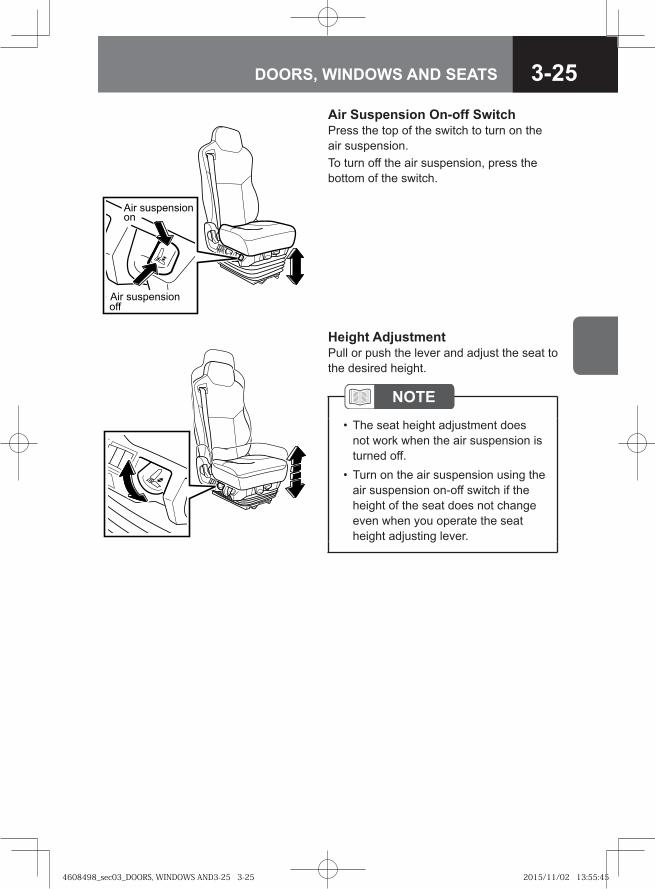
3-25DOORS, WINDOWS AND SEATS
Air Suspension On-off SwitchPress the top of the switch to turn on the air suspension.To turn off the air suspension, press the bottom of the switch.
�� ������������
�� �������������
Height AdjustmentPull or push the lever and adjust the seat to the desired height.
NOTEThe seat height adjustment does not work when the air suspension is turned off.Turn on the air suspension using the air suspension on-off switch if the height of the seat does not change even when you operate the seat height adjusting lever.
•
•
4608498_sec03_DOORS, WINDOWS AND3-25 3-254608498_sec03_DOORS, WINDOWS AND3-25 3-25 2015/11/02 13:55:452015/11/02 13:55:45
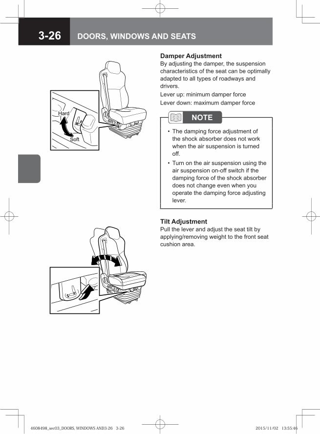
3-26 DOORS, WINDOWS AND SEATS
Damper AdjustmentBy adjusting the damper, the suspension characteristics of the seat can be optimally adapted to all types of roadways and drivers.Lever up: minimum damper forceLever down: maximum damper force
���
����
Tilt AdjustmentPull the lever and adjust the seat tilt by applying/removing weight to the front seat cushion area.
NOTEThe damping force adjustment of the shock absorber does not work when the air suspension is turned off.Turn on the air suspension using the air suspension on-off switch if the damping force of the shock absorber does not change even when you operate the damping force adjusting lever.
•
•
4608498_sec03_DOORS, WINDOWS AND3-26 3-264608498_sec03_DOORS, WINDOWS AND3-26 3-26 2015/11/02 13:55:462015/11/02 13:55:46
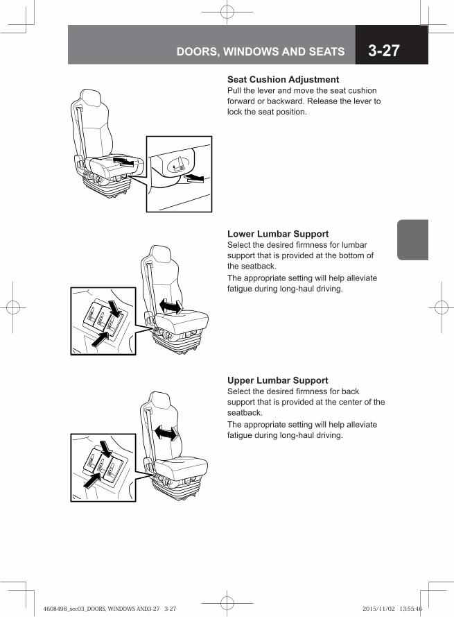
3-27DOORS, WINDOWS AND SEATS
Seat Cushion AdjustmentPull the lever and move the seat cushion forward or backward. Release the lever to lock the seat position.
Lower Lumbar Support Select the desired firmness for lumbar support that is provided at the bottom of the seatback.The appropriate setting will help alleviate fatigue during long-haul driving.
Upper Lumbar Support Select the desired firmness for back support that is provided at the center of the seatback.The appropriate setting will help alleviate fatigue during long-haul driving.
4608498_sec03_DOORS, WINDOWS AND3-27 3-274608498_sec03_DOORS, WINDOWS AND3-27 3-27 2015/11/02 13:55:462015/11/02 13:55:46
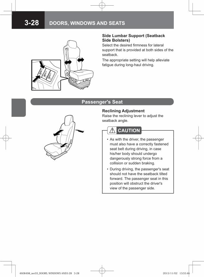
3-28 DOORS, WINDOWS AND SEATS
Reclining AdjustmentRaise the reclining lever to adjust the seatback angle.
Passenger's Seat
CAUTIONAs with the driver, the passenger must also have a correctly fastened seat belt during driving, in case his/her body should undergo dangerously strong force from a collision or sudden braking.During driving, the passenger's seat should not have the seatback tilted forward. The passenger seat in this position will obstruct the driver's view of the passenger side.
•
•
Side Lumbar Support (Seatback Side Bolsters)Select the desired firmness for lateral support that is provided at both sides of the seatback.The appropriate setting will help alleviate fatigue during long-haul driving.
4608498_sec03_DOORS, WINDOWS AND3-28 3-284608498_sec03_DOORS, WINDOWS AND3-28 3-28 2015/11/02 13:55:462015/11/02 13:55:46
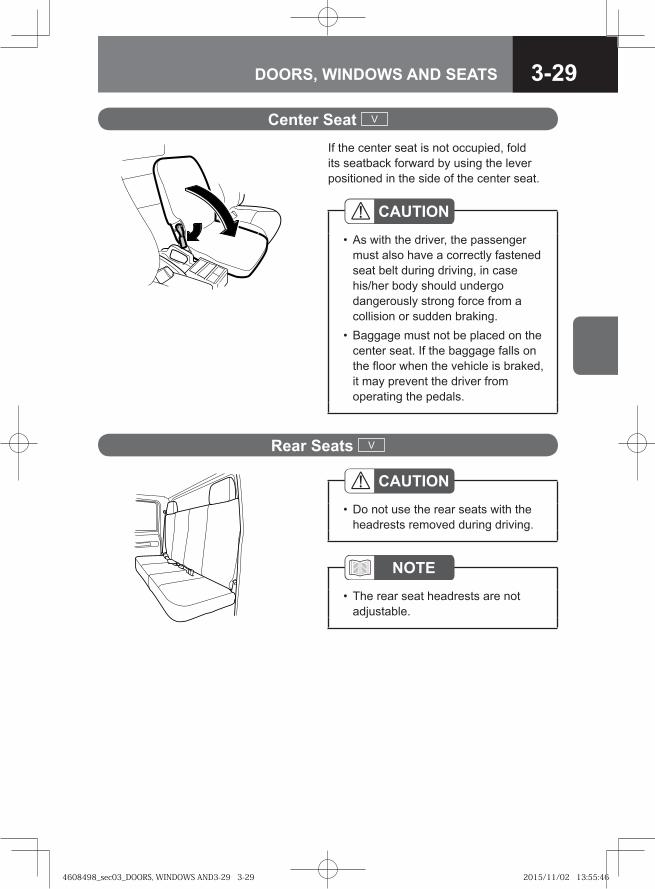
3-29DOORS, WINDOWS AND SEATS
If the center seat is not occupied, fold its seatback forward by using the lever positioned in the side of the center seat.
Center Seat V
CAUTIONAs with the driver, the passenger must also have a correctly fastened seat belt during driving, in case his/her body should undergo dangerously strong force from a collision or sudden braking.Baggage must not be placed on the center seat. If the baggage falls on the floor when the vehicle is braked, it may prevent the driver from operating the pedals.
•
•
Rear Seats V
NOTEThe rear seat headrests are not adjustable.
•
CAUTIONDo not use the rear seats with the headrests removed during driving.
•
4608498_sec03_DOORS, WINDOWS AND3-29 3-294608498_sec03_DOORS, WINDOWS AND3-29 3-29 2015/11/02 13:55:462015/11/02 13:55:46
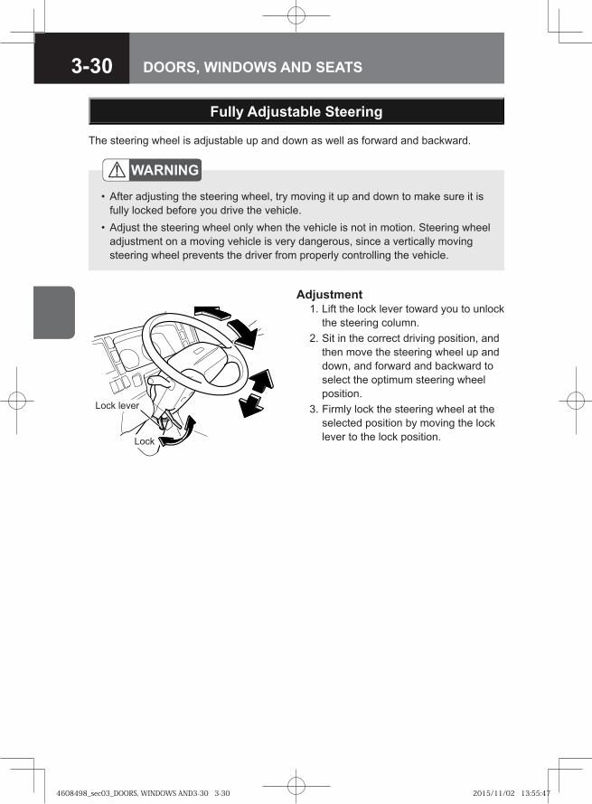
3-30 DOORS, WINDOWS AND SEATS
The steering wheel is adjustable up and down as well as forward and backward.
Adjustment 1. Lift the lock lever toward you to unlock
the steering column. 2. Sit in the correct driving position, and
then move the steering wheel up and down, and forward and backward to select the optimum steering wheel position.
3. Firmly lock the steering wheel at the selected position by moving the lock lever to the lock position.
Lock lever
Lock
Fully Adjustable Steering
WARNING
After adjusting the steering wheel, try moving it up and down to make sure it is fully locked before you drive the vehicle.Adjust the steering wheel only when the vehicle is not in motion. Steering wheel adjustment on a moving vehicle is very dangerous, since a vertically moving steering wheel prevents the driver from properly controlling the vehicle.
•
•
4608498_sec03_DOORS, WINDOWS AND3-30 3-304608498_sec03_DOORS, WINDOWS AND3-30 3-30 2015/11/02 13:55:472015/11/02 13:55:47
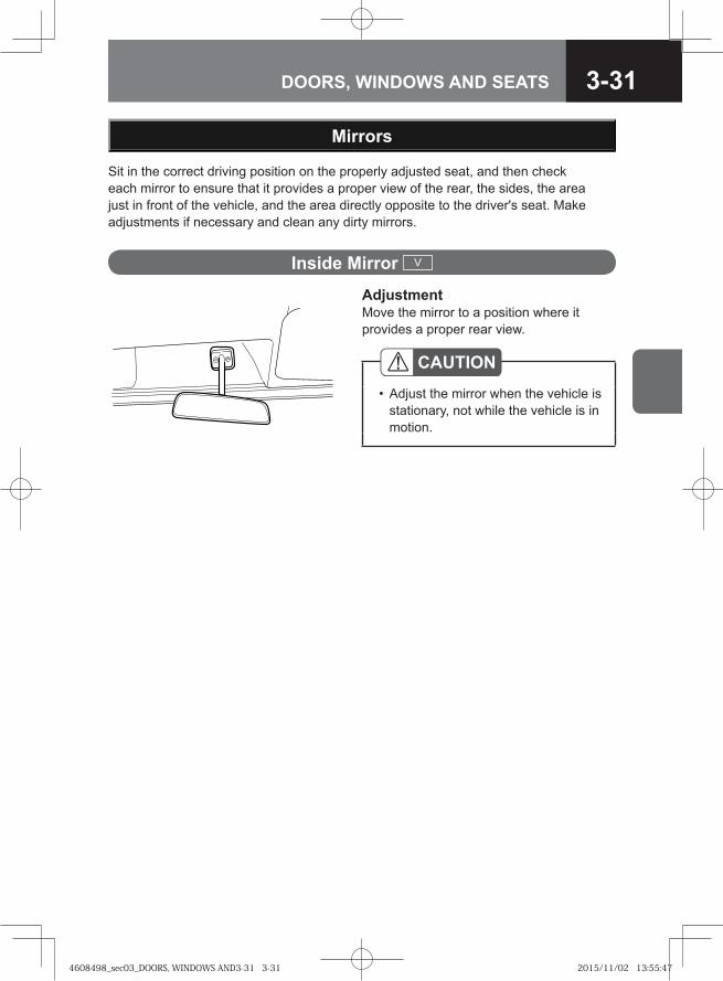
3-31DOORS, WINDOWS AND SEATS
Sit in the correct driving position on the properly adjusted seat, and then check each mirror to ensure that it provides a proper view of the rear, the sides, the area just in front of the vehicle, and the area directly opposite to the driver's seat. Make adjustments if necessary and clean any dirty mirrors.
AdjustmentMove the mirror to a position where it provides a proper rear view.
Mirrors
Inside Mirror V
CAUTIONAdjust the mirror when the vehicle is stationary, not while the vehicle is in motion.
•
4608498_sec03_DOORS, WINDOWS AND3-31 3-314608498_sec03_DOORS, WINDOWS AND3-31 3-31 2015/11/02 13:55:472015/11/02 13:55:47
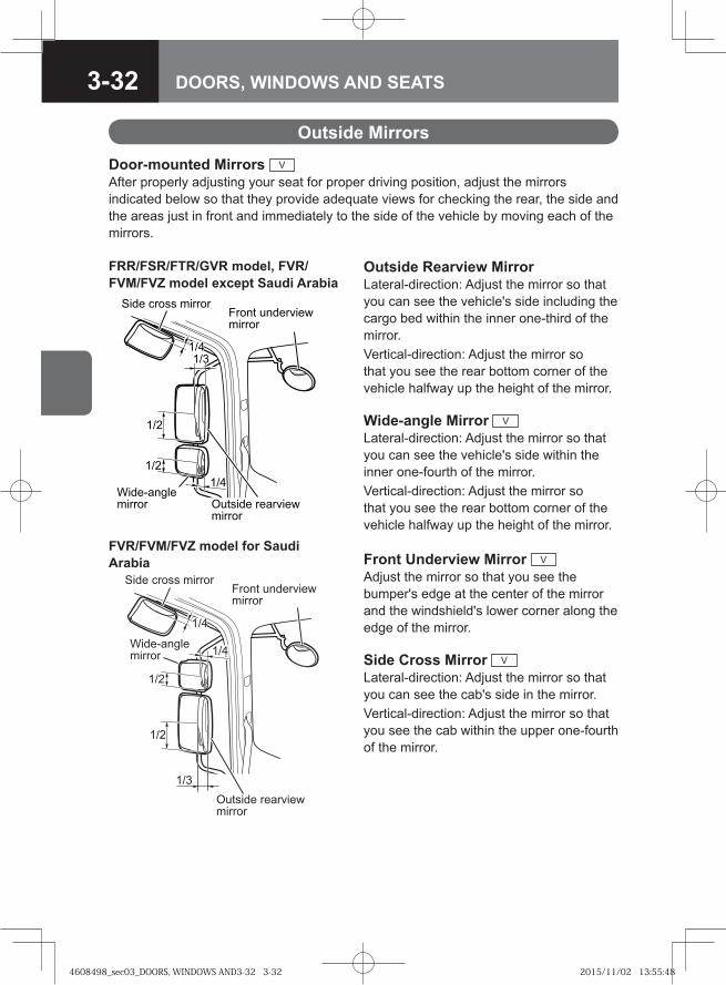
3-32 DOORS, WINDOWS AND SEATS
Front Underview Mirror V
Adjust the mirror so that you see the bumper's edge at the center of the mirror and the windshield's lower corner along the edge of the mirror.
Side Cross Mirror V
Lateral-direction: Adjust the mirror so that you can see the cab's side in the mirror. Vertical-direction: Adjust the mirror so that you see the cab within the upper one-fourth of the mirror.
Door-mounted Mirrors V
After properly adjusting your seat for proper driving position, adjust the mirrors indicated below so that they provide adequate views for checking the rear, the side and the areas just in front and immediately to the side of the vehicle by moving each of the mirrors.
Outside Rearview MirrorLateral-direction: Adjust the mirror so that you can see the vehicle's side including the cargo bed within the inner one-third of the mirror. Vertical-direction: Adjust the mirror so that you see the rear bottom corner of the vehicle halfway up the height of the mirror.
Wide-angle Mirror V
Lateral-direction: Adjust the mirror so that you can see the vehicle's side within the inner one-fourth of the mirror. Vertical-direction: Adjust the mirror so that you see the rear bottom corner of the vehicle halfway up the height of the mirror.
Outside Mirrors
��� ����� ����������� ��� ��� �������
������ � ���� �������
��� ����� ������
�
�
�!
�!�"
FRR/FSR/FTR/GVR model, FVR/FVM/FVZ model except Saudi Arabia
Side cross mirrorFront underviewmirror
Outside rearviewmirror
1/2
1/4
1/3
Wide-anglemirror
1/2
1/4
FVR/FVM/FVZ model for Saudi Arabia
4608498_sec03_DOORS, WINDOWS AND3-32 3-324608498_sec03_DOORS, WINDOWS AND3-32 3-32 2015/11/02 13:55:482015/11/02 13:55:48
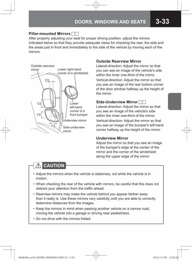
3-33DOORS, WINDOWS AND SEATS
Pillar-mounted Mirrors V
After properly adjusting your seat for proper driving position, adjust the mirrors indicated below so that they provide adequate views for checking the rear, the side and the areas just in front and immediately to the side of the vehicle by moving each of the mirrors.
Outside Rearview MirrorLateral-direction: Adjust the mirror so that you can see an image of the vehicle's side within the inner one-third of the mirror.Vertical-direction: Adjust the mirror so that you see an image of the rear bottom corner of the door window halfway up the height of the mirror.
Side-Underview Mirror V
Lateral-direction: Adjust the mirror so that you see an image of the vehicle's side within the inner one-third of the mirror.Vertical-direction: Adjust the mirror so that you see an image of the bumper's left-hand corner halfway up the height of the mirror.
Underview MirrorAdjust the mirror so that you see an image of the bumper's edge at the center of the mirror and the corner of the windshield along the upper edge of the mirror.
Lower right-hand corner of a windshield
Lowerleft-handcorner of a front bumper
1/3
1/3
1/2
1/2
Outside rearview mirror
Underview mirror
Side-underviewmirror
CAUTIONAdjust the mirrors when the vehicle is stationary, not while the vehicle is in motion.When checking the rear of the vehicle with mirrors, be careful that this does not distract your attention from the traffic ahead.Rearview mirrors may make the vehicle behind you appear farther away than it really is. Use these mirrors very carefully until you are able to correctly determine distances from the images.Keep the mirrors in mind when passing another vehicle on a narrow road, moving the vehicle into a garage or driving near pedestrians.Do not drive with the mirrors folded.
•
•
•
•
•
4608498_sec03_DOORS, WINDOWS AND3-33 3-334608498_sec03_DOORS, WINDOWS AND3-33 3-33 2015/11/02 13:55:482015/11/02 13:55:48
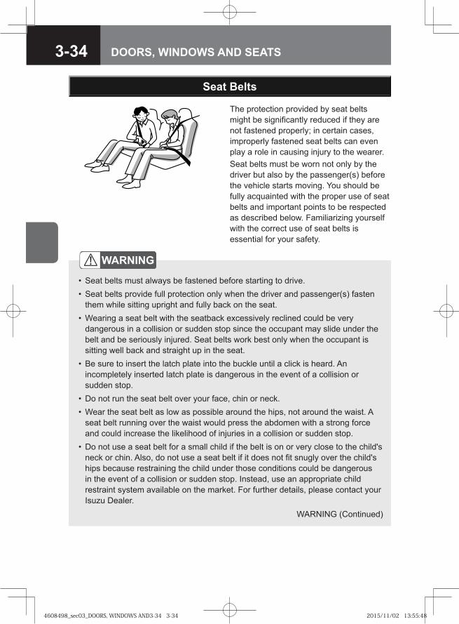
3-34 DOORS, WINDOWS AND SEATS
The protection provided by seat belts might be significantly reduced if they are not fastened properly; in certain cases, improperly fastened seat belts can even play a role in causing injury to the wearer.Seat belts must be worn not only by the driver but also by the passenger(s) before the vehicle starts moving. You should be fully acquainted with the proper use of seat belts and important points to be respected as described below. Familiarizing yourself with the correct use of seat belts is essential for your safety.
Seat Belts
WARNING
Seat belts must always be fastened before starting to drive.Seat belts provide full protection only when the driver and passenger(s) fasten them while sitting upright and fully back on the seat.Wearing a seat belt with the seatback excessively reclined could be very dangerous in a collision or sudden stop since the occupant may slide under the belt and be seriously injured. Seat belts work best only when the occupant is sitting well back and straight up in the seat.Be sure to insert the latch plate into the buckle until a click is heard. An incompletely inserted latch plate is dangerous in the event of a collision or sudden stop.Do not run the seat belt over your face, chin or neck.Wear the seat belt as low as possible around the hips, not around the waist. A seat belt running over the waist would press the abdomen with a strong force and could increase the likelihood of injuries in a collision or sudden stop.Do not use a seat belt for a small child if the belt is on or very close to the child's neck or chin. Also, do not use a seat belt if it does not fit snugly over the child's hips because restraining the child under those conditions could be dangerous in the event of a collision or sudden stop. Instead, use an appropriate child restraint system available on the market. For further details, please contact your Isuzu Dealer.
••
•
•
••
•
WARNING (Continued)
4608498_sec03_DOORS, WINDOWS AND3-34 3-344608498_sec03_DOORS, WINDOWS AND3-34 3-34 2015/11/02 13:55:482015/11/02 13:55:48
3-35DOORS, WINDOWS AND SEATS
WARNING (Continued)Use a child restraint system that fits the size of the infant or child. Install the system according to the manufacturer's instructions.Remove any twists in the seat belt before fastening it. A seat belt with twists will not provide full protection because it cannot disperse shocks efficiently in the event of a collision or sudden stop.Pregnant women or people suffering from chest or abdominal conditions should check with their doctor for specific recommendations about wearing seat belts.Do not use one seat belt for more than one person. If worn by more than one person, the seat belt would not work effectively in a collision or sudden stop.Have seat belts inspected and, if necessary, replaced by your Isuzu Dealer when the webbing becomes frayed or worn and/or when the buckle or other mechanical parts fail to work properly.If your vehicle has been involved in a collision, the seat belts worn at the time may have lost their original strength due to impact even if they appear intact. These seat belts must be inspected and, if necessary, replaced by your Isuzu Dealer.Be careful to keep the buckles and retractors free of dust and foreign matter.Wearing seat belts is a legal requirement in most countries. The driver is responsible not only for wearing a seat belt himself/herself but also for prompting all passengers to wear their seat belts. It is necessary, however, to check with a doctor about the appropriateness of a seat belt for a pregnant woman or a passenger with a chest/abdominal condition.
•
•
•
•
•
•
••
Seats → Refer to page 3-20Seat Belt Warning Light V
→ Refer to page 4-37Seat Belt Care (Except ISRI 6860/875
NTS Model) → Refer to page 7-211
4608498_sec03_DOORS, WINDOWS AND3-35 3-354608498_sec03_DOORS, WINDOWS AND3-35 3-35 2015/11/02 13:55:492015/11/02 13:55:49
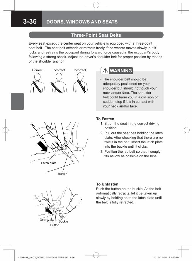
3-36 DOORS, WINDOWS AND SEATS
Every seat except the center seat on your vehicle is equipped with a three-point seat belt. The seat belt extends or retracts freely if the wearer moves slowly, but it locks and restrains the occupant during forward force caused in the occupant's body following a strong shock. Adjust the driver's shoulder belt for proper position by means of the shoulder anchor.
To Fasten 1. Sit on the seat in the correct driving
position. 2. Pull out the seat belt holding the latch
plate. After checking that there are no twists in the belt, insert the latch plate into the buckle until it clicks.
3. Position the lap belt so that it snugly fits as low as possible on the hips.
������ ��������� ���������
Three-Point Seat Belts
WARNING
The shoulder belt should be adequately positioned on your shoulder but should not touch your neck and/or face. The shoulder belt could harm you in a collision or sudden stop if it is in contact with your neck and/or face.
•
�� ��
����� �����
�� �� ��� �
�� ��
������
To UnfastenPush the button on the buckle. As the belt automatically retracts, let it be taken up slowly by holding on to the latch plate until the belt is fully retracted.
4608498_sec03_DOORS, WINDOWS AND3-36 3-364608498_sec03_DOORS, WINDOWS AND3-36 3-36 2015/11/02 13:55:492015/11/02 13:55:49
3-37DOORS, WINDOWS AND SEATS
ADVICEWhile being automatically retracted, the seat belt could damage a nearby window or interior trim unless the latch plate is properly held. Hold the latch plate to ensure that the belt is taken up slowly.Before closing the door, check that the retracted seat belt is taut. A slack belt could become trapped in the door or seat rail.When the passenger's seat belt is fully taken up (or not pulled out), check that the stopper is holding the belt in a fully taut state.
•
•
•
CAUTIONIf you repair any components around the steering wheel, instrument panel, center console and brake/clutch pedal or on the driver's seat belt, or if you install an audio system or other equipment, the seat belt system (with a pretensioner) and supplemental restraint system (SRS) airbag system may be adversely affected, possibly causing the seat belt to unintentionally retract or the airbag (including the passenger airbag, if equipped) to suddenly deploy, resulting in injury. Be sure to have any repair or installation done by your Isuzu Dealer.
•
4608498_sec03_DOORS, WINDOWS AND3-37 3-374608498_sec03_DOORS, WINDOWS AND3-37 3-37 2015/11/02 13:55:492015/11/02 13:55:49
3-38 DOORS, WINDOWS AND SEATS
NOTEThe driver's seat belt system and the passenger's seat belt system (model with a passenger airbag) are provided with both pretensioner and load limiter functions. If your vehicle is equipped with ISRI seats, the driver's seat belt system is provided with a pretensioner function and the passenger's seat belt system (model with a passenger airbag) is provided with both pretensioner and load limiter functions.The three-point seat belts are provided with an emergency locking retractor (ELR) function.
[ELR function]The ELR normally allows the seat belt to move in and out freely as the occupant moves. However, it locks the seat belt to restrain the occupant when a forward force resulting from a collision or sudden stop acts on the occupant.The ELR also locks the seat belt when the belt is pulled out quickly. If this happens, allow it to retract once and then pull it out slowly.
[Load limiter function]The load limiter allows the seat belt to extend while maintaining the load working on the belt at a constant level. This helps alleviate the shock applied on the occupant's chest.
•
•
•
•
•
Seat Belt with Pretensioner and Supplemental Restraint System (SRS) Airbag System V → Refer to page 4-198
4608498_sec03_DOORS, WINDOWS AND3-38 3-384608498_sec03_DOORS, WINDOWS AND3-38 3-38 2015/11/02 13:55:502015/11/02 13:55:50
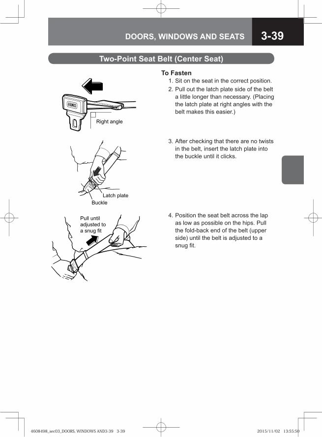
3-39DOORS, WINDOWS AND SEATS
To Fasten 1. Sit on the seat in the correct position. 2. Pull out the latch plate side of the belt
a little longer than necessary. (Placing the latch plate at right angles with the belt makes this easier.)
3. After checking that there are no twists in the belt, insert the latch plate into the buckle until it clicks.
Two-Point Seat Belt (Center Seat)
4. Position the seat belt across the lap as low as possible on the hips. Pull the fold-back end of the belt (upper side) until the belt is adjusted to a snug fit.
�� �� ��� �
������
Pull until adjusted to a snug fit
�� �� �� ��
4608498_sec03_DOORS, WINDOWS AND3-39 3-394608498_sec03_DOORS, WINDOWS AND3-39 3-39 2015/11/02 13:55:502015/11/02 13:55:50
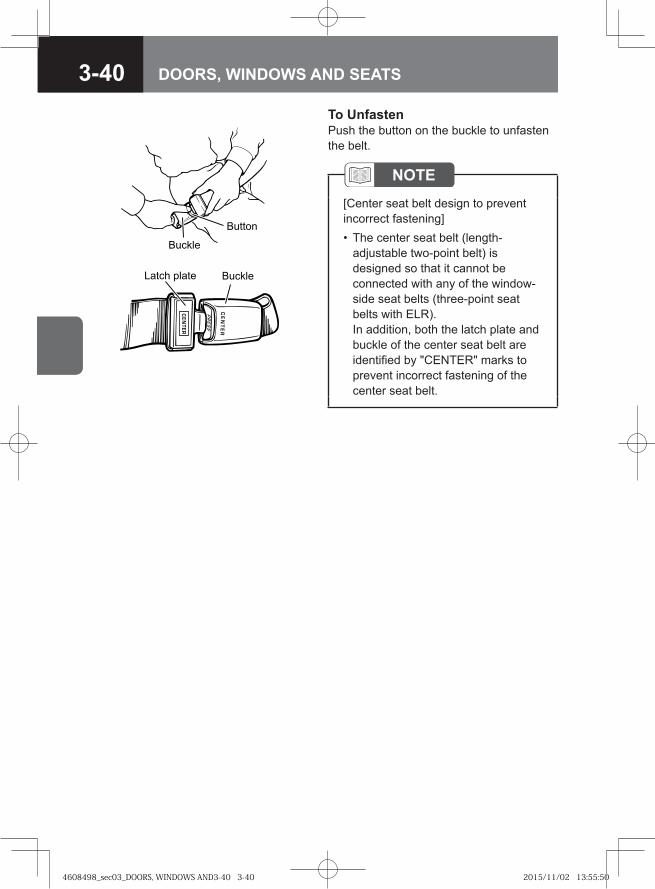
3-40 DOORS, WINDOWS AND SEATS
NOTE[Center seat belt design to prevent incorrect fastening]
The center seat belt (length-adjustable two-point belt) is designed so that it cannot be connected with any of the window-side seat belts (three-point seat belts with ELR).In addition, both the latch plate and buckle of the center seat belt are identified by "CENTER" marks to prevent incorrect fastening of the center seat belt.
•
To UnfastenPush the button on the buckle to unfasten the belt.
�� ��
������
�� �� ��� � ������
4608498_sec03_DOORS, WINDOWS AND3-40 3-404608498_sec03_DOORS, WINDOWS AND3-40 3-40 2015/11/02 13:55:502015/11/02 13:55:50
STARTING AND STOPPING THE ENGINE 4-3
INSTRUMENTS, WARNING LIGHTS AND INDICATOR LIGHTS 4-9
SWITCHES 4-73
DRIVING CONTROLS 4-93
4CONTROLS AND INSTRUMENTS
4608498_sec04_CONTROLS AND INSTR4-1 4-14608498_sec04_CONTROLS AND INSTR4-1 4-1 2015/11/02 13:58:302015/11/02 13:58:30
4608498_sec04_CONTROLS AND INSTR4-2 4-24608498_sec04_CONTROLS AND INSTR4-2 4-2 2015/11/02 13:58:302015/11/02 13:58:30
4-3CONTROLS AND INSTRUMENTS
● Starting the Engine 4-4
● Stopping the Engine 4-7
STARTING AND STOPPING THE ENGINE
4608498_sec04_CONTROLS AND INSTR4-3 4-34608498_sec04_CONTROLS AND INSTR4-3 4-3 2015/11/02 13:58:302015/11/02 13:58:30
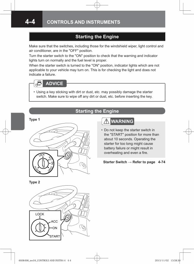
4-4 CONTROLS AND INSTRUMENTS
Make sure that the switches, including those for the windshield wiper, light control and air conditioner, are in the "OFF" position. Turn the starter switch to the "ON" position to check that the warning and indicator lights turn on normally and the fuel level is proper.When the starter switch is turned to the "ON" position, indicator lights which are not applicable to your vehicle may turn on. This is for checking the light and does not indicate a failure.
Starting the Engine
Starting the Engine
ADVICEUsing a key sticking with dirt or dust, etc. may possibly damage the starter switch. Make sure to wipe off any dirt or dust, etc. before inserting the key.
•
WARNING
Do not keep the starter switch in the "START" position for more than about 10 seconds. Operating the starter for too long might cause battery failure or might result in overheating and even a fire.
•
Starter Switch → Refer to page 4-74
Type 1
Type 2
�� �
�
��
�����
4608498_sec04_CONTROLS AND INSTR4-4 4-44608498_sec04_CONTROLS AND INSTR4-4 4-4 2015/11/02 13:58:302015/11/02 13:58:30
4-5CONTROLS AND INSTRUMENTS
CAUTIONIf your vehicle is equipped with a manual transmission, firmly engage the parking brake when you sit in the seat before starting the engine. Also, be sure to start the engine while pressing the clutch pedal and after making sure that the gearshift lever is in "N". If your vehicle is equipped with a Smoother, firmly engage the parking brake when you sit in the driver's seat, check that the gearshift lever is in "N" and the shift indicator shows "N", and firmly press the brake pedal before starting the engine.If your vehicle is equipped with an automatic transmission of the selector lever type, firmly engage the parking brake when you sit in the driver's seat, check that selector lever is in "N", and firmly press the brake pedal before starting the engine.If your vehicle is equipped with an automatic transmission of the selector button type, firmly engaging the parking brake when you sit in the driver's seat, check that the shift selector display shows "NN", and firmly press the brake pedal before starting the engine.It is dangerous to start the engine from outside through the window. If the gearshift lever, selector lever or selector button is not in "N", your vehicle may start moving. Never start the engine in that way.
•
•
•
•
•
4608498_sec04_CONTROLS AND INSTR4-5 4-54608498_sec04_CONTROLS AND INSTR4-5 4-5 2015/11/02 13:58:302015/11/02 13:58:30
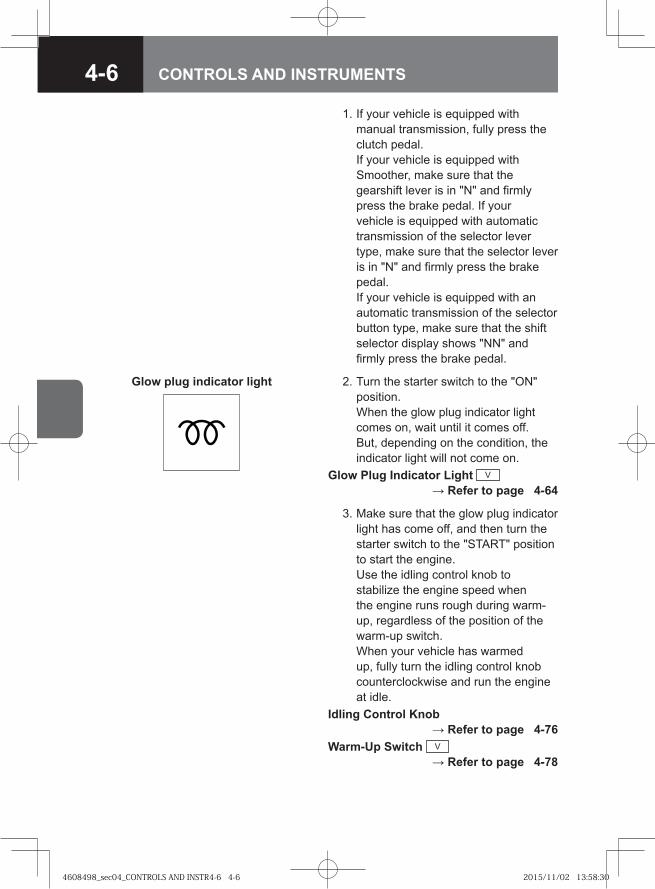
4-6 CONTROLS AND INSTRUMENTS
1. If your vehicle is equipped with manual transmission, fully press the clutch pedal. If your vehicle is equipped with Smoother, make sure that the gearshift lever is in "N" and firmly press the brake pedal. If your vehicle is equipped with automatic transmission of the selector lever type, make sure that the selector lever is in "N" and firmly press the brake pedal. If your vehicle is equipped with an automatic transmission of the selector button type, make sure that the shift selector display shows "NN" and firmly press the brake pedal.
Glow plug indicator light 2. Turn the starter switch to the "ON" position. When the glow plug indicator light comes on, wait until it comes off. But, depending on the condition, the indicator light will not come on.
Glow Plug Indicator Light V → Refer to page 4-64
3. Make sure that the glow plug indicator light has come off, and then turn the starter switch to the "START" position to start the engine. Use the idling control knob to stabilize the engine speed when the engine runs rough during warm-up, regardless of the position of the warm-up switch. When your vehicle has warmed up, fully turn the idling control knob counterclockwise and run the engine at idle.
Idling Control Knob → Refer to page 4-76
Warm-Up Switch V → Refer to page 4-78
4608498_sec04_CONTROLS AND INSTR4-6 4-64608498_sec04_CONTROLS AND INSTR4-6 4-6 2015/11/02 13:58:302015/11/02 13:58:30
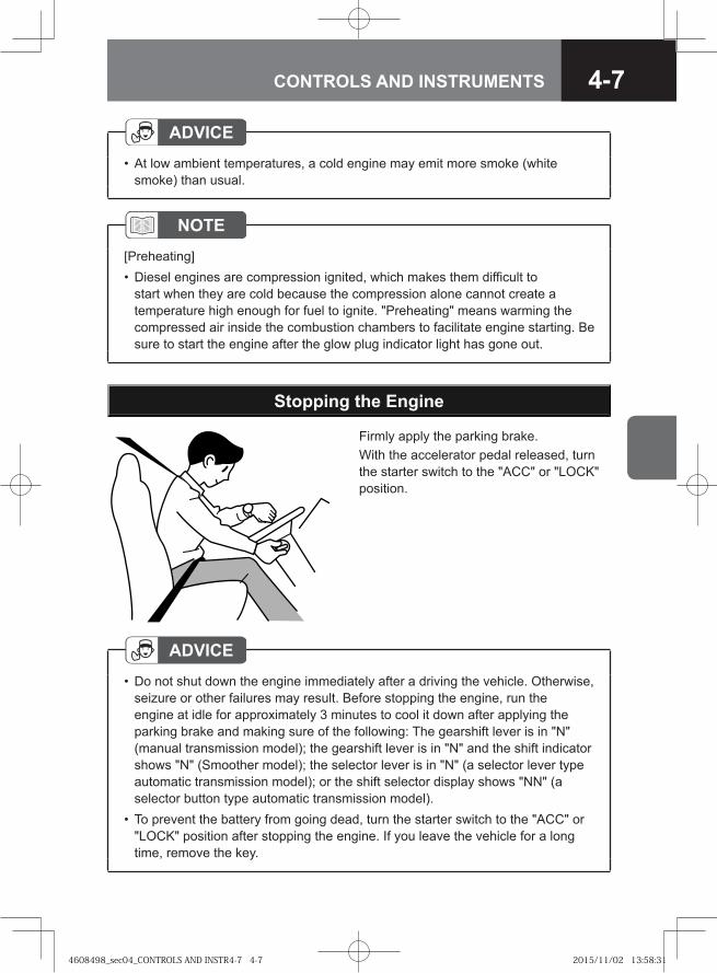
4-7CONTROLS AND INSTRUMENTS
ADVICEAt low ambient temperatures, a cold engine may emit more smoke (white smoke) than usual.
•
Firmly apply the parking brake. With the accelerator pedal released, turn the starter switch to the "ACC" or "LOCK" position.
Stopping the Engine
ADVICEDo not shut down the engine immediately after a driving the vehicle. Otherwise, seizure or other failures may result. Before stopping the engine, run the engine at idle for approximately 3 minutes to cool it down after applying the parking brake and making sure of the following: The gearshift lever is in "N" (manual transmission model); the gearshift lever is in "N" and the shift indicator shows "N" (Smoother model); the selector lever is in "N" (a selector lever type automatic transmission model); or the shift selector display shows "NN" (a selector button type automatic transmission model).To prevent the battery from going dead, turn the starter switch to the "ACC" or "LOCK" position after stopping the engine. If you leave the vehicle for a long time, remove the key.
•
•
NOTE[Preheating]
Diesel engines are compression ignited, which makes them difficult to start when they are cold because the compression alone cannot create a temperature high enough for fuel to ignite. "Preheating" means warming the compressed air inside the combustion chambers to facilitate engine starting. Be sure to start the engine after the glow plug indicator light has gone out.
•
4608498_sec04_CONTROLS AND INSTR4-7 4-74608498_sec04_CONTROLS AND INSTR4-7 4-7 2015/11/02 13:58:312015/11/02 13:58:31
4-8 CONTROLS AND INSTRUMENTS
4608498_sec04_CONTROLS AND INSTR4-8 4-84608498_sec04_CONTROLS AND INSTR4-8 4-8 2015/11/02 13:58:312015/11/02 13:58:31
4-9CONTROLS AND INSTRUMENTS
INSTRUMENTS, WARNING LIGHTS AND INDICATOR LIGHTS
● How to Read the Instruments (Instruments Layout) 4-10
● Speedometer 4-11
● Analog Tachograph V 4-12
● Tachometer 4-13
● Air Pressure Gauge 4-14
● Engine Coolant Temperature Gauge 4-15
● Fuel Gauge 4-16
● Hour Meter V 4-17
● Warning and Indicator Lights Layout 4-18
● Multi-Information Display (MID) V 4-22
● Warning and Indicator Lights 4-37
● Warning Buzzer 4-70
4608498_sec04_CONTROLS AND INSTR4-9 4-94608498_sec04_CONTROLS AND INSTR4-9 4-9 2015/11/02 13:58:312015/11/02 13:58:31
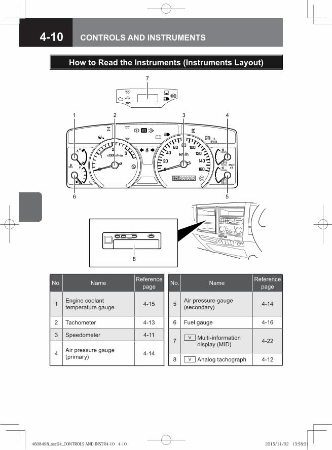
4-10 CONTROLS AND INSTRUMENTS
�� �
�
�
No. Name Reference page
1 Engine coolant temperature gauge 4-15
2 Tachometer 4-13
3 Speedometer 4-11
4 Air pressure gauge (primary) 4-14
No. Name Reference page
5 Air pressure gauge (secondary) 4-14
6 Fuel gauge 4-16
7 V Multi-information display (MID) 4-22
8 V Analog tachograph 4-12
How to Read the Instruments (Instruments Layout)
4608498_sec04_CONTROLS AND INSTR4-10 4-104608498_sec04_CONTROLS AND INSTR4-10 4-10 2015/11/02 13:58:312015/11/02 13:58:31
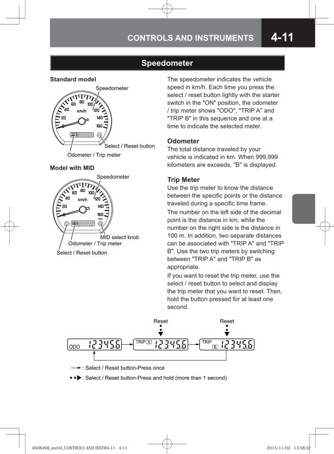
4-11CONTROLS AND INSTRUMENTS
The speedometer indicates the vehicle speed in km/h. Each time you press the select / reset button lightly with the starter switch in the "ON" position, the odometer / trip meter shows "ODO", "TRIP A" and "TRIP B" in this sequence and one at a time to indicate the selected meter.
OdometerThe total distance traveled by your vehicle is indicated in km. When 999,999 kilometers are exceeds, "B" is displayed.
Trip MeterUse the trip meter to know the distance between the specific points or the distance traveled during a specific time frame. The number on the left side of the decimal point is the distance in km, while the number on the right side is the distance in 100 m. In addition, two separate distances can be associated with "TRIP A" and "TRIP B". Use the two trip meters by switching between "TRIP A" and "TRIP B" as appropriate. If you want to reset the trip meter, use the select / reset button to select and display the trip meter that you want to reset. Then, hold the button pressed for at least one second.
Speedometer
: Select / Reset button-Press once
: Select / Reset button-Press and hold (more than 1 second)
Reset Reset
ODOTRIP A TRIP
B
Select / Reset button
Speedometer
Odometer / Trip meter
Standard model
�� ��� � �
���� � � � ���� � � �
� � �� � � � � ������
�� � � �� !���
Model with MID
4608498_sec04_CONTROLS AND INSTR4-11 4-114608498_sec04_CONTROLS AND INSTR4-11 4-11 2015/11/02 13:58:322015/11/02 13:58:32
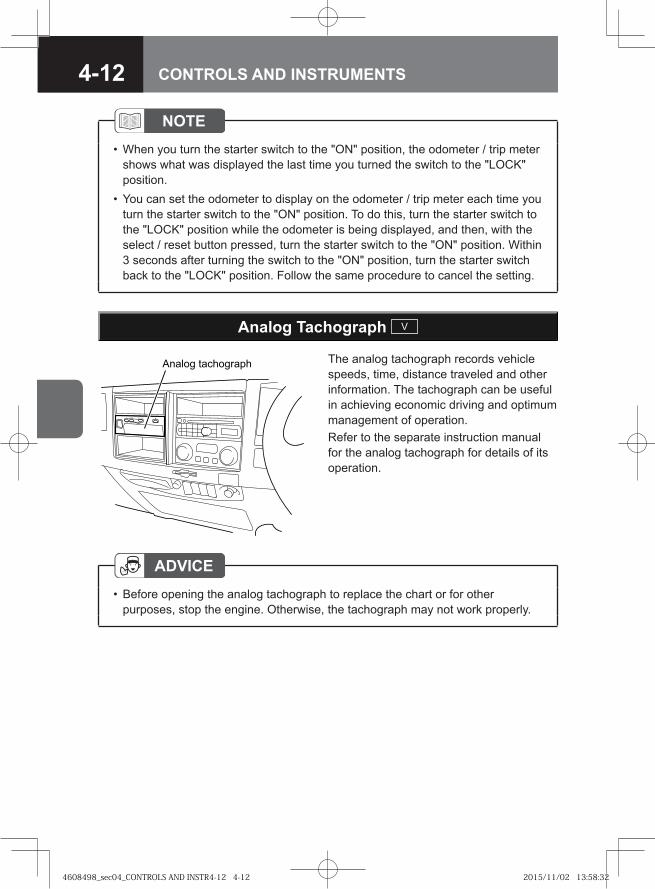
4-12 CONTROLS AND INSTRUMENTS
The analog tachograph records vehicle speeds, time, distance traveled and other information. The tachograph can be useful in achieving economic driving and optimum management of operation.Refer to the separate instruction manual for the analog tachograph for details of its operation.
�� ��� � ����� ��
Analog Tachograph V
ADVICEBefore opening the analog tachograph to replace the chart or for other purposes, stop the engine. Otherwise, the tachograph may not work properly.
•
NOTEWhen you turn the starter switch to the "ON" position, the odometer / trip meter shows what was displayed the last time you turned the switch to the "LOCK" position. You can set the odometer to display on the odometer / trip meter each time you turn the starter switch to the "ON" position. To do this, turn the starter switch to the "LOCK" position while the odometer is being displayed, and then, with the select / reset button pressed, turn the starter switch to the "ON" position. Within 3 seconds after turning the switch to the "ON" position, turn the starter switch back to the "LOCK" position. Follow the same procedure to cancel the setting.
•
•
4608498_sec04_CONTROLS AND INSTR4-12 4-124608498_sec04_CONTROLS AND INSTR4-12 4-12 2015/11/02 13:58:322015/11/02 13:58:32
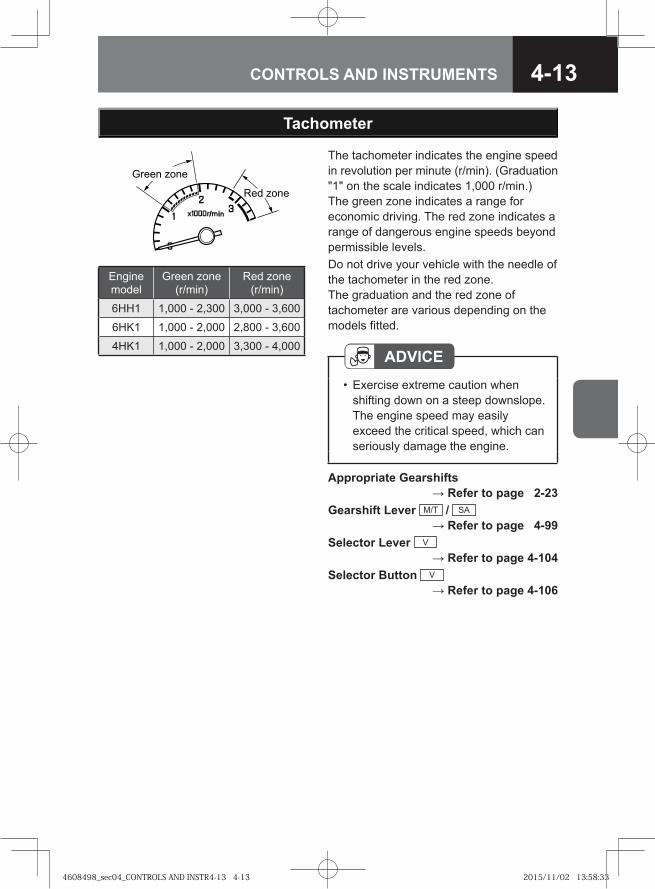
4-13CONTROLS AND INSTRUMENTS
� � ���
�� � ���
The tachometer indicates the engine speed in revolution per minute (r/min). (Graduation "1" on the scale indicates 1,000 r/min.) The green zone indicates a range for economic driving. The red zone indicates a range of dangerous engine speeds beyond permissible levels. Do not drive your vehicle with the needle of the tachometer in the red zone. The graduation and the red zone of tachometer are various depending on the models fitted.
Tachometer
ADVICEExercise extreme caution when shifting down on a steep downslope. The engine speed may easily exceed the critical speed, which can seriously damage the engine.
•
Appropriate Gearshifts → Refer to page 2-23
Gearshift Lever M/T / SA → Refer to page 4-99
Selector Lever V → Refer to page 4-104
Selector Button V → Refer to page 4-106
Engine model
Green zone (r/min)
Red zone (r/min)
6HH1 1,000 - 2,300 3,000 - 3,600
6HK1 1,000 - 2,000 2,800 - 3,600
4HK1 1,000 - 2,000 3,300 - 4,000
4608498_sec04_CONTROLS AND INSTR4-13 4-134608498_sec04_CONTROLS AND INSTR4-13 4-13 2015/11/02 13:58:332015/11/02 13:58:33
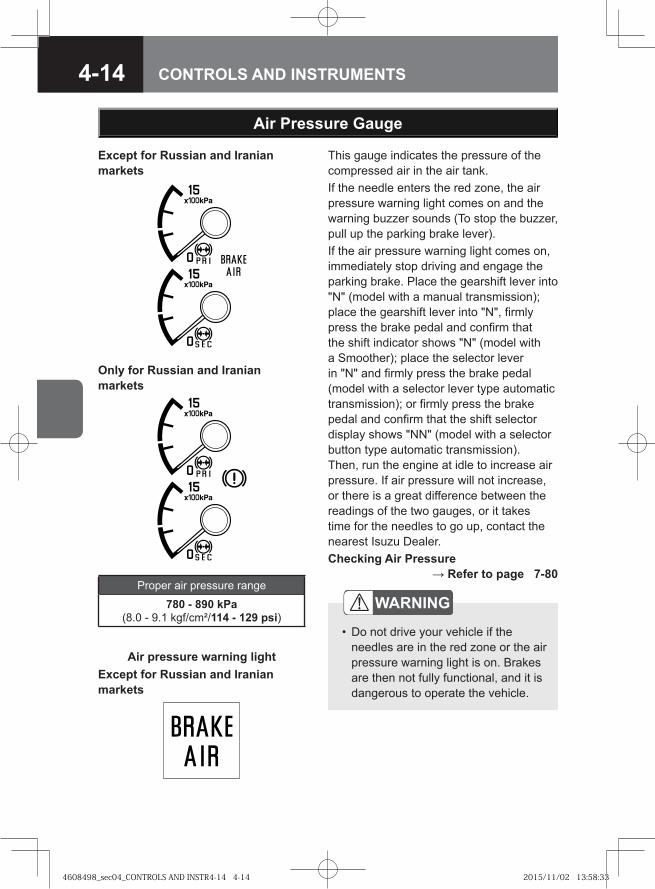
4-14 CONTROLS AND INSTRUMENTS
Air Pressure Gauge
This gauge indicates the pressure of the compressed air in the air tank.If the needle enters the red zone, the air pressure warning light comes on and the warning buzzer sounds (To stop the buzzer, pull up the parking brake lever). If the air pressure warning light comes on, immediately stop driving and engage the parking brake. Place the gearshift lever into "N" (model with a manual transmission); place the gearshift lever into "N", firmly press the brake pedal and confirm that the shift indicator shows "N" (model with a Smoother); place the selector lever in "N" and firmly press the brake pedal (model with a selector lever type automatic transmission); or firmly press the brake pedal and confirm that the shift selector display shows "NN" (model with a selector button type automatic transmission). Then, run the engine at idle to increase air pressure. If air pressure will not increase, or there is a great difference between the readings of the two gauges, or it takes time for the needles to go up, contact the nearest Isuzu Dealer.Checking Air Pressure
→ Refer to page 7-80Proper air pressure range
780 - 890 kPa (8.0 - 9.1 kgf/cm²/114 - 129 psi)
WARNING
Do not drive your vehicle if the needles are in the red zone or the air pressure warning light is on. Brakes are then not fully functional, and it is dangerous to operate the vehicle.
•
Except for Russian and Iranian markets
Only for Russian and Iranian markets
Air pressure warning lightExcept for Russian and Iranian markets
4608498_sec04_CONTROLS AND INSTR4-14 4-144608498_sec04_CONTROLS AND INSTR4-14 4-14 2015/11/02 13:58:332015/11/02 13:58:33
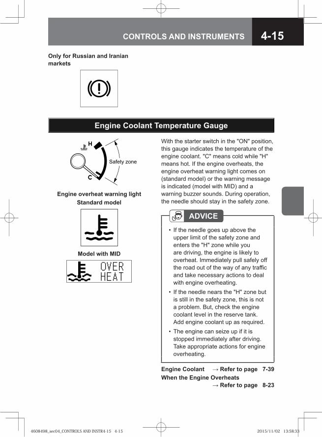
4-15CONTROLS AND INSTRUMENTS
Engine Coolant Temperature Gauge
With the starter switch in the "ON" position, this gauge indicates the temperature of the engine coolant. "C" means cold while "H" means hot. If the engine overheats, the engine overheat warning light comes on (standard model) or the warning message is indicated (model with MID) and a warning buzzer sounds. During operation, the needle should stay in the safety zone.
��� �� ���
Engine overheat warning lightStandard model
Model with MID
Only for Russian and Iranian markets
Engine Coolant → Refer to page 7-39When the Engine Overheats
→ Refer to page 8-23
ADVICEIf the needle goes up above the upper limit of the safety zone and enters the "H" zone while you are driving, the engine is likely to overheat. Immediately pull safely off the road out of the way of any traffic and take necessary actions to deal with engine overheating.If the needle nears the "H" zone but is still in the safety zone, this is not a problem. But, check the engine coolant level in the reserve tank. Add engine coolant up as required.The engine can seize up if it is stopped immediately after driving. Take appropriate actions for engine overheating.
•
•
•
4608498_sec04_CONTROLS AND INSTR4-15 4-154608498_sec04_CONTROLS AND INSTR4-15 4-15 2015/11/02 13:58:332015/11/02 13:58:33
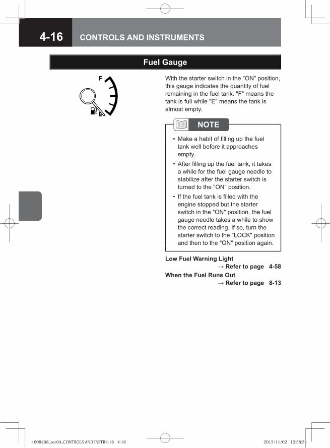
4-16 CONTROLS AND INSTRUMENTS
With the starter switch in the "ON" position, this gauge indicates the quantity of fuel remaining in the fuel tank. "F" means the tank is full while "E" means the tank is almost empty.
Fuel Gauge
Low Fuel Warning Light → Refer to page 4-58
When the Fuel Runs Out → Refer to page 8-13
NOTEMake a habit of filling up the fuel tank well before it approaches empty.After filling up the fuel tank, it takes a while for the fuel gauge needle to stabilize after the starter switch is turned to the "ON" position. If the fuel tank is filled with the engine stopped but the starter switch in the "ON" position, the fuel gauge needle takes a while to show the correct reading. If so, turn the starter switch to the "LOCK" position and then to the "ON" position again.
•
•
•
4608498_sec04_CONTROLS AND INSTR4-16 4-164608498_sec04_CONTROLS AND INSTR4-16 4-16 2015/11/02 13:58:342015/11/02 13:58:34
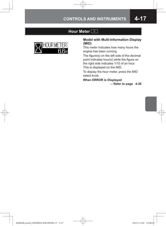
4-17CONTROLS AND INSTRUMENTS
Model with Multi-Information Display (MID)This meter indicates how many hours the engine has been running.The figure(s) on the left side of the decimal point indicates hour(s) while the figure on the right side indicates 1/10 of an hour. This is displayed on the MID.To display the hour meter, press the MID select knob.When ERROR is Displayed
→ Refer to page 4-36
Hour Meter V
4608498_sec04_CONTROLS AND INSTR4-17 4-174608498_sec04_CONTROLS AND INSTR4-17 4-17 2015/11/02 13:58:342015/11/02 13:58:34
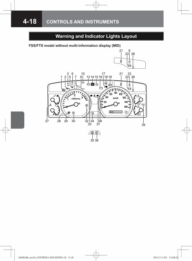
4-18 CONTROLS AND INSTRUMENTS
Warning and Indicator Lights Layout
��
���
��
�
�
� � � �� �
��
��
��
�
��
�� ��
� ���� ��
�
�
��
�
FSS/FTS model without multi-information display (MID)
4608498_sec04_CONTROLS AND INSTR4-18 4-184608498_sec04_CONTROLS AND INSTR4-18 4-18 2015/11/02 13:58:342015/11/02 13:58:34
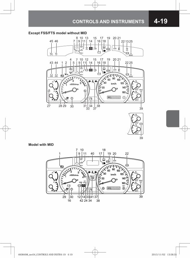
4-19CONTROLS AND INSTRUMENTS
1011
11
181621
25
39
14443 279
12 172214
15
282733 37
3831
1018167 9
1313
171415
519 20
212522
20
29 34
19
30
8
39
4
4645
Except FSS/FTS model without MID
� �� ��� �
��
�� ���
��� � �� �
�
���
��
Model with MID
4608498_sec04_CONTROLS AND INSTR4-19 4-194608498_sec04_CONTROLS AND INSTR4-19 4-19 2015/11/02 13:58:352015/11/02 13:58:35
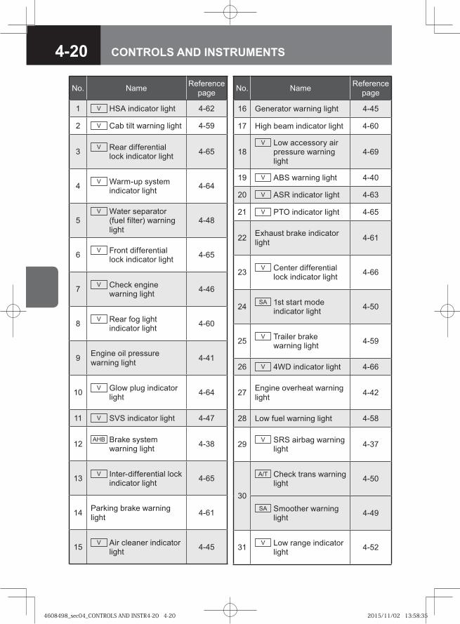
4-20 CONTROLS AND INSTRUMENTS
No. Name Reference page
1 V HSA indicator light 4-62
2 V Cab tilt warning light 4-59
3 V Rear differential lock indicator light 4-65
4 V Warm-up system indicator light 4-64
5V Water separator
(fuel filter) warning light
4-48
6 V Front differential lock indicator light 4-65
7 V Check engine warning light 4-46
8 V Rear fog light indicator light 4-60
9 Engine oil pressure warning light 4-41
10 V Glow plug indicator light 4-64
11 V SVS indicator light 4-47
12 AHB Brake system warning light 4-38
13 V Inter-differential lock indicator light 4-65
14 Parking brake warning light 4-61
15 V Air cleaner indicator light 4-45
No. Name Reference page
16 Generator warning light 4-45
17 High beam indicator light 4-60
18V Low accessory air
pressure warning light
4-69
19 V ABS warning light 4-40
20 V ASR indicator light 4-63
21 V PTO indicator light 4-65
22 Exhaust brake indicator light 4-61
23 V Center differential lock indicator light 4-66
24 SA 1st start mode indicator light 4-50
25 V Trailer brake warning light 4-59
26 V 4WD indicator light 4-66
27 Engine overheat warning light 4-42
28 Low fuel warning light 4-58
29 V SRS airbag warning light 4-37
30
A/T Check trans warning light 4-50
SA Smoother warning light 4-49
31 V Low range indicator light 4-52
4608498_sec04_CONTROLS AND INSTR4-20 4-204608498_sec04_CONTROLS AND INSTR4-20 4-20 2015/11/02 13:58:352015/11/02 13:58:35
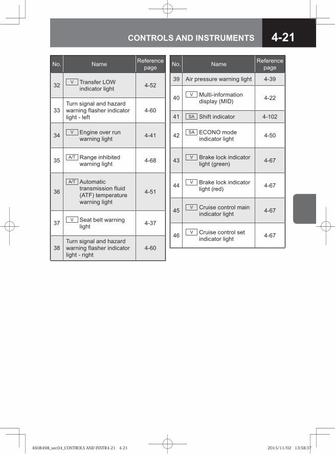
4-21CONTROLS AND INSTRUMENTS
No. Name Reference page
32 V Transfer LOW indicator light 4-52
33Turn signal and hazard warning flasher indicator light - left
4-60
34 V Engine over run warning light 4-41
35 A/T Range inhibited warning light 4-68
36
A/T Automatic transmission fluid (ATF) temperature warning light
4-51
37 V Seat belt warning light 4-37
38Turn signal and hazard warning flasher indicator light - right
4-60
No. Name Reference page
39 Air pressure warning light 4-39
40 V Multi-information display (MID) 4-22
41 SA Shift indicator 4-102
42 SA ECONO mode indicator light 4-50
43 V Brake lock indicator light (green) 4-67
44 V Brake lock indicator light (red) 4-67
45 V Cruise control main indicator light 4-67
46 V Cruise control set indicator light 4-67
4608498_sec04_CONTROLS AND INSTR4-21 4-214608498_sec04_CONTROLS AND INSTR4-21 4-21 2015/11/02 13:58:372015/11/02 13:58:37
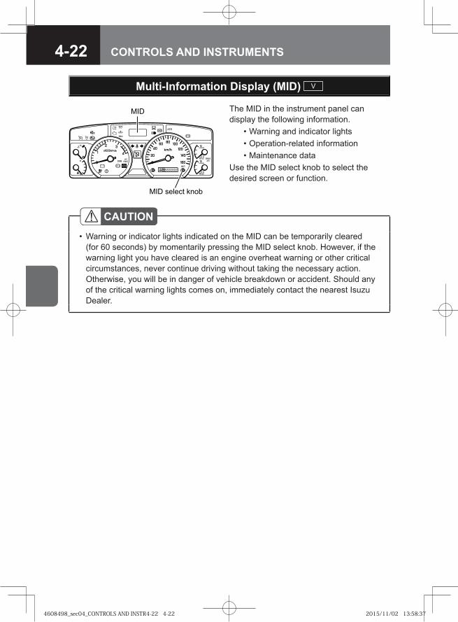
4-22 CONTROLS AND INSTRUMENTS
The MID in the instrument panel can display the following information. • Warning and indicator lights • Operation-related information • Maintenance dataUse the MID select knob to select the desired screen or function.
���
��� ������ ����
Multi-Information Display (MID) V
CAUTIONWarning or indicator lights indicated on the MID can be temporarily cleared (for 60 seconds) by momentarily pressing the MID select knob. However, if the warning light you have cleared is an engine overheat warning or other critical circumstances, never continue driving without taking the necessary action. Otherwise, you will be in danger of vehicle breakdown or accident. Should any of the critical warning lights comes on, immediately contact the nearest Isuzu Dealer.
•
4608498_sec04_CONTROLS AND INSTR4-22 4-224608498_sec04_CONTROLS AND INSTR4-22 4-22 2015/11/02 13:58:372015/11/02 13:58:37
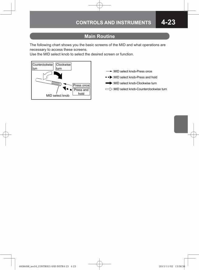
4-23CONTROLS AND INSTRUMENTS
Main RoutineThe following chart shows you the basic screens of the MID and what operations are necessary to access these screens. Use the MID select knob to select the desired screen or function.
�� � ������ ���������� ����
�� � ������ ���������� ��� ����
�� � ������ ���������� !�� �"��
�� � ������ �������"��������� !�� �"��
�� ������������
���
���������
���
����� � ��
����� � �
������� ������ � �
4608498_sec04_CONTROLS AND INSTR4-23 4-234608498_sec04_CONTROLS AND INSTR4-23 4-23 2015/11/02 13:58:382015/11/02 13:58:38
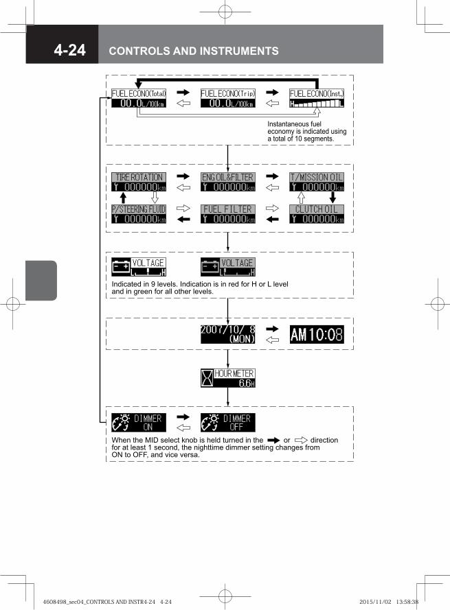
4-24 CONTROLS AND INSTRUMENTS
�� ����� � � ������� �� ��� �� � � ��� ��� � �� � �������� � ����� ��� ��� ����� �������
������������ ��������� ! � �� ����� �� ��� ����� �� � ��� �����
"��� ��� �# ������ $��% � ���� ������ � ��� �� � ���� ����� �� ����� ������& ��� � ���� � � �� ���� �� ������� ��� '( �� '��& ��� � �� ������
4608498_sec04_CONTROLS AND INSTR4-24 4-244608498_sec04_CONTROLS AND INSTR4-24 4-24 2015/11/02 13:58:382015/11/02 13:58:38
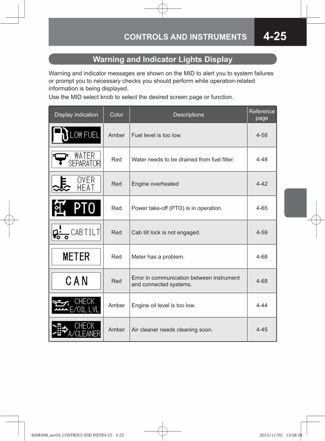
4-25CONTROLS AND INSTRUMENTS
Warning and indicator messages are shown on the MID to alert you to system failures or prompt you to necessary checks you should perform while operation-related information is being displayed.Use the MID select knob to select the desired screen page or function.
Display indication Color Descriptions Reference page
Amber Fuel level is too low. 4-58
Red Water needs to be drained from fuel filter. 4-48
Red Engine overheated 4-42
Red Power take-off (PTO) is in operation. 4-65
Red Cab tilt lock is not engaged. 4-59
Red Meter has a problem. 4-68
Red Error in communication between instrument and connected systems. 4-68
Amber Engine oil level is too low. 4-44
Amber Air cleaner needs cleaning soon. 4-45
Warning and Indicator Lights Display
4608498_sec04_CONTROLS AND INSTR4-25 4-254608498_sec04_CONTROLS AND INSTR4-25 4-25 2015/11/02 13:58:382015/11/02 13:58:38
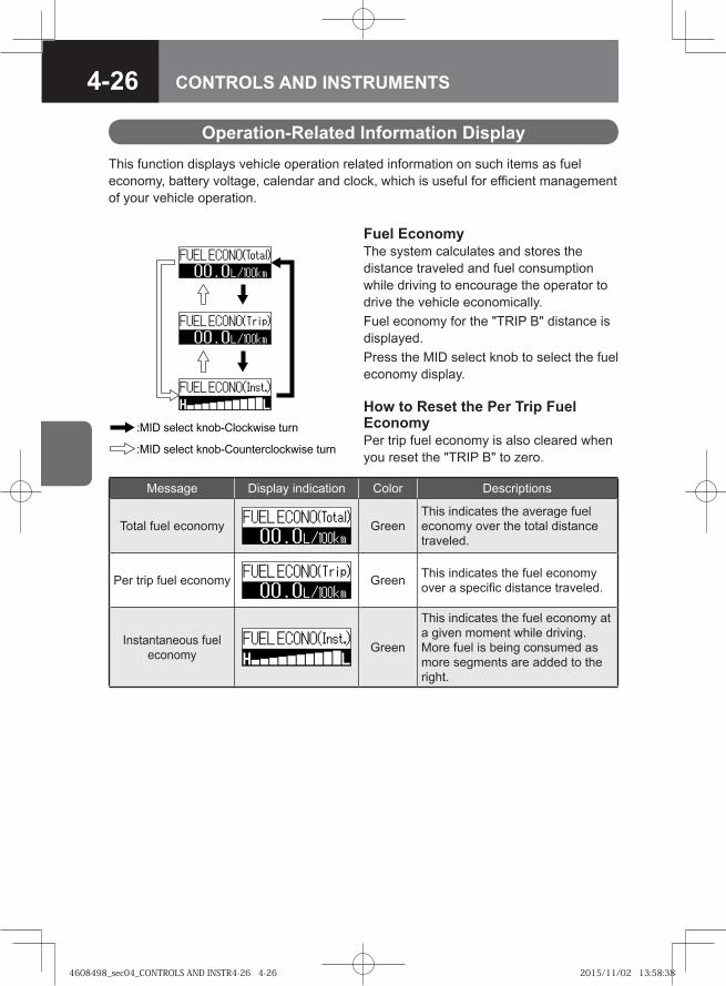
4-26 CONTROLS AND INSTRUMENTS
Message Display indication Color Descriptions
Total fuel economy GreenThis indicates the average fuel economy over the total distance traveled.
Per trip fuel economy Green This indicates the fuel economy over a specific distance traveled.
Instantaneous fuel economy Green
This indicates the fuel economy at a given moment while driving.More fuel is being consumed as more segments are added to the right.
This function displays vehicle operation related information on such items as fuel economy, battery voltage, calendar and clock, which is useful for efficient management of your vehicle operation.
Operation-Related Information Display
Fuel EconomyThe system calculates and stores the distance traveled and fuel consumption while driving to encourage the operator to drive the vehicle economically.Fuel economy for the "TRIP B" distance is displayed. Press the MID select knob to select the fuel economy display.
How to Reset the Per Trip Fuel EconomyPer trip fuel economy is also cleared when you reset the "TRIP B" to zero.
�� � ������ �������������� ����
�� � ������ ��������������������� ����
4608498_sec04_CONTROLS AND INSTR4-26 4-264608498_sec04_CONTROLS AND INSTR4-26 4-26 2015/11/02 13:58:382015/11/02 13:58:38
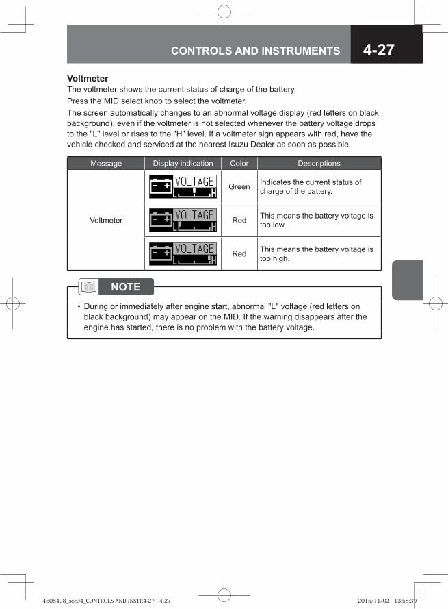
4-27CONTROLS AND INSTRUMENTS
VoltmeterThe voltmeter shows the current status of charge of the battery. Press the MID select knob to select the voltmeter. The screen automatically changes to an abnormal voltage display (red letters on black background), even if the voltmeter is not selected whenever the battery voltage drops to the "L" level or rises to the "H" level. If a voltmeter sign appears with red, have the vehicle checked and serviced at the nearest Isuzu Dealer as soon as possible.
Message Display indication Color Descriptions
Voltmeter
Green Indicates the current status of charge of the battery.
Red This means the battery voltage is too low.
Red This means the battery voltage is too high.
NOTEDuring or immediately after engine start, abnormal "L" voltage (red letters on black background) may appear on the MID. If the warning disappears after the engine has started, there is no problem with the battery voltage.
•
4608498_sec04_CONTROLS AND INSTR4-27 4-274608498_sec04_CONTROLS AND INSTR4-27 4-27 2015/11/02 13:58:392015/11/02 13:58:39
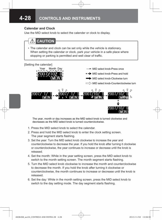
4-28 CONTROLS AND INSTRUMENTS
CAUTIONThe calendar and clock can be set only while the vehicle is stationary.When setting the calendar or clock, park your vehicle in a safe place where stopping or parking is permitted and well clear of traffic.
•
Calendar and Clock
1. Press the MID select knob to select the calendar. 2. Press and hold the MID select knob to enter the clock setting screen.
The year segment starts flashing. 3. Set the year: Turn the MID select knob clockwise to increase the year and
counterclockwise to decrease the year. If you hold the knob after turning it clockwise or counterclockwise, the year continues to increase or decrease until the knob is released.
4. Set the month: While in the year setting screen, press the MID select knob to switch to the month setting screen. The month segment starts flashing.
5. Turn the MID select knob clockwise to increase the month and counterclockwise to decrease the month. If you hold the knob after turning it clockwise or counterclockwise, the month continues to increase or decrease until the knob is released.
6. Set the day: While in the month setting screen, press the MID select knob to switch to the day setting mode. The day segment starts flashing.
[Setting the calendar]
�� ����� ����� �� ��� ��������� �� ��� ��� ������ ���� �� � ���� �����!��� ���
��������� �� ��� ��� ������ ���� �� � ���� �� ���������!���"
�� � ����� � �
Use the MID select knob to select the calender or clock to display.
�� � ������ ���������� ����
�� � ������ ���������� ��� ����
�� � ������ ���������� !�� �"��
�� � ������ �������"��������� !�� �"��
4608498_sec04_CONTROLS AND INSTR4-28 4-284608498_sec04_CONTROLS AND INSTR4-28 4-28 2015/11/02 13:58:392015/11/02 13:58:39
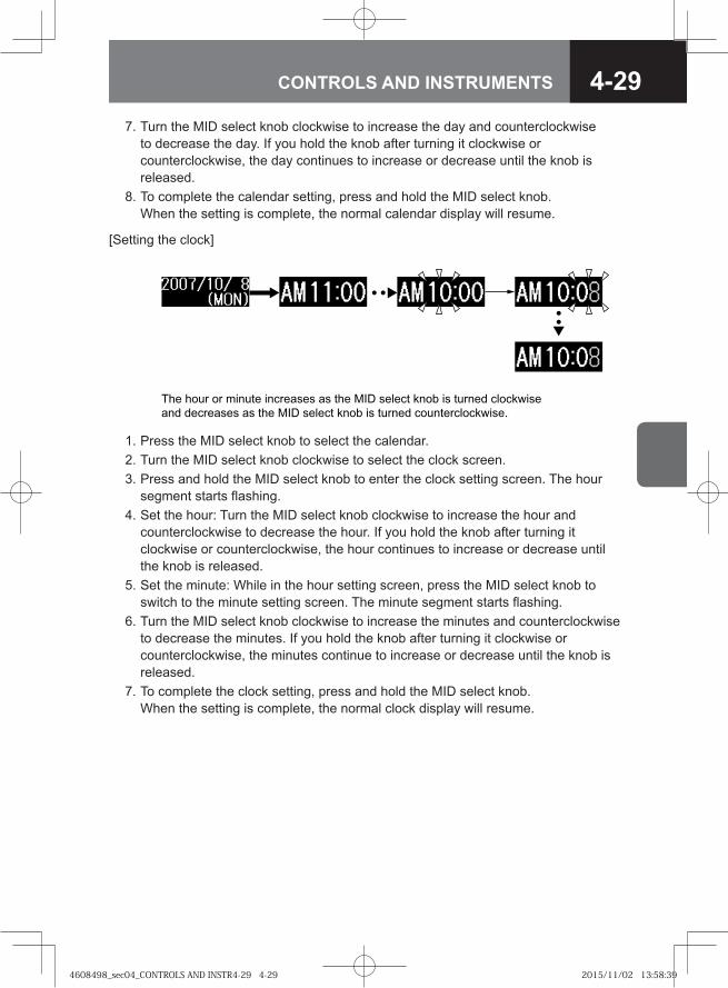
4-29CONTROLS AND INSTRUMENTS
[Setting the clock]
1. Press the MID select knob to select the calendar. 2. Turn the MID select knob clockwise to select the clock screen. 3. Press and hold the MID select knob to enter the clock setting screen. The hour
segment starts flashing. 4. Set the hour: Turn the MID select knob clockwise to increase the hour and
counterclockwise to decrease the hour. If you hold the knob after turning it clockwise or counterclockwise, the hour continues to increase or decrease until the knob is released.
5. Set the minute: While in the hour setting screen, press the MID select knob to switch to the minute setting screen. The minute segment starts flashing.
6. Turn the MID select knob clockwise to increase the minutes and counterclockwise to decrease the minutes. If you hold the knob after turning it clockwise or counterclockwise, the minutes continue to increase or decrease until the knob is released.
7. To complete the clock setting, press and hold the MID select knob. When the setting is complete, the normal clock display will resume.
�� ���� �� ����� ���� �� � �� �� ��� � � �� ���� �� ���� � ����� ��
��� � �� �� � �� �� ��� � � �� ���� �� ���� � ����� ������ �� !
7. Turn the MID select knob clockwise to increase the day and counterclockwise to decrease the day. If you hold the knob after turning it clockwise or counterclockwise, the day continues to increase or decrease until the knob is released.
8. To complete the calendar setting, press and hold the MID select knob. When the setting is complete, the normal calendar display will resume.
4608498_sec04_CONTROLS AND INSTR4-29 4-294608498_sec04_CONTROLS AND INSTR4-29 4-29 2015/11/02 13:58:392015/11/02 13:58:39
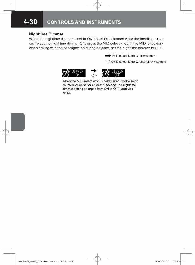
4-30 CONTROLS AND INSTRUMENTS
Nighttime DimmerWhen the nighttime dimmer is set to ON, the MID is dimmed while the headlights are on. To set the nighttime dimmer ON, press the MID select knob. If the MID is too dark when driving with the headlights on during daytime, set the nighttime dimmer to OFF.
�� � �� ��� � � �� ���� �� � �� ���� � �������� ��
����� ��������� ��� � � �� � ����! �� ��"����#
��## � � ����" �� �" � ���# $� �� $��! �� %��
% �� &
�� � ������ �������������� ����
�� � ������ ��������������������� ����
4608498_sec04_CONTROLS AND INSTR4-30 4-304608498_sec04_CONTROLS AND INSTR4-30 4-30 2015/11/02 13:58:392015/11/02 13:58:39
4-31CONTROLS AND INSTRUMENTS
The maintenance data function indicates the distance remaining before the next scheduled maintenance. A scheduled maintenance interval is approaching when the display turns from green to amber. Have the vehicle checked and serviced at your Isuzu Dealer as soon as possible.
Maintenance Data
ADVICEThe displayed distance represents the interval for each maintenance item before or after expiration of the scheduled maintenance. When the next scheduled maintenance is approaching, the display background color changes from green to amber to alert you.
•
CAUTIONThe maintenance schedule for your vehicle may differ from the standard schedule depending on the road conditions, the climate in your area, and/or the use pattern of your vehicle. Ensure that you have your vehicle inspected and repaired according to the maintenance schedule for severe-condition operations.
•
Maintenance Schedule for Severe-condition Operations → Refer to page 7-230
4608498_sec04_CONTROLS AND INSTR4-31 4-314608498_sec04_CONTROLS AND INSTR4-31 4-31 2015/11/02 13:58:392015/11/02 13:58:39
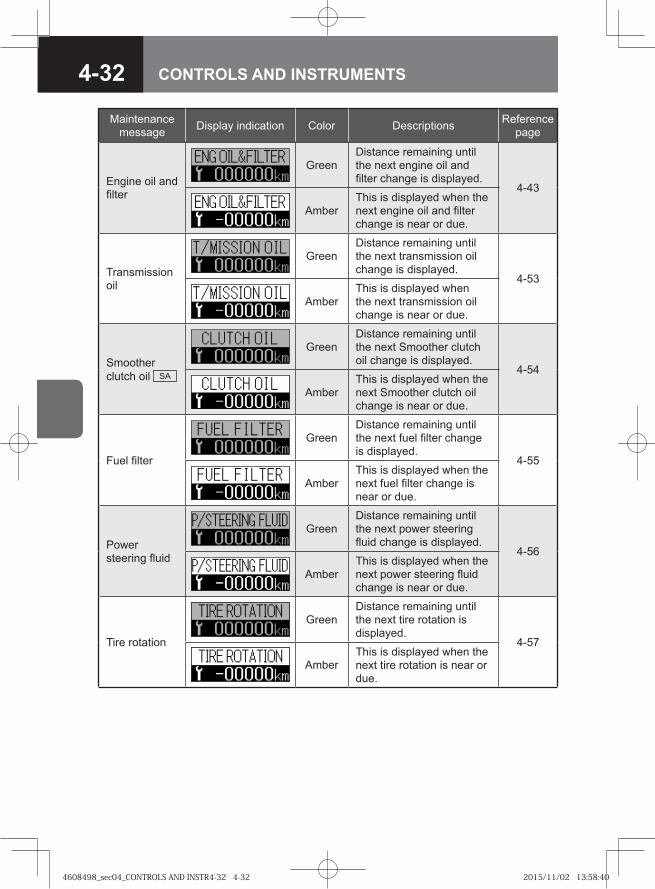
4-32 CONTROLS AND INSTRUMENTS
Maintenance message Display indication Color Descriptions Reference
page
Engine oil and filter
GreenDistance remaining until the next engine oil and filter change is displayed.
4-43
AmberThis is displayed when the next engine oil and filter change is near or due.
Transmission oil
GreenDistance remaining until the next transmission oil change is displayed.
4-53
AmberThis is displayed when the next transmission oil change is near or due.
Smoother clutch oil SA
GreenDistance remaining until the next Smoother clutch oil change is displayed.
4-54
AmberThis is displayed when the next Smoother clutch oil change is near or due.
Fuel filter
GreenDistance remaining until the next fuel filter change is displayed.
4-55
AmberThis is displayed when the next fuel filter change is near or due.
Power steering fluid
GreenDistance remaining until the next power steering fluid change is displayed.
4-56
AmberThis is displayed when the next power steering fluid change is near or due.
Tire rotation
GreenDistance remaining until the next tire rotation is displayed.
4-57
AmberThis is displayed when the next tire rotation is near or due.
4608498_sec04_CONTROLS AND INSTR4-32 4-324608498_sec04_CONTROLS AND INSTR4-32 4-32 2015/11/02 13:58:402015/11/02 13:58:40
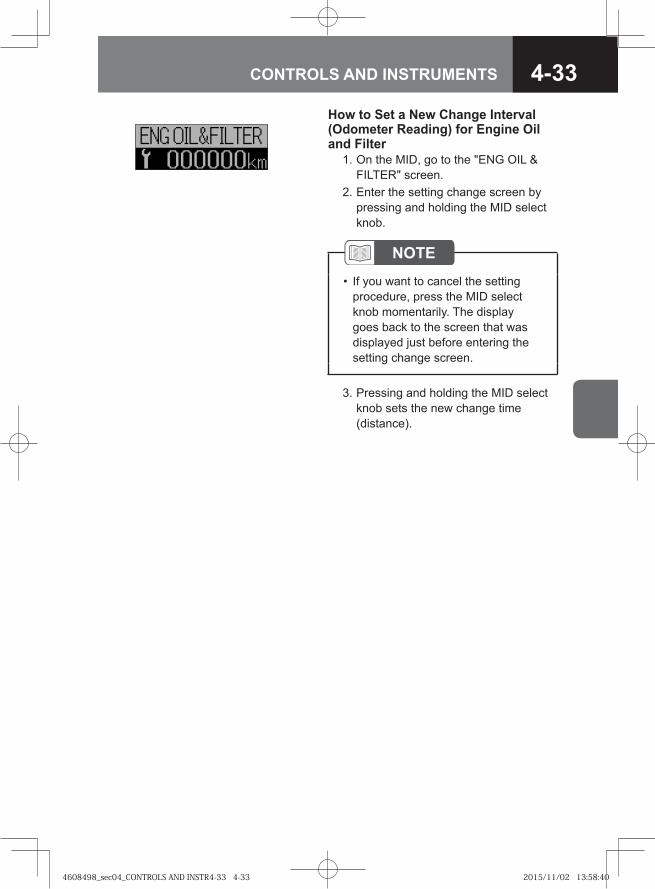
4-33CONTROLS AND INSTRUMENTS
How to Set a New Change Interval (Odometer Reading) for Engine Oil and Filter 1. On the MID, go to the "ENG OIL &
FILTER" screen. 2. Enter the setting change screen by
pressing and holding the MID select knob.
3. Pressing and holding the MID select knob sets the new change time (distance).
NOTEIf you want to cancel the setting procedure, press the MID select knob momentarily. The display goes back to the screen that was displayed just before entering the setting change screen.
•
4608498_sec04_CONTROLS AND INSTR4-33 4-334608498_sec04_CONTROLS AND INSTR4-33 4-33 2015/11/02 13:58:402015/11/02 13:58:40
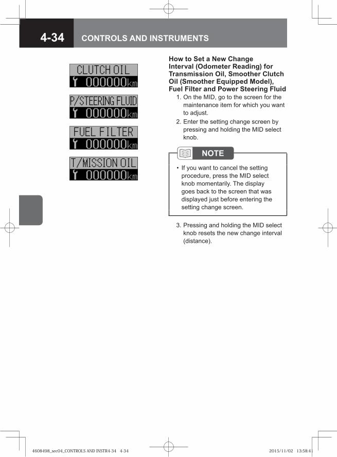
4-34 CONTROLS AND INSTRUMENTS
How to Set a New Change Interval (Odometer Reading) for Transmission Oil, Smoother Clutch Oil (Smoother Equipped Model), Fuel Filter and Power Steering Fluid 1. On the MID, go to the screen for the
maintenance item for which you want to adjust.
2. Enter the setting change screen by pressing and holding the MID select knob.
3. Pressing and holding the MID select knob resets the new change interval (distance).
NOTEIf you want to cancel the setting procedure, press the MID select knob momentarily. The display goes back to the screen that was displayed just before entering the setting change screen.
•
4608498_sec04_CONTROLS AND INSTR4-34 4-344608498_sec04_CONTROLS AND INSTR4-34 4-34 2015/11/02 13:58:412015/11/02 13:58:41
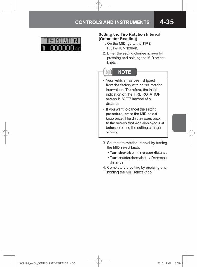
4-35CONTROLS AND INSTRUMENTS
Setting the Tire Rotation Interval (Odometer Reading) 1. On the MID, go to the TIRE
ROTATION screen. 2. Enter the setting change screen by
pressing and holding the MID select knob.
3. Set the tire rotation interval by turning the MID select knob.
• Turn clockwise → Increase distance • Turn counterclockwise → Decrease
distance 4. Complete the setting by pressing and
holding the MID select knob.
NOTEYour vehicle has been shipped from the factory with no tire rotation interval set. Therefore, the initial indication on the TIRE ROTATION screen is "OFF" instead of a distance.If you want to cancel the setting procedure, press the MID select knob once. The display goes back to the screen that was displayed just before entering the setting change screen.
•
•
4608498_sec04_CONTROLS AND INSTR4-35 4-354608498_sec04_CONTROLS AND INSTR4-35 4-35 2015/11/02 13:58:412015/11/02 13:58:41
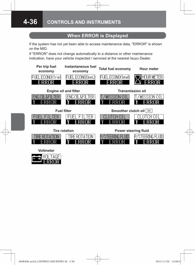
4-36 CONTROLS AND INSTRUMENTS
If the system has not yet been able to access maintenance data, "ERROR" is shown on the MID. If "ERROR" does not change automatically to a distance or other maintenance indication, have your vehicle inspected / serviced at the nearest Isuzu Dealer.
When ERROR is Displayed
Per trip fuel economy
Instantaneous fuel economy Total fuel economy Hour meter
Engine oil and filter Transmission oil
Fuel filter Smoother clutch oil SA
Tire rotation Power steering fluid
Voltmeter
4608498_sec04_CONTROLS AND INSTR4-36 4-364608498_sec04_CONTROLS AND INSTR4-36 4-36 2015/11/02 13:58:412015/11/02 13:58:41
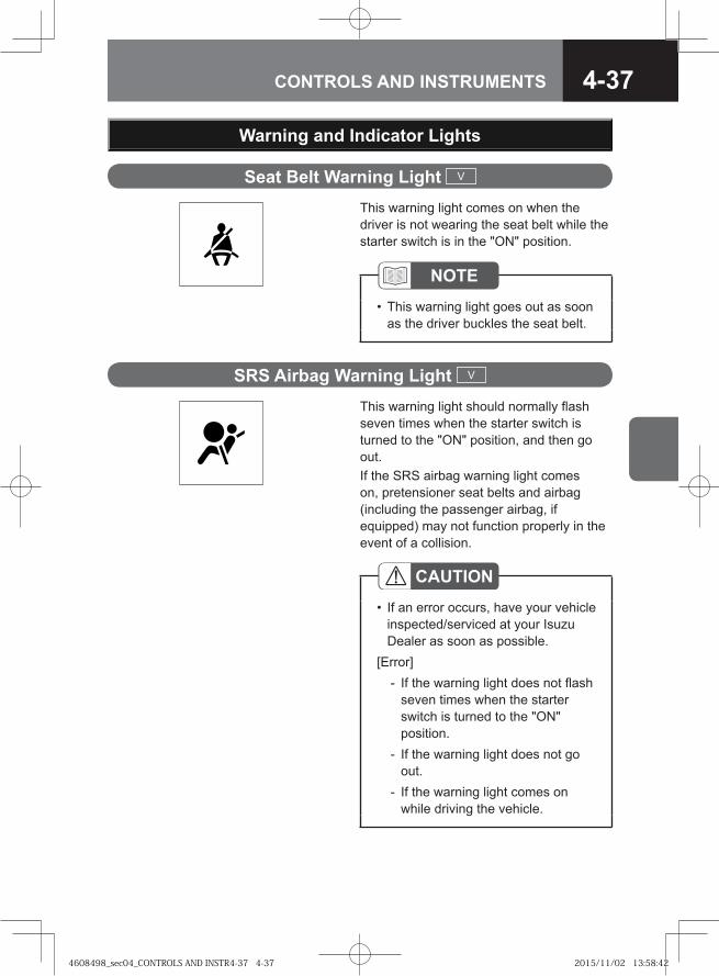
4-37CONTROLS AND INSTRUMENTS
Seat Belt Warning Light V
NOTEThis warning light goes out as soon as the driver buckles the seat belt.
•
This warning light comes on when the driver is not wearing the seat belt while the starter switch is in the "ON" position.
Warning and Indicator Lights
CAUTIONIf an error occurs, have your vehicle inspected/serviced at your Isuzu Dealer as soon as possible.
[Error]If the warning light does not flash seven times when the starter switch is turned to the "ON" position.If the warning light does not go out.If the warning light comes on while driving the vehicle.
•
-
-
-
SRS Airbag Warning Light V
This warning light should normally flash seven times when the starter switch is turned to the "ON" position, and then go out. If the SRS airbag warning light comes on, pretensioner seat belts and airbag (including the passenger airbag, if equipped) may not function properly in the event of a collision.
4608498_sec04_CONTROLS AND INSTR4-37 4-374608498_sec04_CONTROLS AND INSTR4-37 4-37 2015/11/02 13:58:422015/11/02 13:58:42
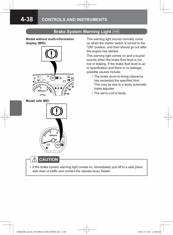
4-38 CONTROLS AND INSTRUMENTS
Brake System Warning Light AHB
This warning light should normally come on when the starter switch is turned to the "ON" position, and then should go out after the engine has started.This warning light comes on and a buzzer sounds when the brake fluid level is too low or leaking. If the brake fluid level is up to specification and there is no leakage, possible causes include: • The brake drum-to-lining clearance
has exceeded the specified limit. This may be due to a faulty automatic brake adjuster.
• The servo unit is faulty.
CAUTIONIf the brake system warning light comes on, immediately pull off to a safe place well clear of traffic and contact the nearest Isuzu Dealer.
•
Model without multi-information display (MID)
Model with MID
4608498_sec04_CONTROLS AND INSTR4-38 4-384608498_sec04_CONTROLS AND INSTR4-38 4-38 2015/11/02 13:58:432015/11/02 13:58:43
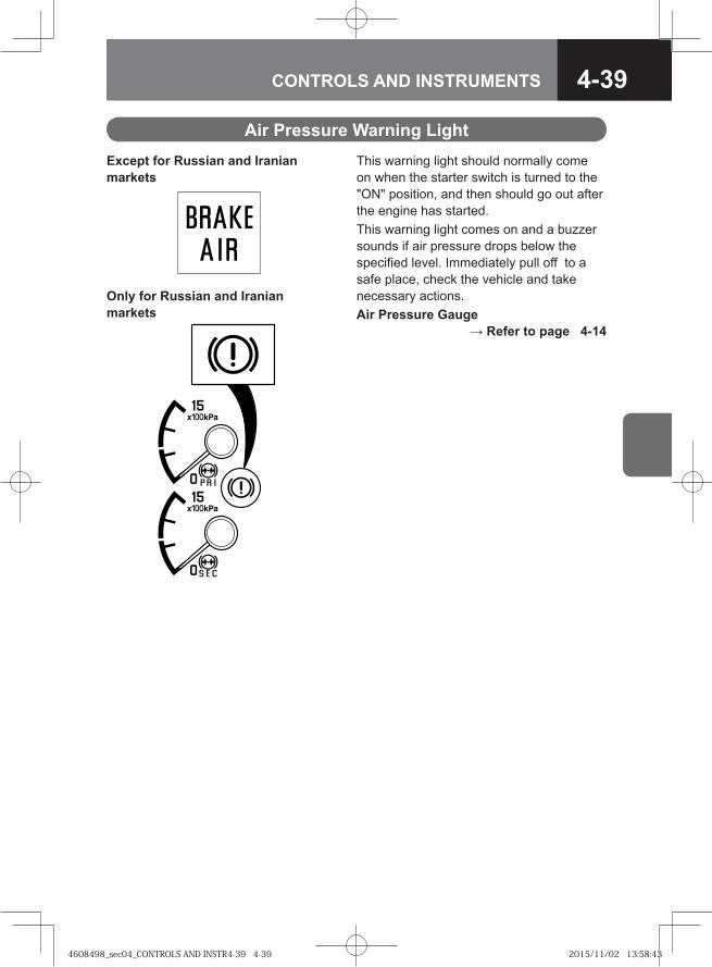
4-39CONTROLS AND INSTRUMENTS
Air Pressure Warning LightThis warning light should normally come on when the starter switch is turned to the "ON" position, and then should go out after the engine has started.This warning light comes on and a buzzer sounds if air pressure drops below the specified level. Immediately pull off to a safe place, check the vehicle and take necessary actions. Air Pressure Gauge
→ Refer to page 4-14
Except for Russian and Iranian markets
Only for Russian and Iranian markets
4608498_sec04_CONTROLS AND INSTR4-39 4-394608498_sec04_CONTROLS AND INSTR4-39 4-39 2015/11/02 13:58:432015/11/02 13:58:43
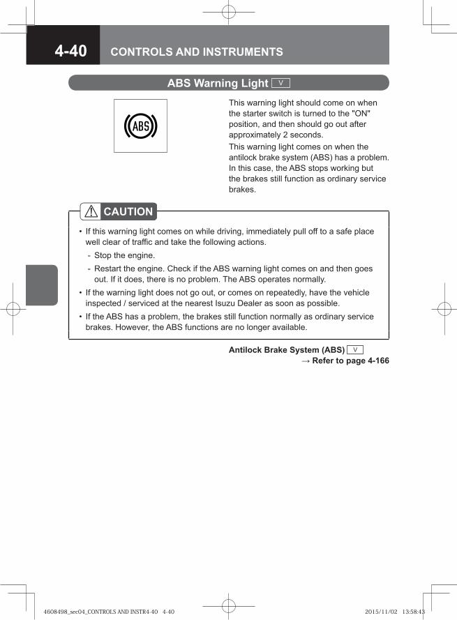
4-40 CONTROLS AND INSTRUMENTS
CAUTIONIf this warning light comes on while driving, immediately pull off to a safe place well clear of traffic and take the following actions.
Stop the engine.Restart the engine. Check if the ABS warning light comes on and then goes out. If it does, there is no problem. The ABS operates normally.
If the warning light does not go out, or comes on repeatedly, have the vehicle inspected / serviced at the nearest Isuzu Dealer as soon as possible.If the ABS has a problem, the brakes still function normally as ordinary service brakes. However, the ABS functions are no longer available.
•
--
•
•
ABS Warning Light V
This warning light should come on when the starter switch is turned to the "ON" position, and then should go out after approximately 2 seconds. This warning light comes on when the antilock brake system (ABS) has a problem. In this case, the ABS stops working but the brakes still function as ordinary service brakes.
Antilock Brake System (ABS) V → Refer to page 4-166
4608498_sec04_CONTROLS AND INSTR4-40 4-404608498_sec04_CONTROLS AND INSTR4-40 4-40 2015/11/02 13:58:432015/11/02 13:58:43
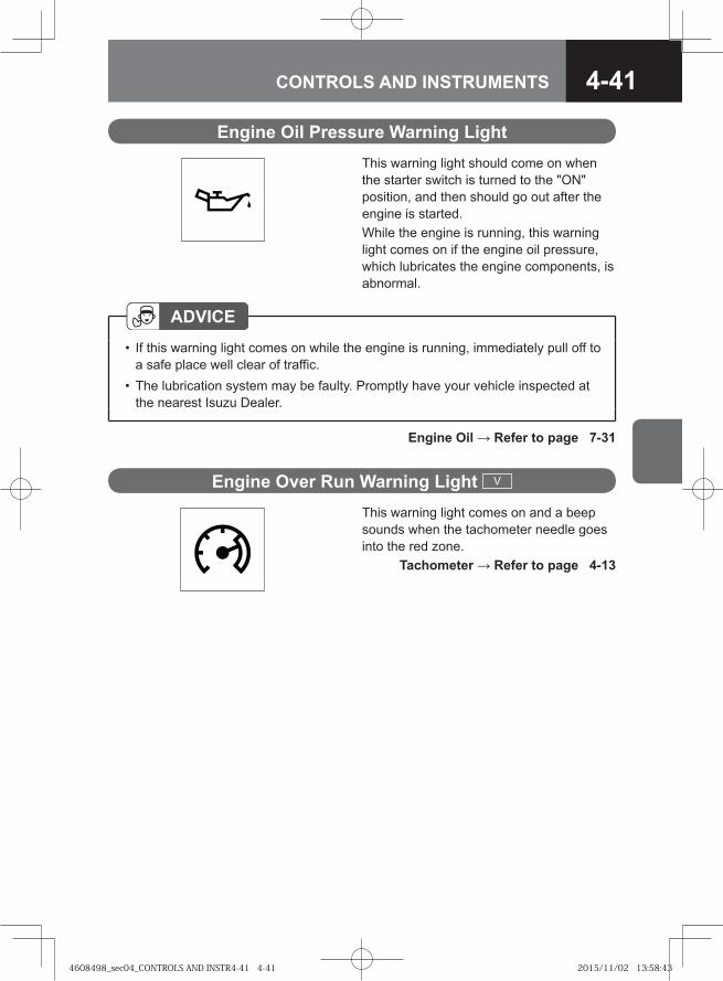
4-41CONTROLS AND INSTRUMENTS
Engine Oil Pressure Warning LightThis warning light should come on when the starter switch is turned to the "ON" position, and then should go out after the engine is started. While the engine is running, this warning light comes on if the engine oil pressure, which lubricates the engine components, is abnormal.
ADVICEIf this warning light comes on while the engine is running, immediately pull off to a safe place well clear of traffic.The lubrication system may be faulty. Promptly have your vehicle inspected at the nearest Isuzu Dealer.
•
•
Engine Oil → Refer to page 7-31
Engine Over Run Warning Light V
This warning light comes on and a beep sounds when the tachometer needle goes into the red zone. Tachometer → Refer to page 4-13
4608498_sec04_CONTROLS AND INSTR4-41 4-414608498_sec04_CONTROLS AND INSTR4-41 4-41 2015/11/02 13:58:432015/11/02 13:58:43
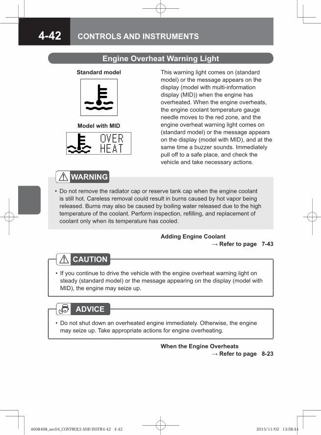
4-42 CONTROLS AND INSTRUMENTS
Engine Overheat Warning Light
WARNING
Do not remove the radiator cap or reserve tank cap when the engine coolant is still hot. Careless removal could result in burns caused by hot vapor being released. Burns may also be caused by boiling water released due to the high temperature of the coolant. Perform inspection, refilling, and replacement of coolant only when its temperature has cooled.
•
ADVICEDo not shut down an overheated engine immediately. Otherwise, the engine may seize up. Take appropriate actions for engine overheating.
•
Adding Engine Coolant → Refer to page 7-43
When the Engine Overheats → Refer to page 8-23
This warning light comes on (standard model) or the message appears on the display (model with multi-information display (MID)) when the engine has overheated. When the engine overheats, the engine coolant temperature gauge needle moves to the red zone, and the engine overheat warning light comes on (standard model) or the message appears on the display (model with MID), and at the same time a buzzer sounds. Immediately pull off to a safe place, and check the vehicle and take necessary actions.
CAUTIONIf you continue to drive the vehicle with the engine overheat warning light on steady (standard model) or the message appearing on the display (model with MID), the engine may seize up.
•
Standard model
Model with MID
4608498_sec04_CONTROLS AND INSTR4-42 4-424608498_sec04_CONTROLS AND INSTR4-42 4-42 2015/11/02 13:58:442015/11/02 13:58:44
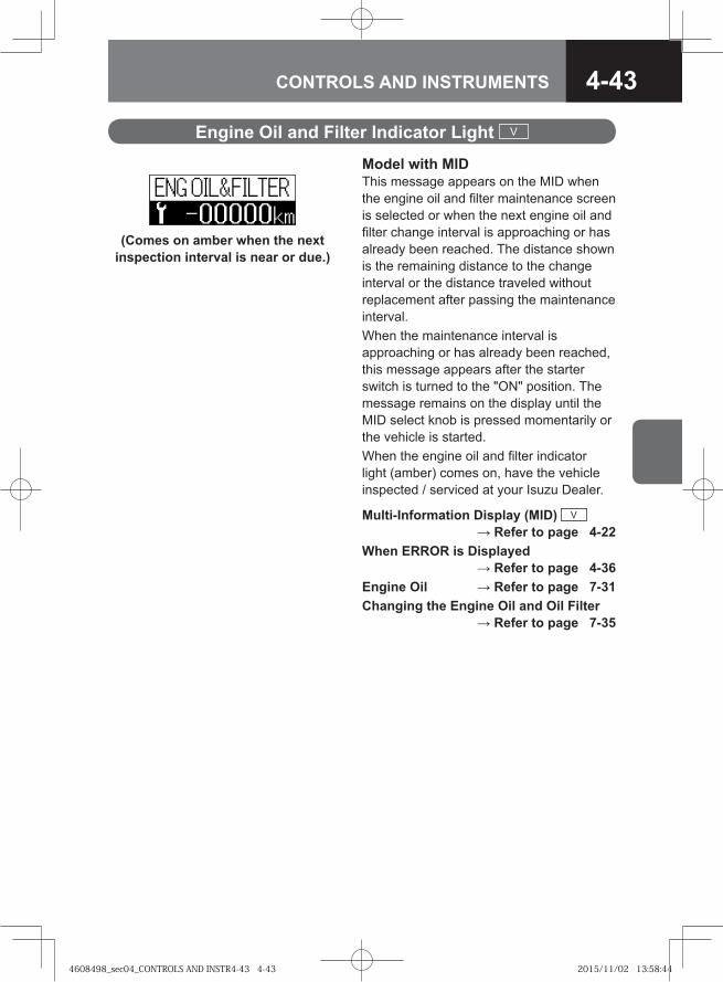
4-43CONTROLS AND INSTRUMENTS
Engine Oil and Filter Indicator Light V
Model with MIDThis message appears on the MID when the engine oil and filter maintenance screen is selected or when the next engine oil and filter change interval is approaching or has already been reached. The distance shown is the remaining distance to the change interval or the distance traveled without replacement after passing the maintenance interval. When the maintenance interval is approaching or has already been reached, this message appears after the starter switch is turned to the "ON" position. The message remains on the display until the MID select knob is pressed momentarily or the vehicle is started. When the engine oil and filter indicator light (amber) comes on, have the vehicle inspected / serviced at your Isuzu Dealer.
Multi-Information Display (MID) V → Refer to page 4-22
When ERROR is Displayed → Refer to page 4-36
Engine Oil → Refer to page 7-31Changing the Engine Oil and Oil Filter
→ Refer to page 7-35
(Comes on amber when the next inspection interval is near or due.)
4608498_sec04_CONTROLS AND INSTR4-43 4-434608498_sec04_CONTROLS AND INSTR4-43 4-43 2015/11/02 13:58:442015/11/02 13:58:44
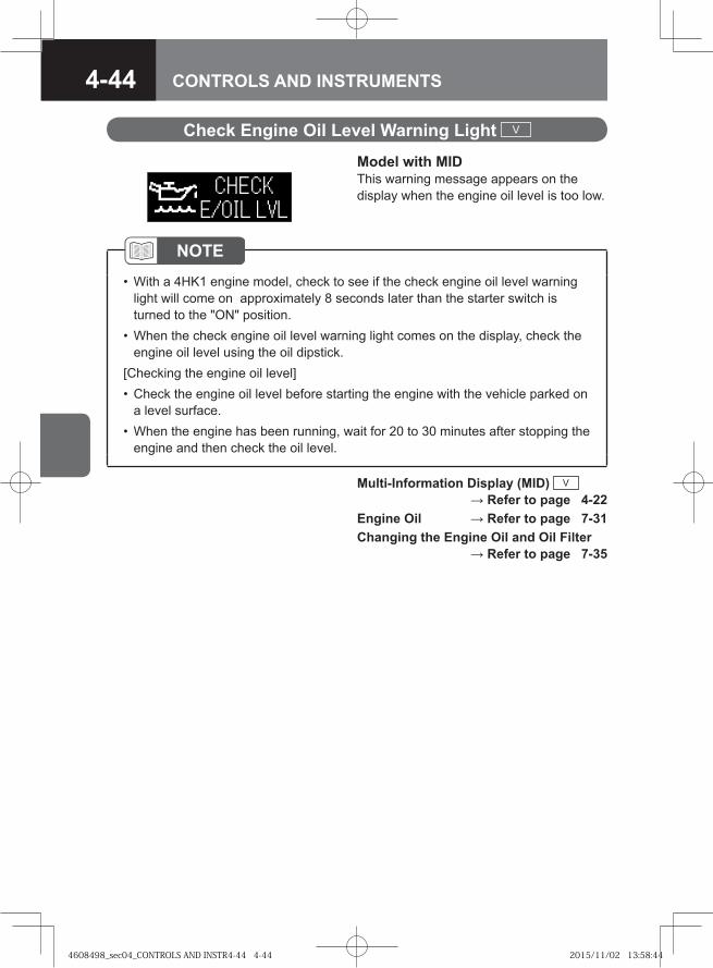
4-44 CONTROLS AND INSTRUMENTS
Check Engine Oil Level Warning Light V
NOTEWith a 4HK1 engine model, check to see if the check engine oil level warning light will come on approximately 8 seconds later than the starter switch is turned to the "ON" position.When the check engine oil level warning light comes on the display, check the engine oil level using the oil dipstick.
[Checking the engine oil level]Check the engine oil level before starting the engine with the vehicle parked on a level surface.When the engine has been running, wait for 20 to 30 minutes after stopping the engine and then check the oil level.
•
•
•
•
Multi-Information Display (MID) V → Refer to page 4-22
Engine Oil → Refer to page 7-31Changing the Engine Oil and Oil Filter
→ Refer to page 7-35
Model with MIDThis warning message appears on the display when the engine oil level is too low.
4608498_sec04_CONTROLS AND INSTR4-44 4-444608498_sec04_CONTROLS AND INSTR4-44 4-44 2015/11/02 13:58:442015/11/02 13:58:44
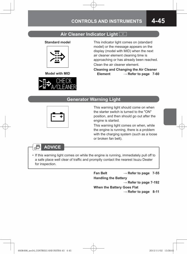
4-45CONTROLS AND INSTRUMENTS
Air Cleaner Indicator Light V
Generator Warning LightThis warning light should come on when the starter switch is turned to the "ON" position, and then should go out after the engine is started. This warning light comes on when, while the engine is running, there is a problem with the charging system (such as a loose or broken fan belt).
Fan Belt → Refer to page 7-55Handling the Battery
→ Refer to page 7-192When the Battery Goes Flat
→ Refer to page 8-11
ADVICEIf this warning light comes on while the engine is running, immediately pull off to a safe place well clear of traffic and promptly contact the nearest Isuzu Dealer for inspection.
•
This indicator light comes on (standard model) or the message appears on the display (model with MID) when the next air cleaner element cleaning time is approaching or has already been reached.Clean the air cleaner element.Cleaning and Changing the Air Cleaner
Element → Refer to page 7-60
Standard model
Model with MID
4608498_sec04_CONTROLS AND INSTR4-45 4-454608498_sec04_CONTROLS AND INSTR4-45 4-45 2015/11/02 13:58:452015/11/02 13:58:45
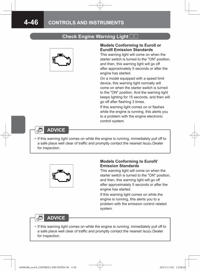
4-46 CONTROLS AND INSTRUMENTS
Models Conforming to EuroII or EuroIII Emission StandardsThis warning light will come on when the starter switch is turned to the "ON" position, and then, this warning light will go off after approximately 5 seconds or after the engine has started. On a model equipped with a speed limit device, this warning light normally will come on when the starter switch is turned to the "ON" position. And the warning light keeps lighting for 15 seconds, and then will go off after flashing 3 times.If this warning light comes on or flashes while the engine is running, this alerts you to a problem with the engine electronic control system.
ADVICEIf this warning light comes on while the engine is running, immediately pull off to a safe place well clear of traffic and promptly contact the nearest Isuzu Dealer for inspection.
•
Check Engine Warning Light V
Models Conforming to EuroIV Emission StandardsThis warning light will come on when the starter switch is turned to the "ON" position, and then, this warning light will go off after approximately 5 seconds or after the engine has started. If this warning light comes on while the engine is running, this alerts you to a problem with the emission control related system.
ADVICEIf this warning light comes on while the engine is running, immediately pull off to a safe place well clear of traffic and promptly contact the nearest Isuzu Dealer for inspection.
•
4608498_sec04_CONTROLS AND INSTR4-46 4-464608498_sec04_CONTROLS AND INSTR4-46 4-46 2015/11/02 13:58:452015/11/02 13:58:45
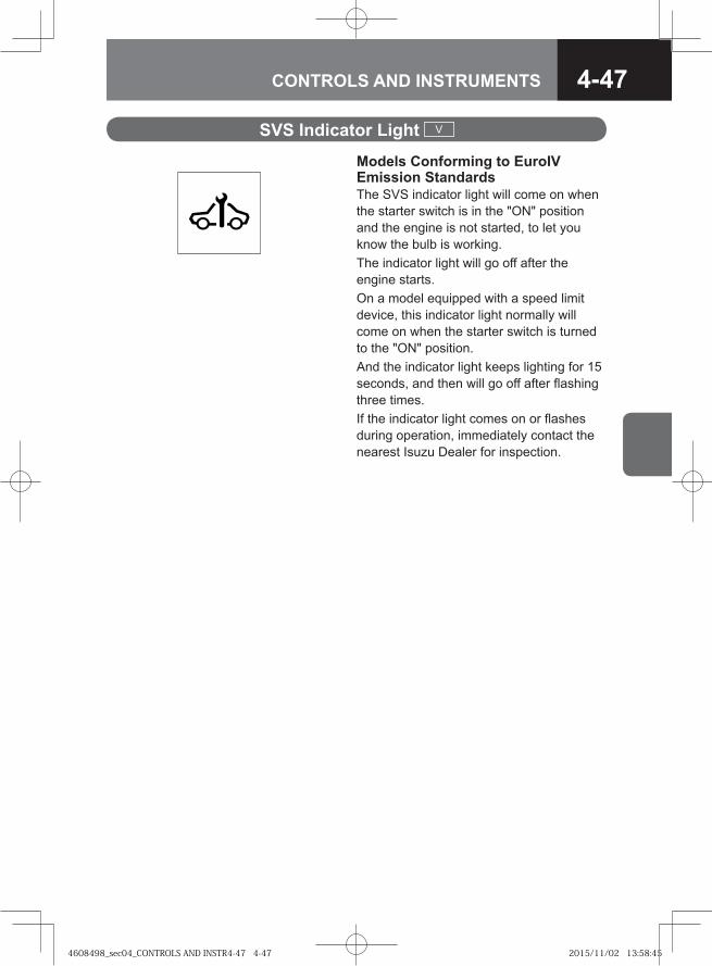
4-47CONTROLS AND INSTRUMENTS
SVS Indicator Light V
Models Conforming to EuroIV Emission StandardsThe SVS indicator light will come on when the starter switch is in the "ON" position and the engine is not started, to let you know the bulb is working.The indicator light will go off after the engine starts.On a model equipped with a speed limit device, this indicator light normally will come on when the starter switch is turned to the "ON" position. And the indicator light keeps lighting for 15 seconds, and then will go off after flashing three times.If the indicator light comes on or flashes during operation, immediately contact the nearest Isuzu Dealer for inspection.
4608498_sec04_CONTROLS AND INSTR4-47 4-474608498_sec04_CONTROLS AND INSTR4-47 4-47 2015/11/02 13:58:452015/11/02 13:58:45
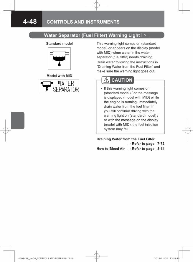
4-48 CONTROLS AND INSTRUMENTS
Water Separator (Fuel Filter) Warning Light V
Draining Water from the Fuel Filter → Refer to page 7-72
How to Bleed Air → Refer to page 8-14
This warning light comes on (standard model) or appears on the display (model with MID) when water in the water separator (fuel filter) needs draining. Drain water following the instructions in "Draining Water from the Fuel Filter" and make sure the warning light goes out.
CAUTIONIf this warning light comes on (standard model) / or the message is displayed (model with MID) while the engine is running, immediately drain water from the fuel filter. If you still continue driving with the warning light on (standard model) / or with the message on the display (model with MID), the fuel injection system may fail.
•
Standard model
Model with MID
4608498_sec04_CONTROLS AND INSTR4-48 4-484608498_sec04_CONTROLS AND INSTR4-48 4-48 2015/11/02 13:58:452015/11/02 13:58:45
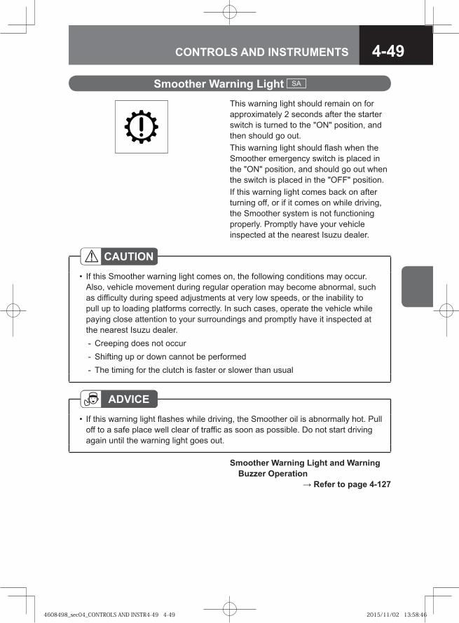
4-49CONTROLS AND INSTRUMENTS
Smoother Warning Light SA
Smoother Warning Light and Warning Buzzer Operation → Refer to page 4-127
This warning light should remain on for approximately 2 seconds after the starter switch is turned to the "ON" position, and then should go out. This warning light should flash when the Smoother emergency switch is placed in the "ON" position, and should go out when the switch is placed in the "OFF" position. If this warning light comes back on after turning off, or if it comes on while driving, the Smoother system is not functioning properly. Promptly have your vehicle inspected at the nearest Isuzu dealer.
ADVICEIf this warning light flashes while driving, the Smoother oil is abnormally hot. Pull off to a safe place well clear of traffic as soon as possible. Do not start driving again until the warning light goes out.
•
CAUTIONIf this Smoother warning light comes on, the following conditions may occur. Also, vehicle movement during regular operation may become abnormal, such as difficulty during speed adjustments at very low speeds, or the inability to pull up to loading platforms correctly. In such cases, operate the vehicle while paying close attention to your surroundings and promptly have it inspected at the nearest Isuzu dealer.
Creeping does not occurShifting up or down cannot be performedThe timing for the clutch is faster or slower than usual
•
---
4608498_sec04_CONTROLS AND INSTR4-49 4-494608498_sec04_CONTROLS AND INSTR4-49 4-49 2015/11/02 13:58:462015/11/02 13:58:46
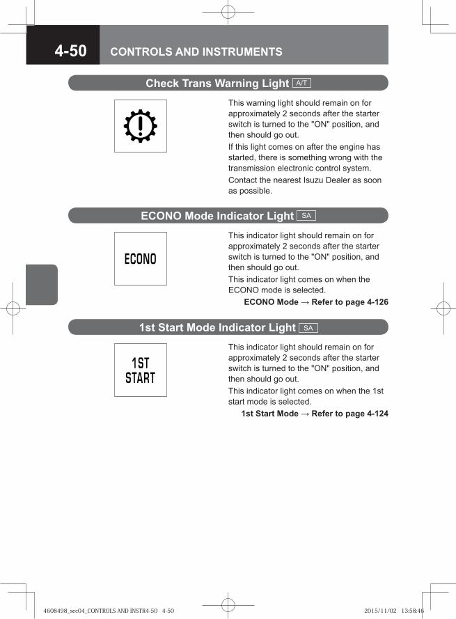
4-50 CONTROLS AND INSTRUMENTS
Check Trans Warning Light A/T
This warning light should remain on for approximately 2 seconds after the starter switch is turned to the "ON" position, and then should go out.If this light comes on after the engine has started, there is something wrong with the transmission electronic control system. Contact the nearest Isuzu Dealer as soon as possible.
ECONO Mode Indicator Light SA
This indicator light should remain on for approximately 2 seconds after the starter switch is turned to the "ON" position, and then should go out. This indicator light comes on when the ECONO mode is selected. ECONO Mode → Refer to page 4-126
1st Start Mode Indicator Light SA
This indicator light should remain on for approximately 2 seconds after the starter switch is turned to the "ON" position, and then should go out. This indicator light comes on when the 1st start mode is selected. 1st Start Mode → Refer to page 4-124
4608498_sec04_CONTROLS AND INSTR4-50 4-504608498_sec04_CONTROLS AND INSTR4-50 4-50 2015/11/02 13:58:462015/11/02 13:58:46
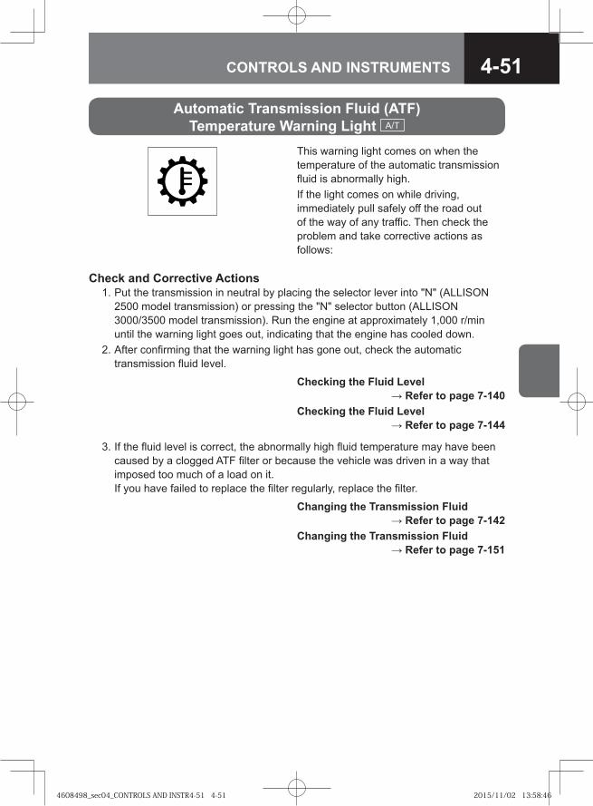
4-51CONTROLS AND INSTRUMENTS
Automatic Transmission Fluid (ATF) Temperature Warning Light A/T
This warning light comes on when the temperature of the automatic transmission fluid is abnormally high.If the light comes on while driving, immediately pull safely off the road out of the way of any traffic. Then check the problem and take corrective actions as follows:
Check and Corrective Actions 1. Put the transmission in neutral by placing the selector lever into "N" (ALLISON
2500 model transmission) or pressing the "N" selector button (ALLISON 3000/3500 model transmission). Run the engine at approximately 1,000 r/min until the warning light goes out, indicating that the engine has cooled down.
2. After confirming that the warning light has gone out, check the automatic transmission fluid level.
3. If the fluid level is correct, the abnormally high fluid temperature may have been caused by a clogged ATF filter or because the vehicle was driven in a way that imposed too much of a load on it.If you have failed to replace the filter regularly, replace the filter.
Checking the Fluid Level → Refer to page 7-140
Checking the Fluid Level → Refer to page 7-144
Changing the Transmission Fluid → Refer to page 7-142
Changing the Transmission Fluid → Refer to page 7-151
4608498_sec04_CONTROLS AND INSTR4-51 4-514608498_sec04_CONTROLS AND INSTR4-51 4-51 2015/11/02 13:58:462015/11/02 13:58:46
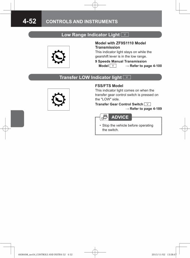
4-52 CONTROLS AND INSTRUMENTS
Low Range Indicator Light V
Model with ZF9S1110 Model Transmission This indicator light stays on while the gearshift lever is in the low range.9 Speeds Manual Transmission
Model V → Refer to page 4-100
ADVICEStop the vehicle before operating the switch.
•
Transfer LOW Indicator light V
FSS/FTS ModelThis indicator light comes on when the transfer gear control switch is pressed on the "LOW" side. Transfer Gear Control Switch V
→ Refer to page 4-189
4608498_sec04_CONTROLS AND INSTR4-52 4-524608498_sec04_CONTROLS AND INSTR4-52 4-52 2015/11/02 13:58:472015/11/02 13:58:47

4-53CONTROLS AND INSTRUMENTS
Transmission Oil Indicator Light V
Model with MIDThis message appears on the MID when the transmission oil maintenance screen is selected or when the next transmission oil change interval is approaching or has already been reached. The distance shown is the remaining distance to the oil change interval or the distance the vehicle traveled after passing the maintenance interval. When the maintenance interval is approaching or has already been reached, this message appears after the starter switch is turned to the "ON" position. The message remains on the display until the MID select knob is pressed momentarily or the vehicle is started. When the transmission oil indicator light (amber) has come on, have the vehicle inspected / serviced at your Isuzu Dealer.Multi-Information Display (MID) V
→ Refer to page 4-22When ERROR is Displayed
→ Refer to page 4-36
(Comes on amber when the next maintenance interval is near or due.)
4608498_sec04_CONTROLS AND INSTR4-53 4-534608498_sec04_CONTROLS AND INSTR4-53 4-53 2015/11/02 13:58:472015/11/02 13:58:47
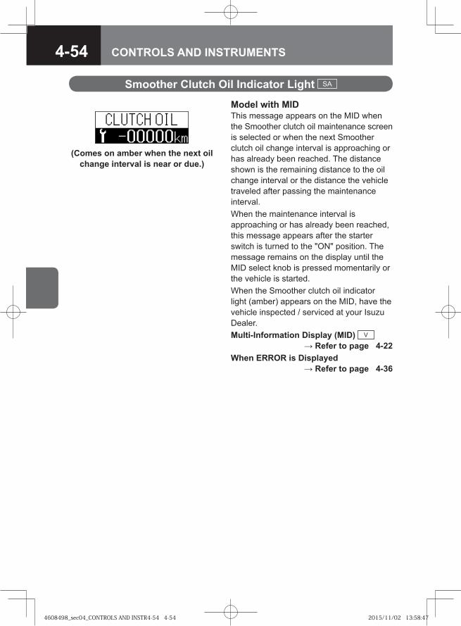
4-54 CONTROLS AND INSTRUMENTS
Smoother Clutch Oil Indicator Light SA
Model with MIDThis message appears on the MID when the Smoother clutch oil maintenance screen is selected or when the next Smoother clutch oil change interval is approaching or has already been reached. The distance shown is the remaining distance to the oil change interval or the distance the vehicle traveled after passing the maintenance interval. When the maintenance interval is approaching or has already been reached, this message appears after the starter switch is turned to the "ON" position. The message remains on the display until the MID select knob is pressed momentarily or the vehicle is started. When the Smoother clutch oil indicator light (amber) appears on the MID, have the vehicle inspected / serviced at your Isuzu Dealer.Multi-Information Display (MID) V
→ Refer to page 4-22When ERROR is Displayed
→ Refer to page 4-36
(Comes on amber when the next oil change interval is near or due.)
4608498_sec04_CONTROLS AND INSTR4-54 4-544608498_sec04_CONTROLS AND INSTR4-54 4-54 2015/11/02 13:58:472015/11/02 13:58:47
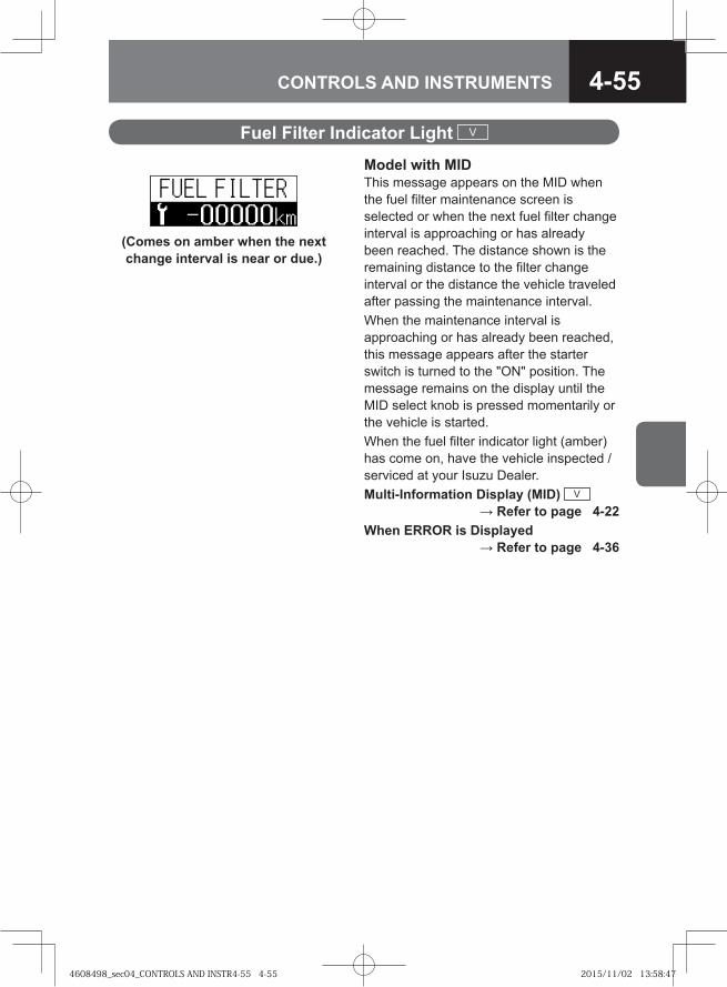
4-55CONTROLS AND INSTRUMENTS
Fuel Filter Indicator Light V
Model with MIDThis message appears on the MID when the fuel filter maintenance screen is selected or when the next fuel filter change interval is approaching or has already been reached. The distance shown is the remaining distance to the filter change interval or the distance the vehicle traveled after passing the maintenance interval. When the maintenance interval is approaching or has already been reached, this message appears after the starter switch is turned to the "ON" position. The message remains on the display until the MID select knob is pressed momentarily or the vehicle is started. When the fuel filter indicator light (amber) has come on, have the vehicle inspected / serviced at your Isuzu Dealer.Multi-Information Display (MID) V
→ Refer to page 4-22When ERROR is Displayed
→ Refer to page 4-36
(Comes on amber when the next change interval is near or due.)
4608498_sec04_CONTROLS AND INSTR4-55 4-554608498_sec04_CONTROLS AND INSTR4-55 4-55 2015/11/02 13:58:472015/11/02 13:58:47

4-56 CONTROLS AND INSTRUMENTS
Power Steering Fluid Indicator Light V
Model with MIDThis message appears on the MID when the power steering fluid maintenance screen is selected or when the next fluid change interval is approaching or has already been reached. The distance shown is the remaining distance to the fluid change interval or the distance the vehicle traveled after passing the maintenance interval. When the maintenance interval is approaching or has already been reached, this message appears after the starter switch is turned to the "ON" position. The message remains on the display until the MID select knob is pressed momentarily or the vehicle is started. When the power steering fluid indicator light (amber) has come on, have the vehicle inspected / serviced at your Isuzu Dealer. Multi-Information Display (MID) V
→ Refer to page 4-22When ERROR is Displayed
→ Refer to page 4-36
(Comes on amber when the next fluid change interval is near or due.)
4608498_sec04_CONTROLS AND INSTR4-56 4-564608498_sec04_CONTROLS AND INSTR4-56 4-56 2015/11/02 13:58:482015/11/02 13:58:48
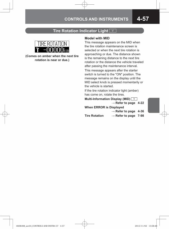
4-57CONTROLS AND INSTRUMENTS
Tire Rotation Indicator Light V
Model with MIDThis message appears on the MID when the tire rotation maintenance screen is selected or when the next tire rotation is approaching or due. The distance shown is the remaining distance to the next tire rotation or the distance the vehicle traveled after passing the maintenance interval.This message appears after the starter switch is turned to the "ON" position. The message remains on the display until the MID select knob is pressed momentarily or the vehicle is started. If the tire rotation indicator light (amber) has come on, rotate the tires. Multi-Information Display (MID) V
→ Refer to page 4-22When ERROR is Displayed
→ Refer to page 4-36Tire Rotation → Refer to page 7-98
(Comes on amber when the next tire rotation is near or due.)
4608498_sec04_CONTROLS AND INSTR4-57 4-574608498_sec04_CONTROLS AND INSTR4-57 4-57 2015/11/02 13:58:482015/11/02 13:58:48
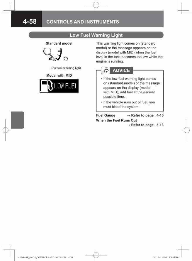
4-58 CONTROLS AND INSTRUMENTS
Low Fuel Warning Light
Fuel Gauge → Refer to page 4-16When the Fuel Runs Out
→ Refer to page 8-13
This warning light comes on (standard model) or the message appears on the display (model with MID) when the fuel level in the tank becomes too low while the engine is running.
Standard model
Model with MID
� � ���� ������� ����� ADVICEIf the low fuel warning light comes on (standard model) or the message appears on the display (model with MID), add fuel at the earliest possible time. If the vehicle runs out of fuel, you must bleed the system.
•
•
4608498_sec04_CONTROLS AND INSTR4-58 4-584608498_sec04_CONTROLS AND INSTR4-58 4-58 2015/11/02 13:58:482015/11/02 13:58:48
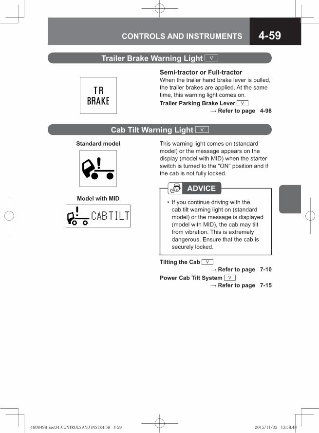
4-59CONTROLS AND INSTRUMENTS
Semi-tractor or Full-tractorWhen the trailer hand brake lever is pulled, the trailer brakes are applied. At the same time, this warning light comes on.Trailer Parking Brake Lever V
→ Refer to page 4-98
Trailer Brake Warning Light V
Cab Tilt Warning Light V
Tilting the Cab V → Refer to page 7-10
Power Cab Tilt System V → Refer to page 7-15
This warning light comes on (standard model) or the message appears on the display (model with MID) when the starter switch is turned to the "ON" position and if the cab is not fully locked.
ADVICEIf you continue driving with the cab tilt warning light on (standard model) or the message is displayed (model with MID), the cab may tilt from vibration. This is extremely dangerous. Ensure that the cab is securely locked.
•
Standard model
Model with MID
4608498_sec04_CONTROLS AND INSTR4-59 4-594608498_sec04_CONTROLS AND INSTR4-59 4-59 2015/11/02 13:58:482015/11/02 13:58:48
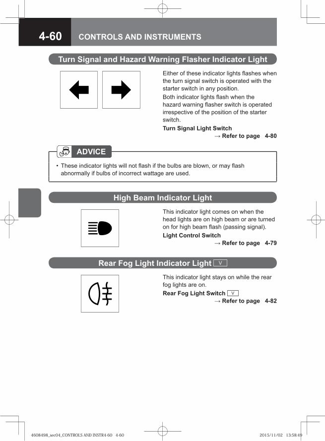
4-60 CONTROLS AND INSTRUMENTS
Turn Signal and Hazard Warning Flasher Indicator LightEither of these indicator lights flashes when the turn signal switch is operated with the starter switch in any position.Both indicator lights flash when the hazard warning flasher switch is operated irrespective of the position of the starter switch.Turn Signal Light Switch
→ Refer to page 4-80
ADVICEThese indicator lights will not flash if the bulbs are blown, or may flash abnormally if bulbs of incorrect wattage are used.
•
High Beam Indicator LightThis indicator light comes on when the head lights are on high beam or are turned on for high beam flash (passing signal).Light Control Switch
→ Refer to page 4-79
Rear Fog Light Indicator Light V
This indicator light stays on while the rear fog lights are on.Rear Fog Light Switch V
→ Refer to page 4-82
4608498_sec04_CONTROLS AND INSTR4-60 4-604608498_sec04_CONTROLS AND INSTR4-60 4-60 2015/11/02 13:58:492015/11/02 13:58:49
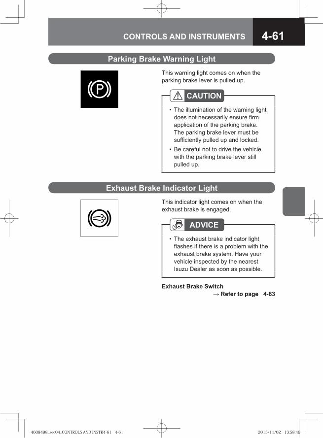
4-61CONTROLS AND INSTRUMENTS
Parking Brake Warning LightThis warning light comes on when the parking brake lever is pulled up.
CAUTIONThe illumination of the warning light does not necessarily ensure firm application of the parking brake. The parking brake lever must be sufficiently pulled up and locked.Be careful not to drive the vehicle with the parking brake lever still pulled up.
•
•
Exhaust Brake Indicator LightThis indicator light comes on when the exhaust brake is engaged.
ADVICEThe exhaust brake indicator light flashes if there is a problem with the exhaust brake system. Have your vehicle inspected by the nearest Isuzu Dealer as soon as possible.
•
Exhaust Brake Switch → Refer to page 4-83
4608498_sec04_CONTROLS AND INSTR4-61 4-614608498_sec04_CONTROLS AND INSTR4-61 4-61 2015/11/02 13:58:492015/11/02 13:58:49
4-62 CONTROLS AND INSTRUMENTS
HSA Indicator Light V
This indicator light comes on when the hill start aid (HSA) system is in operation. The indicator light flashes and a buzzer sounds if you leave the seat while the HSA is in operation, the HSA is used for an extended time period, the vehicle moves when the HSA is engaged, or there is a problem with the HSA system.
ADVICEIf there is a problem with the HSA, disengage the system and have the vehicle inspected at the nearest Isuzu Dealer as soon as possible.
•
Hill Start Aid (HSA) V → Refer to page 4-146
4608498_sec04_CONTROLS AND INSTR4-62 4-624608498_sec04_CONTROLS AND INSTR4-62 4-62 2015/11/02 13:58:502015/11/02 13:58:50
4-63CONTROLS AND INSTRUMENTS
CAUTIONIf the ASR indicator light comes on amber while driving without your operation of the ASR OFF switch, pull off to a safe place well clear of traffic and take the following actions.
Stop the engine.Turn the starter switch to the "ON" position. The system is normal if the indicator light comes on first amber and then turns green before it goes out 2 seconds later. The ASR operates correctly.
If the indicator light does not go out, or comes on repeatedly, have the vehicle inspected / serviced at the nearest Isuzu Dealer as soon as possible.
•
--
•
ASR Indicator Light V
When the starter switch is turned to the "ON" position, the indicator light should come on and change color from amber to green before it goes out 2 seconds later. This indicator light stays on green while the anti-slip regulator (ASR) is in operation. This indicator light comes on amber if there is a problem with the ASR or when you disengage the ASR using the ASR OFF switch.
Anti-Slip Regulator (ASR) V → Refer to page 4-170
4608498_sec04_CONTROLS AND INSTR4-63 4-634608498_sec04_CONTROLS AND INSTR4-63 4-63 2015/11/02 13:58:502015/11/02 13:58:50
4-64 CONTROLS AND INSTRUMENTS
Glow Plug Indicator Light V
This indicator light comes on when the starter switch is turned to the "ON" position and goes out when preheating is completed. When the indicator light has gone out, the engine can be started.However, depending on the engine coolant temperature, the indicator light may not come on.
[6HK1 engine model]The light will come on for about 1-1/2 seconds to 10 seconds, but when the engine coolant temperature is above -5°C (23°F), the light will not come on.
[4HK1 engine model]The light will come on for about 1-1/2 to 10 seconds, and when the engine coolant temperature is above 10°C (50°F), the light will come on for 1/2 seconds.Starting the Engine
→ Refer to page 4-4
[6HH1 engine model]The light will come on for about 15 seconds to 20 seconds, but when the engine coolant temperature is above -5°C (23°F), the light will not come on.
Warm-Up System Indicator Light V
This indicator light comes on when the warm-up switch is pressed. While this indicator is on, the engine is warmed up.Warm-Up Switch V
→ Refer to page 4-78
4608498_sec04_CONTROLS AND INSTR4-64 4-644608498_sec04_CONTROLS AND INSTR4-64 4-64 2015/11/02 13:58:502015/11/02 13:58:50
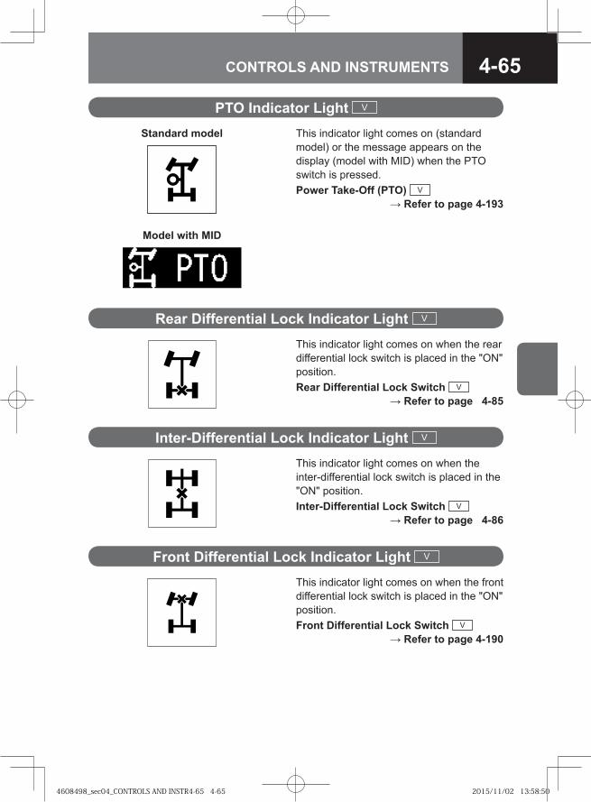
4-65CONTROLS AND INSTRUMENTS
This indicator light comes on when the inter-differential lock switch is placed in the "ON" position. Inter-Differential Lock Switch V
→ Refer to page 4-86
Inter-Differential Lock Indicator Light V
This indicator light comes on when the rear differential lock switch is placed in the "ON" position. Rear Differential Lock Switch V
→ Refer to page 4-85
Rear Differential Lock Indicator Light V
This indicator light comes on when the front differential lock switch is placed in the "ON" position. Front Differential Lock Switch V
→ Refer to page 4-190
Front Differential Lock Indicator Light V
PTO Indicator Light V
This indicator light comes on (standard model) or the message appears on the display (model with MID) when the PTO switch is pressed.Power Take-Off (PTO) V
→ Refer to page 4-193
Standard model
Model with MID
4608498_sec04_CONTROLS AND INSTR4-65 4-654608498_sec04_CONTROLS AND INSTR4-65 4-65 2015/11/02 13:58:502015/11/02 13:58:50
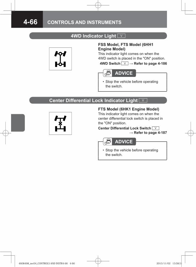
4-66 CONTROLS AND INSTRUMENTS
FSS Model, FTS Model (6HH1 Engine Model)This indicator light comes on when the 4WD switch is placed in the "ON" position. 4WD Switch V → Refer to page 4-186
4WD Indicator Light V
ADVICEStop the vehicle before operating the switch.
•
FTS Model (6HK1 Engine Model)This indicator light comes on when the center differential lock switch is placed in the "ON" position. Center Differential Lock Switch V
→ Refer to page 4-187
Center Differential Lock Indicator Light V
ADVICEStop the vehicle before operating the switch.
•
4608498_sec04_CONTROLS AND INSTR4-66 4-664608498_sec04_CONTROLS AND INSTR4-66 4-66 2015/11/02 13:58:512015/11/02 13:58:51
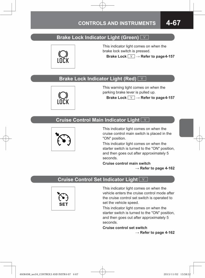
4-67CONTROLS AND INSTRUMENTS
This indicator light comes on when the brake lock switch is pressed. Brake Lock V → Refer to page 4-157
Brake Lock Indicator Light (Green) V
This warning light comes on when the parking brake lever is pulled up. Brake Lock V → Refer to page 4-157
Brake Lock Indicator Light (Red) V
This indicator light comes on when the cruise control main switch is placed in the "ON" position. This indicator light comes on when the starter switch is turned to the "ON" position, and then goes out after approximately 5 seconds. Cruise control main switch
→ Refer to page 4-162
Cruise Control Main Indicator Light V
This indicator light comes on when the vehicle enters the cruise control mode after the cruise control set switch is operated to set the vehicle speed.This indicator light comes on when the starter switch is turned to the "ON" position, and then goes out after approximately 5 seconds. Cruise control set switch
→ Refer to page 4-162
Cruise Control Set Indicator Light V
4608498_sec04_CONTROLS AND INSTR4-67 4-674608498_sec04_CONTROLS AND INSTR4-67 4-67 2015/11/02 13:58:522015/11/02 13:58:52
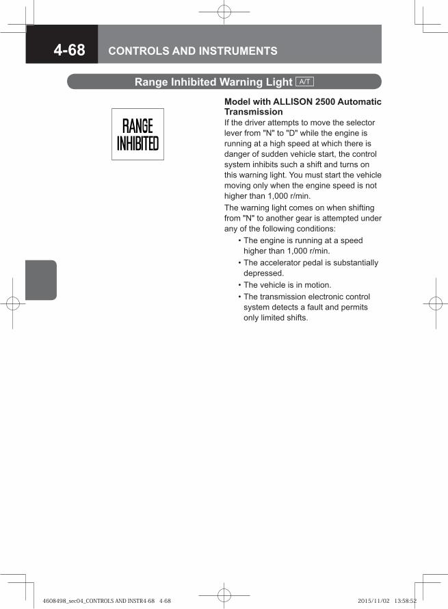
4-68 CONTROLS AND INSTRUMENTS
Model with ALLISON 2500 Automatic TransmissionIf the driver attempts to move the selector lever from "N" to "D" while the engine is running at a high speed at which there is danger of sudden vehicle start, the control system inhibits such a shift and turns on this warning light. You must start the vehicle moving only when the engine speed is not higher than 1,000 r/min.The warning light comes on when shifting from "N" to another gear is attempted under any of the following conditions: • The engine is running at a speed
higher than 1,000 r/min. • The accelerator pedal is substantially
depressed. • The vehicle is in motion. • The transmission electronic control
system detects a fault and permits only limited shifts.
Range Inhibited Warning Light A/T
4608498_sec04_CONTROLS AND INSTR4-68 4-684608498_sec04_CONTROLS AND INSTR4-68 4-68 2015/11/02 13:58:522015/11/02 13:58:52
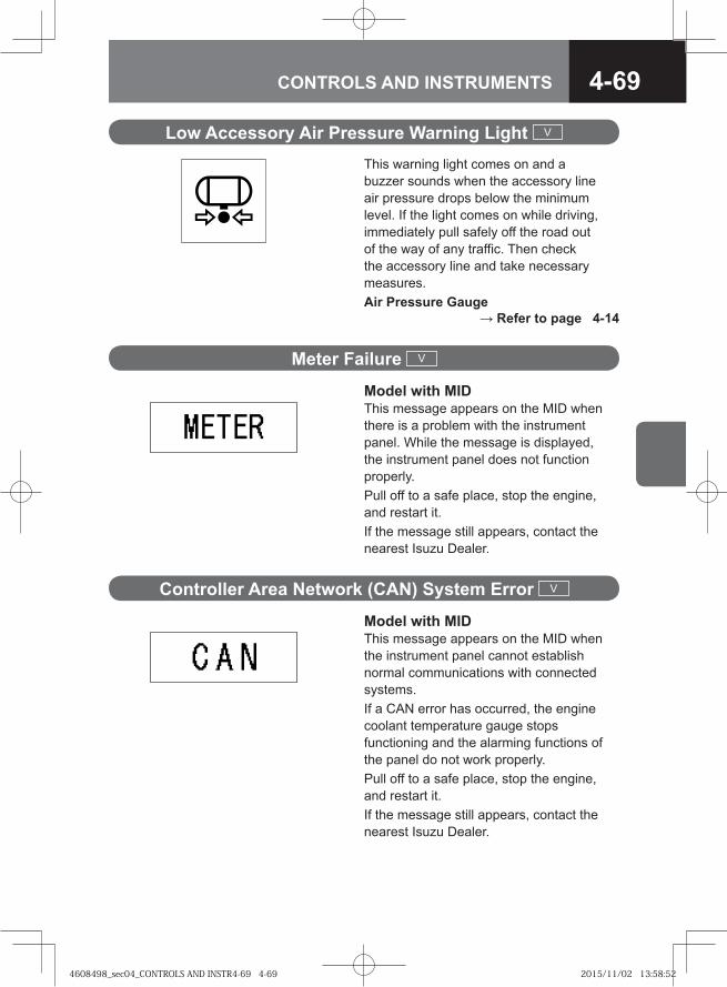
4-69CONTROLS AND INSTRUMENTS
Low Accessory Air Pressure Warning Light V
This warning light comes on and a buzzer sounds when the accessory line air pressure drops below the minimum level. If the light comes on while driving, immediately pull safely off the road out of the way of any traffic. Then check the accessory line and take necessary measures.Air Pressure Gauge
→ Refer to page 4-14
Meter Failure V
Model with MIDThis message appears on the MID when there is a problem with the instrument panel. While the message is displayed, the instrument panel does not function properly.Pull off to a safe place, stop the engine, and restart it. If the message still appears, contact the nearest Isuzu Dealer.
Controller Area Network (CAN) System Error V
Model with MIDThis message appears on the MID when the instrument panel cannot establish normal communications with connected systems.If a CAN error has occurred, the engine coolant temperature gauge stops functioning and the alarming functions of the panel do not work properly. Pull off to a safe place, stop the engine, and restart it. If the message still appears, contact the nearest Isuzu Dealer.
4608498_sec04_CONTROLS AND INSTR4-69 4-694608498_sec04_CONTROLS AND INSTR4-69 4-69 2015/11/02 13:58:522015/11/02 13:58:52
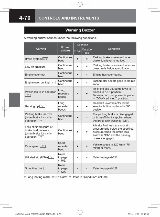
4-70 CONTROLS AND INSTRUMENTS
Warning Buzzer pattern
LocationCondition
In cab Outside cab
Brake system AHB Continuous beep • × Parking brake is released when
brake fluid level is too low.
Low air pressure Continuous beep • × Parking brake is released when air
pressure is below specification.
Engine overheat Continuous beep • × Engine has overheated.
Engine overrunning V Continuous beep • × Tachometer needle goes in the red
zone.
Power cab tilt in operation V
Long, repeated beeps
× •To tilt the cab up, pump lever is placed in "UP" position.To lower cab, pump lever is placed in "DOWN (driving)" position.
Backing up VLong, repeated beeps
• •Gearshift lever/selector lever/selector button is placed in "R" position.
Parking brake inactive (when brake lock is in operation) V
Continuous beep • ×
The parking brake is disengaged or is insufficiently applied when the brake lock switch is "ON".
Loss of air pressure or brake fluid pressure (when brake lock is in operation) V
Continuous beep • •
A brake fluid leak exists or air pressure falls below the specified pressure when the brake lock switch is "ON" and the parking brake is engaged.
Over speed VShort, repeated beep
• × Vehicle speed is 120 km/h (75 MPH) or more.
Hill start aid (HSA) VRefer to page 4-156.
* × Refer to page 4-156.
Smoother SARefer to page 4-127.
* × Refer to page 4-127.
•: Long lasting alarm ×: No alarm *: Refer to "Condition" column.
Warning Buzzer
A warning buzzer sounds under the following conditions.
4608498_sec04_CONTROLS AND INSTR4-70 4-704608498_sec04_CONTROLS AND INSTR4-70 4-70 2015/11/02 13:58:532015/11/02 13:58:53
4-71CONTROLS AND INSTRUMENTS
NOTEOn Smoother models, a warning buzzer sounds for approximately 1 second when the starter switch is turned to the "ON" position.
•
ADVICEThe warning buzzer may not sound if there is a problem with the system. If this occurs, the system needs to be inspected. Please contact the nearest Isuzu Dealer.
•
4608498_sec04_CONTROLS AND INSTR4-71 4-714608498_sec04_CONTROLS AND INSTR4-71 4-71 2015/11/02 13:58:532015/11/02 13:58:53

4-72 CONTROLS AND INSTRUMENTS
4608498_sec04_CONTROLS AND INSTR4-72 4-724608498_sec04_CONTROLS AND INSTR4-72 4-72 2015/11/02 13:58:542015/11/02 13:58:54
4-73CONTROLS AND INSTRUMENTS
● Starter Switch 4-74
● Idling Control Knob 4-76
● Warm-Up Switch V 4-78
● Combination Light Control Switch 4-79
● Headlight Leveling Switch V 4-81
● Front Fog Light Switch V 4-82
● Rear Fog Light Switch V 4-82
● Hazard Warning Flasher Switch 4-83
● Exhaust Brake Switch 4-83
● Rear Differential Lock Switch V 4-85
● Inter-Differential Lock Switch V 4-86
● Windshield Wiper and Windshield Washer Switch 4-87
● Horn Button 4-89
● Retractable Power Mirror Switch V 4-90
● Remote Control Mirror Switch V 4-91
● Mirror Heater Switch V 4-91
SWITCHES
4608498_sec04_CONTROLS AND INSTR4-73 4-734608498_sec04_CONTROLS AND INSTR4-73 4-73 2015/11/02 13:58:542015/11/02 13:58:54

4-74 CONTROLS AND INSTRUMENTS
Starter Switch
WARNING
While driving, never turn the starter switch to the "LOCK" position. The key could be removed from the switch, which then locks the steering wheel. This is extremely dangerous.
•
ADVICEUsing a key sticking with dirt or dust, etc. may possibly damage the starter switch. Make sure to wipe off any dirt or dust, etc. before inserting the key.After starting the engine, do not turn the starter switch to the "START" position. Otherwise, the starter motor may be damaged.Using electronic devices such as the audio system for an extended time period with the engine stopped can completely discharge the battery.
•
•
•
4608498_sec04_CONTROLS AND INSTR4-74 4-744608498_sec04_CONTROLS AND INSTR4-74 4-74 2015/11/02 13:58:542015/11/02 13:58:54
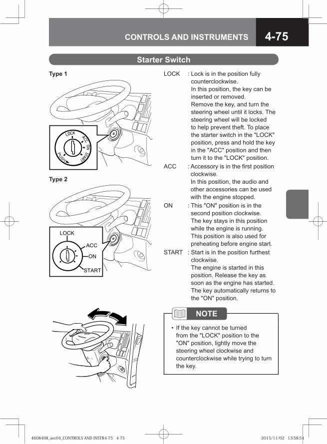
4-75CONTROLS AND INSTRUMENTS
Starter SwitchLOCK : Lock is in the position fully
counterclockwise. In this position, the key can be inserted or removed.Remove the key, and turn the steering wheel until it locks. The steering wheel will be locked to help prevent theft. To place the starter switch in the "LOCK" position, press and hold the key in the "ACC" position and then turn it to the "LOCK" position.
ACC : Accessory is in the first position clockwise. In this position, the audio and other accessories can be used with the engine stopped.
ON : This "ON" position is in the second position clockwise. The key stays in this position while the engine is running. This position is also used for preheating before engine start.
START : Start is in the position furthest clockwise. The engine is started in this position. Release the key as soon as the engine has started. The key automatically returns to the "ON" position.
NOTEIf the key cannot be turned from the "LOCK" position to the "ON" position, lightly move the steering wheel clockwise and counterclockwise while trying to turn the key.
•
Type 1
Type 2
�� �
�
��
�����
4608498_sec04_CONTROLS AND INSTR4-75 4-754608498_sec04_CONTROLS AND INSTR4-75 4-75 2015/11/02 13:58:542015/11/02 13:58:54
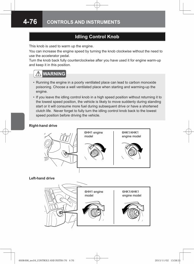
4-76 CONTROLS AND INSTRUMENTS
WARNING
Running the engine in a poorly ventilated place can lead to carbon monoxide poisoning. Choose a well ventilated place when starting and warming-up the engine. If you leave the idling control knob in a high speed position without returning it to the lowest speed position, the vehicle is likely to move suddenly during standing start or it will consume more fuel during subsequent drive or have a shortened clutch life. Never forget to fully turn the idling control knob back to the lowest speed position before driving the vehicle.
•
•
��� ����
��� �
��������
���� ��� �
Idling Control Knob
This knob is used to warm up the engine. You can increase the engine speed by turning the knob clockwise without the need to use the accelerator pedal. Turn the knob back fully counterclockwise after you have used it for engine warm-up and keep it in this position.
Right-hand drive
Left-hand drive
� � �� �
�����
������
� �� � �����
4608498_sec04_CONTROLS AND INSTR4-76 4-764608498_sec04_CONTROLS AND INSTR4-76 4-76 2015/11/02 13:58:552015/11/02 13:58:55
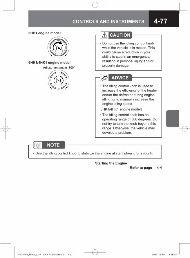
4-77CONTROLS AND INSTRUMENTS
ADVICEThe idling control knob is used to increase the efficiency of the heater and/or the defroster during engine idling, or to manually increase the engine idling speed.
[6HK1/4HK1 engine model]The idling control knob has an operating range of 300 degrees. Do not try to turn the knob beyond this range. Otherwise, the vehicle may develop a problem.
•
•
� �������� �����
NOTEUse the idling control knob to stabilize the engine at start when it runs rough.•
Starting the Engine → Refer to page 4-4
CAUTIONDo not use the idling control knob while the vehicle is in motion. This could cause a reduction in your ability to stop in an emergency, resulting in personal injury and/or property damage.
•
6HH1 engine model
6HK1/4HK1 engine model
4608498_sec04_CONTROLS AND INSTR4-77 4-774608498_sec04_CONTROLS AND INSTR4-77 4-77 2015/11/02 13:58:552015/11/02 13:58:55
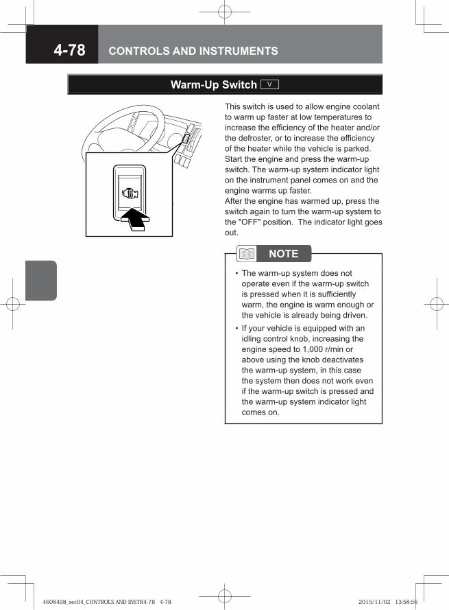
4-78 CONTROLS AND INSTRUMENTS
Warm-Up Switch V
This switch is used to allow engine coolant to warm up faster at low temperatures to increase the efficiency of the heater and/or the defroster, or to increase the efficiency of the heater while the vehicle is parked. Start the engine and press the warm-up switch. The warm-up system indicator light on the instrument panel comes on and the engine warms up faster.After the engine has warmed up, press the switch again to turn the warm-up system to the "OFF" position. The indicator light goes out.
NOTEThe warm-up system does not operate even if the warm-up switch is pressed when it is sufficiently warm, the engine is warm enough or the vehicle is already being driven.If your vehicle is equipped with an idling control knob, increasing the engine speed to 1,000 r/min or above using the knob deactivates the warm-up system, in this case the system then does not work even if the warm-up switch is pressed and the warm-up system indicator light comes on.
•
•
4608498_sec04_CONTROLS AND INSTR4-78 4-784608498_sec04_CONTROLS AND INSTR4-78 4-78 2015/11/02 13:58:562015/11/02 13:58:56
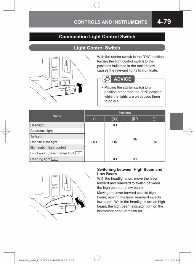
4-79CONTROLS AND INSTRUMENTS
Switching between High Beam and Low BeamWith the headlights on, move the lever forward and rearward to switch between the high beam and low beam.Moving the lever forward selects high beam; moving the lever rearward selects low beam. While the headlights are on high beam, the high beam indicator light on the instrument panel remains on.
Combination Light Control Switch
With the starter switch in the "ON" position, turning the light control switch to the positions indicated in the table below causes the relevant lights to illuminate.
ADVICEPlacing the starter switch to a position other than the "ON" position while the lights are on causes them to go out.
•
Light Control Switch
NamePosition
Headlight
OFF
OFF
ONON
Clearance light
ON
Taillight
License plate light
Illumination light control
Front end outline marker light V
Rear fog light V OFF OFF
4608498_sec04_CONTROLS AND INSTR4-79 4-794608498_sec04_CONTROLS AND INSTR4-79 4-79 2015/11/02 13:58:562015/11/02 13:58:56
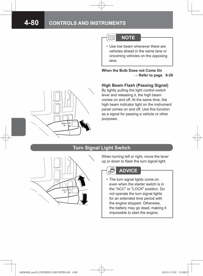
4-80 CONTROLS AND INSTRUMENTS
NOTEUse low beam whenever there are vehicles ahead in the same lane or oncoming vehicles on the opposing lane.
•
When the Bulb Does not Come On → Refer to page 8-29
High Beam Flash (Passing Signal)By lightly pulling the light control switch lever and releasing it, the high beam comes on and off. At the same time, the high beam indicator light on the instrument panel comes on and off. Use this function as a signal for passing a vehicle or other purposes.
When turning left or right, move the lever up or down to flash the turn signal light.
Turn Signal Light Switch
ADVICEThe turn signal lights come on even when the starter switch is in the "ACC" or "LOCK" position. Do not operate the turn signal lights for an extended time period with the engine stopped. Otherwise, the battery may go dead, making it impossible to start the engine.
•
4608498_sec04_CONTROLS AND INSTR4-80 4-804608498_sec04_CONTROLS AND INSTR4-80 4-80 2015/11/02 13:58:572015/11/02 13:58:57
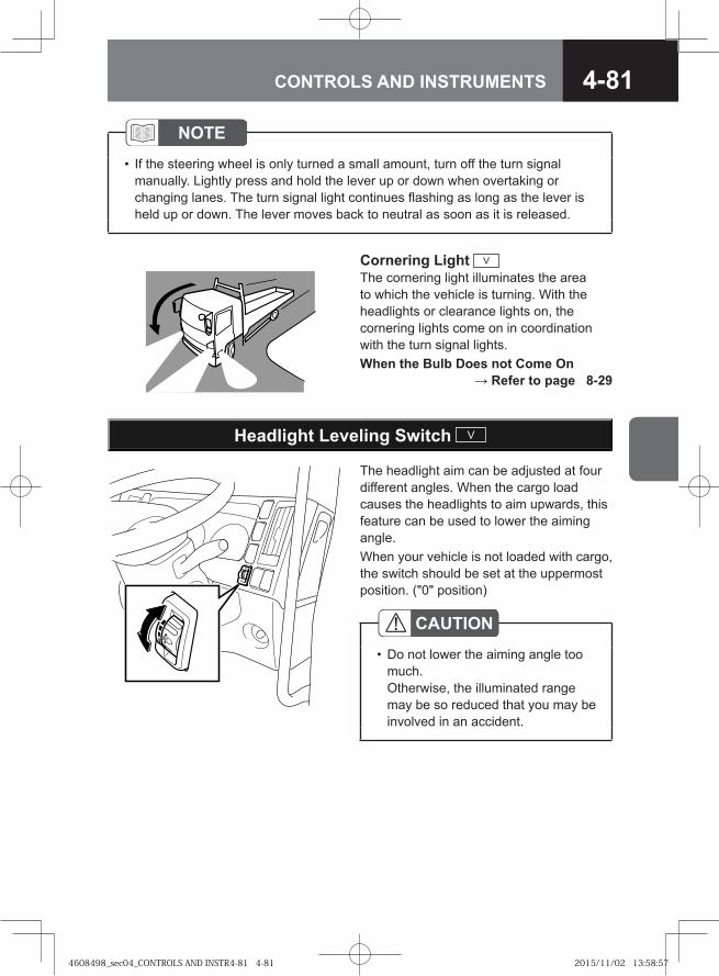
4-81CONTROLS AND INSTRUMENTS
Headlight Leveling Switch V
The headlight aim can be adjusted at four different angles. When the cargo load causes the headlights to aim upwards, this feature can be used to lower the aiming angle.When your vehicle is not loaded with cargo, the switch should be set at the uppermost position. ("0" position)
CAUTIONDo not lower the aiming angle too much. Otherwise, the illuminated range may be so reduced that you may be involved in an accident.
•
Cornering Light V
The cornering light illuminates the area to which the vehicle is turning. With the headlights or clearance lights on, the cornering lights come on in coordination with the turn signal lights. When the Bulb Does not Come On
→ Refer to page 8-29
NOTEIf the steering wheel is only turned a small amount, turn off the turn signal manually. Lightly press and hold the lever up or down when overtaking or changing lanes. The turn signal light continues flashing as long as the lever is held up or down. The lever moves back to neutral as soon as it is released.
•
4608498_sec04_CONTROLS AND INSTR4-81 4-814608498_sec04_CONTROLS AND INSTR4-81 4-81 2015/11/02 13:58:572015/11/02 13:58:57
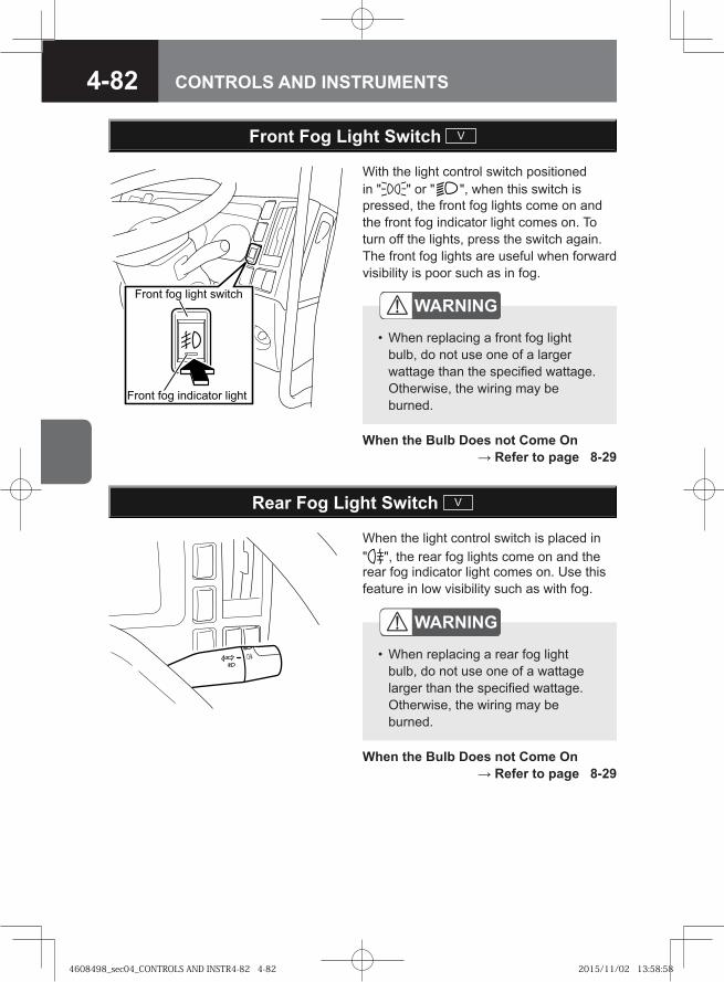
4-82 CONTROLS AND INSTRUMENTS
Front Fog Light Switch V
With the light control switch positioned in " " or " ", when this switch is pressed, the front fog lights come on and the front fog indicator light comes on. To turn off the lights, press the switch again. The front fog lights are useful when forward visibility is poor such as in fog.
��� � ��� ����� ������
��� � ��� � ������� �����
WARNING
When replacing a front fog light bulb, do not use one of a larger wattage than the specified wattage. Otherwise, the wiring may be burned.
•
When the Bulb Does not Come On → Refer to page 8-29
Rear Fog Light Switch V
When the light control switch is placed in " ", the rear fog lights come on and the rear fog indicator light comes on. Use this feature in low visibility such as with fog.
WARNING
When replacing a rear fog light bulb, do not use one of a wattage larger than the specified wattage. Otherwise, the wiring may be burned.
•
When the Bulb Does not Come On → Refer to page 8-29
4608498_sec04_CONTROLS AND INSTR4-82 4-824608498_sec04_CONTROLS AND INSTR4-82 4-82 2015/11/02 13:58:582015/11/02 13:58:58
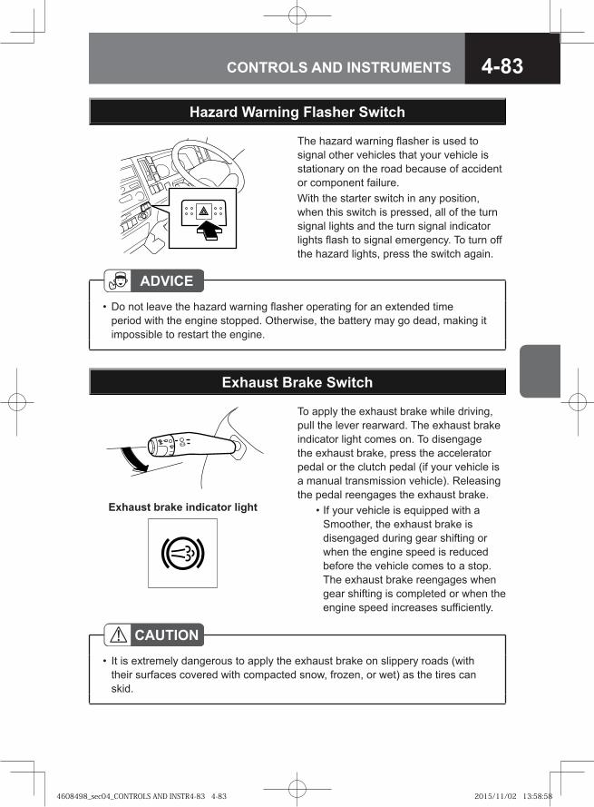
4-83CONTROLS AND INSTRUMENTS
Exhaust Brake Switch
To apply the exhaust brake while driving, pull the lever rearward. The exhaust brake indicator light comes on. To disengage the exhaust brake, press the accelerator pedal or the clutch pedal (if your vehicle is a manual transmission vehicle). Releasing the pedal reengages the exhaust brake. • If your vehicle is equipped with a
Smoother, the exhaust brake is disengaged during gear shifting or when the engine speed is reduced before the vehicle comes to a stop. The exhaust brake reengages when gear shifting is completed or when the engine speed increases sufficiently.
CAUTIONIt is extremely dangerous to apply the exhaust brake on slippery roads (with their surfaces covered with compacted snow, frozen, or wet) as the tires can skid.
•
Exhaust brake indicator light
Hazard Warning Flasher Switch
The hazard warning flasher is used to signal other vehicles that your vehicle is stationary on the road because of accident or component failure.With the starter switch in any position, when this switch is pressed, all of the turn signal lights and the turn signal indicator lights flash to signal emergency. To turn off the hazard lights, press the switch again.
ADVICEDo not leave the hazard warning flasher operating for an extended time period with the engine stopped. Otherwise, the battery may go dead, making it impossible to restart the engine.
•
4608498_sec04_CONTROLS AND INSTR4-83 4-834608498_sec04_CONTROLS AND INSTR4-83 4-83 2015/11/02 13:58:582015/11/02 13:58:58
4-84 CONTROLS AND INSTRUMENTS
ADVICEIf a warning buzzer sounds when the exhaust brake is in operation, promptly pull over the vehicle safely and contact the nearest Isuzu Dealer for inspection.Even if the gearshift lever is placed in the "N" position, the exhaust brake does not disengage until the engine is warmed up if the warm-up system is on.
•
•
Conditions for Inoperable Exhaust BrakeUnder the following conditions, the exhaust brake does not engage. • The accelerator pedal or the clutch pedal (manual transmission models) is
pressed. • The gearshift lever / selector lever / selector button is in the "N" position. • The vehicle is traveling at a speed of 5 km/h (3 MPH) or lower, or the engine
speed drops to a value where the exhaust brake does not engage (excluding automatic transmission models).
• During gear shifting (Smoother models). • The vehicle is traveling in 1st gear (automatic transmission models). • The vehicle is traveling at 20 km/h (12 MPH) or lower speeds (automatic
transmission models).
NOTEIf your vehicle is equipped with an antilock brake system (ABS), the exhaust brake may disengage during ABS operation even when the exhaust brake switch is in the "ON" position and the exhaust brake indicator light is on. The exhaust brake may disengage temporarily as the vehicle passes over a bump even when the brake pedal is not depressed.
•
4608498_sec04_CONTROLS AND INSTR4-84 4-844608498_sec04_CONTROLS AND INSTR4-84 4-84 2015/11/02 13:58:592015/11/02 13:58:59
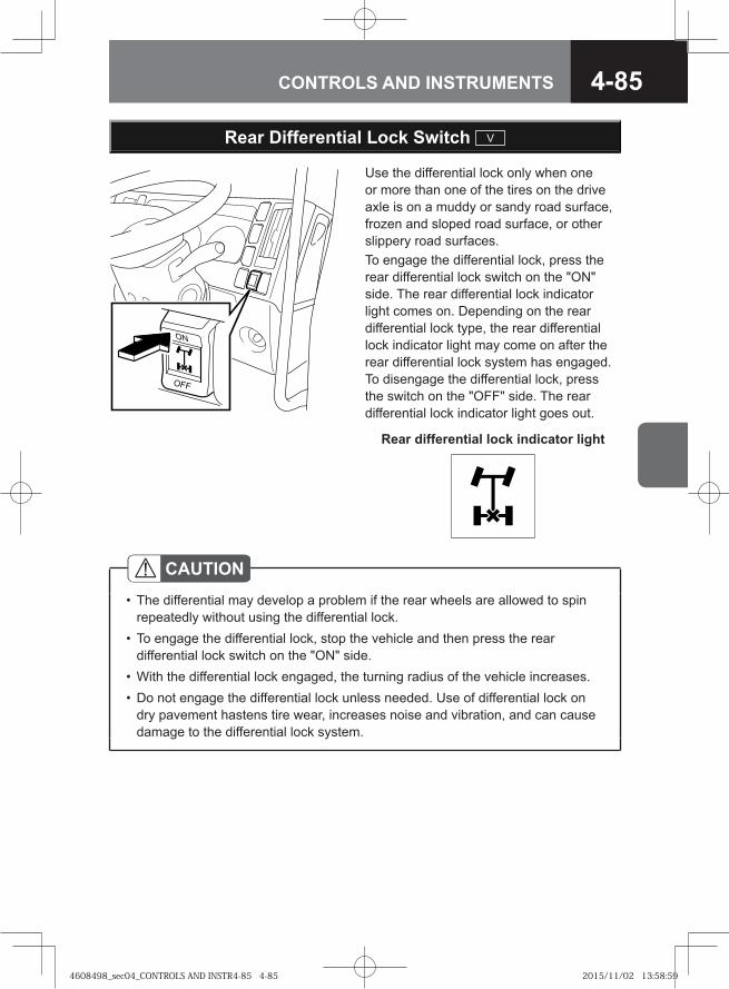
4-85CONTROLS AND INSTRUMENTS
Use the differential lock only when one or more than one of the tires on the drive axle is on a muddy or sandy road surface, frozen and sloped road surface, or other slippery road surfaces.To engage the differential lock, press the rear differential lock switch on the "ON" side. The rear differential lock indicator light comes on. Depending on the rear differential lock type, the rear differential lock indicator light may come on after the rear differential lock system has engaged. To disengage the differential lock, press the switch on the "OFF" side. The rear differential lock indicator light goes out.
Rear Differential Lock Switch V
CAUTIONThe differential may develop a problem if the rear wheels are allowed to spin repeatedly without using the differential lock.To engage the differential lock, stop the vehicle and then press the rear differential lock switch on the "ON" side.With the differential lock engaged, the turning radius of the vehicle increases.Do not engage the differential lock unless needed. Use of differential lock on dry pavement hastens tire wear, increases noise and vibration, and can cause damage to the differential lock system.
•
•
••
Rear differential lock indicator light
4608498_sec04_CONTROLS AND INSTR4-85 4-854608498_sec04_CONTROLS AND INSTR4-85 4-85 2015/11/02 13:58:592015/11/02 13:58:59
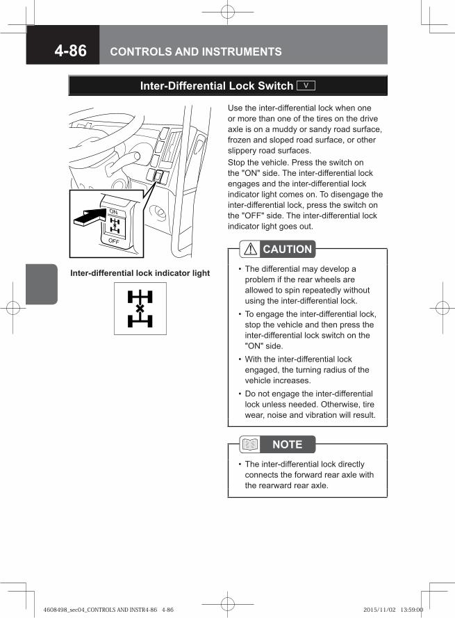
4-86 CONTROLS AND INSTRUMENTS
Use the inter-differential lock when one or more than one of the tires on the drive axle is on a muddy or sandy road surface, frozen and sloped road surface, or other slippery road surfaces.Stop the vehicle. Press the switch on the "ON" side. The inter-differential lock engages and the inter-differential lock indicator light comes on. To disengage the inter-differential lock, press the switch on the "OFF" side. The inter-differential lock indicator light goes out.
Inter-Differential Lock Switch V
Inter-differential lock indicator light
CAUTIONThe differential may develop a problem if the rear wheels are allowed to spin repeatedly without using the inter-differential lock. To engage the inter-differential lock, stop the vehicle and then press the inter-differential lock switch on the "ON" side. With the inter-differential lock engaged, the turning radius of the vehicle increases.Do not engage the inter-differential lock unless needed. Otherwise, tire wear, noise and vibration will result.
•
•
•
•
NOTEThe inter-differential lock directly connects the forward rear axle with the rearward rear axle.
•
4608498_sec04_CONTROLS AND INSTR4-86 4-864608498_sec04_CONTROLS AND INSTR4-86 4-86 2015/11/02 13:59:002015/11/02 13:59:00
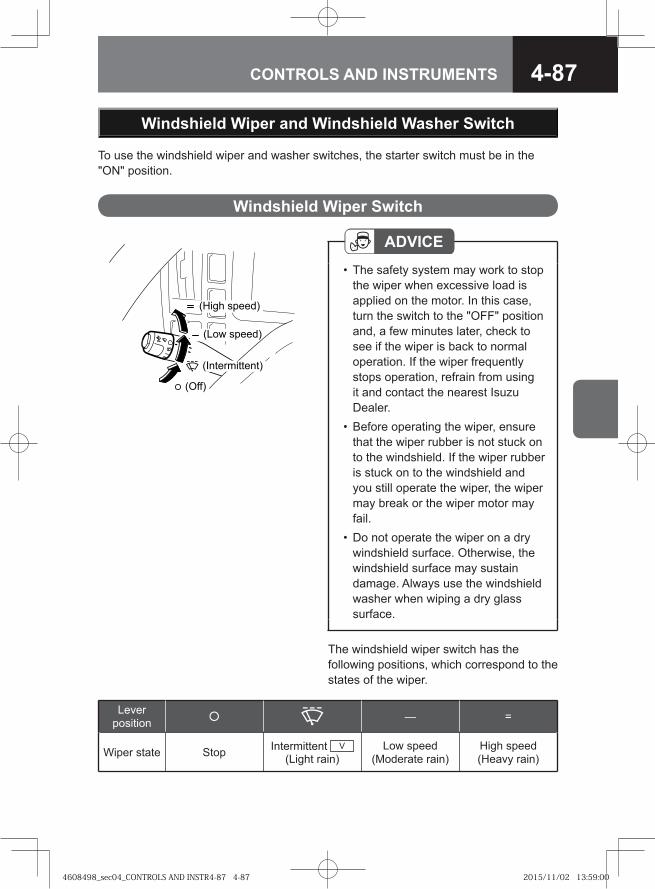
4-87CONTROLS AND INSTRUMENTS
Windshield Wiper and Windshield Washer Switch
To use the windshield wiper and washer switches, the starter switch must be in the "ON" position.
(High speed)
(Low speed)
(Intermittent)
(Off)
The windshield wiper switch has the following positions, which correspond to the states of the wiper.
Lever position — =
Wiper state Stop Intermittent V (Light rain)
Low speed (Moderate rain)
High speed (Heavy rain)
Windshield Wiper Switch
ADVICEThe safety system may work to stop the wiper when excessive load is applied on the motor. In this case, turn the switch to the "OFF" position and, a few minutes later, check to see if the wiper is back to normal operation. If the wiper frequently stops operation, refrain from using it and contact the nearest Isuzu Dealer. Before operating the wiper, ensure that the wiper rubber is not stuck on to the windshield. If the wiper rubber is stuck on to the windshield and you still operate the wiper, the wiper may break or the wiper motor may fail. Do not operate the wiper on a dry windshield surface. Otherwise, the windshield surface may sustain damage. Always use the windshield washer when wiping a dry glass surface.
•
•
•
4608498_sec04_CONTROLS AND INSTR4-87 4-874608498_sec04_CONTROLS AND INSTR4-87 4-87 2015/11/02 13:59:002015/11/02 13:59:00
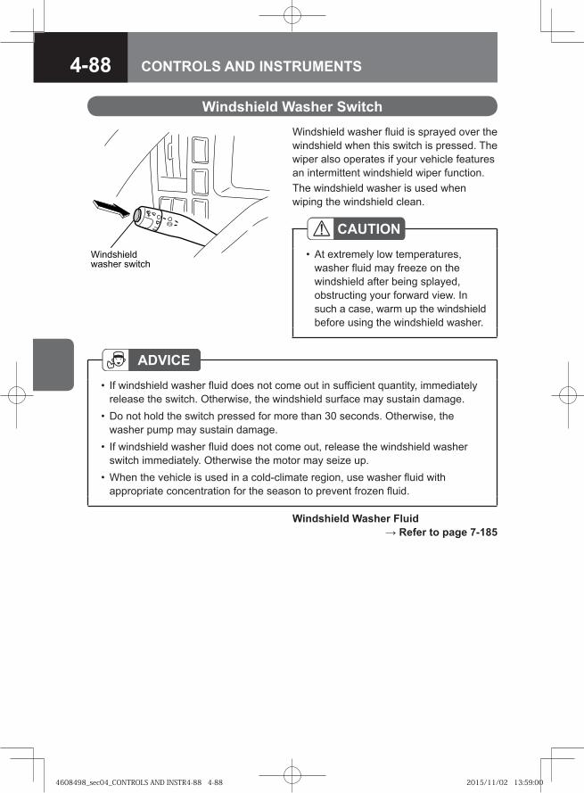
4-88 CONTROLS AND INSTRUMENTS
Windshield washer fluid is sprayed over the windshield when this switch is pressed. The wiper also operates if your vehicle features an intermittent windshield wiper function.The windshield washer is used when wiping the windshield clean.
Windshield Washer Switch
ADVICEIf windshield washer fluid does not come out in sufficient quantity, immediately release the switch. Otherwise, the windshield surface may sustain damage.Do not hold the switch pressed for more than 30 seconds. Otherwise, the washer pump may sustain damage. If windshield washer fluid does not come out, release the windshield washer switch immediately. Otherwise the motor may seize up. When the vehicle is used in a cold-climate region, use washer fluid with appropriate concentration for the season to prevent frozen fluid.
•
•
•
•
CAUTIONAt extremely low temperatures, washer fluid may freeze on the windshield after being splayed, obstructing your forward view. In such a case, warm up the windshield before using the windshield washer.
•� ���� ���
������ �� ���
Windshield Washer Fluid → Refer to page 7-185
4608498_sec04_CONTROLS AND INSTR4-88 4-884608498_sec04_CONTROLS AND INSTR4-88 4-88 2015/11/02 13:59:002015/11/02 13:59:00
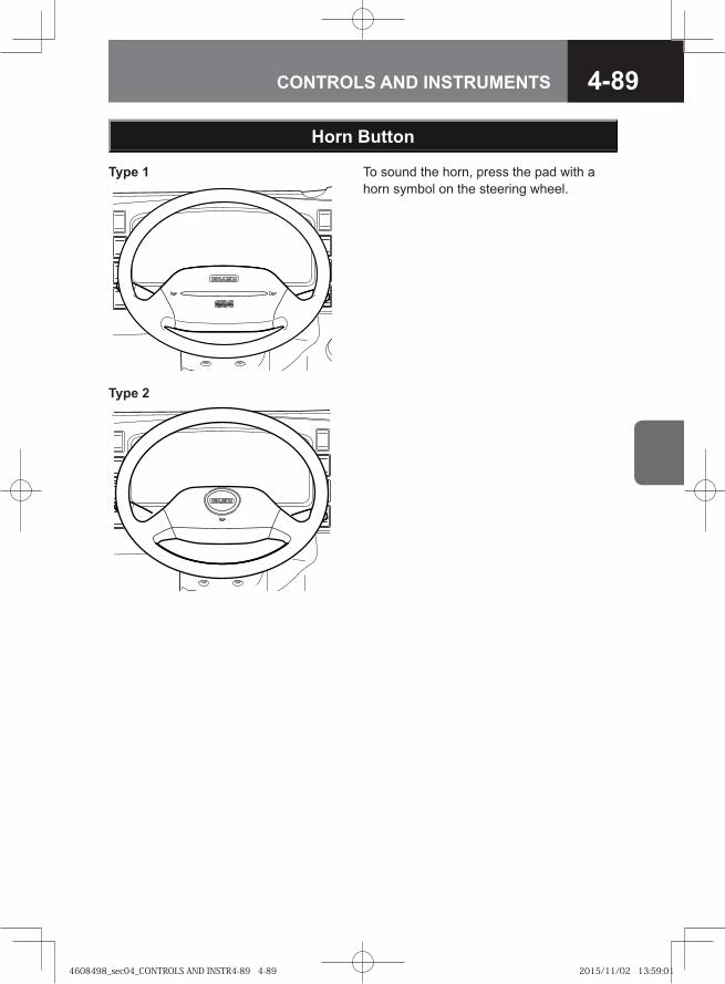
4-89CONTROLS AND INSTRUMENTS
To sound the horn, press the pad with a horn symbol on the steering wheel.
Horn Button
Type 1
Type 2
4608498_sec04_CONTROLS AND INSTR4-89 4-894608498_sec04_CONTROLS AND INSTR4-89 4-89 2015/11/02 13:59:012015/11/02 13:59:01
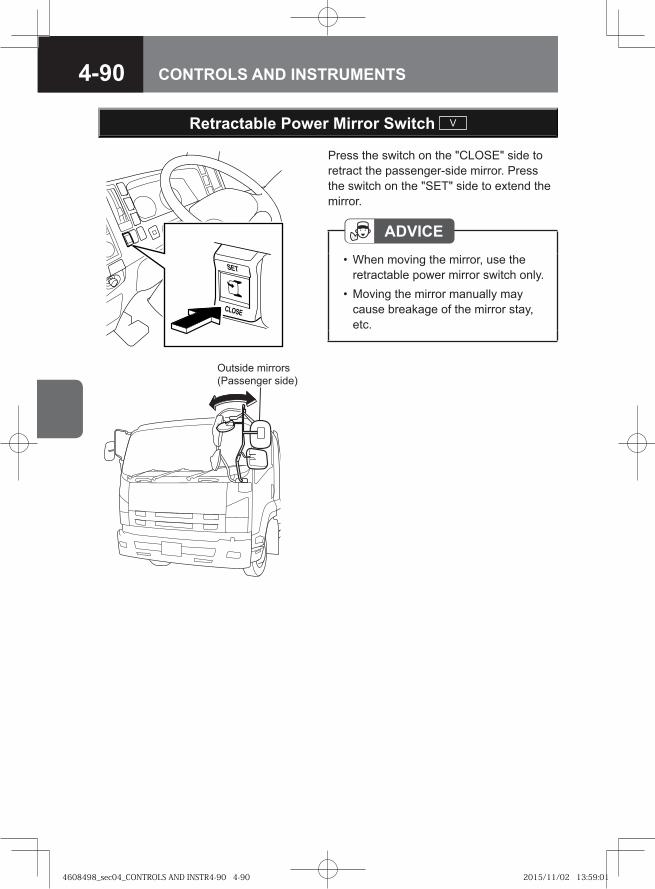
4-90 CONTROLS AND INSTRUMENTS
Outside mirrors(Passenger side)
Retractable Power Mirror Switch V
Press the switch on the "CLOSE" side to retract the passenger-side mirror. Press the switch on the "SET" side to extend the mirror.
ADVICEWhen moving the mirror, use the retractable power mirror switch only. Moving the mirror manually may cause breakage of the mirror stay, etc.
•
•
4608498_sec04_CONTROLS AND INSTR4-90 4-904608498_sec04_CONTROLS AND INSTR4-90 4-90 2015/11/02 13:59:012015/11/02 13:59:01
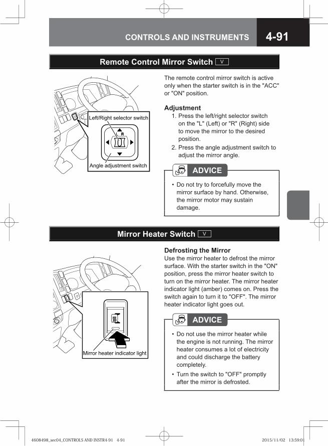
4-91CONTROLS AND INSTRUMENTS
� �������� � � ���� ������
���� �� !��" �� ������
Remote Control Mirror Switch V
The remote control mirror switch is active only when the starter switch is in the "ACC" or "ON" position.
Adjustment 1. Press the left/right selector switch
on the "L" (Left) or "R" (Right) side to move the mirror to the desired position.
2. Press the angle adjustment switch to adjust the mirror angle.
ADVICEDo not try to forcefully move the mirror surface by hand. Otherwise, the mirror motor may sustain damage.
•
���� � ������ ������� � �����
Mirror Heater Switch V
Defrosting the MirrorUse the mirror heater to defrost the mirror surface. With the starter switch in the "ON" position, press the mirror heater switch to turn on the mirror heater. The mirror heater indicator light (amber) comes on. Press the switch again to turn it to "OFF". The mirror heater indicator light goes out.
ADVICEDo not use the mirror heater while the engine is not running. The mirror heater consumes a lot of electricity and could discharge the battery completely. Turn the switch to "OFF" promptly after the mirror is defrosted.
•
•
4608498_sec04_CONTROLS AND INSTR4-91 4-914608498_sec04_CONTROLS AND INSTR4-91 4-91 2015/11/02 13:59:012015/11/02 13:59:01

4-92 CONTROLS AND INSTRUMENTS
4608498_sec04_CONTROLS AND INSTR4-92 4-924608498_sec04_CONTROLS AND INSTR4-92 4-92 2015/11/02 13:59:022015/11/02 13:59:02
4-93CONTROLS AND INSTRUMENTS
● Pedals 4-94
● Parking Brake Lever 4-95
● Gearshift Lever M/T / SA 4-99
● Selector Lever V 4-104
● Selector Button V 4-106
● Model with ZF9S1110 Model Manual Transmission V 4-110
● Model with ES11109/FS8209A Model Manual Transmission V
4-114
● Model with Smoother SA 4-117
● Model with ALLISON2500 Model Automatic Transmission V
4-134
● Model with ALLISON3000/3500 Model Automatic Transmission V
4-141
● Hill Start Aid (HSA) V 4-146
● Brake Lock V 4-157
● Cruise Control V 4-161
● Antilock Brake System (ABS) V 4-166
● Anti-Slip Regulator (ASR) V 4-170
● Pintle Hook V 4-174
● Coupler V 4-178
● Four Wheel Drive (4WD) Model V 4-182
● Power Take-Off (PTO) V 4-193
● Seat Belt with Pretensioner and Supplemental Restraint System (SRS) Airbag System V
4-198
DRIVING CONTROLS
4608498_sec04_CONTROLS AND INSTR4-93 4-934608498_sec04_CONTROLS AND INSTR4-93 4-93 2015/11/02 13:59:432015/11/02 13:59:43
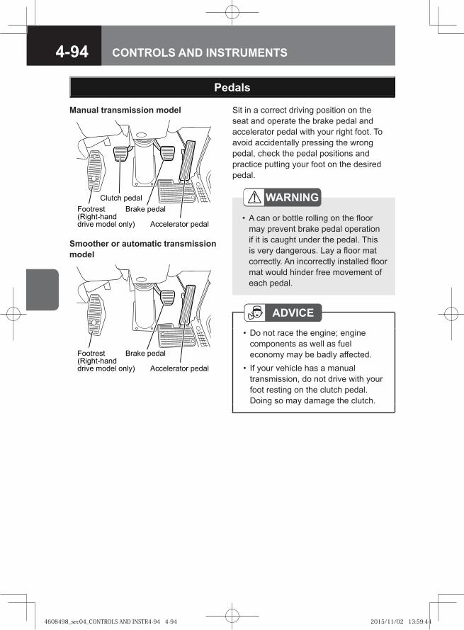
4-94 CONTROLS AND INSTRUMENTS
Sit in a correct driving position on the seat and operate the brake pedal and accelerator pedal with your right foot. To avoid accidentally pressing the wrong pedal, check the pedal positions and practice putting your foot on the desired pedal.
ADVICEDo not race the engine; engine components as well as fuel economy may be badly affected.If your vehicle has a manual transmission, do not drive with your foot resting on the clutch pedal. Doing so may damage the clutch.
•
•
Pedals
WARNING
A can or bottle rolling on the floor may prevent brake pedal operation if it is caught under the pedal. This is very dangerous. Lay a floor mat correctly. An incorrectly installed floor mat would hinder free movement of each pedal.
•� ��� �����
������ �����
������ ��� �����
���� ������ ��!��"�� �#� $���� �"�%&
Manual transmission model
� ��� �����
������ ��� �����
���� ������������ �� �!� "���� � �#$
Smoother or automatic transmission model
4608498_sec04_CONTROLS AND INSTR4-94 4-944608498_sec04_CONTROLS AND INSTR4-94 4-94 2015/11/02 13:59:442015/11/02 13:59:44
4-95CONTROLS AND INSTRUMENTS
Parking Brake Lever
NOTEThere are two types of parking brake. Your vehicle has either of them.
Center parking brake: When you pull the parking brake lever, the center parking brake works on the propeller shaft to lock the rear axle.Wheel parking brake: When you pull the parking brake lever, the wheel parking brake activates the rear wheel brakes to lock them.
•
•
CAUTIONWhen parking or stopping your vehicle, pull the parking brake lever and make sure that the vehicle does not start moving.Avoid parking your vehicle on a slope as much as possible and choose a level and flat place. If it is unavoidable to park your vehicle on a slope, be sure to set the parking brake fully, make sure that the vehicle does not move, and block the wheels with chocks for added safety. If your vehicle is equipped with a manual transmission or Smoother system, engage the transmission in a gear for more secure parking.Do not use the parking brake while the vehicle is in motion except in an emergency. Applying the parking brake before the vehicle has stopped can cause the tires to lock or the vehicle to spin, possibly causing an accident.Unless the parking brake is fully released during driving, a fault and/or a fire may be caused.Illumination of the parking brake warning light does not mean that the parking brake is fully applied. The parking brake lever must be fully pulled up.After using the parking brake during driving, be sure to check if any failure has been caused.
•
•
•
•
•
•
4608498_sec04_CONTROLS AND INSTR4-95 4-954608498_sec04_CONTROLS AND INSTR4-95 4-95 2015/11/02 13:59:452015/11/02 13:59:45
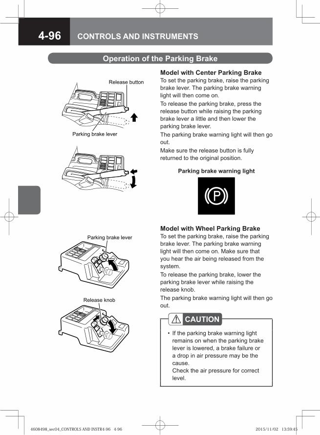
4-96 CONTROLS AND INSTRUMENTS
CAUTIONIf the parking brake warning light remains on when the parking brake lever is lowered, a brake failure or a drop in air pressure may be the cause.Check the air pressure for correct level.
•
Operation of the Parking Brake
Model with Center Parking BrakeTo set the parking brake, raise the parking brake lever. The parking brake warning light will then come on.To release the parking brake, press the release button while raising the parking brake lever a little and then lower the parking brake lever. The parking brake warning light will then go out. Make sure the release button is fully returned to the original position.
Model with Wheel Parking BrakeTo set the parking brake, raise the parking brake lever. The parking brake warning light will then come on. Make sure that you hear the air being released from the system.To release the parking brake, lower the parking brake lever while raising the release knob. The parking brake warning light will then go out.
�� ���� ����
������� ����� ����
�� ���� ������
������� ����� ����
Parking brake warning light
4608498_sec04_CONTROLS AND INSTR4-96 4-964608498_sec04_CONTROLS AND INSTR4-96 4-96 2015/11/02 13:59:452015/11/02 13:59:45
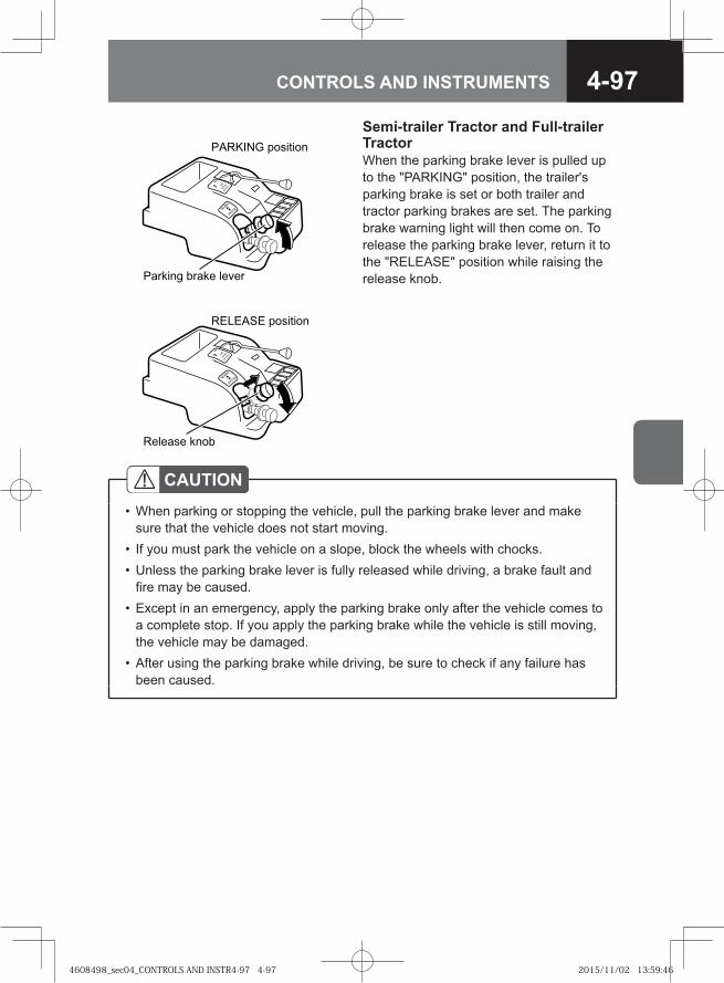
4-97CONTROLS AND INSTRUMENTS
Semi-trailer Tractor and Full-trailer TractorWhen the parking brake lever is pulled up to the "PARKING" position, the trailer's parking brake is set or both trailer and tractor parking brakes are set. The parking brake warning light will then come on. To release the parking brake lever, return it to the "RELEASE" position while raising the release knob.
�� ��������
������ ��������
������ ����
������ ����� ��!��
"���
#��
$��
$�
"���
#��
$��
$�
CAUTIONWhen parking or stopping the vehicle, pull the parking brake lever and make sure that the vehicle does not start moving.If you must park the vehicle on a slope, block the wheels with chocks.Unless the parking brake lever is fully released while driving, a brake fault and fire may be caused.Except in an emergency, apply the parking brake only after the vehicle comes to a complete stop. If you apply the parking brake while the vehicle is still moving, the vehicle may be damaged.After using the parking brake while driving, be sure to check if any failure has been caused.
•
••
•
•
4608498_sec04_CONTROLS AND INSTR4-97 4-974608498_sec04_CONTROLS AND INSTR4-97 4-97 2015/11/02 13:59:462015/11/02 13:59:46
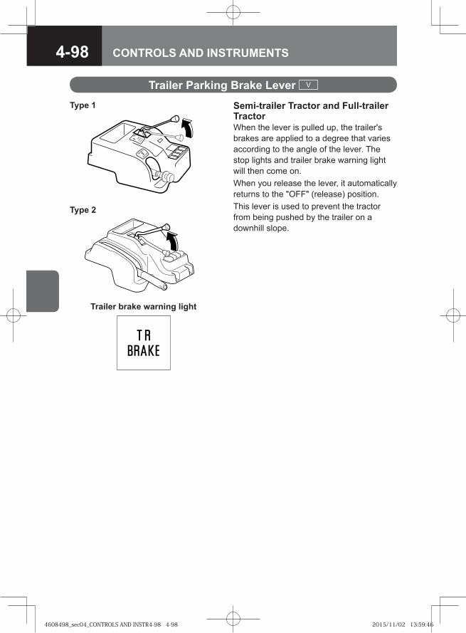
4-98 CONTROLS AND INSTRUMENTS
Semi-trailer Tractor and Full-trailer TractorWhen the lever is pulled up, the trailer's brakes are applied to a degree that varies according to the angle of the lever. The stop lights and trailer brake warning light will then come on.When you release the lever, it automatically returns to the "OFF" (release) position.This lever is used to prevent the tractor from being pushed by the trailer on a downhill slope.
Trailer Parking Brake Lever V
�� ���
�
�� ��
���
��
Trailer brake warning light
Type 1
Type 2
4608498_sec04_CONTROLS AND INSTR4-98 4-984608498_sec04_CONTROLS AND INSTR4-98 4-98 2015/11/02 13:59:462015/11/02 13:59:46
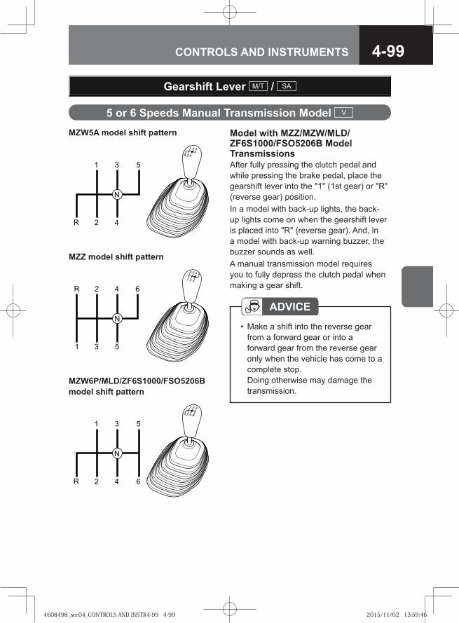
4-99CONTROLS AND INSTRUMENTS
5 or 6 Speeds Manual Transmission Model V
Gearshift Lever M/T / SA
Model with MZZ/MZW/MLD/ZF6S1000/FSO5206B Model TransmissionsAfter fully pressing the clutch pedal and while pressing the brake pedal, place the gearshift lever into the "1" (1st gear) or "R" (reverse gear) position.In a model with back-up lights, the back-up lights come on when the gearshift lever is placed into "R" (reverse gear). And, in a model with back-up warning buzzer, the buzzer sounds as well.A manual transmission model requires you to fully depress the clutch pedal when making a gear shift.
ADVICEMake a shift into the reverse gear from a forward gear or into a forward gear from the reverse gear only when the vehicle has come to a complete stop.Doing otherwise may damage the transmission.
•
MZZ model shift pattern
MZW6P/MLD/ZF6S1000/FSO5206B model shift pattern
MZW5A model shift pattern
�
�
��
�
�
� � �
�
�
� � �
4608498_sec04_CONTROLS AND INSTR4-99 4-994608498_sec04_CONTROLS AND INSTR4-99 4-99 2015/11/02 13:59:462015/11/02 13:59:46
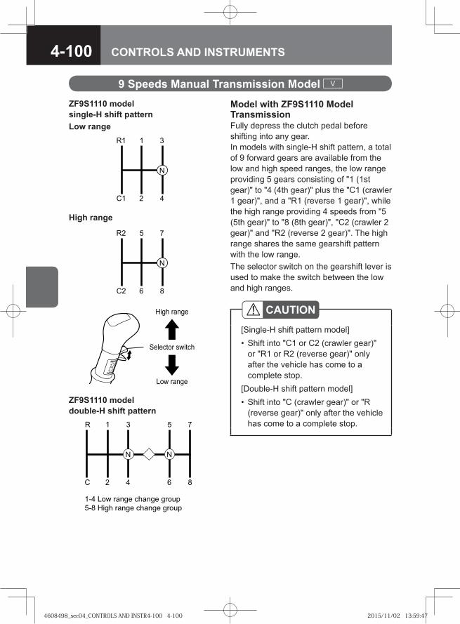
4-100 CONTROLS AND INSTRUMENTS
9 Speeds Manual Transmission Model V
Model with ZF9S1110 Model TransmissionFully depress the clutch pedal before shifting into any gear. In models with single-H shift pattern, a total of 9 forward gears are available from the low and high speed ranges, the low range providing 5 gears consisting of "1 (1st gear)" to "4 (4th gear)" plus the "C1 (crawler 1 gear)", and a "R1 (reverse 1 gear)", while the high range providing 4 speeds from "5 (5th gear)" to "8 (8th gear)", "C2 (crawler 2 gear)" and "R2 (reverse 2 gear)". The high range shares the same gearshift pattern with the low range.The selector switch on the gearshift lever is used to make the switch between the low and high ranges.
��� �����
�������� �����
��� �����
�
� �
��
ZF9S1110 model single-H shift patternLow range
�
� �
� ��
High range
CAUTION[Single-H shift pattern model]
Shift into "C1 or C2 (crawler gear)" or "R1 or R2 (reverse gear)" only after the vehicle has come to a complete stop.
[Double-H shift pattern model]Shift into "C (crawler gear)" or "R (reverse gear)" only after the vehicle has come to a complete stop.
•
•ZF9S1110 model double-H shift pattern
�
�
�
�
�
�
�
��� ��� ����� ������ �����
�� ���� ����� ������ �����
!
4608498_sec04_CONTROLS AND INSTR4-100 4-1004608498_sec04_CONTROLS AND INSTR4-100 4-100 2015/11/02 13:59:472015/11/02 13:59:47
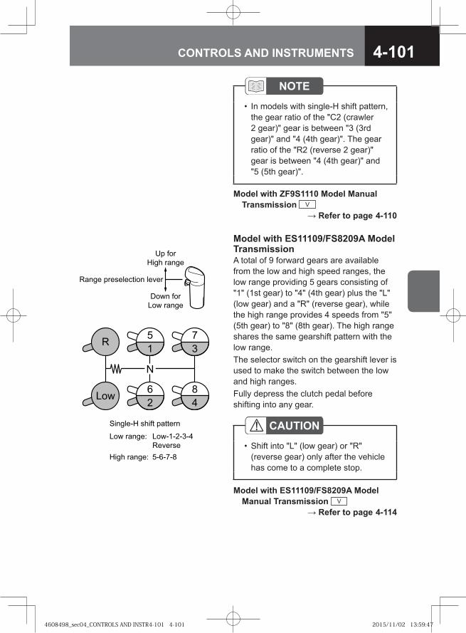
4-101CONTROLS AND INSTRUMENTS
Model with ZF9S1110 Model Manual Transmission V → Refer to page 4-110
NOTEIn models with single-H shift pattern, the gear ratio of the "C2 (crawler 2 gear)" gear is between "3 (3rd gear)" and "4 (4th gear)". The gear ratio of the "R2 (reverse 2 gear)" gear is between "4 (4th gear)" and "5 (5th gear)".
•
Model with ES11109/FS8209A Model TransmissionA total of 9 forward gears are available from the low and high speed ranges, the low range providing 5 gears consisting of "1" (1st gear) to "4" (4th gear) plus the "L" (low gear) and a "R" (reverse gear), while the high range provides 4 speeds from "5" (5th gear) to "8" (8th gear). The high range shares the same gearshift pattern with the low range.The selector switch on the gearshift lever is used to make the switch between the low and high ranges.Fully depress the clutch pedal before shifting into any gear.
Model with ES11109/FS8209A Model Manual Transmission V → Refer to page 4-114
CAUTIONShift into "L" (low gear) or "R" (reverse gear) only after the vehicle has come to a complete stop.
•
���
�
� �
�
� �
�
�� ���
���� �����
���� ������� !��� ��"��
#�����$� ����! ��!!���
��� �����% ���$$�$�$�&
�"����
���� �����% $�$�$�
'��� ���
��� �����
4608498_sec04_CONTROLS AND INSTR4-101 4-1014608498_sec04_CONTROLS AND INSTR4-101 4-101 2015/11/02 13:59:472015/11/02 13:59:47
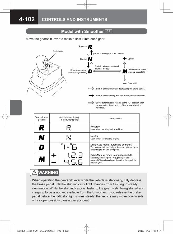
4-102 CONTROLS AND INSTRUMENTS
�� ����
�������
���������
� ����� �� �������� ���� ���� ��� ����� �� �� ������� !
� "� �� �#��$���%���� ���#��� �� ��� &�& �������� �����$� �$��� �� ��� ���%���� �� ��� ����� ���� �� ��������� !
� ����� �� �������� �����#� ��������' ��� ����� �� ��!
��� �(���#�� $� �)$��#�� '��������*
+�#����
��� �(,#�� $� �)�#��$���% '��������*
����%� ������� �#�� �� $��#�� $� ��
)-���� �������' ��� �#�� �#����*.#�� �#����
�� ����� ���� ��������
����� �������� ��������� ���� ����� �����
�� ��������
���� ������ ���� ��!��" �� ��� �������#
$��� ������ ���� ��� ���" ��� ��"���#
% ���&'��� ���� (��������� "�� �����)*�� ������ ������������� ������� �� ������� "�� ���� ���" �� ��� ������� �����#
% ���&������ ���� (������ "�� �����)+�������� ��������" ��� ,-, (�������) � ��� , & ,(���������) �������� ������ ��� � ��� �� ������ ������� �� "�� #
Model with Smoother SA
Move the gearshift lever to make a shift it into each gear.
WARNING
When operating the gearshift lever while the vehicle is stationary, fully depress the brake pedal until the shift indicator light changes from flashing to steady illumination. While the shift indicator is flashing, the gear is still being shifted and creeping force is not yet available from the Smoother. If you release the brake pedal before the indicator light shines steady, the vehicle may move downwards on a slope, possibly causing an accident.
•
4608498_sec04_CONTROLS AND INSTR4-102 4-1024608498_sec04_CONTROLS AND INSTR4-102 4-102 2015/11/02 13:59:472015/11/02 13:59:47
4-103CONTROLS AND INSTRUMENTS
NOTEWhile the engine is not in operation, you cannot shift gears by moving the gearshift lever. Start the engine before you can change the gear.When the vehicle is stationary with the engine running, the shift lock function works for safety. You cannot move the gearshift lever from "N" into "D" or "R" without depressing the brake pedal.When starting the vehicle, be sure to operate the gearshift lever while pressing the brake pedal.
•
•
4608498_sec04_CONTROLS AND INSTR4-103 4-1034608498_sec04_CONTROLS AND INSTR4-103 4-103 2015/11/02 13:59:482015/11/02 13:59:48
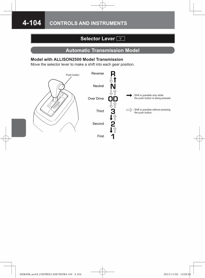
4-104 CONTROLS AND INSTRUMENTS
Selector Lever V
Automatic Transmission Model
Model with ALLISON2500 Model TransmissionMove the selector lever to make a shift into each gear position.
Reverse
Neutral
Over Drive
Third
Second
First
: Shift is possible without pressing the push button.
: Shift is possible only while the push button is being pressed.
Push button
4608498_sec04_CONTROLS AND INSTR4-104 4-1044608498_sec04_CONTROLS AND INSTR4-104 4-104 2015/11/02 13:59:482015/11/02 13:59:48
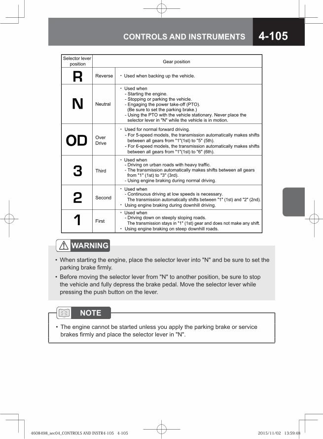
4-105CONTROLS AND INSTRUMENTS
WARNING
When starting the engine, place the selector lever into "N" and be sure to set the parking brake firmly.Before moving the selector lever from "N" to another position, be sure to stop the vehicle and fully depress the brake pedal. Move the selector lever while pressing the push button on the lever.
•
•
NOTEThe engine cannot be started unless you apply the parking brake or service brakes firmly and place the selector lever in "N".
•
�� �� ���
���� ������ ���� ���
��� ��� ������� �� � ������
��� ���
��� ���
��� ���
��� �� ���!�� ������ ��������
"���
#� ���
����
����
$��
%���
&����
' �� ��� � �����' ������ �� ������� � ������' �������� � ���� ��'� ()&$*�
(+ ��� � � � ������� �����*' ����� � )&$ �� � � ����� � � �����,� #�� ���� �
��� �� ��� �� -#- ���� � ����� �� �� !� ����
' %������ �� ����� ����� �� � ���, �� ���' &� ����!������ �� �!� �����, !��� ��� � � �� ��� ����
��! -�- (�� * � -�- (���*�' ����� ���� ������� ������ ���!�� ��������
' .�� ������ ������� � ��� ���� �� ������,�
&� ����!������ �� �!� �����, ��� � � �� -�- (�� * ��� -/- (/��*�
����� ���� ������� ������ �������� ��������
��� ���' %������ ���� �� � ��, ������� ������
&� ����!������ � �,� �� -�- (�� * ��� ��� ��� �� !�� ��, ��� �
����� ���� ������� �� � � �������� ������
' ��� 0'��� !����1 � ����!������ �� �!� �����, !��� ��� �
� �� ��� ���� ��! -�-(�� * � -0- (0 �*�
' ��� 2'��� !����1 � ����!������ �� �!� �����, !��� ��� �
� �� ��� ���� ��! -�-(�� * � -2- (2 �*�
4608498_sec04_CONTROLS AND INSTR4-105 4-1054608498_sec04_CONTROLS AND INSTR4-105 4-105 2015/11/02 13:59:482015/11/02 13:59:48
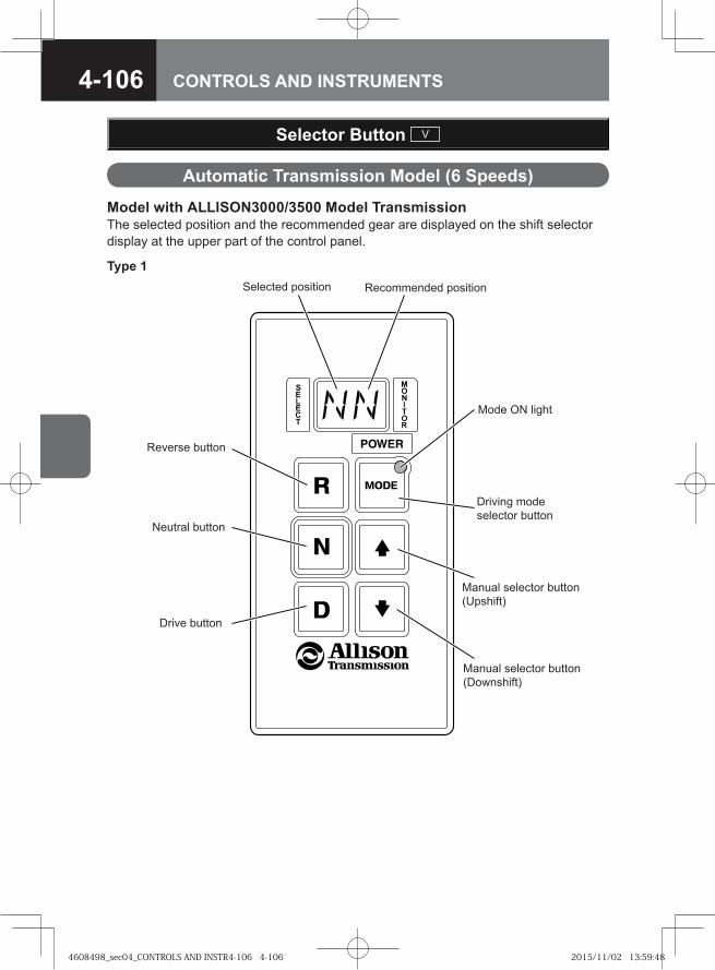
4-106 CONTROLS AND INSTRUMENTS
Selector Button V
Automatic Transmission Model (6 Speeds)
Model with ALLISON3000/3500 Model TransmissionThe selected position and the recommended gear are displayed on the shift selector display at the upper part of the control panel.
Driving mode selector button
Manual selector button (Upshift)
Neutral button
Drive button
Manual selector button (Downshift)
Reverse button
Selected position Recommended position
Mode ON light
Type 1
4608498_sec04_CONTROLS AND INSTR4-106 4-1064608498_sec04_CONTROLS AND INSTR4-106 4-106 2015/11/02 13:59:482015/11/02 13:59:48
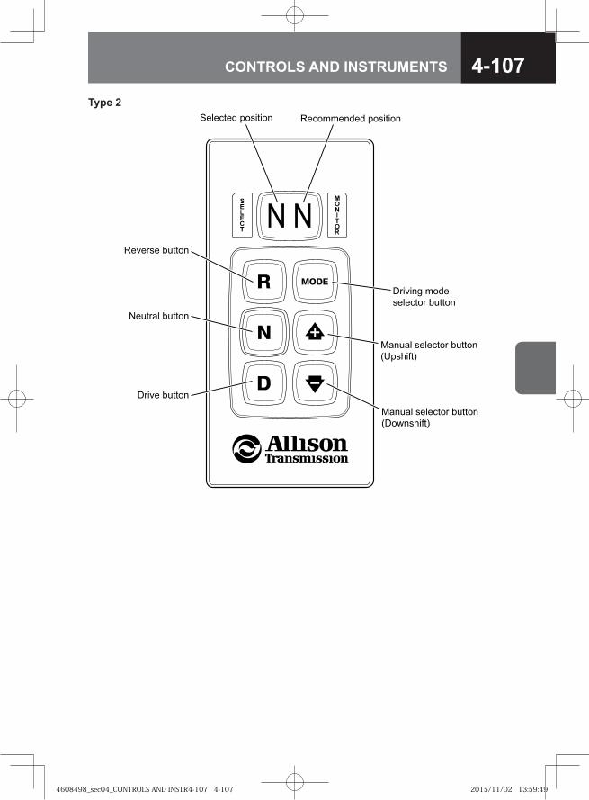
4-107CONTROLS AND INSTRUMENTS
��� � ����
������� �����
�� ��� ������� �����
���������
����� �����
��� �����
�� ��� ������� �����
��! ������
"����� �����
#������� ������� "������ ��� �������
Type 2
4608498_sec04_CONTROLS AND INSTR4-107 4-1074608498_sec04_CONTROLS AND INSTR4-107 4-107 2015/11/02 13:59:492015/11/02 13:59:49
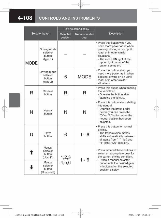
4-108 CONTROLS AND INSTRUMENTS
Selector button
Shift selector display
DescriptionSelected position
Recommended gear
MODE
Driving mode selector button
(type 1)
― ―
• Press this button when you need more power as in when passing, driving on an uphill road, or in other similar situations.- The mode ON light at the
upper right corner of the button comes on.
Driving mode selector button
(type 2)6 MODE
• Press this button when you need more power as in when passing, driving on an uphill road, or in other similar situations.
R Reverse button R R
• Press this button when backing the vehicle up.- Operate the button after
stopping the vehicle.
N Neutral button N N
• Press this button when shifting into neutral.- Depress the brake pedal
before you can press the "D" or "R" button when the neutral position has been selected.
D Drive button 6 1 - 6
• Press this button for normal driving.- The transmission makes
shifts automatically between all gears from "1" (1st) and "6" (6th) ("D6" position).
Manual selector button
(Upshift) 1,2,34,5,6 1 - 6
• Press either of these buttons to select an appropriate gear for the current driving condition.- Press a manual selector
button until the desired gear is indicated on the selected position display.
Manual selector button
(Downshift)
4608498_sec04_CONTROLS AND INSTR4-108 4-1084608498_sec04_CONTROLS AND INSTR4-108 4-108 2015/11/02 13:59:492015/11/02 13:59:49

4-109CONTROLS AND INSTRUMENTS
ADVICEThe shift selector display warns of a serious fault that has occurred in the automatic transmission mechanism or the control unit if it indicates only the recommended gear without indicating the selected position.If this condition occurs, stop driving, do not press any button on the control panel and promptly contact the nearest Isuzu Dealer.
•
4608498_sec04_CONTROLS AND INSTR4-109 4-1094608498_sec04_CONTROLS AND INSTR4-109 4-109 2015/11/02 13:59:492015/11/02 13:59:49
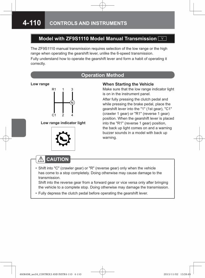
4-110 CONTROLS AND INSTRUMENTS
When Starting the VehicleMake sure that the low range indicator light is on in the instrument panel.After fully pressing the clutch pedal and while pressing the brake pedal, place the gearshift lever into the "1" (1st gear), "C1" (crawler 1 gear) or "R1" (reverse 1 gear) position. When the gearshift lever is placed into the "R1" (reverse 1 gear) position, the back up light comes on and a warning buzzer sounds in a model with back up warning.
�
� �
��
Low range
CAUTIONShift into "C" (crawler gear) or "R" (reverse gear) only when the vehicle has come to a stop completely. Doing otherwise may cause damage to the transmission.Shift into the reverse gear from a forward gear or vice versa only after bringing the vehicle to a complete stop. Doing otherwise may damage the transmission.Fully depress the clutch pedal before operating the gearshift lever.
•
•
Model with ZF9S1110 Model Manual Transmission V
The ZF9S1110 manual transmission requires selection of the low range or the high range when operating the gearshift lever, unlike the 6-speed transmission.Fully understand how to operate the gearshift lever and form a habit of operating it correctly.
Operation Method
Low range indicator light
4608498_sec04_CONTROLS AND INSTR4-110 4-1104608498_sec04_CONTROLS AND INSTR4-110 4-110 2015/11/02 13:59:492015/11/02 13:59:49
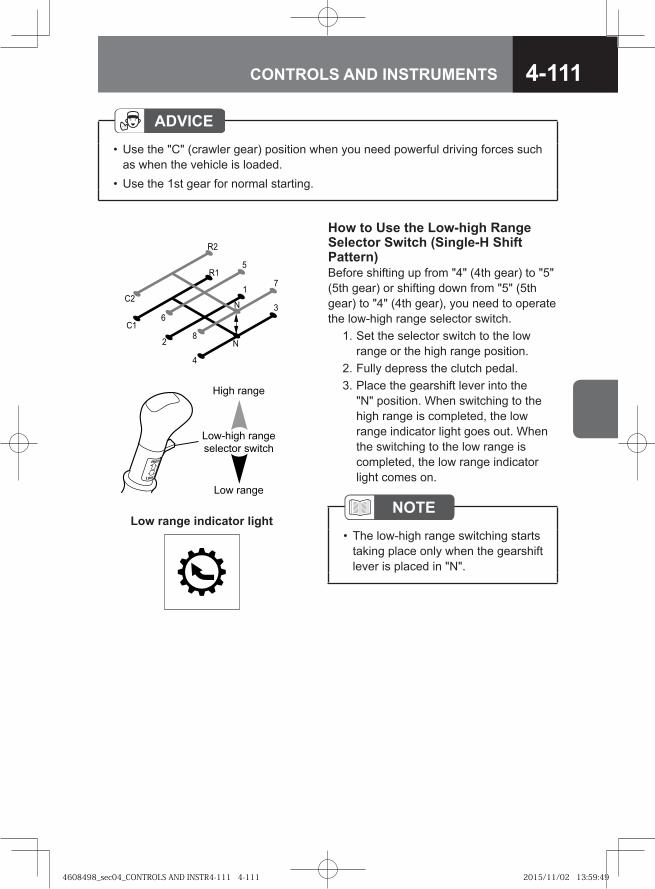
4-111CONTROLS AND INSTRUMENTS
ADVICEUse the "C" (crawler gear) position when you need powerful driving forces such as when the vehicle is loaded.Use the 1st gear for normal starting.
•
•
How to Use the Low-high Range Selector Switch (Single-H Shift Pattern)Before shifting up from "4" (4th gear) to "5" (5th gear) or shifting down from "5" (5th gear) to "4" (4th gear), you need to operate the low-high range selector switch. 1. Set the selector switch to the low
range or the high range position. 2. Fully depress the clutch pedal. 3. Place the gearshift lever into the
"N" position. When switching to the high range is completed, the low range indicator light goes out. When the switching to the low range is completed, the low range indicator light comes on.
��� �����
������� �����
�������� �����
��� �����
��
�
�
�
�
��
��
�
!
�
NOTEThe low-high range switching starts taking place only when the gearshift lever is placed in "N".
•Low range indicator light
4608498_sec04_CONTROLS AND INSTR4-111 4-1114608498_sec04_CONTROLS AND INSTR4-111 4-111 2015/11/02 13:59:492015/11/02 13:59:49
4-112 CONTROLS AND INSTRUMENTS
4. When shifting up from "4" (4th gear) to "5" (5th gear), check that the indicator light remains off and then place the gearshift lever into the "1" (1st gear) position. Move the gearshift lever from "5" (5th gear) to "8" (8th gear) with the selector switch left in the high range position. When shifting down from "5" (5th gear) to "4" (4th gear), check that the low range indicator light is on and then place the gearshift lever into the "4" (4th gear) position.
CAUTIONFully depress the clutch pedal before operating the gearshift lever.Do not change to the low range at 30 km/h (19 MPH) or higher speeds. Doing so may cause a failure in the transmission.Operate the selector switch immediately before the gear change operation. If the selector switch is operated too early, gear shifting does not take place correctly and the transmission may be damaged.
••
•
NOTEIf low-high range switching becomes impossible
If low-to-high range switching is impossible, you can still drive the vehicle. Have your vehicle inspected at the nearest Isuzu Dealer promptly.If high-to-low range switching becomes impossible, you cannot drive the vehicle. Immediately stop your vehicle at a safe place and contact the nearest Isuzu Dealer.
If the vehicle speed exceeds approximately 17 km/h (11 MPH) while the low range is being used, shifting from "3" (3rd gear) or "4" (4th gear) to "1" (1st gear), "2" (2nd gear), "C1" (crawler 1 gear) or "R1" (reverse 1 gear) is prevented from taking place. (The gate interlock mechanism works.)If the vehicle speed exceeds approx. 30 km/h (19 MPH) while the high range is being used, switching from the high range to the low range is prevented from taking place. (The range interlock mechanism works.)
•-
-
•
•
4608498_sec04_CONTROLS AND INSTR4-112 4-1124608498_sec04_CONTROLS AND INSTR4-112 4-112 2015/11/02 13:59:502015/11/02 13:59:50
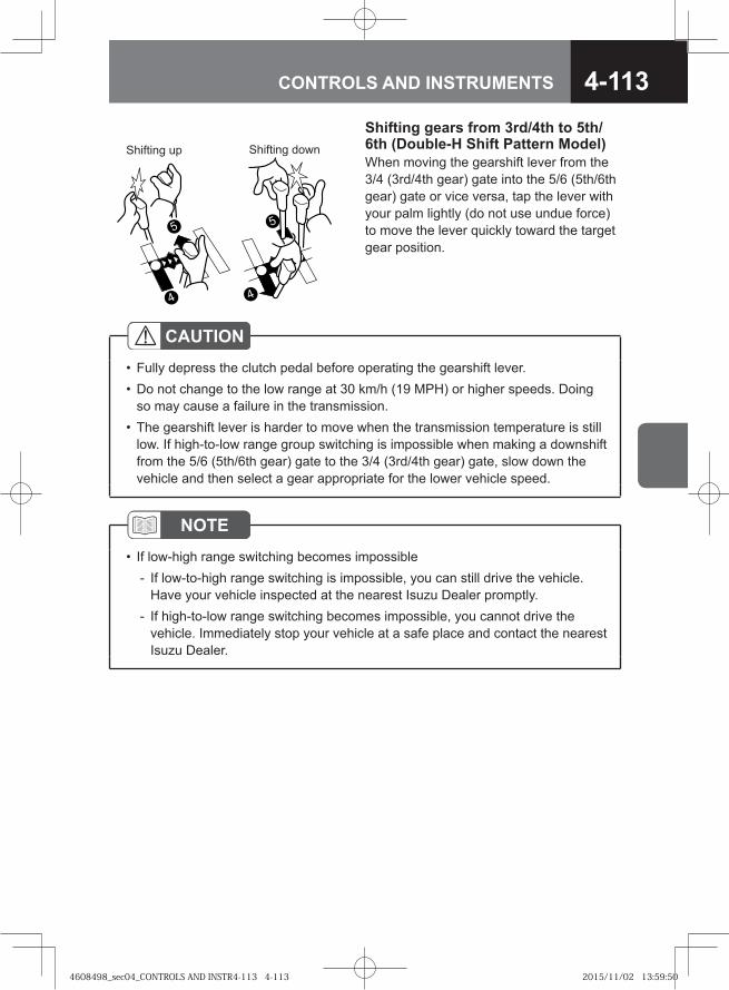
4-113CONTROLS AND INSTRUMENTS
CAUTIONFully depress the clutch pedal before operating the gearshift lever.Do not change to the low range at 30 km/h (19 MPH) or higher speeds. Doing so may cause a failure in the transmission.The gearshift lever is harder to move when the transmission temperature is still low. If high-to-low range group switching is impossible when making a downshift from the 5/6 (5th/6th gear) gate to the 3/4 (3rd/4th gear) gate, slow down the vehicle and then select a gear appropriate for the lower vehicle speed.
••
•
NOTEIf low-high range switching becomes impossible
If low-to-high range switching is impossible, you can still drive the vehicle. Have your vehicle inspected at the nearest Isuzu Dealer promptly.If high-to-low range switching becomes impossible, you cannot drive the vehicle. Immediately stop your vehicle at a safe place and contact the nearest Isuzu Dealer.
•-
-
Shifting gears from 3rd/4th to 5th/6th (Double-H Shift Pattern Model)When moving the gearshift lever from the 3/4 (3rd/4th gear) gate into the 5/6 (5th/6th gear) gate or vice versa, tap the lever with your palm lightly (do not use undue force) to move the lever quickly toward the target gear position.
4
5
4
5
Shifting up Shifting down
4608498_sec04_CONTROLS AND INSTR4-113 4-1134608498_sec04_CONTROLS AND INSTR4-113 4-113 2015/11/02 13:59:502015/11/02 13:59:50
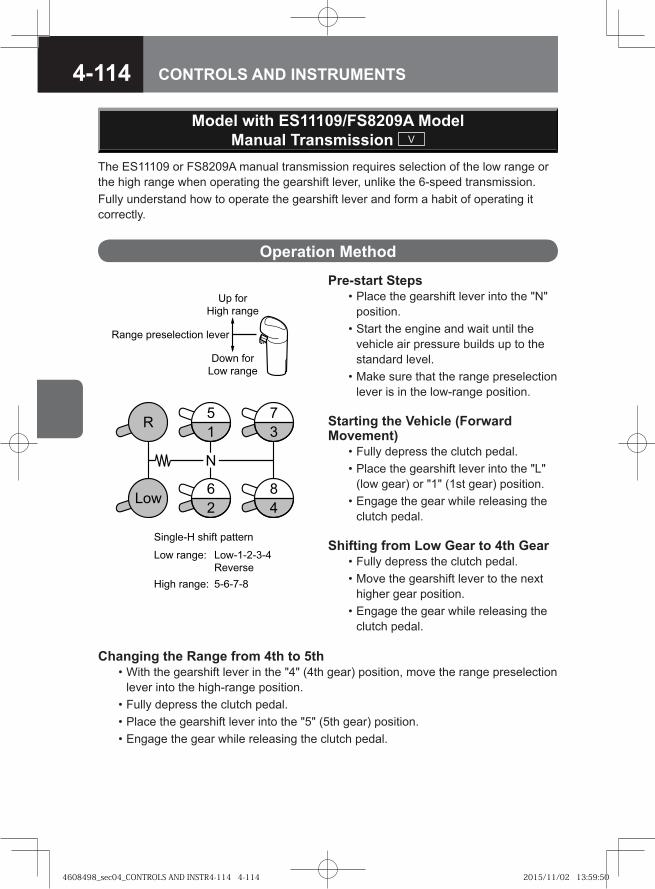
4-114 CONTROLS AND INSTRUMENTS
Pre-start Steps • Place the gearshift lever into the "N"
position. • Start the engine and wait until the
vehicle air pressure builds up to the standard level.
• Make sure that the range preselection lever is in the low-range position.
Starting the Vehicle (Forward Movement) • Fully depress the clutch pedal. • Place the gearshift lever into the "L"
(low gear) or "1" (1st gear) position. • Engage the gear while releasing the
clutch pedal.
Shifting from Low Gear to 4th Gear • Fully depress the clutch pedal. • Move the gearshift lever to the next
higher gear position. • Engage the gear while releasing the
clutch pedal.
The ES11109 or FS8209A manual transmission requires selection of the low range or the high range when operating the gearshift lever, unlike the 6-speed transmission.Fully understand how to operate the gearshift lever and form a habit of operating it correctly.
Operation Method
���
�
� �
�
� �
�
�� ���
���� �����
���� ������� !��� ��"��
#�����$� ����! ��!!���
��� �����% ���$$�$�$�&
�"����
���� �����% $�$�$�
'��� ���
��� �����
Changing the Range from 4th to 5th • With the gearshift lever in the "4" (4th gear) position, move the range preselection
lever into the high-range position. • Fully depress the clutch pedal. • Place the gearshift lever into the "5" (5th gear) position. • Engage the gear while releasing the clutch pedal.
Model with ES11109/FS8209A Model Manual Transmission V
4608498_sec04_CONTROLS AND INSTR4-114 4-1144608498_sec04_CONTROLS AND INSTR4-114 4-114 2015/11/02 13:59:502015/11/02 13:59:50
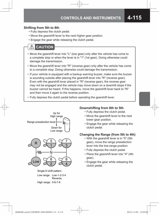
4-115CONTROLS AND INSTRUMENTS
Shifting from 5th to 8th • Fully depress the clutch pedal. • Move the gearshift lever to the next higher gear position. • Engage the gear while releasing the clutch pedal.
CAUTIONMove the gearshift lever into "L" (low gear) only after the vehicle has come to a complete stop or when the lever is in "1" (1st gear). Doing otherwise could damage the transmission. Move the gearshift lever into "R" (reverse gear) only after the vehicle has come to a complete stop. Doing otherwise could damage the transmission.If your vehicle is equipped with a backup warning buzzer, make sure the buzzer is sounding outside after placing the gearshift lever into "R" (reverse gear). Even with the gearshift lever placed in "R" (reverse gear), the reverse gear may not be engaged and the vehicle may move down on a downhill slope if the buzzer cannot be heard. If this happens, move the gearshift lever back to "N" and then move it again to the reverse position.Fully depress the clutch pedal before operating the gearshift lever.
•
•
•
•
Downshifting from 8th to 5th • Fully depress the clutch pedal. • Move the gearshift lever to the next
lower gear position. • Engage the gear while releasing the
clutch pedal.
Changing the Range (from 5th to 4th) • With the gearshift lever is in "5" (5th
gear), move the range preselection lever into the low-range position.
• Fully depress the clutch pedal. • Place the gearshift lever into "4" (4th
gear). • Engage the gear while releasing the
clutch pedal.
���
�
� �
�
� �
�
�� ���
���� �����
���� ������� !��� ��"��
#�����$� ����! ��!!���
��� �����% ���$$�$�$�&
�"����
���� �����% $�$�$�
'��� ���
��� �����
4608498_sec04_CONTROLS AND INSTR4-115 4-1154608498_sec04_CONTROLS AND INSTR4-115 4-115 2015/11/02 13:59:502015/11/02 13:59:50
4-116 CONTROLS AND INSTRUMENTS
Downshifting from 4th to low • Fully depress the clutch pedal. • Move the gearshift lever to the next
lower gear position. • Engage the gear while releasing the
clutch pedal.
Reversing • Place the gearshift lever in "N" and
move the range preselection lever into the low range position.
• Fully depress the clutch pedal. • Move the gearshift lever passing
the detent to "R" (reverse gear); the backup lights will come on and a buzzer will sound.
CAUTIONA range change (from the low to high range or the high to low range) automatically takes place when the gearshift lever passes through "N".Do not place the gearshift lever in "N" while driving in order to make a range change.Do not make any range change with the gearshift lever in "R" (reverse gear).
•
•
•
NOTEDo as follows if range change becomes impossible:
If low-to-high range change is impossible, you can still drive the vehicle. Have the vehicle inspected by the nearest Isuzu Dealer as soon as possible.If high-to-low range change becomes impossible, you cannot drive the vehicle. Immediately pull safely off the road out of the way of any traffic and call the nearest Isuzu Dealer.
•
•
4608498_sec04_CONTROLS AND INSTR4-116 4-1164608498_sec04_CONTROLS AND INSTR4-116 4-116 2015/11/02 13:59:512015/11/02 13:59:51
4-117CONTROLS AND INSTRUMENTS
Smoother is a transmission system that allows the driver to move the vehicle from a standstill, drive the vehicle with gears automatically changed and bring the vehicle to a stop, only using the gearshift lever, accelerator pedal and brake pedal, without needing to operate the clutch pedal. Make sure you fully understand the characteristics of the Smoother system and know how to operate it correctly.
WARNING
Fully depress the brake pedal to prevent the vehicle from moving even if it is stopped on a level road, and place the gearshift lever into "N" and securely set the parking brake as needed.The engine speed is increased immediately after its start, while the air conditioning is in operation. This makes the transmission produce stronger creeping force than usual. For this reason, you then need to firmly depress the brake pedal.
•
•
NOTEThe clutch engagement shock may be significant when the engine speed is increased using the idling control knob. When moving the gearshift lever into any position other than "N", therefore, turn the idling control knob fully counterclockwise.You can utilize the creeping effect of the transmission to move your vehicle smoothly in a traffic jam or in a narrow space by controlling the speed without using the accelerator pedal but using only the brake pedal.
•
•
Smoother Model SA
→ Refer to page 2-31
Model with Smoother SA
Idling Control Knob → Refer to page 4-76
4608498_sec04_CONTROLS AND INSTR4-117 4-1174608498_sec04_CONTROLS AND INSTR4-117 4-117 2015/11/02 13:59:512015/11/02 13:59:51
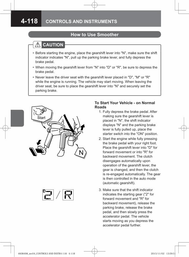
4-118 CONTROLS AND INSTRUMENTS
How to Use Smoother
To Start Your Vehicle - on Normal Roads 1. Fully depress the brake pedal. After
making sure the gearshift lever is placed in "N", the shift indicator displays "N" and the parking brake lever is fully pulled up, place the starter switch into the "ON" position.
2. Start the engine while fully pressing the brake pedal with your right foot. Place the gearshift lever into "D" for forward movement or into "R" for backward movement. The clutch disengages automatically upon operation of the gearshift lever, the gear is changed, and then the clutch is re-engaged automatically. The gear is then controlled in the auto mode (automatic gearshift).
CAUTIONBefore starting the engine, place the gearshift lever into "N", make sure the shift indicator indicates "N", pull up the parking brake lever, and fully depress the brake pedal.When moving the gearshift lever from "N" into "D" or "R", be sure to depress the brake pedal.Never leave the driver seat with the gearshift lever placed in "D", "M" or "R" while the engine is running. The vehicle may start moving. When leaving the driver seat, be sure to place the gearshift lever into "N" and securely set the parking brake.
•
•
•
�
� ��
3. Make sure that the shift indicator indicates the starting gear ("2" for forward movement and "R" for backward movement), release the parking brake, release the brake pedal, and then slowly press the accelerator pedal. The vehicle starts moving as you depress the accelerator pedal further.
4608498_sec04_CONTROLS AND INSTR4-118 4-1184608498_sec04_CONTROLS AND INSTR4-118 4-118 2015/11/02 13:59:512015/11/02 13:59:51
4-119CONTROLS AND INSTRUMENTS
NOTEWhen starting the engine after parking with a gear engaged, make sure that the shift indicator indicates "N". Then, place the gearshift lever into "D" for forward movement and "R" for backward movement.While the engine is not running, you cannot shift gears by moving the gearshift lever. Start the engine before you can shift gears.On a slope, you can start the vehicle smoothly if you also use the hill start aid (HSA). (Model with HSA)When the vehicle is stopped with the engine running, the shift lock function works for safety. You cannot move the gearshift lever from "N" to "D" or "R" without depressing the brake pedal. When starting the vehicle, be sure to operate the gearshift lever while keeping the brake pedal depressed.
•
•
•
•
To Start Your Vehicle - on a Steep Slope 1. Firmly depress the brake pedal and make sure the parking brake lever is fully
pulled up. 2. Place the gearshift lever into "D" for forward movement and "R" for backward
movement while fully depressing the brake pedal with your right foot. (When strong traction is required to start the vehicle, change to 1st start mode.)
3. Make sure that the shift indicator indicates the starting gear ("2" for forward movement and "R" for backward movement), check the surrounding area to be sure it is safe to move the vehicle, ease your right foot pressure off the brake pedal, and slowly press the accelerator pedal.
4. After you feel the vehicle start moving, slowly release the parking brake lever and start the vehicle.
WARNING
When moving a Smoother equipped vehicle from a standstill, you must control the speed using only the accelerator pedal. Operate the accelerator pedal carefully.Do not operate the gearshift lever while depressing the accelerator pedal. The vehicle may make a sudden start, possibly causing an accident.The gear is in the process of being shifted while the shift indicator is flashing. The vehicle may roll down on a slope because driving force is not transmitted to the wheels.Be sure to keep the brake pedal depressed until you see the shift indicator come on steady.
•
•
•
4608498_sec04_CONTROLS AND INSTR4-119 4-1194608498_sec04_CONTROLS AND INSTR4-119 4-119 2015/11/02 13:59:522015/11/02 13:59:52
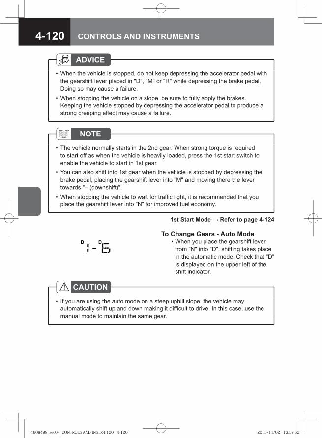
4-120 CONTROLS AND INSTRUMENTS
ADVICEWhen the vehicle is stopped, do not keep depressing the accelerator pedal with the gearshift lever placed in "D", "M" or "R" while depressing the brake pedal. Doing so may cause a failure.When stopping the vehicle on a slope, be sure to fully apply the brakes. Keeping the vehicle stopped by depressing the accelerator pedal to produce a strong creeping effect may cause a failure.
•
•
NOTEThe vehicle normally starts in the 2nd gear. When strong torque is required to start off as when the vehicle is heavily loaded, press the 1st start switch to enable the vehicle to start in 1st gear.You can also shift into 1st gear when the vehicle is stopped by depressing the brake pedal, placing the gearshift lever into "M" and moving there the lever towards "– (downshift)".When stopping the vehicle to wait for traffic light, it is recommended that you place the gearshift lever into "N" for improved fuel economy.
•
•
•
1st Start Mode → Refer to page 4-124
To Change Gears - Auto Mode • When you place the gearshift lever
from "N" into "D", shifting takes place in the automatic mode. Check that "D" is displayed on the upper left of the shift indicator.
CAUTIONIf you are using the auto mode on a steep uphill slope, the vehicle may automatically shift up and down making it difficult to drive. In this case, use the manual mode to maintain the same gear.
•
4608498_sec04_CONTROLS AND INSTR4-120 4-1204608498_sec04_CONTROLS AND INSTR4-120 4-120 2015/11/02 13:59:522015/11/02 13:59:52
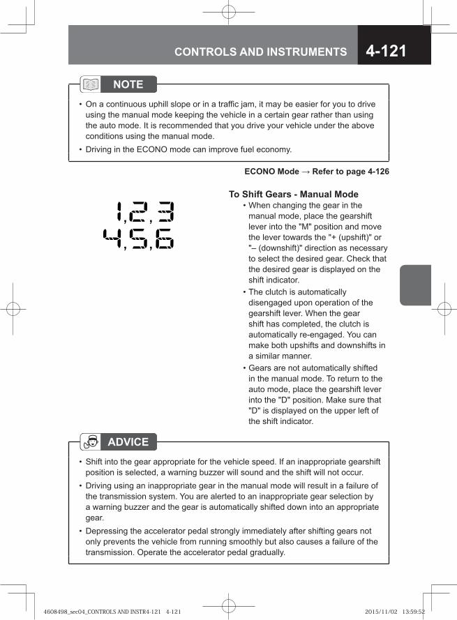
4-121CONTROLS AND INSTRUMENTS
To Shift Gears - Manual Mode • When changing the gear in the
manual mode, place the gearshift lever into the "M" position and move the lever towards the "+ (upshift)" or "– (downshift)" direction as necessary to select the desired gear. Check that the desired gear is displayed on the shift indicator.
• The clutch is automatically disengaged upon operation of the gearshift lever. When the gear shift has completed, the clutch is automatically re-engaged. You can make both upshifts and downshifts in a similar manner.
• Gears are not automatically shifted in the manual mode. To return to the auto mode, place the gearshift lever into the "D" position. Make sure that "D" is displayed on the upper left of the shift indicator.
ADVICEShift into the gear appropriate for the vehicle speed. If an inappropriate gearshift position is selected, a warning buzzer will sound and the shift will not occur.Driving using an inappropriate gear in the manual mode will result in a failure of the transmission system. You are alerted to an inappropriate gear selection by a warning buzzer and the gear is automatically shifted down into an appropriate gear.Depressing the accelerator pedal strongly immediately after shifting gears not only prevents the vehicle from running smoothly but also causes a failure of the transmission. Operate the accelerator pedal gradually.
•
•
•
NOTEOn a continuous uphill slope or in a traffic jam, it may be easier for you to drive using the manual mode keeping the vehicle in a certain gear rather than using the auto mode. It is recommended that you drive your vehicle under the above conditions using the manual mode.Driving in the ECONO mode can improve fuel economy.
•
•
ECONO Mode → Refer to page 4-126
4608498_sec04_CONTROLS AND INSTR4-121 4-1214608498_sec04_CONTROLS AND INSTR4-121 4-121 2015/11/02 13:59:522015/11/02 13:59:52
4-122 CONTROLS AND INSTRUMENTS
NOTEWhen it is necessary to make fine speed control of the vehicle as when reversing it onto a platform, you can utilize the creeping effect of the transmission to move the vehicle smoothly using only the brake pedal, not using the accelerator pedal.Gear shifting will not occur even when shifting into auto mode (shifting from "M" to "D") when the vehicle is stopped. After the vehicle starts moving, the transmission is automatically shifted.
•
•
To Stop the Vehicle 1. Press the brake pedal with your
right foot to slow down and stop the vehicle. No special gear shifting is required.After the vehicle has stopped, the transmission is automatically shifted into the starting gear in both the manual mode and auto mode.
2. While the vehicle is stopped, place the gearshift lever into "N". When the vehicle must be stationary for several minutes, set the parking brake.
CAUTIONWhen leaving the driver seat, be sure to place the gearshift lever into "N", make sure that the shift indicator displays "N" and firmly set the parking brake.
•
NOTEWhen stopping the vehicle to wait for a traffic light, it is recommended that you place the gearshift lever into "N" for improved fuel economy.
•
ADVICEWhen the vehicle is stopped, do not keep depressing the accelerator pedal with the gearshift lever placed in "D", "M" or "R" while depressing the brake pedal. Doing so may cause a failure.When stopping the vehicle on a slope, be sure to fully apply the brakes. Keeping the vehicle stopped by depressing the accelerator pedal to produce a strong creeping effect may cause a failure.
•
•
4608498_sec04_CONTROLS AND INSTR4-122 4-1224608498_sec04_CONTROLS AND INSTR4-122 4-122 2015/11/02 13:59:532015/11/02 13:59:53
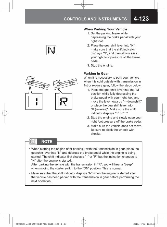
4-123CONTROLS AND INSTRUMENTS
When Parking Your Vehicle 1. Set the parking brake while
depressing the brake pedal with your right foot.
2. Place the gearshift lever into "N", make sure that the shift indicator displays "N", and then slowly ease your right foot pressure off the brake pedal.
3. Stop the engine.
Parking in GearWhen it is necessary to park your vehicle when it is cold outside with transmission in 1st or reverse gear, follow the steps below. 1. Place the gearshift lever into the "M"
position while fully depressing the brake pedal with your right foot, and move the lever towards "– (downshift)" or place the gearshift lever into "R (reverse)". Make sure the shift indicator displays "1" or "R".
2. Stop the engine and slowly ease your right foot pressure off the brake pedal.
3. Make sure the vehicle does not move. Be sure to block the wheels with chocks.
NOTEWhen starting the engine after parking it with the transmission in gear, place the gearshift lever into "N" and depress the brake pedal while the engine is being started. The shift indicator first displays "1" or "R" but the indication changes to "N" after the engine is started.After parking the vehicle with the transmission in "R", you will hear a "beep" when moving the starter switch to the "ON" position. This is normal.Make sure that the shift indicator displays "N" when the engine is started after the vehicle has been parked with the transmission in gear before performing the next operation.
•
•
4608498_sec04_CONTROLS AND INSTR4-123 4-1234608498_sec04_CONTROLS AND INSTR4-123 4-123 2015/11/02 13:59:532015/11/02 13:59:53
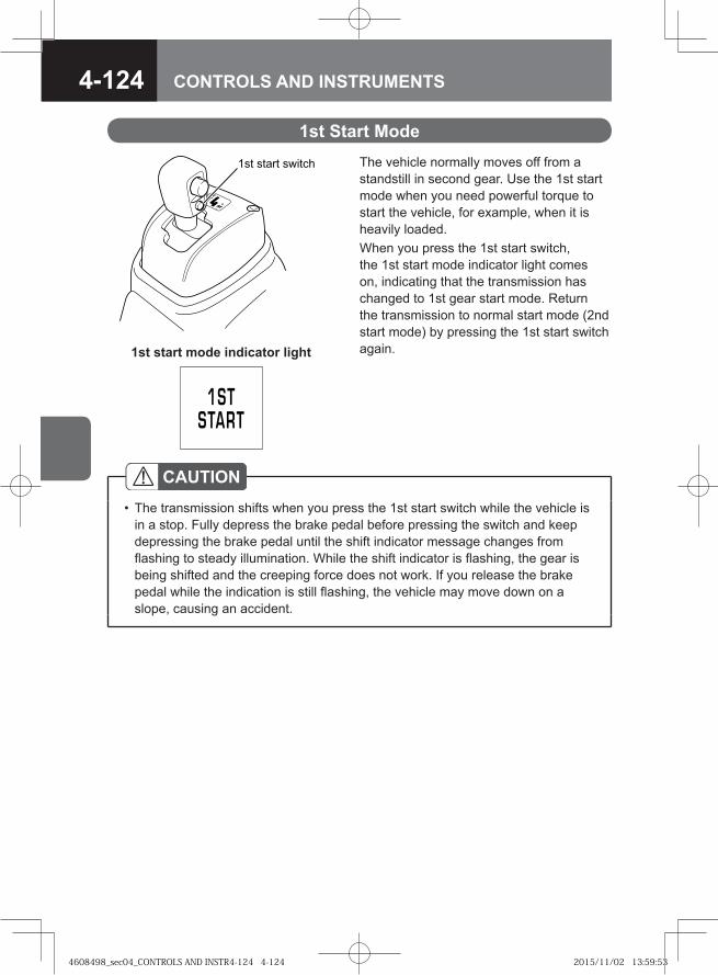
4-124 CONTROLS AND INSTRUMENTS
The vehicle normally moves off from a standstill in second gear. Use the 1st start mode when you need powerful torque to start the vehicle, for example, when it is heavily loaded.When you press the 1st start switch, the 1st start mode indicator light comes on, indicating that the transmission has changed to 1st gear start mode. Return the transmission to normal start mode (2nd start mode) by pressing the 1st start switch again.
1st Start Mode
� � �� ��� ��
CAUTIONThe transmission shifts when you press the 1st start switch while the vehicle is in a stop. Fully depress the brake pedal before pressing the switch and keep depressing the brake pedal until the shift indicator message changes from flashing to steady illumination. While the shift indicator is flashing, the gear is being shifted and the creeping force does not work. If you release the brake pedal while the indication is still flashing, the vehicle may move down on a slope, causing an accident.
•
1st start mode indicator light
4608498_sec04_CONTROLS AND INSTR4-124 4-1244608498_sec04_CONTROLS AND INSTR4-124 4-124 2015/11/02 13:59:532015/11/02 13:59:53
4-125CONTROLS AND INSTRUMENTS
NOTEThe 1st start mode cannot be selected in the manual mode.If the manual mode is selected (the gearshift lever is moved from "D" to "M") after the 1st start switch is pressed, the 1st start mode is suspended and the 1st start mode indicator light goes out. When the mode is changed from the manual mode back to the auto mode (the gearshift lever is moved from "M" to "D"), the 1st start mode is reestablished and the 1st start mode indicator light comes on again but the gear position that was selected in the manual mode is still retained. To enable automatic gear shifting to take place, drive the vehicle and then stop it, or press the 1st start switch again to re-select the 1st start mode, or return the transmission to manual mode enabling the shift into 1st gear and then change back to the auto mode.When you place the starter switch in the "LOCK" position and restart the engine, the transmission returns to the normal start mode (2nd start mode).
•
•
4608498_sec04_CONTROLS AND INSTR4-125 4-1254608498_sec04_CONTROLS AND INSTR4-125 4-125 2015/11/02 13:59:542015/11/02 13:59:54
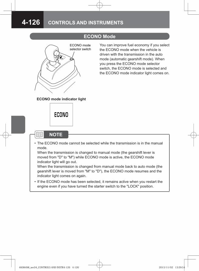
4-126 CONTROLS AND INSTRUMENTS
You can improve fuel economy if you select the ECONO mode when the vehicle is driven with the transmission in the auto mode (automatic gearshift mode). When you press the ECONO mode selector switch, the ECONO mode is selected and the ECONO mode indicator light comes on.
ECONO Mode� ��� ����
�������� ������
NOTEThe ECONO mode cannot be selected while the transmission is in the manual mode.When the transmission is changed to manual mode (the gearshift lever is moved from "D" to "M") while ECONO mode is active, the ECONO mode indicator light will go out. When the transmission is changed from manual mode back to auto mode (the gearshift lever is moved from "M" to "D"), the ECONO mode resumes and the indicator light comes on again. If the ECONO mode has been selected, it remains active when you restart the engine even if you have turned the starter switch to the "LOCK" position.
•
•
ECONO mode indicator light
4608498_sec04_CONTROLS AND INSTR4-126 4-1264608498_sec04_CONTROLS AND INSTR4-126 4-126 2015/11/02 13:59:542015/11/02 13:59:54
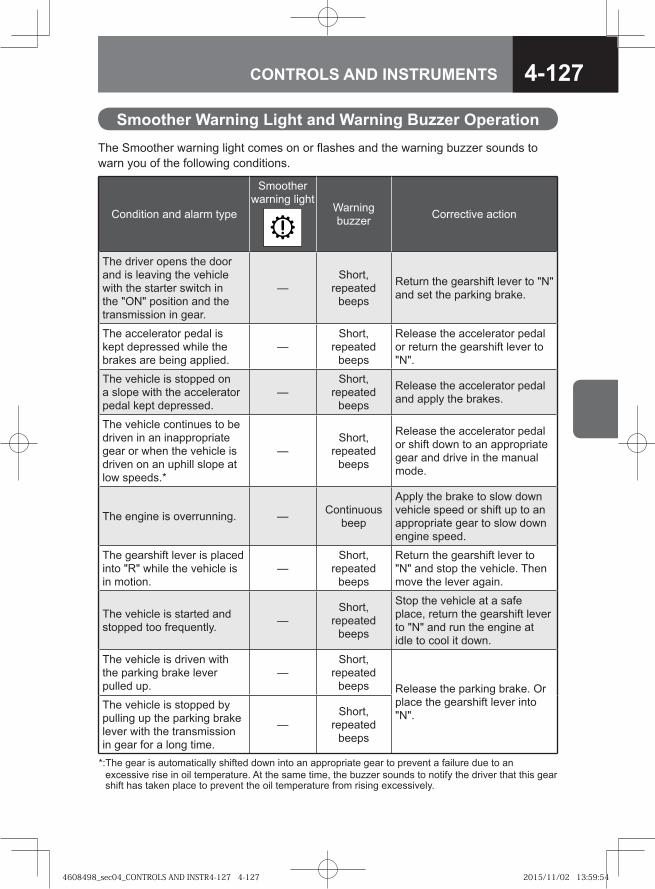
4-127CONTROLS AND INSTRUMENTS
The Smoother warning light comes on or flashes and the warning buzzer sounds to warn you of the following conditions.
Smoother Warning Light and Warning Buzzer Operation
Condition and alarm type
Smoother warning light
Warning buzzer Corrective action
The driver opens the door and is leaving the vehicle with the starter switch in the "ON" position and the transmission in gear.
—Short,
repeated beeps
Return the gearshift lever to "N" and set the parking brake.
The accelerator pedal is kept depressed while the brakes are being applied.
—Short,
repeated beeps
Release the accelerator pedal or return the gearshift lever to "N".
The vehicle is stopped on a slope with the accelerator pedal kept depressed.
—Short,
repeated beeps
Release the accelerator pedal and apply the brakes.
The vehicle continues to be driven in an inappropriate gear or when the vehicle is driven on an uphill slope at low speeds.*
—Short,
repeated beeps
Release the accelerator pedal or shift down to an appropriate gear and drive in the manual mode.
The engine is overrunning. — Continuous beep
Apply the brake to slow down vehicle speed or shift up to an appropriate gear to slow down engine speed.
The gearshift lever is placed into "R" while the vehicle is in motion.
—Short,
repeated beeps
Return the gearshift lever to "N" and stop the vehicle. Then move the lever again.
The vehicle is started and stopped too frequently. —
Short, repeated
beeps
Stop the vehicle at a safe place, return the gearshift lever to "N" and run the engine at idle to cool it down.
The vehicle is driven with the parking brake lever pulled up.
—Short,
repeated beeps Release the parking brake. Or
place the gearshift lever into "N".
The vehicle is stopped by pulling up the parking brake lever with the transmission in gear for a long time.
—Short,
repeated beeps
*: The gear is automatically shifted down into an appropriate gear to prevent a failure due to an excessive rise in oil temperature. At the same time, the buzzer sounds to notify the driver that this gear shift has taken place to prevent the oil temperature from rising excessively.
4608498_sec04_CONTROLS AND INSTR4-127 4-1274608498_sec04_CONTROLS AND INSTR4-127 4-127 2015/11/02 13:59:542015/11/02 13:59:54
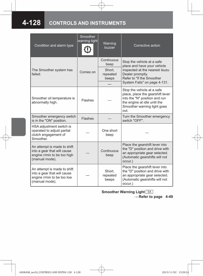
4-128 CONTROLS AND INSTRUMENTS
Condition and alarm type
Smoother warning light
Warning buzzer Corrective action
The Smoother system has failed. Comes on
Continuous beep
Stop the vehicle at a safe place and have your vehicle inspected at the nearest Isuzu Dealer promptly.Refer to "If the Smoother System Fails" on page 4-131.
Short, repeated
beeps
—
Smoother oil temperature is abnormally high. Flashes —
Stop the vehicle at a safe place, place the gearshift lever into the "N" position and run the engine at idle until the Smoother warning light goes out.
Smoother emergency switch is in the "ON" position. Flashes — Turn the Smoother emergency
switch "OFF".
HSA adjustment switch is operated to adjust partial clutch engagement of Smoother.
— One short beep —
An attempt is made to shift into a gear that will cause engine r/min to be too high (manual mode).
— Continuous beep
Place the gearshift lever into the "D" position and drive with an appropriate gear selected. (Automatic gearshifts will not occur.)
An attempt is made to shift into a gear that will cause engine r/min to be too low (manual mode).
—Short,
repeated beeps
Place the gearshift lever into the "D" position and drive with an appropriate gear selected. (Automatic gearshifts will not occur.)
Smoother Warning Light SA → Refer to page 4-49
4608498_sec04_CONTROLS AND INSTR4-128 4-1284608498_sec04_CONTROLS AND INSTR4-128 4-128 2015/11/02 13:59:542015/11/02 13:59:54
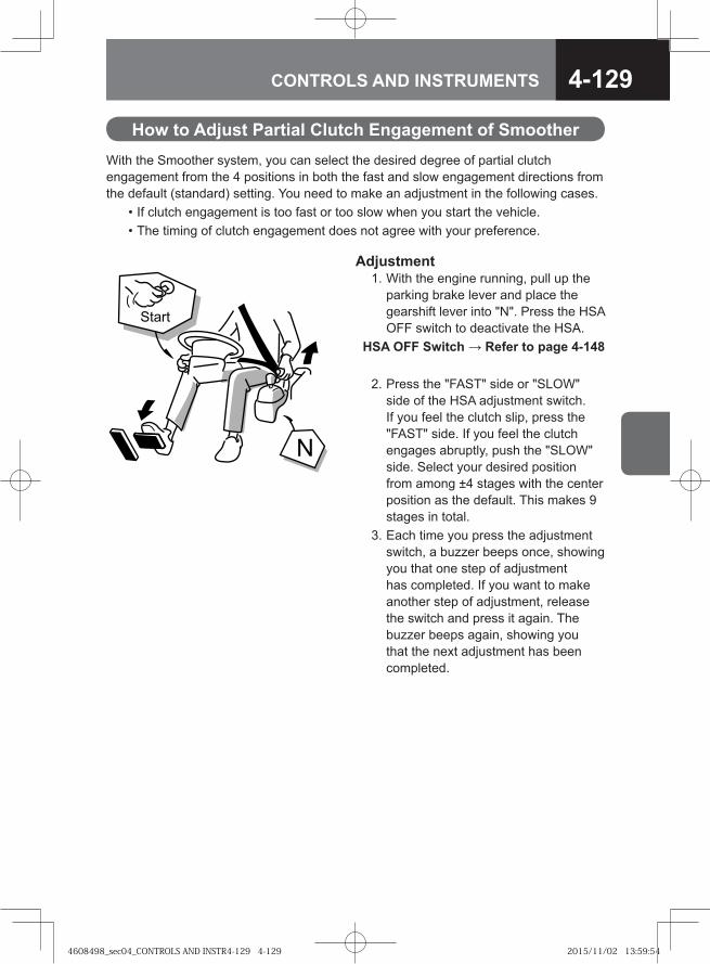
4-129CONTROLS AND INSTRUMENTS
With the Smoother system, you can select the desired degree of partial clutch engagement from the 4 positions in both the fast and slow engagement directions from the default (standard) setting. You need to make an adjustment in the following cases. • If clutch engagement is too fast or too slow when you start the vehicle. • The timing of clutch engagement does not agree with your preference.
How to Adjust Partial Clutch Engagement of Smoother
Adjustment 1. With the engine running, pull up the
parking brake lever and place the gearshift lever into "N". Press the HSA OFF switch to deactivate the HSA.
HSA OFF Switch → Refer to page 4-148
2. Press the "FAST" side or "SLOW" side of the HSA adjustment switch. If you feel the clutch slip, press the "FAST" side. If you feel the clutch engages abruptly, push the "SLOW" side. Select your desired position from among ±4 stages with the center position as the default. This makes 9 stages in total.
3. Each time you press the adjustment switch, a buzzer beeps once, showing you that one step of adjustment has completed. If you want to make another step of adjustment, release the switch and press it again. The buzzer beeps again, showing you that the next adjustment has been completed.
�
� ��
4608498_sec04_CONTROLS AND INSTR4-129 4-1294608498_sec04_CONTROLS AND INSTR4-129 4-129 2015/11/02 13:59:542015/11/02 13:59:54
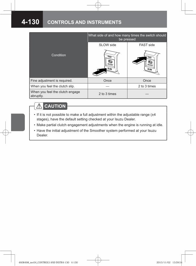
4-130 CONTROLS AND INSTRUMENTS
Condition
What side of and how many times the switch should be pressed
SLOW side FAST side
Fine adjustment is required. Once Once
When you feel the clutch slip. — 2 to 3 times
When you feel the clutch engage abruptly. 2 to 3 times —
CAUTIONIf it is not possible to make a full adjustment within the adjustable range (±4 stages), have the default setting checked at your Isuzu Dealer. Make partial clutch engagement adjustments when the engine is running at idle.Have the initial adjustment of the Smoother system performed at your Isuzu Dealer.
•
••
4608498_sec04_CONTROLS AND INSTR4-130 4-1304608498_sec04_CONTROLS AND INSTR4-130 4-130 2015/11/02 13:59:542015/11/02 13:59:54
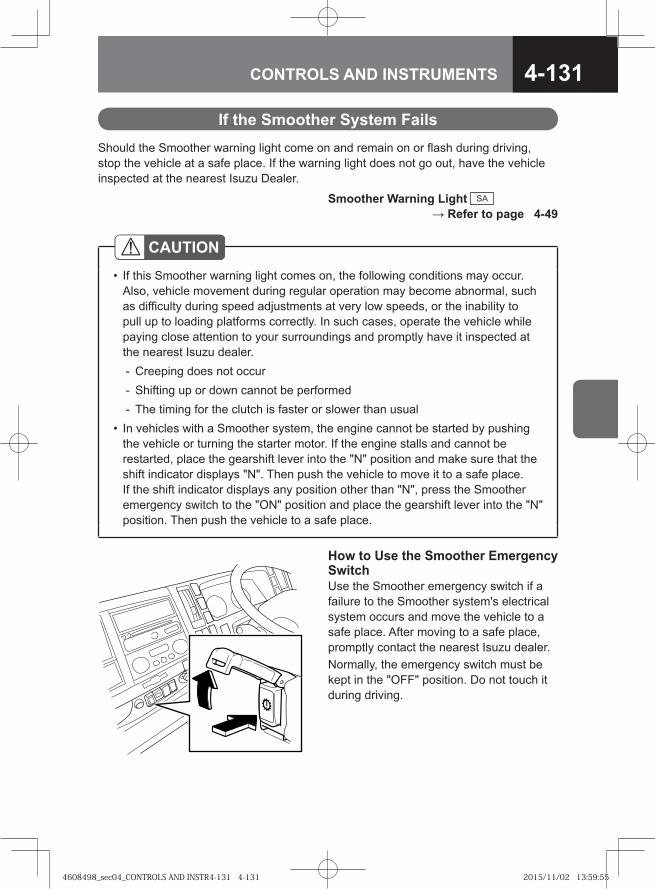
4-131CONTROLS AND INSTRUMENTS
Should the Smoother warning light come on and remain on or flash during driving, stop the vehicle at a safe place. If the warning light does not go out, have the vehicle inspected at the nearest Isuzu Dealer.
If the Smoother System Fails
CAUTIONIf this Smoother warning light comes on, the following conditions may occur. Also, vehicle movement during regular operation may become abnormal, such as difficulty during speed adjustments at very low speeds, or the inability to pull up to loading platforms correctly. In such cases, operate the vehicle while paying close attention to your surroundings and promptly have it inspected at the nearest Isuzu dealer.
Creeping does not occurShifting up or down cannot be performedThe timing for the clutch is faster or slower than usual
In vehicles with a Smoother system, the engine cannot be started by pushing the vehicle or turning the starter motor. If the engine stalls and cannot be restarted, place the gearshift lever into the "N" position and make sure that the shift indicator displays "N". Then push the vehicle to move it to a safe place. If the shift indicator displays any position other than "N", press the Smoother emergency switch to the "ON" position and place the gearshift lever into the "N" position. Then push the vehicle to a safe place.
•
---
•
How to Use the Smoother Emergency SwitchUse the Smoother emergency switch if a failure to the Smoother system's electrical system occurs and move the vehicle to a safe place. After moving to a safe place, promptly contact the nearest Isuzu dealer.Normally, the emergency switch must be kept in the "OFF" position. Do not touch it during driving.
Smoother Warning Light SA → Refer to page 4-49
4608498_sec04_CONTROLS AND INSTR4-131 4-1314608498_sec04_CONTROLS AND INSTR4-131 4-131 2015/11/02 13:59:552015/11/02 13:59:55
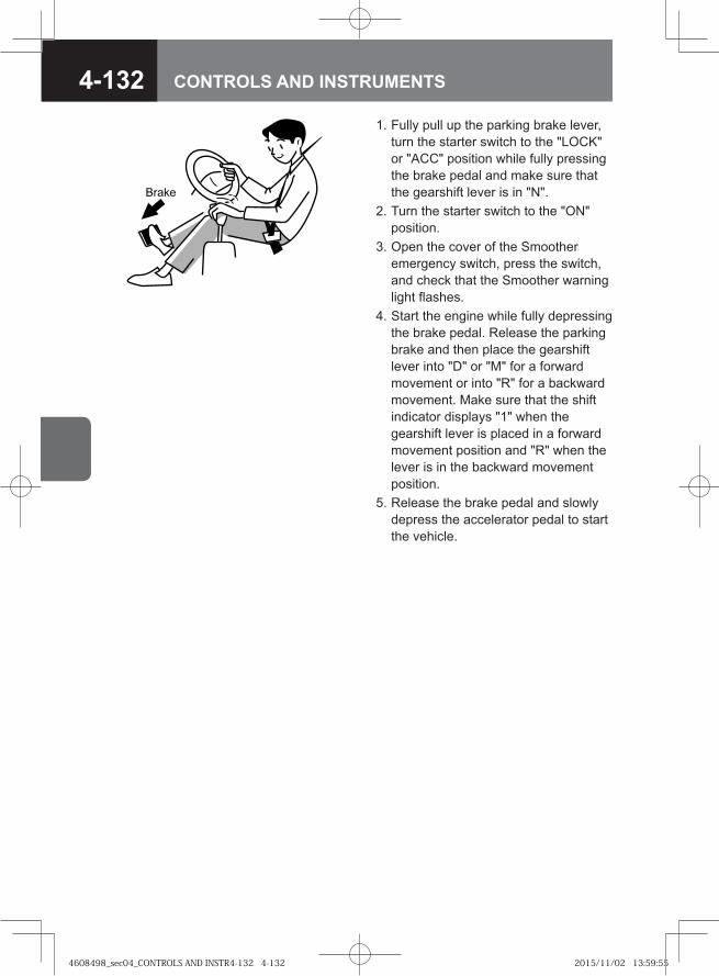
4-132 CONTROLS AND INSTRUMENTS
� ���
1. Fully pull up the parking brake lever, turn the starter switch to the "LOCK" or "ACC" position while fully pressing the brake pedal and make sure that the gearshift lever is in "N".
2. Turn the starter switch to the "ON" position.
3. Open the cover of the Smoother emergency switch, press the switch, and check that the Smoother warning light flashes.
4. Start the engine while fully depressing the brake pedal. Release the parking brake and then place the gearshift lever into "D" or "M" for a forward movement or into "R" for a backward movement. Make sure that the shift indicator displays "1" when the gearshift lever is placed in a forward movement position and "R" when the lever is in the backward movement position.
5. Release the brake pedal and slowly depress the accelerator pedal to start the vehicle.
4608498_sec04_CONTROLS AND INSTR4-132 4-1324608498_sec04_CONTROLS AND INSTR4-132 4-132 2015/11/02 13:59:552015/11/02 13:59:55
4-133CONTROLS AND INSTRUMENTS
CAUTIONThe Smoother emergency switch must be used only in an emergency. Normally, the switch must be kept in the "OFF" position. Do not open the cover of the emergency switch. Never operate the Smoother emergency switch while driving.After you have moved the vehicle to a safe place using the emergency switch, promptly place the emergency switch back to the "OFF" position, return the gearshift lever to "N", and close the cover. When the Smoother emergency switch is in the "ON" position, the Smoother warning light flashes. When the emergency switch is in the "ON" position with the gearshift lever in any position other than "N", the vehicle may suddenly start moving. When turning the emergency switch to the "ON" position, be sure to keep the brake pedal depressed. When the emergency switch is in the "ON" position, the engine can be started even with the gearshift lever in a position other than "N". When the engine is started with the transmission in gear, the vehicle may suddenly start moving. To prevent this, firmly set the parking brake and fully depress the brake pedal with your right foot when starting the engine. When the emergency switch is placed in the "ON" position, the shift lock function does not work. If you fail to depress the brake pedal when moving the gearshift lever from "N" into "D" or "R", the vehicle will suddenly start moving. Operate the gearshift lever only after holding the brake pedal fully depressed.
•
•
•
•
•
•
NOTEWhen the emergency switch is in the "ON" position and the gearshift lever is in the "D" or "M" position, the transmission does not shift to any gear other than the 1st.
•
4608498_sec04_CONTROLS AND INSTR4-133 4-1334608498_sec04_CONTROLS AND INSTR4-133 4-133 2015/11/02 13:59:552015/11/02 13:59:55
4-134 CONTROLS AND INSTRUMENTS
Before Driving
The automatic transmission controls clutch engagement/disengagement and appropriate gear shifting according to the engine speed and driving conditions without need for manual adjustments. Make sure you fully understand the characteristics of the automatic transmission and form a habit of operating the vehicle correctly.
WARNING
Fully depress the brake pedal to prevent the vehicle from moving even if it is stopped on a level road, and place the selector lever into "N" and set the parking brake as needed.The engine speed is higher immediately after its start, while the air conditioning is in operation. This makes the transmission produce stronger creeping force than usual. You need to firmly depress the brake pedal.When the engine speed is increased with the idling control knob, the creeping effect works more strongly than usual. When placing the selector lever into any position other than "N", return the idling control knob to the fully counterclockwise position.
•
•
•
NOTEYou can utilize the creeping effect of the transmission to move your vehicle smoothly in a traffic jam or in a narrow space by controlling the speed without using the accelerator pedal but using only the brake pedal.
•
Idling Control Knob → Refer to page 4-76
Automatic Transmission Model A/T → Refer to page 2-35
Model with ALLISON2500 Model Automatic Transmission V
4608498_sec04_CONTROLS AND INSTR4-134 4-1344608498_sec04_CONTROLS AND INSTR4-134 4-134 2015/11/02 13:59:552015/11/02 13:59:55
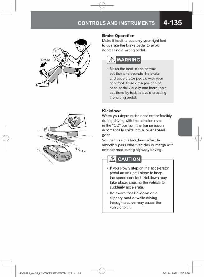
4-135CONTROLS AND INSTRUMENTS
Brake OperationMake it habit to use only your right foot to operate the brake pedal to avoid depressing a wrong pedal.
WARNING
Sit on the seat in the correct position and operate the brake and accelerator pedals with your right foot. Check the position of each pedal visually and learn their positions by feel, to avoid pressing the wrong pedal.
•
� ���
KickdownWhen you depress the accelerator forcibly during driving with the selector lever in the "OD" position, the transmission automatically shifts into a lower speed gear.You can use this kickdown effect to smoothly pass other vehicles or merge with another road during highway driving.
CAUTIONIf you slowly step on the accelerator pedal on an uphill slope to keep the speed constant, kickdown may take place, causing the vehicle to suddenly accelerate.Be aware that kickdown on a slippery road or while driving through a curve may cause the vehicle to tilt.
•
•
4608498_sec04_CONTROLS AND INSTR4-135 4-1354608498_sec04_CONTROLS AND INSTR4-135 4-135 2015/11/02 13:59:562015/11/02 13:59:56
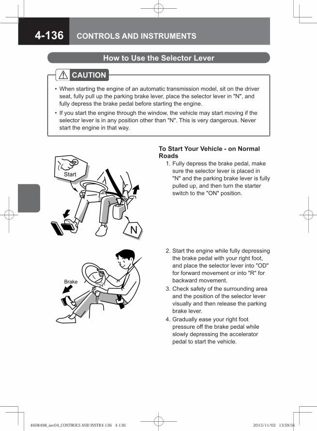
4-136 CONTROLS AND INSTRUMENTS
CAUTIONWhen starting the engine of an automatic transmission model, sit on the driver seat, fully pull up the parking brake lever, place the selector lever in "N", and fully depress the brake pedal before starting the engine.If you start the engine through the window, the vehicle may start moving if the selector lever is in any position other than "N". This is very dangerous. Never start the engine in that way.
•
•
How to Use the Selector Lever
To Start Your Vehicle - on Normal Roads 1. Fully depress the brake pedal, make
sure the selector lever is placed in "N" and the parking brake lever is fully pulled up, and then turn the starter switch to the "ON" position.
�
� ��
� ���
2. Start the engine while fully depressing the brake pedal with your right foot, and place the selector lever into "OD" for forward movement or into "R" for backward movement.
3. Check safety of the surrounding area and the position of the selector lever visually and then release the parking brake lever.
4. Gradually ease your right foot pressure off the brake pedal while slowly depressing the accelerator pedal to start the vehicle.
4608498_sec04_CONTROLS AND INSTR4-136 4-1364608498_sec04_CONTROLS AND INSTR4-136 4-136 2015/11/02 13:59:562015/11/02 13:59:56
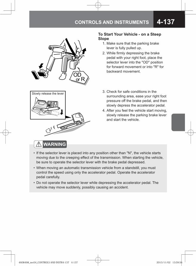
4-137CONTROLS AND INSTRUMENTS
To Start Your Vehicle - on a Steep Slope 1. Make sure that the parking brake
lever is fully pulled up. 2. While firmly depressing the brake
pedal with your right foot, place the selector lever into the "OD" position for forward movement or into "R" for backward movement.
���� �
Slowly release the lever 3. Check for safe conditions in the surrounding area, ease your right foot pressure off the brake pedal, and then slowly depress the accelerator pedal.
4. After you feel the vehicle start moving, slowly release the parking brake lever and start the vehicle.
WARNING
If the selector lever is placed into any position other than "N", the vehicle starts moving due to the creeping effect of the transmission. When starting the vehicle, be sure to operate the selector lever with the brake pedal depressed.When moving an automatic transmission vehicle from a standstill, you must control the speed using only the accelerator pedal. Operate the accelerator pedal carefully.Do not operate the selector lever while depressing the accelerator pedal. The vehicle may move suddenly, possibly causing an accident.
•
•
•
4608498_sec04_CONTROLS AND INSTR4-137 4-1374608498_sec04_CONTROLS AND INSTR4-137 4-137 2015/11/02 13:59:562015/11/02 13:59:56
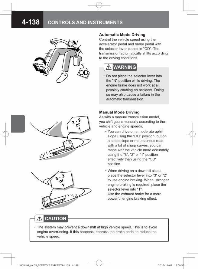
4-138 CONTROLS AND INSTRUMENTS
Automatic Mode DrivingControl the vehicle speed using the accelerator pedal and brake pedal with the selector lever placed in "OD". The transmission automatically shifts according to the driving conditions.
�
WARNING
Do not place the selector lever into the "N" position while driving. The engine brake does not work at all, possibly causing an accident. Doing so may also cause a failure in the automatic transmission.
•
Manual Mode DrivingAs with a manual transmission model, you shift gears manually according to the vehicle and engine speeds. • You can drive on a moderate uphill
slope using the "OD" position, but on a steep slope or mountainous road with a lot of sharp curves, you can maneuver the vehicle more accurately using the "3", "2" or "1" position effectively than using the "OD" position.
• When driving on a downhill slope, place the selector lever into "3" or "2" to use engine braking. When stronger engine braking is required, place the selector lever into "1".Use the exhaust brake for a more powerful engine braking effect.
CAUTIONThe system may prevent a downshift at high vehicle speed. This is to avoid engine overrunning. If this happens, depress the brake pedal to reduce the vehicle speed.
•
4608498_sec04_CONTROLS AND INSTR4-138 4-1384608498_sec04_CONTROLS AND INSTR4-138 4-138 2015/11/02 13:59:572015/11/02 13:59:57
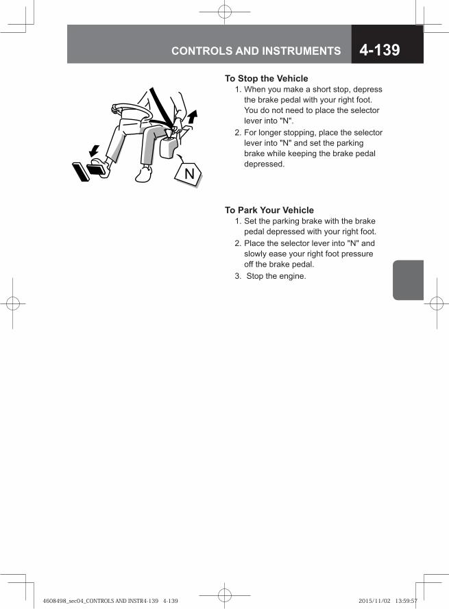
4-139CONTROLS AND INSTRUMENTS
To Stop the Vehicle 1. When you make a short stop, depress
the brake pedal with your right foot. You do not need to place the selector lever into "N".
2. For longer stopping, place the selector lever into "N" and set the parking brake while keeping the brake pedal depressed.
�
To Park Your Vehicle 1. Set the parking brake with the brake
pedal depressed with your right foot. 2. Place the selector lever into "N" and
slowly ease your right foot pressure off the brake pedal.
3. Stop the engine.
4608498_sec04_CONTROLS AND INSTR4-139 4-1394608498_sec04_CONTROLS AND INSTR4-139 4-139 2015/11/02 13:59:572015/11/02 13:59:57
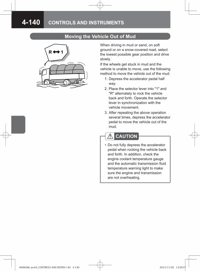
4-140 CONTROLS AND INSTRUMENTS
Moving the Vehicle Out of MudWhen driving in mud or sand, on soft ground or on a snow-covered road, select the lowest possible gear position and drive slowly.If the wheels get stuck in mud and the vehicle is unable to move, use the following method to move the vehicle out of the mud. 1. Depress the accelerator pedal half
way. 2. Place the selector lever into "1" and
"R" alternately to rock the vehicle back and forth. Operate the selector lever in synchronization with the vehicle movement.
3. After repeating the above operation several times, depress the accelerator pedal to move the vehicle out of the mud.
CAUTIONDo not fully depress the accelerator pedal when rocking the vehicle back and forth. In addition, check the engine coolant temperature gauge and the automatic transmission fluid temperature warning light to make sure the engine and transmission are not overheating.
•
4608498_sec04_CONTROLS AND INSTR4-140 4-1404608498_sec04_CONTROLS AND INSTR4-140 4-140 2015/11/02 13:59:572015/11/02 13:59:57
4-141CONTROLS AND INSTRUMENTS
Model with ALLISON3000/3500 Model Automatic Transmission V
Before Driving
The automatic transmission controls clutch engagement/disengagement and gear shifting appropriately according to the engine speed and driving conditions without need for manual adjustments. Make sure you fully understand the characteristics of the automatic transmission and form a habit of operating the vehicle correctly.
WARNING
Even when the vehicle is in a stop on a level road, fully depress the brake pedal, press the neutral button to select the "N" position and engage the parking brake as needed to prevent the vehicle from moving.The engine speed is higher immediately after its start, while the air conditioning is in operation. This makes the transmission produce stronger creeping force than usual. You need to firmly depress the brake pedal.When the engine speed is increased with the idling control knob, the creeping effect works more strongly than usual. When selecting any position other than "N", turn the idling control knob back fully counterclockwise.
•
•
•
Idling Control Knob → Refer to page 4-76
Automatic Transmission Model A/T → Refer to page 2-35
4608498_sec04_CONTROLS AND INSTR4-141 4-1414608498_sec04_CONTROLS AND INSTR4-141 4-141 2015/11/02 13:59:572015/11/02 13:59:57
4-142 CONTROLS AND INSTRUMENTS
NOTEThe lockup clutch does not work in "R".•
ADVICEWhen changing gears from "N" to move the vehicle, press the selector button while depressing the brake pedal. Otherwise the gear is not engaged.If the gear is not engaged, reselect "N", and press the selector button while depressing the brake pedal.When the engine is running at approximately 900 r/min or higher, the transmission does not engage any drive gear and thus the vehicle does not move.If this happens, release the accelerator pedal and return the idling control knob to the fully counterclock position to run the engine at idle. Then, depress the brake pedal and press the desired selector button.When shifting from "N" to "R", the gear is not engaged unless the vehicle is stopped. Being stopped means that the vehicle speed is lower than approximately 3 km/h (approximately 2 MPH).When shifting from a forward gear to the reverse gear or vice versa, stop the vehicle and then press the selector button.If the gear does not shift even when you follow the steps described above, the accelerator sensor system or the automatic transmission system is likely to be faulty. Please contact the nearest Isuzu Dealer.
•
•
•
•
•
4608498_sec04_CONTROLS AND INSTR4-142 4-1424608498_sec04_CONTROLS AND INSTR4-142 4-142 2015/11/02 13:59:582015/11/02 13:59:58
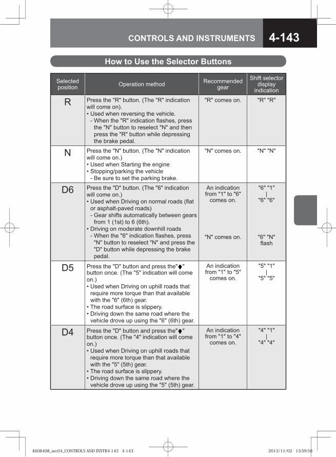
4-143CONTROLS AND INSTRUMENTS
How to Use the Selector Buttons
Selected position Operation method Recommended
gearShift selector
display indication
R Press the "R" button. (The "R" indication will come on).• Used when reversing the vehicle.
- When the "R" indication flashes, press the "N" button to reselect "N" and then press the "R" button while depressing the brake pedal.
"R" comes on. "R" "R"
N Press the "N" button. (The "N" indication will come on.)• Used when Starting the engine• Stopping/parking the vehicle
- Be sure to set the parking brake.
"N" comes on. "N" "N"
D6 Press the "D" button. (The "6" indication will come on.)• Used when Driving on normal roads (flat
or asphalt-paved roads)- Gear shifts automatically between gears
from 1 (1st) to 6 (6th).• Driving on moderate downhill roads
- When the "6" indication flashes, press "N" button to reselect "N" and press the "D" button while depressing the brake pedal.
An indication from "1" to "6"
comes on.
"N" comes on.
"6" "1"|
"6" "6"
"6" "N" flash
D5 Press the "D" button and press the" " button once. (The "5" indication will come on.)• Used when Driving on uphill roads that
require more torque than that available with the "6" (6th) gear.
• The road surface is slippery.• Driving down the same road where the
vehicle drove up using the "6" (6th) gear.
An indication from "1" to "5"
comes on.
"5" "1"|
"5" "5"
D4 Press the "D" button and press the" " button once. (The "4" indication will come on.)• Used when Driving on uphill roads that
require more torque than that available with the "5" (5th) gear.
• The road surface is slippery.• Driving down the same road where the
vehicle drove up using the "5" (5th) gear.
An indication from "1" to "4"
comes on.
"4" "1"|
"4" "4"
4608498_sec04_CONTROLS AND INSTR4-143 4-1434608498_sec04_CONTROLS AND INSTR4-143 4-143 2015/11/02 13:59:582015/11/02 13:59:58
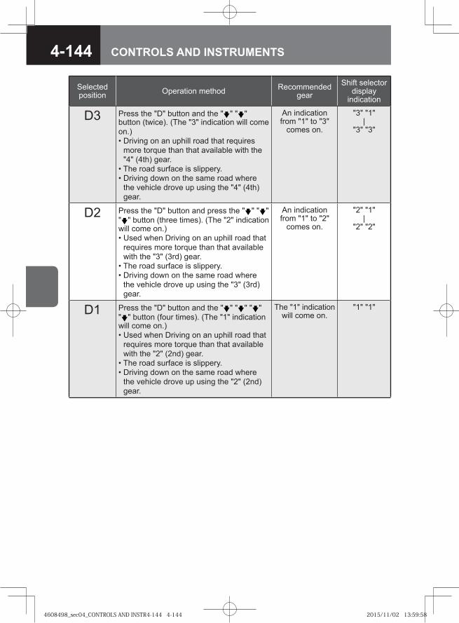
4-144 CONTROLS AND INSTRUMENTS
Selected position Operation method Recommended
gearShift selector
display indication
D3 Press the "D" button and the " " " " button (twice). (The "3" indication will come on.)• Driving on an uphill road that requires
more torque than that available with the "4" (4th) gear.
• The road surface is slippery.• Driving down on the same road where
the vehicle drove up using the "4" (4th) gear.
An indication from "1" to "3"
comes on.
"3" "1"|
"3" "3"
D2 Press the "D" button and press the " " " " " " button (three times). (The "2" indication will come on.)• Used when Driving on an uphill road that
requires more torque than that available with the "3" (3rd) gear.
• The road surface is slippery. • Driving down on the same road where
the vehicle drove up using the "3" (3rd) gear.
An indication from "1" to "2"
comes on.
"2" "1"|
"2" "2"
D1 Press the "D" button and the " " " " " " " " button (four times). (The "1" indication will come on.)• Used when Driving on an uphill road that
requires more torque than that available with the "2" (2nd) gear.
• The road surface is slippery.• Driving down on the same road where
the vehicle drove up using the "2" (2nd) gear.
The "1" indication will come on.
"1" "1"
4608498_sec04_CONTROLS AND INSTR4-144 4-1444608498_sec04_CONTROLS AND INSTR4-144 4-144 2015/11/02 13:59:582015/11/02 13:59:58
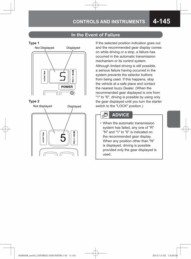
4-145CONTROLS AND INSTRUMENTS
If the selected position indication goes out and the recommended gear display comes on while driving or a stop, a failure has occurred in the automatic transmission mechanism or its control system.Although limited driving is still possible, a serious failure having occurred in the system prevents the selector buttons from being used. If this happens, stop the vehicle at a safe place and contact the nearest Isuzu Dealer. (When the recommended gear displayed is one from "1" to "6", driving is possible by using only the gear displayed until you turn the starter switch to the "LOCK" position.)
In the Event of Failure
�� ��������� ���������
ADVICEWhen the automatic transmission system has failed, any one of "R" "N" and "1" to "6" is indicated on the recommended gear display. When any position other than "N" is displayed, driving is possible provided only the gear displayed is used.
•
Type 1
�
� � ��������� ���������
Type 2
4608498_sec04_CONTROLS AND INSTR4-145 4-1454608498_sec04_CONTROLS AND INSTR4-145 4-145 2015/11/02 13:59:582015/11/02 13:59:58
4-146 CONTROLS AND INSTRUMENTS
When the HSA is not activated, the service brake system retains a certain level of braking pressure only while the brake pedal is being depressed. When HSA is activated, the system retains the braking pressure that is produced when the brake pedal is depressed during a stop even after the brake pedal is released. The vehicle is then held stopped for the period of time until the HSA is deactivated. (The HSA works only while the engine is in operation.)
Hill Start Aid (HSA) V
WARNING
HSA is a temporary braking force retaining device. HSA is not a substitute for the parking brake.Avoid leaving the driver seat with HSA activated. When leaving the driver seat, be sure to set the parking brake and remove the key from the starter switch.The HSA cannot retain the braking force when the brake system pressure drops or the power supply to the HSA is interrupted due to any of the following causes.
The starter switch is turned to a position other than the "ON" position.The fuse for the HSA circuit is removed.The fuse for the Smoother circuit is removed.A battery cable is disconnected.The HSA OFF switch placed in the "ON" position.
Since the HSA does not provide braking pressure if any of the above conditions exist, the vehicle will move down on a slope and very dangerous situation may result. Set the parking brake if you do any of the above.
•
•
•
-----
4608498_sec04_CONTROLS AND INSTR4-146 4-1464608498_sec04_CONTROLS AND INSTR4-146 4-146 2015/11/02 13:59:582015/11/02 13:59:58
4-147CONTROLS AND INSTRUMENTS
CAUTIONWhen the engine is not in operation, the brake system air pressure is low or the battery voltage is low, do not use the HSA because its ability to retain the brakes applied is decreased.Use the parking brake when stopping the vehicle on a slope of an 8% or more gradient if the vehicle is loaded up to the rating limit.When the parking brake lever is pulled up while the HSA is activated, the HSA is automatically cancelled.Even with HSA active, the stop lights go out when you release the brake pedal.When stopping the vehicle for an extended period, set the parking brake rather than relying on the HSA. On a snowy, icy or otherwise slippery road, press the HSA OFF switch to turn off the HSA power and do not use the HSA. When the wheels are locked while driving at a speed as low as approximately 20 km/h (12 MPH), the HSA may be activated and the wheels may stay locked.Release the brake pedal slowly after activating the HSA. If you release the pedal suddenly, the system's brake force level setting may be lowered, causing the vehicle to move down a slope.When the vehicle is brought to a stop by strongly depressing the brake pedal or with the wheels locked, the HSA may become temporarily inoperative. If this occurs, hold the vehicle in position by setting the parking brake or keeping the brake pedal depressed.
•
•
•
••
•
•
•
4608498_sec04_CONTROLS AND INSTR4-147 4-1474608498_sec04_CONTROLS AND INSTR4-147 4-147 2015/11/02 13:59:592015/11/02 13:59:59
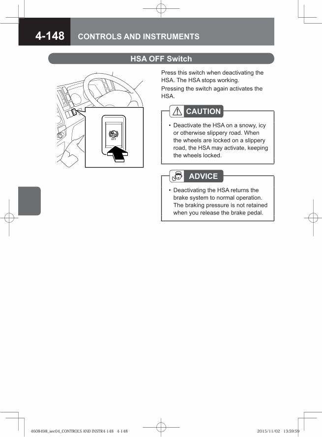
4-148 CONTROLS AND INSTRUMENTS
Press this switch when deactivating the HSA. The HSA stops working.Pressing the switch again activates the HSA.
HSA OFF Switch
CAUTIONDeactivate the HSA on a snowy, icy or otherwise slippery road. When the wheels are locked on a slippery road, the HSA may activate, keeping the wheels locked.
•
ADVICEDeactivating the HSA returns the brake system to normal operation. The braking pressure is not retained when you release the brake pedal.
•
4608498_sec04_CONTROLS AND INSTR4-148 4-1484608498_sec04_CONTROLS AND INSTR4-148 4-148 2015/11/02 13:59:592015/11/02 13:59:59
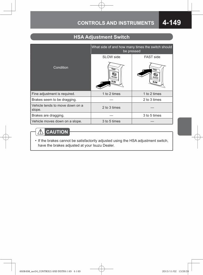
4-149CONTROLS AND INSTRUMENTS
Condition
What side of and how many times the switch should be pressed
SLOW side FAST side
Fine adjustment is required. 1 to 2 times 1 to 2 times
Brakes seem to be dragging. — 2 to 3 times
Vehicle tends to move down on a slope. 2 to 3 times —
Brakes are dragging. — 3 to 5 times
Vehicle moves down on a slope. 3 to 5 times —
HSA Adjustment Switch
CAUTIONIf the brakes cannot be satisfactorily adjusted using the HSA adjustment switch, have the brakes adjusted at your Isuzu Dealer.
•
4608498_sec04_CONTROLS AND INSTR4-149 4-1494608498_sec04_CONTROLS AND INSTR4-149 4-149 2015/11/02 13:59:592015/11/02 13:59:59
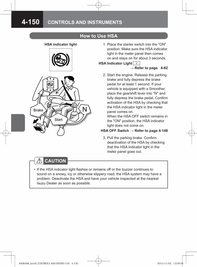
4-150 CONTROLS AND INSTRUMENTS
�� ��
�� ��
�
How to Use HSA 1. Place the starter switch into the "ON"
position. Make sure the HSA indicator light in the meter panel then comes on and stays on for about 3 seconds.
HSA Indicator Light V → Refer to page 4-62
CAUTIONIf the HSA indicator light flashes or remains off or the buzzer continues to sound on a snowy, icy or otherwise slippery road, the HSA system may have a problem. Deactivate the HSA and have your vehicle inspected at the nearest Isuzu Dealer as soon as possible.
•
HSA indicator light
2. Start the engine. Release the parking brake and fully depress the brake pedal for at least 1 second. If your vehicle is equipped with a Smoother, place the gearshift lever into "N" and fully depress the brake pedal. Confirm activation of the HSA by checking that the HSA indicator light in the meter panel comes on.When the HSA OFF switch remains in the "ON" position, the HSA indicator light does not come on.
HSA OFF Switch → Refer to page 4-148
3. Pull the parking brake. Confirm deactivation of the HSA by checking that the HSA indicator light in the meter panel goes out.
4608498_sec04_CONTROLS AND INSTR4-150 4-1504608498_sec04_CONTROLS AND INSTR4-150 4-150 2015/11/02 13:59:592015/11/02 13:59:59
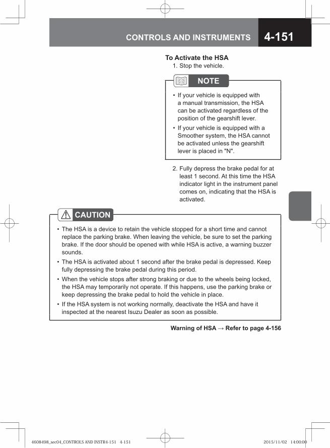
4-151CONTROLS AND INSTRUMENTS
NOTEIf your vehicle is equipped with a manual transmission, the HSA can be activated regardless of the position of the gearshift lever.If your vehicle is equipped with a Smoother system, the HSA cannot be activated unless the gearshift lever is placed in "N".
•
•
To Activate the HSA 1. Stop the vehicle.
2. Fully depress the brake pedal for at least 1 second. At this time the HSA indicator light in the instrument panel comes on, indicating that the HSA is activated.
CAUTIONThe HSA is a device to retain the vehicle stopped for a short time and cannot replace the parking brake. When leaving the vehicle, be sure to set the parking brake. If the door should be opened with while HSA is active, a warning buzzer sounds.The HSA is activated about 1 second after the brake pedal is depressed. Keep fully depressing the brake pedal during this period.When the vehicle stops after strong braking or due to the wheels being locked, the HSA may temporarily not operate. If this happens, use the parking brake or keep depressing the brake pedal to hold the vehicle in place.If the HSA system is not working normally, deactivate the HSA and have it inspected at the nearest Isuzu Dealer as soon as possible.
•
•
•
•
Warning of HSA → Refer to page 4-156
4608498_sec04_CONTROLS AND INSTR4-151 4-1514608498_sec04_CONTROLS AND INSTR4-151 4-151 2015/11/02 14:00:002015/11/02 14:00:00
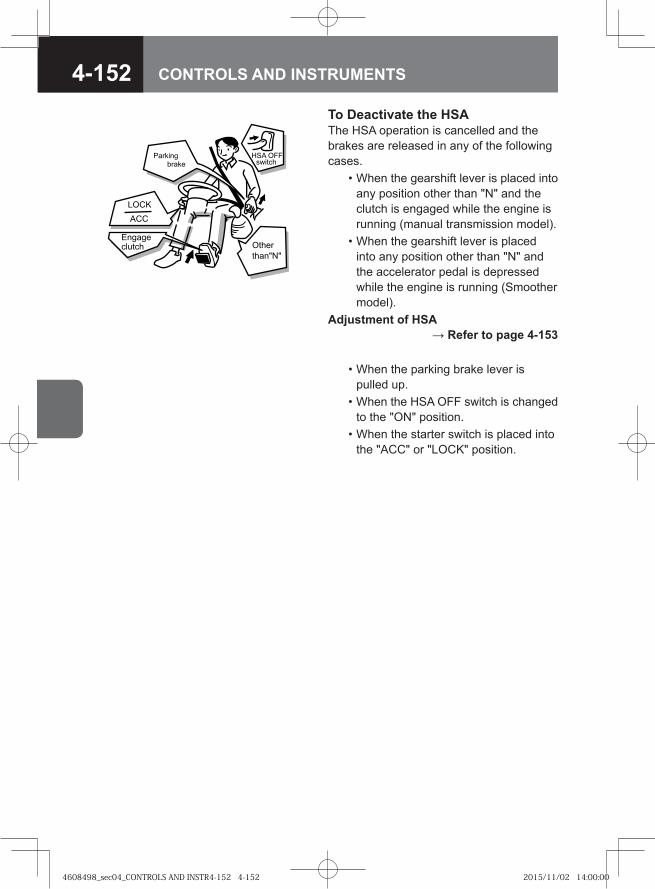
4-152 CONTROLS AND INSTRUMENTS
��� ��
����� �������������
� ��
���
����
�������
������!"���
To Deactivate the HSAThe HSA operation is cancelled and the brakes are released in any of the following cases. • When the gearshift lever is placed into
any position other than "N" and the clutch is engaged while the engine is running (manual transmission model).
• When the gearshift lever is placed into any position other than "N" and the accelerator pedal is depressed while the engine is running (Smoother model).
Adjustment of HSA → Refer to page 4-153
• When the parking brake lever is pulled up.
• When the HSA OFF switch is changed to the "ON" position.
• When the starter switch is placed into the "ACC" or "LOCK" position.
4608498_sec04_CONTROLS AND INSTR4-152 4-1524608498_sec04_CONTROLS AND INSTR4-152 4-152 2015/11/02 14:00:002015/11/02 14:00:00
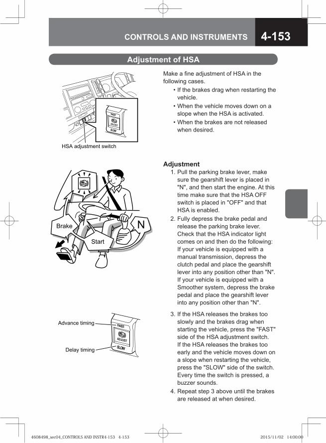
4-153CONTROLS AND INSTRUMENTS
Adjustment of HSAMake a fine adjustment of HSA in the following cases. • If the brakes drag when restarting the
vehicle. • When the vehicle moves down on a
slope when the HSA is activated. • When the brakes are not released
when desired.
Adjustment 1. Pull the parking brake lever, make
sure the gearshift lever is placed in "N", and then start the engine. At this time make sure that the HSA OFF switch is placed in "OFF" and that HSA is enabled.
2. Fully depress the brake pedal and release the parking brake lever. Check that the HSA indicator light comes on and then do the following: If your vehicle is equipped with a manual transmission, depress the clutch pedal and place the gearshift lever into any position other than "N". If your vehicle is equipped with a Smoother system, depress the brake pedal and place the gearshift lever into any position other than "N".
��� ��������� ������
�� ���� ������
����� ������
�� ��
�� ��
�
3. If the HSA releases the brakes too slowly and the brakes drag when starting the vehicle, press the "FAST" side of the HSA adjustment switch. If the HSA releases the brakes too early and the vehicle moves down on a slope when restarting the vehicle, press the "SLOW" side of the switch. Every time the switch is pressed, a buzzer sounds.
4. Repeat step 3 above until the brakes are released at when desired.
4608498_sec04_CONTROLS AND INSTR4-153 4-1534608498_sec04_CONTROLS AND INSTR4-153 4-153 2015/11/02 14:00:002015/11/02 14:00:00
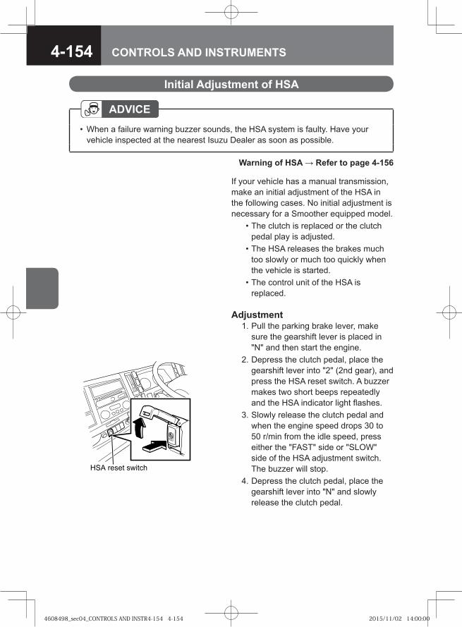
4-154 CONTROLS AND INSTRUMENTS
Initial Adjustment of HSA
Warning of HSA → Refer to page 4-156
ADVICEWhen a failure warning buzzer sounds, the HSA system is faulty. Have your vehicle inspected at the nearest Isuzu Dealer as soon as possible.
•
��� ����� ������
�����
If your vehicle has a manual transmission, make an initial adjustment of the HSA in the following cases. No initial adjustment is necessary for a Smoother equipped model. • The clutch is replaced or the clutch
pedal play is adjusted. • The HSA releases the brakes much
too slowly or much too quickly when the vehicle is started.
• The control unit of the HSA is replaced.
Adjustment 1. Pull the parking brake lever, make
sure the gearshift lever is placed in "N" and then start the engine.
2. Depress the clutch pedal, place the gearshift lever into "2" (2nd gear), and press the HSA reset switch. A buzzer makes two short beeps repeatedly and the HSA indicator light flashes.
3. Slowly release the clutch pedal and when the engine speed drops 30 to 50 r/min from the idle speed, press either the "FAST" side or "SLOW" side of the HSA adjustment switch. The buzzer will stop.
4. Depress the clutch pedal, place the gearshift lever into "N" and slowly release the clutch pedal.
4608498_sec04_CONTROLS AND INSTR4-154 4-1544608498_sec04_CONTROLS AND INSTR4-154 4-154 2015/11/02 14:00:002015/11/02 14:00:00
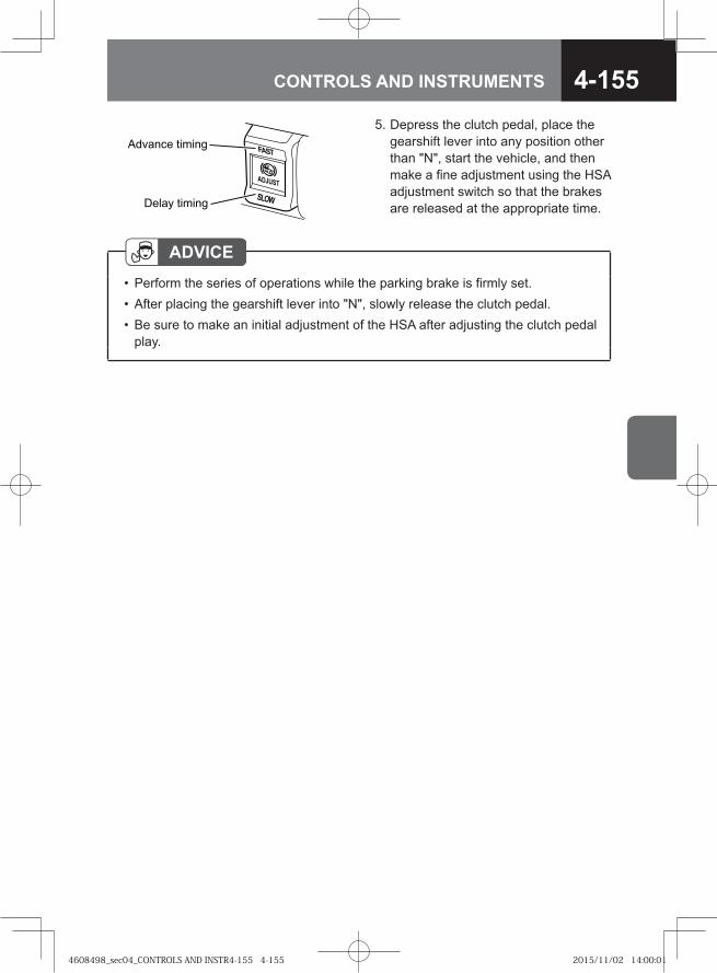
4-155CONTROLS AND INSTRUMENTS
5. Depress the clutch pedal, place the gearshift lever into any position other than "N", start the vehicle, and then make a fine adjustment using the HSA adjustment switch so that the brakes are released at the appropriate time.
ADVICEPerform the series of operations while the parking brake is firmly set.After placing the gearshift lever into "N", slowly release the clutch pedal.Be sure to make an initial adjustment of the HSA after adjusting the clutch pedal play.
•••
�� ���� ������
����� ������
4608498_sec04_CONTROLS AND INSTR4-155 4-1554608498_sec04_CONTROLS AND INSTR4-155 4-155 2015/11/02 14:00:012015/11/02 14:00:01
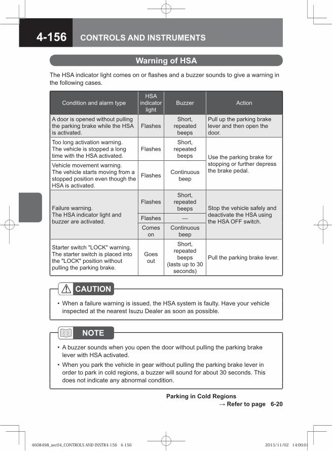
4-156 CONTROLS AND INSTRUMENTS
Warning of HSAThe HSA indicator light comes on or flashes and a buzzer sounds to give a warning in the following cases.
Condition and alarm typeHSA
indicator light
Buzzer Action
A door is opened without pulling the parking brake while the HSA is activated.
FlashesShort,
repeated beeps
Pull up the parking brake lever and then open the door.
Too long activation warning. The vehicle is stopped a long time with the HSA activated.
FlashesShort,
repeated beeps Use the parking brake for
stopping or further depress the brake pedal.
Vehicle movement warning. The vehicle starts moving from a stopped position even though the HSA is activated.
Flashes Continuous beep
Failure warning. The HSA indicator light and buzzer are activated.
FlashesShort,
repeated beeps Stop the vehicle safely and
deactivate the HSA using the HSA OFF switch.Flashes —
Comes on
Continuous beep
Starter switch "LOCK" warning.The starter switch is placed into the "LOCK" position without pulling the parking brake.
Goes out
Short, repeated
beeps (lasts up to 30
seconds)
Pull the parking brake lever.
CAUTIONWhen a failure warning is issued, the HSA system is faulty. Have your vehicle inspected at the nearest Isuzu Dealer as soon as possible.
•
NOTEA buzzer sounds when you open the door without pulling the parking brake lever with HSA activated.When you park the vehicle in gear without pulling the parking brake lever in order to park in cold regions, a buzzer will sound for about 30 seconds. This does not indicate any abnormal condition.
•
•
Parking in Cold Regions → Refer to page 6-20
4608498_sec04_CONTROLS AND INSTR4-156 4-1564608498_sec04_CONTROLS AND INSTR4-156 4-156 2015/11/02 14:00:012015/11/02 14:00:01
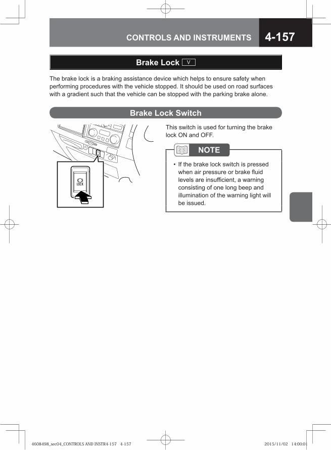
4-157CONTROLS AND INSTRUMENTS
The brake lock is a braking assistance device which helps to ensure safety when performing procedures with the vehicle stopped. It should be used on road surfaces with a gradient such that the vehicle can be stopped with the parking brake alone.
Brake Lock V
This switch is used for turning the brake lock ON and OFF.
NOTEIf the brake lock switch is pressed when air pressure or brake fluid levels are insufficient, a warning consisting of one long beep and illumination of the warning light will be issued.
•
Brake Lock Switch
4608498_sec04_CONTROLS AND INSTR4-157 4-1574608498_sec04_CONTROLS AND INSTR4-157 4-157 2015/11/02 14:00:012015/11/02 14:00:01
4-158 CONTROLS AND INSTRUMENTS
1. The engine is running. 2. There is sufficient air pressure and brake fluid (corresponding warning lights are
off).
CAUTIONThis is a supplemental brake for service use. It should be used in locations where the vehicle can be parked with the parking brake alone and not used for general parking or stopping. Doing so will result in the premature deterioration of rubber brake components and a reduction of braking power, which may cause an accident.Do not use continuously for more than 1 hour.Make sure to apply chock blocks when using the brake lock.Do not use when the engine is off or when air pressure is low.Do not leave the vehicle while the brake lock is in use.If the brake lock indicator light (green) turns off and a long beep sounds while in use, air pressure or braking power has decreased. Stop vehicle operation immediately and contact the nearest Isuzu Dealer.This device is used to brake continuously for long periods of time and places a large strain on brake equipment. For safety reasons, replace parts that require periodic replacement.
•
•••••
•
Pre-operation Check
4608498_sec04_CONTROLS AND INSTR4-158 4-1584608498_sec04_CONTROLS AND INSTR4-158 4-158 2015/11/02 14:00:012015/11/02 14:00:01
4-159CONTROLS AND INSTRUMENTS
1. For vehicles with a center parking brake, forcibly pull the parking brake lever approx. 294 N (30.0 kgf/66 lb). For vehicles with a wheel parking brake, pull until locked and confirm that air discharge can be heard. At this time the brake lock indicator light (red) will illuminate.
2. Press the brake lock switch. At this time the brake lock indicator light (green) will illuminate and the brake lock will operate.
How to Operate
ADVICEThe brake lock will operate when the parking brake is appropriately engaged.For vehicles with a center parking brake, forcibly pull the parking brake lever approx. 294 N (30.0 kgf/66 lb) until the brake lock indicator light (red) illuminates. For vehicles with a wheel parking brake, pull until locked and confirm that air discharge can be heard. Pressing the brake lock switch without pulling the parking brake lever will cause a long warning beep to sound.Make sure to confirm that the brake lock indicator light is illuminated. If the light is not illuminated, the brake lock will not operate.For Smoother vehicles, the brake lock will not operate if the shift lever is in a position other than "N".
••
•
•
•
1. Turn off the brake lock switch. At this time, the brake lock indicator light (green) will turn off.
2. Depress the brake pedal and fully release the parking brake lever to disengage the brake lock. At this time the brake lock indicator light (red) will turn off. Reapply the parking brake the next time the vehicle is parked.
How to Disengage
WARNING
Release the parking brake lever after turning off the brake lock switch. Do not disengage in the opposite order as there is a danger of the vehicle moving.
•
4608498_sec04_CONTROLS AND INSTR4-159 4-1594608498_sec04_CONTROLS AND INSTR4-159 4-159 2015/11/02 14:00:012015/11/02 14:00:01
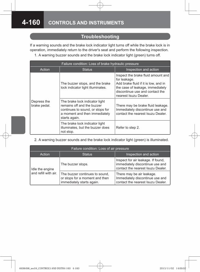
4-160 CONTROLS AND INSTRUMENTS
Failure condition: Loss of air pressure
Action Status Inspection and action
Idle the engine and refill with air.
The buzzer stops.Inspect for air leakage. If found, immediately discontinue use and contact the nearest Isuzu Dealer.
The buzzer continues to sound, or stops for a moment and then immediately starts again.
There may be air leakage. Immediately discontinue use and contact the nearest Isuzu Dealer.
If a warning sounds and the brake lock indicator light turns off while the brake lock is in operation, immediately return to the driver's seat and perform the following inspection. 1. A warning buzzer sounds and the brake lock indicator light (green) turns off.
Troubleshooting
Failure condition: Loss of brake hydraulic pressure
Action Status Inspection and action
Depress the brake pedal.
The buzzer stops, and the brake lock indicator light illuminates.
Inspect the brake fluid amount and for leakage. Add brake fluid if it is low, and in the case of leakage, immediately discontinue use and contact the nearest Isuzu Dealer.
The brake lock indicator light remains off and the buzzer continues to sound, or stops for a moment and then immediately starts again.
There may be brake fluid leakage. Immediately discontinue use and contact the nearest Isuzu Dealer.
The brake lock indicator light illuminates, but the buzzer does not stop.
Refer to step 2.
2. A warning buzzer sounds and the brake lock indicator light (green) is illuminated.
4608498_sec04_CONTROLS AND INSTR4-160 4-1604608498_sec04_CONTROLS AND INSTR4-160 4-160 2015/11/02 14:00:022015/11/02 14:00:02
4-161CONTROLS AND INSTRUMENTS
The cruise control function allows you to drive the vehicle at a constant speed without operating the accelerator pedal. This function should only be used when driving where frequent starting and stopping is not required, such as highway driving.
Cruise Control V
WARNING
Do not use the cruise control function on the following roads, where using it could be dangerous.
A road with heavy traffic, such as an urban roadA road that includes sharp curves and steep downhill slopesAn icy, snowy or otherwise slippery road
•••
Market Vehicle model Speed limit device setting Cruise control setting range
Algeria FRR/FSR/FTR/FVR/FVZ 90 km/h (56 MPH) Approx. 40 - 80 km/h
(approx. 25 - 50 MPH)
4608498_sec04_CONTROLS AND INSTR4-161 4-1614608498_sec04_CONTROLS AND INSTR4-161 4-161 2015/11/02 14:00:022015/11/02 14:00:02
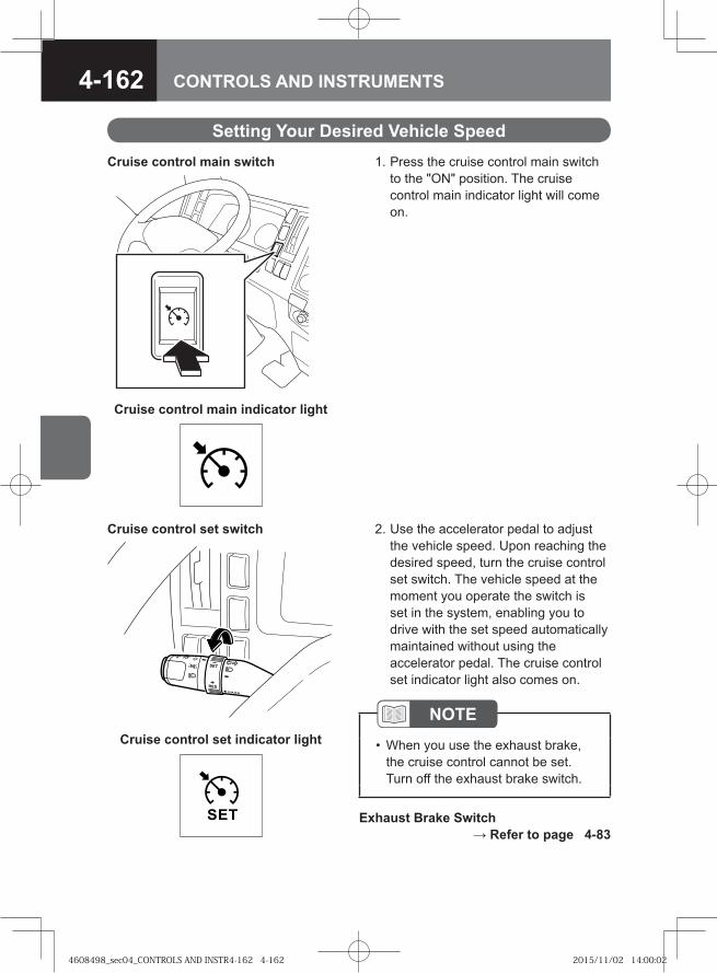
4-162 CONTROLS AND INSTRUMENTS
Setting Your Desired Vehicle Speed 1. Press the cruise control main switch
to the "ON" position. The cruise control main indicator light will come on.
Cruise control main switch
Cruise control main indicator light
2. Use the accelerator pedal to adjust the vehicle speed. Upon reaching the desired speed, turn the cruise control set switch. The vehicle speed at the moment you operate the switch is set in the system, enabling you to drive with the set speed automatically maintained without using the accelerator pedal. The cruise control set indicator light also comes on.
Cruise control set switch
Cruise control set indicator light
NOTEWhen you use the exhaust brake, the cruise control cannot be set. Turn off the exhaust brake switch.
•
Exhaust Brake Switch → Refer to page 4-83
4608498_sec04_CONTROLS AND INSTR4-162 4-1624608498_sec04_CONTROLS AND INSTR4-162 4-162 2015/11/02 14:00:022015/11/02 14:00:02
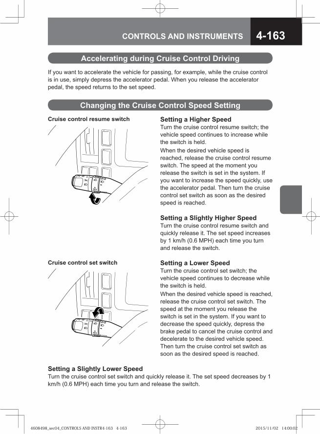
4-163CONTROLS AND INSTRUMENTS
Setting a Higher SpeedTurn the cruise control resume switch; the vehicle speed continues to increase while the switch is held.When the desired vehicle speed is reached, release the cruise control resume switch. The speed at the moment you release the switch is set in the system. If you want to increase the speed quickly, use the accelerator pedal. Then turn the cruise control set switch as soon as the desired speed is reached.
Cruise control resume switch
Accelerating during Cruise Control DrivingIf you want to accelerate the vehicle for passing, for example, while the cruise control is in use, simply depress the accelerator pedal. When you release the accelerator pedal, the speed returns to the set speed.
Changing the Cruise Control Speed Setting
Setting a Slightly Higher SpeedTurn the cruise control resume switch and quickly release it. The set speed increases by 1 km/h (0.6 MPH) each time you turn and release the switch.
Setting a Lower SpeedTurn the cruise control set switch; the vehicle speed continues to decrease while the switch is held.When the desired vehicle speed is reached, release the cruise control set switch. The speed at the moment you release the switch is set in the system. If you want to decrease the speed quickly, depress the brake pedal to cancel the cruise control and decelerate to the desired vehicle speed. Then turn the cruise control set switch as soon as the desired speed is reached.
Cruise control set switch
Setting a Slightly Lower SpeedTurn the cruise control set switch and quickly release it. The set speed decreases by 1 km/h (0.6 MPH) each time you turn and release the switch.
4608498_sec04_CONTROLS AND INSTR4-163 4-1634608498_sec04_CONTROLS AND INSTR4-163 4-163 2015/11/02 14:00:022015/11/02 14:00:02
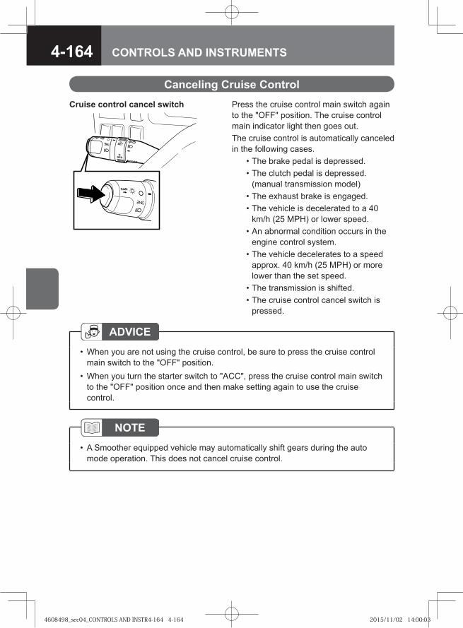
4-164 CONTROLS AND INSTRUMENTS
Cruise control cancel switch Press the cruise control main switch again to the "OFF" position. The cruise control main indicator light then goes out.The cruise control is automatically canceled in the following cases. • The brake pedal is depressed. • The clutch pedal is depressed.
(manual transmission model) • The exhaust brake is engaged. • The vehicle is decelerated to a 40
km/h (25 MPH) or lower speed. • An abnormal condition occurs in the
engine control system. • The vehicle decelerates to a speed
approx. 40 km/h (25 MPH) or more lower than the set speed.
• The transmission is shifted. • The cruise control cancel switch is
pressed.
Canceling Cruise Control
ADVICEWhen you are not using the cruise control, be sure to press the cruise control main switch to the "OFF" position.When you turn the starter switch to "ACC", press the cruise control main switch to the "OFF" position once and then make setting again to use the cruise control.
•
•
NOTEA Smoother equipped vehicle may automatically shift gears during the auto mode operation. This does not cancel cruise control.
•
4608498_sec04_CONTROLS AND INSTR4-164 4-1644608498_sec04_CONTROLS AND INSTR4-164 4-164 2015/11/02 14:00:032015/11/02 14:00:03
4-165CONTROLS AND INSTRUMENTS
If the cruise control is canceled by any of the following, you can resume cruise control driving at the original set speed when you turn and release the cruise control resume switch. As soon as the resume switch is released, the cruise control set indicator light comes on. • The brake pedal is depressed. • The clutch pedal is depressed (manual transmission model). • The exhaust brake is engaged. • The transmission is changed. • The cruise control cancel switch is pressed.
ADVICEWhen the vehicle comes to a halt (0 km/h/0 MPH), the original cruise control setting cannot be recovered by using the resume switch. You must then reset the cruise control.
•
Reengaging the Cruise Control
Cruise Control Coordinated with Auxiliary Braking Function
Models with Auxiliary Brake-coordinated Cruise ControlThis type of cruise control system automatically engages the auxiliary braking function (exhaust brake) while it is in use to limit the increase in speed on a downhill slope. This helps lighten the driver's workload (reducing the need to use the brake pedal to prevent vehicle speed increase).
CAUTIONThe maximum slope angle at which the system can prevent the vehicle speed increase is different depending on the load the vehicle is carrying.
•
Automatic Engagement and Disengagement of Auxiliary Brake • The auxiliary brake is engaged when the vehicle speed exceeds the set speed on
a downhill slope. • The auxiliary brake is disengaged when the vehicle slows down close to the set
speed.
4608498_sec04_CONTROLS AND INSTR4-165 4-1654608498_sec04_CONTROLS AND INSTR4-165 4-165 2015/11/02 14:00:032015/11/02 14:00:03
4-166 CONTROLS AND INSTRUMENTS
Wheels may lock causing a skid during sudden braking or when braking on a snowy or otherwise slippery road. The ABS prevents the wheels from locking during braking by sensing a skid and thus helps maintain directional and control stability of the vehicle. However, even with the ABS, difficulties resulting from driving and stopping exceeding safe limits cannot be avoided. It is your responsibility to drive safely.
Antilock Brake System (ABS) V
CAUTIONThe braking distance on slippery road surfaces is longer than that on a normal dry paved road even with an ABS-equipped vehicle. The braking distance can become even slightly longer in deep snow and on a gravel road when the ABS works than when it does not work. Therefore, always be aware of the road and tire conditions (tire type and wear condition), observe safe driving habits, and drive while keeping a safe following distance.ABS does not prevent accidents if you do not drive safely with current road conditions in mind. Drive the vehicle at a safe speed.Install tires of the specified size, same brand and same tread design (including winter tires) on all wheels. If different tires are installed, the braking distance becomes longer and directional control stability of the vehicle decreases. This is very dangerous.The steering wheel during sudden braking (when the ABS is working) gives you a feeling slightly different than it does when the brakes are not applied. Operate the steering wheel carefully keeping this in mind.ABS operation consumes the brake system air. When the air pressure drops and the air pressure warning light and the buzzer are activated, immediately stop the vehicle at a safe place and wait for the required air pressure to be recovered before driving.
•
•
•
•
•
ADVICEDriving in sand or mud, or on a muddy road may adversely affect the brakes and ABS sensors. Wash the vehicle to remove sand and mud after operating the vehicle in sandy or muddy conditions.Before washing the vehicle, provide necessary protection to prevent water from being splashed on the ABS components (sensors and actuators). Especially when using high-pressure washing, be careful not to allow water to be directly sprayed onto the ABS components and their harness connectors.
•
•
4608498_sec04_CONTROLS AND INSTR4-166 4-1664608498_sec04_CONTROLS AND INSTR4-166 4-166 2015/11/02 14:00:032015/11/02 14:00:03
4-167CONTROLS AND INSTRUMENTS
NOTE[These are not signs of ABS malfunction]
Soon after you start the engine, the sound of valve working may be heard from the rear of the vehicle or underside of the cab. This sound is from a self-check by the ABS system and is normal.When ABS is properly operating, vibration is felt on the steering wheel or a mechanical operating sound is heard.When ABS is activated while the exhaust brake is in operation, the exhaust brake may disengage.ABS is more likely to activate when the brakes are applied during cornering or driving over a bump. This is because inside wheels or wheels that have gone over the bump tend to lock.ABS is not activated immediately after starting the vehicle. It is activated only when the vehicle speed reaches approx. 10 km/h (6 MPH). ABS operation is inactive when the vehicle speed reduces to approx. 5 km/h (3 MPH).
•
•
•
•
•
4608498_sec04_CONTROLS AND INSTR4-167 4-1674608498_sec04_CONTROLS AND INSTR4-167 4-167 2015/11/02 14:00:032015/11/02 14:00:03
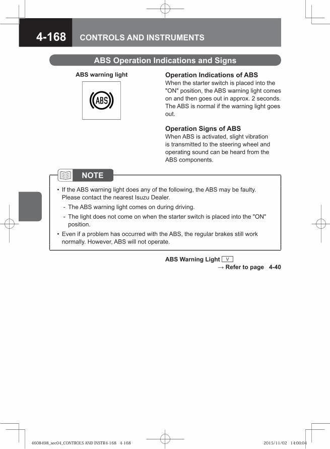
4-168 CONTROLS AND INSTRUMENTS
ABS Operation Indications and Signs
Operation Indications of ABSWhen the starter switch is placed into the "ON" position, the ABS warning light comes on and then goes out in approx. 2 seconds. The ABS is normal if the warning light goes out.
Operation Signs of ABSWhen ABS is activated, slight vibration is transmitted to the steering wheel and operating sound can be heard from the ABS components.
NOTEIf the ABS warning light does any of the following, the ABS may be faulty. Please contact the nearest Isuzu Dealer.
The ABS warning light comes on during driving.The light does not come on when the starter switch is placed into the "ON" position.
Even if a problem has occurred with the ABS, the regular brakes still work normally. However, ABS will not operate.
•
--
•
ABS Warning Light V → Refer to page 4-40
ABS warning light
4608498_sec04_CONTROLS AND INSTR4-168 4-1684608498_sec04_CONTROLS AND INSTR4-168 4-168 2015/11/02 14:00:042015/11/02 14:00:04
4-169CONTROLS AND INSTRUMENTS
ABS is not a device that enables driving and stopping under conditions exceeding safe driving limits. It is your responsibility to drive safely.
Precautions for Driving an ABS-Equipped Vehicle
CAUTIONThe braking distance on slippery road surfaces is longer than that on a normal dry paved road even with an ABS-equipped vehicle. When ABS is activated in the following road surface conditions, the braking distance may be slightly longer compared to that of vehicles not equipped with an ABS. Therefore, always be aware of the road and tire condition (tire type and wear condition), observe safe driving habits, and drive the vehicle while keeping a safe following distance.
Driving on a gravel road and deeply snow-covered roadWhen tire chains are usedWhen driving over road joints or steps such as cat's-eyesWhen driving on a bumpy road, stone-paved road or trackWhen driving on an iron plate or manhole lid
ABS does not work for wheel skid during a standing start, acceleration and cornering which do not involve braking. On a very slippery icy road, tires may lose their grip and the steering wheel operation may not be able to control the vehicle's direction, resulting in very unstable driving. Always drive the vehicle observing a safe speed well matched with both road surface and tire conditions, and avoid sudden braking.If powerful engine braking is applied on a very slippery icy road, the drive wheels may be locked (the ABS then does not work), resulting in loss of vehicle control. If this happens with a manual transmission vehicle, disengage the clutch or place the gearshift lever into "N" to prevent engine braking from acting on the drive wheels. Then, drive the vehicle with the gearshift lever placed in an appropriate gear. ABS operation consumes the brake system air. When the air pressure drops and the air pressure warning light and the buzzer are activated, immediately stop the vehicle at a safe place and wait for the required air pressure to be recovered before driving.When ABS is activated, slight vibration and pull to one side may be felt on the steering wheel (especially when the road surface condition is different between right and left wheels). In addition, an operating sound is produced from the ABS actuators. This does not indicate any abnormal condition. Stay calm and operate the steering wheel properly.
•
-----
•
•
•
•
4608498_sec04_CONTROLS AND INSTR4-169 4-1694608498_sec04_CONTROLS AND INSTR4-169 4-169 2015/11/02 14:00:042015/11/02 14:00:04
4-170 CONTROLS AND INSTRUMENTS
ASR is a device that helps prevent the drive wheels from spinning and improve vehicle stability when driving on a snowy or otherwise slippery road surface. The ASR is automatically activated when the engine is started. You may cancel ASR operation using the ASR OFF switch.
Anti-Slip Regulator (ASR) V
CAUTIONWhen ASR is activated, the ASR indicator light (green) comes on. The road surface at this time is very slippery. If the indicator light comes on, drive carefully and reducing the speed sufficiently before negotiating a curve.Even with an ASR-equipped model, use tire chains or install winter tires when driving on a snowy or icy road and drive the vehicle very carefully.ASR is not a device to drastically improve the vehicle starting performance. Carefully operate the accelerator pedal when moving off on an icy slope.When tire chains are installed, it may be easier for you to start the vehicle to move on an icy slope if the ASR is canceled. Be aware, however, that ASR deactivation will result in reduced stability of vehicle operation.
•
•
•
•
NOTE[These are not signs of ASR malfunction]
The engine speed may suddenly decrease; this is because the ASR device is operating.When using a speed tester and brake tester, press the ASR OFF switch to cancel the ASR.
•
•
4608498_sec04_CONTROLS AND INSTR4-170 4-1704608498_sec04_CONTROLS AND INSTR4-170 4-170 2015/11/02 14:00:042015/11/02 14:00:04
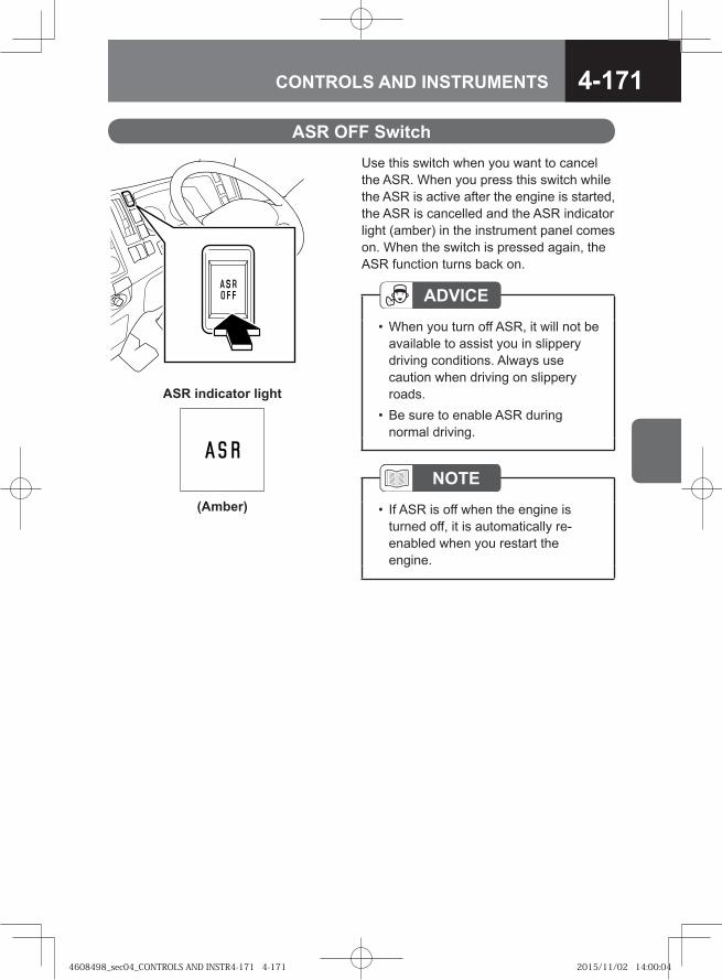
4-171CONTROLS AND INSTRUMENTS
Use this switch when you want to cancel the ASR. When you press this switch while the ASR is active after the engine is started, the ASR is cancelled and the ASR indicator light (amber) in the instrument panel comes on. When the switch is pressed again, the ASR function turns back on.
ASR OFF Switch
ADVICEWhen you turn off ASR, it will not be available to assist you in slippery driving conditions. Always use caution when driving on slippery roads.Be sure to enable ASR during normal driving.
•
•
NOTEIf ASR is off when the engine is turned off, it is automatically re-enabled when you restart the engine.
•
ASR indicator light
(Amber)
4608498_sec04_CONTROLS AND INSTR4-171 4-1714608498_sec04_CONTROLS AND INSTR4-171 4-171 2015/11/02 14:00:042015/11/02 14:00:04
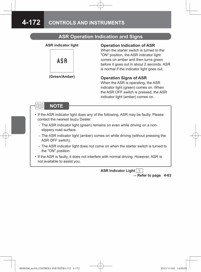
4-172 CONTROLS AND INSTRUMENTS
ASR Operation Indication and Signs
Operation Indication of ASRWhen the starter switch is turned to the "ON" position, the ASR indicator light comes on amber and then turns green before it goes out in about 2 seconds. ASR is normal if the indicator light goes out.
Operation Signs of ASRWhen the ASR is operating, the ASR indicator light (green) comes on. When the ASR OFF switch is pressed, the ASR indicator light (amber) comes on.
NOTEIf the ASR indicator light does any of the following, ASR may be faulty. Please contact the nearest Isuzu Dealer.
The ASR indicator light (green) remains on even while driving on a non-slippery road surface.The ASR indicator light (amber) comes on while driving (without pressing the ASR OFF switch).The ASR indicator light does not come on when the starter switch is turned to the "ON" position.
If the ASR is faulty, it does not interfere with normal driving. However, ASR is not available to assist you.
•
-
-
-
•
ASR Indicator Light V → Refer to page 4-63
ASR indicator light
(Green/Amber)
4608498_sec04_CONTROLS AND INSTR4-172 4-1724608498_sec04_CONTROLS AND INSTR4-172 4-172 2015/11/02 14:00:052015/11/02 14:00:05
4-173CONTROLS AND INSTRUMENTS
Precautions for Driving an ASR-equipped VehicleASR is not a device that enables driving under conditions exceeding safe limits. It is your responsibility to drive safely.
CAUTIONThe ASR does not increase the road grip of tires although it improves starting and accelerating performance on a slippery road surface when compared to a model without ASR. On an icy or otherwise slippery road, the grip decreases steering control, which may result in unstable vehicle behavior. Always drive the vehicle observing a safe speed well matched to the road surface and tire conditions, and also avoid speeding.ASR uses up brake system air. When the air pressure drops and the air pressure warning light and the buzzer are activated, immediately stop the vehicle at a safe place and wait for an air pressure within the normal range to be restored before driving.Even if your vehicle is equipped with an ASR, avoid sudden operation of the accelerator pedal, clutch pedal and steering wheel. Especially when starting the vehicle on a slippery road, start up slowly as you would in a vehicle without an ASR.
•
•
•
NOTEYou can press the ASR OFF switch to deactivate the ASR system when you need increased engine speed to drive up a slippery, long slope or to move the vehicle out of deep snow or mud.
•
ASR OFF Switch → Refer to page 4-171
4608498_sec04_CONTROLS AND INSTR4-173 4-1734608498_sec04_CONTROLS AND INSTR4-173 4-173 2015/11/02 14:00:052015/11/02 14:00:05
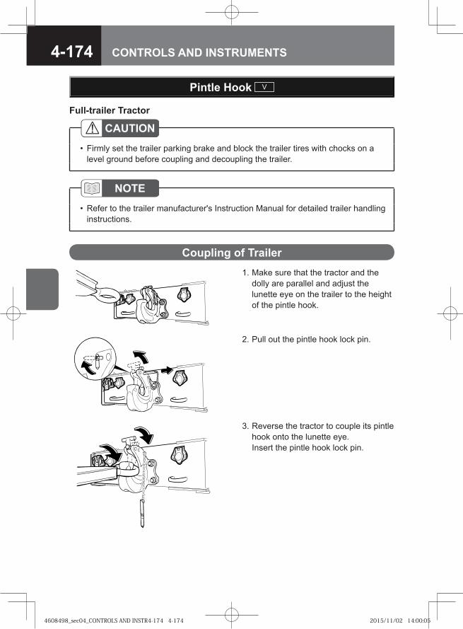
4-174 CONTROLS AND INSTRUMENTS
Pintle Hook V
CAUTIONFirmly set the trailer parking brake and block the trailer tires with chocks on a level ground before coupling and decoupling the trailer.
•
NOTERefer to the trailer manufacturer's Instruction Manual for detailed trailer handling instructions.
•
Full-trailer Tractor
1. Make sure that the tractor and the dolly are parallel and adjust the lunette eye on the trailer to the height of the pintle hook.
Coupling of Trailer
2. Pull out the pintle hook lock pin.
3. Reverse the tractor to couple its pintle hook onto the lunette eye.Insert the pintle hook lock pin.
4608498_sec04_CONTROLS AND INSTR4-174 4-1744608498_sec04_CONTROLS AND INSTR4-174 4-174 2015/11/02 14:00:052015/11/02 14:00:05
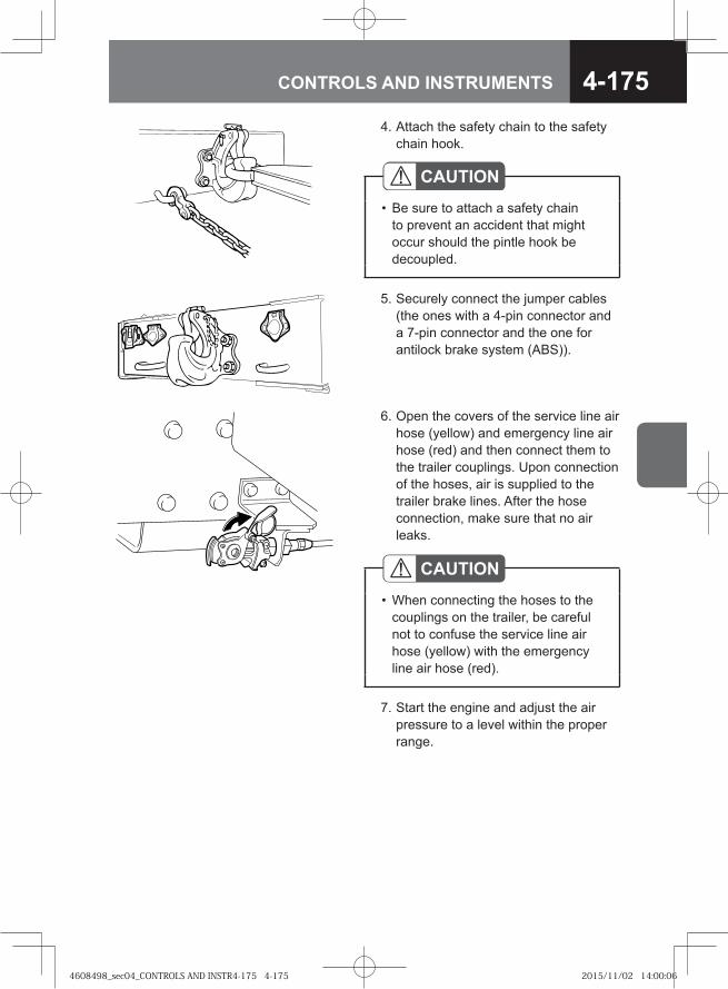
4-175CONTROLS AND INSTRUMENTS
4. Attach the safety chain to the safety chain hook.
5. Securely connect the jumper cables (the ones with a 4-pin connector and a 7-pin connector and the one for antilock brake system (ABS)).
CAUTIONBe sure to attach a safety chain to prevent an accident that might occur should the pintle hook be decoupled.
•
6. Open the covers of the service line air hose (yellow) and emergency line air hose (red) and then connect them to the trailer couplings. Upon connection of the hoses, air is supplied to the trailer brake lines. After the hose connection, make sure that no air leaks.
CAUTIONWhen connecting the hoses to the couplings on the trailer, be careful not to confuse the service line air hose (yellow) with the emergency line air hose (red).
•
7. Start the engine and adjust the air pressure to a level within the proper range.
4608498_sec04_CONTROLS AND INSTR4-175 4-1754608498_sec04_CONTROLS AND INSTR4-175 4-175 2015/11/02 14:00:062015/11/02 14:00:06
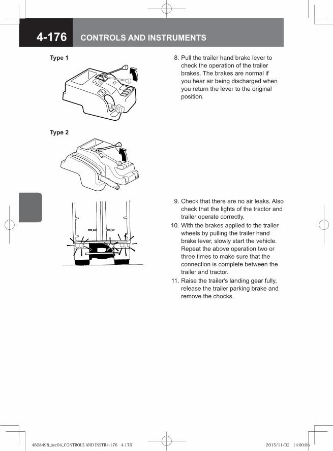
4-176 CONTROLS AND INSTRUMENTS
8. Pull the trailer hand brake lever to check the operation of the trailer brakes. The brakes are normal if you hear air being discharged when you return the lever to the original position.
9. Check that there are no air leaks. Also check that the lights of the tractor and trailer operate correctly.
10. With the brakes applied to the trailer wheels by pulling the trailer hand brake lever, slowly start the vehicle. Repeat the above operation two or three times to make sure that the connection is complete between the trailer and tractor.
11. Raise the trailer's landing gear fully, release the trailer parking brake and remove the chocks.
�� ���
�
�� ��
���
��
Type 1
Type 2
4608498_sec04_CONTROLS AND INSTR4-176 4-1764608498_sec04_CONTROLS AND INSTR4-176 4-176 2015/11/02 14:00:062015/11/02 14:00:06
4-177CONTROLS AND INSTRUMENTS
Decouple the trailer in the reverse order of coupling.Pay attention to the following when decoupling the trailer. 1. Disconnect the emergency line air hose (red) first.
ADVICEWhen the emergency line air hose is disconnected, the brakes are applied to the trailer's wheels.
•
2. When disconnecting the jumper cables, hold the plug end of each cable rather than the cable itself.
ADVICEPulling on the cable will break the cable.•
Decoupling of Trailer
4608498_sec04_CONTROLS AND INSTR4-177 4-1774608498_sec04_CONTROLS AND INSTR4-177 4-177 2015/11/02 14:00:062015/11/02 14:00:06
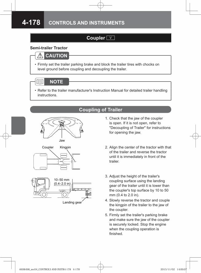
4-178 CONTROLS AND INSTRUMENTS
Coupler V
CAUTIONFirmly set the trailer parking brake and block the trailer tires with chocks on level ground before coupling and decoupling the trailer.
•
NOTERefer to the trailer manufacturer's Instruction Manual for detailed trailer handling instructions.
•
1. Check that the jaw of the coupler is open. If it is not open, refer to "Decoupling of Trailer" for instructions for opening the jaw.
Coupling of Trailer
� �
2. Align the center of the tractor with that of the trailer and reverse the tractor until it is immediately in front of the trailer.
� ��� ��������
3. Adjust the height of the trailer's coupling surface using the landing gear of the trailer until it is lower than the coupler's top surface by 10 to 50 mm (0.4 to 2.0 in).
4. Slowly reverse the tractor and couple the kingpin of the trailer to the jaw of the coupler.
5. Firmly set the trailer's parking brake and make sure the jaw of the coupler is securely locked. Stop the engine when the coupling operation is finished.
Semi-trailer Tractor
��� � ��
������� ���
������� ����
4608498_sec04_CONTROLS AND INSTR4-178 4-1784608498_sec04_CONTROLS AND INSTR4-178 4-178 2015/11/02 14:00:072015/11/02 14:00:07
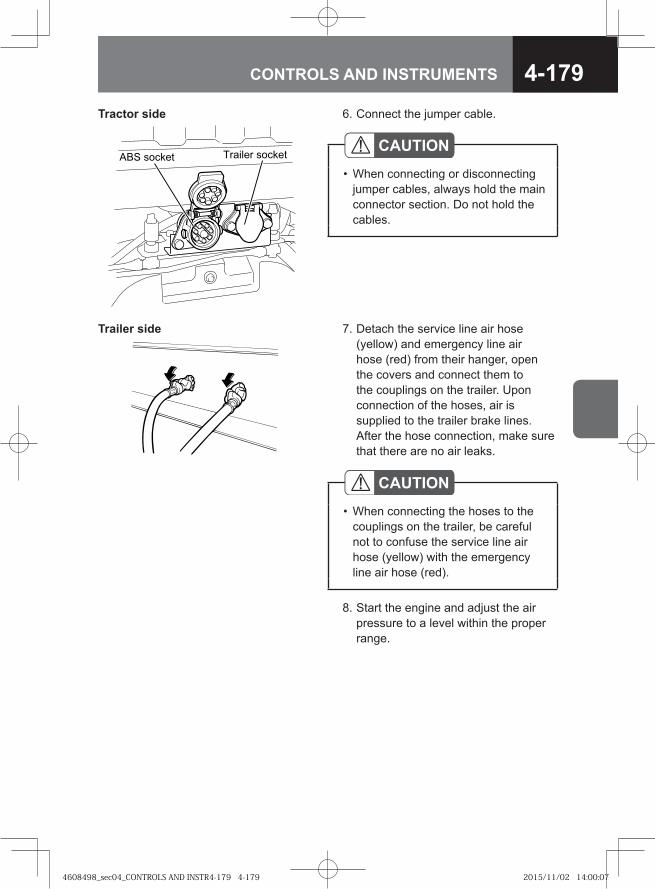
4-179CONTROLS AND INSTRUMENTS
6. Connect the jumper cable.Tractor side
�� ������ ������� ������
7. Detach the service line air hose (yellow) and emergency line air hose (red) from their hanger, open the covers and connect them to the couplings on the trailer. Upon connection of the hoses, air is supplied to the trailer brake lines. After the hose connection, make sure that there are no air leaks.
Trailer side
CAUTIONWhen connecting the hoses to the couplings on the trailer, be careful not to confuse the service line air hose (yellow) with the emergency line air hose (red).
•
8. Start the engine and adjust the air pressure to a level within the proper range.
CAUTIONWhen connecting or disconnecting jumper cables, always hold the main connector section. Do not hold the cables.
•
4608498_sec04_CONTROLS AND INSTR4-179 4-1794608498_sec04_CONTROLS AND INSTR4-179 4-179 2015/11/02 14:00:072015/11/02 14:00:07
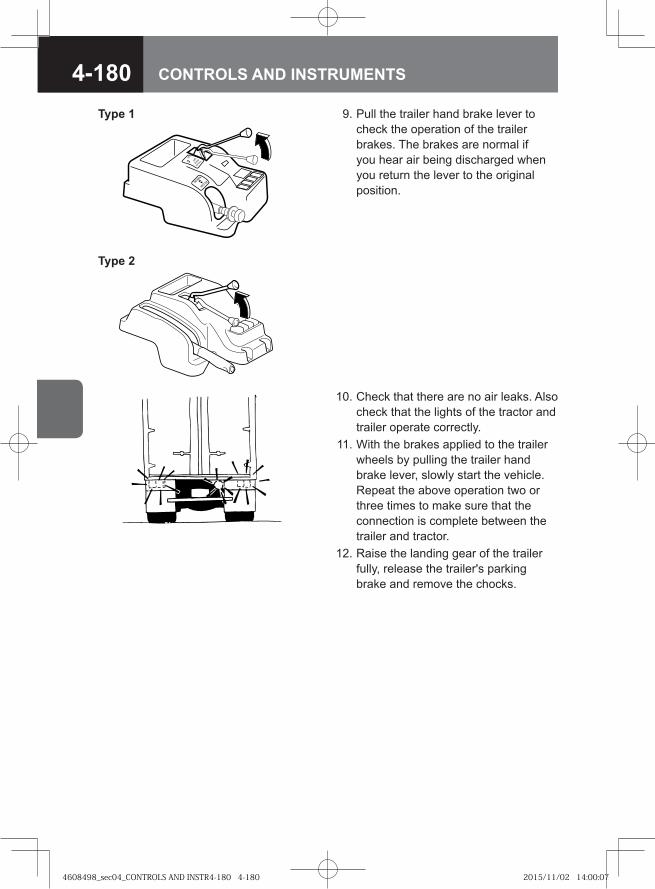
4-180 CONTROLS AND INSTRUMENTS
9. Pull the trailer hand brake lever to check the operation of the trailer brakes. The brakes are normal if you hear air being discharged when you return the lever to the original position.
�� ���
�
�� ��
���
��
Type 1
Type 2
10. Check that there are no air leaks. Also check that the lights of the tractor and trailer operate correctly.
11. With the brakes applied to the trailer wheels by pulling the trailer hand brake lever, slowly start the vehicle. Repeat the above operation two or three times to make sure that the connection is complete between the trailer and tractor.
12. Raise the landing gear of the trailer fully, release the trailer's parking brake and remove the chocks.
4608498_sec04_CONTROLS AND INSTR4-180 4-1804608498_sec04_CONTROLS AND INSTR4-180 4-180 2015/11/02 14:00:072015/11/02 14:00:07
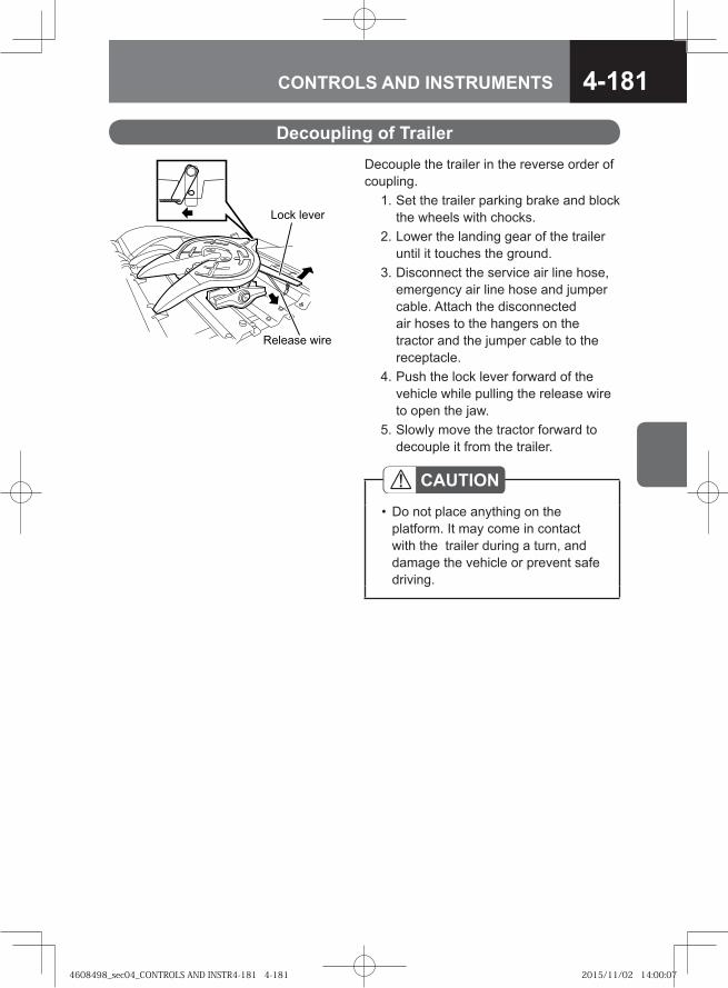
4-181CONTROLS AND INSTRUMENTS
Decouple the trailer in the reverse order of coupling. 1. Set the trailer parking brake and block
the wheels with chocks. 2. Lower the landing gear of the trailer
until it touches the ground. 3. Disconnect the service air line hose,
emergency air line hose and jumper cable. Attach the disconnected air hoses to the hangers on the tractor and the jumper cable to the receptacle.
4. Push the lock lever forward of the vehicle while pulling the release wire to open the jaw.
5. Slowly move the tractor forward to decouple it from the trailer.
������ ����
���� �����
CAUTIONDo not place anything on the platform. It may come in contact with the trailer during a turn, and damage the vehicle or prevent safe driving.
•
Decoupling of Trailer
4608498_sec04_CONTROLS AND INSTR4-181 4-1814608498_sec04_CONTROLS AND INSTR4-181 4-181 2015/11/02 14:00:072015/11/02 14:00:07
4-182 CONTROLS AND INSTRUMENTS
Four Wheel Drive (4WD) Model V
CAUTIONEven a 4WD vehicle does not exempt you from safe driving practices. Operate the accelerator pedal, steering wheel and brake pedal with the same level of caution as when driving a standard rear-wheel drive vehicle.
•
ADVICEBefore using a vehicle that has not been driven for a long period, check the engine, transmission, and transfer case for oil leakage and make sure the oil is at the required levels. If the oil levels are too low, oil is not distributed sufficiently to all components, causing breakdown of these systems.Start the engine and run it at idle at least 5 minutes. Make sure that the engine produces no abnormal noise. Stop the engine, inspect the transfer case for oil leaks, check that the oil is filled up to the specified level, and then drive the vehicle approximately 50 meters (164 ft) forward at a speed of approximately 15 km/h (9 MPH) with the vehicle unloaded. In the case of an FTS model (6HK1 engine model), the inside of the transfer case is lubricated with oil when the vehicle is driven forward.Refer to "Starting the Engine" on page 4-4 to learn how to warm up the engine.
•
•
•
NOTEFSS model, FTS model (6HH1 engine model)The part-time 4WD model allows selecting either two wheel drive (2WD) mode or 4WD mode using the 4WD switch. In addition, the transfer gear control switch also provided on the part-time 4WD model allows you to change between the "HIGH (high-speed)" range and "LOW (low-speed)" range.FTS model (6HK1 engine model)The full-time 4WD model vehicle distributes engine power to all wheels at all times while driving. The center differential lock switch on the full-time 4WD model allows the front and rear axles to be directly connected together. In addition, the transfer gear control switch on the full-time 4WD model allows you to change between the "HIGH (high-speed)" range and "LOW (low-speed)" range.
•
•
4608498_sec04_CONTROLS AND INSTR4-182 4-1824608498_sec04_CONTROLS AND INSTR4-182 4-182 2015/11/02 14:00:082015/11/02 14:00:08
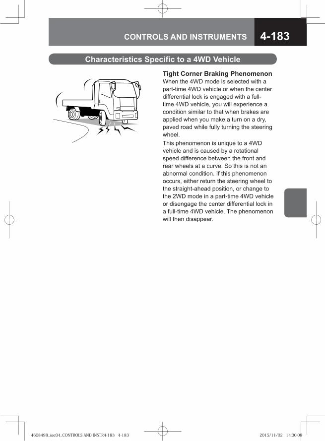
4-183CONTROLS AND INSTRUMENTS
Tight Corner Braking PhenomenonWhen the 4WD mode is selected with a part-time 4WD vehicle or when the center differential lock is engaged with a full-time 4WD vehicle, you will experience a condition similar to that when brakes are applied when you make a turn on a dry, paved road while fully turning the steering wheel.This phenomenon is unique to a 4WD vehicle and is caused by a rotational speed difference between the front and rear wheels at a curve. So this is not an abnormal condition. If this phenomenon occurs, either return the steering wheel to the straight-ahead position, or change to the 2WD mode in a part-time 4WD vehicle or disengage the center differential lock in a full-time 4WD vehicle. The phenomenon will then disappear.
Characteristics Specific to a 4WD Vehicle
4608498_sec04_CONTROLS AND INSTR4-183 4-1834608498_sec04_CONTROLS AND INSTR4-183 4-183 2015/11/02 14:00:082015/11/02 14:00:08
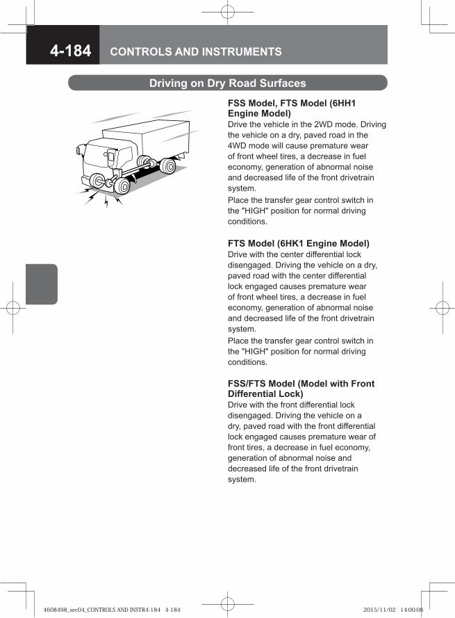
4-184 CONTROLS AND INSTRUMENTS
FSS Model, FTS Model (6HH1 Engine Model)Drive the vehicle in the 2WD mode. Driving the vehicle on a dry, paved road in the 4WD mode will cause premature wear of front wheel tires, a decrease in fuel economy, generation of abnormal noise and decreased life of the front drivetrain system.Place the transfer gear control switch in the "HIGH" position for normal driving conditions.
Driving on Dry Road Surfaces
FTS Model (6HK1 Engine Model)Drive with the center differential lock disengaged. Driving the vehicle on a dry, paved road with the center differential lock engaged causes premature wear of front wheel tires, a decrease in fuel economy, generation of abnormal noise and decreased life of the front drivetrain system.Place the transfer gear control switch in the "HIGH" position for normal driving conditions.
FSS/FTS Model (Model with Front Differential Lock)Drive with the front differential lock disengaged. Driving the vehicle on a dry, paved road with the front differential lock engaged causes premature wear of front tires, a decrease in fuel economy, generation of abnormal noise and decreased life of the front drivetrain system.
4608498_sec04_CONTROLS AND INSTR4-184 4-1844608498_sec04_CONTROLS AND INSTR4-184 4-184 2015/11/02 14:00:082015/11/02 14:00:08
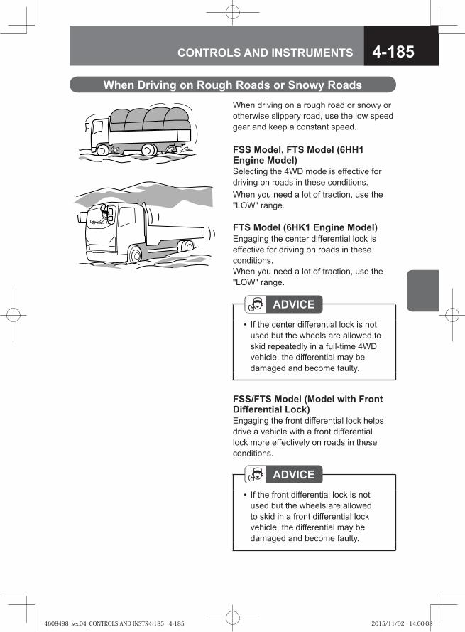
4-185CONTROLS AND INSTRUMENTS
When driving on a rough road or snowy or otherwise slippery road, use the low speed gear and keep a constant speed.
When Driving on Rough Roads or Snowy Roads
ADVICEIf the center differential lock is not used but the wheels are allowed to skid repeatedly in a full-time 4WD vehicle, the differential may be damaged and become faulty.
•
FSS/FTS Model (Model with Front Differential Lock)Engaging the front differential lock helps drive a vehicle with a front differential lock more effectively on roads in these conditions.
ADVICEIf the front differential lock is not used but the wheels are allowed to skid in a front differential lock vehicle, the differential may be damaged and become faulty.
•
FSS Model, FTS Model (6HH1 Engine Model)Selecting the 4WD mode is effective for driving on roads in these conditions.When you need a lot of traction, use the "LOW" range.
FTS Model (6HK1 Engine Model)Engaging the center differential lock is effective for driving on roads in these conditions.When you need a lot of traction, use the "LOW" range.
4608498_sec04_CONTROLS AND INSTR4-185 4-1854608498_sec04_CONTROLS AND INSTR4-185 4-185 2015/11/02 14:00:082015/11/02 14:00:08
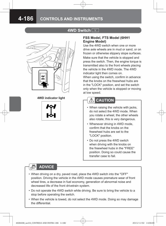
4-186 CONTROLS AND INSTRUMENTS
FSS Model, FTS Model (6HH1 Engine Model)Use the 4WD switch when one or more drive axle wheels are in mud or sand, or on frozen or otherwise slippery slope surfaces.Make sure that the vehicle is stopped and press the switch. Then, the engine torque is transmitted also to the front wheels placing the vehicle in the 4WD mode. The 4WD indicator light then comes on. When using the switch, confirm in advance that the knobs on the freewheel hubs are in the "LOCK" position, and set the switch only when the vehicle is stopped or moving at low speed.
4WD Switch V
CAUTIONWhen raising the vehicle with jacks, do not select the 4WD mode. When you rotate a wheel, the other wheels also rotate; this is very dangerous.Whenever driving in 4WD mode, confirm that the knobs on the freewheel hubs are set to the "LOCK" position.Do not press the 4WD switch when driving with the knobs on the freewheel hubs in the "FREE" position. Doing so could cause the transfer case to fail.
•
•
•
ADVICEWhen driving on a dry, paved road, place the 4WD switch into the "OFF" position. Driving the vehicle in the 4WD mode causes premature wear of front wheel tires, a decrease in fuel economy, generation of abnormal noise and decreased life of the front drivetrain system.Do not operate the 4WD switch while driving. Be sure to bring the vehicle to a stop before operating the switch.When the vehicle is towed, do not select the 4WD mode. Doing so may damage the differential.
•
•
•
4WD indicator light
4608498_sec04_CONTROLS AND INSTR4-186 4-1864608498_sec04_CONTROLS AND INSTR4-186 4-186 2015/11/02 14:00:092015/11/02 14:00:09
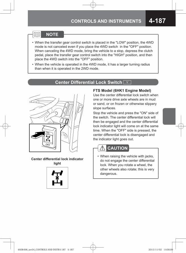
4-187CONTROLS AND INSTRUMENTS
FTS Model (6HK1 Engine Model)Use the center differential lock switch when one or more drive axle wheels are in mud or sand, or on frozen or otherwise slippery slope surfaces.Stop the vehicle and press the "ON" side of the switch. The center differential lock will then be engaged and the center differential lock indicator light will come on at the same time. When the "OFF" side is pressed, the center differential lock is disengaged and the indicator light goes out.
Center Differential Lock Switch V
CAUTIONWhen raising the vehicle with jacks, do not engage the center differential lock. When you rotate a wheel, the other wheels also rotate; this is very dangerous.
•Center differential lock indicator
light
NOTEWhen the transfer gear control switch is placed in the "LOW" position, the 4WD mode is not canceled even if you place the 4WD switch in the "OFF" position. When canceling the 4WD mode, bring the vehicle to a stop, depress the clutch pedal, place the transfer gear control switch into the "HIGH" position, and then place the 4WD switch into the "OFF" position.When the vehicle is operated in the 4WD mode, it has a larger turning radius than when it is operated in the 2WD mode.
•
•
4608498_sec04_CONTROLS AND INSTR4-187 4-1874608498_sec04_CONTROLS AND INSTR4-187 4-187 2015/11/02 14:00:092015/11/02 14:00:09
4-188 CONTROLS AND INSTRUMENTS
ADVICEWhen driving on a dry, paved road, do not engage the center differential lock. Doing so causes premature wear of front wheel tires, a decrease in fuel economy, generation of abnormal noise and decreased life of the front drivetrain system.Do not operate the center differential lock switch while driving. Be sure to bring the vehicle to a stop before operating the switch.When the vehicle is towed, do not engage the center differential lock. Doing so may damage the differential.If the center differential lock is not used but the wheels are allowed to skid, the differential may be damaged and become faulty.
•
•
•
•
NOTE[Center Differential Lock]
This is a differential lock that connects the front axle directly to the rear axle.When the center differential lock is engaged, the vehicle has a larger turning radius than when the center differential lock is not engaged.
••
4608498_sec04_CONTROLS AND INSTR4-188 4-1884608498_sec04_CONTROLS AND INSTR4-188 4-188 2015/11/02 14:00:092015/11/02 14:00:09
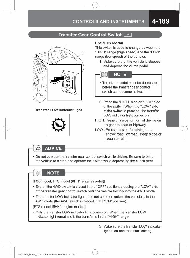
4-189CONTROLS AND INSTRUMENTS
FSS/FTS ModelThis switch is used to change between the "HIGH" range (high speed) and the "LOW" range (low speed) of the transfer. 1. Make sure that the vehicle is stopped
and depress the clutch pedal.
Transfer Gear Control Switch V
NOTEThe clutch pedal must be depressed before the transfer gear control switch can become active.
•
2. Press the "HIGH" side or "LOW" side of the switch. When the "LOW" side of the switch is pressed, the transfer LOW indicator light comes on.
HIGH : Press this side for normal driving on a general road or highway.
LOW : Press this side for driving on a snowy road, icy road, steep slope or rough terrain.
ADVICEDo not operate the transfer gear control switch while driving. Be sure to bring the vehicle to a stop and operate the switch while depressing the clutch pedal.
•
NOTE[FSS model, FTS model (6HH1 engine model)]
Even if the 4WD switch is placed in the "OFF" position, pressing the "LOW" side of the transfer gear control switch puts the vehicle forcibly into the 4WD mode.The transfer LOW indicator light does not come on unless the vehicle is in the 4WD mode (the 4WD switch is placed in the "ON" position).
[FTS model (6HK1 engine model)]Only the transfer LOW indicator light comes on. When the transfer LOW indicator light remains off, the transfer is in the "HIGH" range.
•
•
•
3. Make sure the transfer LOW indicator light is on and then start driving.
Transfer LOW indicator light
4608498_sec04_CONTROLS AND INSTR4-189 4-1894608498_sec04_CONTROLS AND INSTR4-189 4-189 2015/11/02 14:00:102015/11/02 14:00:10
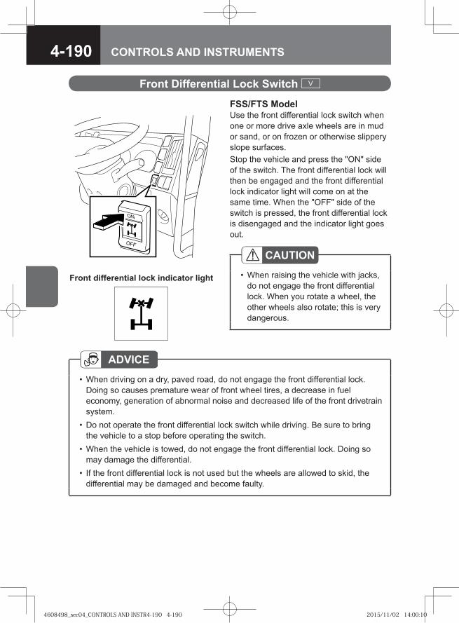
4-190 CONTROLS AND INSTRUMENTS
FSS/FTS ModelUse the front differential lock switch when one or more drive axle wheels are in mud or sand, or on frozen or otherwise slippery slope surfaces.Stop the vehicle and press the "ON" side of the switch. The front differential lock will then be engaged and the front differential lock indicator light will come on at the same time. When the "OFF" side of the switch is pressed, the front differential lock is disengaged and the indicator light goes out.
Front Differential Lock Switch V
CAUTIONWhen raising the vehicle with jacks, do not engage the front differential lock. When you rotate a wheel, the other wheels also rotate; this is very dangerous.
•Front differential lock indicator light
ADVICEWhen driving on a dry, paved road, do not engage the front differential lock. Doing so causes premature wear of front wheel tires, a decrease in fuel economy, generation of abnormal noise and decreased life of the front drivetrain system.Do not operate the front differential lock switch while driving. Be sure to bring the vehicle to a stop before operating the switch.When the vehicle is towed, do not engage the front differential lock. Doing so may damage the differential.If the front differential lock is not used but the wheels are allowed to skid, the differential may be damaged and become faulty.
•
•
•
•
4608498_sec04_CONTROLS AND INSTR4-190 4-1904608498_sec04_CONTROLS AND INSTR4-190 4-190 2015/11/02 14:00:102015/11/02 14:00:10
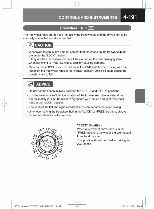
4-191CONTROLS AND INSTRUMENTS
The freewheel hubs are devices that allow the front wheels and the drive shaft to be manually connected and disconnected.
Freewheel Hub V
CAUTIONWhenever driving in 4WD mode, confirm that the knobs on the freewheel hubs are set to the "LOCK" position. If they are free, excessive torque will be exerted on the rear driving system when switching to 4WD low range, possibly causing damage.On a part-time 4WD model, do not press the 4WD switch when driving with the knobs on the freewheel hubs in the "FREE" position. Doing so could cause the transfer case to fail.
•
•
ADVICEDo not set the knobs midway between the "FREE" and "LOCK" positions. In order to ensure sufficient lubrication of the front-wheel drive system, drive approximately 20 km (12 miles) every month with the left and right freewheel hubs in the "LOCK" position. The knob of the left and right freewheel hubs can become hot after driving.Whenever setting the freewheel hub in the "LOCK" or "FREE" position, always do so on both sides of the vehicle.
••
••
"FREE" PositionWhen a freewheel hub's knob is in the "FREE" position, the wheel is disconnected from the drive shaft.This position should be used for driving in 2WD mode.
4608498_sec04_CONTROLS AND INSTR4-191 4-1914608498_sec04_CONTROLS AND INSTR4-191 4-191 2015/11/02 14:00:112015/11/02 14:00:11
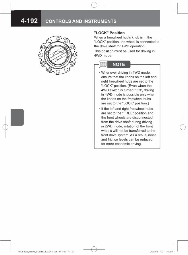
4-192 CONTROLS AND INSTRUMENTS
NOTEWhenever driving in 4WD mode, ensure that the knobs on the left and right freewheel hubs are set to the "LOCK" position. (Even when the 4WD switch is turned "ON", driving in 4WD mode is possible only when the knobs on the freewheel hubs are set to the "LOCK" position.) If the left and right freewheel hubs are set to the "FREE" position and the front wheels are disconnected from the drive shaft during driving in 2WD mode, rotation of the front wheels will not be transferred to the front drive system. As a result, noise and friction levels can be reduced for more economic driving.
•
•
"LOCK" PositionWhen a freewheel hub's knob is in the "LOCK" position, the wheel is connected to the drive shaft for 4WD operation.This position must be used for driving in 4WD mode.
4608498_sec04_CONTROLS AND INSTR4-192 4-1924608498_sec04_CONTROLS AND INSTR4-192 4-192 2015/11/02 14:00:112015/11/02 14:00:11
4-193CONTROLS AND INSTRUMENTS
PTO is a device that is used to provide engine power to special equipment directly from the engine or through the transmission. This manual describes operation of the PTO, but for operation of any special equipment other than the PTO switch, please consult the separate Instruction Manual for the Special Equipment.
Power Take-Off (PTO) V
When Operating the PTO
CAUTIONBefore operating the PTO, make sure that there are no persons or objects around and above the vehicle.Operate the PTO in a level surface.When operating the PTO and special equipment, be sure to place the gearshift lever into the "N" position, firmly pull the parking brake lever and keep the brake pedal fully depressed with your right foot.Do not operate the PTO or special equipment while driving.For the operation method of special equipment, consult the separate Instruction Manual for Special Equipment.Do not shift gears when the PTO is engaged.
•
••
••
•
ADVICEThe PTO of the Smoother model cannot be engaged when the engine speed is high to prevent a failure of the system. PTO cannot be engaged during fast idle control that takes place immediately after the start of a cold engine or when the engine speed is increased using the idling control knob. Wait until engine warm up completes or return the idling control knob to the lowest setting before operating the PTO switch.
•
NOTE[Fast idle control]
A supplementary function to warm up the engine by automatically increasing the idling speed while the engine is cold.
•
4608498_sec04_CONTROLS AND INSTR4-193 4-1934608498_sec04_CONTROLS AND INSTR4-193 4-193 2015/11/02 14:00:112015/11/02 14:00:11
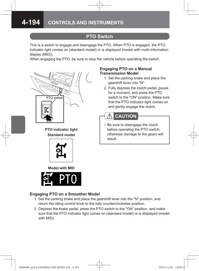
4-194 CONTROLS AND INSTRUMENTS
PTO Switch
Engaging PTO on a Smoother Model 1. Set the parking brake and place the gearshift lever into the "N" position, and
return the idling control knob to the fully counterclockwise position. 2. Depress the brake pedal, press the PTO switch to the "ON" position, and make
sure that the PTO indicator light comes on (standard model) or is displayed (model with MID).
This is a switch to engage and disengage the PTO. When PTO is engaged, the PTO indicator light comes on (standard model) or is displayed (model with multi-information display (MID)).When engaging the PTO, be sure to stop the vehicle before operating the switch.
� � ������
CAUTIONBe sure to disengage the clutch before operating the PTO switch; otherwise damage to the gears will result.
•
Engaging PTO on a Manual Transmission Model 1. Set the parking brake and place the
gearshift lever into "N". 2. Fully depress the clutch pedal, pause
for a moment, and press the PTO switch to the "ON" position. Make sure that the PTO indicator light comes on and gently engage the clutch.
Model with MID
PTO indicator lightStandard model
4608498_sec04_CONTROLS AND INSTR4-194 4-1944608498_sec04_CONTROLS AND INSTR4-194 4-194 2015/11/02 14:00:122015/11/02 14:00:12
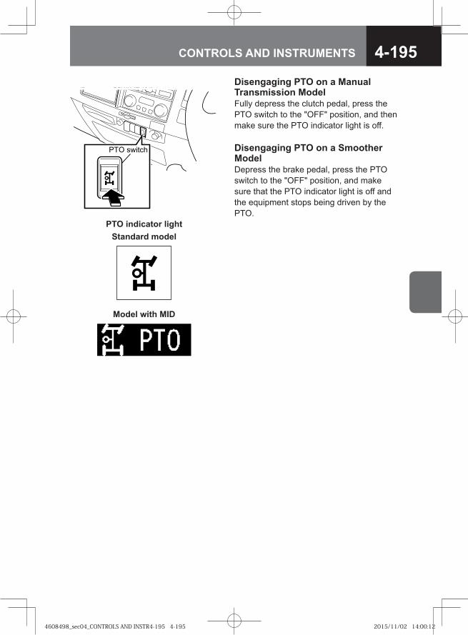
4-195CONTROLS AND INSTRUMENTS
Disengaging PTO on a Manual Transmission ModelFully depress the clutch pedal, press the PTO switch to the "OFF" position, and then make sure the PTO indicator light is off.
� � ������ Disengaging PTO on a Smoother ModelDepress the brake pedal, press the PTO switch to the "OFF" position, and make sure that the PTO indicator light is off and the equipment stops being driven by the PTO.
Model with MID
PTO indicator lightStandard model
4608498_sec04_CONTROLS AND INSTR4-195 4-1954608498_sec04_CONTROLS AND INSTR4-195 4-195 2015/11/02 14:00:122015/11/02 14:00:12
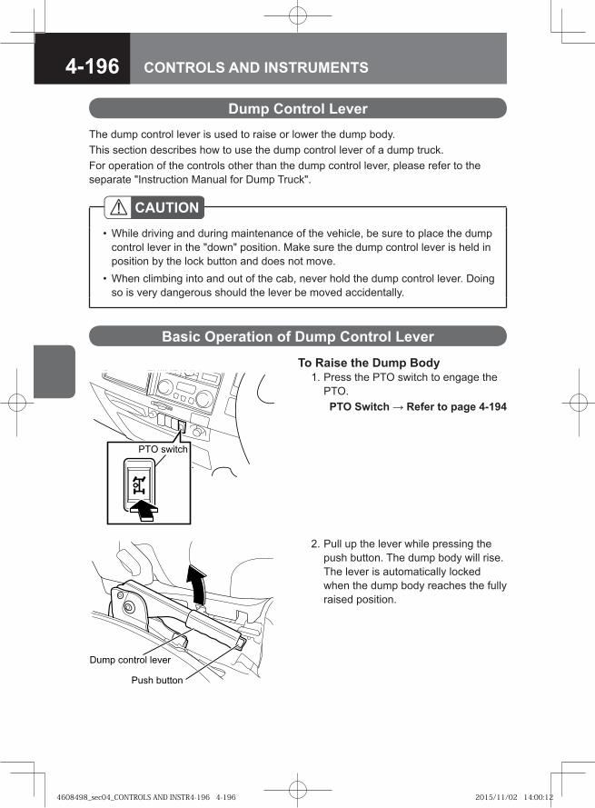
4-196 CONTROLS AND INSTRUMENTS
Dump Control LeverThe dump control lever is used to raise or lower the dump body.This section describes how to use the dump control lever of a dump truck.For operation of the controls other than the dump control lever, please refer to the separate "Instruction Manual for Dump Truck".
CAUTIONWhile driving and during maintenance of the vehicle, be sure to place the dump control lever in the "down" position. Make sure the dump control lever is held in position by the lock button and does not move.When climbing into and out of the cab, never hold the dump control lever. Doing so is very dangerous should the lever be moved accidentally.
•
•
Basic Operation of Dump Control Lever
To Raise the Dump Body 1. Press the PTO switch to engage the
PTO. PTO Switch → Refer to page 4-194
2. Pull up the lever while pressing the push button. The dump body will rise. The lever is automatically locked when the dump body reaches the fully raised position.
� �� ������� �����
� �� � ����
� � ������
4608498_sec04_CONTROLS AND INSTR4-196 4-1964608498_sec04_CONTROLS AND INSTR4-196 4-196 2015/11/02 14:00:122015/11/02 14:00:12
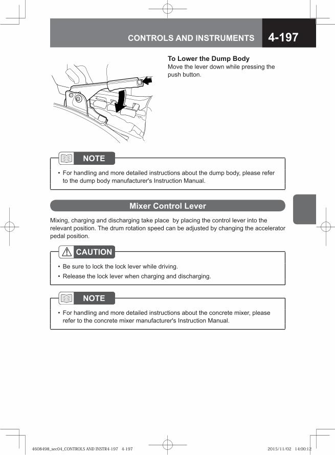
4-197CONTROLS AND INSTRUMENTS
To Lower the Dump BodyMove the lever down while pressing the push button.
Mixer Control LeverMixing, charging and discharging take place by placing the control lever into the relevant position. The drum rotation speed can be adjusted by changing the accelerator pedal position.
NOTEFor handling and more detailed instructions about the dump body, please refer to the dump body manufacturer's Instruction Manual.
•
NOTEFor handling and more detailed instructions about the concrete mixer, please refer to the concrete mixer manufacturer's Instruction Manual.
•
CAUTIONBe sure to lock the lock lever while driving.Release the lock lever when charging and discharging.
••
4608498_sec04_CONTROLS AND INSTR4-197 4-1974608498_sec04_CONTROLS AND INSTR4-197 4-197 2015/11/02 14:00:122015/11/02 14:00:12
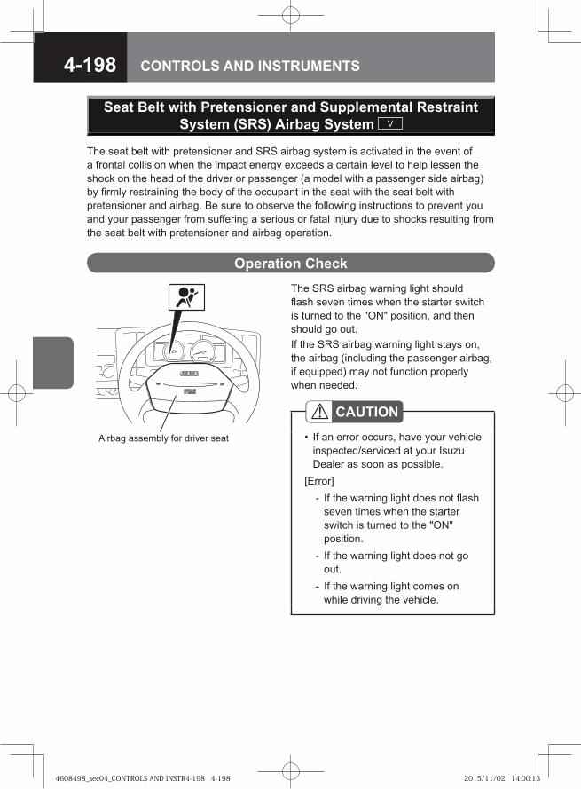
4-198 CONTROLS AND INSTRUMENTS
The seat belt with pretensioner and SRS airbag system is activated in the event of a frontal collision when the impact energy exceeds a certain level to help lessen the shock on the head of the driver or passenger (a model with a passenger side airbag) by firmly restraining the body of the occupant in the seat with the seat belt with pretensioner and airbag. Be sure to observe the following instructions to prevent you and your passenger from suffering a serious or fatal injury due to shocks resulting from the seat belt with pretensioner and airbag operation.
Operation CheckThe SRS airbag warning light should flash seven times when the starter switch is turned to the "ON" position, and then should go out.If the SRS airbag warning light stays on, the airbag (including the passenger airbag, if equipped) may not function properly when needed.
CAUTIONIf an error occurs, have your vehicle inspected/serviced at your Isuzu Dealer as soon as possible.
[Error]If the warning light does not flash seven times when the starter switch is turned to the "ON" position.If the warning light does not go out.If the warning light comes on while driving the vehicle.
•
-
-
-
Seat Belt with Pretensioner and Supplemental Restraint System (SRS) Airbag System V
Airbag assembly for driver seat
4608498_sec04_CONTROLS AND INSTR4-198 4-1984608498_sec04_CONTROLS AND INSTR4-198 4-198 2015/11/02 14:00:132015/11/02 14:00:13
4-199CONTROLS AND INSTRUMENTS
WARNING
If you make any unauthorized modification to the vehicle or install an unauthorized accessory, the seat belt with pretensioner and airbag (including the passenger side airbag, if equipped) may not operate correctly.If the steering wheel is changed to a non-standard one or a sticker is attached to the steering wheel pad, there would be a danger of system malfunction or the sticker flying off in the event of system activation. Attaching stickers or placing such things as accessories or air fresheners on the top surface of the instrument panel is also dangerous. They may prevent normal operation of the airbag or would fly off in the event of system activation.Doing any of the following may require special precautions. Be sure to consult your Isuzu Dealer in advance. Failure to do so may cause the seat belt with pretensioner and airbag to be unduly activated, causing the seat belt to be unexpectedly retracted or the airbag to be suddenly inflated, causing an injury to the occupant. Doing any of them improperly will adversely affect on the operation of the system, causing a malfunction or failure.
Repair or replacement of the steering wheel, instrument panel, center console and parts around the accelerator pedalRepair or replacement of the seat belt with pretensioner and airbag (including the passenger airbag, if equipped), their disposal, or scrapping the vehicle equipped with a seat belt with pretensioner and airbagInstalling audio equipment or accessories, or modification of body installationsRepainting of vehicle front and cab panels
•
•
•
-
-
--
CAUTIONHave your vehicle inspected at the nearest Isuzu Dealer promptly if you encounter any of the following conditions.
The SRS airbag warning light shows an abnormality.The seat belt with pretensioner and airbag (including the passenger side airbag, if equipped) are activated in a collision. (The SRS airbag warning light comes on.)
••
CAUTION (Continued)
4608498_sec04_CONTROLS AND INSTR4-199 4-1994608498_sec04_CONTROLS AND INSTR4-199 4-199 2015/11/02 14:00:132015/11/02 14:00:13
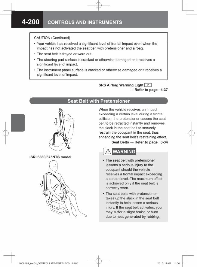
4-200 CONTROLS AND INSTRUMENTS
When the vehicle receives an impact exceeding a certain level during a frontal collision, the pretensioner causes the seat belt to be retracted instantly and removes the slack in the seat belt to securely restrain the occupant in the seat, thus enhancing the seat belt's restraining effect. Seat Belts → Refer to page 3-34
Seat Belt with Pretensioner
SRS Airbag Warning Light V → Refer to page 4-37
ISRI 6860/875NTS model
CAUTION (Continued)Your vehicle has received a significant level of frontal impact even when the impact has not activated the seat belt with pretensioner and airbag.The seat belt is frayed or worn out.The steering pad surface is cracked or otherwise damaged or it receives a significant level of impact.The instrument panel surface is cracked or otherwise damaged or it receives a significant level of impact.
•
••
•
WARNING
The seat belt with pretensioner lessens a serious injury to the occupant should the vehicle receives a frontal impact exceeding a certain level. The maximum effect is achieved only if the seat belt is correctly worn.The seat belts with pretensioner takes up the slack in the seat belt instantly to help lessen a serious injury. If the seat belt activates, you may suffer a slight bruise or burn due to heat generated by rubbing.
•
•
4608498_sec04_CONTROLS AND INSTR4-200 4-2004608498_sec04_CONTROLS AND INSTR4-200 4-200 2015/11/02 14:00:132015/11/02 14:00:13
4-201CONTROLS AND INSTRUMENTS
CAUTIONDo not remove or disassemble the seat belt. Accidental activation of the system may causes parts to fly off, injuring you or will cause the system to malfunction.
•
ADVICEOnce activated in a collision, the seat belt with pretensioner cannot be reused. The seat belt must be replaced immediately at the nearest Isuzu Dealer.
•
NOTEEven if the pretensioner function fails, the seat belt with pretensioner can operate as a regular seat belt (with emergency locking retractor (ELR)), satisfactorily providing normal seat belt function.The seat belt with pretensioner generate a sound at the moment it is activated.When the seat belt with pretensioner and SRS airbag system is activated in a collision, the warning light comes on.
•
••
4608498_sec04_CONTROLS AND INSTR4-201 4-2014608498_sec04_CONTROLS AND INSTR4-201 4-201 2015/11/02 14:00:142015/11/02 14:00:14
4-202 CONTROLS AND INSTRUMENTS
The SRS airbag system (including the passenger side airbag, if equipped) supplements the seat belt to disperse and lessen the impact on the occupant's body by its inflation upon activation of the seat belt with pretensioner at the time of a frontal collision that causes an impact exceeding a certain level.
SRS Airbag
WARNING
The airbag supplements the occupant protection effect of the seat belt by being activated together with the seat belt with pretensioner to reduce severity of damage to the occupant should the vehicle receive a frontal impact exceeding a certain level. The maximum effect is achieved only if the seat belt is correctly worn.The airbag does not replace the seat belt. Be sure to wear the seat belt.The airbag is instantly inflated with considerable force to reduce serious injury. If the airbag inflates, you may suffer a slight bruise or burn due to heat generated by rubbing.
•
••
NOTEThe airbag is quickly deflated after deployment and does not hinder visibility.When the seat belt with pretensioner and airbag are activated in a collision, the SRS airbag warning light comes on.
••
ADVICEWhen the airbag is inflated, a sound and white smoke are produced but this is not the result of a fire. This white smoke is not detrimental to your health. However, if residue (gas and so on) adheres to your eyes and skin, rinse them with water as soon as possible. Although it is rare, a person with delicate skin may suffer from irritation.Immediately after the airbag is inflated, the metal portion that inflates the airbag gets hot. Do not touch it.The airbag cannot be reused once it is inflated. Immediately replace it at the nearest Isuzu Dealer.
•
•
•
4608498_sec04_CONTROLS AND INSTR4-202 4-2024608498_sec04_CONTROLS AND INSTR4-202 4-202 2015/11/02 14:00:142015/11/02 14:00:14
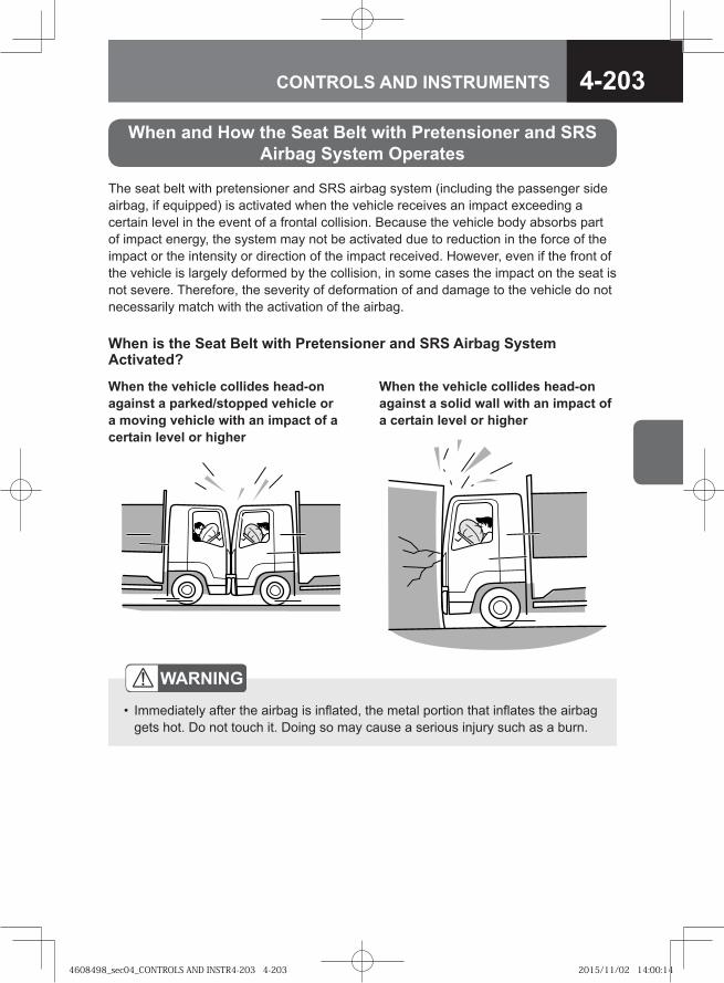
4-203CONTROLS AND INSTRUMENTS
The seat belt with pretensioner and SRS airbag system (including the passenger side airbag, if equipped) is activated when the vehicle receives an impact exceeding a certain level in the event of a frontal collision. Because the vehicle body absorbs part of impact energy, the system may not be activated due to reduction in the force of the impact or the intensity or direction of the impact received. However, even if the front of the vehicle is largely deformed by the collision, in some cases the impact on the seat is not severe. Therefore, the severity of deformation of and damage to the vehicle do not necessarily match with the activation of the airbag.
When and How the Seat Belt with Pretensioner and SRS Airbag System Operates
When is the Seat Belt with Pretensioner and SRS Airbag System Activated?
When the vehicle collides head-on against a solid wall with an impact of a certain level or higher
When the vehicle collides head-on against a parked/stopped vehicle or a moving vehicle with an impact of a certain level or higher
WARNING
Immediately after the airbag is inflated, the metal portion that inflates the airbag gets hot. Do not touch it. Doing so may cause a serious injury such as a burn.
•
4608498_sec04_CONTROLS AND INSTR4-203 4-2034608498_sec04_CONTROLS AND INSTR4-203 4-203 2015/11/02 14:00:142015/11/02 14:00:14
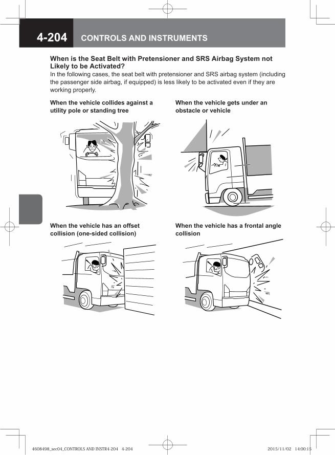
4-204 CONTROLS AND INSTRUMENTS
When is the Seat Belt with Pretensioner and SRS Airbag System not Likely to be Activated?In the following cases, the seat belt with pretensioner and SRS airbag system (including the passenger side airbag, if equipped) is less likely to be activated even if they are working properly.
When the vehicle gets under an obstacle or vehicle
When the vehicle collides against a utility pole or standing tree
When the vehicle has a frontal angle collision
When the vehicle has an offset collision (one-sided collision)
4608498_sec04_CONTROLS AND INSTR4-204 4-2044608498_sec04_CONTROLS AND INSTR4-204 4-204 2015/11/02 14:00:152015/11/02 14:00:15
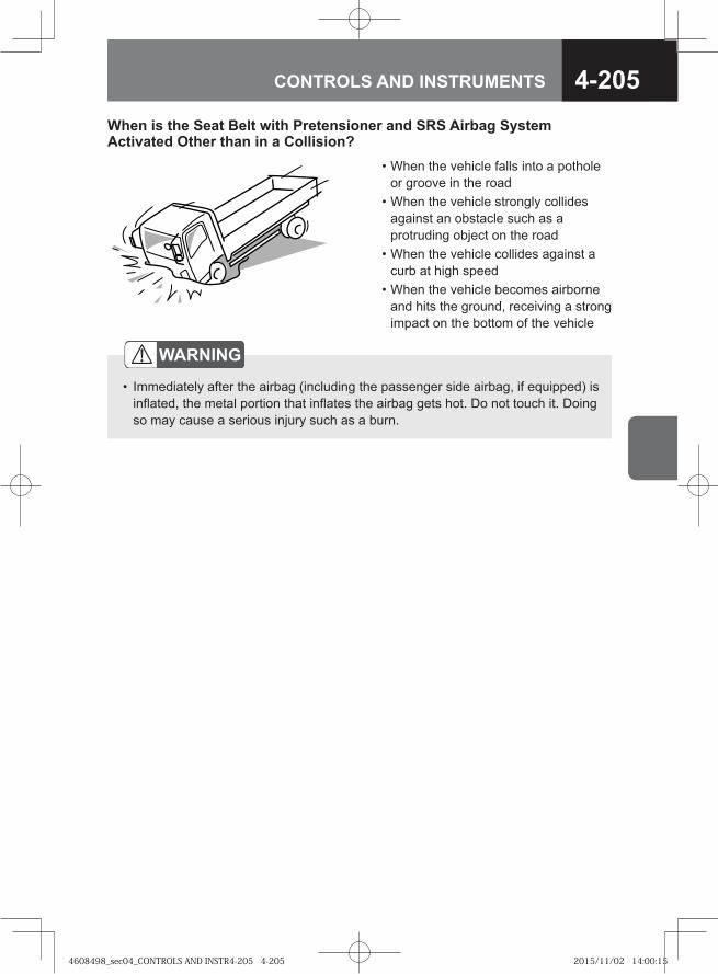
4-205CONTROLS AND INSTRUMENTS
• When the vehicle falls into a pothole or groove in the road
• When the vehicle strongly collides against an obstacle such as a protruding object on the road
• When the vehicle collides against a curb at high speed
• When the vehicle becomes airborne and hits the ground, receiving a strong impact on the bottom of the vehicle
When is the Seat Belt with Pretensioner and SRS Airbag System Activated Other than in a Collision?
WARNING
Immediately after the airbag (including the passenger side airbag, if equipped) is inflated, the metal portion that inflates the airbag gets hot. Do not touch it. Doing so may cause a serious injury such as a burn.
•
4608498_sec04_CONTROLS AND INSTR4-205 4-2054608498_sec04_CONTROLS AND INSTR4-205 4-205 2015/11/02 14:00:152015/11/02 14:00:15
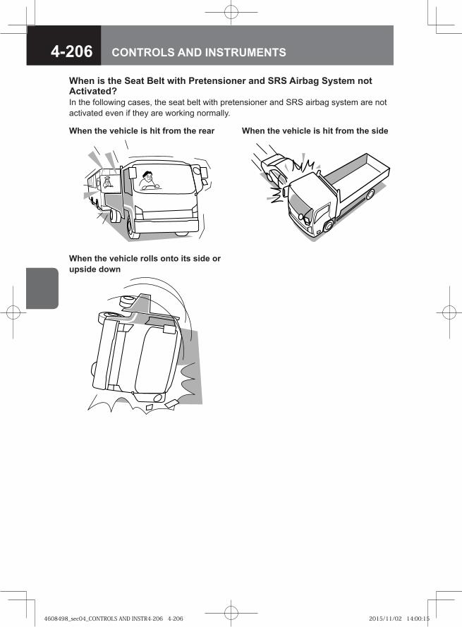
4-206 CONTROLS AND INSTRUMENTS
When is the Seat Belt with Pretensioner and SRS Airbag System not Activated?In the following cases, the seat belt with pretensioner and SRS airbag system are not activated even if they are working normally.
When the vehicle is hit from the sideWhen the vehicle is hit from the rear
When the vehicle rolls onto its side or upside down
4608498_sec04_CONTROLS AND INSTR4-206 4-2064608498_sec04_CONTROLS AND INSTR4-206 4-206 2015/11/02 14:00:152015/11/02 14:00:15
4-207CONTROLS AND INSTRUMENTS
WARNING
Body repair and paint of the cab, repair around the side panel, steering wheel, instrument panel and center console, installation of accessories such as audio equipment and repair around the dashboard may adversely affect the SRS airbag system (including the passenger side airbag, if equipped) or cause a fatal, serious injury due to the impact of the airbag when it is unexpectedly inflates. Never make these repairs yourself, but be sure to consult your Isuzu Dealer.If you make modifications to the front of the vehicle (bumper, frame, etc.), install equipment (snow plow, for example), or change the vehicle height using unauthorized methods and/or materials, the SRS airbag system may fail to operate normally. Be sure to consult your Isuzu Dealer.Special handling is required when an airbag is disposed of. When discarding a vehicle equipped with an SRS airbag system, consult your Isuzu Dealer.
•
•
•
CAUTIONHave your vehicle inspected at the nearest Isuzu Dealer at once in the following cases.
When the SRS airbag warning light does not go out or comes on during driving.When the airbag is inflated.When the airbag was not inflated although the vehicle received a significant frontal impact.When the steering pad surface is cracked or otherwise damaged or it receives an impact.When the instrument panel surface is cracked or otherwise damaged or it receives an impact.
•••
•
•
NOTEWhen the airbag is inflated, gases like white smoke are produced but this is not a fire. This white smoke is not detrimental to your health. However, if residue (gas and so on) adheres to your eyes and skin, rinse them with water as soon as possible. Although it is rare, a person with delicate skin may suffer from irritation.The airbag cannot be reused once it is inflated. Replace it at the nearest Isuzu Dealer.
•
•
4608498_sec04_CONTROLS AND INSTR4-207 4-2074608498_sec04_CONTROLS AND INSTR4-207 4-207 2015/11/02 14:00:152015/11/02 14:00:15
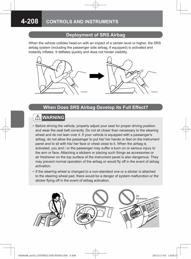
4-208 CONTROLS AND INSTRUMENTS
Deployment of SRS AirbagWhen the vehicle collides head-on with an impact of a certain level or higher, the SRS airbag system (including the passenger side airbag, if equipped) is activated and instantly inflates. It deflates quickly and does not hinder visibility.
When Does SRS Airbag Develop its Full Effect?
WARNING
Before driving the vehicle, properly adjust your seat for proper driving position and wear the seat belt correctly. Do not sit closer than necessary to the steering wheel and do not lean over it. If your vehicle is equipped with a passenger's airbag, do not allow the passenger to put his/ her hands or feet on the instrument panel and to sit with his/ her face or chest close to it. When the airbag is activated, you and / or the passenger may suffer a burn on or serious injury to the arm or face. Attaching a stickers or placing such things as accessories or air freshener on the top surface of the instrument panel is also dangerous. They may prevent normal operation of the airbag or would fly off in the event of airbag activation.If the steering wheel is changed to a non-standard one or a sticker is attached to the steering wheel pad, there would be a danger of system malfunction or the sticker flying off in the event of airbag activation.
•
•
Air freshener
4608498_sec04_CONTROLS AND INSTR4-208 4-2084608498_sec04_CONTROLS AND INSTR4-208 4-208 2015/11/02 14:00:152015/11/02 14:00:15
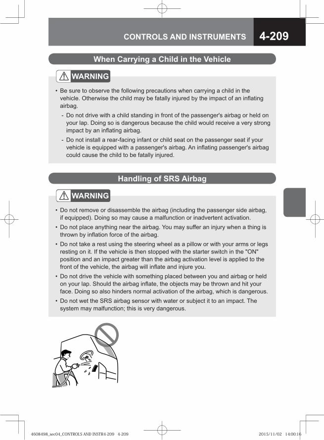
4-209CONTROLS AND INSTRUMENTS
WARNING
Do not remove or disassemble the airbag (including the passenger side airbag, if equipped). Doing so may cause a malfunction or inadvertent activation.Do not place anything near the airbag. You may suffer an injury when a thing is thrown by inflation force of the airbag.Do not take a rest using the steering wheel as a pillow or with your arms or legs resting on it. If the vehicle is then stopped with the starter switch in the "ON" position and an impact greater than the airbag activation level is applied to the front of the vehicle, the airbag will inflate and injure you.Do not drive the vehicle with something placed between you and airbag or held on your lap. Should the airbag inflate, the objects may be thrown and hit your face. Doing so also hinders normal activation of the airbag, which is dangerous.Do not wet the SRS airbag sensor with water or subject it to an impact. The system may malfunction; this is very dangerous.
•
•
•
•
•
When Carrying a Child in the Vehicle
WARNING
Be sure to observe the following precautions when carrying a child in the vehicle. Otherwise the child may be fatally injured by the impact of an inflating airbag.
Do not drive with a child standing in front of the passenger's airbag or held on your lap. Doing so is dangerous because the child would receive a very strong impact by an inflating airbag.Do not install a rear-facing infant or child seat on the passenger seat if your vehicle is equipped with a passenger's airbag. An inflating passenger's airbag could cause the child to be fatally injured.
•
-
-
Handling of SRS Airbag
4608498_sec04_CONTROLS AND INSTR4-209 4-2094608498_sec04_CONTROLS AND INSTR4-209 4-209 2015/11/02 14:00:162015/11/02 14:00:16

4-210 CONTROLS AND INSTRUMENTS
4608498_sec04_CONTROLS AND INSTR4-210 4-2104608498_sec04_CONTROLS AND INSTR4-210 4-210 2015/11/02 14:00:162015/11/02 14:00:16
● Air Outlets 5-2
● Ventilator V 5-4
● Heater/Manual Air Conditioner/Cooler V 5-6
● Interior Lights 5-16
● Sun Visor 5-17
● Cigarette Lighter V 5-17
● Accessory Power Outlet (24V) V 5-19
● Ashtray 5-20
● Seatback Pocket (Driver's Side) V 5-21
● Small Article Storage Pocket V 5-21
● Card Holder 5-21
● Glove Compartment with Lid V 5-22
● Glove Compartment without Lid V 5-23
● Center Console Box V 5-23
● Coin Holder 5-24
● Overhead Shelf 5-24
● Cup Holder V 5-25
● Coat Hook V 5-25
● Hook 5-26
● Operating Tips for the Radio and CD Player 5-26
● Antenna 5-29
● AM/FM Radio V 5-30
● CD Player (with AM/FM Radio) V 5-38
5COMFORT AND CONVENIENCE
4608498_sec05_COMFORT AND CONVEN5-1 5-14608498_sec05_COMFORT AND CONVEN5-1 5-1 2015/11/02 14:11:082015/11/02 14:11:08
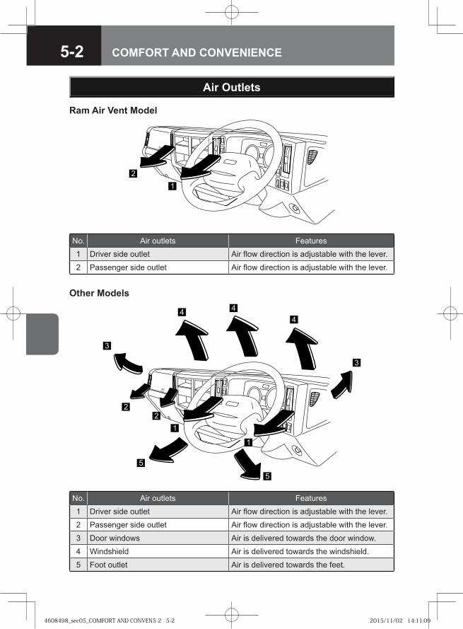
5-2 COMFORT AND CONVENIENCE
Air Outlets
�
�
��
�
�
�
No. Air outlets Features1 Driver side outlet Air flow direction is adjustable with the lever.
2 Passenger side outlet Air flow direction is adjustable with the lever.
3 Door windows Air is delivered towards the door window.
4 Windshield Air is delivered towards the windshield.
5 Foot outlet Air is delivered towards the feet.
Other Models
No. Air outlets Features1 Driver side outlet Air flow direction is adjustable with the lever.
2 Passenger side outlet Air flow direction is adjustable with the lever.
Ram Air Vent Model
�
4608498_sec05_COMFORT AND CONVEN5-2 5-24608498_sec05_COMFORT AND CONVEN5-2 5-2 2015/11/02 14:11:092015/11/02 14:11:09
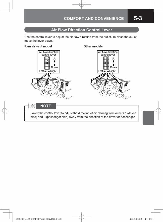
5-3COMFORT AND CONVENIENCE
Air Flow Direction Control LeverUse the control lever to adjust the air flow direction from the outlet. To close the outlet, move the lever down.
Ram air vent model Other models
�� �����
����
��� ���� ���������������� �����
��
�� ������
����
��� ���� ���������������� �����
��
NOTELower the control lever to adjust the direction of air blowing from outlets 1 (driver side) and 2 (passenger side) away from the direction of the driver or passenger.
•
4608498_sec05_COMFORT AND CONVEN5-3 5-34608498_sec05_COMFORT AND CONVEN5-3 5-3 2015/11/02 14:11:092015/11/02 14:11:09
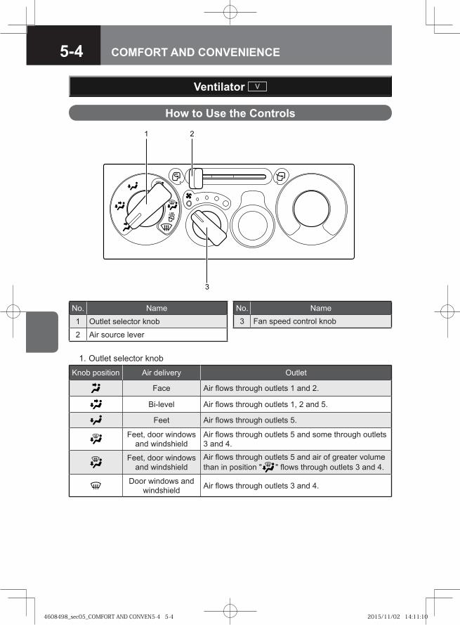
5-4 COMFORT AND CONVENIENCE
How to Use the Controls
Ventilator V
1. Outlet selector knob
�
�
Knob position Air delivery Outlet
Face Air flows through outlets 1 and 2.
Bi-level Air flows through outlets 1, 2 and 5.
Feet Air flows through outlets 5.
Feet, door windows and windshield
Air flows through outlets 5 and some through outlets 3 and 4.
Feet, door windows and windshield
Air flows through outlets 5 and air of greater volume than in position " " flows through outlets 3 and 4.
Door windows and windshield Air flows through outlets 3 and 4.
No. Name
1 Outlet selector knob
2 Air source lever
No. Name3 Fan speed control knob
4608498_sec05_COMFORT AND CONVEN5-4 5-44608498_sec05_COMFORT AND CONVEN5-4 5-4 2015/11/02 14:11:102015/11/02 14:11:10
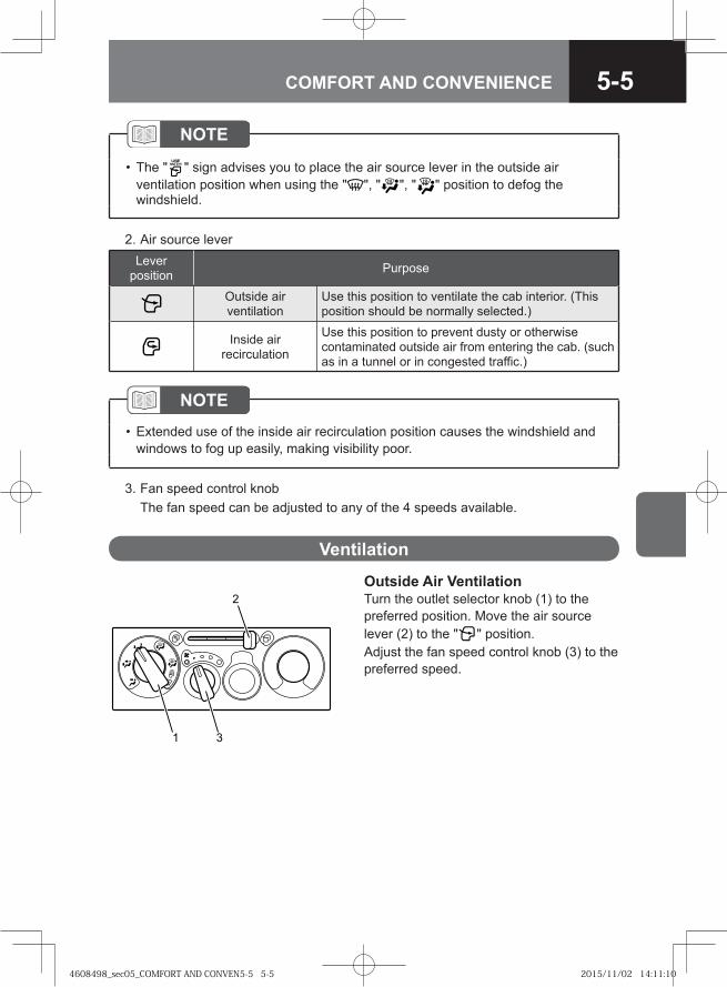
5-5COMFORT AND CONVENIENCE
NOTE
The " " sign advises you to place the air source lever in the outside air ventilation position when using the " ", " ", " " position to defog the windshield.
•
2. Air source lever
NOTEExtended use of the inside air recirculation position causes the windshield and windows to fog up easily, making visibility poor.
•
3. Fan speed control knob The fan speed can be adjusted to any of the 4 speeds available.
Lever position Purpose
Outside air ventilation
Use this position to ventilate the cab interior. (This position should be normally selected.)
Inside air recirculation
Use this position to prevent dusty or otherwise contaminated outside air from entering the cab. (such as in a tunnel or in congested traffic.)
Outside Air VentilationTurn the outlet selector knob (1) to the preferred position. Move the air source lever (2) to the " " position.Adjust the fan speed control knob (3) to the preferred speed.
Ventilation
�
4608498_sec05_COMFORT AND CONVEN5-5 5-54608498_sec05_COMFORT AND CONVEN5-5 5-5 2015/11/02 14:11:102015/11/02 14:11:10
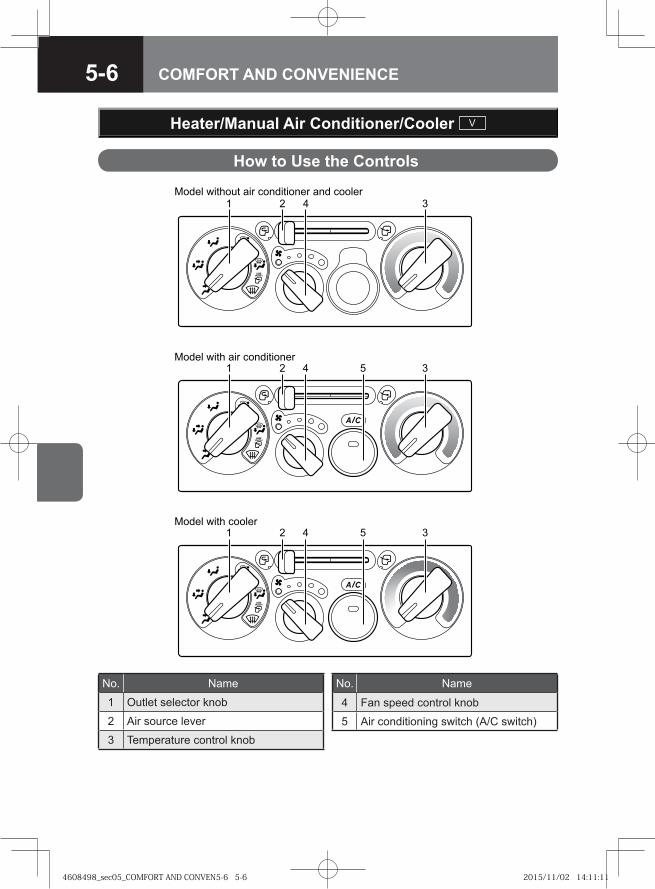
5-6 COMFORT AND CONVENIENCE
How to Use the Controls
Heater/Manual Air Conditioner/Cooler V
No. Name
1 Outlet selector knob
2 Air source lever
3 Temperature control knob
No. Name
4 Fan speed control knob
5 Air conditioning switch (A/C switch)
� � �
�
� ��� ���� �� ��� � ����� ��� ��� � ���
� ��� ���� ��� � ����� ���
� � �
� ��� ���� � ���
�
4608498_sec05_COMFORT AND CONVEN5-6 5-64608498_sec05_COMFORT AND CONVEN5-6 5-6 2015/11/02 14:11:112015/11/02 14:11:11
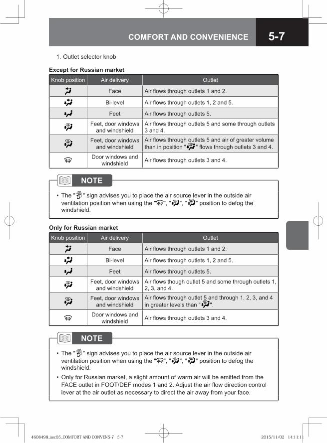
5-7COMFORT AND CONVENIENCE
1. Outlet selector knob
NOTE
The " " sign advises you to place the air source lever in the outside air ventilation position when using the " ", " ", " " position to defog the windshield.
•
Except for Russian marketKnob position Air delivery Outlet
Face Air flows through outlets 1 and 2.
Bi-level Air flows through outlets 1, 2 and 5.
Feet Air flows through outlets 5.
Feet, door windows and windshield
Air flows through outlets 5 and some through outlets 3 and 4.
Feet, door windows and windshield
Air flows through outlets 5 and air of greater volume than in position " " flows through outlets 3 and 4.
Door windows and windshield Air flows through outlets 3 and 4.
Only for Russian marketKnob position Air delivery Outlet
Face Air flows through outlets 1 and 2.
Bi-level Air flows through outlets 1, 2 and 5.
Feet Air flows through outlets 5.
Feet, door windows and windshield
Air flows though outlet 5 and some through outlets 1, 2, 3, and 4.
Feet, door windows and windshield
Air flows through outlet 5 and through 1, 2, 3, and 4 in greater levels than " ".
Door windows and windshield Air flows through outlets 3 and 4.
NOTE
The " " sign advises you to place the air source lever in the outside air ventilation position when using the " ", " ", " " position to defog the windshield.Only for Russian market, a slight amount of warm air will be emitted from the FACE outlet in FOOT/DEF modes 1 and 2. Adjust the air flow direction control lever at the air outlet as necessary to direct the air away from your face.
•
•
4608498_sec05_COMFORT AND CONVEN5-7 5-74608498_sec05_COMFORT AND CONVEN5-7 5-7 2015/11/02 14:11:112015/11/02 14:11:11
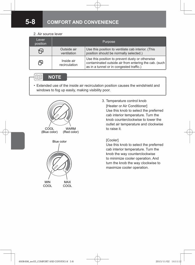
5-8 COMFORT AND CONVENIENCE
3. Temperature control knob [Heater or Air Conditioner]
Use this knob to select the preferred cab interior temperature. Turn the knob counterclockwise to lower the outlet air temperature and clockwise to raise it.
[Cooler]Use this knob to select the preferred cab interior temperature. Turn the knob the way counterclockwise to minimize cooler operation. And turn the knob the way clockwise to maximize cooler operation.
� ������ ������
�������� ������
� �� �� ��
���
����
���
����
2. Air source lever
NOTEExtended use of the inside air recirculation position causes the windshield and windows to fog up easily, making visibility poor.
•
Lever position Purpose
Outside air ventilation
Use this position to ventilate cab interior. (This position should be normally selected.)
Inside air recirculation
Use this position to prevent dusty or otherwise contaminated outside air from entering the cab. (such as in a tunnel or in congested traffic.)
4608498_sec05_COMFORT AND CONVEN5-8 5-84608498_sec05_COMFORT AND CONVEN5-8 5-8 2015/11/02 14:11:122015/11/02 14:11:12
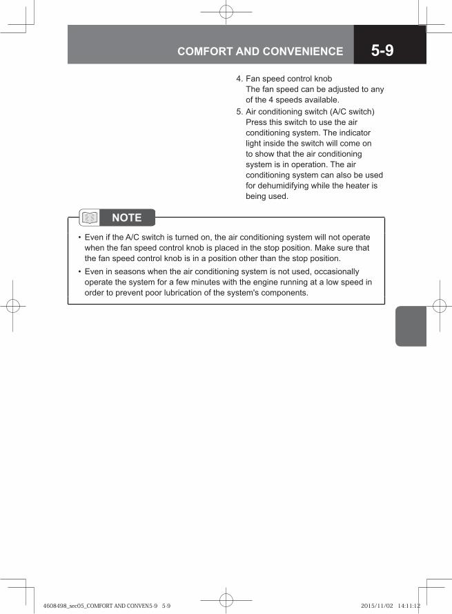
5-9COMFORT AND CONVENIENCE
4. Fan speed control knobThe fan speed can be adjusted to any of the 4 speeds available.
5. Air conditioning switch (A/C switch)Press this switch to use the air conditioning system. The indicator light inside the switch will come on to show that the air conditioning system is in operation. The air conditioning system can also be used for dehumidifying while the heater is being used.
NOTEEven if the A/C switch is turned on, the air conditioning system will not operate when the fan speed control knob is placed in the stop position. Make sure that the fan speed control knob is in a position other than the stop position.Even in seasons when the air conditioning system is not used, occasionally operate the system for a few minutes with the engine running at a low speed in order to prevent poor lubrication of the system's components.
•
•
4608498_sec05_COMFORT AND CONVEN5-9 5-94608498_sec05_COMFORT AND CONVEN5-9 5-9 2015/11/02 14:11:122015/11/02 14:11:12
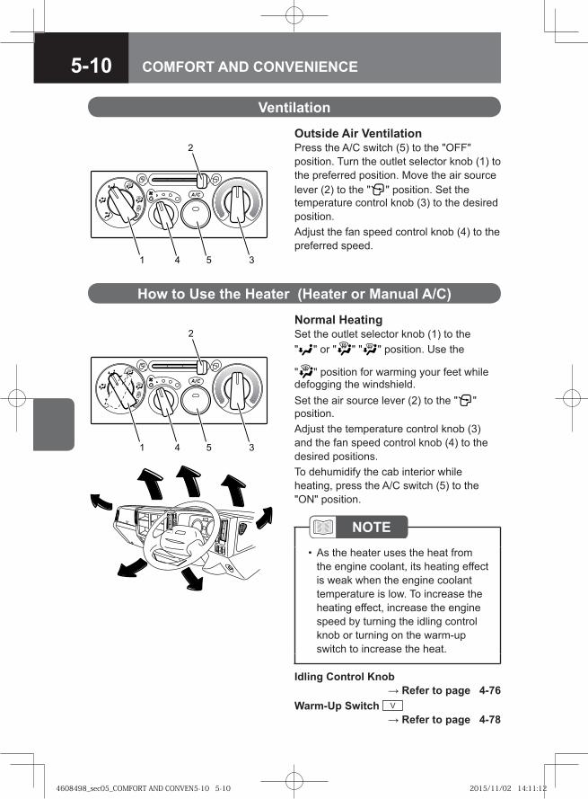
5-10 COMFORT AND CONVENIENCE
Outside Air VentilationPress the A/C switch (5) to the "OFF" position. Turn the outlet selector knob (1) to the preferred position. Move the air source lever (2) to the " " position. Set the temperature control knob (3) to the desired position.Adjust the fan speed control knob (4) to the preferred speed.
Ventilation
� � �
Normal HeatingSet the outlet selector knob (1) to the " " or " " " " position. Use the
" " position for warming your feet while defogging the windshield. Set the air source lever (2) to the " " position.Adjust the temperature control knob (3) and the fan speed control knob (4) to the desired positions. To dehumidify the cab interior while heating, press the A/C switch (5) to the "ON" position.
How to Use the Heater (Heater or Manual A/C)
� � �
NOTEAs the heater uses the heat from the engine coolant, its heating effect is weak when the engine coolant temperature is low. To increase the heating effect, increase the engine speed by turning the idling control knob or turning on the warm-up switch to increase the heat.
•
Idling Control Knob → Refer to page 4-76
Warm-Up Switch V → Refer to page 4-78
4608498_sec05_COMFORT AND CONVEN5-10 5-104608498_sec05_COMFORT AND CONVEN5-10 5-10 2015/11/02 14:11:122015/11/02 14:11:12
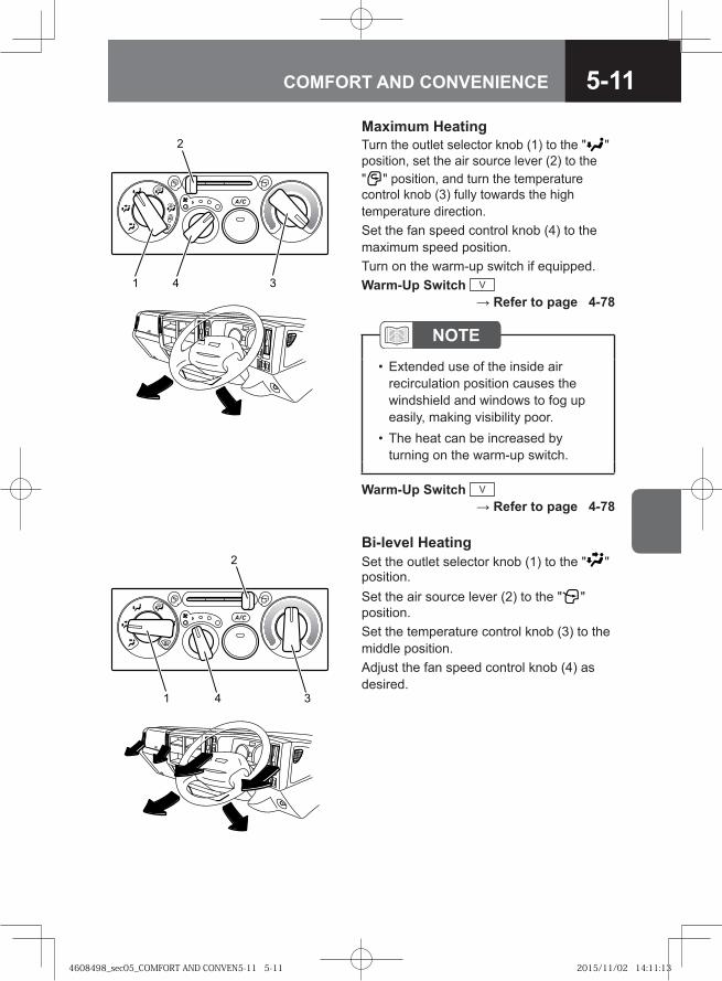
5-11COMFORT AND CONVENIENCE
Maximum HeatingTurn the outlet selector knob (1) to the " " position, set the air source lever (2) to the " " position, and turn the temperature control knob (3) fully towards the high temperature direction.Set the fan speed control knob (4) to the maximum speed position.Turn on the warm-up switch if equipped.Warm-Up Switch V
→ Refer to page 4-78
NOTEExtended use of the inside air recirculation position causes the windshield and windows to fog up easily, making visibility poor.The heat can be increased by turning on the warm-up switch.
•
•
Bi-level HeatingSet the outlet selector knob (1) to the " " position.Set the air source lever (2) to the " " position.Set the temperature control knob (3) to the middle position. Adjust the fan speed control knob (4) as desired.
� �
� �
Warm-Up Switch V → Refer to page 4-78
4608498_sec05_COMFORT AND CONVEN5-11 5-114608498_sec05_COMFORT AND CONVEN5-11 5-11 2015/11/02 14:11:132015/11/02 14:11:13
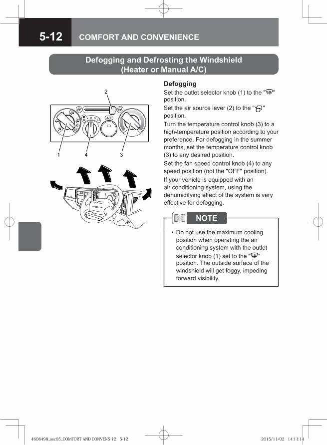
5-12 COMFORT AND CONVENIENCE
DefoggingSet the outlet selector knob (1) to the " " position.Set the air source lever (2) to the " " position.Turn the temperature control knob (3) to a high-temperature position according to your preference. For defogging in the summer months, set the temperature control knob (3) to any desired position. Set the fan speed control knob (4) to any speed position (not the "OFF" position).If your vehicle is equipped with an air conditioning system, using the dehumidifying effect of the system is very effective for defogging.
NOTEDo not use the maximum cooling position when operating the air conditioning system with the outlet selector knob (1) set to the " " position. The outside surface of the windshield will get foggy, impeding forward visibility.
•
��
Defogging and Defrosting the Windshield (Heater or Manual A/C)
4608498_sec05_COMFORT AND CONVEN5-12 5-124608498_sec05_COMFORT AND CONVEN5-12 5-12 2015/11/02 14:11:142015/11/02 14:11:14
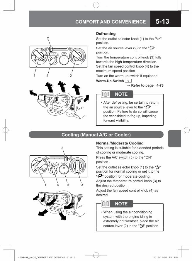
5-13COMFORT AND CONVENIENCE
DefrostingSet the outlet selector knob (1) to the " " position.Set the air source lever (2) to the " " position.Turn the temperature control knob (3) fully towards the high-temperature direction. Set the fan speed control knob (4) to the maximum speed position.Turn on the warm-up switch if equipped.Warm-Up Switch V
→ Refer to page 4-78
� �
NOTEAfter defrosting, be certain to return the air source lever to the " " position. Failure to do so will cause the windshield to fog up, impeding forward visibility.
•
Normal/Moderate CoolingThis setting is suitable for extended periods of cooling or moderate cooling.Press the A/C switch (5) to the "ON" position.Set the outlet selector knob (1) to the " " position for normal cooling or set it to the " " position for moderate cooling.Adjust the temperature control knob (3) to the desired position. Adjust the fan speed control knob (4) as desired.
Cooling (Manual A/C or Cooler)
NOTEWhen using the air conditioning system with the engine idling in extremely hot weather, place the air source lever (2) in the " " position.
•
� ��
4608498_sec05_COMFORT AND CONVEN5-13 5-134608498_sec05_COMFORT AND CONVEN5-13 5-13 2015/11/02 14:11:142015/11/02 14:11:14
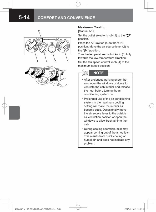
5-14 COMFORT AND CONVENIENCE
Maximum Cooling[Manual A/C]Set the outlet selector knob (1) to the " " position.Press the A/C switch (5) to the "ON" position. Move the air source lever (2) to the " " position.Turn the temperature control knob (3) fully towards the low-temperature direction. Set the fan speed control knob (4) to the maximum speed position.
NOTEAfter prolonged parking under the sun, open the windows or doors to ventilate the cab interior and release the heat before turning the air conditioning system on. Prolonged use of the air conditioning system in the maximum cooling setting will make the interior air become stale. Occasionally move the air source lever to the outside air ventilation position or open the windows to allow fresh air into the cab.During cooling operation, mist may appear coming out of the air outlets. This results from quick cooling of humid air, and does not indicate any problem.
•
•
•
� � �
4608498_sec05_COMFORT AND CONVEN5-14 5-144608498_sec05_COMFORT AND CONVEN5-14 5-14 2015/11/02 14:11:142015/11/02 14:11:14
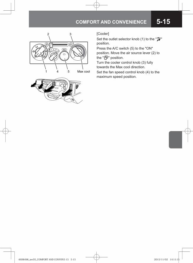
5-15COMFORT AND CONVENIENCE
[Cooler]Set the outlet selector knob (1) to the " " position.Press the A/C switch (5) to the "ON" position. Move the air source lever (2) to the " " position.Turn the cooler control knob (3) fully towards the Max cool direction.Set the fan speed control knob (4) to the maximum speed position.
�
� ��� ����� �
4608498_sec05_COMFORT AND CONVEN5-15 5-154608498_sec05_COMFORT AND CONVEN5-15 5-15 2015/11/02 14:11:152015/11/02 14:11:15
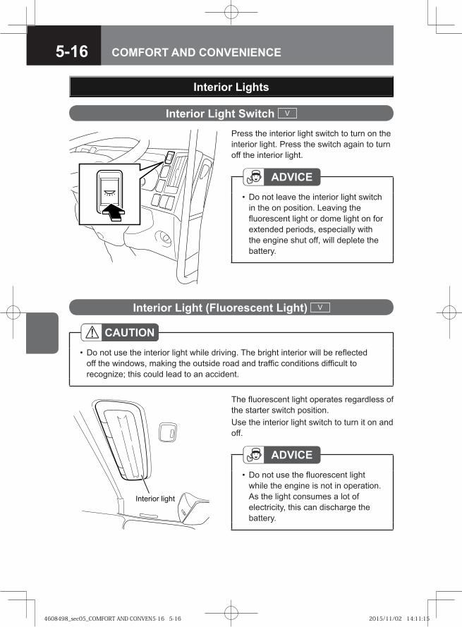
5-16 COMFORT AND CONVENIENCE
Interior Light Switch V
Interior Lights
Press the interior light switch to turn on the interior light. Press the switch again to turn off the interior light.
ADVICEDo not leave the interior light switch in the on position. Leaving the fluorescent light or dome light on for extended periods, especially with the engine shut off, will deplete the battery.
•
Interior Light (Fluorescent Light) V
The fluorescent light operates regardless of the starter switch position.Use the interior light switch to turn it on and off.
ADVICEDo not use the fluorescent light while the engine is not in operation. As the light consumes a lot of electricity, this can discharge the battery.
•
CAUTIONDo not use the interior light while driving. The bright interior will be reflected off the windows, making the outside road and traffic conditions difficult to recognize; this could lead to an accident.
•
������� �����
4608498_sec05_COMFORT AND CONVEN5-16 5-164608498_sec05_COMFORT AND CONVEN5-16 5-16 2015/11/02 14:11:152015/11/02 14:11:15
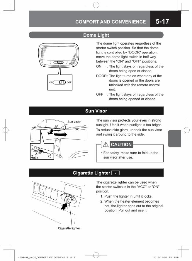
5-17COMFORT AND CONVENIENCE
Dome LightThe dome light operates regardless of the starter switch position. So that the dome light is controlled by "DOOR" operation, move the dome light switch in half way between the "ON" and "OFF" positions.ON : The light stays on regardless of the
doors being open or closed.DOOR : The light turns on when any of the
doors is opened or the doors are unlocked with the remote control unit.
OFF : The light stays off regardless of the doors being opened or closed.
�� ���
��
�� ����The sun visor protects your eyes in strong sunlight. Use it when sunlight is too bright.To reduce side glare, unhook the sun visor and swing it around to the side.
Sun Visor
CAUTIONFor safety, make sure to fold up the sun visor after use.
•
�� ������ �� ����
The cigarette lighter can be used when the starter switch is in the "ACC" or "ON" position. 1. Push the lighter in until it locks. 2. When the heater element becomes
hot, the lighter pops out to the original position. Pull out and use it.
Cigarette Lighter V
4608498_sec05_COMFORT AND CONVEN5-17 5-174608498_sec05_COMFORT AND CONVEN5-17 5-17 2015/11/02 14:11:162015/11/02 14:11:16
5-18 COMFORT AND CONVENIENCE
CAUTIONTo substitute the cigarette lighter socket for an accessory power outlet, consult the nearest Isuzu Dealer.If the cigarette lighter socket was used as an accessory power outlet by necessity, the inside of socket may be deformed. When the cigarette lighter is used with the deformed inside, it may cause failures such as that the red-hot cigarette lighter pops out or it does not come out as it is pressed in.To use it once again as the cigarette lighter changing from the accessory power outlet, or to replace the broken cigarette lighter, use an Isuzu genuine part suitable for the vehicle. Do not use other cigarette lighters.When cleaning the cigarette lighter, do not use too much force. It may cause a deformation.Remove ashes and dirt inside the cigarette lighter socket and on the heater portion of cigarette lighter.
•
•
•
•
•
WARNING
As there is a burn hazard, do not touch the heater element when using the cigarette lighter.Do not leave your finger on the cigarette lighter once it has been pushed in. The lighter will overheat and be damaged or cause a fire.If the cigarette lighter does not pop out after more than 20 seconds, the lighter is defective. Pull out the lighter by hand immediately.Do not leave the vehicle with the cigarette lighter pushed in. This could cause a fire.Do not bend the cigarette lighter. A bent lighter does not function properly and is dangerous.
•
•
•
•
•
ADVICEDo not use the cigarette lighter while the engine is not in operation. As it consumes a lot of electricity, doing so can cause a dead battery.
•
4608498_sec05_COMFORT AND CONVEN5-18 5-184608498_sec05_COMFORT AND CONVEN5-18 5-18 2015/11/02 14:11:162015/11/02 14:11:16
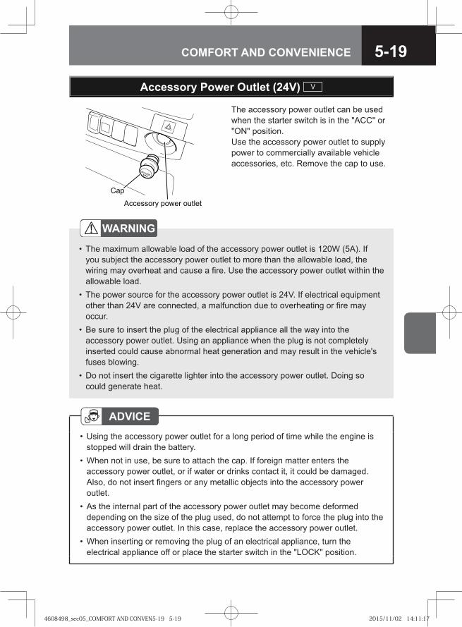
5-19COMFORT AND CONVENIENCE
Accessory Power Outlet (24V) V
The accessory power outlet can be used when the starter switch is in the "ACC" or "ON" position. Use the accessory power outlet to supply power to commercially available vehicle accessories, etc. Remove the cap to use.
��� ����� ��� � ���� �
���
WARNING
The maximum allowable load of the accessory power outlet is 120W (5A). If you subject the accessory power outlet to more than the allowable load, the wiring may overheat and cause a fire. Use the accessory power outlet within the allowable load.The power source for the accessory power outlet is 24V. If electrical equipment other than 24V are connected, a malfunction due to overheating or fire may occur.Be sure to insert the plug of the electrical appliance all the way into the accessory power outlet. Using an appliance when the plug is not completely inserted could cause abnormal heat generation and may result in the vehicle's fuses blowing.Do not insert the cigarette lighter into the accessory power outlet. Doing so could generate heat.
•
•
•
•
ADVICEUsing the accessory power outlet for a long period of time while the engine is stopped will drain the battery.When not in use, be sure to attach the cap. If foreign matter enters the accessory power outlet, or if water or drinks contact it, it could be damaged. Also, do not insert fingers or any metallic objects into the accessory power outlet.As the internal part of the accessory power outlet may become deformed depending on the size of the plug used, do not attempt to force the plug into the accessory power outlet. In this case, replace the accessory power outlet.When inserting or removing the plug of an electrical appliance, turn the electrical appliance off or place the starter switch in the "LOCK" position.
•
•
•
•
4608498_sec05_COMFORT AND CONVEN5-19 5-194608498_sec05_COMFORT AND CONVEN5-19 5-19 2015/11/02 14:11:172015/11/02 14:11:17
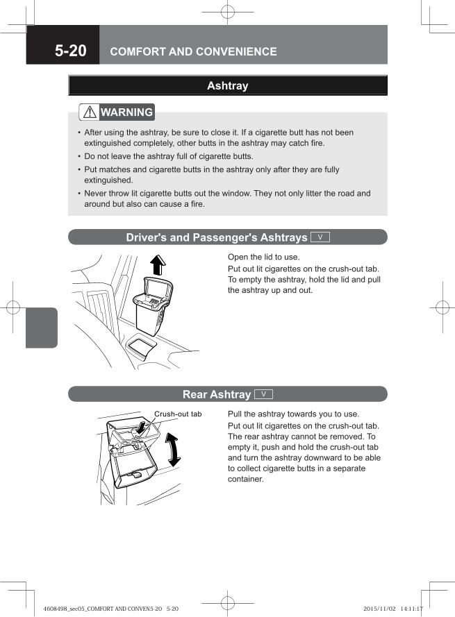
5-20 COMFORT AND CONVENIENCE
Ashtray
WARNING
After using the ashtray, be sure to close it. If a cigarette butt has not been extinguished completely, other butts in the ashtray may catch fire.Do not leave the ashtray full of cigarette butts.Put matches and cigarette butts in the ashtray only after they are fully extinguished.Never throw lit cigarette butts out the window. They not only litter the road and around but also can cause a fire.
•
••
•
Driver's and Passenger's Ashtrays V
Open the lid to use.Put out lit cigarettes on the crush-out tab. To empty the ashtray, hold the lid and pull the ashtray up and out.
Rear Ashtray V
Pull the ashtray towards you to use.Put out lit cigarettes on the crush-out tab. The rear ashtray cannot be removed. To empty it, push and hold the crush-out tab and turn the ashtray downward to be able to collect cigarette butts in a separate container.
Crush-out tab
4608498_sec05_COMFORT AND CONVEN5-20 5-204608498_sec05_COMFORT AND CONVEN5-20 5-20 2015/11/02 14:11:172015/11/02 14:11:17
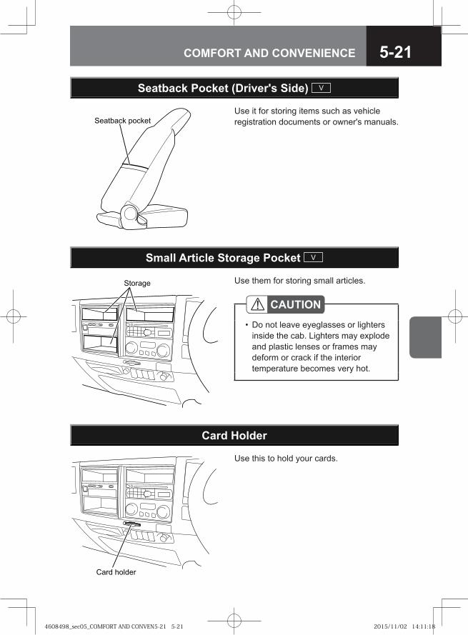
5-21COMFORT AND CONVENIENCE
Use them for storing small articles.
Small Article Storage Pocket V
�� ����
CAUTIONDo not leave eyeglasses or lighters inside the cab. Lighters may explode and plastic lenses or frames may deform or crack if the interior temperature becomes very hot.
•
Use this to hold your cards.
Card Holder
� �� ������
��� ���� �����
Use it for storing items such as vehicle registration documents or owner's manuals.
Seatback Pocket (Driver's Side) V
4608498_sec05_COMFORT AND CONVEN5-21 5-214608498_sec05_COMFORT AND CONVEN5-21 5-21 2015/11/02 14:11:182015/11/02 14:11:18
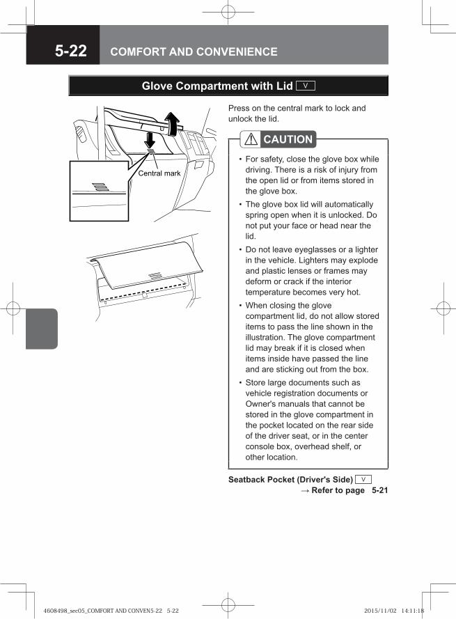
5-22 COMFORT AND CONVENIENCE
Central mark
Press on the central mark to lock and unlock the lid.
Glove Compartment with Lid V
CAUTIONFor safety, close the glove box while driving. There is a risk of injury from the open lid or from items stored in the glove box.The glove box lid will automatically spring open when it is unlocked. Do not put your face or head near the lid.Do not leave eyeglasses or a lighter in the vehicle. Lighters may explode and plastic lenses or frames may deform or crack if the interior temperature becomes very hot.When closing the glove compartment lid, do not allow stored items to pass the line shown in the illustration. The glove compartment lid may break if it is closed when items inside have passed the line and are sticking out from the box.Store large documents such as vehicle registration documents or Owner's manuals that cannot be stored in the glove compartment in the pocket located on the rear side of the driver seat, or in the center console box, overhead shelf, or other location.
•
•
•
•
•
Seatback Pocket (Driver's Side) V → Refer to page 5-21
4608498_sec05_COMFORT AND CONVEN5-22 5-224608498_sec05_COMFORT AND CONVEN5-22 5-22 2015/11/02 14:11:182015/11/02 14:11:18
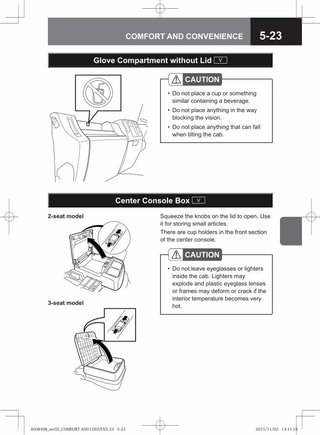
5-23COMFORT AND CONVENIENCE
Glove Compartment without Lid V
CAUTIONDo not place a cup or something similar containing a beverage.Do not place anything in the way blocking the vision.Do not place anything that can fall when tilting the cab.
•
•
•
Squeeze the knobs on the lid to open. Use it for storing small articles.There are cup holders in the front section of the center console.
Center Console Box V
CAUTIONDo not leave eyeglasses or lighters inside the cab. Lighters may explode and plastic eyeglass lenses or frames may deform or crack if the interior temperature becomes very hot.
•
2-seat model
3-seat model
4608498_sec05_COMFORT AND CONVEN5-23 5-234608498_sec05_COMFORT AND CONVEN5-23 5-23 2015/11/02 14:11:192015/11/02 14:11:19
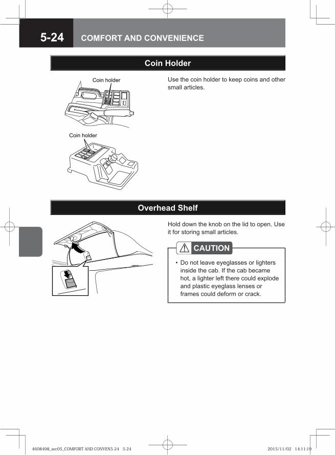
5-24 COMFORT AND CONVENIENCE
Use the coin holder to keep coins and other small articles.
Coin Holder
�� � ������
�� � ������
Hold down the knob on the lid to open. Use it for storing small articles.
Overhead Shelf
CAUTIONDo not leave eyeglasses or lighters inside the cab. If the cab became hot, a lighter left there could explode and plastic eyeglass lenses or frames could deform or crack.
•
4608498_sec05_COMFORT AND CONVEN5-24 5-244608498_sec05_COMFORT AND CONVEN5-24 5-24 2015/11/02 14:11:192015/11/02 14:11:19
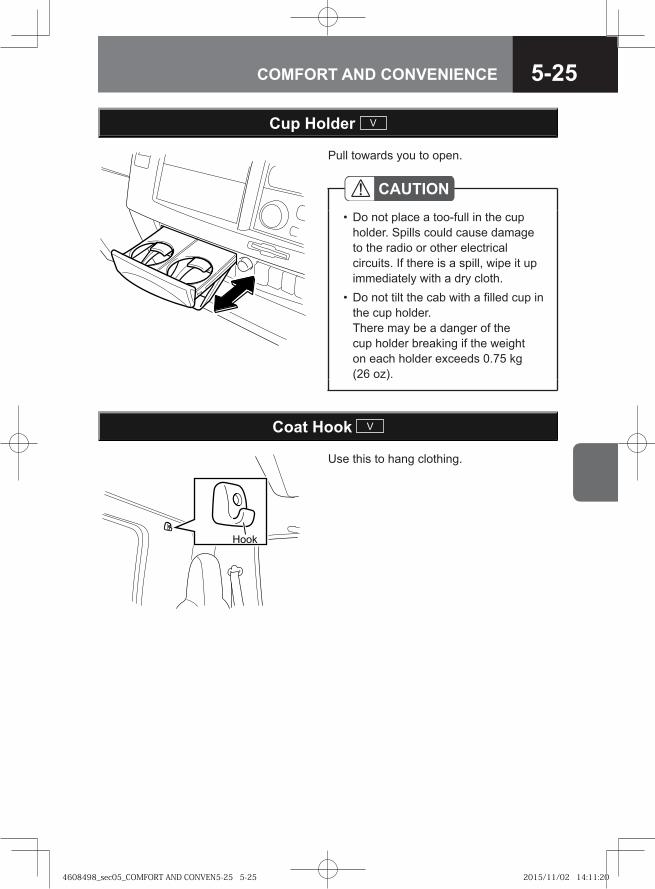
5-25COMFORT AND CONVENIENCE
Pull towards you to open.
Cup Holder V
CAUTIONDo not place a too-full in the cup holder. Spills could cause damage to the radio or other electrical circuits. If there is a spill, wipe it up immediately with a dry cloth.Do not tilt the cab with a filled cup in the cup holder. There may be a danger of the cup holder breaking if the weight on each holder exceeds 0.75 kg (26 oz).
•
•
Use this to hang clothing.
Coat Hook V
���
4608498_sec05_COMFORT AND CONVEN5-25 5-254608498_sec05_COMFORT AND CONVEN5-25 5-25 2015/11/02 14:11:202015/11/02 14:11:20
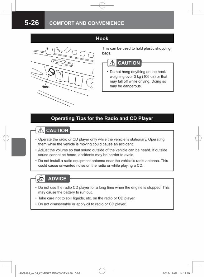
5-26 COMFORT AND CONVENIENCE
This can be used to hold plastic shopping bags.
Hook
CAUTIONDo not hang anything on the hook weighing over 3 kg (106 oz) or that may fall off while driving. Doing so may be dangerous.
•
���
Operating Tips for the Radio and CD Player
CAUTIONOperate the radio or CD player only while the vehicle is stationary. Operating them while the vehicle is moving could cause an accident.Adjust the volume so that sound outside of the vehicle can be heard. If outside sound cannot be heard, accidents may be harder to avoid.Do not install a radio equipment antenna near the vehicle's radio antenna. This could cause unwanted noise on the radio or while playing a CD.
•
•
•
ADVICEDo not use the radioCD player for a long time when the engine is stopped. This may cause the battery to run out.Take care not to spill liquids, etc. on the radio or CD player.Do not disassemble or apply oil to radio or CD player.
•
••
This can be used to hold plastic shopping bags.
Hook
CAUTIONDo not hang anything on the hook weighing over 3 kg (106 oz) or that may fall off while driving. Doing so may be dangerous.
•
���
Operating Tips for the Radio and CD Player
CAUTIONOperate the radio or CD player only while the vehicle is stationary. Operating them while the vehicle is moving could cause an accident.Adjust the volume so that sound outside of the vehicle can be heard. If outside sound cannot be heard, accidents may be harder to avoid.Do not install a radio equipment antenna near the vehicle's radio antenna. This could cause unwanted noise on the radio or while playing a CD.
•
•
•
ADVICEDo not use the radio CD player for a long time when the engine is stopped. This may cause the battery to run out.Take care not to spill liquids, etc. on the radio or CD player.Do not disassemble or apply oil to radio or CD player.
•
••
4608498_sec05_COMFORT AND CONVEN5-26 5-264608498_sec05_COMFORT AND CONVEN5-26 5-26 2015/11/02 14:11:202015/11/02 14:11:20
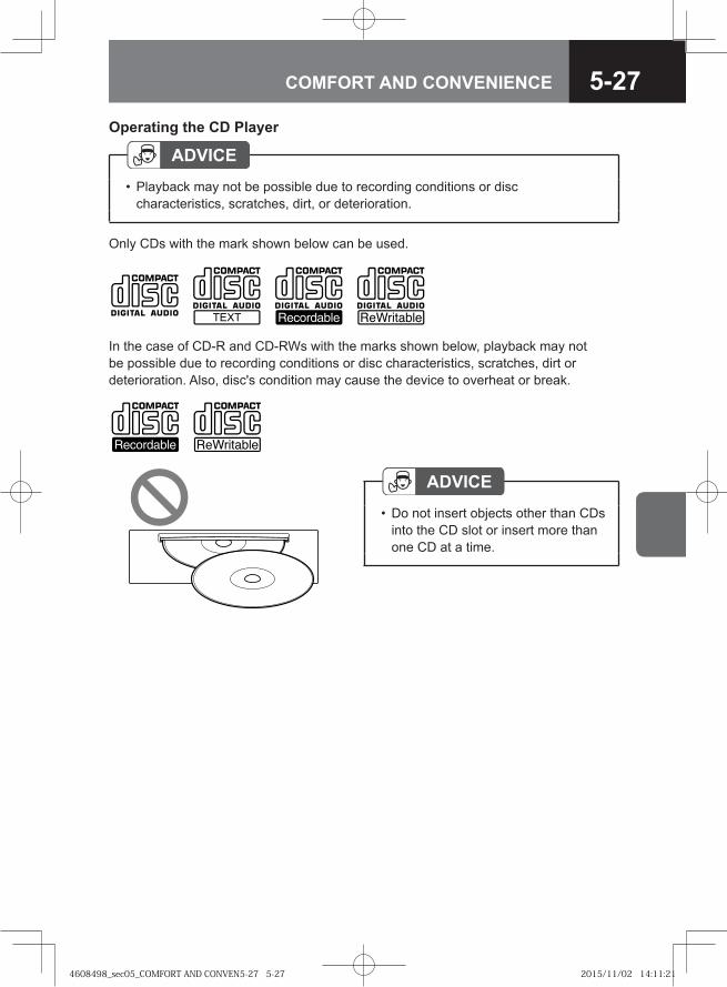
5-27COMFORT AND CONVENIENCE
Operating the CD Player
In the case of CD-R and CD-RWs with the marks shown below, playback may not be possible due to recording conditions or disc characteristics, scratches, dirt or deterioration. Also, disc's condition may cause the device to overheat or break.
ADVICEPlayback may not be possible due to recording conditions or disc characteristics, scratches, dirt, or deterioration.
•
Only CDs with the mark shown below can be used.
ADVICEDo not insert objects other than CDs into the CD slot or insert more than one CD at a time.
•
4608498_sec05_COMFORT AND CONVEN5-27 5-274608498_sec05_COMFORT AND CONVEN5-27 5-27 2015/11/02 14:11:212015/11/02 14:11:21
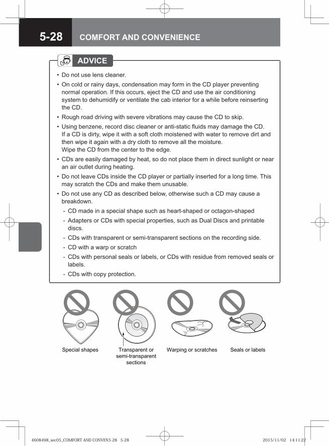
5-28 COMFORT AND CONVENIENCE
ADVICEDo not use lens cleaner.On cold or rainy days, condensation may form in the CD player preventing normal operation. If this occurs, eject the CD and use the air conditioning system to dehumidify or ventilate the cab interior for a while before reinserting the CD.Rough road driving with severe vibrations may cause the CD to skip.Using benzene, record disc cleaner or anti-static fluids may damage the CD.If a CD is dirty, wipe it with a soft cloth moistened with water to remove dirt and then wipe it again with a dry cloth to remove all the moisture. Wipe the CD from the center to the edge.CDs are easily damaged by heat, so do not place them in direct sunlight or near an air outlet during heating.Do not leave CDs inside the CD player or partially inserted for a long time. This may scratch the CDs and make them unusable.Do not use any CD as described below, otherwise such a CD may cause a breakdown.
CD made in a special shape such as heart-shaped or octagon-shapedAdapters or CDs with special properties, such as Dual Discs and printable discs.CDs with transparent or semi-transparent sections on the recording side.CD with a warp or scratchCDs with personal seals or labels, or CDs with residue from removed seals or labels.CDs with copy protection.
••
••
•
•
•
--
---
-
��� � �� � �� �� ��� ��
������ �� ���
�������
� ���� �� ��� ���� � �� �� � ���
4608498_sec05_COMFORT AND CONVEN5-28 5-284608498_sec05_COMFORT AND CONVEN5-28 5-28 2015/11/02 14:11:222015/11/02 14:11:22
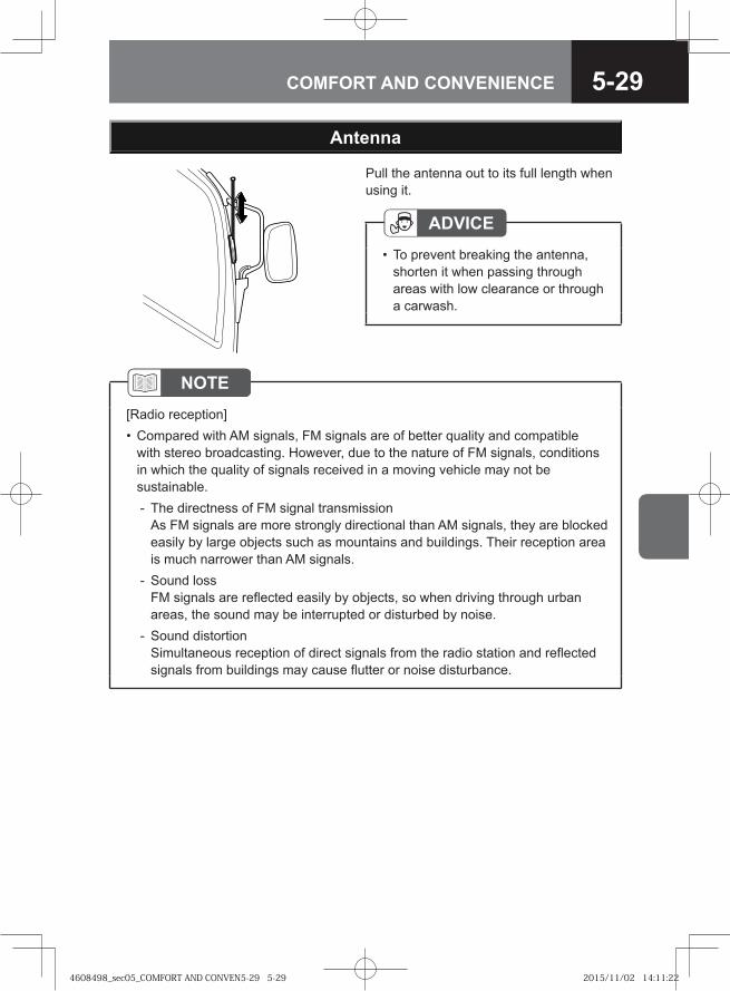
5-29COMFORT AND CONVENIENCE
Antenna
Pull the antenna out to its full length when using it.
ADVICETo prevent breaking the antenna, shorten it when passing through areas with low clearance or through a carwash.
•
NOTE[Radio reception]
Compared with AM signals, FM signals are of better quality and compatible with stereo broadcasting. However, due to the nature of FM signals, conditions in which the quality of signals received in a moving vehicle may not be sustainable.
The directness of FM signal transmissionAs FM signals are more strongly directional than AM signals, they are blocked easily by large objects such as mountains and buildings. Their reception area is much narrower than AM signals.Sound loss FM signals are reflected easily by objects, so when driving through urban areas, the sound may be interrupted or disturbed by noise.Sound distortionSimultaneous reception of direct signals from the radio station and reflected signals from buildings may cause flutter or noise disturbance.
•
-
-
-
4608498_sec05_COMFORT AND CONVEN5-29 5-294608498_sec05_COMFORT AND CONVEN5-29 5-29 2015/11/02 14:11:222015/11/02 14:11:22
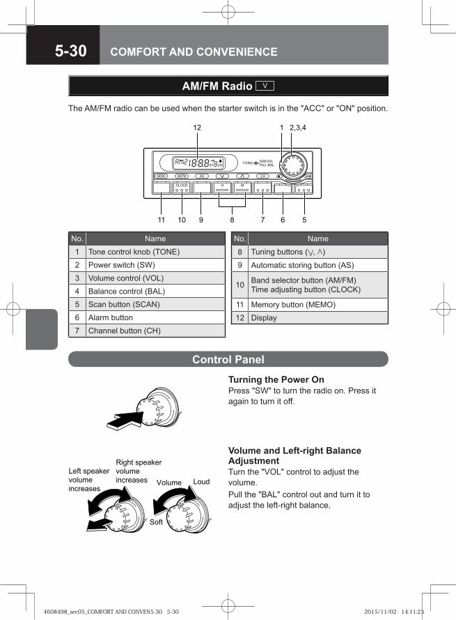
5-30 COMFORT AND CONVENIENCE
The AM/FM radio can be used when the starter switch is in the "ACC" or "ON" position.
AM/FM Radio V
Control Panel
Turning the Power OnPress "SW" to turn the radio on. Press it again to turn it off.
� ���
��������� �� ��
� �
���� ����� �� ��
����
�
��������
� ����
� ��
���� �������
� ����
���������
�� !� �������
� ����
��������� " ����
� ��
No. Name
1 Tone control knob (TONE)
2 Power switch (SW)
3 Volume control (VOL)
4 Balance control (BAL)
5 Scan button (SCAN)
6 Alarm button
7 Channel button (CH)
No. Name
8 Tuning buttons ( , )
9 Automatic storing button (AS)
10 Band selector button (AM/FM)Time adjusting button (CLOCK)
11 Memory button (MEMO)
12 Display
Volume and Left-right Balance AdjustmentTurn the "VOL" control to adjust the volume.Pull the "BAL" control out and turn it to adjust the left-right balance.
4608498_sec05_COMFORT AND CONVEN5-30 5-304608498_sec05_COMFORT AND CONVEN5-30 5-30 2015/11/02 14:11:232015/11/02 14:11:23
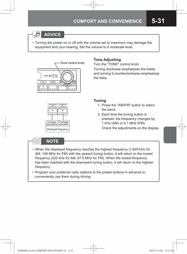
5-31COMFORT AND CONVENIENCE
ADVICETurning the power on or off with the volume set to maximum may damage the equipment and your hearing. Set the volume to a moderate level.
•
Tone AdjustingTurn the "TONE" control knob.Turning clockwise emphasizes the treble, and turning it counterclockwise emphasizes the bass.
�� �������
���� ���
�
��
���� ������� ���
H M
Changesupwards
Displayed frequency
Changesdownwards
Tuning 1. Press the "AM/FM" button to select
the band. 2. Each time the tuning button is
pressed, the frequency changes by 1 kHz (AM) or 0.1 MHz (FM).
Check the adjustments on the display.
NOTEWhen the displayed frequency reaches the highest frequency (1,629 kHz for AM, 108 MHz for FM) with the upward tuning button, it will return to the lowest frequency (522 kHz for AM, 87.5 MHz for FM). When the lowest frequency has been reached with the downward tuning button, it will return to the highest frequency.Program your preferred radio stations to the preset buttons in advance to conveniently use them during driving.
•
•
4608498_sec05_COMFORT AND CONVEN5-31 5-314608498_sec05_COMFORT AND CONVEN5-31 5-31 2015/11/02 14:11:232015/11/02 14:11:23
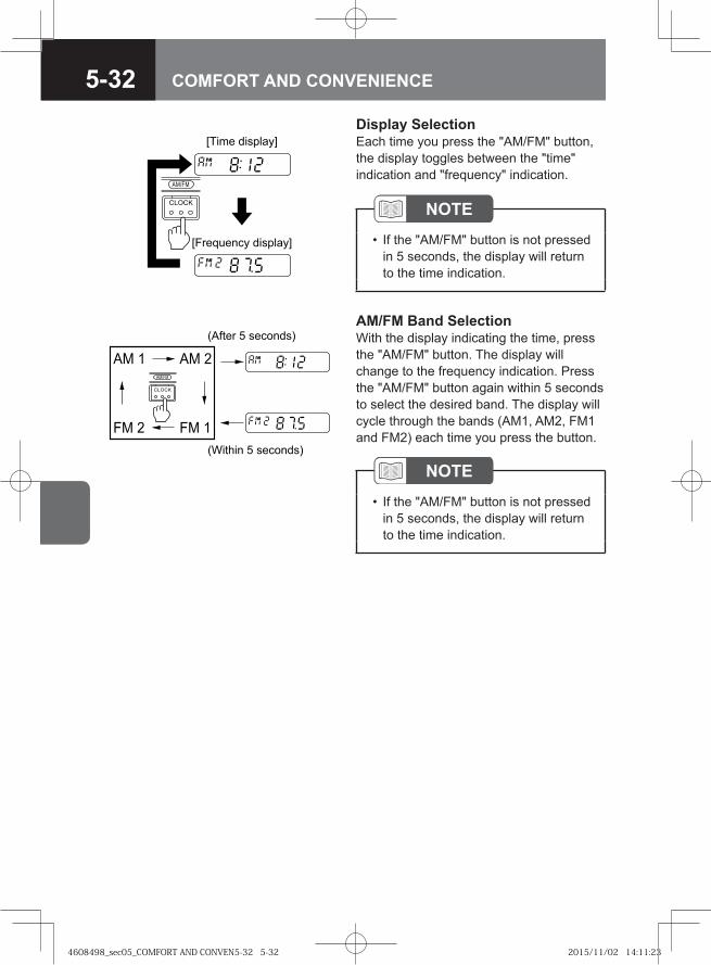
5-32 COMFORT AND CONVENIENCE
AM/FM Band SelectionWith the display indicating the time, press the "AM/FM" button. The display will change to the frequency indication. Press the "AM/FM" button again within 5 seconds to select the desired band. The display will cycle through the bands (AM1, AM2, FM1 and FM2) each time you press the button.
NOTEIf the "AM/FM" button is not pressed in 5 seconds, the display will return to the time indication.
•
�� � �� �
�� � �� �
�����
�����
������ ��������
�� �! � ��������
�� ������� ��������
����� ��������
�� ��
!�"!#
Display SelectionEach time you press the "AM/FM" button, the display toggles between the "time" indication and "frequency" indication.
NOTEIf the "AM/FM" button is not pressed in 5 seconds, the display will return to the time indication.
•
4608498_sec05_COMFORT AND CONVEN5-32 5-324608498_sec05_COMFORT AND CONVEN5-32 5-32 2015/11/02 14:11:232015/11/02 14:11:23
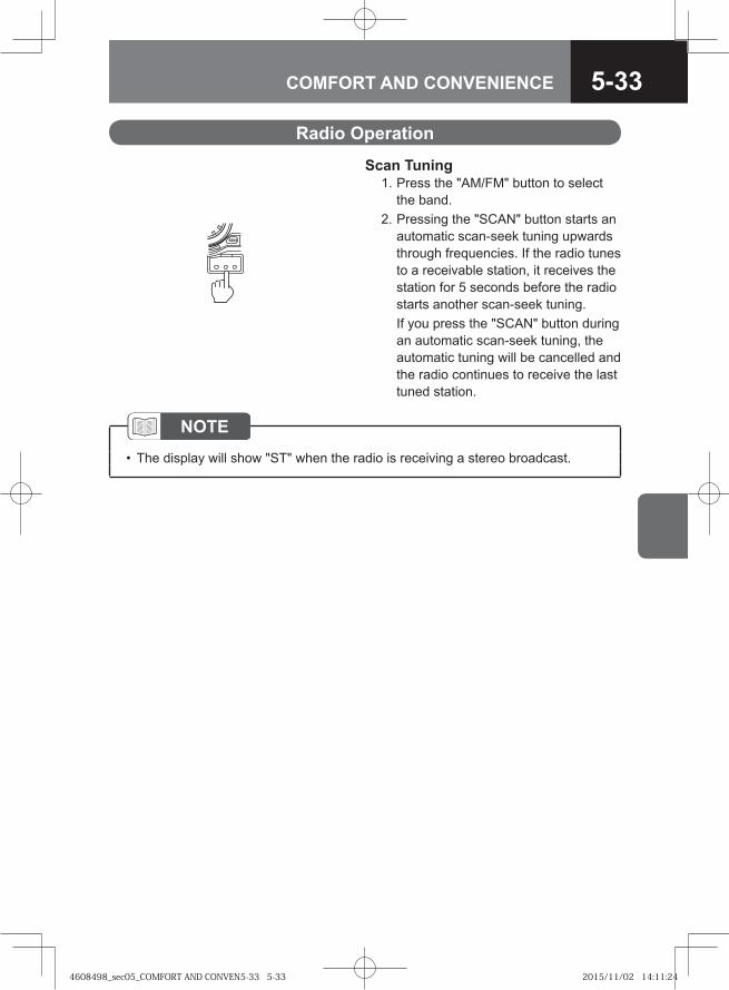
5-33COMFORT AND CONVENIENCE
Radio Operation
Scan Tuning 1. Press the "AM/FM" button to select
the band. 2. Pressing the "SCAN" button starts an
automatic scan-seek tuning upwards through frequencies. If the radio tunes to a receivable station, it receives the station for 5 seconds before the radio starts another scan-seek tuning.
If you press the "SCAN" button during an automatic scan-seek tuning, the automatic tuning will be cancelled and the radio continues to receive the last tuned station.
NOTEThe display will show "ST" when the radio is receiving a stereo broadcast.•
4608498_sec05_COMFORT AND CONVEN5-33 5-334608498_sec05_COMFORT AND CONVEN5-33 5-33 2015/11/02 14:11:242015/11/02 14:11:24
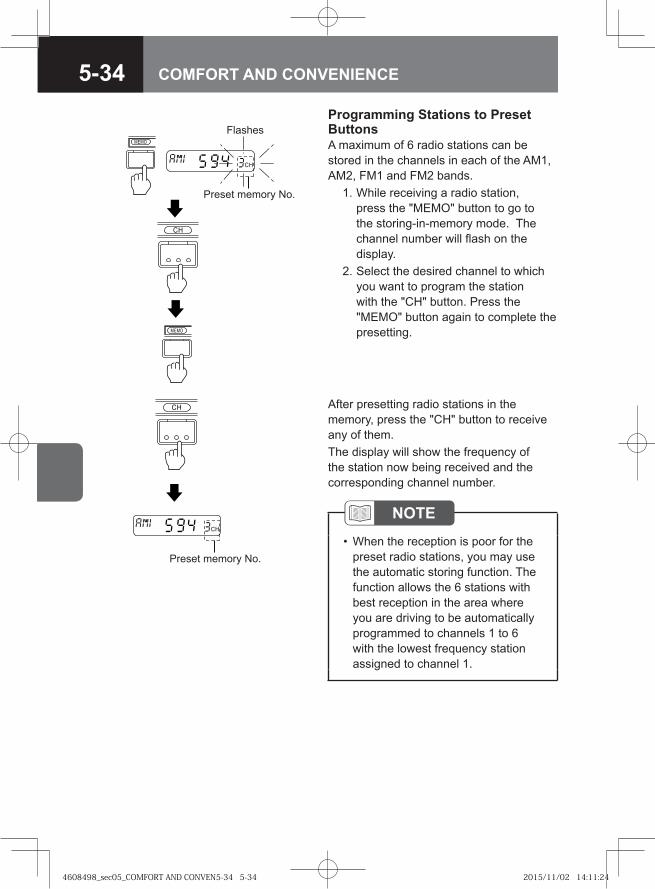
5-34 COMFORT AND CONVENIENCE
Preset memory No.
MEMO
MEMO
CH
CH
FlashesProgramming Stations to Preset ButtonsA maximum of 6 radio stations can be stored in the channels in each of the AM1, AM2, FM1 and FM2 bands. 1. While receiving a radio station,
press the "MEMO" button to go to the storing-in-memory mode. The channel number will flash on the display.
2. Select the desired channel to which you want to program the station with the "CH" button. Press the "MEMO" button again to complete the presetting.
After presetting radio stations in the memory, press the "CH" button to receive any of them.The display will show the frequency of the station now being received and the corresponding channel number.
CH
CH
Preset memory No.
NOTEWhen the reception is poor for the preset radio stations, you may use the automatic storing function. The function allows the 6 stations with best reception in the area where you are driving to be automatically programmed to channels 1 to 6 with the lowest frequency station assigned to channel 1.
•
4608498_sec05_COMFORT AND CONVEN5-34 5-344608498_sec05_COMFORT AND CONVEN5-34 5-34 2015/11/02 14:11:242015/11/02 14:11:24
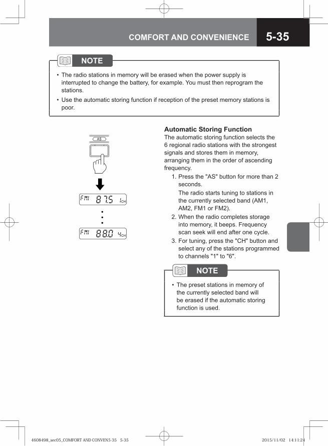
5-35COMFORT AND CONVENIENCE
NOTEThe radio stations in memory will be erased when the power supply is interrupted to change the battery, for example. You must then reprogram the stations.Use the automatic storing function if reception of the preset memory stations is poor.
•
•
�
��
��
Automatic Storing FunctionThe automatic storing function selects the 6 regional radio stations with the strongest signals and stores them in memory, arranging them in the order of ascending frequency. 1. Press the "AS" button for more than 2
seconds. The radio starts tuning to stations in
the currently selected band (AM1, AM2, FM1 or FM2).
2. When the radio completes storage into memory, it beeps. Frequency scan seek will end after one cycle.
3. For tuning, press the "CH" button and select any of the stations programmed to channels "1" to "6".
NOTEThe preset stations in memory of the currently selected band will be erased if the automatic storing function is used.
•
4608498_sec05_COMFORT AND CONVEN5-35 5-354608498_sec05_COMFORT AND CONVEN5-35 5-35 2015/11/02 14:11:242015/11/02 14:11:24
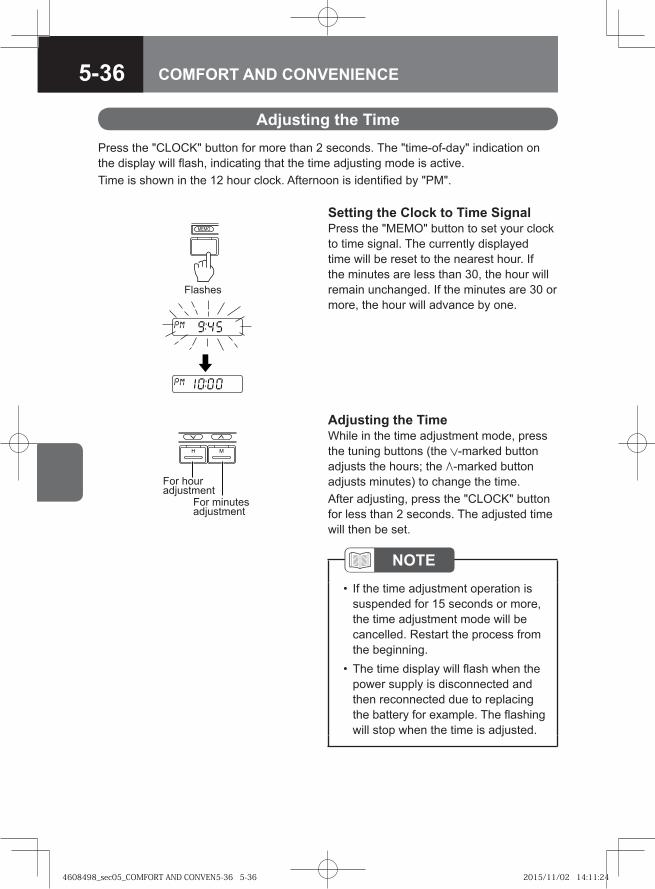
5-36 COMFORT AND CONVENIENCE
Adjusting the TimePress the "CLOCK" button for more than 2 seconds. The "time-of-day" indication on the display will flash, indicating that the time adjusting mode is active.Time is shown in the 12 hour clock. Afternoon is identified by "PM".
MEMO
Flashes
H M
For minutes adjustment
For hour adjustment
Adjusting the TimeWhile in the time adjustment mode, press the tuning buttons (the -marked button adjusts the hours; the -marked button adjusts minutes) to change the time.After adjusting, press the "CLOCK" button for less than 2 seconds. The adjusted time will then be set.
NOTEIf the time adjustment operation is suspended for 15 seconds or more, the time adjustment mode will be cancelled. Restart the process from the beginning.The time display will flash when the power supply is disconnected and then reconnected due to replacing the battery for example. The flashing will stop when the time is adjusted.
•
•
Setting the Clock to Time SignalPress the "MEMO" button to set your clock to time signal. The currently displayed time will be reset to the nearest hour. If the minutes are less than 30, the hour will remain unchanged. If the minutes are 30 or more, the hour will advance by one.
4608498_sec05_COMFORT AND CONVEN5-36 5-364608498_sec05_COMFORT AND CONVEN5-36 5-36 2015/11/02 14:11:242015/11/02 14:11:24
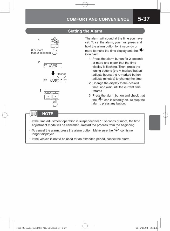
5-37COMFORT AND CONVENIENCE
Setting the AlarmThe alarm will sound at the time you have set. To set the alarm, you must press and hold the alarm button for 2 seconds or more to make the time display and the " " icon flash. 1. Press the alarm button for 2 seconds
or more and check that the time display is flashing. Then, press the tuning buttons (the -marked button adjusts hours; the -marked button adjusts minutes) to change the time.
2. Change the display to the desired time, and wait until the current time returns.
3. Press the alarm button and check that the " " icon is steadily on. To stop the alarm, press any button.
MFU75
1
2
3
(For more than 2 seconds)
Flashes
H M
NOTEIf the time adjustment operation is suspended for 15 seconds or more, the time adjustment mode will be cancelled. Restart the process from the beginning.
To cancel the alarm, press the alarm button. Make sure the " " icon is no longer displayed.If the vehicle is not to be used for an extended period, cancel the alarm.
•
•
•
4608498_sec05_COMFORT AND CONVEN5-37 5-374608498_sec05_COMFORT AND CONVEN5-37 5-37 2015/11/02 14:11:252015/11/02 14:11:25
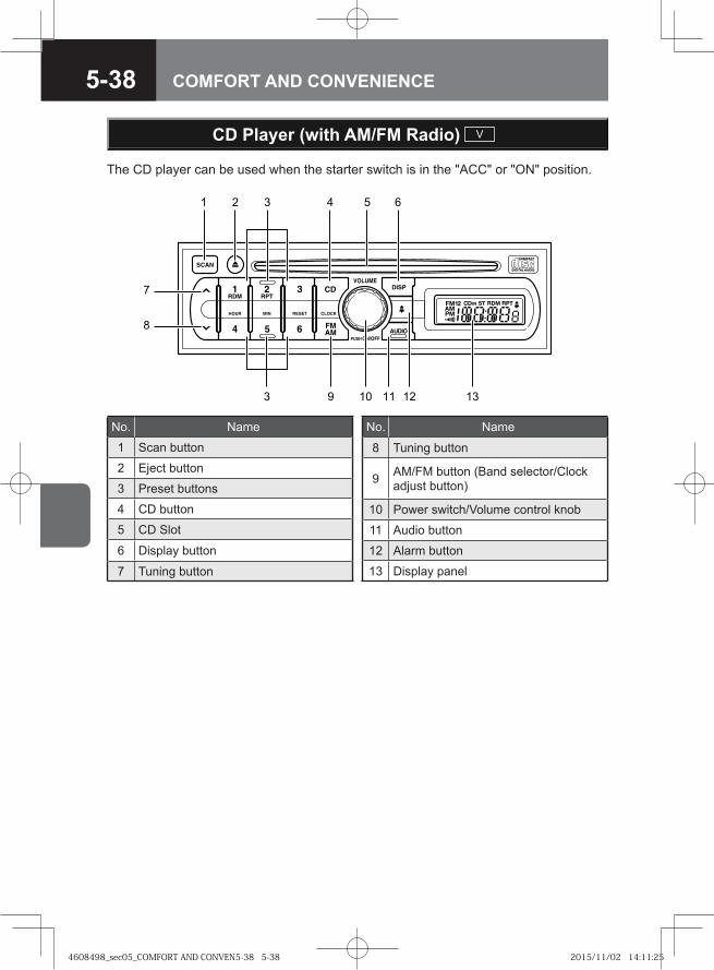
5-38 COMFORT AND CONVENIENCE
CD Player (with AM/FM Radio) V
The CD player can be used when the starter switch is in the "ACC" or "ON" position.
1
7
2 3 4 65
12 131193 10
8
No. Name
1 Scan button
2 Eject button
3 Preset buttons
4 CD button
5 CD Slot
6 Display button
7 Tuning button
No. Name
8 Tuning button
9 AM/FM button (Band selector/Clock adjust button)
10 Power switch/Volume control knob
11 Audio button
12 Alarm button
13 Display panel
4608498_sec05_COMFORT AND CONVEN5-38 5-384608498_sec05_COMFORT AND CONVEN5-38 5-38 2015/11/02 14:11:252015/11/02 14:11:25
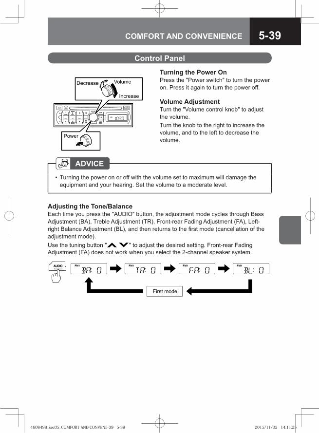
5-39COMFORT AND CONVENIENCE
Control Panel
ADVICETurning the power on or off with the volume set to maximum will damage the equipment and your hearing. Set the volume to a moderate level.
•
Decrease
Increase
Volume
Power
Turning the Power OnPress the "Power switch" to turn the power on. Press it again to turn the power off.
Volume AdjustmentTurn the "Volume control knob" to adjust the volume. Turn the knob to the right to increase the volume, and to the left to decrease the volume.
Adjusting the Tone/BalanceEach time you press the "AUDIO" button, the adjustment mode cycles through Bass Adjustment (BA), Treble Adjustment (TR), Front-rear Fading Adjustment (FA), Left-right Balance Adjustment (BL), and then returns to the first mode (cancellation of the adjustment mode).Use the tuning button " " to adjust the desired setting. Front-rear Fading Adjustment (FA) does not work when you select the 2-channel speaker system.
First mode
4608498_sec05_COMFORT AND CONVEN5-39 5-394608498_sec05_COMFORT AND CONVEN5-39 5-39 2015/11/02 14:11:252015/11/02 14:11:25
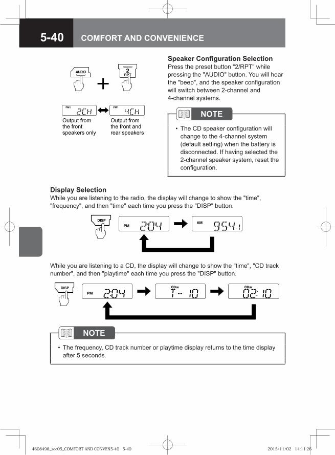
5-40 COMFORT AND CONVENIENCE
NOTEThe frequency, CD track number or playtime display returns to the time display after 5 seconds.
•
NOTEThe CD speaker configuration will change to the 4-channel system (default setting) when the battery is disconnected. If having selected the 2-channel speaker system, reset the configuration.
•
Display SelectionWhile you are listening to the radio, the display will change to show the "time", "frequency", and then "time" each time you press the "DISP" button.
While you are listening to a CD, the display will change to show the "time", "CD track number", and then "playtime" each time you press the "DISP" button.
Output from the front speakers only
Output from the front and rear speakers
Speaker Configuration SelectionPress the preset button "2/RPT" while pressing the "AUDIO" button. You will hear the "beep", and the speaker configuration will switch between 2-channel and 4-channel systems.
4608498_sec05_COMFORT AND CONVEN5-40 5-404608498_sec05_COMFORT AND CONVEN5-40 5-40 2015/11/02 14:11:262015/11/02 14:11:26
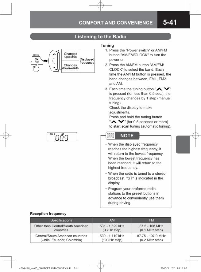
5-41COMFORT AND CONVENIENCE
Listening to the Radio
Tuning 1. Press the "Power switch" or AM/FM
button "AM/FM/CLOCK" to turn the power on.
2. Press the AM/FM button "AM/FM/CLOCK" to select the band. Each time the AM/FM button is pressed, the band changes between, FM1, FM2 and AM.
3. Each time the tuning button " " is pressed (for less than 0.5 sec.), the frequency changes by 1 step (manual tuning). Check the display to make adjustments. Press and hold the tuning button " " (for 0.5 seconds or more) to start scan tuning (automatic tuning).
Changesdownwards
Changesupwards
Displayedfrequency
NOTEWhen the displayed frequency reaches the highest frequency, it will return to the lowest frequency. When the lowest frequency has been reached, it will return to the highest frequency. When the radio is tuned to a stereo broadcast, "ST" is indicated in the display. Program your preferred radio stations to the preset buttons in advance to conveniently use them during driving.
•
•
•
Reception frequency
Specifications AM FM
Other than Central/South American countries
531 - 1,629 kHz (9 kHz step)
87.5 - 108 MHz (0.1 MHz step)
Central/South American countries (Chile, Ecuador, Colombia)
530 - 1,710 kHz (10 kHz step)
87.75 - 107.9 MHz (0.2 MHz step)
4608498_sec05_COMFORT AND CONVEN5-41 5-414608498_sec05_COMFORT AND CONVEN5-41 5-41 2015/11/02 14:11:262015/11/02 14:11:26
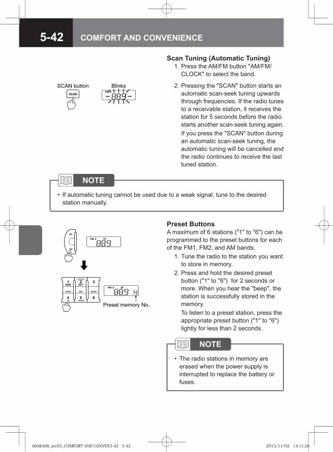
5-42 COMFORT AND CONVENIENCE
Scan Tuning (Automatic Tuning) 1. Press the AM/FM button "AM/FM/
CLOCK" to select the band.
Preset memory No.
Preset ButtonsA maximum of 6 stations ("1" to "6") can be programmed to the preset buttons for each of the FM1, FM2, and AM bands. 1. Tune the radio to the station you want
to store in memory. 2. Press and hold the desired preset
button ("1" to "6") for 2 seconds or more. When you hear the "beep", the station is successfully stored in the memory.
To listen to a preset station, press the appropriate preset button ("1" to "6") lightly for less than 2 seconds.
NOTEIf automatic tuning cannot be used due to a weak signal, tune to the desired station manually.
•
NOTEThe radio stations in memory are erased when the power supply is interrupted to replace the battery or fuses.
•
BlinksSCAN button 2. Pressing the "SCAN" button starts an automatic scan-seek tuning upwards through frequencies. If the radio tunes to a receivable station, it receives the station for 5 seconds before the radio starts another scan-seek tuning again.
If you press the "SCAN" button during an automatic scan-seek tuning, the automatic tuning will be cancelled and the radio continues to receive the last tuned station.
4608498_sec05_COMFORT AND CONVEN5-42 5-424608498_sec05_COMFORT AND CONVEN5-42 5-42 2015/11/02 14:11:262015/11/02 14:11:26
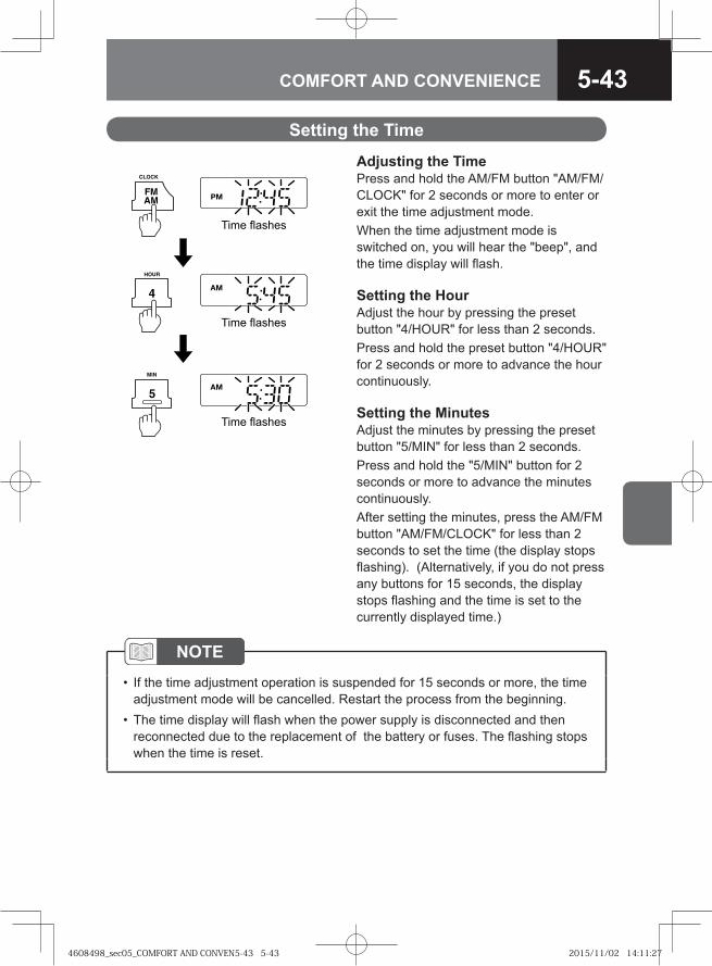
5-43COMFORT AND CONVENIENCE
Time flashes
Time flashes
Time flashes
Adjusting the Time Press and hold the AM/FM button "AM/FM/CLOCK" for 2 seconds or more to enter or exit the time adjustment mode. When the time adjustment mode is switched on, you will hear the "beep", and the time display will flash.
Setting the Hour Adjust the hour by pressing the preset button "4/HOUR" for less than 2 seconds. Press and hold the preset button "4/HOUR" for 2 seconds or more to advance the hour continuously.
Setting the Minutes Adjust the minutes by pressing the preset button "5/MIN" for less than 2 seconds. Press and hold the "5/MIN" button for 2 seconds or more to advance the minutes continuously. After setting the minutes, press the AM/FM button "AM/FM/CLOCK" for less than 2 seconds to set the time (the display stops flashing). (Alternatively, if you do not press any buttons for 15 seconds, the display stops flashing and the time is set to the currently displayed time.)
Setting the Time
NOTEIf the time adjustment operation is suspended for 15 seconds or more, the time adjustment mode will be cancelled. Restart the process from the beginning. The time display will flash when the power supply is disconnected and then reconnected due to the replacement of the battery or fuses. The flashing stops when the time is reset.
•
•
4608498_sec05_COMFORT AND CONVEN5-43 5-434608498_sec05_COMFORT AND CONVEN5-43 5-43 2015/11/02 14:11:272015/11/02 14:11:27
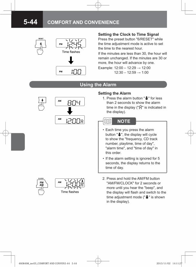
5-44 COMFORT AND CONVENIENCE
Setting the Clock to Time SignalPress the preset button "6/RESET" while the time adjustment mode is active to set the time to the nearest hour. If the minutes are less than 30, the hour will remain unchanged. If the minutes are 30 or more, the hour will advance by one. Example: 12:00 – 12:29 → 12:00
12:30 – 12:59 → 1:00
Time flashes
Setting the Alarm 1. Press the alarm button " " for less
than 2 seconds to show the alarm time in the display (" " is indicated in the display).
Using the Alarm
Time flashes
2. Press and hold the AM/FM button "AM/FM/CLOCK" for 2 seconds or more until you hear the "beep", and the display will flash and switch to the time adjustment mode (" " is shown in the display).
NOTEEach time you press the alarm button " ", the display will cycle to show the "frequency, CD track number, playtime, time of day", "alarm time", and "time of day" in this order. If the alarm setting is ignored for 5 seconds, the display returns to the time of day.
•
•
4608498_sec05_COMFORT AND CONVEN5-44 5-444608498_sec05_COMFORT AND CONVEN5-44 5-44 2015/11/02 14:11:272015/11/02 14:11:27
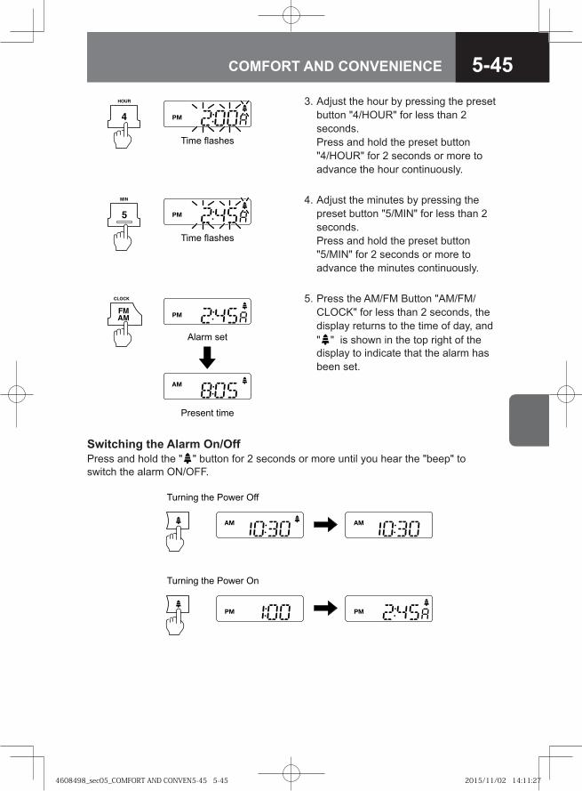
5-45COMFORT AND CONVENIENCE
Time flashes
Time flashes
Alarm set
Present time
3. Adjust the hour by pressing the preset button "4/HOUR" for less than 2 seconds.Press and hold the preset button "4/HOUR" for 2 seconds or more to advance the hour continuously.
4. Adjust the minutes by pressing the preset button "5/MIN" for less than 2 seconds. Press and hold the preset button "5/MIN" for 2 seconds or more to advance the minutes continuously.
5. Press the AM/FM Button "AM/FM/CLOCK" for less than 2 seconds, the display returns to the time of day, and " " is shown in the top right of the display to indicate that the alarm has been set.
Turning the Power Off
Turning the Power On
Switching the Alarm On/OffPress and hold the " " button for 2 seconds or more until you hear the "beep" to switch the alarm ON/OFF.
4608498_sec05_COMFORT AND CONVEN5-45 5-454608498_sec05_COMFORT AND CONVEN5-45 5-45 2015/11/02 14:11:272015/11/02 14:11:27
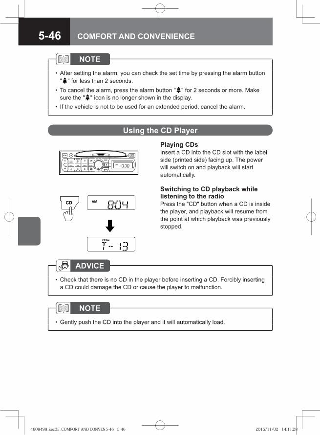
5-46 COMFORT AND CONVENIENCE
Playing CDsInsert a CD into the CD slot with the label side (printed side) facing up. The power will switch on and playback will start automatically.
Switching to CD playback while listening to the radioPress the "CD" button when a CD is inside the player, and playback will resume from the point at which playback was previously stopped.
Using the CD Player
NOTEAfter setting the alarm, you can check the set time by pressing the alarm button " " for less than 2 seconds.To cancel the alarm, press the alarm button " " for 2 seconds or more. Make sure the " " icon is no longer shown in the display. If the vehicle is not to be used for an extended period, cancel the alarm.
•
•
•
NOTEGently push the CD into the player and it will automatically load. •
ADVICECheck that there is no CD in the player before inserting a CD. Forcibly inserting a CD could damage the CD or cause the player to malfunction.
•
4608498_sec05_COMFORT AND CONVEN5-46 5-464608498_sec05_COMFORT AND CONVEN5-46 5-46 2015/11/02 14:11:282015/11/02 14:11:28
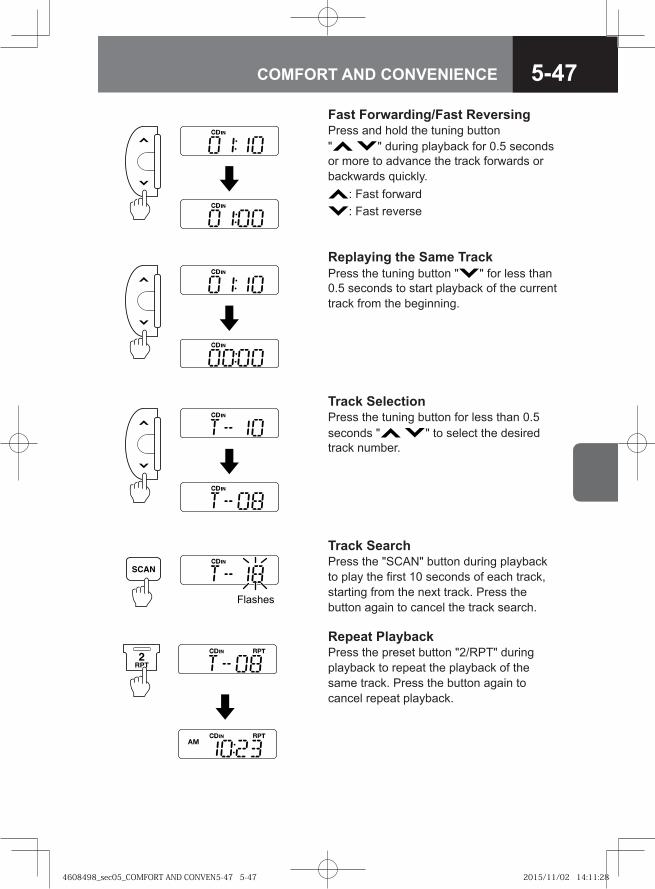
5-47COMFORT AND CONVENIENCE
Fast Forwarding/Fast Reversing Press and hold the tuning button " " during playback for 0.5 seconds or more to advance the track forwards or backwards quickly.
: Fast forward: Fast reverse
Replaying the Same TrackPress the tuning button " " for less than 0.5 seconds to start playback of the current track from the beginning.
Track Selection Press the tuning button for less than 0.5 seconds " " to select the desired track number.
Track SearchPress the "SCAN" button during playback to play the first 10 seconds of each track, starting from the next track. Press the button again to cancel the track search.
Repeat Playback Press the preset button "2/RPT" during playback to repeat the playback of the same track. Press the button again to cancel repeat playback.
Flashes
4608498_sec05_COMFORT AND CONVEN5-47 5-474608498_sec05_COMFORT AND CONVEN5-47 5-47 2015/11/02 14:11:282015/11/02 14:11:28
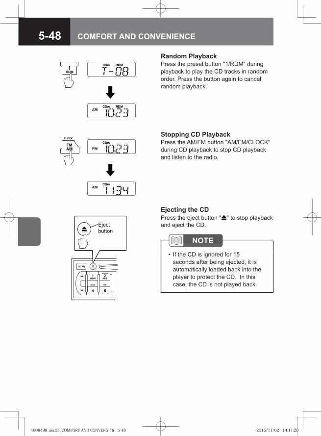
5-48 COMFORT AND CONVENIENCE
Random PlaybackPress the preset button "1/RDM" during playback to play the CD tracks in random order. Press the button again to cancel random playback.
Stopping CD PlaybackPress the AM/FM button "AM/FM/CLOCK" during CD playback to stop CD playback and listen to the radio.
Eject button
Ejecting the CDPress the eject button " " to stop playback and eject the CD.
NOTEIf the CD is ignored for 15 seconds after being ejected, it is automatically loaded back into the player to protect the CD. In this case, the CD is not played back.
•
4608498_sec05_COMFORT AND CONVEN5-48 5-484608498_sec05_COMFORT AND CONVEN5-48 5-48 2015/11/02 14:11:292015/11/02 14:11:29
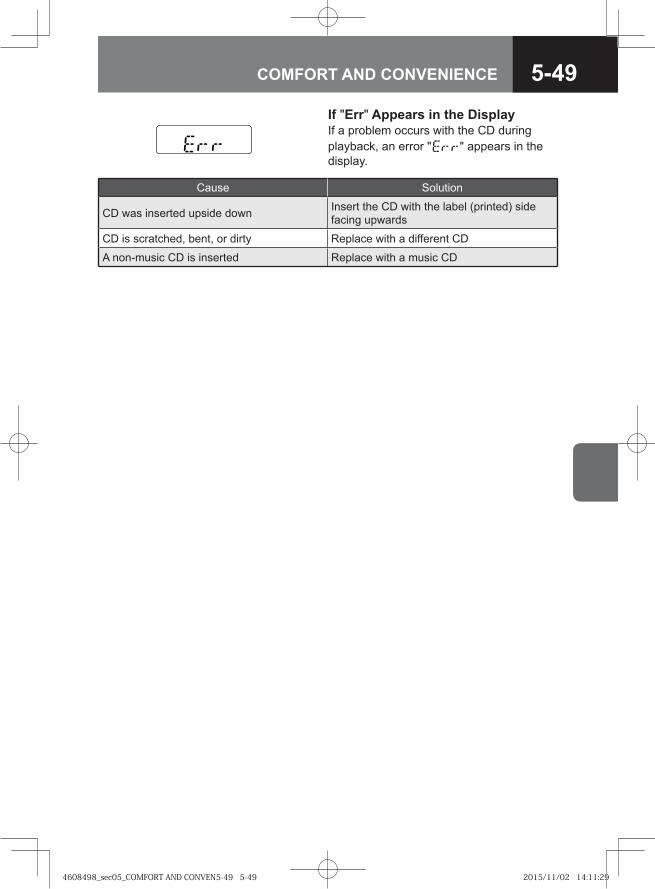
5-49COMFORT AND CONVENIENCE
If "Err" Appears in the DisplayIf a problem occurs with the CD during playback, an error " " appears in the display.
Cause Solution
CD was inserted upside down Insert the CD with the label (printed) side facing upwards
CD is scratched, bent, or dirty Replace with a different CD
A non-music CD is inserted Replace with a music CD
4608498_sec05_COMFORT AND CONVEN5-49 5-494608498_sec05_COMFORT AND CONVEN5-49 5-49 2015/11/02 14:11:292015/11/02 14:11:29
5-50 COMFORT AND CONVENIENCE
4608498_sec05_COMFORT AND CONVEN5-50 5-504608498_sec05_COMFORT AND CONVEN5-50 5-50 2015/11/02 14:11:292015/11/02 14:11:29
TIPS ON SAFE AND SMOOTH OPERATION
● Driving Safely and with Confidence 6-2
● On the Road 6-2
● Driving with a Trailer 6-17
● Cautions for Parking 6-20
● Cautions for Driving in Hot Regions and Season 6-21
● Cautions for Driving in Cold Regions and Season 6-22
● Using Tire Chains 6-27
6
4608498_sec06_SAFE AND SMOOTH OP6-1 6-14608498_sec06_SAFE AND SMOOTH OP6-1 6-1 2015/11/02 14:12:362015/11/02 14:12:36
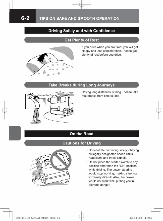
6-2 TIPS ON SAFE AND SMOOTH OPERATION
Get Plenty of RestIf you drive when you are tired, you will get sleepy and lose concentration. Please get plenty of rest before you drive.
Driving Safely and with Confidence
��� �� ���� ����
Take Breaks during Long JourneysDriving long distances is tiring. Please take rest breaks from time to time.
On the Road
Cautions for Driving • Concentrate on driving safely, obeying
all legally designated speed limits, road signs and traffic signals.
• Do not place the starter switch to any position other than the "ON" position while driving. The power steering would stop working, making steering extremely difficult. Also, the brakes would not work well, putting you in extreme danger.
4608498_sec06_SAFE AND SMOOTH OP6-2 6-24608498_sec06_SAFE AND SMOOTH OP6-2 6-2 2015/11/02 14:12:362015/11/02 14:12:36
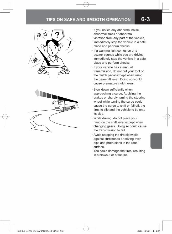
6-3TIPS ON SAFE AND SMOOTH OPERATION
• If you notice any abnormal noise, abnormal smell or abnormal vibration from any part of the vehicle, immediately stop the vehicle in a safe place and perform checks.
• If a warning light comes on or a buzzer sounds while you are driving, immediately stop the vehicle in a safe place and perform checks.
• If your vehicle has a manual transmission, do not put your foot on the clutch pedal except when using the gearshift lever. Doing so would cause premature clutch wear.
• Slow down sufficiently when approaching a curve. Applying the brakes or sharply turning the steering wheel while turning the curve could cause the cargo to shift or fall off, the tires to slip and the vehicle to tip onto its side.
• While driving, do not place your hand on the shift lever except when changing gears. Doing so could cause the transmission to fail.
• Avoid scraping the tire sidewalls against curbstones or driving over dips and protrusions in the road surface. You could damage the tires, resulting in a blowout or a flat tire.
4608498_sec06_SAFE AND SMOOTH OP6-3 6-34608498_sec06_SAFE AND SMOOTH OP6-3 6-3 2015/11/02 14:12:372015/11/02 14:12:37
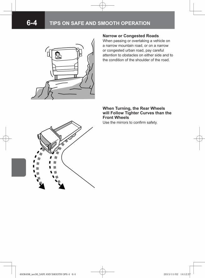
6-4 TIPS ON SAFE AND SMOOTH OPERATION
Narrow or Congested RoadsWhen passing or overtaking a vehicle on a narrow mountain road, or on a narrow or congested urban road, pay careful attention to obstacles on either side and to the condition of the shoulder of the road.
When Turning, the Rear Wheels will Follow Tighter Curves than the Front Wheels Use the mirrors to confirm safety.
4608498_sec06_SAFE AND SMOOTH OP6-4 6-44608498_sec06_SAFE AND SMOOTH OP6-4 6-4 2015/11/02 14:12:372015/11/02 14:12:37
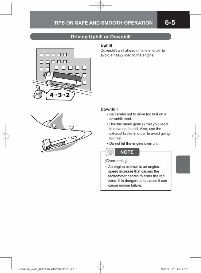
6-5TIPS ON SAFE AND SMOOTH OPERATION
Driving Uphill or Downhill
UphillDownshift well ahead of time in order to avoid a heavy load to the engine.
Downhill • Be careful not to drive too fast on a
downhill road. • Use the same gear(s) that you used
to drive up the hill. Also, use the exhaust brake in order to avoid going too fast.
• Do not let the engine overrun.
NOTE[Overrunning]
An engine overrun is an engine-speed increase that causes the tachometer needle to enter the red zone. It is dangerous because it can cause engine failure.
•
4608498_sec06_SAFE AND SMOOTH OP6-5 6-54608498_sec06_SAFE AND SMOOTH OP6-5 6-5 2015/11/02 14:12:372015/11/02 14:12:37
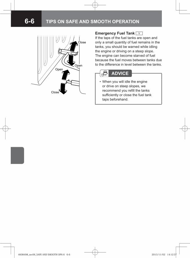
6-6 TIPS ON SAFE AND SMOOTH OPERATION
Emergency Fuel Tank V
If the taps of the fuel tanks are open and only a small quantity of fuel remains in the tanks, you should be warned while idling the engine or driving on a steep slope. The engine can become starved of fuel because the fuel moves between tanks due to the difference in level between the tanks.
ADVICEWhen you will idle the engine or drive on steep slopes, we recommend you refill the tanks sufficiently or close the fuel tank taps beforehand.
•
�� �
�� �
����
����
4608498_sec06_SAFE AND SMOOTH OP6-6 6-64608498_sec06_SAFE AND SMOOTH OP6-6 6-6 2015/11/02 14:12:372015/11/02 14:12:37
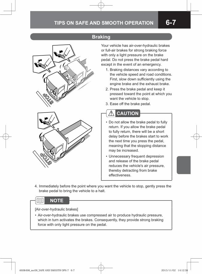
6-7TIPS ON SAFE AND SMOOTH OPERATION
BrakingYour vehicle has air-over-hydraulic brakes or full-air brakes for strong braking force with only a light pressure on the brake pedal. Do not press the brake pedal hard except in the event of an emergency. 1. Braking distances vary according to
the vehicle speed and road conditions. First, slow down sufficiently using the engine brake and the exhaust brake.
2. Press the brake pedal and keep it pressed toward the point at which you want the vehicle to stop.
3. Ease off the brake pedal.
NOTE[Air-over-hydraulic brakes]
Air-over-hydraulic brakes use compressed air to produce hydraulic pressure, which in turn activates the brakes. Consequently, they provide strong braking force with only light pressure on the pedal.
•
CAUTIONDo not allow the brake pedal to fully return. If you allow the brake pedal to fully return, there will be a short delay before the brakes start to work the next time you press the pedal, meaning that the stopping distance may be increased.Unnecessary frequent depression and release of the brake pedal reduces the vehicle's air pressure, thereby detracting from brake effectiveness.
•
•
4. Immediately before the point where you want the vehicle to stop, gently press the brake pedal to bring the vehicle to a halt.
4608498_sec06_SAFE AND SMOOTH OP6-7 6-74608498_sec06_SAFE AND SMOOTH OP6-7 6-7 2015/11/02 14:12:382015/11/02 14:12:38
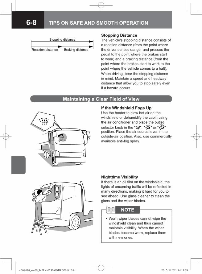
6-8 TIPS ON SAFE AND SMOOTH OPERATION
Maintaining a Clear Field of View
If the Windshield Fogs UpUse the heater to blow hot air on the windshield or dehumidify the cabin using the air conditioner and place the outlet selector knob in the " ", " " or " " position. Place the air source lever in the outside-air position. Also, use commercially available anti-fog spray.
Nighttime VisibilityIf there is an oil film on the windshield, the lights of oncoming traffic will be reflected in many directions, making it hard for you to see ahead. Use glass cleaner to clean the glass and the wiper blades.
NOTEWorn wiper blades cannot wipe the windshield clean and thus cannot maintain visibility. When the wiper blades become worn, replace them with new ones.
•
Stopping DistanceThe vehicle's stopping distance consists of a reaction distance (from the point where the driver senses danger and presses the pedal to the point where the brakes start to work) and a braking distance (from the point where the brakes start to work to the point where the vehicle comes to a halt).When driving, bear the stopping distance in mind. Maintain a speed and headway distance that allow you to stop safely even if a hazard occurs.
�� ���� ���� ����� ����� ���� ���
�������� ���� ���
4608498_sec06_SAFE AND SMOOTH OP6-8 6-84608498_sec06_SAFE AND SMOOTH OP6-8 6-8 2015/11/02 14:12:382015/11/02 14:12:38
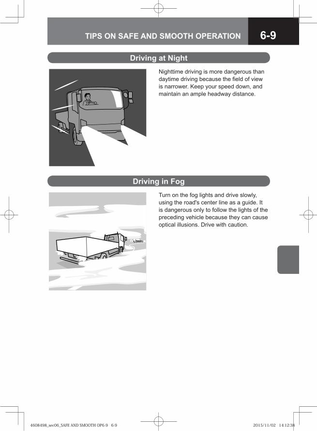
6-9TIPS ON SAFE AND SMOOTH OPERATION
Nighttime driving is more dangerous than daytime driving because the field of view is narrower. Keep your speed down, and maintain an ample headway distance.
Driving at Night
Driving in FogTurn on the fog lights and drive slowly, using the road's center line as a guide. It is dangerous only to follow the lights of the preceding vehicle because they can cause optical illusions. Drive with caution.
4608498_sec06_SAFE AND SMOOTH OP6-9 6-94608498_sec06_SAFE AND SMOOTH OP6-9 6-9 2015/11/02 14:12:382015/11/02 14:12:38
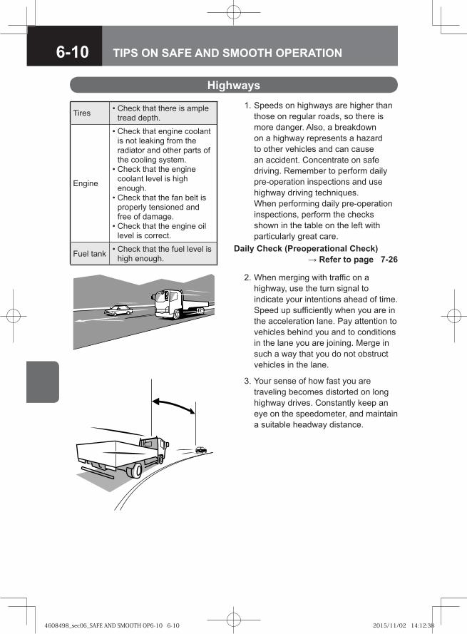
6-10 TIPS ON SAFE AND SMOOTH OPERATION
1. Speeds on highways are higher than those on regular roads, so there is more danger. Also, a breakdown on a highway represents a hazard to other vehicles and can cause an accident. Concentrate on safe driving. Remember to perform daily pre-operation inspections and use highway driving techniques.When performing daily pre-operation inspections, perform the checks shown in the table on the left with particularly great care.
Daily Check (Preoperational Check) → Refer to page 7-26
Tires • Check that there is ample tread depth.
Engine
• Check that engine coolant is not leaking from the radiator and other parts of the cooling system.
• Check that the engine coolant level is high enough.
• Check that the fan belt is properly tensioned and free of damage.
• Check that the engine oil level is correct.
Fuel tank • Check that the fuel level is high enough.
3. Your sense of how fast you are traveling becomes distorted on long highway drives. Constantly keep an eye on the speedometer, and maintain a suitable headway distance.
Highways
2. When merging with traffic on a highway, use the turn signal to indicate your intentions ahead of time. Speed up sufficiently when you are in the acceleration lane. Pay attention to vehicles behind you and to conditions in the lane you are joining. Merge in such a way that you do not obstruct vehicles in the lane.
4608498_sec06_SAFE AND SMOOTH OP6-10 6-104608498_sec06_SAFE AND SMOOTH OP6-10 6-10 2015/11/02 14:12:382015/11/02 14:12:38
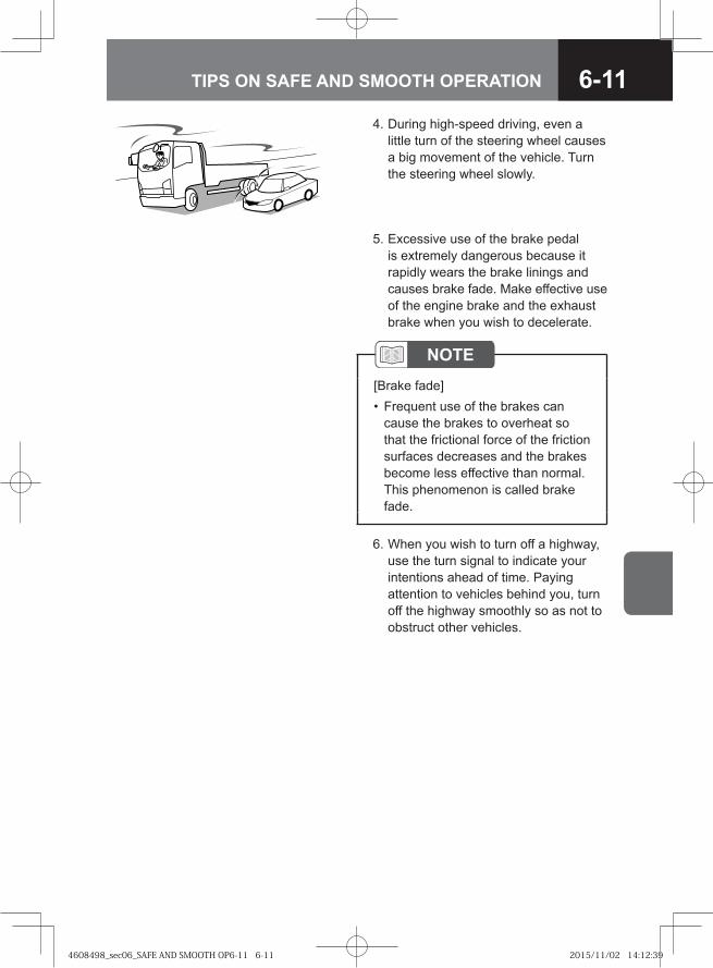
6-11TIPS ON SAFE AND SMOOTH OPERATION
4. During high-speed driving, even a little turn of the steering wheel causes a big movement of the vehicle. Turn the steering wheel slowly.
NOTE[Brake fade]
Frequent use of the brakes can cause the brakes to overheat so that the frictional force of the friction surfaces decreases and the brakes become less effective than normal. This phenomenon is called brake fade.
•
6. When you wish to turn off a highway, use the turn signal to indicate your intentions ahead of time. Paying attention to vehicles behind you, turn off the highway smoothly so as not to obstruct other vehicles.
5. Excessive use of the brake pedal is extremely dangerous because it rapidly wears the brake linings and causes brake fade. Make effective use of the engine brake and the exhaust brake when you wish to decelerate.
4608498_sec06_SAFE AND SMOOTH OP6-11 6-114608498_sec06_SAFE AND SMOOTH OP6-11 6-11 2015/11/02 14:12:392015/11/02 14:12:39
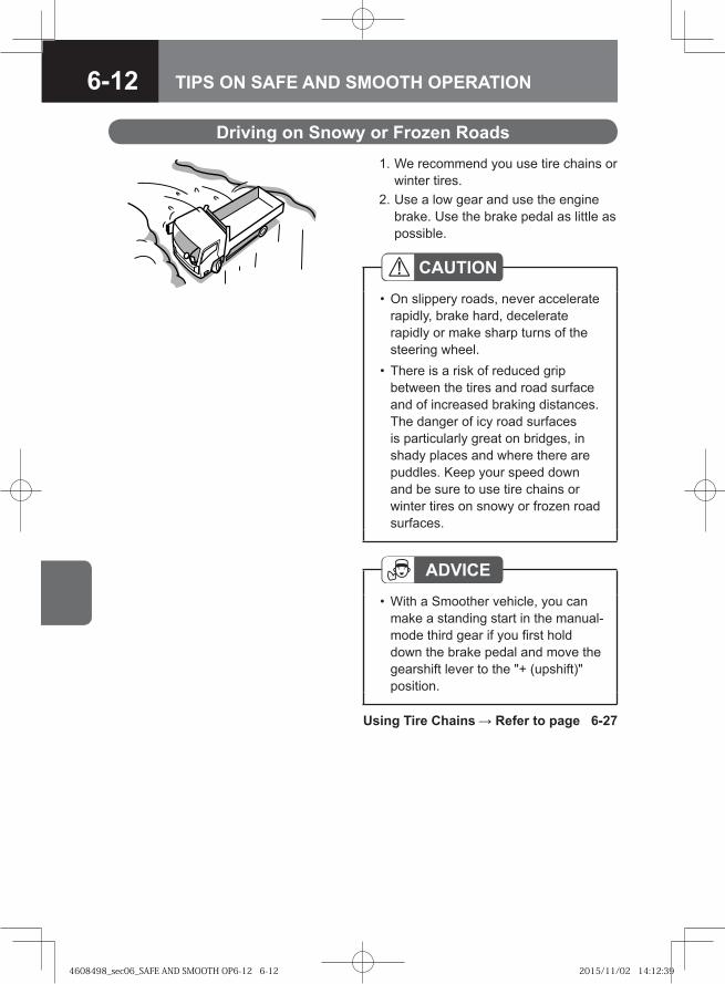
6-12 TIPS ON SAFE AND SMOOTH OPERATION
Driving on Snowy or Frozen Roads
Using Tire Chains → Refer to page 6-27
CAUTIONOn slippery roads, never accelerate rapidly, brake hard, decelerate rapidly or make sharp turns of the steering wheel. There is a risk of reduced grip between the tires and road surface and of increased braking distances. The danger of icy road surfaces is particularly great on bridges, in shady places and where there are puddles. Keep your speed down and be sure to use tire chains or winter tires on snowy or frozen road surfaces.
•
•
1. We recommend you use tire chains or winter tires.
2. Use a low gear and use the engine brake. Use the brake pedal as little as possible.
ADVICEWith a Smoother vehicle, you can make a standing start in the manual-mode third gear if you first hold down the brake pedal and move the gearshift lever to the "+ (upshift)" position.
•
4608498_sec06_SAFE AND SMOOTH OP6-12 6-124608498_sec06_SAFE AND SMOOTH OP6-12 6-12 2015/11/02 14:12:392015/11/02 14:12:39
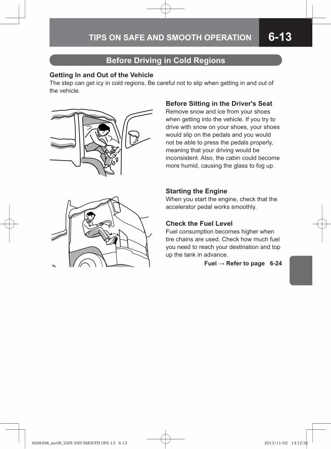
6-13TIPS ON SAFE AND SMOOTH OPERATION
Before Sitting in the Driver's SeatRemove snow and ice from your shoes when getting into the vehicle. If you try to drive with snow on your shoes, your shoes would slip on the pedals and you would not be able to press the pedals properly, meaning that your driving would be inconsistent. Also, the cabin could become more humid, causing the glass to fog up.
Starting the EngineWhen you start the engine, check that the accelerator pedal works smoothly.
Before Driving in Cold Regions
Getting In and Out of the VehicleThe step can get icy in cold regions. Be careful not to slip when getting in and out of the vehicle.
Check the Fuel LevelFuel consumption becomes higher when tire chains are used. Check how much fuel you need to reach your destination and top up the tank in advance. Fuel → Refer to page 6-24
4608498_sec06_SAFE AND SMOOTH OP6-13 6-134608498_sec06_SAFE AND SMOOTH OP6-13 6-13 2015/11/02 14:12:392015/11/02 14:12:39
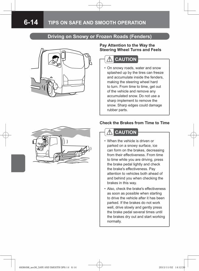
6-14 TIPS ON SAFE AND SMOOTH OPERATION
Driving on Snowy or Frozen Roads (Fenders)
Pay Attention to the Way the Steering Wheel Turns and Feels
CAUTIONOn snowy roads, water and snow splashed up by the tires can freeze and accumulate inside the fenders, making the steering wheel hard to turn. From time to time, get out of the vehicle and remove any accumulated snow. Do not use a sharp implement to remove the snow. Sharp edges could damage rubber parts.
•
Check the Brakes from Time to Time
CAUTIONWhen the vehicle is driven or parked on a snowy surface, ice can form on the brakes, decreasing from their effectiveness. From time to time while you are driving, press the brake pedal lightly and check the brake's effectiveness. Pay attention to vehicles both ahead of and behind you when checking the brakes in this way.Also, check the brake's effectiveness as soon as possible when starting to drive the vehicle after it has been parked. If the brakes do not work well, drive slowly and gently press the brake pedal several times until the brakes dry out and start working normally.
•
•
4608498_sec06_SAFE AND SMOOTH OP6-14 6-144608498_sec06_SAFE AND SMOOTH OP6-14 6-14 2015/11/02 14:12:392015/11/02 14:12:39
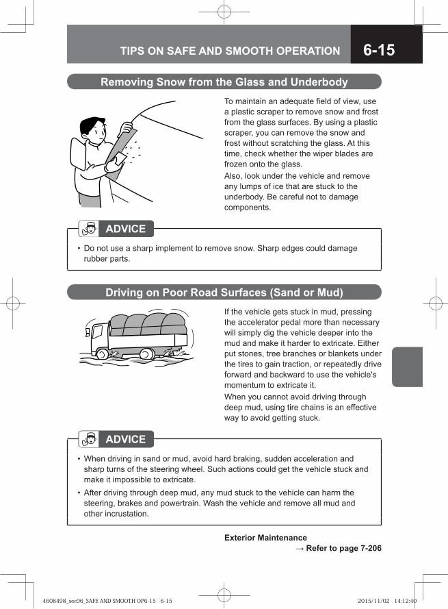
6-15TIPS ON SAFE AND SMOOTH OPERATION
Driving on Poor Road Surfaces (Sand or Mud)If the vehicle gets stuck in mud, pressing the accelerator pedal more than necessary will simply dig the vehicle deeper into the mud and make it harder to extricate. Either put stones, tree branches or blankets under the tires to gain traction, or repeatedly drive forward and backward to use the vehicle's momentum to extricate it.When you cannot avoid driving through deep mud, using tire chains is an effective way to avoid getting stuck.
ADVICEWhen driving in sand or mud, avoid hard braking, sudden acceleration and sharp turns of the steering wheel. Such actions could get the vehicle stuck and make it impossible to extricate.After driving through deep mud, any mud stuck to the vehicle can harm the steering, brakes and powertrain. Wash the vehicle and remove all mud and other incrustation.
•
•
Exterior Maintenance → Refer to page 7-206
Removing Snow from the Glass and UnderbodyTo maintain an adequate field of view, use a plastic scraper to remove snow and frost from the glass surfaces. By using a plastic scraper, you can remove the snow and frost without scratching the glass. At this time, check whether the wiper blades are frozen onto the glass. Also, look under the vehicle and remove any lumps of ice that are stuck to the underbody. Be careful not to damage components.
ADVICEDo not use a sharp implement to remove snow. Sharp edges could damage rubber parts.
•
4608498_sec06_SAFE AND SMOOTH OP6-15 6-154608498_sec06_SAFE AND SMOOTH OP6-15 6-15 2015/11/02 14:12:402015/11/02 14:12:40
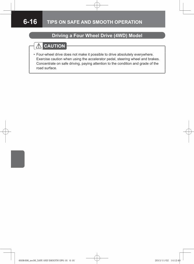
6-16 TIPS ON SAFE AND SMOOTH OPERATION
Driving a Four Wheel Drive (4WD) Model
CAUTIONFour-wheel drive does not make it possible to drive absolutely everywhere. Exercise caution when using the accelerator pedal, steering wheel and brakes. Concentrate on safe driving, paying attention to the condition and grade of the road surface.
•
4608498_sec06_SAFE AND SMOOTH OP6-16 6-164608498_sec06_SAFE AND SMOOTH OP6-16 6-16 2015/11/02 14:12:402015/11/02 14:12:40
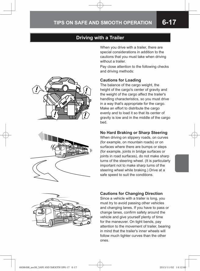
6-17TIPS ON SAFE AND SMOOTH OPERATION
When you drive with a trailer, there are special considerations in addition to the cautions that you must take when driving without a trailer. Pay close attention to the following checks and driving methods:
Cautions for LoadingThe balance of the cargo weight, the height of the cargo's center of gravity and the weight of the cargo affect the trailer's handling characteristics, so you must drive in a way that's appropriate for the cargo. Make an effort to distribute the cargo evenly and to load it so that its center of gravity is low and in the middle of the cargo bed.
Driving with a Trailer
No Hard Braking or Sharp SteeringWhen driving on slippery roads, on curves (for example, on mountain roads) or on surfaces where there are bumps or steps (for example, joints in bridge surfaces or joints in road surfaces), do not make sharp turns of the steering wheel. (It is particularly important not to make sharp turns of the steering wheel while braking.) Drive at a safe speed to suit the conditions.
Cautions for Changing DirectionSince a vehicle with a trailer is long, you must try to avoid passing other vehicles and changing lanes. If you have to pass or change lanes, confirm safety around the vehicle and give yourself plenty of time for the maneuver. On tight bends, pay attention to the movement of trailer, bearing in mind that the trailer's inner wheels will follow much tighter curves than the other ones.
4608498_sec06_SAFE AND SMOOTH OP6-17 6-174608498_sec06_SAFE AND SMOOTH OP6-17 6-17 2015/11/02 14:12:402015/11/02 14:12:40
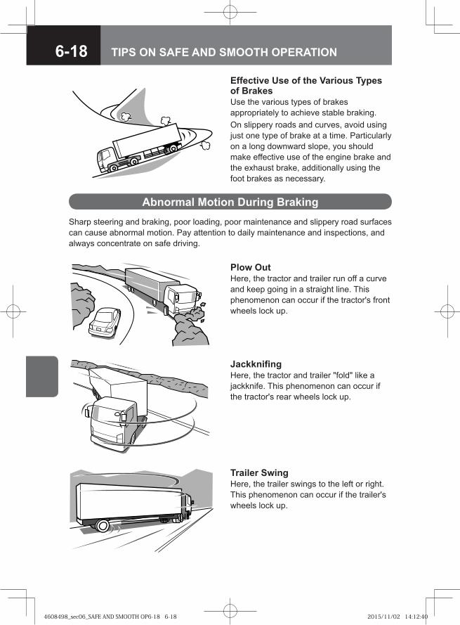
6-18 TIPS ON SAFE AND SMOOTH OPERATION
Effective Use of the Various Types of BrakesUse the various types of brakes appropriately to achieve stable braking.On slippery roads and curves, avoid using just one type of brake at a time. Particularly on a long downward slope, you should make effective use of the engine brake and the exhaust brake, additionally using the foot brakes as necessary.
Abnormal Motion During BrakingSharp steering and braking, poor loading, poor maintenance and slippery road surfaces can cause abnormal motion. Pay attention to daily maintenance and inspections, and always concentrate on safe driving.
Plow OutHere, the tractor and trailer run off a curve and keep going in a straight line. This phenomenon can occur if the tractor's front wheels lock up.
JackknifingHere, the tractor and trailer "fold" like a jackknife. This phenomenon can occur if the tractor's rear wheels lock up.
Trailer SwingHere, the trailer swings to the left or right. This phenomenon can occur if the trailer's wheels lock up.
4608498_sec06_SAFE AND SMOOTH OP6-18 6-184608498_sec06_SAFE AND SMOOTH OP6-18 6-18 2015/11/02 14:12:402015/11/02 14:12:40
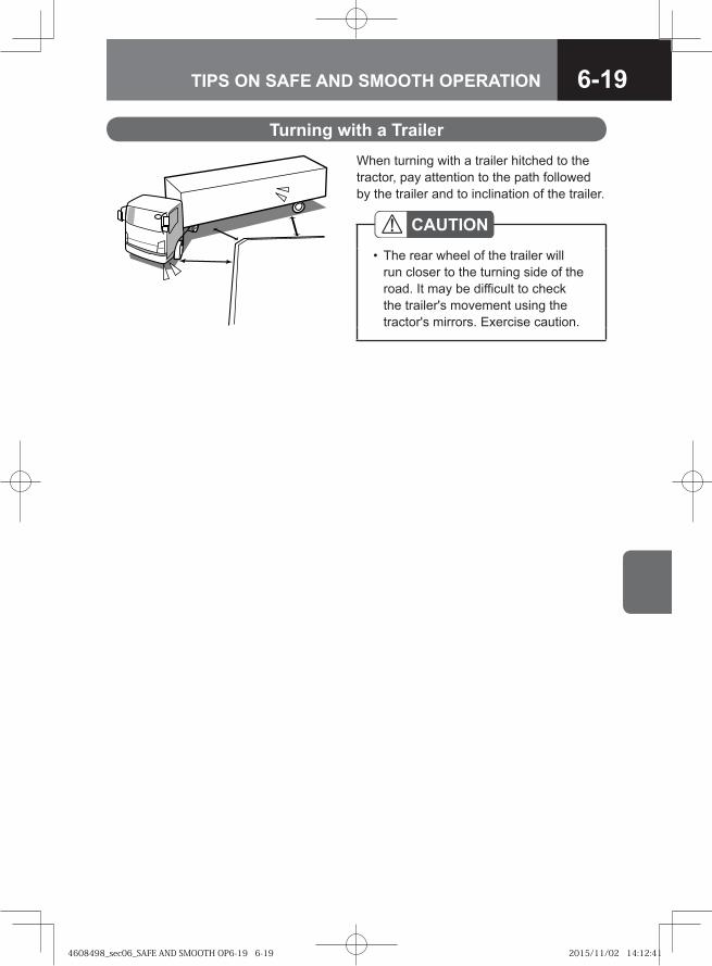
6-19TIPS ON SAFE AND SMOOTH OPERATION
Turning with a TrailerWhen turning with a trailer hitched to the tractor, pay attention to the path followed by the trailer and to inclination of the trailer.
CAUTIONThe rear wheel of the trailer will run closer to the turning side of the road. It may be difficult to check the trailer's movement using the tractor's mirrors. Exercise caution.
•
4608498_sec06_SAFE AND SMOOTH OP6-19 6-194608498_sec06_SAFE AND SMOOTH OP6-19 6-19 2015/11/02 14:12:412015/11/02 14:12:41
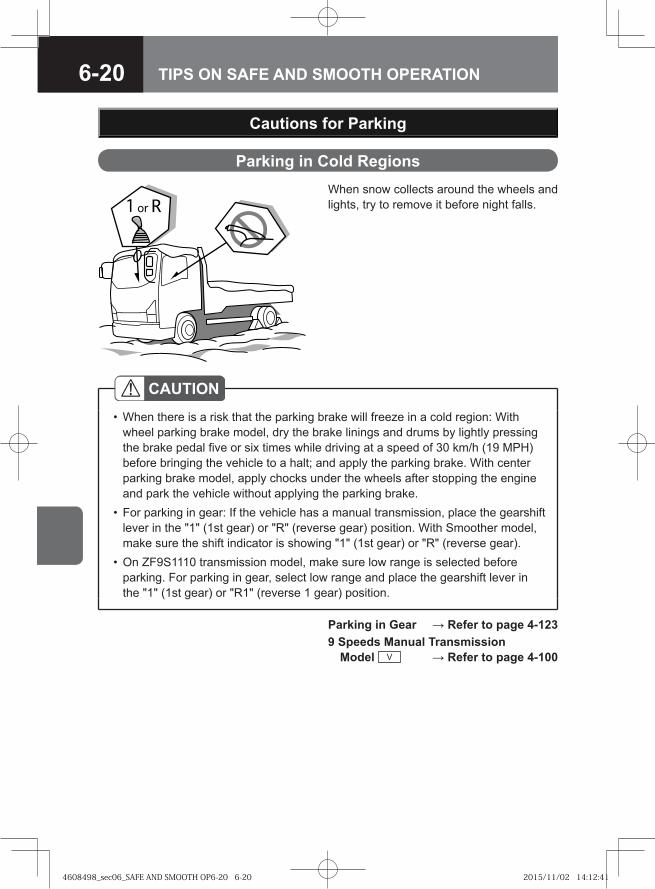
6-20 TIPS ON SAFE AND SMOOTH OPERATION
Parking in Cold RegionsWhen snow collects around the wheels and lights, try to remove it before night falls.
Cautions for Parking
CAUTIONWhen there is a risk that the parking brake will freeze in a cold region: With wheel parking brake model, dry the brake linings and drums by lightly pressing the brake pedal five or six times while driving at a speed of 30 km/h (19 MPH) before bringing the vehicle to a halt; and apply the parking brake. With center parking brake model, apply chocks under the wheels after stopping the engine and park the vehicle without applying the parking brake.For parking in gear: If the vehicle has a manual transmission, place the gearshift lever in the "1" (1st gear) or "R" (reverse gear) position. With Smoother model, make sure the shift indicator is showing "1" (1st gear) or "R" (reverse gear).On ZF9S1110 transmission model, make sure low range is selected before parking. For parking in gear, select low range and place the gearshift lever in the "1" (1st gear) or "R1" (reverse 1 gear) position.
•
•
•
Parking in Gear → Refer to page 4-1239 Speeds Manual Transmission
Model V → Refer to page 4-100
4608498_sec06_SAFE AND SMOOTH OP6-20 6-204608498_sec06_SAFE AND SMOOTH OP6-20 6-20 2015/11/02 14:12:412015/11/02 14:12:41
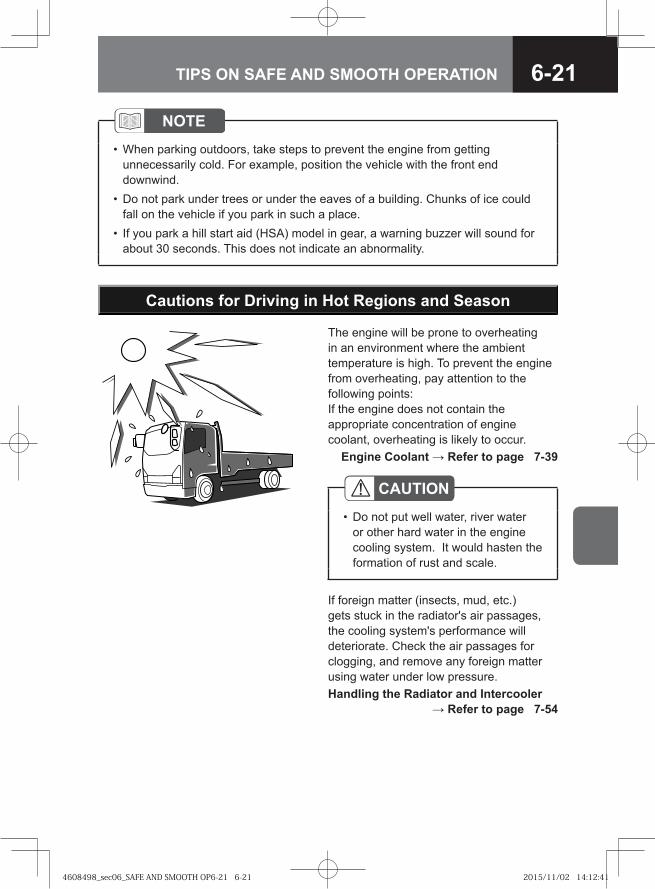
6-21TIPS ON SAFE AND SMOOTH OPERATION
NOTEWhen parking outdoors, take steps to prevent the engine from getting unnecessarily cold. For example, position the vehicle with the front end downwind.Do not park under trees or under the eaves of a building. Chunks of ice could fall on the vehicle if you park in such a place.If you park a hill start aid (HSA) model in gear, a warning buzzer will sound for about 30 seconds. This does not indicate an abnormality.
•
•
•
Cautions for Driving in Hot Regions and Season
The engine will be prone to overheating in an environment where the ambient temperature is high. To prevent the engine from overheating, pay attention to the following points:If the engine does not contain the appropriate concentration of engine coolant, overheating is likely to occur. Engine Coolant → Refer to page 7-39
If foreign matter (insects, mud, etc.) gets stuck in the radiator's air passages, the cooling system's performance will deteriorate. Check the air passages for clogging, and remove any foreign matter using water under low pressure.Handling the Radiator and Intercooler
→ Refer to page 7-54
CAUTIONDo not put well water, river water or other hard water in the engine cooling system. It would hasten the formation of rust and scale.
•
4608498_sec06_SAFE AND SMOOTH OP6-21 6-214608498_sec06_SAFE AND SMOOTH OP6-21 6-21 2015/11/02 14:12:412015/11/02 14:12:41
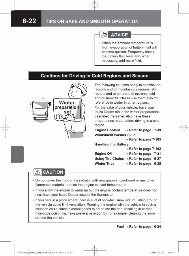
6-22 TIPS ON SAFE AND SMOOTH OPERATION
CAUTIONDo not cover the front of the radiator with newspapers, cardboard or any other flammable material to raise the engine coolant temperature.If you allow the engine to warm up but the engine coolant temperature does not rise, have your Isuzu Dealer inspect the thermostat.If you park in a place where there is a lot of snowfall, snow accumulating around the vehicle could limit ventilation. Running the engine with the vehicle in such a situation could cause exhaust gases to enter into the cab, resulting in carbon-monoxide poisoning. Take preventive action by, for example, clearing the snow around the vehicle.
•
•
•
Fuel → Refer to page 6-24
Cautions for Driving in Cold Regions and Season
Winter preparation
set
The following cautions apply to snowbound regions and to mountainous regions, ski resorts and other areas of extreme cold and/or snowfall. Please use them also for reference in winter in other regions.For the sake of your vehicle, have your Isuzu Dealer make the winter preparations described hereafter. Also have these preparations made before driving to a cold region.Engine Coolant → Refer to page 7-39Windshield Washer Fluid
→ Refer to page 7-185Handling the Battery
→ Refer to page 7-192Engine Oil → Refer to page 7-31Using Tire Chains → Refer to page 6-27Winter Tires → Refer to page 6-25
ADVICEWhen the ambient temperature is high, evaporation of battery fluid will become quicker. Frequently check the battery fluid level and, when necessary, add more fluid.
•
4608498_sec06_SAFE AND SMOOTH OP6-22 6-224608498_sec06_SAFE AND SMOOTH OP6-22 6-22 2015/11/02 14:12:412015/11/02 14:12:41
6-23TIPS ON SAFE AND SMOOTH OPERATION
Engine CoolantTo prevent the engine damage due to freezing of the engine coolant, mix the coolant and water to be an appropriate concentration.Changing the Engine Coolant
→ Refer to page 7-44Preparing Engine Coolant
→ Refer to page 7-40Recommended Fluids, Lubricants and
Diesel Fuels → Refer to page 7-242
Replacing the Engine Oil
Transmission Oil (ZF6S1000/ZF9S1110)
When Starting the Vehicle in Cold RegionsThe oil used in the ZF6S1000/ZF9S1110 transmission has a low-temperature limit. If you start to drive the vehicle under the ambient temperature of below -15°C (5°F), replace the transmission oil with an appropriate one which has sufficient low temperature performance. Another approach is to warm the transmission before starting the engine. When warming the transmission, do not use hot air with a temperature exceeding 130°C (266°F).
Changing the Engine Oil and Oil Filter → Refer to page 7-35
Recommended Fluids, Lubricants and Diesel Fuels → Refer to page 7-242
Engine Oil and Gear Oil Viscosity Charts → Refer to page 7-247
The engine oil tends to thicken with lowering temperatures. Use engine oil with a viscosity suited to ambient temperature.
4608498_sec06_SAFE AND SMOOTH OP6-23 6-234608498_sec06_SAFE AND SMOOTH OP6-23 6-23 2015/11/02 14:12:422015/11/02 14:12:42
6-24 TIPS ON SAFE AND SMOOTH OPERATION
Fuel
If you drive to a cold region in winter while using diesel fuel for warmer regions that freezes at a relatively high temperature, the fuel may freeze. As the ambient temperature decreases, the fuel in the fuel tank and pipes may freeze like slush, making the engine hard to start.
NOTEThe specifications of diesel fuel differ according to the climate and region.When driving to a cold region, put just enough fuel to reach the colder region in the tank. As soon as you reach the cold region, fill the tank with fuel that has a low freezing temperature.When taking the vehicle to a cold region on a ferry, board the ferry with only a minimal amount of fuel in the tank and then, after reaching the cold region, fill the tank with fuel that has a low freezing temperature.
••
•
CAUTIONBe sure to use diesel fuel. For models conforming to EuroIV emission standards, be sure to use low-sulfur diesel fuel (containing sulfur of 50 ppm or lower) or extra-low-sulfur diesel fuel (containing sulfur of 10 ppm or lower). If you supply the vehicle with poor-quality fuel, water-removal additive or other additive, gasoline, kerosene or alcohol-based fuel, it could harm the fuel filter, prevent proper movement of fuel-lubricated parts in the injectors and adversely affect engine components, possibly resulting in a breakdown. If you accidentally put the wrong fuel in the tank, drain it all out. Starting the engine with the wrong fuel in the tank could result in fire and engine damage.Using diesel fuel other than extra-low-sulfur diesel fuel or low-sulfur diesel fuel in a model conforming to EuroIV emission standards could prevent the vehicle from complying with local legal requirements.Open the fuel tank filler cap slowly. If you open it quickly, fuel may spurt out.
•
•
•
WARNING
If you leave the vehicle with the engine running, be sure to apply the parking brake to prevent the vehicle from rolling suddenly.
•
Low Temperature Limits → Refer to page 7-233
4608498_sec06_SAFE AND SMOOTH OP6-24 6-244608498_sec06_SAFE AND SMOOTH OP6-24 6-24 2015/11/02 14:12:422015/11/02 14:12:42
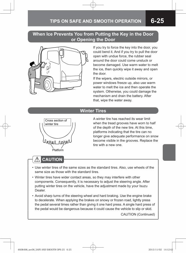
6-25TIPS ON SAFE AND SMOOTH OPERATION
When Ice Prevents You from Putting the Key in the Dooror Opening the Door
If you try to force the key into the door, you could bend it. And if you try to pull the door open with undue force, the rubber seal around the door could come unstuck or become damaged. Use warm water to melt the ice, then quickly wipe it away and open the door.If the wipers, electric outside mirrors, or power windows freeze up, also use warm water to melt the ice and then operate the system. Otherwise, you could damage the mechanism and drain the battery. After that, wipe the water away.
Winter Tires A winter tire has reached its wear limit when the tread grooves have worn to half of the depth of the new tire. At this time, platforms indicating that the tire can no longer give adequate performance on snow become visible in the grooves. Replace the tire with a new one.
�� �����
����� ������� ��
������ ����
CAUTIONUse winter tires of the same sizes as the standard tires. Also, use wheels of the same size as those with the standard tires.Winter tires have wider contact areas, so they may interfere with other components. Consequently, it is necessary to adjust the steering angle. After putting winter tires on the vehicle, have the adjustment made by your Isuzu Dealer.Avoid sharp turns of the steering wheel and hard braking. Use the engine brake to decelerate. When applying the brakes on snowy or frozen road, lightly press the pedal several times rather than giving it one hard press. A single hard press of the pedal would be dangerous because it could cause the vehicle to slip or skid.
•
•
•
CAUTION (Continued)
4608498_sec06_SAFE AND SMOOTH OP6-25 6-254608498_sec06_SAFE AND SMOOTH OP6-25 6-25 2015/11/02 14:12:422015/11/02 14:12:42
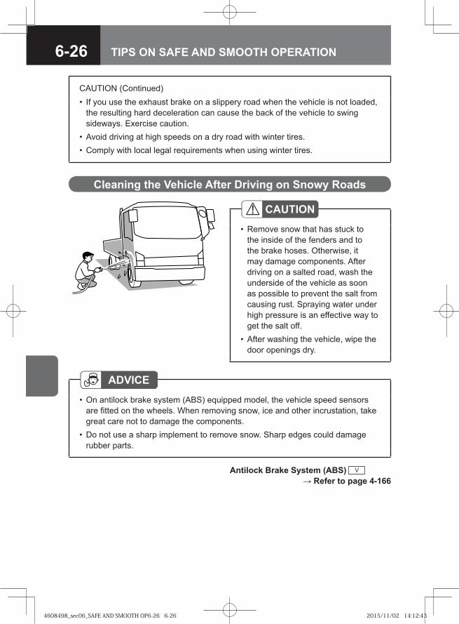
6-26 TIPS ON SAFE AND SMOOTH OPERATION
Cleaning the Vehicle After Driving on Snowy Roads
ADVICEOn antilock brake system (ABS) equipped model, the vehicle speed sensors are fitted on the wheels. When removing snow, ice and other incrustation, take great care not to damage the components.Do not use a sharp implement to remove snow. Sharp edges could damage rubber parts.
•
•
CAUTIONRemove snow that has stuck to the inside of the fenders and to the brake hoses. Otherwise, it may damage components. After driving on a salted road, wash the underside of the vehicle as soon as possible to prevent the salt from causing rust. Spraying water under high pressure is an effective way to get the salt off.After washing the vehicle, wipe the door openings dry.
•
•
CAUTION (Continued)If you use the exhaust brake on a slippery road when the vehicle is not loaded, the resulting hard deceleration can cause the back of the vehicle to swing sideways. Exercise caution.Avoid driving at high speeds on a dry road with winter tires.Comply with local legal requirements when using winter tires.
•
••
Antilock Brake System (ABS) V → Refer to page 4-166
4608498_sec06_SAFE AND SMOOTH OP6-26 6-264608498_sec06_SAFE AND SMOOTH OP6-26 6-26 2015/11/02 14:12:432015/11/02 14:12:43
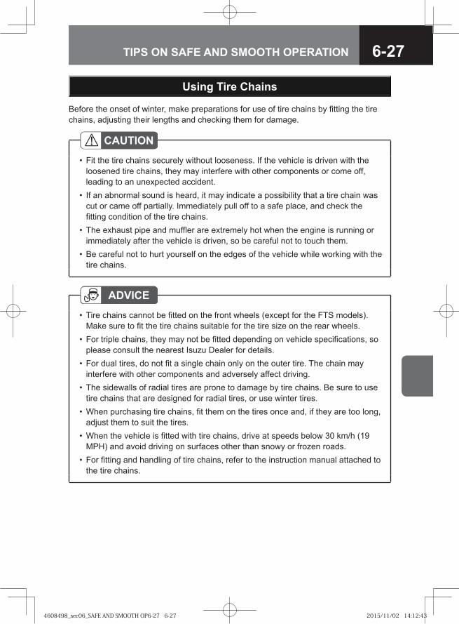
6-27TIPS ON SAFE AND SMOOTH OPERATION
Before the onset of winter, make preparations for use of tire chains by fitting the tire chains, adjusting their lengths and checking them for damage.
Using Tire Chains
CAUTIONFit the tire chains securely without looseness. If the vehicle is driven with the loosened tire chains, they may interfere with other components or come off, leading to an unexpected accident.If an abnormal sound is heard, it may indicate a possibility that a tire chain was cut or came off partially. Immediately pull off to a safe place, and check the fitting condition of the tire chains.The exhaust pipe and muffler are extremely hot when the engine is running or immediately after the vehicle is driven, so be careful not to touch them.Be careful not to hurt yourself on the edges of the vehicle while working with the tire chains.
•
•
•
•
ADVICETire chains cannot be fitted on the front wheels (except for the FTS models). Make sure to fit the tire chains suitable for the tire size on the rear wheels. For triple chains, they may not be fitted depending on vehicle specifications, so please consult the nearest Isuzu Dealer for details.For dual tires, do not fit a single chain only on the outer tire. The chain may interfere with other components and adversely affect driving.The sidewalls of radial tires are prone to damage by tire chains. Be sure to use tire chains that are designed for radial tires, or use winter tires.When purchasing tire chains, fit them on the tires once and, if they are too long, adjust them to suit the tires.When the vehicle is fitted with tire chains, drive at speeds below 30 km/h (19 MPH) and avoid driving on surfaces other than snowy or frozen roads.For fitting and handling of tire chains, refer to the instruction manual attached to the tire chains.
•
•
•
•
•
•
•
4608498_sec06_SAFE AND SMOOTH OP6-27 6-274608498_sec06_SAFE AND SMOOTH OP6-27 6-27 2015/11/02 14:12:432015/11/02 14:12:43
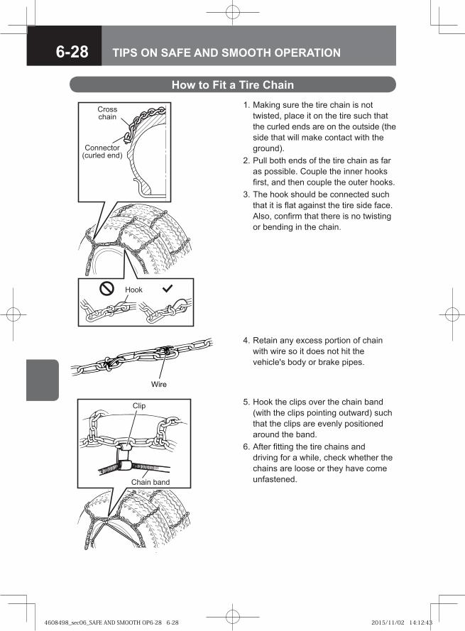
6-28 TIPS ON SAFE AND SMOOTH OPERATION
How to Fit a Tire Chain 1. Making sure the tire chain is not
twisted, place it on the tire such that the curled ends are on the outside (the side that will make contact with the ground).
2. Pull both ends of the tire chain as far as possible. Couple the inner hooks first, and then couple the outer hooks.
3. The hook should be connected such that it is flat against the tire side face. Also, confirm that there is no twisting or bending in the chain.
Hook
Crosschain
Connector(curled end)
�� �
4. Retain any excess portion of chain with wire so it does not hit the vehicle's body or brake pipes.
5. Hook the clips over the chain band (with the clips pointing outward) such that the clips are evenly positioned around the band.
6. After fitting the tire chains and driving for a while, check whether the chains are loose or they have come unfastened.
Clip
Chain band
4608498_sec06_SAFE AND SMOOTH OP6-28 6-284608498_sec06_SAFE AND SMOOTH OP6-28 6-28 2015/11/02 14:12:432015/11/02 14:12:43
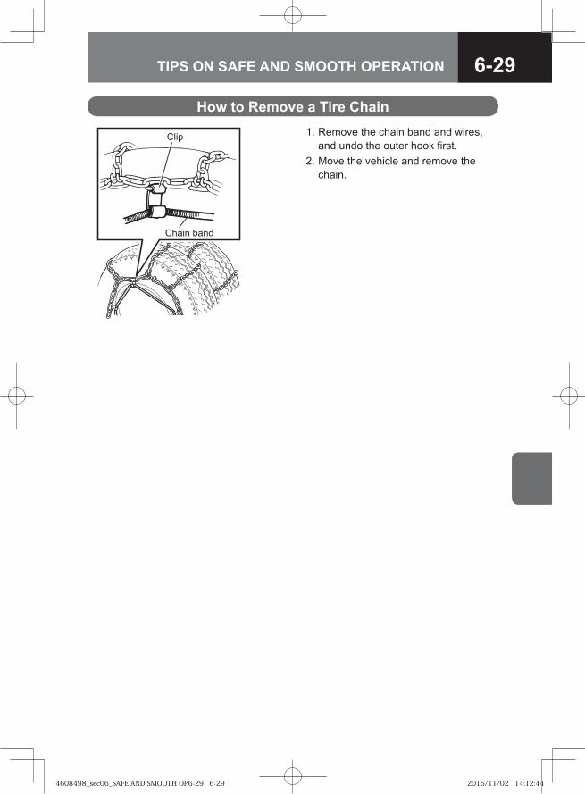
6-29TIPS ON SAFE AND SMOOTH OPERATION
How to Remove a Tire Chain 1. Remove the chain band and wires,
and undo the outer hook first. 2. Move the vehicle and remove the
chain.
Clip
Chain band
4608498_sec06_SAFE AND SMOOTH OP6-29 6-294608498_sec06_SAFE AND SMOOTH OP6-29 6-29 2015/11/02 14:12:442015/11/02 14:12:44
6-30 TIPS ON SAFE AND SMOOTH OPERATION
4608498_sec06_SAFE AND SMOOTH OP6-30 6-304608498_sec06_SAFE AND SMOOTH OP6-30 6-30 2015/11/02 14:12:442015/11/02 14:12:44
BEFORE SERVICE AND MAINTENANCE 7-3
DAILY INSPECTION 7-25
ENGINE-RELATED SERVICE AND MAINTENANCE 7-29
CHASSIS-RELATED SERVICE AND MAINTENANCE 7-75
OTHER SERVICE AND MAINTENANCE 7-179
INTERIOR AND EXTERIOR MAINTENANCE 7-205
MAINTENANCE DATA 7-215
7SERVICE AND MAINTENANCE
4608498_sec07_SERVICE AND MAINTE7-1 7-14608498_sec07_SERVICE AND MAINTE7-1 7-1 2015/11/04 9:59:222015/11/04 9:59:22

4608498_sec07_SERVICE AND MAINTE7-2 7-24608498_sec07_SERVICE AND MAINTE7-2 7-2 2015/11/04 9:59:222015/11/04 9:59:22
7-3SERVICE AND MAINTENANCE
● Precautions for Checking and Adjustments 7-4
● Discarded Parts, Oils and Other Liquids 7-6
● Isuzu Genuine Oils and Grease 7-6
● Tools 7-7
● Front Lid 7-8
● Tilting the Cab V 7-10
● Power Cab Tilt System V 7-15
BEFORE SERVICE AND MAINTENANCE
4608498_sec07_SERVICE AND MAINTE7-3 7-34608498_sec07_SERVICE AND MAINTE7-3 7-3 2015/11/04 9:59:222015/11/04 9:59:22
7-4 SERVICE AND MAINTENANCE
Precautions for Checking and Adjustments
WARNING
Make sure to turn off the engine and remove the key from the starter switch before performing any checks.Pull the parking brake lever firmly and put the transmission in neutral.
If your vehicle is equipped with a manual transmission, make sure the gearshift lever is in "N".If your vehicle is equipped with a Smoother system, place the gearshift lever in "N" and make sure the shift indicator displays "N".If your vehicle is equipped with an ALLISON2500 model automatic transmission, place the selector lever in "N".If your vehicle is equipped with an ALLISON3000/3500 model automatic transmission, make sure the shift selector display indicates "N".
Select a place with a hard and level surface for performing the checking and maintenance work. Make sure to chock the wheels. It would be very dangerous if the vehicle started to move.When raising the vehicle, use a suitable jack, not the one provided on the vehicle.After raising the vehicle and before going underneath to perform work, make sure the vehicle is supported with jack stands.When performing work on the electrical system, begin by turning the starter switch to the "LOCK" position, wait at least 1 minute, and then disconnect the negative cable from the negative terminal on battery. If the negative cable is disconnected within 1 minute, the engine control module may malfunction.The engine, exhaust pipe, radiator, and other parts surrounding them will be hot immediately after the vehicle is driven. Be careful around these parts to prevent burns. Perform all checks when the engine is cold.Do not perform work near an open flame or other heat sources.When working on the fuel line or fuel filter, remove the fuel tank filler cap. The fuel system is under pressure, and the fuel will overspill unless the pressure is relieved, possibly leading to combustion or a fire.Do not let the engine run in poorly ventilated garages or sheds. This could cause carbon monoxide poisoning.
•
•-
-
-
-
•
•
•
•
•
••
•
4608498_sec07_SERVICE AND MAINTE7-4 7-44608498_sec07_SERVICE AND MAINTE7-4 7-4 2015/11/04 9:59:232015/11/04 9:59:23
7-5SERVICE AND MAINTENANCE
ADVICEUse only appropriate tools.Oils, brake fluid, battery fluid, and engine coolant have lubrication, cooling, and rust prevention functions. If these liquids deteriorate through loss or contamination, it will cause a decline in the performance of parts and such problems as seizure or malfunctioning. Replenish or change these liquids when performing checks (daily and periodic checks) as required by the relevant regulations, or in accordance with the Maintenance Schedule (when either the specified driving distance or period of time, whichever comes first, has expired).Confirm that all systems and components are normal after performing the work.Do not leave the removed parts or tools in the engine compartment. They could damage the equipment if caught in the belts or other moving components.Dirty water, dirt and other impurities seriously impair the effectiveness of the oil, grease and fluids, and damage parts.Exercise all due caution to prevent waste or other refuse from coming in contact with parts or material that have been removed when handling them for change or replenishment.
••
••
•
CAUTIONDiscarded parts, oil, grease, and fluids could have an adverse effect on the environment. It is difficult to dispose of these, so have your Isuzu Dealer handle all checks and replacements.
•
4608498_sec07_SERVICE AND MAINTE7-5 7-54608498_sec07_SERVICE AND MAINTE7-5 7-5 2015/11/04 9:59:232015/11/04 9:59:23
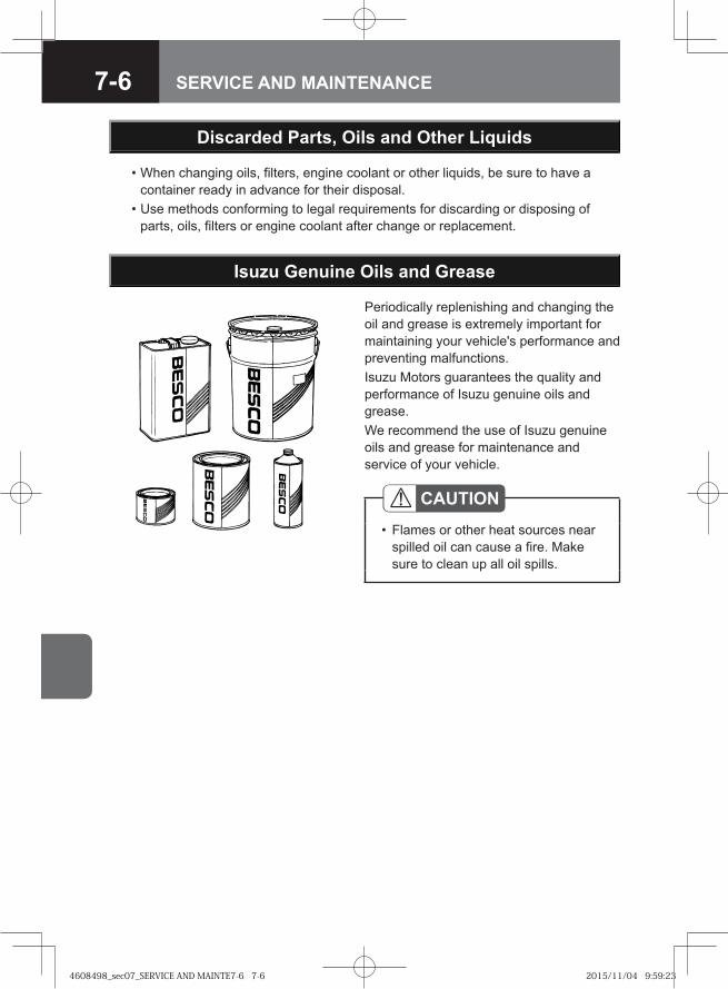
7-6 SERVICE AND MAINTENANCE
Discarded Parts, Oils and Other Liquids
• When changing oils, filters, engine coolant or other liquids, be sure to have a container ready in advance for their disposal.
• Use methods conforming to legal requirements for discarding or disposing of parts, oils, filters or engine coolant after change or replacement.
Isuzu Genuine Oils and Grease
Periodically replenishing and changing the oil and grease is extremely important for maintaining your vehicle's performance and preventing malfunctions. Isuzu Motors guarantees the quality and performance of Isuzu genuine oils and grease. We recommend the use of Isuzu genuine oils and grease for maintenance and service of your vehicle.
CAUTIONFlames or other heat sources near spilled oil can cause a fire. Make sure to clean up all oil spills.
•
4608498_sec07_SERVICE AND MAINTE7-6 7-64608498_sec07_SERVICE AND MAINTE7-6 7-6 2015/11/04 9:59:232015/11/04 9:59:23
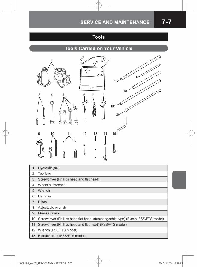
7-7SERVICE AND MAINTENANCE
Tools
Tools Carried on Your Vehicle
�
�
�
�
��
� �
�
� �
� ��
�
1 Hydraulic jack
2 Tool bag
3 Screwdriver (Phillips head and flat head)
4 Wheel nut wrench
5 Wrench
6 Hammer
7 Pliers
8 Adjustable wrench
9 Grease pump
10 Screwdriver (Phillips head/flat head interchangeable type) (Except FSS/FTS model)
11 Screwdriver (Phillips head and flat head) (FSS/FTS model)
12 Wrench (FSS/FTS model)
13 Bleeder hose (FSS/FTS model)
4608498_sec07_SERVICE AND MAINTE7-7 7-74608498_sec07_SERVICE AND MAINTE7-7 7-7 2015/11/04 9:59:242015/11/04 9:59:24
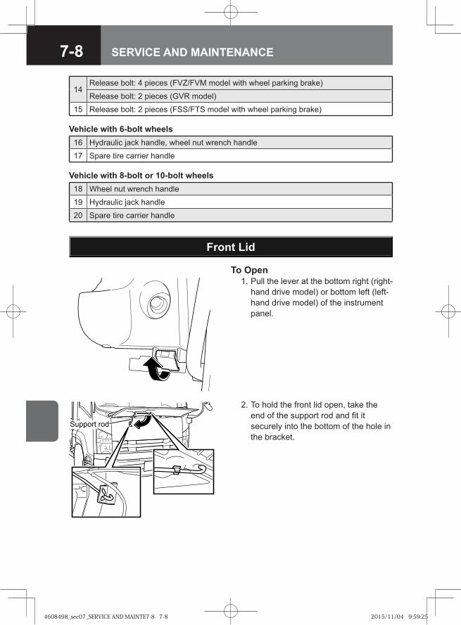
7-8 SERVICE AND MAINTENANCE
Front Lid
To Open 1. Pull the lever at the bottom right (right-
hand drive model) or bottom left (left-hand drive model) of the instrument panel.
Support rod
2. To hold the front lid open, take the end of the support rod and fit it securely into the bottom of the hole in the bracket.
Vehicle with 6-bolt wheels16 Hydraulic jack handle, wheel nut wrench handle
17 Spare tire carrier handle
18 Wheel nut wrench handle
19 Hydraulic jack handle
20 Spare tire carrier handle
Vehicle with 8-bolt or 10-bolt wheels
14Release bolt: 4 pieces (FVZ/FVM model with wheel parking brake)
Release bolt: 2 pieces (GVR model)
15 Release bolt: 2 pieces (FSS/FTS model with wheel parking brake)
4608498_sec07_SERVICE AND MAINTE7-8 7-84608498_sec07_SERVICE AND MAINTE7-8 7-8 2015/11/04 9:59:252015/11/04 9:59:25
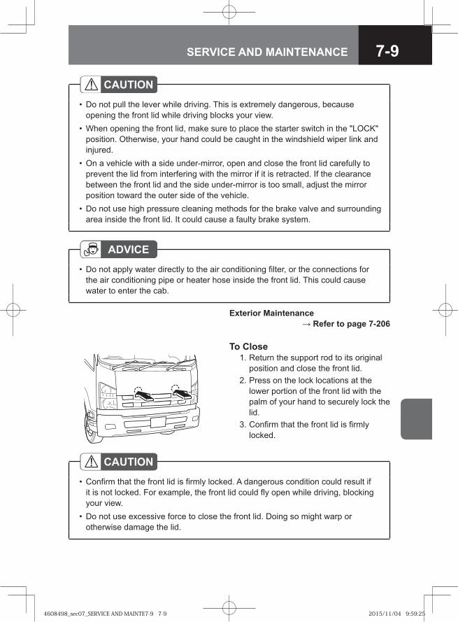
7-9SERVICE AND MAINTENANCE
To Close 1. Return the support rod to its original
position and close the front lid. 2. Press on the lock locations at the
lower portion of the front lid with the palm of your hand to securely lock the lid.
3. Confirm that the front lid is firmly locked.
CAUTIONDo not pull the lever while driving. This is extremely dangerous, because opening the front lid while driving blocks your view.When opening the front lid, make sure to place the starter switch in the "LOCK" position. Otherwise, your hand could be caught in the windshield wiper link and injured.On a vehicle with a side under-mirror, open and close the front lid carefully to prevent the lid from interfering with the mirror if it is retracted. If the clearance between the front lid and the side under-mirror is too small, adjust the mirror position toward the outer side of the vehicle.Do not use high pressure cleaning methods for the brake valve and surrounding area inside the front lid. It could cause a faulty brake system.
•
•
•
•
ADVICEDo not apply water directly to the air conditioning filter, or the connections for the air conditioning pipe or heater hose inside the front lid. This could cause water to enter the cab.
•
Exterior Maintenance → Refer to page 7-206
CAUTIONConfirm that the front lid is firmly locked. A dangerous condition could result if it is not locked. For example, the front lid could fly open while driving, blocking your view.Do not use excessive force to close the front lid. Doing so might warp or otherwise damage the lid.
•
•
4608498_sec07_SERVICE AND MAINTE7-9 7-94608498_sec07_SERVICE AND MAINTE7-9 7-9 2015/11/04 9:59:252015/11/04 9:59:25
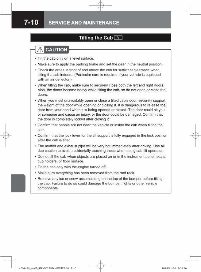
7-10 SERVICE AND MAINTENANCE
Tilting the Cab V
CAUTIONTilt the cab only on a level surface.Make sure to apply the parking brake and set the gear in the neutral position.Check the areas in front of and above the cab for sufficient clearance when tilting the cab indoors. (Particular care is required if your vehicle is equipped with an air deflector.)When tilting the cab, make sure to securely close both the left and right doors. Also, the doors become heavy while tilting the cab, so do not open or close the doors.When you must unavoidably open or close a tilted cab's door, securely support the weight of the door while opening or closing it. It is dangerous to release the door from your hand when it is being opened or closed. The door could hit you or someone and cause an injury, or the door could be damaged. Confirm that the door is completely locked after closing it.Confirm that people are not near the vehicle or inside the cab when tilting the cab.Confirm that the lock lever for the tilt support is fully engaged in the lock position after the cab is tilted.The muffler and exhaust pipe will be very hot immediately after driving. Use all due caution to avoid accidentally touching these when doing cab tilt operation.Do not tilt the cab when objects are placed on or in the instrument panel, seats, cup holders, or floor surface.Tilt the cab only with the engine turned off.Make sure everything has been removed from the roof rack.Remove any ice or snow accumulating on the top of the bumper before tilting the cab. Failure to do so could damage the bumper, lights or other vehicle components.
•••
•
•
•
•
•
•
•••
4608498_sec07_SERVICE AND MAINTE7-10 7-104608498_sec07_SERVICE AND MAINTE7-10 7-10 2015/11/04 9:59:262015/11/04 9:59:26
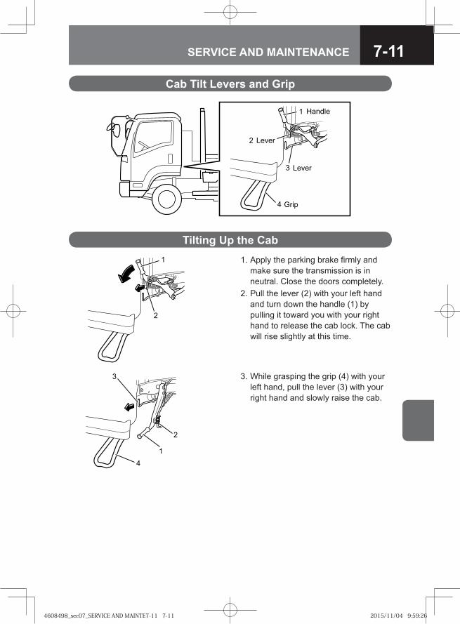
7-11SERVICE AND MAINTENANCE
Cab Tilt Levers and Grip
�
�
�
����
����
����
������
Tilting Up the Cab 1. Apply the parking brake firmly and
make sure the transmission is in neutral. Close the doors completely.
2. Pull the lever (2) with your left hand and turn down the handle (1) by pulling it toward you with your right hand to release the cab lock. The cab will rise slightly at this time.
3. While grasping the grip (4) with your left hand, pull the lever (3) with your right hand and slowly raise the cab.
�
�
�
4608498_sec07_SERVICE AND MAINTE7-11 7-114608498_sec07_SERVICE AND MAINTE7-11 7-11 2015/11/04 9:59:262015/11/04 9:59:26
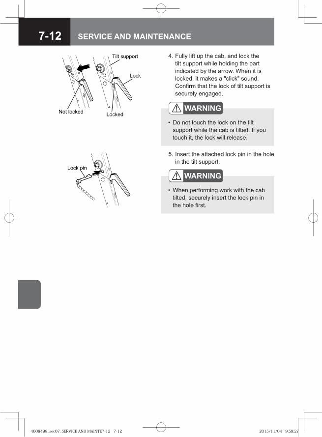
7-12 SERVICE AND MAINTENANCE
4. Fully lift up the cab, and lock the tilt support while holding the part indicated by the arrow. When it is locked, it makes a "click" sound. Confirm that the lock of tilt support is securely engaged.
WARNING
Do not touch the lock on the tilt support while the cab is tilted. If you touch it, the lock will release.
•
Lock pin
5. Insert the attached lock pin in the hole in the tilt support.
WARNING
When performing work with the cab tilted, securely insert the lock pin in the hole first.
•
Not locked Locked
Lock
Tilt support
4608498_sec07_SERVICE AND MAINTE7-12 7-124608498_sec07_SERVICE AND MAINTE7-12 7-12 2015/11/04 9:59:272015/11/04 9:59:27
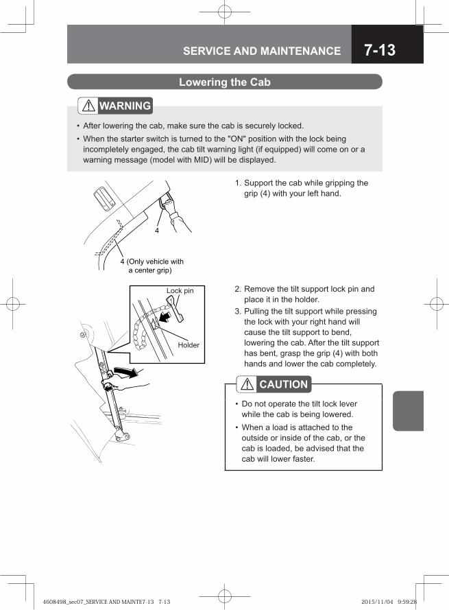
7-13SERVICE AND MAINTENANCE
2. Remove the tilt support lock pin and place it in the holder.
3. Pulling the tilt support while pressing the lock with your right hand will cause the tilt support to bend, lowering the cab. After the tilt support has bent, grasp the grip (4) with both hands and lower the cab completely.
CAUTIONDo not operate the tilt lock lever while the cab is being lowered.When a load is attached to the outside or inside of the cab, or the cab is loaded, be advised that the cab will lower faster.
•
•
Lock pin
Holder
Lowering the Cab
1. Support the cab while gripping the grip (4) with your left hand.
���� ������� ����
� ������ �����
WARNING
After lowering the cab, make sure the cab is securely locked.When the starter switch is turned to the "ON" position with the lock being incompletely engaged, the cab tilt warning light (if equipped) will come on or a warning message (model with MID) will be displayed.
••
4608498_sec07_SERVICE AND MAINTE7-13 7-134608498_sec07_SERVICE AND MAINTE7-13 7-13 2015/11/04 9:59:282015/11/04 9:59:28
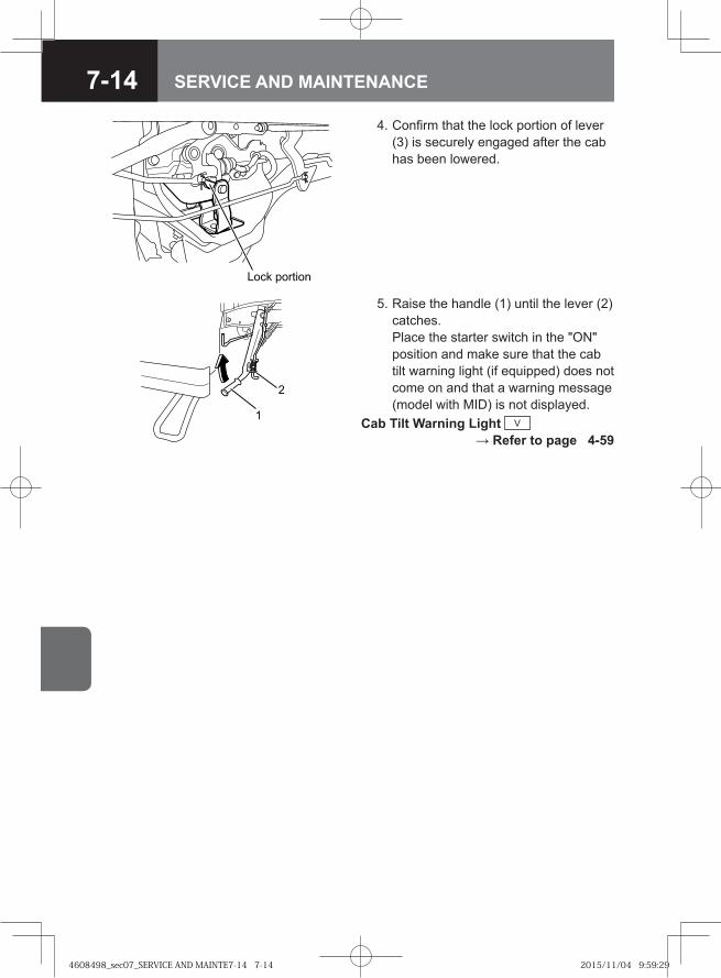
7-14 SERVICE AND MAINTENANCE
4. Confirm that the lock portion of lever (3) is securely engaged after the cab has been lowered.
�� � �������
5. Raise the handle (1) until the lever (2) catches. Place the starter switch in the "ON" position and make sure that the cab tilt warning light (if equipped) does not come on and that a warning message (model with MID) is not displayed.
Cab Tilt Warning Light V → Refer to page 4-59
�
4608498_sec07_SERVICE AND MAINTE7-14 7-144608498_sec07_SERVICE AND MAINTE7-14 7-14 2015/11/04 9:59:292015/11/04 9:59:29
7-15SERVICE AND MAINTENANCE
Power Cab Tilt System V
CAUTIONTilt the cab only on a level surface.Make sure to apply the parking brake and set the gear in the neutral position.Check the areas in front of and above the cab for sufficient clearance when tilting the cab indoors. (Particular care is required if your vehicle is equipped with an air deflector.)When tilting the cab, make sure to securely close both the left and right doors. Also, the doors become heavy while tilting the cab, so do not open or close the doors.When you must unavoidably open or close a tilted cab's door, securely support the weight of the door while opening or closing it. It is dangerous to release the door from your hand when it is being opened or closed. The door could hit you or someone and cause an injury, or the door could be damaged. Confirm that the door is completely locked after closing it.Confirm that people are not near the vehicle or inside the cab when tilting the cab.While buzzer is sounding, stay out from under the cab.The muffler and exhaust pipe will be very hot immediately after driving. Use all due caution to avoid accidentally touching these when doing cab tilt operation.Do not tilt the cab when objects are placed on or in the instrument panel, seats, cup holders, or floor surface.Tilt the cab only with the engine turned off.Make sure everything has been removed from the roof rack.Remove any ice or snow accumulating on the top of the bumper before tilting the cab. Failure to do so could damage the bumper, lights or other vehicle components.
•••
•
•
•
••
•
•••
4608498_sec07_SERVICE AND MAINTE7-15 7-154608498_sec07_SERVICE AND MAINTE7-15 7-15 2015/11/04 9:59:292015/11/04 9:59:29
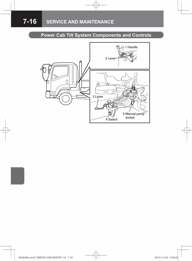
7-16 SERVICE AND MAINTENANCE
Power Cab Tilt System Components and Controls
� � �
�����
� � � �
� ������
� ������ ����� �! �
4608498_sec07_SERVICE AND MAINTE7-16 7-164608498_sec07_SERVICE AND MAINTE7-16 7-16 2015/11/04 9:59:292015/11/04 9:59:29
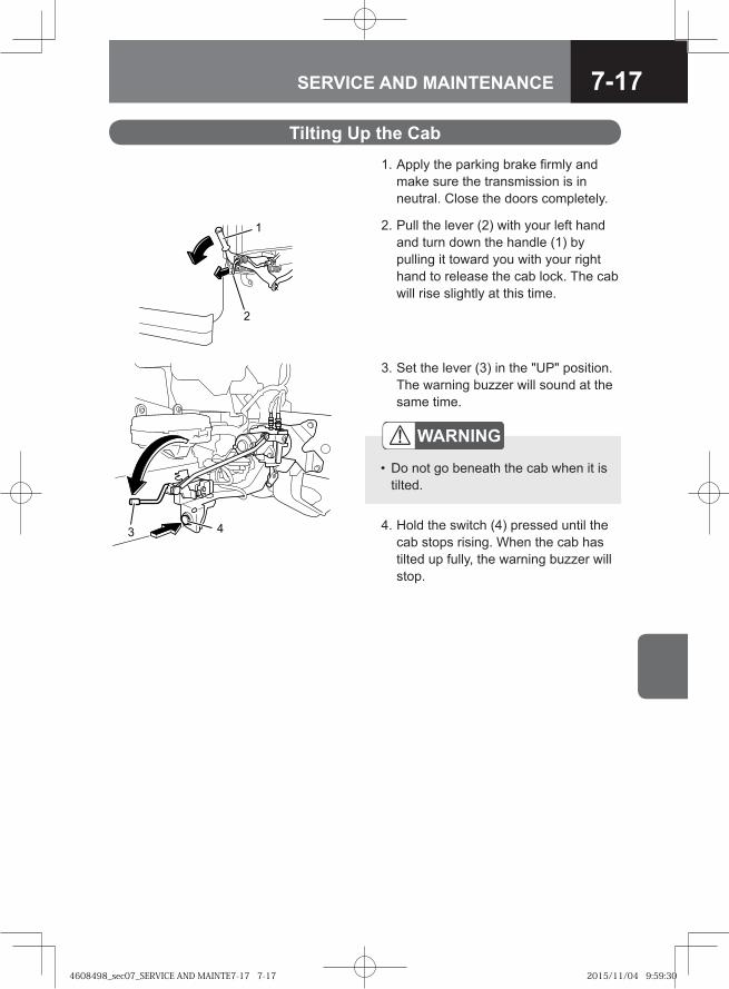
7-17SERVICE AND MAINTENANCE
WARNING
Do not go beneath the cab when it is tilted.
•
4. Hold the switch (4) pressed until the cab stops rising. When the cab has tilted up fully, the warning buzzer will stop.
3. Set the lever (3) in the "UP" position. The warning buzzer will sound at the same time.
Tilting Up the Cab 1. Apply the parking brake firmly and
make sure the transmission is in neutral. Close the doors completely.
2. Pull the lever (2) with your left hand and turn down the handle (1) by pulling it toward you with your right hand to release the cab lock. The cab will rise slightly at this time.
4608498_sec07_SERVICE AND MAINTE7-17 7-174608498_sec07_SERVICE AND MAINTE7-17 7-17 2015/11/04 9:59:302015/11/04 9:59:30
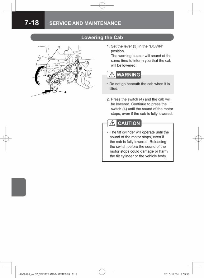
7-18 SERVICE AND MAINTENANCE
2. Press the switch (4) and the cab will be lowered. Continue to press the switch (4) until the sound of the motor stops, even if the cab is fully lowered.
CAUTIONThe tilt cylinder will operate until the sound of the motor stops, even if the cab is fully lowered. Releasing the switch before the sound of the motor stops could damage or harm the tilt cylinder or the vehicle body.
•
1. Set the lever (3) in the "DOWN" position. The warning buzzer will sound at the same time to inform you that the cab will be lowered.
WARNING
Do not go beneath the cab when it is tilted.
•
Lowering the Cab
�
4608498_sec07_SERVICE AND MAINTE7-18 7-184608498_sec07_SERVICE AND MAINTE7-18 7-18 2015/11/04 9:59:302015/11/04 9:59:30
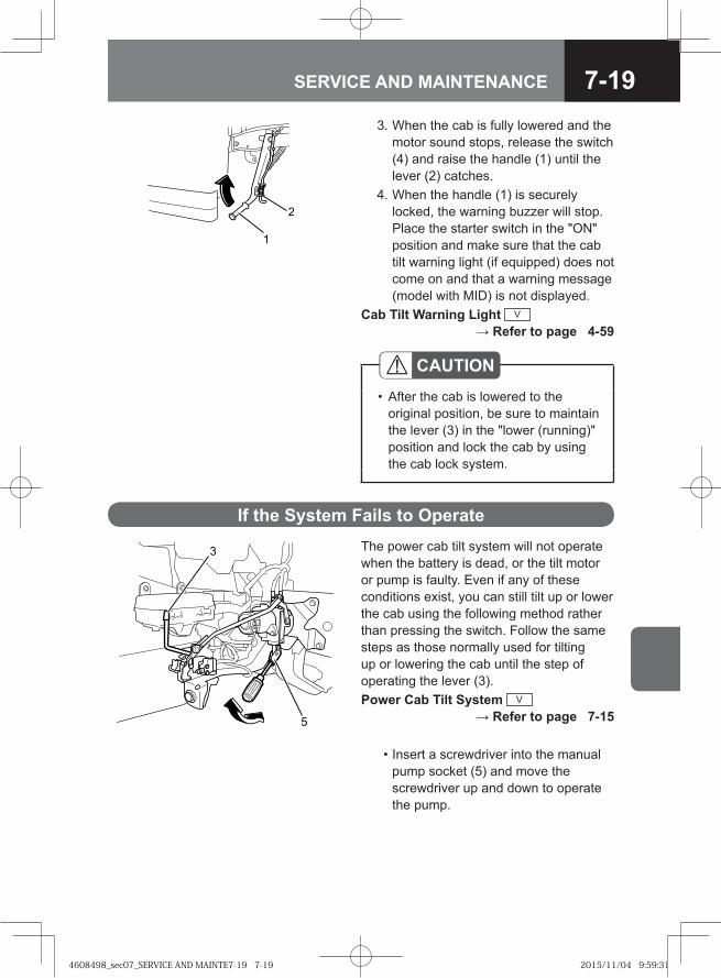
7-19SERVICE AND MAINTENANCE
3. When the cab is fully lowered and the motor sound stops, release the switch (4) and raise the handle (1) until the lever (2) catches.
4. When the handle (1) is securely locked, the warning buzzer will stop. Place the starter switch in the "ON" position and make sure that the cab tilt warning light (if equipped) does not come on and that a warning message (model with MID) is not displayed.
Cab Tilt Warning Light V → Refer to page 4-59
�
CAUTIONAfter the cab is lowered to the original position, be sure to maintain the lever (3) in the "lower (running)" position and lock the cab by using the cab lock system.
•
The power cab tilt system will not operate when the battery is dead, or the tilt motor or pump is faulty. Even if any of these conditions exist, you can still tilt up or lower the cab using the following method rather than pressing the switch. Follow the same steps as those normally used for tilting up or lowering the cab until the step of operating the lever (3).Power Cab Tilt System V
→ Refer to page 7-15
• Insert a screwdriver into the manual pump socket (5) and move the screwdriver up and down to operate the pump.
If the System Fails to Operate
�
4608498_sec07_SERVICE AND MAINTE7-19 7-194608498_sec07_SERVICE AND MAINTE7-19 7-19 2015/11/04 9:59:312015/11/04 9:59:31
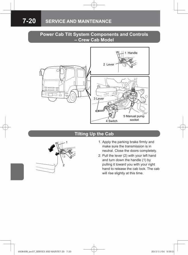
7-20 SERVICE AND MAINTENANCE
Power Cab Tilt System Components and Controls – Crew Cab Model
� �� ���
�����
� �����
� ������
� �� ��� ����
!�"��
1. Apply the parking brake firmly and make sure the transmission is in neutral. Close the doors completely.
2. Pull the lever (2) with your left hand and turn down the handle (1) by pulling it toward you with your right hand to release the cab lock. The cab will rise slightly at this time.
Tilting Up the Cab
4608498_sec07_SERVICE AND MAINTE7-20 7-204608498_sec07_SERVICE AND MAINTE7-20 7-20 2015/11/04 9:59:312015/11/04 9:59:31
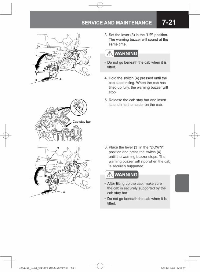
7-21SERVICE AND MAINTENANCE
3. Set the lever (3) in the "UP" position. The warning buzzer will sound at the same time.
5. Release the cab stay bar and insert its end into the holder on the cab.
Cab stay bar
4. Hold the switch (4) pressed until the cab stops rising. When the cab has tilted up fully, the warning buzzer will stop.
WARNING
Do not go beneath the cab when it is tilted.
•
6. Place the lever (3) in the "DOWN" position and press the switch (4) until the warning buzzer stops. The warning buzzer will stop when the cab is securely supported.
�
WARNING
After tilting up the cab, make sure the cab is securely supported by the cab stay bar.Do not go beneath the cab when it is tilted.
•
•
4608498_sec07_SERVICE AND MAINTE7-21 7-214608498_sec07_SERVICE AND MAINTE7-21 7-21 2015/11/04 9:59:322015/11/04 9:59:32
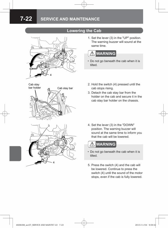
7-22 SERVICE AND MAINTENANCE
1. Set the lever (3) in the "UP" position. The warning buzzer will sound at the same time.
Lowering the Cab
2. Hold the switch (4) pressed until the cab stops rising.
3. Detach the cab stay bar from the holder on the cab and secure it in the cab stay bar holder on the chassis.
Cab staybar holder Cab stay bar
4. Set the lever (3) in the "DOWN" position. The warning buzzer will sound at the same time to inform you that the cab will be lowered.
5. Press the switch (4) and the cab will be lowered. Continue to press the switch (4) until the sound of the motor stops, even if the cab is fully lowered.
�
WARNING
Do not go beneath the cab when it is tilted.
•
WARNING
Do not go beneath the cab when it is tilted.
•
4608498_sec07_SERVICE AND MAINTE7-22 7-224608498_sec07_SERVICE AND MAINTE7-22 7-22 2015/11/04 9:59:322015/11/04 9:59:32
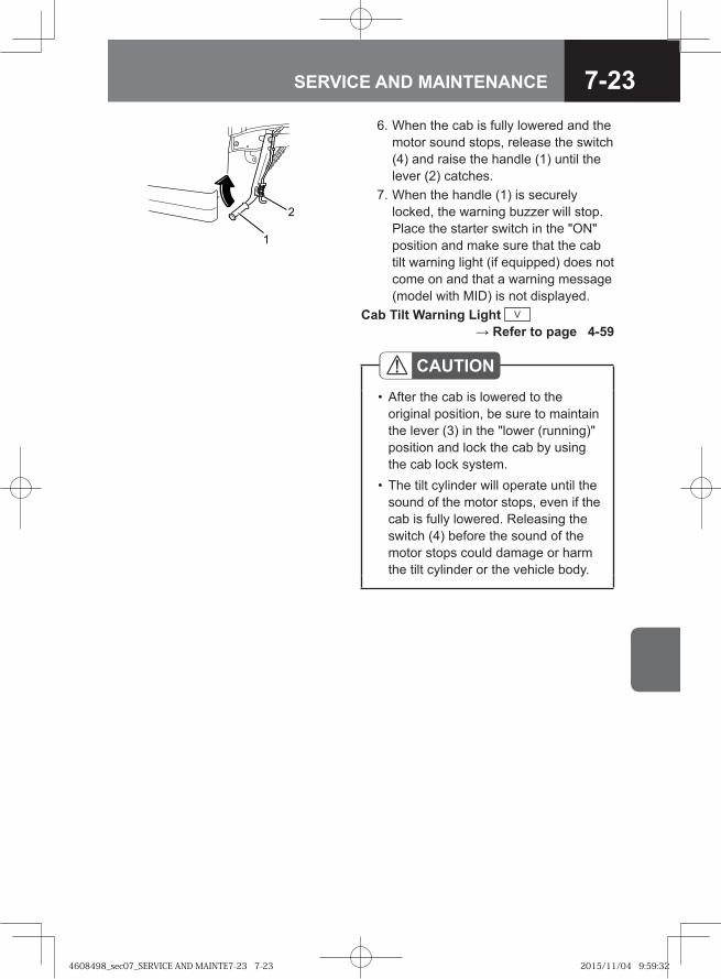
7-23SERVICE AND MAINTENANCE
6. When the cab is fully lowered and the motor sound stops, release the switch (4) and raise the handle (1) until the lever (2) catches.
7. When the handle (1) is securely locked, the warning buzzer will stop. Place the starter switch in the "ON" position and make sure that the cab tilt warning light (if equipped) does not come on and that a warning message (model with MID) is not displayed.
Cab Tilt Warning Light V → Refer to page 4-59
�
CAUTIONAfter the cab is lowered to the original position, be sure to maintain the lever (3) in the "lower (running)" position and lock the cab by using the cab lock system.The tilt cylinder will operate until the sound of the motor stops, even if the cab is fully lowered. Releasing the switch (4) before the sound of the motor stops could damage or harm the tilt cylinder or the vehicle body.
•
•
4608498_sec07_SERVICE AND MAINTE7-23 7-234608498_sec07_SERVICE AND MAINTE7-23 7-23 2015/11/04 9:59:322015/11/04 9:59:32
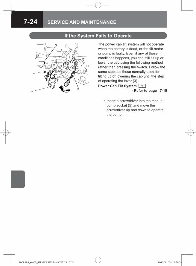
7-24 SERVICE AND MAINTENANCE
The power cab tilt system will not operate when the battery is dead, or the tilt motor or pump is faulty. Even if any of these conditions happens, you can still tilt up or lower the cab using the following method rather than pressing the switch. Follow the same steps as those normally used for tilting up or lowering the cab until the step of operating the lever (3).Power Cab Tilt System V
→ Refer to page 7-15
• Insert a screwdriver into the manual pump socket (5) and move the screwdriver up and down to operate the pump.
If the System Fails to Operate
3
5
4608498_sec07_SERVICE AND MAINTE7-24 7-244608498_sec07_SERVICE AND MAINTE7-24 7-24 2015/11/04 9:59:332015/11/04 9:59:33
7-25SERVICE AND MAINTENANCE
● Daily Check (Preoperational Check) 7-26
● Checking a Part Where there was an Abnormality the Previous Time the Vehicle was Driven 7-28
DAILY INSPECTION
4608498_sec07_SERVICE AND MAINTE7-25 7-254608498_sec07_SERVICE AND MAINTE7-25 7-25 2015/11/04 9:59:342015/11/04 9:59:34
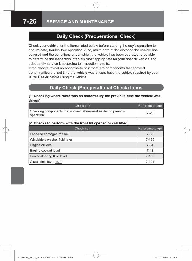
7-26 SERVICE AND MAINTENANCE
Daily Check (Preoperational Check)
Check your vehicle for the items listed below before starting the day's operation to ensure safe, trouble-free operation. Also, make note of the distance the vehicle has covered and the conditions under which the vehicle has been operated to be able to determine the inspection intervals most appropriate for your specific vehicle and adequately service it according to inspection results.If the checks reveal an abnormality or if there are components that showed abnormalities the last time the vehicle was driven, have the vehicle repaired by your Isuzu Dealer before using the vehicle.
Daily Check (Preoperational Check) Items[1. Checking where there was an abnormality the previous time the vehicle was driven]
Check item Reference page
Checking components that showed abnormalities during previous operation 7-28
[2. Checks to perform with the front lid opened or cab tilted]Check item Reference page
Loose or damaged fan belt 7-55
Windshield washer fluid level 7-185
Engine oil level 7-31
Engine coolant level 7-43
Power steering fluid level 7-166
Clutch fluid level M/T 7-121
4608498_sec07_SERVICE AND MAINTE7-26 7-264608498_sec07_SERVICE AND MAINTE7-26 7-26 2015/11/04 9:59:342015/11/04 9:59:34
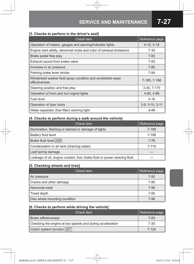
7-27SERVICE AND MAINTENANCE
[3. Checks to perform in the driver's seat]Check item Reference page
Operation of meters, gauges and warning/indicator lights 4-10, 4-18
Engine start ability, abnormal noise and color of exhaust emissions 7-30
Brake pedal free play 7-83
Exhaust sound from brake valve 7-83
Increase in air pressure 7-80
Parking brake lever stroke 7-84
Windshield washer fluid spray condition and windshield wiper effectiveness 7-185, 7-186
Steering position and free play 3-30, 7-170
Operation of horn and turn signal lights 4-80, 4-89
Fuel level 4-16
Operation of door locks 3-9, 3-10, 3-11
Water separator (fuel filter) warning light 4-48
[4. Checks to perform during a walk around the vehicle]Check item Reference page
Illumination, flashing or stained or damage of lights 7-189
Battery fluid level 7-196
Brake fluid level AHB 7-76
Condensation in air tank (draining water) 7-119
Leaf spring damage ―
Leakage of oil, engine coolant, fuel, brake fluid or power steering fluid ―
[5. Checking wheels and tires]Check item Reference page
Air pressure 7-92
Cracks and other damage 7-95
Abnormal wear 7-95
Tread depth 7-95
Disc wheel mounting condition 7-96
[6. Checks to perform while driving the vehicle]Check item Reference page
Brake effectiveness 7-83
Checking the engine at low speeds and during acceleration 7-30
Clutch system function M/T 7-124
4608498_sec07_SERVICE AND MAINTE7-27 7-274608498_sec07_SERVICE AND MAINTE7-27 7-27 2015/11/04 9:59:342015/11/04 9:59:34
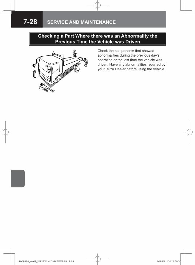
7-28 SERVICE AND MAINTENANCE
Check the components that showed abnormalities during the previous day's operation or the last time the vehicle was driven. Have any abnormalities repaired by your Isuzu Dealer before using the vehicle.
Checking a Part Where there was an Abnormality the Previous Time the Vehicle was Driven
4608498_sec07_SERVICE AND MAINTE7-28 7-284608498_sec07_SERVICE AND MAINTE7-28 7-28 2015/11/04 9:59:352015/11/04 9:59:35
7-29SERVICE AND MAINTENANCE
● Engine Conditions 7-30
● Engine Oil 7-31
● Engine Coolant 7-39
● Handling the Radiator and Intercooler 7-54
● Fan Belt 7-55
● Air Cleaner 7-60
● Fuel Filter 7-63
ENGINE-RELATED SERVICE AND MAINTENANCE
4608498_sec07_SERVICE AND MAINTE7-29 7-294608498_sec07_SERVICE AND MAINTE7-29 7-29 2015/11/04 9:59:352015/11/04 9:59:35
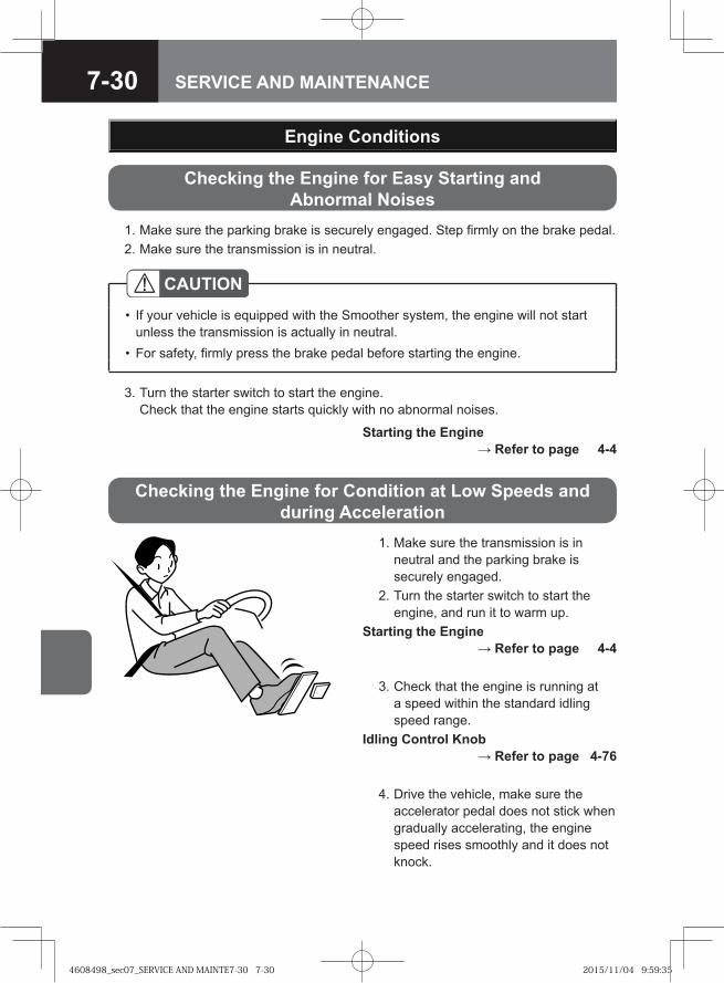
7-30 SERVICE AND MAINTENANCE
Checking the Engine for Easy Starting and Abnormal Noises
1. Make sure the parking brake is securely engaged. Step firmly on the brake pedal. 2. Make sure the transmission is in neutral.
3. Turn the starter switch to start the engine.Check that the engine starts quickly with no abnormal noises.
Starting the Engine → Refer to page 4-4
Engine Conditions
CAUTIONIf your vehicle is equipped with the Smoother system, the engine will not start unless the transmission is actually in neutral.For safety, firmly press the brake pedal before starting the engine.
•
•
1. Make sure the transmission is in neutral and the parking brake is securely engaged.
2. Turn the starter switch to start the engine, and run it to warm up.
Starting the Engine → Refer to page 4-4
3. Check that the engine is running at a speed within the standard idling speed range.
Idling Control Knob → Refer to page 4-76
4. Drive the vehicle, make sure the accelerator pedal does not stick when gradually accelerating, the engine speed rises smoothly and it does not knock.
Checking the Engine for Condition at Low Speeds and during Acceleration
4608498_sec07_SERVICE AND MAINTE7-30 7-304608498_sec07_SERVICE AND MAINTE7-30 7-30 2015/11/04 9:59:352015/11/04 9:59:35
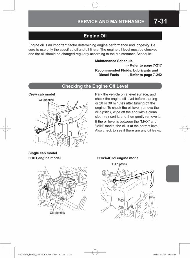
7-31SERVICE AND MAINTENANCE
Crew cab model�� ��������
Single cab model6HH1 engine model 6HK1/4HK1 engine model
� � � ��� ��
Oil dipstick
Engine Oil
Engine oil is an important factor determining engine performance and longevity. Be sure to use only the specified oil and oil filters. The engine oil level must be checked and the oil should be changed regularly according to the Maintenance Schedule.
Maintenance Schedule → Refer to page 7-217
Recommended Fluids, Lubricants and Diesel Fuels → Refer to page 7-242
Checking the Engine Oil LevelPark the vehicle on a level surface, and check the engine oil level before starting or 20 or 30 minutes after turning off the engine. To check the oil level, remove the oil dipstick, wipe off the end with a clean cloth, reinsert it, and then gently remove it.If the oil level is between the "MAX" and "MIN" marks, the oil is at the correct level. Also check to see if there are any oil leaks.
4608498_sec07_SERVICE AND MAINTE7-31 7-314608498_sec07_SERVICE AND MAINTE7-31 7-31 2015/11/04 9:59:362015/11/04 9:59:36
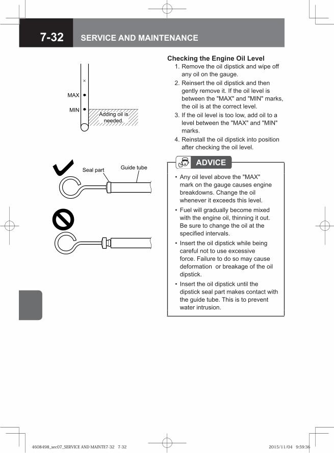
7-32 SERVICE AND MAINTENANCE
Adding oil isneeded.
MAX
MIN
Checking the Engine Oil Level 1. Remove the oil dipstick and wipe off
any oil on the gauge. 2. Reinsert the oil dipstick and then
gently remove it. If the oil level is between the "MAX" and "MIN" marks, the oil is at the correct level.
3. If the oil level is too low, add oil to a level between the "MAX" and "MIN" marks.
4. Reinstall the oil dipstick into position after checking the oil level.
ADVICEAny oil level above the "MAX" mark on the gauge causes engine breakdowns. Change the oil whenever it exceeds this level.Fuel will gradually become mixed with the engine oil, thinning it out. Be sure to change the oil at the specified intervals.Insert the oil dipstick while being careful not to use excessive force. Failure to do so may cause deformation or breakage of the oil dipstick.Insert the oil dipstick until the dipstick seal part makes contact with the guide tube. This is to prevent water intrusion.
•
•
•
•
�� �� �������� ����
4608498_sec07_SERVICE AND MAINTE7-32 7-324608498_sec07_SERVICE AND MAINTE7-32 7-32 2015/11/04 9:59:362015/11/04 9:59:36
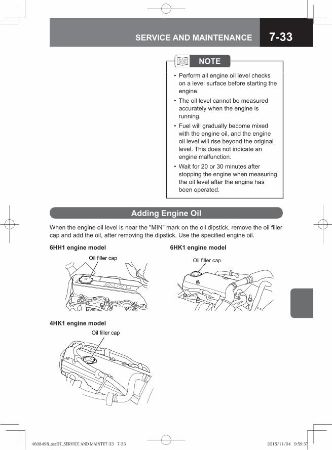
7-33SERVICE AND MAINTENANCE
NOTEPerform all engine oil level checks on a level surface before starting the engine.The oil level cannot be measured accurately when the engine is running.Fuel will gradually become mixed with the engine oil, and the engine oil level will rise beyond the original level. This does not indicate an engine malfunction.Wait for 20 or 30 minutes after stopping the engine when measuring the oil level after the engine has been operated.
•
•
•
•
Adding Engine OilWhen the engine oil level is near the "MIN" mark on the oil dipstick, remove the oil filler cap and add the oil, after removing the dipstick. Use the specified engine oil.
6HH1 engine model 6HK1 engine model� � � ���� ��� Oil filler cap
4HK1 engine modelOil filler cap
4608498_sec07_SERVICE AND MAINTE7-33 7-334608498_sec07_SERVICE AND MAINTE7-33 7-33 2015/11/04 9:59:372015/11/04 9:59:37
7-34 SERVICE AND MAINTENANCE
ADVICEEngine oil lubricates and cools the engine interior components. The quality of the oil is degraded and the quantity of oil is reduced by evaporation, exhaust, and combustion during the engine's operation. Continually using the same oil without checking the level, or without replenishing and changing it could cause seizure or damage to the engine. Add or change the oil when the quality of the oil has degraded or the quantity is reduced, even if that occurs before expiration of the specified intervals in the Maintenance Schedule, which will differ depending on the conditions of use.Prevent dirt from entering the filler port when adding oil. If foreign matter were to become mixed with the oil, it could damage the engine.Do not fill the engine with oil above the "MAX" mark on the oil dipstick. This could damage the engine.
•
•
•
WARNING
When adding oil, keep a rag handy and be careful not to spill any.If any oil spills on the engine, wipe it all off. It could ignite and cause a fire.Do not leave flammable items, such as rags or gloves in the engine compartment. They could cause a fire.The engine oil is hot after driving, so when changing the oil after driving, be careful not to be scalded.
•
•
•
4608498_sec07_SERVICE AND MAINTE7-34 7-344608498_sec07_SERVICE AND MAINTE7-34 7-34 2015/11/04 9:59:372015/11/04 9:59:37
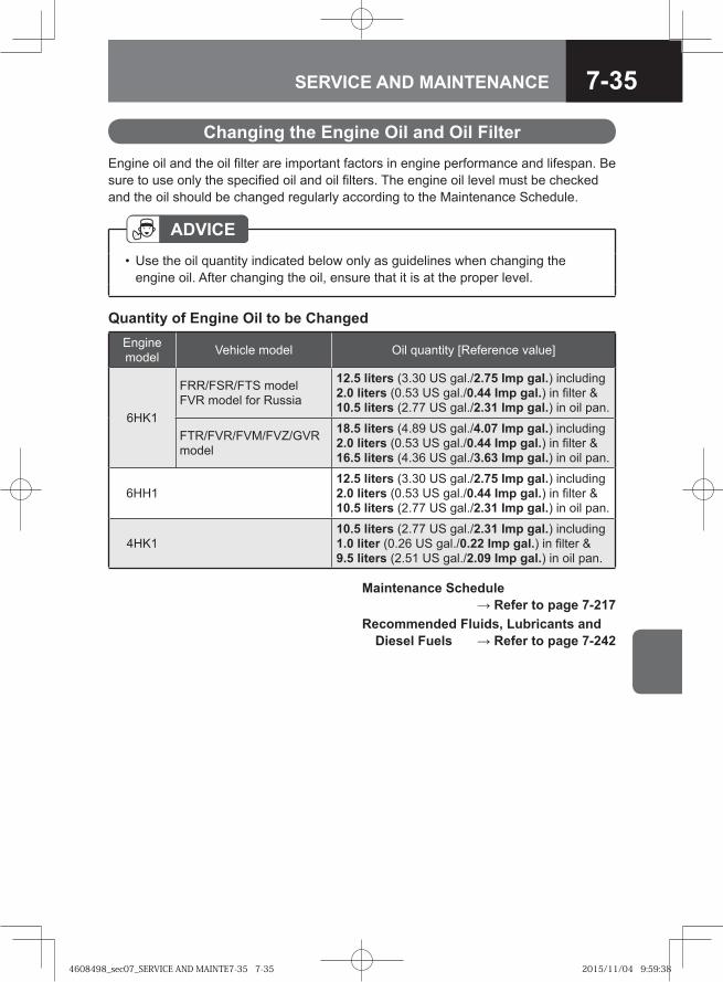
7-35SERVICE AND MAINTENANCE
Changing the Engine Oil and Oil FilterEngine oil and the oil filter are important factors in engine performance and lifespan. Be sure to use only the specified oil and oil filters. The engine oil level must be checked and the oil should be changed regularly according to the Maintenance Schedule.
ADVICEUse the oil quantity indicated below only as guidelines when changing the engine oil. After changing the oil, ensure that it is at the proper level.
•
Quantity of Engine Oil to be ChangedEngine model Vehicle model Oil quantity [Reference value]
6HK1
FRR/FSR/FTS modelFVR model for Russia
12.5 liters (3.30 US gal./2.75 Imp gal.) including 2.0 liters (0.53 US gal./0.44 Imp gal.) in filter & 10.5 liters (2.77 US gal./2.31 Imp gal.) in oil pan.
FTR/FVR/FVM/FVZ/GVR model
18.5 liters (4.89 US gal./4.07 Imp gal.) including 2.0 liters (0.53 US gal./0.44 Imp gal.) in filter & 16.5 liters (4.36 US gal./3.63 Imp gal.) in oil pan.
6HH112.5 liters (3.30 US gal./2.75 Imp gal.) including 2.0 liters (0.53 US gal./0.44 Imp gal.) in filter & 10.5 liters (2.77 US gal./2.31 Imp gal.) in oil pan.
4HK110.5 liters (2.77 US gal./2.31 Imp gal.) including 1.0 liter (0.26 US gal./0.22 Imp gal.) in filter & 9.5 liters (2.51 US gal./2.09 Imp gal.) in oil pan.
Maintenance Schedule → Refer to page 7-217
Recommended Fluids, Lubricants and Diesel Fuels → Refer to page 7-242
4608498_sec07_SERVICE AND MAINTE7-35 7-354608498_sec07_SERVICE AND MAINTE7-35 7-35 2015/11/04 9:59:382015/11/04 9:59:38
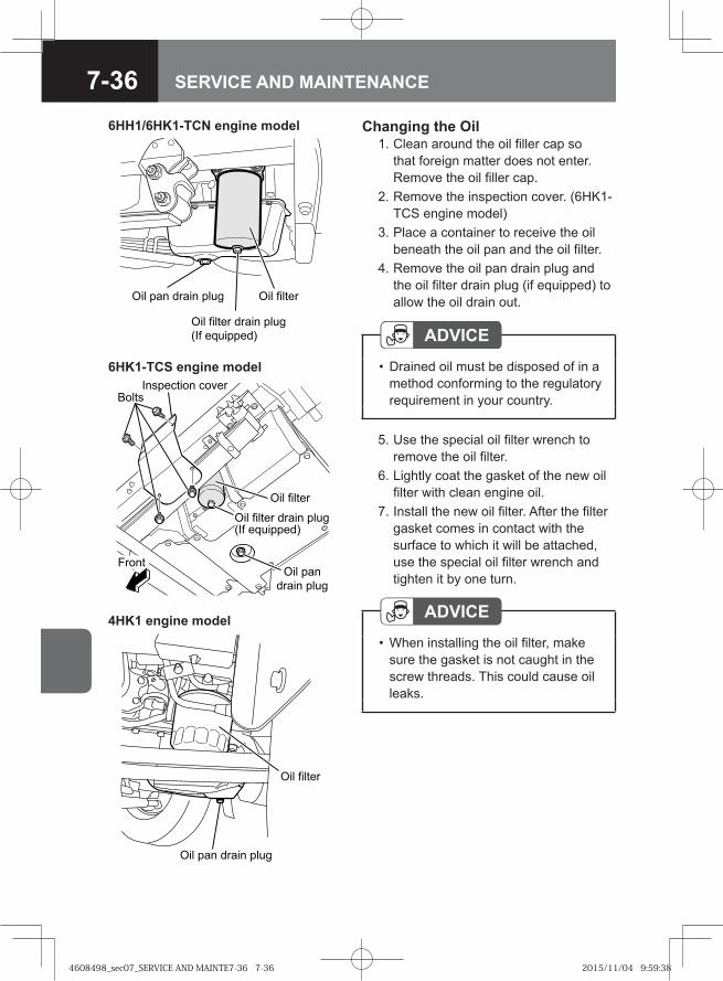
7-36 SERVICE AND MAINTENANCE
Changing the Oil 1. Clean around the oil filler cap so
that foreign matter does not enter. Remove the oil filler cap.
2. Remove the inspection cover. (6HK1-TCS engine model)
3. Place a container to receive the oil beneath the oil pan and the oil filter.
4. Remove the oil pan drain plug and the oil filter drain plug (if equipped) to allow the oil drain out.
5. Use the special oil filter wrench to remove the oil filter.
6. Lightly coat the gasket of the new oil filter with clean engine oil.
7. Install the new oil filter. After the filter gasket comes in contact with the surface to which it will be attached, use the special oil filter wrench and tighten it by one turn.
6HH1/6HK1-TCN engine model
4HK1 engine model
�� �� ���
�� ��� ����� � ��
ADVICEDrained oil must be disposed of in a method conforming to the regulatory requirement in your country.
•
ADVICEWhen installing the oil filter, make sure the gasket is not caught in the screw threads. This could cause oil leaks.
•
6HK1-TCS engine model� ������� �����
��� ������
��� ���� ��
���� ����
�����
��� ������ ���� ������� � ������!
�� ��� ����� � ��
�� �� ��� ����� � ��
��� ���������
�� �� ���
4608498_sec07_SERVICE AND MAINTE7-36 7-364608498_sec07_SERVICE AND MAINTE7-36 7-36 2015/11/04 9:59:382015/11/04 9:59:38
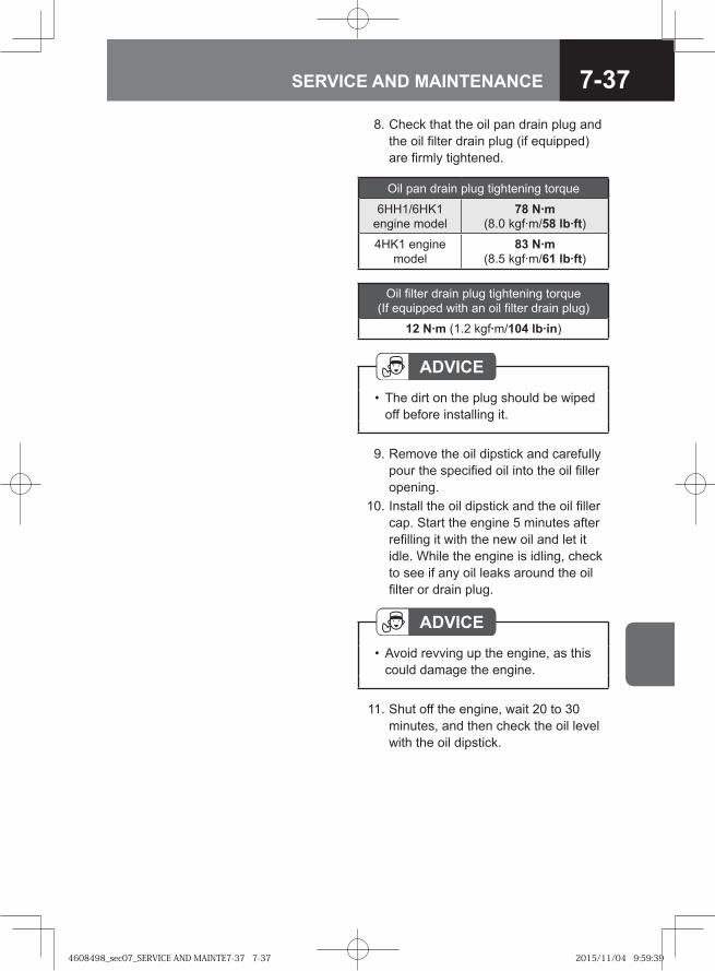
7-37SERVICE AND MAINTENANCE
8. Check that the oil pan drain plug and the oil filter drain plug (if equipped) are firmly tightened.
9. Remove the oil dipstick and carefully pour the specified oil into the oil filler opening.
10. Install the oil dipstick and the oil filler cap. Start the engine 5 minutes after refilling it with the new oil and let it idle. While the engine is idling, check to see if any oil leaks around the oil filter or drain plug.
Oil pan drain plug tightening torque
6HH1/6HK1 engine model
78 N·m (8.0 kgf·m/58 lb·ft)
4HK1 engine model
83 N·m (8.5 kgf·m/61 lb·ft)
11. Shut off the engine, wait 20 to 30 minutes, and then check the oil level with the oil dipstick.
ADVICEThe dirt on the plug should be wiped off before installing it.
•
ADVICEAvoid revving up the engine, as this could damage the engine.
•
Oil filter drain plug tightening torque (If equipped with an oil filter drain plug)
12 N·m (1.2 kgf·m/104 lb·in)
4608498_sec07_SERVICE AND MAINTE7-37 7-374608498_sec07_SERVICE AND MAINTE7-37 7-37 2015/11/04 9:59:392015/11/04 9:59:39
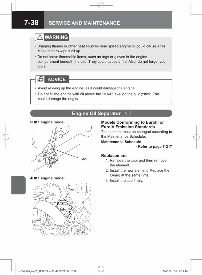
7-38 SERVICE AND MAINTENANCE
WARNING
Bringing flames or other heat sources near spilled engine oil could cause a fire. Make sure to wipe it all up.Do not leave flammable items, such as rags or gloves in the engine compartment beneath the cab. They could cause a fire. Also, do not forget your tools.
•
•
ADVICEAvoid revving up the engine, as it could damage the engine.Do not fill the engine with oil above the "MAX" level on the oil dipstick. This could damage the engine.
••
Engine Oil Separator V
Models Conforming to EuroIII or EuroIV Emission StandardsThe element must be changed according to the Maintenance Schedule.Maintenance Schedule
→ Refer to page 7-217
Replacement 1. Remove the cap, and then remove
the element. 2. Install the new element. Replace the
O-ring at the same time. 3. Install the cap firmly.
6HK1 engine model
4HK1 engine model
Cap
Cap
4608498_sec07_SERVICE AND MAINTE7-38 7-384608498_sec07_SERVICE AND MAINTE7-38 7-38 2015/11/04 9:59:402015/11/04 9:59:40
7-39SERVICE AND MAINTENANCE
Engine Coolant
The engine coolant must be changed according to the Maintenance Schedule.
Maintenance Schedule → Refer to page 7-217
Recommended Fluids, Lubricants and Diesel Fuels → Refer to page 7-242
WARNING
Check, replenish or change the engine coolant only after the engine has sufficiently cooled down.Do not remove the radiator cap or reserve tank cap when the engine coolant is still hot. Careless removal could result in burns caused by hot vapor being released. Burns may also be caused by boiling water released due to the high temperature of the coolant. Perform inspection, refilling, and replacement of coolant only when its temperature has cooled.When removing the radiator cap or reserve tank cap, use a thick cloth to cover the cap and turn it slowly.Engine coolant is toxic and must not be ingested. If the engine coolant is mistakenly ingested, immediately vomit it and seek prompt medical attention.If the engine coolant gets in your eyes, rinse it off immediately with a large amount of water for 15 minutes or longer. Also, if still abnormality such as irritation is felt, seek medical attention.If the engine coolant gets on your skin, rinse it off using a soap with a large amount of water. Also, if abnormality is seen, seek medical attention.Engine coolant is flammable, and therefore, it must be kept away from flames and other heat sources. Engine coolant also could ignite if it comes in contact with a hot surface, such as the exhaust manifold. Exercise caution to prevent this from happening.
•
•
•
•
•
•
•
ADVICEReplace the engine coolant periodically. If the engine coolant is not replaced periodically, rust is generated due to degradation of the engine coolant, which may cause a failure such as water leakage or clogging of the radiator or heater core.
•
4608498_sec07_SERVICE AND MAINTE7-39 7-394608498_sec07_SERVICE AND MAINTE7-39 7-39 2015/11/04 9:59:402015/11/04 9:59:40
7-40 SERVICE AND MAINTENANCE
Preparing Engine Coolant
Engine Coolant QuantityThe quantity of engine coolant is indicated below for your use as a guideline when changing the engine coolant. After changing the engine coolant, check that the engine coolant is up to the specified level.
NOTEEngine coolant is fluid which is made by mixing coolant and water at an appropriate concentration.
•
To prevent the engine damage due to freezing of the engine coolant and to protect the cooling system from corrosion, mix the Isuzu recommended coolant and water to be at 50% concentration.For other than Isuzu genuine coolant (Caltex/Texaco/Chevron, etc.), it is recommended to use directly "50/50 Pre-diluted" product which is already diluted to 50% concentration.
Recommended Fluids, Lubricants and Diesel Fuels → Refer to page 7-242
ADVICEIsuzu does not guarantee the use of the engine or vehicle at the outside temperature of -30°C (-22°F) or below.However, if the engine or vehicle is used at the outside temperature of -30°C (-22°F) or below, the coolant concentration of 55% is recommended.
•
•
4608498_sec07_SERVICE AND MAINTE7-40 7-404608498_sec07_SERVICE AND MAINTE7-40 7-40 2015/11/04 9:59:402015/11/04 9:59:40
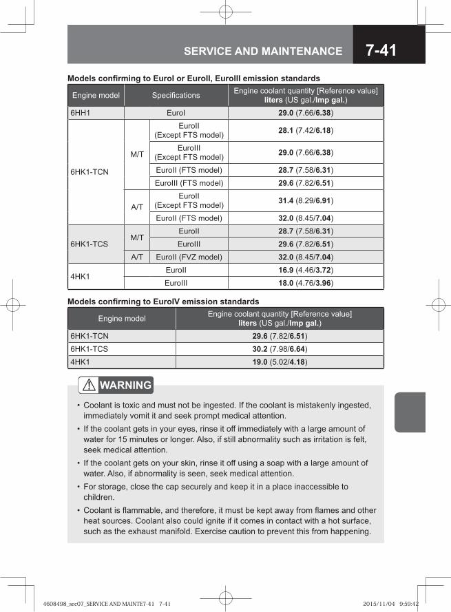
7-41SERVICE AND MAINTENANCE
Models confirming to EuroI or EuroII, EuroIII emission standards
Engine model Specifications Engine coolant quantity [Reference value] liters (US gal./Imp gal.)
6HH1 EuroI 29.0 (7.66/6.38)
6HK1-TCN
M/T
EuroII (Except FTS model) 28.1 (7.42/6.18)
EuroIII (Except FTS model) 29.0 (7.66/6.38)
EuroII (FTS model) 28.7 (7.58/6.31)
EuroIII (FTS model) 29.6 (7.82/6.51)
A/TEuroII
(Except FTS model) 31.4 (8.29/6.91)
EuroII (FTS model) 32.0 (8.45/7.04)
6HK1-TCSM/T
EuroII 28.7 (7.58/6.31)
EuroIII 29.6 (7.82/6.51)
A/T EuroII (FVZ model) 32.0 (8.45/7.04)
4HK1EuroII 16.9 (4.46/3.72)
EuroIII 18.0 (4.76/3.96)
Models confirming to EuroIV emission standards
Engine model Engine coolant quantity [Reference value] liters (US gal./Imp gal.)
6HK1-TCN 29.6 (7.82/6.51)
6HK1-TCS 30.2 (7.98/6.64)
4HK1 19.0 (5.02/4.18)
WARNING
Coolant is toxic and must not be ingested. If the coolant is mistakenly ingested, immediately vomit it and seek prompt medical attention.If the coolant gets in your eyes, rinse it off immediately with a large amount of water for 15 minutes or longer. Also, if still abnormality such as irritation is felt, seek medical attention.If the coolant gets on your skin, rinse it off using a soap with a large amount of water. Also, if abnormality is seen, seek medical attention.For storage, close the cap securely and keep it in a place inaccessible to children. Coolant is flammable, and therefore, it must be kept away from flames and other heat sources. Coolant also could ignite if it comes in contact with a hot surface, such as the exhaust manifold. Exercise caution to prevent this from happening.
•
•
•
•
•
4608498_sec07_SERVICE AND MAINTE7-41 7-414608498_sec07_SERVICE AND MAINTE7-41 7-41 2015/11/04 9:59:422015/11/04 9:59:42
7-42 SERVICE AND MAINTENANCE
ADVICETo dilute the coolant, use distilled water or deionized water.Do not use the coolant at any coolant concentration other than that specified. If the coolant concentration is 60% or higher, overheating is likely to occur, while if it is 30% or lower, anti-corrosion function is not provided sufficiently.Using coolant at any coolant concentration other than that specified may reduce anti-freezing performance, and engine coolant may freeze.If the engine coolant decreases rapidly, go immediately to the nearest Isuzu Dealer for a check or repair.
••
•
•
CAUTIONUse only an Isuzu recommended coolant.Using any coolant other than that Isuzu recommended could cause damage to the engine, radiator or heater core. In particular, use of coolants containing borate salts or silicates may result in engine or radiator corrosion, causing engine coolant leaks and other problems.
••
4608498_sec07_SERVICE AND MAINTE7-42 7-424608498_sec07_SERVICE AND MAINTE7-42 7-42 2015/11/04 9:59:422015/11/04 9:59:42
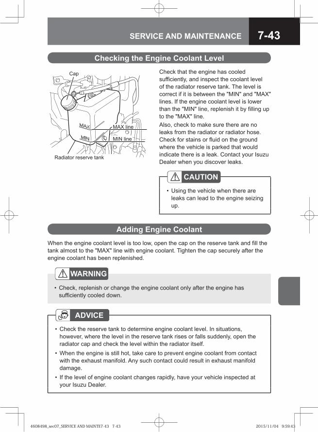
7-43SERVICE AND MAINTENANCE
Check that the engine has cooled sufficiently, and inspect the coolant level of the radiator reserve tank. The level is correct if it is between the "MIN" and "MAX" lines. If the engine coolant level is lower than the "MIN" line, replenish it by filling up to the "MAX" line. Also, check to make sure there are no leaks from the radiator or radiator hose. Check for stains or fluid on the ground where the vehicle is parked that would indicate there is a leak. Contact your Isuzu Dealer when you discover leaks.
Checking the Engine Coolant Level
CAUTIONUsing the vehicle when there are leaks can lead to the engine seizing up.
•
MAX line
MIN line
Cap
Radiator reserve tank
Adding Engine CoolantWhen the engine coolant level is too low, open the cap on the reserve tank and fill the tank almost to the "MAX" line with engine coolant. Tighten the cap securely after the engine coolant has been replenished.
WARNING
Check, replenish or change the engine coolant only after the engine has sufficiently cooled down.
•
ADVICECheck the reserve tank to determine engine coolant level. In situations, however, where the level in the reserve tank rises or falls suddenly, open the radiator cap and check the level within the radiator itself. When the engine is still hot, take care to prevent engine coolant from contact with the exhaust manifold. Any such contact could result in exhaust manifold damage.If the level of engine coolant changes rapidly, have your vehicle inspected at your Isuzu Dealer.
•
•
•
4608498_sec07_SERVICE AND MAINTE7-43 7-434608498_sec07_SERVICE AND MAINTE7-43 7-43 2015/11/04 9:59:432015/11/04 9:59:43
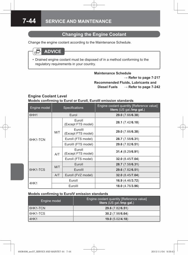
7-44 SERVICE AND MAINTENANCE
Changing the Engine CoolantChange the engine coolant according to the Maintenance Schedule.
Maintenance Schedule → Refer to page 7-217
Recommended Fluids, Lubricants and Diesel Fuels → Refer to page 7-242
ADVICEDrained engine coolant must be disposed of in a method conforming to the regulatory requirements in your country.
•
Engine Coolant LevelModels confirming to EuroI or EuroII, EuroIII emission standards
Engine model Specifications Engine coolant quantity [Reference value] liters (US gal./Imp gal.)
6HH1 EuroI 29.0 (7.66/6.38)
6HK1-TCN
M/T
EuroII (Except FTS model) 28.1 (7.42/6.18)
EuroIII (Except FTS model) 29.0 (7.66/6.38)
EuroII (FTS model) 28.7 (7.58/6.31)
EuroIII (FTS model) 29.6 (7.82/6.51)
A/TEuroII
(Except FTS model) 31.4 (8.29/6.91)
EuroII (FTS model) 32.0 (8.45/7.04)
6HK1-TCSM/T
EuroII 28.7 (7.58/6.31)
EuroIII 29.6 (7.82/6.51)
A/T EuroII (FVZ model) 32.0 (8.45/7.04)
4HK1EuroII 16.9 (4.46/3.72)
EuroIII 18.0 (4.76/3.96)
Models confirming to EuroIV emission standards
Engine model Engine coolant quantity [Reference value] liters (US gal./Imp gal.)
6HK1-TCN 29.6 (7.82/6.51)
6HK1-TCS 30.2 (7.98/6.64)
4HK1 19.0 (5.02/4.18)
4608498_sec07_SERVICE AND MAINTE7-44 7-444608498_sec07_SERVICE AND MAINTE7-44 7-44 2015/11/04 9:59:432015/11/04 9:59:43
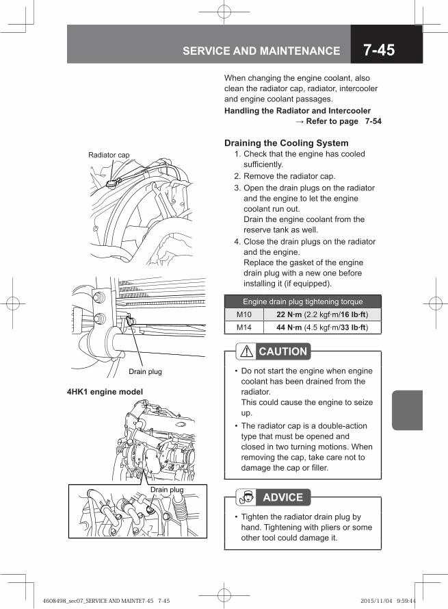
7-45SERVICE AND MAINTENANCE
When changing the engine coolant, also clean the radiator cap, radiator, intercooler and engine coolant passages.Handling the Radiator and Intercooler
→ Refer to page 7-54
Draining the Cooling System 1. Check that the engine has cooled
sufficiently. 2. Remove the radiator cap. 3. Open the drain plugs on the radiator
and the engine to let the engine coolant run out. Drain the engine coolant from the reserve tank as well.
4. Close the drain plugs on the radiator and the engine. Replace the gasket of the engine drain plug with a new one before installing it (if equipped).
Radiator cap
� ��� ����
CAUTIONDo not start the engine when engine coolant has been drained from the radiator.This could cause the engine to seize up.The radiator cap is a double-action type that must be opened and closed in two turning motions. When removing the cap, take care not to damage the cap or filler.
•
•
ADVICETighten the radiator drain plug by hand. Tightening with pliers or some other tool could damage it.
•
��� � ����
Engine drain plug tightening torque
M10 22 N·m (2.2 kgf·m/16 lb·ft)M14 44 N·m (4.5 kgf·m/33 lb·ft)
4HK1 engine model
4608498_sec07_SERVICE AND MAINTE7-45 7-454608498_sec07_SERVICE AND MAINTE7-45 7-45 2015/11/04 9:59:442015/11/04 9:59:44
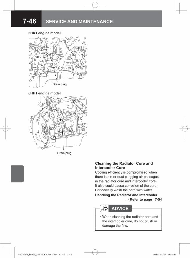
7-46 SERVICE AND MAINTENANCE
ADVICEWhen cleaning the radiator core and the intercooler core, do not crush or damage the fins.
•
Cleaning the Radiator Core and Intercooler CoreCooling efficiency is compromised when there is dirt or dust plugging air passages in the radiator core and intercooler core. It also could cause corrosion of the core. Periodically wash the core with water.Handling the Radiator and Intercooler
→ Refer to page 7-54
��� � ����
6HK1 engine model
��� � ����
6HH1 engine model
4608498_sec07_SERVICE AND MAINTE7-46 7-464608498_sec07_SERVICE AND MAINTE7-46 7-46 2015/11/04 9:59:452015/11/04 9:59:45
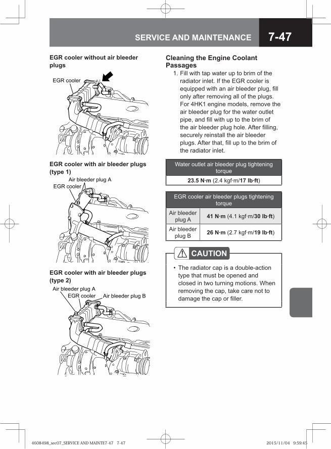
7-47SERVICE AND MAINTENANCE
CAUTIONThe radiator cap is a double-action type that must be opened and closed in two turning motions. When removing the cap, take care not to damage the cap or filler.
•
Water outlet air bleeder plug tightening torque
23.5 N·m (2.4 kgf·m/17 lb·ft)
Cleaning the Engine Coolant Passages 1. Fill with tap water up to brim of the
radiator inlet. If the EGR cooler is equipped with an air bleeder plug, fill only after removing all of the plugs. For 4HK1 engine models, remove the air bleeder plug for the water outlet pipe, and fill with up to the brim of the air bleeder plug hole. After filling, securely reinstall the air bleeder plugs. After that, fill up to the brim of the radiator inlet.
�� ������
EGR cooler without air bleeder plugs
EGR cooler with air bleeder plugs (type 1)
�� ������ ���� �
��� �����
�� ������� ���� �
�� ������� ����
��� ������
EGR cooler with air bleeder plugs (type 2)
EGR cooler air bleeder plugs tightening torque
Air bleeder plug A 41 N·m (4.1 kgf·m/30 lb·ft)
Air bleeder plug B 26 N·m (2.7 kgf·m/19 lb·ft)
4608498_sec07_SERVICE AND MAINTE7-47 7-474608498_sec07_SERVICE AND MAINTE7-47 7-47 2015/11/04 9:59:452015/11/04 9:59:45
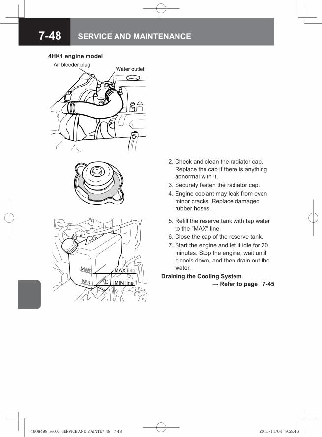
7-48 SERVICE AND MAINTENANCE
2. Check and clean the radiator cap. Replace the cap if there is anything abnormal with it.
3. Securely fasten the radiator cap. 4. Engine coolant may leak from even
minor cracks. Replace damaged rubber hoses.
MAX line
MIN line
5. Refill the reserve tank with tap water to the "MAX" line.
6. Close the cap of the reserve tank. 7. Start the engine and let it idle for 20
minutes. Stop the engine, wait until it cools down, and then drain out the water.
Draining the Cooling System → Refer to page 7-45
�� ������ �������� ������
4HK1 engine model
4608498_sec07_SERVICE AND MAINTE7-48 7-484608498_sec07_SERVICE AND MAINTE7-48 7-48 2015/11/04 9:59:462015/11/04 9:59:46
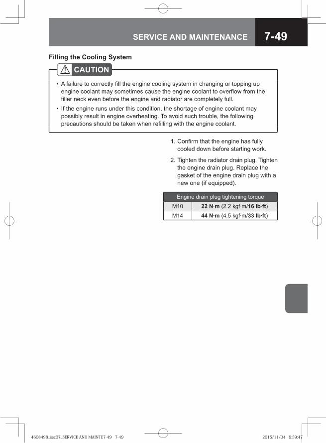
7-49SERVICE AND MAINTENANCE
2. Tighten the radiator drain plug. Tighten the engine drain plug. Replace the gasket of the engine drain plug with a new one (if equipped).
Engine drain plug tightening torque
M10 22 N·m (2.2 kgf·m/16 lb·ft)M14 44 N·m (4.5 kgf·m/33 lb·ft)
Filling the Cooling System
CAUTIONA failure to correctly fill the engine cooling system in changing or topping up engine coolant may sometimes cause the engine coolant to overflow from the filler neck even before the engine and radiator are completely full.If the engine runs under this condition, the shortage of engine coolant may possibly result in engine overheating. To avoid such trouble, the following precautions should be taken when refilling with the engine coolant.
•
•
1. Confirm that the engine has fully cooled down before starting work.
4608498_sec07_SERVICE AND MAINTE7-49 7-494608498_sec07_SERVICE AND MAINTE7-49 7-49 2015/11/04 9:59:472015/11/04 9:59:47
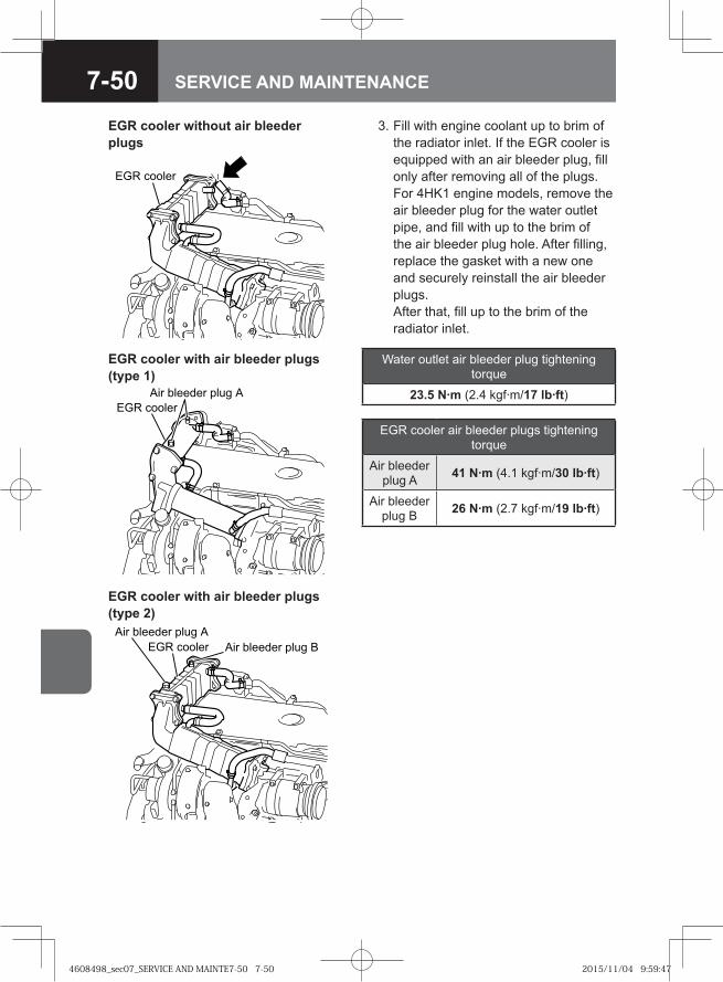
7-50 SERVICE AND MAINTENANCE
Water outlet air bleeder plug tightening torque
23.5 N·m (2.4 kgf·m/17 lb·ft)
3. Fill with engine coolant up to brim of the radiator inlet. If the EGR cooler is equipped with an air bleeder plug, fill only after removing all of the plugs. For 4HK1 engine models, remove the air bleeder plug for the water outlet pipe, and fill with up to the brim of the air bleeder plug hole. After filling, replace the gasket with a new one and securely reinstall the air bleeder plugs. After that, fill up to the brim of the radiator inlet.
�� ������
EGR cooler without air bleeder plugs
EGR cooler with air bleeder plugs (type 1)
�� ������ ���� �
��� �����
�� ������� ���� �
�� ������� ����
��� ������
EGR cooler with air bleeder plugs (type 2)
EGR cooler air bleeder plugs tightening torque
Air bleeder plug A 41 N·m (4.1 kgf·m/30 lb·ft)
Air bleeder plug B 26 N·m (2.7 kgf·m/19 lb·ft)
4608498_sec07_SERVICE AND MAINTE7-50 7-504608498_sec07_SERVICE AND MAINTE7-50 7-50 2015/11/04 9:59:472015/11/04 9:59:47
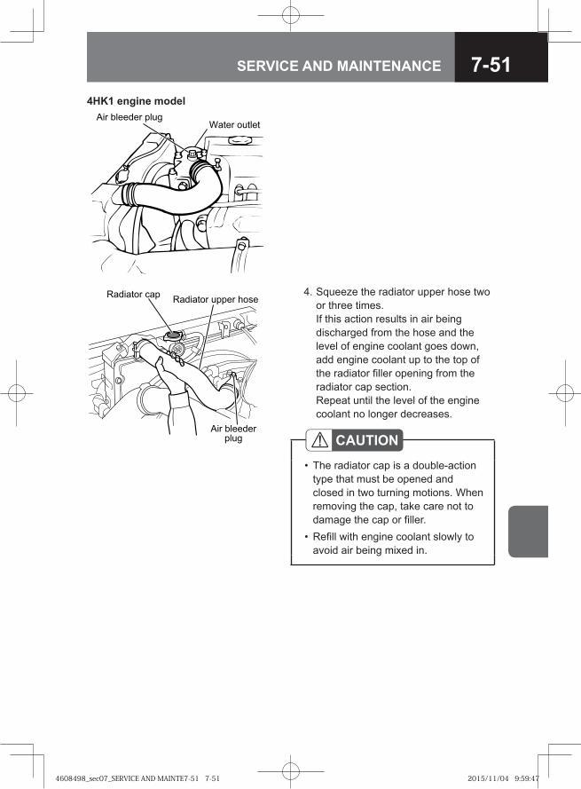
7-51SERVICE AND MAINTENANCE
�� ���� ����� ���� ����� ����
� � ����������� CAUTION
The radiator cap is a double-action type that must be opened and closed in two turning motions. When removing the cap, take care not to damage the cap or filler.Refill with engine coolant slowly to avoid air being mixed in.
•
•
4. Squeeze the radiator upper hose two or three times. If this action results in air being discharged from the hose and the level of engine coolant goes down, add engine coolant up to the top of the radiator filler opening from the radiator cap section. Repeat until the level of the engine coolant no longer decreases.
4HK1 engine model�� ������ ����
���� ������
4608498_sec07_SERVICE AND MAINTE7-51 7-514608498_sec07_SERVICE AND MAINTE7-51 7-51 2015/11/04 9:59:472015/11/04 9:59:47
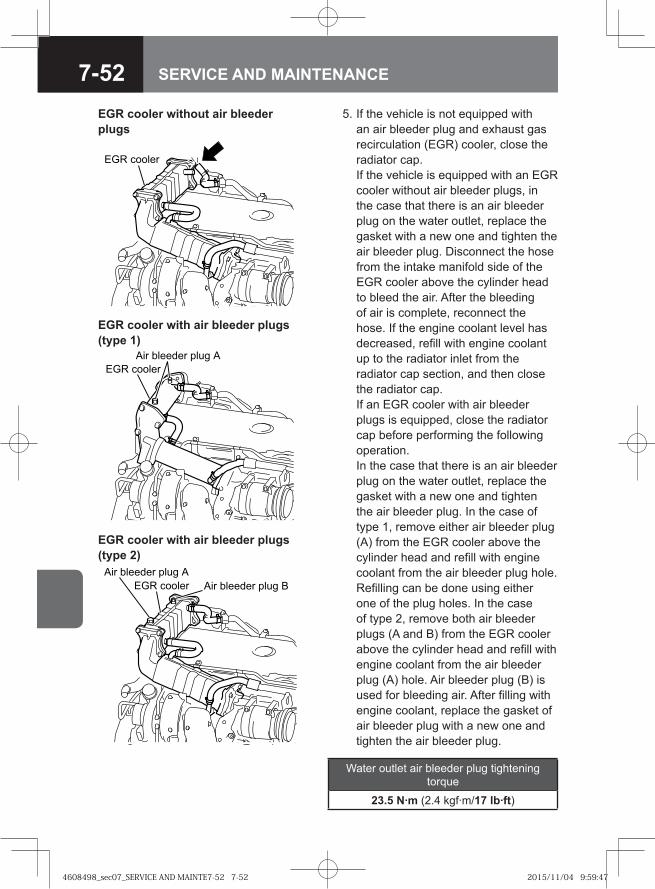
7-52 SERVICE AND MAINTENANCE
5. If the vehicle is not equipped with an air bleeder plug and exhaust gas recirculation (EGR) cooler, close the radiator cap. If the vehicle is equipped with an EGR cooler without air bleeder plugs, in the case that there is an air bleeder plug on the water outlet, replace the gasket with a new one and tighten the air bleeder plug. Disconnect the hose from the intake manifold side of the EGR cooler above the cylinder head to bleed the air. After the bleeding of air is complete, reconnect the hose. If the engine coolant level has decreased, refill with engine coolant up to the radiator inlet from the radiator cap section, and then close the radiator cap. If an EGR cooler with air bleeder plugs is equipped, close the radiator cap before performing the following operation. In the case that there is an air bleeder plug on the water outlet, replace the gasket with a new one and tighten the air bleeder plug. In the case of type 1, remove either air bleeder plug (A) from the EGR cooler above the cylinder head and refill with engine coolant from the air bleeder plug hole. Refilling can be done using either one of the plug holes. In the case of type 2, remove both air bleeder plugs (A and B) from the EGR cooler above the cylinder head and refill with engine coolant from the air bleeder plug (A) hole. Air bleeder plug (B) is used for bleeding air. After filling with engine coolant, replace the gasket of air bleeder plug with a new one and tighten the air bleeder plug.
�� ������
EGR cooler without air bleeder plugs
EGR cooler with air bleeder plugs (type 1)
�� ������ ���� �
��� �����
�� ������� ���� �
�� ������� ����
��� ������
EGR cooler with air bleeder plugs (type 2)
Water outlet air bleeder plug tightening torque
23.5 N·m (2.4 kgf·m/17 lb·ft)
4608498_sec07_SERVICE AND MAINTE7-52 7-524608498_sec07_SERVICE AND MAINTE7-52 7-52 2015/11/04 9:59:472015/11/04 9:59:47
7-53SERVICE AND MAINTENANCE
6. Fill the reserve tank with engine coolant to the "MAX" line. Close the cap of the reserve tank.
7. Start the engine, let it idle for 5 minutes or more and then stop the engine. 8. Check that the engine has cooled sufficiently and remove the radiator cap. If the
engine coolant level has decreased, add coolant up to the brim of the radiator inlet. If the level is extremely low, inspect whether coolant is leaking from the radiator, coolant passages, or the reserve tank hose. If a leakage is found, contact your nearest Isuzu Dealer.
9. After firmly closing the radiator cap, idle the engine until the needle of the coolant temperature gauge reaches the center and the thermostat opens. If the vehicle is equipped with an air conditioner, turn the A/C switch off to facilitate warming. If the vehicle is equipped with a heater, turn off the fan to facilitate warming. In order to save time, if the vehicle is equipped with a warm-up switch, turn the switch on to warm up the engine. If the vehicle is not equipped with a warm-up switch, maintain the engine speed approximately 2,000 r/min to warm up the engine. After the needle of the coolant temperature gauge reaches the center, increase the engine speed to approximately 2,000 r/min, and maintain this speed for 5 minutes. Check if the thermostat is open or not by checking whether the upper hose is hot. If the vehicle is equipped with a heater, turn the temperature control to the maximum setting and make sure that hot air comes out.
10. Let the engine idle for 5 minutes and then stop the engine. 11. Check that the engine has cooled sufficiently and remove the radiator cap. If the
engine coolant level has decreased, add coolant up to the brim of the radiator inlet. If the level is extremely low, inspect whether coolant is leaking from the radiator, coolant passages, or the reserve tank hose. If a leakage is found, contact your nearest Isuzu Dealer.
12. Repeat steps 9 through 11 until the engine coolant level in the radiator filler opening stops declining.
13. Firmly close the radiator cap. 14. Replenish the engine coolant in the reserve tank up to the "MAX" line, and then
close the reserve tank cap. 15. Check the engine coolant level of the reserve tank the next morning. If the engine
coolant level has decreased, refill with engine coolant to the "MAX" line.
EGR cooler air bleeder plugs tightening torque
Air bleeder plug A 41 N·m (4.1 kgf·m/30 lb·ft)
Air bleeder plug B 26 N·m (2.7 kgf·m/19 lb·ft)
4608498_sec07_SERVICE AND MAINTE7-53 7-534608498_sec07_SERVICE AND MAINTE7-53 7-53 2015/11/04 9:59:472015/11/04 9:59:47
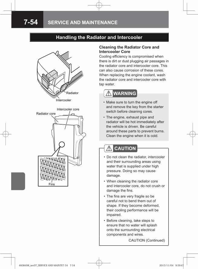
7-54 SERVICE AND MAINTENANCE
Handling the Radiator and Intercooler
Cleaning the Radiator Core and Intercooler Core Cooling efficiency is compromised when there is dirt or dust plugging air passages in the radiator core and intercooler core. This can also cause corrosion of these cores. When replacing the engine coolant, wash the radiator core and intercooler core with tap water.
Radiator
Intercooler
Fins
Radiator coreIntercooler core
CAUTIONDo not clean the radiator, intercooler and their surrounding areas using water that is supplied under high pressure. Doing so may cause damage.When cleaning the radiator core and intercooler core, do not crush or damage the fins.The fins are very fragile so be careful not to bend them out of shape. If they become deformed, their cooling performance will be impaired.Before cleaning, take steps to ensure that no water will splash onto the surrounding electrical components and wires.
•
•
•
•
CAUTION (Continued)
WARNING
Make sure to turn the engine off and remove the key from the starter switch before cleaning cores.The engine, exhaust pipe and radiator will be hot immediately after the vehicle is driven. Be careful around these parts to prevent burns. Clean the engine when it is cold.
•
•
4608498_sec07_SERVICE AND MAINTE7-54 7-544608498_sec07_SERVICE AND MAINTE7-54 7-54 2015/11/04 9:59:472015/11/04 9:59:47
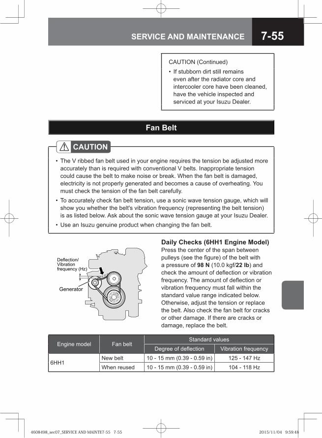
7-55SERVICE AND MAINTENANCE
Fan Belt
CAUTIONThe V ribbed fan belt used in your engine requires the tension be adjusted more accurately than is required with conventional V belts. Inappropriate tension could cause the belt to make noise or break. When the fan belt is damaged, electricity is not properly generated and becomes a cause of overheating. You must check the tension of the fan belt carefully.To accurately check fan belt tension, use a sonic wave tension gauge, which will show you whether the belt's vibration frequency (representing the belt tension) is as listed below. Ask about the sonic wave tension gauge at your Isuzu Dealer.Use an Isuzu genuine product when changing the fan belt.
•
•
•
Engine model Fan beltStandard values
Degree of deflection Vibration frequency
6HH1New belt 10 - 15 mm (0.39 - 0.59 in) 125 - 147 Hz
When reused 10 - 15 mm (0.39 - 0.59 in) 104 - 118 Hz
CAUTION (Continued)If stubborn dirt still remains even after the radiator core and intercooler core have been cleaned, have the vehicle inspected and serviced at your Isuzu Dealer.
•
Daily Checks (6HH1 Engine Model)Press the center of the span between pulleys (see the figure) of the belt with a pressure of 98 N (10.0 kgf/22 lb) and check the amount of deflection or vibration frequency. The amount of deflection or vibration frequency must fall within the standard value range indicated below. Otherwise, adjust the tension or replace the belt. Also check the fan belt for cracks or other damage. If there are cracks or damage, replace the belt.
�� ������
��������� ��������� ������ �� ���
4608498_sec07_SERVICE AND MAINTE7-55 7-554608498_sec07_SERVICE AND MAINTE7-55 7-55 2015/11/04 9:59:482015/11/04 9:59:48
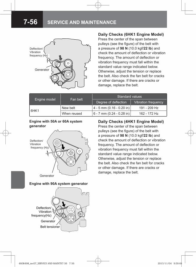
7-56 SERVICE AND MAINTENANCE
Daily Checks (4HK1 Engine Model)Press the center of the span between pulleys (see the figure) of the belt with a pressure of 98 N (10.0 kgf/22 lb) and check the amount of deflection or vibration frequency. The amount of deflection or vibration frequency must fall within the standard value range indicated below. Otherwise, adjust the tension or replace the belt. Also check the fan belt for cracks or other damage. If there are cracks or damage, replace the belt.
�� ������
��������� �
��������
������ �� ���
Engine with 50A or 60A system generator
��� ���������
���������
�����������
���������
���� ���!"�#$
Engine with 90A system generator
Daily Checks (6HK1 Engine Model)Press the center of the span between pulleys (see the figure) of the belt with a pressure of 98 N (10.0 kgf/22 lb) and check the amount of deflection or vibration frequency. The amount of deflection or vibration frequency must fall within the standard value range indicated below. Otherwise, adjust the tension or replace the belt. Also check the fan belt for cracks or other damage. If there are cracks or damage, replace the belt.
��� ���
�����������
��� �����
� ������� ����
Engine model Fan beltStandard values
Degree of deflection Vibration frequency
6HK1New belt 4 - 5 mm (0.16 - 0.20 in) 191 - 209 Hz
When reused 6 - 7 mm (0.24 - 0.28 in) 162 - 172 Hz
4608498_sec07_SERVICE AND MAINTE7-56 7-564608498_sec07_SERVICE AND MAINTE7-56 7-56 2015/11/04 9:59:482015/11/04 9:59:48
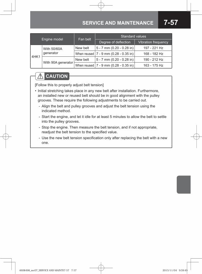
7-57SERVICE AND MAINTENANCE
Engine model Fan beltStandard values
Degree of deflection Vibration frequency
4HK1
With 50/60A generator
New belt 5 - 7 mm (0.20 - 0.28 in) 197 - 221 Hz
When reused 7 - 9 mm (0.28 - 0.35 in) 168 - 182 Hz
With 90A generatorNew belt 5 - 7 mm (0.20 - 0.28 in) 190 - 212 Hz
When reused 7 - 9 mm (0.28 - 0.35 in) 163 - 175 Hz
CAUTION[Follow this to properly adjust belt tension]
Initial stretching takes place in any new belt after installation. Furthermore, an installed new or reused belt should be in good alignment with the pulley grooves. These require the following adjustments to be carried out.
Align the belt and pulley grooves and adjust the belt tension using the indicated method.Start the engine, and let it idle for at least 5 minutes to allow the belt to settle into the pulley grooves.Stop the engine. Then measure the belt tension, and if not appropriate, readjust the belt tension to the specified value.Use the new belt tension specification only after replacing the belt with a new one.
•
-
-
-
-
4608498_sec07_SERVICE AND MAINTE7-57 7-574608498_sec07_SERVICE AND MAINTE7-57 7-57 2015/11/04 9:59:492015/11/04 9:59:49
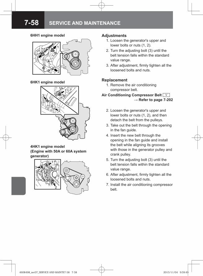
7-58 SERVICE AND MAINTENANCE
Adjustments 1. Loosen the generator's upper and
lower bolts or nuts (1, 2). 2. Turn the adjusting bolt (3) until the
belt tension falls within the standard value range.
3. After adjustment, firmly tighten all the loosened bolts and nuts.
Replacement 1. Remove the air conditioning
compressor belt.Air Conditioning Compressor Belt V
→ Refer to page 7-202
2. Loosen the generator's upper and lower bolts or nuts (1, 2), and then detach the belt from the pulleys.
3. Take out the belt through the opening in the fan guide.
4. Insert the new belt through the opening in the fan guide and install the belt while aligning its grooves with those in the generator pulley and crank pulley.
5. Turn the adjusting bolt (3) until the belt tension falls within the standard value range.
6. After adjustment, firmly tighten all the loosened bolts and nuts.
7. Install the air conditioning compressor belt.
�
�
6HH1 engine model
�
�
4HK1 engine model (Engine with 50A or 60A system generator)
�
�
6HK1 engine model
4608498_sec07_SERVICE AND MAINTE7-58 7-584608498_sec07_SERVICE AND MAINTE7-58 7-58 2015/11/04 9:59:492015/11/04 9:59:49
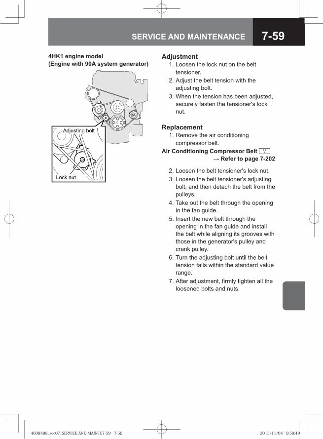
7-59SERVICE AND MAINTENANCE
Adjustment 1. Loosen the lock nut on the belt
tensioner. 2. Adjust the belt tension with the
adjusting bolt. 3. When the tension has been adjusted,
securely fasten the tensioner's lock nut.
� �� ���
��������� � ��
4HK1 engine model (Engine with 90A system generator)
Replacement 1. Remove the air conditioning
compressor belt.Air Conditioning Compressor Belt V
→ Refer to page 7-202
2. Loosen the belt tensioner's lock nut. 3. Loosen the belt tensioner's adjusting
bolt, and then detach the belt from the pulleys.
4. Take out the belt through the opening in the fan guide.
5. Insert the new belt through the opening in the fan guide and install the belt while aligning its grooves with those in the generator's pulley and crank pulley.
6. Turn the adjusting bolt until the belt tension falls within the standard value range.
7. After adjustment, firmly tighten all the loosened bolts and nuts.
4608498_sec07_SERVICE AND MAINTE7-59 7-594608498_sec07_SERVICE AND MAINTE7-59 7-59 2015/11/04 9:59:492015/11/04 9:59:49
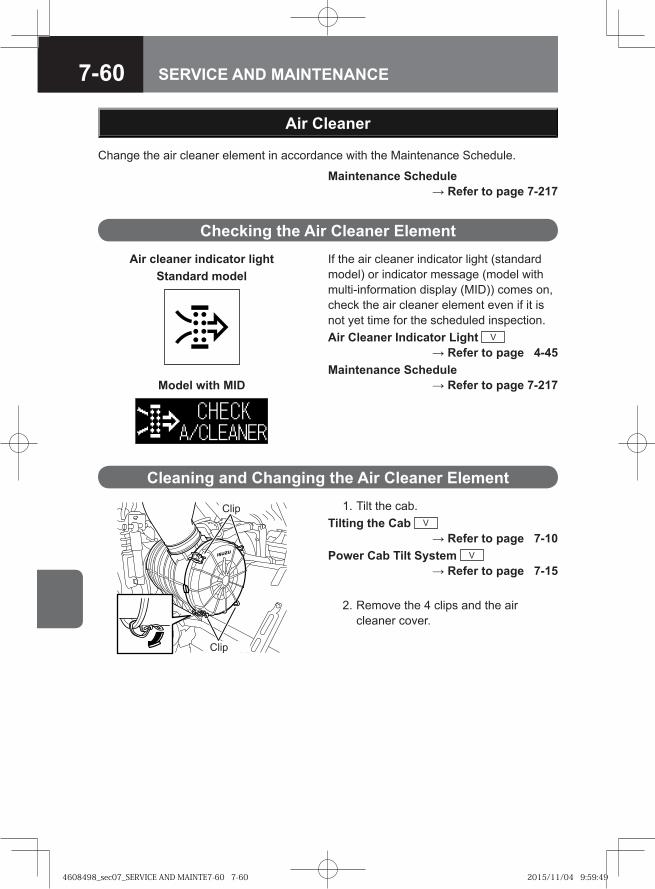
7-60 SERVICE AND MAINTENANCE
Checking the Air Cleaner Element
Air Cleaner
Change the air cleaner element in accordance with the Maintenance Schedule.
Maintenance Schedule → Refer to page 7-217
Cleaning and Changing the Air Cleaner Element 1. Tilt the cab.Tilting the Cab V
→ Refer to page 7-10Power Cab Tilt System V
→ Refer to page 7-15
2. Remove the 4 clips and the air cleaner cover.
Clip
Clip
If the air cleaner indicator light (standard model) or indicator message (model with multi-information display (MID)) comes on, check the air cleaner element even if it is not yet time for the scheduled inspection.Air Cleaner Indicator Light V
→ Refer to page 4-45Maintenance Schedule
→ Refer to page 7-217Model with MID
Air cleaner indicator lightStandard model
4608498_sec07_SERVICE AND MAINTE7-60 7-604608498_sec07_SERVICE AND MAINTE7-60 7-60 2015/11/04 9:59:492015/11/04 9:59:49
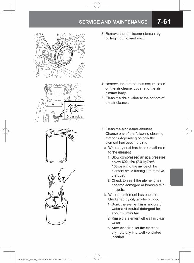
7-61SERVICE AND MAINTENANCE
3. Remove the air cleaner element by pulling it out toward you.
4. Remove the dirt that has accumulated on the air cleaner cover and the air cleaner body.
5. Clean the drain valve at the bottom of the air cleaner.
Drain valve
6. Clean the air cleaner element.Choose one of the following cleaning methods depending on how the element has become dirty.
a. When dry dust has become adhered to the element
1. Blow compressed air at a pressure below 690 kPa (7.0 kgf/cm²/100 psi) into the inside of the element while turning it to remove the dust.
2. Check to see if the element has become damaged or become thin in spots.
b. When the element has become blackened by oily smoke or soot
1. Soak the element in a mixture of water and neutral detergent for about 30 minutes.
2. Rinse the element off well in clean water.
3. After cleaning, let the element dry naturally in a well-ventilated location.
4608498_sec07_SERVICE AND MAINTE7-61 7-614608498_sec07_SERVICE AND MAINTE7-61 7-61 2015/11/04 9:59:502015/11/04 9:59:50
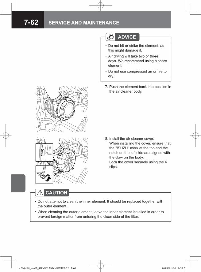
7-62 SERVICE AND MAINTENANCE
7. Push the element back into position in the air cleaner body.
8. Install the air cleaner cover. When installing the cover, ensure that the "ISUZU" mark at the top and the notch on the left side are aligned with the claw on the body.Lock the cover securely using the 4 clips.
CAUTIONDo not attempt to clean the inner element. It should be replaced together with the outer element.When cleaning the outer element, leave the inner element installed in order to prevent foreign matter from entering the clean side of the filter.
•
•
ADVICEDo not hit or strike the element, as this might damage it.Air drying will take two or three days. We recommend using a spare element.Do not use compressed air or fire to dry.
•
•
•
4608498_sec07_SERVICE AND MAINTE7-62 7-624608498_sec07_SERVICE AND MAINTE7-62 7-62 2015/11/04 9:59:512015/11/04 9:59:51
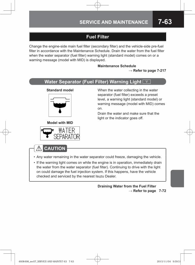
7-63SERVICE AND MAINTENANCE
Change the engine-side main fuel filter (secondary filter) and the vehicle-side pre-fuel filter in accordance with the Maintenance Schedule. Drain the water from the fuel filter when the water separator (fuel filter) warning light (standard model) comes on or a warning message (model with MID) is displayed.
Water Separator (Fuel Filter) Warning Light V
Fuel Filter
Draining Water from the Fuel Filter → Refer to page 7-72
CAUTIONAny water remaining in the water separator could freeze, damaging the vehicle.If the warning light comes on while the engine is in operation, immediately drain the water from the water separator (fuel filter). Continuing to drive with the light on could damage the fuel injection system. If this happens, have the vehicle checked and serviced by the nearest Isuzu Dealer.
••
Maintenance Schedule → Refer to page 7-217
When the water collecting in the water separator (fuel filter) exceeds a preset level, a warning light (standard model) or warning message (model with MID) comes on.Drain the water and make sure that the light or the indicator goes off.
Standard model
Model with MID
4608498_sec07_SERVICE AND MAINTE7-63 7-634608498_sec07_SERVICE AND MAINTE7-63 7-63 2015/11/04 9:59:512015/11/04 9:59:51
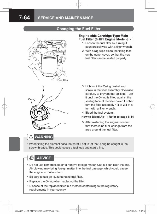
7-64 SERVICE AND MAINTENANCE
Changing the Fuel Filter
Engine-side Cartridge Type Main Fuel Filter (6HH1 Engine Model) V
1. Loosen the fuel filter by turning it counterclockwise with a filter wrench.
2. With a rag wipe clean the fitting face on the upper cover, so that the new fuel filter can be seated properly.
�� � ���� �
3. Lightly oil the O-ring. Install and screw in the filter assembly clockwise carefully to prevent fuel spillage. Turn it until the O-ring is fitted against the sealing face of the filter cover. Further turn the filter assembly 1/3 to 2/3 of a turn with a filter wrench.
4. Bleed the fuel system. How to Bleed Air → Refer to page 8-14
�� ���
5. After restarting the engine, confirm that there is no fuel leakage from the area around the fuel filter.
WARNING
When fitting the element case, be careful not to let the O-ring be caught in the screw threads. This could cause a fuel leak and start a fire.
•
ADVICEDo not use compressed air to remove foreign matter. Use a clean cloth instead. Air blowing may bring foreign matter into the fuel passage, which could cause the engine to malfunction.Be sure to use an Isuzu genuine fuel filter.Replace the O-ring when replacing the filter.Dispose of the replaced filter in a method conforming to the regulatory requirements in your country.
•
•••
4608498_sec07_SERVICE AND MAINTE7-64 7-644608498_sec07_SERVICE AND MAINTE7-64 7-64 2015/11/04 9:59:522015/11/04 9:59:52
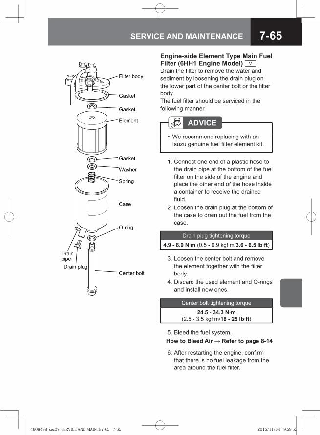
7-65SERVICE AND MAINTENANCE
ADVICEWe recommend replacing with an Isuzu genuine fuel filter element kit.
•
Drain plug tightening torque
4.9 - 8.9 N·m (0.5 - 0.9 kgf·m/3.6 - 6.5 lb·ft)
Engine-side Element Type Main Fuel Filter (6HH1 Engine Model) V
Drain the filter to remove the water and sediment by loosening the drain plug on the lower part of the center bolt or the filter body. The fuel filter should be serviced in the following manner.
1. Connect one end of a plastic hose to the drain pipe at the bottom of the fuel filter on the side of the engine and place the other end of the hose inside a container to receive the drained fluid.
2. Loosen the drain plug at the bottom of the case to drain out the fuel from the case.
3. Loosen the center bolt and remove the element together with the filter body.
4. Discard the used element and O-rings and install new ones.
Center bolt tightening torque
24.5 - 34.3 N·m (2.5 - 3.5 kgf·m/18 - 25 lb·ft)
��� �� ����
�����
�����
������
�����
������
�����
!���
"#���
$��������
$���� ��%
!�� �� ���
6. After restarting the engine, confirm that there is no fuel leakage from the area around the fuel filter.
5. Bleed the fuel system. How to Bleed Air → Refer to page 8-14
4608498_sec07_SERVICE AND MAINTE7-65 7-654608498_sec07_SERVICE AND MAINTE7-65 7-65 2015/11/04 9:59:522015/11/04 9:59:52
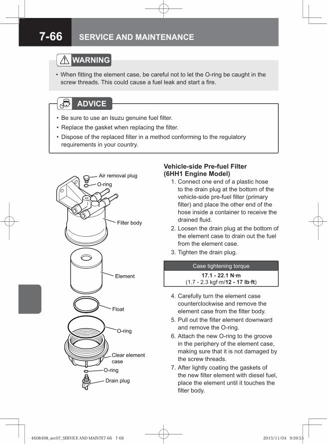
7-66 SERVICE AND MAINTENANCE
Vehicle-side Pre-fuel Filter (6HH1 Engine Model) 1. Connect one end of a plastic hose
to the drain plug at the bottom of the vehicle-side pre-fuel filter (primary filter) and place the other end of the hose inside a container to receive the drained fluid.
2. Loosen the drain plug at the bottom of the element case to drain out the fuel from the element case.
3. Tighten the drain plug.
�� ������� ����
������
������
������
������ ����
�������
�����
����� �������
�!�
"���� ����
4. Carefully turn the element case counterclockwise and remove the element case from the filter body.
5. Pull out the filter element downward and remove the O-ring.
6. Attach the new O-ring to the groove in the periphery of the element case, making sure that it is not damaged by the screw threads.
7. After lightly coating the gaskets of the new filter element with diesel fuel, place the element until it touches the filter body.
Case tightening torque
17.1 - 22.1 N·m (1.7 - 2.3 kgf·m/12 - 17 lb·ft)
WARNING
When fitting the element case, be careful not to let the O-ring be caught in the screw threads. This could cause a fuel leak and start a fire.
•
ADVICEBe sure to use an Isuzu genuine fuel filter.Replace the gasket when replacing the filter.Dispose of the replaced filter in a method conforming to the regulatory requirements in your country.
•••
4608498_sec07_SERVICE AND MAINTE7-66 7-664608498_sec07_SERVICE AND MAINTE7-66 7-66 2015/11/04 9:59:532015/11/04 9:59:53
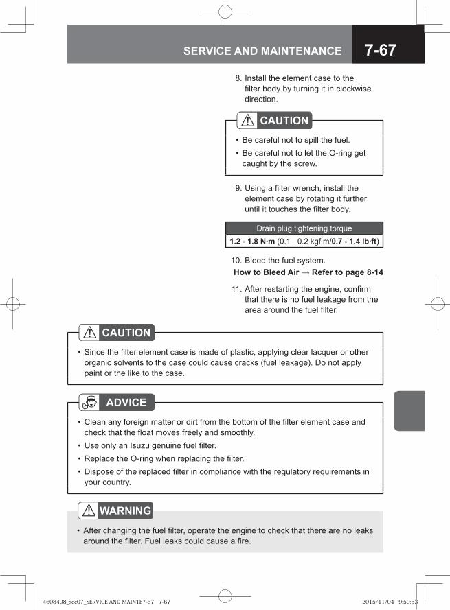
7-67SERVICE AND MAINTENANCE
WARNING
After changing the fuel filter, operate the engine to check that there are no leaks around the filter. Fuel leaks could cause a fire.
•
11. After restarting the engine, confirm that there is no fuel leakage from the area around the fuel filter.
CAUTIONSince the filter element case is made of plastic, applying clear lacquer or other organic solvents to the case could cause cracks (fuel leakage). Do not apply paint or the like to the case.
•
ADVICEClean any foreign matter or dirt from the bottom of the filter element case and check that the float moves freely and smoothly.Use only an Isuzu genuine fuel filter.Replace the O-ring when replacing the filter.Dispose of the replaced filter in compliance with the regulatory requirements in your country.
•
•••
9. Using a filter wrench, install the element case by rotating it further until it touches the filter body.
10. Bleed the fuel system. How to Bleed Air → Refer to page 8-14
Drain plug tightening torque
1.2 - 1.8 N·m (0.1 - 0.2 kgf·m/0.7 - 1.4 lb·ft)
8. Install the element case to the filter body by turning it in clockwise direction.
CAUTIONBe careful not to spill the fuel.Be careful not to let the O-ring get caught by the screw.
••
4608498_sec07_SERVICE AND MAINTE7-67 7-674608498_sec07_SERVICE AND MAINTE7-67 7-67 2015/11/04 9:59:532015/11/04 9:59:53
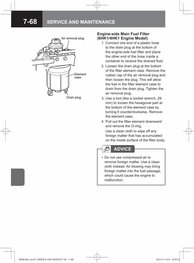
7-68 SERVICE AND MAINTENANCE
ADVICEDo not use compressed air to remove foreign matter. Use a clean cloth instead. Air blowing may bring foreign matter into the fuel passage, which could cause the engine to malfunction.
•
Engine-side Main Fuel Filter (6HK1/4HK1 Engine Model) 1. Connect one end of a plastic hose
to the drain plug at the bottom of the engine-side fuel filter and place the other end of the hose inside a container to receive the drained fluid.
2. Loosen the drain plug at the bottom of the filter element case. Remove the rubber cap of the air removal plug and then loosen the plug. This will allow the fuel in the filter element case to drain from the drain plug. Tighten the air removal plug.
3. Use a tool (like a socket wrench, 29 mm) to loosen the hexagonal part at the bottom of the element case by turning it counterclockwise. Remove the element case.
4. Pull out the filter element downward and remove the O-ring.
Use a clean cloth to wipe off any foreign matter that has accumulated on the inside surface of the filter body.
� � ������� ����
�����������
��� � ����
4608498_sec07_SERVICE AND MAINTE7-68 7-684608498_sec07_SERVICE AND MAINTE7-68 7-68 2015/11/04 9:59:532015/11/04 9:59:53
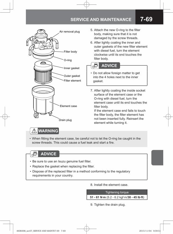
7-69SERVICE AND MAINTENANCE
5. Attach the new O-ring to the filter body, making sure that it is not damaged by the screw threads.
6. After lightly coating the inner and outer gaskets of the new filter element with diesel fuel, turn the element clockwise until its end touches the filter body.
WARNING
When fitting the element case, be careful not to let the O-ring be caught in the screw threads. This could cause a fuel leak and start a fire.
•
7. After lightly coating the inside socket surface of the element case or the O-ring with diesel fuel, turn the element case until its end touches the filter body.If the element case end fails to touch the filter body, the filter element has not been inserted fully. Reinsert the element while turning it.
ADVICEDo not allow foreign matter to get into the 4 holes next to the inner gasket.
•
ADVICEBe sure to use an Isuzu genuine fuel filter.Replace the gasket when replacing the filter.Dispose of the replaced filter in a method conforming to the regulatory requirements in your country.
•••
�� ������� ����
������ ����
������
����� ��� ��
����� ��� ��
������ �������
!������ "���
#���� ����
8. Install the element case.
Tightening torque
51 - 61 N·m (5.2 - 6.2 kgf·m/38 - 45 lb·ft)
9. Tighten the drain plug.
4608498_sec07_SERVICE AND MAINTE7-69 7-694608498_sec07_SERVICE AND MAINTE7-69 7-69 2015/11/04 9:59:542015/11/04 9:59:54
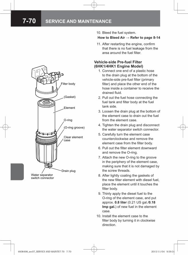
7-70 SERVICE AND MAINTENANCE
10. Bleed the fuel system. How to Bleed Air → Refer to page 8-14
Vehicle-side Pre-fuel Filter (6HK1/4HK1 Engine Model) 1. Connect one end of a plastic hose
to the drain plug at the bottom of the vehicle-side pre-fuel filter (primary filter) and place the other end of the hose inside a container to receive the drained fluid.
2. Pull out the fuel hose connecting the fuel tank and filter body at the fuel tank side.
3. Loosen the drain plug at the bottom of the element case to drain out the fuel from the element case.
4. Tighten the drain plug and disconnect the water separator switch connector.
5. Carefully turn the element case counterclockwise and remove the element case from the filter body.
6. Pull out the filter element downward and remove the O-ring.
7. Attach the new O-ring to the groove in the periphery of the element case, making sure that it is not damaged by the screw threads.
8. After lightly coating the gaskets of the new filter element with diesel fuel, place the element until it touches the filter body.
9. Thinly apply the diesel fuel to the O-ring of the element case, and put approx. 0.8 liter (0.21 US gal./0.18 Imp gal.) of new fuel in the element case.
10. Install the element case to the filter body by turning it in clockwise direction.
��� ����
��������
������
�� ��
��� �� � �����
�� ������!���
"��� ��#� ��� �$�!% !����!��
& �� #'�
11. After restarting the engine, confirm that there is no fuel leakage from the area around the fuel filter.
4608498_sec07_SERVICE AND MAINTE7-70 7-704608498_sec07_SERVICE AND MAINTE7-70 7-70 2015/11/04 9:59:542015/11/04 9:59:54
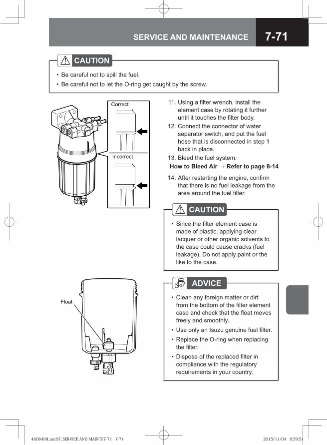
7-71SERVICE AND MAINTENANCE
14. After restarting the engine, confirm that there is no fuel leakage from the area around the fuel filter.
CAUTIONSince the filter element case is made of plastic, applying clear lacquer or other organic solvents to the case could cause cracks (fuel leakage). Do not apply paint or the like to the case.
•
ADVICEClean any foreign matter or dirt from the bottom of the filter element case and check that the float moves freely and smoothly.Use only an Isuzu genuine fuel filter.Replace the O-ring when replacing the filter.Dispose of the replaced filter in compliance with the regulatory requirements in your country.
•
••
•
Float
11. Using a filter wrench, install the element case by rotating it further until it touches the filter body.
12. Connect the connector of water separator switch, and put the fuel hose that is disconnected in step 1 back in place.
13. Bleed the fuel system. How to Bleed Air → Refer to page 8-14
�� ���
���� ���
CAUTIONBe careful not to spill the fuel.Be careful not to let the O-ring get caught by the screw.
••
4608498_sec07_SERVICE AND MAINTE7-71 7-714608498_sec07_SERVICE AND MAINTE7-71 7-71 2015/11/04 9:59:542015/11/04 9:59:54
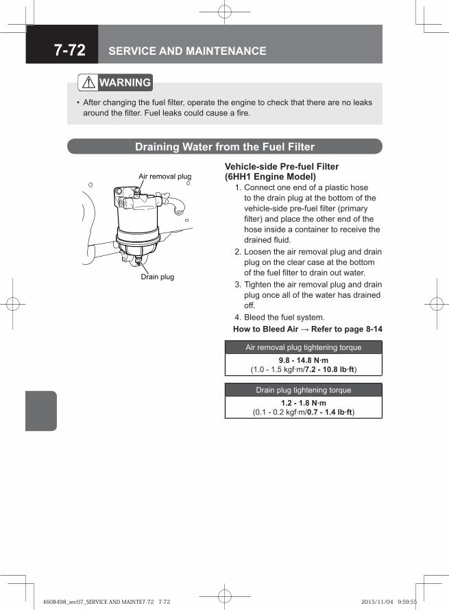
7-72 SERVICE AND MAINTENANCE
WARNING
After changing the fuel filter, operate the engine to check that there are no leaks around the filter. Fuel leaks could cause a fire.
•
Draining Water from the Fuel Filter
Vehicle-side Pre-fuel Filter (6HH1 Engine Model) 1. Connect one end of a plastic hose
to the drain plug at the bottom of the vehicle-side pre-fuel filter (primary filter) and place the other end of the hose inside a container to receive the drained fluid.
2. Loosen the air removal plug and drain plug on the clear case at the bottom of the fuel filter to drain out water.
3. Tighten the air removal plug and drain plug once all of the water has drained off.
4. Bleed the fuel system. How to Bleed Air → Refer to page 8-14
� ��� ����
�� ������ ����
Air removal plug tightening torque
9.8 - 14.8 N·m (1.0 - 1.5 kgf·m/7.2 - 10.8 lb·ft)
Drain plug tightening torque
1.2 - 1.8 N·m (0.1 - 0.2 kgf·m/0.7 - 1.4 lb·ft)
4608498_sec07_SERVICE AND MAINTE7-72 7-724608498_sec07_SERVICE AND MAINTE7-72 7-72 2015/11/04 9:59:552015/11/04 9:59:55
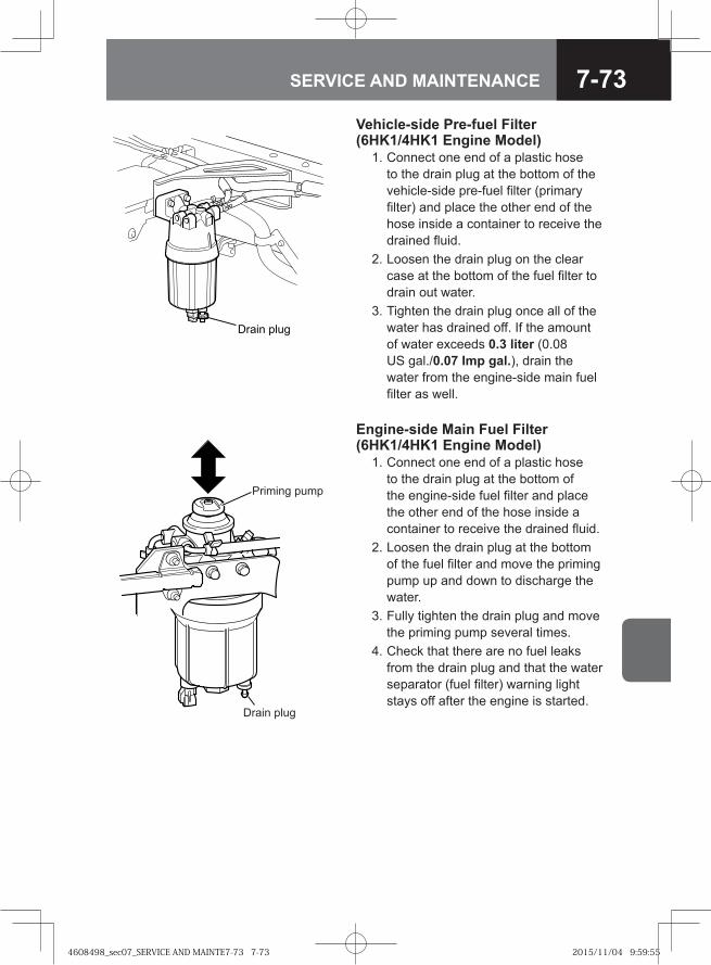
7-73SERVICE AND MAINTENANCE
Priming pump
Drain plug
Engine-side Main Fuel Filter (6HK1/4HK1 Engine Model) 1. Connect one end of a plastic hose
to the drain plug at the bottom of the engine-side fuel filter and place the other end of the hose inside a container to receive the drained fluid.
2. Loosen the drain plug at the bottom of the fuel filter and move the priming pump up and down to discharge the water.
3. Fully tighten the drain plug and move the priming pump several times.
4. Check that there are no fuel leaks from the drain plug and that the water separator (fuel filter) warning light stays off after the engine is started.
Vehicle-side Pre-fuel Filter (6HK1/4HK1 Engine Model) 1. Connect one end of a plastic hose
to the drain plug at the bottom of the vehicle-side pre-fuel filter (primary filter) and place the other end of the hose inside a container to receive the drained fluid.
2. Loosen the drain plug on the clear case at the bottom of the fuel filter to drain out water.
3. Tighten the drain plug once all of the water has drained off. If the amount of water exceeds 0.3 liter (0.08 US gal./0.07 Imp gal.), drain the water from the engine-side main fuel filter as well.
�� �� ����
4608498_sec07_SERVICE AND MAINTE7-73 7-734608498_sec07_SERVICE AND MAINTE7-73 7-73 2015/11/04 9:59:552015/11/04 9:59:55
7-74 SERVICE AND MAINTENANCE
CAUTIONClean off any fuel that has adhered to the vehicle body.Starting the engine immediately after draining the water from the fuel filter requires a little more time than usual. If the engine doesn't start in 10 seconds, wait for a while and try again.Fuel will be mixed in the drained water. Dispose of it in a method conforming to the regulatory requirements in your country.
••
•
4608498_sec07_SERVICE AND MAINTE7-74 7-744608498_sec07_SERVICE AND MAINTE7-74 7-74 2015/11/04 9:59:552015/11/04 9:59:55
7-75SERVICE AND MAINTENANCE
● Brakes 7-76
● Parking Brake 7-84
● Drum Brakes 7-88
● Wheels and Tires 7-92
● Tire Rotation 7-98
● Preparation for Changing a Tire 7-100
● Changing a Tire (JIS 6-Bolt or 8-Bolt Wheels) V 7-101
● Changing a Tire (ISO 10-Bolt Wheels) V 7-110
● Spare Tire V 7-117
● Checking Axle Shaft Bolts 7-119
● Air Tanks 7-119
● Air Dryer V 7-121
● Clutch Fluid M/T 7-121
● Clutch M/T 7-124
● Manual Transmission Oil M/T / SA 7-129
● ALLISON2500 Model Transmission Fluid V 7-140
● ALLISON3000/3500 Model Transmission Fluid V 7-144
● Smoother Clutch Oil SA 7-153
● Rear Axle Differential Gear Oil 7-156
● Front Axle Differential Gear Oil V 7-159
● Transfer Gear Case Oil V 7-163
● Power Steering Fluid 7-166
● Power Steering Fluid Filter 7-169
● Steering Wheel 7-170
● Fuel Tank 7-171
● Greasing Chassis Components 7-172
CHASSIS-RELATED SERVICE AND MAINTENANCE
4608498_sec07_SERVICE AND MAINTE7-75 7-754608498_sec07_SERVICE AND MAINTE7-75 7-75 2015/11/02 14:20:392015/11/02 14:20:39
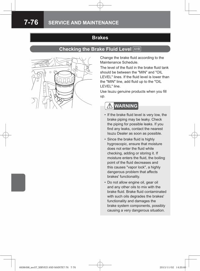
7-76 SERVICE AND MAINTENANCE
Change the brake fluid according to the Maintenance Schedule.The level of the fluid in the brake fluid tank should be between the "MIN" and "OIL LEVEL" lines. If the fluid level is lower than the "MIN" line, add fluid up to the "OIL LEVEL" line.Use Isuzu genuine products when you fill up.
Brakes
WARNING
If the brake fluid level is very low, the brake piping may be leaky. Check the piping for possible leaks. If you find any leaks, contact the nearest Isuzu Dealer as soon as possible.Since the brake fluid is highly hygroscopic, ensure that moisture does not enter the fluid while checking, adding or storing it. If moisture enters the fluid, the boiling point of the fluid decreases and this causes "vapor lock", a highly dangerous problem that affects brakes' functionality.Do not allow engine oil, gear oil and any other oils to mix with the brake fluid. Brake fluid contaminated with such oils degrades the brakes' functionality and damages the brake system components, possibly causing a very dangerous situation.
•
•
•
Checking the Brake Fluid Level AHB
4608498_sec07_SERVICE AND MAINTE7-76 7-764608498_sec07_SERVICE AND MAINTE7-76 7-76 2015/11/02 14:20:402015/11/02 14:20:40
7-77SERVICE AND MAINTENANCE
ADVICEBrake fluid melts paintwork and vehicle component materials such as plastic, vinyl and rubber. It is also highly corrosive for metals. If it is spilled, wipe it off the affected surface immediately and wash the affected surface fully in water.
•
Bleeding the Brake Hydraulic System AHB
If air is present in the brake hydraulic system, it adversely affects the brake operation. Bleed the system if the brakes are used when the quantity of the brake fluid in the tank is extremely low or the brake piping is removed during maintenance operation. Do not perform bleeding by yourself; it should be done with the help of another person.
WARNING
Since the brake fluid is highly hygroscopic, ensure that moisture does not enter the fluid while checking, adding or storing it. If moisture enters the fluid, the boiling point of the fluid decreases and this causes "vapor lock", a highly dangerous problem that affects brakes' functionality.Do not allow engine oil, gear oil and any other oils to mix with the brake fluid. Brake fluid contaminated with such oils degrades the brakes' functionality and damages the brake system components, possibly causing a very dangerous situation.
•
•
CAUTIONBrake fluid melts paintwork and vehicle component materials such as plastic, vinyl and rubber. It is also highly corrosive for metals. If it is spilled, wipe it off the affected surface immediately and wash the affected surface fully in water.
•
Maintenance Schedule → Refer to page 7-217
4608498_sec07_SERVICE AND MAINTE7-77 7-774608498_sec07_SERVICE AND MAINTE7-77 7-77 2015/11/02 14:20:402015/11/02 14:20:40
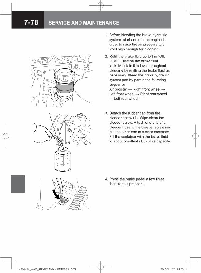
7-78 SERVICE AND MAINTENANCE
3. Detach the rubber cap from the bleeder screw (1). Wipe clean the bleeder screw. Attach one end of a bleeder hose to the bleeder screw and put the other end in a clear container. Fill the container with the brake fluid to about one-third (1/3) of its capacity.
4. Press the brake pedal a few times, then keep it pressed.
2. Refill the brake fluid up to the "OIL LEVEL" line on the brake fluid tank. Maintain this level throughout bleeding by refilling the brake fluid as necessary. Bleed the brake hydraulic system part by part in the following sequence:Air booster → Right front wheel → Left front wheel → Right rear wheel → Left rear wheel
1. Before bleeding the brake hydraulic system, start and run the engine in order to raise the air pressure to a level high enough for bleeding.
4608498_sec07_SERVICE AND MAINTE7-78 7-784608498_sec07_SERVICE AND MAINTE7-78 7-78 2015/11/02 14:20:412015/11/02 14:20:41
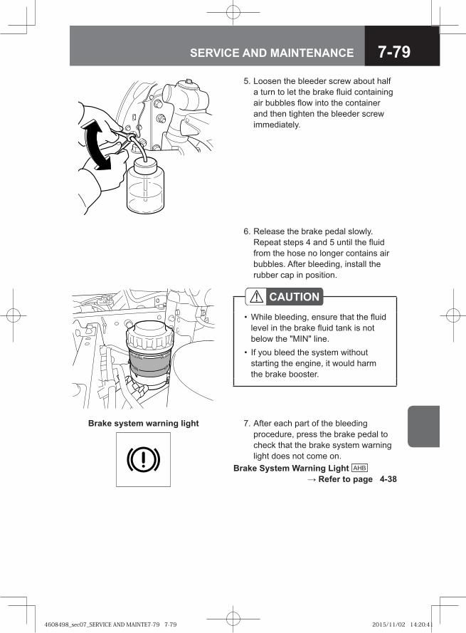
7-79SERVICE AND MAINTENANCE
6. Release the brake pedal slowly. Repeat steps 4 and 5 until the fluid from the hose no longer contains air bubbles. After bleeding, install the rubber cap in position.
CAUTIONWhile bleeding, ensure that the fluid level in the brake fluid tank is not below the "MIN" line.If you bleed the system without starting the engine, it would harm the brake booster.
•
•
7. After each part of the bleeding procedure, press the brake pedal to check that the brake system warning light does not come on.
Brake System Warning Light AHB → Refer to page 4-38
5. Loosen the bleeder screw about half a turn to let the brake fluid containing air bubbles flow into the container and then tighten the bleeder screw immediately.
Brake system warning light
4608498_sec07_SERVICE AND MAINTE7-79 7-794608498_sec07_SERVICE AND MAINTE7-79 7-79 2015/11/02 14:20:412015/11/02 14:20:41
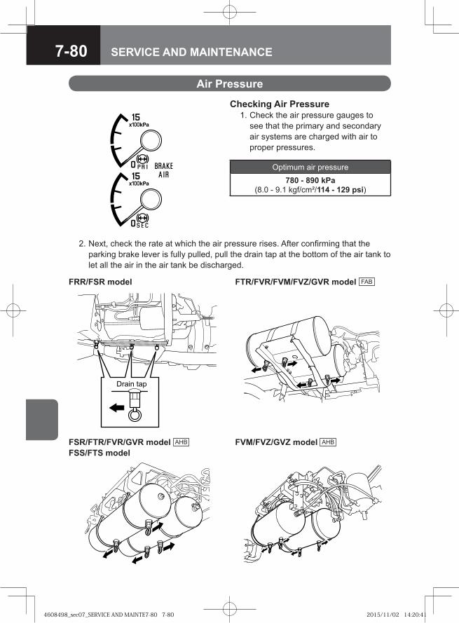
7-80 SERVICE AND MAINTENANCE
Air Pressure
Checking Air Pressure 1. Check the air pressure gauges to
see that the primary and secondary air systems are charged with air to proper pressures.
Optimum air pressure
780 - 890 kPa (8.0 - 9.1 kgf/cm²/114 - 129 psi)
2. Next, check the rate at which the air pressure rises. After confirming that the parking brake lever is fully pulled, pull the drain tap at the bottom of the air tank to let all the air in the air tank be discharged.
FRR/FSR model FTR/FVR/FVM/FVZ/GVR model FAB
� ��� ���
FSR/FTR/FVR/GVR model AHB FSS/FTS model
FVM/FVZ/GVZ model AHB
4608498_sec07_SERVICE AND MAINTE7-80 7-804608498_sec07_SERVICE AND MAINTE7-80 7-80 2015/11/02 14:20:412015/11/02 14:20:41
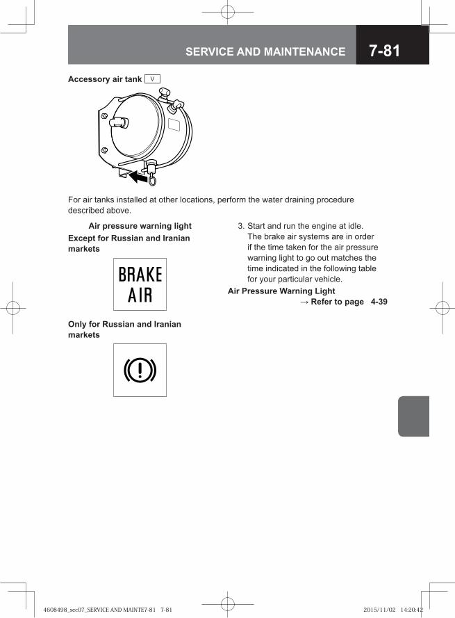
7-81SERVICE AND MAINTENANCE
Accessory air tank V
3. Start and run the engine at idle. The brake air systems are in order if the time taken for the air pressure warning light to go out matches the time indicated in the following table for your particular vehicle.
Air Pressure Warning Light → Refer to page 4-39
Air pressure warning lightExcept for Russian and Iranian markets
Only for Russian and Iranian markets
For air tanks installed at other locations, perform the water draining procedure described above.
4608498_sec07_SERVICE AND MAINTE7-81 7-814608498_sec07_SERVICE AND MAINTE7-81 7-81 2015/11/02 14:20:422015/11/02 14:20:42
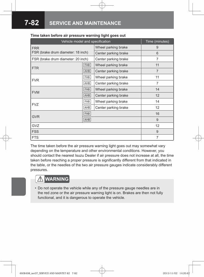
7-82 SERVICE AND MAINTENANCE
The time taken before the air pressure warning light goes out may somewhat vary depending on the temperature and other environmental conditions. However, you should contact the nearest Isuzu Dealer if air pressure does not increase at all, the time taken before reaching a proper pressure is significantly different from that indicated in the table, or the needles of the two air pressure gauges indicate considerably different pressures.
WARNING
Do not operate the vehicle while any of the pressure gauge needles are in the red zone or the air pressure warning light is on. Brakes are then not fully functional, and it is dangerous to operate the vehicle.
•
Vehicle model and specification Time (minutes)
FRRFSR (brake drum diameter: 18 inch)
Wheel parking brake 9
Center parking brake 6
FSR (brake drum diameter: 20 inch) Center parking brake 7
FTRFAB Wheel parking brake 11AHB Center parking brake 7
FVRFAB Wheel parking brake 11AHB Center parking brake 7
FVMFAB Wheel parking brake 14AHB Center parking brake 12
FVZFAB Wheel parking brake 14AHB Center parking brake 12
GVRFAB 16AHB 9
GVZ 12
FSS 9
FTS 7
Time taken before air pressure warning light goes out
4608498_sec07_SERVICE AND MAINTE7-82 7-824608498_sec07_SERVICE AND MAINTE7-82 7-82 2015/11/02 14:20:422015/11/02 14:20:42
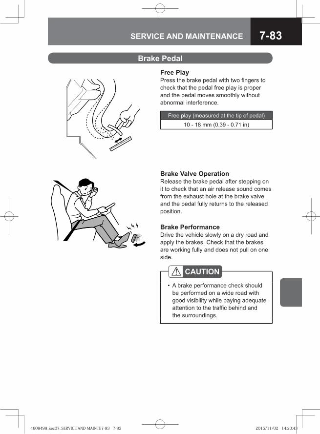
7-83SERVICE AND MAINTENANCE
Brake Pedal
Free PlayPress the brake pedal with two fingers to check that the pedal free play is proper and the pedal moves smoothly without abnormal interference.
Free play (measured at the tip of pedal)
10 - 18 mm (0.39 - 0.71 in)
Brake Valve OperationRelease the brake pedal after stepping on it to check that an air release sound comes from the exhaust hole at the brake valve and the pedal fully returns to the released position.
Brake PerformanceDrive the vehicle slowly on a dry road and apply the brakes. Check that the brakes are working fully and does not pull on one side.
CAUTIONA brake performance check should be performed on a wide road with good visibility while paying adequate attention to the traffic behind and the surroundings.
•
4608498_sec07_SERVICE AND MAINTE7-83 7-834608498_sec07_SERVICE AND MAINTE7-83 7-83 2015/11/02 14:20:432015/11/02 14:20:43
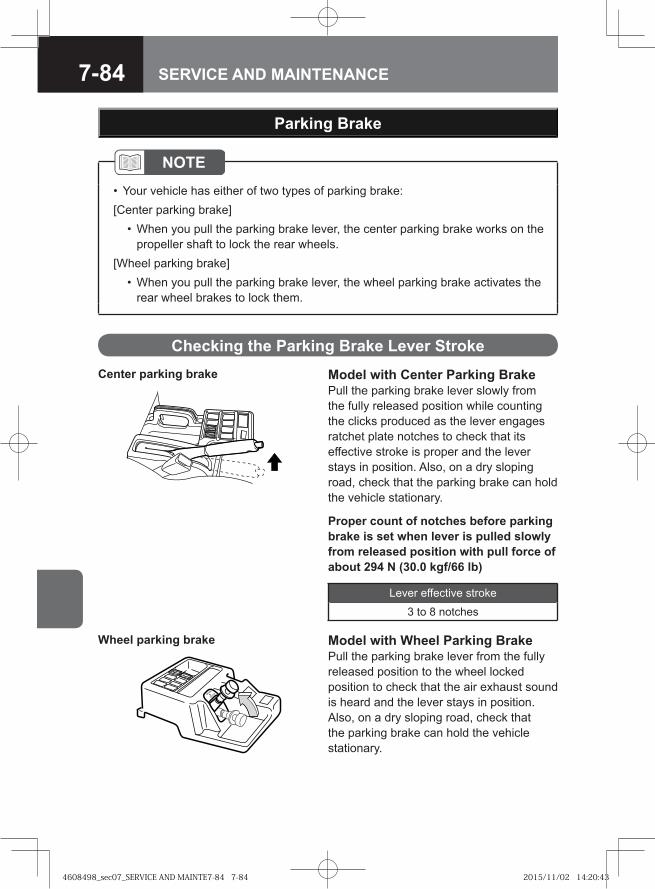
7-84 SERVICE AND MAINTENANCE
Parking Brake
Model with Center Parking BrakePull the parking brake lever slowly from the fully released position while counting the clicks produced as the lever engages ratchet plate notches to check that its effective stroke is proper and the lever stays in position. Also, on a dry sloping road, check that the parking brake can hold the vehicle stationary.
NOTEYour vehicle has either of two types of parking brake:
[Center parking brake]When you pull the parking brake lever, the center parking brake works on the propeller shaft to lock the rear wheels.
[Wheel parking brake]When you pull the parking brake lever, the wheel parking brake activates the rear wheel brakes to lock them.
•
•
•
Model with Wheel Parking BrakePull the parking brake lever from the fully released position to the wheel locked position to check that the air exhaust sound is heard and the lever stays in position. Also, on a dry sloping road, check that the parking brake can hold the vehicle stationary.
Lever effective stroke
3 to 8 notches
Center parking brake
Wheel parking brake
Checking the Parking Brake Lever Stroke
Proper count of notches before parking brake is set when lever is pulled slowly from released position with pull force of about 294 N (30.0 kgf/66 lb)
4608498_sec07_SERVICE AND MAINTE7-84 7-844608498_sec07_SERVICE AND MAINTE7-84 7-84 2015/11/02 14:20:432015/11/02 14:20:43
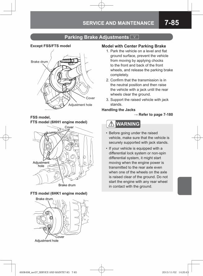
7-85SERVICE AND MAINTENANCE
Parking Brake Adjustments V
Model with Center Parking Brake 1. Park the vehicle on a level and flat
ground surface, prevent the vehicle from moving by applying chocks to the front and back of the front wheels, and release the parking brake completely.
2. Confirm that the transmission is in the neutral position and then raise the vehicle with a jack until the rear wheels clear the ground.
3. Support the raised vehicle with jack stands.
Handling the Jacks → Refer to page 7-180
WARNING
Before going under the raised vehicle, make sure that the vehicle is securely supported with jack stands.If your vehicle is equipped with a differential lock system or non-spin differential system, it might start moving when the engine power is transmitted to the rear axle even when one of the wheels on the axle is raised clear of the ground. Do not start the engine with any rear wheel in contact with the ground.
•
•
Adjustment hole
Cover
Brake drum
Except FSS/FTS model
� ��� � ��
����
��������������
FSS model, FTS model (6HH1 engine model)
� ��� � ��
���� ���������� ����
FTS model (6HK1 engine model)
4608498_sec07_SERVICE AND MAINTE7-85 7-854608498_sec07_SERVICE AND MAINTE7-85 7-85 2015/11/02 14:20:432015/11/02 14:20:43
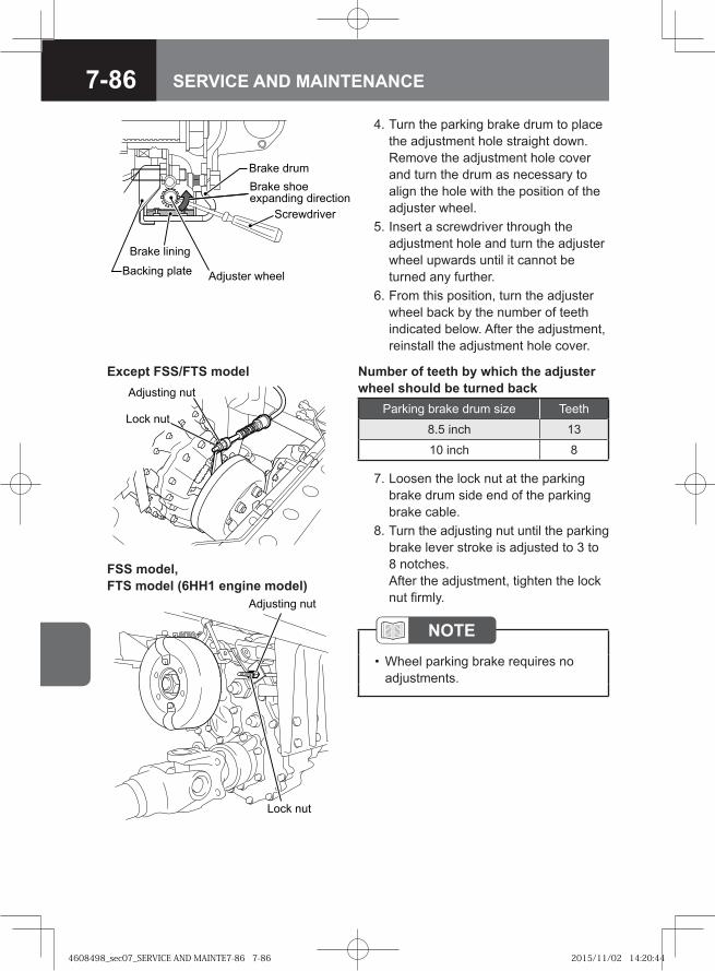
7-86 SERVICE AND MAINTENANCE
4. Turn the parking brake drum to place the adjustment hole straight down. Remove the adjustment hole cover and turn the drum as necessary to align the hole with the position of the adjuster wheel.
5. Insert a screwdriver through the adjustment hole and turn the adjuster wheel upwards until it cannot be turned any further.
6. From this position, turn the adjuster wheel back by the number of teeth indicated below. After the adjustment, reinstall the adjustment hole cover.
Backing plate
Brake lining
Brake shoe expanding direction
Screwdriver
Brake drum
Adjuster wheel
7. Loosen the lock nut at the parking brake drum side end of the parking brake cable.
8. Turn the adjusting nut until the parking brake lever stroke is adjusted to 3 to 8 notches.After the adjustment, tighten the lock nut firmly.
NOTEWheel parking brake requires no adjustments.
•
� �� ���
��������� ���
Except FSS/FTS model
Parking brake drum size Teeth
8.5 inch 13
10 inch 8
Number of teeth by which the adjuster wheel should be turned back
�� � ���
��������� ���
FSS model, FTS model (6HH1 engine model)
4608498_sec07_SERVICE AND MAINTE7-86 7-864608498_sec07_SERVICE AND MAINTE7-86 7-86 2015/11/02 14:20:442015/11/02 14:20:44
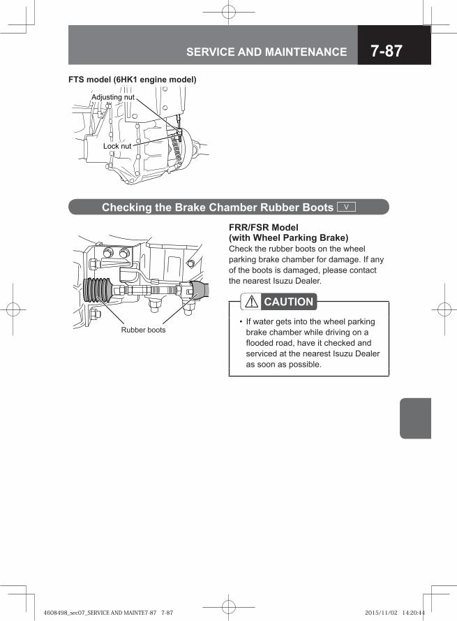
7-87SERVICE AND MAINTENANCE
FRR/FSR Model (with Wheel Parking Brake)Check the rubber boots on the wheel parking brake chamber for damage. If any of the boots is damaged, please contact the nearest Isuzu Dealer.
Rubber boots
CAUTIONIf water gets into the wheel parking brake chamber while driving on a flooded road, have it checked and serviced at the nearest Isuzu Dealer as soon as possible.
•
Checking the Brake Chamber Rubber Boots V
FTS model (6HK1 engine model)
� ������� ���
���� ���
4608498_sec07_SERVICE AND MAINTE7-87 7-874608498_sec07_SERVICE AND MAINTE7-87 7-87 2015/11/02 14:20:442015/11/02 14:20:44
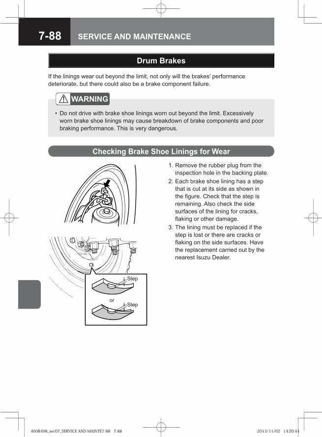
7-88 SERVICE AND MAINTENANCE
Drum Brakes
If the linings wear out beyond the limit, not only will the brakes' performance deteriorate, but there could also be a brake component failure.
WARNING
Do not drive with brake shoe linings worn out beyond the limit. Excessively worn brake shoe linings may cause breakdown of brake components and poor braking performance. This is very dangerous.
•
Checking Brake Shoe Linings for Wear 1. Remove the rubber plug from the
inspection hole in the backing plate. 2. Each brake shoe lining has a step
that is cut at its side as shown in the figure. Check that the step is remaining. Also check the side surfaces of the lining for cracks, flaking or other damage.
3. The lining must be replaced if the step is lost or there are cracks or flaking on the side surfaces. Have the replacement carried out by the nearest Isuzu Dealer.
or
Step
Step
4608498_sec07_SERVICE AND MAINTE7-88 7-884608498_sec07_SERVICE AND MAINTE7-88 7-88 2015/11/02 14:20:442015/11/02 14:20:44
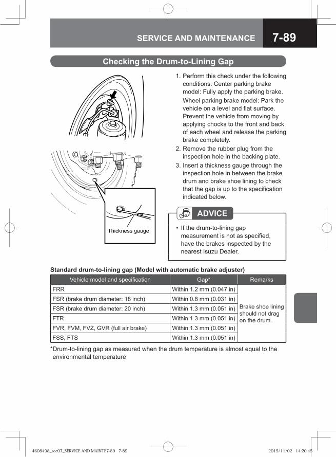
7-89SERVICE AND MAINTENANCE
Checking the Drum-to-Lining Gap 1. Perform this check under the following
conditions: Center parking brake model: Fully apply the parking brake.
Wheel parking brake model: Park the vehicle on a level and flat surface. Prevent the vehicle from moving by applying chocks to the front and back of each wheel and release the parking brake completely.
2. Remove the rubber plug from the inspection hole in the backing plate.
3. Insert a thickness gauge through the inspection hole in between the brake drum and brake shoe lining to check that the gap is up to the specification indicated below.
ADVICEIf the drum-to-lining gap measurement is not as specified, have the brakes inspected by the nearest Isuzu Dealer.
•
Vehicle model and specification Gap* Remarks
FRR Within 1.2 mm (0.047 in)
Brake shoe lining should not drag on the drum.
FSR (brake drum diameter: 18 inch) Within 0.8 mm (0.031 in)
FSR (brake drum diameter: 20 inch) Within 1.3 mm (0.051 in)
FTR Within 1.3 mm (0.051 in)
FVR, FVM, FVZ, GVR (full air brake) Within 1.3 mm (0.051 in)
FSS, FTS Within 1.3 mm (0.051 in)
* Drum-to-lining gap as measured when the drum temperature is almost equal to the environmental temperature
Standard drum-to-lining gap (Model with automatic brake adjuster)
Thickness gauge
4608498_sec07_SERVICE AND MAINTE7-89 7-894608498_sec07_SERVICE AND MAINTE7-89 7-89 2015/11/02 14:20:452015/11/02 14:20:45
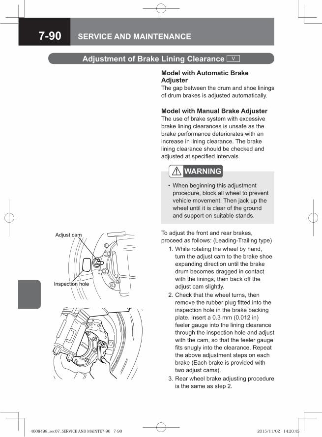
7-90 SERVICE AND MAINTENANCE
Model with Automatic Brake AdjusterThe gap between the drum and shoe linings of drum brakes is adjusted automatically.
Adjustment of Brake Lining Clearance V
WARNING
When beginning this adjustment procedure, block all wheel to prevent vehicle movement. Then jack up the wheel until it is clear of the ground and support on suitable stands.
•
Model with Manual Brake Adjuster The use of brake system with excessive brake lining clearances is unsafe as the brake performance deteriorates with an increase in lining clearance. The brake lining clearance should be checked and adjusted at specified intervals.
To adjust the front and rear brakes, proceed as follows: (Leading-Trailing type) 1. While rotating the wheel by hand,
turn the adjust cam to the brake shoe expanding direction until the brake drum becomes dragged in contact with the linings, then back off the adjust cam slightly.
2. Check that the wheel turns, then remove the rubber plug fitted into the inspection hole in the brake backing plate. Insert a 0.3 mm (0.012 in) feeler gauge into the lining clearance through the inspection hole and adjust with the cam, so that the feeler gauge fits snugly into the clearance. Repeat the above adjustment steps on each brake (Each brake is provided with two adjust cams).
3. Rear wheel brake adjusting procedure is the same as step 2.
�� ��� ���
���������� ����
4608498_sec07_SERVICE AND MAINTE7-90 7-904608498_sec07_SERVICE AND MAINTE7-90 7-90 2015/11/02 14:20:452015/11/02 14:20:45
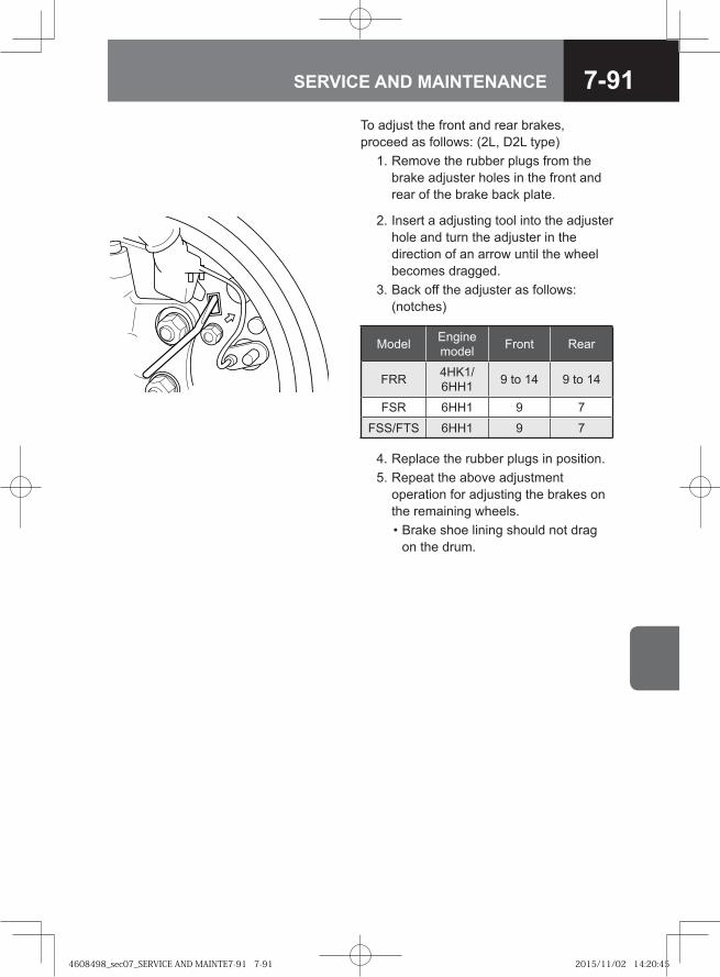
7-91SERVICE AND MAINTENANCE
To adjust the front and rear brakes, proceed as follows: (2L, D2L type) 1. Remove the rubber plugs from the
brake adjuster holes in the front and rear of the brake back plate.
2. Insert a adjusting tool into the adjuster hole and turn the adjuster in the direction of an arrow until the wheel becomes dragged.
3. Back off the adjuster as follows: (notches)
4. Replace the rubber plugs in position. 5. Repeat the above adjustment
operation for adjusting the brakes on the remaining wheels.
• Brake shoe lining should not drag on the drum.
Model Engine model Front Rear
FRR 4HK1/6HH1 9 to 14 9 to 14
FSR 6HH1 9 7
FSS/FTS 6HH1 9 7
4608498_sec07_SERVICE AND MAINTE7-91 7-914608498_sec07_SERVICE AND MAINTE7-91 7-91 2015/11/02 14:20:452015/11/02 14:20:45
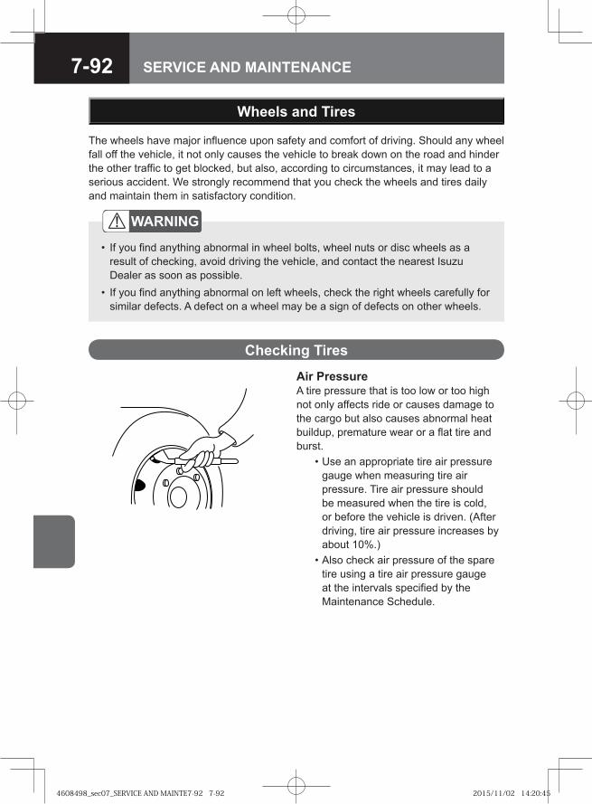
7-92 SERVICE AND MAINTENANCE
Wheels and Tires
Checking Tires
Air PressureA tire pressure that is too low or too high not only affects ride or causes damage to the cargo but also causes abnormal heat buildup, premature wear or a flat tire and burst. • Use an appropriate tire air pressure
gauge when measuring tire air pressure. Tire air pressure should be measured when the tire is cold, or before the vehicle is driven. (After driving, tire air pressure increases by about 10%.)
• Also check air pressure of the spare tire using a tire air pressure gauge at the intervals specified by the Maintenance Schedule.
The wheels have major influence upon safety and comfort of driving. Should any wheel fall off the vehicle, it not only causes the vehicle to break down on the road and hinder the other traffic to get blocked, but also, according to circumstances, it may lead to a serious accident. We strongly recommend that you check the wheels and tires daily and maintain them in satisfactory condition.
WARNING
If you find anything abnormal in wheel bolts, wheel nuts or disc wheels as a result of checking, avoid driving the vehicle, and contact the nearest Isuzu Dealer as soon as possible.If you find anything abnormal on left wheels, check the right wheels carefully for similar defects. A defect on a wheel may be a sign of defects on other wheels.
•
•
4608498_sec07_SERVICE AND MAINTE7-92 7-924608498_sec07_SERVICE AND MAINTE7-92 7-92 2015/11/02 14:20:452015/11/02 14:20:45
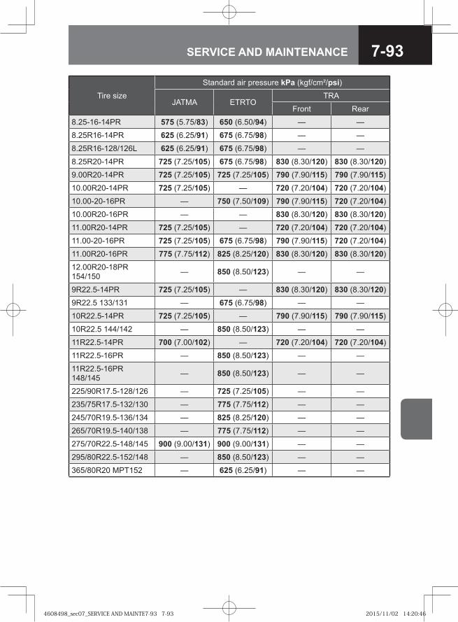
7-93SERVICE AND MAINTENANCE
Tire size
Standard air pressure kPa (kgf/cm²/psi)
JATMA ETRTOTRA
Front Rear
8.25-16-14PR 575 (5.75/83) 650 (6.50/94) — —
8.25R16-14PR 625 (6.25/91) 675 (6.75/98) — —
8.25R16-128/126L 625 (6.25/91) 675 (6.75/98) — —
8.25R20-14PR 725 (7.25/105) 675 (6.75/98) 830 (8.30/120) 830 (8.30/120)
9.00R20-14PR 725 (7.25/105) 725 (7.25/105) 790 (7.90/115) 790 (7.90/115)
10.00R20-14PR 725 (7.25/105) — 720 (7.20/104) 720 (7.20/104)
10.00-20-16PR — 750 (7.50/109) 790 (7.90/115) 720 (7.20/104)
10.00R20-16PR — — 830 (8.30/120) 830 (8.30/120)
11.00R20-14PR 725 (7.25/105) — 720 (7.20/104) 720 (7.20/104)
11.00-20-16PR 725 (7.25/105) 675 (6.75/98) 790 (7.90/115) 720 (7.20/104)
11.00R20-16PR 775 (7.75/112) 825 (8.25/120) 830 (8.30/120) 830 (8.30/120)
12.00R20-18PR 154/150 — 850 (8.50/123) — —
9R22.5-14PR 725 (7.25/105) — 830 (8.30/120) 830 (8.30/120)
9R22.5 133/131 — 675 (6.75/98) — —
10R22.5-14PR 725 (7.25/105) — 790 (7.90/115) 790 (7.90/115)
10R22.5 144/142 — 850 (8.50/123) — —
11R22.5-14PR 700 (7.00/102) — 720 (7.20/104) 720 (7.20/104)
11R22.5-16PR — 850 (8.50/123) — —
11R22.5-16PR 148/145 — 850 (8.50/123) — —
225/90R17.5-128/126 — 725 (7.25/105) — —
235/75R17.5-132/130 — 775 (7.75/112) — —
245/70R19.5-136/134 — 825 (8.25/120) — —
265/70R19.5-140/138 — 775 (7.75/112) — —
275/70R22.5-148/145 900 (9.00/131) 900 (9.00/131) — —
295/80R22.5-152/148 — 850 (8.50/123) — —
365/80R20 MPT152 — 625 (6.25/91) — —
4608498_sec07_SERVICE AND MAINTE7-93 7-934608498_sec07_SERVICE AND MAINTE7-93 7-93 2015/11/02 14:20:462015/11/02 14:20:46
7-94 SERVICE AND MAINTENANCE
CAUTIONOver-inflated tires result in harsh ride and are likely to cause damage to the cargo. Under-inflated tires build up heat and could burst. Always keep the tires of your vehicle inflated to the standard air pressures.
•
ADVICEThere should not be a difference in air pressure between the inside and outside tires on a dual-tire rear wheel.It is not easy to identify an under-inflated dual-wheel tire or low aspect ratio tire (aspect ratio at 70%). Always use a tire air pressure gauge to check the air pressure of any tire.
•
•
WARNING
Insufficiently inflated or worn-out tires are highly dangerous as they easily skid and can even burst. Should they burst, the tires may burn and this could cause a fire in the vehicle.If you drive on under-inflated or flat tires, the wheel bolts will be placed under excessive stress. Under this condition, the bolts may break and the wheel may come off the vehicle, possibly causing an accident.
•
•
4608498_sec07_SERVICE AND MAINTE7-94 7-944608498_sec07_SERVICE AND MAINTE7-94 7-94 2015/11/02 14:20:462015/11/02 14:20:46
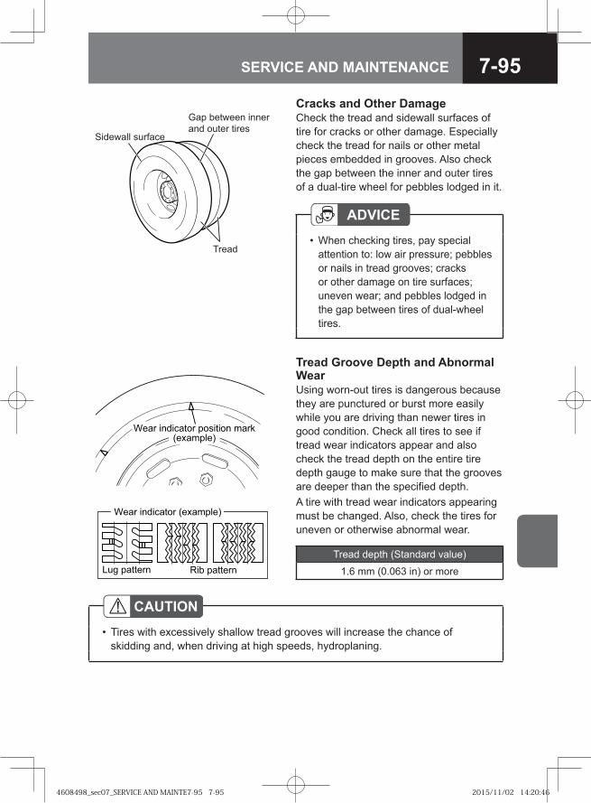
7-95SERVICE AND MAINTENANCE
Cracks and Other DamageCheck the tread and sidewall surfaces of tire for cracks or other damage. Especially check the tread for nails or other metal pieces embedded in grooves. Also check the gap between the inner and outer tires of a dual-tire wheel for pebbles lodged in it.
Gap between innerand outer tires
Tread
Sidewall surface
ADVICEWhen checking tires, pay special attention to: low air pressure; pebbles or nails in tread grooves; cracks or other damage on tire surfaces; uneven wear; and pebbles lodged in the gap between tires of dual-wheel tires.
•
Tread Groove Depth and Abnormal WearUsing worn-out tires is dangerous because they are punctured or burst more easily while you are driving than newer tires in good condition. Check all tires to see if tread wear indicators appear and also check the tread depth on the entire tire depth gauge to make sure that the grooves are deeper than the specified depth.A tire with tread wear indicators appearing must be changed. Also, check the tires for uneven or otherwise abnormal wear.
Tread depth (Standard value)
1.6 mm (0.063 in) or more
CAUTIONTires with excessively shallow tread grooves will increase the chance of skidding and, when driving at high speeds, hydroplaning.
•
� �� ��������� �������� ����� ����� �
� � ������� ��� �������
���� ��������� ������ �!
4608498_sec07_SERVICE AND MAINTE7-95 7-954608498_sec07_SERVICE AND MAINTE7-95 7-95 2015/11/02 14:20:462015/11/02 14:20:46
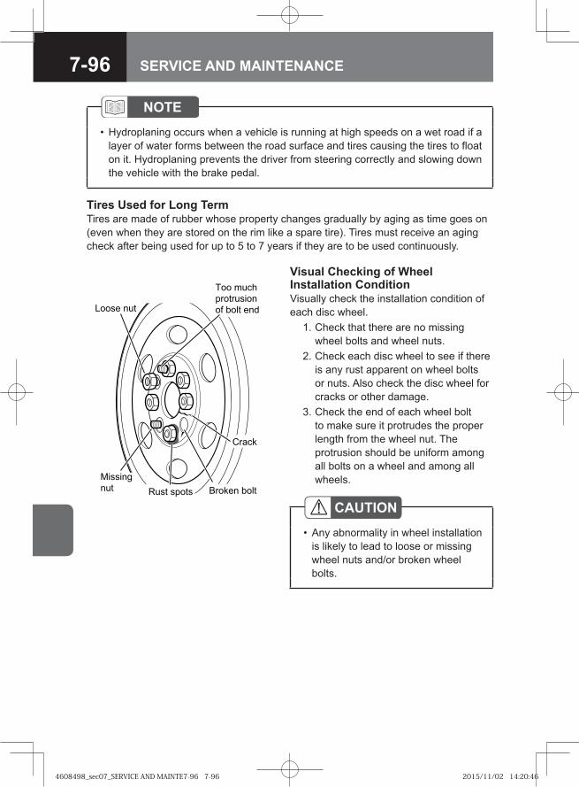
7-96 SERVICE AND MAINTENANCE
� �� ���
�������
��� ���� �� ��
� ����
�� ����� �
� � �� ��
!�"�#
$� #�� � ��
Visual Checking of Wheel Installation ConditionVisually check the installation condition of each disc wheel. 1. Check that there are no missing
wheel bolts and wheel nuts. 2. Check each disc wheel to see if there
is any rust apparent on wheel bolts or nuts. Also check the disc wheel for cracks or other damage.
3. Check the end of each wheel bolt to make sure it protrudes the proper length from the wheel nut. The protrusion should be uniform among all bolts on a wheel and among all wheels.
CAUTIONAny abnormality in wheel installation is likely to lead to loose or missing wheel nuts and/or broken wheel bolts.
•
NOTEHydroplaning occurs when a vehicle is running at high speeds on a wet road if a layer of water forms between the road surface and tires causing the tires to float on it. Hydroplaning prevents the driver from steering correctly and slowing down the vehicle with the brake pedal.
•
Tires Used for Long TermTires are made of rubber whose property changes gradually by aging as time goes on (even when they are stored on the rim like a spare tire). Tires must receive an aging check after being used for up to 5 to 7 years if they are to be used continuously.
4608498_sec07_SERVICE AND MAINTE7-96 7-964608498_sec07_SERVICE AND MAINTE7-96 7-96 2015/11/02 14:20:462015/11/02 14:20:46
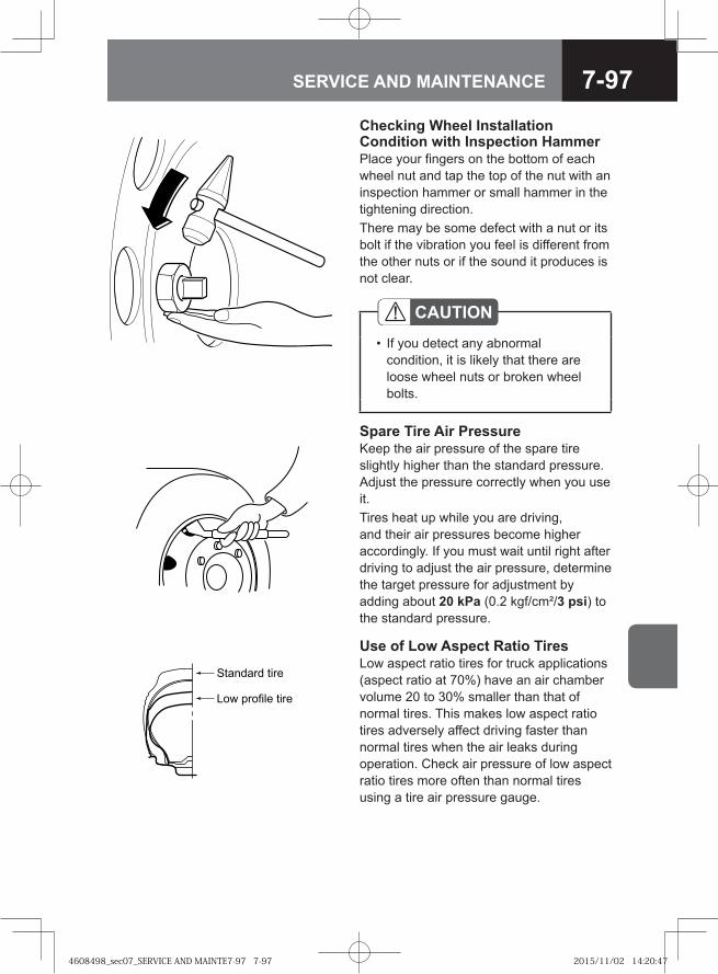
7-97SERVICE AND MAINTENANCE
Checking Wheel Installation Condition with Inspection HammerPlace your fingers on the bottom of each wheel nut and tap the top of the nut with an inspection hammer or small hammer in the tightening direction.There may be some defect with a nut or its bolt if the vibration you feel is different from the other nuts or if the sound it produces is not clear.
CAUTIONIf you detect any abnormal condition, it is likely that there are loose wheel nuts or broken wheel bolts.
•
Spare Tire Air PressureKeep the air pressure of the spare tire slightly higher than the standard pressure. Adjust the pressure correctly when you use it.Tires heat up while you are driving, and their air pressures become higher accordingly. If you must wait until right after driving to adjust the air pressure, determine the target pressure for adjustment by adding about 20 kPa (0.2 kgf/cm²/3 psi) to the standard pressure.
��� ���� ����
��� ������� ����
Use of Low Aspect Ratio TiresLow aspect ratio tires for truck applications (aspect ratio at 70%) have an air chamber volume 20 to 30% smaller than that of normal tires. This makes low aspect ratio tires adversely affect driving faster than normal tires when the air leaks during operation. Check air pressure of low aspect ratio tires more often than normal tires using a tire air pressure gauge.
4608498_sec07_SERVICE AND MAINTE7-97 7-974608498_sec07_SERVICE AND MAINTE7-97 7-97 2015/11/02 14:20:472015/11/02 14:20:47
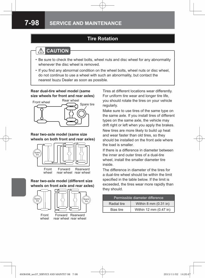
7-98 SERVICE AND MAINTENANCE
Tire Rotation
Tires at different locations wear differently. For uniform tire wear and longer tire life, you should rotate the tires on your vehicle regularly.Make sure to use tires of the same type on the same axle. If you install tires of different types on the same axle, the vehicle may drift right or left when you apply the brakes. New tires are more likely to build up heat and wear faster than old tires, so they should be installed on the front axle where the load is smaller. If there is a difference in diameter between the inner and outer tires of a dual-tire wheel, install the smaller diameter tire inside. The difference in diameter of the tires for a dual-tire wheel should be within the limit specified in the table below. If the limit is exceeded, the tires wear more rapidly than they should.
Rear dual-tire wheel model (same size wheels for front and rear axles)
Rear two-axle model (same size wheels on both front and rear axles)
CAUTIONBe sure to check the wheel bolts, wheel nuts and disc wheel for any abnormality whenever the disc wheel is removed.If you find any abnormal condition on the wheel bolts, wheel nuts or disc wheel, do not continue to use a wheel with such an abnormality, but contact the nearest Isuzu Dealer as soon as possible.
•
•
Rear two-axle model (different size wheels on front axle and rear axles)
Permissible diameter difference
Radial tire Within 8 mm (0.31 in)
Bias tire Within 12 mm (0.47 in)
Rear wheelFront wheel Spare tire
�� �����
������ �����
�������� �����
���� ��
�� �����
������ �����
�������� �����
���� ��
���� ��
4608498_sec07_SERVICE AND MAINTE7-98 7-984608498_sec07_SERVICE AND MAINTE7-98 7-98 2015/11/02 14:20:472015/11/02 14:20:47
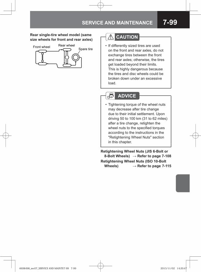
7-99SERVICE AND MAINTENANCE
CAUTIONIf differently sized tires are used on the front and rear axles, do not exchange tires between the front and rear axles; otherwise, the tires get loaded beyond their limits. This is highly dangerous because the tires and disc wheels could be broken down under an excessive load.
•
ADVICETightening torque of the wheel nuts may decrease after tire change due to their initial settlement. Upon driving 50 to 100 km (31 to 62 miles) after a tire change, retighten the wheel nuts to the specified torques according to the instructions in the "Retightening Wheel Nuts" section in this chapter.
•
Retightening Wheel Nuts (JIS 6-Bolt or 8-Bolt Wheels) → Refer to page 7-108
Retightening Wheel Nuts (ISO 10-Bolt Wheels) → Refer to page 7-115
Front wheel Rear wheelSpare tire
Rear single-tire wheel model (same size wheels for front and rear axles)
4608498_sec07_SERVICE AND MAINTE7-99 7-994608498_sec07_SERVICE AND MAINTE7-99 7-99 2015/11/02 14:20:472015/11/02 14:20:47
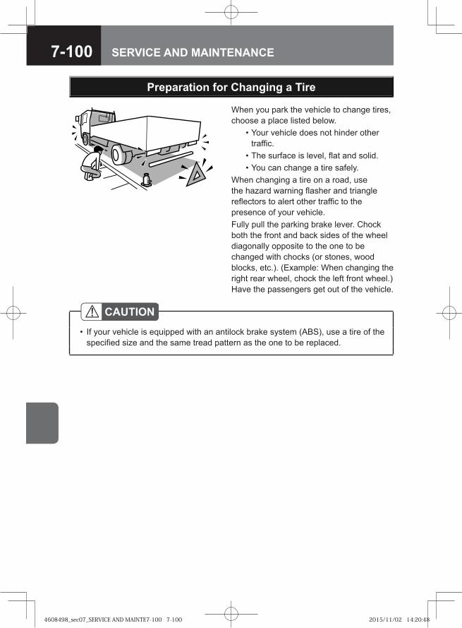
7-100 SERVICE AND MAINTENANCE
When you park the vehicle to change tires, choose a place listed below. • Your vehicle does not hinder other
traffic. • The surface is level, flat and solid. • You can change a tire safely.When changing a tire on a road, use the hazard warning flasher and triangle reflectors to alert other traffic to the presence of your vehicle.Fully pull the parking brake lever. Chock both the front and back sides of the wheel diagonally opposite to the one to be changed with chocks (or stones, wood blocks, etc.). (Example: When changing the right rear wheel, chock the left front wheel.) Have the passengers get out of the vehicle.
Preparation for Changing a Tire
CAUTIONIf your vehicle is equipped with an antilock brake system (ABS), use a tire of the specified size and the same tread pattern as the one to be replaced.
•
4608498_sec07_SERVICE AND MAINTE7-100 7-1004608498_sec07_SERVICE AND MAINTE7-100 7-100 2015/11/02 14:20:482015/11/02 14:20:48
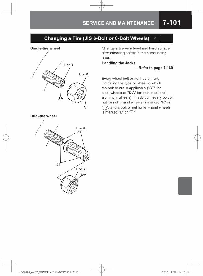
7-101SERVICE AND MAINTENANCE
Change a tire on a level and hard surface after checking safety in the surrounding area.Handling the Jacks
→ Refer to page 7-180
Every wheel bolt or nut has a mark indicating the type of wheel to which the bolt or nut is applicable ("ST" for steel wheels or "S·A" for both steel and aluminum wheels). In addition, every bolt or nut for right-hand wheels is marked "R" or " ", and a bolt or nut for left-hand wheels is marked "L" or " ".
� �� �
� �� �
��
���
�� �
�� �
���
��
Changing a Tire (JIS 6-Bolt or 8-Bolt Wheels) V
Single-tire wheel
Dual-tire wheel
4608498_sec07_SERVICE AND MAINTE7-101 7-1014608498_sec07_SERVICE AND MAINTE7-101 7-101 2015/11/02 14:20:482015/11/02 14:20:48
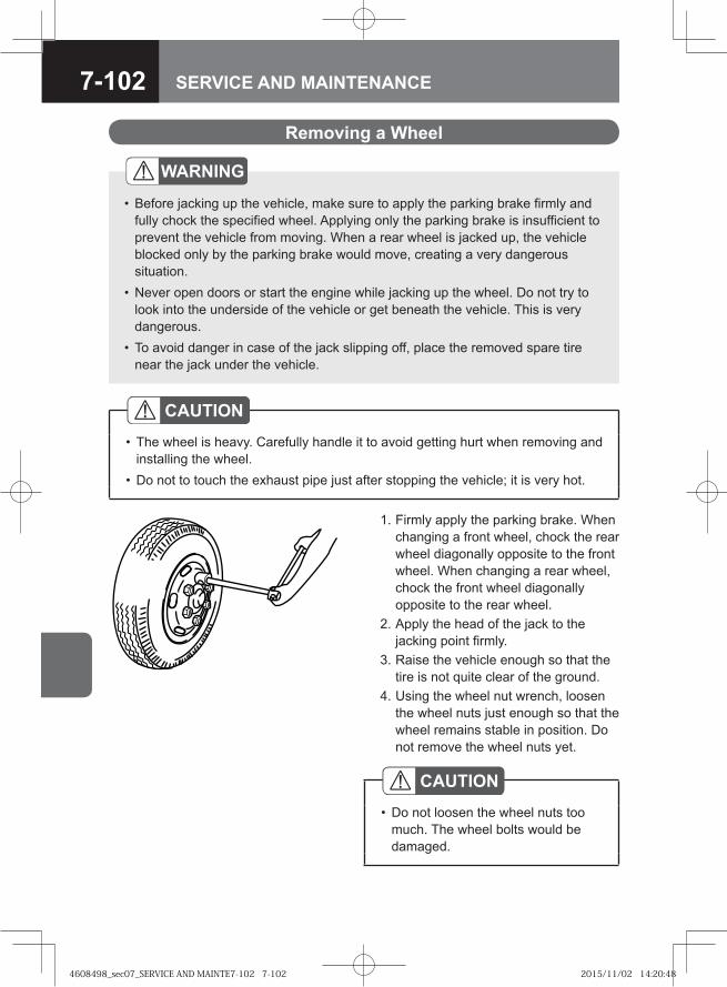
7-102 SERVICE AND MAINTENANCE
1. Firmly apply the parking brake. When changing a front wheel, chock the rear wheel diagonally opposite to the front wheel. When changing a rear wheel, chock the front wheel diagonally opposite to the rear wheel.
2. Apply the head of the jack to the jacking point firmly.
3. Raise the vehicle enough so that the tire is not quite clear of the ground.
4. Using the wheel nut wrench, loosen the wheel nuts just enough so that the wheel remains stable in position. Do not remove the wheel nuts yet.
Removing a Wheel
WARNING
Before jacking up the vehicle, make sure to apply the parking brake firmly and fully chock the specified wheel. Applying only the parking brake is insufficient to prevent the vehicle from moving. When a rear wheel is jacked up, the vehicle blocked only by the parking brake would move, creating a very dangerous situation.Never open doors or start the engine while jacking up the wheel. Do not try to look into the underside of the vehicle or get beneath the vehicle. This is very dangerous.To avoid danger in case of the jack slipping off, place the removed spare tire near the jack under the vehicle.
•
•
•
CAUTIONThe wheel is heavy. Carefully handle it to avoid getting hurt when removing and installing the wheel.Do not to touch the exhaust pipe just after stopping the vehicle; it is very hot.
•
•
CAUTIONDo not loosen the wheel nuts too much. The wheel bolts would be damaged.
•
4608498_sec07_SERVICE AND MAINTE7-102 7-1024608498_sec07_SERVICE AND MAINTE7-102 7-102 2015/11/02 14:20:482015/11/02 14:20:48
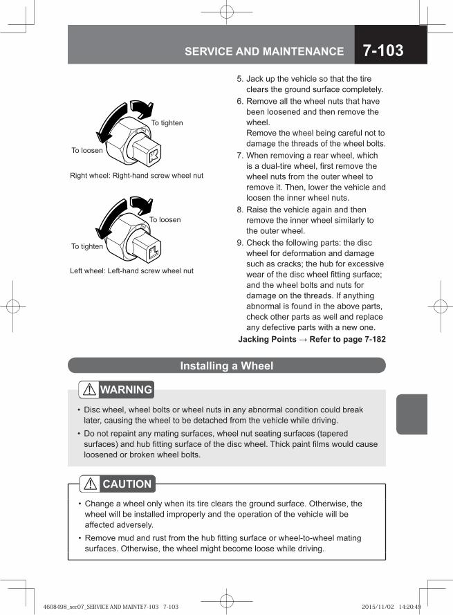
7-103SERVICE AND MAINTENANCE
5. Jack up the vehicle so that the tire clears the ground surface completely.
6. Remove all the wheel nuts that have been loosened and then remove the wheel.Remove the wheel being careful not to damage the threads of the wheel bolts.
7. When removing a rear wheel, which is a dual-tire wheel, first remove the wheel nuts from the outer wheel to remove it. Then, lower the vehicle and loosen the inner wheel nuts.
8. Raise the vehicle again and then remove the inner wheel similarly to the outer wheel.
9. Check the following parts: the disc wheel for deformation and damage such as cracks; the hub for excessive wear of the disc wheel fitting surface; and the wheel bolts and nuts for damage on the threads. If anything abnormal is found in the above parts, check other parts as well and replace any defective parts with a new one.
Jacking Points → Refer to page 7-182
To tighten
To loosen
Left wheel: Left-hand screw wheel nut
To tighten
To loosen
Right wheel: Right-hand screw wheel nut
WARNING
Disc wheel, wheel bolts or wheel nuts in any abnormal condition could break later, causing the wheel to be detached from the vehicle while driving.Do not repaint any mating surfaces, wheel nut seating surfaces (tapered surfaces) and hub fitting surface of the disc wheel. Thick paint films would cause loosened or broken wheel bolts.
•
•
Installing a Wheel
CAUTIONChange a wheel only when its tire clears the ground surface. Otherwise, the wheel will be installed improperly and the operation of the vehicle will be affected adversely.Remove mud and rust from the hub fitting surface or wheel-to-wheel mating surfaces. Otherwise, the wheel might become loose while driving.
•
•
4608498_sec07_SERVICE AND MAINTE7-103 7-1034608498_sec07_SERVICE AND MAINTE7-103 7-103 2015/11/02 14:20:492015/11/02 14:20:49
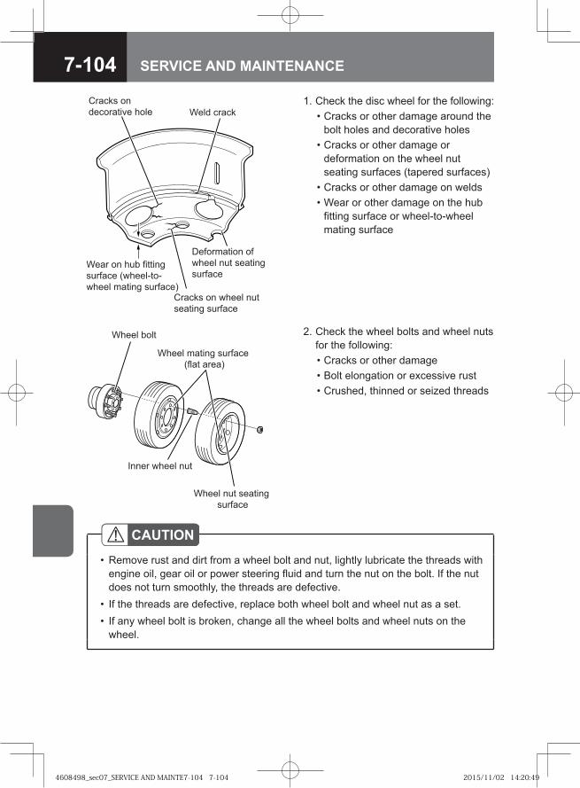
7-104 SERVICE AND MAINTENANCE
1. Check the disc wheel for the following: • Cracks or other damage around the
bolt holes and decorative holes • Cracks or other damage or
deformation on the wheel nut seating surfaces (tapered surfaces)
• Cracks or other damage on welds • Wear or other damage on the hub
fitting surface or wheel-to-wheel mating surface
HEU770
Cracks on decorative hole
Wear on hub fitting surface (wheel-to-wheel mating surface)
Weld crack
Deformation of wheel nut seating surface
Cracks on wheel nut seating surface
Wheel bolt
Wheel mating surface (flat area)
Wheel nut seating surface
Inner wheel nut
2. Check the wheel bolts and wheel nuts for the following:
• Cracks or other damage • Bolt elongation or excessive rust • Crushed, thinned or seized threads
CAUTIONRemove rust and dirt from a wheel bolt and nut, lightly lubricate the threads with engine oil, gear oil or power steering fluid and turn the nut on the bolt. If the nut does not turn smoothly, the threads are defective.If the threads are defective, replace both wheel bolt and wheel nut as a set.If any wheel bolt is broken, change all the wheel bolts and wheel nuts on the wheel.
•
••
4608498_sec07_SERVICE AND MAINTE7-104 7-1044608498_sec07_SERVICE AND MAINTE7-104 7-104 2015/11/02 14:20:492015/11/02 14:20:49
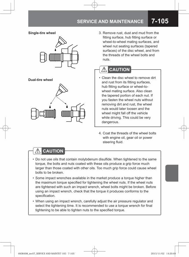
7-105SERVICE AND MAINTENANCE
3. Remove rust, dust and mud from the fitting surface, hub fitting surface or wheel-to-wheel mating surfaces, and wheel nut seating surfaces (tapered surfaces) of the disc wheel, and from the threads of the wheel bolts and nuts.
Dual-tire wheel
Single-tire wheel
CAUTIONClean the disc wheel to remove dirt and rust from its fitting surfaces, hub fitting surface or wheel-to-wheel mating surface. Also clean the tapered portion of each nut. If you fasten the wheel nuts without removing dirt and rust, the wheel nuts would later loosen and the wheel might fall off the vehicle while driving. This could be very dangerous.
•
4. Coat the threads of the wheel bolts with engine oil, gear oil or power steering fluid.
CAUTIONDo not use oils that contain molybdenum disulfide. When tightened to the same torque, the bolts and nuts coated with these oils produce a grip force much larger than those coated with other oils. Too much grip force could cause wheel bolts to be broken.Some impact wrenches available in the market produce a torque higher than the maximum torque specified for tightening the wheel nuts. If the wheel nuts are tightened with such an impact wrench, wheel bolts might be broken. Before using an impact wrench, check that the torque it produces conforms to the specification.When using an impact wrench, carefully adjust the air pressure regulator and select the tightening time. It is recommended to use a torque wrench for final tightening to be able to tighten nuts to the specified torque.
•
•
•
4608498_sec07_SERVICE AND MAINTE7-105 7-1054608498_sec07_SERVICE AND MAINTE7-105 7-105 2015/11/02 14:20:492015/11/02 14:20:49
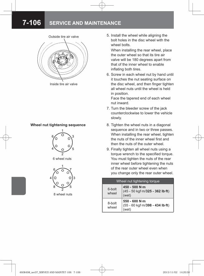
7-106 SERVICE AND MAINTENANCE
5. Install the wheel while aligning the bolt holes in the disc wheel with the wheel bolts.
When installing the rear wheel, place the outer wheel so that its tire air valve will be 180 degrees apart from that of the inner wheel to enable inflating both tires.
6. Screw in each wheel nut by hand until it touches the nut seating surface on the disc wheel, and then finger tighten all wheel nuts until the wheel is held in position. Face the tapered end of each wheel nut inward.
7. Turn the bleeder screw of the jack counterclockwise to lower the vehicle slowly.
Inside tire air valve
Outside tire air valve
Wheel nut tightening sequence1
2
16
4 3
7
8 52
3
5
6
4
6 wheel nuts
8 wheel nuts
Wheel nut tightening torque
6-bolt wheel
450 - 500 N·m (45 - 50 kgf·m/325 - 362 lb·ft) (wet)
8-bolt wheel
550 - 600 N·m (55 - 60 kgf·m/398 - 434 lb·ft) (wet)
8. Tighten the wheel nuts in a diagonal sequence and in two or three passes. When installing the rear wheel, tighten the nuts of the inner wheel first and then the nuts of the outer wheel.
9. Finally tighten all wheel nuts using a torque wrench to the specified torque. You must tighten the nuts of the rear inner wheel before tightening the nuts of the rear outer wheel even when you change only the rear outer wheel.
4608498_sec07_SERVICE AND MAINTE7-106 7-1064608498_sec07_SERVICE AND MAINTE7-106 7-106 2015/11/02 14:20:502015/11/02 14:20:50
7-107SERVICE AND MAINTENANCE
ADVICEAfter changing a tire, turn the steering wheel in both directions to make sure that the wheels do not interfere with the surrounding components. If you are not sure about this, please contact the nearest Isuzu Dealer.Tightening torque of the wheel nuts may decrease after tire replacement due to their initial settlement. Upon driving 50 to 100 km (31 to 62 miles) after tire replacement, retighten the wheel nuts to the specified torque according to the instructions in the "Retightening Wheel Nuts" section in this chapter.
•
•
Retightening Wheel Nuts (JIS 6-Bolt or 8-Bolt Wheels) → Refer to page 7-108
4608498_sec07_SERVICE AND MAINTE7-107 7-1074608498_sec07_SERVICE AND MAINTE7-107 7-107 2015/11/02 14:20:502015/11/02 14:20:50
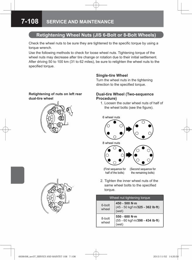
7-108 SERVICE AND MAINTENANCE
2. Tighten the inner wheel nuts of the same wheel bolts to the specified torque.
Retightening Wheel Nuts (JIS 6-Bolt or 8-Bolt Wheels)Check the wheel nuts to be sure they are tightened to the specific torque by using a torque wrench.Use the following methods to check for loose wheel nuts. Tightening torque of the wheel nuts may decrease after tire change or rotation due to their initial settlement. After driving 50 to 100 km (31 to 62 miles), be sure to retighten the wheel nuts to the specified torque.
Single-tire WheelTurn the wheel nuts in the tightening direction to the specified torque.
Dual-tire Wheel (Two-sequence Procedure) 1. Loosen the outer wheel nuts of half of
the wheel bolts (see the figure).
Retightening of nuts on left rear dual-tire wheel
�� ��� �������� ���
���� �� ��� ������
� ����� ����
����� ����
������� �������� ���
��� �� � � �! ������
Wheel nut tightening torque
6-bolt wheel
450 - 500 N·m (45 - 50 kgf·m/325 - 362 lb·ft) (wet)
8-bolt wheel
550 - 600 N·m (55 - 60 kgf·m/398 - 434 lb·ft) (wet)
4608498_sec07_SERVICE AND MAINTE7-108 7-1084608498_sec07_SERVICE AND MAINTE7-108 7-108 2015/11/02 14:20:502015/11/02 14:20:50
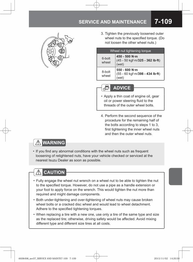
7-109SERVICE AND MAINTENANCE
CAUTIONFully engage the wheel nut wrench on a wheel nut to be able to tighten the nut to the specified torque. However, do not use a pipe as a handle extension or your foot to apply force on the wrench. This would tighten the nut more than required and might damage components.Both under-tightening and over-tightening of wheel nuts may cause broken wheel bolts or a cracked disc wheel and would lead to wheel detachment. Adhere to the specified tightening torques.When replacing a tire with a new one, use only a tire of the same type and size as the replaced tire; otherwise, driving safety would be affected. Avoid mixing different type and different size tires at all costs.
•
•
•
3. Tighten the previously loosened outer wheel nuts to the specified torque. (Do not loosen the other wheel nuts.)
4. Perform the second sequence of the procedure for the remaining half of the bolts according to steps 1 to 3, first tightening the inner wheel nuts and then the outer wheel nuts.
ADVICEApply a thin coat of engine oil, gear oil or power steering fluid to the threads of the outer wheel bolts.
•
WARNING
If you find any abnormal conditions with the wheel nuts such as frequent loosening of retightened nuts, have your vehicle checked or serviced at the nearest Isuzu Dealer as soon as possible.
•
Wheel nut tightening torque
6-bolt wheel
450 - 500 N·m (45 - 50 kgf·m/325 - 362 lb·ft) (wet)
8-bolt wheel
550 - 600 N·m (55 - 60 kgf·m/398 - 434 lb·ft) (wet)
4608498_sec07_SERVICE AND MAINTE7-109 7-1094608498_sec07_SERVICE AND MAINTE7-109 7-109 2015/11/02 14:20:502015/11/02 14:20:50
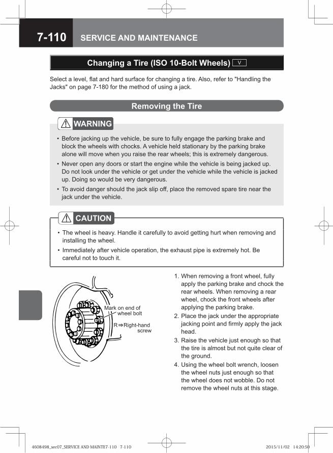
7-110 SERVICE AND MAINTENANCE
Changing a Tire (ISO 10-Bolt Wheels) V
Select a level, flat and hard surface for changing a tire. Also, refer to "Handling the Jacks" on page 7-180 for the method of using a jack.
Removing the Tire
WARNING
Before jacking up the vehicle, be sure to fully engage the parking brake and block the wheels with chocks. A vehicle held stationary by the parking brake alone will move when you raise the rear wheels; this is extremely dangerous.Never open any doors or start the engine while the vehicle is being jacked up. Do not look under the vehicle or get under the vehicle while the vehicle is jacked up. Doing so would be very dangerous.To avoid danger should the jack slip off, place the removed spare tire near the jack under the vehicle.
•
•
•
CAUTIONThe wheel is heavy. Handle it carefully to avoid getting hurt when removing and installing the wheel.Immediately after vehicle operation, the exhaust pipe is extremely hot. Be careful not to touch it.
•
•
1. When removing a front wheel, fully apply the parking brake and chock the rear wheels. When removing a rear wheel, chock the front wheels after applying the parking brake.
2. Place the jack under the appropriate jacking point and firmly apply the jack head.
3. Raise the vehicle just enough so that the tire is almost but not quite clear of the ground.
4. Using the wheel bolt wrench, loosen the wheel nuts just enough so that the wheel does not wobble. Do not remove the wheel nuts at this stage.
R Right-hand screw
Mark on end of wheel bolt
4608498_sec07_SERVICE AND MAINTE7-110 7-1104608498_sec07_SERVICE AND MAINTE7-110 7-110 2015/11/02 14:20:502015/11/02 14:20:50
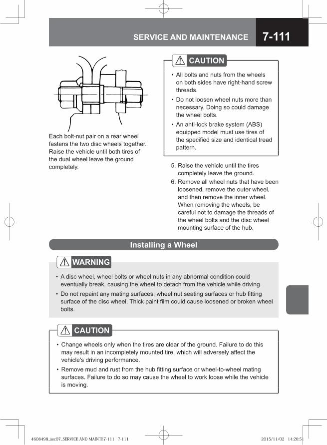
7-111SERVICE AND MAINTENANCE
Installing a Wheel
WARNING
A disc wheel, wheel bolts or wheel nuts in any abnormal condition could eventually break, causing the wheel to detach from the vehicle while driving.Do not repaint any mating surfaces, wheel nut seating surfaces or hub fitting surface of the disc wheel. Thick paint film could cause loosened or broken wheel bolts.
•
•
CAUTIONAll bolts and nuts from the wheels on both sides have right-hand screw threads.Do not loosen wheel nuts more than necessary. Doing so could damage the wheel bolts.An anti-lock brake system (ABS) equipped model must use tires of the specified size and identical tread pattern.
•
•
•
5. Raise the vehicle until the tires completely leave the ground.
6. Remove all wheel nuts that have been loosened, remove the outer wheel, and then remove the inner wheel.When removing the wheels, be careful not to damage the threads of the wheel bolts and the disc wheel mounting surface of the hub.
CAUTIONChange wheels only when the tires are clear of the ground. Failure to do this may result in an incompletely mounted tire, which will adversely affect the vehicle's driving performance.Remove mud and rust from the hub fitting surface or wheel-to-wheel mating surfaces. Failure to do so may cause the wheel to work loose while the vehicle is moving.
•
•
Each bolt-nut pair on a rear wheel fastens the two disc wheels together. Raise the vehicle until both tires of the dual wheel leave the ground completely.
4608498_sec07_SERVICE AND MAINTE7-111 7-1114608498_sec07_SERVICE AND MAINTE7-111 7-111 2015/11/02 14:20:512015/11/02 14:20:51
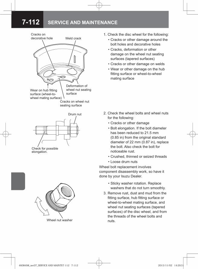
7-112 SERVICE AND MAINTENANCE
1. Check the disc wheel for the following: • Cracks or other damage around the
bolt holes and decorative holes • Cracks, deformation or other
damage on the wheel nut seating surfaces (tapered surfaces)
• Cracks or other damage on welds • Wear or other damage on the hub
fitting surface or wheel-to-wheel mating surface
Cracks on decorative hole
Wear on hub fitting surface (wheel-to-wheel mating surface)
Weld crack
Deformation of wheel nut seating surface
Cracks on wheel nut seating surface
2. Check the wheel bolts and wheel nuts for the following:
• Cracks or other damage • Bolt elongation. If the bolt diameter
has been reduced to 21.5 mm (0.85 in) from the original standard diameter of 22 mm (0.87 in), replace the bolt. Also check the bolt for noticeable rust.
• Crushed, thinned or seized threads • Loose drum nutsWheel bolt replacement involves component disassembly work, so have it done by your Isuzu Dealer.
Drum nut
Check for possible elongation.
Wheel nut washer
• Sticky washer rotation. Replace washers that do not turn smoothly.
3. Remove rust, dust and mud from the fitting surface, hub fitting surface or wheel-to-wheel mating surface, and wheel nut seating surfaces (tapered surfaces) of the disc wheel, and from the threads of the wheel bolts and nuts.
4608498_sec07_SERVICE AND MAINTE7-112 7-1124608498_sec07_SERVICE AND MAINTE7-112 7-112 2015/11/02 14:20:512015/11/02 14:20:51
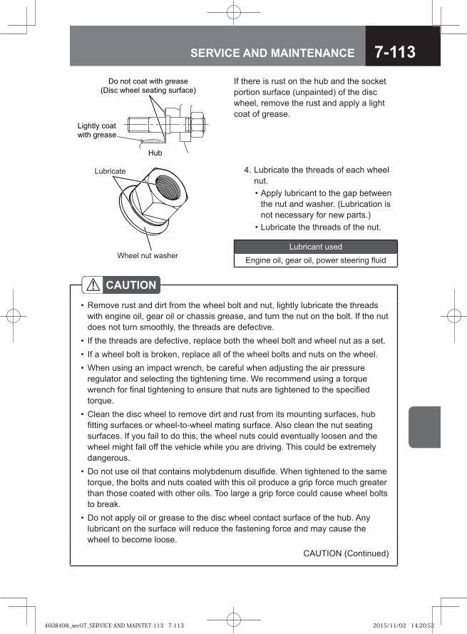
7-113SERVICE AND MAINTENANCE
4. Lubricate the threads of each wheel nut.
• Apply lubricant to the gap between the nut and washer. (Lubrication is not necessary for new parts.)
• Lubricate the threads of the nut.
Lubricant used
Engine oil, gear oil, power steering fluid
� �
������� ����
���� ������
�� ��� ���� ���� ������
���� ����� ������� � �!���"If there is rust on the hub and the socket portion surface (unpainted) of the disc wheel, remove the rust and apply a light coat of grease.
Lubricate
Wheel nut washer
CAUTIONRemove rust and dirt from the wheel bolt and nut, lightly lubricate the threads with engine oil, gear oil or chassis grease, and turn the nut on the bolt. If the nut does not turn smoothly, the threads are defective.If the threads are defective, replace both the wheel bolt and wheel nut as a set.If a wheel bolt is broken, replace all of the wheel bolts and nuts on the wheel.When using an impact wrench, be careful when adjusting the air pressure regulator and selecting the tightening time. We recommend using a torque wrench for final tightening to ensure that nuts are tightened to the specified torque.Clean the disc wheel to remove dirt and rust from its mounting surfaces, hub fitting surfaces or wheel-to-wheel mating surface. Also clean the nut seating surfaces. If you fail to do this, the wheel nuts could eventually loosen and the wheel might fall off the vehicle while you are driving. This could be extremely dangerous.Do not use oil that contains molybdenum disulfide. When tightened to the same torque, the bolts and nuts coated with this oil produce a grip force much greater than those coated with other oils. Too large a grip force could cause wheel bolts to break.Do not apply oil or grease to the disc wheel contact surface of the hub. Any lubricant on the surface will reduce the fastening force and may cause the wheel to become loose.
•
•••
•
•
•
CAUTION (Continued)
4608498_sec07_SERVICE AND MAINTE7-113 7-1134608498_sec07_SERVICE AND MAINTE7-113 7-113 2015/11/02 14:20:522015/11/02 14:20:52
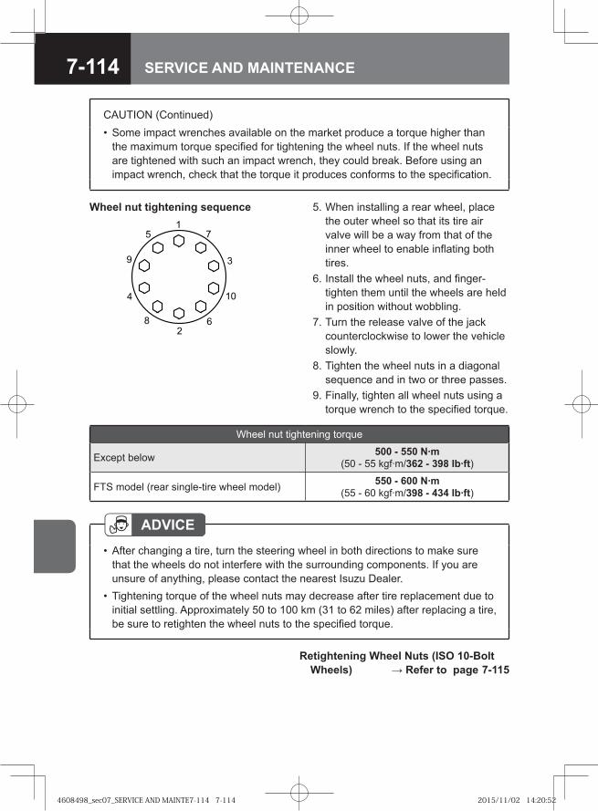
7-114 SERVICE AND MAINTENANCE
5. When installing a rear wheel, place the outer wheel so that its tire air valve will be a way from that of the inner wheel to enable inflating both tires.
6. Install the wheel nuts, and finger-tighten them until the wheels are held in position without wobbling.
7. Turn the release valve of the jack counterclockwise to lower the vehicle slowly.
8. Tighten the wheel nuts in a diagonal sequence and in two or three passes.
9. Finally, tighten all wheel nuts using a torque wrench to the specified torque.
�
�
�
�
� �
�
Wheel nut tightening sequence
ADVICEAfter changing a tire, turn the steering wheel in both directions to make sure that the wheels do not interfere with the surrounding components. If you are unsure of anything, please contact the nearest Isuzu Dealer.Tightening torque of the wheel nuts may decrease after tire replacement due to initial settling. Approximately 50 to 100 km (31 to 62 miles) after replacing a tire, be sure to retighten the wheel nuts to the specified torque.
•
•
Retightening Wheel Nuts (ISO 10-Bolt Wheels) → Refer to page 7-115
CAUTION (Continued)Some impact wrenches available on the market produce a torque higher than the maximum torque specified for tightening the wheel nuts. If the wheel nuts are tightened with such an impact wrench, they could break. Before using an impact wrench, check that the torque it produces conforms to the specification.
•
Wheel nut tightening torque
Except below 500 - 550 N·m (50 - 55 kgf·m/362 - 398 lb·ft)
FTS model (rear single-tire wheel model) 550 - 600 N·m (55 - 60 kgf·m/398 - 434 lb·ft)
4608498_sec07_SERVICE AND MAINTE7-114 7-1144608498_sec07_SERVICE AND MAINTE7-114 7-114 2015/11/02 14:20:522015/11/02 14:20:52
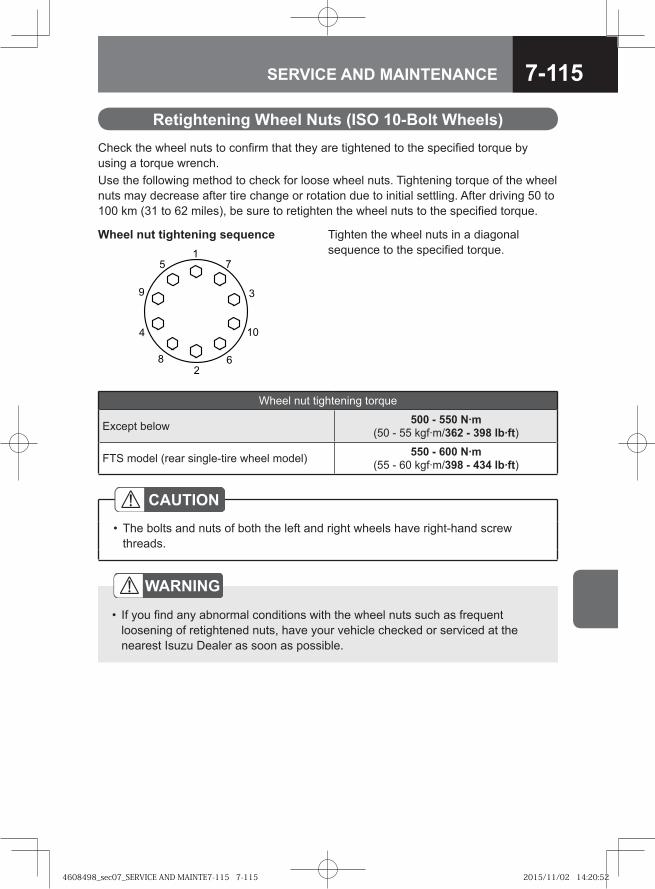
7-115SERVICE AND MAINTENANCE
Retightening Wheel Nuts (ISO 10-Bolt Wheels)
WARNING
If you find any abnormal conditions with the wheel nuts such as frequent loosening of retightened nuts, have your vehicle checked or serviced at the nearest Isuzu Dealer as soon as possible.
•
Check the wheel nuts to confirm that they are tightened to the specified torque by using a torque wrench.Use the following method to check for loose wheel nuts. Tightening torque of the wheel nuts may decrease after tire change or rotation due to initial settling. After driving 50 to 100 km (31 to 62 miles), be sure to retighten the wheel nuts to the specified torque.
Wheel nut tightening sequence Tighten the wheel nuts in a diagonal sequence to the specified torque.
�
�
�
�
� �
�
Wheel nut tightening torque
Except below 500 - 550 N·m (50 - 55 kgf·m/362 - 398 lb·ft)
FTS model (rear single-tire wheel model) 550 - 600 N·m (55 - 60 kgf·m/398 - 434 lb·ft)
CAUTIONThe bolts and nuts of both the left and right wheels have right-hand screw threads.
•
4608498_sec07_SERVICE AND MAINTE7-115 7-1154608498_sec07_SERVICE AND MAINTE7-115 7-115 2015/11/02 14:20:522015/11/02 14:20:52
7-116 SERVICE AND MAINTENANCE
CAUTIONFully engage the wheel bolt wrench on a wheel nut to be able to tighten the nut to the specified torque. However, do not use a pipe as a handle extension or your foot to apply force to the wrench. This could tighten the nut more than necessary and damage the components.Both under-tightening and over-tightening the wheel nuts might cause broken wheel bolts or a cracked disc wheel and could lead to wheel detachment. Adhere to the specified tightening torque.When replacing a tire with a new one, use only a tire of the same type and size as the replaced tire; otherwise, driving safety could be compromised. Avoid mixing different types and sizes of tires at all costs.
•
•
•
4608498_sec07_SERVICE AND MAINTE7-116 7-1164608498_sec07_SERVICE AND MAINTE7-116 7-116 2015/11/02 14:20:522015/11/02 14:20:52
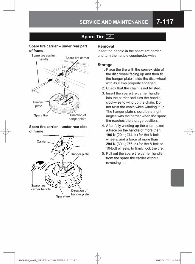
7-117SERVICE AND MAINTENANCE
Spare Tire V
RemovalInsert the handle in the spare tire carrier and turn the handle counterclockwise.
Spare tire carrier – under rear part of frame
Spare tire carrierSpare tire carrier
handle
Hanger plate
Direction of hanger plate
Spare tire
Storage 1. Place the tire with the convex side of
the disc wheel facing up and then fit the hanger plate inside the disc wheel with its claws properly engaged.
2. Check that the chain is not twisted. 3. Insert the spare tire carrier handle
into the carrier and turn the handle clockwise to wind up the chain. Do not twist the chain while winding it up. The hanger plate should be at right angles with the carrier when the spare tire reaches the storage position.
4. After fully winding up the chain, exert a force on the handle of more than 196 N (20 kgf/44 lb) for the 6-bolt wheels, and a force of more than 294 N (30 kgf/66 lb) for the 8-bolt or 10-bolt wheels, to firmly lock the tire.
5. Pull out the spare tire carrier handle from the spare tire carrier without reversing it.
Spare tire carrier – under rear side of frame
� ���� �� ��
������ �����
���� ��
������ �����
����� � ��
����� � ��
���� �� ������
4608498_sec07_SERVICE AND MAINTE7-117 7-1174608498_sec07_SERVICE AND MAINTE7-117 7-117 2015/11/02 14:20:522015/11/02 14:20:52
7-118 SERVICE AND MAINTENANCE
Air PressureCheck the air pressure of the spare tire using a tire air pressure gauge at the intervals specified in the Maintenance Schedule.A spare tire inflated to a normal pressure may lose its pressure little by little due to leaks over time. You should therefore inflate it to a pressure a little higher than the normal pressure.
ADVICEAfter storing the spare tire, check that it is not loose by strongly pushing the tire with your foot. If the tire is loose, fasten it again after checking that the carrier is not damaged and does not have a deformed bracket or hanger plate. If you cannot tighten the tire in the carrier, do not continue driving but contact the nearest Isuzu Dealer.
•
Maintenance Schedule → Refer to page 7-217
CAUTIONIf the chain twisted when it is wound, it becomes loose while running due to vibration or shocks and the tire might fall off; this is very dangerous.After storing the tire in the carrier, check that the tire is held firmly. If loosely retained, the tire becomes loose while you are driving due to vibration or shocks and the tire might fall off; this is very dangerous.
•
•
4608498_sec07_SERVICE AND MAINTE7-118 7-1184608498_sec07_SERVICE AND MAINTE7-118 7-118 2015/11/02 14:20:532015/11/02 14:20:53

7-119SERVICE AND MAINTENANCE
Checking Axle Shaft Bolts
Rear axle shaft bolts Check the axle shaft bolts for looseness.
Model Axle shaft bolt tightening torque
FRR, FSR and FSS modelsFTS model (rear single-tire wheel model)
98 - 127 N·m (10.0 - 13.0 kgf·m/72 - 94 lb·ft)
FTR, FVR, FVM, FVZ, GVR and GVZ modelsFTS model (rear dual-tire wheel model)
167 - 196 N·m (17.0 - 20.0 kgf·m/123 - 145 lb·ft)
Air Tanks
Air tanks may contain water. You must drain them by pulling the ring of the drain taps at the bottom of the air tank to discharge water.After discharging water, check that air is not leaking from each drain tap. If a large volume of water drains from an air tank, the desiccant of the air dryer may have deteriorated. If desiccant replacement is necessary, have it performed by the nearest Isuzu Dealer.
WARNING
Water collecting in the air tank may cause moisture to freeze inside the air piping in winter. This is very dangerous because the air compressor may fail and as a result, sufficient braking forces may no longer be available.
•
4608498_sec07_SERVICE AND MAINTE7-119 7-1194608498_sec07_SERVICE AND MAINTE7-119 7-119 2015/11/02 14:20:542015/11/02 14:20:54
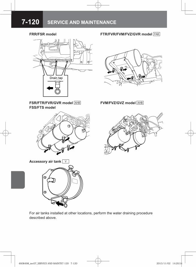
7-120 SERVICE AND MAINTENANCE
FRR/FSR model FTR/FVR/FVM/FVZ/GVR model FAB
� ��� ���
FSR/FTR/FVR/GVR model AHB FSS/FTS model
FVM/FVZ/GVZ model AHB
Accessory air tank V
For air tanks installed at other locations, perform the water draining procedure described above.
4608498_sec07_SERVICE AND MAINTE7-120 7-1204608498_sec07_SERVICE AND MAINTE7-120 7-120 2015/11/02 14:20:542015/11/02 14:20:54
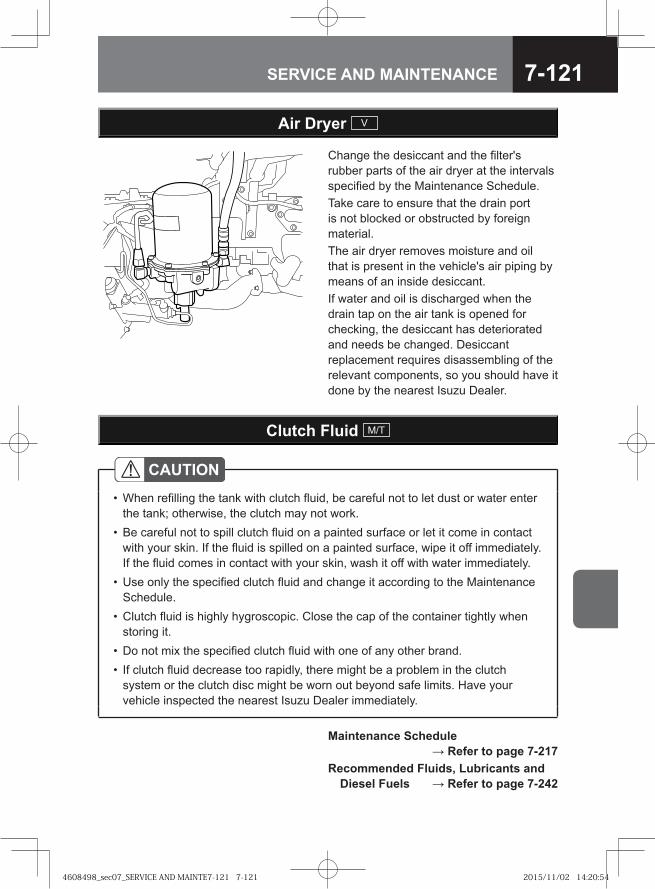
7-121SERVICE AND MAINTENANCE
Clutch Fluid M/T
CAUTIONWhen refilling the tank with clutch fluid, be careful not to let dust or water enter the tank; otherwise, the clutch may not work.Be careful not to spill clutch fluid on a painted surface or let it come in contact with your skin. If the fluid is spilled on a painted surface, wipe it off immediately. If the fluid comes in contact with your skin, wash it off with water immediately. Use only the specified clutch fluid and change it according to the Maintenance Schedule.Clutch fluid is highly hygroscopic. Close the cap of the container tightly when storing it.Do not mix the specified clutch fluid with one of any other brand.If clutch fluid decrease too rapidly, there might be a problem in the clutch system or the clutch disc might be worn out beyond safe limits. Have your vehicle inspected the nearest Isuzu Dealer immediately.
•
•
•
•
••
Maintenance Schedule → Refer to page 7-217
Recommended Fluids, Lubricants and Diesel Fuels → Refer to page 7-242
Change the desiccant and the filter's rubber parts of the air dryer at the intervals specified by the Maintenance Schedule.Take care to ensure that the drain port is not blocked or obstructed by foreign material.The air dryer removes moisture and oil that is present in the vehicle's air piping by means of an inside desiccant. If water and oil is discharged when the drain tap on the air tank is opened for checking, the desiccant has deteriorated and needs be changed. Desiccant replacement requires disassembling of the relevant components, so you should have it done by the nearest Isuzu Dealer.
Air Dryer V
4608498_sec07_SERVICE AND MAINTE7-121 7-1214608498_sec07_SERVICE AND MAINTE7-121 7-121 2015/11/02 14:20:542015/11/02 14:20:54
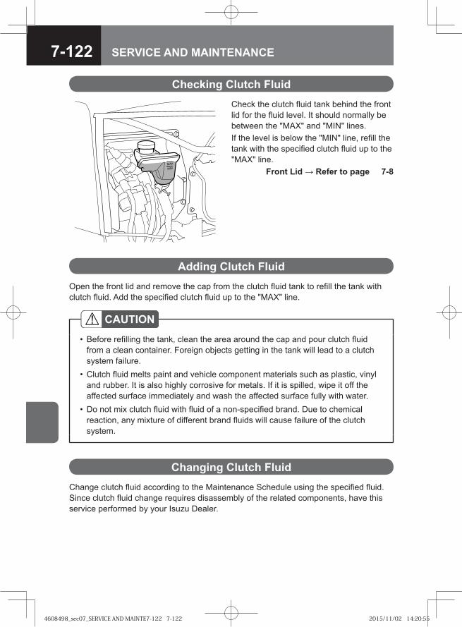
7-122 SERVICE AND MAINTENANCE
Check the clutch fluid tank behind the front lid for the fluid level. It should normally be between the "MAX" and "MIN" lines.If the level is below the "MIN" line, refill the tank with the specified clutch fluid up to the "MAX" line. Front Lid → Refer to page 7-8
Checking Clutch Fluid
Change clutch fluid according to the Maintenance Schedule using the specified fluid. Since clutch fluid change requires disassembly of the related components, have this service performed by your Isuzu Dealer.
CAUTIONBefore refilling the tank, clean the area around the cap and pour clutch fluid from a clean container. Foreign objects getting in the tank will lead to a clutch system failure.Clutch fluid melts paint and vehicle component materials such as plastic, vinyl and rubber. It is also highly corrosive for metals. If it is spilled, wipe it off the affected surface immediately and wash the affected surface fully with water.Do not mix clutch fluid with fluid of a non-specified brand. Due to chemical reaction, any mixture of different brand fluids will cause failure of the clutch system.
•
•
•
Adding Clutch FluidOpen the front lid and remove the cap from the clutch fluid tank to refill the tank with clutch fluid. Add the specified clutch fluid up to the "MAX" line.
Changing Clutch Fluid
4608498_sec07_SERVICE AND MAINTE7-122 7-1224608498_sec07_SERVICE AND MAINTE7-122 7-122 2015/11/02 14:20:552015/11/02 14:20:55
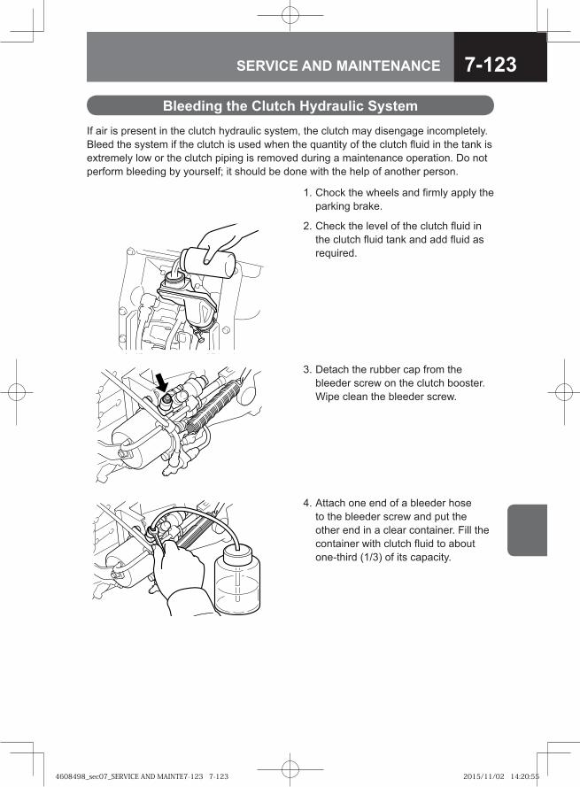
7-123SERVICE AND MAINTENANCE
If air is present in the clutch hydraulic system, the clutch may disengage incompletely. Bleed the system if the clutch is used when the quantity of the clutch fluid in the tank is extremely low or the clutch piping is removed during a maintenance operation. Do not perform bleeding by yourself; it should be done with the help of another person.
Bleeding the Clutch Hydraulic System
1. Chock the wheels and firmly apply the parking brake.
2. Check the level of the clutch fluid in the clutch fluid tank and add fluid as required.
3. Detach the rubber cap from the bleeder screw on the clutch booster. Wipe clean the bleeder screw.
4. Attach one end of a bleeder hose to the bleeder screw and put the other end in a clear container. Fill the container with clutch fluid to about one-third (1/3) of its capacity.
4608498_sec07_SERVICE AND MAINTE7-123 7-1234608498_sec07_SERVICE AND MAINTE7-123 7-123 2015/11/02 14:20:552015/11/02 14:20:55
7-124 SERVICE AND MAINTENANCE
5. Press the clutch pedal several times and keep it pressed the last time.
6. Loosen the bleeder screw to let the clutch fluid containing air bubbles flow into the container and then tighten the bleeder screw immediately.
7. Release the clutch pedal slowly. Repeat steps 5 and 6 until the fluid from the hose no longer contains air bubbles. After bleeding, install the rubber cap in position.
CAUTIONWhile bleeding, ensure that the fluid level in the clutch fluid tank is not below the "MIN" line.
•
Clutch M/T
The clutch disc wears down as the clutch is used, and this causes the free play of the clutch pedal to decrease. If you continue to use the clutch with reduced clutch pedal play, the clutch slips easily. On the other hand, if there is too much free play, the clutch disengages poorly, making gearshifts difficult.
Checking the Clutch
Daily CheckInspect whether an abnormal sound is heard or the clutch pedal is abnormally heavy when the clutch pedal is depressed while the engine is idling. If an abnormal sound is heard or the clutch pedal operation is heavy with the sufficient air pressure supplied, provide lubrication. Also, check whether the shift lever can be placed in the 1st or reverse position easily.Check also that the clutch engages smoothly without any slip when the vehicle starts to move slowly.
Greasing Chassis Components → Refer to page 7-172
Maintenance Schedule → Refer to page 7-217
4608498_sec07_SERVICE AND MAINTE7-124 7-1244608498_sec07_SERVICE AND MAINTE7-124 7-124 2015/11/02 14:20:552015/11/02 14:20:55
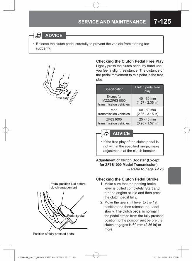
7-125SERVICE AND MAINTENANCE
���� ����
ADVICERelease the clutch pedal carefully to prevent the vehicle from starting too suddenly.
•
Checking the Clutch Pedal Free PlayLightly press the clutch pedal by hand until you feel a slight resistance. The distance of the pedal movement to this point is the free play.
Checking the Clutch Pedal Stroke 1. Make sure that the parking brake
lever is pulled completely. Start and run the engine at idle and then press the clutch pedal fully.
2. Move the gearshift lever to the 1st position and then release the pedal slowly. The clutch pedal is normal if the pedal stroke from the fully pressed position to the position just before the clutch engages is 60 mm (2.36 in) or more.
Specification Clutch pedal free play
Except for MZZ/ZF6S1000
transmission vehicles
40 - 60 mm (1.57 - 2.36 in)
MZZ transmission vehicles
60 - 80 mm (2.36 - 3.15 in)
ZF6S1000 transmission vehicles
25 - 40 mm (0.98 - 1.57 in)
� ���� � � ����� ������� �����
����� � ���� � ���� ��� ��
������ �� � �!���
����� ��� "�
Adjustment of Clutch Booster (Except for ZF6S1000 Model Transmission) → Refer to page 7-126
ADVICEIf the free play of the clutch pedal is not within the specified range, make adjustments at the clutch booster.
•
4608498_sec07_SERVICE AND MAINTE7-125 7-1254608498_sec07_SERVICE AND MAINTE7-125 7-125 2015/11/02 14:20:562015/11/02 14:20:56
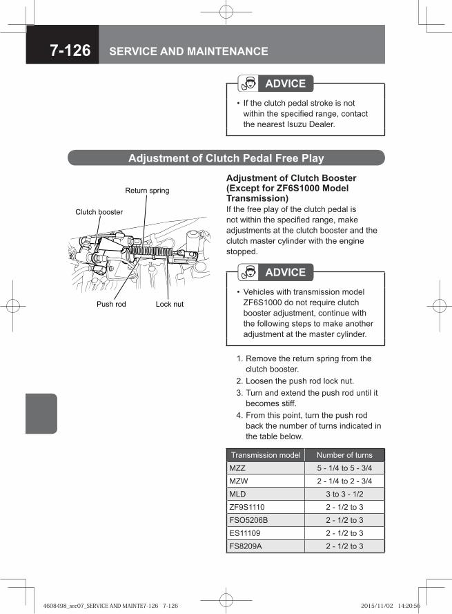
7-126 SERVICE AND MAINTENANCE
Adjustment of Clutch Pedal Free Play
Adjustment of Clutch Booster (Except for ZF6S1000 Model Transmission)If the free play of the clutch pedal is not within the specified range, make adjustments at the clutch booster and the clutch master cylinder with the engine stopped.
ADVICEIf the clutch pedal stroke is not within the specified range, contact the nearest Isuzu Dealer.
•
� ���� �������
������ ������
���� ��� ��� ���
1. Remove the return spring from the clutch booster.
2. Loosen the push rod lock nut. 3. Turn and extend the push rod until it
becomes stiff. 4. From this point, turn the push rod
back the number of turns indicated in the table below.
ADVICEVehicles with transmission model ZF6S1000 do not require clutch booster adjustment, continue with the following steps to make another adjustment at the master cylinder.
•
Transmission model Number of turns
MZZ 5 - 1/4 to 5 - 3/4
MZW 2 - 1/4 to 2 - 3/4
MLD 3 to 3 - 1/2
ZF9S1110 2 - 1/2 to 3
FSO5206B 2 - 1/2 to 3
ES11109 2 - 1/2 to 3
FS8209A 2 - 1/2 to 3
4608498_sec07_SERVICE AND MAINTE7-126 7-1264608498_sec07_SERVICE AND MAINTE7-126 7-126 2015/11/02 14:20:562015/11/02 14:20:56
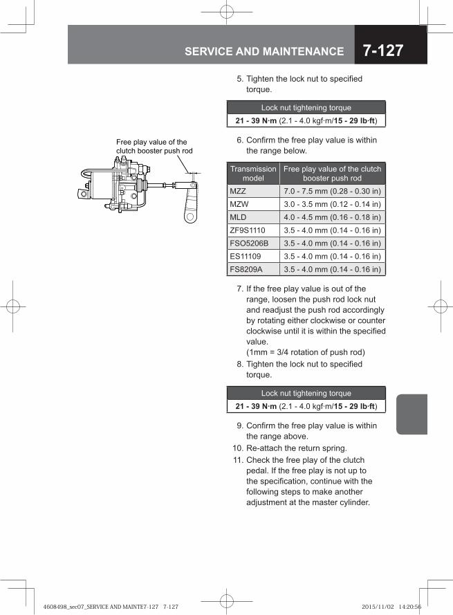
7-127SERVICE AND MAINTENANCE
5. Tighten the lock nut to specified torque.
Lock nut tightening torque
21 - 39 N·m (2.1 - 4.0 kgf·m/15 - 29 lb·ft)
9. Confirm the free play value is within the range above.
10. Re-attach the return spring. 11. Check the free play of the clutch
pedal. If the free play is not up to the specification, continue with the following steps to make another adjustment at the master cylinder.
6. Confirm the free play value is within the range below.
Transmission model
Free play value of the clutch booster push rod
MZZ 7.0 - 7.5 mm (0.28 - 0.30 in)
MZW 3.0 - 3.5 mm (0.12 - 0.14 in)
MLD 4.0 - 4.5 mm (0.16 - 0.18 in)
ZF9S1110 3.5 - 4.0 mm (0.14 - 0.16 in)
FSO5206B 3.5 - 4.0 mm (0.14 - 0.16 in)
ES11109 3.5 - 4.0 mm (0.14 - 0.16 in)
FS8209A 3.5 - 4.0 mm (0.14 - 0.16 in)
7. If the free play value is out of the range, loosen the push rod lock nut and readjust the push rod accordingly by rotating either clockwise or counter clockwise until it is within the specified value. (1mm = 3/4 rotation of push rod)
8. Tighten the lock nut to specified torque.
Lock nut tightening torque
21 - 39 N·m (2.1 - 4.0 kgf·m/15 - 29 lb·ft)
��� ��� ����� �� ���
������ ������ ��� ��
4608498_sec07_SERVICE AND MAINTE7-127 7-1274608498_sec07_SERVICE AND MAINTE7-127 7-127 2015/11/02 14:20:562015/11/02 14:20:56
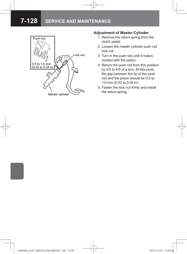
7-128 SERVICE AND MAINTENANCE
�� � � ������ � ��� ���
���� ���
���� ��
��� � �!"��� �
Adjustment of Master Cylinder 1. Remove the return spring from the
clutch pedal. 2. Loosen the master cylinder push rod
lock nut. 3. Turn in the push rod until it makes
contact with the piston. 4. Return the push rod from this position
by 2/5 to 4/5 of a turn. At this point, the gap between the tip of the push rod and the piston should be 0.5 to 1.0 mm (0.02 to 0.04 in).
5. Fasten the lock nut firmly and install the return spring.
4608498_sec07_SERVICE AND MAINTE7-128 7-1284608498_sec07_SERVICE AND MAINTE7-128 7-128 2015/11/02 14:20:562015/11/02 14:20:56
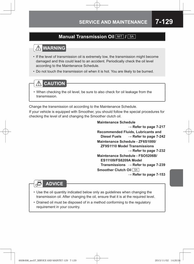
7-129SERVICE AND MAINTENANCE
Manual Transmission Oil M/T / SA
Change the transmission oil according to the Maintenance Schedule.If your vehicle is equipped with Smoother, you should follow the special procedures for checking the level of and changing the Smoother clutch oil.
Maintenance Schedule → Refer to page 7-217
Recommended Fluids, Lubricants and Diesel Fuels → Refer to page 7-242
Maintenance Schedule - ZF6S1000/ZF9S1110 Model Transmissions → Refer to page 7-232
Maintenance Schedule - FSO5206B/ES11109/FS8209A Model Transmissions → Refer to page 7-239
Smoother Clutch Oil SA → Refer to page 7-153
ADVICEUse the oil quantity indicated below only as guidelines when changing the transmission oil. After changing the oil, ensure that it is at the required level.Drained oil must be disposed of in a method conforming to the regulatory requirement in your country.
•
•
WARNING
If the level of transmission oil is extremely low, the transmission might become damaged and this could lead to an accident. Periodically check the oil level according to the Maintenance Schedule.Do not touch the transmission oil when it is hot. You are likely to be burned.
•
•
CAUTIONWhen checking the oil level, be sure to also check for oil leakage from the transmission.
•
4608498_sec07_SERVICE AND MAINTE7-129 7-1294608498_sec07_SERVICE AND MAINTE7-129 7-129 2015/11/02 14:20:562015/11/02 14:20:56
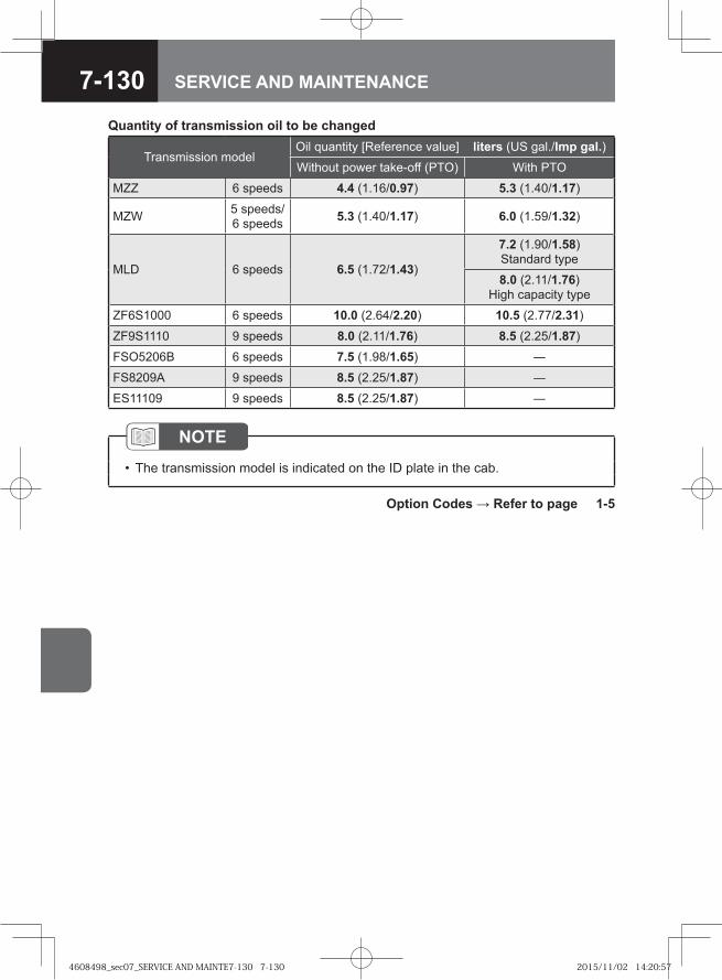
7-130 SERVICE AND MAINTENANCE
Quantity of transmission oil to be changed
Transmission modelOil quantity [Reference value] liters (US gal./Imp gal.)Without power take-off (PTO) With PTO
MZZ 6 speeds 4.4 (1.16/0.97) 5.3 (1.40/1.17)
MZW 5 speeds/6 speeds 5.3 (1.40/1.17) 6.0 (1.59/1.32)
MLD 6 speeds 6.5 (1.72/1.43)
7.2 (1.90/1.58)Standard type
8.0 (2.11/1.76)High capacity type
ZF6S1000 6 speeds 10.0 (2.64/2.20) 10.5 (2.77/2.31)
ZF9S1110 9 speeds 8.0 (2.11/1.76) 8.5 (2.25/1.87)
FSO5206B 6 speeds 7.5 (1.98/1.65) ―
FS8209A 9 speeds 8.5 (2.25/1.87) ―
ES11109 9 speeds 8.5 (2.25/1.87) ―
NOTEThe transmission model is indicated on the ID plate in the cab. •
Option Codes → Refer to page 1-5
4608498_sec07_SERVICE AND MAINTE7-130 7-1304608498_sec07_SERVICE AND MAINTE7-130 7-130 2015/11/02 14:20:572015/11/02 14:20:57
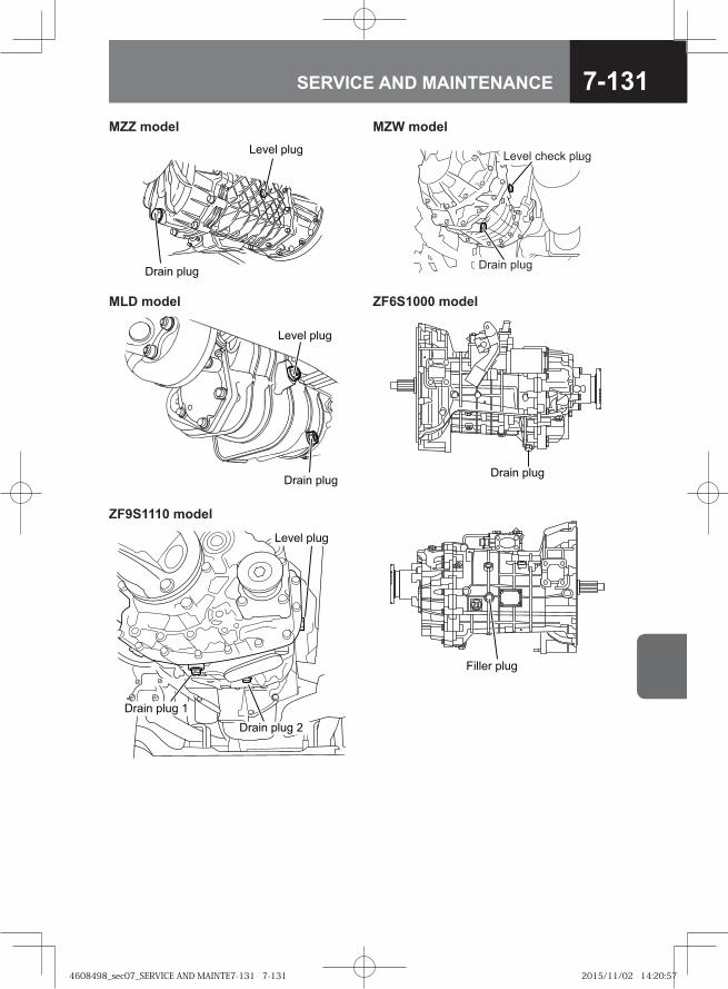
7-131SERVICE AND MAINTENANCE
MZZ model MZW model
�� �� ����
����� ����
Drain plug
Level check plug
MLD model ZF6S1000 model
���� ����
����� ������ � ����
� ���� ����
ZF9S1110 model
� � � ����
����� ���� �
����� ���� �
4608498_sec07_SERVICE AND MAINTE7-131 7-1314608498_sec07_SERVICE AND MAINTE7-131 7-131 2015/11/02 14:20:572015/11/02 14:20:57
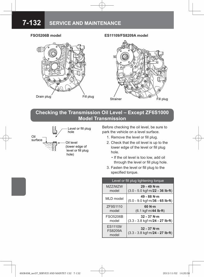
7-132 SERVICE AND MAINTENANCE
Level or fill plug hole
Oil level (lower edge of level or fill plug hole)
Oil surface
Before checking the oil level, be sure to park the vehicle on a level surface. 1. Remove the level or fill plug. 2. Check that the oil level is up to the
lower edge of the level or fill plug hole.
• If the oil level is too low, add oil through the level or fill plug hole.
3. Fasten the level or fill plug to the specified torque.
Checking the Transmission Oil Level – Except ZF6S1000 Model Transmission
Level or fill plug tightening torque
MZZ/MZW model
29 - 49 N·m (3.0 - 5.0 kgf·m/22 - 36 lb·ft)
MLD model 49 - 88 N·m (5.0 - 9.0 kgf·m/36 - 65 lb·ft)
ZF9S1110 model
60 N·m (6.1 kgf·m/44 lb·ft)
FSO5206B model
32 - 37 N·m (3.3 - 3.8 kgf·m/24 - 27 lb·ft)
ES11109/FS8209A
model
32 - 37 N·m (3.3 - 3.8 kgf·m/24 - 27 lb·ft)
FSO5206B model ES11109/FS8209A model
Drain plug Fill plugStrainer Fill plug
4608498_sec07_SERVICE AND MAINTE7-132 7-1324608498_sec07_SERVICE AND MAINTE7-132 7-132 2015/11/02 14:20:582015/11/02 14:20:58
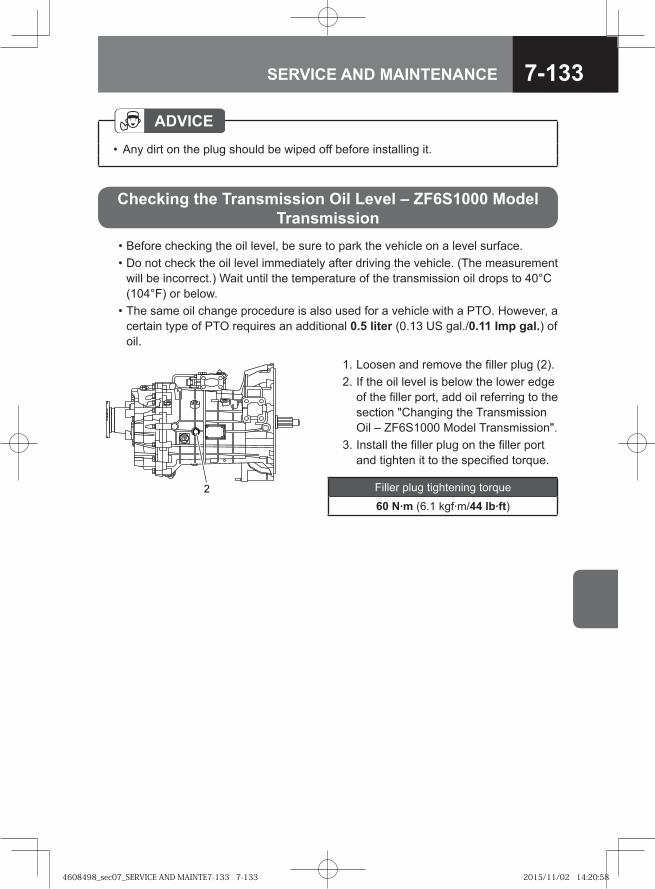
7-133SERVICE AND MAINTENANCE
ADVICEAny dirt on the plug should be wiped off before installing it.•
• Before checking the oil level, be sure to park the vehicle on a level surface. • Do not check the oil level immediately after driving the vehicle. (The measurement
will be incorrect.) Wait until the temperature of the transmission oil drops to 40°C (104°F) or below.
• The same oil change procedure is also used for a vehicle with a PTO. However, a certain type of PTO requires an additional 0.5 liter (0.13 US gal./0.11 Imp gal.) of oil.
1. Loosen and remove the filler plug (2). 2. If the oil level is below the lower edge
of the filler port, add oil referring to the section "Changing the Transmission Oil – ZF6S1000 Model Transmission".
3. Install the filler plug on the filler port and tighten it to the specified torque.
Filler plug tightening torque
60 N·m (6.1 kgf·m/44 lb·ft)
Checking the Transmission Oil Level – ZF6S1000 Model Transmission
4608498_sec07_SERVICE AND MAINTE7-133 7-1334608498_sec07_SERVICE AND MAINTE7-133 7-133 2015/11/02 14:20:582015/11/02 14:20:58
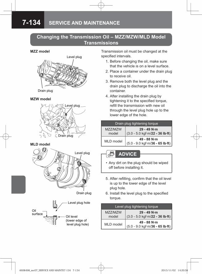
7-134 SERVICE AND MAINTENANCE
Transmission oil must be changed at the specified intervals. 1. Before changing the oil, make sure
that the vehicle is on a level surface. 2. Place a container under the drain plug
to receive oil. 3. Remove both the level plug and the
drain plug to discharge the oil into the container.
4. After installing the drain plug by tightening it to the specified torque, refill the transmission with new oil through the level plug hole up to the lower edge of the hole.
Level plug hole
Oil level (lower edge of level plug hole)
Oil surface
ADVICEAny dirt on the plug should be wiped off before installing it.
•
5. After refilling, confirm that the oil level is up to the lower edge of the level plug hole.
6. Install the level plug to the specified torque.
���� ����
����� ����
Changing the Transmission Oil – MZZ/MZW/MLD ModelTransmissions
Drain plug tightening torque
MZZ/MZW model
29 - 49 N·m (3.0 - 5.0 kgf·m/22 - 36 lb·ft)
MLD model 49 - 88 N·m (5.0 - 9.0 kgf·m/36 - 65 lb·ft)
MZW model
MLD model
���� ����
����� ����
Level plug tightening torque
MZZ/MZW model
29 - 49 N·m (3.0 - 5.0 kgf·m/22 - 36 lb·ft)
MLD model 49 - 88 N·m (5.0 - 9.0 kgf·m/36 - 65 lb·ft)
MZZ model
�� �� ����
����� ����
4608498_sec07_SERVICE AND MAINTE7-134 7-1344608498_sec07_SERVICE AND MAINTE7-134 7-134 2015/11/02 14:20:582015/11/02 14:20:58
7-135SERVICE AND MAINTENANCE
WARNING
Do not touch the transmission or the oil while the transmission is still hot; you could be burned.
•
CAUTIONChange the transmission oil when it is at operating temperature and low viscosity after the vehicle has been driven, for example.Avoid letting the oil mix with waste water, underground water or sewage water. Collect spilled oil in an appropriate container.Drained oil must be disposed of in a method conforming to the regulatory requirements in your country.
•
•
•
The same oil change procedure is also used for a vehicle with a PTO. However, a certain type of PTO requires an additional 0.5 liter (0.13 US gal./0.11 Imp gal.) of oil.
NOTEThe transmission model and model code is indicated on the ID plate in the cab. •
Changing the Transmission Oil – ZF6S1000 Model Transmission
ADVICEAny dirt on the plug should be wiped off before installing it.Because the cases of the MZZ and MZW transmissions are made of aluminum, be extremely careful not to tighten the oil level plug and drain plug to an excessively large torque when installing them. Otherwise, the threads might be damaged.
••
4608498_sec07_SERVICE AND MAINTE7-135 7-1354608498_sec07_SERVICE AND MAINTE7-135 7-135 2015/11/02 14:20:592015/11/02 14:20:59
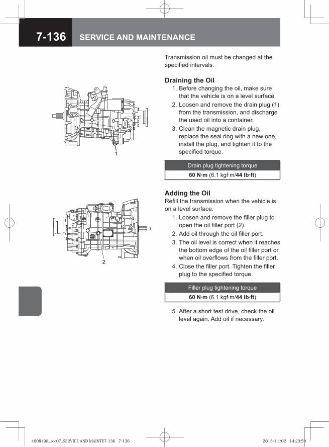
7-136 SERVICE AND MAINTENANCE
Filler plug tightening torque
60 N·m (6.1 kgf·m/44 lb·ft)
5. After a short test drive, check the oil level again. Add oil if necessary.
Adding the OilRefill the transmission when the vehicle is on a level surface. 1. Loosen and remove the filler plug to
open the oil filler port (2). 2. Add oil through the oil filler port. 3. The oil level is correct when it reaches
the bottom edge of the oil filler port or when oil overflows from the filler port.
4. Close the filler port. Tighten the filler plug to the specified torque.
Draining the Oil 1. Before changing the oil, make sure
that the vehicle is on a level surface. 2. Loosen and remove the drain plug (1)
from the transmission, and discharge the used oil into a container.
3. Clean the magnetic drain plug, replace the seal ring with a new one, install the plug, and tighten it to the specified torque.
Drain plug tightening torque
60 N·m (6.1 kgf·m/44 lb·ft)
�
Transmission oil must be changed at the specified intervals.
4608498_sec07_SERVICE AND MAINTE7-136 7-1364608498_sec07_SERVICE AND MAINTE7-136 7-136 2015/11/02 14:20:592015/11/02 14:20:59
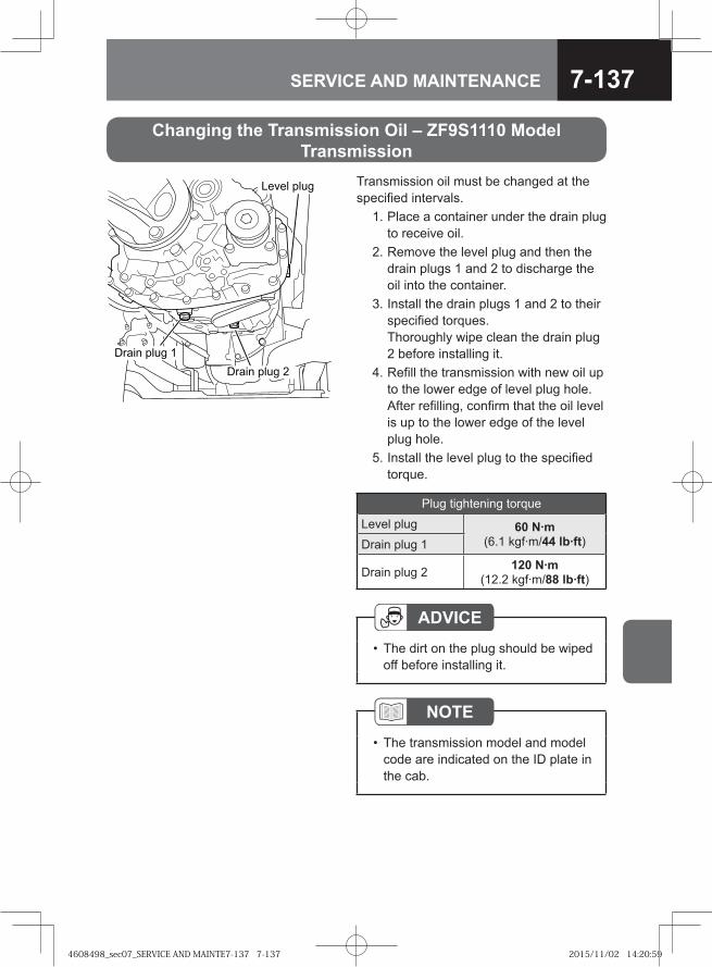
7-137SERVICE AND MAINTENANCE
Transmission oil must be changed at the specified intervals. 1. Place a container under the drain plug
to receive oil. 2. Remove the level plug and then the
drain plugs 1 and 2 to discharge the oil into the container.
3. Install the drain plugs 1 and 2 to their specified torques.Thoroughly wipe clean the drain plug 2 before installing it.
4. Refill the transmission with new oil up to the lower edge of level plug hole. After refilling, confirm that the oil level is up to the lower edge of the level plug hole.
5. Install the level plug to the specified torque.
Plug tightening torque
Level plug 60 N·m (6.1 kgf·m/44 lb·ft)Drain plug 1
Drain plug 2 120 N·m (12.2 kgf·m/88 lb·ft)
� � � ����
����� ���� �
����� ���� �
Changing the Transmission Oil – ZF9S1110 ModelTransmission
ADVICEThe dirt on the plug should be wiped off before installing it.
•
NOTEThe transmission model and model code are indicated on the ID plate in the cab.
•
4608498_sec07_SERVICE AND MAINTE7-137 7-1374608498_sec07_SERVICE AND MAINTE7-137 7-137 2015/11/02 14:20:592015/11/02 14:20:59
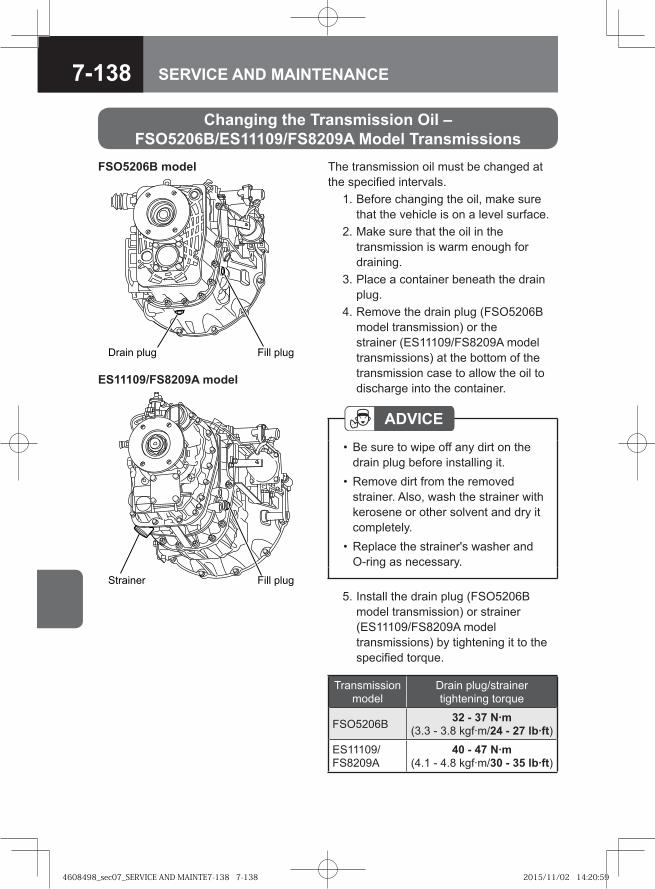
7-138 SERVICE AND MAINTENANCE
Drain plug Fill plug
Changing the Transmission Oil – FSO5206B/ES11109/FS8209A Model Transmissions
The transmission oil must be changed at the specified intervals. 1. Before changing the oil, make sure
that the vehicle is on a level surface. 2. Make sure that the oil in the
transmission is warm enough for draining.
3. Place a container beneath the drain plug.
4. Remove the drain plug (FSO5206B model transmission) or the strainer (ES11109/FS8209A model transmissions) at the bottom of the transmission case to allow the oil to discharge into the container.
ADVICEBe sure to wipe off any dirt on the drain plug before installing it.Remove dirt from the removed strainer. Also, wash the strainer with kerosene or other solvent and dry it completely.Replace the strainer's washer and O-ring as necessary.
•
•
•
Strainer Fill plug
ES11109/FS8209A model
FSO5206B model
5. Install the drain plug (FSO5206B model transmission) or strainer (ES11109/FS8209A model transmissions) by tightening it to the specified torque.
Transmission model
Drain plug/strainer tightening torque
FSO5206B 32 - 37 N·m (3.3 - 3.8 kgf·m/24 - 27 lb·ft)
ES11109/FS8209A
40 - 47 N·m (4.1 - 4.8 kgf·m/30 - 35 lb·ft)
4608498_sec07_SERVICE AND MAINTE7-138 7-1384608498_sec07_SERVICE AND MAINTE7-138 7-138 2015/11/02 14:20:592015/11/02 14:20:59
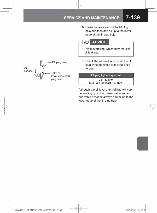
7-139SERVICE AND MAINTENANCE
�� � �� �� �
�� ���
� ���� ���� �� ��
� �� �� ��
�� �������
7. Check the oil level, and install the fill plug by tightening it to the specified torque.
Fill plug tightening torque
32 - 37 N·m (3.3 - 3.8 kgf·m/24 - 27 lb·ft)
Although the oil level after refilling will vary depending upon the transmission angle and vehicle model, always add oil up to the lower edge of the fill plug hole.
6. Clean the area around the fill plug hole and then add oil up to the lower edge of the fill plug hole.
ADVICEAvoid overfilling, which may result in oil leakage.
•
4608498_sec07_SERVICE AND MAINTE7-139 7-1394608498_sec07_SERVICE AND MAINTE7-139 7-139 2015/11/02 14:21:002015/11/02 14:21:00
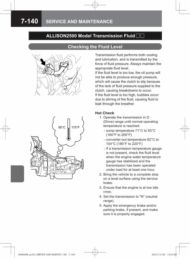
7-140 SERVICE AND MAINTENANCE
Transmission fluid performs both cooling and lubrication, and is transmitted by the force of fluid pressure. Always maintain the appropriate fluid level. If the fluid level is too low, the oil pump will not be able to produce enough pressure, which will cause the clutch to slip because of the lack of fluid pressure supplied to the clutch, causing breakdowns to occur. If the fluid level is too high, bubbles occur due to stirring of the fluid, causing fluid to leak through the breather.
Checking the Fluid Level
ALLISON2500 Model Transmission Fluid V
Hot Check 1. Operate the transmission in D
(Drive) range until normal operating temperature is reached:
- sump temperature 71°C to 93°C (160°F to 200°F)
- converter-out temperature 82°C to 104°C (180°F to 220°F)
- If a transmission temperature gauge is not present, check the fluid level when the engine water temperature gauge has stabilized and the transmission has been operated under load for at least one hour.
2. Bring the vehicle to a complete stop on a level surface using the service brake.
3. Ensure that the engine is at low idle r/min.
4. Set the transmission to "N" (neutral range).
5. Apply the emergency brake and/or parking brake, if present, and make sure it is properly engaged.
4608498_sec07_SERVICE AND MAINTE7-140 7-1404608498_sec07_SERVICE AND MAINTE7-140 7-140 2015/11/02 14:21:002015/11/02 14:21:00
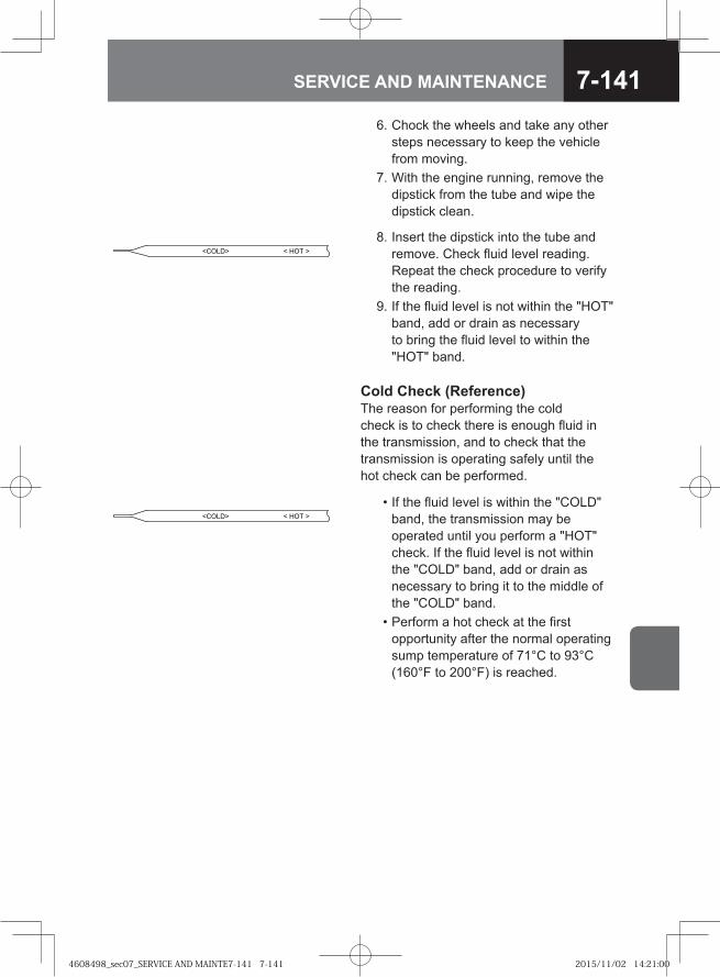
7-141SERVICE AND MAINTENANCE
<COLD> < HOT >
6. Chock the wheels and take any other steps necessary to keep the vehicle from moving.
7. With the engine running, remove the dipstick from the tube and wipe the dipstick clean.
Cold Check (Reference)The reason for performing the cold check is to check there is enough fluid in the transmission, and to check that the transmission is operating safely until the hot check can be performed.
<COLD> < HOT >
8. Insert the dipstick into the tube and remove. Check fluid level reading. Repeat the check procedure to verify the reading.
9. If the fluid level is not within the "HOT" band, add or drain as necessary to bring the fluid level to within the "HOT" band.
• If the fluid level is within the "COLD" band, the transmission may be operated until you perform a "HOT" check. If the fluid level is not within the "COLD" band, add or drain as necessary to bring it to the middle of the "COLD" band.
• Perform a hot check at the first opportunity after the normal operating sump temperature of 71°C to 93°C (160°F to 200°F) is reached.
4608498_sec07_SERVICE AND MAINTE7-141 7-1414608498_sec07_SERVICE AND MAINTE7-141 7-141 2015/11/02 14:21:002015/11/02 14:21:00
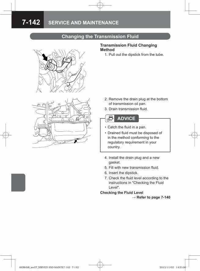
7-142 SERVICE AND MAINTENANCE
Transmission Fluid Changing Method 1. Pull out the dipstick from the tube.
ADVICECatch the fluid in a pan.Drained fluid must be disposed of in the method conforming to the regulatory requirement in your country.
••
2. Remove the drain plug at the bottom of transmission oil pan.
3. Drain transmission fluid.
4. Install the drain plug and a new gasket.
5. Fill with new transmission fluid. 6. Insert the dipstick. 7. Check the fluid level according to the
instructions in "Checking the Fluid Level".
Checking the Fluid Level → Refer to page 7-140
Changing the Transmission Fluid
4608498_sec07_SERVICE AND MAINTE7-142 7-1424608498_sec07_SERVICE AND MAINTE7-142 7-142 2015/11/02 14:21:002015/11/02 14:21:00
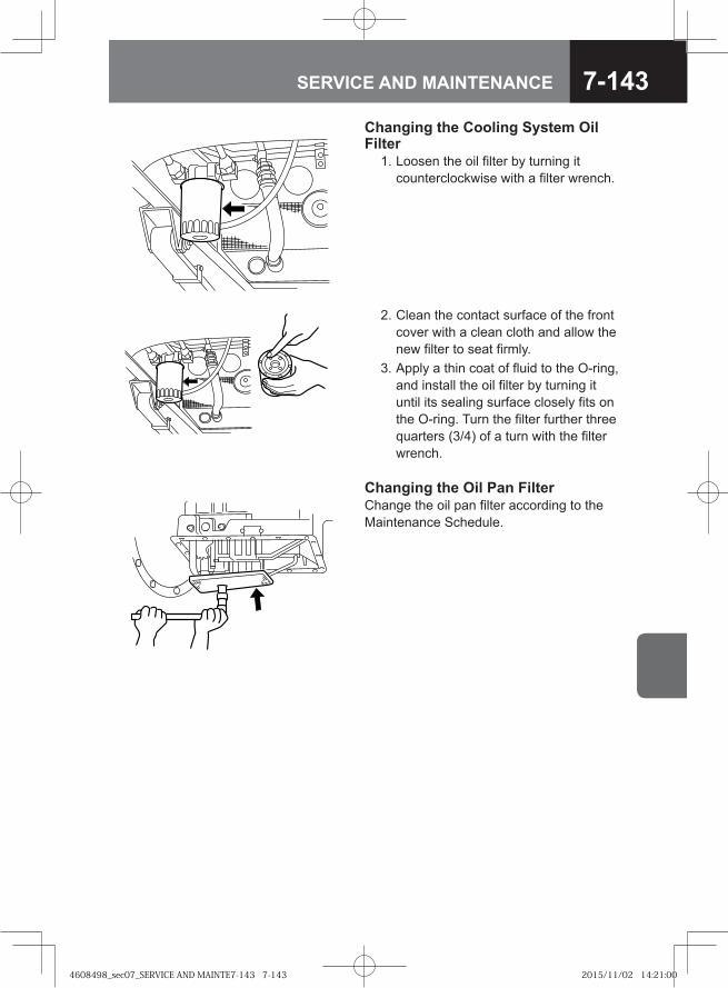
7-143SERVICE AND MAINTENANCE
Changing the Cooling System Oil Filter 1. Loosen the oil filter by turning it
counterclockwise with a filter wrench.
2. Clean the contact surface of the front cover with a clean cloth and allow the new filter to seat firmly.
3. Apply a thin coat of fluid to the O-ring, and install the oil filter by turning it until its sealing surface closely fits on the O-ring. Turn the filter further three quarters (3/4) of a turn with the filter wrench.
Changing the Oil Pan Filter Change the oil pan filter according to the Maintenance Schedule.
4608498_sec07_SERVICE AND MAINTE7-143 7-1434608498_sec07_SERVICE AND MAINTE7-143 7-143 2015/11/02 14:21:002015/11/02 14:21:00
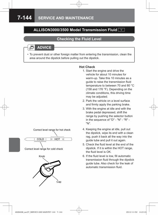
7-144 SERVICE AND MAINTENANCE
Hot Check 1. Start the engine and drive the
vehicle for about 10 minutes for warm-up. Take this 10 minutes as a guide to raise the transmission fluid temperature to between 70 and 80 °C (158 and 176 °F). Depending on the climate conditions, this driving time may be adjusted.
2. Park the vehicle on a level surface and firmly apply the parking brake.
3. With the engine at idle and with the brake pedal depressed, shift the range by pushing the selector button in the sequence of "D" - "N" - "R" - "N".
� ��
���
Checking the Fluid Level
ADVICETo prevent dust or other foreign matter from entering the transmission, clean the area around the dipstick before pulling out the dipstick.
•
ALLISON3000/3500 Model Transmission Fluid V
4. Keeping the engine at idle, pull out the dipstick, wipe its end with a clean rag, push it back all the way into the guide tube and pull it out again.
5. Check the fluid level at the end of the dipstick. If it is within the HOT range, the fluid level is OK.
6. If the fluid level is low, fill automatic transmission fluid through the dipstick guide tube. Also check for the leak of automatic transmission fluid.
��� ���
������ ����� ����� ��� ���� �����
������ ����� ����� ��� ��� �����
4608498_sec07_SERVICE AND MAINTE7-144 7-1444608498_sec07_SERVICE AND MAINTE7-144 7-144 2015/11/02 14:21:012015/11/02 14:21:01
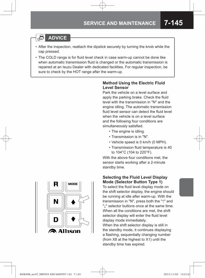
7-145SERVICE AND MAINTENANCE
Method Using the Electric Fluid Level SensorPark the vehicle on a level surface and apply the parking brake. Check the fluid level with the transmission in "N" and the engine idling. The automatic transmission fluid level sensor can detect the fluid level when the vehicle is on a level surface and the following four conditions are simultaneously satisfied. • The engine is idling. • Transmission is in "N". • Vehicle speed is 0 km/h (0 MPH). • Transmission fluid temperature is 40
to 104°C (104 to 220°F).With the above four conditions met, the sensor starts working after a 2-minute standby time.
ADVICEAfter the inspection, reattach the dipstick securely by turning the knob while the cap pressed.The COLD range is for fluid level check in case warm-up cannot be done like when automatic transmission fluid is changed or the automatic transmission is repaired at an Isuzu Dealer with dedicated facilities. For regular inspection, be sure to check by the HOT range after the warm-up.
•
•
Selecting the Fluid Level Display Mode (Selector Button Type 1)To select the fluid level display mode on the shift selector display, the engine should be running at idle after warm-up. With the transmission in "N", press both the "↑" and "↓" selector buttons once at the same time. When all the conditions are met, the shift selector display will enter the fluid level display mode immediately. When the shift selector display is still in the standby mode, it continues displaying a flashing, sequentially changing number (from X8 at the highest to X1) until the standby time has expired.
4608498_sec07_SERVICE AND MAINTE7-145 7-1454608498_sec07_SERVICE AND MAINTE7-145 7-145 2015/11/02 14:21:012015/11/02 14:21:01
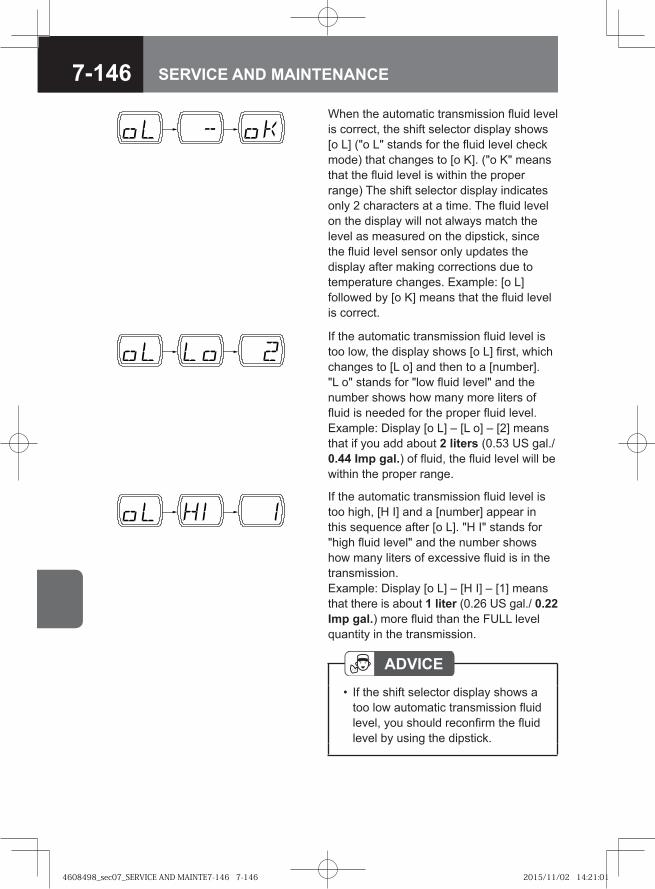
7-146 SERVICE AND MAINTENANCE
If the automatic transmission fluid level is too low, the display shows [o L] first, which changes to [L o] and then to a [number]. "L o" stands for "low fluid level" and the number shows how many more liters of fluid is needed for the proper fluid level. Example: Display [o L] – [L o] – [2] means that if you add about 2 liters (0.53 US gal./ 0.44 Imp gal.) of fluid, the fluid level will be within the proper range.
If the automatic transmission fluid level is too high, [H I] and a [number] appear in this sequence after [o L]. "H I" stands for "high fluid level" and the number shows how many liters of excessive fluid is in the transmission.Example: Display [o L] – [H I] – [1] means that there is about 1 liter (0.26 US gal./ 0.22 Imp gal.) more fluid than the FULL level quantity in the transmission.
ADVICEIf the shift selector display shows a too low automatic transmission fluid level, you should reconfirm the fluid level by using the dipstick.
•
When the automatic transmission fluid level is correct, the shift selector display shows [o L] ("o L" stands for the fluid level check mode) that changes to [o K]. ("o K" means that the fluid level is within the proper range) The shift selector display indicates only 2 characters at a time. The fluid level on the display will not always match the level as measured on the dipstick, since the fluid level sensor only updates the display after making corrections due to temperature changes. Example: [o L] followed by [o K] means that the fluid level is correct.
4608498_sec07_SERVICE AND MAINTE7-146 7-1464608498_sec07_SERVICE AND MAINTE7-146 7-146 2015/11/02 14:21:012015/11/02 14:21:01
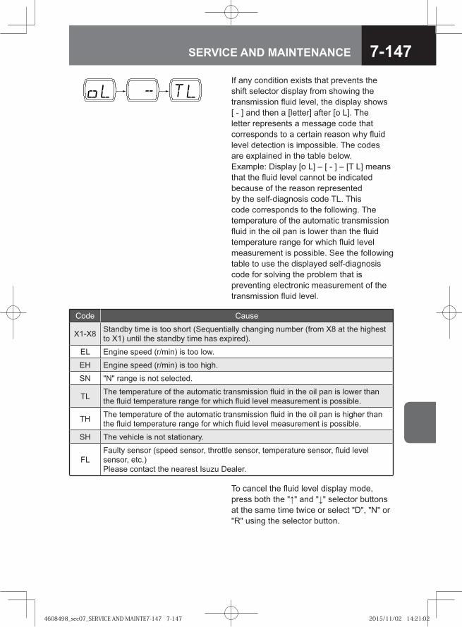
7-147SERVICE AND MAINTENANCE
To cancel the fluid level display mode, press both the "↑" and "↓" selector buttons at the same time twice or select "D", "N" or "R" using the selector button.
Code Cause
X1-X8 Standby time is too short (Sequentially changing number (from X8 at the highest to X1) until the standby time has expired).
EL Engine speed (r/min) is too low.
EH Engine speed (r/min) is too high.
SN "N" range is not selected.
TL The temperature of the automatic transmission fluid in the oil pan is lower than the fluid temperature range for which fluid level measurement is possible.
TH The temperature of the automatic transmission fluid in the oil pan is higher than the fluid temperature range for which fluid level measurement is possible.
SH The vehicle is not stationary.
FLFaulty sensor (speed sensor, throttle sensor, temperature sensor, fluid level sensor, etc.)Please contact the nearest Isuzu Dealer.
If any condition exists that prevents the shift selector display from showing the transmission fluid level, the display shows [ - ] and then a [letter] after [o L]. The letter represents a message code that corresponds to a certain reason why fluid level detection is impossible. The codes are explained in the table below.Example: Display [o L] – [ - ] – [T L] means that the fluid level cannot be indicated because of the reason represented by the self-diagnosis code TL. This code corresponds to the following. The temperature of the automatic transmission fluid in the oil pan is lower than the fluid temperature range for which fluid level measurement is possible. See the following table to use the displayed self-diagnosis code for solving the problem that is preventing electronic measurement of the transmission fluid level.
4608498_sec07_SERVICE AND MAINTE7-147 7-1474608498_sec07_SERVICE AND MAINTE7-147 7-147 2015/11/02 14:21:022015/11/02 14:21:02
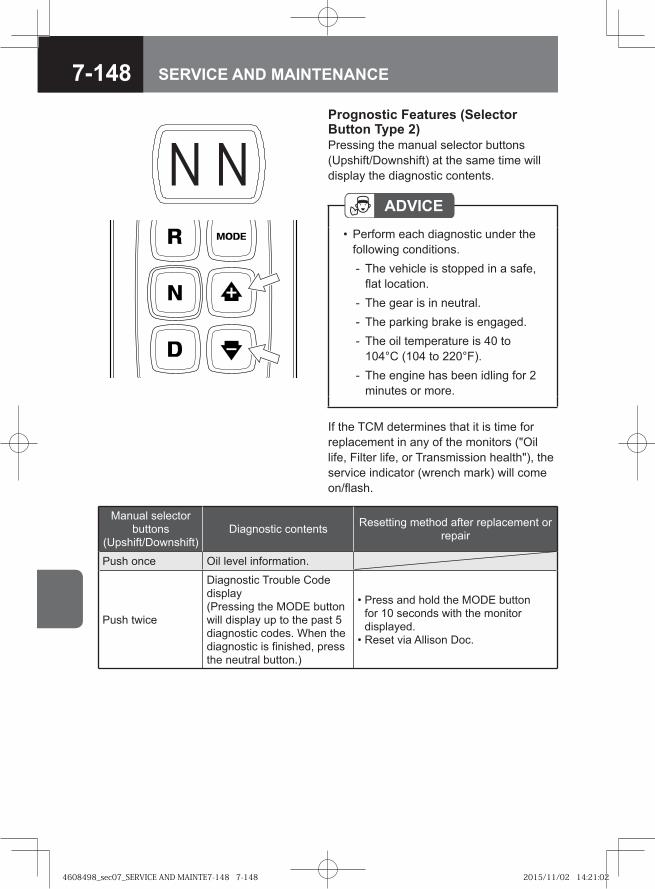
7-148 SERVICE AND MAINTENANCE
Prognostic Features (Selector Button Type 2)Pressing the manual selector buttons (Upshift/Downshift) at the same time will display the diagnostic contents.
ADVICEPerform each diagnostic under the following conditions.
The vehicle is stopped in a safe, flat location.The gear is in neutral.The parking brake is engaged.The oil temperature is 40 to 104°C (104 to 220°F).The engine has been idling for 2 minutes or more.
•
-
---
-
If the TCM determines that it is time for replacement in any of the monitors ("Oil life, Filter life, or Transmission health"), the service indicator (wrench mark) will come on/flash.
Manual selector buttons
(Upshift/Downshift)Diagnostic contents Resetting method after replacement or
repair
Push once Oil level information.
Push twice
Diagnostic Trouble Code display (Pressing the MODE button will display up to the past 5 diagnostic codes. When the diagnostic is finished, press the neutral button.)
• Press and hold the MODE button for 10 seconds with the monitor displayed.
• Reset via Allison Doc.
4608498_sec07_SERVICE AND MAINTE7-148 7-1484608498_sec07_SERVICE AND MAINTE7-148 7-148 2015/11/02 14:21:022015/11/02 14:21:02
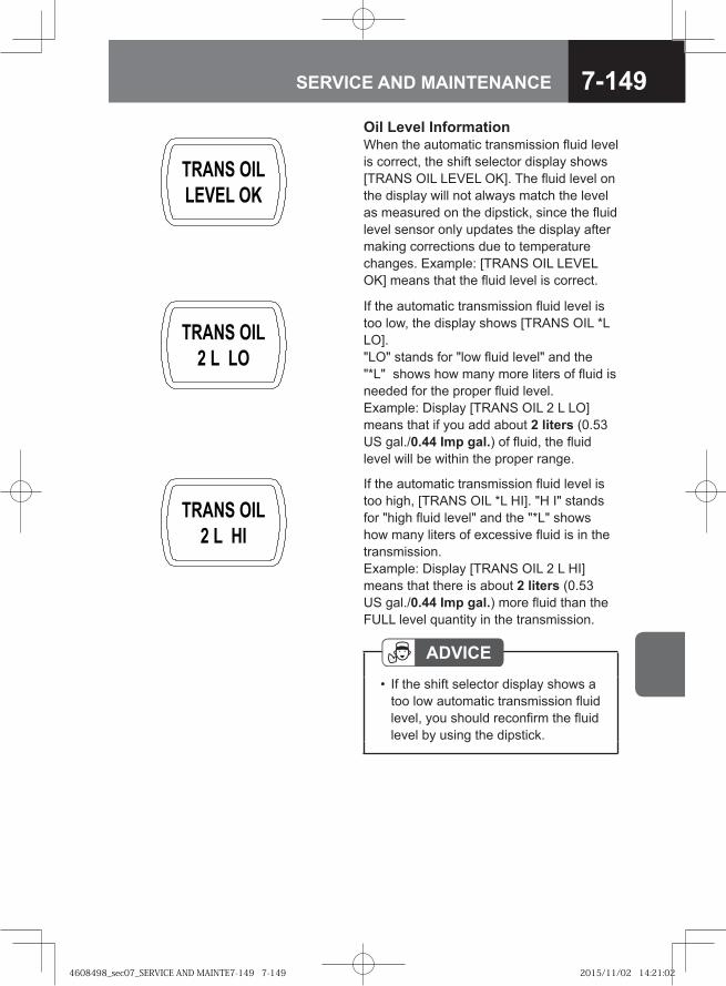
7-149SERVICE AND MAINTENANCE
If the automatic transmission fluid level is too low, the display shows [TRANS OIL *L LO]. "LO" stands for "low fluid level" and the "*L" shows how many more liters of fluid is needed for the proper fluid level. Example: Display [TRANS OIL 2 L LO] means that if you add about 2 liters (0.53 US gal./0.44 Imp gal.) of fluid, the fluid level will be within the proper range.
If the automatic transmission fluid level is too high, [TRANS OIL *L HI]. "H I" stands for "high fluid level" and the "*L" shows how many liters of excessive fluid is in the transmission.Example: Display [TRANS OIL 2 L HI] means that there is about 2 liters (0.53 US gal./0.44 Imp gal.) more fluid than the FULL level quantity in the transmission.
ADVICEIf the shift selector display shows a too low automatic transmission fluid level, you should reconfirm the fluid level by using the dipstick.
•
Oil Level InformationWhen the automatic transmission fluid level is correct, the shift selector display shows [TRANS OIL LEVEL OK]. The fluid level on the display will not always match the level as measured on the dipstick, since the fluid level sensor only updates the display after making corrections due to temperature changes. Example: [TRANS OIL LEVEL OK] means that the fluid level is correct.
4608498_sec07_SERVICE AND MAINTE7-149 7-1494608498_sec07_SERVICE AND MAINTE7-149 7-149 2015/11/02 14:21:022015/11/02 14:21:02
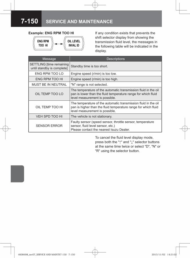
7-150 SERVICE AND MAINTENANCE
To cancel the fluid level display mode, press both the "↑" and "↓" selector buttons at the same time twice or select "D", "N" or "R" using the selector button.
If any condition exists that prevents the shift selector display from showing the transmission fluid level, the messages in the following table will be indicated in the display.
Example: ENG RPM TOO HI
Message Descriptions
SETTLING [time remaining until standby is complete] Standby time is too short.
ENG RPM TOO LO Engine speed (r/min) is too low.
ENG RPM TOO HI Engine speed (r/min) is too high.
MUST BE IN NEUTRAL "N" range is not selected.
OIL TEMP TOO LOThe temperature of the automatic transmission fluid in the oil pan is lower than the fluid temperature range for which fluid level measurement is possible.
OIL TEMP TOO HIThe temperature of the automatic transmission fluid in the oil pan is higher than the fluid temperature range for which fluid level measurement is possible.
VEH SPD TOO HI The vehicle is not stationary.
SENSOR ERRORFaulty sensor (speed sensor, throttle sensor, temperature sensor, fluid level sensor, etc.) Please contact the nearest Isuzu Dealer.
4608498_sec07_SERVICE AND MAINTE7-150 7-1504608498_sec07_SERVICE AND MAINTE7-150 7-150 2015/11/02 14:21:022015/11/02 14:21:02
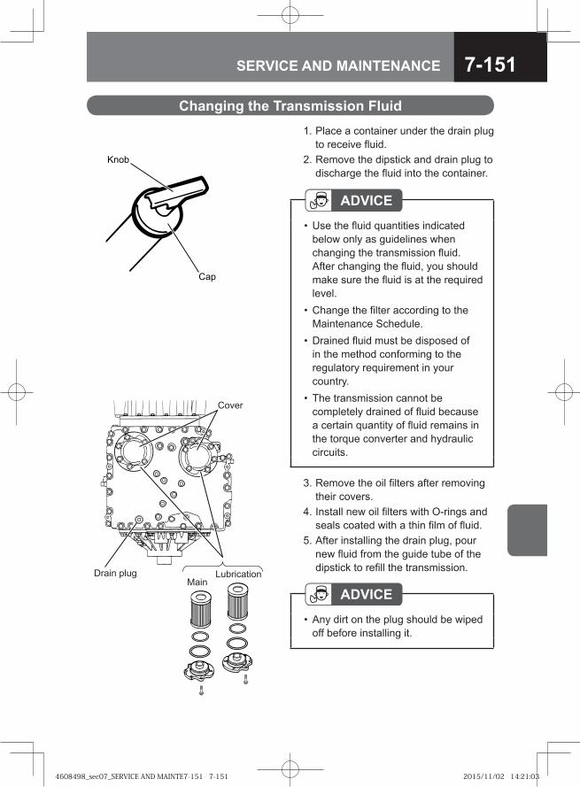
7-151SERVICE AND MAINTENANCE
1. Place a container under the drain plug to receive fluid.
2. Remove the dipstick and drain plug to discharge the fluid into the container.
ADVICEUse the fluid quantities indicated below only as guidelines when changing the transmission fluid. After changing the fluid, you should make sure the fluid is at the required level.Change the filter according to the Maintenance Schedule.Drained fluid must be disposed of in the method conforming to the regulatory requirement in your country.The transmission cannot be completely drained of fluid because a certain quantity of fluid remains in the torque converter and hydraulic circuits.
•
•
•
•
3. Remove the oil filters after removing their covers.
4. Install new oil filters with O-rings and seals coated with a thin film of fluid.
5. After installing the drain plug, pour new fluid from the guide tube of the dipstick to refill the transmission.
ADVICEAny dirt on the plug should be wiped off before installing it.
•
� ��
���
Cover
LubricationMain
Drain plug
Changing the Transmission Fluid
4608498_sec07_SERVICE AND MAINTE7-151 7-1514608498_sec07_SERVICE AND MAINTE7-151 7-151 2015/11/02 14:21:032015/11/02 14:21:03
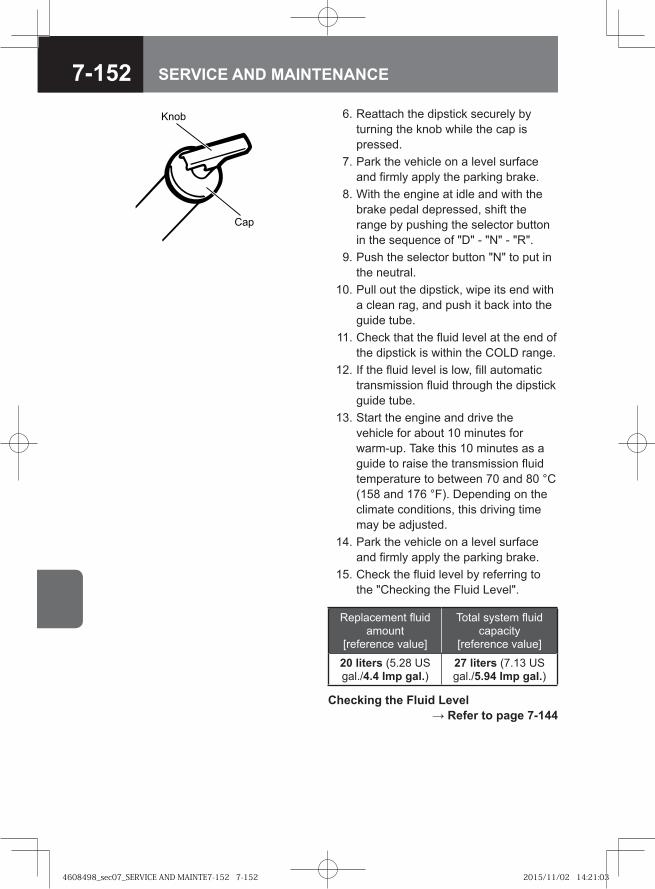
7-152 SERVICE AND MAINTENANCE
6. Reattach the dipstick securely by turning the knob while the cap is pressed.
7. Park the vehicle on a level surface and firmly apply the parking brake.
8. With the engine at idle and with the brake pedal depressed, shift the range by pushing the selector button in the sequence of "D" - "N" - "R".
9. Push the selector button "N" to put in the neutral.
10. Pull out the dipstick, wipe its end with a clean rag, and push it back into the guide tube.
11. Check that the fluid level at the end of the dipstick is within the COLD range.
12. If the fluid level is low, fill automatic transmission fluid through the dipstick guide tube.
13. Start the engine and drive the vehicle for about 10 minutes for warm-up. Take this 10 minutes as a guide to raise the transmission fluid temperature to between 70 and 80 °C (158 and 176 °F). Depending on the climate conditions, this driving time may be adjusted.
14. Park the vehicle on a level surface and firmly apply the parking brake.
15. Check the fluid level by referring to the "Checking the Fluid Level".
� ��
���
Replacement fluid amount
[reference value]
Total system fluid capacity
[reference value]
20 liters (5.28 US gal./4.4 Imp gal.)
27 liters (7.13 US gal./5.94 Imp gal.)
Checking the Fluid Level → Refer to page 7-144
4608498_sec07_SERVICE AND MAINTE7-152 7-1524608498_sec07_SERVICE AND MAINTE7-152 7-152 2015/11/02 14:21:032015/11/02 14:21:03
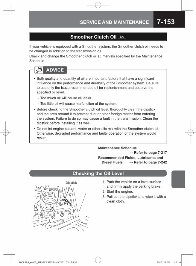
7-153SERVICE AND MAINTENANCE
Smoother Clutch Oil SA
If your vehicle is equipped with a Smoother system, the Smoother clutch oil needs to be changed in addition to the transmission oil.Check and change the Smoother clutch oil at intervals specified by the Maintenance Schedule.
ADVICEBoth quality and quantity of oil are important factors that have a significant influence on the performance and durability of the Smoother system. Be sure to use only the Isuzu recommended oil for replenishment and observe the specified oil level.
Too much oil will cause oil leaks.Too little oil will cause malfunction of the system.
Before checking the Smoother clutch oil level, thoroughly clean the dipstick and the area around it to prevent dust or other foreign matter from entering the system. Failure to do so may cause a fault in the transmission. Clean the dipstick before installing it as well.Do not let engine coolant, water or other oils mix with the Smoother clutch oil. Otherwise, degraded performance and faulty operation of the system would result.
•
--
•
•
1. Park the vehicle on a level surface and firmly apply the parking brake.
2. Start the engine. 3. Pull out the dipstick and wipe it with a
clean cloth.
Checking the Oil Level
Dipstick
Maintenance Schedule → Refer to page 7-217
Recommended Fluids, Lubricants and Diesel Fuels → Refer to page 7-242
4608498_sec07_SERVICE AND MAINTE7-153 7-1534608498_sec07_SERVICE AND MAINTE7-153 7-153 2015/11/02 14:21:032015/11/02 14:21:03
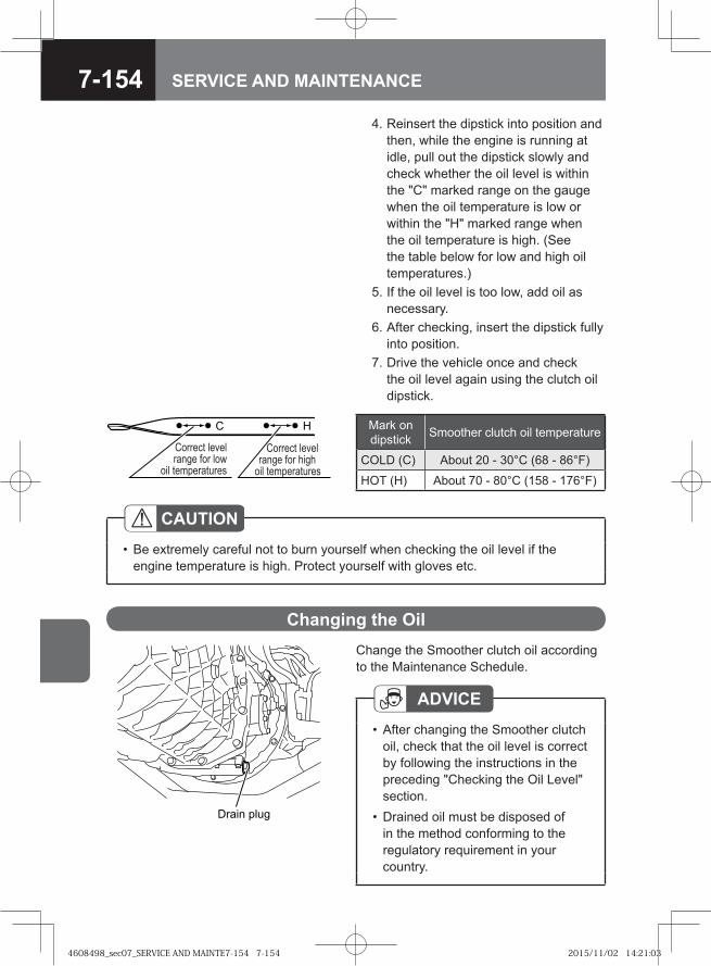
7-154 SERVICE AND MAINTENANCE
Change the Smoother clutch oil according to the Maintenance Schedule.
Changing the Oil
ADVICEAfter changing the Smoother clutch oil, check that the oil level is correct by following the instructions in the preceding "Checking the Oil Level" section.Drained oil must be disposed of in the method conforming to the regulatory requirement in your country.
•
•Drain plug
CAUTIONBe extremely careful not to burn yourself when checking the oil level if the engine temperature is high. Protect yourself with gloves etc.
•
C H
Correct level range for low
oil temperatures
Correct level range for high
oil temperatures
Mark on dipstick Smoother clutch oil temperature
COLD (C) About 20 - 30°C (68 - 86°F)
HOT (H) About 70 - 80°C (158 - 176°F)
4. Reinsert the dipstick into position and then, while the engine is running at idle, pull out the dipstick slowly and check whether the oil level is within the "C" marked range on the gauge when the oil temperature is low or within the "H" marked range when the oil temperature is high. (See the table below for low and high oil temperatures.)
5. If the oil level is too low, add oil as necessary.
6. After checking, insert the dipstick fully into position.
7. Drive the vehicle once and check the oil level again using the clutch oil dipstick.
4608498_sec07_SERVICE AND MAINTE7-154 7-1544608498_sec07_SERVICE AND MAINTE7-154 7-154 2015/11/02 14:21:032015/11/02 14:21:03
7-155SERVICE AND MAINTENANCE
NOTESmoother clutch oil cannot be completely drained because a certain quantity of oil remains in the fluid coupling and hydraulic circuits.
•
5. Install the drain plug by tightening it to the specified torque.
Drain plug tightening torque
29 - 49 N·m (3.0 - 5.0 kgf·m/22 - 36 lb·ft)
6. Pour new oil into the guide tube of the dipstick.
7. Check the oil level according to the "Checking the Oil Level" section.
Checking the Oil Level → Refer to page 7-153
Maintenance Schedule → Refer to page 7-217
Recommended Fluids, Lubricants and Diesel Fuels → Refer to page 7-242
Manual Transmission Oil M/T / SA → Refer to page 7-129
1. Place a container under the drain plug. 2. Tilt the cab. 3. Pull out the dipstick. 4. Remove the drain plug to discharge
the oil into the container.
4608498_sec07_SERVICE AND MAINTE7-155 7-1554608498_sec07_SERVICE AND MAINTE7-155 7-155 2015/11/02 14:21:042015/11/02 14:21:04
7-156 SERVICE AND MAINTENANCE
Rear Axle Differential Gear Oil
The rear axle differential gear oil must be changed according to the Maintenance Schedule.
ADVICEUse the oil quantity indicated later in this section only as guidelines when changing the rear axle differential gear oil. After changing the oil, ensure that it is at the required level.Drained oil must be disposed of in a method conforming to the regulatory requirement in your country.
•
••
Maintenance Schedule → Refer to page 7-217
Recommended Fluids, Lubricants and Diesel Fuels → Refer to page 7-242
4608498_sec07_SERVICE AND MAINTE7-156 7-1564608498_sec07_SERVICE AND MAINTE7-156 7-156 2015/11/02 14:21:042015/11/02 14:21:04
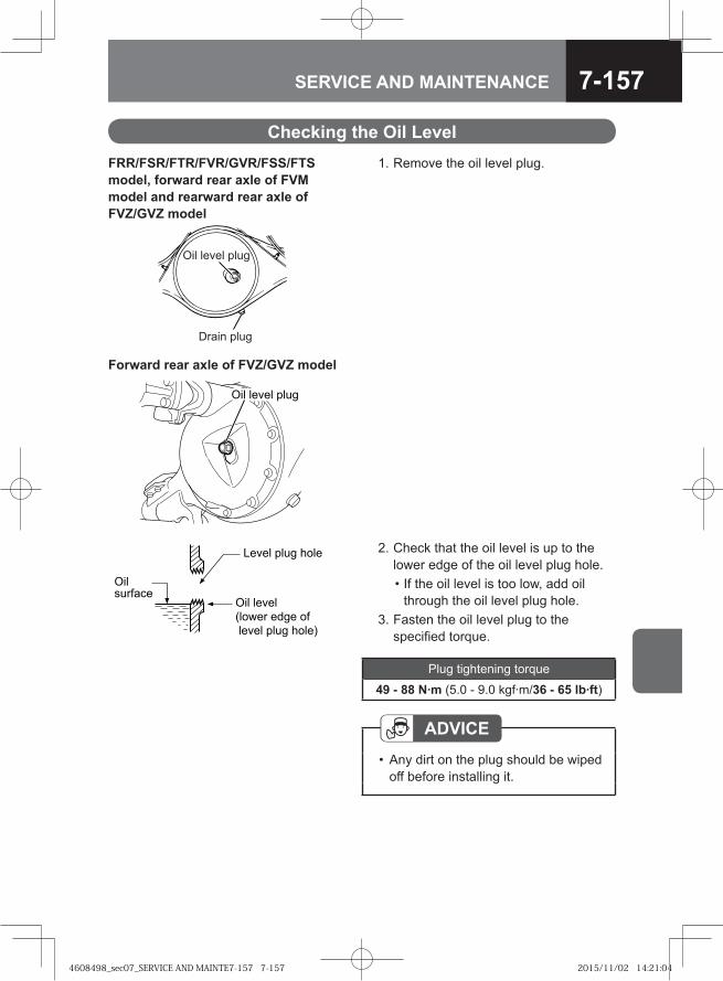
7-157SERVICE AND MAINTENANCE
Level plug hole
Oil level (lower edge of level plug hole)
Oil surface
2. Check that the oil level is up to the lower edge of the oil level plug hole.
• If the oil level is too low, add oil through the oil level plug hole.
3. Fasten the oil level plug to the specified torque.
Checking the Oil LevelFRR/FSR/FTR/FVR/GVR/FSS/FTS model, forward rear axle of FVM model and rearward rear axle of FVZ/GVZ model
Oil level plug
Drain plug
Forward rear axle of FVZ/GVZ model
Oil level plug
ADVICEAny dirt on the plug should be wiped off before installing it.
•
Plug tightening torque
49 - 88 N·m (5.0 - 9.0 kgf·m/36 - 65 lb·ft)
1. Remove the oil level plug.
4608498_sec07_SERVICE AND MAINTE7-157 7-1574608498_sec07_SERVICE AND MAINTE7-157 7-157 2015/11/02 14:21:042015/11/02 14:21:04
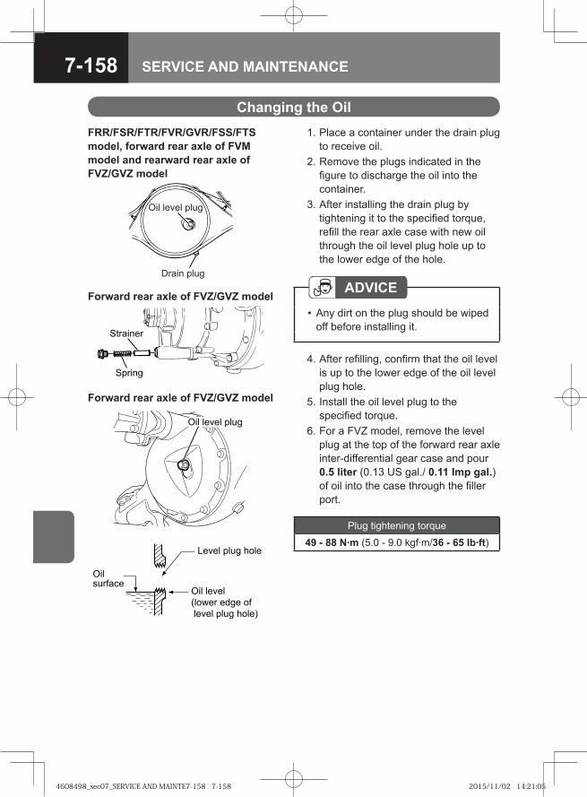
7-158 SERVICE AND MAINTENANCE
1. Place a container under the drain plug to receive oil.
2. Remove the plugs indicated in the figure to discharge the oil into the container.
3. After installing the drain plug by tightening it to the specified torque, refill the rear axle case with new oil through the oil level plug hole up to the lower edge of the hole.
Changing the OilFRR/FSR/FTR/FVR/GVR/FSS/FTS model, forward rear axle of FVM model and rearward rear axle of FVZ/GVZ model
Oil level plug
Drain plug
Forward rear axle of FVZ/GVZ model
� ����
��������
Oil level plug
ADVICEAny dirt on the plug should be wiped off before installing it.
•
4. After refilling, confirm that the oil level is up to the lower edge of the oil level plug hole.
5. Install the oil level plug to the specified torque.
6. For a FVZ model, remove the level plug at the top of the forward rear axle inter-differential gear case and pour 0.5 liter (0.13 US gal./ 0.11 Imp gal.) of oil into the case through the filler port.
Plug tightening torque
49 - 88 N·m (5.0 - 9.0 kgf·m/36 - 65 lb·ft)
Forward rear axle of FVZ/GVZ model
Level plug hole
Oil level (lower edge of level plug hole)
Oil surface
4608498_sec07_SERVICE AND MAINTE7-158 7-1584608498_sec07_SERVICE AND MAINTE7-158 7-158 2015/11/02 14:21:052015/11/02 14:21:05
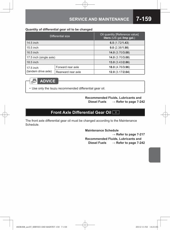
7-159SERVICE AND MAINTENANCE
Quantity of differential gear oil to be changed
Differential size Oil quantity [Reference value] liters (US gal./Imp gal.)
14.5 inch 6.5 (1.72/1.43)
15.5 inch 9.0 (2.38/1.98)
16.5 inch 14.0 (3.70/3.08)
17.5 inch (single axle) 14.0 (3.70/3.08)
18.5 inch 13.0 (3.43/2.86)
17.5 inch (tandem drive axle)
Forward rear axle 18.0 (4.76/3.96)
Rearward rear axle 12.0 (3.17/2.64)
ADVICEUse only the Isuzu recommended differential gear oil.•
Recommended Fluids, Lubricants and Diesel Fuels → Refer to page 7-242
Front Axle Differential Gear Oil V
The front axle differential gear oil must be changed according to the Maintenance Schedule.
Maintenance Schedule → Refer to page 7-217
Recommended Fluids, Lubricants and Diesel Fuels → Refer to page 7-242
4608498_sec07_SERVICE AND MAINTE7-159 7-1594608498_sec07_SERVICE AND MAINTE7-159 7-159 2015/11/02 14:21:052015/11/02 14:21:05
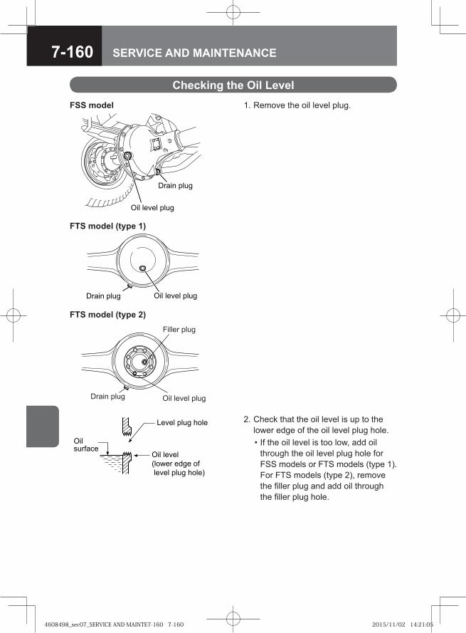
7-160 SERVICE AND MAINTENANCE
��� � ����
� � ����� ����
FSS model 1. Remove the oil level plug.
Checking the Oil Level
FTS model (type 1)
��� ���� ��� ����� ����
2. Check that the oil level is up to the lower edge of the oil level plug hole.
• If the oil level is too low, add oil through the oil level plug hole for FSS models or FTS models (type 1). For FTS models (type 2), remove the filler plug and add oil through the filler plug hole.
Level plug hole
Oil level (lower edge of level plug hole)
Oil surface
FTS model (type 2)Filler plug
Drain plug Oil level plug
4608498_sec07_SERVICE AND MAINTE7-160 7-1604608498_sec07_SERVICE AND MAINTE7-160 7-160 2015/11/02 14:21:052015/11/02 14:21:05
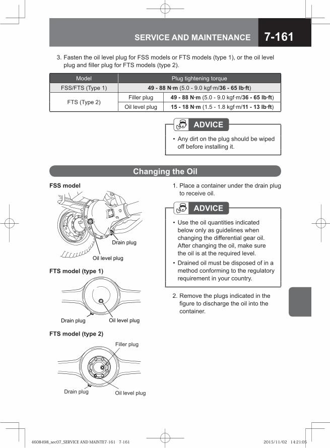
7-161SERVICE AND MAINTENANCE
1. Place a container under the drain plug to receive oil.
Changing the Oil
ADVICEUse the oil quantities indicated below only as guidelines when changing the differential gear oil. After changing the oil, make sure the oil is at the required level.Drained oil must be disposed of in a method conforming to the regulatory requirement in your country.
•
•
2. Remove the plugs indicated in the figure to discharge the oil into the container.
ADVICEAny dirt on the plug should be wiped off before installing it.
•
3. Fasten the oil level plug for FSS models or FTS models (type 1), or the oil level plug and filler plug for FTS models (type 2).
��� � ����
� � ����� ����
FSS model
FTS model (type 1)
��� ���� ��� ����� ����
FTS model (type 2)Filler plug
Drain plug Oil level plug
Model Plug tightening torque
FSS/FTS (Type 1) 49 - 88 N·m (5.0 - 9.0 kgf·m/36 - 65 lb·ft)
FTS (Type 2)Filler plug 49 - 88 N·m (5.0 - 9.0 kgf·m/36 - 65 lb·ft)
Oil level plug 15 - 18 N·m (1.5 - 1.8 kgf·m/11 - 13 lb·ft)
4608498_sec07_SERVICE AND MAINTE7-161 7-1614608498_sec07_SERVICE AND MAINTE7-161 7-161 2015/11/02 14:21:052015/11/02 14:21:05
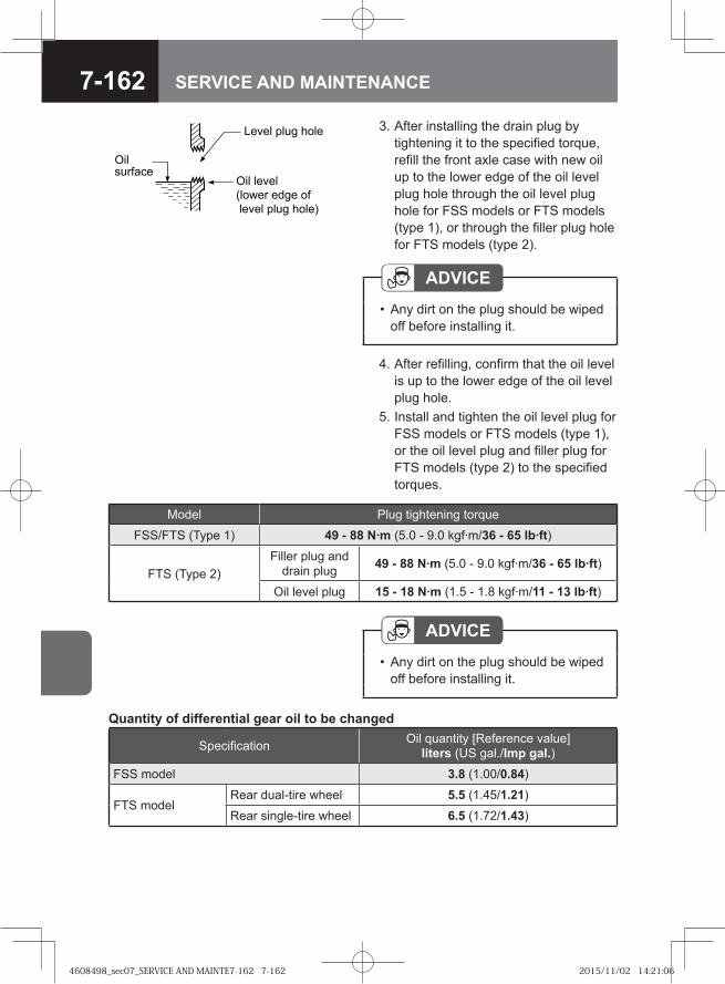
7-162 SERVICE AND MAINTENANCE
ADVICEAny dirt on the plug should be wiped off before installing it.
•
4. After refilling, confirm that the oil level is up to the lower edge of the oil level plug hole.
5. Install and tighten the oil level plug for FSS models or FTS models (type 1), or the oil level plug and filler plug for FTS models (type 2) to the specified torques.
Quantity of differential gear oil to be changed
Specification Oil quantity [Reference value] liters (US gal./Imp gal.)
FSS model 3.8 (1.00/0.84)
FTS modelRear dual-tire wheel 5.5 (1.45/1.21)
Rear single-tire wheel 6.5 (1.72/1.43)
3. After installing the drain plug by tightening it to the specified torque, refill the front axle case with new oil up to the lower edge of the oil level plug hole through the oil level plug hole for FSS models or FTS models (type 1), or through the filler plug hole for FTS models (type 2).
ADVICEAny dirt on the plug should be wiped off before installing it.
•
Level plug hole
Oil level (lower edge of level plug hole)
Oil surface
Model Plug tightening torque
FSS/FTS (Type 1) 49 - 88 N·m (5.0 - 9.0 kgf·m/36 - 65 lb·ft)
FTS (Type 2)Filler plug and
drain plug 49 - 88 N·m (5.0 - 9.0 kgf·m/36 - 65 lb·ft)
Oil level plug 15 - 18 N·m (1.5 - 1.8 kgf·m/11 - 13 lb·ft)
4608498_sec07_SERVICE AND MAINTE7-162 7-1624608498_sec07_SERVICE AND MAINTE7-162 7-162 2015/11/02 14:21:062015/11/02 14:21:06
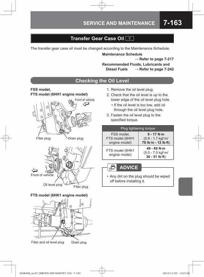
7-163SERVICE AND MAINTENANCE
Transfer Gear Case Oil V
The transfer gear case oil must be changed according to the Maintenance Schedule.
FSS model, FTS model (6HH1 engine model)
Drain plugFiller plug
Front of vehicle
FTS model (6HK1 engine model)
Filler and oil level plug Drain plug
Filler plugOil level plug
Front of vehicle
1. Remove the oil level plug. 2. Check that the oil level is up to the
lower edge of the oil level plug hole. • If the oil level is too low, add oil
through the oil level plug hole. 3. Fasten the oil level plug to the
specified torque.
Checking the Oil Level
ADVICEAny dirt on the plug should be wiped off before installing it.
•
Plug tightening torque
FSS model, FTS model (6HH1
engine model)
9 - 17 N·m (0.9 - 1.7 kgf·m/
78 lb·in - 12 lb·ft)
FTS model (6HK1 engine model)
49 - 69 N·m (5.0 - 7.0 kgf·m/
36 - 51 lb·ft)
Maintenance Schedule → Refer to page 7-217
Recommended Fluids, Lubricants and Diesel Fuels → Refer to page 7-242
4608498_sec07_SERVICE AND MAINTE7-163 7-1634608498_sec07_SERVICE AND MAINTE7-163 7-163 2015/11/02 14:21:062015/11/02 14:21:06
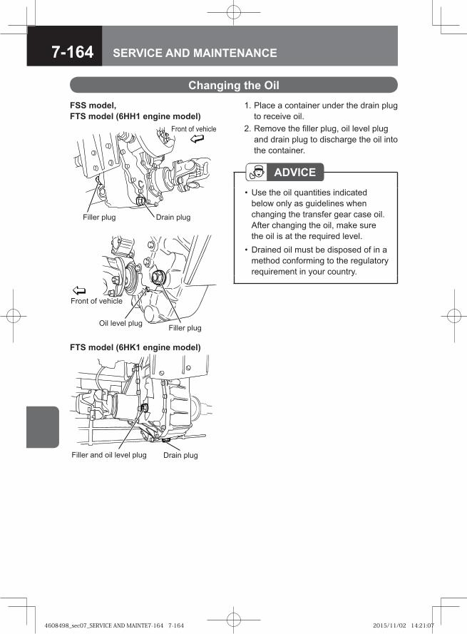
7-164 SERVICE AND MAINTENANCE
1. Place a container under the drain plug to receive oil.
2. Remove the filler plug, oil level plug and drain plug to discharge the oil into the container.
Changing the Oil
ADVICEUse the oil quantities indicated below only as guidelines when changing the transfer gear case oil. After changing the oil, make sure the oil is at the required level.Drained oil must be disposed of in a method conforming to the regulatory requirement in your country.
•
•
FSS model, FTS model (6HH1 engine model)
Drain plugFiller plug
Front of vehicle
FTS model (6HK1 engine model)
Filler and oil level plug Drain plug
Filler plugOil level plug
Front of vehicle
4608498_sec07_SERVICE AND MAINTE7-164 7-1644608498_sec07_SERVICE AND MAINTE7-164 7-164 2015/11/02 14:21:072015/11/02 14:21:07
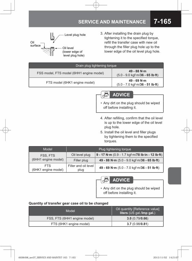
7-165SERVICE AND MAINTENANCE
ADVICEAny dirt on the plug should be wiped off before installing it.
•
Quantity of transfer gear case oil to be changed
Model Oil quantity [Reference value] liters (US gal./Imp gal.)
FSS, FTS (6HH1 engine model) 3.0 (0.79/0.66)
FTS (6HK1 engine model) 3.7 (0.98/0.81)
3. After installing the drain plug by tightening it to the specified torque, refill the transfer case with new oil through the filler plug hole up to the lower edge of the oil level plug hole.
ADVICEAny dirt on the plug should be wiped off before installing it.
•
4. After refilling, confirm that the oil level is up to the lower edge of the oil level plug hole.
5. Install the oil level and filler plugs by tightening them to the specified torques.
Model Plug tightening torque
FSS, FTS (6HH1 engine model)
Oil level plug 9 - 17 N·m (0.9 - 1.7 kgf·m/78 lb·in - 12 lb·ft)Filler plug 49 - 88 N·m (5.0 - 9.0 kgf·m/36 - 65 lb·ft)
FTS (6HK1 engine model)
Filler and oil level plug 49 - 69 N·m (5.0 - 7.0 kgf·m/36 - 51 lb·ft)
Level plug hole
Oil level (lower edge of level plug hole)
Oil surface
Drain plug tightening torque
FSS model, FTS model (6HH1 engine model) 49 - 88 N·m (5.0 - 9.0 kgf·m/36 - 65 lb·ft)
FTS model (6HK1 engine model) 49 - 69 N·m (5.0 - 7.0 kgf·m/36 - 51 lb·ft)
4608498_sec07_SERVICE AND MAINTE7-165 7-1654608498_sec07_SERVICE AND MAINTE7-165 7-165 2015/11/02 14:21:072015/11/02 14:21:07
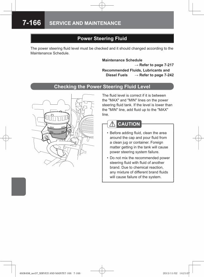
7-166 SERVICE AND MAINTENANCE
Power Steering Fluid
The fluid level is correct if it is between the "MAX" and "MIN" lines on the power steering fluid tank. If the level is lower than the "MIN" line, add fluid up to the "MAX" line.
CAUTIONBefore adding fluid, clean the area around the cap and pour fluid from a clean jug or container. Foreign matter getting in the tank will cause power steering system failure.Do not mix the recommended power steering fluid with fluid of another brand. Due to chemical reaction, any mixture of different brand fluids will cause failure of the system.
•
•
Checking the Power Steering Fluid Level
The power steering fluid level must be checked and it should changed according to the Maintenance Schedule.
Maintenance Schedule → Refer to page 7-217
Recommended Fluids, Lubricants and Diesel Fuels → Refer to page 7-242
4608498_sec07_SERVICE AND MAINTE7-166 7-1664608498_sec07_SERVICE AND MAINTE7-166 7-166 2015/11/02 14:21:072015/11/02 14:21:07
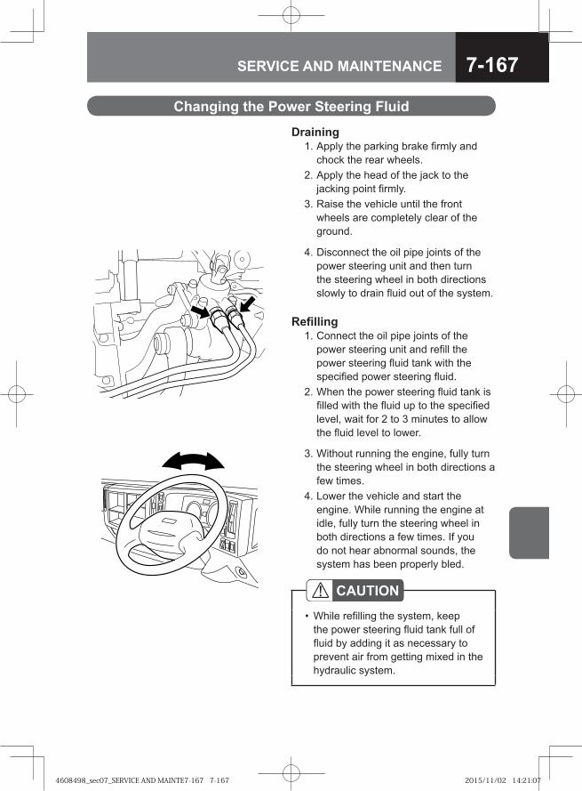
7-167SERVICE AND MAINTENANCE
Changing the Power Steering Fluid
Draining 1. Apply the parking brake firmly and
chock the rear wheels. 2. Apply the head of the jack to the
jacking point firmly. 3. Raise the vehicle until the front
wheels are completely clear of the ground.
4. Disconnect the oil pipe joints of the power steering unit and then turn the steering wheel in both directions slowly to drain fluid out of the system.
CAUTIONWhile refilling the system, keep the power steering fluid tank full of fluid by adding it as necessary to prevent air from getting mixed in the hydraulic system.
•
Refilling 1. Connect the oil pipe joints of the
power steering unit and refill the power steering fluid tank with the specified power steering fluid.
2. When the power steering fluid tank is filled with the fluid up to the specified level, wait for 2 to 3 minutes to allow the fluid level to lower.
3. Without running the engine, fully turn the steering wheel in both directions a few times.
4. Lower the vehicle and start the engine. While running the engine at idle, fully turn the steering wheel in both directions a few times. If you do not hear abnormal sounds, the system has been properly bled.
4608498_sec07_SERVICE AND MAINTE7-167 7-1674608498_sec07_SERVICE AND MAINTE7-167 7-167 2015/11/02 14:21:072015/11/02 14:21:07
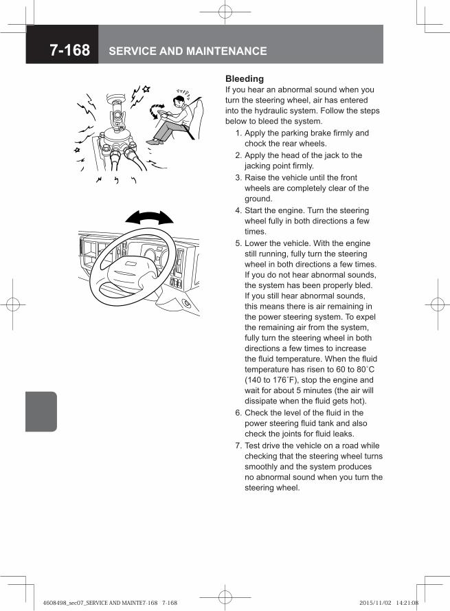
7-168 SERVICE AND MAINTENANCE
BleedingIf you hear an abnormal sound when you turn the steering wheel, air has entered into the hydraulic system. Follow the steps below to bleed the system. 1. Apply the parking brake firmly and
chock the rear wheels. 2. Apply the head of the jack to the
jacking point firmly. 3. Raise the vehicle until the front
wheels are completely clear of the ground.
4. Start the engine. Turn the steering wheel fully in both directions a few times.
5. Lower the vehicle. With the engine still running, fully turn the steering wheel in both directions a few times. If you do not hear abnormal sounds, the system has been properly bled. If you still hear abnormal sounds, this means there is air remaining in the power steering system. To expel the remaining air from the system, fully turn the steering wheel in both directions a few times to increase the fluid temperature. When the fluid temperature has risen to 60 to 80˚C (140 to 176˚F), stop the engine and wait for about 5 minutes (the air will dissipate when the fluid gets hot).
6. Check the level of the fluid in the power steering fluid tank and also check the joints for fluid leaks.
7. Test drive the vehicle on a road while checking that the steering wheel turns smoothly and the system produces no abnormal sound when you turn the steering wheel.
4608498_sec07_SERVICE AND MAINTE7-168 7-1684608498_sec07_SERVICE AND MAINTE7-168 7-168 2015/11/02 14:21:082015/11/02 14:21:08
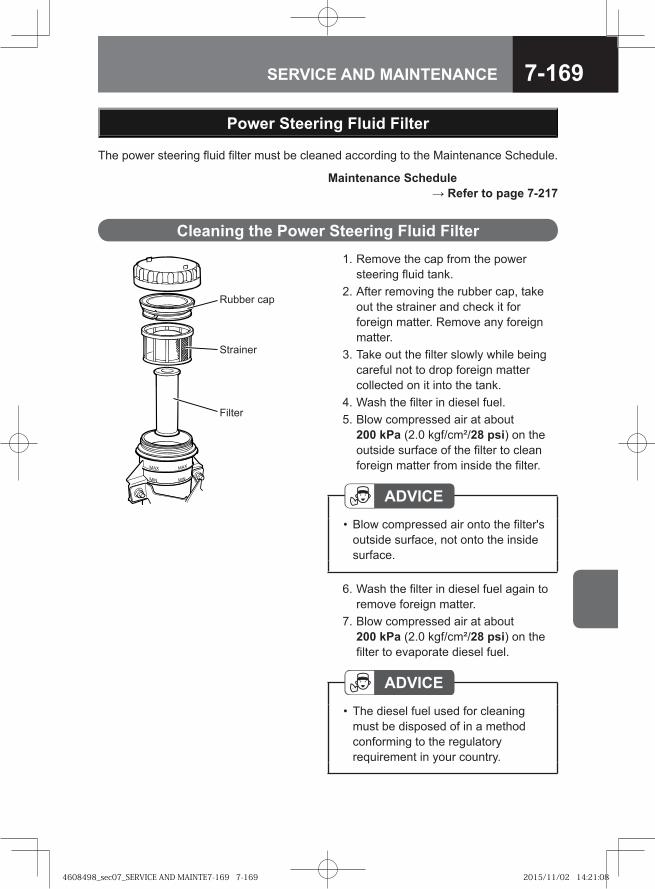
7-169SERVICE AND MAINTENANCE
1. Remove the cap from the power steering fluid tank.
2. After removing the rubber cap, take out the strainer and check it for foreign matter. Remove any foreign matter.
3. Take out the filter slowly while being careful not to drop foreign matter collected on it into the tank.
4. Wash the filter in diesel fuel. 5. Blow compressed air at about
200 kPa (2.0 kgf/cm²/28 psi) on the outside surface of the filter to clean foreign matter from inside the filter.
Cleaning the Power Steering Fluid Filter
Rubber cap
Strainer
Filter
ADVICEBlow compressed air onto the filter's outside surface, not onto the inside surface.
•
6. Wash the filter in diesel fuel again to remove foreign matter.
7. Blow compressed air at about 200 kPa (2.0 kgf/cm²/28 psi) on the filter to evaporate diesel fuel.
ADVICEThe diesel fuel used for cleaning must be disposed of in a method conforming to the regulatory requirement in your country.
•
Power Steering Fluid Filter
The power steering fluid filter must be cleaned according to the Maintenance Schedule.
Maintenance Schedule → Refer to page 7-217
4608498_sec07_SERVICE AND MAINTE7-169 7-1694608498_sec07_SERVICE AND MAINTE7-169 7-169 2015/11/02 14:21:082015/11/02 14:21:08
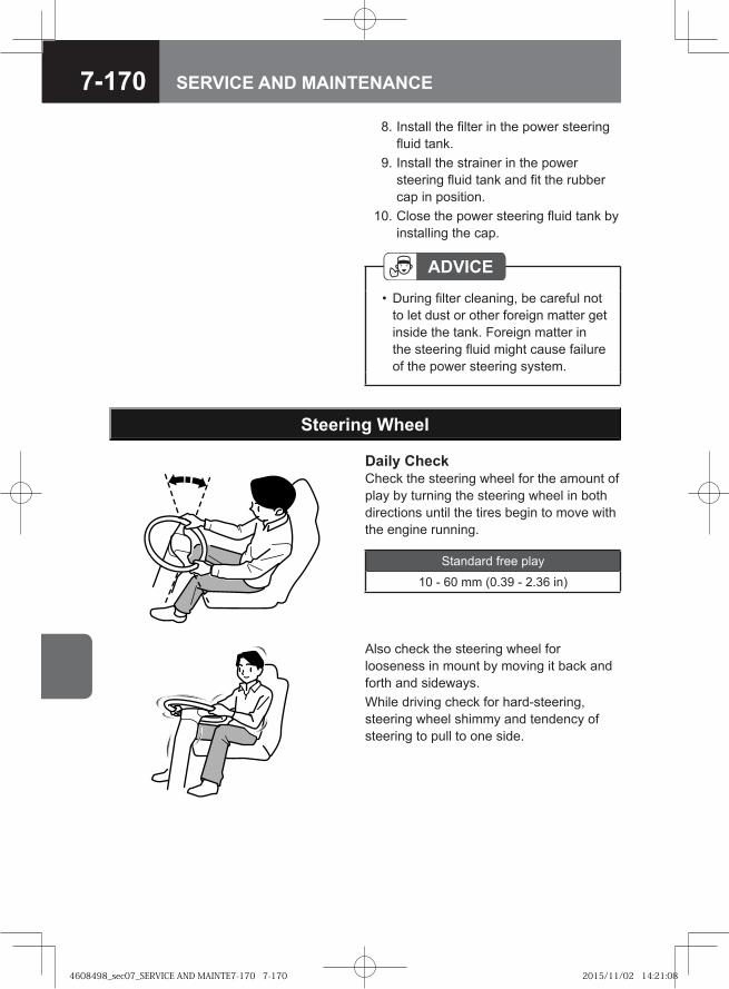
7-170 SERVICE AND MAINTENANCE
ADVICEDuring filter cleaning, be careful not to let dust or other foreign matter get inside the tank. Foreign matter in the steering fluid might cause failure of the power steering system.
•
8. Install the filter in the power steering fluid tank.
9. Install the strainer in the power steering fluid tank and fit the rubber cap in position.
10. Close the power steering fluid tank by installing the cap.
Steering Wheel
Daily CheckCheck the steering wheel for the amount of play by turning the steering wheel in both directions until the tires begin to move with the engine running.
Standard free play
10 - 60 mm (0.39 - 2.36 in)
Also check the steering wheel for looseness in mount by moving it back and forth and sideways.While driving check for hard-steering, steering wheel shimmy and tendency of steering to pull to one side.
4608498_sec07_SERVICE AND MAINTE7-170 7-1704608498_sec07_SERVICE AND MAINTE7-170 7-170 2015/11/02 14:21:082015/11/02 14:21:08
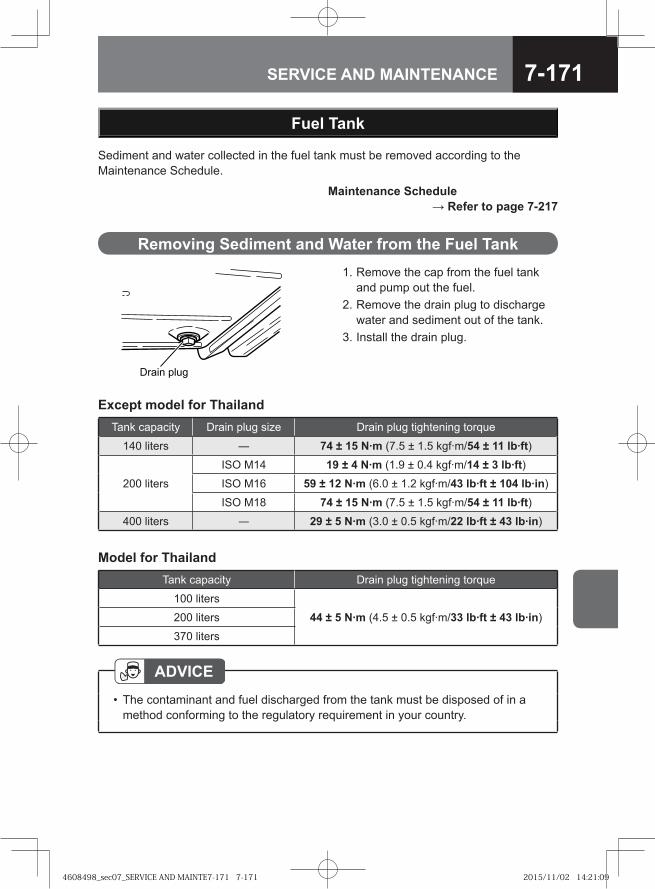
7-171SERVICE AND MAINTENANCE
Fuel Tank
Sediment and water collected in the fuel tank must be removed according to the Maintenance Schedule.
ADVICEThe contaminant and fuel discharged from the tank must be disposed of in a method conforming to the regulatory requirement in your country.
•
Drain plug
Removing Sediment and Water from the Fuel Tank 1. Remove the cap from the fuel tank
and pump out the fuel. 2. Remove the drain plug to discharge
water and sediment out of the tank. 3. Install the drain plug.
Maintenance Schedule → Refer to page 7-217
Tank capacity Drain plug size Drain plug tightening torque
140 liters ― 74 ± 15 N·m (7.5 ± 1.5 kgf·m/54 ± 11 lb·ft)
200 liters
ISO M14 19 ± 4 N·m (1.9 ± 0.4 kgf·m/14 ± 3 lb·ft)ISO M16 59 ± 12 N·m (6.0 ± 1.2 kgf·m/43 lb·ft ± 104 lb·in)
ISO M18 74 ± 15 N·m (7.5 ± 1.5 kgf·m/54 ± 11 lb·ft)400 liters — 29 ± 5 N·m (3.0 ± 0.5 kgf·m/22 lb·ft ± 43 lb·in)
Except model for Thailand
Tank capacity Drain plug tightening torque
100 liters
44 ± 5 N·m (4.5 ± 0.5 kgf·m/33 lb·ft ± 43 lb·in)200 liters
370 liters
Model for Thailand
4608498_sec07_SERVICE AND MAINTE7-171 7-1714608498_sec07_SERVICE AND MAINTE7-171 7-171 2015/11/02 14:21:092015/11/02 14:21:09
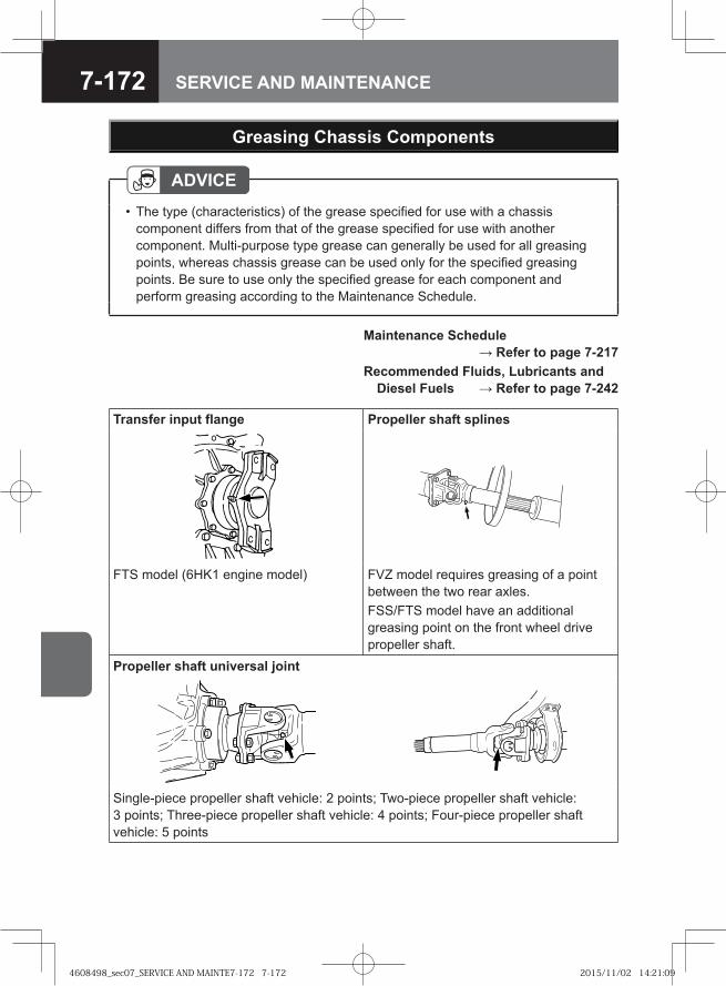
7-172 SERVICE AND MAINTENANCE
Greasing Chassis Components
Maintenance Schedule → Refer to page 7-217
Recommended Fluids, Lubricants and Diesel Fuels → Refer to page 7-242
ADVICEThe type (characteristics) of the grease specified for use with a chassis component differs from that of the grease specified for use with another component. Multi-purpose type grease can generally be used for all greasing points, whereas chassis grease can be used only for the specified greasing points. Be sure to use only the specified grease for each component and perform greasing according to the Maintenance Schedule.
•
Transfer input flange Propeller shaft splines
FTS model (6HK1 engine model) FVZ model requires greasing of a point between the two rear axles. FSS/FTS model have an additional greasing point on the front wheel drive propeller shaft.
Propeller shaft universal joint
Single-piece propeller shaft vehicle: 2 points; Two-piece propeller shaft vehicle: 3 points; Three-piece propeller shaft vehicle: 4 points; Four-piece propeller shaft vehicle: 5 points
4608498_sec07_SERVICE AND MAINTE7-172 7-1724608498_sec07_SERVICE AND MAINTE7-172 7-172 2015/11/02 14:21:092015/11/02 14:21:09
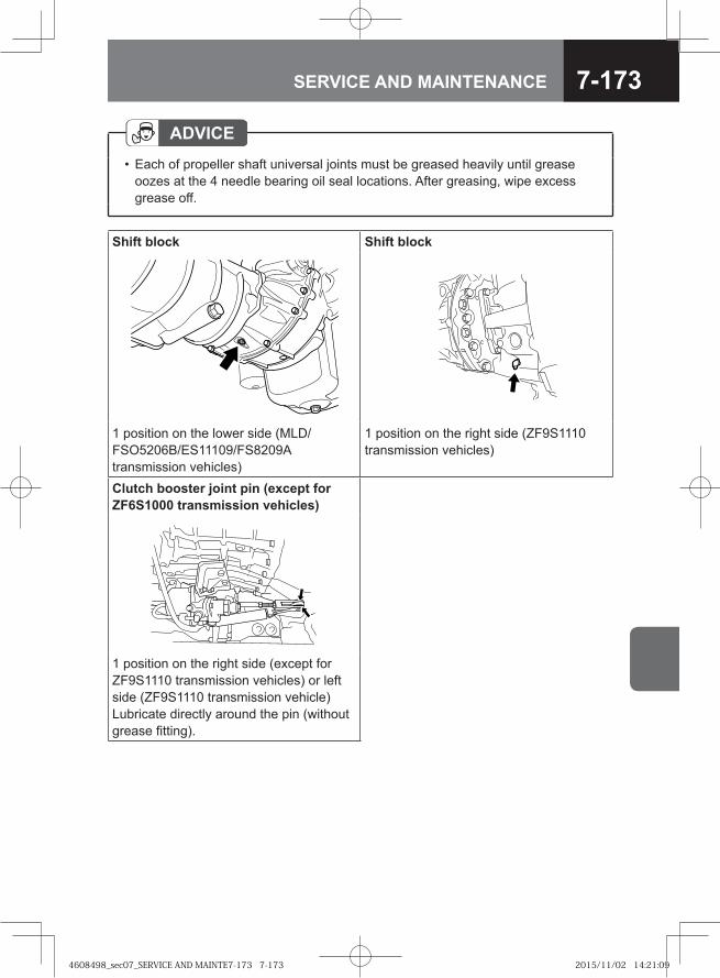
7-173SERVICE AND MAINTENANCE
ADVICEEach of propeller shaft universal joints must be greased heavily until grease oozes at the 4 needle bearing oil seal locations. After greasing, wipe excess grease off.
•
Shift block Shift block
1 position on the lower side (MLD/FSO5206B/ES11109/FS8209A transmission vehicles)
1 position on the right side (ZF9S1110 transmission vehicles)
Clutch booster joint pin (except for ZF6S1000 transmission vehicles)
1 position on the right side (except for ZF9S1110 transmission vehicles) or left side (ZF9S1110 transmission vehicle) Lubricate directly around the pin (without grease fitting).
4608498_sec07_SERVICE AND MAINTE7-173 7-1734608498_sec07_SERVICE AND MAINTE7-173 7-173 2015/11/02 14:21:092015/11/02 14:21:09
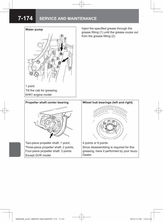
7-174 SERVICE AND MAINTENANCE
Inject the specified grease through the grease fitting (1) until the grease oozes out from the grease fitting (2).
Water pump
1 pointTilt the cab for greasing. 6HK1 engine model
Propeller shaft center bearing Wheel hub bearings (left and right)
Two-piece propeller shaft: 1 point; Three-piece propeller shaft: 2 points; Four-piece propeller shaft: 3 points Except GVR model
4 points or 6 pointsSince disassembling is required for this greasing, have it performed by your Isuzu Dealer.
4608498_sec07_SERVICE AND MAINTE7-174 7-1744608498_sec07_SERVICE AND MAINTE7-174 7-174 2015/11/02 14:21:102015/11/02 14:21:10
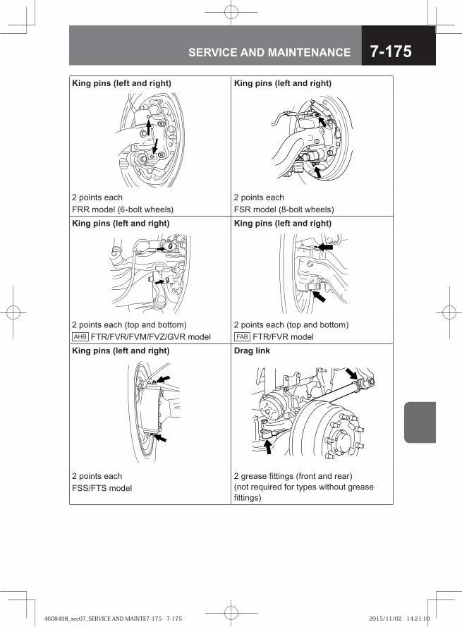
7-175SERVICE AND MAINTENANCE
King pins (left and right) King pins (left and right)
2 points eachFRR model (6-bolt wheels)
2 points eachFSR model (8-bolt wheels)
King pins (left and right) King pins (left and right)
2 points each (top and bottom)AHB FTR/FVR/FVM/FVZ/GVR model
2 points each (top and bottom)FAB FTR/FVR model
King pins (left and right) Drag link
2 points eachFSS/FTS model
2 grease fittings (front and rear) (not required for types without grease fittings)
4608498_sec07_SERVICE AND MAINTE7-175 7-1754608498_sec07_SERVICE AND MAINTE7-175 7-175 2015/11/02 14:21:102015/11/02 14:21:10
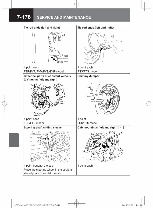
7-176 SERVICE AND MAINTENANCE
Tie rod ends (left and right) Tie rod ends (left and right)
1 point eachFTR/FVR/FVM/FVZ/GVR model
1 point eachFSS/FTS model
Spherical parts of constant velocity (CV) joints (left and right)
Shimmy dumper
1 point eachFSS/FTS model
1 pointFSS/FTS model
Steering shaft sliding sleeve Cab mountings (left and right) V
1 point beneath the cabPlace the steering wheel in the straight-ahead position and tilt the cab.
1 point each
4608498_sec07_SERVICE AND MAINTE7-176 7-1764608498_sec07_SERVICE AND MAINTE7-176 7-176 2015/11/02 14:21:102015/11/02 14:21:10
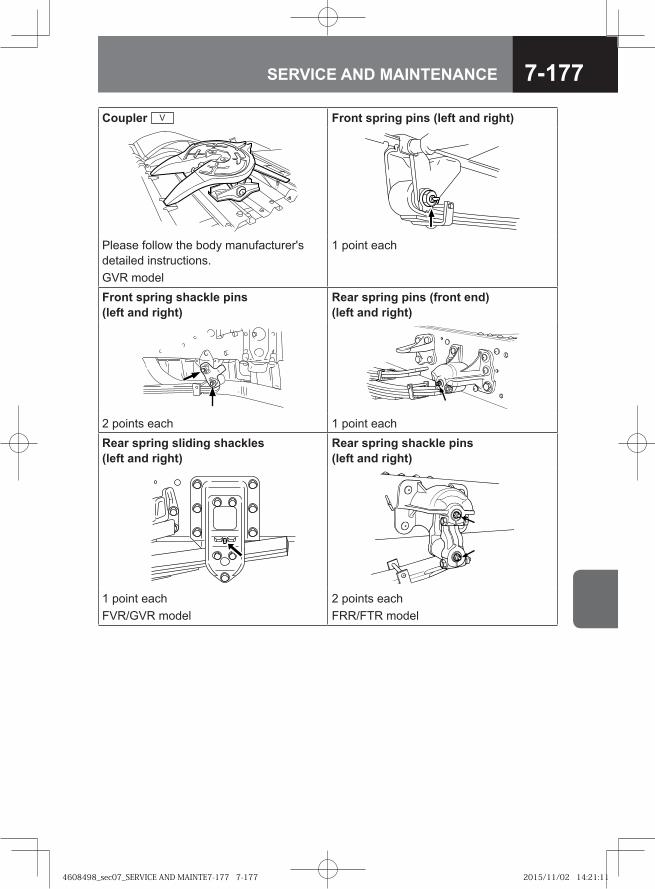
7-177SERVICE AND MAINTENANCE
Coupler V Front spring pins (left and right)
Please follow the body manufacturer's detailed instructions.GVR model
1 point each
Front spring shackle pins (left and right)
Rear spring pins (front end) (left and right)
2 points each 1 point eachRear spring sliding shackles (left and right)
Rear spring shackle pins (left and right)
1 point eachFVR/GVR model
2 points eachFRR/FTR model
4608498_sec07_SERVICE AND MAINTE7-177 7-1774608498_sec07_SERVICE AND MAINTE7-177 7-177 2015/11/02 14:21:112015/11/02 14:21:11
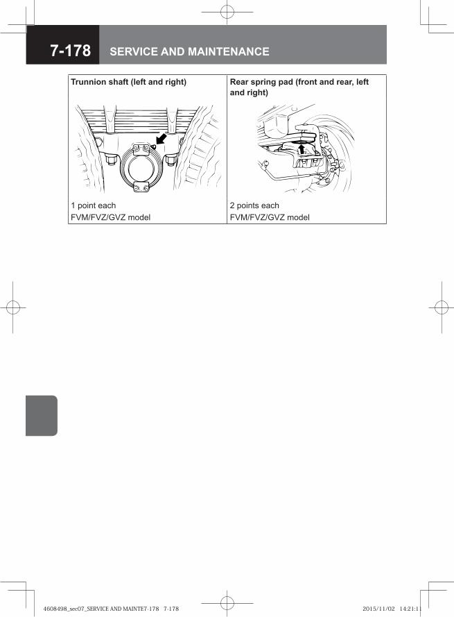
7-178 SERVICE AND MAINTENANCE
Trunnion shaft (left and right) Rear spring pad (front and rear, left and right)
1 point eachFVM/FVZ/GVZ model
2 points eachFVM/FVZ/GVZ model
4608498_sec07_SERVICE AND MAINTE7-178 7-1784608498_sec07_SERVICE AND MAINTE7-178 7-178 2015/11/02 14:21:112015/11/02 14:21:11
7-179SERVICE AND MAINTENANCE
● Handling the Jacks 7-180
● Windshield Washer Fluid 7-185
● Windshield Wiper Blades 7-186
● Exterior Lights 7-189
● Handling the Battery 7-192
● Air Conditioning Filters V 7-199
● Refrigerant V 7-201
● Air Conditioning Compressor Belt V 7-202
OTHER SERVICE AND MAINTENANCE
4608498_sec07_SERVICE AND MAINTE7-179 7-1794608498_sec07_SERVICE AND MAINTE7-179 7-179 2015/11/04 10:04:432015/11/04 10:04:43
7-180 SERVICE AND MAINTENANCE
Handling the Jacks
WARNING
Raising the vehicle with a jack is extremely dangerous when carried out on soft or inclined surfaces. Ensure that you always carry out this operation on flat, hard surfaces.Always apply the parking brake fully and correctly chock the wheels before raising the vehicle. Applying only the parking brake is insufficient to prevent the vehicle from moving; when a rear wheel is jacked up, the vehicle blocked only by the parking brake could move, creating a very dangerous situation.Ensure that there are no people or objects present in the vehicle before it is jacked up.In order to ensure safety, doors should never be opened and the engine should never be started during a jack-up operation. In addition, you should never have any part of your body below the vehicle at this time, nor allow anybody else to do so. Failure to observe this precaution could result in serious injury if the jack were to slip.If the underside of the vehicle is to be worked on after jacking up, jack stands must be used to support the vehicle.The jack must only be used at one of the specified jacking points. In addition, you must confirm that it makes good contact with the specified point.In order to provide extra safety should the jack slip, once a spare tire has been removed, it should be placed under the vehicle near the jack.Before starting a jacking operation, ensure that the jack and the jacking point to be used are clear of dirt, oil, and grease. Failure to observe this precaution can lead to extremely dangerous situations such as entrapment beneath the vehicle should the dirt or oil cause the jack to slip.If your vehicle is equipped with a differential lock system or non-spin differential system, it might start moving when the engine power is transmitted to the rear axle even when one of the wheels on the axle is raised clear of the ground. Do not start the engine with any rear wheel in contact with the ground.The jack provided with your vehicle must be used only for changing tires and fitting or removing tire chains. In order to ensure safety, furthermore, only one wheel should be jacked up at a time.If using a two-stage, extension type jack and the stop mark (yellow) becomes visible, stop raising the vehicle. Failure to observe this precaution can result in jack breakage.
•
•
•
•
•
•
•
•
•
•
•
4608498_sec07_SERVICE AND MAINTE7-180 7-1804608498_sec07_SERVICE AND MAINTE7-180 7-180 2015/11/04 10:04:442015/11/04 10:04:44
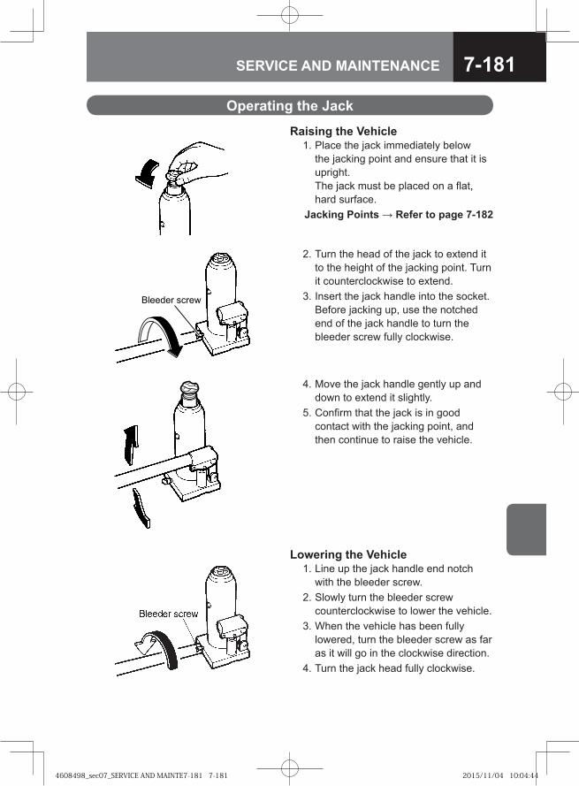
7-181SERVICE AND MAINTENANCE
Operating the Jack
Raising the Vehicle 1. Place the jack immediately below
the jacking point and ensure that it is upright.The jack must be placed on a flat, hard surface.
Jacking Points → Refer to page 7-182
2. Turn the head of the jack to extend it to the height of the jacking point. Turn it counterclockwise to extend.
3. Insert the jack handle into the socket. Before jacking up, use the notched end of the jack handle to turn the bleeder screw fully clockwise.
Bleeder screw
4. Move the jack handle gently up and down to extend it slightly.
5. Confirm that the jack is in good contact with the jacking point, and then continue to raise the vehicle.
Lowering the Vehicle 1. Line up the jack handle end notch
with the bleeder screw. 2. Slowly turn the bleeder screw
counterclockwise to lower the vehicle. 3. When the vehicle has been fully
lowered, turn the bleeder screw as far as it will go in the clockwise direction.
4. Turn the jack head fully clockwise.
4608498_sec07_SERVICE AND MAINTE7-181 7-1814608498_sec07_SERVICE AND MAINTE7-181 7-181 2015/11/04 10:04:442015/11/04 10:04:44
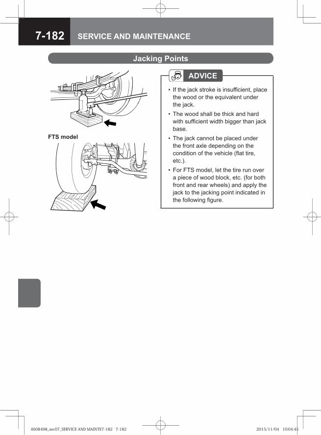
7-182 SERVICE AND MAINTENANCE
Jacking Points
ADVICEIf the jack stroke is insufficient, place the wood or the equivalent under the jack.The wood shall be thick and hard with sufficient width bigger than jack base.The jack cannot be placed under the front axle depending on the condition of the vehicle (flat tire, etc.).For FTS model, let the tire run over a piece of wood block, etc. (for both front and rear wheels) and apply the jack to the jacking point indicated in the following figure.
•
•
•
•
FTS model
4608498_sec07_SERVICE AND MAINTE7-182 7-1824608498_sec07_SERVICE AND MAINTE7-182 7-182 2015/11/04 10:04:452015/11/04 10:04:45
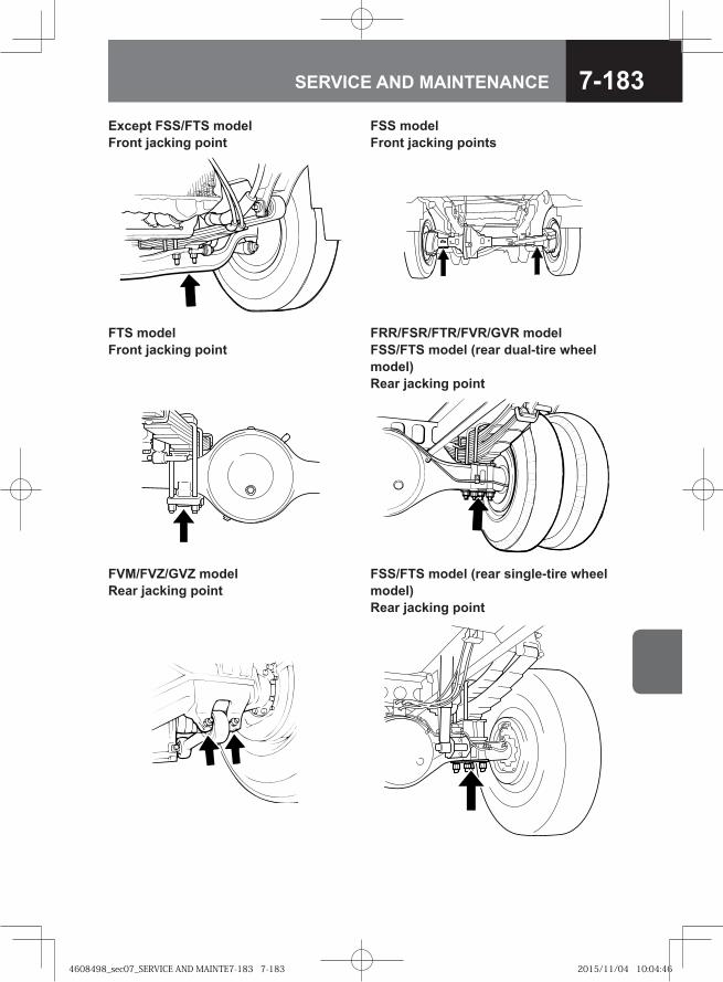
7-183SERVICE AND MAINTENANCE
Except FSS/FTS model Front jacking point
FSS model Front jacking points
FTS model Front jacking point
FRR/FSR/FTR/FVR/GVR model FSS/FTS model (rear dual-tire wheel model)Rear jacking point
FVM/FVZ/GVZ model Rear jacking point
FSS/FTS model (rear single-tire wheel model)Rear jacking point
4608498_sec07_SERVICE AND MAINTE7-183 7-1834608498_sec07_SERVICE AND MAINTE7-183 7-183 2015/11/04 10:04:462015/11/04 10:04:46
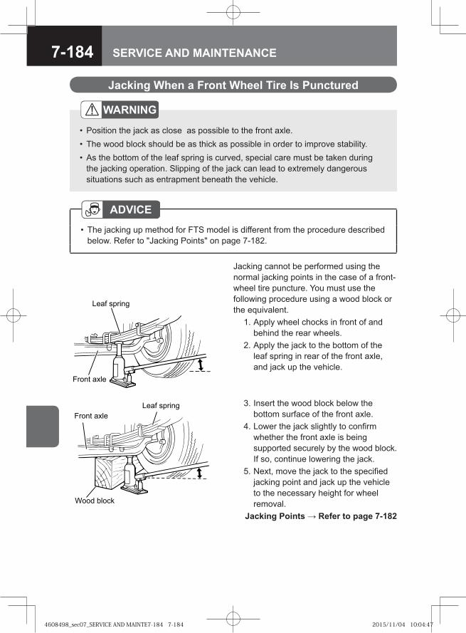
7-184 SERVICE AND MAINTENANCE
Jacking cannot be performed using the normal jacking points in the case of a front-wheel tire puncture. You must use the following procedure using a wood block or the equivalent. 1. Apply wheel chocks in front of and
behind the rear wheels. 2. Apply the jack to the bottom of the
leaf spring in rear of the front axle, and jack up the vehicle.
WARNING
Position the jack as close as possible to the front axle. The wood block should be as thick as possible in order to improve stability.As the bottom of the leaf spring is curved, special care must be taken during the jacking operation. Slipping of the jack can lead to extremely dangerous situations such as entrapment beneath the vehicle.
•••
Leaf spring
Front axle
Wood block
Front axleLeaf spring 3. Insert the wood block below the
bottom surface of the front axle. 4. Lower the jack slightly to confirm
whether the front axle is being supported securely by the wood block. If so, continue lowering the jack.
5. Next, move the jack to the specified jacking point and jack up the vehicle to the necessary height for wheel removal.
Jacking Points → Refer to page 7-182
Jacking When a Front Wheel Tire Is Punctured
ADVICEThe jacking up method for FTS model is different from the procedure described below. Refer to "Jacking Points" on page 7-182.
•
4608498_sec07_SERVICE AND MAINTE7-184 7-1844608498_sec07_SERVICE AND MAINTE7-184 7-184 2015/11/04 10:04:472015/11/04 10:04:47
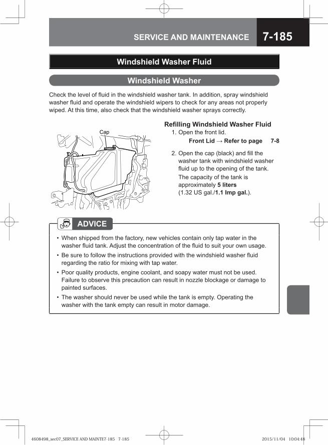
7-185SERVICE AND MAINTENANCE
Windshield WasherCheck the level of fluid in the windshield washer tank. In addition, spray windshield washer fluid and operate the windshield wipers to check for any areas not properly wiped. At this time, also check that the windshield washer sprays correctly.
Windshield Washer Fluid
Refilling Windshield Washer Fluid 1. Open the front lid. Front Lid → Refer to page 7-8
��
ADVICEWhen shipped from the factory, new vehicles contain only tap water in the washer fluid tank. Adjust the concentration of the fluid to suit your own usage.Be sure to follow the instructions provided with the windshield washer fluid regarding the ratio for mixing with tap water. Poor quality products, engine coolant, and soapy water must not be used. Failure to observe this precaution can result in nozzle blockage or damage to painted surfaces.The washer should never be used while the tank is empty. Operating the washer with the tank empty can result in motor damage.
•
•
•
•
2. Open the cap (black) and fill the washer tank with windshield washer fluid up to the opening of the tank.
The capacity of the tank is approximately 5 liters (1.32 US gal./1.1 Imp gal.).
4608498_sec07_SERVICE AND MAINTE7-185 7-1854608498_sec07_SERVICE AND MAINTE7-185 7-185 2015/11/04 10:04:482015/11/04 10:04:48
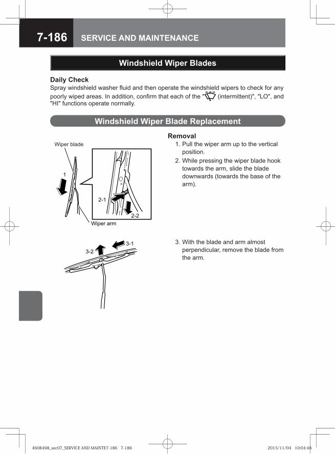
7-186 SERVICE AND MAINTENANCE
Wiper arm
1
2-1
2-2
Wiper blade
�
�
Windshield Wiper Blade Replacement
Windshield Wiper Blades
Removal 1. Pull the wiper arm up to the vertical
position. 2. While pressing the wiper blade hook
towards the arm, slide the blade downwards (towards the base of the arm).
3. With the blade and arm almost perpendicular, remove the blade from the arm.
Daily CheckSpray windshield washer fluid and then operate the windshield wipers to check for any poorly wiped areas. In addition, confirm that each of the " (intermittent)", "LO", and "HI" functions operate normally.
4608498_sec07_SERVICE AND MAINTE7-186 7-1864608498_sec07_SERVICE AND MAINTE7-186 7-186 2015/11/04 10:04:482015/11/04 10:04:48
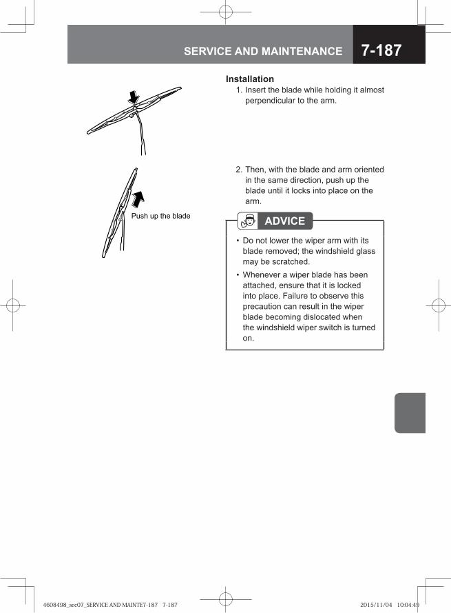
7-187SERVICE AND MAINTENANCE
Installation 1. Insert the blade while holding it almost
perpendicular to the arm.
Push up the blade
2. Then, with the blade and arm oriented in the same direction, push up the blade until it locks into place on the arm.
ADVICEDo not lower the wiper arm with its blade removed; the windshield glass may be scratched.Whenever a wiper blade has been attached, ensure that it is locked into place. Failure to observe this precaution can result in the wiper blade becoming dislocated when the windshield wiper switch is turned on.
•
•
4608498_sec07_SERVICE AND MAINTE7-187 7-1874608498_sec07_SERVICE AND MAINTE7-187 7-187 2015/11/04 10:04:492015/11/04 10:04:49
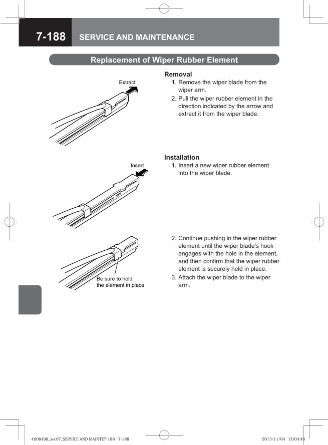
7-188 SERVICE AND MAINTENANCE
Replacement of Wiper Rubber Element
Removal 1. Remove the wiper blade from the
wiper arm. 2. Pull the wiper rubber element in the
direction indicated by the arrow and extract it from the wiper blade.
Extract
Installation 1. Insert a new wiper rubber element
into the wiper blade.
2. Continue pushing in the wiper rubber element until the wiper blade's hook engages with the hole in the element, and then confirm that the wiper rubber element is securely held in place.
3. Attach the wiper blade to the wiper arm.
Insert
� ��� �� ����
��� ������� �� �����
4608498_sec07_SERVICE AND MAINTE7-188 7-1884608498_sec07_SERVICE AND MAINTE7-188 7-188 2015/11/04 10:04:492015/11/04 10:04:49
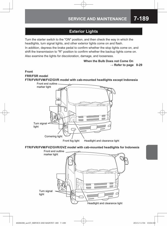
7-189SERVICE AND MAINTENANCE
Turn the starter switch to the "ON" position, and then check the way in which the headlights, turn signal lights, and other exterior lights come on and flash. In addition, depress the brake pedal to confirm whether the stop lights come on, and shift the transmission to "R" position to confirm whether the backup lights come on.Also examine the lights for discoloration, damage, and looseness.
Exterior Lights
When the Bulb Does not Come On → Refer to page 8-29
FrontFRR/FSR modelFTR/FVR/FVM/FVZ/GVR model with cab-mounted headlights except Indonesia
��� �� ����� ��������� ��� �������� �����
��� ������
�����
������ �����
��� ��� ������
���� �����
FTR/FVR/FVM/FVZ/GVR/GVZ model with cab-mounted headlights for Indonesia
�� ����� �� ��������� �����
���� ������
�����
����� �� �������
������ �����
4608498_sec07_SERVICE AND MAINTE7-189 7-1894608498_sec07_SERVICE AND MAINTE7-189 7-189 2015/11/04 10:04:502015/11/04 10:04:50
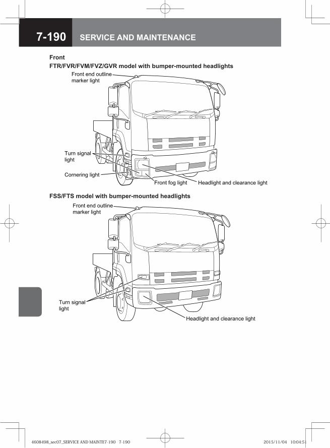
7-190 SERVICE AND MAINTENANCE
FrontFTR/FVR/FVM/FVZ/GVR model with bumper-mounted headlights
��� � ����� ��������� �� �������� �����
��� �����
�����
������ �����
��� �� �����
������ �����
FSS/FTS model with bumper-mounted headlights
Headlight and clearance light
Turn signallight
Front end outlinemarker light
4608498_sec07_SERVICE AND MAINTE7-190 7-1904608498_sec07_SERVICE AND MAINTE7-190 7-190 2015/11/04 10:04:512015/11/04 10:04:51
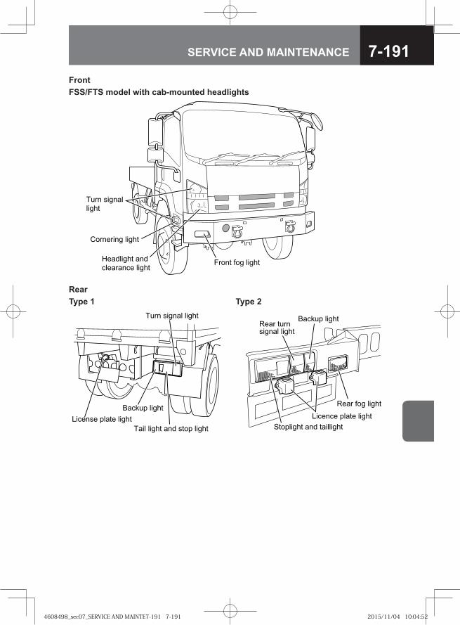
7-191SERVICE AND MAINTENANCE
FrontFSS/FTS model with cab-mounted headlights
��� ��� ��
����� � ���
���� � ���
� ���
����� �� � ���
����� ��� � ���
RearType 1 Type 2
�� � ������ �����
���� ����� ��� ���� �����
������ �����
������� ����� �����
�� � �������� � �����
� ���� �����
�� � ��� �����
������� �� �� �����
��������� �� � �������
4608498_sec07_SERVICE AND MAINTE7-191 7-1914608498_sec07_SERVICE AND MAINTE7-191 7-191 2015/11/04 10:04:522015/11/04 10:04:52
7-192 SERVICE AND MAINTENANCE
Handling the Battery
WARNING
Always stop the engine whenever the battery is to be inspected. Dilute sulfuric acid is used as the battery fluid. Special care must be taken to ensure that this fluid does not come into contact with skin, clothing, or metal surfaces.When disconnecting cables, turn the starter switch to the "LOCK" position, wait at least 1 minute, and then disconnect the cables starting with the negative cable from the terminals. If the negative cable is disconnected within 1 minute, the engine control module may malfunction. When reconnecting them, the negative cable should be reconnected last.
••
•
DANGER
Usage or charging of the battery when the battery fluid is below the "LOWER LEVEL" line can accelerate deterioration and give rise to dangerous situations such as the generation of heat and even explosion.If battery fluid should enter an eye, immediately wash away using a large amount of water and continue washing for at least 5 minutes. Following this, you should seek medical assistance.When using tools or other metal objects in the vicinity of the battery, take care to prevent them from coming into contact with the positive terminal. As the vehicle itself will conduct electricity, any such contact can result in a short-circuit and a highly dangerous electric shock.A vehicle battery generates extremely flammable hydrogen gas. For this reason, operations producing sparks or requiring the usage of open flames must never be carried out near a vehicle battery. Failure to observe this precaution can result in explosion if the hydrogen gas ignites. Whenever wiping up battery fluid, a damp cloth should be used.
•
•
•
•
4608498_sec07_SERVICE AND MAINTE7-192 7-1924608498_sec07_SERVICE AND MAINTE7-192 7-192 2015/11/04 10:04:532015/11/04 10:04:53
7-193SERVICE AND MAINTENANCE
ADVICEBattery fluid should never be filled beyond the "UPPER LEVEL" line. Failure to observe this precaution can result in battery fluid spillage and corrosion of battery terminals and other components. Any spilled battery fluid should be immediately washed away with water.Whenever battery fluid has been added, the battery should be recharged (by driving the vehicle). In winter months in particular, battery fluid can freeze and damage the battery case if you fail to recharge the battery.If the battery fluid level continues to drop at an unusually fast rate, have an inspection carried out immediately by the nearest Isuzu Dealer.
•
•
•
4608498_sec07_SERVICE AND MAINTE7-193 7-1934608498_sec07_SERVICE AND MAINTE7-193 7-193 2015/11/04 10:04:532015/11/04 10:04:53
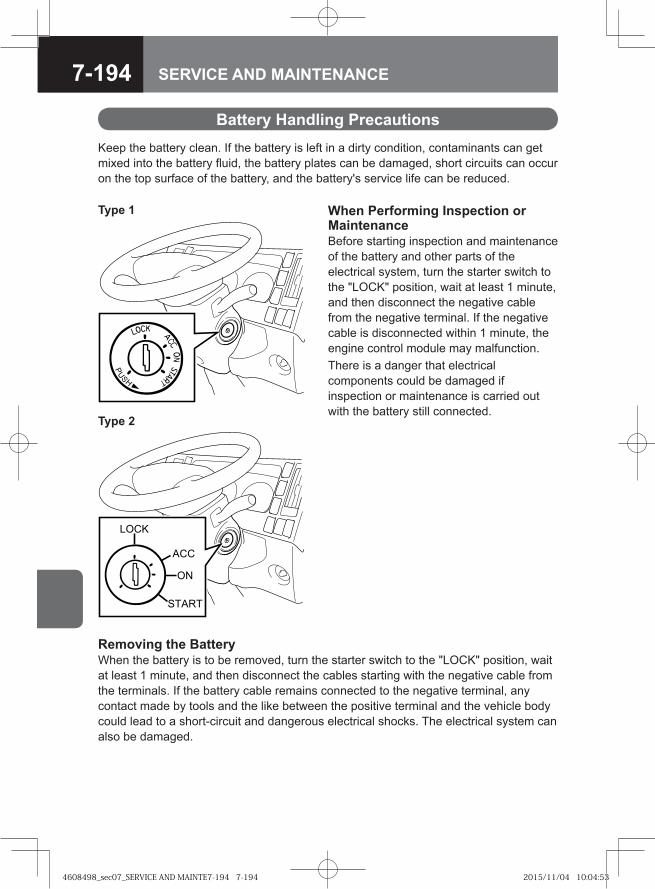
7-194 SERVICE AND MAINTENANCE
Keep the battery clean. If the battery is left in a dirty condition, contaminants can get mixed into the battery fluid, the battery plates can be damaged, short circuits can occur on the top surface of the battery, and the battery's service life can be reduced.
Battery Handling Precautions
When Performing Inspection or MaintenanceBefore starting inspection and maintenance of the battery and other parts of the electrical system, turn the starter switch to the "LOCK" position, wait at least 1 minute, and then disconnect the negative cable from the negative terminal. If the negative cable is disconnected within 1 minute, the engine control module may malfunction.There is a danger that electrical components could be damaged if inspection or maintenance is carried out with the battery still connected.
Removing the BatteryWhen the battery is to be removed, turn the starter switch to the "LOCK" position, wait at least 1 minute, and then disconnect the cables starting with the negative cable from the terminals. If the battery cable remains connected to the negative terminal, any contact made by tools and the like between the positive terminal and the vehicle body could lead to a short-circuit and dangerous electrical shocks. The electrical system can also be damaged.
Type 1
Type 2
�� �
�
��
�����
4608498_sec07_SERVICE AND MAINTE7-194 7-1944608498_sec07_SERVICE AND MAINTE7-194 7-194 2015/11/04 10:04:532015/11/04 10:04:53
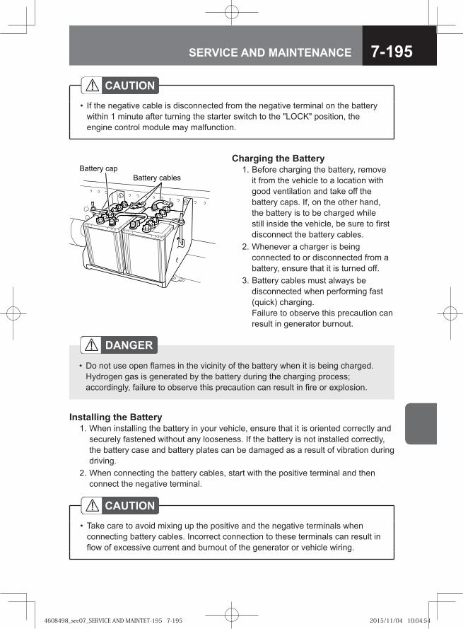
7-195SERVICE AND MAINTENANCE
Charging the Battery 1. Before charging the battery, remove
it from the vehicle to a location with good ventilation and take off the battery caps. If, on the other hand, the battery is to be charged while still inside the vehicle, be sure to first disconnect the battery cables.
2. Whenever a charger is being connected to or disconnected from a battery, ensure that it is turned off.
3. Battery cables must always be disconnected when performing fast (quick) charging.Failure to observe this precaution can result in generator burnout.
Battery cablesBattery cap
Installing the Battery 1. When installing the battery in your vehicle, ensure that it is oriented correctly and
securely fastened without any looseness. If the battery is not installed correctly, the battery case and battery plates can be damaged as a result of vibration during driving.
2. When connecting the battery cables, start with the positive terminal and then connect the negative terminal.
CAUTIONTake care to avoid mixing up the positive and the negative terminals when connecting battery cables. Incorrect connection to these terminals can result in flow of excessive current and burnout of the generator or vehicle wiring.
•
DANGER
Do not use open flames in the vicinity of the battery when it is being charged.Hydrogen gas is generated by the battery during the charging process; accordingly, failure to observe this precaution can result in fire or explosion.
•
CAUTIONIf the negative cable is disconnected from the negative terminal on the battery within 1 minute after turning the starter switch to the "LOCK" position, the engine control module may malfunction.
•
4608498_sec07_SERVICE AND MAINTE7-195 7-1954608498_sec07_SERVICE AND MAINTE7-195 7-195 2015/11/04 10:04:542015/11/04 10:04:54
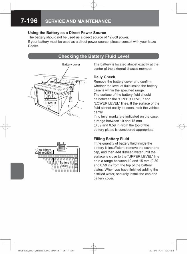
7-196 SERVICE AND MAINTENANCE
Using the Battery as a Direct Power SourceThe battery should not be used as a direct source of 12-volt power.If your battery must be used as a direct power source, please consult with your Isuzu Dealer.
The battery is located almost exactly at the center of the external chassis member.
Daily CheckRemove the battery cover and confirm whether the level of fluid inside the battery case is within the specified range.The surface of the battery fluid should be between the "UPPER LEVEL" and "LOWER LEVEL" lines. If the surface of the fluid cannot easily be seen, rock the vehicle gently.If no level marks are indicated on the case, a range between 10 and 15 mm (0.39 and 0.59 in) from the top of the battery plates is considered appropriate.
Checking the Battery Fluid Level
�� � ��������� � �������
�� ������ ��
UPPERLEVEL
Battery cover
LOWERLEVEL
Filling Battery FluidIf the quantity of battery fluid inside the battery is insufficient, remove the cover and cap, and then add distilled water until the surface is close to the "UPPER LEVEL" line or in a range between 10 and 15 mm (0.39 and 0.59 in) from the top of the battery plates. When you have finished adding the distilled water, securely install the cap and battery cover.
4608498_sec07_SERVICE AND MAINTE7-196 7-1964608498_sec07_SERVICE AND MAINTE7-196 7-196 2015/11/04 10:04:542015/11/04 10:04:54
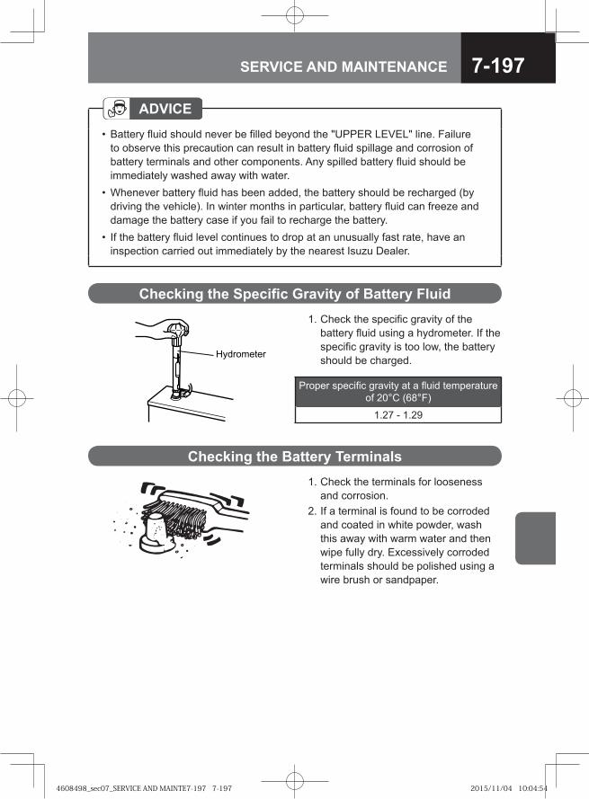
7-197SERVICE AND MAINTENANCE
1. Check the specific gravity of the battery fluid using a hydrometer. If the specific gravity is too low, the battery should be charged.
Checking the Specific Gravity of Battery Fluid
Proper specific gravity at a fluid temperature of 20°C (68°F)
1.27 - 1.29
1. Check the terminals for looseness and corrosion.
2. If a terminal is found to be corroded and coated in white powder, wash this away with warm water and then wipe fully dry. Excessively corroded terminals should be polished using a wire brush or sandpaper.
Checking the Battery Terminals
Hydrometer
ADVICEBattery fluid should never be filled beyond the "UPPER LEVEL" line. Failure to observe this precaution can result in battery fluid spillage and corrosion of battery terminals and other components. Any spilled battery fluid should be immediately washed away with water.Whenever battery fluid has been added, the battery should be recharged (by driving the vehicle). In winter months in particular, battery fluid can freeze and damage the battery case if you fail to recharge the battery.If the battery fluid level continues to drop at an unusually fast rate, have an inspection carried out immediately by the nearest Isuzu Dealer.
•
•
•
4608498_sec07_SERVICE AND MAINTE7-197 7-1974608498_sec07_SERVICE AND MAINTE7-197 7-197 2015/11/04 10:04:542015/11/04 10:04:54
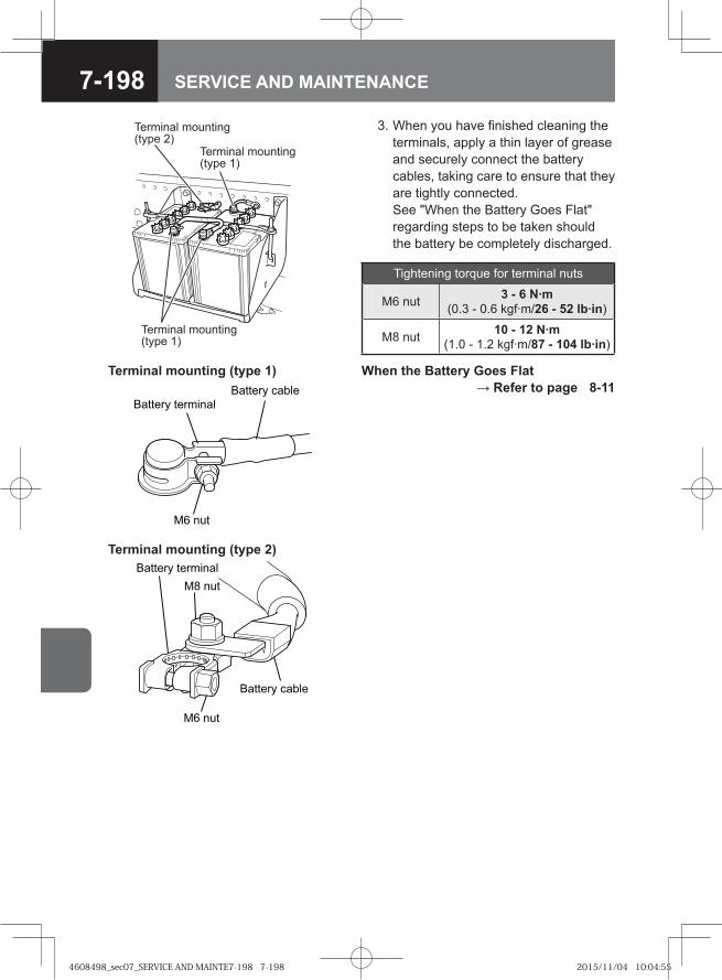
7-198 SERVICE AND MAINTENANCE
When the Battery Goes Flat → Refer to page 8-11
Tightening torque for terminal nuts
M6 nut 3 - 6 N·m (0.3 - 0.6 kgf·m/26 - 52 lb·in)
M8 nut 10 - 12 N·m (1.0 - 1.2 kgf·m/87 - 104 lb·in)
Terminal mounting (type 2)
Terminal mounting (type 1)�� ��� �����
�� ��
�� ��� �������
� � �
�� � �
������� ��������
������� �����
Terminal mounting(type 1)
Terminal mounting(type 1)
Terminal mounting(type 2)
3. When you have finished cleaning the terminals, apply a thin layer of grease and securely connect the battery cables, taking care to ensure that they are tightly connected.See "When the Battery Goes Flat" regarding steps to be taken should the battery be completely discharged.
4608498_sec07_SERVICE AND MAINTE7-198 7-1984608498_sec07_SERVICE AND MAINTE7-198 7-198 2015/11/04 10:04:552015/11/04 10:04:55

7-199SERVICE AND MAINTENANCE
Air Conditioning Filters V
Removing the Inside-air Filter 1. Open the front lid. Front Lid → Refer to page 7-8
3. Fully remove the filter. Use a vacuum cleaner or the like to clean dust and dirt from its surface.
ADVICEIn order to avoid filter damage, hard brushes should not be used for filter cleaning.
•
The air conditioning filters should be removed and cleaned once every month.
Installing the Inside-air Filter 1. Install the filter in the reverse order to removal.
CAUTIONEnsure that the filter is returned securely to its original position.Failure to observe this precaution can lead to rattling during travel, or should the filter become loose, to very dangerous situations. The vehicle must not be used with the filter removed or incorrectly installed. Failure to observe this precaution can lead to air conditioning system damage as a result of dust, dirt, water, snow, and the like entering the system.
•
•
2. While pressing in on both sides of the filter lock, pull out the filter.
4608498_sec07_SERVICE AND MAINTE7-199 7-1994608498_sec07_SERVICE AND MAINTE7-199 7-199 2015/11/04 10:04:552015/11/04 10:04:55
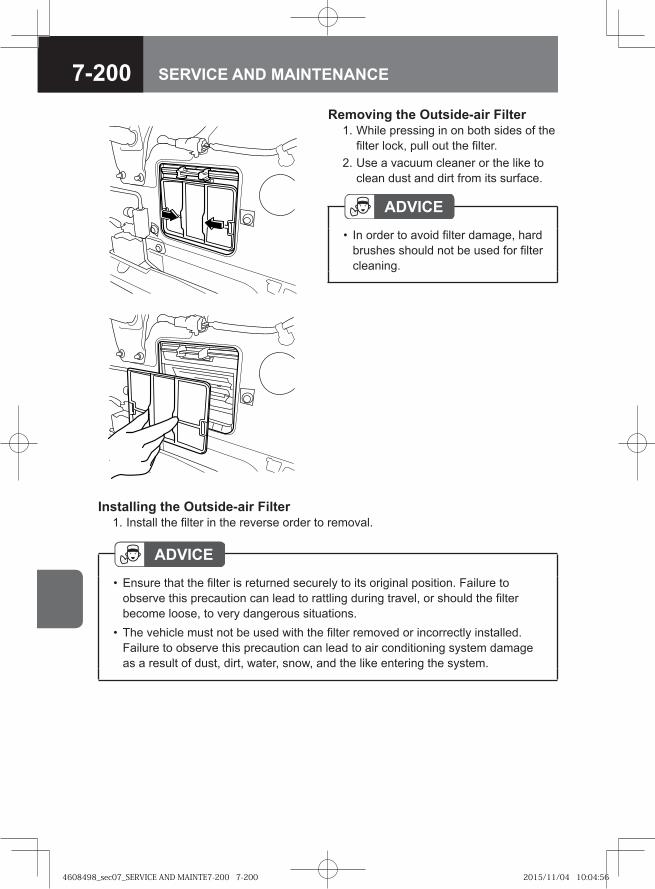
7-200 SERVICE AND MAINTENANCE
Removing the Outside-air Filter 1. While pressing in on both sides of the
filter lock, pull out the filter. 2. Use a vacuum cleaner or the like to
clean dust and dirt from its surface.
ADVICEIn order to avoid filter damage, hard brushes should not be used for filter cleaning.
•
Installing the Outside-air Filter 1. Install the filter in the reverse order to removal.
ADVICEEnsure that the filter is returned securely to its original position. Failure to observe this precaution can lead to rattling during travel, or should the filter become loose, to very dangerous situations.The vehicle must not be used with the filter removed or incorrectly installed. Failure to observe this precaution can lead to air conditioning system damage as a result of dust, dirt, water, snow, and the like entering the system.
•
•
4608498_sec07_SERVICE AND MAINTE7-200 7-2004608498_sec07_SERVICE AND MAINTE7-200 7-200 2015/11/04 10:04:562015/11/04 10:04:56
7-201SERVICE AND MAINTENANCE
The air conditioning system will not be able to cool the cab interior effectively if the refrigerant level is low. Accordingly, the refrigerant level must be topped up whenever necessary.Please contact your Isuzu Dealer whenever refrigerant must be added.
Refrigerant V
ADVICEOperating the air conditioning while the refrigerant level is too low leads not only to poor cooling performance but also to air conditioning system damage. This vehicle uses the new refrigerant HFC134a (R134a) in the air conditioning system. No other type of refrigerant can be used. In order to protect the environment, care must be taken to ensure that refrigerant gas is never released into open air. When refrigerant must be replaced, therefore, please contact your Isuzu Dealer or another service facility equipped with a gas recovery system.
•
•
4608498_sec07_SERVICE AND MAINTE7-201 7-2014608498_sec07_SERVICE AND MAINTE7-201 7-201 2015/11/04 10:04:572015/11/04 10:04:57
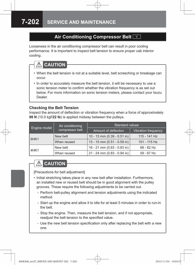
7-202 SERVICE AND MAINTENANCE
Looseness in the air conditioning compressor belt can result in poor cooling performance. It is important to inspect belt tension to ensure proper cab interior cooling.
Air Conditioning Compressor Belt V
Checking the Belt TensionInspect the amount of deflection or vibration frequency when a force of approximately 98 N (10.0 kgf/22 lb) is applied midway between the pulleys.
Engine model Air conditioning compressor belt
Standard values
Amount of deflection Vibration frequency
6HK1New belt 10 - 13 mm (0.39 - 0.51 in) 115 - 141 Hz
When reused 13 - 15 mm (0.51 - 0.59 in) 101 - 115 Hz
4HK1New belt 16 - 21 mm (0.63 - 0.83 in) 68 - 82 Hz
When reused 21 - 24 mm (0.83 - 0.94 in) 59 - 67 Hz
CAUTION[Precautions for belt adjustment]
Initial stretching takes place in any new belt after installation. Furthermore, an installed new or reused belt should be in good alignment with the pulley grooves. These require the following adjustments to be carried out.
Perform belt-pulley alignment and tension adjustments using the indicated method.Start up the engine and allow it to idle for at least 5 minutes in order to run-in the belt.Stop the engine. Then, measure the belt tension, and if not appropriate, readjust the belt tension to the specified value.Use the new belt tension specification only after replacing the belt with a new one.
•
-
-
-
-
CAUTIONWhen the belt tension is not at a suitable level, belt screeching or breakage can occur. In order to accurately measure the belt tension, it will be necessary to use a sonic tension meter to confirm whether the vibration frequency is as set out below. For more information on sonic tension meters, please contact your Isuzu Dealer.
•
•
4608498_sec07_SERVICE AND MAINTE7-202 7-2024608498_sec07_SERVICE AND MAINTE7-202 7-202 2015/11/04 10:04:572015/11/04 10:04:57
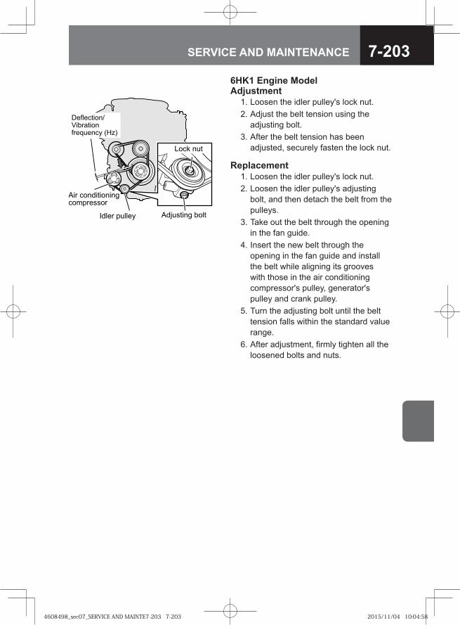
7-203SERVICE AND MAINTENANCE
�� ����� ����
�� �����������������������
����� � ����
��� � �
!�"�������#$���%�����"��& ���� '�()
6HK1 Engine Model Adjustment 1. Loosen the idler pulley's lock nut. 2. Adjust the belt tension using the
adjusting bolt. 3. After the belt tension has been
adjusted, securely fasten the lock nut.
Replacement 1. Loosen the idler pulley's lock nut. 2. Loosen the idler pulley's adjusting
bolt, and then detach the belt from the pulleys.
3. Take out the belt through the opening in the fan guide.
4. Insert the new belt through the opening in the fan guide and install the belt while aligning its grooves with those in the air conditioning compressor's pulley, generator's pulley and crank pulley.
5. Turn the adjusting bolt until the belt tension falls within the standard value range.
6. After adjustment, firmly tighten all the loosened bolts and nuts.
4608498_sec07_SERVICE AND MAINTE7-203 7-2034608498_sec07_SERVICE AND MAINTE7-203 7-203 2015/11/04 10:04:582015/11/04 10:04:58
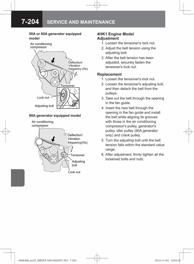
7-204 SERVICE AND MAINTENANCE
4HK1 Engine Model Adjustment 1. Loosen the tensioner's lock nut. 2. Adjust the belt tension using the
adjusting bolt. 3. After the belt tension has been
adjusted, securely fasten the tensioner's lock nut.
50A or 60A generator equipped model
�� �����
��� ������������������� ��
���� ���
���� ���� ����
�!�������"#���$�����!��%����& '�()
90A generator equipped modelAir conditioningcompressor
Tensioner
Adjustingbolt
Lock nut
Deflection/Vibration frequency(Hz)
Replacement 1. Loosen the tensioner's lock nut. 2. Loosen the tensioner's adjusting bolt,
and then detach the belt from the pulleys.
3. Take out the belt through the opening in the fan guide.
4. Insert the new belt through the opening in the fan guide and install the belt while aligning its grooves with those in the air conditioning compressor's pulley, generator's pulley, idler pulley (90A generator only) and crank pulley.
5. Turn the adjusting bolt until the belt tension falls within the standard value range.
6. After adjustment, firmly tighten all the loosened bolts and nuts.
4608498_sec07_SERVICE AND MAINTE7-204 7-2044608498_sec07_SERVICE AND MAINTE7-204 7-204 2015/11/04 10:04:582015/11/04 10:04:58

7-205SERVICE AND MAINTENANCE
● Exterior Maintenance 7-206
● Interior Maintenance 7-210
INTERIOR AND EXTERIOR MAINTENANCE
4608498_sec07_SERVICE AND MAINTE7-205 7-2054608498_sec07_SERVICE AND MAINTE7-205 7-205 2015/11/04 10:04:582015/11/04 10:04:58
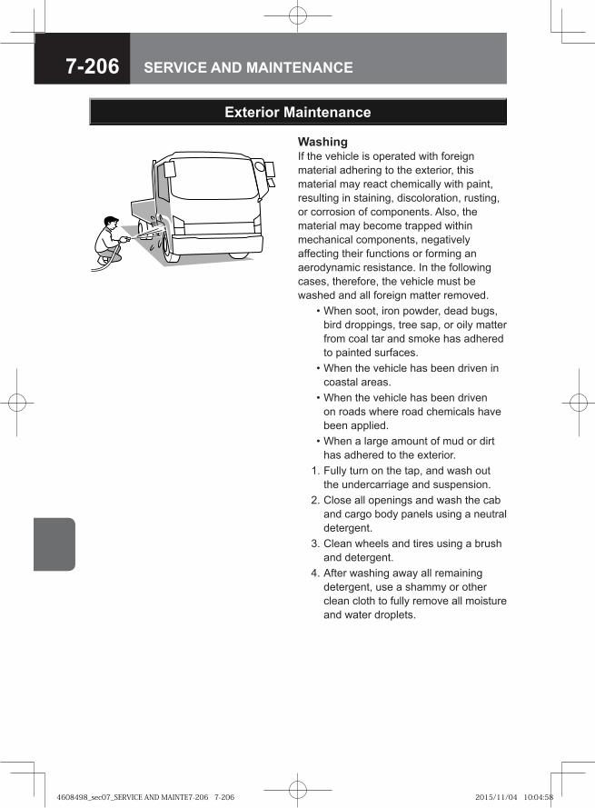
7-206 SERVICE AND MAINTENANCE
WashingIf the vehicle is operated with foreign material adhering to the exterior, this material may react chemically with paint, resulting in staining, discoloration, rusting, or corrosion of components. Also, the material may become trapped within mechanical components, negatively affecting their functions or forming an aerodynamic resistance. In the following cases, therefore, the vehicle must be washed and all foreign matter removed. • When soot, iron powder, dead bugs,
bird droppings, tree sap, or oily matter from coal tar and smoke has adhered to painted surfaces.
• When the vehicle has been driven in coastal areas.
• When the vehicle has been driven on roads where road chemicals have been applied.
• When a large amount of mud or dirt has adhered to the exterior.
1. Fully turn on the tap, and wash out the undercarriage and suspension.
2. Close all openings and wash the cab and cargo body panels using a neutral detergent.
3. Clean wheels and tires using a brush and detergent.
4. After washing away all remaining detergent, use a shammy or other clean cloth to fully remove all moisture and water droplets.
Exterior Maintenance
4608498_sec07_SERVICE AND MAINTE7-206 7-2064608498_sec07_SERVICE AND MAINTE7-206 7-206 2015/11/04 10:04:582015/11/04 10:04:58
7-207SERVICE AND MAINTENANCE
CAUTIONDo not apply water directly in order to clean the cab interior. Failure to observe this precaution can result in malfunction or breakdown of electronic control units and electrical components, or in rusting of the cab floor. Do not apply water from a high-pressure washer nozzle directly to the electric connectors. Failure to observe this precaution can lead to faulty operation of electrical system components.Do not spray high pressure water at or near the brake valves behind the front lid. Failure to observe this precaution can lead to faulty operation of the related components.Do not spray water directly at the air conditioning filter area, the air conditioning piping, or the heater hose connections behind the front lid. Failure to observe this precaution can result in water entering the cab.
•
•
•
•
ADVICEIf automatic washing is used with vehicles having dark or metallic coating, the painted surfaces can be damaged by the brushes, lose their luster, or be very noticeably scratched.
When cleaning the front-lid area, set the air source lever to the " " position in order to prevent water entering the cab. Do not apply water directly to the air conditioning filter, or the connections for the air conditioning pipe or heater hose inside the front lid. Failure to observe this precaution can result in water entering the cab. Do not apply water to the engine compartment or to electrical components. Failure to observe this precaution can lead to a poorly starting and operating engine and problems in electrical system components.Ensure that mirrors and the antenna are retracted before washing the vehicle.When washing the vehicle, be sure to observe the following precautions to avoid heat deformation of the plastic parts, mechanical breakage and water entry into the cab.
Avoid washing with water jet of high pressure and/or of high temperature.Keep the distance of more than 0.4 m (15.75 in) between the washer nozzle and the vehicle, and hold the nozzle at a right angle to the door glasses.
Ensure that all detergent is fully washed and wiped away. Particularly in the case of strong alkaline detergents (typically those for industrial uses), there is a danger that hairline cracks can develop in lighting-cluster lenses if the vehicle is operated without detergent being fully wiped away.
•
•
•
•
••
--
•
4608498_sec07_SERVICE AND MAINTE7-207 7-2074608498_sec07_SERVICE AND MAINTE7-207 7-207 2015/11/04 10:04:582015/11/04 10:04:58
7-208 SERVICE AND MAINTENANCE
Vehicle Storage In order to maintain your vehicle's attractive appearance as long as possible, special consideration must be given to its storage location.If the vehicle is stored or kept for an extended period of time in any of the following locations, a chemical change may occur in the paintwork, resulting in staining, discoloration, rusting, and corrosion of components. • Locations where a large amount of oily matter, soot, heavy smoke or metal
powder can adhere. • Areas around pharmaceutical plants and other facilities that discharge chemical
matter. • Coastal areas • Locations where a large amount of dead bugs, bird droppings or tree sap can
adhere.
Waxing Painted and chrome-plated surfaces should be waxed once or twice a month, or whenever water is being poorly repelled by the surfaces. Ensure that wax is applied in the shade, and that the temperature of the painted surface is no more than 40°C (104°F). Always follow the instructions provided with your wax product.
CAUTIONWax must not be applied to the windshield. Failure to observe this precaution can result in irregular reflection of light, impairing your view.
•
ADVICEDo not use wax containing abrasive material. Failure to observe this precaution can lead to scratching of painted surfaces or plastic components. The application of wax to rubber component surfaces can result in permanent whitening.
•
•
NOTEWax must not be applied to the windshield. A layer of wax can impair your view in rainy weather, and can also lead to rough movements of the windshield wiper. If engine oil or grease comes into contact with the windshield, staining or discoloration may result. It must be immediately cleaned away.
•
•
4608498_sec07_SERVICE AND MAINTE7-208 7-2084608498_sec07_SERVICE AND MAINTE7-208 7-208 2015/11/04 10:04:582015/11/04 10:04:58
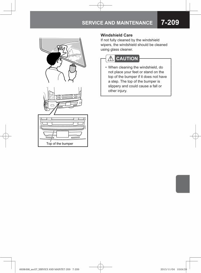
7-209SERVICE AND MAINTENANCE
Windshield CareIf not fully cleaned by the windshield wipers, the windshield should be cleaned using glass cleaner.
�� �� ��� ������
CAUTIONWhen cleaning the windshield, do not place your feet or stand on the top of the bumper if it does not have a step. The top of the bumper is slippery and could cause a fall or other injury.
•
4608498_sec07_SERVICE AND MAINTE7-209 7-2094608498_sec07_SERVICE AND MAINTE7-209 7-209 2015/11/04 10:04:592015/11/04 10:04:59
7-210 SERVICE AND MAINTENANCE
Interior Maintenance
Remove dust and dirt from the interior of the cab using an automotive cleaner or vacuum cleaner, and gently wipe surfaces clean using a cloth wet with warm or cold water.
WARNING
When cleaning the interior of the cab, water should never be sprayed directly. Failure to observe this precaution can lead to vehicle malfunction and possibly fire if water should enter the audio system or other electrical components located underneath the floor carpet. Petroleum ether, gasoline, and other organic solvents should not be used to clean seat belts.In addition, seat belt webbing should be neither bleached nor redyed. Failure to observe these precautions can lead to the performance or strength of the seat belts being impaired. In the case of a collision, therefore, the belts could be insufficiently effective, and serious life-threatening injuries could result. When cleaning, use warm water in which a small amount of neutral detergent has been dissolved to gently wipe the seat belts.
•
•
CAUTIONThe interior of the vehicle must never be cleaned using acidic or alkaline solvents, or petroleum ether, gasoline, and other organic solvents. Failure to observe this precaution can result in discoloration and staining. It should be noted that certain types of cleaning products contain these compounds. Be sure to read cleaning product labels carefully. Air freshener (liquid, solid, gel, or plate types) must not come into direct contact with, or spill onto, interior components such as the air conditioning or audio system. Compounds contained in these products can cause discoloration, staining, or peeling of paint.Glass cleaners that contain these compounds must not be used to clean the inside of the windshield or window glass. To clean the glass, wipe using a cloth wet with warm or cold water.
•
•
•
4608498_sec07_SERVICE AND MAINTE7-210 7-2104608498_sec07_SERVICE AND MAINTE7-210 7-210 2015/11/04 10:05:002015/11/04 10:05:00
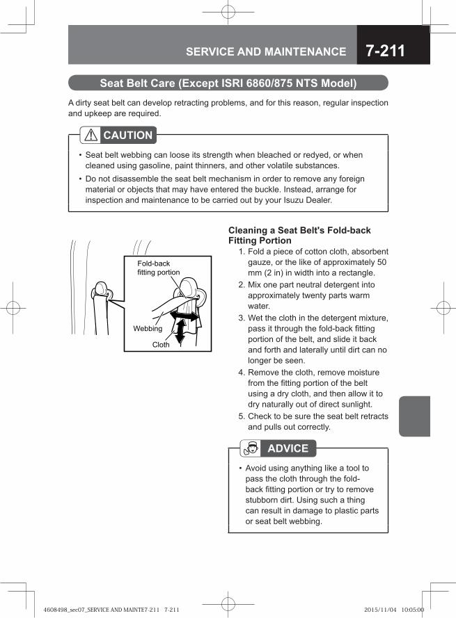
7-211SERVICE AND MAINTENANCE
A dirty seat belt can develop retracting problems, and for this reason, regular inspection and upkeep are required.
CAUTIONSeat belt webbing can loose its strength when bleached or redyed, or when cleaned using gasoline, paint thinners, and other volatile substances. Do not disassemble the seat belt mechanism in order to remove any foreign material or objects that may have entered the buckle. Instead, arrange for inspection and maintenance to be carried out by your Isuzu Dealer.
•
•
Seat Belt Care (Except ISRI 6860/875 NTS Model)
Cleaning a Seat Belt's Fold-back Fitting Portion 1. Fold a piece of cotton cloth, absorbent
gauze, or the like of approximately 50 mm (2 in) in width into a rectangle.
2. Mix one part neutral detergent into approximately twenty parts warm water.
3. Wet the cloth in the detergent mixture, pass it through the fold-back fitting portion of the belt, and slide it back and forth and laterally until dirt can no longer be seen.
4. Remove the cloth, remove moisture from the fitting portion of the belt using a dry cloth, and then allow it to dry naturally out of direct sunlight.
5. Check to be sure the seat belt retracts and pulls out correctly.
��� ����
������� �����
�������
����
ADVICEAvoid using anything like a tool to pass the cloth through the fold-back fitting portion or try to remove stubborn dirt. Using such a thing can result in damage to plastic parts or seat belt webbing.
•
4608498_sec07_SERVICE AND MAINTE7-211 7-2114608498_sec07_SERVICE AND MAINTE7-211 7-211 2015/11/04 10:05:002015/11/04 10:05:00
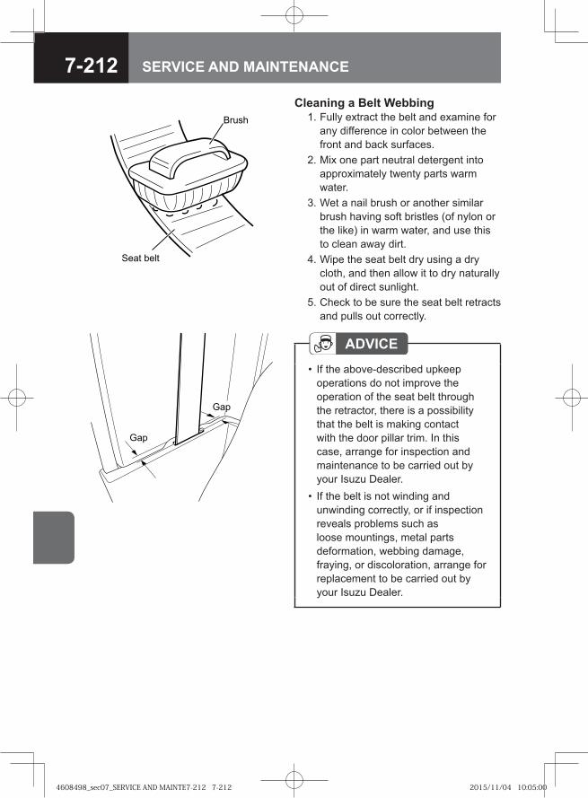
7-212 SERVICE AND MAINTENANCE
Gap
Gap
Cleaning a Belt Webbing 1. Fully extract the belt and examine for
any difference in color between the front and back surfaces.
2. Mix one part neutral detergent into approximately twenty parts warm water.
3. Wet a nail brush or another similar brush having soft bristles (of nylon or the like) in warm water, and use this to clean away dirt.
4. Wipe the seat belt dry using a dry cloth, and then allow it to dry naturally out of direct sunlight.
5. Check to be sure the seat belt retracts and pulls out correctly.
ADVICEIf the above-described upkeep operations do not improve the operation of the seat belt through the retractor, there is a possibility that the belt is making contact with the door pillar trim. In this case, arrange for inspection and maintenance to be carried out by your Isuzu Dealer. If the belt is not winding and unwinding correctly, or if inspection reveals problems such as loose mountings, metal parts deformation, webbing damage, fraying, or discoloration, arrange for replacement to be carried out by your Isuzu Dealer.
•
•
Seat belt
Brush
4608498_sec07_SERVICE AND MAINTE7-212 7-2124608498_sec07_SERVICE AND MAINTE7-212 7-212 2015/11/04 10:05:002015/11/04 10:05:00
7-213SERVICE AND MAINTENANCE
Fabric Seat Covering and Carpet Care
Remove dirt and dust using a home-use electric vacuum cleaner. Do not remove the carpet. Use standard household cleaning products and methods to remove stains from food, drink, and the like.Be sure to use neutral detergents or cleaning products indicated as higher alcohol based detergents.
4608498_sec07_SERVICE AND MAINTE7-213 7-2134608498_sec07_SERVICE AND MAINTE7-213 7-213 2015/11/04 10:05:012015/11/04 10:05:01

7-214 SERVICE AND MAINTENANCE
4608498_sec07_SERVICE AND MAINTE7-214 7-2144608498_sec07_SERVICE AND MAINTE7-214 7-214 2015/11/04 10:05:012015/11/04 10:05:01

7-215SERVICE AND MAINTENANCE
● Inspection and Maintenance 7-217
MAINTENANCE DATA
4608498_sec07_SERVICE AND MAINTE7-215 7-2154608498_sec07_SERVICE AND MAINTE7-215 7-215 2015/11/20 11:43:502015/11/20 11:43:50
4608498_sec07_SERVICE AND MAINTE7-216 7-2164608498_sec07_SERVICE AND MAINTE7-216 7-216 2015/11/20 11:43:502015/11/20 11:43:50

7-217SERVICE AND MAINTENANCE
Inspection and Maintenance
Maintenance Schedule
For safe and economic driving, we recommend that you have your vehicle inspected and serviced regularly according to the schedule indicated in this chapter.
To drive your vehicle safely and at minimum cost, it is essential to have your vehicle regularly inspected and serviced at your Isuzu Dealer as per the specified maintenance schedule.Contact your Isuzu Dealer for inspection that requires disassembly and/or special equipment.
Letters Used to Indicate Maintenance Service TypesI : Inspect then clean, repair or replace as necessaryA: AdjustR: ReplaceT: Tighten to the specified torqueL: Add lubricant
ADVICEWhen inspecting the items listed below, also inspect the routine inspection items as well.
•
*: Your vehicle needs to be maintained more often if it is driven in severe conditions.
Maintenance Schedule for Severe-condition Operations → Refer to page 7-230
4608498_sec07_SERVICE AND MAINTE7-217 7-2174608498_sec07_SERVICE AND MAINTE7-217 7-217 2015/11/20 11:43:502015/11/20 11:43:50
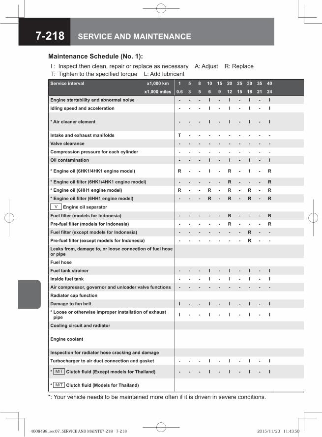
7-218 SERVICE AND MAINTENANCE
Maintenance Schedule (No. 1):I : Inspect then clean, repair or replace as necessary A: Adjust R: Replace T: Tighten to the specified torque L: Add lubricantService interval x1,000 km 1 5 8 10 15 20 25 30 35 40
x1,000 miles 0.6 3 5 6 9 12 15 18 21 24
Engine startability and abnormal noise - - - I - I - I - I
Idling speed and acceleration - - - I - I - I - I
* Air cleaner element - - - I - I - I - I
Intake and exhaust manifolds T - - - - - - - - -
Valve clearance - - - - - - - - - -
Compression pressure for each cylinder - - - - - - - - - -
Oil contamination - - - I - I - I - I
* Engine oil (6HK1/4HK1 engine model) R - - I - R - I - R
* Engine oil filter (6HK1/4HK1 engine model) - - - - - R - - - R
* Engine oil (6HH1 engine model) R - - R - R - R - R
* Engine oil filter (6HH1 engine model) - - - R - R - R - R
V Engine oil separator
Fuel filter (models for Indonesia) - - - - - R - - - R
Pre-fuel filter (models for Indonesia) - - - - - R - - - R
Fuel filter (except models for Indonesia) - - - - - - - R - -
Pre-fuel filter (except models for Indonesia) - - - - - - - R - -
Leaks from, damage to, or loose connection of fuel hose or pipe
Fuel hose
Fuel tank strainer - - - I - I - I - I
Inside fuel tank - - - I - I - I - I
Air compressor, governor and unloader valve functions - - - - - - - - - -
Radiator cap function
Damage to fan belt I - - I - I - I - I
* Loose or otherwise improper installation of exhaust pipe I - - I - I - I - I
Cooling circuit and radiator
Engine coolant
Inspection for radiator hose cracking and damage
Turbocharger to air duct connection and gasket - - - I - I - I - I
* M/T Clutch fluid (Except models for Thailand) - - - I - I - I - I
* M/T Clutch fluid (Models for Thailand)
*: Your vehicle needs to be maintained more often if it is driven in severe conditions.
4608498_sec07_SERVICE AND MAINTE7-218 7-2184608498_sec07_SERVICE AND MAINTE7-218 7-218 2015/11/20 11:43:502015/11/20 11:43:50
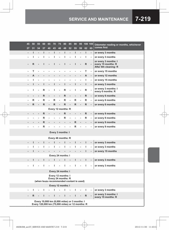
7-219SERVICE AND MAINTENANCE
45 50 55 60 65 70 75 80 85 90 95 100 105 Odometer reading or months, whichever comes first27 31 34 37 40 43 46 49 52 55 59 62 65
- I - I - I - I - I - I - or every 3 months
- I - I - I - I - I - I - or every 3 months
- R - I - I - I - I - R -or every 3 months: I every 15 months: R After 6th cleaning: R
- T - - - - - - - - - T - or every 15 months
- A - - - - - - - - - A - or every 12 months
- I - - - - - - - - - I - or every 15 months
- I - I - I - I - I - I - or every 3 months
- I - R - I - R - I - R - or every 3 months: I every 6 months: R
- - - R - - - R - - - R - or every 6 months
- R - R - R - R - R - R - or every 6 months
- R - R - R - R - R - R - or every 6 months
Every 12 months: R
- - - R - - - R - - - R - or every 9 months
- - - R - - - R - - - R - or every 9 months
- - - R - - - - - R - - - or every 9 months
- - - R - - - - - R - - - or every 9 months
Every 3 months: I
Every 48 months: R
- I - I - I - I - I - I - or every 3 months
- I - I - I - I - I - I - or every 3 months
- I - - - - - - - - - I - or every 15 months
Every 24 months: I
- I - I - I - I - I - I - or every 3 months
- I - I - I - I - I - I - or every 3 months
Every 24 months: I
Every 12 months: IEvery 24 months: R
(when Isuzu recommended coolant is used)
Every 12 months: I
- I - I - I - I - I - I - or every 3 months
- R - I - I - I - I - R - or every 3 months: I every 15 months: R
Every 10,000 km (6,000 miles) or 3 months: IEvery 120,000 km (75,000 miles) or 12 months: R
4608498_sec07_SERVICE AND MAINTE7-219 7-2194608498_sec07_SERVICE AND MAINTE7-219 7-219 2015/11/20 11:43:512015/11/20 11:43:51
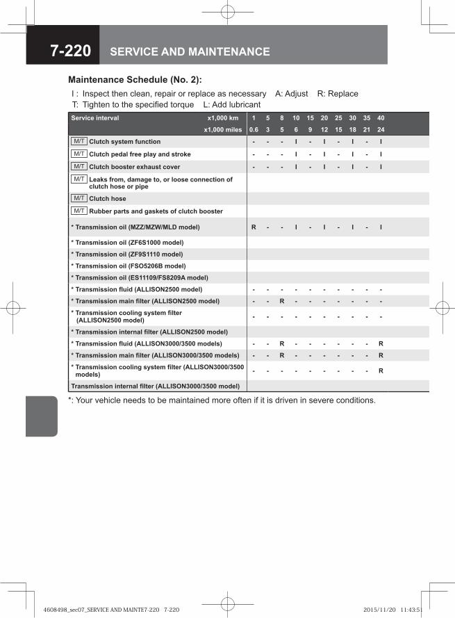
7-220 SERVICE AND MAINTENANCE
Service interval x1,000 km 1 5 8 10 15 20 25 30 35 40
x1,000 miles 0.6 3 5 6 9 12 15 18 21 24
M/T Clutch system function - - - I - I - I - I
M/T Clutch pedal free play and stroke - - - I - I - I - I
M/T Clutch booster exhaust cover - - - I - I - I - I
M/T Leaks from, damage to, or loose connection of clutch hose or pipe
M/T Clutch hose
M/T Rubber parts and gaskets of clutch booster
* Transmission oil (MZZ/MZW/MLD model) R - - I - I - I - I
* Transmission oil (ZF6S1000 model)
* Transmission oil (ZF9S1110 model)
* Transmission oil (FSO5206B model)
* Transmission oil (ES11109/FS8209A model)
* Transmission fluid (ALLISON2500 model) - - - - - - - - - -
* Transmission main filter (ALLISON2500 model) - - R - - - - - - -
* Transmission cooling system filter (ALLISON2500 model) - - - - - - - - - -
* Transmission internal filter (ALLISON2500 model)
* Transmission fluid (ALLISON3000/3500 models) - - R - - - - - - R
* Transmission main filter (ALLISON3000/3500 models) - - R - - - - - - R
* Transmission cooling system filter (ALLISON3000/3500 models) - - - - - - - - - R
Transmission internal filter (ALLISON3000/3500 model)
Maintenance Schedule (No. 2):I : Inspect then clean, repair or replace as necessary A: Adjust R: Replace T: Tighten to the specified torque L: Add lubricant
*: Your vehicle needs to be maintained more often if it is driven in severe conditions.
4608498_sec07_SERVICE AND MAINTE7-220 7-2204608498_sec07_SERVICE AND MAINTE7-220 7-220 2015/11/20 11:43:512015/11/20 11:43:51
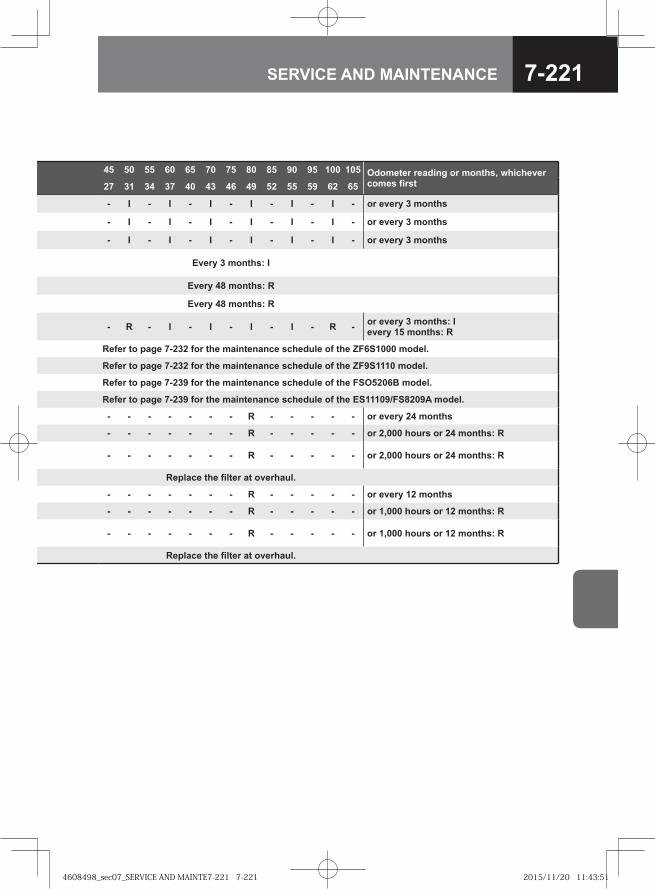
7-221SERVICE AND MAINTENANCE
45 50 55 60 65 70 75 80 85 90 95 100 105 Odometer reading or months, whichever comes first27 31 34 37 40 43 46 49 52 55 59 62 65
- I - I - I - I - I - I - or every 3 months
- I - I - I - I - I - I - or every 3 months
- I - I - I - I - I - I - or every 3 months
Every 3 months: I
Every 48 months: R
Every 48 months: R
- R - I - I - I - I - R - or every 3 months: I every 15 months: R
Refer to page 7-232 for the maintenance schedule of the ZF6S1000 model.
Refer to page 7-232 for the maintenance schedule of the ZF9S1110 model.
Refer to page 7-239 for the maintenance schedule of the FSO5206B model.
Refer to page 7-239 for the maintenance schedule of the ES11109/FS8209A model.
- - - - - - - R - - - - - or every 24 months
- - - - - - - R - - - - - or 2,000 hours or 24 months: R
- - - - - - - R - - - - - or 2,000 hours or 24 months: R
Replace the filter at overhaul.
- - - - - - - R - - - - - or every 12 months
- - - - - - - R - - - - - or 1,000 hours or 12 months: R
- - - - - - - R - - - - - or 1,000 hours or 12 months: R
Replace the filter at overhaul.
4608498_sec07_SERVICE AND MAINTE7-221 7-2214608498_sec07_SERVICE AND MAINTE7-221 7-221 2015/11/20 11:43:512015/11/20 11:43:51
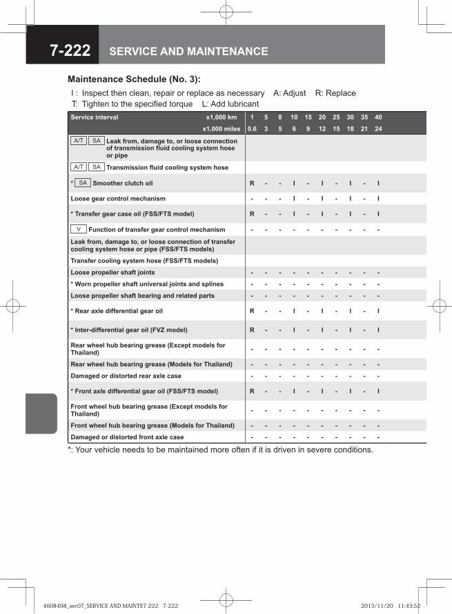
7-222 SERVICE AND MAINTENANCE
Service interval x1,000 km 1 5 8 10 15 20 25 30 35 40
x1,000 miles 0.6 3 5 6 9 12 15 18 21 24
A/T SA Leak from, damage to, or loose connection of transmission fluid cooling system hose or pipe
A/T SA Transmission fluid cooling system hose
* SA Smoother clutch oil R - - I - I - I - I
Loose gear control mechanism - - - I - I - I - I
* Transfer gear case oil (FSS/FTS model) R - - I - I - I - I
V Function of transfer gear control mechanism - - - - - - - - - -
Leak from, damage to, or loose connection of transfer cooling system hose or pipe (FSS/FTS models)
Transfer cooling system hose (FSS/FTS models)
Loose propeller shaft joints - - - - - - - - - -
* Worn propeller shaft universal joints and splines - - - - - - - - - -
Loose propeller shaft bearing and related parts - - - - - - - - - -
* Rear axle differential gear oil R - - I - I - I - I
* Inter-differential gear oil (FVZ model) R - - I - I - I - I
Rear wheel hub bearing grease (Except models for Thailand) - - - - - - - - - -
Rear wheel hub bearing grease (Models for Thailand) - - - - - - - - - -
Damaged or distorted rear axle case - - - - - - - - - -
* Front axle differential gear oil (FSS/FTS model) R - - I - I - I - I
Front wheel hub bearing grease (Except models for Thailand) - - - - - - - - - -
Front wheel hub bearing grease (Models for Thailand) - - - - - - - - - -
Damaged or distorted front axle case - - - - - - - - - -
Maintenance Schedule (No. 3):I : Inspect then clean, repair or replace as necessary A: Adjust R: Replace T: Tighten to the specified torque L: Add lubricant
*: Your vehicle needs to be maintained more often if it is driven in severe conditions.
4608498_sec07_SERVICE AND MAINTE7-222 7-2224608498_sec07_SERVICE AND MAINTE7-222 7-222 2015/11/20 11:43:522015/11/20 11:43:52
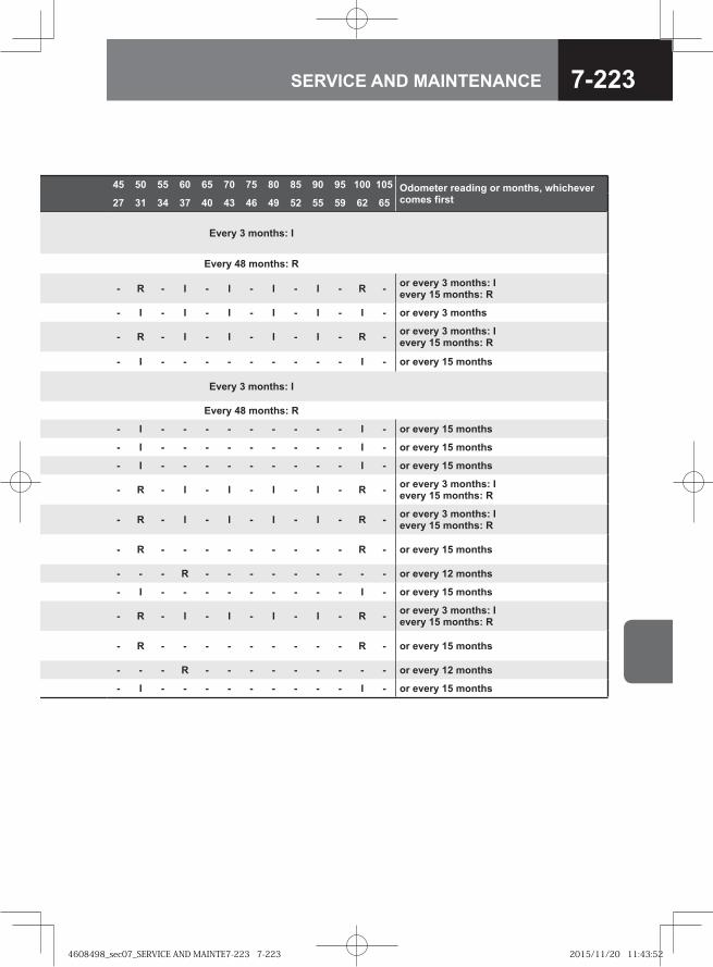
7-223SERVICE AND MAINTENANCE
45 50 55 60 65 70 75 80 85 90 95 100 105 Odometer reading or months, whichever comes first27 31 34 37 40 43 46 49 52 55 59 62 65
Every 3 months: I
Every 48 months: R
- R - I - I - I - I - R - or every 3 months: I every 15 months: R
- I - I - I - I - I - I - or every 3 months
- R - I - I - I - I - R - or every 3 months: I every 15 months: R
- I - - - - - - - - - I - or every 15 months
Every 3 months: I
Every 48 months: R
- I - - - - - - - - - I - or every 15 months
- I - - - - - - - - - I - or every 15 months
- I - - - - - - - - - I - or every 15 months
- R - I - I - I - I - R - or every 3 months: I every 15 months: R
- R - I - I - I - I - R - or every 3 months: I every 15 months: R
- R - - - - - - - - - R - or every 15 months
- - - R - - - - - - - - - or every 12 months
- I - - - - - - - - - I - or every 15 months
- R - I - I - I - I - R - or every 3 months: I every 15 months: R
- R - - - - - - - - - R - or every 15 months
- - - R - - - - - - - - - or every 12 months
- I - - - - - - - - - I - or every 15 months
4608498_sec07_SERVICE AND MAINTE7-223 7-2234608498_sec07_SERVICE AND MAINTE7-223 7-223 2015/11/20 11:43:522015/11/20 11:43:52
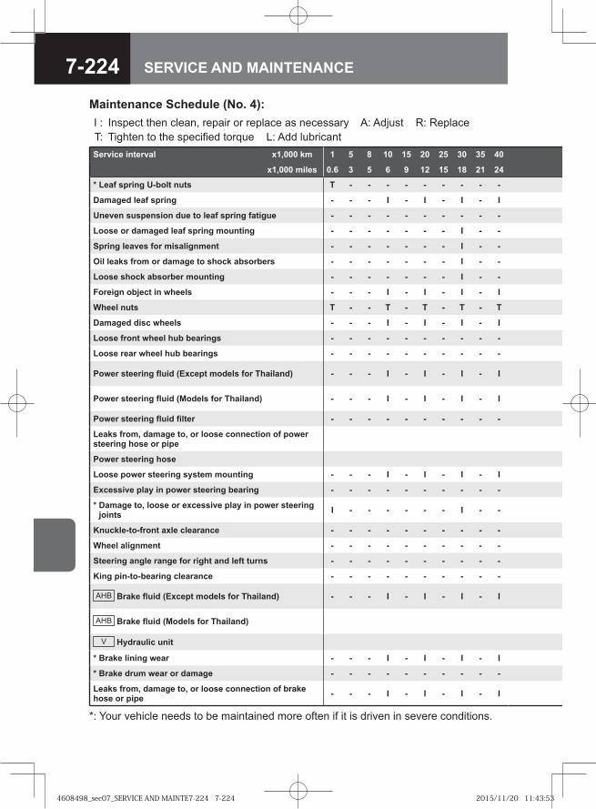
7-224 SERVICE AND MAINTENANCE
Service interval x1,000 km 1 5 8 10 15 20 25 30 35 40
x1,000 miles 0.6 3 5 6 9 12 15 18 21 24
* Leaf spring U-bolt nuts T - - - - - - - - -
Damaged leaf spring - - - I - I - I - I
Uneven suspension due to leaf spring fatigue - - - - - - - - - -
Loose or damaged leaf spring mounting - - - - - - - I - -
Spring leaves for misalignment - - - - - - - I - -
Oil leaks from or damage to shock absorbers - - - - - - - I - -
Loose shock absorber mounting - - - - - - - I - -
Foreign object in wheels - - - I - I - I - I
Wheel nuts T - - T - T - T - T
Damaged disc wheels - - - I - I - I - I
Loose front wheel hub bearings - - - - - - - - - -
Loose rear wheel hub bearings - - - - - - - - - -
Power steering fluid (Except models for Thailand) - - - I - I - I - I
Power steering fluid (Models for Thailand) - - - I - I - I - I
Power steering fluid filter - - - - - - - - - -
Leaks from, damage to, or loose connection of power steering hose or pipe
Power steering hose
Loose power steering system mounting - - - I - I - I - I
Excessive play in power steering bearing - - - - - - - - - -
* Damage to, loose or excessive play in power steering joints I - - - - - - I - -
Knuckle-to-front axle clearance - - - - - - - - - -
Wheel alignment - - - - - - - - - -
Steering angle range for right and left turns - - - - - - - - - -
King pin-to-bearing clearance - - - - - - - - - -
AHB Brake fluid (Except models for Thailand) - - - I - I - I - I
AHB Brake fluid (Models for Thailand)
V Hydraulic unit
* Brake lining wear - - - I - I - I - I
* Brake drum wear or damage - - - - - - - - - -
Leaks from, damage to, or loose connection of brake hose or pipe - - - I - I - I - I
Maintenance Schedule (No. 4):I : Inspect then clean, repair or replace as necessary A: Adjust R: Replace T: Tighten to the specified torque L: Add lubricant
*: Your vehicle needs to be maintained more often if it is driven in severe conditions.
4608498_sec07_SERVICE AND MAINTE7-224 7-2244608498_sec07_SERVICE AND MAINTE7-224 7-224 2015/11/20 11:43:532015/11/20 11:43:53
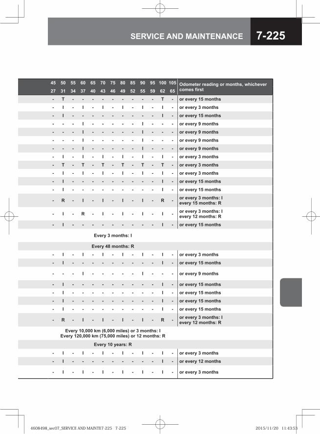
7-225SERVICE AND MAINTENANCE
45 50 55 60 65 70 75 80 85 90 95 100 105 Odometer reading or months, whichever comes first27 31 34 37 40 43 46 49 52 55 59 62 65
- T - - - - - - - - - T - or every 15 months
- I - I - I - I - I - I - or every 3 months
- I - - - - - - - - - I - or every 15 months
- - - I - - - - - I - - - or every 9 months
- - - I - - - - - I - - - or every 9 months
- - - I - - - - - I - - - or every 9 months
- - - I - - - - - I - - - or every 9 months
- I - I - I - I - I - I - or every 3 months
- T - T - T - T - T - T - or every 3 months
- I - I - I - I - I - I - or every 3 months
- I - - - - - - - - - I - or every 15 months
- I - - - - - - - - - I - or every 15 months
- R - I - I - I - I - R - or every 3 months: I every 15 months: R
- I - R - I - I - I - I - or every 3 months: I every 12 months: R
- I - - - - - - - - - I - or every 15 months
Every 3 months: I
Every 48 months: R
- I - I - I - I - I - I - or every 3 months
- I - - - - - - - - - I - or every 15 months
- - - I - - - - - I - - - or every 9 months
- I - - - - - - - - - I - or every 15 months
- I - - - - - - - - - I - or every 15 months
- I - - - - - - - - - I - or every 15 months
- I - - - - - - - - - I - or every 15 months
- R - I - I - I - I - R - or every 3 months: I every 12 months: R
Every 10,000 km (6,000 miles) or 3 months: IEvery 120,000 km (75,000 miles) or 12 months: R
Every 10 years: R
- I - I - I - I - I - I - or every 3 months
- I - - - - - - - - - I - or every 12 months
- I - I - I - I - I - I - or every 3 months
4608498_sec07_SERVICE AND MAINTE7-225 7-2254608498_sec07_SERVICE AND MAINTE7-225 7-225 2015/11/20 11:43:532015/11/20 11:43:53
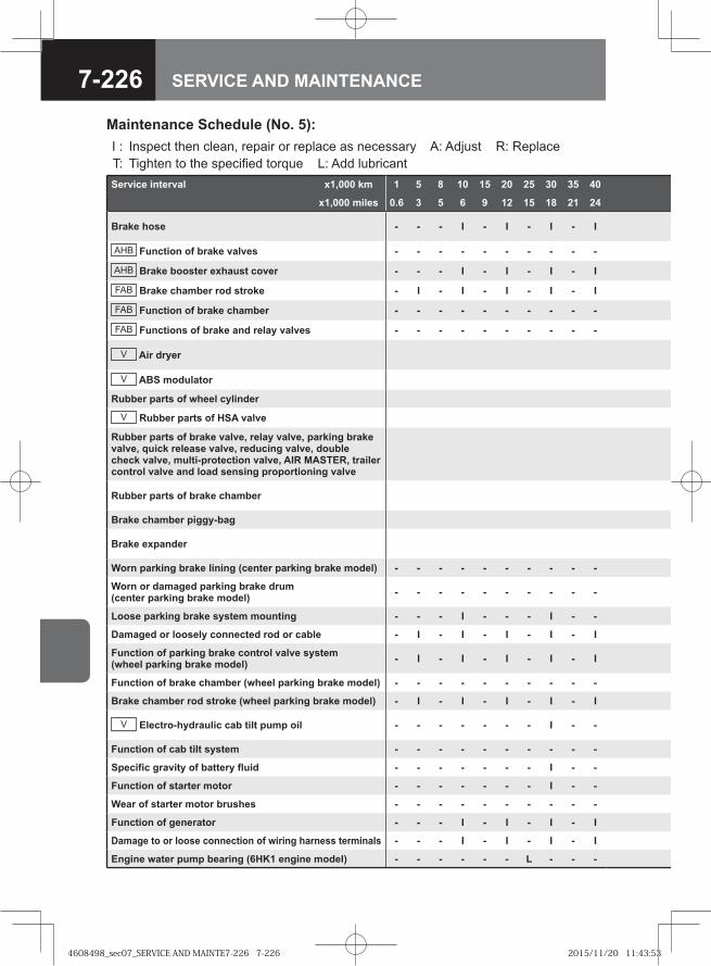
7-226 SERVICE AND MAINTENANCE
Service interval x1,000 km 1 5 8 10 15 20 25 30 35 40
x1,000 miles 0.6 3 5 6 9 12 15 18 21 24
Brake hose - - - I - I - I - I
AHB Function of brake valves - - - - - - - - - -
AHB Brake booster exhaust cover - - - I - I - I - I
FAB Brake chamber rod stroke - I - I - I - I - I
FAB Function of brake chamber - - - - - - - - - -
FAB Functions of brake and relay valves - - - - - - - - - -
V Air dryer
V ABS modulator
Rubber parts of wheel cylinder
V Rubber parts of HSA valve
Rubber parts of brake valve, relay valve, parking brake valve, quick release valve, reducing valve, double check valve, multi-protection valve, AIR MASTER, trailer control valve and load sensing proportioning valve
Rubber parts of brake chamber
Brake chamber piggy-bag
Brake expander
Worn parking brake lining (center parking brake model) - - - - - - - - - -
Worn or damaged parking brake drum (center parking brake model) - - - - - - - - - -
Loose parking brake system mounting - - - I - - - I - -
Damaged or loosely connected rod or cable - I - I - I - I - I
Function of parking brake control valve system (wheel parking brake model) - I - I - I - I - I
Function of brake chamber (wheel parking brake model) - - - - - - - - - -
Brake chamber rod stroke (wheel parking brake model) - I - I - I - I - I
V Electro-hydraulic cab tilt pump oil - - - - - - - I - -
Function of cab tilt system - - - - - - - - - -
Specific gravity of battery fluid - - - - - - - I - -
Function of starter motor - - - - - - - I - -
Wear of starter motor brushes - - - - - - - - - -
Function of generator - - - I - I - I - I
Damage to or loose connection of wiring harness terminals - - - I - I - I - I
Engine water pump bearing (6HK1 engine model) - - - - - - L - - -
Maintenance Schedule (No. 5):I : Inspect then clean, repair or replace as necessary A: Adjust R: Replace T: Tighten to the specified torque L: Add lubricant
4608498_sec07_SERVICE AND MAINTE7-226 7-2264608498_sec07_SERVICE AND MAINTE7-226 7-226 2015/11/20 11:43:532015/11/20 11:43:53
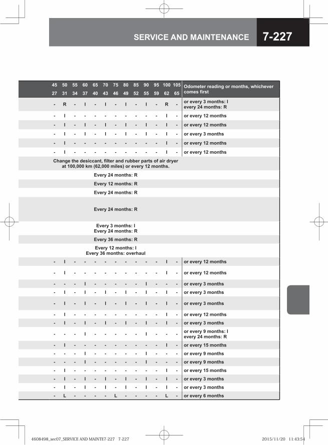
7-227SERVICE AND MAINTENANCE
45 50 55 60 65 70 75 80 85 90 95 100 105 Odometer reading or months, whichever comes first27 31 34 37 40 43 46 49 52 55 59 62 65
- R - I - I - I - I - R - or every 3 months: I every 24 months: R
- I - - - - - - - - - I - or every 12 months
- I - I - I - I - I - I - or every 12 months
- I - I - I - I - I - I - or every 3 months
- I - - - - - - - - - I - or every 12 months
- I - - - - - - - - - I - or every 12 months
Change the desiccant, filter and rubber parts of air dryer at 100,000 km (62,000 miles) or every 12 months.
Every 24 months: R
Every 12 months: R
Every 24 months: R
Every 24 months: R
Every 3 months: IEvery 24 months: R
Every 36 months: R
Every 12 months: IEvery 36 months: overhaul
- I - - - - - - - - - I - or every 12 months
- I - - - - - - - - - I - or every 12 months
- - - I - - - - - I - - - or every 3 months
- I - I - I - I - I - I - or every 3 months
- I - I - I - I - I - I - or every 3 months
- I - - - - - - - - - I - or every 12 months
- I - I - I - I - I - I - or every 3 months
- - - I - - - - - I - - - or every 9 months: I every 24 months: R
- I - - - - - - - - - I - or every 15 months
- - - I - - - - - I - - - or every 9 months
- - - I - - - - - I - - - or every 9 months
- I - - - - - - - - - I - or every 15 months
- I - I - I - I - I - I - or every 3 months
- I - I - I - I - I - I - or every 3 months
- L - - - - L - - - - L - or every 6 months
4608498_sec07_SERVICE AND MAINTE7-227 7-2274608498_sec07_SERVICE AND MAINTE7-227 7-227 2015/11/20 11:43:542015/11/20 11:43:54
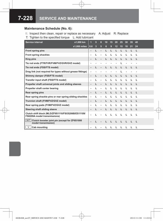
7-228 SERVICE AND MAINTENANCE
Service interval x1,000 km 1 5 8 10 15 20 25 30 35 40
x1,000 miles 0.6 3 5 6 9 12 15 18 21 24
Front spring pins - L - L L L L L L L
Front spring shackles - L - L L L L L L L
King pins - L - L L L L L L L
Tie rod ends (FTR/FVR/FVM/FVZ/GVR/GVZ model) - - - - - - L - - -
Tie rod ends (FSS/FTS model) - L - L L L L L L L
Drag link (not required for types without grease fittings) - - - - - - L - - -
Shimmy damper (FSS/FTS model) - L - L L L L L L L
Transfer input shaft (FSS/FTS model) - L - L L L L L L L
Propeller shaft universal joints and sliding sleeves - L - L L L L L L L
Propeller shaft center bearing - L - L L L L L L L
Rear spring pins - L - L L L L L L L
Rear spring shackle pins or rear spring sliding shackles - L - L L L L L L L
Trunnion shaft (FVM/FVZ/GVZ model) - L - L L L L L L L
Rear spring pads (FVM/FVZ/GVZ model) - L - L L L L L L L
Steering shaft sliding sleeve - L - L L L L L L L
Clutch shift block (MLD/ZF9S1110/FSO5206B/ES11109/FS8209A model transmissions) - L - L L L L L L L
M/T Clutch booster joint pin (except for ZF6S1000 model transmission) - L - L L L L L L L
V Cab mounting - L - L L L L L L L
Maintenance Schedule (No. 6):I : Inspect then clean, repair or replace as necessary A: Adjust R: Replace T: Tighten to the specified torque L: Add lubricant
4608498_sec07_SERVICE AND MAINTE7-228 7-2284608498_sec07_SERVICE AND MAINTE7-228 7-228 2015/11/20 11:43:542015/11/20 11:43:54
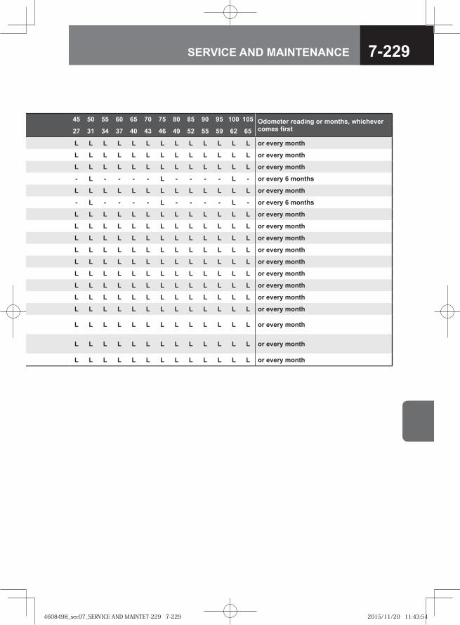
7-229SERVICE AND MAINTENANCE
45 50 55 60 65 70 75 80 85 90 95 100 105 Odometer reading or months, whichever comes first27 31 34 37 40 43 46 49 52 55 59 62 65
L L L L L L L L L L L L L or every month
L L L L L L L L L L L L L or every month
L L L L L L L L L L L L L or every month
- L - - - - L - - - - L - or every 6 months
L L L L L L L L L L L L L or every month
- L - - - - L - - - - L - or every 6 months
L L L L L L L L L L L L L or every month
L L L L L L L L L L L L L or every month
L L L L L L L L L L L L L or every month
L L L L L L L L L L L L L or every month
L L L L L L L L L L L L L or every month
L L L L L L L L L L L L L or every month
L L L L L L L L L L L L L or every month
L L L L L L L L L L L L L or every month
L L L L L L L L L L L L L or every month
L L L L L L L L L L L L L or every month
L L L L L L L L L L L L L or every month
L L L L L L L L L L L L L or every month
4608498_sec07_SERVICE AND MAINTE7-229 7-2294608498_sec07_SERVICE AND MAINTE7-229 7-229 2015/11/20 11:43:542015/11/20 11:43:54
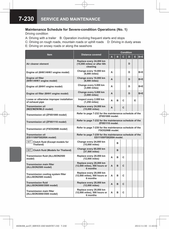
7-230 SERVICE AND MAINTENANCE
Maintenance Schedule for Severe-condition Operations (No. 1)Driving conditionA: Driving with a trailer B: Operation involving frequent starts and stops C: Driving on rough roads, mountain roads or uphill roads D: Driving in dusty areas E: Driving on snowy roads or along the seashore
Item Distance coveredCondition
A B C D E B+E
Air cleaner elementReplace every 24,000 km (15,000 miles) or after 6th
cleaningD
Engine oil (6HK1/4HK1 engine model) Change every 10,000 km (6,000 miles) A D B+E
Engine oil filter (6HK1/4HK1 engine model)
Change every 10,000 km (6,000 miles) A D B+E
Engine oil (6HH1 engine model) Change every 5,000 km (3,000 miles) A D B+E
Engine oil filter (6HH1 engine model) Change every 5,000 km (3,000 miles) A D B+E
Loose or otherwise improper installation of exhaust pipe
Inspect every 2,000 km (1,250 miles) A B C E
Transmission oil (MZZ/MZW/MLD model)
Replace every 24,000 km (15,000 miles) A C
Transmission oil (ZF6S1000 model) Refer to page 7-232 for the maintenance schedule of the ZF6S1000 model.
Transmission oil (ZF9S1110 model) Refer to page 7-232 for the maintenance schedule of the ZF9S1110 model.
Transmission oil (FSO5206B model) Refer to page 7-239 for the maintenance schedule of the FSO5206B model.
Transmission oil (ES11109/FS8209A model)
Refer to page 7-239 for the maintenance schedule of the ES11109/FS8209A model.
M/T Clutch fluid (Except models for Thailand)
Change every 24,000 km (15,000 miles) B
M/T Clutch fluid (Models for Thailand) Change every 60,000 km (37,500 miles) B
Transmission fluid (ALLISON2500 model)
Replace every 20,000 km (12,000 miles) A B C
Transmission main filter (ALLISON2500 model)
Replace every 20,000 km (12,000 miles), 500 hours or
6 monthsA B C
Transmission cooling system filter (ALLISON2500 model)
Replace every 20,000 km (12,000 miles), 500 hours or
6 monthsA B C
Transmission fluid (ALLISON3000/3500 model)
Replace every 20,000 km (12,000 miles) A B C
Transmission main filter (ALLISON3000/3500 model)
Replace every 20,000 km (12,000 miles), 500 hours or
6 monthsA B C
4608498_sec07_SERVICE AND MAINTE7-230 7-2304608498_sec07_SERVICE AND MAINTE7-230 7-230 2015/11/20 11:43:552015/11/20 11:43:55
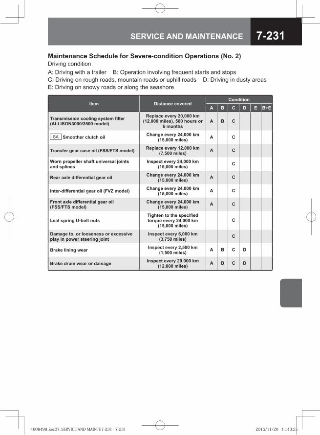
7-231SERVICE AND MAINTENANCE
Item Distance coveredCondition
A B C D E B+E
Transmission cooling system filter (ALLISON3000/3500 model)
Replace every 20,000 km (12,000 miles), 500 hours or
6 monthsA B C
SA Smoother clutch oil Change every 24,000 km (15,000 miles) A C
Transfer gear case oil (FSS/FTS model) Replace every 12,000 km (7,500 miles) A C
Worn propeller shaft universal joints and splines
Inspect every 24,000 km (15,000 miles) C
Rear axle differential gear oil Change every 24,000 km (15,000 miles) A C
Inter-differential gear oil (FVZ model) Change every 24,000 km (15,000 miles) A C
Front axle differential gear oil (FSS/FTS model)
Change every 24,000 km (15,000 miles) A C
Leaf spring U-bolt nutsTighten to the specified torque every 24,000 km
(15,000 miles)C
Damage to, or looseness or excessive play in power steering joint
Inspect every 6,000 km (3,750 miles) C
Brake lining wear Inspect every 2,500 km (1,500 miles) A B C D
Brake drum wear or damage Inspect every 20,000 km (12,000 miles) A B C D
Maintenance Schedule for Severe-condition Operations (No. 2)Driving conditionA: Driving with a trailer B: Operation involving frequent starts and stops C: Driving on rough roads, mountain roads or uphill roads D: Driving in dusty areas E: Driving on snowy roads or along the seashore
4608498_sec07_SERVICE AND MAINTE7-231 7-2314608498_sec07_SERVICE AND MAINTE7-231 7-231 2015/11/20 11:43:552015/11/20 11:43:55
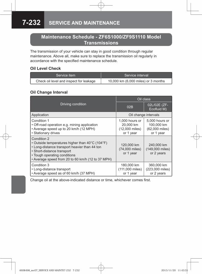
7-232 SERVICE AND MAINTENANCE
Maintenance Schedule - ZF6S1000/ZF9S1110 Model Transmissions
The transmission of your vehicle can stay in good condition through regular maintenance. Above all, make sure to replace the transmission oil regularly in accordance with the specified maintenance schedule.
Oil Level CheckService item Service interval
Check oil level and inspect for leakage 10,000 km (6,000 miles) or 3 months
Oil Change Interval
Driving conditionOil class
02B 02L/02E (ZF-Ecofluid M)
Application Oil change intervals
Condition 1• Off-road operation e.g. mining application• Average speed up to 20 km/h (12 MPH)• Stationary drives
1,000 hours or 20,000 km
(12,000 miles) or 1 year
5,000 hours or 100,000 km
(62,000 miles) or 1 year
Condition 2• Outside temperatures higher than 40°C (104°F)• Long-distance transport heavier than 44 ton• Short-distance transport• Tough operating conditions• Average speed from 20 to 60 km/h (12 to 37 MPH)
120,000 km (74,000 miles)
or 1 year
240,000 km (149,000 miles)
or 2 years
Condition 3• Long-distance transport• Average speed as of 60 km/h (37 MPH)
180,000 km (111,000 miles)
or 1 year
360,000 km (223,000 miles)
or 2 years
Change oil at the above-indicated distance or time, whichever comes first.
4608498_sec07_SERVICE AND MAINTE7-232 7-2324608498_sec07_SERVICE AND MAINTE7-232 7-232 2015/11/20 11:43:552015/11/20 11:43:55
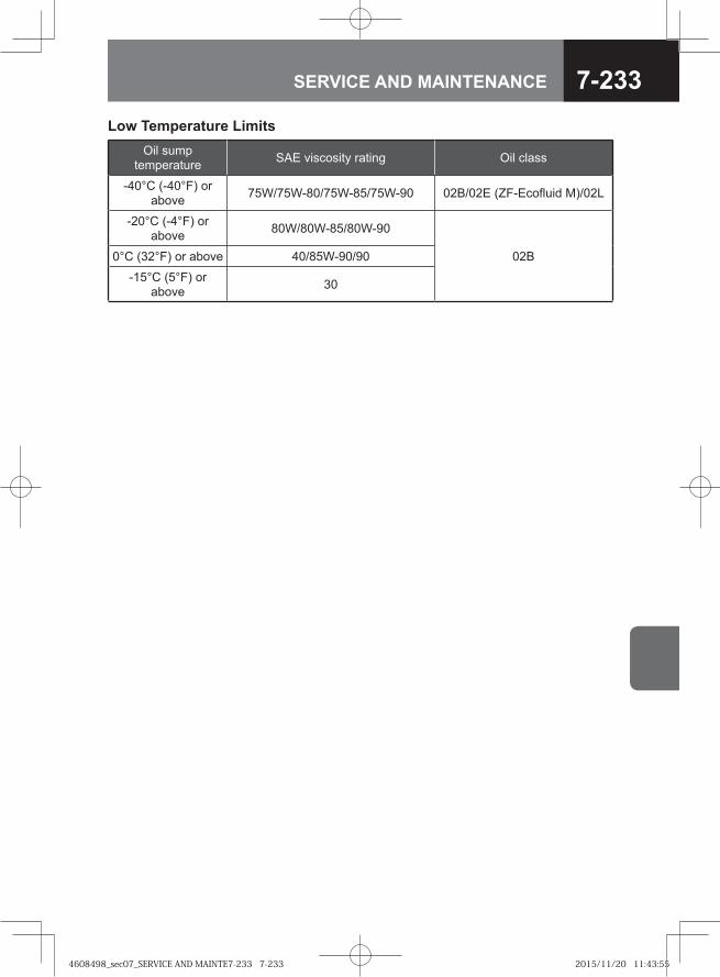
7-233SERVICE AND MAINTENANCE
Low Temperature LimitsOil sump
temperature SAE viscosity rating Oil class
-40°C (-40°F) or above 75W/75W-80/75W-85/75W-90 02B/02E (ZF-Ecofluid M)/02L
-20°C (-4°F) or above 80W/80W-85/80W-90
02B0°C (32°F) or above 40/85W-90/90
-15°C (5°F) or above 30
4608498_sec07_SERVICE AND MAINTE7-233 7-2334608498_sec07_SERVICE AND MAINTE7-233 7-233 2015/11/20 11:43:552015/11/20 11:43:55
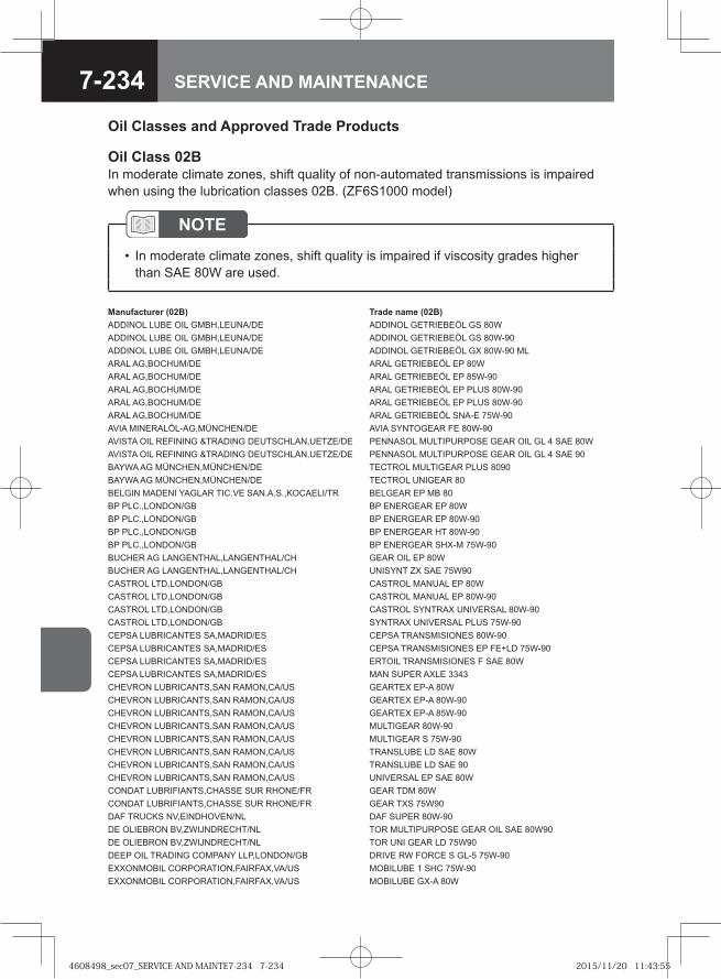
7-234 SERVICE AND MAINTENANCE
Oil Classes and Approved Trade Products
Oil Class 02BIn moderate climate zones, shift quality of non-automated transmissions is impaired when using the lubrication classes 02B. (ZF6S1000 model)
NOTEIn moderate climate zones, shift quality is impaired if viscosity grades higher than SAE 80W are used.
•
Manufacturer (02B) Trade name (02B)ADDINOL LUBE OIL GMBH,LEUNA/DE ADDINOL GETRIEBEÖL GS 80WADDINOL LUBE OIL GMBH,LEUNA/DE ADDINOL GETRIEBEÖL GS 80W-90ADDINOL LUBE OIL GMBH,LEUNA/DE ADDINOL GETRIEBEÖL GX 80W-90 MLARAL AG,BOCHUM/DE ARAL GETRIEBEÖL EP 80WARAL AG,BOCHUM/DE ARAL GETRIEBEÖL EP 85W-90ARAL AG,BOCHUM/DE ARAL GETRIEBEÖL EP PLUS 80W-90ARAL AG,BOCHUM/DE ARAL GETRIEBEÖL EP PLUS 80W-90ARAL AG,BOCHUM/DE ARAL GETRIEBEÖL SNA-E 75W-90AVIA MINERALÖL-AG,MÜNCHEN/DE AVIA SYNTOGEAR FE 80W-90AVISTA OIL REFINING &TRADING DEUTSCHLAN,UETZE/DE PENNASOL MULTIPURPOSE GEAR OIL GL 4 SAE 80WAVISTA OIL REFINING &TRADING DEUTSCHLAN,UETZE/DE PENNASOL MULTIPURPOSE GEAR OIL GL 4 SAE 90BAYWA AG MÜNCHEN,MÜNCHEN/DE TECTROL MULTIGEAR PLUS 8090BAYWA AG MÜNCHEN,MÜNCHEN/DE TECTROL UNIGEAR 80BELGIN MADENI YAGLAR TIC.VE SAN.A.S.,KOCAELI/TR BELGEAR EP MB 80BP PLC.,LONDON/GB BP ENERGEAR EP 80WBP PLC.,LONDON/GB BP ENERGEAR EP 80W-90BP PLC.,LONDON/GB BP ENERGEAR HT 80W-90BP PLC.,LONDON/GB BP ENERGEAR SHX-M 75W-90BUCHER AG LANGENTHAL,LANGENTHAL/CH GEAR OIL EP 80WBUCHER AG LANGENTHAL,LANGENTHAL/CH UNISYNT ZX SAE 75W90CASTROL LTD,LONDON/GB CASTROL MANUAL EP 80WCASTROL LTD,LONDON/GB CASTROL MANUAL EP 80W-90CASTROL LTD,LONDON/GB CASTROL SYNTRAX UNIVERSAL 80W-90CASTROL LTD,LONDON/GB SYNTRAX UNIVERSAL PLUS 75W-90CEPSA LUBRICANTES SA,MADRID/ES CEPSA TRANSMISIONES 80W-90CEPSA LUBRICANTES SA,MADRID/ES CEPSA TRANSMISIONES EP FE+LD 75W-90CEPSA LUBRICANTES SA,MADRID/ES ERTOIL TRANSMISIONES F SAE 80WCEPSA LUBRICANTES SA,MADRID/ES MAN SUPER AXLE 3343CHEVRON LUBRICANTS,SAN RAMON,CA/US GEARTEX EP-A 80WCHEVRON LUBRICANTS,SAN RAMON,CA/US GEARTEX EP-A 80W-90CHEVRON LUBRICANTS,SAN RAMON,CA/US GEARTEX EP-A 85W-90CHEVRON LUBRICANTS,SAN RAMON,CA/US MULTIGEAR 80W-90CHEVRON LUBRICANTS,SAN RAMON,CA/US MULTIGEAR S 75W-90CHEVRON LUBRICANTS,SAN RAMON,CA/US TRANSLUBE LD SAE 80WCHEVRON LUBRICANTS,SAN RAMON,CA/US TRANSLUBE LD SAE 90CHEVRON LUBRICANTS,SAN RAMON,CA/US UNIVERSAL EP SAE 80WCONDAT LUBRIFIANTS,CHASSE SUR RHONE/FR GEAR TDM 80WCONDAT LUBRIFIANTS,CHASSE SUR RHONE/FR GEAR TXS 75W90DAF TRUCKS NV,EINDHOVEN/NL DAF SUPER 80W-90DE OLIEBRON BV,ZWIJNDRECHT/NL TOR MULTIPURPOSE GEAR OIL SAE 80W90DE OLIEBRON BV,ZWIJNDRECHT/NL TOR UNI GEAR LD 75W90DEEP OIL TRADING COMPANY LLP,LONDON/GB DRIVE RW FORCE S GL-5 75W-90EXXONMOBIL CORPORATION,FAIRFAX,VA/US MOBILUBE 1 SHC 75W-90EXXONMOBIL CORPORATION,FAIRFAX,VA/US MOBILUBE GX-A 80W
4608498_sec07_SERVICE AND MAINTE7-234 7-2344608498_sec07_SERVICE AND MAINTE7-234 7-234 2015/11/20 11:43:552015/11/20 11:43:55
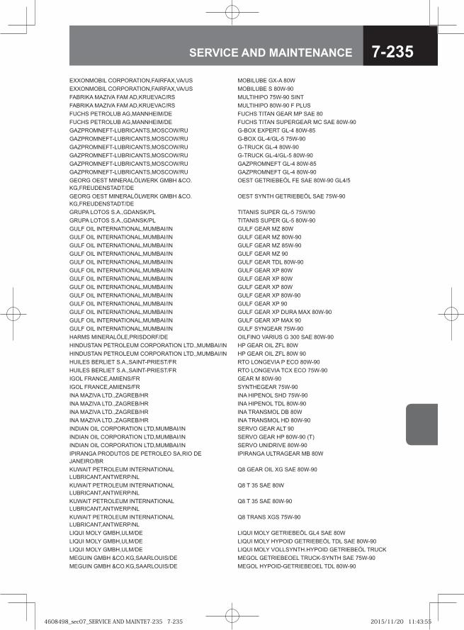
7-235SERVICE AND MAINTENANCE
EXXONMOBIL CORPORATION,FAIRFAX,VA/US MOBILUBE GX-A 80WEXXONMOBIL CORPORATION,FAIRFAX,VA/US MOBILUBE S 80W-90FABRIKA MAZIVA FAM AD,KRUEVAC/RS MULTIHIPO 75W-90 SINTFABRIKA MAZIVA FAM AD,KRUEVAC/RS MULTIHIPO 80W-90 F PLUSFUCHS PETROLUB AG,MANNHEIM/DE FUCHS TITAN GEAR MP SAE 80FUCHS PETROLUB AG,MANNHEIM/DE FUCHS TITAN SUPERGEAR MC SAE 80W-90GAZPROMNEFT-LUBRICANTS,MOSCOW/RU G-BOX EXPERT GL-4 80W-85GAZPROMNEFT-LUBRICANTS,MOSCOW/RU G-BOX GL-4/GL-5 75W-90GAZPROMNEFT-LUBRICANTS,MOSCOW/RU G-TRUCK GL-4 80W-90GAZPROMNEFT-LUBRICANTS,MOSCOW/RU G-TRUCK GL-4/GL-5 80W-90GAZPROMNEFT-LUBRICANTS,MOSCOW/RU GAZPROMNEFT GL-4 80W-85GAZPROMNEFT-LUBRICANTS,MOSCOW/RU GAZPROMNEFT GL-4 80W-90GEORG OEST MINERALÖLWERK GMBH &CO.KG,FREUDENSTADT/DE
OEST GETRIEBEÖL FE SAE 80W-90 GL4/5
GEORG OEST MINERALÖLWERK GMBH &CO.KG,FREUDENSTADT/DE
OEST SYNTH GETRIEBEÖL SAE 75W-90
GRUPA LOTOS S.A.,GDANSK/PL TITANIS SUPER GL-5 75W/90GRUPA LOTOS S.A.,GDANSK/PL TITANIS SUPER GL-5 80W-90GULF OIL INTERNATIONAL,MUMBAI/IN GULF GEAR MZ 80WGULF OIL INTERNATIONAL,MUMBAI/IN GULF GEAR MZ 80W-90GULF OIL INTERNATIONAL,MUMBAI/IN GULF GEAR MZ 85W-90GULF OIL INTERNATIONAL,MUMBAI/IN GULF GEAR MZ 90GULF OIL INTERNATIONAL,MUMBAI/IN GULF GEAR TDL 80W-90GULF OIL INTERNATIONAL,MUMBAI/IN GULF GEAR XP 80WGULF OIL INTERNATIONAL,MUMBAI/IN GULF GEAR XP 80WGULF OIL INTERNATIONAL,MUMBAI/IN GULF GEAR XP 80WGULF OIL INTERNATIONAL,MUMBAI/IN GULF GEAR XP 80W-90GULF OIL INTERNATIONAL,MUMBAI/IN GULF GEAR XP 90GULF OIL INTERNATIONAL,MUMBAI/IN GULF GEAR XP DURA MAX 80W-90GULF OIL INTERNATIONAL,MUMBAI/IN GULF GEAR XP MAX 90GULF OIL INTERNATIONAL,MUMBAI/IN GULF SYNGEAR 75W-90HARMS MINERALÖLE,PRISDORF/DE OILFINO VARIUS G 300 SAE 80W-90HINDUSTAN PETROLEUM CORPORATION LTD.,MUMBAI/IN HP GEAR OIL ZFL 80WHINDUSTAN PETROLEUM CORPORATION LTD.,MUMBAI/IN HP GEAR OIL ZFL 80W 90HUILES BERLIET S.A.,SAINT-PRIEST/FR RTO LONGEVIA P ECO 80W-90HUILES BERLIET S.A.,SAINT-PRIEST/FR RTO LONGEVIA TCX ECO 75W-90IGOL FRANCE,AMIENS/FR GEAR M 80W-90IGOL FRANCE,AMIENS/FR SYNTHEGEAR 75W-90INA MAZIVA LTD.,ZAGREB/HR INA HIPENOL SHD 75W-90INA MAZIVA LTD.,ZAGREB/HR INA HIPENOL TDL 80W-90INA MAZIVA LTD.,ZAGREB/HR INA TRANSMOL DB 80WINA MAZIVA LTD.,ZAGREB/HR INA TRANSMOL HD 80W-90INDIAN OIL CORPORATION LTD,MUMBAI/IN SERVO GEAR ALT 90INDIAN OIL CORPORATION LTD,MUMBAI/IN SERVO GEAR HP 80W-90 (T)INDIAN OIL CORPORATION LTD,MUMBAI/IN SERVO UNIDRIVE 80W-90IPIRANGA PRODUTOS DE PETROLEO SA,RIO DE JANEIRO/BR
IPIRANGA ULTRAGEAR MB 80W
KUWAIT PETROLEUM INTERNATIONAL LUBRICANT,ANTWERP/NL
Q8 GEAR OIL XG SAE 80W-90
KUWAIT PETROLEUM INTERNATIONAL LUBRICANT,ANTWERP/NL
Q8 T 35 SAE 80W
KUWAIT PETROLEUM INTERNATIONAL LUBRICANT,ANTWERP/NL
Q8 T 35 SAE 80W-90
KUWAIT PETROLEUM INTERNATIONAL LUBRICANT,ANTWERP/NL
Q8 TRANS XGS 75W-90
LIQUI MOLY GMBH,ULM/DE LIQUI MOLY GETRIEBEÖL GL4 SAE 80WLIQUI MOLY GMBH,ULM/DE LIQUI MOLY HYPOID GETRIEBEÖL TDL SAE 80W-90LIQUI MOLY GMBH,ULM/DE LIQUI MOLY VOLLSYNTH.HYPOID GETRIEBEÖL TRUCKMEGUIN GMBH &CO.KG,SAARLOUIS/DE MEGOL GETRIEBEOEL TRUCK-SYNTH SAE 75W-90MEGUIN GMBH &CO.KG,SAARLOUIS/DE MEGOL HYPOID-GETRIEBEOEL TDL 80W-90
4608498_sec07_SERVICE AND MAINTE7-235 7-2354608498_sec07_SERVICE AND MAINTE7-235 7-235 2015/11/20 11:43:552015/11/20 11:43:55
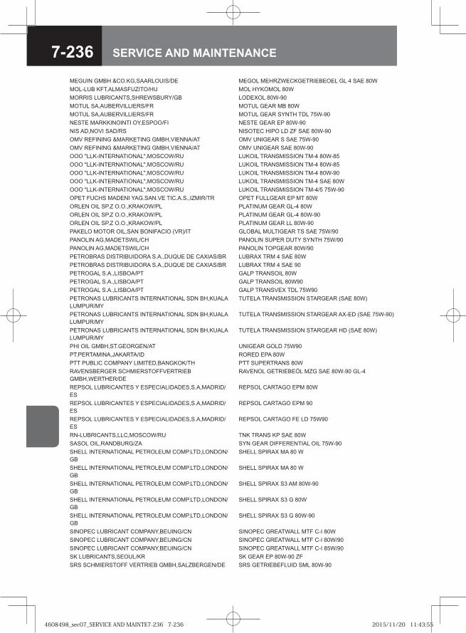
7-236 SERVICE AND MAINTENANCE
MEGUIN GMBH &CO.KG,SAARLOUIS/DE MEGOL MEHRZWECKGETRIEBEOEL GL 4 SAE 80WMOL-LUB KFT,ALMASFUZITO/HU MOL HYKOMOL 80WMORRIS LUBRICANTS,SHREWSBURY/GB LODEXOL 80W-90MOTUL SA,AUBERVILLIERS/FR MOTUL GEAR MB 80WMOTUL SA,AUBERVILLIERS/FR MOTUL GEAR SYNTH TDL 75W-90NESTE MARKKINOINTI OY,ESPOO/FI NESTE GEAR EP 80W-90NIS AD,NOVI SAD/RS NISOTEC HIPO LD ZF SAE 80W-90OMV REFINING &MARKETING GMBH,VIENNA/AT OMV UNIGEAR S SAE 75W-90OMV REFINING &MARKETING GMBH,VIENNA/AT OMV UNIGEAR SAE 80W-90OOO "LLK-INTERNATIONAL",MOSCOW/RU LUKOIL TRANSMISSION TM-4 80W-85OOO "LLK-INTERNATIONAL",MOSCOW/RU LUKOIL TRANSMISSION TM-4 80W-85OOO "LLK-INTERNATIONAL",MOSCOW/RU LUKOIL TRANSMISSION TM-4 80W-90OOO "LLK-INTERNATIONAL",MOSCOW/RU LUKOIL TRANSMISSION TM-4 SAE 80WOOO "LLK-INTERNATIONAL",MOSCOW/RU LUKOIL TRANSMISSION TM-4/5 75W-90OPET FUCHS MADENI YAG.SAN.VE TIC.A.S.,IZMIR/TR OPET FULLGEAR EP MT 80WORLEN OIL SP.Z O.O.,KRAKOW/PL PLATINUM GEAR GL-4 80WORLEN OIL SP.Z O.O.,KRAKOW/PL PLATINUM GEAR GL-4 80W-90ORLEN OIL SP.Z O.O.,KRAKOW/PL PLATINUM GEAR LL 80W-90PAKELO MOTOR OIL,SAN BONIFACIO (VR)/IT GLOBAL MULTIGEAR TS SAE 75W/90PANOLIN AG,MADETSWIL/CH PANOLIN SUPER DUTY SYNTH 75W/90PANOLIN AG,MADETSWIL/CH PANOLIN TOPGEAR 80W/90PETROBRAS DISTRIBUIDORA S.A.,DUQUE DE CAXIAS/BR LUBRAX TRM 4 SAE 80WPETROBRAS DISTRIBUIDORA S.A.,DUQUE DE CAXIAS/BR LUBRAX TRM 4 SAE 90PETROGAL S.A.,LISBOA/PT GALP TRANSOIL 80WPETROGAL S.A.,LISBOA/PT GALP TRANSOIL 80W90PETROGAL S.A.,LISBOA/PT GALP TRANSVEX TDL 75W90PETRONAS LUBRICANTS INTERNATIONAL SDN BH,KUALA LUMPUR/MY
TUTELA TRANSMISSION STARGEAR (SAE 80W)
PETRONAS LUBRICANTS INTERNATIONAL SDN BH,KUALA LUMPUR/MY
TUTELA TRANSMISSION STARGEAR AX-ED (SAE 75W-90)
PETRONAS LUBRICANTS INTERNATIONAL SDN BH,KUALA LUMPUR/MY
TUTELA TRANSMISSION STARGEAR HD (SAE 80W)
PHI OIL GMBH,ST.GEORGEN/AT UNIGEAR GOLD 75W90PT.PERTAMINA,JAKARTA/ID RORED EPA 80WPTT PUBLIC COMPANY LIMITED,BANGKOK/TH PTT SUPERTRANS 80WRAVENSBERGER SCHMIERSTOFFVERTRIEB GMBH,WERTHER/DE
RAVENOL GETRIEBEÖL MZG SAE 80W-90 GL-4
REPSOL LUBRICANTES Y ESPECIALIDADES,S.A,MADRID/ES
REPSOL CARTAGO EPM 80W
REPSOL LUBRICANTES Y ESPECIALIDADES,S.A,MADRID/ES
REPSOL CARTAGO EPM 90
REPSOL LUBRICANTES Y ESPECIALIDADES,S.A,MADRID/ES
REPSOL CARTAGO FE LD 75W90
RN-LUBRICANTS,LLC,MOSCOW/RU TNK TRANS KP SAE 80WSASOL OIL,RANDBURG/ZA SYN GEAR DIFFERENTIAL OIL 75W-90SHELL INTERNATIONAL PETROLEUM COMP.LTD,LONDON/GB
SHELL SPIRAX MA 80 W
SHELL INTERNATIONAL PETROLEUM COMP.LTD,LONDON/GB
SHELL SPIRAX MA 80 W
SHELL INTERNATIONAL PETROLEUM COMP.LTD,LONDON/GB
SHELL SPIRAX S3 AM 80W-90
SHELL INTERNATIONAL PETROLEUM COMP.LTD,LONDON/GB
SHELL SPIRAX S3 G 80W
SHELL INTERNATIONAL PETROLEUM COMP.LTD,LONDON/GB
SHELL SPIRAX S3 G 80W-90
SINOPEC LUBRICANT COMPANY,BEIJING/CN SINOPEC GREATWALL MTF C-I 80WSINOPEC LUBRICANT COMPANY,BEIJING/CN SINOPEC GREATWALL MTF C-I 80W/90SINOPEC LUBRICANT COMPANY,BEIJING/CN SINOPEC GREATWALL MTF C-I 85W/90SK LUBRICANTS,SEOUL/KR SK GEAR EP 80W-90 ZFSRS SCHMIERSTOFF VERTRIEB GMBH,SALZBERGEN/DE SRS GETRIEBEFLUID SML 80W-90
4608498_sec07_SERVICE AND MAINTE7-236 7-2364608498_sec07_SERVICE AND MAINTE7-236 7-236 2015/11/20 11:43:552015/11/20 11:43:55
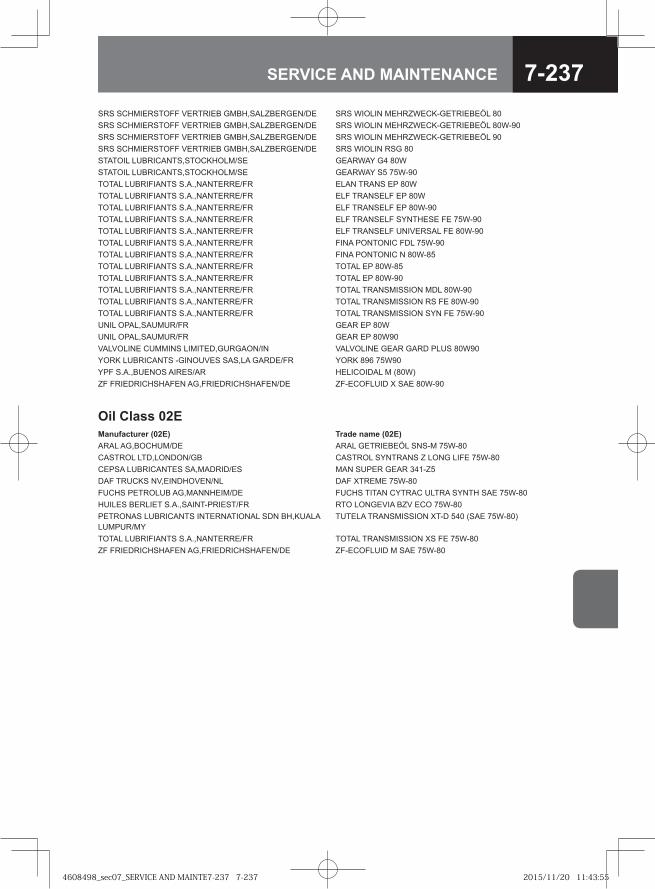
7-237SERVICE AND MAINTENANCE
SRS SCHMIERSTOFF VERTRIEB GMBH,SALZBERGEN/DE SRS WIOLIN MEHRZWECK-GETRIEBEÖL 80SRS SCHMIERSTOFF VERTRIEB GMBH,SALZBERGEN/DE SRS WIOLIN MEHRZWECK-GETRIEBEÖL 80W-90SRS SCHMIERSTOFF VERTRIEB GMBH,SALZBERGEN/DE SRS WIOLIN MEHRZWECK-GETRIEBEÖL 90SRS SCHMIERSTOFF VERTRIEB GMBH,SALZBERGEN/DE SRS WIOLIN RSG 80STATOIL LUBRICANTS,STOCKHOLM/SE GEARWAY G4 80WSTATOIL LUBRICANTS,STOCKHOLM/SE GEARWAY S5 75W-90TOTAL LUBRIFIANTS S.A.,NANTERRE/FR ELAN TRANS EP 80WTOTAL LUBRIFIANTS S.A.,NANTERRE/FR ELF TRANSELF EP 80WTOTAL LUBRIFIANTS S.A.,NANTERRE/FR ELF TRANSELF EP 80W-90TOTAL LUBRIFIANTS S.A.,NANTERRE/FR ELF TRANSELF SYNTHESE FE 75W-90TOTAL LUBRIFIANTS S.A.,NANTERRE/FR ELF TRANSELF UNIVERSAL FE 80W-90TOTAL LUBRIFIANTS S.A.,NANTERRE/FR FINA PONTONIC FDL 75W-90TOTAL LUBRIFIANTS S.A.,NANTERRE/FR FINA PONTONIC N 80W-85TOTAL LUBRIFIANTS S.A.,NANTERRE/FR TOTAL EP 80W-85TOTAL LUBRIFIANTS S.A.,NANTERRE/FR TOTAL EP 80W-90TOTAL LUBRIFIANTS S.A.,NANTERRE/FR TOTAL TRANSMISSION MDL 80W-90TOTAL LUBRIFIANTS S.A.,NANTERRE/FR TOTAL TRANSMISSION RS FE 80W-90TOTAL LUBRIFIANTS S.A.,NANTERRE/FR TOTAL TRANSMISSION SYN FE 75W-90UNIL OPAL,SAUMUR/FR GEAR EP 80WUNIL OPAL,SAUMUR/FR GEAR EP 80W90VALVOLINE CUMMINS LIMITED,GURGAON/IN VALVOLINE GEAR GARD PLUS 80W90YORK LUBRICANTS -GINOUVES SAS,LA GARDE/FR YORK 896 75W90YPF S.A.,BUENOS AIRES/AR HELICOIDAL M (80W)ZF FRIEDRICHSHAFEN AG,FRIEDRICHSHAFEN/DE ZF-ECOFLUID X SAE 80W-90
Oil Class 02EManufacturer (02E) Trade name (02E)ARAL AG,BOCHUM/DE ARAL GETRIEBEÖL SNS-M 75W-80CASTROL LTD,LONDON/GB CASTROL SYNTRANS Z LONG LIFE 75W-80CEPSA LUBRICANTES SA,MADRID/ES MAN SUPER GEAR 341-Z5DAF TRUCKS NV,EINDHOVEN/NL DAF XTREME 75W-80FUCHS PETROLUB AG,MANNHEIM/DE FUCHS TITAN CYTRAC ULTRA SYNTH SAE 75W-80HUILES BERLIET S.A.,SAINT-PRIEST/FR RTO LONGEVIA BZV ECO 75W-80PETRONAS LUBRICANTS INTERNATIONAL SDN BH,KUALA LUMPUR/MY
TUTELA TRANSMISSION XT-D 540 (SAE 75W-80)
TOTAL LUBRIFIANTS S.A.,NANTERRE/FR TOTAL TRANSMISSION XS FE 75W-80ZF FRIEDRICHSHAFEN AG,FRIEDRICHSHAFEN/DE ZF-ECOFLUID M SAE 75W-80
4608498_sec07_SERVICE AND MAINTE7-237 7-2374608498_sec07_SERVICE AND MAINTE7-237 7-237 2015/11/20 11:43:552015/11/20 11:43:55
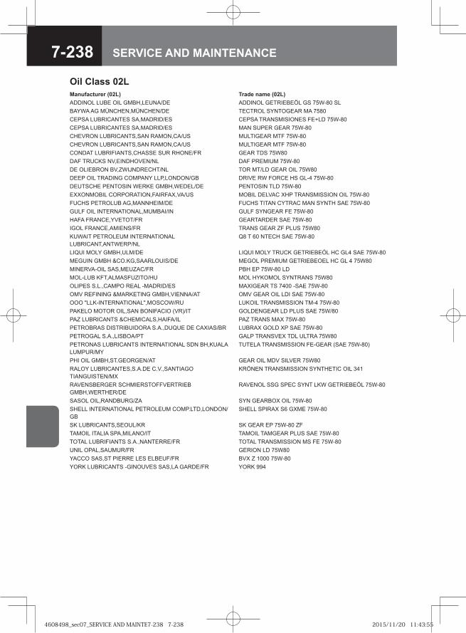
7-238 SERVICE AND MAINTENANCE
Oil Class 02LManufacturer (02L) Trade name (02L)ADDINOL LUBE OIL GMBH,LEUNA/DE ADDINOL GETRIEBEÖL GS 75W-80 SLBAYWA AG MÜNCHEN,MÜNCHEN/DE TECTROL SYNTOGEAR MA 7580CEPSA LUBRICANTES SA,MADRID/ES CEPSA TRANSMISIONES FE+LD 75W-80CEPSA LUBRICANTES SA,MADRID/ES MAN SUPER GEAR 75W-80CHEVRON LUBRICANTS,SAN RAMON,CA/US MULTIGEAR MTF 75W-80CHEVRON LUBRICANTS,SAN RAMON,CA/US MULTIGEAR MTF 75W-80CONDAT LUBRIFIANTS,CHASSE SUR RHONE/FR GEAR TDS 75W80DAF TRUCKS NV,EINDHOVEN/NL DAF PREMIUM 75W-80DE OLIEBRON BV,ZWIJNDRECHT/NL TOR MT/LD GEAR OIL 75W80DEEP OIL TRADING COMPANY LLP,LONDON/GB DRIVE RW FORCE HS GL-4 75W-80DEUTSCHE PENTOSIN WERKE GMBH,WEDEL/DE PENTOSIN TLD 75W-80EXXONMOBIL CORPORATION,FAIRFAX,VA/US MOBIL DELVAC XHP TRANSMISSION OIL 75W-80FUCHS PETROLUB AG,MANNHEIM/DE FUCHS TITAN CYTRAC MAN SYNTH SAE 75W-80GULF OIL INTERNATIONAL,MUMBAI/IN GULF SYNGEAR FE 75W-80HAFA FRANCE,YVETOT/FR GEARTARDER SAE 75W-80IGOL FRANCE,AMIENS/FR TRANS GEAR ZF PLUS 75W80KUWAIT PETROLEUM INTERNATIONAL LUBRICANT,ANTWERP/NL
Q8 T 60 NTECH SAE 75W-80
LIQUI MOLY GMBH,ULM/DE LIQUI MOLY TRUCK GETRIEBEÖL HC GL4 SAE 75W-80MEGUIN GMBH &CO.KG,SAARLOUIS/DE MEGOL PREMIUM GETRIEBEOEL HC GL 4 75W80MINERVA-OIL SAS,MEUZAC/FR PBH EP 75W-80 LDMOL-LUB KFT,ALMASFUZITO/HU MOL HYKOMOL SYNTRANS 75W80OLIPES S.L.,CAMPO REAL -MADRID/ES MAXIGEAR TS 7400 -SAE 75W-80OMV REFINING &MARKETING GMBH,VIENNA/AT OMV GEAR OIL LDI SAE 75W-80OOO "LLK-INTERNATIONAL",MOSCOW/RU LUKOIL TRANSMISSION TM-4 75W-80PAKELO MOTOR OIL,SAN BONIFACIO (VR)/IT GOLDENGEAR LD PLUS SAE 75W/80PAZ LUBRICANTS &CHEMICALS,HAIFA/IL PAZ TRANS MAX 75W-80PETROBRAS DISTRIBUIDORA S.A.,DUQUE DE CAXIAS/BR LUBRAX GOLD XP SAE 75W-80PETROGAL S.A.,LISBOA/PT GALP TRANSVEX TDL ULTRA 75W80PETRONAS LUBRICANTS INTERNATIONAL SDN BH,KUALA LUMPUR/MY
TUTELA TRANSMISSION FE-GEAR (SAE 75W-80)
PHI OIL GMBH,ST.GEORGEN/AT GEAR OIL MDV SILVER 75W80RALOY LUBRICANTES,S.A.DE C.V.,SANTIAGO TIANGUISTEN/MX
KRÖNEN TRANSMISSION SYNTHETIC OIL 341
RAVENSBERGER SCHMIERSTOFFVERTRIEB GMBH,WERTHER/DE
RAVENOL SSG SPEC SYNT LKW GETRIEBEÖL 75W-80
SASOL OIL,RANDBURG/ZA SYN GEARBOX OIL 75W-80SHELL INTERNATIONAL PETROLEUM COMP.LTD,LONDON/GB
SHELL SPIRAX S6 GXME 75W-80
SK LUBRICANTS,SEOUL/KR SK GEAR EP 75W-80 ZFTAMOIL ITALIA SPA,MILANO/IT TAMOIL TAMGEAR PLUS SAE 75W-80TOTAL LUBRIFIANTS S.A.,NANTERRE/FR TOTAL TRANSMISSION MS FE 75W-80UNIL OPAL,SAUMUR/FR GERION LD 75W80YACCO SAS,ST PIERRE LES ELBEUF/FR BVX Z 1000 75W-80YORK LUBRICANTS -GINOUVES SAS,LA GARDE/FR YORK 994
4608498_sec07_SERVICE AND MAINTE7-238 7-2384608498_sec07_SERVICE AND MAINTE7-238 7-238 2015/11/20 11:43:552015/11/20 11:43:55
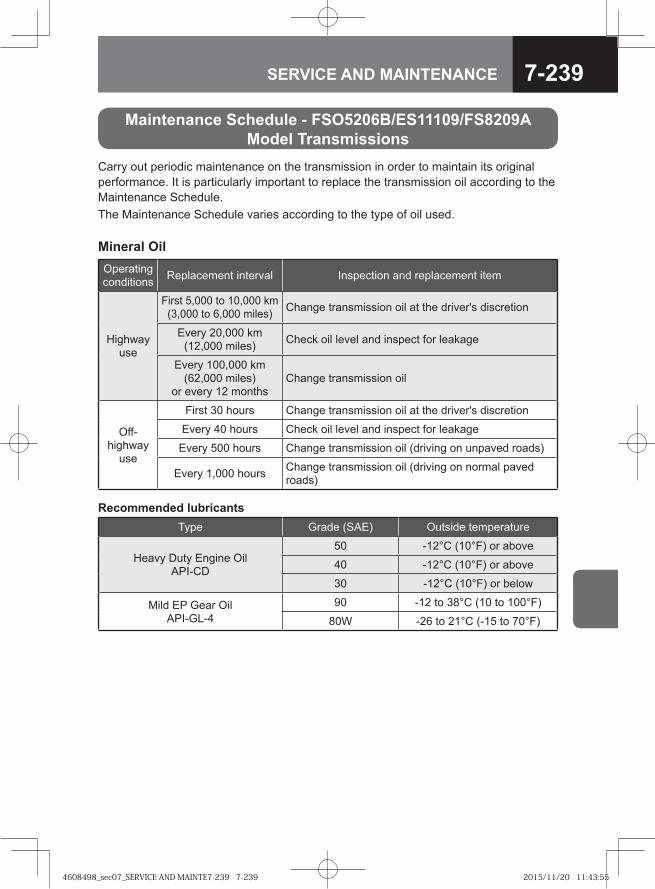
7-239SERVICE AND MAINTENANCE
Carry out periodic maintenance on the transmission in order to maintain its original performance. It is particularly important to replace the transmission oil according to the Maintenance Schedule.The Maintenance Schedule varies according to the type of oil used.
Operating conditions Replacement interval Inspection and replacement item
Highway use
First 5,000 to 10,000 km(3,000 to 6,000 miles) Change transmission oil at the driver's discretion
Every 20,000 km(12,000 miles) Check oil level and inspect for leakage
Every 100,000 km(62,000 miles)
or every 12 monthsChange transmission oil
Off-highway
use
First 30 hours Change transmission oil at the driver's discretion
Every 40 hours Check oil level and inspect for leakage
Every 500 hours Change transmission oil (driving on unpaved roads)
Every 1,000 hours Change transmission oil (driving on normal paved roads)
Recommended lubricantsType Grade (SAE) Outside temperature
Heavy Duty Engine Oil API-CD
50 -12°C (10°F) or above
40 -12°C (10°F) or above
30 -12°C (10°F) or below
Mild EP Gear Oil API-GL-4
90 -12 to 38°C (10 to 100°F)
80W -26 to 21°C (-15 to 70°F)
Maintenance Schedule - FSO5206B/ES11109/FS8209A Model Transmissions
Mineral Oil
4608498_sec07_SERVICE AND MAINTE7-239 7-2394608498_sec07_SERVICE AND MAINTE7-239 7-239 2015/11/20 11:43:552015/11/20 11:43:55
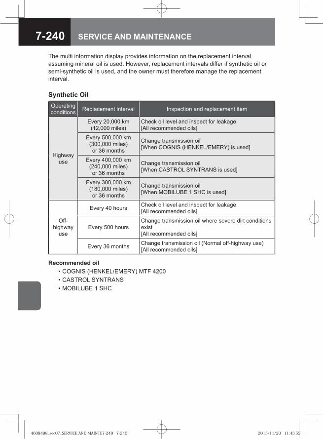
7-240 SERVICE AND MAINTENANCE
Operating conditions Replacement interval Inspection and replacement item
Highway use
Every 20,000 km(12,000 miles)
Check oil level and inspect for leakage [All recommended oils]
Every 500,000 km (300,000 miles) or 36 months
Change transmission oil [When COGNIS (HENKEL/EMERY) is used]
Every 400,000 km (240,000 miles) or 36 months
Change transmission oil [When CASTROL SYNTRANS is used]
Every 300,000 km (180,000 miles) or 36 months
Change transmission oil [When MOBILUBE 1 SHC is used]
Off-highway
use
Every 40 hours Check oil level and inspect for leakage[All recommended oils]
Every 500 hoursChange transmission oil where severe dirt conditions exist [All recommended oils]
Every 36 months Change transmission oil (Normal off-highway use)[All recommended oils]
Synthetic Oil
Recommended oil • COGNIS (HENKEL/EMERY) MTF 4200 • CASTROL SYNTRANS • MOBILUBE 1 SHC
The multi information display provides information on the replacement interval assuming mineral oil is used. However, replacement intervals differ if synthetic oil or semi-synthetic oil is used, and the owner must therefore manage the replacement interval.
4608498_sec07_SERVICE AND MAINTE7-240 7-2404608498_sec07_SERVICE AND MAINTE7-240 7-240 2015/11/20 11:43:552015/11/20 11:43:55
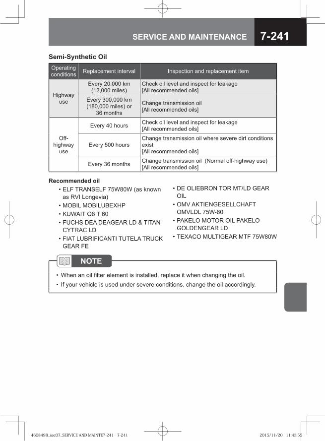
7-241SERVICE AND MAINTENANCE
Operating conditions Replacement interval Inspection and replacement item
Highway use
Every 20,000 km (12,000 miles)
Check oil level and inspect for leakage [All recommended oils]
Every 300,000 km (180,000 miles) or
36 months
Change transmission oil [All recommended oils]
Off-highway
use
Every 40 hours Check oil level and inspect for leakage [All recommended oils]
Every 500 hoursChange transmission oil where severe dirt conditions exist [All recommended oils]
Every 36 months Change transmission oil (Normal off-highway use)[All recommended oils]
Semi-Synthetic Oil
Recommended oil • ELF TRANSELF 75W80W (as known
as RVI Longevia) • MOBIL MOBILUBEXHP • KUWAIT Q8 T 60 • FUCHS DEA DEAGEAR LD & TITAN
CYTRAC LD • FIAT LUBRIFICANTI TUTELA TRUCK
GEAR FE
• DE OLIEBRON TOR MT/LD GEAR OIL
• OMV AKTIENGESELLCHAFT OMVLDL 75W-80
• PAKELO MOTOR OIL PAKELO GOLDENGEAR LD
• TEXACO MULTIGEAR MTF 75W80W
NOTEWhen an oil filter element is installed, replace it when changing the oil.If your vehicle is used under severe conditions, change the oil accordingly.
••
4608498_sec07_SERVICE AND MAINTE7-241 7-2414608498_sec07_SERVICE AND MAINTE7-241 7-241 2015/11/20 11:43:552015/11/20 11:43:55
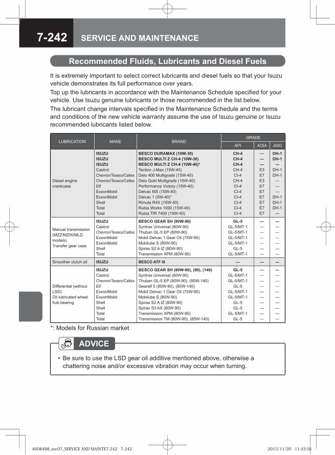
7-242 SERVICE AND MAINTENANCE
Recommended Fluids, Lubricants and Diesel FuelsIt is extremely important to select correct lubricants and diesel fuels so that your Isuzu vehicle demonstrates its full performance over years.Top up the lubricants in accordance with the Maintenance Schedule specified for your vehicle. Use Isuzu genuine lubricants or those recommended in the list below. The lubricant change intervals specified in the Maintenance Schedule and the terms and conditions of the new vehicle warranty assume the use of Isuzu genuine or Isuzu recommended lubricants listed below.
LUBRICATION MAKE BRANDGRADE
API ACEA JASO
Diesel engine crankcase
ISUZUISUZUISUZUCastrolChevron/Texaco/CaltexChevron/Texaco/CaltexElfExxonMobilExxonMobilShellTotalTotal
BESCO DURAMAX (10W-30)BESCO MULTI Z CH-4 (10W-30)BESCO MULTI Z CH-4 (10W-40)*Tection J-Max (15W-40)Delo 400 Multigrade (15W-40)Delo Gold Multigrade (15W-40)Performance Victory (15W-40)Delvac MX (15W-40)Delvac 1 (5W-40)*Rimula R4X (15W-40)Rubia Works 1000 (15W-40)Rubia TIR 7400 (15W-40)
CH-4CH-4CH-4CH-4CI-4CH-4CI-4CI-4CI-4CI-4CI-4CI-4
―――E3E7E3E7E7E7E7E7E7
DH-1DH-1―
DH-1DH-1―――
DH-1DH-1DH-1―
Manual transmission (MZZ/MZW/MLD models)Transfer gear case
ISUZUCastrolChevron/Texaco/CaltexExxonMobilExxonMobilShellTotal
BESCO GEAR SH (80W-90)Syntrax Universal (80W-90)Thuban GL-5 EP (80W-90)Mobil Delvac 1 Gear Oil (75W-90)Mobilube S (80W-90)Spirax S2 A IZ (80W-90)Transmission XPM (80W-90)
GL-5GL-5/MT-1GL-5/MT-1GL-5/MT-1GL-5/MT-1
GL-5GL-5/MT-1
―――――――
―――――――
Smoother clutch oil ISUZU BESCO ATF III ― ― ―
Differential (without LSD)Oil lubricated wheel hub bearing
ISUZUCastrolChevron/Texaco/CaltexElfExxonMobilExxonMobilShellShellTotalTotal
BESCO GEAR SH (80W-90), (90), (140)Syntrax Universal (80W-90)Thuban GL-5 EP (80W-90), (85W-140)Gearelf 5 (80W-90), (85W-140)Mobil Delvac 1 Gear Oil (75W-90)Mobilube S (80W-90)Spirax S2 A IZ (80W-90)Spirax S3 AX (80W-90)Transmission XPM (80W-90)Transmission TM (80W-90), (85W-140)
GL-5GL-5/MT-1GL-5/MT-1
GL-5GL-5/MT-1GL-5/MT-1
GL-5GL-5
GL-5/MT-1GL-5
――――――――――
――――――――――
*: Models for Russian market
ADVICEBe sure to use the LSD gear oil additive mentioned above, otherwise a chattering noise and/or excessive vibration may occur when turning.
•
4608498_sec07_SERVICE AND MAINTE7-242 7-2424608498_sec07_SERVICE AND MAINTE7-242 7-242 2015/11/20 11:43:562015/11/20 11:43:56
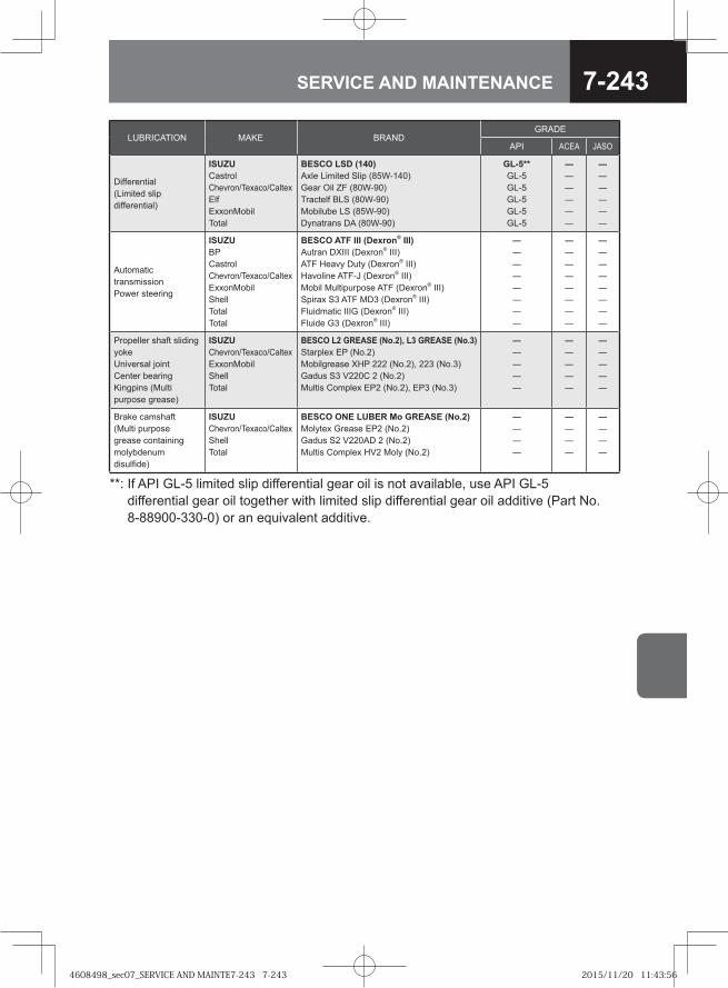
7-243SERVICE AND MAINTENANCE
LUBRICATION MAKE BRANDGRADE
API ACEA JASO
Differential (Limited slip differential)
ISUZUCastrolChevron/Texaco/CaltexElfExxonMobilTotal
BESCO LSD (140)Axle Limited Slip (85W-140)Gear Oil ZF (80W-90)Tractelf BLS (80W-90)Mobilube LS (85W-90)Dynatrans DA (80W-90)
GL-5**GL-5GL-5GL-5GL-5GL-5
――――――
――――――
Automatic transmissionPower steering
ISUZUBPCastrolChevron/Texaco/CaltexExxonMobilShellTotalTotal
BESCO ATF III (Dexron® III)Autran DXIII (Dexron® III)ATF Heavy Duty (Dexron® III)Havoline ATF-J (Dexron® III)Mobil Multipurpose ATF (Dexron® III)Spirax S3 ATF MD3 (Dexron® III)Fluidmatic IIIG (Dexron® III)Fluide G3 (Dexron® III)
――――――――
――――――――
――――――――
Propeller shaft sliding yokeUniversal jointCenter bearingKingpins (Multi purpose grease)
ISUZUChevron/Texaco/CaltexExxonMobilShellTotal
BESCO L2 GREASE (No.2), L3 GREASE (No.3)Starplex EP (No.2)Mobilgrease XHP 222 (No.2), 223 (No.3)Gadus S3 V220C 2 (No.2)Multis Complex EP2 (No.2), EP3 (No.3)
―――――
―――――
―――――
Brake camshaft (Multi purpose grease containing molybdenum disulfide)
ISUZUChevron/Texaco/CaltexShellTotal
BESCO ONE LUBER Mo GREASE (No.2)Molytex Grease EP2 (No.2)Gadus S2 V220AD 2 (No.2)Multis Complex HV2 Moly (No.2)
――――
――――
――――
**: If API GL-5 limited slip differential gear oil is not available, use API GL-5 differential gear oil together with limited slip differential gear oil additive (Part No. 8-88900-330-0) or an equivalent additive.
4608498_sec07_SERVICE AND MAINTE7-243 7-2434608498_sec07_SERVICE AND MAINTE7-243 7-243 2015/11/20 11:43:562015/11/20 11:43:56
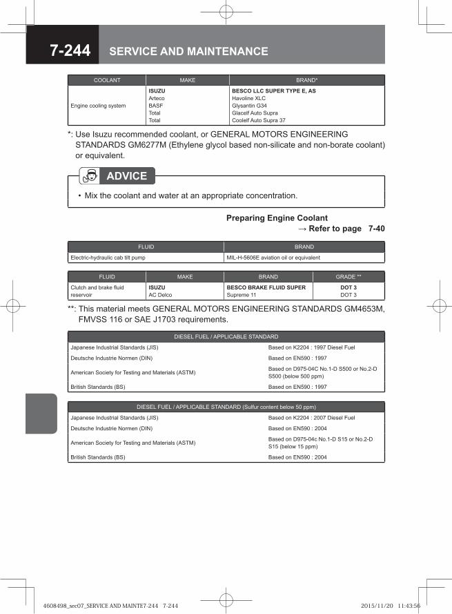
7-244 SERVICE AND MAINTENANCE
DIESEL FUEL / APPLICABLE STANDARD (Sulfur content below 50 ppm)
Japanese Industrial Standards (JIS) Based on K2204 : 2007 Diesel Fuel
Deutsche Industrie Normen (DIN) Based on EN590 : 2004
American Society for Testing and Materials (ASTM)Based on D975-04c No.1-D S15 or No.2-D S15 (below 15 ppm)
British Standards (BS) Based on EN590 : 2004
DIESEL FUEL / APPLICABLE STANDARD
Japanese Industrial Standards (JIS) Based on K2204 : 1997 Diesel Fuel
Deutsche Industrie Normen (DIN) Based on EN590 : 1997
American Society for Testing and Materials (ASTM)Based on D975-04C No.1-D S500 or No.2-D S500 (below 500 ppm)
British Standards (BS) Based on EN590 : 1997
ADVICEMix the coolant and water at an appropriate concentration.•
Preparing Engine Coolant → Refer to page 7-40
COOLANT MAKE BRAND*
Engine cooling system
ISUZUArtecoBASFTotalTotal
BESCO LLC SUPER TYPE E, ASHavoline XLCGlysantin G34Glacelf Auto SupraCoolelf Auto Supra 37
*: Use Isuzu recommended coolant, or GENERAL MOTORS ENGINEERING STANDARDS GM6277M (Ethylene glycol based non-silicate and non-borate coolant) or equivalent.
FLUID MAKE BRAND GRADE **
Clutch and brake fluid reservoir
ISUZUAC Delco
BESCO BRAKE FLUID SUPERSupreme 11
DOT 3DOT 3
**: This material meets GENERAL MOTORS ENGINEERING STANDARDS GM4653M, FMVSS 116 or SAE J1703 requirements.
FLUID BRAND
Electric-hydraulic cab tilt pump MIL-H-5606E aviation oil or equivalent
4608498_sec07_SERVICE AND MAINTE7-244 7-2444608498_sec07_SERVICE AND MAINTE7-244 7-244 2015/11/20 11:43:562015/11/20 11:43:56
7-245SERVICE AND MAINTENANCE
CAUTIONBe sure to use diesel fuel. For models conforming to EuroIV emission standards, be sure to use low-sulfur diesel fuel (containing sulfur of 50 ppm or lower) or extra-low-sulfur diesel fuel (containing sulfur of 10 ppm or lower). If you supply the vehicle with poor-quality fuel, water-removal additive or other additive, gasoline, kerosene or alcohol-based fuel, it could harm the fuel filter, prevent proper movement of fuel-lubricated parts in the injectors and adversely affect engine components, possibly resulting in a breakdown. If you accidentally put the wrong fuel in the tank, drain it all out. Starting the engine with the wrong fuel in the tank could result in fire and engine damage.Open the fuel tank filler cap slowly. If you open it quickly, fuel may spurt out.
•
•
ADVICEOnly use fuels listed above. Do not use other fuels as they may adversely affect the engine.
•
4608498_sec07_SERVICE AND MAINTE7-245 7-2454608498_sec07_SERVICE AND MAINTE7-245 7-245 2015/11/20 11:43:562015/11/20 11:43:56
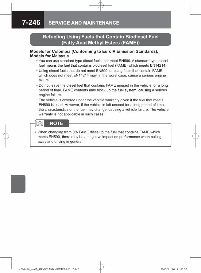
7-246 SERVICE AND MAINTENANCE
Refueling Using Fuels that Contain Biodiesel Fuel (Fatty Acid Methyl Esters (FAME))
Models for Colombia (Conforming to EuroIV Emission Standards), Models for Malaysia • You can use standard type diesel fuels that meet EN590. A standard type diesel
fuel means the fuel that contains biodiesel fuel (FAME) which meets EN14214. • Using diesel fuels that do not meet EN590, or using fuels that contain FAME
which does not meet EN14214 may, in the worst case, cause a serious engine failure.
• Do not leave the diesel fuel that contains FAME unused in the vehicle for a long period of time. FAME contents may block up the fuel system, causing a serious engine failure.
• The vehicle is covered under the vehicle warranty given if the fuel that meets EN590 is used. However, if the vehicle is left unused for a long period of time, the characteristics of the fuel may change, causing a vehicle failure. The vehicle warranty is not applicable in such cases.
NOTEWhen changing from 0% FAME diesel to the fuel that contains FAME which meets EN590, there may be a negative impact on performance when pulling away and driving in general.
•
4608498_sec07_SERVICE AND MAINTE7-246 7-2464608498_sec07_SERVICE AND MAINTE7-246 7-246 2015/11/20 11:43:562015/11/20 11:43:56
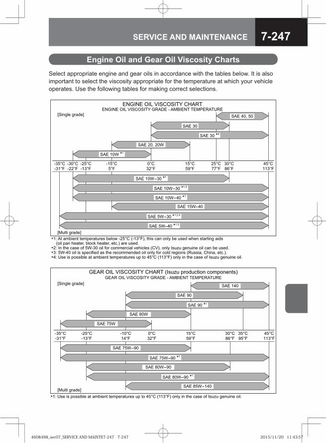
7-247SERVICE AND MAINTENANCE
Engine Oil and Gear Oil Viscosity ChartsSelect appropriate engine and gear oils in accordance with the tables below. It is also important to select the viscosity appropriate for the temperature at which your vehicle operates. Use the following tables for making correct selections.
�� �� ������ ������ ����� ����� ����� ��� ��!" �#�� $ � ���% �� ���& �#�� �� ����' �&����� � � #� ���" ���$( #� ���" ��$)! �� ���&)
�� *� �#� $ �� �+ �,� � ��� +�� $�����$� � -�#�$��� ��.!" ���% *��/� '������ ��� $ � �� ���&)
� �,�0� ��� �� ���$�+��& � �#� ��$�����&�& ��� ���% +�� $��& ��'���� �1���� " �#�� " ��$)!)
�0 ��� �� �������� � ������ ������ ����� �� �� 0��� ��� ��! ���% �� �#� $ �� �+ *��/� '������ ���)
2����� '� &�3
4�5 ��,� � ��
4�5 ��,�0� ��
4�5 � �0
4�5 ��" ��,
4�5 ��, ��
4�5 ��,�0�
4�5 �,� � ��"�"0
4�5 �,�0� ��"
4�5 �
4�5 0�" ��
567*65 8*9 .*4�84*:; 71��5 � ��<*56: :5�=51�:�15567*65 8*9 .*4�84*:; �>�1:
24��'�� '� &�3
4�5 ��,� � ��"0
� ��� � ��� ����� ����� ��� ���� ���� ��� 0����� ��?@�������A�� �������� �������� ���
�� �
�� ������
�� ���
� �� ��� ��������� ���� � ���� �� � �� �����
� �� ��� ��������� ����� �� !"! #$%&!'()%* '%+#%*,*( -
.�)*/0, /$1&,2
.�!0() /$1&,2
�� ������ 3
�� 4��
�� ��
�� �� 3
�� 4�����
�� 4����� 3
�� 4����
35 � , ) #% )60, 1( 1+6),*( (,+#,$1(!$, !# (% �7� �87�- %*09 )* (:, '1 , %; � !"! /,*!)*, %)0<
�8�7� �=�7� ��7� �7� �7� 8�7� �7�87���7�
8�7�4>7���7�8=7�7��87��87�
4608498_sec07_SERVICE AND MAINTE7-247 7-2474608498_sec07_SERVICE AND MAINTE7-247 7-247 2015/11/20 11:43:572015/11/20 11:43:57
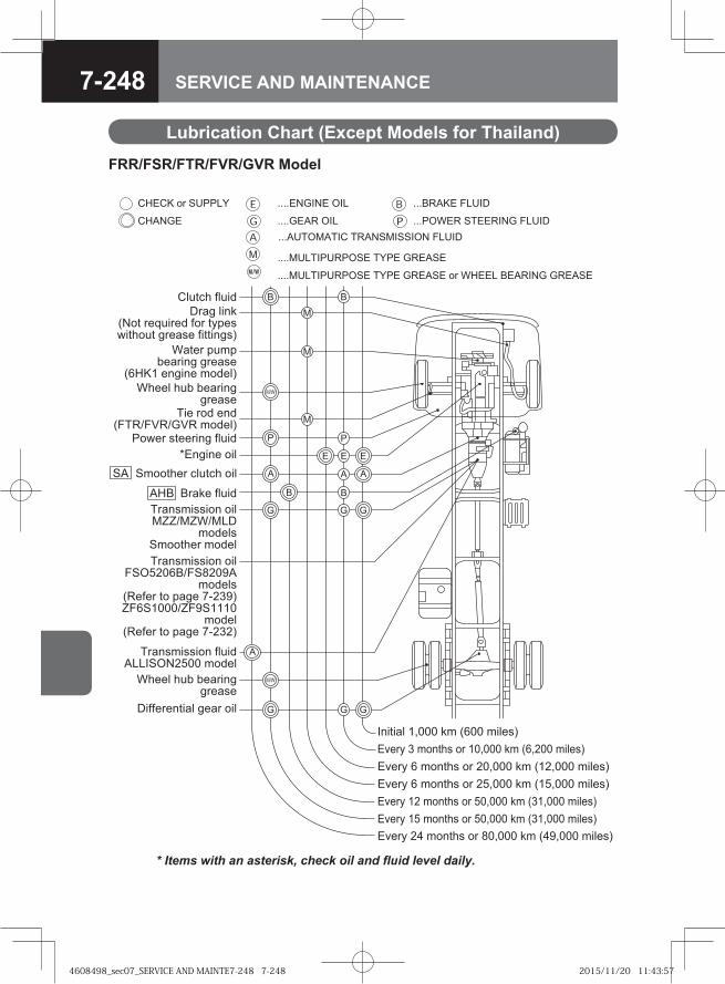
7-248 SERVICE AND MAINTENANCE
Lubrication Chart (Except Models for Thailand)
FRR/FSR/FTR/FVR/GVR Model
P
G GG
G GG
P
B B
E EE
B B
M/W
CHECK or SUPPLY ....ENGINE OIL ...BRAKE FLUID
CHANGE ....GEAR OIL
....MULTIPURPOSE TYPE GREASE
....MULTIPURPOSE TYPE GREASE or WHEEL BEARING GREASE
Clutch fluid
Wheel hub bearinggrease
AHB Brake fluid
Power steering fluid*Engine oil
Transmission oilMZZ/MZW/MLD
modelsSmoother modelTransmission oil
FSO5206B/FS8209Amodels
(Refer to page 7-239)ZF6S1000/ZF9S1110
model (Refer to page 7-232)
Transmission fluidALLISON2500 model
Differential gear oil
M/W
M
M
Wheel hub bearinggrease
Water pumpbearing grease
(6HK1 engine model)
Drag link(Not required for typeswithout grease fittings)
MTie rod end(FTR/FVR/GVR model)
Initial 1,000 km (600 miles)Every 3 months or 10,000 km (6,200 miles)Every 6 months or 20,000 km (12,000 miles)Every 6 months or 25,000 km (15,000 miles)Every 12 months or 50,000 km (31,000 miles)Every 15 months or 50,000 km (31,000 miles)Every 24 months or 80,000 km (49,000 miles)
...POWER STEERING FLUID
A
A
AASA Smoother clutch oil
...AUTOMATIC TRANSMISSION FLUID
4608498_sec07_SERVICE AND MAINTE7-248 7-2484608498_sec07_SERVICE AND MAINTE7-248 7-248 2015/11/20 11:43:572015/11/20 11:43:57
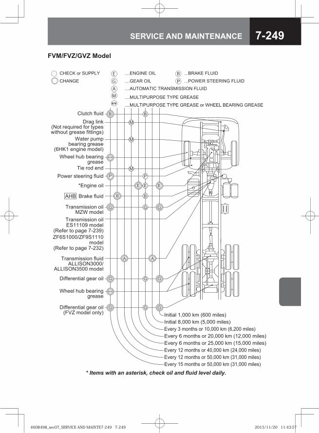
7-249SERVICE AND MAINTENANCE
CHECK or SUPPLY ....ENGINE OIL ...BRAKE FLUID
CHANGE ....GEAR OIL
....MULTIPURPOSE TYPE GREASE
....MULTIPURPOSE TYPE GREASE or WHEEL BEARING GREASE
...POWER STEERING FLUID....AUTOMATIC TRANSMISSION FLUID
M/W
P
G GG
P
E EE
B B
M
M
M/W
Clutch fluid
Wheel hub bearinggrease
Water pumpbearing grease
(6HK1 engine model)
MTie rod end
Drag link(Not required for typeswithout grease fittings)
Wheel hub bearinggrease
Power steering fluid
*Engine oil
Transmission oilES11109 model
(Refer to page 7-239)ZF6S1000/ZF9S1110
model (Refer to page 7-232)
Differential gear oil(FVZ model only)
G GGDifferential gear oil
G GG
B
A A
BAHB Brake fluid
Transmission oilMZW model
Transmission fluidALLISON3000/
ALLISON3500 model
Initial 1,000 km (600 miles)Initial 8,000 km (5,000 miles)Every 3 months or 10,000 km (6,200 miles)Every 6 months or 20,000 km (12,000 miles)Every 6 months or 25,000 km (15,000 miles)Every 12 months or 40,000 km (24,000 miles)Every 12 months or 50,000 km (31,000 miles)Every 15 months or 50,000 km (31,000 miles)
FVM/FVZ/GVZ Model
4608498_sec07_SERVICE AND MAINTE7-249 7-2494608498_sec07_SERVICE AND MAINTE7-249 7-249 2015/11/20 11:43:572015/11/20 11:43:57
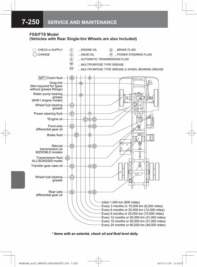
7-250 SERVICE AND MAINTENANCE
FSS/FTS Model (Vehicles with Rear Single-tire Wheels are also Included)
���
�
�
� �
� ��
� �
�
�
���
�
����� �� ������ ������ ��� ��� �������� �����
���� � ���� ��� ���
������� �������� ��� �����
������� �������� ��� ����� �� ����� ������ �����
�!"#"$% &��� '( )*�� ("%+,-
�.+�/ 0 (�!#1, �� �&��� '( )*&��� ("%+,-
�.+�/ * (�!#1, �� �&��� '( )&��� ("%+,-
�.+�/ * (�!#1, �� ��&��� '( )�&��� ("%+,-
�.+�/ � (�!#1, �� �&��� '( )0&��� ("%+,-
�.+�/ (�!#1, �� �&��� '( )0&��� ("%+,-
�.+�/ �2 (�!#1, �� 3�&��� '( )24&��� ("%+,-
�%5#61 7%5"8
�1++% 159 9+$�"!::�+$,+
�1++% 159 9+$�"!::�+$,+
���!# $;%+8"77+�+!#"$% :+$� �"%
�$#+� <5(< 9+$�"!::�+$,+
)*�� +!:"!+ (�8+%-
��$: %"!')��# �+=5"�+8 7�� #/<+,>"#1�5# :�+$,+ 7"##"!:,-
��$'+ 7%5"8
��>+� ,#++�"!: 7%5"8
?�!:"!+ �"%
�$!5$%#�$!,(",,"�! �"%
�@����� (�8+%,
�$!,7+� :+$� 6$,+ �"%
�+$� $;%+8"77+�+!#"$% :+$� �"%
�������� � ����� �����
������ ��� �� ����������� �����
��
�$!,(",,"�! 7%5"8���������� (�8+%
4608498_sec07_SERVICE AND MAINTE7-250 7-2504608498_sec07_SERVICE AND MAINTE7-250 7-250 2015/11/20 11:43:572015/11/20 11:43:57
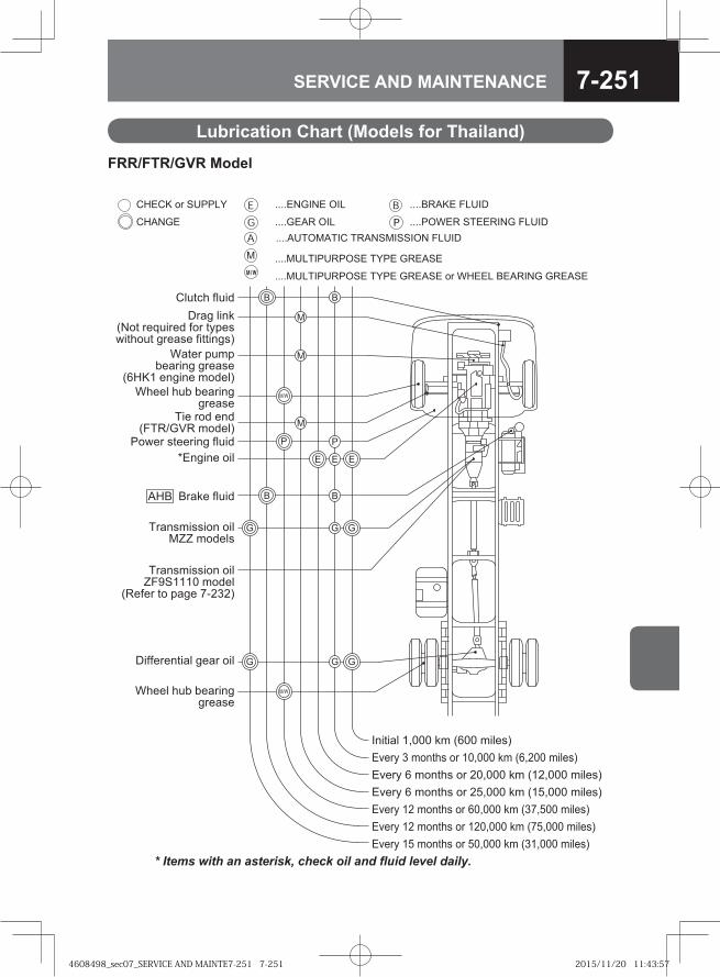
7-251SERVICE AND MAINTENANCE
Lubrication Chart (Models for Thailand)
P
G GG
G GG
P
B B
E EE
B B
M/W
CHECK or SUPPLY ....ENGINE OIL ....BRAKE FLUID
CHANGE ....GEAR OIL
....MULTIPURPOSE TYPE GREASE
....MULTIPURPOSE TYPE GREASE or WHEEL BEARING GREASE
Clutch fluid
Wheel hub bearinggrease
AHB Brake fluid
Power steering fluid*Engine oil
Transmission oilMZZ models
Transmission oilZF9S1110 model
(Refer to page 7-232)
Differential gear oil
M/W
M
Wheel hub bearinggrease
Water pumpbearing grease
(6HK1 engine model)
M Drag link(Not required for typeswithout grease fittings)
MTie rod end(FTR/GVR model)
Initial 1,000 km (600 miles)Every 3 months or 10,000 km (6,200 miles)Every 6 months or 20,000 km (12,000 miles)Every 6 months or 25,000 km (15,000 miles)Every 12 months or 60,000 km (37,500 miles)Every 12 months or 120,000 km (75,000 miles)Every 15 months or 50,000 km (31,000 miles)
....POWER STEERING FLUID....AUTOMATIC TRANSMISSION FLUID
FRR/FTR/GVR Model
4608498_sec07_SERVICE AND MAINTE7-251 7-2514608498_sec07_SERVICE AND MAINTE7-251 7-251 2015/11/20 11:43:572015/11/20 11:43:57
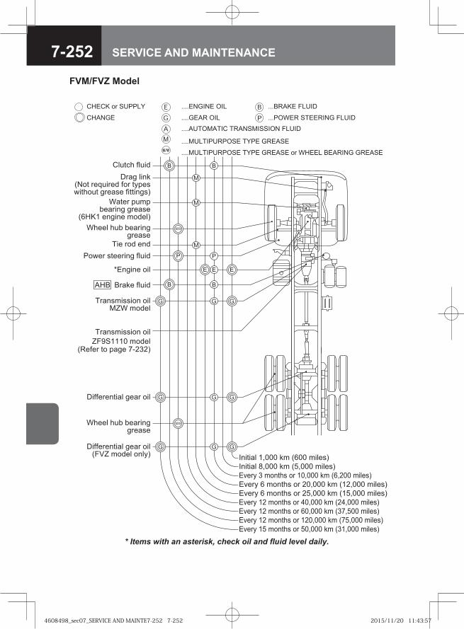
7-252 SERVICE AND MAINTENANCE
CHECK or SUPPLY ....ENGINE OIL ...BRAKE FLUID
CHANGE ....GEAR OIL
....MULTIPURPOSE TYPE GREASE
....MULTIPURPOSE TYPE GREASE or WHEEL BEARING GREASE
...POWER STEERING FLUID....AUTOMATIC TRANSMISSION FLUID
M/W
P
G GG
P
E EE
B B
M
M
M/W
Clutch fluid
Wheel hub bearinggrease
Water pumpbearing grease
(6HK1 engine model)
MTie rod end
Drag link(Not required for typeswithout grease fittings)
Wheel hub bearinggrease
Power steering fluid
*Engine oil
Transmission oilZF9S1110 model
(Refer to page 7-232)
Differential gear oil(FVZ model only)
G GGDifferential gear oil
G GG
B BAHB Brake fluid
Transmission oilMZW model
Initial 1,000 km (600 miles)Initial 8,000 km (5,000 miles)Every 3 months or 10,000 km (6,200 miles)Every 6 months or 20,000 km (12,000 miles)Every 6 months or 25,000 km (15,000 miles)Every 12 months or 40,000 km (24,000 miles)
Every 12 months or 120,000 km (75,000 miles)Every 12 months or 60,000 km (37,500 miles)
Every 15 months or 50,000 km (31,000 miles)
FVM/FVZ Model
4608498_sec07_SERVICE AND MAINTE7-252 7-2524608498_sec07_SERVICE AND MAINTE7-252 7-252 2015/11/20 11:43:572015/11/20 11:43:57
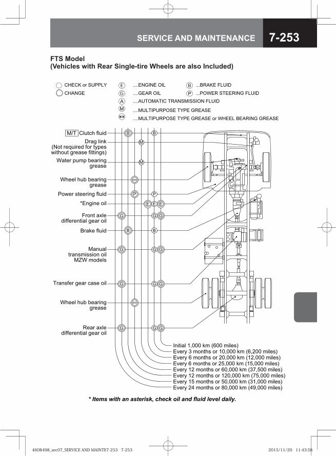
7-253SERVICE AND MAINTENANCE
FTS Model (Vehicles with Rear Single-tire Wheels are also Included)
�� �� ������ ���������� ��� ������ � �����
����� �������� ���
���������������� ���� ������
���������������� ���� ������ �� ����� ������� ������
�� ! "# $��� %& '(�� & #)*+�,)�- . &��!/* �� �$��� %& '($��� & #)*+
�,)�- ( &��!/* �� �0$��� %& '0$��� & #)*+�,)�- ( &��!/* �� ��$��� %& '�$��� & #)*+
�,)�- � &��!/* �� (�$��� %& '.�$0�� & #)*+
�,)�- 0 &��!/* �� 0�$��� %& '.$��� & #)*+�,)�- � &��!/* �� ��$��� %& '�0$��� & #)*+
�,)�- �1 &��!/* �� 2�$��� %& '13$��� & #)*+
#4!5/ 6#4 7
�/))# /48 8)"� �99�)"*)
�/))# /48 8)"� �99�)"*)
����! ":#)7 66)�)�! "# 9)"� � #
�"!)� ;4&; 8)"� �99�)"*)
��"9 # �%'��! �)<4 �)7 6�� !-;)*= !/�4! 9�)"*) 6 !! �9*+
��"%) 6#4 7
��=)� *!))� �9 6#4 7
>��9 �) � #
�"�4"#!�"�*& ** �� � #
�?� &�7)#*
��"�*6)� 9)"� 5"*) � #
�)"� ":#)7 66)�)�! "# 9)"� � #
�������� �������� �����
������������ ������������ �����
�@�
�@�
�
�
��
� ��
� ��
� ��
�
� �
� ��
� �
�
�
�@�
4608498_sec07_SERVICE AND MAINTE7-253 7-2534608498_sec07_SERVICE AND MAINTE7-253 7-253 2015/11/20 11:43:582015/11/20 11:43:58
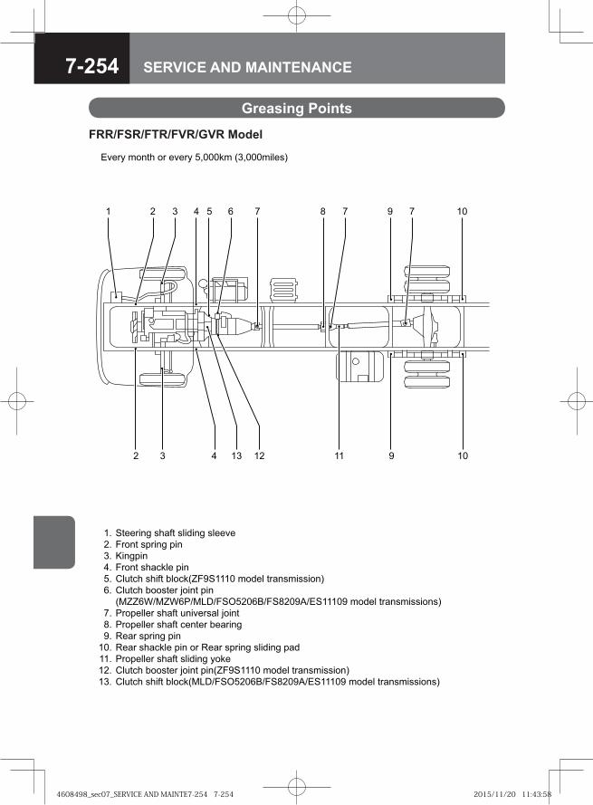
7-254 SERVICE AND MAINTENANCE
Greasing Points
��� � ����� � ��� � ������� ������������
�
� � � � �
� � � � � � �
�
!
!
�!
�!
�!
!
�!
�!
�!
�!
!
!
�!
"��� ��# ��$%� ���&��# ������
� ��� �' ��# '��
(��#'��
� ��� ��$)��� '��
*�+�)� ���%� ,��)��-��"� ��&�� � $����������
*�+�)� ,����� .���� '��
��-- /0�-/ 10�230�"4�� 50�"���60�"�� ��&�� � $�����������
1 �'���� ��$%� +���� �$� .����
1 �'���� ��$%� )���� ,�$ ��#
7�$ �' ��# '��
7�$ ��$)��� '�� � 7�$ �' ��# ���&��# '$&
1 �'���� ��$%� ���&��# ����
*�+�)� ,����� .���� '���-��"� ��&�� � $����������
*�+�)� ���%� ,��)���230�"4�� 50�"���60�"�� ��&�� � $�����������
FRR/FSR/FTR/FVR/GVR Model
4608498_sec07_SERVICE AND MAINTE7-254 7-2544608498_sec07_SERVICE AND MAINTE7-254 7-254 2015/11/20 11:43:582015/11/20 11:43:58
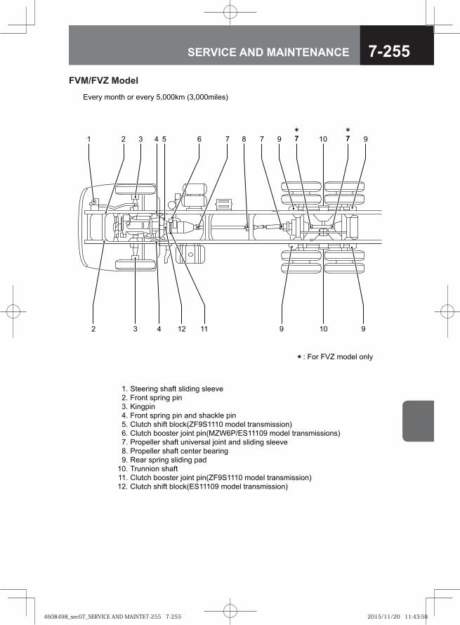
7-255SERVICE AND MAINTENANCE
��� ��� ����� ������� ������
� ��� �� ��� ���
�������
� ��� �� ��� ��� ��� ������� ���
������ ����� ����!"�#���� $���� � ���$������%
������ ����� &���� ���!�"'()*+����# $���� � ���$�������%
) ������ ����� ����� ��� &���� ��� ������� ������
) ������ ����� ����� �� ���
,�� �� ��� ������� ���
- ������ �����
������ ����� &���� ���!"�#���� $���� � ���$������%
������ ����� ����!+����# $���� � ���$������%
�.
/.
0.
.
1.
(.
�.
2.
#.
��.
��.
�/.
+�� 3 $���� � ��� 3 14����$ !04���$����%
5 �� �6" $���� ���3
� / 0
/ 0 #��#
� 2 � # � ��� #(
���/
1
FVM/FVZ Model
4608498_sec07_SERVICE AND MAINTE7-255 7-2554608498_sec07_SERVICE AND MAINTE7-255 7-255 2015/11/20 11:43:582015/11/20 11:43:58
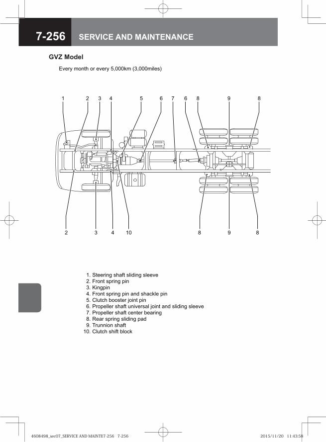
7-256 SERVICE AND MAINTENANCE
��� ��� ����� ������� ������
� ��� �� ��� ���
�������
� ��� �� ��� ��� ��� ������� ���
������ ����� !���� ���
" ������ ����� ����� ��� !���� ��� ������� ������
" ������ ����� ����� �� ���
#�� �� ��� ������� ���
$ ������ �����
������ ����� ����
%
&%
�%
'%
(%
)%
�%
*%
+%
�%
��� , -���� � ��� , (.����- /�.���-����0
& �
& � ' *+*
' ) � ) * + *(
�
GVZ Model
4608498_sec07_SERVICE AND MAINTE7-256 7-2564608498_sec07_SERVICE AND MAINTE7-256 7-256 2015/11/20 11:43:582015/11/20 11:43:58
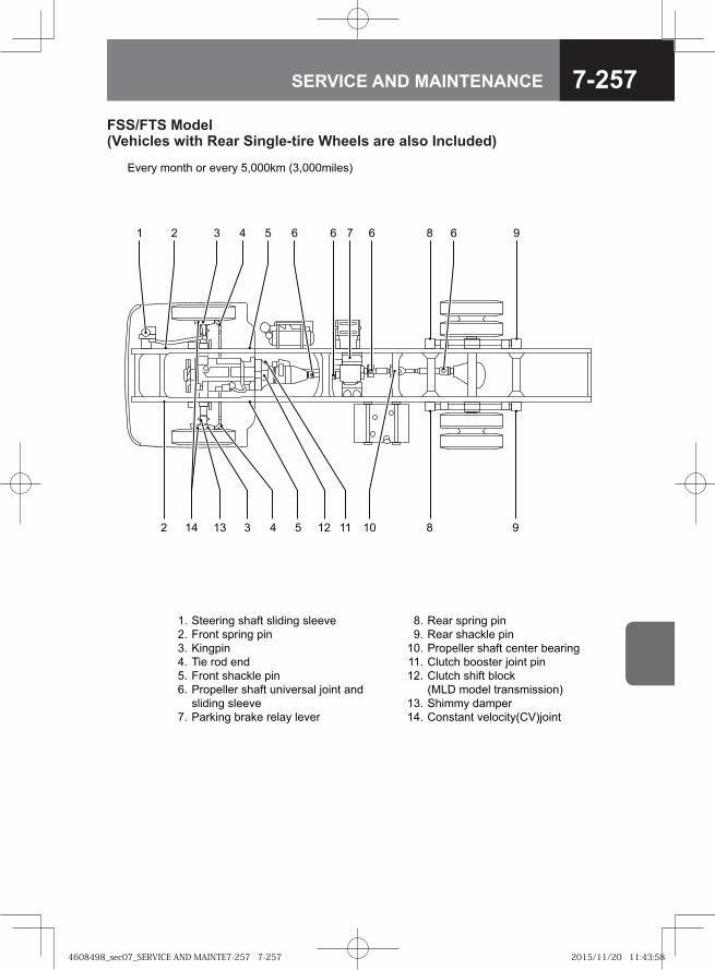
7-257SERVICE AND MAINTENANCE
�� � ����� � ��� � ������� ������������
� �
� � � � � � �
� � ! " ! ! �!
� �
#
�#
�#
#
�#
�#
�#
$�% �& ��' &��
$�% ��%(��� &��
) �&���� ��%*� (���� +�% ��'
,�-�(� +����� .���� &��
,�-�(� ���*� +��(�/
��01 ��2�� � %����������
3����� 2%�&�
,����%�� ����(����,4�.����
#
�#
�#
�#
�#
!#
"#
3��� ��' ��%*� ���2��' ������
� ��� �& ��' &��
5��'&��
6�� �2 ��2
� ��� ��%(��� &��
) �&���� ��%*� -���� �%� .���� %�2
���2��' ������/
)% ���' + %�� ��%� ����
FSS/FTS Model (Vehicles with Rear Single-tire Wheels are also Included)
4608498_sec07_SERVICE AND MAINTE7-257 7-2574608498_sec07_SERVICE AND MAINTE7-257 7-257 2015/11/20 11:43:582015/11/20 11:43:58
7-258 SERVICE AND MAINTENANCE
4608498_sec07_SERVICE AND MAINTE7-258 7-2584608498_sec07_SERVICE AND MAINTE7-258 7-258 2015/11/20 11:43:582015/11/20 11:43:58
● Troubleshooting 8-2
● When the Vehicle Breaks Down during Driving 8-7
● When the Tire Goes Flat 8-7
● When the Engine Stops While Driving 8-8
● When the Engine Stalls and Cannot be Restarted 8-9
● When the Brakes Do not Work 8-10
● When the Battery Goes Flat 8-11
● When the Fuel Runs Out 8-13
● When the Warning Light Comes On 8-16
● When the Engine Overheats 8-23
● When the Meter Shows an Abnormality 8-25
● When the Parking Brake Cannot be Released V 8-26
● When the Bulb Does not Come On 8-29
● Replacing the Fuses and Relays 8-53
● When Driving on Bad Roads 8-72
● When Towing 8-73
8IN CASE OF EMERGENCY
4608498_sec08_IN CASE OF EMERGEN8-1 8-14608498_sec08_IN CASE OF EMERGEN8-1 8-1 2015/11/02 14:45:402015/11/02 14:45:40
8-2 IN CASE OF EMERGENCY
Performing regular inspections and maintenance prevents damage. Be sure to perform inspections and maintenance at regular intervals. Also, quickly rectify any fault in the vehicle (even a small fault) to prevent it from becoming more serious. If a symptom shown in the following table occurs, perform inspections and take corrective action in accordance with the table. If you are unable to perform a repair, the corrective action shown in the table does not eliminate a symptom or you can not locate a fault, contact the nearest Isuzu Dealer.
Troubleshooting
ADVICEAny item for which there is a in the "Corrective action" column requires repairs and adjustments. Contact the nearest Isuzu Dealer.
•
4608498_sec08_IN CASE OF EMERGEN8-2 8-24608498_sec08_IN CASE OF EMERGEN8-2 8-2 2015/11/02 14:45:412015/11/02 14:45:41
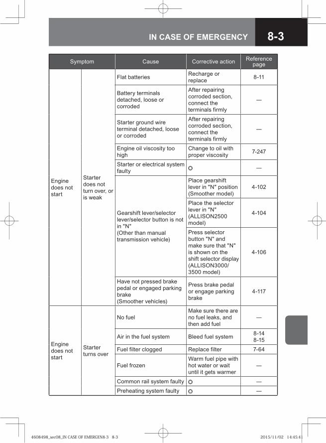
8-3IN CASE OF EMERGENCY
Symptom Cause Corrective action Reference page
Engine does not start
Starter does not turn over, or is weak
Flat batteries Recharge or replace 8-11
Battery terminals detached, loose or corroded
After repairing corroded section, connect the terminals firmly
―
Starter ground wire terminal detached, loose or corroded
After repairing corroded section, connect the terminals firmly
―
Engine oil viscosity too high
Change to oil with proper viscosity 7-247
Starter or electrical system faulty ―
Gearshift lever/selector lever/selector button is not in "N"(Other than manual transmission vehicle)
Place gearshift lever in "N" position (Smoother model)
4-102
Place the selector lever in "N" (ALLISON2500 model)
4-104
Press selector button "N" and make sure that "N" is shown on the shift selector display (ALLISON3000/3500 model)
4-106
Have not pressed brake pedal or engaged parking brake(Smoother vehicles)
Press brake pedal or engage parking brake
4-117
Engine does not start
Starter turns over
No fuelMake sure there are no fuel leaks, and then add fuel
―
Air in the fuel system Bleed fuel system 8-148-15
Fuel filter clogged Replace filter 7-64
Fuel frozenWarm fuel pipe with hot water or wait until it gets warmer
―
Common rail system faulty ―
Preheating system faulty ―
4608498_sec08_IN CASE OF EMERGEN8-3 8-34608498_sec08_IN CASE OF EMERGEN8-3 8-3 2015/11/02 14:45:412015/11/02 14:45:41
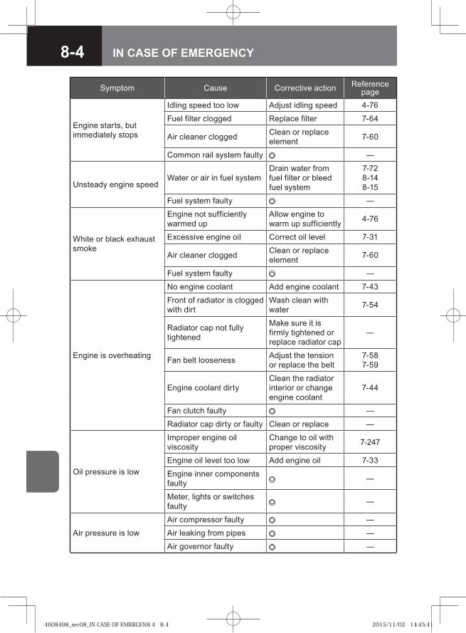
8-4 IN CASE OF EMERGENCY
Symptom Cause Corrective action Reference page
Engine starts, but immediately stops
Idling speed too low Adjust idling speed 4-76
Fuel filter clogged Replace filter 7-64
Air cleaner clogged Clean or replace element 7-60
Common rail system faulty ―
Unsteady engine speedWater or air in fuel system
Drain water from fuel filter or bleed fuel system
7-728-148-15
Fuel system faulty ―
White or black exhaust smoke
Engine not sufficiently warmed up
Allow engine to warm up sufficiently 4-76
Excessive engine oil Correct oil level 7-31
Air cleaner clogged Clean or replace element 7-60
Fuel system faulty ―
Engine is overheating
No engine coolant Add engine coolant 7-43
Front of radiator is clogged with dirt
Wash clean with water 7-54
Radiator cap not fully tightened
Make sure it is firmly tightened or replace radiator cap
―
Fan belt looseness Adjust the tension or replace the belt
7-587-59
Engine coolant dirtyClean the radiator interior or change engine coolant
7-44
Fan clutch faulty ―
Radiator cap dirty or faulty Clean or replace ―
Oil pressure is low
Improper engine oil viscosity
Change to oil with proper viscosity 7-247
Engine oil level too low Add engine oil 7-33
Engine inner components faulty ―
Meter, lights or switches faulty ―
Air pressure is low
Air compressor faulty ―
Air leaking from pipes ―
Air governor faulty ―
4608498_sec08_IN CASE OF EMERGEN8-4 8-44608498_sec08_IN CASE OF EMERGEN8-4 8-4 2015/11/02 14:45:412015/11/02 14:45:41
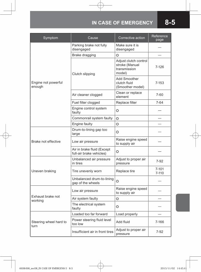
8-5IN CASE OF EMERGENCY
Symptom Cause Corrective action Reference page
Engine not powerful enough
Parking brake not fully disengaged
Make sure it is disengaged ―
Brake dragging ―
Clutch slipping
Adjust clutch control stroke (Manual transmission model)
7-126
Add Smoother clutch fluid (Smoother model)
7-153
Air cleaner clogged Clean or replace element 7-60
Fuel filter clogged Replace filter 7-64
Engine control system faulty ―
Commonrail system faulty ―
Engine faulty ―
Brake not effective
Drum-to-lining gap too large ―
Low air pressure Raise engine speed to supply air ―
Air in brake fluid (Except full-air brake vehicles) ―
Uneven braking
Unbalanced air pressure in tires
Adjust to proper air pressure 7-92
Tire unevenly worn Replace tire 7-1017-110
Unbalanced drum-to-lining gap of the wheels ―
Exhaust brake not working
Low air pressure Raise engine speed to supply air ―
Air system faulty ―
The electrical system faulty ―
Steering wheel hard to turn
Loaded too far forward Load properly ―
Power steering fluid level too low Add fluid 7-166
Insufficient air in front tires Adjust to proper air pressure 7-92
4608498_sec08_IN CASE OF EMERGEN8-5 8-54608498_sec08_IN CASE OF EMERGEN8-5 8-5 2015/11/02 14:45:412015/11/02 14:45:41
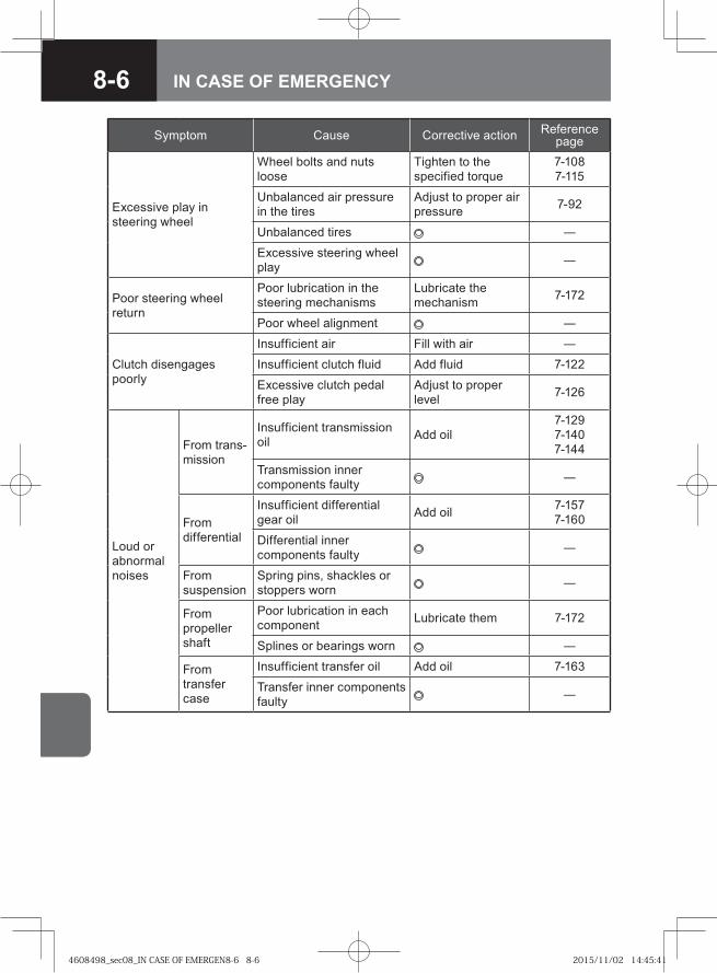
8-6 IN CASE OF EMERGENCY
Symptom Cause Corrective action Reference page
Excessive play in steering wheel
Wheel bolts and nuts loose
Tighten to the specified torque
7-1087-115
Unbalanced air pressure in the tires
Adjust to proper air pressure 7-92
Unbalanced tires ―
Excessive steering wheel play ―
Poor steering wheel return
Poor lubrication in the steering mechanisms
Lubricate the mechanism 7-172
Poor wheel alignment ―
Clutch disengages poorly
Insufficient air Fill with air ―
Insufficient clutch fluid Add fluid 7-122
Excessive clutch pedal free play
Adjust to proper level 7-126
Loud or abnormal noises
From trans-mission
Insufficient transmission oil Add oil
7-1297-1407-144
Transmission inner components faulty ―
From differential
Insufficient differential gear oil Add oil 7-157
7-160
Differential inner components faulty ―
From suspension
Spring pins, shackles or stoppers worn ―
From propeller shaft
Poor lubrication in each component Lubricate them 7-172
Splines or bearings worn ―
From transfer case
Insufficient transfer oil Add oil 7-163
Transfer inner components faulty ―
4608498_sec08_IN CASE OF EMERGEN8-6 8-64608498_sec08_IN CASE OF EMERGEN8-6 8-6 2015/11/02 14:45:412015/11/02 14:45:41
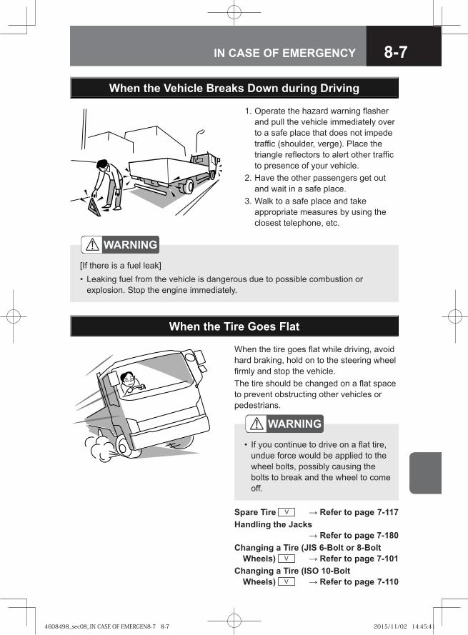
8-7IN CASE OF EMERGENCY
1. Operate the hazard warning flasher and pull the vehicle immediately over to a safe place that does not impede traffic (shoulder, verge). Place the triangle reflectors to alert other traffic to presence of your vehicle.
2. Have the other passengers get out and wait in a safe place.
3. Walk to a safe place and take appropriate measures by using the closest telephone, etc.
When the Vehicle Breaks Down during Driving
WARNING
[If there is a fuel leak]Leaking fuel from the vehicle is dangerous due to possible combustion or explosion. Stop the engine immediately.
•
When the tire goes flat while driving, avoid hard braking, hold on to the steering wheel firmly and stop the vehicle.The tire should be changed on a flat space to prevent obstructing other vehicles or pedestrians.
When the Tire Goes Flat
WARNING
If you continue to drive on a flat tire, undue force would be applied to the wheel bolts, possibly causing the bolts to break and the wheel to come off.
•
Spare Tire V → Refer to page 7-117Handling the Jacks
→ Refer to page 7-180Changing a Tire (JIS 6-Bolt or 8-Bolt
Wheels) V → Refer to page 7-101Changing a Tire (ISO 10-Bolt
Wheels) V → Refer to page 7-110
4608498_sec08_IN CASE OF EMERGEN8-7 8-74608498_sec08_IN CASE OF EMERGEN8-7 8-7 2015/11/02 14:45:412015/11/02 14:45:41
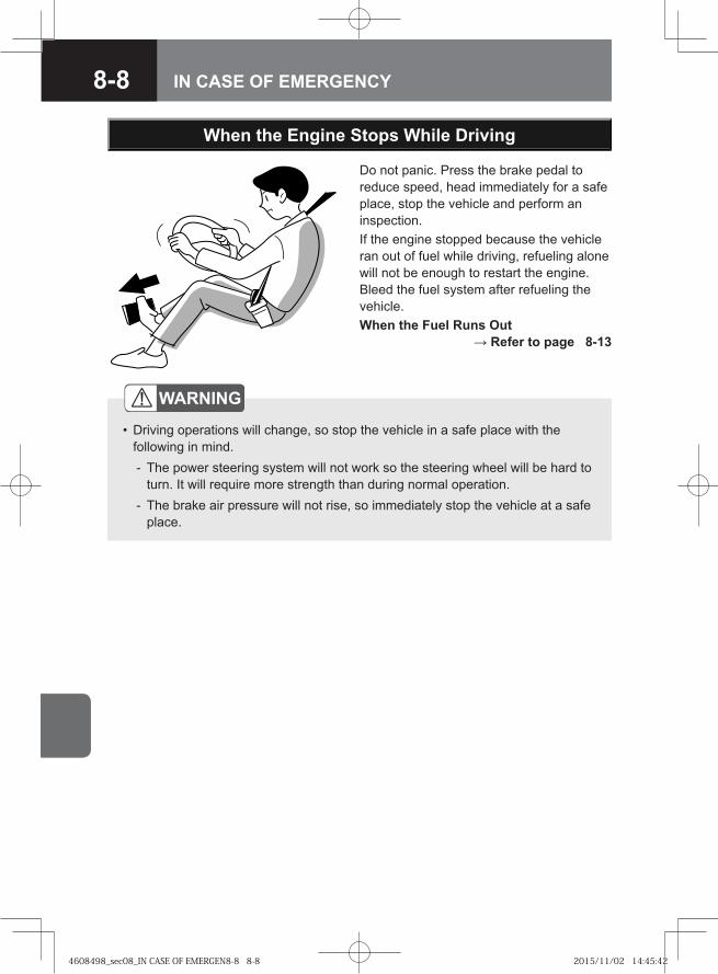
8-8 IN CASE OF EMERGENCY
When the Engine Stops While Driving
WARNING
Driving operations will change, so stop the vehicle in a safe place with the following in mind.
The power steering system will not work so the steering wheel will be hard to turn. It will require more strength than during normal operation.The brake air pressure will not rise, so immediately stop the vehicle at a safe place.
•
-
-
Do not panic. Press the brake pedal to reduce speed, head immediately for a safe place, stop the vehicle and perform an inspection.If the engine stopped because the vehicle ran out of fuel while driving, refueling alone will not be enough to restart the engine. Bleed the fuel system after refueling the vehicle.When the Fuel Runs Out
→ Refer to page 8-13
4608498_sec08_IN CASE OF EMERGEN8-8 8-84608498_sec08_IN CASE OF EMERGEN8-8 8-8 2015/11/02 14:45:422015/11/02 14:45:42
8-9IN CASE OF EMERGENCY
• In a manual transmission model, place the gearshift lever in "N" and push the vehicle to a safe place.
• In Smoother models, place the gearshift lever in "N". If the shift indicator reads "N", push the vehicle to a safe place. If the shift indicator displays other mode than "N", place the emergency switch into "ON" and the gearshift lever into "N". Then, make sure that the shift indicator displays "N" and push the vehicle to a safe place.
• In the model with an ALLISON2500 model transmission, place the selector lever in "N" and push the vehicle to a safe place.
• For a model with an ALLISON3000/3500 model transmission, push selector button "N". Then, make sure that the shift selector display is showing "NN" and push the vehicle to a safe place.
When the Engine Stalls and Cannot be Restarted
CAUTIONIn case of emergency with manual transmission models, place the gearshift lever in "R" (reverse gear), "1" (1st gear) or "2" (2nd gear) if the starter turns over.Then, keep the starter switch in "START" with your foot off the clutch pedal to move the vehicle.
•
•
NOTEFor vehicles with hill start aid (HSA), cancel the HSA by pressing the HSA OFF switch.
•
HSA OFF Switch → Refer to page 4-148
If the Smoother System Fails → Refer to page 4-131
4608498_sec08_IN CASE OF EMERGEN8-9 8-94608498_sec08_IN CASE OF EMERGEN8-9 8-9 2015/11/02 14:45:422015/11/02 14:45:42
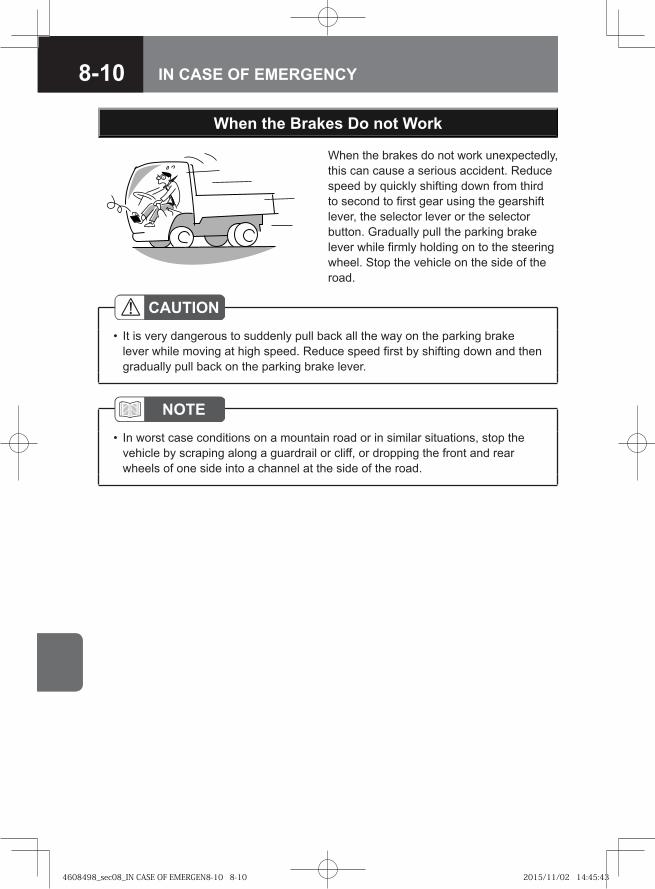
8-10 IN CASE OF EMERGENCY
NOTEIn worst case conditions on a mountain road or in similar situations, stop the vehicle by scraping along a guardrail or cliff, or dropping the front and rear wheels of one side into a channel at the side of the road.
•
When the Brakes Do not Work
When the brakes do not work unexpectedly, this can cause a serious accident. Reduce speed by quickly shifting down from third to second to first gear using the gearshift lever, the selector lever or the selector button. Gradually pull the parking brake lever while firmly holding on to the steering wheel. Stop the vehicle on the side of the road.
CAUTIONIt is very dangerous to suddenly pull back all the way on the parking brake lever while moving at high speed. Reduce speed first by shifting down and then gradually pull back on the parking brake lever.
•
4608498_sec08_IN CASE OF EMERGEN8-10 8-104608498_sec08_IN CASE OF EMERGEN8-10 8-10 2015/11/02 14:45:432015/11/02 14:45:43
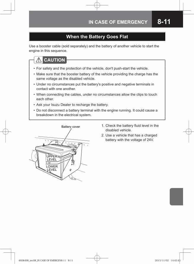
8-11IN CASE OF EMERGENCY
When the Battery Goes Flat
Use a booster cable (sold separately) and the battery of another vehicle to start the engine in this sequence.
CAUTIONFor safety and the protection of the vehicle, don't push-start the vehicle.Make sure that the booster battery of the vehicle providing the charge has the same voltage as the disabled vehicle.Under no circumstances put the battery's positive and negative terminals in contact with one another.When connecting the cables, under no circumstances allow the clips to touch each other.Ask your Isuzu Dealer to recharge the battery.Do not disconnect a battery terminal with the engine running. It could cause a breakdown in the electrical system.
••
•
•
••
UPPERLEVEL
LOWERLEVEL
Battery cover 1. Check the battery fluid level in the disabled vehicle.
2. Use a vehicle that has a charged battery with the voltage of 24V.
4608498_sec08_IN CASE OF EMERGEN8-11 8-114608498_sec08_IN CASE OF EMERGEN8-11 8-11 2015/11/02 14:45:432015/11/02 14:45:43
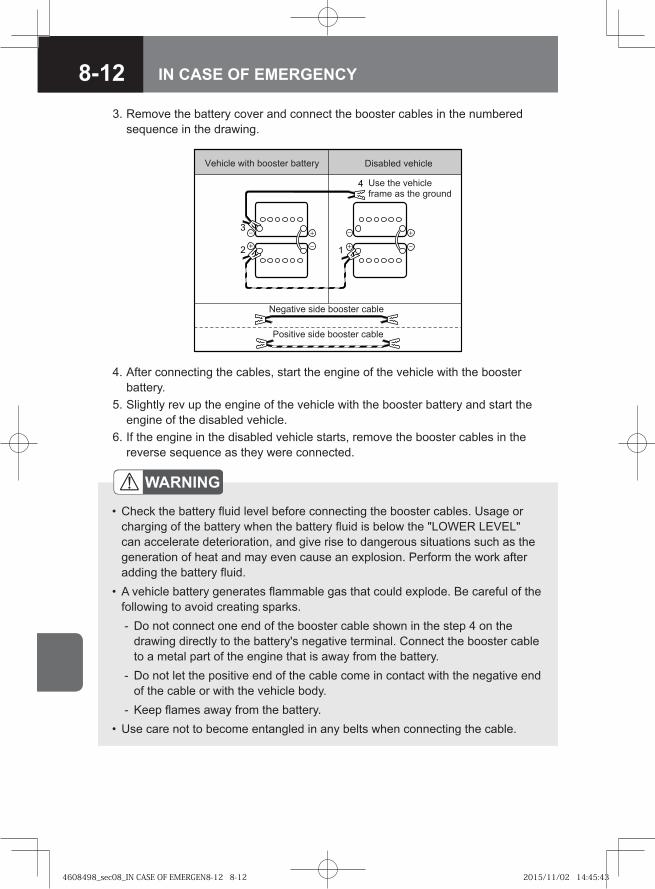
8-12 IN CASE OF EMERGENCY
3
2 1
4
Vehicle with booster battery
Positive side booster cable
Disabled vehicle
Negative side booster cable
Use the vehicle frame as the ground
WARNING
Check the battery fluid level before connecting the booster cables. Usage or charging of the battery when the battery fluid is below the "LOWER LEVEL" can accelerate deterioration, and give rise to dangerous situations such as the generation of heat and may even cause an explosion. Perform the work after adding the battery fluid.A vehicle battery generates flammable gas that could explode. Be careful of the following to avoid creating sparks.
Do not connect one end of the booster cable shown in the step 4 on the drawing directly to the battery's negative terminal. Connect the booster cable to a metal part of the engine that is away from the battery.Do not let the positive end of the cable come in contact with the negative end of the cable or with the vehicle body.Keep flames away from the battery.
Use care not to become entangled in any belts when connecting the cable.
•
•
-
-
-•
3. Remove the battery cover and connect the booster cables in the numbered sequence in the drawing.
4. After connecting the cables, start the engine of the vehicle with the booster battery.
5. Slightly rev up the engine of the vehicle with the booster battery and start the engine of the disabled vehicle.
6. If the engine in the disabled vehicle starts, remove the booster cables in the reverse sequence as they were connected.
4608498_sec08_IN CASE OF EMERGEN8-12 8-124608498_sec08_IN CASE OF EMERGEN8-12 8-12 2015/11/02 14:45:432015/11/02 14:45:43
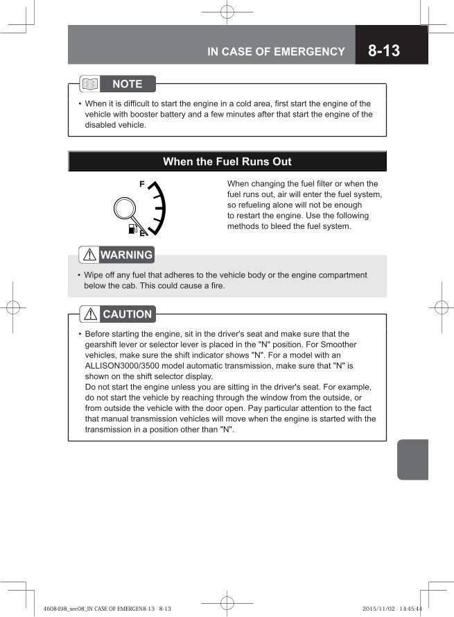
8-13IN CASE OF EMERGENCY
When the Fuel Runs Out
When changing the fuel filter or when the fuel runs out, air will enter the fuel system, so refueling alone will not be enough to restart the engine. Use the following methods to bleed the fuel system.
WARNING
Wipe off any fuel that adheres to the vehicle body or the engine compartment below the cab. This could cause a fire.
•
CAUTIONBefore starting the engine, sit in the driver's seat and make sure that the gearshift lever or selector lever is placed in the "N" position. For Smoother vehicles, make sure the shift indicator shows "N". For a model with an ALLISON3000/3500 model automatic transmission, make sure that "N" is shown on the shift selector display. Do not start the engine unless you are sitting in the driver's seat. For example, do not start the vehicle by reaching through the window from the outside, or from outside the vehicle with the door open. Pay particular attention to the fact that manual transmission vehicles will move when the engine is started with the transmission in a position other than "N".
•
NOTEWhen it is difficult to start the engine in a cold area, first start the engine of the vehicle with booster battery and a few minutes after that start the engine of the disabled vehicle.
•
4608498_sec08_IN CASE OF EMERGEN8-13 8-134608498_sec08_IN CASE OF EMERGEN8-13 8-13 2015/11/02 14:45:442015/11/02 14:45:44
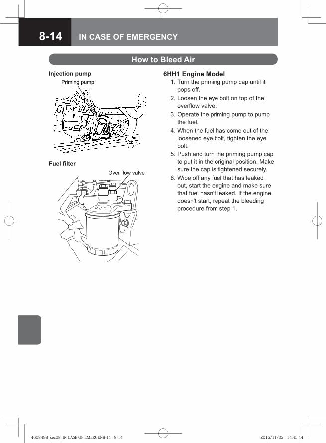
8-14 IN CASE OF EMERGENCY
How to Bleed Air
6HH1 Engine Model 1. Turn the priming pump cap until it
pops off. 2. Loosen the eye bolt on top of the
overflow valve. 3. Operate the priming pump to pump
the fuel. 4. When the fuel has come out of the
loosened eye bolt, tighten the eye bolt.
5. Push and turn the priming pump cap to put it in the original position. Make sure the cap is tightened securely.
6. Wipe off any fuel that has leaked out, start the engine and make sure that fuel hasn't leaked. If the engine doesn't start, repeat the bleeding procedure from step 1.
�� ��� �� �
Injection pump
�� � ���� ����
Fuel filter
4608498_sec08_IN CASE OF EMERGEN8-14 8-144608498_sec08_IN CASE OF EMERGEN8-14 8-14 2015/11/02 14:45:442015/11/02 14:45:44
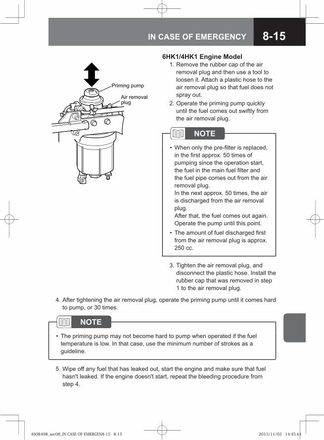
8-15IN CASE OF EMERGENCY
6HK1/4HK1 Engine Model 1. Remove the rubber cap of the air
removal plug and then use a tool to loosen it. Attach a plastic hose to the air removal plug so that fuel does not spray out.
2. Operate the priming pump quickly until the fuel comes out swiftly from the air removal plug.
NOTEThe priming pump may not become hard to pump when operated if the fuel temperature is low. In that case, use the minimum number of strokes as a guideline.
•
5. Wipe off any fuel that has leaked out, start the engine and make sure that fuel hasn't leaked. If the engine doesn't start, repeat the bleeding procedure from step 4.
� ����� ����
�� ����������
3. Tighten the air removal plug, and disconnect the plastic hose. Install the rubber cap that was removed in step 1 to the air removal plug.
NOTEWhen only the pre-filter is replaced, in the first approx. 50 times of pumping since the operation start, the fuel in the main fuel filter and the fuel pipe comes out from the air removal plug. In the next approx. 50 times, the air is discharged from the air removal plug. After that, the fuel comes out again. Operate the pump until this point.The amount of fuel discharged first from the air removal plug is approx. 250 cc.
•
•
4. After tightening the air removal plug, operate the priming pump until it comes hard to pump, or 30 times.
4608498_sec08_IN CASE OF EMERGEN8-15 8-154608498_sec08_IN CASE OF EMERGEN8-15 8-15 2015/11/02 14:45:442015/11/02 14:45:44
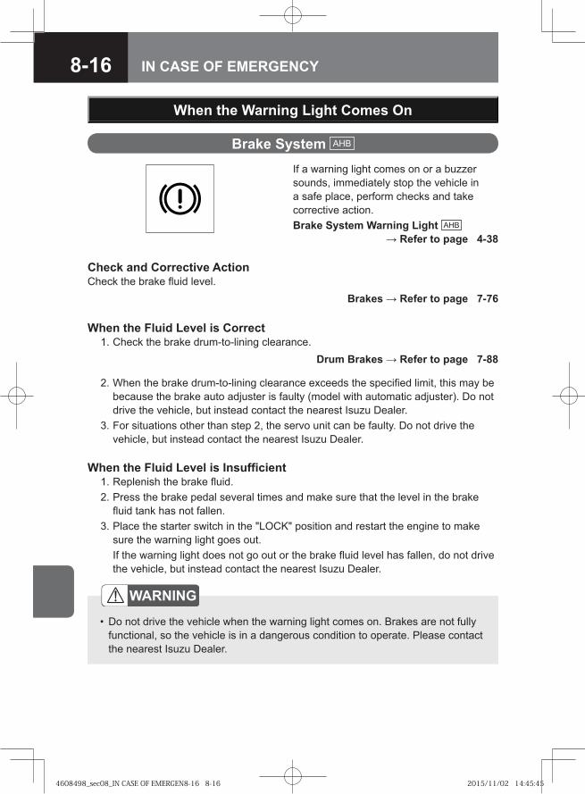
8-16 IN CASE OF EMERGENCY
Brake System AHB
If a warning light comes on or a buzzer sounds, immediately stop the vehicle in a safe place, perform checks and take corrective action.Brake System Warning Light AHB
→ Refer to page 4-38
When the Warning Light Comes On
Check and Corrective ActionCheck the brake fluid level.
WARNING
Do not drive the vehicle when the warning light comes on. Brakes are not fully functional, so the vehicle is in a dangerous condition to operate. Please contact the nearest Isuzu Dealer.
•
Brakes → Refer to page 7-76
Drum Brakes → Refer to page 7-88
When the Fluid Level is Correct 1. Check the brake drum-to-lining clearance.
2. When the brake drum-to-lining clearance exceeds the specified limit, this may be because the brake auto adjuster is faulty (model with automatic adjuster). Do not drive the vehicle, but instead contact the nearest Isuzu Dealer.
3. For situations other than step 2, the servo unit can be faulty. Do not drive the vehicle, but instead contact the nearest Isuzu Dealer.
When the Fluid Level is Insufficient 1. Replenish the brake fluid. 2. Press the brake pedal several times and make sure that the level in the brake
fluid tank has not fallen. 3. Place the starter switch in the "LOCK" position and restart the engine to make
sure the warning light goes out. If the warning light does not go out or the brake fluid level has fallen, do not drive
the vehicle, but instead contact the nearest Isuzu Dealer.
4608498_sec08_IN CASE OF EMERGEN8-16 8-164608498_sec08_IN CASE OF EMERGEN8-16 8-16 2015/11/02 14:45:452015/11/02 14:45:45
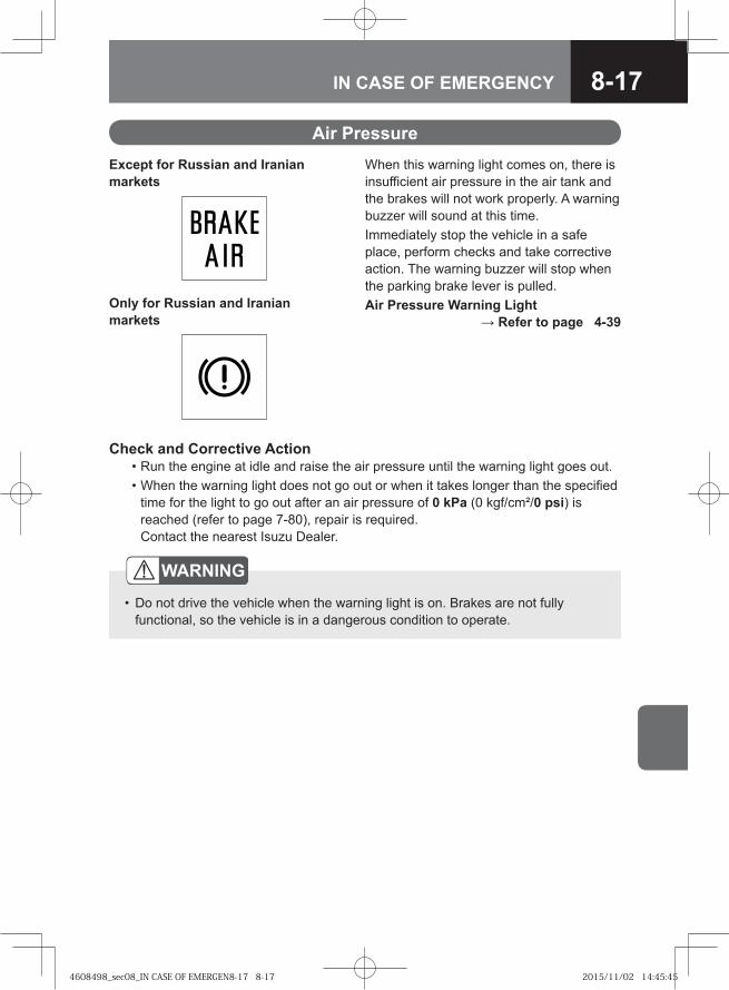
8-17IN CASE OF EMERGENCY
Air PressureWhen this warning light comes on, there is insufficient air pressure in the air tank and the brakes will not work properly. A warning buzzer will sound at this time.Immediately stop the vehicle in a safe place, perform checks and take corrective action. The warning buzzer will stop when the parking brake lever is pulled.Air Pressure Warning Light
→ Refer to page 4-39
Check and Corrective Action • Run the engine at idle and raise the air pressure until the warning light goes out. • When the warning light does not go out or when it takes longer than the specified
time for the light to go out after an air pressure of 0 kPa (0 kgf/cm²/0 psi) is reached (refer to page 7-80), repair is required. Contact the nearest Isuzu Dealer.
WARNING
Do not drive the vehicle when the warning light is on. Brakes are not fully functional, so the vehicle is in a dangerous condition to operate.
•
Except for Russian and Iranian markets
Only for Russian and Iranian markets
4608498_sec08_IN CASE OF EMERGEN8-17 8-174608498_sec08_IN CASE OF EMERGEN8-17 8-17 2015/11/02 14:45:452015/11/02 14:45:45
8-18 IN CASE OF EMERGENCY
GeneratorWhen this warning light comes on, the charging system may have failed.Immediately stop the vehicle in a safe place, perform checks and take corrective action.
Check and Corrective Action 1. Check to see if the fan belt is broken
or loose. 2. If the fan belt is loose, adjust the
tension. 3. If there is no abnormality in the fan
belt, contact the nearest Isuzu Dealer. Fan Belt → Refer to page 7-55
CAUTIONDo not drive the vehicle when the warning light is on. The battery may drain.•
NOTESince disassembling is required for replacing the fan belt, have it performed by the nearest Isuzu Dealer.
•
4608498_sec08_IN CASE OF EMERGEN8-18 8-184608498_sec08_IN CASE OF EMERGEN8-18 8-18 2015/11/02 14:45:452015/11/02 14:45:45
8-19IN CASE OF EMERGENCY
Engine Oil PressureWhen this warning light comes on, the oil pressure is too low.Immediately stop the vehicle in a safe place, stop the engine, perform checks and take corrective action.
Check and Corrective Action 1. Check the engine oil level. 2. If the engine oil level is too low, check
for leaks and add oil. 3. When the oil level is normal and there
are no oil leaks, the oil filter may be clogged.Replace the oil filter.
4. When the oil level is normal and the oil filter is not clogged, but there are oil leaks, contact the nearest Isuzu Dealer.
Engine Oil → Refer to page 7-31Changing the Engine Oil and Oil Filter
→ Refer to page 7-35
CAUTIONDo not drive the vehicle when the warning light is on. It could damage the engine.
•
NOTEIn cold areas, when the engine oil temperature is low and the oil viscosity is high, the light might come on for a time. It will go out when the engine warms up.
•
4608498_sec08_IN CASE OF EMERGEN8-19 8-194608498_sec08_IN CASE OF EMERGEN8-19 8-19 2015/11/02 14:45:462015/11/02 14:45:46
8-20 IN CASE OF EMERGENCY
SRS Airbag V
In the following cases, an abnormality is indicated in the seat belt with pretensioner and SRS airbag system. • When the SRS airbag warning light
comes on during driving. • When the starter switch is placed in
the "ON" position, the warning light does not come on.
• When the starter switch is placed in the "ON" position, the warning light comes on, but does not go out after flashing 7 times.
CAUTIONIf there is an abnormality in the seat belt with pretensioner and airbag (including the passenger airbag, if equipped), they may not work normally. Have the system checked by the nearest Isuzu Dealer.
•
NOTEIt is normal for the warning light to come on, flash 7 times and then go out when the starter switch is placed in the "ON" position. The SRS airbag warning light may come on again immediately after the engine is started, but it is normal if it goes out after flashing 7 times.The SRS airbag warning light may come on suddenly if the starter switch is placed in the "ACC" position or electrical equipment is operated, but this is not abnormal.
•
•
4608498_sec08_IN CASE OF EMERGEN8-20 8-204608498_sec08_IN CASE OF EMERGEN8-20 8-20 2015/11/02 14:45:462015/11/02 14:45:46
8-21IN CASE OF EMERGENCY
Check Engine V
Models Conforming to EuroII or EuroIII Emission StandardsIf this warning light comes on or flashes while the engine is running, this alerts you to a problem with the engine electronic control system. Since checking and repairing the control system is required, immediately contact the nearest Isuzu Dealer.
HSA V
Hill Start Aid (HSA) V → Refer to page 4-146
SVS V
Models Conforming to EuroIV Emission StandardsIf the indicator light comes on or flashes during operation, immediately contact the nearest Isuzu Dealer for inspection.
Models Conforming to EuroIV Emission StandardsIf this warning light comes on while the engine is running, this alerts you to a problem with the emission control related system. Since checking and repairing the control system is required, immediately contact the nearest Isuzu Dealer.
4608498_sec08_IN CASE OF EMERGEN8-21 8-214608498_sec08_IN CASE OF EMERGEN8-21 8-21 2015/11/02 14:45:462015/11/02 14:45:46
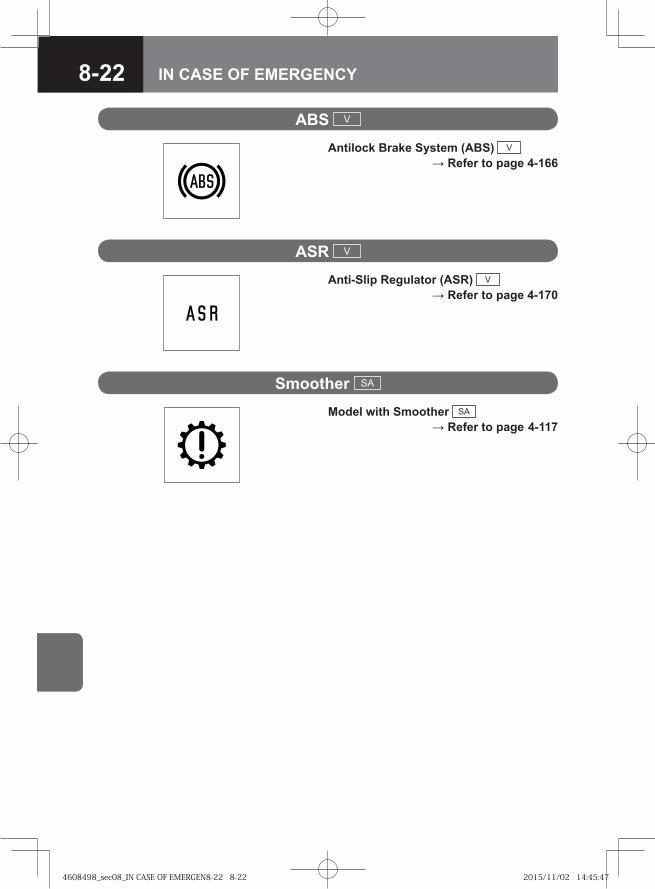
8-22 IN CASE OF EMERGENCY
ASR V
Anti-Slip Regulator (ASR) V → Refer to page 4-170
ABS V
Antilock Brake System (ABS) V → Refer to page 4-166
Smoother SA
Model with Smoother SA → Refer to page 4-117
4608498_sec08_IN CASE OF EMERGEN8-22 8-224608498_sec08_IN CASE OF EMERGEN8-22 8-22 2015/11/02 14:45:472015/11/02 14:45:47
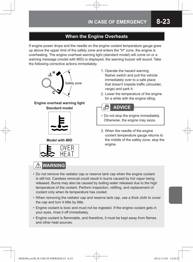
8-23IN CASE OF EMERGENCY
If engine power drops and the needle on the engine coolant temperature gauge goes up above the upper limit of the safety zone and enters the "H" zone, the engine is overheating. The engine overheat warning light (standard model) will come on or a warning message (model with MID) is displayed, the warning buzzer will sound. Take the following corrective actions immediately.
1. Operate the hazard warning flasher switch and pull the vehicle immediately over to a safe place that doesn't impede traffic (shoulder, verge) and park it.
2. Lower the temperature of the engine for a while with the engine idling.
ADVICEDo not stop the engine immediately. Otherwise, the engine may seize.
•
3. When the needle of the engine coolant temperature gauge returns to the middle of the safety zone, stop the engine.
When the Engine Overheats
��� �� ���
WARNING
Do not remove the radiator cap or reserve tank cap when the engine coolant is still hot. Careless removal could result in burns caused by hot vapor being released. Burns may also be caused by boiling water released due to the high temperature of the coolant. Perform inspection, refilling, and replacement of coolant only when its temperature has cooled.When removing the radiator cap and reserve tank cap, use a thick cloth to cover the cap and turn it little by little.Engine coolant is toxic and must not be ingested. If the engine coolant gets in your eyes, rinse it off immediately.Engine coolant is flammable, and therefore, it must be kept away from flames and other heat sources.
•
•
•
•
Model with MID
Engine overheat warning lightStandard model
4608498_sec08_IN CASE OF EMERGEN8-23 8-234608498_sec08_IN CASE OF EMERGEN8-23 8-23 2015/11/02 14:45:472015/11/02 14:45:47
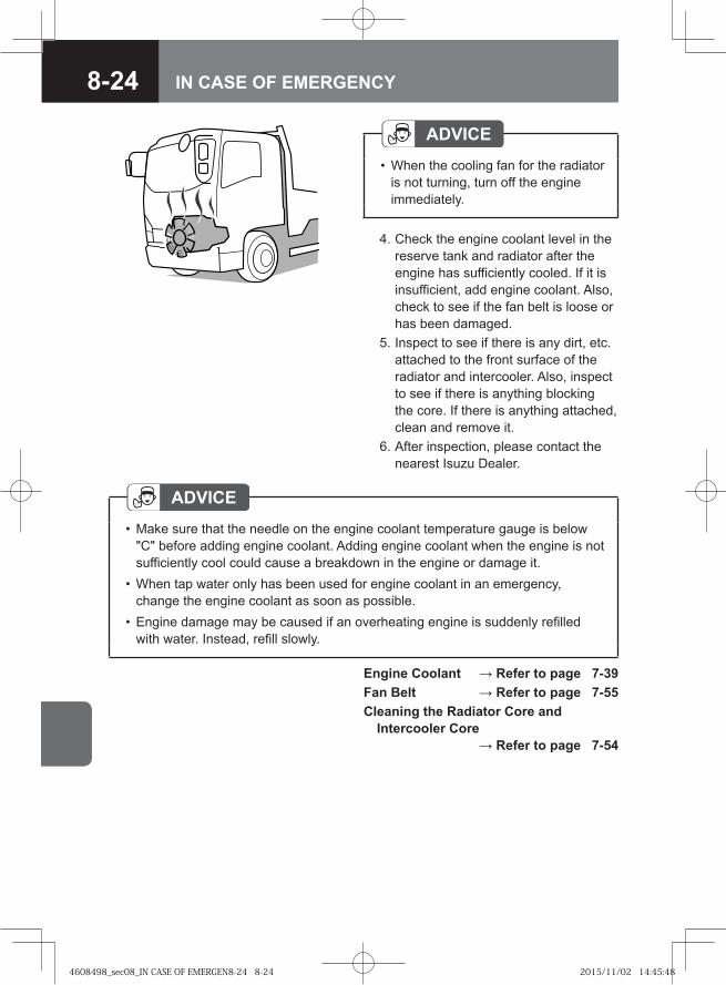
8-24 IN CASE OF EMERGENCY
ADVICEWhen the cooling fan for the radiator is not turning, turn off the engine immediately.
•
4. Check the engine coolant level in the reserve tank and radiator after the engine has sufficiently cooled. If it is insufficient, add engine coolant. Also, check to see if the fan belt is loose or has been damaged.
5. Inspect to see if there is any dirt, etc. attached to the front surface of the radiator and intercooler. Also, inspect to see if there is anything blocking the core. If there is anything attached, clean and remove it.
6. After inspection, please contact the nearest Isuzu Dealer.
ADVICEMake sure that the needle on the engine coolant temperature gauge is below "C" before adding engine coolant. Adding engine coolant when the engine is not sufficiently cool could cause a breakdown in the engine or damage it.When tap water only has been used for engine coolant in an emergency, change the engine coolant as soon as possible.Engine damage may be caused if an overheating engine is suddenly refilled with water. Instead, refill slowly.
•
•
•
Engine Coolant → Refer to page 7-39Fan Belt → Refer to page 7-55Cleaning the Radiator Core and
Intercooler Core → Refer to page 7-54
4608498_sec08_IN CASE OF EMERGEN8-24 8-244608498_sec08_IN CASE OF EMERGEN8-24 8-24 2015/11/02 14:45:482015/11/02 14:45:48
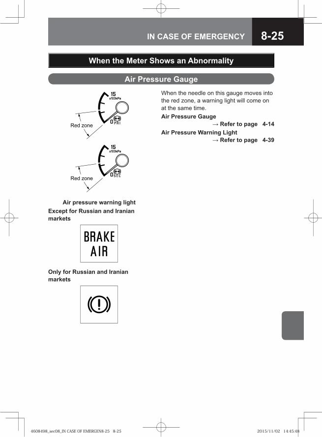
8-25IN CASE OF EMERGENCY
When the Meter Shows an Abnormality
Air Pressure GaugeWhen the needle on this gauge moves into the red zone, a warning light will come on at the same time.Air Pressure Gauge
→ Refer to page 4-14Air Pressure Warning Light
→ Refer to page 4-39
Air pressure warning lightExcept for Russian and Iranian markets
�� ����
�� ����
Only for Russian and Iranian markets
4608498_sec08_IN CASE OF EMERGEN8-25 8-254608498_sec08_IN CASE OF EMERGEN8-25 8-25 2015/11/02 14:45:482015/11/02 14:45:48
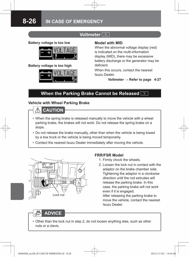
8-26 IN CASE OF EMERGENCY
When the Parking Brake Cannot be Released V
CAUTIONWhen the spring brake is released manually to move the vehicle with a wheel parking brake, the brakes will not work. Do not release the spring brake on a slope.Do not release the brake manually, other than when the vehicle is being towed by a tow truck or the vehicle is being moved temporarily.Contact the nearest Isuzu Dealer immediately after moving the vehicle.
•
•
•
FRR/FSR Model 1. Firmly chock the wheels. 2. Loosen the lock nut in contact with the
adaptor on the brake chamber side. Tightening the adaptor in a clockwise direction until the rod extrudes will release the parking brake. In this case, the parking brake will not work even if it is engaged. After releasing the parking brake to move the vehicle, contact the nearest Isuzu Dealer.
Adaptor
Lock nut
ADVICEOther than the lock nut in step 2, do not loosen anything else, such as other nuts or a clevis.
•
Vehicle with Wheel Parking Brake
Voltmeter V
Model with MIDWhen the abnormal voltage display (red) is indicated on the multi-information display (MID), there may be excessive battery discharge or the generator may be deficient.When this occurs, contact the nearest Isuzu Dealer. Voltmeter → Refer to page 4-27
Battery voltage is too low
Battery voltage is too high
4608498_sec08_IN CASE OF EMERGEN8-26 8-264608498_sec08_IN CASE OF EMERGEN8-26 8-26 2015/11/02 14:45:482015/11/02 14:45:48
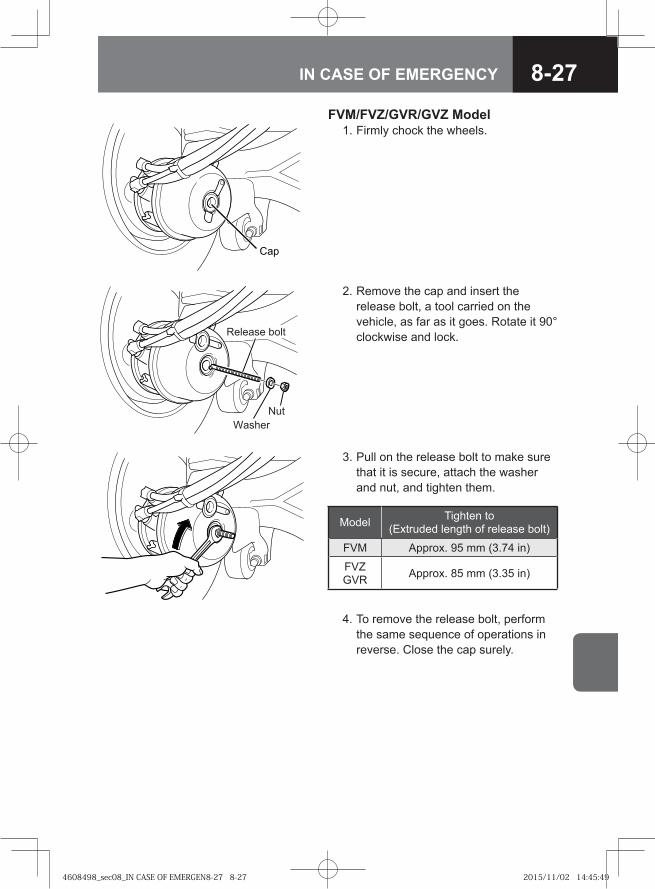
8-27IN CASE OF EMERGENCY
FVM/FVZ/GVR/GVZ Model 1. Firmly chock the wheels.
2. Remove the cap and insert the release bolt, a tool carried on the vehicle, as far as it goes. Rotate it 90° clockwise and lock.
Cap
Release bolt
WasherNut
3. Pull on the release bolt to make sure that it is secure, attach the washer and nut, and tighten them.
4. To remove the release bolt, perform the same sequence of operations in reverse. Close the cap surely.
Model Tighten to (Extruded length of release bolt)
FVM Approx. 95 mm (3.74 in)
FVZGVR Approx. 85 mm (3.35 in)
4608498_sec08_IN CASE OF EMERGEN8-27 8-274608498_sec08_IN CASE OF EMERGEN8-27 8-27 2015/11/02 14:45:492015/11/02 14:45:49
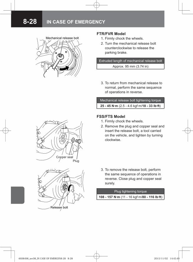
8-28 IN CASE OF EMERGENCY
FTR/FVR Model 1. Firmly chock the wheels. 2. Turn the mechanical release bolt
counterclockwise to release the parking brake.
Mechanical release bolt
Mechanical release bolt tightening torque
25 - 45 N·m (2.5 - 4.6 kgf·m/18 - 33 lb·ft)
Extruded length of mechanical release bolt
Approx. 95 mm (3.74 in)
3. To return from mechanical release to normal, perform the same sequence of operations in reverse.
FSS/FTS Model 1. Firmly chock the wheels. 2. Remove the plug and copper seal and
insert the release bolt, a tool carried on the vehicle, and tighten by turning clockwise.
PlugCopper seal
Release bolt
3. To remove the release bolt, perform the same sequence of operations in reverse. Close plug and copper seal surely.
Plug tightening torque
108 - 157 N·m (11 - 16 kgf·m/80 - 116 lb·ft)
4608498_sec08_IN CASE OF EMERGEN8-28 8-284608498_sec08_IN CASE OF EMERGEN8-28 8-28 2015/11/02 14:45:492015/11/02 14:45:49
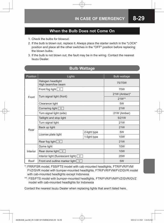
8-29IN CASE OF EMERGENCY
When the Bulb Does not Come On
Bulb Wattage
Position Lights Bulb wattage
Front
Halogen headlightHigh beam/low beam 75/70W
Front fog light V 70W
Turn signal light (front)21W (Amber)*
21W**
Clearance light 5W
Cornering light V 21W
Turn signal light (side) 21W (Amber)
Rear
Taillight and stop light 5/21W
Turn signal light 21W
Back up light 21W
License plate light2-light type 5W
1-light type 10W
Rear fog light V 21W
Interior
Dome light 10W
Rear dome light V 10W
Interior light (fluorescent light) V 20W
Roof Front end outline marker light V 5W
*: FRR/FSR model, FSS/FTS model with cab-mounted headlights, FTR/FVR/FVM/FVZ/GVR model with bumper-mounted headlights, FTR/FVR/FVM/FVZ/GVR model with cab-mounted headlights except Indonesia
**: FSS/FTS model with bumper-mounted headlights, FTR/FVR/FVM/FVZ/GVR/GVZ model with cab-mounted headlights for Indonesia
1. Check the bulbs for blowout. 2. If the bulb is blown out, replace it. Always place the starter switch in the "LOCK"
position and place all the other switches in the "OFF" position before replacing the blown bulbs.
3. If the bulb is not blown out, the fault may be in the wiring. Contact the nearest Isuzu Dealer.
Contact the nearest Isuzu Dealer when replacing lights that aren't listed here.
4608498_sec08_IN CASE OF EMERGEN8-29 8-294608498_sec08_IN CASE OF EMERGEN8-29 8-29 2015/11/02 14:45:502015/11/02 14:45:50
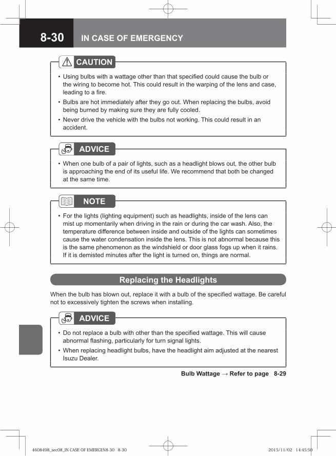
8-30 IN CASE OF EMERGENCY
CAUTIONUsing bulbs with a wattage other than that specified could cause the bulb or the wiring to become hot. This could result in the warping of the lens and case, leading to a fire.Bulbs are hot immediately after they go out. When replacing the bulbs, avoid being burned by making sure they are fully cooled.Never drive the vehicle with the bulbs not working. This could result in an accident.
•
•
•
When the bulb has blown out, replace it with a bulb of the specified wattage. Be careful not to excessively tighten the screws when installing.
Replacing the Headlights
ADVICEDo not replace a bulb with other than the specified wattage. This will cause abnormal flashing, particularly for turn signal lights.When replacing headlight bulbs, have the headlight aim adjusted at the nearest Isuzu Dealer.
•
•
Bulb Wattage → Refer to page 8-29
ADVICEWhen one bulb of a pair of lights, such as a headlight blows out, the other bulb is approaching the end of its useful life. We recommend that both be changed at the same time.
•
NOTEFor the lights (lighting equipment) such as headlights, inside of the lens can mist up momentarily when driving in the rain or during the car wash. Also, the temperature difference between inside and outside of the lights can sometimes cause the water condensation inside the lens. This is not abnormal because this is the same phenomenon as the windshield or door glass fogs up when it rains. If it is demisted minutes after the light is turned on, things are normal.
•
4608498_sec08_IN CASE OF EMERGEN8-30 8-304608498_sec08_IN CASE OF EMERGEN8-30 8-30 2015/11/02 14:45:502015/11/02 14:45:50
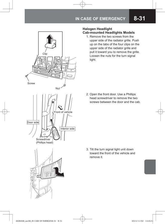
8-31IN CASE OF EMERGENCY
2. Open the front door. Use a Phillips head screwdriver to remove the two screws between the door and the cab.
Front of vehicle
Door side
Screwdriver (Phillips head)
Interior side
3. Tilt the turn signal light unit down toward the front of the vehicle and remove it.
Halogen Headlight Cab-mounted Headlights Models 1. Remove the two screws from the
upper side of the radiator grille. Push up on the tabs of the four clips on the upper side of the radiator grille and pull it toward you to remove the grille. Loosen the nuts for the turn signal light.
Screw
Nut
Clip
4608498_sec08_IN CASE OF EMERGEN8-31 8-314608498_sec08_IN CASE OF EMERGEN8-31 8-31 2015/11/02 14:45:512015/11/02 14:45:51
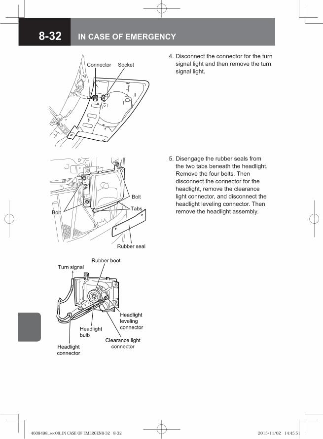
8-32 IN CASE OF EMERGENCY
4. Disconnect the connector for the turn signal light and then remove the turn signal light.
Connector Socket
Bolt
Bolt
Rubber seal
Tabs
5. Disengage the rubber seals from the two tabs beneath the headlight. Remove the four bolts. Then disconnect the connector for the headlight, remove the clearance light connector, and disconnect the headlight leveling connector. Then remove the headlight assembly.
� ���� ����
���������
� ��
���������
���������
��������� �����
���������
� �� ������
���������
��������
���������
4608498_sec08_IN CASE OF EMERGEN8-32 8-324608498_sec08_IN CASE OF EMERGEN8-32 8-32 2015/11/02 14:45:512015/11/02 14:45:51
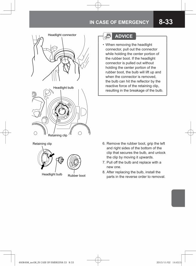
8-33IN CASE OF EMERGENCY
ADVICEWhen removing the headlight connector, pull out the connector while holding the center portion of the rubber boot. If the headlight connector is pulled out without holding the center portion of the rubber boot, the bulb will lift up and when the connector is removed, the bulb can hit the reflector by the reactive force of the retaining clip, resulting in the breakage of the bulb.
•
�� ������ ���������
6. Remove the rubber boot, grip the left and right sides of the bottom of the clip that secures the bulb, and unlock the clip by moving it upwards.
7. Pull off the bulb and replace with a new one.
8. After replacing the bulb, install the parts in the reverse order to removal.
�� ����� ����
����� ������ ������ ����
��� ����� ����
��������� ����
4608498_sec08_IN CASE OF EMERGEN8-33 8-334608498_sec08_IN CASE OF EMERGEN8-33 8-33 2015/11/02 14:45:512015/11/02 14:45:51
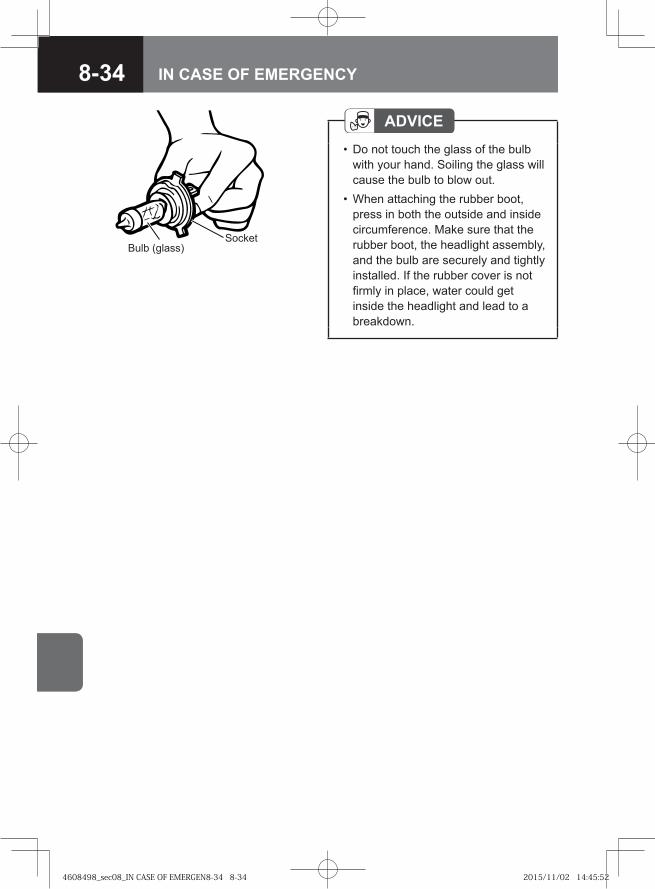
8-34 IN CASE OF EMERGENCY
ADVICEDo not touch the glass of the bulb with your hand. Soiling the glass will cause the bulb to blow out.When attaching the rubber boot, press in both the outside and inside circumference. Make sure that the rubber boot, the headlight assembly, and the bulb are securely and tightly installed. If the rubber cover is not firmly in place, water could get inside the headlight and lead to a breakdown.
•
•
Bulb (glass)Socket
4608498_sec08_IN CASE OF EMERGEN8-34 8-344608498_sec08_IN CASE OF EMERGEN8-34 8-34 2015/11/02 14:45:522015/11/02 14:45:52
8-35IN CASE OF EMERGENCY
WARNING
Do not touch the lock on the cab support while the cab is tilted. If you touch it, the lock will release.
•
CAUTIONTilt the cab only on a level surface.Check the areas in front of and above the cab for sufficient clearance when tilting the cab indoors. When tilting the cab, close the doors securely. You should avoid opening or closing the doors when the cab is tilted.Confirm that the lock for the cab support is securely engaged after the cab is tilted.Do not tilt the cab when objects are placed on or in the instrument panel, seats, cup holders or on floor.Remove any ice or snow accumulating on the top of the bumper before tilting the cab. Failure to do so could damage the bumper, headlights, back panel tray or other components.When you must unavoidably open or close a tilted cab's door, securely support the weight of the door while opening or closing it. It is dangerous to release the door from your hand when it is being opened or closed. The door could hit you or someone and cause an injury or the door could be damaged. Confirm that the door is completely shut after closing it.
••
•
•
•
•
•
Tilting the Cab V → Refer to page 7-10
Power Cab Tilt System V → Refer to page 7-15
Halogen Headlight Bumper-mounted Headlights Models 1. Tilt the cab and work from front-
sideways of the vehicle for the replacement.
4608498_sec08_IN CASE OF EMERGEN8-35 8-354608498_sec08_IN CASE OF EMERGEN8-35 8-35 2015/11/02 14:45:522015/11/02 14:45:52
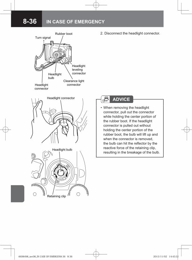
8-36 IN CASE OF EMERGENCY
� ���� ����
���������
� ��
���������
���������
��������� �����
���������
� �� ������
���������
��������
���������
ADVICEWhen removing the headlight connector, pull out the connector while holding the center portion of the rubber boot. If the headlight connector is pulled out without holding the center portion of the rubber boot, the bulb will lift up and when the connector is removed, the bulb can hit the reflector by the reactive force of the retaining clip, resulting in the breakage of the bulb.
•
2. Disconnect the headlight connector.
�� ������ ���������
��� ����� ����
��������� ����
4608498_sec08_IN CASE OF EMERGEN8-36 8-364608498_sec08_IN CASE OF EMERGEN8-36 8-36 2015/11/02 14:45:522015/11/02 14:45:52
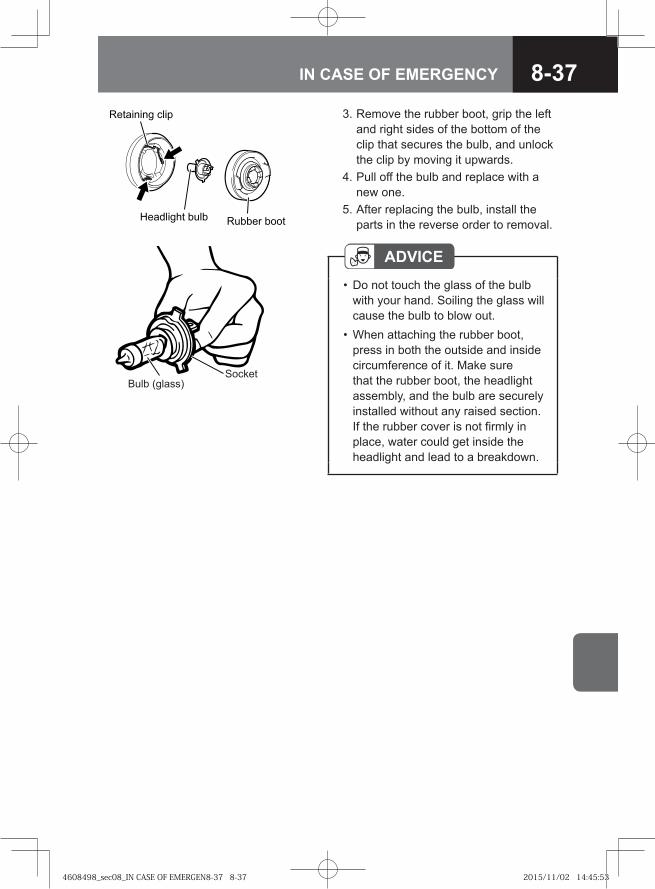
8-37IN CASE OF EMERGENCY
ADVICEDo not touch the glass of the bulb with your hand. Soiling the glass will cause the bulb to blow out.When attaching the rubber boot, press in both the outside and inside circumference of it. Make sure that the rubber boot, the headlight assembly, and the bulb are securely installed without any raised section. If the rubber cover is not firmly in place, water could get inside the headlight and lead to a breakdown.
•
•
Bulb (glass)Socket
3. Remove the rubber boot, grip the left and right sides of the bottom of the clip that secures the bulb, and unlock the clip by moving it upwards.
4. Pull off the bulb and replace with a new one.
5. After replacing the bulb, install the parts in the reverse order to removal.
�� ����� ����
����� ������ ������ ����
4608498_sec08_IN CASE OF EMERGEN8-37 8-374608498_sec08_IN CASE OF EMERGEN8-37 8-37 2015/11/02 14:45:532015/11/02 14:45:53
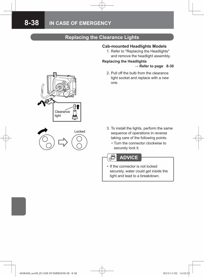
8-38 IN CASE OF EMERGENCY
�� �����
�����
2. Pull off the bulb from the clearance light socket and replace with a new one.
3. To install the lights, perform the same sequence of operations in reverse taking care of the following points:
• Turn the connector clockwise to securely lock it.
ADVICEIf the connector is not locked securely, water could get inside the light and lead to a breakdown.
•
Replacing the Clearance Lights
Cab-mounted Headlights Models 1. Refer to "Replacing the Headlights"
and remove the headlight assembly.Replacing the Headlights
→ Refer to page 8-30
Locked
4608498_sec08_IN CASE OF EMERGEN8-38 8-384608498_sec08_IN CASE OF EMERGEN8-38 8-38 2015/11/02 14:45:532015/11/02 14:45:53
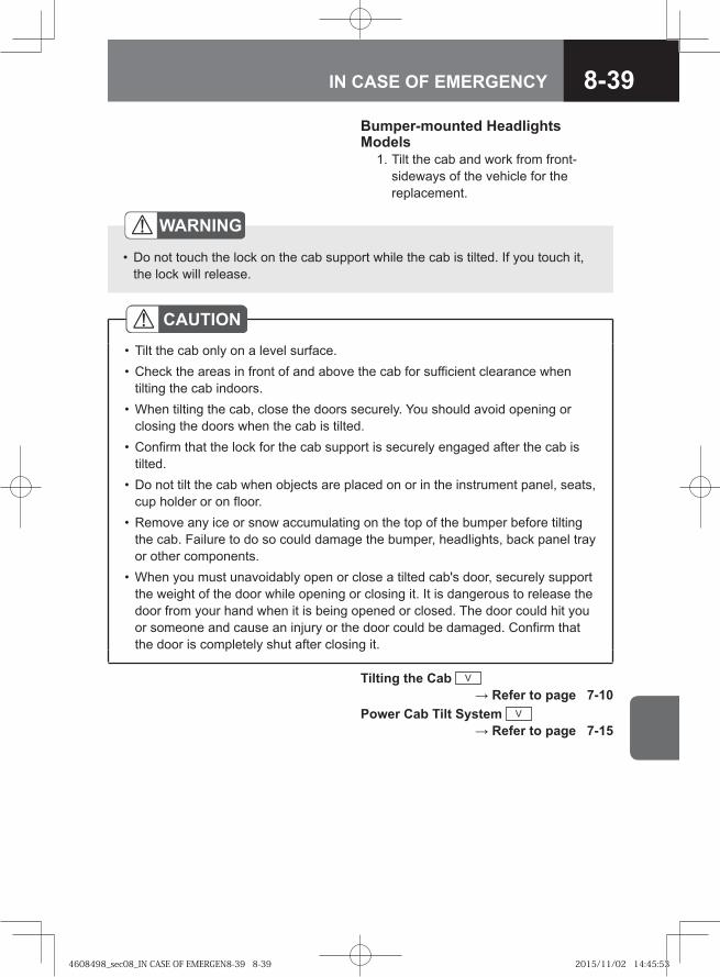
8-39IN CASE OF EMERGENCY
WARNING
Do not touch the lock on the cab support while the cab is tilted. If you touch it, the lock will release.
•
CAUTIONTilt the cab only on a level surface.Check the areas in front of and above the cab for sufficient clearance when tilting the cab indoors. When tilting the cab, close the doors securely. You should avoid opening or closing the doors when the cab is tilted.Confirm that the lock for the cab support is securely engaged after the cab is tilted.Do not tilt the cab when objects are placed on or in the instrument panel, seats, cup holder or on floor.Remove any ice or snow accumulating on the top of the bumper before tilting the cab. Failure to do so could damage the bumper, headlights, back panel tray or other components.When you must unavoidably open or close a tilted cab's door, securely support the weight of the door while opening or closing it. It is dangerous to release the door from your hand when it is being opened or closed. The door could hit you or someone and cause an injury or the door could be damaged. Confirm that the door is completely shut after closing it.
••
•
•
•
•
•
Bumper-mounted Headlights Models 1. Tilt the cab and work from front-
sideways of the vehicle for the replacement.
Tilting the Cab V → Refer to page 7-10
Power Cab Tilt System V → Refer to page 7-15
4608498_sec08_IN CASE OF EMERGEN8-39 8-394608498_sec08_IN CASE OF EMERGEN8-39 8-39 2015/11/02 14:45:532015/11/02 14:45:53
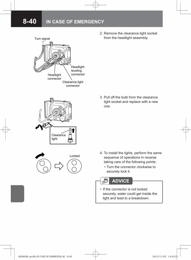
8-40 IN CASE OF EMERGENCY
�� ������
������������ � ��� �����
���������
���� ���� �
�� ������
��������
���������
2. Remove the clearance light socket from the headlight assembly.
�� �����
�����
3. Pull off the bulb from the clearance light socket and replace with a new one.
4. To install the lights, perform the same sequence of operations in reverse taking care of the following points:
• Turn the connector clockwise to securely lock it.
ADVICEIf the connector is not locked securely, water could get inside the light and lead to a breakdown.
•
Locked
4608498_sec08_IN CASE OF EMERGEN8-40 8-404608498_sec08_IN CASE OF EMERGEN8-40 8-40 2015/11/02 14:45:532015/11/02 14:45:53
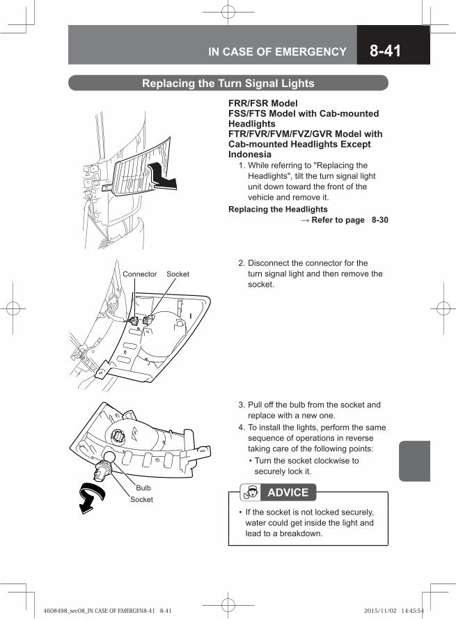
8-41IN CASE OF EMERGENCY
BulbSocket
3. Pull off the bulb from the socket and replace with a new one.
4. To install the lights, perform the same sequence of operations in reverse taking care of the following points:
• Turn the socket clockwise to securely lock it.
ADVICEIf the socket is not locked securely, water could get inside the light and lead to a breakdown.
•
Connector Socket 2. Disconnect the connector for the
turn signal light and then remove the socket.
Replacing the Turn Signal Lights
FRR/FSR ModelFSS/FTS Model with Cab-mounted HeadlightsFTR/FVR/FVM/FVZ/GVR Model with Cab-mounted Headlights Except Indonesia 1. While referring to "Replacing the
Headlights", tilt the turn signal light unit down toward the front of the vehicle and remove it.
Replacing the Headlights → Refer to page 8-30
4608498_sec08_IN CASE OF EMERGEN8-41 8-414608498_sec08_IN CASE OF EMERGEN8-41 8-41 2015/11/02 14:45:542015/11/02 14:45:54
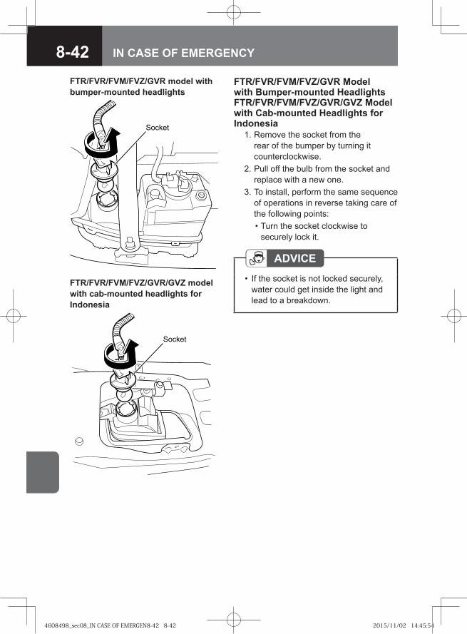
8-42 IN CASE OF EMERGENCY
Socket
FTR/FVR/FVM/FVZ/GVR Model with Bumper-mounted Headlights FTR/FVR/FVM/FVZ/GVR/GVZ Model with Cab-mounted Headlights for Indonesia 1. Remove the socket from the
rear of the bumper by turning it counterclockwise.
2. Pull off the bulb from the socket and replace with a new one.
3. To install, perform the same sequence of operations in reverse taking care of the following points:
• Turn the socket clockwise to securely lock it.
ADVICEIf the socket is not locked securely, water could get inside the light and lead to a breakdown.
•
FTR/FVR/FVM/FVZ/GVR model with bumper-mounted headlights
FTR/FVR/FVM/FVZ/GVR/GVZ model with cab-mounted headlights for Indonesia
��� ��
4608498_sec08_IN CASE OF EMERGEN8-42 8-424608498_sec08_IN CASE OF EMERGEN8-42 8-42 2015/11/02 14:45:542015/11/02 14:45:54
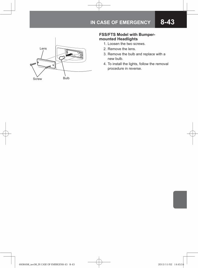
8-43IN CASE OF EMERGENCY
FSS/FTS Model with Bumper-mounted Headlights 1. Loosen the two screws. 2. Remove the lens. 3. Remove the bulb and replace with a
new bulb. 4. To install the lights, follow the removal
procedure in reverse.
Lens
BulbScrew
4608498_sec08_IN CASE OF EMERGEN8-43 8-434608498_sec08_IN CASE OF EMERGEN8-43 8-43 2015/11/02 14:45:542015/11/02 14:45:54
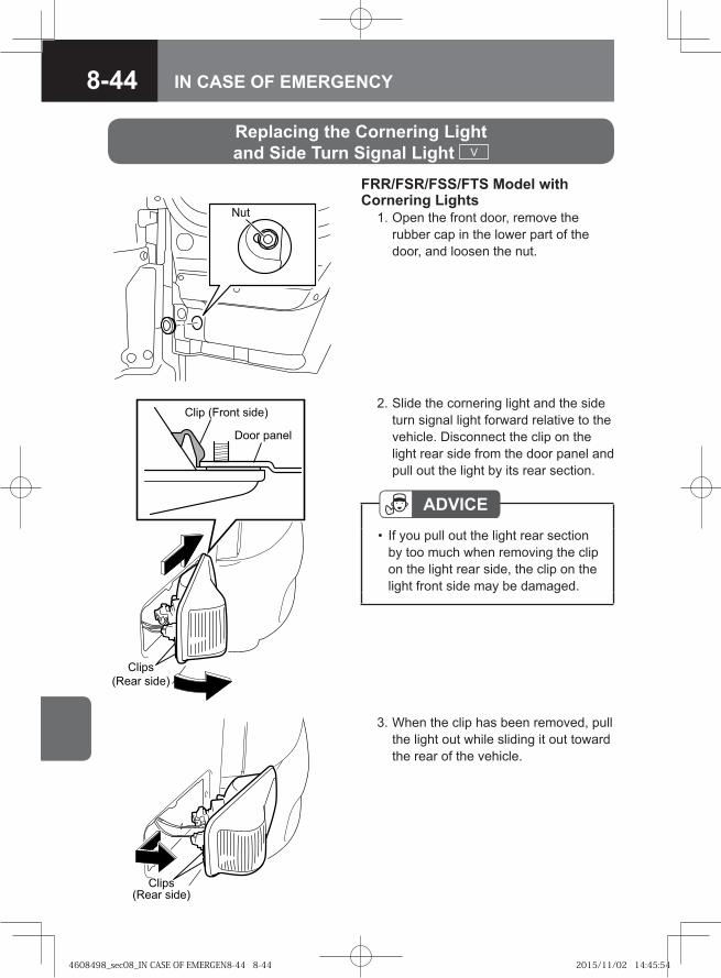
8-44 IN CASE OF EMERGENCY
Nut
3. When the clip has been removed, pull the light out while sliding it out toward the rear of the vehicle.
FRR/FSR/FSS/FTS Model with Cornering Lights 1. Open the front door, remove the
rubber cap in the lower part of the door, and loosen the nut.
Replacing the Cornering Light and Side Turn Signal Light V
�����
�� � ������ � ���
�� ��
����� � ���
���� �����
�� ������� � ���
2. Slide the cornering light and the side turn signal light forward relative to the vehicle. Disconnect the clip on the light rear side from the door panel and pull out the light by its rear section.
ADVICEIf you pull out the light rear section by too much when removing the clip on the light rear side, the clip on the light front side may be damaged.
•
4608498_sec08_IN CASE OF EMERGEN8-44 8-444608498_sec08_IN CASE OF EMERGEN8-44 8-44 2015/11/02 14:45:542015/11/02 14:45:54
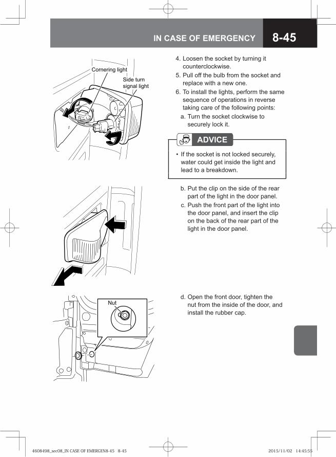
8-45IN CASE OF EMERGENCY
4. Loosen the socket by turning it counterclockwise.
5. Pull off the bulb from the socket and replace with a new one.
6. To install the lights, perform the same sequence of operations in reverse taking care of the following points:
a. Turn the socket clockwise to securely lock it.
ADVICEIf the socket is not locked securely, water could get inside the light and lead to a breakdown.
•
b. Put the clip on the side of the rear part of the light in the door panel.
c. Push the front part of the light into the door panel, and insert the clip on the back of the rear part of the light in the door panel.
Nut d. Open the front door, tighten the
nut from the inside of the door, and install the rubber cap.
�� �� ��� �����
���� �� �
������ �����
4608498_sec08_IN CASE OF EMERGEN8-45 8-454608498_sec08_IN CASE OF EMERGEN8-45 8-45 2015/11/02 14:45:552015/11/02 14:45:55
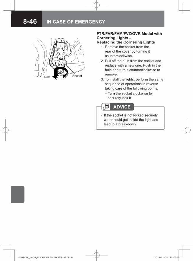
8-46 IN CASE OF EMERGENCY
Socket
FTR/FVR/FVM/FVZ/GVR Model with Cornering Lights - Replacing the Cornering Lights 1. Remove the socket from the
rear of the cover by turning it counterclockwise.
2. Pull off the bulb from the socket and replace with a new one. Push in the bulb and turn it counterclockwise to remove.
3. To install the lights, perform the same sequence of operations in reverse taking care of the following points:
• Turn the socket clockwise to securely lock it.
ADVICEIf the socket is not locked securely, water could get inside the light and lead to a breakdown.
•
4608498_sec08_IN CASE OF EMERGEN8-46 8-464608498_sec08_IN CASE OF EMERGEN8-46 8-46 2015/11/02 14:45:552015/11/02 14:45:55
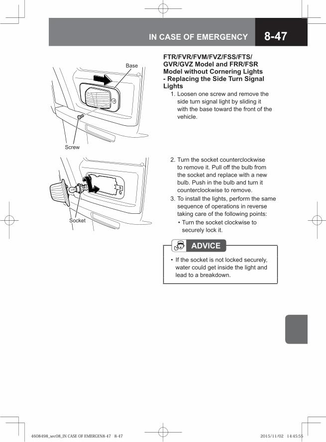
8-47IN CASE OF EMERGENCY
ADVICEIf the socket is not locked securely, water could get inside the light and lead to a breakdown.
•
Screw
BaseFTR/FVR/FVM/FVZ/FSS/FTS/GVR/GVZ Model and FRR/FSR Model without Cornering Lights - Replacing the Side Turn Signal Lights 1. Loosen one screw and remove the
side turn signal light by sliding it with the base toward the front of the vehicle.
2. Turn the socket counterclockwise to remove it. Pull off the bulb from the socket and replace with a new bulb. Push in the bulb and turn it counterclockwise to remove.
3. To install the lights, perform the same sequence of operations in reverse taking care of the following points:
• Turn the socket clockwise to securely lock it.
Socket
4608498_sec08_IN CASE OF EMERGEN8-47 8-474608498_sec08_IN CASE OF EMERGEN8-47 8-47 2015/11/02 14:45:552015/11/02 14:45:55
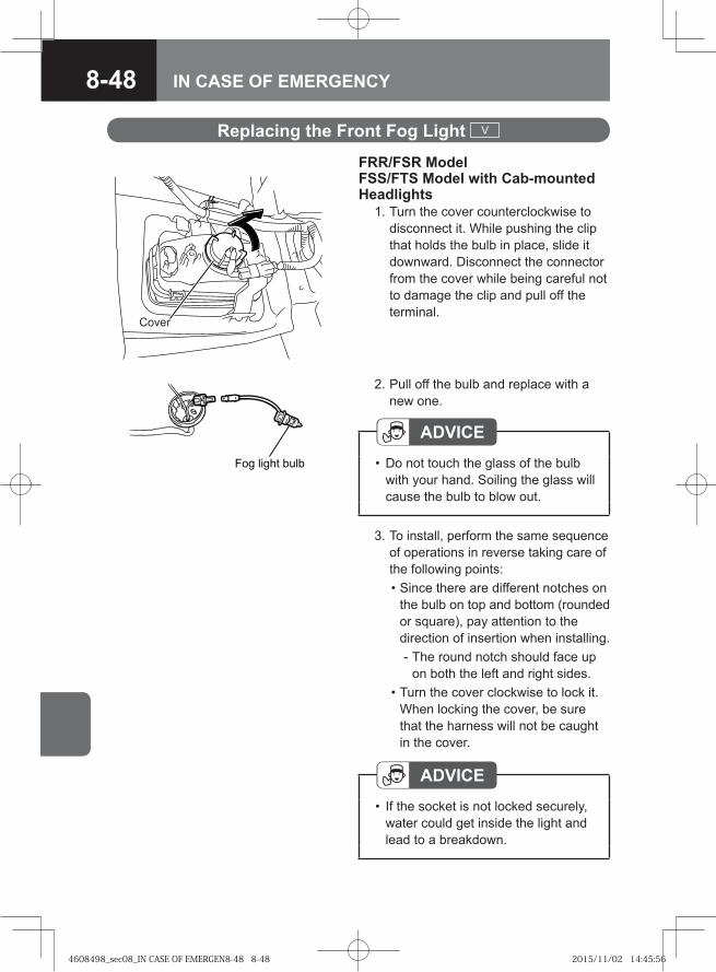
8-48 IN CASE OF EMERGENCY
Cover
2. Pull off the bulb and replace with a new one.
ADVICEDo not touch the glass of the bulb with your hand. Soiling the glass will cause the bulb to blow out.
•��� ����� ����
Replacing the Front Fog Light V
FRR/FSR Model FSS/FTS Model with Cab-mounted Headlights 1. Turn the cover counterclockwise to
disconnect it. While pushing the clip that holds the bulb in place, slide it downward. Disconnect the connector from the cover while being careful not to damage the clip and pull off the terminal.
3. To install, perform the same sequence of operations in reverse taking care of the following points:
• Since there are different notches on the bulb on top and bottom (rounded or square), pay attention to the direction of insertion when installing.
- The round notch should face up on both the left and right sides.
• Turn the cover clockwise to lock it. When locking the cover, be sure that the harness will not be caught in the cover.
ADVICEIf the socket is not locked securely, water could get inside the light and lead to a breakdown.
•
4608498_sec08_IN CASE OF EMERGEN8-48 8-484608498_sec08_IN CASE OF EMERGEN8-48 8-48 2015/11/02 14:45:562015/11/02 14:45:56
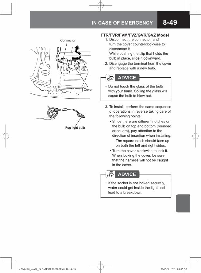
8-49IN CASE OF EMERGENCY
Connector
Cover
FTR/FVR/FVM/FVZ/GVR/GVZ Model 1. Disconnect the connector, and
turn the cover counterclockwise to disconnect it. While pushing the clip that holds the bulb in place, slide it downward.
2. Disengage the terminal from the cover and replace with a new bulb.
ADVICEDo not touch the glass of the bulb with your hand. Soiling the glass will cause the bulb to blow out.
•
3. To install, perform the same sequence of operations in reverse taking care of the following points:
• Since there are different notches on the bulb on top and bottom (rounded or square), pay attention to the direction of insertion when installing.
- The square notch should face up on both the left and right sides.
• Turn the cover clockwise to lock it. When locking the cover, be sure that the harness will not be caught in the cover.
�� �� �� ����
ADVICEIf the socket is not locked securely, water could get inside the light and lead to a breakdown.
•
4608498_sec08_IN CASE OF EMERGEN8-49 8-494608498_sec08_IN CASE OF EMERGEN8-49 8-49 2015/11/02 14:45:562015/11/02 14:45:56
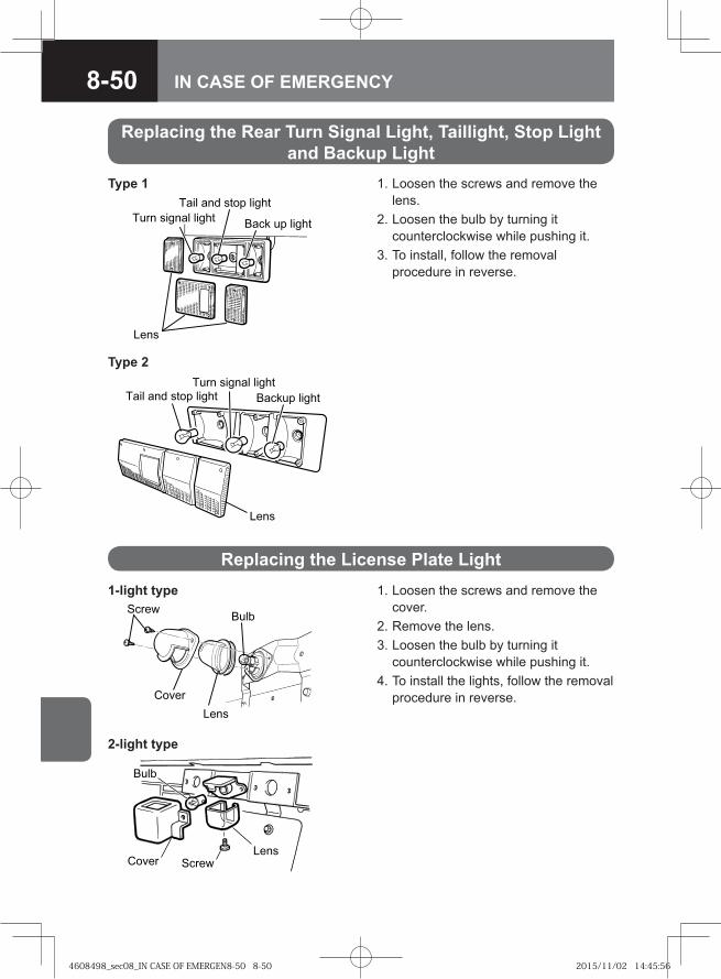
8-50 IN CASE OF EMERGENCY
1. Loosen the screws and remove the lens.
2. Loosen the bulb by turning it counterclockwise while pushing it.
3. To install, follow the removal procedure in reverse.
Replacing the License Plate Light 1. Loosen the screws and remove the
cover. 2. Remove the lens. 3. Loosen the bulb by turning it
counterclockwise while pushing it. 4. To install the lights, follow the removal
procedure in reverse.
��� �����
�����
����
1-light type
�� �
����������
����
2-light type
� �� �� ���� �����
� �� �� �����
����
���� ���� � �����
Type 1
� �� �� ���� �����
���� ���� � �����
� ���� �����
����
Type 2
Replacing the Rear Turn Signal Light, Taillight, Stop Light and Backup Light
4608498_sec08_IN CASE OF EMERGEN8-50 8-504608498_sec08_IN CASE OF EMERGEN8-50 8-50 2015/11/02 14:45:562015/11/02 14:45:56
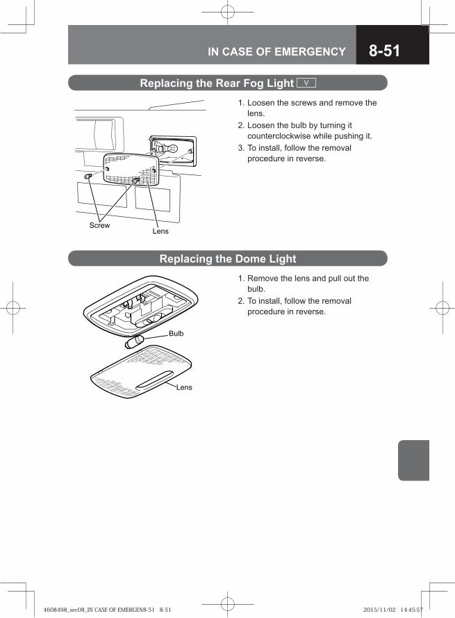
8-51IN CASE OF EMERGENCY
1. Remove the lens and pull out the bulb.
2. To install, follow the removal procedure in reverse.
Replacing the Dome Light
� ��
����
Replacing the Rear Fog Light V
1. Loosen the screws and remove the lens.
2. Loosen the bulb by turning it counterclockwise while pushing it.
3. To install, follow the removal procedure in reverse.
� ����� �
4608498_sec08_IN CASE OF EMERGEN8-51 8-514608498_sec08_IN CASE OF EMERGEN8-51 8-51 2015/11/02 14:45:572015/11/02 14:45:57
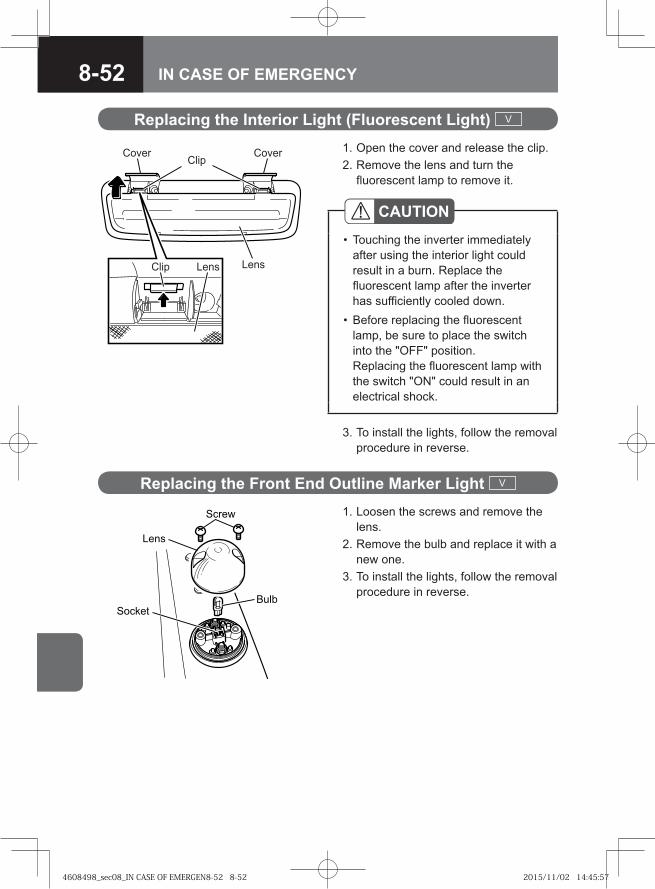
8-52 IN CASE OF EMERGENCY
Replacing the Interior Light (Fluorescent Light) V
Clip
Clip
LensLens
Cover Cover 1. Open the cover and release the clip. 2. Remove the lens and turn the
fluorescent lamp to remove it.
CAUTIONTouching the inverter immediately after using the interior light could result in a burn. Replace the fluorescent lamp after the inverter has sufficiently cooled down.Before replacing the fluorescent lamp, be sure to place the switch into the "OFF" position. Replacing the fluorescent lamp with the switch "ON" could result in an electrical shock.
•
•
3. To install the lights, follow the removal procedure in reverse.
Replacing the Front End Outline Marker Light V
1. Loosen the screws and remove the lens.
2. Remove the bulb and replace it with a new one.
3. To install the lights, follow the removal procedure in reverse.
�� ��
����
������
����
4608498_sec08_IN CASE OF EMERGEN8-52 8-524608498_sec08_IN CASE OF EMERGEN8-52 8-52 2015/11/02 14:45:572015/11/02 14:45:57
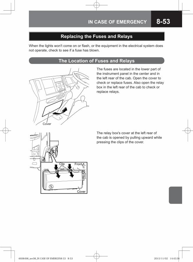
8-53IN CASE OF EMERGENCY
Cover
The fuses are located in the lower part of the instrument panel in the center and in the left rear of the cab. Open the cover to check or replace fuses. Also open the relay box in the left rear of the cab to check or replace relays.
When the lights won't come on or flash, or the equipment in the electrical system does not operate, check to see if a fuse has blown.
The Location of Fuses and Relays
Replacing the Fuses and Relays
� ���
����
����
The relay box's cover at the left rear of the cab is opened by pulling upward while pressing the clips of the cover.
4608498_sec08_IN CASE OF EMERGEN8-53 8-534608498_sec08_IN CASE OF EMERGEN8-53 8-53 2015/11/02 14:45:582015/11/02 14:45:58
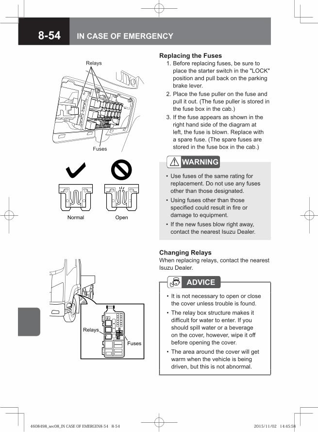
8-54 IN CASE OF EMERGENCY
Normal Open
WARNING
Use fuses of the same rating for replacement. Do not use any fuses other than those designated.Using fuses other than those specified could result in fire or damage to equipment.If the new fuses blow right away, contact the nearest Isuzu Dealer.
•
•
•
Relays
Fuses
Replacing the Fuses 1. Before replacing fuses, be sure to
place the starter switch in the "LOCK" position and pull back on the parking brake lever.
2. Place the fuse puller on the fuse and pull it out. (The fuse puller is stored in the fuse box in the cab.)
3. If the fuse appears as shown in the right hand side of the diagram at left, the fuse is blown. Replace with a spare fuse. (The spare fuses are stored in the fuse box in the cab.)
� ����
��� �
ADVICEIt is not necessary to open or close the cover unless trouble is found.The relay box structure makes it difficult for water to enter. If you should spill water or a beverage on the cover, however, wipe it off before opening the cover.The area around the cover will get warm when the vehicle is being driven, but this is not abnormal.
•
•
•
Changing RelaysWhen replacing relays, contact the nearest Isuzu Dealer.
4608498_sec08_IN CASE OF EMERGEN8-54 8-544608498_sec08_IN CASE OF EMERGEN8-54 8-54 2015/11/02 14:45:582015/11/02 14:45:58
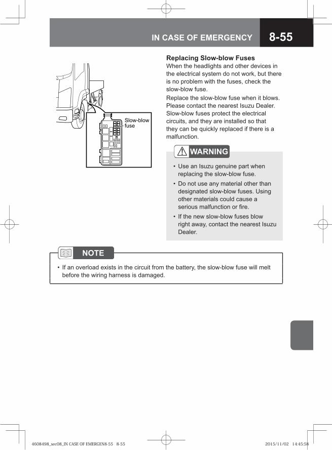
8-55IN CASE OF EMERGENCY
NOTEIf an overload exists in the circuit from the battery, the slow-blow fuse will melt before the wiring harness is damaged.
•
Replacing Slow-blow FusesWhen the headlights and other devices in the electrical system do not work, but there is no problem with the fuses, check the slow-blow fuse. Replace the slow-blow fuse when it blows. Please contact the nearest Isuzu Dealer.Slow-blow fuses protect the electrical circuits, and they are installed so that they can be quickly replaced if there is a malfunction.
� ���� ��
����
WARNING
Use an Isuzu genuine part when replacing the slow-blow fuse.Do not use any material other than designated slow-blow fuses. Using other materials could cause a serious malfunction or fire.If the new slow-blow fuses blow right away, contact the nearest Isuzu Dealer.
•
•
•
4608498_sec08_IN CASE OF EMERGEN8-55 8-554608498_sec08_IN CASE OF EMERGEN8-55 8-55 2015/11/02 14:45:582015/11/02 14:45:58
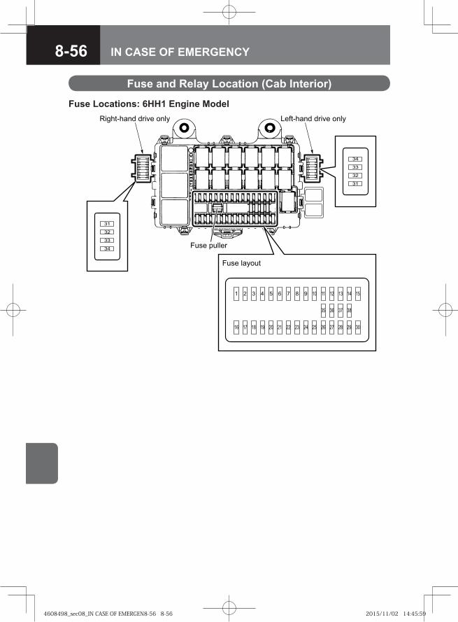
8-56 IN CASE OF EMERGENCY
Fuse and Relay Location (Cab Interior)
Fuse Locations: 6HH1 Engine Model
��� �����
��� �����
�
��
��
��
��
��
��
�
� � � � � � � � � � � � �
� � � � �� � �� �� �� �� �� �� �� ��
�� �� �� ��
��
��������� ��!� ���� "�#����� ��!� ����
4608498_sec08_IN CASE OF EMERGEN8-56 8-564608498_sec08_IN CASE OF EMERGEN8-56 8-56 2015/11/02 14:45:592015/11/02 14:45:59
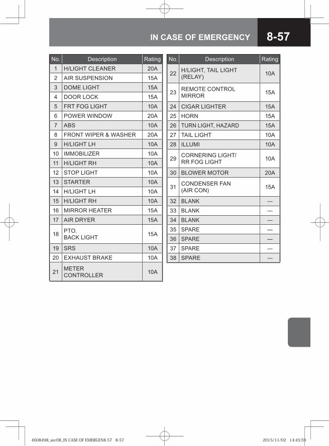
8-57IN CASE OF EMERGENCY
No. Description Rating
1 H/LIGHT CLEANER 20A
2 AIR SUSPENSION 15A
3 DOME LIGHT 15A
4 DOOR LOCK 15A
5 FRT FOG LIGHT 10A
6 POWER WINDOW 20A
7 ABS 10A
8 FRONT WIPER & WASHER 20A
9 H/LIGHT LH 10A
10 IMMOBILIZER 10A
11 H/LIGHT RH 10A
12 STOP LIGHT 10A
13 STARTER 10A
14 H/LIGHT LH 10A
15 H/LIGHT RH 10A
16 MIRROR HEATER 15A
17 AIR DRYER 15A
18 PTO.BACK LIGHT 15A
19 SRS 10A
20 EXHAUST BRAKE 10A
21 METERCONTROLLER 10A
No. Description Rating
22 H/LIGHT, TAIL LIGHT(RELAY) 10A
23 REMOTE CONTROLMIRROR 15A
24 CIGAR LIGHTER 15A
25 HORN 15A
26 TURN LIGHT, HAZARD 15A
27 TAIL LIGHT 10A
28 ILLUMI 10A
29 CORNERING LIGHT/RR FOG LIGHT 10A
30 BLOWER MOTOR 20A
31 CONDENSER FAN(AIR CON) 15A
32 BLANK ―
33 BLANK ―
34 BLANK ―
35 SPARE ―
36 SPARE ―
37 SPARE ―
38 SPARE ―
4608498_sec08_IN CASE OF EMERGEN8-57 8-574608498_sec08_IN CASE OF EMERGEN8-57 8-57 2015/11/02 14:45:592015/11/02 14:45:59
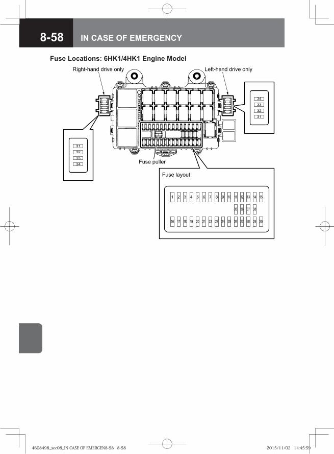
8-58 IN CASE OF EMERGENCY
Fuse Locations: 6HK1/4HK1 Engine Model
��� �����
��� �����
�
��
��
��
��
��
��
�
� � � � � � � � � � � � �
� � � � �� � �� �� �� �� �� �� �� ��
�� �� �� ��
��
��������� ��!� ���� "�#����� ��!� ����
4608498_sec08_IN CASE OF EMERGEN8-58 8-584608498_sec08_IN CASE OF EMERGEN8-58 8-58 2015/11/02 14:45:592015/11/02 14:45:59
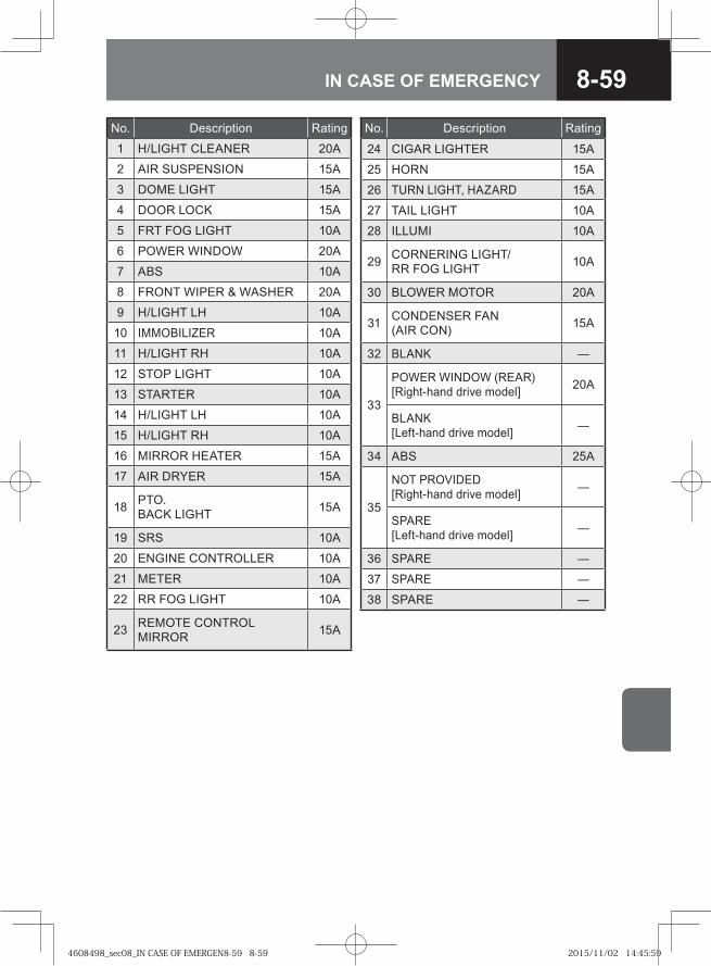
8-59IN CASE OF EMERGENCY
No. Description Rating
1 H/LIGHT CLEANER 20A
2 AIR SUSPENSION 15A
3 DOME LIGHT 15A
4 DOOR LOCK 15A
5 FRT FOG LIGHT 10A
6 POWER WINDOW 20A
7 ABS 10A
8 FRONT WIPER & WASHER 20A
9 H/LIGHT LH 10A
10 IMMOBILIZER 10A
11 H/LIGHT RH 10A
12 STOP LIGHT 10A
13 STARTER 10A
14 H/LIGHT LH 10A
15 H/LIGHT RH 10A
16 MIRROR HEATER 15A
17 AIR DRYER 15A
18 PTO.BACK LIGHT 15A
19 SRS 10A
20 ENGINE CONTROLLER 10A
21 METER 10A
22 RR FOG LIGHT 10A
23 REMOTE CONTROLMIRROR 15A
No. Description Rating
24 CIGAR LIGHTER 15A
25 HORN 15A
26 TURN LIGHT, HAZARD 15A
27 TAIL LIGHT 10A
28 ILLUMI 10A
29 CORNERING LIGHT/RR FOG LIGHT 10A
30 BLOWER MOTOR 20A
31 CONDENSER FAN(AIR CON) 15A
32 BLANK ―
33
POWER WINDOW (REAR)[Right-hand drive model] 20A
BLANK[Left-hand drive model] ―
34 ABS 25A
35
NOT PROVIDED[Right-hand drive model] ―
SPARE[Left-hand drive model] ―
36 SPARE ―
37 SPARE ―
38 SPARE ―
4608498_sec08_IN CASE OF EMERGEN8-59 8-594608498_sec08_IN CASE OF EMERGEN8-59 8-59 2015/11/02 14:45:592015/11/02 14:45:59
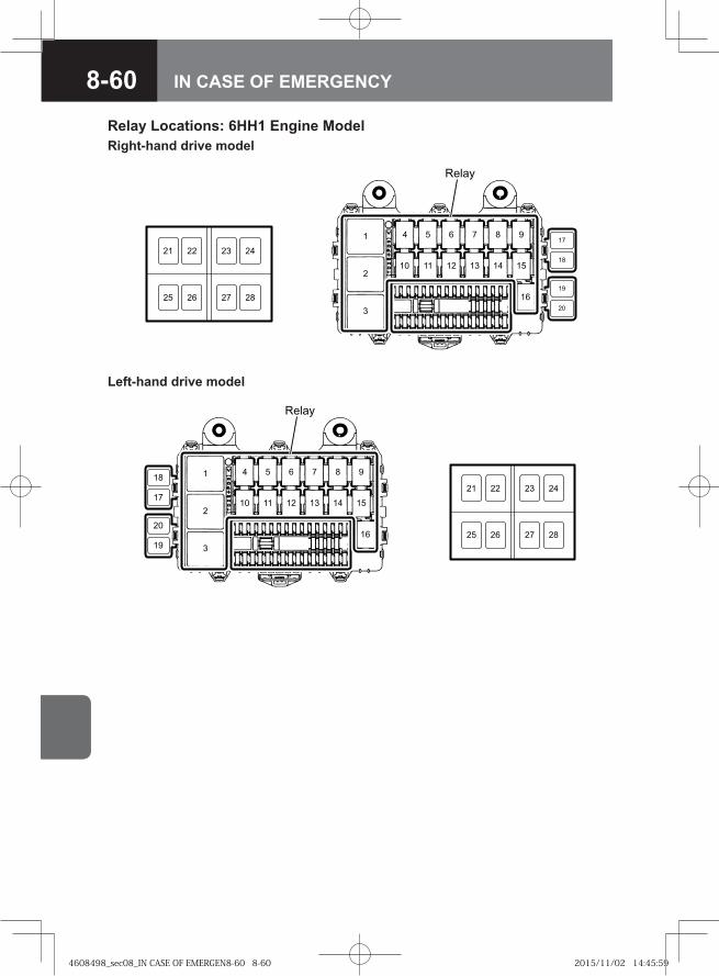
8-60 IN CASE OF EMERGENCY
Relay Locations: 6HH1 Engine Model
��
� � � � � � �
�� �� �� �� �� ��
��
�
� ��
��
��
��
�� ��
��������
����
Right-hand drive model
�� �
� � � � � �
� � � � �
�
�
�
�� ��
��������
����
�
�
��
Left-hand drive model
4608498_sec08_IN CASE OF EMERGEN8-60 8-604608498_sec08_IN CASE OF EMERGEN8-60 8-60 2015/11/02 14:45:592015/11/02 14:45:59
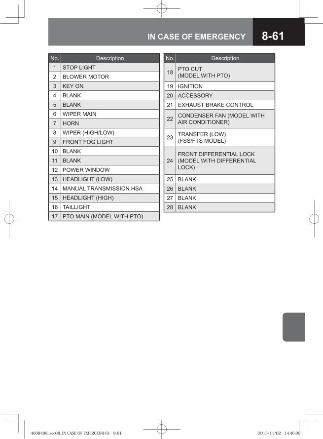
8-61IN CASE OF EMERGENCY
No. Description
1 STOP LIGHT
2 BLOWER MOTOR
3 KEY ON
4 BLANK
5 BLANK
6 WIPER MAIN
7 HORN
8 WIPER (HIGH/LOW)
9 FRONT FOG LIGHT
10 BLANK
11 BLANK
12 POWER WINDOW
13 HEADLIGHT (LOW)
14 MANUAL TRANSMISSION HSA
15 HEADLIGHT (HIGH)
16 TAILLIGHT
17 PTO MAIN (MODEL WITH PTO)
No. Description
18 PTO CUT(MODEL WITH PTO)
19 IGNITION
20 ACCESSORY
21 EXHAUST BRAKE CONTROL
22 CONDENSER FAN (MODEL WITH AIR CONDITIONER)
23 TRANSFER (LOW)(FSS/FTS MODEL)
24FRONT DIFFERENTIAL LOCK(MODEL WITH DIFFERENTIAL LOCK)
25 BLANK
26 BLANK
27 BLANK
28 BLANK
4608498_sec08_IN CASE OF EMERGEN8-61 8-614608498_sec08_IN CASE OF EMERGEN8-61 8-61 2015/11/02 14:46:002015/11/02 14:46:00
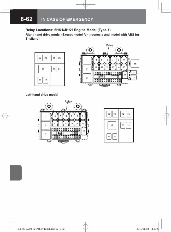
8-62 IN CASE OF EMERGENCY
�� �
� � � � � �
� � � � �
�
�
� �
�
�� ��
���
����
����
�
��
Right-hand drive model (Except model for Indonesia and model with ABS for Thailand)
�� �
� � � � � �
� � � � �
�
�
�
�� ��
���
����
����
�
Left-hand drive model
Relay Locations: 6HK1/4HK1 Engine Model (Type 1)
4608498_sec08_IN CASE OF EMERGEN8-62 8-624608498_sec08_IN CASE OF EMERGEN8-62 8-62 2015/11/02 14:46:002015/11/02 14:46:00
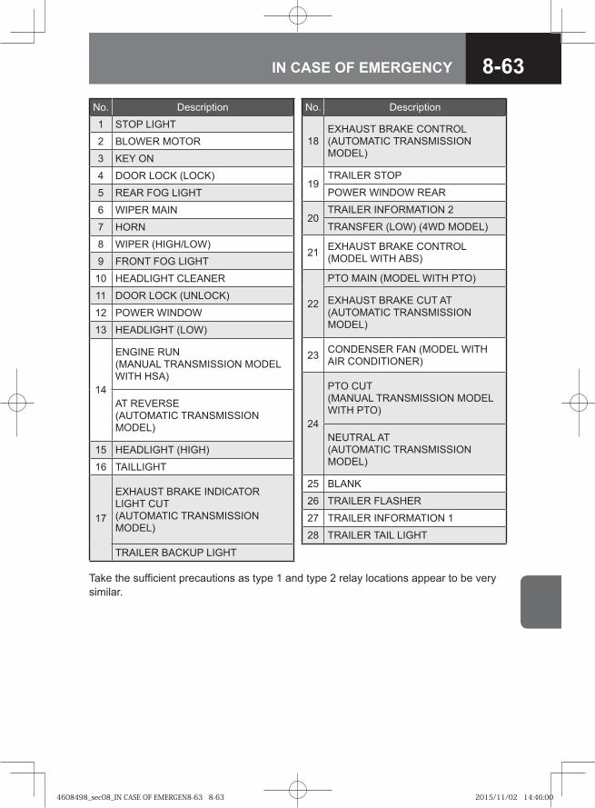
8-63IN CASE OF EMERGENCY
No. Description
1 STOP LIGHT
2 BLOWER MOTOR
3 KEY ON
4 DOOR LOCK (LOCK)
5 REAR FOG LIGHT
6 WIPER MAIN
7 HORN
8 WIPER (HIGH/LOW)
9 FRONT FOG LIGHT
10 HEADLIGHT CLEANER
11 DOOR LOCK (UNLOCK)
12 POWER WINDOW
13 HEADLIGHT (LOW)
14
ENGINE RUN (MANUAL TRANSMISSION MODEL WITH HSA)
AT REVERSE (AUTOMATIC TRANSMISSION MODEL)
15 HEADLIGHT (HIGH)
16 TAILLIGHT
17
EXHAUST BRAKE INDICATOR LIGHT CUT (AUTOMATIC TRANSMISSION MODEL)
TRAILER BACKUP LIGHT
No. Description
18EXHAUST BRAKE CONTROL (AUTOMATIC TRANSMISSION MODEL)
19TRAILER STOP
POWER WINDOW REAR
20TRAILER INFORMATION 2
TRANSFER (LOW) (4WD MODEL)
21 EXHAUST BRAKE CONTROL (MODEL WITH ABS)
22
PTO MAIN (MODEL WITH PTO)
EXHAUST BRAKE CUT AT (AUTOMATIC TRANSMISSION MODEL)
23 CONDENSER FAN (MODEL WITH AIR CONDITIONER)
24
PTO CUT(MANUAL TRANSMISSION MODEL WITH PTO)
NEUTRAL AT (AUTOMATIC TRANSMISSION MODEL)
25 BLANK
26 TRAILER FLASHER
27 TRAILER INFORMATION 1
28 TRAILER TAIL LIGHT
Take the sufficient precautions as type 1 and type 2 relay locations appear to be very similar.
4608498_sec08_IN CASE OF EMERGEN8-63 8-634608498_sec08_IN CASE OF EMERGEN8-63 8-63 2015/11/02 14:46:002015/11/02 14:46:00
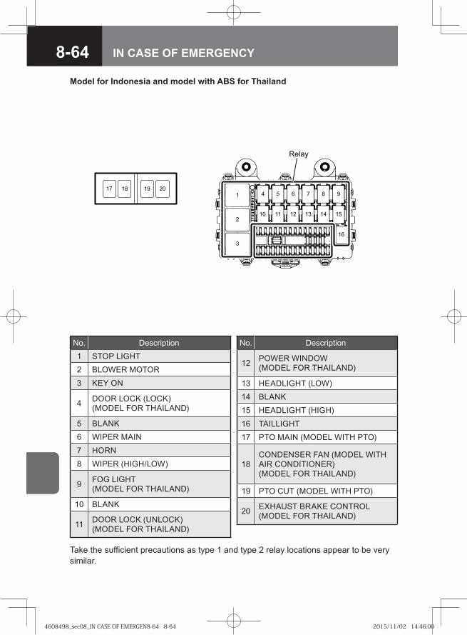
8-64 IN CASE OF EMERGENCY
Relay
1 4 5 6 7 8 9
10 11 12 13 14 15
16
2
3
19 201817
Model for Indonesia and model with ABS for Thailand
No. Description1 STOP LIGHT
2 BLOWER MOTOR
3 KEY ON
4 DOOR LOCK (LOCK) (MODEL FOR THAILAND)
5 BLANK
6 WIPER MAIN
7 HORN
8 WIPER (HIGH/LOW)
9 FOG LIGHT (MODEL FOR THAILAND)
10 BLANK
11 DOOR LOCK (UNLOCK) (MODEL FOR THAILAND)
No. Description
12 POWER WINDOW (MODEL FOR THAILAND)
13 HEADLIGHT (LOW)
14 BLANK
15 HEADLIGHT (HIGH)
16 TAILLIGHT
17 PTO MAIN (MODEL WITH PTO)
18CONDENSER FAN (MODEL WITH AIR CONDITIONER) (MODEL FOR THAILAND)
19 PTO CUT (MODEL WITH PTO)
20 EXHAUST BRAKE CONTROL (MODEL FOR THAILAND)
Take the sufficient precautions as type 1 and type 2 relay locations appear to be very similar.
4608498_sec08_IN CASE OF EMERGEN8-64 8-644608498_sec08_IN CASE OF EMERGEN8-64 8-64 2015/11/02 14:46:002015/11/02 14:46:00
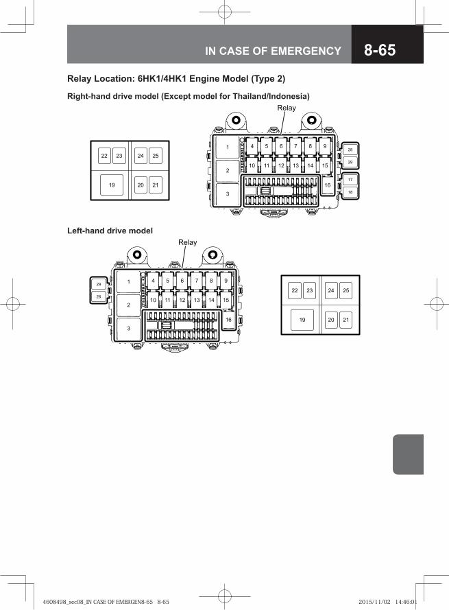
8-65IN CASE OF EMERGENCY
�� �
� � � � � �
� � � � �
�
�
� �
�
��
��
�� ��
���
����
�
Right-hand drive model (Except model for Thailand/Indonesia)
�� �
� � � � � �
� � � � �
�
�
�
�� ��
���
����
�
��
��
Left-hand drive model
Relay Location: 6HK1/4HK1 Engine Model (Type 2)
4608498_sec08_IN CASE OF EMERGEN8-65 8-654608498_sec08_IN CASE OF EMERGEN8-65 8-65 2015/11/02 14:46:012015/11/02 14:46:01
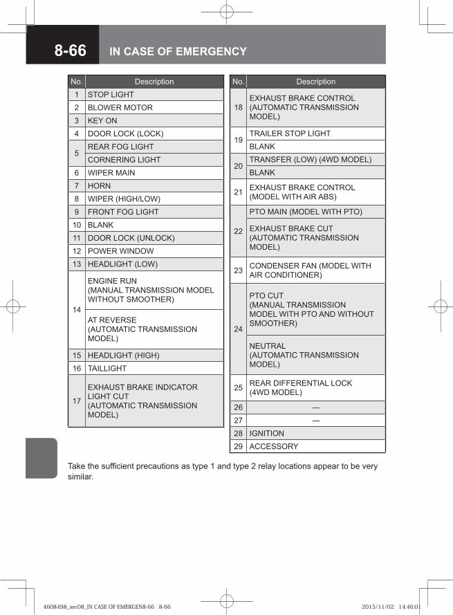
8-66 IN CASE OF EMERGENCY
No. Description
1 STOP LIGHT
2 BLOWER MOTOR
3 KEY ON
4 DOOR LOCK (LOCK)
5REAR FOG LIGHT
CORNERING LIGHT
6 WIPER MAIN
7 HORN
8 WIPER (HIGH/LOW)
9 FRONT FOG LIGHT
10 BLANK
11 DOOR LOCK (UNLOCK)
12 POWER WINDOW
13 HEADLIGHT (LOW)
14
ENGINE RUN (MANUAL TRANSMISSION MODEL WITHOUT SMOOTHER)
AT REVERSE (AUTOMATIC TRANSMISSION MODEL)
15 HEADLIGHT (HIGH)
16 TAILLIGHT
17
EXHAUST BRAKE INDICATOR LIGHT CUT (AUTOMATIC TRANSMISSION MODEL)
No. Description
18EXHAUST BRAKE CONTROL (AUTOMATIC TRANSMISSION MODEL)
19TRAILER STOP LIGHT
BLANK
20TRANSFER (LOW) (4WD MODEL)
BLANK
21 EXHAUST BRAKE CONTROL (MODEL WITH AIR ABS)
22
PTO MAIN (MODEL WITH PTO)
EXHAUST BRAKE CUT (AUTOMATIC TRANSMISSION MODEL)
23 CONDENSER FAN (MODEL WITH AIR CONDITIONER)
24
PTO CUT (MANUAL TRANSMISSION MODEL WITH PTO AND WITHOUT SMOOTHER)
NEUTRAL (AUTOMATIC TRANSMISSION MODEL)
25 REAR DIFFERENTIAL LOCK (4WD MODEL)
26 ―
27 ―
28 IGNITION
29 ACCESSORY
Take the sufficient precautions as type 1 and type 2 relay locations appear to be very similar.
4608498_sec08_IN CASE OF EMERGEN8-66 8-664608498_sec08_IN CASE OF EMERGEN8-66 8-66 2015/11/02 14:46:012015/11/02 14:46:01
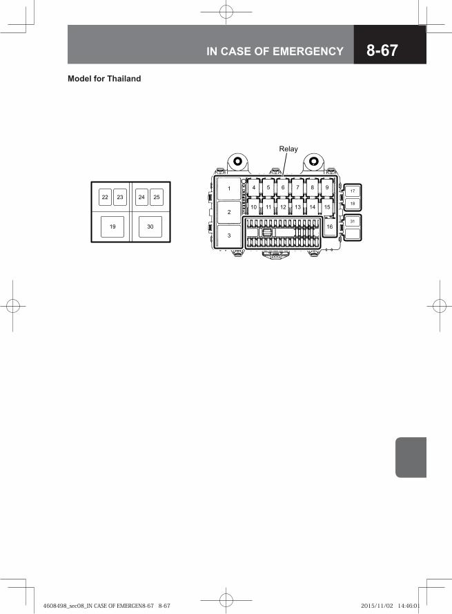
8-67IN CASE OF EMERGENCY
��
� � � � � � �
�� �� �� �� �� ��
��
�
�
��
��
��
�� ������
�� ��
Model for Thailand
4608498_sec08_IN CASE OF EMERGEN8-67 8-674608498_sec08_IN CASE OF EMERGEN8-67 8-67 2015/11/02 14:46:012015/11/02 14:46:01
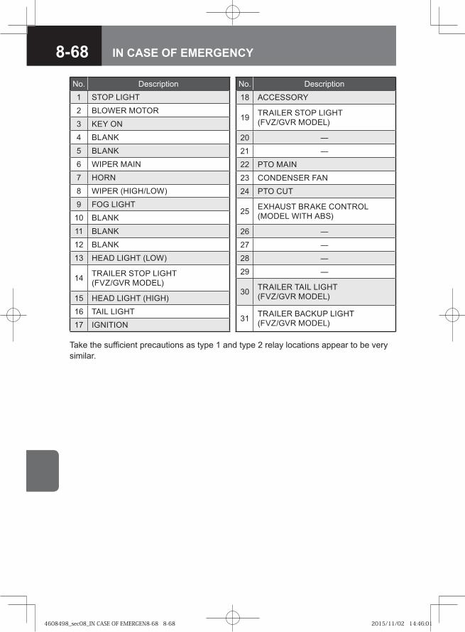
8-68 IN CASE OF EMERGENCY
No. Description1 STOP LIGHT
2 BLOWER MOTOR
3 KEY ON
4 BLANK
5 BLANK
6 WIPER MAIN
7 HORN
8 WIPER (HIGH/LOW)
9 FOG LIGHT
10 BLANK
11 BLANK
12 BLANK
13 HEAD LIGHT (LOW)
14 TRAILER STOP LIGHT (FVZ/GVR MODEL)
15 HEAD LIGHT (HIGH)
16 TAIL LIGHT17 IGNITION
No. Description
18 ACCESSORY
19 TRAILER STOP LIGHT (FVZ/GVR MODEL)
20 ―
21 ―
22 PTO MAIN
23 CONDENSER FAN
24 PTO CUT
25 EXHAUST BRAKE CONTROL (MODEL WITH ABS)
26 ―
27 ―
28 ―
29 ―
30 TRAILER TAIL LIGHT (FVZ/GVR MODEL)
31 TRAILER BACKUP LIGHT (FVZ/GVR MODEL)
Take the sufficient precautions as type 1 and type 2 relay locations appear to be very similar.
4608498_sec08_IN CASE OF EMERGEN8-68 8-684608498_sec08_IN CASE OF EMERGEN8-68 8-68 2015/11/02 14:46:012015/11/02 14:46:01
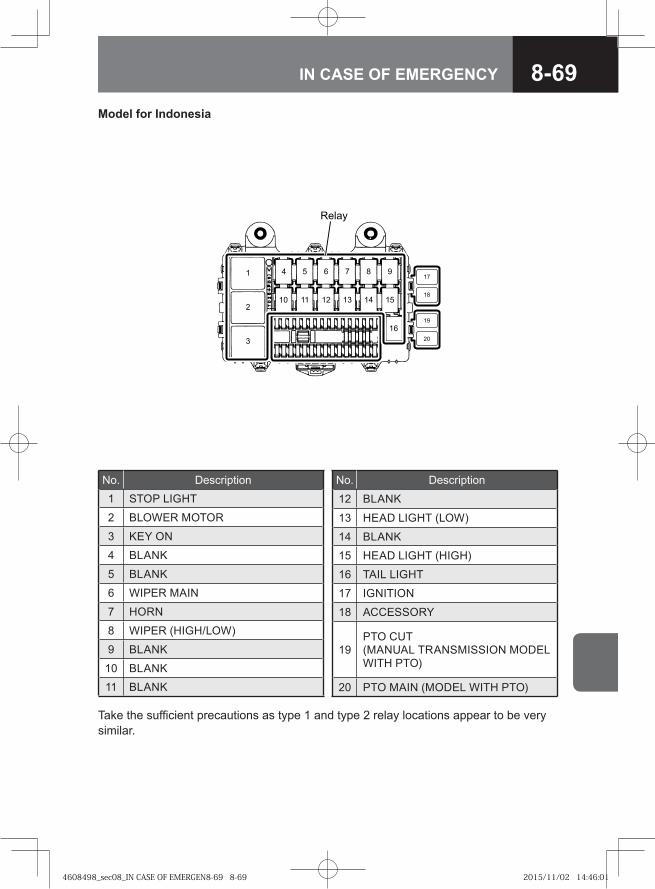
8-69IN CASE OF EMERGENCY
�� �
� � � � � �
� � � � �
�
�
�
�
��
�
�
Model for Indonesia
No. Description1 STOP LIGHT
2 BLOWER MOTOR
3 KEY ON
4 BLANK
5 BLANK
6 WIPER MAIN
7 HORN
8 WIPER (HIGH/LOW)
9 BLANK
10 BLANK11 BLANK
No. Description
12 BLANK
13 HEAD LIGHT (LOW)
14 BLANK
15 HEAD LIGHT (HIGH)
16 TAIL LIGHT
17 IGNITION
18 ACCESSORY
19PTO CUT (MANUAL TRANSMISSION MODEL WITH PTO)
20 PTO MAIN (MODEL WITH PTO)
Take the sufficient precautions as type 1 and type 2 relay locations appear to be very similar.
4608498_sec08_IN CASE OF EMERGEN8-69 8-694608498_sec08_IN CASE OF EMERGEN8-69 8-69 2015/11/02 14:46:012015/11/02 14:46:01
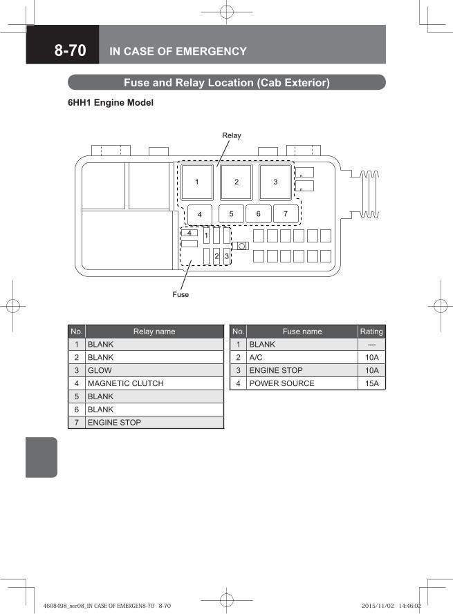
8-70 IN CASE OF EMERGENCY
Fuse and Relay Location (Cab Exterior)
6HH1 Engine Model
��
���
�
��
� �
� � ��
� �
No. Relay name
1 BLANK
2 BLANK
3 GLOW
4 MAGNETIC CLUTCH
5 BLANK
6 BLANK
7 ENGINE STOP
No. Fuse name Rating
1 BLANK ―
2 A/C 10A
3 ENGINE STOP 10A
4 POWER SOURCE 15A
4608498_sec08_IN CASE OF EMERGEN8-70 8-704608498_sec08_IN CASE OF EMERGEN8-70 8-70 2015/11/02 14:46:022015/11/02 14:46:02
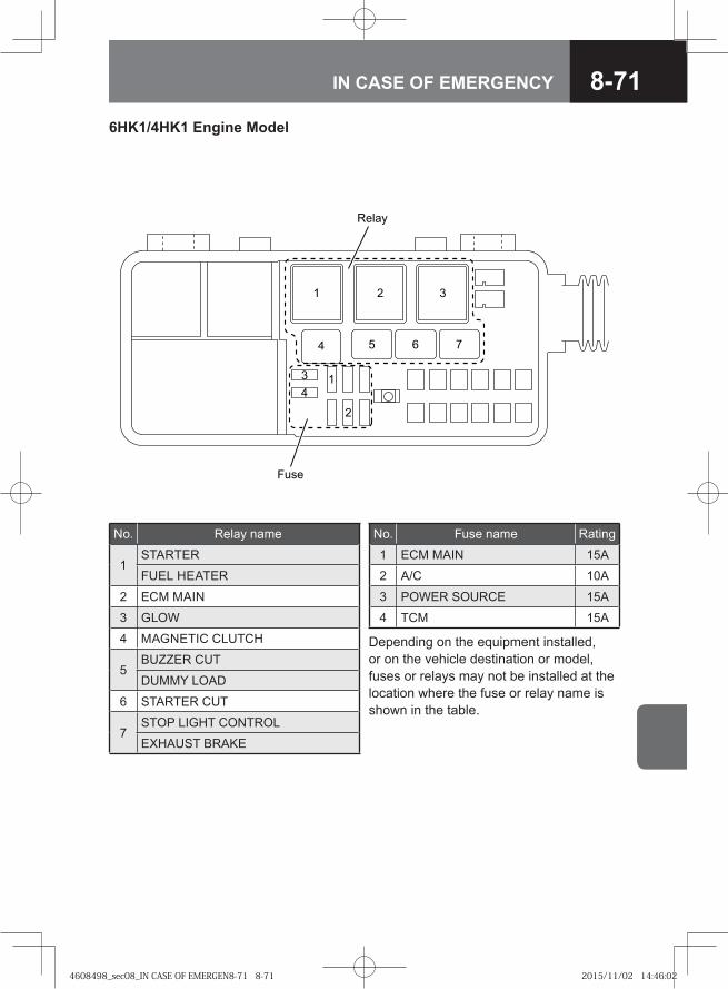
8-71IN CASE OF EMERGENCY
��
���
�
��
�
�
� � ��
� �
No. Relay name
1STARTER
FUEL HEATER
2 ECM MAIN
3 GLOW
4 MAGNETIC CLUTCH
5BUZZER CUT
DUMMY LOAD
6 STARTER CUT
7STOP LIGHT CONTROL
EXHAUST BRAKE
No. Fuse name Rating
1 ECM MAIN 15A
2 A/C 10A
3 POWER SOURCE 15A
4 TCM 15A
Depending on the equipment installed, or on the vehicle destination or model, fuses or relays may not be installed at the location where the fuse or relay name is shown in the table.
6HK1/4HK1 Engine Model
4608498_sec08_IN CASE OF EMERGEN8-71 8-714608498_sec08_IN CASE OF EMERGEN8-71 8-71 2015/11/02 14:46:022015/11/02 14:46:02
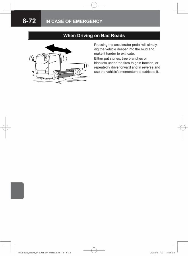
8-72 IN CASE OF EMERGENCY
Pressing the accelerator pedal will simply dig the vehicle deeper into the mud and make it harder to extricate. Either put stones, tree branches or blankets under the tires to gain traction, or repeatedly drive forward and in reverse and use the vehicle's momentum to extricate it.
When Driving on Bad Roads
4608498_sec08_IN CASE OF EMERGEN8-72 8-724608498_sec08_IN CASE OF EMERGEN8-72 8-72 2015/11/02 14:46:022015/11/02 14:46:02
8-73IN CASE OF EMERGENCY
To move a disabled vehicle, it is best to rely on someone in the wrecker or tow truck business. If that is not possible, follow these procedures.When towing, use appropriate equipment and comply with local legal requirements. Do not try to start the engine by towing or pushing the vehicle.
When Towing
CAUTIONFor MZZ, MZW and MLD manual transmission models, place the gearshift lever in the "N" position, and tow for a maximum distance of 10 km (6.2 miles) at speeds less than 40 km/h (25 MPH). Other than the above, disconnect the propeller shaft when towing to avoid damage to the transmission.For Smoother vehicles, place the gearshift lever in the "N" position and make sure the shift indicator displays "N". Tow for a maximum distance of 10 km (6.2 miles) at speeds less than 40 km/h (25 MPH).When the shift indicator does not indicate "N", or in situations other than the above, disconnect the propeller shaft when towing to avoid damage to the transmission.Whenever possible, tow a vehicle with the engine started.If the engine is not started:
The brakes will not be as effective;The steering wheel will be hard to turn;The steering wheel could lock, making it impossible to move. This is extremely dangerous. (When the ignition key is removed.)
•
•
•
---
WARNING
Be sure to chock the wheels when disconnecting the propeller shaft. The vehicle could start to move and cause a serious accident.
•
Towing Vehicles with ZF9S1110 Model Transmission V → Refer to page 8-78
Towing Vehicles with ZF6S1000 Model Transmission V → Refer to page 8-79
Towing Vehicles with ALLISON 2500/3000/3500 Model Transmission
V → Refer to page 8-79Towing Vehicles with FSO5206B/
ES11109/FS8209A Model Transmissions V → Refer to page 8-80
4608498_sec08_IN CASE OF EMERGEN8-73 8-734608498_sec08_IN CASE OF EMERGEN8-73 8-73 2015/11/02 14:46:022015/11/02 14:46:02
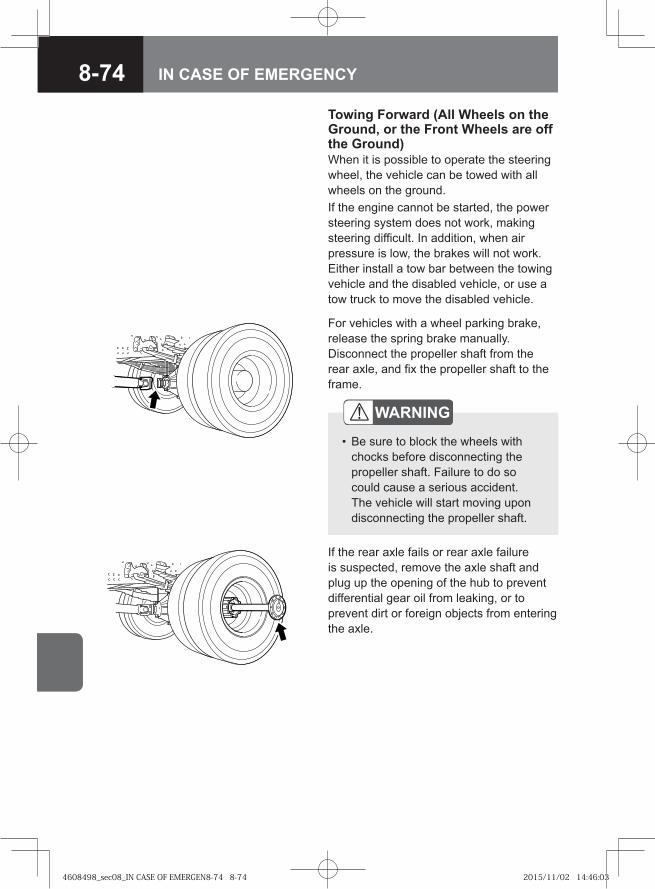
8-74 IN CASE OF EMERGENCY
Towing Forward (All Wheels on the Ground, or the Front Wheels are off the Ground)When it is possible to operate the steering wheel, the vehicle can be towed with all wheels on the ground.If the engine cannot be started, the power steering system does not work, making steering difficult. In addition, when air pressure is low, the brakes will not work. Either install a tow bar between the towing vehicle and the disabled vehicle, or use a tow truck to move the disabled vehicle.
If the rear axle fails or rear axle failure is suspected, remove the axle shaft and plug up the opening of the hub to prevent differential gear oil from leaking, or to prevent dirt or foreign objects from entering the axle.
WARNING
Be sure to block the wheels with chocks before disconnecting the propeller shaft. Failure to do so could cause a serious accident. The vehicle will start moving upon disconnecting the propeller shaft.
•
For vehicles with a wheel parking brake, release the spring brake manually. Disconnect the propeller shaft from the rear axle, and fix the propeller shaft to the frame.
4608498_sec08_IN CASE OF EMERGEN8-74 8-744608498_sec08_IN CASE OF EMERGEN8-74 8-74 2015/11/02 14:46:032015/11/02 14:46:03
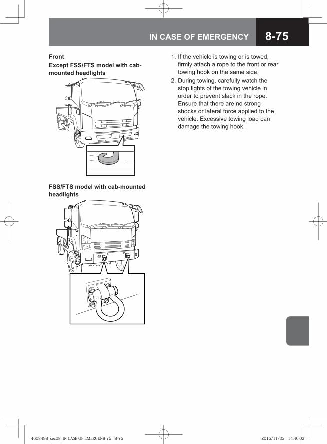
8-75IN CASE OF EMERGENCY
FrontExcept FSS/FTS model with cab-mounted headlights
1. If the vehicle is towing or is towed, firmly attach a rope to the front or rear towing hook on the same side.
2. During towing, carefully watch the stop lights of the towing vehicle in order to prevent slack in the rope. Ensure that there are no strong shocks or lateral force applied to the vehicle. Excessive towing load can damage the towing hook.
FSS/FTS model with cab-mounted headlights
4608498_sec08_IN CASE OF EMERGEN8-75 8-754608498_sec08_IN CASE OF EMERGEN8-75 8-75 2015/11/02 14:46:032015/11/02 14:46:03
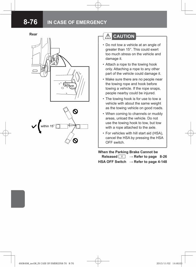
8-76 IN CASE OF EMERGENCY
Rear
� �� � ��
CAUTIONDo not tow a vehicle at an angle of greater than 15°. This could exert too much stress on the vehicle and damage it.Attach a rope to the towing hook only. Attaching a rope to any other part of the vehicle could damage it.Make sure there are no people near the towing rope and hook before towing a vehicle. If the rope snaps, people nearby could be injured.The towing hook is for use to tow a vehicle with about the same weight as the towing vehicle on good roads.When coming to channels or muddy areas, unload the vehicle. Do not use the towing hook to tow, but tow with a rope attached to the axle.For vehicles with hill start aid (HSA), cancel the HSA by pressing the HSA OFF switch.
•
•
•
•
•
•
When the Parking Brake Cannot be Released V → Refer to page 8-26
HSA OFF Switch → Refer to page 4-148
4608498_sec08_IN CASE OF EMERGEN8-76 8-764608498_sec08_IN CASE OF EMERGEN8-76 8-76 2015/11/02 14:46:032015/11/02 14:46:03
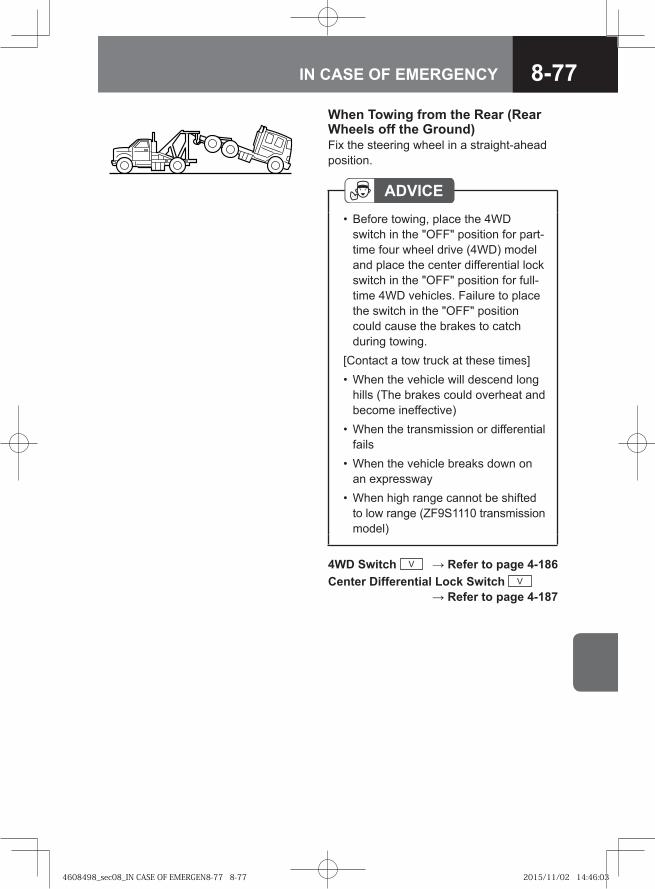
8-77IN CASE OF EMERGENCY
ADVICEBefore towing, place the 4WD switch in the "OFF" position for part-time four wheel drive (4WD) model and place the center differential lock switch in the "OFF" position for full-time 4WD vehicles. Failure to place the switch in the "OFF" position could cause the brakes to catch during towing.
[Contact a tow truck at these times]When the vehicle will descend long hills (The brakes could overheat and become ineffective)When the transmission or differential failsWhen the vehicle breaks down on an expresswayWhen high range cannot be shifted to low range (ZF9S1110 transmission model)
•
•
•
•
•
When Towing from the Rear (Rear Wheels off the Ground)Fix the steering wheel in a straight-ahead position.
4WD Switch V → Refer to page 4-186Center Differential Lock Switch V
→ Refer to page 4-187
4608498_sec08_IN CASE OF EMERGEN8-77 8-774608498_sec08_IN CASE OF EMERGEN8-77 8-77 2015/11/02 14:46:032015/11/02 14:46:03
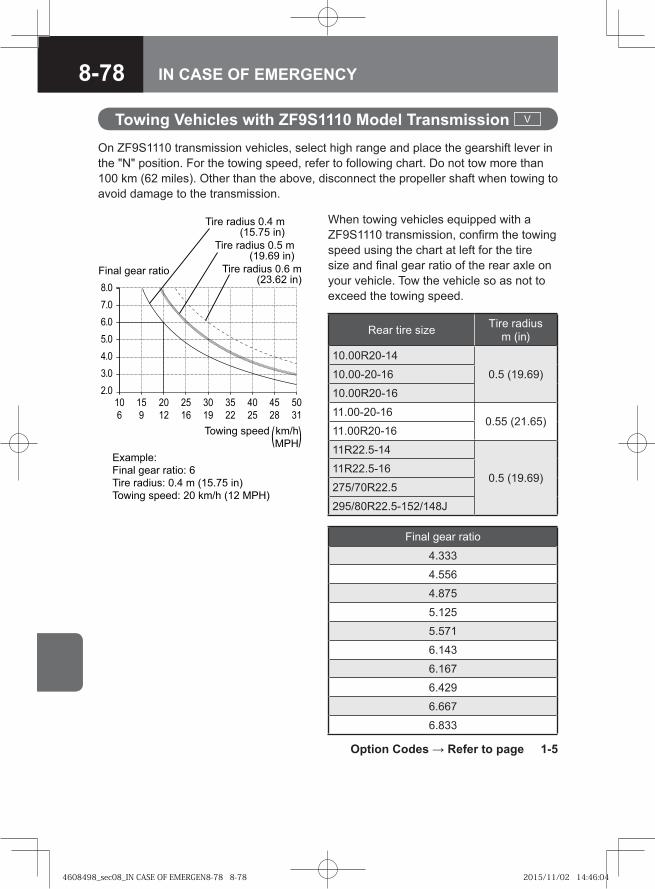
8-78 IN CASE OF EMERGENCY
Towing Vehicles with ZF9S1110 Model Transmission V
When towing vehicles equipped with a ZF9S1110 transmission, confirm the towing speed using the chart at left for the tire size and final gear ratio of the rear axle on your vehicle. Tow the vehicle so as not to exceed the towing speed.
Rear tire size Tire radius m (in)
10.00R20-14
0.5 (19.69)10.00-20-16
10.00R20-16
11.00-20-160.55 (21.65)
11.00R20-16
11R22.5-14
0.5 (19.69)11R22.5-16
275/70R22.5
295/80R22.5-152/148J
Final gear ratio
4.333
4.556
4.875
5.125
5.571
6.143
6.167
6.429
6.667
6.833
On ZF9S1110 transmission vehicles, select high range and place the gearshift lever in the "N" position. For the towing speed, refer to following chart. Do not tow more than 100 km (62 miles). Other than the above, disconnect the propeller shaft when towing to avoid damage to the transmission.
Option Codes → Refer to page 1-5
��� ���� ����
���
���
���
���
���
���
����
�
�
�
��
�
��
�
��
�
��
��
��
��
��
��
��
�
����� ��
��� ���� ����� �
�� ��!"#� ��� � $���� �%
�&�� #���!� �� '�() $� �*�%
�&�� #���! '�()
�*�
�� ��!"# ��� �$���� �%
�� ��!"# ��� �$����� �%
�� ��!"# ��� �$���� �%
4608498_sec08_IN CASE OF EMERGEN8-78 8-784608498_sec08_IN CASE OF EMERGEN8-78 8-78 2015/11/02 14:46:042015/11/02 14:46:04
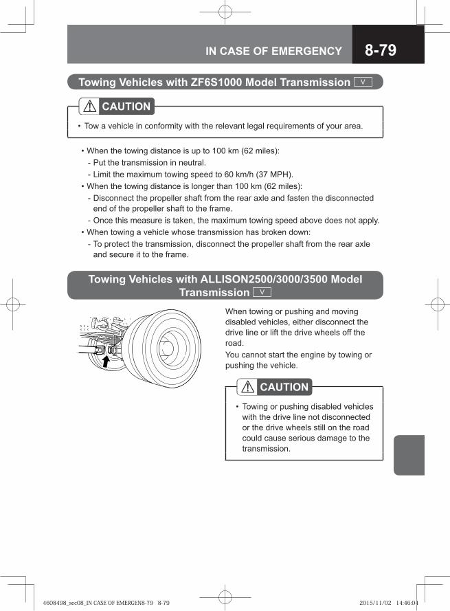
8-79IN CASE OF EMERGENCY
• When the towing distance is up to 100 km (62 miles): - Put the transmission in neutral. - Limit the maximum towing speed to 60 km/h (37 MPH). • When the towing distance is longer than 100 km (62 miles): - Disconnect the propeller shaft from the rear axle and fasten the disconnected
end of the propeller shaft to the frame. - Once this measure is taken, the maximum towing speed above does not apply. • When towing a vehicle whose transmission has broken down: - To protect the transmission, disconnect the propeller shaft from the rear axle
and secure it to the frame.
Towing Vehicles with ZF6S1000 Model Transmission V
CAUTIONTow a vehicle in conformity with the relevant legal requirements of your area.•
When towing or pushing and moving disabled vehicles, either disconnect the drive line or lift the drive wheels off the road. You cannot start the engine by towing or pushing the vehicle.
CAUTIONTowing or pushing disabled vehicles with the drive line not disconnected or the drive wheels still on the road could cause serious damage to the transmission.
•
Towing Vehicles with ALLISON2500/3000/3500 Model Transmission V
4608498_sec08_IN CASE OF EMERGEN8-79 8-794608498_sec08_IN CASE OF EMERGEN8-79 8-79 2015/11/02 14:46:042015/11/02 14:46:04
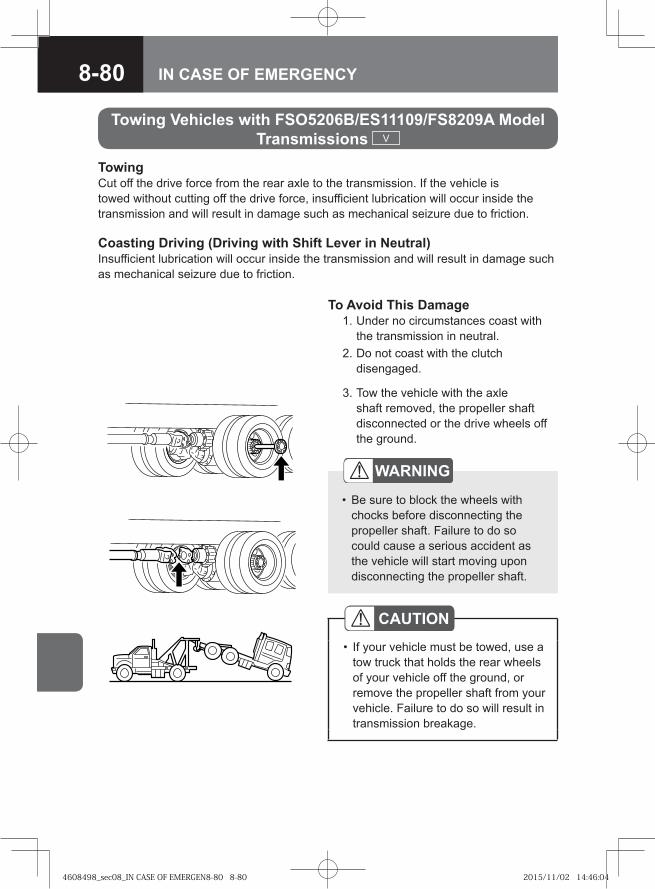
8-80 IN CASE OF EMERGENCY
To Avoid This Damage 1. Under no circumstances coast with
the transmission in neutral. 2. Do not coast with the clutch
disengaged.
WARNING
Be sure to block the wheels with chocks before disconnecting the propeller shaft. Failure to do so could cause a serious accident as the vehicle will start moving upon disconnecting the propeller shaft.
•
CAUTIONIf your vehicle must be towed, use a tow truck that holds the rear wheels of your vehicle off the ground, or remove the propeller shaft from your vehicle. Failure to do so will result in transmission breakage.
•
TowingCut off the drive force from the rear axle to the transmission. If the vehicle is towed without cutting off the drive force, insufficient lubrication will occur inside the transmission and will result in damage such as mechanical seizure due to friction.
Coasting Driving (Driving with Shift Lever in Neutral)Insufficient lubrication will occur inside the transmission and will result in damage such as mechanical seizure due to friction.
Towing Vehicles with FSO5206B/ES11109/FS8209A Model Transmissions V
3. Tow the vehicle with the axle shaft removed, the propeller shaft disconnected or the drive wheels off the ground.
4608498_sec08_IN CASE OF EMERGEN8-80 8-804608498_sec08_IN CASE OF EMERGEN8-80 8-80 2015/11/02 14:46:042015/11/02 14:46:04
● Main Data and Specifications 9-2
● Others 9-32
9MAIN DATA
4608498_sec09_MAIN DATA.indd 9-14608498_sec09_MAIN DATA.indd 9-1 2015/11/02 14:46:312015/11/02 14:46:31
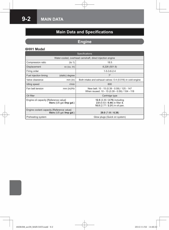
9-2 MAIN DATA
Engine
Main Data and Specifications
6HH1 ModelSpecifications
Water-cooled, overhead camshaft, direct injection engine
Compression ratio (to 1) 18.5
Displacement cc (cu. in) 8,226 (501.9)
Firing order 1-5-3-6-2-4
Fuel injection timing (static) degree 7°
Valve clearance mm (in) Both intake and exhaust valves: 0.4 (0.016) in cold engine
Idling speed r/min 600
Fan belt tension mm (in)/Hz New belt: 10 - 15 (0.39 - 0.59) / 125 - 147When reused: 10 - 15 (0.39 - 0.59) / 104 - 118
Oil filter Cartridge type
Engine oil capacity [Reference value] liters (US gal./Imp gal.)
12.5 (3.30 / 2.75) including 2.0 (0.53 / 0.44) in filter &
10.5 (2.77 / 2.31) in oil pan.
Engine coolant capacity [Reference value] liters (US gal./Imp gal.) 29.0 (7.66 / 6.38)
Preheating system Glow plugs (Quick on system)
4608498_sec09_MAIN DATA.indd 9-24608498_sec09_MAIN DATA.indd 9-2 2015/11/02 14:46:322015/11/02 14:46:32
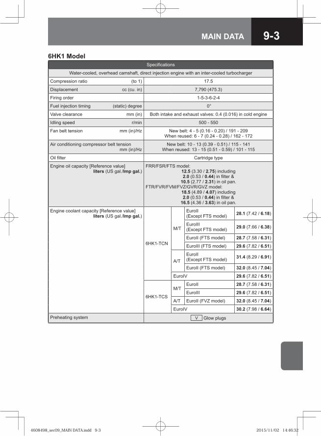
9-3MAIN DATA
6HK1 ModelSpecifications
Water-cooled, overhead camshaft, direct injection engine with an inter-cooled turbocharger
Compression ratio (to 1) 17.5
Displacement cc (cu. in) 7,790 (475.3)
Firing order 1-5-3-6-2-4
Fuel injection timing (static) degree 0°
Valve clearance mm (in) Both intake and exhaust valves: 0.4 (0.016) in cold engine
Idling speed r/min 500 - 550
Fan belt tension mm (in)/Hz New belt: 4 - 5 (0.16 - 0.20) / 191 - 209When reused: 6 - 7 (0.24 - 0.28) / 162 - 172
Air conditioning compressor belt tension mm (in)/Hz
New belt: 10 - 13 (0.39 - 0.51) / 115 - 141When reused: 13 - 15 (0.51 - 0.59) / 101 - 115
Oil filter Cartridge type
Engine oil capacity [Reference value] liters (US gal./Imp gal.)
FRR/FSR/FTS model: 12.5 (3.30 / 2.75) including 2.0 (0.53 / 0.44) in filter &
10.5 (2.77 / 2.31) in oil pan.FTR/FVR/FVM/FVZ/GVR/GVZ model:
18.5 (4.89 / 4.07) including 2.0 (0.53 / 0.44) in filter &
16.5 (4.36 / 3.63) in oil pan.
Engine coolant capacity [Reference value] liters (US gal./Imp gal.)
6HK1-TCN
M/T
EuroII (Except FTS model) 28.1 (7.42 / 6.18)
EuroIII (Except FTS model) 29.0 (7.66 / 6.38)
EuroII (FTS model) 28.7 (7.58 / 6.31)
EuroIII (FTS model) 29.6 (7.82 / 6.51)
A/TEuroII (Except FTS model) 31.4 (8.29 / 6.91)
EuroII (FTS model) 32.0 (8.45 / 7.04)
EuroIV 29.6 (7.82 / 6.51)
6HK1-TCS
M/TEuroII 28.7 (7.58 / 6.31)
EuroIII 29.6 (7.82 / 6.51)
A/T EuroII (FVZ model) 32.0 (8.45 / 7.04)
EuroIV 30.2 (7.98 / 6.64)
Preheating system V Glow plugs
4608498_sec09_MAIN DATA.indd 9-34608498_sec09_MAIN DATA.indd 9-3 2015/11/02 14:46:322015/11/02 14:46:32
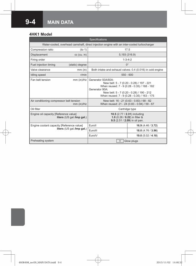
9-4 MAIN DATA
4HK1 ModelSpecifications
Water-cooled, overhead camshaft, direct injection engine with an inter-cooled turbocharger
Compression ratio (to 1) 17.5
Displacement cc (cu. in) 5,193 (316.9)
Firing order 1-3-4-2
Fuel injection timing (static) degree 0°
Valve clearance mm (in) Both intake and exhaust valves: 0.4 (0.016) in cold engine
Idling speed r/min 550 - 600
Fan belt tension mm (in)/Hz Generator 50A/60A: New belt: 5 - 7 (0.20 - 0.28) / 197 - 221
When reused: 7 - 9 (0.28 - 0.35) / 168 - 182Generator 90A:
New belt: 5 - 7 (0.20 - 0.28) / 190 - 212When reused: 7 - 9 (0.28 - 0.35) / 163 - 175
Air conditioning compressor belt tension mm (in)/Hz
New belt: 16 - 21 (0.63 - 0.83) / 68 - 82When reused: 21 - 24 (0.83 - 0.94) / 59 - 67
Oil filter Cartridge type
Engine oil capacity [Reference value] liters (US gal./Imp gal.)
10.5 (2.77 / 2.31) including 1.0 (0.26 / 0.22) in filter & 9.5 (2.51 / 2.09) in oil pan.
Engine coolant capacity [Reference value] liters (US gal./Imp gal.)
EuroII 16.9 (4.46 / 3.72)
EuroIII 18.0 (4.76 / 3.96)
EuroIV 19.0 (5.02 / 4.18)
Preheating system V Glow plugs
4608498_sec09_MAIN DATA.indd 9-44608498_sec09_MAIN DATA.indd 9-4 2015/11/02 14:46:322015/11/02 14:46:32
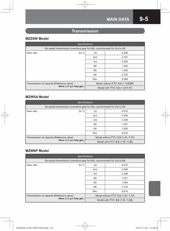
9-5MAIN DATA
MZW6P ModelSpecifications
Six-speed transmission (overdrive gear for 6th), synchromesh for 2nd to 6th
Gear ratio (to 1) 1st 6.615
2nd 4.095
3rd 2.358
4th 1.531
5th 1.000
6th 0.722
Rev. 6.615
Transmission oil capacity [Reference value] liters (US gal./Imp gal.)
Model without PTO: 5.3 (1.40 / 1.17)
Model with PTO: 6.0 (1.59 / 1.32)
Transmission
MZZ6W ModelSpecifications
Six-speed transmission (overdrive gear for 6th), synchromesh for 2nd to 6th
Gear ratio (to 1) 1st 6.369
2nd 3.767
3rd 2.385
4th 1.442
5th 1.000
6th 0.720
Rev. 6.369
Transmission oil capacity [Reference value] liters (US gal./Imp gal.)
Model without PTO: 4.4 (1.16/0.97)
Model with PTO: 5.3 (1.40/1.17)
MZW5A ModelSpecifications
Six-speed transmission (overdrive gear for 5th), synchromesh for 2nd to 5th
Gear ratio (to 1) 1st 6.615
2nd 4.095
3rd 2.358
4th 1.531
5th 1.000
Rev. 6.615
Transmission oil capacity [Reference value] liters (US gal./Imp gal.)
Model without PTO: 5.3 (1.40 / 1.17)
Model with PTO: 6.0 (1.59 / 1.32)
4608498_sec09_MAIN DATA.indd 9-54608498_sec09_MAIN DATA.indd 9-5 2015/11/02 14:46:322015/11/02 14:46:32
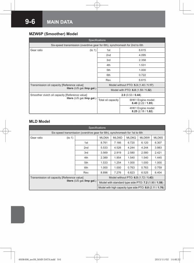
9-6 MAIN DATA
MLD ModelSpecifications
Six-speed transmission (overdrive gear for 6th), synchromesh for 1st to 6th
Gear ratio (to 1) MLD6A MLD6D MLD6Q MLD6W MLD6S
1st 8.761 7.166 6.720 6.120 6.307
2nd 5.533 4.526 4.244 4.244 3.983
3rd 3.569 2.919 2.580 2.580 2.421
4th 2.389 1.954 1.540 1.540 1.445
5th 1.533 1.254 1.000 1.000 1.000
6th 1.000 1.000 0.763 0.763 0.759
Rev. 8.896 7.276 6.823 6.525 6.404
Transmission oil capacity [Reference value] liters (US gal./Imp gal.)
Model without PTO: 6.5 (1.72 / 1.43)
Model with standard type side PTO: 7.2 (1.90 / 1.58)
Model with high capacity type side PTO: 8.0 (2.11 / 1.76)
MZW6P (Smoother) ModelSpecifications
Six-speed transmission (overdrive gear for 6th), synchromesh for 2nd to 6th
Gear ratio (to 1) 1st 6.615
2nd 4.095
3rd 2.358
4th 1.531
5th 1.000
6th 0.722
Rev. 6.615
Transmission oil capacity [Reference value] liters (US gal./Imp gal.)
Model without PTO: 5.3 (1.40 / 1.17)
Model with PTO: 6.0 (1.59 / 1.32)
Smoother clutch oil capacity [Reference value] liters (US gal./Imp gal.)
2.0 (0.53 / 0.44)
Total oil capacity 6HK1 Engine model: 8.40 (2.22 / 1.85)
4HK1 Engine model: 8.25 (2.18 / 1.82)
4608498_sec09_MAIN DATA.indd 9-64608498_sec09_MAIN DATA.indd 9-6 2015/11/02 14:46:322015/11/02 14:46:32
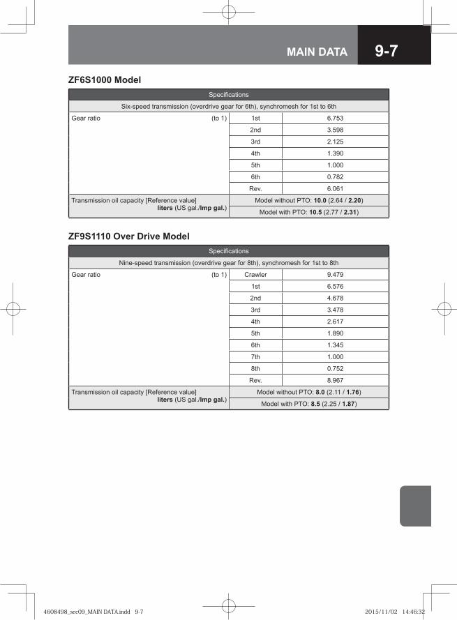
9-7MAIN DATA
ZF6S1000 ModelSpecifications
Six-speed transmission (overdrive gear for 6th), synchromesh for 1st to 6th
Gear ratio (to 1) 1st 6.753
2nd 3.598
3rd 2.125
4th 1.390
5th 1.000
6th 0.782
Rev. 6.061
Transmission oil capacity [Reference value] liters (US gal./Imp gal.)
Model without PTO: 10.0 (2.64 / 2.20)
Model with PTO: 10.5 (2.77 / 2.31)
ZF9S1110 Over Drive ModelSpecifications
Nine-speed transmission (overdrive gear for 8th), synchromesh for 1st to 8th
Gear ratio (to 1) Crawler 9.479
1st 6.576
2nd 4.678
3rd 3.478
4th 2.617
5th 1.890
6th 1.345
7th 1.000
8th 0.752
Rev. 8.967
Transmission oil capacity [Reference value] liters (US gal./Imp gal.)
Model without PTO: 8.0 (2.11 / 1.76)
Model with PTO: 8.5 (2.25 / 1.87)
4608498_sec09_MAIN DATA.indd 9-74608498_sec09_MAIN DATA.indd 9-7 2015/11/02 14:46:322015/11/02 14:46:32
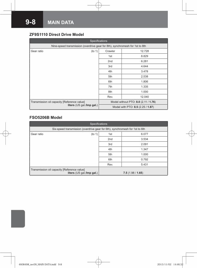
9-8 MAIN DATA
ZF9S1110 Direct Drive ModelSpecifications
Nine-speed transmission (overdrive gear for 8th), synchromesh for 1st to 8th
Gear ratio (to 1) Crawler 12.728
1st 8.829
2nd 6.281
3rd 4.644
4th 3.478
5th 2.538
6th 1.806
7th 1.335
8th 1.000
Rev. 12.040
Transmission oil capacity [Reference value] liters (US gal./Imp gal.)
Model without PTO: 8.0 (2.11 / 1.76)
Model with PTO: 8.5 (2.25 / 1.87)
FSO5206B ModelSpecifications
Six-speed transmission (overdrive gear for 6th), synchromesh for 1st to 6th
Gear ratio (to 1) 1st 6.077
2nd 3.534
3rd 2.091
4th 1.347
5th 1.000
6th 0.792
Rev. 5.431
Transmission oil capacity [Reference value] liters (US gal./Imp gal.) 7.5 (1.98 / 1.65)
4608498_sec09_MAIN DATA.indd 9-84608498_sec09_MAIN DATA.indd 9-8 2015/11/02 14:46:322015/11/02 14:46:32
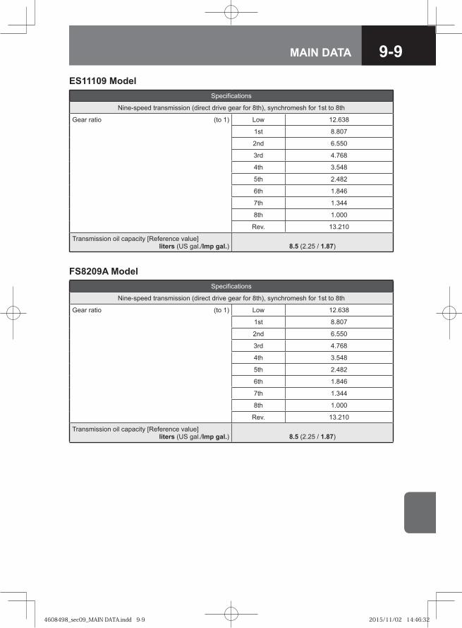
9-9MAIN DATA
FS8209A ModelSpecifications
Nine-speed transmission (direct drive gear for 8th), synchromesh for 1st to 8th
Gear ratio (to 1) Low 12.638
1st 8.807
2nd 6.550
3rd 4.768
4th 3.548
5th 2.482
6th 1.846
7th 1.344
8th 1.000
Rev. 13.210
Transmission oil capacity [Reference value] liters (US gal./Imp gal.) 8.5 (2.25 / 1.87)
ES11109 ModelSpecifications
Nine-speed transmission (direct drive gear for 8th), synchromesh for 1st to 8th
Gear ratio (to 1) Low 12.638
1st 8.807
2nd 6.550
3rd 4.768
4th 3.548
5th 2.482
6th 1.846
7th 1.344
8th 1.000
Rev. 13.210
Transmission oil capacity [Reference value] liters (US gal./Imp gal.) 8.5 (2.25 / 1.87)
4608498_sec09_MAIN DATA.indd 9-94608498_sec09_MAIN DATA.indd 9-9 2015/11/02 14:46:322015/11/02 14:46:32
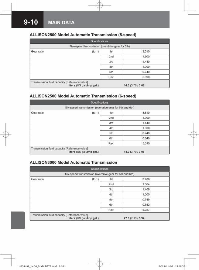
9-10 MAIN DATA
ALLISON2500 Model Automatic Transmission (5-speed)Specifications
Five-speed transmission (overdrive gear for 5th)
Gear ratio (to 1) 1st 3.510
2nd 1.900
3rd 1.440
4th 1.000
5th 0.740
Rev. 5.090
Transmission fluid capacity [Reference value] liters (US gal./Imp gal.) 14.0 (3.70 / 3.08)
ALLISON3000 Model Automatic TransmissionSpecifications
Six-speed transmission (overdrive gear for 5th and 6th)
Gear ratio (to 1) 1st 3.486
2nd 1.864
3rd 1.409
4th 1.000
5th 0.749
6th 0.652
Rev. 5.027
Transmission fluid capacity [Reference value] liters (US gal./Imp gal.) 27.0 (7.13 / 5.94)
ALLISON2500 Model Automatic Transmission (6-speed)Specifications
Six-speed transmission (overdrive gear for 5th and 6th)
Gear ratio (to 1) 1st 3.510
2nd 1.900
3rd 1.440
4th 1.000
5th 0.740
6th 0.640
Rev. 5.090
Transmission fluid capacity [Reference value] liters (US gal./Imp gal.) 14.0 (3.70 / 3.08)
4608498_sec09_MAIN DATA.indd 9-104608498_sec09_MAIN DATA.indd 9-10 2015/11/02 14:46:322015/11/02 14:46:32
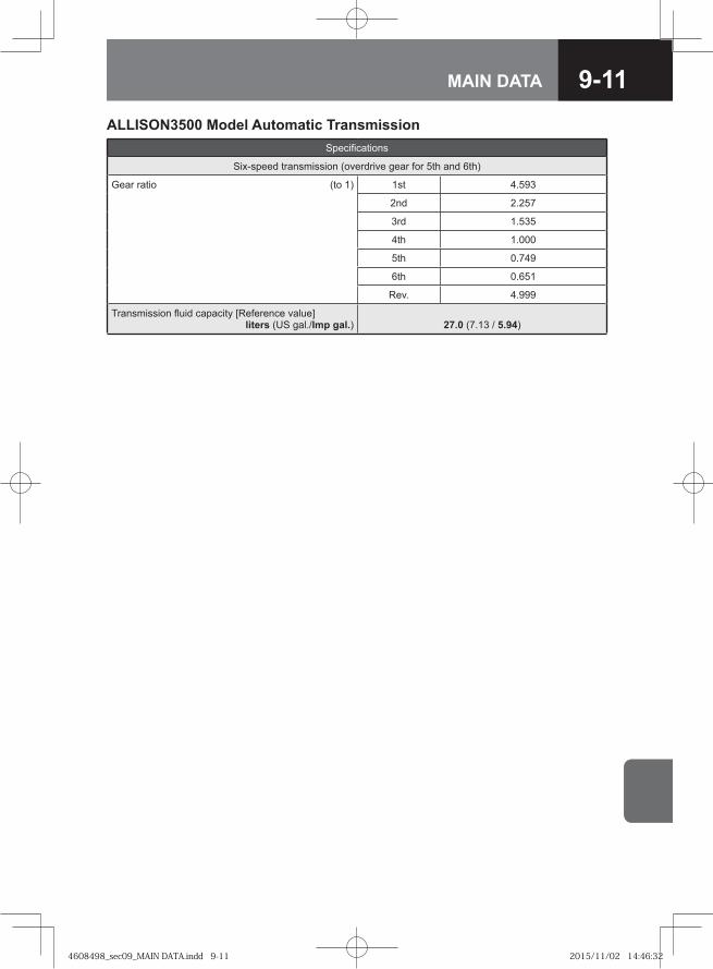
9-11MAIN DATA
ALLISON3500 Model Automatic TransmissionSpecifications
Six-speed transmission (overdrive gear for 5th and 6th)
Gear ratio (to 1) 1st 4.593
2nd 2.257
3rd 1.535
4th 1.000
5th 0.749
6th 0.651
Rev. 4.999
Transmission fluid capacity [Reference value] liters (US gal./Imp gal.) 27.0 (7.13 / 5.94)
4608498_sec09_MAIN DATA.indd 9-114608498_sec09_MAIN DATA.indd 9-11 2015/11/02 14:46:322015/11/02 14:46:32
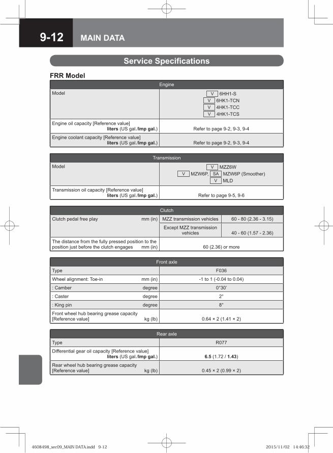
9-12 MAIN DATA
Service Specifications
FRR ModelEngine
Model V 6HH1-SV 6HK1-TCNV 4HK1-TCCV 4HK1-TCS
Engine oil capacity [Reference value] liters (US gal./Imp gal.) Refer to page 9-2, 9-3, 9-4
Engine coolant capacity [Reference value] liters (US gal./Imp gal.) Refer to page 9-2, 9-3, 9-4
Transmission
Model V MZZ6WV MZW6P, SA MZW6P (Smoother)
V MLD
Transmission oil capacity [Reference value] liters (US gal./Imp gal.) Refer to page 9-5, 9-6
Clutch
Clutch pedal free play mm (in) MZZ transmission vehicles 60 - 80 (2.36 - 3.15)
Except MZZ transmission vehicles 40 - 60 (1.57 - 2.36)
The distance from the fully pressed position to the position just before the clutch engages mm (in) 60 (2.36) or more
Front axle
Type F036
Wheel alignment: Toe-in mm (in) -1 to 1 (-0.04 to 0.04)
: Camber degree 0°30’
: Caster degree 2°
: King pin degree 8°
Front wheel hub bearing grease capacity [Reference value] kg (lb) 0.64 × 2 (1.41 × 2)
Rear axle
Type R077
Differential gear oil capacity [Reference value] liters (US gal./Imp gal.) 6.5 (1.72 / 1.43)
Rear wheel hub bearing grease capacity [Reference value] kg (lb) 0.45 × 2 (0.99 × 2)
4608498_sec09_MAIN DATA.indd 9-124608498_sec09_MAIN DATA.indd 9-12 2015/11/02 14:46:322015/11/02 14:46:32

9-13MAIN DATA
Steering
Steering wheel free play mm (in) 10 - 60 (0.39 - 2.36)
Power steering fluid capacity [Reference value] liters (US gal./Imp gal.) 3.0 (0.79 / 0.66)
Service brakes
Type Air over hydraulic, dual circuit
Brake pedal free play mm (in) 10 - 18 (0.39 - 0.71)
Parking brake
Type V Mechanical internal expanding at rear of transmission
V Spring actuator at rear wheels
Brake lever travel (Model with center parking brake) notches
Under pull force of approx. 294N (30.0kgf / 66lb) :3 - 8
Fuel
Fuel tank capacity [Reference value] liters (US gal./Imp gal.)
V 200 (52.8 / 44.0)V 100 (26.4 / 22.0)
Electrical system
Battery type V 65D23L, V 80D26L, V 115E41L
Generator volt/amp. V 24 / 50, V 24 / 60, V 24 / 90
4608498_sec09_MAIN DATA.indd 9-134608498_sec09_MAIN DATA.indd 9-13 2015/11/02 14:46:332015/11/02 14:46:33
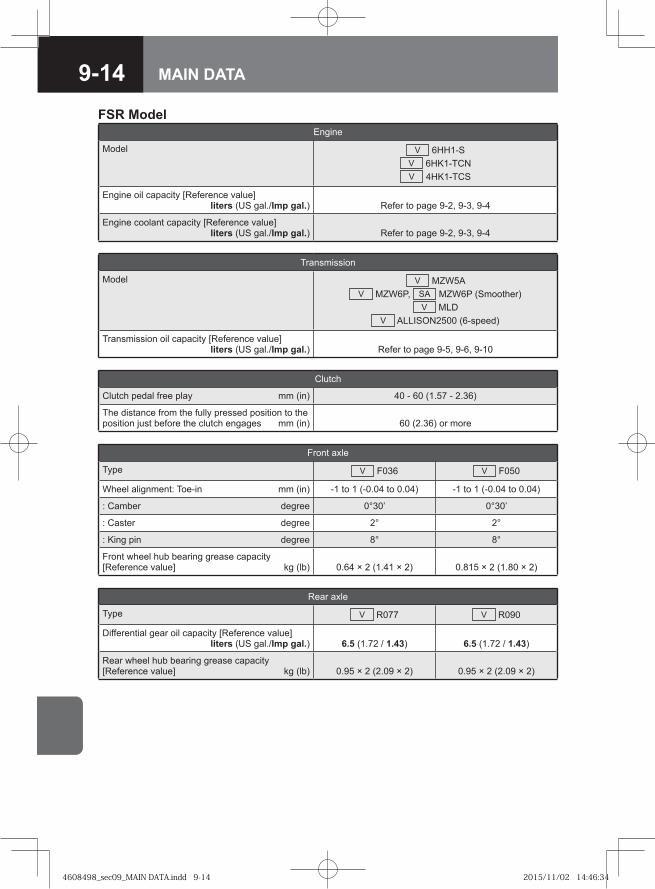
9-14 MAIN DATA
FSR ModelEngine
Model V 6HH1-SV 6HK1-TCNV 4HK1-TCS
Engine oil capacity [Reference value] liters (US gal./Imp gal.) Refer to page 9-2, 9-3, 9-4
Engine coolant capacity [Reference value] liters (US gal./Imp gal.) Refer to page 9-2, 9-3, 9-4
Transmission
Model V MZW5AV MZW6P, SA MZW6P (Smoother)
V MLDV ALLISON2500 (6-speed)
Transmission oil capacity [Reference value] liters (US gal./Imp gal.) Refer to page 9-5, 9-6, 9-10
Clutch
Clutch pedal free play mm (in) 40 - 60 (1.57 - 2.36)
The distance from the fully pressed position to the position just before the clutch engages mm (in) 60 (2.36) or more
Front axle
Type V F036 V F050
Wheel alignment: Toe-in mm (in) -1 to 1 (-0.04 to 0.04) -1 to 1 (-0.04 to 0.04)
: Camber degree 0°30’ 0°30’
: Caster degree 2° 2°
: King pin degree 8° 8°
Front wheel hub bearing grease capacity [Reference value] kg (lb) 0.64 × 2 (1.41 × 2) 0.815 × 2 (1.80 × 2)
Rear axle
Type V R077 V R090
Differential gear oil capacity [Reference value] liters (US gal./Imp gal.) 6.5 (1.72 / 1.43) 6.5 (1.72 / 1.43)
Rear wheel hub bearing grease capacity [Reference value] kg (lb) 0.95 × 2 (2.09 × 2) 0.95 × 2 (2.09 × 2)
4608498_sec09_MAIN DATA.indd 9-144608498_sec09_MAIN DATA.indd 9-14 2015/11/02 14:46:342015/11/02 14:46:34
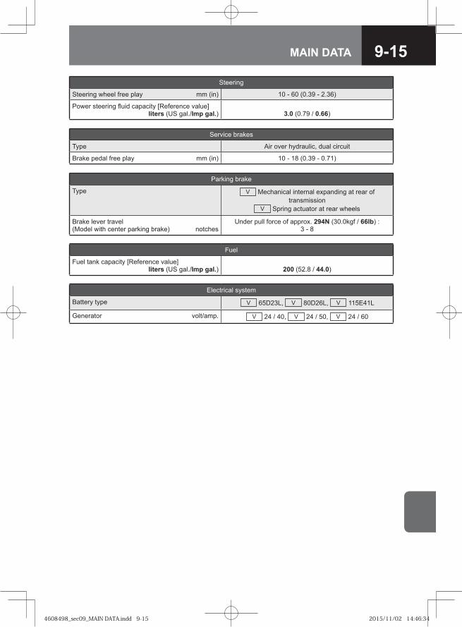
9-15MAIN DATA
Steering
Steering wheel free play mm (in) 10 - 60 (0.39 - 2.36)
Power steering fluid capacity [Reference value] liters (US gal./Imp gal.) 3.0 (0.79 / 0.66)
Service brakes
Type Air over hydraulic, dual circuit
Brake pedal free play mm (in) 10 - 18 (0.39 - 0.71)
Parking brake
Type V Mechanical internal expanding at rear of transmission
V Spring actuator at rear wheels
Brake lever travel (Model with center parking brake) notches
Under pull force of approx. 294N (30.0kgf / 66lb) :3 - 8
Fuel
Fuel tank capacity [Reference value] liters (US gal./Imp gal.) 200 (52.8 / 44.0)
Electrical system
Battery type V 65D23L, V 80D26L, V 115E41L
Generator volt/amp. V 24 / 40, V 24 / 50, V 24 / 60
4608498_sec09_MAIN DATA.indd 9-154608498_sec09_MAIN DATA.indd 9-15 2015/11/02 14:46:342015/11/02 14:46:34

9-16 MAIN DATA
FTR ModelEngine
Model V 6HK1-TCNV 4HK1-TCS
Engine oil capacity [Reference value] liters (US gal./Imp gal.) Refer to page 9-3, 9-4
Engine coolant capacity [Reference value] liters (US gal./Imp gal.) Refer to page 9-3, 9-4
Transmission
Model V MZW6P, SA MZW6P (Smoother)V MLD
Transmission oil capacity [Reference value] liters (US gal./Imp gal.) Refer to page 9-5, 9-6
Clutch
Clutch pedal free play mm (in) 40 - 60 (1.57 - 2.36)
The distance from the fully pressed position to the position just before the clutch engages mm (in) 60 (2.36) or more
Front axle
Type F063
Wheel alignment: Toe-in mm (in) -1 to 1 (-0.04 to 0.04)
: Camber degree 0°30’
: Caster degree 2°
: King pin degree 7°30’
Front wheel hub bearing grease capacity [Reference value] kg (lb)
JIS 8-bolt wheels: 0.505 × 2 (1.11 × 2)ISO 10-bolt wheels: 0.345 × 2 (0.76 × 2)
Rear axle
Type R092
Differential gear oil capacity [Reference value] liters (US gal./Imp gal.) 9.0 (2.38 / 1.98)
Rear wheel hub bearing grease capacity [Reference value] kg (lb)
JIS 8-bolt wheels: 1.015 × 2 (2.238 × 2)ISO 10-bolt wheels: 1.820 × 2 (4.013 × 2)
4608498_sec09_MAIN DATA.indd 9-164608498_sec09_MAIN DATA.indd 9-16 2015/11/02 14:46:352015/11/02 14:46:35

9-17MAIN DATA
Steering
Steering wheel free play mm (in) 10 - 60 (0.39 - 2.36)
Power steering fluid capacity [Reference value] liters (US gal./Imp gal.) 3.0 (0.79 / 0.66)
Service brakes
Type V Air over hydraulic, dual circuitV Full air dual circuit
Brake pedal free play mm (in) 10 - 18 (0.39 - 0.71)
Parking brake
Type V Mechanical internal expanding at rear of transmission
V Spring actuator at rear wheels
Brake lever travel (Model with center parking brake) notches
Under pull force of approx. 294N (30.0kgf / 66lb) :3 - 8
Fuel
Fuel tank capacity [Reference value] liters (US gal./Imp gal.)
V 200 (52.8 / 44.0)V 200 (52.8 / 44.0) + 200 (52.8 / 44.0)
Electrical system
Battery type V 65D23L, V 80D26L, V 115E41L
Generator volt/amp. V 24 / 50, V 24 / 60, V 24 / 90
4608498_sec09_MAIN DATA.indd 9-174608498_sec09_MAIN DATA.indd 9-17 2015/11/02 14:46:352015/11/02 14:46:35
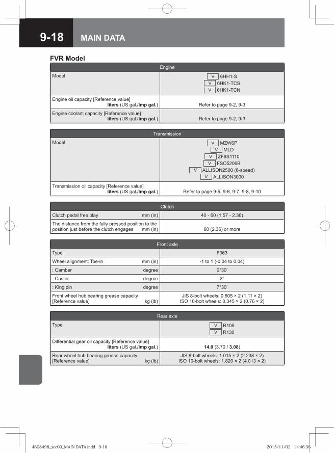
9-18 MAIN DATA
FVR ModelEngine
Model V 6HH1-SV 6HK1-TCSV 6HK1-TCN
Engine oil capacity [Reference value] liters (US gal./Imp gal.) Refer to page 9-2, 9-3
Engine coolant capacity [Reference value] liters (US gal./Imp gal.) Refer to page 9-2, 9-3
Transmission
Model V MZW6PV MLD
V ZF9S1110V FSO5206B
V ALLISON2500 (6-speed)V ALLISON3000
Transmission oil capacity [Reference value] liters (US gal./Imp gal.) Refer to page 9-5, 9-6, 9-7, 9-8, 9-10
Clutch
Clutch pedal free play mm (in) 40 - 60 (1.57 - 2.36)
The distance from the fully pressed position to the position just before the clutch engages mm (in) 60 (2.36) or more
Front axle
Type F063
Wheel alignment: Toe-in mm (in) -1 to 1 (-0.04 to 0.04)
: Camber degree 0°30’
: Caster degree 2°
: King pin degree 7°30’
Front wheel hub bearing grease capacity [Reference value] kg (lb)
JIS 8-bolt wheels: 0.505 × 2 (1.11 × 2)ISO 10-bolt wheels: 0.345 × 2 (0.76 × 2)
Rear axle
Type V R105V R130
Differential gear oil capacity [Reference value] liters (US gal./Imp gal.) 14.0 (3.70 / 3.08)
Rear wheel hub bearing grease capacity [Reference value] kg (lb)
JIS 8-bolt wheels: 1.015 × 2 (2.238 × 2)ISO 10-bolt wheels: 1.820 × 2 (4.013 × 2)
4608498_sec09_MAIN DATA.indd 9-184608498_sec09_MAIN DATA.indd 9-18 2015/11/02 14:46:362015/11/02 14:46:36
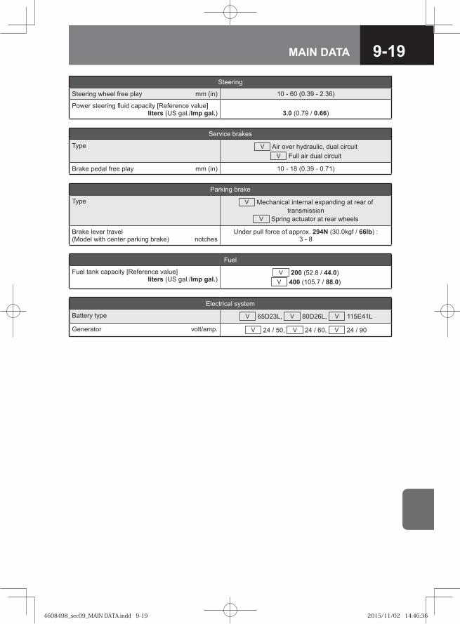
9-19MAIN DATA
Steering
Steering wheel free play mm (in) 10 - 60 (0.39 - 2.36)
Power steering fluid capacity [Reference value] liters (US gal./Imp gal.) 3.0 (0.79 / 0.66)
Service brakes
Type V Air over hydraulic, dual circuitV Full air dual circuit
Brake pedal free play mm (in) 10 - 18 (0.39 - 0.71)
Parking brake
Type V Mechanical internal expanding at rear of transmission
V Spring actuator at rear wheels
Brake lever travel (Model with center parking brake) notches
Under pull force of approx. 294N (30.0kgf / 66lb) :3 - 8
Fuel
Fuel tank capacity [Reference value] liters (US gal./Imp gal.)
V 200 (52.8 / 44.0)V 400 (105.7 / 88.0)
Electrical system
Battery type V 65D23L, V 80D26L, V 115E41L
Generator volt/amp. V 24 / 50, V 24 / 60, V 24 / 90
4608498_sec09_MAIN DATA.indd 9-194608498_sec09_MAIN DATA.indd 9-19 2015/11/02 14:46:362015/11/02 14:46:36
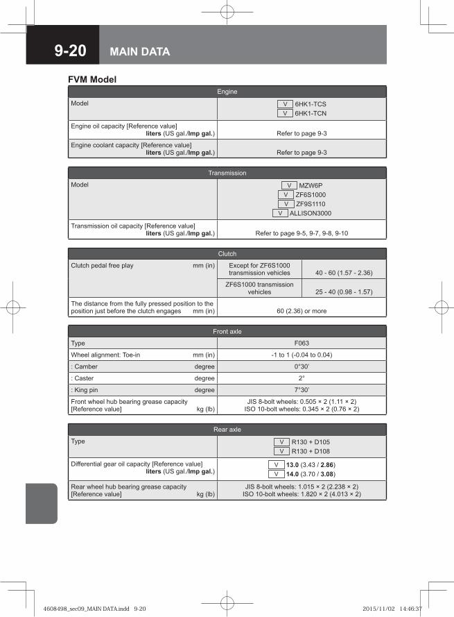
9-20 MAIN DATA
FVM ModelEngine
Model V 6HK1-TCSV 6HK1-TCN
Engine oil capacity [Reference value] liters (US gal./Imp gal.) Refer to page 9-3
Engine coolant capacity [Reference value] liters (US gal./Imp gal.) Refer to page 9-3
Transmission
Model V MZW6PV ZF6S1000V ZF9S1110
V ALLISON3000
Transmission oil capacity [Reference value] liters (US gal./Imp gal.) Refer to page 9-5, 9-7, 9-8, 9-10
Clutch
Clutch pedal free play mm (in) Except for ZF6S1000 transmission vehicles 40 - 60 (1.57 - 2.36)
ZF6S1000 transmission vehicles 25 - 40 (0.98 - 1.57)
The distance from the fully pressed position to the position just before the clutch engages mm (in) 60 (2.36) or more
Front axle
Type F063
Wheel alignment: Toe-in mm (in) -1 to 1 (-0.04 to 0.04)
: Camber degree 0°30’
: Caster degree 2°
: King pin degree 7°30’
Front wheel hub bearing grease capacity [Reference value] kg (lb)
JIS 8-bolt wheels: 0.505 × 2 (1.11 × 2)ISO 10-bolt wheels: 0.345 × 2 (0.76 × 2)
Rear axle
Type V R130 + D105V R130 + D108
Differential gear oil capacity [Reference value] liters (US gal./Imp gal.)
V 13.0 (3.43 / 2.86)V 14.0 (3.70 / 3.08)
Rear wheel hub bearing grease capacity [Reference value] kg (lb)
JIS 8-bolt wheels: 1.015 × 2 (2.238 × 2)ISO 10-bolt wheels: 1.820 × 2 (4.013 × 2)
4608498_sec09_MAIN DATA.indd 9-204608498_sec09_MAIN DATA.indd 9-20 2015/11/02 14:46:372015/11/02 14:46:37

9-21MAIN DATA
Steering
Steering wheel free play mm (in) 10 - 60 (0.39 - 2.36)
Power steering fluid capacity [Reference value] liters (US gal./Imp gal.) 3.0 (0.79 / 0.66)
Service brakes
Type V Air over hydraulic, dual circuitV Full air dual circuit
Brake pedal free play mm (in) 10 - 18 (0.39 - 0.71)
Parking brake
Type V Mechanical internal expanding at rear of transmission
V Spring actuator at rear wheels
Brake lever travel (Model with center parking brake) notches
Under pull force of approx. 294N (30.0kgf / 66lb) :3 - 8
Fuel
Fuel tank capacity [Reference value] liters (US gal./Imp gal.)
V 200 (52.8 / 44.0)V 370 (97.8 / 81.4)
V 400 (105.7 / 88.0)
Electrical system
Battery type V 65D23L, V 80D26L, V 115E41L
Generator volt/amp. V 24 / 50, V 24 / 60
4608498_sec09_MAIN DATA.indd 9-214608498_sec09_MAIN DATA.indd 9-21 2015/11/02 14:46:382015/11/02 14:46:38
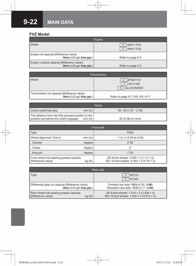
9-22 MAIN DATA
FVZ ModelEngine
Model V 6HK1-TCSV 6HK1-TCN
Engine oil capacity [Reference value] liters (US gal./Imp gal.) Refer to page 9-3
Engine coolant capacity [Reference value] liters (US gal./Imp gal.) Refer to page 9-3
Transmission
Model V ZF9S1110V ES11109
V ALLISON3500
Transmission oil capacity [Reference value] liters (US gal./Imp gal.) Refer to page 9-7, 9-8, 9-9, 9-11
Clutch
Clutch pedal free play mm (in) 40 - 60 (1.57 - 2.36)
The distance from the fully pressed position to the position just before the clutch engages mm (in) 60 (2.36) or more
Front axle
Type F063
Wheel alignment: Toe-in mm (in) -1 to 1 (-0.04 to 0.04)
: Camber degree 0°30’
: Caster degree 2°
: King pin degree 7°30’
Front wheel hub bearing grease capacity [Reference value] kg (lb)
JIS 8-bolt wheels: 0.505 × 2 (1.11 × 2)ISO 10-bolt wheels: 0.345 × 2 (0.76 × 2)
Rear axle
Type V RT210V RT250
Differential gear oil capacity [Reference value] liters (US gal./Imp gal.)
Forward rear axle: 18.0 (4.76 / 3.96)Rearward rear axle: 12.0 (3.17 / 2.64)
Rear wheel hub bearing grease capacity [Reference value] kg (lb)
JIS 8-bolt wheels: 1.015 × 2 (2.238 × 2)ISO 10-bolt wheels: 1.820 × 2 (4.013 × 2)
4608498_sec09_MAIN DATA.indd 9-224608498_sec09_MAIN DATA.indd 9-22 2015/11/02 14:46:392015/11/02 14:46:39

9-23MAIN DATA
Steering
Steering wheel free play mm (in) 10 - 60 (0.39 - 2.36)
Power steering fluid capacity [Reference value] liters (US gal./Imp gal.) 3.0 (0.79 / 0.66)
Service brakes
Type V Air over hydraulic, dual circuitV Full air dual circuit
Brake pedal free play mm (in) 10 - 18 (0.39 - 0.71)
Parking brake
Type V Mechanical internal expanding at rear of transmission
V Spring actuator at rear wheels
Brake lever travel (Model with center parking brake) notches
Under pull force of approx. 294N (30.0kgf / 66lb) :3 - 8
Fuel
Fuel tank capacity [Reference value] liters (US gal./Imp gal.)
V 200 (52.8 / 44.0)V 370 (97.8 / 81.4)
Electrical system
Battery type V 65D23L, V 80D26L, V 115E41L
Generator volt/amp. V 24 / 50, V 24 / 60
4608498_sec09_MAIN DATA.indd 9-234608498_sec09_MAIN DATA.indd 9-23 2015/11/02 14:46:392015/11/02 14:46:39
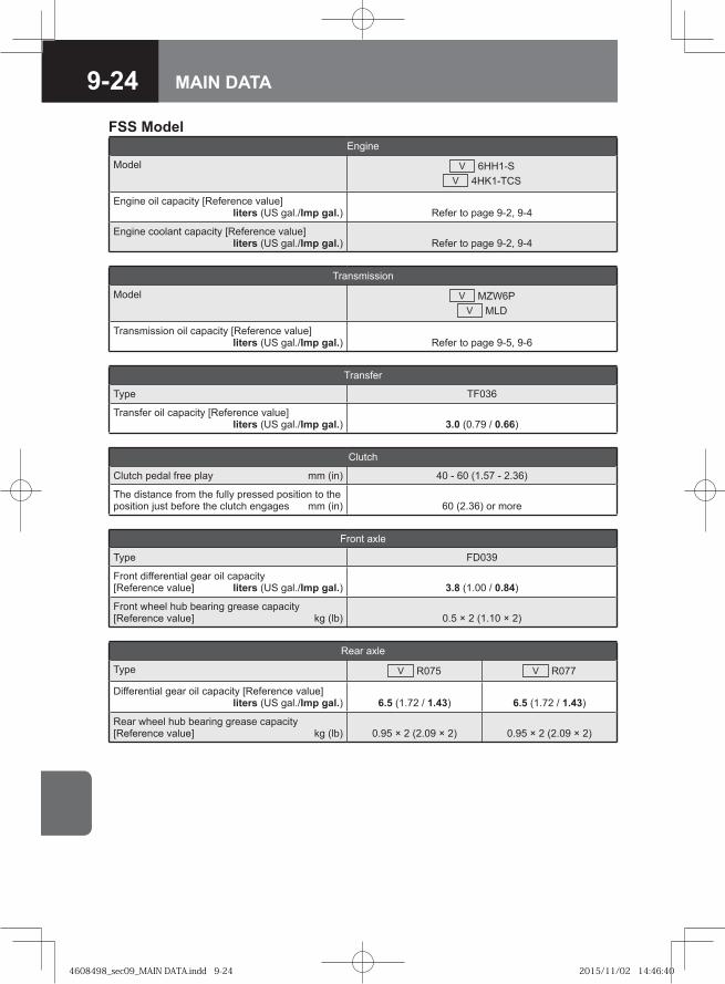
9-24 MAIN DATA
FSS ModelEngine
Model V 6HH1-SV 4HK1-TCS
Engine oil capacity [Reference value] liters (US gal./Imp gal.) Refer to page 9-2, 9-4
Engine coolant capacity [Reference value] liters (US gal./Imp gal.) Refer to page 9-2, 9-4
Transmission
Model V MZW6PV MLD
Transmission oil capacity [Reference value] liters (US gal./Imp gal.) Refer to page 9-5, 9-6
Transfer
Type TF036
Transfer oil capacity [Reference value] liters (US gal./Imp gal.) 3.0 (0.79 / 0.66)
Clutch
Clutch pedal free play mm (in) 40 - 60 (1.57 - 2.36)
The distance from the fully pressed position to the position just before the clutch engages mm (in) 60 (2.36) or more
Front axle
Type FD039
Front differential gear oil capacity [Reference value] liters (US gal./Imp gal.) 3.8 (1.00 / 0.84)
Front wheel hub bearing grease capacity [Reference value] kg (lb) 0.5 × 2 (1.10 × 2)
Rear axle
Type V R075 V R077
Differential gear oil capacity [Reference value] liters (US gal./Imp gal.) 6.5 (1.72 / 1.43) 6.5 (1.72 / 1.43)
Rear wheel hub bearing grease capacity [Reference value] kg (lb) 0.95 × 2 (2.09 × 2) 0.95 × 2 (2.09 × 2)
4608498_sec09_MAIN DATA.indd 9-244608498_sec09_MAIN DATA.indd 9-24 2015/11/02 14:46:402015/11/02 14:46:40

9-25MAIN DATA
Steering
Steering wheel free play mm (in) 10 - 60 (0.39 - 2.36)
Power steering fluid capacity [Reference value] liters (US gal./Imp gal.) 3.0 (0.79 / 0.66)
Service brakes
Type Air over hydraulic, dual circuit
Brake pedal free play mm (in) 10 - 18 (0.39 - 0.71)
Parking brake
Type V Mechanical internal expanding at rear of transfer gear case
V Spring actuator at rear wheels
Brake lever travel (Model with center parking brake) notches
Under pull force of approx. 294N (30.0kgf / 66lb) :3 - 8
Fuel
Fuel tank capacity [Reference value] liters (US gal./Imp gal.)
V 140 (37.0 / 30.8)V 200 (52.8 / 44.0)
Electrical system
Battery type V 65D23L, V 80D26L, V 115E41L
Generator volt/amp. V 24 / 50, V 24 / 60
4608498_sec09_MAIN DATA.indd 9-254608498_sec09_MAIN DATA.indd 9-25 2015/11/02 14:46:402015/11/02 14:46:40
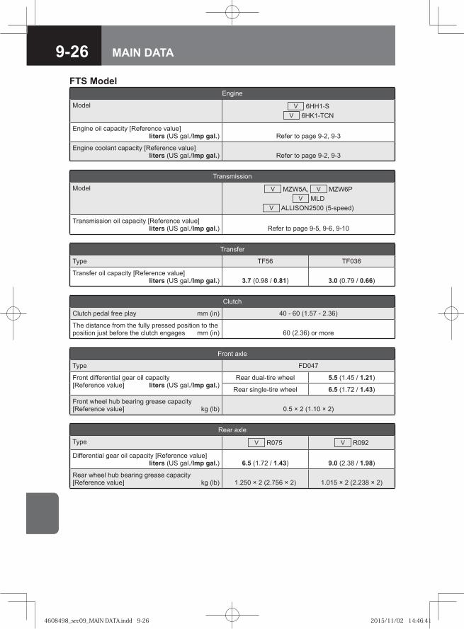
9-26 MAIN DATA
FTS ModelEngine
Model V 6HH1-SV 6HK1-TCN
Engine oil capacity [Reference value] liters (US gal./Imp gal.) Refer to page 9-2, 9-3
Engine coolant capacity [Reference value] liters (US gal./Imp gal.) Refer to page 9-2, 9-3
Transmission
Model V MZW5A, V MZW6PV MLD
V ALLISON2500 (5-speed)
Transmission oil capacity [Reference value] liters (US gal./Imp gal.) Refer to page 9-5, 9-6, 9-10
Transfer
Type TF56 TF036
Transfer oil capacity [Reference value] liters (US gal./Imp gal.) 3.7 (0.98 / 0.81) 3.0 (0.79 / 0.66)
Clutch
Clutch pedal free play mm (in) 40 - 60 (1.57 - 2.36)
The distance from the fully pressed position to the position just before the clutch engages mm (in) 60 (2.36) or more
Front axle
Type FD047
Front differential gear oil capacity [Reference value] liters (US gal./Imp gal.)
Rear dual-tire wheel 5.5 (1.45 / 1.21)
Rear single-tire wheel 6.5 (1.72 / 1.43)
Front wheel hub bearing grease capacity [Reference value] kg (lb) 0.5 × 2 (1.10 × 2)
Rear axle
Type V R075 V R092
Differential gear oil capacity [Reference value] liters (US gal./Imp gal.) 6.5 (1.72 / 1.43) 9.0 (2.38 / 1.98)
Rear wheel hub bearing grease capacity [Reference value] kg (lb) 1.250 × 2 (2.756 × 2) 1.015 × 2 (2.238 × 2)
4608498_sec09_MAIN DATA.indd 9-264608498_sec09_MAIN DATA.indd 9-26 2015/11/02 14:46:412015/11/02 14:46:41

9-27MAIN DATA
Steering
Steering wheel free play mm (in) 10 - 60 (0.39 - 2.36)
Power steering fluid capacity [Reference value] liters (US gal./Imp gal.) 3.0 (0.79 / 0.66)
Service brakes
Type Air over hydraulic, dual circuit
Brake pedal free play mm (in) 10 - 18 (0.39 - 0.71)
Parking brake
Type V Mechanical internal expanding at rear of transfer gear case
V Spring actuator at rear wheels
Brake lever travel (Model with center parking brake) notches
Under pull force of approx. 294N (30.0kgf / 66lb) :3 - 8
Fuel
Fuel tank capacity [Reference value] liters (US gal./Imp gal.) 200 (52.8 / 44.0)
Electrical system
Battery type V 65D23L, V 80D26L, V 115E41L
Generator volt/amp. V 24 / 50, V 24 / 60
4608498_sec09_MAIN DATA.indd 9-274608498_sec09_MAIN DATA.indd 9-27 2015/11/02 14:46:412015/11/02 14:46:41
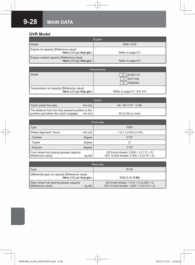
9-28 MAIN DATA
GVR ModelEngine
Model 6HK1-TCS
Engine oil capacity [Reference value] liters (US gal./Imp gal.) Refer to page 9-3
Engine coolant capacity [Reference value] liters (US gal./Imp gal.) Refer to page 9-3
Transmission
Model V ZF9S1110V ES11109V FS8209A
Transmission oil capacity [Reference value] liters (US gal./Imp gal.) Refer to page 9-7, 9-8, 9-9
Clutch
Clutch pedal free play mm (in) 40 - 60 (1.57 - 2.36)
The distance from the fully pressed position to the position just before the clutch engages mm (in) 60 (2.36) or more
Front axle
Type F063
Wheel alignment: Toe-in mm (in) -1 to 1 (-0.04 to 0.04)
: Camber degree 0°30’
: Caster degree 2°
: King pin degree 7°30’
Front wheel hub bearing grease capacity [Reference value] kg (lb)
JIS 8-bolt wheels: 0.505 × 2 (1.11 × 2)ISO 10-bolt wheels: 0.345 × 2 (0.76 × 2)
Rear axle
Type R130
Differential gear oil capacity [Reference value] liters (US gal./Imp gal.) 13.0 (3.43 /2.86)
Rear wheel hub bearing grease capacity [Reference value] kg (lb)
JIS 8-bolt wheels: 1.015 × 2 (2.238 × 2)ISO 10-bolt wheels: 1.820 × 2 (4.013 × 2)
4608498_sec09_MAIN DATA.indd 9-284608498_sec09_MAIN DATA.indd 9-28 2015/11/02 14:46:422015/11/02 14:46:42

9-29MAIN DATA
Steering
Steering wheel free play mm (in) 10 - 60 (0.39 - 2.36)
Power steering fluid capacity [Reference value] liters (US gal./Imp gal.) 3.0 (0.79 / 0.66)
Service brakes
Type V Air over hydraulic, dual circuitV Full air dual circuit
Brake pedal free play mm (in) 10 - 18 (0.39 - 0.71)
Parking brake
Type V Mechanical internal expanding at rear of transmission
V Spring actuator at rear wheels
Brake lever travel (Model with center parking brake) notches
Under pull force of approx. 294N (30.0kgf / 66lb) :3 - 8
Fuel
Fuel tank capacity [Reference value] liters (US gal./Imp gal.)
V 200 (52.8 / 44.0)V 400 (105.7 / 88.0)
Electrical system
Battery type V 65D23L, V 80D26L, V 115E41L
Generator volt/amp. V 24 / 50, V 24 / 60
4608498_sec09_MAIN DATA.indd 9-294608498_sec09_MAIN DATA.indd 9-29 2015/11/02 14:46:422015/11/02 14:46:42
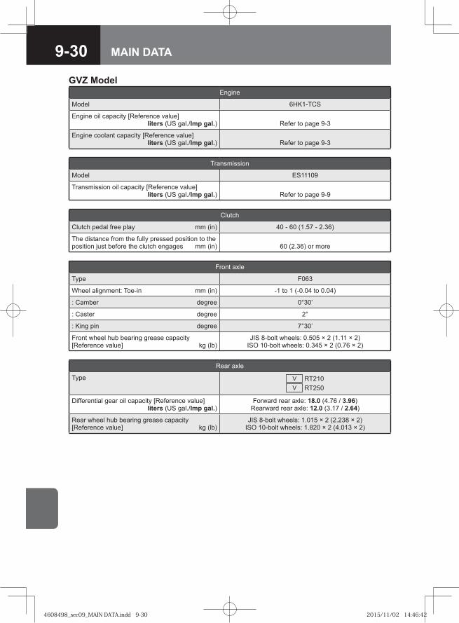
9-30 MAIN DATA
GVZ ModelEngine
Model 6HK1-TCS
Engine oil capacity [Reference value] liters (US gal./Imp gal.) Refer to page 9-3
Engine coolant capacity [Reference value] liters (US gal./Imp gal.) Refer to page 9-3
Transmission
Model ES11109
Transmission oil capacity [Reference value] liters (US gal./Imp gal.) Refer to page 9-9
Clutch
Clutch pedal free play mm (in) 40 - 60 (1.57 - 2.36)
The distance from the fully pressed position to the position just before the clutch engages mm (in) 60 (2.36) or more
Front axle
Type F063
Wheel alignment: Toe-in mm (in) -1 to 1 (-0.04 to 0.04)
: Camber degree 0°30’
: Caster degree 2°
: King pin degree 7°30’
Front wheel hub bearing grease capacity [Reference value] kg (lb)
JIS 8-bolt wheels: 0.505 × 2 (1.11 × 2)ISO 10-bolt wheels: 0.345 × 2 (0.76 × 2)
Rear axle
Type V RT210V RT250
Differential gear oil capacity [Reference value] liters (US gal./Imp gal.)
Forward rear axle: 18.0 (4.76 / 3.96)Rearward rear axle: 12.0 (3.17 / 2.64)
Rear wheel hub bearing grease capacity [Reference value] kg (lb)
JIS 8-bolt wheels: 1.015 × 2 (2.238 × 2)ISO 10-bolt wheels: 1.820 × 2 (4.013 × 2)
4608498_sec09_MAIN DATA.indd 9-304608498_sec09_MAIN DATA.indd 9-30 2015/11/02 14:46:422015/11/02 14:46:42

9-31MAIN DATA
Steering
Steering wheel free play mm (in) 10 - 60 (0.39 - 2.36)
Power steering fluid capacity [Reference value] liters (US gal./Imp gal.) 3.0 (0.79 / 0.66)
Service brakes
Type Air over hydraulic, dual circuit
Brake pedal free play mm (in) 10 - 18 (0.39 - 0.71)
Parking brake
Type Mechanical internal expanding at rear of transmission
Brake lever travel (Model with center parking brake) notches
Under pull force of approx. 294N (30.0kgf / 66lb) :3 - 8
Fuel
Fuel tank capacity [Reference value] liters (US gal./Imp gal.)
V 200 (52.8 / 44.0)V 400 (105.7 / 88.0)
Electrical system
Battery type V 65D23L, V 80D26L, V 115E41L
Generator volt/amp. V 24 / 50, V 24 / 60
4608498_sec09_MAIN DATA.indd 9-314608498_sec09_MAIN DATA.indd 9-31 2015/11/02 14:46:432015/11/02 14:46:43
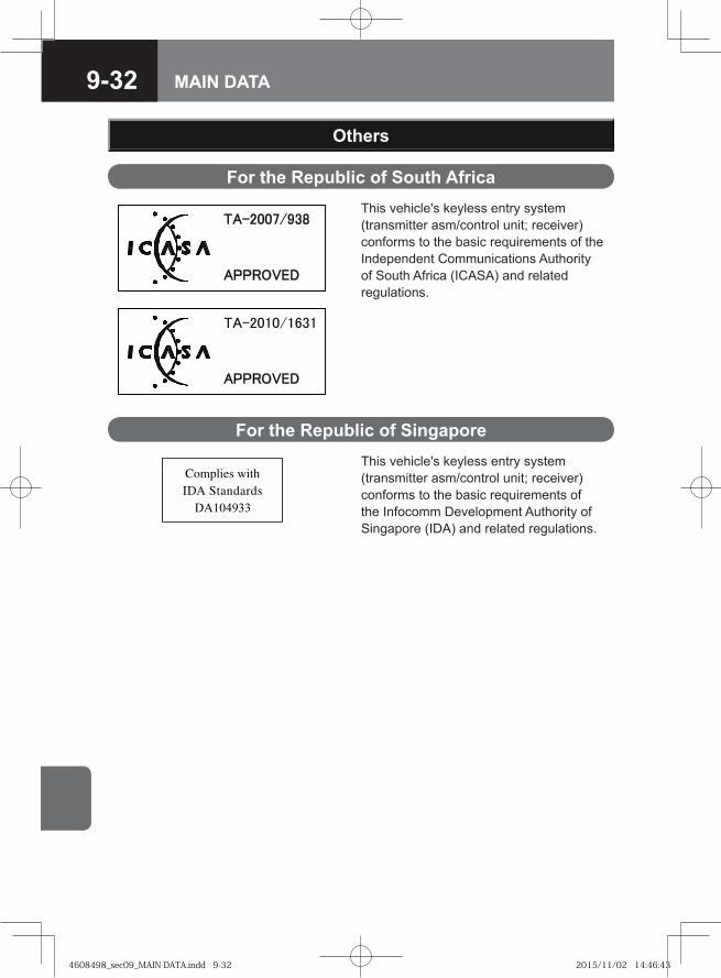
9-32 MAIN DATA
Others
For the Republic of South Africa
For the Republic of Singapore
This vehicle's keyless entry system (transmitter asm/control unit; receiver) conforms to the basic requirements of the Independent Communications Authority of South Africa (ICASA) and related regulations.
This vehicle's keyless entry system (transmitter asm/control unit; receiver) conforms to the basic requirements of the Infocomm Development Authority of Singapore (IDA) and related regulations.
4608498_sec09_MAIN DATA.indd 9-324608498_sec09_MAIN DATA.indd 9-32 2015/11/02 14:46:432015/11/02 14:46:43
9-33MAIN DATA
PurposeThis installation guidelines give requirement and recommendations for the installation in vehicles of • radio frequency (RF) transmitting equipment. • ancillary equipment associated with these.
Guidelines for Installation of Aftermarket Radio Frequency Transmitting Equipment
NOTEThese guidelines are intended to supplement, but not to be used in place of, detailed instructions for such installations which are the sole responsibility of the manufacturer of the involved radio telephone or land mobile radio.
•
General 1. Only the RF-transmitting equipment and ancillary equipment (microphone,
converter, booster, etc.) with 'CE' mark or 'e' may be installed in vehicle. 2. Installation of RF-transmitting equipment shall be performed by competent
personal permitted by the country regulation. The vehicle and RF-transmitting equipment manufacturer's instruction manuals and installation notes shall be followed.
NOTEVehicle manufacturer's instructions take priority in case of conflict.Installation of RF-transmitting equipment to any part of the vehicle, other than an authorized connection or mounting location, may invalidate the vehicle warranty.If a problem is found and can not be rectified, and it is suspected that the RF-transmitting equipment is out of specification, the appropriate manufacturer, agent or supplier shall be consulted.Expenses incurred from any adverse effect of any such installation are not the responsibility of vehicle manufacturer.
••
•
•
4608498_sec09_MAIN DATA.indd 9-334608498_sec09_MAIN DATA.indd 9-33 2015/11/02 14:46:432015/11/02 14:46:43
9-34 MAIN DATA
3. The installation shall comply with national legal requirements for the installation and use of RF-transmitting equipment in vehicles.
4. Full consideration shall be given to the positioning of RF-transmitting equipment such that electromagnetic interference (EMI) and radio frequency interference (RFI) is minimized between the RF-transmitting equipment being installed and the vehicle electrical and electronic systems.
5. Care shall be taken when planning the installation that any additional equipment used does not constitute a safety hazard and does not contravene safety regulations.
6. Care shall be taken to ensure that any microphone/handset lead is not such that the lead can interfere with the vehicle controls or driver.
7. Where a hand portable or transportable unit is installed in road vehicles, the correct car adapter kit specified for the product shall be used.
InstallationCare shall be taken in • choosing the antenna, • sitting it in a recommended location, • installing it correctly, • ensuring that all connection in the antenna feeder are sealed to prevent dirt and
water from entering the feeder and affecting its performance, • ensuring that all connection are electrically tested after installation, and • ensuring that a satisfactory VSWR reading is obtained.
Antenna 1. For RF-transmitting equipments with output power levels above 100mW (peak),
an external antenna is strongly recommended. 2. The external antenna and feeder cable shall be impedance matched with a
VSWR < 2.0. 3. The antenna should be a permanent-mount type located in the roof or the rear
trunk lid. If a magnet-mount antenna is used, care should be taken to mount the antenna in the same location as a permanent-mount type.
NOTEEach vehicle model and body style reacts to radio frequency energy differently. When dealing with an unfamiliar vehicle, it is suggested that a magnetic-mount antenna be used to check the proposed antenna location for unwanted effects on the vehicle. An antenna location is a major factor in these effects.The best position for an antenna is on the metallic roof, preferably towards the center, but where possible with a distance of > λ/4 (λ = wavelength) from any opening, such as a sunroof or windows.
•
•
4608498_sec09_MAIN DATA.indd 9-344608498_sec09_MAIN DATA.indd 9-34 2015/11/02 14:46:442015/11/02 14:46:44
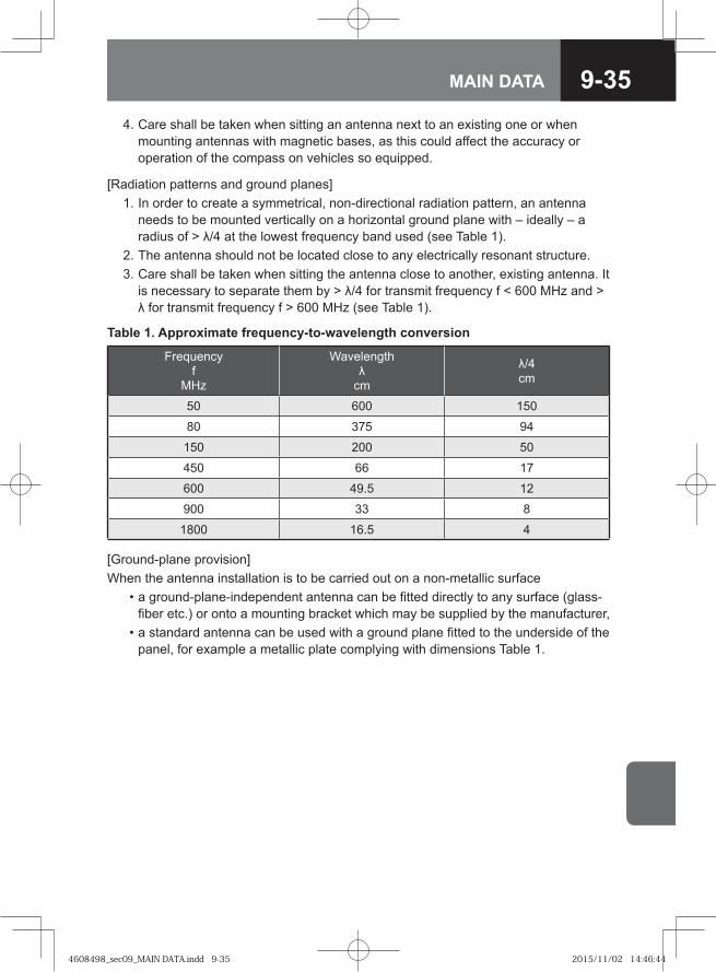
9-35MAIN DATA
4. Care shall be taken when sitting an antenna next to an existing one or when mounting antennas with magnetic bases, as this could affect the accuracy or operation of the compass on vehicles so equipped.
[Radiation patterns and ground planes] 1. In order to create a symmetrical, non-directional radiation pattern, an antenna
needs to be mounted vertically on a horizontal ground plane with – ideally – a radius of > λ/4 at the lowest frequency band used (see Table 1).
2. The antenna should not be located close to any electrically resonant structure. 3. Care shall be taken when sitting the antenna close to another, existing antenna. It
is necessary to separate them by > λ/4 for transmit frequency f < 600 MHz and > λ for transmit frequency f > 600 MHz (see Table 1).
Table 1. Approximate frequency-to-wavelength conversion
Frequencyf
MHz
Wavelengthλ
cm
λ/4cm
50 600 150
80 375 94
150 200 50
450 66 17
600 49.5 12
900 33 8
1800 16.5 4
[Ground-plane provision]When the antenna installation is to be carried out on a non-metallic surface • a ground-plane-independent antenna can be fitted directly to any surface (glass-
fiber etc.) or onto a mounting bracket which may be supplied by the manufacturer, • a standard antenna can be used with a ground plane fitted to the underside of the
panel, for example a metallic plate complying with dimensions Table 1.
4608498_sec09_MAIN DATA.indd 9-354608498_sec09_MAIN DATA.indd 9-35 2015/11/02 14:46:442015/11/02 14:46:44
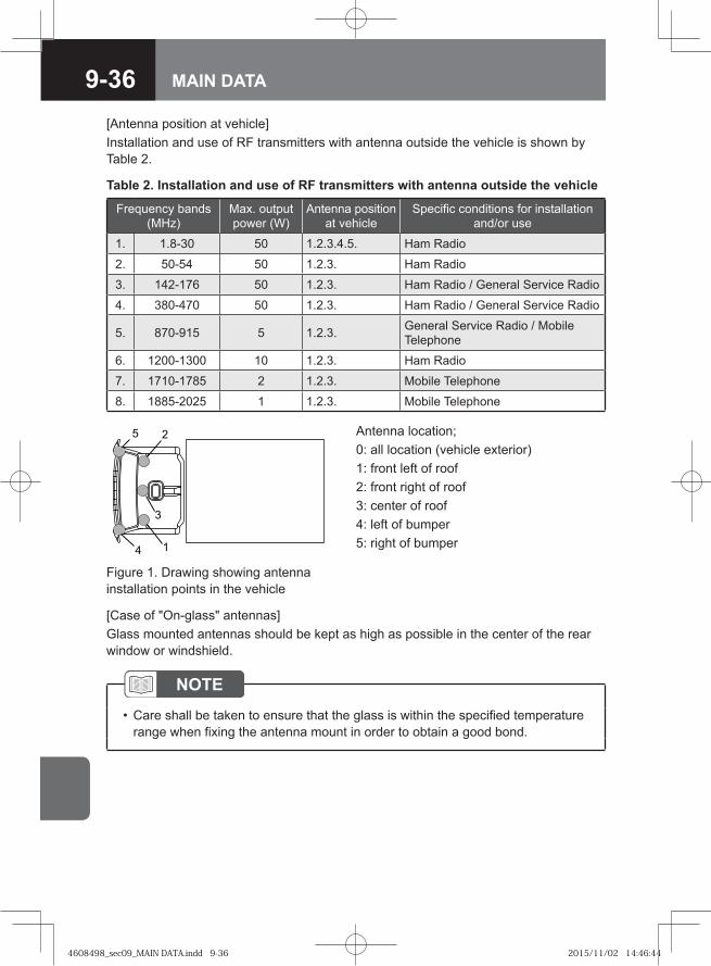
9-36 MAIN DATA
[Antenna position at vehicle]Installation and use of RF transmitters with antenna outside the vehicle is shown by Table 2.
Table 2. Installation and use of RF transmitters with antenna outside the vehicle
Frequency bands (MHz)
Max. output power (W)
Antenna position at vehicle
Specific conditions for installation and/or use
1. 1.8-30 50 1.2.3.4.5. Ham Radio
2. 50-54 50 1.2.3. Ham Radio
3. 142-176 50 1.2.3. Ham Radio / General Service Radio
4. 380-470 50 1.2.3. Ham Radio / General Service Radio
5. 870-915 5 1.2.3. General Service Radio / Mobile Telephone
6. 1200-1300 10 1.2.3. Ham Radio
7. 1710-1785 2 1.2.3. Mobile Telephone
8. 1885-2025 1 1.2.3. Mobile Telephone
�
�
�
Figure 1. Drawing showing antenna installation points in the vehicle
Antenna location;0: all location (vehicle exterior)1: front left of roof2: front right of roof3: center of roof4: left of bumper5: right of bumper
[Case of "On-glass" antennas]Glass mounted antennas should be kept as high as possible in the center of the rear window or windshield.
NOTECare shall be taken to ensure that the glass is within the specified temperature range when fixing the antenna mount in order to obtain a good bond.
•
4608498_sec09_MAIN DATA.indd 9-364608498_sec09_MAIN DATA.indd 9-36 2015/11/02 14:46:442015/11/02 14:46:44
9-37MAIN DATA
Antenna Cable 1. Use a high quality, one piece coaxial cable (at least 95% shield coverage) that is
impedance matched for the RF-transmitting equipment (VSWR < 2.0). 2. Excess coaxial cable shall not be coiled, as this may affect the tuning of the
antenna as well as producing electrical interference. 3. If possible, the antenna cable should be cut to the correct length. 4. The cable should be routed so as to avoid sharp bends. 5. Safety-sensitive electronic unit (e.g. airbag and ABS systems), circuits and
harnesses shall not be used for parallel wiring. 6. If it is necessary to cross other wiring, cross at right angles. 7. If an extension feeder cable is required, suitable coaxial cable shall be used and
correctly terminated with good quality, low-loss connectors.
NOTEFit the correct antenna connectors at each end of the feeder cable to match the equipment using either crimp or soldered connectors as appropriate.
•
NOTEExtending the length of the feeder cable will result in additional losses, particularly at frequencies > 800 MHz.
•
8. If the antenna cable provided is too short, wherever possible the cable should be replaced by a suitable feeder cable of correct length.
9. Ensure that the feeder cable is not strained or distorted by, for example, excessive tightening of cable ties.
10. When vehicle trim is replaced, make sure that the panels do not trap the feeder cable.
11. Additional care should be taken when installing a glass mount to the rear screen of a hatch-back type vehicle to allow opening and to prevent damage to the feeder cable.
4608498_sec09_MAIN DATA.indd 9-374608498_sec09_MAIN DATA.indd 9-37 2015/11/02 14:46:442015/11/02 14:46:44
9-38 MAIN DATA
RF-transmitting Equipment[Mounting of RF-transmitting equipment] 1. Location of a RF-transmitting equipment should be selected that provides a solid
mounting point which does not interfere with the vehicle operator controls and provides adequate ventilation.
2. RF-transmitting equipment shall not be able to be damaged or its ventilation restricted. Special care should be taken to ensure that RF-transmitting equipment can not be damaged by ingress of water.
3. Access to vehicle equipment in the load storage area shall not be barred, e.g. by wheel jack, fire extinguishers or spare wheel.
4. The connections to the RF-transmitting equipment should be easily accessible in order that the equipment may be removed for operation in transportable mode, or for repairs and servicing.
5. It shall not hinder the operation of airbags or other safety equipment.
NOTEGreat care should be taken not to mount any RF-transmitting equipment, microphones or any other item in the deployment path of a Supplemental Inflatable Restraint or "Air Bag".
•
[Routing of RF-transmitting equipment's cables] 1. Where possible, all cables should pass inside or underneath trim and through
moldings in such a way as to afford maximum protection. If necessary, use sleeving, a proprietary protector and/or cable ties where required.
2. Select a route for the cable, ideally on the opposite side of the vehicle to the fuel pipe, clear of brake pipes, cables, controls, vehicle wiring and any hot components. Under no circumstances shall any cables be attached to the foregoing.
3. Cable shall be routed so that they avoid • sharp edges, • continual bending, • stress or strain, • abrasion, • extreme temperature, and • becoming a hazard to the occupants of the car.
4608498_sec09_MAIN DATA.indd 9-384608498_sec09_MAIN DATA.indd 9-38 2015/11/02 14:46:442015/11/02 14:46:44
9-39MAIN DATA
Power Supply for RF-transmitting Equipment[General] 1. A dedicated supply cable should be used for the RF-transmitting equipment
installation which should be as short as possible to the battery positive and negative connections. Do not connect directly to the battery pillars, but use the battery terminals provided.
NOTEConnections shall not be made to any electronic control unit feeds under any circumstances. For example, avoid using cigar lighter as power sources for a RF-transmitting equipment.
•
2. It is also recommended that, unless a molded twin supply cable is used, the two supply lines be twisted together along their length in order to reduce radiated noise or induce noise.
NOTEThe supply cable from the RF-transmitting equipment should approach the battery in such a way that, when terminated, the two wires can not be inadvertently reversed, e.g. one wire is shorter than the other.
•
3. If ignition switch control is desired, the handset or control unit positive lead may be connected through an appropriate in-line fuse to an available accessory circuit or ignition circuit not powered during cranking.
4608498_sec09_MAIN DATA.indd 9-394608498_sec09_MAIN DATA.indd 9-39 2015/11/02 14:46:452015/11/02 14:46:45
9-40 MAIN DATA
[Supply cable and routing] 1. Heavy-duty cable of a low electrical resistance should be used on long cable runs
to minimize voltage drop. 2. The cable shall be of a higher current capacity than the protection fuse, and the
correct fuse shall be fitted. 3. The cable should be as short as possible. 4. The cable shall be secured well clear of moving parts, (shock absorbers, steering,
drive shaft, control pedals, etc.). 5. The cable shall be secured well clear of the engine, exhaust system or other hot
items. 6. The supply cable run should, where possible, be separate from that of the in-
car entertainment equipment control cables, although they may pass through the same holes in the chassis and body for ease of fitting; suitable grommets should be fitted if additional holes are drilled.
7. The cable shall be supported, avoiding sharp bends, and shall not be subjected to strain.
8. The cable shall be sited away from ignition coil, the high voltage circuits of the ignition systems and electronic control units and, where possible, other vehicle wiring.
2. The supply cable to the regulator or converter shall be as practicable and suitable fuses should be fitted as close as possible to the supply.
NOTEMost mobile RF-transmitting equipment operates from a 12 V supply. ISUZU FRR90/FSR34/FVR34/FSR90 have a 24 V, so it is essential that a suitable regulator or converter be used which will provide the nominal supply voltage and current for which the RF-transmitting equipment is designed.
•
NOTEThe installation of the RF-transmitting equipment shall be carried out such that the integrity of the vehicle isolated power supply is not impaired.
•
[Vehicle Electrical Supply Systems with Voltages 24 V] 1. A 12 V tap shall not be taken from 24 V vehicle batteries.
3. The unit shall be mounted in accordance with the manufacturer's instructions. Unless environmentally protected, it should be located in a dry and well-ventilated position.
4608498_sec09_MAIN DATA.indd 9-404608498_sec09_MAIN DATA.indd 9-40 2015/11/02 14:46:452015/11/02 14:46:45
10-1INDEX
AAccessory Power Outlet (24V) V 5-19Air Cleaner 7-60
Air Conditioning Compressor Belt V 7-202
Air Conditioning Filters V 7-199
Air Dryer V 7-121Air Outlets 5-2
Air Pressure Gauge 4-14
Air Tanks 7-119
ALLISON2500 Model Transmission Fluid V 7-140
ALLISON3000/3500 Model Transmission Fluid V 7-144
AM/FM Radio V 5-30
Analog Tachograph V 4-12Antenna 5-29
Antilock Brake System (ABS) V 4-166
Anti-Slip Regulator (ASR) V 4-170Ashtray 5-20
Automatic Transmission Model A/T 2-35
BBefore Driving 2-2
Brake Lock V 4-157Brakes 7-76
CCard Holder 5-21
Carrying Children 2-15
Cautions for Driving in Cold Regions and Season 6-22
Cautions for Driving in Hot Regions and Season 6-21
Cautions for Parking 6-20
CD Player (with AM/FM Radio) V 5-38
Center Console Box V 5-23
Changing a Tire (ISO 10-Bolt Wheels) V 7-110
Changing a Tire (JIS 6-Bolt or 8-Bolt Wheels) V 7-101Checking a Part Where there was an Abnormality the Previous Time the Vehicle was Driven 7-28
Checking Axle Shaft Bolts 7-119
Cigarette Lighter V 5-17
Clutch M/T 7-124
Clutch Fluid M/T 7-121
Coat Hook V 5-25Coin Holder 5-24
Combination Light Control Switch 4-79
Coupler V 4-178
Cruise Control V 4-161
Cup Holder V 5-25
DDaily Check (Preoperational Check) 7-26
Discarded Parts, Oils and Other Liquids 7-6
Driving 2-17
Driving Safely and with Confidence 6-2
Driving with a Trailer 6-17
Drum Brakes 7-88
4608498_sec10_INDEX.indd 10-14608498_sec10_INDEX.indd 10-1 2015/11/04 10:09:092015/11/04 10:09:09
10-2 INDEX
EEngine Conditions 7-30
Engine Coolant 7-39
Engine Coolant Temperature Gauge 4-15
Engine Oil 7-31
ES11109/FS8209A Manual Transmission Model V 2-31Exhaust Brake Switch 4-83
Exterior (PICTORIAL INDEX) 0-11
Exterior Lights 7-189
Exterior Maintenance 7-206
FFan Belt 7-55
Four Wheel Drive (4WD) Model V 2-36, 4-182
Front Axle Differential Gear Oil V 7-159
Front Fog Light Switch V 4-82Front Lid 7-8
Fuel Filter 7-63
Fuel Gauge 4-16
Fuel Tank 3-17, 7-171
Fully Adjustable Steering 3-30
GGearshift Lever M/T / SA 4-99Getting In and Out of the Vehicle 3-13
Glove Compartment with Lid V 5-22
Glove Compartment without Lid V 5-23Greasing Chassis Components 7-172
HHandling the Battery 7-192
Handling the Jacks 7-180
Handling the Radiator and Intercooler 7-54
Hazard Warning Flasher Switch 4-83
Headlight Leveling Switch V 4-81
Heater/Manual Air Conditioner/Cooler V 5-6
Hill Start Aid (HSA) V 4-146Hook 5-26
Horn Button 4-89
Hour Meter V 4-17How to Read the Instruments (Instruments Layout) 4-10
IIdling Control Knob 4-76
Inspection and Maintenance 7-217
Inter-Differential Lock Switch V 4-86Interior (PICTORIAL INDEX) 0-6
Interior Lights 5-16
Interior Maintenance 7-210
Isuzu Genuine Oils and Grease 7-6
KKey 3-2
Key with Immobilizer Transponder Chip V 3-3
Keyless Entry System V 3-4
4608498_sec10_INDEX.indd 10-24608498_sec10_INDEX.indd 10-2 2015/11/04 10:09:112015/11/04 10:09:11
10-3INDEX
MMain Data and Specifications 9-2
Manual Transmission Oil M/T / SA 7-129
Manually Operated Windows V 3-16
Mirror Heater Switch V 4-91Mirrors 3-31
Model with ALLISON2500 Model Automatic Transmission V 4-134Model with ALLISON3000/3500 Model Automatic Transmission V 4-141Model with ES11109/FS8209A Model Manual Transmission V 4-114
Model with Smoother SA 4-117Model with ZF9S1110 Model Manual Transmission V 4-110
Multi-Information Display (MID) V 4-22
OOn the Road 6-2
Opening and Closing Doors 3-9
Operating Tips for the Radio and CD Player 5-26
Others 9-32
Overhead Shelf 5-24
PParking Brake 7-84
Parking Brake Lever 4-95
Pedals 4-94
Pintle Hook V 4-174
Power Cab Tilt System V 7-15Power Steering Fluid 7-166
Power Steering Fluid Filter 7-169
Power Take-Off (PTO) V 4-193
Power Windows V 3-15Precautions for Checking and Adjustments 7-4
Preparation for Changing a Tire 7-100
Preventing Breakdowns 2-49
RRear Axle Differential Gear Oil 7-156
Rear Differential Lock Switch V 4-85
Rear Fog Light Switch V 4-82
Refrigerant V 7-201
Remote Control Mirror Switch V 4-91Replacing the Fuses and Relays 8-53
Retractable Power Mirror Switch V 4-90
SSeat Belt with Pretensioner and Supplemental Restraint System (SRS) Airbag System V 2-55, 4-198Seat Belts 3-34
Seatback Pocket (Driver's Side) V 5-21Seats 3-20
Selector Button V 4-106
Selector Lever V 4-104
Small Article Storage Pocket V 5-21
Smoother Clutch Oil SA 7-153
Smoother Model SA 2-31
Spare Tire V 7-117
Speed Limit Device V 2-54Speedometer 4-11
Starter Switch 4-74
Starting the Engine 4-4
Statement of Compliance with ECE R13 2-57
Staying Safe 2-44
Steering Wheel 7-170
Stopping and Parking 2-38
Stopping the Engine 4-7
Sun Visor 5-17
4608498_sec10_INDEX.indd 10-34608498_sec10_INDEX.indd 10-3 2015/11/04 10:09:132015/11/04 10:09:13
10-4 INDEX
TTachometer 4-13
Tilting the Cab V 7-10Tire Rotation 7-98
Tools 7-7
Transfer Gear Case Oil V 7-163Troubleshooting 8-2
UUsing Tire Chains 6-27
VVehicle Data Collection 2-57
Vehicle Identification Number (VIN) and Engine Numbers 1-2
Ventilator V 5-4
WWarm-Up Switch V 4-78Warning and Indicator Lights 4-37
Warning and Indicator Lights Layout 4-18
Warning Buzzer 4-70
Warning/Caution Labels in Your Vehicle 0-21
Warning/Indicator Light Index 0-15
Wheels and Tires 7-92
When Driving on Bad Roads 8-72
When the Battery Goes Flat 8-11
When the Brakes Do not Work 8-10
When the Bulb Does not Come On 8-29
When the Engine Overheats 8-23
When the Engine Stalls and Cannot be Restarted 8-9
When the Engine Stops While Driving 8-8
When the Fuel Runs Out 8-13
When the Meter Shows an Abnormality 8-25
When the Parking Brake Cannot be Released V 8-26When the Tire Goes Flat 8-7
When the Vehicle Breaks Down during Driving 8-7
When the Warning Light Comes On 8-16
When to Visit an Isuzu Dealer 2-51
When Towing 8-73
Windshield Washer Fluid 7-185
Windshield Wiper and Windshield Washer Switch 4-87
Windshield Wiper Blades 7-186
ZZF9S1110 Manual Transmission Model V 2-30
4608498_sec10_INDEX.indd 10-44608498_sec10_INDEX.indd 10-4 2015/11/04 10:09:182015/11/04 10:09:18
MEMO
4608498_sec10_INDEX.indd 10-54608498_sec10_INDEX.indd 10-5 2015/11/04 10:09:182015/11/04 10:09:18
MEMO
4608498_sec10_INDEX.indd 10-64608498_sec10_INDEX.indd 10-6 2015/11/04 10:09:182015/11/04 10:09:18