freescale powerpoint template - nxp
TRANSCRIPT

TM

TM 2
Arrow Brasil
Rodrigo Rodrigues
Field Application Engineer
F:+55 11 3613-9331
Date: 30/01/2014
TM 3
• State-of-the-art review
− Introduction
− How a Gyro Works
− Performance and Applications
− Fusion with Other Sensors
− FXAS2100 Enablement
• Conclusions and Questions

TM
TM 5
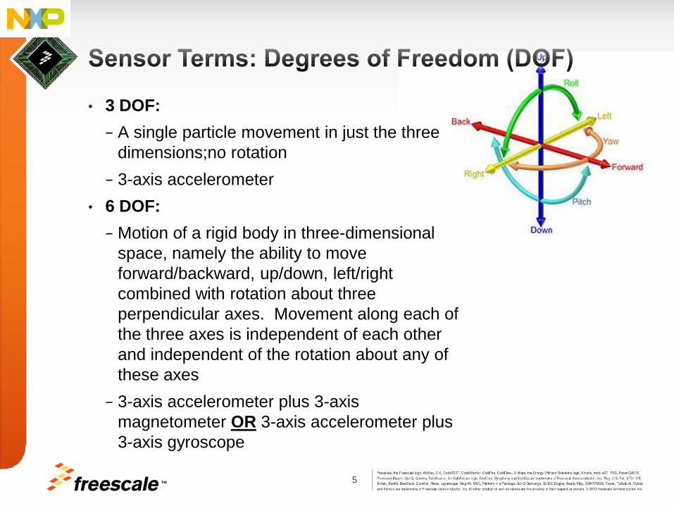
• 3 DOF:
− A single particle movement in just the three
dimensions;no rotation
− 3-axis accelerometer
• 6 DOF:
− Motion of a rigid body in three-dimensional
space, namely the ability to move
forward/backward, up/down, left/right
combined with rotation about three
perpendicular axes. Movement along each of
the three axes is independent of each other
and independent of the rotation about any of
these axes
− 3-axis accelerometer plus 3-axis
magnetometer OR 3-axis accelerometer plus
3-axis gyroscope
TM 6
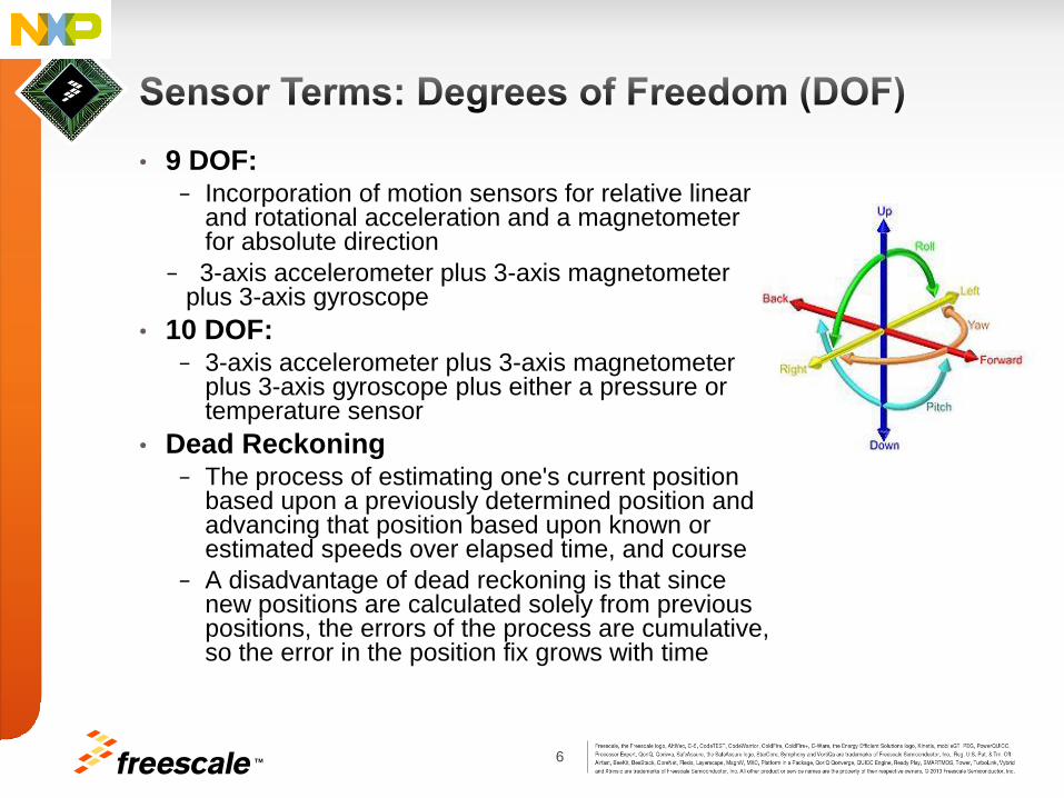
• 9 DOF: − Incorporation of motion sensors for relative linear
and rotational acceleration and a magnetometer for absolute direction
− 3-axis accelerometer plus 3-axis magnetometer plus 3-axis gyroscope
• 10 DOF: − 3-axis accelerometer plus 3-axis magnetometer
plus 3-axis gyroscope plus either a pressure or temperature sensor
• Dead Reckoning − The process of estimating one's current position
based upon a previously determined position and advancing that position based upon known or estimated speeds over elapsed time, and course
− A disadvantage of dead reckoning is that since new positions are calculated solely from previous positions, the errors of the process are cumulative, so the error in the position fix grows with time
TM
8 TM
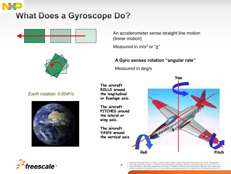
An accelerometer sense straight line motion
(linear motion)
Measured in m/s2 or “g”
A Gyro senses rotation “angular rate”
Measured in deg/s
Earth rotation: 0.004o/s

9 TM
rc VmF 2
dc VmF
2
A fictional force on a moving object when
observed on a rotating frame. The Coriolis force
scales with the angular velocity of the frame.
Angular rate (), drive motion (Vd) and Coriolis
force (Fc) are always located on there axes
orthogonal to each other.
This is where the confusion might begin. We
called XY gyro with the sensing direction is in Z-
axis while Z gyro with sensing direction in XY
direction ….
Input angular
rate ()
Coriolis
Force Drive
Motion
Input
Rotation
Drive
Velocity
Coriolis
Force
Coriolis Force
X (Fc)
Z ()
Y (Vd)
Coriolis force causes
spiral motion in
Hurricanes

10 TM
• Three types of Gyros:
− Spinning Mass (Gimbal) -tilting produces precession
Impractical in MEMS
− Optical – measure time differences in laser paths
Very expensive, but also the best performance
− Vibrating – based on Coriolis effect
The most common
11 TM
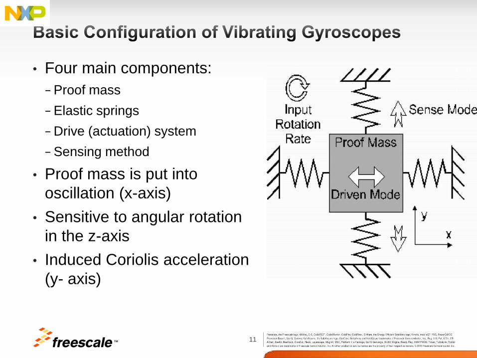
• Four main components:
− Proof mass
− Elastic springs
− Drive (actuation) system
− Sensing method
• Proof mass is put into
oscillation (x-axis)
• Sensitive to angular rotation
in the z-axis
• Induced Coriolis acceleration
(y- axis)
12 TM
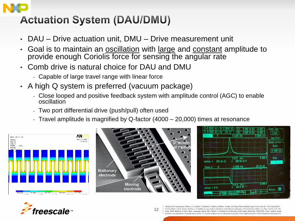
• DAU – Drive actuation unit, DMU – Drive measurement unit
• Goal is to maintain an oscillation with large and constant amplitude to provide enough Coriolis force for sensing the angular rate
• Comb drive is natural choice for DAU and DMU
- Capable of large travel range with linear force
• A high Q system is preferred (vacuum package)
- Close looped and positive feedback system with amplitude control (AGC) to enable oscillation
- Two port differential drive (push/pull) often used
- Travel amplitude is magnified by Q-factor (4000 – 20,000) times at resonance
13 TM
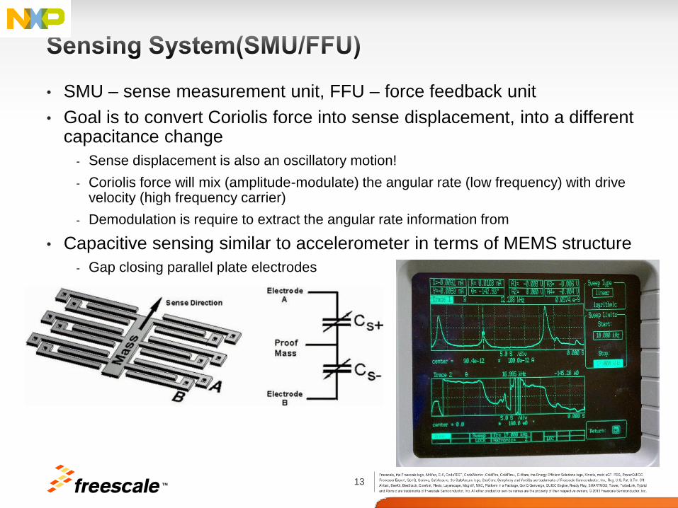
• SMU – sense measurement unit, FFU – force feedback unit
• Goal is to convert Coriolis force into sense displacement, into a different capacitance change
- Sense displacement is also an oscillatory motion!
- Coriolis force will mix (amplitude-modulate) the angular rate (low frequency) with drive velocity (high frequency carrier)
- Demodulation is require to extract the angular rate information from
• Capacitive sensing similar to accelerometer in terms of MEMS structure
- Gap closing parallel plate electrodes

TM
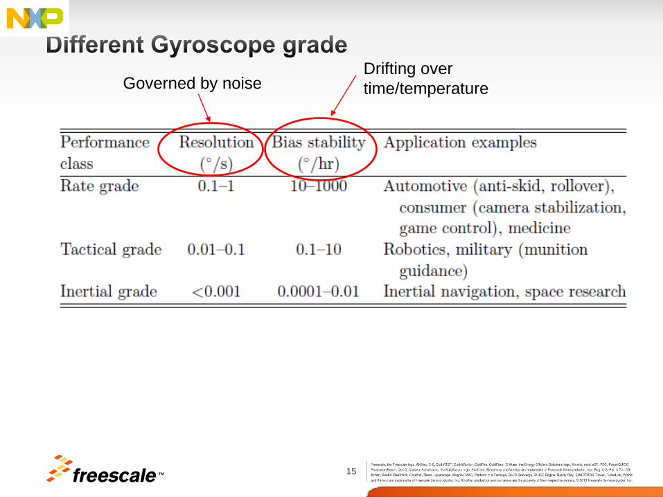
15 TM
Governed by noise Drifting over
time/temperature
16 TM
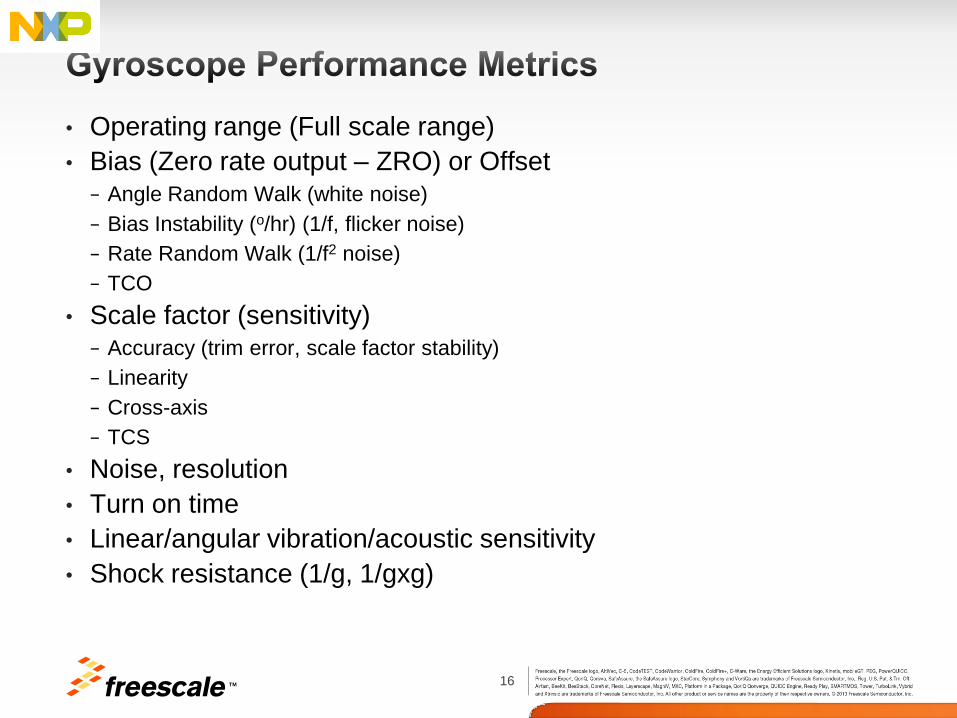
• Operating range (Full scale range)
• Bias (Zero rate output – ZRO) or Offset − Angle Random Walk (white noise)
− Bias Instability (o/hr) (1/f, flicker noise)
− Rate Random Walk (1/f2 noise)
− TCO
• Scale factor (sensitivity) − Accuracy (trim error, scale factor stability)
− Linearity
− Cross-axis
− TCS
• Noise, resolution
• Turn on time
• Linear/angular vibration/acoustic sensitivity
• Shock resistance (1/g, 1/gxg)

17 TM

18 TM
19 TM
20 TM
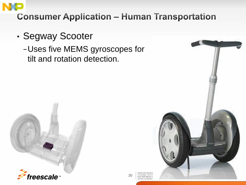
• Segway Scooter
−Uses five MEMS gyroscopes for
tilt and rotation detection.

21 TM

TM
23 TM
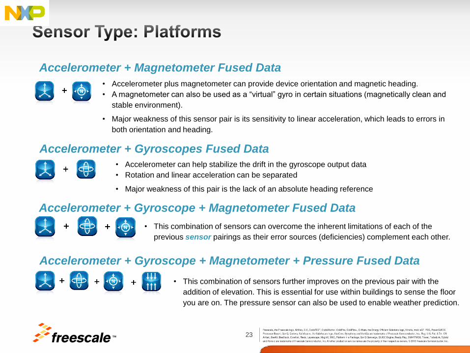
Accelerometer + Gyroscopes Fused Data
• Accelerometer can help stabilize the drift in the gyroscope output data
• Rotation and linear acceleration can be separated
• Major weakness of this pair is the lack of an absolute heading reference
Accelerometer + Gyroscope + Magnetometer Fused Data
• This combination of sensors can overcome the inherent limitations of each of the
previous sensor pairings as their error sources (deficiencies) complement each other.
• This combination of sensors further improves on the previous pair with the
addition of elevation. This is essential for use within buildings to sense the floor
you are on. The pressure sensor can also be used to enable weather prediction.
Accelerometer + Gyroscope + Magnetometer + Pressure Fused Data
• Accelerometer plus magnetometer can provide device orientation and magnetic heading.
• A magnetometer can also be used as a “virtual” gyro in certain situations (magnetically clean and
stable environment).
• Major weakness of this sensor pair is its sensitivity to linear acceleration, which leads to errors in
both orientation and heading.
Accelerometer + Magnetometer Fused Data

TM

25 TM
Xtrinsic ISF Gyro Adapters available
Sensor Adapter Board for
Demonstration
FXCL950000 tools for
Sensor Hub and gyro applications
9-Axis DIP for Prototyping

26 TM
• High Demo of key
functionality
• ODR, FS, HPF,
• Sample Time,
Data logger

27 TM
Q&A Rodrigo Rodrigues
Field Application Engineer
F:+55 11 3613-9331
Date: 30/01/2014

TM