free-form thick layer object manufacturing technology for large-sized physical models
TRANSCRIPT

Free-form thick layer object manufacturing technology for
large-sized physical models
Johan J. Broek*, Imre Horvath, Bram de Smit, Alex F. Lennings, Zoltan Rusak,Joris S.M. Vergeest
Faculty of Design Engineering and Production, Sub-Faculty of Industrial Design Engineering, Delft University of Technology, Jaffalaan 9,
NL-2628 BX Delft, Netherlands
Abstract
Large-sized free-form objects of different materials are widely used in various industrial applications. Currently, layered
rapid prototyping technologies are not suitable for the fabrication of this kind of objects, due to the necessity of a large number
of layers and the limitations in size. This paper reports a novel approach of layered manufacturing that is more appropriate for
the fabrication of these large objects. A method of thick-layered object manufacturing is presented, which is based on a higher
order approximation of the shape and application of a flexible curved cutting tool.
The method allows the production of physical prototypes, which need little or no finishing. In order to meet the designer’s
intend, as closely as possible, some feasible system characteristics are introduced. The process is ordered in a sequential way
and provides a highly automated process. A hierarchical decomposition of the CAD geometry takes place into components,
segments, layers and sectors, based on morphological analysis. This method enables the manufacturing and the re-assembly of
the parts to produce the physical prototypes without affecting the requested functionality. Due to the possibility of obtaining
multiple solutions in the physical model, much attention must be paid to the efficiency of the process. D 2002 Elsevier Science
B.V. All rights reserved.
Keywords: Rapid prototyping; Free-form thick-layered object manufacturing (FF-TLOM); Higher order approximation; Flexibly curved cutting
tool; Geometric decomposition; Conceptual design
1. Introduction
In the process of industrial design engineering,
testing and reasoning with the help of prototypes or
physical models is commonly accepted among design-
ers and stylists. The material of these objects might
vary considerably and can include plastic foam, paper,
cardboard, plywood, clay, plaster, compound mate-
rials, etc. The applications of these models are often
many-sided.
In the concept phase of the design process, the
physical model (PM) is supportive in the case of
reasoning, communicating with customers, testing
for the functionality and evaluation of the require-
ments of the product. In such cases, the PM is created
and used for only a short period of time. In other cases
the physical model is used for the initiation of the
fabrication of a range of products. Both examples
require different appearances and manufacturing tech-
niques for the PM due to the divergent requirements.
The physical models are mostly generated from com-
0926-5805/02/$ - see front matter D 2002 Elsevier Science B.V. All rights reserved.
PII: S0926-5805 (00 )00108 -4
* Corresponding author.
Internet address: http://www.io.tudelft.nl/research/ica/.
E-mail address: [email protected] (J.J. Broek).
www.elsevier.com/locate/autcon
Automation in Construction 11 (2002) 335–347

puter-based data and produced by a specific Rapid
Prototyping (RP) process.
A distinction can be made between two fundamen-
tal approaches to RP, namely that of incremental and
decremental processes. The decremental process starts
with a solid block of material (stock), which will be
machined or shaped sequentially according to the
geometric CAD data. Characteristic examples of dec-
remental methods are applications like the Sculpturing
Robot [35] and high speed milling [12]. The accessi-
bility check for the machining (avoiding tool interfer-
ence) can be highly calculation intensive and not
always successful.
The second approach is that based upon an incre-
mental fabrication technology. This manufacturing
process is highly or fully automated. A dominant part
of the available RP-processes is based on Layered
Manufacturing Technologies (LMT). The shape is
built up from layers, which are deposited and ma-
nufactured separately. These are stacked onto each
other to create the required shape of a physical mo-
del. Different incremental technologies exist on the
RP-market, e.g. 3D printing, stereolithography, lay-
ered object manufacturing, selective laser sintering
and fused filament deposition. In general, the avail-
able conventional (incremental) LMT are the best
for manufacturing of small and mid-size objects, be-
cause the applicable layer thicknesses in these pro-
cesses are relatively small compared to the dimen-
sions of the model [21,23,24]. More information
about typical technological parameters of these
layer-oriented fabrication methods is presented in
Refs. [4,25,29]. Rapid prototyping in fact can be
considered as an optimization process for productivity
and accuracy [26,27,38,39,41].
Large-sized, free-form PM’s (up to 5 m and
beyond) are made of soft and light materials. Such
models are used in the household appliances manu-
facturing, in the automotive industry, advertisements,
and entertainment industry. Additionally they are used
for scenery pieces in movie film making, for stage sets
in theatres, sculptures, ornaments and for extra-sized
human or animal mannequins. In scientific research
and industry, these models support the visualization of
mathematical models, the testing of human–product
interaction, analyzing aerodynamic and hydrodynamic
behavior, as well as aesthetic and ergonomic impres-
sions.
PM’s of that large size need a large amount of
material for realization. Both decremental and incre-
mental processes are not well equipped for this large-
sized application. The decremental process needs
machining time on very expensive equipment propor-
tional to the volume of the stock. The common LMT
need such a large amount of layers that the fabrication
time exceeds the efficient realization of that kind of
PM [10,30] (also due to the extended area of depos-
ited thin layers). Normally, the dimensions of the ma-
nufacturing equipment put a limitation on the object
dimensions. These conditions need to be addressed by
a different type of technique, like the application of a
thick layer approach.
2. Thick-layered object manufacturing
In recent years, thick layer object manufacturing
(TLOM) has been demonstrated [6,13,36]. The meth-
ods of geometry approximation and machining tech-
nology are based on adaptive slicing and first order
approximation (ruled surface or slanted front faces) of
the nominal shape geometry. Systems like Trusurf,
Charly Robot and Shapemaker offer specific technol-
ogies to fabricate large-sized objects in such a manner.
A survey in the field of TLOM is presented in Ref.
[2]. The fabrication of large-sized free-form PM’s is a
real challenge especially for layered manufacturing.
To come up with practical solutions, the research team
of the authors is deeply involved in the methodolog-
ical and technological issues in order to extend con-
ventional LOM to the large size domain. They propose
the method of free-form thick-layered object manufac-
turing (FF-TLOM) [3,16].
The principle of this new technology is to combine
advantages of both decremental and incremental
methods. This will open up an extension of RP
applications.
2.1. Free-form thick-layered object manufacturing
The principle of the proposed FF-TLOM technol-
ogy is based on the shaping of the front faces of each
layer, which is performed in a free-form way. At a
later stage, the machined layers are assembled or
stacked to obtain the PM. A brief description about
the implications of higher order approximations
J.J. Broek et al. / Automation in Construction 11 (2002) 335–347336

(HOA) is mentioned in Ref. [28] and the idea of a
curved cutting tool is first presented in Ref. [13]. It is
easy to imagine that HOA creates possibilities for the
application of thicker layers under the same or better
accuracy and smoother outside surfaces of a prototype
(a higher layer-thickness/accuracy ratio). HOAapplied,
as circular or free-form approximation of the nominal
shape, however, requires sophisticated shaping techno-
logies.
The tool applications of a fixed curved shape or a
flexible curved shape are considered for the manufac-
ture of the front faces of the layers. The shaping itself
might take place by smearing of hardening plaster or
by cutting light and soft materials like foam. Fixed
curved spherical or conicoid cutting tools [34] can be
applied using the best fitting part of the cutting tool in
order to approximate locally the best nominal shape.
The result will be a layer with a cusped front face,
which might need finishing actions.
The PM fabrication with the FF-TLOM technology
is achieved in such a way that possibly little or no
finishing effort is needed for a proper functional
usage. The proposed technology uses thick high-
density polystyrene foam layers, whose front faces
are shaped according to the principle of free-form
cutting. This lightweight material (ranging from 28 to
40 kg/m3) is cheap, and readily available on the
market in standardized sizes and layer thicknesses.
In the proposed method, the foam layers are shaped
with a flexible hot knife, which is heated by electrical
current. The cutting blade is flexible and its curvature
is adjusted according to the local shape requirements
set by the nominal shape of the CAD-model. The
cutting of the layers is a newly developed technology
and will be explained in more detail in the next
paragraph. Current applicable shaping techniques are
discussed in the following.
3. Flexible blade cutting
In current thick-layered object manufacturing
(TLOM), well-known cutting technologies are ap-
plied, such as hot-wire cutting, water jet cutting, side
face milling, hot knife cutting, filing, milling, and
sanding. Those techniques are related to the chosen
shape approximation based on slanted front layer faces
or ruled surfaces. The thickness of each layer depends,
in case of adaptive slicing, on the maximum allowed
approximation error and the standard slab thicknesses
available in store. Therefore, the applied layer thick-
ness can vary dependent upon each change in local
curvature of the nominal shape.
The approach of TLOM is to find an orientation,
which will need the minimal number of slices and
then orientating the model to keep the slicing of the
complete object in the same direction. It is obvious
that this method can be improved by considering a
different treatment for thin layers due to very local
curvature changes and degenerated layers like the first
and last layer of an object. More about these issues is
presented in the section about decomposition.
A valuable extension of the TLOM method is the
application of a cutting technology, which is based on
a cutting device able to adapt to the local curvature
requirements and hereby offers the possibilities of
increased applied layer thickness.
Fig. 1. FF-TLOM cutting head.
J.J. Broek et al. / Automation in Construction 11 (2002) 335–347 337

The fabricating technology under development in
our group is based on the cutting of polystyrene foam
with a flexible cutter. Polystyrene is a cheap and com-
monly available material, which is also commonly
applied in creating physical models. The foam is melt-
able and can be shaped easily with hot wire cutting,
filing, sawing, sanding, etc.
The cutting is performed with a cutter, which
consist of a flexible cutting blade supported at both
ends. This is shown in Fig. 1 where the supports are
rotatable and introduce an inclination at both blade
ends in respect to the U-shaped support structure. In
Fig. 2, a typical layout of the layer cutting is pre-
sented. The shape and curvature of the blade are
defined by the inclination of the blade at both support-
ing ends, the length of the blade, the endpoints and the
assumption that the blade will take up a shape related
to the minimal strain energy inside the blade.
The cutting blade is electrically heated. Due to heat
radiation towards the foam, the foam melts locally and
creates a gap in which the cutting blade can proceed.
This is a continuous process, which require continu-
ous energy input into the cutting blade to prevent the
blade cooling down. The amount of power required
depends, amongst other things, on the cutting speed
and the electrical properties of the cutting blade.
When the applied cutter speed is too high the melting
does not have proper time to have effect, the gap is not
sufficiently shaped and the foam material opposes the
blade. This will create higher cutting forces, which
will deform the blade shape. On the other hand, when
the speed is too low the foam melts away in a wide
gap, which will have also a negative effect on the
cutting accuracy. Cutting speed, surface quality and
provided heat are important items and need thorough
investigations to achieve a feasible cutting technology.
Fig. 2. FF-TLOM process simulation.
J.J. Broek et al. / Automation in Construction 11 (2002) 335–347338

Preliminary results indicate that the technology is able
to give feasible results in a reasonable application
domain Ref. [7]. The cross-section of the blade is
considered constant having a high aspect ratio (thick-
ness/width ratio). The cutting blade is applied as a
circumferential cutting tool. So the cutting direction of
the blade is tangential to the slicing contour of the
layer front face and the blade-bending plane is kept
perpendicular to the front surface of the layer. The
blade cross-section introduces some limitations in the
cutting of high curvature regions in the cutting direc-
tion and regions, which need a large change in pitch of
the cutter. Also due to the tangential cutting direction,
the movements of the cutting head and the slab will
introduce acceleration movements, which will expose
a high dynamic load on the cutting manipulator. A
kinematic concept of the blade and its support is
presented in Ref. [33]. The related cutting and han-
dling manipulation is analyzed and presented in Refs.
[8,11].
As previously explained, the blade is heated elec-
trically and must be bent during heating in a flexible
manner. The cutting blade has to be flexible enough to
take up the requested tool profile, referred to as tool
shape, in order to give the required shape curve
(nominal shape). It must also be rigid enough to
sustain that tool shape during cutting. These condi-
tions of flexibility at high temperature bring their own
specific material requirements. At the same time, the
blade material must have electrical resistance in order
to be heated up and also have good dynamic heating
characteristics. The blade material is thus very impor-
tant and it seems to be most likely that the requested
material properties cannot be achieved in one specific
type of material [40] and the application of compound
material for the blade will thus be considered.
In order to control the blade shape of the actual
cutter and to define the blade shape for the approx-
imation of the local nominal shape, a mathematical
model of the blade mechanics is necessary. From a
mechanical standpoint, the blade is in fact a very
slender bar with a small cross-section to length ratio
[9] and thus behaves like a ‘‘physical spline’’, which
takes up its shape by following the law of ‘‘minimum
strain energy’’. Since the deformation is comparable
to the nominal size of the blade, the linear theory is
not applicable, therefore, a higher order theory has
been developed to describe the blade behavior. The
shape of the blade is derived as a function of mechan-
ical property and degrees of freedom mentioned
Fig. 3. Minimum strain curve calculation.
J.J. Broek et al. / Automation in Construction 11 (2002) 335–347 339

before. The higher order mechanical model consists of
a non-linear differential equation, for which no exact
analytical solutions are provided [14]. Geometric
based modelling of the blade curve can help to solve
the problem during approximation calculations of the
blade shape and the nominal object shape. The
assumption is that, irrespective of the blade cross-
section, the curved blade can be substituted by its two-
dimensional profile curve of ‘‘least strain energy’’ and
prescribed length [16,17]. Kallay [22] presents an
algorithm, which allows the calculation of a least
strain energy curve and the applied method of calcu-
lation is presented in Ref. [18]. The calculation of the
smoothest curve of prescribed length, endpoints and
tangent vectors starts with a poly-line, which is
represented as a saw-tooth curve in Fig. 3. The other
curve in Fig. 3 represents the calculated curve of least
strain energy. This computed curve is used for the
shape approximation and for visualization of the
cutting process. However, the calculation of each
curve has a tendency to become very time-consuming.
A complete set of parametric curves is computed
offline in order to solve the problem of representing
a bent blade, indexed and put into a database, since
the tool profile has to be adjusted continuously at
sufficiently small increments. Practical measurements
are needed to calibrate the bending characteristics of
the cutting blade in order to develop and to apply an
accurate and reliable cutting tool. The challenge is the
development of this cutting tool, together with the
application methodology in a FF-TLOM system.
4. Decomposition of CAD geometry
First step in the RP process is the transfer and input
of geometry into the RP system. The computer
generated geometry, a CAD model or here referred
to as nominal shape is transferred into the analyzing
and decomposition section of the RP-system in a
standard geometric transfer format. Different standard
formats are available. An overview of these is pre-
sented in Refs. [5a,b]. A commonly applied transfer
standard is the STL-format, which contains only
information about triangular shaped elements defined
by corner points and orientation. Nowadays, all solid
modellers deliver correct STL transfer data. Funda-
mentally, surface modellers have difficulty in produc-
ing correct STL files. Special software is available on
the market that is able to repair the inconsistencies of
the STL data.
Special shape details, not covered by the chosen RP
method, will require special treatment during the pre-
paration of the geometric data. The information trans-
fer of object and application related data of the phy-
sical model towards the RP system will facilitate the
analysis and decomposition of the geometry. NURBS
[31] representations are elegant in terms of the amount
of data to be transferred and the exact representation
of the nominal shape. Practically, a STEP transfer
format, combined with the geometric representation
of NURBS, is used for the input of the FF-TLOM
preparation process [32].
According to the needs and intentions, PM’s sup-
port his endeavors of the designer during an efficient
design process, in order to obtain as early as possible
the correct and supportive information. This approach
reflects the need of having PM’s, virtual models, etc.,
which are suited for only one or a few more specific
aspects of reasoning or functionality testing. In turn
these aspects will have an impact on the extent and
structure of the PM. The intention of the designer
during conceptual design is to test one single or a
restricted group of functional properties, rather than
the preparing and manufacturing of a complete and
expensive PM. It often takes too much time and effort
to realize such a PM that may be used for a very short
period. As a result of the testing, the design might be
changed and the PM produced may be scrapped. The
full PM might thus not provide any more information
than a simplified version. At this moment, none of the
geometry transfer formats, like STEP, IGES, etc.,
support such kind of functionality transfer.
Next step in the RP process is the conversion of the
geometry data into an internal representation, that will
facilitate the storage and manipulation of the data
during the total process of calculations and geometric
reasoning.
In common LMT, the word ‘‘decomposition’’ is
used for the slicing of the nominal model in an ad-
vantageous orientation. The slicing criteria are related
to manufacturability, minimum number of deposited
layers, accuracy and finishing effort. When the ap-
plied layers become thicker, the appearance and
accuracy of the PM is affected and the finally as-
sembled product will need much finishing effort.
J.J. Broek et al. / Automation in Construction 11 (2002) 335–347340

When creating a part from thin layers with conven-
tional LOM technologies, the morphological com-
plexity and geometric complexity of the part has
significantly less impact on the fabrication process,
but for the production of a PM much manufacturing
time is needed. In the case of large-sized free-form
physical models, the application of thick layers
reduces the manufacturing time. If the above-men-
tioned characteristics coexist at the same time, phys-
ical model fabrication results in a complex manu-
facturability problem (even when the FF-TLOM
technology is applied). A way of reducing the manu-
facturing and handling problems is thought the intro-
duction of a form of artifact decomposition.
The RP preprocessing and preparation phase is
based on FF-TLOM technology, on geometric analy-
sis of the CAD model and depends on functionality of
the prototype and type of physical prototype realiza-
tion. This phase might be realized successfully apply-
ing a decomposition of the geometry into elements
that are efficiently manufactured, assembled, stacked
and finished.
Geometric models are generated and adapted dur-
ing a product development process and commonly
complete assemblies are under development and are to
be prototyped. The expression assembly is related to a
system of parts, units or components that is in a
specific relational, functional and morphological con-
nection to each other. For the purpose of RP, an as-
sembly is decomposed for reasons of structure, shape,
size, materialization, fabrication, handling and/or
functioning. In Fig. 4, the decomposition related to
the FF-TLOM technology is subdivided into four
hierarchical levels and is represented at the right side
of the figure. In the same figure at the left side the
hierarchical manufacturing or recombining levels of
the physical prototype are represented. It will be ob-
vious that decomposition must support an efficient
and competitive RP-fabrication process and has to
deliver a functional prototype.
A functional decomposition of assemblies is
defined by the following actions: the assembly is
subdivided in single parts, each part has a known
relationship to the complete assembly in terms of
kinematic mobility to the other parts. The complete
collection of assembly parts is analyzed for required
functionality and inserts. An insert is defined as a part,
which is not manufactured by the FF-TLOM technol-
ogy and will become available from other manufactur-
ing processes, RP-technologies or standard parts.
Some examples of inserts are parts that are embedded
inside the foam structure, e.g. a metal part for weight
simulation or a skeleton for mechanical strength.
Those inserts are considered as alien parts and are left
out of the FF-TLOM manufacturing stream, but are
included into the logistic support of the system,
because they are needed for a successful assembly
and might possibly influence the assembly sequence of
the PM.
As a result of functional testing of one single or a
few functional issues and allowing only those char-
acteristics for the restricted functionality test, might,
for efficiency reasons, result in an analysis of the
minimal functionality of the PM for that specific
situation. Until that moment, only the designer is
aware of the extent of the tests and only he can decide
on the details of the tests and so, on the materializa-
tion of the required PM, e.g. parts which are inter-
connected rigidly are considered to be one rigid
subassembly and will be manufactured likewise.
Another decision can be made about the needed
kinematic freedom of the parts for testing purpose
only. The decision about which combination of
assembly parts have kinematic freedom or are sup-
posed rigidly interconnected, cannot be automated
because the functional decomposition depends on
Fig. 4. Decomposition and assembly process.
J.J. Broek et al. / Automation in Construction 11 (2002) 335–347 341

the designer’s personal intent and his knowledge
about the functioning of the prototype during testing.
A positive influence on the efficiency of a PM pro-
duction process is obtained when the number of ri-
gid connected parts or subassemblies are minimized.
Parts, set of parts, units, subassemblies, which are
manufactured in one single piece without loosing
any requested functionality are referred to as compo-
nents. When the components are decided on, gener-
ation of an enclosing boundary of the set of parts
(component) is performed in an automatically way.
The components are elaborated and decomposed at the
next hierarchical level.
A morphological decomposition of the components
into technological advantageous segments is based on
partly morphological and partly technological issues.
By means of morphological considerations, compo-
nents can be subdivided into smaller parts. The process
is called segmentation, and the aim to reduce the
dimensional and morphological complexities. It will
provide better conditions for the manufacturing of the
physical model. The morphological issues are related
to the detection of shape characteristics that need
special care in the FF-TLOM technology. Attention
must be paid to discontinuities in curvature and tan-
gency, the so-called singularities [15], regions of high
and moderate change of curvature and flat regions. The
technological issues are related to the choice of an
optimal segment orientation for slicing and stacking,
the applied layer manufacturing technology and the
manufacturing efficiency in time and costs. The com-
plex task is to decompose each of the component into
segments, taking into account the special shape char-
acteristics in such a manner that it supports optimally
the efficient PM production and in the same time
satisfying the requirements.
For the automation of the process, an algorithm
might perform the decomposition of components into
segments. In Ref. [19], a segmentation method based
on the FF-TLOM technology is described. The
assumptions are:
� the nominal shape are morphological well
behaved objects,� the need for an extreme long blade and extreme
arm positions are avoided and the range of
movement is kept in between + 45� and � 45�(total range 90�) measured from the basic tool
access plane. The tool access restriction will be
called pitch constraint,� Support structures for assembly are considered
to be external devices,� Depending on the requirements, different
efficient segmentation solutions are possible.
The object segmentation starts with the selection of
a segmenting orientation, which depends on efficiency
factors like fabrication time and cost, complexity of
tasks, minimal cutting length for manufacturing of a
complete PM, etc. When an orientation is selected, the
calculation and morphological interrogation can start.
A normal distribution across the component surface is
calculated and cases where the surface normal is
collinear or almost collinear with the segmentation
orientation are detected and defined as feature points.
In Ref. [19], different feature point configurations are
classified. Near these feature points positions of
Fig. 5. Regions of maximum cutter pitch.
J.J. Broek et al. / Automation in Construction 11 (2002) 335–347342

maximum pitch of the cutting tool are calculated.
Next step is more deeply investigation of these
regions in order to create feasible segments (Fig. 5).
The method of shape analysis for segmenting purpo-
ses is very effective and appears to be not computing
intensive.
A geometric decomposition of the segments into
thick layers is called slicing. The slicing process can
be automated on the basis of a slicing algorithm. This
method applies higher order approximation and adap-
tive layers and is discussed in Ref. [16]. The flexible
hot knife cutting is performed tangential to the slicing
contour. The local nominal shape curve is derived
from the intersection of a plane perpendicular to the
slicing contour and the nominal shape. The curve
representing a section of the tool shape curve is
subsequently matched under tolerance constraint
[17] against the nominal shape. In order to speed up
the matching process and to minimize the computing
effort a library of pre-calculated tool profile curves is
available (Fig. 6). All the curves in the library satisfy
the requirement of being planar least energy curves.
All the available tool shape curves in the library are
applied for matching. For each successful match, the
relevant tool data is stored. However, when the match
fails, another tool shape curve from the library or
another section of the same tool curve is considered.
When no match is found against all the curves of
the tool shape library, then the section length of the
tool shape curve is decreased and correspondingly
the thickness of the applied layer will be reduced,
until matching is achieved. This procedure is repeated
along the slicing contour at all positions. The final
result is a set of successful matched tool curves at
each selected position at the base contour of a layer.
The minimal section height is selected and the layer
thickness is chosen. Next, a standard layer thickness,
which is the maximum slab thickness fitting inside
the calculated layer thickness, is selected from the
foam stock. The tool shape data at the periphery is
analyzed and a family of tool shape curves and tool
control data is selected. The selection is based on
principles of minimal tool adaptation, adjustments
and movements during the cutting of the specific
contour.
For a good appearance, a prototype must at least
have a first order continuity in the transient regions of
the layers. This principle requires the same contours at
the contact planes of the layers. In order to satisfy
these requirements, an error compensation d in pitch
of the cutting tool and a related tolerance check is
performed (Fig. 7). Finally, the tool data of the sliced
layer is prepared for tool path calculations. Subse-
quently, the top of the calculated layer becomes the
basis of the slicing procedure of the next layer. The
choice of slicing positions will be influenced by the
achievable preciseness of the shape approximation.
An extended description of this issue is presented in
Ref. [16].
In Ref. [6], specific TLOM problems using one
single slicing orientation for the complete PM are the
branching problem, the correspondence problem and
the difficulty to manufacture degenerated layers. The
branching problem occurs when during slicing in
successive positions, the number of closed contours
(loops) changes. When the next slicing positions
contain more closed slicing contours, then locally,
Fig. 6. Examples of tool shape library.
J.J. Broek et al. / Automation in Construction 11 (2002) 335–347 343

the shape is branched in more branches. In this case,
the geometric information of the shape in between
both cross-section levels is not properly defined and a
segmentation of the nominal shape is proposed. In
some circumstances, the branching problem can be
avoided, e.g. when the slicing orientation is changed.
The correspondence problem occurs when adjacent
slicing levels contain multiple contours and intercon-
nection of the individual slicing contours is subject to
multiple interpretations.
During slicing, some regions of the layers might
become very thin and also the front face inclination
is so extreme that manufacturing of that layers
cannot be achieved with normal TLOM techniques.
These layers are referred to as degenerated layers.
Application of a combination of morphological and
geometrical decomposition may solve these problems
(Fig. 8).
A technological decomposition of layers into sec-
tors is completely a technological issue. The cutting
tool interference with a foam slab, the hollowing of a
layer, the maximum working space of the flexible
cutting machine, the transportation and handling of
the layers (e.g. weight, dimensions), the stacking
provisions, the rigidity of the slab during manipula-
tion, stacking of the sectors and the complete model
are considered in this decomposition. Each of the
enumerated issues will introduce their own decom-
position in sectors. Some issues are strongly related to
a precise geometric subdivision (due to curvature,
undercutting, tool holder interference) while others
allow a more general subdivision (due to hollowing
and dimensions). In order to perform the decomposi-
tion in an efficient way, the decomposition sequence
must start with the precise position related sectoring.
This sectoring might already satisfy the remaining
sectoring requirements. When sectoring is completed,
the created sectors are geometrically closed in order to
create consistently closed objects. The sectors are
individually marked for logistic reasons, and accord-
ing to the sequence of stacking.
When the decomposition of the object is com-
pleted, the next step is to generate for each single
part the tool paths along the contour of that part.
Minimization of tool and slab movements is needed to
obtain minimal dynamic effects on the cutting equip-
ment. In Fig. 9, a typical tool path for FF-TLOM is
Fig. 8. Example of segmented object.
Fig. 7. Cutting tool correction.
J.J. Broek et al. / Automation in Construction 11 (2002) 335–347344
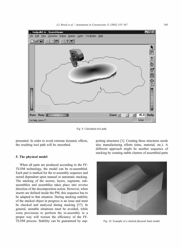
presented. In order to avoid extreme dynamic effects,
the resulting tool path will be smoothed.
5. The physical model
When all parts are produced according to the FF-
TLOM technology, the model can be re-assembled.
Each part is marked for the re-assembly sequence and
stored dependent upon manual or automatic stacking.
The stacking of the sectors, layers, segments, sub-
assemblies and assemblies takes place into reverse
direction of the decomposition action. However, when
inserts are defined inside the PM, this sequence has to
be adapted to that situation. During stacking stability
of the stacked object in progress is an issue and must
be checked and analyzed during stacking [37]. In
general, unstable situations must be avoided, while
extra provisions to perform the re-assembly in a
proper way will worsen the efficiency of the FF-
TLOM process. Stability can be guaranteed by sup-
porting structures [1]. Creating these structures needs
also manufacturing efforts (time, material, etc.). A
different approach might be another sequence of
stacking by creating stable clusters of assembled parts
Fig. 9. Calculated tool path.
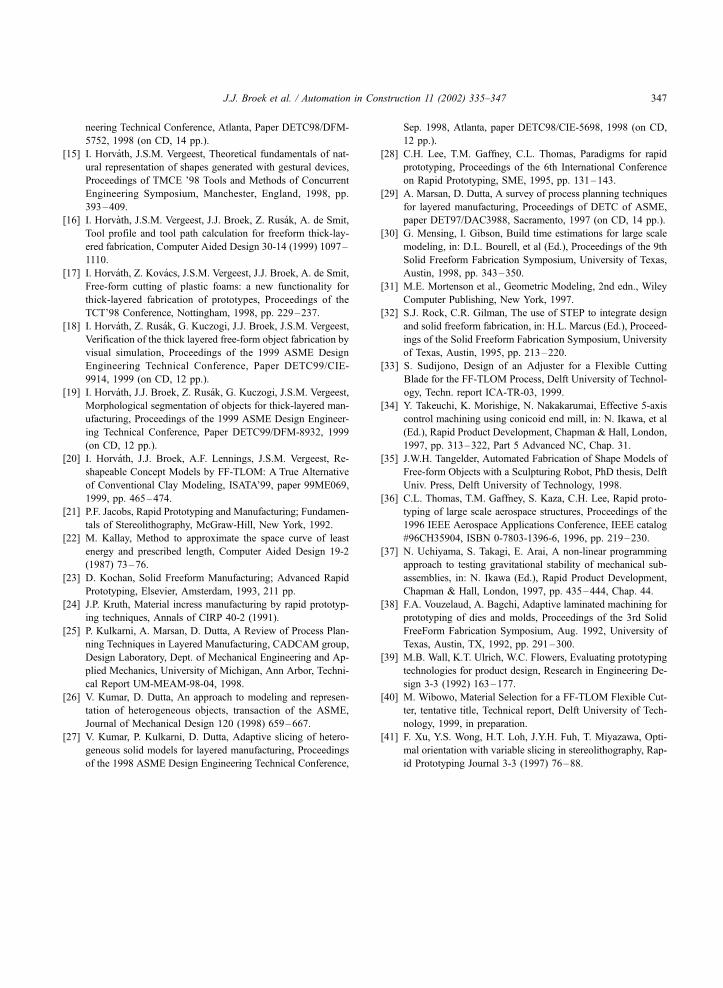
Fig. 10. Example of a stacked physical foam model.
J.J. Broek et al. / Automation in Construction 11 (2002) 335–347 345

and at a later stage to interconnect these subassem-
blies. The accuracy and rigidity of the PM will depend
on the way the stacking is performed, e.g. the inter-
connection of the parts by dowels in center holes and
glueing the layers together. When a subassembly is
applicable for more than one PM (family of PM’s),
then it must be possible to decide about a detachable
interconnection [20]. Finally, a PM is finished and
conserved according to the needs of the designer.
A typical example of a physical model of the FF-
TLOM process is an object, which consists of four
stacked layers of 5 cm thick each (Fig. 10).
6. Conclusions
This paper describes the proposed FF-TLOM
method, which is very well suited for large-sized
monolithic doubly curved objects. The process is
based on higher order approximation of the nominal
shape, decomposition of this shape into easy to manu-
facture parts, stacking the parts in order to obtain a
large-sized physical model and finally, finishing it.
The higher order approximation is supported by a
technology of a flexible hot knife cutting. The geom-
etry decomposition is subdivided into a few hierarch-
ical levels, each with its specific input and result
(functionality, shape representation, accuracy, applied
technology, etc.). The stacking of the parts is per-
formed in the opposite direction of the decomposition.
The process of creating a physical model is feasible
and allows the designer to apply functional physical
models in an early stage of a design process and to
perform it in an optimal way (dedicated to pinpoint
functionality). The amount of effort to finish the object
is minimal and is, in many cases, restricted only to
painting. The FF-TLOM process, however, show a
tendency to become very complicated and care must
be taken to efficiency of the process in order to remain
competitive against other RP methods. Special features
like hollowing, inserts and dedicated tool path gener-
ation might improve the applicability of the process.
Acknowledgements
The research work reported in this paper is a part of
the Integrated Concept Advancement (ICA) project of
the Sub-Faculty of Industrial Design Engineering,
FDEP, of the Delft University of Technology.
References
[1] S. Allen, D. Dutta, On the computation of part orientation
using support structures in layered manufacturing, in: H.L.
Marcus, et al (Ed.), Proceedings of Solid Freeform Fabrication
Symposium, 1994, pp. 259–269, Austin.
[2] J.J. Broek, I. Horvath, A. de Smit, J.S.M. Vergeest, Survey of
Thick Layered Large Object, Manufacturing (FF-TLOM) in
Rapid Prototyping, 1999, in preparation.
[3] J.J. Broek, I. Horvath, A. de Smit, A.F. Lennings, J.S.M.
Vergeest, Aspects of shape decomposition for thick layered
object manufacturing of large sized prototypes, Revue Inter-
nationale de CFAO et d’Informatique Graphique 13-4,5,6
(1998) 153–172.
[4] B.N.K.L. Chalasani, A. Grogan, C.C. Bagchi, A.A. Jara-
Almonte, R.L. Ogale, An algorithm to slice 3D shapes for
reconstruction in prototyping systems, Proceedings of 1991
ASME Computers in Engineering Conference, 1991, pp. 209–
215.
[5a] C.K. Chua, G.K.J. Gan, M. Tong, Interface between CAD and
rapid prototyping systems. Part 1: A study of existing inter-
faces, International Journal of Advanced Manufacturing Tech-
nology 13-8 (1997) 566–570.
[5b] C.K. Chua, G.K.J. Gan, M. Tong, Part 2: LMI—an improved
interface, International Journal of Advanced Manufacturing
Technology 13-8 (1997) 571–576.
[6] P.J. de Jager, Development of a New Slicing Methodology to
Improve Layered Manufacturing, PhD thesis, Delft University
of Technology, 1998.
[7] A. de Smit, J.J. Broek, I. Horvath, Experimental Investigation
of Factors Influential for the Flexible Blade Based Prototyping
Process, Proceedings of the 1999 ASME Design Engineering
Technical Conference, paper DETC99/DFM-8960, 1999 (on
CD, 12 pp.).
[8] J.M. Ferro Pozo, Design of a Foam Slab Manipulator for the
FF-TLOM Equipment, tentative title, Technical report, Delft
University of Technology, 1999, in preparation.
[9] R. Frisch-Fay, Flexible Bars, Butterworth, London, 1962.
[10] I. Gibson, G. Mensing, Rapid prototyping on large scale, Pro-
ceedings of ICMA’97, Hong Kong, 1997, pp. 455 –460,
ISBN-962-85138-1-8.
[11] I. Gil Docampo, Design of a Foam Slab Gripper for the FF-
TLOM Equipment, tentative title, Technical report, Delft Uni-
versity of Technology, 1999, in preparation.
[12] J.W. Gunnink, Multi-Axis High Speed Milling, How to Speed
up Prototyping and Tooling Processes by Using STL-Technol-
ogy TCT’98 Proceedings, Nottingham, 1998, pp. 43–65.
[13] R.L. Hope, P.A. Jacobs, R.N. Roth, Rapid prototyping with
sloping surfaces, Rapid Prototyping Journal 3-1 (1997) 12–
19.
[14] I. Horvath, J.S.M. Vergeest, I. Juhasz, Finding the shape of a
flexible blade for freeform layered manufacturing of plastic
foam objects, Proceedings of the 1998 ASME Design Engi-
J.J. Broek et al. / Automation in Construction 11 (2002) 335–347346
neering Technical Conference, Atlanta, Paper DETC98/DFM-
5752, 1998 (on CD, 14 pp.).
[15] I. Horvath, J.S.M. Vergeest, Theoretical fundamentals of nat-
ural representation of shapes generated with gestural devices,
Proceedings of TMCE ’98 Tools and Methods of Concurrent
Engineering Symposium, Manchester, England, 1998, pp.
393–409.
[16] I. Horvath, J.S.M. Vergeest, J.J. Broek, Z. Rusak, A. de Smit,
Tool profile and tool path calculation for freeform thick-lay-
ered fabrication, Computer Aided Design 30-14 (1999) 1097–
1110.
[17] I. Horvath, Z. Kovacs, J.S.M. Vergeest, J.J. Broek, A. de Smit,
Free-form cutting of plastic foams: a new functionality for
thick-layered fabrication of prototypes, Proceedings of the
TCT’98 Conference, Nottingham, 1998, pp. 229–237.
[18] I. Horvath, Z. Rusak, G. Kuczogi, J.J. Broek, J.S.M. Vergeest,
Verification of the thick layered free-form object fabrication by
visual simulation, Proceedings of the 1999 ASME Design
Engineering Technical Conference, Paper DETC99/CIE-
9914, 1999 (on CD, 12 pp.).
[19] I. Horvath, J.J. Broek, Z. Rusak, G. Kuczogi, J.S.M. Vergeest,
Morphological segmentation of objects for thick-layered man-
ufacturing, Proceedings of the 1999 ASME Design Engineer-
ing Technical Conference, Paper DETC99/DFM-8932, 1999
(on CD, 12 pp.).
[20] I. Horvath, J.J. Broek, A.F. Lennings, J.S.M. Vergeest, Re-
shapeable Concept Models by FF-TLOM: A True Alternative
of Conventional Clay Modeling, ISATA’99, paper 99ME069,
1999, pp. 465–474.
[21] P.F. Jacobs, Rapid Prototyping and Manufacturing; Fundamen-
tals of Stereolithography, McGraw-Hill, New York, 1992.
[22] M. Kallay, Method to approximate the space curve of least
energy and prescribed length, Computer Aided Design 19-2
(1987) 73–76.
[23] D. Kochan, Solid Freeform Manufacturing; Advanced Rapid
Prototyping, Elsevier, Amsterdam, 1993, 211 pp.
[24] J.P. Kruth, Material incress manufacturing by rapid prototyp-
ing techniques, Annals of CIRP 40-2 (1991).
[25] P. Kulkarni, A. Marsan, D. Dutta, A Review of Process Plan-
ning Techniques in Layered Manufacturing, CADCAM group,
Design Laboratory, Dept. of Mechanical Engineering and Ap-
plied Mechanics, University of Michigan, Ann Arbor, Techni-
cal Report UM-MEAM-98-04, 1998.
[26] V. Kumar, D. Dutta, An approach to modeling and represen-
tation of heterogeneous objects, transaction of the ASME,
Journal of Mechanical Design 120 (1998) 659–667.
[27] V. Kumar, P. Kulkarni, D. Dutta, Adaptive slicing of hetero-
geneous solid models for layered manufacturing, Proceedings
of the 1998 ASME Design Engineering Technical Conference,
Sep. 1998, Atlanta, paper DETC98/CIE-5698, 1998 (on CD,
12 pp.).
[28] C.H. Lee, T.M. Gaffney, C.L. Thomas, Paradigms for rapid
prototyping, Proceedings of the 6th International Conference
on Rapid Prototyping, SME, 1995, pp. 131–143.
[29] A. Marsan, D. Dutta, A survey of process planning techniques
for layered manufacturing, Proceedings of DETC of ASME,
paper DET97/DAC3988, Sacramento, 1997 (on CD, 14 pp.).
[30] G. Mensing, I. Gibson, Build time estimations for large scale
modeling, in: D.L. Bourell, et al (Ed.), Proceedings of the 9th
Solid Freeform Fabrication Symposium, University of Texas,
Austin, 1998, pp. 343–350.
[31] M.E. Mortenson et al., Geometric Modeling, 2nd edn., Wiley
Computer Publishing, New York, 1997.
[32] S.J. Rock, C.R. Gilman, The use of STEP to integrate design
and solid freeform fabrication, in: H.L. Marcus (Ed.), Proceed-
ings of the Solid Freeform Fabrication Symposium, University
of Texas, Austin, 1995, pp. 213–220.
[33] S. Sudijono, Design of an Adjuster for a Flexible Cutting
Blade for the FF-TLOM Process, Delft University of Technol-
ogy, Techn. report ICA-TR-03, 1999.
[34] Y. Takeuchi, K. Morishige, N. Nakakarumai, Effective 5-axis
control machining using conicoid end mill, in: N. Ikawa, et al
(Ed.), Rapid Product Development, Chapman & Hall, London,
1997, pp. 313–322, Part 5 Advanced NC, Chap. 31.
[35] J.W.H. Tangelder, Automated Fabrication of Shape Models of
Free-form Objects with a Sculpturing Robot, PhD thesis, Delft
Univ. Press, Delft University of Technology, 1998.
[36] C.L. Thomas, T.M. Gaffney, S. Kaza, C.H. Lee, Rapid proto-
typing of large scale aerospace structures, Proceedings of the
1996 IEEE Aerospace Applications Conference, IEEE catalog
#96CH35904, ISBN 0-7803-1396-6, 1996, pp. 219–230.
[37] N. Uchiyama, S. Takagi, E. Arai, A non-linear programming
approach to testing gravitational stability of mechanical sub-
assemblies, in: N. Ikawa (Ed.), Rapid Product Development,
Chapman & Hall, London, 1997, pp. 435–444, Chap. 44.
[38] F.A. Vouzelaud, A. Bagchi, Adaptive laminated machining for
prototyping of dies and molds, Proceedings of the 3rd Solid
FreeForm Fabrication Symposium, Aug. 1992, University of
Texas, Austin, TX, 1992, pp. 291–300.
[39] M.B. Wall, K.T. Ulrich, W.C. Flowers, Evaluating prototyping
technologies for product design, Research in Engineering De-
sign 3-3 (1992) 163–177.
[40] M. Wibowo, Material Selection for a FF-TLOM Flexible Cut-
ter, tentative title, Technical report, Delft University of Tech-
nology, 1999, in preparation.
[41] F. Xu, Y.S. Wong, H.T. Loh, J.Y.H. Fuh, T. Miyazawa, Opti-
mal orientation with variable slicing in stereolithography, Rap-
id Prototyping Journal 3-3 (1997) 76–88.
J.J. Broek et al. / Automation in Construction 11 (2002) 335–347 347