fourier-transform infrared (ftir) characterization of ... - dtic
TRANSCRIPT
ARMY RESEARCH LABORATORY
Fourier-Transform Infrared (FTIR) Characterization of Chemical Agent
Resistant Coatings (CARC) Durability Using Infrared (IR) Cards and
Silicon Wafers
by William Lum and Philip Patterson
ARL-TR-1494 September 1997
[SXEXC QUALITY INSPECTED 8
fNO
ro
Approved for public release; distribution is unlimited.
The findings in this report are not to be construed as an official Department of the Army position unless so designated by other authorized documents.
Citation of manufacturer's or trade names does not constitute an official endorsement or approval of the use thereof.
Destroy this report when it is no longer needed. Do not return it to the originator.
Army Research Laboratory Aberdeen Proving Ground, MD 21005-5066
ARL-TR-1494 September 1997
Fourier-Transform Infrared (FTIR) Characterization of Chemical Agent Resistant Coatings (CARC) Durability Using Infrared (IR) Cards and Silicon Wafers
William Lum, Philip Patterson Weapons and Materials Research Directorate, ARL
[DTIQ QUALITY INSPECTED S
Approved for public release; distribution is unlimited.
Abstract
Rapid, cost-effective sampling accessories for Fourier-Transform Infrared (FTIR) analysis are quite suitable with minimum sample preparation in coating materials studies. The U.S. Army's camouflage, polyurethane topcoat MIL-C-46168, "Chemical Agent Resistant Coating" (CARC) was applied to infrared (IR) cards and silicon wafers. After curing, the coating's durability was tested using two separate accelerated weathering techniques (QUV-CON and Xenon-Arc), and as well as, two outdoor exposure test methods (South Florida and EMMA(QUA)*-NTW). Characterization of the binder's chemical changes during both natural and accelerated weathering processes was monitored using the FTIR. This final report summarizes the experimental results of the coating's resistance to the accelerated-weathering and outdoor-exposure conditions. Additionally, a brief description of the author's method is described for the preparation of silicon wafers and subsequent FTIR analysis.
Trade name.
TABLE OF CONTENTS
Page
LIST OFFIGURES v
1. BACKGROUND 1
2. APPROACH 2
3. EXPERIMENTAL 4
4. RESULTS 6
5. CONCLUSIONS 11
6. PLANS 11
APPENDIX A: EMMA(QUA) LOG FILE 13
APPENDIX B: XENON-ARC LOG FILE 17
APPENDIX C: QUV-CON LOG FILE 23
APPENDIX D: FORT BELVOIR LOG FILE 27
APPENDKE: SOUTH FLORIDA EXPOSURE 31
DISTRIBUTION LIST 35
REPORT DOCUMENTATION PAGE 39
m
INTENTIONALLY LEFT BLANK.
IV
LIST OF FIGURES
Figure 2age
1. Coated IR cards with metal apertures after 3-mo exposure at Fort Belvoir site ... 8
8 2. Coated aluminum holders with silicon wafers after 800 hr of xenon-arc
exposure
3. Coated IR cards after 600 hr of QUV-CON exposure and a 3-M type 62 background 9
4. Coated aluminum holders with silicon wafers after 300 MJ/m2 EMMA(QUA) exposure 9
5. "Spreadsheet" IR spectra of resins after 0,400, 800 hr xenon-arc exposure 10
A-l. Before EMMA(QUA) exposure 15
A-2. After 150 MH/m2 of EMMA(QUA) exposure 15
A-3. After 300 MJ/m2 of EMMA(QUA) exposure 16
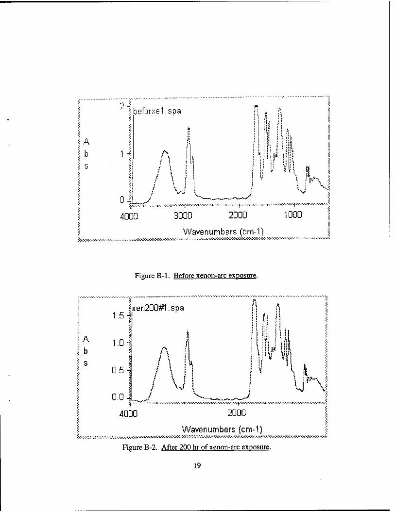
B-l. Before xenon-arc exposure 19
B-2. After 200 hr of xenon-arc exposure 19
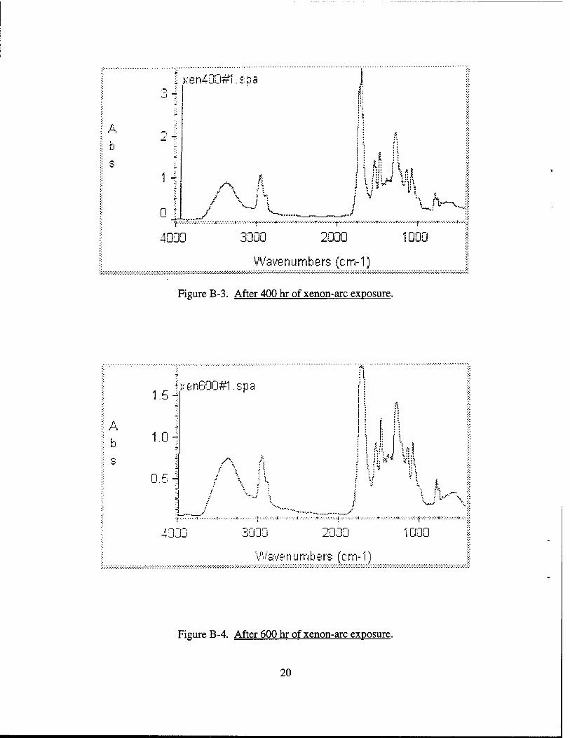
B-3. After 400 hr of xenon-arc exposure 20
B-4. After 600 hr of xenon-arc exposure 20
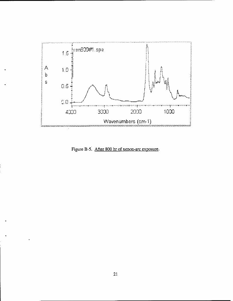
B-5. After 800 hr of xenon-arc exposure 21
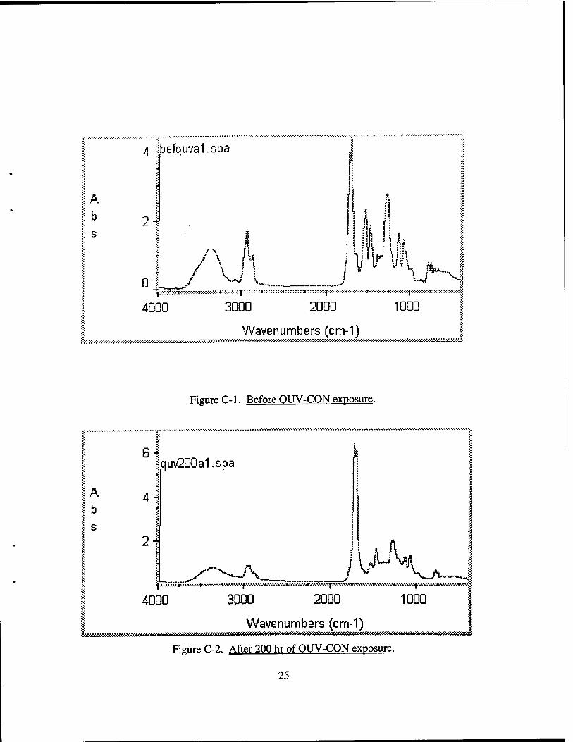
C-l. Before QUV-CON exposure 25
C-2. After 200 hr of QUV-CON exposure 25
C-3. After 400 hr of QUV-CON exposure 26
D-l. Before Belvoir-site exposure 29
D-2. After 1 mo of Belvoir-site exposure 29
Figure Page
D-3. After 3 mo of Belvoir-site exposure 30
E-l. Before South Florida exposure 33
E-2. After 6 mo of South Florida exposure 33
VI
1. BACKGROUND
This comprehensive paper will cover three main objectives, as well as, initial and final results
of the 2-yr investigation. The first aim is to utilize and explore capabilities of advanced
instrumentation and sampling accessories available in the commercial market. The second
purpose is to attempt a better understanding and relationship between accelerated-weathering and
outdoor-exposure testing. The material is the U.S. Army's Chemical Agent Resistance Coatings
(CARC) polyurethane topcoat, comparing test results to its weathering durability. Finally, the
third intention is to establish a rapid, easy-to-do, cost-effective technique to make quick
determinations of the coating's infrared (IR) characteristics and its chemical changes during the
weatherability testing.
The 2-yr Department of the Army (DA) work package (#3261) project utilized the technique
of Fourier transform IR (FTIR) spectroscopy with different sampling accessories. The search for
better tools for rapid analysis has been on-going as demands increase for test information of
newly formulated coating materials. This unique opportunity has been addressed entirely by
determining the most efficient technique. It was identified and selected through testing and
evolution of several coating materials.
The Army's basic camouflage CARC topcoat is the two-component military specification
MIL-C-46168D polyurethane. The CARC system is required on all Army combat, combat-
support, and ground-support equipment, and tactical aircraft. Because of its significant
importance, this coating was used in our study. The applied coating on different sampling
accessories consisted of a clear, polyester polyurethane. The resins, Reichhold Chemicals/
Sherwin-Williams polyester polyol and Bayer Desmodur 851 aliphatic polyisocyanate,* were
obtained from Sherwin-Williams Co.
* Reichhold Chemicals, polyester polyol and Bayer Industrial Chemicals Desmodur 851 aliphatic polyisocyanate, Sherwin-Williams Co., Chicago II.
1
2. APPROACH
The project began by reviewing application literature on FTIR accessories and sampling
methods. Technical training on weathering techniques and IR interpretation was obtained,
followed by procurement of supplies, accessories, and related equipment.
The FTIR spectrometer* was used to investigate the various sampling techniques. The
accessories and techniques identified and selected for this study were as follows:
(1) magnetic sample holders with electronic-grade silicon wafers;1
(2) 3-M disposable IR cards, both polyethylene (PE) and polytetrafluroethylene (PTFE)
microporous film substrates;**
(3) polyvinyl chloride ECRAN Screen Cell card;tf
(4) vertically-oriented attenuated total reflectance (ATR) spectroscopy and;
(5) free films via transmittance.
Preliminary coating samples were run on a trial basis using different spectroscopic techniques
and accessories. A spectrum of each sample, before and after outdoor-exposure and accelerated-
weathering techniques, was scanned and saved in the Nicolet's Omnic FTIR software spectrum
file or the .SPA extension as a standard saving procedure. Omnic was employed to acquire
background and sample spectra, peak positions, and tables. Initially, version 1.1 was installed in
the computer. However, an updated 2.0 version became available and was implemented for use
in all parts of this project.
A new background was used for each sample. Twenty-four actual scans of the sample were
time-averaged with the Fourier transform technique, and the final spectrum was used with
Model 5DX-B, Nicolet Instrument Corp., Madison, WI. f Harrick Scientific Corp., Ossining, NY.
** 3-M New Products Development, Inc., St. Paul, MN. ft Janos Technology, Inc., Townshend, VT.
enhancements for comparison with other spectra. Transmittance was converted into absorbance
in order to do a baseline correction. The appearances of the spectra were adjusted using baseline
corrections and data-smoothing enhancement.
Thallium bromo iodide (KRS-5) crystal was used with a vertical ATR.* The spectral range of
the crystal is from 2200 cm"1 to 250 cm"1, which allows an extended view of the lower region of
the spectrum. The KRS-5 crystal is relatively insoluble and reasonably durable and will produce
the best spectra for the widest variety of samples. The resolution was set at 4 cm"1. Spectra were
measured in the range of 4,000 cm"1 to 400 cm"1 primarily.
All the initial findings are covered in a U.S. Army Research Laboratory (ARL)t progress
report. This interim publication mentioned the selection and elimination of most accessories and
techniques and then focused on two accessories and techniques.
In the second phase, as was in the conclusive phase of the first year, specific IR absorption
bands were monitored to follow the chemical degradation process. The traditional outdoor
Florida exposure" plus EMMA(QUA)tf accelerated outdoor Arizona testing and accelerated-
weathering techniques and devices*" were used for all samples. Techniques were fine-tuned as
problems arose from the trial runs. Changes were made to optimize the FTIR instrument and
sample film preparation for the best reproducibility.
The American Society for Testing and Material (ASTM) method designation G 53 was
selected in using the QUV-CON device with UVA-340 fluorescent sunlamps. This method is
also cited in our coatings specifications, which require 8 hr of ultraviolet (UV) light exposure and
4 hr in a condensation environment in a 12-hr cycle. Temperature settings during UV cycle were
Spectra-Tech, Inc., Shelton, CT. f Lum, W., and P. Patterson. ARL-MR-319, U.S. Army Research Laboratory, Aberdeen Proving Ground (APG),
Aberdeen, MD, July 1996. South Florida Test Division (SFTD), Atlas Electric Devices Co., Miami, FL.
n DSET Laboratories Division, Atlas Electric Devices Co., Phoenix, AZ.
*" QUV-CON UV/condensation and xenon-arc weather-ometer, Adas electric Devices Co., Chicago, IL.
at 70° C and condensation cycle at 50° C. The specified practice in using the Weather-Ometer
device refers to the ASTM method designation G 26, which describes operating conditions of
102 min of UV light and 18 min of both UV light and deionized water spray and 0.35 W/m2 of
irradiance. The conditions are also used in CARC coatings testing program. The EMMA(QUA)
testing followed the ASTM-D-4141 procedure, in which we also included night time wetting
(NTW). NTW is a 3-min water spray done five times during the night to simulate rainfall and
temperature-cooling effect and, therefore, to accelerate degradation.
All test samples were sprayed to a dry film thickness (DFT) of 0.3-0.4 nails of clear resins
and air-dried for at least 1 wk. A tight requirement of extremely thin films was required in order
to get sufficient signal throughputs and reasonable spectra. The main concern was the loss of
adhesion after a period of any exposures. In fact, this had happened on one EMMA(QUA)
sample after 300 MJ/m2 of UV radiance.
The final objective was to determine the most efficient technique for evaluating coating
materials based on their weathering properties. Evaluation encompassed quick IR
characterization, tracking of chemical changes, and rapid service life determination. This
technical report concludes the entire investigation by encompassing all the results of the analysis.
3. EXPERIMENTAL
Coated and uncoated silicon wafer magnetic holders, screen cells, and disposable IR
cards underwent both natural and accelerated weathering. The applied coating consisted of a
clear, two-component polyester polyurethane, typical of a CARC coating. The resins used were
Desmophen 650A-65 polyester polyol and Desmodur N-75 polyisocyanate, obtained from Bayer
Corp.* The resins also used were Reichhold/Sherwin-Williams polyester polyol and Bayer
Desmodur 851U polyisocyanate.
' Desmophen 650A-65 polyester polyol and Desmodur N-75 polyisocyanate, Bayer Corp., Industrial Chemicals Division, Coatings, Pittsburgh, PA.

The natural-weathering phase was performed at the Fort Belvoir, VA site with the racks
facing in a southerly direction at a 45° angle. Open backing holders were used for direct-
weathering (DWI) exposure. This procedure follows the requirements as specified by the ARL
CARC military specifications.
A concept that was initially attempted involved the preparation and analysis of free-standing
strips of cured films. The free-film concept was somewhat effective; however, it proved to be
extremely sensitive to film thickness and very difficult to reproduce quality spectra. Therefore, it
was dropped as a further consideration in the first year.
Thirteen-millimeter-diameter silicon wafers with lab-improvised aluminum holders were
used as the only technique whenever a high temperature (above 60° C) was present as a key
accelerating element of a test. The disposable IR cards as a stand-alone did not fare well under
high temperature. CARC-coated IR cards did better than the uncoated ones, but still, the
limitation is the microporous film construction. Magnetic holders did not withstand direct
sunlight (natural or simulated), rain, and humidity. We found that the silicon wafer was the best
way in tracking particular spectral bands relating to the chemical degradation process. However,
this approach had a higher start-up cost than the disposable IR and screen cards. Most projects
have to be within budget and schedule; therefore, cost is an important consideration.
Once the equipment was ready to run, both the silicon wafer and disposable IR card methods
took only a minute when analyzing a sample. This approach allowed the authors to turn around
the samples quickly and test again for another cycle of weathering exposure. It was proven to be
less time-consuming, more effective, and easily done, even by a spectroscopist with a limited
coatings' background.
However, both the Janos Screen Cell and 3-M IR cards are quite limited in their high
temperature and moisture tolerance. They turned brown in color and warped in shape after
accelerated testing. We therefore improvised our own aluminum holder design for the silicon
wafer as our first-choice method.
4. RESULTS
Particular bands were tracked for each analysis. In the case of CARC coatings, one of the
absorbance bands of interest is at approximately 2,265 cm"1, which signifies a presence of
unreacted isocyanate. Based on the curing time, the relative intensity shows the completeness of
the polyurethane reaction (polyisocyanate with polyol). This band was used by the authors to
monitor the chemical change that was occurring, such as the completeness of the reaction or the
cure time of the coating.
The carbonyl band is around 1,740 cm"1, signifying the presence of anhydrides, ketones, or
esters used in a particular coating. Examples of usage are various polyesters, medium-oil maleic
anhydride and o-phthalic anhydride alkyds, and polyketone polymers. Quick IR runs had
provided a lot of spectral information about a coating, making IR characterization a proven
process.
The polyurethane cross-linking band, also known as the amide II band, is around 1,540 cm"1.
This band indicates the integrity of its urethane cross-links. A loss of intensity of this band is a
result of urethane cross-linking breakage. This significant change was monitored to assess
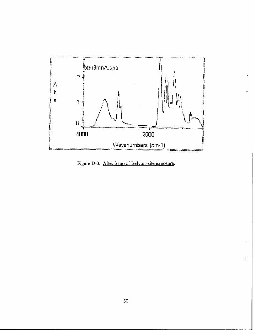
product performance, relating to 3-mo outdoor Belvoir-site exposure and to 24-mo outdoor
Florida exposure. The 6-mo samples from South Florida Test Division (SFTD) were received
and are shown in Figure E-2.
The other important bands are hydrocarbon stretch (around 2,950 cm"1), C-H deformation
band (around 1,450 cm"1), and out-of-plane bending of hydrogens on an aromatic ring C-H band
(around 750 cm"1), along with the aromatic ring bending band (around 710 cm"1).
The clear resin films were completely cured in all exposure methods by the end of the first
exposure cycle. We noticed the diminished band for unreacted isocyanate between the before-
exposure samples and after-exposure samples (Figures A-l-D-3, Appendices A-D).
By examining at the amide II band region, it was apparent that as exposure time increased,
the urethane cross-links were breaking down. Given that fact, something could be said about the
service-life performance of a coating at a drastically reduced testing time. The Reichhold/
Sherwin-Williams resins were able to endure comprehensive simulation of end-use conditions.
This same resin system also passed the CARC test, which is done at the U.S. Army Dugway
Proving Ground, Dugway, UT.
Figures A-l-D-3 (Appendices A-D) represent visual comparisons of some spectra obtained
from different exposure methods and durations. We used the log-file feature in the Omnic
software to generate the spectra series, along with their text describing data collection, processing
operations, and results of the operations. However, application "bugs" were found when we
attempted to make changes to them after we were done with the initial layout.
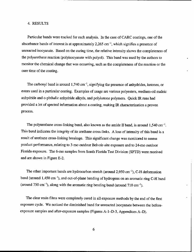
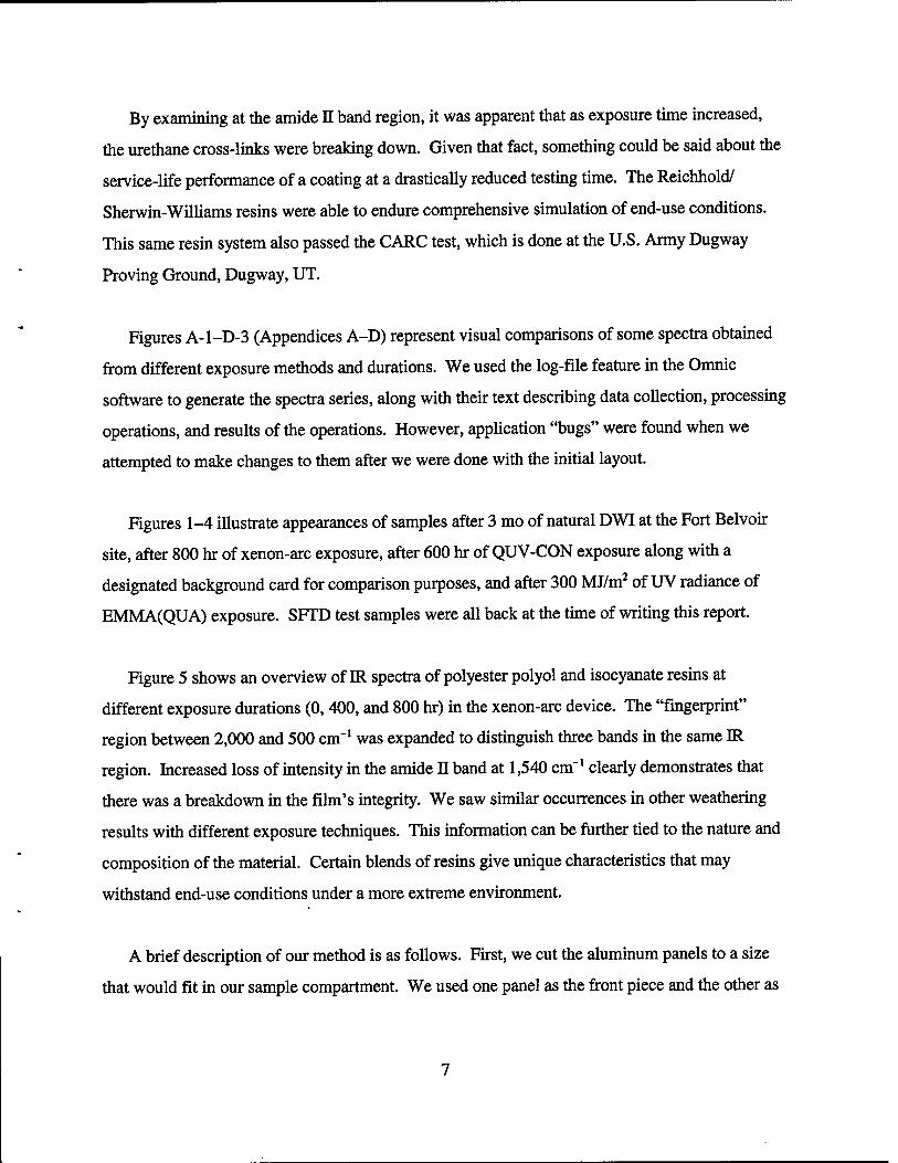
Figures 1-4 illustrate appearances of samples after 3 mo of natural DWI at the Fort Belvoir
site, after 800 hr of xenon-arc exposure, after 600 hr of QUV-CON exposure along with a
designated background card for comparison purposes, and after 300 MJ/m2 of UV radiance of
EMMA(QUA) exposure. SFTD test samples were all back at the time of writing this report.
Figure 5 shows an overview of IR spectra of polyester polyol and isocyanate resins at
different exposure durations (0,400, and 800 hr) in the xenon-arc device. The "fingerprint"
region between 2,000 and 500 cm"1 was expanded to distinguish three bands in the same IR
region. Increased loss of intensity in the amide II band at 1,540 cm"1 clearly demonstrates that
there was a breakdown in the film's integrity. We saw similar occurrences in other weathering
results with different exposure techniques. This information can be further tied to the nature and
composition of the material. Certain blends of resins give unique characteristics that may
withstand end-use conditions under a more extreme environment.
A brief description of our method is as follows. First, we cut the aluminum panels to a size
that would fit in our sample compartment. We used one panel as the front piece and the other as
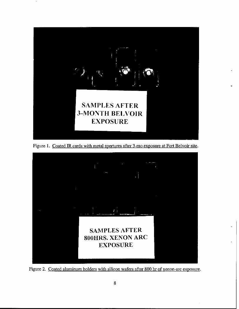
Figure 1. Coated IR cards with metal apertures after 3-mo exposure at Fort Belvoir site.
Figure 2. Coated aluminum holders with silicon wafers after 800 hr of xenon-arc exposure.
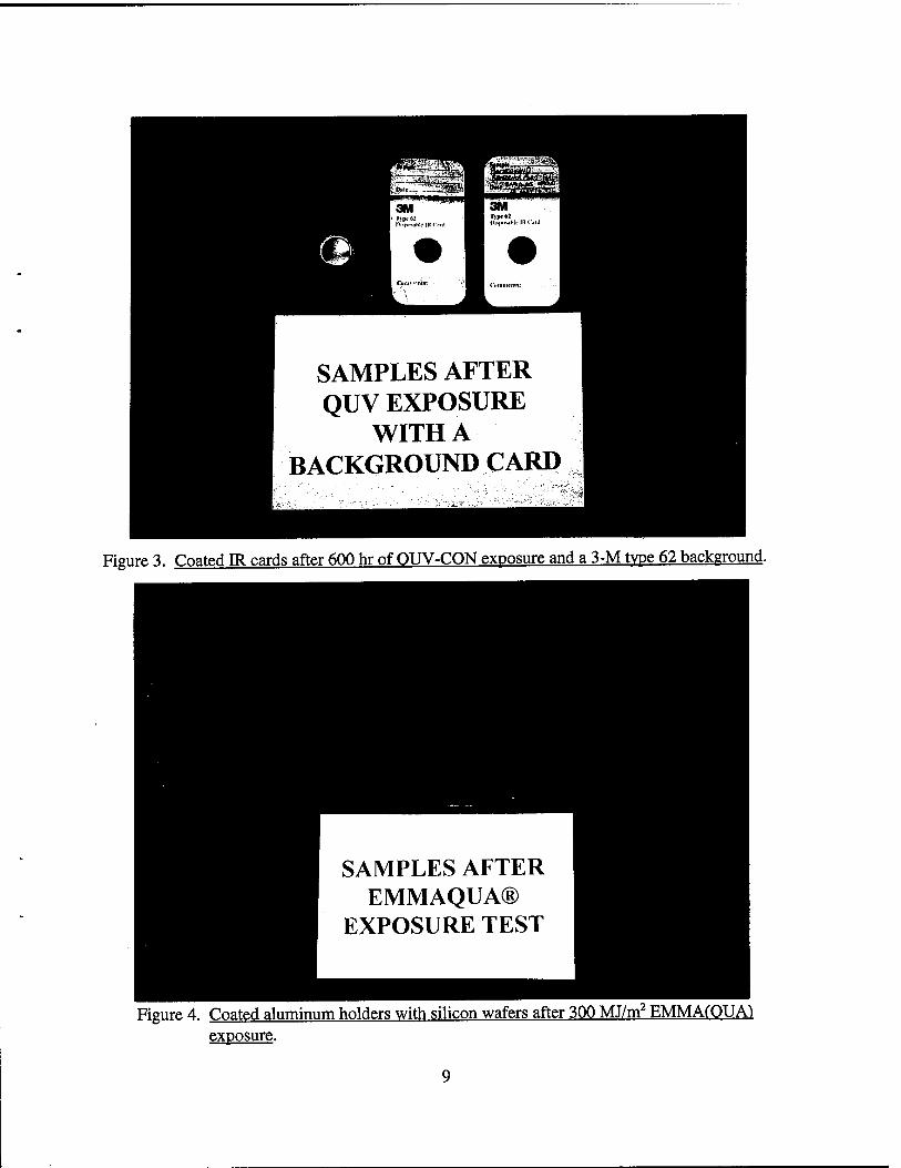
Figure 3. Coated IR cards after 600 hr of OUV-CON exposure and a 3-M type 62 background.
Figure 4. Coated aluminum holders with silicon wafers after 300 MJ/m2 EMMACOUAt exposure.
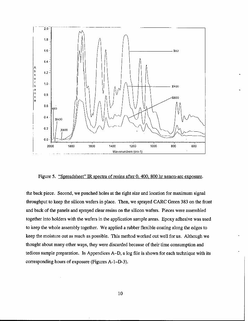
Figure 5. "Spreadsheet" IR spectra of resins after 0. 400. 800 hr xenon-arc exposure.
the back piece. Second, we punched holes at the right size and location for maximum signal
throughput to keep the silicon wafers in place. Then, we sprayed CARC Green 383 on the front
and back of the panels and sprayed clear resins on the silicon wafers. Pieces were assembled
together into holders with the wafers in the application sample areas. Epoxy adhesive was used
to keep the whole assembly together. We applied a rubber flexible coating along the edges to
keep the moisture out as much as possible. This method worked out well for us. Although we
thought about many other ways, they were discarded because of their time consumption and
tedious sample preparation. In Appendices A-D, a log file is shown for each technique with its
corresponding hours of exposure (Figures A-l-D-3).
10
5. CONCLUSIONS
IR band tracking of chemical changes is a highly feasible task. It has been proven that a
wealth of spectral information can be extracted by using the FTIR technique with easy-to-use
accessories. The chemical changes can explain the reasons for the loss of gloss, color, or both;
adhesion; the subject failure in CARC testing; and the gradual inability to resist weathering
effects.
The use of silicon wafers and IR cards can help to provide rapid, reliable answers to coatings'
weatherability questions. Now, studies and results about a certain products' durability can be
realized much sooner. Accelerated weathering can be done with new commercial products of
FTIR accessories in making material prediction more accurate.
The best possible method is the usage of silicon wafers, followed closely by IR cards.
Coatings' testing with natural and accelerated exposure systems is the only area we explored.
However, this paves the way of analyzing a wide variety of samples with minimum sample
preparation.
FTIR spectroscopy is definitely a valuable tool in the evaluation of coating materials relating
to their durability characteristics. Advancements in commercially available accessory products
has made spectral analysis simple and enhanced productivity and capabilities.
6. PLANS
Two-year exposure test results from SFTD will conclude this investigation. Also, authors
plan to obtain the last test result from EMMA(QUA) Arizona testing. Correlation of all
weathering data will be prepared.
11
INTENTIONALLY LEFT BLANK.
12
APPENDIX A:
EMMA(QUA) LOG FILE
13
INTENTIONALLY LEFT BLANK.
14
|A
I" § s
2.51 | emqinitl.spa
2.0 4
1.5 4
1.0-1
0.5 4
0.0 j *«
4000 3000 2000 1000
I Wavenumbers (cm-1) ^.£WtotöOC'toC,WWWX'WW>>XtovX^'vvOw
Figure A-1. Before EMMA(OUA) exposure.
A b s
64 |emm150&\spa
44
24
0 I _JX, 4000 3000
I J
[ftj NJw-
2000 1000
Wavenumbers (cm-1)
Figure A-2. After 150 MH/m2 of EMMA(OUA1 exposure.
15
&y-üvWrWXMtätt&M^^ Wavenumbers (cm-1)
•'^^^'•v^^^^^j,^^^^j"^j-.vy,^^^.v/^.*j-^.vj'A%%v>.->j'>>>>>>>Xv>>>>>>Xw>>>>>>>>>X
Figure A-3. After 300 MJ/m2 of EMMAfOUA) exposure.
16
APPENDIX B:
XENON-ARC LOG FILE
17
INTENTIONALLY LEFT BLANK.
18
A b s
7 4 i; beforxel.spa
1 4
Oi
j | :ni; i i *
y
MM ! W'tf ijM
/
.J.v
4000 3000 2000 1000 I
Wavenumbers (cm-1)
Figure B-l. Before xenon-arc exposure.
A b s
1.5 -f
1.0 i
0.5-j
o.o J
jxer<200#l.spa
A
/ V
4000 2000
Wavenumbers (cm-1)
Figure B-2. After 200 hr of xenon-arc exposure.
19
A D
S
I xen400#1.spa
n
1 4
0
/*\ A \ i
4000
11
\\i hi J
3000 2000
Wave numbers (cm-1)
100C
Figure B-3. After 400 hr of xenon-arc exposure.
A
*xen600#1.spa 1.5^
1.0-i
0.5 ^
:f,,,,,,o.
4000 orin-'""i oUJu
H
; i || j j \\A
t J
1.. •' -. : ■v; %
k '--.J
V, l
---... -.", ., .- s ' •■■ ••■ ••■■•• ■■■■ • v•■"•':" >.-lI- • -. -.•.-.<.- -.+.-.•.-.•.*. ...j ..■■•■.••: ,...,,,,,,,,.,,K.,,,,,,,
•■■■■■■■■■■■*■■•■■■■■■■•■■■*
200C
■h
moo
wavenumDers icm-i j
Figure B-4. After 600 hr of xenon-arc exposure.
20
7 L
„ . b;enS00#1.sps fl Lb ü |!
I | i
1 A I b
I s
:|i | : ;| ■* ; ■ ;-
i n J i ■ ?. < >U nif i
? i i Ml! * £ i i ^ 'Sd ■;
0.5-f /\ ,1 ) W* if\ 1 I / \j\ y \ fc i f _y ^ , ,/ ^ ^|
4030 3000 2000 1000
Wave numbers (cm-1) i; :-:-:-:-:■>:-:■:•:•:•:■:■ .:*:.:.:.:->>x->>x>;-:*>»:*>:>^^ -x-x*x-x*x-x*
Figure B-5. After 800 hr of xenon-arc exposure.
21
INTENTIONALLY LEFT BLANK.
22
APPENDIX C:
QUV-CON LOG FILE
23
INTENTIONALLY LEFT BLANK.
24
A b s
4 Jbefquval.spa
2-1
0 l
A l\ f W v^
r •:
J ii'if \iK u 'jd*-«,
4000 3000 2000 1000
•.■v.v.v.w.r.».V.V.--%*.v.
Wavenumbers (cm-1) |
Figure C-l. Before OUV-CON exposure.
6-!
|A
I b
I S
fquv200a1.spa
J V^V
44
2ij A |
4000 3000 2000 1000 |
Wavenumbers (cm-1) J
Figure C-2. After 200 hr of OUV-CON exposure.
25
4000 3000 2000 1000
Wave numbers (cm-1)
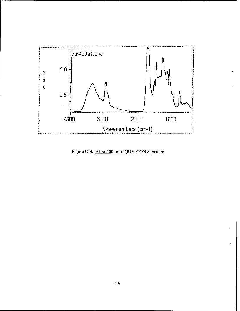
Figure C-3. After 400 hr of OUV-CON exposure.
26
APPENDIX D:
FORT BELVOIR LOG FILE
27
INTENTIONALLY LEFT BLANK.
28
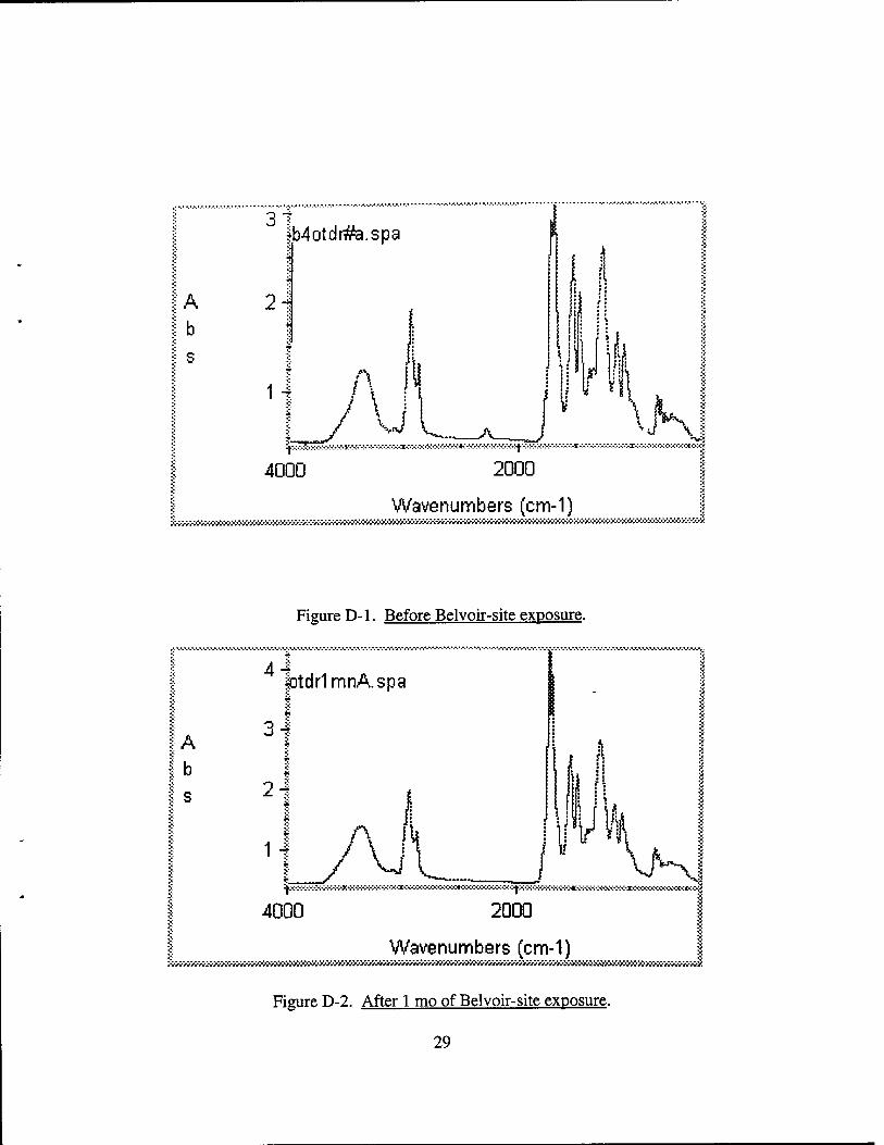
4000 2000
Wavenumbers (cm-1) f
Figure D-l. Before Belvoir-site exposure.
I b
I S
|otdr1mnA.spa
4000 2000 1
Wavenumbers (cm-1)
Figure D-2. After 1 mo of Belvoir-site exposure.
29
A b s
|Dtdr3mnA.spa
2 4
1 4
0 1
/ A 'W
./
si ii
1? *1 \> M
4000 2000
Wavenumbers (cm-1)
Figure D-3. After 3 mo of Belvoir-site exposure.
30
APPENDIX E:
SOUTH FLORIDA EXPOSURE
31
INTENTIONALLY LEFT BLANK.
32
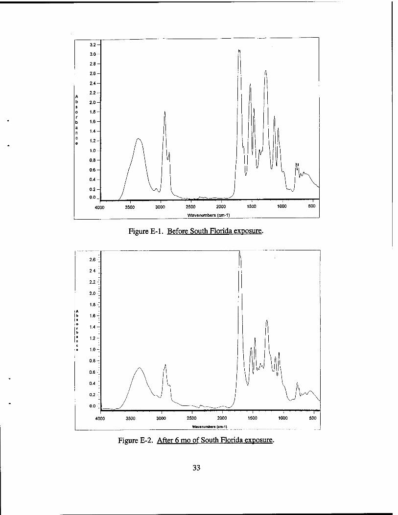
Figure E-l. Before South Florida exposure.
Figure E-2. After 6 mo of South Florida exposure.
33
INTENTIONALLY LEFT BLANK.
34

NO. OF COPIES ORGANIZATION
DEFENSE TECHNICAL INFORMATION CENTER DTIC DDA 8725 JOHN J KINGMAN RD STE0944 FT BELVOIR VA 22060-6218
HQDA DAMOFDQ DENNIS SCHMIDT 400 ARMY PENTAGON WASHINGTON DC 20310-0460
CECOM SP & TRRSTRL COMMCTN DIV AMSEL RD ST MC M H SOICHER FT MONMOUTH NJ 07703-5203
NO. OF COPIES ORGANIZATION
1 INSTFORADVNCDTCHNLGY THE UNIV OF TEXAS AT AUSTIN PO BOX 202797 AUSTIN TX 78720-2797
1 DUSD SPACE 1E765 JGMCNEFF 3900 DEFENSE PENTAGON WASHINGTON DC 20301-3900
1 USAASA MOASAI WPARRON 9325 GUNSTON RD STE N319 FT BELVOIR VA 22060-5582
1 CECOM PMGPS COLS YOUNG FT MONMOUTH NJ 07703
PRIN DPTY FOR TCHNLGY HQ US ARMY MATCOM AMCDCG T MFISETTE 5001 EISENHOWER AVE ALEXANDRIA VA 22333-0001
PRIN DPTY FOR ACQUSTN HQS US ARMY MATCOM AMCDCG A D ADAMS 5001 EISENHOWER AVE ALEXANDRIA VA 22333-0001
DPTY CG FOR RDE HQS US ARMY MATCOM AMCRD BG BEAUCHAMP 5001 EISENHOWER AVE ALEXANDRIA VA 22333-0001
DPTY ASSIST SCY FOR R&T SARDTT TRILLION THEPENTAGON WASHINGTON DC 20310-0103
OSD OUSD(A&T)/ODDDR&E(R) JLUPO THEPENTAGON WASHINGTON DC 20301-7100
GPS JOINT PROG OFC DIR COLJCLAY 2435 VELA WAY STE 1613 LOS ANGELES AFB CA 90245-5500
ELECTRONIC SYS DIV DIR CECOM RDEC JNIEMELA FT MONMOUTH NJ 07703
DARPA L STOTTS JPENNELLA B KASPAR 3701 N FAIRFAX DR ARLINGTON VA 22203-1714
SPCL ASST TO WING CMNDR 50SW/CCX CAPTPH BERNSTEIN 300 O'MALLEY AVE STE 20 FALCON AFB CO 80912-3020
USAFSMC/CED DMA/JPO MISON 2435 VELA WAY STE 1613 LOS ANGELES AFB CA 90245-5500
35
NO. OF COPIES ORGANIZATION
1 US MILITARY ACADEMY MATH SCI CTR OF EXCELLENCE DEPT OF MATHEMATICAL SCI MDN A MAJ DON ENGEN THAYERHALL WEST POINT NY 10996-1786
1 DIRECTOR US ARMY RESEARCH LAB AMSRLCSALTP 2800 POWDER MILL RD ADELPHI MD 20783-1145
1 DIRECTOR US ARMY RESEARCH LAB AMSRLCSALTA 2800 POWDER MILL RD ADELPHI MD 20783-1145
3 DIRECTOR US ARMY RESEARCH LAB AMSRL CILL 2800 POWDER MILL RD ADELPHI MD 20783-1145
ABERDEEN PROVING GROUND
DIRUSARL AMSRL CILP (305)
36
NO. OF COPIES ORGANIZATION
ABERDEEN PROVING GROUND
2 DIR USAMSAA AMXSY-ST AMXSY-D
1 CDRUSATECOM AMSTE-TA
1 CDR CBDCOM TECHNICAL LIBRARY BLDG E3330
1 DIR CBIAC BLDG E3330, RM 150
DIRUSARL AMSRL-SL
JWADE MSTARKS
AMSRL-SL-C, J BEILFUSS (E3331) AMSRL-SL-B, P DELTZ (328) AMSRL-WM-MA (TECH LIB) AMSRL-WM-M
37
INTENTIONALLY LEFT BLANK.
38
REPORT DOCUMENTATION PAGE Form Approved OMB No. 0704-0188
Public »porting burden for this collKtlon of Information It estimated to average 1 hour par response, Including the urn« for reviewing Instruction», searching eUstlneidataisources, gathering and maintaining the data needed, and completing and reviewing the collection of Information. Send commente regerrjng Ulla burden esumate orenyother aspectlotthl» collection of Information, Including suggestions tor reducing this burden, to Weshlngton Heedquartera Services, Directorate!« Information Operations •"<«"•»<«*; 121S Jo"«™»" Dmn.Hion»«s..it.iw< *mnomn v» nm-tM> .nd m tn. otfic M M.n.n«n«.i «nd Budo.i. P.oerwnrt RfriucllwnFW^ro704^196l Wn^lnalon, PC «m
1. AGENCY USE ONLY (Leave blank) 2. REPORT DATE
September 1997
3. REPORT TYPE AND DATES COVERED
Final, September 1995 - October 1996 4. TITLE AND SUBTITLE
Fourier-Transform Infrared (FTIR) Characterization of Chemical Agent Resistant Coatings (CARC) Durability Using Infrared (IR) Cards and Silicon Wafers 6. AUTHORJS)
William Lum and Philip Patterson
7. PERFORMING ORGANIZATION NAME(S) AND ADDRESS(ES)
Director U.S. Army Research Laboratory ATTN: AMSRL-WM-MA Fort Belvoir, VA 22060-5812
9. SPONSORING/MONITORING AGENCY NAMES(S) AND ADDRESS(ES)
5. FUNDING NUMBERS
55SS22
8. PERFORMING ORGANIZATION REPORT NUMBER
ARL-TR-1494
10.SPONSORING/MONITORING AGENCY REPORT NUMBER
11. SUPPLEMENTARY NOTES
12a. DISTRIBUTION/AVAILABILITY STATEMENT
Approved for public release; distribution is unlimited.
12b. DISTRIBUTION CODE
13. ABSTRACT (Maximum 200 words)
Rapid, cost-effective sampling accessories for Fourier-Transform Infrared (FTIR) analysis are quite suitable with minimum sample preparation in coating materials studies. The U.S. Army's camouflage, polyurethane topcoat MEL-C-46168, "Chemical Agent Resistant Coating" (CARC) was applied to infrared (IR) cards and silicon wafers. After curing, the coating's durability was tested using two separate accelerated weathering techniques (QUV-CON and Xenon-Arc), and as well as, two outdoor exposure test methods (South Florida and EMMA(QUA)*-NTW). Characterization of the binder's chemical changes during both natural and accelerated weathering processes was monitored using the FTIR. This final report summarizes the experimental results of the coating's resistance to the accelerated-weathering and outdoor-exposure conditions. Additionally, a brief description of the author's method is described for the preparation of silicon wafers and subsequent FTIR analysis.
♦Trade name.
14. SUBJECT TERMS
Chemical Agent Resistant Coatings (CARC), Fourier-Transform Infrared (FTIR), weatherabilitv. durability study. Fl IK characterization
15. NUMBER OF PAGES
36 16. PRICE CODE
17. SECURITY CLASSIFICATION OFREPORT
UNCLASSIFIED
18. SECURITY CLASSIFICATION OF THIS PAGE
UNCLASSIFIED
19. SECURITY CLASSIFICATION OF ABSTRACT
UNCLASSIFIED
20. LIMITATION OF ABSTRACT
UL NSN 7540-01-280-5500
39 Standard Form 298 (Rev. 2-89) Prescribed by ANSI Std. 239-18 298-102
INTENTIONALLY LEFT BLANK.
40
USER EVALUATION SHEET/CHANGE OF ADDRESS
This Laboratory undertakes a continuing effort to improve the quality of the reports it publishes. Your comments/answers to the items/questions below will aid us in our efforts.
1. ARL Report Number/Author ARL-TR-1494(Lum) Date of Report September 1997
2. Date Report Received .
3. Does this report satisfy a need? (Comment on purpose, related project, or other area of interest for which the report will
be used.)
4. Specifically, how is the report being used? (Information source, design data, procedure, source of ideas, etc.).
5. Has the information in this report led to any quantitative savings as far as man-hours or dollars saved, operating costs
avoided, or efficiencies achieved, etc? If so, please elaborate.
6. General Comments. What do you think should be changed to improve future reports? (Indicate changes to organization,
technical content, format, etc.)
Organization
CURRENT Name E-mail Name ADDRESS
Street or P.O. Box No.
City, State, Zip Code
7. If indicating a Change of Address or Address Correction, please provide the Current or Correct address above and the Old
or Incorrect address below.
Organization
OLD Name ADDRESS
Street or P.O. Box No.
City, State, Zip Code
(Remove this sheet, fold as indicated, tape closed, and mail.) (DO NOT STAPLE)