contouring of diffused objects using lensless fourier transform digital moiré holography
TRANSCRIPT
Contouring of diffused objects using lensless Fouriertransform digital moiré holography
Md. Mosarraf Hossain,1 Gyanendra Sheoran,2 Varun Kumar,2 and Chandra Shakher2,*1Space Physics Laboratory, Vikram Sarabhai Space Center, Thiruvananthapuram-695022, Kerala, India
2Laser Application and Holography Laboratory, IDDC, Indian Institute of Technology Delhi, New Delhi-110016, India
*Corresponding author: [email protected]
Received 21 February 2012; revised 5 May 2012; accepted 4 June 2012;posted 6 June 2012 (Doc. ID 163343); published 20 July 2012
Amethod is proposed for contouring of diffused objects using digital holographic moiré interferometry inlensless Fourier transform configuration. Fringe projection moiré technique combined with digitaldouble-exposure holography produces the contours in this method. Two digital holograms of a 10 mmaluminum alloy cube are recorded by tilting the illumination angle slightly between exposures, and athird one is recorded by translating the detector a little laterally with the final illumination angle un-changed. Upon numerical processing of the first two holograms, a plane parallel fringe system seems tobe projected onto the object. This fringe system can be referred to as the modified grid. Processing of thesecond and the third hologram results in another grid, the reference grid. In effect, processing of the firstand the third hologram combines the modified and the reference grids to produce the moiré contourfringes. The range of contour intervals obtained remains between 2.73 and 0.38 mm with seven differentcontours in between. The presentmethod canmeasure details of a great variety of sizes on objects of largedimensional range. Deviations in themeasured contour intervals from the theoretically calculated valuesare found to be within 12%–18%. This seems to be because of the deviation in the present experimentalgeometry from the ideal theoretical configuration, the hologram digitization, and the particular recon-struction algorithm used in the present experimental arrangement. © 2012 Optical Society of AmericaOCIS codes: 090.1995, 120.2880, 120.3940, 120.4120, 120.4290.
1. Introduction
Optical contouring is the formation of the image of anobject modulated by a fringe pattern correspondingto contours of constant elevation with respect to a re-ference plane. This fringe pattern maps topographi-cal contours onto the surface of the reconstructedimage. Such an image and contour map can be easilyinterpreted to provide a high-resolution whole-fielddisplay of the three-dimensional (3D) shape of anobject [1]. Numerous whole-field noncontact inter-ferometric contouring methods involving speckletechniques, moiré, and holography have been devel-oped and extensively used in various applications
such as, automated contouring of diffuse surfaces[2], defects measurement in art work [3], profilome-try of 3D objects with large height steps/spatially iso-lated surfaces [4], surface profiling of single-step andchannel (dip) objects using phase shifting Talbot in-terferometry [5], and automated manufacturing andquality control [6], where both the high dynamicrange and high precision are required. Moiré is his-torically the first member of this family of opticalmethods. All of these methods have a common math-ematical framework and the moiré theory providesthe basis for understanding the whole family [7].
Moiré is an optical phenomenon where beatpattern isproducedwhen two identical or closely iden-tical systemsof linesaresuperimposed. Inmoiré inter-ferometry, simplicity of geometricalmoiré is combinedwith the high sensitivity of optical interferometry.
1559-128X/12/215331-09$15.00/0© 2012 Optical Society of America
20 July 2012 / Vol. 51, No. 21 / APPLIED OPTICS 5331
Moiré interferometry provides contour maps of in-plane displacement fields with high sensitivity andhigh-spatial resolution that can be seen from its cap-ability of deformation measurement in tiny zones[8]. This technique easily suits the requirement ofreal-time observation of displacement fields with var-iation of external physical parameters. Consequently,this technique has already been established to be aninvaluable tool in science and engineering [8]. Moiréfringepatternsareusedtomeasurevariousquantitiessuch as in- plane or out-of-plane displacements, rota-tions, strains, and curvature. However, the rigorousmathematical analysis proves that moiré is insensi-tive to all out-of-plane motion including rotation [8].Measurement of out-of-plane displacements is eitherfor the purpose of contouring surfaces or to monitordisplacements normal to the surface under study.The two most common methods for out-of-plane mea-surements are shadow moiré and projection moiré/holographic moiré. The surface heights measured inthese techniques are relative to a plane reference sur-faceas longas theprojected fringesorgrating linesarestraightandequallyspacedat theobject.Eachof thesetechniques provides similar results as long as the illu-mination and viewing are collimated. The only differ-ence between the moiré techniques and the projectedfringes and holographic moiré is the change in the lo-cation of the reference plane [9]. Holographic moirécontouring has been realized by many ways: the twosourcemethod, where the angle of object illuminationbeam or the reference beam is changed [10,11],holographic-sandwich method [12], by translatingthe object [13], by displacing the object and the illumi-nationbeam[14],andbydisplacingtherecordingmed-ium and the illumination beam [15]. The holographicmoiré contouringmethod canbeapplied tomanyprac-tical purposes in a much easier way than other moirémethods that need the troublesome preparation ofgrids in front of the object.
In recent decades, digital holography [16–19] hasemerged as amore reliable, faster, andmore accuratetechnique than its conventional counterpart. Be-cause this technique uses opto-electronic sensorssuch as CCD/CMOS for recording holograms, it doesnot involve complex and time-consuming chemicalprocessing of the recording medium. Also, fast re-cording and the high-speed numerical reconstructionrate of digital holograms, due to the availability ofvideo frequencies of the sensor and fast computers,is now a reality. Most importantly, this has madeaccurate quantitative access to the phase of an indi-vidual object wavefront possible in addition to theamplitude based on a single digital hologram, unlikeany optical methods including conventional hologra-phy. Interferometry based on digital holographyis widely termed as digital holographic interferome-try (DHI) [17–19]. In DHI, two separate digitalholograms are recorded corresponding to two differ-ent states of the object. The complex object wave-fronts are reconstructed from these hologramsnumerically in a computer. Then the interference
phase, which is the difference between phases of thetwo reconstructed wavefronts, is calculated. The in-terference phase combined with the information onthe sensitivity vector and the experimental param-eters of the holographic set-up gives the physicalquantities of interest such as deformation, refractiveindex, and temperature. DHI has been applied innumerous practical applications including shape/contour measurement and nondestructive testing[17–28]. In this manuscript we have demonstrateda method for contouring of diffused objects using di-gital holographic moiré interferometry (DHMI) inlensless Fourier transform configuration. The pre-sent method exploits easier applicability of holo-graphic moiré compared to other moiré methods,better accuracy of digital holography comparedto conventional holography, and simple/fast lens-less Fourier transform digital holography (LFDH)configuration to yield a contouring technique thatcould be effective with proper instrumentation foronline defect/deformation measurement of small,as well as large diffused objects in an industrialenvironment.
2. Theory
A. Recording and Numerical Reconstruction of Hologramin LFDH
LFDH is similar in principle to its conventional coun-terpart where although lenses are used, no Fouriertransforming lens (FTL) is used. In this type of holo-gram recording geometry, although no Fourier trans-form actually takes place, the reason for associatingthe words Fourier transform can be understood byconsidering the interference pattern generated bylight waves from a single point on an object andthe point reference source. Since in this configura-tion, the reference wave is brought to focus in theplane of cross section of interest of the object, boththe object wave and the reference wave are divergingspherical waves with the same average curvature. Asa consequence, when they interfere the intensity dis-tribution produced is (within the paraxial approxi-mation) a sinusoidal fringe pattern of a spatialfrequency that is unique to that object point. The ho-logram obtained in this way gains the same propertythat holds for a true Fourier transform hologram andhence the mention of lensless Fourier in this type ofhologram [29].
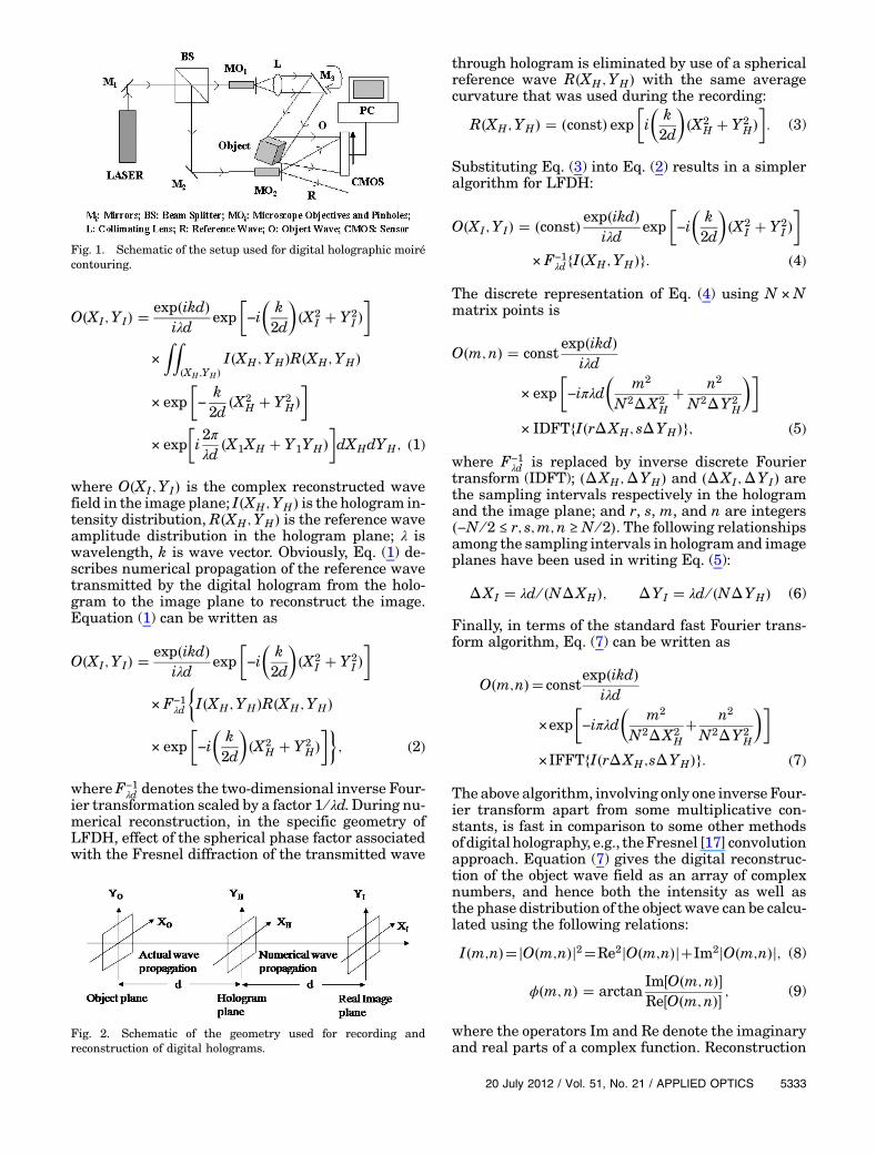
Figure 1 shows the schematic of a typical LFDHset-up. Optical interference between the object and refer-ence beams coming from the same plane generate ahologram that is recorded using a CMOS sensorand stored in the memory of a computer as a digitalhologram. Numerical reconstruction of LFDH isbased on the Fresnel reconstruction algorithm thatwas first presented by Schnars [17]. Schematic of geo-metry used for recording and reconstruction of digitalholograms is shown inFig. 2. TheFresnel algorithm isexpressed by the Fresnel diffraction integral [17]:
5332 APPLIED OPTICS / Vol. 51, No. 21 / 20 July 2012
O�XI; YI� �exp�ikd�
iλdexp
�−i�k2d
��X2
I � Y2I ��
×ZZ
�XH;YH�I�XH;YH�R�XH;YH�
× exp�−
k2d
�X2H � Y2
H��
× exp�i2πλd
�X1XH � Y1YH��dXHdYH; (1)
where O�XI; YI� is the complex reconstructed wavefield in the image plane; I�XH;YH� is the hologram in-tensity distribution, R�XH;YH� is the reference waveamplitude distribution in the hologram plane; λ iswavelength, k is wave vector. Obviously, Eq. (1) de-scribes numerical propagation of the reference wavetransmitted by the digital hologram from the holo-gram to the image plane to reconstruct the image.Equation (1) can be written as
O�XI; YI� �exp�ikd�
iλdexp
�−i�k2d
��X2
I � Y2I ��
× F−1λd
�I�XH;YH�R�XH;YH�
× exp�−i�k2d
��X2
H � Y2H�
��; (2)
whereF−1λd denotes the two-dimensional inverse Four-
ier transformation scaled by a factor 1 ∕ λd. During nu-merical reconstruction, in the specific geometry ofLFDH, effect of the spherical phase factor associatedwith the Fresnel diffraction of the transmitted wave
through hologram is eliminated by use of a sphericalreference wave R�XH;YH� with the same averagecurvature that was used during the recording:
R�XH;YH� � �const� exp�i�k2d
��X2
H � Y2H�
�: (3)
Substituting Eq. (3) into Eq. (2) results in a simpleralgorithm for LFDH:
O�XI; YI� � �const� exp�ikd�iλd
exp�−i�k2d
��X2
I � Y2I ��
× F−1λdfI�XH;YH�g: (4)
The discrete representation of Eq. (4) using N ×Nmatrix points is
O�m;n� � constexp�ikd�
iλd
× exp�−iπλd
�m2
N2ΔX2H
� n2
N2ΔY2H
��
× IDFTfI�rΔXH; sΔYH�g; (5)
where F−1λd is replaced by inverse discrete Fourier
transform (IDFT); �ΔXH;ΔYH� and �ΔXI;ΔYI� arethe sampling intervals respectively in the hologramand the image plane; and r, s, m, and n are integers�−N ∕ 2 ≤ r; s;m; n ≥ N ∕ 2�. The following relationshipsamong the sampling intervals in hologram and imageplanes have been used in writing Eq. (5):
ΔXI � λd ∕ �NΔXH�; ΔYI � λd ∕ �NΔYH� (6)
Finally, in terms of the standard fast Fourier trans-form algorithm, Eq. (7) can be written as
O�m;n�� constexp�ikd�
iλd
×exp�−iπλd
�m2
N2ΔX2H
� n2
N2ΔY2H
��
×IFFTfI�rΔXH;sΔYH�g: (7)
The above algorithm, involving only one inverse Four-ier transform apart from some multiplicative con-stants, is fast in comparison to some other methodsof digital holography, e.g., theFresnel [17] convolutionapproach. Equation (7) gives the digital reconstruc-tion of the object wave field as an array of complexnumbers, and hence both the intensity as well asthe phase distribution of the object wave can be calcu-lated using the following relations:
I�m;n��jO�m;n�j2�Re2jO�m;n�j�Im2jO�m;n�j; (8)
ϕ�m;n� � arctanIm�O�m;n��Re�O�m;n�� ; (9)
where the operators Im and Re denote the imaginaryand real parts of a complex function. Reconstruction
Fig. 1. Schematic of the setup used for digital holographic moirécontouring.
Fig. 2. Schematic of the geometry used for recording andreconstruction of digital holograms.
20 July 2012 / Vol. 51, No. 21 / APPLIED OPTICS 5333
of a digital hologram using Eq. (7) yields the twinimages: the real and the conjugate images plus thezero order of diffraction, the DC component. Suitablefiltering techniques must be used for removal ofthe conjugate as well as the DC image to enhancethe signal-to-noise ratio of the primary reconstructedimage.
B. Digital Holographic Interferometry
In DHI, two digital holograms, I1�r; s� and I2�r; s� cor-responding to two different states of the object arerecorded. These holograms can be added to formthe digital double exposure hologram (DDEH)I1�r; s� � I2�r; s�. Numerical reconstruction of theDDEH, according to Eq. (7), gives an interferogramsuperimposed on the reconstructed image of theobject. Such an intense interferogram requires anevaluation to yield the desired interference phasedistribution. It is known that digital holographyhas access to the accurate quantitative phase ofthe individual reconstructed wave field. The phasedistributions ϕ1�m;n� and ϕ2�m;n�, correspondingto two digital holograms can be calculated usingEqs. (7) and (9). The interference phase distributioncan then be calculated by the following modulo 2πsubtraction:
ΔΦ�m;n� �8<:Φ2�m;n� −Φ1�m;n� � 2π if Φ2�m;n� −Φ1�m;n� < −πΦ2�m;n� −Φ1�m;n� − 2π if Φ2�m;n� −Φ1�m;n� ≥ �πΦ2�m;n� −Φ1�m;n� else
: (10)
DHI uses the interference phase along with the con-cerned parameters of the holographic arrangementto give the quantitative information on change ofstate of the object and/or the concerned physicalquantities/parameters in an accurate and simpleway unlike its conventional counterpart or any otheroptical methods. DHI also exploits the other impor-tant advantages of digital holography mentioned inthe Introduction and hence is becoming an accuratepowerful tool covering a widest range of applications.
The phase values calculated according to Eq. (9)and the interference phase remain wrapped in therange �−π;�π� radians corresponding to the princi-pal value of the arctan function. The numericallycalculated interference phase is discontinuous, butactually it is continuous and may range over aninterval greater than 2π. The discontinuities are cor-rected by the phase unwrapping technique that es-sentially consists of adding or subtracting suitableinteger multiples of 2π to phase values at all points.DHI uses the accurate quantitative continuous un-wrapped phase that is directly linked to the shapeof the object to be contoured and/or the concernedphysical properties/parameters to be measured.
C. Contouring Methodology
The present digital holographic contouring method isof fringe projection moiré type. Here, two digitalholograms of an object are recorded in LFDHconfiguration—the first one with the initial illumina-tion angle β, and the other one with the final illumi-nation angle reached through a slight tilt θ given tothe collimated illumination beam about the initialangle β. Complex object wavefronts are reconstructedfrom the holograms numerically using the simple al-gorithm of LFDH. The interference phase obtainedfrom the individual phases of the wavefronts yieldsequidistant, parallel straight fringes superimposedon the reconstructed image of the object. Effectively,upon processing of these holograms, the object seemsto be illuminated by two collimated beams fromslightly different directions and the resulting equallyspaced, parallel plane fringes are projected onto theobject surface. These fringes intersect the object andare altered by its surface relief. The altered set offringes can be termed as the modified grid. Fringespacing of the modified grid is given by
lM � λ ∕ 2 sin θ; (11)
where λ is wavelength of laser light and θ is mirrorrotation angle about β. Then a third hologram is re-corded by translating the detector a bit laterally in aplane perpendicular to the line joining the object andthe detector while keeping the final illumination an-gle unchanged. Numerical processing of the secondand the third holograms in the way mentioned aboveresults in the vicinity of the normal through the cen-ter of the detector equally spaced straight fringessuperimposed on the image of the object. Thesefringes, in general, are a set of rotational hyperbo-loids, the two foci being the centers of the detectorbefore and after the translation. This set of planeparallel fringes is referred to as the reference gridas it is not projected onto the object and hence notaffected by the presence of the object. The referencegrid fringe spacing is given by [15]
lR � �d ∕ 2t�λ; (12)
where d is the distance between hologram and theimage plane, and t is half the distance of detectortranslation.
In effect, processing of the first hologram recordedwith the initial illumination angle and the third
5334 APPLIED OPTICS / Vol. 51, No. 21 / 20 July 2012
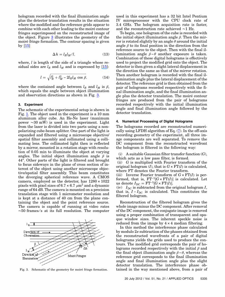
hologram recorded with the final illumination angleplus the detector translation results in the situationwhere the modified and the reference grids appear tocombine with each other leading to the moiré contourfringes superimposed on the reconstructed image ofthe object. Figure 3 illustrates the geometry of themoiré fringe formation. The contour spacing is givenby [15]
Δh � lRlM ∕ l; (13)
where, l is length of the side of a triangle whose re-sidual sides are lR and lM and is expressed by [15]:
l �������������������������������������������������l2R � l2M − 2lRlM cos β
q; (14)
where the contained angle between lR and lM is β,which equals the angle between object illuminationand observation directions as shown in Fig. 3.
3. Experiment
The schematic of the experimental setup is shown inFig. 1. The object used in the experiment is a 10 mmaluminum alloy cube. An He-Ne laser (maximumpower ∼30 mW) is used in the experiment. Lightfrom the laser is divided into two parts using a non-polarizing cube-beam splitter. One part of the light isexpanded and filtered using a microscope objective/spatial filter assembly and collimated using a colli-mating lens. The collimated light then is reflectedby a mirror, mounted in a rotation stage with resolu-tion of 0.05 min to illuminate the object at varyingangles. The initial object illumination angle β is44°. Other parts of the light is filtered and broughtto focus sideways in the plane of cross section of in-terest of the object using another microscope objec-tive/spatial filter assembly. This beam constitutesthe diverging spherical reference wave. A CMOScamera, employed as the detector, has 1280 × 1022pixels with pixel sizes of 6.7 × 6.7 μm2 and a dynamicrange of 64 dB. The camera is mounted on a precisiontranslation stage with 1 micrometer resolution andis kept at a distance of 40 cm from the plane con-taining the object and the point reference source.The camera is capable of running at video rates∼50 frames ∕ s at its full resolution. The computer
used in this experiment has a 32 bit Intel PentiumIV microprocessor with the CPU clock rate of3.4 GHz. The hologram acquisition rate is faster,and the reconstruction rate achieved ∼1 Hz.
To begin, one hologram of the cube is recorded withthe initial object illumination angle β. Then the mir-ror is rotated slightly by an angle θ around the initialangle β to its final position in the direction from thereference source to the object. Then with the final il-lumination angle β−θ another exposure is taken.Combination of these digital holograms is effectivelyused to project the modified grid onto the object. Thedetector is then given a slight lateral displacement inthe direction the same as that of the mirror rotation.Then another hologram is recorded with the final il-lumination angle plus the lateral displacement of thedetector. The reference grid is then obtained from thepair of holograms recorded respectively with the fi-nal illumination angle, and the final illumination an-gle plus the detector translation. The moiré contourfringes are produced from the pair of hologramsrecorded respectively with the initial illuminationangle and final illumination angle followed by thedetector translation.
4. Numerical Processing of Digital Holograms
The holograms recorded are reconstructed numeri-cally using LFDH algorithm of Eq. (7). In the off-axisrecording geometry of the experiment, all three im-age components are well separated. To remove theDC component from the reconstructed wavefrontthe hologram is filtered in the following way:
(i) A suitable Gaussian filter transfer function (G),which acts as a low pass filter, is formed.(ii) G is multiplied with Fourier transform of theoriginal hologram (I), that is G × FT�I� is calculated,where FT denotes the Fourier transform.(iii) Inverse Fourier transform of G × FT�I� is per-formed, that is, FT−1�G × FT�I�� is calculated. Letus denote IDC � FT−1�G × FT�I��.(iv) IDC is subtracted from the original hologram I,that is, I − IDC is calculated. This constitutes thefiltered hologram.
Reconstruction of the filtered hologram gives thewhole imageminus the DC component. After removalof the DC component, the conjugate image is removedusing a proper combination of transparent and opa-que window sizes. The inherent speckle noise isreduced from the image by 4 × 4 median filtering.
In this method the interference phase calculatedbymodulo 2π subtraction of the phases obtained fromthe reconstructed wavefronts of a pair of digitalholograms yields the grids used to produce the con-tours. The modified grid corresponds the pair of ho-lograms recorded respectively with the initial β andthe final object illumination angle β−θ, whereas thereference grid corresponds to the final illuminationangle and final illumination angle plus the slightdetector translation. The interference phase ob-tained in the way mentioned above, from a pair ofFig. 3. Schematic of the geometry for moiré fringe formation.
20 July 2012 / Vol. 51, No. 21 / APPLIED OPTICS 5335
holograms recorded respectively with the initial illu-mination angle and final illumination angle plus thedetector translation, gives the moiré contour fringessuperimposed on the reconstructed image of the ob-ject. The inherent speckle noise is reduced from theinterference phase map by 5 × 5median filtering. Re-construction and all the concerned processing of thedigital holograms are carried out in the MATLABenvironment.
5. Results and Discussion
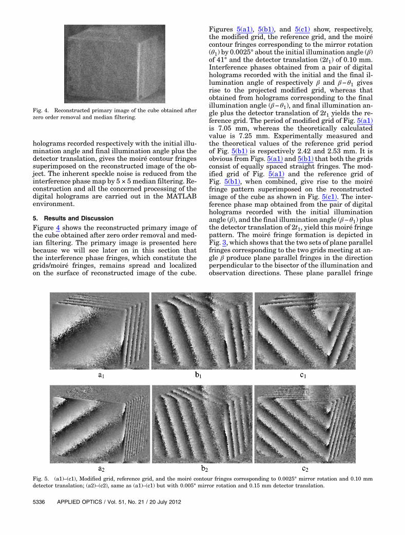
Figure 4 shows the reconstructed primary image ofthe cube obtained after zero order removal and med-ian filtering. The primary image is presented herebecause we will see later on in this section thatthe interference phase fringes, which constitute thegrids/moiré fringes, remains spread and localizedon the surface of reconstructed image of the cube.
Figures 5(a1), 5(b1), and 5(c1) show, respectively,the modified grid, the reference grid, and the moirécontour fringes corresponding to the mirror rotation(θ1) by 0.0025° about the initial illumination angle (β)of 41° and the detector translation (2t1) of 0.10 mm.Interference phases obtained from a pair of digitalholograms recorded with the initial and the final il-lumination angle of respectively β and β−θ1 givesrise to the projected modified grid, whereas thatobtained from holograms corresponding to the finalillumination angle (β−θ1), and final illumination an-gle plus the detector translation of 2t1 yields the re-ference grid. The period of modified grid of Fig. 5(a1)is 7.05 mm, whereas the theoretically calculatedvalue is 7.25 mm. Experimentally measured andthe theoretical values of the reference grid periodof Fig. 5(b1) is respectively 2.42 and 2.53 mm. It isobvious from Figs. 5(a1) and 5(b1) that both the gridsconsist of equally spaced straight fringes. The mod-ified grid of Fig. 5(a1) and the reference grid ofFig. 5(b1), when combined, give rise to the moiréfringe pattern superimposed on the reconstructedimage of the cube as shown in Fig. 5(c1). The inter-ference phase map obtained from the pair of digitalholograms recorded with the initial illuminationangle (β), and the final illumination angle (β−θ1) plusthe detector translation of 2t1, yield this moiré fringepattern. The moiré fringe formation is depicted inFig. 3, which shows that the two sets of plane parallelfringes corresponding to the two grids meeting at an-gle β produce plane parallel fringes in the directionperpendicular to the bisector of the illumination andobservation directions. These plane parallel fringe
Fig. 4. Reconstructed primary image of the cube obtained afterzero order removal and median filtering.
Fig. 5. (a1)–(c1), Modified grid, reference grid, and the moiré contour fringes corresponding to 0.0025° mirror rotation and 0.10 mmdetector translation; (a2)–(c2), same as (a1)–(c1) but with 0.005° mirror rotation and 0.15 mm detector translation.
5336 APPLIED OPTICS / Vol. 51, No. 21 / 20 July 2012
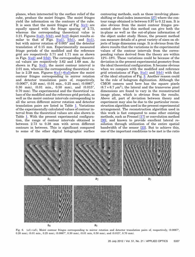
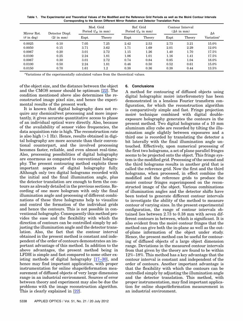
planes, when intersected by the surface relief of thecube, produce the moiré fringes. The moiré fringesyield the information on the contours of the cube.It is seen that the moiré fringes of Fig. 5(c1) areequally spaced with the fringe spacing of 2.73,whereas the corresponding theoretical value is3.21. Figures 5(a2), 5(b2), and 5(c2) depict results si-milar to that of Figs. 5(a1), 5(b1), and 5(c1),but with mirror rotation of 0.005° and the detectortranslation of 0.15 mm. Experimentally measuredfringe periods of the modified and the referencegrid are respectively 3.71 and 1.71 mm as shownin Figs. 5(a2) and 5(b2). The corresponding theoreti-cal values are respectively 3.62 and 1.69 mm. Asshown in Fig. 5(c2), the moiré contour interval is2.01 mm, whereas the corresponding theoretical va-lue is 2.29 mm. Figures 6(a1)–6(a5)show the moirécontour fringes corresponding to mirror rotationand detector translation pairs of, respectively,(0.0067°, 0.20 mm), (0.01 min., 0.25 mm), (0.0067°,0.30 mm), (0.01 min., 0.50 mm), and (0.015°,0.70 mm). The experimental and the theoretical va-lues of the modified and the reference grid periods, aswell as the moiré contour intervals corresponding toall the seven different mirror rotation and detectortranslation pairs are listed in Table 1. Variationsof the experimentally calculated values of contour in-terval from the theoretical values are also shown inTable 1. With the present experimental configura-tion, the range of contour intervals obtained isbetween 2.73 to 0.38 mm with seven differentcontours in between. This is significant comparedto some of the other digital holographic surface
contouring methods, such as those involving phase-shifting or dual-index immersion [27] where the con-tour range obtained is between 0.97 to 0.12 mm. It isalso obvious from the moiré contour fringes pre-sented above that this method can give both thein-plane as well as the out-of-plane information ofthe object under study. Hence, the present methodcan measure details of a great variety of sizes on ob-jects of large dimension range. It is obvious from theabove results that the variations in the experimentalvalues of the contour intervals from the corres-ponding values derived from the theory are within12%–18%. These variations could be because of thedeviation in the present experimental geometry fromthe ideal theoretical configuration. It became obviouswhen we compare with the modified and referencegrid orientations of Figs. 5(a1) and 5(b1) with thatof the ideal situation of Fig. 3. Another reason couldbe the role of hologram digitization. Although theCMOS camera used here has the square pixels(6.7 × 6.7 μm2), the lateral and the transverse pixeldimensions are found to vary in the reconstructedimage plane, which is obvious from the results.Above all, part of deviation between theory andexperiment may also be due to the particular recon-struction algorithm used in the present experimentalarrangement. The reconstruction algorithm used inthis work is fast compared to some other existingmethods, such as Fresnel [17] or convolution method[30], and known to provide excellent lateral re-solution through utilization of the entire spatialbandwidth of the sensor [22]. But to achieve this,one of the important conditions to be met is the ratio
Fig. 6. (a1)–(a5), Moiré contour fringes corresponding to mirror rotation and detector translation pairs of, respectively, (0.0067°,0.20 mm), (0.01 min., 0.25 mm), (0.0067°, 0.30 mm), (0.01 min, 0.50 mm), and (0.015°, 0.70 mm).
20 July 2012 / Vol. 51, No. 21 / APPLIED OPTICS 5337
of the object size, and the distance between the objectand the CMOS sensor should be optimum [22]. Thecondition mentioned above also determines the re-constructed image pixel size, and hence the experi-mental results of the present work.
It is known that digital holography does not re-quire any chemical/wet processing and more impor-tantly, it gives accurate quantitative access to phaseof an individual optical wave directly. Also, becauseof the availability of sensor video frequencies, thedata acquisition rate is high. The reconstruction rateis also high (>1 Hz). Hence, results obtained in digi-tal holography are more accurate than their conven-tional counterpart, and the involved processingbecomes faster, reliable, and even almost real-time.Also, processing possibilities of digital holographyare enormous as compared to conventional hologra-phy. The present contouring method exploits theseimportant aspects of digital holography fully.Although only two digital holograms recorded withthe initial and the final illumination angle, plusthe detector translation are enough to form the con-tours as already detailed in the previous sections. Re-cording of one more hologram with only the finalillumination angle and processing of different combi-nations of these three holograms help to visualizeand control the formation of the individual gridsand hence the contours. This is not possible in con-ventional holography. Consequently this method pro-vides the ease and the flexibility with which thedirection of contours can be controlled simply by ad-justing the illumination angle and the detector trans-lation. Also, the fact that the contour intervalobtained in the present method is constant and inde-pendent of the order of contours demonstrates an im-portant advantage of this method. In addition to theabove advantages, the present method being inLFDH is simple and fast compared to some other ex-isting methods of digital holography [17–30], andhence may find important application, with properinstrumentation for online shape/deformation mea-surement of diffused objects of very large dimensionrange in an industrial environment. Sources of errorbetween theory and experiment may also be due theproblems with the image reconstruction algorithm.This is clearly explained in [22].
6. Conclusions
A method for contouring of diffused objects usingdigital holographic moiré interferometry has beendemonstrated in a lensless Fourier transform con-figuration, for which the reconstruction algorithmis comparatively simple and fast. Fringe projectionmoiré technique combined with digital double-exposure holography generates the contours in thepresent method. Two digital holograms of a 10 mmaluminum alloy cube are recorded by tilting the illu-mination angle slightly between exposures and athird one is recorded by translating the detector abit laterally with the final illumination angle un-touched. Effectively, upon numerical processing ofthe first two holograms, a set of plane parallel fringesseems to be projected onto the object. This fringe sys-tem is themodified grid. Processing of the second andthe third holograms results in another grid that iscalled the reference grid. Now the first and the thirdholograms, when processed, in effect combine themodified and the reference grids to produce themoiré contour fringes superimposed on the recon-structed image of the object. Various combinationsof illumination angles and the detector shifts havebeen tested to generate different contour intervalsto investigate the ability of the method to measurecontour of varying sizes. In the present experimentalconfiguration, the range of contour intervals ob-tained lies between 2.73 to 0.38 mm with seven dif-ferent contours in between, which is significant. It isalso evident from the moiré contour fringes that themethod can give both the in-plane as well as the out-of-plane information of the object under study.Hence, the present method can be useful for contour-ing of diffused objects of a large object dimensionrange. Deviations in the measured contour intervalsfrom that given by the theory are found to be within12%–18%. This method has a key advantage that thecontour interval is constant and independent of theorder of contours. Another important advantage isthat the flexibility with which the contours can becontrolled simply by adjusting the illumination angleand the detector translation. This method, withproper instrumentation, may find important applica-tion for online shape/deformation measurement inan industrial environment.
Table 1. The Experimental and Theoretical Values of the Modified and the Reference Grid Periods as well as the Moiré Contour IntervalsCorresponding to the Seven Different Mirror Rotation and Detector Translation Pairs
Mirror Rot.(θ in deg)
Detector Displ.(2t in mm)
Mod. GridPeriod (IM in mm)
Ref. GridPeriod (IR in mm)
Contour Interval(Δh in mm) Δh
VariationaExpt. Theory Expt Theory Expt Theory
0.0025 0.10 7.05 7.25 2.42 2.53 2.73 3.21 15.0%0.0050 0.15 3.71 3.62 1.71 1.69 2.01 2.29 12.0%0.0067 0.20 3.01 2.72 1.15 1.26 1.40 1.70 17.5%0.0100 0.25 2.24 1.81 1.06 1.01 1.16 1.41 17.5%0.0067 0.30 3.01 2.72 0.74 0.84 0.85 1.04 18.0%0.0100 0.50 2.24 1.81 0.46 0.50 0.52 0.61 15.0%0.0150 0.70 1.61 1.2 0.38 0.36 0.38 0.44 13.5%aVariations of the experimentally calculated values from the theoretical values.
5338 APPLIED OPTICS / Vol. 51, No. 21 / 20 July 2012
References
1. R. J. Collier, C. B. Burckhardt, and L. H. Lin, Optical Hologra-phy (Academic, 1971).
2. D. T. Moore and B. E. Truax, “Phase-locked moiré fringeanalysis for automated contouring of diffuse surfaces,” Appl.Opt. 18, 91–96 (1979).
3. P. Carelli, D. Paoletti, G. Schirripa Spagnolo, and A. De Altorio,“Holograhic contouring method: application to automaticmeasurements of surface defects in artwork,” Opt. Eng. 30,1294–1298 (1991).
4. M. Takeda and H. Yamamoto, “Fourier-transform speckle pro-filometry: three-dimensional shape measurements of diffuseobjects with large height steps and or spatially isolated sur-faces,” Appl. Opt. 33, 7829–7837 (1994).
5. S. Mirza and C. Shakher, “Surface profiling using phase shiftingTalbot interferometric technique,” Opt. Eng. 44, 013601 (2005).
6. F. Chen, G. M. Brown, and M. Song, “Overview of three-dimensional shape measurement using optical methods,”Opt. Eng. 39, 10–22 (2000).
7. C. A. Sciammarella, “Moiré in science and engineering,” inTrends in Optical Nondestructive Testing and Inspection,P. Rastogi and D. Inaudi, eds. (Elsevier, 2000), pp. 345–373.
8. D. Post and B. Han, “Moiré interferometry,” in Springer Hand-book of Experimental Solid Mechanics, W. N. Sharpe, Jr., ed.(Springer, 2008), pp. 1–26.
9. K. Creath and J. C. Wyant, “Moiré and fringe projection tech-niques,” in Optical Shop Testing, 2nd ed., D. Malacara, ed.(Wiley, 1992), pp. 653–685.
10. K. A. Haines and B. P. Hildebrand, “Contour generation bywave front reconstruction,” Phys. Lett. 19, 10–11 (1965).
11. B. P. Hildebrand and K. A. Haines, “Multiple-wavelength andmultiple-source holography applied to contour generation,” J.Opt. Soc. Am. 57, 155–162 (1967).
12. N. Abramson, “Sandwich hologram interferometry. 3: contour-ing,” Appl. Opt. 15, 200–205 (1976).
13. N. Abramson, “Holographic contouring by translation,” Appl.Opt. 15, 1018–1022 (1976).
14. P. Demattia and V. Fossati-Bellani, “Holographic contouringby displacing the object and the illumination beam,” Opt.Commun. 26, 17–21 (1978).
15. K. Asai, “Contouring method by parallel light moire hologra-phy,” Jpn. J. Appl. Phys. 17, 383–389 (1978).
16. O. Coquoz, C. Depeursinge, R. Conde, and F. Taleblou, “Num-erical reconstruction of images from endoscopic holograms,” inProceedings of the 14th Annual International Conference of the
IEEE Engineering in Medicine and Biology Society (IEEE,1992), pp. 338–339.
17. U. Schnars and W. Jüptner, “Direct recording of holograms bya CCD target and numerical reconstruction,” Appl. Opt. 33,179–181 (1994).
18. U. Schnars, “Direct phase determination in hologram inter-ferometry with use of digitally recorded holograms,” J. Opt.Soc. Am. A 11, 2011–2015 (1994).
19. U. Schnars and W. P. O. Jüptner, “Digital recording and recon-struction of holograms in hologram interferometry and shear-ography,” Appl. Opt. 33, 4373–4377 (1994).
20. U. Schnars and W. P. O. Juptner, “Digital recording and nu-merical reconstruction of holograms,” Meas. Sci. Technol. 13,R85–R101 (2002).
21. T. C. Poon, T. Yatagai, and W. Jüptner, “Digital holography—coherent optics of the 21st century: introduction,” Appl. Opt.45, 821 (2006).
22. C. Wagner, S. Seebacher, W. Osten, and W. Juptner, “Digitalrecording and numerical reconstruction of lensless Fourierholograms in optical metrology,” Appl. Opt. 38, 4812–4820(1999).
23. S. Schedin, G. Pedrini, and H. J. Tiziani, “Pulsed digital holo-graphy for deformation measurements on biological tissues,”Appl. Opt. 39, 2853–2857 (2000).
24. I. Yamaguchi, S. Ohta, and J. Kato, “Surface contouring byphase-shifting digital holography,” Opt. Lasers Eng. 36,417–428 (2001).
25. D Dirksen, H. Droste, B. Kemper, H. Delere, M. Deiwick,H. H. Scheld, and G. von Bally, “Lensless Fourier holographyfor digital holographic interferometry on biological samples,”Opt. Lasers Eng. 36, 241–249 (2001).
26. A. T. Saucedo, F. M. Santoyo, M. D. Torre-Ibarra, G.Pedrini, and W. Osten, “Endoscopic pulsed digital holo-graphy for 3D measurements,” Opt. Express 14, 1468–1475(2006).
27. M. Hossain, G. Sheoran, D. S. Mehta, and C. Shakher,“Contouring of diffused objects by using digital holography,”Opt. Lasers Eng. 45, 684–689 (2007).
28. M. Hossain and C. Shakher, “Temperature measurement inlaminar free convective flow using digital holography,” Appl.Opt. 48, 1869–1877 (2009).
29. J. W. Goodman, Introduction to Fourier Optics (McGraw-Hill,1996).
30. T. M. Kreis, “Frequency analysis of digital holography withreconstruction by convolution,” Opt. Eng. 41, 1829–1839(2002).
20 July 2012 / Vol. 51, No. 21 / APPLIED OPTICS 5339