foreword - subaru uk
TRANSCRIPT
Black plate (1,1)
一般Model "A1300GE-A" EDITED: 2016/ 7/ 21
Foreword
Congratulations on choosing a SUBARU vehicle. This Owner’sManual has all the information necessary to keep your SUBARU inexcellent condition and to properly maintain the emission controlsystem for minimizing emission pollutants. We urge you to readthis manual carefully so that you may understand your vehicle andits operation. For information not found in this Owner’s Manual,such as details concerning repairs or adjustments, we recommendthat you contact the SUBARU dealer from whom you purchasedyour SUBARU or the nearest SUBARU dealer.
The information, specifications and illustrations found in thismanual are those in effect at the time of printing. FUJI HEAVYINDUSTRIES LTD. reserves the right to change specifications anddesigns at any time without prior notice and without incurring anyobligation to make the same or similar changes on vehiclespreviously sold. This Owner’s Manual applies to all models andcovers all equipment, including factory installed options. Someexplanations, therefore may be for equipment not installed in yourvehicle.
Please leave this manual in the vehicle at the time of resale. Thenext owner will need the information found herein.
NOTE: “SUBARU dealer” means an authorized SUBARU dealerand/or repairer.
FUJI HEAVY INDUSTRIES LTD., TOKYO, JAPAN
is a registered trademark of FUJI HEAVY INDUSTRIES LTD.
*C Copyright 2016 FUJI HEAVY INDUSTRIES LTD.
Black plate (2,1)
一般Model "A1300GE-A" EDITED: 2016/ 7/ 21
Vehicle types
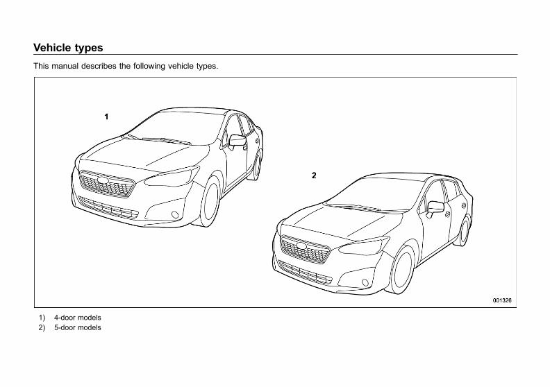
This manual describes the following vehicle types.
1) 4-door models2) 5-door models

Black plate (3,1)
一般Model "A1300GE-A" EDITED: 2016/ 9/ 13
Warranties
All warranty information, including detailsof coverage and exclusions, is in the“Warranty and Service Booklet”. Pleaseread these warranties carefully.
How to use this Owner’sManual
& Using your Owner’s ManualBefore you operate your vehicle, carefullyread this manual. To protect yourself andextend the service life of your vehicle,follow the instructions in this manual.Failure to observe these instructions mayresult in serious injury and damage to yourvehicle.
This manual is composed of fourteenchapters. Each chapter begins with a brieftable of contents, so you can usually tell ata glance if that chapter contains theinformation you want.
Chapter 1: Seat, seatbelt and SRSairbagsThis chapter informs you how to use theseat and seatbelt and contains precau-tions for the SRS airbags.Chapter 2: Keys and doorsThis chapter informs you how to operatethe keys, locks and windows.Chapter 3: Instruments and controlsThis chapter informs you about the opera-tion of instrument panel indicators andhow to use the instruments and otherswitches.
Chapter 4: Climate controlThis chapter informs you how to operatethe climate control.Chapter 5: AudioThis chapter informs you about your audiosystem.Chapter 6: Interior equipmentThis chapter informs you how to operateinterior equipment.Chapter 7: Starting and operatingThis chapter informs you how to start andoperate your SUBARU.Chapter 8: Driving tipsThis chapter informs you how to drive yourSUBARU in various conditions and ex-plains some safety tips on driving.Chapter 9: In case of emergencyThis chapter informs you what to do if youhave a problem, such as a flat tire orengine overheating.Chapter 10: Appearance careThis chapter informs you how to keep yourSUBARU looking good.Chapter 11: Maintenance and serviceThis chapter informs you when you needto take your SUBARU to the dealer forscheduled maintenance and informs youhow to keep your SUBARU runningproperly.
1
– CONTINUED –
0

Black plate (4,1)
一般Model "A1300GE-A" EDITED: 2016/ 9/ 13
2
Chapter 12: SpecificationsThis chapter informs you about dimensionand capacities of your SUBARU.Chapter 13: SupplementThis chapter informs you of supplemen-tary information complied with somecountries’ requirements.Chapter 14: IndexThis is an alphabetical listing of all that’s inthis manual. You can use it to quickly findsomething you want to read.
For models with EyeSight system:For details about the EyeSight system,refer to the Owner’s Manual supplementfor the EyeSight system.
& Safety warningsYou will find a number of WARNINGs,CAUTIONs and NOTEs in this manual.These safety warnings alert you to poten-tial hazards that could result in injury toyou or others.Please read these safety warnings as wellas all other portions of this manual care-fully in order to gain a better understand-ing of how to use your SUBARU vehiclesafely.
WARNING
A WARNING indicates a situation inwhich serious injury or death couldresult if the warning is ignored.
CAUTION
A CAUTION indicates a situation inwhich injury or damage to yourvehicle, or both, could result if thecaution is ignored.
NOTEA NOTE gives information or sugges-tions how to make better use of yourvehicle.
& Safety symbol
You will find a circle with a slash through itin this manual. This symbol means “Donot”, “Do not do this”, or “Do not let thishappen”, depending upon the context.

Black plate (5,1)
一般Model "A1300GE-A" EDITED: 2016/ 9/ 13
& Abbreviation listYou may find several abbreviations in thismanual. The meanings of the abbrevia-tions are shown in the following list.
Abbreviation Meaning
A/C Air conditioner
ALR/ELR Automatic locking retractor/Emergency locking retractor
ABS Anti-lock brake system
ALR Automatic locking retractor
AWD All-wheel drive
CVT Continuously variable trans-mission
CVTF Continuously variable trans-mission fluid
D/R Dual range
EBD Electronic brake force distri-bution
ELR Emergency locking retractor
FWD Front-wheel drive
GPS Global positioning system
INT Intermittent
LED Light emitting diode
LHD Left-hand drive
MPW Maximum permissible weight
OBD On-board diagnostics
Abbreviation Meaning
Rear MPAW Maximum permissible rearaxle weight
RHD Right-hand drive
RON Research octane number
SRH Steering responsive headlight
SRS Supplemental restraint sys-tem
SRVD SUBARU rear vehicle detec-tion
TPMS Tire pressure monitoring sys-tem
Vehicle symbols
There are some of the symbols you maysee on your vehicle.
Mark Name
WARNING
CAUTION
Read these instructions care-fully
Wear eye protection
Battery fluid contains sulfuricacid
Keep children away
Keep flames away
Prevent explosions
3
0

Black plate (6,1)
一般Model "A1300GE-A" EDITED: 2016/ 9/ 13
4
Safety precautions whendriving
& Seatbelt and SRS airbag
WARNING
. All persons in the vehicle mustfasten their seatbelts BEFOREthe vehicle starts to move. Other-wise, the possibility of seriousinjury becomes greater in theevent of a sudden stop or acci-dent.
. To obtain maximum protection inthe event of an accident, thedriver and all passengers mustalways wear seatbelts when inthe vehicle. The SRS (Supple-mental Restraint System) airbagdoes not do away with the needto fasten seatbelts. In combina-tion with the seatbelts, it offersthe best combined protection incase of a serious accident.
Not wearing a seatbelt increasesthe chance of severe injury ordeath in a crash even when thevehicle has the SRS airbag.
. The SRS airbags deploy withconsiderable speed and force.Occupants who are out of properposition when the SRS airbagdeploys could suffer very seriousinjuries. Because the SRS airbagneeds enough space for deploy-ment, the driver should alwayssit upright and well back in theseat as far from the steeringwheel as practical while stillmaintaining full vehicle controland the front passenger shouldmove the seat as far back aspossible and sit upright and wellback in the seat.
For instructions and precautions, carefullyread the following sections.. For the seatbelt system, refer to “Seat-belts” F1-12.. For the SRS airbag system, refer to“*SRS airbag (Supplemental RestraintSystem airbag)” F1-49.
& Child safety
WARNING
. Never hold a child on your lap orin your arms while the vehicle ismoving. The passenger cannotprotect the child from injury in acollision, because the child willbe caught between the passen-ger and objects inside the vehi-cle.
. While riding in the vehicle, in-fants and small children shouldalways be seated in the REARseat in an infant or a childrestraint system which is appro-priate for the child’s age, heightand weight. If a child is too big fora child restraint system, the childshould sit in the REAR seat andbe restrained using the seatbelts.According to accident statistics,children are safer when properlyrestrained in the rear seatingpositions than in the front seat-ing positions. Never allow a childto stand up or kneel on the seat.
. Put children in the REAR seatproperly restrained at all times ina child restraint device or in aseatbelt. The SRS airbag deploys
Black plate (7,1)
一般Model "A1300GE-A" EDITED: 2016/ 9/ 13
with considerable speed andforce and can injure or even killchildren, especially if they arenot restrained or improperly re-strained. Because children arelighter and weaker than adults,their risk of being injured fromdeployment is greater.
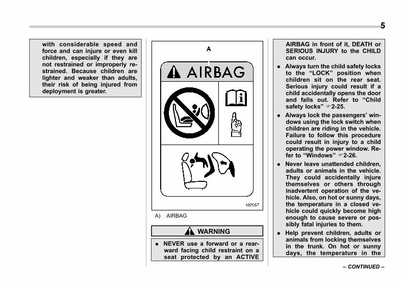
A) AIRBAG
WARNING
. NEVER use a forward or a rear-ward facing child restraint on aseat protected by an ACTIVE
AIRBAG in front of it, DEATH orSERIOUS INJURY to the CHILDcan occur.
. Always turn the child safety locksto the “LOCK” position whenchildren sit on the rear seat.Serious injury could result if achild accidentally opens the doorand falls out. Refer to “Childsafety locks” F2-25.
. Always lock the passengers’ win-dows using the lock switch whenchildren are riding in the vehicle.Failure to follow this procedurecould result in injury to a childoperating the power window. Re-fer to “Windows” F2-26.
. Never leave unattended children,adults or animals in the vehicle.They could accidentally injurethemselves or others throughinadvertent operation of the ve-hicle. Also, on hot or sunny days,the temperature in a closed ve-hicle could quickly become highenough to cause severe or pos-sibly fatal injuries to them.
. Help prevent children, adults oranimals from locking themselvesin the trunk. On hot or sunnydays, the temperature in the
5
– CONTINUED –
0
Black plate (8,1)
一般Model "A1300GE-A" EDITED: 2016/ 9/ 13
6
trunk could quickly become highenough to cause death or seriousheat-related injuries includingbrain damage to anyone lockedinside, particularly for small chil-dren.
. When leaving the vehicle, closeall windows and lock all doors.Also make certain that the trunkis closed.
For instructions and precautions, carefullyread the following sections.. For the seatbelt system, refer to “Seat-belts” F1-12.. For the child restraint system, refer to“Child restraint systems” F1-25.. For the SRS airbag system, refer to“*SRS airbag (Supplemental RestraintSystem airbag)” F1-49.
& Engine exhaust gas (carbonmonoxide)
WARNING
. Never inhale engine exhaust gas.Engine exhaust gas containscarbon monoxide, a colorlessand odorless gas which is dan-gerous, or even lethal, if inhaled.
. Always properly maintain the en-gine exhaust system to preventengine exhaust gas from enter-ing the vehicle.
. Never run the engine in a closedspace, such as a garage, exceptfor the brief time needed to drivethe vehicle in or out of it.
. Avoid remaining in a parkedvehicle for a lengthy time whilethe engine is running. If that isunavoidable, then use the venti-lation fan to force outside air intothe vehicle.
. Always keep the front ventilatorinlet grille free from snow, leavesor other obstructions to ensurethat the ventilation system al-ways works properly.
. If at any time you suspect thatexhaust fumes are entering the
vehicle, have the problemchecked and corrected as soonas possible. If you must driveunder these conditions, driveonly with all windows fully open.
. Keep the trunk lid or rear gateclosed while driving to preventexhaust gas from entering thevehicle.
& Drinking and driving
WARNING
Drinking and then driving is verydangerous. Alcohol in the blood-stream delays your reaction andimpairs your perception, judgmentand attentiveness. If you drive afterdrinking – even if you drink just alittle – it will increase the risk ofbeing involved in a serious or fatalaccident, injuring or killing yourself,your passengers and others. Inaddition, if you are injured in theaccident, alcohol may increase theseverity of that injury.
Please don’t drink and drive.
Drunken driving is one of the mostfrequent causes of accidents. Since alco-
Black plate (9,1)
一般Model "A1300GE-A" EDITED: 2016/ 9/ 13
hol affects all people differently, you mayhave consumed too much alcohol to drivesafely even if the level of alcohol in yourblood is below the legal limit. The safestthing you can do is never drink and drive.
& Drugs and driving
WARNING
There are some drugs (over thecounter and prescription) that candelay your reaction time and impairyour perception, judgment and at-tentiveness. If you drive after takingthem, it may increase your, yourpassengers’ and other persons’ riskof being involved in a serious orfatal accident.
If you are taking any drugs, check withyour doctor or pharmacist or read theliterature that accompanies the medicationto determine if the drug you are taking canimpair your driving ability. Do not driveafter taking any medications that canmake you drowsy or otherwise affect yourability to safely operate a motor vehicle. Ifyou have a medical condition that requiresyou to take drugs, please consult withyour doctor.
Never drive if you are under the influence
of any illicit mind-altering drugs. For yourown health and well-being, we urge younot to take illegal drugs in the first placeand to seek treatment if you are addictedto those drugs.
& Driving when tired or sleepy
WARNING
When you are tired or sleepy, yourreaction will be delayed and yourperception, judgment and attentive-ness will be impaired. If you drivewhen tired or sleepy, your, yourpassengers’ and other persons’chances of being involved in aserious accident may increase.
Please do not continue to drive butinstead find a safe place to rest if youare tired or sleepy. On long trips, youshould make periodic rest stops to refreshyourself before continuing on your journey.When possible, you should share thedriving with others.
& Modification of your vehicle
CAUTION
Your vehicle should not be modified.Modification could affect its perfor-mance, safety or durability, and mayeven violate governmental regula-tions. In addition, damage or perfor-mance problems resulting frommodification may not be coveredunder warranties.
& Car phone/cell phone anddriving
CAUTION
Do not use a car phone/cell phonewhile driving; it may distract yourattention from driving and can leadto an accident. If you use a carphone/cell phone, pull off the roadand park in a safe place beforeusing your phone. In some coun-tries, only hands-free phones maylegally be used while driving.
7
– CONTINUED –
0

Black plate (10,1)
一般Model "A1300GE-A" EDITED: 2016/ 9/ 13
8
& Driving vehicles equippedwith navigation system
WARNING
Do not allow the monitor to distractyour attention from driving. Also, donot operate the controls of thenavigation system while driving.The loss of attention to drivingcould lead to an accident. If youwish to operate the controls of thenavigation system, first take thevehicle off the road and stop it in asafe location.
& Driving with petsUnrestrained pets can interfere with yourdriving and distract your attention fromdriving. In a collision or sudden stop,unrestrained pets or cages can be thrownaround inside the vehicle and hurt you oryour passengers. Besides, the pets canbe hurt under these situations. It is also fortheir own safety that pets should beproperly restrained in your vehicle. Re-strain a pet with a special travelingharness which can be secured to the rearseat with a seatbelt or use a pet carrierwhich can be secured to the rear seat byrouting a seatbelt through the carrier’s
handle. Never restrain pets or pet carriersin the front passenger’s seat. For furtherinformation, consult your veterinarian,local animal protection society or petshop.
& Tire pressuresCheck and, if necessary, adjust thepressure of each tire (including the spare)at least once a month and before any longjourney.
Check the tire pressure when the tires arecold. Use a pressure gauge to adjust thetire pressures to the values shown on thetire placard.
For detailed information, refer to “Tiresand wheels” F11-24.
WARNING
Driving at high speeds with exces-sively low tire pressures can causethe tires to deform severely and torapidly become hot. A sharp in-crease in temperature could causetread separation, and destruction ofthe tires. The resulting loss ofvehicle control could lead to anaccident.
& Attaching accessories
WARNING
. Do not attach any accessories,labels or stickers (other thanproperly placed inspection stick-ers) to the windshield. Suchitems may obstruct your view.
. If it is necessary to attach anaccessory (such as an electronictoll collection (ETC) device orsecurity pass) to the windshield,consult your SUBARU dealer fordetails on the proper location.
Black plate (11,1)
一般Model "A1300GE-A" EDITED: 2016/ 9/ 13
General information
& Gear shift indicator (Europeand Australia models)
CAUTION
The indication of the gear shiftindicator is only a guideline fordriving more fuel-efficiently. Theindicator does not inform the driverabout safe shift operation timing.The driver has the responsibility forsuitable shift operation dependingon the traffic conditions or drivingconditions (e.g., overtaking or driv-ing on an uphill slope).
This indicator supports the driver to drivemore fuel-efficiently. The vehicle systemdetermines the shift operation timingdepending on the driving conditions, andinforms the driver by the indicator on thecombination meter. For details, refer to“Gear shift indicator” F3-34.
NOTEUsually, the gear shift indicator isguideline for driving more fuel-effi-ciency and it also may operate toprevent a possible engine stall at lowengine speed.
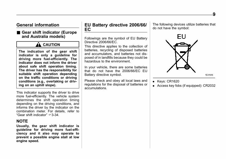
EU Battery directive 2006/66/EC
Followings are the symbol of EU BatteryDirective 2006/66/EC.This directive applies to the collection ofbatteries, recycling of disposed batteriesand accumulators, and batteries not dis-posed of in landfills because they could behazardous to the environment.
In your vehicle, there are some batteriesthat do not have the 2006/66/EC EUBattery directive symbol.
Please check and obey all local laws andregulations for the disposal of batteries oraccumulations.
The following devices utilize batteries thatdo not have the symbol:
. Keys: CR1620
. Access key fobs (if equipped): CR2032
9
0
Black plate (12,1)
一般Model "A1300GE-A" EDITED: 2016/ 9/ 13
10
Noise levels inside the vehi-cle (Customs Union Regula-tion)
TR CU 018/2011(TECHNICAL REGULATION OF THECUSTOMS UNION, On Safety ofWheeled Vehicles),Attachment No. 3: Section 2(Requirements for vehicles concerningtheir interior noise):Table 2.1: Remarks: No. 3,The noise level measured during accel-eration may reach up to 81 dBA asmaximum.This vehicle may not be used for publicpurposes (as taxis, for example).
Black plate (1,1)
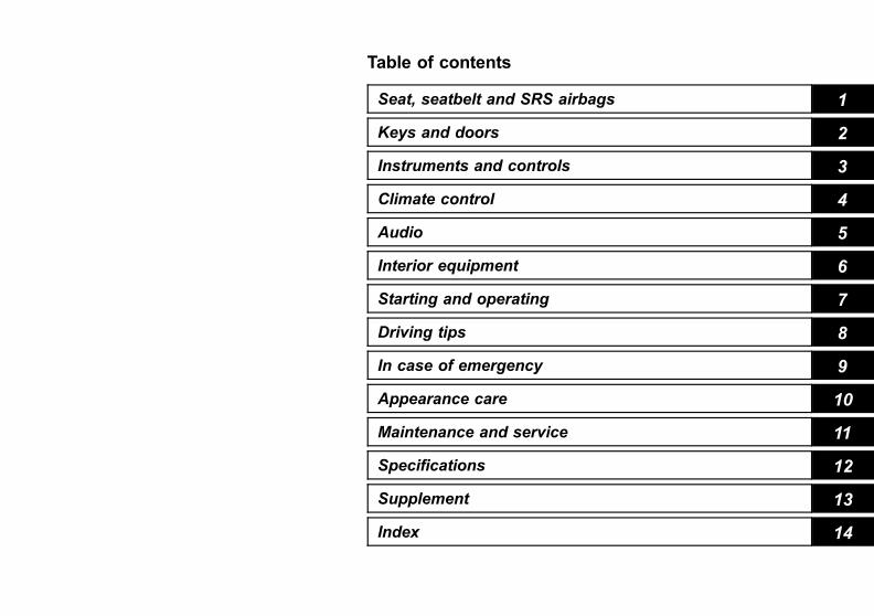
Table of contents
Seat, seatbelt and SRS airbags 1
Keys and doors 2
Instruments and controls
Climate control 4
Audio 5
Interior equipment 6
Starting and operating 7
Driving tips 8
In case of emergency 9
Appearance care 10
Maintenance and service 11
Specifications 12
Supplement 13
Index 14
3
一般Model "A1300GE-A" Edited: 2016/ 2/ 29

Black plate (14,1)
一般Model "A1300GE-A" EDITED: 2016/ 9/ 13
12
Illustrated index
& Exterior
1) Engine hood (page 11-11)2) Front wiper (page 3-86)3) Headlight (page 3-70)4) Replacing bulbs (page 11-42)5) Sunroof (page 2-31)6) Outside mirror (page 3-92)7) Door locks (page 2-20)8) Tire pressure (page 11-26)9) Flat tires (page 9-6)10) Tire chains (page 8-11)11) Fog light (page 3-81)12) Tie-down hooks (page 9-24)13) Towing hook (page 9-24)
Black plate (15,1)
一般Model "A1300GE-A" EDITED: 2016/ 9/ 13
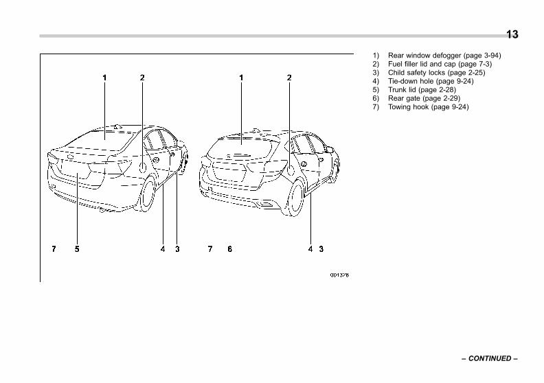
1) Rear window defogger (page 3-94)2) Fuel filler lid and cap (page 7-3)3) Child safety locks (page 2-25)4) Tie-down hole (page 9-24)5) Trunk lid (page 2-28)6) Rear gate (page 2-29)7) Towing hook (page 9-24)
13
– CONTINUED –
0

Black plate (16,1)
一般Model "A1300GE-A" EDITED: 2016/ 9/ 13
14
& Interior
! Passenger compartment area
1) Anchor bars for ISOFIX child restraintsystem (page 1-45)
2) Seatbelt (page 1-12)3) Front seat (page 1-5)4) Rear seat (page 1-6)5) Warning labels for child restraint system
(page 1-29)6) SOS button for ERA-GLONASS systemA) AIRBAG
*: NEVER use a forward or a rearwardfacing child restraint on a seat pro-tected by an ACTIVE AIRBAG in frontof it, DEATH or SERIOUS INJURY tothe CHILD can occur.
NOTEERA-GLONASS will be available inRussia, Kazakhstan and Belarus. Asof March 2016, the service is onlyavailable in Russia. Refer to the Own-er’s Manual supplement for the ERA-GLONASS system.
Black plate (17,1)
一般Model "A1300GE-A" EDITED: 2016/ 9/ 13
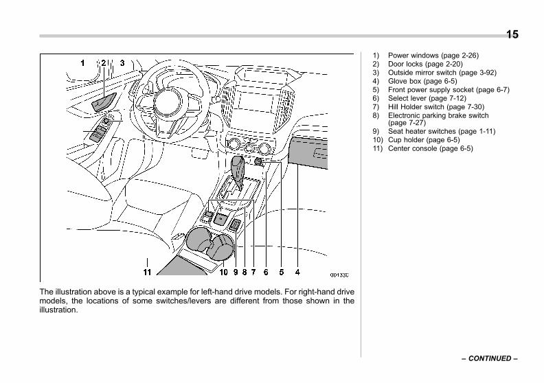
The illustration above is a typical example for left-hand drive models. For right-hand drivemodels, the locations of some switches/levers are different from those shown in theillustration.
1) Power windows (page 2-26)2) Door locks (page 2-20)3) Outside mirror switch (page 3-92)4) Glove box (page 6-5)5) Front power supply socket (page 6-7)6) Select lever (page 7-12)7) Hill Holder switch (page 7-30)8) Electronic parking brake switch
(page 7-27)9) Seat heater switches (page 1-11)10) Cup holder (page 6-5)11) Center console (page 6-5)
15
– CONTINUED –
0
Black plate (18,1)
一般Model "A1300GE-A" EDITED: 2016/ 9/ 13
16
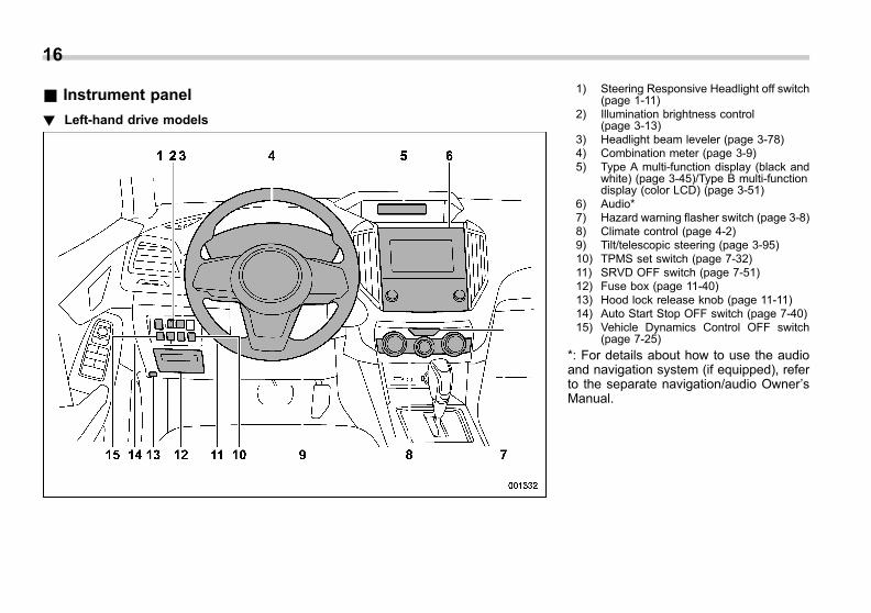
& Instrument panel
! Left-hand drive models
1) Steering Responsive Headlight off switch(page 1-11)
2) Illumination brightness control(page 3-13)
3) Headlight beam leveler (page 3-78)4) Combination meter (page 3-9)5) Type A multi-function display (black and
white) (page 3-45)/Type B multi-functiondisplay (color LCD) (page 3-51)
6) Audio*7) Hazard warning flasher switch (page 3-8)8) Climate control (page 4-2)9) Tilt/telescopic steering (page 3-95)10) TPMS set switch (page 7-32)11) SRVD OFF switch (page 7-51)12) Fuse box (page 11-40)13) Hood lock release knob (page 11-11)14) Auto Start Stop OFF switch (page 7-40)15) Vehicle Dynamics Control OFF switch
(page 7-25)
*: For details about how to use the audioand navigation system (if equipped), referto the separate navigation/audio Owner’sManual.
Black plate (19,1)
一般Model "A1300GE-A" EDITED: 2016/ 9/ 13
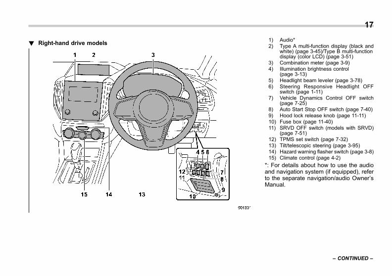
! Right-hand drive models1) Audio*2) Type A multi-function display (black and
white) (page 3-45)/Type B multi-functiondisplay (color LCD) (page 3-51)
3) Combination meter (page 3-9)4) Illumination brightness control
(page 3-13)5) Headlight beam leveler (page 3-78)6) Steering Responsive Headlight OFF
switch (page 1-11)7) Vehicle Dynamics Control OFF switch
(page 7-25)8) Auto Start Stop OFF switch (page 7-40)9) Hood lock release knob (page 11-11)10) Fuse box (page 11-40)11) SRVD OFF switch (models with SRVD)
(page 7-51)12) TPMS set switch (page 7-32)13) Tilt/telescopic steering (page 3-95)14) Hazard warning flasher switch (page 3-8)15) Climate control (page 4-2)
*: For details about how to use the audioand navigation system (if equipped), referto the separate navigation/audio Owner’sManual.
17
– CONTINUED –
0
Black plate (20,1)
一般Model "A1300GE-A" EDITED: 2016/ 9/ 13
18
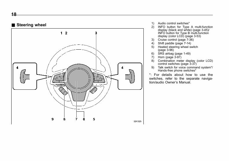
& Steering wheel 1) Audio control switches*2) INFO button for Type A multi-function
display (black and white) (page 3-45)/INFO button for Type B multi-functiondisplay (color LCD) (page 3-53)
3) Cruise control (page 7-36)4) Shift paddle (page 7-14)5) Heated steering wheel switch
(page 3-96)6) SRS airbag (page 1-49)7) Horn (page 3-97)8) Combination meter display (color LCD)
control switches (page 3-37)9) Talk switch for voice command system*/
Hands-free phone switches*
*: For details about how to use theswitches, refer to the separate naviga-tion/audio Owner’s Manual.
Black plate (21,1)
一般Model "A1300GE-A" EDITED: 2016/ 9/ 13
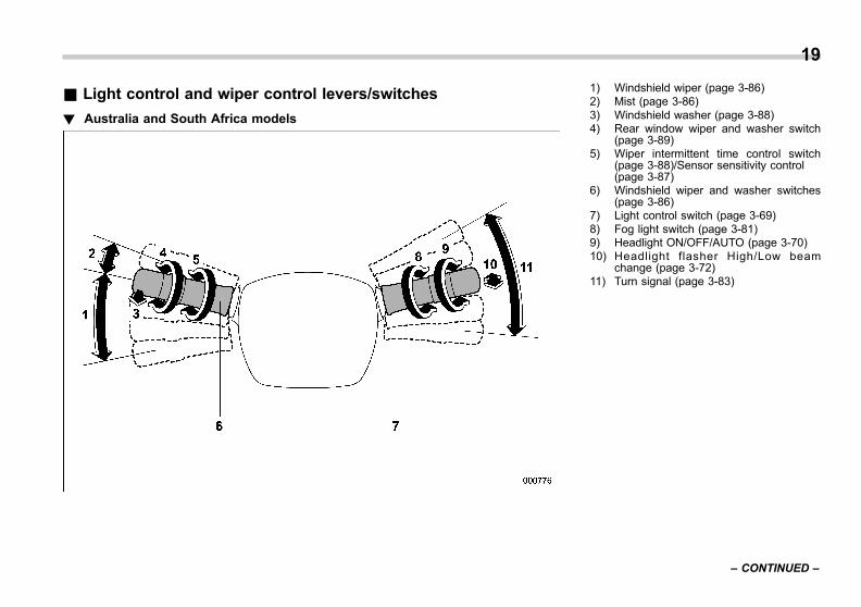
& Light control and wiper control levers/switches
! Australia and South Africa models
1) Windshield wiper (page 3-86)2) Mist (page 3-86)3) Windshield washer (page 3-88)4) Rear window wiper and washer switch
(page 3-89)5) Wiper intermittent time control switch
(page 3-88)/Sensor sensitivity control(page 3-87)
6) Windshield wiper and washer switches(page 3-86)
7) Light control switch (page 3-69)8) Fog light switch (page 3-81)9) Headlight ON/OFF/AUTO (page 3-70)10) Headlight flasher High/Low beam
change (page 3-72)11) Turn signal (page 3-83)
19
– CONTINUED –
0
Black plate (22,1)
一般Model "A1300GE-A" EDITED: 2016/ 9/ 13
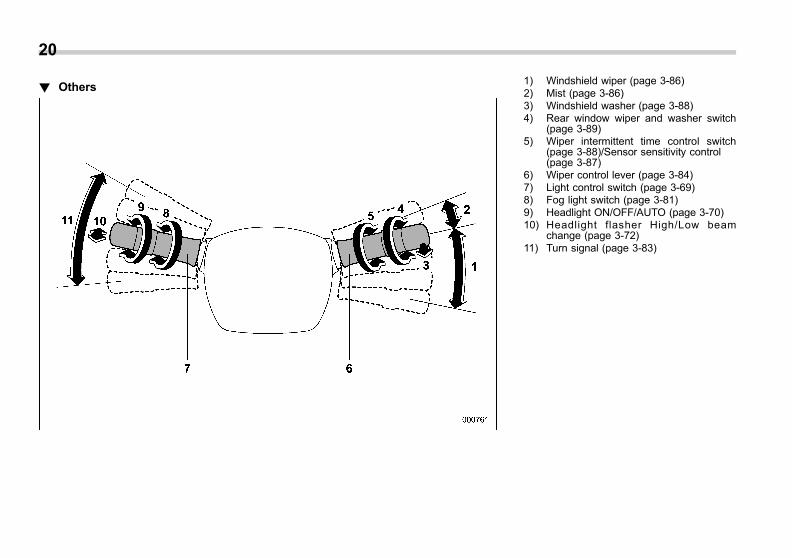
20
! Others1) Windshield wiper (page 3-86)2) Mist (page 3-86)3) Windshield washer (page 3-88)4) Rear window wiper and washer switch
(page 3-89)5) Wiper intermittent time control switch
(page 3-88)/Sensor sensitivity control(page 3-87)
6) Wiper control lever (page 3-84)7) Light control switch (page 3-69)8) Fog light switch (page 3-81)9) Headlight ON/OFF/AUTO (page 3-70)10) Headlight flasher High/Low beam
change (page 3-72)11) Turn signal (page 3-83)

Black plate (23,1)
一般Model "A1300GE-A" EDITED: 2016/ 9/ 13
& Combination meter
! Type A
The illustration above is a typical example. For some models, the combination metermay be slightly different to that shown in the illustration.
1) Tachometer (page 3-9)2) Select lever/gear position indicator
(page 3-34)3) Trip meter and odometer (page 3-9)4) Speedometer (page 3-9)5) Fuel gauge (page 3-10)
21
– CONTINUED –
0

Black plate (24,1)
一般Model "A1300GE-A" EDITED: 2016/ 9/ 13
22
! Type B
The illustration above is a typical example. For some models, the combination metermay be slightly different than that shown in the illustration.
1) Tachometer (page 3-9)2) Select lever/gear position indicator
(page 3-34)3) Combination meter display (color LCD)
(page 3-37)4) Trip meter and odometer (page 3-9)5) Speedometer (page 3-9)6) Fuel gauge (page 3-10)

Black plate (25,1)
一般Model "A1300GE-A" EDITED: 2016/ 9/ 13
& Warning and indicator lights
Mark Name Page
Seatbelt warning light 3-14
SRS airbag systemwarning light 3-17
/Front passenger’sfrontal airbag ON indi-cator (if equipped)
3-17
/Front passenger’sfrontal airbag OFF in-dicator (if equipped)
3-17
Malfunction indicatorlight (Check Enginelight)
3-18
Coolant temperaturelow indicator light/Coolant temperaturehigh warning light
3-19
Charge warning light 3-20
Oil pressure warninglight 3-20
Engine low oil levelwarning light
3-20
Mark Name Page
AT OIL TEMP warninglight 3-21
ABS warning light 3-23
Brake system warninglight (red) 3-25
Electronic parkingbrake warning light/Vacuum pressure sys-tem warning light (yel-low)
3-26
Electronic parkingbrake indicator light 3-26
/ Door open warninglight 3-27
AWD warning light(AWD models) 3-27
Power steering warn-ing light 3-28
Hill holder indicatorlight 3-27
Vehicle DynamicsControl warning light/Vehicle DynamicsControl operation indi-cator light
3-23
Mark Name Page
Vehicle DynamicsControl OFF indicatorlight
3-24
Turn signal indicatorlights 3-34
High beam indicatorlight 3-34
High beam assist indi-cator light (green) (ifequipped)
3-35
High beam assistwarning indicator (yel-low) (if equipped)
3-35
Automatic headlightbeam leveler warninglight (if equipped)
3-28
Steering ResponsiveHeadlight warninglight/Steering Respon-sive Headlight OFFindicator light (ifequipped)
3-77
Front fog light indicatorlight (if equipped) 3-35
Rear fog light indicatorlight (if equipped) 3-35
Access key warninglight (if equipped) 3-29
23
– CONTINUED –
0
Black plate (26,1)
一般Model "A1300GE-A" EDITED: 2016/ 9/ 13
24
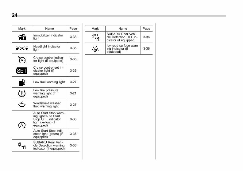
Mark Name Page
Immobilizer indicatorlight 3-33
Headlight indicatorlight 3-35
Cruise control indica-tor light (if equipped) 3-35
Cruise control set in-dicator light (ifequipped)
3-35
Low fuel warning light 3-27
Low tire pressurewarning light (ifequipped)
3-21
Windshield washerfluid warning light 3-27
Auto Start Stop warn-ing light/Auto StartStop OFF indicatorlight (yellow) (ifequipped)
3-36
Auto Start Stop indi-cator light (green) (ifequipped)
3-36
SUBARU Rear Vehi-cle Detection warningindicator (if equipped)
3-36
Mark Name Page
SUBARU Rear Vehi-cle Detection OFF in-dicator (if equipped)
3-36
Icy road surface warn-ing indicator (ifequipped)
3-36
Black plate (27,1)
一般Model "A1300GE-A" EDITED: 2016/ 9/ 13
Function settings
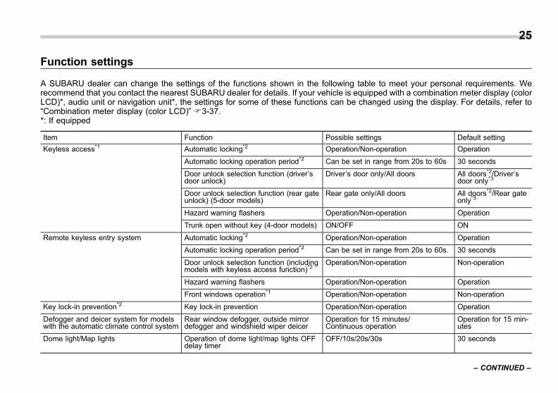
A SUBARU dealer can change the settings of the functions shown in the following table to meet your personal requirements. Werecommend that you contact the nearest SUBARU dealer for details. If your vehicle is equipped with a combination meter display (colorLCD)*, audio unit or navigation unit*, the settings for some of these functions can be changed using the display. For details, refer to“Combination meter display (color LCD)” F3-37.*: If equipped
Item Function Possible settings Default setting
Keyless access*1 Automatic locking*2 Operation/Non-operation Operation
Automatic locking operation period*2 Can be set in range from 20s to 60s 30 seconds
Door unlock selection function (driver’sdoor unlock)
Driver’s door only/All doors All doors*2/Driver’sdoor only*3
Door unlock selection function (rear gateunlock) (5-door models)
Rear gate only/All doors All doors*2/Rear gateonly*3
Hazard warning flashers Operation/Non-operation Operation
Trunk open without key (4-door models) ON/OFF ON
Remote keyless entry system Automatic locking*2 Operation/Non-operation Operation
Automatic locking operation period*2 Can be set in range from 20s to 60s. 30 seconds
Door unlock selection function (includingmodels with keyless access function)*2
Operation/Non-operation Non-operation
Hazard warning flashers Operation/Non-operation Operation
Front windows operation*1 Operation/Non-operation Non-operation
Key lock-in prevention*2 Key lock-in prevention Operation/Non-operation Operation
Defogger and deicer system for modelswith the automatic climate control system
Rear window defogger, outside mirrordefogger and windshield wiper deicer
Operation for 15 minutes/Continuous operation
Operation for 15 min-utes
Dome light/Map lights Operation of dome light/map lights OFFdelay timer
OFF/10s/20s/30s 30 seconds
25
– CONTINUED –
0

Black plate (28,1)
一般Model "A1300GE-A" EDITED: 2016/ 9/ 13
26
Item Function Possible settings Default setting
Battery drainage prevention function Battery drainage prevention function Operation/Non-operation Operation
Auto on/off headlights*1 Sensitivity of the operation of the auto on/off headlights
Low/Normal/High/Very high Normal
Automatic rain sensing windshield wiper*1 Automatic adjusting mode of wiper timing Rain-sensing mode/vehicle speed interlocking mode
Rain-sensing mode
Automatic headlight illumination linkedwiper operation
Operation/Non-operation Operation
Headlight OFF delay setting Operation of the timer OFF/30 seconds/60 seconds/90 sec-onds
30 seconds
Reverse gear interlocked rear wiper(5-door models)
Reverse gear interlocked rear wiperoperation
Operation/Non-operation Operation
One-touch lane changer Operation of the one-touch lane changer Operation/Non-operation Operation
Auto dimmer cancel (if equipped) Sensitivity of the operation of the autodimmer cancel
OFF/Min/Low/Mid/Hi/Max Mid
High beam assist function*1 High beam assist function Operation/Non-operation Operation
Emergency stop signal Emergency stop signal function Operation/Non-operation Operation
*1: If equipped*2: Applicable to models without double locking system*3: Applicable to models with double locking system

Black plate (1,1)
一般Model "A1300GE-A" EDITED: 2016/ 9/ 13
Seats .................................................................... 1-2Safety tips........................................................... 1-2Front seats ......................................................... 1-5Rear seats .......................................................... 1-6Head restraint ..................................................... 1-8
Seat heater (if equipped) ................................... 1-11Seatbelts ............................................................. 1-12
Seatbelt safety tips............................................. 1-12Emergency Locking Retractor (ELR) ................... 1-14Automatic Locking Retractor/Emergency LockingRetractor (ALR/ELR) (Australia models) ............ 1-14
Seatbelt warning light and chime ........................ 1-14Fastening the seatbelt ........................................ 1-15Seatbelt maintenance ......................................... 1-20
Seatbelt pretensioners....................................... 1-21Front seatbelt with shoulder belt and lap beltpretensioners................................................... 1-21
Rear window-side seatbelt with shoulder beltpretensioners (if equipped) ............................... 1-23
Seatbelt pretensioners safety tips ....................... 1-24System monitors ................................................ 1-24System servicing................................................ 1-24Precautions against vehicle modification ............ 1-25
Child restraint systems...................................... 1-25Applications for Australia models ....................... 1-25Safety precautions ............................................. 1-25Safety tips for installing child restraintsystems ........................................................... 1-27
Where to place a child restraint system .............. 1-27
Choosing a child restraint system ...................... 1-29Only for the models with the front passenger’sfrontal airbag ON/OFF indicator - Wheninstalling child restraint systems to the frontpassenger’s seat ............................................. 1-34
Only for the models without the front passenger’sfrontal airbag ON/OFF indicator - Wheninstalling child restraint systems to the frontpassenger’s seat ............................................. 1-37
Installing child restraint systems withseatbelt ........................................................... 1-39
Installing a booster seat..................................... 1-44Installation of child restraint systems usingISOFIX anchor bars.......................................... 1-45
Top tether anchorages ....................................... 1-48*SRS airbag (Supplemental RestraintSystem airbag)................................................ 1-49General precautions regarding SRS airbagsystem ............................................................ 1-50
General precautions regarding SRS airbagsystem for accessories and any objects ........... 1-52
General precautions regarding SRS airbagsystem for children.......................................... 1-54
Components...................................................... 1-57SRS airbag ........................................................ 1-60System operation............................................... 1-65SRS airbag system monitor................................ 1-76SRS airbag system servicing ............................. 1-77Precautions against vehicle modification............ 1-78
Seat, seatbelt and SRS airbags
1

Black plate (32,1)
一般Model "A1300GE-A" EDITED: 2016/ 9/ 13
1-2 Seat, seatbelt and SRS airbags/Seats
Seats
& Safety tips
! Safety tips for seat
WARNING
. Never adjust the seat while driv-ing to avoid loss of vehicle con-trol and personal injury.
. Before adjusting the seat, makesure that cargo and the handsand feet of rear seat passengersare clear of the adjusting me-chanism.
. After adjusting the seat, push itslightly to make sure it is se-curely locked. If the seat is notsecurely locked, it may move orthe seatbelt may not operateproperly.
. Do not put objects under the frontseats. They may interfere withfront seat locking and cause anaccident.
. Seatbelts provide maximum re-straint when the occupant sitswell back and upright in the seat.To reduce the risk of slidingunder the seatbelt in a collision,the front seatbacks should be
always used in the upright posi-tion while the vehicle is running.If the front seatbacks are notused in the upright position in acollision, the risk of sliding underthe lap belt and of the lap beltsliding up over the abdomen willincrease, and both can result inserious internal injury or death.
. The SRS airbags deploy withconsiderable speed and force.Occupants who are not in theproper position when the SRSairbag deploys could suffer veryserious injuries. Because theSRS airbag needs enough spacefor deployment, the driver shouldalways sit upright and well backin the seat as far from the steer-ing wheel as practical while stillmaintaining full vehicle controland the front passenger shouldmove the seat as far back aspossible and sit upright and wellback in the seat.
WARNING
Put children aged 12 and under or1.5 m (4 feet 11 inches) tall or less inthe REAR seat properly restrainedat all times in a child restraint deviceor in a seatbelt, whichever is appro-priate for the child’s age, height andweight. The SRS airbag deploys withconsiderable speed and force andcan injure or even kill children,especially if they are 12 years ofage and under or 1.5 m (4 feet 11inches) tall or less and are notrestrained or improperly restrained.Because children are lighter andweaker than adults, their risk ofbeing injured from deployment isgreater.
Black plate (33,1)
一般Model "A1300GE-A" EDITED: 2016/ 9/ 13
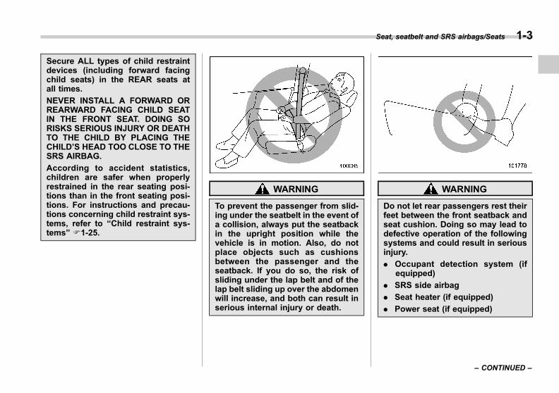
Secure ALL types of child restraintdevices (including forward facingchild seats) in the REAR seats atall times.
NEVER INSTALL A FORWARD ORREARWARD FACING CHILD SEATIN THE FRONT SEAT. DOING SORISKS SERIOUS INJURY OR DEATHTO THE CHILD BY PLACING THECHILD’S HEAD TOO CLOSE TO THESRS AIRBAG.
According to accident statistics,children are safer when properlyrestrained in the rear seating posi-tions than in the front seating posi-tions. For instructions and precau-tions concerning child restraint sys-tems, refer to “Child restraint sys-tems” F1-25.
WARNING
To prevent the passenger from slid-ing under the seatbelt in the event ofa collision, always put the seatbackin the upright position while thevehicle is in motion. Also, do notplace objects such as cushionsbetween the passenger and theseatback. If you do so, the risk ofsliding under the lap belt and of thelap belt sliding up over the abdomenwill increase, and both can result inserious internal injury or death.
WARNING
Do not let rear passengers rest theirfeet between the front seatback andseat cushion. Doing so may lead todefective operation of the followingsystems and could result in seriousinjury.
. Occupant detection system (ifequipped)
. SRS side airbag
. Seat heater (if equipped)
. Power seat (if equipped)
Seat, seatbelt and SRS airbags/Seats 1-3
– CONTINUED –
1
Black plate (34,1)
一般Model "A1300GE-A" EDITED: 2016/ 9/ 13
1-4 Seat, seatbelt and SRS airbags/Seats
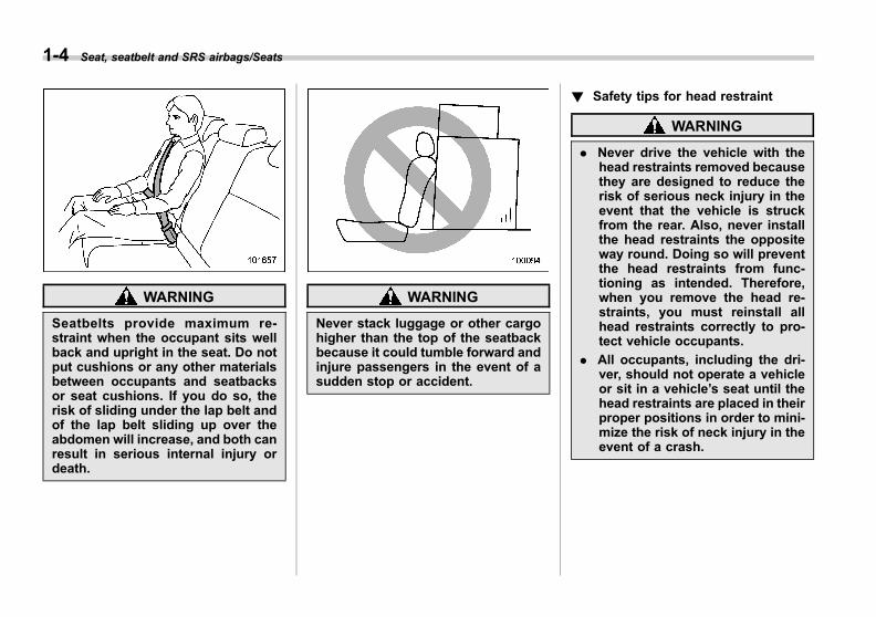
WARNING
Seatbelts provide maximum re-straint when the occupant sits wellback and upright in the seat. Do notput cushions or any other materialsbetween occupants and seatbacksor seat cushions. If you do so, therisk of sliding under the lap belt andof the lap belt sliding up over theabdomen will increase, and both canresult in serious internal injury ordeath.
WARNING
Never stack luggage or other cargohigher than the top of the seatbackbecause it could tumble forward andinjure passengers in the event of asudden stop or accident.
! Safety tips for head restraint
WARNING
. Never drive the vehicle with thehead restraints removed becausethey are designed to reduce therisk of serious neck injury in theevent that the vehicle is struckfrom the rear. Also, never installthe head restraints the oppositeway round. Doing so will preventthe head restraints from func-tioning as intended. Therefore,when you remove the head re-straints, you must reinstall allhead restraints correctly to pro-tect vehicle occupants.
. All occupants, including the dri-ver, should not operate a vehicleor sit in a vehicle’s seat until thehead restraints are placed in theirproper positions in order to mini-mize the risk of neck injury in theevent of a crash.
Black plate (35,1)
一般Model "A1300GE-A" EDITED: 2016/ 9/ 13
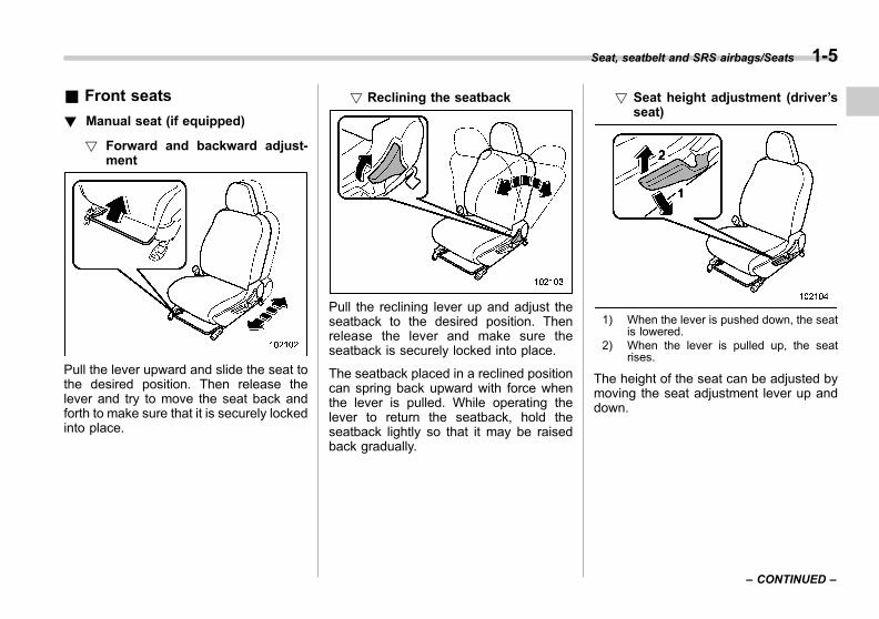
& Front seats
! Manual seat (if equipped)
! Forward and backward adjust-ment
Pull the lever upward and slide the seat tothe desired position. Then release thelever and try to move the seat back andforth to make sure that it is securely lockedinto place.
! Reclining the seatback
Pull the reclining lever up and adjust theseatback to the desired position. Thenrelease the lever and make sure theseatback is securely locked into place.
The seatback placed in a reclined positioncan spring back upward with force whenthe lever is pulled. While operating thelever to return the seatback, hold theseatback lightly so that it may be raisedback gradually.
! Seat height adjustment (driver’sseat)
1) When the lever is pushed down, the seatis lowered.
2) When the lever is pulled up, the seatrises.
The height of the seat can be adjusted bymoving the seat adjustment lever up anddown.
Seat, seatbelt and SRS airbags/Seats 1-5
– CONTINUED –
1

Black plate (36,1)
一般Model "A1300GE-A" EDITED: 2016/ 9/ 13
1-6 Seat, seatbelt and SRS airbags/Seats
! Power seat (driver’s seat – ifequipped)
1) Seat position forward/backward con-trol switchTo adjust the seat forward or backward,move the control switch forward orbackward. During forward/backward ad-justment of the seat, you cannot adjustthe seat cushion angle or seat height.
2) Seat cushion angle control switchTo adjust the seat cushion angle, pull upor push down the front end of the controlswitch.
3) Seat height control switchTo adjust the seat height, pull up or pushdown the rear end of the control switch.
4) Seatback angle (reclining) controlswitchTo adjust the angle of the seatback,move the control switch.
& Rear seats
! Armrest (if equipped)
To lower the armrest, pull on the top edgeof the armrest.
WARNING
To avoid serious injury, passengersmust never be allowed to sit on thecenter armrest.
! Folding down the rear seatback
WARNING
. When you fold down the seat-back, check that there are nopassengers or objects on therear seat. Not doing so createsa risk of injury or property da-mage if the seatback suddenlyfolds down.
. Never allow passengers to rideon the folded rear seatback or inthe cargo area or trunk. Doing somay result in serious injury ordeath.
. Secure all objects and especiallylong items properly to preventthem from being thrown aroundinside the vehicle and causingserious injury during a suddenstop, a sudden steering maneu-ver or a rapid acceleration.

Black plate (37,1)
一般Model "A1300GE-A" EDITED: 2016/ 9/ 13
1. Lower the head restraints.
2. Unlock the seatback by pulling the lockrelease knob and then fold the seatbackdown.
! Return the rear seatback
WARNING
When returning the seatback to itsoriginal position, observe the follow-ing precaution.
Failure to observe the precautionmay damage the seatbelt, impairingits effectiveness, and possibly re-sult in a serious injury.
. When returning the seatback toits original position, pull theseatbelt out towards the vehicleexterior so that it will not becaught between the seatbackand the trim.
Lock release knob1) Unlocked2) LockedA) Unlocking marker in red
To return the seatback to its originalposition, raise the seatback until it locksinto place and make sure that the unlock-ing marker on the lock release knob is nolonger visible.
WARNING
When you return the seatback to itsoriginal position, check that theunlocking marker on the lock re-lease knob is not visible. Also,shake the seatback slightly to con-firm that it is securely fixed in place.If the seatback is not securely fixedin place, the seatback may suddenly
Seat, seatbelt and SRS airbags/Seats 1-7
– CONTINUED –
1

Black plate (38,1)
一般Model "A1300GE-A" EDITED: 2016/ 9/ 13
1-8 Seat, seatbelt and SRS airbags/Seats
fold down in the event of suddenbraking, or objects may move outfrom the cargo area or trunk, whichcould cause serious injury or death.
& Head restraint
! Front seat
Both the driver’s seat and front passen-ger’s seat are equipped with head re-straints. Both head restraints are adjusta-ble in the following ways.
! Height adjustment
1) Head restraint2) Release button3) Remove button
To raise:. Lowermost to the 1st stepPull the head restraint up.. 1st step to the 3rd stepPull the head restraint up while pressingthe release button on the top of theseatback.
To lower:Push the head restraint down whilepressing the release button on the top ofthe seatback.To remove:While pressing the remove button using a
key or other hard, pointed object, pull outthe head restraint.To install:Install the head restraint into the holes thatare located on the top of the seatback untilthe head restraint locks.
Each head restraint should be adjusted sothat the center of the head restraint isclosest to the top of the occupant’s ears.
NOTEWhen the head restraint cannot bepulled out or installed due to insuffi-cient clearance between the head re-straint and the roof, tilt the seatbackand then perform the installation andremoval tasks.

Black plate (39,1)
一般Model "A1300GE-A" EDITED: 2016/ 9/ 13
! Angle adjustment
The angle of the head restraint can beadjusted in several steps. While maintain-ing a suitable driving posture, adjust thehead restraint to a position where the backof your head is as close to the headrestraint as possible.
To tilt:Tilt the head restraint by hand to thepreferred position. A click will be audiblewhen the head restraint is locked.To return:Tilt the head restraint once as far forwardas it can go. The head restraint willautomatically return to the fully uprightposition. Then, adjust the head restraintagain to the preferred angle.
! Rear seats
Both of the rear window side seats and therear center seat are equipped with headrestraints.
! Rear windows side seating posi-tion
CAUTION
The head restraint is not intended tobe used in the retracted position.Before sitting on the seat, raise thehead restraint to the extended posi-tion.
1) When not used (retracted position)2) When used (extended position)
1) Head restraint2) Release button
To raise:Pull the head restraint up.To lower:Push the head restraint down whilepressing the release button on the top ofthe seatback.To remove:While pressing the release button, pull outthe head restraint.To install:Install the head restraint into the holes thatare located on the top of the seatback untilthe head restraint locks.
When the seats are not occupied, lowerthe head restraints to improve rearward
Seat, seatbelt and SRS airbags/Seats 1-9
– CONTINUED –
1
Black plate (40,1)
一般Model "A1300GE-A" EDITED: 2016/ 9/ 13
1-10 Seat, seatbelt and SRS airbags/Seats
visibility.
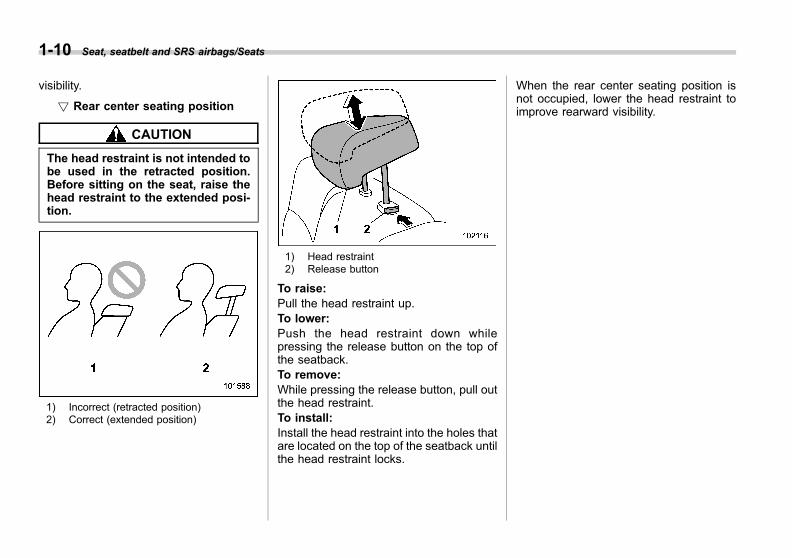
! Rear center seating position
CAUTION
The head restraint is not intended tobe used in the retracted position.Before sitting on the seat, raise thehead restraint to the extended posi-tion.
1) Incorrect (retracted position)2) Correct (extended position)
1) Head restraint2) Release button
To raise:Pull the head restraint up.To lower:Push the head restraint down whilepressing the release button on the top ofthe seatback.To remove:While pressing the release button, pull outthe head restraint.To install:Install the head restraint into the holes thatare located on the top of the seatback untilthe head restraint locks.
When the rear center seating position isnot occupied, lower the head restraint toimprove rearward visibility.
Black plate (41,1)
一般Model "A1300GE-A" EDITED: 2016/ 9/ 13
Seat heater (if equipped)
The seat heater is equipped in the frontseats.
The seat heater operates when the igni-tion switch is either in the “ACC” or “ON”position.
CAUTION
. There is a possibility that peoplewith delicate skin may sufferslight burns even at low tempera-tures if they use the seat heaterfor a long period of time. Whenusing the heater, always be sureto warn the persons concerned.
. Do not put anything on the seatwhich insulates against heat,such as a blanket, cushion, orsimilar items. This may cause theseat heater to overheat.
. When the seat is warmed enoughor before you leave the vehicle,be sure to turn off the seat heater.
NOTEUse of the seat heater for a long periodof time while the engine is not runningcan cause battery discharge.
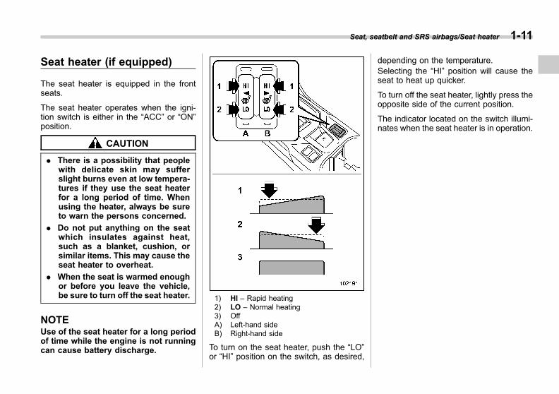
1) HI – Rapid heating2) LO – Normal heating3) OffA) Left-hand sideB) Right-hand side
To turn on the seat heater, push the “LO”or “HI” position on the switch, as desired,
depending on the temperature.Selecting the “HI” position will cause theseat to heat up quicker.
To turn off the seat heater, lightly press theopposite side of the current position.
The indicator located on the switch illumi-nates when the seat heater is in operation.
Seat, seatbelt and SRS airbags/Seat heater 1-11
1

Black plate (42,1)
一般Model "A1300GE-A" EDITED: 2016/ 9/ 13
1-12 Seat, seatbelt and SRS airbags/Seatbelts
Seatbelts
& Seatbelt safety tips
WARNING
. All persons in the vehicle mustfasten their seatbelts BEFOREthe vehicle starts to move. Other-wise, the possibility of seriousinjury becomes greater in theevent of a sudden stop or acci-dent.
. All belts should fit snugly in orderto provide full restraint. Loosefitting belts are not as effective inpreventing or reducing injury.
. Each seatbelt is designed tosupport only one person. Neveruse a single belt for two or morepersons – even children. Other-wise, in an accident, seriousinjury or death could result.
. Replace all seatbelt assembliesincluding retractors and attach-ing hardware worn by occupantsof a vehicle that has been in aserious accident. Also, be sure toreplace seatbelt assemblies thatshow signs of severe fraying orhaving been cut. The entire as-sembly should be replaced even
if damage is not obvious.
. When replacing a seatbelt, thenew seatbelt must be type-ap-proved and intended for installa-tion in the same position as thereplaced seatbelt.
. When wearing the seatbelt, insertthe tongue plate into the correctbuckle. Otherwise, in an acci-dent, serious injury or deathcould result.
. Do not fasten your seatbelt with achild on your knees. Otherwise,in an accident, serious injury ordeath could result.
. Never use a belt that is twisted orreversed. In an accident, this canincrease the risk or severity ofinjury.
. Keep the lap belt as low aspossible on your hips. In a colli-sion, this spreads the force of thelap belt over stronger hip bonesinstead of across the weakerabdomen.
. Seatbelts provide maximum re-straint when the occupant sitswell back and upright in the seat.To reduce the risk of slidingunder the seatbelt in a collision,the front seatbacks should be
always used in the upright posi-tion while the vehicle is running.If the front seatbacks are notused in the upright position in acollision, the risk of sliding underthe lap belt and of the lap beltsliding up over the abdomen willincrease, and both can result inserious internal injury or death.
. Do not put cushions or any othermaterials between occupantsand seatbacks or seat cushions.If you do so, the risk of slidingunder the lap belt and of the lapbelt sliding up over the abdomenwill increase, and both can resultin serious internal injury ordeath.
Black plate (43,1)
一般Model "A1300GE-A" EDITED: 2016/ 9/ 13
WARNING
Never place the shoulder belt underthe arm or behind the back. If anaccident occurs, this can increasethe risk or severity of injury.
CAUTION
Metallic parts of the seatbelt canbecome very hot in a vehicle thathas been closed up in sunny weath-er; they could burn an occupant. Donot touch such hot parts until theycool.
! Infants or small children
Use a child restraint system that issuitable for your vehicle. Refer to “Childrestraint systems” F1-25.
! Children
WARNING
Put children aged 12 and under or1.5 m (4 feet 11 inches) tall or less inthe REAR seat properly restrainedat all times in a child restraint deviceor in a seatbelt, whichever is appro-priate for the child’s age, height andweight. The SRS airbag deploys with
considerable speed and force andcan injure or even kill children,especially if they are 12 years ofage and under or 1.5 m (4 feet 11inches) tall or less and are notrestrained or improperly restrained.Because children are lighter andweaker than adults, their risk ofbeing injured from deployment isgreater.
Secure ALL types of child restraintdevices (including forward facingchild seats) in the REAR seats atall times.
NEVER INSTALL A FORWARD ORREARWARD FACING CHILD SEATIN THE FRONT SEAT. DOING SORISKS SERIOUS INJURY OR DEATHTO THE CHILD BY PLACING THECHILD’S HEAD TOO CLOSE TO THESRS AIRBAG.
According to accident statistics,children are safer when properlyrestrained in the rear seating posi-tions than in the front seating posi-tions. For instructions and precau-tions concerning the child restraintsystem, refer to “Child restraintsystems” F1-25.
If a child is too big for a child restraintsystem, the child should sit in the rear seat
and be restrained using the seatbelts.According to accident statistics, childrenare safer when properly restrained in therear seating positions than in the frontseating positions. Never allow a child tostand up or kneel on the seat.
Seatbelts are designed under the as-sumption that adult-sized occupants willuse them. If the shoulder portion of thebelt crosses the face or neck, move thechild closer to the belt buckle to helpprovide a good shoulder belt fit. Care mustbe taken to securely place the lap belt aslow as possible on the hips and not on thechild’s waist. If the shoulder portion of thebelt cannot be properly positioned, a childrestraint system should be used. Neverplace the shoulder belt under the child’sarm or behind the child’s back.
Seat, seatbelt and SRS airbags/Seatbelts 1-13
– CONTINUED –
1

Black plate (44,1)
一般Model "A1300GE-A" EDITED: 2016/ 9/ 13
1-14 Seat, seatbelt and SRS airbags/Seatbelts
! Expectant mothers
Expectant mothers also need to use theseatbelts. They should consult their doctorfor specific recommendations. The lap beltshould be worn securely and as low aspossible over the hips, not over the waist.
& Emergency Locking Retrac-tor (ELR)
All seatbelts in the vehicle have anEmergency Locking Retractor (ELR).The emergency locking retractor allowsnormal body movement but the retractorlocks automatically during a sudden stop,impact or if you pull the belt very quicklyout of the retractor.
& Automatic Locking Retractor/Emergency Locking Retrac-tor (ALR/ELR) (Australiamodels)
For some models, each rear passenger’sseatbelt has an Automatic Locking Re-tractor/Emergency Locking Retractor(ALR/ELR). The Automatic Locking Re-tractor/Emergency Locking Retractor nor-mally functions as an Emergency LockingRetractor (ELR). The ALR/ELR has anadditional locking mode, “Automatic Lock-ing Retractor (ALR) mode”, intended tosecure a child restraint system.
First check if the ALR mode is equippedfor the seatbelts of the vehicle. If the ALRmode is equipped, the seatbelts functionas follows.When a seatbelt is once drawn outcompletely and is then retracted evenslightly, the retractor locks the seatbelt inthat position and the seatbelt cannot beextended. As the belt is rewinding, clickswill be heard which indicate the retractorfunctions as an ALR. When the seatbelt isretracted fully, the ALR mode is canceledand the ELR mode is restored.
For models with ALR/ELR seatbelts, whensecuring a child restraint system to therear seats by using a seatbelt in the
forward-facing direction, the seatbelt mustbe changed over to the Automatic LockingRetractor (ALR) mode. For instructions onhow to install the child restraint systemusing a seatbelt, refer to “Installing childrestraint systems with seatbelt” F1-39.
When the child restraint system is re-moved, make sure that the retractor isrestored to the Emergency Locking Re-tractor (ELR) mode by allowing the seat-belt to retract fully.
& Seatbelt warning lightand chime
Refer to “Seatbelt warning light andchime” F3-14.
Black plate (45,1)
一般Model "A1300GE-A" EDITED: 2016/ 9/ 13
& Fastening the seatbelt
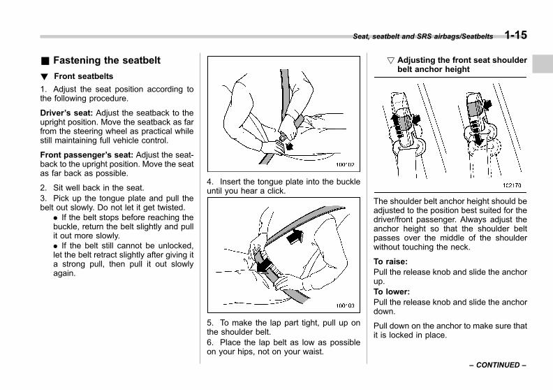
! Front seatbelts
1. Adjust the seat position according tothe following procedure.
Driver’s seat: Adjust the seatback to theupright position. Move the seatback as farfrom the steering wheel as practical whilestill maintaining full vehicle control.
Front passenger’s seat: Adjust the seat-back to the upright position. Move the seatas far back as possible.
2. Sit well back in the seat.3. Pick up the tongue plate and pull thebelt out slowly. Do not let it get twisted.
. If the belt stops before reaching thebuckle, return the belt slightly and pullit out more slowly.. If the belt still cannot be unlocked,let the belt retract slightly after giving ita strong pull, then pull it out slowlyagain.
4. Insert the tongue plate into the buckleuntil you hear a click.
5. To make the lap part tight, pull up onthe shoulder belt.6. Place the lap belt as low as possibleon your hips, not on your waist.
! Adjusting the front seat shoulderbelt anchor height
The shoulder belt anchor height should beadjusted to the position best suited for thedriver/front passenger. Always adjust theanchor height so that the shoulder beltpasses over the middle of the shoulderwithout touching the neck.
To raise:Pull the release knob and slide the anchorup.To lower:Pull the release knob and slide the anchordown.
Pull down on the anchor to make sure thatit is locked in place.
Seat, seatbelt and SRS airbags/Seatbelts 1-15
– CONTINUED –
1
Black plate (46,1)
一般Model "A1300GE-A" EDITED: 2016/ 9/ 13
1-16 Seat, seatbelt and SRS airbags/Seatbelts
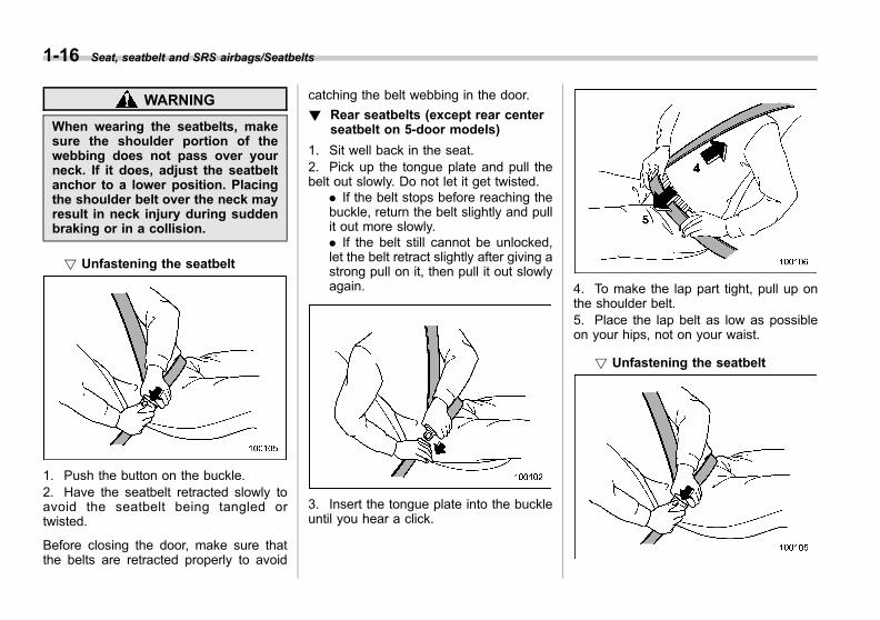
WARNING
When wearing the seatbelts, makesure the shoulder portion of thewebbing does not pass over yourneck. If it does, adjust the seatbeltanchor to a lower position. Placingthe shoulder belt over the neck mayresult in neck injury during suddenbraking or in a collision.
! Unfastening the seatbelt
1. Push the button on the buckle.2. Have the seatbelt retracted slowly toavoid the seatbelt being tangled ortwisted.
Before closing the door, make sure thatthe belts are retracted properly to avoid
catching the belt webbing in the door.
! Rear seatbelts (except rear centerseatbelt on 5-door models)
1. Sit well back in the seat.2. Pick up the tongue plate and pull thebelt out slowly. Do not let it get twisted.
. If the belt stops before reaching thebuckle, return the belt slightly and pullit out more slowly.. If the belt still cannot be unlocked,let the belt retract slightly after giving astrong pull on it, then pull it out slowlyagain.
3. Insert the tongue plate into the buckleuntil you hear a click.
4. To make the lap part tight, pull up onthe shoulder belt.5. Place the lap belt as low as possibleon your hips, not on your waist.
! Unfastening the seatbelt
Black plate (47,1)
一般Model "A1300GE-A" EDITED: 2016/ 9/ 13
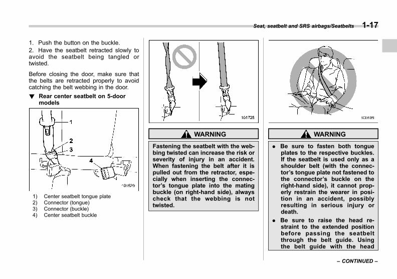
1. Push the button on the buckle.2. Have the seatbelt retracted slowly toavoid the seatbelt being tangled ortwisted.
Before closing the door, make sure thatthe belts are retracted properly to avoidcatching the belt webbing in the door.
! Rear center seatbelt on 5-doormodels
1) Center seatbelt tongue plate2) Connector (tongue)3) Connector (buckle)4) Center seatbelt buckle
WARNING
Fastening the seatbelt with the web-bing twisted can increase the risk orseverity of injury in an accident.When fastening the belt after it ispulled out from the retractor, espe-cially when inserting the connec-tor’s tongue plate into the matingbuckle (on right-hand side), alwayscheck that the webbing is nottwisted.
WARNING
. Be sure to fasten both tongueplates to the respective buckles.If the seatbelt is used only as ashoulder belt (with the connec-tor’s tongue plate not fastened tothe connector’s buckle on theright-hand side), it cannot prop-erly restrain the wearer in posi-tion in an accident, possiblyresulting in serious injury ordeath.
. Be sure to raise the head re-straint to the extended positionbefore passing the seatbeltthrough the belt guide. Usingthe belt guide with the head
Seat, seatbelt and SRS airbags/Seatbelts 1-17
– CONTINUED –
1

Black plate (48,1)
一般Model "A1300GE-A" EDITED: 2016/ 9/ 13
1-18 Seat, seatbelt and SRS airbags/Seatbelts
restraint at the retracted positionmay result in serious injury.
The rear center seatbelt is stowed in theseatbelt holder on the right side of thecargo area.
1. Raise the head restraint to the ex-tended position. Do not remove the headrestraint.
2. Remove the tongue plate from the beltholder and pull out the seatbelt slowly.
3. After drawing out the seatbelt, pass itthrough the belt guide as follows: Firstinsert one edge of the belt into the opengap in the belt guide; then slide the rest of
the belt in, so that the whole belt fitsinside.
4. After confirming that the webbing is nottwisted, insert the connector (tongue)attached at the webbing end into thebuckle on the right-hand side until a clickis heard.
. If the belt stops before reaching thebuckle, return the belt slightly and pullit out more slowly.. If the belt still cannot be unlocked,let the belt retract slightly after giving ita strong pull, then pull it out slowlyagain.
Black plate (49,1)
一般Model "A1300GE-A" EDITED: 2016/ 9/ 13
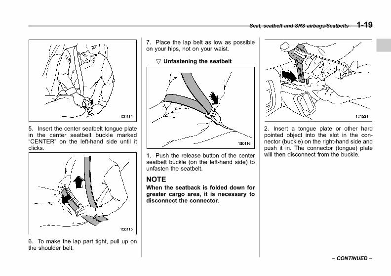
5. Insert the center seatbelt tongue platein the center seatbelt buckle marked“CENTER” on the left-hand side until itclicks.
6. To make the lap part tight, pull up onthe shoulder belt.
7. Place the lap belt as low as possibleon your hips, not on your waist.
! Unfastening the seatbelt
1. Push the release button of the centerseatbelt buckle (on the left-hand side) tounfasten the seatbelt.
NOTEWhen the seatback is folded down forgreater cargo area, it is necessary todisconnect the connector.
2. Insert a tongue plate or other hardpointed object into the slot in the con-nector (buckle) on the right-hand side andpush it in. The connector (tongue) platewill then disconnect from the buckle.
Seat, seatbelt and SRS airbags/Seatbelts 1-19
– CONTINUED –
1

Black plate (50,1)
一般Model "A1300GE-A" EDITED: 2016/ 9/ 13
1-20 Seat, seatbelt and SRS airbags/Seatbelts
3. Allow the retractor to roll up the belt.You should hold the webbing end andguide it back into the retractor while it isrolling up. Then, pass the webbing underthe belt holder and insert the tongue plateinto the holder.
CAUTION
. Do not allow the retractor to rollup the seatbelt too quickly.Otherwise, the metal tongueplates may hit against the trim,resulting in damaged trim.
. Have the seatbelt fully rolled upso that the tongue plates areneatly stored. A hanging tongueplate can swing and hit againstthe trim during driving, causingdamage to the trim.
& Seatbelt maintenanceTo clean the seatbelts, use a mild soapand lukewarm water. Never bleach or dyethe belts because this could seriouslyaffect their strength.
Inspect the seatbelts and attachmentsincluding the webbing and all hardwareperiodically for cracks, cuts, gashes,tears, damage, loose bolts or worn areas.Replace the seatbelts even if only minordamage is found.
CAUTION
. Keep the belts free of polishes,oils, chemicals and particularlybattery acid.
. Never attempt to make modifica-tions or changes that will preventthe seatbelt from operating prop-erly.
Black plate (51,1)
一般Model "A1300GE-A" EDITED: 2016/ 9/ 13
Seatbelt pretensioners
The following seatbelts have a seatbeltpretensioner.. Driver’s seatbelt. Front passenger’s seatbelt. Rear window-s ide seatbe l t ( i fequipped)
The seatbelt pretensioners are designedto be activated in the event of an accidentinvolving a moderate to severe frontal orside collision.
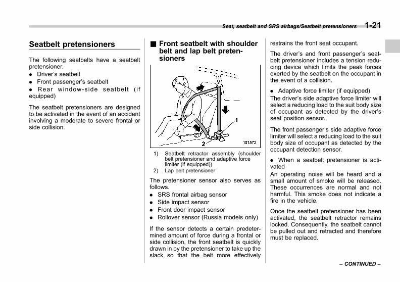
& Front seatbelt with shoulderbelt and lap belt preten-sioners
1) Seatbelt retractor assembly (shoulderbelt pretensioner and adaptive forcelimiter (if equipped))
2) Lap belt pretensioner
The pretensioner sensor also serves asfollows.. SRS frontal airbag sensor. Side impact sensor. Front door impact sensor. Rollover sensor (Russia models only)
If the sensor detects a certain predeter-mined amount of force during a frontal orside collision, the front seatbelt is quicklydrawn in by the pretensioner to take up theslack so that the belt more effectively
restrains the front seat occupant.
The driver’s and front passenger’s seat-belt pretensioner includes a tension redu-cing device which limits the peak forcesexerted by the seatbelt on the occupant inthe event of a collision.
. Adaptive force limiter (if equipped)The driver’s side adaptive force limiter willselect a reducing load to the suit body sizeof occupant as detected by the driver’sseat position sensor.
The front passenger’s side adaptive forcelimiter will select a reducing load to the suitbody size of occupant as detected by theoccupant detection sensor.
. When a seatbelt pretensioner is acti-vatedAn operating noise will be heard and asmall amount of smoke will be released.These occurrences are normal and notharmful. This smoke does not indicate afire in the vehicle.
Once the seatbelt pretensioner has beenactivated, the seatbelt retractor remainslocked. Consequently, the seatbelt cannotbe pulled out and retracted and thereforemust be replaced.
Seat, seatbelt and SRS airbags/Seatbelt pretensioners 1-21
– CONTINUED –
1
Black plate (52,1)
一般Model "A1300GE-A" EDITED: 2016/ 9/ 13
1-22 Seat, seatbelt and SRS airbags/Seatbelt pretensioners
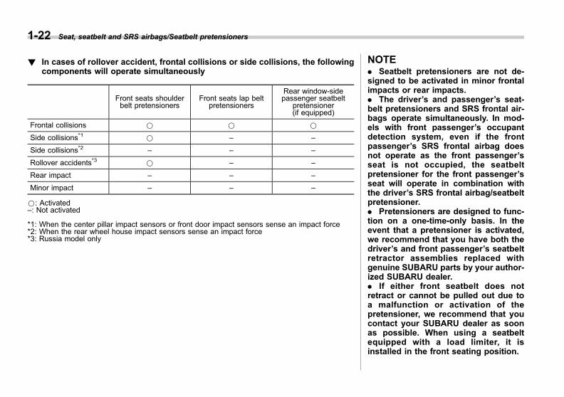
! In cases of rollover accident, frontal collisions or side collisions, the followingcomponents will operate simultaneously
Front seats shoulderbelt pretensioners
Front seats lap beltpretensioners
Rear window-sidepassenger seatbelt
pretensioner(if equipped)
Frontal collisions * * *
Side collisions*1 * – –
Side collisions*2 – – –
Rollover accidents*3 * – –
Rear impact – – –
Minor impact – – –
*: Activated–: Not activated
*1: When the center pillar impact sensors or front door impact sensors sense an impact force*2: When the rear wheel house impact sensors sense an impact force*3: Russia model only
NOTE. Seatbelt pretensioners are not de-signed to be activated in minor frontalimpacts or rear impacts.. The driver’s and passenger’s seat-belt pretensioners and SRS frontal air-bags operate simultaneously. In mod-els with front passenger’s occupantdetection system, even if the frontpassenger’s SRS frontal airbag doesnot operate as the front passenger’sseat is not occupied, the seatbeltpretensioner for the front passenger’sseat will operate in combination withthe driver’s SRS frontal airbag/seatbeltpretensioner.. Pretensioners are designed to func-tion on a one-time-only basis. In theevent that a pretensioner is activated,we recommend that you have both thedriver’s and front passenger’s seatbeltretractor assemblies replaced withgenuine SUBARU parts by your author-ized SUBARU dealer.. If either front seatbelt does notretract or cannot be pulled out due toa malfunction or activation of thepretensioner, we recommend that youcontact your SUBARU dealer as soonas possible. When using a seatbeltequipped with a load limiter, it isinstalled in the front seating position.
Black plate (53,1)
一般Model "A1300GE-A" EDITED: 2016/ 9/ 13
. If the front seatbelt retractor assem-bly or surrounding area has beendamaged, we recommend that youcontact your SUBARU dealer as soonas possible.. When you sell your vehicle, we urgeyou to explain to the buyer that it hasseatbelt pretensioners by alerting thebuyer to the contents of this section.
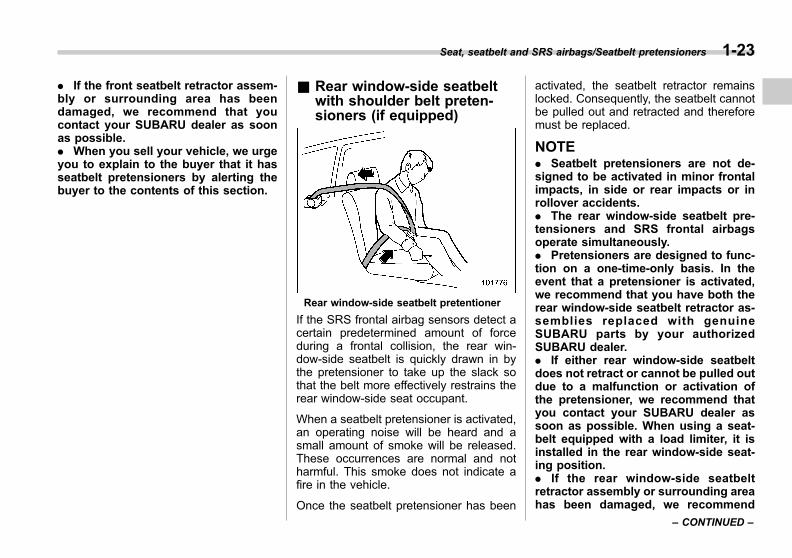
& Rear window-side seatbeltwith shoulder belt preten-sioners (if equipped)
Rear window-side seatbelt pretentioner
If the SRS frontal airbag sensors detect acertain predetermined amount of forceduring a frontal collision, the rear win-dow-side seatbelt is quickly drawn in bythe pretensioner to take up the slack sothat the belt more effectively restrains therear window-side seat occupant.
When a seatbelt pretensioner is activated,an operating noise will be heard and asmall amount of smoke will be released.These occurrences are normal and notharmful. This smoke does not indicate afire in the vehicle.
Once the seatbelt pretensioner has been
activated, the seatbelt retractor remainslocked. Consequently, the seatbelt cannotbe pulled out and retracted and thereforemust be replaced.
NOTE. Seatbelt pretensioners are not de-signed to be activated in minor frontalimpacts, in side or rear impacts or inrollover accidents.. The rear window-side seatbelt pre-tensioners and SRS frontal airbagsoperate simultaneously.. Pretensioners are designed to func-tion on a one-time-only basis. In theevent that a pretensioner is activated,we recommend that you have both therear window-side seatbelt retractor as-semblies replaced with genuineSUBARU parts by your authorizedSUBARU dealer.. If either rear window-side seatbeltdoes not retract or cannot be pulled outdue to a malfunction or activation ofthe pretensioner, we recommend thatyou contact your SUBARU dealer assoon as possible. When using a seat-belt equipped with a load limiter, it isinstalled in the rear window-side seat-ing position.. If the rear window-side seatbeltretractor assembly or surrounding areahas been damaged, we recommend
Seat, seatbelt and SRS airbags/Seatbelt pretensioners 1-23
– CONTINUED –
1
Black plate (54,1)
一般Model "A1300GE-A" EDITED: 2016/ 9/ 13
1-24 Seat, seatbelt and SRS airbags/Seatbelt pretensioners
that you contact your SUBARU dealeras soon as possible.. When you sell your vehicle, we urgeyou to explain to the buyer that it hasseatbelt pretensioners by alerting thebuyer to the contents of this section.
& Seatbelt pretensioners safetytips
WARNING
. To obtain maximum protection,the occupants should sit in anupright position with their seat-belts properly fastened. Refer to“Seatbelts” F1-12.
. Do not modify, remove or strikethe seatbelt retractor assembliesequipped with seatbelt preten-sioners or surrounding area. Thiscould result in accidental activa-tion of the seatbelt pretensionersor could make the system inop-erative, possibly resulting in ser-ious injury. Seatbelt preten-sioners have no user-serviceableparts. For required servicing ofseatbelt retractors equipped withseatbelt pretensioners, consultyour SUBARU dealer.
. When discarding seatbelt retrac-tor assemblies equipped withseatbelt pretensioners or scrap-ping the entire vehicle due tocollision damage or for otherreasons, we recommend thatyou consult your SUBARU deal-er.
& System monitorsA diagnostic system continually monitorsthe readiness of the seatbelt pretensionerwhile the vehicle is being driven. Theseatbelt pretensioners share the controlmodule with the SRS airbag system.Therefore, if any malfunction occurs in aseatbelt pretensioner, the SRS airbagsystem warning light will illuminate. Fordetails, refer to “SRS airbag systemmonitor” F1-76.
& System servicing
WARNING
. When discarding a seatbelt re-tractor assembly or scrappingthe entire vehicle damaged by acollision, we recommend thatyou consult your SUBARU deal-er.
. Tampering with or disconnectingthe system’s wiring could resultin accidental activation of theseatbelt pretensioner and/orSRS airbag or could make thesystem inoperative, which mayresult in serious injury. Do notuse electrical test equipment onany circuit related to the seatbeltpretensioner and SRS airbagsystems. For required servicingof the seatbelt pretensioner, werecommend that you consultyour nearest SUBARU dealer.

Black plate (55,1)
一般Model "A1300GE-A" EDITED: 2016/ 9/ 13
CAUTION
The sensors and the SRS airbagcontrol module are located in thefollowing locations.
. Front sub sensors: on both theright and left sides at the front ofthe vehicle
. Front door impact sensors: onboth front doors
. Satellite safing sensor: under therear center seat
. SRS airbag control module (in-cluding the impact sensors androllover sensor): under the cen-ter of the instrument panel
If you need service or repair in thoseareas or near the seatbelt retractors,we recommend that you have thework performed by your authorizedSUBARU dealer.
NOTEIf the front or side part of the vehicle isdamaged in an accident to the extentthat the seatbelt pretensioner does notoperate, we recommend that you con-tact your SUBARU dealer as soon aspossible.
& Precautions against vehiclemodification
We recommend that you consult yourSUBARU dealer if you want to install anyaccessory parts to your vehicle.
CAUTION
Do not perform any of the followingmodifications. Such modificationscan interfere with proper operationof the seatbelt pretensioners.
. Attachment of any equipment(bush bar, bullbar, winches, snowplow, skid/sump plate, etc.) to thefront end other than genuineSUBARU accessory parts orparts that match the quality ofgenuine SUBARU accessoryparts.
. Modification of the suspensionsystem or front end structure.
. Installation of a tire of differentsize and construction from thetires specified on the vehicleplacard attached to the driver’sdoor pillar or specified for indivi-dual vehicle models in this Own-er’s Manual.
Child restraint systems
& Applications for Australiamodels
Refer to the Owner’s Manual supple-ment for the instructions of the childrestraint system.
& Safety precautions
Infants and small children aged 12 andunder or 1.5 m (4 feet 11 inches) tall orless should always be placed in an infantor child restraint system in the rear seatwhile riding in the vehicle. You should usean infant or child restraint system that isappropriate for the child’s age and size. Allchild restraint systems are designed to besecured in the vehicle seats.
Seat, seatbelt and SRS airbags/Child restraint systems 1-25
– CONTINUED –
1
Black plate (56,1)
一般Model "A1300GE-A" EDITED: 2016/ 9/ 13
1-26 Seat, seatbelt and SRS airbags/Child restraint systems
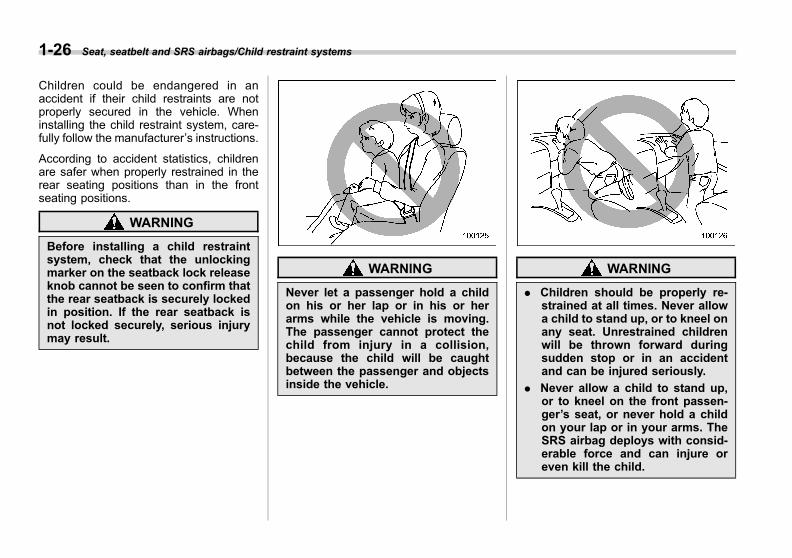
Children could be endangered in anaccident if their child restraints are notproperly secured in the vehicle. Wheninstalling the child restraint system, care-fully follow the manufacturer’s instructions.
According to accident statistics, childrenare safer when properly restrained in therear seating positions than in the frontseating positions.
WARNING
Before installing a child restraintsystem, check that the unlockingmarker on the seatback lock releaseknob cannot be seen to confirm thatthe rear seatback is securely lockedin position. If the rear seatback isnot locked securely, serious injurymay result.
WARNING
Never let a passenger hold a childon his or her lap or in his or herarms while the vehicle is moving.The passenger cannot protect thechild from injury in a collision,because the child will be caughtbetween the passenger and objectsinside the vehicle.
WARNING
. Children should be properly re-strained at all times. Never allowa child to stand up, or to kneel onany seat. Unrestrained childrenwill be thrown forward duringsudden stop or in an accidentand can be injured seriously.
. Never allow a child to stand up,or to kneel on the front passen-ger’s seat, or never hold a childon your lap or in your arms. TheSRS airbag deploys with consid-erable force and can injure oreven kill the child.

Black plate (57,1)
一般Model "A1300GE-A" EDITED: 2016/ 9/ 13
& Safety tips for installing childrestraint systems
WARNING
. Child restraint systems and seat-belts can become hot in a vehiclethat has been closed up in sunnyweather; they could burn a smallchild. Check the child restraintsystem before you place a childin it.
. Do not leave an unsecured childrestraint system in your vehicle.Unsecured child restraint sys-tems can be thrown around in-side of the vehicle in a suddenstop, turn or accident; they canstrike and injure vehicle occu-pants as well as result in seriousinjuries or death to the child.
CAUTION
When you install a child restraintsystem, follow the manufacturer’sinstructions supplied with it. Afterinstalling the child restraint system,check to ensure that it is heldsecurely in position. If it is not heldtight and secure, the danger of your
child suffering personal injury in theevent of an accident may be in-creased.
& Where to place a child re-straint system
The following are SUBARU’s recommen-dations on where to place a child restraintsystem in your vehicle.
Left-hand drive models
Right-hand drive models
A: Front passenger’s seatDo not install a child restraint system(including a booster cushion) due to thehazard to children posed by the passen-
Seat, seatbelt and SRS airbags/Child restraint systems 1-27
– CONTINUED –
1
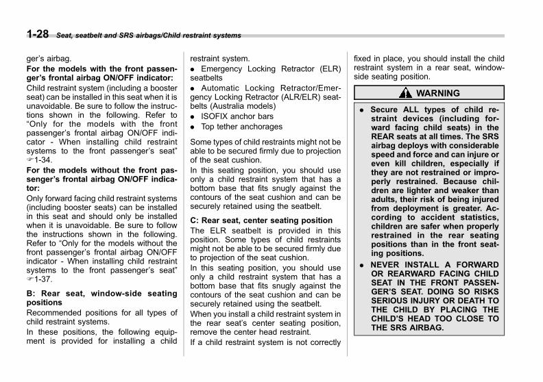
Black plate (58,1)
一般Model "A1300GE-A" EDITED: 2016/ 9/ 13
1-28 Seat, seatbelt and SRS airbags/Child restraint systems
ger’s airbag.For the models with the front passen-ger’s frontal airbag ON/OFF indicator:Child restraint system (including a boosterseat) can be installed in this seat when it isunavoidable. Be sure to follow the instruc-tions shown in the following. Refer to“Only for the models with the frontpassenger’s frontal airbag ON/OFF indi-cator - When installing child restraintsystems to the front passenger’s seat”F1-34.For the models without the front pas-senger’s frontal airbag ON/OFF indica-tor:Only forward facing child restraint systems(including booster seats) can be installedin this seat and should only be installedwhen it is unavoidable. Be sure to followthe instructions shown in the following.Refer to “Only for the models without thefront passenger’s frontal airbag ON/OFFindicator - When installing child restraintsystems to the front passenger’s seat”F1-37.
B: Rear seat, window-side seatingpositionsRecommended positions for all types ofchild restraint systems.In these positions, the following equip-ment is provided for installing a child
restraint system.. Emergency Locking Retractor (ELR)seatbelts. Automatic Locking Retractor/Emer-gency Locking Retractor (ALR/ELR) seat-belts (Australia models). ISOFIX anchor bars. Top tether anchorages
Some types of child restraints might not beable to be secured firmly due to projectionof the seat cushion.In this seating position, you should useonly a child restraint system that has abottom base that fits snugly against thecontours of the seat cushion and can besecurely retained using the seatbelt.
C: Rear seat, center seating positionThe ELR seatbelt is provided in thisposition. Some types of child restraintsmight not be able to be secured firmly dueto projection of the seat cushion.In this seating position, you should useonly a child restraint system that has abottom base that fits snugly against thecontours of the seat cushion and can besecurely retained using the seatbelt.When you install a child restraint system inthe rear seat’s center seating position,remove the center head restraint.If a child restraint system is not correctly
fixed in place, you should install the childrestraint system in a rear seat, window-side seating position.
WARNING
. Secure ALL types of child re-straint devices (including for-ward facing child seats) in theREAR seats at all times. The SRSairbag deploys with considerablespeed and force and can injure oreven kill children, especially ifthey are not restrained or impro-perly restrained. Because chil-dren are lighter and weaker thanadults, their risk of being injuredfrom deployment is greater. Ac-cording to accident statistics,children are safer when properlyrestrained in the rear seatingpositions than in the front seat-ing positions.
. NEVER INSTALL A FORWARDOR REARWARD FACING CHILDSEAT IN THE FRONT PASSEN-GER’S SEAT. DOING SO RISKSSERIOUS INJURY OR DEATH TOTHE CHILD BY PLACING THECHILD’S HEAD TOO CLOSE TOTHE SRS AIRBAG.

Black plate (59,1)
一般Model "A1300GE-A" EDITED: 2016/ 9/ 13
. Never install a child restraintsystem in the front passenger’sseat. The force of the rapiddeployment of the front passen-ger’s SRS frontal airbag cancause death or serious injury tothe child in the event of anaccident.
! Warning label
WARNING
. Warning labels are located onboth sides of the front passen-ger’s sun visor. The warninglabel indicates that it is forbiddento install a rearward facing childrestraint system in the front pas-senger’s seat.
. NEVER use a rearward facingchild restraint on a seat pro-tected by an ACTIVE AIRBAG infront of it, DEATH or SERIOUSINJURY to the CHILD can occur.
Warning label
A) AIRBAG
& Choosing a child restraintsystem
Choose a child restraint system that isappropriate for the child’s size and age toprovide the child with proper protection.Also it is important that the child restraintsystem meets safety standards applicableto your country.In most European countries, child restraintsystems must meet the requirement ofECE regulation No. 44. It can be identifiedby looking for the approval label on thechild restraint system or the manufac-turer’s statement of compliance on the boxand the system.According to the ECE regulation No. 44,child restraint systems are classified intothe following five “mass groups”.
Seat, seatbelt and SRS airbags/Child restraint systems 1-29
– CONTINUED –
1

Black plate (60,1)
一般Model "A1300GE-A" EDITED: 2016/ 9/ 13
1-30 Seat, seatbelt and SRS airbags/Child restraint systems
Group 0: for children of a mass less than10 kgGroup 0+: for children of a mass less than13 kgGroup I: for children of mass from 9 to 18kgGroup II: for children of mass from 15 to25 kgGroup III: for children of mass from 22 to36 kg
For European countries, refer to thefollowing table for the recommended childrestraint system.“i-Size” child restraint systems do notapply to this vehicle.
! Child Restraint SystemChild Restraint System suitability for various Seat Positions
Mass Group
Suitability
Front passenger*1 Rear
Without occu-pant detection
system*2
With occupant detection systemOutboard Center*3
Airbag ON*2 Airbag OFF
0 up to 10 kg X X L or U L or U L or U
0+ up to 13 kg X X L or U L or U L or U
I 9 to 18 kg L or UF L or UF L or U L or U L or U
II 15 to 25 kg L or UF L or UF L or U L or U L or U
III 22 to 36 kg L or UF L or UF L or U L or U L or U
L: Child seats permitted to install SUBARU IMPREZA (refer to applicable vehicle models listattached the child seat products)
U: Suitable for universal category child restraint system.UF: Suitable for forward-facing “universal” category restraints approved for use in this mass group.X: Not suitable for child restraint system in this mass group.*1: Front passenger seat adjustment
Seatback: UprightForward and backward adjustment: Rear most
*2: Suitable for only forward-facing category child restraint system approved.*3: Child restraints with a support leg cannot be used for the rear center seat position due to vehicle
floor shape.

Black plate (61,1)
一般Model "A1300GE-A" EDITED: 2016/ 9/ 13
Recommend Child Restraint System suitability for mass group
Mass Group Child Restraint System
0 up to 10 kgChildseat SUBARU Baby Safe Plus
0+ up to 13 kg
I 9 to 18 kg Childseat SUBARU Duo Plus
II 15 to 25 kg Childseat SUBARU Kid PlusChildseat SUBARU Kidfix XPIII 22 to 36 kg
Seat, seatbelt and SRS airbags/Child restraint systems 1-31
– CONTINUED –
1
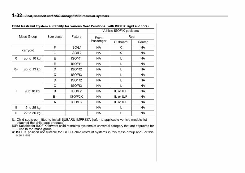
Black plate (62,1)
一般Model "A1300GE-A" EDITED: 2016/ 9/ 13
1-32 Seat, seatbelt and SRS airbags/Child restraint systems
Child Restraint System suitability for various Seat Positions (with ISOFIX rigid anchors)
Mass Group Size class Fixture
Vehicle ISOFIX positions
FrontPassenger
Rear
Outboard Center
carrycotF ISO/L1 NA X NA
G ISO/L2 NA X NA
0 up to 10 kg E ISO/R1 NA IL NA
0+ up to 13 kg
E ISO/R1 NA IL NA
D ISO/R2 NA IL NA
C ISO/R3 NA IL NA
I 9 to 18 kg
D ISO/R2 NA IL NA
C ISO/R3 NA IL NA
B ISO/F2 NA IL or IUF NA
B1 ISO/F2X NA IL or IUF NA
A ISO/F3 NA IL or IUF NA
II 15 to 25 kg NA IL NA
III 22 to 36 kg NA IL NA
IL: Child seats permitted to install SUBARU IMPREZA (refer to applicable vehicle models listattached the child seat products)
IUF: Suitable for ISOFIX forward child restraints systems of universal category that are approved foruse in the mass group.
X: ISOFIX position not suitable for ISOFIX child restraint systems in this mass group and / or thissize class.
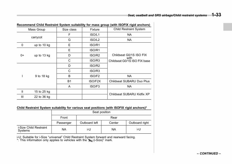
Black plate (63,1)
一般Model "A1300GE-A" EDITED: 2016/ 9/ 13
Recommend Child Restraint System suitability for mass group (with ISOFIX rigid anchors)
Mass Group Size class Fixture Child Restraint System
carrycotF ISO/L1 NA
G ISO/L2 NA
0 up to 10 kg E ISO/R1
Childseat G0/1S ISO FIXwith
Childseat G0/1S ISO FIX base
0+ up to 13 kg
E ISO/R1
D ISO/R2
C ISO/R3
I 9 to 18 kg
D ISO/R2
C ISO/R3
B ISO/F2 NA
B1 ISO/F2X Childseat SUBARU Duo Plus
A ISO/F3 NA
II 15 to 25 kgChildseat SUBARU Kidfix XP
III 22 to 36 kg
Child Restraint System suitability for various seat positions (with ISOFIX rigid anchors)*
Seat position
Front Rear
Passenger Outboard left Center Outboard right
i-Size Child RestraintSystems NA i-U NA i-U
i-U: Suitable for i-Size “universal” Child Restraint System forward and rearward facing.*: This information only applies to vehicles with the “ (i-Size)” mark.
Seat, seatbelt and SRS airbags/Child restraint systems 1-33
– CONTINUED –
1
Black plate (64,1)
一般Model "A1300GE-A" EDITED: 2016/ 9/ 13
1-34 Seat, seatbelt and SRS airbags/Child restraint systems
& Only for the models with thefront passenger’s frontal air-bag ON/OFF indicator - Wheninstalling child restraint sys-tems to the front passenger’sseat
WARNING
. Never install a rearward facingchild restraint system when thefront passenger’s frontal airbagON indicator is illuminated.Otherwise, there is an increasedrisk of injury to the child whenthe airbags are deployed, evenwhen a child restraint system isused.
. When you install a child restraintsystem, follow the manufac-turer’s instructions supplied withit. After installing the child re-straint system, check to ensurethat it is held securely in posi-tion. If it is not held tight andsecure, the danger in the event ofan accident may be increased.
. Do not place the removed headrestraint in the passenger com-partment to prevent it from beingthrown around in a sudden stop
or a sharp turn.
. When the SRS airbag systemwarning indicator and the frontpassenger’s frontal airbag OFFindicator are illuminated, the oc-cupant detection system may bemalfunctioning. In such case,install the child restraint systemto the rear seat.
. When installing a rear facingchild restraint system to the frontpassenger’s seat, check that thefront passenger’s frontal airbagOFF indicator is illuminated whilethe child is seated in the childrestraint system.
. When the front passenger’s fron-tal airbag ON indicator illumi-nates during driving, park thevehicle at the nearest safe placeand install the child restraintsystem to the rear seat.
. After installing the child restraintsystem securely to the frontpassenger’s seat, check the frontpassenger’s frontal airbag ON/OFF indicator status.
CAUTION
For safety reasons, always install achild restraint system to the rearseat. When it is unavoidable, thefront passenger’s seat can be useddepending on the front passenger’sfrontal airbag ON/OFF indicator’sstatus. For details, refer to “Wheninstalling the child restraint systemto the front passenger’s seat” F1-35.
NOTEThe instructions that are stated on thewarning label for the AIRBAG will notbe applied when all required conditionsshown in the Owner’s Manual are met.

Black plate (65,1)
一般Model "A1300GE-A" EDITED: 2016/ 9/ 13
! When installing the child restraintsystem to the front passenger’sseat
When you install a child restraint systemto the front passenger’s seat, perform thefollowing procedure.1. Adjust the front passenger’s seat asfollows.
A) Seat position: Rear mostB) Seatback: Upright
2. Install the child restraint system to thefront passenger’s seat. Refer to “Installingchild restraint systems with seatbelt” F1-39.3. Place and secure the child (or infant)in the child restraint system.4. Check that the front passenger’s fron-tal airbag ON/OFF indicator status meets
the requirements of your child restraintsystem.
A) Front passenger’s frontal airbag OFFindicator
B) Front passenger’s frontal airbag ONindicator
. Indicator status and applicablechild restraint system
is illuminat-ing
is illuminat-ing
Forward Facing OK OK
Rearward Facing OK NA
When front passenger’s frontal airbagOFF indicator is illuminated:Both forward and rearward facing childrestraint systems can be installed.When front passenger’s frontal airbagON indicator is illuminated:Only forward facing child restraint systemscan be installed. Rearward facing childrestraint systems cannot be installed.Further details, refer to “SRS airbag” F1-60.
NOTEDepending on the type and/or shape ofthe child restraint system, and thechild’s weight, the front passenger’sfrontal airbag ON indicator status maynot meet the requirements of your childrestraint system. In this case, installthe child restraint system to a rear seat.For details about the front passenger’sfrontal airbag ON indicator, refer to“Occupant detection system” F1-60.
5. Check that the child restraint systemdoes not contact the head restraint. If thechild restraint system does make contactwith the head restraint, raise the headrestraint to the extended position. If thechild restraint system still makes contact,remove the head restraint. For details,refer to “Head restraint” F1-8.
Seat, seatbelt and SRS airbags/Child restraint systems 1-35
– CONTINUED –
1
Black plate (66,1)
一般Model "A1300GE-A" EDITED: 2016/ 9/ 13
1-36 Seat, seatbelt and SRS airbags/Child restraint systems
! Installation procedure
For the installation procedure, refer to“Installing child restraint systems withseatbelt” F1-39.
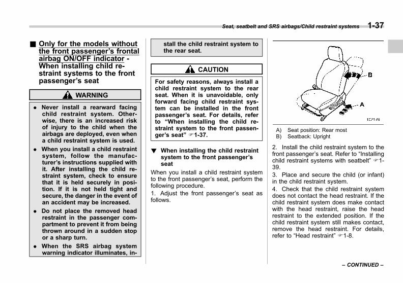
Black plate (67,1)
一般Model "A1300GE-A" EDITED: 2016/ 9/ 13
& Only for the models withoutthe front passenger’s frontalairbag ON/OFF indicator -When installing child re-straint systems to the frontpassenger’s seat
WARNING
. Never install a rearward facingchild restraint system. Other-wise, there is an increased riskof injury to the child when theairbags are deployed, even whena child restraint system is used.
. When you install a child restraintsystem, follow the manufac-turer’s instructions supplied withit. After installing the child re-straint system, check to ensurethat it is held securely in posi-tion. If it is not held tight andsecure, the danger in the event ofan accident may be increased.
. Do not place the removed headrestraint in the passenger com-partment to prevent it from beingthrown around in a sudden stopor a sharp turn.
. When the SRS airbag systemwarning indicator illuminates, in-
stall the child restraint system tothe rear seat.
CAUTION
For safety reasons, always install achild restraint system to the rearseat. When it is unavoidable, onlyforward facing child restraint sys-tem can be installed in the frontpassenger’s seat. For details, referto “When installing the child re-straint system to the front passen-ger’s seat” F1-37.
! When installing the child restraintsystem to the front passenger’sseat
When you install a child restraint systemto the front passenger’s seat, perform thefollowing procedure.1. Adjust the front passenger’s seat asfollows.
A) Seat position: Rear mostB) Seatback: Upright
2. Install the child restraint system to thefront passenger’s seat. Refer to “Installingchild restraint systems with seatbelt” F1-39.3. Place and secure the child (or infant)in the child restraint system.4. Check that the child restraint systemdoes not contact the head restraint. If thechild restraint system does make contactwith the head restraint, raise the headrestraint to the extended position. If thechild restraint system still makes contact,remove the head restraint. For details,refer to “Head restraint” F1-8.
Seat, seatbelt and SRS airbags/Child restraint systems 1-37
– CONTINUED –
1

Black plate (68,1)
一般Model "A1300GE-A" EDITED: 2016/ 9/ 13
1-38 Seat, seatbelt and SRS airbags/Child restraint systems
! Installation procedure
For the installation procedure, refer to“Installing child restraint systems withseatbelt” F1-39.

Black plate (69,1)
一般Model "A1300GE-A" EDITED: 2016/ 9/ 13
& Installing child restraint sys-tems with seatbelt
! Preparation for installing child re-straint system
First check if the Automatic LockingRetractor (ALR) is equipped for theseatbelts of the vehicle according to thefollowing procedure.1. Draw out the seatbelt completely.2. Retract the seatbelt even slightly andtry to draw out the seatbelt again.3. If the seatbelt is locked in that positionand cannot be extended, it indicates thatan ALR is equipped for the seatbelt.
When the seatbelt is retracted fully, theALR mode is canceled and the Emer-gency Locking Retractor (ELR) mode isrestored.
NOTE. For details about the ELR, refer to“Emergency Locking Retractor (ELR)”F1-14.. For details about the ALR, refer to“Automatic Locking Retractor/Emer-gency Locking Retractor (ALR/ELR)(Australia models)” F1-14.
! Installing a rearward facing childrestraint
WARNING
NEVER INSTALL A FORWARD ORREARWARD FACING CHILD SEATIN THE FRONT PASSENGER’SSEAT. DOING SO RISKS SERIOUSINJURY OR DEATH TO THE CHILDBY PLACING THE CHILD’S HEADTOO CLOSE TO THE SRS AIRBAG.
NOTE. For models with ALR:If using ALR mode is recommended bythe manufacturer’s instructions sup-plied with the child restraint system,use ALR mode.
1) Lock-off device2) Locking clip
. If using the lock-off device or thelocking clip is recommended by themanufacturer’s instructions suppliedwith the child restraint system, usethe lock-off device or the locking clipto secure the child restraint system.
Through the following steps, the childrestraint system is fastened with a seatbeltthat is set to ELR mode.
Seat, seatbelt and SRS airbags/Child restraint systems 1-39
– CONTINUED –
1

Black plate (70,1)
一般Model "A1300GE-A" EDITED: 2016/ 9/ 13
1-40 Seat, seatbelt and SRS airbags/Child restraint systems
1. Place the child restraint system in therear seating position.2. Run the lap and shoulder belt throughor around the child restraint systemfollowing the instructions provided by itsmanufacturer.3. Insert the tongue plate into the buckleuntil you hear a click.
4. Take up the slack in the lap belt.
5. Push and pull the child restraintsystem forward and from side to side tocheck if it is firmly secured.6. To remove the child restraint system,press the release button on the seatbelt
buckle.
! Installing forward facing child re-straint
If the ALR is not equipped for the seatbelt,refer to “Models without ALR” F1-40.
If the ALR is equipped for the seatbelt,refer to “Models with ALR” F1-42.
! Models without ALR
1. Remove the head restraint of the rearseating position where the child restraintsystem is to be installed.2. Place the child restraint system in theseat.
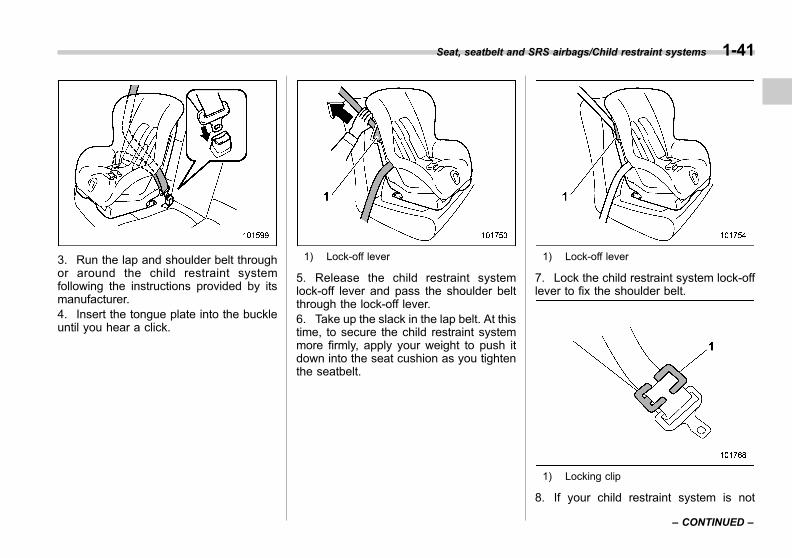
Black plate (71,1)
一般Model "A1300GE-A" EDITED: 2016/ 9/ 13
3. Run the lap and shoulder belt throughor around the child restraint systemfollowing the instructions provided by itsmanufacturer.4. Insert the tongue plate into the buckleuntil you hear a click.
1) Lock-off lever
5. Release the child restraint systemlock-off lever and pass the shoulder beltthrough the lock-off lever.6. Take up the slack in the lap belt. At thistime, to secure the child restraint systemmore firmly, apply your weight to push itdown into the seat cushion as you tightenthe seatbelt.
1) Lock-off lever
7. Lock the child restraint system lock-offlever to fix the shoulder belt.
1) Locking clip
8. If your child restraint system is not
Seat, seatbelt and SRS airbags/Child restraint systems 1-41
– CONTINUED –
1
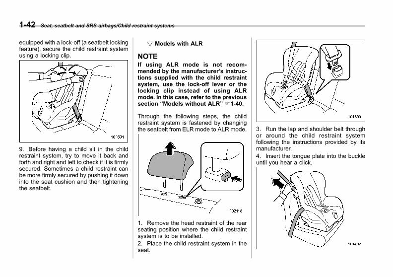
Black plate (72,1)
一般Model "A1300GE-A" EDITED: 2016/ 9/ 13
1-42 Seat, seatbelt and SRS airbags/Child restraint systems
equipped with a lock-off (a seatbelt lockingfeature), secure the child restraint systemusing a locking clip.
9. Before having a child sit in the childrestraint system, try to move it back andforth and right and left to check if it is firmlysecured. Sometimes a child restraint canbe more firmly secured by pushing it downinto the seat cushion and then tighteningthe seatbelt.
! Models with ALR
NOTEIf using ALR mode is not recom-mended by the manufacturer’s instruc-tions supplied with the child restraintsystem, use the lock-off lever or thelocking clip instead of using ALRmode. In this case, refer to the previoussection “Models without ALR” F1-40.
Through the following steps, the childrestraint system is fastened by changingthe seatbelt from ELR mode to ALR mode.
1. Remove the head restraint of the rearseating position where the child restraintsystem is to be installed.2. Place the child restraint system in theseat.
3. Run the lap and shoulder belt throughor around the child restraint systemfollowing the instructions provided by itsmanufacturer.4. Insert the tongue plate into the buckleuntil you hear a click.

Black plate (73,1)
一般Model "A1300GE-A" EDITED: 2016/ 9/ 13
5. Take up the slack in the lap belt.6. Pull out the seatbelt fully from theretractor to change the retractor over fromthe Emergency Locking Retractor (ELR)to the Automatic Locking Retractor (ALR)function. Then, allow the belt to rewindinto the retractor. As the belt is rewinding,clicks will be heard which indicate theretractor functions as ALR.
7. Before having a child sit in the childrestraint system, try to move it back andforth and right and left to check that it isfirmly secured. Sometimes a child restraintcan be more firmly secured by pushing itdown into the seat cushion and thentightening the seatbelt.8. Pull at the shoulder portion of the beltto confirm that it cannot be pulled out (ALRproperly functioning).
4-door models
5-door models
9. If the child restraint system requires atop tether, latch the hook onto the toptether anchorage and tighten the toptether. For additional instructions, refer to
“Top tether anchorages” F1-48.
10. To remove the child restraint system,press the release button on the seatbeltbuckle and allow the belt to retractcompletely. The belt will return to theELR mode.
NOTEWhen the child restraint system is nolonger in use, remove it and restore theELR function of the retractor. Thatfunction is restored by allowing theseatbelt to retract fully.
Seat, seatbelt and SRS airbags/Child restraint systems 1-43
– CONTINUED –
1
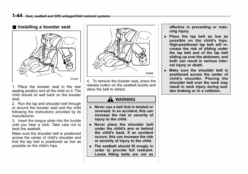
Black plate (74,1)
一般Model "A1300GE-A" EDITED: 2016/ 9/ 13
1-44 Seat, seatbelt and SRS airbags/Child restraint systems
& Installing a booster seat
1. Place the booster seat in the rearseating position and sit the child on it. Thechild should sit well back on the boosterseat.2. Run the lap and shoulder belt throughor around the booster seat and the childfollowing the instructions provided by itsmanufacturer.3. Insert the tongue plate into the buckleuntil you hear a click. Take care not totwist the seatbelt.Make sure the shoulder belt is positionedacross the center of child’s shoulder andthat the lap belt is positioned as low aspossible on the child’s hips.
4. To remove the booster seat, press therelease button on the seatbelt buckle andallow the belt to retract.
WARNING
. Never use a belt that is twisted orreversed. In an accident, this canincrease the risk or severity ofinjury to the child.
. Never place the shoulder beltunder the child’s arm or behindthe child’s back. If an accidentoccurs, this can increase the riskor severity of injury to the child.
. The seatbelt should fit snugly inorder to provide full restraint.Loose fitting belts are not as
effective in preventing or redu-cing injury.
. Place the lap belt as low aspossible on the child’s hips.High-positioned lap belt will in-crease the risk of sliding underthe lap belt and of the lap beltsliding up over the abdomen, andboth can result in serious inter-nal injury or death.
. Make sure the shoulder belt ispositioned across the center ofchild’s shoulder. Placing theshoulder belt over the neck mayresult in neck injury during sud-den braking or in a collision.
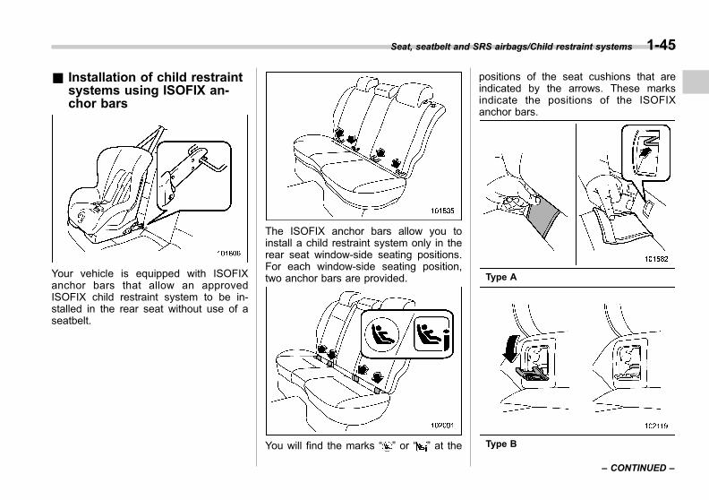
Black plate (75,1)
一般Model "A1300GE-A" EDITED: 2016/ 9/ 13
& Installation of child restraintsystems using ISOFIX an-chor bars
Your vehicle is equipped with ISOFIXanchor bars that allow an approvedISOFIX child restraint system to be in-stalled in the rear seat without use of aseatbelt.
The ISOFIX anchor bars allow you toinstall a child restraint system only in therear seat window-side seating positions.For each window-side seating position,two anchor bars are provided.
You will find the marks “ ” or “ ” at the
positions of the seat cushions that areindicated by the arrows. These marksindicate the positions of the ISOFIXanchor bars.
Type A
Type B
Seat, seatbelt and SRS airbags/Child restraint systems 1-45
– CONTINUED –
1
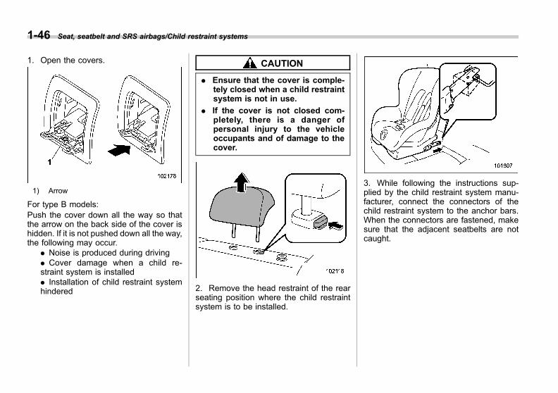
Black plate (76,1)
一般Model "A1300GE-A" EDITED: 2016/ 9/ 13
1-46 Seat, seatbelt and SRS airbags/Child restraint systems
1. Open the covers.
1) Arrow
For type B models:Push the cover down all the way so thatthe arrow on the back side of the cover ishidden. If it is not pushed down all the way,the following may occur.
. Noise is produced during driving
. Cover damage when a child re-straint system is installed. Installation of child restraint systemhindered
CAUTION
. Ensure that the cover is comple-tely closed when a child restraintsystem is not in use.
. If the cover is not closed com-pletely, there is a danger ofpersonal injury to the vehicleoccupants and of damage to thecover.
2. Remove the head restraint of the rearseating position where the child restraintsystem is to be installed.
3. While following the instructions sup-plied by the child restraint system manu-facturer, connect the connectors of thechild restraint system to the anchor bars.When the connectors are fastened, makesure that the adjacent seatbelts are notcaught.
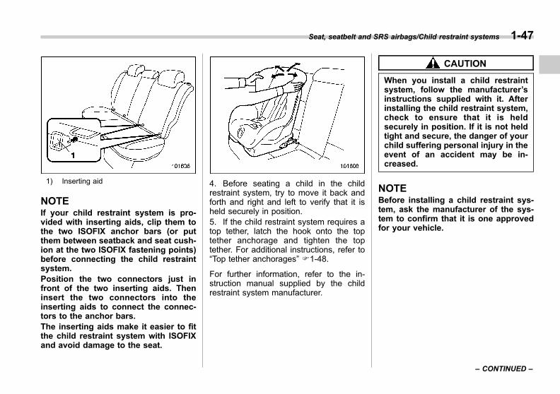
Black plate (77,1)
一般Model "A1300GE-A" EDITED: 2016/ 9/ 13
1) Inserting aid
NOTEIf your child restraint system is pro-vided with inserting aids, clip them tothe two ISOFIX anchor bars (or putthem between seatback and seat cush-ion at the two ISOFIX fastening points)before connecting the child restraintsystem.Position the two connectors just infront of the two inserting aids. Theninsert the two connectors into theinserting aids to connect the connec-tors to the anchor bars.The inserting aids make it easier to fitthe child restraint system with ISOFIXand avoid damage to the seat.
4. Before seating a child in the childrestraint system, try to move it back andforth and right and left to verify that it isheld securely in position.5. If the child restraint system requires atop tether, latch the hook onto the toptether anchorage and tighten the toptether. For additional instructions, refer to“Top tether anchorages” F1-48.
For further information, refer to the in-struction manual supplied by the childrestraint system manufacturer.
CAUTION
When you install a child restraintsystem, follow the manufacturer’sinstructions supplied with it. Afterinstalling the child restraint system,check to ensure that it is heldsecurely in position. If it is not heldtight and secure, the danger of yourchild suffering personal injury in theevent of an accident may be in-creased.
NOTEBefore installing a child restraint sys-tem, ask the manufacturer of the sys-tem to confirm that it is one approvedfor your vehicle.
Seat, seatbelt and SRS airbags/Child restraint systems 1-47
– CONTINUED –
1

Black plate (78,1)
一般Model "A1300GE-A" EDITED: 2016/ 9/ 13
1-48 Seat, seatbelt and SRS airbags/Child restraint systems
& Top tether anchoragesYour vehicle is provided with two or threetop tether anchorages so that a childrestraint system having a top tether canbe installed in the rear seat. Wheninstalling a child restraint system usingtop tether, proceed as follows, whileobserving the instructions by the childrestraint system manufacturer.
Since a top tether can provide additionalstability by offering another connectionbetween a child restraint system and thevehicle, we recommend that you use a toptether whenever one is required or avail-able.
! Anchorage location
Anchorages are installed as shown in thefollowing illustrations.
4-door models1) For left seat2) For center seat (if equipped)3) For right seat
5-door models1) For left seat2) For center seat (if equipped)3) For right seat

Black plate (79,1)
一般Model "A1300GE-A" EDITED: 2016/ 9/ 13
! To hook the top tether
4-door models
5-door models
1. Open the cover (4-door models).Attach the top tether hook to the appro-priate upper anchorage.
2. Tighten the top tether securely.
We recommend that you contact yourSUBARU dealer if you have any questionregarding the installation of a child re-straint system.
*SRS airbag (SupplementalRestraint System airbag)
*SRS: This stands for supplemental re-straint system. This name is used be-cause the airbag system supplements thevehicle’s seatbelts.
Your vehicle is equipped with a supple-mental restraint system in addition to alap/shoulder/adaptive force limiter (ifequipped) for the front seats and rearwindow-side seat ing posi t ions ( i fequipped).The supplemental restraint system (SRS)consists of seven airbags. The configura-tions are as follows.. Frontal airbags for driver and frontpassenger. Knee airbag for driver. Side airbags for driver and frontpassenger. Curtain airbags for driver, front pas-senger and window-side rear passengers
These SRS airbags are designed onlyas a supplement to the primary protec-tion provided by the seatbelt.
The system also controls front seatbeltpretensioners. For operation instructionsand precautions concerning the seatbelt
Seat, seatbelt and SRS airbags/*SRS airbag (Supplemental Restraint System airbag) 1-49
– CONTINUED –
1

Black plate (80,1)
一般Model "A1300GE-A" EDITED: 2016/ 9/ 13
1-50 Seat, seatbelt and SRS airbags/*SRS airbag (Supplemental Restraint System airbag)
pretensioner, refer to “Seatbelt preten-sioners” F1-21.
& General precautions regard-ing SRS airbag system
WARNING
. To obtain maximum protection inthe event of an accident, thedriver and all passengers mustalways wear seatbelts when inthe vehicle. The SRS airbag isdesigned only to be a supple-ment to the primary protectionprovided by the seatbelt. It doesnot eliminate the need to fastenseatbelts. In combination withthe seatbelts, it offers the bestcombined protection in case of aserious accident.
Not wearing a seatbelt increasesthe chance of severe injury ordeath in a crash even when thevehicle has the SRS airbag.
For instructions and precautionsconcerning the seatbelt system,refer to “Seatbelts” F1-12.
. The SRS side airbag and SRScurtain airbag are designed onlyto be a supplement to the primaryprotection provided by the seat-
belt. They do not eliminate theneed to fasten seatbelts. It is alsoimportant to wear your seatbeltto help avoid injuries that canresult when an occupant is notseated in a proper upright posi-tion.
WARNING
The SRS airbags deploy with con-siderable speed and force. Occu-pants who are out of proper positionwhen the SRS airbag deploys couldsuffer very serious injuries. Be-cause the SRS airbag needs enoughspace for deployment, the drivershould always sit upright and wellback in the seat as far from the
steering wheel as practical whilestill maintaining full vehicle controland the front passenger shouldmove the seat as far back aspossible and sit upright and wellback in the seat.
WARNING
. Do not sit or lean unnecessarilyclose to either front door. TheSRS side airbags are stored inboth front seat seatbacks next tothe door, and they provide pro-tection by deploying rapidly (fas-ter than the blink of an eye) in theevent of a side impact collision.However, the force of SRS sideairbag deployment may cause
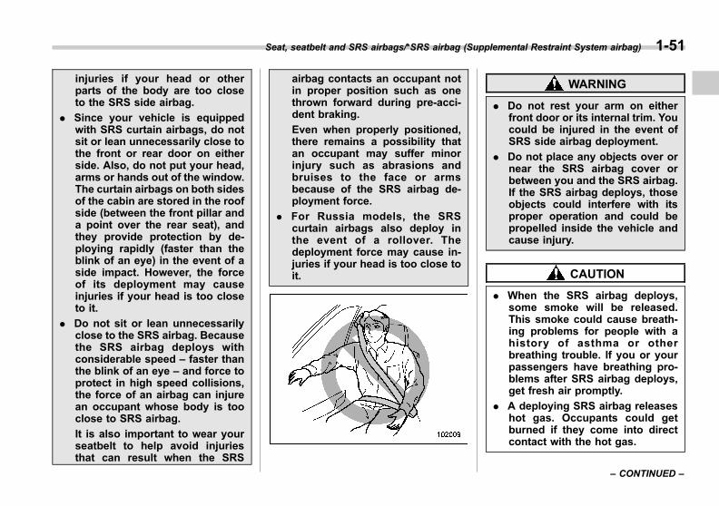
Black plate (81,1)
一般Model "A1300GE-A" EDITED: 2016/ 9/ 13
injuries if your head or otherparts of the body are too closeto the SRS side airbag.
. Since your vehicle is equippedwith SRS curtain airbags, do notsit or lean unnecessarily close tothe front or rear door on eitherside. Also, do not put your head,arms or hands out of the window.The curtain airbags on both sidesof the cabin are stored in the roofside (between the front pillar anda point over the rear seat), andthey provide protection by de-ploying rapidly (faster than theblink of an eye) in the event of aside impact. However, the forceof its deployment may causeinjuries if your head is too closeto it.
. Do not sit or lean unnecessarilyclose to the SRS airbag. Becausethe SRS airbag deploys withconsiderable speed – faster thanthe blink of an eye – and force toprotect in high speed collisions,the force of an airbag can injurean occupant whose body is tooclose to SRS airbag.
It is also important to wear yourseatbelt to help avoid injuriesthat can result when the SRS
airbag contacts an occupant notin proper position such as onethrown forward during pre-acci-dent braking.
Even when properly positioned,there remains a possibility thatan occupant may suffer minorinjury such as abrasions andbruises to the face or armsbecause of the SRS airbag de-ployment force.
. For Russia models, the SRScurtain airbags also deploy inthe event of a rollover. Thedeployment force may cause in-juries if your head is too close toit.
WARNING
. Do not rest your arm on eitherfront door or its internal trim. Youcould be injured in the event ofSRS side airbag deployment.
. Do not place any objects over ornear the SRS airbag cover orbetween you and the SRS airbag.If the SRS airbag deploys, thoseobjects could interfere with itsproper operation and could bepropelled inside the vehicle andcause injury.
CAUTION
. When the SRS airbag deploys,some smoke will be released.This smoke could cause breath-ing problems for people with ahistory of asthma or otherbreathing trouble. If you or yourpassengers have breathing pro-blems after SRS airbag deploys,get fresh air promptly.
. A deploying SRS airbag releaseshot gas. Occupants could getburned if they come into directcontact with the hot gas.
Seat, seatbelt and SRS airbags/*SRS airbag (Supplemental Restraint System airbag) 1-51
– CONTINUED –
1
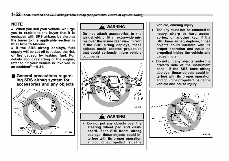
Black plate (82,1)
一般Model "A1300GE-A" EDITED: 2016/ 9/ 13
1-52 Seat, seatbelt and SRS airbags/*SRS airbag (Supplemental Restraint System airbag)
NOTE. When you sell your vehicle, we urgeyou to explain to the buyer that it isequipped with SRS airbags by alertingthe buyer to the applicable section inthis Owner’s Manual.. If the SRS airbag deploys, fuelsupply will be cut off to reduce the riskof fire caused by leaking fuel. Fordetails about restarting of the engine,refer to “If your vehicle is involved inan accident” F9-31.
& General precautions regard-ing SRS airbag system foraccessories and any objects
WARNING
Do not attach accessories to thewindshield, or fit an extra-wide mir-ror over the inside rear view mirror.If the SRS airbag deploys, theseobjects could become projectilesthat could seriously injure vehicleoccupants.
WARNING
. Do not put any objects over thesteering wheel pad and dash-board. If the SRS frontal airbagdeploys, these objects could in-terfere with its proper operationand could be propelled inside the
vehicle, causing injury.
. The key must not be attached toheavy, sharp or hard acces-sories, or another key. If theSRS knee airbag deploys, thoseobjects could interfere with itsproper operation and could bepropelled inside the vehicle andcause injury.
. Do not put any objects under thedriver’s side of the instrumentpanel. If the SRS knee airbagdeploys, those objects could in-terfere with its proper operationand could be propelled inside thevehicle and cause injury.

Black plate (83,1)
一般Model "A1300GE-A" EDITED: 2016/ 9/ 13
WARNING
. Do not attach accessories to thedoor trim or near either SRS sideairbags and do not place objectsnear the SRS side airbags. In theevent of SRS side airbag deploy-ment, they could be propelleddangerously toward the vehicle’soccupants and cause injuries.
. Do not attach a hands-free micro-phone or any other accessory toa front pillar, a center pillar, a rearpillar, the windshield, a side win-dow, an assist grip, or any othercabin surface that would be neara deploying SRS curtain airbag.A hands-free microphone orother accessory in such a loca-tion could be propelled throughthe cabin with great force by thecurtain airbag, or it could preventcorrect deployment of the curtainairbag. In either case, the resultcould be serious injuries.
. Never hang or place coat hangersor other hard or pointed objectsnear the side windows. If suchitems are present when the SRScurtain airbags deploy, theycould be thrown through thepassenger compartment and
cause serious injuries. Theycould also prevent proper opera-tion of the SRS curtain airbags.
WARNING
Do not hang coat hangers or otherhard or pointed objects on the coathooks. If such items are hanging onthe coat hooks during deploymentof the SRS curtain airbags, theycould cause serious injuries bycoming off the coat hooks and beingthrown through the cabin or bypreventing deployment of the cur-tain airbags.
Before hanging clothing on the coathooks, make sure there are no sharp
objects in the pockets. Hang cloth-ing directly on the coat hooks with-out using hangers.
WARNING
. Do not put any kind of clothes orother objects over either frontseatback and do not attach labelsor stickers to the front seat sur-face on or near the SRS sideairbag. They could prevent prop-er deployment of the SRS sideairbag, reducing protection avail-able to the front seat’s occupant.
. Do not install a seat cover unlessit is a genuine SUBARU seatcover exclusively designed for
Seat, seatbelt and SRS airbags/*SRS airbag (Supplemental Restraint System airbag) 1-53
– CONTINUED –
1
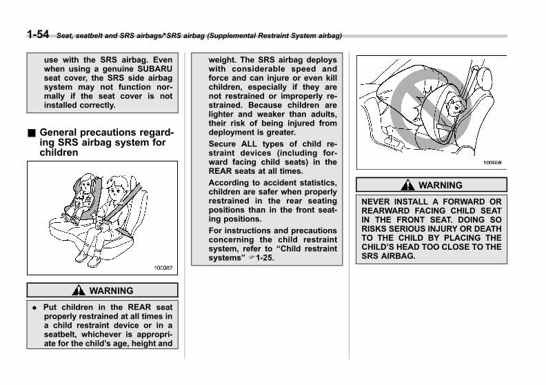
Black plate (84,1)
一般Model "A1300GE-A" EDITED: 2016/ 9/ 13
1-54 Seat, seatbelt and SRS airbags/*SRS airbag (Supplemental Restraint System airbag)
use with the SRS airbag. Evenwhen using a genuine SUBARUseat cover, the SRS side airbagsystem may not function nor-mally if the seat cover is notinstalled correctly.
& General precautions regard-ing SRS airbag system forchildren
WARNING
. Put children in the REAR seatproperly restrained at all times ina child restraint device or in aseatbelt, whichever is appropri-ate for the child’s age, height and
weight. The SRS airbag deployswith considerable speed andforce and can injure or even killchildren, especially if they arenot restrained or improperly re-strained. Because children arelighter and weaker than adults,their risk of being injured fromdeployment is greater.
Secure ALL types of child re-straint devices (including for-ward facing child seats) in theREAR seats at all times.
According to accident statistics,children are safer when properlyrestrained in the rear seatingpositions than in the front seat-ing positions.
For instructions and precautionsconcerning the child restraintsystem, refer to “Child restraintsystems” F1-25.
WARNING
NEVER INSTALL A FORWARD ORREARWARD FACING CHILD SEATIN THE FRONT SEAT. DOING SORISKS SERIOUS INJURY OR DEATHTO THE CHILD BY PLACING THECHILD’S HEAD TOO CLOSE TO THESRS AIRBAG.

Black plate (85,1)
一般Model "A1300GE-A" EDITED: 2016/ 9/ 13
WARNING
Never allow a child to stand up orkneel on the front passenger’s seat.The SRS airbag deploys with con-siderable force and can injure oreven kill the child.
WARNING
Never hold a child on your lap or inyour arms. The SRS airbag deployswith considerable force and caninjure or even kill the child.
Seat, seatbelt and SRS airbags/*SRS airbag (Supplemental Restraint System airbag) 1-55
– CONTINUED –
1

Black plate (86,1)
一般Model "A1300GE-A" EDITED: 2016/ 9/ 13
1-56 Seat, seatbelt and SRS airbags/*SRS airbag (Supplemental Restraint System airbag)
WARNING
. Never allow a child to do thefollowing.
– Kneel on any passenger’sseat facing the side window
– Wrap his/her arms around thefront seat seatback
– Put his/her head, arms orother parts of the body out ofthe window
In the event of an accident, theforce of SRS side airbag and/orSRS curtain airbag deploymentcould injure the child seriouslybecause his/her head, arms orother parts of the body are tooclose to the SRS side airbag and/or SRS curtain airbag.
. Since your vehicle is alsoequipped with a front passen-ger’s SRS frontal airbag, childrenaged 12 and under or 1.5 m (4feet 11 inches) tall or less shouldbe placed in the rear seat anywayand should be properly re-strained at all times.

Black plate (87,1)
一般Model "A1300GE-A" EDITED: 2016/ 9/ 13
& Components
1) Driver’s SRS frontal airbag2) Front passenger’s SRS frontal airbag3) SRS side airbag4) SRS curtain airbag5) SRS knee airbag
The SRS airbags are stowed in thefollowing locations.
Driver’s SRS frontal airbag: in the centerportion of the steering wheelA “SRS AIRBAG” mark is located at thepad of the airbag.
Front passenger’s SRS frontal airbag:near the top of the dashboard under the“SRS AIRBAG” mark
SRS side airbag: in the door side of eachfront seat seatback which bears the “SRSAIRBAG” label
SRS curtain airbag: in the roof side(between the front pillar and a point overthe rear seat)“SRS AIRBAG” marks are located at thetop of each center pillar.
SRS knee airbag: under the steeringcolumnA “SRS AIRBAG” mark is located at thedoor of the airbag.
Seat, seatbelt and SRS airbags/*SRS airbag (Supplemental Restraint System airbag) 1-57
– CONTINUED –
1

Black plate (88,1)
一般Model "A1300GE-A" EDITED: 2016/ 9/ 13
1-58 Seat, seatbelt and SRS airbags/*SRS airbag (Supplemental Restraint System airbag)
Left-hand drive models1) Front sub sensor (right-hand side)2) SRS airbag system warning light3) Frontal airbag module (driver’s side)4) Airbag control module (including impact
sensors [all models] and rollover sensor[Russia models])
5) Frontal airbag module (front passenger’sside)
6) Front passenger’s frontal airbag ON andOFF indicator (if equipped)
7) Front passenger’s occupant detectionsensors (if equipped)
8) Front passenger’s occupant detectioncontrol module (if equipped)
9) Curtain airbag module (left-hand side)10) Front door impact sensor (front passen-
ger’s side)11) Side airbag module (front passenger’s
side)12) Side airbag sensor (center pillar right-
hand side)13) Curtain airbag module (right-hand side)14) Rear seatbelt pretensioner (if equipped)15) Curtain airbag sensor (rear wheel house
right-hand side)16) Seatbelt pretensioner and adaptive force
limiter (if equipped) (front passenger’sside)
17) Lap belt pretensioner (front passenger’sside)
18) Satellite safing sensor (under the rearcenter seat)
19) Rear seatbelt pretensioner (if equipped)20) Curtain airbag sensor (rear wheel house
left-hand side)21) Seatbelt buckle switch (front passenger’s
side) (if equipped)22) Seatbelt pretensioner and adaptive force
limiter (if equipped) (driver’s side)23) Lap belt pretensioner (driver’s side)24) Side airbag sensor (center pillar left-hand
side)25) Side airbag module (driver’s side)26) Driver ’s seat posit ion sensor ( i f
equipped)27) Front door impact sensor (driver’s side)28) Knee airbag module (driver’s side)29) Front sub sensor (left-hand side)
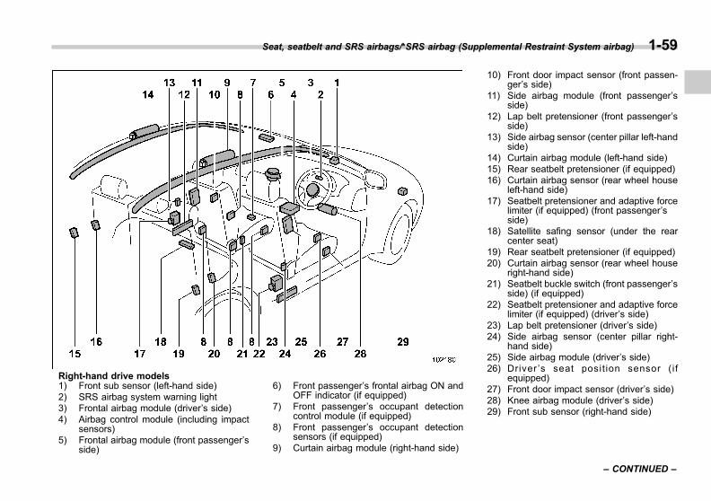
Black plate (89,1)
一般Model "A1300GE-A" EDITED: 2016/ 9/ 13
Right-hand drive models1) Front sub sensor (left-hand side)2) SRS airbag system warning light3) Frontal airbag module (driver’s side)4) Airbag control module (including impact
sensors)5) Frontal airbag module (front passenger’s
side)
6) Front passenger’s frontal airbag ON andOFF indicator (if equipped)
7) Front passenger’s occupant detectioncontrol module (if equipped)
8) Front passenger’s occupant detectionsensors (if equipped)
9) Curtain airbag module (right-hand side)
10) Front door impact sensor (front passen-ger’s side)
11) Side airbag module (front passenger’sside)
12) Lap belt pretensioner (front passenger’sside)
13) Side airbag sensor (center pillar left-handside)
14) Curtain airbag module (left-hand side)15) Rear seatbelt pretensioner (if equipped)16) Curtain airbag sensor (rear wheel house
left-hand side)17) Seatbelt pretensioner and adaptive force
limiter (if equipped) (front passenger’sside)
18) Satellite safing sensor (under the rearcenter seat)
19) Rear seatbelt pretensioner (if equipped)20) Curtain airbag sensor (rear wheel house
right-hand side)21) Seatbelt buckle switch (front passenger’s
side) (if equipped)22) Seatbelt pretensioner and adaptive force
limiter (if equipped) (driver’s side)23) Lap belt pretensioner (driver’s side)24) Side airbag sensor (center pillar right-
hand side)25) Side airbag module (driver’s side)26) Driver ’s seat posit ion sensor ( i f
equipped)27) Front door impact sensor (driver’s side)28) Knee airbag module (driver’s side)29) Front sub sensor (right-hand side)
Seat, seatbelt and SRS airbags/*SRS airbag (Supplemental Restraint System airbag) 1-59
– CONTINUED –
1
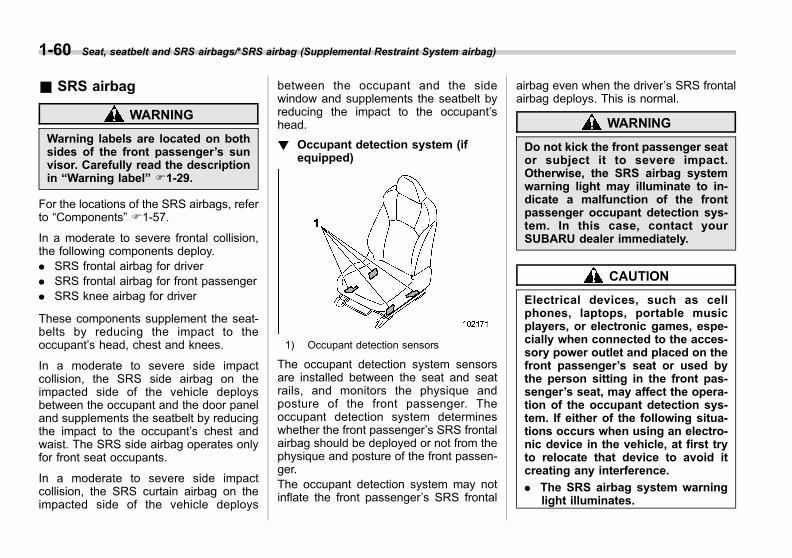
Black plate (90,1)
一般Model "A1300GE-A" EDITED: 2016/ 9/ 13
1-60 Seat, seatbelt and SRS airbags/*SRS airbag (Supplemental Restraint System airbag)
& SRS airbag
WARNING
Warning labels are located on bothsides of the front passenger’s sunvisor. Carefully read the descriptionin “Warning label” F1-29.
For the locations of the SRS airbags, referto “Components” F1-57.
In a moderate to severe frontal collision,the following components deploy.. SRS frontal airbag for driver. SRS frontal airbag for front passenger. SRS knee airbag for driver
These components supplement the seat-belts by reducing the impact to theoccupant’s head, chest and knees.
In a moderate to severe side impactcollision, the SRS side airbag on theimpacted side of the vehicle deploysbetween the occupant and the door paneland supplements the seatbelt by reducingthe impact to the occupant’s chest andwaist. The SRS side airbag operates onlyfor front seat occupants.
In a moderate to severe side impactcollision, the SRS curtain airbag on theimpacted side of the vehicle deploys
between the occupant and the sidewindow and supplements the seatbelt byreducing the impact to the occupant’shead.
! Occupant detection system (ifequipped)
1) Occupant detection sensors
The occupant detection system sensorsare installed between the seat and seatrails, and monitors the physique andposture of the front passenger. Theoccupant detection system determineswhether the front passenger’s SRS frontalairbag should be deployed or not from thephysique and posture of the front passen-ger.The occupant detection system may notinflate the front passenger’s SRS frontal
airbag even when the driver’s SRS frontalairbag deploys. This is normal.
WARNING
Do not kick the front passenger seator subject it to severe impact.Otherwise, the SRS airbag systemwarning light may illuminate to in-dicate a malfunction of the frontpassenger occupant detection sys-tem. In this case, contact yourSUBARU dealer immediately.
CAUTION
Electrical devices, such as cellphones, laptops, portable musicplayers, or electronic games, espe-cially when connected to the acces-sory power outlet and placed on thefront passenger’s seat or used bythe person sitting in the front pas-senger’s seat, may affect the opera-tion of the occupant detection sys-tem. If either of the following situa-tions occurs when using an electro-nic device in the vehicle, at first tryto relocate that device to avoid itcreating any interference.
. The SRS airbag system warninglight illuminates.
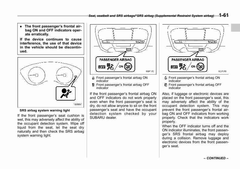
Black plate (91,1)
一般Model "A1300GE-A" EDITED: 2016/ 9/ 13
. The front passenger’s frontal air-bag ON and OFF indicators oper-ate erratically.
If the device continues to causeinterference, the use of that devicein the vehicle should be discontin-ued.
SRS airbag system warning light
If the front passenger’s seat cushion iswet, this may adversely affect the ability ofthe occupant detection system. Wipe offliquid from the seat, let the seat drynaturally and then check the SRS airbagsystem warning light.
: Front passenger’s frontal airbag ONindicator
: Front passenger’s frontal airbag OFFindicator
If the front passenger’s frontal airbag ONand OFF indicators do not work properlyeven when the front passenger’s seat isdry, do not allow anyone to sit on the frontpassenger’s seat and have the occupantdetection system checked by yourSUBARU dealer.
: Front passenger’s frontal airbag ONindicator
: Front passenger’s frontal airbag OFFindicator
Also, if luggage or electronic devices areplaced on the front passenger’s seat, thismay adversely affect the ability of theoccupant detection system. This mayprevent the front passenger’s frontal air-bag ON and OFF indicators from workingproperly. Check that the indicators workproperly.When the OFF indicator turns off and theON indicator illuminates, the front passen-ger’s SRS frontal airbag may deployduring a collision. Remove luggage andelectronic devices from the front passen-ger’s seat.
Seat, seatbelt and SRS airbags/*SRS airbag (Supplemental Restraint System airbag) 1-61
– CONTINUED –
1
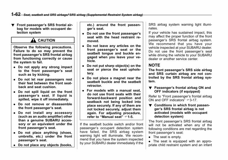
Black plate (92,1)
一般Model "A1300GE-A" EDITED: 2016/ 9/ 13
1-62 Seat, seatbelt and SRS airbags/*SRS airbag (Supplemental Restraint System airbag)
! Front passenger’s SRS frontal air-bag for models with occupant de-tection system
CAUTION
Observe the following precautions.Failure to do so may prevent thefront passenger’s SRS frontal airbagfrom functioning correctly or causethe system to fail.
. Do not apply any strong impactto the front passenger’s seatsuch as by kicking.
. Do not let rear passengers resttheir feet between the front seat-back and seat cushion.
. Do not spill liquid on the frontpassenger’s seat. If liquid isspilled, wipe it off immediately.
. Do not remove or disassemblethe front passenger’s seat.
. Do not install any accessory(such as an audio amplifier) otherthan a genuine SUBARU acces-sory or an equivalent under thefront passenger’s seat.
. Do not place anything (shoes,umbrella, etc.) under the frontpassenger’s seat.
. Do not place any objects (books,
etc.) around the front passen-ger’s seat.
. Do not use the front passenger’sseat with the head restraint re-moved.
. Do not leave any articles on thefront passenger’s seat or theseatbelt tongue and buckle en-gaged when you leave your ve-hicle.
. Do not put sharp object(s) on theseat or pierce the seat uphols-tery.
. Do not place a magnet near theseatbelt buckle and the seatbeltretractor.
. For models with a manual seat,do not use front seats with theirforward-backward position andseatback not being locked intoplace securely. If any of them arenot locked securely, adjust themagain. For adjusting procedure,refer to “Manual seat” F1-5.
If the seatbelt buckle switch and/or frontpassenger’s occupant detection systemhave failed, the SRS airbag systemwarning light will illuminate. We recom-mend that you have the system inspectedby your SUBARU dealer immediately if the
SRS airbag system warning light illumi-nates.If your vehicle has sustained impact, thismay affect the proper function of the frontpassenger’s SRS frontal airbag system.We recommend that you have yourvehicle inspected at your SUBARU dealer.Do not use the front passenger’s seatwhile driving the vehicle to your SUBARUdealer or another service center.
NOTEThe front passenger’s SRS side airbagand SRS curtain airbag are not con-trolled by the SRS frontal airbag sys-tem.
! Passenger’s frontal airbag ON andOFF indicators (if equipped)
Refer to “Front passenger’s frontal airbagON and OFF indicators” F3-17.
! Conditions in which front passen-ger’s SRS frontal airbag is notactivated (models with occupantdetection system)
The front passenger’s SRS frontal airbagwill not be activated when any of thefollowing conditions are met regarding thefront passenger’s seat:. The seat is empty.. The seat is equipped with an appro-priate child restraint system and an infant

Black plate (93,1)
一般Model "A1300GE-A" EDITED: 2016/ 9/ 13
is restrained in it. (See WARNING thatfollows.). The system is being checked after theignition switch is turned to the “ON”position.. The front passenger’s occupant detec-tion system is malfunctioning.
WARNING
NEVER INSTALL A FORWARD ORREARWARD FACING CHILD SEATIN THE FRONT PASSENGER’S SEATEVEN IF THE FRONT PASSEN-GER’S SRS FRONTAL AIRBAG ISDEACTIVATED. Be sure to install itin the REAR seat in a correctmanner. Also, it is strongly recom-mended that any forward facingchild seat or booster seat be in-stalled in the REAR seat, and thateven children who have outgrown achild restraint system be alsoseated in the REAR seat. This isbecause children sitting in the frontpassenger’s seat may be killed orseverely injured should the frontpassenger’s SRS frontal airbag de-ploy. REAR seats are the safestplace for children.
CAUTION
When the front passenger’s seat isoccupied by an infant in an appro-priate child restraint system, ob-serve the following precautions.Failure to do so may interfere withthe proper operation of the occu-pant detection system, activatingthe front passenger’s SRS frontalairbag even though that seat isoccupied by the infant in the childrestraint system.
. Do not place any article (includ-ing electronic devices) on theseat other than the infant in thechild restraint system.
. Do not place more than oneinfant in the child restraint sys-tem.
! If the front passenger’s frontalairbag ON indicator illuminatesand the OFF indicator turns offeven when an infant or a smallchild is in a child restraint sys-tem (including booster seat)
: Front passenger’s frontal airbag ONindicator
: Front passenger’s frontal airbag OFFindicator
1. Turn the ignition switch to the “LOCK”/“OFF” position.2. Remove the child restraint systemfrom the seat.3. By referring to the child restraintmanufacturer’s recommendations as wellas the child restraint system installationprocedures in “Child restraint systems”F1-25, correctly install the child restraint
Seat, seatbelt and SRS airbags/*SRS airbag (Supplemental Restraint System airbag) 1-63
– CONTINUED –
1

Black plate (94,1)
一般Model "A1300GE-A" EDITED: 2016/ 9/ 13
1-64 Seat, seatbelt and SRS airbags/*SRS airbag (Supplemental Restraint System airbag)
system.4. Turn the ignition switch to the “ON”position and make sure that the frontpassenger’s frontal airbag ON indicatorturns off and the OFF indicator illuminates.
If still the ON indicator remains illuminatedwhile the OFF indicator turns off, take thefollowing actions.. Ensure that no article is placed on theseat other than the child restraint systemand the child occupant.. Ensure that the backward-forward po-sition and seatback of front passenger’sseat are locked into place securely bymoving the seat back and forth (modelswith manual seat only).
If the ON indicator still remains illuminatedwhile the OFF indicator turns off aftertaking relevant corrective actions de-scribed above, relocate the child restraintsystem to the rear seat. We recommendthat you immediately contact yourSUBARU dealer for an inspection.
NOTEWhen a child who has outgrown a childrestraint system or a small adult isseated in the front passenger’s seat,the SRS frontal airbag system may ormay not activate the front passenger’sSRS frontal airbag depending on the
occupant’s seating posture. Childrenshould always wear a seatbelt whensitting in the seat irrespective ofwhether the airbag is deactivated oractivated. If the front passenger’s SRSfrontal airbag is activated (the ONindicator remains illuminated whilethe OFF indicator turns off), take thefollowing action.. Ensure that no article is placed onthe seat other than the occupant.
If the ON indicator still remains illumi-nated while the OFF indicator turns offdespite the fact that the actions notedabove have been taken, seat the child/small adult in the rear seat. We recom-mend that you immediately contactyour SUBARU dealer for an inspection.Even if the system has passed thedealer inspection, it is recommendedthat on subsequent trips the child/small adult always take the rear seat.
Children who have outgrown a childrestraint system should always wear theseatbelt irrespective of whether the airbagis deactivated or activated.
! Conditions in which front passen-ger’s SRS frontal airbag is activated(models with occupant detectionsystem)
The front passenger’s SRS frontal airbagwill be activated for deployment uponimpact when any of the following condi-tions are met regarding the front passen-ger’s seat.. When the seat is occupied by an adult.. When certain items (e.g. jug of water)are placed on the seat.
CAUTION
When the front passenger’s seat isoccupied by an adult, do not placeanything (shoes, umbrella, etc.) un-der the front passenger’s seat.Doing so may deactivate the frontpassenger’s SRS frontal airbag de-spite the fact that the seat is occu-pied by an adult. This may result inpersonal injury.
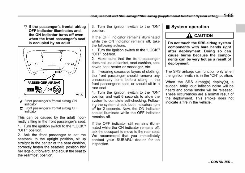
Black plate (95,1)
一般Model "A1300GE-A" EDITED: 2016/ 9/ 13
! If the passenger’s frontal airbagOFF indicator illuminates andthe ON indicator turns off evenwhen the front passenger’s seatis occupied by an adult
: Front passenger’s frontal airbag ONindicator
: Front passenger’s frontal airbag OFFindicator
This can be caused by the adult incor-rectly sitting in the front passenger’s seat.1. Turn the ignition switch to the “LOCK”/“OFF” position.2. Ask the front passenger to set theseatback to the upright position, sit upstraight in the center of the seat cushion,correctly fasten the seatbelt, position his/her legs out forward, and adjust the seat tothe rearmost position.
3. Turn the ignition switch to the “ON”position.
If the OFF indicator remains illuminatedwhile the ON indicator remains off, takethe following actions.1. Turn the ignition switch to the “LOCK”/“OFF” position.2. Make sure that the front passengerdoes not use a blanket, seat cushion, seatcover, seat heater or massager, etc.3. If wearing excessive layers of clothing,the front passenger should remove anyunnecessary items before sitting in thefront passenger’s seat, or should sit in arear seat.4. Turn the ignition switch to the “ON”position and wait 6 seconds to allow thesystem to complete self-checking. Follow-ing the system check, both indicators turnoff for 2 seconds. Now, the ON indicatorshould illuminate while the OFF indicatorremains off.
If the OFF indicator still remains illumi-nated while the ON indicator remains off,ask the occupant to move to the rear seat.We recommend that you immediatelycontact your SUBARU dealer for aninspection.
& System operation
CAUTION
Do not touch the SRS airbag systemcomponents with bare hands rightafter deployment. Doing so cancause burns because the compo-nents can be very hot as a result ofdeployment.
The SRS airbags can function only whenthe ignition switch is in the “ON” position.
When the SRS airbag(s) deploy(s), asudden, fairly loud inflation noise will beheard and some smoke will be released.These occurrences are a normal result ofthe deployment. This smoke does notindicate a fire in the vehicle.
Seat, seatbelt and SRS airbags/*SRS airbag (Supplemental Restraint System airbag) 1-65
– CONTINUED –
1

Black plate (96,1)
一般Model "A1300GE-A" EDITED: 2016/ 9/ 13
1-66 Seat, seatbelt and SRS airbags/*SRS airbag (Supplemental Restraint System airbag)
! SRS frontal airbag operation
A) Driver’s sideB) Passenger’s side1) SRS AIRBAGs deploy as soon as a collision occurs.2) After deployment, SRS AIRBAGs start to deflate immediately so that the driver’s vision is not
obstructed.
If the following sensors detect a certainpredetermined amount of force during afrontal collision, the control module sendssignals to the frontal airbag modulesinstructing them to inflate the SRS frontalairbags.. front sub sensors located on both theright and left sides at the front of thevehicle. the impact sensors in the airbag controlmodule
Then both airbag modules produce gas,which instantly inflates driver’s and pas-senger’s SRS frontal airbags. The SRSknee airbag is also inflated in combinationwith the SRS frontal airbags.
! After deployment
After deployment, the SRS airbags im-mediately start to deflate so that thedriver’s vision is not obstructed and thedriver’s ability to maintain control of thevehicle is not interfered. The time requiredfrom detecting impact to the deflation ofthe SRS airbag after deployment is short-er than the blink of an eye.
If the vehicle is equipped with the occu-pant detection system for the front pas-senger’s seat, the SRS system detectswhether the front passenger’s seat isoccupied by a passenger or not. If the
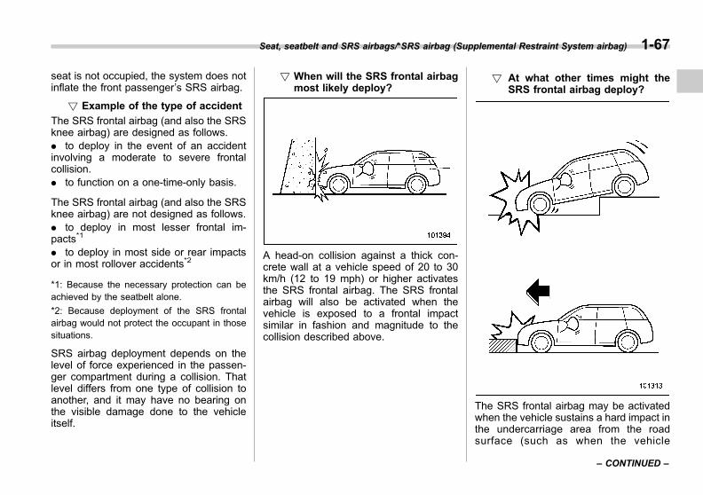
Black plate (97,1)
一般Model "A1300GE-A" EDITED: 2016/ 9/ 13
seat is not occupied, the system does notinflate the front passenger’s SRS airbag.
! Example of the type of accident
The SRS frontal airbag (and also the SRSknee airbag) are designed as follows.. to deploy in the event of an accidentinvolving a moderate to severe frontalcollision.. to function on a one-time-only basis.
The SRS frontal airbag (and also the SRSknee airbag) are not designed as follows.. to deploy in most lesser frontal im-pacts*1
. to deploy in most side or rear impactsor in most rollover accidents*2
*1: Because the necessary protection can beachieved by the seatbelt alone.
*2: Because deployment of the SRS frontalairbag would not protect the occupant in thosesituations.
SRS airbag deployment depends on thelevel of force experienced in the passen-ger compartment during a collision. Thatlevel differs from one type of collision toanother, and it may have no bearing onthe visible damage done to the vehicleitself.
! When will the SRS frontal airbagmost likely deploy?
A head-on collision against a thick con-crete wall at a vehicle speed of 20 to 30km/h (12 to 19 mph) or higher activatesthe SRS frontal airbag. The SRS frontalairbag will also be activated when thevehicle is exposed to a frontal impactsimilar in fashion and magnitude to thecollision described above.
! At what other times might theSRS frontal airbag deploy?
The SRS frontal airbag may be activatedwhen the vehicle sustains a hard impact inthe undercarriage area from the roadsurface (such as when the vehicle
Seat, seatbelt and SRS airbags/*SRS airbag (Supplemental Restraint System airbag) 1-67
– CONTINUED –
1
Black plate (98,1)
一般Model "A1300GE-A" EDITED: 2016/ 9/ 13
1-68 Seat, seatbelt and SRS airbags/*SRS airbag (Supplemental Restraint System airbag)
plunges into a deep ditch, is severelyimpacted or knocked hard against anobstacle on the road such as a curb).

Black plate (99,1)
一般Model "A1300GE-A" EDITED: 2016/ 9/ 13
! When is the SRS frontal airbag unlikely to deploy?1) The vehicle strikes an object, such as a
telephone pole or sign pole.2) The vehicle slides under the load bed of
a truck.3) The vehicle sustains an oblique offset
frontal impact.4) The vehicle sustains an offset frontal
collision.5) The vehicle strikes an object that can
move or deform, such as a parkedvehicle.
There are many types of collisions whichmight not necessarily require SRS frontalairbag deployment. In the event of acci-dents like those illustrated, the SRS frontalairbag may not deploy depending on thelevel of accident forces involved.
Seat, seatbelt and SRS airbags/*SRS airbag (Supplemental Restraint System airbag) 1-69
– CONTINUED –
1
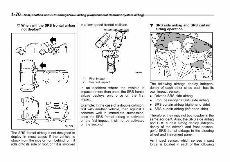
Black plate (100,1)
一般Model "A1300GE-A" EDITED: 2016/ 9/ 13
1-70 Seat, seatbelt and SRS airbags/*SRS airbag (Supplemental Restraint System airbag)
! When will the SRS frontal airbagnot deploy?
The SRS frontal airbag is not designed todeploy in most cases if the vehicle isstruck from the side or from behind, or if itrolls onto its side or roof, or if it is involved
in a low-speed frontal collision.
1) First impact2) Second impact
In an accident where the vehicle isimpacted more than once, the SRS frontalairbag deploys only once on the firstimpact.
Example: In the case of a double collision,first with another vehicle, then against aconcrete wall in immediate succession,once the SRS frontal airbag is activatedon the first impact, it will not be activatedon the second.
! SRS side airbag and SRS curtainairbag operation
The following airbags deploy indepen-dently of each other since each has itsown impact sensor.. Driver’s SRS side airbag. Front passenger’s SRS side airbag. SRS curtain airbag (right-hand side). SRS curtain airbag (left-hand side)
Therefore, they may not both deploy in thesame accident. Also, the SRS side airbagand SRS curtain airbag deploy indepen-dently of the driver’s and front passen-ger’s SRS frontal airbags in the steeringwheel and instrument panel.
An impact sensor, which senses impactforce, is located in each of the following
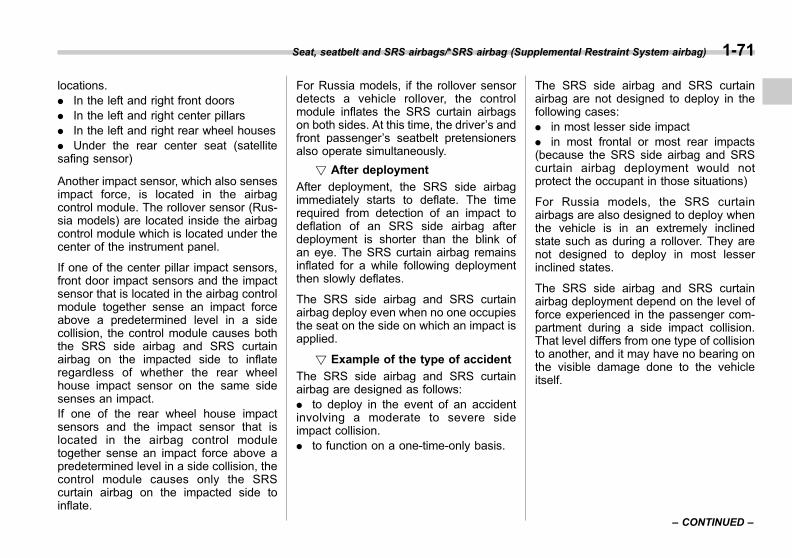
Black plate (101,1)
一般Model "A1300GE-A" EDITED: 2016/ 9/ 13
locations.. In the left and right front doors. In the left and right center pillars. In the left and right rear wheel houses. Under the rear center seat (satellitesafing sensor)
Another impact sensor, which also sensesimpact force, is located in the airbagcontrol module. The rollover sensor (Rus-sia models) are located inside the airbagcontrol module which is located under thecenter of the instrument panel.
If one of the center pillar impact sensors,front door impact sensors and the impactsensor that is located in the airbag controlmodule together sense an impact forceabove a predetermined level in a sidecollision, the control module causes boththe SRS side airbag and SRS curtainairbag on the impacted side to inflateregardless of whether the rear wheelhouse impact sensor on the same sidesenses an impact.If one of the rear wheel house impactsensors and the impact sensor that islocated in the airbag control moduletogether sense an impact force above apredetermined level in a side collision, thecontrol module causes only the SRScurtain airbag on the impacted side toinflate.
For Russia models, if the rollover sensordetects a vehicle rollover, the controlmodule inflates the SRS curtain airbagson both sides. At this time, the driver’s andfront passenger’s seatbelt pretensionersalso operate simultaneously.
! After deployment
After deployment, the SRS side airbagimmediately starts to deflate. The timerequired from detection of an impact todeflation of an SRS side airbag afterdeployment is shorter than the blink ofan eye. The SRS curtain airbag remainsinflated for a while following deploymentthen slowly deflates.
The SRS side airbag and SRS curtainairbag deploy even when no one occupiesthe seat on the side on which an impact isapplied.
! Example of the type of accident
The SRS side airbag and SRS curtainairbag are designed as follows:. to deploy in the event of an accidentinvolving a moderate to severe sideimpact collision.. to function on a one-time-only basis.
The SRS side airbag and SRS curtainairbag are not designed to deploy in thefollowing cases:. in most lesser side impact. in most frontal or most rear impacts(because the SRS side airbag and SRScurtain airbag deployment would notprotect the occupant in those situations)
For Russia models, the SRS curtainairbags are also designed to deploy whenthe vehicle is in an extremely inclinedstate such as during a rollover. They arenot designed to deploy in most lesserinclined states.
The SRS side airbag and SRS curtainairbag deployment depend on the level offorce experienced in the passenger com-partment during a side impact collision.That level differs from one type of collisionto another, and it may have no bearing onthe visible damage done to the vehicleitself.
Seat, seatbelt and SRS airbags/*SRS airbag (Supplemental Restraint System airbag) 1-71
– CONTINUED –
1
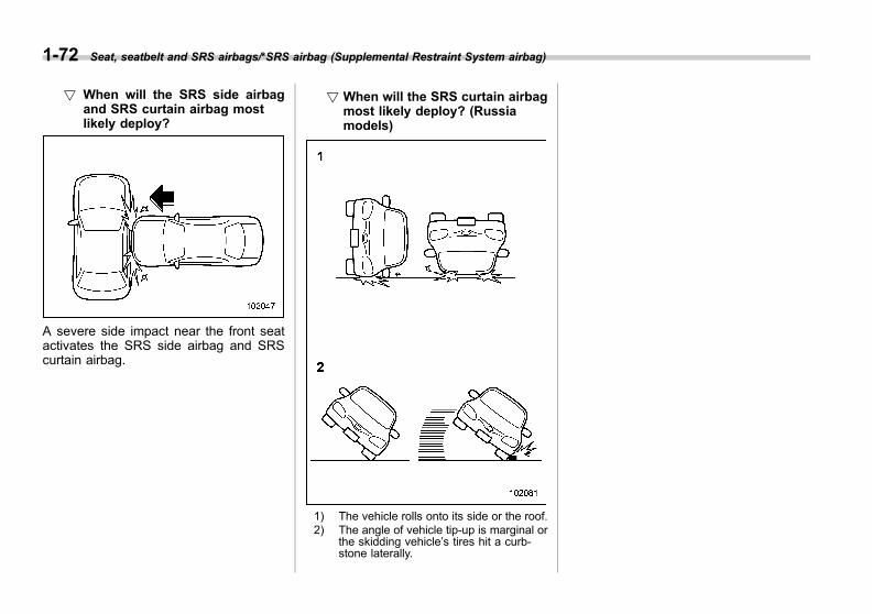
Black plate (102,1)
一般Model "A1300GE-A" EDITED: 2016/ 9/ 13
1-72 Seat, seatbelt and SRS airbags/*SRS airbag (Supplemental Restraint System airbag)
! When will the SRS side airbagand SRS curtain airbag mostlikely deploy?
A severe side impact near the front seatactivates the SRS side airbag and SRScurtain airbag.
! When will the SRS curtain airbagmost likely deploy? (Russiamodels)
1) The vehicle rolls onto its side or the roof.2) The angle of vehicle tip-up is marginal or
the skidding vehicle’s tires hit a curb-stone laterally.

Black plate (103,1)
一般Model "A1300GE-A" EDITED: 2016/ 9/ 13
! When is the SRS side airbag unlikely to deploy?1) The vehicle is involved in an oblique
side-on impact.2) The vehicle is involved in a side-on
impact in an area outside the vicinity ofthe passenger compartment.
3) The vehicle strikes a telephone pole orsimilar object.
4) The vehicle is involved in a side-onimpact from a motorcycle.
5) The vehicle rolls onto its side or roof.
There are many types of collisions whichmight not necessarily require SRS sideairbag deployment. In the event of acci-dents like those illustrated, the SRS sideairbag may not deploy depending on thelevel of accident forces involved.
Seat, seatbelt and SRS airbags/*SRS airbag (Supplemental Restraint System airbag) 1-73
– CONTINUED –
1
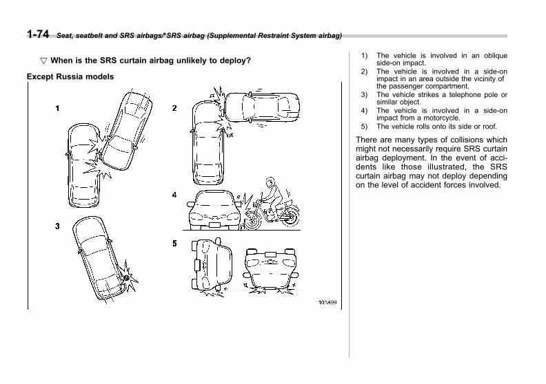
Black plate (104,1)
一般Model "A1300GE-A" EDITED: 2016/ 9/ 13
1-74 Seat, seatbelt and SRS airbags/*SRS airbag (Supplemental Restraint System airbag)
! When is the SRS curtain airbag unlikely to deploy?
Except Russia models
1) The vehicle is involved in an obliqueside-on impact.
2) The vehicle is involved in a side-onimpact in an area outside the vicinity ofthe passenger compartment.
3) The vehicle strikes a telephone pole orsimilar object.
4) The vehicle is involved in a side-onimpact from a motorcycle.
5) The vehicle rolls onto its side or roof.
There are many types of collisions whichmight not necessarily require SRS curtainairbag deployment. In the event of acci-dents like those illustrated, the SRScurtain airbag may not deploy dependingon the level of accident forces involved.

Black plate (105,1)
一般Model "A1300GE-A" EDITED: 2016/ 9/ 13
Russia models 1) The vehicle is involved in an obliqueside-on impact.
2) The vehicle is involved in a side-onimpact in an area outside the vicinity ofthe passenger compartment.
3) The vehicle strikes a telephone pole orsimilar object.
4) The vehicle is involved in a side-onimpact from a motorcycle.
There are many types of collisions whichmight not necessarily require SRS curtainairbag deployment. In the event of acci-dents like those illustrated, the SRScurtain airbag may not deploy dependingon the level of accident forces involved.
Seat, seatbelt and SRS airbags/*SRS airbag (Supplemental Restraint System airbag) 1-75
– CONTINUED –
1
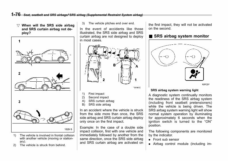
Black plate (106,1)
一般Model "A1300GE-A" EDITED: 2016/ 9/ 13
1-76 Seat, seatbelt and SRS airbags/*SRS airbag (Supplemental Restraint System airbag)
! When will the SRS side airbagand SRS curtain airbag not de-ploy?
1) The vehicle is involved in frontal collisionwith another vehicle (moving or station-ary).
2) The vehicle is struck from behind.
3) The vehicle pitches end over end.
In the event of accidents like thoseillustrated, the SRS side airbag and SRScurtain airbag are not designed to deployin most cases.
1) First impact2) Second impactA) SRS curtain airbagB) SRS side airbag
In an accident where the vehicle is struckfrom the side more than once, the SRSside airbag and SRS curtain airbag deployonly once on the first impact.
Example: In the case of a double sideimpact collision, first with one vehicle andimmediately followed by another from thesame direction, once the SRS side airbagand SRS curtain airbag are activated on
the first impact, they will not be activatedon the second.
& SRS airbag system monitor
SRS airbag system warning light
A diagnostic system continually monitorsthe readiness of the SRS airbag system(including front seatbelt pretensioners)while the vehicle is being driven. TheSRS airbag system warning light will shownormal system operation by illuminatingfor approximately 6 seconds when theignition switch is turned to the “ON”position.
The following components are monitoredby the indicator.. Front sub sensor. Airbag control module (including im-
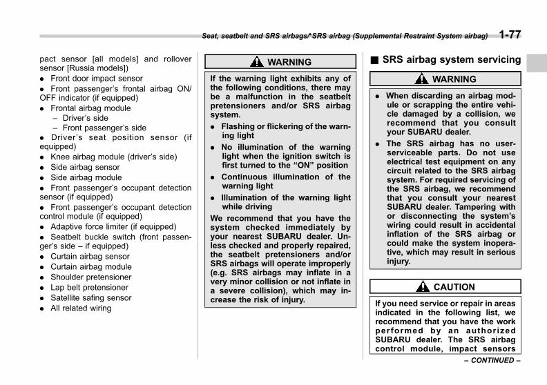
Black plate (107,1)
一般Model "A1300GE-A" EDITED: 2016/ 9/ 13
pact sensor [all models] and rolloversensor [Russia models]). Front door impact sensor. Front passenger’s frontal airbag ON/OFF indicator (if equipped). Frontal airbag module
– Driver’s side– Front passenger’s side
. Driver ’s seat position sensor (ifequipped). Knee airbag module (driver’s side). Side airbag sensor. Side airbag module. Front passenger’s occupant detectionsensor (if equipped). Front passenger’s occupant detectioncontrol module (if equipped). Adaptive force limiter (if equipped). Seatbelt buckle switch (front passen-ger’s side – if equipped). Curtain airbag sensor. Curtain airbag module. Shoulder pretensioner. Lap belt pretensioner. Satellite safing sensor. All related wiring
WARNING
If the warning light exhibits any ofthe following conditions, there maybe a malfunction in the seatbeltpretensioners and/or SRS airbagsystem.
. Flashing or flickering of the warn-ing light
. No illumination of the warninglight when the ignition switch isfirst turned to the “ON” position
. Continuous illumination of thewarning light
. Illumination of the warning lightwhile driving
We recommend that you have thesystem checked immediately byyour nearest SUBARU dealer. Un-less checked and properly repaired,the seatbelt pretensioners and/orSRS airbags will operate improperly(e.g. SRS airbags may inflate in avery minor collision or not inflate ina severe collision), which may in-crease the risk of injury.
& SRS airbag system servicing
WARNING
. When discarding an airbag mod-ule or scrapping the entire vehi-cle damaged by a collision, werecommend that you consultyour SUBARU dealer.
. The SRS airbag has no user-serviceable parts. Do not useelectrical test equipment on anycircuit related to the SRS airbagsystem. For required servicing ofthe SRS airbag, we recommendthat you consult your nearestSUBARU dealer. Tampering withor disconnecting the system’swiring could result in accidentalinflation of the SRS airbag orcould make the system inopera-tive, which may result in seriousinjury.
CAUTION
If you need service or repair in areasindicated in the following list, werecommend that you have the workperformed by an author izedSUBARU dealer. The SRS airbagcontrol module, impact sensors
Seat, seatbelt and SRS airbags/*SRS airbag (Supplemental Restraint System airbag) 1-77
– CONTINUED –
1

Black plate (108,1)
一般Model "A1300GE-A" EDITED: 2016/ 9/ 13
1-78 Seat, seatbelt and SRS airbags/*SRS airbag (Supplemental Restraint System airbag)
and airbag modules are stored inthe following areas.
. Under the center of the instru-ment panel
. On both the right and left sides atthe front of the vehicle
. Steering wheel and column andnearby areas
. Bottom of the steering columnand nearby areas
. Top of the dashboard on frontpassenger’s side and nearbyareas
. Each front seat and nearby area
. Inside each center pillar
. Inside each front door
. In each roof side (from the frontpillar to a point over the rear seat)
. Between the rear seat cushionand rear wheel house on eachside
. Under the rear center seat
In the event that the SRS airbag systemis deployed, we recommend that youhave the system replaced with genuineSUBARU parts at an authorizedSUBARU dealer.
NOTEIn the following cases, we recommendthat you contact your SUBARU dealeras soon as possible.. The front part of the vehicle wasinvolved in an accident in which theSRS frontal airbags did not deploy.. The pad of the steering wheel, thecover over the front passenger’s fron-tal airbag, or either roof side (from thefront pillar to a point over the rear seat)is scratched, cracked, or otherwisedamaged.. The center pillar, rear wheel houseor rear sub frame, or an area near theseparts, was involved in an accident inwhich the SRS side airbag and SRScurtain airbag did not deploy.. The fabric or leather of either frontseatback is cut, frayed, or otherwisedamaged.. The rear part of the vehicle wasinvolved in an accident.
& Precautions against vehiclemodification
WARNING
To avoid accidental activation of thesystem or rendering the systeminoperative, which may result inserious injury, no modificationsshould be made to any componentsor wiring of the SRS airbag system.
This includes the following modifi-cations.
. Installation of custom steeringwheels
. Attachment of additional trimmaterials to the dashboard
. Installation of custom seats
. Replacement of seat fabric orleather
. Installation of additional fabric orleather on the front seat
. Attachment of a hands-free mi-crophone or any other accessoryto a front pillar, a center pillar, arear pillar, the windshield, a sidewindow, an assist grip, or anyother cabin surface that would benear a deploying SRS curtainairbag.

Black plate (109,1)
一般Model "A1300GE-A" EDITED: 2016/ 9/ 13
. Installation of additional electri-cal/electronic equipment such asa mobile two-way radio on ornear the SRS airbag systemcomponents and/or wiring is notadvisable. This could interferewith proper operation of theSRS airbag system.
CAUTION
Do not perform any of the followingmodifications. Such modificationscan interfere with proper operationof the SRS airbag system.
. Attachment of any equipment(bush bar, bullbar, winches, snowplow, skid/sump plate, etc.) to thefront end other than genuineSUBARU accessory parts orparts that match the quality ofgenuine SUBARU accessoryparts.
. Modification of the suspensionsystem or front end structure.
. Installation of a tire of differentsize and construction from thetires specified on the vehicleplacard attached to the driver’sdoor pillar or specified for indivi-dual vehicle models in this Own-
er’s Manual.
. Attachment of any equipment(side steps or side sill protectors,etc.) to the side body other thangenuine SUBARU accessoryparts specially designed forSRS side airbags, or parts thatmatch the quality of genuineSUBARU accessory parts spe-cially designed for SRS side air-bags (only for models with sideairbags).
We recommend that you always consultyour SUBARU dealer if you want to installany accessory parts on your vehicle.
Seat, seatbelt and SRS airbags/*SRS airbag (Supplemental Restraint System airbag) 1-79
1

Black plate (3,1)
一般Model "A1300GE-A" EDITED: 2016/ 9/ 13
Keys ..................................................................... 2-2Key number plate................................................ 2-2
Keyless access with push-button startsystem (if equipped) ........................................ 2-3Access key fob ................................................... 2-3Safety precautions .............................................. 2-4Locking and unlocking by holding the access keyfob.................................................................... 2-7
Unlock using PIN Code Access .......................... 2-11Power saving function........................................ 2-13Power saving function of access key fob ............ 2-13Disabling keyless access function ...................... 2-14Warning chimes and warning light ...................... 2-15When access key fob does not operateproperly ........................................................... 2-15
Replacing battery of access key fob ................... 2-15Technical information for Europe models ............ 2-15
Immobilizer ......................................................... 2-15Immobilizer indicator light .................................. 2-16Key replacement ................................................ 2-16Technical information of the radio waveregulation ........................................................ 2-16
Remote keyless entry system ........................... 2-17Locking the doors .............................................. 2-18Unlocking the doors ........................................... 2-18Automatic locking (models without doublelocking system)................................................ 2-19
Opening the trunk lid (4-door models)................. 2-19Unlocking the rear gate (5-door models) ............. 2-19Opening/closing the front windows (exceptAustralia models) ............................................. 2-19
Replacing battery............................................... 2-19Technical information......................................... 2-19
Door locks.......................................................... 2-20Locking and unlocking from the outside............. 2-20Locking and unlocking from the inside............... 2-21Key lock-in prevention function (models withoutdouble locking system) .................................... 2-22
Battery drainage prevention function.................. 2-22Double locking system (if equipped) ............... 2-23
To set double locking system............................. 2-23To cancel double locking system ....................... 2-24In an emergency................................................ 2-24If a battery goes dead ........................................ 2-24To reset double locking system.......................... 2-24
Function disabling unlocking with thepower door locking switch (Australiamodels)............................................................ 2-25
Child safety locks .............................................. 2-25Windows............................................................. 2-26
Power window operation.................................... 2-26Initialization of power window with one-touchauto up/down function ..................................... 2-28
Trunk lid (4-door models).................................. 2-28To open and close the trunk lid from outside...... 2-29To open the trunk lid from inside........................ 2-29
Rear gate (5-door models) ................................ 2-29Lock/unlock....................................................... 2-30Open/close ........................................................ 2-30
Sunroof (if equipped) ........................................ 2-31Sunroof switches............................................... 2-31Sun shade ......................................................... 2-32
Keys and doors
2
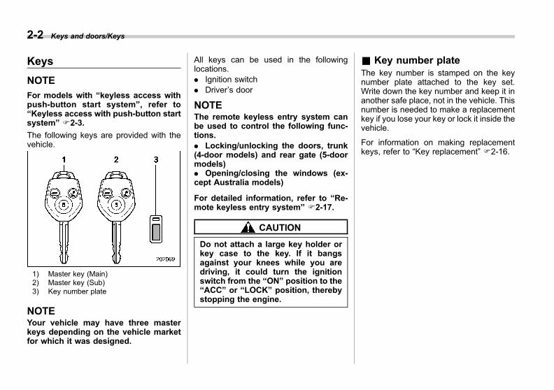
Black plate (112,1)
一般Model "A1300GE-A" EDITED: 2016/ 9/ 13
2-2 Keys and doors/Keys
Keys
NOTE
For models with “keyless access withpush-button start system”, refer to“Keyless access with push-button startsystem” F2-3.
The following keys are provided with thevehicle.
1) Master key (Main)2) Master key (Sub)3) Key number plate
NOTEYour vehicle may have three masterkeys depending on the vehicle marketfor which it was designed.
All keys can be used in the followinglocations.. Ignition switch. Driver’s door
NOTEThe remote keyless entry system canbe used to control the following func-tions.. Locking/unlocking the doors, trunk(4-door models) and rear gate (5-doormodels). Opening/closing the windows (ex-cept Australia models)
For detailed information, refer to “Re-mote keyless entry system” F2-17.
CAUTION
Do not attach a large key holder orkey case to the key. If it bangsagainst your knees while you aredriving, it could turn the ignitionswitch from the “ON” position to the“ACC” or “LOCK” position, therebystopping the engine.
& Key number plateThe key number is stamped on the keynumber plate attached to the key set.Write down the key number and keep it inanother safe place, not in the vehicle. Thisnumber is needed to make a replacementkey if you lose your key or lock it inside thevehicle.
For information on making replacementkeys, refer to “Key replacement” F2-16.
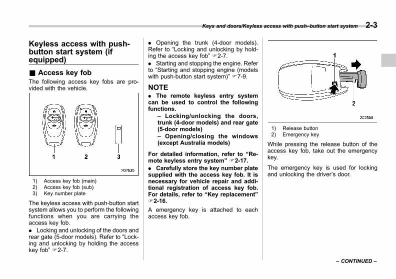
Black plate (113,1)
一般Model "A1300GE-A" EDITED: 2016/ 9/ 13
Keyless access with push-button start system (ifequipped)
& Access key fobThe following access key fobs are pro-vided with the vehicle.
1) Access key fob (main)2) Access key fob (sub)3) Key number plate
The keyless access with push-button startsystem allows you to perform the followingfunctions when you are carrying theaccess key fob.. Locking and unlocking of the doors andrear gate (5-door models). Refer to “Lock-ing and unlocking by holding the accesskey fob” F2-7.
. Opening the trunk (4-door models).Refer to “Locking and unlocking by hold-ing the access key fob” F2-7.. Starting and stopping the engine. Referto “Starting and stopping engine (modelswith push-button start system)” F7-9.
NOTE. The remote keyless entry systemcan be used to control the followingfunctions.
– Locking/unlocking the doors,trunk (4-door models) and rear gate(5-door models)– Opening/closing the windows(except Australia models)
For detailed information, refer to “Re-mote keyless entry system” F2-17.. Carefully store the key number platesupplied with the access key fob. It isnecessary for vehicle repair and addi-tional registration of access key fob.For details, refer to “Key replacement”F2-16.
A emergency key is attached to eachaccess key fob.
1) Release button2) Emergency key
While pressing the release button of theaccess key fob, take out the emergencykey.
The emergency key is used for lockingand unlocking the driver’s door.
Keys and doors/Keyless access with push–button start system 2-3
– CONTINUED –
2

Black plate (114,1)
一般Model "A1300GE-A" EDITED: 2016/ 9/ 13
2-4 Keys and doors/Keyless access with push–button start system
& Safety precautions
WARNING
If you wear an implanted pacemakeror an implanted defibrillator, stay atleast 22 cm (8.7 in) away from thetransmitting antennas installed onthe vehicle.
The radio waves from the transmit-ting antennas on the vehicle couldadversely affect the operation ofimplanted pacemakers and im-planted defibrillators.
If you wear electronic medicalequipment other than an implantedpacemaker or an implanted defibril-lator, before using the keyless ac-cess with push-button start system,refer to “Radio waves used for thekeyless access with push-buttonstart system” mentioned later, andcontact the electronic medicalequipment manufacturer for moreinformation. The radio waves fromthe transmitting antennas on thevehicle could adversely affect theoperation of the electronic medicalequipment.
“Radio waves used for the keylessaccess with push-button start sys-
tem”
. The keyless access with push-button start system uses radiowaves of the following fre-quency* in addition to the radiowaves used for the remote key-less entry system. The radiowaves are periodically outputfrom the antennas installed onthe vehicle as shown in thefollowing illustrations.
* Radio frequency: 134.2 kHz
4-door models1) Antenna
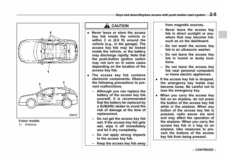
Black plate (115,1)
一般Model "A1300GE-A" EDITED: 2016/ 9/ 13
5-door models1) Antenna
CAUTION
. Never leave or store the accesskey fob inside the vehicle orwithin 2 m (6.6 ft) around thevehicle (e.g., in the garage). Theaccess key fob may be lockedinside the vehicle, or the batterymay discharge rapidly. Note thatthe push-button ignition switchmay not turn on in some casesdepending on the location of theaccess key fob.
. The access key fob containselectronic components. Observethe following precautions to pre-vent malfunctions.
– Although you can replace thebattery of the access key fobyourself, it is recommendedthat the battery be replaced bya SUBARU dealer to avoid therisk of damage at the time ofreplacement.
– Do not get the access key fobwet. If the access key fob getswet, wipe it off immediatelyand let it dry completely.
– Do not apply strong impactsto the access key fob.
– Keep the access key fob away
from magnetic sources.
– Never leave the access keyfob in direct sunlight or any-where that may become hot,such as on the dashboard.
– Do not wash the access keyfob in an ultrasonic washer.
– Do not leave the access keyfob in humid or dusty loca-tions.
– Do not leave the access keyfob near personal computersor home electric appliances.
. If the access key fob is dropped,the emergency key inside maybecome loose. Be careful not tolose the emergency key.
. When you carry the access keyfob on an airplane, do not pressthe button of the access key fobwhile in the airplane. When anybutton of the access key fob ispressed, radio waves are sentand may affect the operation ofthe airplane. When you carry theaccess key fob in a bag on anairplane, take measures to pre-vent the buttons of the accesskey fob from being pressed.
Keys and doors/Keyless access with push–button start system 2-5
– CONTINUED –
2

Black plate (116,1)
一般Model "A1300GE-A" EDITED: 2016/ 9/ 13
2-6 Keys and doors/Keyless access with push–button start system
NOTE. The operational/non-operationalsetting for the keyless access functioncan be changed. For the setting proce-dure, refer to “Disabling keyless ac-cess function” F2-14.. For detailed information about theoperation method for the push-buttonignition switch while the keyless ac-cess function is switched to the non-operational mode, refer to “Access keyfob – if access key fob does notoperate properly” F9-28.. The keyless access with push-but-ton start system uses weak radiowaves. The status of the access keyfob and environmental conditions mayinterfere with the communication be-tween the access key fob and thevehicle under the following conditions,and it may not be possible to lock orunlock the doors or start the engine.
– When operating near a facilitywhere strong radio waves are trans-mitted, such as a broadcast stationand power transmission lines– When products that transmitradio waves are used, such as anaccess key fob or a remote trans-mitter key of another vehicle– When carrying the access keyfob of your vehicle together with an
access key fob or a remote trans-mitter of another vehicle– When the access key fob isplaced near wireless communica-tion equipment such as a cell phone– When the access key fob isplaced near a metallic object– When metallic accessories areattached to the access key fob– When carrying the access keyfob with electronic appliances suchas a laptop computer– When the battery of the accesskey fob is discharged
. The access key fob is always com-municating with the vehicle and iscontinuously using the battery.Although the life of the battery variesdepending on the operating conditions,it is approximately 1 to 2 years. If thebattery becomes fully discharged, re-place it with a new one.. If an access key fob is lost, it isrecommended that all of the remainingaccess key fobs be reregistered. Forreregistration of an access key fob, werecommend that you contact aSUBARU dealer.. For a spare access key fob, werecommend that you contact aSUBARU dealer.. Up to 7 access key fobs can be
registered for one vehicle.. Do not leave the access key fob inthe storage spaces inside the vehicle,such as the door pocket, dashboard,inside the trunk and the corner of thecargo area. Vibrations may damage theaccess key fob or turn on the switch,possibly resulting in a lockout.. After the vehicle battery is dis-charged or replaced, initialization ofthe steering lock system may be re-quired to start the engine. In this case,perform the following procedure toinitialize the steering lock.
(1) Turn the push-button ignitionswitch to the “OFF” position. Fordetails, refer to “Switching powerstatus” F3-7.(2) Open and close the driver’sdoor.(3) Wait for approximately 10 sec-onds.
When the steering is locked, the initi-alization is completed.. Do not leave the access key fob inthe following places.
– On the instrument panel– On the floor– Inside the glove box– Inside the door trim pocket– On the rear seat
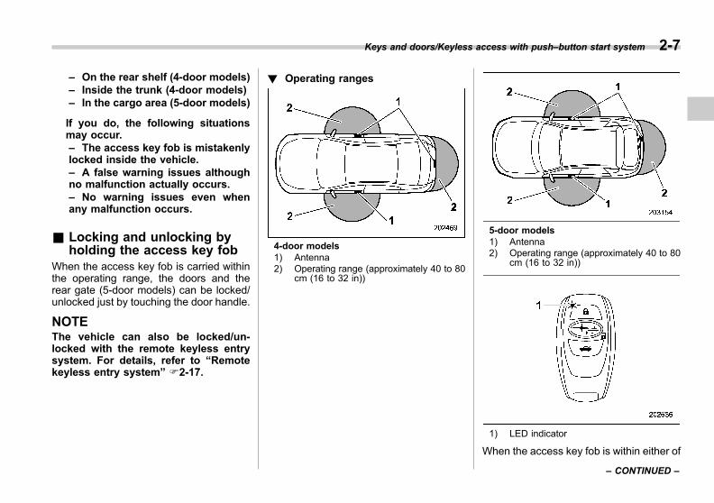
Black plate (117,1)
一般Model "A1300GE-A" EDITED: 2016/ 9/ 13
– On the rear shelf (4-door models)– Inside the trunk (4-door models)– In the cargo area (5-door models)
If you do, the following situationsmay occur.– The access key fob is mistakenlylocked inside the vehicle.– A false warning issues althoughno malfunction actually occurs.– No warning issues even whenany malfunction occurs.
& Locking and unlocking byholding the access key fob
When the access key fob is carried withinthe operating range, the doors and therear gate (5-door models) can be locked/unlocked just by touching the door handle.
NOTEThe vehicle can also be locked/un-locked with the remote keyless entrysystem. For details, refer to “Remotekeyless entry system” F2-17.
! Operating ranges
4-door models1) Antenna2) Operating range (approximately 40 to 80
cm (16 to 32 in))
5-door models1) Antenna2) Operating range (approximately 40 to 80
cm (16 to 32 in))
1) LED indicator
When the access key fob is within either of
Keys and doors/Keyless access with push–button start system 2-7
– CONTINUED –
2

Black plate (118,1)
一般Model "A1300GE-A" EDITED: 2016/ 9/ 13
2-8 Keys and doors/Keyless access with push–button start system
the operating ranges of the front doors,the LED indicator on the access key fobflashes. When the keyless access func-tions are disabled, the LED indicator doesnot flash unless a button on the accesskey fob is pressed.
NOTE. If the access key fob is placed tooclose to the vehicle body, the keylessaccess function may not operate prop-erly. If it does not operate properly,repeat the operation from further away.. If the access key fob is placed nearthe ground or in an elevated locationfrom the ground, even if it is in theindicated operating range, the keylessaccess function may not operate prop-erly.. When the access key fob is withinthe operating range, it is possible foranyone, even someone who is notcarrying the access key fob, to operatethe keyless access function. Note thatlocking and unlocking can be operatedonly by the door handle, door locksensor, rear gate opener button or rearlock button in the operating range inwhich the access key fob is detected.. It is not possible to lock the doorsand rear gate using the keyless accessfunction when the access key fob isinside the vehicle. However, depending
on the status of the access key fob andthe environmental conditions, the ac-cess key fob may be locked inside thevehicle. Before locking, make sure thatyou have the access key fob.. When the battery of the access keyfob is discharged, or when operating itin a location with strong radio waves ornoise (e.g., near a radio tower, powerplant, broadcast station, large display,airport, electrical sign board or an areawhere wireless equipment is used), orwhile talking on a cell phone, theoperating ranges may be reduced, orthe keyless access function may notoperate.In such a case, perform the proceduredescribed in “Locking and unlocking”F9-28.. The doors may lock or unlock whenthe car is being washed or exposed tosignificant amount of water contactingthe door handle while the access keyfob is still in the operating range.
! How to lock and unlock
You can perform the following operationwhen you are carrying the access key fob.. Lock and unlock the doors. Unlock the trunk (4-door models). Lock and unlock rear gate (5-doormodels)
NOTE. The trunk can be opened without theaccess key fob if all doors are un-locked. When you begin driving thevehicle, the trunk lid will lock automa-tically. Refer to “Opening trunk (4-doormodels)” F2-10.. It is not possible to lock the doorsand rear gate using the keyless accessfunction when the push-button ignitionswitch is in the “ACC” or “ON” posi-tion. Refer to “Switching power status”F3-7.. If the door handle is gripped with agloved hand, the door lock may not bereleased.. If the door lock sensor is touchedthree times or more repeatedly, thesystem will ignore the sensor opera-tion.. When performing the locking proce-dure too quickly, locking may not havebeen completed. After locking thedoors, it is recommended to pull theREAR door handles to confirm that thedoors have been locked.. Within 3 seconds after locking thedoors and the rear gate by using thekeyless access function, it is notpossible to unlock the doors and/orthe rear gate by using the keylessaccess function.
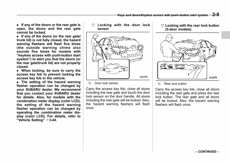
Black plate (119,1)
一般Model "A1300GE-A" EDITED: 2016/ 9/ 13
. If any of the doors or the rear gate isopen, the doors and the rear gatecannot be locked.. If any of the doors (or the rear gate/trunk lid) is not fully closed, the hazardwarning flashers will flash five times(the outside warning chime alsosounds five times for models with“keyless access with push-button startsystem”) to alert you that the doors (orthe rear gate/trunk lid) are not properlyclosed.. When locking, be sure to carry theaccess key fob to prevent locking theaccess key fob in the vehicle.. The setting of the hazard warningflasher operation can be changed byyour SUBARU dealer. We recommendthat you contact your SUBARU dealerfor details. Also, for models with thecombination meter display (color LCD),the setting of the hazard warningflasher operation can be changed byoperating the combination meter dis-play (color LCD). For details, refer to“Vehicle Setting” F3-44.
! Locking with the door locksensor
1) Door lock sensor
Carry the access key fob, close all doorsincluding the rear gate and touch the doorlock sensor on the door handle. All doorsincluding the rear gate will be locked. Also,the hazard warning flashers will flashonce.
! Locking with the rear lock button(5-door models)
1) Rear lock button
Carry the access key fob, close all doorsincluding the rear gate and press the rearlock button. The rear gate and all doorswill be locked. Also, the hazard warningflashers will flash once.
Keys and doors/Keyless access with push–button start system 2-9
– CONTINUED –
2

Black plate (120,1)
一般Model "A1300GE-A" EDITED: 2016/ 9/ 13
2-10 Keys and doors/Keyless access with push–button start system
! Unlocking
Carry the access key fob, and grip thedoor handle.
. Models without double locking sys-tem:All doors and the rear gate (5-doormodels) will be unlocked. Also, the hazardwarning flashers will flash twice.. Models with double locking system:
– The driver’s door handle:Only the driver’s door will be unlocked.– The front passenger’s door handle:All doors and the rear gate will beunlocked.
Also, the hazard warning flashers will flashtwice.
! Opening rear gate (5-door mod-els)
1) Rear gate opener button
Carry the access key fob, and press therear gate opener button.
. Models without double locking sys-tem:The rear gate and all doors will beunlocked, and the rear gate will beopened. Also, the hazard warning flasherswill flash twice.. Models with double locking system:Only the rear gate will unlock and open.Also, the hazard warning flashers will flashtwice.
! Opening trunk (4-door models)
1) Trunk opener button
Carry the access key fob, and press thetrunk opener button. The trunk will open.The hazard warning flashers will flashtwice.
NOTEUnder the following conditions, thetrunk can be opened without the ac-cess key fob.. the trunk lock/unlock setting is setto on. all doors are unlocked
The trunk lock/unlock setting can bechanged by a SUBARU dealer. Werecommend that you contact yourSUBARU dealer to change the setting.
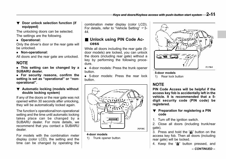
Black plate (121,1)
一般Model "A1300GE-A" EDITED: 2016/ 9/ 13
! Door unlock selection function (ifequipped)
The unlocking doors can be selected.The settings are the following.. Operational:Only the driver’s door or the rear gate willbe unlocked.. Non-operational:All doors and the rear gate are unlocked.
NOTE. This setting can be changed by aSUBARU dealer.. For security reasons, confirm thesetting is set as “operational” or “non-operational”.
! Automatic locking (models withoutdouble locking system)
If any of the doors or the rear gate was notopened within 30 seconds after unlocking,they will be automatically locked again.
The function’s operational/non-operationalsetting and the time until automatic lockingtakes place can be changed by aSUBARU dealer. For more details, werecommend that you contact a SUBARUdealer.
For models with the combination meterdisplay (color LCD), the setting and thetime can be changed by operating the
combination meter display (color LCD).For details, refer to “Vehicle Setting” F3-44.
& Unlock using PIN Code Ac-cess
While all doors including the rear gate (5-door models) are locked, you can unlockthe doors (including rear gate) without akey by performing the following proce-dure.. 4-door models: Press the trunk openerbutton.. 5-door models: Press the rear lockbutton.
4-door models1) Trunk opener button
5-door models1) Rear lock button
NOTEPIN Code Access will be helpful if theaccess key fob is accidentally left in thevehicle. It is recommended that a 5-digit security code (PIN code) beregistered.
! Preparation for registering a PINcode
1. Turn off the ignition switch.2. Close all doors (including trunk/reargate).3. Press and hold the “ ” button on theaccess key fob. Then all doors (includingrear gate) will be locked.4. Keep the “ ” button pressed, and
Keys and doors/Keyless access with push–button start system 2-11
– CONTINUED –
2
Black plate (122,1)
一般Model "A1300GE-A" EDITED: 2016/ 9/ 13
2-12 Keys and doors/Keyless access with push–button start system
press the trunk opener button (4-doormodels)/rear lock button (5-door models)within 5 seconds after step 3.5. Press and hold the trunk openerbutton/rear lock button for more than 5seconds. Confirm a chirp sound.6. Release the “ ” button and trunkopener button/rear lock button.7. Press the “ ” button on the access keyfob while the chirp sounds.Then the chirp will stop and the prepara-tion is complete.
NOTEPress the “ ” button within 30 secondsof step 6 to end the preparation modeand move on to the registration stage.Unless the “ ” button is pressed within30 seconds after step 6, the PIN coderegistration will be canceled.
! Registration for a PIN code
For example, to register “32468” as thePIN code, perform the following proce-dure.1. Press the trunk opener button (4-doormodels)/rear lock button (5-door models)three times.2. After a chirp sounds once, press thetrunk opener button/rear lock button twice.3. After a chirp sounds once, press the
trunk opener button/rear lock button fourtimes.4. After a chirp sounds once, press thetrunk opener button/rear lock button sixtimes.5. After a chirp sounds once, press thetrunk opener button/rear lock button eighttimes.6. Perform steps 1 to 5 again withinapproximately 30 seconds after the chirpstarts sounding intermittently.7. All doors will be unlocked and locked.Then the PIN code will be registered.
NOTE. Press the trunk opener button/rearlock button ten times to enter “0”.. Change the PIN code frequently toprotect your vehicle from theft.. If you have lent your vehicle toanother person, confirm that the PINcode has not been changed or deleted.If the PIN code has been changed ordeleted, reregister a new PIN code.. If you make an error during theregistration procedure, press the “ ”or “ ” button on the access key fob.Then, start over from the proceduredescribed in “Preparation for register-ing a PIN code”.. To protect your vehicle from theft,
you cannot register a string of thesame five numbers together, such as“00000”, nor “12345” as a PIN code.. Do not register your vehicle licenseplate number or simple numbers suchas “11122” or “12121” as a PIN code.Doing so will increase the risk ofvehicle theft.. When you try to register “22222”,the registered PIN code will be deleted.You cannot unlock the doors by PINCode Access until a new code isregistered.. After registering a new PIN code,make sure that you can unlock thedoors using the PIN code.. The PIN code cannot be deletedwhile the keyless access function isdisabled by operating the access keyfob.. Reregister the PIN code in thefollowing case.
– when you forget the PIN code– when you want to change the PINcode

Black plate (123,1)
一般Model "A1300GE-A" EDITED: 2016/ 9/ 13
! Unlocking
Perform steps 1 to 5 described in “Regis-tration for a PIN code”.
NOTE. You cannot unlock by PIN CodeAccess in the following cases.
– when the access key fob is withinthe operating ranges– when the ignition switch is in the“ACC” or “ON” position
. If you make an operation errorduring the unlocking procedure, startover with the unlocking procedure afterwaiting for 5 seconds or longer.. To protect your vehicle from theft, abuzzer will sound if incorrect PIN codesare entered five times continuously. Ifthis occurs, you cannot unlock thedoors by PIN Code Access for 5minutes.
& Power saving functionThe keyless access function will bedisabled in the following cases to protectthe access key fob battery and the vehiclebattery.. Case 1: When the keyless accessfunction and the remote keyless entrysystem have not been used for 2 weeksor longer while all doors are locked
Operate one of the following items torecover the keyless access function:
– Unlock the doors by operating anyprocedure other than gripping the frontpassenger’s door handle– Lock the doors– Open a door and then close it
. Case 2: When the access key fob hasbeen left in the operating range for 10minutes or longer while all doors arelocked
Operate one of the following items torecover the keyless access function:
– Unlock the doors by gripping thedoor handle– Unlock the doors by pressing therear gate opener button– Lock the doors by touching the doorlock sensor– Lock or unlock the doors by usingthe remote keyless entry system– Lock or unlock the doors by usingthe power door locking switch– Open either of the front doors
& Power saving function of ac-cess key fob
This function stops the access key fobfrom receiving signals and helps minimizethe battery consumption of the access keyfob.1. Press the “ ” button twice whileholding the “ ” button.
1) LED indicator
2. Confirm that the LED indicator blinks 4times to notify that the setting is complete.When the access key fob is in the powersave mode, the keyless access functionand push-button start system will not beavailable.To cancel the power save mode, pressone of the buttons on the access key fob.
Keys and doors/Keyless access with push–button start system 2-13
– CONTINUED –
2
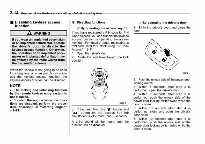
Black plate (124,1)
一般Model "A1300GE-A" EDITED: 2016/ 9/ 13
2-14 Keys and doors/Keyless access with push–button start system
& Disabling keyless accessfunction
WARNING
If you wear an implanted pacemakeror an implanted defibrillator, operatethe driver’s door to disable thekeyless access function. Otherwise,the operation of an implanted pace-maker or implanted defibrillator maybe affected by the radio waves fromthe transmitter antenna.
When the vehicle is not going to be usedfor a long time, or when you choose not touse the keyless access function, thekeyless access function can be disabled.
NOTE. The locking and unlocking functionby the remote keyless entry system isnot disabled.. To start the engine while the func-tions are disabled, perform the proce-dure described in “Starting engine”F9-29.
! Disabling functions
! By operating the access key fob
If you have registered a PIN code for PINCode Access, you can disable the keylessaccess function by operating the accesskey fob. For details about registering aPIN code, refer to “Unlock using PIN CodeAccess” F2-11.1. Open the driver’s door.2. Rotate the lock lever toward the lockposition.
3. Press and hold the “ ” button and“ ” button on the access key fobsimultaneously for more than 5 seconds.
A chirp sound will be heard, and thefunction will be disabled.
! By operating the driver’s door
1. Sit in the driver’s seat, and close thedoor.
2. Push the unlock side of the power doorlocking switch.3. Within 5 seconds after step 2 isperformed, open the driver’s door.4. Within 5 seconds after step 3 isperformed, push the unlock side of thepower door locking switch twice while thedoor is open.5. Within 10 seconds after step 4 isperformed, close and open the driver’sdoor twice.6. Within 10 seconds after step 5 isperformed, push the unlock side of thepower door locking switch twice while thedoor is open.
Black plate (125,1)
一般Model "A1300GE-A" EDITED: 2016/ 9/ 13
7. Within 10 seconds after step 6 isperformed, close and open the driver’sdoor once.8. Within 5 seconds after step 7 isperformed, close the door.
A chirp sound will be heard, and thefunctions will be disabled.
NOTEIn steps 4 and 6, press the power doorlocking switch slowly. If the switch ispressed quickly, the functions may notbe disabled.
! Enabling functions
When the procedure to disable the func-tions is performed again, the functions areenabled.A chirp sound will be heard once.
& Warning chimes and warninglight
The keyless access with push-button startsystem sounds a warning chime andflashes the access key warning light onthe combination meter in order to minimizeimproper operations and help protect yourvehicle from theft.For details, refer to “Warning chimes andwarning light of the keyless access withpush-button start system” F3-29.
& When access key fob doesnot operate properly
Refer to “Access key fob – if access keyfob does not operate properly” F9-28.
& Replacing battery of accesskey fob
Refer to “Replacing battery of access keyfob” F11-54.
& Technical information forEurope models
. This device complies with the essentialrequirements of the Radio and Telecom-munications Terminal Equipment Directive1999/5/EC. A copy of the original Declara-tion of Conformity and the CE marking arefound in chapter 13.. Hereby, DENSO CORPORATION de-clares that this FJ16-1/14AHK is in com-pliance with the essential requirementsand other relevant provisions of Directive1999/5/EC.
Immobilizer
The immobilizer system is designed toprevent an unauthorized person fromstarting the engine. Only keys registeredwith your vehicle’s immobilizer system canbe used to operate your vehicle. If enginestart is attempted with an unregisteredaccess key fob or key, the engine will notstart. Even if the engine does start, it willstop after a few seconds. This system,however, is not a 100% anti-theft guaran-tee.
CAUTION
. Do not place the key under directsunlight or anywhere it maybecome hot.
. Do not get the key wet. If the keygets wet, wipe it dry with a clothimmediately.
. Do not modify or remove thesystem. If modified or removed,the proper operation of the sys-tem cannot be guaranteed.
Keys and doors/Immobilizer 2-15
– CONTINUED –
2

Black plate (126,1)
一般Model "A1300GE-A" EDITED: 2016/ 9/ 13
2-16 Keys and doors/Immobilizer
NOTE. To protect your vehicle from theft,please pay close attention to the fol-lowing security precautions:
– Never leave your vehicle unat-tended with its keys inside.– Before leaving your vehicle,close all windows and the sunroof(if equipped), and lock the doors,trunk (4-door models) and rear gate(5-door models).– Do not leave spare keys or anyrecord of your key number in thevehicle.
. The vehicle has a maintenance-freetype engine immobilizer system.
& Immobilizer indicatorlight
Refer to “Immobilizer indicator light” F3-33.
& Key replacementYour key number plate will be required ifyou ever need a replacement key made.Any new key must be registered for usewith your vehicle’s immobilizer systembefore it can be used. The maximumnumber of keys that can be registeredfor use with one vehicle is as follows.. Four (models without “keyless accesswith push-button start system”). Seven (models with “keyless accesswith push-button start system”)
One key that has already been registeredis required in order to register a new key.
NOTEIf you lose a key, the lost key’s ID codestill remains in the memory of thevehicle’s immobilizer system. For se-curity reasons, the lost key’s ID codeshould be erased from the memory. Toerase the lost key’s ID code, all keysthat will be used are required.
For details about new key registrationand erasing the lost key’s ID code, werecommend that you contact yourSUBARU dealer.
& Technical information of theradio wave regulation
These devices comply with the essentialrequirements and provisions such as theRadio and Telecommunications TerminalEquipment Directive 1999/5/EC.Requirements and provisions differ de-pending on the country.See chapter 13 to confirm the informationrelevant to each country (e.g., a copy ofthe original Declaration of Conformity andthe CE marking are required for the EU).
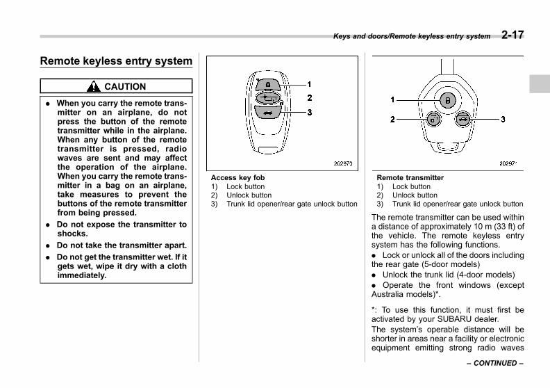
Black plate (127,1)
一般Model "A1300GE-A" EDITED: 2016/ 9/ 13
Remote keyless entry system
CAUTION
. When you carry the remote trans-mitter on an airplane, do notpress the button of the remotetransmitter while in the airplane.When any button of the remotetransmitter is pressed, radiowaves are sent and may affectthe operation of the airplane.When you carry the remote trans-mitter in a bag on an airplane,take measures to prevent thebuttons of the remote transmitterfrom being pressed.
. Do not expose the transmitter toshocks.
. Do not take the transmitter apart.
. Do not get the transmitter wet. If itgets wet, wipe it dry with a clothimmediately.
Access key fob1) Lock button2) Unlock button3) Trunk lid opener/rear gate unlock button
Remote transmitter1) Lock button2) Unlock button3) Trunk lid opener/rear gate unlock button
The remote transmitter can be used withina distance of approximately 10 m (33 ft) ofthe vehicle. The remote keyless entrysystem has the following functions.. Lock or unlock all of the doors includingthe rear gate (5-door models). Unlock the trunk lid (4-door models). Operate the front windows (exceptAustralia models)*.
*: To use this function, it must first beactivated by your SUBARU dealer.The system’s operable distance will beshorter in areas near a facility or electronicequipment emitting strong radio waves
Keys and doors/Remote keyless entry system 2-17
– CONTINUED –
2
Black plate (128,1)
一般Model "A1300GE-A" EDITED: 2016/ 9/ 13
2-18 Keys and doors/Remote keyless entry system
such as a power plant, broadcast station,TV tower, or remote controller of homeelectronic appliances.
NOTE. Before leaving the vehicle, makesure that the doors are locked.. The remote keyless entry systemdoes not operate when the key isinserted in the ignition switch or whenany of the doors or the rear gate is notfully closed.. For models with “keyless accesswith push-button start system”, whenthe lock button on the access key fob ispressed while the access key fob isplaced too close to the vehicle body,unlocking by the keyless access func-tions may not work. In such a case, thefunctions will recover by unlockingusing the remote keyless entry system.. The setting of the hazard warningflasher operation can be changed byyour SUBARU dealer. We recommendthat you contact your SUBARU dealerfor details. Also, for models with thecombination meter display (color LCD),the setting of the hazard warningflasher operation can be changed byoperating the combination meter dis-play (color LCD). For details, refer to“Vehicle Setting” F3-44.
& Locking the doorsPressing the lock button on the accesskey fob/transmitter locks all doors and therear gate (5-door models).
NOTE. If any of the doors (or the rear gate/trunk lid) is not fully closed, the hazardwarning flashers will flash five times(the outside warning chime alsosounds five times for models with“keyless access with push-button startsystem”) to alert you that the doors (orthe rear gate/trunk lid) are not properlyclosed.. For models with “keyless accesswith push-button start system”, thefront door will be unlocked if you gripthe front door handle while an accesskey fob is in the operating range. Pullthe REAR door handle to make surethat the doors have been locked.
& Unlocking the doorsPress the unlock button on the access keyfob/transmitter near the vehicle.
! Models without door unlock selec-tion function
. Models without double locking sys-tem:All doors and the rear gate (5-doormodels) will be unlocked. Also, the hazardwarning flashers will flash twice.. Models with double locking system:1. Only the driver’s door will be unlocked.Also, the hazard warning flashers will flashtwice.2. If you press the unlock button againwithin 5 seconds of unlocking the driver’sdoor, all of the other doors and the reargate will be unlocked.
! Models with door unlock selectionfunction
NOTEFor security reasons, confirm thesetting is set as “operational” or“non-operational”.
The door unlock selection function makesit possible to unlock the driver’s doorwithout unlocking any other doors. Theoperational/non-operational setting for thisfunction can be changed by a SUBARU
Black plate (129,1)
一般Model "A1300GE-A" EDITED: 2016/ 9/ 13
dealer.
. Operational:Only the driver’s door will be unlocked. Ifyou press the unlock button again within 5seconds of unlocking the driver’s door, allof the other doors and the rear gate (5-door models) will be unlocked.. Non-operational:All doors and the rear gate are unlocked.
For further details, we recommend thatyou consult a SUBARU dealer.
& Automatic locking (modelswithout double locking sys-tem)
When the unlock button is pressed, all ofthe doors and the rear gate (5-doormodels) are automatically locked 30 sec-onds later unless any one of the fourdoors or the rear gate is opened duringthat period.
The automatic locking function’s opera-tional/non-operational setting and thesetting for the locking time period (thetime period after which locking takesplace) can be changed by a SUBARUdealer. We recommend that you contactthe nearest SUBARU dealer for details.Also, for models with a combination meterdisplay (color LCD), this setting can be
changed by operating the combinationmeter display (color LCD). For details,refer to “Vehicle Setting” F3-44
& Opening the trunk lid(4-door models)
Press and hold the trunk lid opener buttonto open the trunk lid. The hazard warningflashers will flash twice.
& Unlocking the rear gate(5-door models)
Press the rear gate unlock button tounlock the rear gate.The hazard warning flashers will flashtwice.
& Opening/closing the frontwindows (except Australiamodels)
With the engine turned off, you can openand close the front windows by using theremote keyless entry system from outsidethe vehicle. Operate the front windows inthe following way.. Press and hold the lock button to closethe front windows.. Press and hold the unlock button toopen the front windows.
NOTEWe recommend that you consult yourSUBARU dealer to have this functionset to enabled or disabled.
& Replacing batteryRefer to “Replacing key battery” F11-54.
& Technical informationThe trade, model and supplier’s names ofthis device are as follows.. Equipment’s trade name: SUBARU. Equipment’s model name: TB1G077. Supplier’s name: ALPS ELECTRIC
For Europe:This device complies with the essentialrequirements of the Radio and Telecom-munications Terminal Equipment Directive1999/5/EC. A copy of the original Declara-tion of Conformity and the CE marking arefound in the chapter 13.
Keys and doors/Remote keyless entry system 2-19
2
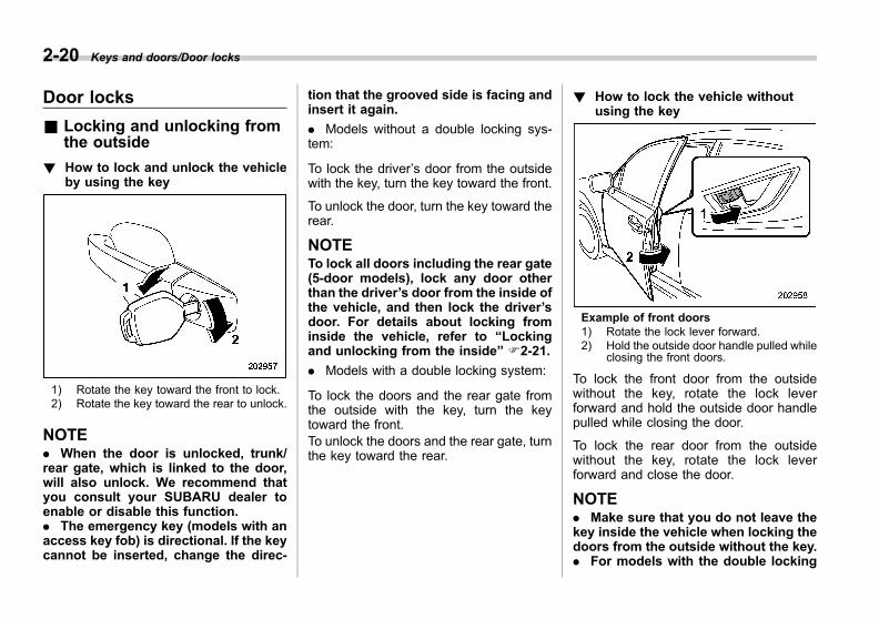
Black plate (130,1)
一般Model "A1300GE-A" EDITED: 2016/ 9/ 13
2-20 Keys and doors/Door locks
Door locks
& Locking and unlocking fromthe outside
! How to lock and unlock the vehicleby using the key
1) Rotate the key toward the front to lock.2) Rotate the key toward the rear to unlock.
NOTE. When the door is unlocked, trunk/rear gate, which is linked to the door,will also unlock. We recommend thatyou consult your SUBARU dealer toenable or disable this function.. The emergency key (models with anaccess key fob) is directional. If the keycannot be inserted, change the direc-
tion that the grooved side is facing andinsert it again.
. Models without a double locking sys-tem:
To lock the driver’s door from the outsidewith the key, turn the key toward the front.
To unlock the door, turn the key toward therear.
NOTETo lock all doors including the rear gate(5-door models), lock any door otherthan the driver’s door from the inside ofthe vehicle, and then lock the driver’sdoor. For details about locking frominside the vehicle, refer to “Lockingand unlocking from the inside” F2-21.
. Models with a double locking system:
To lock the doors and the rear gate fromthe outside with the key, turn the keytoward the front.To unlock the doors and the rear gate, turnthe key toward the rear.
! How to lock the vehicle withoutusing the key
Example of front doors1) Rotate the lock lever forward.2) Hold the outside door handle pulled while
closing the front doors.
To lock the front door from the outsidewithout the key, rotate the lock leverforward and hold the outside door handlepulled while closing the door.
To lock the rear door from the outsidewithout the key, rotate the lock leverforward and close the door.
NOTE. Make sure that you do not leave thekey inside the vehicle when locking thedoors from the outside without the key.. For models with the double locking
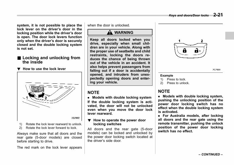
Black plate (131,1)
一般Model "A1300GE-A" EDITED: 2016/ 9/ 13
system, it is not possible to place thelock lever on the driver’s door in thelocking position while the driver’s dooris open. The door lock levers functiononly when the driver’s door is securelyclosed and the double locking systemis not set.
& Locking and unlocking fromthe inside
! How to use the lock lever
1) Rotate the lock lever rearward to unlock.2) Rotate the lock lever forward to lock.
Always make sure that all doors and therear gate (5-door models) are closedbefore starting to drive.
The red mark on the lock lever appears
when the door is unlocked.
WARNING
Keep all doors locked when youdrive, especially when small chil-dren are in your vehicle. Along withthe proper use of seatbelts and childrestraints, locking the doors re-duces the chance of being thrownout of the vehicle in an accident. Italso helps prevent passengers fromfalling out if a door is accidentallyopened, and intruders from unex-pectedly opening doors and enter-ing your vehicle.
NOTE. Models with double locking systemIf the double locking system is acti-vated, the door will not be unlockedeven when you move the door locklever rearward.
! How to operate the power doorlocking switches
All doors and the rear gate (5-doormodels) can be locked and unlocked bythe power door locking switch located atthe driver’s side door.
Example1) Press to lock.2) Press to unlock.
NOTE. Models with double locking system,pushing the unlocking position of thepower door locking switch has noeffect when the double locking systemis activated.. For Australia models, after lockingall doors and the rear gate using theremote transmitter, pushing the unlockposition of the power door lockingswitch has no effect.
Keys and doors/Door locks 2-21
– CONTINUED –
2
Black plate (132,1)
一般Model "A1300GE-A" EDITED: 2016/ 9/ 13
2-22 Keys and doors/Door locks
& Key lock-in prevention func-tion (models without doublelocking system)
This function prevents the doors frombeing locked under the following condi-tions.. The key is still in the ignition switch(models without “keyless access withpush-button start system”). The ignition switch is in the “ON”position (models with “keyless access withpush-button start system”). With the driver’s door open, the doorsare automatically kept unlocked even ifthe power door locking switch is pressedto the lock position.
NOTE. This function’s operational/non-op-erational setting can be changed by aSUBARU dealer. We recommend thatyou contact a SUBARU dealer fordetails.. When leaving the vehicle, make surethat you are holding the key beforelocking the doors.
! Behavior with key lock-in preven-tion function non-operational
We recommend that you consult yourSUBARU dealer about setting this to thenon-operational setting.The doors can be locked in the followingway.. If the lock lever is turned to the front(lock) position with the driver’s door openand the driver’s door is then closed, thedriver’s door is locked.. If the spare key is used to lock thedriver’s door from the outside of thevehicle, the door is locked.
& Battery drainage preventionfunction
If a door or the rear gate (5-door models)is not completely closed, the interior lightswill remain illuminated as a result. How-ever, several lights are automaticallyturned off by the battery drainage preven-tion function to prevent the battery fromdischarging. The following interior lightsare affected by this function.
Item Switchposition
Automatically turningoff
Map lights DOOR Approximately 20minutes later
Dome light DOOR Approximately 20minutes later
Ignitionswitch light — Approximately 20
minutes later
Cargo arealight DOOR Approximately 20
minutes later
NOTE. The default setting for this functionis set as “operational”. The opera-tional/non-operational setting of thisfunction can be changed by a SUBARUdealer. We recommend that you con-tact your SUBARU dealer to change thesetting.. When leaving the vehicle, pleasemake sure that all doors and the reargate are completely closed.. For models with the push-buttonignition switch, the battery drainageprevention function does not operatewhile the ignition switch is in “ACC” or“ON” position.. For models without the push-buttonignition switch, the battery drainageprevention function does not operatewhile the key is in the ignition switch.
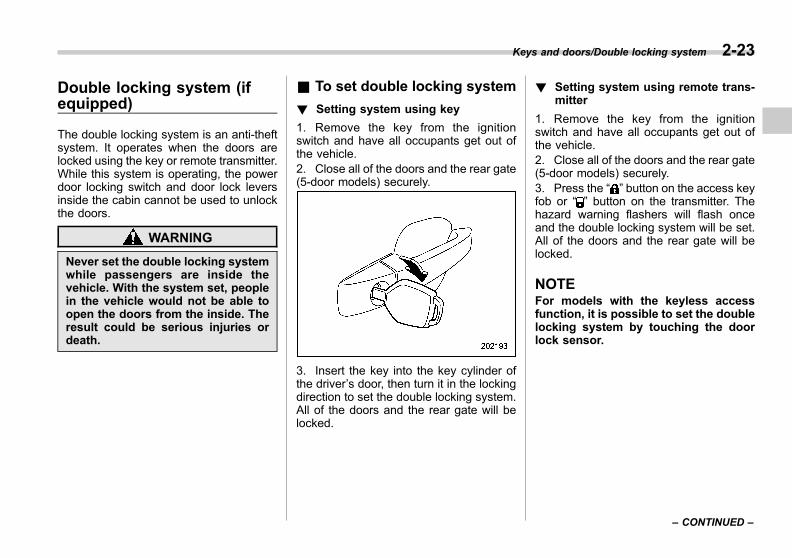
Black plate (133,1)
一般Model "A1300GE-A" EDITED: 2016/ 9/ 13
Double locking system (ifequipped)
The double locking system is an anti-theftsystem. It operates when the doors arelocked using the key or remote transmitter.While this system is operating, the powerdoor locking switch and door lock leversinside the cabin cannot be used to unlockthe doors.
WARNING
Never set the double locking systemwhile passengers are inside thevehicle. With the system set, peoplein the vehicle would not be able toopen the doors from the inside. Theresult could be serious injuries ordeath.
& To set double locking system
! Setting system using key
1. Remove the key from the ignitionswitch and have all occupants get out ofthe vehicle.2. Close all of the doors and the rear gate(5-door models) securely.
3. Insert the key into the key cylinder ofthe driver’s door, then turn it in the lockingdirection to set the double locking system.All of the doors and the rear gate will belocked.
! Setting system using remote trans-mitter
1. Remove the key from the ignitionswitch and have all occupants get out ofthe vehicle.2. Close all of the doors and the rear gate(5-door models) securely.3. Press the “ ” button on the access keyfob or “ ” button on the transmitter. Thehazard warning flashers will flash onceand the double locking system will be set.All of the doors and the rear gate will belocked.
NOTEFor models with the keyless accessfunction, it is possible to set the doublelocking system by touching the doorlock sensor.
Keys and doors/Double locking system 2-23
– CONTINUED –
2
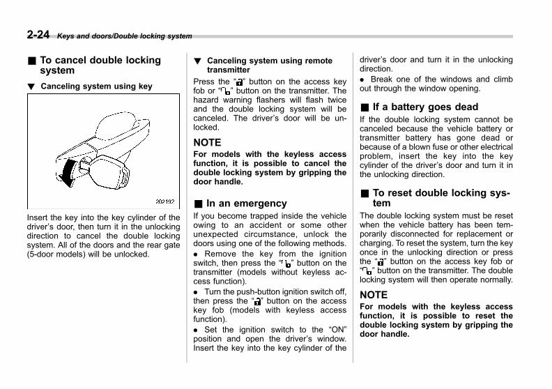
Black plate (134,1)
一般Model "A1300GE-A" EDITED: 2016/ 9/ 13
2-24 Keys and doors/Double locking system
& To cancel double lockingsystem
! Canceling system using key
Insert the key into the key cylinder of thedriver’s door, then turn it in the unlockingdirection to cancel the double lockingsystem. All of the doors and the rear gate(5-door models) will be unlocked.
! Canceling system using remotetransmitter
Press the “ ” button on the access keyfob or “ ” button on the transmitter. Thehazard warning flashers will flash twiceand the double locking system will becanceled. The driver’s door will be un-locked.
NOTEFor models with the keyless accessfunction, it is possible to cancel thedouble locking system by gripping thedoor handle.
& In an emergencyIf you become trapped inside the vehicleowing to an accident or some otherunexpected circumstance, unlock thedoors using one of the following methods.. Remove the key from the ignitionswitch, then press the “ ” button on thetransmitter (models without keyless ac-cess function).. Turn the push-button ignition switch off,then press the “ ” button on the accesskey fob (models with keyless accessfunction).. Set the ignition switch to the “ON”position and open the driver’s window.Insert the key into the key cylinder of the
driver’s door and turn it in the unlockingdirection.. Break one of the windows and climbout through the window opening.
& If a battery goes deadIf the double locking system cannot becanceled because the vehicle battery ortransmitter battery has gone dead orbecause of a blown fuse or other electricalproblem, insert the key into the keycylinder of the driver’s door and turn it inthe unlocking direction.
& To reset double locking sys-tem
The double locking system must be resetwhen the vehicle battery has been tem-porarily disconnected for replacement orcharging. To reset the system, turn the keyonce in the unlocking direction or pressthe “ ” button on the access key fob or“ ” button on the transmitter. The doublelocking system will then operate normally.
NOTEFor models with the keyless accessfunction, it is possible to reset thedouble locking system by gripping thedoor handle.
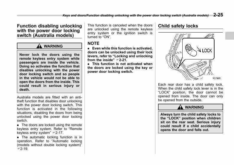
Black plate (135,1)
一般Model "A1300GE-A" EDITED: 2016/ 9/ 13
Function disabling unlockingwith the power door lockingswitch (Australia models)
WARNING
Never lock the doors using theremote keyless entry system whilepassengers are inside the vehicle.Doing so activates the function thatdisables unlocking with the powerdoor locking switch and so peoplein the vehicle would not be able toopen the doors from the inside. Thiscould result in serious injury ordeath.
Australia models are fitted with an anti-theft function that disables door unlockingwith the power door locking switch. Thisfunction is activated in the followingsituations, disabling the doors from beingunlocked using the power door lockingswitch.. The doors are locked using the remotekeyless entry system. Refer to “Remotekeyless entry system” F2-17.. The automatic locking function is inoperation. Refer to “Automatic locking(models without double locking system)”F2-19.
This function is canceled when the doorsare unlocked using the remote keylessentry system or the ignition switch isturned to “ON”.
NOTE. Even while this function is activated,doors can be unlocked using their locklevers, refer to “Locking and unlockingfrom the inside” F2-21.. This function is not activated whenthe doors are locked using the key orpower door locking switch.
Child safety locks
Each rear door has a child safety lock.When the child safety lock lever is in the“LOCK” position, the door cannot beopened from inside. The door can onlybe opened from the outside.
WARNING
Always turn the child safety locks tothe “LOCK” position when childrensit on the rear seat. Serious injurycould result if a child accidentallyopens the door and falls out.
Keys and doors/Function disabling unlocking with the power door locking switch (Australia models) 2-25
2
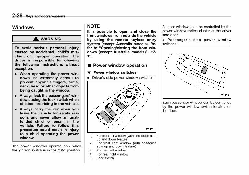
Black plate (136,1)
一般Model "A1300GE-A" EDITED: 2016/ 9/ 13
2-26 Keys and doors/Windows
Windows
WARNING
To avoid serious personal injurycaused by accidental, child’s mis-chief, or improper operation, thedriver is responsible for obeyingthe following instructions withoutexception.
. When operating the power win-dows, be extremely careful toprevent anyone’s fingers, arms,neck, head or other objects frombeing caught in the window.
. Always lock the passengers’ win-dows using the lock switch whenchildren are riding in the vehicle.
. Always carry the key when youleave the vehicle for safety rea-sons and never allow an unat-tended child to remain in thevehicle. Failure to follow thisprocedure could result in injuryto a child operating the powerwindow.
The power windows operate only whenthe ignition switch is in the “ON” position.
NOTEIt is possible to open and close thefront windows from outside the vehicleby using the remote keyless entrysystem (except Australia models). Re-fer to “Opening/closing the front win-dows (except Australia models)” F2-19.
& Power window operation
! Power window switches
. Driver’s side power window switches:
1) For front left window (with one-touch autoup and down feature)
2) For front right window (with one-touchauto up and down feature)
3) For rear left window4) For rear right window5) Lock switch
All door windows can be controlled by thepower window switch cluster at the driverside door.. Passenger ’s side power windowswitches:
Each passenger window can be controlledby the power window switch located onthe door.
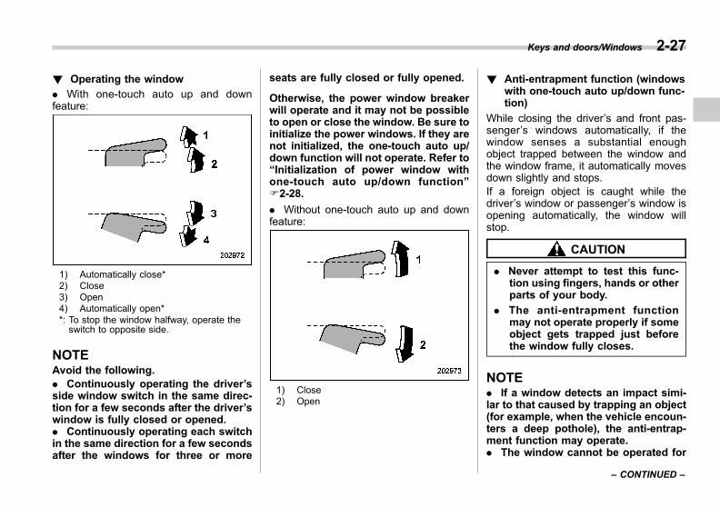
Black plate (137,1)
一般Model "A1300GE-A" EDITED: 2016/ 9/ 13
! Operating the window
. With one-touch auto up and downfeature:
1) Automatically close*2) Close3) Open4) Automatically open**: To stop the window halfway, operate theswitch to opposite side.
NOTEAvoid the following.. Continuously operating the driver’sside window switch in the same direc-tion for a few seconds after the driver’swindow is fully closed or opened.. Continuously operating each switchin the same direction for a few secondsafter the windows for three or more
seats are fully closed or fully opened.
Otherwise, the power window breakerwill operate and it may not be possibleto open or close the window. Be sure toinitialize the power windows. If they arenot initialized, the one-touch auto up/down function will not operate. Refer to“Initialization of power window withone-touch auto up/down function”F2-28.
. Without one-touch auto up and downfeature:
1) Close2) Open
! Anti-entrapment function (windowswith one-touch auto up/down func-tion)
While closing the driver’s and front pas-senger’s windows automatically, if thewindow senses a substantial enoughobject trapped between the window andthe window frame, it automatically movesdown slightly and stops.If a foreign object is caught while thedriver’s window or passenger’s window isopening automatically, the window willstop.
CAUTION
. Never attempt to test this func-tion using fingers, hands or otherparts of your body.
. The anti-entrapment functionmay not operate properly if someobject gets trapped just beforethe window fully closes.
NOTE. If a window detects an impact simi-lar to that caused by trapping an object(for example, when the vehicle encoun-ters a deep pothole), the anti-entrap-ment function may operate.. The window cannot be operated for
Keys and doors/Windows 2-27
– CONTINUED –
2

Black plate (138,1)
一般Model "A1300GE-A" EDITED: 2016/ 9/ 13
2-28 Keys and doors/Trunk lid (4–door models)
a few seconds after the anti-entrap-ment function operates.
! Off delay function (windows withone-touch auto up/down function)
The front windows can be operated forapproximately 45 seconds even after theignition switch is turned to the “ACC” or“OFF” position. If a front door is openedwithin 45 seconds, the off delay function iscanceled.
! Locking the passengers’ windows
1) Lock2) Unlock
When the lock switch is in the lockposition, the passengers’ windows cannotbe opened or closed.
& Initialization of power win-dow with one-touch auto up/down function
If the power window automatic function(one-touch auto up and down function)does not operate properly, operate eachwindow according to the following proce-dure in order to initialize the power windowsystem.1. Close the door.2. Turn the ignition switch to the “ON”position.3. Open the window completely and thenpress and hold down the power windowswitch for approximately 1 second.4. Close the window completely and thenpull and hold the power window switch forapproximately 1 second.
Trunk lid (4-door models)
WARNING
. To prevent dangerous exhaustgas from entering the vehicle,always keep the trunk lid closedwhile the engine is running.
. Help prevent young children fromlocking themselves in the trunk.On hot or sunny days, the tem-perature in the trunk couldquickly become high enough tocause death or serious heat-related injuries including braindamage to anyone locked inside,particularly for small children.
. When leaving the vehicle, closeall windows and lock all doors.Also make certain that the trunkis closed.
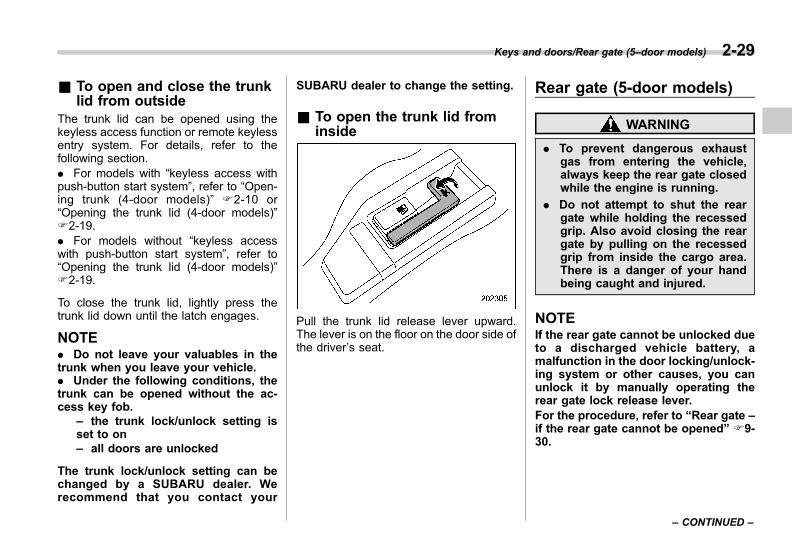
Black plate (139,1)
一般Model "A1300GE-A" EDITED: 2016/ 9/ 13
& To open and close the trunklid from outside
The trunk lid can be opened using thekeyless access function or remote keylessentry system. For details, refer to thefollowing section.. For models with “keyless access withpush-button start system”, refer to “Open-ing trunk (4-door models)” F2-10 or“Opening the trunk lid (4-door models)”F2-19.. For models without “keyless accesswith push-button start system”, refer to“Opening the trunk lid (4-door models)”F2-19.
To close the trunk lid, lightly press thetrunk lid down until the latch engages.
NOTE. Do not leave your valuables in thetrunk when you leave your vehicle.. Under the following conditions, thetrunk can be opened without the ac-cess key fob.
– the trunk lock/unlock setting isset to on– all doors are unlocked
The trunk lock/unlock setting can bechanged by a SUBARU dealer. Werecommend that you contact your
SUBARU dealer to change the setting.
& To open the trunk lid frominside
Pull the trunk lid release lever upward.The lever is on the floor on the door side ofthe driver’s seat.
Rear gate (5-door models)
WARNING
. To prevent dangerous exhaustgas from entering the vehicle,always keep the rear gate closedwhile the engine is running.
. Do not attempt to shut the reargate while holding the recessedgrip. Also avoid closing the reargate by pulling on the recessedgrip from inside the cargo area.There is a danger of your handbeing caught and injured.
NOTEIf the rear gate cannot be unlocked dueto a discharged vehicle battery, amalfunction in the door locking/unlock-ing system or other causes, you canunlock it by manually operating therear gate lock release lever.For the procedure, refer to “Rear gate –if the rear gate cannot be opened” F9-30.
Keys and doors/Rear gate (5–door models) 2-29
– CONTINUED –
2

Black plate (140,1)
一般Model "A1300GE-A" EDITED: 2016/ 9/ 13
2-30 Keys and doors/Rear gate (5–door models)
& Lock/unlockThe rear gate can be locked and unlockedusing any of the following systems.. Power door locking switch: Refer to“How to operate the power door lockingswitches” F2-21.. Keyless access with the push-buttonstart system (if equipped): Refer to “Key-less access with push-button start system”F2-3.. Remote keyless entry system: Refer to“Remote keyless entry system” F2-17.. Locking and unlocking from the outsidewith the key (models with double lockingsystem): Refer to “Locking and unlockingfrom the outside” F2-20.
& Open/close
To open:First unlock the rear gate lock then pushthe rear gate opener button.
To close:Lower the rear gate slowly and push down
firmly until the latch engages.The rear gate can be lowered easily if youpull down on the inside handle as shownin the illustration.
CAUTION
. Do not jam a plastic bag in orplace cellophane tape on the reargate stays or scratch the stayswhile loading or unloading cargo.That could cause leakage of gasfrom the stays, which may resultin their inability to hold the reargate open.
. Be careful not to hit your head orface on the rear gate when open-ing or closing the rear gate andwhen loading or unloading car-go.

Black plate (141,1)
一般Model "A1300GE-A" EDITED: 2016/ 9/ 13
Sunroof (if equipped)
WARNING
Never let anyone’s hands, arms,head or any objects protrude fromthe sunroof. A person could beseriously injured if any of the follow-ing conditions occur.
. The vehicle stops suddenly.
. The vehicle turns sharply.
. The vehicle is involved in anaccident.
. Body parts protruding from thevehicle are struck by outsideobjects.
To avoid serious personal injurycaused by accidental, child’s mis-chief, or improper operation, thedriver is responsible for obeyingthe following instructions withoutexception.
. Before closing the sunroof, makesure that no one’s hands, arms,head or other objects will beaccidentally caught in the sun-roof.
. Always carry the key when youleave the vehicle for safety rea-
sons and never allow an unat-tended child to remain in thevehicle. Failure to follow thisprocedure could result in injuryto a child operating the sunroof.
. Never try to check the anti-en-trapment function by deliberatelyplacing part of your body in thesunroof.
CAUTION
. Do not sit on the edge of the opensunroof.
. Do not operate the sunroof iffalling snow or extremely coldconditions have caused it tofreeze shut.
. The anti-entrapment functiondoes not operate when the sun-roof is being tilted down. Be sureto confirm safety before tiltingthe sunroof down.
. If the sunroof does not close, werecommend that you have thesystem checked by a SUBARUdealer.
The sunroof operates only when theignition switch is in the “ON” position.
& Sunroof switches
! Tilting sunroof
1) Up2) Down
To raise the sunroof, press and hold theswitch in the up side and release. To lowerthe sunroof, press and hold the switch inthe down side.
NOTERelease the switch after the sunroofhas been raised or has been loweredcompletely. Pressing the switch con-tinuously may cause damage to thesunroof.
Keys and doors/Sunroof 2-31
– CONTINUED –
2
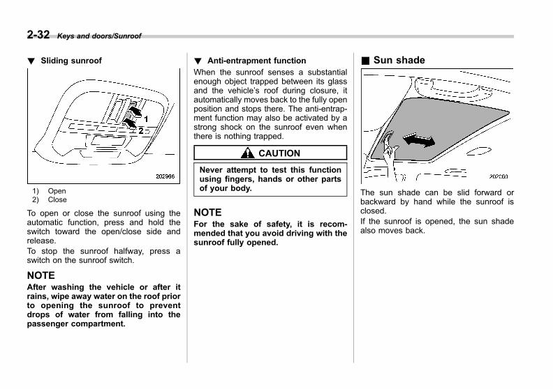
Black plate (142,1)
一般Model "A1300GE-A" EDITED: 2016/ 9/ 13
2-32 Keys and doors/Sunroof
! Sliding sunroof
1) Open2) Close
To open or close the sunroof using theautomatic function, press and hold theswitch toward the open/close side andrelease.To stop the sunroof halfway, press aswitch on the sunroof switch.
NOTEAfter washing the vehicle or after itrains, wipe away water on the roof priorto opening the sunroof to preventdrops of water from falling into thepassenger compartment.
! Anti-entrapment function
When the sunroof senses a substantialenough object trapped between its glassand the vehicle’s roof during closure, itautomatically moves back to the fully openposition and stops there. The anti-entrap-ment function may also be activated by astrong shock on the sunroof even whenthere is nothing trapped.
CAUTION
Never attempt to test this functionusing fingers, hands or other partsof your body.
NOTEFor the sake of safety, it is recom-mended that you avoid driving with thesunroof fully opened.
& Sun shade
The sun shade can be slid forward orbackward by hand while the sunroof isclosed.If the sunroof is opened, the sun shadealso moves back.
Black plate (5,1)
一般Model "A1300GE-A" EDITED: 2016/ 9/ 13
Ignition switch (models without push-button start system)......................................... 3-4Key positions...................................................... 3-4Key reminder chime (if equipped) ........................ 3-5Ignition switch light (if equipped) ......................... 3-5
Push-button ignition switch (models with“keyless access with push-button startsystem”)............................................................ 3-6Safety precautions .............................................. 3-6Operating range for push-button start system ...... 3-6Switch location ................................................... 3-7Switching power status ....................................... 3-7When access key fob does not operateproperly ............................................................ 3-8
Hazard warning flasher....................................... 3-8Meters and gauges.............................................. 3-9
Speedometer....................................................... 3-9Tachometer ......................................................... 3-9Odometer............................................................ 3-9Double trip meter ............................................... 3-10Fuel gauge......................................................... 3-10ECO gauge (if equipped) .................................... 3-11Combination meter settings................................ 3-11
Illumination brightness control ......................... 3-13Auto dimmer cancel function (if equipped) .......... 3-13
Warning and indicator lights ............................. 3-13Initial illumination for system check.................... 3-13Seatbelt warning light and chime ........................ 3-14Rear seatbelt indicator light and chime (Europeand Australia models) ...................................... 3-16
SRS airbag system warning light ........................ 3-17
Front passenger’s frontal airbag ON and OFFindicators (if equipped) .................................... 3-17
Malfunction indicator light (Check Enginelight) ............................................................... 3-18
Coolant temperature low indicator light/Coolanttemperature high warning light......................... 3-19
Charge warning light.......................................... 3-20Oil pressure warning light .................................. 3-20Engine low oil level warning light ....................... 3-20AT OIL TEMP warning light................................. 3-21Low tire pressure warning light (if equipped) ...... 3-21ABS warning light.............................................. 3-23Vehicle Dynamics Control warning light/VehicleDynamics Control operation indicator light ....... 3-23
Vehicle Dynamics Control OFF indicator light ..... 3-24Brake system warning light (red)........................ 3-25Electronic parking brake warning light/Vacuumpressure system warning light (yellow)............. 3-26
Electronic parking brake indicator light .............. 3-26Low fuel warning light ....................................... 3-27Windshield washer fluid warning light ................ 3-27Hill Holder indicator light ................................... 3-27Door open warning light .................................... 3-27All-Wheel Drive warning light (AWD models)....... 3-27Power steering warning light.............................. 3-28Automatic headlight beam leveler warning light(models with LED headlights)........................... 3-28
LED headlight warning light (models with LEDheadlights) ...................................................... 3-28
Steering Responsive Headlight warning light/Steering Responsive Headlight OFF indicatorlight (if equipped)............................................. 3-28
Instruments and controls
3
Black plate (6,1)
一般Model "A1300GE-A" EDITED: 2016/ 9/ 13
Instruments and controls
Warning chimes and warning light of the keylessaccess with push-button start system (ifequipped)......................................................... 3-29
Immobilizer indicator light .................................. 3-33Select lever/gear position indicator ..................... 3-34Turn signal indicator lights ................................. 3-34High beam indicator light ................................... 3-34High Beam Assist indicator light (green) (ifequipped)......................................................... 3-35
High Beam Assist warning indicator (yellow) (ifequipped)......................................................... 3-35
Cruise control indicator light (if equipped) .......... 3-35Cruise control set indicator light (ifequipped)......................................................... 3-35
Headlight indicator light ..................................... 3-35Front fog light indicator light (if equipped) .......... 3-35Rear fog light indicator light (if equipped) ........... 3-35Auto Start Stop warning light/Auto Start Stop OFFindicator light (yellow) (if equipped) .................. 3-36
Auto Start Stop indicator light (green) (ifequipped)......................................................... 3-36
SUBARU Rear Vehicle Detection warningindicator (if equipped) ...................................... 3-36
SUBARU Rear Vehicle Detection OFF indicator (ifequipped)......................................................... 3-36
Icy road surface warning indicator (ifequipped)......................................................... 3-36
Combination meter display (color LCD) (ifequipped) ......................................................... 3-37Basic operation.................................................. 3-38Welcome screen and Good-bye screen ............... 3-39Warning screen .................................................. 3-39
Telltale screen ................................................... 3-39Basic screens.................................................... 3-40Menu screens .................................................... 3-42
Multi-function display (black and white) (ifequipped) ........................................................ 3-45Driving information display ................................ 3-45Outside temperature indicator ............................ 3-50Clock ................................................................ 3-51
Multi-function display (color LCD) (ifequipped) ........................................................ 3-51Features ............................................................ 3-51Welcome screen ................................................ 3-52Self-check screen .............................................. 3-52Interruption screen ............................................ 3-53Basic operation ................................................. 3-53Basic screens.................................................... 3-53Setting screen ................................................... 3-61How to get the source code using the opensource............................................................. 3-66
Clock .................................................................. 3-67Preparation for clock adjustment setting ............ 3-67Setting the clock automatically........................... 3-67Setting the clock manually ................................. 3-68Regulatory information ...................................... 3-69
Light control switch........................................... 3-69Headlights ......................................................... 3-70High/low beam change (dimmer) ........................ 3-72Headlight flasher ............................................... 3-73High Beam Assist function (if equipped)............. 3-73Daytime running light system (if equipped)......... 3-76
Black plate (7,1)
一般Model "A1300GE-A" EDITED: 2016/ 9/ 13
Instruments and controls
Steering Responsive Headlight (SRH) (ifequipped) ......................................................... 3-77SRH OFF switch................................................. 3-77
Headlight beam leveler (if equipped) ................ 3-78Automatic headlight beam leveler (models withLED headlights)................................................ 3-78
Manual headlight beam leveler (models withoutLED headlights)................................................ 3-78
Fog light switch.................................................. 3-81Front fog light switch (if equipped) ..................... 3-81Rear fog light switch (if equipped) ...................... 3-82
Turn signal lever ................................................ 3-83One-touch lane changer ..................................... 3-83
Wiper and washer.............................................. 3-84Windshield wiper and washer switches .............. 3-86Rear window wiper and washer switch (5-doormodels) ........................................................... 3-89
Headlight washer (if equipped)......................... 3-90Mirrors ................................................................ 3-91
Inside mirror...................................................... 3-91Auto-dimming mirror (if equipped)...................... 3-91Outside mirrors ................................................. 3-92
Defogger and deicer .......................................... 3-94Tilt/telescopic steering wheel ........................... 3-95Heated Steering Wheel system (ifequipped) ........................................................ 3-96
Horn.................................................................... 3-97
1

Black plate (148,1)
一般Model "A1300GE-A" EDITED: 2016/ 9/ 13
3-4 Instruments and controls/Ignition switch (models without push–button start system)
Ignition switch (models with-out push-button start sys-tem)
WARNING
. Never turn the ignition switch tothe “LOCK” position while thevehicle is being driven or towedbecause that will lock the steer-ing wheel, preventing steeringcontrol. And when the engine isturned off, it takes a much great-er effort than usual to steer.
. Before leaving the vehicle, al-ways remove the key from theignition switch for safety andnever allow an unattended childto remain in the vehicle. Failureto follow this procedure couldresult in injury to a child orothers. Children could operatethe power windows or other con-trols or even make the vehiclemove.
CAUTION
Do not attach a large key holder orkey case to either key. If it bangs
against your knees while you aredriving, it could turn the ignitionswitch from the “ON” position to the“ACC” or “LOCK” position, therebystopping the engine.
The ignition switch has four positions:LOCK, ACC, ON and START.
NOTE. Keep the ignition switch in the“LOCK” position when the engine isnot running.. Using electrical accessories for along time with the ignition switch in the“ON” or “ACC” position can cause thebattery to go dead.. If the ignition switch will not movefrom the “LOCK” position to the “ACC”
position, turn the steering wheelslightly to the left and right as you turnthe ignition switch.
& Key positions
Position Description
LOCK
The key can only be insertedor removed in this position.The ignition switch will lockthe steering wheel when youremove the key.
ACC
In this position the electricalaccessories (audio, acces-sory power outlet, etc.) canbe used.
ONThis is the normal operatingposition after starting the en-gine.
START The engine is started in thisposition.
CAUTION
Do not turn the ignition switch to the“START” position while the engineis running.

Black plate (149,1)
一般Model "A1300GE-A" EDITED: 2016/ 9/ 13
NOTE
. To turn the key from the “ACC” to“LOCK” position, the select lever mustbe in the “P” position and the key mustbe pushed in and turned.. If your registered key fails to startthe engine, pull out the key once (thesecurity indicator light will blink), andthen insert the key again and turn it tothe “START” position again to restartthe engine.
. The engine may not start in thefollowing cases:
– The key grip is touching anotherkey or a metallic key holder.
– The key is near another key thatcontains an immobilizer transpon-
der.– The key is near or touchinganother transmitter.
& Key reminder chime (ifequipped)
The reminder chime sounds when thedriver’s door is opened and the ignitionswitch is in the “LOCK” or “ACC” position.
The chime stops under the followingconditions.. when the ignition switch is turned to the“ON” position. when the key is removed from theignition switch. when the driver’s door is closed
& Ignition switch light (ifequipped)
For easy access to the ignition switch inthe dark, the ignition switch light illumi-nates when the driver’s door is opened orwhen the driver’s door is unlocked usingthe remote keyless entry transmitter.
The light remains illuminated for severaltens of seconds and then gradually turnsoff under the following conditions.. when the driver’s door is closed. when the doors are unlocked using the
Instruments and controls/Ignition switch (models without push–button start system) 3-5
– CONTINUED –
3
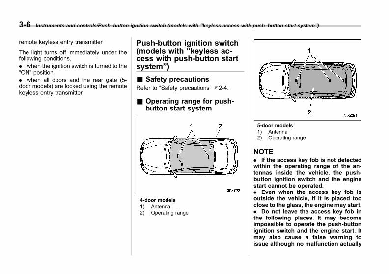
Black plate (150,1)
一般Model "A1300GE-A" EDITED: 2016/ 9/ 13
3-6 Instruments and controls/Push–button ignition switch (models with “keyless access with push–button start system”)
remote keyless entry transmitter
The light turns off immediately under thefollowing conditions.. when the ignition switch is turned to the“ON” position. when all doors and the rear gate (5-door models) are locked using the remotekeyless entry transmitter
Push-button ignition switch(models with “keyless ac-cess with push-button startsystem”)
& Safety precautionsRefer to “Safety precautions” F2-4.
& Operating range for push-button start system
4-door models1) Antenna2) Operating range
5-door models1) Antenna2) Operating range
NOTE. If the access key fob is not detectedwithin the operating range of the an-tennas inside the vehicle, the push-button ignition switch and the enginestart cannot be operated.. Even when the access key fob isoutside the vehicle, if it is placed tooclose to the glass, the engine may start.. Do not leave the access key fob inthe following places. It may becomeimpossible to operate the push-buttonignition switch and the engine start. Itmay also cause a false warning toissue although no malfunction actually

Black plate (151,1)
一般Model "A1300GE-A" EDITED: 2016/ 9/ 13
occurs, or not to issue a warning whenany malfunction occurs.
– On the instrument panel– On the floor– Inside the glove box– Inside the door trim pocket– On the rear seat– On the rear shelf (4-door models)– Inside the trunk (4-door models)– In the cargo area (5-door models)
. When operating the push-buttonignition switch or starting the engine,if the battery of the access key fob isdischarged, perform the proceduredescribed in “Access key fob – ifaccess key fob does not operate prop-erly” F9-28. In such a case, replace thebattery immediately. Refer to “Repla-cing battery of access key fob” F11-54.
& Switch location
Left-hand drive models
Right-hand drive models
1) Operation indicator2) Push-button ignition switch
& Switching power statusThe power is switched every time thepush-button ignition switch is pressed.1. Carry the access key fob, and sit in thedriver’s seat.2. Shift the select lever in the “P” posi-tion.3. Press the push-button ignition switchwithout depressing the brake pedal. Everytime the button is pressed, the power isswitched in the sequence of “OFF”,“ACC”, “ON” and “OFF”. The operationindicator on the push-button ignitionswitch illuminates or turns off as shownin the following chart.
Powerstatus Indicator color Operation
OFF Turned off Power is turned off.
ACC Orange
The following partscan be used:
wipers, washer,audio and acces-sory power outlet.
ON
Orange(while engine is
stopped) All electrical partscan be used.Turned off
(while engine isrunning)
Instruments and controls/Push–button ignition switch (models with “keyless access with push–button start system”) 3-7
– CONTINUED –
3
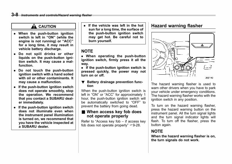
Black plate (152,1)
一般Model "A1300GE-A" EDITED: 2016/ 9/ 13
3-8 Instruments and controls/Hazard warning flasher
CAUTION
. When the push-button ignitionswitch is left in “ON” (while theengine is not running) or “ACC”for a long time, it may result invehicle battery discharge.
. Do not spill drinks or otherliquids on the push-button igni-tion switch. It may cause a mal-function.
. Do not touch the push-buttonignition switch with a hand soiledwith oil or other contaminants. Itmay cause a malfunction.
. If the push-button ignition switchdoes not operate smoothly, stopthe operation. We recommendthat you contact a SUBARU deal-er immediately.
. If the push-button ignition switchdoes not illuminate even whenthe instrument panel illuminationis turned on, we recommend thatyou have the vehicle inspected ata SUBARU dealer.
. If the vehicle was left in the hotsun for a long time, the surface ofthe push-button ignition switchmay get hot. Be careful not toburn yourself.
NOTE. When operating the push-buttonignition switch, firmly press it all theway.. If the push-button ignition switch ispressed quickly, the power may notturn on or off.
! Battery drainage prevention func-tion
When the push-button ignition switch isleft in “ON” or “ACC” for approximately 1hour, the push-button ignition switch willbe automatically switched to “OFF” toprevent the battery from going dead.
& When access key fob doesnot operate properly
Refer to “Access key fob – if access keyfob does not operate properly” F9-28.
Hazard warning flasher
The hazard warning flasher is used towarn other drivers when you have to parkyour vehicle under emergency conditions.The hazard warning flasher works with theignition switch in any position.
To turn on the hazard warning flasher,press the hazard warning button on theinstrument panel. All the turn signal lightsand the turn signal indicator lights willflash. To turn off the flasher, press thebutton again.
NOTEWhen the hazard warning flasher is on,the turn signals do not work.
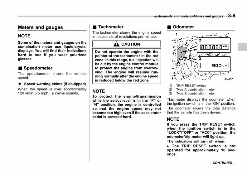
Black plate (153,1)
一般Model "A1300GE-A" EDITED: 2016/ 9/ 13
Meters and gauges
NOTE
Some of the meters and gauges on thecombination meter use liquid-crystaldisplays. You will find their indicationshard to see if you wear polarizedglasses.
& SpeedometerThe speedometer shows the vehiclespeed.
! Speed warning chime (if equipped)
When the speed is over approximately120 km/h (75 mph), a chime sounds.
& TachometerThe tachometer shows the engine speedin thousands of revolutions per minute.
CAUTION
Do not operate the engine with thepointer of the tachometer in the redzone. In this range, fuel injection willbe cut by the engine control moduleto protect the engine from overrev-ving. The engine will resume run-ning normally after the engine speedis reduced below the red zone.
NOTETo protect the engine/transmissionwhile the select lever is in the “P” or“N” position, the engine is controlledso that the engine speed may notbecome too high even if the acceleratorpedal is pressed hard.
& Odometer
1) TRIP RESET switch2) Type A combination meter3) Type B combination meter
This meter displays the odometer whenthe ignition switch is in the “ON” position.The odometer shows the total distancethat the vehicle has been driven.
NOTEIf you press the TRIP RESET switchwhen the ignition switch is in the“LOCK”/“OFF” or “ACC” position, theodometer/trip meter will light up.The indicators will turn off when:. The TRIP RESET switch is notoperated for approximately 10 sec-onds.
Instruments and controls/Meters and gauges 3-9
– CONTINUED –
3

Black plate (154,1)
一般Model "A1300GE-A" EDITED: 2016/ 9/ 13
3-10 Instruments and controls/Meters and gauges
. The driver’s door is opened andthen closed.
& Double trip meter
1) TRIP RESET switch2) Type A combination meter3) Type B combination meter
This combination meter has two tripmeters.This meter displays a trip meter when theignition switch is in the “ON” position.The trip meter shows the distance that thevehicle has been driven since you last setit to zero.
The display can be switched as shown inthe following sequence by pressing theTRIP RESET switch.
To set the trip meter to zero, select the Atrip or B trip meter by pressing the TRIPRESET switch and keep the TRIP RESETswitch pressed for more than 2 seconds.
CAUTION
To ensure safety, do not attempt tochange the function of the indicatorduring driving, as an accident couldresult.
NOTE. If the connection between the com-bination meter and battery is broken forany reason such as vehicle mainte-nance or fuse replacement, the datarecorded on the trip meter will be lost.. If you press the TRIP RESET switchwhen the ignition switch is in the“LOCK”/“OFF” or “ACC” position, theodometer/trip meter will light up. It ispossible to switch between the A tripmeter and B trip meter indicationswhile the odometer/trip meter is lit up.In addition, it is possible to reset thetrip meter by pressing and holding the
TRIP RESET switch.
The indicators will turn off when:. The TRIP RESET switch is notoperated for approximately 10 sec-onds.. The driver’s door is opened andthen closed.
& Fuel gauge
1) TRIP RESET switch2) Type A combination meter3) Type B combination meter
The fuel gauge is displayed when theignition is in the “ON” position, and itshows the approximate amount of fuelremaining in the tank.
The gauge indication may change slightly

Black plate (155,1)
一般Model "A1300GE-A" EDITED: 2016/ 9/ 13
during braking, turning or acceleration dueto fuel level movement in the tank.
NOTE. You will see the “ ” sign in the fuelgauge. This indicates that the fuel fillerdoor (lid) is located on the right side ofthe vehicle.. If you press the TRIP RESET switchwhile the ignition switch is in the“LOCK”/“OFF” or “ACC” position, thefuel gauge will light up and indicate theamount of fuel remaining in the tank.
The indicators will turn off when:. The TRIP RESET switch is notoperated for approximately 10 sec-onds.. The driver’s door is opened andthen closed.
& ECO gauge (if equipped)
The ECO gauge shows the differencebetween the current rate of fuel consump-tion and the average rate of fuel consump-tion since the trip meter was last reset.
If the ECO gauge moves towards the +side, this indicates better fuel efficiency.
NOTE. The ECO gauge shows only anapproximate indication of fuel effi-ciency.. After resetting the trip meter, theaverage rate of fuel consumption is notshown until you have driven for 1 km(or 1 mile). Before that time, the ECOgauge does not operate.
& Combination meter settingsMeter and vehicle settings can be set onthe combination meter.
! Type A combination meter
Various adjustments can be made, suchas switching units shown on the combina-tion meter and adjusting the warning tonevolume.While the ignition switch is in the “OFF”position, each press of TRIP RESETswitch results in items shown in the tablebelow being switched.
Item Combinationmeter display
Possiblesettings
A trip —
B trip —
Gaugeneedlesweepfunction
On/Off
Changingthe unit* mile/km
Warningvolume* Lv. 1/Lv. 2/Lv. 3
*: if available
Instruments and controls/Meters and gauges 3-11
– CONTINUED –
3

Black plate (156,1)
一般Model "A1300GE-A" EDITED: 2016/ 9/ 13
3-12 Instruments and controls/Meters and gauges
NOTE. If you switch the units on thecombination meter, the units on themulti-function display (black and white)also switches accordingly.. If either of the following conditionsis met, the combination meter settingmode will be canceled.
– The driver’s door is opened.– The TRIP RESET switch is notoperated for approximately 10 sec-onds or more.
! Switching method
1. Push the ignition switch in the “OFF”position.
1) TRIP RESET switch
2. Press the TRIP RESET switch repeat-edly until the item you want to change isdisplayed.3. Press and hold the TRIP RESETswitch while the item to be changed isdisplayed, the setting of the item will beswitched.
! Type B combination meter
Meter and vehicle settings can be set onthe combination meter display (colorLCD). Refer to “Menu screens” F3-42.
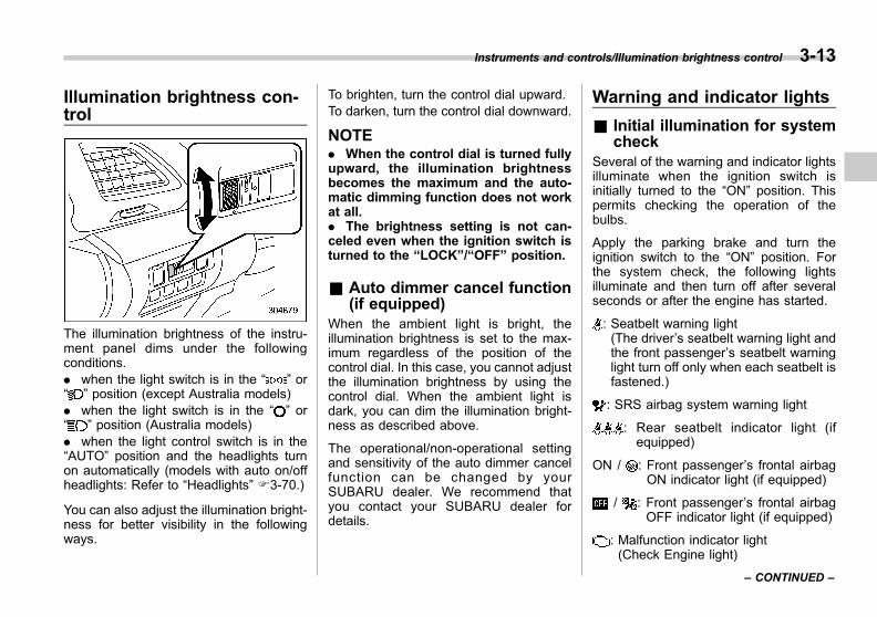
Black plate (157,1)
一般Model "A1300GE-A" EDITED: 2016/ 9/ 13
Illumination brightness con-trol
The illumination brightness of the instru-ment panel dims under the followingconditions.. when the light switch is in the “ ” or“ ” position (except Australia models). when the light switch is in the “ ” or“ ” position (Australia models). when the light control switch is in the“AUTO” position and the headlights turnon automatically (models with auto on/offheadlights: Refer to “Headlights” F3-70.)
You can also adjust the illumination bright-ness for better visibility in the followingways.
To brighten, turn the control dial upward.To darken, turn the control dial downward.
NOTE. When the control dial is turned fullyupward, the illumination brightnessbecomes the maximum and the auto-matic dimming function does not workat all.. The brightness setting is not can-celed even when the ignition switch isturned to the “LOCK”/“OFF” position.
& Auto dimmer cancel function(if equipped)
When the ambient light is bright, theillumination brightness is set to the max-imum regardless of the position of thecontrol dial. In this case, you cannot adjustthe illumination brightness by using thecontrol dial. When the ambient light isdark, you can dim the illumination bright-ness as described above.
The operational/non-operational settingand sensitivity of the auto dimmer cancelfunction can be changed by yourSUBARU dealer. We recommend thatyou contact your SUBARU dealer fordetails.
Warning and indicator lights
& Initial illumination for systemcheck
Several of the warning and indicator lightsilluminate when the ignition switch isinitially turned to the “ON” position. Thispermits checking the operation of thebulbs.
Apply the parking brake and turn theignition switch to the “ON” position. Forthe system check, the following lightsilluminate and then turn off after severalseconds or after the engine has started.
: Seatbelt warning light(The driver’s seatbelt warning light andthe front passenger’s seatbelt warninglight turn off only when each seatbelt isfastened.)
: SRS airbag system warning light
: Rear seatbelt indicator light (ifequipped)
ON / : Front passenger’s frontal airbagON indicator light (if equipped)
/ : Front passenger’s frontal airbagOFF indicator light (if equipped)
: Malfunction indicator light(Check Engine light)
Instruments and controls/Illumination brightness control 3-13
– CONTINUED –
3
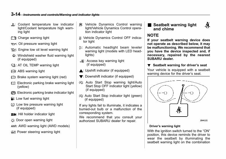
Black plate (158,1)
一般Model "A1300GE-A" EDITED: 2016/ 9/ 13
3-14 Instruments and controls/Warning and indicator lights
: Coolant temperature low indicatorlight/Coolant temperature high warn-ing light
: Charge warning light
: Oil pressure warning light
: Engine low oil level warning light
: Windshield washer fluid warning light(if equipped)
: AT OIL TEMP warning light
: ABS warning light
: Brake system warning light (red)
: Electronic parking brake warning light(yellow)
: Electronic parking brake indicator light
: Low fuel warning light
: Low tire pressure warning light(if equipped)
: Hill holder indicator light
: Door open warning light
: AWD warning light (AWD models)
: Power steering warning light
: Vehicle Dynamics Control warninglight/Vehicle Dynamics Control opera-tion indicator light
: Vehicle Dynamics Control OFF indica-tor light
: Automatic headlight beam levelerwarning light (models with LED head-lights)
: Access key warning light(if equipped)
: Upshift indicator (if equipped)
: Downshift indicator (if equipped)
: Auto Start Stop warning light/AutoStart Stop OFF indicator light (yellow)(if equipped)
: Auto Start Stop indicator light (green)(if equipped)
If any lights fail to illuminate, it indicates aburned-out bulb or a malfunction of thecorresponding system.We recommend that you consult yourauthorized SUBARU dealer for repair.
& Seatbelt warning lightand chime
NOTEIf your seatbelt warning device doesnot operate as described below, it maybe malfunctioning. We recommend thatyou have the device inspected and, ifnecessary, repaired by the nearestSUBARU dealer.
! Seatbelt warning for driver’s seat
Your vehicle is equipped with a seatbeltwarning device for the driver’s seat.
Driver’s warning light
With the ignition switch turned to the “ON”position, this device reminds the driver towear the seatbelt by illuminating theseatbelt warning light on the combination

Black plate (159,1)
一般Model "A1300GE-A" EDITED: 2016/ 9/ 13
meter.If the vehicle is driven at a speed nohigher than approximately 20 km/h (12.5mph) with the driver’s seatbelt not fas-tened, the warning light will illuminatecontinuously.If the vehicle subsequently reaches aspeed of approximately 20 km/h (12.5mph) with the driver’s seatbelt not fas-tened, the warning light will flash and thechime will sound. If the seatbelt is fas-tened at this time, the warning light willturn off and the chime will stop soundingimmediately.This condition will continue for approxi-mately 2 minutes. If the driver’s seatbelt isstill not fastened when the 2-minute periodhas elapsed, the warning light will stopflashing and the chime will stop sounding.The warning light, however, will remainilluminated continuously unless the seat-belt is fastened.
! Seatbelt warning for front passen-ger’s seat (if equipped)
Your vehicle is equipped with a seatbeltwarning device for the front passenger’sseat.
Front passenger’s warning light
With the ignition switch turned to the “ON”position, this device reminds the frontpassenger to fasten his/her seatbelt byilluminating a warning light as shown inthe illustration.If the vehicle is driven at a speed nohigher than approximately 20 km/h (12.5mph) with the front passenger’s seatbeltnot fastened, the warning light(s) corre-sponding to the unfastened seatbelt(s) willilluminate continuously.If the vehicle subsequently reaches aspeed of approximately 20 km/h (12.5
mph) with the front passenger’s seatbeltnot fastened, the warning light will flashand the chime will sound.If the seatbelt is fastened at this time, thewarning light will turn off and the chime willstop sounding immediately.
WARNING
. The occupant detection systemmay not detect a passenger un-der the following circumstances.
– When cushions, etc., are used
– When a child or small adult issitting in the seat
. Observe the following precau-tions. Failure to do so may pre-vent the front passenger’s SRSfrontal airbag from functioningcorrectly or cause the system tofail.
– Do not apply any strong im-pact to the front passenger’sseat.
– Do not let rear passengersrest their feet between thefront seatback and seat cush-ion.
– Do not insert objects betweenthe front seatback and seatcushion.
Instruments and controls/Warning and indicator lights 3-15
– CONTINUED –
3

Black plate (160,1)
一般Model "A1300GE-A" EDITED: 2016/ 9/ 13
3-16 Instruments and controls/Warning and indicator lights
– Do not spill liquid on the frontpassenger’s seat. If liquid isspilled, wipe it off immedi-ately.
– Do not remove or disassem-ble the front passenger’s seat.
– Do not place any objects(shoes, umbrella, etc.) underthe front passenger’s seat.
NOTE. If the driver’s and front passenger’sseatbelts are not fastened simulta-neously (if one seatbelt is fastenedsignificantly earlier or later than theother), the buzzer may sound longer(10 seconds maximum).. The occupant detection system ofthe front passenger’s seat detects if theseat is occupied by a passenger. How-ever, if there is an object on the seat,the seatbelt warning system may beactivated even the seat is not occupied.
If the front passenger’s seatbelt is still notfastened when the 2-minute period haselapsed, the warning light will stop flash-ing and the chime will stop sounding. Thewarning light, however, will remain illumi-nated continuously unless the corre-sponding seatbelt is fastened.
& Rear seatbelt indicator lightand chime (Europe and Aus-tralia models)
1) Rear seat (left position)2) Rear seat (center position)3) Rear seat (right position)
This indicator light is located as shown inthe illustration. It illuminates to show onlythe seating positions in which seatbeltshave not been fastened.
WARNING
. The occupant detection systemmay not detect passenger(s) un-der the following circumstances.
– When cushions, etc., are used
– When a child or small adult is
sitting in the seat
. Observe the following precau-tions.
– Do not apply any strong im-pact to the rear seat.
– Do not fold the seatback for-ward when objects are on theseat.
– Do not spill liquid on the rearseat. If liquid is spilled, wipe itoff immediately.
– Do not remove or disassem-ble the rear seat.
NOTEThe occupant detection system of therear seat detects if the seat is occupiedby a passenger. However, if there is anobject on the seat, the seatbelt warningsystem may be activated even the seatis not occupied.

Black plate (161,1)
一般Model "A1300GE-A" EDITED: 2016/ 9/ 13
& SRS airbag systemwarning light
WARNING
If the warning light exhibits any ofthe following conditions, there maybe a malfunction in the seatbeltpretensioners and/or SRS airbagsystem. We recommend that youhave the system checked immedi-ately by your nearest SUBARU deal-er. Unless checked and properlyrepaired, the seatbelt pretensionersand/or SRS airbags will operateimproperly (e.g. SRS airbags mayinflate in a very minor collision ornot inflate in a severe collision),which may increase the risk ofinjury.
. Flashing or flickering of the warn-ing light
. No illumination of the warninglight when the ignition switch isfirst turned to the “ON” position
. Continuous illumination of thewarning light
. Illumination of the warning lightwhile driving
For details about the components mon-itored by the warning light, refer to “SRSairbag system monitor” F1-76.
& Front passenger’s frontalairbag ON and OFF indica-tors (if equipped)
: Front passenger’s frontal airbag ONindicator
: Front passenger’s frontal airbag OFFindicator
The indicators are located as shown in theillustration. The front passenger’s frontalairbag ON and OFF indicators show youthe status of the front passenger’s SRSfrontal airbag.When the ignition switch is turned to the“ON” position, both the ON and OFFindicators illuminate for 6 seconds during
which time the system is checked. Follow-ing the system check, both indicators turnoff for 2 seconds. After that, one of theindicators illuminates depending on thestatus of the front passenger’s SRS frontalairbag determined by the frontal airbagsystem monitoring.
If the front passenger’s SRS frontal airbagis activated, the passenger’s frontal airbagON indicator will illuminate while the OFFindicator will remain off.If the front passenger’s SRS frontal airbagis deactivated, the passenger’s frontalairbag ON indicator will remain off whilethe OFF indicator will illuminate.
With the ignition switch turned to the “ON”position, if both the ON and OFF indica-tors remain illuminated or off simulta-neously even after the system checkperiod, the system is malfunctioning. Werecommend that you contact yourSUBARU dealer immediately for an in-spection.
Instruments and controls/Warning and indicator lights 3-17
– CONTINUED –
3

Black plate (162,1)
一般Model "A1300GE-A" EDITED: 2016/ 9/ 13
3-18 Instruments and controls/Warning and indicator lights
& Malfunction indicatorlight (Check Enginelight)
! Models equipped with OBD system
Vehicles sold in Europe are equipped withan enhanced on-board diagnostics sys-tem called OBD that monitors the perfor-mance of the vehicle’s emission controlsystem.Vehicles sold in some countries outsideEurope may be equipped with the OBDsystem. We recommend that you ask yourSUBARU dealer to ascertain whether yourvehicle has the OBD system.
The OBD system helps to protect theenvironment by ensuring that emissionsare at acceptable levels for the life of thevehicle.
If the malfunction indicator light illuminatessteadily or blinks while the engine isrunning, it may indicate that there is aproblem or potential problem somewherein the emission control system and thatservice is required. The OBD system alsoassists your service technician in properlydiagnosing any malfunction.
CAUTION
If the malfunction indicator lightilluminates while you are driving,we recommend that you have yourvehicle checked/repaired by yourSUBARU dealer as soon as possi-ble. Continued vehicle operationwithout having the emission controlsystem checked and repaired asnecessary could cause serious da-mage, which may not be covered byyour vehicle’s warranty.
! If the light illuminates steadily
If the light illuminates steadily while drivingor does not turn off after the engine starts,an emission control system malfunctionhas been detected.
We recommend that you have yourvehicle checked by an authorizedSUBARU dealer immediately.
! If the light is blinking
If the light is blinking while driving, anengine misfire condition has been de-tected which may damage the emissioncontrol system.
To prevent serious damage to the emis-sion control system, you should do thefollowing.
. Reduce vehicle speed.
. Avoid hard acceleration.
. Avoid steep uphill grades.
. Reduce the amount of cargo, if possi-ble.. Stop towing a trailer as soon aspossible (5-door models).
The malfunction indicator light may stopblinking and illuminate steadily after sev-eral driving trips. We recommend that youhave your vehicle checked by an author-ized SUBARU dealer immediately.
! Models NOT equipped with OBDsystem
If the malfunction indicator light illuminateswhen the engine is running, it may indicatethat there is a problem somewhere in theengine control system.If the light illuminates while driving or doesnot turn off after the engine starts, werecommend that you contact your nearestSUBARU dealer immediately.
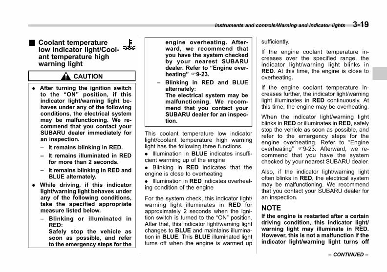
Black plate (163,1)
一般Model "A1300GE-A" EDITED: 2016/ 9/ 13
& Coolant temperaturelow indicator light/Cool-ant temperature highwarning light
CAUTION
. After turning the ignition switchto the “ON” position, if thisindicator light/warning light be-haves under any of the followingconditions, the electrical systemmay be malfunctioning. We re-commend that you contact yourSUBARU dealer immediately foran inspection.
– It remains blinking in RED.
– It remains illuminated in REDfor more than 2 seconds.
– It remains blinking in RED andBLUE alternately.
. While driving, if this indicatorlight/warning light behaves underany of the following conditions,take the specified appropriatemeasure listed below.
– Blinking or illuminated inRED:Safely stop the vehicle assoon as possible, and referto the emergency steps for the
engine overheating. After-ward, we recommend thatyou have the system checkedby your nearest SUBARUdealer. Refer to “Engine over-heating” F9-23.
– Blinking in RED and BLUEalternately:The electrical system may bemalfunctioning. We recom-mend that you contact yourSUBARU dealer for an inspec-tion.
This coolant temperature low indicatorlight/coolant temperature high warninglight has the following three functions.. Illumination in BLUE indicates insuffi-cient warming up of the engine. Blinking in RED indicates that theengine is close to overheating. Illumination in RED indicates overheat-ing condition of the engine
For the system check, this indicator light/warning light illuminates in RED forapproximately 2 seconds when the igni-tion switch is turned to the “ON” position.After that, this indicator light/warning lightchanges to BLUE and maintains illumina-tion in BLUE. This BLUE illuminated lightturns off when the engine is warmed up
sufficiently.
If the engine coolant temperature in-creases over the specified range, theindicator light/warning light blinks inRED. At this time, the engine is close tooverheating.
If the engine coolant temperature in-creases further, the indicator light/warninglight illuminates in RED continuously. Atthis time, the engine may be overheating.
When the indicator light/warning lightblinks in RED or illuminates in RED, safelystop the vehicle as soon as possible, andrefer to the emergency steps for theengine overheating. Refer to “Engineoverheating” F9-23. Afterward, we re-commend that you have the systemchecked by your nearest SUBARU dealer.
Also, if the indicator light/warning lightoften blinks in RED, the electrical systemmay be malfunctioning. We recommendthat you contact your SUBARU dealer foran inspection.
NOTEIf the engine is restarted after a certaindriving condition, this indicator light/warning light may illuminate in RED.However, this is not a malfunction if theindicator light/warning light turns off
Instruments and controls/Warning and indicator lights 3-19
– CONTINUED –
3
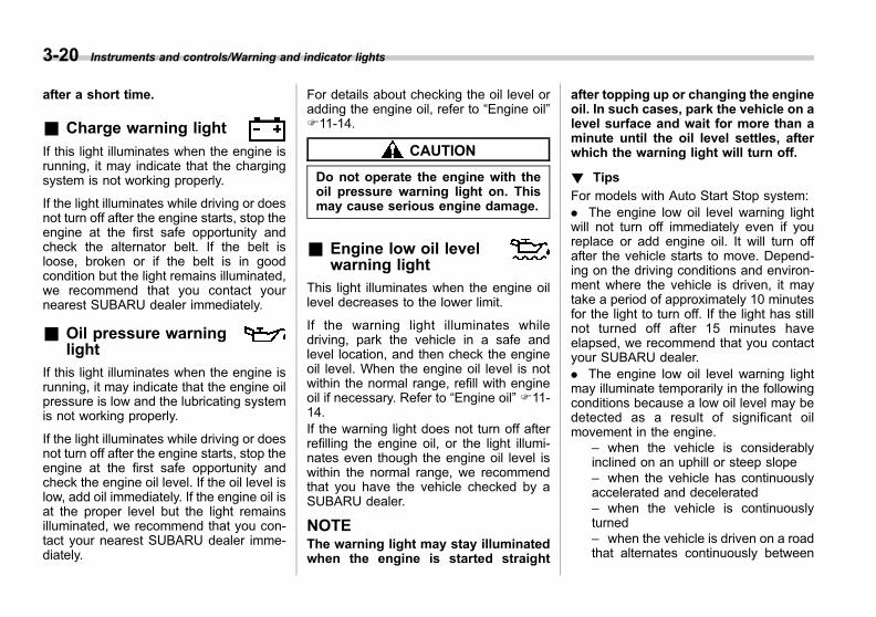
Black plate (164,1)
一般Model "A1300GE-A" EDITED: 2016/ 9/ 13
3-20 Instruments and controls/Warning and indicator lights
after a short time.
& Charge warning light
If this light illuminates when the engine isrunning, it may indicate that the chargingsystem is not working properly.
If the light illuminates while driving or doesnot turn off after the engine starts, stop theengine at the first safe opportunity andcheck the alternator belt. If the belt isloose, broken or if the belt is in goodcondition but the light remains illuminated,we recommend that you contact yournearest SUBARU dealer immediately.
& Oil pressure warninglight
If this light illuminates when the engine isrunning, it may indicate that the engine oilpressure is low and the lubricating systemis not working properly.
If the light illuminates while driving or doesnot turn off after the engine starts, stop theengine at the first safe opportunity andcheck the engine oil level. If the oil level islow, add oil immediately. If the engine oil isat the proper level but the light remainsilluminated, we recommend that you con-tact your nearest SUBARU dealer imme-diately.
For details about checking the oil level oradding the engine oil, refer to “Engine oil”F11-14.
CAUTION
Do not operate the engine with theoil pressure warning light on. Thismay cause serious engine damage.
& Engine low oil levelwarning light
This light illuminates when the engine oillevel decreases to the lower limit.
If the warning light illuminates whiledriving, park the vehicle in a safe andlevel location, and then check the engineoil level. When the engine oil level is notwithin the normal range, refill with engineoil if necessary. Refer to “Engine oil” F11-14.If the warning light does not turn off afterrefilling the engine oil, or the light illumi-nates even though the engine oil level iswithin the normal range, we recommendthat you have the vehicle checked by aSUBARU dealer.
NOTEThe warning light may stay illuminatedwhen the engine is started straight
after topping up or changing the engineoil. In such cases, park the vehicle on alevel surface and wait for more than aminute until the oil level settles, afterwhich the warning light will turn off.
! Tips
For models with Auto Start Stop system:. The engine low oil level warning lightwill not turn off immediately even if youreplace or add engine oil. It will turn offafter the vehicle starts to move. Depend-ing on the driving conditions and environ-ment where the vehicle is driven, it maytake a period of approximately 10 minutesfor the light to turn off. If the light has stillnot turned off after 15 minutes haveelapsed, we recommend that you contactyour SUBARU dealer.. The engine low oil level warning lightmay illuminate temporarily in the followingconditions because a low oil level may bedetected as a result of significant oilmovement in the engine.
– when the vehicle is considerablyinclined on an uphill or steep slope– when the vehicle has continuouslyaccelerated and decelerated– when the vehicle is continuouslyturned– when the vehicle is driven on a roadthat alternates continuously between
Black plate (165,1)
一般Model "A1300GE-A" EDITED: 2016/ 9/ 13
uphill and downhill
For models without Auto Start Stopsystem:. The engine low oil level warning lightturns off when the ignition switch is turnedto the “LOCK”/“OFF” position. However,after the next time you turn on the engine,if the engine oil level has decreased to thelower limit, the warning light illuminatesfrequently while the engine is running.. When the vehicle is considerably in-clined on an uphill or steep slope, thewarning light may illuminate temporarilydue to the movement of engine oil in theengine.
& AT OIL TEMP warninglight
If this light illuminates when the engine isrunning, it may indicate that the transmis-sion fluid temperature is too hot.
If the light illuminates while driving, im-mediately stop the vehicle in a safelocation and let the engine idle until thewarning light turns off.
! Transmission control system warn-ing
If the “AT OIL TEMP” warning light flashesafter the engine has started, it mayindicate that the transmission control
system is not working properly. We re-commend that you contact your nearestSUBARU dealer for service immediately.
& Low tire pressurewarning light (ifequipped)
When the ignition switch is turned to the“ON” position, the low tire pressure warn-ing light will illuminate for approximately 2seconds to check that the tire pressuremonitoring system (TPMS) is functioningproperly. If the system functions normallyand the tire pressure of all four wheels isappropriate for the selected TPMS mode,the warning light will turn off. The TPMSmode should be changed according to thespecified pressure shown on the tireinflation pressure label. For how to changea mode and information about the mode tobe selected, refer to “Tire pressure mon-itoring system (TPMS)” F11-25.Each tire, including the spare (if provided),should be checked monthly when coldand inflated to the inflation pressurerecommended by the vehicle manufac-turer on the vehicle placard or tire inflationpressure label. (If your vehicle has tires ofa different size than the size indicated onthe vehicle placard or tire inflation pres-sure label, you should determine theproper tire inflation pressure for those
tires.)
As an added safety feature, your vehiclehas been equipped with a tire pressuremonitoring system (TPMS) that illuminatesa low tire pressure telltale when one ormore of your tires is significantly under-inflated. Accordingly, when the low tirepressure telltale illuminates, you shouldstop and check your tires as soon aspossible, and inflate them to the properpressure. Driving on a significantly under-inflated tire causes the tire to overheat andcan lead to tire failure. Under-inflation alsoreduces fuel efficiency and tire tread life,and may affect the vehicle’s handling andstopping ability.Please note that the TPMS is not asubstitute for proper tire maintenance,and it is the driver’s responsibility tomaintain correct tire pressure, even ifunder-inflation has not reached the levelto trigger illumination of the TPMS low tirepressure telltale.Your vehicle has also been equipped witha TPMS malfunction indicator to indicatewhen the system is not operating properly.The TPMS malfunction indicator is com-bined with the low tire pressure telltale.When the system detects a malfunction,the telltale will flash for approximately oneminute and then remain continuouslyilluminated. This sequence will continue
Instruments and controls/Warning and indicator lights 3-21
– CONTINUED –
3

Black plate (166,1)
一般Model "A1300GE-A" EDITED: 2016/ 9/ 13
3-22 Instruments and controls/Warning and indicator lights
upon subsequent vehicle start-ups as longas the malfunction exists. When themalfunction indicator is illuminated, thesystem may not be able to detect or signallow tire pressure as intended. TPMSmalfunctions may occur for a variety ofreasons, including the installation of re-placement or alternate tires or wheels onthe vehicle that prevent the TPMS fromfunctioning properly. Always check theTPMS malfunction telltale after replacingone or more tires or wheels on yourvehicle to ensure that the replacement oralternate tires and wheels allow the TPMSto continue to function properly.Should the warning light illuminate stea-dily after blinking for approximately oneminute, we recommend that you have thesystem inspected by your nearestSUBARU dealer as soon as possible.
WARNING
If this light does not illuminatebriefly after the ignition switch isturned ON or the light illuminatessteadily after blinking for approxi-mately one minute, we recommendthat you have your Tire PressureMonitoring System checked at aSUBARU dealer as soon as possi-ble.
If this light illuminates while driving,never brake suddenly and keepdriving straight ahead while gradu-ally reducing speed. Then slowlypull off the road to a safe place.Otherwise an accident involvingserious vehicle damage and seriouspersonal injury could occur.
If this light still illuminates whiledriving after adjusting the tire pres-sure, a tire may have significantdamage and a fast leak that causesthe tire to lose air rapidly. If you havea flat tire, replace it with a spare tireas soon as possible.
When a spare tire is mounted or awheel rim is replaced without theoriginal pressure sensor/transmitterbeing transferred, the Low tire pres-sure warning light will illuminatesteadily after blinking for approxi-mately one minute. This indicatesthe TPMS is unable to monitor allfour road wheels. We recommendthat you contact your SUBARU deal-er as soon as possible for tire andsensor replacement and/or systemresetting.
If the light illuminates steadily afterblinking for approximately one min-ute, we recommend that youpromptly contact a SUBARU dealer
to have the system inspected.
CAUTION
The tire pressure monitoring systemis NOT a substitute for manuallychecking tire pressure. The tirepressure should be checked peri-odically (at least monthly) using atire gauge. Change the TPMS modeaccording to the specified pressureshown on the tire inflation pressurelabel. After any change to tire pres-sure(s), the tire pressure monitoringsystem will not re-check tire infla-tion pressures until the vehicle isfirst driven more than 40 km/h (25mph). After adjusting the tire pres-sures, increase the vehicle speed toat least 40 km/h (25 mph) to start theTPMS re-checking of the tire infla-tion pressures. If the tire pressuresare now above the severe lowpressure threshold, the low tirepressure warning light should turnoff a few minutes later. Therefore, besure to install the specified size forthe front and rear tires.
Black plate (167,1)
一般Model "A1300GE-A" EDITED: 2016/ 9/ 13
& ABS warning light
CAUTION
. If any of the following conditionsoccur, we recommend that youhave the ABS system repaired atthe first available opportunity byyour SUBARU dealer.
– The warning light does notilluminate when the ignitionswitch is turned to the “ON”position.
– The warning light illuminateswhen the ignition switch isturned to the “ON” position,but it does not turn off evenafter the vehicle is started.
– The warning light illuminatesduring driving.
. When the warning light is on (andthe brake system warning light isoff), the ABS function shutsdown. However, the conventionalbrake system continues to oper-ate normally.
The ABS warning light illuminates to-gether with the brake system warning lightif the EBD system malfunctions. Forfurther details of the EBD system mal-
function warning, refer to “ElectronicBrake Force Distribution (EBD) systemwarning” F3-25.
NOTEIf the warning light behavior is asshown in the following, the ABS sys-tem may be considered normal.. The warning light illuminates whenthe ignition switch is turned to the“ON” position and turns off approxi-mately 2 seconds after the engine hasstarted.. The warning light illuminates rightafter the engine is started but turns offimmediately, remaining off.. The warning light remains illumi-nated after the engine has been started,but it turns off during driving.. The warning light illuminates duringdriving, but it turns off immediately andremains off.
When driving with an insufficient batteryvoltage such as when the engine is jumpstarted, the ABS warning light may illumi-nate. This is due to the low battery voltageand does not indicate a malfunction.When the battery becomes fully charged,the light will turn off.
& Vehicle DynamicsControl warning light/Vehicle Dynamics Con-trol operation indicatorlight
! Vehicle Dynamics Control warninglight
CAUTION
The Vehicle Dynamics Control sys-tem provides its ABS controlthrough the electrical circuit of theABS system. Accordingly, if the ABSis inoperative, the Vehicle DynamicsControl system becomes unable toprovide ABS control. As a result, theVehicle Dynamics Control systembecomes inoperative, causing thewarning light to illuminate. Althoughboth the Vehicle Dynamics Controland ABS systems are inoperative inthis case, the ordinary functions ofthe brake system are still available.
Instruments and controls/Warning and indicator lights 3-23
– CONTINUED –
3
Black plate (168,1)
一般Model "A1300GE-A" EDITED: 2016/ 9/ 13
3-24 Instruments and controls/Warning and indicator lights
You will be safe while driving withthis condition, but drive carefullyand we recommend that you haveyour vehicle checked at a SUBARUdealer as soon as possible.
NOTE. If the electrical circuit of the VehicleDynamics Control system itself mal-functions, the warning light only illumi-nates. At this time, the ABS (Anti-lockBrake System) remains fully opera-tional.. The warning light illuminates whenthe electronic control system of theABS/Vehicle Dynamics Control systemmalfunctions.
The Vehicle Dynamics Control system isprobably inoperative under any of thefollowing conditions. We recommend thatyou have your vehicle checked at aSUBARU dealer immediately.. The warning light does not illuminatewhen the ignition switch is turned to the“ON” position.. The warning light illuminates while thevehicle is running.
NOTEIf the warning light behavior is asdescribed in the following examples,the Vehicle Dynamics Control systemmay be considered normal.. The warning light illuminates whenthe ignition switch is turned to the“ON” position and turns off approxi-mately 2 seconds after the engine hasstarted.. The warning light illuminates rightafter the engine is started but turns offimmediately and remains off.. The warning light illuminates afterthe engine has started and turns offwhile the vehicle is subsequently beingdriven.. The warning light illuminates duringdriving, but turns off immediately andremains off.. The warning light illuminates whenthe engine has stalled and continues toilluminate after the engine has beenrestarted. However, it will turn off oncethe vehicle starts moving.
! Vehicle Dynamics Control opera-tion indicator light
The indicator light flashes during activa-tion of the skid suppression function andduring activation of the traction controlfunction.
NOTE. The light may remain illuminated fora short period of time after the enginehas been started, especially in coldweather. This does not indicate theexistence of a problem. The lightshould turn off as soon as the enginehas warmed up.. The indicator light illuminates whenthe engine has developed a malfunc-tion and the malfunction indicator light/CHECK ENGINE warning light is on.
The Vehicle Dynamics Control system isprobably malfunctioning under the follow-ing condition. We recommend that youhave your vehicle checked at a SUBARUdealer as soon as possible.. The light does not turn off even afterthe lapse of several minutes (the enginehas warmed up) after the engine hasstarted.
& Vehicle DynamicsControl OFF indicatorlight
The light illuminates when the VehicleDynamics Control OFF switch is pressedto deactivate the Vehicle Dynamics Con-trol system.
The Vehicle Dynamics Control system isprobably malfunctioning under any of the

Black plate (169,1)
一般Model "A1300GE-A" EDITED: 2016/ 9/ 13
following conditions. We recommend thatyou have your vehicle checked at aSUBARU dealer immediately.. The light does not illuminate when theignition switch is turned to the “ON”position.. The light does not turn off even after aperiod of approximately 2 seconds afterthe ignition switch has been turned to the“ON” position.
& Brake system warninglight (red)
WARNING
. Driving with the brake systemwarning light on is dangerous.This indicates your brake systemmay not be working properly. Ifthe light remains illuminated, werecommend that you have thebrakes inspected by a SUBARUdealer immediately.
. If at all in doubt about whetherthe brakes are operating prop-erly, do not drive the vehicle. Werecommend that you have yourvehicle towed to the nearestSUBARU dealer for repair.
The brake system warning light has the
following functions.
! Brake fluid level warning
The light illuminates when the brake fluidlevel has dropped to near the “MIN” levelof the brake fluid reservoir with the ignitionswitch in the “ON” position and with theparking brake fully released.
If the light should illuminate while driving(with the parking brake fully released andwith the ignition switch positioned in“ON”), it could be an indication of leakingof brake fluid or worn brake pads. If thisoccurs, immediately stop the vehicle at thenearest safe location and check the brakefluid level. For details, refer to “Brake fluid”F11-22. If the fluid level is below the“MIN” mark in the reservoir, do not drivethe vehicle. We recommend that you havethe vehicle towed to the nearest SUBARUdealer for repair. For details, refer to“Towing” F9-24.
! Electronic Brake Force Distribution(EBD) system warning
The EBD system may be malfunctioning ifthe brake system warning light, VehicleDynamics Control warning light and ABSwarning light illuminate simultaneouslyduring driving.
Even if the EBD system fails, the conven-tional braking system will still function.
However, the rear wheels will be moreprone to locking when the brakes areapplied harder than usual and the vehi-cle’s motion may therefore become some-what harder to control.
If the brake system warning light, VehicleDynamics Control warning light and ABSwarning light illuminate simultaneously,take the following steps.1. Stop the vehicle in the nearest safe,flat location.2. Shut down the engine, apply theparking brake, and then restart it.3. Fully release the parking brake.4. Even if all the warning lights do notcome back on, the EBD system may havea possible malfunction. Drive carefully tothe nearest SUBARU dealer and have thesystem inspected.5. If all the warning lights stay illuminatedor come back on after approximately 2seconds, shut down the engine, apply theparking brake and check the brake fluidlevel. For details, refer to “Brake fluid”F11-22.
. If the brake fluid level is not below the“MIN” mark, the EBD system may bemalfunctioning. We recommend that youdrive carefully to the nearest SUBARUdealer and have the system inspected.
Instruments and controls/Warning and indicator lights 3-25
– CONTINUED –
3

Black plate (170,1)
一般Model "A1300GE-A" EDITED: 2016/ 9/ 13
3-26 Instruments and controls/Warning and indicator lights
. If the brake fluid level is below the“MIN” mark, DO NOT drive the vehicle.Instead, we recommend that you have thevehicle towed to the nearest SUBARUdealer for repair. For details, refer to“Towing” F9-24.
& Electronic parkingbrake warning light/Va-cuum pressure systemwarning light (yellow)
This light illuminates when the electronicparking brake system is malfunctioning.
WARNING
When the electronic parking brakewarning light illuminates, immedi-ately stop the vehicle in a safelocation and we recommend thatyou contact your SUBARU dealer.
NOTE. If the warning light behaves asdescribed in the following conditions,the electronic parking brake system isoperating normally.
– The warning light remains illumi-nated after the engine is started, butit turns off after the electronicparking brake is released, and thewarning light remains off.
– The warning light illuminatesduring driving, but it turns off andremains off.
. If you start the engine while operat-ing the electronic parking brake switch,the electronic parking brake warninglight may illuminate. In this case,restart the engine and then operatethe electronic parking brake switch. Ifthe warning light turns off, the systemmay be considered normal.
! Vacuum pressure system warning
The vacuum pressure system warninglight will illuminate when the vacuumpressure sensor is malfunctioning orbrake booster pressure is decreasing. Ifthe vacuum pressure system warning lightcontinues to illuminate for several minutesafter starting the engine, there may be amalfunction in the vacuum system. In thiscase, drive the vehicle carefully and havethe system inspected by a SUBARUdealer.
& Electronic parkingbrake indicator light
This light illuminates while the electronicparking brake is applied. If you operate theelectronic parking brake switch while theelectronic parking brake cannot be oper-ated, this light flashes for approximately
10 seconds. When the electronic parkingbrake system is malfunctioning, this lightmay flash.
WARNING
. When the electronic parkingbrake indicator light continuesto flash, the electronic parkingbrake system may malfunction(excluding when the vehicle wasstopped on a steep up/downhillslope, or when the electric park-ing brake was applied at highbrake temperature). Immediatelystop the vehicle in a safe locationand we recommend that youcontact your SUBARU dealer.
. When the electronic parkingbrake indicator light does notturn off even if you release theelectronic parking brake whilethe engine is running, immedi-ately stop the vehicle in a safelocation, we recommend that youcontact your SUBARU dealer andhave the electronic parking brakesystem inspected.
Black plate (171,1)
一般Model "A1300GE-A" EDITED: 2016/ 9/ 13
& Low fuel warning light
The low fuel warning light illuminateswhen the tank is nearly empty, at approxi-mately 7.5 liters (2 US gal, 1.65 Imp gal). Itonly operates when the ignition switch isin the “ON” position. When this lightilluminates, fill the fuel tank immediately.
NOTEThis light does not turn off unless thetank is replenished up to an internalfuel quantity of approximately 8.1 liters(2.1 US gal, 1.8 Imp gal).
CAUTION
Promptly put fuel in the tank when-ever the low fuel warning lightilluminates. Engine misfires as aresult of an empty tank could causedamage to the engine.
& Windshield washerfluid warning light
This light illuminates when the fluid level inthe windshield washer fluid tank de-creases to the lower limit (approximately0.6 liter, 0.6 US qt, 0.5 Imp qt).
& Hill Holder indicatorlight
WARNING
If the Hill Holder indicator light doesnot illuminate even when the HillHolder switch is pressed to activatethe Hill Holder function, the electro-nic parking brake system may bemalfunctioning. Immediately stopthe vehicle in a safe location. Werecommend that you contact yourSUBARU dealer immediately.
The light illuminates when the Hill Holderswitch is pressed to activate the HillHolder function. For details about the HillHolder function, refer to “Hill Holderfunction” F7-29.
& Door open warninglight
The warning light illuminates if any door,rear gate (5-door models) or trunk lid (4-door models) is not fully closed. Thisfunction is effective even if the ignitionswitch is in the “LOCK”/“OFF” or “ACC”position, or the key is removed from theignition switch.
Always make sure this light is not illumi-
nated before you start to drive.
& All-Wheel Drive warn-ing light (AWD models)
CAUTION
Continuing to drive with the AWDwarning light flashing can damagethe powertrain. If the AWD warninglight starts to flash, promptly park ina safe place and check whether thetires have differing diameters andwhether any of the tires has anexcessively low inflation pressure.
NOTEIf the temporary spare tire is used, theAWD warning light may flash. Use ofthe temporary spare tire should there-fore be restricted to the minimum timenecessary. Replace the temporaryspare tire with a conventional tire assoon as possible.
This light flashes if the vehicle is drivenwith tires of different diameters fitted on itswheels or with the air pressure exces-sively low in any of its tires.
Instruments and controls/Warning and indicator lights 3-27
– CONTINUED –
3

Black plate (172,1)
一般Model "A1300GE-A" EDITED: 2016/ 9/ 13
3-28 Instruments and controls/Warning and indicator lights
& Power steering warn-ing light
While the engine is running, this warninglight illuminates when a malfunction hasbeen detected in the electric power steer-ing system.
CAUTION
When the power steering warninglight is illuminated, there may bemore resistance when the steeringwheel is operated. We recommendthat you drive carefully to the near-est SUBARU dealer and have thevehicle inspected immediately.
NOTEIf the steering wheel is operated in thefollowing ways, the power steeringcontrol system may temporarily limitthe power assist in order to prevent thesystem components, such as the con-trol computer and drive motor, fromoverheating.. The steering wheel is operated fre-quently and turned sharply while thevehicle is maneuvered at extremely lowspeeds, such as while frequently turn-ing the steering wheel during parallelparking.
. The steering wheel remains in thefully turned position for a long periodof time.
At this time, there will be more resis-tance when steering. However this isnot a malfunction. Normal steeringforce will be restored after the steeringwheel is not operated for a while andthe power steering control system hasan opportunity to cool down. However,if the power steering is operated in anon-standard way which causes powerassist limitation to occur too fre-quently, this may result in a malfunc-tion of the power steering controlsystem.
& Automatic headlightbeam leveler warninglight (models with LEDheadlights)
This light illuminates when the automaticheadlight beam leveler does not operatenormally.If this light illuminates while driving, werecommend that you have your vehicleinspected at your SUBARU dealer.
& LED headlight warninglight (models with LEDheadlights)
This light illuminates if the LED headlightsmalfunction. We recommend that youhave your vehicle inspected at a SUBARUdealer as soon as possible.
& Steering ResponsiveHeadlight warning light/Steering ResponsiveHeadlight OFF indicatorlight (if equipped)
This light illuminates when the SteeringResponsive Headlight OFF switch ispressed to deactivate the Steering Re-sponsive Headlight. Also, the light flasheswhen a malfunction occurs in the SteeringResponsive Headlight. Refer to “SteeringResponsive Headlight (SRH)” F3-77.
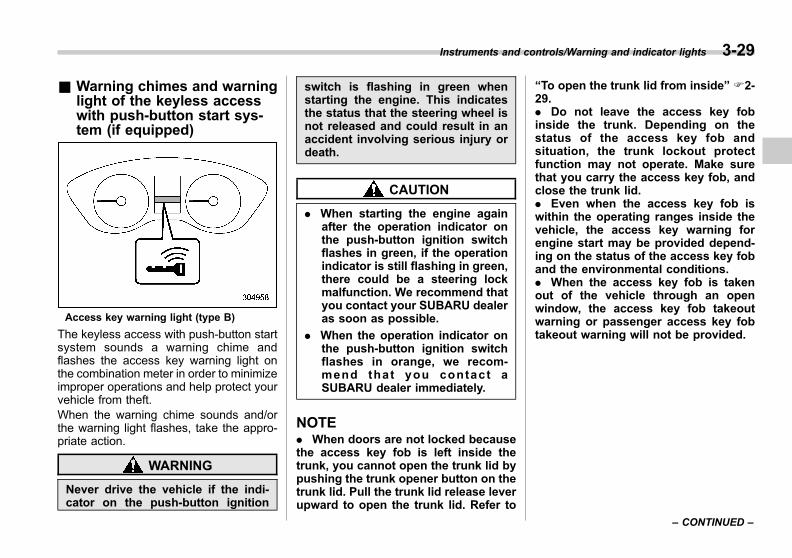
Black plate (173,1)
一般Model "A1300GE-A" EDITED: 2016/ 9/ 13
& Warning chimes and warninglight of the keyless accesswith push-button start sys-tem (if equipped)
Access key warning light (type B)
The keyless access with push-button startsystem sounds a warning chime andflashes the access key warning light onthe combination meter in order to minimizeimproper operations and help protect yourvehicle from theft.When the warning chime sounds and/orthe warning light flashes, take the appro-priate action.
WARNING
Never drive the vehicle if the indi-cator on the push-button ignition
switch is flashing in green whenstarting the engine. This indicatesthe status that the steering wheel isnot released and could result in anaccident involving serious injury ordeath.
CAUTION
. When starting the engine againafter the operation indicator onthe push-button ignition switchflashes in green, if the operationindicator is still flashing in green,there could be a steering lockmalfunction. We recommend thatyou contact your SUBARU dealeras soon as possible.
. When the operation indicator onthe push-button ignition switchflashes in orange, we recom-mend that you contact aSUBARU dealer immediately.
NOTE. When doors are not locked becausethe access key fob is left inside thetrunk, you cannot open the trunk lid bypushing the trunk opener button on thetrunk lid. Pull the trunk lid release leverupward to open the trunk lid. Refer to
“To open the trunk lid from inside” F2-29.. Do not leave the access key fobinside the trunk. Depending on thestatus of the access key fob andsituation, the trunk lockout protectfunction may not operate. Make surethat you carry the access key fob, andclose the trunk lid.. Even when the access key fob iswithin the operating ranges inside thevehicle, the access key warning forengine start may be provided depend-ing on the status of the access key foband the environmental conditions.. When the access key fob is takenout of the vehicle through an openwindow, the access key fob takeoutwarning or passenger access key fobtakeout warning will not be provided.
Instruments and controls/Warning and indicator lights 3-29
– CONTINUED –
3

Black plate (174,1)
一般Model "A1300GE-A" EDITED: 2016/ 9/ 13
3-30 Instruments and controls/Warning and indicator lights
! List of warnings
Inside warningchime
Outside warningchime
Operation indicatoron push-button igni-
tion switchStatus Action
Ding,ding ...
(intermittent)— —
The driver’s door was opened while thepush-button ignition switch is “ACC”(when the select lever is in the “P”position).
Switch the push-button ignition switch to“OFF”, or close the driver’s door.*When exiting the vehicle, be sure toswitch the push-button ignition switch to“OFF”.
The push-button ignition switch wasswitched to “OFF” while the driver’s dooris open.
Close the driver’s door.
Ding Short beep(2 seconds) —
Lockout warning:An attempt was made to lock all doorswhile the access key fob is left inside thevehicle.
Take out the access key fob from thevehicle, and lock the doors.*The doors cannot be locked while theaccess key fob is inside the vehicle.*A chirp sound will be heard, and alldoors will be unlocked.
— Short beep(2 seconds) —
Trunk lockout warning:The trunk was closed with the accesskey fob in it while all doors are locked (orduring the automatic lock time period) (4-door models).
Take out the access key fob from thetrunk, and close the trunk.*By pressing the trunk opener buttonafter this warning chime sounds, thetrunk can be unlocked.
Access key lock-in warning:The door lock sensor was touched whilethe push-button ignition switch is “OFF”and the access key fob is inside thevehicle.
Take out the access key fob from thevehicle, and lock the doors.*If the access key fob is inside thevehicle, the doors cannot be locked.
— Beep, beep ...(5 beeps) —
Door ajar warning:The door lock sensor is touched whilethe push-button ignition switch is in the“OFF” position and one of the doorsincluding the rear gate is opened.
Close the doors securely and lock them.*If one of the doors including the reargate is opened, the doors cannot belocked.
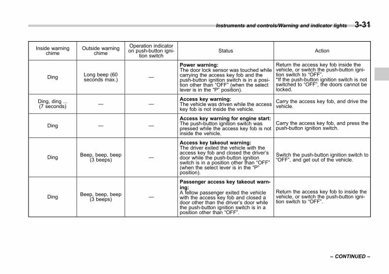
Black plate (175,1)
一般Model "A1300GE-A" EDITED: 2016/ 9/ 13
Inside warningchime
Outside warningchime
Operation indicatoron push-button igni-
tion switchStatus Action
Ding Long beep (60seconds max.) —
Power warning:The door lock sensor was touched whilecarrying the access key fob and thepush-button ignition switch is in a posi-tion other than “OFF” (when the selectlever is in the “P” position).
Return the access key fob inside thevehicle, or switch the push-button igni-tion switch to “OFF”.*If the push-button ignition switch is notswitched to “OFF”, the doors cannot belocked.
Ding, ding ...(7 seconds) — —
Access key warning:The vehicle was driven while the accesskey fob is not inside the vehicle.
Carry the access key fob, and drive thevehicle.
Ding — —
Access key warning for engine start:The push-button ignition switch waspressed while the access key fob is notinside the vehicle.
Carry the access key fob, and press thepush-button ignition switch.
Ding Beep, beep, beep(3 beeps) —
Access key takeout warning:The driver exited the vehicle with theaccess key fob and closed the driver’sdoor while the push-button ignitionswitch is in a position other than “OFF”(when the select lever is in the “P”position).
Switch the push-button ignition switch to“OFF”, and get out of the vehicle.
Ding Beep, beep, beep(3 beeps) —
Passenger access key takeout warn-ing:A fellow passenger exited the vehiclewith the access key fob and closed adoor other than the driver’s door whilethe push-button ignition switch is in aposition other than “OFF”.
Return the access key fob to inside thevehicle, or switch the push-button igni-tion switch to “OFF”.
Instruments and controls/Warning and indicator lights 3-31
– CONTINUED –
3

Black plate (176,1)
一般Model "A1300GE-A" EDITED: 2016/ 9/ 13
3-32 Instruments and controls/Warning and indicator lights
Inside warningchime
Outside warningchime
Operation indicatoron push-button igni-
tion switchStatus Action
Long beep(continuous)
Long beep(continuous) —
The driver exited the vehicle with theaccess key fob and closed the driver’sdoor while the push-button ignitionswitch is in a position other than “OFF”and the select lever is in a position otherthan the “P” position.
Shift the select lever to the “P” position,switch the push-button ignition switch to“OFF” (all models) and exit the vehicle.
Long beep(continuous) — —
Select lever position warning:The driver’s door was opened while thepush-button ignition switch is in a posi-tion other than “OFF” and the selectlever is in a position other than the “P”position.
Shift the select lever to the “P” position,switch the push-button ignition switch to“OFF” and exit the vehicle.
Long beep(continuous) — —
Select lever position warning:The engine is turned off by pressing thepush-button ignition switch while theselect lever is in a position other than the“P” position.
Shift the select lever to the “P” position orstart the engine.
Ding — — The battery of the access key fob is low. Replace the battery of the access keyfob.
Ding — Flashes in green(15 seconds max.)
Steering lock warning:The engine start procedure was per-formed, but the steering is still locked.
While turning the steering wheel rightand left lightly, depress the brake pedaland press the push-button ignitionswitch.
Ding — Flashes in orangeSystem malfunction warning:A malfunction was detected in the powersystem or steering lock.
We recommend that you contact aSUBARU dealer immediately and havethe vehicle inspected.
Black plate (177,1)
一般Model "A1300GE-A" EDITED: 2016/ 9/ 13
& Immobilizer indicatorlight
This light begins flashing under any of thefollowing conditions.
For models with “keyless access withpush-button start system”:. Immediately after the push-button igni-tion switch is turned to the “OFF” position.. Immediately after the driver’s door isopened or closed when all of the followingconditions are met.
– The push-button ignition switch is inthe “ON” or “ACC” position.– The access key fob is outside thevehicle.– The engine is not running.
In the event that the push-button ignitionswitch is pressed to turn it on or to startthe engine carrying an unauthorized key(for example, the key is unregistered orthe ID code does not match), the power isnot switched to “ON” and the immobilizerindicator light continues blinking.For models without “keyless accesswith push-button start system”:. Immediately after the key is pulled out.. Approximately 60 seconds after theignition switch is turned from the “ON”position to the “ACC” or “LOCK” position.
If the indicator light does not blink in theabove conditions, it may indicate thatimmobilizer system may be malfunction-ing. We recommend that you contact yournearest SUBARU dealer immediately.
In the event that an unauthorized key (forexample, an unauthorized duplicate) isused to start the engine, the immobilizerindicator light illuminates. For detailsabout the immobilizer system, refer to“Immobilizer” F2-15.
NOTE. The immobilizer indicator light re-mains off in the following conditions. Itmeans that the matching of the ID codeis completed and the immobilizer sys-tem is deactivated, and it does notindicate a malfunction.
Models with “keyless access withpush-button start system”:– while the engine is running– the push-button ignition switchhas been turned to the “ON” or“ACC” position and the driver’sdoor has not been opened or closed
Models without “keyless accesswith push-button start system”:– while the engine is running– when the ignition switch is in the
“ON” position– for approximately 60 secondsafter the ignition switch is turnedfrom the “ON” position to the“ACC” or “LOCK” position
. Even if a malfunction occurs, suchas the immobilizer indicator lightflashes irregularly, it will not affect thefunctionality of the immobilizer system.
Instruments and controls/Warning and indicator lights 3-33
– CONTINUED –
3

Black plate (178,1)
一般Model "A1300GE-A" EDITED: 2016/ 9/ 13
3-34 Instruments and controls/Warning and indicator lights
& Select lever/gear position in-dicator
Type A1) Upshift indicator2) Downshift indicator3) Gear position indicator
Type B1) Upshift indicator2) Downshift indicator3) Gear position indicator
This indicator shows the position of theselect lever.
When the manual mode (if equipped) isselected, the gear position indicator(which shows the current gear selection)and the upshift/downshift indicator lightup. Refer to “Selection of manual mode”F7-14.
! Gear shift indicator (if equipped)
When shifting up is recommended forgood fuel economy, the upshift indicatorblinks.When shifting down is recommended, thedownshift indicator blinks.
NOTE. The gear shift indicator cannot bedeactivated.. Usually, the gear shift indicator isguideline for driving more fuel-effi-ciency and it also may operate toprevent a possible engine stall at lowengine speed.. Also, the gear shift indicator oper-ates to prevent engine damage at highengine speed.
& Turn signal indicatorlights
These lights show the operation of the turnsignal or lane change signal.If the indicator lights do not blink or blinkrapidly, the turn signal bulb may be burnedout. Replace the bulb as soon as possible.Refer to “Front turn signal light andposition light (models with halogen head-lights)” F11-45 or “Rear combinationlights” F11-48.
& High beam indicatorlight
This light shows that the headlights are inthe high beam mode.This indicator light also illuminates whenthe headlight flasher is operated.

Black plate (179,1)
一般Model "A1300GE-A" EDITED: 2016/ 9/ 13
& High Beam Assist in-dicator light (green) (ifequipped)
This light illuminates when the High BeamAssist function is activated. For detailsabout the High Beam Assist function, referto “High Beam Assist function” F3-73.
& High Beam Assistwarning indicator (yel-low) (if equipped)
This warning indicator appears when theHigh Beam Assist function malfunctions.When this warning indicator appears, werecommend that you have your vehicleinspected by your SUBARU dealer.
& Cruise control indica-tor light (if equipped)
This light illuminates when the cruisecontrol main button is pressed to activatethe cruise control function. For details,refer to “To set cruise control” F7-36.If this light blinks, do not use the cruisecontrol. In addition, if it blinks frequently,we recommend that you contact yourSUBARU dealer for an inspection.
CAUTION
If the malfunction indicator light“ ” illuminates, the cruise controlindicator light flashes at the sametime. At this time, avoid driving athigh speed. We recommend that youhave your vehicle inspected at aSUBARU dealer as soon as possi-ble.
NOTEAfter the engine has started, if thisindicator light does not illuminate evenwhen you press the cruise control mainbutton, the cruise control system maynot operate properly. We recommendthat you have your vehicle checked byyour SUBARU dealer.
& Cruise control set in-dicator light (ifequipped)
This light illuminates when vehicle speedhas been set to use the cruise controlfunction. For details, refer to “To set cruisecontrol” F7-36.
& Headlight indicatorlight
This indicator light illuminates under thefollowing conditions.. when the light switch is turned to the“ ” or “ ” position. when the light control switch is in the“AUTO” position and the headlights illumi-nate automatically (models with auto on/off headlights)
& Front fog light indicatorlight (if equipped)
This indicator light illuminates while thefront fog lights are illuminated.
& Rear fog light indicatorlight (if equipped)
This indicator light illuminates while therear fog light is illuminated.
Instruments and controls/Warning and indicator lights 3-35
– CONTINUED –
3

Black plate (180,1)
一般Model "A1300GE-A" EDITED: 2016/ 9/ 13
3-36 Instruments and controls/Warning and indicator lights
& Auto Start Stop warn-ing light/Auto Start StopOFF indicator light (yel-low) (if equipped)
! Auto Start Stop warning light (yel-low)
CAUTION
. If the Auto Start Stop warninglight is flashing in yellow, theremay be a malfunction in the AutoStart Stop system. We recom-mend that you have your vehicleinspected at a SUBARU author-ized dealer as soon as possible.
. If the Auto Start Stop warninglight is illuminated in yellow atany time other than in the follow-ing cases, and will not turn offeven if the Auto Start Stop OFFswitch is pushed and held, werecommend that you have yourvehicle inspected at a SUBARUdealer as soon as possible.
The Auto Start Stop warning light willilluminate in yellow if you open the enginehood when the engine has been tempora-rily stopped by the Auto Start Stop system.
In this case, to ensure safety, the enginewill not be automatically restarted, even ifyou release the brake pedal. Use normaloperation to restart the engine.
! Auto Start Stop OFF indicator light(yellow)
This light will illuminate in yellow when theAuto Start Stop OFF switch is pressed toprevent the Auto Start Stop system fromoperating. It will turn off when the AutoStart Stop OFF switch is pressed oncemore to enable operation of the Auto StartStop system.
& Auto Start Stop indica-tor light (green) (ifequipped)
This indicator light illuminates when theengine has been temporarily stopped bythe Auto Start Stop system. It will turn offwhen the engine is restarted.
& SUBARU Rear VehicleDetection warning indi-cator (if equipped)
This warning indicator appears when theSUBARU Rear Vehicle Detection (SRVD)is malfunctioning. When this indicatorappears, we recommend that you haveyour vehicle inspected by your SUBARU
dealer as soon as possible.
& SUBARU Rear VehicleDetection OFF indicator(if equipped)
This indicator appears when the SRVDOFF switch is pressed to deactivate theSUBARU Rear Vehicle Detection (SRVD).For details, refer to “SRVD OFF switch”F7-51.
& Icy road surface warn-ing indicator (ifequipped)
When the outside temperature is 38C(378F) or less, the icy road surfacewarning indicator will illuminate to informthe driver that the road surface may befrozen.
NOTE. The outside temperature indicatorshows the temperature in the areaaround the sensor. Therefore, the tem-perature indication may differ from theactual outside air temperature.. Treat the icy road surface warningindicator only as a guide. Be sure tocheck the condition of the road surfacebefore driving.. Once the icy road surface warning

Black plate (181,1)
一般Model "A1300GE-A" EDITED: 2016/ 9/ 13
indicator appears, it will not disappearunless the outside temperature hasincreased to 58C (418F) or higher.
Combination meter display(color LCD) (if equipped)
WARNING
Always pay adequate attention tosafe driving when operating thecombination meter display (colorLCD) while the vehicle is in motion.When operation of the combinationmeter display (color LCD) interfereswith your ability to concentrate ondriving, stop the vehicle beforeperforming operations on thescreen. Also, do not concentrateon the display while driving. Doingso may cause you to look away fromthe road and could result in anaccident.
Various information will be shown on thecombination meter display (color LCD).Also, a warning message will appear onthe display if a malfunction, etc. isdetected. In addition, several settings forthe displayed content can be performed.
Combination meter display (color LCD)1) ECO gauge2) Warning screen (refer to “Warning
screen” F3-39.)/Basic screen (refer to“Basic screens” F3-40.)
3) EyeSight screen4) Cruise control information screen5) Telltale screen
Instruments and controls/Combination meter display (color LCD) 3-37
– CONTINUED –
3
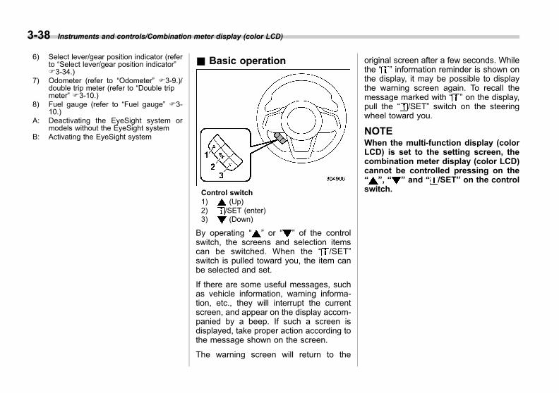
Black plate (182,1)
一般Model "A1300GE-A" EDITED: 2016/ 9/ 13
3-38 Instruments and controls/Combination meter display (color LCD)
6) Select lever/gear position indicator (referto “Select lever/gear position indicator”F3-34.)
7) Odometer (refer to “Odometer” F3-9.)/double trip meter (refer to “Double tripmeter” F3-10.)
8) Fuel gauge (refer to “Fuel gauge” F3-10.)
A: Deactivating the EyeSight system ormodels without the EyeSight system
B: Activating the EyeSight system
& Basic operation
Control switch1) (Up)2) /SET (enter)3) (Down)
By operating “ ” or “ ” of the controlswitch, the screens and selection itemscan be switched. When the “ /SET”switch is pulled toward you, the item canbe selected and set.
If there are some useful messages, suchas vehicle information, warning informa-tion, etc., they will interrupt the currentscreen, and appear on the display accom-panied by a beep. If such a screen isdisplayed, take proper action according tothe message shown on the screen.
The warning screen will return to the
original screen after a few seconds. Whilethe “ ” information reminder is shown onthe display, it may be possible to displaythe warning screen again. To recall themessage marked with “ ” on the display,pull the “ /SET” switch on the steeringwheel toward you.
NOTEWhen the multi-function display (colorLCD) is set to the setting screen, thecombination meter display (color LCD)cannot be controlled pressing on the“ ”, “ ” and “ /SET” on the controlswitch.
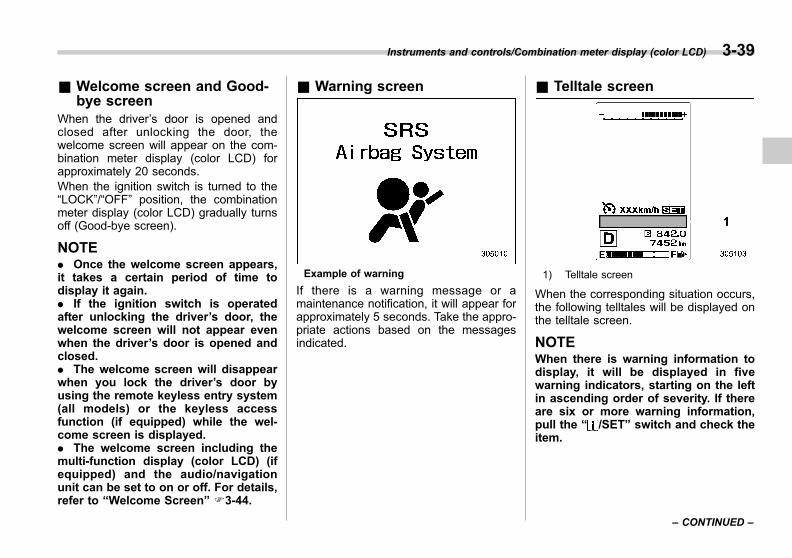
Black plate (183,1)
一般Model "A1300GE-A" EDITED: 2016/ 9/ 13
& Welcome screen and Good-bye screen
When the driver’s door is opened andclosed after unlocking the door, thewelcome screen will appear on the com-bination meter display (color LCD) forapproximately 20 seconds.When the ignition switch is turned to the“LOCK”/“OFF” position, the combinationmeter display (color LCD) gradually turnsoff (Good-bye screen).
NOTE. Once the welcome screen appears,it takes a certain period of time todisplay it again.. If the ignition switch is operatedafter unlocking the driver’s door, thewelcome screen will not appear evenwhen the driver’s door is opened andclosed.. The welcome screen will disappearwhen you lock the driver’s door byusing the remote keyless entry system(all models) or the keyless accessfunction (if equipped) while the wel-come screen is displayed.. The welcome screen including themulti-function display (color LCD) (ifequipped) and the audio/navigationunit can be set to on or off. For details,refer to “Welcome Screen” F3-44.
& Warning screen
Example of warning
If there is a warning message or amaintenance notification, it will appear forapproximately 5 seconds. Take the appro-priate actions based on the messagesindicated.
& Telltale screen
1) Telltale screen
When the corresponding situation occurs,the following telltales will be displayed onthe telltale screen.
NOTEWhen there is warning information todisplay, it will be displayed in fivewarning indicators, starting on the leftin ascending order of severity. If thereare six or more warning information,pull the “ /SET” switch and check theitem.
Instruments and controls/Combination meter display (color LCD) 3-39
– CONTINUED –
3
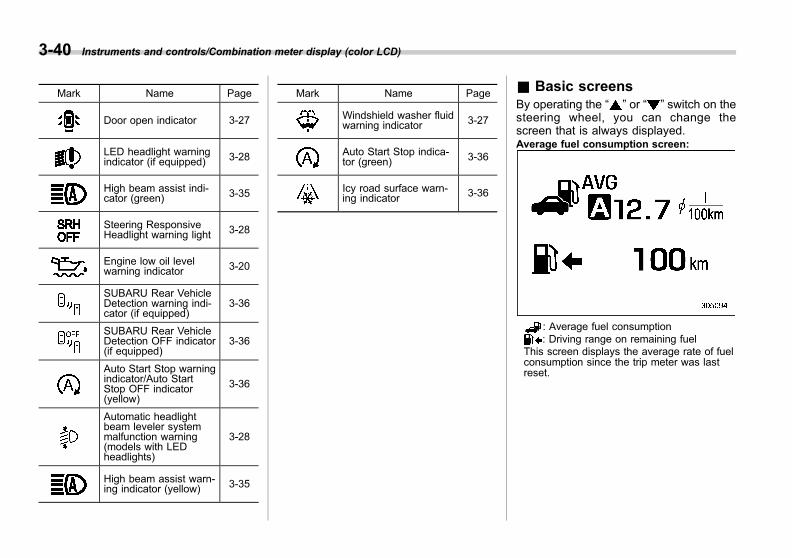
Black plate (184,1)
一般Model "A1300GE-A" EDITED: 2016/ 9/ 13
3-40 Instruments and controls/Combination meter display (color LCD)
Mark Name Page
Door open indicator 3-27
LED headlight warningindicator (if equipped) 3-28
High beam assist indi-cator (green) 3-35
Steering ResponsiveHeadlight warning light 3-28
Engine low oil levelwarning indicator 3-20
SUBARU Rear VehicleDetection warning indi-cator (if equipped)
3-36
SUBARU Rear VehicleDetection OFF indicator(if equipped)
3-36
Auto Start Stop warningindicator/Auto StartStop OFF indicator(yellow)
3-36
Automatic headlightbeam leveler systemmalfunction warning(models with LEDheadlights)
3-28
High beam assist warn-ing indicator (yellow) 3-35
Mark Name Page
Windshield washer fluidwarning indicator 3-27
Auto Start Stop indica-tor (green) 3-36
Icy road surface warn-ing indicator 3-36
& Basic screensBy operating the “ ” or “ ” switch on thesteering wheel, you can change thescreen that is always displayed.Average fuel consumption screen:
: Average fuel consumption: Driving range on remaining fuel
This screen displays the average rate of fuelconsumption since the trip meter was lastreset.
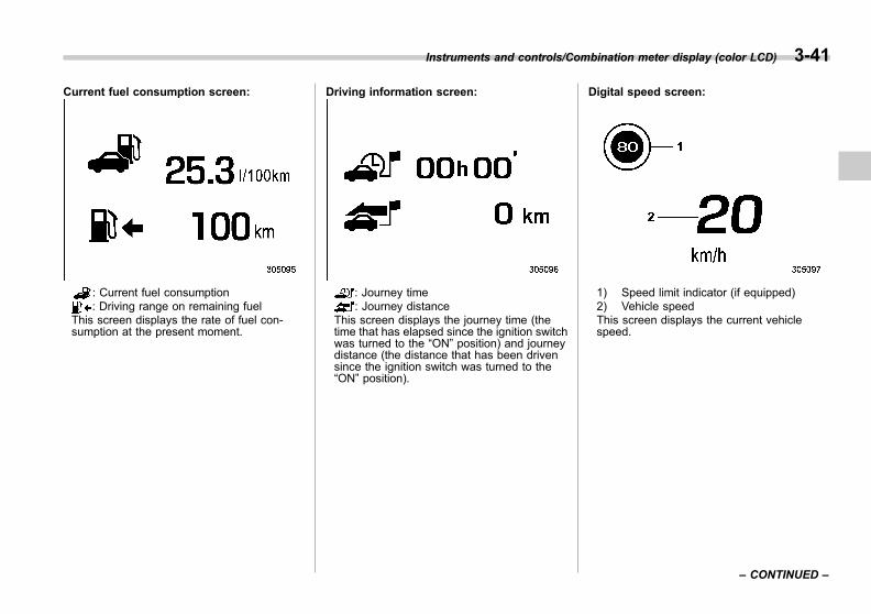
Black plate (185,1)
一般Model "A1300GE-A" EDITED: 2016/ 9/ 13
Current fuel consumption screen:
: Current fuel consumption: Driving range on remaining fuel
This screen displays the rate of fuel con-sumption at the present moment.
Driving information screen:
: Journey time: Journey distance
This screen displays the journey time (thetime that has elapsed since the ignition switchwas turned to the “ON” position) and journeydistance (the distance that has been drivensince the ignition switch was turned to the“ON” position).
Digital speed screen:
1) Speed limit indicator (if equipped)2) Vehicle speedThis screen displays the current vehiclespeed.
Instruments and controls/Combination meter display (color LCD) 3-41
– CONTINUED –
3
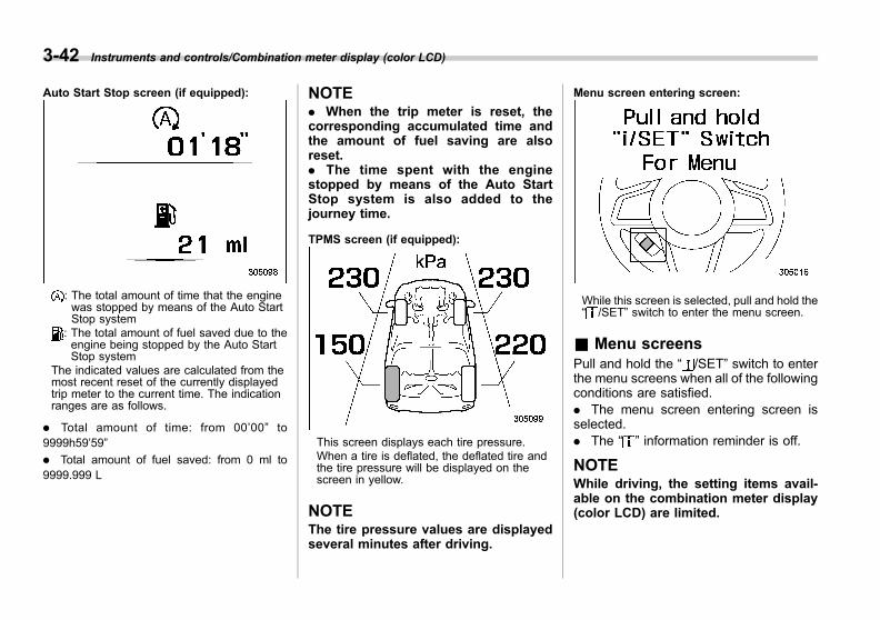
Black plate (186,1)
一般Model "A1300GE-A" EDITED: 2016/ 9/ 13
3-42 Instruments and controls/Combination meter display (color LCD)
Auto Start Stop screen (if equipped):
: The total amount of time that the enginewas stopped by means of the Auto StartStop system
: The total amount of fuel saved due to theengine being stopped by the Auto StartStop system
The indicated values are calculated from themost recent reset of the currently displayedtrip meter to the current time. The indicationranges are as follows.
. Total amount of time: from 00’00” to9999h59’59”
. Total amount of fuel saved: from 0 ml to9999.999 L
NOTE. When the trip meter is reset, thecorresponding accumulated time andthe amount of fuel saving are alsoreset.. The time spent with the enginestopped by means of the Auto StartStop system is also added to thejourney time.
TPMS screen (if equipped):
This screen displays each tire pressure.When a tire is deflated, the deflated tire andthe tire pressure will be displayed on thescreen in yellow.
NOTEThe tire pressure values are displayedseveral minutes after driving.
Menu screen entering screen:
While this screen is selected, pull and hold the“ /SET” switch to enter the menu screen.
& Menu screensPull and hold the “ /SET” switch to enterthe menu screens when all of the followingconditions are satisfied.. The menu screen entering screen isselected.. The “ ” information reminder is off.
NOTEWhile driving, the setting items avail-able on the combination meter display(color LCD) are limited.
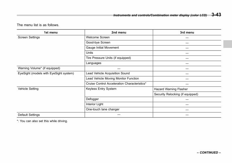
Black plate (187,1)
一般Model "A1300GE-A" EDITED: 2016/ 9/ 13
The menu list is as follows.
1st menu 2nd menu 3rd menu
Screen Settings Welcome Screen ―
Good-bye Screen ―
Gauge Initial Movement ―
Units ―
Tire Pressure Units (if equipped) ―
Languages ―
Warning Volume* (if equipped) ― ―
EyeSight (models with EyeSight system) Lead Vehicle Acquisition Sound ―
Lead Vehicle Moving Monitor Function ―
Cruise Control Acceleration Characteristics* ―
Vehicle Setting Keyless Entry System Hazard Warning Flasher
Security Relocking (if equipped)
Defogger ―
Interior Light ―
One-touch lane changer ―
Default Settings ― ―
*: You can also set this while driving.
Instruments and controls/Combination meter display (color LCD) 3-43
– CONTINUED –
3
Black plate (188,1)
一般Model "A1300GE-A" EDITED: 2016/ 9/ 13
3-44 Instruments and controls/Combination meter display (color LCD)
By operating the “ ” or “ ” switch on thesteering wheel, you can select the menu.Pull the “ /SET” switch to enter theselected menu.
NOTEIf you enter the “Go Back” menu, thesystem will return to the previousscreen.
! Screen Settings
After entering the “Screen Settings” menu,select one of the following menus.
! Welcome Screen
The welcome screen can be activated ordeactivated.
! Good-bye Screen
The good-bye screen can be activated ordeactivated.
! Gauge Initial Movement
The movement of the meter needles andgauge needles that occurs when theignition switch is turned to the “ON”position can be activated or deactivated.
! Units
Changes the units displayed in the com-bination meter display (color LCD), type Amulti-function display (black and white)and type B multi-function display (color
LCD).
! Tire Pressure Units (if equipped)
Changes the units displayed in the TirePressure Monitoring system.
! Languages
Changes the language displayed in thecombination meter display (color LCD)and multi-function display (color LCD).
! Warning Volume (if equipped)
Sets the EyeSight warning volume andSRVD warning volume.
! EyeSight (models with EyeSightsystem)
NOTEFor models with the EyeSight system,refer to the Owner’s Manual supple-ment for the EyeSight system.
After entering the “EyeSight” menu, selectone of the following menus.
! Lead Vehicle Acquisition Sound
When adaptive cruise control is used, thebuzzer that sounds if a vehicle is detectedin front or if detection is not possible canbe activated or deactivated.
! Lead Vehicle Moving MonitorFunction
When adaptive cruise control is used, thebuzzer that sounds if a vehicle in front hasstarted can be activated or deactivated.
! Cruise Control AccelerationCharacteristics
Adaptive Cruise Control acceleration char-acteristics can be set in four steps.
! Vehicle Setting
After entering the “Vehicle Setting” menu,select one of the following menus.
! Keyless Entry System
Sets the settings used when the keylessaccess function was operated.. Hazard Warning Flasher:Sets the operation of the hazard warningflasher that blinks when the door is lockedor unlocked.. Security Relocking (if equipped):The automatic locking operation periodcan be set or customized. Select thepreferred seconds to customize the op-eration period.
! Defogger
Sets and customizes the operation of thedefogger.

Black plate (189,1)
一般Model "A1300GE-A" EDITED: 2016/ 9/ 13
! Interior Light
Sets and customizes the interior light offdelay.
! One-touch lane changer
Sets the one-touch lane changer on/off.
! Default Settings
Select “Yes” to use the menu screen torestore customized settings to the factorydefault settings. Select “No” to return tothe previous screen without restoring tothe factory default settings.
Multi-function display (blackand white) (if equipped)
NOTE
For models with multi-function display(color LCD), refer to “Type B multi-function display (color LCD)” F3-68.
1) Outside temperature indicator2) Driving information display3) Clock
With the ignition switch in the “ACC”position, the clock appears on the display.
With the ignition switch in the “ON”position, the outside temperature indica-tor, driving information display and clockall appear on the display.
NOTEThe indicated values vary in accor-dance with changes in the vehicle’srunning conditions. Also, the indicatedvalues may differ slightly from theactual values and should therefore betreated only as a guide.
& Driving information displayNOTEYou can set the units for both the multi-function display (black and white) andthe combination meter at the sametime. For details about setting thelanguage and units, refer to “Type Acombination meter” F3-11 or “Menuscreens” F3-42.
Instruments and controls/Multi–function display (black and white) 3-45
– CONTINUED –
3
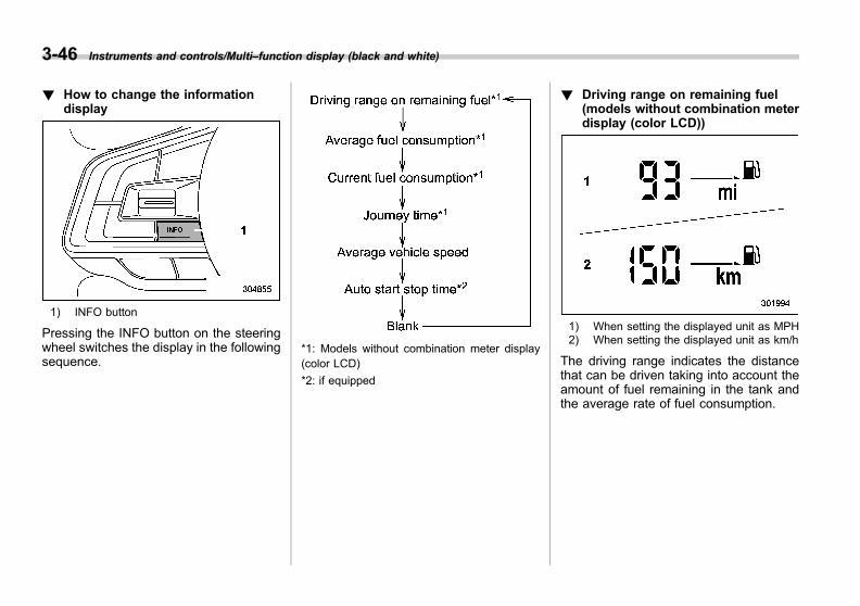
Black plate (190,1)
一般Model "A1300GE-A" EDITED: 2016/ 9/ 13
3-46 Instruments and controls/Multi–function display (black and white)
! How to change the informationdisplay
1) INFO button
Pressing the INFO button on the steeringwheel switches the display in the followingsequence.
*1: Models without combination meter display(color LCD)
*2: if equipped
! Driving range on remaining fuel(models without combination meterdisplay (color LCD))
1) When setting the displayed unit as MPH2) When setting the displayed unit as km/h
The driving range indicates the distancethat can be driven taking into account theamount of fuel remaining in the tank andthe average rate of fuel consumption.
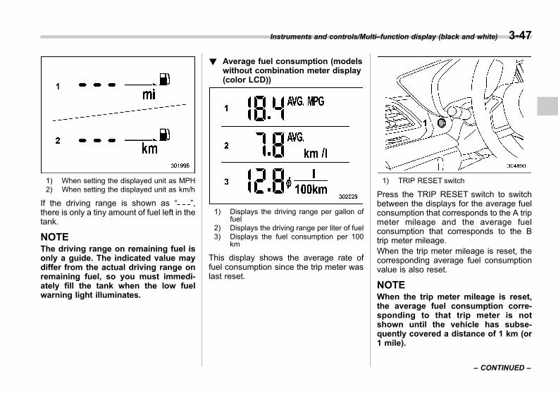
Black plate (191,1)
一般Model "A1300GE-A" EDITED: 2016/ 9/ 13
1) When setting the displayed unit as MPH2) When setting the displayed unit as km/h
If the driving range is shown as “ ”,there is only a tiny amount of fuel left in thetank.
NOTEThe driving range on remaining fuel isonly a guide. The indicated value maydiffer from the actual driving range onremaining fuel, so you must immedi-ately fill the tank when the low fuelwarning light illuminates.
! Average fuel consumption (modelswithout combination meter display(color LCD))
1) Displays the driving range per gallon offuel
2) Displays the driving range per liter of fuel3) Displays the fuel consumption per 100
km
This display shows the average rate offuel consumption since the trip meter waslast reset.
1) TRIP RESET switch
Press the TRIP RESET switch to switchbetween the displays for the average fuelconsumption that corresponds to the A tripmeter mileage and the average fuelconsumption that corresponds to the Btrip meter mileage.When the trip meter mileage is reset, thecorresponding average fuel consumptionvalue is also reset.
NOTEWhen the trip meter mileage is reset,the average fuel consumption corre-sponding to that trip meter is notshown until the vehicle has subse-quently covered a distance of 1 km (or1 mile).
Instruments and controls/Multi–function display (black and white) 3-47
– CONTINUED –
3
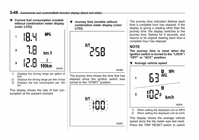
Black plate (192,1)
一般Model "A1300GE-A" EDITED: 2016/ 9/ 13
3-48 Instruments and controls/Multi–function display (black and white)
! Current fuel consumption (modelswithout combination meter display(color LCD))
1) Displays the driving range per gallon offuel
2) Displays the driving range per liter of fuel3) Displays the fuel consumption per 100
km
This display shows the rate of fuel con-sumption at the present moment.
! Journey time (models withoutcombination meter display (colorLCD))
The journey time shows the time that haselapsed since the ignition switch wasturned to the “START” position.
The journey time indication flashes eachtime a complete hour has elapsed. If thedisplay is giving a reading other than thejourney time, the display switches to thejourney time, flashes for 5 seconds, andreturns to its original reading each time acomplete hour has elapsed.
NOTEThe journey time is reset when theignition switch is turned to the “LOCK”/“OFF” or “ACC” position.
! Average vehicle speed
1) When setting the displayed unit as MPH2) When setting the displayed unit as km/h
This display shows the average vehiclespeed since the trip meter was last reset.Press the TRIP RESET switch to switch

Black plate (193,1)
一般Model "A1300GE-A" EDITED: 2016/ 9/ 13
between the displays for the averagevehicle speed that corresponds to the Atrip meter mileage and the averagevehicle speed that corresponds to the Btrip meter mileage.When the trip meter display is reset, thecorresponding average vehicle speedvalue is also reset.
NOTEWhen the trip meter display is reset, theaverage vehicle speed correspondingto that trip meter display is not shownuntil the vehicle has subsequentlycovered a distance of 1 km (or 1 mile).
! Auto Start Stop time (if equipped)
1) Total time in conjunction with the tripmeter
2) Total time in conjunction with the ignitionswitch
This display shows the total time that theengine was stopped by the Auto StartStop system in the following ways.
Total time in conjunction with the tripmeter: Displays the total time that theengine was stopped by the Auto StartStop system, from the last time thecurrently displayed trip meter was resetuntil the current time. By pressing theTRIP RESET switch, you can toggle thedisplay between the time the engine wasstopped for trip A and the time the enginewas stopped for trip B.
NOTEWhen the trip meter mileage is reset,the total time in conjunction with thetrip meter is not shown until the vehiclehas subsequently covered a distanceof 1 km (or 1 mile).
Total time in conjunction with theignition switch: Displays the total timethat the engine was stopped by the AutoStart Stop system, from the time when theignition switch was turned to the “ON”position to the current time.
! How to switch the display
Perform the following operation to togglethe display between the total time inconjunction with the trip meter and thetotal time in conjunction with the ignitionswitch.
Instruments and controls/Multi–function display (black and white) 3-49
– CONTINUED –
3
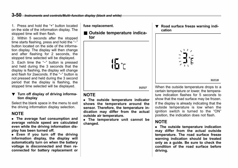
Black plate (194,1)
一般Model "A1300GE-A" EDITED: 2016/ 9/ 13
3-50 Instruments and controls/Multi–function display (black and white)
1. Press and hold the “+” button locatedon the side of the information display. Thestopped time will then flash.2. Within 5 seconds after the stoppedtime starts flashing, press and hold the “−”button located on the side of the informa-tion display. The display will then changeand after flashing for 2 seconds, thestopped time selected will be displayed.3. Each time the “−” button is pressedand held during the 3 seconds that thedisplay is flashing, the display will changeand flash for 2seconds. If the “−” button isnot pressed and held during the 3 secondperiod that the display is flashing, thestopped time selected will be displayed.
! Turn off display of driving informa-tion display
Select the blank space in the menu to exitthe driving information display selection.
NOTE. The average fuel consumption andaverage vehicle speed are calculatedeven while the driving information dis-play has been turned off.. Even if you turn off the drivinginformation display, the display willautomatically turn on when the batteryvoltage is disconnected and then re-connected for battery replacement or
fuse replacement.
& Outside temperature indica-tor
NOTE. The outside temperature indicatorshows the temperature around thesensor. Therefore, the temperature in-dication may differ from the actualoutside air temperature.. The temperature unit cannot bechanged.
! Road surface freeze warning indi-cation
When the outside temperature drops to acertain temperature or lower, the tempera-ture indication flashes for 5 seconds toshow that the road surface may be frozen.If the display is already indicating that theoutside temperature is low when theignition switch is turned to the “ON”position, the indication does not flash.
NOTE. The outside temperature indicationmay differ from the actual outsidetemperature. The road surface freezewarning indication should be treatedonly as a guide. Be sure to check thecondition of the road surface beforedriving.

Black plate (195,1)
一般Model "A1300GE-A" EDITED: 2016/ 9/ 13
. After the road surface freeze warn-ing has already appeared on the dis-play, the warning will not appear againeven if the outside temperature dropsto 38C (378F) or lower until once theoutside temperature has increased to58C (418F) or more before that time.
& ClockFor details about clock setting, refer to“Clock” F3-67.
Multi-function display (colorLCD) (if equipped)
NOTE
For models with multi-function display(black and white), refer to “Multi-func-tion display (black and white)” F3-45.
WARNING
Always pay adequate attention tosafe driving when operating themulti-function display (color LCD)while the vehicle is in motion. Whenoperation of the multi-function dis-play (color LCD) is disturbing yourawareness and ability to concen-trate on driving, stop the vehicle in asafe place before performing opera-tions on the screen. Also, do notconcentrate on the display whiledriving. Doing so may cause you tolook away from the road and couldresult in an accident.
& FeaturesThe multi-function display (color LCD) hasthe following functions.
Description Page
Displays useful messages, suchas notifications, etc. 3-53
Displays basic screens (e.g. fuelconsumption screen, etc.) 3-53
Sets and adjusts maintenancenotification 3-65
Also, the multi-function display (colorLCD) can also be used to set and initializethe multi function display itself.
NOTE. When the vehicle is in motion,certain functions and selections maynot be available.. You can set the language and unitsfor both the multi-function display(color LCD) and the combination meterat the same time. For details aboutsetting the language and units, refer to“Screen Settings” F3-44.. The images displayed in this Own-er’s Manual are sample images. Theactual image may vary depending onthe destinations and specifications.
Instruments and controls/Multi–function display (color LCD) 3-51
– CONTINUED –
3
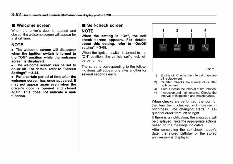
Black plate (196,1)
一般Model "A1300GE-A" EDITED: 2016/ 9/ 13
3-52 Instruments and controls/Multi–function display (color LCD)
& Welcome screenWhen the driver’s door is opened andclosed, the welcome screen will appear fora short time.
NOTE. The welcome screen will disappearwhen the ignition switch is turned tothe “ON” position while the welcomescreen is displayed.. The welcome screen can be set toon or off. For details, refer to “ScreenSettings” F3-44.. For a certain period of time after thewelcome screen has once appeared, itmay not appear again even when thedriver’s door is opened and closedagain. This does not indicate a mal-function.
& Self-check screenNOTEWhen the setting is “On”, the selfcheck screen appears. For detailsabout this setting, refer to “On/Offsetting” F3-65.
When the ignition switch is turned to the“ON” position, the vehicle self-check willbe performed.
The screens corresponding to the follow-ing items will appear one after another forseveral seconds each. 1) Engine oil: Checks the interval of engine
oil replacement.2) Oil filter: Checks the interval of oil filter
replacement.3) Tires: Checks the interval of tire rotation.4) Inspection and maintenance: Checks the
interval of inspection and maintenance.
When checks are performed, the icon forthe item being checked will increase inbrightness. The changing starts in se-quential order from left to right.If there is a notification, the message willbe displayed. Take the appropriate actionsbased on the message indicated.After completing the self-check, today’sdate, the stored birthday or the storedanniversary is displayed.

Black plate (197,1)
一般Model "A1300GE-A" EDITED: 2016/ 9/ 13
NOTE. After performing the maintenance,change the setting of the correspond-ing maintenance item. For details, referto “Maintenance settings” F3-65.. The maintenance notification screenwill be displayed under either of thefollowing conditions.
– The period of time remaininguntil the registered notification dateis 15 days or less.– The total driving distance remain-ing until the registered notificationdistance is approximately 500 km(311 miles) or less.
. The maintenance notification screenwill be displayed until either of thefollowing conditions is satisfied.
– The period of time passed afterthe registered notification date is 15days or more.– The total distance driven after theregistered notification distance isapproximately 500 km (311 miles) ormore.
& Interruption screen
Example
Useful messages, such as reminder in-formation may interrupt the current screenand appear on the display accompaniedby a beep. Take proper action accordingto the message.
The interrupt screen will return to theoriginal screen after a few seconds. Also,the interrupt screen can be skipped bypressing the INFO button.
& Basic operation
Control switch1) INFO button2) (Up)3) “ /SET”4) (Down)
Press the INFO button on the steeringwheel to switch the item displayed on thebasic screen. You can operate the itemson the setting screen by using the “ ”,“ ” and “ /SET” switches.
& Basic screensWhile the ignition switch is in the “ON”position, the basic screen will be dis-played.
Instruments and controls/Multi–function display (color LCD) 3-53
– CONTINUED –
3
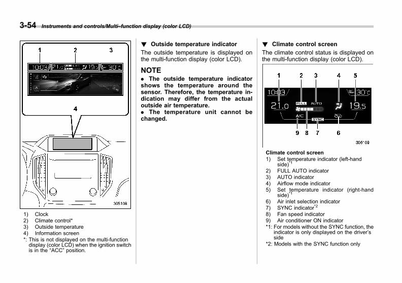
Black plate (198,1)
一般Model "A1300GE-A" EDITED: 2016/ 9/ 13
3-54 Instruments and controls/Multi–function display (color LCD)
1) Clock2) Climate control*3) Outside temperature4) Information screen*: This is not displayed on the multi-functiondisplay (color LCD) when the ignition switchis in the “ACC” position.
! Outside temperature indicator
The outside temperature is displayed onthe multi-function display (color LCD).
NOTE. The outside temperature indicatorshows the temperature around thesensor. Therefore, the temperature in-dication may differ from the actualoutside air temperature.. The temperature unit cannot bechanged.
! Climate control screen
The climate control status is displayed onthe multi-function display (color LCD).
Climate control screen1) Set temperature indicator (left-hand
side)*1
2) FULL AUTO indicator3) AUTO indicator4) Airflow mode indicator5) Set temperature indicator (right-hand
side)*1
6) Air inlet selection indicator7) SYNC indicator*2
8) Fan speed indicator9) Air conditioner ON indicator*1: For models without the SYNC function, the
indicator is only displayed on the driver’sside
*2: Models with the SYNC function only

Black plate (199,1)
一般Model "A1300GE-A" EDITED: 2016/ 9/ 13
When operating the climate control sys-tem, the basic screen switches to theclimate control screen. For details aboutclimate control operation, refer to “Climatecontrol panel” F4-2.
! Clock
The clock can be displayed in either 12-hour display or 24-hour display. For detailsabout the setting, refer to “Clock” F3-67.
Instruments and controls/Multi–function display (color LCD) 3-55
– CONTINUED –
3

Black plate (200,1)
一般Model "A1300GE-A" EDITED: 2016/ 9/ 13
3-56 Instruments and controls/Multi–function display (color LCD)
! Information screen
Press the INFO button on the steering wheel to switch the item displayed on the information screen.
Content Description Page
Electric components operating status screen Displays the operating status of the electric components and equipment. 3-57
Prevention safety screen Displays the status of your vehicle. 3-57
EyeSight screen*1 Displays the operating status of EyeSight. 3-58
Favorite screen Displays up to 3 optional items. 3-58
Navigation screen*2 Displays information linked with the navigation system. 3-59
Audio screen Displays audio system information. 3-59
Fuel consumption screen Displays fuel consumption information. 3-60
Clock screen Displays the clock. 3-60
Guidance screen Shifts to the setting screen. 3-60
*1: Models with EyeSight system*2: Models with navigation system
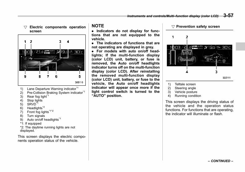
Black plate (201,1)
一般Model "A1300GE-A" EDITED: 2016/ 9/ 13
! Electric components operationscreen
1) Lane Departure Warning indicator*1
2) Pre-Collision Braking System indicator*1
3) Rear fog light*1
4) Stop lights5) SRVD*1
6) Headlights*2
7) Front fog lights*1*2
8) Turn signals9) Auto on/off headlights*1
*1: If equipped*2: The daytime running lights are notdisplayed.
This screen displays the electric compo-nents operation status of the vehicle.
NOTE. Indicators do not display for func-tions that are not equipped to thevehicle.. The indicators of functions that arenot operating are displayed in grey.. For models with auto on/off head-lights; If the multi-function display(color LCD) unit, battery, or fuse isremoved, the Auto on/off headlightsindicator turns off on the multi-functiondisplay (color LCD). After reinstallingthe removed multi-function display(color LCD) unit, battery, or fuse to thevehicle, the Auto on/off headlightsindicator will appear once more if thelight control switch is turned to the“AUTO” position.
! Prevention safety screen
1) Telltale screen2) Steering angle3) Vehicle posture4) Running condition
This screen displays the driving status ofthe vehicle and the operation statusfunctions. For functions that are operating,the indicator will illuminate or flash.
Instruments and controls/Multi–function display (color LCD) 3-57
– CONTINUED –
3

Black plate (202,1)
一般Model "A1300GE-A" EDITED: 2016/ 9/ 13
3-58 Instruments and controls/Multi–function display (color LCD)
NOTEThe vehicle posture indication maydiffer from the actual vehicle posture.
! EyeSight screen (models withEyeSight system)
1) Lead vehicle indicator2) Your own vehicle indicator3) Stop lights
This screen displays the status of theEyeSight system.The lead vehicle indicator moves forwardand backward depending on the distancewith the vehicle in front. For details, referto the Owner’s Manual supplement for theEyeSight system.
! Favorite screen
Favorite screen (display example)
This screen displays up to three optionalpieces of information that can be selectedfrom the following items.
Item Details
The engine coolant temperature isdisplayed.
The engine oil temperature isdisplayed.
The average vehicle speed isdisplayed.
The accelerator opening ratio isdisplayed.
The vehicle posture is displayed.
The current rate of fuel consump-tion is displayed.
The direction of the vehicle isdisplayed.*1
The posted speed limit of the roadyou are currently driving on isdisplayed.*1
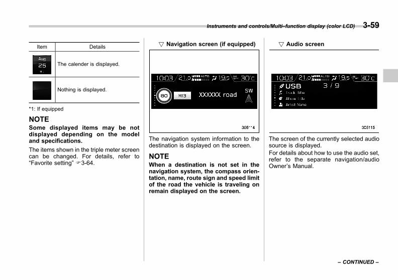
Black plate (203,1)
一般Model "A1300GE-A" EDITED: 2016/ 9/ 13
Item Details
The calender is displayed.
Nothing is displayed.
*1: If equipped
NOTESome displayed items may be notdisplayed depending on the modeland specifications.
The items shown in the triple meter screencan be changed. For details, refer to“Favorite setting” F3-64.
! Navigation screen (if equipped)
The navigation system information to thedestination is displayed on the screen.
NOTEWhen a destination is not set in thenavigation system, the compass orien-tation, name, route sign and speed limitof the road the vehicle is traveling onremain displayed on the screen.
! Audio screen
The screen of the currently selected audiosource is displayed.For details about how to use the audio set,refer to the separate navigation/audioOwner’s Manual.
Instruments and controls/Multi–function display (color LCD) 3-59
– CONTINUED –
3

Black plate (204,1)
一般Model "A1300GE-A" EDITED: 2016/ 9/ 13
3-60 Instruments and controls/Multi–function display (color LCD)
! Fuel consumption screen
1) Average fuel consumption correspondingto the driving distance of each trip meter
2) Current fuel consumption3) Driving range on remaining fuel
The fuel consumption information is dis-played on the screen.
! Clock/date screen
The time and date are displayed.You can select the time and date. Fordetails, refer to “Clock” F3-67.
! Guidance screen
When the INFO button on the steeringwheel is pressed and held on this screen,the setting screen can be displayed.For details, refer to “Setting screen” F3-61.
NOTEWhen the menu screen entering screenis displayed on the combination meterdisplay (color LCD), pressing the INFObutton will not transfer the display tothe setting screen.
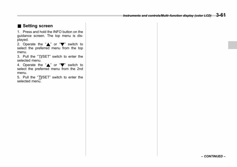
Black plate (205,1)
一般Model "A1300GE-A" EDITED: 2016/ 9/ 13
& Setting screen1. Press and hold the INFO button on theguidance screen. The top menu is dis-played.2. Operate the “ ” or “ ” switch toselect the preferred menu from the topmenu.3. Pull the “ /SET” switch to enter theselected menu.4. Operate the “ ” or “ ” switch toselect the preferred menu from the 2ndmenu.5. Pull the “ /SET” switch to enter theselected menu.
Instruments and controls/Multi–function display (color LCD) 3-61
– CONTINUED –
3
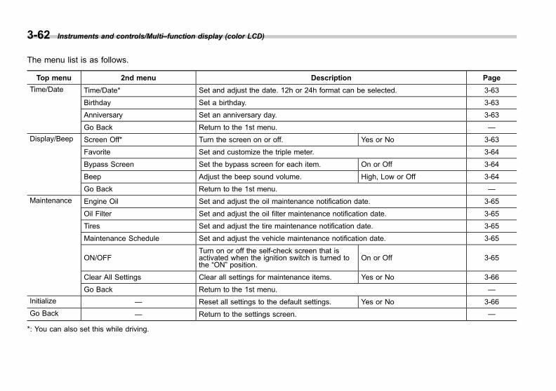
Black plate (206,1)
一般Model "A1300GE-A" EDITED: 2016/ 9/ 13
3-62 Instruments and controls/Multi–function display (color LCD)
The menu list is as follows.
Top menu 2nd menu Description Page
Time/Date Time/Date* Set and adjust the date. 12h or 24h format can be selected. 3-63
Birthday Set a birthday. 3-63
Anniversary Set an anniversary day. 3-63
Go Back Return to the 1st menu. —
Display/Beep Screen Off* Turn the screen on or off. Yes or No 3-63
Favorite Set and customize the triple meter. 3-64
Bypass Screen Set the bypass screen for each item. On or Off 3-64
Beep Adjust the beep sound volume. High, Low or Off 3-64
Go Back Return to the 1st menu. —
Maintenance Engine Oil Set and adjust the oil maintenance notification date. 3-65
Oil Filter Set and adjust the oil filter maintenance notification date. 3-65
Tires Set and adjust the tire maintenance notification date. 3-65
Maintenance Schedule Set and adjust the vehicle maintenance notification date. 3-65
ON/OFFTurn on or off the self-check screen that isactivated when the ignition switch is turned tothe “ON” position.
On or Off 3-65
Clear All Settings Clear all settings for maintenance items. Yes or No 3-66
Go Back Return to the 1st menu. —
Initialize — Reset all settings to the default settings. Yes or No 3-66
Go Back — Return to the settings screen. —
*: You can also set this while driving.

Black plate (207,1)
一般Model "A1300GE-A" EDITED: 2016/ 9/ 13
! Date and time settings
You can set the date, time and 12h or 24hformat settings.
! Current date and time setting
For details about clock setting, refer to“Clock” F3-67.
! Birthday setting
1. Select “Birthday” from the 2nd menu inthe setting screen. Refer to “Settingscreen” F3-61.
2. Select from the list the number thatyou want to register.
3. Enter the date and the text by usingthe control switches.4. Select “Set” to exit settings. Select “GoBack” to return to the previous screenwithout applying the setting changes.
NOTEYou can store a maximum of the 5birthdays.
If a birthday is approaching, the reminderscreen will be displayed when the ignitionswitch has been turned to the “ON”position. This function can be set to onor off. For details, refer to “Bypass screensetting” F3-64.
! Anniversary setting
1. The procedure for setting an anniver-sary is the same as “Birthday setting” F3-63, except that in step 1 “Anniversary” isselected.
NOTEYou can store a maximum of 5 anni-versaries.
! Display/Beep settings
You can set the display settings andvolume settings.
! Screen OFF setting
1. Select “Screen Off” from 2nd menu insetting screen. Refer to “Setting screen”F3-61.
Instruments and controls/Multi–function display (color LCD) 3-63
– CONTINUED –
3
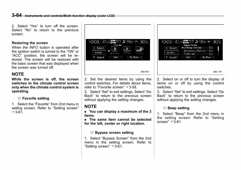
Black plate (208,1)
一般Model "A1300GE-A" EDITED: 2016/ 9/ 13
3-64 Instruments and controls/Multi–function display (color LCD)
2. Select “Yes” to turn off the screen.Select “No” to return to the previousscreen.
Restoring the screenWhen the INFO button is operated afterthe ignition switch is turned to the “ON” or“ACC” position, the screen will be re-stored. The screen will be restored withthe basic screen that was displayed whenthe screen was turned off.
NOTEWhile the screen is off, the screenswitches to the climate control screenonly when the climate control system isoperating.
! Favorite setting
1. Select the “Favorite” from 2nd menu insetting screen. Refer to “Setting screen”F3-61.
2. Set the desired items by using thecontrol switches. For details about items,refer to “Favorite screen” F3-58.3. Select “Set” to exit settings. Select “GoBack” to return to the previous screenwithout applying the setting changes.
NOTE. You can display a maximum of the 3items.. The same item cannot be selectedfor the left, center or right location.
! Bypass screen setting
1. Select “Bypass Screen” from the 2ndmenu in the setting screen. Refer to“Setting screen” F3-61.
2. Select on or off to turn the display ofitems on or off by using the controlswitches.3. Select “Set” to exit settings. Select “GoBack” to return to the previous screenwithout applying the setting changes.
! Beep setting
1. Select “Beep” from the 2nd menu inthe setting screen. Refer to “Settingscreen” F3-61.
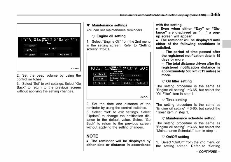
Black plate (209,1)
一般Model "A1300GE-A" EDITED: 2016/ 9/ 13
2. Set the beep volume by using thecontrol switches.3. Select “Set” to exit settings. Select “GoBack” to return to the previous screenwithout applying the setting changes.
! Maintenance settings
You can set maintenance reminders.
! Engine oil setting
1. Select “Engine Oil” from the 2nd menuin the setting screen. Refer to “Settingscreen” F3-61.
2. Set the date and distance of thereminder by using the control switches.3. Select “Set” to exit settings. Select“Update” to change the notification dis-tance to the default value. Select “GoBack” to return to the previous screenwithout applying the setting changes.
NOTE. The reminder will be displayed byeither date or distance in accordance
with the setting.. Even when either “Day” or “Dis-tance” are displayed as “_ _” a pop-up screen will appear.. The reminder will be displayed untileither of the following conditions issatisfied.
– The period of time passed afterthe registered notification date is 15days or more.– The total distance driven after theregistered notification distance isapproximately 500 km (311 miles) ormore.
! Oil filter setting
The setting procedure is the same as“Engine oil setting” F3-65, but select the“Oil Filter” item in step 1.
! Tires setting
The setting procedure is the same as“Engine oil setting” F3-65, but select the“Tires” item in step 1.
! Maintenance schedule setting
The setting procedure is the same as“Engine oil setting” F3-65, but select the“Maintenance Schedule” item in step 1.
! On/Off setting
1. Select “On/Off” from the 2nd menu onthe setting screen. Refer to “Setting
Instruments and controls/Multi–function display (color LCD) 3-65
– CONTINUED –
3
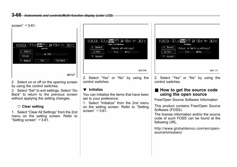
Black plate (210,1)
一般Model "A1300GE-A" EDITED: 2016/ 9/ 13
3-66 Instruments and controls/Multi–function display (color LCD)
screen” F3-61.
2. Select on or off on the opening screenby using the control switches.3. Select “Set” to exit settings. Select “GoBack” to return to the previous screenwithout applying the setting changes.
! Clear setting
1. Select “Clear All Settings” from the 2ndmenu on the setting screen. Refer to“Setting screen” F3-61.
2. Select “Yes” or “No” by using thecontrol switches.
! Initialize
You can initialize the items that have beenset to your preference.1. Select “Initialize” from the 2nd menuon the setting screen. Refer to “Settingscreen” F3-61.
2. Select “Yes” or “No” by using thecontrol switches.
& How to get the source codeusing the open source
Free/Open Source Software Information
This product contains Free/Open SourceSoftware (FOSS).The license information and/or the sourcecode of such FOSS can be found at thefollowing URL.
http://www.globaldenso.com/en/open-source/ivi/subaru/

Black plate (211,1)
一般Model "A1300GE-A" EDITED: 2016/ 9/ 13
Clock
For models with a SUBARU genuinenavigation and/or audio system, the clockcan be adjusted using either “Auto” modeor “Manual” mode.. Auto mode: automatic clock adjust-ment. Manual mode: manual clock adjust-ment
& Preparation for clock adjust-ment setting
Before setting the clock, the setting mode(“Auto” or “Manual”) will need to beselected.To select the mode, perform the followingprocedure.
1. Press the button.2. Select “Settings”.3. Select “Vehicle”.4. Select “Clock adjustment” and thenselect either “Manual” or “Auto”.
& Setting the clock automati-cally
To set the clock automatically, the “Auto”mode must be selected in the clockadjustment setting preparation procedure.
! Models with navigation system
The clock will be set automatically wherea GPS signal is available.
! Models without navigation system
The clock will be set and adjusted auto-matically when a smartphone is con-nected via Bluetooth® for transferringphonebook data.1. Register the smartphone to the audiosystem. For details, refer to “BluetoothSETTINGS” in the supplemental Owner’sManual for the audio/navigation system.2. Transfer phonebook data to the sys-tem. For details, refer to “Bluetooth SET-TINGS” in the supplemental Owner’sManual for the audio/navigation system.The clock will be adjusted automatically.
Instruments and controls/Clock 3-67
– CONTINUED –
3
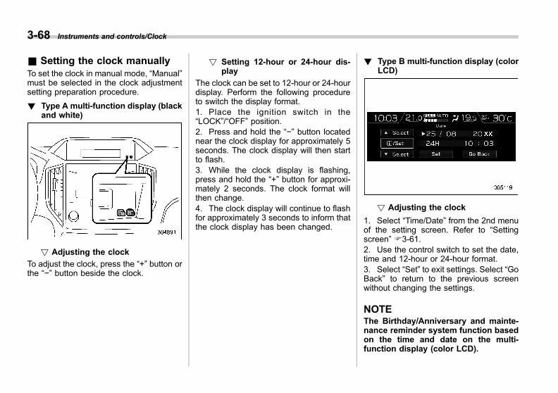
Black plate (212,1)
一般Model "A1300GE-A" EDITED: 2016/ 9/ 13
3-68 Instruments and controls/Clock
& Setting the clock manuallyTo set the clock in manual mode, “Manual”must be selected in the clock adjustmentsetting preparation procedure.
! Type A multi-function display (blackand white)
! Adjusting the clock
To adjust the clock, press the “+” button orthe “−” button beside the clock.
! Setting 12-hour or 24-hour dis-play
The clock can be set to 12-hour or 24-hourdisplay. Perform the following procedureto switch the display format.1. Place the ignition switch in the“LOCK”/“OFF” position.2. Press and hold the “−” button locatednear the clock display for approximately 5seconds. The clock display will then startto flash.3. While the clock display is flashing,press and hold the “+” button for approxi-mately 2 seconds. The clock format willthen change.4. The clock display will continue to flashfor approximately 3 seconds to inform thatthe clock display has been changed.
! Type B multi-function display (colorLCD)
! Adjusting the clock
1. Select “Time/Date” from the 2nd menuof the setting screen. Refer to “Settingscreen” F3-61.2. Use the control switch to set the date,time and 12-hour or 24-hour format.3. Select “Set” to exit settings. Select “GoBack” to return to the previous screenwithout changing the settings.
NOTEThe Birthday/Anniversary and mainte-nance reminder system function basedon the time and date on the multi-function display (color LCD).
Black plate (213,1)
一般Model "A1300GE-A" EDITED: 2016/ 9/ 13
& Regulatory information
The Bluetooth® word mark and logos areregistered trademarks owned by BluetoothSIG, Inc.
Light control switch
CAUTION
. Use of any lights for a long periodof time while the engine is notrunning can cause the battery todischarge.
. Before leaving the vehicle, makesure that the light control switchis turned to the off position. If thevehicle is left unattended for along time with the light controlswitch set to a position otherthan the off position, the batterymay be discharged.
Models with “keyless access withpush-button start system”:The light control switch operates when thepush-button ignition switch is in the “ACC”or “ON” position.Regardless of the position of the lightcontrol switch, the illuminated lights areturned off when the push-button ignitionswitch is turned off.
Models without “keyless access withpush-button start system”:The light control switch operates when thekey is inserted in the ignition switch.
Regardless of the position of the lightcontrol switch, the illuminated lights areturned off when the key is removed fromthe ignition switch.
NOTEThe light control switch can be oper-ated (except auto on/off headlights),even under the following conditions.. when the key is not inserted into theignition switch (models without “key-less access with push-button startsystem”). when the push-button ignitionswitch is turned off (models with “key-less access with push-button startsystem”)
If the driver’s door is opened while theheadlights are illuminated under suchconditions, the chirp sound will informthe driver that the lights are illumi-nated.
Instruments and controls/Light control switch 3-69
– CONTINUED –
3

Black plate (214,1)
一般Model "A1300GE-A" EDITED: 2016/ 9/ 13
3-70 Instruments and controls/Light control switch
& HeadlightsNOTEWhen you drive in a foreign country inwhich the vehicular lane (left-handtraffic or right-hand traffic) is differentfrom your country, to avoid blinding theoncoming driver, you need to block apart of the headlight lenses. For details,refer to “Driving in a foreign country inwhich the vehicular lane is different toyour country” F8-4.
! Operation
Except Australia models1) Second position2) First position3) Auto position (if equipped)4) Off position
Australia models1) Second position2) First position3) Auto position (if equipped)4) Off position
To turn on the headlights, turn the knob onthe end of the turn signal lever.
Second position:Headlights, front position lights, instru-ment panel illumination, tail lights andlicense plate lights are on.
First position:Front position lights, instrument panelillumination, tail lights and license platelights are on.
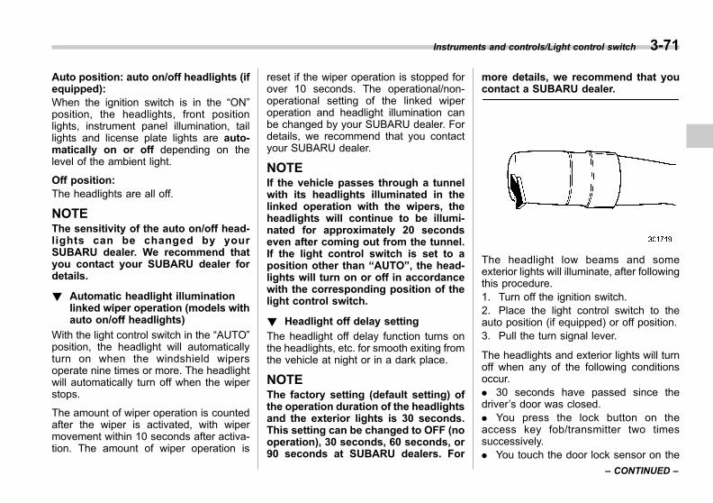
Black plate (215,1)
一般Model "A1300GE-A" EDITED: 2016/ 9/ 13
Auto position: auto on/off headlights (ifequipped):When the ignition switch is in the “ON”position, the headlights, front positionlights, instrument panel illumination, taillights and license plate lights are auto-matically on or off depending on thelevel of the ambient light.
Off position:The headlights are all off.
NOTEThe sensitivity of the auto on/off head-lights can be changed by yourSUBARU dealer. We recommend thatyou contact your SUBARU dealer fordetails.
! Automatic headlight illuminationlinked wiper operation (models withauto on/off headlights)
With the light control switch in the “AUTO”position, the headlight will automaticallyturn on when the windshield wipersoperate nine times or more. The headlightwill automatically turn off when the wiperstops.
The amount of wiper operation is countedafter the wiper is activated, with wipermovement within 10 seconds after activa-tion. The amount of wiper operation is
reset if the wiper operation is stopped forover 10 seconds. The operational/non-operational setting of the linked wiperoperation and headlight illumination canbe changed by your SUBARU dealer. Fordetails, we recommend that you contactyour SUBARU dealer.
NOTEIf the vehicle passes through a tunnelwith its headlights illuminated in thelinked operation with the wipers, theheadlights will continue to be illumi-nated for approximately 20 secondseven after coming out from the tunnel.If the light control switch is set to aposition other than “AUTO”, the head-lights will turn on or off in accordancewith the corresponding position of thelight control switch.
! Headlight off delay setting
The headlight off delay function turns onthe headlights, etc. for smooth exiting fromthe vehicle at night or in a dark place.
NOTEThe factory setting (default setting) ofthe operation duration of the headlightsand the exterior lights is 30 seconds.This setting can be changed to OFF (nooperation), 30 seconds, 60 seconds, or90 seconds at SUBARU dealers. For
more details, we recommend that youcontact a SUBARU dealer.
The headlight low beams and someexterior lights will illuminate, after followingthis procedure.1. Turn off the ignition switch.2. Place the light control switch to theauto position (if equipped) or off position.3. Pull the turn signal lever.
The headlights and exterior lights will turnoff when any of the following conditionsoccur.. 30 seconds have passed since thedriver’s door was closed.. You press the lock button on theaccess key fob/transmitter two timessuccessively.. You touch the door lock sensor on the
Instruments and controls/Light control switch 3-71
– CONTINUED –
3
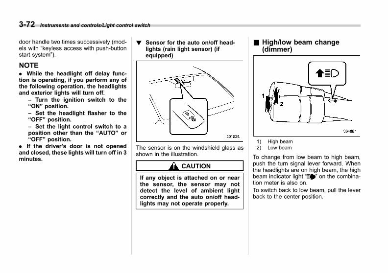
Black plate (216,1)
一般Model "A1300GE-A" EDITED: 2016/ 9/ 13
3-72 Instruments and controls/Light control switch
door handle two times successively (mod-els with “keyless access with push-buttonstart system”).
NOTE. While the headlight off delay func-tion is operating, if you perform any ofthe following operation, the headlightsand exterior lights will turn off.
– Turn the ignition switch to the“ON” position.– Set the headlight flasher to the“OFF” position.– Set the light control switch to aposition other than the “AUTO” or“OFF” position.
. If the driver’s door is not openedand closed, these lights will turn off in 3minutes.
! Sensor for the auto on/off head-lights (rain light sensor) (ifequipped)
The sensor is on the windshield glass asshown in the illustration.
CAUTION
If any object is attached on or nearthe sensor, the sensor may notdetect the level of ambient lightcorrectly and the auto on/off head-lights may not operate properly.
& High/low beam change(dimmer)
1) High beam2) Low beam
To change from low beam to high beam,push the turn signal lever forward. Whenthe headlights are on high beam, the highbeam indicator light “ ” on the combina-tion meter is also on.To switch back to low beam, pull the leverback to the center position.

Black plate (217,1)
一般Model "A1300GE-A" EDITED: 2016/ 9/ 13
& Headlight flasher
CAUTION
Do not hold the lever in the flashingposition for more than just a fewseconds.
To flash the headlights, pull the levertoward you and then release it. The highbeam will stay on for as long as you holdthe lever.
When the headlights are on high beam,the high beam indicator light “ ” on thecombination meter is also on.
& High Beam Assist function (ifequipped)
NOTE. Do not overestimate the capacity ofthe High Beam Assist function. Thedriver always has the responsibility tounderstand the surrounding situation,to drive safely, and to change theheadlight mode manually if necessary.. Observe the following points inorder to operate the High Beam Assistfunction properly.
– Do not attach labels or stickers tothe windshield glass near the cam-era.– Do not attach any accessoriesnear the inside mirror and camera.– Do not place any objects over the
dashboard.– Do not touch the lens of thecamera.– Do not touch the camera.– Do not apply any strong impactto the camera or the inside mirror.– Do not disassemble the cameraand inside mirror.– Do not spill liquid on the insidemirror and camera.– Do not carry excessive luggage.– Do not modify the vehicle.– Always replace the windshieldglass with genuine SUBARU parts(or equivalent products).
1) Camera for High Beam Assist function
The high beam assist function automati-cally changes the headlight from high
Instruments and controls/Light control switch 3-73
– CONTINUED –
3
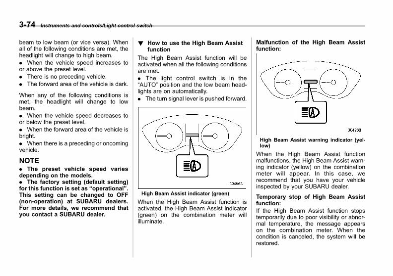
Black plate (218,1)
一般Model "A1300GE-A" EDITED: 2016/ 9/ 13
3-74 Instruments and controls/Light control switch
beam to low beam (or vice versa). Whenall of the following conditions are met, theheadlight will change to high beam.. When the vehicle speed increases toor above the preset level.. There is no preceding vehicle.. The forward area of the vehicle is dark.
When any of the following conditions ismet, the headlight will change to lowbeam.. When the vehicle speed decreases toor below the preset level.. When the forward area of the vehicle isbright.. When there is a preceding or oncomingvehicle.
NOTE. The preset vehicle speed variesdepending on the models.. The factory setting (default setting)for this function is set as “operational”.This setting can be changed to OFF(non-operation) at SUBARU dealers.For more details, we recommend thatyou contact a SUBARU dealer.
! How to use the High Beam Assistfunction
The High Beam Assist function will beactivated when all the following conditionsare met.. The light control switch is in the“AUTO” position and the low beam head-lights are on automatically.. The turn signal lever is pushed forward.
High Beam Assist indicator (green)
When the High Beam Assist function isactivated, the High Beam Assist indicator(green) on the combination meter willilluminate.
Malfunction of the High Beam Assistfunction:
High Beam Assist warning indicator (yel-low)
When the High Beam Assist functionmalfunctions, the High Beam Assist warn-ing indicator (yellow) on the combinationmeter will appear. In this case, werecommend that you have your vehicleinspected by your SUBARU dealer.
Temporary stop of High Beam Assistfunction:If the High Beam Assist function stopstemporarily due to poor visibility or abnor-mal temperature, the message appearson the combination meter. When thecondition is canceled, the system will berestored.
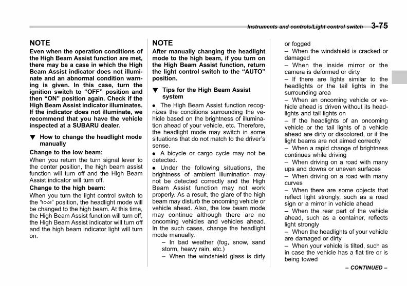
Black plate (219,1)
一般Model "A1300GE-A" EDITED: 2016/ 9/ 13
NOTEEven when the operation conditions ofthe High Beam Assist function are met,there may be a case in which the HighBeam Assist indicator does not illumi-nate and an abnormal condition warn-ing is given. In this case, turn theignition switch to “OFF” position andthen “ON” position again. Check if theHigh Beam Assist indicator illuminates.If the indicator does not illuminate, werecommend that you have the vehicleinspected at a SUBARU dealer.
! How to change the headlight modemanually
Change to the low beam:When you return the turn signal lever tothe center position, the high beam assistfunction will turn off and the High BeamAssist indicator will turn off.Change to the high beam:When you turn the light control switch tothe “ ” position, the headlight mode willbe changed to the high beam. At this time,the High Beam Assist function will turn off,the High Beam Assist indicator will turn offand the high beam indicator light will turnon.
NOTEAfter manually changing the headlightmode to the high beam, if you turn onthe High Beam Assist function, returnthe light control switch to the “AUTO”position.
! Tips for the High Beam Assistsystem
. The High Beam Assist function recog-nizes the conditions surrounding the ve-hicle based on the brightness of illumina-tion ahead of your vehicle, etc. Therefore,the headlight mode may switch in somesituations that do not match to the driver’ssense.. A bicycle or cargo cycle may not bedetected.. Under the following situations, thebrightness of ambient illumination maynot be detected correctly and the HighBeam Assist function may not workproperly. As a result, the glare of the highbeam may disturb the oncoming vehicle orvehicle ahead. Also, the low beam modemay continue although there are nooncoming vehicles and vehicles ahead.In the such cases, change the headlightmode manually.
– In bad weather (fog, snow, sandstorm, heavy rain, etc.)– When the windshield glass is dirty
or fogged– When the windshield is cracked ordamaged– When the inside mirror or thecamera is deformed or dirty– If there are lights similar to theheadlights or the tail lights in thesurrounding area– When an oncoming vehicle or ve-hicle ahead is driven without its head-lights and tail lights on– If the headlights of an oncomingvehicle or the tail lights of a vehicleahead are dirty or discolored, or if thelight beams are not aimed correctly– When a rapid change of brightnesscontinues while driving– When driving on a road with manyups and downs or uneven surfaces– When driving on a road with manycurves– When there are some objects thatreflect light strongly, such as a roadsign or a mirror in vehicle ahead– When the rear part of the vehicleahead, such as a container, reflectslight strongly– When the headlights of your vehicleare damaged or dirty– When your vehicle is tilted, such asin case the vehicle has a flat tire or isbeing towed
Instruments and controls/Light control switch 3-75
– CONTINUED –
3

Black plate (220,1)
一般Model "A1300GE-A" EDITED: 2016/ 9/ 13
3-76 Instruments and controls/Light control switch
. In the following conditions, the head-light mode will not be automatically chan-ged from the high beam to the low beam.
– When your vehicle passes an on-coming vehicle suddenly in a blindcurve– When another vehicle passes infront of your vehicle– When an oncoming vehicle or ve-hicle ahead comes in and out of viewbecause of continuous curves, medianstrips, roadside trees, etc.
. If the camera detects the light of thefront fog lights of an oncoming vehicle, theheadlight mode may change from the highbeam to the low beam automatically.. The headlight mode may change fromthe high beam to the low beam, or the lowbeam mode may continue, when affectedby a street light, traffic signal, illuminationof an advertisement board, or a reflectiveobject such as a road sign and signboard.. The timing of the change of headlightmode may differ due to the followingfactors.
– Color or brightness of the head-lights of an oncoming vehicle or the taillights of a vehicle ahead– Movement and direction of an on-coming vehicle or a vehicle ahead– When the headlights of an oncom-ing vehicle or the tail lights of a vehicle
ahead illuminate on only one side– When the oncoming vehicle orvehicle ahead is a motorcycle– Conditions of a road (slope, curve,road surface, etc.)– Number of passengers and weightof loaded cargo
. The range recognizable for the camerais +15 degrees in both directions (30degrees in total) from the vehicle front.The recognizable distance differs depend-ing on the situation in the surroundingarea.. This function can be disabled atSUBARU dealers. For more details, werecommend that you contact a SUBARUdealer.
& Daytime running light system(if equipped)
WARNING
When the daytime running lights areilluminated, the tail lights do notilluminate. When it becomes darkoutside, turn the light switch to the“ ” position to illuminate the head-lights and tail lights. This will im-prove visibility and allow other dri-vers to see your vehicle more easily.
The daytime running lights will automati-cally illuminate when the following condi-tions are fulfilled.. The engine is running.. The parking brake is fully released.. The light control switch is in the“AUTO” (if equipped), “ ”/“ ” or offposition.. The select lever is in a position otherthan the “P” position.
NOTE. When the headlight switch is in the“ ” or “ ” position, the daytimerunning light system is deactivated.. For models with the auto on/offheadlights, while the headlight switchis in the “AUTO” position and theheadlights turn on automatically, thedaytime running light is deactivated.
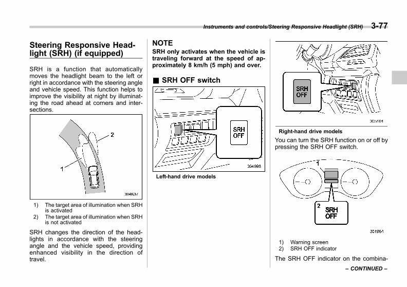
Black plate (221,1)
一般Model "A1300GE-A" EDITED: 2016/ 9/ 13
Steering Responsive Head-light (SRH) (if equipped)
SRH is a function that automaticallymoves the headlight beam to the left orright in accordance with the steering angleand vehicle speed. This function helps toimprove the visibility at night by illuminat-ing the road ahead at corners and inter-sections.
1) The target area of illumination when SRHis activated
2) The target area of illumination when SRHis not activated
SRH changes the direction of the head-lights in accordance with the steeringangle and the vehicle speed, providingenhanced visibility in the direction oftravel.
NOTESRH only activates when the vehicle istraveling forward at the speed of ap-proximately 8 km/h (5 mph) and over.
& SRH OFF switch
Left-hand drive models
Right-hand drive models
You can turn the SRH function on or off bypressing the SRH OFF switch.
1) Warning screen2) SRH OFF indicator
The SRH OFF indicator on the combina-
Instruments and controls/Steering Responsive Headlight (SRH) 3-77
– CONTINUED –
3
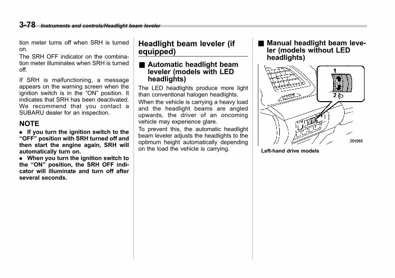
Black plate (222,1)
一般Model "A1300GE-A" EDITED: 2016/ 9/ 13
3-78 Instruments and controls/Headlight beam leveler
tion meter turns off when SRH is turnedon.The SRH OFF indicator on the combina-tion meter illuminates when SRH is turnedoff.
If SRH is malfunctioning, a messageappears on the warning screen when theignition switch is in the “ON” position. Itindicates that SRH has been deactivated.We recommend that you contact aSUBARU dealer for an inspection.
NOTE. If you turn the ignition switch to the“OFF” position with SRH turned off andthen start the engine again, SRH willautomatically turn on.. When you turn the ignition switch tothe “ON” position, the SRH OFF indi-cator will illuminate and turn off afterseveral seconds.
Headlight beam leveler (ifequipped)
& Automatic headlight beamleveler (models with LEDheadlights)
The LED headlights produce more lightthan conventional halogen headlights.When the vehicle is carrying a heavy loadand the headlight beams are angledupwards, the driver of an oncomingvehicle may experience glare.To prevent this, the automatic headlightbeam leveler adjusts the headlights to theoptimum height automatically dependingon the load the vehicle is carrying.
& Manual headlight beam leve-ler (models without LEDheadlights)
Left-hand drive models
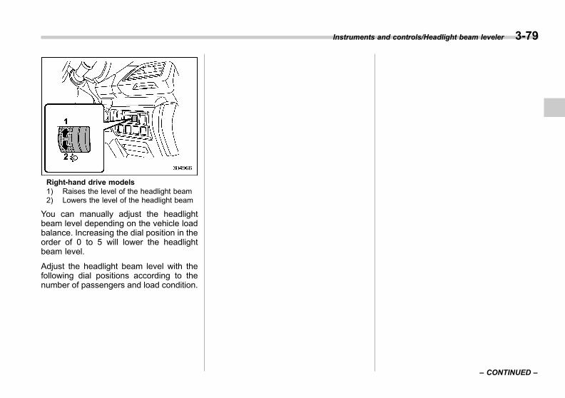
Black plate (223,1)
一般Model "A1300GE-A" EDITED: 2016/ 9/ 13
Right-hand drive models1) Raises the level of the headlight beam2) Lowers the level of the headlight beam
You can manually adjust the headlightbeam level depending on the vehicle loadbalance. Increasing the dial position in theorder of 0 to 5 will lower the headlightbeam level.
Adjust the headlight beam level with thefollowing dial positions according to thenumber of passengers and load condition.
Instruments and controls/Headlight beam leveler 3-79
– CONTINUED –
3
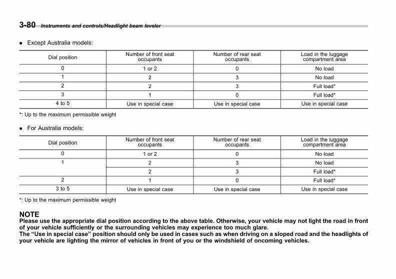
Black plate (224,1)
一般Model "A1300GE-A" EDITED: 2016/ 9/ 13
3-80 Instruments and controls/Headlight beam leveler
. Except Australia models:
Dial positionNumber of front seat
occupantsNumber of rear seat
occupantsLoad in the luggagecompartment area
0 1 or 2 0 No load
1 2 3 No load
2 2 3 Full load*
3 1 0 Full load*
4 to 5 Use in special case Use in special case Use in special case
*: Up to the maximum permissible weight
. For Australia models:
Dial positionNumber of front seat
occupantsNumber of rear seat
occupantsLoad in the luggagecompartment area
0 1 or 2 0 No load
1 2 3 No load
2 3 Full load*
2 1 0 Full load*
3 to 5 Use in special case Use in special case Use in special case
*: Up to the maximum permissible weight
NOTEPlease use the appropriate dial position according to the above table. Otherwise, your vehicle may not light the road in frontof your vehicle sufficiently or the surrounding vehicles may experience too much glare.The “Use in special case” position should only be used in cases such as when driving on a sloped road and the headlights ofyour vehicle are lighting the mirror of vehicles in front of you or the windshield of oncoming vehicles.
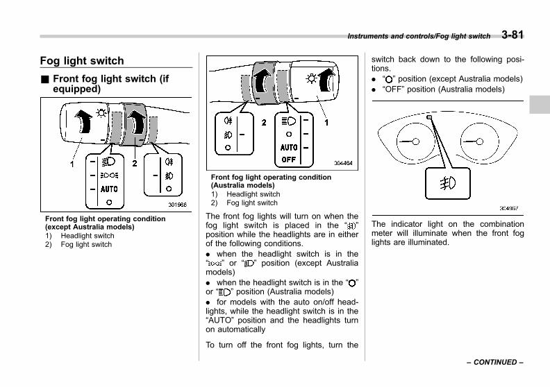
Black plate (225,1)
一般Model "A1300GE-A" EDITED: 2016/ 9/ 13
Fog light switch
& Front fog light switch (ifequipped)
Front fog light operating condition(except Australia models)1) Headlight switch2) Fog light switch
Front fog light operating condition(Australia models)1) Headlight switch2) Fog light switch
The front fog lights will turn on when thefog light switch is placed in the “ ”position while the headlights are in eitherof the following conditions.. when the headlight switch is in the“ ” or “ ” position (except Australiamodels). when the headlight switch is in the “ ”or “ ” position (Australia models). for models with the auto on/off head-lights, while the headlight switch is in the“AUTO” position and the headlights turnon automatically
To turn off the front fog lights, turn the
switch back down to the following posi-tions.. “ ” position (except Australia models). “OFF” position (Australia models)
The indicator light on the combinationmeter will illuminate when the front foglights are illuminated.
Instruments and controls/Fog light switch 3-81
– CONTINUED –
3

Black plate (226,1)
一般Model "A1300GE-A" EDITED: 2016/ 9/ 13
3-82 Instruments and controls/Fog light switch
& Rear fog light switch (ifequipped)
Rear fog light operating condition (exceptAustralia models)1) Headlight switch2) Fog light switch
Rear fog light operating condition (Austra-lia models)1) Headlight switch2) Fog light switch
The rear fog light will turn on when the foglight switch is turned to the “ ” positionwhile the headlights are in either of thefollowing conditions.. while the headlight switch is in the“ ” or “ ” position (except Australiamodels). when the headlight switch is in the “ ”or “ ” position (Australia models). for models with the auto on/off head-lights, while the headlight switch is in the“AUTO” position and the headlights turnon automatically
The switch will return to the following
position when released.. “ ” position (models with front foglights). “ ” position (models without front foglights)
To turn off the rear fog light, perform eitherof the following procedures.. Turn the fog light switch upward to the“ ” position again (all models). Turn the fog light switch downward tothe “ ” position (models with front foglights)
The indicator light on the combinationmeter will illuminate when the rear foglight is illuminated.
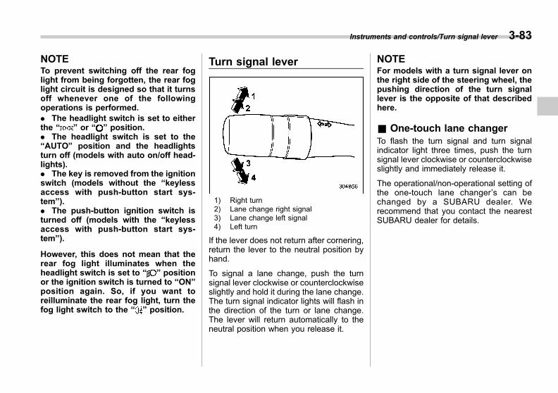
Black plate (227,1)
一般Model "A1300GE-A" EDITED: 2016/ 9/ 13
NOTETo prevent switching off the rear foglight from being forgotten, the rear foglight circuit is designed so that it turnsoff whenever one of the followingoperations is performed.. The headlight switch is set to eitherthe “ ” or “ ” position.. The headlight switch is set to the“AUTO” position and the headlightsturn off (models with auto on/off head-lights).. The key is removed from the ignitionswitch (models without the “keylessaccess with push-button start sys-tem”).. The push-button ignition switch isturned off (models with the “keylessaccess with push-button start sys-tem”).
However, this does not mean that therear fog light illuminates when theheadlight switch is set to “ ” positionor the ignition switch is turned to “ON”position again. So, if you want toreilluminate the rear fog light, turn thefog light switch to the “ ” position.
Turn signal lever
1) Right turn2) Lane change right signal3) Lane change left signal4) Left turn
If the lever does not return after cornering,return the lever to the neutral position byhand.
To signal a lane change, push the turnsignal lever clockwise or counterclockwiseslightly and hold it during the lane change.The turn signal indicator lights will flash inthe direction of the turn or lane change.The lever will return automatically to theneutral position when you release it.
NOTEFor models with a turn signal lever onthe right side of the steering wheel, thepushing direction of the turn signallever is the opposite of that describedhere.
& One-touch lane changerTo flash the turn signal and turn signalindicator light three times, push the turnsignal lever clockwise or counterclockwiseslightly and immediately release it.
The operational/non-operational setting ofthe one-touch lane changer’s can bechanged by a SUBARU dealer. Werecommend that you contact the nearestSUBARU dealer for details.
Instruments and controls/Turn signal lever 3-83
3

Black plate (228,1)
一般Model "A1300GE-A" EDITED: 2016/ 9/ 13
3-84 Instruments and controls/Wiper and washer
Wiper and washer
WARNING
In freezing weather, do not use thewindshield washer until the wind-shield is sufficiently warmed by thedefroster.
Otherwise the washer fluid canfreeze on the windshield, blockingyour view.
CAUTION
. Do not operate the washer con-tinuously for more than 10 sec-onds, or when the washer fluidtank is empty. This may causeoverheating of the washer motor.Check the washer fluid levelfrequently, such as at fuel stops.
. Do not operate the wipers whenthe windshield or rear window isdry. This may scratch the glass,damage the blade rubbers andmight cause the wiper motor tofail. Before operating the wiperon a dry windshield or rearwindow, always use the wind-shield washer.
. In freezing weather, be sure thatthe blade rubbers are not frozento the windshield or rear windowbefore switching on the wipers.Attempting to operate the wiperwith the blades frozen to thewindow glass could cause notonly the blade rubbers to bedamaged but also might causethe wiper motor to fail. If theblade rubbers are frozen to thewindow glass, be sure to operatethe defroster, windshield wiperdeicer (if equipped) or rear win-dow defogger before turning onthe wiper.
. If the wipers stop during opera-tion because of ice or some otherobstruction on the window, thismight cause the wiper motor tofail even if the wiper switch isturned off. I f this occurs,promptly stop the vehicle in asafe place, turn the ignitionswitch to the “LOCK”/“OFF” po-sition and clean the windowglass to allow proper wiper op-eration.
. Use clean water if windshieldwasher fluid is unavailable. Inareas where water freezes inwinter, use SUBARU Windshield
Washer Fluid or the equivalent.Refer to “Windshield washerfluid” F11-32.
Also, when driving the vehiclewhen there are freezing tempera-tures, use non-freezing typeblade rubbers.
. Do not clean the blade rubberswith fuel or a solvent, such aspaint thinner or benzine. This willcause deterioration of the bladerubbers.
For models with automatic rain sen-sing windshield wipers:
. When the wiper switch is in the“AUTO” position, do not touchthe windshield near the rain lightsensor and do not place a wetcloth on the windshield near therain light sensor. Doing so mayresult in unexpected wiper opera-tion and cause injury.
. When washing the vehicle, makesure that the wiper is turned off.Otherwise, the wipers may oper-ate unexpectedly and cause in-jury.
. When having your vehiclewashed in an automatic carwash, make sure that the wiperis turned off. Otherwise, the wi-

Black plate (229,1)
一般Model "A1300GE-A" EDITED: 2016/ 9/ 13
pers may be damaged becausethey may operate unexpectedlyand car wash brushes couldbecome tangled around them.
NOTE. The windshield wiper motor is pro-tected against overloads by a circuitbreaker. If the motor operates continu-ously under an unusually heavy load,the circuit breaker may trip to stop themotor temporarily. If this happens, parkyour vehicle in a safe place, turn off thewiper switch, and wait for approxi-mately 10 minutes. The circuit breakerwill reset itself, and the wipers willagain operate normally.. Clean the blade rubbers and windowglass periodically with a washer solu-tion to prevent streaking, and to re-move accumulations of road salt orroad film. Operate the windshieldwasher for at least 1 second so thatwasher solution will be sprinkled allover the windshield or rear window.. Grease, wax, insects or other mate-rial on the windshield or the bladerubber results in jerky wiper operationand streaking on the glass. If youcannot remove those streaks afteroperating the washer or if the wiperoperation is jerky, clean the outer sur-
face of the windshield or rear windowand the blade rubbers using a spongeor soft cloth with a neutral detergent ormild-abrasive cleaner. After cleaning,rinse the window glass and bladerubbers with clean water. The glass isclean if no beads form on the glasswhen you rinse with water.. If you cannot eliminate the streakingeven after following this procedure,replace the blade rubbers with newones. For replacement instructions,refer to “Replacement of wiper blades”F11-34.
NOTEFor models with automatic rain sensingwindshield wipers:. When the wiper switch is turned tothe “AUTO” position while the ignitionswitch is in the “ON” position, thewipers will operate once. This indicatesthat the wiper switch is in the “AUTO”position.. When the wiper switch is in the“AUTO” position, the following situa-tions may occur.
– The wipers may operate if therain light sensor or the windshieldis vibrated or objects such as,insects, dirt, mud, etc. are coveringthem. Turn off the wiper unless it is
raining or snowing.– The wipers do not operate if therain light sensor does not detectrain or snow. If necessary, push thewiper control lever down to the lowspeed position or high speed posi-tion.– The wipers may not operateproperly if the rain light sensordoes not detect the amount of rain-drops because of the water-repel-lent coating on the windshield, ordirt or ice on the upper half of thewindshield.– The rain light sensor may bemalfunctioning if the wiper intermit-tent operation does not vary de-pending on the amount of rainfall. Ifnecessary, turn the wiper switch toany position except for the “AUTO”position. We recommend that youcontact your SUBARU dealer andhave the system inspected as soonas possible.– The wipers stop operation if theambient temperature decreases to−158C (58F) or lower. The wipersresume operation when the ambienttemperature increases to −108C(148F) or higher. If you need tooperate the wipers under −158C(58F), push the wiper control lever
Instruments and controls/Wiper and washer 3-85
– CONTINUED –
3
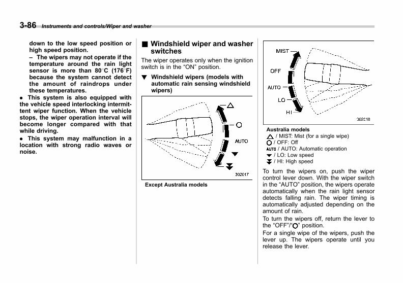
Black plate (230,1)
一般Model "A1300GE-A" EDITED: 2016/ 9/ 13
3-86 Instruments and controls/Wiper and washer
down to the low speed position orhigh speed position.– The wipers may not operate if thetemperature around the rain lightsensor is more than 808C (1768F)because the system cannot detectthe amount of raindrops underthese temperatures.
. This system is also equipped withthe vehicle speed interlocking intermit-tent wiper function. When the vehiclestops, the wiper operation interval willbecome longer compared with thatwhile driving.. This system may malfunction in alocation with strong radio waves ornoise.
& Windshield wiper and washerswitches
The wiper operates only when the ignitionswitch is in the “ON” position.
! Windshield wipers (models withautomatic rain sensing windshieldwipers)
Except Australia models
Australia models/ MIST: Mist (for a single wipe)/ OFF: Off/ AUTO: Automatic operation
/ LO: Low speed/ HI: High speed
To turn the wipers on, push the wipercontrol lever down. With the wiper switchin the “AUTO” position, the wipers operateautomatically when the rain light sensordetects falling rain. The wiper timing isautomatically adjusted depending on theamount of rain.To turn the wipers off, return the lever tothe “OFF”/“ ” position.For a single wipe of the wipers, push thelever up. The wipers operate until yourelease the lever.

Black plate (231,1)
一般Model "A1300GE-A" EDITED: 2016/ 9/ 13
NOTEThe automatic adjusting mode of thewiper timing can be changed from therain-sensing mode to the vehicle speedinterlocking mode. The setting can bechanged by a SUBARU dealer. Formore details, we recommend that youcontact a SUBARU dealer.
! Rain light sensor
The rain light sensor is on the windshieldglass.
! Sensor sensitivity control
1) Except Australia models2) Australia models
Turn the dial to adjust the sensitivity of therain light sensor for wiper control. Turn thedial downward to increase the sensitivity.Turn the dial upward to decrease thesensitivity.
! Windshield wipers (models withoutautomatic rain sensing windshieldwipers)
Except Australia models
Instruments and controls/Wiper and washer 3-87
– CONTINUED –
3

Black plate (232,1)
一般Model "A1300GE-A" EDITED: 2016/ 9/ 13
3-88 Instruments and controls/Wiper and washer
Australia models/ MIST: Mist (for a single wipe)/ OFF: Off/ INT: Intermittent/ LO: Low speed/ HI: High speed
To turn the wipers on, push the wipercontrol lever down.
To turn the wipers off, return the lever tothe “ ”/“OFF” position.
For a single wipe of the wipers, push thelever up. The wipers operate until yourelease the lever.
! Wiper intermittent time control
1) Except Australia models2) Australia models
When the wiper switch is in the “ ”/“INT”position, turn the dial to adjust the operat-ing interval of the wiper. The operatinginterval can be adjusted in several stepsfrom the shortest interval to the longest.
! Windshield washer
1) Except Australia models2) Australia models
To wash the windshield, pull the wipercontrol lever toward you. The washer fluidsprays until you release the lever. Thewipers operate while you pull the lever.
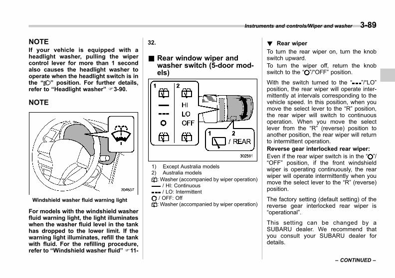
Black plate (233,1)
一般Model "A1300GE-A" EDITED: 2016/ 9/ 13
NOTEIf your vehicle is equipped with aheadlight washer, pulling the wipercontrol lever for more than 1 secondalso causes the headlight washer tooperate when the headlight switch is inthe “ ” position. For further details,refer to “Headlight washer” F3-90.
NOTE
Windshield washer fluid warning light
For models with the windshield washerfluid warning light, the light illuminateswhen the washer fluid level in the tankhas dropped to the lower limit. If thewarning light illuminates, refill the tankwith fluid. For the refilling procedure,refer to “Windshield washer fluid” F11-
32.
& Rear window wiper andwasher switch (5-door mod-els)
1) Except Australia models2) Australia models
: Washer (accompanied by wiper operation)/ HI: Continuous/ LO: Intermittent
/ OFF: Off: Washer (accompanied by wiper operation)
! Rear wiper
To turn the rear wiper on, turn the knobswitch upward.To turn the wiper off, return the knobswitch to the “ ”/“OFF” position.
With the switch turned to the “ ”/“LO”position, the rear wiper will operate inter-mittently at intervals corresponding to thevehicle speed. In this position, when youmove the select lever to the “R” position,the rear wiper will switch to continuousoperation. When you move the selectlever from the “R” (reverse) position toanother position, the rear wiper will returnto intermittent operation.Reverse gear interlocked rear wiper:Even if the rear wiper switch is in the “ ”/“OFF” position, if the front windshieldwiper is operating continuously, the rearwiper will operate intermittently when youmove the select lever to the “R” (reverse)position.
The factory setting (default setting) of thereverse gear interlocked rear wiper is“operational”.
This setting can be changed by aSUBARU dealer. We recommend thatyou consult your SUBARU dealer fordetails.
Instruments and controls/Wiper and washer 3-89
– CONTINUED –
3
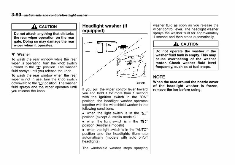
Black plate (234,1)
一般Model "A1300GE-A" EDITED: 2016/ 9/ 13
3-90 Instruments and controls/Headlight washer
CAUTION
Do not attach anything that disturbsthe rear wiper operation on the reargate. Doing so may damage the rearwiper when it operates.
! Washer
To wash the rear window while the rearwiper is operating, turn the knob switchupward to the “ ” position. The washerfluid sprays until you release the knob.To wash the rear window when the rearwiper is not in use, turn the knob switchdownward to the “ ” position. The washerfluid sprays and the wiper operates untilyou release the knob.
Headlight washer (ifequipped)
If you pull the wiper control lever towardyou and hold it for more than 1 secondwith the ignition switch in the “ON”position, the headlight washer operatestogether with the windshield washer in thefollowing conditions.. when the light switch is in the “ ”position (except Australia models). when the light switch is in the “ ”position (Australia models). when the light switch is in the “AUTO”position and the headlights illuminateautomatically (models with auto on/offheadlights)
The windshield washer stops spraying
washer fluid as soon as you release thewiper control lever. The headlight washersprays the washer fluid for approximately1 second and then stops automatically.
CAUTION
Do not operate the washer if thewasher fluid tank is empty. This maycause overheating of the washermotor. Check washer fluid levelfrequently, such as at fuel stops.
NOTEWhen the area around the nozzle coverof the headlight washer is frozen,remove the ice before using.
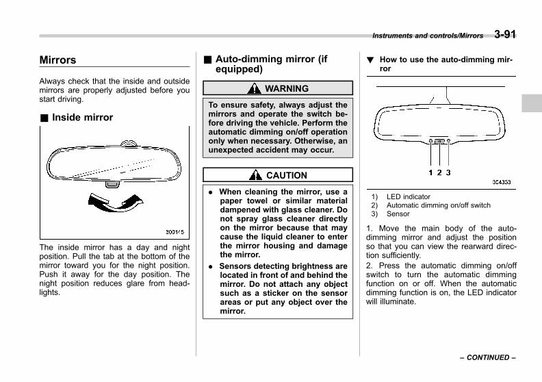
Black plate (235,1)
一般Model "A1300GE-A" EDITED: 2016/ 9/ 13
Mirrors
Always check that the inside and outsidemirrors are properly adjusted before youstart driving.
& Inside mirror
The inside mirror has a day and nightposition. Pull the tab at the bottom of themirror toward you for the night position.Push it away for the day position. Thenight position reduces glare from head-lights.
& Auto-dimming mirror (ifequipped)
WARNING
To ensure safety, always adjust themirrors and operate the switch be-fore driving the vehicle. Perform theautomatic dimming on/off operationonly when necessary. Otherwise, anunexpected accident may occur.
CAUTION
. When cleaning the mirror, use apaper towel or similar materialdampened with glass cleaner. Donot spray glass cleaner directlyon the mirror because that maycause the liquid cleaner to enterthe mirror housing and damagethe mirror.
. Sensors detecting brightness arelocated in front of and behind themirror. Do not attach any objectsuch as a sticker on the sensorareas or put any object over themirror.
! How to use the auto-dimming mir-ror
1) LED indicator2) Automatic dimming on/off switch3) Sensor
1. Move the main body of the auto-dimming mirror and adjust the positionso that you can view the rearward direc-tion sufficiently.2. Press the automatic dimming on/offswitch to turn the automatic dimmingfunction on or off. When the automaticdimming function is on, the LED indicatorwill illuminate.
Instruments and controls/Mirrors 3-91
– CONTINUED –
3
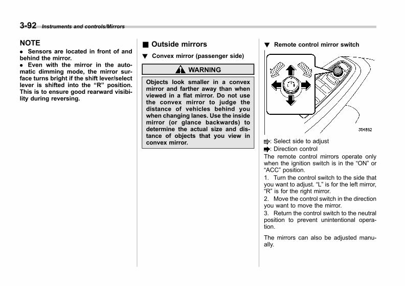
Black plate (236,1)
一般Model "A1300GE-A" EDITED: 2016/ 9/ 13
3-92 Instruments and controls/Mirrors
NOTE. Sensors are located in front of andbehind the mirror.. Even with the mirror in the auto-matic dimming mode, the mirror sur-face turns bright if the shift lever/selectlever is shifted into the “R” position.This is to ensure good rearward visibi-lity during reversing.
& Outside mirrors
! Convex mirror (passenger side)
WARNING
Objects look smaller in a convexmirror and farther away than whenviewed in a flat mirror. Do not usethe convex mirror to judge thedistance of vehicles behind youwhen changing lanes. Use the insidemirror (or glance backwards) todetermine the actual size and dis-tance of objects that you view inconvex mirror.
! Remote control mirror switch
: Select side to adjust: Direction control
The remote control mirrors operate onlywhen the ignition switch is in the “ON” or“ACC” position.1. Turn the control switch to the side thatyou want to adjust. “L” is for the left mirror,“R” is for the right mirror.2. Move the control switch in the directionyou want to move the mirror.3. Return the control switch to the neutralposition to prevent unintentional opera-tion.
The mirrors can also be adjusted manu-ally.
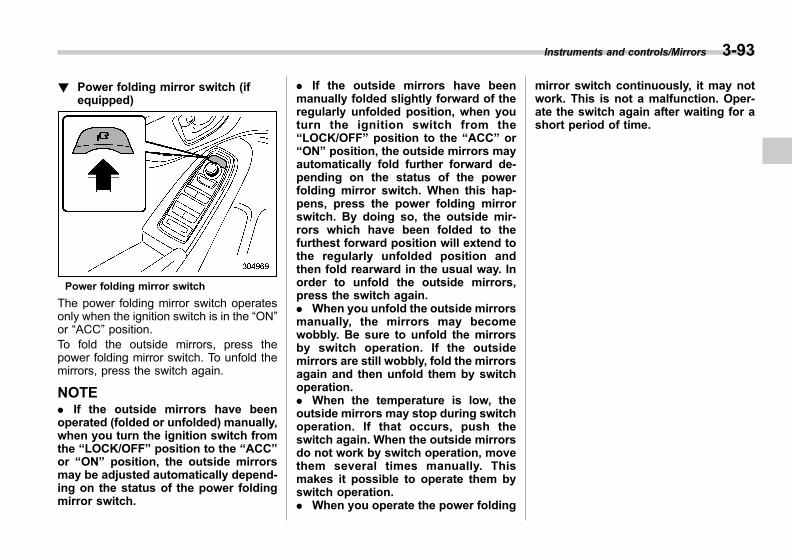
Black plate (237,1)
一般Model "A1300GE-A" EDITED: 2016/ 9/ 13
! Power folding mirror switch (ifequipped)
Power folding mirror switch
The power folding mirror switch operatesonly when the ignition switch is in the “ON”or “ACC” position.To fold the outside mirrors, press thepower folding mirror switch. To unfold themirrors, press the switch again.
NOTE. If the outside mirrors have beenoperated (folded or unfolded) manually,when you turn the ignition switch fromthe “LOCK/OFF” position to the “ACC”or “ON” position, the outside mirrorsmay be adjusted automatically depend-ing on the status of the power foldingmirror switch.
. If the outside mirrors have beenmanually folded slightly forward of theregularly unfolded position, when youturn the ignition switch from the“LOCK/OFF” position to the “ACC” or“ON” position, the outside mirrors mayautomatically fold further forward de-pending on the status of the powerfolding mirror switch. When this hap-pens, press the power folding mirrorswitch. By doing so, the outside mir-rors which have been folded to thefurthest forward position will extend tothe regularly unfolded position andthen fold rearward in the usual way. Inorder to unfold the outside mirrors,press the switch again.. When you unfold the outside mirrorsmanually, the mirrors may becomewobbly. Be sure to unfold the mirrorsby switch operation. If the outsidemirrors are still wobbly, fold the mirrorsagain and then unfold them by switchoperation.. When the temperature is low, theoutside mirrors may stop during switchoperation. If that occurs, push theswitch again. When the outside mirrorsdo not work by switch operation, movethem several times manually. Thismakes it possible to operate them byswitch operation.. When you operate the power folding
mirror switch continuously, it may notwork. This is not a malfunction. Oper-ate the switch again after waiting for ashort period of time.
Instruments and controls/Mirrors 3-93
3

Black plate (238,1)
一般Model "A1300GE-A" EDITED: 2016/ 9/ 13
3-94 Instruments and controls/Defogger and deicer
Defogger and deicer
1) Rear window defogger2) Outside mirror defogger (if equipped)3) Windshield wiper deicer (if equipped)
The vehicle is equipped with a rear
window defogger. Some models are alsoequipped with an outside mirror defoggerand/or windshield wiper deicer. The de-fogger and deicer system is activated onlywhen the ignition switch is in the “ON”position.
Type A or type B climate control system1) Models without outside mirror defogger2) Models with outside mirror defogger
Type C or type D climate control system1) Models without outside mirror defogger2) Models with outside mirror defogger
To activate the defogger and deicersystem, press the control switch that islocated on the climate control panel. Therear window defogger, outside mirrordefogger and windshield wiper deicer areactivated simultaneously. The indicatorlight on the control switch illuminates whilethe defogger and deicer system is acti-vated.
To turn them off, press the control switchagain. They also turn off when the ignitionswitch is turned to the “ACC” or “LOCK”/“OFF” position.
The defogger and deicer system willautomatically shut off after approximately

Black plate (239,1)
一般Model "A1300GE-A" EDITED: 2016/ 9/ 13
15 minutes. If the rear window and theoutside mirrors have been cleared and thewindshield blade rubbers have beendeiced completely before that time, pressthe control switch to turn them off. Ifdefrosting, defogging or deicing is notcomplete, you have to press the controlswitch to turn them on again.
For models with the automatic climatecontrol system, it is possible for thedefogger and deicer system to be set tocontinuous operation mode by a SUBARUdealer. We recommend that you consultyour SUBARU dealer for details. Also, formodels with a combination meter display(color LCD), it is possible to set thedefogger and deicer system for the con-tinuous operation mode. For details, referto “Vehicle Setting” F3-44.
CAUTION
. To prevent the battery from beingdischarged, do not operate thedefogger and deicer system con-tinuously for any longer thannecessary.
. Do not use sharp instruments orwindow cleaner containing abra-sives to clean the inner surfaceof the rear window. They maydamage the conductors printed
on the window.
NOTE. Turn on the defogger and deicersystem if the wipers are frozen to thewindshield.. If the windshield is covered withsnow, remove the snow so that thewindshield wiper deicer works effec-tively.. While the defogger and deicer sys-tem is in the continuous operationmode:
– If the vehicle speed remains at 15km/h (9 mph) or lower for 15minutes, the windshield wiper dei-cer stops operating. However, therear window defogger and outsidemirror defogger maintain continu-ous operation.– If the battery voltage drops belowthe permissible level, the defoggerand deicer system stops operating.
Tilt/telescopic steering wheel
WARNING
. Do not adjust the steering wheeltilt/telescopic position while driv-ing. This may cause loss ofvehicle control and result inpersonal injury.
. If the lever cannot be raised tothe fixed position, adjust thesteering wheel again. It is dan-gerous to drive without lockingthe steering wheel. This maycause loss of vehicle controland result in personal injury.
Instruments and controls/Tilt/telescopic steering wheel 3-95
– CONTINUED –
3

Black plate (240,1)
一般Model "A1300GE-A" EDITED: 2016/ 9/ 13
3-96 Instruments and controls/Heated Steering Wheel system
1) Tilt adjustment2) Telescopic adjustment3) Tilt/telescopic lock lever
1. Adjust the seat position. Refer to“Front seats” F1-5.2. Pull the tilt/telescopic lock lever down.3. Move the steering wheel to the desiredlevel.4. Pull the lever up to lock the steeringwheel in place.5. Make sure that the steering wheel issecurely locked by moving it up and down,and forward and backward.
Heated Steering Wheel sys-tem (if equipped)
The Heated Steering Wheel systemwarms the surface of the steering wheelat a constant temperature.
1) Heated Steering Wheel switch2) Indicator light3) Heated area
Pull the Heated Steering Wheel switch towarm the steering wheel when the ignitionswitch is in the “ACC” or “ON” position.When the Heated Steering Wheel systemis turned on, the indicator light on theswitch will illuminate.
Pull the switch again to turn the HeatedSteering Wheel system off manually. Theindicator light will turn off.
CAUTION
. If you use the Heated SteeringWheel system without the enginerunning, the battery voltage maydrop below the permissible leveland it may not be possible tostart the engine.
. There is a possibility that peoplewith delicate skin may sufferslight burns even at low tempera-tures if they use the HeatedSteering Wheel for a long periodof time. When using the HeatedSteering Wheel, always be sureto warn the persons concerned.
. Do not cover the Heated SteeringWheel with an object such as asteering wheel cover. Doing somay cause the Heated SteeringWheel to overheat.
NOTE. If the surface temperature of thesteering wheel is approximately morethan 408C (1048F) when the switch isturned on, the indicator light will illu-minate, but the system will not heat thesteering wheel.. The Heated Steering Wheel systemis equipped with a 30-minute timer. The
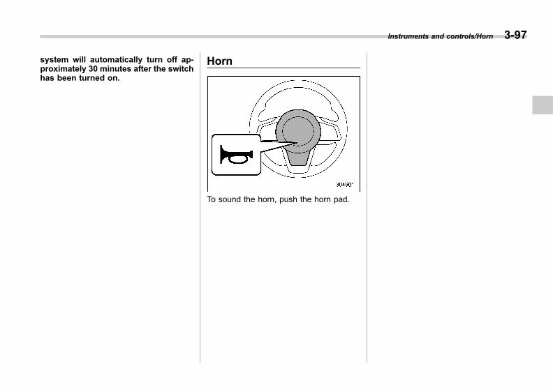
Black plate (241,1)
一般Model "A1300GE-A" EDITED: 2016/ 9/ 13
system will automatically turn off ap-proximately 30 minutes after the switchhas been turned on.
Horn
To sound the horn, push the horn pad.
Instruments and controls/Horn 3-97
3
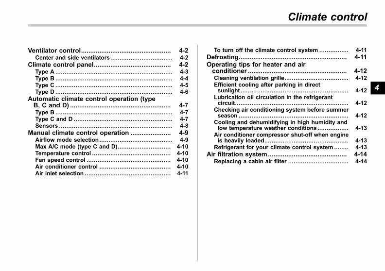
Black plate (9,1)
一般Model "A1300GE-A" EDITED: 2016/ 9/ 13
Ventilator control................................................. 4-2Center and side ventilators.................................. 4-2
Climate control panel.......................................... 4-2Type A ................................................................ 4-3Type B ................................................................ 4-4Type C ................................................................ 4-5Type D ................................................................ 4-6
Automatic climate control operation (typeB, C and D) ....................................................... 4-7Type B ................................................................ 4-7Type C and D ...................................................... 4-7Sensors .............................................................. 4-8
Manual climate control operation ...................... 4-9Airflow mode selection ........................................ 4-9Max A/C mode (type C and D)............................. 4-10Temperature control ........................................... 4-10Fan speed control .............................................. 4-10Air conditioner control ....................................... 4-10Air inlet selection ............................................... 4-11
To turn off the climate control system ................ 4-11Defrosting........................................................... 4-11Operating tips for heater and airconditioner ...................................................... 4-12Cleaning ventilation grille................................... 4-12Efficient cooling after parking in directsunlight ........................................................... 4-12
Lubrication oil circulation in the refrigerantcircuit.............................................................. 4-12
Checking air conditioning system before summerseason ............................................................ 4-12
Cooling and dehumidifying in high humidity andlow temperature weather conditions ................. 4-13
Air conditioner compressor shut-off when engineis heavily loaded.............................................. 4-13
Refrigerant for your climate control system ........ 4-13Air filtration system........................................... 4-14
Replacing a cabin air filter ................................. 4-14
Climate control
4

Black plate (244,1)
一般Model "A1300GE-A" EDITED: 2016/ 9/ 13
4-2 Climate control/Ventilator control
Ventilator control
& Center and side ventilators
Center ventilators
To adjust the airflow direction, move thetab. To close the ventilator, move the taball the way down.
Side ventilators1) Close2) Open
To adjust the flow direction, move the tab.
Climate control panel
WARNING
. The cooling function operatesonly when the engine is running.
. Do not leave children or adultswho would normally require thesupport of others alone in yourvehicle. Pets should not be leftalone either. On hot, sunny days,temperatures in a closed vehiclecould quickly become high en-ough to cause severe or possiblyfatal injuries to people or ani-mals.
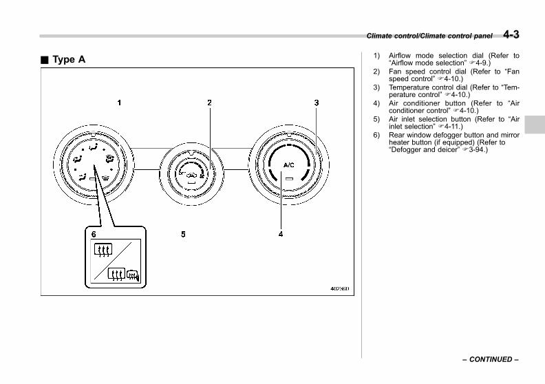
Black plate (245,1)
一般Model "A1300GE-A" EDITED: 2016/ 9/ 13
& Type A 1) Airflow mode selection dial (Refer to“Airflow mode selection” F4-9.)
2) Fan speed control dial (Refer to “Fanspeed control” F4-10.)
3) Temperature control dial (Refer to “Tem-perature control” F4-10.)
4) Air conditioner button (Refer to “Airconditioner control” F4-10.)
5) Air inlet selection button (Refer to “Airinlet selection” F4-11.)
6) Rear window defogger button and mirrorheater button (if equipped) (Refer to“Defogger and deicer” F3-94.)
Climate control/Climate control panel 4-3
– CONTINUED –
4
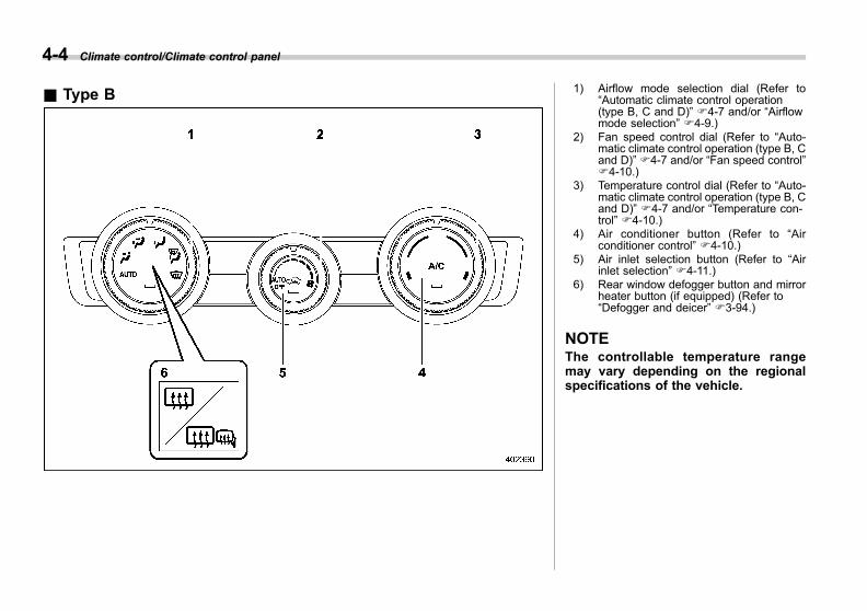
Black plate (246,1)
一般Model "A1300GE-A" EDITED: 2016/ 9/ 13
4-4 Climate control/Climate control panel
& Type B 1) Airflow mode selection dial (Refer to“Automatic climate control operation(type B, C and D)” F4-7 and/or “Airflowmode selection” F4-9.)
2) Fan speed control dial (Refer to “Auto-matic climate control operation (type B, Cand D)” F4-7 and/or “Fan speed control”F4-10.)
3) Temperature control dial (Refer to “Auto-matic climate control operation (type B, Cand D)” F4-7 and/or “Temperature con-trol” F4-10.)
4) Air conditioner button (Refer to “Airconditioner control” F4-10.)
5) Air inlet selection button (Refer to “Airinlet selection” F4-11.)
6) Rear window defogger button and mirrorheater button (if equipped) (Refer to“Defogger and deicer” F3-94.)
NOTEThe controllable temperature rangemay vary depending on the regionalspecifications of the vehicle.

Black plate (247,1)
一般Model "A1300GE-A" EDITED: 2016/ 9/ 13
& Type C
1) Temperature control dial (Refer to “Auto-matic climate control operation (type B, Cand D)” F4-7 and/or “Temperature con-trol” F4-10.)
2) AUTO button (Refer to “Automatic cli-mate control operation (type B, C and D)”F4-7.)
3) Air conditioner button (Refer to “Airconditioner control” F4-10.)
4) Air inlet selection button (Refer to “Airinlet selection” F4-11.)
5) MAX A/C button (Refer to “Max A/Cmode (type C and D)” F4-10.)
6) Defroster button (Refer to “Defrosting”F4-11.)
7) Rear window defogger button and mirrorheater button (if equipped) (Refer to“Defogger and deicer” F3-94.)
8) Airflow mode selection dial (Refer to“Airflow mode selection” F4-9.)
9) Fan speed control dial (Refer to “Fanspeed control” F4-10.)
10) ON/OFF button (Refer to “Automaticclimate control operation (type B, C andD)” F4-7.)
NOTE. The illustration on the left is a typicalexample for left-hand drive models. Forright-hand drive models, the locationsof some buttons/dials are different tothat shown in the illustration.. The climate control screen is dis-played on the multi-function display(color LCD). Refer to “Climate controlscreen” F3-54.
Climate control/Climate control panel 4-5
– CONTINUED –
4
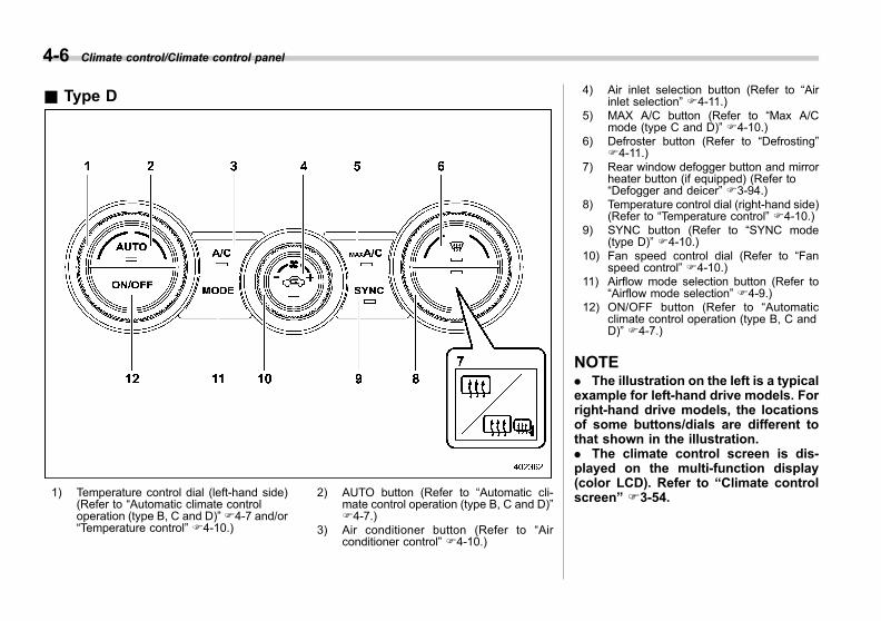
Black plate (248,1)
一般Model "A1300GE-A" EDITED: 2016/ 9/ 13
4-6 Climate control/Climate control panel
& Type D
1) Temperature control dial (left-hand side)(Refer to “Automatic climate controloperation (type B, C and D)” F4-7 and/or“Temperature control” F4-10.)
2) AUTO button (Refer to “Automatic cli-mate control operation (type B, C and D)”F4-7.)
3) Air conditioner button (Refer to “Airconditioner control” F4-10.)
4) Air inlet selection button (Refer to “Airinlet selection” F4-11.)
5) MAX A/C button (Refer to “Max A/Cmode (type C and D)” F4-10.)
6) Defroster button (Refer to “Defrosting”F4-11.)
7) Rear window defogger button and mirrorheater button (if equipped) (Refer to“Defogger and deicer” F3-94.)
8) Temperature control dial (right-hand side)(Refer to “Temperature control” F4-10.)
9) SYNC button (Refer to “SYNC mode(type D)” F4-10.)
10) Fan speed control dial (Refer to “Fanspeed control” F4-10.)
11) Airflow mode selection button (Refer to“Airflow mode selection” F4-9.)
12) ON/OFF button (Refer to “Automaticclimate control operation (type B, C andD)” F4-7.)
NOTE. The illustration on the left is a typicalexample for left-hand drive models. Forright-hand drive models, the locationsof some buttons/dials are different tothat shown in the illustration.. The climate control screen is dis-played on the multi-function display(color LCD). Refer to “Climate controlscreen” F3-54.
Black plate (249,1)
一般Model "A1300GE-A" EDITED: 2016/ 9/ 13
Automatic climate controloperation (type B, C and D)
When this mode is selected, the fanspeed, airflow distribution, air-inlet control,and air conditioner compressor operationare automatically controlled. To activatethis mode, perform the following.
NOTE. Operate the automatic climate con-trol system when the engine is running.. Even when cooling is not necessary,the air conditioner compressor willautomatically turn on if the temperatureis set much lower than the currentoutlet air temperature. Even in thiscase, the “A/C” indicator light on thecontrol panel illuminates.. The air conditioner may not operatein the following cases:
– when the cabin temperature islow– when the ambient temperaturedecreases close to 08C (328F)
. The controllable temperature rangemay vary depending on the regionalspecifications of the vehicle.
& Type B1. Turn the airflow mode selection dialand fan speed control dial to the “AUTO”position.2. Set the preferred temperature usingthe temperature control dial.
NOTEEach function can be individually set tothe “AUTO” mode independently of theother functions. Any function set to the“AUTO” mode is controlled automati-cally. Any function not set to the“AUTO” mode can be manually ad-justed as desired.
To turn off the climate control system, turnthe fan speed control dial to the “OFF”position. The status of the air inlet selec-tion will be changed as follows dependingon the setting when the climate controlsystem is turned off.
. When the air inlet selection is in“AUTO” mode, the mode will be set tooutside air inlet.. When the air inlet selection is in“MANUAL” mode, the mode from beforethe climate control system was turned offwill be maintained.
& Type C and D1. Press the AUTO button. The indicatorlight “FULL AUTO” on the multi-functiondisplay (color LCD) illuminates.2. Set the preferred temperature usingthe temperature control dial.
NOTEIf you operate any of the buttons on thecontrol panel other than the ON/OFFbutton, rear window defogger button,SYNC button (if equipped) and tem-perature control dial(s) during FULLAUTO mode operation, the “FULL”indicator light on the control panel willturn off and the “AUTO” indicator lightwill remain illuminated. You can thenmanually control the system as desiredusing the button you operated. Tochange the system back to the “FULLAUTO” mode, press the “AUTO” but-ton.
To turn off the climate control system,press the ON/OFF button. The status ofthe air inlet selection will be changed asfollows depending on the setting when theclimate control system is turned off.
. When the air inlet selection is in“AUTO” mode, the mode will be set tooutside air inlet.
Climate control/Automatic climate control operation (type B, C and D) 4-7
– CONTINUED –
4
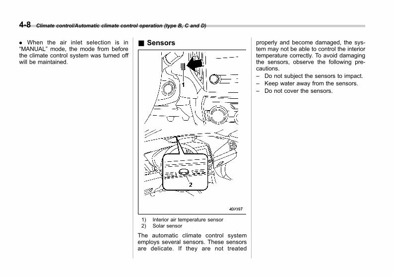
Black plate (250,1)
一般Model "A1300GE-A" EDITED: 2016/ 9/ 13
4-8 Climate control/Automatic climate control operation (type B, C and D)
. When the air inlet selection is in“MANUAL” mode, the mode from beforethe climate control system was turned offwill be maintained.
& Sensors
1) Interior air temperature sensor2) Solar sensor
The automatic climate control systememploys several sensors. These sensorsare delicate. If they are not treated
properly and become damaged, the sys-tem may not be able to control the interiortemperature correctly. To avoid damagingthe sensors, observe the following pre-cautions.– Do not subject the sensors to impact.– Keep water away from the sensors.– Do not cover the sensors.

Black plate (251,1)
一般Model "A1300GE-A" EDITED: 2016/ 9/ 13
Manual climate control op-eration
& Airflow mode selectionSelect the airflow mode by using theairflow mode selection dial (type A andB) or the airflow mode selection button(type C and D).Airflow modes are as follows.
(Ventilation): Instrument panel outlets
(Ventilation 2 for type C and D): Instru-ment panel outlets and foot outlets
(Bi-level): Instrument panel outlets andfoot outlets
(Heat): Foot outlets, both side outlets ofthe instrument panel and some throughwindshield defroster outlets (A smallamount of air flows to the windshield andboth side windows to prevent fogging.)
(Heat-def): Windshield defroster outlets,
Climate control/Manual climate control operation 4-9
– CONTINUED –
4
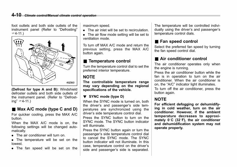
Black plate (252,1)
一般Model "A1300GE-A" EDITED: 2016/ 9/ 13
4-10 Climate control/Manual climate control operation
foot outlets and both side outlets of theinstrument panel (Refer to “Defrosting”F4-11.)
(Defrost for type A and B): Windshielddefroster outlets and both side outlets ofthe instrument panel. (Refer to “Defrost-ing” F4-11.)
& Max A/C mode (type C and D)For quicker cooling, press the MAX A/Cbutton.When the MAX A/C mode is on, thefollowing settings will be changed auto-matically.. The air conditioner will turn on.. The temperature will be set on thelowest.. The fan speed will be set on the
maximum speed.. The air inlet will be set to recirculation.. The air flow mode setting will be set toventilation mode.
To turn off MAX A/C mode and return theprevious setting, press the MAX A/Cbutton again.
& Temperature controlTurn the temperature control dial to set thepreferred interior temperature.
NOTEThe controllable temperature rangemay vary depending on the regionalspecifications of the vehicle.
! SYNC mode (type D)
When the SYNC mode is turned on, boththe driver’s and passenger’s side tem-peratures are synchronized using thedriver’s side temperature control dial.Press the SYNC button to turn on theSYNC mode. The SYNC button indicatorwill illuminate.Press the SYNC button again or turn thepassenger’s side temperature control dialto cancel the SYNC mode. The SYNCbutton indicator will not illuminate. In thiscase, temperature control on the driver’sside and passenger’s side is separated.
The temperature will be controlled indivi-dually using the driver’s and passenger’stemperature control dials.
& Fan speed controlSelect the preferred fan speed by turningthe fan speed control dial.
& Air conditioner controlThe air conditioner operates only whenthe engine is running.Press the air conditioner button while thefan is in operation to turn on the airconditioner. When the air conditioner ison, the “A/C” indicator light illuminates.To turn off the air conditioner, press thebutton again.
NOTEFor efficient defogging or dehumidify-ing in cold weather, turn on the airconditioner. However, if the ambienttemperature decreases to approxi-mately 08C (328F), the air conditionerand dehumidification system may notoperate properly.
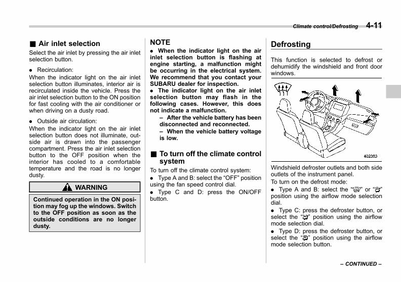
Black plate (253,1)
一般Model "A1300GE-A" EDITED: 2016/ 9/ 13
& Air inlet selectionSelect the air inlet by pressing the air inletselection button.
. Recirculation:When the indicator light on the air inletselection button illuminates, interior air isrecirculated inside the vehicle. Press theair inlet selection button to the ON positionfor fast cooling with the air conditioner orwhen driving on a dusty road.
. Outside air circulation:When the indicator light on the air inletselection button does not illuminate, out-side air is drawn into the passengercompartment. Press the air inlet selectionbutton to the OFF position when theinterior has cooled to a comfortabletemperature and the road is no longerdusty.
WARNING
Continued operation in the ON posi-tion may fog up the windows. Switchto the OFF position as soon as theoutside conditions are no longerdusty.
NOTE. When the indicator light on the airinlet selection button is flashing atengine starting, a malfunction mightbe occurring in the electrical system.We recommend that you contact yourSUBARU dealer for inspection.. The indicator light on the air inletselection button may flash in thefollowing cases. However, this doesnot indicate a malfunction.
– After the vehicle battery has beendisconnected and reconnected.– When the vehicle battery voltageis low.
& To turn off the climate controlsystem
To turn off the climate control system:. Type A and B: select the “OFF” positionusing the fan speed control dial.. Type C and D: press the ON/OFFbutton.
Defrosting
This function is selected to defrost ordehumidify the windshield and front doorwindows.
Windshield defroster outlets and both sideoutlets of the instrument panel.To turn on the defrost mode:. Type A and B: select the “ ” or “ ”position using the airflow mode selectiondial.. Type C: press the defroster button, orselect the “ ” position using the airflowmode selection dial.. Type D: press the defroster button, orselect the “ ” position using the airflowmode selection button.
Climate control/Defrosting 4-11
– CONTINUED –
4

Black plate (254,1)
一般Model "A1300GE-A" EDITED: 2016/ 9/ 13
4-12 Climate control/Operating tips for heater and air conditioner
NOTE. For type A climate control system,when the “ ” or “ ” mode is se-lected, the air conditioner compressorautomatically operates to more quicklydefrost the windshield. At the sametime, the air inlet selection is automa-tically set to the outside air mode.. For type C and D climate controlsystem, after defrosting the windshieldby pressing the defroster button,pressing the button again returns thesystem to the setting that had beenselected before the defroster was acti-vated.
Operating tips for heater andair conditioner
& Cleaning ventilation grille
1) Front ventilation inlet grille
Always keep the front ventilation inlet grillefree of snow, leaves, or other obstructionsto ensure efficient heating and defrosting.Since the condenser is located in front ofthe radiator, this area should be kept cleanbecause cooling performance is impairedby any accumulation of insects and leaveson the condenser.
& Efficient cooling after parkingin direct sunlight
After parking in direct sunlight, drive withthe windows open for a few minutes toallow outside air to circulate into theheated interior. This results in quickercooling by the air conditioner. Keep thewindows closed during the operation ofthe air conditioner for maximum coolingefficiency.
& Lubrication oil circulation inthe refrigerant circuit
Operate the air conditioner compressor ata low engine speed (at idle or low drivingspeeds) a few minutes each month duringthe off-season to circulate its oil.
& Checking air conditioningsystem before summer sea-son
Check the air conditioner unit for refriger-ant leaks, hose conditions, and properoperation each spring. We recommendthat you have your SUBARU dealer per-form this check.
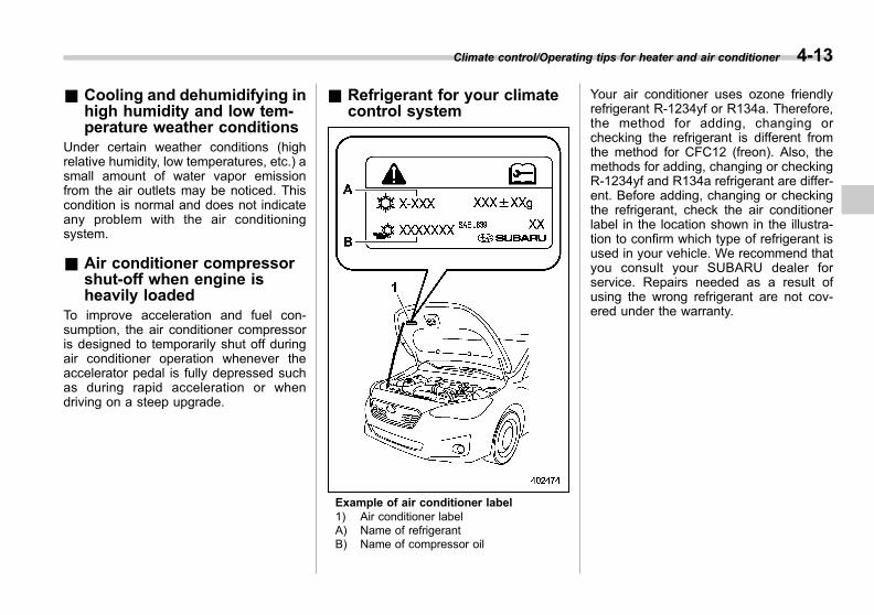
Black plate (255,1)
一般Model "A1300GE-A" EDITED: 2016/ 9/ 13
& Cooling and dehumidifying inhigh humidity and low tem-perature weather conditions
Under certain weather conditions (highrelative humidity, low temperatures, etc.) asmall amount of water vapor emissionfrom the air outlets may be noticed. Thiscondition is normal and does not indicateany problem with the air conditioningsystem.
& Air conditioner compressorshut-off when engine isheavily loaded
To improve acceleration and fuel con-sumption, the air conditioner compressoris designed to temporarily shut off duringair conditioner operation whenever theaccelerator pedal is fully depressed suchas during rapid acceleration or whendriving on a steep upgrade.
& Refrigerant for your climatecontrol system
Example of air conditioner label1) Air conditioner labelA) Name of refrigerantB) Name of compressor oil
Your air conditioner uses ozone friendlyrefrigerant R-1234yf or R134a. Therefore,the method for adding, changing orchecking the refrigerant is different fromthe method for CFC12 (freon). Also, themethods for adding, changing or checkingR-1234yf and R134a refrigerant are differ-ent. Before adding, changing or checkingthe refrigerant, check the air conditionerlabel in the location shown in the illustra-tion to confirm which type of refrigerant isused in your vehicle. We recommend thatyou consult your SUBARU dealer forservice. Repairs needed as a result ofusing the wrong refrigerant are not cov-ered under the warranty.
Climate control/Operating tips for heater and air conditioner 4-13
4
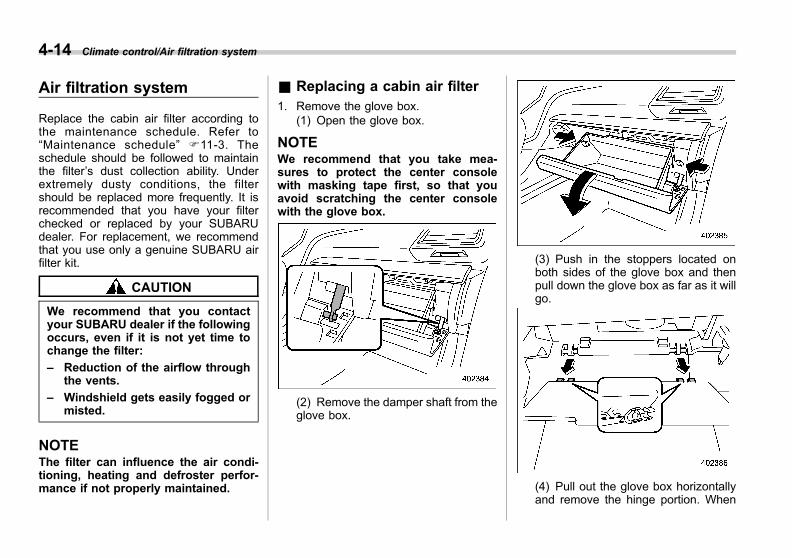
Black plate (256,1)
一般Model "A1300GE-A" EDITED: 2016/ 9/ 13
4-14 Climate control/Air filtration system
Air filtration system
Replace the cabin air filter according tothe maintenance schedule. Refer to“Maintenance schedule” F11-3. Theschedule should be followed to maintainthe filter’s dust collection ability. Underextremely dusty conditions, the filtershould be replaced more frequently. It isrecommended that you have your filterchecked or replaced by your SUBARUdealer. For replacement, we recommendthat you use only a genuine SUBARU airfilter kit.
CAUTION
We recommend that you contactyour SUBARU dealer if the followingoccurs, even if it is not yet time tochange the filter:
– Reduction of the airflow throughthe vents.
– Windshield gets easily fogged ormisted.
NOTEThe filter can influence the air condi-tioning, heating and defroster perfor-mance if not properly maintained.
& Replacing a cabin air filter1. Remove the glove box.
(1) Open the glove box.
NOTEWe recommend that you take mea-sures to protect the center consolewith masking tape first, so that youavoid scratching the center consolewith the glove box.
(2) Remove the damper shaft from theglove box.
(3) Push in the stoppers located onboth sides of the glove box and thenpull down the glove box as far as it willgo.
(4) Pull out the glove box horizontallyand remove the hinge portion. When
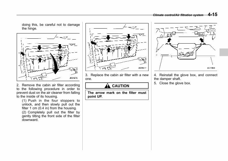
Black plate (257,1)
一般Model "A1300GE-A" EDITED: 2016/ 9/ 13
doing this, be careful not to damagethe hinge.
2. Remove the cabin air filter accordingto the following procedure in order toprevent dust on the air cleaner from fallingto the inside of its housing.
(1) Push in the four stoppers tounlock, and then slowly pull out thefilter 1 cm (0.4 in) from the housing.(2) Completely pull out the filter bygently tilting the front side of the filterdownward.
3. Replace the cabin air filter with a newone.
CAUTION
The arrow mark on the filter mustpoint UP.
4. Reinstall the glove box, and connectthe damper shaft.5. Close the glove box.
Climate control/Air filtration system 4-15
4
Black plate (11,1)
一般Model "A1300GE-A" EDITED: 2016/ 9/ 13
Antenna................................................................ 5-2Roof antenna ...................................................... 5-2
Audio set .............................................................. 5-2
Audio
5
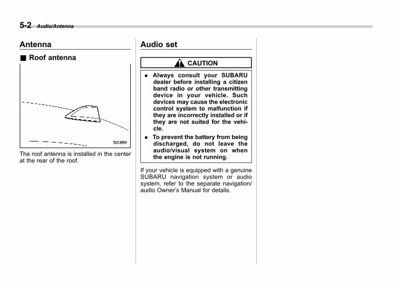
Black plate (262,1)
一般Model "A1300GE-A" EDITED: 2016/ 9/ 13
5-2 Audio/Antenna
Antenna
& Roof antenna
The roof antenna is installed in the centerat the rear of the roof.
Audio set
CAUTION
. Always consult your SUBARUdealer before installing a citizenband radio or other transmittingdevice in your vehicle. Suchdevices may cause the electroniccontrol system to malfunction ifthey are incorrectly installed or ifthey are not suited for the vehi-cle.
. To prevent the battery from beingdischarged, do not leave theaudio/visual system on whenthe engine is not running.
If your vehicle is equipped with a genuineSUBARU navigation system or audiosystem, refer to the separate navigation/audio Owner’s Manual for details.
Black plate (13,1)
一般Model "A1300GE-A" EDITED: 2016/ 9/ 13
Interior light ......................................................... 6-2Map lights ........................................................... 6-2Dome light .......................................................... 6-2Cargo area light (5-door models) ......................... 6-3OFF delay timer .................................................. 6-3
Sun visors ........................................................... 6-3Vanity mirror ....................................................... 6-4Vanity mirror with light (if equipped) .................... 6-4
Storage compartment ......................................... 6-4Glove box ........................................................... 6-5Center console.................................................... 6-5Cup holders ........................................................ 6-5Bottle holders ..................................................... 6-6
Accessory power outlets.................................... 6-7Cigarette lighter (if equipped) .............................. 6-8
USB power supply............................................... 6-9Ashtray (if equipped)......................................... 6-10Floor mat ............................................................ 6-11Coat hook........................................................... 6-12Shopping bag hook (5-door models) ............... 6-12Cargo area cover (5-door models – ifequipped) ........................................................ 6-13Using the cover ................................................. 6-13To remove the cover housing............................. 6-13Stowage of the cargo area cover ........................ 6-14To install the cover housing ............................... 6-14
Cargo tie-down hooks (5-door models – ifequipped) ........................................................ 6-15
Under-floor storage compartment (ifequipped) ........................................................ 6-15
Interior equipment
6
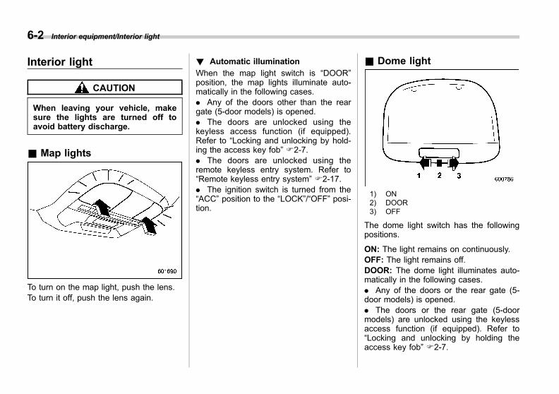
Black plate (266,1)
一般Model "A1300GE-A" EDITED: 2016/ 9/ 13
6-2 Interior equipment/Interior light
Interior light
CAUTION
When leaving your vehicle, makesure the lights are turned off toavoid battery discharge.
& Map lights
To turn on the map light, push the lens.To turn it off, push the lens again.
! Automatic illumination
When the map light switch is “DOOR”position, the map lights illuminate auto-matically in the following cases.. Any of the doors other than the reargate (5-door models) is opened.. The doors are unlocked using thekeyless access function (if equipped).Refer to “Locking and unlocking by hold-ing the access key fob” F2-7.. The doors are unlocked using theremote keyless entry system. Refer to“Remote keyless entry system” F2-17.. The ignition switch is turned from the“ACC” position to the “LOCK”/“OFF” posi-tion.
& Dome light
1) ON2) DOOR3) OFF
The dome light switch has the followingpositions.
ON: The light remains on continuously.OFF: The light remains off.DOOR: The dome light illuminates auto-matically in the following cases.. Any of the doors or the rear gate (5-door models) is opened.. The doors or the rear gate (5-doormodels) are unlocked using the keylessaccess function (if equipped). Refer to“Locking and unlocking by holding theaccess key fob” F2-7.

Black plate (267,1)
一般Model "A1300GE-A" EDITED: 2016/ 9/ 13
. The doors or the rear gate (5-doormodels) are unlocked using the remotekeyless entry system. Refer to “Remotekeyless entry system” F2-17.. The ignition switch is turned from the“ACC” position to the “LOCK”/“OFF” posi-tion.
& Cargo area light (5-doormodels)
1) DOOR2) OFF
DOOR: The light illuminates when the reargate is opened. The light remains illumi-nated for several seconds and graduallyturns off after the rear gate is closed.OFF: The light remains off.
& OFF delay timerThe following lights have an automaticillumination function.. dome light. map light. cargo area light (5-door models)
When the interior light switch is set to the“DOOR” position, the light will automati-cally turn on and turn off depending on thelocking and unlocking of the doors, theopening and closing of the doors, as wellas the position of the ignition switch.
NOTEThe setting for the period of time inwhich the lights remain on (OFF delaytimer) can be changed by a SUBARUdealer. We recommend that you con-tact your SUBARU dealer for details.For models with the combination meterdisplay (color LCD), the setting canalso be changed by operating thecombination meter display (colorLCD). For details, refer to “VehicleSetting” F3-44.
Sun visors
To block out glare, swing down the visors.To use the sun visor at a side window,swing it down and move it sideways.
Interior equipment/Sun visors 6-3
– CONTINUED –
6
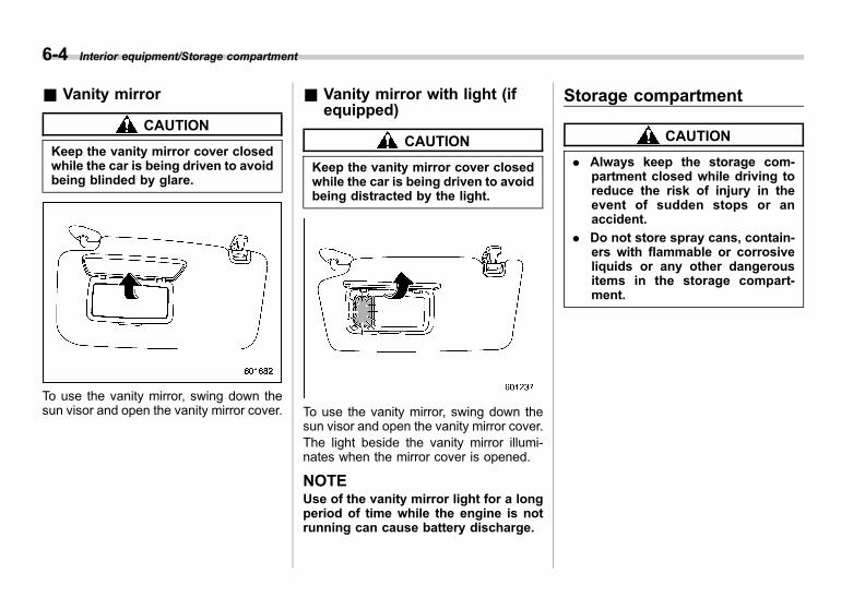
Black plate (268,1)
一般Model "A1300GE-A" EDITED: 2016/ 9/ 13
6-4 Interior equipment/Storage compartment
& Vanity mirror
CAUTION
Keep the vanity mirror cover closedwhile the car is being driven to avoidbeing blinded by glare.
To use the vanity mirror, swing down thesun visor and open the vanity mirror cover.
& Vanity mirror with light (ifequipped)
CAUTION
Keep the vanity mirror cover closedwhile the car is being driven to avoidbeing distracted by the light.
To use the vanity mirror, swing down thesun visor and open the vanity mirror cover.The light beside the vanity mirror illumi-nates when the mirror cover is opened.
NOTEUse of the vanity mirror light for a longperiod of time while the engine is notrunning can cause battery discharge.
Storage compartment
CAUTION
. Always keep the storage com-partment closed while driving toreduce the risk of injury in theevent of sudden stops or anaccident.
. Do not store spray cans, contain-ers with flammable or corrosiveliquids or any other dangerousitems in the storage compart-ment.

Black plate (269,1)
一般Model "A1300GE-A" EDITED: 2016/ 9/ 13
& Glove box
To open the glove box, pull the handle. Toclose it, push the lid firmly upward.
& Center consoleThe center console box provides a sto-rage space.
1) Card holder2) Holder (smartphone, card, etc.)
The top of the console can be used as anarmrest.
& Cup holders
CAUTION
. Do not pick up a cup from the cupholder or put a cup in the holderwhile you are driving, as this maydistract you and lead to anaccident.
. Take care to avoid spills. Bev-erages, if hot, might burn youand/or your passengers. Spilledbeverages may also damage up-holstery, carpets or audio equip-ment.
! Front passenger’s cup holder
A dual cup holder is built into the console.
Interior equipment/Storage compartment 6-5
– CONTINUED –
6

Black plate (270,1)
一般Model "A1300GE-A" EDITED: 2016/ 9/ 13
6-6 Interior equipment/Storage compartment
! Rear passenger’s cup holder (ifequipped)
CAUTION
When a cup in the rear passenger’scup holder contains a beverage, donot fold down the rear seatback.Otherwise, the beverage could spilland, if the beverage is hot, it couldburn you and/or your passengers.
A dual cup holder is built into the armrest.
& Bottle holders
CAUTION
. Do not pick up a bottle from thebottle holder or put a bottle in theholder while you are driving, asthis may distract you and lead toan accident.
. When placing a beverage in abottle holder, make sure it iscapped. Otherwise, the beveragecould spill when opening/closingthe door or while driving and, ifthe beverage is hot, it could scaldyou and/or your passengers.
The bottle holder equipped on each doortrim can be used to hold beverage bottlesand other items.
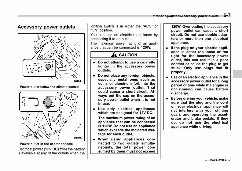
Black plate (271,1)
一般Model "A1300GE-A" EDITED: 2016/ 9/ 13
Accessory power outlets
Power outlet below the climate control
Power outlet in the center console
Electrical power (12V DC) from the batteryis available at any of the outlets when the
ignition switch is in either the “ACC” or“ON” position.You can use an electrical appliance byconnecting it to an outlet.The maximum power rating of an appli-ance that can be connected is 120W.
CAUTION
. Do not attempt to use a cigarettelighter in the accessory poweroutlets.
. Do not place any foreign objects,especially metal ones such ascoins or aluminum foil, into theaccessory power outlet. Thatcould cause a short circuit. Al-ways put the cap on the acces-sory power outlet when it is notin use.
. Use only electrical applianceswhich are designed for 12V DC.
The maximum power rating of anappliance that can be connectedis 120W. Do not use an appliancewhich exceeds the indicated wat-tage for each outlet.
. When using appliances con-nected to two outlets simulta-neously, the total power con-sumed by them must not exceed
120W. Overloading the accessorypower outlet can cause a shortcircuit. Do not use double adap-ters or more than one electricalappliance.
. If the plug on your electric appli-ance is either too loose or tootight for the accessory poweroutlet, this can result in a poorcontact or cause the plug to getstuck. Only use plugs that fitproperly.
. Use of an electric appliance in theaccessory power outlet for a longperiod of time while the engine isnot running can cause batterydischarge.
. Before driving your vehicle, makesure that the plug and the cordon your electrical appliance willnot interfere with your shiftinggears and operating the accel-erator and brake pedals. If theydo, do not use the electricalappliance while driving.
Interior equipment/Accessory power outlets 6-7
– CONTINUED –
6
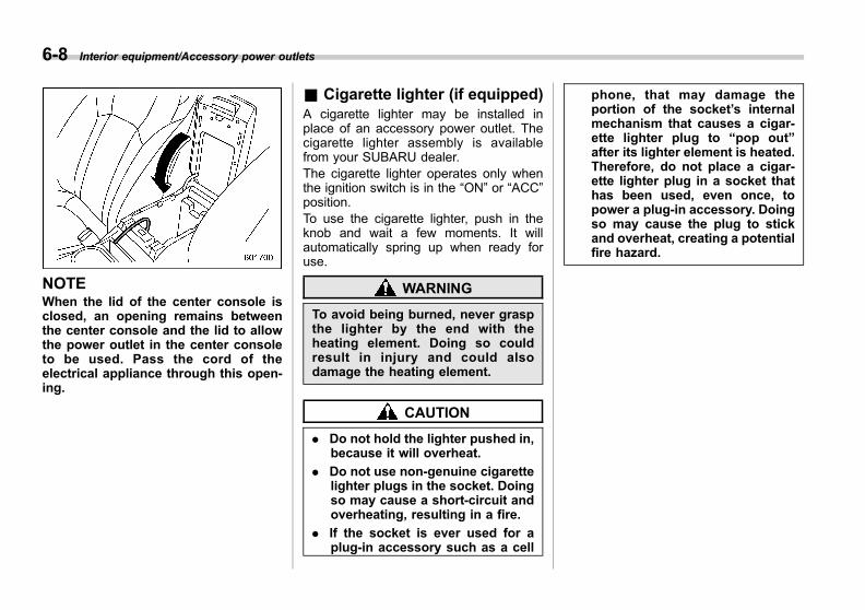
Black plate (272,1)
一般Model "A1300GE-A" EDITED: 2016/ 9/ 13
6-8 Interior equipment/Accessory power outlets
NOTEWhen the lid of the center console isclosed, an opening remains betweenthe center console and the lid to allowthe power outlet in the center consoleto be used. Pass the cord of theelectrical appliance through this open-ing.
& Cigarette lighter (if equipped)A cigarette lighter may be installed inplace of an accessory power outlet. Thecigarette lighter assembly is availablefrom your SUBARU dealer.The cigarette lighter operates only whenthe ignition switch is in the “ON” or “ACC”position.To use the cigarette lighter, push in theknob and wait a few moments. It willautomatically spring up when ready foruse.
WARNING
To avoid being burned, never graspthe lighter by the end with theheating element. Doing so couldresult in injury and could alsodamage the heating element.
CAUTION
. Do not hold the lighter pushed in,because it will overheat.
. Do not use non-genuine cigarettelighter plugs in the socket. Doingso may cause a short-circuit andoverheating, resulting in a fire.
. If the socket is ever used for aplug-in accessory such as a cell
phone, that may damage theportion of the socket’s internalmechanism that causes a cigar-ette lighter plug to “pop out”after its lighter element is heated.Therefore, do not place a cigar-ette lighter plug in a socket thathas been used, even once, topower a plug-in accessory. Doingso may cause the plug to stickand overheat, creating a potentialfire hazard.

Black plate (273,1)
一般Model "A1300GE-A" EDITED: 2016/ 9/ 13
USB power supply
CAUTION
. The specification of a USB term-inal that can be used is the A-type. If a different specification ofterminal is connected, powersupply or charging may not bepossible, or the device may mal-function.
. There is no guarantee even whena connected device malfunctionsor data is damaged. The connec-tion of a device shall be per-formed at your responsibility.
. To avoid an electric shock or amalfunction, observe the follow-ing precautions.
– Do not connect a USB hub.
– Do not insert any metal orother foreign object into theUSB terminal.
– Do not spill water or otherliquid on the USB terminal.
. When you have connected acable, pay attention not to pullon the connected cable with yourlegs. Otherwise, it may result ininjury to you by falling over, or a
malfunction of the connecteddevice.
. If a device is connected for a longtime when the engine is notrunning, doing so may causethe risk of a discharged battery.Even when the engine is running,we recommend that you do notconnect a device for an unneces-sarily long time.
. Do not connect a malfunctioningdevice. Doing so may cause therisk of smoke and fire.
NOTE. The USB power supply is designedto supply a maximum rated power of5.25V/1A. Before connecting a device,be sure to read the instruction manualof the device and check whether or notthis specification of the output issupported by the device. If a devicethat requires power exceeding themaximum rating is connected, powersupply or charging may not be possi-ble. Even if charging could be com-pleted, the time required for chargingmay be longer than when the genuinecharger for that device is used.. Depending on the device, chargingmay be possible only when a special
cable is used. In this case, be sure toconnect the device using the specialcable.. When a device that communicateswith a PC is connected, power supplyor charging may not be possible.. When connect a device for charging,disconnect the device promptly aftercharging is completed.
Front seat USB power supply (An audiodevice can be connected and used)
Interior equipment/USB power supply 6-9
– CONTINUED –
6
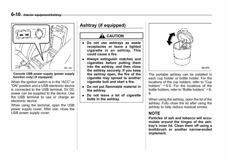
Black plate (274,1)
一般Model "A1300GE-A" EDITED: 2016/ 9/ 13
6-10 Interior equipment/Ashtray
Console USB power supply (power supplyfunction only) (if equipped)
When the ignition switch is in the “ACC” or“ON” position and a USB electronic deviceis connected to the USB terminal, 5V DCpower can be supplied to the device. Usethe USB terminal to use or charge anelectronic device.When using the terminal, open the USBpower supply cover. After use, close theUSB power supply cover.
Ashtray (if equipped)
CAUTION
. Do not use ashtrays as wastereceptacles or leave a lightedcigarette in an ashtray. Thiscould cause a fire.
. Always extinguish matches andcigarettes before putting theminto the ashtray, and then closethe ashtray securely. If you keepthe ashtray open, the fire of thecigarette may spread to anothercigarette butt and start a fire.
. Do not put flammable material inthe ashtray.
. Do not leave a lot of cigarettebutts in the ashtray.
The portable ashtray can be installed ineach cup holder or bottle holder. For thelocations of the cup holders, refer to “Cupholders” F6-5. For the locations of thebottle holders, refer to “Bottle holders”F6-6.
When using the ashtray, open the lid of theashtray. Fully close the lid after using theashtray to help reduce residual smoke.
NOTEParticles of ash and tobacco will accu-mulate around the hinges of the ash-tray’s inner lid. Clean them off using atoothbrush or another narrow-endedimplement.
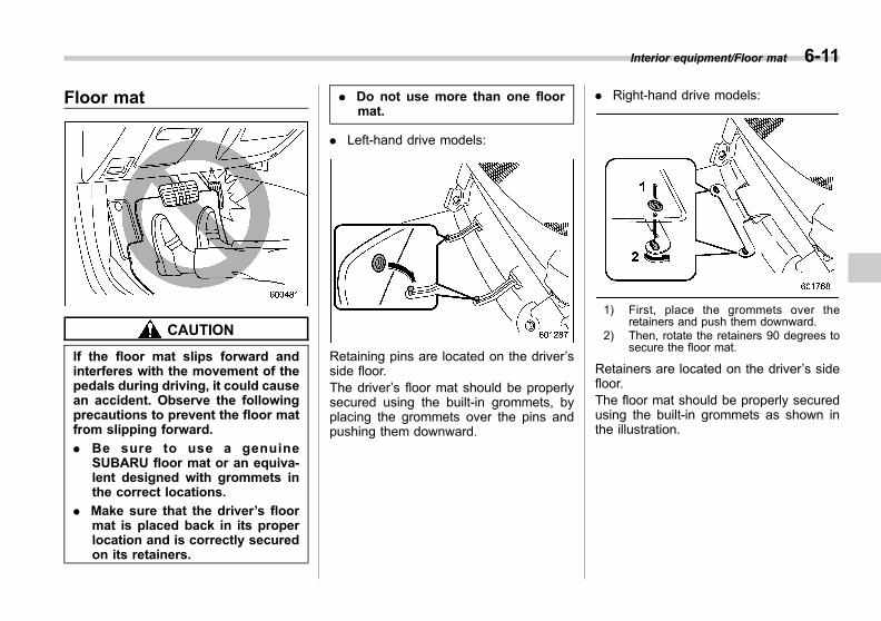
Black plate (275,1)
一般Model "A1300GE-A" EDITED: 2016/ 9/ 13
Floor mat
CAUTION
If the floor mat slips forward andinterferes with the movement of thepedals during driving, it could causean accident. Observe the followingprecautions to prevent the floor matfrom slipping forward.
. Be sure to use a genuineSUBARU floor mat or an equiva-lent designed with grommets inthe correct locations.
. Make sure that the driver’s floormat is placed back in its properlocation and is correctly securedon its retainers.
. Do not use more than one floormat.
. Left-hand drive models:
Retaining pins are located on the driver’sside floor.The driver’s floor mat should be properlysecured using the built-in grommets, byplacing the grommets over the pins andpushing them downward.
. Right-hand drive models:
1) First, place the grommets over theretainers and push them downward.
2) Then, rotate the retainers 90 degrees tosecure the floor mat.
Retainers are located on the driver’s sidefloor.The floor mat should be properly securedusing the built-in grommets as shown inthe illustration.
Interior equipment/Floor mat 6-11
6
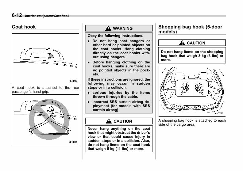
Black plate (276,1)
一般Model "A1300GE-A" EDITED: 2016/ 9/ 13
6-12 Interior equipment/Coat hook
Coat hook
A coat hook is attached to the rearpassenger’s hand grip.
WARNING
Obey the following instructions.
. Do not hang coat hangers orother hard or pointed objects onthe coat hooks. Hang clothingdirectly on the coat hooks with-out using hangers.
. Before hanging clothing on thecoat hooks, make sure there areno pointed objects in the pock-ets.
If these instructions are ignored, thefollowing may occur in suddenstops or in a collision.
. serious injuries by the itemsthrown through the cabin.
. incorrect SRS curtain airbag de-ployment (for models with SRScurtain airbag)
CAUTION
Never hang anything on the coathook that might obstruct the driver’sview or that could cause injury insudden stops or in a collision. Also,do not hang items on the coat hookthat weigh 5 kg (11 lbs) or more.
Shopping bag hook (5-doormodels)
CAUTION
Do not hang items on the shoppingbag hook that weigh 3 kg (6 lbs) ormore.
A shopping bag hook is attached to eachside of the cargo area.

Black plate (277,1)
一般Model "A1300GE-A" EDITED: 2016/ 9/ 13
Cargo area cover (5-doormodels – if equipped)
The cargo area cover is provided forcovering the cargo area and to protect itscontents from direct sunlight. This cover isdetachable to make room for additionalcargo.
& Using the cover
To extend the cover, pull the end of thecover out of the housing, then insert itshooks into the catches as shown. Torewind it, unhook it from the catches andit will rewind automatically. You shouldhold on to the cover and guide it back intothe cover housing while it is rewinding.
WARNING
Do not place anything on the ex-tended cover. Putting excessiveweight on the extended cover canbreak it and an object on the covercould tumble forward in the event ofa sudden stop or collision. Thiscould cause serious injury.
CAUTION
Be careful not to scratch the reargate stays while extending andrewinding the cover. Scratches onthe stays could cause leakage ofgas from the stays, which mayresult in their inability to hold therear gate open.
& To remove the cover housing1. Rewind the cover.
2. Push the cover housing to the rightside and shorten it.3. Take it off the retainer.
Interior equipment/Cargo area cover (5–door models – if equipped) 6-13
– CONTINUED –
6
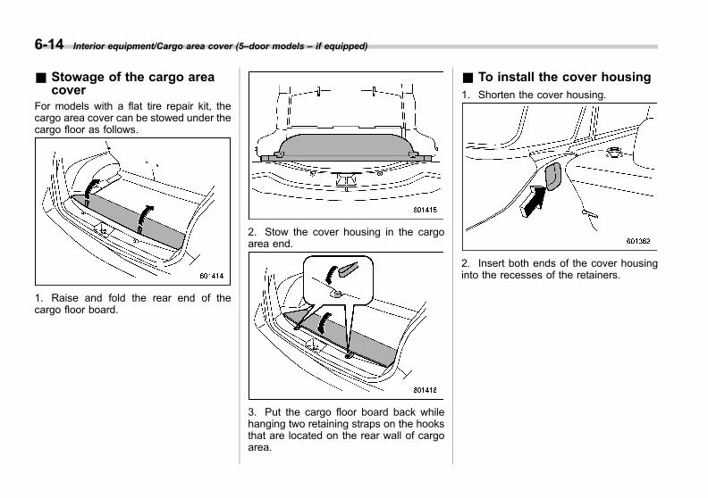
Black plate (278,1)
一般Model "A1300GE-A" EDITED: 2016/ 9/ 13
6-14 Interior equipment/Cargo area cover (5–door models – if equipped)
& Stowage of the cargo areacover
For models with a flat tire repair kit, thecargo area cover can be stowed under thecargo floor as follows.
1. Raise and fold the rear end of thecargo floor board.
2. Stow the cover housing in the cargoarea end.
3. Put the cargo floor board back whilehanging two retaining straps on the hooksthat are located on the rear wall of cargoarea.
& To install the cover housing1. Shorten the cover housing.
2. Insert both ends of the cover housinginto the recesses of the retainers.

Black plate (279,1)
一般Model "A1300GE-A" EDITED: 2016/ 9/ 13
Cargo tie-down hooks(5-door models – if equipped)
The cargo area is equipped with four tie-down hooks so that cargo can be securedwith a cargo net or ropes.When using the front tie-down hooks, turnthem down out of the storing recesses.
CAUTION
The cargo tie-down hooks are de-signed only for securing light cargo.Never try to secure cargo thatexceeds the capacity of the hooks.The maximum load capacity is 10 kg(22 lbs) per a hook.
Under-floor storage compart-ment (if equipped)
NOTE
The shape of the storage compartmentmay be different depending on themodel.
The storage compartment is located underthe floor of the trunk (4-door models) orthe cargo area (5-door models) and canbe used to store small items.
CAUTION
. Always keep the lid of the storagecompartment closed while driv-ing to reduce the risk of injury inthe event of sudden stop or an
accident.
. Do not store spray cans, contain-ers with flammable or corrosiveliquids or any other dangerousitems in the storage compart-ment.
Interior equipment/Cargo tie–down hooks (5–door models – if equipped) 6-15
6
Black plate (15,1)
一般Model "A1300GE-A" EDITED: 2016/ 9/ 13
Fuel ...................................................................... 7-3Fuel requirements ............................................... 7-3Fuel filler lid and cap........................................... 7-3
Preparing to drive ............................................... 7-6Starting and stopping engine (modelswithout push-button start system).................. 7-7Starting engine.................................................... 7-7Stopping engine.................................................. 7-8
Starting and stopping engine (models withpush-button start system) ............................... 7-9Safety precautions .............................................. 7-9Operating range for push-button start system ...... 7-9Starting engine.................................................... 7-9Stopping engine................................................. 7-10When access key fob does not operateproperly ........................................................... 7-11
Continuously variable transmission ................. 7-11Select lever ........................................................ 7-12Selection of manual mode (if equipped) .............. 7-14Selection of “L” (if equipped).............................. 7-16Shift lock function .............................................. 7-16Driving tips ........................................................ 7-18
Power steering ................................................... 7-18Braking................................................................ 7-19
Braking tips ....................................................... 7-19Brake system..................................................... 7-19Disc brake pad wear warning indicators.............. 7-21
ABS (Anti-lock Brake System) .......................... 7-21ABS self-check................................................... 7-21ABS warning light .............................................. 7-22
Electronic Brake Force Distribution (EBD)system............................................................. 7-22Steps to take if EBD system fails ....................... 7-22
Vehicle Dynamics Control system.................... 7-23Vehicle Dynamics Control system monitor.......... 7-25Vehicle Dynamics Control OFF switch ................ 7-25
Parking your vehicle ......................................... 7-27Electronic parking brake .................................... 7-27Parking tips ....................................................... 7-31
Tire pressure monitoring system (TPMS) (ifequipped) ........................................................ 7-32TPMS screen (type B combination meter) (ifequipped) ........................................................ 7-33
TPMS mode setting............................................ 7-34Cruise control (if equipped) .............................. 7-36
To set cruise control .......................................... 7-36To temporarily cancel the cruise control ............. 7-38To turn off the cruise control.............................. 7-38To change the cruising speed ............................ 7-38Cruise control indicator light.............................. 7-39Cruise control set indicator light ........................ 7-39
Auto Start Stop system (if equipped)............... 7-40System operation............................................... 7-40Displaying the Auto Start Stop system status ..... 7-44System warning................................................. 7-44
Subaru Rear Vehicle Detection (SRVD) (ifequipped) ........................................................ 7-44System features................................................. 7-45System operation............................................... 7-47SRVD approach indicator light/warningbuzzer ............................................................. 7-48
Starting and operating
7
Black plate (16,1)
一般Model "A1300GE-A" EDITED: 2016/ 9/ 13
Starting and operating
SRVD warning indicator ..................................... 7-50SRVD OFF switch............................................... 7-51
Handling of radar sensors.................................. 7-52
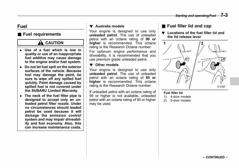
Black plate (285,1)
一般Model "A1300GE-A" EDITED: 2016/ 9/ 13
Fuel
& Fuel requirements
CAUTION
. Use of a fuel which is low inquality or use of an inappropriatefuel additive may cause damageto the engine and/or fuel system.
. Do not let fuel spill on the exteriorsurfaces of the vehicle. Becausefuel may damage the paint, besure to wipe off any spilled fuelquickly. Paint damage caused byspilled fuel is not covered underthe SUBARU Limited Warranty.
. The neck of the fuel filler pipe isdesigned to accept only an un-leaded petrol filler nozzle. Underno circumstances should leadedpetrol be used because it willdamage the emission controlsystem and may impair driveabil-ity and fuel economy. Also, thiscan increase maintenance costs.
! Australia models
Your engine is designed to use onlyunleaded petrol. The use of unleadedpetrol with an octane rating of 90 orhigher is recommended. This octanerating is the Research Octane number.For optimum engine performance anddriveability, it is recommended that youuse premium grade unleaded petrol.
! Other models
Your engine is designed to use onlyunleaded petrol. The use of unleadedpetrol with an octane rating of 95 orhigher is recommended. This octanerating is the Research Octane number.
If unleaded petrol with an octane rating of95 or higher is not available, unleadedpetrol with an octane rating of 90 or highermay be used.
& Fuel filler lid and cap
! Locations of the fuel filler lid andthe lid release lever
Fuel filler lid1) 4-door models2) 5-door models
Starting and operating/Fuel 7-3
– CONTINUED –
7

Black plate (286,1)
一般Model "A1300GE-A" EDITED: 2016/ 9/ 13
7-4 Starting and operating/Fuel
Fuel filler lid release lever1) 4-door models2) 5-door models
! Refueling
Only one person should be involved inrefueling. Do not allow others to approachthe area of the vehicle near the fuel fillerpipe while refueling is in progress.Be sure to observe any other precautionsthat are posted at the service station.
1. Stop the vehicle and turn off theengine.2. To open the fuel filler lid, pull the lidrelease lever up. The lever is on the floorof the driver’s seat.
WARNING
Before opening the fuel filler cap,first touch the vehicle body or ametal portion of the fuel pump orsimilar object to discharge anystatic electricity that may be presenton your body. If your body is carry-ing an electrostatic charge, there isa possibility that an electric sparkcould ignite the fuel, which couldburn you. To avoid acquiring a newstatic electric charge, do not getback into the vehicle while refuelingis in progress.
1) Open2) Close
3. Remove the fuel filler cap by turning it
slowly counterclockwise.
WARNING
. Fuel vapor is highly flammable.Before refueling, always firststop the engine and close allvehicle doors and windows.Make sure that there are nolighted cigarettes, open flamesor electrical sparks in the adja-cent area. Only handle fuel out-doors. Quickly wipe up anyspilled fuel.
. When opening the cap, grasp itfirmly and turn it slowly counter-clockwise. Do not remove thecap quickly. Fuel may be underpressure and spray out of thefuel filler neck, especially in hotweather. If you hear a hissingsound while you are removingthe cap, wait for the sound tostop and then slowly open thecap to prevent fuel from sprayingout and creating a fire hazard.

Black plate (287,1)
一般Model "A1300GE-A" EDITED: 2016/ 9/ 13
4. Set the fuel filler cap on the cap holderinside the fuel filler lid.
WARNING
. When refueling, insert the fuelnozzle securely into the fuel fillerpipe. If the nozzle is lifted or notfully inserted, its automatic stop-ping mechanism may not func-tion, causing fuel to overflow thetank and creating a fire hazard.
. Stop refueling when the auto-matic stop mechanism on thefuel nozzle activates. If you con-tinue to add fuel, temperaturechanges or other conditionsmay cause fuel to overflow fromthe tank and create a fire hazard.
5. Stop filling the tank after the fuel fillerpump automatically stops. Do not add anymore fuel.6. Put the cap back on, turn it clockwiseuntil you hear a clicking noise. Be certainnot to catch the tether under the cap whiletightening.
CAUTION
Make sure that the cap is tighteneduntil it clicks to prevent fuel spillagein the event of an accident.
7. Close the fuel filler lid completely.
CAUTION
If you spill any fuel on the paintedsurface, rinse it off immediately.Otherwise, the painted surfacecould be damaged.
NOTEYou will see the “ ” sign in the fuelgauge. This indicates that the fuel fillerdoor (lid) is located on the right side ofthe vehicle.
CAUTION
. Never add any cleaning agents tothe fuel tank. The addition of acleaning agent may cause da-mage to the fuel system.
. After refueling, turn the capclockwise until it clicks to ensurethat it is fully tightened. If the capis not securely tightened, fuelmay leak out while the vehicle isbeing driven or fuel spillagecould occur in the event of anaccident, creating a fire hazard.
. Do not let fuel spill on the exteriorsurfaces of the vehicle. Becausefuel may damage the paint, besure to wipe off any spilled fuelquickly. Paint damage caused byspilled fuel is not covered underthe SUBARU Limited Warranty.
. We recommend that you alwaysuse a genuine SUBARU fuel fillercap. If you use the wrong cap, itmay not fit or have proper vent-ing and your fuel tank and emis-
Starting and operating/Fuel 7-5
– CONTINUED –
7
Black plate (288,1)
一般Model "A1300GE-A" EDITED: 2016/ 9/ 13
7-6 Starting and operating/Preparing to drive
sion control system may be da-maged. It could also lead to fuelspillage and a fire.
. Immediately put fuel in the tankwhenever the low fuel warninglight illuminates. Engine misfiresas a result of an empty tankcould cause damage to the en-gine. Continuing to operate yourvehicle at an extremely low fuellevel may result in reduced en-gine performance.
Preparing to drive
You should perform the following checksand adjustments every day before youstart driving.1. Check that all windows, mirrors, andlights are clean and unobstructed.2. Check the appearance and conditionof the tires. Also check tires for properinflation.3. Look under the vehicle for any sign ofleaks and check that no small animal isunder the vehicle.4. Check that no small animal enters theengine compartment.5. Check that the hood, trunk (4-doormodels) and rear gate (5-door models) arefully closed.6. Check the adjustment of the seat.7. Check the adjustment of the insideand outside mirrors.8. Fasten your seatbelt. Check that yourpassengers have fastened their seatbelts.9. Check the operation of the warningand indicator lights when the ignitionswitch is turned to the “ON” position.10. Check the gauges, indicator and warn-ing lights after starting the engine.
CAUTION
Trapping small animals in the cool-ing fan and belts of the engine mayresult in a malfunction. Check thatno small animal enters the enginecompartment and under the vehiclebefore starting the engine.
NOTE. Engine oil, engine coolant, brakefluid, washer fluid and other fluid levelsshould be checked daily, weekly or atfuel stops.. Before towing a trailer, refer to“Trailer towing (5-door models)” F8-14.
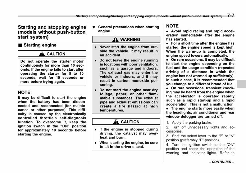
Black plate (289,1)
一般Model "A1300GE-A" EDITED: 2016/ 9/ 13
Starting and stopping engine(models without push-buttonstart system)
& Starting engine
CAUTION
Do not operate the starter motorcontinuously for more than 10 sec-onds. If the engine fails to start afteroperating the starter for 5 to 10seconds, wait for 10 seconds ormore before trying again.
NOTEIt may be difficult to start the enginewhen the battery has been discon-nected and reconnected (for mainte-nance or other purposes). This diffi-culty is caused by the electronicallycontrolled throttle’s self-diagnosisfunction. To overcome it, keep theignition switch in the “ON” positionfor approximately 10 seconds beforestarting the engine.
! General precautions when startingengine
WARNING
. Never start the engine from out-side the vehicle. It may result inan accident.
. Do not leave the engine runningin locations with poor ventilation,such as a garage and indoors.The exhaust gas may enter thevehicle or indoors, and it mayresult in carbon monoxide poi-soning.
. Do not start the engine near dryfoliage, paper, or other flam-mable substances. The exhaustpipe and exhaust emissions cancreate a fire hazard at hightemperatures.
CAUTION
. If the engine is stopped duringdriving, the catalyst may over-heat and burn.
. When starting the engine, be sureto sit in the driver’s seat.
NOTE. Avoid rapid racing and rapid accel-eration immediately after the enginehas started.. For a short time after the engine hasstarted, the engine speed is kept high.When the warm-up is completed, theengine speed lowers automatically.. On rare occasions, it may be difficultto start the engine depending on thefuel and the usage condition (repeateddriving of a distance in which theengine has not warmed up sufficiently).In such a case, it is recommended thatyou change to a different brand of fuel.. On rare occasions, transient knock-ing may be heard from the engine whenthe accelerator is operated rapidlysuch as a rapid start-up and a rapidacceleration. This is not a malfunction.. The engine starts more easily whenthe headlights, air conditioner and rearwindow defogger are turned off.
1. Apply the parking brake.2. Turn off unnecessary lights and ac-cessories.3. Shift the select lever to the “P” or “N”position (preferably “P” position).4. Turn the ignition switch to the “ON”position and check the operation of thewarning and indicator lights. Refer to
Starting and operating/Starting and stopping engine (models without push–button start system) 7-7
– CONTINUED –
7
Black plate (290,1)
一般Model "A1300GE-A" EDITED: 2016/ 9/ 13
7-8 Starting and operating/Starting and stopping engine (models without push–button start system)
“Warning and indicator lights” F3-13.5. Turn the ignition switch to the “START”position without depressing the accelera-tor pedal. Release the key immediatelyafter the engine has started.
If the engine does not start, try thefollowing procedures.
(1) Turn the ignition switch to the“LOCK” position and wait for at least10 seconds. After checking that theparking brake is firmly set, turn theignition switch to the “START” positionwhile depressing the accelerator pedalslightly (approximately a quarter of thefull stroke). Release the acceleratorpedal as soon as the engine starts.(2) If this fails to start the engine, turnthe ignition switch back to the “LOCK”position and wait for at least 10seconds. Then fully depress the accel-erator pedal and turn the ignitionswitch to the “START” position. If theengine starts, quickly release theaccelerator pedal.(3) If this fails to start the engine, turnthe ignition switch again to the “LOCK”position. After waiting for 10 secondsor longer, turn the ignition switch to the“START” position without depressingthe accelerator pedal.(4) If the engine still fails to start, we
recommend that you contact yournearest SUBARU dealer for assis-tance.
6. Confirm that all warning and indicatorlights have turned off after the engine hasstarted. The fuel injection system auto-matically lowers the idle speed as theengine warms up.While the engine is warming up, makesure that the select lever is at the “P” or“N” position and that the parking brake isapplied.
CAUTION
If you restart the engine while thevehicle is moving, shift the selectlever into the “N” position. Do notattempt to place the select lever of amoving vehicle into the “P” posi-tion.
& Stopping engineThe ignition switch should be turned offonly when the vehicle is stopped and theengine is idling.
WARNING
Do not stop the engine when thevehicle is moving. This will causeloss of power to the power steeringand the brake booster, making steer-ing and braking more difficult. Itcould also result in accidental acti-vation of the “LOCK” position on theignition switch, causing the steeringwheel to lock.
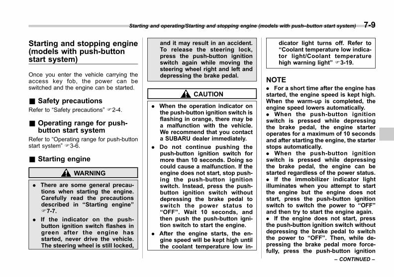
Black plate (291,1)
一般Model "A1300GE-A" EDITED: 2016/ 9/ 13
Starting and stopping engine(models with push-buttonstart system)
Once you enter the vehicle carrying theaccess key fob, the power can beswitched and the engine can be started.
& Safety precautionsRefer to “Safety precautions” F2-4.
& Operating range for push-button start system
Refer to “Operating range for push-buttonstart system” F3-6.
& Starting engine
WARNING
. There are some general precau-tions when starting the engine.Carefully read the precautionsdescribed in “Starting engine”F7-7.
. If the indicator on the push-button ignition switch flashes ingreen after the engine hasstarted, never drive the vehicle.The steering wheel is still locked,
and it may result in an accident.To release the steering lock,press the push-button ignitionswitch again while moving thesteering wheel right and left anddepressing the brake pedal.
CAUTION
. When the operation indicator onthe push-button ignition switch isflashing in orange, there may bea malfunction with the vehicle.We recommend that you contacta SUBARU dealer immediately.
. Do not continue pushing thepush-button ignition switch formore than 10 seconds. Doing socould cause a malfunction. If theengine does not start, stop push-ing the push-button ignitionswitch. Instead, press the push-button ignition switch withoutdepressing the brake pedal toswitch the power status to“OFF”. Wait 10 seconds, andthen push the push-button igni-tion switch to start the engine.
. After the engine starts, the en-gine speed will be kept high untilthe coolant temperature low in-
dicator light turns off. Refer to“Coolant temperature low indica-tor light/Coolant temperaturehigh warning light” F3-19.
NOTE. For a short time after the engine hasstarted, the engine speed is kept high.When the warm-up is completed, theengine speed lowers automatically.. When the push-button ignitionswitch is pressed while depressingthe brake pedal, the engine starteroperates for a maximum of 10 secondsand after starting the engine, the starterstops automatically.. When the push-button ignitionswitch is pressed while depressingthe brake pedal, the engine can bestarted regardless of the power status.. If the immobilizer indicator lightilluminates when you attempt to startthe engine but the engine does notstart, press the push-button ignitionswitch to switch the power to “OFF”and then try to start the engine again.. If the engine does not start, pressthe push-button ignition switch withoutdepressing the brake pedal to switchthe power to “OFF”. Then, while de-pressing the brake pedal more force-fully, press the push-button ignition
Starting and operating/Starting and stopping engine (models with push–button start system) 7-9
– CONTINUED –
7

Black plate (292,1)
一般Model "A1300GE-A" EDITED: 2016/ 9/ 13
7-10 Starting and operating/Starting and stopping engine (models with push–button start system)
switch.. The engine start procedures maynot function depending on the radiowave conditions around the vehicle. Insuch a case, refer to “Starting engine”F9-29.. If the vehicle battery is discharged,the steering cannot be unlocked.Charge the battery.
1) Operation indicator2) Push-button ignition switch
When the push-button ignition switch ispressed while depressing the brake pedal,the engine will start. The start procedureof the engine is as follows.1. Carry the access key fob, and sit in thedriver’s seat.2. Apply the parking brake.3. Shift the select lever in the “P” posi-
tion. The engine can also start when theselect lever is in the “N” position, however,for safety reasons, start in the “P” position.4. Depress the brake pedal until theoperation indicator on the push-buttonignition switch turns green. When startingwith the select lever in the “N” position, theindicator does not turn green.5. While depressing the brake pedal,press the push-button ignition switch.
NOTE. While pressing the select lever but-ton, the indicator on the push-buttonignition switch will not turn green evenwhen the select lever is in the “P”position.. In case the engine does not start bythe normal engine start procedure,move the select lever to the “P” posi-tion, and switch the power to “ACC”.Depress the brake pedal, and press thepush-button ignition switch for at least15 seconds. The engine may start. Onlyuse this engine start procedure in caseof emergency.. When the engine is not started, thebrake pedal may feel stiff. In such acase, depress the brake pedal moreforcefully than usual. Check that theoperation indicator on the push-buttonignition switch turns green, and press
the push-button ignition switch to startthe engine.
& Stopping engine1. Stop the vehicle completely.2. Move the select lever to the “P”position.3. Press the push-button ignition switch.The engine will stop, and the power will beswitched to “OFF”.
WARNING
. Do not touch the push-buttonignition switch during driving.
When the push-button ignitionswitch is operated as follows,the engine will stop.
– The switch is pressed and heldfor 3 seconds or longer.
– The switch is pressed briefly 3times or more in succession.
When the engine stops, the brakebooster will not function. A great-er foot pressure will be requiredon the brake pedal.
The power steering system willnot operate either. A greaterforce will be required to steer,and it may result in an accident.

Black plate (293,1)
一般Model "A1300GE-A" EDITED: 2016/ 9/ 13
. If the engine stops during driving,do not operate the push-buttonignition switch or open any of thedoors until the vehicle is stoppedin a safe location. It is dangerousbecause the steering lock may beactivated. Stop the vehicle in asafe location, and we recom-mend that you contact aSUBARU dealer immediately.
CAUTION
. Do not stop the engine while theselect lever is in a position otherthan the “P” position.
. If the engine is stopped while theselect lever is in a position otherthan the “P” position, the powerwill be in “ACC”. If the vehicle isleft in this condition, the batterymay be discharged.
NOTEAlthough you can stop the engine byoperating the push-button ignitionswitch, do not stop the engine duringdriving except in an emergency.
& When access key fob doesnot operate properly
Refer to “Access key fob – if access keyfob does not operate properly” F9-28.
Continuously variable trans-mission
The continuously variable transmission iselectronically controlled and provides aninfinite number of forward speeds and 1reverse speed. For some models, it alsohas a manual mode or an “L” position.
WARNING
Do not shift from the “P” or “N”position into the “D” or “R” positionwhile depressing the acceleratorpedal. This may cause the vehicleto lurch forward or backward.
CAUTION
. Shift into the “P” or “R” positiononly after the vehicle is comple-tely stopped. Shifting while thevehicle is moving may causedamage to the transmission.
. Do not race the engine for morethan 5 seconds in any positionexcept the “N” or “P” positionwhen the brake is applied orwhen chocks are used in thewheels. This may cause thetransmission fluid to overheat.
Starting and operating/Continuously variable transmission 7-11
– CONTINUED –
7
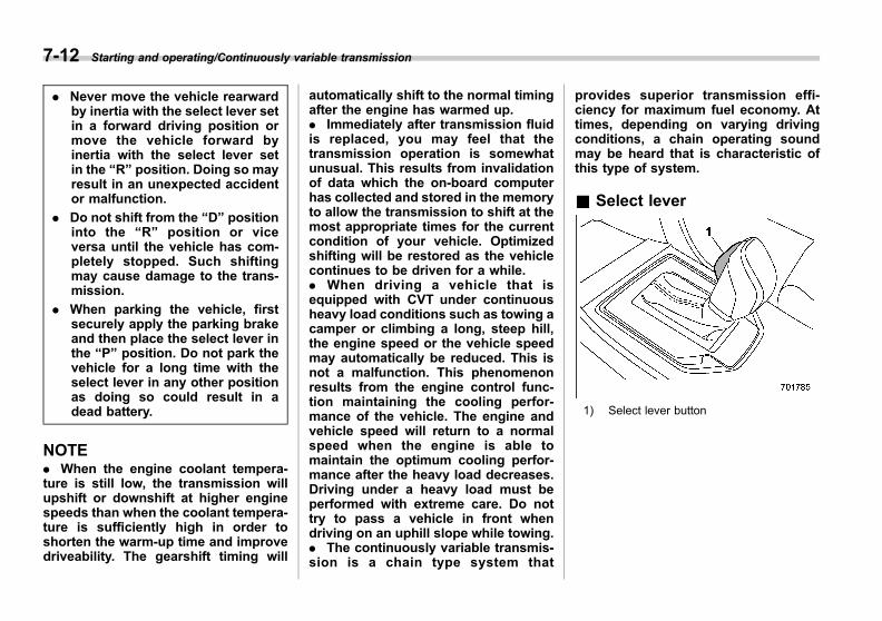
Black plate (294,1)
一般Model "A1300GE-A" EDITED: 2016/ 9/ 13
7-12 Starting and operating/Continuously variable transmission
. Never move the vehicle rearwardby inertia with the select lever setin a forward driving position ormove the vehicle forward byinertia with the select lever setin the “R” position. Doing so mayresult in an unexpected accidentor malfunction.
. Do not shift from the “D” positioninto the “R” position or viceversa until the vehicle has com-pletely stopped. Such shiftingmay cause damage to the trans-mission.
. When parking the vehicle, firstsecurely apply the parking brakeand then place the select lever inthe “P” position. Do not park thevehicle for a long time with theselect lever in any other positionas doing so could result in adead battery.
NOTE. When the engine coolant tempera-ture is still low, the transmission willupshift or downshift at higher enginespeeds than when the coolant tempera-ture is sufficiently high in order toshorten the warm-up time and improvedriveability. The gearshift timing will
automatically shift to the normal timingafter the engine has warmed up.. Immediately after transmission fluidis replaced, you may feel that thetransmission operation is somewhatunusual. This results from invalidationof data which the on-board computerhas collected and stored in the memoryto allow the transmission to shift at themost appropriate times for the currentcondition of your vehicle. Optimizedshifting will be restored as the vehiclecontinues to be driven for a while.. When driving a vehicle that isequipped with CVT under continuousheavy load conditions such as towing acamper or climbing a long, steep hill,the engine speed or the vehicle speedmay automatically be reduced. This isnot a malfunction. This phenomenonresults from the engine control func-tion maintaining the cooling perfor-mance of the vehicle. The engine andvehicle speed will return to a normalspeed when the engine is able tomaintain the optimum cooling perfor-mance after the heavy load decreases.Driving under a heavy load must beperformed with extreme care. Do nottry to pass a vehicle in front whendriving on an uphill slope while towing.. The continuously variable transmis-sion is a chain type system that
provides superior transmission effi-ciency for maximum fuel economy. Attimes, depending on varying drivingconditions, a chain operating soundmay be heard that is characteristic ofthis type of system.
& Select lever
1) Select lever button

Black plate (295,1)
一般Model "A1300GE-A" EDITED: 2016/ 9/ 13
1) Models with “L” position2) Models with manual mode
: With the brake pedal depressed, shiftwhile pressing the select lever buttonin.
: Shift while pressing the select leverbutton in.
: Shift without pressing the select leverbutton.
The select lever has four positions, “P”,“R”, “N”, “D” and it also has an “L” or “M”gate.
NOTEFor some models, to protect the enginewhile the select lever is in the “P” or“N” position, the engine is controlledso that the engine speed may notbecome too high even if the acceleratorpedal is depressed hard.
! P (Park)
This position is for parking the vehicle andstarting the engine. In this position, thetransmission is mechanically locked toprevent the vehicle from rolling freely.
When you park the vehicle, first apply theparking brake firmly, then shift into the “P”position. Do not hold the vehicle with onlythe mechanical friction of the transmis-sion.
To shift the select lever from the “P”position to any other position, you shoulddepress the brake pedal fully then movethe select lever. This prevents the vehiclefrom lurching when it is started.
! R (Reverse)
This position is for backing the vehicle. Toshift from the “N” to “R” position, stop thevehicle completely then move the lever tothe “R” position while pressing the selectlever button in.
When the ignition switch has been turnedto the “LOCK”/“OFF” position, movementof the select lever from the “N” to “R”position is possible for a limited timeperiod by depressing the brake pedal,and then it becomes impossible. Fordetails, refer to “Shift lock function”F7-16.
! N (Neutral)
This position is for restarting a stalledengine. In this position, the transmission isneutral, meaning that the wheels andtransmission are not locked. Therefore,the vehicle will roll freely, even on theslightest incline unless the parking brakeor foot brake is applied.
Avoid coasting with the transmission inneutral. Engine braking has no effect inthis condition.
WARNING
Do not drive the vehicle with theselect lever in the “N” (neutral)position. Engine braking has noeffect in this condition and the riskof an accident is consequently in-creased.
NOTEIf the select lever is in the “N” positionwhen you stop the engine for parking,you may not subsequently be able tomove it to the “R” and “P” positions. Ifthis happens, turn the ignition switch tothe “ON” position. You will then be ableto move the select lever to the “P”position.
Starting and operating/Continuously variable transmission 7-13
– CONTINUED –
7

Black plate (296,1)
一般Model "A1300GE-A" EDITED: 2016/ 9/ 13
7-14 Starting and operating/Continuously variable transmission
! D (Drive)
This position is for normal driving. Thetransmission shifts automatically and con-tinuously into a suitable gear according tothe vehicle speed and the accelerationyou require. Also, while driving up anddown a hill, the transmission assists andcontrols the driving performance andengine braking while corresponding tothe road grade.
When more acceleration is required in “D”position, depress the accelerator pedalfully to the floor and hold that position. Thetransmission will automatically downshift.In this case, the transmission will operatelike a conventional automatic transmis-sion. When you release the pedal, thetransmission will return to the original gearposition.
For models with manual mode, if one ofthe shift paddles behind the steeringwheel is operated while driving in the “D”position, the transmission will temporarilyswitch to the manual mode. In this mode,you can shift into any gear position usingthe shift paddles. For details about themanual mode, refer to “Selection ofmanual mode” F7-14. Once the vehiclespeed stabilizes, the transmission willswitch from the manual mode back tothe “D” position for normal driving.
& Selection of manual mode (ifequipped)
CAUTION
Do not place or hang anything onthe shift paddles. Doing so mayresult in accidental gear shifting.
NOTEPlease read the following points care-fully and bear them in mind when usingthe manual mode.. If you attempt to shift down whenthe engine speed is too high, i.e., whena downshift would push the tachometerneedle beyond the red zone, beeps willbe emitted to warn you that the down-shift is not possible.. If you attempt to shift up when thevehicle speed is too low, the transmis-sion will not respond.. You can perform a skip-shift (forexample, from 4th to 2nd) by operatingthe shift paddle twice in rapid succes-sion.. The transmission automatically se-lects 1st gear when the vehicle stopsmoving.. If the temperature of the transmis-sion fluid becomes too high, the “AT
OIL TEMP” warning light on the combi-nation meter will illuminate. Immedi-ately stop the vehicle in a safe locationand let the engine idle until the warninglight turns off.
With the vehicle either moving or station-ary, move the select lever from the “D”position to the “M” position to select themanual mode.
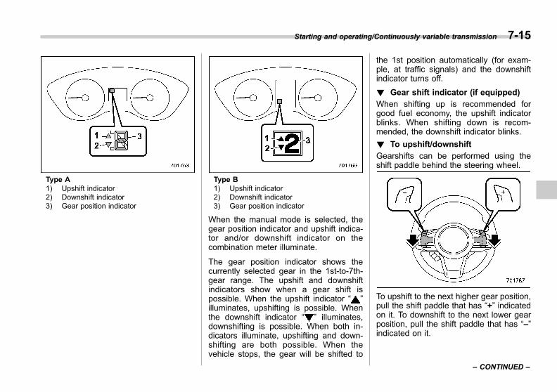
Black plate (297,1)
一般Model "A1300GE-A" EDITED: 2016/ 9/ 13
Type A1) Upshift indicator2) Downshift indicator3) Gear position indicator
Type B1) Upshift indicator2) Downshift indicator3) Gear position indicator
When the manual mode is selected, thegear position indicator and upshift indica-tor and/or downshift indicator on thecombination meter illuminate.
The gear position indicator shows thecurrently selected gear in the 1st-to-7th-gear range. The upshift and downshiftindicators show when a gear shift ispossible. When the upshift indicator “ ”illuminates, upshifting is possible. Whenthe downshift indicator “ ” illuminates,downshifting is possible. When both in-dicators illuminate, upshifting and down-shifting are both possible. When thevehicle stops, the gear will be shifted to
the 1st position automatically (for exam-ple, at traffic signals) and the downshiftindicator turns off.
! Gear shift indicator (if equipped)
When shifting up is recommended forgood fuel economy, the upshift indicatorblinks. When shifting down is recom-mended, the downshift indicator blinks.
! To upshift/downshift
Gearshifts can be performed using theshift paddle behind the steering wheel.
To upshift to the next higher gear position,pull the shift paddle that has “+” indicatedon it. To downshift to the next lower gearposition, pull the shift paddle that has “–”indicated on it.
Starting and operating/Continuously variable transmission 7-15
– CONTINUED –
7
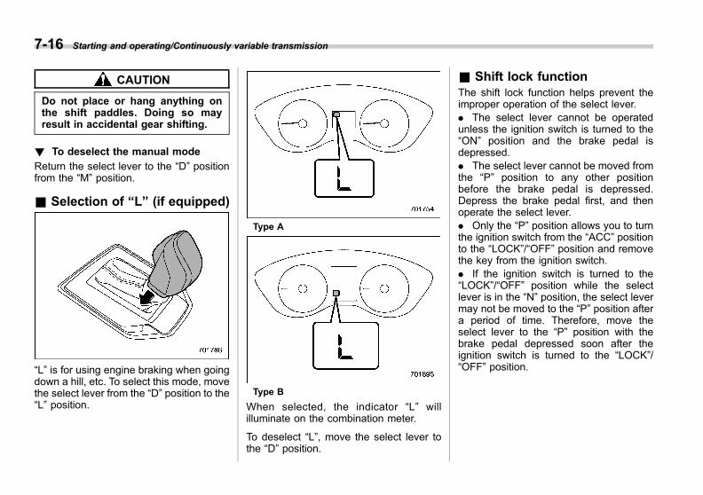
Black plate (298,1)
一般Model "A1300GE-A" EDITED: 2016/ 9/ 13
7-16 Starting and operating/Continuously variable transmission
CAUTION
Do not place or hang anything onthe shift paddles. Doing so mayresult in accidental gear shifting.
! To deselect the manual mode
Return the select lever to the “D” positionfrom the “M” position.
& Selection of “L” (if equipped)
“L” is for using engine braking when goingdown a hill, etc. To select this mode, movethe select lever from the “D” position to the“L” position.
Type A
Type B
When selected, the indicator “L” willilluminate on the combination meter.
To deselect “L”, move the select lever tothe “D” position.
& Shift lock functionThe shift lock function helps prevent theimproper operation of the select lever.. The select lever cannot be operatedunless the ignition switch is turned to the“ON” position and the brake pedal isdepressed.. The select lever cannot be moved fromthe “P” position to any other positionbefore the brake pedal is depressed.Depress the brake pedal first, and thenoperate the select lever.. Only the “P” position allows you to turnthe ignition switch from the “ACC” positionto the “LOCK”/“OFF” position and removethe key from the ignition switch.. If the ignition switch is turned to the“LOCK”/“OFF” position while the selectlever is in the “N” position, the select levermay not be moved to the “P” position aftera period of time. Therefore, move theselect lever to the “P” position with thebrake pedal depressed soon after theignition switch is turned to the “LOCK”/“OFF” position.

Black plate (299,1)
一般Model "A1300GE-A" EDITED: 2016/ 9/ 13
! Shift lock release
If the select lever cannot be operated, turnthe ignition switch back to the “ON”position then move the select lever to the“P” position with the select lever buttonpressed and brake pedal depressed.
If the select lever does not move afterperforming the above procedure, performthe following steps.. When the select lever cannot beshifted from “P” to “N”:Refer to “Shift lock release using the shiftlock release button” F7-17.. When the select lever cannot beshifted from “N” to “R”, “P”:Within 60 seconds after placing the igni-tion switch in the “ACC” position, move theselect lever to the “P” position with theselect lever button pressed and brakepedal depressed.
If you must perform the above procedure,the shift lock system (or the vehicle controlsystem) may be malfunctioning. We re-commend that you contact a SUBARUdealer for an inspection as soon aspossible.
If the select lever does not move afterperforming the above procedure, refer to“Shift lock release using the shift lockrelease button” F7-17.
! Shift lock release using the shiftlock release button
Perform the following procedure to releasethe shift lock.1. Apply the parking brake and stop theengine.
2. Wrap the tip of a flat-head screwdriverwith vinyl tape or a cloth and use it toremove the shift lock cover. The shift lockrelease button is located under the shiftlock cover.
3. Remove the grip portion of the screw-driver.
4. While depressing the brake pedal,insert a screwdriver into the hole, move itright and left while pushing the shift lockrelease button using a screwdriver, and
Starting and operating/Continuously variable transmission 7-17
– CONTINUED –
7
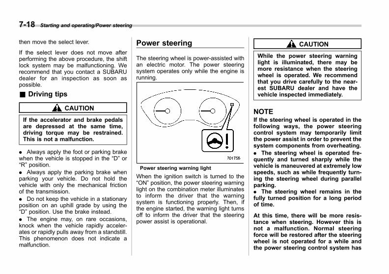
Black plate (300,1)
一般Model "A1300GE-A" EDITED: 2016/ 9/ 13
7-18 Starting and operating/Power steering
then move the select lever.
If the select lever does not move afterperforming the above procedure, the shiftlock system may be malfunctioning. Werecommend that you contact a SUBARUdealer for an inspection as soon aspossible.
& Driving tips
CAUTION
If the accelerator and brake pedalsare depressed at the same time,driving torque may be restrained.This is not a malfunction.
. Always apply the foot or parking brakewhen the vehicle is stopped in the “D” or“R” position.. Always apply the parking brake whenparking your vehicle. Do not hold thevehicle with only the mechanical frictionof the transmission.. Do not keep the vehicle in a stationaryposition on an uphill grade by using the“D” position. Use the brake instead.. The engine may, on rare occasions,knock when the vehicle rapidly acceler-ates or rapidly pulls away from a standstill.This phenomenon does not indicate amalfunction.
Power steering
The steering wheel is power-assisted withan electric motor. The power steeringsystem operates only while the engine isrunning.
Power steering warning light
When the ignition switch is turned to the“ON” position, the power steering warninglight on the combination meter illuminatesto inform the driver that the warningsystem is functioning properly. Then, ifthe engine started, the warning light turnsoff to inform the driver that the steeringpower assist is operational.
CAUTION
While the power steering warninglight is illuminated, there may bemore resistance when the steeringwheel is operated. We recommendthat you drive carefully to the near-est SUBARU dealer and have thevehicle inspected immediately.
NOTEIf the steering wheel is operated in thefollowing ways, the power steeringcontrol system may temporarily limitthe power assist in order to prevent thesystem components from overheating.. The steering wheel is operated fre-quently and turned sharply while thevehicle is maneuvered at extremely lowspeeds, such as while frequently turn-ing the steering wheel during parallelparking.. The steering wheel remains in thefully turned position for a long periodof time.
At this time, there will be more resis-tance when steering. However this isnot a malfunction. Normal steeringforce will be restored after the steeringwheel is not operated for a while andthe power steering control system has
Black plate (301,1)
一般Model "A1300GE-A" EDITED: 2016/ 9/ 13
an opportunity to cool down. However,if the power steering is operated in anon-standard way which causes powerassist limitation to occur too fre-quently, this may result in a malfunc-tion of the power steering controlsystem.
Braking
& Braking tips
WARNING
Never rest your foot on the brakepedal while driving. This can causedangerous overheating of thebrakes and needless wear on thebrake pads and linings.
! When the brakes get wet
When driving in rain or after washing thevehicle, the brakes may get wet. As aresult, brake stopping distance will belonger. To dry the brakes, drive the vehicleat a safe speed while lightly depressingthe brake pedal to heat up the brakes.
! Use of engine braking
Remember to make use of engine brakingin addition to foot braking. When descend-ing a grade, if only the foot brake is used,the brakes may start working improperlybecause of brake fluid overheating,caused by overheated brake pads. Tohelp prevent this, shift into a lower gear toget stronger engine braking.
! Braking when a tire is punctured
Do not depress the brake pedal suddenlywhen a tire is punctured. This could causea loss of control of the vehicle. Keepdriving straight ahead while graduallyreducing speed. Then slowly pull off theroad to a safe location.
& Brake system
! Two separate circuits
Your vehicle has two separate circuitbrake systems. Each circuit works diag-onally across the vehicle. If one circuit ofthe brake system should fail, the other halfof the system still works. If one circuit fails,the brake pedal will go down much closerto the floor than usual and you will need topress it down much harder. And a muchlonger distance will be needed to stop thevehicle.
! Brake booster
The brake booster uses engine manifoldvacuum to assist braking force. Do notturn off the engine while driving becausethat will turn off the brake booster, result-ing in poor braking power.The brakes will continue to work evenwhen the brake booster completely stopsfunctioning. If this happens, you will haveto depress the pedal much harder than
Starting and operating/Braking 7-19
– CONTINUED –
7
Black plate (302,1)
一般Model "A1300GE-A" EDITED: 2016/ 9/ 13
7-20 Starting and operating/Braking
during normal braking, and the brakingdistance will increase.
! Supplemental booster functionwhen vacuum pressure fails
While the ignition switch is turned “ON”and the engine is running, the supple-mental booster function operates whenthe brake booster performance is de-creased due to insufficient vacuum boost.When the brake pedal is depressed whilethe supplemental booster function is oper-ating, an operation sound and brake pedalvibration may be generated. This is not amalfunction.
! Brake assist system
WARNING
Do not be overconfident about thebrake assist. It is not a system thatbrings more braking ability to thevehicle beyond its braking capabil-ity. Always use the utmost carewhen driving regarding vehiclespeed and safe distance.
CAUTION
When you need to brake suddenly,continue depressing the brake pedalstrongly to bring the effect of the
brake assist.
Brake assist is a driver assistance system.It assists the brake power when the drivercannot depress the brake pedal stronglyand the brake power is insufficient.Brake assist generates the brake poweraccording to the speed at which the driverdepresses the brake pedal.
NOTEWhen you depress the brake pedalstrongly or suddenly, the followingphenomena occur. However, eventhough these occur, they do not indi-cate any malfunctions, and the brakeassist system is operating properly.. You might feel that the brake pedalis applied by lighter force and gener-ates a greater braking force.. You might hear the sound of theABS operating from the engine com-partment.
! Emergency Stop Signal
The Emergency Stop Signal is a functionthat automatically blinks the hazard warn-ing flasher in short intervals when thebrake pedal is depressed suddenly. Therapid flashing of the hazard warningflasher cautions the vehicles behind andreduces the possibility of a collision.
CAUTION
The Emergency Stop Signal is acti-vated in priority over the turn signal.
! Operating condition
The Emergency Stop Signal activateswhen all of the following conditions aremet.. The hazard warning flasher is off.. The vehicle speed is 60 km/h (37 mph)or more.. The system judges that sudden brakinghas occurred based on the vehicle decel-eration when the brake pedal is de-pressed.
! Automatic cancel
The Emergency Stop Signal is canceled ineither of the following circumstances.. The hazard warning flasher is turnedon.. The brake pedal is released.. The system judges that sudden brakinghas ended, based on the vehicle decel-eration.
The operational/non-operational setting ofthe Emergency Stop Signal can be chan-ged by a SUBARU dealer. For details, werecommend that you contact your
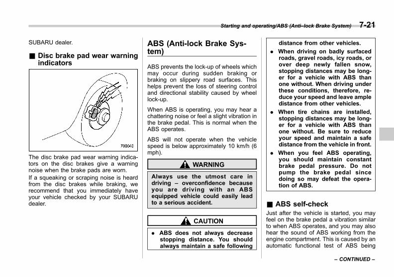
Black plate (303,1)
一般Model "A1300GE-A" EDITED: 2016/ 9/ 13
SUBARU dealer.
& Disc brake pad wear warningindicators
The disc brake pad wear warning indica-tors on the disc brakes give a warningnoise when the brake pads are worn.If a squeaking or scraping noise is heardfrom the disc brakes while braking, werecommend that you immediately haveyour vehicle checked by your SUBARUdealer.
ABS (Anti-lock Brake Sys-tem)
ABS prevents the lock-up of wheels whichmay occur during sudden braking orbraking on slippery road surfaces. Thishelps prevent the loss of steering controland directional stability caused by wheellock-up.
When ABS is operating, you may hear achattering noise or feel a slight vibration inthe brake pedal. This is normal when theABS operates.
ABS will not operate when the vehiclespeed is below approximately 10 km/h (6mph).
WARNING
Always use the utmost care indriving – overconfidence becauseyou are driving with an ABSequipped vehicle could easily leadto a serious accident.
CAUTION
. ABS does not always decreasestopping distance. You shouldalways maintain a safe following
distance from other vehicles.
. When driving on badly surfacedroads, gravel roads, icy roads, orover deep newly fallen snow,stopping distances may be long-er for a vehicle with ABS thanone without. When driving underthese conditions, therefore, re-duce your speed and leave ampledistance from other vehicles.
. When tire chains are installed,stopping distances may be long-er for a vehicle with ABS thanone without. Be sure to reduceyour speed and maintain a safedistance from the vehicle in front.
. When you feel ABS operating,you should maintain constantbrake pedal pressure. Do notpump the brake pedal sincedoing so may defeat the opera-tion of ABS.
& ABS self-checkJust after the vehicle is started, you mayfeel on the brake pedal a vibration similarto when ABS operates, and you may alsohear the sound of ABS working from theengine compartment. This is caused by anautomatic functional test of ABS being
Starting and operating/ABS (Anti–lock Brake System) 7-21
– CONTINUED –
7

Black plate (304,1)
一般Model "A1300GE-A" EDITED: 2016/ 9/ 13
7-22 Starting and operating/Electronic Brake Force Distribution (EBD) system
carried out and does not indicate amalfunction.
& ABS warning lightRefer to “ABS warning light” F3-23.
Electronic Brake Force Dis-tribution (EBD) system
The EBD system maximizes the effective-ness of the brakes by allowing the rearbrakes to supply a greater proportion ofthe braking force. It functions by adjustingthe distribution of braking force to the rearwheels in accordance with the vehicle’sloading condition and speed.The EBD system is an integral part of theABS system and uses some of the ABSsystem’s components to perform its func-tion of optimizing the distribution of brak-ing force. If any of the ABS componentsused by the EBD system malfunction, theEBD system also stops working.
When the EBD system is operating, youmay hear a chattering noise or feel a slightvibration in the brake pedal. This is normaland does not indicate a malfunction.
& Steps to take if EBD systemfails
If a malfunction occurs in the EBD system,the system stops working and the follow-ing warning lights illuminate simulta-neously.. Brake system warning light. ABS warning light. Vehicle Dynamics Control warning light
The EBD system may be malfunctioning ifall the warning lights illuminate simulta-neously during driving.Even if the EBD system malfunctions, theconventional braking system will still func-tion. However, the rear wheels will bemore prone to locking when the brakesare applied harder than usual and thevehicle’s motion may therefore become
Black plate (305,1)
一般Model "A1300GE-A" EDITED: 2016/ 9/ 13
somewhat harder to control.
If all the warning lights illuminate simulta-neously, take the following steps.1. Stop the vehicle in the nearest safe,flat location.2. Apply the parking brake and turn offthe engine.3. Restart the engine.4. Release the parking brake.
If all the warning lights do not comeback on:The EBD system have a possible mal-function. Drive carefully to the nearestSUBARU dealer and have the systeminspected.
If all the warning lights stay illuminatedor come back on after approximately 2seconds:1. Turn off the engine again.2. Check the brake fluid level. For detailsabout checking the brake fluid level, referto “Checking the fluid level” F11-22.
. If the brake fluid level is not below the“MIN” mark, the EBD system may bemalfunctioning. We recommend that youdrive carefully to the nearest SUBARUdealer and have the system inspected.. If the brake fluid level is below the“MIN” mark, DO NOT drive the vehicle.
Instead, we recommend that you have thevehicle towed to the nearest SUBARUdealer for repair.
WARNING
. Driving with the brake systemwarning light illuminated is dan-gerous. This indicates your brakesystem may not be workingproperly. If the light remainsilluminated, we recommend thatyou have the brakes inspectedby a SUBARU dealer immedi-ately.
. If at all in doubt about whetherthe brakes are operating prop-erly, do not drive the vehicle. Werecommend that you have yourvehicle towed to the nearestSUBARU dealer for repair.
Vehicle Dynamics Controlsystem
WARNING
Always use the utmost care indriving – overconfidence becauseyou are driving a vehicle with theVehicle Dynamics Control systemcould easily lead to a serious acci-dent.
CAUTION
. Even if your vehicle is equippedwith Vehicle Dynamics Control,winter tires or snow chainsshould be used when driving onsnow-covered or icy roads; inaddition, vehicle speed shouldbe reduced considerably. Simplyhaving a Vehicle Dynamics Con-trol system does not guaranteethat the vehicle will be able toavoid accidents in any situation.
. When a vehicle is fitted withsnow chains, the effectivenessof the Vehicle Dynamics Controlsystem is reduced and thisshould be taken into account
Starting and operating/Vehicle Dynamics Control system 7-23
– CONTINUED –
7

Black plate (306,1)
一般Model "A1300GE-A" EDITED: 2016/ 9/ 13
7-24 Starting and operating/Vehicle Dynamics Control system
when driving the vehicle in sucha condition.
. Activation of the Vehicle Dy-namics Control system is anindication that the road beingtravelled on has a slippery sur-face; since having Vehicle Dy-namics Control is no guaranteethat full vehicle control will bemaintained at all times and underall conditions, its activationshould be seen as a sign thatthe speed of the vehicle shouldbe reduced considerably.
. Whenever suspension compo-nents, steering components, oran axle are removed from avehicle, we recommend that youhave an inspection of that sys-tem performed by an authorizedSUBARU dealer.
. The following precautions shouldbe observed in order to ensurethat the Vehicle Dynamics Con-trol system is operating properly:
– All four wheels should befitted with tires of the samesize, type, and brand. Further-more, the amount of wearshould be the same for allfour tires.
– Keep the tire pressure at theproper level as shown on thelabel attached to the vehicle’sdoor pillar.
– Use only the special tempor-ary spare tire to replace a flattire. With a temporary sparetire, the effectiveness of theVehicle Dynamics Controlsystem is reduced and thisshould be taken into accountwhen driving the vehicle insuch a condition.
. If non-matching tires are used,the Vehicle Dynamics Controlsystem may not operate cor-rectly.
. The Vehicle Dynamics Controlsystem helps prevent unstablevehicle motion such as skiddingusing control of the brakes andengine power. Do not turn off theVehicle Dynamics Control sys-tem unless it is absolutely ne-cessary. If you must turn off theVehicle Dynamics Control sys-tem, drive very carefully accord-ing to the road surface condition.
In the event of wheelspin and/or skiddingon a slippery road surface and/or duringcornering and/or an evasive maneuver,
the Vehicle Dynamics Control systemadjusts the engine’s output and thewheels’ respective braking forces to helpmaintain traction and directional control.
. Traction Control FunctionThe traction control function is designed toprevent spinning of the driving wheels onslippery road surfaces, thereby helping tomaintain traction and directional control.Activation of this function is shown byflashing the Vehicle Dynamics Controloperation indicator light.
. Skid Suppression FunctionThe skid suppression function is designedto help maintain directional stability bysuppressing the wheels’ tendency to slidesideways during steering operations. Acti-vation of this function is shown by flashingof the Vehicle Dynamics Control operationindicator light.
NOTE. The Vehicle Dynamics Control sys-tem may be considered normal whenthe following conditions occur.
– Slight twitching of the brakepedal is felt.– The vehicle or steering wheelshakes to a small degree.– An operating sound from theengine compartment is heard
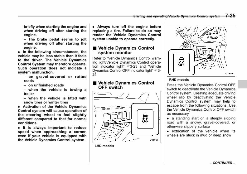
Black plate (307,1)
一般Model "A1300GE-A" EDITED: 2016/ 9/ 13
briefly when starting the engine andwhen driving off after starting theengine.– The brake pedal seems to joltwhen driving off after starting theengine.
. In the following circumstances, thevehicle may be less stable than it feelsto the driver. The Vehicle DynamicsControl System may therefore operate.Such operation does not indicate asystem malfunction.
– on gravel-covered or ruttedroads– on unfinished roads– when the vehicle is towing atrailer– when the vehicle is fitted withsnow tires or winter tires
. Activation of the Vehicle DynamicsControl system will cause operation ofthe steering wheel to feel slightlydifferent compared to that for normalconditions.. It is always important to reducespeed when approaching a corner,even if your vehicle is equipped withthe Vehicle Dynamics Control system.
. Always turn off the engine beforereplacing a tire. Failure to do so mayrender the Vehicle Dynamics Controlsystem unable to operate correctly.
& Vehicle Dynamics Controlsystem monitor
Refer to “Vehicle Dynamics Control warn-ing light/Vehicle Dynamics Control opera-tion indicator light” F3-23 and “VehicleDynamics Control OFF indicator light”F3-24.
& Vehicle Dynamics ControlOFF switch
LHD models
RHD models
Press the Vehicle Dynamics Control OFFswitch to deactivate the Vehicle DynamicsControl system. Creating adequate drivingwheel slip by deactivating the VehicleDynamics Control system may help toescape from the following situations. Usethe Vehicle Dynamics Control OFF switchas necessary.. a standing start on a steeply slopingroad with a snowy, gravel-covered, orotherwise slippery surface. extrication of the vehicle when itswheels are stuck in mud or deep snow
Starting and operating/Vehicle Dynamics Control system 7-25
– CONTINUED –
7
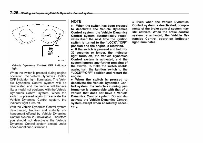
Black plate (308,1)
一般Model "A1300GE-A" EDITED: 2016/ 9/ 13
7-26 Starting and operating/Vehicle Dynamics Control system
Vehicle Dynamics Control OFF indicatorlight
When the switch is pressed during engineoperation, the Vehicle Dynamics ControlOFF indicator light illuminates. The Vehi-cle Dynamics Control system will bedeactivated and the vehicle will behavelike a model not equipped with the VehicleDynamics Control system. When theswitch is pressed again to reactivate theVehicle Dynamics Control system, theindicator light turns off.With the Vehicle Dynamics Control systemdeactivated, traction and stability en-hancement offered by Vehicle DynamicsControl system is unavailable. Thereforeyou should not deactivate the VehicleDynamics Control system except underabove-mentioned situations.
NOTE. When the switch has been pressedto deactivate the Vehicle DynamicsControl system, the Vehicle DynamicsControl system automatically reacti-vates itself the next time the ignitionswitch is turned to the “LOCK”/“OFF”position and the engine is restarted.. If the switch is pressed and held for30 seconds or longer, the indicatorlight turns off, the Vehicle DynamicsControl system is activated, and thesystem ignores any further pressing ofthe switch. To make the switch usableagain, turn the ignition switch to the“LOCK”/“OFF” position and restart theengine.. When the switch is pressed todeactivate the Vehicle Dynamics Con-trol system, the vehicle’s running per-formance is comparable with that of avehicle that does not have a VehicleDynamics Control system. Do not de-activate the Vehicle Dynamics Controlsystem except when absolutely neces-sary.
. Even when the Vehicle DynamicsControl system is deactivated, compo-nents of the brake control system maystill activate. When the brake controlsystem is activated, the Vehicle Dy-namics Control operation indicatorlight illuminates.
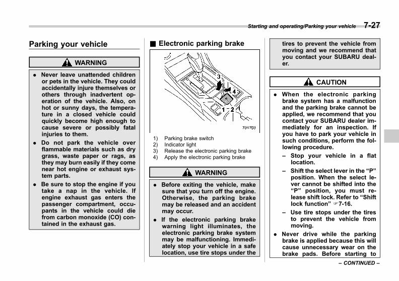
Black plate (309,1)
一般Model "A1300GE-A" EDITED: 2016/ 9/ 13
Parking your vehicle
WARNING
. Never leave unattended childrenor pets in the vehicle. They couldaccidentally injure themselves orothers through inadvertent op-eration of the vehicle. Also, onhot or sunny days, the tempera-ture in a closed vehicle couldquickly become high enough tocause severe or possibly fatalinjuries to them.
. Do not park the vehicle overflammable materials such as drygrass, waste paper or rags, asthey may burn easily if they comenear hot engine or exhaust sys-tem parts.
. Be sure to stop the engine if youtake a nap in the vehicle. Ifengine exhaust gas enters thepassenger compartment, occu-pants in the vehicle could diefrom carbon monoxide (CO) con-tained in the exhaust gas.
& Electronic parking brake
1) Parking brake switch2) Indicator light3) Release the electronic parking brake4) Apply the electronic parking brake
WARNING
. Before exiting the vehicle, makesure that you turn off the engine.Otherwise, the parking brakemay be released and an accidentmay occur.
. If the electronic parking brakewarning light illuminates, theelectronic parking brake systemmay be malfunctioning. Immedi-ately stop your vehicle in a safelocation, use tire stops under the
tires to prevent the vehicle frommoving and we recommend thatyou contact your SUBARU deal-er.
CAUTION
. When the electronic parkingbrake system has a malfunctionand the parking brake cannot beapplied, we recommend that youcontact your SUBARU dealer im-mediately for an inspection. Ifyou have to park your vehicle insuch conditions, perform the fol-lowing procedure.
– Stop your vehicle in a flatlocation.
– Shift the select lever in the “P”position. When the select le-ver cannot be shifted into the“P” position, you must re-lease shift lock. Refer to “Shiftlock function” F7-16.
– Use tire stops under the tiresto prevent the vehicle frommoving.
. Never drive while the parkingbrake is applied because this willcause unnecessary wear on thebrake pads. Before starting to
Starting and operating/Parking your vehicle 7-27
– CONTINUED –
7

Black plate (310,1)
一般Model "A1300GE-A" EDITED: 2016/ 9/ 13
7-28 Starting and operating/Parking your vehicle
drive, always make sure that theparking brake has been releasedand the electronic parking brakeindicator light has turned off.
. The braking power of the electro-nic parking brake may not besufficient when strong brakingpower is needed (e.g., whenparking on a steep slope whiletowing a trailer).
Your vehicle is equipped with an electronicparking brake. You can apply/release theparking brake by operating the parkingbrake switch.
To apply: Pull up the parking brakeswitch.To release: Press the parking brakeswitch firmly while the ignition switch isin the “ON” position and the brake pedal isdepressed.
Electronic parking brake indicator light
When the parking brake is applied whilethe ignition switch is in the “ON” position,the following indicator lights illuminate.. the indicator light on the parking brakeswitch. the electronic parking brake indicatorlight on the combination meter (for details,refer to “Electronic parking brake indicatorlight” F3-26.)
NOTE. If the parking brake switch ispressed with the ignition switch in the“ACC” or “LOCK”/“OFF” position, theparking brake is not released.. If the parking brake switch ispressed without depressing the brakepedal, the parking brake is not re-
leased.. The electronic parking brake systemuses motors to apply the parkingbrake. Therefore, operating soundsfrom the motors will be heard whenapplying or releasing the parkingbrake. Make sure that the motorsounds are heard when applying orreleasing the parking brake. Addition-ally, the motor sounds will be heardwhen operating the select lever ordepressing the brake pedal. This isnot a malfunction. The sounds willoccur when the electronic parkingbrake system automatically controlsthe motors.. When the electronic parking brakesystem has a malfunction or the elec-tronic parking brake operation is pro-hibited temporarily, if the parking brakeswitch is operated, a chirp sound isheard and the electronic parking brakeindicator light flashes.. When the electronic parking brake isapplied under any of the followingconditions, the operating sound of theelectronic parking brake may be heardseveral minutes after the electronicparking brake indicator light illumi-nates. However, this does not indicatea malfunction.
– The parking brake overheats.

Black plate (311,1)
一般Model "A1300GE-A" EDITED: 2016/ 9/ 13
– The vehicle is parked on a steepslope.– You operate the parking brakeswitch after the ignition switch hasbeen turned off.
. If you use the electronic parkingbrake under the following conditions,the electronic parking brake indicatorlight may flash.
– The parking brake overheats.– The vehicle is stopped on a steepslope.
Even in these cases, the electronicparking brake will operate. However,use tire stops because the vehicle maymove.. The Auto Start Stop system (ifequipped) is deactivated while theelectronic parking brake is applied.. If you operate the electronic parkingbrake switch while the Auto Start Stopsystem (if equipped) is activated, theAuto Start Stop system will be deacti-vated. The electronic parking brake willactivate after the engine is restarted.After the electronic parking brake in-dicator light is illuminated, release yourfoot from the brake pedal.. When starting the engine or restart-ing the engine using the Auto StartStop system (if equipped), if you oper-
ate the electronic parking brake switch,the electronic parking brake indicatorlight may flash temporarily. However,this is not a malfunction if the lightturns off after the electronic parkingbrake is deactivated.
! Automatic release function by ac-celerator pedal
The electronic parking brake system hasan automatic release function. The park-ing brake will be automatically released bydepressing the accelerator pedal. How-ever, the automatic release function doesnot operate under the following conditions.. Any door is open.. The driver’s seatbelt is not fastened.. The select lever is in the “P” or “N”position.
If the parking brake is automaticallyreleased, the electronic parking brakeindicator light and the indicator light onthe parking brake switch turn off.
NOTEWhile pulling up the parking brakeswitch, the parking brake will not beautomatically released even when theaccelerator pedal is depressed.
! Hill Holder function
WARNING
When stopping on an uphill slopewith the Hill Holder function acti-vated, release the brake pedal afterthe electronic parking brake indica-tor light has illuminated. Otherwise,the Hill Holder function may notoperate properly and an accidentmay occur.
The electronic parking brake system has aHill Holder function. If the Hill Holderfunction is activated, the parking brakewill be automatically applied when stop-ping on an uphill slope with the brakepedal depressed. In this case, the electro-nic parking brake indicator light and theindicator light on the parking brake switchilluminate.The Hill Holder function also activateswhen driving uphill in reverse.
NOTE. The Hill Holder function may notactivate on a gentle uphill slope. In thiscase, manually apply the electronicparking brake.. If you do not depress the brakepedal sufficiently, the Hill Holder func-
Starting and operating/Parking your vehicle 7-29
– CONTINUED –
7

Black plate (312,1)
一般Model "A1300GE-A" EDITED: 2016/ 9/ 13
7-30 Starting and operating/Parking your vehicle
tion may not operate properly. How-ever, this is not a malfunction. Whenstopping on an uphill slope, depressthe brake pedal firmly and release itafter the electronic parking brake in-dicator light illuminates.. Depending on the condition of theroad surface and braking force, thebrakes operate temporarily and feeldifferent than usual.. When the electronic parking brakesystem has a malfunction while the HillHolder function is activated, a chirpsound is heard, the Hill Holder indica-tor light turns off and the electronicparking brake warning light illuminates.. If the Hill Holder function activatesautomatically and the driver releasesthe function manually and continues topark, the function will not activateautomatically again. In this case, oper-ate the electronic parking brake manu-ally to activate the function.. If the driver does not fasten theseatbelt when the Hill Holder functionis activated, the vehicle may not startmoving smoothly from a stop, or anoise may be heard from the brakecomponents.
! Hill Holder switch
Hill Holder switch
You can activate/deactivate the Hill Holderfunction by pressing the Hill Holder switch.
To activate: Press the Hill Holder switch.To deactivate: Press the Hill Holderswitch again.
Deactivate the Hill Holder function underthe following conditions.. When towing a trailer. When carrying a heavy load. When you do not frequently use theparking brake when stopping on an uphillslope
NOTE. If the Hill Holder switch is pressedfor more than 30 seconds, the HillHolder indicator light turns off, electro-nic parking brake warning light illumi-nates and the system ignores anyfurther pressing of the switch. Toactivate the switch again, turn theignition switch to the “LOCK”/“OFF”position and restart the engine.. When the Hill Holder function isdeactivated while the Hill Holder func-tion has a malfunction, if you press theHill Holder switch, a chirp sounds.
! Hill Holder indicator light
Refer to “Hill Holder indicator light” F3-27.
! Emergency brake
CAUTION
Use the emergency brake only incase of an emergency. If the emer-gency brake is excessively used,the brake parts will wear downfaster or the brake may not worksufficiently due to rear wheel brakeoverheating.

Black plate (313,1)
一般Model "A1300GE-A" EDITED: 2016/ 9/ 13
NOTEWhile using the emergency brake, theelectronic parking brake indicator lightand the indicator light on the parkingbrake switch illuminate and a chirpsounds.
If the foot brake has a malfunction, youcan stop the vehicle by pulling the parkingbrake switch continuously.While applying the emergency brake, theelectronic parking brake indicator light andthe indicator on the parking brake switchilluminate and a chirp sounds.
! Electronic parking brake systemwarning
CAUTION
If the electronic parking brake in-dicator light flashes, the electronicparking brake system may be mal-functioning. Immediately stop yourvehicle in the nearest safe locationand we recommend that you contactyour SUBARU dealer.
1) Electronic parking brake indicator light2) Electronic parking brake warning light
If a malfunction occurs in the electronicparking brake system, the electronic park-ing brake warning light illuminates and/orthe electronic parking brake indicator lightflashes. Refer to “Electronic parking brakewarning light/Vacuum pressure systemwarning light (yellow)” F3-26 and “Elec-tronic parking brake indicator light”F3-26.
& Parking tipsWhen parking your vehicle, always per-form the following items.. Apply the parking brake.. Put the select lever in the “P” (Park)position.
Never rely on the mechanical friction ofthe transmission alone to hold the vehicle.
When parking on a hill, always turn thesteering wheel. When the vehicle isheaded up the hill, the front wheels shouldbe turned away from the curb.
Starting and operating/Parking your vehicle 7-31
– CONTINUED –
7

Black plate (314,1)
一般Model "A1300GE-A" EDITED: 2016/ 9/ 13
7-32 Starting and operating/Tire pressure monitoring system (TPMS)
When facing downhill, the front wheelsshould be turned into the curb.
Tire pressure monitoringsystem (TPMS) (if equipped)
Low tire pressure warning light
The tire pressure monitoring system pro-vides the driver with a warning messageby sending a signal from a sensor that isinstalled in each wheel when a tirepressure is severely low relative to theselected TPMS mode. Refer to “Low tirepressure warning light” F3-21The tire pressure monitoring system willactivate only when the vehicle is driven atspeeds above 40 km/h (25 mph). Also,this system may not react immediately to asudden drop in tire pressure (for example,a blow-out caused by running over asharp object).
WARNING
. If the low tire pressure warninglight illuminates while driving,never brake suddenly. Instead,perform the following procedure.Otherwise an accident involvingserious vehicle damage and ser-ious personal injury could occur.
(1) Keep driving straight aheadwhile gradually reducingspeed.
(2) Slowly pull off the road to asafe place.
(3)Models equipped for towing,check the pressure for all fourtires and adjust the pressureaccording to the most appro-priate one of three (normal,loading, or towing) COLD tirepressure values shown on thetire placard located on thedoor pillar on the driver’sside.
(4)Models not equipped for tow-ing, check the pressure for allfour tires and adjust the pres-sure according to the mostappropriate one of two (nor-mal or loading) COLD tirepressure values shown on

Black plate (315,1)
一般Model "A1300GE-A" EDITED: 2016/ 9/ 13
the tire placard located on thedoor pillar on the driver’sside.
Even when the vehicle is driven avery short distance, the tires getwarm and their pressures increaseaccordingly. Be sure to let the tirescool thoroughly before adjustingtheir pressures to the standardvalues shown on the tire placard.Refer to “Tires and wheels” F11-24.The tire pressure monitoring systemdoes not function when the vehicleis stationary. After adjusting the tirepressures, increase the vehiclespeed to at least 40 km/h (25 mph)to start the TPMS rechecking of thetire inflation pressures. If the tirepressures are now above the severelow pressure threshold, the low tirepressure warning light should turnoff a few minutes later.
If this light still illuminates whiledriving after adjusting the tire pres-sure, a tire may have significantdamage and a fast leak that causesthe tire to lose air rapidly. If you havea flat tire, replace it with a spare tireas soon as possible.
. When a spare tire is mounted or awheel rim is replaced without theoriginal pressure sensor/trans-
mitter being transferred, the lowtire pressure warning light willilluminate steadily after blinkingfor approximately one minute.This indicates the TPMS is un-able to monitor all four roadwheels. We recommend that youcontact your SUBARU dealer assoon as possible for tire andsensor replacement and/or sys-tem resetting.
. When a tire is repaired with liquidsealant, the tire pressure warningvalve and transmitter may notoperate properly. If a liquid sea-lant is used, we recommend thatyou contact your nearestSUBARU dealer or other qualifiedservice shop as soon as possi-ble. Make sure to replace the tirepressure warning valve andtransmitter when replacing thetire. You may reuse the wheel ifthere is no damage to it and if thesealant residue is properlycleaned off. If the light illumi-nates steadily after blinking forapproximately one minute, werecommend that you promptlycontact a SUBARU dealer to havethe system inspected.
CAUTION
Do not place metal film or any metalparts in the cargo area/trunk. Thismay cause poor reception of thesignals from the tire pressure sen-sors, and the tire pressure monitor-ing system will not function prop-erly.
& TPMS screen (type B combi-nation meter) (if equipped)
This screen displays each tire pressure.Refer to “Basic screens” F3-40.
Starting and operating/Tire pressure monitoring system (TPMS) 7-33
– CONTINUED –
7
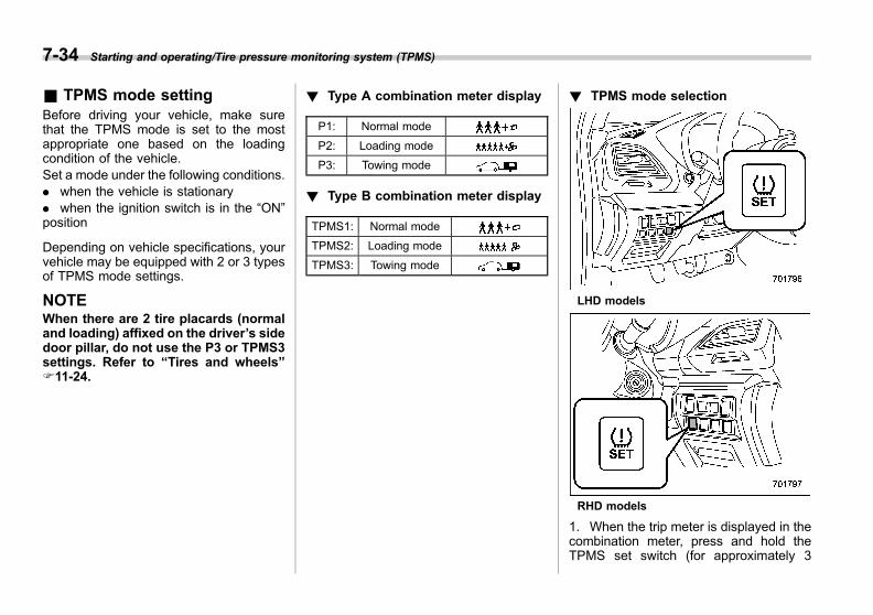
Black plate (316,1)
一般Model "A1300GE-A" EDITED: 2016/ 9/ 13
7-34 Starting and operating/Tire pressure monitoring system (TPMS)
& TPMS mode settingBefore driving your vehicle, make surethat the TPMS mode is set to the mostappropriate one based on the loadingcondition of the vehicle.Set a mode under the following conditions.. when the vehicle is stationary. when the ignition switch is in the “ON”position
Depending on vehicle specifications, yourvehicle may be equipped with 2 or 3 typesof TPMS mode settings.
NOTEWhen there are 2 tire placards (normaland loading) affixed on the driver’s sidedoor pillar, do not use the P3 or TPMS3settings. Refer to “Tires and wheels”F11-24.
! Type A combination meter display
P1: Normal mode
P2: Loading mode
P3: Towing mode
! Type B combination meter display
TPMS1: Normal mode
TPMS2: Loading mode
TPMS3: Towing mode
! TPMS mode selection
LHD models
RHD models
1. When the trip meter is displayed in thecombination meter, press and hold theTPMS set switch (for approximately 3
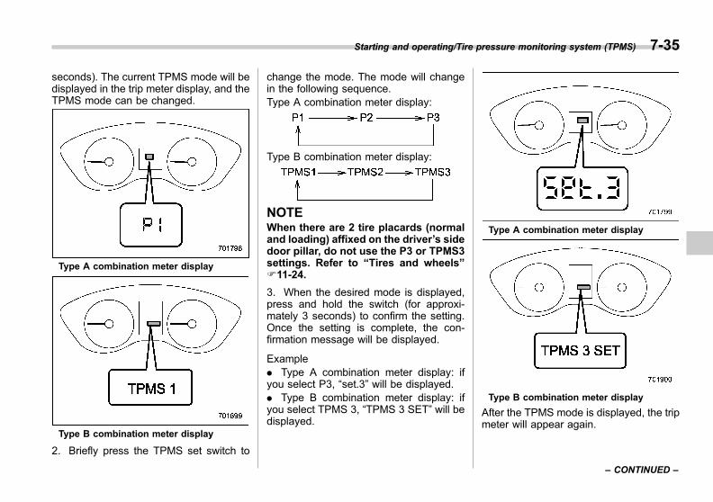
Black plate (317,1)
一般Model "A1300GE-A" EDITED: 2016/ 9/ 13
seconds). The current TPMS mode will bedisplayed in the trip meter display, and theTPMS mode can be changed.
Type A combination meter display
Type B combination meter display
2. Briefly press the TPMS set switch to
change the mode. The mode will changein the following sequence.Type A combination meter display:
Type B combination meter display:
NOTEWhen there are 2 tire placards (normaland loading) affixed on the driver’s sidedoor pillar, do not use the P3 or TPMS3settings. Refer to “Tires and wheels”F11-24.
3. When the desired mode is displayed,press and hold the switch (for approxi-mately 3 seconds) to confirm the setting.Once the setting is complete, the con-firmation message will be displayed.
Example. Type A combination meter display: ifyou select P3, “set.3” will be displayed.. Type B combination meter display: ifyou select TPMS 3, “TPMS 3 SET” will bedisplayed.
Type A combination meter display
Type B combination meter display
After the TPMS mode is displayed, the tripmeter will appear again.
Starting and operating/Tire pressure monitoring system (TPMS) 7-35
– CONTINUED –
7
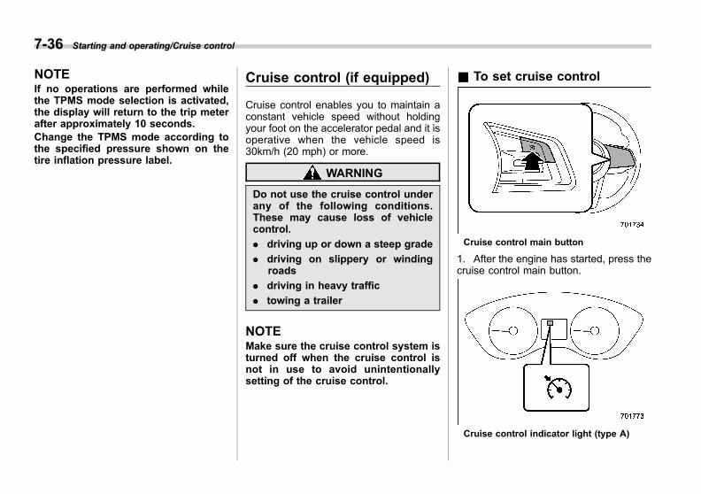
Black plate (318,1)
一般Model "A1300GE-A" EDITED: 2016/ 9/ 13
7-36 Starting and operating/Cruise control
NOTEIf no operations are performed whilethe TPMS mode selection is activated,the display will return to the trip meterafter approximately 10 seconds.Change the TPMS mode according tothe specified pressure shown on thetire inflation pressure label.
Cruise control (if equipped)
Cruise control enables you to maintain aconstant vehicle speed without holdingyour foot on the accelerator pedal and it isoperative when the vehicle speed is30km/h (20 mph) or more.
WARNING
Do not use the cruise control underany of the following conditions.These may cause loss of vehiclecontrol.
. driving up or down a steep grade
. driving on slippery or windingroads
. driving in heavy traffic
. towing a trailer
NOTEMake sure the cruise control system isturned off when the cruise control isnot in use to avoid unintentionallysetting of the cruise control.
& To set cruise control
Cruise control main button
1. After the engine has started, press thecruise control main button.
Cruise control indicator light (type A)

Black plate (319,1)
一般Model "A1300GE-A" EDITED: 2016/ 9/ 13
Cruise control indicator light (type B)
The cruise control indicator light on thecombination meter will illuminate.2. Depress the accelerator pedal until thevehicle reaches the desired speed.
3. Press the “RES/SET” switch to the
“SET” side and release it. Then releasethe accelerator pedal.
NOTEIf the set vehicle speed has not beenmemorized (other than when it hasbeen temporarily canceled), the vehiclespeed can be set even if the “RES/SET”switch is pressed to the “RES” side.
Cruise control set indicator light (type A)1) When setting the displayed unit as
“MPH”2) When setting the displayed unit as “km/h”
Cruise control set indicator light (type B)1) When setting the displayed unit as
“MPH”2) When setting the displayed unit as “km/h”
At this time, the cruise control set indicatorlight is illuminated in the combinationmeter. The set speed will be shown onthe combination meter. You can changethe displayed units by operating thecombination meter display.
. For type A meter details , refer to“Combination meter settings” F3-11.. For type B meter details, refer to“Menu screens” F3-42.
The vehicle will maintain the desiredspeed.
Starting and operating/Cruise control 7-37
– CONTINUED –
7
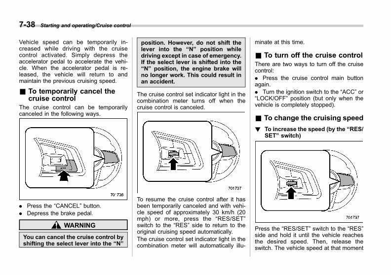
Black plate (320,1)
一般Model "A1300GE-A" EDITED: 2016/ 9/ 13
7-38 Starting and operating/Cruise control
Vehicle speed can be temporarily in-creased while driving with the cruisecontrol activated. Simply depress theaccelerator pedal to accelerate the vehi-cle. When the accelerator pedal is re-leased, the vehicle will return to andmaintain the previous cruising speed.
& To temporarily cancel thecruise control
The cruise control can be temporarilycanceled in the following ways.
. Press the “CANCEL” button.
. Depress the brake pedal.
WARNING
You can cancel the cruise control byshifting the select lever into the “N”
position. However, do not shift thelever into the “N” position whiledriving except in case of emergency.If the select lever is shifted into the“N” position, the engine brake willno longer work. This could result inan accident.
The cruise control set indicator light in thecombination meter turns off when thecruise control is canceled.
To resume the cruise control after it hasbeen temporarily canceled and with vehi-cle speed of approximately 30 km/h (20mph) or more, press the “RES/SET”switch to the “RES” side to return to theoriginal cruising speed automatically.The cruise control set indicator light in thecombination meter will automatically illu-
minate at this time.
& To turn off the cruise controlThere are two ways to turn off the cruisecontrol:. Press the cruise control main buttonagain.. Turn the ignition switch to the “ACC” or“LOCK/OFF” position (but only when thevehicle is completely stopped).
& To change the cruising speed
! To increase the speed (by the “RES/SET” switch)
Press the “RES/SET” switch to the “RES”side and hold it until the vehicle reachesthe desired speed. Then, release theswitch. The vehicle speed at that moment

Black plate (321,1)
一般Model "A1300GE-A" EDITED: 2016/ 9/ 13
will be memorized and treated as the newset speed.
When setting the displayed unit as“MPH”:The set speed can be increased 1 mph(1.6 km/h) each time by pressing the“RES/SET” switch to the “RES” side.
When setting the displayed unit as“km/h”:The set speed can be increased 1 km/heach time by pressing the “RES/SET”switch to the “RES” side.
! To increase the speed (by accel-erator pedal)
1. Depress the accelerator pedal toaccelerate the vehicle to the desiredspeed.2. Press the “RES/SET” switch to the“SET” side once. Now the desired speedis set and the vehicle will keep running atthat speed without depressing the accel-erator pedal.
! To decrease the speed (by the“RES/SET” switch)
Press the “RES/SET” switch to the “SET”side and hold it until the vehicle reachesthe desired speed. Then, release theswitch. The vehicle speed at that momentwill be memorized and treated as the newset speed.
When setting the displayed unit as“MPH”:The set speed can be decreased 1 mph(1.6 km/h) each time by pressing the“RES/SET” switch to the “SET” side.
When setting the displayed unit as“km/h”:The set speed can be decreased 1 km/heach time by pressing the “RES/SET”switch to the “SET” side.
! To decrease the speed (by brakepedal)
1. Depress the brake pedal to releasecruise control temporarily.2. When the speed decreases to thedesired speed, press the “RES/SET”switch to the “SET” side once. Now thedesired speed is set and the vehicle willkeep running at that speed without de-pressing the accelerator pedal.
& Cruise control indicator lightRefer to “Cruise control indicator light”F3-35.
& Cruise control set indicatorlight
Refer to “Cruise control set indicator light”F3-35.
Starting and operating/Cruise control 7-39
7

Black plate (322,1)
一般Model "A1300GE-A" EDITED: 2016/ 9/ 13
7-40 Starting and operating/Auto Start Stop system
Auto Start Stop system (ifequipped)
The Auto Start Stop system is designed toautomatically stop and restart the enginewhen the vehicle is stationary for a shortperiod of time (while waiting for a trafficlight or in a traffic jam, etc.) after theengine has warmed up, in order to reducefuel consumption and exhaust emissions,as well as undesired idling noise.
& System operation
CAUTION
. The Auto Start Stop system isdesigned to automatically stopand restart the engine for a shortperiod of time during idling. Donot use the system when parkingthe vehicle normally.
. The Auto Start Stop system doesnot operate when a trailer hitchconnector is connected. If theAuto Start Stop system operateswhen a trailer hitch connector isconnected, we recommend thatyou consult your SUBARU deal-er. Continuing to drive the vehi-cle while using the system in thiscondition could result in lurching
down downhill slopes or rollingback on uphill slopes, or couldcause damage to the transmis-sion.
So that it can be used safely andcomfortably, in addition to driver opera-tions, the Auto Start Stop system isdesigned to constantly monitor the vehicleconditions as well as the environmentinside and outside the vehicle, in order tocontrol stopping and restarting of theengine. The engine can be automaticallystopped by the system when all of thefollowing conditions are met.. when the vehicle has been driven onceafter the engine was started (If the vehicleis left continuously idling without beingdriven, the engine will not be stoppedautomatically. Also, the engine will not bestopped and restarted repeatedly whilethe vehicle is stationary.). the engine is sufficiently warmed up. the vehicle battery is in good condition. the engine hood is closed. the driver’s door is closed. the driver’s seatbelt is fastened. the rear window defogger is not in use. the defroster is not in use. the air conditioner is not in use (refer to“Air conditioner control” F4-10.)
. climate control for the driver’s seat isset to any temperature setting except themaximum heating or maximum coolingsettings (refer to “Temperature control”F4-10.). the vehicle is at an altitude of less thanapproximately 1,500 m (4,900 ft). the outside temperature is higher thanapproximately −108C (148F). the Auto Start Stop warning light(yellow) is not illuminated. the malfunction indicator light (CheckEngine light) is off. the steering wheel is in the straightahead position. the steering wheel is not being oper-ated. the vehicle is not be used for towing. the vehicle is not stopped on a roadthat has a steep slope. negative pressure in the brake boosteris sufficient. the brake pedal is firmly depressedfully after it has been depressed to stopthe vehicle (The system may not operatein some cases if the brake pedal is notfully depressed or if the brake is appliedsuddenly.). the electronic parking brake is notapplied. the select lever is in the “D” position

Black plate (323,1)
一般Model "A1300GE-A" EDITED: 2016/ 9/ 13
. the CVT fluid is sufficiently warmed up
. the temperature of the CVT fluid is notabnormally high
Auto Start Stop indicator light (green) (typeA)
Auto Start Stop indicator light (green) (typeB)
If the engine is temporarily stopped by thesystem, the Auto Start Stop indicator lighton the combination meter will illuminate ingreen. This indicator light will turn off whenthe system restarts the engine.
NOTE. Vehicles that are equipped with theAuto Start Stop system are alsoequipped with a special high-perfor-mance battery. When replacing thevehicle battery, be sure to replace itwith a genuine SUBARU battery (orequivalent) designed specifically foruse in a vehicle equipped with the AutoStart Stop system. For details, werecommend that you consult your
SUBARU dealer.. In the following cases, it may takesome time for the Auto Start Stopsystem to operate.
– when the battery is dischargedbecause the vehicle has not beenused for a long period of time, etc.– when the outside temperature isvery high, or when it is very low– when the battery terminals aredisconnected after replacing thebattery
After depressing the brake pedal with theselect lever in the “D” position andstopping the vehicle, if the brake pedal isfurther depressed, the engine will beautomatically stopped.If you release the brake pedal with theselect lever in the “D” position, the enginewill be automatically restarted.
! Restarting the engine after it hasbeen temporarily stopped by theAuto Start Stop system
CAUTION
While the engine is temporarilystopped by the Auto Start Stopsystem, if the engine does notrestart, even if you release the brakepedal, we recommend that you have
Starting and operating/Auto Start Stop system 7-41
– CONTINUED –
7
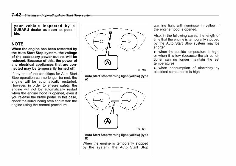
Black plate (324,1)
一般Model "A1300GE-A" EDITED: 2016/ 9/ 13
7-42 Starting and operating/Auto Start Stop system
your vehicle inspected by aSUBARU dealer as soon as possi-ble.
NOTEWhen the engine has been restarted bythe Auto Start Stop system, the voltageof the accessory power outlets will bereduced. Because of this, the power ofany electrical appliances that are con-nected may be temporarily turned off.
If any one of the conditions for Auto StartStop operation can no longer be met, theengine will be automatically restarted.However, in order to ensure safety, theengine will not be automatically restartwhen the engine hood is opened, even ifyou release the brake pedal. In this case,check the surrounding area and restart theengine using the normal procedure.
Auto Start Stop warning light (yellow) (typeA)
Auto Start Stop warning light (yellow) (typeB)
When the engine is temporarily stoppedby the system, the Auto Start Stop
warning light will illuminate in yellow ifthe engine hood is opened.
Also, in the following cases, the length oftime that the engine is temporarily stoppedby the Auto Start Stop system may beshorter.. when the outside temperature is high,or when it is low (because the air condi-tioner can no longer maintain the settemperature). when consumption of electricity byelectrical components is high

Black plate (325,1)
一般Model "A1300GE-A" EDITED: 2016/ 9/ 13
! Auto Start Stop OFF switch
LHD models
RHD models
Auto Start Stop OFF indicator light (yellow)(type A)
Auto Start Stop OFF indicator light (yellow)(type B)
If the Auto Start Stop OFF switch ispressed, operation of the Auto Start Stop
system will be disabled. The Auto StartStop OFF indicator light on the combina-tion meter will then illuminate in yellow. Ifthe switch is pressed once more, the AutoStart Stop system will turn on again. TheAuto Start Stop OFF indicator light willthen turn off.
While the engine is temporarily stopped bythe system, if the Auto Start Stop OFFswitch is pressed, the engine will berestarted even if you do not release thebrake pedal.
NOTE. If the engine is restarted when theAuto Start Stop system is not opera-tional and the ignition switch has beenturned to the “LOCK”/“OFF” position,the Auto Start Stop system will turn onagain.. Be sure to turn the ignition switch tothe “LOCK”/“OFF” position when leav-ing the vehicle. Failure to do so couldresult in the battery discharging.
Starting and operating/Auto Start Stop system 7-43
– CONTINUED –
7

Black plate (326,1)
一般Model "A1300GE-A" EDITED: 2016/ 9/ 13
7-44 Starting and operating/Subaru Rear Vehicle Detection (SRVD)
& Displaying the Auto StartStop system status
Approximate indications of the time thatthe engine has been stopped by the AutoStart Stop system and/or the amount offuel saved can be displayed on the multi-function display (black and white) orcombination meter display (color LCD).For details, refer to “Auto Start Stop time”F3-49 or “Basic screens” F3-40.
& System warningSo that it can be used safely andcomfortably, the Auto Start Stop systemis designed to constantly monitor thevehicle conditions as well as the environ-ment inside and outside the vehicle inaddition to driver operations, and toprovide various warnings to the driver viathe warning light and/or indicator lightilluminating or flashing and a buzzersounding. For details about the warninglight and indicator light, refer to “Auto StartStop warning light/Auto Start Stop OFFindicator light (yellow)” F3-36 and “AutoStart Stop indicator light (green)” F3-36.
! Warning buzzer
The buzzer will sound when the enginehood is opened while the engine isstopped by the Auto Start Stop system.When this occurs, the buzzer will stopsounding when the following operationsare performed.. the engine is restarted by normaloperation (refer to “Preparing to drive”F7-6). the ignition switch is turned to the“LOCK”/“OFF” position
! Display of warning messages(models with combination meterdisplay (color LCD))
If a warning message is displayed on thecombination meter display (color LCD)while the vehicle is being driven, amalfunction may have occurred in theAuto Start Stop system. In this case, theAuto Start Stop warning light will illuminateor flash in yellow. We recommend that youhave your vehicle inspected at a SUBARUdealer as soon as possible.
Subaru Rear Vehicle Detec-tion (SRVD) (if equipped)
The Subaru Rear Vehicle Detection(SRVD) consists of rear radar with BlindSpot Detection, Lane Change Assist, andRear Cross Traffic Alert.These functions enable the system todetect objects or vehicles to the rear,and alert the driver’s attention whenchanging lanes or when driving in reverse.
WARNING
The driver is responsible for drivingsafely. Always be sure to check thesurroundings with your eyes whenchanging lanes or reversing thevehicle.
The system is designed to assist thedriver by monitoring the rear andside areas of the vehicle during alane change or reversing. However,you cannot rely on this systemalone in assuring the safety duringa lane change or reversing. Over-confidence in this system couldresult in an accident and lead toserious injury or death. Since thesystem operation has various limita-tions, the flashing or illumination ofthe SRVD approach indicator light

Black plate (327,1)
一般Model "A1300GE-A" EDITED: 2016/ 9/ 13
may be delayed or it may notoperate at all even when a vehicleis present in a neighboring lane orapproaching from either side.
The driver is responsible for payingattention to the rear and side areasof the vehicle.
& System featuresNOTEThe SRVD radar sensor is approvedunder the radio wave related laws ofeach country. For details, refer to“Subaru Rear Vehicle Detection(SRVD)” F13-20 and “Technical infor-mation” F13-25.
SRVD consists of the following functions:. to detect a vehicle in a blind spot in anadjacent lane or a vehicle approaching athigh speed while driving the vehicle (BlindSpot Detection and Lane Change Assist). to detect a vehicle approaching fromright or left while reversing the vehicle(Rear Cross Traffic Alert)
The system uses radar sensors for thefollowing features.
! Blind Spot Detection (BSD)
1) Operating range
The system notifies the driver of vehiclesexisting in the blind area.. If the system detects a vehicle existingin the blind area, it warns the driver ofdangers by illuminating the SRVD ap-proach indicator light(s) on the outsidemirror(s).
SRVD approach indicator light
. If the driver operates the turn signallever in the direction where the SRVDapproach indicator light is illuminating, thesystem warns the driver of dangers byflashing the SRVD approach indicatorlight.
Starting and operating/Subaru Rear Vehicle Detection (SRVD) 7-45
– CONTINUED –
7
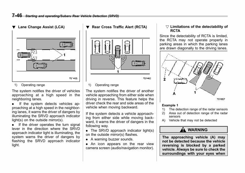
Black plate (328,1)
一般Model "A1300GE-A" EDITED: 2016/ 9/ 13
7-46 Starting and operating/Subaru Rear Vehicle Detection (SRVD)
! Lane Change Assist (LCA)
1) Operating range
The system notifies the driver of vehiclesapproaching at a high speed in theneighboring lanes.. If the system detects vehicles ap-proaching at a high speed in the neighbor-ing lanes, it warns the driver of dangers byilluminating the SRVD approach indicatorlight(s) on the outside mirror(s).. If the driver operates the turn signallever in the direction where the SRVDapproach indicator light is illuminating, thesystem warns the driver of dangers byflashing the SRVD approach indicatorlight.
! Rear Cross Traffic Alert (RCTA)
1) Operating range
The system notifies the driver of anothervehicle approaching from either side whendriving in reverse. This feature helps thedriver check the rear and side areas of thevehicle when moving backward.
If the system detects a vehicle approach-ing from either side while moving back-ward, it warns the driver of dangers in thefollowing way.. The SRVD approach indicator light(s)on the outside mirror(s) flashes.. A warning buzzer sounds.. An icon appears on the rear viewcamera screen (audio/navigation monitor).
! Limitations of the detectability ofRCTA
Since the detectability of RCTA is limited,the RCTA may not operate properly inparking areas in which the parking lanesare drawn diagonally to the driving lanes.
Example 11) The detection range of the radar sensors2) Area out of detection range of the radar
sensorsA) Vehicle that may not be detected
WARNING
The approaching vehicle (A) maynot be detected because the vehiclereversing is blocked by a parkedvehicle. Always be sure to check thesurroundings with your eyes when

Black plate (329,1)
一般Model "A1300GE-A" EDITED: 2016/ 9/ 13
reversing the vehicle.
Example 21) The detection range of the radar sensorsB) Vehicle that may be detected
NOTEThe system may detect a vehicle (B)that is coming across the front of yourvehicle. Always be sure to check thesurroundings with your eyes whenreversing the vehicle.
& System operation
! Operating conditions
The SRVD will operate when all of thefollowing conditions are met.. The ignition switch is in the “ON”position.. The SRVD warning indicator andSRVD OFF indicator are turned off.. The vehicle is driven at speeds above10 km/h (6 mph) (except when reversing).. The select lever is in the “R” position(RCTA only).
The SRVD will not operate in the followingsituations.. The SRVD OFF indicator appears.. The vehicle speed is below 10 km/h (6mph) even when the SRVD OFF indicatorremains off (except when reversing).
NOTE. When a malfunction occurs in thesystem (including the SRVD approachindicator light), the SRVD will stopoperating and the SRVD warning in-dicator will appear. If the SRVD warningindicator appears, we recommend thatyou have your vehicle inspected at aSUBARU dealer as soon as possible.. In the following cases, the SRVD willtemporarily stop operating (or may
stop operating) and the SRVD warningindicator will appear. The SRVD willresume operation once these condi-tions are corrected, and the SRVDwarning indicator will disappear. How-ever, if the SRVD warning indicator hasappeared for a prolonged time, werecommend that you have the systeminspected at a SUBARU dealer as soonas possible.
– When a large amount of snow orice sticks to the rear bumper sur-face around the radar sensors– When the vehicle is driven on asnow-covered road or in an envir-onment in which there are noobjects around (such as desert) fora long time– When the temperature aroundthe radar sensors increased exces-sively due to long driving on uphillgrades in summer, etc.– When the temperature aroundthe radar sensors becomes extre-mely low– When the vehicle battery voltagelowers– When the vehicle battery be-comes overvoltage– When the radar sensor becomessignificantly misaligned (If the or-ientation of the radar sensor is
Starting and operating/Subaru Rear Vehicle Detection (SRVD) 7-47
– CONTINUED –
7
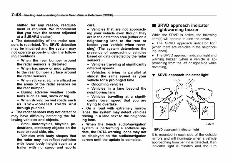
Black plate (330,1)
一般Model "A1300GE-A" EDITED: 2016/ 9/ 13
7-48 Starting and operating/Subaru Rear Vehicle Detection (SRVD)
shifted for any reason, readjust-ment is required. We recommendthat you have the sensor adjustedat a SUBARU dealer.)
. The detectability of the radar sen-sors is restricted. The SRVD detectionmay be impaired and the system maynot operate properly under the follow-ing conditions.
– When the rear bumper aroundthe radar sensors is distorted– When ice, snow or mud adheresto the rear bumper surface aroundthe radar sensors– When stickers, etc. are affixed onthe areas of the radar sensors onthe rear bumper– During adverse weather condi-tions such as rain, snow or fog– When driving on wet roads suchas snow-covered roads andthrough puddles
. The radar sensors may not detect ormay have difficulty detecting the fol-lowing vehicles and objects.
– Small motorcycles, bicycles, pe-destrians, stationary objects on theroad or road side, etc.– Vehicles with body shapes thatthe radar may not reflect (vehicleswith lower body height such as atrailer with no cargo and sports
cars)– Vehicles that are not approach-ing your vehicle even though theyare in the detection area (either on aneighboring lane to the rear orbeside your vehicle when rever-sing) (The system determines thepresence of approaching vehiclesbased on data detected by the radarsensors.)– Vehicles traveling at significantlydifferent speeds– Vehicles driving in parallel atalmost the same speed as yourvehicle for a prolonged time– Oncoming vehicles– Vehicles in a lane beyond theneighboring lane– Vehicles travelling at a signifi-cantly lower speed that you aretrying to overtake
. On a road with extremely narrowlanes, the system may detect vehiclesdriving in a lane next to the neighbor-ing lane.. When the 8-inch audio/navigationsystem is performing a software up-date, the RCTA warning icons may notbe displayed on the audio/navigationscreen until the update is complete.
& SRVD approach indicatorlight/warning buzzer
While the SRVD is active, the followingitem(s) will operate to alert the driver.. The SRVD approach indicator light(when there are vehicles in the neighbor-ing lanes). The SRVD approach indicator light andwarning buzzer (when a vehicle is ap-proaching from the left or right side whilereversing)
! SRVD approach indicator light
SRVD approach indicator light
It is mounted in each side of the outsidemirrors and will illuminate when a vehicleapproaching from behind is detected. If anindicator light illuminates and the turn
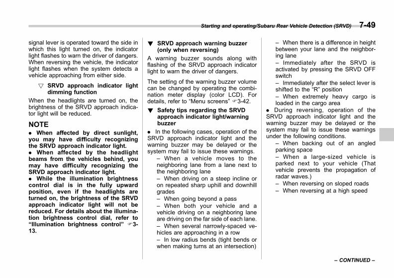
Black plate (331,1)
一般Model "A1300GE-A" EDITED: 2016/ 9/ 13
signal lever is operated toward the side inwhich this light turned on, the indicatorlight flashes to warn the driver of dangers.When reversing the vehicle, the indicatorlight flashes when the system detects avehicle approaching from either side.
! SRVD approach indicator lightdimming function
When the headlights are turned on, thebrightness of the SRVD approach indica-tor light will be reduced.
NOTE. When affected by direct sunlight,you may have difficulty recognizingthe SRVD approach indicator light.. When affected by the headlightbeams from the vehicles behind, youmay have difficulty recognizing theSRVD approach indicator light.. While the illumination brightnesscontrol dial is in the fully upwardposition, even if the headlights areturned on, the brightness of the SRVDapproach indicator light will not bereduced. For details about the illumina-tion brightness control dial, refer to“Illumination brightness control” F3-13.
! SRVD approach warning buzzer(only when reversing)
A warning buzzer sounds along withflashing of the SRVD approach indicatorlight to warn the driver of dangers.
The setting of the warning buzzer volumecan be changed by operating the combi-nation meter display (color LCD). Fordetails, refer to “Menu screens” F3-42.
! Safety tips regarding the SRVDapproach indicator light/warningbuzzer
. In the following cases, operation of theSRVD approach indicator light and thewarning buzzer may be delayed or thesystem may fail to issue these warnings.
– When a vehicle moves to theneighboring lane from a lane next tothe neighboring lane– When driving on a steep incline oron repeated sharp uphill and downhillgrades– When going beyond a pass– When both your vehicle and avehicle driving on a neighboring laneare driving on the far side of each lane.– When several narrowly-spaced ve-hicles are approaching in a row– In low radius bends (tight bends orwhen making turns at an intersection)
– When there is a difference in heightbetween your lane and the neighbor-ing lane– Immediately after the SRVD isactivated by pressing the SRVD OFFswitch– Immediately after the select lever isshifted to the “R” position– When extremely heavy cargo isloaded in the cargo area
. During reversing, operation of theSRVD approach indicator light and thewarning buzzer may be delayed or thesystem may fail to issue these warningsunder the following conditions.
– When backing out of an angledparking space– When a large-sized vehicle isparked next to your vehicle (Thatvehicle prevents the propagation ofradar waves.)– When reversing on sloped roads– When reversing at a high speed
Starting and operating/Subaru Rear Vehicle Detection (SRVD) 7-49
– CONTINUED –
7
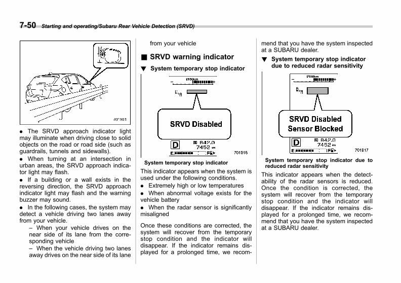
Black plate (332,1)
一般Model "A1300GE-A" EDITED: 2016/ 9/ 13
7-50 Starting and operating/Subaru Rear Vehicle Detection (SRVD)
. The SRVD approach indicator lightmay illuminate when driving close to solidobjects on the road or road side (such asguardrails, tunnels and sidewalls).. When turning at an intersection inurban areas, the SRVD approach indica-tor light may flash.. If a building or a wall exists in thereversing direction, the SRVD approachindicator light may flash and the warningbuzzer may sound.. In the following cases, the system maydetect a vehicle driving two lanes awayfrom your vehicle.
– When your vehicle drives on thenear side of its lane from the corre-sponding vehicle– When the vehicle driving two lanesaway drives on the near side of its lane
from your vehicle
& SRVD warning indicator
! System temporary stop indicator
System temporary stop indicator
This indicator appears when the system isused under the following conditions.. Extremely high or low temperatures. When abnormal voltage exists for thevehicle battery. When the radar sensor is significantlymisaligned
Once these conditions are corrected, thesystem will recover from the temporarystop condition and the indicator willdisappear. If the indicator remains dis-played for a prolonged time, we recom-
mend that you have the system inspectedat a SUBARU dealer.
! System temporary stop indicatordue to reduced radar sensitivity
System temporary stop indicator due toreduced radar sensitivity
This indicator appears when the detect-ability of the radar sensors is reduced.Once the condition is corrected, thesystem will recover from the temporarystop condition and the indicator willdisappear. If the indicator remains dis-played for a prolonged time, we recom-mend that you have the system inspectedat a SUBARU dealer.
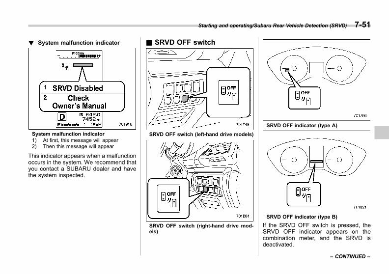
Black plate (333,1)
一般Model "A1300GE-A" EDITED: 2016/ 9/ 23
! System malfunction indicator
System malfunction indicator1) At first, this message will appear2) Then this message will appear
This indicator appears when a malfunctionoccurs in the system. We recommend thatyou contact a SUBARU dealer and havethe system inspected.
& SRVD OFF switch
SRVD OFF switch (left-hand drive models)
SRVD OFF switch (right-hand drive mod-els)
SRVD OFF indicator (type A)
SRVD OFF indicator (type B)
If the SRVD OFF switch is pressed, theSRVD OFF indicator appears on thecombination meter, and the SRVD isdeactivated.
Starting and operating/Subaru Rear Vehicle Detection (SRVD) 7-51
– CONTINUED –
7
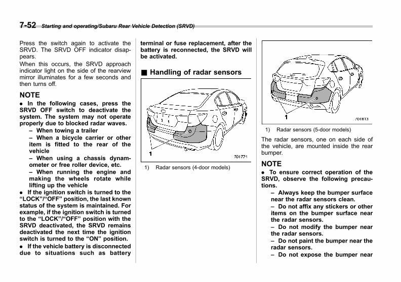
Black plate (334,1)
一般Model "A1300GE-A" EDITED: 2016/ 9/ 15
7-52 Starting and operating/Subaru Rear Vehicle Detection (SRVD)
Press the switch again to activate theSRVD. The SRVD OFF indicator disap-pears.When this occurs, the SRVD approachindicator light on the side of the rearviewmirror illuminates for a few seconds andthen turns off.
NOTE. In the following cases, press theSRVD OFF switch to deactivate thesystem. The system may not operateproperly due to blocked radar waves.
– When towing a trailer– When a bicycle carrier or otheritem is fitted to the rear of thevehicle– When using a chassis dynam-ometer or free roller device, etc.– When running the engine andmaking the wheels rotate whilelifting up the vehicle
. If the ignition switch is turned to the“LOCK”/“OFF” position, the last knownstatus of the system is maintained. Forexample, if the ignition switch is turnedto the “LOCK”/“OFF” position with theSRVD deactivated, the SRVD remainsdeactivated the next time the ignitionswitch is turned to the “ON” position.. If the vehicle battery is disconnecteddue to situations such as battery
terminal or fuse replacement, after thebattery is reconnected, the SRVD willbe activated.
& Handling of radar sensors
1) Radar sensors (4-door models)
1) Radar sensors (5-door models)
The radar sensors, one on each side ofthe vehicle, are mounted inside the rearbumper.
NOTE. To ensure correct operation of theSRVD, observe the following precau-tions.
– Always keep the bumper surfacenear the radar sensors clean.– Do not affix any stickers or otheritems on the bumper surface nearthe radar sensors.– Do not modify the bumper nearthe radar sensors.– Do not paint the bumper near theradar sensors.– Do not expose the bumper near

Black plate (335,1)
一般Model "A1300GE-A" EDITED: 2016/ 9/ 13
the radar sensors to strong im-pacts. If a sensor becomes misa-ligned, a system malfunction mayoccur, including the inability todetect vehicles entering the detec-tion areas. If any strong shock isapplied to the bumper, we recom-mend that you contact yourSUBARU dealer for inspection.– Do not disassemble the radarsensors.
. If the radar sensors require repair orreplacement, or the bumper areaaround the radar sensors requiresrepair, paintwork or replacement, werecommend that you contact yourSUBARU dealer for assistance.
Starting and operating/Subaru Rear Vehicle Detection (SRVD) 7-53
7
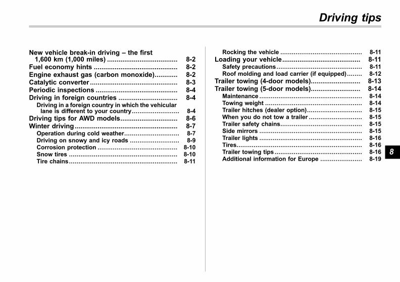
Black plate (17,1)
一般Model "A1300GE-A" EDITED: 2016/ 9/ 13
New vehicle break-in driving – the first1,600 km (1,000 miles) ..................................... 8-2
Fuel economy hints ............................................ 8-2Engine exhaust gas (carbon monoxide)............ 8-2Catalytic converter .............................................. 8-3Periodic inspections ........................................... 8-4Driving in foreign countries ............................... 8-4
Driving in a foreign country in which the vehicularlane is different to your country......................... 8-4
Driving tips for AWD models.............................. 8-6Winter driving ...................................................... 8-7
Operation during cold weather............................. 8-7Driving on snowy and icy roads .......................... 8-9Corrosion protection .......................................... 8-10Snow tires ......................................................... 8-10Tire chains......................................................... 8-11
Rocking the vehicle ........................................... 8-11Loading your vehicle......................................... 8-11
Safety precautions............................................. 8-11Roof molding and load carrier (if equipped)........ 8-12
Trailer towing (4-door models).......................... 8-13Trailer towing (5-door models).......................... 8-14
Maintenance ...................................................... 8-14Towing weight ................................................... 8-14Trailer hitches (dealer option)............................. 8-15When you do not tow a trailer ............................ 8-15Trailer safety chains........................................... 8-15Side mirrors ...................................................... 8-15Trailer lights ...................................................... 8-16Tires.................................................................. 8-16Trailer towing tips .............................................. 8-16Additional information for Europe ...................... 8-19
Driving tips
8

Black plate (338,1)
一般Model "A1300GE-A" EDITED: 2016/ 9/ 13
8-2 Driving tips/New vehicle break–in driving – the first 1,600 km (1,000 miles)
New vehicle break-in driving– the first 1,600 km (1,000miles)
The performance and long life of yourvehicle are dependent on how you handleand care for your vehicle while it is new.Follow these instructions during the first1,600 km (1,000 miles):. Do not allow the engine speed toexceed 4,000 rpm except in an emer-gency.. Do not drive at one constant engine orvehicle speed, either fast or slow.. Avoid starting suddenly and rapidacceleration, except in an emergency.. Avoid hard braking, except in anemergency.
The same break-in procedures should beapplied to an overhauled engine, newlymounted engine or when brake pads orbrake linings are replaced with new ones.
Fuel economy hints
The following suggestions will help to saveyour fuel.
. Select the proper gear position for thespeed and road conditions.. Avoid sudden acceleration or decelera-tion. Always accelerate gently until youreach the desired speed. Then try tomaintain that speed for as long aspossible.. Do not pump the accelerator pedal andavoid racing the engine.. Avoid unnecessary engine idling.. Keep the engine properly tuned.. Keep the tires inflated to the correctpressure shown on the tire placard, whichis located under the door latch on thedriver’s side. Low pressure will increasetire wear and fuel consumption.. Use the air conditioner only whennecessary.. Keep the front and rear wheels inproper alignment.. Avoid carrying unnecessary luggage orcargo.
Engine exhaust gas (carbonmonoxide)
WARNING
. Never inhale engine exhaust gas.Engine exhaust gas containscarbon monoxide, a colorlessand odorless gas which is dan-gerous, or even lethal, if inhaled.
. Always properly maintain the en-gine exhaust system to preventengine exhaust gas from enter-ing the vehicle.
. Never run the engine in a closedspace, such as a garage, exceptfor the brief time needed to drivethe vehicle in or out of it.
. Avoid remaining in a parkedvehicle for a lengthy time whilethe engine is running. If that isunavoidable, then use the venti-lation fan to force fresh air intothe vehicle.
. Always keep the front ventilatorinlet grille free from snow, leavesor other obstructions to ensurethat the ventilation system al-ways works properly.
. If at any time you suspect that

Black plate (339,1)
一般Model "A1300GE-A" EDITED: 2016/ 9/ 13
exhaust fumes are entering thevehicle, have the problemchecked and corrected as soonas possible. If you must driveunder these conditions, driveonly with all windows fully open.
. Keep the trunk lid (4-door mod-els) or rear gate (5-door models)closed while driving to preventexhaust gas from entering thevehicle.
NOTEDue to the expansion and contractionof the metals used in the manufactureof the exhaust system, you may hear acrackling sound coming from the ex-haust system for a short time after theengine has been shut off. This sound isnormal.
Catalytic converter
The catalytic converter is installed in theexhaust system. It serves as catalyst toreduce HC, CO and NOx in exhaustgases, thus providing cleaner exhaust.
To avoid damage to the catalytic conver-ter:. Use only unleaded petrol. Even a smallamount of leaded fuel will damage thecatalytic converter.. Never start the engine by pushing orpulling the vehicle.. Avoid racing the engine.. Never turn off the ignition switch whilethe vehicle is moving.. Keep your engine tuned-up. If you feelthe engine running rough (misfiring, back-
firing or incomplete combustion), we re-commend that you have your vehiclechecked and repaired by an authorizedSUBARU dealer.. Do not apply undercoating or rustprevention treatment to the heat shield ofcatalytic converter and the exhaust sys-tem.. Do not drive with an extremely low fuellevel.
WARNING
. Avoid fire hazards. Do not driveor park the vehicle anywherenear flammable materials (e.g.grass, paper, rags or leaves),because the catalytic converteroperates at very high tempera-tures.
. Keep everyone and flammablematerials away from the exhaustpipe while the engine is running.The exhaust gas is very hot.
Driving tips/Catalytic converter 8-3
8
Black plate (340,1)
一般Model "A1300GE-A" EDITED: 2016/ 9/ 13
8-4 Driving tips/Periodic inspections
Periodic inspections
To keep your vehicle in the best conditionat all times, always have the recom-mended maintenance services listed inthe maintenance schedule performed atthe specified time or mileage intervals.
Driving in foreign countries
When planning to use your vehicle inanother country:. Confirm the availability of the correctfuel. Refer to “Fuel” F7-3.. Comply with all regulations and re-quirements of each country.
& Driving in a foreign countryin which the vehicular lane isdifferent to your country
When you drive in a foreign country inwhich the vehicular lane (left-hand trafficor right-hand traffic) is different from yourcountry, to avoid blinding the oncomingdriver, you need to block a part of theheadlight lenses.
We recommend that you consult aSUBARU dealer concerning whether theheadlight of your vehicle is designed forleft-hand traffic or right-hand traffic. Referto the following method when you attachlightproof adhesive tape to the headlightlenses.
! When you drive a vehicle that isdesigned for left-hand traffic inright-hand traffic countries (modelswith halogen light)
Right side headlight1) Bulb center2) Lightproof adhesive tapeA) 72 mm (2.83 in)B) 15 mm (0.59 in)C) 65 mm (2.56 in)D) 32.4 mm (1.28 in)

Black plate (341,1)
一般Model "A1300GE-A" EDITED: 2016/ 9/ 13
Left side headlight1) Bulb center2) Lightproof adhesive tapeA) 72 mm (2.83 in)B) 15 mm (0.59 in)C) 65 mm (2.56 in)D) 32.4 mm (1.28 in)
! When you drive a vehicle that isdesigned for right-hand traffic inleft-hand traffic countries (modelswith halogen light)
Right side headlight1) Bulb center2) Lightproof adhesive tapeA) 72 mm (2.83 in)B) 32.4 mm (1.28 in)C) 65 mm (2.56 in)D) 15 mm (0.59 in)
Left side headlight1) Bulb center2) Lightproof adhesive tapeA) 72 mm (2.83 in)B) 32.4 mm (1.28 in)C) 65 mm (2.56 in)D) 15 mm (0.59 in)
Driving tips/Driving in foreign countries 8-5
8
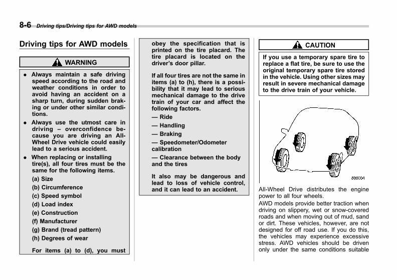
Black plate (342,1)
一般Model "A1300GE-A" EDITED: 2016/ 9/ 13
8-6 Driving tips/Driving tips for AWD models
Driving tips for AWD models
WARNING
. Always maintain a safe drivingspeed according to the road andweather conditions in order toavoid having an accident on asharp turn, during sudden brak-ing or under other similar condi-tions.
. Always use the utmost care indriving – overconfidence be-cause you are driving an All-Wheel Drive vehicle could easilylead to a serious accident.
. When replacing or installingtire(s), all four tires must be thesame for the following items.
(a) Size
(b) Circumference
(c) Speed symbol
(d) Load index
(e) Construction
(f) Manufacturer
(g) Brand (tread pattern)
(h) Degrees of wear
For items (a) to (d), you must
obey the specification that isprinted on the tire placard. Thetire placard is located on thedriver’s door pillar.
If all four tires are not the same initems (a) to (h), there is a possi-bility that it may lead to seriousmechanical damage to the drivetrain of your car and affect thefollowing factors.
— Ride
— Handling
— Braking
— Speedometer/Odometercalibration
— Clearance between the bodyand the tires
It also may be dangerous andlead to loss of vehicle control,and it can lead to an accident.
CAUTION
If you use a temporary spare tire toreplace a flat tire, be sure to use theoriginal temporary spare tire storedin the vehicle. Using other sizes mayresult in severe mechanical damageto the drive train of your vehicle.
All-Wheel Drive distributes the enginepower to all four wheels.AWD models provide better traction whendriving on slippery, wet or snow-coveredroads and when moving out of mud, sandor dirt. These vehicles, however, are notdesigned for off road use. If you do this,the vehicles may experience excessivestress. AWD vehicles should be drivenonly under the same conditions suitable
Black plate (343,1)
一般Model "A1300GE-A" EDITED: 2016/ 9/ 13
for ordinary front wheel drive vehicles.
For safety purpose as well as to avoiddamaging the AWD system, you shouldkeep the following tips in mind:. An AWD vehicle is better able to climbsteeper roads under snowy or slipperyconditions than a front wheel drive vehicle.There is little difference in handling,however, during extremely sharp turns orsudden braking. Therefore, when drivingdown a slope or turning corners, be sureto reduce your speed and maintain anample distance from other vehicles.. Never attempt to drive through poolsand puddles, or roads flooded with water.Water entering the engine air intake or theexhaust pipe or water splashing ontoelectrical parts may damage your vehicleand may cause it to stall.. An AWD vehicle can be used totraverse difficult areas covered with snow,mud and slush, or sand and dirt. It is,however, designed as an all-road vehicleand not as an all-terrain vehicle. For thisreason, an AWD vehicle should behandled with as much care as an ordinarypassenger vehicle.. Always check your brakes for effec-tiveness immediately after driving in sand,mud or puddle. Do this by driving slowlyand stepping on the brake pedal. Repeat
that process several times to dry out thebrake discs and brake pads.. Always check the cold tire pressurebefore starting to drive. The recom-mended tire pressure is provided on thetire placard, which is located under thedoor latch on the driver’s side.. Tire chains should always be placed onthe front wheels only.. Frequent driving of an AWD vehicleunder hard-driving conditions such assteep hills or dusty roads will necessitatemore frequent replacement of the follow-ing items than that specified in “Mainte-nance schedule” F11-3.
– Engine oil– Brake fluid– Rear differential gear oil– Continuously variable transmissionfluid– Front differential gear oil
. There are some precautions that youmust observe when towing your vehicle.For detail information, refer to “Towing”F9-24.
Winter driving
& Operation during coldweather
Carry some emergency equipment, suchas tire chains, a window scraper, a bag ofsand, flares, a small shovel, and jumpercables.
Check the battery and cables. Coldtemperatures reduce battery capacity.The battery must be in good condition toprovide enough power for cold winterstarts.
It normally takes longer to start the enginein very cold weather conditions. Use anengine oil of a suitable grade and viscosityfor cold weather. Using heavy summer oilwill make it harder to start the engine.
Keep the door locks from freezing bysquirting them with deicer or glycerin.Forcing a frozen door open may damageor separate the rubber weather stripsaround the door. If the door is frozen,use hot water to melt the ice, and after-wards thoroughly wipe the water away.
Use a windshield washer fluid that con-tains an antifreeze solution. Do not useengine antifreeze or other substitutesbecause they may damage the paint of
Driving tips/Winter driving 8-7
– CONTINUED –
8
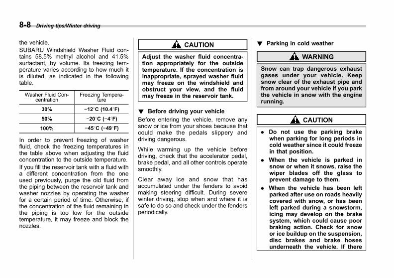
Black plate (344,1)
一般Model "A1300GE-A" EDITED: 2016/ 9/ 13
8-8 Driving tips/Winter driving
the vehicle.SUBARU Windshield Washer Fluid con-tains 58.5% methyl alcohol and 41.5%surfactant, by volume. Its freezing tem-perature varies according to how much itis diluted, as indicated in the followingtable.
Washer Fluid Con-centration
Freezing Tempera-ture
30% −128C (10.48F)
50% −208C (−48F)
100% −458C (−498F)
In order to prevent freezing of washerfluid, check the freezing temperatures inthe table above when adjusting the fluidconcentration to the outside temperature.If you fill the reservoir tank with a fluid witha different concentration from the oneused previously, purge the old fluid fromthe piping between the reservoir tank andwasher nozzles by operating the washerfor a certain period of time. Otherwise, ifthe concentration of the fluid remaining inthe piping is too low for the outsidetemperature, it may freeze and block thenozzles.
CAUTION
Adjust the washer fluid concentra-tion appropriately for the outsidetemperature. If the concentration isinappropriate, sprayed washer fluidmay freeze on the windshield andobstruct your view, and the fluidmay freeze in the reservoir tank.
! Before driving your vehicle
Before entering the vehicle, remove anysnow or ice from your shoes because thatcould make the pedals slippery anddriving dangerous.
While warming up the vehicle beforedriving, check that the accelerator pedal,brake pedal, and all other controls operatesmoothly.
Clear away ice and snow that hasaccumulated under the fenders to avoidmaking steering difficult. During severewinter driving, stop when and where it issafe to do so and check under the fendersperiodically.
! Parking in cold weather
WARNING
Snow can trap dangerous exhaustgases under your vehicle. Keepsnow clear of the exhaust pipe andfrom around your vehicle if you parkthe vehicle in snow with the enginerunning.
CAUTION
. Do not use the parking brakewhen parking for long periods incold weather since it could freezein that position.
. When the vehicle is parked insnow or when it snows, raise thewiper blades off the glass toprevent damage to them.
. When the vehicle has been leftparked after use on roads heavilycovered with snow, or has beenleft parked during a snowstorm,icing may develop on the brakesystem, which could cause poorbraking action. Check for snowor ice buildup on the suspension,disc brakes and brake hosesunderneath the vehicle. If there

Black plate (345,1)
一般Model "A1300GE-A" EDITED: 2016/ 9/ 13
is caked snow or ice, remove it,being careful not to damage thedisc brakes and brake hoses andABS harness.
When parking for long periods in coldweather, you should observe the followingtips.1. Place the select lever in the “P”position.2. Use tire stops under the tires toprevent the vehicle from moving.
! Refueling in cold weather
To help prevent moisture from forming inthe fuel system and the risk of its freezing,use of an antifreeze additive in the fueltank is recommended during cold weather.Use only additives that are specificallydesigned for this purpose. When anantifreeze additive is used, its effect lastslonger if the tank is refilled whenever thefuel level reaches half empty.
If your SUBARU is not going to be usedfor an extended period, it is best to havethe fuel tank filled to capacity.
& Driving on snowy and icyroads
To prevent skidding and slipping, avoidsudden braking, abrupt acceleration, high-speed driving, and sharp turning whendriving on snowy or icy roads.Always maintain ample distance betweenyour vehicle and the vehicle ahead of youto avoid the need for sudden braking.To supplement the foot brake, use theengine brake effectively to control thevehicle speed. (Shift into a lower gearwhen necessary.)Avoid shifting down abruptly. Such beha-vior can cause the wheels to lock, possiblyleading to loss of vehicle control.
An anti-lock brake system (ABS) en-hances your vehicle’s braking perfor-mance on snowy and icy roads. Forinformation about braking on slipperysurfaces, refer to “ABS (Anti-lock BrakeSystem)” F7-21 and “Vehicle DynamicsControl system” F7-23.
WARNING
For models with cruise control:
Do not use the cruise control onslippery roads such as snowy or icyroads. This may cause loss ofvehicle control.
CAUTION
Avoid prolonged continuous drivingin snowstorms. Snow will enter theengine’s intake system and mayhinder the airflow, which could re-sult in engine shutdown or evenbreakdown.
! Wiper operation when snowing
Before driving in cold weather, make surethe wiper rubbers are not frozen to thewindshield or rear window.
If the wiper rubbers are frozen to thewindshield or rear window, perform thefollowing procedure.. To thaw the windshield wiper rubbers,use the defroster and set the temperaturefor maximum warmth until the wiperrubbers are completely thawed. Refer to“Defrosting” F4-11.. If your vehicle is equipped with a wiper
Driving tips/Winter driving 8-9
– CONTINUED –
8
Black plate (346,1)
一般Model "A1300GE-A" EDITED: 2016/ 9/ 13
8-10 Driving tips/Winter driving
deicer, use it. It is helpful to thaw thewindshield wiper rubbers. Refer to “De-fogger and deicer” F3-94.. To thaw the rear wiper rubber, use therear window defogger. Refer to “Defoggerand deicer” F3-94.
When driving in snow, if frozen snow startsto stick on the surface of the windshielddespite wiper operation, use the defrosterand set the temperature for maximumwarmth. After the windshield gets warmedenough to melt the frozen snow on it,wash it away using the windshield washer.Refer to “Windshield washer” F3-88.
Snow stuck on the wiper arm prevents thewiper from working effectively. If snow isstuck on the wiper arm, pull off the road toa safe place, then remove it. If you stopthe vehicle at road side, use the hazardwarning flasher to alert other drivers.Refer to “Hazard warning flasher” F3-8.
& Corrosion protectionRefer to “Corrosion protection” F10-4.
& Snow tires
WARNING
. When replacing original tires withwinter (snow) tires, all four tiresmust be the same for the follow-ing items.
(a) Size
(b) Circumference
(c) Speed symbol
(d) Load index
(e) Construction
(f) Manufacturer
(g) Brand (tread pattern)
(h) Degrees of wear
For items (a) to (d), you mustobey the specification that isprinted on the tire placard. Thetire placard is located on thedriver’s door pillar.
If all four tires are not the same initems (a) to (h), there is a possi-bility that it may lead to seriousmechanical damage to the drivetrain of your car and affect thefollowing factors.
— Ride
— Handling
— Braking
— Speedometer/Odometercalibration
— Clearance between the bodyand the tires
It also may be dangerous andlead to loss of vehicle control,and it can lead to an accident.
. Do not use a combination ofradial, belted bias or bias tiressince it may cause dangeroushandling characteristics and leadto an accident.
In winter, it may be possible to enhanceperformance through use of tires designedspecifically for winter driving conditions. Ifyou choose to install winter tires on yourvehicle, be sure to use the correct tire sizeand type. All four tires must be of the samesize, construction, brand and load indexand you should never mix radial, beltedbias or bias tires since this may result indangerous handling characteristics. Re-member to drive with care at all timesregardless of the type of tires on yourvehicle.
When using winter tires (speed symbol Q,T or H) never exceed 160 km/h (99 mph),
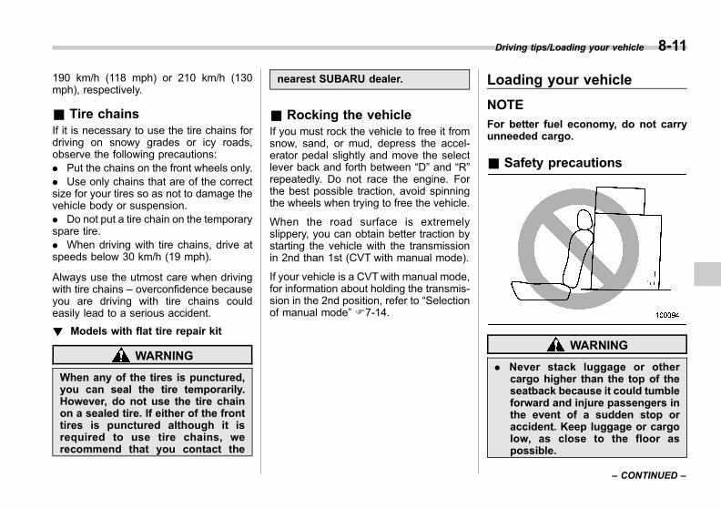
Black plate (347,1)
一般Model "A1300GE-A" EDITED: 2016/ 9/ 13
190 km/h (118 mph) or 210 km/h (130mph), respectively.
& Tire chainsIf it is necessary to use the tire chains fordriving on snowy grades or icy roads,observe the following precautions:. Put the chains on the front wheels only.. Use only chains that are of the correctsize for your tires so as not to damage thevehicle body or suspension.. Do not put a tire chain on the temporaryspare tire.. When driving with tire chains, drive atspeeds below 30 km/h (19 mph).
Always use the utmost care when drivingwith tire chains – overconfidence becauseyou are driving with tire chains couldeasily lead to a serious accident.
! Models with flat tire repair kit
WARNING
When any of the tires is punctured,you can seal the tire temporarily.However, do not use the tire chainon a sealed tire. If either of the fronttires is punctured although it isrequired to use tire chains, werecommend that you contact the
nearest SUBARU dealer.
& Rocking the vehicleIf you must rock the vehicle to free it fromsnow, sand, or mud, depress the accel-erator pedal slightly and move the selectlever back and forth between “D” and “R”repeatedly. Do not race the engine. Forthe best possible traction, avoid spinningthe wheels when trying to free the vehicle.
When the road surface is extremelyslippery, you can obtain better traction bystarting the vehicle with the transmissionin 2nd than 1st (CVT with manual mode).
If your vehicle is a CVTwith manual mode,for information about holding the transmis-sion in the 2nd position, refer to “Selectionof manual mode” F7-14.
Loading your vehicle
NOTE
For better fuel economy, do not carryunneeded cargo.
& Safety precautions
WARNING
. Never stack luggage or othercargo higher than the top of theseatback because it could tumbleforward and injure passengers inthe event of a sudden stop oraccident. Keep luggage or cargolow, as close to the floor aspossible.
Driving tips/Loading your vehicle 8-11
– CONTINUED –
8
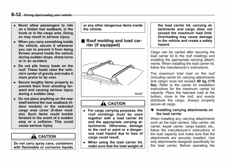
Black plate (348,1)
一般Model "A1300GE-A" EDITED: 2016/ 9/ 13
8-12 Driving tips/Loading your vehicle
. Never allow passengers to rideon a folded rear seatback, in thetrunk or in the cargo area. Doingso may result in serious injury.
. When you carry something insidethe vehicle, secure it wheneveryou can to prevent it from beingthrown around inside the vehicleduring sudden stops, sharp turnsor in an accident.
. Do not pile heavy loads on theroof. These loads raise the vehi-cle’s center of gravity and make itmore prone to tip over.
. Secure lengthy items properly toprevent them from shooting for-ward and causing serious injuryduring a sudden stop.
. Do not place anything on the rearshelf behind the rear seatback (4-door models) or the extendedcargo area cover (5-door mod-els). Such items could tumbleforward in the event of a suddenstop or a collision. This couldcause serious injury.
CAUTION
Do not carry spray cans, containerswith flammable or corrosive liquids
or any other dangerous items insidethe vehicle.
& Roof molding and load car-rier (if equipped)
CAUTION
. For cargo carrying purposes, theroof moldings must be usedtogether with a load carrier kitand the appropriate carrying at-tachments. Otherwise, damageto the roof or paint or a danger-ous road hazard due to loss ofcargo could result.
. When using the load carrier kit,make sure that the total weight of
the load carrier kit, carrying at-tachments and cargo does notexceed the maximum load limit.Overloading may cause damageto the vehicle and create a safetyhazard.
Cargo can be carried after securing theload carrier kit to the roof moldings andinstalling the appropriate carrying attach-ments. When installing the load carrier kit,follow the manufacturer’s instructions.
The maximum total load on the roof(including carrier kit, carrying attachmentsand cargo) must not exceed 80 kg (176lbs). Refer to the carrier kit installationinstructions for the maximum carrier kitcapacity. Place the heaviest load at thebottom, close to the roof, and evenlydistribute the cargo. Always properlysecure all cargo.
! Installing carrying attachments onthe load carrier
When installing any carrying attachmentssuch as the load carriers, bike carrier, skicarrier, kayak carrier, cargo basket, etc.,follow the manufacturer’s instructions ofthe load capacity and make sure that theattachments are securely installed. Useonly attachments designed specifically forthe load carrier. Before operating the

Black plate (349,1)
一般Model "A1300GE-A" EDITED: 2016/ 9/ 13
vehicle, make sure that the cargo isproperly secured on the attachments.
NOTERemember that the vehicle’s center ofgravity is altered with the weight of theload on the roof, thus affecting thedriving characteristics.Drive carefully. Avoid rapid starts, hardcornering and abrupt stops. Crosswindeffects will be increased.
! Removal and installation of the loadcarrier
Each of the two roof moldings has twomounting points for the load carrier kit.Each mounting point is fitted with a cover.Use a flat-head screwdriver to remove thecovers. When installing the load carrier kit
on the roof moldings, follow the manufac-turer’s instructions.
Trailer towing (4-door mod-els)
Your vehicle is neither designed norintended to be used for trailer towing.Therefore, never tow a trailer with yourvehicle.SUBARU assumes no responsibility forinjuries or vehicle damage that may resultfrom trailer towing, from any trailer towingequipment or from any errors or omissionsin the instructions accompanying suchequipment. SUBARU warranties do notapply to vehicle damage or malfunctioncaused by trailer towing.
Driving tips/Trailer towing (4–door models) 8-13
8

Black plate (350,1)
一般Model "A1300GE-A" EDITED: 2016/ 9/ 13
8-14 Driving tips/Trailer towing (5–door models)
Trailer towing (5-door mod-els)
WARNING
. For models with flat tire repair kit:When any of the tires are punc-tured, you can seal the tiretemporarily. However, do nottow a trailer when a sealed tireis used. We recommend that youconsult the nearest SUBARUdealer for details.
. Use only the ball mount that issuitable for the trailer hitch. Usethe hitch only as a weight carry-ing hitch. Do not use with anytype of weight distributing hitch.
. The standard bumper beam mustbe installed after you remove thetrailer hitch. We recommend thatyou consult a SUBARU dealer forpurchase of a standard bumperbeam if you do not have theoriginal.
. Safety performance is decreasedand there is increased risk ofinjury to passengers in the caseof an accident if the trailer hitchor a standard bumper beam isnot installed. One of them must
always be installed on the vehi-cle.
. If a trailer hitch is installed, it isnot possible to install the reartowing hook (eye bolt).
Your vehicle is designed and intended tobe used primarily as a passenger-carryingvehicle. Towing a trailer puts additionalloads on your vehicle’s engine, drive train,brakes, tires and suspension and has anadverse effect on fuel economy.
In some countries, there are some regula-tions which you have to obey when towinga trailer. If you do decide to tow a trailer,your safety and satisfaction depend uponproper use of correct equipment andcautious operation of your vehicle. Werecommend that you seek the advice ofyour SUBARU dealer to assist you inpurchasing a hitch and other necessarytowing equipment appropriate for yourvehicle. In addition, be sure to follow theinstructions on correct installation and useprovided by the trailer and other towingequipment manufacturers.SUBARU assumes no responsibility forinjuries or vehicle damage that result fromtrailer towing equipment, or from anyerrors or omissions in the instructionsaccompanying such equipment or for your
failure to follow the proper instructions.
NOTEAuto Start Stop system (if equipped)will not operate when towing a trailer.Refer to “Auto Start Stop system” F7-40.
& MaintenanceIf you use your vehicle to tow a trailer,more frequent maintenance will be re-quired due to the additional load. Refer to“Maintenance schedule” F11-3.Under no circumstances should a trailerbe towed with a new vehicle or a vehiclewith any new powertrain component (en-gine, transmission, differential, wheelbearings, etc.) for the first 1,600 km(1,000 miles) of driving.
& Towing weightBefore towing a trailer, we recommendthat you confirm the towing capacity andball coupling load with your nearestSUBARU dealer or the vehicle registrationdocuments and/or hitch installation man-ual and make sure your trailer is within thetowing capacity.The total trailer weight (trailer weight withbrakes plus its cargo weight) must neverexceed the maximum towing weight.
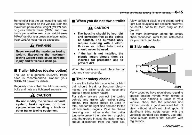
Black plate (351,1)
一般Model "A1300GE-A" EDITED: 2016/ 9/ 13
Remember that the ball coupling load willincrease the load on the vehicle. Both themaximum permissible weight (MPW) and/or gross vehicle mass (GVM) and max-imum permissible rear axle weight (rearMPAW) and/or rear gross axle laden rating(rear GALR) must not be exceeded.
WARNING
Never exceed the maximum towingweight. Exceeding the maximumtowing weight could cause personalinjury and/or vehicle damage.
& Trailer hitches (dealer option)The use of a genuine SUBARU trailerhitch is recommended. Consult yourSUBARU dealer for details.
Regularly check that the hitch mountingbolts and nuts are tightened securely.
CAUTION
Do not modify the vehicle exhaustsystem, brake system, or othersystem when installing a hitch orother trailer towing equipment.
& When you do not tow a trailer
CAUTION
. The housing should be kept dirtand corrosion-free at the pointsof contact. The surfaces onlyrequire cleaning with a cloth.Grease or other lubricantsshould never be used.
. If the ball is not installed, theplastic insert should then beinserted for protection and toprevent dirt.
When the ball is not used, place the ballcap and store securely.
& Trailer safety chainsIn case the trailer hitch connector or hitchball should break or become discon-nected, the trailer could get loose andcreate a traffic safety hazard.For safety, always connect the towingvehicle and trailer with trailer safetychains. Two chains should be used intotal, one for the right side and one for theleft side trailer tongues. Pass the chainscrossing each other under the trailertongue to prevent the trailer from droppingonto the ground in case the trailer tongueshould disconnect from the hitch ball.
Allow sufficient slack in the chains takingtight-turn situations into account; however,be careful not to let them drag on theground.For more information about the safetychain connection, refer to the instructionsfor your hitch and trailer.
& Side mirrors
Many countries have regulations requiringspecial outside mirrors when towing atrailer. After hitching a trailer to yourvehicle, check that the standard sidemirrors provide a good rearward field ofview without significant blind spots. Ifsignificant blind spots occur with thevehicle’s standard side mirrors, use addi-tional outside mirrors that conform withregulations.
Driving tips/Trailer towing (5–door models) 8-15
– CONTINUED –
8

Black plate (352,1)
一般Model "A1300GE-A" EDITED: 2016/ 9/ 13
8-16 Driving tips/Trailer towing (5–door models)
& Trailer lightsConnection of trailer lights to your vehi-cle’s electrical system requires modifica-tions to the vehicle’s lighting circuit toincrease its capacity and accommodatewiring changes. To ensure the trailer lightsare connected properly, we recommendthat you consult your SUBARU dealer.Check for proper operation of the turnsignals and the brake lights each time youconnect a trailer to your vehicle.
CAUTION
Direct splicing or other improperconnection of trailer lights maydamage your vehicle’s electricalsystem and cause a malfunction ofyour vehicle lighting system.
& TiresMake sure that all the tires on your vehicleare inflated to the pressure under towingconditions as shown on the tire placardlocated on the door pillar on the driver’sside.
Trailer tire condition, size, load rating andproper inflation pressure should be inaccordance with the trailer manufacturer’sspecifications.
WARNING
Never tow a trailer when the tem-porary spare tire is used. The tem-porary spare tire is not designed tosustain the towing load. Use of thetemporary spare tire when towingcan result in failure of the spare tireand/or less stability of the vehicleand may lead to an accident.
& Trailer towing tips
WARNING
. Never exceed 80 km/h (50 mph)or legal towing speed limit,whichever is lower. Exceedingthe speed limit could cause lossof vehicle stability and/or couldlead to an accident.
. When towing a trailer, steering,stability, stopping distance andbraking performance will be dif-ferent when compared to normaloperation. You should neverdrive at excessive speeds butalways employ extra cautionwhen towing a trailer. You shouldalso keep the following tips inmind.
CAUTION
When towing a trailer, press theSRVD (Subaru Rear Vehicle Detec-tion) OFF switch to deactivate thesystem (if equipped). The systemmay not operate properly due to theblocked radar waves. For detailsabout the SRVD OFF switch, referto “SRVD OFF switch” F7-51.
! Before starting out on a trip
. Be sure to check regulations concern-ing the maximum speed or driving restric-tions for vehicles towing trailers. If you aredriving across several countries, checkeach country’s requirement before leavinghome, because regulations may vary.. Check that the vehicle and vehicle-to-hitch mounting are in good condition. If
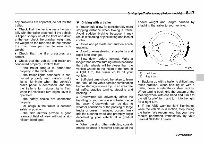
Black plate (353,1)
一般Model "A1300GE-A" EDITED: 2016/ 9/ 13
any problems are apparent, do not tow thetrailer.. Check that the vehicle rests horizon-tally with the trailer attached. If the vehicleis tipped sharply up at the front and downat the rear, check the drawbar weight andthe weight on the rear axle do not exceedthe maximum permissible rear axleweight.. Check that the tire pressures arecorrect.. Check that the vehicle and trailer areconnected properly. Confirm that:
– the trailer tongue is connectedproperly to the hitch ball.– the trailer lights connector is con-nected properly and trailer’s brakelights illuminate when the vehicle’sbrake pedal is depressed, and thatthe trailer’s turn signal lights flashwhen the vehicle’s turn signal lever isoperated.– the safety chains are connectedproperly.– all cargo in the trailer is securedsafely in position.– the side mirrors provide a goodrearward field of view without a sig-nificant blind spot.
! Driving with a trailer
. You should allow for considerably morestopping distance when towing a trailer.Avoid sudden braking because it mayresult in skidding or jackknifing and loss ofcontrol.. Avoid abrupt starts and sudden accel-erations.. Avoid uneven steering, sharp turns andrapid lane changes.. Slow down before turning. Make alonger than normal turning radius becausethe trailer wheels will be closer than thevehicle wheels to the inside of the turn. Ina tight turn, the trailer could hit yourvehicle.. Sufficient time should be taken to learnthe “feel” of the vehicle/trailer combinationbefore starting out on a trip. In an area freeof traffic, practice turning, stopping andbacking up.. Crosswinds will adversely affect thehandling of your vehicle and trailer, caus-ing sway. Crosswinds can be due toweather conditions or the passing of largetrucks or buses. If swaying occurs, firmlygrip the steering wheel and promptly begindecelerating your vehicle at a gradualpace.. When passing other vehicles, consid-erable distance is required because of the
added weight and length caused byattaching the trailer to your vehicle.
1) Left turn2) Right turn
. Backing up with a trailer is difficult andtakes practice. When backing up with atrailer, never accelerate or steer rapidly.When turning back, grip the bottom of thesteering wheel with one hand and turn it tothe left for a left turn, and turn it to the rightfor a right turn.. If the ABS warning light illuminateswhile the vehicle is in motion, stop towingthe trailer. We recommend that you haverepairs performed immediately by yournearest SUBARU dealer.
Driving tips/Trailer towing (5–door models) 8-17
– CONTINUED –
8

Black plate (354,1)
一般Model "A1300GE-A" EDITED: 2016/ 9/ 13
8-18 Driving tips/Trailer towing (5–door models)
! Driving on grades
. On vehicles equipped with a dualrange transmission, it is recommendedthat the LO position be used when startingthe vehicle on an uphill slope.. Before going down a steep hill, slowdown and shift into lower gear (if neces-sary, use 1st gear) in order to utilize theengine braking effect and prevent over-heating of your vehicle’s brakes. Do notmake sudden downshifts.. When driving uphill in hot weather, theair conditioner may turn off automaticallyto protect the engine from overheating.. When driving uphill in hot weather, payattention to the following indicators be-cause the engine and transmission arerelatively prone to overheating.
: Coolant temperature high warning light
: AT OIL TEMP warning light
If any of the following conditions occur,immediately turn off the air conditioner andstop the vehicle in the nearest safelocation. Refer to “If you park your vehiclein case of an emergency” F9-2 and“Engine overheating” F9-23.
– “Coolant temperature low indicatorlight/Coolant temperature high warn-ing light” F3-19– “AT OIL TEMP warning light” F3-21
. Avoid using the accelerator pedal tostay stationary on an uphill slope insteadof using the parking brake or foot brake.That may cause the transmission fluid tooverheat.. Place the select lever as follows.Uphill slopes: “D” positionDownhill slopes: A low-speed gear posi-tion to use engine braking (models withmanual mode)/“L” position (models with“L” position)
! Parking on a grade
CAUTION
The braking power of the electronicparking brake may not be sufficientwhen strong braking power isneeded (e.g., when parking on asteep slope while towing a trailer).
Always block the wheels under bothvehicle and trailer when parking. Applythe parking brake firmly. You should notpark on a hill or slope. If parking on a hill orslope cannot be avoided, you should takethe following steps:
1. Apply the brakes and hold the pedaldown.2. Have someone place wheel blocksunder both the vehicle and trailer wheels.
3. When the wheel blocks are in place,release the regular brakes slowly until theblocks absorb the load.4. Apply the regular brakes and thenapply the parking brake; slowly releasethe regular brakes.5. Shift into the “P” position and shut offthe engine.
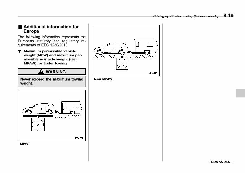
Black plate (355,1)
一般Model "A1300GE-A" EDITED: 2016/ 9/ 13
& Additional information forEurope
The following information represents theEuropean statutory and regulatory re-quirements of EEC 1230/2010.
! Maximum permissible vehicleweight (MPW) and maximum per-missible rear axle weight (rearMPAW) for trailer towing
WARNING
Never exceed the maximum towingweight.
MPW
Rear MPAW
Driving tips/Trailer towing (5–door models) 8-19
– CONTINUED –
8

Black plate (356,1)
一般Model "A1300GE-A" EDITED: 2016/ 9/ 13
8-20 Driving tips/Trailer towing (5–door models)
Model MPW at towing (kg) MPAW at towing (kg)
5-door models 2.0 L AWD CVT 2,000 1,140
CVT: Continuously Variable TransmissionAWD: All-Wheel Drive

Black plate (357,1)
一般Model "A1300GE-A" EDITED: 2016/ 9/ 13
! The technically permissible maxi-mum mass at the coupling point(ball coupling load)
80 kg
! Mounting points of the couplingdevice
The mounting points of the coupling on thetowing vehicle are shown in the diagram.
5-door models1) Maximum permissible rear overhang for the coupling point: 909 mm (36 in)2) Coupling3) Fixing points: Two places underneath the rear frame and three places on the rear end of the
rear frame for each side4) Fixing points: One place on the side of the rear frame for each side5) Rear frame
Driving tips/Trailer towing (5–door models) 8-21
– CONTINUED –
8
Black plate (19,1)
一般Model "A1300GE-A" EDITED: 2016/ 9/ 13
If you park your vehicle in case of anemergency ........................................................ 9-2
Temporary spare tire (if equipped) .................... 9-2Maintenance tools ............................................... 9-3
Tool bag.............................................................. 9-4Under the rear floor............................................. 9-4
Flat tires............................................................... 9-6Changing flat tire ................................................ 9-6Sealing flat tire (models with flat tire repairkit) .................................................................... 9-9
Tire pressure monitoring system (TPMS) (ifequipped)......................................................... 9-18
Jump starting ..................................................... 9-19Battery Precautions!........................................... 9-19Precautions when jump starting! ........................ 9-20How to jump start............................................... 9-21
Engine overheating ............................................ 9-23If steam is coming from the enginecompartment.................................................... 9-23
If no steam is coming from the enginecompartment ................................................... 9-23
Towing ................................................................ 9-24Towing hooks and tie-down hooks/holes ............ 9-24Using a flat-bed truck......................................... 9-27Towing with all wheels on the ground................. 9-27
Electronic parking brake – if the electronicparking brake cannot be released................. 9-28
Access key fob – if access key fob does notoperate properly ............................................. 9-28Locking and unlocking....................................... 9-28Switching power status...................................... 9-29Starting engine .................................................. 9-29
Rear gate – if the rear gate cannot beopened............................................................. 9-30Models with double locking system.................... 9-31
Sunroof (if equipped) – if the sunroof doesnot close.......................................................... 9-31
If your vehicle is involved in an accident ........ 9-31
In case of emergency
9

Black plate (362,1)
一般Model "A1300GE-A" EDITED: 2016/ 9/ 13
9-2 In case of emergency/If you park your vehicle in case of an emergency
If you park your vehicle incase of an emergency
The hazard warning flasher should beused in day or night to warn other driverswhen you have to park your vehicle underemergency conditions.Avoid stopping on the road. It is best tosafely pull off the road if a problem occurs.
The hazard warning flasher can be acti-vated regardless of the ignition switchposition.Turn on the hazard warning by pushingthe hazard warning flasher switch. Turn itoff by pushing the switch again.
NOTEWhen the hazard warning flasher is on,the turn signals do not work.
Temporary spare tire (ifequipped)
WARNING
. Never tow a trailer when thetemporary spare tire is used.The temporary spare tire is notdesigned to sustain the towingload. Use of the temporary sparetire when towing can result infailure of the spare tire and/orless stability of the vehicle andmay lead to an accident.
. When a spare tire is mounted or awheel rim is replaced without theoriginal pressure sensor/trans-mitter being transferred, the lowtire pressure warning light willilluminate steadily after blinkingfor approximately one minute.This indicates the tire pressuremonitoring system (TPMS) is un-able to monitor all four roadwheels. We recommend that youcontact your SUBARU dealer assoon as possible for tire andsensor replacement and/or sys-tem resetting.

Black plate (363,1)
一般Model "A1300GE-A" EDITED: 2016/ 9/ 13
CAUTION
Never use any temporary spare tireother than the original. Using othersizes may result in severe mechan-ical damage to the drive train of yourvehicle.
The temporary spare tire is smaller andlighter than a conventional tire and isdesigned for emergency use only. Re-move the temporary spare tire and re-install the conventional tire as soon aspossible because the spare tire is de-signed only for temporary use.
Check the inflation pressure of the tem-porary spare tire periodically to keep thetire ready for use. For the correct pres-sure, refer to “Tires” F12-9.
When using the temporary spare tire, notethe following.. Drive with caution when the temporaryspare tire is installed. Avoid hard accel-eration and braking, or fast cornering, ascontrol of the vehicle may be lost.. Do not exceed 80 km/h (50 mph).. Do not put a tire chain on the temporaryspare tire. Because of the smaller tire size,a tire chain will not fit properly.. Do not use two or more temporaryspare tires at the same time.
. Do not drive over obstacles. This tirehas a smaller diameter, so road clearanceis reduced.
1) Tread wear indicator bar2) Indicator location mark
. When the wear indicator appears onthe tread, replace the tire.. The temporary spare tire must be usedonly on a rear wheel. If a front wheel tiregets punctured, replace the wheel with arear wheel and install the temporary sparetire in place of the removed rear wheel.
Maintenance tools
Your vehicle is equipped with the followingmaintenance tools:
. Jack
. Jack handle
. Screwdriver
. Towing hook (eye bolt)
. Wheel nut wrench
NOTEThis jack complies with the MachineryDirective 2006/42/EC. A copy of theoriginal Declaration of Conformity isfound in chapter 13.
In case of emergency/Maintenance tools 9-3
– CONTINUED –
9

Black plate (364,1)
一般Model "A1300GE-A" EDITED: 2016/ 9/ 13
9-4 In case of emergency/Maintenance tools
& Tool bag
1) Screwdriver2) Wheel nut wrench3) Tool bag
The screwdriver and wheel nut wrench arestored in the tool bag. These tools canalso be stored in the tool bucket.
& Under the rear floorThe jack, jack handle and towing hook arestored as shown in the following illustra-tions.
! Models without flat tire repair kit
1) Jack handleA) 4-door modelsB) 5-door models
1) Under-floor storage compartment (ifequipped) (Refer to “Under-floor storagecompartment” F6-15.)
2) Tool bucket3) Spare tireA) 4-door modelsB) 5-door models

Black plate (365,1)
一般Model "A1300GE-A" EDITED: 2016/ 9/ 13
1) Wheel nut wrench2) Screwdriver3) Jack4) Towing hook (eye bolt)
Example of jack label1) Jack labelA) CAUTIONB) WORKING LOAD LIMIT
NOTE. For how to use the jack, refer to“Flat tires” F9-6.. The following items may be differentdepending on the model.
– The shape of the storage com-partment– The locations of some mainte-nance tools
! Models with flat tire repair kit
1) Jack handle2) Jack3) Towing hook (eye bolt)
In case of emergency/Maintenance tools 9-5
9
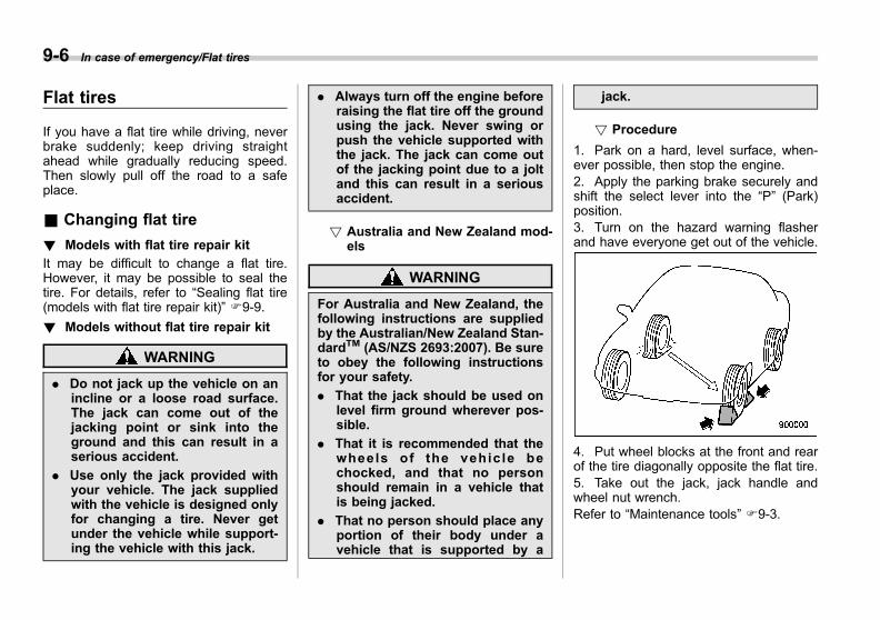
Black plate (366,1)
一般Model "A1300GE-A" EDITED: 2016/ 9/ 13
9-6 In case of emergency/Flat tires
Flat tires
If you have a flat tire while driving, neverbrake suddenly; keep driving straightahead while gradually reducing speed.Then slowly pull off the road to a safeplace.
& Changing flat tire
! Models with flat tire repair kit
It may be difficult to change a flat tire.However, it may be possible to seal thetire. For details, refer to “Sealing flat tire(models with flat tire repair kit)” F9-9.
! Models without flat tire repair kit
WARNING
. Do not jack up the vehicle on anincline or a loose road surface.The jack can come out of thejacking point or sink into theground and this can result in aserious accident.
. Use only the jack provided withyour vehicle. The jack suppliedwith the vehicle is designed onlyfor changing a tire. Never getunder the vehicle while support-ing the vehicle with this jack.
. Always turn off the engine beforeraising the flat tire off the groundusing the jack. Never swing orpush the vehicle supported withthe jack. The jack can come outof the jacking point due to a joltand this can result in a seriousaccident.
! Australia and New Zealand mod-els
WARNING
For Australia and New Zealand, thefollowing instructions are suppliedby the Australian/New Zealand Stan-dardTM (AS/NZS 2693:2007). Be sureto obey the following instructionsfor your safety.
. That the jack should be used onlevel firm ground wherever pos-sible.
. That it is recommended that thewheels of the vehic le bechocked, and that no personshould remain in a vehicle thatis being jacked.
. That no person should place anyportion of their body under avehicle that is supported by a
jack.
! Procedure
1. Park on a hard, level surface, when-ever possible, then stop the engine.2. Apply the parking brake securely andshift the select lever into the “P” (Park)position.3. Turn on the hazard warning flasherand have everyone get out of the vehicle.
4. Put wheel blocks at the front and rearof the tire diagonally opposite the flat tire.5. Take out the jack, jack handle andwheel nut wrench.Refer to “Maintenance tools” F9-3.
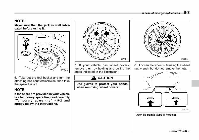
Black plate (367,1)
一般Model "A1300GE-A" EDITED: 2016/ 9/ 13
NOTEMake sure that the jack is well lubri-cated before using it.
6. Take out the tool bucket and turn theattaching bolt counterclockwise, then takethe spare tire out.
NOTEIf the spare tire provided in your vehicleis a temporary spare tire, read carefully“Temporary spare tire” F9-2 andstrictly follow the instructions.
7. If your vehicle has wheel covers,remove them by holding and pulling theareas indicated in the illustration.
CAUTION
Use gloves to protect your handswhen removing wheel covers.
8. Loosen the wheel nuts using the wheelnut wrench but do not remove the nuts.
Jack-up points (type A models)
In case of emergency/Flat tires 9-7
– CONTINUED –
9

Black plate (368,1)
一般Model "A1300GE-A" EDITED: 2016/ 9/ 13
9-8 In case of emergency/Flat tires
Jack-up points (type B models)
9. Place the jack under the side sill at thefront or rear jack-up point closest to the flattire.
Turn the jackscrew by hand until the jackhead engages firmly into the jack-up point.
10. Insert the jack handle into the jack-screw, and turn the handle until the tireclears the ground. Do not raise the vehiclehigher than necessary.11. Remove the wheel nuts and the flattire.
12. Before putting the spare tire on, cleanthe mounting surface of the wheel and hubwith a cloth.13. Put on the spare tire. Replace thewheel nuts. Tighten them by hand.
WARNING
Do not use oil or grease on thewheel studs or nuts when the sparetire is installed. This could cause thenuts to become loose and lead to anaccident.
14. Turn the jack handle counterclockwiseto lower the vehicle.

Black plate (369,1)
一般Model "A1300GE-A" EDITED: 2016/ 9/ 13
15. Use the wheel nut wrench to securelytighten the wheel nuts to the specifiedtorque, following the tightening order in theillustration.For the wheel nut tightening torque, referto “Tires” F12-9. Never use your foot onthe wheel nut wrench or a pipe extensionon the wrench because you may exceedthe specified torque. Have the wheel nuttorque checked at the nearest automotiveservice facility.
1) Support holder
16. Store the flat tire in the spare tirecompartment. Install with the supportholder facing upward and secure the flattire by firmly tightening the attaching bolt.
NOTEIf you cannot fix the flat tire firmly, tryturning the support holder upsidedown.
17. Store the jack, jack handle and wheelnut wrench in their storage locations.
WARNING
Never place a flat tire or tire chan-ging tools in the passenger com-partment after changing a flat tire. Ina sudden stop or collisions, loose
equipment could strike occupantsand cause injury. Store the tire andall tools in the proper place.
& Sealing flat tire (models withflat tire repair kit)
WARNING
Read these instructions andwarnings carefully before sealing aflat tire.
Compliance with these instructionsis vital to ensuring vehicle safety.Noncompliance with these instruc-tions means risking tire damage,which can affect vehicle handlingand lead to loss of vehicle control.This may result in serious injury ordeath.
If the tire is punctured, you can seal theflat tire temporarily by using the flat tirerepair kit. You can seal a flat tire caused,for example, by nails or similar objectswith less than 4 mm (0.2 in). However,depending on the type and extent of tiredamage, some tires can only be partiallysealed or not sealed at all, and this
In case of emergency/Flat tires 9-9
– CONTINUED –
9
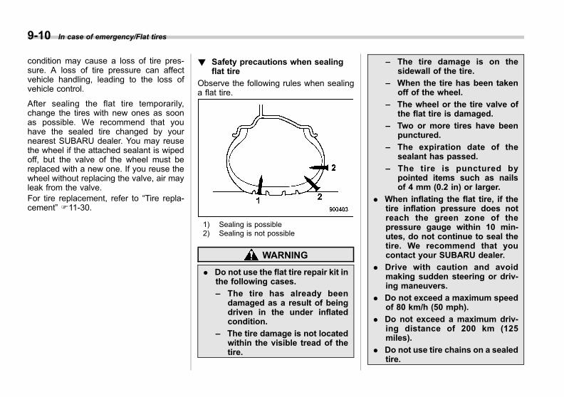
Black plate (370,1)
一般Model "A1300GE-A" EDITED: 2016/ 9/ 13
9-10 In case of emergency/Flat tires
condition may cause a loss of tire pres-sure. A loss of tire pressure can affectvehicle handling, leading to the loss ofvehicle control.
After sealing the flat tire temporarily,change the tires with new ones as soonas possible. We recommend that youhave the sealed tire changed by yournearest SUBARU dealer. You may reusethe wheel if the attached sealant is wipedoff, but the valve of the wheel must bereplaced with a new one. If you reuse thewheel without replacing the valve, air mayleak from the valve.For tire replacement, refer to “Tire repla-cement” F11-30.
! Safety precautions when sealingflat tire
Observe the following rules when sealinga flat tire.
1) Sealing is possible2) Sealing is not possible
WARNING
. Do not use the flat tire repair kit inthe following cases.
– The tire has already beendamaged as a result of beingdriven in the under inflatedcondition.
– The tire damage is not locatedwithin the visible tread of thetire.
– The tire damage is on thesidewall of the tire.
– When the tire has been takenoff of the wheel.
– The wheel or the tire valve ofthe flat tire is damaged.
– Two or more tires have beenpunctured.
– The expiration date of thesealant has passed.
– The tire is punctured bypointed items such as nailsof 4 mm (0.2 in) or larger.
. When inflating the flat tire, if thetire inflation pressure does notreach the green zone of thepressure gauge within 10 min-utes, do not continue to seal thetire. We recommend that youcontact your SUBARU dealer.
. Drive with caution and avoidmaking sudden steering or driv-ing maneuvers.
. Do not exceed a maximum speedof 80 km/h (50 mph).
. Do not exceed a maximum driv-ing distance of 200 km (125miles).
. Do not use tire chains on a sealedtire.
Black plate (371,1)
一般Model "A1300GE-A" EDITED: 2016/ 9/ 13
. Do not tow a trailer.
. If used for a purpose other thansealing a flat tire, the flat tirerepair kit may cause a severeaccident or injury due to the factthat compressed air can act asan explosive or propellant.
. Safely park your vehicle on theroadside so that you do notobstruct the flow of traffic andso that you are able to seal theflat tire without being in danger.
. Apply the parking brake, even ifthe vehicle is parked on a levelroad, to make sure that thevehicle will not move.
. Stop the engine before sealingthe flat tire.
. Turn on the hazard warningflasher while sealing the flat tire.
. Do not attempt to remove foreignobjects like nails or screws thathave penetrated the tire. Leavethem as they are.
. Never leave the flat tire repair kitunattended while in use.
. Only one tire can be repaired withone bottle of sealant.
. The tires can be repaired whenthe ambient temperature is −308C
(−228F) or higher.
CAUTION
. Remember that the flat tire repairkit only provides temporary mo-bility. Regulations concerningtire repair after usage of flat tirerepair kit may differ from countryto country. We recommend thatyou consult your SUBARU dealeror tire dealer for advice.
. Store the flat tire repair kit safelyand secure it in the cargo area.Storing it anywhere in the pas-senger compartment is not advi-sable because it could strike anoccupant in the event of a sud-den stop or collision and causeinjury.
. Use the flat tire repair kit withoriginal vehicle tires only.
. Do not keep the air compressoroperating for more than 10 min-utes, otherwise there is a risk ofoverheating.
. The temperature of the air com-pressor may become high. Becareful not to burn yourself.
. When raining, take measures to
prevent the air compressor frombeing exposed directly to therain. Exposing to rain may causea malfunction.
. Do not use air compressors otherthan the one in the repair kit.Using an air compressor otherthan the one in the repair kit maydamage the tires.
. Do not disassemble or modify theair compressor to enable the useof a power supply or a batteryother than DC12V.
. If a temporary puncture repair isperformed with the repair kit, theTire Pressure Monitoring System(TPMS) may not operate nor-mally.
In case of emergency/Flat tires 9-11
– CONTINUED –
9
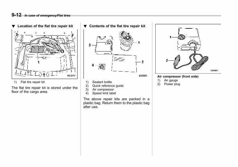
Black plate (372,1)
一般Model "A1300GE-A" EDITED: 2016/ 9/ 13
9-12 In case of emergency/Flat tires
! Location of the flat tire repair kit
1) Flat tire repair kit
The flat tire repair kit is stored under thefloor of the cargo area.
! Contents of the flat tire repair kit
1) Sealant bottle2) Quick reference guide3) Air compressor4) Speed limit label
The above repair kits are packed in aplastic bag. Return them to the plastic bagafter use.
Air compressor (front side)1) Air gauge2) Power plug
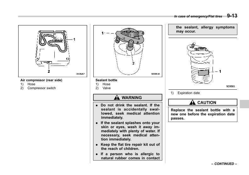
Black plate (373,1)
一般Model "A1300GE-A" EDITED: 2016/ 9/ 13
Air compressor (rear side)1) Hose2) Compressor switch
Sealant bottle1) Hose2) Valve
WARNING
. Do not drink the sealant. If thesealant is accidentally swal-lowed, seek medical attentionimmediately.
. If the sealant splashes onto yourskin or eyes, wash it away im-mediately with plenty of water. Ifnecessary, seek medical atten-tion immediately.
. Keep the flat tire repair kit out ofthe reach of children.
. If a person who is allergic tonatural rubber comes in contact
the sealant, allergy symptomsmay occur.
1) Expiration date
CAUTION
Replace the sealant bottle with anew one before the expiration datepasses.
In case of emergency/Flat tires 9-13
– CONTINUED –
9
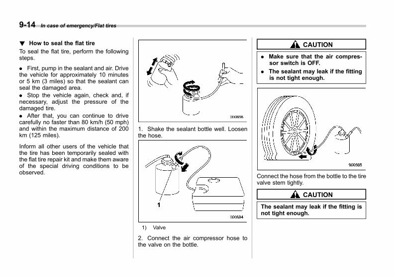
Black plate (374,1)
一般Model "A1300GE-A" EDITED: 2016/ 9/ 13
9-14 In case of emergency/Flat tires
! How to seal the flat tire
To seal the flat tire, perform the followingsteps.
. First, pump in the sealant and air. Drivethe vehicle for approximately 10 minutesor 5 km (3 miles) so that the sealant canseal the damaged area.. Stop the vehicle again, check and, ifnecessary, adjust the pressure of thedamaged tire.. After that, you can continue to drivecarefully no faster than 80 km/h (50 mph)and within the maximum distance of 200km (125 miles).
Inform all other users of the vehicle thatthe tire has been temporarily sealed withthe flat tire repair kit and make them awareof the special driving conditions to beobserved.
1. Shake the sealant bottle well. Loosenthe hose.
1) Valve
2. Connect the air compressor hose tothe valve on the bottle.
CAUTION
. Make sure that the air compres-sor switch is OFF.
. The sealant may leak if the fittingis not tight enough.
Connect the hose from the bottle to the tirevalve stem tightly.
CAUTION
The sealant may leak if the fitting isnot tight enough.
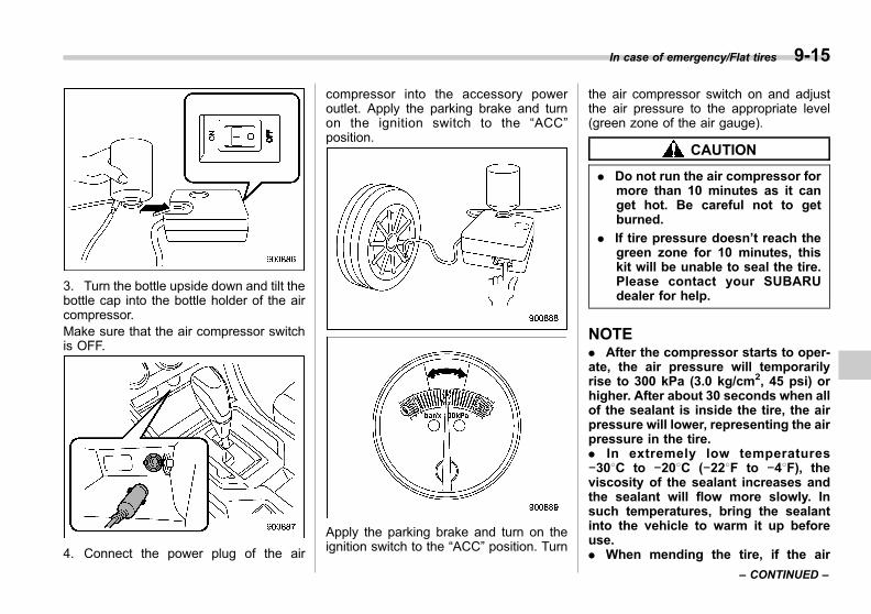
Black plate (375,1)
一般Model "A1300GE-A" EDITED: 2016/ 9/ 13
3. Turn the bottle upside down and tilt thebottle cap into the bottle holder of the aircompressor.Make sure that the air compressor switchis OFF.
4. Connect the power plug of the air
compressor into the accessory poweroutlet. Apply the parking brake and turnon the ignition switch to the “ACC”position.
Apply the parking brake and turn on theignition switch to the “ACC” position. Turn
the air compressor switch on and adjustthe air pressure to the appropriate level(green zone of the air gauge).
CAUTION
. Do not run the air compressor formore than 10 minutes as it canget hot. Be careful not to getburned.
. If tire pressure doesn’t reach thegreen zone for 10 minutes, thiskit will be unable to seal the tire.Please contact your SUBARUdealer for help.
NOTE. After the compressor starts to oper-ate, the air pressure will temporarilyrise to 300 kPa (3.0 kg/cm2, 45 psi) orhigher. After about 30 seconds when allof the sealant is inside the tire, the airpressure will lower, representing the airpressure in the tire.. In extremely low temperatures−308C to −208C (−228F to −48F), theviscosity of the sealant increases andthe sealant will flow more slowly. Insuch temperatures, bring the sealantinto the vehicle to warm it up beforeuse.. When mending the tire, if the air
In case of emergency/Flat tires 9-15
– CONTINUED –
9
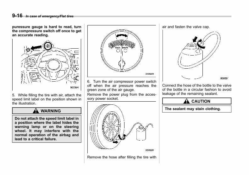
Black plate (376,1)
一般Model "A1300GE-A" EDITED: 2016/ 9/ 13
9-16 In case of emergency/Flat tires
puressure gauge is hard to read, turnthe compressure switch off once to getan accurate reading.
5. While filling the tire with air, attach thespeed limit label on the position shown inthe illustration.
WARNING
Do not attach the speed limit label ina position where the label hides thewarning lamp or on the steeringwheel. It may interfere with thenormal operation of the airbag andlead to a critical failure.
6. Turn the air compressor power switchoff when the air pressure reaches thegreen zone of the air gauge.Remove the power plug from the acces-sory power socket.
Remove the hose after filling the tire with
air and fasten the valve cap.
Connect the hose of the bottle to the valveof the bottle in a circular fashion to avoidleakage of the remaining sealant.
CAUTION
The sealant may stain clothing.

Black plate (377,1)
一般Model "A1300GE-A" EDITED: 2016/ 9/ 13
7. Stow the kit back in the vehicle anddrive your vehicle immediately for 10minutes or 5 km (3 miles).
WARNING
. Drive carefully. Do not exceed 80km/h (50 mph). Driving fasterthan that can result in the vehicleshaking.
. Do not use tire chains on a sealedtire.
. Do not tow a trailer.
. If heavy vibrations, unsteadysteering behavior or noises oc-cur while driving, reduce yourspeed and drive with caution to alocation where it is safe for youto stop the vehicle. Recheck the
tire and its pressure. If the tirepressure is in the red zone of theair gauge or if there are anycracks, bumps or similar tiredamage visible, temporary re-pairs cannot be performed withthe repair kit. We recommendthat you consult with yourSUBARU dealer or road serviceprovider.
8. After driving for 10 minutes or 5 km (3miles), whichever comes first, stop thevehicle in a safe place to recheck the airpressure (see step 4).If necessary, fill the tire with air to theappropriate air pressure again and drivecarefully to the nearest SUBARU dealerfor tire, valve stem and sealant bottle
replacement.
NOTEConnect the air compressor only to thetire valve.
CAUTION
. If the air pressure is in red zoneof the air gauge, the kit did notsuccessfully seal the puncture.In this case, please stop drivingand contact your SUBARU dealerfor help.
. Do not drive your vehicle with thesealed tire for more than 200 km(125 miles). Failure to replace thevalve stem may result in airleakage at the valve stem.
Before the tire is removed from the rim,inform your SUBARU dealer or other tiredealer that the tire contains sealant.
CAUTION
The sealant bottle and speed limitlabel need to be replaced after usingthe flat tire repair kit.
In case of emergency/Flat tires 9-17
– CONTINUED –
9

Black plate (378,1)
一般Model "A1300GE-A" EDITED: 2016/ 9/ 13
9-18 In case of emergency/Flat tires
NOTENew sealant and replacement parts canbe purchased from your authorizedrepair shop or SUBARU dealer, andthey should also be installed into thekit by a specialist. Empty sealantbottles and replacement parts must bereturned to your SUBARU dealer ordisposed of in compliance with localwaste disposal regulations.
! Technical data of air compressor
Line voltage DC 12V
Operating voltage DC 10 – 15V
Amperage Max. 10A
& Tire pressure monitoringsystem (TPMS) (if equipped)
Low tire pressure warning light
The tire pressure monitoring system pro-vides the driver with a warning messageby sending a signal from a sensor that isinstalled in each wheel when a tirepressure is severely low relative to theselected TPMS mode. Refer to “Low tirepressure warning light” F3-21.The tire pressure monitoring system willactivate only when the vehicle is driven atspeeds above 40 km/h (25 mph). Also,this system may not react immediately to asudden drop in tire pressure (for example,a blow-out caused by running over asharp object).
WARNING
If the low tire pressure warning lightilluminates while driving, neverbrake suddenly and keep drivingstraight ahead while gradually redu-cing speed. Then slowly pull off theroad to a safe place. Otherwise anaccident involving serious vehicledamage and serious personal injurycould occur.
Check the pressure for all four tiresand adjust the pressure accordingto the most appropriate one of three(normal, loading, towing) COLD tirepressure values shown on the tireplacard located on the door pillar onthe driver’s side. If this light stillilluminates while driving after ad-justing the tire pressure, a tire mayhave significant damage and a fastleak that causes the tire to lose airrapidly. If you have a flat tire, replaceit with a spare tire as soon aspossible.
When a spare tire is mounted or awheel rim is replaced without theoriginal pressure sensor/transmitterbeing transferred, the low tire pres-sure warning light will illuminatesteadily after blinking for approxi-mately one minute. This indicates
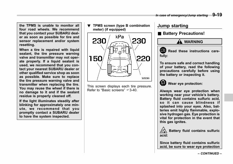
Black plate (379,1)
一般Model "A1300GE-A" EDITED: 2016/ 9/ 13
the TPMS is unable to monitor allfour road wheels. We recommendthat you contact your SUBARU deal-er as soon as possible for tire andsensor replacement and/or systemresetting.
When a tire is repaired with liquidsealant, the tire pressure warningvalve and transmitter may not oper-ate properly. If a liquid sealant isused, we recommend that you con-tact your nearest SUBARU dealer orother qualified service shop as soonas possible. Make sure to replacethe tire pressure warning valve andtransmitter when replacing the tire.You may reuse the wheel if there isno damage to it and if the sealantresidue is properly cleaned off.
If the light illuminates steadily afterblinking for approximately one min-ute, we recommend that youpromptly contact a SUBARU dealerto have the system inspected.
! TPMS screen (type B combinationmeter) (if equipped)
This screen displays each tire pressure.Refer to “Basic screens” F3-40.
Jump starting
& Battery Precautions!
WARNING
Read these instructions care-fully:
To ensure safe and correct handlingof your battery, read the followingprecautions carefully before usingthe battery or inspecting it.
Wear eye protection:
Always wear eye protection whenworking near your vehicle’s battery.Battery fluid contains sulfuric acid,so it can cause blindness ifsplashed into your eyes. Also, bat-teries emit highly flammable, explo-sive hydrogen gas. Eye protection isvital for protection in the event thatthis gas ignites.
Battery fluid contains sulfuricacid:
Since battery fluid contains sulfuricacid, be sure to wear eye protection
In case of emergency/Jump starting 9-19
– CONTINUED –
9
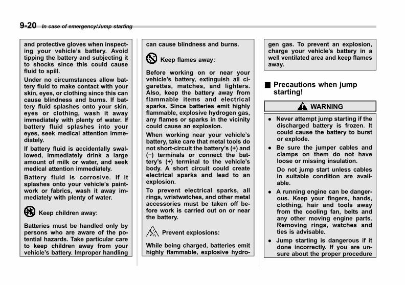
Black plate (380,1)
一般Model "A1300GE-A" EDITED: 2016/ 9/ 13
9-20 In case of emergency/Jump starting
and protective gloves when inspect-ing your vehicle’s battery. Avoidtipping the battery and subjecting itto shocks since this could causefluid to spill.
Under no circumstances allow bat-tery fluid to make contact with yourskin, eyes, or clothing since this cancause blindness and burns. If bat-tery fluid splashes onto your skin,eyes or clothing, wash it awayimmediately with plenty of water. Ifbattery fluid splashes into youreyes, seek medical attention imme-diately.
If battery fluid is accidentally swal-lowed, immediately drink a largeamount of milk or water, and seekmedical attention immediately.
Battery fluid is corrosive. If itsplashes onto your vehicle’s paint-work or fabrics, wash it away im-mediately with plenty of water.
Keep children away:
Batteries must be handled only bypersons who are aware of the po-tential hazards. Take particular careto keep children away from yourvehicle’s battery. Improper handling
can cause blindness and burns.
Keep flames away:
Before working on or near yourvehicle’s battery, extinguish all ci-garettes, matches, and lighters.Also, keep the battery away fromflammable items and electricalsparks. Since batteries emit highlyflammable, explosive hydrogen gas,any flames or sparks in the vicinitycould cause an explosion.
When working near your vehicle’sbattery, take care that metal tools donot short-circuit the battery’s (+) and(−) terminals or connect the bat-tery’s (+) terminal to the vehicle’sbody. A short circuit could createelectrical sparks and lead to anexplosion.
To prevent electrical sparks, allrings, wristwatches, and other metalaccessories must be taken off be-fore work is carried out on or nearthe battery.
Prevent explosions:
While being charged, batteries emithighly flammable, explosive hydro-
gen gas. To prevent an explosion,charge your vehicle’s battery in awell ventilated area and keep flamesaway.
& Precautions when jumpstarting!
WARNING
. Never attempt jump starting if thedischarged battery is frozen. Itcould cause the battery to burstor explode.
. Be sure the jumper cables andclamps on them do not haveloose or missing insulation.
Do not jump start unless cablesin suitable condition are avail-able.
. A running engine can be danger-ous. Keep your fingers, hands,clothing, hair and tools awayfrom the cooling fan, belts andany other moving engine parts.Removing rings, watches andties is advisable.
. Jump starting is dangerous if itdone incorrectly. If you are un-sure about the proper procedure

Black plate (381,1)
一般Model "A1300GE-A" EDITED: 2016/ 9/ 13
for jump starting, consult a com-petent mechanic.
CAUTION
The battery used for boosting mustbe 12 V. Do not jump start unlessyou are sure that the booster batteryis correct.
When your vehicle does not start due to arun down (discharged) battery, the vehiclemay be jump started by connecting yourbattery to another battery (called thebooster battery) with jumper cables.
& How to jump start1. Make sure the booster battery is 12volts and the negative terminal isgrounded.2. If the booster battery is in anothervehicle, do not let the two vehicles touch.3. Turn off all unnecessary lights andaccessories.4. Connect the jumper cables exactly inthe sequence illustrated.
In case of emergency/Jump starting 9-21
– CONTINUED –
9
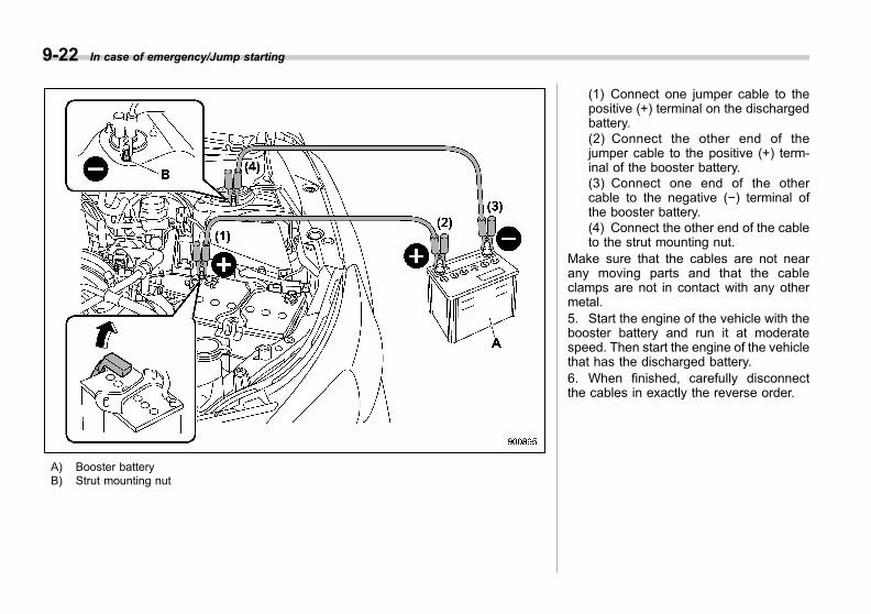
Black plate (382,1)
一般Model "A1300GE-A" EDITED: 2016/ 9/ 13
9-22 In case of emergency/Jump starting
A) Booster batteryB) Strut mounting nut
(1) Connect one jumper cable to thepositive (+) terminal on the dischargedbattery.(2) Connect the other end of thejumper cable to the positive (+) term-inal of the booster battery.(3) Connect one end of the othercable to the negative (−) terminal ofthe booster battery.(4) Connect the other end of the cableto the strut mounting nut.
Make sure that the cables are not nearany moving parts and that the cableclamps are not in contact with any othermetal.5. Start the engine of the vehicle with thebooster battery and run it at moderatespeed. Then start the engine of the vehiclethat has the discharged battery.6. When finished, carefully disconnectthe cables in exactly the reverse order.
Black plate (383,1)
一般Model "A1300GE-A" EDITED: 2016/ 9/ 13
Engine overheating
WARNING
Never attempt to remove the radia-tor cap until the engine has beenshut off and has fully cooled down.When the engine is hot, the coolantis under pressure. Removing thecap while the engine is still hotcould release a spray of boiling hotcoolant, which could burn you veryseriously.
If the engine overheats, safely pull off theroad and stop the vehicle in a safelocation.
& If steam is coming from theengine compartment
. Turn off the engine and get everyoneaway from the vehicle until it cools down.. We recommend that you contact anauthorized SUBARU dealer.
& If no steam is coming fromthe engine compartment
1. Keep the engine running at idlingspeed.2. Open the engine hood to ventilate theengine compartment. Refer to “Enginehood” F11-11.Confirm that the cooling fan is turning. Ifthe fan is not turning, immediately turn offthe engine and contact your authorizeddealer for repair.3. After the coolant temperature highwarning light that has blinked or illumi-nated in RED turns off, turn off the engine.For details about the warning light, refer to“Coolant temperature low indicator light/Coolant temperature high warning light”F3-19.4. After the engine has fully cooled down,check the coolant level in the reservetank. If the coolant level is below the“LOW” mark, add coolant up to the “FULL”mark.
NOTEFor details about how to check thecoolant level or how to add coolant,refer to “Engine coolant” F11-17.
5. If there is no coolant in the reservetank, add coolant to the reserve tank.Then remove the radiator cap and fill the
radiator with coolant.
If you have to remove the radiator capfrom a hot radiator, first wrap a thick clotharound the radiator cap, then turn the capcounterclockwise slowly without pressingdown until it stops. Release the pressurefrom the radiator. After the pressure hasbeen fully released, remove the cap bypressing down and turning it.
In case of emergency/Engine overheating 9-23
9
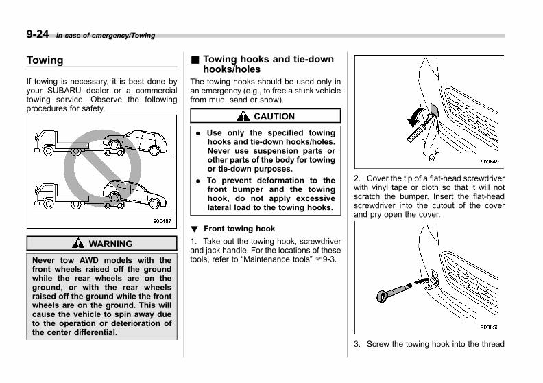
Black plate (384,1)
一般Model "A1300GE-A" EDITED: 2016/ 9/ 13
9-24 In case of emergency/Towing
Towing
If towing is necessary, it is best done byyour SUBARU dealer or a commercialtowing service. Observe the followingprocedures for safety.
WARNING
Never tow AWD models with thefront wheels raised off the groundwhile the rear wheels are on theground, or with the rear wheelsraised off the ground while the frontwheels are on the ground. This willcause the vehicle to spin away dueto the operation or deterioration ofthe center differential.
& Towing hooks and tie-downhooks/holes
The towing hooks should be used only inan emergency (e.g., to free a stuck vehiclefrom mud, sand or snow).
CAUTION
. Use only the specified towinghooks and tie-down hooks/holes.Never use suspension parts orother parts of the body for towingor tie-down purposes.
. To prevent deformation to thefront bumper and the towinghook, do not apply excessivelateral load to the towing hooks.
! Front towing hook
1. Take out the towing hook, screwdriverand jack handle. For the locations of thesetools, refer to “Maintenance tools” F9-3.
2. Cover the tip of a flat-head screwdriverwith vinyl tape or cloth so that it will notscratch the bumper. Insert the flat-headscrewdriver into the cutout of the coverand pry open the cover.
3. Screw the towing hook into the thread
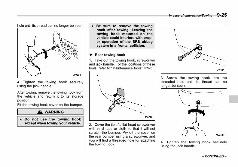
Black plate (385,1)
一般Model "A1300GE-A" EDITED: 2016/ 9/ 13
hole until its thread can no longer be seen.
4. Tighten the towing hook securelyusing the jack handle.
After towing, remove the towing hook fromthe vehicle and return it to its storageposition.Fit the towing hook cover on the bumper.
WARNING
. Do not use the towing hookexcept when towing your vehicle.
. Be sure to remove the towinghook after towing. Leaving thetowing hook mounted on thevehicle could interfere with prop-er operation of the SRS airbagsystem in a frontal collision.
! Rear towing hook
1. Take out the towing hook, screwdriverand jack handle. For the locations of thesetools, refer to “Maintenance tools” F9-3.
2. Cover the tip of a flat-head screwdriverwith vinyl tape or cloth so that it will notscratch the bumper. Pry off the cover onthe rear bumper using a screwdriver, andyou will find a threaded hole for attachingthe towing hook.
3. Screw the towing hook into thethreaded hole until its thread can nolonger be seen.
4. Tighten the towing hook securelyusing the jack handle.
In case of emergency/Towing 9-25
– CONTINUED –
9
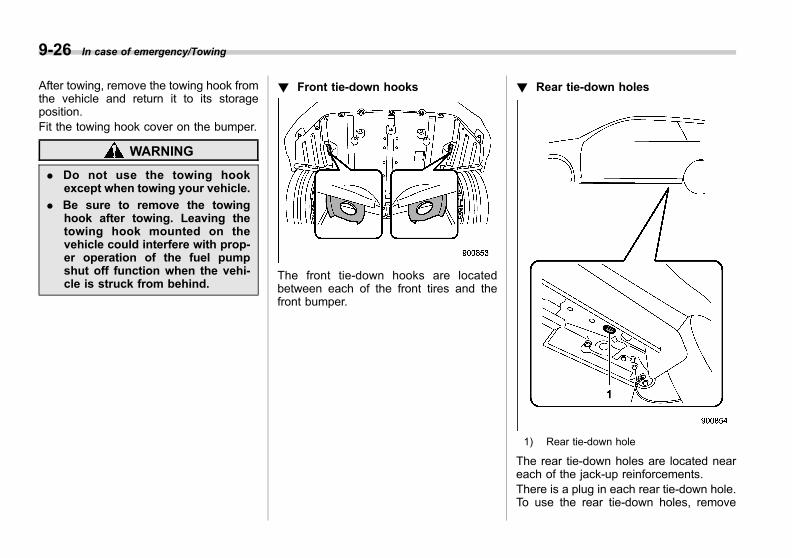
Black plate (386,1)
一般Model "A1300GE-A" EDITED: 2016/ 9/ 13
9-26 In case of emergency/Towing
After towing, remove the towing hook fromthe vehicle and return it to its storageposition.Fit the towing hook cover on the bumper.
WARNING
. Do not use the towing hookexcept when towing your vehicle.
. Be sure to remove the towinghook after towing. Leaving thetowing hook mounted on thevehicle could interfere with prop-er operation of the fuel pumpshut off function when the vehi-cle is struck from behind.
! Front tie-down hooks
The front tie-down hooks are locatedbetween each of the front tires and thefront bumper.
! Rear tie-down holes
1) Rear tie-down hole
The rear tie-down holes are located neareach of the jack-up reinforcements.There is a plug in each rear tie-down hole.To use the rear tie-down holes, remove
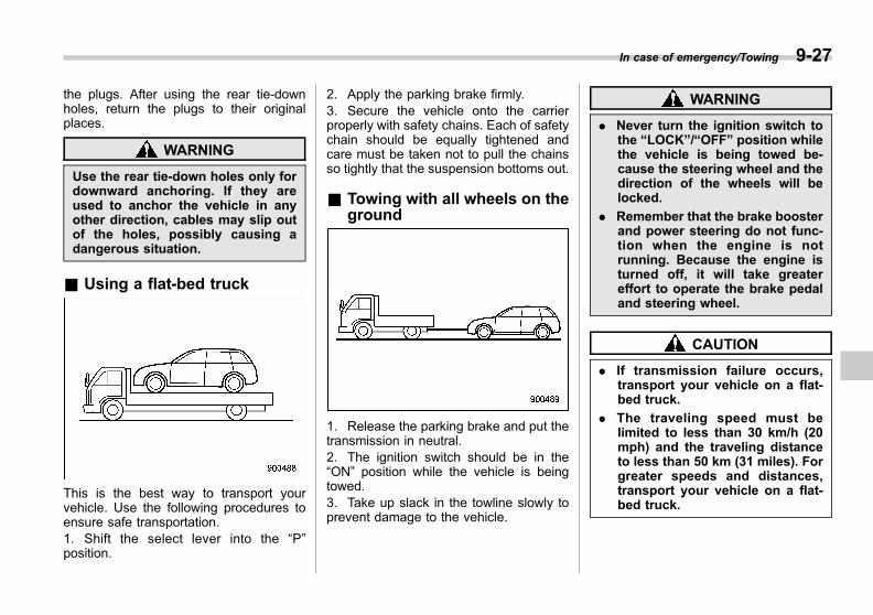
Black plate (387,1)
一般Model "A1300GE-A" EDITED: 2016/ 9/ 13
the plugs. After using the rear tie-downholes, return the plugs to their originalplaces.
WARNING
Use the rear tie-down holes only fordownward anchoring. If they areused to anchor the vehicle in anyother direction, cables may slip outof the holes, possibly causing adangerous situation.
& Using a flat-bed truck
This is the best way to transport yourvehicle. Use the following procedures toensure safe transportation.1. Shift the select lever into the “P”position.
2. Apply the parking brake firmly.3. Secure the vehicle onto the carrierproperly with safety chains. Each of safetychain should be equally tightened andcare must be taken not to pull the chainsso tightly that the suspension bottoms out.
& Towing with all wheels on theground
1. Release the parking brake and put thetransmission in neutral.2. The ignition switch should be in the“ON” position while the vehicle is beingtowed.3. Take up slack in the towline slowly toprevent damage to the vehicle.
WARNING
. Never turn the ignition switch tothe “LOCK”/“OFF” position whilethe vehicle is being towed be-cause the steering wheel and thedirection of the wheels will belocked.
. Remember that the brake boosterand power steering do not func-tion when the engine is notrunning. Because the engine isturned off, it will take greatereffort to operate the brake pedaland steering wheel.
CAUTION
. If transmission failure occurs,transport your vehicle on a flat-bed truck.
. The traveling speed must belimited to less than 30 km/h (20mph) and the traveling distanceto less than 50 km (31 miles). Forgreater speeds and distances,transport your vehicle on a flat-bed truck.
In case of emergency/Towing 9-27
9
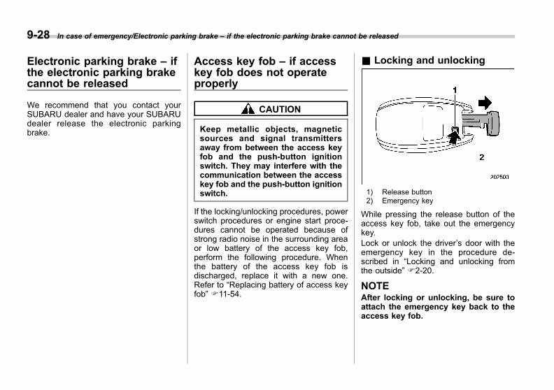
Black plate (388,1)
一般Model "A1300GE-A" EDITED: 2016/ 9/ 13
9-28 In case of emergency/Electronic parking brake – if the electronic parking brake cannot be released
Electronic parking brake – ifthe electronic parking brakecannot be released
We recommend that you contact yourSUBARU dealer and have your SUBARUdealer release the electronic parkingbrake.
Access key fob – if accesskey fob does not operateproperly
CAUTION
Keep metallic objects, magneticsources and signal transmittersaway from between the access keyfob and the push-button ignitionswitch. They may interfere with thecommunication between the accesskey fob and the push-button ignitionswitch.
If the locking/unlocking procedures, powerswitch procedures or engine start proce-dures cannot be operated because ofstrong radio noise in the surrounding areaor low battery of the access key fob,perform the following procedure. Whenthe battery of the access key fob isdischarged, replace it with a new one.Refer to “Replacing battery of access keyfob” F11-54.
& Locking and unlocking
1) Release button2) Emergency key
While pressing the release button of theaccess key fob, take out the emergencykey.Lock or unlock the driver’s door with theemergency key in the procedure de-scribed in “Locking and unlocking fromthe outside” F2-20.
NOTEAfter locking or unlocking, be sure toattach the emergency key back to theaccess key fob.
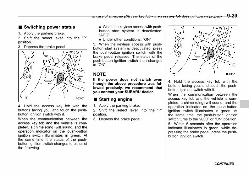
Black plate (389,1)
一般Model "A1300GE-A" EDITED: 2016/ 9/ 13
& Switching power status1. Apply the parking brake.2. Shift the select lever into the “P”position.3. Depress the brake pedal.
4. Hold the access key fob with thebuttons facing you, and touch the push-button ignition switch with it.When the communication between theaccess key fob and the vehicle is com-pleted, a chime (ding) will sound, and theoperation indicator on the push-buttonignition switch illuminates in green. Atthe same time, the status of the push-button ignition switch changes to either ofthe following.
. When the keyless access with push-button start system is deactivated:“ACC”. Under other conditions: “ON”
5. When the keyless access with push-button start system is deactivated, pressthe push-button ignition switch with thebrake pedal released. The status of thepush-button ignition switch then changesto “ON”.
NOTEIf the power does not switch eventhough the above procedure was fol-lowed precisely, we recommend thatyou contact your SUBARU dealer.
& Starting engine1. Apply the parking brake.2. Shift the select lever into the “P”position.3. Depress the brake pedal.
4. Hold the access key fob with thebuttons facing you, and touch the push-button ignition switch with it.When the communication between theaccess key fob and the vehicle is com-pleted, a chime (ding) will sound, and theoperation indicator on the push-buttonignition switch illuminates in green. Atthe same time, the push-button ignitionswitch turns to the “ACC” or “ON” position.5. Within 5 seconds after the operationindicator illuminates in green, while de-pressing the brake pedal, press the push-button ignition switch.
In case of emergency/Access key fob – if access key fob does not operate properly 9-29
– CONTINUED –
9
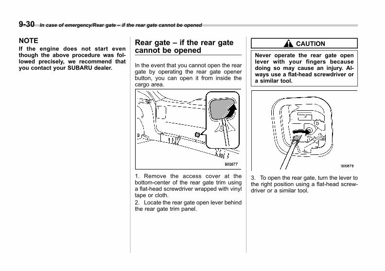
Black plate (390,1)
一般Model "A1300GE-A" EDITED: 2016/ 9/ 13
9-30 In case of emergency/Rear gate – if the rear gate cannot be opened
NOTEIf the engine does not start eventhough the above procedure was fol-lowed precisely, we recommend thatyou contact your SUBARU dealer.
Rear gate – if the rear gatecannot be opened
In the event that you cannot open the reargate by operating the rear gate openerbutton, you can open it from inside thecargo area.
1. Remove the access cover at thebottom-center of the rear gate trim usinga flat-head screwdriver wrapped with vinyltape or cloth.2. Locate the rear gate open lever behindthe rear gate trim panel.
CAUTION
Never operate the rear gate openlever with your fingers becausedoing so may cause an injury. Al-ways use a flat-head screwdriver ora similar tool.
3. To open the rear gate, turn the lever tothe right position using a flat-head screw-driver or a similar tool.

Black plate (391,1)
一般Model "A1300GE-A" EDITED: 2016/ 9/ 13
& Models with double lockingsystem
NOTEThe rear gate open lever is stillshielded with an anti-theft cover evenafter removing the access cover. So,remove the anti-theft cover using aPhillips screwdriver to access the reargate open lever.
Sunroof (if equipped) – if thesunroof does not close
If the sunroof does not close, we recom-mend that you have the system checkedby a SUBARU dealer.
If your vehicle is involved inan accident
CAUTION
If your vehicle is involved in anaccident, be sure to inspect theground under the vehicle beforerestarting the engine. If you find thatfuel has leaked on the ground, donot try to restart the engine. The fuelsystem has been damaged and is inneed of repair. Immediately contactthe nearest automotive service facil-ity. We recommend that you consultyour SUBARU dealer.
Your vehicle has a fuel pump shut offsystem. When the vehicle sustains animpact in an accident, rollover (Russiamodels) etc., the fuel pump shut offsystem stops supplying the fuel in orderto minimize fuel leakage. However, de-pending on the impact conditions at thetime of collision, the fuel pump shut-offsystem may not operate.Perform the following procedures to re-start the engine after the system isactivated.
In case of emergency/Sunroof – if the sunroof does not close 9-31
– CONTINUED –
9
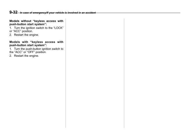
Black plate (392,1)
一般Model "A1300GE-A" EDITED: 2016/ 9/ 13
9-32 In case of emergency/If your vehicle is involved in an accident
Models without “keyless access withpush-button start system”:1. Turn the ignition switch to the “LOCK”or “ACC” position.2. Restart the engine.
Models with “keyless access withpush-button start system”:1. Turn the push-button ignition switch tothe “ACC” or “OFF” position.2. Restart the engine.
Black plate (21,1)
一般Model "A1300GE-A" EDITED: 2016/ 9/ 13
Exterior care ....................................................... 10-2Washing............................................................. 10-2Waxing and polishing ......................................... 10-3Cleaning alloy wheels......................................... 10-4
Corrosion protection.......................................... 10-4Most common causes of corrosion ..................... 10-4To help prevent corrosion................................... 10-5
Cleaning the interior.......................................... 10-5Seat fabric......................................................... 10-5Leather seat materials........................................ 10-6Synthetic leather upholstery............................... 10-6Seatbelt ............................................................. 10-6Climate control panel, audio panel, instrumentpanel, console panel, switches, combinationmeter, and other plastic surfaces ..................... 10-6
Monitor.............................................................. 10-7
Appearance care
10
Black plate (396,1)
一般Model "A1300GE-A" EDITED: 2016/ 9/ 13
10-2 Appearance care/Exterior care
Exterior care
& Washing
CAUTION
. When washing the vehicle, thebrakes may get wet. As a result,the brake stopping distance willbe longer. To dry the brakes,drive the vehicle at a safe speedwhile lightly depressing thebrake pedal to heat up thebrakes.
. Do not wash the engine compart-ment and area adjacent to it. Ifwater enters the engine air in-take, electrical parts or the powersteering fluid reservoir (ifequipped), it will cause enginetrouble or a malfunction of thepower steering.
. When washing inner fenders,underbody, bumpers and pro-truding objects such as exhaustpipes and exhaust finishers, becareful to prevent injuries fromcontacting sharp ends.
. Do not use organic solventswhen washing the surface of thebulb assembly cover. However, ifa detergent with organic solventsis used to wash the cover sur-face, completely rinse off thedetergent with water. Otherwise,the surface may be damaged.
. Models with automatic rain sen-sing windshield wipers: Whenwashing the vehicle, turn off thewiper. If the wiper switch is in the“AUTO” position, the wipers mayoperate unexpectedly whilewashing the vehicle and causeinjury.
. (5-door models only) Since yourvehicle is equipped with a rearwiper, automatic car-washbrushes could become tangledaround it, damaging the wiperarm and other components. Askthe automatic car-wash operatornot to let the brushes touch thewiper arm or to fix the wiper armon the rear window glass withadhesive tape before operatingthe machine.
. For models with a rod-type roofantenna, remove the antenna rodbefore washing your car at a carwash. If the antenna rod remains
attached, it may scratch the roof.When reinstalling the removedantenna rod, be sure to fullytighten it.
NOTEWhen having your vehicle washed inan automatic car wash:. Make sure beforehand that the carwash is of suitable type.. When washing a vehicle equippedwith automatic rain sensing windshieldwipers, make sure that the wiper isturned off. If the wiper switch is in the“AUTO” position, the wipers may oper-ate unexpectedly while washing thevehicle and the wiper blades could bedamaged.. The rear view camera lens has ahard coating to help prevent scratches.When washing the vehicle or cleaningthe camera lens, be careful not toscratch the camera lens. Do not use awashing brush directly on the cameralens. This may cause the image qualityof the rear view camera to deteriorate.
The best way to preserve your vehicle’sbeauty is frequent washing. Wash thevehicle at least once a month to avoidcontamination by road grime.
Black plate (397,1)
一般Model "A1300GE-A" EDITED: 2016/ 9/ 13
Wash dirt off with a wet sponge and plentyof lukewarm or cold water. Do not washthe vehicle with hot water and in directsunlight.
Salt, chemicals, insects, tar, soot, treesap, and bird droppings should be washedoff by using a light detergent, as required.If you use a light detergent, make certainthat it is a neutral detergent. Do not usestrong soap or chemical detergents. Allcleaning agents should be promptlyflushed from the surface and not allowedto dry there. Rinse the vehicle thoroughlywith plenty of lukewarm water. Wipe theremaining water off with a chamois or softcloth. Wear rubber gloves and use a handbrush when washing down underbody,inner fenders and suspension to effec-tively remove mud and dirt off.
! Washing the underbody
Chemicals, salts and gravel used fordeicing road surfaces are extremely cor-rosive, accelerating the corrosion of un-derbody components, such as the exhaustsystem, fuel and brake lines, brakecables, floor pan and fenders, and sus-pension.Thoroughly flush the underbody and in-side of the fenders with lukewarm or coldwater at frequent intervals to reduce theharmful effects of such agents.
Mud and sand adhering to the underbodycomponents may accelerate their corro-sion.After driving off-road or on muddy orsandy roads, wash the mud and sand offthe underbody.Carefully flush the suspension and axleparts, as they are particularly prone tomud and sand buildup. Do not use asharp-edged tool to remove caked mud.
CAUTION
. Be careful not to damage brakehoses, sensor harnesses, andother parts when washing sus-pension components.
. Be careful not to flush the enginebottom for a long time. It maycause damage of some electricalparts.
! Using a warm water washer
. Keep a good distance of 30 cm (12 in)or more between the washer nozzle andthe vehicle.. Do not wash the same area continu-ously.. If a stain will not come out easily, washby hand. Some warm water washers areof the high temperature, high pressure
type, and they can damage or deform theresin parts such as moldings, or causewater to leak into the vehicle.
& Waxing and polishingAlways wash and dry the vehicle beforewaxing and polishing.Use a good quality polish and wax andapply them according to the manufac-turer’s instructions. Wax or polish whenthe painted surface is cool.
Be sure to polish and wax the chrome trim,as well as the painted surfaces. Loss ofwax on a painted surface leads to loss ofthe original luster and also quickens thedeterioration of the surface. It is recom-mended that a coat of wax be applied atleast once a month, or whenever thesurface no longer repels water.
If the appearance of the paint has dimin-ished to the point where the luster or tonecannot be restored, lightly polish thesurface with a fine-grained compound.Never polish just the affected area, butinclude the surrounding area as well.Always polish in only one direction. ANo. 2000 grain compound is recom-mended. Never use a coarse-grainedcompound. Coarser grained compoundshave a smaller grain-size number andcould damage the paint. After polishing
Appearance care/Exterior care 10-3
– CONTINUED –
10
Black plate (398,1)
一般Model "A1300GE-A" EDITED: 2016/ 9/ 13
10-4 Appearance care/Corrosion protection
with a compound, coat with wax to restorethe original luster. Frequent polishing witha compound or an incorrect polishingtechnique will result in removing the paintlayer and exposing the undercoat. Whenin doubt, we recommend that you alwayscontact your SUBARU dealer or an autopaint specialist.
CAUTION
Do not use any agents with organicsolvents on the surface of the bulbassembly cover. However, if a polishor wax with organic solvents isapplied to the cover surface, com-pletely wipe off the polish or wax.Otherwise, the cover surface may bedamaged.
NOTE. Be careful not to block the wind-shield washer nozzles with wax whenwaxing the vehicle.. Do not wipe the rear view camerawith alcohol, benzine or paint thinner.Otherwise, discoloration may occur. Toremove contamination, wipe the cam-era with a cloth moistened with dilutedneutral detergent and then wipe it witha soft, dry cloth.. When waxing the vehicle, be careful
not to apply the wax to the rear viewcamera. If it comes in contact with thecamera, moisten a clean cloth withdiluted neutral detergent to removethe wax.
& Cleaning alloy wheels. Promptly wipe the alloy wheels clean ofany kind of grime or agent. If dirt is left ontoo long, it may be difficult to clean off.. Do not use soap containing grit toclean the wheels. Be sure to use a neutralcleaning agent, and later rinse thoroughlywith water. Do not clean the wheels with astiff brush or expose them to a high-speedwashing device.. Clean the vehicle (including the alloywheels) with water as soon as possiblewhen it has been splashed with sea water,exposed to sea breezes, or driven onroads treated with salt or other agents.
Corrosion protection
Your SUBARU has been designed andbuilt to resist corrosion. Special materialsand protective finishes have been used onmost parts of the vehicle to help maintainfine appearance, strength, and reliableoperation.
& Most common causes ofcorrosion
The most common causes of corrosionare:. The accumulation of moisture retainingdirt and debris in body panel sections,cavities, and other areas.. Damage to paint and other protectivecoatings caused by gravel and stonechips or minor accidents.
Corrosion is accelerated on the vehiclewhen:. It is exposed to road salt or dust controlchemicals, or used in coastal areas wherethere is more salt in the air, or in areaswhere there is considerable industrialpollution.. It is driven in areas of high humidity,especially when temperatures range justabove freezing.. Dampness in certain parts of the
Black plate (399,1)
一般Model "A1300GE-A" EDITED: 2016/ 9/ 13
vehicle remains for a long time, eventhough other parts of the vehicle may bedry.. High temperatures will cause corrosionto parts of the vehicle which cannot dryquickly due to lack of proper ventilation.
& To help prevent corrosionWash the vehicle regularly to preventcorrosion of the body and suspensioncomponents. Also, wash the vehiclepromptly after driving on any of thefollowing surfaces:. roads that have been salted to preventthem from freezing in winter. mud, sand, or gravel. coastal roads
After the winter has ended, it is recom-mended that the underbody be given avery thorough washing.
Before the beginning of winter, check thecondition of underbody components, suchas the exhaust system, fuel and brakelines, brake cables, suspension, steeringsystem, floor pan, and fenders. If any ofthem are found to be rusted, they shouldbe given an appropriate rust preventiontreatment or should be replaced. Werecommend that you contact yourSUBARU dealer to perform this kind of
maintenance and treatment if you needassistance.
Repair chips and scratches in the paint assoon as you find them.
Check the interior of the vehicle for waterand dirt accumulation under the floor matsbecause that could cause corrosion.Occasionally check under the mats tomake sure the area is dry.Keep your garage dry. Do not park yourvehicle in a damp, poorly ventilatedgarage. In such a garage, corrosion canbe caused by dampness. If you wash thevehicle in the garage or put the vehicleinto the garage when wet or covered withsnow, that can cause dampness.
If your vehicle is operated in cold weatherand/or in areas where road salts and othercorrosive materials are used, the doorhinges and locks and hood latch shouldbe inspected and lubricated periodically.
Cleaning the interior
Use a soft, damp cloth to clean the climatecontrol panel, audio equipment, instru-ment panel, center console, combinationmeter panel, and switches. (Do not useorganic solvents.)
CAUTION
Do not use sharp instruments orwindow cleaner containing abra-sives to clean the inner surface ofthe rear window. They may damagethe conductors printed on the win-dow.
& Seat fabricRemove loose dirt, dust or debris with avacuum cleaner. If the dirt is caked on thefabric or hard to remove with a vacuumcleaner, use a soft brush then vacuum it.Wipe the fabric surface with a tightlywrung cloth and dry the seat fabricthoroughly. If the fabric is still dirty, wipeusing a solution of mild soap and luke-warm water then dry thoroughly.
If the stain does not come out, try acommercially-available fabric cleaner. Usethe cleaner on a hidden place and make
Appearance care/Cleaning the interior 10-5
– CONTINUED –
10

Black plate (400,1)
一般Model "A1300GE-A" EDITED: 2016/ 9/ 13
10-6 Appearance care/Cleaning the interior
sure it does not affect the fabric adversely.Use the cleaner according to its instruc-tions.
CAUTION
When cleaning the seat, do not usebenzine, paint thinner, or any similarmaterials. Doing so could damagethe surface and cause the color todeteriorate.
& Leather seat materialsThe leather used by SUBARU is a highquality natural product which will retain itsdistinctive appearance and feel for manyyears with proper care.Allowing dust or road dirt to build up on thesurface can cause the material to becomebrittle and to wear prematurely. Regularcleaning with a soft, moist, natural fibercloth should be performed monthly, takingcare not to soak the leather or allow waterto penetrate the stitched seams.A mild detergent suitable for cleaningwoolen fabrics may be used to removedifficult dirt spots, rubbing with a soft, drycloth afterwards to restore the luster. Ifyour SUBARU is to be parked for a longtime in bright sunlight, it is recommendedthat the seats and head restraints be
covered, or the windows shaded, toprevent fading or shrinkage.Seat covers and head restraint coversshould be removed before operating thevehicle.Minor surface blemishes or bald patchesmay be treated with a commercial leatherspray lacquer. You will discover that eachleather seat section will develop soft foldsor wrinkles, which is characteristic ofgenuine leather.
& Synthetic leather upholsteryThe synthetic leather material used on theSUBARU may be cleaned using mild soapor detergent and water, after first vacuum-ing or brushing away loose dirt. Allow thesoap to soak in for a few minutes and wipeoff with a clean, damp cloth. Commercialfoam-type cleaners suitable for syntheticleather materials may be used whennecessary.
CAUTION
Strong cleaning agents such assolvents, paint thinners, windowcleaner or fuel must never be usedon leather or synthetic interior ma-terials. Doing so could damage thesurface and cause the color todeteriorate.
& SeatbeltFor details about how to clean theseatbelt, refer to “Seatbelt maintenance”F1-20.
& Climate control panel, audiopanel, instrument panel,console panel, switches,combination meter, and otherplastic surfaces
Use a soft, damp cloth to clean the climatecontrol panel, audio equipment, instru-ment panel, center console, combinationmeter panel, and switches.
CAUTION
. Do not use organic solvents suchas paint thinners or fuel, orstrong cleaning agents that con-
Black plate (401,1)
一般Model "A1300GE-A" EDITED: 2016/ 9/ 13
tain those solvents. Doing socould damage the surface andcause the color to deteriorate.
. Do not use chemical solventsthat contain silicone on the vehi-cle audio system, electrical com-ponents of the air-conditioner orany switches. If silicone adheresto these parts, it may causedamage to electrical compo-nents.
& MonitorTo clean the audio/navigation/multi-func-tion display monitor, wipe it with a siliconecloth or with a soft cloth. If the monitor isextremely dirty, clean it with a soft clothmoistened with neutral detergent thencarefully wipe off any remaining detergent.
CAUTION
. Do not spray neutral detergentdirectly onto the monitor. Doingso could damage the monitor’scomponents.
. Do not wipe the monitor with ahard cloth. Doing so couldscratch the monitor.
. Do not use cleaning fluid thatcontains thinner, fuel, or any
other volatile substance. Suchcleaning fluid could erase thelettering on the switches at thebottom of the monitor.
Appearance care/Cleaning the interior 10-7
10
Black plate (23,1)
一般Model "A1300GE-A" EDITED: 2016/ 9/ 13
Maintenance schedule ....................................... 11-3Maintenance precautions................................... 11-7
Before checking or servicing in the enginecompartment.................................................... 11-8
When checking or servicing in the enginecompartment.................................................... 11-8
When checking or servicing in the enginecompartment while the engine is running.......... 11-8
Maintenance tips ................................................ 11-9When replacing parts ......................................... 11-9Removing and reinstalling clips.......................... 11-9
Engine hood ..................................................... 11-11Engine compartment overview........................ 11-13Engine oil.......................................................... 11-14
Engine oil consumption.................................... 11-14Checking the oil level ....................................... 11-14Changing the oil and oil filter............................ 11-15Recommended grade and viscosity .................. 11-15Synthetic oil..................................................... 11-16
Cooling system ................................................ 11-16Cooling fan, hose and connections................... 11-16Engine coolant ................................................. 11-17
Air cleaner element .......................................... 11-19Replacing the air cleaner element ..................... 11-19
Spark plugs ...................................................... 11-20Drive belts ........................................................ 11-21Continuously variable transmission fluid....... 11-21Front differential gear oil (all models) andrear differential gear oil (AWD models) ....... 11-21Recommended grade and viscosity .................. 11-21
Brake fluid........................................................ 11-22Checking the fluid level.................................... 11-22Recommended brake fluid ............................... 11-22
Brake booster .................................................. 11-23Brake pedal ...................................................... 11-23
Checking the brake pedal free play .................. 11-23Checking the brake pedal reserve distance....... 11-23
Replacement of brake pad .............................. 11-24Breaking-in of new brake pads......................... 11-24
Tires and wheels.............................................. 11-24Types of tires................................................... 11-24Tire pressure monitoring system (TPMS) (ifequipped) ...................................................... 11-25
Tire inspection................................................. 11-26Tire pressures and wear .................................. 11-26Wheel balance ................................................. 11-28Wear indicators ............................................... 11-28Tire rotation direction mark.............................. 11-29Tire rotation..................................................... 11-29Tire replacement.............................................. 11-30Wheel replacement .......................................... 11-31Wheel covers (if equipped)............................... 11-31
Alloy wheels (if equipped)............................... 11-32Windshield washer fluid.................................. 11-32
Checking the windshield washer fluid level ...... 11-32Adding the windshield washer fluid.................. 11-33Windshield washer fluid ................................... 11-33
Replacement of wiper blades ......................... 11-34Windshield wiper blade assembly..................... 11-35Window wiper blade rubber.............................. 11-36
Maintenance and service
11
Black plate (24,1)
一般Model "A1300GE-A" EDITED: 2016/ 9/ 13
Maintenance and service
Rear window wiper blade assembly (5-doormodels).......................................................... 11-36
Rear window wiper blade rubber (5-doormodels).......................................................... 11-37
Battery............................................................... 11-38Battery Precautions!......................................... 11-38
Fuses ................................................................ 11-40Installation of accessories............................... 11-41Replacing bulbs ............................................... 11-42
Headlights (models with LED headlights) .......... 11-42Headlights (models with halogenheadlights) ..................................................... 11-42
Front turn signal light (models with LEDheadlights) ..................................................... 11-44
Front turn signal light and position light(models with halogen headlights) ................... 11-45
Front fog light and daytime running light (ifequipped) ...................................................... 11-46
Side turn signal light (if equipped).................... 11-48Rear combination lights ................................... 11-48Back-up light/Rear fog light (if equipped).......... 11-50License plate light ........................................... 11-52Map light ......................................................... 11-52Vanity mirror light (if equipped) ........................ 11-53Dome light and cargo area light ....................... 11-53Trunk light (4-door models) .............................. 11-53Other bulbs ..................................................... 11-53
Replacing key battery...................................... 11-54Replacing battery of access key fob................. 11-54Replacing battery of transmitter ....................... 11-55

Black plate (405,1)
一般Model "A1300GE-A" EDITED: 2016/ 9/ 13
Maintenance schedule
To keep your vehicle in proper operating condition and to assure peak performance at all times, the recommended maintenanceservice should be performed in accordance with the maintenance schedule.
NOTE. The frequency of scheduled inspection and maintenance services as set forth is minimal. However, it may be necessarythat they be performed more frequently depending on road conditions, weather, atmospheric conditions and vehicle usage.These conditions may differ from one country to another. Therefore there may be special requirement in your country. Werecommend that you ask your authorized SUBARU dealer for the actual maintenance schedule applied to your vehicle.. For models with a multi-function display (color LCD), you can set a reminder to be displayed when a scheduledmaintenance item is almost due. For details, refer to “Setting screen” F3-61.
Continue periodic maintenance beyond 120,000 km (75,000 miles) or 96 months by returning to the third column of the maintenanceschedule and adding 120,000 km (75,000 miles) or 96 months to the column headings.
Symbols used:R: ReplaceI: Inspect, and then adjust, correct or replace if necessary.P: Perform(I): Recommended service for safe vehicle operation
MAINTENANCE ITEM
MAINTENANCE INTERVAL(Number of months or km (miles), whichever occurs first)
REMARKSMonths 12 24 36 48 60 72 84 96
6 1,000 km 15 30 45 60 75 90 105 120
6 1,000 miles 9 19 28 38 47 56 66 75
1 Engine oil R R R R R R R R See NOTE 1)
2 Engine oil filter R R R R R R R R See NOTE 1)
3 Drive belt(s) I I I I I I I I Replace every 160,000km (100,000 miles)
Maintenance and service/Maintenance schedule 11-3
– CONTINUED –
11
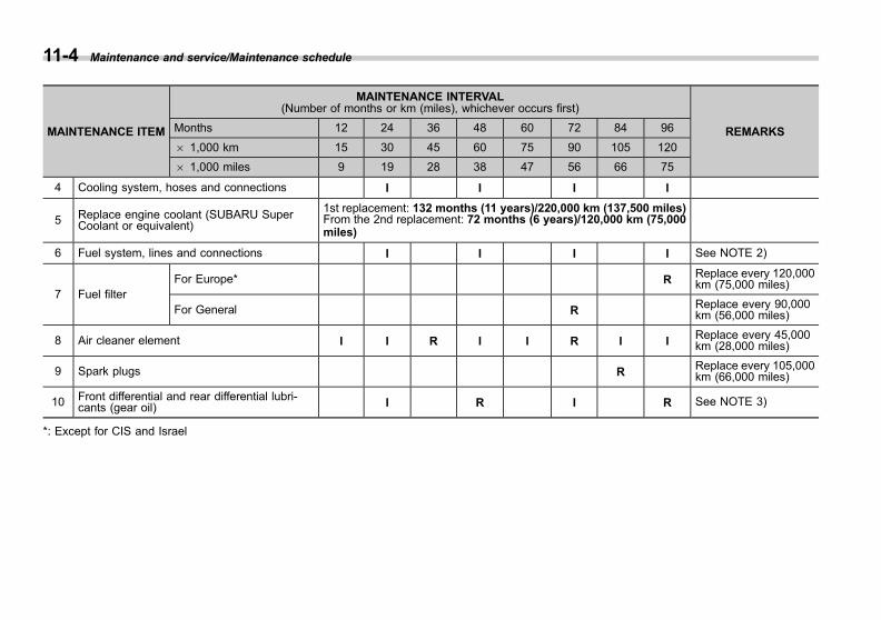
Black plate (406,1)
一般Model "A1300GE-A" EDITED: 2016/ 9/ 13
11-4 Maintenance and service/Maintenance schedule
MAINTENANCE ITEM
MAINTENANCE INTERVAL(Number of months or km (miles), whichever occurs first)
REMARKSMonths 12 24 36 48 60 72 84 96
6 1,000 km 15 30 45 60 75 90 105 120
6 1,000 miles 9 19 28 38 47 56 66 75
4 Cooling system, hoses and connections I I I I
5 Replace engine coolant (SUBARU SuperCoolant or equivalent)
1st replacement: 132 months (11 years)/220,000 km (137,500 miles)From the 2nd replacement: 72 months (6 years)/120,000 km (75,000miles)
6 Fuel system, lines and connections I I I I See NOTE 2)
7 Fuel filterFor Europe* R Replace every 120,000
km (75,000 miles)
For General R Replace every 90,000km (56,000 miles)
8 Air cleaner element I I R I I R I I Replace every 45,000km (28,000 miles)
9 Spark plugs R Replace every 105,000km (66,000 miles)
10 Front differential and rear differential lubri-cants (gear oil) I R I R See NOTE 3)
*: Except for CIS and Israel

Black plate (407,1)
一般Model "A1300GE-A" EDITED: 2016/ 9/ 13
MAINTENANCE ITEM
MAINTENANCE INTERVAL(Number of months or km (miles), whichever occurs first)
REMARKSMonths 12 24 36 48 60 72 84 96
6 1,000 km 15 30 45 60 75 90 105 120
6 1,000 miles 9 19 28 38 47 56 66 75
11 Continuously variable transmission fluid I I I I See NOTE 4)
12 Brake fluid R R R R See NOTE 5)
13 Disc brake pads and discs/Front and rear axleboots and axle shaft joint portions I I I I I I I I See NOTE 2)
14 Brake lining and drums (including parkingbrake linings and drums) I I I I See NOTE 2)
15 Inspect brake lines and check operation ofparking and service brake system P P P P See NOTE 2)
16 Steering and suspension system I I I I See NOTE 2)
17 Front and rear wheel bearing (I)
18 Air filter element for the climate control system(except for CIS and Israel) I R I R I R I R See NOTE 6)
19 Air filter element for the climate control system(for CIS and Israel)
Replace every 12 months or 12,000 km (7,500 miles) whichever occursfirst See NOTE 6)
Maintenance and service/Maintenance schedule 11-5
– CONTINUED –
11

Black plate (408,1)
一般Model "A1300GE-A" EDITED: 2016/ 9/ 13
11-6 Maintenance and service/Maintenance schedule
NOTE1) When the vehicle is used under severe driving conditions mentioned in the following examples*, the engine oil and oilfilter should be changed more frequently.2) When the vehicle is used under severe driving conditions mentioned in the following examples*, inspection should beperformed at every 15,000 km (9,000 miles) or 12 months whichever occurs first.3) When the vehicle is frequently operated under severe driving conditions, such as towing a trailer, replacement ofdifferential gear oil (front and rear) should be performed more frequently.4) When the vehicle is used under the severe driving conditions mentioned in the following examples*, the continuouslyvariable transmission fluid should be changed every 45,000 km (28,000 miles).5) When the vehicle is used in the following areas, change fluid every 15,000 km (9,000 miles) or 12 months whichever occursfirst.
(1) High humidity areas(2) Mountainous areas
6) When the vehicle is used under severe driving conditions mentioned in the following examples*, the air cleaner elementand air filter should be replaced more frequently.
* Examples of severe driving conditions:(1) Operating in extremely cold weather (Items 1, 2 and 16 only)(2) Towing a trailer (Items 1, 2, 10, 11, 13 and 15 only)(3) Repeated short trips (Items 1, 2, 13 and 14 only)(4) Driving on dusty roads (Items 8, 13, 14, 16, 18 and 19 only)(5) Driving on rough and/or muddy roads (items 13, 14, 16, 18 and 19 only)(6) Driving in areas that use road salt or other corrosive materials (items 6, 13, 14, 15 and 16 only)(7) Living on coastal areas (items 6, 13, 14, 15 and 16 only)
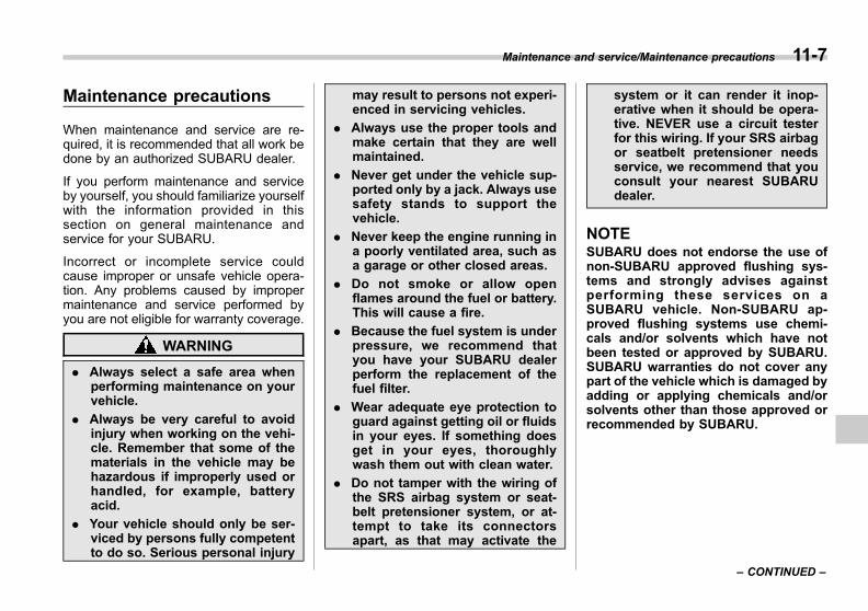
Black plate (409,1)
一般Model "A1300GE-A" EDITED: 2016/ 9/ 13
Maintenance precautions
When maintenance and service are re-quired, it is recommended that all work bedone by an authorized SUBARU dealer.
If you perform maintenance and serviceby yourself, you should familiarize yourselfwith the information provided in thissection on general maintenance andservice for your SUBARU.
Incorrect or incomplete service couldcause improper or unsafe vehicle opera-tion. Any problems caused by impropermaintenance and service performed byyou are not eligible for warranty coverage.
WARNING
. Always select a safe area whenperforming maintenance on yourvehicle.
. Always be very careful to avoidinjury when working on the vehi-cle. Remember that some of thematerials in the vehicle may behazardous if improperly used orhandled, for example, batteryacid.
. Your vehicle should only be ser-viced by persons fully competentto do so. Serious personal injury
may result to persons not experi-enced in servicing vehicles.
. Always use the proper tools andmake certain that they are wellmaintained.
. Never get under the vehicle sup-ported only by a jack. Always usesafety stands to support thevehicle.
. Never keep the engine running ina poorly ventilated area, such asa garage or other closed areas.
. Do not smoke or allow openflames around the fuel or battery.This will cause a fire.
. Because the fuel system is underpressure, we recommend thatyou have your SUBARU dealerperform the replacement of thefuel filter.
. Wear adequate eye protection toguard against getting oil or fluidsin your eyes. If something doesget in your eyes, thoroughlywash them out with clean water.
. Do not tamper with the wiring ofthe SRS airbag system or seat-belt pretensioner system, or at-tempt to take its connectorsapart, as that may activate the
system or it can render it inop-erative when it should be opera-tive. NEVER use a circuit testerfor this wiring. If your SRS airbagor seatbelt pretensioner needsservice, we recommend that youconsult your nearest SUBARUdealer.
NOTESUBARU does not endorse the use ofnon-SUBARU approved flushing sys-tems and strongly advises againstperforming these services on aSUBARU vehicle. Non-SUBARU ap-proved flushing systems use chemi-cals and/or solvents which have notbeen tested or approved by SUBARU.SUBARU warranties do not cover anypart of the vehicle which is damaged byadding or applying chemicals and/orsolvents other than those approved orrecommended by SUBARU.
Maintenance and service/Maintenance precautions 11-7
– CONTINUED –
11
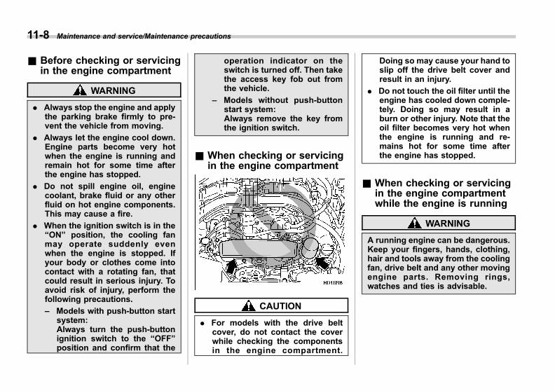
Black plate (410,1)
一般Model "A1300GE-A" EDITED: 2016/ 9/ 13
11-8 Maintenance and service/Maintenance precautions
& Before checking or servicingin the engine compartment
WARNING
. Always stop the engine and applythe parking brake firmly to pre-vent the vehicle from moving.
. Always let the engine cool down.Engine parts become very hotwhen the engine is running andremain hot for some time afterthe engine has stopped.
. Do not spill engine oil, enginecoolant, brake fluid or any otherfluid on hot engine components.This may cause a fire.
. When the ignition switch is in the“ON” position, the cooling fanmay operate suddenly evenwhen the engine is stopped. Ifyour body or clothes come intocontact with a rotating fan, thatcould result in serious injury. Toavoid risk of injury, perform thefollowing precautions.
– Models with push-button startsystem:Always turn the push-buttonignition switch to the “OFF”position and confirm that the
operation indicator on theswitch is turned off. Then takethe access key fob out fromthe vehicle.
– Models without push-buttonstart system:Always remove the key fromthe ignition switch.
& When checking or servicingin the engine compartment
CAUTION
. For models with the drive beltcover, do not contact the coverwhile checking the componentsin the engine compartment.
Doing so may cause your hand toslip off the drive belt cover andresult in an injury.
. Do not touch the oil filter until theengine has cooled down comple-tely. Doing so may result in aburn or other injury. Note that theoil filter becomes very hot whenthe engine is running and re-mains hot for some time afterthe engine has stopped.
& When checking or servicingin the engine compartmentwhile the engine is running
WARNING
A running engine can be dangerous.Keep your fingers, hands, clothing,hair and tools away from the coolingfan, drive belt and any other movingengine parts. Removing rings,watches and ties is advisable.
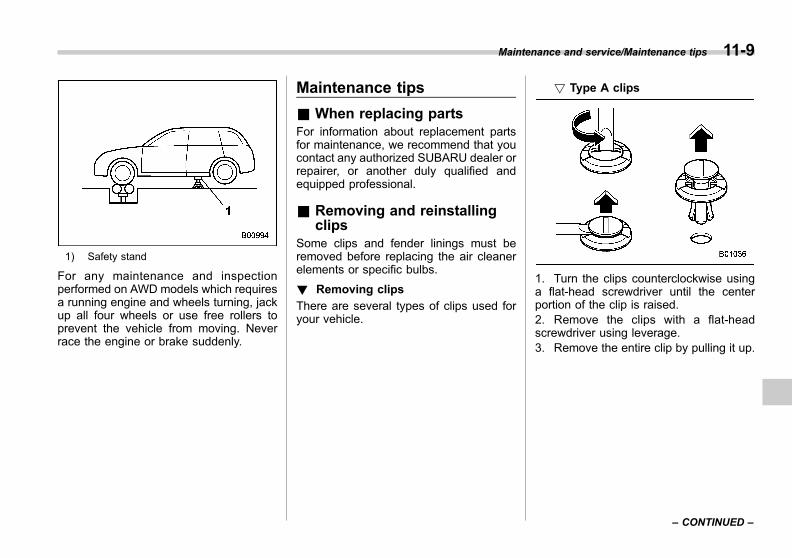
Black plate (411,1)
一般Model "A1300GE-A" EDITED: 2016/ 9/ 13
1) Safety stand
For any maintenance and inspectionperformed on AWD models which requiresa running engine and wheels turning, jackup all four wheels or use free rollers toprevent the vehicle from moving. Neverrace the engine or brake suddenly.
Maintenance tips
& When replacing partsFor information about replacement partsfor maintenance, we recommend that youcontact any authorized SUBARU dealer orrepairer, or another duly qualified andequipped professional.
& Removing and reinstallingclips
Some clips and fender linings must beremoved before replacing the air cleanerelements or specific bulbs.
! Removing clips
There are several types of clips used foryour vehicle.
! Type A clips
1. Turn the clips counterclockwise usinga flat-head screwdriver until the centerportion of the clip is raised.2. Remove the clips with a flat-headscrewdriver using leverage.3. Remove the entire clip by pulling it up.
Maintenance and service/Maintenance tips 11-9
– CONTINUED –
11
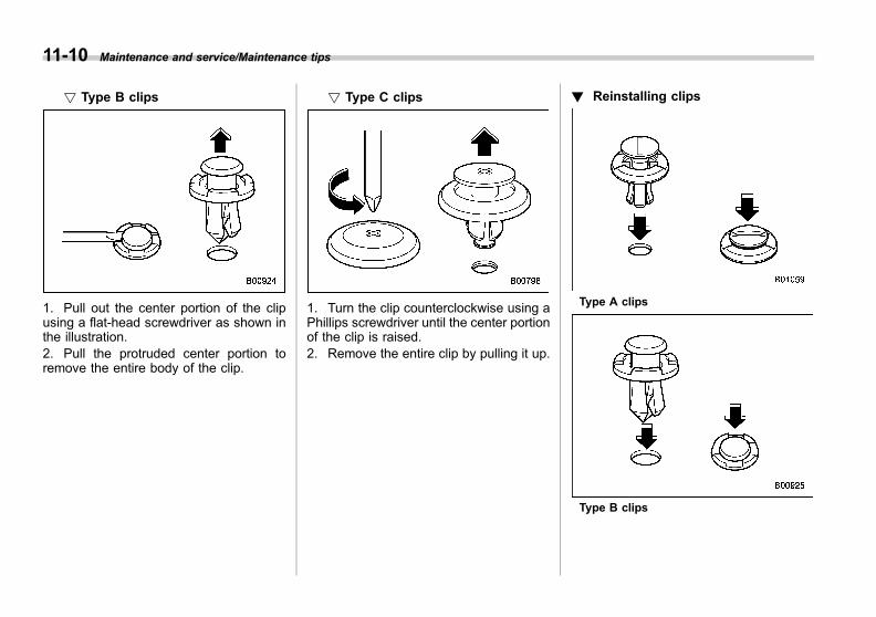
Black plate (412,1)
一般Model "A1300GE-A" EDITED: 2016/ 9/ 13
11-10 Maintenance and service/Maintenance tips
! Type B clips
1. Pull out the center portion of the clipusing a flat-head screwdriver as shown inthe illustration.2. Pull the protruded center portion toremove the entire body of the clip.
! Type C clips
1. Turn the clip counterclockwise using aPhillips screwdriver until the center portionof the clip is raised.2. Remove the entire clip by pulling it up.
! Reinstalling clips
Type A clips
Type B clips
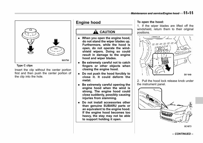
Black plate (413,1)
一般Model "A1300GE-A" EDITED: 2016/ 9/ 13
Type C clips
Insert the clip without the center portionfirst and then push the center portion ofthe clip into the hole.
Engine hood
CAUTION
. When you open the engine hood,do not stand the wiper blades up.Furthermore, while the hood isopen, do not operate the wind-shield wipers. Doing so couldresult in damage to the enginehood and wiper blades.
. Be extremely careful not to catchfingers or other objects whenclosing the engine hood.
. Do not push the hood forcibly toclose it. It could deform themetal.
. Be extremely careful opening theengine hood when the wind isstrong. The engine hood couldclose suddenly, possibly causinginjuries from slamming.
. Do not install accessories otherthan genuine SUBARU parts oran equivalent to the engine hood.If the engine hood becomes tooheavy, the stay may not be ableto support holding it open.
To open the hood:1. If the wiper blades are lifted off thewindshield, return them to their originalpositions.
2. Pull the hood lock release knob underthe instrument panel.
Maintenance and service/Engine hood 11-11
– CONTINUED –
11

Black plate (414,1)
一般Model "A1300GE-A" EDITED: 2016/ 9/ 13
11-12 Maintenance and service/Engine hood
3. Release the secondary hood releaseby moving the lever between the frontgrille and the hood toward the left.
4. Lift up the hood, release the hood propfrom its retainer and put the end of thehood prop into the slot in the hood.
To close the hood:1. Lift the hood slightly and remove thehood prop from the slot in the hood andreturn the prop to its retainer.2. Lower the hood to a height of approxi-mately 15 cm (5.9 in) above its closedposition and then let it drop.3. After closing the hood, be sure thehood is securely locked.
If this does not close the hood, release itfrom a slightly higher position.
WARNING
Always check that the hood isproperly locked before you startdriving. If it is not, it might fly openwhile the vehicle is moving andblock your view, which may causean accident and serious bodily in-jury.
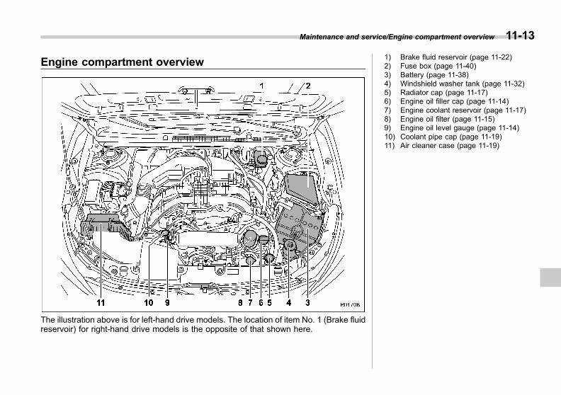
Black plate (415,1)
一般Model "A1300GE-A" EDITED: 2016/ 9/ 13
Engine compartment overview
The illustration above is for left-hand drive models. The location of item No. 1 (Brake fluidreservoir) for right-hand drive models is the opposite of that shown here.
1) Brake fluid reservoir (page 11-22)2) Fuse box (page 11-40)3) Battery (page 11-38)4) Windshield washer tank (page 11-32)5) Radiator cap (page 11-17)6) Engine oil filler cap (page 11-14)7) Engine coolant reservoir (page 11-17)8) Engine oil filter (page 11-15)9) Engine oil level gauge (page 11-14)10) Coolant pipe cap (page 11-19)11) Air cleaner case (page 11-19)
Maintenance and service/Engine compartment overview 11-13
11

Black plate (416,1)
一般Model "A1300GE-A" EDITED: 2016/ 9/ 13
11-14 Maintenance and service/Engine oil
Engine oil
CAUTION
. If the level gauge cannot bepulled out easily, twist the levelgauge right and left, then gentlypull it out. Otherwise, you may beinjured accidentally strainingyourself.
. Use only engine oil with therecommended grade and vis-cosity.
. Be careful not to spill engine oilwhen adding it. If oil touches theexhaust pipe, it may cause a badsmell, smoke, and/or a fire. Ifengine oil gets on the exhaustpipe, be sure to wipe it off.
& Engine oil consumptionSome engine oil will be consumed whiledriving. Under the following conditions, oilconsumption can be increased and thusrequire refilling between maintenanceintervals:. When the engine is new and within thebreak-in period. When the engine oil is of lower quality. When the incorrect oil viscosity is used
. When engine braking is employed
. When the engine is operated at highengine speeds. When the engine is operated underheavy loads. When towing a trailer. When the engine idles for long periodsof time. When the vehicle is operated in stopand go and/or heavy traffic situations. When the vehicle is used under severethermal conditions. When the vehicle accelerates anddecelerates frequently
Under these or similar conditions, youshould check your oil at least every 2ndfuel fill-up and change your engine oilmore frequently. If your oil consumptionrate is greater than 1 liter every 2,000kilometers or 1 quart every 1,200 miles,we recommend that you contact yourSUBARU dealer who may perform a testunder controlled conditions.
& Checking the oil level1. Park the vehicle on a level surface andstop the engine. If you check the oil leveljust after stopping the engine, wait a fewminutes for the oil to drain back into the oilpan before checking the level.
1) Oil level gauge2) Oil filler cap3) Oil filterA) ENGINE OILB) SEE OWNER’S MANUAL
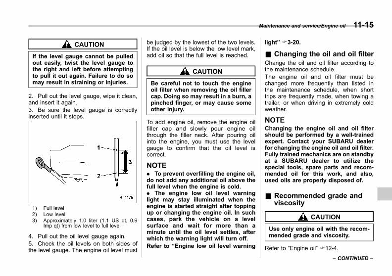
Black plate (417,1)
一般Model "A1300GE-A" EDITED: 2016/ 9/ 13
CAUTION
If the level gauge cannot be pulledout easily, twist the level gauge tothe right and left before attemptingto pull it out again. Failure to do somay result in straining or injuries.
2. Pull out the level gauge, wipe it clean,and insert it again.3. Be sure the level gauge is correctlyinserted until it stops.
1) Full level2) Low level3) Approximately 1.0 liter (1.1 US qt, 0.9
Imp qt) from low level to full level
4. Pull out the oil level gauge again.5. Check the oil levels on both sides ofthe level gauge. The engine oil level must
be judged by the lowest of the two levels.If the oil level is below the low level mark,add oil so that the full level is reached.
CAUTION
Be careful not to touch the engineoil filter when removing the oil fillercap. Doing so may result in a burn, apinched finger, or may cause someother injury.
To add engine oil, remove the engine oilfiller cap and slowly pour engine oilthrough the filler neck. After pouring oilinto the engine, you must use the levelgauge to confirm that the oil level iscorrect.
NOTE. To prevent overfilling the engine oil,do not add any additional oil above thefull level when the engine is cold.. The engine low oil level warninglight may stay illuminated when theengine is started straight after toppingup or changing the engine oil. In suchcases, park the vehicle on a levelsurface and wait for more than aminute until the oil level settles, afterwhich the warning light will turn off.Refer to “Engine low oil level warning
light” F3-20.
& Changing the oil and oil filterChange the oil and oil filter according tothe maintenance schedule.The engine oil and oil filter must bechanged more frequently than listed inthe maintenance schedule, when shorttrips are frequently made, when towing atrailer, or when driving in extremely coldweather.
NOTEChanging the engine oil and oil filtershould be performed by a well-trainedexpert. Contact your SUBARU dealerfor changing the engine oil and oil filter.Fully trained mechanics are on standbyat a SUBARU dealer to utilize thespecial tools, spare parts and recom-mended oil for this work, and also,used oils are properly disposed of.
& Recommended grade andviscosity
CAUTION
Use only engine oil with the recom-mended grade and viscosity.
Refer to “Engine oil” F12-4.
Maintenance and service/Engine oil 11-15
– CONTINUED –
11

Black plate (418,1)
一般Model "A1300GE-A" EDITED: 2016/ 9/ 13
11-16 Maintenance and service/Cooling system
NOTEEngine oil viscosity (thickness) affectsfuel economy. Oils of lower viscosityprovide better fuel economy. However,in hot weather, oil of higher viscosity isrequired to properly lubricate the en-gine.
& Synthetic oilYou can use synthetic engine oil thatmeets the same requirements given forconventional engine oil. When usingsynthetic oil, you must use oil of the sameclassification, viscosity and grade shownin this Owner’s Manual. Refer to “Engineoil” F12-4. Also, you must follow the oiland filter changing intervals shown in themaintenance schedule. Refer to “Mainte-nance schedule” F11-3.
NOTESynthetic oil of the grade and viscositynoted in chapter 12 is the recom-mended engine oil for optimum engineperformance. Conventional oil may beused with no detriment to engine dur-ability or driveability.
Cooling system
CAUTION
. The cooling system has beenfilled at the factory with a highquality, corrosion-inhibiting,year-around coolant which pro-vides protection against freezingdown to −368C (−338F). Makesure to always use genuineSUBARU Super Coolant or anequivalent (non-amine type cool-ant).
. If the coolant requires water dilu-tion, be sure to use soft water (orclear and drinkable water) and tofollow the required dilution ratio.
. Mixing with a different coolantand/or hard water may result inproblems including, but not lim-ited to, shortened engine compo-nent life, cooling system clog-ging, coolant leaks and enginedamage from overheating. There-fore, never mix different kinds ofcoolant and/or hard water even iffreezing temperatures are notexpected.
. Do not splash the engine coolantover painted parts. The alcohol
contained in the engine coolantmay damage the paint surface.
& Cooling fan, hose and con-nections
Your vehicle employs an electric coolingfan which is thermostatically controlled tooperate when the engine coolant reachesa specific temperature.If the radiator cooling fan does not operateeven when the coolant temperature highwarning light blinks or illuminates in RED,the cooling fan circuit may be defective.Refer to “Coolant temperature low indica-tor light/Coolant temperature high warninglight” F3-19.
Check the fuse and replace it if necessary.Refer to “Fuses” F11-40 and “Fuse panellocated in the engine compartment” F12-12.If the fuse is not blown, we recommendthat you have the cooling system checkedby your SUBARU dealer.
If frequent addition of coolant is neces-sary, there may be a leak in the enginecooling system. It is recommended thatthe cooling system and connections bechecked for leaks, damage, or looseness.

Black plate (419,1)
一般Model "A1300GE-A" EDITED: 2016/ 9/ 13
& Engine coolant
WARNING
Never attempt to remove the radia-tor cap until the engine has beenshut off and has cooled downcompletely. Since the coolant isunder pressure, you may sufferserious burns from a spray of boil-ing hot coolant when the cap isremoved.
! Checking the coolant level
1) “FULL” level mark2) “LOW” level markA) COOLANTB) SEE OWNER’S MANUAL
Check the coolant level at each fuel stop.
1. Check the coolant level on the outsideof the reservoir while the engine is cool.2. If the level is close to or lower than the“LOW” level mark, add coolant up to the“FULL” level mark.
Maintenance and service/Cooling system 11-17
– CONTINUED –
11
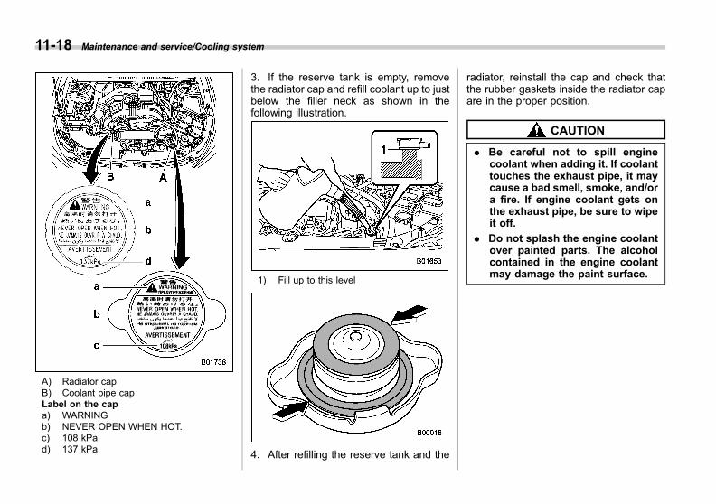
Black plate (420,1)
一般Model "A1300GE-A" EDITED: 2016/ 9/ 13
11-18 Maintenance and service/Cooling system
A) Radiator capB) Coolant pipe capLabel on the capa) WARNINGb) NEVER OPEN WHEN HOT.c) 108 kPad) 137 kPa
3. If the reserve tank is empty, removethe radiator cap and refill coolant up to justbelow the filler neck as shown in thefollowing illustration.
1) Fill up to this level
4. After refilling the reserve tank and the
radiator, reinstall the cap and check thatthe rubber gaskets inside the radiator capare in the proper position.
CAUTION
. Be careful not to spill enginecoolant when adding it. If coolanttouches the exhaust pipe, it maycause a bad smell, smoke, and/ora fire. If engine coolant gets onthe exhaust pipe, be sure to wipeit off.
. Do not splash the engine coolantover painted parts. The alcoholcontained in the engine coolantmay damage the paint surface.
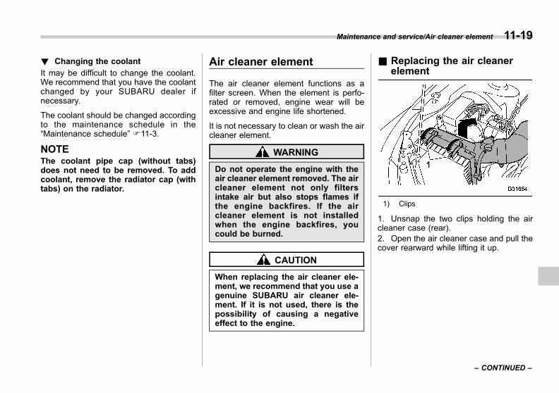
Black plate (421,1)
一般Model "A1300GE-A" EDITED: 2016/ 9/ 13
! Changing the coolant
It may be difficult to change the coolant.We recommend that you have the coolantchanged by your SUBARU dealer ifnecessary.
The coolant should be changed accordingto the maintenance schedule in the“Maintenance schedule” F11-3.
NOTEThe coolant pipe cap (without tabs)does not need to be removed. To addcoolant, remove the radiator cap (withtabs) on the radiator.
Air cleaner element
The air cleaner element functions as afilter screen. When the element is perfo-rated or removed, engine wear will beexcessive and engine life shortened.
It is not necessary to clean or wash the aircleaner element.
WARNING
Do not operate the engine with theair cleaner element removed. The aircleaner element not only filtersintake air but also stops flames ifthe engine backfires. If the aircleaner element is not installedwhen the engine backfires, youcould be burned.
CAUTION
When replacing the air cleaner ele-ment, we recommend that you use agenuine SUBARU air cleaner ele-ment. If it is not used, there is thepossibility of causing a negativeeffect to the engine.
& Replacing the air cleanerelement
1) Clips
1. Unsnap the two clips holding the aircleaner case (rear).2. Open the air cleaner case and pull thecover rearward while lifting it up.
Maintenance and service/Air cleaner element 11-19
– CONTINUED –
11

Black plate (422,1)
一般Model "A1300GE-A" EDITED: 2016/ 9/ 13
11-20 Maintenance and service/Spark plugs
3. Remove the air cleaner element.4. Clean the inside of the air cleaner case(both front and rear) with a damp cloth andinstall a new air cleaner element.
5. To install the air cleaner case (rear),insert the three projections on the air
cleaner case (rear) into the slits on theair cleaner case (front).6. Install in the reverse order of removal.
NOTEInstall the air cleaner element so thatthe surface with “UPR” printed on itfaces upward.
Spark plugs
It may be difficult to replace the sparkplugs. We recommend that you have thespark plugs replaced by your SUBARUdealer.
The spark plugs should be replacedaccording to the maintenance schedule.Refer to “Maintenance schedule” F11-3.
NOTEFor the recommended spark plugs,refer to “Electrical system” F12-9.

Black plate (423,1)
一般Model "A1300GE-A" EDITED: 2016/ 9/ 13
Drive belts
It is unnecessary to check the deflection ofthe drive belt periodically because yourengine is equipped with an automatic belttension adjuster. However, replacement ofthe belt should be done according to themaintenance schedule in the “Mainte-nance schedule” F11-3. We recommendthat you consult your SUBARU dealer forreplacement.If the drive belt is loose, cracked or worn,contact your SUBARU dealer.
Continuously variable trans-mission fluid
There is no fluid level gauge. It isunnecessary to check the continuouslyvariable transmission fluid level. However,if necessary, we recommend that youconsult your SUBARU dealer for inspec-tion.
Front differential gear oil (allmodels) and rear differentialgear oil (AWD models)
There is no oil level gauge. To check thefront and rear differential gear oil level, werecommend that you consult yourSUBARU dealer.
& Recommended grade andviscosity
Each oil manufacturer has its own baseoils and additives. Never use differentbrands together. For details, refer to “Frontdifferential and rear differential gear oil”F12-6.
CAUTION
Using a differential gear oil otherthan the specified oil may cause adecline in vehicle performance.
Maintenance and service/Drive belts 11-21
11

Black plate (424,1)
一般Model "A1300GE-A" EDITED: 2016/ 9/ 13
11-22 Maintenance and service/Brake fluid
Brake fluid
& Checking the fluid level
1) “MAX” level line2) The fluid level must be checked in this
area.3) “MIN” level line
Check the fluid level monthly.Check the fluid level on the outside of thereservoir. Be sure to check the fluid levelfor the brake system at the front part ofthe reservoir (shaded area in the illustra-tion). If the level is below “MIN”, add therecommended brake fluid to “MAX”.Use only brake fluid from a sealedcontainer.
WARNING
. Never let brake fluid contact youreyes because brake fluid can beharmful to your eyes. If brakefluid gets in your eyes, immedi-ately flush them thoroughly withclean water. For safety, whenperforming this work, wearingeye protection is advisable.
. Brake fluid absorbs moisturefrom the air. Any absorbed moist-ure can cause a dangerous lossof braking performance.
. If the vehicle requires frequentrefilling, there may be a leak. Ifyou suspect a problem, we re-commend that you have thevehicle checked at your SUBARUdealer.
CAUTION
. When adding brake fluid, be care-ful not to allow any dirt into thereservoir.
. Never splash the brake fluid overpainted surfaces or rubber parts.Alcohol contained in the brakefluid may damage them.
. Be careful not to spill brake fluid
when adding it. If brake fluidtouches the exhaust pipe, it maycause a bad smell, smoke, and/ora fire. If brake fluid gets on theexhaust pipe, be sure to wipe itoff.
& Recommended brake fluidRefer to “Fluids” F12-8.
CAUTION
Never use different brands of brakefluid together. Also, avoid mixingDOT 3 and DOT 4 brake fluids even ifthey are the same brand.
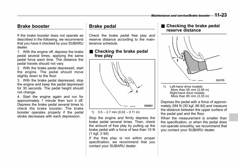
Black plate (425,1)
一般Model "A1300GE-A" EDITED: 2016/ 9/ 13
Brake booster
If the brake booster does not operate asdescribed in the following, we recommendthat you have it checked by your SUBARUdealer.1. With the engine off, depress the brakepedal several times, applying the samepedal force each time. The distance thepedal travels should not vary.2. With the brake pedal depressed, startthe engine. The pedal should moveslightly down to the floor.3. With the brake pedal depressed, stopthe engine and keep the pedal depressedfor 30 seconds. The pedal height shouldnot change.4. Start the engine again and run forapproximately 1 minute then turn it off.Depress the brake pedal several times tocheck the brake booster. The brakebooster operates properly if the pedalstroke decreases with each depression.
Brake pedal
Check the brake pedal free play andreserve distance according to the main-tenance schedule.
& Checking the brake pedalfree play
1) 0.5 – 2.7 mm (0.02 – 0.11 in)
Stop the engine and firmly depress thebrake pedal several times. Then, checkthe amount of free play by pulling up thebrake pedal with a force of less than 10 N(1 kgf, 2 lbf).If the free play is not within properspecification, we recommend that youcontact your SUBARU dealer.
& Checking the brake pedalreserve distance
1) Left-hand drive models:More than 65 mm (2.56 in)Right-hand drive models:More than 85 mm (3.35 in)
Depress the pedal with a force of approxi-mately 294 N (30 kgf, 66 lbf) and measurethe distance between the upper surface ofthe pedal pad and the floor.When the measurement is smaller thanthe specification, or when the pedal doesnot operate smoothly, we recommend thatyou contact your SUBARU dealer.
Maintenance and service/Brake booster 11-23
11
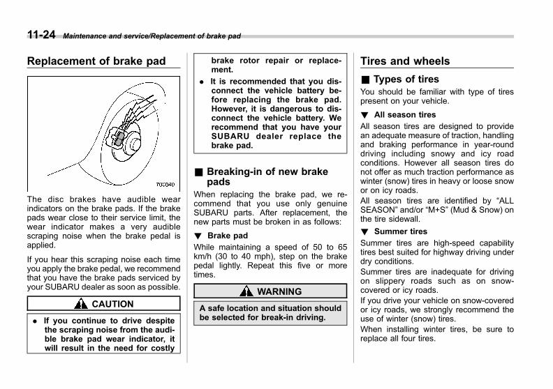
Black plate (426,1)
一般Model "A1300GE-A" EDITED: 2016/ 9/ 13
11-24 Maintenance and service/Replacement of brake pad
Replacement of brake pad
The disc brakes have audible wearindicators on the brake pads. If the brakepads wear close to their service limit, thewear indicator makes a very audiblescraping noise when the brake pedal isapplied.
If you hear this scraping noise each timeyou apply the brake pedal, we recommendthat you have the brake pads serviced byyour SUBARU dealer as soon as possible.
CAUTION
. If you continue to drive despitethe scraping noise from the audi-ble brake pad wear indicator, itwill result in the need for costly
brake rotor repair or replace-ment.
. It is recommended that you dis-connect the vehicle battery be-fore replacing the brake pad.However, it is dangerous to dis-connect the vehicle battery. Werecommend that you have yourSUBARU dealer replace thebrake pad.
& Breaking-in of new brakepads
When replacing the brake pad, we re-commend that you use only genuineSUBARU parts. After replacement, thenew parts must be broken in as follows:
! Brake pad
While maintaining a speed of 50 to 65km/h (30 to 40 mph), step on the brakepedal lightly. Repeat this five or moretimes.
WARNING
A safe location and situation shouldbe selected for break-in driving.
Tires and wheels
& Types of tiresYou should be familiar with type of tirespresent on your vehicle.
! All season tires
All season tires are designed to providean adequate measure of traction, handlingand braking performance in year-rounddriving including snowy and icy roadconditions. However all season tires donot offer as much traction performance aswinter (snow) tires in heavy or loose snowor on icy roads.All season tires are identified by “ALLSEASON” and/or “M+S” (Mud & Snow) onthe tire sidewall.
! Summer tires
Summer tires are high-speed capabilitytires best suited for highway driving underdry conditions.Summer tires are inadequate for drivingon slippery roads such as on snow-covered or icy roads.If you drive your vehicle on snow-coveredor icy roads, we strongly recommend theuse of winter (snow) tires.When installing winter tires, be sure toreplace all four tires.
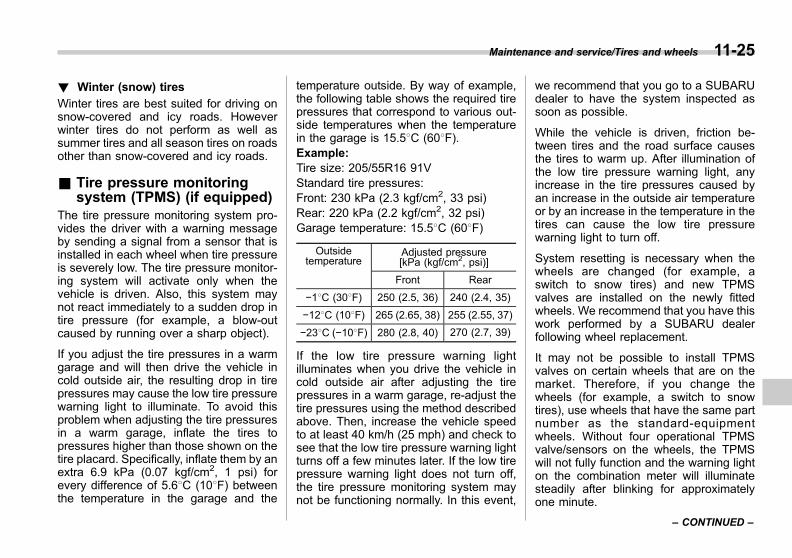
Black plate (427,1)
一般Model "A1300GE-A" EDITED: 2016/ 9/ 13
! Winter (snow) tires
Winter tires are best suited for driving onsnow-covered and icy roads. Howeverwinter tires do not perform as well assummer tires and all season tires on roadsother than snow-covered and icy roads.
& Tire pressure monitoringsystem (TPMS) (if equipped)
The tire pressure monitoring system pro-vides the driver with a warning messageby sending a signal from a sensor that isinstalled in each wheel when tire pressureis severely low. The tire pressure monitor-ing system will activate only when thevehicle is driven. Also, this system maynot react immediately to a sudden drop intire pressure (for example, a blow-outcaused by running over a sharp object).
If you adjust the tire pressures in a warmgarage and will then drive the vehicle incold outside air, the resulting drop in tirepressures may cause the low tire pressurewarning light to illuminate. To avoid thisproblem when adjusting the tire pressuresin a warm garage, inflate the tires topressures higher than those shown on thetire placard. Specifically, inflate them by anextra 6.9 kPa (0.07 kgf/cm2, 1 psi) forevery difference of 5.68C (108F) betweenthe temperature in the garage and the
temperature outside. By way of example,the following table shows the required tirepressures that correspond to various out-side temperatures when the temperaturein the garage is 15.58C (608F).Example:Tire size: 205/55R16 91VStandard tire pressures:Front: 230 kPa (2.3 kgf/cm2, 33 psi)Rear: 220 kPa (2.2 kgf/cm2, 32 psi)Garage temperature: 15.58C (608F)
Outsidetemperature
Adjusted pressure[kPa (kgf/cm2, psi)]
Front Rear
−18C (308F) 250 (2.5, 36) 240 (2.4, 35)
−128C (108F) 265 (2.65, 38) 255 (2.55, 37)
−238C (−108F) 280 (2.8, 40) 270 (2.7, 39)
If the low tire pressure warning lightilluminates when you drive the vehicle incold outside air after adjusting the tirepressures in a warm garage, re-adjust thetire pressures using the method describedabove. Then, increase the vehicle speedto at least 40 km/h (25 mph) and check tosee that the low tire pressure warning lightturns off a few minutes later. If the low tirepressure warning light does not turn off,the tire pressure monitoring system maynot be functioning normally. In this event,
we recommend that you go to a SUBARUdealer to have the system inspected assoon as possible.
While the vehicle is driven, friction be-tween tires and the road surface causesthe tires to warm up. After illumination ofthe low tire pressure warning light, anyincrease in the tire pressures caused byan increase in the outside air temperatureor by an increase in the temperature in thetires can cause the low tire pressurewarning light to turn off.
System resetting is necessary when thewheels are changed (for example, aswitch to snow tires) and new TPMSvalves are installed on the newly fittedwheels. We recommend that you have thiswork performed by a SUBARU dealerfollowing wheel replacement.
It may not be possible to install TPMSvalves on certain wheels that are on themarket. Therefore, if you change thewheels (for example, a switch to snowtires), use wheels that have the same partnumber as the standard-equipmentwheels. Without four operational TPMSvalve/sensors on the wheels, the TPMSwill not fully function and the warning lighton the combination meter will illuminatesteadily after blinking for approximatelyone minute.
Maintenance and service/Tires and wheels 11-25
– CONTINUED –
11

Black plate (428,1)
一般Model "A1300GE-A" EDITED: 2016/ 9/ 13
11-26 Maintenance and service/Tires and wheels
When a tire is replaced, adjustments arenecessary to ensure continued normaloperation of the tire pressure monitoringsystem. As with wheel replacement, there-fore, we recommend that you have thework performed by a SUBARU dealer.
WARNING
If the low tire pressure warning lightdoes not illuminate briefly after theignition switch is turned ON or thelight illuminates steadily after blink-ing for approximately one minute,we recommend that you have yourTire Pressure Monitoring Systemchecked at a SUBARU dealer assoon as possible.
If this light illuminates while driving,never brake suddenly and keepdriving straight ahead while gradu-ally reducing speed. Then slowlypull off the road to a safe place.Otherwise an accident involvingserious vehicle damage and seriouspersonal injury could occur.
If this light still illuminates whiledriving after adjusting the tire pres-sure, a tire may have significantdamage and a fast leak that causesthe tire to lose air rapidly. If you havea flat tire, replace it with a spare tire
as soon as possible.
When a spare tire is mounted or awheel rim is replaced without theoriginal pressure sensor/transmitterbeing transferred, the low tire pres-sure warning light will illuminatesteadily after blinking for approxi-mately one minute. This indicatesthe TPMS is unable to monitor allfour road wheels. We recommendthat you contact your SUBARU deal-er as soon as possible for tire andsensor replacement and/or systemresetting. If the light illuminatessteadily after blinking for approxi-mately one minute, we recommendthat you promptly contact aSUBARU dealer to have the systeminspected.
& Tire inspectionCheck on a daily basis that the tires arefree from serious damage, nails, andstones. At the same time, check the tiresfor abnormal wear.We recommend that you contact yourSUBARU dealer immediately if you findany problem.
NOTE. When the wheels and tires strikecurbs or are subjected to harsh treat-ment as when the vehicle is driven on arough surface, they can suffer damagethat cannot be seen with the naked eye.This type of damage does not becomeevident until time has passed. Try notto drive over curbs, potholes or onother rough surfaces. If doing so isunavoidable, keep the vehicle’s speeddown to a walking pace or less, andapproach the curbs as squarely aspossible. Also, make sure the tires arenot pressed against the curb when youpark the vehicle.. If you feel unusual vibration whiledriving or find it difficult to steer thevehicle in a straight line, one of thetires and/or wheels may be damaged.We recommend that you drive slowly tothe nearest authorized SUBARU dealerand have the vehicle inspected.
& Tire pressures and wearMaintaining the correct tire pressureshelps to maximize the tires’ service livesand is essential for good running perfor-mance. Check and, if necessary, adjustthe pressure of each tire (including thespare - if equipped) at least once a month(for example, during a fuel stop) and
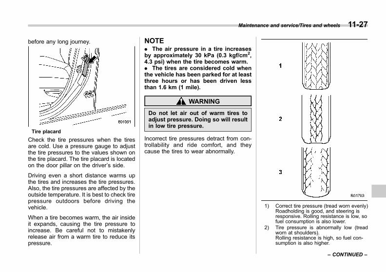
Black plate (429,1)
一般Model "A1300GE-A" EDITED: 2016/ 9/ 13
before any long journey.
Tire placard
Check the tire pressures when the tiresare cold. Use a pressure gauge to adjustthe tire pressures to the values shown onthe tire placard. The tire placard is locatedon the door pillar on the driver’s side.
Driving even a short distance warms upthe tires and increases the tire pressures.Also, the tire pressures are affected by theoutside temperature. It is best to check tirepressure outdoors before driving thevehicle.
When a tire becomes warm, the air insideit expands, causing the tire pressure toincrease. Be careful not to mistakenlyrelease air from a warm tire to reduce itspressure.
NOTE. The air pressure in a tire increasesby approximately 30 kPa (0.3 kgf/cm2,4.3 psi) when the tire becomes warm.. The tires are considered cold whenthe vehicle has been parked for at leastthree hours or has been driven lessthan 1.6 km (1 mile).
WARNING
Do not let air out of warm tires toadjust pressure. Doing so will resultin low tire pressure.
Incorrect tire pressures detract from con-trollability and ride comfort, and theycause the tires to wear abnormally.
1) Correct tire pressure (tread worn evenly)Roadholding is good, and steering isresponsive. Rolling resistance is low, sofuel consumption is also lower.
2) Tire pressure is abnormally low (treadworn at shoulders).Rolling resistance is high, so fuel con-sumption is also higher.
Maintenance and service/Tires and wheels 11-27
– CONTINUED –
11
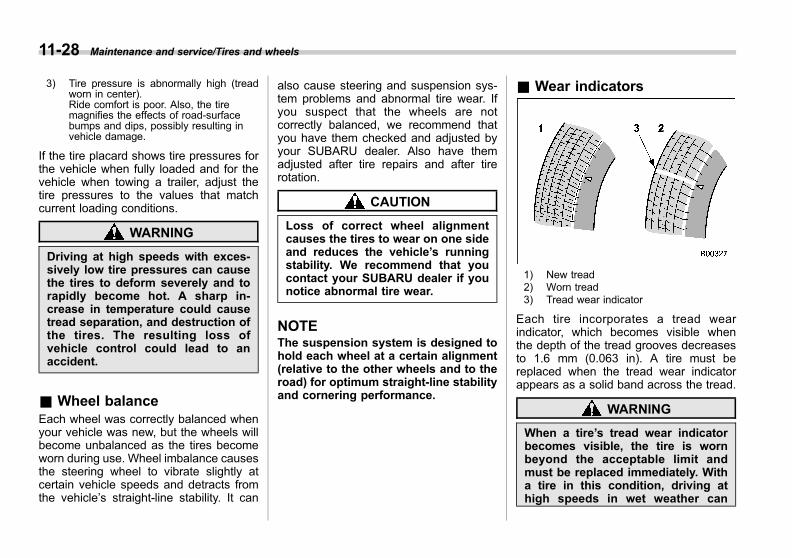
Black plate (430,1)
一般Model "A1300GE-A" EDITED: 2016/ 9/ 13
11-28 Maintenance and service/Tires and wheels
3) Tire pressure is abnormally high (treadworn in center).Ride comfort is poor. Also, the tiremagnifies the effects of road-surfacebumps and dips, possibly resulting invehicle damage.
If the tire placard shows tire pressures forthe vehicle when fully loaded and for thevehicle when towing a trailer, adjust thetire pressures to the values that matchcurrent loading conditions.
WARNING
Driving at high speeds with exces-sively low tire pressures can causethe tires to deform severely and torapidly become hot. A sharp in-crease in temperature could causetread separation, and destruction ofthe tires. The resulting loss ofvehicle control could lead to anaccident.
& Wheel balanceEach wheel was correctly balanced whenyour vehicle was new, but the wheels willbecome unbalanced as the tires becomeworn during use. Wheel imbalance causesthe steering wheel to vibrate slightly atcertain vehicle speeds and detracts fromthe vehicle’s straight-line stability. It can
also cause steering and suspension sys-tem problems and abnormal tire wear. Ifyou suspect that the wheels are notcorrectly balanced, we recommend thatyou have them checked and adjusted byyour SUBARU dealer. Also have themadjusted after tire repairs and after tirerotation.
CAUTION
Loss of correct wheel alignmentcauses the tires to wear on one sideand reduces the vehicle’s runningstability. We recommend that youcontact your SUBARU dealer if younotice abnormal tire wear.
NOTEThe suspension system is designed tohold each wheel at a certain alignment(relative to the other wheels and to theroad) for optimum straight-line stabilityand cornering performance.
& Wear indicators
1) New tread2) Worn tread3) Tread wear indicator
Each tire incorporates a tread wearindicator, which becomes visible whenthe depth of the tread grooves decreasesto 1.6 mm (0.063 in). A tire must bereplaced when the tread wear indicatorappears as a solid band across the tread.
WARNING
When a tire’s tread wear indicatorbecomes visible, the tire is wornbeyond the acceptable limit andmust be replaced immediately. Witha tire in this condition, driving athigh speeds in wet weather can

Black plate (431,1)
一般Model "A1300GE-A" EDITED: 2016/ 9/ 13
cause the vehicle to hydroplane.The resulting loss of vehicle controlcan lead to an accident.
NOTEFor safety, inspect tire tread regularlyand replace the tires before their treadwear indicators become visible.
& Tire rotation direction mark
Example of tire rotation direction mark1) Front
If the tire has the rotation directionspecification, the tire rotation directionmark is placed on its sidewall.
When you install a tire that has the tirerotation direction mark, install the tire with
the direction mark facing forward.
& Tire rotation
Models equipped with 4 non-unidirectionaltires1) Front
Models equipped with unidirectional tires1) Front
Tire wear varies from wheel to wheel. Tomaximize the life of each tire and ensurethat the tires wear uniformly, it is best torotate the tires every 10,000 km (6,200miles). Move the tires to the positionsshown in the illustration each time they arerotated.Replace any damaged or unevenly worntire at the time of rotation. After tirerotation, adjust the tire pressures andmake sure the wheel nuts are correctlytightened.
After driving approximately 1,000 km (600miles), check the wheel nuts again andretighten any nut that has become loose.For handling alloy wheels (if equipped),
Maintenance and service/Tires and wheels 11-29
– CONTINUED –
11

Black plate (432,1)
一般Model "A1300GE-A" EDITED: 2016/ 9/ 13
11-30 Maintenance and service/Tires and wheels
refer to “Alloy wheels” F11-32.
! Models with flat tire repair kit
NOTEIt may be difficult to rotate the tires. Werecommend that you have the tiresrotated by your SUBARU dealer.
& Tire replacementThe wheels and tires are important andintegral parts of your vehicle’s design;they cannot be changed arbitrarily. Thetires fitted as standard equipment areoptimally matched to the characteristicsof the vehicle and were selected to givethe best possible combination of runningperformance, ride comfort, and servicelife. It is essential for every tire to have asize and construction matching thoseshown on the tire placard and to have aspeed symbol and load index matchingthose shown on the tire placard.
Using tires of a non-specified size detractsfrom controllability, ride comfort, brakingperformance, speedometer accuracy andodometer accuracy. It also creates incor-rect body-to-tire clearances and inappro-priately changes the vehicle’s groundclearance.
All four tires must be the same in terms of
manufacturer, brand (tread pattern), con-struction, and size. You are advised toreplace the tires with new ones that areidentical to those fitted as standard equip-ment.For safe vehicle operation, SUBARUrecommends replacing all four tires atthe same time.
WARNING
. When replacing or installingtire(s), all four tires must be thesame for the following items.
(a) Size
(b) Circumference
(c) Speed symbol
(d) Load index
(e) Construction
(f) Manufacturer
(g) Brand (tread pattern)
(h) Degrees of wear
For items (a) to (d), you mustobey the specification that isprinted on the tire placard. Thetire placard is located on thedriver’s door pillar.
If all four tires are not the same initems (a) to (h), there is a possi-
bility that it may lead to seriousmechanical damage to the drivetrain of your car and affect thefollowing factors.
— Ride
— Handling
— Braking
— Speedometer/Odometercalibration
— Clearance between the bodyand the tires
It also may be dangerous andlead to loss of vehicle control,and it can lead to an accident.
. Use only radial tires. Do not useradial tires together with beltedbias tires and/or bias-ply tires.Doing so can dangerously re-duce controllability, resulting inan accident.

Black plate (433,1)
一般Model "A1300GE-A" EDITED: 2016/ 9/ 13
& Wheel replacementWhen replacing wheels due, for example,to damage, make sure the replacementwheels match the specifications of thewheels that are fitted as standard equip-ment. Replacement wheels are availablefrom SUBARU dealers.
WARNING
Use only those wheels that arespecified for your vehicle. Wheelsnot meeting specifications couldinterfere with brake caliper opera-tion and may cause the tires to rubagainst the wheel well housing dur-ing turns. The resulting loss ofvehicle control could lead to anaccident.
NOTEWhen any of the wheels are removedand replaced for tire rotation or tochange a flat tire, always check thetightness of the wheel nuts after driv-ing approximately 1,000 km (600 miles).If any nut is loose, tighten it to thespecified torque.
& Wheel covers (if equipped)
! Removing the wheel cover
If your vehicle has wheel covers, removethem by holding and pulling the areasindicated in the illustration.
CAUTION
Use gloves to protect your handswhen removing wheel covers.
! Installing the wheel cover
1) Valve hole
Maintenance and service/Tires and wheels 11-31
– CONTINUED –
11
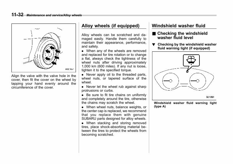
Black plate (434,1)
一般Model "A1300GE-A" EDITED: 2016/ 9/ 13
11-32 Maintenance and service/Alloy wheels
Align the valve with the valve hole in thecover, then fit the cover on the wheel bytapping your hand evenly around thecircumference of the cover.
Alloy wheels (if equipped)
Alloy wheels can be scratched and da-maged easily. Handle them carefully tomaintain their appearance, performance,and safety.. When any of the wheels are removedand replaced for tire rotation or to changea flat, always check the tightness of thewheel nuts after driving approximately1,000 km (600 miles). If any nut is loose,tighten it to the specified torque.. Never apply oil to the threaded parts,wheel nuts, or tapered surface of thewheel.. Never let the wheel rub against sharpprotrusions or curbs.. Be sure to fit tire chains on uniformlyand completely around the tire, otherwisethe chains may scratch the wheel.. When wheel nuts, balance weights, orthe center cap is replaced, we recommendthat you replace them with genuineSUBARU parts designed for alloy wheels.. When stacking and storing removedtires, place shock-absorbing material be-tween the tires to protect the wheels frombecoming scratched.
Windshield washer fluid
& Checking the windshieldwasher fluid level
! Checking by the windshield washerfluid warning light (if equipped)
Windshield washer fluid warning light(type A)

Black plate (435,1)
一般Model "A1300GE-A" EDITED: 2016/ 9/ 13
Windshield washer fluid warning light(type B)
Check the windshield washer fluid warn-ing light. When the light illuminates, thereis only a small amount of washer fluidremaining. In this case, refill the washerfluid.
& Adding the windshieldwasher fluid
CAUTION
Never use engine coolant as washerfluid because it could cause paintdamage.
Remove the washer tank filler cap, thenadd windshield washer fluid until itreaches the “FULL” mark on the tank.
& Windshield washer fluidUse windshield washer fluid. If windshieldwasher fluid is unavailable use cleanwater.In areas where water freezes in winter,use an anti-freeze type windshield washerfluid. SUBARU Windshield Washer Fluidcontains 58.5% methyl alcohol and 41.5%surfactant, by volume. Its freezing tem-perature varies according to how much itis diluted, as indicated in the followingtable.
Washer FluidConcentration
FreezingTemperature
30% −128C (10.48F)
50% −208C (−48F)
100% −458C (−498F)
In order to prevent freezing of washerfluid, check the freezing temperatures inthe table above when adjusting the fluidconcentration to the outside temperature.If you fill the reservoir tank with a fluid witha different concentration from the oneused previously, purge the old fluid fromthe piping between the reservoir tank andwasher nozzles by operating the washerfor a certain period of time. Otherwise, ifthe concentration of the fluid remaining inthe piping is too low for the outside
Maintenance and service/Windshield washer fluid 11-33
– CONTINUED –
11
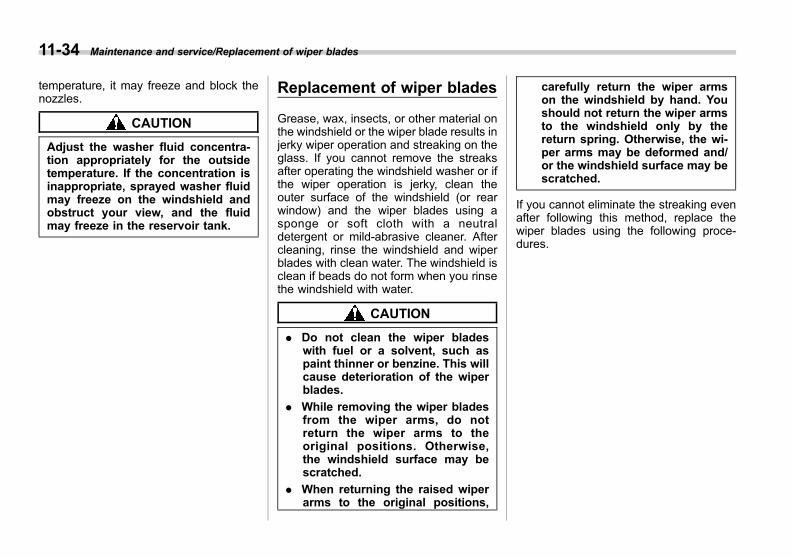
Black plate (436,1)
一般Model "A1300GE-A" EDITED: 2016/ 9/ 13
11-34 Maintenance and service/Replacement of wiper blades
temperature, it may freeze and block thenozzles.
CAUTION
Adjust the washer fluid concentra-tion appropriately for the outsidetemperature. If the concentration isinappropriate, sprayed washer fluidmay freeze on the windshield andobstruct your view, and the fluidmay freeze in the reservoir tank.
Replacement of wiper blades
Grease, wax, insects, or other material onthe windshield or the wiper blade results injerky wiper operation and streaking on theglass. If you cannot remove the streaksafter operating the windshield washer or ifthe wiper operation is jerky, clean theouter surface of the windshield (or rearwindow) and the wiper blades using asponge or soft cloth with a neutraldetergent or mild-abrasive cleaner. Aftercleaning, rinse the windshield and wiperblades with clean water. The windshield isclean if beads do not form when you rinsethe windshield with water.
CAUTION
. Do not clean the wiper bladeswith fuel or a solvent, such aspaint thinner or benzine. This willcause deterioration of the wiperblades.
. While removing the wiper bladesfrom the wiper arms, do notreturn the wiper arms to theoriginal positions. Otherwise,the windshield surface may bescratched.
. When returning the raised wiperarms to the original positions,
carefully return the wiper armson the windshield by hand. Youshould not return the wiper armsto the windshield only by thereturn spring. Otherwise, the wi-per arms may be deformed and/or the windshield surface may bescratched.
If you cannot eliminate the streaking evenafter following this method, replace thewiper blades using the following proce-dures.
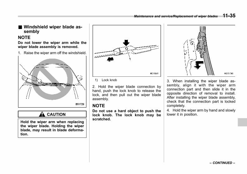
Black plate (437,1)
一般Model "A1300GE-A" EDITED: 2016/ 9/ 13
& Windshield wiper blade as-sembly
NOTEDo not lower the wiper arm while thewiper blade assembly is removed.
1. Raise the wiper arm off the windshield.
CAUTION
Hold the wiper arm when replacingthe wiper blade. Holding the wiperblade, may result in blade deforma-tion.
1) Lock knob
2. Hold the wiper blade connection byhand, push the lock knob to release thelock, and then pull out the wiper bladeassembly.
NOTEDo not use a hard object to push thelock knob. The lock knob may bescratched.
3. When installing the wiper blade as-sembly, align it with the wiper armconnection part and then slide it in theopposite direction of removal to install.After installing the wiper blade assembly,check that the connection part is lockedcompletely.4. Hold the wiper arm by hand and slowlylower it in position.
Maintenance and service/Replacement of wiper blades 11-35
– CONTINUED –
11

Black plate (438,1)
一般Model "A1300GE-A" EDITED: 2016/ 9/ 13
11-36 Maintenance and service/Replacement of wiper blades
& Window wiper blade rubber
Replace the wiper blade rubber accordingto the following procedure.1. Pull the wiper blade rubber until the sliton the underside of the wiper blade is inthe removal position, as shown in the
illustration, so that it can be removed.2. Pull the end of the wiper blade rubberthrough the slit to remove it.3. To install a new wiper blade rubber,perform the removal procedure in thereverse order. After installation, check thatthe tip of the wiper rubber has reached theend of the cap.
NOTEIt may be difficult to perform the wiperblade rubber replacement. We recom-mend that you contact your SUBARUdealer for wiper blade rubber replace-ment if necessary.
& Rear window wiper bladeassembly (5-door models)
1. Raise the wiper arm off the rearwindow.
2. Turn the wiper blade assembly coun-terclockwise.

Black plate (439,1)
一般Model "A1300GE-A" EDITED: 2016/ 9/ 13
3. Pull the wiper blade assembly towardyou to remove it from the wiper arm.4. Install the wiper blade assembly to thewiper arm. Make sure that it locks in place.5. Hold the wiper arm by hand and slowlylower it in position.
& Rear window wiper bladerubber (5-door models)
1. Pull out the end of the blade rubberassembly to unlock it from the plasticsupport.
2. Pull the blade rubber assembly out ofthe plastic support.
1) Metal spines
3. If the new blade rubber is not providedwith two metal spines, remove the metalspines from the old blade rubber and
Maintenance and service/Replacement of wiper blades 11-37
– CONTINUED –
11
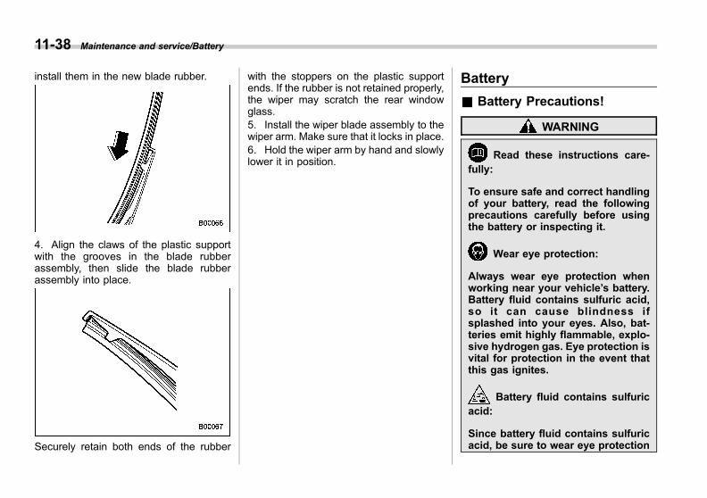
Black plate (440,1)
一般Model "A1300GE-A" EDITED: 2016/ 9/ 13
11-38 Maintenance and service/Battery
install them in the new blade rubber.
4. Align the claws of the plastic supportwith the grooves in the blade rubberassembly, then slide the blade rubberassembly into place.
Securely retain both ends of the rubber
with the stoppers on the plastic supportends. If the rubber is not retained properly,the wiper may scratch the rear windowglass.5. Install the wiper blade assembly to thewiper arm. Make sure that it locks in place.6. Hold the wiper arm by hand and slowlylower it in position.
Battery
& Battery Precautions!
WARNING
Read these instructions care-fully:
To ensure safe and correct handlingof your battery, read the followingprecautions carefully before usingthe battery or inspecting it.
Wear eye protection:
Always wear eye protection whenworking near your vehicle’s battery.Battery fluid contains sulfuric acid,so it can cause blindness ifsplashed into your eyes. Also, bat-teries emit highly flammable, explo-sive hydrogen gas. Eye protection isvital for protection in the event thatthis gas ignites.
Battery fluid contains sulfuricacid:
Since battery fluid contains sulfuricacid, be sure to wear eye protection
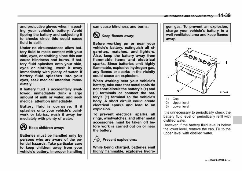
Black plate (441,1)
一般Model "A1300GE-A" EDITED: 2016/ 9/ 13
and protective gloves when inspect-ing your vehicle’s battery. Avoidtipping the battery and subjecting itto shocks since this could causefluid to spill.
Under no circumstances allow bat-tery fluid to make contact with yourskin, eyes, or clothing since this cancause blindness and burns. If bat-tery fluid splashes onto your skin,eyes or clothing, wash it awayimmediately with plenty of water. Ifbattery fluid splashes into youreyes, seek medical attention imme-diately.
If battery fluid is accidentally swal-lowed, immediately drink a largeamount of milk or water, and seekmedical attention immediately.
Battery fluid is corrosive. If itsplashes onto your vehicle’s paint-work or fabrics, wash it away im-mediately with plenty of water.
Keep children away:
Batteries must be handled only bypersons who are aware of the po-tential hazards. Take particular careto keep children away from yourvehicle’s battery. Improper handling
can cause blindness and burns.
Keep flames away:
Before working on or near yourvehicle’s battery, extinguish all ci-garettes, matches, and lighters.Also, keep the battery away fromflammable items and electricalsparks. Since batteries emit highlyflammable, explosive hydrogen gas,any flames or sparks in the vicinitycould cause an explosion.
When working near your vehicle’sbattery, take care that metal tools donot short-circuit the battery’s (+) and(−) terminals or connect the bat-tery’s (+) terminal to the vehicle’sbody. A short circuit could createelectrical sparks and lead to anexplosion.
To prevent electrical sparks, allrings, wristwatches, and other metalaccessories must be taken off be-fore work is carried out on or nearthe battery.
Prevent explosions:
While being charged, batteries emithighly flammable, explosive hydro-
gen gas. To prevent an explosion,charge your vehicle’s battery in awell ventilated area and keep flamesaway.
1) Cap2) Upper level3) Lower level
It is unnecessary to periodically check thebattery fluid level or periodically refill withdistilled water.However, if the battery fluid level is belowthe lower level, remove the cap. Fill to theupper level with distilled water.
Maintenance and service/Battery 11-39
– CONTINUED –
11

Black plate (442,1)
一般Model "A1300GE-A" EDITED: 2016/ 9/ 13
11-40 Maintenance and service/Fuses
CAUTION
Never use more than 10 ampereswhen charging the battery becauseit will shorten battery life.
Fuses
CAUTION
Never replace a fuse with one hav-ing a higher rating or with materialother than a fuse because seriousdamage or a fire could result.
The fuses are designed to melt during anoverload to prevent damage to the wiringharness and electrical equipment. Thefuses are located in two fuse boxes.
One is located under the instrument panelbehind the fuse box cover on the driver’sseat side. To remove the cover, pull it out.
1) Spare fuses
The other one (main fuse box) is housedin the engine compartment. The sparefuses are stored in the fuse box cover.
The fuse puller is stored in the main fusebox in the engine compartment.

Black plate (443,1)
一般Model "A1300GE-A" EDITED: 2016/ 9/ 13
Pinch the upper part of the fuse pullerwhen removing it from the main fuse box.
1) Good2) Blown
If any lights, accessories or other electricalcontrols do not operate, inspect thecorresponding fuse. If a fuse has blown,replace it.1. Turn the ignition switch to the “LOCK”/“OFF” position and turn off all electricalaccessories.2. Remove the cover.3. Determine which fuse may be blown.Look at the back side of each fuse boxcover and refer to “Fuses and circuits”F12-10.
4. Pull out the fuse with the fuse puller.5. Inspect the fuse. If it has blown,replace it with a spare fuse of the samerating.6. If the same fuse blows again, thisindicates that its system has a problem.We recommend that you contact yourSUBARU dealer for repairs.
Installation of accessories
We recommend that you always consultyour SUBARU dealer before installing foglights or any other electrical equipment inyour vehicle. Such accessories maycause the electronic system to malfunc-tion if they are incorrectly installed or ifthey are not suited for the vehicle. Werecommend that you install only genuineSUBARU accessories on your vehicle.Also, we recommend that you alwaysconsult your SUBARU dealer beforeinstalling a radio in your vehicle.
Maintenance and service/Installation of accessories 11-41
11

Black plate (444,1)
一般Model "A1300GE-A" EDITED: 2016/ 9/ 13
11-42 Maintenance and service/Replacing bulbs
Replacing bulbs
It may be difficult to replace the bulbs. Werecommend that you have the bulbsreplaced by your SUBARU dealer ifnecessary.
WARNING
Bulbs may become very hot whileilluminated. Before replacing bulbs,turn off the lights and wait until thebulbs cool down. Otherwise, there isthe risk of sustaining a burn injury.
CAUTION
Replace any bulb only with a newbulb of the specified wattage. Usinga bulb of different wattage couldresult in a fire. For the specifiedwattage of each bulb, refer to “Bulbchart” F12-14.
Do not touch the glass portion of thelight bulb with bare hands. Whenholding the glass portion is una-voidable, hold it with a clean drycloth to avoid getting moisture andgrease on the bulb. If there are anyfingerprints or grease on the bulbsurface, wipe them away with a soft
cloth moistened with alcohol. Also,if the bulb is scratched or dropped,it may blow out or crack.
& Headlights (models with LEDheadlights)
LED headlight warning light (type A)
LED headlight warning light (type B)
The LED headlight warning light illumi-nates if the LED headlights malfunction.We recommend that you have yourvehicle inspected at a SUBARU dealeras soon as possible.
& Headlights (models with ha-logen headlights)
CAUTION
Halogen headlight bulbs becomevery hot while in use. If you touchthe bulb surface with bare hands orgreasy gloves, fingerprints orgrease on the bulb surface willdevelop into hot spots, causing thebulb to break. If there are finger-prints or grease on the bulb surface,
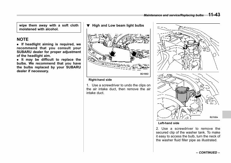
Black plate (445,1)
一般Model "A1300GE-A" EDITED: 2016/ 9/ 13
wipe them away with a soft clothmoistened with alcohol.
NOTE. If headlight aiming is required, werecommend that you consult yourSUBARU dealer for proper adjustmentof the headlight aim.. It may be difficult to replace thebulbs. We recommend that you havethe bulbs replaced by your SUBARUdealer if necessary.
! High and Low beam light bulbs
Right-hand side
1. Use a screwdriver to undo the clips onthe air intake duct, then remove the airintake duct.
Left-hand side
2. Use a screwdriver to remove thesecured clip of the washer tank. To makeit easy to access the bulb, turn the neck ofthe washer fluid filler pipe as illustrated.
Maintenance and service/Replacing bulbs 11-43
– CONTINUED –
11
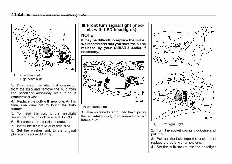
Black plate (446,1)
一般Model "A1300GE-A" EDITED: 2016/ 9/ 13
11-44 Maintenance and service/Replacing bulbs
1) Low beam bulb2) High beam bulb
3. Disconnect the electrical connectorfrom the bulb and remove the bulb fromthe headlight assembly by turning itcounterclockwise.4. Replace the bulb with new one. At thistime, use care not to touch the bulbsurface.5. To install the bulb to the headlightassembly, turn it clockwise until it clicks.6. Reconnect the electrical connector.7. Install the air intake duct with clips.8. Set the washer tank to the originalplace and secure it by clip.
& Front turn signal light (mod-els with LED headlights)
NOTEIt may be difficult to replace the bulbs.We recommend that you have the bulbsreplaced by your SUBARU dealer ifnecessary.
Right-hand side
1. Use a screwdriver to undo the clips onthe air intake duct, then remove the airintake duct.
1) Turrn signal light
2. Turn the socket counterclockwise andpull it out.3. Pull out the bulb from the socket andreplace the bulb with a new one.4. Set the bulb socket into the headlight

Black plate (447,1)
一般Model "A1300GE-A" EDITED: 2016/ 9/ 13
assembly and turn it clockwise until itlocks.5. Install the air intake duct with clips.
& Front turn signal light andposition light (models withhalogen headlights)
NOTE. It may be difficult to replace thebulbs. We recommend that you havethe bulbs replaced by your SUBARUdealer if necessary.. The bulbs used for the position lightemit light that is whiter than conven-tional bulbs. We recommend that youconsult your SUBARU dealer for repla-cement.
1. Start the engine and turn the steeringwheel fully in the opposite direction of thebulb to be replaced.2. Stop the engine.
3. Remove the 2 clips from the fenderlining.
4. Pull off the fender lining.
1) Position light2) Turn signal light
5. Turn the socket counterclockwise andpull it out.6. Pull out the bulb from the socket andreplace the bulb with a new one.
Maintenance and service/Replacing bulbs 11-45
– CONTINUED –
11

Black plate (448,1)
一般Model "A1300GE-A" EDITED: 2016/ 9/ 13
11-46 Maintenance and service/Replacing bulbs
7. After replacing the bulb, reattach thefender lining.
& Front fog light and daytimerunning light (if equipped)
NOTEIt may be difficult to replace the bulbs.We recommend that you have the bulbsreplaced by your SUBARU dealer ifnecessary.
1. Remove the 2 clips and turn over themud guard.2. Disconnect the electrical connectorfrom the bulb.

Black plate (449,1)
一般Model "A1300GE-A" EDITED: 2016/ 9/ 13
Type A1) Fog light
Type B1) Fog light2) Daytime running light
Type C1) Daytime running light
3. Remove the bulb.4. Replace the bulb with a new one.5. After replacing the bulb, reattach themud guard.
Maintenance and service/Replacing bulbs 11-47
– CONTINUED –
11
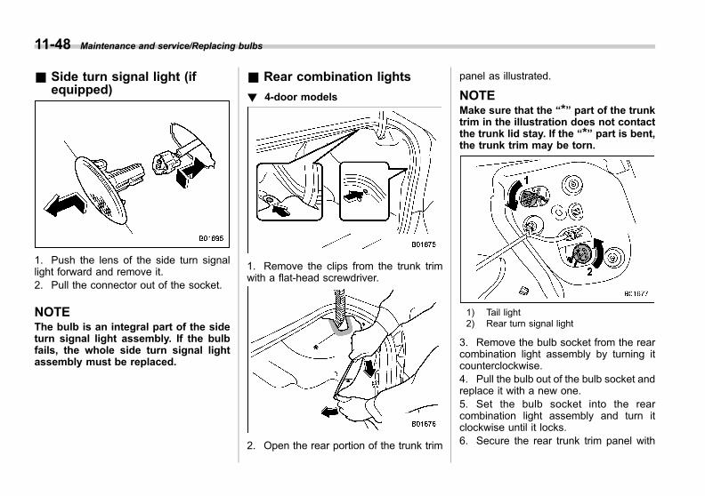
Black plate (450,1)
一般Model "A1300GE-A" EDITED: 2016/ 9/ 13
11-48 Maintenance and service/Replacing bulbs
& Side turn signal light (ifequipped)
1. Push the lens of the side turn signallight forward and remove it.2. Pull the connector out of the socket.
NOTEThe bulb is an integral part of the sideturn signal light assembly. If the bulbfails, the whole side turn signal lightassembly must be replaced.
& Rear combination lights
! 4-door models
1. Remove the clips from the trunk trimwith a flat-head screwdriver.
2. Open the rear portion of the trunk trim
panel as illustrated.
NOTEMake sure that the “*” part of the trunktrim in the illustration does not contactthe trunk lid stay. If the “*” part is bent,the trunk trim may be torn.
1) Tail light2) Rear turn signal light
3. Remove the bulb socket from the rearcombination light assembly by turning itcounterclockwise.4. Pull the bulb out of the bulb socket andreplace it with a new one.5. Set the bulb socket into the rearcombination light assembly and turn itclockwise until it locks.6. Secure the rear trunk trim panel with

Black plate (451,1)
一般Model "A1300GE-A" EDITED: 2016/ 9/ 13
the clips.
! 5-door models
1. Remove the covers.
2. Using a Phillips screwdriver, removethe upper and lower screws that secure
the rear combination light assembly.
3. Slide the rear combination light as-sembly rearward and remove it from thevehicle.
1) Tail light2) Rear turn signal light
4. Remove the bulb socket from the rearcombination light assembly by turning itcounterclockwise.5. Pull the bulb out of the bulb socket andreplace it with a new one.6. Set the bulb socket into the rearcombination light assembly and turn itclockwise until it locks.
Maintenance and service/Replacing bulbs 11-49
– CONTINUED –
11

Black plate (452,1)
一般Model "A1300GE-A" EDITED: 2016/ 9/ 13
11-50 Maintenance and service/Replacing bulbs
1) Guide pins2) Catch3) Clip
7. Put the rear combination light assem-bly into place while aligning the 2 guidepins and a catch with the guide holes anda clip on the vehicle.
8. Tighten the upper and lower screws.9. Reinstall the covers.
& Back-up light/Rear fog light(if equipped)
NOTEIt may be difficult to replace the bulbs.We recommend that you have the bulbsreplaced by your SUBARU dealer ifnecessary.
! 4-door models
1. Open the trunk.
2. Remove the trunk trim lining by re-moving the clips and trunk trim handleindicated in the illustration.

Black plate (453,1)
一般Model "A1300GE-A" EDITED: 2016/ 9/ 13
3. For left side light, turn the bulb socketclockwise and remove it.For right side light, turn the bulb socketcounterclockwise and remove it.4. Pull the bulb out of the bulb socket andreplace it with a new one.5. Install the bulb socket by turning itclockwise.6. Reconnect the electrical connector.7. Reinstall the trunk trim lining.
! 5-door models
1. Apply a flat-head screwdriver to thelight cover as shown in the illustration, andpry the light cover off from the rear gatetrim.
2. For left side light, turn the bulb socket
clockwise and remove it.For right side light, turn the bulb socketcounterclockwise and remove it.
3. Pull the bulb out of the bulb socket andreplace it with a new one.4. Install the bulb socket by turning itclockwise.5. Install the light cover on the rear gate.
Maintenance and service/Replacing bulbs 11-51
– CONTINUED –
11
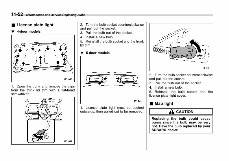
Black plate (454,1)
一般Model "A1300GE-A" EDITED: 2016/ 9/ 13
11-52 Maintenance and service/Replacing bulbs
& License plate light
! 4-door models
1. Open the trunk and remove the clipsfrom the trunk lid trim with a flat-headscrewdriver.
2. Turn the bulb socket counterclockwiseand pull out the socket.3. Pull the bulb out of the socket.4. Install a new bulb.5. Reinstall the bulb socket and the trunklid trim.
! 5-door models
1. License plate light must be pushedoutwards, then pulled out to be removed.
2. Turn the bulb socket counterclockwiseand pull out the socket.3. Pull the bulb out of the socket.4. Install a new bulb.5. Reinstall the bulb socket and thelicense plate light cover.
& Map light
CAUTION
Replacing the bulb could causeburns since the bulb may be veryhot. Have the bulb replaced by yourSUBARU dealer.

Black plate (455,1)
一般Model "A1300GE-A" EDITED: 2016/ 9/ 13
& Vanity mirror light (ifequipped)
CAUTION
Replacing the bulb could causeburns since the bulb may be veryhot. Have the bulb replaced by yourSUBARU dealer.
& Dome light and cargo arealight
Dome light
Cargo area light
1. Remove the lens by prying the edge ofthe lens with a flat-head screwdriver.2. Pull the bulb out of the socket.3. Install a new bulb.4. Reinstall the lens.
& Trunk light (4-door models)
CAUTION
Replacing the bulb could causeburns since the bulb may be veryhot. Have the bulb replaced by yourSUBARU dealer.
& Other bulbsIt may be difficult to replace the bulbs.We recommend that you have the bulbsreplaced by your SUBARU dealer ifnecessary.
Maintenance and service/Replacing bulbs 11-53
11
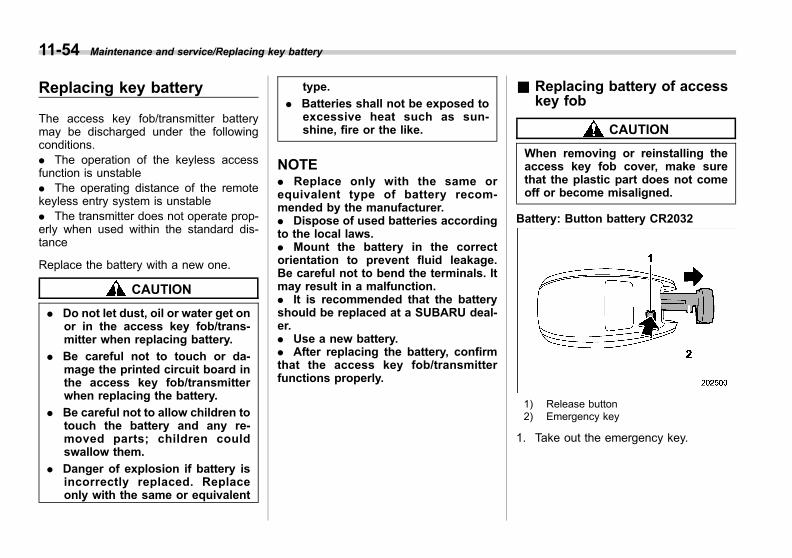
Black plate (456,1)
一般Model "A1300GE-A" EDITED: 2016/ 9/ 13
11-54 Maintenance and service/Replacing key battery
Replacing key battery
The access key fob/transmitter batterymay be discharged under the followingconditions.. The operation of the keyless accessfunction is unstable. The operating distance of the remotekeyless entry system is unstable. The transmitter does not operate prop-erly when used within the standard dis-tance
Replace the battery with a new one.
CAUTION
. Do not let dust, oil or water get onor in the access key fob/trans-mitter when replacing battery.
. Be careful not to touch or da-mage the printed circuit board inthe access key fob/transmitterwhen replacing the battery.
. Be careful not to allow children totouch the battery and any re-moved parts; children couldswallow them.
. Danger of explosion if battery isincorrectly replaced. Replaceonly with the same or equivalent
type.
. Batteries shall not be exposed toexcessive heat such as sun-shine, fire or the like.
NOTE. Replace only with the same orequivalent type of battery recom-mended by the manufacturer.. Dispose of used batteries accordingto the local laws.. Mount the battery in the correctorientation to prevent fluid leakage.Be careful not to bend the terminals. Itmay result in a malfunction.. It is recommended that the batteryshould be replaced at a SUBARU deal-er.. Use a new battery.. After replacing the battery, confirmthat the access key fob/transmitterfunctions properly.
& Replacing battery of accesskey fob
CAUTION
When removing or reinstalling theaccess key fob cover, make surethat the plastic part does not comeoff or become misaligned.
Battery: Button battery CR2032
1) Release button2) Emergency key
1. Take out the emergency key.

Black plate (457,1)
一般Model "A1300GE-A" EDITED: 2016/ 9/ 13
2. Wrap a flat-head screwdriver with vinyltape or a cloth, and insert it in the gap toremove the cover.
3. Take out the battery using a flat-headscrewdriver with vinyl tape or a cloth.
4. Insert a new battery with its positive (+)side facing upward as shown in the figure.
5. Attach the cover to the access key fobby fitting the projections and recessestogether.
& Replacing battery of trans-mitter
Battery: Button battery CR1620
1. Wrap a flat-head screwdriver with vinyltape or a cloth. Open the key head usingthe flat-head screwdriver.
Maintenance and service/Replacing key battery 11-55
– CONTINUED –
11

Black plate (458,1)
一般Model "A1300GE-A" EDITED: 2016/ 9/ 13
11-56 Maintenance and service/Replacing key battery
2. Remove the transmitter case from thekey head.
3. Open the transmitter case by releasingthe hooks.
1) Negative (−) side facing up
4. Replace the old battery with a newbattery (type CR1620 or equivalent) mak-ing sure to install the new battery with thenegative (−) side facing up.5. Put together the transmitter case byfitting the hooks on the case.6. Reinstall the transmitter case in thekey head.7. Refit the removed half of the key head.
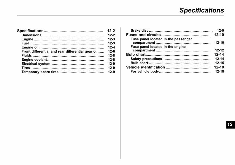
Black plate (25,1)
一般Model "A1300GE-A" EDITED: 2016/ 9/ 13
Specifications..................................................... 12-2Dimensions........................................................ 12-2Engine ............................................................... 12-3Fuel ................................................................... 12-3Engine oil .......................................................... 12-4Front differential and rear differential gear oil...... 12-6Fluids ................................................................ 12-8Engine coolant ................................................... 12-8Electrical system................................................ 12-9Tires .................................................................. 12-9Temporary spare tires ........................................ 12-9
Brake disc ......................................................... 12-9Fuses and circuits ........................................... 12-10
Fuse panel located in the passengercompartment ................................................. 12-10
Fuse panel located in the enginecompartment ................................................. 12-12
Bulb chart......................................................... 12-14Safety precautions........................................... 12-14Bulb chart ....................................................... 12-15
Vehicle identification ....................................... 12-18For vehicle body.............................................. 12-18
Specifications
12
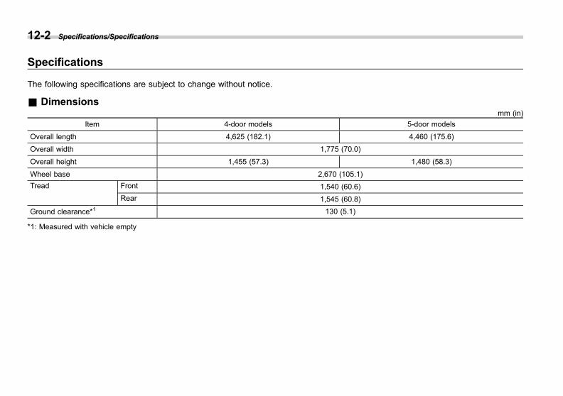
Black plate (462,1)
一般Model "A1300GE-A" EDITED: 2016/ 9/ 13
12-2 Specifications/Specifications
Specifications
The following specifications are subject to change without notice.
& Dimensionsmm (in)
Item 4-door models 5-door models
Overall length 4,625 (182.1) 4,460 (175.6)
Overall width 1,775 (70.0)
Overall height 1,455 (57.3) 1,480 (58.3)
Wheel base 2,670 (105.1)
Tread Front 1,540 (60.6)
Rear 1,545 (60.8)
Ground clearance*1 130 (5.1)
*1: Measured with vehicle empty

Black plate (463,1)
一般Model "A1300GE-A" EDITED: 2016/ 9/ 13
& Engine
Engine model FB20(2.0 L, DOHC, non-turbo)
Engine type Horizontally opposed, liquid cooled 4 cylinder, 4-stroke petrol engine
Displacement cc 1,995
Bore 6 Stroke mm (in) 84.0 6 90.0(3.31 6 3.54)
Compression ratio 12.5 : 1
Firing order 1 – 3 – 2 – 4
& Fuel
Vehicle model Fuel requirement Fuel tank capacity
Australia models Unleaded petrol with Research Octane number 90 or higher50 liters (13.2 US gal, 11.0 Imp gal)
Other models Unleaded petrol with Research Octane number 95 or higher*1
*1: If the specified grade fuel is not available, refer to “Fuel” F7-3.
Specifications/Specifications 12-3
– CONTINUED –
12

Black plate (464,1)
一般Model "A1300GE-A" EDITED: 2016/ 9/ 13
12-4 Specifications/Specifications
& Engine oilFor the checking, adding and replacing procedure or other details, refer to “Engine oil” F11-14.
NOTEThe procedure for changing the engine oil and oil filter should be performed by a properly-trained expert. It is recommendedthat you have this service performed by your SUBARU dealer.
! Approved engine oil
Always use the SUBARU approved engine oil. For further details, we recommend that you contact your SUBARU dealer.If the approved engine oil is unavailable, use the alternative engine oil described on the next page.
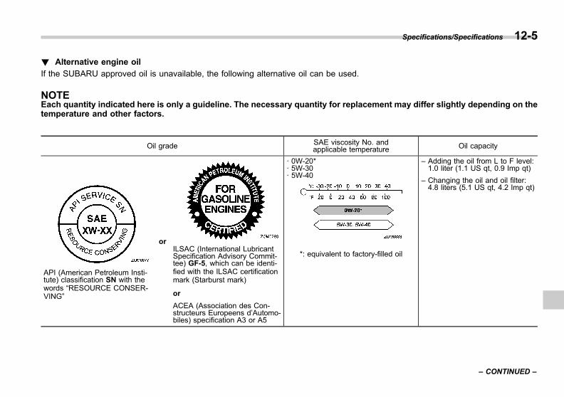
Black plate (465,1)
一般Model "A1300GE-A" EDITED: 2016/ 9/ 13
! Alternative engine oil
If the SUBARU approved oil is unavailable, the following alternative oil can be used.
NOTEEach quantity indicated here is only a guideline. The necessary quantity for replacement may differ slightly depending on thetemperature and other factors.
Oil grade SAE viscosity No. andapplicable temperature Oil capacity
API (American Petroleum Insti-tute) classification SN with thewords “RESOURCE CONSER-VING”
orILSAC (International LubricantSpecification Advisory Commit-tee) GF-5, which can be identi-fied with the ILSAC certificationmark (Starburst mark)
or
ACEA (Association des Con-structeurs Europeens d’Automo-biles) specification A3 or A5
· 0W-20*· 5W-30· 5W-40
– Adding the oil from L to F level:1.0 liter (1.1 US qt, 0.9 Imp qt)
– Changing the oil and oil filter:4.8 liters (5.1 US qt, 4.2 Imp qt)
*: equivalent to factory-filled oil
Specifications/Specifications 12-5
– CONTINUED –
12
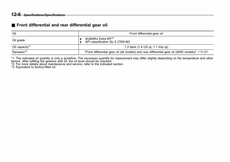
Black plate (466,1)
一般Model "A1300GE-A" EDITED: 2016/ 9/ 13
12-6 Specifications/Specifications
& Front differential and rear differential gear oil
Oil Front differential gear oil
Oil grade . SUBARU Extra MT*3
. API classification GL-5 (75W-90)
Oil capacity*1 1.3 liters (1.4 US qt, 1.1 Imp qt)
Remarks*2 “Front differential gear oil (all models) and rear differential gear oil (AWD models)” F11-21
*1: The indicated oil quantity is only a guideline. The necessary quantity for replacement may differ slightly depending on the temperature and otherfactors. After refilling the gearbox with oil, the oil level should be checked.*2: For more details about maintenance and service, refer to the indicated section.*3: Equivalent to factory-filled oil.
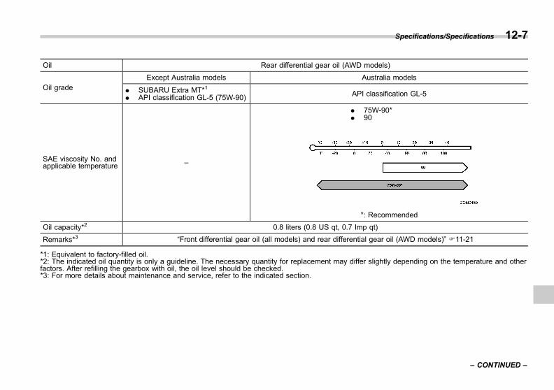
Black plate (467,1)
一般Model "A1300GE-A" EDITED: 2016/ 9/ 27
Oil Rear differential gear oil (AWD models)
Oil gradeExcept Australia models Australia models
. SUBARU Extra MT*1
. API classification GL-5 (75W-90) API classification GL-5
SAE viscosity No. andapplicable temperature –
. 75W-90*
. 90
*: Recommended
Oil capacity*2 0.8 liters (0.8 US qt, 0.7 Imp qt)
Remarks*3 “Front differential gear oil (all models) and rear differential gear oil (AWD models)” F11-21
*1: Equivalent to factory-filled oil.*2: The indicated oil quantity is only a guideline. The necessary quantity for replacement may differ slightly depending on the temperature and otherfactors. After refilling the gearbox with oil, the oil level should be checked.*3: For more details about maintenance and service, refer to the indicated section.
Specifications/Specifications 12-7
– CONTINUED –
12

Black plate (468,1)
一般Model "A1300GE-A" EDITED: 2016/ 9/ 13
12-8 Specifications/Specifications
& Fluids
Fluid Fluid type*1 Fluid capacity*2 Remarks*3
Continuously variable transmis-sion fluid
We recommend that you consultyour SUBARU dealer.
Models without Auto Start Stop sys-tems: 10.7 liters (11.3 US qt, 9.4 Imp qt)Models with Auto Start Stop systems:10.8 liters (11.4 US qt, 9.5 Imp qt)
“Continuously variable transmis-sion fluid” F11-21
Brake fluid FMVSS No. 116, fresh DOT 3 orDOT 4 brake fluid – “Brake fluid” F11-22
*1: Use one of the indicated types of fluid.*2: The indicated fluid quantity is only a guideline. The necessary quantity for replacement may differ slightly depending on the temperature and otherfactors.*3: For more details about maintenance and service, refer to the indicated section.
& Engine coolant
Vehicle model Coolant capacity Coolant type
2.0 L models 7.8 liters (8.2 US qt, 6.9 Imp qt) SUBARU Super Coolant
The indicated coolant quantity is only a guideline. The necessary quantity for replacement may differ slightly depending on the temperature and otherfactors. For more details about maintenance and service, refer to “Cooling system” F11-16.

Black plate (469,1)
一般Model "A1300GE-A" EDITED: 2016/ 9/ 13
& Electrical system
Battery type and capacity (5HR) Models without Auto Start Stop system 55D23L
Models with Auto Start Stop system Q-85
Alternator 12V-130A
Spark plugs 2.0 L models DILKAR7B8 (NGK)
& TiresFor the tire specifications, see the tire pressure label located on the door pillar on the driver’s side. When towing, always follow therecommended tire pressure that is specified on the label.
& Temporary spare tires
Temporary spare tire size T135/80D16 205/55R16 205/50R17
Temporary spare tire inflation pressure(recommended cold tire inflation pressure) 420 kPa (4.2 kgf/cm2, 60 psi) 230 kPa (2.3 kgf/cm2, 33 psi)
Wheel nut tightening torque 120 N·m (12 kgf·m, 89 lbf·ft)*1*2
*1: This torque is equivalent to applying approximately 40 to 50 kgf (88 to 110 lbf) at the end of the wheel nut wrench. If you have tightened the wheelnuts by yourself, have the tightening torque checked at the nearest automotive service facility as soon as possible.*2: For the wheel nut tightening procedure, refer to “Changing flat tire” F9-6.
& Brake discIf you need information on the usage limit value of brake discs and the method for measuring them, we recommend that you consultyour SUBARU dealer.
Specifications/Specifications 12-9
12
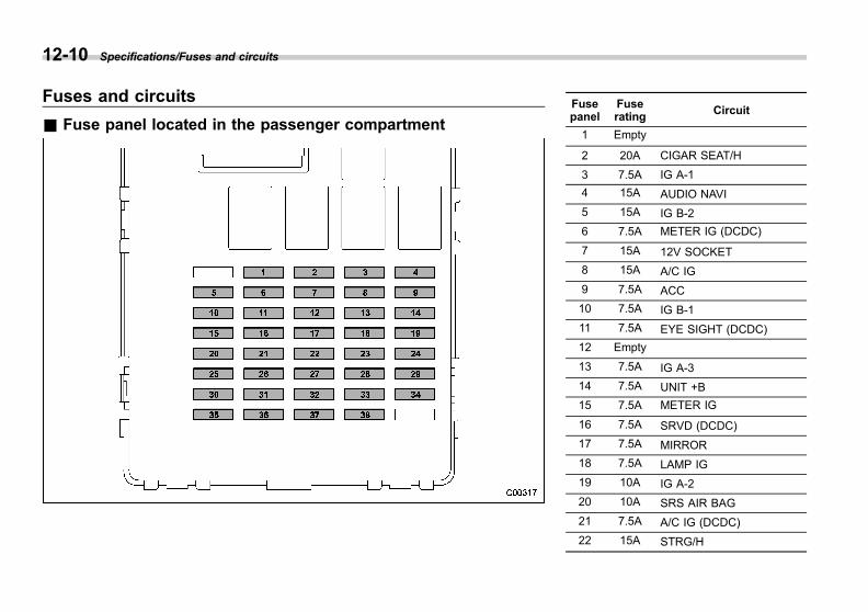
Black plate (470,1)
一般Model "A1300GE-A" EDITED: 2016/ 9/ 13
12-10 Specifications/Fuses and circuits
Fuses and circuits
& Fuse panel located in the passenger compartment
Fusepanel
Fuserating Circuit
1 Empty
2 20A CIGAR SEAT/H
3 7.5A IG A-1
4 15A AUDIO NAVI
5 15A IG B-2
6 7.5A METER IG (DCDC)
7 15A 12V SOCKET
8 15A A/C IG
9 7.5A ACC
10 7.5A IG B-1
11 7.5A EYE SIGHT (DCDC)
12 Empty
13 7.5A IG A-3
14 7.5A UNIT +B
15 7.5A METER IG
16 7.5A SRVD (DCDC)
17 7.5A MIRROR
18 7.5A LAMP IG
19 10A IG A-2
20 10A SRS AIR BAG
21 7.5A A/C IG (DCDC)
22 15A STRG/H
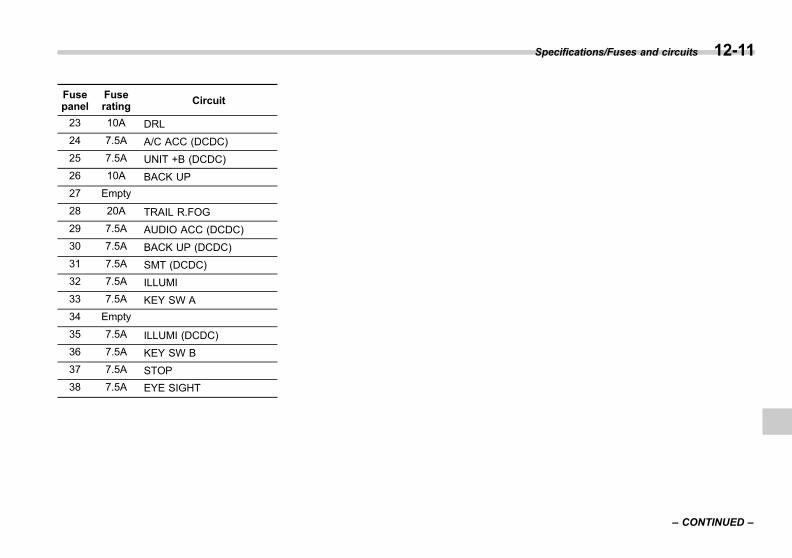
Black plate (471,1)
一般Model "A1300GE-A" EDITED: 2016/ 9/ 13
Fusepanel
Fuserating Circuit
23 10A DRL
24 7.5A A/C ACC (DCDC)
25 7.5A UNIT +B (DCDC)
26 10A BACK UP
27 Empty
28 20A TRAIL R.FOG
29 7.5A AUDIO ACC (DCDC)
30 7.5A BACK UP (DCDC)
31 7.5A SMT (DCDC)
32 7.5A ILLUMI
33 7.5A KEY SW A
34 Empty
35 7.5A ILLUMI (DCDC)
36 7.5A KEY SW B
37 7.5A STOP
38 7.5A EYE SIGHT
Specifications/Fuses and circuits 12-11
– CONTINUED –
12

Black plate (472,1)
一般Model "A1300GE-A" EDITED: 2016/ 9/ 13
12-12 Specifications/Fuses and circuits
& Fuse panel located in the engine compartment
A) Main fuse
Fusepanel
Fuserating Circuit
1 7.5A HORN 2
2 7.5A HORN 1
3 15A H/L LO RH
4 15A H/L LO LH
5 7.5A ACTGS
6 10A H/L HI RH
7 10A H/L HI LH
8 10A TAIL
9 10A ODS
10 7.5A OBD
11 7.5A PU B/UP
12 30A JB-B
13 15A HAZARD
14 20A FUEL
15 7.5A D-OP+B
16 10A MB-B
17 15A D/L
18 10A DCM
19 20A TCU
20 7.5A CVT SSR
21 15A IG COIL
22 10A AVCS

Black plate (473,1)
一般Model "A1300GE-A" EDITED: 2016/ 9/ 13
Fusepanel
Fuserating Circuit
23 10A E/G2
24 Empty
25 Empty
26 20A O2 HTR
27 15A E/G1
28 Empty
29 30A BACKUP
30 25A R. DEF
31 20A AUDIO
32 30A VDC SOL
33 25A MAIN FAN
34 25A SUB FAN
35 10A DEICER
36 15A F. FOG
37 15A BLOWER
38 15A BLOWER
39 Empty
40 30A F. WIPER
41 15A F. WASH
42 15A R. WIPER
43 Empty
44 Empty
Specifications/Fuses and circuits 12-13
12

Black plate (474,1)
一般Model "A1300GE-A" EDITED: 2016/ 9/ 13
12-14 Specifications/Bulb chart
Bulb chart
& Safety precautions
WARNING
Bulbs may become very hot whileilluminated. Before replacing bulbs,turn off the lights and wait until thebulbs cool down. Otherwise, there isa risk of sustaining a burn injury.
CAUTION
Replace any bulb only with a newbulb of the specified wattage. Usinga bulb of different wattage couldresult in a fire.
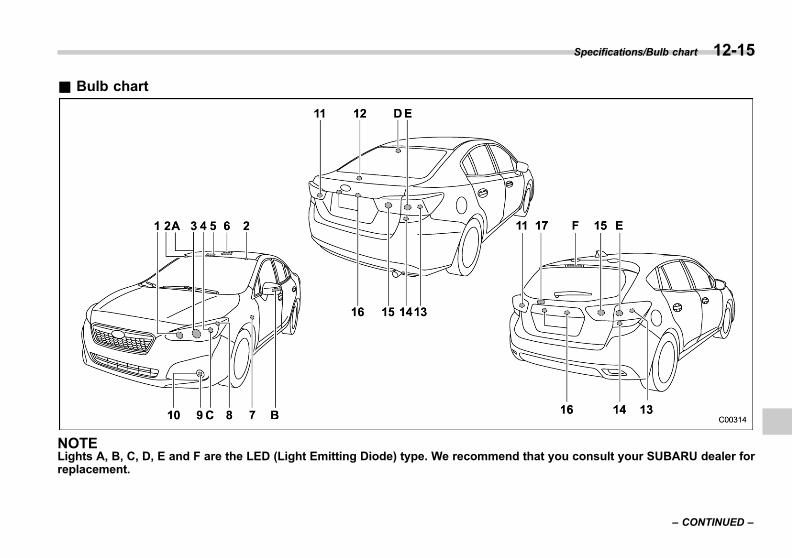
Black plate (475,1)
一般Model "A1300GE-A" EDITED: 2016/ 9/ 13
& Bulb chart
NOTELights A, B, C, D, E and F are the LED (Light Emitting Diode) type. We recommend that you consult your SUBARU dealer forreplacement.
Specifications/Bulb chart 12-15
– CONTINUED –
12

Black plate (476,1)
一般Model "A1300GE-A" EDITED: 2016/ 9/ 13
12-16 Specifications/Bulb chart
Wattage Bulb No.*1
1) High beam headlight (models with halogen headlight) 12V-60W HB3
Front turn signal light (models with LED headlight) 12V-21W WY21W
2) Vanity mirror light (if equipped) 12V-2W –
3) Low beam headlight (models with halogen headlight) 12V-55W H11
4) Front turn signal light (models with halogen headlight) 12V-21W WY21W
5) Map light 12V-8W –
6) Dome light 12V-8W –
7) Side turn signal light (if equipped)*2 12V-5W W5W
8) Front position light 12V-5W W5W
9) Daytime running light (if equipped) 12V-13W P13W
10) Front fog light (if equipped)
Type A 12V-19W H16
Type B 12V-35W H8
11) Backup light 12V-21W W21W
Rear fog light (LHD models) (if equipped) 12V-21W W21W
12) Trunk light (4-door models) 12V-3.8W SAE#194
13) Tail light 12V-5W W5W
14) Rear turn signal light 12V-21W WY21W
15) Backup light 12V-21W W21W
Rear fog light (RHD models) (if equipped) 12V-21W W21W
16) License plate light 12V-5W W5W
17) Cargo area light (5-door models) 12V-5W –

Black plate (477,1)
一般Model "A1300GE-A" EDITED: 2016/ 9/ 13
Wattage Bulb No.*1
A) Low and high beam headlight (models with LED headlight) – –
B) Side turn signal light (if equipped) – –
C) Front position light/Daytime running light (models with LEDheadlight) – –
D) High-mounted stop light (4-door models) – –
E) Stop light – –
F) High-mounted stop light (5-door models) – –
*1: ECE specification*2: The bulb is an integral part of the side turn signal light assembly. If the bulb fails, the whole sideturn signal light assembly must be replaced.
Specifications/Bulb chart 12-17
12

Black plate (478,1)
一般Model "A1300GE-A" EDITED: 2016/ 9/ 13
12-18 Specifications/Vehicle identification
Vehicle identification
& For vehicle body
1) Vehicle identification number under thefloor carpet of the right-hand front seat
2) ID label (Europe and Russia models)3) Tire inflation pressure label4) Year of manufacture label (Middle East
models)5) Model number label (General models)6) Built date label (Australia models)7) ADR compliance plate (Australia models)8) Fuel label9) Air conditioner label10) Vehicle identification number plate
Black plate (27,1)
一般Model "A1300GE-A" EDITED: 2016/ 9/ 23
ID label (Russia models).................................... 13-2Information for Middle East models ................. 13-2
Year of manufacture and country of origin .......... 13-2Speed limit, maximum torque and maximumpower at rpm ................................................... 13-3
Tires .................................................................. 13-3Fuel economy tips.............................................. 13-3
Declaration of conformity in accordancewith the radio and telecommunicationsterminal equipment directive 1999/5/EC ........ 13-4Transmitter for the keyless entry system............. 13-4Receiver for the keyless entry system................. 13-5Immobilizer ........................................................ 13-6Keyless access with push-button startsystem........................................................... 13-15
Subaru Rear Vehicle Detection (SRVD).............. 13-20Tire pressure monitoring system ...................... 13-22Compressor ..................................................... 13-23
Declaration of conformity in accordancewith the Machinery Directive 2006/42/EC .... 13-24Jack................................................................. 13-24
Technical information ...................................... 13-25Singapore models ............................................ 13-25Panama models ............................................... 13-26Dominican Republic models ............................. 13-26Serbia models .................................................. 13-27
Vietnam models............................................... 13-28Taiwan models................................................. 13-28Jordan models................................................. 13-30Argentina models ............................................ 13-31Jamaica models............................................... 13-31Commonwealth of Dominica models................. 13-31Brazil models .................................................. 13-32Republic of South Africa models ...................... 13-35Russia/Kazakhstan models .............................. 13-36Paraguay models............................................. 13-36Bahamas models ............................................. 13-37Bahrain models ............................................... 13-37British Virgin Islands/Bermuda/Boliviamodels .......................................................... 13-37
El Salvador models.......................................... 13-37Australia/New Zealand models ......................... 13-38Israel models................................................... 13-39Ukraine models ............................................... 13-41Suriname models............................................. 13-41Saint Martin models ......................................... 13-41Venezuela models............................................ 13-41Oman models .................................................. 13-42UAE models .................................................... 13-42Nigeria models ................................................ 13-43Morocco models .............................................. 13-43
Supplement
13
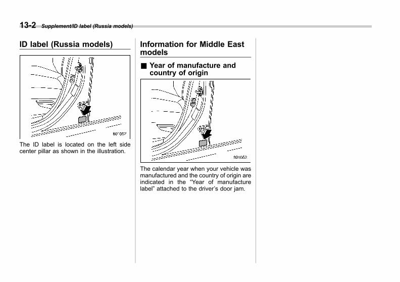
Black plate (482,1)
一般Model "A1300GE-A" EDITED: 2016/ 9/ 23
13-2 Supplement/ID label (Russia models)
ID label (Russia models)
The ID label is located on the left sidecenter pillar as shown in the illustration.
Information for Middle Eastmodels
& Year of manufacture andcountry of origin
The calendar year when your vehicle wasmanufactured and the country of origin areindicated in the “Year of manufacturelabel” attached to the driver’s door jam.

Black plate (483,1)
一般Model "A1300GE-A" EDITED: 2016/ 9/ 23
& Speed limit, maximum torque and maximum power at rpm
Model2.0 L models
CVT
Speed limit km/h 197
Maximum torqueN·m (kgf·m)/rpm 196 (20.0) /4,000
Maximum powerkW (PS)/rpm 115 (156) /6,000
. The performance data above is the numeric value measured according to the GSO-ISO-1585-2008 quality norm.
. The performance data above is the numeric value measured from petrol with an octane rating of95 (Research Octane number).
& Tires
Tire size*1 205/55R16 91V205/50R17 89V225/40R18 92W
Pressure*1&*2 Front 230 kPa (2.3 kgf/cm2, 33.3 psi)
Rear 220 kPa (2.2 kgf/cm2, 31.9 psi)
*1: For the information about spare tire, refer to “Temporary spare tires” F12-9.*2: Pressures listed above are applied for normal condition. When the vehicle is in full load condition,adjust to the corresponding tire pressure that showing on the tire pressure label located on thedriver’s door pillar.
NOTEFor the information about wheel nut tightening torque, refer to “Temporary sparetires” F12-9.
& Fuel economy tipsObserve the following in order to improveyour vehicle’s fuel economy and reduceCO2 emissions.. Drive the vehicle appropriately.. Have your vehicle maintained periodi-cally.. Do not drive recklessly.. Do not drive at excessively highspeeds.. Keep the tires inflated to an appropriatetire pressure.. Minimize engine idling.. Do not carry excessively heavy cargo.
Supplement/Information for Middle East models 13-3
13

Black plate (484,1)
一般Model "A1300GE-A" EDITED: 2016/ 9/ 13
13-4 Supplement/Declaration of conformity in accordance with the radio and telecommunications terminal equipment directive 1999/5/EC
Declaration of conformity in accordance with the radio and telecommunications terminalequipment directive 1999/5/EC
& Transmitter for the keyless entry system
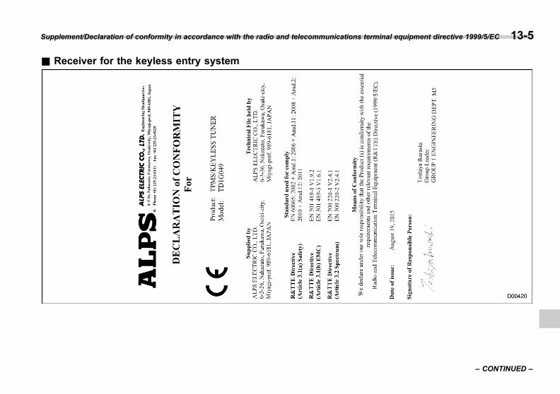
Black plate (485,1)
一般Model "A1300GE-A" EDITED: 2016/ 9/ 13
& Receiver for the keyless entry system
Supplement/Declaration of conformity in accordance with the radio and telecommunications terminal equipment directive 1999/5/EC 13-5
– CONTINUED –
13
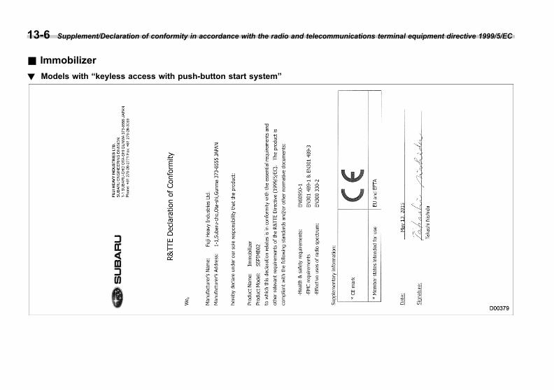
Black plate (486,1)
一般Model "A1300GE-A" EDITED: 2016/ 9/ 13
13-6 Supplement/Declaration of conformity in accordance with the radio and telecommunications terminal equipment directive 1999/5/EC
& Immobilizer
! Models with “keyless access with push-button start system”

Black plate (487,1)
一般Model "A1300GE-A" EDITED: 2016/ 9/ 13
Supplement/Declaration of conformity in accordance with the radio and telecommunications terminal equipment directive 1999/5/EC 13-7
– CONTINUED –
13
Black plate (488,1)
一般Model "A1300GE-A" EDITED: 2016/ 9/ 13
13-8 Supplement/Declaration of conformity in accordance with the radio and telecommunications terminal equipment directive 1999/5/EC
Black plate (489,1)
一般Model "A1300GE-A" EDITED: 2016/ 9/ 13
! Models without “keyless accesswith push-button start system”
! Models with immobilizer ECU
Supplement/Declaration of conformity in accordance with the radio and telecommunications terminal equipment directive 1999/5/EC 13-9
– CONTINUED –
13
Black plate (490,1)
一般Model "A1300GE-A" EDITED: 2016/ 9/ 13
13-10 Supplement/Declaration of conformity in accordance with the radio and telecommunications terminal equipment directive 1999/5/EC

Black plate (491,1)
一般Model "A1300GE-A" EDITED: 2016/ 9/ 13
Supplement/Declaration of conformity in accordance with the radio and telecommunications terminal equipment directive 1999/5/EC 13-11
– CONTINUED –
13

Black plate (492,1)
一般Model "A1300GE-A" EDITED: 2016/ 9/ 13
13-12 Supplement/Declaration of conformity in accordance with the radio and telecommunications terminal equipment directive 1999/5/EC
The DECLARATION of CONFORMITY(DoC) is available at the following ad-dress:http://www.tokai-rika.co.jp/pc/
! Models without Immobilizer ECU
The latest “DECLARATION of CONFOR-MITY” (DoC) is available at the followingaddress:http://www.globaldenso.com/en/products/oem/index.html
Black plate (493,1)
一般Model "A1300GE-A" EDITED: 2016/ 9/ 13
Supplement/Declaration of conformity in accordance with the radio and telecommunications terminal equipment directive 1999/5/EC 13-13
– CONTINUED –
13

Black plate (494,1)
一般Model "A1300GE-A" EDITED: 2016/ 9/ 13
13-14 Supplement/Declaration of conformity in accordance with the radio and telecommunications terminal equipment directive 1999/5/EC

Black plate (495,1)
一般Model "A1300GE-A" EDITED: 2016/ 9/ 13
& Keyless access with push-button start system
. Replace only with the same or equiva-lent type recommended by the manufac-turer.. Dispose of used batteries according tothe local laws.
The latest “DECLARATION of CONFOR-MITY” (DoC) is available at the followingaddress:http://www.globaldenso.com/en/products/oem/index.html
Supplement/Declaration of conformity in accordance with the radio and telecommunications terminal equipment directive 1999/5/EC 13-15
– CONTINUED –
13
Black plate (496,1)
一般Model "A1300GE-A" EDITED: 2016/ 9/ 13
13-16 Supplement/Declaration of conformity in accordance with the radio and telecommunications terminal equipment directive 1999/5/EC

Black plate (497,1)
一般Model "A1300GE-A" EDITED: 2016/ 9/ 13
Supplement/Declaration of conformity in accordance with the radio and telecommunications terminal equipment directive 1999/5/EC 13-17
– CONTINUED –
13

Black plate (498,1)
一般Model "A1300GE-A" EDITED: 2016/ 9/ 13
13-18 Supplement/Declaration of conformity in accordance with the radio and telecommunications terminal equipment directive 1999/5/EC

Black plate (499,1)
一般Model "A1300GE-A" EDITED: 2016/ 9/ 13
Supplement/Declaration of conformity in accordance with the radio and telecommunications terminal equipment directive 1999/5/EC 13-19
– CONTINUED –
13
Black plate (500,1)
一般Model "A1300GE-A" EDITED: 2016/ 9/ 13
13-20 Supplement/Declaration of conformity in accordance with the radio and telecommunications terminal equipment directive 1999/5/EC
& Subaru Rear Vehicle Detec-tion (SRVD)
The latest “DECLARATION of CONFOR-MITY” (DoC) is available at the following:
Black plate (501,1)
一般Model "A1300GE-A" EDITED: 2016/ 9/ 13
Supplement/Declaration of conformity in accordance with the radio and telecommunications terminal equipment directive 1999/5/EC 13-21
– CONTINUED –
13
Black plate (502,1)
一般Model "A1300GE-A" EDITED: 2016/ 9/ 13
13-22 Supplement/Declaration of conformity in accordance with the radio and telecommunications terminal equipment directive 1999/5/EC
DoC (Declaration of Conformity) in locallanguagesLink to the original DoChttp://continental.automotive-approvals.com/
& Tire pressure monitoringsystem
Hereby, Schrader Electronics Ltd., de-clares that this TPMS is in compliancewith the essential requirements and otherprovisions of directive 1999/5/EC. Thedeclaration of conformity may be con-sulted at [email protected]

Black plate (503,1)
一般Model "A1300GE-A" EDITED: 2016/ 9/ 13
& Compressor
Supplement/Declaration of conformity in accordance with the radio and telecommunications terminal equipment directive 1999/5/EC 13-23
13
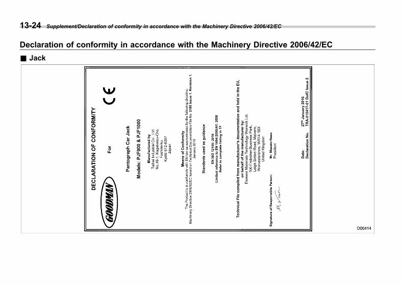
Black plate (504,1)
一般Model "A1300GE-A" EDITED: 2016/ 9/ 13
13-24 Supplement/Declaration of conformity in accordance with the Machinery Directive 2006/42/EC
Declaration of conformity in accordance with the Machinery Directive 2006/42/EC
& Jack

Black plate (505,1)
一般Model "A1300GE-A" EDITED: 2016/ 9/ 13
Technical information
& Singapore models
! Access key fob
! Remote keyless entry transmitter
! Keyless access with push-buttonstart system
! Push-button ignition switch
! Tire pressure monitoring system
Supplement/Technical information 13-25
– CONTINUED –
13
Black plate (506,1)
一般Model "A1300GE-A" EDITED: 2016/ 9/ 13
13-26 Supplement/Technical information
! Subaru Rear Vehicle Detection(SRVD)
& Panama models
CAUTION
FCC WARNING
Changes or modifications not ex-pressly approved by the party re-sponsible for compliance could voidthe user’s authority to operate theequipment.
NOTEThis device complies with part 15 of theFCC Rules. Operation is subject to thefollowing two conditions: (1) This de-vice may not cause harmful interfer-ence, and (2) this device must acceptany interference received, includinginterference that may cause undesiredoperation.
! Access key fob
FCC ID: HYQ14AHK
! Keyless access with push-buttonstart system
FCC ID: Y8PFJ16-1
! Immobilizer for models without“keyless access with push-buttonstart system”
FCC ID: Y8PFJ16-2
& Dominican Republic models
CAUTION
FCC WARNING
Changes or modifications not ex-pressly approved by the party re-sponsible for compliance could voidthe user’s authority to operate theequipment.
NOTEThis device complies with part 15 of theFCC Rules. Operation is subject to thefollowing two conditions: (1) This de-vice may not cause harmful interfer-ence, and (2) this device must acceptany interference received, includinginterference that may cause undesiredoperation.
! Access key fob
FCC ID: HYQ14AHK
! Keyless access with push-buttonstart system
FCC ID: Y8PFJ16-1
! Immobilizer for models with “key-less access with push-button startsystem”
FCC ID: Y8PSSPIMB02

Black plate (507,1)
一般Model "A1300GE-A" EDITED: 2016/ 9/ 13
! Immobilizer for models without“keyless access with push-buttonstart system”
FCC ID: Y8PFJ16-2
! Subaru Rear Vehicle Detection(SRVD)
FCC ID: OAYSRR2A
& Serbia models
! Tire pressure monitoring system
! Access key fob ! Remote keyless entry system
! Transmitter
Model: TB1G077
Supplement/Technical information 13-27
– CONTINUED –
13

Black plate (508,1)
一般Model "A1300GE-A" EDITED: 2016/ 9/ 13
13-28 Supplement/Technical information
! Receiver
Model: TD1G049
! Subaru Rear Vehicle Detection(SRVD)
& Vietnam models
! Subaru Rear Vehicle Detection(SRVD)
! Tire pressure monitoring system
& Taiwan models
! Access key fob
Black plate (509,1)
一般Model "A1300GE-A" EDITED: 2016/ 9/ 13
! Keyless access with push-buttonstart system
! Immobilizer for models with “key-less access with push-button startsystem”
! Immobilizer for models without“keyless access with push-buttonstart system”
Supplement/Technical information 13-29
– CONTINUED –
13
Black plate (510,1)
一般Model "A1300GE-A" EDITED: 2016/ 9/ 13
13-30 Supplement/Technical information
! Remote keyless entry system & Jordan models
! Access key fob
! Remote keyless entry system
! Tire pressure monitoring system
Black plate (511,1)
一般Model "A1300GE-A" EDITED: 2016/ 9/ 13
& Argentina models
! Access key
! Remote keyless entry transmitter
& Jamaica models
! Access key fob
This product has been Type Approved byJamaica: SMA-14AHK.
! Keyless access with push-buttonstart system
This product has been Type Approved byJamaica: SMA-FJ16-1.
! Immobilizer for models with “key-less access with push-button startsystem”
This product has been Type Approved byJamaica: SMA, Equipment identifier isplaced on the product.
! Immobilizer for models without“keyless access with push-buttonstart system”
This product has been Type Approved byJamaica: SMA-FJ16-2.
! Remote keyless entry system
This product has been Type Approved byJamaica: SMA-“TB1G077”.This product has been Type Approved byJamaica: SMA-“TD1G049”.
& Commonwealth of Dominicamodels
! Access key fob
The latest “DECLARATION of CONFOR-MITY” (DoC) is available at the followingaddress:http://www.globaldenso.com/en/products/oem/index.html
Hereby, DENSO CORPORATION de-clares that this 14AHK is in compliancewith the essential requirements and otherrelevant provisions of Directive 1999/5/EC.
– Replace only with the same or equiva-lent type recommended by the manufac-turer.– Dispose of used batteries according tothe local laws.
Supplement/Technical information 13-31
– CONTINUED –
13
Black plate (512,1)
一般Model "A1300GE-A" EDITED: 2016/ 9/ 13
13-32 Supplement/Technical information
! Keyless access with push-buttonstart system
CAUTION
FCC WARNING
Changes or modifications not ex-pressly approved by the party re-sponsible for compliance could voidthe user’s authority to operate theequipment.
NOTEThis device complies with part 15 of theFCC Rules. Operation is subject to thefollowing two conditions: (1) This de-vice may not cause harmful interfer-ence, and (2) this device must acceptany interference received, includinginterference that may cause undesiredoperation.
FCC ID: Y8PFJ16-1
! Immobilizer for models without“keyless access with push-buttonstart system”
CAUTION
FCC WARNING
Changes or modifications not ex-pressly approved by the party re-sponsible for compliance could voidthe user’s authority to operate theequipment.
NOTEThis device complies with part 15 of theFCC Rules. Operation is subject to thefollowing two conditions: (1) This de-vice may not cause harmful interfer-ence, and (2) this device must acceptany interference received, includinginterference that may cause undesiredoperation.
FCC ID: Y8PFJ16-2
& Brazil models
! Access key fob
Black plate (513,1)
一般Model "A1300GE-A" EDITED: 2016/ 9/ 13
! Keyless access with push-buttonstart system
! Immobilizer for models with “key-less access with push-button startsystem”
Supplement/Technical information 13-33
– CONTINUED –
13

Black plate (514,1)
一般Model "A1300GE-A" EDITED: 2016/ 9/ 13
13-34 Supplement/Technical information
! Remote keyless entry transmitter ! Subaru Rear Vehicle Detection(SRVD)
Black plate (515,1)
一般Model "A1300GE-A" EDITED: 2016/ 9/ 13
& Republic of South Africamodels
! Access key fob
! Remote keyless entry system
! Transmitter
! Receiver
! Subaru Rear Vehicle Detection(SRVD)
Supplement/Technical information 13-35
– CONTINUED –
13

Black plate (516,1)
一般Model "A1300GE-A" EDITED: 2016/ 9/ 13
13-36 Supplement/Technical information
& Russia/Kazakhstan models
! Remote keyless entry system
MODEL: TB1G077ALPS ELECTRIC CO., LTD.Country of origin: Japan, MexicoFrequency band: 433.92 MHzType of modulation: FSK
! Tire pressure monitoring system & Paraguay models
! Remote keyless entry transmitter
Approved Number: 2015-09-I-0000269Manufacturer: ALPS ELECTRIC CO.,LTD.Vendor: Tokyo Motors S.A.Address: Av. Eusebio Ayala No. 4649 Km.5 1/2 Asuncion, Paraguay
! Access key fob
Vendor: Tokyo Motors S.A.Address: Av. Eusebio Ayala No. 4649 Km.5 1/2 Asuncion, Paraguay
! Keyless access with push-buttonstart system
Vendor: Tokyo Motors S.A.Address: Av. Eusebio Ayala No. 4649 Km.5 1/2 Asuncion, Paraguay
! Immobilizer for models without“keyless access with push-buttonstart system”
Vendor: Tokyo Motors S.A.Address: Av. Eusebio Ayala No. 4649 Km.5 1/2 Asuncion, Paraguay
Black plate (517,1)
一般Model "A1300GE-A" EDITED: 2016/ 9/ 13
& Bahamas models
! Remote keyless entry system
ALPS ELECTRIC CO., LTD.MODEL: TB1G077FCC ID: CWTB1G077
& Bahrain models
! Remote keyless entry system
! Transmitter
ALPS ELECTRIC CO., LTD.Model: TB1G077
! Receiver
ALPS ELECTRIC CO., LTD.Model: TD1G049
& British Virgin Islands/Bermu-da/Bolivia models
! Remote keyless entry system
CAUTION
FCC WARNING
Changes or modifications not ex-pressly approved by the party re-sponsible for compliance could voidthe user’s authority to operate theequipment.
NOTEThis device complies with part 15 of theFCC Rules. Operation is subject to thefollowing two conditions: (1) This de-vice may not cause harmful interfer-ence, and (2) this device must acceptany interference received, includinginterference that may cause undesiredoperation.
& El Salvador models
! Subaru Rear Vehicle Detection(SRVD)
FCC ID: OAYSRR2A
CAUTION
FCC WARNING
Changes or modifications not ex-pressly approved by the party re-sponsible for compliance could voidthe user’s authority to operate theequipment.
NOTEThis device complies with part 15 of theFCC Rules. Operation is subject to thefollowing two conditions: (1) This de-vice may not cause harmful interfer-ence, and (2) this device must acceptany interference received, includinginterference that may cause undesiredoperation.
Supplement/Technical information 13-37
– CONTINUED –
13
Black plate (518,1)
一般Model "A1300GE-A" EDITED: 2016/ 9/ 13
13-38 Supplement/Technical information
& Australia/New Zealand mod-els
! Subaru Rear Vehicle Detection(SRVD)

Black plate (519,1)
一般Model "A1300GE-A" EDITED: 2016/ 9/ 13
& Israel models
! Tire pressure monitoring system
Supplement/Technical information 13-39
– CONTINUED –
13
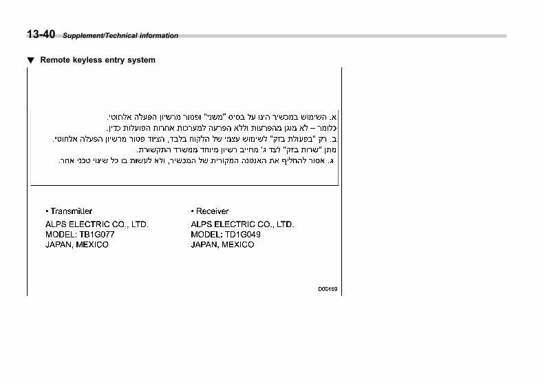
Black plate (520,1)
一般Model "A1300GE-A" EDITED: 2016/ 9/ 13
13-40 Supplement/Technical information
! Remote keyless entry system

Black plate (521,1)
一般Model "A1300GE-A" EDITED: 2016/ 9/ 13
& Ukraine models
! Remote keyless entry system
! Tire pressure monitoring system
! Subaru Rear Vehicle Detection(SRVD)
& Suriname models
! Remote keyless entry system
! Remote keyless entry transmitter
ALPS ELECTRIC CO., LTD.SUBARUTransmitter: TB1G077FCC ID: CWTB1G077/
! Receiver
ALPS ELECTRIC CO., LTD.SUBARUReceiver: TD1G049FCC ID: CWTD1G049/
& Saint Martin models
! Remote keyless entry system
This device complies with part 15 of theFCC Rules. Operation is subject to thefollowing two conditions: (1) This devicemay not cause harmful interference, and(2) this device must accept any interfer-ence received, including interference thatmay cause undesired operation.
& Venezuela models
! Remote keyless entry system
ALPS ELECTRIC CO., LTD.SUBARUTransmitter: TB1G077FCC ID: CWTB1G077/
Supplement/Technical information 13-41
– CONTINUED –
13

Black plate (522,1)
一般Model "A1300GE-A" EDITED: 2016/ 9/ 13
13-42 Supplement/Technical information
& Oman models
! Remote keyless entry system
! Remote keyless entry transmitter
! Receiver
! Tire pressure monitoring system
& UAE models
! Remote keyless entry system
! Remote keyless entry transmitter
! Receiver
! Tire pressure monitoring system
Black plate (523,1)
一般Model "A1300GE-A" EDITED: 2016/ 9/ 13
& Nigeria models
! Access key fob
Model: 14AHKConnection and use of this communica-tions equipment is permitted by theNigerian Communications Commission.
! Keyless access with push-buttonstart system
Model: FJ16-1Connection and use of this communica-tions equipment is permitted by theNigerian Communications Commission.
! Remote keyless entry system
! Remote keyless entry transmitter
! Receiver
! Immobilizer for models without“keyless access with push-buttonstart system”
Model: FJ16-2Connection and use of this communica-tions equipment is permitted by theNigerian Communications Commission.
! Subaru Rear Vehicle Detection(SRVD)
Connection and use of this communica-tions equipment is permitted by theNigerian Communications Commission.
& Morocco models
! Access key fob
MOROCCO: MR10573/2015DENSO 14AHK
! Remote keyless entry system
! Transmitter
Supplement/Technical information 13-43
– CONTINUED –
13
Black plate (524,1)
一般Model "A1300GE-A" EDITED: 2016/ 9/ 13
13-44 Supplement/Technical information
! Receiver
! Tire pressure monitoring system
Black plate (31,1)
一般Model "A1300GE-A" EDITED: 2016/ 9/ 13
Index
14

Black plate (2,1)
一般Model "A1300GE-A" EDITED: 2016/ 9/ 13
14-2 Index
AAbbreviation ................................................................... 3ABS (Anti-lock Brake System) ..................................... 7-21
Warning light ......................................................... 3-23Access key fob ............................................................ 2-3
Warning light ......................................................... 3-29Accessories.............................................................. 11-41Accessory power outlet................................................. 6-7Additional information for Europe ................................. 8-19Air cleaner element ................................................... 11-19Air conditioner
Automatic climate control .......................................... 4-7Manual climate control .............................................. 4-9
Air filtration system..................................................... 4-14Air flow mode .............................................................. 4-9All-Wheel Drive warning light ....................................... 3-27Alloy wheel .............................................................. 11-32
Cleaning ............................................................... 10-4Antenna
Roof antenna .......................................................... 5-2Anti-lock Brake System (ABS) ..................................... 7-21Ashtray ..................................................................... 6-10AT OIL TEMP warning light ......................................... 3-21Audio set .................................................................... 5-2Auto on/off headlights ................................................. 3-70
Sensor.................................................................. 3-72Auto Start Stop system............................................... 7-40
Indicator light......................................................... 3-36OFF indicator light.................................................. 3-36Warning light ......................................................... 3-36
Auto-dimming mirror ................................................... 3-91
Auto-dimming mirror/compass ...................................... 3-91Automatic headlight beam leveler ................................. 3-78
Warning light.......................................................... 3-28Automatic Locking Retractor/Emergency LockingRetractor (ALR/ELR) ................................................ 1-14
Automatic rain sensing windshield wipers ...................... 3-86Sensor .................................................................. 3-87Sensor sensitivity control ......................................... 3-87
BBattery
Disposal and recycling ................................................ 9Drainage prevention function.................................... 2-22Jump starting ......................................................... 9-19Replacement (access key fob) ............................... 11-54Replacement (remote keyless entry system) ............ 11-55Replacement (transmitter)...................................... 11-55Vehicle battery ..................................................... 11-38
Booster seat .............................................................. 1-44Brake
Assist.................................................................... 7-20Booster ....................................................... 7-19, 11-23Disc ...................................................................... 12-9Fluid ........................................................... 11-22, 12-8Pad and lining...................................................... 11-24Parking ................................................................. 7-27Pedal .................................................................. 11-23System.................................................................. 7-19
Brake pedalFree play............................................................. 11-23Reserve distance.................................................. 11-23
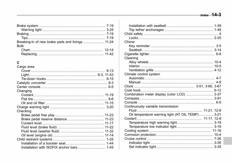
Black plate (3,1)
一般Model "A1300GE-A" EDITED: 2016/ 9/ 13
Brake system ............................................................ 7-19Warning light ......................................................... 3-25
Braking..................................................................... 7-19Tips...................................................................... 7-19
Breaking-in of new brake pads and linings ................... 11-24Bulb
Chart .................................................................. 12-14Replacing............................................................. 11-42
CCargo area
Cover ................................................................... 6-13Light............................................................. 6-3, 11-53Tie-down hooks ..................................................... 6-15
Catalytic converter ....................................................... 8-3Center console ............................................................ 6-5Changing
Coolant................................................................ 11-19Flat tire ................................................................... 9-6Oil and oil filter ..................................................... 11-15
Charge warning light .................................................. 3-20Checking
Brake pedal free play ............................................ 11-23Brake pedal reserve distance ................................. 11-23Coolant level ........................................................ 11-17Fluid level (brake fluid) .......................................... 11-22Fluid level (washer fluid) ........................................ 11-32Oil level (engine oil) .............................................. 11-14
Child restraint systems ............................................... 1-25Installation of a booster seat.................................... 1-44Installation with ISOFIX anchor bars......................... 1-45
Installation with seatbelt .......................................... 1-39Top tether anchorages ............................................ 1-48
Child safety ................................................................... 4Locks.................................................................... 2-25
ChimeKey reminder .......................................................... 3-5Seatbelt................................................................. 3-14
Cigarette lighter........................................................... 6-8Cleaning
Alloy wheels .......................................................... 10-4Interior .................................................................. 10-5Ventilation grille ...................................................... 4-12
Climate control systemAutomatic ............................................................... 4-7Manual................................................................... 4-9
Clock ....................................................... 3-51, 3-60, 3-67Coat hook.................................................................. 6-12Combination meter display (color LCD) ......................... 3-37Compass................................................................... 3-91Console ..................................................................... 6-5Continuously variable transmission
Fluid ........................................................... 11-21, 12-8Oil temperature warning light (AT OIL TEMP) ............. 3-21
Coolant ........................................................... 11-17, 12-8Temperature high warning light................................. 3-19Temperature low indicator light ................................. 3-19
Cooling system ........................................................ 11-16Corrosion protection.................................................... 10-4Cruise control ............................................................ 7-36
Indicator light ......................................................... 3-35Set indicator light.................................................... 3-35
Index 14-3
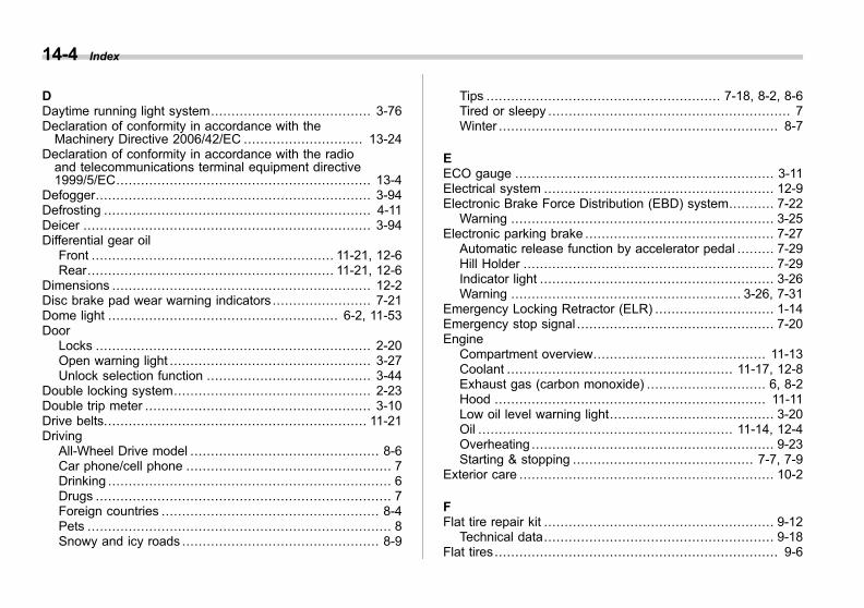
Black plate (4,1)
一般Model "A1300GE-A" EDITED: 2016/ 9/ 13
14-4 Index
DDaytime running light system....................................... 3-76Declaration of conformity in accordance with theMachinery Directive 2006/42/EC ............................. 13-24
Declaration of conformity in accordance with the radioand telecommunications terminal equipment directive1999/5/EC.............................................................. 13-4
Defogger................................................................... 3-94Defrosting ................................................................. 4-11Deicer ...................................................................... 3-94Differential gear oil
Front ........................................................... 11-21, 12-6Rear............................................................ 11-21, 12-6
Dimensions ............................................................... 12-2Disc brake pad wear warning indicators ........................ 7-21Dome light ........................................................ 6-2, 11-53Door
Locks ................................................................... 2-20Open warning light ................................................. 3-27Unlock selection function ........................................ 3-44
Double locking system................................................ 2-23Double trip meter ....................................................... 3-10Drive belts................................................................ 11-21Driving
All-Wheel Drive model .............................................. 8-6Car phone/cell phone .................................................. 7Drinking ..................................................................... 6Drugs ........................................................................ 7Foreign countries ..................................................... 8-4Pets .......................................................................... 8Snowy and icy roads ................................................ 8-9
Tips ......................................................... 7-18, 8-2, 8-6Tired or sleepy ........................................................... 7Winter .................................................................... 8-7
EECO gauge ............................................................... 3-11Electrical system ........................................................ 12-9Electronic Brake Force Distribution (EBD) system........... 7-22
Warning ................................................................ 3-25Electronic parking brake .............................................. 7-27
Automatic release function by accelerator pedal ......... 7-29Hill Holder ............................................................. 7-29Indicator light ......................................................... 3-26Warning ........................................................ 3-26, 7-31
Emergency Locking Retractor (ELR) ............................. 1-14Emergency stop signal ................................................ 7-20Engine
Compartment overview.......................................... 11-13Coolant ....................................................... 11-17, 12-8Exhaust gas (carbon monoxide) ............................. 6, 8-2Hood .................................................................. 11-11Low oil level warning light........................................ 3-20Oil .............................................................. 11-14, 12-4Overheating ........................................................... 9-23Starting & stopping ............................................ 7-7, 7-9
Exterior care .............................................................. 10-2
FFlat tire repair kit ........................................................ 9-12
Technical data........................................................ 9-18Flat tires ..................................................................... 9-6

Black plate (5,1)
一般Model "A1300GE-A" EDITED: 2016/ 9/ 13
Floor mat .................................................................. 6-11Fluid level
Brake .................................................................. 11-22Continuously variable transmission.......................... 11-21
Folding mirror switch .................................................. 3-93Front
Differential gear oil ........................................ 11-21, 12-6Seatbelt pretensioners ............................................ 1-21Turn signal light .................................................... 11-45
Front fog light ............................................................ 3-81Bulb .......................................................... 11-46, 12-14Indicator light......................................................... 3-35Switch .................................................................. 3-81
Fuel ........................................................................... 7-3Consumption indicator ............................ 3-40, 3-45, 3-60Economy hints......................................................... 8-2Filler lid and cap ...................................................... 7-3Gauge .................................................................. 3-10Requirements .................................................. 7-3, 12-3
Fuses ...................................................................... 11-40Fuses and circuits .................................................... 12-10
GGear shift indicator ......................................... 9, 3-34, 7-15Glove box ................................................................... 6-5
HHazard warning flasher ........................................... 3-8, 9-2Headlight .................................................................. 3-70
Beam leveler ......................................................... 3-78Bulb wattage ....................................................... 12-14
Control switch ........................................................ 3-69Flasher.................................................................. 3-73Indicator light ......................................................... 3-35Off delay setting ..................................................... 3-71Washer ................................................................. 3-90
High Beam Assist ....................................................... 3-73High beam assist function............................................ 3-73
Indicator light ......................................................... 3-35Warning indicator.................................................... 3-35
High beam indicator light ............................................. 3-34High/low beam change (dimmer) .................................. 3-72Hill Holder ................................................................. 7-29
Indicator light ................................................. 3-27, 7-30Switch................................................................... 7-30
HookCoat ..................................................................... 6-12Convenient tie-down ............................................... 6-15Shopping bag ........................................................ 6-12Towing and tie-down ............................................... 9-24
Horn ......................................................................... 3-97Hose and connections............................................... 11-16
IIgnition switch ............................................................. 3-4
Light ...................................................................... 3-5Illumination brightness control ...................................... 3-13Immobilizer ................................................................ 2-15
Indicator light ......................................................... 3-33Indicator light
Auto Start Stop ...................................................... 3-36Auto Start Stop OFF ............................................... 3-36
Index 14-5
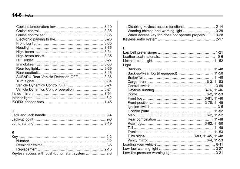
Black plate (6,1)
一般Model "A1300GE-A" EDITED: 2016/ 9/ 13
14-6 Index
Coolant temperature low ......................................... 3-19Cruise control ........................................................ 3-35Cruise control set................................................... 3-35Electronic parking brake.......................................... 3-26Front fog light ........................................................ 3-35Headlight .............................................................. 3-35High beam ............................................................ 3-34High beam assist ................................................... 3-35Hill Holder ............................................................. 3-27Immobilizer............................................................ 3-33Rear fog light......................................................... 3-35Rear seatbelt......................................................... 3-16SUBARU Rear Vehicle Detection OFF...................... 3-36Turn signal ............................................................ 3-34Vehicle Dynamics Control OFF ................................ 3-24Vehicle Dynamics Control operation ......................... 3-24
Inside mirror .............................................................. 3-91Interior lights ............................................................... 6-2ISOFIX anchor bars ................................................... 1-45
JJack and jack handle.................................................... 9-4Jack-up point............................................................... 9-6Jump starting............................................................. 9-19
KKey ............................................................................ 2-2
Number .................................................................. 2-2Reminder chime....................................................... 3-5Replacement ......................................................... 2-16
Keyless access with push-button start system ................. 2-3
Disabling keyless access functions ........................... 2-14Warning chimes and warning light ............................ 3-29When access key fob does not operate properly ........ 9-28
Keyless entry system .................................................. 2-17
LLap belt pretensioner .................................................. 1-21Leather seat materials................................................. 10-6License plate light..................................................... 11-52Light
Back-up .............................................................. 11-48Back-up/Rear fog (if equipped)............................... 11-50Brake/Tail ............................................................ 11-48Cargo area .................................................... 6-3, 11-53Control switch ........................................................ 3-69Daytime running ........................................... 3-76, 11-46Dome............................................................ 6-2, 11-53Front fog ..................................................... 3-81, 11-46Front position ............................................... 3-70, 11-45Ignition switch ......................................................... 3-5License plate ....................................................... 11-52Map .............................................................. 6-2, 11-52Rear combination ................................................. 11-48Rear fog...................................................... 3-82, 11-50Tail ..................................................................... 11-48Trunk .................................................................. 11-53Turn signal ........................................ 3-83, 11-45, 11-48Vanity mirror .................................................. 6-4, 11-53
Loading your vehicle ................................................... 8-11Low fuel warning light ................................................. 3-27Low tire pressure warning light ..................................... 3-21
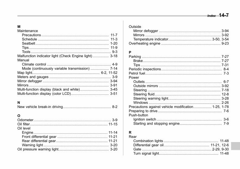
Black plate (7,1)
一般Model "A1300GE-A" EDITED: 2016/ 9/ 13
MMaintenance
Precautions ........................................................... 11-7Schedule .............................................................. 11-3Seatbelt ................................................................ 1-20Tips...................................................................... 11-9Tools ...................................................................... 9-3
Malfunction indicator light (Check Engine light) .............. 3-18Manual
Climate control ........................................................ 4-9Mode (continuously variable transmission) ................ 7-14
Map light........................................................... 6-2, 11-52Meters and gauges ...................................................... 3-9Mirror defogger .......................................................... 3-94Mirrors...................................................................... 3-91Multi-function display (black and white) ......................... 3-45Multi-function display (color LCD)................................. 3-51
NNew vehicle break-in driving.......................................... 8-2
OOdometer.................................................................... 3-9Oil filter.................................................................... 11-15Oil level
Engine................................................................. 11-14Front differential gear ............................................ 11-21Rear differential gear ............................................. 11-21Warning light ......................................................... 3-20
Oil pressure warning light............................................ 3-20
OutsideMirror defogger ...................................................... 3-94Mirrors .................................................................. 3-92Temperature indicator...................................... 3-50, 3-54
Overheating engine .................................................... 9-23
PParking ..................................................................... 7-27
Brake.................................................................... 7-27Tips ...................................................................... 7-31
Periodic inspections ..................................................... 8-4Petrol fuel................................................................... 7-3Power
Outlets ................................................................... 6-7Outside mirrors ...................................................... 3-92Steering ................................................................ 7-18Steering fluid.......................................................... 12-8Steering warning light.............................................. 3-28Windows ............................................................... 2-26
Precautions against vehicle modification................ 1-25, 1-78Preparing to drive ........................................................ 7-6Push-button
Ignition switch ......................................................... 3-6Starting and stopping engine..................................... 7-9
RRear
Combination lights ................................................ 11-48Differential gear oil........................................ 11-21, 12-6Gate ............................................................. 2-29, 9-30Turn signal light.................................................... 11-48
Index 14-7
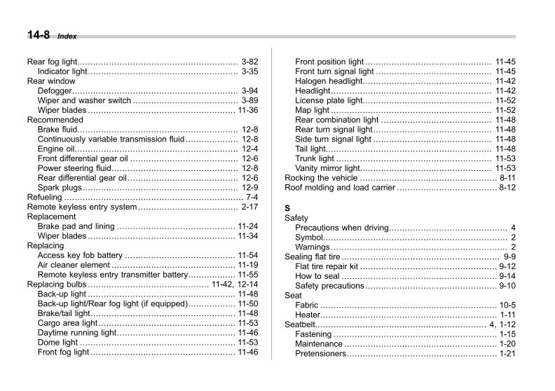
Black plate (8,1)
一般Model "A1300GE-A" EDITED: 2016/ 9/ 13
14-8 Index
Rear fog light............................................................. 3-82Indicator light......................................................... 3-35
Rear windowDefogger............................................................... 3-94Wiper and washer switch ........................................ 3-89Wiper blades ........................................................ 11-36
RecommendedBrake fluid............................................................. 12-8Continuously variable transmission fluid .................... 12-8Engine oil.............................................................. 12-4Front differential gear oil ......................................... 12-6Power steering fluid................................................ 12-8Rear differential gear oil .......................................... 12-6Spark plugs........................................................... 12-9
Refueling .................................................................... 7-4Remote keyless entry system ...................................... 2-17Replacement
Brake pad and lining ............................................. 11-24Wiper blades ........................................................ 11-34
ReplacingAccess key fob battery .......................................... 11-54Air cleaner element ............................................... 11-19Remote keyless entry transmitter battery.................. 11-55
Replacing bulbs .............................................. 11-42, 12-14Back-up light ........................................................ 11-48Back-up light/Rear fog light (if equipped).................. 11-50Brake/tail light....................................................... 11-48Cargo area light .................................................... 11-53Daytime running light............................................. 11-46Dome light ........................................................... 11-53Front fog light ....................................................... 11-46
Front position light ................................................ 11-45Front turn signal light ............................................ 11-45Halogen headlight................................................. 11-42Headlight............................................................. 11-42License plate light................................................. 11-52Map light ............................................................. 11-52Rear combination light .......................................... 11-48Rear turn signal light............................................. 11-48Side turn signal light ............................................. 11-48Tail light............................................................... 11-48Trunk light ........................................................... 11-53Vanity mirror light.................................................. 11-53
Rocking the vehicle .................................................... 8-11Roof molding and load carrier ...................................... 8-12
SSafety
Precautions when driving............................................. 4Symbol...................................................................... 2Warnings................................................................... 2
Sealing flat tire ............................................................ 9-9Flat tire repair kit .................................................... 9-12How to seal ........................................................... 9-14Safety precautions.................................................. 9-10
SeatFabric ................................................................... 10-5Heater................................................................... 1-11
Seatbelt................................................................. 4, 1-12Fastening .............................................................. 1-15Maintenance .......................................................... 1-20Pretensioners......................................................... 1-21

Black plate (9,1)
一般Model "A1300GE-A" EDITED: 2016/ 9/ 13
Safety tips............................................................. 1-12Warning light and chime ......................................... 3-14
SecurityImmobilizer............................................................ 2-15
Select leverPosition indicator ................................................... 3-34Shift lock function................................................... 7-16
Shopping bag hook .................................................... 6-12Snow tires........................................................ 8-10, 11-25Snowy and icy roads .................................................... 8-9Spark plugs...................................................... 11-20, 12-9Specifications ............................................................ 12-2Speed limit, maximum torque and maximum power atrpm (Middle East models only) ................................. 13-3
Speedometer............................................................... 3-9SRS
Frontal airbag ........................................................ 1-60SRS airbag (Supplemental Restraint System airbag) ... 4, 1-49SRS airbag system
Monitors................................................................ 1-76Servicing............................................................... 1-77Warning light ......................................................... 3-17
Starting & stopping engine ...................................... 7-7, 7-9Steering Responsive Headlight .................................... 3-77Steering wheel
Heated Steering Wheel system................................ 3-96Power................................................................... 7-18Tilt/telescopic......................................................... 3-95
Storage compartment ................................................... 6-4SUBARU Rear Vehicle Detection (SRVD) ..................... 7-44
OFF indicator ........................................................ 3-36
OFF switch ............................................................ 7-51SRVD approach indicator light/warning buzzer ........... 7-48Warning indicator............................................ 3-36, 7-50
Sun shade................................................................. 2-32Sun visors .................................................................. 6-3Sunroof ............................................................. 2-31, 9-31Supplemental Restraint System airbag (SRS) ............ 4, 1-49Synthetic leather upholstery ......................................... 10-6
TTachometer................................................................. 3-9Temperature warning light
AT OIL TEMP......................................................... 3-21Coolant ................................................................. 3-19
Temporary spare tire ............................................ 9-2, 12-9Tether (child restraint system) ...................................... 1-48Tie-down hooks/holes ................................................. 9-24Tire................................................................. 11-24, 12-9
Chains .................................................................. 8-11Inspection............................................................ 11-26Pressures and wear.............................................. 11-26Replacement........................................................ 11-30Rotation .............................................................. 11-29Size and pressure .................................................. 12-9Types.................................................................. 11-24
Tire pressure monitoring system (TPMS) ..... 7-32, 9-18, 11-25TPMS mode setting ................................................ 7-34Warning light.......................................................... 3-21
Tires and wheels ...................................................... 11-24Tools.......................................................................... 9-3Top tether anchorages ................................................ 1-48
Index 14-9

Black plate (10,1)
一般Model "A1300GE-A" EDITED: 2016/ 9/ 13
14-10 Index
Towing...................................................................... 9-24All wheels on the ground ........................................ 9-27Flat-bed truck ........................................................ 9-27Hooks................................................................... 9-24Weight.................................................................. 8-14
TrailerHitch .................................................................... 8-15Towing.................................................................. 8-14Towing tips............................................................ 8-16
Trip meter ................................................................. 3-10Trunk lid ................................................................... 2-28Trunk light ................................................................ 11-53Turn signal
Indicator lights ....................................................... 3-34Lever.................................................................... 3-83
UUnder-floor storage compartment ................................. 6-15USB power supply ....................................................... 6-9
VVanity mirror ...................................................... 6-4, 11-53
Light.................................................................... 11-53Vehicle
Identification ........................................................ 12-18Symbols .................................................................... 3
Vehicle Dynamics ControlOFF indicator light.................................................. 3-24OFF switch ........................................................... 7-25Operation indicator light .......................................... 3-24System ................................................................. 7-23
Warning light.......................................................... 3-23Ventilator .................................................................... 4-2
WWarning and indicator lights ......................................... 3-13Warning chimes
Keyless access with push-button start system............ 3-29Seatbelt................................................................. 3-14
Warning lightABS...................................................................... 3-23Access key............................................................ 3-29All-Wheel Drive ...................................................... 3-27AT OIL TEMP......................................................... 3-21Auto Start Stop ...................................................... 3-36Automatic headlight beam leveler ............................. 3-28Brake system......................................................... 3-25Charge.................................................................. 3-20Coolant temperature high ........................................ 3-19Door open ............................................................. 3-27Electronic parking brake .......................................... 3-26Engine low oil level................................................. 3-20High beam assist.................................................... 3-35High Beam Assist warning....................................... 3-35Icy road surface ..................................................... 3-36Keyless access with push-button start system............ 3-29LED headlight ........................................................ 3-28Low fuel ................................................................ 3-27Low tire pressure.................................................... 3-21Oil pressure ........................................................... 3-20Power steering ....................................................... 3-28Seatbelt................................................................. 3-14

Black plate (11,1)
一般Model "A1300GE-A" EDITED: 2016/ 9/ 13
SRS airbag system ................................................ 3-17Steering Responsive Headlight ................................ 3-28SUBARU Rear Vehicle Detection ............................. 3-36Vehicle Dynamics Control ....................................... 3-23Windshield washer fluid .......................................... 3-27
Warranties ..................................................................... 1Washing ................................................................... 10-2Waxing and polishing ................................................. 10-3Wear indicators......................................................... 11-28Wheel
Alloy.................................................................... 11-32Balance ............................................................... 11-28Covers................................................................. 11-31Nut tightening torque .............................................. 12-9Replacement ........................................................ 11-31
Windows................................................................... 2-26Windshield
Washer fluid ......................................................... 11-32Wiper and washer switches..................................... 3-86Wiper blades ........................................................ 11-35Wiper deicer.......................................................... 3-94
WinterDriving.................................................................... 8-7Tires............................................................ 8-10, 11-25
Wiper and washer ...................................................... 3-84Wiper deicer.............................................................. 3-94
Index 14-11
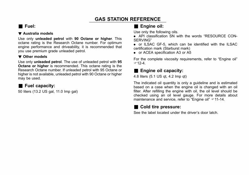
Black plate (2,1)
一般Model "A1300GE-A" EDITED: 2016/ 9/ 13
GAS STATION REFERENCE& Fuel:
! Australia models
Use only unleaded petrol with 90 Octane or higher. Thisoctane rating is the Research Octane number. For optimumengine performance and driveability, it is recommended thatyou use premium grade unleaded petrol.
! Other models
Use only unleaded petrol. The use of unleaded petrol with 95Octane or higher is recommended. This octane rating is theResearch Octane number. If unleaded petrol with 95 Octane orhigher is not available, unleaded petrol with 90 Octane or highermay be used.
& Fuel capacity:50 liters (13.2 US gal, 11.0 Imp gal)
& Engine oil:Use only the following oils.. API classification SN with the words “RESOURCE CON-SERVING”. or ILSAC GF-5, which can be identified with the ILSACcertification mark (Starburst mark). or ACEA specification A3 or A5
For the complete viscosity requirements, refer to “Engine oil”F12-4.
& Engine oil capacity:4.8 liters (5.1 US qt, 4.2 Imp qt)
The indicated oil quantity is only a guideline and is estimatedbased on a case when the engine oil is changed with an oilfilter. After refilling the engine with oil, the oil level should bechecked using an oil level gauge. For more details aboutmaintenance and service, refer to “Engine oil” F11-14.
& Cold tire pressure:See the label located under the driver’s door latch.