foreword - priuschat
TRANSCRIPT
NOTICEWhen handling supplemental restraint system components (removal,installation or inspection, etc.), always follow the direction given in the repairmanuals listed above to prevent accidents and supplemental restraintsystem malfunction.
CAUTIONWhen repairing the hybrid vehicle (HV), always follow the direction given inthe repair manual listed above to prevent electrical shock, leakage orexplosion.
FOREWORD
This wiring diagram manual has been prepared to provide
information on the electrical system of the 2004 PRIUS.
Applicable models: NHW20 Series
For service specifications and repair procedures of the above
models other than those listed in this manual, refer to the
following manuals;
Manual Name Pub. No. 2004 PRIUS Repair Manual
Volume 1Volume 2Volume 3
2004 PRIUS New Car Features
RM1075U1RM1075U2RM1075U3NCF255U
All information in this manual is based on the latest product
information at the time of publication. However, specifications
and procedures are subject to change without notice.

2003All rights reserved. This book may not bereproduced or copied, in whole or in part, withoutthe written permission of Toyota MotorCorporation.
2004 PRIUS (EWD555U)
1
2004 PRIUSELECTRICAL WIRING DIAGRAM
Section Code Page
INTRODUCTION A. . . . . . . . . . . . . . . . . . . . . . . . . . . . . . 2
HOW TO USE THIS MANUAL B. . . . . . . . . . . . . . . . . . 3
TROUBLESHOOTING C. . . . . . . . . . . . . . . . . . . . . . . . . 12
ABBREVIATIONS D. . . . . . . . . . . . . . . . . . . . . . . . . . . . . 17
GLOSSARY OF TERMS AND SYMBOLS E. . . . . . . . 18
RELAY LOCATIONS F. . . . . . . . . . . . . . . . . . . . . . . . . . . 20
ELECTRICAL WIRING ROUTING G. . . . . . . . . . . . . . . 44
SYSTEM CIRCUITS H. . . . . . . . . . . . . . . . . . . . . . . . . . . 65
GROUND POINT I. . . . . . . . . . . . . . . . . . . . . . . . . . . . . . . 364
POWER SOURCE (Current Flow Chart) J. . . . . . . . . 370
CONNECTOR LIST K. . . . . . . . . . . . . . . . . . . . . . . . . . . . 378
PART NUMBER OF CONNECTORS L. . . . . . . . . . . . . 390
OVERALL ELECTRICAL WIRING DIAGRAM M. . . . . 394
2004 PRIUS (EWD555U)
2
A INTRODUCTION
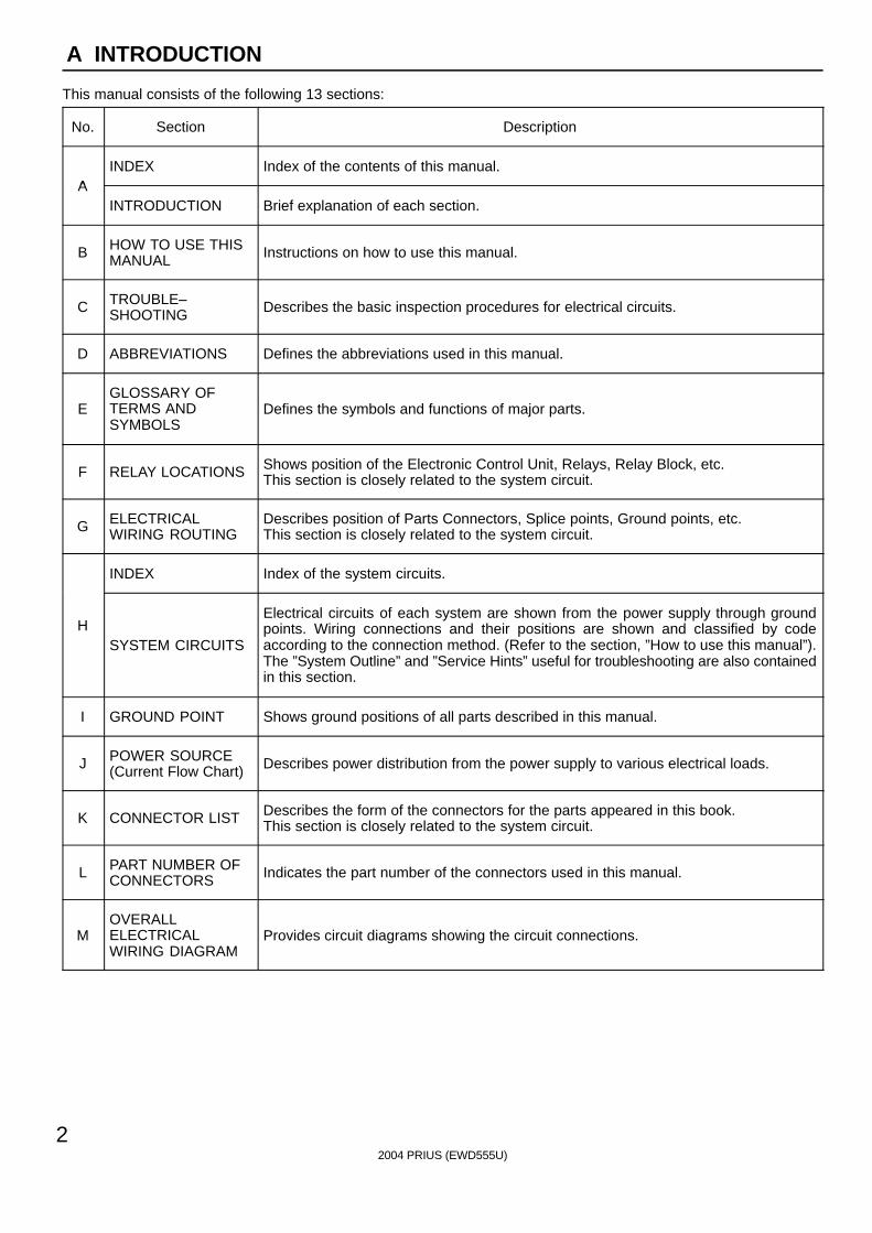
This manual consists of the following 13 sections:
No. Section Description
AINDEX Index of the contents of this manual.
AINTRODUCTION Brief explanation of each section.
B HOW TO USE THISMANUAL Instructions on how to use this manual.
C TROUBLE–SHOOTING Describes the basic inspection procedures for electrical circuits.
D ABBREVIATIONS Defines the abbreviations used in this manual.
EGLOSSARY OFTERMS ANDSYMBOLS
Defines the symbols and functions of major parts.
F RELAY LOCATIONS Shows position of the Electronic Control Unit, Relays, Relay Block, etc.This section is closely related to the system circuit.
G ELECTRICALWIRING ROUTING
Describes position of Parts Connectors, Splice points, Ground points, etc.This section is closely related to the system circuit.
INDEX Index of the system circuits.
HSYSTEM CIRCUITS
Electrical circuits of each system are shown from the power supply through groundpoints. Wiring connections and their positions are shown and classified by codeaccording to the connection method. (Refer to the section, ”How to use this manual”).The ”System Outline” and ”Service Hints” useful for troubleshooting are also containedin this section.
I GROUND POINT Shows ground positions of all parts described in this manual.
J POWER SOURCE(Current Flow Chart) Describes power distribution from the power supply to various electrical loads.
K CONNECTOR LIST Describes the form of the connectors for the parts appeared in this book.This section is closely related to the system circuit.
L PART NUMBER OFCONNECTORS Indicates the part number of the connectors used in this manual.
MOVERALLELECTRICALWIRING DIAGRAM
Provides circuit diagrams showing the circuit connections.
2004 PRIUS (EWD555U)
3
HOW TO USE THIS MANUAL B
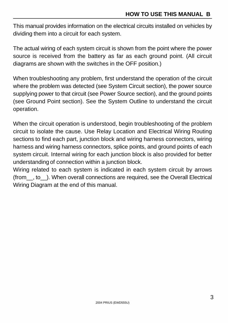
This manual provides information on the electrical circuits installed on vehicles bydividing them into a circuit for each system.
The actual wiring of each system circuit is shown from the point where the powersource is received from the battery as far as each ground point. (All circuitdiagrams are shown with the switches in the OFF position.)
When troubleshooting any problem, first understand the operation of the circuitwhere the problem was detected (see System Circuit section), the power sourcesupplying power to that circuit (see Power Source section), and the ground points(see Ground Point section). See the System Outline to understand the circuitoperation.
When the circuit operation is understood, begin troubleshooting of the problemcircuit to isolate the cause. Use Relay Location and Electrical Wiring Routingsections to find each part, junction block and wiring harness connectors, wiringharness and wiring harness connectors, splice points, and ground points of eachsystem circuit. Internal wiring for each junction block is also provided for betterunderstanding of connection within a junction block.Wiring related to each system is indicated in each system circuit by arrows(from__, to__). When overall connections are required, see the Overall ElectricalWiring Diagram at the end of this manual.
[A]
[B]
[H]
[D]
[F]
[E]
[ I ]
[L]
[M]
[J]
[K]
[G][C]
1
2
IB
IB
3
4
47
2 1 11
13
4
1
2
6
3
1
2
B18
BL
R LG
R
B18G R
3
4
Rea
r C
ombi
natio
n Li
ght R
HR
7
Rea
r C
ombi
natio
n Li
ght L
HR
6
High MountedStop Light
H17
Light Failure Sensor
Stop Light SW
ABS ECU
S 6
CombinationMeter
C 7
BV11 W B
(Shielded)
BV11
I 5G W
IB2
IB1
IE114
BO
50
8L 4
15ASTOP
7.5AGAUGE
From Power Source System (See Page 66)
Stop Light
GR
WB
WB
WB
WB
GB
YG
RL
R
GR
WR
GW
WB
GW
W/G
)
( S/D
)L
L
( ( S/D
)
Sto
p
Sto
p
Rea
r Li
ghts
2004 PRIUS (EWD555U)
4
B HOW TO USE THIS MANUAL
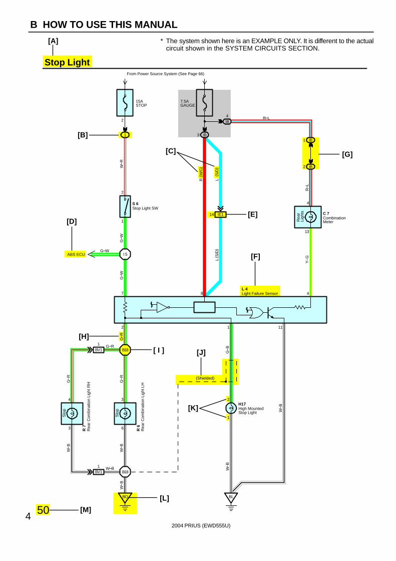
∗ The system shown here is an EXAMPLE ONLY. It is different to the actualcircuit shown in the SYSTEM CIRCUITS SECTION.
2004 PRIUS (EWD555U)
5
B
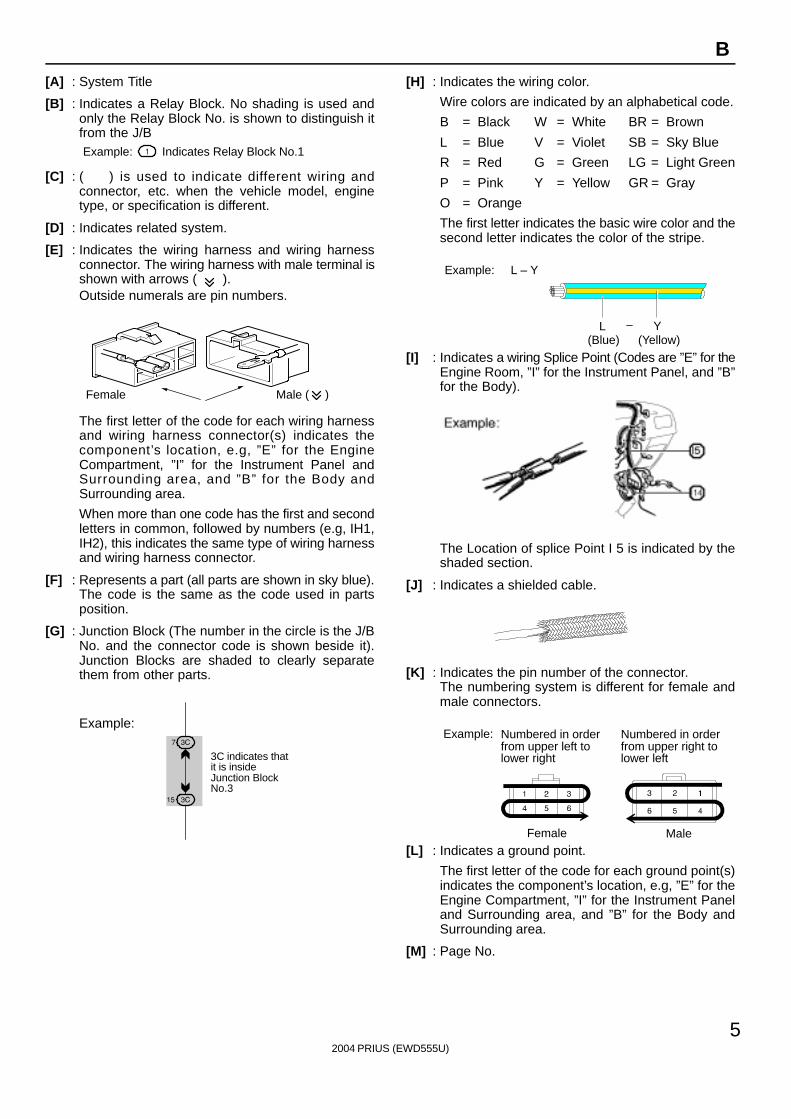
[A] : System Title
[B] : Indicates a Relay Block. No shading is used andonly the Relay Block No. is shown to distinguish itfrom the J/BExample: Indicates Relay Block No.1
[C] : ( ) is used to indicate different wiring andconnector, etc. when the vehicle model, enginetype, or specification is different.
[D] : Indicates related system.
[E] : Indicates the wiring harness and wiring harnessconnector. The wiring harness with male terminal isshown with arrows ( ).Outside numerals are pin numbers.
Female Male ( )
The first letter of the code for each wiring harnessand wiring harness connector(s) indicates thecomponent’s location, e.g, ”E” for the EngineCompartment, ”I” for the Instrument Panel andSurrounding area, and ”B” for the Body andSurrounding area.
When more than one code has the first and secondletters in common, followed by numbers (e.g, IH1,IH2), this indicates the same type of wiring harnessand wiring harness connector.
[F] : Represents a part (all parts are shown in sky blue).The code is the same as the code used in partsposition.
[G] : Junction Block (The number in the circle is the J/BNo. and the connector code is shown beside it).Junction Blocks are shaded to clearly separatethem from other parts.
3C indicates thatit is insideJunction BlockNo.3
Example:
[H] : Indicates the wiring color.
Wire colors are indicated by an alphabetical code.
B = Black W = White BR = Brown
L = Blue V = Violet SB = Sky Blue
R = Red G = Green LG = Light Green
P = Pink Y = Yellow GR = Gray
O = Orange
The first letter indicates the basic wire color and thesecond letter indicates the color of the stripe.
Example: L – Y
L(Blue)
Y(Yellow)
[I] : Indicates a wiring Splice Point (Codes are ”E” for theEngine Room, ”I” for the Instrument Panel, and ”B”for the Body).
The Location of splice Point I 5 is indicated by theshaded section.
[J] : Indicates a shielded cable.
[K] : Indicates the pin number of the connector.The numbering system is different for female andmale connectors.
Example: Numbered in orderfrom upper left tolower right
Numbered in orderfrom upper right tolower left
Female Male
[L] : Indicates a ground point.
The first letter of the code for each ground point(s)indicates the component’s location, e.g, ”E” for theEngine Compartment, ”I” for the Instrument Paneland Surrounding area, and ”B” for the Body andSurrounding area.
[M] : Page No.
[N]
[O]
[P]
[Q]
[R]
[S]
[T]
[U]
2004 PRIUS (EWD555U)
6
B HOW TO USE THIS MANUAL
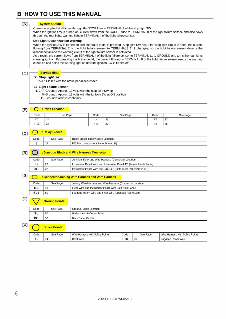
Current is applied at all times through the STOP fuse to TERMINAL 2 of the stop light SW.When the ignition SW is turned on, current flows from the GAUGE fuse to TERMINAL 8 of the light failure sensor, and also flowsthrough the rear lights warning light to TERMINAL 4 of the light failure sensor.
Stop Light Disconnection WarningWhen the ignition SW is turned on and the brake pedal is pressed (Stop light SW on), if the stop light circuit is open, the currentflowing from TERMINAL 7 of the light failure sensor to TERMINALS 1, 2 changes, so the light failure sensor detects thedisconnection and the warning circuit of the light failure sensor is activated.As a result, the current flows from TERMINAL 4 of the light failure sensor to TERMINAL 11 to GROUND and turns the rear lightswarning light on. By pressing the brake pedal, the current flowing to TERMINAL 8 of the light failure sensor keeps the warningcircuit on and holds the warning light on until the ignition SW is turned off.
S6 Stop Light SW2–1 : Closed with the brake pedal depressed
L4 Light Failure Sensor1, 2, 7–Ground : Approx. 12 volts with the stop light SW on
4, 8–Ground : Approx. 12 volts with the ignition SW at ON position11–Ground : Always continuity
: Parts Location
Code See Page Code See Page Code See Page
C7 34 L4 36 R7 37
H17 36 R6 37 S6 35
: Relay Blocks
Code See Page Relay Blocks (Relay Block Location)
1 18 R/B No.1 (Instrument Panel Brace LH)
: Junction Block and Wire Harness Connector
Code See Page Junction Block and Wire Harness (Connector Location)
IB 20 Instrument Panel Wire and Instrument Panel J/B (Lower Finish Panel)
3C 22 Instrument Panel Wire and J/B No.3 (Instrument Panel Brace LH)
: Connector Joining Wire Harness and Wire Harness
Code See Page Joining Wire Harness and Wire Harness (Connector Location)
IE1 42 Floor Wire and Instrument Panel Wire (Left Kick Panel)
BV1 50 Luggage Room Wire and Floor Wire (Luggage Room Left)
: Ground Points
Code See Page Ground Points Location
BL 50 Under the Left Center Pillar
BO 50 Back Panel Center
: Splice Points
Code See Page Wire Harness with Splice Points Code See Page Wire Harness with Splice Points
I5 44 Cowl Wire B18 50 Luggage Room Wire
System Outline
Service Hints
2004 PRIUS (EWD555U)
7
B
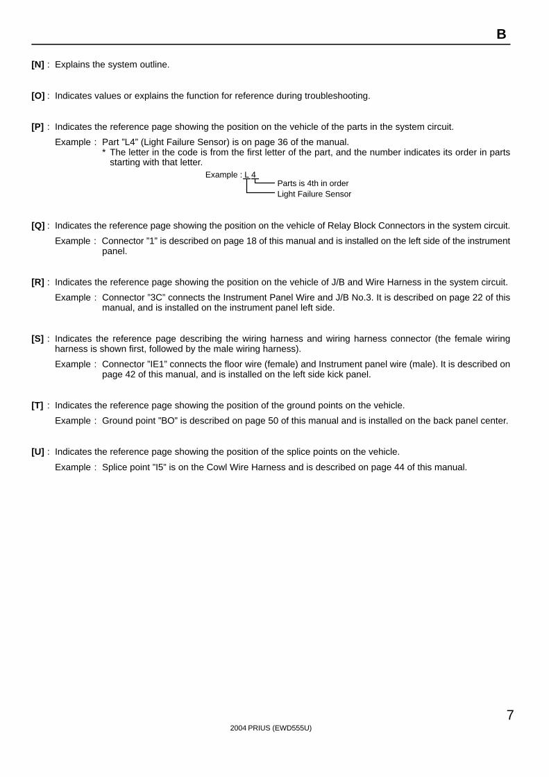
[N] : Explains the system outline.
[O] : Indicates values or explains the function for reference during troubleshooting.
[P] : Indicates the reference page showing the position on the vehicle of the parts in the system circuit.
Example : Part ”L4” (Light Failure Sensor) is on page 36 of the manual.∗ The letter in the code is from the first letter of the part, and the number indicates its order in parts
starting with that letter.Example : L 4 Á
ÁParts is 4th in orderLight Failure Sensor
[Q] : Indicates the reference page showing the position on the vehicle of Relay Block Connectors in the system circuit.
Example : Connector ”1” is described on page 18 of this manual and is installed on the left side of the instrumentpanel.
[R] : Indicates the reference page showing the position on the vehicle of J/B and Wire Harness in the system circuit.
Example : Connector ”3C” connects the Instrument Panel Wire and J/B No.3. It is described on page 22 of thismanual, and is installed on the instrument panel left side.
[S] : Indicates the reference page describing the wiring harness and wiring harness connector (the female wiringharness is shown first, followed by the male wiring harness).
Example : Connector ”IE1” connects the floor wire (female) and Instrument panel wire (male). It is described onpage 42 of this manual, and is installed on the left side kick panel.
[T] : Indicates the reference page showing the position of the ground points on the vehicle.
Example : Ground point ”BO” is described on page 50 of this manual and is installed on the back panel center.
[U] : Indicates the reference page showing the position of the splice points on the vehicle.
Example : Splice point ”I5” is on the Cowl Wire Harness and is described on page 44 of this manual.
2004 PRIUS (EWD555U)
8
B HOW TO USE THIS MANUAL
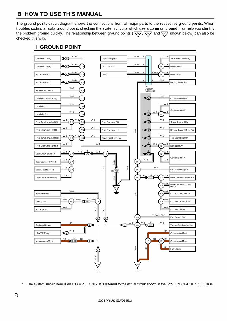
The ground points circuit diagram shows the connections from all major parts to the respective ground points. Whentroubleshooting a faulty ground point, checking the system circuits which use a common ground may help you identifythe problem ground quickly. The relationship between ground points ( EA , IB and IC shown below) can also bechecked this way.
5
5
5
5
4
4
4
4
4BA15
IB18
EA2
ID115
IC33
IA12
E 3
W–B
W–B
W–B
W–B
W–B
W–B
W–B
W–B
W–B W–B
W–B
W–B W–B
W–B
W–B W–B W–B
W–B
W–B
W–B
W–B
W–B
W–B
W–B
W–B W–B W–B
W–B
BR
W–B
BR BR
W–B
W–BW–B
W–B
W–B
W–B
W–BW–B W–B
W–B
W–B
W–B
W–B
W–B
BR
W–B
BRBR
BR
W–B (4A–GZE)
W–BW–B
I 2
I 2
B 5I 5
I 5
I 5
B 5
B 5
B 5
I 5
I 5
I 3I 3
E 3
E 3
E 3
E 2
E 4
E 5
E 4
E 5
E 6E 4
E 4
B 4
EA
I 4
B 4
B 4
I 4 I 8
IB IC
4
4
3E5
3E6
3G13
3F3
3D1
3B7
W–B
W–B
W–BW–B
W–B
W–B
W–B
W–B
W–B
W–B
W–B
W–B
W–B
W–B
W–B
I 6
I 6
I 23C7
10
A
A
A
A
A
A
JunctionConnector
J 1
W–B
W–B
W–B
W–B
BR
W–B
W–B
W–B
W–B
W–B
W–B
I GROUND POINT
FAN MAIN Relay
FAN MAIN Relay
A/C Relay No.2
A/C Relay No.3
Radiator Fan Motor
Headlight Cleaner Relay
Headlight LH
Headlight RH
Front Fog Light LH
Brake Fluid Level SW
Front Fog Light RHFront Turn Signal Light RH
Front Clearance Light RH
Front Turn Signal Light LH
Front Clearance Light LH
Door Lock Control SW
Door Courtesy SW RH
Door Lock Motor RH
Door Lock Control Relay
Blower Resistor
Idle–Up SW
A/C Amplifier
Radio and Player
HEATER Relay
Auto Antenna Motor
A/C Control Assembly
Blower Motor
Blower SW
Parking Brake SW
Combination Meter
Combination SW
Cruise Control ECU
Remote Control Mirror SW
Turn Signal Flasher
Defogger SW
Unlock Warning SW
Power Window Master SW
Power Window ControlRelay
Door Courtesy SW LH
Door Lock Control SW
Door Lock Motor LH
Fuel Control SW
Woofer Speaker Amplifier
Combination Meter
Combination Meter
Fuel Sender
Cigarette Lighter
O/D Main SW
Clock
Combination SW
∗ The system shown here is an EXAMPLE ONLY. It is different to the actual circuit shown in the SYSTEM CIRCUITS SECTION.
2004 PRIUS (EWD555U)
9
B
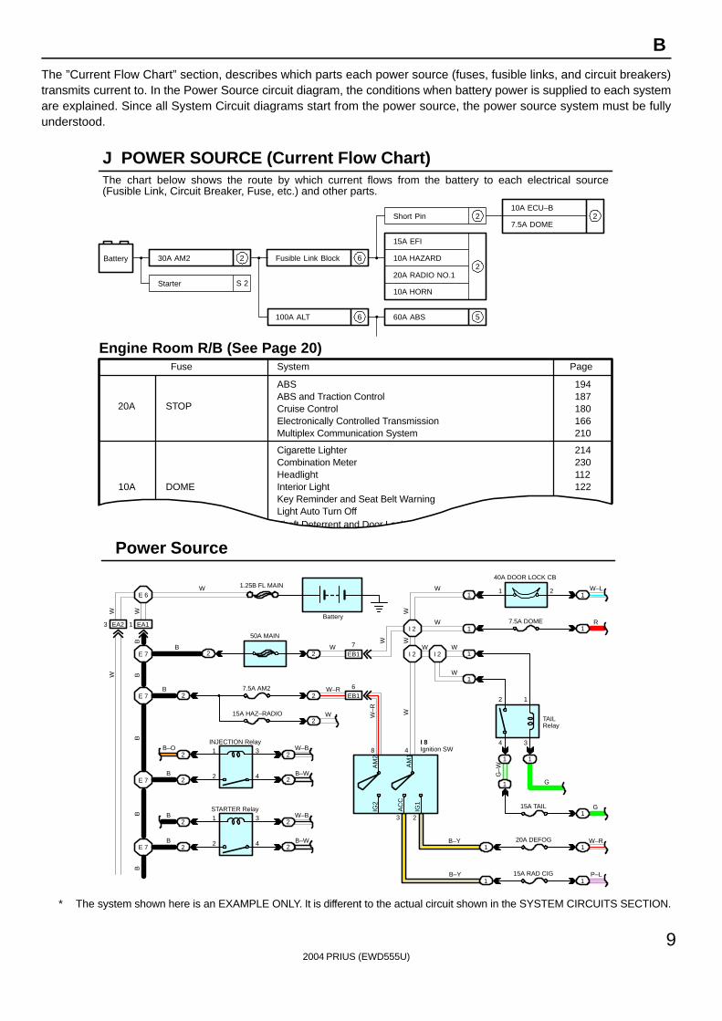
The ”Current Flow Chart” section, describes which parts each power source (fuses, fusible links, and circuit breakers)transmits current to. In the Power Source circuit diagram, the conditions when battery power is supplied to each systemare explained. Since all System Circuit diagrams start from the power source, the power source system must be fullyunderstood.
AC
C
S 2
6
6 5
2
2
2
Battery 30A AM2
Starter
Short Pin
100A ALT
Fusible Link Block
60A ABS
10A ECU–B
7.5A DOME
15A EFI
10A HAZARD
20A RADIO NO.1
10A HORN
20A
10A
Fuse Page
214230112122
194187180166210
ABS
Cigarette LighterCombination Meter
Key Reminder and Seat Belt WarningLight Auto Turn OffTheft Deterrent and Door Lock Control
ABS and Traction ControlCruise ControlElectronically Controlled TransmissionMultiplex Communication System
STOP
System
DOMEHeadlightInterior Light
3 EA2 1 EA1
E 6
E 7
E 7
2
2
22
2
2
2
2
INJECTION Relay
STARTER Relay
B
B
B
B–O 1
1
2
2
3
4
3
4
W–B
W–B
B–W
B–W
E 7
E 7
B
B
W 1.25B FL MAIN
50A MAIN
7.5A AM2
15A HAZ–RADIO
2
2
2
2
2
W
W
EB1
EB1
7
6W–R
I 2 I 2
I 2
W W
W
W
W
1
1
1
1
40A DOOR LOCK CB
7.5A DOME
1 W–L
R
1
1
2
4 3
1
11
1
1 1
1
G
G
W–R
15A TAIL
20A DEFOGB–Y
8 4
3 2
Ignition SWI 8
B–Y1 1
P–L
Battery
15A RAD CIG
2
TAILRelay
Power Source
J POWER SOURCE (Current Flow Chart)
Engine Room R/B (See Page 20)
2
WW
BB
BB
B
W–R
WW
W
G–WA
M2
AM
1
IG2
IG1
W
W
The chart below shows the route by which current flows from the battery to each electrical source(Fusible Link, Circuit Breaker, Fuse, etc.) and other parts.
∗ The system shown here is an EXAMPLE ONLY. It is different to the actual circuit shown in the SYSTEM CIRCUITS SECTION.
Black
[D]
K CONNECTOR LIST
J4 K1 K2 L1
L2 L3 L4 M1 M2 M3
M4 N1 N2 O1 O2
Dark Gray
Gray
Dark GrayBlackGrayGray
A B BA A B C C C
D DD D
AA
AA
AAA A 1
1 2 1 2
1 12 1
2
1 2 36 7 8 9 101112
4 5
71 23 45 6 8
4321
1 2 3 2 3 48 9 105 6
17
1 2 1 1
[A]
[C]
[B]J3
1 2 1 2
6 7 8
1 2A
A
A
AA AA B BA A B C C C
D DD D
I14 I15 I16 J1 J2Dark Gray Gray Black
2004 PRIUS (EWD555U)
10
B HOW TO USE THIS MANUAL
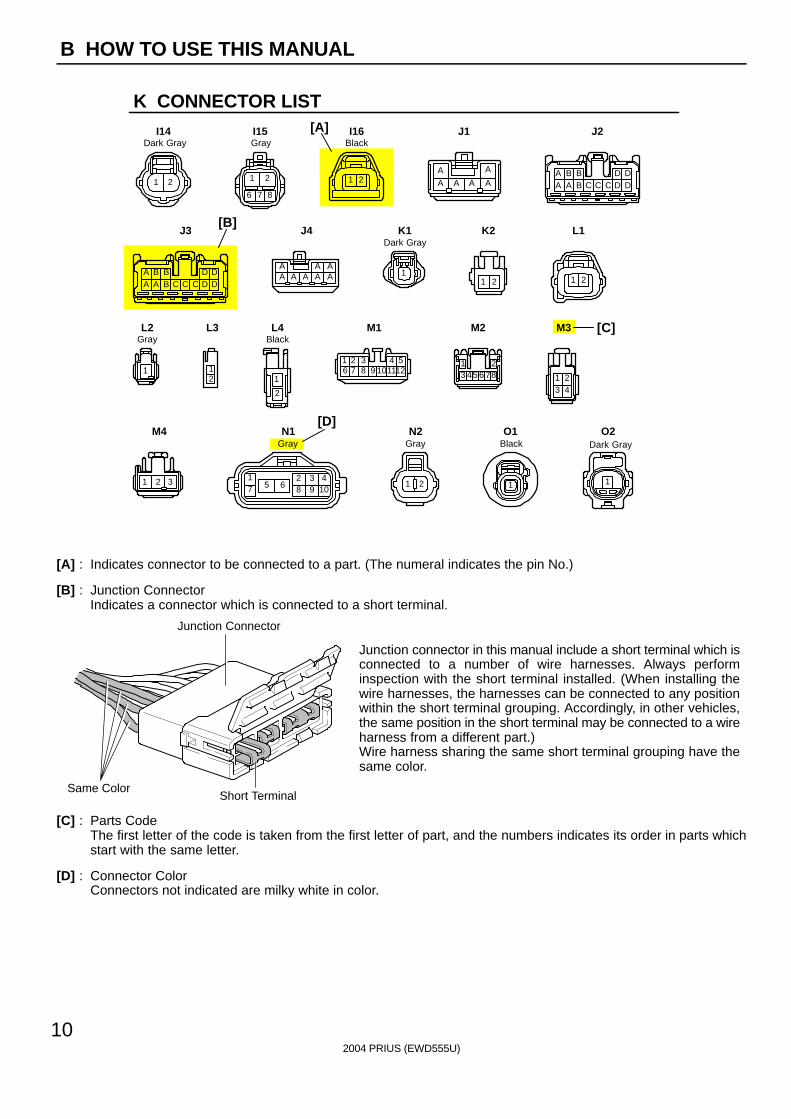
[A] : Indicates connector to be connected to a part. (The numeral indicates the pin No.)
[B] : Junction ConnectorIndicates a connector which is connected to a short terminal.
Junction Connector
Short TerminalSame Color
Junction connector in this manual include a short terminal which isconnected to a number of wire harnesses. Always performinspection with the short terminal installed. (When installing thewire harnesses, the harnesses can be connected to any positionwithin the short terminal grouping. Accordingly, in other vehicles,the same position in the short terminal may be connected to a wireharness from a different part.)Wire harness sharing the same short terminal grouping have thesame color.
[C] : Parts CodeThe first letter of the code is taken from the first letter of part, and the numbers indicates its order in parts whichstart with the same letter.
[D] : Connector ColorConnectors not indicated are milky white in color.
A 1
L PART NUMBER OF CONNECTORS
A/C Ambient Temp. Sensor
Code
90980–11070
Part Number
D 4 Diode (Courtesy)
Code
90980–11608
A 2 A/C Condenser Fan Motor 90980–11237 D 5 Diode (Interior Light) 90980–10962
A 3 A/C Condenser Fan Relay 90980–10940 D 6 Diode (Moon Roof) 90980–11608
A 4 A/C Condenser Fan Resistor 90980–10928
90980–11271
D 7 Door Lock Control Relay 90980–10848
A 5 A/C Magnetic Clutch
90980–11413
D 8 Door Lock Control SW LH90980–11148
A 6 A/T Oil Temp. Sensor
90980–11151
D 9 Door Lock Control SW RH
A 7 ABS Actuator
90980–11009
Door Courtesy SW LH90980–11097
A 8 ABS Actuator
90980–10941
Door Courtesy SW RH
A 9 ABS Speed Sensor Front LH
90980–11002
Door Courtesy SW Front LH
ABS Speed Sensor Front RH
90980–11856
Door Courtesy SW Front RH90980–11156
Airbag Sensor Front LH Door Courtesy SW Rear LH
Airbag Sensor Front RH Door Courtesy SW Rear RH
A10
A11
A12
A13 Airbag Squib 90980–11194 Door Key Lock and Unlock SW LH90980–11170
90980–11070
D10
D11
D12
D13
D14
D15
D16
D17 Door Key Lock and Unlock SW RH
Part NumberPart NamePart Name
[A] [B] [C]
2004 PRIUS (EWD555U)
11
B
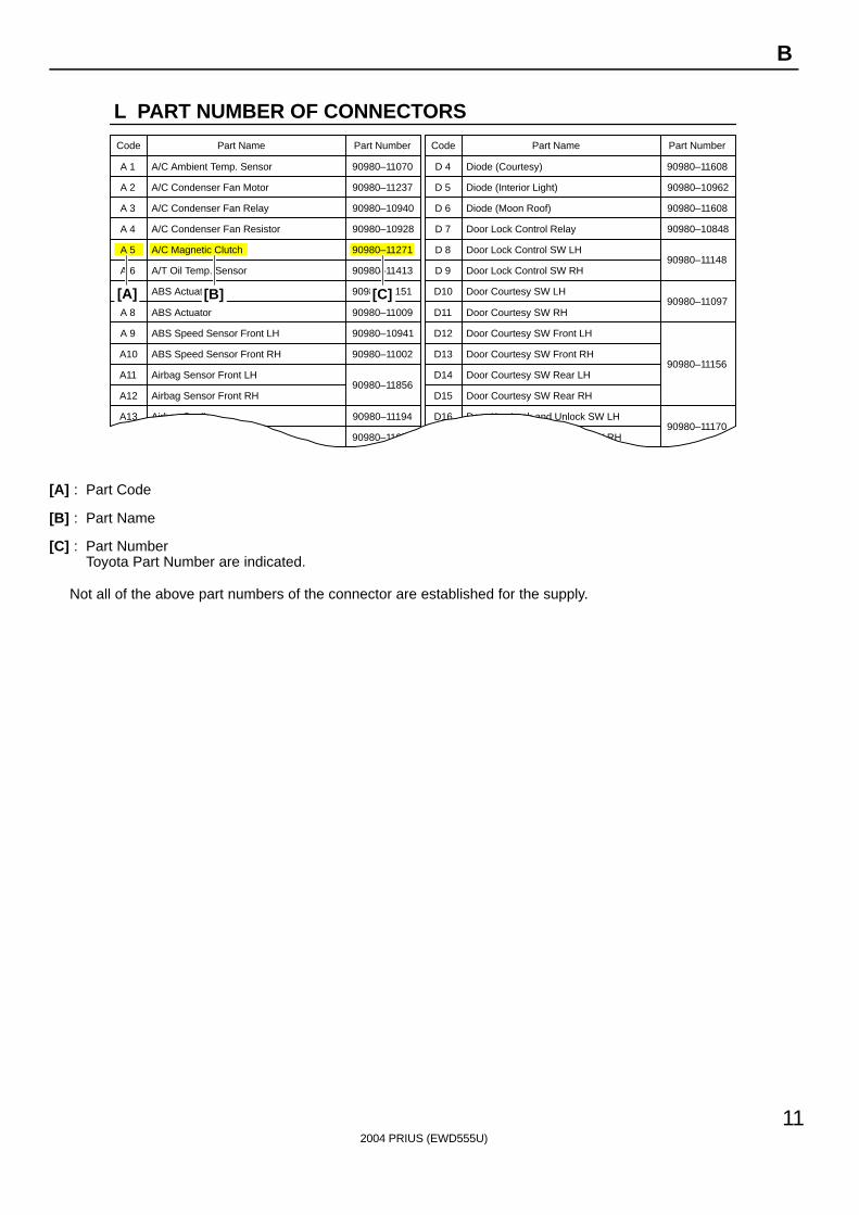
[A] : Part Code
[B] : Part Name
[C] : Part NumberToyota Part Number are indicated.
Not all of the above part numbers of the connector are established for the supply.
To Ignition SWIG Terminal
Fuse
VoltmeterSW 1
Relay
SW 2 Solenoid
[A]
[B]
[C]
Ohmmeter
SW
Ohmmeter
Diode
Digital Type Analog Type
2004 PRIUS (EWD555U)
12
C TROUBLESHOOTING
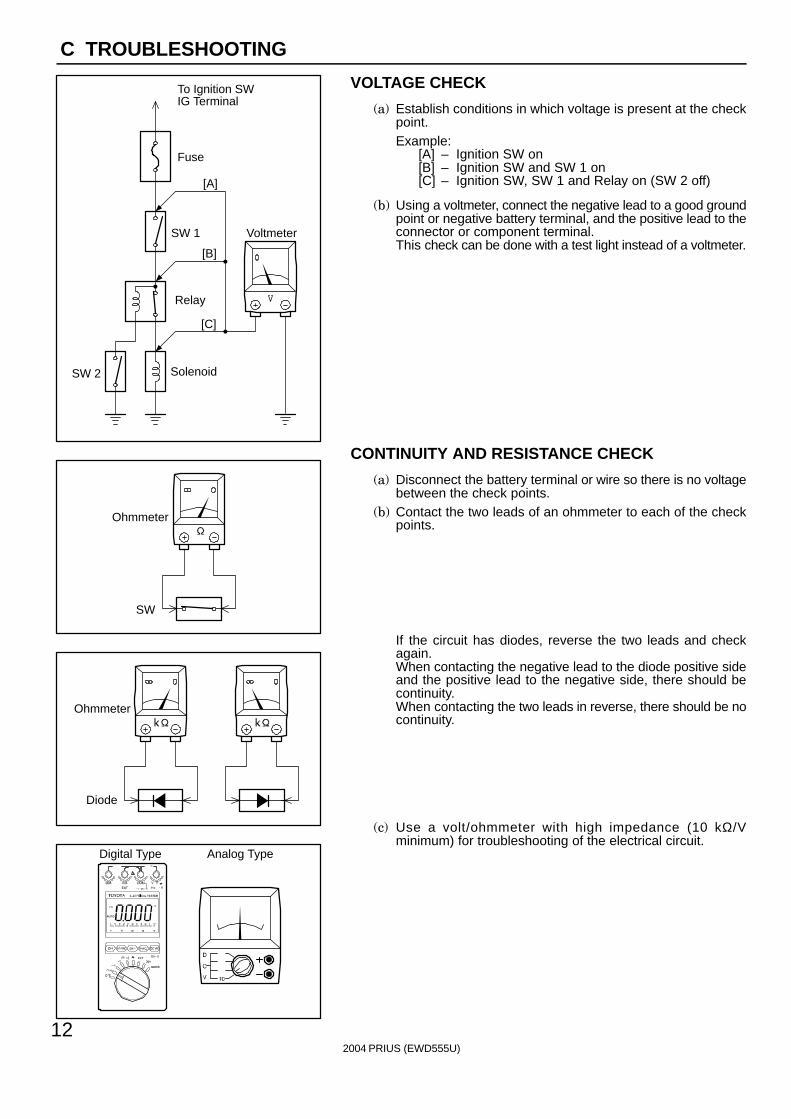
VOLTAGE CHECK
(a) Establish conditions in which voltage is present at the checkpoint.Example:
[A] – Ignition SW on[B] – Ignition SW and SW 1 on[C] – Ignition SW, SW 1 and Relay on (SW 2 off)
(b) Using a voltmeter, connect the negative lead to a good groundpoint or negative battery terminal, and the positive lead to theconnector or component terminal.This check can be done with a test light instead of a voltmeter.
CONTINUITY AND RESISTANCE CHECK
(a) Disconnect the battery terminal or wire so there is no voltagebetween the check points.
(b) Contact the two leads of an ohmmeter to each of the checkpoints.
If the circuit has diodes, reverse the two leads and checkagain.When contacting the negative lead to the diode positive sideand the positive lead to the negative side, there should becontinuity.When contacting the two leads in reverse, there should be nocontinuity.
(c) Use a volt/ohmmeter with high impedance (10 kΩ/Vminimum) for troubleshooting of the electrical circuit.
To Ignition SWIG Terminal
Test Light
RelayLight
SW 2 Solenoid
Disconnect
Short [A]
DisconnectDisconnect
SW 1
Fuse Case
Short [B]
Short [C]
Pull Up
Press Down Press Down
Pull Up
2004 PRIUS (EWD555U)
13
C
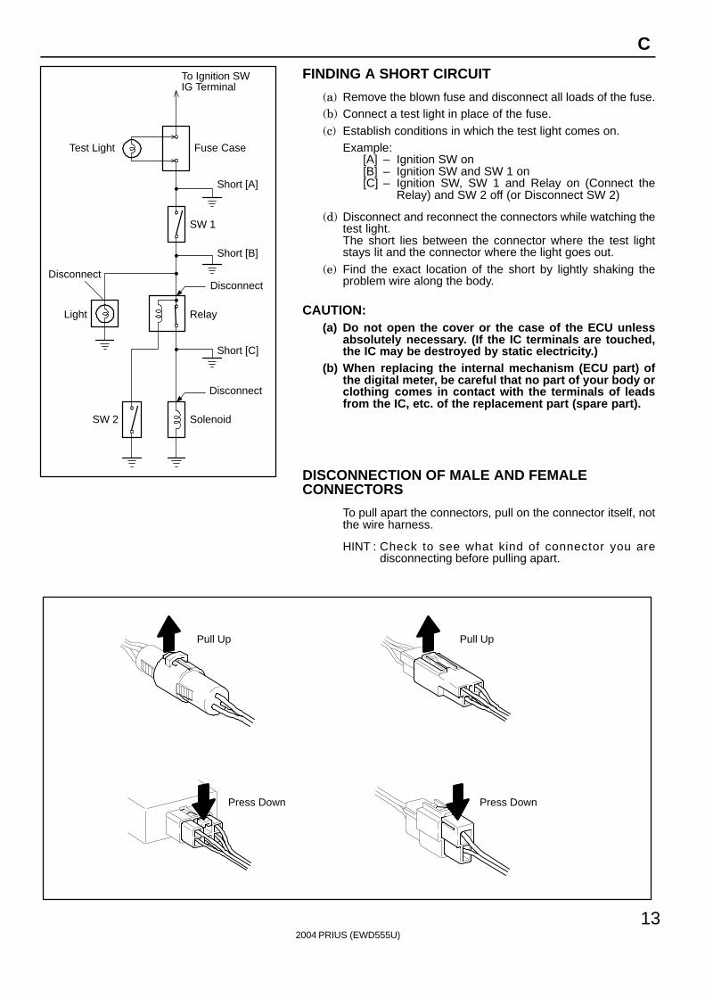
FINDING A SHORT CIRCUIT
(a) Remove the blown fuse and disconnect all loads of the fuse.(b) Connect a test light in place of the fuse.(c) Establish conditions in which the test light comes on.
Example:[A] – Ignition SW on[B] – Ignition SW and SW 1 on[C] – Ignition SW, SW 1 and Relay on (Connect the
Relay) and SW 2 off (or Disconnect SW 2)
(d) Disconnect and reconnect the connectors while watching thetest light.The short lies between the connector where the test lightstays lit and the connector where the light goes out.
(e) Find the exact location of the short by lightly shaking theproblem wire along the body.
CAUTION:(a) Do not open the cover or the case of the ECU unless
absolutely necessary. (If the IC terminals are touched,the IC may be destroyed by static electricity.)
(b) When replacing the internal mechanism (ECU part) ofthe digital meter, be careful that no part of your body orclothing comes in contact with the terminals of leadsfrom the IC, etc. of the replacement part (spare part).
DISCONNECTION OF MALE AND FEMALECONNECTORS
To pull apart the connectors, pull on the connector itself, notthe wire harness.
HINT : Check to see what kind of connector you aredisconnecting before pulling apart.
10
3
0.21
1
(mm)
Reference:
ToolUpExample:(Case 1)
Terminal Retainer
Terminal Retainer
[Retainer at Full Lock Position]
[Retainer at Temporary Lock Position]
StopperTerminalRetainer
SecondaryLocking Device
Example:(Case 2)
2004 PRIUS (EWD555U)
14
C TROUBLESHOOTING
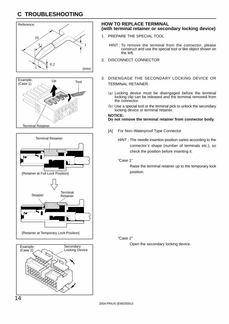
HOW TO REPLACE TERMINAL(with terminal retainer or secondary locking device)
1. PREPARE THE SPECIAL TOOL
HINT : To remove the terminal from the connector, pleaseconstruct and use the special tool or like object shown onthe left.
2. DISCONNECT CONNECTOR
3. DISENGAGE THE SECONDARY LOCKING DEVICE OR
TERMINAL RETAINER.
(a) Locking device must be disengaged before the terminallocking clip can be released and the terminal removed fromthe connector.
(b) Use a special tool or the terminal pick to unlock the secondarylocking device or terminal retainer.
NOTICE:Do not remove the terminal retainer from connector body.
[A] For Non–Waterproof Type Connector
HINT : The needle insertion position varies according to the
connector’s shape (number of terminals etc.), so
check the position before inserting it.
”Case 1”
Raise the terminal retainer up to the temporary lock
position.
”Case 2”
Open the secondary locking device.
ToolTab
Tab
TerminalRetainer
Access Hole( Mark)
Tool
Tool
[Female]
Example:
[Male]
(Case 1)
[Male] [Female]
Retainerat Full Lock Position
Retainerat Temporary Lock Position
Terminal Retainer
[Male] Press Down [Female]Press Down
ToolTool
Example:(Case 2)
2004 PRIUS (EWD555U)
15
C
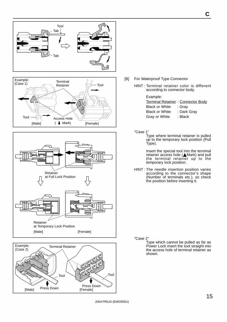
[B] For Waterproof Type Connector
HINT : Terminal retainer color is differentaccording to connector body.
Example:Terminal Retainer : Connector BodyBlack or White : GrayBlack or White : Dark GrayGray or White : Black
”Case 1”Type where terminal retainer is pulledup to the temporary lock position (PullType).
Insert the special tool into the terminalretainer access hole (Mark) and pullthe terminal retainer up to thetemporary lock position.
HINT : The needle insertion position variesaccording to the connector’s shape(Number of terminals etc.), so checkthe position before inserting it.
”Case 2”Type which cannot be pulled as far asPower Lock insert the tool straight intothe access hole of terminal retainer asshown.
Retainer atFull Lock Position
[Male] [Female]
Retainer atTemporary Lock Position
Locking Lug
Tool
2004 PRIUS (EWD555U)
16
C TROUBLESHOOTING
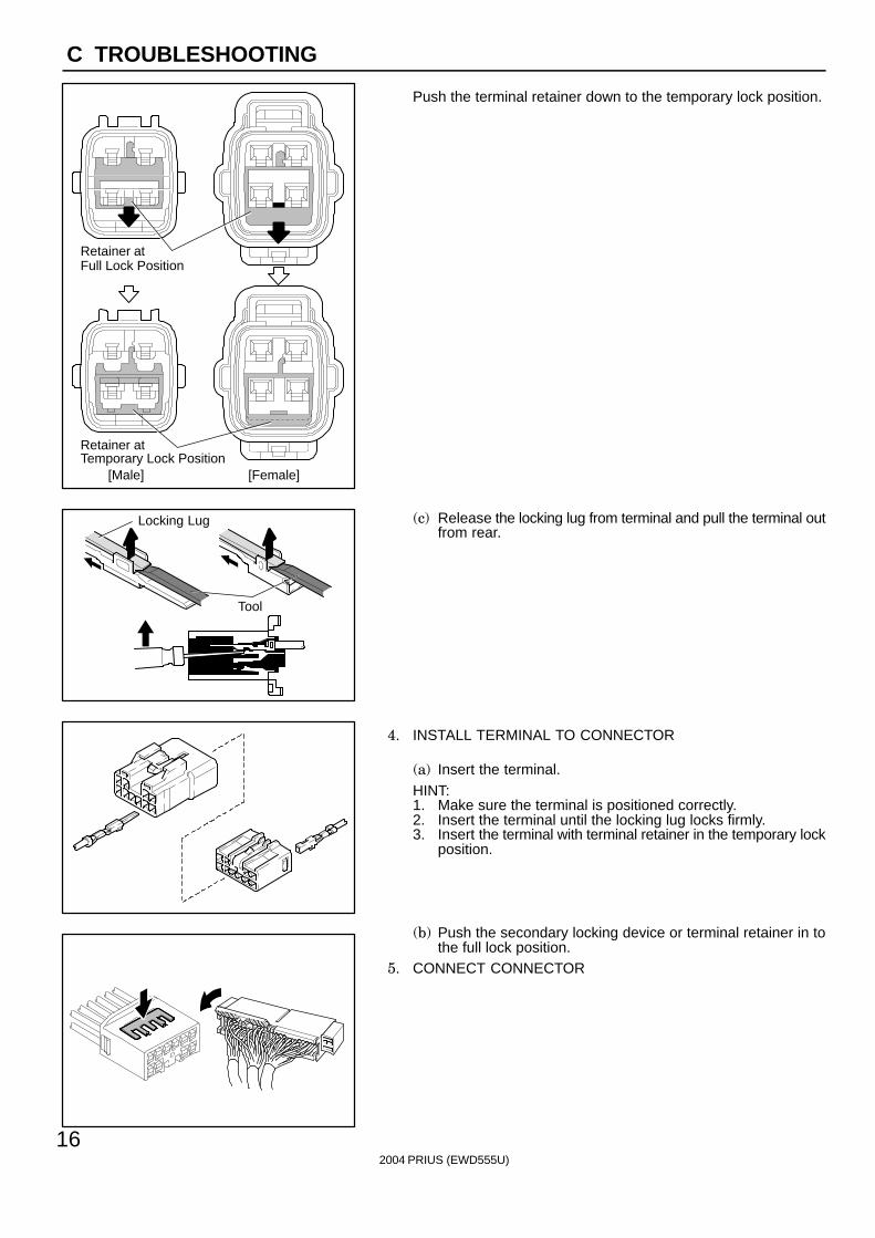
Push the terminal retainer down to the temporary lock position.
(c) Release the locking lug from terminal and pull the terminal outfrom rear.
4. INSTALL TERMINAL TO CONNECTOR
(a) Insert the terminal.HINT:1. Make sure the terminal is positioned correctly.2. Insert the terminal until the locking lug locks firmly.3. Insert the terminal with terminal retainer in the temporary lock
position.
(b) Push the secondary locking device or terminal retainer in tothe full lock position.
5. CONNECT CONNECTOR
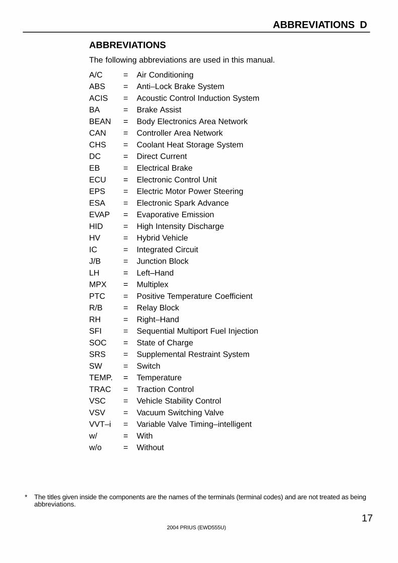
∗ The titles given inside the components are the names of the terminals (terminal codes) and are not treated as beingabbreviations.
2004 PRIUS (EWD555U)
17
ABBREVIATIONS D
ABBREVIATIONS
The following abbreviations are used in this manual.
A/C = Air ConditioningABS = Anti–Lock Brake System
ACIS = Acoustic Control Induction SystemBA = Brake Assist
BEAN = Body Electronics Area NetworkCAN = Controller Area Network
CHS = Coolant Heat Storage SystemDC = Direct Current
EB = Electrical Brake
ECU = Electronic Control UnitEPS = Electric Motor Power Steering
ESA = Electronic Spark AdvanceEVAP = Evaporative Emission
HID = High Intensity DischargeHV = Hybrid Vehicle
IC = Integrated CircuitJ/B = Junction Block
LH = Left–HandMPX = Multiplex
PTC = Positive Temperature CoefficientR/B = Relay Block
RH = Right–HandSFI = Sequential Multiport Fuel Injection
SOC = State of ChargeSRS = Supplemental Restraint System
SW = SwitchTEMP. = Temperature
TRAC = Traction ControlVSC = Vehicle Stability Control
VSV = Vacuum Switching ValveVVT–i = Variable Valve Timing–intelligent
w/ = Withw/o = Without
2004 PRIUS (EWD555U)
18
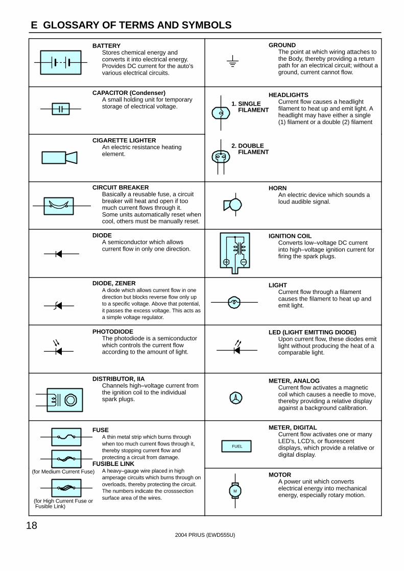
E GLOSSARY OF TERMS AND SYMBOLS
BATTERYStores chemical energy andconverts it into electrical energy.Provides DC current for the auto’svarious electrical circuits.
GROUNDThe point at which wiring attaches tothe Body, thereby providing a returnpath for an electrical circuit; without aground, current cannot flow.
CAPACITOR (Condenser)A small holding unit for temporarystorage of electrical voltage.
HEADLIGHTSCurrent flow causes a headlightfilament to heat up and emit light. Aheadlight may have either a single(1) filament or a double (2) filament
1. SINGLE FILAMENT
CIGARETTE LIGHTERAn electric resistance heatingelement.
2. DOUBLE FILAMENT
CIRCUIT BREAKERBasically a reusable fuse, a circuitbreaker will heat and open if toomuch current flows through it.Some units automatically reset whencool, others must be manually reset.
HORNAn electric device which sounds aloud audible signal.
DIODEA semiconductor which allowscurrent flow in only one direction.
IGNITION COILConverts low–voltage DC currentinto high–voltage ignition current forfiring the spark plugs.
DIODE, ZENERA diode which allows current flow in onedirection but blocks reverse flow only upto a specific voltage. Above that potential,it passes the excess voltage. This acts asa simple voltage regulator.
LIGHTCurrent flow through a filamentcauses the filament to heat up andemit light.
PHOTODIODEThe photodiode is a semiconductorwhich controls the current flowaccording to the amount of light.
LED (LIGHT EMITTING DIODE)Upon current flow, these diodes emitlight without producing the heat of acomparable light.
DISTRIBUTOR, IIAChannels high–voltage current fromthe ignition coil to the individualspark plugs.
METER, ANALOGCurrent flow activates a magneticcoil which causes a needle to move,thereby providing a relative displayagainst a background calibration.
FUSEA thin metal strip which burns throughwhen too much current flows through it,thereby stopping current flow andprotecting a circuit from damage.
FUSIBLE LINK
METER, DIGITALCurrent flow activates one or manyLED’s, LCD’s, or fluorescentdisplays, which provide a relative ordigital display.
FUEL
FUSIBLE LINKA heavy–gauge wire placed in highamperage circuits which burns through onoverloads, thereby protecting the circuit.The numbers indicate the crosssectionsurface area of the wires.
(for Medium Current Fuse)
(for High Current Fuse or Fusible Link)
MOTORA power unit which convertselectrical energy into mechanicalenergy, especially rotary motion.
M
2004 PRIUS (EWD555U)
19
E
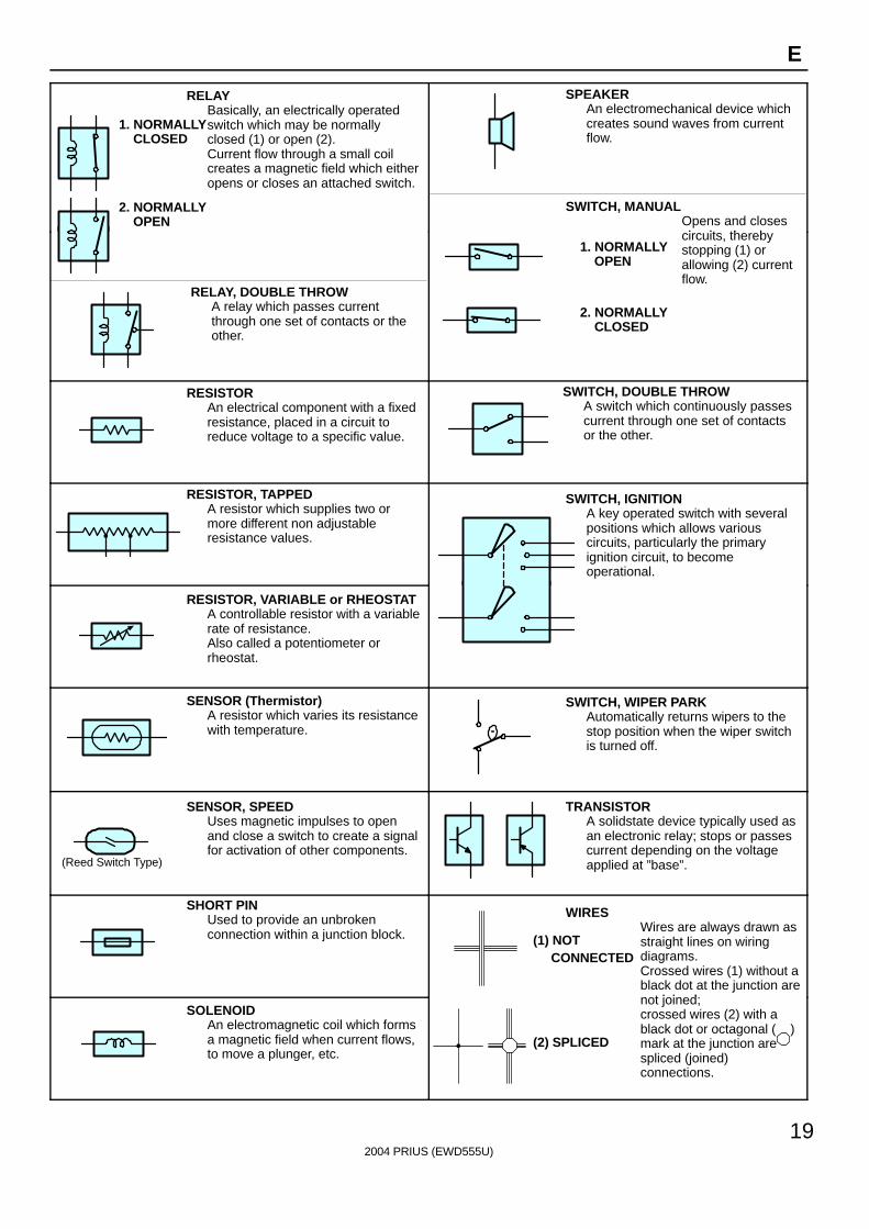
RELAYBasically, an electrically operatedswitch which may be normallyclosed (1) or open (2).Current flow through a small coilcreates a magnetic field which eitheropens or closes an attached switch.
1. NORMALLY CLOSED
2. NORMALLY OPEN
SWITCH, MANUALOpens and closesi it th b
SPEAKERAn electromechanical device whichcreates sound waves from currentflow.
RELAY, DOUBLE THROWA relay which passes currentthrough one set of contacts or theother.
circuits, therebystopping (1) orallowing (2) currentflow.
1. NORMALLY OPEN
2. NORMALLY CLOSED
RESISTORAn electrical component with a fixedresistance, placed in a circuit toreduce voltage to a specific value.
SWITCH, DOUBLE THROWA switch which continuously passescurrent through one set of contactsor the other.
RESISTOR, TAPPEDA resistor which supplies two ormore different non adjustableresistance values.
SWITCH, IGNITIONA key operated switch with severalpositions which allows variouscircuits, particularly the primaryignition circuit, to becomeoperational.
RESISTOR, VARIABLE or RHEOSTATA controllable resistor with a variablerate of resistance.Also called a potentiometer orrheostat.
SENSOR (Thermistor)A resistor which varies its resistancewith temperature.
SWITCH, WIPER PARKAutomatically returns wipers to thestop position when the wiper switchis turned off.
(Reed Switch Type)
SENSOR, SPEEDUses magnetic impulses to openand close a switch to create a signalfor activation of other components.
TRANSISTORA solidstate device typically used asan electronic relay; stops or passescurrent depending on the voltageapplied at ”base”.
SHORT PINUsed to provide an unbrokenconnection within a junction block.
WIRESWires are always drawn asstraight lines on wiringdiagrams.Crossed wires (1) without ablack dot at the junction are
t j i d
(1) NOT CONNECTED
SOLENOIDAn electromagnetic coil which formsa magnetic field when current flows,to move a plunger, etc.
jnot joined;crossed wires (2) with ablack dot or octagonal ( )mark at the junction arespliced (joined)connections.
(2) SPLICED
2004 PRIUS (EWD555U)
20
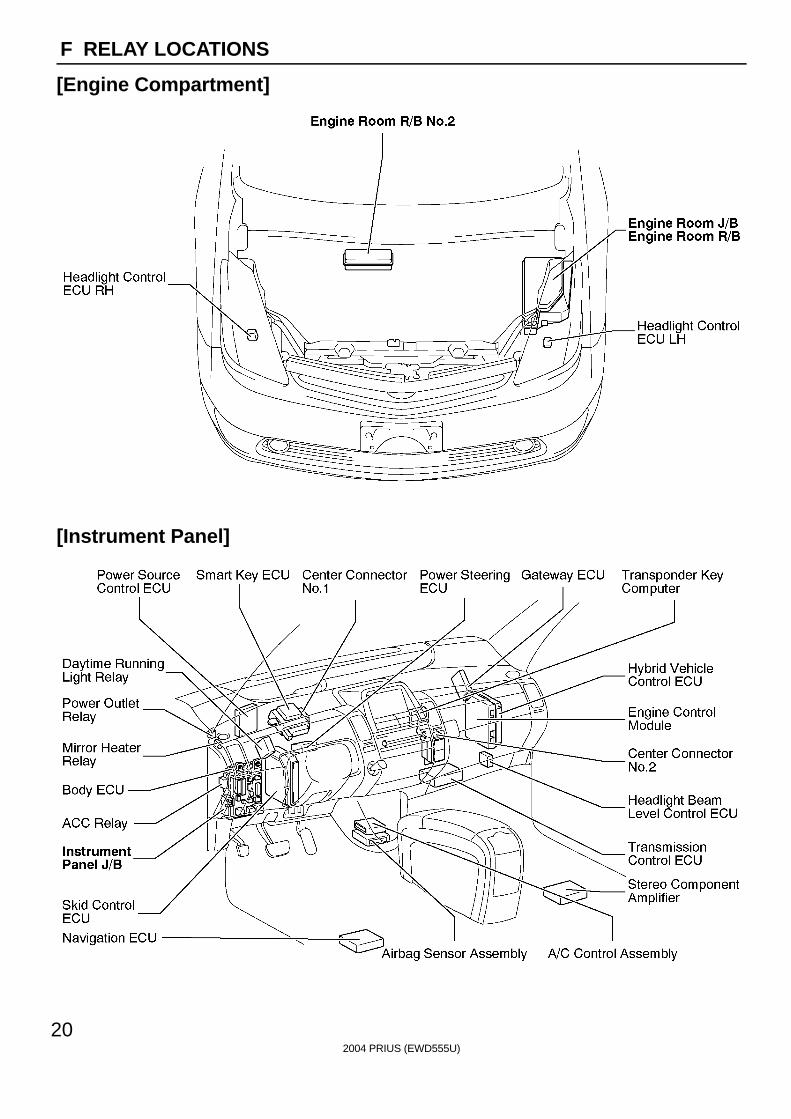
F RELAY LOCATIONS
[Engine Compartment]
[Instrument Panel]
2004 PRIUS (EWD555U)
21
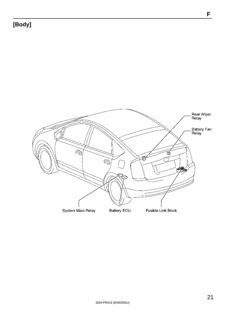
F
[Body]
2004 PRIUS (EWD555U)
22
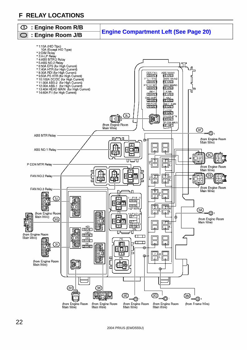
F RELAY LOCATIONS
3 : Engine Room R/BEngine Compartment Left (See Page 20): Engine Room J/B Engine Compar tment Left (See Page 20)

2004 PRIUS (EWD555U)
23
Memo
2004 PRIUS (EWD555U)
24
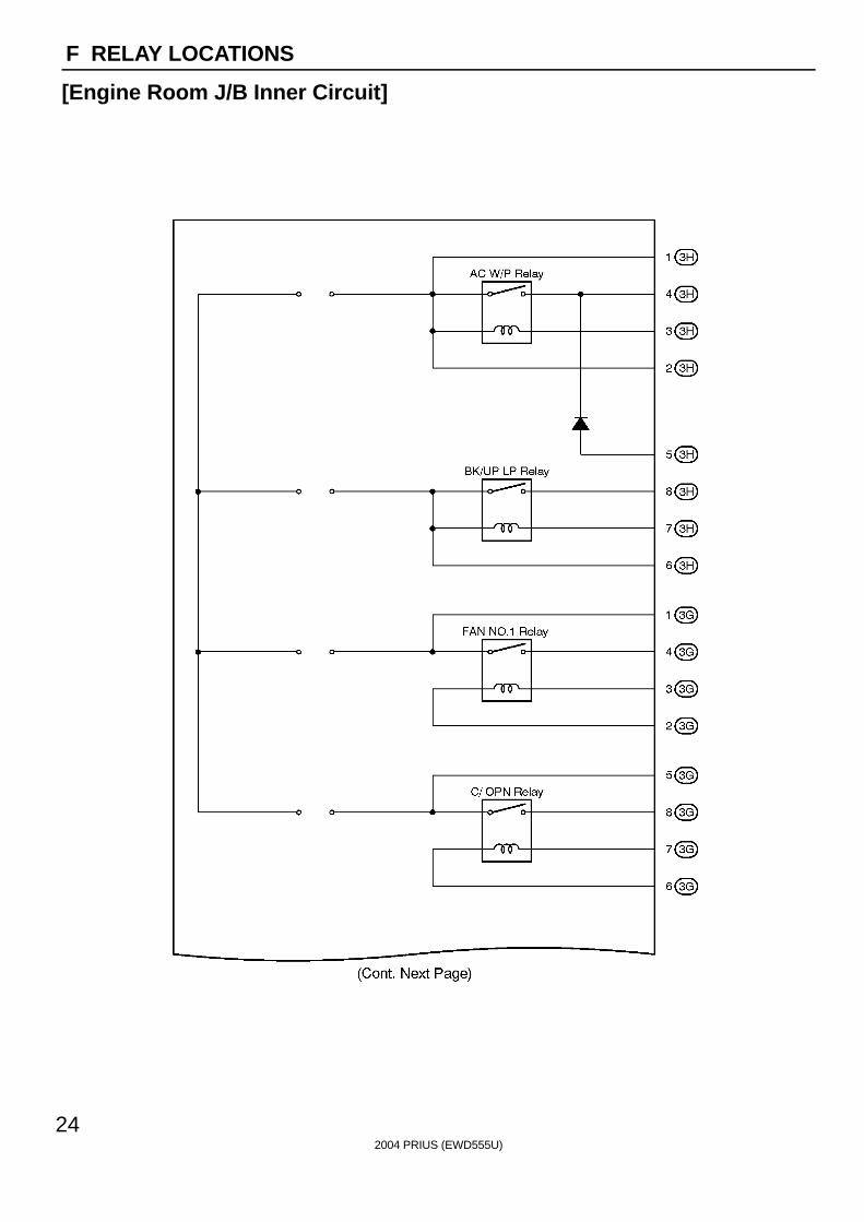
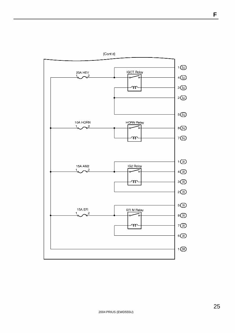
F RELAY LOCATIONS
[Engine Room J/B Inner Circuit]
2004 PRIUS (EWD555U)
25
F
2004 PRIUS (EWD555U)
26
F RELAY LOCATIONS
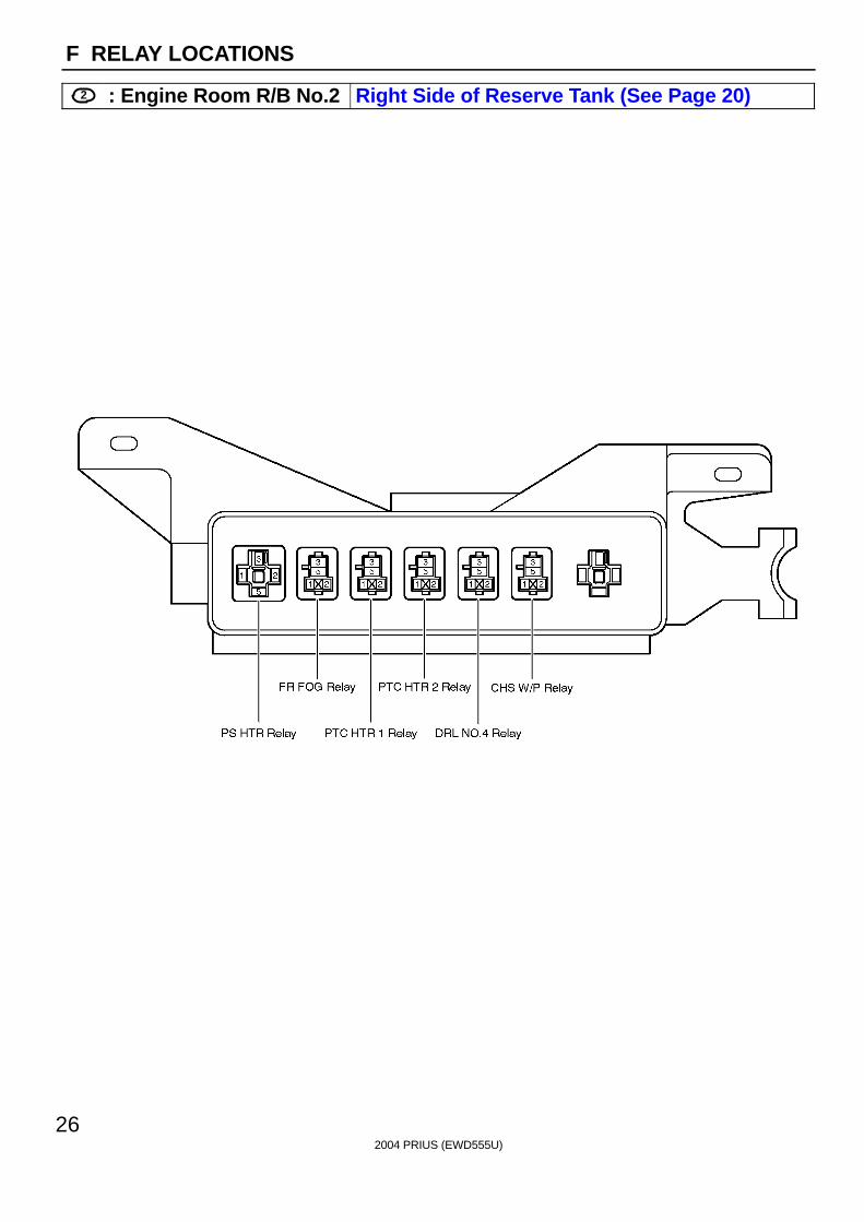
2 : Engine Room R/B No.2 Right Side of Reserve Tank (See Page 20)

2004 PRIUS (EWD555U)
27
F
Fusible Link Block Luggage Room Right (See Page 21)
2004 PRIUS (EWD555U)
28
F RELAY LOCATIONS
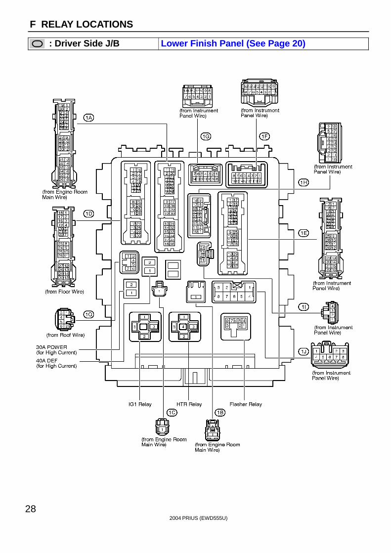
: Driver Side J/B Lower Finish Panel (See Page 20)
2004 PRIUS (EWD555U)
29
F
2004 PRIUS (EWD555U)
30
F RELAY LOCATIONS
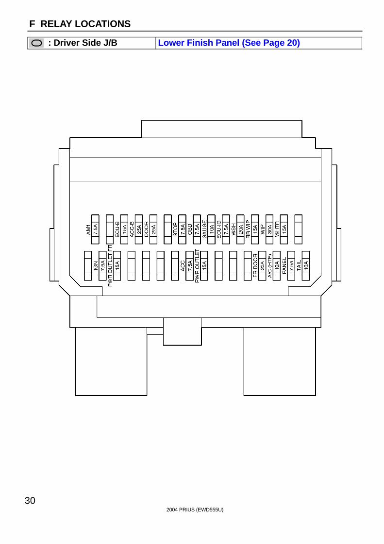
: Driver Side J/B Lower Finish Panel (See Page 20)
2004 PRIUS (EWD555U)
31
Memo
2004 PRIUS (EWD555U)
32
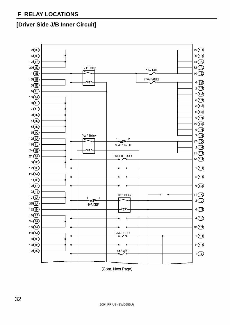
F RELAY LOCATIONS
[Driver Side J/B Inner Circuit]
2004 PRIUS (EWD555U)
33
F
2004 PRIUS (EWD555U)
34
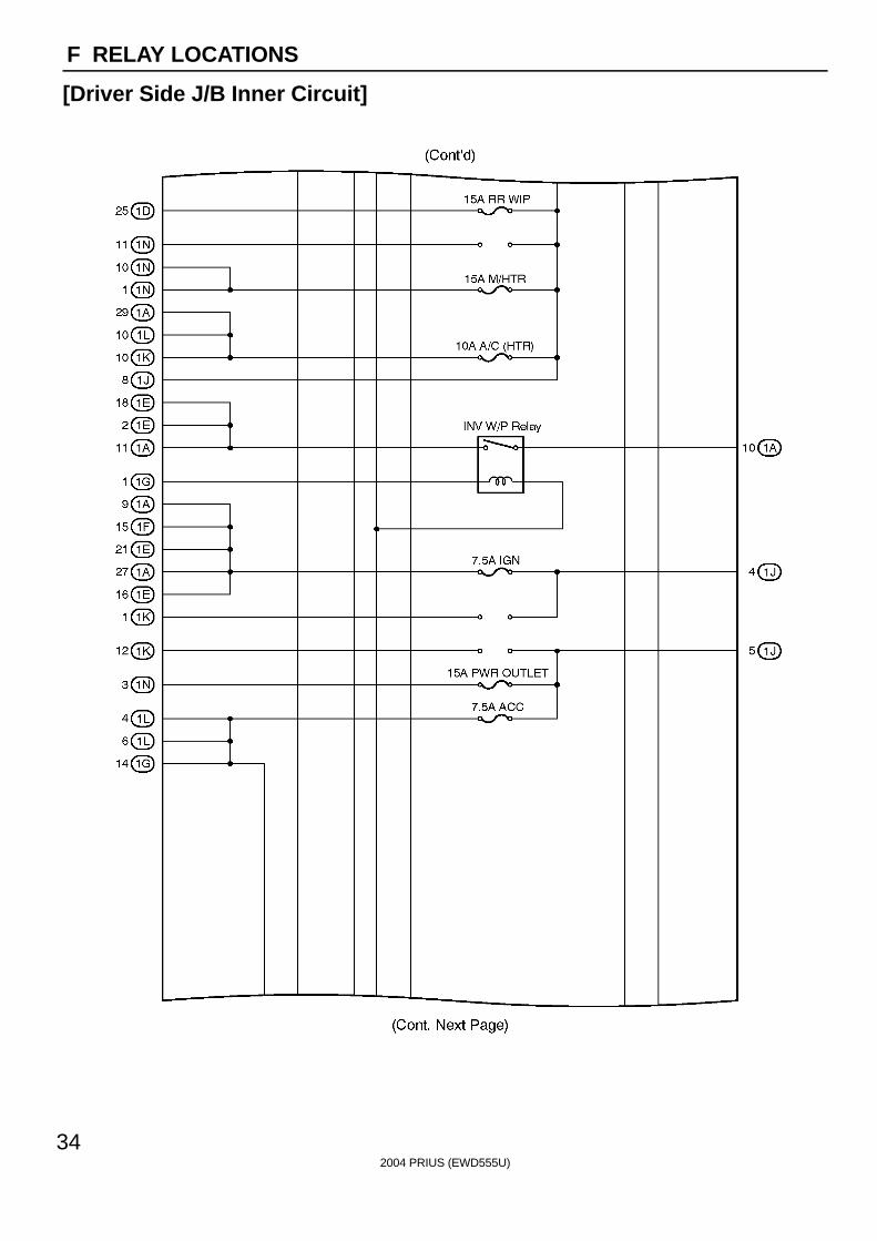
F RELAY LOCATIONS
[Driver Side J/B Inner Circuit]
2004 PRIUS (EWD555U)
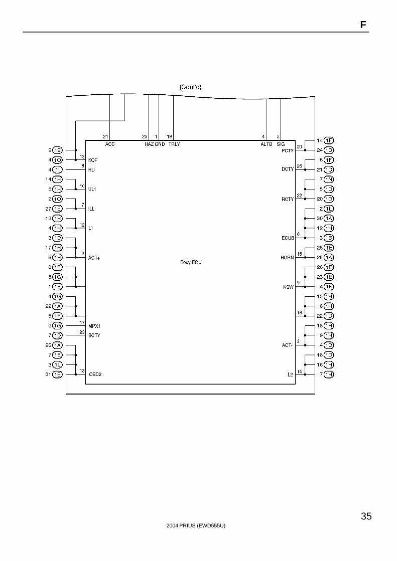
35
F
2004 PRIUS (EWD555U)
36
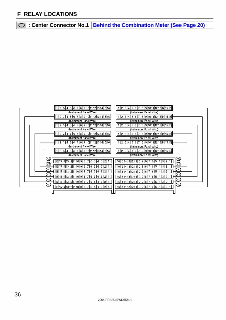
F RELAY LOCATIONS
: Center Connector No.1 Behind the Combination Meter (See Page 20)

2004 PRIUS (EWD555U)
37
Memo
2004 PRIUS (EWD555U)
38
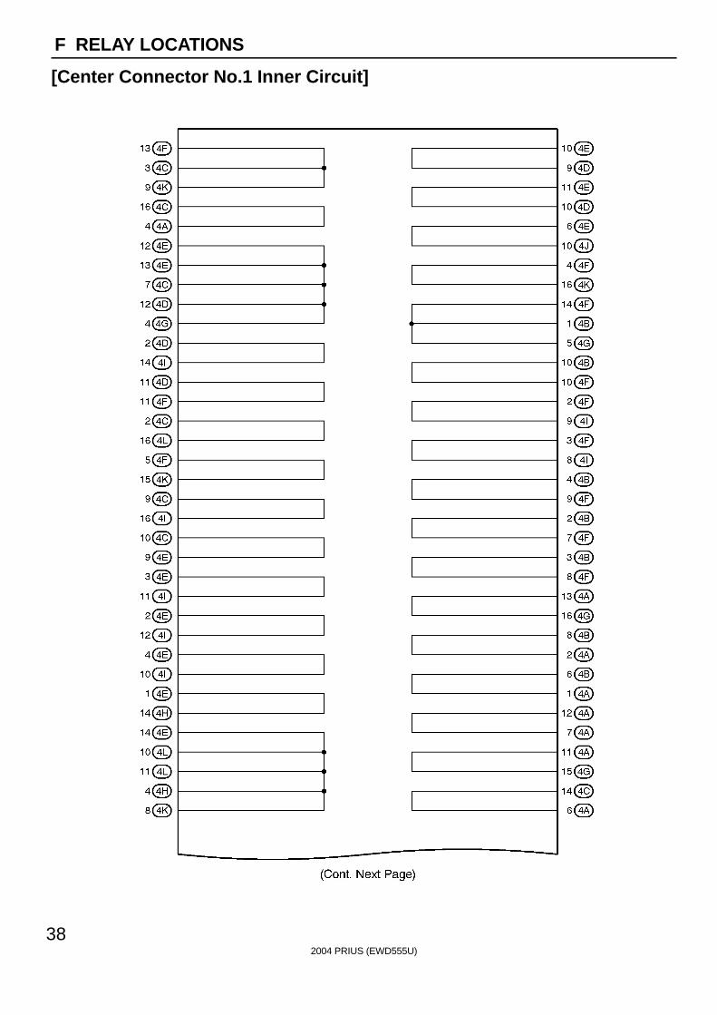
F RELAY LOCATIONS
[Center Connector No.1 Inner Circuit]
2004 PRIUS (EWD555U)
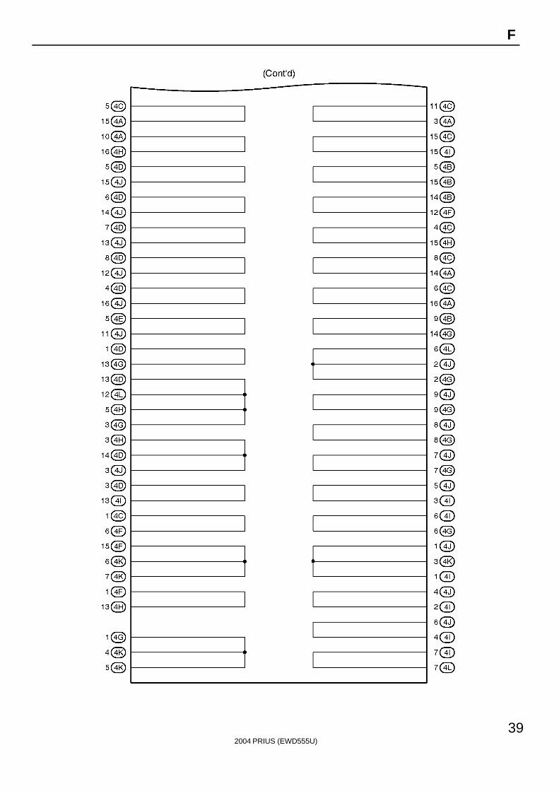
39
F
2004 PRIUS (EWD555U)
40
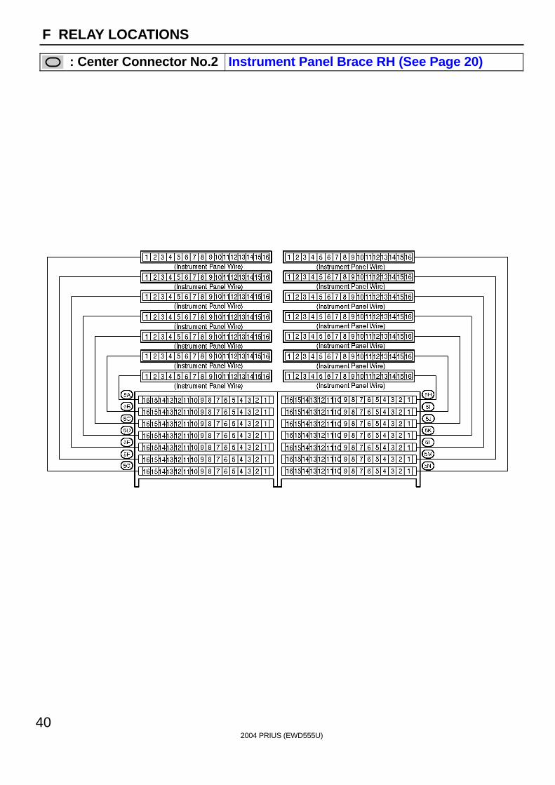
F RELAY LOCATIONS
: Center Connector No.2 Instrument Panel Brace RH (See Page 20)
2004 PRIUS (EWD555U)
41
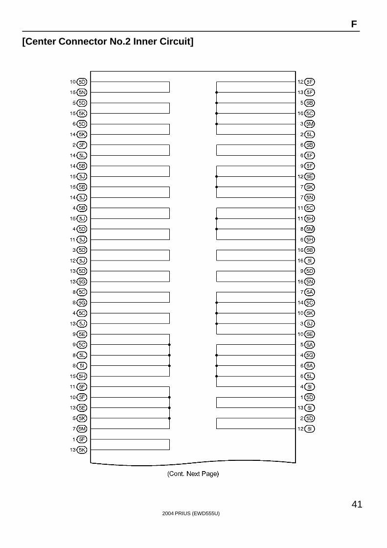
F
[Center Connector No.2 Inner Circuit]
2004 PRIUS (EWD555U)
42
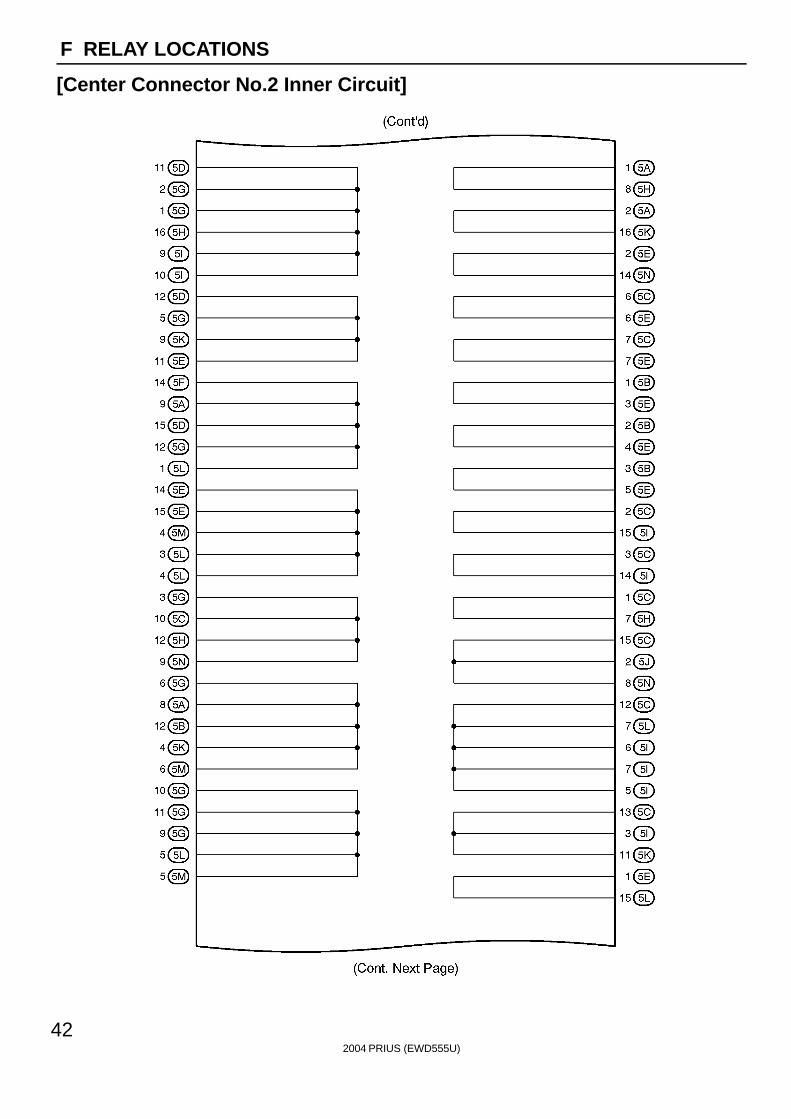
F RELAY LOCATIONS
[Center Connector No.2 Inner Circuit]
2004 PRIUS (EWD555U)
43
F
2004 PRIUS (EWD555U)
44
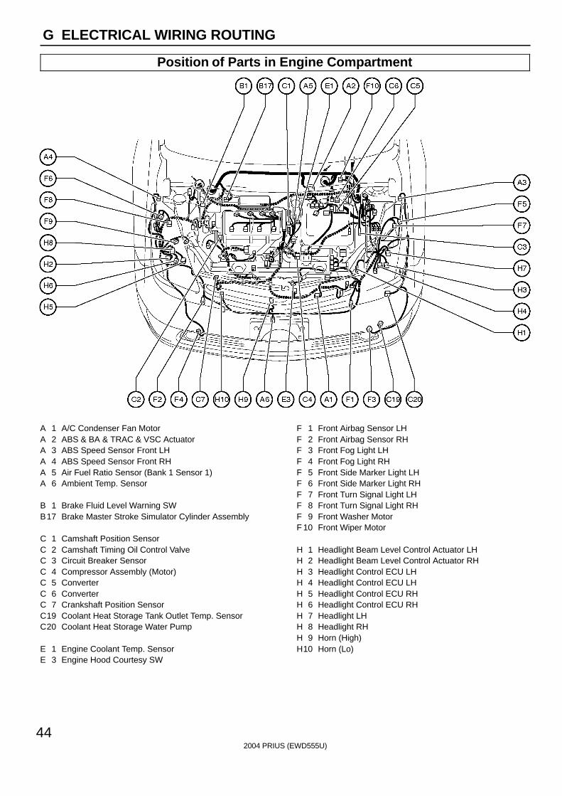
G ELECTRICAL WIRING ROUTING
Position of Parts in Engine Compartment
A 1 A/C Condenser Fan MotorA 2 ABS & BA & TRAC & VSC ActuatorA 3 ABS Speed Sensor Front LHA 4 ABS Speed Sensor Front RHA 5 Air Fuel Ratio Sensor (Bank 1 Sensor 1)A 6 Ambient Temp. Sensor
B 1 Brake Fluid Level Warning SWB17 Brake Master Stroke Simulator Cylinder Assembly
C 1 Camshaft Position SensorC 2 Camshaft Timing Oil Control ValveC 3 Circuit Breaker SensorC 4 Compressor Assembly (Motor)C 5 ConverterC 6 ConverterC 7 Crankshaft Position SensorC19 Coolant Heat Storage Tank Outlet Temp. SensorC20 Coolant Heat Storage Water Pump
E 1 Engine Coolant Temp. SensorE 3 Engine Hood Courtesy SW
F 1 Front Airbag Sensor LHF 2 Front Airbag Sensor RHF 3 Front Fog Light LHF 4 Front Fog Light RHF 5 Front Side Marker Light LHF 6 Front Side Marker Light RHF 7 Front Turn Signal Light LHF 8 Front Turn Signal Light RHF 9 Front Washer MotorF 10 Front Wiper Motor
H 1 Headlight Beam Level Control Actuator LHH 2 Headlight Beam Level Control Actuator RHH 3 Headlight Control ECU LHH 4 Headlight Control ECU LHH 5 Headlight Control ECU RHH 6 Headlight Control ECU RHH 7 Headlight LHH 8 Headlight RHH 9 Horn (High)H10 Horn (Lo)

2004 PRIUS (EWD555U)
45
G
Position of Parts in Engine Compartment
I 1 Ignition Coil and Igniter No.1I 2 Ignition Coil and Igniter No.2I 3 Ignition Coil and Igniter No.3I 4 Ignition Coil and Igniter No.4I 5 Injector No.1I 6 Injector No.2I 7 Injector No.3I 8 Injector No.4I 9 InverterI 10 InverterI 11 InverterI 12 InverterI 13 InverterI 14 InverterI 15 InverterI 16 Inverter
J 1 Junction ConnectorJ 2 Junction ConnectorJ 3 Junction ConnectorJ 4 Junction Connector
K 1 Knock Sensor
M 1 Mass Air Flow MeterM 2 Motor Generator No.1M 3 Motor Generator No.1M 4 Motor Generator No.1M 5 Motor Generator No.1M 6 Motor Generator No.2M 7 Motor Generator No.2
M 8 Motor Generator No.2M 9 Motor Generator No.2M10 Motor Generator No.2
N 1 Noise Filter (Ignition)
O 1 Oil Pressure SW
P 1 Pressure SW
R 1 Radiator Fan MotorR 2 Rear Washer Motor
S 1 Shift Control ActuatorS 2 Short ConnectorS 3 Short ConnectorS27 Short Connector (Water Pump)S28 Short Connector (Water Pump)
T 1 Theft Deterrent HornT 2 Throttle Control MotorT 3 Throttle Position Sensor
V 1 VSV (EVAP)
W 1 Water Pump Motor (A/C)W 3 Water Pump Motor (Inverter)W 4 Water Temp. SWW 5 Water ValveW 6 Wireless Door Lock Buzzer

2004 PRIUS (EWD555U)
46
G ELECTRICAL WIRING ROUTING
Position of Parts in Instrument Panel
A 7 A/C Control AssemblyA 8 A/C Control AssemblyA 9 A/C Room Temp. SensorA10 A/C Solar SensorA 11 A/C ThermistorA12 ACC RelayA13 Accel Position SensorA14 Air Inlet Control Servo MotorA15 Air Mix Control Servo MotorA16 Air Vent Mode Control Servo MotorA17 Airbag Sensor AssemblyA18 Airbag Sensor AssemblyA19 Airbag Sensor AssemblyA20 Airbag Squib (Front Passenger Airbag Assembly No.1)A21 Airbag Squib (Front Passenger Airbag Assembly No.2)A22 Airbag Squib (Steering Wheel Pad)A23 Antenna AmplifierA24 Automatic Light Control Sensor
B 2 Blower MotorB 3 Blower Motor ControllerB 4 Blower Motor ControllerB 5 Body ECUB 6 Body ECUB 7 Body ECUB 8 Brake Pedal Stroke Sensor
2004 PRIUS (EWD555U)
47
G
Position of Parts in Instrument Panel
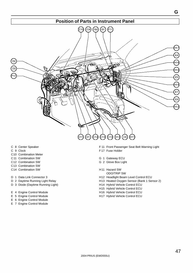
C 8 Center SpeakerC 9 ClockC10 Combination MeterC11 Combination SWC12 Combination SWC13 Combination SWC14 Combination SW
D 1 Data Link Connector 3D 2 Daytime Running Light RelayD 3 Diode (Daytime Running Light)
E 4 Engine Control ModuleE 5 Engine Control ModuleE 6 Engine Control ModuleE 7 Engine Control Module
F 11 Front Passenger Seat Belt Warning LightF 17 Fuse Holder
G 1 Gateway ECUG 2 Glove Box Light
H11 Hazard SWODO/TRIP SW
H12 Headlight Beam Level Control ECUH13 Heated Oxygen Sensor (Bank 1 Sensor 2)H14 Hybrid Vehicle Control ECUH15 Hybrid Vehicle Control ECUH16 Hybrid Vehicle Control ECUH17 Hybrid Vehicle Control ECU
2004 PRIUS (EWD555U)
48
G ELECTRICAL WIRING ROUTING
Position of Parts in Instrument Panel
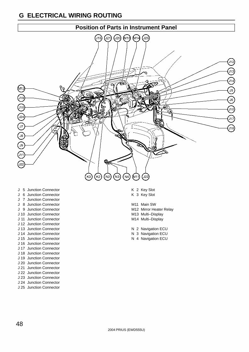
J 5 Junction ConnectorJ 6 Junction ConnectorJ 7 Junction ConnectorJ 8 Junction ConnectorJ 9 Junction ConnectorJ 10 Junction ConnectorJ 11 Junction ConnectorJ 12 Junction ConnectorJ 13 Junction ConnectorJ 14 Junction ConnectorJ 15 Junction ConnectorJ 16 Junction ConnectorJ 17 Junction ConnectorJ 18 Junction ConnectorJ 19 Junction ConnectorJ 20 Junction ConnectorJ 21 Junction ConnectorJ 22 Junction ConnectorJ 23 Junction ConnectorJ 24 Junction ConnectorJ 25 Junction Connector
K 2 Key SlotK 3 Key Slot
M11 Main SWM12 Mirror Heater RelayM13 Multi–DisplayM14 Multi–Display
N 2 Navigation ECUN 3 Navigation ECUN 4 Navigation ECU
2004 PRIUS (EWD555U)
49
G
Position of Parts in Instrument Panel
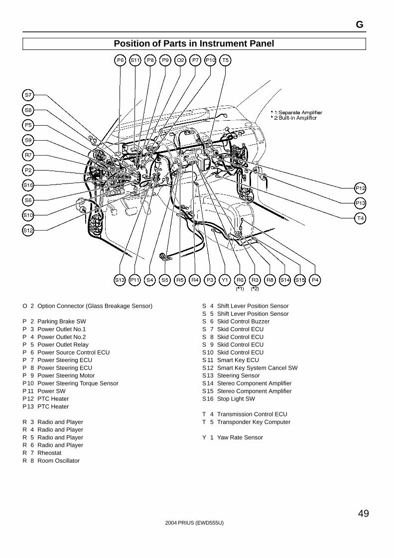
O 2 Option Connector (Glass Breakage Sensor)
P 2 Parking Brake SWP 3 Power Outlet No.1P 4 Power Outlet No.2P 5 Power Outlet RelayP 6 Power Source Control ECUP 7 Power Steering ECUP 8 Power Steering ECUP 9 Power Steering MotorP10 Power Steering Torque SensorP 11 Power SWP12 PTC HeaterP13 PTC Heater
R 3 Radio and PlayerR 4 Radio and PlayerR 5 Radio and PlayerR 6 Radio and PlayerR 7 RheostatR 8 Room Oscillator
S 4 Shift Lever Position SensorS 5 Shift Lever Position SensorS 6 Skid Control BuzzerS 7 Skid Control ECUS 8 Skid Control ECUS 9 Skid Control ECUS10 Skid Control ECUS 11 Smart Key ECUS12 Smart Key System Cancel SWS13 Steering SensorS14 Stereo Component AmplifierS15 Stereo Component AmplifierS16 Stop Light SW
T 4 Transmission Control ECUT 5 Transponder Key Computer
Y 1 Yaw Rate Sensor
2004 PRIUS (EWD555U)
50
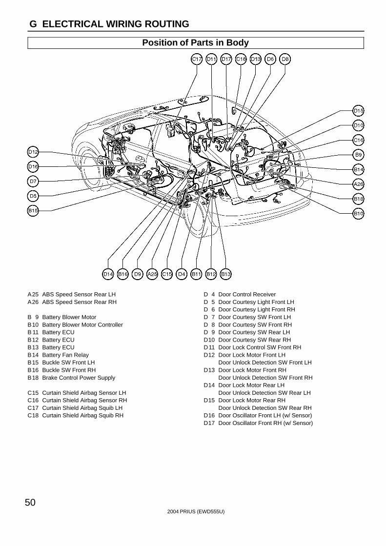
G ELECTRICAL WIRING ROUTING
Position of Parts in Body
A25 ABS Speed Sensor Rear LHA26 ABS Speed Sensor Rear RH
B 9 Battery Blower MotorB10 Battery Blower Motor ControllerB 11 Battery ECUB12 Battery ECUB13 Battery ECUB14 Battery Fan RelayB15 Buckle SW Front LHB16 Buckle SW Front RHB18 Brake Control Power Supply
C15 Curtain Shield Airbag Sensor LHC16 Curtain Shield Airbag Sensor RHC17 Curtain Shield Airbag Squib LHC18 Curtain Shield Airbag Squib RH
D 4 Door Control ReceiverD 5 Door Courtesy Light Front LHD 6 Door Courtesy Light Front RHD 7 Door Courtesy SW Front LHD 8 Door Courtesy SW Front RHD 9 Door Courtesy SW Rear LHD10 Door Courtesy SW Rear RHD11 Door Lock Control SW Front RHD12 Door Lock Motor Front LH
Door Unlock Detection SW Front LHD13 Door Lock Motor Front RH
Door Unlock Detection SW Front RHD14 Door Lock Motor Rear LH
Door Unlock Detection SW Rear LHD15 Door Lock Motor Rear RH
Door Unlock Detection SW Rear RHD16 Door Oscillator Front LH (w/ Sensor)D17 Door Oscillator Front RH (w/ Sensor)
2004 PRIUS (EWD555U)
51
G
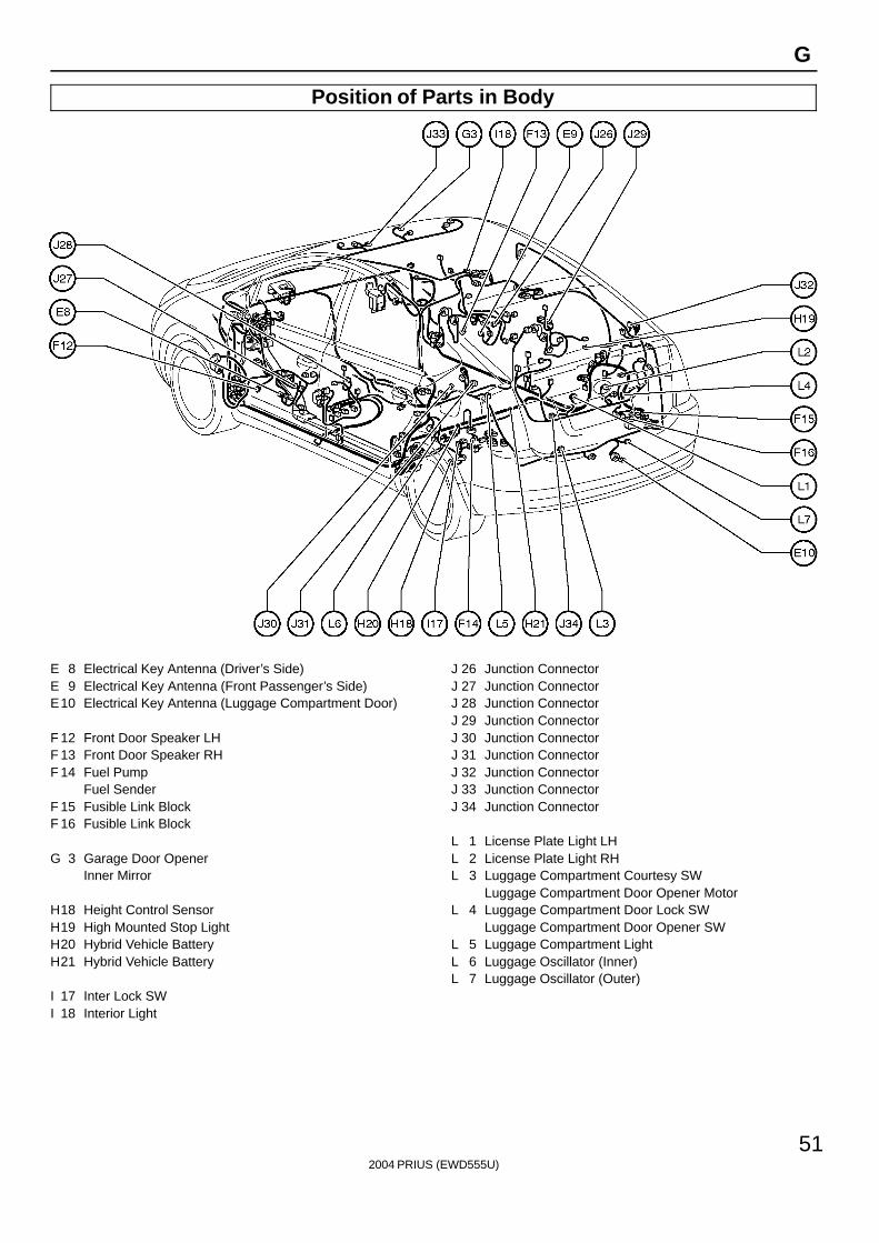
Position of Parts in Body
E 8 Electrical Key Antenna (Driver’s Side)E 9 Electrical Key Antenna (Front Passenger’s Side)E10 Electrical Key Antenna (Luggage Compartment Door)
F 12 Front Door Speaker LHF 13 Front Door Speaker RHF 14 Fuel Pump
Fuel SenderF 15 Fusible Link BlockF 16 Fusible Link Block
G 3 Garage Door OpenerInner Mirror
H18 Height Control SensorH19 High Mounted Stop LightH20 Hybrid Vehicle BatteryH21 Hybrid Vehicle Battery
I 17 Inter Lock SWI 18 Interior Light
J 26 Junction ConnectorJ 27 Junction ConnectorJ 28 Junction ConnectorJ 29 Junction ConnectorJ 30 Junction ConnectorJ 31 Junction ConnectorJ 32 Junction ConnectorJ 33 Junction ConnectorJ 34 Junction Connector
L 1 License Plate Light LHL 2 License Plate Light RHL 3 Luggage Compartment Courtesy SW
Luggage Compartment Door Opener MotorL 4 Luggage Compartment Door Lock SW
Luggage Compartment Door Opener SWL 5 Luggage Compartment LightL 6 Luggage Oscillator (Inner)L 7 Luggage Oscillator (Outer)
2004 PRIUS (EWD555U)
52
G ELECTRICAL WIRING ROUTING
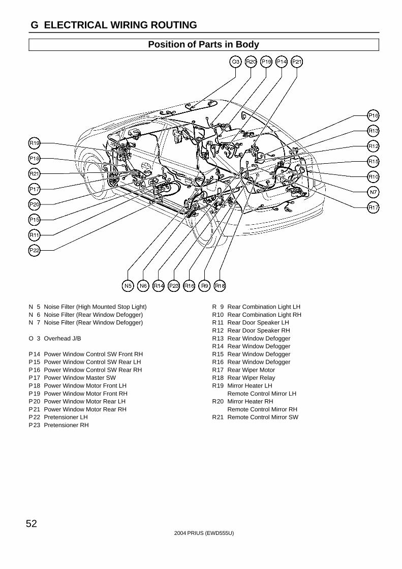
Position of Parts in Body
N 5 Noise Filter (High Mounted Stop Light)N 6 Noise Filter (Rear Window Defogger)N 7 Noise Filter (Rear Window Defogger)
O 3 Overhead J/B
P14 Power Window Control SW Front RHP15 Power Window Control SW Rear LHP16 Power Window Control SW Rear RHP17 Power Window Master SWP18 Power Window Motor Front LHP19 Power Window Motor Front RHP20 Power Window Motor Rear LHP21 Power Window Motor Rear RHP22 Pretensioner LHP23 Pretensioner RH
R 9 Rear Combination Light LHR10 Rear Combination Light RHR11 Rear Door Speaker LHR12 Rear Door Speaker RHR13 Rear Window DefoggerR14 Rear Window DefoggerR15 Rear Window DefoggerR16 Rear Window DefoggerR17 Rear Wiper MotorR18 Rear Wiper RelayR19 Mirror Heater LH
Remote Control Mirror LHR20 Mirror Heater RH
Remote Control Mirror RHR21 Remote Control Mirror SW
2004 PRIUS (EWD555U)
53
G
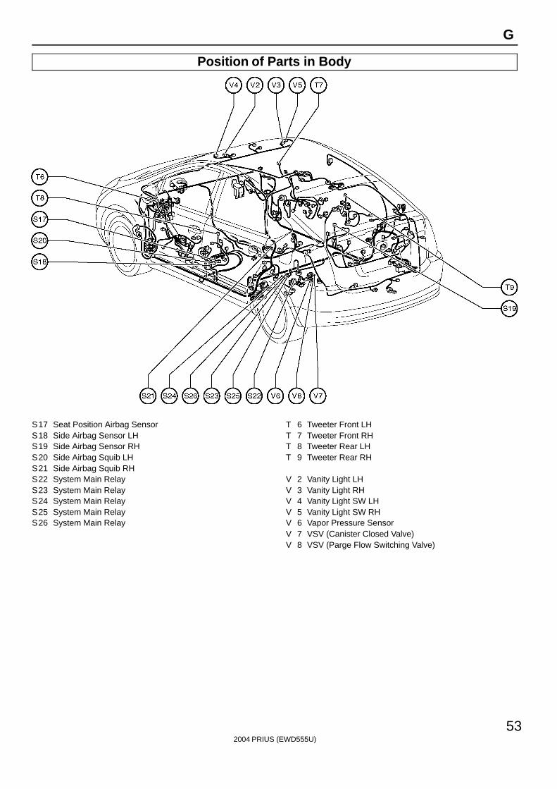
Position of Parts in Body
S17 Seat Position Airbag SensorS18 Side Airbag Sensor LHS19 Side Airbag Sensor RHS20 Side Airbag Squib LHS21 Side Airbag Squib RHS22 System Main RelayS23 System Main RelayS24 System Main RelayS25 System Main RelayS26 System Main Relay
T 6 Tweeter Front LHT 7 Tweeter Front RHT 8 Tweeter Rear LHT 9 Tweeter Rear RH
V 2 Vanity Light LHV 3 Vanity Light RHV 4 Vanity Light SW LHV 5 Vanity Light SW RHV 6 Vapor Pressure SensorV 7 VSV (Canister Closed Valve)V 8 VSV (Parge Flow Switching Valve)
2004 PRIUS (EWD555U)
54
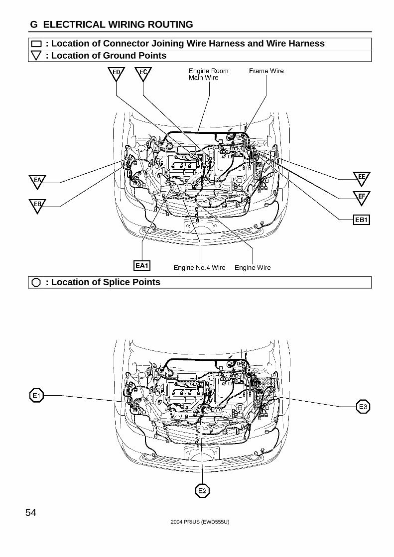
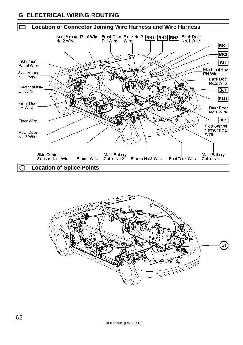
G ELECTRICAL WIRING ROUTING
: Location of Connector Joining Wire Harness and Wire Harness: Location of Ground Points
: Location of Splice Points
2004 PRIUS (EWD555U)
55
G
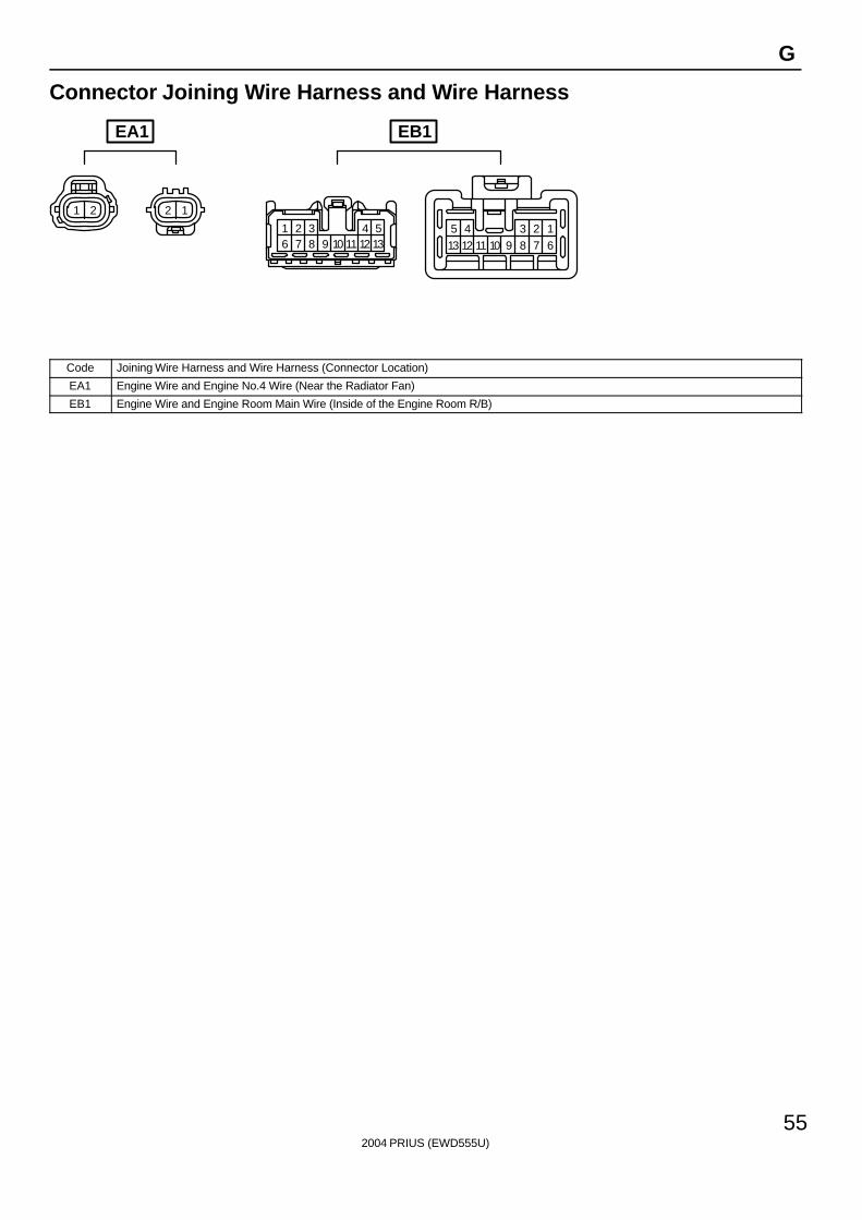
Connector Joining Wire Harness and Wire Harness
1 2 2 1
1 2 3 4 56 7 8 9 10 11 12 13
1234513 6789101112
EA1 EB1
Code Joining Wire Harness and Wire Harness (Connector Location)
EA1 Engine Wire and Engine No.4 Wire (Near the Radiator Fan)
EB1 Engine Wire and Engine Room Main Wire (Inside of the Engine Room R/B)
2004 PRIUS (EWD555U)
56
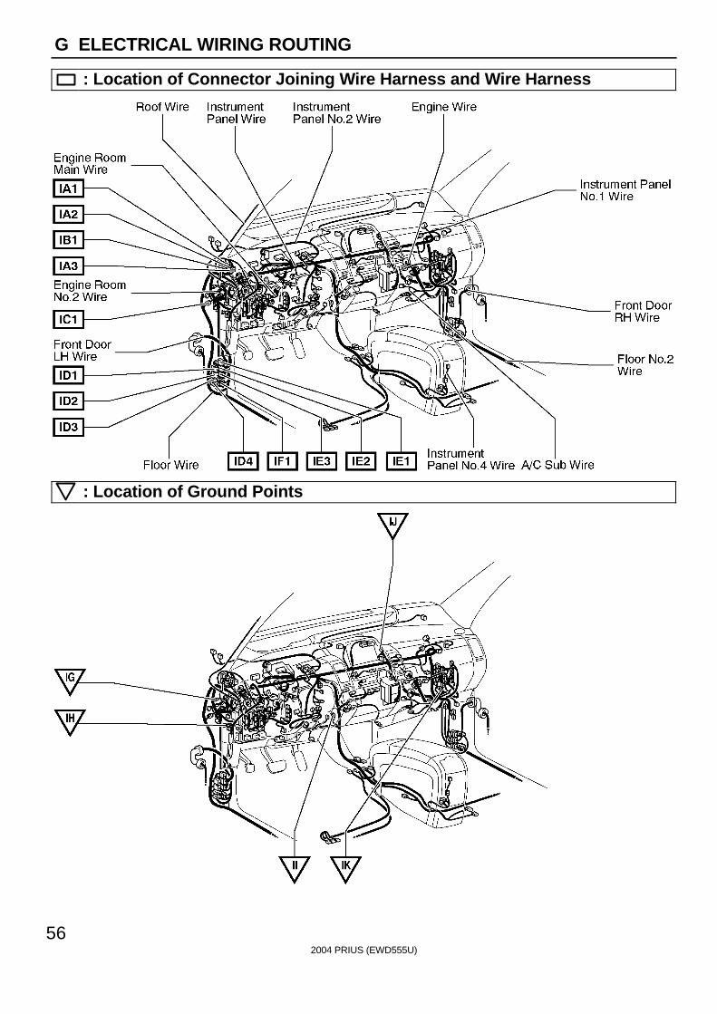
G ELECTRICAL WIRING ROUTING
: Location of Connector Joining Wire Harness and Wire Harness
: Location of Ground Points
2004 PRIUS (EWD555U)
57
G
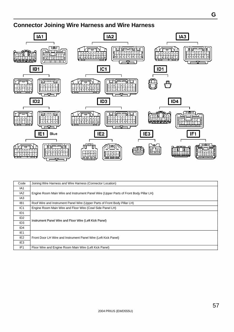
Connector Joining Wire Harness and Wire Harness
Code Joining Wire Harness and Wire Harness (Connector Location)
IA1
IA2 Engine Room Main Wire and Instrument Panel Wire (Upper Parts of Front Body Pillar LH)
IA3
g ( y )
IB1 Roof Wire and Instrument Panel Wire (Upper Parts of Front Body Pillar LH)
IC1 Engine Room Main Wire and Floor Wire (Cowl Side Panel LH)
ID1
ID2Instrument Panel Wire and Floor Wire (Left Kick Panel)
ID3Instrument Panel Wire and Floor Wire (Left Kick Panel)
ID4
IE1
IE2 Front Door LH Wire and Instrument Panel Wire (Left Kick Panel)
IE3
( )
IF1 Floor Wire and Engine Room Main Wire (Left Kick Panel)
2004 PRIUS (EWD555U)
58
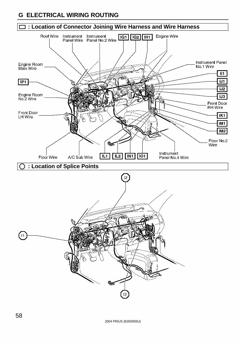
G ELECTRICAL WIRING ROUTING
: Location of Connector Joining Wire Harness and Wire Harness
: Location of Splice Points
2004 PRIUS (EWD555U)
59
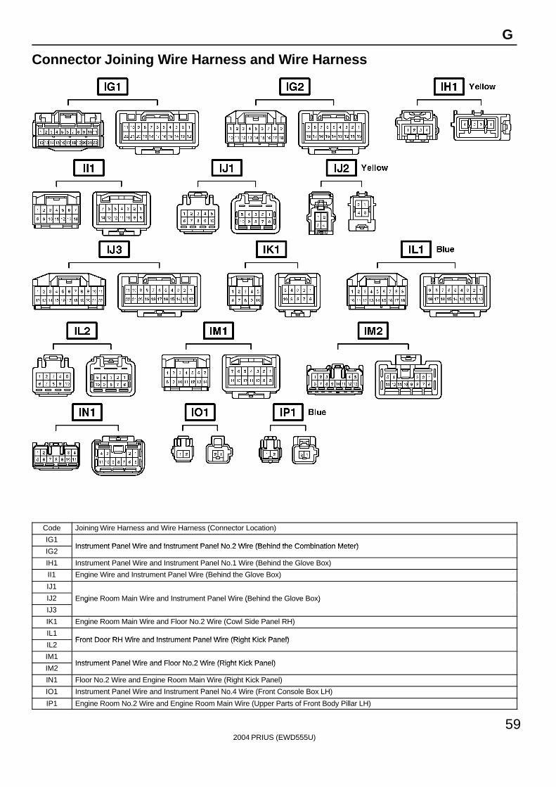
G
Connector Joining Wire Harness and Wire Harness
Code Joining Wire Harness and Wire Harness (Connector Location)
IG1Instrument Panel Wire and Instrument Panel No 2 Wire (Behind the Combination Meter)
IG2Instrument Panel Wire and Instrument Panel No.2 Wire (Behind the Combination Meter)
IH1 Instrument Panel Wire and Instrument Panel No.1 Wire (Behind the Glove Box)
II1 Engine Wire and Instrument Panel Wire (Behind the Glove Box)
IJ1
IJ2 Engine Room Main Wire and Instrument Panel Wire (Behind the Glove Box)
IJ3
g ( )
IK1 Engine Room Main Wire and Floor No.2 Wire (Cowl Side Panel RH)
IL1Front Door RH Wire and Instrument Panel Wire (Right Kick Panel)
IL2Front Door RH Wire and Instrument Panel Wire (Right Kick Panel)
IM1Instrument Panel Wire and Floor No 2 Wire (Right Kick Panel)
IM2Instrument Panel Wire and Floor No.2 Wire (Right Kick Panel)
IN1 Floor No.2 Wire and Engine Room Main Wire (Right Kick Panel)
IO1 Instrument Panel Wire and Instrument Panel No.4 Wire (Front Console Box LH)
IP1 Engine Room No.2 Wire and Engine Room Main Wire (Upper Parts of Front Body Pillar LH)
2004 PRIUS (EWD555U)
60
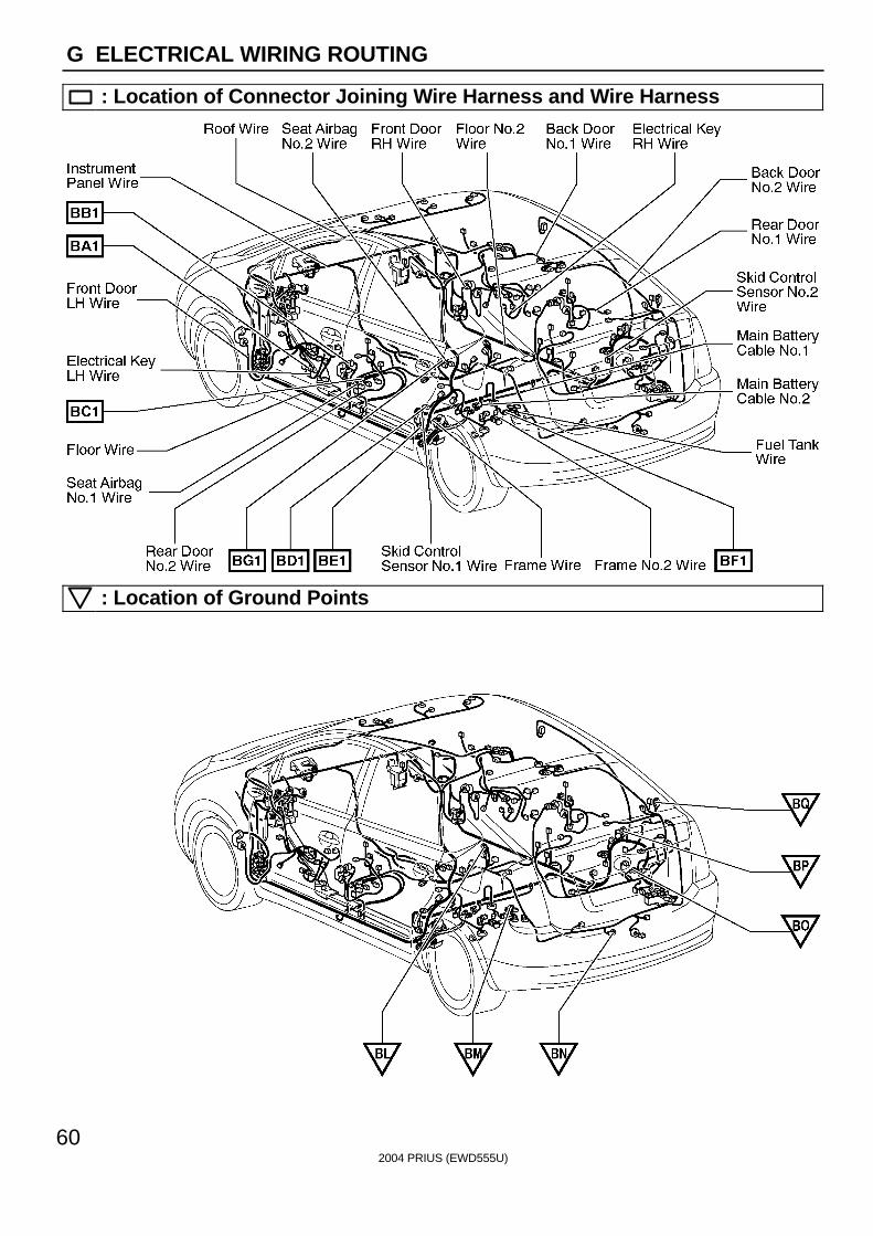
G ELECTRICAL WIRING ROUTING
: Location of Connector Joining Wire Harness and Wire Harness
: Location of Ground Points
2004 PRIUS (EWD555U)
61
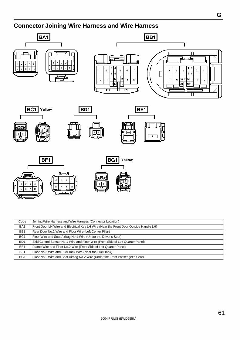
G
Connector Joining Wire Harness and Wire Harness
Code Joining Wire Harness and Wire Harness (Connector Location)
BA1 Front Door LH Wire and Electrical Key LH Wire (Near the Front Door Outside Handle LH)
BB1 Rear Door No.2 Wire and Floor Wire (Left Center Pillar)
BC1 Floor Wire and Seat Airbag No.1 Wire (Under the Driver’s Seat)
BD1 Skid Control Sensor No.1 Wire and Floor Wire (Front Side of Left Quarter Panel)
BE1 Frame Wire and Floor No.2 Wire (Front Side of Left Quarter Panel)
BF1 Floor No.2 Wire and Fuel Tank Wire (Near the Fuel Tank)
BG1 Floor No.2 Wire and Seat Airbag No.2 Wire (Under the Front Passenger’s Seat)
2004 PRIUS (EWD555U)
62
G ELECTRICAL WIRING ROUTING
: Location of Connector Joining Wire Harness and Wire Harness
: Location of Splice Points
2004 PRIUS (EWD555U)
63
G
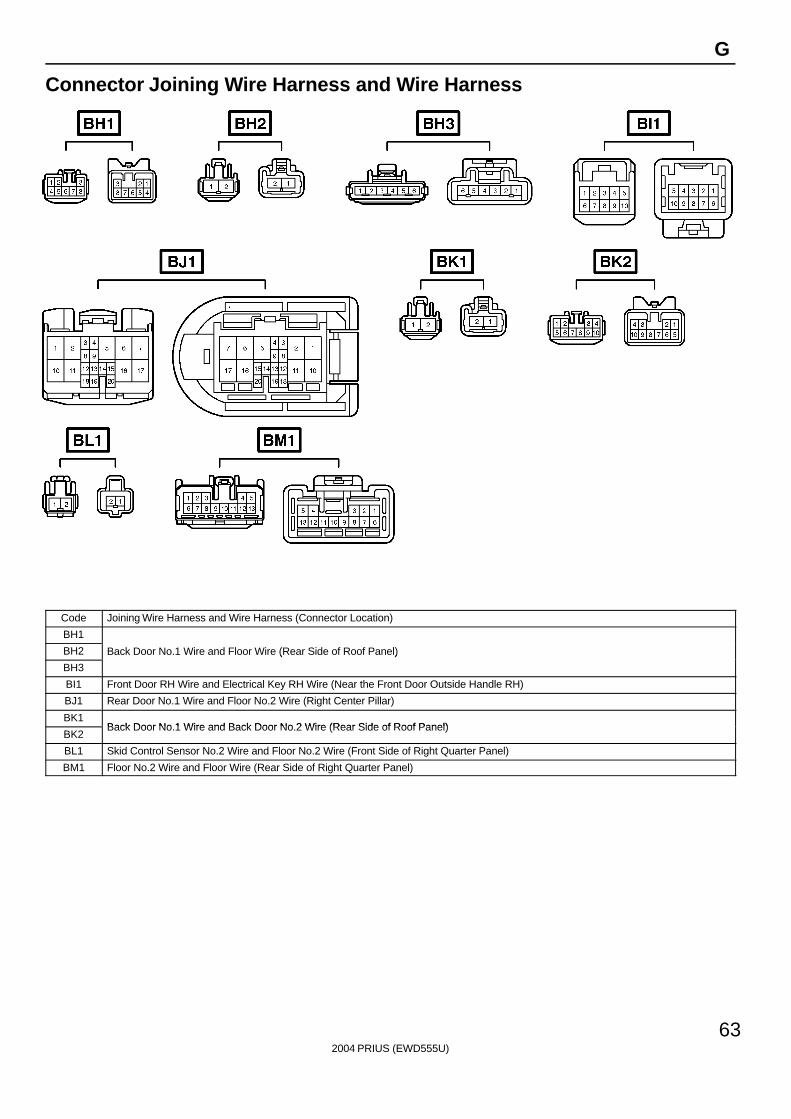
Connector Joining Wire Harness and Wire Harness
Code Joining Wire Harness and Wire Harness (Connector Location)
BH1
BH2 Back Door No.1 Wire and Floor Wire (Rear Side of Roof Panel)
BH3
( )
BI1 Front Door RH Wire and Electrical Key RH Wire (Near the Front Door Outside Handle RH)
BJ1 Rear Door No.1 Wire and Floor No.2 Wire (Right Center Pillar)
BK1Back Door No 1 Wire and Back Door No 2 Wire (Rear Side of Roof Panel)
BK2Back Door No.1 Wire and Back Door No.2 Wire (Rear Side of Roof Panel)
BL1 Skid Control Sensor No.2 Wire and Floor No.2 Wire (Front Side of Right Quarter Panel)
BM1 Floor No.2 Wire and Floor Wire (Rear Side of Right Quarter Panel)

2004 PRIUS (EWD555U)
64
Memo
2004 PRIUS (EWD555U)
65
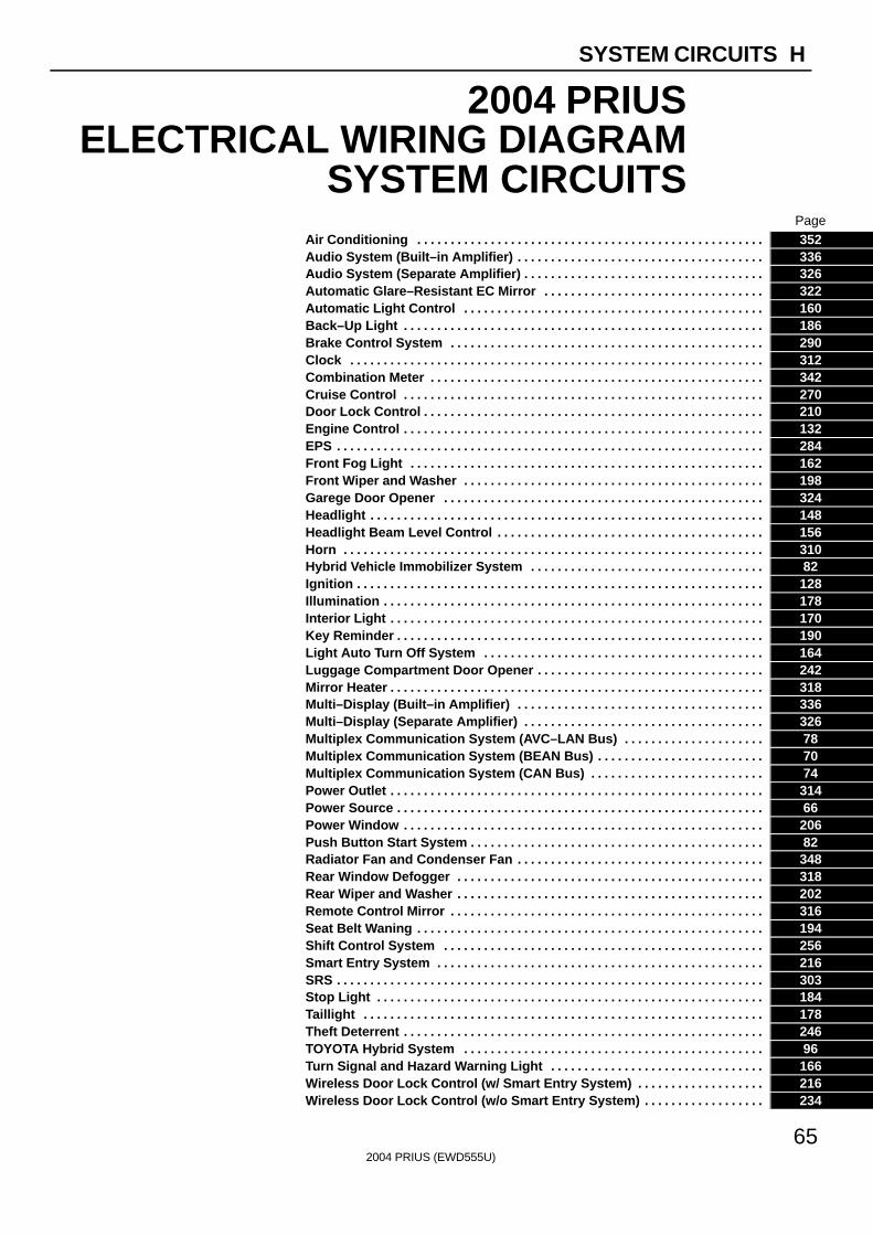
SYSTEM CIRCUITS H
2004 PRIUSELECTRICAL WIRING DIAGRAM
SYSTEM CIRCUITSPage
Air Conditioning . . . . . . . . . . . . . . . . . . . . . . . . . . . . . . . . . . . . . . . . . . . . . . . . . . . . 352Audio System (Built–in Amplifier) . . . . . . . . . . . . . . . . . . . . . . . . . . . . . . . . . . . . . 336Audio System (Separate Amplifier) . . . . . . . . . . . . . . . . . . . . . . . . . . . . . . . . . . . . 326Automatic Glare–Resistant EC Mirror . . . . . . . . . . . . . . . . . . . . . . . . . . . . . . . . . 322Automatic Light Control . . . . . . . . . . . . . . . . . . . . . . . . . . . . . . . . . . . . . . . . . . . . . 160Back–Up Light . . . . . . . . . . . . . . . . . . . . . . . . . . . . . . . . . . . . . . . . . . . . . . . . . . . . . . 186Brake Control System . . . . . . . . . . . . . . . . . . . . . . . . . . . . . . . . . . . . . . . . . . . . . . . 290Clock . . . . . . . . . . . . . . . . . . . . . . . . . . . . . . . . . . . . . . . . . . . . . . . . . . . . . . . . . . . . . . 312Combination Meter . . . . . . . . . . . . . . . . . . . . . . . . . . . . . . . . . . . . . . . . . . . . . . . . . . 342Cruise Control . . . . . . . . . . . . . . . . . . . . . . . . . . . . . . . . . . . . . . . . . . . . . . . . . . . . . . 270Door Lock Control . . . . . . . . . . . . . . . . . . . . . . . . . . . . . . . . . . . . . . . . . . . . . . . . . . . 210Engine Control . . . . . . . . . . . . . . . . . . . . . . . . . . . . . . . . . . . . . . . . . . . . . . . . . . . . . . 132EPS . . . . . . . . . . . . . . . . . . . . . . . . . . . . . . . . . . . . . . . . . . . . . . . . . . . . . . . . . . . . . . . . 284Front Fog Light . . . . . . . . . . . . . . . . . . . . . . . . . . . . . . . . . . . . . . . . . . . . . . . . . . . . . 162Front Wiper and Washer . . . . . . . . . . . . . . . . . . . . . . . . . . . . . . . . . . . . . . . . . . . . . 198Garege Door Opener . . . . . . . . . . . . . . . . . . . . . . . . . . . . . . . . . . . . . . . . . . . . . . . . 324Headlight . . . . . . . . . . . . . . . . . . . . . . . . . . . . . . . . . . . . . . . . . . . . . . . . . . . . . . . . . . . 148Headlight Beam Level Control . . . . . . . . . . . . . . . . . . . . . . . . . . . . . . . . . . . . . . . . 156Horn . . . . . . . . . . . . . . . . . . . . . . . . . . . . . . . . . . . . . . . . . . . . . . . . . . . . . . . . . . . . . . . 310Hybrid Vehicle Immobilizer System . . . . . . . . . . . . . . . . . . . . . . . . . . . . . . . . . . . 82Ignition . . . . . . . . . . . . . . . . . . . . . . . . . . . . . . . . . . . . . . . . . . . . . . . . . . . . . . . . . . . . . 128Illumination . . . . . . . . . . . . . . . . . . . . . . . . . . . . . . . . . . . . . . . . . . . . . . . . . . . . . . . . . 178Interior Light . . . . . . . . . . . . . . . . . . . . . . . . . . . . . . . . . . . . . . . . . . . . . . . . . . . . . . . . 170Key Reminder . . . . . . . . . . . . . . . . . . . . . . . . . . . . . . . . . . . . . . . . . . . . . . . . . . . . . . . 190Light Auto Turn Off System . . . . . . . . . . . . . . . . . . . . . . . . . . . . . . . . . . . . . . . . . . 164Luggage Compartment Door Opener . . . . . . . . . . . . . . . . . . . . . . . . . . . . . . . . . . 242Mirror Heater . . . . . . . . . . . . . . . . . . . . . . . . . . . . . . . . . . . . . . . . . . . . . . . . . . . . . . . . 318Multi–Display (Built–in Amplifier) . . . . . . . . . . . . . . . . . . . . . . . . . . . . . . . . . . . . . 336Multi–Display (Separate Amplifier) . . . . . . . . . . . . . . . . . . . . . . . . . . . . . . . . . . . . 326Multiplex Communication System (AVC–LAN Bus) . . . . . . . . . . . . . . . . . . . . . 78Multiplex Communication System (BEAN Bus) . . . . . . . . . . . . . . . . . . . . . . . . . 70Multiplex Communication System (CAN Bus) . . . . . . . . . . . . . . . . . . . . . . . . . . 74Power Outlet . . . . . . . . . . . . . . . . . . . . . . . . . . . . . . . . . . . . . . . . . . . . . . . . . . . . . . . . 314Power Source . . . . . . . . . . . . . . . . . . . . . . . . . . . . . . . . . . . . . . . . . . . . . . . . . . . . . . . 66Power Window . . . . . . . . . . . . . . . . . . . . . . . . . . . . . . . . . . . . . . . . . . . . . . . . . . . . . . 206Push Button Start System . . . . . . . . . . . . . . . . . . . . . . . . . . . . . . . . . . . . . . . . . . . . 82Radiator Fan and Condenser Fan . . . . . . . . . . . . . . . . . . . . . . . . . . . . . . . . . . . . . 348Rear Window Defogger . . . . . . . . . . . . . . . . . . . . . . . . . . . . . . . . . . . . . . . . . . . . . . 318Rear Wiper and Washer . . . . . . . . . . . . . . . . . . . . . . . . . . . . . . . . . . . . . . . . . . . . . . 202Remote Control Mirror . . . . . . . . . . . . . . . . . . . . . . . . . . . . . . . . . . . . . . . . . . . . . . . 316Seat Belt Waning . . . . . . . . . . . . . . . . . . . . . . . . . . . . . . . . . . . . . . . . . . . . . . . . . . . . 194Shift Control System . . . . . . . . . . . . . . . . . . . . . . . . . . . . . . . . . . . . . . . . . . . . . . . . 256Smart Entry System . . . . . . . . . . . . . . . . . . . . . . . . . . . . . . . . . . . . . . . . . . . . . . . . . 216SRS . . . . . . . . . . . . . . . . . . . . . . . . . . . . . . . . . . . . . . . . . . . . . . . . . . . . . . . . . . . . . . . . 303Stop Light . . . . . . . . . . . . . . . . . . . . . . . . . . . . . . . . . . . . . . . . . . . . . . . . . . . . . . . . . . 184Taillight . . . . . . . . . . . . . . . . . . . . . . . . . . . . . . . . . . . . . . . . . . . . . . . . . . . . . . . . . . . . 178Theft Deterrent . . . . . . . . . . . . . . . . . . . . . . . . . . . . . . . . . . . . . . . . . . . . . . . . . . . . . . 246TOYOTA Hybrid System . . . . . . . . . . . . . . . . . . . . . . . . . . . . . . . . . . . . . . . . . . . . . 96Turn Signal and Hazard Warning Light . . . . . . . . . . . . . . . . . . . . . . . . . . . . . . . . 166Wireless Door Lock Control (w/ Smart Entry System) . . . . . . . . . . . . . . . . . . . 216Wireless Door Lock Control (w/o Smart Entry System) . . . . . . . . . . . . . . . . . . 234
2004 PRIUS (EWD555U)
70
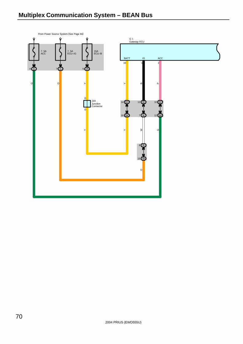
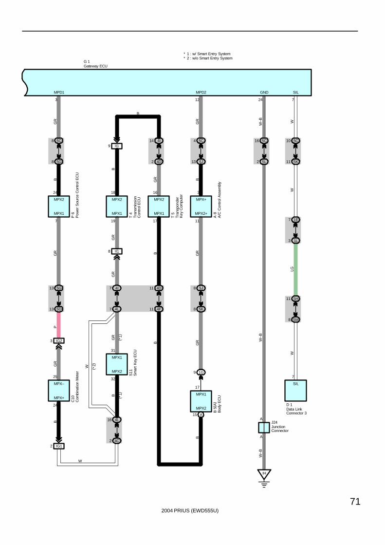
Multiplex Communication System – BEAN Bus
7. 5AACC
1L4
7. 5AECU–IG
From Power Source System (See Page 66)
1L7
15AECU–B
1K5
D
D
5C14 5C12 5C10
5L8
5K10 5L7 5H12
5H15
2110
ACCIGBATT
OW GY
YOG
Y
Y B P
J19
G 1Gateway ECU
JunctionConnector
2004 PRIUS (EWD555U)
71
5C8
5G8
5D13
5G13
IG23
IG12
4L16
4C2
5C4
5J13
5K8
5J8
1G9
4I14
4D2
4F11
4D11
A15
4L7
4I7
II19
II18
123
7 19 17 11
24
32
17
31
25
24 18 16 3
MPD2MPD1
B
MPX1 MPX1 MPX1 MPX2+
MPX2
MPX2
MPX+
W
GR
B
BG
RG
R
GR B GR
GRB
GR
BGR
B
BG
R
W
BG
RP
MPX1
MPX1
MPX–
MPX2 MPX2 MPX2 MPX+
G 1
P 6
T 4
T 5
A 8
( *1)
( *1)
( *2)
B 5
( A)
S11
C10
* 2 : w/o Smart Entry System* 1 : w/ Smart Entry System
A
5C16
5L2
IH
A
24
7
J24
D 1
GND
SIL
W–B
W–B
W–B
5K
SIL
7
5M8
11 5H
1E7
3 1L
11
10 5C
WLG
WW
A/C
Con
trol
Ass
embl
yB
ody
EC
U
Com
bina
tion
Met
er
Data LinkConnector 3
Gateway ECU
JunctionConnector
Tra
nspo
nder
Key
Com
pute
r
Tra
nsm
issi
onC
ontr
ol E
CU
Sm
art
Key
EC
U
Pow
er S
ourc
e C
ontr
ol E
CU
2004 PRIUS (EWD555U)
72
Multiplex Communication System – BEAN Bus
BEAN consists of body electrical systems such as body ECU, A/C control assembly, power source control ECU, combinationmeter, smart key ECU∗, transmission control ECU, transponder key computer and gateway ECU. Gateway ECU hascommunication circuit to correspond with different types of communication data. Different types of communication data canbe shared among communication parts after it goes through gateway ECU. Vehicle information is input to body ECU at anassembling plant as a representative ECU which delivers the information to other ECUs through multiplex communication.
∗ Optional equipment
This system is working for the following systems:∗ Air Conditioning∗ Audio System∗ Brake Control System∗ Combination Meter∗ Cruise Control∗ Engine Control∗ EPS∗ Headlight∗ Hybrid Vehicle Immobilizer System∗ Illumination∗ Interior Light∗ Key Reminder∗ Luggage Compartment Door Opener∗ Mirror Heater∗ Multi–Display∗ Push Button Start System∗ Rear Window Defogger∗ Shift Control System∗ Smart Entry System∗ Taillight∗ TOYOTA Hybrid System
G1 Gateway ECU10–Ground : Always approx. 12 volts
1–Ground : Approx. 12 volts with the power SW at IG ON position2–Ground : Approx. 12 volts with the power SW at ACC ON or IG ON position
24–Ground : Always continuity
: Parts Location
Code See Page Code See Page Code See Page
A8 46 G1 47 S11 49
B5 A 46 J19 48 T4 49
C10 47 J24 48 T5 49
D1 47 P6 49
System Outline
Service Hints
2004 PRIUS (EWD555U)
73
: Junction Block and Wire Harness Connector
Code See Page Junction Block and Wire Harness (Connector Location)
1E
1G28 Instrument Panel Wire and Driver Side J/B (Lower Finish Panel)
1K28 Instrument Panel Wire and Driver Side J/B (Lower Finish Panel)
1L
4C
4D
4F 36 Instrument Panel Wire and Center Connector No.1 (Behind the Combination Meter)
4I
( )
4L
5C
5D
5G
5H40 Instrument Panel Wire and Center Connector No 2 (Instrument Panel Brace RH)
5J40 Instrument Panel Wire and Center Connector No.2 (Instrument Panel Brace RH)
5K
5L
5M
: Connector Joining Wire Harness and Wire Harness
Code See Page Joining Wire Harness and Wire Harness (Connector Location)
IG158 Instrument Panel Wire and Instrument Panel No 2 Wire (Behind the Combination Meter)
IG258 Instrument Panel Wire and Instrument Panel No.2 Wire (Behind the Combination Meter)
II1 58 Engine Wire and Instrument Panel Wire (Behind the Glove Box)
: Ground Points
Code See Page Ground Points Location
IH 56 Cowl Side Panel LH
2004 PRIUS (EWD555U)
74
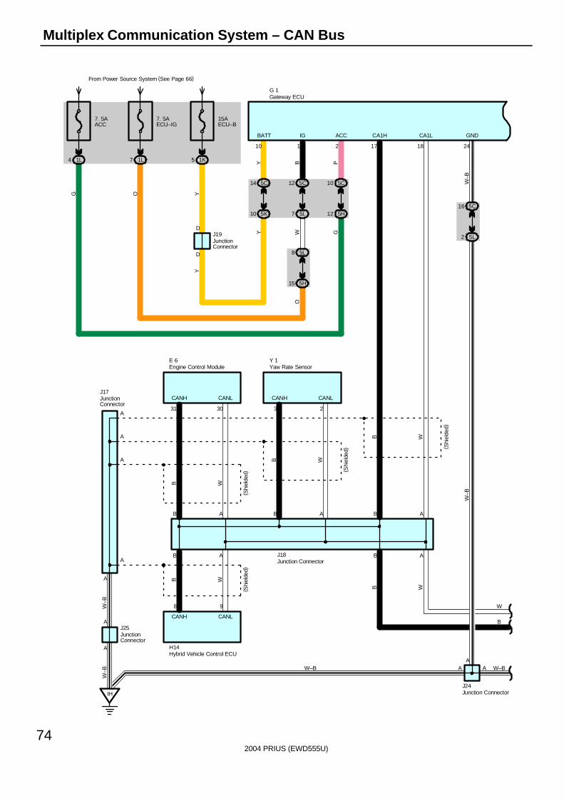
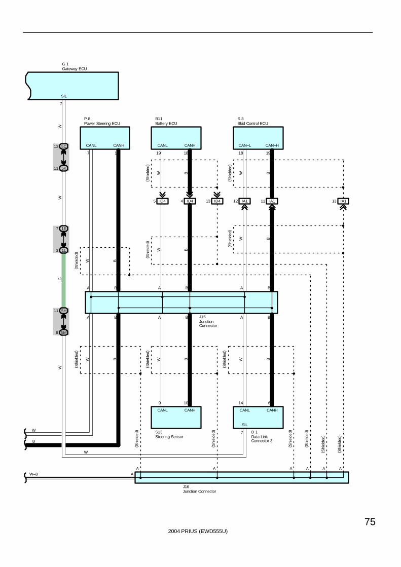
Multiplex Communication System – CAN Bus
7. 5AACC
1L4
7. 5AECU–IG
From Power Source System (See Page 66)
1L7
15AECU–B
1K5
D
D
5C14 5C12 5C10
5L8
5K10 5L7 5H12
5H15
2110
ACCIGBATT
OW GY
YOG
Y
Y B P
J19
G 1
5C16
5L2
IH
A
A
A
A
31 30 3 2
241817
A
J24
J18
H14
AB
J25
AB
J17
AB
8 9
A
A
A
A
Y 1
A
( Shi
elde
d)
GND
B
(Shi
elde
d)
CA1LCA1H
( Shi
elde
d)
CANL
A
CANH
CANH
CANLCANH
( Shi
elde
d)
CANL
W–B
B A
W–B
WB
W
E 6
B
WBB W
W–B
W–B
B W
W–B
W
B
W–B
Engine Control Module
Gateway ECU
Hybrid Vehicle Control ECU
JunctionConnector
Junction Connector
JunctionConnector
Junction Connector
JunctionConnector
Yaw Rate Sensor
2004 PRIUS (EWD555U)
75
G 1
A A
ID45
B
ID44 ID413 IA112 IA111 IA113
B A B
1918181917
9 10 14 6
AA A A A A A
BABABA
B11
D 1
P 8
J15
CAN–HCAN–LCANHCANLCANHCANL
J16
CANL
(Shi
elde
d)
B
( Shi
elde
d)
W
CANH
B
( Shi
elde
d)
WB
( Shi
elde
d)
W
CANL
B
( Shi
elde
d)
W
B
( Shi
elde
d)
W
CANH
W
( Shi
elde
d)
B
W
( Shi
elde
d)
B W
( Shi
elde
d)
B
S13
( Shi
elde
d)
( Shi
elde
d)
( Shi
elde
d)
( Shi
elde
d)
( Shi
elde
d)
S 8
5K
SIL
7
5M8
11 5H
1E7
3 1L
11
13 5C
WLG
WW
W
7
SILW
B
W–B
Skid Control ECUBattery ECU
Data LinkConnector 3
Gateway ECU
JunctionConnector
Junction Connector
Steering Sensor
Power Steering ECU
2004 PRIUS (EWD555U)
76
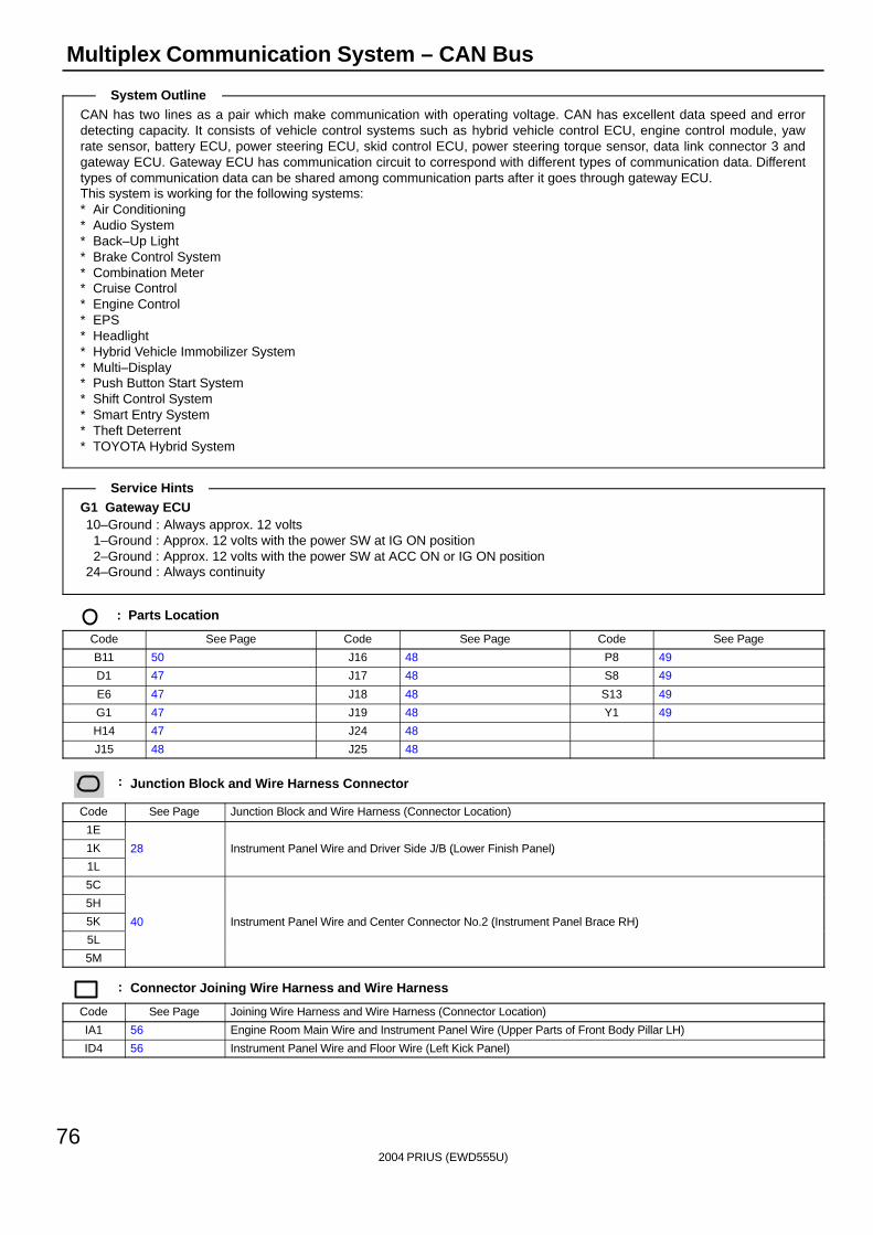
Multiplex Communication System – CAN Bus
CAN has two lines as a pair which make communication with operating voltage. CAN has excellent data speed and errordetecting capacity. It consists of vehicle control systems such as hybrid vehicle control ECU, engine control module, yawrate sensor, battery ECU, power steering ECU, skid control ECU, power steering torque sensor, data link connector 3 andgateway ECU. Gateway ECU has communication circuit to correspond with different types of communication data. Differenttypes of communication data can be shared among communication parts after it goes through gateway ECU.This system is working for the following systems:∗ Air Conditioning∗ Audio System∗ Back–Up Light∗ Brake Control System∗ Combination Meter∗ Cruise Control∗ Engine Control∗ EPS∗ Headlight∗ Hybrid Vehicle Immobilizer System∗ Multi–Display∗ Push Button Start System∗ Shift Control System∗ Smart Entry System∗ Theft Deterrent∗ TOYOTA Hybrid System
G1 Gateway ECU10–Ground : Always approx. 12 volts
1–Ground : Approx. 12 volts with the power SW at IG ON position2–Ground : Approx. 12 volts with the power SW at ACC ON or IG ON position
24–Ground : Always continuity
: Parts Location
Code See Page Code See Page Code See Page
B11 50 J16 48 P8 49
D1 47 J17 48 S8 49
E6 47 J18 48 S13 49
G1 47 J19 48 Y1 49
H14 47 J24 48
J15 48 J25 48
: Junction Block and Wire Harness Connector
Code See Page Junction Block and Wire Harness (Connector Location)
1E
1K 28 Instrument Panel Wire and Driver Side J/B (Lower Finish Panel)
1L
( )
5C
5H
5K 40 Instrument Panel Wire and Center Connector No.2 (Instrument Panel Brace RH)
5L
( )
5M
: Connector Joining Wire Harness and Wire Harness
Code See Page Joining Wire Harness and Wire Harness (Connector Location)
IA1 56 Engine Room Main Wire and Instrument Panel Wire (Upper Parts of Front Body Pillar LH)
ID4 56 Instrument Panel Wire and Floor Wire (Left Kick Panel)
System Outline
Service Hints
2004 PRIUS (EWD555U)
77
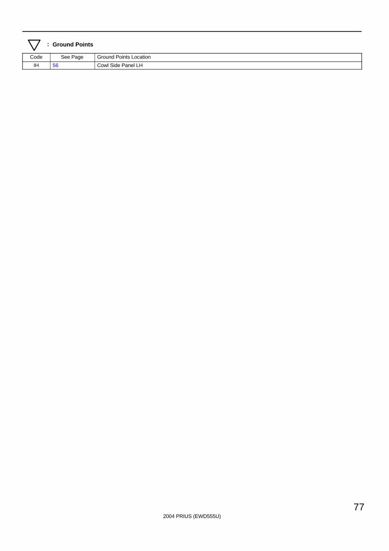
: Ground Points
Code See Page Ground Points Location
IH 56 Cowl Side Panel LH
2004 PRIUS (EWD555U)
78
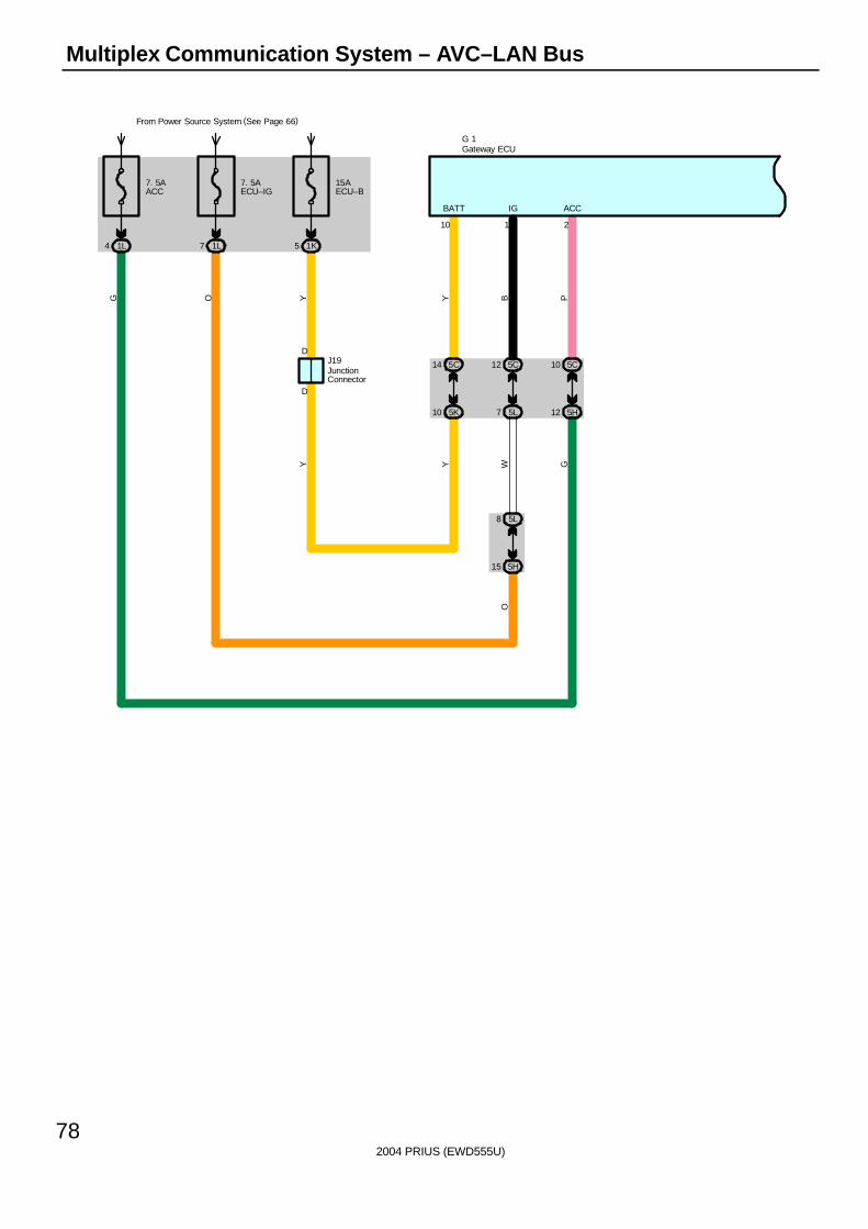
Multiplex Communication System – AVC–LAN Bus
7. 5AACC
1L4
7. 5AECU–IG
From Power Source System (See Page 66)
1L7
15AECU–B
1K5
D
D
5C14 5C12 5C10
5L8
5K10 5L7 5H12
5H15
2110
ACCIGBATT
OW GY
YOG
Y
Y B P
J19
G 1Gateway ECU
JunctionConnector
2004 PRIUS (EWD555U)
79
5E6 5E7
5C6 5C7
216
GTX–GTX+
B W
B W
TX1–TX1+
M13(A), M14(B)
G 1
A4 A5
B13 B14 A19A18
A5 A15
B9 B10
TX2–TX2+TX–TX+
ATX+ ATX–
TX–TX+TX–TX+
TX+ TX–
W P P W
P O
5 10
8 7
( *1)
( *1)
( *2)
( *2)
N 3
S15
R 5
( B) ,
R 6
( A)
5C16
5L2
IH
A
24
7
J24
D 1
GND
SIL
W–B
W–B
5K
SIL
7
5M8
11 5H
1E7
3 1L
11
13 5C
WLG
WW
A
W–B
* 2 : w/ Separate Amplifier* 1 : w/ Navigation System
Data LinkConnector 3
Gateway ECU
JunctionConnector
Multi–Display
Navigation ECU
Rad
io a
nd P
laye
r
Stereo ComponentAmplifier
2004 PRIUS (EWD555U)
80
Multiplex Communication System – AVC–LAN Bus
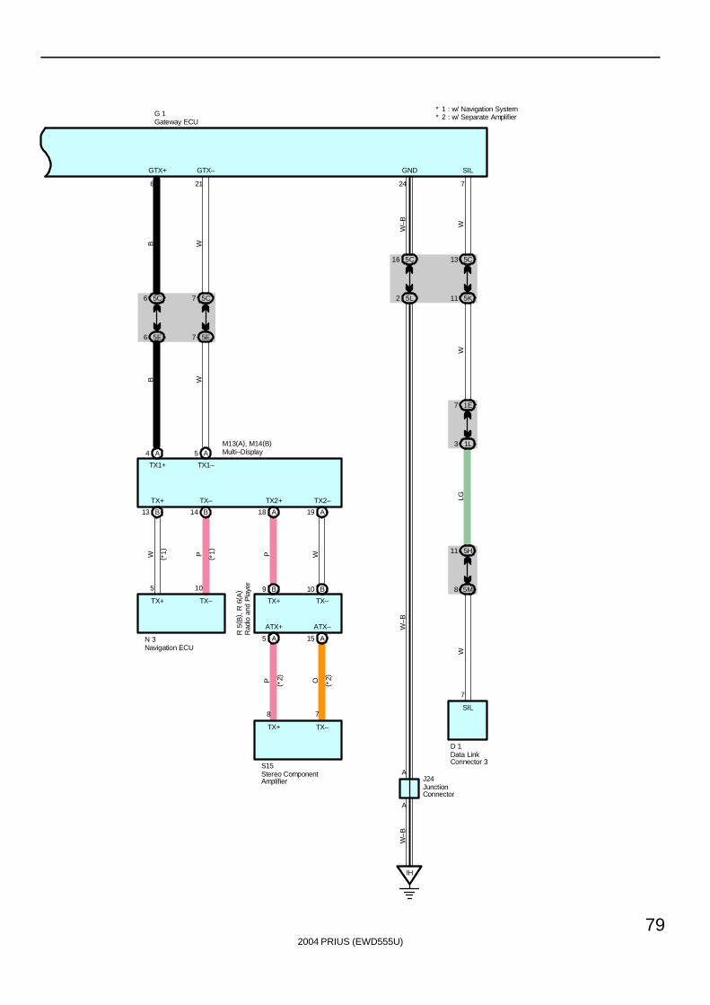
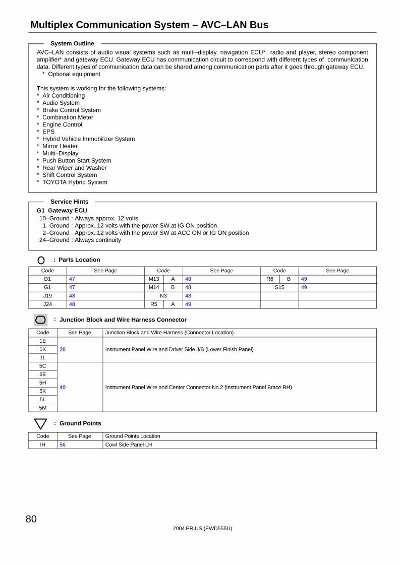
AVC–LAN consists of audio visual systems such as multi–display, navigation ECU∗, radio and player, stereo componentamplifier∗ and gateway ECU. Gateway ECU has communication circuit to correspond with different types of communicationdata. Different types of communication data can be shared among communication parts after it goes through gateway ECU.
∗ Optional equipment
This system is working for the following systems:∗ Air Conditioning∗ Audio System∗ Brake Control System∗ Combination Meter∗ Engine Control∗ EPS∗ Hybrid Vehicle Immobilizer System∗ Mirror Heater∗ Multi–Display∗ Push Button Start System∗ Rear Wiper and Washer∗ Shift Control System∗ TOYOTA Hybrid System
G1 Gateway ECU10–Ground : Always approx. 12 volts
1–Ground : Approx. 12 volts with the power SW at IG ON position2–Ground : Approx. 12 volts with the power SW at ACC ON or IG ON position
24–Ground : Always continuity
: Parts Location
Code See Page Code See Page Code See Page
D1 47 M13 A 48 R6 B 49
G1 47 M14 B 48 S15 49
J19 48 N3 48
J24 48 R5 A 49
: Junction Block and Wire Harness Connector
Code See Page Junction Block and Wire Harness (Connector Location)
1E
1K 28 Instrument Panel Wire and Driver Side J/B (Lower Finish Panel)
1L
( )
5C
5E
5H40 Instrument Panel Wire and Center Connector No 2 (Instrument Panel Brace RH)
5K40 Instrument Panel Wire and Center Connector No.2 (Instrument Panel Brace RH)
5L
5M
: Ground Points
Code See Page Ground Points Location
IH 56 Cowl Side Panel LH
System Outline
Service Hints

2004 PRIUS (EWD555U)
81
Memo
2004 PRIUS (EWD555U)
82
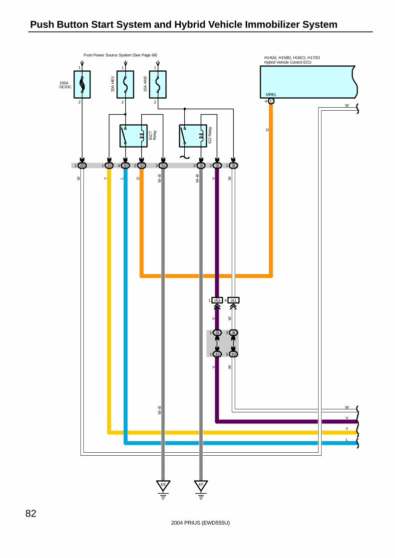
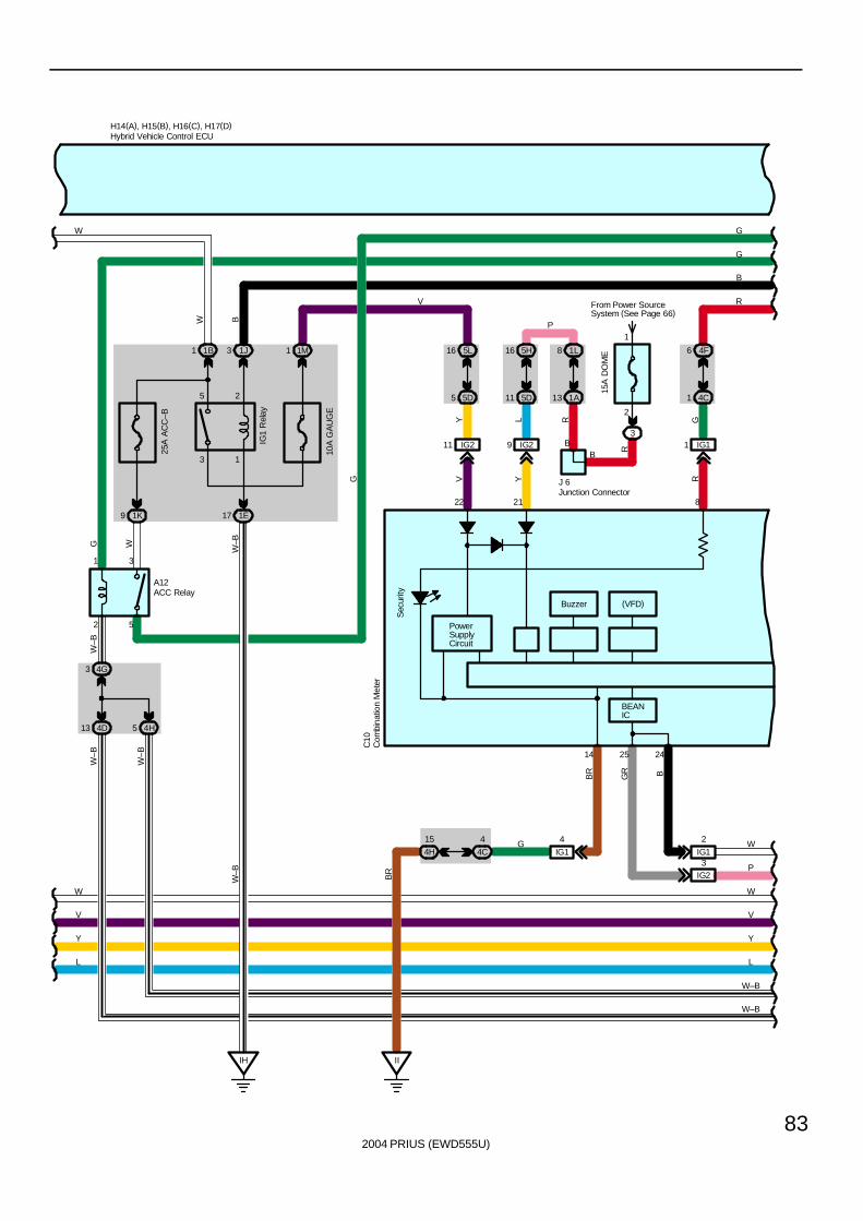
Push Button Start System and Hybrid Vehicle Immobilizer System
15A
AM
2
2
1
20A
HE
V
From Power Source System (See Page 66)
2
1
3J4 3J23J1 3J3 3I3 3I2 3I1
IGC
TR
elay
IG2
Rel
ay
EF
W–B
C4
MREL
O
O
H14(A), H15(B), H16(C), H17(D)
L
L
EE
W–B
W–B
Y
Y
IA14IA31
4I34I1
4J54J1
V W
V W
V W
V
W
100ADC/DC
3D1
2
1
W
W
Hybrid Vehicle Control ECU
2004 PRIUS (EWD555U)
83
From Power SourceSystem (See Page 66)
1M1
10A
GA
UG
E
1 1B 3 1J
25
13
31
52
9 1K
25A
AC
C–B
1E17
4G3
4D13
IH
W–B
W–B
W–B
W
W–B
G
A12
IG1
Rel
ay
W
1
2
3
15A
DO
ME
B
BEANIC
PowerSupplyCircuit
IG211 IG29
5D5 5D11
16 5L 5H16 1L8
1A13
Y L
V Y
22 21
R
R
C10
V
BR
B
II
BR
14
G
25 24
H14(A), H15(B), H16(C), H17(D)
G
LL
Y Y
4
4C4H
15 G
VV
W W
W–B
4
IG1
GR B
W
PIG23
IG1
2
B
J 6
P
(VFD)
G
B
4H5
W–B
W–B
Buzzer
W
IG11
4C1
6 4F
GR
8
Sec
urityACC Relay
Com
bina
tion
Met
er
Hybrid Vehicle Control ECU
Junction Connector
R
2004 PRIUS (EWD555U)
84
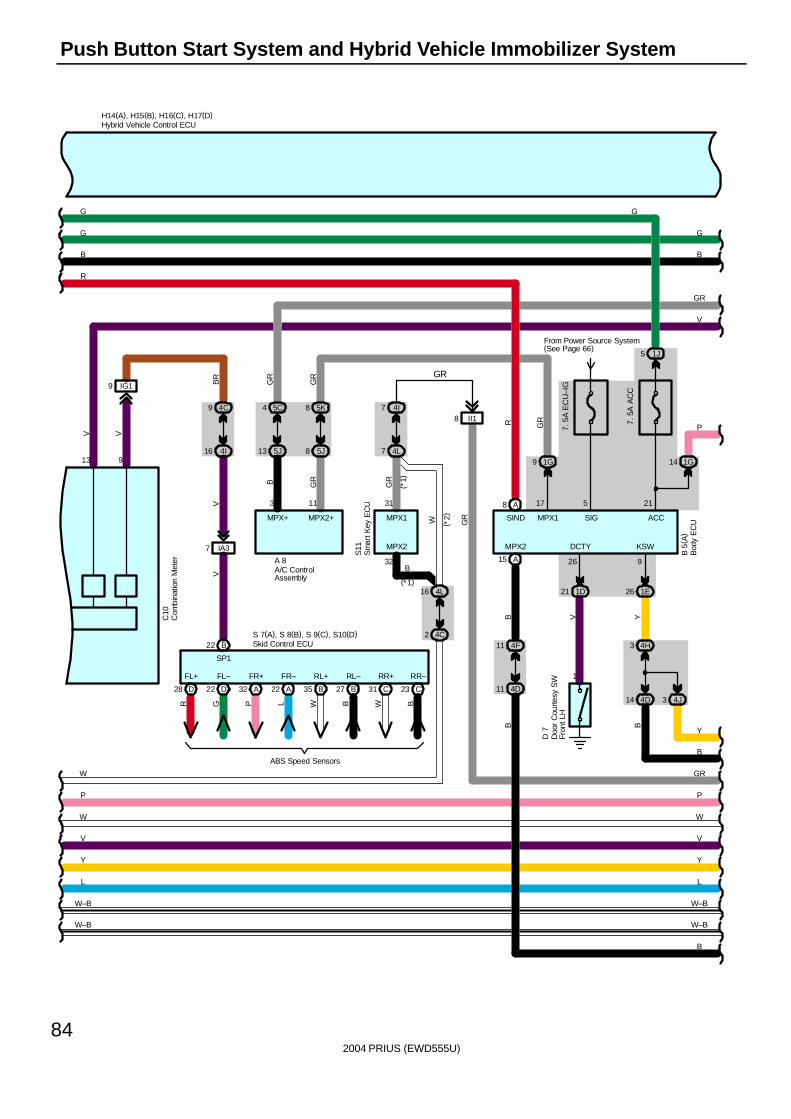
Push Button Start System and Hybrid Vehicle Immobilizer System
SIND
B 5
( A)
V
Y Y
G
B
G
B
H14(A), H15(B), H16(C), H17(D)
G
P
LL
W W
VV
MPX+
S11
( *2)
B
GR
B
W
GR
RMPX1
31
MPX2
32
MPX2
15 A
4 5C
13 5J
7 4I
7 4L
16 4L
2 4C
(*1)
II18
P
GR
P
W
B
GR
V
9
3
MPX2+
GR
GR
8 5K
8 5J
11
1G9
MPX1
17
GR
11 4F
11 4D
B
V
13
IG19 BR
V
9 4C
16 4I
IA37
V
C10
GR
SP1
W–B
W–B
W–B
W–B
7. 5
A E
CU
–IG
ACC
215
SIG
From Power Source System(See Page 66)
7. 5
A A
CC
1D21
1
26
DCTY
V
D 7
4D14 3 4J
9
KSW
B
Y
B22 B
S 7(A), S 8(B), S 9(C), S10(D)
ABS Speed Sensors
BWBWLPGR
RR–RR+RL–RL+FR–FR+FL–FL+
23 C31 C27 B35 B22 A32 A22 D28 D
Skid Control ECU
Bod
y E
CU
Com
bina
tion
Met
er
Doo
r C
ourte
sy S
WFr
ont L
H
Hybrid Vehicle Control ECU
Sm
art K
ey E
CU
1G14
26 1E
4H3Y
A/C ControlAssembly
A 8
5 1J
G
R
8 A
GR
B
(*1)
2004 PRIUS (EWD555U)
85
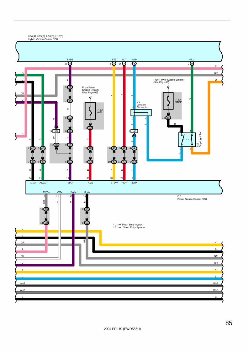
4J8
4G8
33
AM1
R
SPD1
A19
5F9
5K7
8 1F
1G8
5K912 5D
5G5
19
SPD
7 4G
7 4J 4J9
4G9
V
IG214
W V
V
WV
8
7. 5ASTOP
From Power Source System(See Page 66)
1A18
BGR
35
AM2
12
V
L
STP
3 B
H14(A), H15(B), H16(C), H17(D)
GR
J 9
S16
C
C
L
G
3
42
1
ST1–
2 B
RY
RDYST2
28 A5 A
1 1J
From PowerSource System(See Page 66)
7. 5AAM1
G
B
G RB
RYGB
P
V
247
GR
P 6
P
RDYSTSWACCDIG1D
MPX2MPX1
2239
5 4E6 4E
W
11 4J10 4J
1134
13 5G
13 5D
W
V
IG2D
B
B
Y
L
* 2 : w/o Smart Entry System
L
Y
B
* 1 : w/ Smart Entry System
O
GR
P
W–B
W–B
5G8
W–B
W–B
5C
GR
GR
GR
Y
B
B
Y
Hybrid Vehicle Control ECU
JunctionConnector
Sto
p Li
ght S
WPower Source Control ECU
L
STP
1
4 4I
6 4J
L
IA32
C
LL
2004 PRIUS (EWD555U)
86
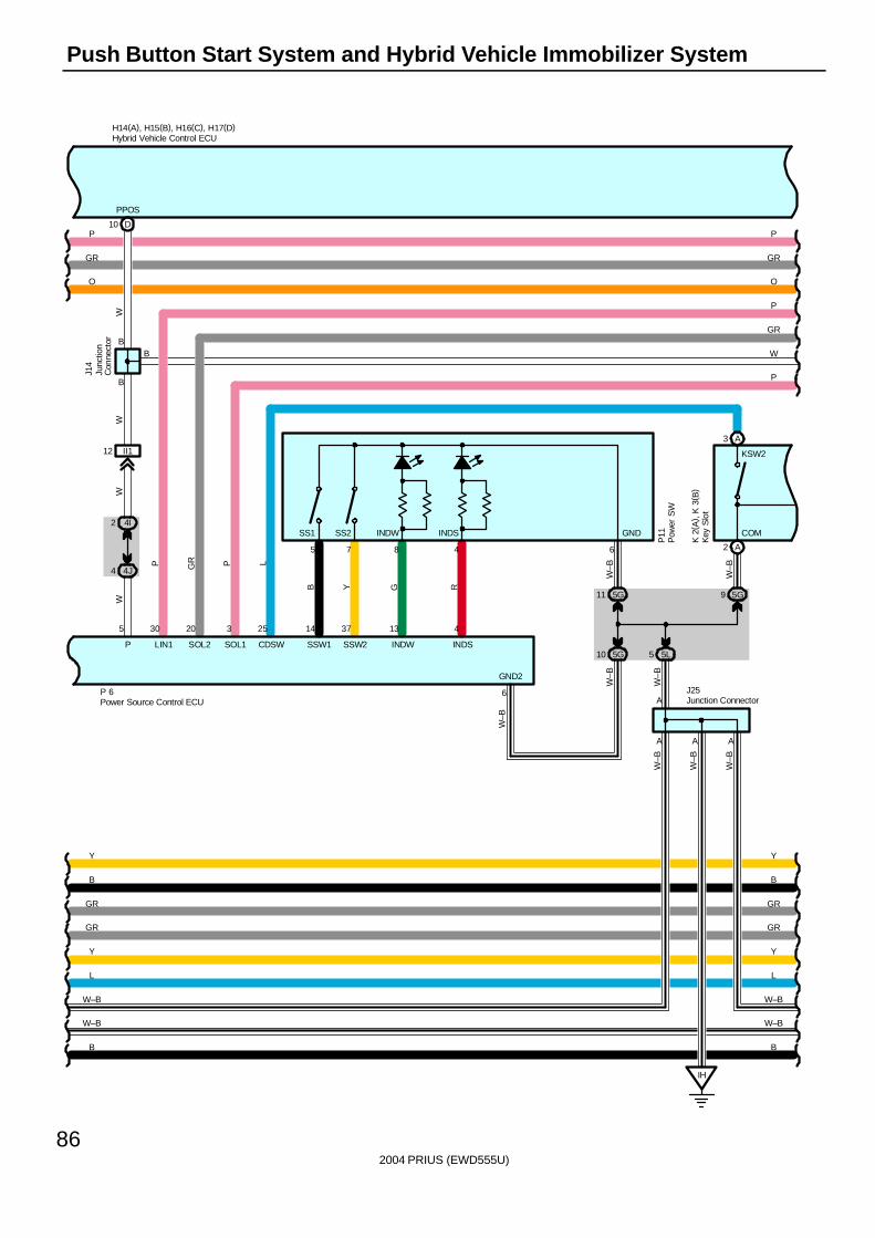
Push Button Start System and Hybrid Vehicle Immobilizer System
12 II1
30
GR
LIN1
P
20 3 25
SOL2
P
14 37 13 4
SSW1 SSW2 INDW INDS
5 7
W–B
8 4
P11
B
L
Y G R
H14(A), H15(B), H16(C), H17(D)
WB
SOL1
GR
W
P 6
CDSWP
D10
PPOS
W
5
2 4I
4 4J
P
B
WW
B
O
A
5G11 5G9
5 5L
IH
6
W–B
W–B
W–B
W–B
A
AJ25
W–B
GR
P
P
5G10
W–B
6
GND2
P
GR
W–B
O
J14
L
Y
L
Y
W–B
W–B
W–B
W–B
A3
SS1 SS2 INDW INDS GND
A2
COM
KSW2
K 2
( A) ,
K 3
( B)
A
GR
GR
GR
GR
B B
B
Y
B
Y
Hybrid Vehicle Control ECU
Junc
tion
Con
nect
or
Junction Connector
Pow
er S
W
Power Source Control ECUK
ey S
lot
2004 PRIUS (EWD555U)
87
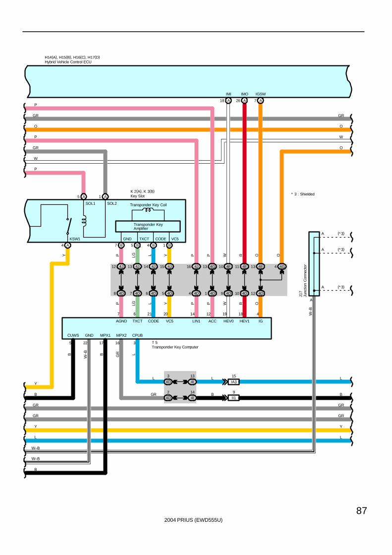
GND
22
K 2(A), K 3(B)
H14(A), H15(B), H16(C), H17(D)
MPX2
GR
4E1110 4E4J16
4 4D 4D9 4D104D1 12 4D
4G44E134G13
OPP W R
41214 19 18
IGACCLIN1 HEV0 HEV1
T 5
B
17
MPX1
16
P
A7
IGSW
A18
IMI
W
A26
IMO
RP
L
3
CPUB
4J12 4J13 4J14 4J15
4D8 4D7 4D6 4D5
7
AGND
6
TXCT
21
CODE
20
VC5
P LG L YYLLGP OO
B
4I
13
W–B
4I14
4D
3
W–B
4D2
GR
IA3
15
II19
L
Y
L
P
L
Y
B
W
LL
GR
P
O
GR
P
W
O
GR
(*3)
(*3)
W–B
A
A
A
A
J17
(* 3)
A5 A1
B7 B5 B4
O
B14 A
Y
GND TXCT CODE VC5KSW1
SOL1 SOL2
Transponder KeyAmplifier
Transponder Key Coil
GR
GRGR
GR
B
W–B
* 3 : Shielded
B
Y
CUWS
5
B
Hybrid Vehicle Control ECU
Junc
tion
Con
nect
or
Transponder Key Computer
Key Slot
2004 PRIUS (EWD555U)
88
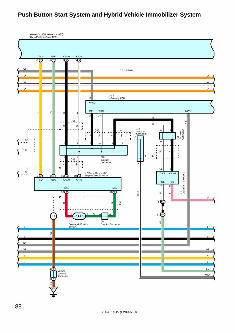
Push Button Start System and Hybrid Vehicle Immobilizer System
GO NEO
MPD2
12
J16
A
H14(A), H15(B), H16(C), H17(D)
O
WW
O
B
B
J15A
A9A8
B
B A B A
B A
WW
17 18
B W
J18
B W
CANH CANL
B
CANLCANH
W
CA1LCA1H
A
W–B
E 4(A), E 6(C), E 7(D)C31 C30
O
D2 D1
C12C13
NEOGO
Y LG
(* 3)
(*3)
(*3)
(*3)
(*3)
(*3) (*3)
A
G 1
* 3 : Shielded
O
GR
GR
3
MPD1
W B14 6
CANL CANH
13
TC
P
7
SIL
W D 1
(* 3)
A B
LG
GR
5M8
5H11
LG
GR
GR
Y
L
Y
L
B
L L
B
W–B
A B
W
B
A34A33
NE+ NE–
GR
C 7
I 3
( *3)
BR
1 2 A A
J14
G
P
Crankshaft PositionSensor
Dat
a Li
nk C
onne
ctor
3
Engine Control Module
Gateway ECU
Hybrid Vehicle Control ECU
Junction Connector
Junc
tion
Con
nect
orJunctionConnector
JunctionConnector
EC
BR
JunctionConnector
J12(A)AA
AA
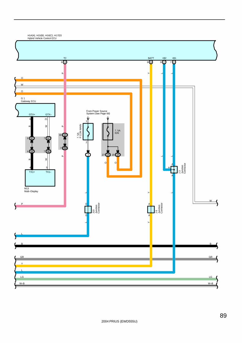
2004 PRIUS (EWD555U)
89
H14(A), H15(B), H16(C), H17(D)
A6
TC
7 5M
10 5F
PP
7. 5AIGN
1A27 1F15
D
From Power SourceSystem (See Page 66)
J10
O
B6
BATT
Y
O
D
Y
A
LL
C7
+B1
J 3
L
C6
+B2
L
AA
3
2
1
7. 5
AP
CO
N M
AIN
A
J 6
A
B
L
LG
GR
L
Y
L
YL
L
P
W–B
O
W
O
W
B
GR
LG
W–B
GTX+ GTX–
5E6 5E7
5C6 5C7
6 21
B W
B W
M13
TX1–TX1+
4 5
G 1
P
Gateway ECU
Hybrid Vehicle Control ECU
Junc
tion
Con
nect
or
Junc
tion
Con
nect
or
Junc
tion
Con
nect
or
Multi–Display
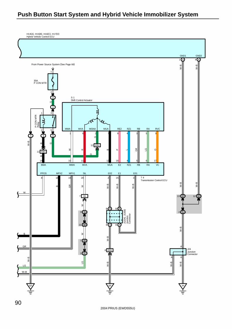
2004 PRIUS (EWD555U)
90
Push Button Start System and Hybrid Vehicle Immobilizer System
3 5I
II17
B
18
MPX2
GR
19
MPX1
1E7
5K11
1L3
W
2
E02
WW
LG
A1 A4
5F13 5F12
5L2
IH
W–B
W–B
W–B
W–B
GND1 GND2
A
A
W–B
W–B
J24
A
W–B
B
BMA
14
2 5
1 3
333
10
3
30AP CON MTR
From Power Source System (See Page 66)
3
2
1
EF
EB111
EB112
OLGGRLPB
GB
W–B
G
W R
G
G
11 12 16 4 5 6 17
1 6 2 7 8 4 3 5 9
P C
ON
MTR
Rel
ay
S 1
MWA MVA MUA E2 RZ1 RB RA VC
RE2 RZ1 RB RA RVCMUAMGNAMVAMWA
W–B
T 48
PPOS
LG
W–B
GR
B
W
JunctionConnector
Transmission Control ECU
Shift Control Actuator
H14(A), H15(B), H16(C), H17(D)Hybrid Vehicle Control ECU
EF
AB AB
BB BB
EB18
20
SIL
15
E1
3
E01
W–B
W–B
W–B
W–B
W–B
Junc
tion
Con
nect
or
J12(
A) ,
J13(
B)
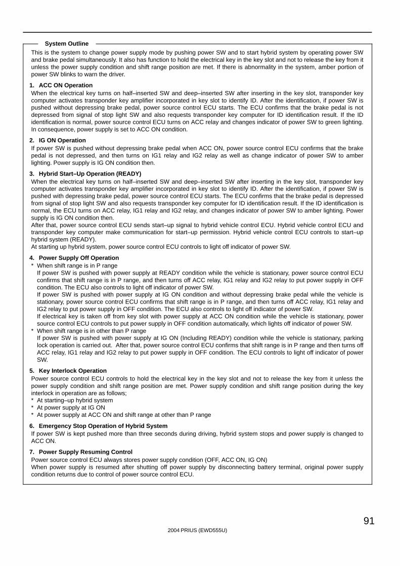
2004 PRIUS (EWD555U)
91
This is the system to change power supply mode by pushing power SW and to start hybrid system by operating power SWand brake pedal simultaneously. It also has function to hold the electrical key in the key slot and not to release the key from itunless the power supply condition and shift range position are met. If there is abnormality in the system, amber portion ofpower SW blinks to warn the driver.
1. ACC ON OperationWhen the electrical key turns on half–inserted SW and deep–inserted SW after inserting in the key slot, transponder keycomputer activates transponder key amplifier incorporated in key slot to identify ID. After the identification, if power SW ispushed without depressing brake pedal, power source control ECU starts. The ECU confirms that the brake pedal is notdepressed from signal of stop light SW and also requests transponder key computer for ID identification result. If the IDidentification is normal, power source control ECU turns on ACC relay and changes indicator of power SW to green lighting.In consequence, power supply is set to ACC ON condition.
2. IG ON OperationIf power SW is pushed without depressing brake pedal when ACC ON, power source control ECU confirms that the brakepedal is not depressed, and then turns on IG1 relay and IG2 relay as well as change indicator of power SW to amberlighting. Power supply is IG ON condition then.
3. Hybrid Start–Up Operation (READY)When the electrical key turns on half–inserted SW and deep–inserted SW after inserting in the key slot, transponder keycomputer activates transponder key amplifier incorporated in key slot to identify ID. After the identification, if power SW ispushed with depressing brake pedal, power source control ECU starts. The ECU confirms that the brake pedal is depressedfrom signal of stop light SW and also requests transponder key computer for ID identification result. If the ID identification isnormal, the ECU turns on ACC relay, IG1 relay and IG2 relay, and changes indicator of power SW to amber lighting. Powersupply is IG ON condition then.After that, power source control ECU sends start–up signal to hybrid vehicle control ECU. Hybrid vehicle control ECU andtransponder key computer make communication for start–up permission. Hybrid vehicle control ECU controls to start–uphybrid system (READY).At starting up hybrid system, power source control ECU controls to light off indicator of power SW.
4. Power Supply Off Operation∗ When shift range is in P range
If power SW is pushed with power supply at READY condition while the vehicle is stationary, power source control ECUconfirms that shift range is in P range, and then turns off ACC relay, IG1 relay and IG2 relay to put power supply in OFFcondition. The ECU also controls to light off indicator of power SW.If power SW is pushed with power supply at IG ON condition and without depressing brake pedal while the vehicle isstationary, power source control ECU confirms that shift range is in P range, and then turns off ACC relay, IG1 relay andIG2 relay to put power supply in OFF condition. The ECU also controls to light off indicator of power SW.If electrical key is taken off from key slot with power supply at ACC ON condition while the vehicle is stationary, powersource control ECU controls to put power supply in OFF condition automatically, which lights off indicator of power SW.
∗ When shift range is in other than P rangeIf power SW is pushed with power supply at IG ON (Including READY) condition while the vehicle is stationary, parkinglock operation is carried out. After that, power source control ECU confirms that shift range is in P range and then turns offACC relay, IG1 relay and IG2 relay to put power supply in OFF condition. The ECU controls to light off indicator of powerSW.
5. Key Interlock OperationPower source control ECU controls to hold the electrical key in the key slot and not to release the key from it unless thepower supply condition and shift range position are met. Power supply condition and shift range position during the keyinterlock in operation are as follows;∗ At starting–up hybrid system∗ At power supply at IG ON∗ At power supply at ACC ON and shift range at other than P range
6. Emergency Stop Operation of Hybrid SystemIf power SW is kept pushed more than three seconds during driving, hybrid system stops and power supply is changed toACC ON.
7. Power Supply Resuming ControlPower source control ECU always stores power supply condition (OFF, ACC ON, IG ON)When power supply is resumed after shutting off power supply by disconnecting battery terminal, original power supplycondition returns due to control of power source control ECU.
System Outline
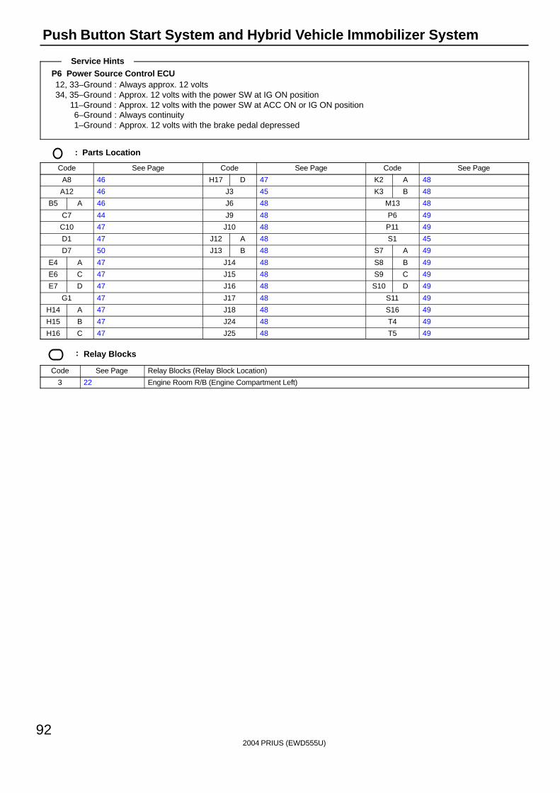
2004 PRIUS (EWD555U)
92
Push Button Start System and Hybrid Vehicle Immobilizer System
P6 Power Source Control ECU12, 33–Ground : Always approx. 12 volts34, 35–Ground : Approx. 12 volts with the power SW at IG ON position
11–Ground : Approx. 12 volts with the power SW at ACC ON or IG ON position6–Ground : Always continuity1–Ground : Approx. 12 volts with the brake pedal depressed
: Parts Location
Code See Page Code See Page Code See Page
A8 46 H17 D 47 K2 A 48
A12 46 J3 45 K3 B 48
B5 A 46 J6 48 M13 48
C7 44 J9 48 P6 49
C10 47 J10 48 P11 49
D1 47 J12 A 48 S1 45
D7 50 J13 B 48 S7 A 49
E4 A 47 J14 48 S8 B 49
E6 C 47 J15 48 S9 C 49
E7 D 47 J16 48 S10 D 49
G1 47 J17 48 S11 49
H14 A 47 J18 48 S16 49
H15 B 47 J24 48 T4 49
H16 C 47 J25 48 T5 49
: Relay Blocks
Code See Page Relay Blocks (Relay Block Location)
3 22 Engine Room R/B (Engine Compartment Left)
Service Hints
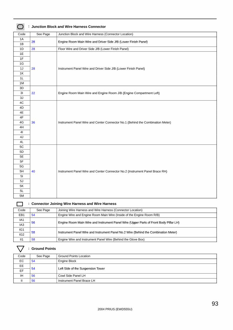
2004 PRIUS (EWD555U)
93
: Junction Block and Wire Harness Connector
Code See Page Junction Block and Wire Harness (Connector Location)
1A28 Engine Room Main Wire and Driver Side J/B (Lower Finish Panel)
1B28 Engine Room Main Wire and Driver Side J/B (Lower Finish Panel)
1D 28 Floor Wire and Driver Side J/B (Lower Finish Panel)
1E
1F
1G
1J 28 Instrument Panel Wire and Driver Side J/B (Lower Finish Panel)
1K
( )
1L
1M
3D
3I 22 Engine Room Main Wire and Engine Room J/B (Engine Compartment Left)
3J
g g ( g )
4C
4D
4E
4F
4G 36 Instrument Panel Wire and Center Connector No.1 (Behind the Combination Meter)
4H
( )
4I
4J
4L
5C
5D
5E
5F
5G
5H 40 Instrument Panel Wire and Center Connector No.2 (Instrument Panel Brace RH)
5I
( )
5J
5K
5L
5M
: Connector Joining Wire Harness and Wire Harness
Code See Page Joining Wire Harness and Wire Harness (Connector Location)
EB1 54 Engine Wire and Engine Room Main Wire (Inside of the Engine Room R/B)
IA156 Engine Room Main Wire and Instrument Panel Wire (Upper Parts of Front Body Pillar LH)
IA356 Engine Room Main Wire and Instrument Panel Wire (Upper Parts of Front Body Pillar LH)
IG158 Instrument Panel Wire and Instrument Panel No 2 Wire (Behind the Combination Meter)
IG258 Instrument Panel Wire and Instrument Panel No.2 Wire (Behind the Combination Meter)
II1 58 Engine Wire and Instrument Panel Wire (Behind the Glove Box)
: Ground Points
Code See Page Ground Points Location
EC 54 Engine Block
EE54 Left Side of the Suspension Tower
EF54 Left Side of the Suspension Tower
IH 56 Cowl Side Panel LH
II 56 Instrument Panel Brace LH
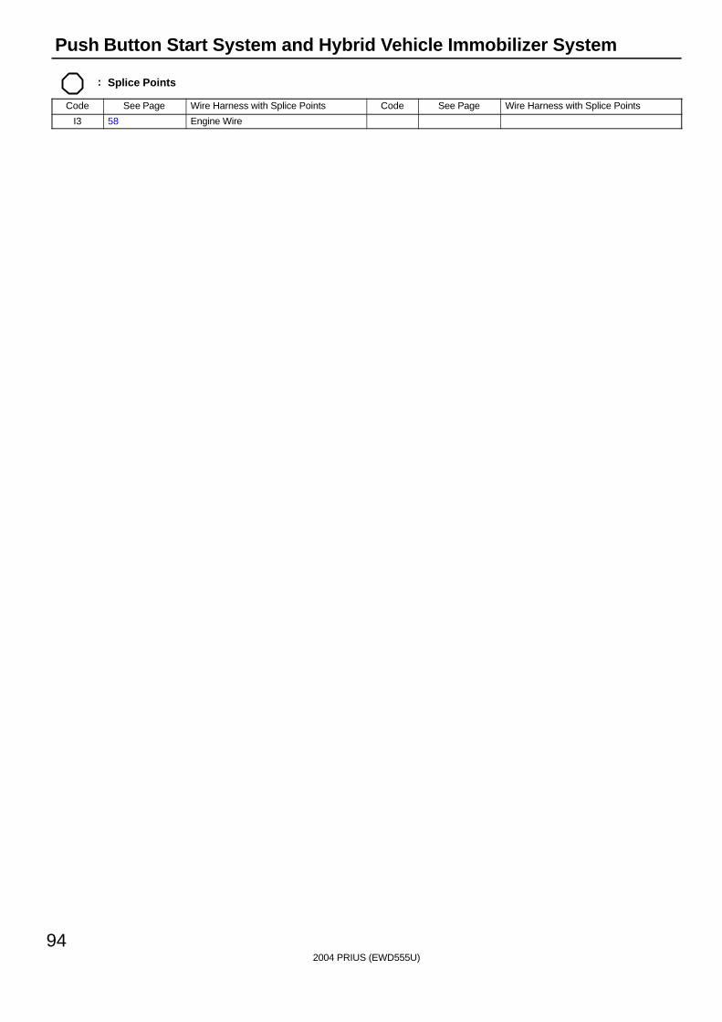
2004 PRIUS (EWD555U)
94
Push Button Start System and Hybrid Vehicle Immobilizer System
: Splice Points
Code See Page Wire Harness with Splice Points Code See Page Wire Harness with Splice Points
I3 58 Engine Wire

2004 PRIUS (EWD555U)
95
Memo
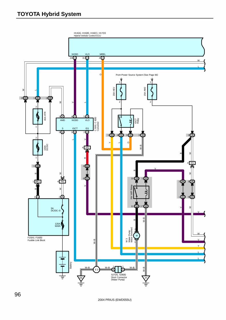
2004 PRIUS (EWD555U)
96
TOYOTA Hybrid System
VR
VL
V
W–B
5J6
4 5H
4 IA2
A2
ID1IGCT
1 A
1 3E
B2A1
BE11 IN14
B1
A3
3M1
100A
DC
/DC
1
2
Bat
tery
5ADC/DC–S
120AMAIN
F15(A), F16(B)
WB
WB
C 5
( A) ,
C 6
( B)
S
AMD
W
NODD VLO
A4
C24
NODD
V
A5
C31
VLO
L
15A
AM
2
2
1
20A
HE
V
From Power Source System (See Page 66)
2
1
3J4 3J23J1 3J3 3I1IG
CT
Rel
ay
C4
MREL
O
O
H14(A), H15(B), H16(C), H17(D)
L
L
L
EE
W–B
W 3
E 3
W–B
W–B
Y
Y
IA14
4I3
4J54J1
WW
V W
V
W
3C1
L
40A
HT
R
1
2
3D1
W
W
L
Con
vert
er
Fusible Link Block
Hybrid Vehicle Control ECU
Wat
er P
ump
Mot
or (
Inve
rter
)
4K3
1A11 1E17
1A10 1G1
IH
V
BB
W–B
W–B
INV
W/P
Rel
ay
B
B1
A1
Short Connector(Water Pump)
S27(A), S28(B)
W–B
M
2
1
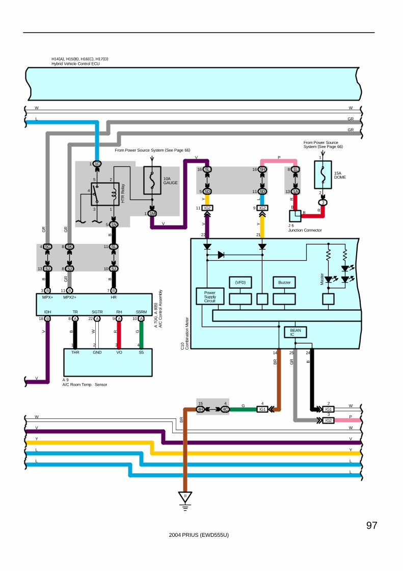
2004 PRIUS (EWD555U)
97
From Power SourceSystem (See Page 66)
1
2
3
15ADOME
Mas
ter
B
BEANIC
PowerSupplyCircuit
IG211 IG29
5D5 5D11
16 5L 5H16 1L8
1A13
Y L
V Y
22 21
R
R
C10
V
BR
II
BR
14 25 24
H14(A), H15(B), H16(C), H17(D)
L
L
L
L
Y
Y
44C4H
15 G
V
V
W
W
4IG1
GR B
W
PIG2
3IG12
V
B
J 6
P
(VFD) Buzzer
10AGAUGE
From Power Source System (See Page 66)
1M13 1
4
5 2
1C1
1N5
HTR
Rel
ay
5J10
5L11
A109 A22 A8 A
7 B
B W R G
A 9
1 2 3 4
HR
TR SGTR RH S5RM
THR GND VO S5
A 7
( A) ,
A 8
( B)
BB
W
L
W
18 B
V
IDH
V
MPX+
GR
B
4 5C
13 5J
MPX2+
GR
GR
8 5K
8 5J
11 B3 B
GR
GR
A/C
Con
trol
Ass
embl
y
A/C Room Temp. Sensor
Com
bina
tion
Met
er
Hybrid Vehicle Control ECU
Junction Connector
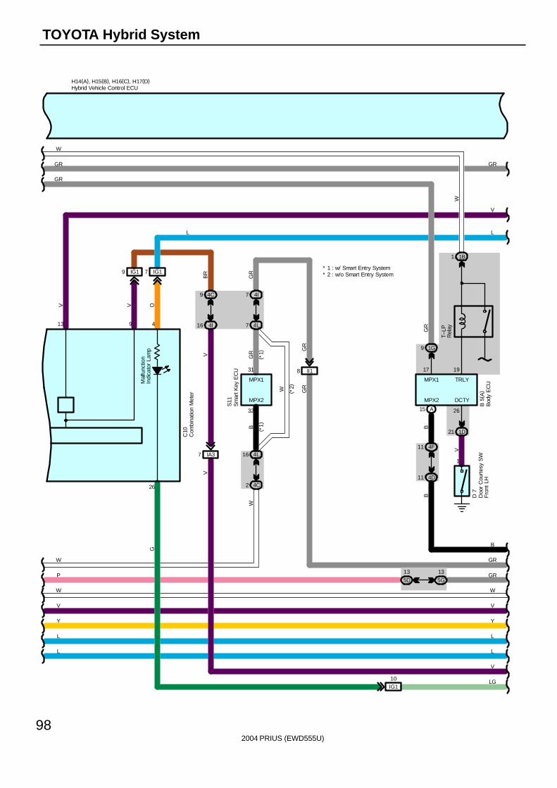
2004 PRIUS (EWD555U)
98
TOYOTA Hybrid System
Y Y
H14(A), H15(B), H16(C), H17(D)
LL
LL
W W
VV
S11
( *2)
B
GR
GR
W
GR
B
MPX1
31
MPX2
32
MPX2
15 A
7 4I
7 4L
16 4L
2 4C
(*1)
( *1)
II18
GR
GR
P
W
B
GR
LG10IG1
V
V
9
Mal
func
tion
Indi
cato
r La
mp
26
4
G
1G9
MPX1
17
GR
O
IG17
L
11 4F
11 4D
B
V
13
IG19
BR
V
9 4C
16 4I
IA37
V
C10
GR
13
5D
19
TRLY
1V
D 7
13
5G
B 5
( A)
1D21
26
DCTY
T–LP
Rel
ay
1B1
W
W
GR
GR
Bod
y E
CU
Com
bina
tion
Met
er
Doo
r C
ourt
esy
SW
Fro
nt L
H
Hybrid Vehicle Control ECU
Sm
art K
ey E
CU
* 1 : w/ Smart Entry System* 2 : w/o Smart Entry System
W
V
L
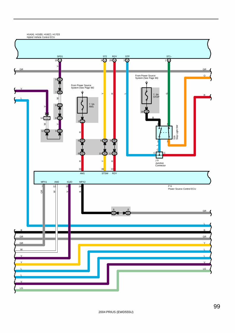
2004 PRIUS (EWD555U)
99
4J8
4G8
33
AM1
R
SPD1
A19
5F9
5K7
8 1F
1G8
5K912 5D
IG214
W V
V
WV
C
7. 5ASTOP
From Power SourceSystem (See Page 66)
1A18
BGR
35
AM2
12
V
L
STP
3 B
H14(A), H15(B), H16(C), H17(D)
GR
J 9
S16
C
L
G
3
42
1
ST1–
2 B
RY
RDYST2
28 A5 A
1 1J
From Power SourceSystem (See Page 66)
7. 5AAM1
R
RY
247
GR
P 6
GR
RDYSTSW
MPX2MPX1
2239
5 4E6 4E
W
11 4J10 4J
W
V
IG2D
B
B
Y
L
L
V
LG
LG
V
L
L
Y
B
L
O
GR
GR
5C8
5G8 GR
C
R
Hybrid Vehicle Control ECU
JunctionConnector
Sto
p Li
ght S
W
Power Source Control ECU
V
L
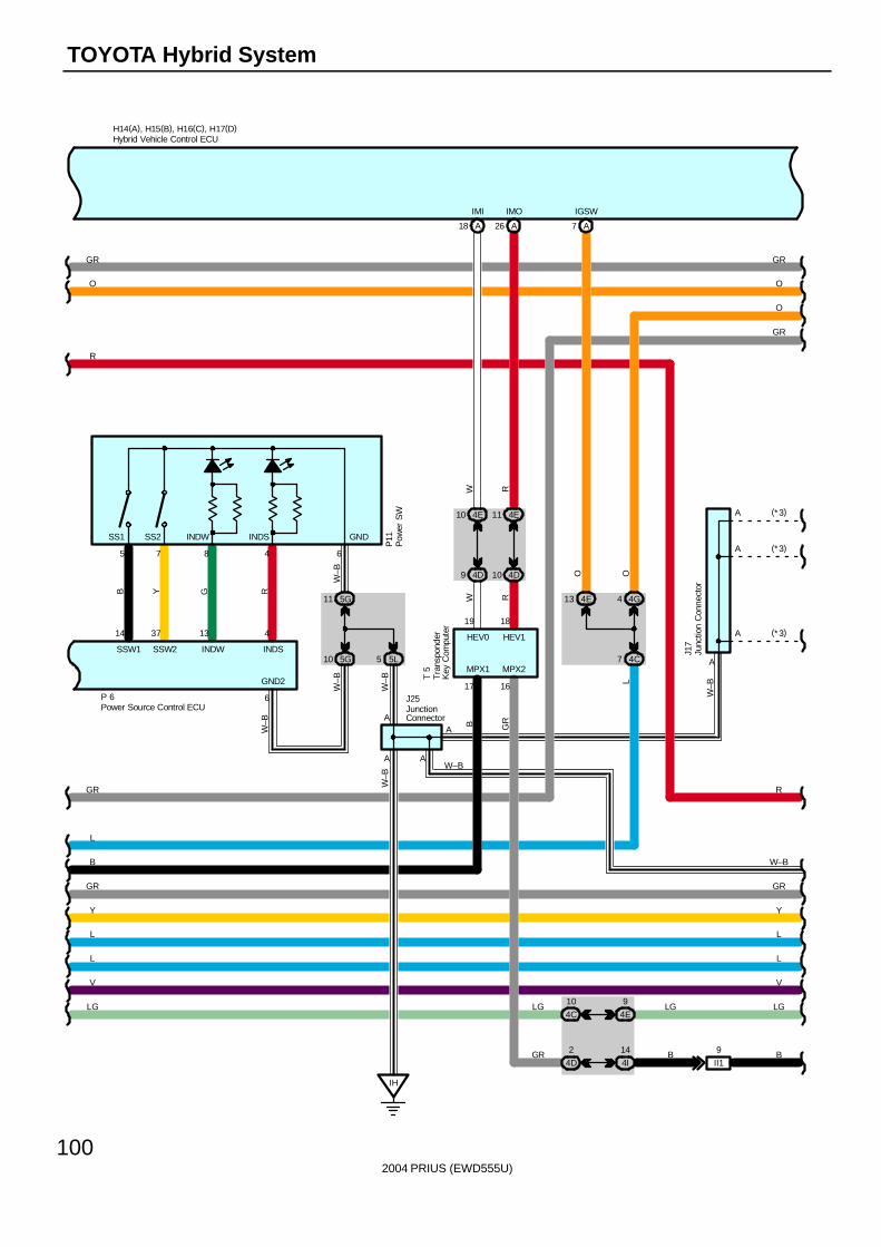
2004 PRIUS (EWD555U)
100
TOYOTA Hybrid System
14 37 13 4
SSW1 SSW2 INDW INDS
5 7 8 4
P11
B Y G R
H14(A), H15(B), H16(C), H17(D)
P 6
A
5G11
5 5L
IH
6
W–B
W–B
W–B
A
J25
5G10
W–B
6
GND2
LG
W–B
V
L
L
Y
L
MPX2
GR
4E1110 4E
4D9 4D10
4G44E13W R
19 18
HEV0 HEV1
B
17
MPX1
16
A7
IGSW
A18
IMI
W
A26
IMO
R
7 4C
LOO
B
B
4I
14
4D
2
II1
9
LG
V
L
L
Y
BGR
O
GR
O
GR
(*3)
(*3)
W–B
A
A
A
A
J17
(* 3)
O
INDSINDWSS2SS1 GND
A
GR
GR
GR
GR
R
R
4E
9
4C
10LGLG
T 5
Hybrid Vehicle Control ECU
Junc
tion
Con
nect
orJunctionConnector
Tra
nspo
nder
Key
Com
pute
r
W–B
A
W–B
Pow
er S
W
Power Source Control ECU
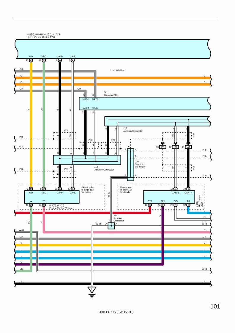
2004 PRIUS (EWD555U)
101
W
GO NEO
SP1
MPD2
12
A
H14(A), H15(B), H16(C), H17(D)
O
O
B
B
J15
A A
A9A8B
B A B A
B A
B A A B
WW
17 18
B W
J18
B W
CANH CANL
B
CANLCANH
W
CA1LCA1H
W B
W B
CAN–L CAN–H
IH
A
J24
W–B
E 6(C), E 7(D)
C31 C30
C18
O
D2 D1
C12C13
NEOGO
Y LG
Y
L
L
Y
L
L
V
B
LG
B
V
(*3)
(*3)
(*3)
(*3)
(*3)
(*3) (*3)
A (*3)
G 1
* 3 : Shielded
O
GR
LG
GR GR
TC
C14
GR
MPD1
3
GR
P
P
W–B
S 8
( B)D/G TS
W
L
A
(*3)
(*3)
STP
R
( *3)
( *3)
A
A
J16
Ski
d C
ontro
lE
CU
Engine Control Module
Gateway ECU
Hybrid Vehicle Control ECU
Junction Connector
JunctionConnector
Junction Connector
JunctionConnector
Please referto page 113for details
Please referto page 118for details
IA113 IA112 IA111A
W–B
W–B
AW–B
B18 B19
B32B28B22B14
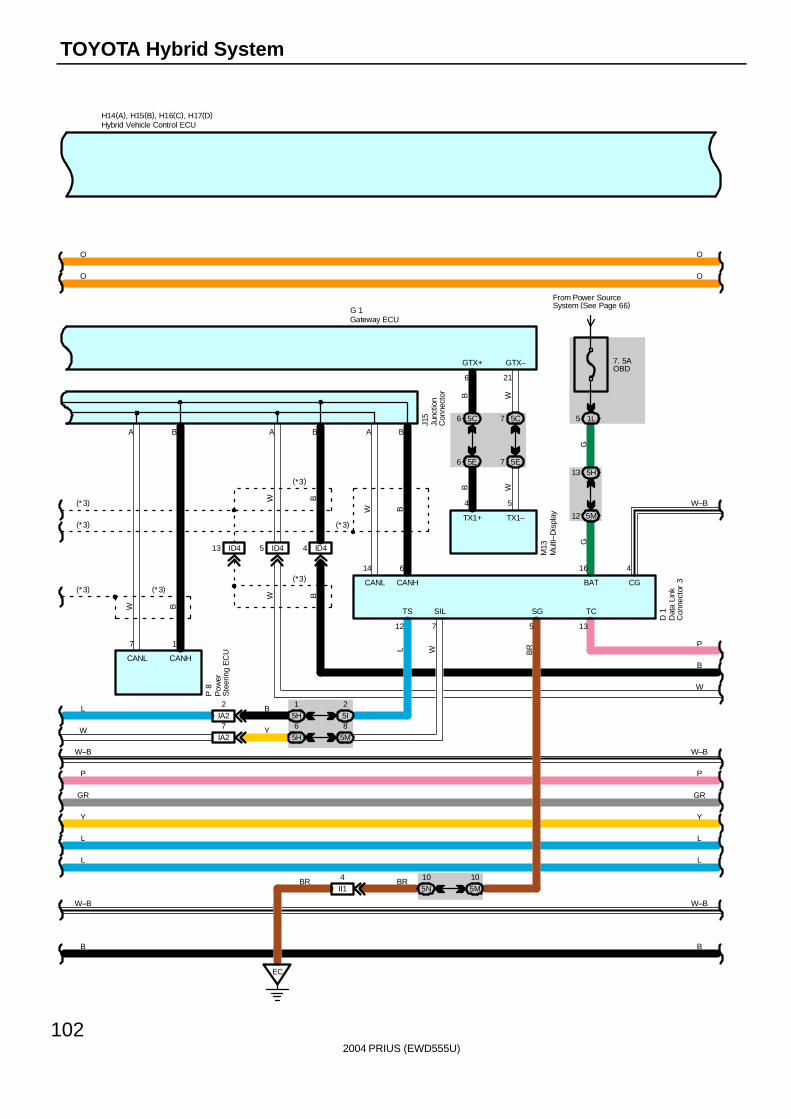
2004 PRIUS (EWD555U)
102
TOYOTA Hybrid System
B
A B
ID45 ID44
W B
W
B
W
(*3)
(*3)
7 5E6 5E
7 5C6 5C
B
G 1
W
B W4 5
TX1+ TX1–
6 21
GTX+ GTX–W B
14 6
CANL CANH
13
TC
7
SIL
D 1
(* 3)
A BJ1
5
H14(A), H15(B), H16(C), H17(D)
Y
L
L
Y
L
L
BB
GR GR
O
O
O
O
M13
7. 5AOBD
From Power SourceSystem (See Page 66)
1L5
5H13
5M12
16
BATG
G
EC
5
SG
BRW
P
W–B
5I2
5H1
IA22
IA27W
L B
Y
12
L
TS
A B
W B
7 1
CANL CANH
P 8
(* 3)
(*3)
(*3)
(*3)
P
105M
105N
BR
65H
85M
P
BRII14
Dat
a Li
nkC
onne
ctor
3
Gateway ECU
Hybrid Vehicle Control ECU
Junc
tion
Con
nect
or
Mul
ti–D
ispl
ay
Pow
erS
teer
ing
EC
U
ID413
W–B
W–B
CG
4
W–B W–B
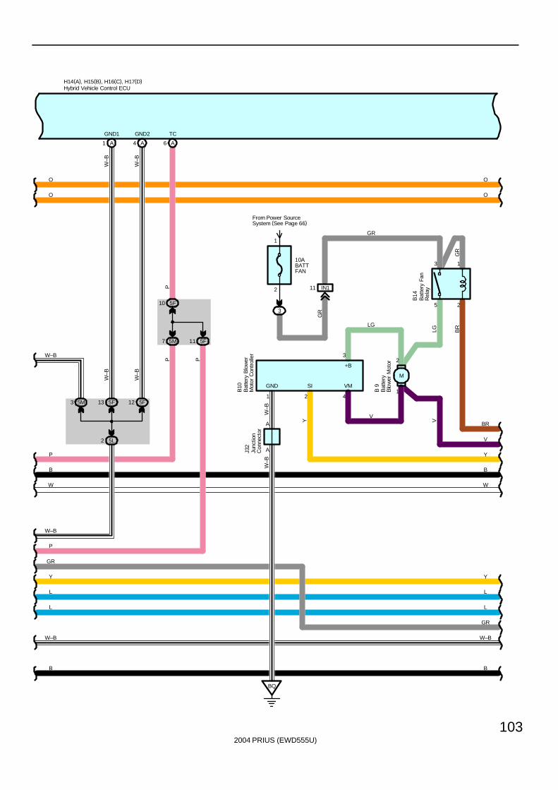
2004 PRIUS (EWD555U)
103
B
L
L
YY
L
B10
10ABATTFAN
3
2
1
1
2
BQ
B14
J32
W–B
W–B
A
3
1 4
A
GND VM
V
+B
From Power SourceSystem (See Page 66)
GR
O
O
H14(A), H15(B), H16(C), H17(D)
L
O
GR
3 1
25
W
B
O
A6
TC
7 5M
10 5F
PP
IN111
GR
B 9
2
SI
LG
GR
LG BR
VY
BR
V
Y
B
W
B
GR
5F11
P
P
P
Bat
tery
Blo
wer
Mot
or
Bat
tery
Fan
Rel
ay
Bat
tery
Blo
wer
Mot
or C
ontr
olle
r
Hybrid Vehicle Control ECU
Junc
tion
Con
nect
or
A1 A4
5F13 5F12
5L2
W–B
W–B
W–B
W–B
GND1 GND2
5M3
W–B
W–B
W–BW–B
M
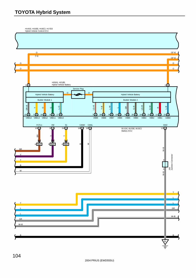
2004 PRIUS (EWD555U)
104
TOYOTA Hybrid System
Y
L
L
O
GR
B
Y
L
L
GR
B
O
Service Plug
BM16 BM15 BM14
BR V Y
19 A
6 B16 B5 B15 B
GR
–B Y O G L–O
LG–R
Y–B
L–W L GR
G–R
LG–B
G–W
FCTL1 VM S1 GND
BL
J30
W–B
A
A
W–B
VBB14 VBB13 VBB12 VBB11 VBB10 VBB9 VBB8 VBB7 VBB6 VBB5 VBB4 VBB3 VBB2
Hybrid Vehicle Battery
Busber Module 1
Hybrid Vehicle Battery
Busber Module 2
B17 B7 B18 B8 B19 B9 B20 B10 B21
O O
H14(A), H15(B), H16(C), H17(D)
A1
O(*4)
(*4)
O
B W
CANH CANL
A12A24A9 18 A10 A
H20(A), H21(B)
B11(A), B12(B), B13(C)
O O
R L–B
VBB1 GBB0
B11 B22
B1
O(*4)
BR
V
Y
B
W
Battery ECU
Hybrid Vehicle Control ECU
Junc
tion
Con
nect
or
Hybrid Vehicle Battery
W–B
W–B
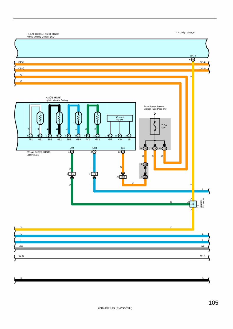
2004 PRIUS (EWD555U)
105
* 4 : High Voltage
B
L
L
GR
B
GR
L
L
7. 5AIGN
1A271E21 1F15
4K5
4G1
O
ID322
O
IG2
13 A
O
A
From Power SourceSystem (See Page 66)
J 6
CurrentSensor
IF17IF18
TB1 GB1 TB2 GB2 TB3 GB3 TC1
IGCT
Y
GC1 GIB VIB IB
C1 C2 C3 C4 C5 C6 C9 C10 C14 C15 C16
LG
AM
O
O
B6
BATT
Y
O
H14(A), H15(B), H16(C), H17(D)
O(*4)
O(*4)
O(*4)
O
A A
H20(A), H21(B)
B11(A), B12(B), B13(C)
AA
O(*4)
L
LG
21
Y
G
Y
GGLLBBWW
Battery ECU
Hybrid Vehicle Control ECU
Junc
tion
Con
nect
or
Hybrid Vehicle Battery
W–B W–B
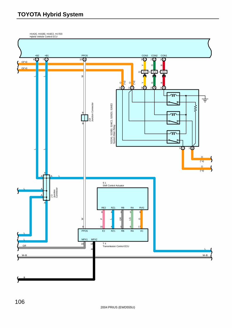
2004 PRIUS (EWD555U)
106
TOYOTA Hybrid System
L
A
LL
L
C7
+B1
J 3
L
C6
+B2
L
B
AA
AL
GR
OLGGRLP
16 4 5 6 17
8 4 3 5 9
T 4
E2 RZ1 RB RA VC
RE2 RZ1 RB RA RVG
19
MPX1
B
18
MPX2
GY
C3 2 C C1
IC122 IC11 IC12
H14(A), H15(B), H16(C), H17(D)
O(*4)
O(*4)
CON3 CON2 CON1
RGY
RO ( *4)O ( *4)
L
D10
PPOS
W
J14
B
B
W
8
PPOS
A
O
O
(*4)
(*4)
A L
Hybrid Vehicle Control ECU
Junc
tion
Con
nect
or
Junc
tion
Con
nect
or
Transmission Control ECU
S 1
W–B W–B
A3 A2 A1
B1C1
E1 D1
S22
( A) ,
S23
( B) ,
S24
( C) ,
S25
( D) ,
S26
( E)
Sys
tem
Mai
n R
elay
Shift Control Actuator
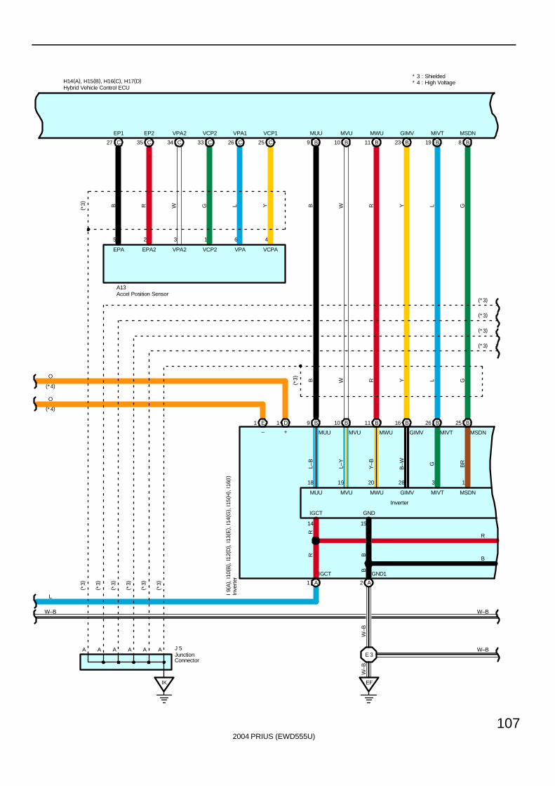
2004 PRIUS (EWD555U)
107
1 65
C27 25 CC2633 CC3435 C
D1E1
19 B B8
B25
W–B
A2
EF
1 A
MWU
B26
23 B
B16
11 B
B11
10 B
B10
9 B
B9
I 9(
A) ,
I10(
B) ,
I12(
D) ,
I13(
E) ,
I14(
G) ,
I15(
H) ,
I16(
I)
H14(A), H15(B), H16(C), H17(D)
B( *3) R W G L Y B W R Y L G
B W R Y L G( *3)
EP1 EP2 VPA2 VCP2 VPA1 VCP1 MUU MVU MWU GIMV MIVT MSDN
IGCT
VPA2
2 3 4
* 3 : Shielded
EPA2
A13
+–
VCPAVPAVCP2EPA
(*3)
* 4 : High Voltage
L
GIMV
GND
MIVT
28
MSDN
IGCT
MVUMUU
MUU
3
MVU
B
MWU
1
GIMV MIVT MSDN
L–B
L–Y
15
Y–B
R
B–W
14
G BR
B
RR
201918
GND1
B
Accel Position Sensor
Hybrid Vehicle Control ECU
Inve
rter
E 3
W–B
W–B
W–B W–B
A J 5AAAAA
( *3)
( *3)
( *3)
( *3)
( *3)
( *3)
IK
JunctionConnector
O
O
(*4)
(*4)
(*3)
(*3)
(*3)
Inverter
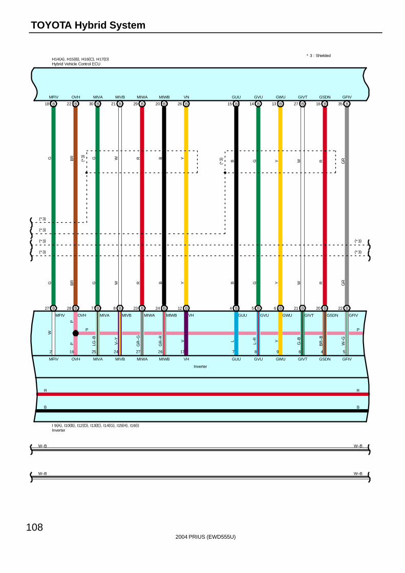
2004 PRIUS (EWD555U)
108
TOYOTA Hybrid System
B16
I 9(A), I10(B), I12(D), I13(E), I14(G), I15(H), I16(I)
B22 26 BB2029 BB2130 B
B28 B7 B8 B23 B24 B12
27 BB1314 BB15
27 B
18 B
B4 B5 B6 B21 B20
B35
B22
* 3 : ShieldedH14(A), H15(B), H16(C), H17(D)
G BR G W R B Y
G BR G W R B Y
B G Y W R GR
B G Y W R GR
MFIV OVH MIVA MIVB MIWA MIWB VN GUU GVU GWU GIVT GSDN GFIV
GWUGUU GFIV
(*3)( *
3)
(* 3)
(*3)
(*3)
(*3)
5469
MFIV
87
OVH
1726
MIVA
2724
MIVB
2516
MIWA
2
MIWB
VH
VH GUU
MIWB
GVU GWU
MIWA
GIVT GSDN
MIVB
GFIV
GIVTMIVA
R
GSDN
B
R
OVH
B
P P
MFIV
W
P
GVU
P LG–B
V–Y
GR
–G
GR
–R V L
L–R Y
G–B
BR
–B
W–G
W–B W–B
Hybrid Vehicle Control ECU
Inverter
W–B W–B
(*3)
(*3)
Inverter
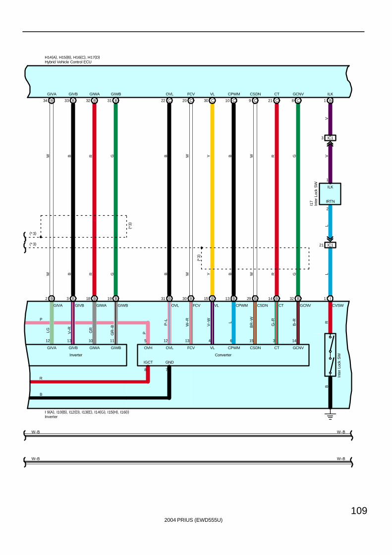
2004 PRIUS (EWD555U)
109
C20 8 CC219 CC1030 C
B30 B15 B13 B29 B14 B32
22 CB3132 BB3334 B
B2 B3 B18 B19 B31
I 9(A), I10(B), I12(D), I13(E), I14(G), I15(H), I16(I)
H14(A), H15(B), H16(C), H17(D)
Y B W R GBGRBW
( *3)
W
( *3)
W B R G B W Y B W R G
GIVA GIVB GIWA GIWB OVL FCV VL CPWM CSDN CT GCNV
GIVBGIVA GIWB CSDN
(*3)
(*3)
GIWA
12 13 10 11 5 12 13 4 6 15 3 14
8 7
IGCT GND
GIVA
B
R
GIVB GIWA GIWB OVH
P
OVL FCV VL CPWM CSDN CT GCNV
LG V–R GR
GR
–B
P
P–L
W–R
V–W L
BR
–W
G–R
B–R
GCNVCTCPWMVLFCVOVL
W–BW–B
Hybrid Vehicle Control ECU
Inverter
W–BW–B
I1
CVSW
Inte
r Lo
ck S
W
RB
ILK
IRTN
I17
L
2
1
ILK
LV
V
21 IC1
3 IC1
B1
ConverterInverter
Inte
r Lo
ck S
W
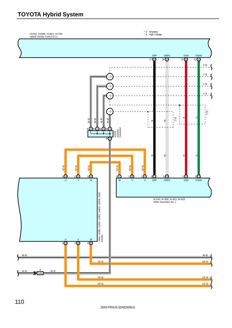
2004 PRIUS (EWD555U)
110
TOYOTA Hybrid System
* 3 : Shielded
26 DD27 21 DD22
H14(A), H15(B), H16(C), H17(D)
I 3
I 3
I 3
I 3
B W
R G
B W R G
GRF GRFG GSN GSNG
GRF GRFG GSN GSNG
( *3)
W–B
(*3)
Hybrid Vehicle Control ECU
EB1
8 W–B
J12(
A)
Junc
tion
Con
nect
or
W–B
W–B
W–B
W–B
W–BW–B
M 2(A), M 3(B), M 4(C), M 5(D)
Inve
rter
I 9( A
) , I1
0(B
) , I1
2(D
) , I1
3(E
) , I1
4(G
) , I1
5(H
) , I1
6(I)
Motor Generator No. 1
1 A1 B1 C
U V W
U V
H3
O( *
4)
H2
O( *
4)
W
H1
O( *
4)
G3G2G1
O(*4)
O(*4)
O(*4)
O(*4)
O(*4)
O(*4)
O( *
4)
O( *
4)
O( *
4)
W V U
D3 D6 D2 D5
* 4 : High Voltage
(*3)
(*3)
(*3)
(*3)
ABABABAB
AB
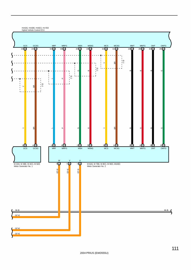
2004 PRIUS (EWD555U)
111
24 DD23 33 DD34 19 DD20 31 DD32 28 DD18 29 DD30
Y BR
L P
Y BR L P G R Y BR
G R
Y BR
B R B G
B R B G
GCS GCSG MRF MRFG MSN MSNG MCS MCSG MMT MMTG OMT OMTG
GCS GCSG MRF MRFG MSN MSNG MCS MCSG MMT MMTG OMT OMTG
( *3)
( *3)
( *3)
( *3)
D1 D4 D2 D5 D3 D6 E1 E4 E3 E6
H14(A), H15(B), H16(C), H17(D)
W–B
Hybrid Vehicle Control ECU
W–B
M 6(A), M 7(B), M 8(C), M 9(D), M10(E)Motor Generator No. 2
1 A1 B1 C
O( *
4)
O( *
4)
O( *
4)
O(*4)
O(*4)
O(*4)
W V U
Motor Generator No. 1M 2(A), M 3(B), M 4(C), M 5(D)
D1 D4
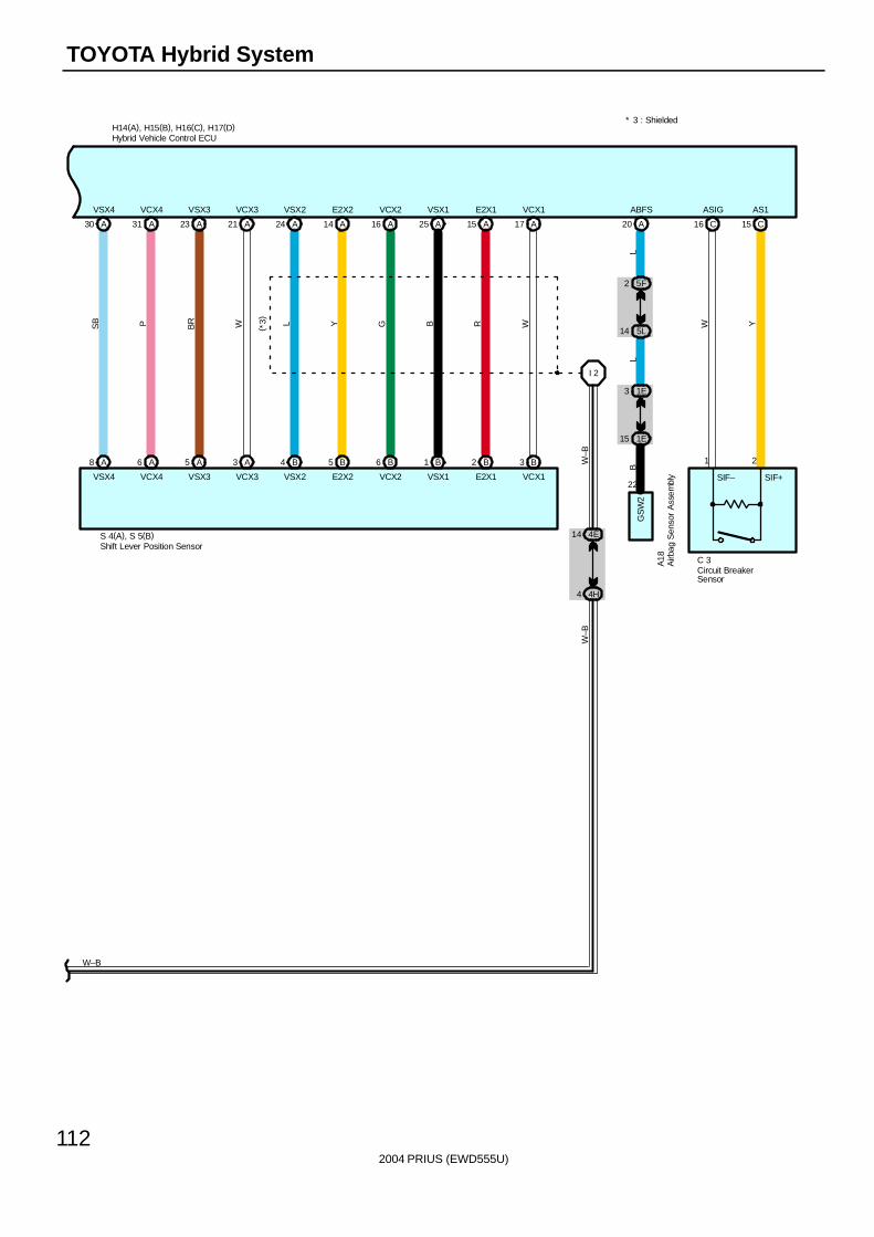
2004 PRIUS (EWD555U)
112
TOYOTA Hybrid System
A20
ABFS
2 5F
5L14
1E3
15 1E
LL
B
A18
GS
W2
H14(A), H15(B), H16(C), H17(D)
A30 A31 A23 A21 A24 A14 A16 A25 A15 A17
A8 A6 A5 A3 B4 B5 B6 B1 B2 B3
I 2
4E14
4H4
SB P BR W L Y G B R W
W–B
( *3)
VSX4 VCX4 VSX3 VCX3 VSX2 E2X2 VCX2 VSX1 E2X1 VCX1
VSX4 VCX4 VSX3 VCX3 VSX2 E2X2 VCX2 VSX1 E2X1 VCX1
S 4(A), S 5(B)
* 3 : Shielded
W–B
Airb
ag S
enso
r A
ssem
bly
Hybrid Vehicle Control ECU
Shift Lever Position Sensor
W–B
22
C 3
21
AS1ASIG
YW
C1516 C
SIF– SIF+
Circuit BreakerSensor
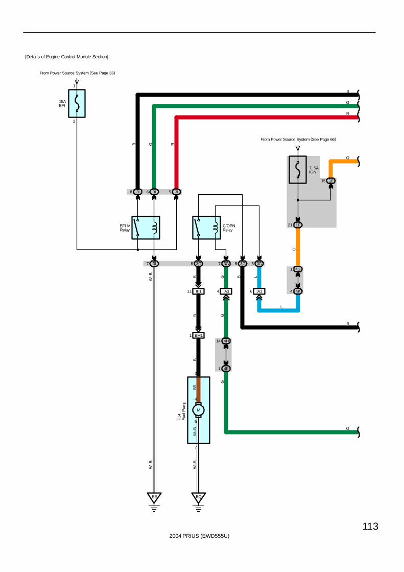
2004 PRIUS (EWD555U)
113
15AEFI
3I8 3I6 3I5
3I7
EE
3G
From Power Source System (See Page 66)
7. 5AIGN
8 3G7
5
4
BQ
1 BM114 4H
4E1
G
R
G
W–B
W–B
B
GGB
RGB
2
1
C/OPNRelay
F14
From Power Source System (See Page 66)
B
1F15
O
Fue
l Pum
p
[Details of Engine Control Module Section]
EFI MRelay
3G5
IA34
GB B
W–B
3G6
1E21
4K4
4G1
IA36O
L
L
M
B
3
7
BR
W–B
IF111
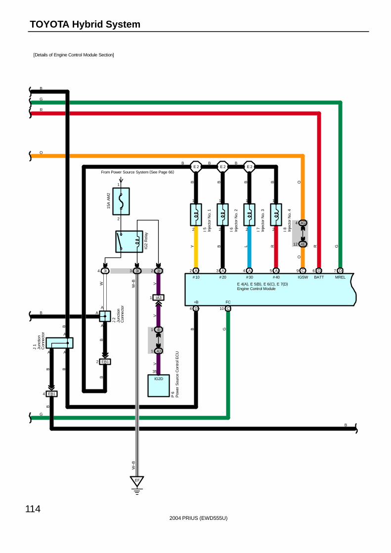
2004 PRIUS (EWD555U)
114
TOYOTA Hybrid System
B
J 1
EB14
A A
B
B
B B
E 4(A), E 5(B), E 6(C), E 7(D)
I 5
6 D
BATT
7 D
MREL
I 8
C10
FC
2
1
2
1 1
2 2
1
2 A
#10
3 A
#20
4 A
#30
5 A
#40
E 2 E 2 E 2
I 7I 6
B
D4
+B
B
GRRL
BBBB
B
B G
Y
G
R
G
B
OO
4 4G
12 4E
IGSW
C9
O
Engine Control Module
Inje
ctor
No.
1
Inje
ctor
No.
2
Inje
ctor
No.
3
Inje
ctor
No.
4
Junc
tion
Con
nect
or
[Details of Engine Control Module Section]
15A
AM
2
From Power Source System (See Page 66)
2
1
3I4 3I3 3I2
IG2
Rel
ay
W–B
EB12
WB
B
A
A
IA31
4I1
4J1
VV
EF
A
35
IG2D
P 6
Pow
er S
ourc
e C
ontro
l EC
U
W–B
V
B
Junc
tion
Con
nect
or
J 2
AB
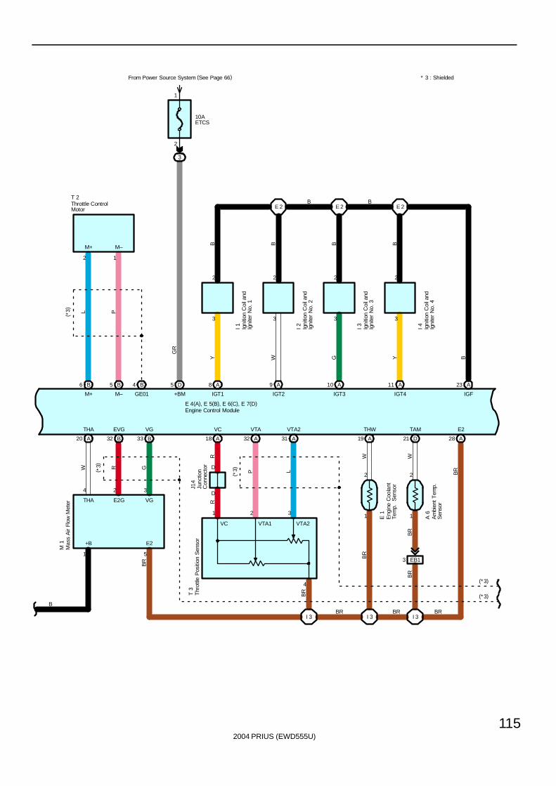
2004 PRIUS (EWD555U)
115
1
2
3
From Power Source System (See Page 66)
10AETCS
BR
BR
A 6
W
3 EB1
I 3
TAM
21 D
1
5 D
+BM
M 1
( *3)
A20
THA
B32
EVG
B33
VG
E 4(A), E 5(B), E 6(C), E 7(D)
2
5
324
GR
BR
GRW
1
B
+B E2
THA E2G VG
* 3 : Shielded
R
D
B6 B5 B4
L P( *3)
2 1
M+ M–
M+ M– GE01
T 2
11 AA109 A8 A A23
E 2 E 2 E 2Y
B B B B
W G Y B
3 3 3 3
2 2 2 2
I 1 I 2 I 3 I 4
A3132 A
1
2
A19
VTA VTA2 THW
A18
I 3 I 3
A28
B B
(*3)
(*3)
BR
R
P L
W
BR
BR
BR
E 1
( *3)
4
32
BR
1
BR
T 3
J14
VC
D
IGT1 IGT2 IGT3 IGT4 IGF
E2
VTA2VTA1VC
Am
bien
t Tem
p.
Sen
sor
Engine Control Module
Eng
ine
Coo
lant
Tem
p.
Sen
sor
Igni
tion
Coi
l and
Igni
ter
No.
1
Igni
tion
Coi
l and
Igni
ter
No.
2
Igni
tion
Coi
l and
Igni
ter
No.
3
Igni
tion
Coi
l and
Igni
ter
No.
4
Junc
tion
Con
nect
or
Mas
s A
ir Fl
ow M
eter
Throttle ControlMotor
Thr
ottle
Pos
ition
Sen
sor
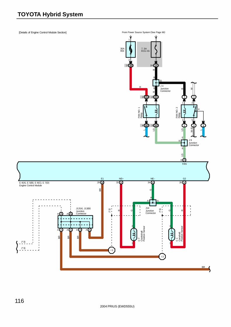
2004 PRIUS (EWD555U)
116
TOYOTA Hybrid System
E 4(A), E 5(B), E 6(C), E 7(D)
8 D
FAN
BA BA
AA AA AA AA
2
1 1
2
A34A33 A26
I 3
I 3
B28
E1 NE+ NE– G2
(*3)
(*3)
AA
LG
BR G
A
G G RR( *3)
( *3)J12(A), J13(B) J14
C 7
C 1
BR
BR
BR
BR
3G1 3G2 3 3
2 5
1 3
4
3G4 3G3 3 3 3
30ARDI
From Power Source System (See Page 66)
3B2
2
1
7. 5AECU–IG
1A24
B
B W
L LG LG W–B L
B
EE
E
B
B
R
J 9
J 4
FAN
NO
. 2R
elay
FAN
NO
. 1R
elay
Cra
nksh
aft
Pos
ition
Sen
sor
Cam
shaf
tP
ositi
on S
enso
r
Engine Control Module
JunctionConnector
JunctionConnector
JunctionConnector
JunctionConnector
B
[Details of Engine Control Module Section]
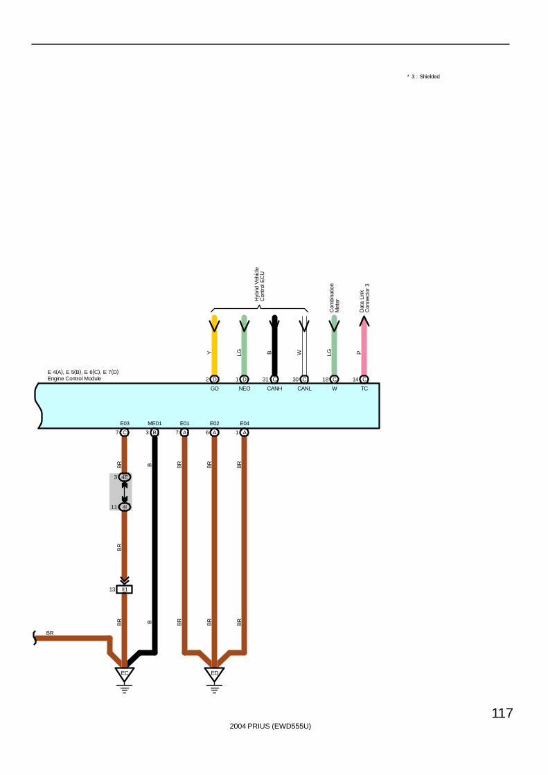
2004 PRIUS (EWD555U)
117
* 3 : Shielded
E 4(A), E 5(B), E 6(C), E 7(D)
E03 E04
1 A7 C B3
ME01 E01
7 A A6
E02
ED
4I11
4E3
II113
EC
BR B BR
BR
BR
BR B BR
BR
BR
BR
BR
2 D
GO NEO
D1Engine Control Module
Com
bina
tion
Met
er
30 C
CANLCANH
C31 18 C
W TC
C14
Y LG B W LG P
Hyb
rid V
ehic
leC
ontr
ol E
CU
Dat
a Li
nkC
onne
ctor
3
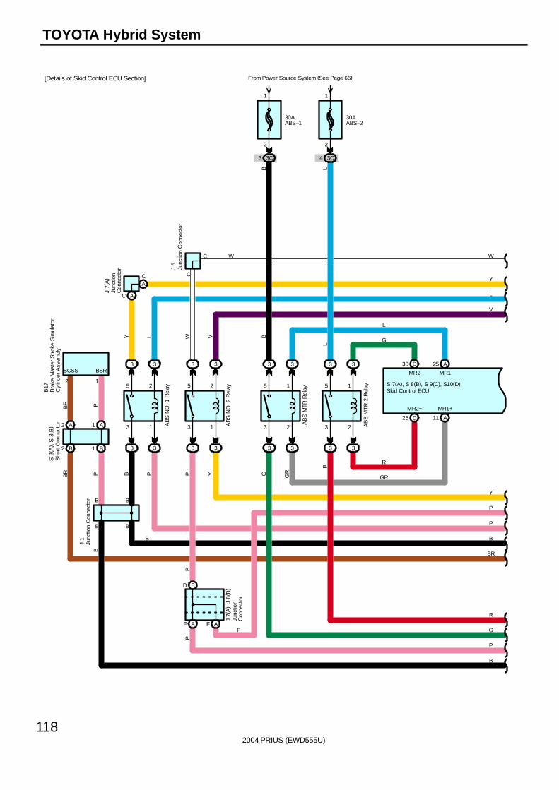
2004 PRIUS (EWD555U)
118
TOYOTA Hybrid System
B
3 2
5 1
3 2
5 1
3 3
11 A25 D
3
R
3
AB
S N
O. 2
Rel
ay
A25
MR1MR2
3 3
AB
S M
TR R
elay
30AABS–1
From Power Source System (See Page 66)
3C3
2
1
30AABS–2
3C4
2
1
3
3 1
5 2
3
3 3
AF AF
BD
3
AB
S M
TR
2 R
elay
3
D
MR2+ MR1+
S 7(A), S 8(B), S 9(C), S10(D)
30
W
V
Y
P
R
G
P
R
GR
G
L
W
PP Y GR
BVW
J 7(
A) ,
J 8
( B)
J 6
C
C
LL
G
Skid Control ECU
Junc
tion
Con
nect
or
Junc
tion
Con
nect
or
J 7(
A)
B
3 1
5 2
B
3
3 3
AB
S N
O. 1
Rel
ay
3
B1B2
A1A2
B
BR P B P
Y
B
Y
L
P
B
BR
B
J 1
S 2
( A) ,
S 3
( B)
B
BR P
B17
BSRBCSS
12
Junc
tion
Con
nect
or
Junc
tion
Con
nect
or
Bra
ke M
aste
r S
trok
e S
imul
ator
Cyl
inde
r A
ssem
bly
Sho
rt C
onne
ctor
P
P
B
[Details of Skid Control ECU Section]
L
AC
AC
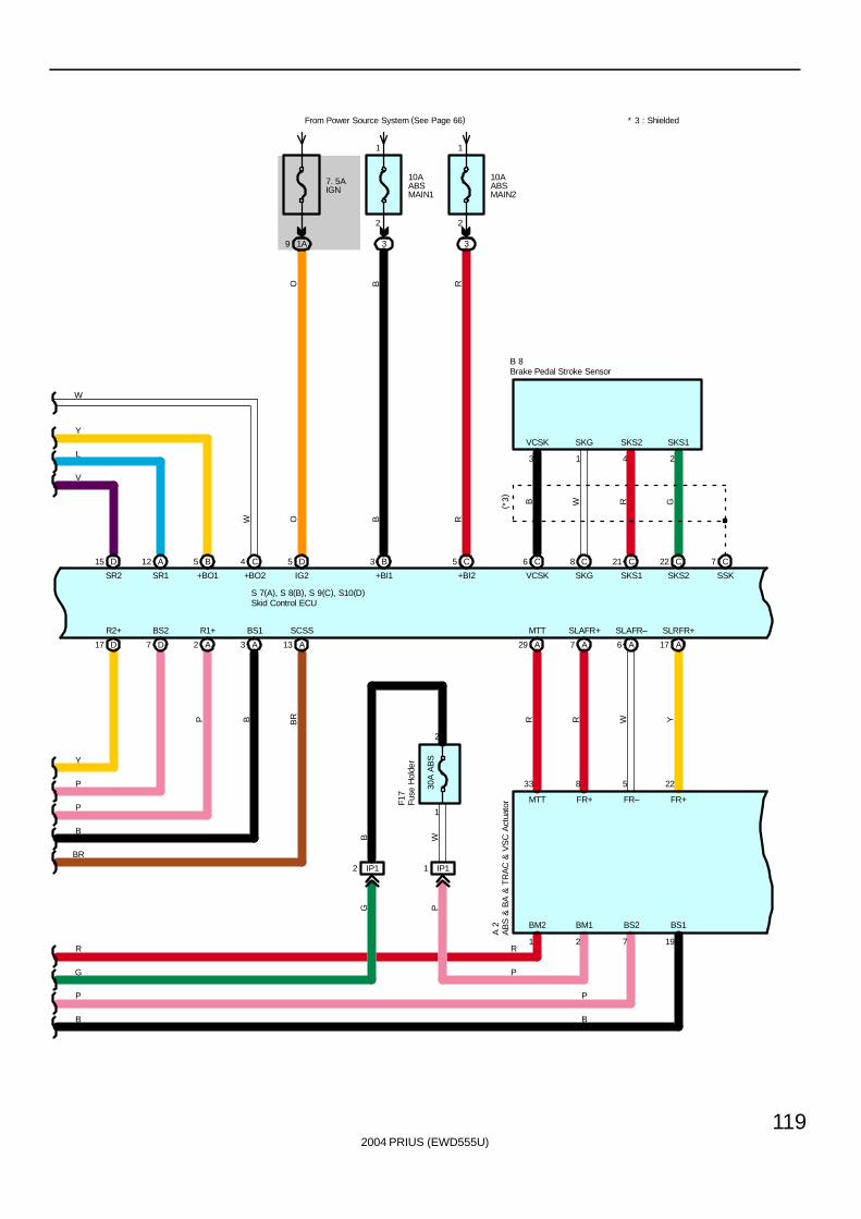
2004 PRIUS (EWD555U)
119
15 D 12 A 5 B 4 C 3 B 5 C
1
2
3
From Power Source System (See Page 66)
10AABSMAIN2
1
2
3
10AABSMAIN1
SR2
S 7(A), S 8(B), S 9(C), S10(D)
+BO1 +BO2
D17 D7 A2 A3 A13 A29 A7 A6 A17
R1+BS2R2+ BS1 SCSS MTT SLAFR+ SLAFR– SLRFR+
33 8 5 22
R R W Y
22 C21 C
A 2
8 C6 C C7
1 4 2
WB BR
B 8
GRWVCSK+BI2+BI1SR1
1 2 7 19
VCSK SKG SKS2 SKS1
BM2 BM1 BS2 BS1
FR–FR+MTT FR+
B
SKS1SKG SKS2 SSK
W
Y
L
V
Y
P
P
B
BR
R
G
P
B
B R
B R3
( *3)
B
P
P
R
P
5 D
IG2
O
* 3 : Shielded
AB
S &
BA
& T
RA
C &
VS
C A
ctua
tor
Skid Control ECU
Brake Pedal Stroke Sensor
7. 5AIGN
1A9
O
IP12 IP11
30A
AB
S
1
2
WBG P
Fuse
Hol
der
F17
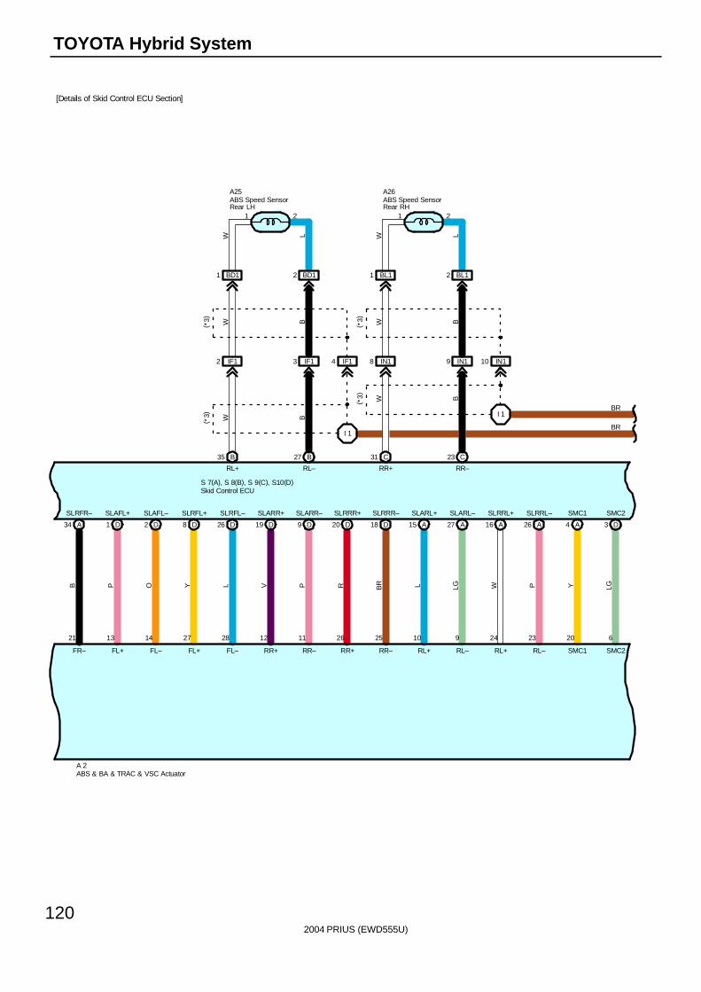
2004 PRIUS (EWD555U)
120
TOYOTA Hybrid System
A 2
I 1
A34 D1 D2 D8
SLRFR– SLAFL+ SLAFL– SLRFL+
21 13 14 27
B P O Y
D26 D19 D9 D20
SLRFL– SLARR+ SLARR– SLRRR+
28 12 11 26
L V P R
D18 A15 A27 A16
SLRRR– SLARL+ SLARL– SLRRL+
25 10 9 24
BR L LG W
A26 A4 D3
SLRRL– SMC1 SMC2
23 20 6
P Y LG
B35 B27 C31 C23
I 1
A25 A26
S 7(A), S 8(B), S 9(C), S10(D)
BR
BR
BW
B
B
W
WBW
FR– FL+ FL– FL+ FL– RR+ RR– SMC2SMC1
RR+RL–RL+
RL–RL+RL–RL+RR–RR+
RR–
1 12 2
( *3)
( *3)
( *3)
( *3)
BD11 BD12 BL11 BL12
W L W L
ABS & BA & TRAC & VSC Actuator
Skid Control ECU
ABS Speed SensorRear LH
ABS Speed SensorRear RH
[Details of Skid Control ECU Section]
IF12 IF13 IF14 IN18 IN19 IN110
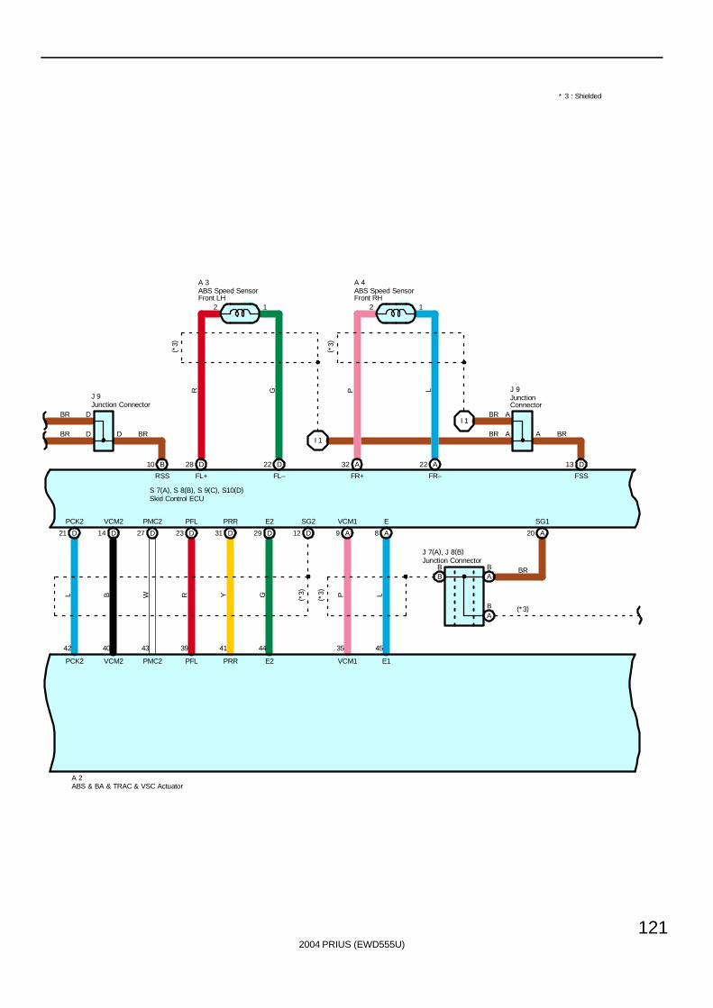
2004 PRIUS (EWD555U)
121
* 3 : Shielded
BA
BB
J 9
BR
BR BR
D21 D14 D27 D23
PCK2 VCM2 PMC2 PFL
42 40 43 39
L B W R
D31 D29 D12 A9
PRR E2 SG2 VCM1
41 44 35
Y G ( *3) P
A8
A 2
E
45
L
BR
(*3)
LP
A
GR
J 7(A), J 8(B)
J 9
10 B
S 7(A), S 8(B), S 9(C), S10(D)
I 1
D28 D22 A32 A22
20
BA
A
13 D
I 1BR
BR
E2 VCM1 E1PFL PRRPMC2VCM2PCK2
RSS FL+ FL– FR+ FR– FSS
D
D D BR
(*3)
2
SG1
21 1
AA
A 3
( *3)
( *3)
A 4ABS Speed SensorFront LH
ABS Speed SensorFront RH
ABS & BA & TRAC & VSC Actuator
Skid Control ECU
Junction Connector
JunctionConnectorJunction Connector
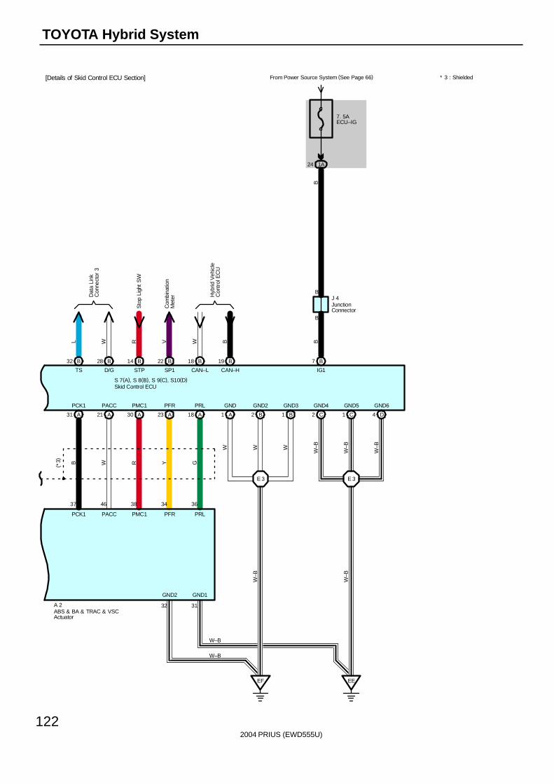
2004 PRIUS (EWD555U)
122
TOYOTA Hybrid System
S 7(A), S 8(B), S 9(C), S10(D)
B
B
A31 A21
PCK1 PACC
37 46
B W
A30 A23 A18
PMC1 PFR PRL
38 34 36
R Y G
E 3
A 2
EEEF
E 3
1 B1 A 2 B 4 D2 C 1 C
PCK1 PACC PMC1
B18
From Power Source System (See Page 66)
PRLPFR
GND2 GND1
32 31
7 B
24 1A
7. 5AECU–IG
CAN–L IG1
B
W B
W W W
W–B
W–B
W–B
W–B
W–B
J 4
GND6GND5GND4GND3GND2GND
W–B
W–B
* 3 : Shielded
( *3)
B19
CAN–H
B
ABS & BA & TRAC & VSCActuator
Skid Control ECU
JunctionConnector
V
SP1
22 BB14
STP
RL
TS
32 B B28
D/G
W
Hyb
rid V
ehic
leC
ontr
ol E
CU
Dat
a Li
nkC
onne
ctor
3
Com
bina
tion
Met
er
Sto
p Li
ght
SW
[Details of Skid Control ECU Section]
2004 PRIUS (EWD555U)
123
This system controls the following modes in order to achieve the most efficient operations to match the driving conditions.
1. Motor Generator Condition(1) Supply of electrical power from the HV battery to motor generator no.2 provides force to drive the wheels.
(2) While the tires are driven by the engine via the planetary gears, motor generator no.1 activates to supply electricity viathe planetary gears to motor generator no.2 to drive the wheels.
(3) When the vehicle is decelerating, kinetic energy from the wheels is recovered into electrical energy and used torecharge the HV battery by motor generator no.2.
The hybrid vehicle control ECU switches between these modes (1, 2, 1+2, or 3) according to the driving conditions.However, when the state of charge of the HV battery is low, the HV battery is charged by the engine turning motor generatorno.1.
2. Inverter∗ The inverter converts high–voltage direct current of HV battery to three–phase alternating current for driving motor
generator no.1 and motor generator no.2.∗ The activation of the power transistors is controlled by the HV ECU. In addition, the inverter transmits necessary
information for current control, such as the output amperage or voltage, to the HV ECU.∗ Along with motor generator no.1 and motor generator no.2, the inverter is cooled by the exclusive radiator of the coolant
system that is separated from that of the engine.∗ In vehicle collision, circuit breaker sensor installed in the inverter outputs collision signal to stop the system.∗ Boost converter has been adopted in the inverter, which increases rated voltage output from HV battery of DC 201.6V to
DC 500V. After increasing voltage, the inverter converts direct current to alternating current.
3. ConverterThe power source for auxiliary equipment of the vehicle such as the lights, audio system, and the air conditioning system, aswell as the ECUs, is based on a rated voltage of DC 12V system. Because the generator outputs at DC 201.6V, theconverter is used to transform the voltage from rated voltage of DC 201.6V to DC 12V in order to recharge the auxiliarybattery. The converter is installed on the underside of the inverter.
4. HV Battery∗ In Prius, the sealed nickel hydride (Ni–MH) battery has been adopted. This HV battery has high power density, lightweight
and longevity to match characteristics of TOYOTA hybrid system. Because TOYOTA hybrid system controlscharge/discharge to maintain charge/discharge control to maintain SOC (State of charge) at constant level while thevehicle is operating normally, it does not have to rely on the use of external recharges.
∗ The HV battery, battery ECU, system main relay and the cooling fan are put in a signal case which is placed in the luggagecompartment behind the rear seat to make more effective use of vehicle space.
∗ A service plug that shuts off circuit is provided in the middle of the 28 modules (Rated battery capacity = 201.6V). Beforeservicing any portion of the high–voltage circuits, make sure to remove the service plug.Please do not READY ON when you remove the service plug. There is a possibility that battery ECU breaks down.
∗ To ensure the HV battery’s performance, the battery ECU controls the operation of the cooling fan to avoid the heat that isgenerated in the HV battery during charging and discharging.
5. Regenerative System OperationThis system operates the motor as a generator to change the kinetic energy of the vehicle into the electricity when accelpedal is released or foot braking decelerates the vehicle speed, and store the electricity in the battery.
H14 (A), H15 (B), H16 (C) Hybrid Vehicle Control ECU(B) 6–Ground : Always approx. 12 volts
(C) 6, (C) 7–Ground : Approx. 12 volts with the hybrid system at ON (READY) position(A) 7–Ground : Approx. 12 volts with the power SW at IG ON position(B) 3–Ground : Approx. 12 volts with the brake pedal depressed
(A) 1, (A) 4–Ground : Always continuity
System Outline
Service Hints
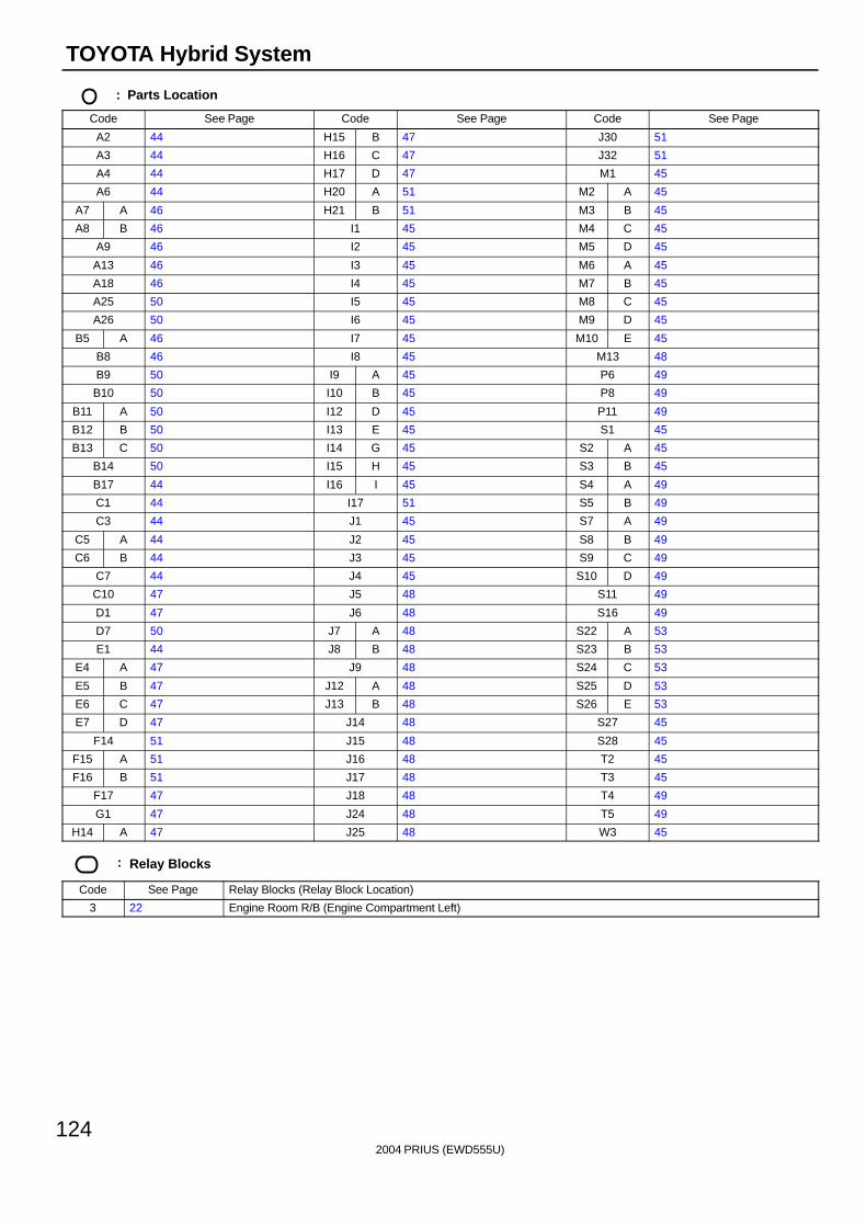
2004 PRIUS (EWD555U)
124
TOYOTA Hybrid System
: Parts Location
Code See Page Code See Page Code See Page
A2 44 H15 B 47 J30 51
A3 44 H16 C 47 J32 51
A4 44 H17 D 47 M1 45
A6 44 H20 A 51 M2 A 45
A7 A 46 H21 B 51 M3 B 45
A8 B 46 I1 45 M4 C 45
A9 46 I2 45 M5 D 45
A13 46 I3 45 M6 A 45
A18 46 I4 45 M7 B 45
A25 50 I5 45 M8 C 45
A26 50 I6 45 M9 D 45
B5 A 46 I7 45 M10 E 45
B8 46 I8 45 M13 48
B9 50 I9 A 45 P6 49
B10 50 I10 B 45 P8 49
B11 A 50 I12 D 45 P11 49
B12 B 50 I13 E 45 S1 45
B13 C 50 I14 G 45 S2 A 45
B14 50 I15 H 45 S3 B 45
B17 44 I16 I 45 S4 A 49
C1 44 I17 51 S5 B 49
C3 44 J1 45 S7 A 49
C5 A 44 J2 45 S8 B 49
C6 B 44 J3 45 S9 C 49
C7 44 J4 45 S10 D 49
C10 47 J5 48 S11 49
D1 47 J6 48 S16 49
D7 50 J7 A 48 S22 A 53
E1 44 J8 B 48 S23 B 53
E4 A 47 J9 48 S24 C 53
E5 B 47 J12 A 48 S25 D 53
E6 C 47 J13 B 48 S26 E 53
E7 D 47 J14 48 S27 45
F14 51 J15 48 S28 45
F15 A 51 J16 48 T2 45
F16 B 51 J17 48 T3 45
F17 47 J18 48 T4 49
G1 47 J24 48 T5 49
H14 A 47 J25 48 W3 45
: Relay Blocks
Code See Page Relay Blocks (Relay Block Location)
3 22 Engine Room R/B (Engine Compartment Left)
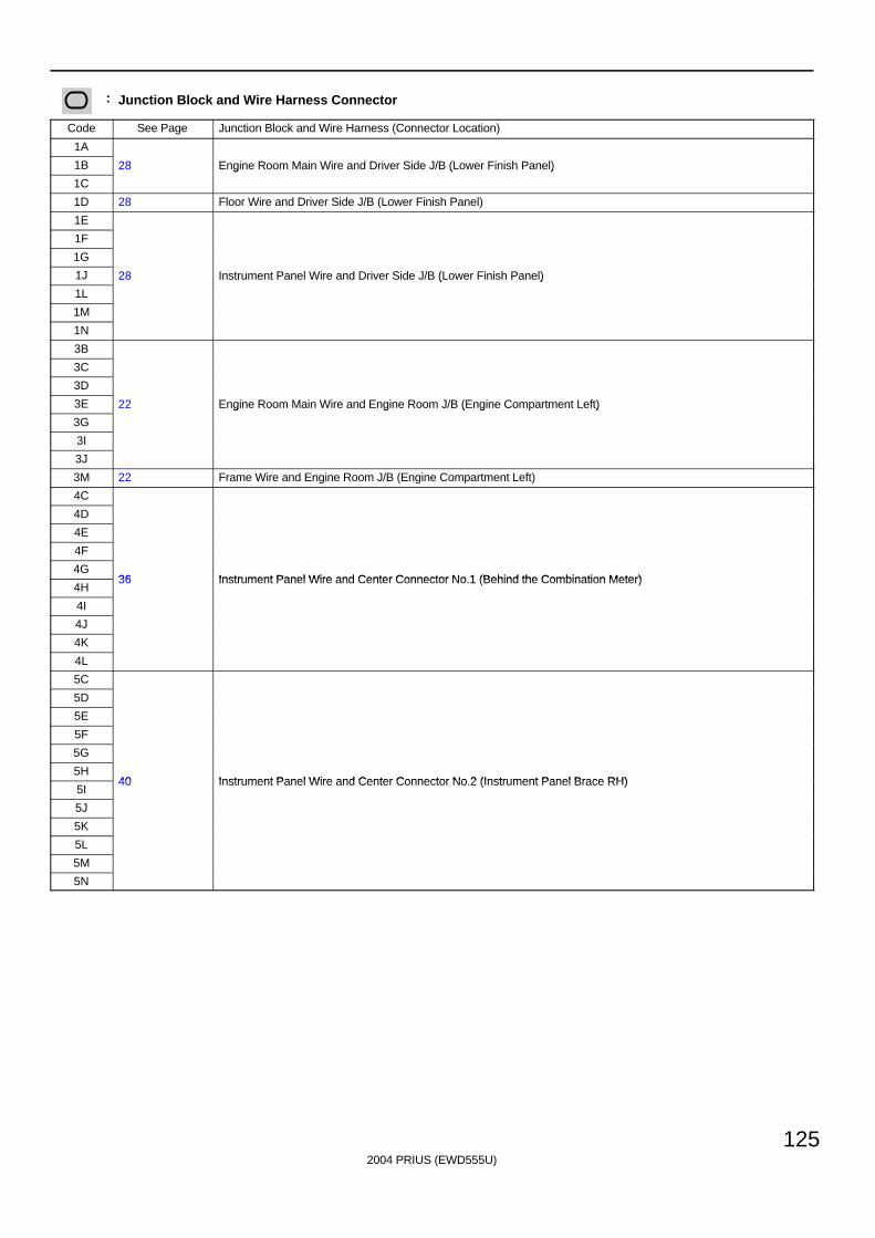
2004 PRIUS (EWD555U)
125
: Junction Block and Wire Harness Connector
Code See Page Junction Block and Wire Harness (Connector Location)
1A
1B 28 Engine Room Main Wire and Driver Side J/B (Lower Finish Panel)
1C
g ( )
1D 28 Floor Wire and Driver Side J/B (Lower Finish Panel)
1E
1F
1G
1J 28 Instrument Panel Wire and Driver Side J/B (Lower Finish Panel)
1L
( )
1M
1N
3B
3C
3D
3E 22 Engine Room Main Wire and Engine Room J/B (Engine Compartment Left)
3G
g g ( g )
3I
3J
3M 22 Frame Wire and Engine Room J/B (Engine Compartment Left)
4C
4D
4E
4F
4G36 Instrument Panel Wire and Center Connector No 1 (Behind the Combination Meter)
4H36 Instrument Panel Wire and Center Connector No.1 (Behind the Combination Meter)
4I
4J
4K
4L
5C
5D
5E
5F
5G
5H40 Instrument Panel Wire and Center Connector No 2 (Instrument Panel Brace RH)
5I40 Instrument Panel Wire and Center Connector No.2 (Instrument Panel Brace RH)
5J
5K
5L
5M
5N
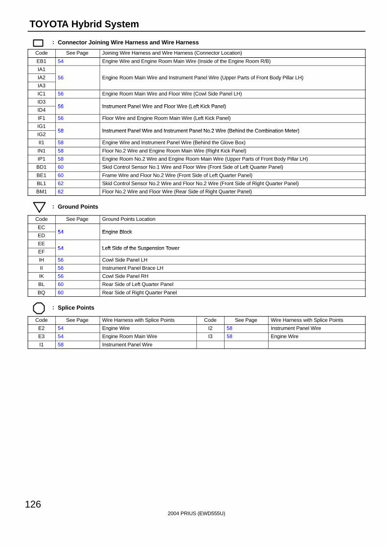
2004 PRIUS (EWD555U)
126
TOYOTA Hybrid System
: Connector Joining Wire Harness and Wire Harness
Code See Page Joining Wire Harness and Wire Harness (Connector Location)
EB1 54 Engine Wire and Engine Room Main Wire (Inside of the Engine Room R/B)
IA1
IA2 56 Engine Room Main Wire and Instrument Panel Wire (Upper Parts of Front Body Pillar LH)
IA3
g ( y )
IC1 56 Engine Room Main Wire and Floor Wire (Cowl Side Panel LH)
ID356 Instrument Panel Wire and Floor Wire (Left Kick Panel)
ID456 Instrument Panel Wire and Floor Wire (Left Kick Panel)
IF1 56 Floor Wire and Engine Room Main Wire (Left Kick Panel)
IG158 Instrument Panel Wire and Instrument Panel No 2 Wire (Behind the Combination Meter)
IG258 Instrument Panel Wire and Instrument Panel No.2 Wire (Behind the Combination Meter)
II1 58 Engine Wire and Instrument Panel Wire (Behind the Glove Box)
IN1 58 Floor No.2 Wire and Engine Room Main Wire (Right Kick Panel)
IP1 58 Engine Room No.2 Wire and Engine Room Main Wire (Upper Parts of Front Body Pillar LH)
BD1 60 Skid Control Sensor No.1 Wire and Floor Wire (Front Side of Left Quarter Panel)
BE1 60 Frame Wire and Floor No.2 Wire (Front Side of Left Quarter Panel)
BL1 62 Skid Control Sensor No.2 Wire and Floor No.2 Wire (Front Side of Right Quarter Panel)
BM1 62 Floor No.2 Wire and Floor Wire (Rear Side of Right Quarter Panel)
: Ground Points
Code See Page Ground Points Location
EC54 Engine Block
ED54 Engine Block
EE54 Left Side of the Suspension Tower
EF54 Left Side of the Suspension Tower
IH 56 Cowl Side Panel LH
II 56 Instrument Panel Brace LH
IK 56 Cowl Side Panel RH
BL 60 Rear Side of Left Quarter Panel
BQ 60 Rear Side of Right Quarter Panel
: Splice Points
Code See Page Wire Harness with Splice Points Code See Page Wire Harness with Splice Points
E2 54 Engine Wire I2 58 Instrument Panel Wire
E3 54 Engine Room Main Wire I3 58 Engine Wire
I1 58 Instrument Panel Wire

2004 PRIUS (EWD555U)
127
Memo
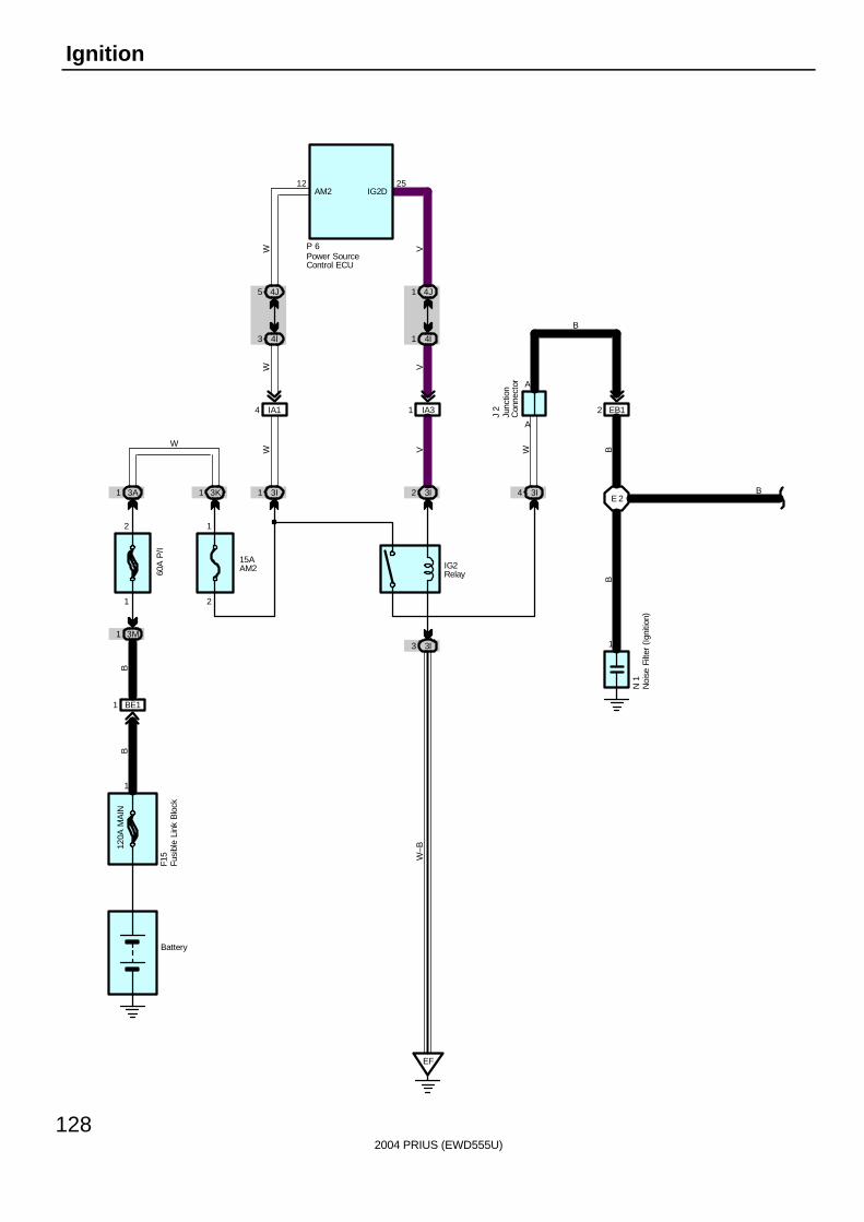
2004 PRIUS (EWD555U)
128
Ignition
BE11
3A1
3M1
3K1 3I1 3I2 3I4
3I3
EF
4J5 4J1
4I3 4I1
IA14 IA31
IG2Relay
15AAM260
A P
/I
120A
MA
IN
1
12 25
A
A
EB12
1
E 2J
2
P 6
N 1
BB
W V
W V
W V
W BB
B
B
F15
Battery
W
1
2
2
1
AM2 IG2D
W–B
Fusi
ble
Link
Blo
ck
Junc
tion
Con
nect
or
Noi
se F
ilter
(Ig
nitio
n)
Power SourceControl ECU
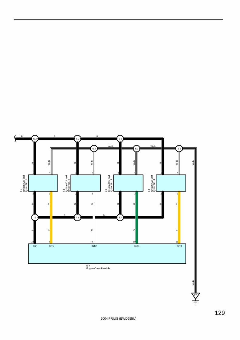
2004 PRIUS (EWD555U)
129
E 2 E 2
E 2 E 2 E 2
E 2
I 3 I 3 I 3
I 1 I 2 I 3 I 4
B
W–B B
W–B B
W–B B
W–B
W–B
B
IGF IGT1 IGT2 IGT3 IGT4
E 4
2 3 2 3 2 3 2 3
1 4 1 4 1 4 1 4
23 8 9 10 11
B B
W–B W–B
B Y B W B G B Y
B Y W G Y
W–B
BB
ED
Engine Control Module
Igni
tion
Coi
l and
Igni
ter
No.
1
Igni
tion
Coi
l and
Igni
ter
No.
2
Igni
tion
Coi
l and
Igni
ter
No.
3
Igni
tion
Coi
l and
Igni
ter
No.
4
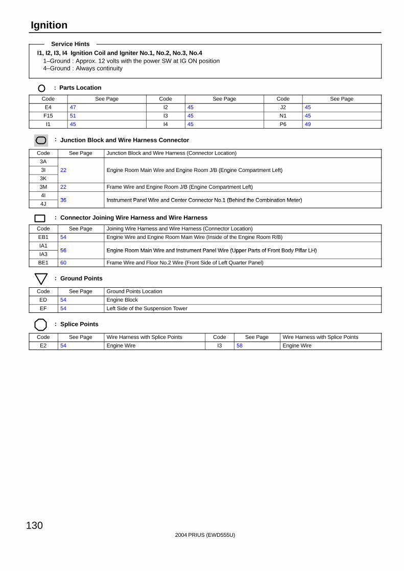
2004 PRIUS (EWD555U)
130
Ignition
I1, I2, I3, I4 Ignition Coil and Igniter No.1, No.2, No.3, No.41–Ground : Approx. 12 volts with the power SW at IG ON position4–Ground : Always continuity
: Parts Location
Code See Page Code See Page Code See Page
E4 47 I2 45 J2 45
F15 51 I3 45 N1 45
I1 45 I4 45 P6 49
: Junction Block and Wire Harness Connector
Code See Page Junction Block and Wire Harness (Connector Location)
3A
3I 22 Engine Room Main Wire and Engine Room J/B (Engine Compartment Left)
3K
g g ( g )
3M 22 Frame Wire and Engine Room J/B (Engine Compartment Left)
4I36 Instrument Panel Wire and Center Connector No 1 (Behind the Combination Meter)
4J36 Instrument Panel Wire and Center Connector No.1 (Behind the Combination Meter)
: Connector Joining Wire Harness and Wire Harness
Code See Page Joining Wire Harness and Wire Harness (Connector Location)
EB1 54 Engine Wire and Engine Room Main Wire (Inside of the Engine Room R/B)
IA156 Engine Room Main Wire and Instrument Panel Wire (Upper Parts of Front Body Pillar LH)
IA356 Engine Room Main Wire and Instrument Panel Wire (Upper Parts of Front Body Pillar LH)
BE1 60 Frame Wire and Floor No.2 Wire (Front Side of Left Quarter Panel)
: Ground Points
Code See Page Ground Points Location
ED 54 Engine Block
EF 54 Left Side of the Suspension Tower
: Splice Points
Code See Page Wire Harness with Splice Points Code See Page Wire Harness with Splice Points
E2 54 Engine Wire I3 58 Engine Wire
Service Hints

2004 PRIUS (EWD555U)
131
Memo
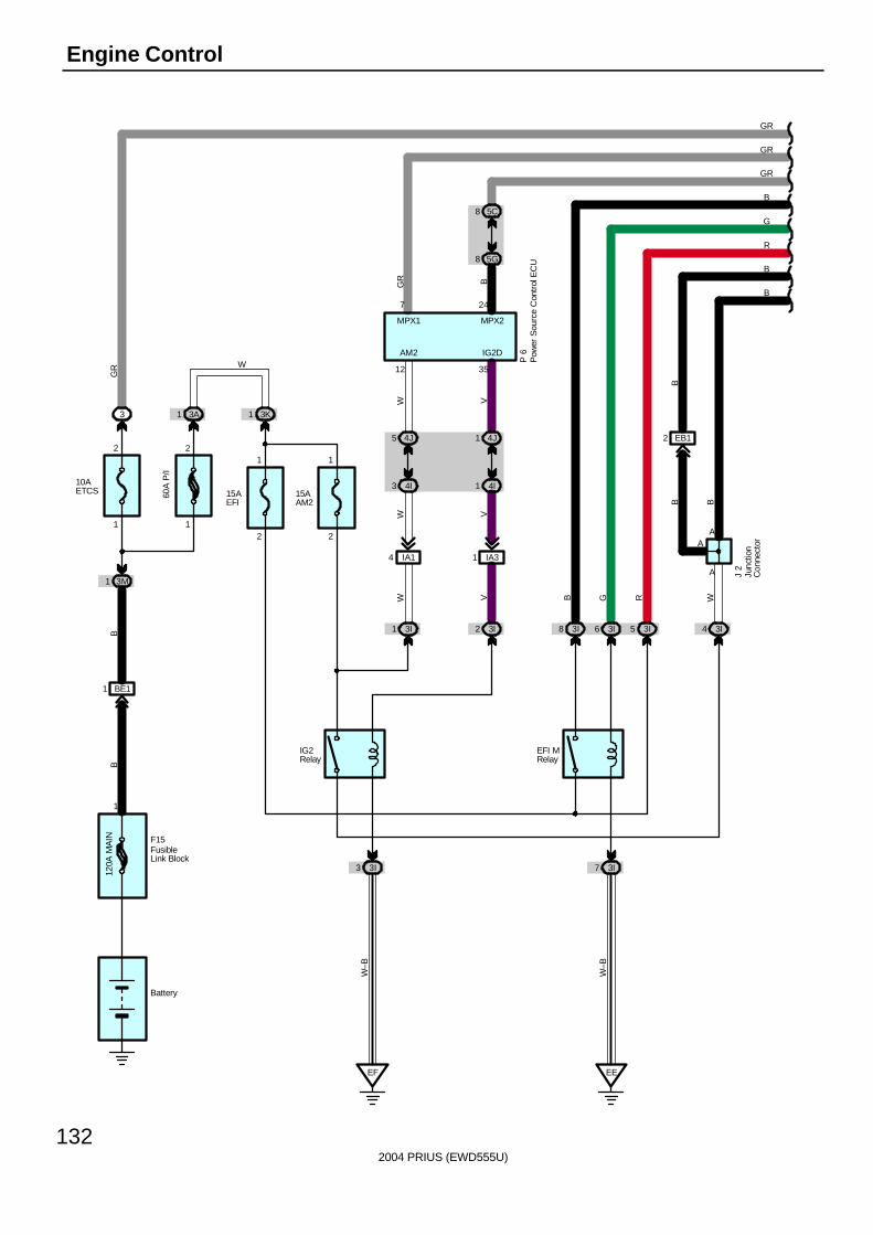
2004 PRIUS (EWD555U)
132
Engine Control
120A
MA
IN
BE11
3M1
10AETCS
3 3A1
60A
P/I
15AEFI
15AAM2
3K1
3I8 3I6 3I5
3I3 3I7
EEEF
3I43I1 3I2
IA14 IA31
4I3 4I1
4J5 4J1 EB12
BB
GR
W–B
W–B
RGBVW W
W V
W V
B
B
F15
J 2
A
A
Battery
1
IG2Relay
B
GR
W
21 1
2
1 12 2
EFI MRelay
R
G
B
GR
GR
P 6
MPX2
24
35
IG2D
12
AM2
MPX1
7
5G8
5C8
BGR
FusibleLink Block
Junc
tion
Con
nect
orA
B
B
Pow
er S
ourc
e C
ontr
ol E
CU
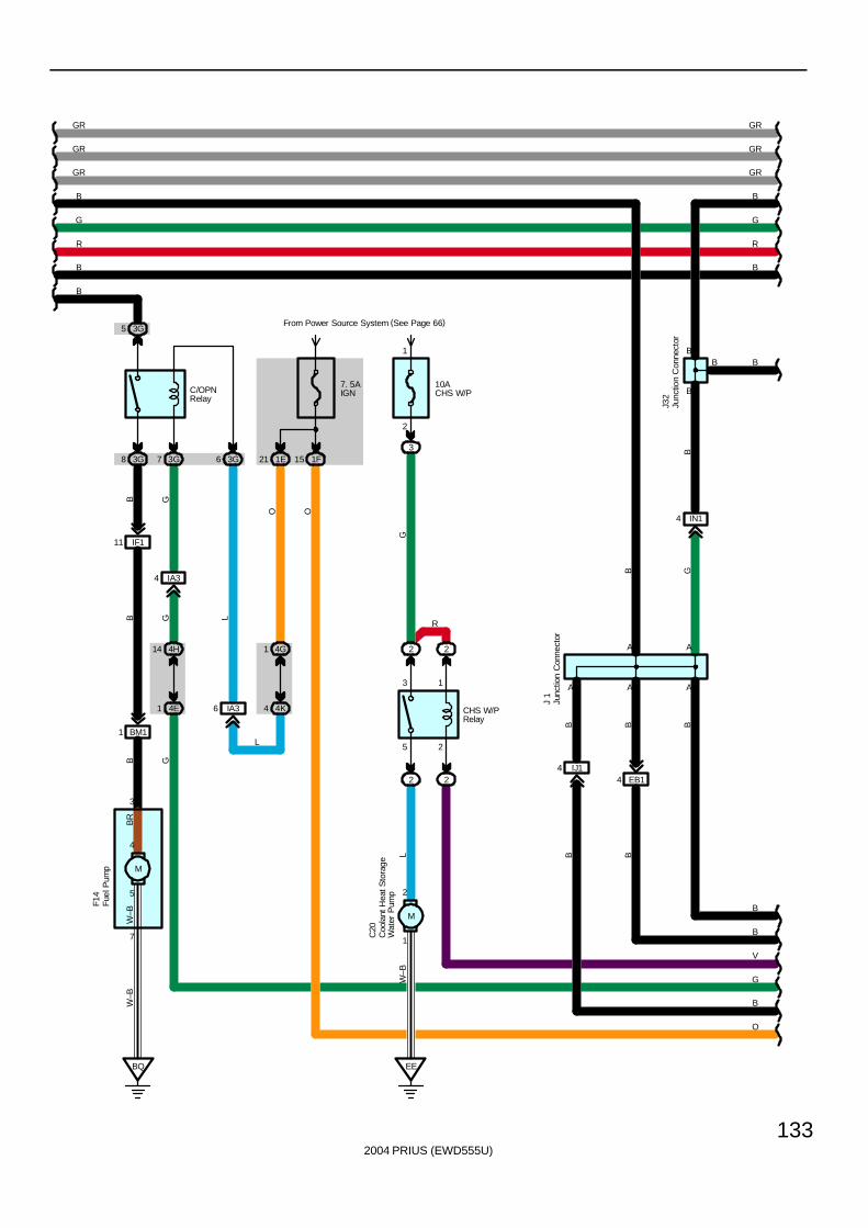
2004 PRIUS (EWD555U)
133
7. 5AIGN
From Power Source System (See Page 66)
10ACHS W/P
3
2
1
3G8 3G7 1F15
2 2
2
1
2
EEBQ
BM11
14 4H
4E1
3G5
W–B
W–B
B
L
GGB
G
GR
B
G
R
B
B
V
G
O
C20
C/OPNRelay
O
CHS W/PRelay
GR
B
R
G
B
GR
GR
GR
GR
J 1
J32
EB14IJ14
AA A
B
AA
BB
B B
B
B G
BB
B
B
B
B
Junc
tion
Con
nect
or
Junc
tion
Con
nect
or
7
3
BR
W–B
Fuel
Pum
pF1
4
M
5
4
B
1E21
1 4G
4K4IA36
3G6
L
O
L
IA34
B G
2
R
3 1
5 2
Coo
lant
Hea
t Sto
rage
Wat
er P
ump
IN14
M
IF111
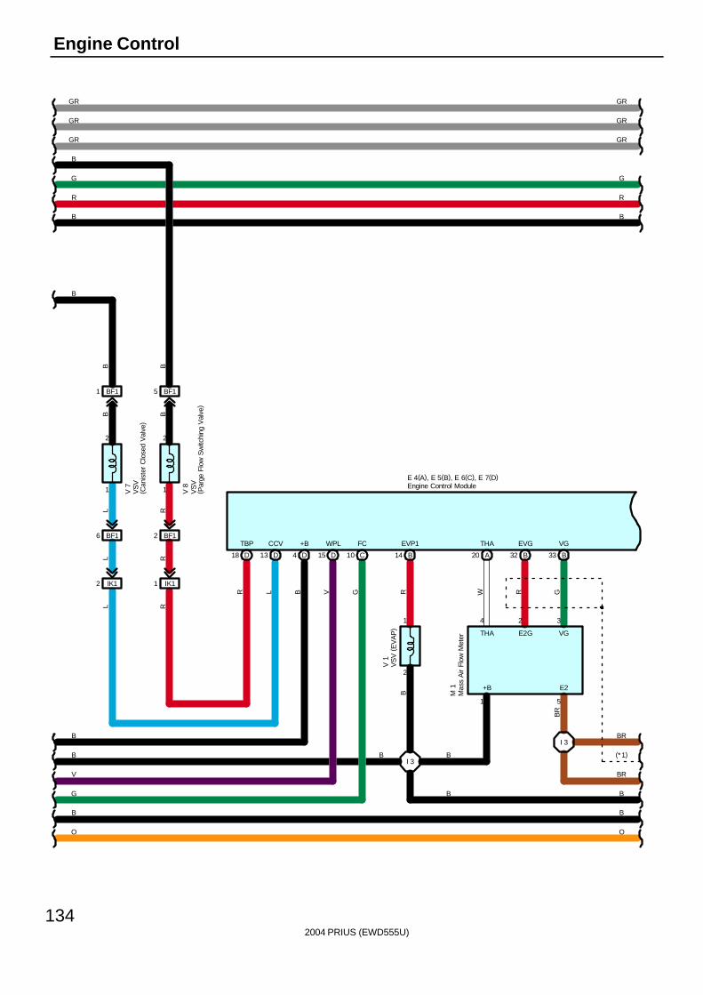
2004 PRIUS (EWD555U)
134
Engine Control
E 4(A), E 5(B), E 6(C), E 7(D)
D15 C10
WPL FC
BF11 BF15
1
2
1
2
BF16 BF12
IK12 IK11
D4
+B
B14
EVP1
A20
THA
B32
EVG
B33
VG
2
1
I 3
I 3
GR
B
G
R
B
B
V
G
O
BR
(*1)
BR
B
B
O
L R
L RRL
B B
RGVB W R G
B
BR
4 2 3
1 5
B
R
G
GR
V 7
V 8
M 1
V 1
B B
+B E2
THA E2G VG
B
B
B
B
D13
CCV
LR
TBP
18 D
GRGR
GRGR
B B
Engine Control Module
Mas
s A
ir Fl
ow M
eter
VS
V (
EV
AP
)
VS
V( C
anis
ter
Clo
sed
Val
ve)
VS
V( P
arge
Flo
w S
witc
hing
Val
ve)
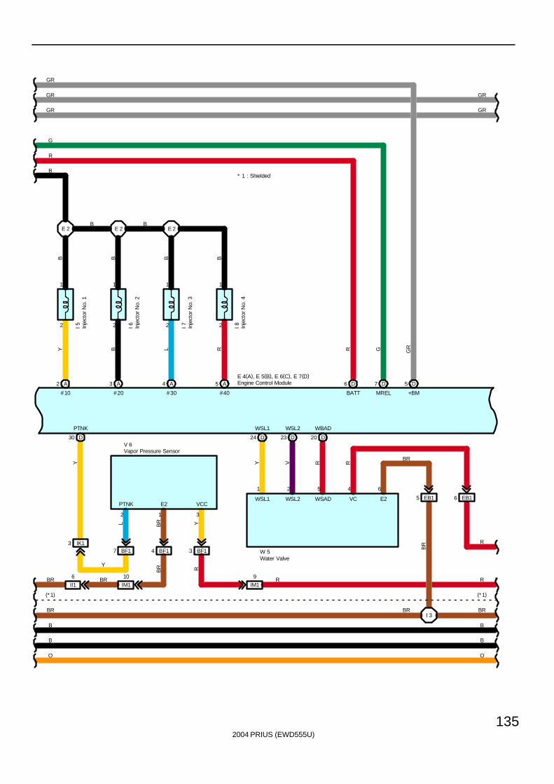
2004 PRIUS (EWD555U)
135
6 D
BATT
7 D
MREL
5 D
+BM
2
1
2
1
2
1
2
1
2 A
#10
3 A
#20
4 A
#30
5 A
#40
E 2 E 2 E 2
E 4(A), E 5(B), E 6(C), E 7(D)
BF17 BF14 BF13IK13
D30
PTNK
II1
6
IM1
9
D24
WSL1
D23
WSL2
D20
WBAD
EB15 EB16
I 3
R
R
(*1)
BR
B
B
O
R
BR
BR
(*1)
BR
B
B
O
Y
BR
Y B
B B B B
L R R G GR
L BR Y
Y V R R
BR
BR
1 2 5 4 6
2 1 3
B B
B
R
G
GR
V 6
W 5
I 5 I 6 I 7 I 8
IM1
10
BR R
PTNK E2 VCC
Y
WSL1 WSL2 WSAD VC E2
* 1 : Shielded
GRGR
GR GR
Engine Control Module
Inje
ctor
No.
1
Inje
ctor
No.
2
Inje
ctor
No.
3
Inje
ctor
No.
4
Vapor Pressure Sensor
Water Valve
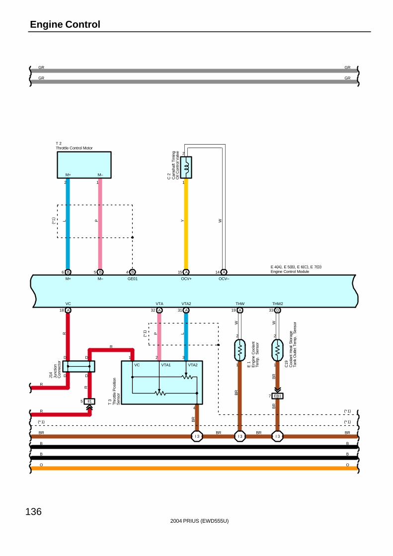
2004 PRIUS (EWD555U)
136
Engine Control
O
B
B
BR
(*1)
R
R
E 4(A), E 5(B), E 6(C), E 7(D)B6 B5 B4 A15 A14
1
2
L P Y W( *1)
2 1
M+ M–
M+ M– GE01 OCV+ OCV–
T 2
C 2
A31A32
1
2
1
2
A19 D33
VTA VTA2 THW THW2
A18
I 3 I 3 I 3
EB17
(*1)
(*1)
BR
B
B
O
R P L
W W
R
BR
BR
BR
BR
BR
T 3
J14
D D
D D
VC
R
BR
1 2 3
4
(*1)
E 1
C19
GRGR
GR GR
II15
VC VTA1 VTA2
Cam
shaf
t Ti
min
gO
il C
ontr
ol V
alve
Engine Control Module
Eng
ine
Coo
lant
Tem
p.
Sen
sor
Junc
tion
Con
nect
or
Throttle Control Motor
Thro
ttle
Pos
ition
Sen
sor
Coo
lant
Hea
t S
tora
geTa
nk O
utle
t Tem
p.
Sen
sor
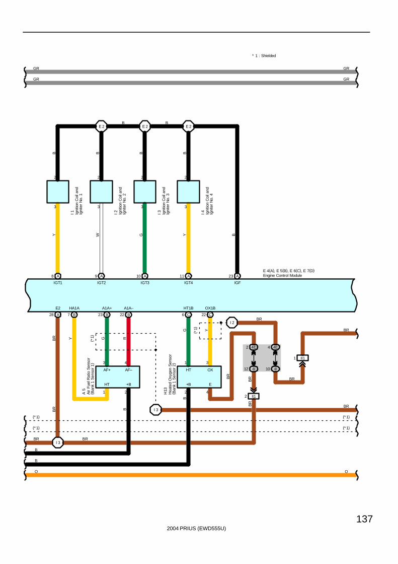
2004 PRIUS (EWD555U)
137
E 4(A), E 5(B), E 6(C), E 7(D)
BR
BR
(*1)
(*1)
O
A8 A9 A10 A11 A23
E 2 E 2 E 2
YB B B B
W G Y B
3 3 3 3
2 2 2 2
I 1 I 2 I 3 I 4
B23 B22B7A28
I 3
C6 C22
4E2 4E4
4I12 4I10
II12
II11
I 3
I 2
O
B
B
BR
(*1)
(*1)
BR Y G R
BR B
G Y
B
BR
BR
BR
BR
BR
BR
H13
A 5
IGT1 IGT2 IGT3 IGT4 IGF
E2 HA1A A1A+ A1A– HT1B OX1B
HT +B E+B
AF– OXHTAF+
3 4 1 3
1 2 2 4
(*1)
( *1)
B B
GRGR
GR GR
Air
Fue
l Rat
io S
enso
r( B
ank
1 S
enso
r 1)
Engine Control Module
Hea
ted
Oxy
gen
Sen
sor
( Ban
k 1
Sen
sor
2)
Igni
tion
Coi
l and
Igni
ter
No.
1
Igni
tion
Coi
l and
Igni
ter
No.
2
Igni
tion
Coi
l and
Igni
ter
No.
3
Igni
tion
Coi
l and
Igni
ter
No.
4
* 1 : Shielded
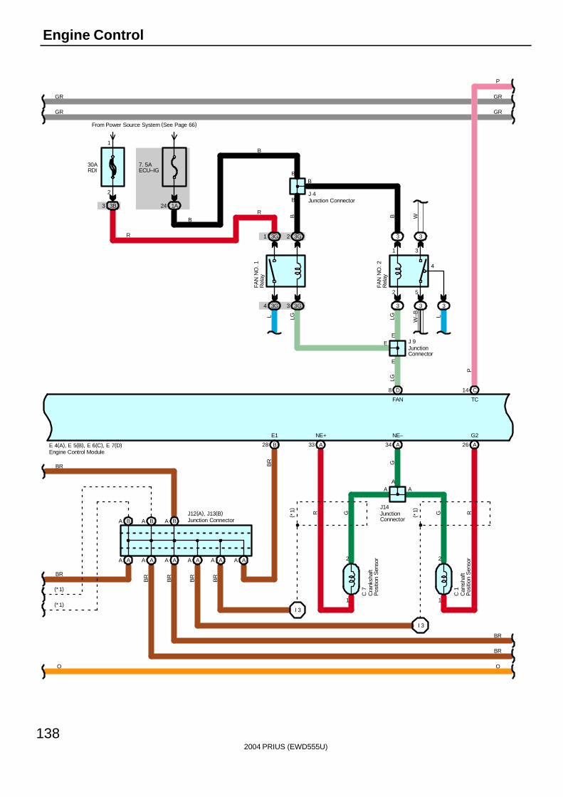
2004 PRIUS (EWD555U)
138
Engine Control
E 4(A), E 5(B), E 6(C), E 7(D)
D8
FAN
BA BA BA
AA AA AA AA AA AA
1
2
1
2
A34A33 A26
I 3
I 3
B28
E1 NE+ NE– G2
BR
BR
(*1)
(*1)
O
AA
LG
BR G
A
G G RR( *1)
( *1)J12(A), J13(B)
J14
C 7
C 1
BR
BR
O
BR
BR
BR
BR
GRGR
GR
P
14 C
TC
P
GR
3G1 3G2 3 3
2 5
1 3
4
3G4 3G3 3 3 3
30ARDI
From Power Source System (See Page 66)
3B3
2
1
7. 5AECU–IG
1A24
B B W
L LG LG W–B L
B
EE
E
B
B
B
RB
R
J 9
J 4
FAN
NO
. 2R
elay
FAN
NO
. 1R
elay
Cra
nksh
aft
Pos
ition
Sen
sor
Cam
shaf
tP
ositi
on S
enso
r
Engine Control Module
Junction Connector
JunctionConnector
Junction ConnectorJunctionConnector

2004 PRIUS (EWD555U)
139
E 4(A), E 5(B), E 6(C), E 7(D)
C18
WIGSW
9 CB1 B2
EA12 EA11
E04
1 A
E02
6 AA7
E01ME01
3 BC7
E03
ED
4I11
4E3
II113
EC
KNK1 EKNK
30 C
CANL
31 C
CANH
9 A
CANL
8 A
CANH
C13 C12
GO NEO
1 D
NEO
2 D
GO
B A B A A B
A
A
17 18
2 1
A A A
A
B A
B W
B W
Y LG
B W
B W
BR B BR
BR
BR
BR B BR
BR
BRO
B W
O LG W–B
W–B
LG
O
O
W
B
BR
K 1
G 1
J25
J17
J18
P
BR
O
BR
I 3
( *1)
MOPS
15 B
1
Y
O 1
CA1LCA1H
( *1)
( *1)
( *1)
* 1 : Shielded
GRGR
P
GRGR
25 C
VCP1
Y
26 C
VPA1
LG
VCP2
C3334 C
VPA2
WR
EP2
C3527 C
EP1
B
4
VCPA
6
VPA
1
VCP2
3
VPA2
2
EP2
5
BPA
(*1)
A13
H14(A), H16(C)
IK
J 5A
Accel Position Sensor
Engine Control Module
Gateway ECU
Hybrid Vehicle Control ECU
JunctionConnector
JunctionConnector
Junction Connector
JunctionConnector
Knock Sensor
Oil
Pre
ssur
e S
W
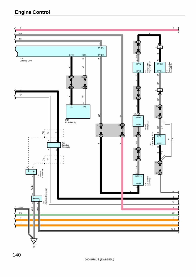
2004 PRIUS (EWD555U)
140
Engine Control
( *2)
( *2)
A15
9 1G
4C2
4L16
4L7
4I7
II18
II19
5D13
5G13
5J8
5K8
5J13
5C4 MPX1
4F11
4D11
MPX2
17
MPD2
12
MPX+
3
MPX2
32
MPX1
19
MPX1
17
16
MPX2
18
MPX2
31
MPX1
11
MPX2+
BG
R
W
B
GR
GR
GR
GR
GR
B
BB
B
GR
( *3)
T 4
S11
A 8
T 5
B 5
( A)
5C75C6
5E75E6
14 4I
2 4D
GR
B
IH
A A
A
A A
A
G 1
4 5
A B
A B
B
W
W–B
LG
O
O
W–B
O
O
LG
P
W
B
W
P P
W B
W B
B W
B W
J24
J16
M13
J15
W–B
W–B
W–B
6 21
GTX–GTX+
TX1+ TX1–
GR
GR
( *1)
( *1)
P
3
MPD1
A/C
Con
trol
Ass
embl
yB
ody
EC
U
Gateway ECU
JunctionConnector
Junc
tion
Con
nect
or
Junc
tion
Con
nect
or
Multi–Display
Tran
spon
der
Key
Com
pute
r
Tran
smis
sion
Con
trol
EC
U
Sm
art K
ey E
CU
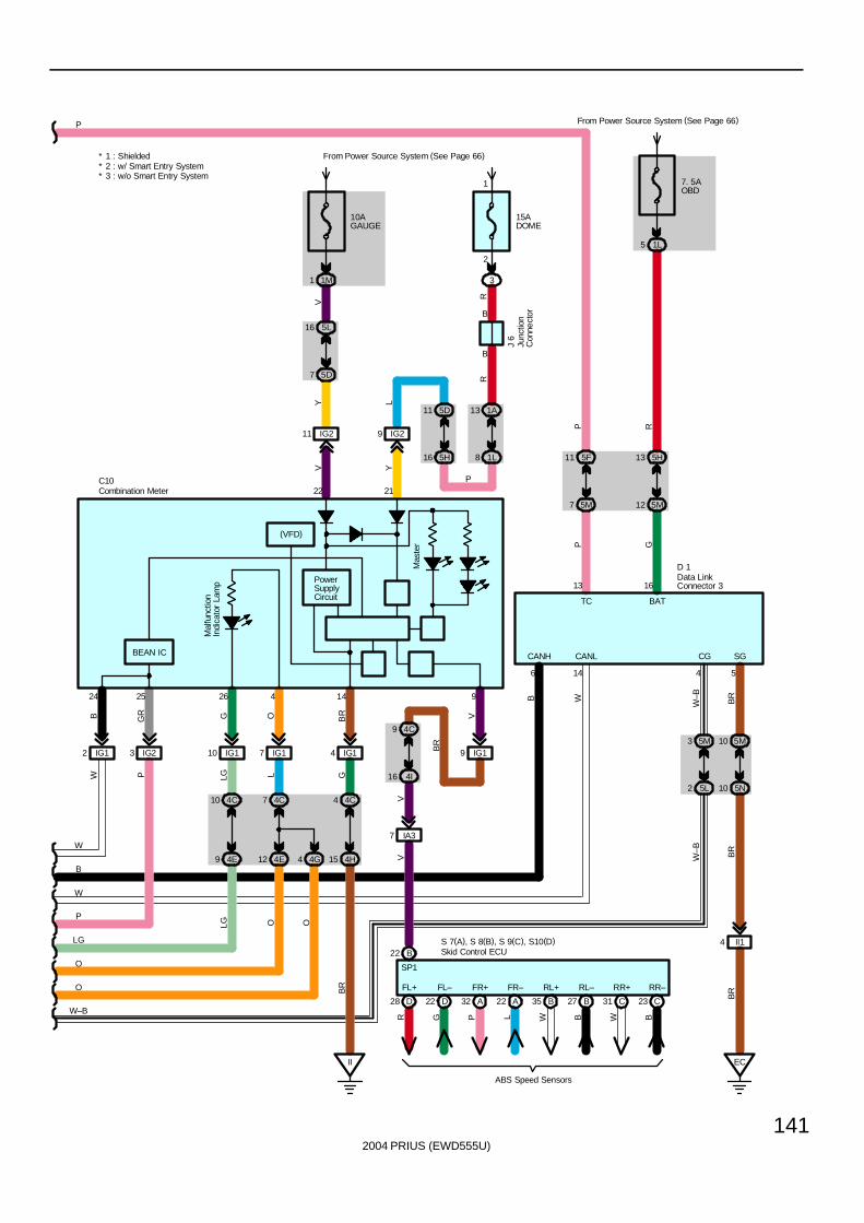
2004 PRIUS (EWD555U)
141
15ADOME
3
2
1
B
B
1A13
1L8
IG29IG211
10AGAUGE
From Power Source System (See Page 66)
1M1
5L16
5D7
22 21
IG19
4C9
4I16
II
BEAN IC
IG23IG12
92524
V Y
Y L
V
RR
VGRB
BR
BR
P
P
J 6
C10
PowerSupplyCircuit
5M3 5M10
5L2 5N10
EC
II14
7. 5AOBD
From Power Source System (See Page 66)
1L5
5F11
5M7
13 5H
5M12
W
Mal
func
tion
Indi
cato
r La
mp
IG110 IG17
10 4C
9 4E
16 5H
11 5D
4E
7
12
4C
4G4
W
B
W
P
LG
O
O
W–B
P
13 16
6 14 4 5
P R
P G
B W
W–B BR
BR
W–B
BR
G O
LG L
LG O O
CANH CANL CG SG
TC BAT
26 4
* 1 : Shielded* 2 : w/ Smart Entry System* 3 : w/o Smart Entry System
GB
R
14
15 4H
4 4C
4 IG1
7 IA3
VV
D 1Mas
ter
D28 D22 A32 A22 B35 B27 C31 C23
FL+ FL– FR+ FR– RL+ RL– RR+ RR–
R G P L W B W B
ABS Speed Sensors
S 7(A), S 8(B), S 9(C), S10(D)B22
SP1
(VFD)
Skid Control ECU
Combination Meter
Data LinkConnector 3
Junc
tion
Con
nect
or
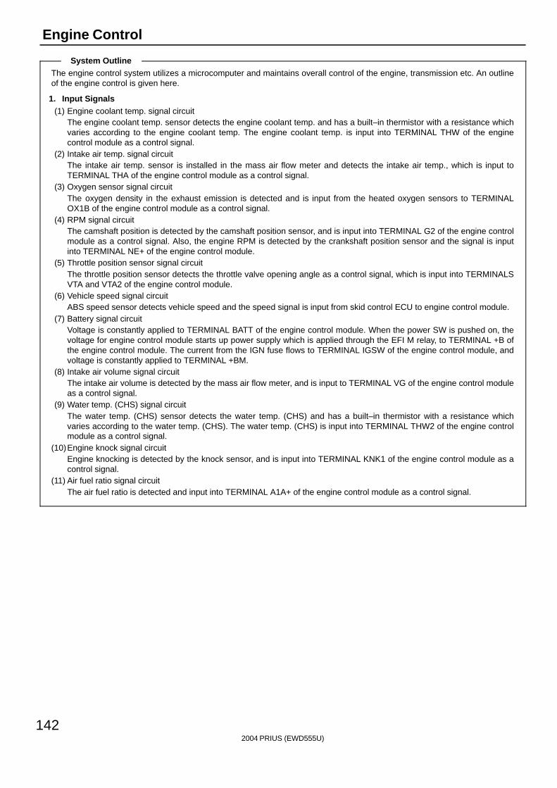
2004 PRIUS (EWD555U)
142
Engine Control
The engine control system utilizes a microcomputer and maintains overall control of the engine, transmission etc. An outlineof the engine control is given here.
1. Input Signals(1) Engine coolant temp. signal circuit
The engine coolant temp. sensor detects the engine coolant temp. and has a built–in thermistor with a resistance whichvaries according to the engine coolant temp. The engine coolant temp. is input into TERMINAL THW of the enginecontrol module as a control signal.
(2) Intake air temp. signal circuitThe intake air temp. sensor is installed in the mass air flow meter and detects the intake air temp., which is input toTERMINAL THA of the engine control module as a control signal.
(3) Oxygen sensor signal circuitThe oxygen density in the exhaust emission is detected and is input from the heated oxygen sensors to TERMINALOX1B of the engine control module as a control signal.
(4) RPM signal circuitThe camshaft position is detected by the camshaft position sensor, and is input into TERMINAL G2 of the engine controlmodule as a control signal. Also, the engine RPM is detected by the crankshaft position sensor and the signal is inputinto TERMINAL NE+ of the engine control module.
(5) Throttle position sensor signal circuitThe throttle position sensor detects the throttle valve opening angle as a control signal, which is input into TERMINALSVTA and VTA2 of the engine control module.
(6) Vehicle speed signal circuitABS speed sensor detects vehicle speed and the speed signal is input from skid control ECU to engine control module.
(7) Battery signal circuitVoltage is constantly applied to TERMINAL BATT of the engine control module. When the power SW is pushed on, thevoltage for engine control module starts up power supply which is applied through the EFI M relay, to TERMINAL +B ofthe engine control module. The current from the IGN fuse flows to TERMINAL IGSW of the engine control module, andvoltage is constantly applied to TERMINAL +BM.
(8) Intake air volume signal circuitThe intake air volume is detected by the mass air flow meter, and is input to TERMINAL VG of the engine control moduleas a control signal.
(9) Water temp. (CHS) signal circuitThe water temp. (CHS) sensor detects the water temp. (CHS) and has a built–in thermistor with a resistance whichvaries according to the water temp. (CHS). The water temp. (CHS) is input into TERMINAL THW2 of the engine controlmodule as a control signal.
(10)Engine knock signal circuitEngine knocking is detected by the knock sensor, and is input into TERMINAL KNK1 of the engine control module as acontrol signal.
(11) Air fuel ratio signal circuitThe air fuel ratio is detected and input into TERMINAL A1A+ of the engine control module as a control signal.
System Outline
2004 PRIUS (EWD555U)
143
2. Control System∗ SFI system
The SFI system monitors the engine condition through the signals input from each sensors to the engine control module.The control signal is sent to the engine control module TERMINALS #10, #20, #30 and #40 to operate the injector (Fuelinjection). The SFI system controls the fuel injection with the engine control module according to the driving conditions.
∗ ESA systemThe ESA system monitors the engine condition through the signals input from each sensors to the engine control module.The best ignition timing is decided according to this data and the data stored in the engine control module. The controlsignal is output to TERMINALS IGT1, IGT2, IGT3 and IGT4, and these signals control the igniter to provide the bestignition timing.
∗ Heater control system of heated oxygen sensorThe heater control system of heated oxygen sensor turns the heater on when the intake air volume is low (Temp. ofexhaust emission is low), and warms up the heated oxygen sensors to improve their detecting performance. The enginecontrol module evaluates the signals from each sensors, and outputs current to TERMINAL HT1B to control the heater.
∗ Heater control system of air fuel ratio sensorThe heater control system of air fuel ratio sensor turns the heater on when the intake air volume is low (Temp. of exhaustemission is low), and warms up the air fuel ratio sensor to improve detecting performance of the sensor.The engine control module evaluates the signals from each sensor, current is output to TERMINAL HA1A, controlling theheater.
∗ Fuel pump control systemThe engine control module supplies current to TERMINAL FC, and controls the operation of the fuel pump with the C/OPNrelay.
∗ VVT–iVVT–i controls the intake camshaft to optimal valve timing in accordance with the engine condition.
∗ CHS systemEngine control module controls CHS W/P relay to run electric pump to supply heated water stored in CHS tank to enginehead. The electric pump stops when the water reaches certain temperature or certain time goes by. Warming engine headoptimizes combustion conditions at engine start to reduce emission of incomplete combustion gas.
3. Diagnosis SystemWhen there is malfunction in the engine control module signal system, the malfunctioning system is recorded in the memory.The system can be found by reading the code displayed on the malfunction indicator lamp.
4. Fail–Safe SystemWhen malfunction has occurred in any system, there is possibility of engine trouble due to continuous control based on thatsystem. In such a case, the fail–safe system either controls the system using the data (Standard values) recorded in theengine control module memory, or stops the engine.
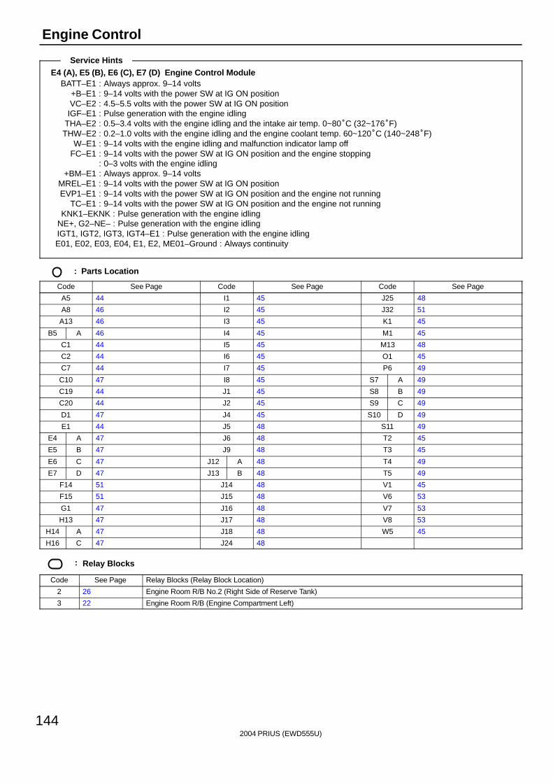
2004 PRIUS (EWD555U)
144
Engine Control
E4 (A), E5 (B), E6 (C), E7 (D) Engine Control ModuleBATT–E1 : Always approx. 9–14 volts
+B–E1 : 9–14 volts with the power SW at IG ON positionVC–E2 : 4.5–5.5 volts with the power SW at IG ON positionIGF–E1 : Pulse generation with the engine idling
THA–E2 : 0.5–3.4 volts with the engine idling and the intake air temp. 0~80°C (32~176°F)THW–E2 : 0.2–1.0 volts with the engine idling and the engine coolant temp. 60~120°C (140~248°F)
W–E1 : 9–14 volts with the engine idling and malfunction indicator lamp offFC–E1 : 9–14 volts with the power SW at IG ON position and the engine stopping
: 0–3 volts with the engine idling+BM–E1 : Always approx. 9–14 volts
MREL–E1 : 9–14 volts with the power SW at IG ON positionEVP1–E1 : 9–14 volts with the power SW at IG ON position and the engine not running
TC–E1 : 9–14 volts with the power SW at IG ON position and the engine not runningKNK1–EKNK : Pulse generation with the engine idling
NE+, G2–NE– : Pulse generation with the engine idlingIGT1, IGT2, IGT3, IGT4–E1 : Pulse generation with the engine idlingE01, E02, E03, E04, E1, E2, ME01–Ground : Always continuity
: Parts Location
Code See Page Code See Page Code See Page
A5 44 I1 45 J25 48
A8 46 I2 45 J32 51
A13 46 I3 45 K1 45
B5 A 46 I4 45 M1 45
C1 44 I5 45 M13 48
C2 44 I6 45 O1 45
C7 44 I7 45 P6 49
C10 47 I8 45 S7 A 49
C19 44 J1 45 S8 B 49
C20 44 J2 45 S9 C 49
D1 47 J4 45 S10 D 49
E1 44 J5 48 S11 49
E4 A 47 J6 48 T2 45
E5 B 47 J9 48 T3 45
E6 C 47 J12 A 48 T4 49
E7 D 47 J13 B 48 T5 49
F14 51 J14 48 V1 45
F15 51 J15 48 V6 53
G1 47 J16 48 V7 53
H13 47 J17 48 V8 53
H14 A 47 J18 48 W5 45
H16 C 47 J24 48
: Relay Blocks
Code See Page Relay Blocks (Relay Block Location)
2 26 Engine Room R/B No.2 (Right Side of Reserve Tank)
3 22 Engine Room R/B (Engine Compartment Left)
Service Hints
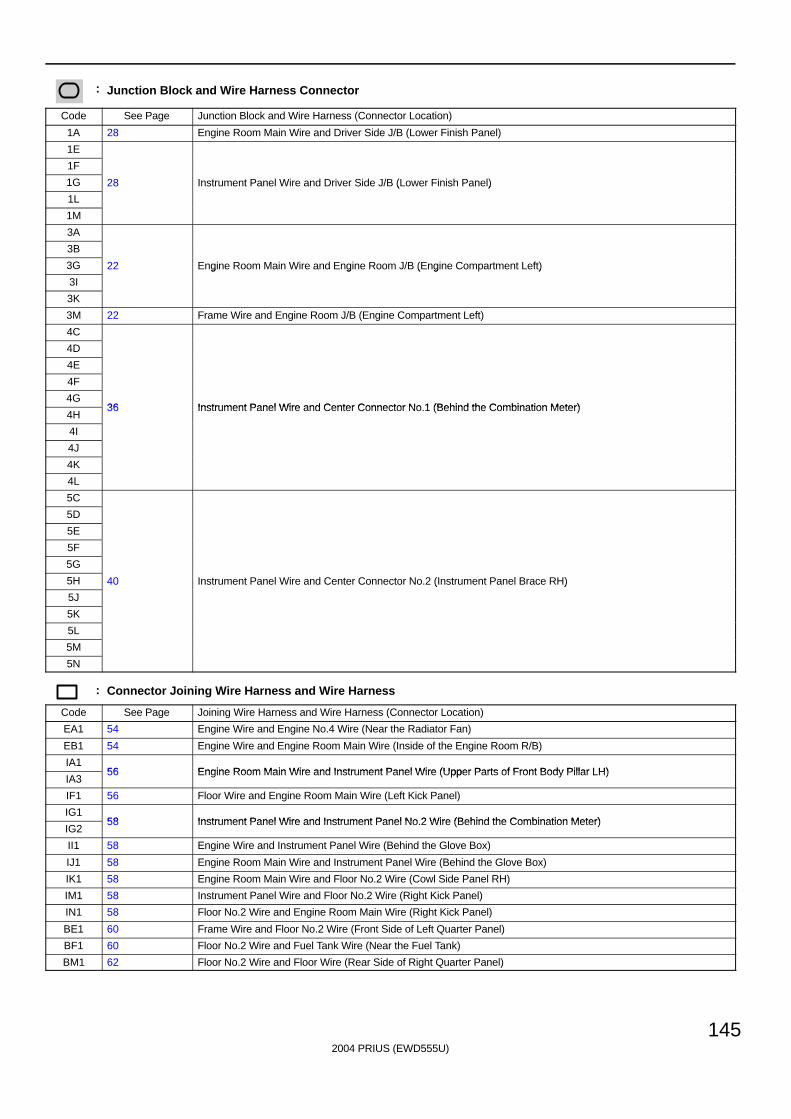
2004 PRIUS (EWD555U)
145
: Junction Block and Wire Harness Connector
Code See Page Junction Block and Wire Harness (Connector Location)
1A 28 Engine Room Main Wire and Driver Side J/B (Lower Finish Panel)
1E
1F
1G 28 Instrument Panel Wire and Driver Side J/B (Lower Finish Panel)
1L
( )
1M
3A
3B
3G 22 Engine Room Main Wire and Engine Room J/B (Engine Compartment Left)
3I
g g ( g )
3K
3M 22 Frame Wire and Engine Room J/B (Engine Compartment Left)
4C
4D
4E
4F
4G36 Instrument Panel Wire and Center Connector No 1 (Behind the Combination Meter)
4H36 Instrument Panel Wire and Center Connector No.1 (Behind the Combination Meter)
4I
4J
4K
4L
5C
5D
5E
5F
5G
5H 40 Instrument Panel Wire and Center Connector No.2 (Instrument Panel Brace RH)
5J
( )
5K
5L
5M
5N
: Connector Joining Wire Harness and Wire Harness
Code See Page Joining Wire Harness and Wire Harness (Connector Location)
EA1 54 Engine Wire and Engine No.4 Wire (Near the Radiator Fan)
EB1 54 Engine Wire and Engine Room Main Wire (Inside of the Engine Room R/B)
IA156 Engine Room Main Wire and Instrument Panel Wire (Upper Parts of Front Body Pillar LH)
IA356 Engine Room Main Wire and Instrument Panel Wire (Upper Parts of Front Body Pillar LH)
IF1 56 Floor Wire and Engine Room Main Wire (Left Kick Panel)
IG158 Instrument Panel Wire and Instrument Panel No 2 Wire (Behind the Combination Meter)
IG258 Instrument Panel Wire and Instrument Panel No.2 Wire (Behind the Combination Meter)
II1 58 Engine Wire and Instrument Panel Wire (Behind the Glove Box)
IJ1 58 Engine Room Main Wire and Instrument Panel Wire (Behind the Glove Box)
IK1 58 Engine Room Main Wire and Floor No.2 Wire (Cowl Side Panel RH)
IM1 58 Instrument Panel Wire and Floor No.2 Wire (Right Kick Panel)
IN1 58 Floor No.2 Wire and Engine Room Main Wire (Right Kick Panel)
BE1 60 Frame Wire and Floor No.2 Wire (Front Side of Left Quarter Panel)
BF1 60 Floor No.2 Wire and Fuel Tank Wire (Near the Fuel Tank)
BM1 62 Floor No.2 Wire and Floor Wire (Rear Side of Right Quarter Panel)
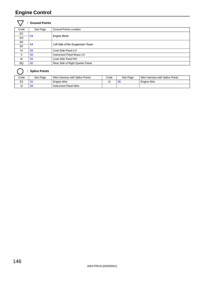
2004 PRIUS (EWD555U)
146
Engine Control
: Ground Points
Code See Page Ground Points Location
EC54 Engine Block
ED54 Engine Block
EE54 Left Side of the Suspension Tower
EF54 Left Side of the Suspension Tower
IH 56 Cowl Side Panel LH
II 56 Instrument Panel Brace LH
IK 56 Cowl Side Panel RH
BQ 60 Rear Side of Right Quarter Panel
: Splice Points
Code See Page Wire Harness with Splice Points Code See Page Wire Harness with Splice Points
E2 54 Engine Wire I3 58 Engine Wire
I2 58 Instrument Panel Wire

2004 PRIUS (EWD555U)
147
Memo
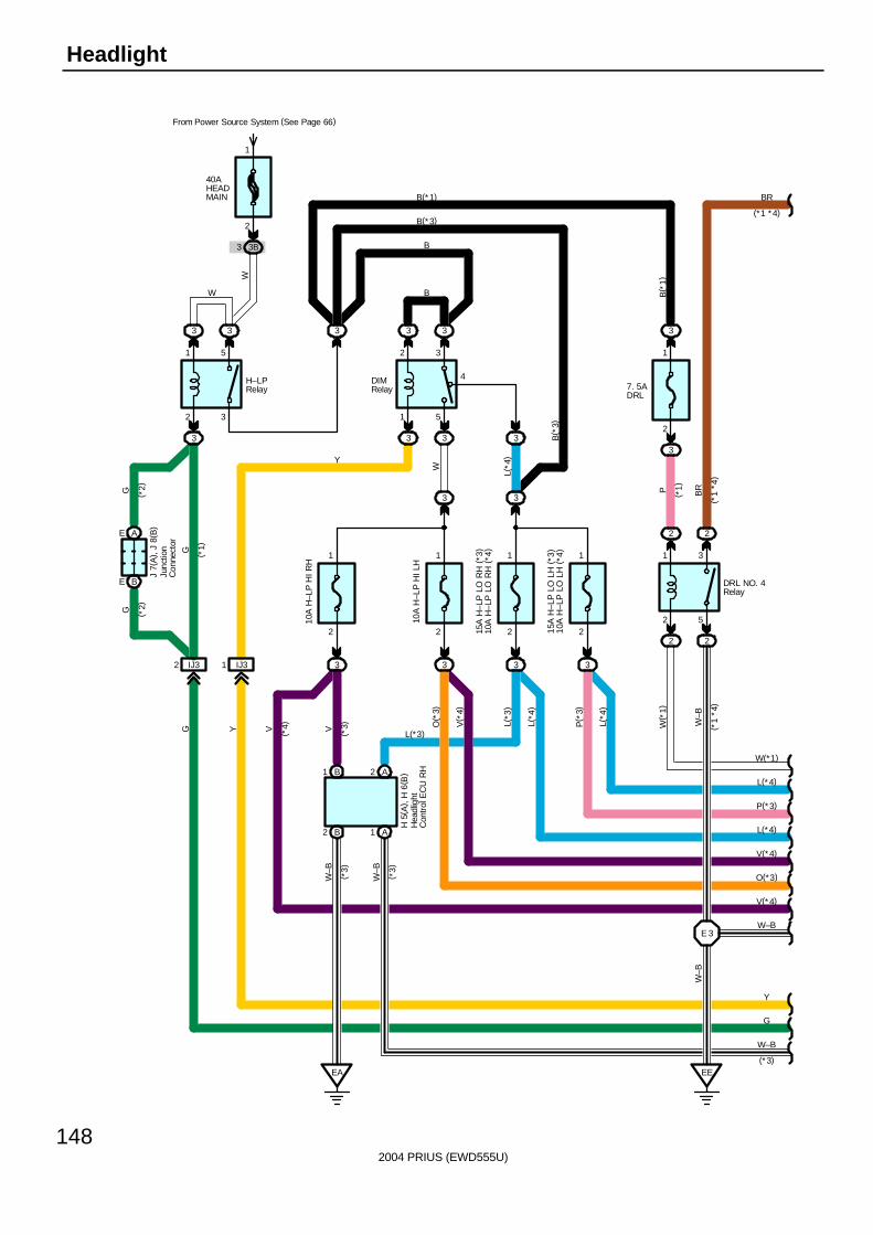
2004 PRIUS (EWD555U)
148
Headlight
40AHEADMAIN
From Power Source System (See Page 66)
3B3
2
1
2 3
1 5
3 3
3
3
1 5
2 3
4
3 3
3 3 32
1
3
3
3 3
2
1
2
1
10A
H–L
P H
I LH
15A
H–L
P L
O R
H (
*3)
10A
H–L
P L
O R
H (
*4)
33
2
115
A H
–LP
LO
LH
(*3
)10
A H
–LP
LO
LH
(*4
)
3
10A
H–L
P H
I RH
2
1
3
2 5
1 3
2 2
2 2
7. 5ADRL
EE
IJ32 IJ31
BE
AE
B1 A2
B2 A1
EA
E 3W–B
W–B
G
Y
V(*4)
O(*3)
V(*4)
L(*4)
P(*3)
L(*4)
W(*1)
BR
BW
B
B(*3)
B(*1)
Y
L(*3)
G
G
G
VVYG
W–B
W–B
W–B
O( *
3)
V( *
4)
L(*3
)
L(*4
)
P( *
3)
L(*4
)
W( *
1)
W–B
P BR
B( *
1)
B( *
3)
L(*4
)
W
W
J 7(
A) ,
J 8
( B)
( *1)
( *2)
( *2)
H–LPRelay
( *1)
( *1
*4)
(*1 *4)
DIMRelay
DRL NO. 4Relay
H 5
( A) ,
H 6
( B)
( *3)
( *4)
( *3)
( *3)
( *1
*4)
(* 3)
Hea
dlig
htC
ontr
ol E
CU
RH
Junc
tion
Con
nect
or
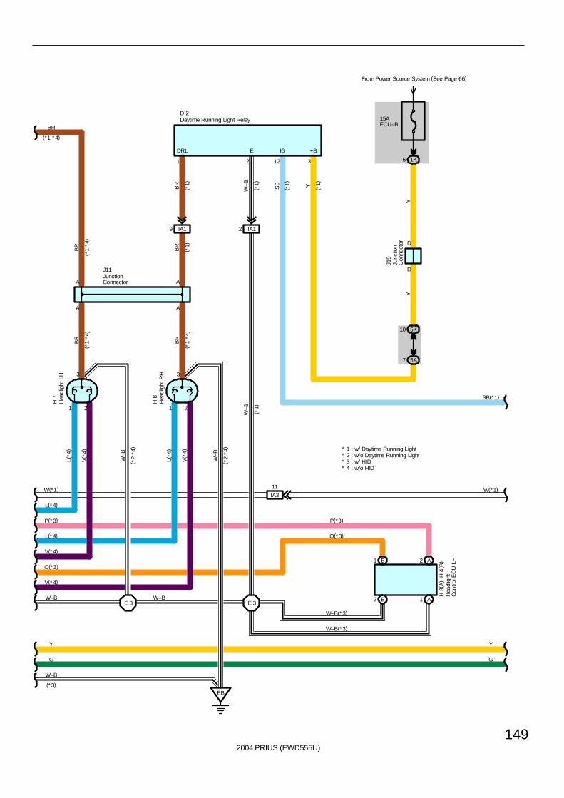
2004 PRIUS (EWD555U)
149
1 2
3
1 2
3
A
A
EB
E 3
A
W(*1)
L(*4)
P(*3)
L(*4)
V(*4)
O(*3)
V(*4)
Y
G
W–B
W–B
BR
W–B
L(*4
)
V( *
4)
W–B
L(*4
)
V( *
4)
W–B
BR
BR
BR
(*1 *4)
( *1
*4)
( *1
*4)
( *1
*4)
H 7
H 8
J11
( *2
*4)
( *2
*4)
IA19 IA12
E 3
IA3
11
1 2 312
G
Y
SB(*1)
BR
W–B YSB
W–B
DRL E +BIG
( *1)
( *1)
( *1)
( *1)
( *1)
D 2
* 1 : w/ Daytime Running Light* 2 : w/o Daytime Running Light* 3 : w/ HID* 4 : w/o HID
(*3)
Y
2 A
15AECU–B
From Power Source System (See Page 66)
1K5
D
D
1 B
5K10
1
5A7
A2 B
Y
J19
H 3
( A) ,
H 4
( B)
A
( *1)
BR
W(*1)
O(*3)
P(*3)
W–B(*3)
W–B(*3)
Daytime Running Light Relay
Hea
dlig
htC
ontro
l EC
U L
H
Hea
dlig
ht L
H
Hea
dlig
ht R
H
JunctionConnector
Junc
tion
Con
nect
or
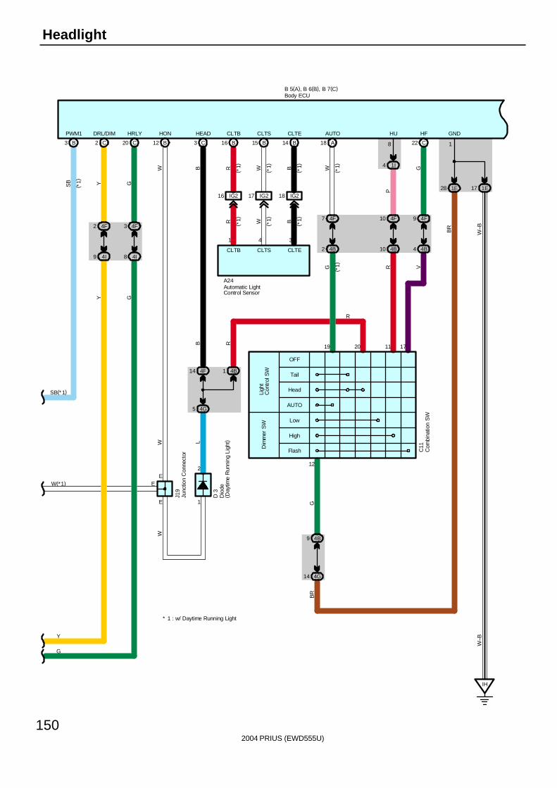
2004 PRIUS (EWD555U)
150
Headlight
SB(*1)
( *1)
SB Y G
B3 C2 C20
4F2 4F3
4I9 4I8
W(*1)
Y
G
1E171E28
GND
IH
HRLYDRL/DIMPWM1
1
W–BBR
B 5(A), B 6(B), B 7(C)
Y G
W–B
Tail
OFF
Head
AUTO
Low
High
Flash
Ligh
tC
ontr
ol S
WD
imm
er S
W
E
E
1 4B
5 4G
14 4F
B12 C3
4B9
4G14
4F7 4F10 4F9
4B2 4B10 4B4
A18 C22B16 15 B B14
IG216 IG217 18 IG2
E
CLTBHEADHON CLTS CLTE AUTO HU HF
1I4
8
J19
( *1)
( *1)
C11
A24
BR
G
G R VG
P
W
W
B
W B
BWR
BWR
W
19 1711
1 4 3
12
CLTECLTSCLTB
20R
1
2
D 3
L
( *1)
( *1)
( *1)
( *1)
( *1)
( *1)
R
* 1 : w/ Daytime Running Light
Automatic LightControl Sensor
Body ECU
Com
bina
tion
SW
Dio
de( D
aytim
e R
unni
ng L
ight
)
Junc
tion
Con
nect
or
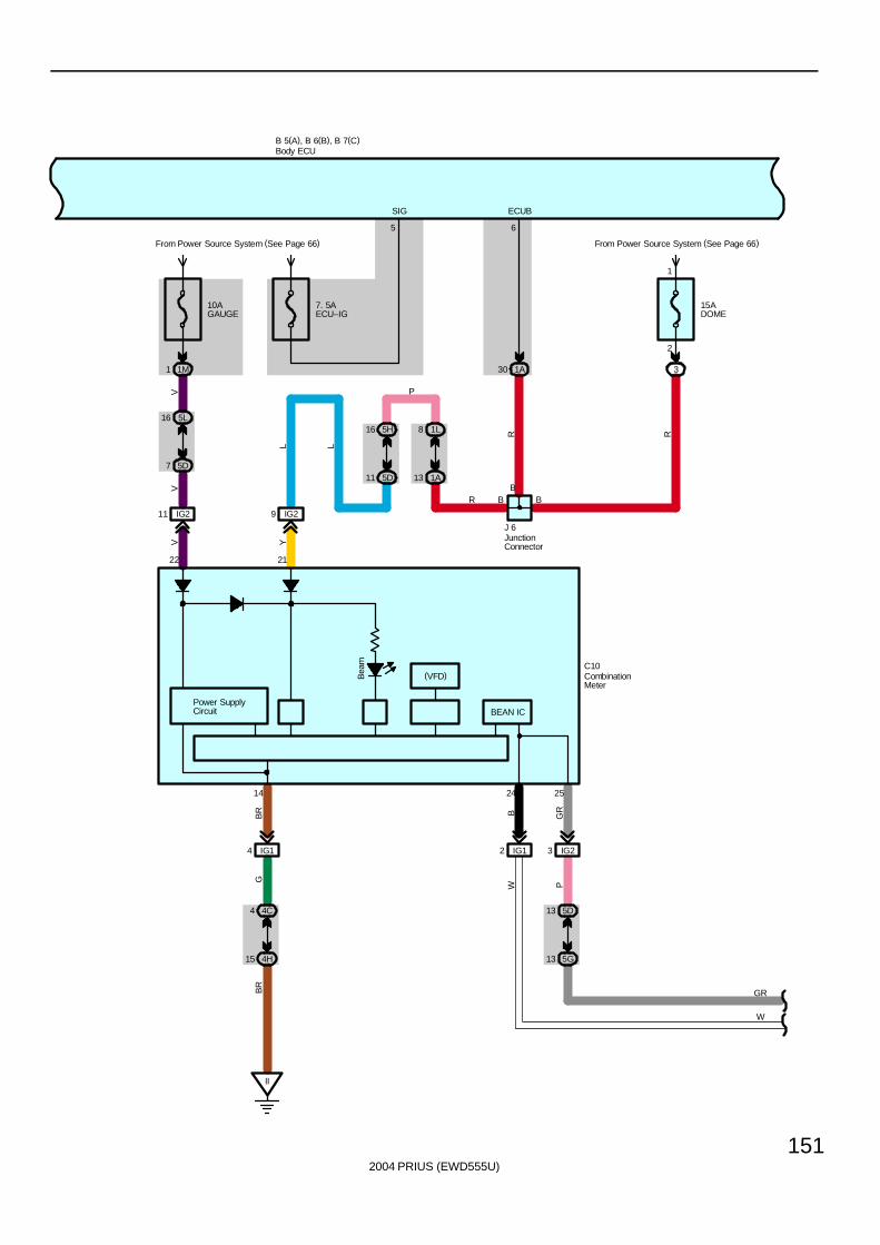
2004 PRIUS (EWD555U)
151
B 5(A), B 6(B), B 7(C)
5
SIG
Bea
m
Power SupplyCircuit
14 2524
2122
10AGAUGE
From Power Source System (See Page 66)
1M1
16 5L
5D7
IG211
II
IG14
4C4
4H15
IG29
IG12 3 IG2
5D13
5G13
YVV
V
B GR
BR
GB
R
PW
BEAN IC
15ADOME
From Power Source System (See Page 66)
3
2
1
7. 5AECU–IG
1A30
6
ECUB
B
1L85H16
1A135D11
P
LL
R R
R B B
J 6
GR
W
C10(VFD)
Body ECU
CombinationMeter
JunctionConnector
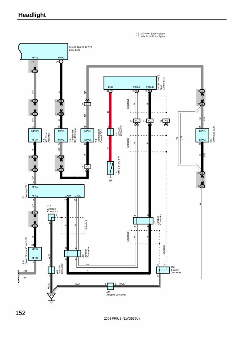
2004 PRIUS (EWD555U)
152
Headlight
B 5(A), B 6(B), B 7(C)
A15
9 1G
4D11
4F11
4I14
4D2
5J8
5K8
5C4
5J13
5G8
5C8
17
T 5
A 8
7
3
3 16
P 6
24
11 17
MPX2MPX1
G 1 MPD1
MPX1
MPX+ MPX2
BGR
GR B
MPX2
GRB
MPX2+ MPX1
GR
BG
R
II18
3218
4L7
4L16
4C2
( *5)
3119
MPX2MPX2
T 4
GR
W
GR
GR
B
W
( *6)
B ( *5)
MPX1 MPX1
GR
W
B
B
1
S11
J 9
RR
P 2
A/C
Con
trol
Ass
embl
yBody ECU
Gat
eway
EC
U
Junc
tion
Con
nect
orP
arki
ng B
rake
SW
Tran
spon
der
Key
Com
pute
r
Tran
smis
sion
Con
trol
EC
U
Sm
art K
ey E
CU
Pow
er S
ourc
e C
ontr
ol E
CU
W–B
IH
A
A
IA112 IA111 IA113
A
1817
A
J24
J18
A
AB
J25
J17
A
A
CAN–H
B
CAN–L
CA1LCA1H
( Shi
elde
d)
J16
W–B
BW
( Shi
elde
d)
A
( Shi
elde
d)
W B
WB
( Shi
elde
d)
W–B
S 8
( B) ,
S 9
( C)
W–B
Ski
dC
ontr
ol E
CU
JunctionConnector
JunctionConnector
Junc
tion
Con
nect
or
Junction Connector
Junc
tion
Con
nect
or
A
A B
J15
B
W B
Junc
tion
Con
nect
or
( Shi
elde
d)
A
B18 B19C14
PKB
12
MPD2
W
B
4I7
II19
B
A
* 6 : w/o Smart Entry System* 5 : w/ Smart Entry System
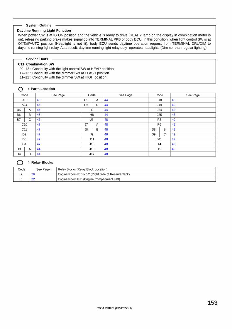
2004 PRIUS (EWD555U)
153
Daytime Running Light FunctionWhen power SW is at IG ON position and the vehicle is ready to drive (READY lamp on the display in combination meter ison), releasing parking brake makes signal go into TERMINAL PKB of body ECU. In this condition, when light control SW is atOff/Tail/AUTO position (Headlight is not lit), body ECU sends daytime operation request from TERMINAL DRL/DIM todaytime running light relay. As a result, daytime running light relay duty–operates headlights (Dimmer than regular lighting)
C11 Combination SW20–12 : Continuity with the light control SW at HEAD position17–12 : Continuity with the dimmer SW at FLASH position11–12 : Continuity with the dimmer SW at HIGH position
: Parts Location
Code See Page Code See Page Code See Page
A8 46 H5 A 44 J18 48
A24 46 H6 B 44 J19 48
B5 A 46 H7 44 J24 48
B6 B 46 H8 44 J25 48
B7 C 46 J6 48 P2 49
C10 47 J7 A 48 P6 49
C11 47 J8 B 48 S8 B 49
D2 47 J9 48 S9 C 49
D3 47 J11 48 S11 49
G1 47 J15 48 T4 49
H3 A 44 J16 48 T5 49
H4 B 44 J17 48
: Relay Blocks
Code See Page Relay Blocks (Relay Block Location)
2 26 Engine Room R/B No.2 (Right Side of Reserve Tank)
3 22 Engine Room R/B (Engine Compartment Left)
System Outline
Service Hints
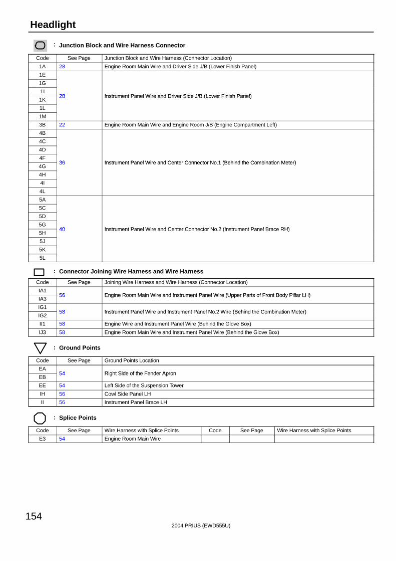
2004 PRIUS (EWD555U)
154
Headlight
: Junction Block and Wire Harness Connector
Code See Page Junction Block and Wire Harness (Connector Location)
1A 28 Engine Room Main Wire and Driver Side J/B (Lower Finish Panel)
1E
1G
1I28 Instrument Panel Wire and Driver Side J/B (Lower Finish Panel)
1K28 Instrument Panel Wire and Driver Side J/B (Lower Finish Panel)
1L
1M
3B 22 Engine Room Main Wire and Engine Room J/B (Engine Compartment Left)
4B
4C
4D
4F36 Instrument Panel Wire and Center Connector No 1 (Behind the Combination Meter)
4G36 Instrument Panel Wire and Center Connector No.1 (Behind the Combination Meter)
4H
4I
4L
5A
5C
5D
5G40 Instrument Panel Wire and Center Connector No 2 (Instrument Panel Brace RH)
5H40 Instrument Panel Wire and Center Connector No.2 (Instrument Panel Brace RH)
5J
5K
5L
: Connector Joining Wire Harness and Wire Harness
Code See Page Joining Wire Harness and Wire Harness (Connector Location)
IA156 Engine Room Main Wire and Instrument Panel Wire (Upper Parts of Front Body Pillar LH)
IA356 Engine Room Main Wire and Instrument Panel Wire (Upper Parts of Front Body Pillar LH)
IG158 Instrument Panel Wire and Instrument Panel No 2 Wire (Behind the Combination Meter)
IG258 Instrument Panel Wire and Instrument Panel No.2 Wire (Behind the Combination Meter)
II1 58 Engine Wire and Instrument Panel Wire (Behind the Glove Box)
IJ3 58 Engine Room Main Wire and Instrument Panel Wire (Behind the Glove Box)
: Ground Points
Code See Page Ground Points Location
EA54 Right Side of the Fender Apron
EB54 Right Side of the Fender Apron
EE 54 Left Side of the Suspension Tower
IH 56 Cowl Side Panel LH
II 56 Instrument Panel Brace LH
: Splice Points
Code See Page Wire Harness with Splice Points Code See Page Wire Harness with Splice Points
E3 54 Engine Room Main Wire

2004 PRIUS (EWD555U)
155
Memo
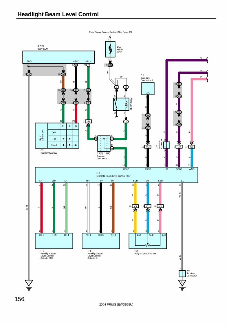
2004 PRIUS (EWD555U)
156
Headlight Beam Level Control
LHT LH+ LH–
4 14 23
2 3 1
R G LG
LH 1 LH 3 LH 4
H 2
RHT RH+ RH–
3 13 22
2 3 1
W B BR
RH 1 RH 3 RH 4
H 1
SGR SHR SBR
20 5 2
1 2 3
Y L P
H18
Y L P
IC120 IC119 IC118
IK
A
40AHEADMAIN
From Power Source System (See Page 66)
3B3
2
1
3 2
5 1
3 3
3
5M11
5N11
IA312
10 9
OP3
8
IJ37 IJ317
5N7
5K7
1G8
1F8
D
D
HDLP PRST
1
IG
12
SPDR
11
WNG
GG B V V L
BB
VV PV
W
V
V
PW
W–B
W–B
J 5
H12
D 1
J10
H–L
P R
elay
E1
24
4F3
4I8
HRLY
GG
B 7(C)
G
BE
AE
AE
J 7(A), J 8(B)
IJ32
OFF
Tail
Head
EL T H
Ligh
tC
ontr
ol S
W
4F14
4B1
4G14
4B9
1E17 1E28
C3 C20
RB
GB
R
1
HEADGND
IH
W–B
2012
C11
SHG SHRL SHB
Body ECU
Combination SW
Data LinkConnector 3
Headlight Beam Level Control ECU
Headlight BeamLevel ControlActuator LH
Headlight BeamLevel ControlActuator RH
Height Control Sensor
JunctionConnector
JunctionConnector
Junc
tion
Con
nect
or
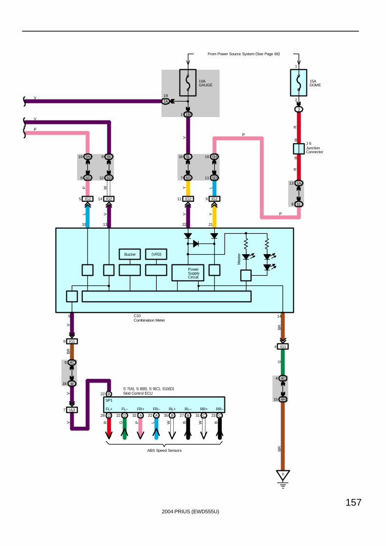
2004 PRIUS (EWD555U)
157
IG25
5D9
5N16
IG214
12 5D
5K9
PowerSupplyCircuit
10AGAUGE
1M1
1A
19
IG211
7 5D
5L16
15ADOME
From Power Source System (See Page 66)
3
B
B
8 1L
1A13
IG29
11 5D
5H16
II
15 4H
4C4
IG14
14
10 13 22 21
L V V Y
P W Y L
V
V
V
P
BR
GB
R
RR
P
P
C10
J 6
2
1
(VFD)
16 4I
4C9
IG19
9
VB
RV
IA37
V
Mas
terBuzzer
D28 D22 A32 A22 B35 B27 C31 C23
FL+ FL– FR+ FR– RL+ RL– RR+ RR–
R G P L W B W B
ABS Speed Sensors
S 7(A), S 8(B), S 9(C), S10(D)B22
SP1
Skid Control ECU
Combination Meter
JunctionConnector
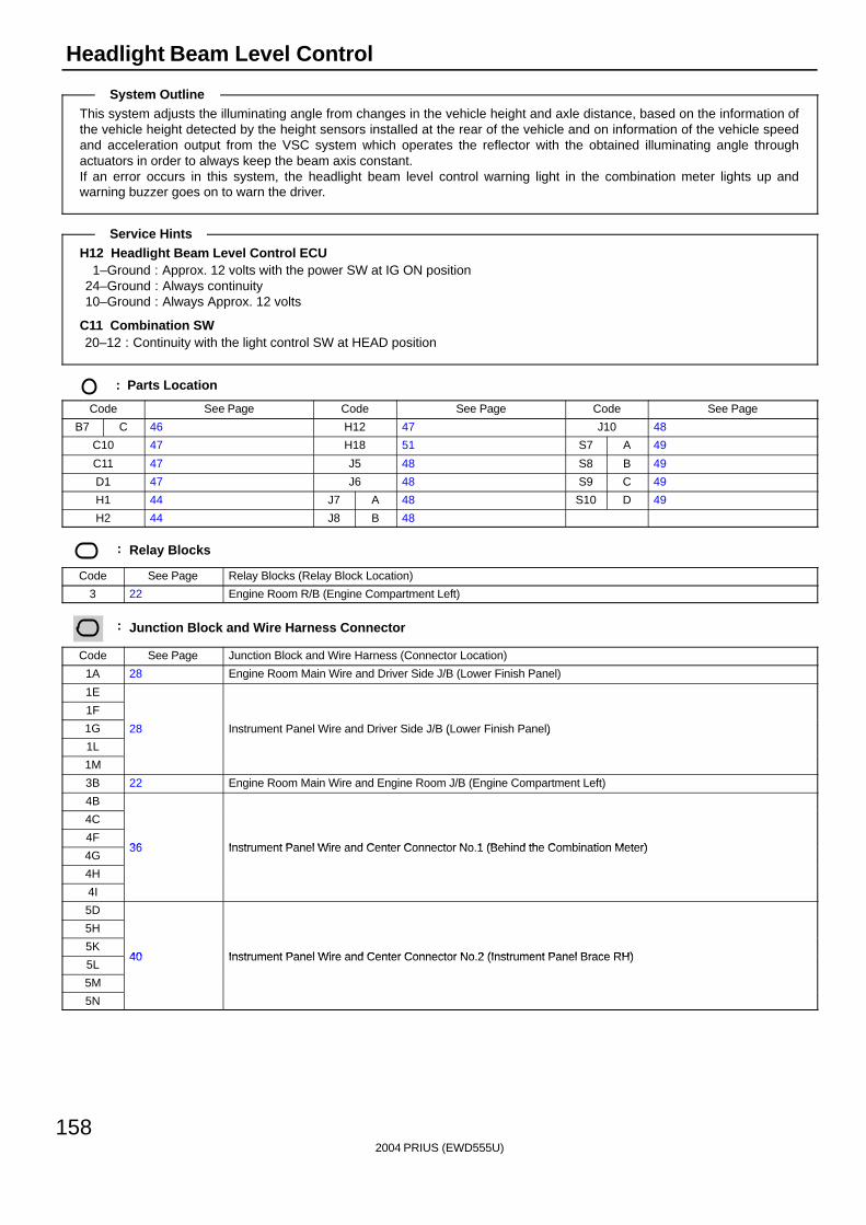
2004 PRIUS (EWD555U)
158
Headlight Beam Level Control
This system adjusts the illuminating angle from changes in the vehicle height and axle distance, based on the information ofthe vehicle height detected by the height sensors installed at the rear of the vehicle and on information of the vehicle speedand acceleration output from the VSC system which operates the reflector with the obtained illuminating angle throughactuators in order to always keep the beam axis constant.If an error occurs in this system, the headlight beam level control warning light in the combination meter lights up andwarning buzzer goes on to warn the driver.
H12 Headlight Beam Level Control ECU1–Ground : Approx. 12 volts with the power SW at IG ON position
24–Ground : Always continuity10–Ground : Always Approx. 12 volts
C11 Combination SW20–12 : Continuity with the light control SW at HEAD position
: Parts Location
Code See Page Code See Page Code See Page
B7 C 46 H12 47 J10 48
C10 47 H18 51 S7 A 49
C11 47 J5 48 S8 B 49
D1 47 J6 48 S9 C 49
H1 44 J7 A 48 S10 D 49
H2 44 J8 B 48
: Relay Blocks
Code See Page Relay Blocks (Relay Block Location)
3 22 Engine Room R/B (Engine Compartment Left)
: Junction Block and Wire Harness Connector
Code See Page Junction Block and Wire Harness (Connector Location)
1A 28 Engine Room Main Wire and Driver Side J/B (Lower Finish Panel)
1E
1F
1G 28 Instrument Panel Wire and Driver Side J/B (Lower Finish Panel)
1L
( )
1M
3B 22 Engine Room Main Wire and Engine Room J/B (Engine Compartment Left)
4B
4C
4F36 Instrument Panel Wire and Center Connector No 1 (Behind the Combination Meter)
4G36 Instrument Panel Wire and Center Connector No.1 (Behind the Combination Meter)
4H
4I
5D
5H
5K40 Instrument Panel Wire and Center Connector No 2 (Instrument Panel Brace RH)
5L40 Instrument Panel Wire and Center Connector No.2 (Instrument Panel Brace RH)
5M
5N
System Outline
Service Hints
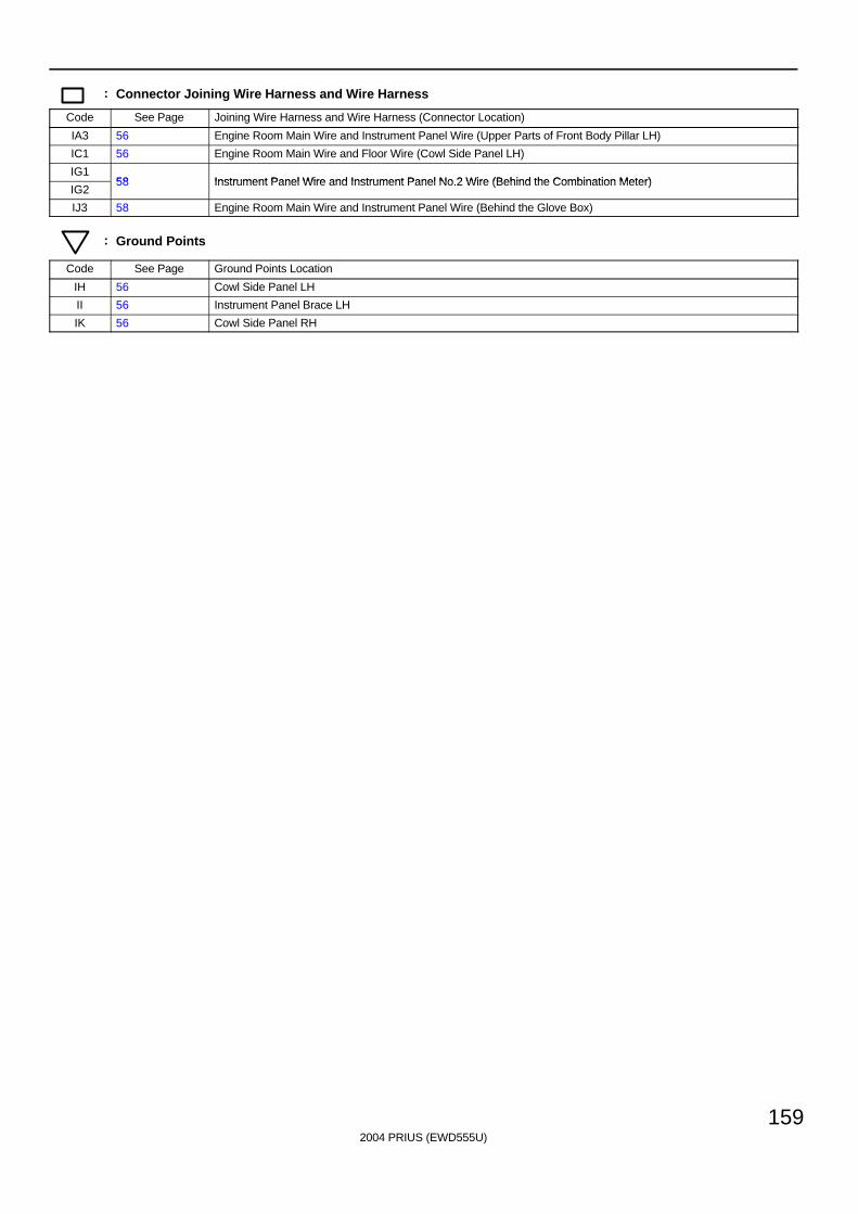
2004 PRIUS (EWD555U)
159
: Connector Joining Wire Harness and Wire Harness
Code See Page Joining Wire Harness and Wire Harness (Connector Location)
IA3 56 Engine Room Main Wire and Instrument Panel Wire (Upper Parts of Front Body Pillar LH)
IC1 56 Engine Room Main Wire and Floor Wire (Cowl Side Panel LH)
IG158 Instrument Panel Wire and Instrument Panel No 2 Wire (Behind the Combination Meter)
IG258 Instrument Panel Wire and Instrument Panel No.2 Wire (Behind the Combination Meter)
IJ3 58 Engine Room Main Wire and Instrument Panel Wire (Behind the Glove Box)
: Ground Points
Code See Page Ground Points Location
IH 56 Cowl Side Panel LH
II 56 Instrument Panel Brace LH
IK 56 Cowl Side Panel RH
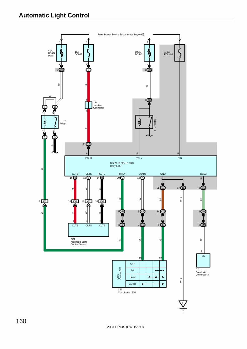
2004 PRIUS (EWD555U)
160
Automatic Light Control
40AHEADMAIN
From Power Source System (See Page 66)
3B3
2
1
2 3
1 5
3 3
3
IJ32
W
G
W
H–LPRelay
1 1B
T–LP
Rel
ay
7. 5AECU–IG
100ADC/DC
3D1
W
1
2
4F3
4I8
C20
3
HRLY
TRLY
19
SIG
5
15ADOME
3
2
1
B
B
1A30
6
ECUB
RR
B
G
B16 15 B B14
IG216 IG217 18 IG2
CLTB CLTS CLTE
A24
BWR
BWR
1 4 3
CLTECLTSCLTB
Tail
OFF
Head
AUTO
Ligh
tC
ontr
ol S
W
19 12
C11
4B2
4F7 4G14
4B9
A18
AUTO
1E28 1E17
IH
GND
1
1L3
DBD2
18
5H11
5M8
7
SIL
D 1
B 5(A), B 6(B), B 7(C)
W BR
W–B LG
G G G W
W–B
G
J 6
Automatic LightControl Sensor
Body ECU
Combination SW
Data LinkConnector 3
JunctionConnector
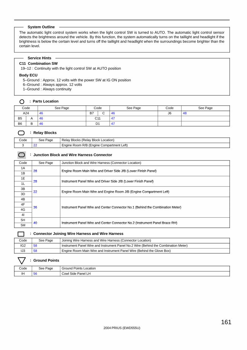
2004 PRIUS (EWD555U)
161
The automatic light control system works when the light control SW is turned to AUTO. The automatic light control sensordetects the brightness around the vehicle. By this function, the system automatically turns on the taillight and headlight if thebrightness is below the certain level and turns off the taillight and headlight when the surroundings become brighter than thecertain level.
C11 Combination SW19–12 : Continuity with the light control SW at AUTO position
Body ECU5–Ground : Approx. 12 volts with the power SW at IG ON position6–Ground : Always approx. 12 volts1–Ground : Always continuity
: Parts Location
Code See Page Code See Page Code See Page
A24 46 B7 C 46 J6 48
B5 A 46 C11 47
B6 B 46 D1 47
: Relay Blocks
Code See Page Relay Blocks (Relay Block Location)
3 22 Engine Room R/B (Engine Compartment Left)
: Junction Block and Wire Harness Connector
Code See Page Junction Block and Wire Harness (Connector Location)
1A28 Engine Room Main Wire and Driver Side J/B (Lower Finish Panel)
1B28 Engine Room Main Wire and Driver Side J/B (Lower Finish Panel)
1E28 Instrument Panel Wire and Driver Side J/B (Lower Finish Panel)
1L28 Instrument Panel Wire and Driver Side J/B (Lower Finish Panel)
3B22 Engine Room Main Wire and Engine Room J/B (Engine Compartment Left)
3D22 Engine Room Main Wire and Engine Room J/B (Engine Compartment Left)
4B
4F36 Instrument Panel Wire and Center Connector No 1 (Behind the Combination Meter)
4G36 Instrument Panel Wire and Center Connector No.1 (Behind the Combination Meter)
4I
5H40 Instrument Panel Wire and Center Connector No 2 (Instrument Panel Brace RH)
5M40 Instrument Panel Wire and Center Connector No.2 (Instrument Panel Brace RH)
: Connector Joining Wire Harness and Wire Harness
Code See Page Joining Wire Harness and Wire Harness (Connector Location)
IG2 58 Instrument Panel Wire and Instrument Panel No.2 Wire (Behind the Combination Meter)
IJ3 58 Engine Room Main Wire and Instrument Panel Wire (Behind the Glove Box)
: Ground Points
Code See Page Ground Points Location
IH 56 Cowl Side Panel LH
System Outline
Service Hints

2004 PRIUS (EWD555U)
162
Front Fog Light
Low
High
Flash
Off
On
Dim
mer
SW
Fog
SW
4B9 4B5
4G14 4B15
4F12
4B14
LIB1
BR O
OLG
SB
SB
4
31612
1E28
1E17
IH
15AFR FOG
From Power Source System (See Page 66)
3
2
1
2 2
2 2
5 2
3 1
BF
AD
EE EA
10ATAIL
1A33
B
B
IA310
BR
BR
LGLGLG
W–B
Y
13
FFOG
17
G
YJ1
1
FR
FO
GR
elay
J 7(
A) ,
J 8
( B)
C11
B 5
AD
W–B
W–B
1
2
1
2
F 4
F 3
Bod
y E
CU
Combination SW
Fron
t Fo
gLi
ght
LH
Fron
t Fo
gLi
ght
RH
Junc
tion
Con
nect
or
Junc
tion
Con
nect
or
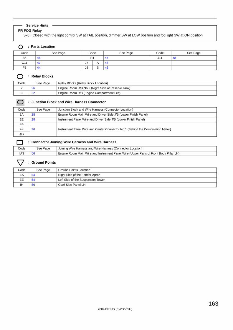
2004 PRIUS (EWD555U)
163
FR FOG Relay3–5 : Closed with the light control SW at TAIL position, dimmer SW at LOW position and fog light SW at ON position
: Parts Location
Code See Page Code See Page Code See Page
B5 46 F4 44 J11 48
C11 47 J7 A 48
F3 44 J8 B 48
: Relay Blocks
Code See Page Relay Blocks (Relay Block Location)
2 26 Engine Room R/B No.2 (Right Side of Reserve Tank)
3 22 Engine Room R/B (Engine Compartment Left)
: Junction Block and Wire Harness Connector
Code See Page Junction Block and Wire Harness (Connector Location)
1A 28 Engine Room Main Wire and Driver Side J/B (Lower Finish Panel)
1E 28 Instrument Panel Wire and Driver Side J/B (Lower Finish Panel)
4B
4F 36 Instrument Panel Wire and Center Connector No.1 (Behind the Combination Meter)
4G
( )
: Connector Joining Wire Harness and Wire Harness
Code See Page Joining Wire Harness and Wire Harness (Connector Location)
IA3 56 Engine Room Main Wire and Instrument Panel Wire (Upper Parts of Front Body Pillar LH)
: Ground Points
Code See Page Ground Points Location
EA 54 Right Side of the Fender Apron
EE 54 Left Side of the Suspension Tower
IH 56 Cowl Side Panel LH
Service Hints
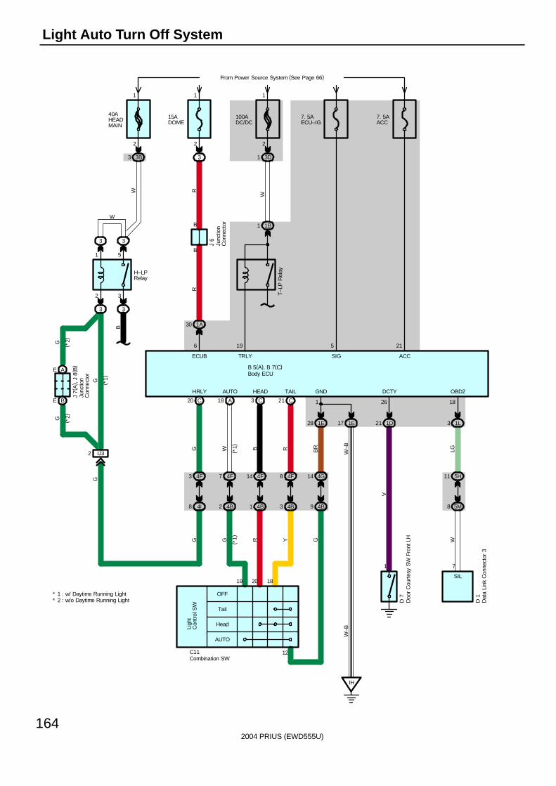
2004 PRIUS (EWD555U)
164
Light Auto Turn Off System
40AHEADMAIN
From Power Source System (See Page 66)
3B3
2
1
2 3
1 5
3 3
3
IJ32
BE
AE
W
G
G
G
W
H–LPRelay
( *2)
( *2)
( *1)
J 7(
A) ,
J 8(
B)
1 1B
T–LP
Rel
ay
7. 5AECU–IG
100ADC/DC
3D1
W
1
2
4F3
4I8
C20
3
HRLY
TRLY
19
SIG
5
15ADOME
3
2
1
B
B
1A30
6
ECUB
RR
B
G
Tail
OFF
Head
AUTO
Ligh
tC
ontr
ol S
W
19
C11
4B1
4F14 4G14
4B9
C3
HEAD
1E28 1E17
IH
GND
1
1L3
OBD2
18
5H11
5M8
7
SIL
B 5(A), B 7(C)
B BR
W–B LG
G R G W
W–B
G
18
4B3
4F8
C21
TAIL
RY
20
4B2
4F7
A18
AUTO
WG
12
1
D 7
D 1
1D21
DCTY
26
V
J 6
7. 5AACC
ACC
21
(*1)
( *1)
* 1 : w/ Daytime Running Light* 2 : w/o Daytime Running Light
Body ECU
Combination SW
Dat
a Li
nk C
onne
ctor
3
Doo
r C
ourt
esy
SW
Fro
nt L
H
Junc
tion
Con
nect
or
Junc
tion
Con
nect
or
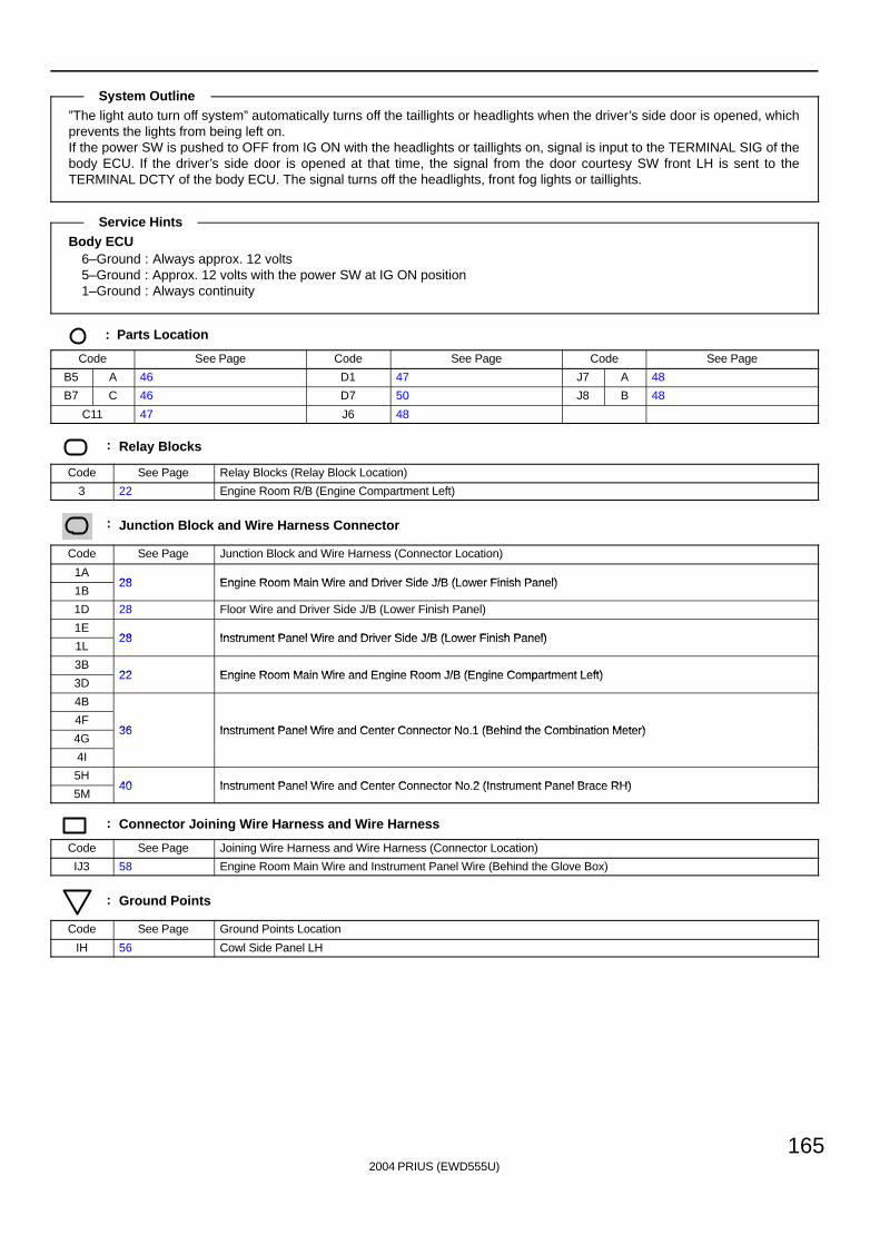
2004 PRIUS (EWD555U)
165
”The light auto turn off system” automatically turns off the taillights or headlights when the driver’s side door is opened, whichprevents the lights from being left on.If the power SW is pushed to OFF from IG ON with the headlights or taillights on, signal is input to the TERMINAL SIG of thebody ECU. If the driver’s side door is opened at that time, the signal from the door courtesy SW front LH is sent to theTERMINAL DCTY of the body ECU. The signal turns off the headlights, front fog lights or taillights.
Body ECU6–Ground : Always approx. 12 volts5–Ground : Approx. 12 volts with the power SW at IG ON position1–Ground : Always continuity
: Parts Location
Code See Page Code See Page Code See Page
B5 A 46 D1 47 J7 A 48
B7 C 46 D7 50 J8 B 48
C11 47 J6 48
: Relay Blocks
Code See Page Relay Blocks (Relay Block Location)
3 22 Engine Room R/B (Engine Compartment Left)
: Junction Block and Wire Harness Connector
Code See Page Junction Block and Wire Harness (Connector Location)
1A28 Engine Room Main Wire and Driver Side J/B (Lower Finish Panel)
1B28 Engine Room Main Wire and Driver Side J/B (Lower Finish Panel)
1D 28 Floor Wire and Driver Side J/B (Lower Finish Panel)
1E28 Instrument Panel Wire and Driver Side J/B (Lower Finish Panel)
1L28 Instrument Panel Wire and Driver Side J/B (Lower Finish Panel)
3B22 Engine Room Main Wire and Engine Room J/B (Engine Compartment Left)
3D22 Engine Room Main Wire and Engine Room J/B (Engine Compartment Left)
4B
4F36 Instrument Panel Wire and Center Connector No 1 (Behind the Combination Meter)
4G36 Instrument Panel Wire and Center Connector No.1 (Behind the Combination Meter)
4I
5H40 Instrument Panel Wire and Center Connector No 2 (Instrument Panel Brace RH)
5M40 Instrument Panel Wire and Center Connector No.2 (Instrument Panel Brace RH)
: Connector Joining Wire Harness and Wire Harness
Code See Page Joining Wire Harness and Wire Harness (Connector Location)
IJ3 58 Engine Room Main Wire and Instrument Panel Wire (Behind the Glove Box)
: Ground Points
Code See Page Ground Points Location
IH 56 Cowl Side Panel LH
System Outline
Service Hints
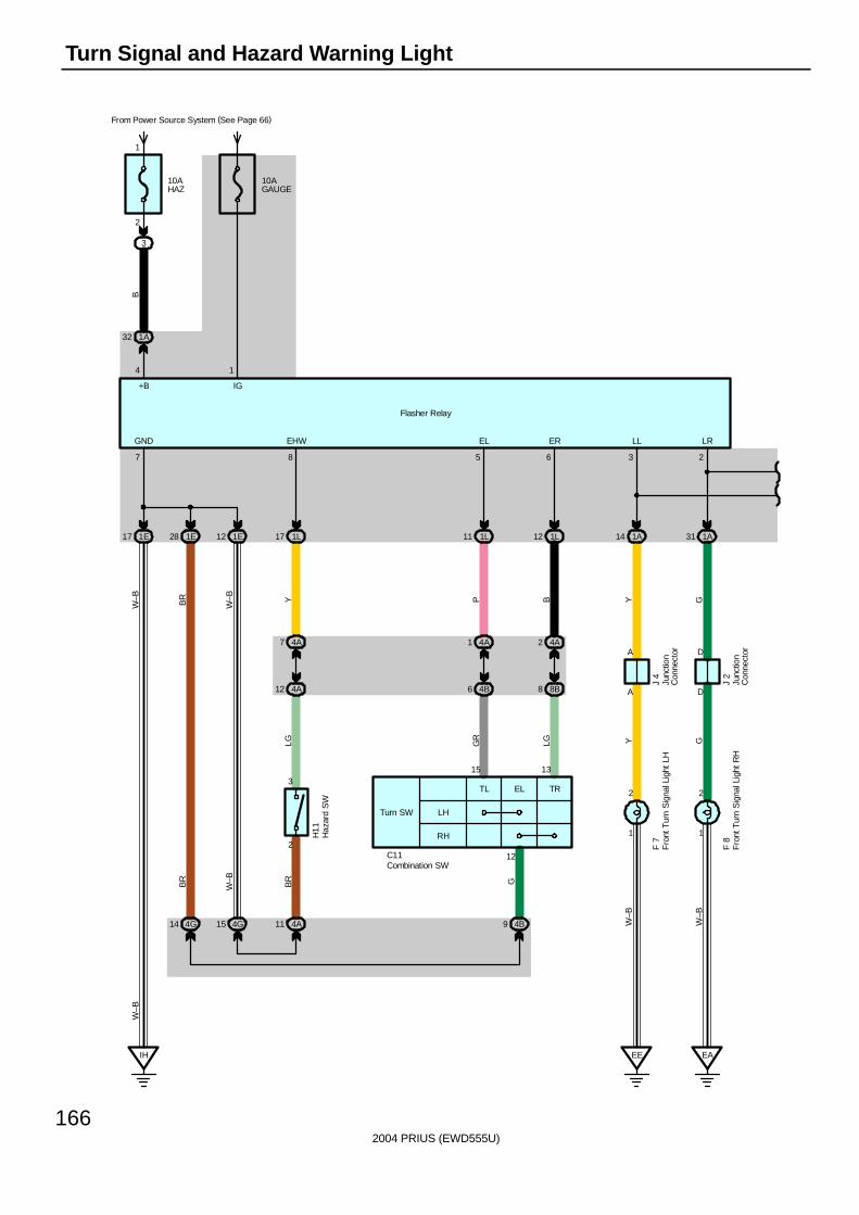
2004 PRIUS (EWD555U)
166
Turn Signal and Hazard Warning Light
IH
15 13
12
Flasher Relay
LH
RH
Turn SW
TL EL TR3
21
2
A
A
1
2
D
D
7 8 5 6 3 2
4
GND EHW EL ER LL LR
+B
10AHAZ
From Power Source System (See Page 66)
3
2
1
10AGAUGE
1A32
1
IG
B
1E17 1E28 1E12 1L17 1L11 1L12 1A14 1A31
4A2
8B8
4A1
4B6
4A7
4A12
4G14 4G15 4A11 4B9
EE EA
GYBPG
R
LG Y GW
–B
W–B
GBR
LG
W–B Y
W–B
BR
BR
W–B
W–B
F 8
F 7
J 2
J 4
H11
C11Combination SW
Fro
nt T
urn
Sig
nal L
ight
LH
Fro
nt T
urn
Sig
nal L
ight
RH
Haz
ard
SW
Junc
tion
Con
nect
or
Junc
tion
Con
nect
or
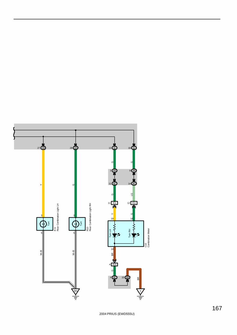
2004 PRIUS (EWD555U)
167
Turn
5
3
Turn
5
3
Tur
n R
H
Tur
n LH
14
19 18
1D27 1D28 1L13 1L16
4A6
4C1411 4C
3 4A
BN II
4C4 4H15
IG112IG111
IG14
BR
GB
RY G
LGG
W–B
W–B
GG
GY
C10
R10
R 9
Com
bina
tion
Met
erRea
r C
ombi
natio
n Li
ght
LH
Rea
r C
ombi
natio
n Li
ght
RH
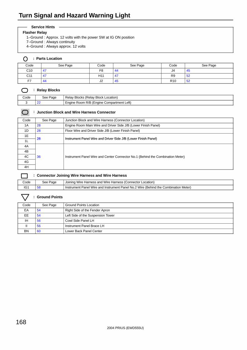
2004 PRIUS (EWD555U)
168
Turn Signal and Hazard Warning Light
Flasher Relay1–Ground : Approx. 12 volts with the power SW at IG ON position7–Ground : Always continuity4–Ground : Always approx. 12 volts
: Parts Location
Code See Page Code See Page Code See Page
C10 47 F8 44 J4 45
C11 47 H11 47 R9 52
F7 44 J2 45 R10 52
: Relay Blocks
Code See Page Relay Blocks (Relay Block Location)
3 22 Engine Room R/B (Engine Compartment Left)
: Junction Block and Wire Harness Connector
Code See Page Junction Block and Wire Harness (Connector Location)
1A 28 Engine Room Main Wire and Driver Side J/B (Lower Finish Panel)
1D 28 Floor Wire and Driver Side J/B (Lower Finish Panel)
1E28 Instrument Panel Wire and Driver Side J/B (Lower Finish Panel)
1L28 Instrument Panel Wire and Driver Side J/B (Lower Finish Panel)
4A
4B
4C 36 Instrument Panel Wire and Center Connector No.1 (Behind the Combination Meter)
4G
( )
4H
: Connector Joining Wire Harness and Wire Harness
Code See Page Joining Wire Harness and Wire Harness (Connector Location)
IG1 58 Instrument Panel Wire and Instrument Panel No.2 Wire (Behind the Combination Meter)
: Ground Points
Code See Page Ground Points Location
EA 54 Right Side of the Fender Apron
EE 54 Left Side of the Suspension Tower
IH 56 Cowl Side Panel LH
II 56 Instrument Panel Brace LH
BN 60 Lower Back Panel Center
Service Hints

2004 PRIUS (EWD555U)
169
Memo
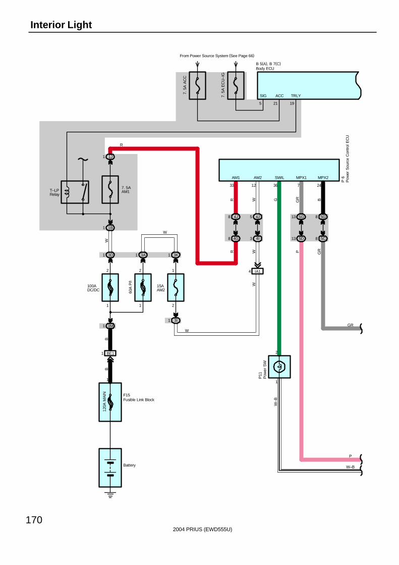
2004 PRIUS (EWD555U)
170
Interior Light
B 5(A), B 7(C)
5
SIG
21
ACC7. 5
A E
CU
–IG
From Power Source System (See Page 66)
7. 5
A A
CC
5D13
5G13
5C8
5G8
120A
MA
IN
BE11
3M1
100ADC/DC
3K1
15AAM2
3A1
60A
P/I
IA14
3 4I
4J5
F15
BB
W
WW
21
2 1
1
2
W
1
Battery
P 6
12
AM2
24
MPX2MPX1
7
PG
R BG
R
GR
P
3I1
W
3D1
7. 5AAM1
1B1
1J1
8 4G
4J8
RR
33
AM1
R
T–LPRelay
19
TRLY
W
W–B
W–B
G
36
SWIL
Body ECU
Fusible Link Block
Pow
er S
ourc
e C
ontr
ol E
CU
1
2
Pow
er S
WP
11
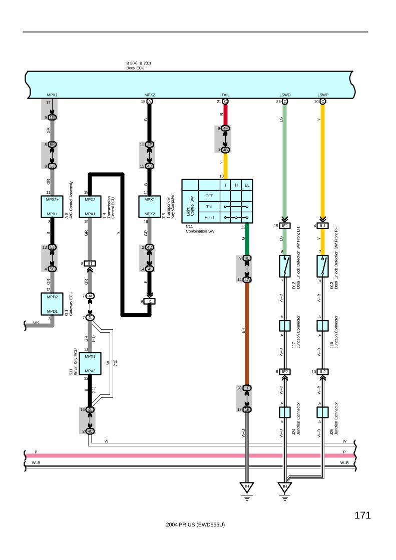
2004 PRIUS (EWD555U)
171
IE115
W–B
C25
W–B
W–B
IH
IE25
A
A
IL210
A
A
LSWD
W–B
W–B
W–B
LGLG
A A
IL14
C10
8
7
LSWP
Y
D13
YA
W–B
W–B
A
7
8
D12
J27
J26
J24
J25
B 5(A), B 7(C)
( *1)
( *1)
9 1G
4C2
4L16
4L7
4I7
II18
II19
4I14
4D2
5J8
5K8
5C4
5J13
MPX1
17
MPX+
3
MPX2
32
MPX1
19
MPX2
16
17
MPX1
18
MPX2
31
MPX1
11
MPX2+
BG
R
W
GR
GR
GR
GR B
B
( *2)
T 4
S11
A 8
T 5
B
MPD1
3
12
MPD2
G 1
GR
A15
MPX2
B4F11
4D11
BG
R
P
W
P
W
C21
4F9
4B3
C11 12
18
ELHTLi
ght
Con
trol
SW
Head
Tail
OFF
4B9
4G14
1E28
1E17
IH
TAIL
RY
GB
RW
–B
GR
W–B W–B
A/C
Con
trol
Ass
embl
yBody ECU
Combination SW
Doo
r U
nloc
k D
etec
tion
SW
Fro
nt L
H
Doo
r U
nloc
k D
etec
tion
SW
Fro
nt R
H
Gat
eway
EC
U
Junc
tion
Con
nect
or
Junc
tion
Con
nect
orJu
nctio
n C
onne
ctor
Junc
tion
Con
nect
or
Tra
nspo
nder
Key
Com
pute
r
Tra
nsm
issi
onC
ontr
ol E
CU
Sm
art K
ey E
CU
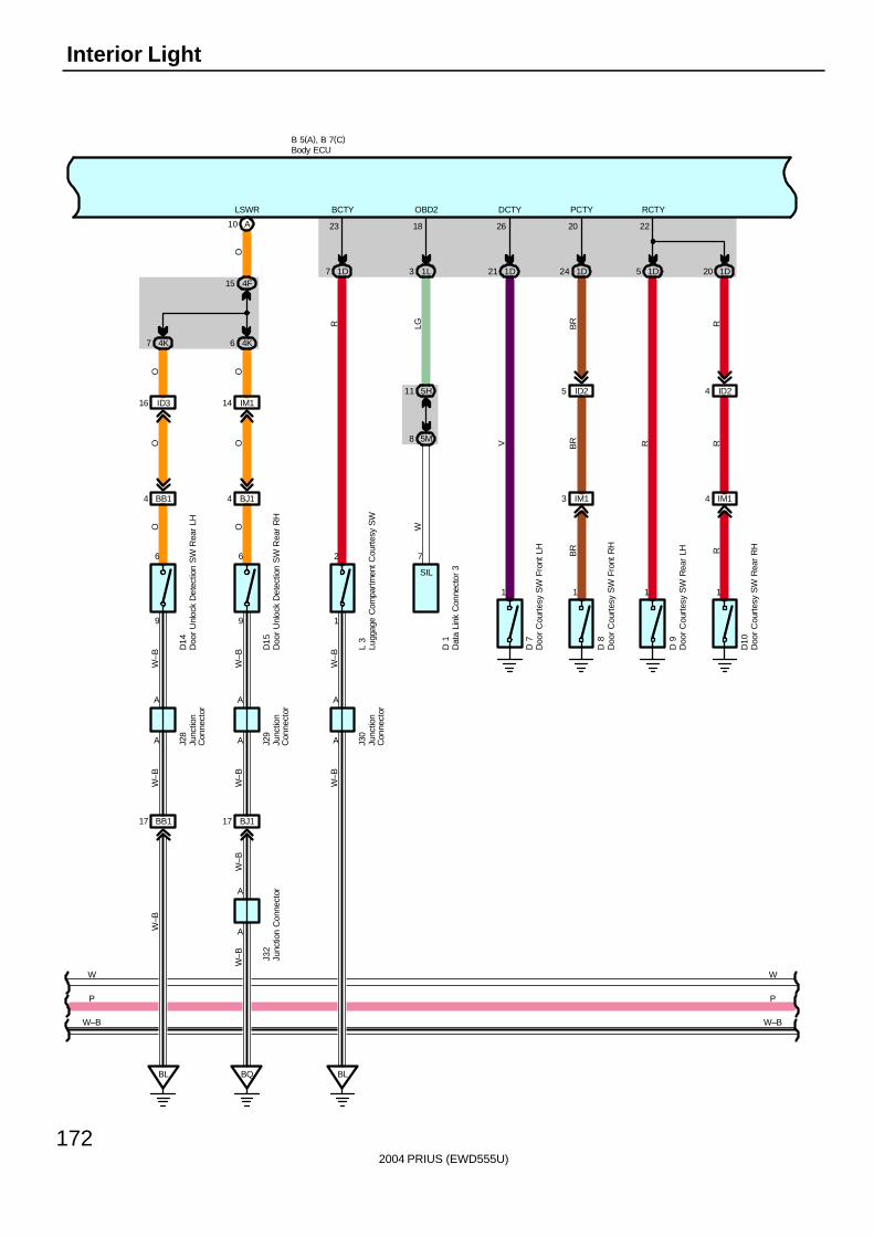
2004 PRIUS (EWD555U)
172
Interior Light
D 1
OBD2
7
1L3
18
5M8
5H11
LGW
SIL
1D21 1D24 1D5 1D20
1 1 1 1
IM13 IM14
ID25 ID24
222026
RCTYPCTYDCTY
RR
R
RBR
BR
BR
V
D 7
D 8
D 9
D10
BL
7 1D
A
2
A
1
23
BCTY
RW
–BW
–B
L 3
J30
A A
BB14
W–B
W–B
BL
BB117 BJ117
A
A
W–B
W–B
W–B
OW
–B
A A
6
D14
9
BJ14
A10
9
6
LSWR
W–B
O
D15
O
J28
J29
J32
BQ
4K6
4F15
O
IM114ID316
4K7
OOO
B 5(A), B 7(C)
W
P
W
P
W–B W–B
Body ECU
Lugg
age
Com
part
men
t Cou
rtes
y S
W
Dat
a Li
nk C
onne
ctor
3
Doo
r U
nloc
k D
etec
tion
SW
Rea
r LH
Doo
r U
nloc
k D
etec
tion
SW
Rea
r R
H
Doo
r C
ourt
esy
SW
Fro
nt L
H
Doo
r C
ourt
esy
SW
Fro
nt R
H
Doo
r C
ourt
esy
SW
Rea
r LH
Doo
r C
ourt
esy
SW
Rea
r R
H
Junc
tion
Con
nect
or
Junc
tion
Con
nect
or
Junc
tion
Con
nect
or
Junc
tion
Con
nect
or
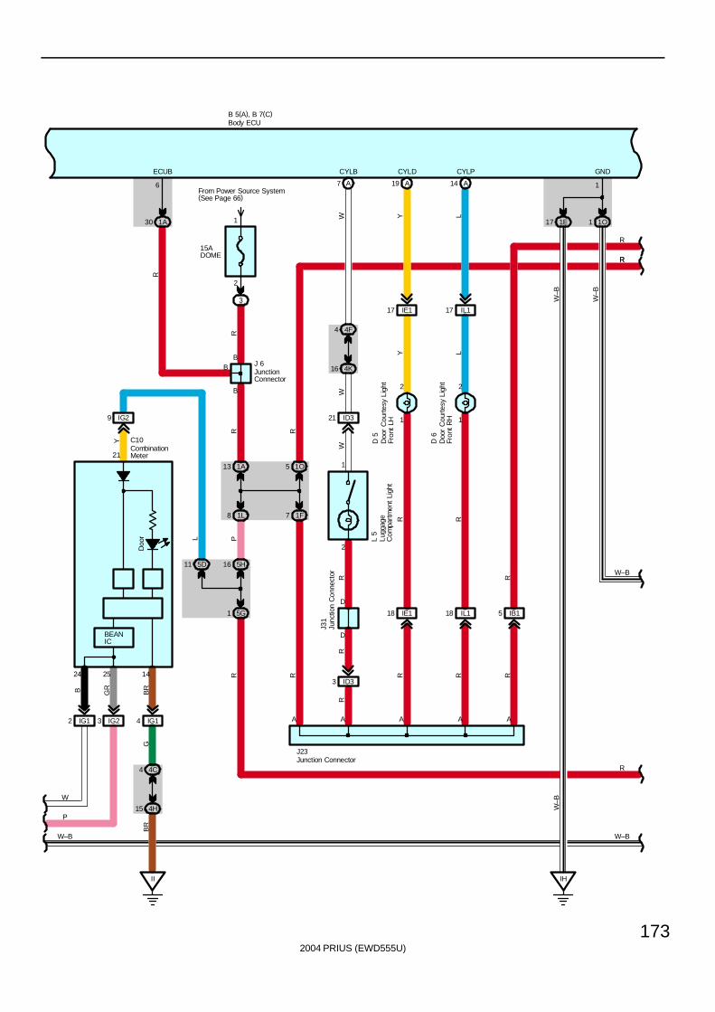
2004 PRIUS (EWD555U)
173
B 5(A), B 7(C)
Doo
r
14
21
II
IG14
4C4
4H15
IG29
L
Y C10
BR
GB
R
J31
WW
WR
RR
CYLB
L 5
A
3 ID3
D
D
2
1
21 ID3
7 AFrom Power Source System(See Page 66)
3
2
1
B
B
1A30
1A13
5D11
1L8
5H16
1F7
1O5
A
6
ECUB
R R
P
R
R
R
5G1
R
4F4
4K16B J 6
15ADOME
J23
R
R
1E 1O117
1
GND
W–B
W–B
R
IB15
RR
A
A19
IE117
IE118
RY
YR
A
CYLD
1
2
D 5
A14
IL117
IL118
RL
LR
A
CYLP
1
2
D 6
IH
W–B
IG12 IG23
24 25
B GR
W
P
R
W–B
W–B W–B
BEANIC
Body ECU
CombinationMeter
JunctionConnector
Junction Connector
Junc
tion
Con
nect
or
Lugg
age
Com
part
men
t Li
ght
Doo
r C
ourte
sy L
ight
Fron
t LH
Doo
r C
ourte
sy L
ight
Fron
t RH
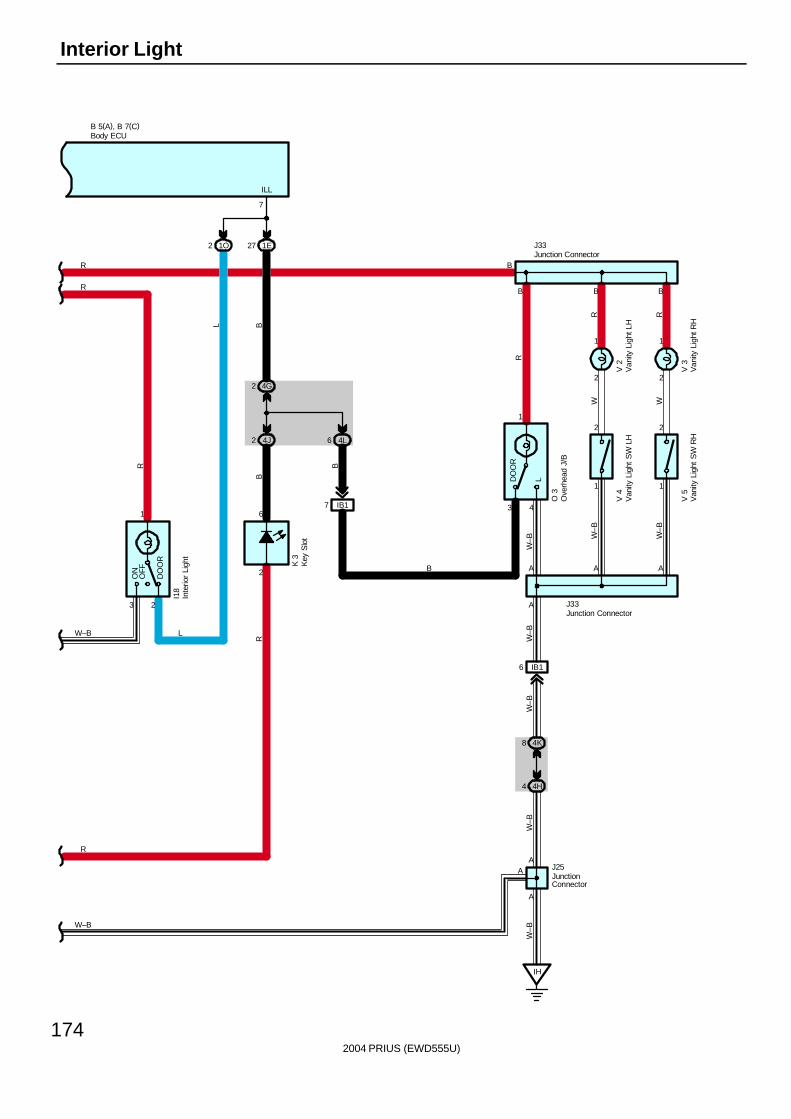
2004 PRIUS (EWD555U)
174
Interior Light
B
6 4L
4G2
4J2
3
1
OFF
DO
OR
ON
3
1
LDO
OR
IB17
2
1
2
1
1
2
1
2
IB16
B 5(A), B 7(C)
AA
V 4
2
2
6
L
V 5
I18
K 3
B B
R
B
B
A
R
A
B
O 3
RRW W
R
J33
W–B W
–B
W–B
W–B
W–B
J33
4
V 2
V 3
J25
4K8
4H4
IH
A
A
W–B
W–B
R
R
1O 1E272
7
ILL
BL
B
R
W–B
W–B
A
Body ECU
Inte
rior
Ligh
t
JunctionConnector
Junction Connector
Junction Connector
Ove
rhea
d J/
B
Van
ity L
ight
LH
Van
ity L
ight
RH
Van
ity L
ight
SW
LH
Van
ity L
ight
SW
RH
Key
Slo
t

2004 PRIUS (EWD555U)
175
Interior light operates with control of body ECU.
Illumination ControlLighting function of interior light, overhead J/B, power SW, electrical key holderWhen any door is opened, signal is sent from door courtesy SW to body ECU. Interior light, overhead J/B, power SW, andkey slot light on gradually from unlit condition to fully lit condition within 1.5 seconds if lighting SW of interior light andoverhead J/B is set for door.After that, when all the doors are shut and any one of the door is unlocked, interior light, overhead J/B, power SW, and keyslot are lit up for about 15 seconds (Timer lighting) and then are lit off gradually.Under conditions that power SW is set at OFF position and all the doors are closed, when any one of the door is unlocked,interior light, overhead J/B, power SW, and key slot light on gradually from unlit condition to fully lit condition within 1.5seconds, stay on for the certain time (Timer lighting) and then light off gradually. If power SW is turned from OFF position toACC ON or IG ON position during timer lighting, the timer lighting function is cut off immediately and the light goes offgradually.Even though timer lighting conditions are satisfied when power SW is at ACC ON or IG ON position, the light does not stayon for certain time (For 15 sec.) after lighting, but goes off gradually.All the doors are locked during timer lighting, the timer lighting function is cut off immediately and the light goes off gradually.
Body ECU5–Ground : Approx. 12 volts with the power SW at IG ON position
21–Ground : Approx. 12 volts with the power SW at ACC ON or IG ON position6–Ground : Always approx. 12 volts1–Ground : Always continuity
26–Ground : Continuity with the driver’s door open20–Ground : Continuity with the front passenger’s door open22–Ground : Continuity with the rear LH and/or RH door open
: Parts Location
Code See Page Code See Page Code See Page
A8 46 D15 50 J33 51
B5 A 46 F15 51 K3 48
B7 C 46 G1 47 L3 51
C10 47 I18 51 L5 51
C11 47 J6 48 O3 52
D1 47 J23 48 P6 49
D5 50 J24 48 P11 49
D6 50 J25 48 S11 49
D7 50 J26 51 T4 49
D8 50 J27 51 T5 49
D9 50 J28 51 V2 53
D10 50 J29 51 V3 53
D12 50 J30 51 V4 53
D13 50 J31 51 V5 53
D14 50 J32 51
: Relay Blocks
Code See Page Relay Blocks (Relay Block Location)
3 22 Engine Room R/B (Engine Compartment Left)
System Outline
Service Hints
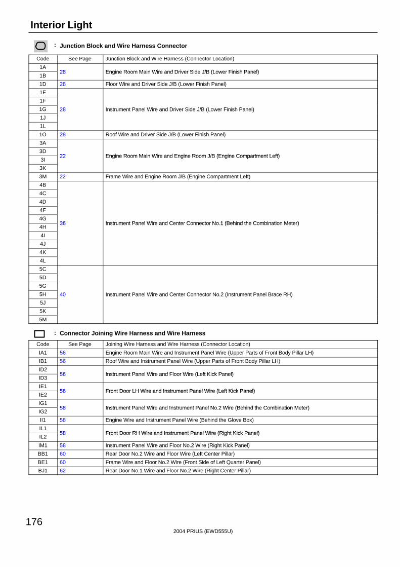
2004 PRIUS (EWD555U)
176
Interior Light
: Junction Block and Wire Harness Connector
Code See Page Junction Block and Wire Harness (Connector Location)
1A28 Engine Room Main Wire and Driver Side J/B (Lower Finish Panel)
1B28 Engine Room Main Wire and Driver Side J/B (Lower Finish Panel)
1D 28 Floor Wire and Driver Side J/B (Lower Finish Panel)
1E
1F
1G 28 Instrument Panel Wire and Driver Side J/B (Lower Finish Panel)
1J
( )
1L
1O 28 Roof Wire and Driver Side J/B (Lower Finish Panel)
3A
3D22 Engine Room Main Wire and Engine Room J/B (Engine Compartment Left)
3I22 Engine Room Main Wire and Engine Room J/B (Engine Compartment Left)
3K
3M 22 Frame Wire and Engine Room J/B (Engine Compartment Left)
4B
4C
4D
4F
4G36 Instrument Panel Wire and Center Connector No 1 (Behind the Combination Meter)
4H36 Instrument Panel Wire and Center Connector No.1 (Behind the Combination Meter)
4I
4J
4K
4L
5C
5D
5G
5H 40 Instrument Panel Wire and Center Connector No.2 (Instrument Panel Brace RH)
5J
( )
5K
5M
: Connector Joining Wire Harness and Wire Harness
Code See Page Joining Wire Harness and Wire Harness (Connector Location)
IA1 56 Engine Room Main Wire and Instrument Panel Wire (Upper Parts of Front Body Pillar LH)
IB1 56 Roof Wire and Instrument Panel Wire (Upper Parts of Front Body Pillar LH)
ID256 Instrument Panel Wire and Floor Wire (Left Kick Panel)
ID356 Instrument Panel Wire and Floor Wire (Left Kick Panel)
IE156 Front Door LH Wire and Instrument Panel Wire (Left Kick Panel)
IE256 Front Door LH Wire and Instrument Panel Wire (Left Kick Panel)
IG158 Instrument Panel Wire and Instrument Panel No 2 Wire (Behind the Combination Meter)
IG258 Instrument Panel Wire and Instrument Panel No.2 Wire (Behind the Combination Meter)
II1 58 Engine Wire and Instrument Panel Wire (Behind the Glove Box)
IL158 Front Door RH Wire and Instrument Panel Wire (Right Kick Panel)
IL258 Front Door RH Wire and Instrument Panel Wire (Right Kick Panel)
IM1 58 Instrument Panel Wire and Floor No.2 Wire (Right Kick Panel)
BB1 60 Rear Door No.2 Wire and Floor Wire (Left Center Pillar)
BE1 60 Frame Wire and Floor No.2 Wire (Front Side of Left Quarter Panel)
BJ1 62 Rear Door No.1 Wire and Floor No.2 Wire (Right Center Pillar)
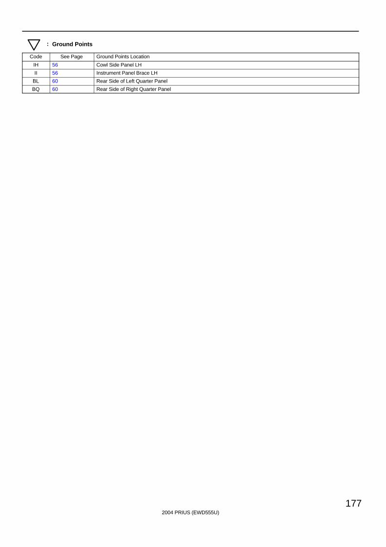
2004 PRIUS (EWD555U)
177
: Ground Points
Code See Page Ground Points Location
IH 56 Cowl Side Panel LH
II 56 Instrument Panel Brace LH
BL 60 Rear Side of Left Quarter Panel
BQ 60 Rear Side of Right Quarter Panel
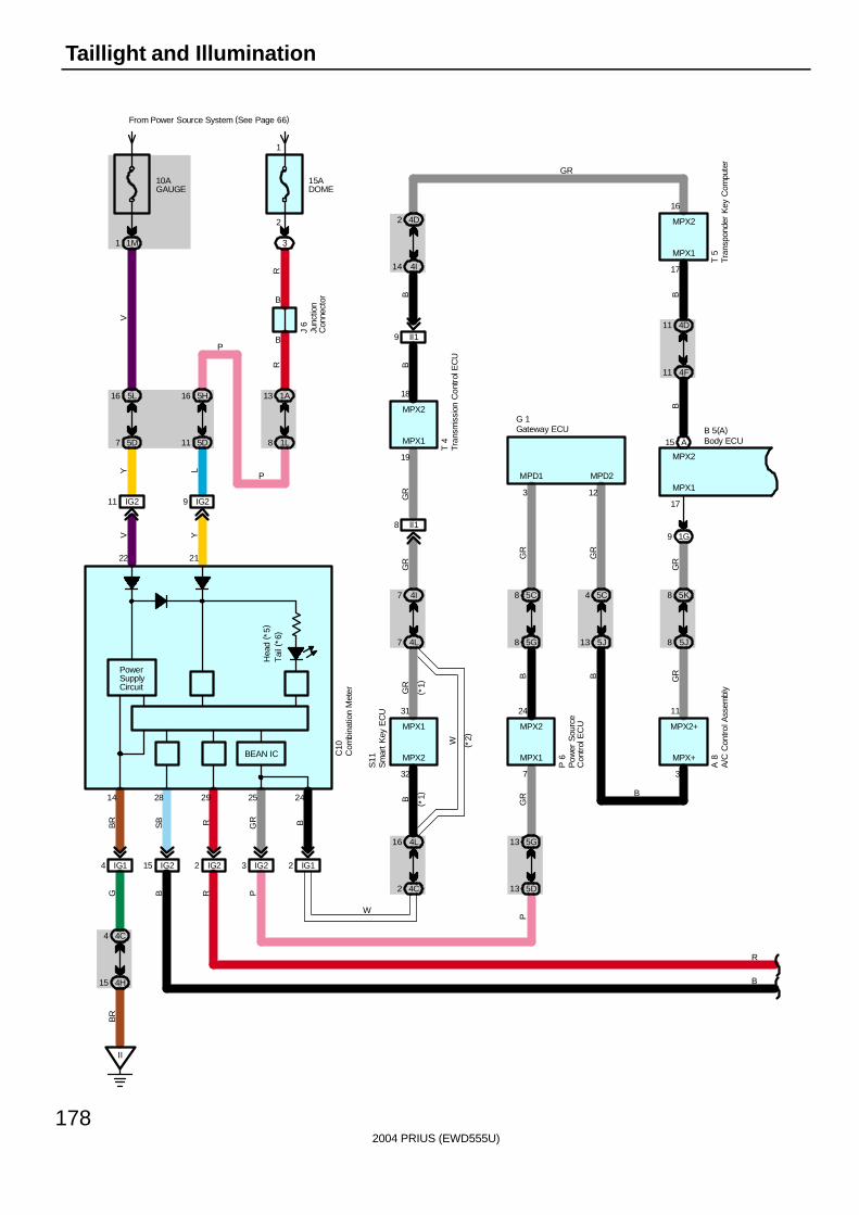
2004 PRIUS (EWD555U)
178
Taillight and Illumination
15ADOME
3
2
1
B
B
1A13
1L8
5H16
5D11
IG29IG211
10AGAUGE
From Power Source System (See Page 66)
1M1
5L16
5D7
22 21
IG14
4C4
4H15
II
BEAN IC
A15
IG23 IG12
4C2
4L16
4L7
4I7
II18
II19
4I14
4D2
5D13
5G13
5G8
5C8
5J8
5K8
5J13
5C4
1G9
4F11
4D11
MPX1
MPX2
17
MPD1
3
MPD2
12
MPX+
3
MPX1
7
MPX2
32
MPX1
19
MPX1
17
16
MPX2
18
MPX2
31
MPX1
24
MPX2
11
MPX2+
14 25 24
V Y
Y L
V
RR
BR
GR B
GB
R
P
P
BG
R
W
B B GR
GR
GR
GR
GR
GR
BB B
B
GR
B
P
P
GR
W
J 6
T 4
S11
P 6
A 8
C10
T 5
B 5(A)G 1( *
1)( *
1)
( *2)
PowerSupplyCircuit
IG22IG215
28 29
RRB
R
B
Tai
l (*6
)H
ead
( *5)
A/C
Con
trol A
ssem
bly
Body ECU
Com
bina
tion
Met
er
Gateway ECU
Junc
tion
Con
nect
or
Tran
spon
der
Key
Com
pute
r
Tran
smis
sion
Con
trol
EC
U
Sm
art
Key
EC
U
Pow
er S
ourc
eC
ontr
ol E
CU
SB
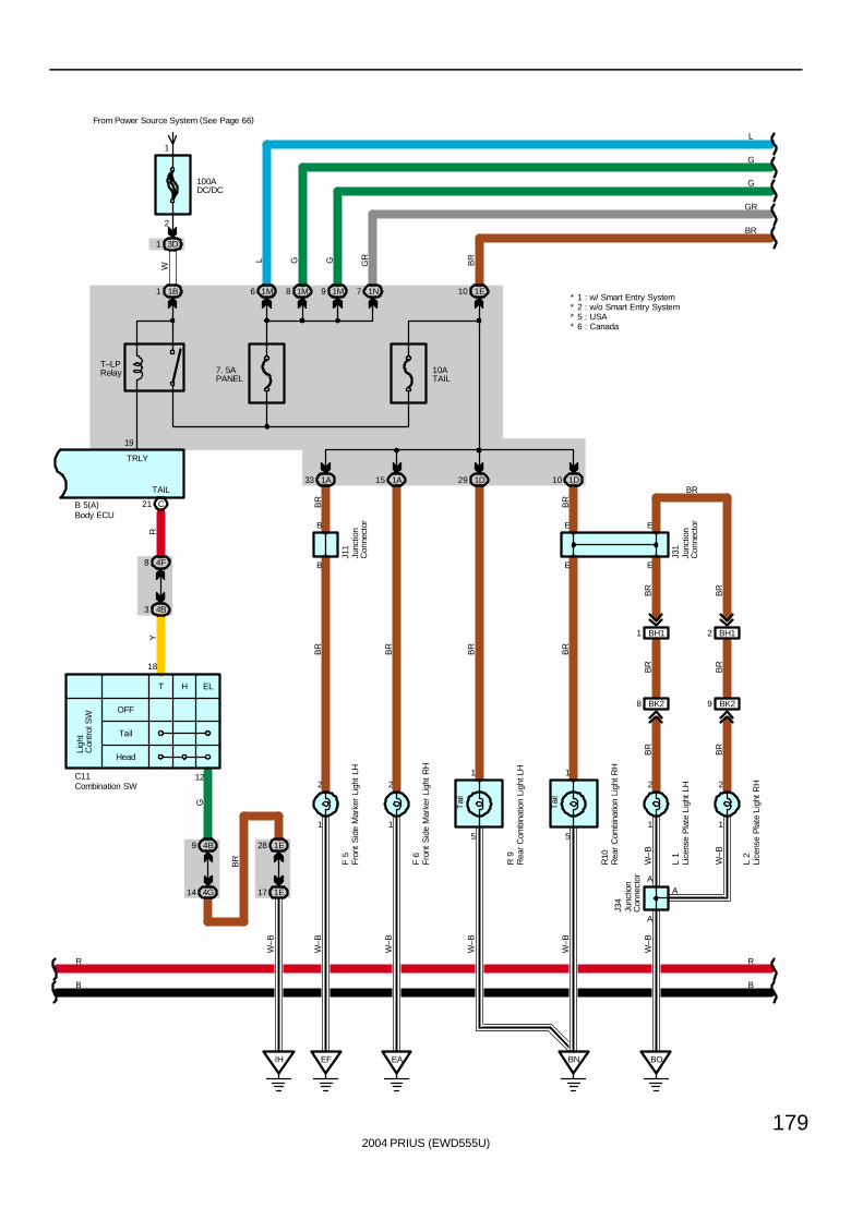
2004 PRIUS (EWD555U)
179
100ADC/DC
From Power Source System (See Page 66)
3D1
2
1
1B1
C21
4F8
4B3
OFF
Tail
Head
Ligh
tC
ontr
ol S
W
T H EL
18
12C11
4B9
4G14
1E28
1E17
IH
10ATAIL
1A33 1A15 1D29
B
B
1
2
1
2
5
1
5
1
1D10
E
E
EAEF BN
1
2
1
2
BH11
BK28
BH12
BK29
A
A
BO
A
E
19
E
TAIL
TRLY
F 5
F 6
R 9
R10
L 1
L 2
RY
G
BR
W–B
BR
BR
BR
BR
BR
BR
BR
BR
BR
BR
BR
W–B
W–B
W–B
W–B
W–B
W–B
W–B
BR
BR
W
J31
J11
B 5(A)
T–LPRelay
J34
Tai
l
Tai
l
7. 5APANEL
1E101M6 1M8 1M9 1N7
L
G
G
GR
BR
R
B
R
B
L G G GR
BR
* 6 : Canada* 5 : USA
Body ECU
Combination SW
Fron
t S
ide
Mar
ker
Ligh
t LH
Fron
t S
ide
Mar
ker
Ligh
t R
H
Junc
tion
Con
nect
or
Junc
tion
Con
nect
or
Junc
tion
Con
nect
or
Lice
nse
Pla
te L
ight
LH
Lice
nse
Pla
te L
ight
RH
Rea
r C
ombi
natio
n Li
ght L
H
Rea
r C
ombi
natio
n Li
ght R
H
* 1 : w/ Smart Entry System* 2 : w/o Smart Entry System

2004 PRIUS (EWD555U)
180
Taillight and Illumination
5K16
5A2
2
1
5A5
5L6
IH
5K4
5A8
5M6
5B12
5K13
5F1
5F14
5D15
5A9
5L1
G GR G LG G
W–B
Illum
inat
ion
W–B
W–B R W
W–B
A
2 2 12 4
A
1 1
W–B
R
B
BR
GR
G
G
L L
G
GR
G
W
B
W–BW–B
G 2
J24
S 4
M11
C12
GR G GR
ILL+ EAU
Com
bina
tion
SW
Glo
ve B
ox L
ight
Junc
tion
Con
nect
or
Shi
ft Le
ver
Pos
ition
Sen
sor
Mai
n S
W

2004 PRIUS (EWD555U)
181
5M16
5D8
5M5
5L5
5M4
5L3
A10
B5 A7
C6
5L4
5E14 5E5
5B3
5E5
II
4G16
4A13
4A10
4H16
B
W–B W
W–B
W–B
BR
BR
W–B
SB
W–B R
W–B
W–B BR
BR
GR
GGGRGGR
L
TC E ILL– ILL– ILL– GND
2 1
C
4
A D
A D
7 5 6 2 1
T ILL+
G
GR
G
L
W
B
W–B
C C C
GND ILL+
R 7
M13
R 3
( A) ,
R 4
( B) ,
R 5
( C)
H11
J19
* 3 : Separate Amplifier* 4 : Built–in Amplifier
A2
A12 20 A
C6
ILL– GND
GND ILL+
R 5
( C) ,
R 6
( A)
RW
–B
( *3)
( *3)
( *4)
( *4)
( *4)
( *4)
( *4)
( *3)
( *3)
BR
( *3)
J25 J20
Haz
ard
SW
Junc
tion
Con
nect
or
JunctionConnector
JunctionConnector
Mul
ti–D
ispl
ay
Rad
io a
nd P
laye
r
Rad
io a
nd P
laye
r
Rhe
osta
t
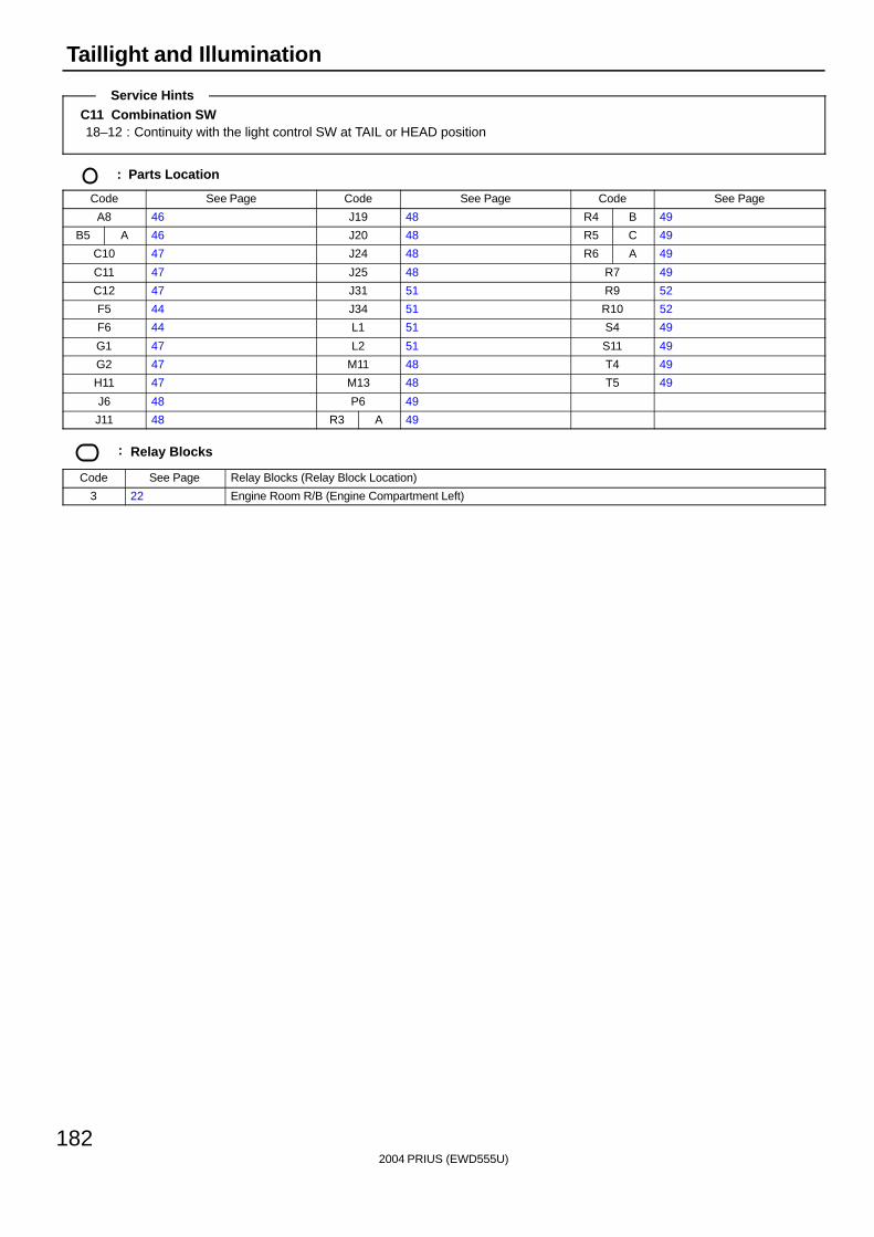
2004 PRIUS (EWD555U)
182
Taillight and Illumination
C11 Combination SW18–12 : Continuity with the light control SW at TAIL or HEAD position
: Parts Location
Code See Page Code See Page Code See Page
A8 46 J19 48 R4 B 49
B5 A 46 J20 48 R5 C 49
C10 47 J24 48 R6 A 49
C11 47 J25 48 R7 49
C12 47 J31 51 R9 52
F5 44 J34 51 R10 52
F6 44 L1 51 S4 49
G1 47 L2 51 S11 49
G2 47 M11 48 T4 49
H11 47 M13 48 T5 49
J6 48 P6 49
J11 48 R3 A 49
: Relay Blocks
Code See Page Relay Blocks (Relay Block Location)
3 22 Engine Room R/B (Engine Compartment Left)
Service Hints
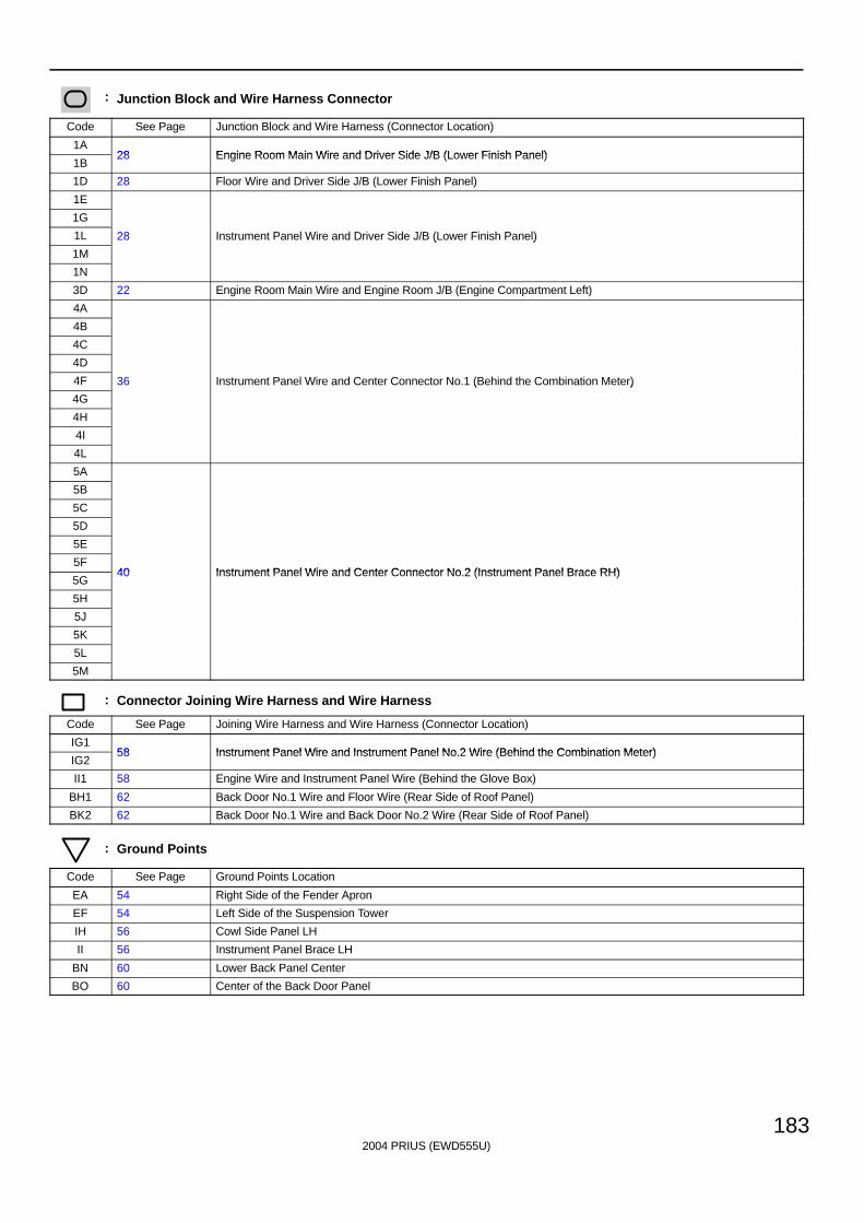
2004 PRIUS (EWD555U)
183
: Junction Block and Wire Harness Connector
Code See Page Junction Block and Wire Harness (Connector Location)
1A28 Engine Room Main Wire and Driver Side J/B (Lower Finish Panel)
1B28 Engine Room Main Wire and Driver Side J/B (Lower Finish Panel)
1D 28 Floor Wire and Driver Side J/B (Lower Finish Panel)
1E
1G
1L 28 Instrument Panel Wire and Driver Side J/B (Lower Finish Panel)
1M
( )
1N
3D 22 Engine Room Main Wire and Engine Room J/B (Engine Compartment Left)
4A
4B
4C
4D
4F 36 Instrument Panel Wire and Center Connector No.1 (Behind the Combination Meter)
4G
( )
4H
4I
4L
5A
5B
5C
5D
5E
5F40 Instrument Panel Wire and Center Connector No 2 (Instrument Panel Brace RH)
5G40 Instrument Panel Wire and Center Connector No.2 (Instrument Panel Brace RH)
5H
5J
5K
5L
5M
: Connector Joining Wire Harness and Wire Harness
Code See Page Joining Wire Harness and Wire Harness (Connector Location)
IG158 Instrument Panel Wire and Instrument Panel No 2 Wire (Behind the Combination Meter)
IG258 Instrument Panel Wire and Instrument Panel No.2 Wire (Behind the Combination Meter)
II1 58 Engine Wire and Instrument Panel Wire (Behind the Glove Box)
BH1 62 Back Door No.1 Wire and Floor Wire (Rear Side of Roof Panel)
BK2 62 Back Door No.1 Wire and Back Door No.2 Wire (Rear Side of Roof Panel)
: Ground Points
Code See Page Ground Points Location
EA 54 Right Side of the Fender Apron
EF 54 Left Side of the Suspension Tower
IH 56 Cowl Side Panel LH
II 56 Instrument Panel Brace LH
BN 60 Lower Back Panel Center
BO 60 Center of the Back Door Panel
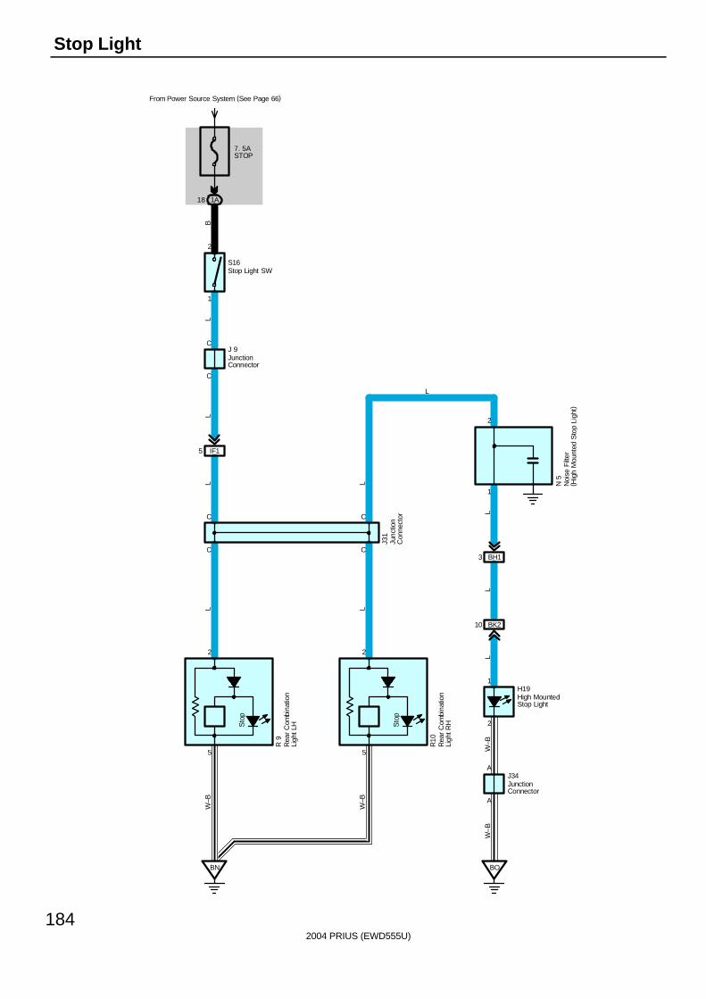
2004 PRIUS (EWD555U)
184
Stop Light
C
C
5
2
A
A
2
1
1
2
C
C
C
C
H19
J34
1
2
BN BO
S16
J 9
7. 5ASTOP
From Power Source System (See Page 66)
1A18B
LL
L L
LL
W–B
W–B
W–B
W–B
L
LL
IF15
L
BK210
BH13N
5
J31
R 9
High MountedStop Light
JunctionConnector
Junc
tion
Con
nect
or
JunctionConnector
Noi
se F
ilter
( Hig
h M
ount
ed S
top
Ligh
t)
Rea
r C
ombi
natio
nLi
ght L
H
Stop Light SW
Sto
p
5
2
R10
Rea
r C
ombi
natio
nLi
ght R
HSto
p
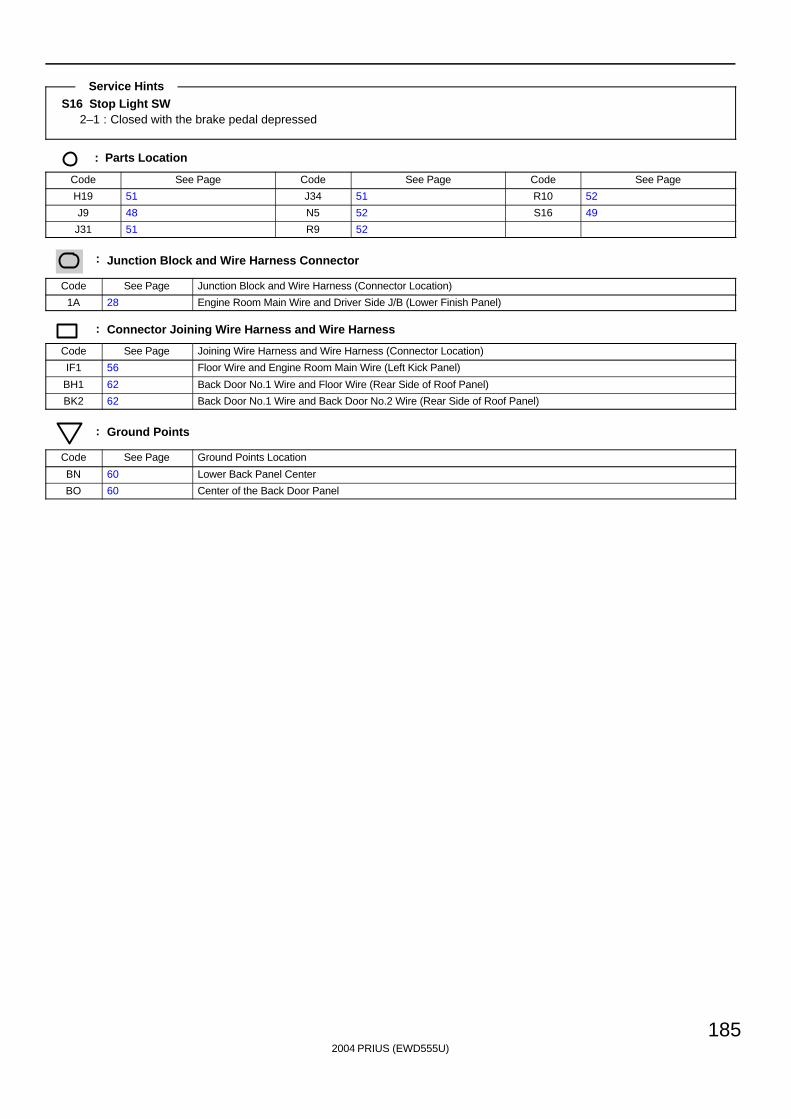
2004 PRIUS (EWD555U)
185
S16 Stop Light SW2–1 : Closed with the brake pedal depressed
: Parts Location
Code See Page Code See Page Code See Page
H19 51 J34 51 R10 52
J9 48 N5 52 S16 49
J31 51 R9 52
: Junction Block and Wire Harness Connector
Code See Page Junction Block and Wire Harness (Connector Location)
1A 28 Engine Room Main Wire and Driver Side J/B (Lower Finish Panel)
: Connector Joining Wire Harness and Wire Harness
Code See Page Joining Wire Harness and Wire Harness (Connector Location)
IF1 56 Floor Wire and Engine Room Main Wire (Left Kick Panel)
BH1 62 Back Door No.1 Wire and Floor Wire (Rear Side of Roof Panel)
BK2 62 Back Door No.1 Wire and Back Door No.2 Wire (Rear Side of Roof Panel)
: Ground Points
Code See Page Ground Points Location
BN 60 Lower Back Panel Center
BO 60 Center of the Back Door Panel
Service Hints
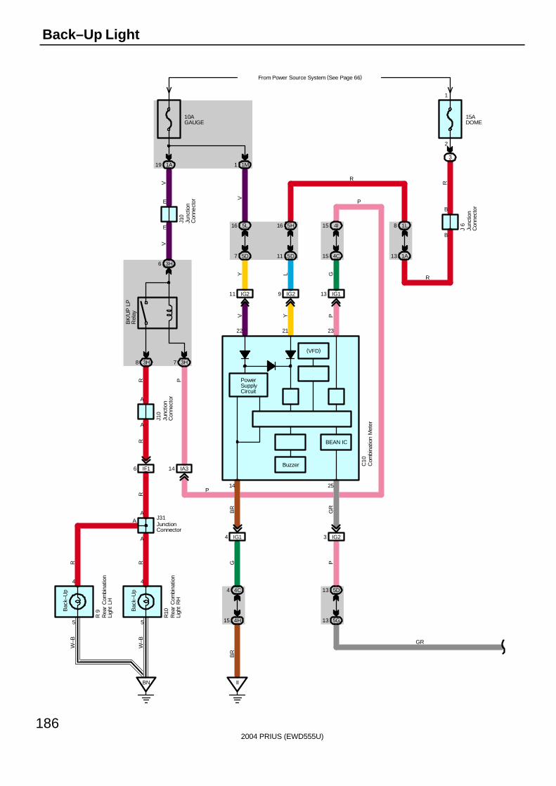
2004 PRIUS (EWD555U)
186
Back–Up Light
10AGAUGE
From Power Source System (See Page 66)
1A19
3H6
3H8
A
A
IF16
A
A
5
4
5
4
BN
E
E
1M1
IG211
5L16
5D7
IG29
5H16
5D11
1L8
1A13
15ADOME
3
B
B
3H7
IG113
4I15
4C15
IA314
IG14
4C4
4H15
II
A
R 9
R10
J10
J10
J 6
J31
C10
14
22 21 23
V Y P
Y L G
VV
VB
RG
BR
W–B
W–B
RR
RR
R P
R
R
P
R
PowerSupplyCircuit
P
Bac
k–U
p
Bac
k–U
pB
K/U
P L
PR
elay
2
1
25
GR
P
5D13
5G13
IG23
GR
BEAN IC
(VFD)
Buzzer Com
bina
tion
Met
er
Junc
tion
Con
nect
or
Junc
tion
Con
nect
or
Junc
tion
Con
nect
or
JunctionConnector
Rea
r C
ombi
natio
nLi
ght
LH
Rea
r C
ombi
natio
nLi
ght
RH
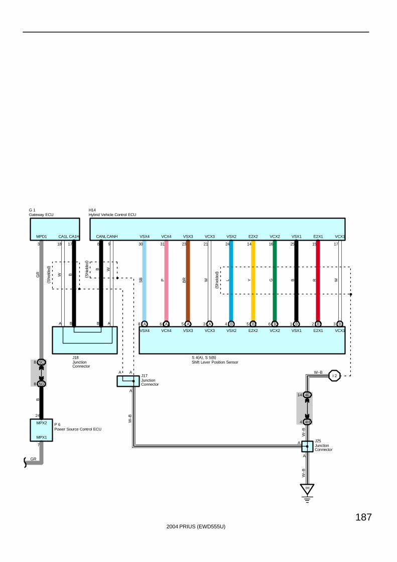
2004 PRIUS (EWD555U)
187
A8 A6 A5 3 A 4 B B5 B6 B1 B2 B3
30 31 23 21 24 14 16 25 15 179817183
7
24
A B B A
MPD1 CA1L CA1H CANLCANH VSX4 VCX4 VSX3 VCX3 VSX2 E2X2 VCX2 VSX1 E2X1 VCX1
VSX4 VCX4 VSX3 VCX3 VSX2 E2X2 VCX2 VSX1 E2X1 VCX1
W B
B W
SB P BR W L Y G B R W
I 2
5C8
4E14
5G8
4H4
IH
W–B
GR
B
W–B
W–B
W–BA A
A
MPX1
MPX2
S 4(A), S 5(B)
P 6
J17
J18
(Shi
elde
d)
( Shi
elde
d)
( Shi
elde
d)
A
A
J25
GR
G 1 H14Gateway ECU Hybrid Vehicle Control ECU
JunctionConnector
JunctionConnector
JunctionConnector
Shift Lever Position Sensor
Power Source Control ECU
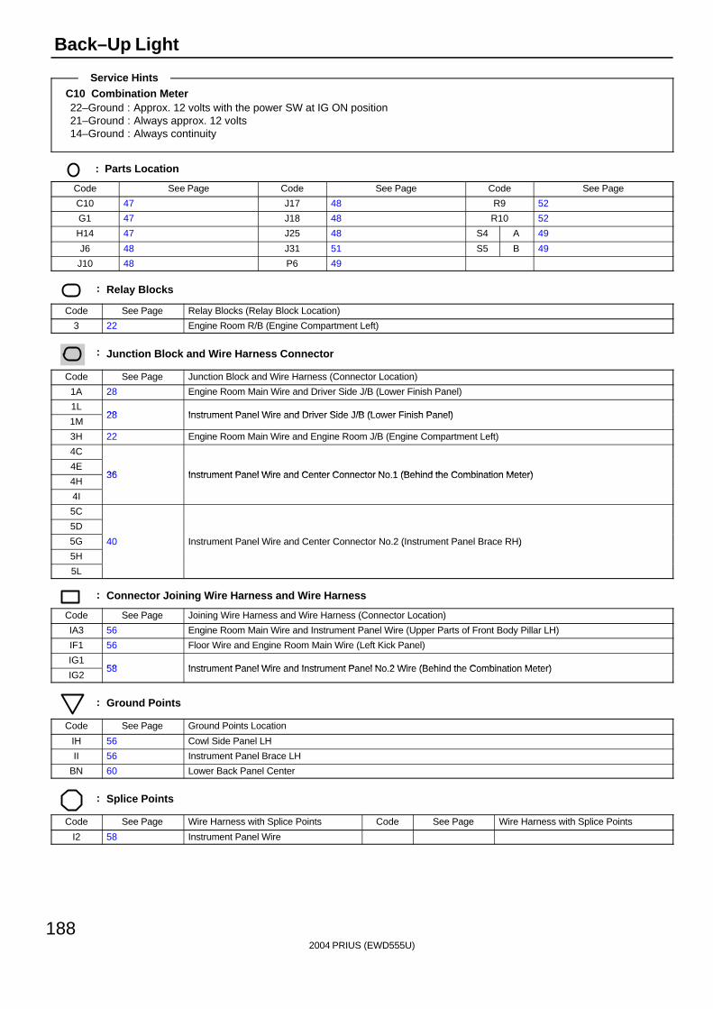
2004 PRIUS (EWD555U)
188
Back–Up Light
C10 Combination Meter22–Ground : Approx. 12 volts with the power SW at IG ON position21–Ground : Always approx. 12 volts14–Ground : Always continuity
: Parts Location
Code See Page Code See Page Code See Page
C10 47 J17 48 R9 52
G1 47 J18 48 R10 52
H14 47 J25 48 S4 A 49
J6 48 J31 51 S5 B 49
J10 48 P6 49
: Relay Blocks
Code See Page Relay Blocks (Relay Block Location)
3 22 Engine Room R/B (Engine Compartment Left)
: Junction Block and Wire Harness Connector
Code See Page Junction Block and Wire Harness (Connector Location)
1A 28 Engine Room Main Wire and Driver Side J/B (Lower Finish Panel)
1L28 Instrument Panel Wire and Driver Side J/B (Lower Finish Panel)
1M28 Instrument Panel Wire and Driver Side J/B (Lower Finish Panel)
3H 22 Engine Room Main Wire and Engine Room J/B (Engine Compartment Left)
4C
4E36 Instrument Panel Wire and Center Connector No 1 (Behind the Combination Meter)
4H36 Instrument Panel Wire and Center Connector No.1 (Behind the Combination Meter)
4I
5C
5D
5G 40 Instrument Panel Wire and Center Connector No.2 (Instrument Panel Brace RH)
5H
( )
5L
: Connector Joining Wire Harness and Wire Harness
Code See Page Joining Wire Harness and Wire Harness (Connector Location)
IA3 56 Engine Room Main Wire and Instrument Panel Wire (Upper Parts of Front Body Pillar LH)
IF1 56 Floor Wire and Engine Room Main Wire (Left Kick Panel)
IG158 Instrument Panel Wire and Instrument Panel No 2 Wire (Behind the Combination Meter)
IG258 Instrument Panel Wire and Instrument Panel No.2 Wire (Behind the Combination Meter)
: Ground Points
Code See Page Ground Points Location
IH 56 Cowl Side Panel LH
II 56 Instrument Panel Brace LH
BN 60 Lower Back Panel Center
: Splice Points
Code See Page Wire Harness with Splice Points Code See Page Wire Harness with Splice Points
I2 58 Instrument Panel Wire
Service Hints

2004 PRIUS (EWD555U)
189
Memo
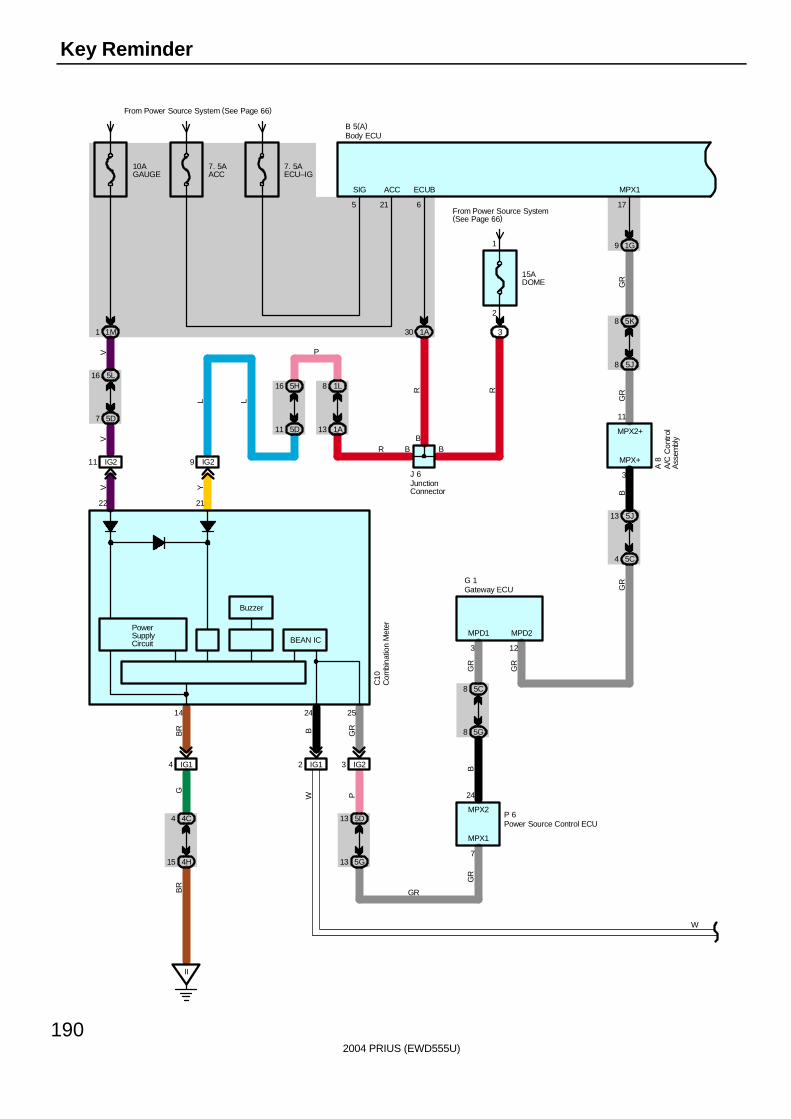
2004 PRIUS (EWD555U)
190
Key Reminder
9 1G
5J8
5K8
5C4
5J13
5G8
5C8
17
A 8
7
3 12
3
P 6
24
11
MPX1
MPD2
G 1
MPD1
MPX1
MPX+
GR
GR
MPX2
B
MPX2+
GR
GR
BG
R
GR
5
B 5(A)
SIG
PowerSupplyCircuit
14 2524
2122
10AGAUGE
From Power Source System (See Page 66)
1M1
16 5L
5D7
IG211
II
IG14
4C4
4H15
IG29
IG12 3 IG2
5D13
5G13
YVV
V
B GR
BR
GB
R
PW
BEAN IC
15ADOME
From Power Source System(See Page 66)
3
2
1
7. 5AECU–IG
1A30
6
ECUB
B
1L85H16
1A135D11
P
LL
R R
R B B
J 6
W
Buzzer
7. 5AACC
21
ACC
C10
GR
A/C
Con
trol
Ass
embl
y
Body ECU
Com
bina
tion
Met
er
Gateway ECU
JunctionConnector
Power Source Control ECU
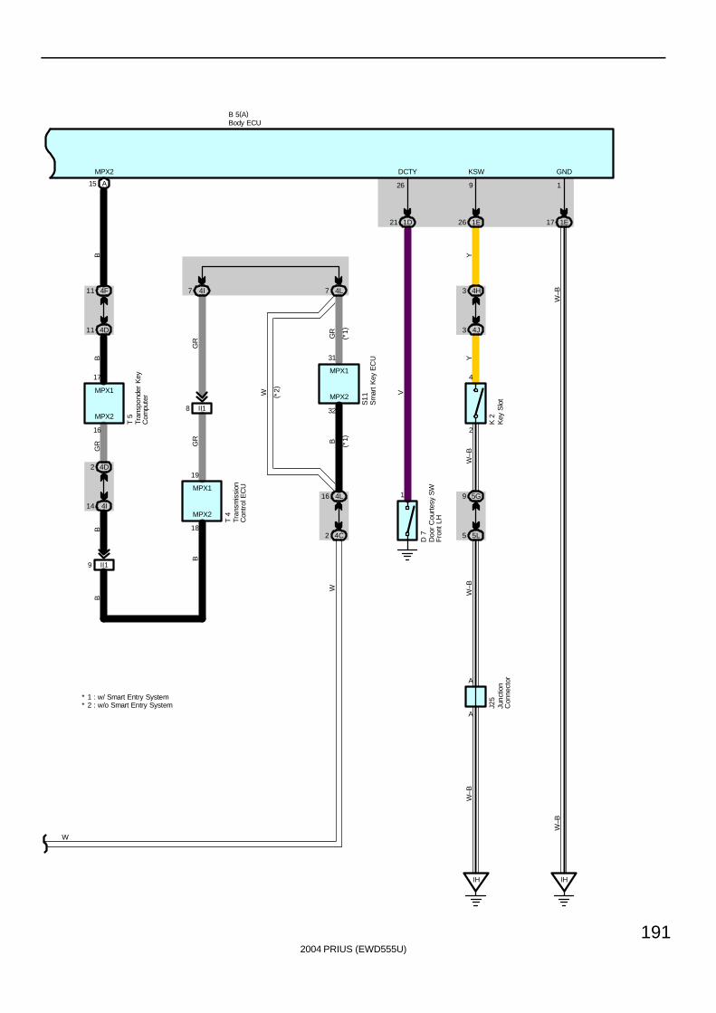
2004 PRIUS (EWD555U)
191
B 5(A)
A15
4D11
4F11
4I14
4D2
II19
T 5
16
17
MPX2
MPX2
BB
GR
BB
MPX1
II18 32
18
4L7
4L16
4C2
(*1)
7 4I
31
19
MPX2
MPX2
T 4
GR
W
GR
GR
B
W
( *2)
B ( *1)
MPX1
MPX1
W
1E17
GND
IH
1
W–B
W–B
21 1D
26
DCTY
V
1
D 7
KSW
9
1E26
4J3
4H3
5L5
5G9K
2
2
4
YY
W–B
IH
A
A
W–B
W–B
J25* 1 : w/ Smart Entry System
* 2 : w/o Smart Entry System
S11
Body ECU
Doo
r C
ourt
esy
SW
Fro
nt L
H
Junc
tion
Con
nect
or
Tran
spon
der
Key
Com
pute
r
Tran
smis
sion
Con
trol
EC
U
Sm
art
Key
EC
U
Key
Slo
t
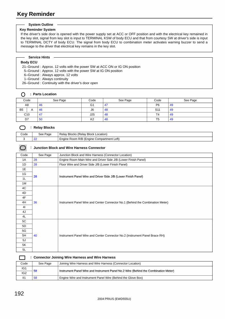
2004 PRIUS (EWD555U)
192
Key Reminder
Key Reminder SystemIf the driver’s side door is opened with the power supply set at ACC or OFF position and with the electrical key remained inthe key slot, signal from key slot is input to TERMINAL KSW of body ECU and that from courtesy SW at driver’s side is inputto TERMINAL DCTY of body ECU. The signal from body ECU to combination meter activates warning buzzer to send amessage to the driver that electrical key remains in the key slot.
Body ECU21–Ground : Approx. 12 volts with the power SW at ACC ON or IG ON position
5–Ground : Approx. 12 volts with the power SW at IG ON position6–Ground : Always approx. 12 volts1–Ground : Always continuity
26–Ground : Continuity with the driver’s door open
: Parts Location
Code See Page Code See Page Code See Page
A8 46 G1 47 P6 49
B5 A 46 J6 48 S11 49
C10 47 J25 48 T4 49
D7 50 K2 48 T5 49
: Relay Blocks
Code See Page Relay Blocks (Relay Block Location)
3 22 Engine Room R/B (Engine Compartment Left)
: Junction Block and Wire Harness Connector
Code See Page Junction Block and Wire Harness (Connector Location)
1A 28 Engine Room Main Wire and Driver Side J/B (Lower Finish Panel)
1D 28 Floor Wire and Driver Side J/B (Lower Finish Panel)
1E
1G28 Instrument Panel Wire and Driver Side J/B (Lower Finish Panel)
1L28 Instrument Panel Wire and Driver Side J/B (Lower Finish Panel)
1M
4C
4D
4F
4H 36 Instrument Panel Wire and Center Connector No.1 (Behind the Combination Meter)
4I
( )
4J
4L
5C
5D
5G
5H 40 Instrument Panel Wire and Center Connector No.2 (Instrument Panel Brace RH)
5J
( )
5K
5L
: Connector Joining Wire Harness and Wire Harness
Code See Page Joining Wire Harness and Wire Harness (Connector Location)
IG158 Instrument Panel Wire and Instrument Panel No 2 Wire (Behind the Combination Meter)
IG258 Instrument Panel Wire and Instrument Panel No.2 Wire (Behind the Combination Meter)
II1 58 Engine Wire and Instrument Panel Wire (Behind the Glove Box)
System Outline
Service Hints
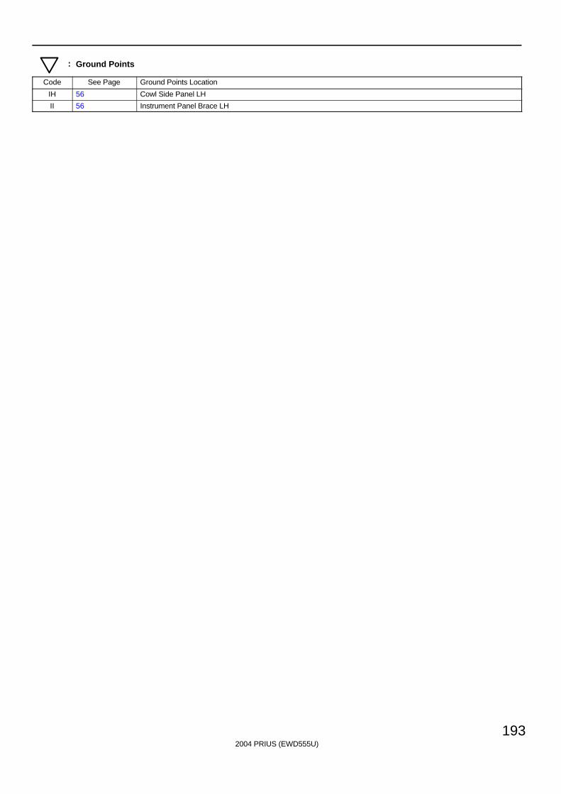
2004 PRIUS (EWD555U)
193
: Ground Points
Code See Page Ground Points Location
IH 56 Cowl Side Panel LH
II 56 Instrument Panel Brace LH
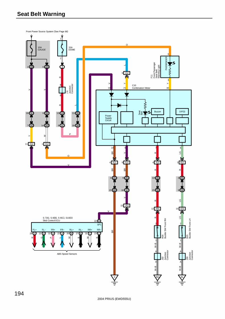
2004 PRIUS (EWD555U)
194
Seat Belt Warning
II
3
7
6
30
A
A
6
1
2
A
A
1
2
22
14
21
Sea
tB
elt
PowerSupplyCircuit
10AGAUGE
From Power Source System (See Page 66)
1M1
15ADOME
31G6
B
B
RR
5K6
5D14
IG21
VW
5L16
5D7
IG211
VY
1A13
1L8
5D11
5H16
IG29
L
BQ BL
J 6
P
O
V
F11
B15
B16
J30
J32
4C4
4H15
BR
4C3
4K9
ID315
LG5D10
5N15
IM112
R
RRBR
R LG
IG14 IG24 IG13
LGRBR
C10
YYV
L
W–B
W–B
W–B
W–B
Buzzer (VFD)
9 IG1
9
BR
V
4C9
4I16
IA315
V
O
PA
SS
EN
GE
R
D28 D22 A32 A22 B35 B27 C31 C23
FL+ FL– FR+ FR– RL+ RL– RR+ RR–
R G P L W B W B
ABS Speed Sensors
S 7(A), S 8(B), S 9(C), S10(D)B22
SP1
V
Skid Control ECU
Buc
kle
SW
Fro
nt L
H
Buc
kle
SW
Fro
nt R
H
Combination Meter
Fro
nt P
asse
nger
Sea
t Bel
tW
arni
ng L
ight
Junc
tion
Con
nect
or
Junc
tion
Con
nect
or
Junc
tion
Con
nect
or
1
2
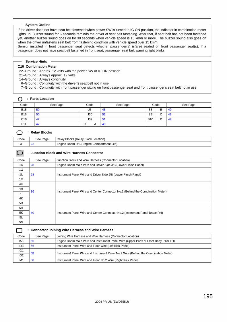
2004 PRIUS (EWD555U)
195
If the driver does not have seat belt fastened when power SW is turned to IG ON position, the indicator in combination meterlights up. Buzzer sound for 6 seconds reminds the driver of seat belt fastening. After that, if seat belt has not been fastenedyet, another buzzer sound goes on for 30 seconds when vehicle speed is 15 km/h or more. The buzzer sound also goes onwhen the driver unfastens seat belt from fastening condition with vehicle speed over 15 km/h.Sensor installed in front passenger seat detects whether passenger(s) is(are) seated on front passenger seat(s). If apassenger does not have seat belt fastened in front seat, passenger seat belt warning light blinks.
C10 Combination Meter22–Ground : Approx. 12 volts with the power SW at IG ON position21–Ground : Always approx. 12 volts14–Ground : Always continuity
6–Ground : Continuity with the driver’s seat belt not in use7–Ground : Continuity with front passenger sitting on front passenger seat and front passenger’s seat belt not in use
: Parts Location
Code See Page Code See Page Code See Page
B15 50 J6 48 S8 B 49
B16 50 J30 51 S9 C 49
C10 47 J32 51 S10 D 49
F11 47 S7 A 49
: Relay Blocks
Code See Page Relay Blocks (Relay Block Location)
3 22 Engine Room R/B (Engine Compartment Left)
: Junction Block and Wire Harness Connector
Code See Page Junction Block and Wire Harness (Connector Location)
1A 28 Engine Room Main Wire and Driver Side J/B (Lower Finish Panel)
1G
1L 28 Instrument Panel Wire and Driver Side J/B (Lower Finish Panel)
1M
( )
4C
4H36 Instrument Panel Wire and Center Connector No 1 (Behind the Combination Meter)
4I36 Instrument Panel Wire and Center Connector No.1 (Behind the Combination Meter)
4K
5D
5H
5K 40 Instrument Panel Wire and Center Connector No.2 (Instrument Panel Brace RH)
5L
( )
5N
: Connector Joining Wire Harness and Wire Harness
Code See Page Joining Wire Harness and Wire Harness (Connector Location)
IA3 56 Engine Room Main Wire and Instrument Panel Wire (Upper Parts of Front Body Pillar LH)
ID3 56 Instrument Panel Wire and Floor Wire (Left Kick Panel)
IG158 Instrument Panel Wire and Instrument Panel No 2 Wire (Behind the Combination Meter)
IG258 Instrument Panel Wire and Instrument Panel No.2 Wire (Behind the Combination Meter)
IM1 58 Instrument Panel Wire and Floor No.2 Wire (Right Kick Panel)
System Outline
Service Hints
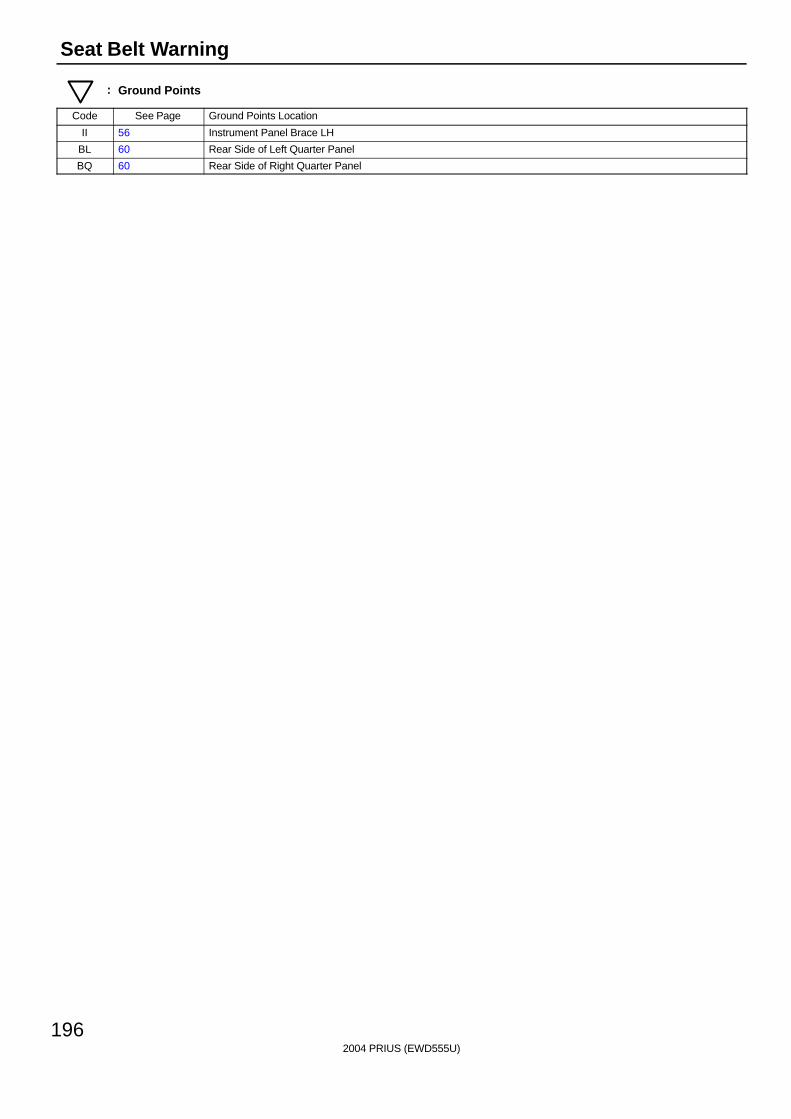
2004 PRIUS (EWD555U)
196
Seat Belt Warning
: Ground Points
Code See Page Ground Points Location
II 56 Instrument Panel Brace LH
BL 60 Rear Side of Left Quarter Panel
BQ 60 Rear Side of Right Quarter Panel

2004 PRIUS (EWD555U)
197
Memo
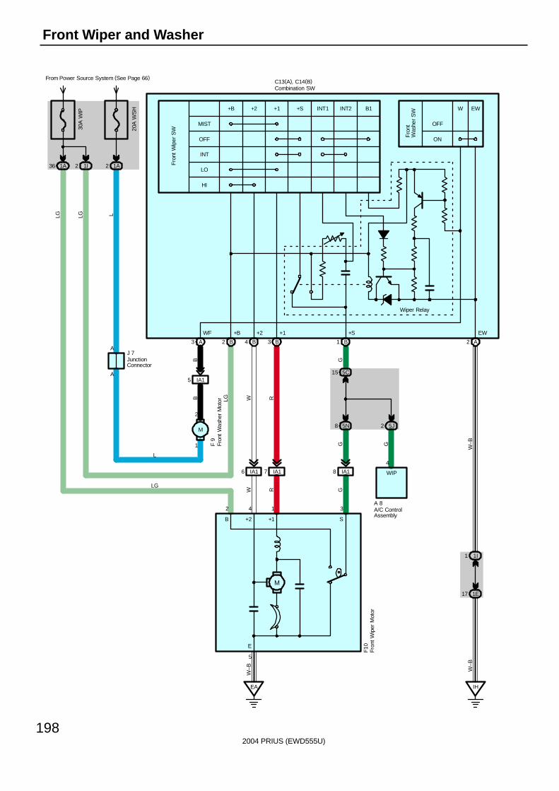
2004 PRIUS (EWD555U)
198
Front Wiper and Washer
OFF
MIST
HI
LO
INT
+B +2 +1 +S INT1 B1INT2
B +2 +1 S
M
E
Fro
nt W
iper
SW
5
2 4 1 3
W EW
OFF
ON
Fro
nt
Was
her
SW
20A
WS
H
1A2
From Power Source System (See Page 66)30
A W
IP
1I21A36
1I1
1E17
EA IH
W–B
W–B
W–BGG
IA18IA17IA16
GRW
RWLGBB G
5C15
5N8 5J2
4
WIP
A 8
A3 B2 B4 B3 B1 A2
IA15A
AJ 7
LG LG L
L
LG
F 9
F10
C13(A), C14(B)
Wiper Relay
EW+S+1+2+BWF
A/C ControlAssembly
Combination SW
Fron
t Wip
er M
otor
Fron
t W
ashe
r M
otor
JunctionConnector
M
2
1
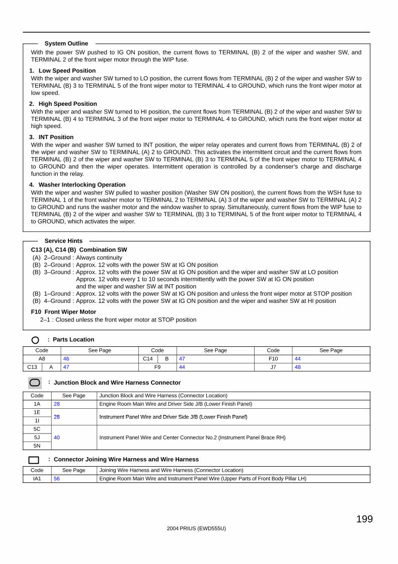
2004 PRIUS (EWD555U)
199
With the power SW pushed to IG ON position, the current flows to TERMINAL (B) 2 of the wiper and washer SW, andTERMINAL 2 of the front wiper motor through the WIP fuse.
1. Low Speed PositionWith the wiper and washer SW turned to LO position, the current flows from TERMINAL (B) 2 of the wiper and washer SW toTERMINAL (B) 3 to TERMINAL 5 of the front wiper motor to TERMINAL 4 to GROUND, which runs the front wiper motor atlow speed.
2. High Speed PositionWith the wiper and washer SW turned to HI position, the current flows from TERMINAL (B) 2 of the wiper and washer SW toTERMINAL (B) 4 to TERMINAL 3 of the front wiper motor to TERMINAL 4 to GROUND, which runs the front wiper motor athigh speed.
3. INT PositionWith the wiper and washer SW turned to INT position, the wiper relay operates and current flows from TERMINAL (B) 2 ofthe wiper and washer SW to TERMINAL (A) 2 to GROUND. This activates the intermittent circuit and the current flows fromTERMINAL (B) 2 of the wiper and washer SW to TERMINAL (B) 3 to TERMINAL 5 of the front wiper motor to TERMINAL 4to GROUND and then the wiper operates. Intermittent operation is controlled by a condenser’s charge and dischargefunction in the relay.
4. Washer Interlocking OperationWith the wiper and washer SW pulled to washer position (Washer SW ON position), the current flows from the WSH fuse toTERMINAL 1 of the front washer motor to TERMINAL 2 to TERMINAL (A) 3 of the wiper and washer SW to TERMINAL (A) 2to GROUND and runs the washer motor and the window washer to spray. Simultaneously, current flows from the WIP fuse toTERMINAL (B) 2 of the wiper and washer SW to TERMINAL (B) 3 to TERMINAL 5 of the front wiper motor to TERMINAL 4to GROUND, which activates the wiper.
C13 (A), C14 (B) Combination SW(A) 2–Ground : Always continuity(B) 2–Ground : Approx. 12 volts with the power SW at IG ON position(B) 3–Ground : Approx. 12 volts with the power SW at IG ON position and the wiper and washer SW at LO position
Approx. 12 volts every 1 to 10 seconds intermittently with the power SW at IG ON positionand the wiper and washer SW at INT position
(B) 1–Ground : Approx. 12 volts with the power SW at IG ON position and unless the front wiper motor at STOP position(B) 4–Ground : Approx. 12 volts with the power SW at IG ON position and the wiper and washer SW at HI position
F10 Front Wiper Motor2–1 : Closed unless the front wiper motor at STOP position
: Parts Location
Code See Page Code See Page Code See Page
A8 46 C14 B 47 F10 44
C13 A 47 F9 44 J7 48
: Junction Block and Wire Harness Connector
Code See Page Junction Block and Wire Harness (Connector Location)
1A 28 Engine Room Main Wire and Driver Side J/B (Lower Finish Panel)
1E28 Instrument Panel Wire and Driver Side J/B (Lower Finish Panel)
1I28 Instrument Panel Wire and Driver Side J/B (Lower Finish Panel)
5C
5J 40 Instrument Panel Wire and Center Connector No.2 (Instrument Panel Brace RH)
5N
( )
: Connector Joining Wire Harness and Wire Harness
Code See Page Joining Wire Harness and Wire Harness (Connector Location)
IA1 56 Engine Room Main Wire and Instrument Panel Wire (Upper Parts of Front Body Pillar LH)
System Outline
Service Hints
2004 PRIUS (EWD555U)
200
Front Wiper and Washer
: Ground Points
Code See Page Ground Points Location
EA 54 Right Side of the Fender Apron
IH 56 Cowl Side Panel LH

2004 PRIUS (EWD555U)
201
Memo
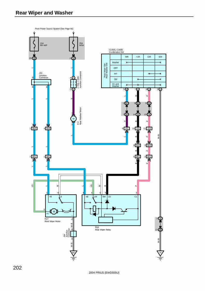
2004 PRIUS (EWD555U)
202
Rear Wiper and Washer
Rea
r W
iper
SW
OFF
Washer
On andWasher
ON
INT
WR +1R CIR EW
1
2
B
B
A
15ARR WIP
1D25
20AWSH
From Power Source System (See Page 66)
1A2
BH31 BH34
BK27 BK21
LL L
L L
AA
BC
J 7(
A) ,
J 8
( B)
J31L
VL
L
B5 A7 A6 A2
1I1
1E17
5C
14 5I
31
5H7
5C
BH33 BH32
IA28 ID310 ID311
BK22BK25
L B P
W–B
PBV
B P
B PPB
W–B
BO
J34
C13(A), C14(B)
R 2
IH
5C
15 5I
2
W–B
B
L L
Rea
r W
ashe
r S
W
M
+B
+1–
S
3
1 4
2R17
R18
3 4 5 6 2
W–B
PBWLGLWLLG
A
+B LM SM LS C1
Combination SW
Junc
tion
Con
nect
or
JunctionConnector
Junc
tion
Con
nect
or
Rea
r W
ashe
r M
otor
Rear Wiper Relay
Rear Wiper Motor
M
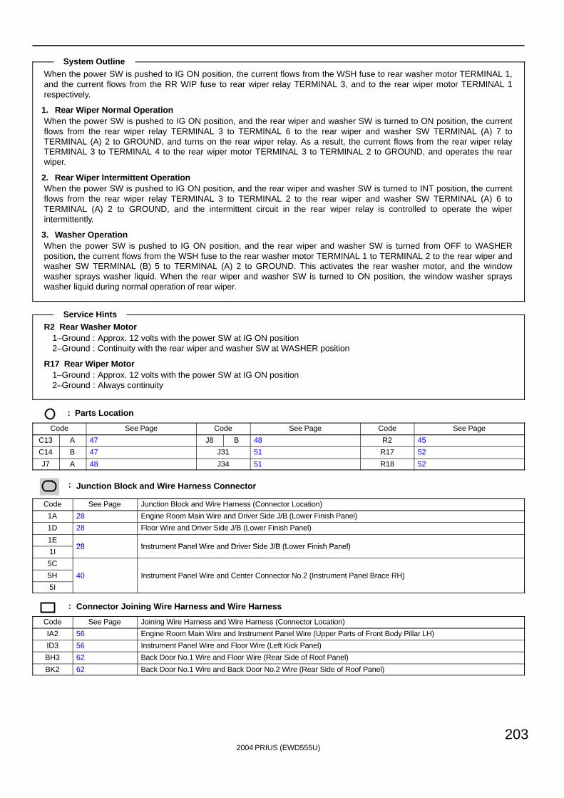
2004 PRIUS (EWD555U)
203
When the power SW is pushed to IG ON position, the current flows from the WSH fuse to rear washer motor TERMINAL 1,and the current flows from the RR WIP fuse to rear wiper relay TERMINAL 3, and to the rear wiper motor TERMINAL 1respectively.
1. Rear Wiper Normal OperationWhen the power SW is pushed to IG ON position, and the rear wiper and washer SW is turned to ON position, the currentflows from the rear wiper relay TERMINAL 3 to TERMINAL 6 to the rear wiper and washer SW TERMINAL (A) 7 toTERMINAL (A) 2 to GROUND, and turns on the rear wiper relay. As a result, the current flows from the rear wiper relayTERMINAL 3 to TERMINAL 4 to the rear wiper motor TERMINAL 3 to TERMINAL 2 to GROUND, and operates the rearwiper.
2. Rear Wiper Intermittent OperationWhen the power SW is pushed to IG ON position, and the rear wiper and washer SW is turned to INT position, the currentflows from the rear wiper relay TERMINAL 3 to TERMINAL 2 to the rear wiper and washer SW TERMINAL (A) 6 toTERMINAL (A) 2 to GROUND, and the intermittent circuit in the rear wiper relay is controlled to operate the wiperintermittently.
3. Washer OperationWhen the power SW is pushed to IG ON position, and the rear wiper and washer SW is turned from OFF to WASHERposition, the current flows from the WSH fuse to the rear washer motor TERMINAL 1 to TERMINAL 2 to the rear wiper andwasher SW TERMINAL (B) 5 to TERMINAL (A) 2 to GROUND. This activates the rear washer motor, and the windowwasher sprays washer liquid. When the rear wiper and washer SW is turned to ON position, the window washer sprayswasher liquid during normal operation of rear wiper.
R2 Rear Washer Motor1–Ground : Approx. 12 volts with the power SW at IG ON position2–Ground : Continuity with the rear wiper and washer SW at WASHER position
R17 Rear Wiper Motor1–Ground : Approx. 12 volts with the power SW at IG ON position2–Ground : Always continuity
: Parts Location
Code See Page Code See Page Code See Page
C13 A 47 J8 B 48 R2 45
C14 B 47 J31 51 R17 52
J7 A 48 J34 51 R18 52
: Junction Block and Wire Harness Connector
Code See Page Junction Block and Wire Harness (Connector Location)
1A 28 Engine Room Main Wire and Driver Side J/B (Lower Finish Panel)
1D 28 Floor Wire and Driver Side J/B (Lower Finish Panel)
1E28 Instrument Panel Wire and Driver Side J/B (Lower Finish Panel)
1I28 Instrument Panel Wire and Driver Side J/B (Lower Finish Panel)
5C
5H 40 Instrument Panel Wire and Center Connector No.2 (Instrument Panel Brace RH)
5I
( )
: Connector Joining Wire Harness and Wire Harness
Code See Page Joining Wire Harness and Wire Harness (Connector Location)
IA2 56 Engine Room Main Wire and Instrument Panel Wire (Upper Parts of Front Body Pillar LH)
ID3 56 Instrument Panel Wire and Floor Wire (Left Kick Panel)
BH3 62 Back Door No.1 Wire and Floor Wire (Rear Side of Roof Panel)
BK2 62 Back Door No.1 Wire and Back Door No.2 Wire (Rear Side of Roof Panel)
System Outline
Service Hints
2004 PRIUS (EWD555U)
204
Rear Wiper and Washer
: Ground Points
Code See Page Ground Points Location
IH 56 Cowl Side Panel LH
BO 60 Center of the Back Door Panel

2004 PRIUS (EWD555U)
205
Memo
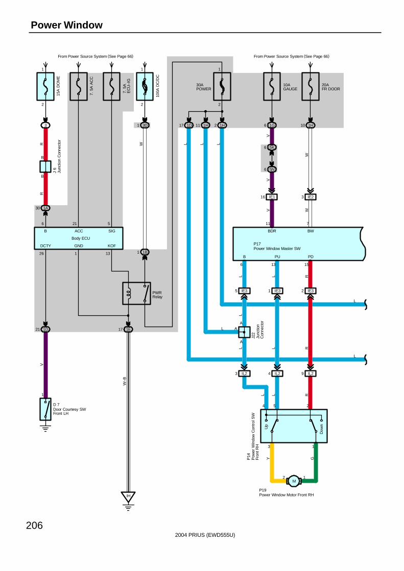
2004 PRIUS (EWD555U)
206
Power Window
A
A
B
6
PU PD
1513
12
254
13
Dow
n
Up
10AGAUGE
From Power Source System (See Page 66)
1G6
20AFR DOOR
1H10
5K6
5N6
IE116
VV
11
BDR
V
IE23
W
BW
7
W
IL29IL24IL23
IE32IE31IE35
30APOWER
1H2
2
1
1H111D17
LLL
P17
P19
P14
J22
GY
RLL
RLLL L R
L
L
AL
IH
1E17
2
1
3D1
1B1
From Power Source System (See Page 66)
W
13
KOF
Body ECU
W–B
PWRRelay
L
3
2
1
100A
DC
/DC
7. 5
AE
CU
–IG
7. 5
A A
CC
15A
DO
ME
1A30
B
B
5216
RR
J 6
SIGACCB
1D21
1
GNDDCTY
26
1
V
D 7Door Courtesy SWFront LH
Junc
tion
Con
nect
or
Junc
tion
Con
nect
or
Pow
er W
indo
w C
ontro
l SW
Fron
t RH
Power Window Master SW
Power Window Motor Front RH
M
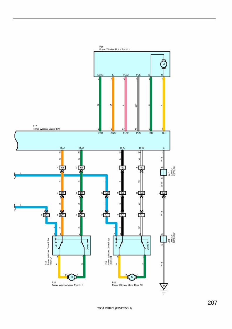
2004 PRIUS (EWD555U)
207
Up
Dow
n
3 1
4 5 2
2 1
12 10
RLDRLU
Up
Dow
n
3 1
4 5 2
2 1
18 16
RRDRRU
BJ11BJ17BJ12BB11BB17BB12
IE26IE27IE33IE34
ID47 ID46 IM26 IM29 IM28
1
A
A
A
A
E
IH
W–B
W–B
W–B
W–BWB
B WWB
BL WGY
IE25
P17
P18
P21P20
P16
P15
GY
GOL
O GGO L
O G
J27
J24
L
L
3
VCC
2
GND
17
PLS2
14
PLS
9
DD
4
DU
M
6
E
3
PLS2
5
PLS
1 24
SSRB D U
G O P GR G Y
L
Junc
tion
Con
nect
orJu
nctio
nC
onne
ctor
Pow
er W
indo
w C
ontro
l SW
Rea
r LH
Pow
er W
indo
w C
ontro
l SW
Rea
r R
H
Power Window Master SW
Power Window Motor Front LH
Power Window Motor Rear LH Power Window Motor Rear RH
M M
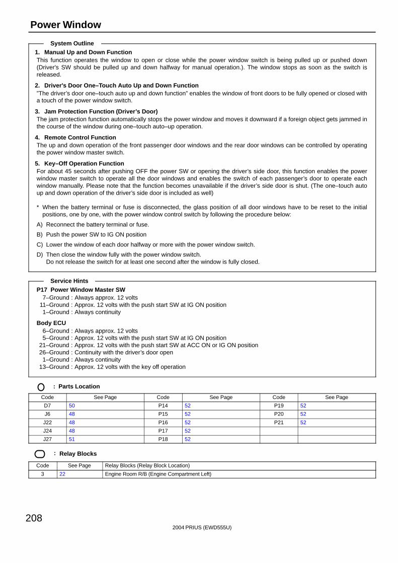
2004 PRIUS (EWD555U)
208
Power Window
1. Manual Up and Down FunctionThis function operates the window to open or close while the power window switch is being pulled up or pushed down(Driver’s SW should be pulled up and down halfway for manual operation.). The window stops as soon as the switch isreleased.
2. Driver’s Door One–Touch Auto Up and Down Function”The driver’s door one–touch auto up and down function” enables the window of front doors to be fully opened or closed witha touch of the power window switch.
3. Jam Protection Function (Driver’s Door)The jam protection function automatically stops the power window and moves it downward if a foreign object gets jammed inthe course of the window during one–touch auto–up operation.
4. Remote Control FunctionThe up and down operation of the front passenger door windows and the rear door windows can be controlled by operatingthe power window master switch.
5. Key–Off Operation FunctionFor about 45 seconds after pushing OFF the power SW or opening the driver’s side door, this function enables the powerwindow master switch to operate all the door windows and enables the switch of each passenger’s door to operate eachwindow manually. Please note that the function becomes unavailable if the driver’s side door is shut. (The one–touch autoup and down operation of the driver’s side door is included as well)
∗ When the battery terminal or fuse is disconnected, the glass position of all door windows have to be reset to the initialpositions, one by one, with the power window control switch by following the procedure below:
A) Reconnect the battery terminal or fuse.
B) Push the power SW to IG ON position
C) Lower the window of each door halfway or more with the power window switch.
D) Then close the window fully with the power window switch.Do not release the switch for at least one second after the window is fully closed.
P17 Power Window Master SW7–Ground : Always approx. 12 volts
11–Ground : Approx. 12 volts with the push start SW at IG ON position1–Ground : Always continuity
Body ECU6–Ground : Always approx. 12 volts5–Ground : Approx. 12 volts with the push start SW at IG ON position
21–Ground : Approx. 12 volts with the push start SW at ACC ON or IG ON position26–Ground : Continuity with the driver’s door open
1–Ground : Always continuity13–Ground : Approx. 12 volts with the key off operation
: Parts Location
Code See Page Code See Page Code See Page
D7 50 P14 52 P19 52
J6 48 P15 52 P20 52
J22 48 P16 52 P21 52
J24 48 P17 52
J27 51 P18 52
: Relay Blocks
Code See Page Relay Blocks (Relay Block Location)
3 22 Engine Room R/B (Engine Compartment Left)
System Outline
Service Hints
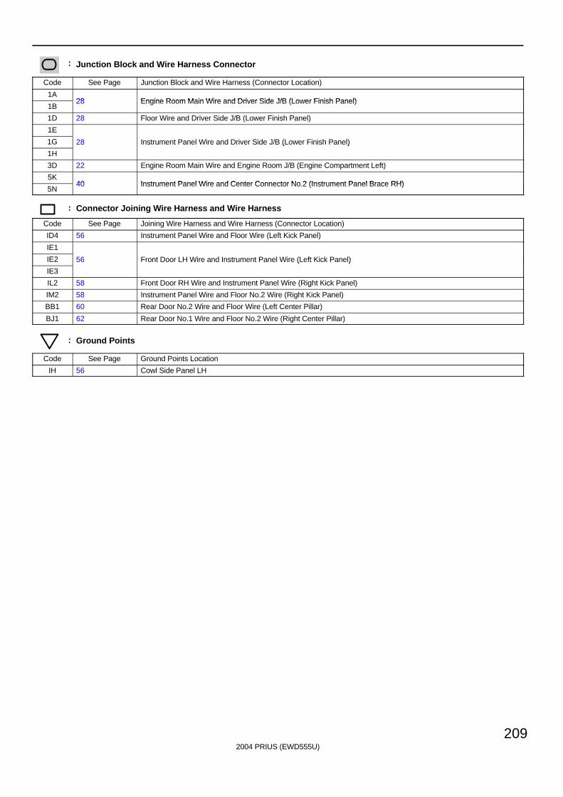
2004 PRIUS (EWD555U)
209
: Junction Block and Wire Harness Connector
Code See Page Junction Block and Wire Harness (Connector Location)
1A28 Engine Room Main Wire and Driver Side J/B (Lower Finish Panel)
1B28 Engine Room Main Wire and Driver Side J/B (Lower Finish Panel)
1D 28 Floor Wire and Driver Side J/B (Lower Finish Panel)
1E
1G 28 Instrument Panel Wire and Driver Side J/B (Lower Finish Panel)
1H
( )
3D 22 Engine Room Main Wire and Engine Room J/B (Engine Compartment Left)
5K40 Instrument Panel Wire and Center Connector No 2 (Instrument Panel Brace RH)
5N40 Instrument Panel Wire and Center Connector No.2 (Instrument Panel Brace RH)
: Connector Joining Wire Harness and Wire Harness
Code See Page Joining Wire Harness and Wire Harness (Connector Location)
ID4 56 Instrument Panel Wire and Floor Wire (Left Kick Panel)
IE1
IE2 56 Front Door LH Wire and Instrument Panel Wire (Left Kick Panel)
IE3
( )
IL2 58 Front Door RH Wire and Instrument Panel Wire (Right Kick Panel)
IM2 58 Instrument Panel Wire and Floor No.2 Wire (Right Kick Panel)
BB1 60 Rear Door No.2 Wire and Floor Wire (Left Center Pillar)
BJ1 62 Rear Door No.1 Wire and Floor No.2 Wire (Right Center Pillar)
: Ground Points
Code See Page Ground Points Location
IH 56 Cowl Side Panel LH
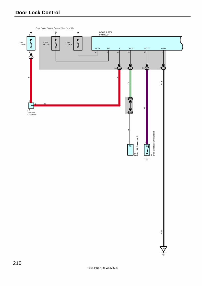
2004 PRIUS (EWD555U)
210
Door Lock Control
7. 5AECU–IG
From Power Source System (See Page 66)
1E17
GND
IH
1
W–B
5
B 5(A), B 7(C)
SIG
W–B
1D21
1
26
DCTY
V
D 7
25ADOOR
4
ALTB
15ADOME
3
2
1
B
1A30
B
6
B
J 6
RR
D 1
OBD2
7
1L3
18
5M8
5H11
LGW
SIL
R
Body ECU
Dat
a Li
nk C
onne
ctor
3
Doo
r C
ourt
esy
SW
Fro
nt L
H
JunctionConnector
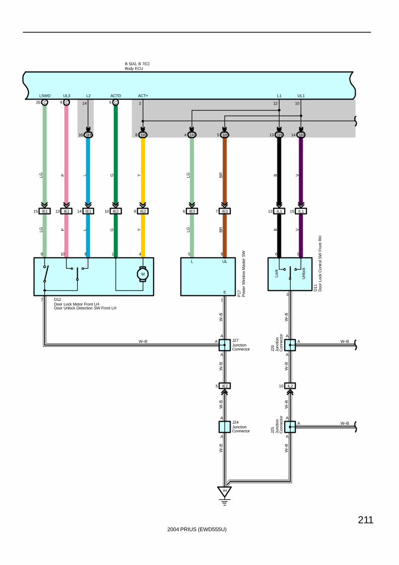
2004 PRIUS (EWD555U)
211
5 1H4 1H
IE376 IE3
M
IE115 13 IE1
1H16
14 IE1 IE210 9 IE2
8 1H
W–B
5 C9 CC25
W–B
W–B
Unl
ock
Lock
3
6 5
IL113 IL115
1H13 1H14
IH
IE25
A
A
IL210
A
A
LSWD UL3 L2 ACTD ACT+ L1 UL1
E
W–B
UL
W–B
W–B
W–B
W–B
LG P L G Y LG BR B V
VD12
BBR
LGLG P L G Y
B 5(A), B 7(C)
J24
P17
D11
J27
J26
W–B W–BAAA A
8 10 9 1 4 5
214
8
12
1
A
10
7
A
L
J25
W–BA
Body ECU
Doo
r Lo
ck C
ontr
ol S
W F
ront
RH
Door Lock Motor Front LHDoor Unlock Detection SW Front LH
JunctionConnector Ju
nctio
nC
onne
ctor
Junc
tion
Con
nect
or
JunctionConnector
Pow
er W
indo
w M
aste
r S
W
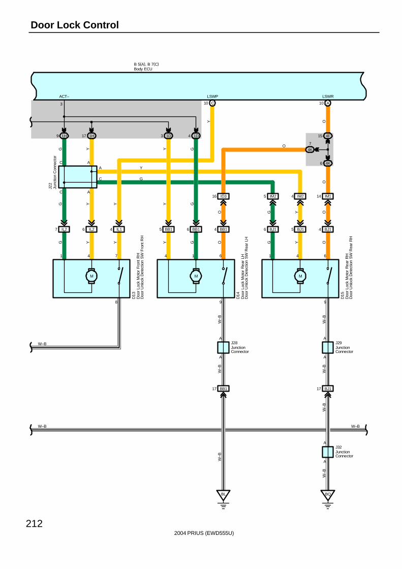
2004 PRIUS (EWD555U)
212
Door Lock Control
6 IL27 IL2 IL14
M
6 BB15 BB1 BB14
M
5 BJ16 BJ1 BJ14
M
IM25 IM24 IM114ID316
1H9 1H17 1D3 1D4
C10 A10
6 4K
4F15
4K
7
BL
BB117
BQ
BJ117
A
A
998
B 5(A), B 7(C)
A A
C A
3
641614741
AC
AA
A
C
LSWRLSWPACT–
W–BD
15
Y
G
O
G Y Y
G Y
D14
Y
G
J28
Y Y G
Y G
Y
D13
G O G
J29
Y OW
–B
W–B
J22
W–B
W–B
W–B
W–B
J32
W–B
OYGO
OOY
W–B W–B
Body ECU
Doo
r Lo
ck M
otor
Fro
nt R
HD
oor
Unl
ock
Det
ectio
n S
W F
ront
RH
Doo
r Lo
ck M
otor
Rea
r LH
Doo
r U
nloc
k D
etec
tion
SW
Rea
r LH
Doo
r Lo
ck M
otor
Rea
r R
HD
oor
Unl
ock
Det
ectio
n S
W R
ear
RH
Junc
tion
Con
nect
or
JunctionConnector
JunctionConnector
JunctionConnector
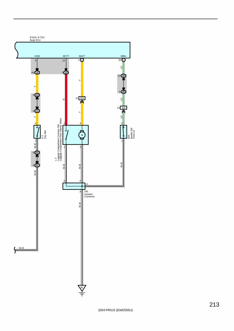
2004 PRIUS (EWD555U)
213
B 5(A), B 7(C)
BL
ID4
1 C
12
M
7 1D
A A
2 4
A
1 3
23
J30
BCTY BACT
Y
R
Y
L 3
W–B
W–B
W–B
1E26
4H3
4J3
9
4
KSW
YY
5L5
5G9
2
W–B
W–B
W–B
K 2
Body ECU
Lugg
age
Com
part
men
t C
ourt
esy
SW
Lugg
age
Com
part
men
t D
oor
Ope
ner
Mot
or
JunctionConnector
Key
Slo
t
4F13
4K9
2
DBKL
LGLG
1
W–B
B15
Buc
kle
SW
Fron
t LH
ID315
LG
A
26 C
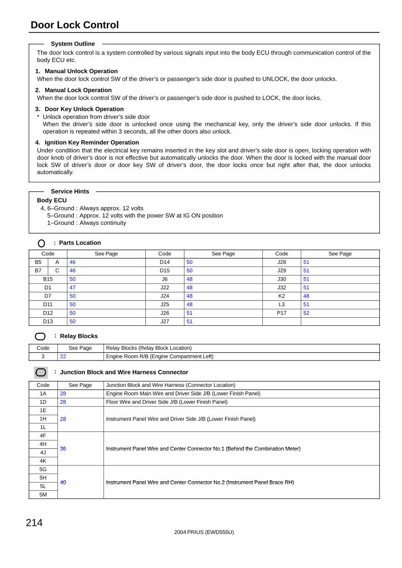
2004 PRIUS (EWD555U)
214
Door Lock Control
The door lock control is a system controlled by various signals input into the body ECU through communication control of thebody ECU etc.
1. Manual Unlock OperationWhen the door lock control SW of the driver’s or passenger’s side door is pushed to UNLOCK, the door unlocks.
2. Manual Lock OperationWhen the door lock control SW of the driver’s or passenger’s side door is pushed to LOCK, the door locks.
3. Door Key Unlock Operation∗ Unlock operation from driver’s side door
When the driver’s side door is unlocked once using the mechanical key, only the driver’s side door unlocks. If thisoperation is repeated within 3 seconds, all the other doors also unlock.
4. Ignition Key Reminder OperationUnder condition that the electrical key remains inserted in the key slot and driver’s side door is open, locking operation withdoor knob of driver’s door is not effective but automatically unlocks the door. When the door is locked with the manual doorlock SW of driver’s door or door key SW of driver’s door, the door locks once but right after that, the door unlocksautomatically.
Body ECU4, 6–Ground : Always approx. 12 volts
5–Ground : Approx. 12 volts with the power SW at IG ON position1–Ground : Always continuity
: Parts Location
Code See Page Code See Page Code See Page
B5 A 46 D14 50 J28 51
B7 C 46 D15 50 J29 51
B15 50 J6 48 J30 51
D1 47 J22 48 J32 51
D7 50 J24 48 K2 48
D11 50 J25 48 L3 51
D12 50 J26 51 P17 52
D13 50 J27 51
: Relay Blocks
Code See Page Relay Blocks (Relay Block Location)
3 22 Engine Room R/B (Engine Compartment Left)
: Junction Block and Wire Harness Connector
Code See Page Junction Block and Wire Harness (Connector Location)
1A 28 Engine Room Main Wire and Driver Side J/B (Lower Finish Panel)
1D 28 Floor Wire and Driver Side J/B (Lower Finish Panel)
1E
1H 28 Instrument Panel Wire and Driver Side J/B (Lower Finish Panel)
1L
( )
4F
4H36 Instrument Panel Wire and Center Connector No 1 (Behind the Combination Meter)
4J36 Instrument Panel Wire and Center Connector No.1 (Behind the Combination Meter)
4K
5G
5H40 Instrument Panel Wire and Center Connector No 2 (Instrument Panel Brace RH)
5L40 Instrument Panel Wire and Center Connector No.2 (Instrument Panel Brace RH)
5M
System Outline
Service Hints
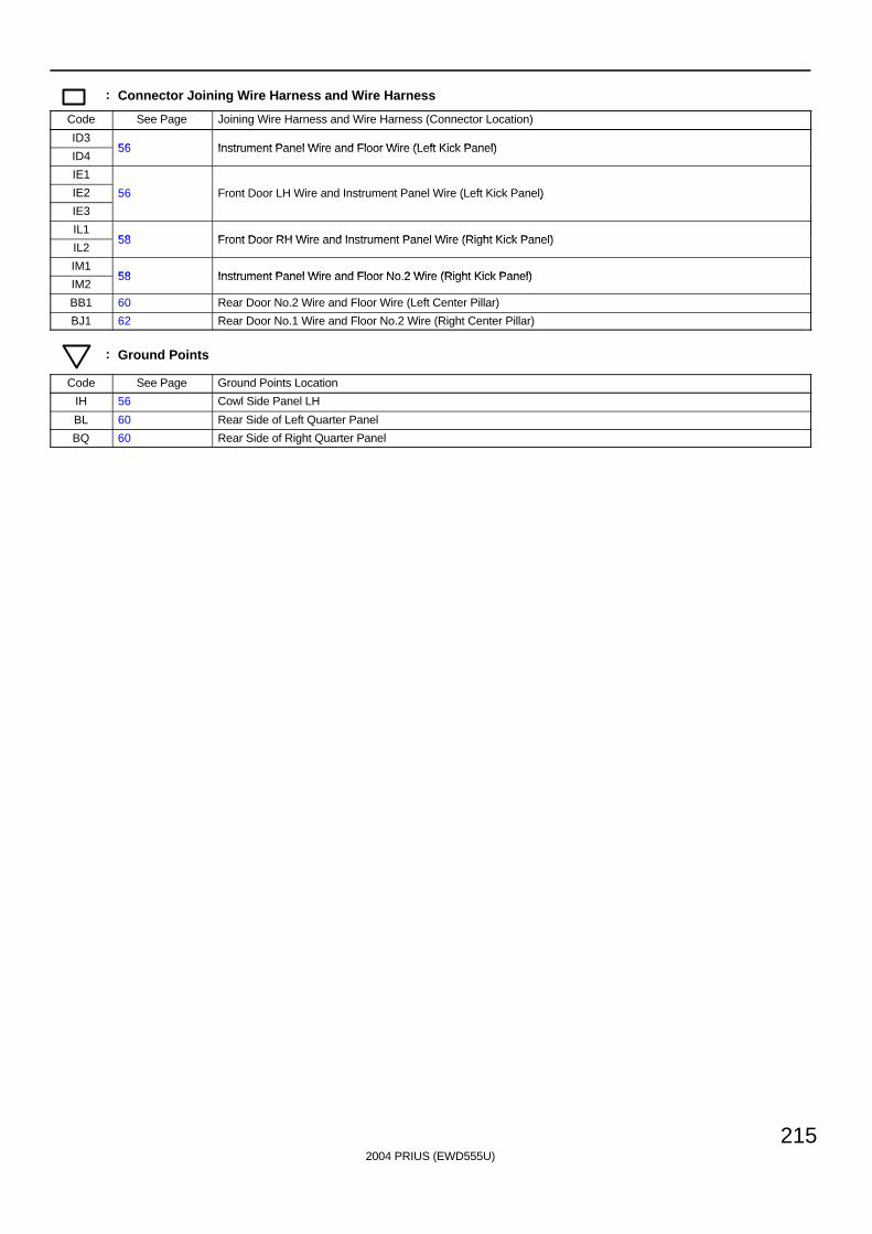
2004 PRIUS (EWD555U)
215
: Connector Joining Wire Harness and Wire Harness
Code See Page Joining Wire Harness and Wire Harness (Connector Location)
ID356 Instrument Panel Wire and Floor Wire (Left Kick Panel)
ID456 Instrument Panel Wire and Floor Wire (Left Kick Panel)
IE1
IE2 56 Front Door LH Wire and Instrument Panel Wire (Left Kick Panel)
IE3
( )
IL158 Front Door RH Wire and Instrument Panel Wire (Right Kick Panel)
IL258 Front Door RH Wire and Instrument Panel Wire (Right Kick Panel)
IM158 Instrument Panel Wire and Floor No 2 Wire (Right Kick Panel)
IM258 Instrument Panel Wire and Floor No.2 Wire (Right Kick Panel)
BB1 60 Rear Door No.2 Wire and Floor Wire (Left Center Pillar)
BJ1 62 Rear Door No.1 Wire and Floor No.2 Wire (Right Center Pillar)
: Ground Points
Code See Page Ground Points Location
IH 56 Cowl Side Panel LH
BL 60 Rear Side of Left Quarter Panel
BQ 60 Rear Side of Right Quarter Panel
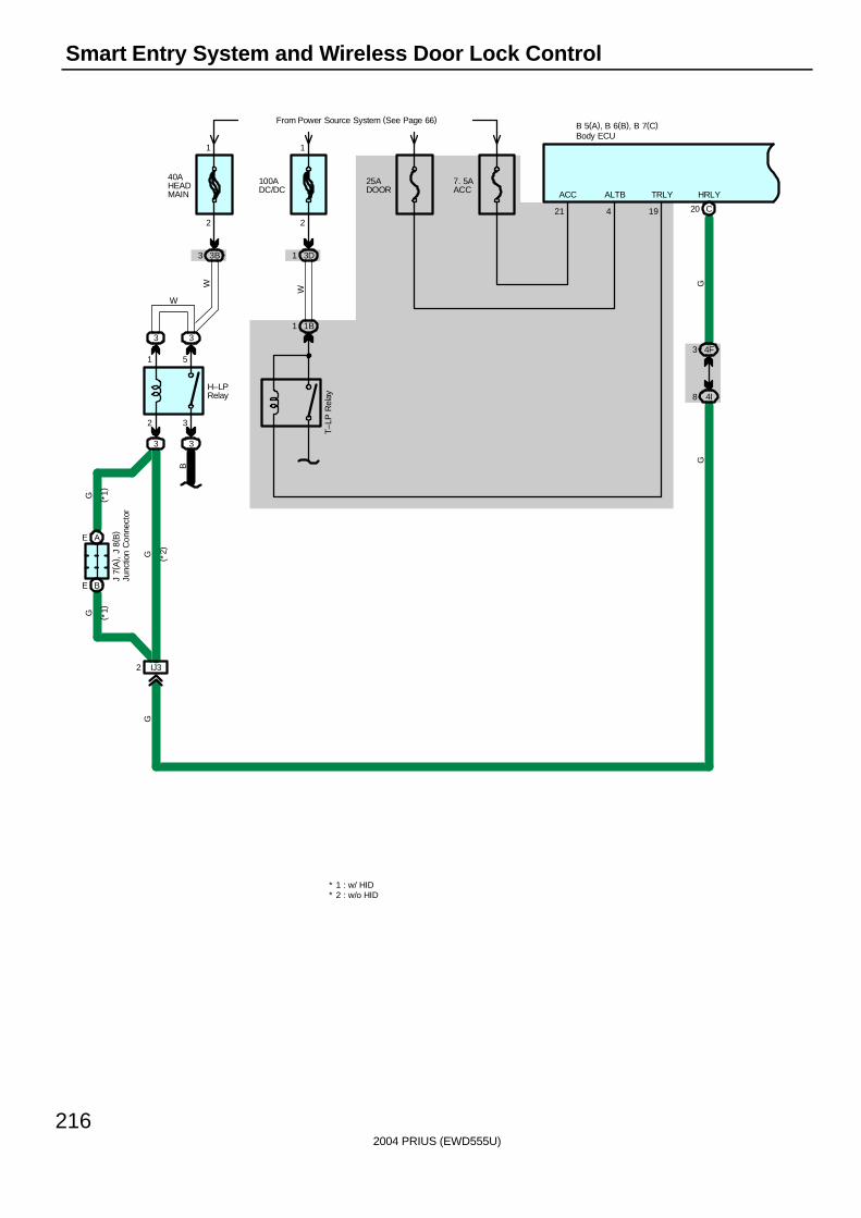
2004 PRIUS (EWD555U)
216
Smart Entry System and Wireless Door Lock Control
G
C20
4F3
4I8
HRLY
4
B 5(A), B 6(B), B 7(C)
G
ALTB
19
TRLY
40AHEADMAIN
From Power Source System (See Page 66)
3B3
2
1
2 3
1 5
3 3
3
IJ32
BE
AE
W
G
G
G
W
H–LPRelay
( *1)
( *1)
( *2)
J 7(
A) ,
J 8
( B)
3
B
1 1BT–
LP R
elay
25ADOOR
100ADC/DC
3D1
W
1
2
7. 5AACC
21
ACC
* 2 : w/o HID* 1 : w/ HID
GBody ECU
Junc
tion
Con
nect
or

2004 PRIUS (EWD555U)
217
B 5(A), B 6(B), B 7(C)
1E17
W–B
1 1O
GND
IH
1
W–B
W–B
W–B
W
From Power Source System(See Page 66)
1L7
5H15
5L8
O
5
SIG
7. 5AECU–IG
5L7
5I6
B
B
D 1
Y
1
3 IA1
Y
1 B
OBD2 SEC
7
1L3
18
5M8
5H11
T 1
LGW
SIL
1D21 1D24 1D5 1D20
1 1 1 1
IM13 IM14
ID25 ID24
222026
RCTYPCTYDCTY
RR
R
RBR
BR
BR
V
D 7
D 8
D 9
D10
Body ECU
Dat
a Li
nk C
onne
ctor
3
Doo
r C
ourt
esy
SW
Fro
nt L
H
Doo
r C
ourt
esy
SW
Fro
nt R
H
Doo
r C
ourt
esy
SW
Rea
r LH
Doo
r C
ourt
esy
SW
Rea
r R
H
The
ft D
eter
rent
Hor
n
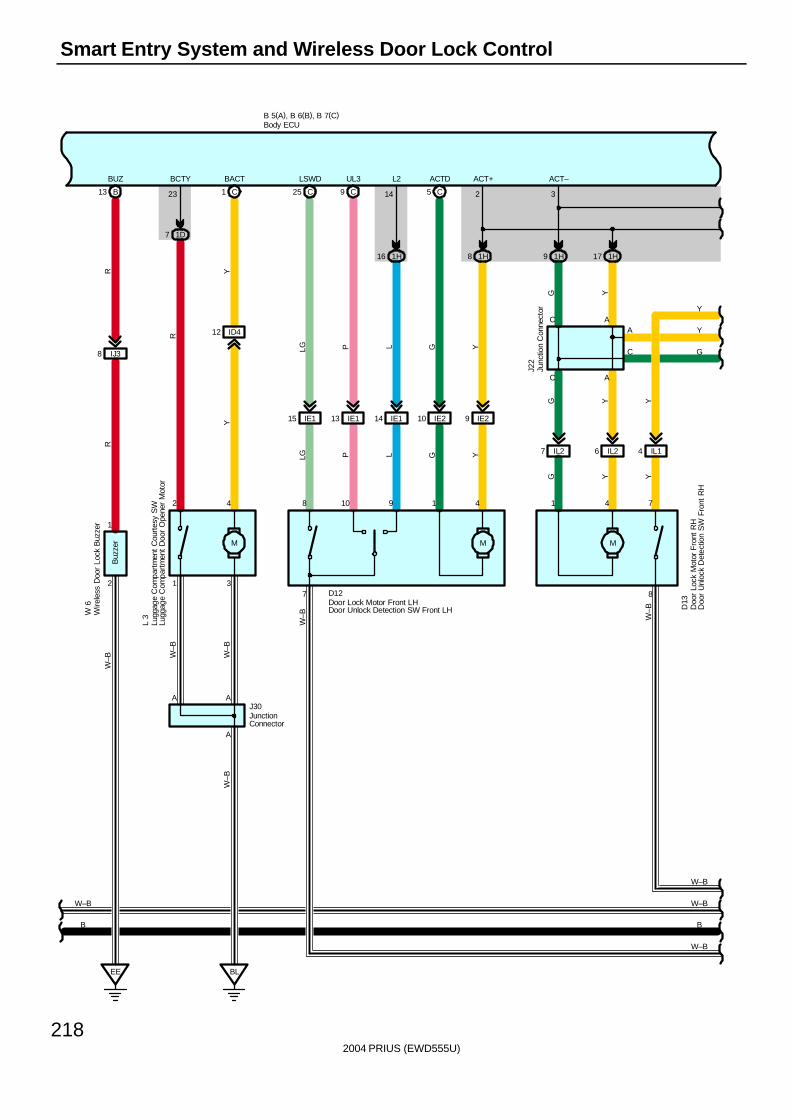
2004 PRIUS (EWD555U)
218
Smart Entry System and Wireless Door Lock Control
M
IE115 IE210 9 IE2
8 1H
5 CC25
B 5(A), B 6(B), B 7(C)
LSWD ACTD ACT+
W–B
LG G Y
LG G Y
B B
8 1 4
2
7
W–B
6 IL27 IL2 IL14
M
1H9 1H17
8
C A
3
741
ACA
C
ACT–
G Y Y
G Y Y
G Y
J22
W–B W–B
Y
G
Y
BL
ID4
1 C
12
M
7 1D
A A
2 4
A
1 3
23
J30
BCTY BACT
Y
R
Y
L 3
W–B
W–B
W–B
B13
EE
IJ38
1
2
BUZ
RR
W–B
W 6
IE113
C9
UL3
PP
10
IE114
LL
9
16 1H
L2
14
D12
D13
Buz
zer
W–B
W–B
Body ECU
Lugg
age
Com
part
men
t C
ourt
esy
SW
Lugg
age
Com
part
men
t D
oor
Ope
ner
Mot
or
Door Lock Motor Front LHDoor Unlock Detection SW Front LH D
oor
Lock
Mot
or F
ront
RH
Doo
r U
nloc
k D
etec
tion
SW
Fro
nt R
H
Junc
tion
Con
nect
or
JunctionConnector
Wire
less
Doo
r Lo
ck B
uzze
r
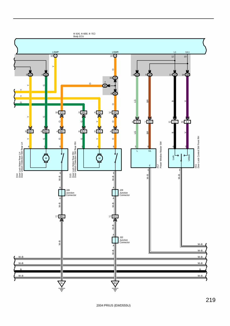
2004 PRIUS (EWD555U)
219
B 5(A), B 6(B), B 7(C)
6 BB15 BB1 BB14
M
5 BJ16 BJ1 BJ14
M
IM25 IM24 IM114ID316
1D3 1D4
C10 A10
6 4K
4F15
4K
7
BL
BB117
BQ
BJ117
A
A
99
A A
641614
AA
LSWRLSWP
B B
Y
G
O
J28
Y G
Y G
Y G O G
J29
Y OW
–B
W–B
W–B
W–B
W–B
W–B
J32
W–B
OYGO
OO
Y
W–B W–B
Y
D14
D15
5 1H4 1H
IE376 IE3
Unl
ock
Lock
3
6 5
IL113 IL115
1H13 1H14
L1 UL1
E
UL
W–B
W–B
LG BR B V
VBBR
LG
P17
D11
5 8
12
1
10
L
W–B
W–B
W–B
W–B
W–B
W–B
Body ECU
Doo
r Lo
ck C
ontr
ol S
W F
ront
RH
Doo
r Lo
ck M
otor
Rea
r LH
Doo
r U
nloc
k D
etec
tion
SW
Rea
r LH
Doo
r Lo
ck M
otor
Rea
r R
HD
oor
Unl
ock
Det
ectio
n S
W R
ear
RH
JunctionConnector
JunctionConnector
JunctionConnector
Pow
er W
indo
w M
aste
r S
W

2004 PRIUS (EWD555U)
220
Smart Entry System and Wireless Door Lock Control
B 5(A), B 6(B), B 7(C)
Sm
art
Ent
ry
PowerSupplyCircuit
14 25 24
2122
10AGAUGE
1M1
16 5L
5D7
IG211
II
IG14
4C4
IG29
IG12
L
3 IG2
YVY
V
BGR
BR
G P W
BEAN IC
B
W–B
B
W–B
P
W
15ADOME
From Power Source System(See Page 66)
3
2
1
B
B
1A30
1A13
5D11
1L8
5H16
5G1
1O5
6
ECUB
R R
PLR
J 6
R
1F7
R
R
R
R
28 1A
15
HORN
3J73J8
10AHORN
From Power Source System(See Page 66)
B
Y
HO
RN
Rel
ay
C10Buzzer
W–B W–B
15 4H
BR
W–B W–B
W–BW–B
W–B W–B
IG19
VB
R
9 4C
4I16
9
V
SP1
IA3
7
B22
V V
RB
S 7(A), S 8(B), S 9(C), S10(D)
(VFD)
Skid Control ECU
Body ECU
Com
bina
tion
Met
er
JunctionConnector
1
2
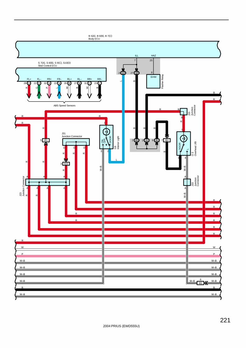
2004 PRIUS (EWD555U)
221
B 5(A), B 6(B), B 7(C)
J31
RR
A
3 ID3
D D
1O
D
1E27
IB15 4G2 4L6
3
1
OFF
DO
OR
ON
2
W
P
W–B
B
R
R
R
R
W
P
B
AAA
R
A
2
A
J23
7
ILL
L
R
I18
R
RR
RR
W–B
B
L
R
A
R R
R
R
R
R
3
1
LDO
OR
IB17
R
B
A
A
B
O 3
R
B
J33
W–B
W–B
J33
4
W–B
EHW
8
HAZ
Fla
sher
Rel
ay
25
4J2
B
B B
R
W–BW–B
W–B W–B
W–B W–B
W–B W–B
R
IB1
6W–B
B
D28 D22 A32 A22 B35 B27 C31 C23
FL+ FL– FR+ FR– RL+ RL– RR+ RR–
R G P L W B W B
ABS Speed Sensors
S 7(A), S 8(B), S 9(C), S10(D)Skid Control ECU
Body ECU
Inte
rior
Ligh
t
Junc
tion
Con
nect
or
Junction Connector
Junc
tion
Con
nect
or
Junc
tion
Con
nect
orO
verh
ead
J/B
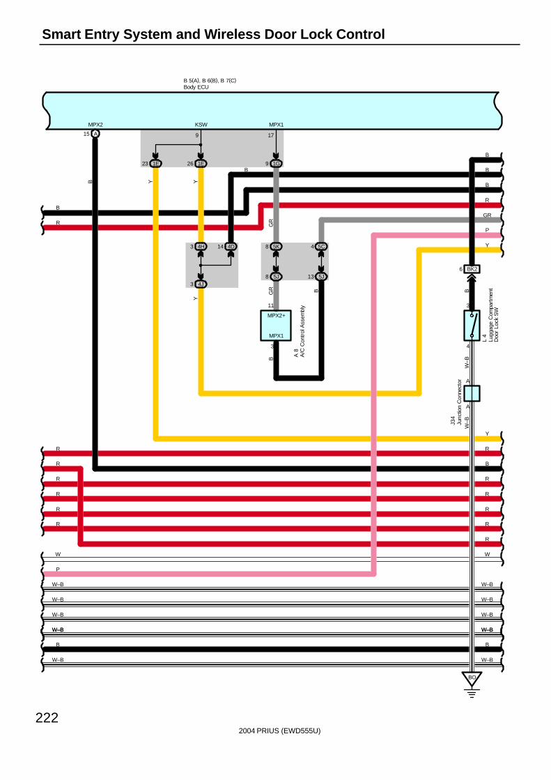
2004 PRIUS (EWD555U)
222
Smart Entry System and Wireless Door Lock Control
A
3
4
A
W–B
W–B
B
L 4
6 BK2
BO
R
R
B 5(A), B 6(B), B 7(C)
A15
9 1G1E26
P
1E23
5J8
5K8
W–B
4J3
4H3
R
W
R
R
B
17
R
Y
W–B
R
W
R
R
B
9
Y
A 8
B
P
3
11
B
B
KSWMPX2 MPX1
MPX1
YB
GR
GR
Y
B
MPX2+
R
RR
R
B
RGR
Y
J34
4D14
BB
5J13
5C4
B
W–B W–B
W–BW–B
W–B W–BW–BW–B
W–BW–B
A/C
Con
trol
Ass
embl
y
Body ECU
Lugg
age
Com
part
men
tD
oor
Lock
SW
Junc
tion
Con
nect
or
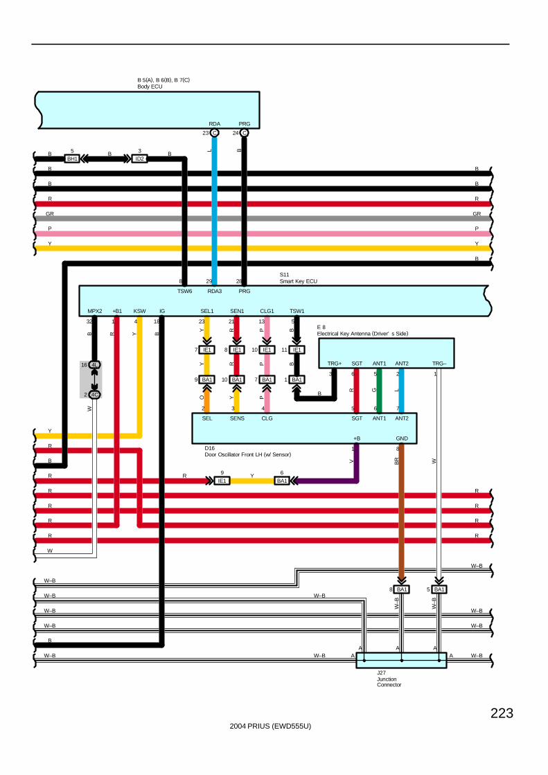
2004 PRIUS (EWD555U)
223
P
R
B
B
B 5(A), B 6(B), B 7(C)
432 18
4L16
4C2
C23 C24
IE17 IE18 IE110 IE111
23 21 13 5
29 288
R
Y
W–B
R
W
R
R
B
B
B
TSW1CLG1SEN1SEL1IG
S11
KSW+B1MPX2
GND
D16
PRGRDA
W–B
W–B
R
R
R
BL
SEL
WB
SENS
R Y
CLG
B
Y R P B
Y R P
TSW6B
RDA3
W–B
W
PRG
RR
R
1
3ID2
5BH1
B
GR
Y
P
R
B
GR
Y
B B
B
SGT
R
ANT1
G
ANT2
L
W–B
W–B
W–B
W–B
W–B
Body ECU
Door Oscillator Front LH (w/ Sensor)
Smart Key ECU
SGT ANT1 TRG–
6 5 1
5 6 7
Electrical Key Antenna (Driver’ s Side)E 8
TRG+
3
8
BA18
BA19 BA110 BA17 BA11
2 3 4
O Y P
BR
BA15
B
W–B
W–B
A A
IE1
9
BA1
6Y
+B
1
V
R
JunctionConnector
J27
AA A
W–B
2
ANT2
W–B
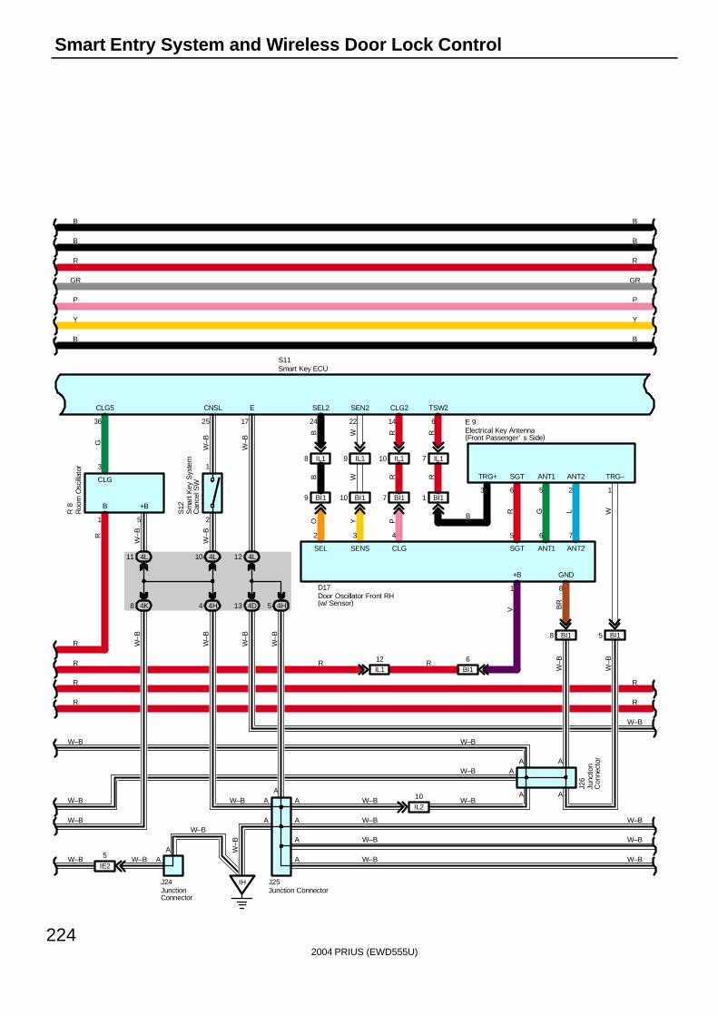
2004 PRIUS (EWD555U)
224
Smart Entry System and Wireless Door Lock Control
A
13 4D
Roo
m O
scill
ator
R 8
W–B
E
10 IL19 IL18 IL1
17
5 4H
12 4L
CLG
R
4L
G
B B
E 9Electrical Key Antenna(Front Passenger’ s Side)
76
B
11
CLG5
3
1 5
R
5
Door Oscillator Front RH(w/ Sensor)
1
ANT1 ANT2
6
24
2
1
4L10
4H4
36 14
IH
A
+B
W–B
22
R
IL210
6
S12
25
A
AA
AA
AA
A
CLG2
J25
SEN2SEL2 TSW2CNSL
5
W–B
R
S11
W–B
W–B
R
R
R
W–B
W–B
W–B
W–BW–B
W–B
W–B
A
V
W–B
W–B
B W R R
TRG+
R R
A
W–B
P
R
B
GR
Y
P
R
B
GR
W–B
Y
B B
IL1
2
L
ANT2G
ANT1
R
SGT
SGT
3
W
RRWBO
CLGSENSSEL
8J2
6
A
W–BW–B
W–B
W–B W–B
W–B
7
Junction Connector
D17
Sm
art K
ey S
yste
mC
ance
l SW
Smart Key ECU
GND
4K8
IE2
5 W–B
8 BI1
J24JunctionConnector
BI19 BI110 BI17 BI11
2 3 4
Y P
BR
BI15
B
TRG–
Junc
tion
Con
nect
or
AW–B
W–B
W–B
W–B
W–B
1
+B
BI16
IL112
W–B
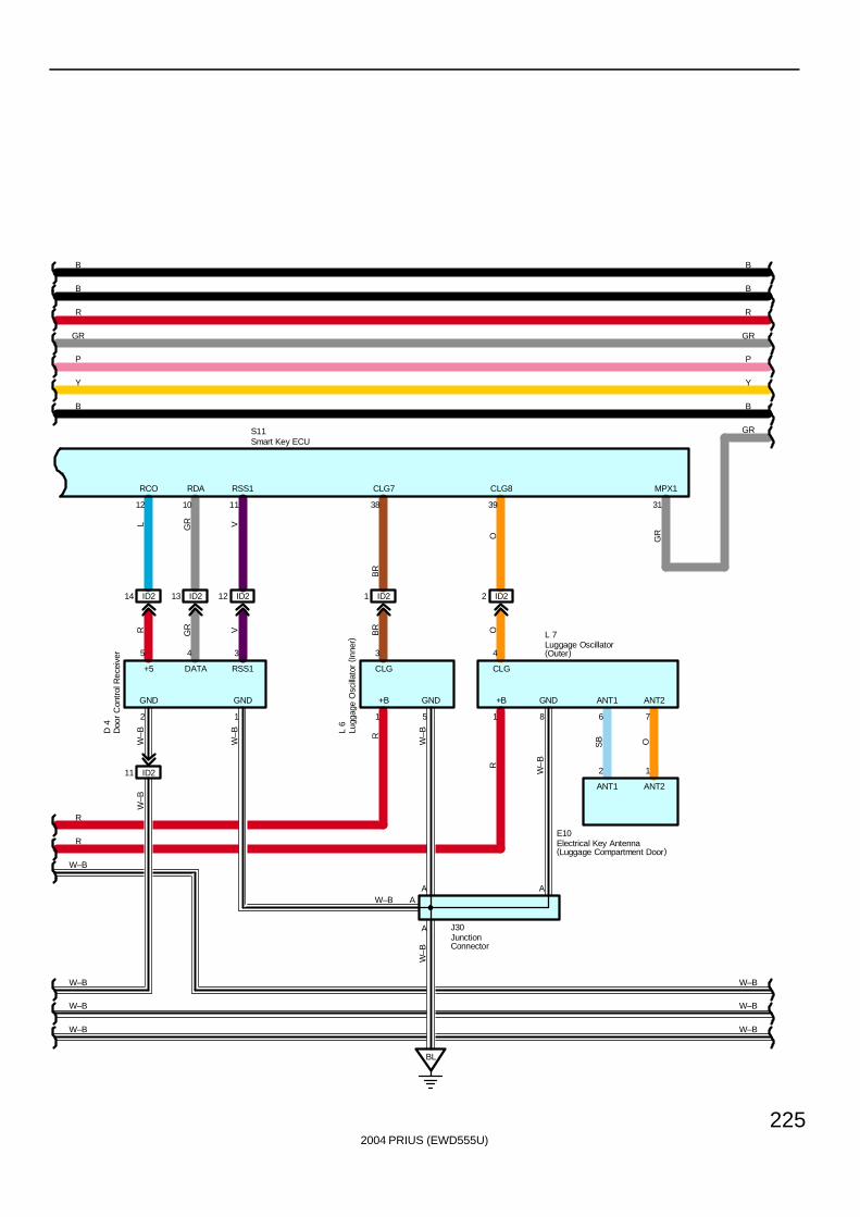
2004 PRIUS (EWD555U)
225
BB
D 4
W–B
OSB
W–B
OO
W–B
W–B
W–B
R
W–B
1
BRVGRR
BR
VGRL
W–B
ANT2ANT1GND
+5
GNDGND
DATA
GND
S11
RCO
RSS1
RDA RSS1
CLG
CLG7 CLG8
R
AA
12
CLG
A
5
ANT1
4 3
ANT2
3 4
2
+B
1
W–B
R
5
A
8 6 7
J30
3938111012
E10
2 ID2
BL
1
1 ID2
11 ID2
12 ID213 ID2ID214
+B
R
GR
L 7
P
R
B
GR
W–B
Y
P
R
B
GR
Y
BB
L 6
W–B
W–B W–B
W–B
W–B
JunctionConnector
Lugg
age
Osc
illato
r ( In
ner) Luggage Oscillator
(Outer)
Doo
r C
ontr
ol R
ecei
ver
Smart Key ECU
Electrical Key Antenna(Luggage Compartment Door)
GR
MPX1
31
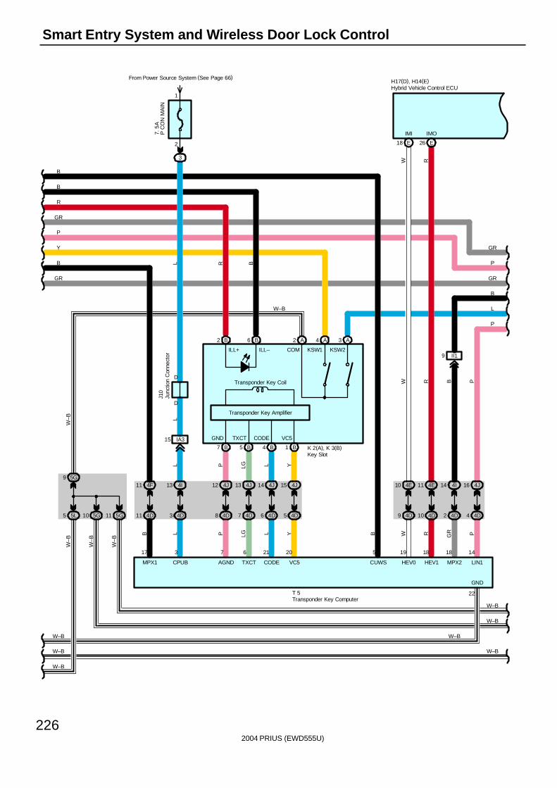
2004 PRIUS (EWD555U)
226
Smart Entry System and Wireless Door Lock Control
5G9
5L5
W–B
5G10
W–B
GR GR
W–B
P LG L YYLLGP
VC5
20
CODE
21
TXCT
6
AGND
7
5 4D6 4D7 4D8 4D
15 4J14 4J13 4J12 4J
B
RR
IMO
26 E
WW
IMI
18 E
P
B
P
CUWS
5
T 5
HEV1HEV0 LIN1
1819 14
RW P
10 4D9 4D 4D4
16 4J4E10 11 4E
5
CODE VC5
Transponder Key Coil
Transponder Key Amplifier
1 BB4
11 4F
22
GND
W–B
W–B
H17(D), H14(E)
KSW2
W–B
4D11 3 4D
A
KSW1
2 4 A
From Power Source System (See Page 66)
3
2
1
D
7. 5
AP
CO
N M
AIN
4I13
IA315
LL
L
D
J10
P
R
B
GR
W–B
Y
P
GR
L
R B
B
7 B
B
MPX1
17 3
CPUB
L
II1
B
MPX2
18
GR
4D2
14 4I
9
B
B
GND TXCT
B2 B6
COM
A3
K 2(A), K 3(B)
ILL+ ILL–
Hybrid Vehicle Control ECU
Junc
tion
Con
nect
or
Transponder Key Computer
W–B
W–B
Key Slot
W–B
11 5G
W–B
W–B
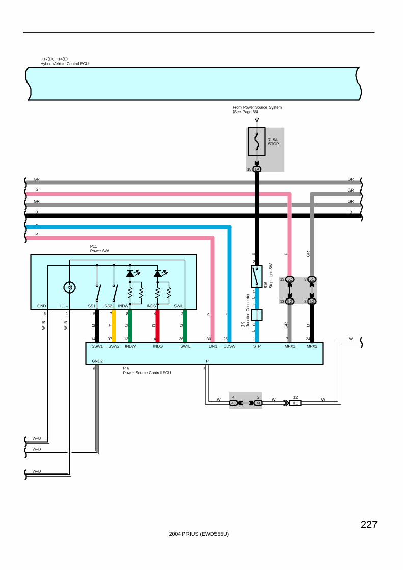
2004 PRIUS (EWD555U)
227
H17(D), H14(E)
B
14 37 13 4 36 2530
SSW1 SSW2 INDW INDS SWIL CDSWLIN1
5 7 8 4 26 1
P 6
P
B Y G R G
L
W–B
W–B
P
P
5
P
2
1
7. 5ASTOP
From Power Source System(See Page 66)
1A18
LL
C
C
S16
1
STP
J 9
WII1
12
4J
4
4I
2 WW
W7
MPX1 MPX2
24
P
GR
L
GR
GR
GR B
5C8
5G8
GR
GR GR
BB
P11
5D13
5G13SWILINDSINDWSS2SS1ILL–GND
Hybrid Vehicle Control ECU
Junc
tion
Con
nect
or
Sto
p Li
ght S
W
W–B
W–B
Power SW
Power Source Control ECU
W–B
6
GND2
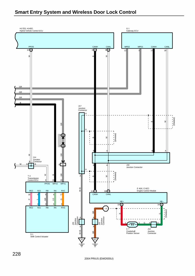
2004 PRIUS (EWD555U)
228
Smart Entry System and Wireless Door Lock Control
BR
PPOS
10 D
B
W
B
W
B
9 E
WB
E8
MPD2
GR
MPD1
12 3
OLGGRLP
W
RE2 RZ1 RB RA RVC
RE2 RZ1 RB RA RVG
8
PPOS
65
IH
A
A
A
1817
J18
AB
W
J17
AB
A
A
A
(Shi
elde
d)
CANLCANH
(Shi
elde
d)
A
CANLCANH
(Shi
elde
d)
BWB
H17(D), H14(E)
WBB W
W–B
W–B
GR
G 1
95348
1716 4
MPX2 MPX1
18
II18
7 4I
GR
GR
GR
4L7
19
GR
B
B
CANH CANL
E 4(A), E 6(C)C31 C30
A34A33
NE+ NE–
G
GR
C 7
I 3
( Shi
elde
d)
BR
A
A
J12 1 2 A A
J14CrankshaftPosition Sensor
Engine Control Module
Gateway ECUHybrid Vehicle Control ECU
Junc
tion
Con
nect
or
JunctionConnector
JunctionConnector
Junction Connector
TransmissionControl ECU
T 4
S 1
JunctionConnector
J14
Junc
tion
Con
nect
or
J25
EC
Shift Control Actuator
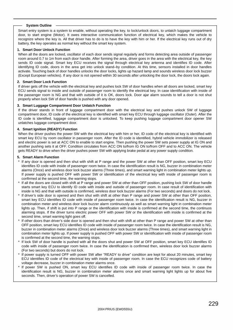
2004 PRIUS (EWD555U)
229
Smart entry system is a system to enable, without operating the key, to lock/unlock doors, to unlatch luggage compartmentdoor, to start engine (Motor). It owes interactive communication function of electrical key, which makes the vehicle torecognize where the key is. All that driver has to do is to have the key with him or her. If the electrical key runs out of drybattery, the key operates as normal key without the smart key system.
1. Smart Door Unlock FunctionWhen all the doors are locked, oscillator of each door sends signal regularly and forms detecting area outside of passengerroom around 0.7 to 1m from each door handle. After forming the area, driver goes in the area with the electrical key, the keysends ID code signal. Smart key ECU receives the signal through electrical key antenna and identifies ID code. Afteridentifying ID code, doors in the area get into unlock stand–by condition. At this time, sensors installed in door handlesactivate. Touching back of door handles unlocks the door locks, lights up hazard lamp and sounds wireless door lock buzzer(Except European vehicles). If any door is not opened within 30 seconds after unlocking the door lock, the doors lock again.
2. Smart Door Lock FunctionIf driver gets off the vehicle with the electrical key and pushes lock SW of door handles when all doors are locked, smart keyECU sends signal to inside and outside of passenger room to identify the electrical key. In case identification with inside ofthe passenger room is NG and that with outside of it is OK, doors lock. Door ajar alarm sounds to tell a door is not shutproperly when lock SW of door handle is pushed with any door opened.
3. Smart Luggage Compartment Door Unlatch FunctionIf the driver stands in front of luggage compartment door with the electrical key and pushes unlock SW of luggagecompartment door, ID code of the electrical key is identified with smart key ECU through luggage oscillator (Outer). After theID code is identified, luggage compartment door is unlocked. To keep pushing luggage compartment door opener SWunlatches luggage compartment door.
4. Smart Ignition (READY) FunctionWhen the driver pushes the power SW with the electrical key with him or her, ID code of the electrical key is identified withsmart key ECU by room oscillator in passenger room. After the ID code is identified, hybrid vehicle immobilizer is releasedand electric power is set at ACC ON to enable to start engine. Then pushing the power SW sets power supply at IG ON andanother pushing sets it at OFF. Condition circulates from ACC ON to/from IG ON to/from OFF and to ACC ON. The vehiclegets READY to drive when the driver pushes power SW with applying brake pedal at any power supply condition.
5. Smart Alarm Function∗ If any door is opened and then shut with shift at P range and the power SW at other than OFF position, smart key ECU
identifies ID code with inside of passenger room twice. In case the identification result is NG, buzzer in combination meteralarms (Once) and wireless door lock buzzer alarms (Three times), and smart warning light in combination meter lights up.If power supply is pushed OFF with power SW or identification of the electrical key with inside of passenger room isconfirmed at the second time, the warning stops.
∗ If all the doors are closed with shift at P range and power SW at other than OFF position, pushing lock SW of door handlestarts smart key ECU to identify ID code with inside and outside of passenger room. In case result of identification withinside is NG and that with outside is confirmed, wireless door lock buzzer alarms (For two seconds) and doors do not lock.
∗ If driver’s side door is opened and then shut with shift at other than P range and power SW at other than OFF position,smart key ECU identifies ID code with inside of passenger room twice. In case the identification result is NG, buzzer incombination meter and wireless door lock buzzer alarm continuously as well as smart warning light in combination meterlights up. Then, if shift is put into P range or the identification with inside is confirmed at the second time, the continuosalarming stops. If the driver turns electric power OFF with power SW or the identification with inside is confirmed at thesecond time, smart warning light goes off.
∗ If other doors than driver’s side door is opened and then shut with shift at other than P range and power SW at other thanOFF position, smart key ECU identifies ID code with inside of passenger room twice. In case the identification result is NG,buzzer in combination meter alarms (Once) and wireless door lock buzzer alarms (Three times), and smart warning light incombination meter lights up. If power supply is pushed OFF with power SW or identification with inside of passenger roomis confirmed at the second time, the warning stops.
∗ If lock SW of door handle is pushed with all the doors shut and power SW at OFF position, smart key ECU identifies IDcode with inside of passenger room twice. In case the identification is confirmed then, wireless door lock buzzer alarms(For two seconds) but doors do not lock.
∗ If power supply is turned OFF with power SW after ”READY to drive” condition are kept for about 20 minutes, smart keyECU identifies ID code of the electrical key with inside of passenger room. In case the ECU recognizes code of batteryvoltage decrease, buzzer in combination meter alarms once.
∗ If power SW is pushed ON, smart key ECU identifies ID code with inside of passenger room twice. In case theidentification result is NG, buzzer in combination meter alarms once and smart warning light lights up for about fiveseconds. Then, driver’s operation of power SW is cancelled.
System Outline
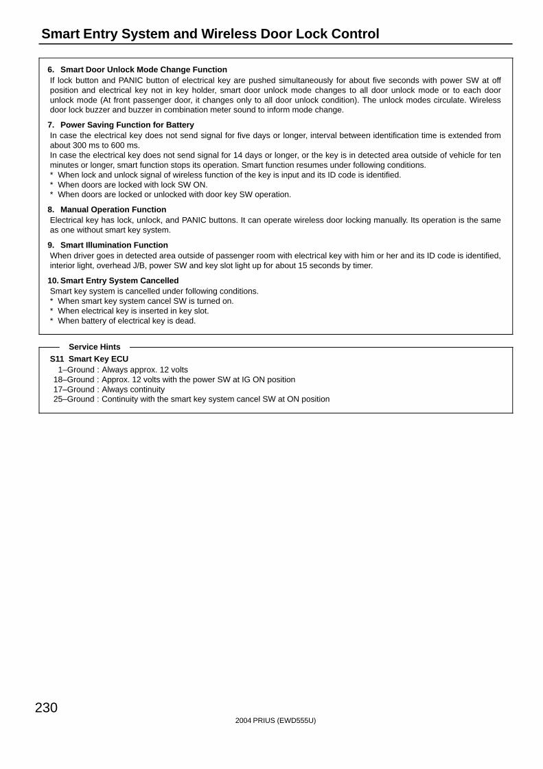
2004 PRIUS (EWD555U)
230
Smart Entry System and Wireless Door Lock Control
6. Smart Door Unlock Mode Change FunctionIf lock button and PANIC button of electrical key are pushed simultaneously for about five seconds with power SW at offposition and electrical key not in key holder, smart door unlock mode changes to all door unlock mode or to each doorunlock mode (At front passenger door, it changes only to all door unlock condition). The unlock modes circulate. Wirelessdoor lock buzzer and buzzer in combination meter sound to inform mode change.
7. Power Saving Function for BatteryIn case the electrical key does not send signal for five days or longer, interval between identification time is extended fromabout 300 ms to 600 ms.In case the electrical key does not send signal for 14 days or longer, or the key is in detected area outside of vehicle for tenminutes or longer, smart function stops its operation. Smart function resumes under following conditions.∗ When lock and unlock signal of wireless function of the key is input and its ID code is identified.∗ When doors are locked with lock SW ON.∗ When doors are locked or unlocked with door key SW operation.
8. Manual Operation FunctionElectrical key has lock, unlock, and PANIC buttons. It can operate wireless door locking manually. Its operation is the sameas one without smart key system.
9. Smart Illumination FunctionWhen driver goes in detected area outside of passenger room with electrical key with him or her and its ID code is identified,interior light, overhead J/B, power SW and key slot light up for about 15 seconds by timer.
10. Smart Entry System CancelledSmart key system is cancelled under following conditions.∗ When smart key system cancel SW is turned on.∗ When electrical key is inserted in key slot.∗ When battery of electrical key is dead.
S11 Smart Key ECU1–Ground : Always approx. 12 volts
18–Ground : Approx. 12 volts with the power SW at IG ON position17–Ground : Always continuity25–Ground : Continuity with the smart key system cancel SW at ON position
Service Hints
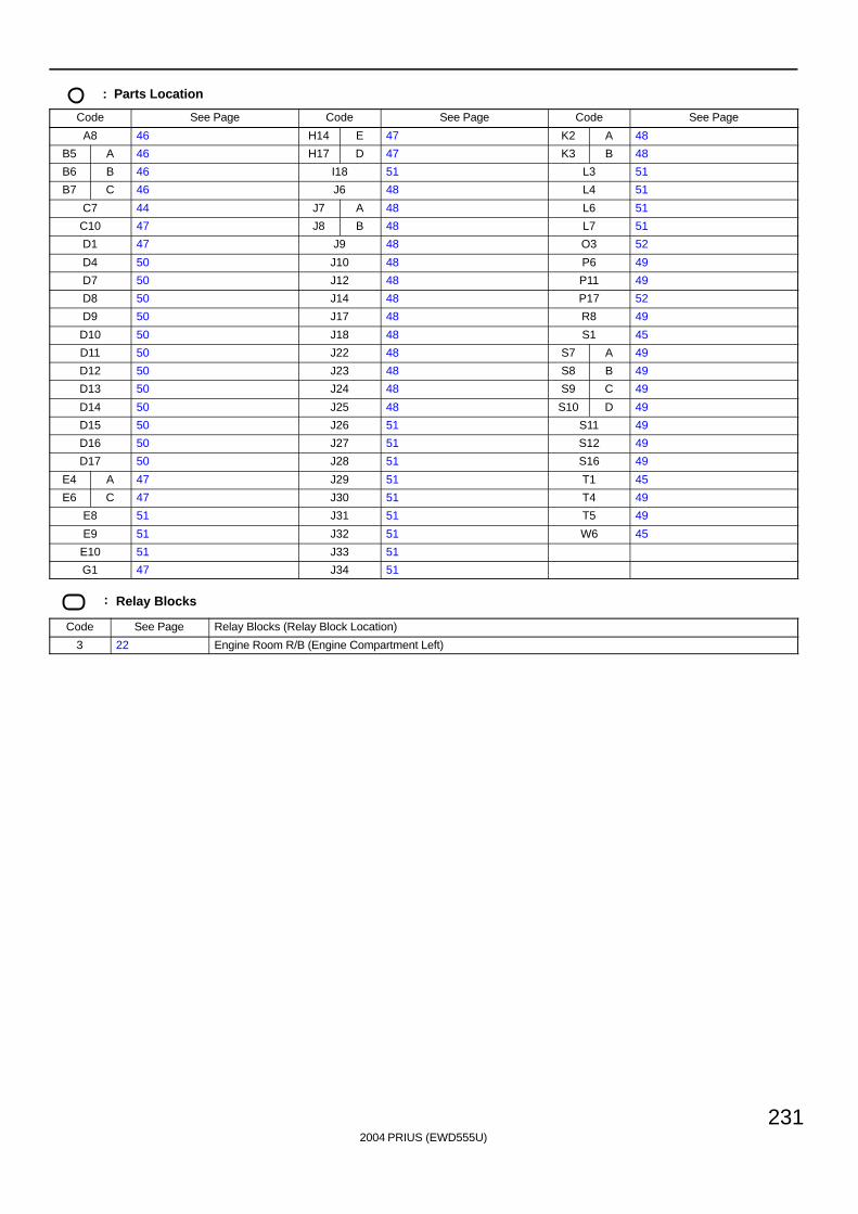
2004 PRIUS (EWD555U)
231
: Parts Location
Code See Page Code See Page Code See Page
A8 46 H14 E 47 K2 A 48
B5 A 46 H17 D 47 K3 B 48
B6 B 46 I18 51 L3 51
B7 C 46 J6 48 L4 51
C7 44 J7 A 48 L6 51
C10 47 J8 B 48 L7 51
D1 47 J9 48 O3 52
D4 50 J10 48 P6 49
D7 50 J12 48 P11 49
D8 50 J14 48 P17 52
D9 50 J17 48 R8 49
D10 50 J18 48 S1 45
D11 50 J22 48 S7 A 49
D12 50 J23 48 S8 B 49
D13 50 J24 48 S9 C 49
D14 50 J25 48 S10 D 49
D15 50 J26 51 S11 49
D16 50 J27 51 S12 49
D17 50 J28 51 S16 49
E4 A 47 J29 51 T1 45
E6 C 47 J30 51 T4 49
E8 51 J31 51 T5 49
E9 51 J32 51 W6 45
E10 51 J33 51
G1 47 J34 51
: Relay Blocks
Code See Page Relay Blocks (Relay Block Location)
3 22 Engine Room R/B (Engine Compartment Left)
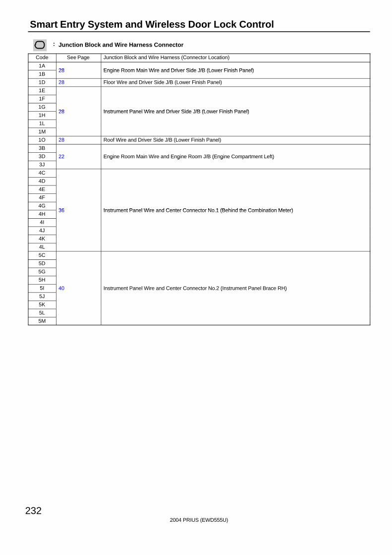
2004 PRIUS (EWD555U)
232
Smart Entry System and Wireless Door Lock Control
: Junction Block and Wire Harness Connector
Code See Page Junction Block and Wire Harness (Connector Location)
1A28 Engine Room Main Wire and Driver Side J/B (Lower Finish Panel)
1B28 Engine Room Main Wire and Driver Side J/B (Lower Finish Panel)
1D 28 Floor Wire and Driver Side J/B (Lower Finish Panel)
1E
1F
1G28 Instrument Panel Wire and Driver Side J/B (Lower Finish Panel)
1H28 Instrument Panel Wire and Driver Side J/B (Lower Finish Panel)
1L
1M
1O 28 Roof Wire and Driver Side J/B (Lower Finish Panel)
3B
3D 22 Engine Room Main Wire and Engine Room J/B (Engine Compartment Left)
3J
g g ( g )
4C
4D
4E
4F
4G36 Instrument Panel Wire and Center Connector No 1 (Behind the Combination Meter)
4H36 Instrument Panel Wire and Center Connector No.1 (Behind the Combination Meter)
4I
4J
4K
4L
5C
5D
5G
5H
5I 40 Instrument Panel Wire and Center Connector No.2 (Instrument Panel Brace RH)
5J
( )
5K
5L
5M
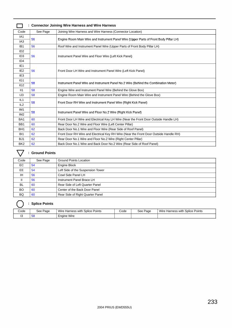
2004 PRIUS (EWD555U)
233
: Connector Joining Wire Harness and Wire Harness
Code See Page Joining Wire Harness and Wire Harness (Connector Location)
IA156 Engine Room Main Wire and Instrument Panel Wire (Upper Parts of Front Body Pillar LH)
IA356 Engine Room Main Wire and Instrument Panel Wire (Upper Parts of Front Body Pillar LH)
IB1 56 Roof Wire and Instrument Panel Wire (Upper Parts of Front Body Pillar LH)
ID2
ID3 56 Instrument Panel Wire and Floor Wire (Left Kick Panel)
ID4
( )
IE1
IE2 56 Front Door LH Wire and Instrument Panel Wire (Left Kick Panel)
IE3
( )
IG158 Instrument Panel Wire and Instrument Panel No 2 Wire (Behind the Combination Meter)
IG258 Instrument Panel Wire and Instrument Panel No.2 Wire (Behind the Combination Meter)
II1 58 Engine Wire and Instrument Panel Wire (Behind the Glove Box)
IJ3 58 Engine Room Main Wire and Instrument Panel Wire (Behind the Glove Box)
IL158 Front Door RH Wire and Instrument Panel Wire (Right Kick Panel)
IL258 Front Door RH Wire and Instrument Panel Wire (Right Kick Panel)
IM158 Instrument Panel Wire and Floor No 2 Wire (Right Kick Panel)
IM258 Instrument Panel Wire and Floor No.2 Wire (Right Kick Panel)
BA1 60 Front Door LH Wire and Electrical Key LH Wire (Near the Front Door Outside Handle LH)
BB1 60 Rear Door No.2 Wire and Floor Wire (Left Center Pillar)
BH1 62 Back Door No.1 Wire and Floor Wire (Rear Side of Roof Panel)
BI1 62 Front Door RH Wire and Electrical Key RH Wire (Near the Front Door Outside Handle RH)
BJ1 62 Rear Door No.1 Wire and Floor No.2 Wire (Right Center Pillar)
BK2 62 Back Door No.1 Wire and Back Door No.2 Wire (Rear Side of Roof Panel)
: Ground Points
Code See Page Ground Points Location
EC 54 Engine Block
EE 54 Left Side of the Suspension Tower
IH 56 Cowl Side Panel LH
II 56 Instrument Panel Brace LH
BL 60 Rear Side of Left Quarter Panel
BO 60 Center of the Back Door Panel
BQ 60 Rear Side of Right Quarter Panel
: Splice Points
Code See Page Wire Harness with Splice Points Code See Page Wire Harness with Splice Points
I3 58 Engine Wire
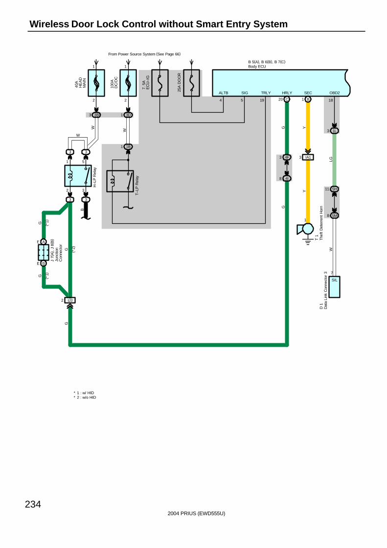
2004 PRIUS (EWD555U)
234
Wireless Door Lock Control without Smart Entry System
G
C20
4F3
4I8
HRLY
5
B 5(A), B 6(B), B 7(C)
G
SIG
19
TRLY
40A
HE
AD
MA
IN
From Power Source System (See Page 66)
3B3
2
1
2 3
1 5
3 3
3
IJ32
BE
AE
W
G
G
G
WH
–LP
Rel
ay
( *1)
( *1)
( *2)
J 7(
A) ,
J 8
( B)
3
B
1 1B
T–LP
Rel
ay
7. 5
AE
CU
–IG
100A
DC
/DC
3D1
W
1
2
Y
1
3 IA1
Y
1 B
OBD2SEC
7
1L3
18
5M8
5H11
T 1
LGW
SIL
* 1 : w/ HID* 2 : w/o HID
G
25A
DO
OR
4
ALTB
D 1
Body ECU
Dat
a Li
nk C
onne
ctor
3
Junc
tion
Con
nect
or
Thef
t D
eter
rent
Hor
n
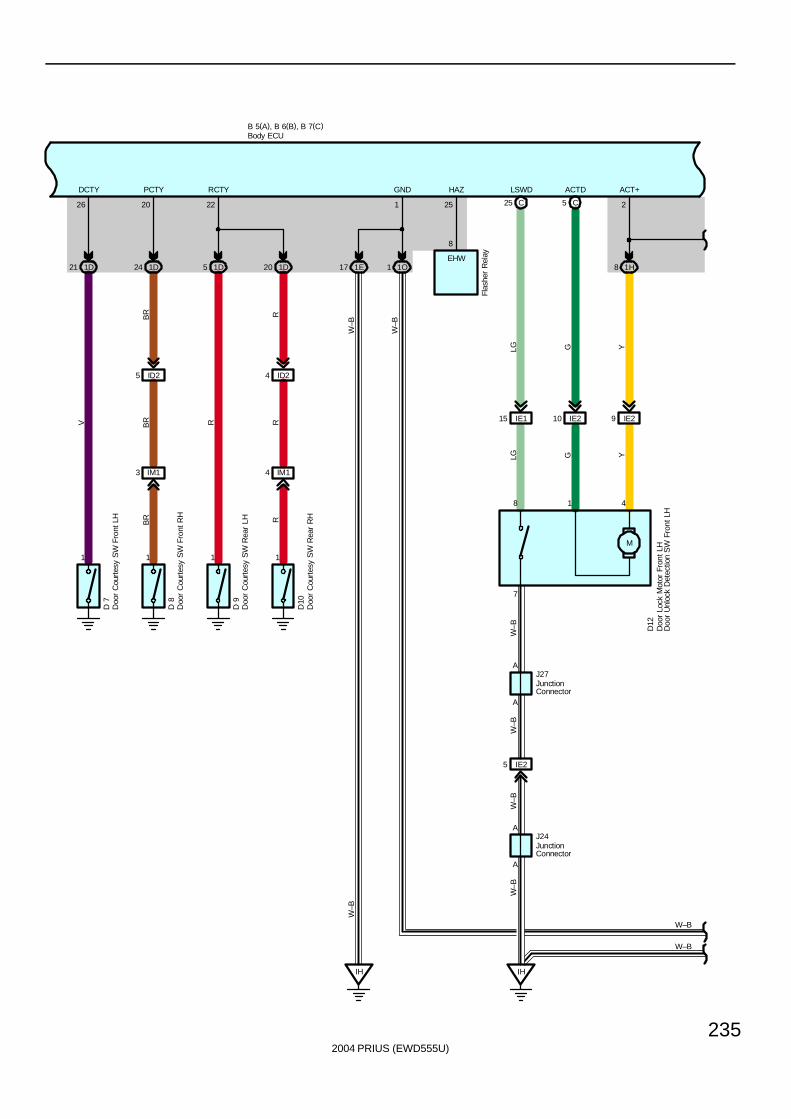
2004 PRIUS (EWD555U)
235
B 5(A), B 6(B), B 7(C)
1E17
W–B
1 1O
HAZGND
IH
251
W–B
W–B
W–B
8
EHW
Flas
her
Rel
ay
M
IE115 IE210 9 IE2
8 1H
5 CC25
W–B
IH
IE25
A
A
LSWD ACTD ACT+
W–B
W–B
W–B
LG G Y
D12
LG G Y
J24
J27A
8 1 4
2
A
7
W–B
1D21 1D24 1D5 1D20
1 1 1 1
IM13 IM14
ID25 ID24
222026
RCTYPCTYDCTY
RR
R
RBR
BR
BR
V
D 7
D 8
D 9
D10
Body ECU
Doo
r Lo
ck M
otor
Fro
nt L
HD
oor
Unl
ock
Det
ectio
n S
W F
ront
LH
Doo
r C
ourt
esy
SW
Fro
nt L
H
Doo
r C
ourt
esy
SW
Fro
nt R
H
Doo
r C
ourt
esy
SW
Rea
r LH
Doo
r C
ourt
esy
SW
Rea
r R
H
JunctionConnector
JunctionConnector
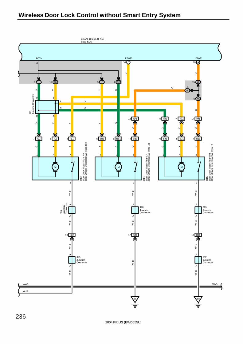
2004 PRIUS (EWD555U)
236
Wireless Door Lock Control without Smart Entry System
W–B
W–B
IL210
A
A
W–B
W–B
J25
J26
A
A
6 IL27 IL2 IL14
M
6 BB15 BB1 BB14
M
5 BJ16 BJ1 BJ14
M
IM25 IM24 IM114ID316
1H9 1H17 1D3 1D4
C10 A10
6 4K
4F15
4K
7
BL
BB117
BQ
BJ117
A
A
998
B 5(A), B 6(B), B 7(C)
A A
C A
3
641614741
AC
AA
A
C
LSWRLSWPACT–
W–B W–B
D15
Y
G
O
G Y Y
G Y
D14
Y
G
J28
Y Y G
Y G
Y
D13
G O G
J29
Y OW
–B
W–B
J22
W–B
W–B
W–B
W–B
J32
W–B
OYGO
OOY
W–B
Body ECU
Doo
r Lo
ck M
otor
Fro
nt R
HD
oor
Unl
ock
Det
ectio
n S
W F
ront
RH
Doo
r Lo
ck M
otor
Rea
r LH
Doo
r U
nloc
k D
etec
tion
SW
Rea
r LH
Doo
r Lo
ck M
otor
Rea
r R
HD
oor
Unl
ock
Det
ectio
n S
W R
ear
RH
Junc
tion
Con
nect
or
JunctionConnector
Junc
tion
Con
nect
or
JunctionConnector
JunctionConnector
JunctionConnector
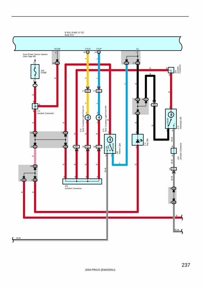
2004 PRIUS (EWD555U)
237
15ADOME
From Power Source System(See Page 66)
3
2
1
B
B
1A30
1A13
1L8
5G1
5H16
5I9
1O
1F7
1E27
IB15
4G2
4J2
4L6
3
1
OFF
DO
OR
ON
1O5
2
3
1
LDO
OR
IB17
IB16
W–B
R
B 5(A), B 6(B), B 7(C)
2
2
A
6
B
J23
76
B
R
ECUB ILL
L
I18
R R
PRR
R
K 3
R
J 6
BR
W–B
R
BL
R
B
A
R
R
A
B
O 3
R
B
J33
W–B
W–B
W–B
J33
4
A
W–B
4K8
4H4
IE118 IL118
1
2
1
2
IE117 IL117
A19
CYLD
A14
CYLP
Y L
Y L
Y L
R R
R R
A A
D 5
D 6
Body ECU
Inte
rior
Ligh
t
Junction Connector
Junction Connector
Junc
tion
Con
nect
orJu
nctio
nC
onne
ctor
Ove
rhea
d J/
B
Doo
r C
ourt
esy
Ligh
t Fro
nt L
H
Doo
r C
ourt
esy
Ligh
t Fro
nt R
H
Key
Slo
t
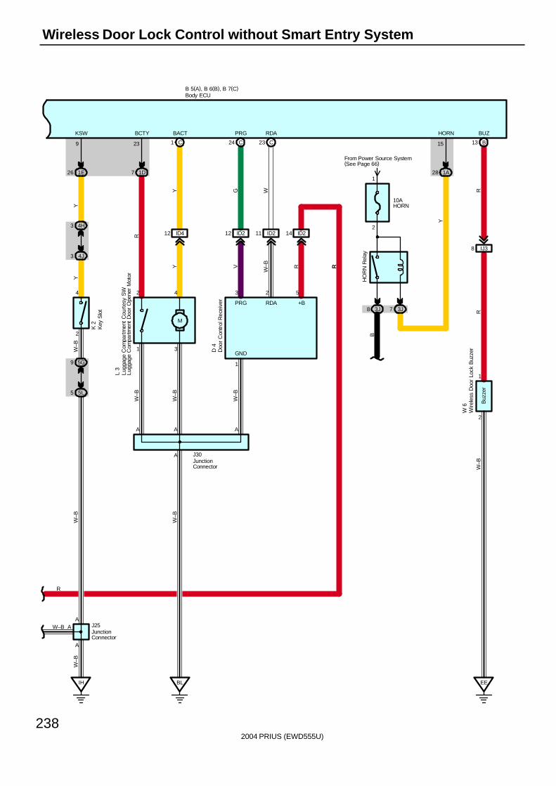
2004 PRIUS (EWD555U)
238
Wireless Door Lock Control without Smart Entry System
BL
23 C24 C
ID4
1 C
12 14 ID211 ID212 ID2
M
7 1D 28 1A
B13
EE
IJ38
B 5(A), B 6(B), B 7(C)
1E26
4J3
4H3
W–B
R
A A A
2 4 3 2 5
1
2
9
A
1
1
15
3
23
J30
W 6
BCTY BACT PRG RDA HORN BUZ
GND
Y G W
R
Y V
W–B
L 3
R
W–B
W–B
W–B
D 4
RR
W–B
+BRDAPRG
4
KSW
YY
5L5
5G9
2
W–B
3J73J8
10AHORN
From Power Source System(See Page 66)
B
Y
HO
RN
Rel
ay
IH
A
AJ25
W–B
W–B
A
RR
W–B
Buz
zer
K 2
Body ECU
Lugg
age
Com
partm
ent
Cou
rtes
y S
WLu
ggag
e C
ompa
rtmen
t D
oor
Ope
ner
Mot
or
JunctionConnector
JunctionConnector
Wire
less
Doo
r Lo
ck B
uzze
rDoo
r C
ontr
ol R
ecei
ver
Key
Slo
t
1
2
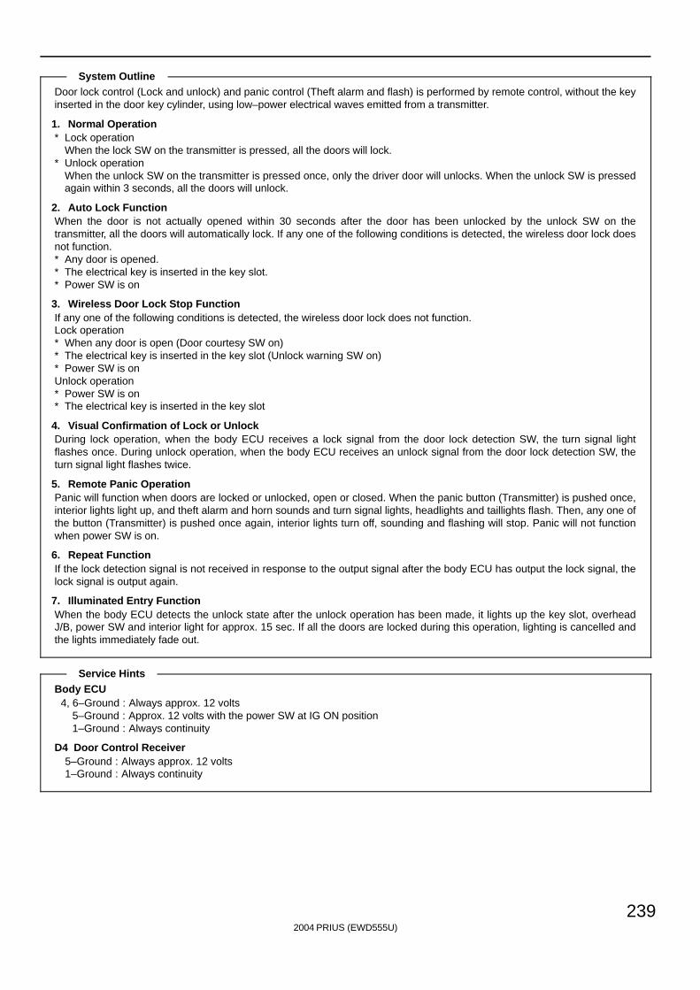
2004 PRIUS (EWD555U)
239
Door lock control (Lock and unlock) and panic control (Theft alarm and flash) is performed by remote control, without the keyinserted in the door key cylinder, using low–power electrical waves emitted from a transmitter.
1. Normal Operation∗ Lock operation
When the lock SW on the transmitter is pressed, all the doors will lock.∗ Unlock operation
When the unlock SW on the transmitter is pressed once, only the driver door will unlocks. When the unlock SW is pressedagain within 3 seconds, all the doors will unlock.
2. Auto Lock FunctionWhen the door is not actually opened within 30 seconds after the door has been unlocked by the unlock SW on thetransmitter, all the doors will automatically lock. If any one of the following conditions is detected, the wireless door lock doesnot function.∗ Any door is opened.∗ The electrical key is inserted in the key slot.∗ Power SW is on
3. Wireless Door Lock Stop FunctionIf any one of the following conditions is detected, the wireless door lock does not function.Lock operation∗ When any door is open (Door courtesy SW on)∗ The electrical key is inserted in the key slot (Unlock warning SW on)∗ Power SW is onUnlock operation∗ Power SW is on∗ The electrical key is inserted in the key slot
4. Visual Confirmation of Lock or UnlockDuring lock operation, when the body ECU receives a lock signal from the door lock detection SW, the turn signal lightflashes once. During unlock operation, when the body ECU receives an unlock signal from the door lock detection SW, theturn signal light flashes twice.
5. Remote Panic OperationPanic will function when doors are locked or unlocked, open or closed. When the panic button (Transmitter) is pushed once,interior lights light up, and theft alarm and horn sounds and turn signal lights, headlights and taillights flash. Then, any one ofthe button (Transmitter) is pushed once again, interior lights turn off, sounding and flashing will stop. Panic will not functionwhen power SW is on.
6. Repeat FunctionIf the lock detection signal is not received in response to the output signal after the body ECU has output the lock signal, thelock signal is output again.
7. Illuminated Entry FunctionWhen the body ECU detects the unlock state after the unlock operation has been made, it lights up the key slot, overheadJ/B, power SW and interior light for approx. 15 sec. If all the doors are locked during this operation, lighting is cancelled andthe lights immediately fade out.
Body ECU4, 6–Ground : Always approx. 12 volts
5–Ground : Approx. 12 volts with the power SW at IG ON position1–Ground : Always continuity
D4 Door Control Receiver5–Ground : Always approx. 12 volts1–Ground : Always continuity
System Outline
Service Hints
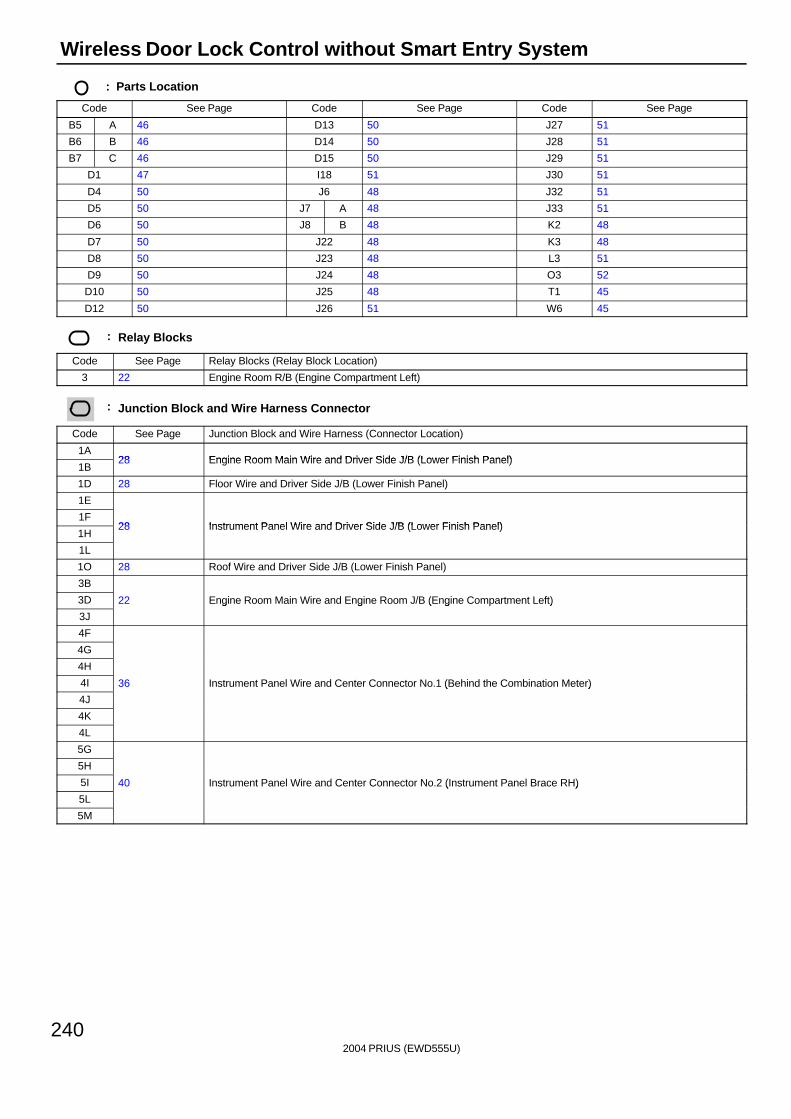
2004 PRIUS (EWD555U)
240
Wireless Door Lock Control without Smart Entry System
: Parts Location
Code See Page Code See Page Code See Page
B5 A 46 D13 50 J27 51
B6 B 46 D14 50 J28 51
B7 C 46 D15 50 J29 51
D1 47 I18 51 J30 51
D4 50 J6 48 J32 51
D5 50 J7 A 48 J33 51
D6 50 J8 B 48 K2 48
D7 50 J22 48 K3 48
D8 50 J23 48 L3 51
D9 50 J24 48 O3 52
D10 50 J25 48 T1 45
D12 50 J26 51 W6 45
: Relay Blocks
Code See Page Relay Blocks (Relay Block Location)
3 22 Engine Room R/B (Engine Compartment Left)
: Junction Block and Wire Harness Connector
Code See Page Junction Block and Wire Harness (Connector Location)
1A28 Engine Room Main Wire and Driver Side J/B (Lower Finish Panel)
1B28 Engine Room Main Wire and Driver Side J/B (Lower Finish Panel)
1D 28 Floor Wire and Driver Side J/B (Lower Finish Panel)
1E
1F28 Instrument Panel Wire and Driver Side J/B (Lower Finish Panel)
1H28 Instrument Panel Wire and Driver Side J/B (Lower Finish Panel)
1L
1O 28 Roof Wire and Driver Side J/B (Lower Finish Panel)
3B
3D 22 Engine Room Main Wire and Engine Room J/B (Engine Compartment Left)
3J
g g ( g )
4F
4G
4H
4I 36 Instrument Panel Wire and Center Connector No.1 (Behind the Combination Meter)
4J
( )
4K
4L
5G
5H
5I 40 Instrument Panel Wire and Center Connector No.2 (Instrument Panel Brace RH)
5L
( )
5M
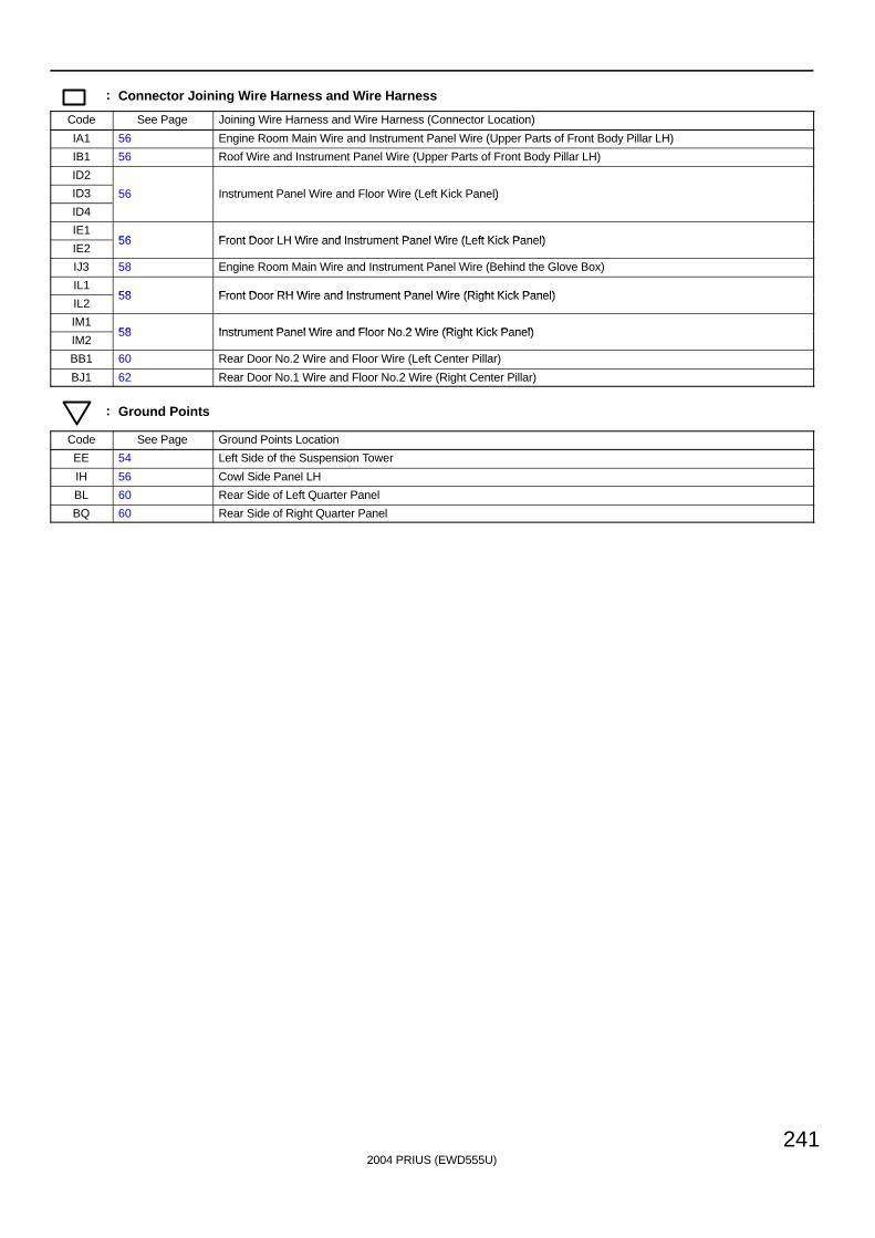
2004 PRIUS (EWD555U)
241
: Connector Joining Wire Harness and Wire Harness
Code See Page Joining Wire Harness and Wire Harness (Connector Location)
IA1 56 Engine Room Main Wire and Instrument Panel Wire (Upper Parts of Front Body Pillar LH)
IB1 56 Roof Wire and Instrument Panel Wire (Upper Parts of Front Body Pillar LH)
ID2
ID3 56 Instrument Panel Wire and Floor Wire (Left Kick Panel)
ID4
( )
IE156 Front Door LH Wire and Instrument Panel Wire (Left Kick Panel)
IE256 Front Door LH Wire and Instrument Panel Wire (Left Kick Panel)
IJ3 58 Engine Room Main Wire and Instrument Panel Wire (Behind the Glove Box)
IL158 Front Door RH Wire and Instrument Panel Wire (Right Kick Panel)
IL258 Front Door RH Wire and Instrument Panel Wire (Right Kick Panel)
IM158 Instrument Panel Wire and Floor No 2 Wire (Right Kick Panel)
IM258 Instrument Panel Wire and Floor No.2 Wire (Right Kick Panel)
BB1 60 Rear Door No.2 Wire and Floor Wire (Left Center Pillar)
BJ1 62 Rear Door No.1 Wire and Floor No.2 Wire (Right Center Pillar)
: Ground Points
Code See Page Ground Points Location
EE 54 Left Side of the Suspension Tower
IH 56 Cowl Side Panel LH
BL 60 Rear Side of Left Quarter Panel
BQ 60 Rear Side of Right Quarter Panel
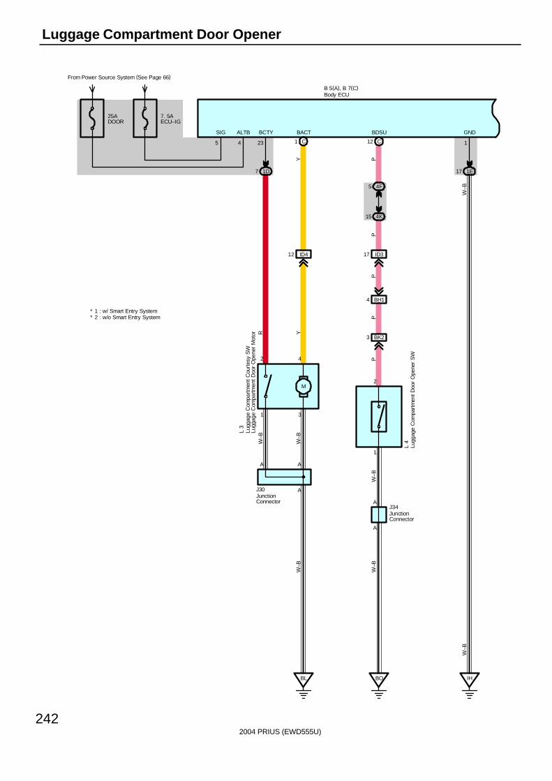
2004 PRIUS (EWD555U)
242
Luggage Compartment Door Opener
From Power Source System (See Page 66)
1E17
GND
IH
1
W–B
5
SIG
W–B
BL
ID4
1 C
12
M
7 1D
C12
4F5
4K15
BO
ID317
BK23
BH14
A A
2 4
A
1 3
23
J30
L 4
BCTY BACT
Y
R Y
L 3
W–B
W–B
W–B
PP
PP
PW
–BW
–B
A
1
2
AJ34
BDSU
25ADOOR
4
ALTB
7. 5AECU–IG
B 5(A), B 7(C)
* 1 : w/ Smart Entry System
Body ECU
Lugg
age
Com
partm
ent
Cou
rtes
y S
WLu
ggag
e C
ompa
rtmen
t D
oor
Ope
ner
Mot
or
Lugg
age
Com
part
men
t Doo
r O
pene
r S
W
JunctionConnector
JunctionConnector
* 2 : w/o Smart Entry System
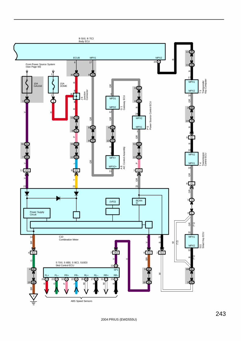
2004 PRIUS (EWD555U)
243
Power SupplyCircuit
14
2122
10AGAUGE
From Power Source System(See Page 66)
1M1
16 5L
5D7
IG211
II
IG14
4C4
4H15
IG29
LY
VV
V
C10
BR
GB
R
4I16
4C9
7 IA3
15ADOME
3
2
1
B
1A30
6
ECUB
R
R
B 5(A), B 7(C)
1A13
1L8
P
11
5H16
5D
B
J 6
(VFD)
D28 D22 A32 A22 B35 B27 C31 C23
FL+ FL– FR+ FR– RL+ RL– RR+ RR–
R G P L W B W B
ABS Speed Sensors
S 7(A), S 8(B), S 9(C), S10(D)B22
SP1
V
Skid Control ECU
Body ECU
Combination Meter
Junc
tion
Con
nect
or
MPX2
MPX2+
MPX2
MPX1
MPX1
MPD2
3
17
18
24
25
31
32
11
16
19
7
5C8
5G8
5D13
5G13
12
3 IG2
4L16
4C2
5C4
5J135J8
5K8
4F11
4D11
4I14
4D2
4L7
4I7
II19
II18
A 8
( *1)
( *1)
( *2)
T 5
GR
B
BG
RG
R
GR
GR
GR
T 4
P 6
GR
B
BB
GR
W
GR
MPX1
MPX2
MPX2
S11
MPX1
MPX+
A/C
Con
trol
Ass
embl
y
Tran
spon
der
Key
Com
pute
rTr
ansm
issi
onC
ontr
ol E
CU
Sm
art K
ey E
CU
Pow
er S
ourc
e C
ontr
ol E
CU
3
MPD1
G 1
Gat
eway
EC
U
BEANIC
P
R
B
1G9
17
MPX1
A15
MPX2
GR
9
IG19
VB
RV
24
IG12
BW
B
B
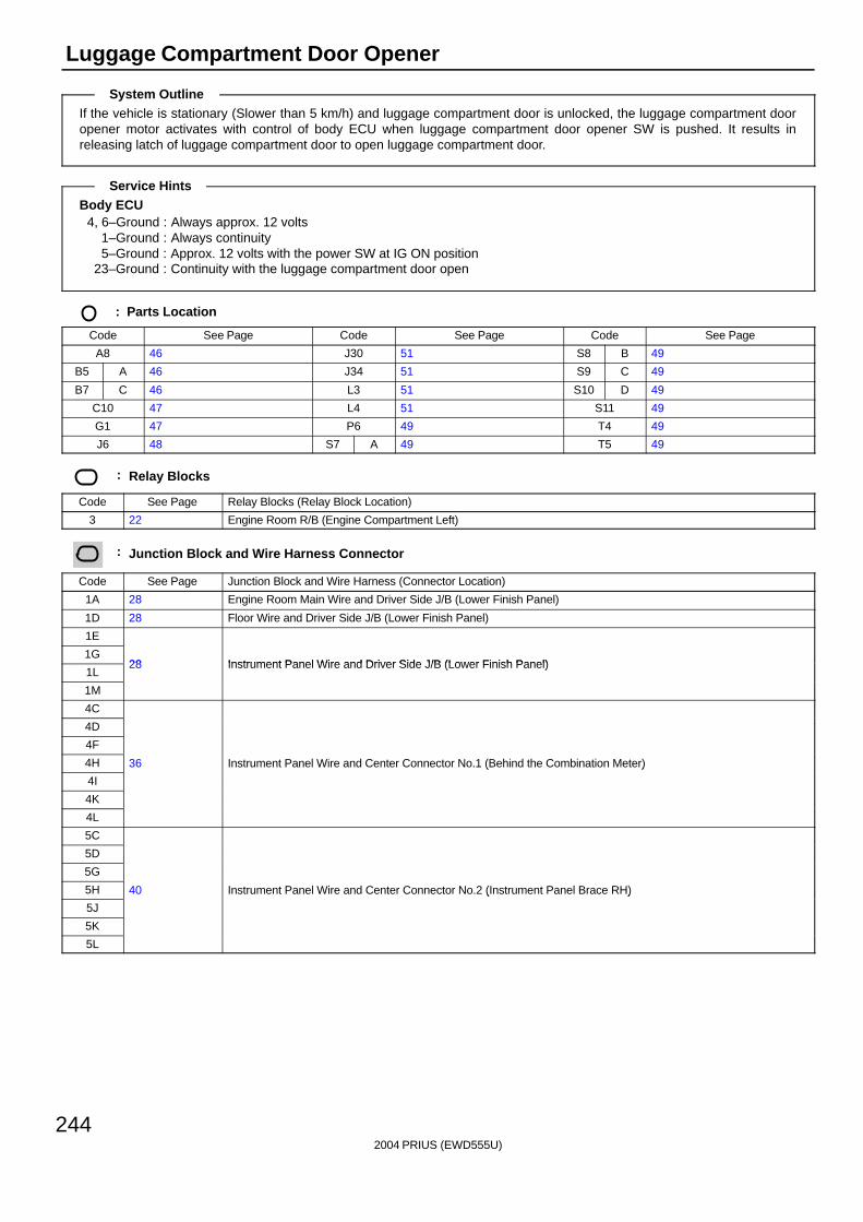
2004 PRIUS (EWD555U)
244
Luggage Compartment Door Opener
If the vehicle is stationary (Slower than 5 km/h) and luggage compartment door is unlocked, the luggage compartment dooropener motor activates with control of body ECU when luggage compartment door opener SW is pushed. It results inreleasing latch of luggage compartment door to open luggage compartment door.
Body ECU4, 6–Ground : Always approx. 12 volts
1–Ground : Always continuity5–Ground : Approx. 12 volts with the power SW at IG ON position
23–Ground : Continuity with the luggage compartment door open
: Parts Location
Code See Page Code See Page Code See Page
A8 46 J30 51 S8 B 49
B5 A 46 J34 51 S9 C 49
B7 C 46 L3 51 S10 D 49
C10 47 L4 51 S11 49
G1 47 P6 49 T4 49
J6 48 S7 A 49 T5 49
: Relay Blocks
Code See Page Relay Blocks (Relay Block Location)
3 22 Engine Room R/B (Engine Compartment Left)
: Junction Block and Wire Harness Connector
Code See Page Junction Block and Wire Harness (Connector Location)
1A 28 Engine Room Main Wire and Driver Side J/B (Lower Finish Panel)
1D 28 Floor Wire and Driver Side J/B (Lower Finish Panel)
1E
1G28 Instrument Panel Wire and Driver Side J/B (Lower Finish Panel)
1L28 Instrument Panel Wire and Driver Side J/B (Lower Finish Panel)
1M
4C
4D
4F
4H 36 Instrument Panel Wire and Center Connector No.1 (Behind the Combination Meter)
4I
( )
4K
4L
5C
5D
5G
5H 40 Instrument Panel Wire and Center Connector No.2 (Instrument Panel Brace RH)
5J
( )
5K
5L
System Outline
Service Hints
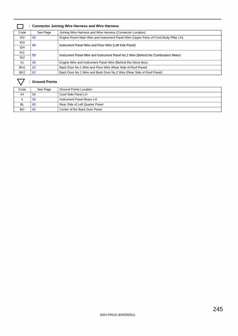
2004 PRIUS (EWD555U)
245
: Connector Joining Wire Harness and Wire Harness
Code See Page Joining Wire Harness and Wire Harness (Connector Location)
IA3 56 Engine Room Main Wire and Instrument Panel Wire (Upper Parts of Front Body Pillar LH)
ID356 Instrument Panel Wire and Floor Wire (Left Kick Panel)
ID456 Instrument Panel Wire and Floor Wire (Left Kick Panel)
IG158 Instrument Panel Wire and Instrument Panel No 2 Wire (Behind the Combination Meter)
IG258 Instrument Panel Wire and Instrument Panel No.2 Wire (Behind the Combination Meter)
II1 58 Engine Wire and Instrument Panel Wire (Behind the Glove Box)
BH1 62 Back Door No.1 Wire and Floor Wire (Rear Side of Roof Panel)
BK2 62 Back Door No.1 Wire and Back Door No.2 Wire (Rear Side of Roof Panel)
: Ground Points
Code See Page Ground Points Location
IH 56 Cowl Side Panel LH
II 56 Instrument Panel Brace LH
BL 60 Rear Side of Left Quarter Panel
BO 60 Center of the Back Door Panel
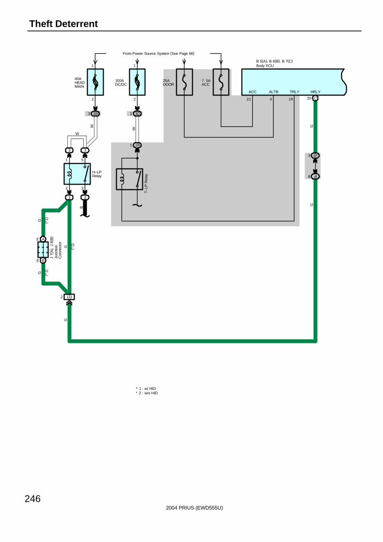
2004 PRIUS (EWD555U)
246
Theft Deterrent
G
C20
4F3
4I8
HRLY
4
B 5(A), B 6(B), B 7(C)
G
ALTB
19
TRLY
40AHEADMAIN
From Power Source System (See Page 66)
3B3
2
1
2 3
1 5
3 3
3
IJ32
BE
AE
W
G
G
G
W
H–LPRelay
( *1)
( *1)
( *2)
J 7(
A) ,
J 8
( B)
3
B
1 1BT–
LP R
elay
25ADOOR
100ADC/DC
3D1
W
1
2
7. 5AACC
21
ACC
* 2 : w/o HID* 1 : w/ HID
GBody ECU
Junc
tion
Con
nect
or
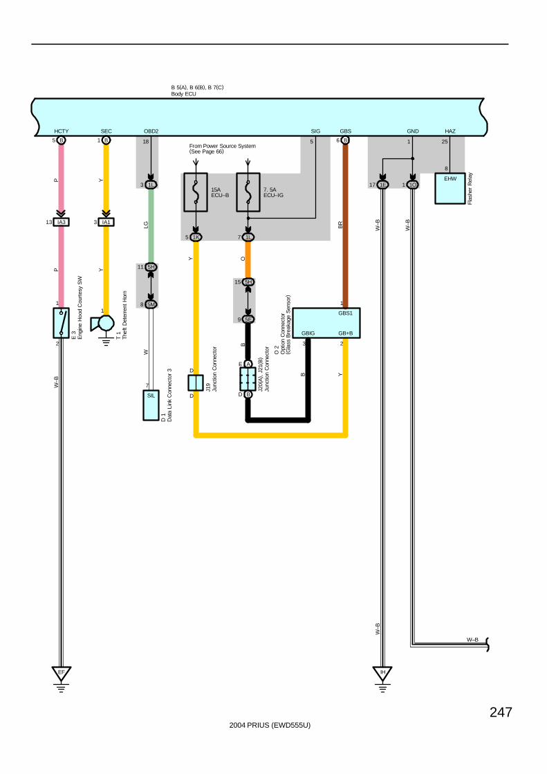
2004 PRIUS (EWD555U)
247
B 5(A), B 6(B), B 7(C)
1E17
W–B
1 1O
HAZGND
IH
251
W–B
W–B
W–B
8
EHW
Flas
her
Rel
ay
D 1
Y
1
3 IA1
Y
1 B
OBD2SEC
7
1L3
18
5M8
5H11
T 1
LGW
SIL
5 B
E 3
W–B
PP
IA313
2
1
HCTY
EF
J20(
A) ,
J21
( B)
B
From Power Source System(See Page 66)
1L7
O 2
5H15
5E9
B6
GBS
GB+BGBIG
1
3 2
O
BR
B Y
5
GBS1
SIG
1K5
Y15AECU–B
7. 5AECU–IG
J19
D
DAE
BD
Body ECU
Dat
a Li
nk C
onne
ctor
3
Eng
ine
Hoo
d C
ourt
esy
SW
Junc
tion
Con
nect
or
Junc
tion
Con
nect
or
Thef
t D
eter
rent
Hor
n
Opt
ion
Con
nect
or( G
lass
Bre
akag
e S
enso
r)
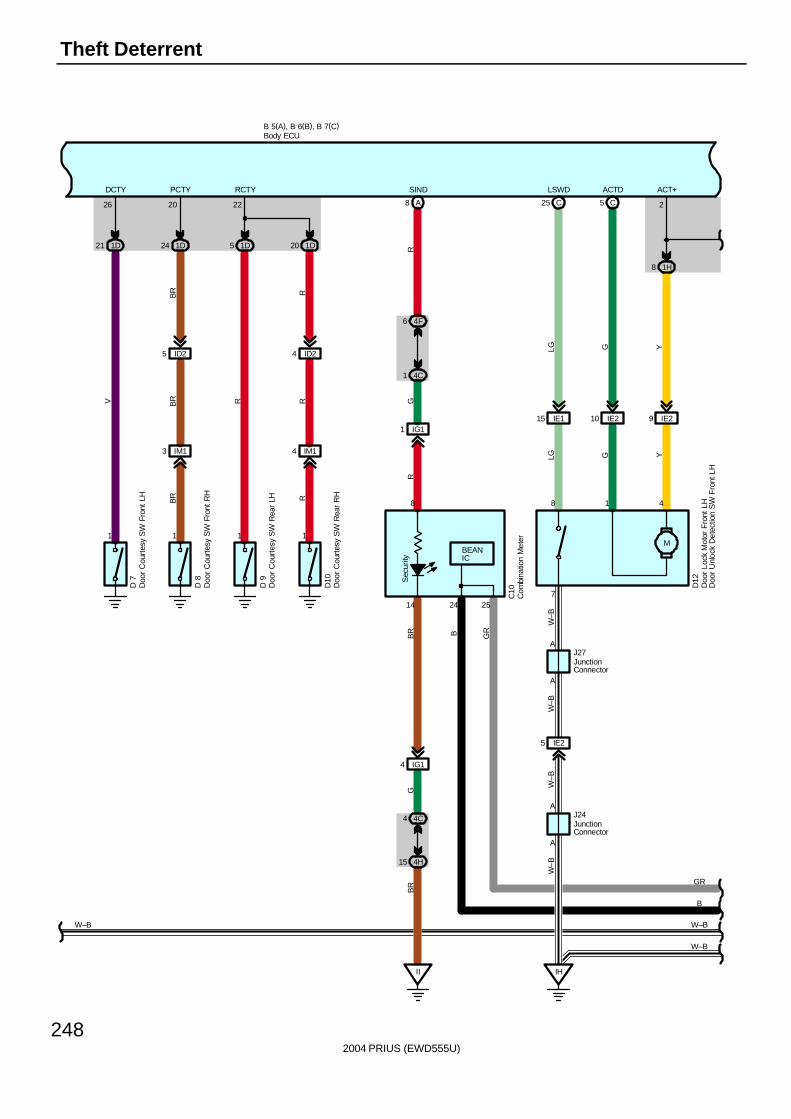
2004 PRIUS (EWD555U)
248
Theft Deterrent
M
IE115 IE210 9 IE2
8 1H
5 CC25
W–B
IH
B 5(A), B 6(B), B 7(C)
IE25
A
A
LSWD ACTD ACT+
W–B
W–B
W–B
LG G Y
D12
LG G Y
J24
J27
W–B W–B
A
8 1 4
2
A
7
W–B
Sec
urity
14
8
A8
IG11
4F6
4C1
II
IG14
4C4
4H15
GR
SIND
RB
RG
BR
1D21 1D24 1D5 1D20
1 1 1 1
IM13 IM14
ID25 ID24
222026
RCTYPCTYDCTY
RR
R
RBR
BR
BR
V
D 7
D 8
D 9
D10
C10
B
GR
24 25
B GR
BEANIC
Body ECU
Com
bina
tion
Met
er
Doo
r Lo
ck M
otor
Fro
nt L
HD
oor
Unl
ock
Det
ectio
n S
W F
ront
LH
Doo
r C
ourt
esy
SW
Fro
nt L
H
Doo
r C
ourt
esy
SW
Fro
nt R
H
Doo
r C
ourt
esy
SW
Rea
r LH
Doo
r C
ourt
esy
SW
Rea
r R
H
JunctionConnector
JunctionConnector
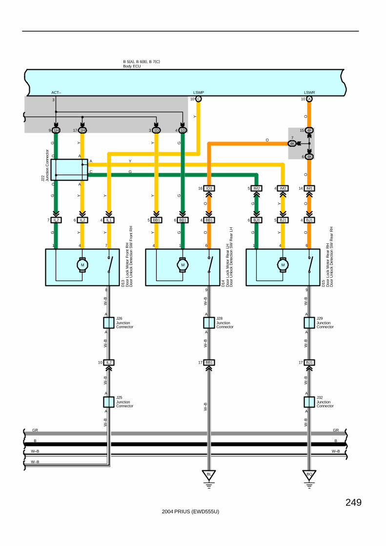
2004 PRIUS (EWD555U)
249
B 5(A), B 6(B), B 7(C)
W–B
W–B
IL210
A
A
W–B
W–B
J25
J26A
A
6 IL27 IL2 IL14
M
6 BB15 BB1 BB14
M
5 BJ16 BJ1 BJ14
M
IM25 IM24 IM114ID316
1H9 1H17 1D3 1D4
C10 A10
6 4K
4F15
4K
7
BL
BB117
BQ
BJ117
A
A
998
A A
C A
3
641614741
AC
AA
A
C
LSWRLSWPACT–
W–B W–B
D15
Y
G
O
G Y Y
G Y
D14
Y
G
J28
Y Y G
Y G
Y
D13
G O G
J29
Y OW
–B
W–B
J22
W–B
W–B
W–B
W–B
J32
W–B
OYGO
OOY
W–B
B B
GR GR
Body ECU
Doo
r Lo
ck M
otor
Fro
nt R
HD
oor
Unl
ock
Det
ectio
n S
W F
ront
RH
Doo
r Lo
ck M
otor
Rea
r LH
Doo
r U
nloc
k D
etec
tion
SW
Rea
r LH
Doo
r Lo
ck M
otor
Rea
r R
HD
oor
Unl
ock
Det
ectio
n S
W R
ear
RH
Junc
tion
Con
nect
or
JunctionConnector
JunctionConnector
JunctionConnector
JunctionConnector
JunctionConnector
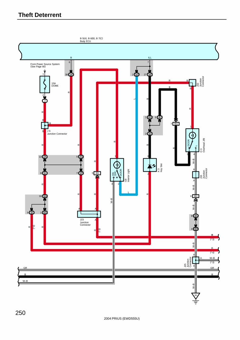
2004 PRIUS (EWD555U)
250
Theft Deterrent
B 5(A), B 6(B), B 7(C)
15ADOME
From Power Source System(See Page 66)
3
2
1
B
B
1A30
1A13
1L8
5G1
5H16
5I9
1O
1F7
1E27
IB15
4G2
4J2
4L6
3
1
OFF
DO
OR
ON
1O5
2
3
1
LDO
OR
IB17
IB16
W–B
R
2
2
A
6
B
J23
76
B
R
B ILL
L
I18
R R
RRR
R
K 3
R
J 6
B
R
W–B
R
BL
R
B
A
R
R
A
B
O 3
R
B
J33
W–B
W–B
W–B
J33
4
A
4K8
4H4
W–B
A
A
IH
W–B
( *3)R
( *4)
(* 4)
R
(*3)
R
W–B
(*3)
A
A
J25
B
GR
B
GR
Body ECU
Inte
rior
Ligh
t
Junction Connector
JunctionConnector
Junc
tion
Con
nect
or
Junc
tion
Con
nect
or
Junc
tion
Con
nect
orO
verh
ead
J/B
Key
Slo
t
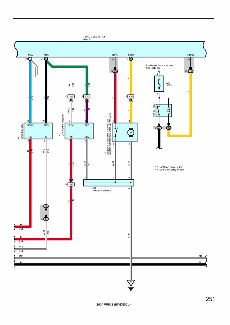
2004 PRIUS (EWD555U)
251
BL
ID4
1 C
1212 ID211 ID2
M
7 1D 28 1A
B 5(A), B 6(B), B 7(C)
R
A A
2 42 3
A
11
15
3
23
J30
BCTY BACT HORN
GND
Y
W G
R
Y
W–B V
L 3
W–B
W–B
W–B
D 4
PRGRDA3J73J8
10AHORN
From Power Source System(See Page 66)
B
Y
HO
RN
Rel
ay
24 C
PRG
23 C
RDA
28
PRG
29
RDA3
BL
( *3)
( *3)
S11
12 4L
( *3)R ( *3)
W–B
( *3)
W–B
( *4)
( *4)
( *4)
( *4)
( *4)
(* 4)(*4)
R
(*3)
R
W–B
(*3)
17
E
1
+B1
5 4H
W–B
* 4 : w/o Smart Entry System* 3 : w/ Smart Entry System
A
5
+B
R ( *4)
ID214
R ( *4)
B
GR
B
GR
Body ECU
Lugg
age
Com
partm
ent
Cou
rtes
y S
WLu
ggag
e C
ompa
rtmen
t D
oor
Ope
ner
Mot
or
Junction Connector
Doo
r C
ontr
ol R
ecei
ver
Sm
art K
ey E
CU
1
2
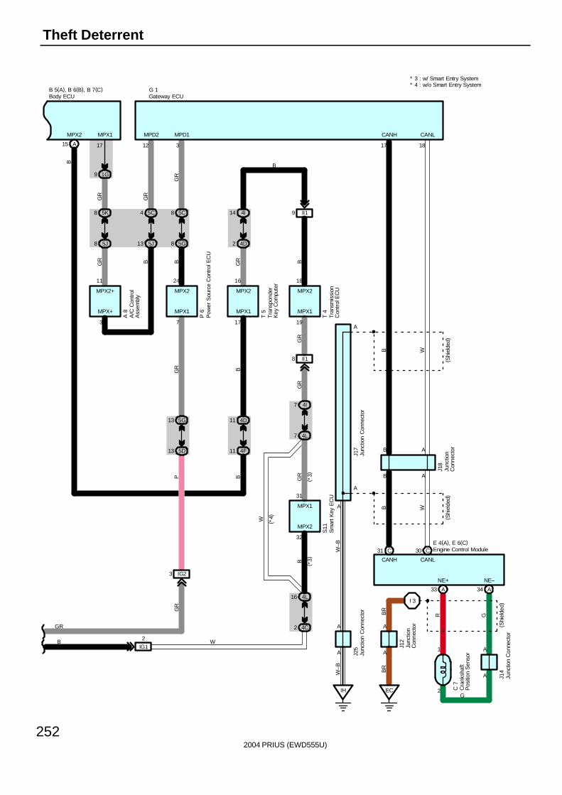
2004 PRIUS (EWD555U)
252
Theft Deterrent
MPD2
12
IH
A
A
A
1817
AB
J25
A
A
CANLCANH
(Shi
elde
d)
A
( Shi
elde
d)
B
WBB W
W–B
W–B
G 1
CANH CANL
E 4(A), E 6(C)C31 C30
A34A33
NE+ NE–
G
GR
I 3
( Shi
elde
d)
BR
A
A
J12
9 1G
5J8
5K8
17
A 8
3
11
MPX1
MPX+
GR
GR
MPX2+
BG
R
4 5C
13 5J
B
MPX2
MPX1 MPX1MPX1
B
MPD1
16 1824
31
32
17 197
5C8
5G8
5D13
5G13
3
3 IG2
4L16
4C2
4I14
4D2
4F11
4D11
4L7
4I7
II19
II18
( *3)
( *3)
( *4)
T 5
GR
B BG
RG
R
GR B
T 4
P 6
GR
BG
R
W
GR
P
MPX1
MPX2 MPX2
S11
MPX2
IG1
2
GR
W
15 A
MPX2
B
B
2
1 A
A
C 7
J14
J17
B 5(A), B 6(B), B 7(C)
J18
* 3 : w/ Smart Entry System* 4 : w/o Smart Entry System
A/C
Con
trol
Ass
embl
y
Body ECU
Cra
nksh
aft
Pos
ition
Sen
sor
Engine Control Module
Gateway ECU
Junc
tion
Con
nect
or
Junc
tion
Con
nect
or
Junc
tion
Con
nect
or
Junc
tion
Con
nect
or
Junc
tion
Con
nect
or
Tra
nspo
nder
Key
Com
pute
r
Tra
nsm
issi
onC
ontr
ol E
CU
Sm
art K
ey E
CU
EC
BR
Pow
er S
ourc
e C
ontr
ol E
CU
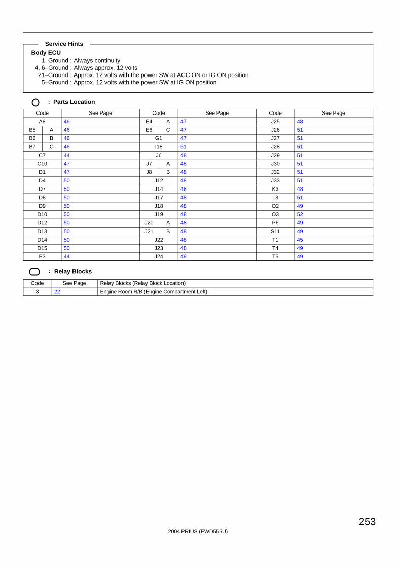
2004 PRIUS (EWD555U)
253
Body ECU1–Ground : Always continuity
4, 6–Ground : Always approx. 12 volts21–Ground : Approx. 12 volts with the power SW at ACC ON or IG ON position
5–Ground : Approx. 12 volts with the power SW at IG ON position
: Parts Location
Code See Page Code See Page Code See Page
A8 46 E4 A 47 J25 48
B5 A 46 E6 C 47 J26 51
B6 B 46 G1 47 J27 51
B7 C 46 I18 51 J28 51
C7 44 J6 48 J29 51
C10 47 J7 A 48 J30 51
D1 47 J8 B 48 J32 51
D4 50 J12 48 J33 51
D7 50 J14 48 K3 48
D8 50 J17 48 L3 51
D9 50 J18 48 O2 49
D10 50 J19 48 O3 52
D12 50 J20 A 48 P6 49
D13 50 J21 B 48 S11 49
D14 50 J22 48 T1 45
D15 50 J23 48 T4 49
E3 44 J24 48 T5 49
: Relay Blocks
Code See Page Relay Blocks (Relay Block Location)
3 22 Engine Room R/B (Engine Compartment Left)
Service Hints
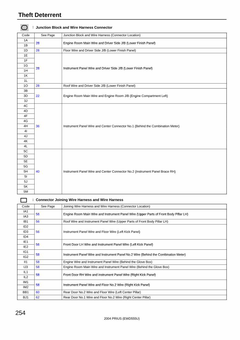
2004 PRIUS (EWD555U)
254
Theft Deterrent
: Junction Block and Wire Harness Connector
Code See Page Junction Block and Wire Harness (Connector Location)
1A28 Engine Room Main Wire and Driver Side J/B (Lower Finish Panel)
1B28 Engine Room Main Wire and Driver Side J/B (Lower Finish Panel)
1D 28 Floor Wire and Driver Side J/B (Lower Finish Panel)
1E
1F
1G28 Instrument Panel Wire and Driver Side J/B (Lower Finish Panel)
1H28 Instrument Panel Wire and Driver Side J/B (Lower Finish Panel)
1K
1L
1O 28 Roof Wire and Driver Side J/B (Lower Finish Panel)
3B
3D 22 Engine Room Main Wire and Engine Room J/B (Engine Compartment Left)
3J
g g ( g )
4C
4D
4F
4G
4H 36 Instrument Panel Wire and Center Connector No.1 (Behind the Combination Meter)
4I
( )
4J
4K
4L
5C
5D
5E
5G
5H 40 Instrument Panel Wire and Center Connector No.2 (Instrument Panel Brace RH)
5I
( )
5J
5K
5M
: Connector Joining Wire Harness and Wire Harness
Code See Page Joining Wire Harness and Wire Harness (Connector Location)
IA156 Engine Room Main Wire and Instrument Panel Wire (Upper Parts of Front Body Pillar LH)
IA356 Engine Room Main Wire and Instrument Panel Wire (Upper Parts of Front Body Pillar LH)
IB1 56 Roof Wire and Instrument Panel Wire (Upper Parts of Front Body Pillar LH)
ID2
ID3 56 Instrument Panel Wire and Floor Wire (Left Kick Panel)
ID4
( )
IE156 Front Door LH Wire and Instrument Panel Wire (Left Kick Panel)
IE256 Front Door LH Wire and Instrument Panel Wire (Left Kick Panel)
IG158 Instrument Panel Wire and Instrument Panel No 2 Wire (Behind the Combination Meter)
IG258 Instrument Panel Wire and Instrument Panel No.2 Wire (Behind the Combination Meter)
II1 58 Engine Wire and Instrument Panel Wire (Behind the Glove Box)
IJ3 58 Engine Room Main Wire and Instrument Panel Wire (Behind the Glove Box)
IL158 Front Door RH Wire and Instrument Panel Wire (Right Kick Panel)
IL258 Front Door RH Wire and Instrument Panel Wire (Right Kick Panel)
IM158 Instrument Panel Wire and Floor No 2 Wire (Right Kick Panel)
IM258 Instrument Panel Wire and Floor No.2 Wire (Right Kick Panel)
BB1 60 Rear Door No.2 Wire and Floor Wire (Left Center Pillar)
BJ1 62 Rear Door No.1 Wire and Floor No.2 Wire (Right Center Pillar)
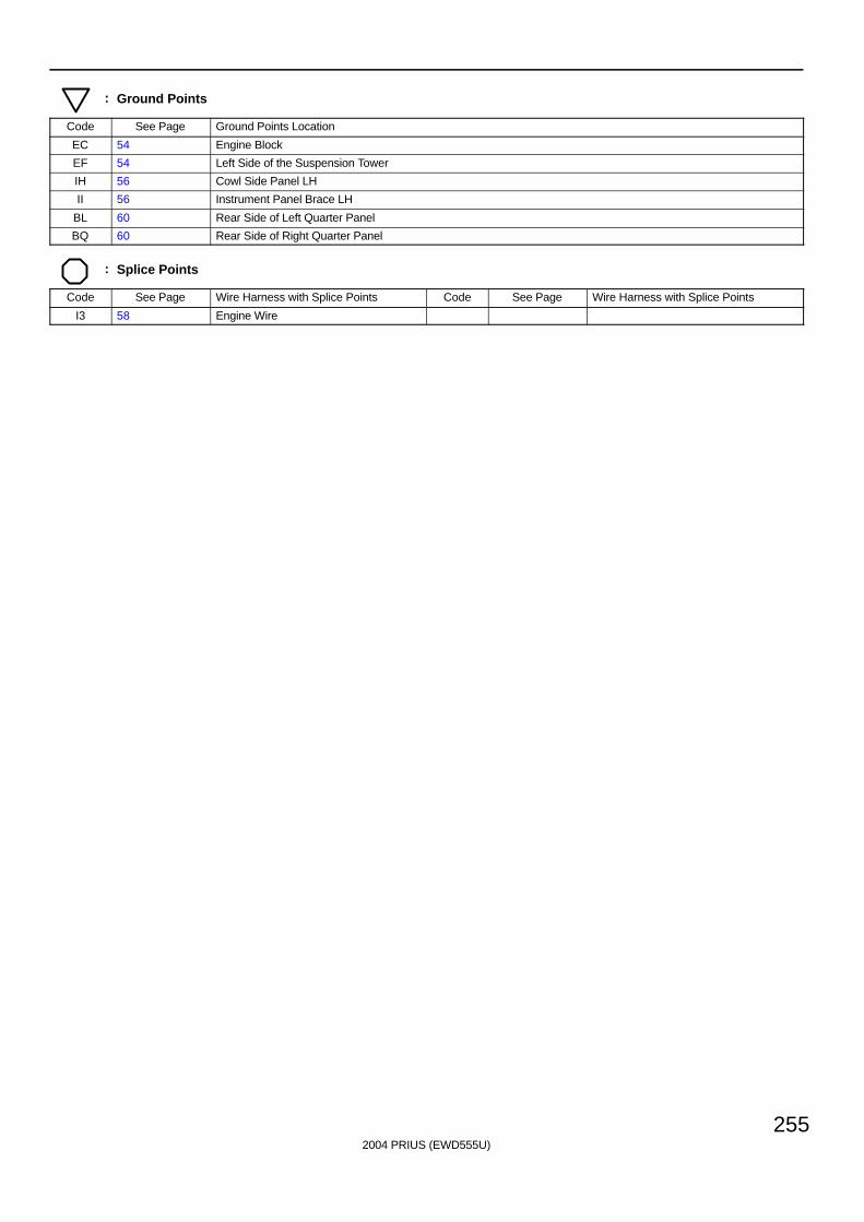
2004 PRIUS (EWD555U)
255
: Ground Points
Code See Page Ground Points Location
EC 54 Engine Block
EF 54 Left Side of the Suspension Tower
IH 56 Cowl Side Panel LH
II 56 Instrument Panel Brace LH
BL 60 Rear Side of Left Quarter Panel
BQ 60 Rear Side of Right Quarter Panel
: Splice Points
Code See Page Wire Harness with Splice Points Code See Page Wire Harness with Splice Points
I3 58 Engine Wire
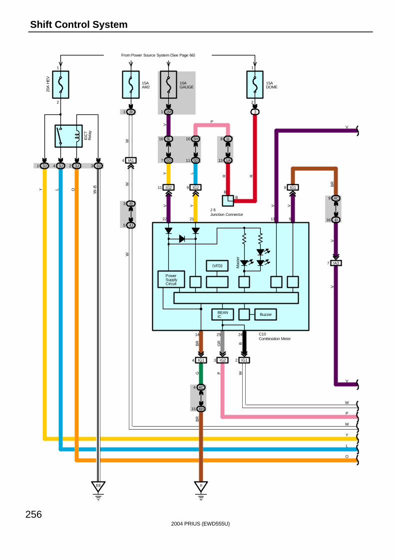
2004 PRIUS (EWD555U)
256
Shift Control System
L
EE
Y
P
W
W
15AAM2
W
3I1
4J5
3 4I
2
1
20A
HE
V
From Power Source System (See Page 66)
3J4 3J23J1 3J3
IGC
TR
elay
O
W
L
W–BY
10AGAUGE
1M1
5D7
16 5L
VIA14
W
WP
V
7 IA3
4I16
4C9
VB
R
11 IG2
22
V
4H15
BGR
4C
IG2
242514
BR
G
C10
PowerSupplyCircuit
BEANIC
(VFD)
4
3 IG12IG14
II
13
V
Mas
ter
O
V
9 IG1
9
V
Y
J 6
1
2
3
15ADOME
BIG29
5D11
5H16 1L8
1A13
LY
21
B
R R
P
Buzzer
V
Combination Meter
Junction Connector
BR
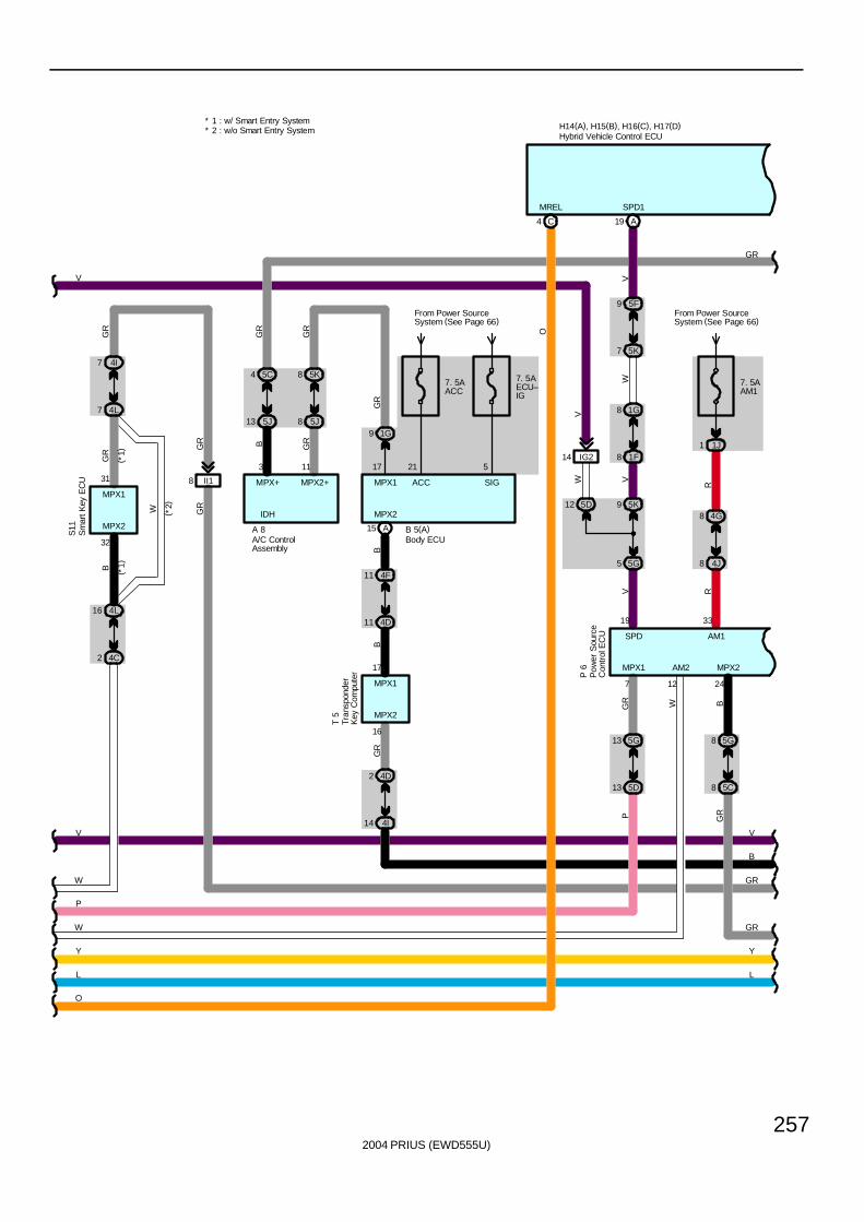
2004 PRIUS (EWD555U)
257
4D
B 5(A)
L L
O
W GR
YY
MPX+
A 8
( *2)
11
GR
GR
GR
B
W
GR
B
MPX1
31
4F
32
MPX2
11
A
4 5C
13 5J
7 4I
7 4L
16 4L
2 4C
(*1)
( *1)
II18
GR
P
W
4J
IDH
8
B
GR
4G8
5D
3
MPX2+
GR
GR
8 5K
8 5J
11
1G9
MPX1
17
GR
33
AM1
13
5G
R
15
MPX2
B
GR
SPD1
A19
5F9
5K7
8 1F
1G8
5K912 5D
5G5
19
SPDV
IG214
W V
V
WV
BGR
AM2
12
1 1J
From Power SourceSystem (See Page 66)
7. 5AAM1
R
247
MPX2MPX1W
13
B
T 5
17
16
MPX2
MPX1
2 4D
14 4I
GR
C4
MREL
O
P
5C8
5G8
GR
H14(A), H15(B), H16(C), H17(D)
S11
P 6
* 1 : w/ Smart Entry System* 2 : w/o Smart Entry System
V
ACC
21
From Power SourceSystem (See Page 66)
7. 5AACC
7. 5AECU–IG
5
SIG
V V
A/C ControlAssembly
Body ECU
Hybrid Vehicle Control ECU
Tran
spon
der
Key
Com
pute
r
Sm
art K
ey E
CU
Pow
er S
ourc
eC
ontr
ol E
CU
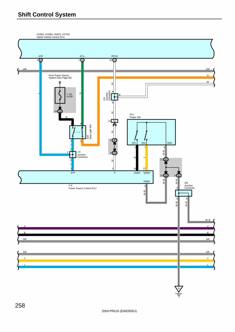
2004 PRIUS (EWD555U)
258
Shift Control System
W
C
7. 5ASTOP
From Power SourceSystem (See Page 66)
1A18
L
STP
3 B
H14(A), H15(B), H16(C), H17(D)
GR
J 9
STP
1
S16
C
C
LL
G
3
42
1
ST1–
2 B
GR
P 6
GR
Y
B
B
GR
Y
LL
B
O
GR
GR
W–B
A
J25W
–B
5G10
W–B
6
GND2
W–B
J14
SS2SS1 GND
A
P11
12 II1
14 37
SSW1 SSW2
5 7
B Y
B
W
P
D10
PPOS
W
5
2 4I
4 4J
B
WW
B
A
5G11
5 5L
IH
6
W–B
W–B
W–B
VV
Hybrid Vehicle Control ECU
JunctionConnector
Junc
tion
Con
nect
or
JunctionConnector
Sto
p Li
ght S
W
Power Source Control ECU
Power SW
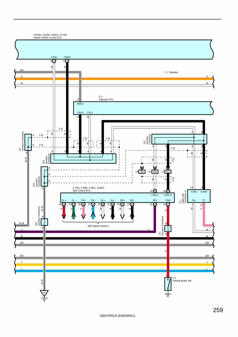
2004 PRIUS (EWD555U)
259
W–B
A
A
A
J17
H14(A), H15(B), H16(C), H17(D)
MPD2
12
A
W
O
B
A9 A8
B A B A
17 18
BW
B W B
CANL CANH
WCA1LCA1H
IH
A
A
J24
W–B
W–B
(* 3)
(*3)
(*3)
(*3) (*3)
A
G 1
GR
W B
14 6
CANL CANH
13
TCP
7
SIL
W
D 1
(* 3)A B
L
Y
GR
W–B
GR
B
L
Y
GR
GR
B
W
O
W
* 3 : Shielded
A B
CAN–L CAN–H
A B
J16
W B ( *3)
IA111IA112IA113
A
A
A
( *3)W B
BW
V
SP1
V
B18 B19
B22 C14
PKB
B
BJ 9
RR
1P 2
D28 D22 A32 A22 B35 B27 C31 C23
FL+ FL– FR+ FR– RL+ RL– RR+ RR–
R G P L W B W B
ABS Speed Sensors
S 7(A), S 8(B), S 9(C), S10(D)
J18
J15
Skid Control ECU
Dat
a Li
nkC
onne
ctor
3
Gateway ECU
Hybrid Vehicle Control ECU
Junc
tion
Con
nect
or
Junc
tion
Con
nect
or
Junc
tion
Con
nect
or
Junc
tion
Con
nect
or
Junc
tion
Con
nect
or
Junc
tion
Con
nect
or
Parking Brake SW
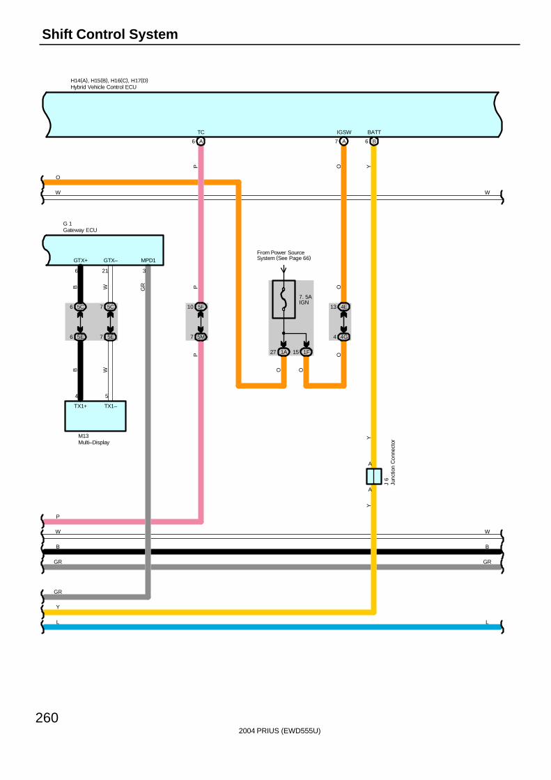
2004 PRIUS (EWD555U)
260
Shift Control System
P
H14(A), H15(B), H16(C), H17(D)
W
GR
3
MPD1
A6
TC
7 5M
10 5F
PP
GR
GR
L
Y
L
B
W
7 5E6 5E
7 5C6 5C
B W
B W
4 5
TX1+ TX1–
6 21
GTX+ GTX–
M13
7. 5AIGN
1A27 1F15
From Power SourceSystem (See Page 66)
O O
O
A7
IGSW
4 4G
13 4E
OO
GR
B
W
P
B6
BATT
YY
A
J 6
A
Y
G 1
W
O
Gateway ECU
Hybrid Vehicle Control ECU
Junc
tion
Con
nect
orMulti–Display
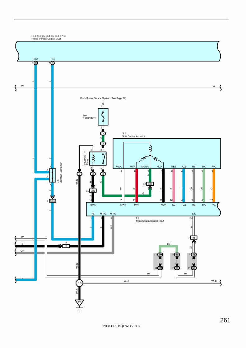
2004 PRIUS (EWD555U)
261
L
L
GR
A
LL
W
C7
+B1J
3
L
C6
+B2
LH14(A), H15(B), H16(C), H17(D)
L
AA
A
L
W
W
B
EB11
B
BMA
14
2 5
1 3
333
10
3
30AP CON MTR
From Power Source System (See Page 66)
3
2
1
EF
E 3
EB111
EB112
OLGGRLPB
GB
W–B
G
W R
W–B
W–B
G
G
11 12 16 4 5 6 17
1 6 2 7 8 4 3 5 9
P C
ON
MT
RR
elay
S 1
T 4
MWA MVA MUA E2 RZ1 RB RA VC
RE2 RZ1 RB RA RVCMUAMGNAMVAMWA
3 5I
II17
1
+B
GR
19
MPX1
B
18
MPX2
1L35H11
5K111E75M8
W
20
SIL
W–B
W
LG
W
W
W–B
II1
9
Hybrid Vehicle Control ECU
Junc
tion
Con
nect
or
Transmission Control ECU
Shift Control Actuator
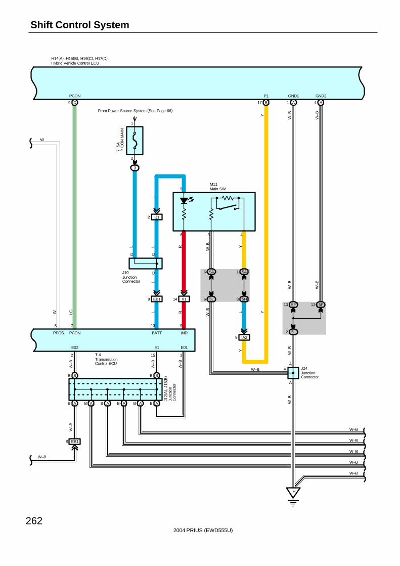
2004 PRIUS (EWD555U)
262
Shift Control System
W
AB AB
BB BB
EB18
W–B
W–B
W–B
W–B
6 5A 5A1
5L6 5H8
IA29
II114EB19
From Power Source System (See Page 66)
3
2
1
L L
13 9
2 15 3
R
W–B Y
LL R
W–B L
6 3 4
D
D D
M11
T 4
J10
J12(
A) ,
J13
( B)
E02 E1 E01
BATT IND
IJ12
5
L
B17
P1
Y
Y
8
PPOS
WH14(A), H15(B), H16(C), H17(D)
D9
PCON
7. 5
AP
CO
N M
AIN
7
LG
PCON
W–B
Y
A1 A4
5F13 5F12
5L2
IH
W–B
W–B
W–B
W–B
GND1 GND2
A
A
W–B
W–B
J24
W–B
AW–B
W–B
W–B
W–B
W–B
ABB AABB A
Hybrid Vehicle Control ECU
JunctionConnector
Junc
tion
Con
nect
or
JunctionConnector
TransmissionControl ECU
Main SW
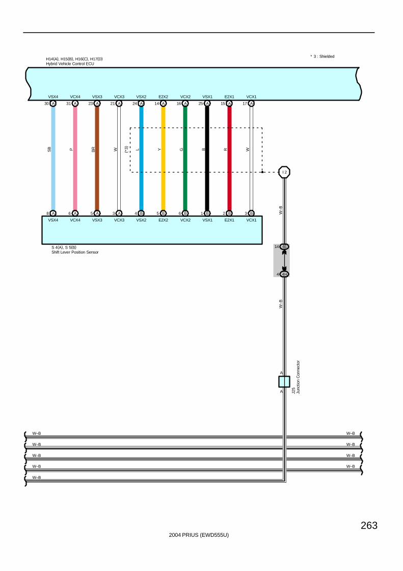
2004 PRIUS (EWD555U)
263
H14(A), H15(B), H16(C), H17(D)
A30 A31 A23 A21 A24 A14 A16 A25 A15 A17
A8 A6 A5 A3 B4 B5 B6 B1 B2 B3
I 2
4E14
4H4
SB P BR W L Y G B R W
W–B
W–B
W–B
(*3)
VSX4 VCX4 VSX3 VCX3 VSX2 E2X2 VCX2 VSX1 E2X1 VCX1
VSX4 VCX4 VSX3 VCX3 VSX2 E2X2 VCX2 VSX1 E2X1 VCX1
S 4(A), S 5(B)
J25
A
A
* 3 : Shielded
W–B
W–B
W–B
W–B W–B
W–B
W–B
W–B
Hybrid Vehicle Control ECU
Junc
tion
Con
nect
or
Shift Lever Position Sensor
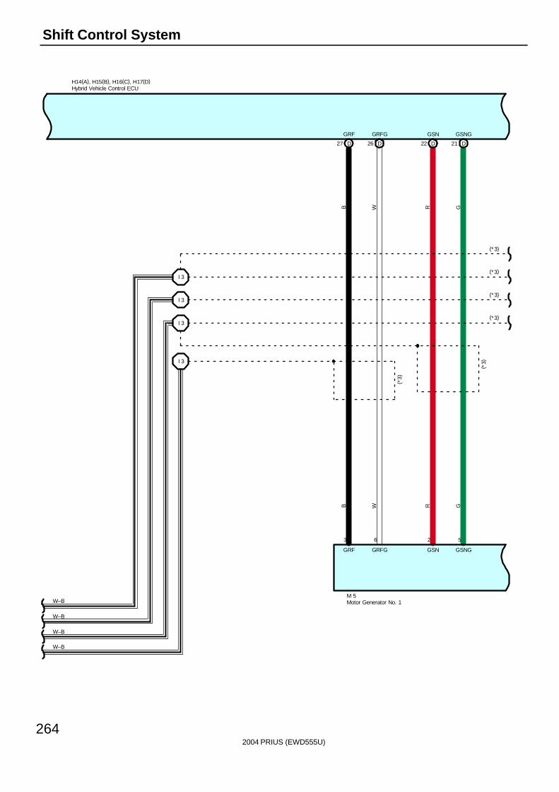
2004 PRIUS (EWD555U)
264
Shift Control System
H14(A), H15(B), H16(C), H17(D)
M 5W–B
26 DD27 21 DD22
I 3
I 3
I 3
I 3
B W R G
B W R G
GRF GRFG GSN GSNG
GRF GRFG GSN GSNG
(*3)
3 6 2 5
W–B
W–B
W–B
(*3)
(*3)
(*3)
(*3)
( *3)
Hybrid Vehicle Control ECU
Motor Generator No. 1
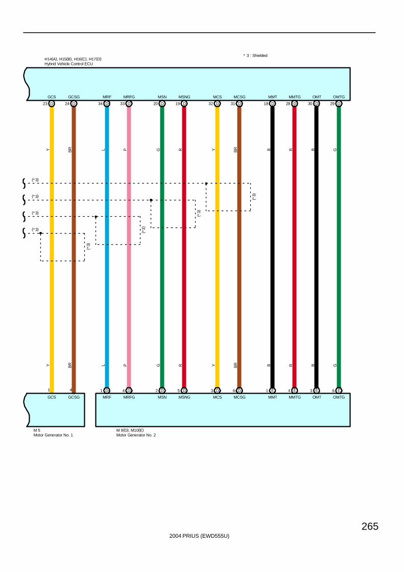
2004 PRIUS (EWD555U)
265
* 3 : Shielded
24 DD23 33 DD34 19 DD20
H14(A), H15(B), H16(C), H17(D)
31 DD32 28 DD18 29 DD30
Y BR L P
Y BR L P G R Y BR
G R Y BR B R B G
B R B G
GCS GCSG MRF MRFG MSN MSNG MCS MCSG MMT MMTG OMT OMTG
GCS GCSG MRF MRFG MSN MSNG MCS MCSG MMT MMTG OMT OMTG
(*3)
( *3)
( *3)
( *3)
1 4 D1
M 9(D), M10(E)M 5
(*3)
(*3)
(*3)
(*3)
D4 D2 D5 D3 D6 E1 E4 E3 E6
Hybrid Vehicle Control ECU
Motor Generator No. 1 Motor Generator No. 2
2004 PRIUS (EWD555U)
266
Shift Control System
Under this system, operating signal of shift lever is sent to hybrid vehicle control ECU to control hybrid motor, which changesshift ranges (R, N, D, B) electrically. When shift is put in P range, transmission control ECU receives operating signal fromhybrid vehicle control ECU and activates parking lock electrically.
1. Shift Range Change FunctionGear can be shifted to any shift range under condition when vehicle can drive except when reject function is in operation.When vehicle cannot drive with power SW at IG ON position, gear can be shifted only to P and N range.When vehicle cannot drive with power SW at ACC ON position, gear can be shifted only to P range.When power SW is at OFF position, gear cannot be shifted to any range.When main SW is operated at vehicle stop after starting hybrid system, gear is automatically changed to P range from anyother gear range and turns off power supply.
2. Reject FunctionChanging gear may not effect to change range under certain vehicle condition. Under such condition, warning buzzer ofcombination meter sounds to show the rejection and call for driver’s attention. Followings are shift operations and shift rangeconditions under which reject function is activated.∗ When gear is shifted from P range to other range without applying brake pedal, gear stays in P range.∗ Main SW cannot put gear in P range during driving but changes to N range.∗ Shift change to forward or backward during driving changes gear to N range.∗ When gear is changed from other range than D range to B range, gear is changed to N range automatically.
3. Combination Meter IndicationThe combination meter shows present shift range position. Other shift range positions than D or B range are not shown inlighting in the combination meter. This is to avoid unnecessary shifting operation to B range from other shift position except Drange.
4. Operation of Parking LockOperation signal from/to P range is sent from main SW or power SW to transmission control ECU through hybrid vehiclecontrol ECU. At that time the transmission control ECU operates P CON MTR relay, activates parking lock actuator withappropriate control of electric current, and lights up main SW when shift is at P range. If the system has abnormality onparking lock operation, it tells the system abnormality to the driver by lighting up master warning light on combination meter,displaying warning of the system abnormality on the multi–display, and blinking indicator light of main SW.
5. Operation at Electric Power OFFUnder electric power OFF, transmission control ECU receives signal from power source control ECU bymulti–communication, and sends shift range position information to hybrid vehicle control ECU. The hybrid vehicle controlECU sends signal to power source control ECU to tell whether it is right or wrong condition to turn off electric power.Accepted conditions for electric power OFF are as follows;∗ When hybrid vehicle control ECU is not sending request signal for parking lock release with shift range in P range position.∗ With shift range is at other range than P range, when hybrid vehicle control ECU is outputting signal that hybrid system is
not running or request signal for parking lock.∗ When there is abnormal motor’s not running condition with paring lock in operation, and hybrid system is not running and
parking brake is being applied.
T4 Transmission Control ECU1–Ground : Approx. 12 volts with the power SW at IG ON position
13–Ground : Always approx. 12 volts2, 3, 15–Ground : Always continuity
System Outline
Service Hints
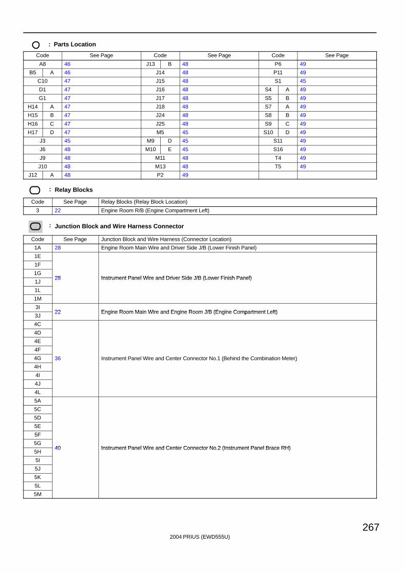
2004 PRIUS (EWD555U)
267
: Parts Location
Code See Page Code See Page Code See Page
A8 46 J13 B 48 P6 49
B5 A 46 J14 48 P11 49
C10 47 J15 48 S1 45
D1 47 J16 48 S4 A 49
G1 47 J17 48 S5 B 49
H14 A 47 J18 48 S7 A 49
H15 B 47 J24 48 S8 B 49
H16 C 47 J25 48 S9 C 49
H17 D 47 M5 45 S10 D 49
J3 45 M9 D 45 S11 49
J6 48 M10 E 45 S16 49
J9 48 M11 48 T4 49
J10 48 M13 48 T5 49
J12 A 48 P2 49
: Relay Blocks
Code See Page Relay Blocks (Relay Block Location)
3 22 Engine Room R/B (Engine Compartment Left)
: Junction Block and Wire Harness Connector
Code See Page Junction Block and Wire Harness (Connector Location)
1A 28 Engine Room Main Wire and Driver Side J/B (Lower Finish Panel)
1E
1F
1G28 Instrument Panel Wire and Driver Side J/B (Lower Finish Panel)
1J28 Instrument Panel Wire and Driver Side J/B (Lower Finish Panel)
1L
1M
3I22 Engine Room Main Wire and Engine Room J/B (Engine Compartment Left)
3J22 Engine Room Main Wire and Engine Room J/B (Engine Compartment Left)
4C
4D
4E
4F
4G 36 Instrument Panel Wire and Center Connector No.1 (Behind the Combination Meter)
4H
( )
4I
4J
4L
5A
5C
5D
5E
5F
5G40 Instrument Panel Wire and Center Connector No 2 (Instrument Panel Brace RH)
5H40 Instrument Panel Wire and Center Connector No.2 (Instrument Panel Brace RH)
5I
5J
5K
5L
5M
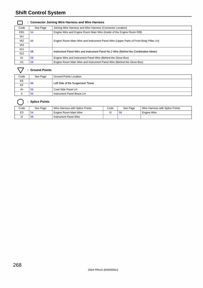
2004 PRIUS (EWD555U)
268
Shift Control System
: Connector Joining Wire Harness and Wire Harness
Code See Page Joining Wire Harness and Wire Harness (Connector Location)
EB1 54 Engine Wire and Engine Room Main Wire (Inside of the Engine Room R/B)
IA1
IA2 56 Engine Room Main Wire and Instrument Panel Wire (Upper Parts of Front Body Pillar LH)
IA3
g ( y )
IG158 Instrument Panel Wire and Instrument Panel No 2 Wire (Behind the Combination Meter)
IG258 Instrument Panel Wire and Instrument Panel No.2 Wire (Behind the Combination Meter)
II1 58 Engine Wire and Instrument Panel Wire (Behind the Glove Box)
IJ1 58 Engine Room Main Wire and Instrument Panel Wire (Behind the Glove Box)
: Ground Points
Code See Page Ground Points Location
EE54 Left Side of the Suspension Tower
EF54 Left Side of the Suspension Tower
IH 56 Cowl Side Panel LH
II 56 Instrument Panel Brace LH
: Splice Points
Code See Page Wire Harness with Splice Points Code See Page Wire Harness with Splice Points
E3 54 Engine Room Main Wire I3 58 Engine Wire
I2 58 Instrument Panel Wire

2004 PRIUS (EWD555U)
269
Memo
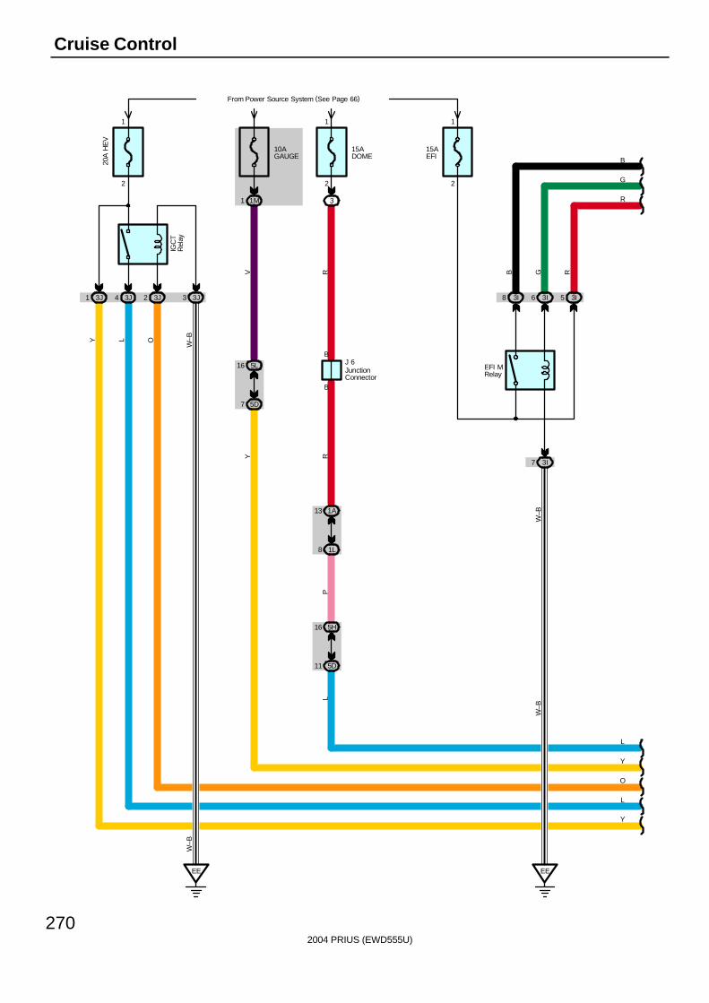
2004 PRIUS (EWD555U)
270
Cruise Control
5D7
5D11
16 5L
5H16
1A13
1L8
2
1
20A
HE
VFrom Power Source System (See Page 66)
3J4 3J23J1 3J3
IGC
TR
elay
OL
W–B
W–B
Y
Y
10AGAUGE
1M1
15ADOME
3
2
1
B
B
Y
L
V R
Y R
J 6
PL
15AEFI
3I8 3I6
3I7
EE
W–B
GB
EFI MRelay
2
1
W–B
3I5
R
L
O
R
G
B
JunctionConnector
EE
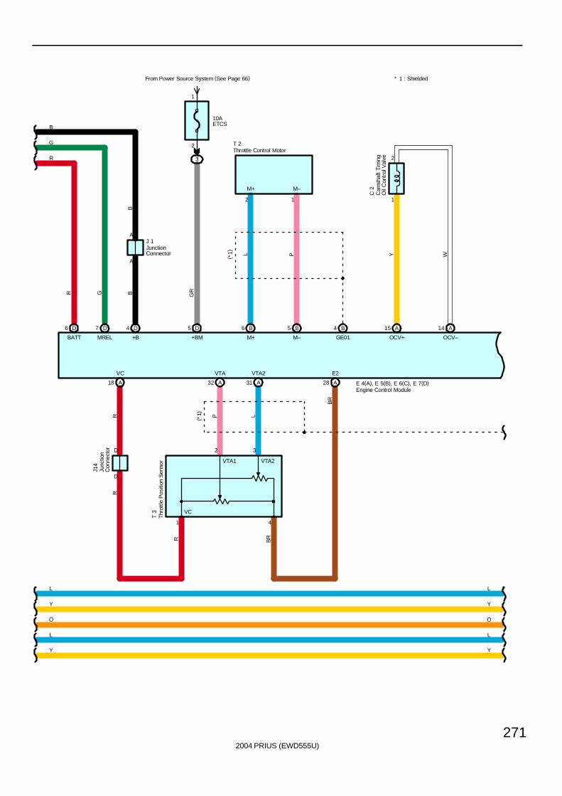
2004 PRIUS (EWD555U)
271
GR
A
A
+BM
5 D
E 4(A), E 5(B), E 6(C), E 7(D)
6 D
BATT
7 D
MREL
4 D
+B
BGR
J 1
10AETCS
3
2
1
From Power Source System (See Page 66)
VTA1 VTA2
D
VC
J14
T 3
1
2 3
4
( *1)
R
VC
BR
BR
LPRR
18 A
E2VTA2VTA
28 AA32 31 A
C 2
T 2
OCV–OCV+GE01M–M+
M–M+
12
( *1) WYPL
2
1
14 A15 A4 B5 B6 B
L
Y
O
L
Y
L
Y
O
Y
L
R
G
BB
* 1 : Shielded
D
Cam
shaf
t Ti
min
gO
il C
ontr
ol V
alve
Engine Control Module
JunctionConnector
Junc
tion
Con
nect
or
Throttle Control Motor
Thro
ttle
Pos
ition
Sen
sor
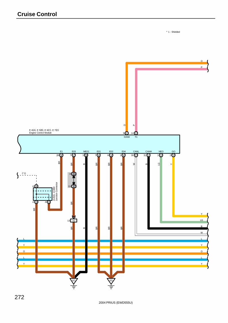
2004 PRIUS (EWD555U)
272
Cruise Control
L L
Y
O
Y
L
E 4(A), E 5(B), E 6(C), E 7(D)
BA
AA AA
E03 E04
1 A7 C B3
ME01 E01
7 A A6
E02
ED
II113
EC
B28
E1
BR
BR B BR
BR
BR
BR B BR
BR
BR
J12(
A) ,
J13
( B)
BR
BR
PTC
C14
Y
O
Y
L
4I11
4E3
P
W
B
LG
Y
CANL
30 C
W
CANH
31 C
B
NEO
1 D
LG
GO
2 D
Y(*1)
* 1 : Shielded
Engine Control Module
Junc
tion
Con
nect
or
O
IGSW
C9
O
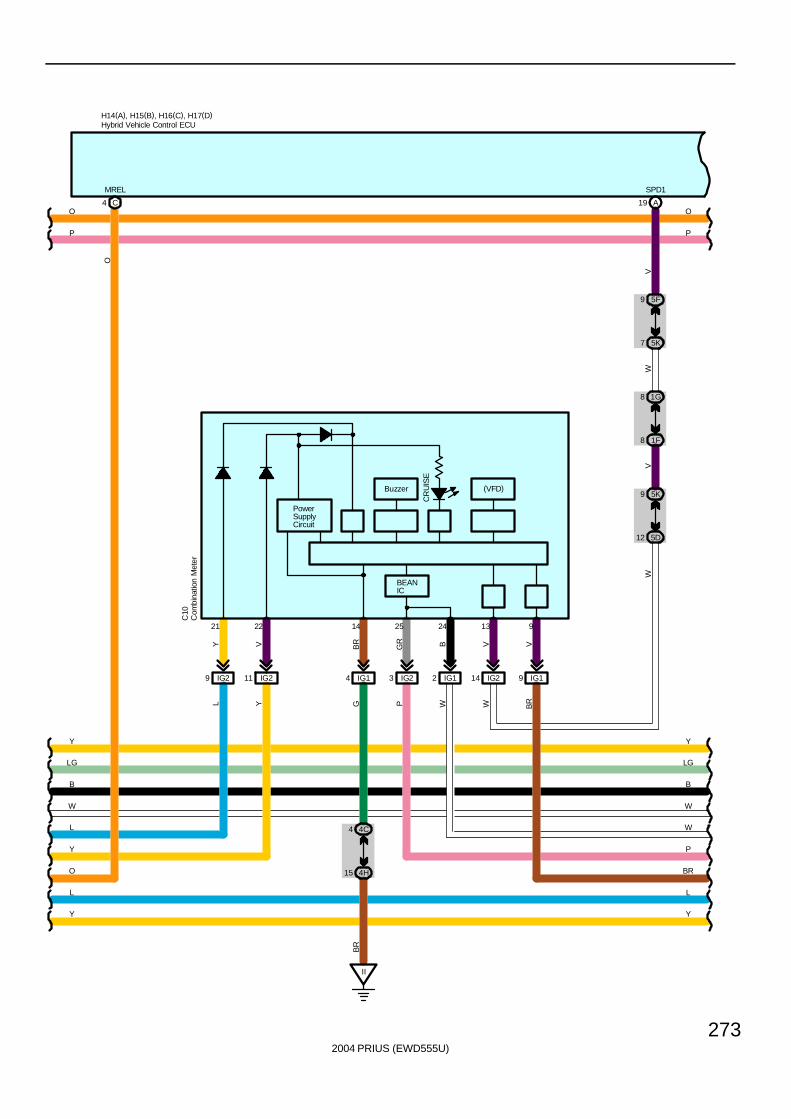
2004 PRIUS (EWD555U)
273
O
WWP
V
13
IG214
VW
V
8 1G
1F8
7 5K
9 5F
19 A
SPD1
5K9
5D12
4H15
P
W
BGR
4C
IG2
YY
L
H14(A), H15(B), H16(C), H17(D)
2425
O
MREL
4 C
14
BR
II
G
C10
PowerSupplyCircuit
BEANIC
CR
UIS
E
Buzzer
Y
IG211
4
BR
21
Y
22
VY
IG29 3
L
IG12IG14
L
L
W
PP
W
B
LG
Y
W
B
LG
Y
V
9
IG19
BR
BR
(VFD)
Com
bina
tion
Met
er
Hybrid Vehicle Control ECU
O O
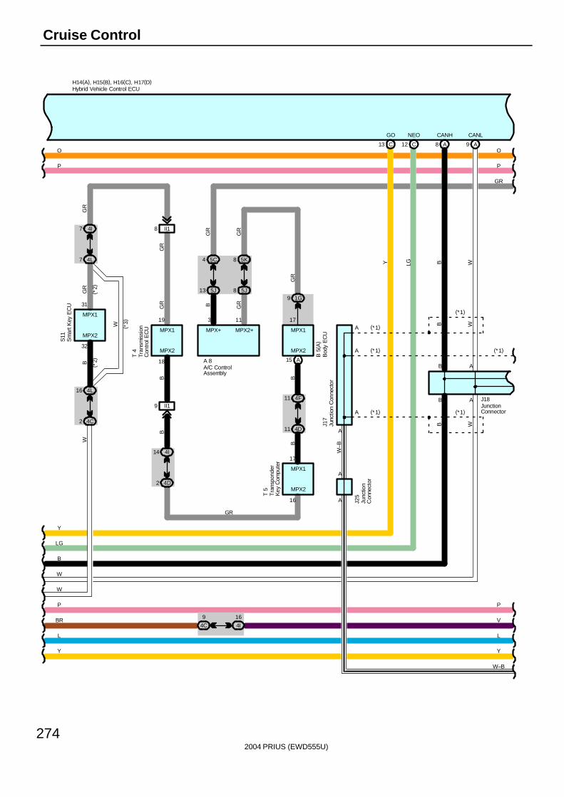
2004 PRIUS (EWD555U)
274
Cruise Control
MPX1
B 5
( A)
B
Y Y
H14(A), H15(B), H16(C), H17(D)
LL
MPX+
A 8
S11
( *3)
B
GR
GR
B
W
GR
B
MPX1
31
MPX232
MPX2
15 A
4 5C
13 5J
7 4I
7 4L
16 4L
2 4C
(*2)
( *2)
II18
GR
GR
P
W
3
MPX2+
GR
GR
8 5K
8 5J
11
1G9
MPX1
17
GR
11 4F
11 4D
B
GR
B
4D2
4I14
T 5
17
16
MPX2
MPX1
9 II1
MPX2
18
19
GR
T 4
A
B
B
A9A8
B
B A
WW
B W
CANLCANH
C12C13
NEOGO
Y LG
(*1)
(*1)
(*1)
W–B
A
A
A
AJ1
7
(* 1)
P
PP
W
B
LG
Y
W–B
A
A
J25
(* 1)
J18
BR V4C
9
4I
16
A/C ControlAssembly
Bod
y E
CU
Hybrid Vehicle Control ECU
Junc
tion
Con
nect
or
JunctionConnector
Junc
tion
Con
nect
or
Tra
nspo
nder
Key
Com
pute
r
Tran
smis
sion
Con
trol E
CU
Sm
art K
ey E
CU
OO
(*1)
W
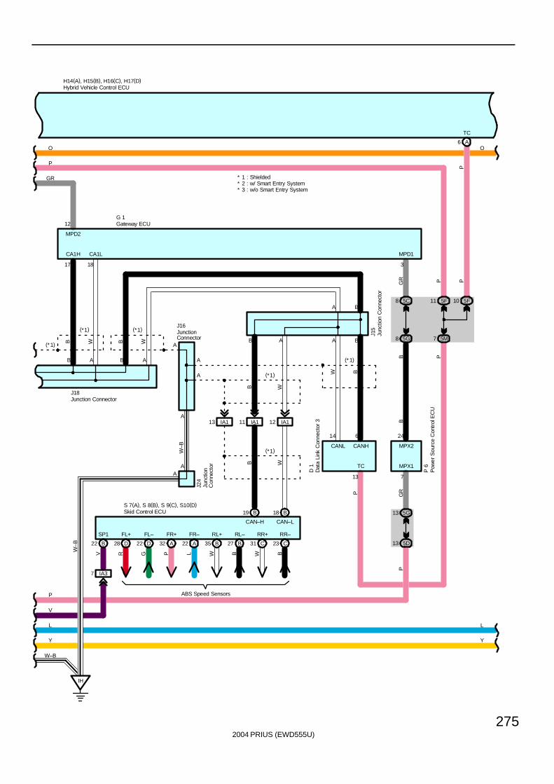
2004 PRIUS (EWD555U)
275
MPX1
P
5D13
5G13
MPX2
GR
7
24
P 6
H14(A), H15(B), H16(C), H17(D)
B
Y
LL
Y
13
TC
P
D 1
(* 1)
A B
P
MPD2
12
J16
J15
A
B A B A
17 18
J18
B W B W
CA1LCA1H
A
IH
A
J24
W–B
(*1) (*1)
A
G 1
* 2 : w/ Smart Entry System* 3 : w/o Smart Entry System
* 1 : ShieldedGR
GR
3
MPD1
W B
14 6
CANL CANH
A6
TC
7 5M
11 5F
PP
P
8 5G
8 5C
B
W–B
5F10
P
P
W–B
A B
IA111IA113 IA112
CAN–H CAN–L
A
(*1)
(*1)
BB W
W
B A
D28 D22 A32 A22 B35 B27 C31 C23
FL+ FL– FR+ FR– RL+ RL– RR+ RR–
R G P L W B W B
ABS Speed Sensors
S 7(A), S 8(B), S 9(C), S10(D)
A
B22
SP1
V
IA37
B19 B18
V
Skid Control ECU
Dat
a Li
nk C
onne
ctor
3
Gateway ECU
Hybrid Vehicle Control ECU
Junc
tion
Con
nect
or
JunctionConnector
Junction Connector
Junc
tion
Con
nect
or
O O
(*1)
Pow
er S
ourc
e C
ontr
ol E
CU
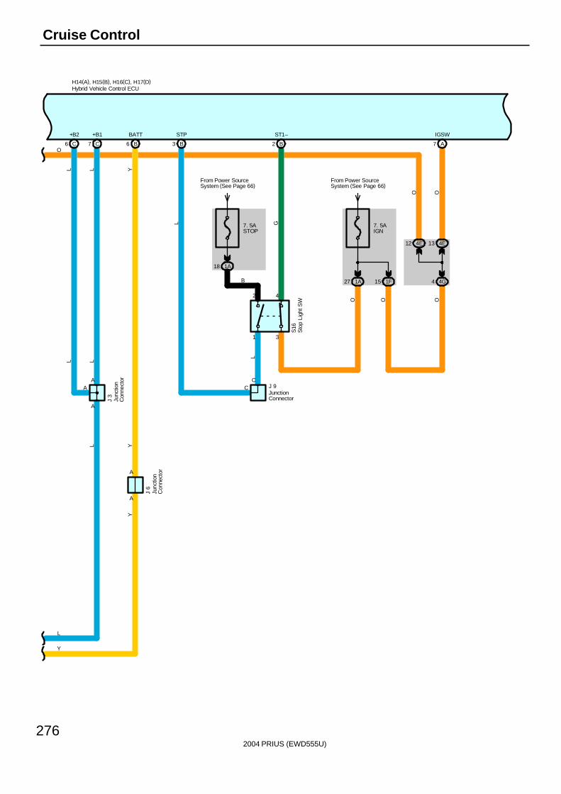
2004 PRIUS (EWD555U)
276
Cruise Control
Y
A
J 6
A
Y
H14(A), H15(B), H16(C), H17(D)
YBATT
6 B
A
LL
C7
+B1
J 3
L
C6
+B2
L
AA
L
L
Y
B2
ST1–
1
2 4
3
G
L
C
S16
J 9
B3
STP
L
18 1A
From Power SourceSystem (See Page 66)
7. 5ASTOP
C
B
7. 5AIGN
1A27 1F15
From Power SourceSystem (See Page 66)
O O
A7
IGSW
4E13
4G4
OO
Hybrid Vehicle Control ECU
Junc
tion
Con
nect
or
Junc
tion
Con
nect
or
JunctionConnector
Sto
p Li
ght S
W
4E12
O
O
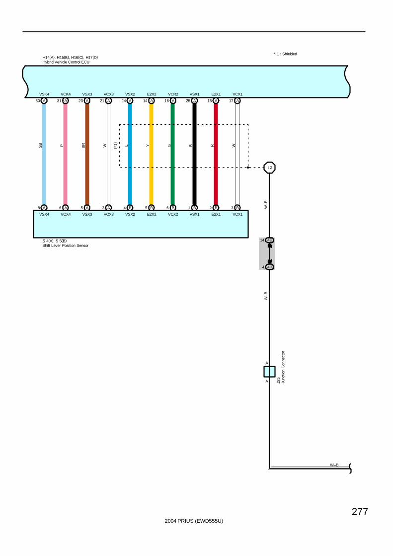
2004 PRIUS (EWD555U)
277
H14(A), H15(B), H16(C), H17(D)* 1 : Shielded
A30 A31 A23 A21 A24 A14 A16 A25 A15 A17
A8 A6 A5 A3 B4 B5 B6 B1 B2 B3
I 2
4E14
4H4
SB P BR W L Y G B R W
W–B
W–B
W–B
( *1)
VSK4 VCK4 VSX3 VCX3 VSX2 E2X2 VCR2 VSX1 E2X1 VCX1
VSX4 VCX4 VSX3 VCX3 VSX2 E2X2 VCX2 VSX1 E2X1 VCX1
S 4(A), S 5(B)
J25
A
A
Hybrid Vehicle Control ECU
Junc
tion
Con
nect
or
Shift Lever Position Sensor
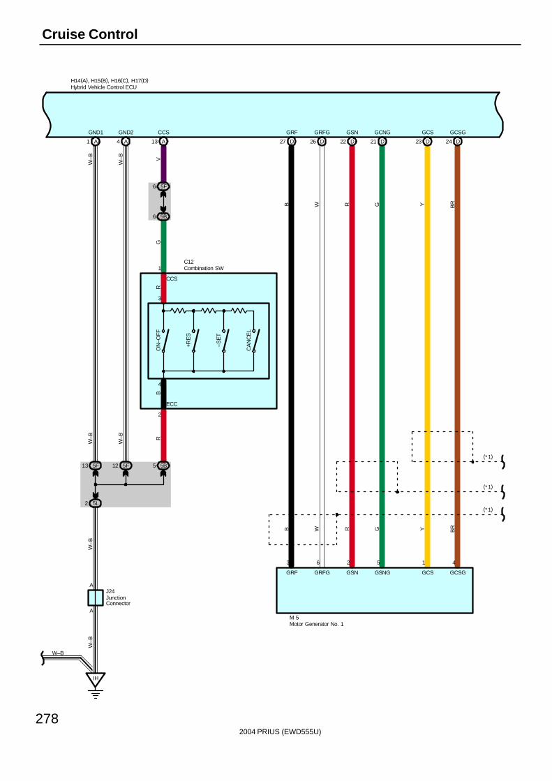
2004 PRIUS (EWD555U)
278
Cruise Control
DD27 21 DD22 24 DD23
B W R G Y BR
B W R G Y BR
GRF GRFG GSN GSNG GCS GCSG
GRF GRFG GSN GCNG GCS GCSG
3 6 2 5 1 4
M 5
26
H14(A), H15(B), H16(C), H17(D)
A1 A4 A13
5F6
5B6
5F13 5F12 5B5
5L2
IH
V
W–B
R
1
G
W–B
R
2
W–B
W–B
ON
–OFF
+RE
S
–SE
T
CA
NC
EL
B
C12
GND1 GND2 CCS
A
A
W–B
W–B
W–B
CCS
ECC
3
4
J24
(*1)
(*1)
(*1)
Combination SW
Hybrid Vehicle Control ECU
JunctionConnector
Motor Generator No. 1
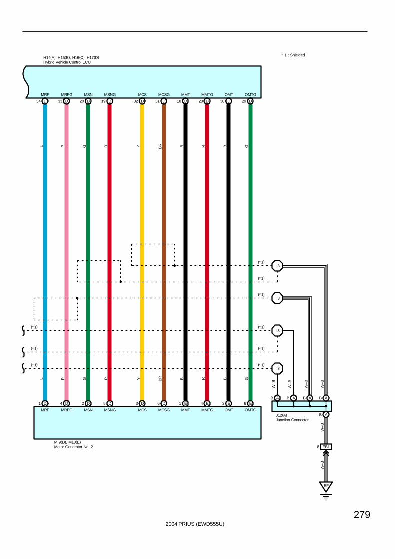
2004 PRIUS (EWD555U)
279
H14(A), H15(B), H16(C), H17(D)
33 DD34 19 DD20 31 DD32 28 DD18 29 DD30
L P
L P G R Y BR
G R Y BR B R B G
B R B G
MRF MRFG MSN MSNG MCS MCSG MMT MMTG OMT OMTG
MRF MRFG MSN MSNG MCS MCSG MMT MMTG OMT OMTG
D1
M 9(D), M10(E)
D4 D2 D5 D3 D6 E1 E4 E3 E6
EF
EB18
I 3
I 3
I 3
I 3
(*1)
(*1)
(*1)
(*1)
(*1)
(*1)
(*1)
(*1)
(*1)
W–B
W–B
W–B
W–B
W–B
W–B
J12(A)
* 1 : Shielded
Hybrid Vehicle Control ECU
Junction Connector
Motor Generator No. 2
ABABABAB
AB
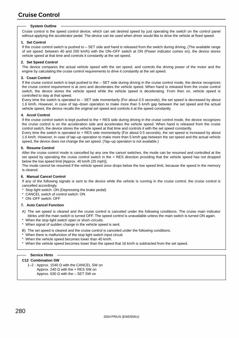
2004 PRIUS (EWD555U)
280
Cruise Control
Cruise control is the speed control device, which can set desired speed by just operating the switch on the control panelwithout applying the accelerator pedal. The device can be used when driver would like to drive the vehicle at fixed speed.
1. Set ControlIf the cruise control switch is pushed to – SET side and hand is released from the switch during driving, (The available rangeof set speed: between 40 and 200 km/h) with the ON–OFF switch at ON (Power indicator comes on), the device storesvehicle speed at that time and controls it constantly at the set speed.
2. Set Speed ControlThe device compares the actual vehicle speed with the set speed, and controls the driving power of the motor and theengine by calculating the cruise control requirements to drive it constantly at the set speed.
3. Coast ControlIf the cruise control switch is kept pushed to the – SET side during driving in the cruise control mode, the device recognizesthe cruise control requirement is at zero and decelerates the vehicle speed. When hand is released from the cruise controlswitch, the device stores the vehicle speed while the vehicle speed is decelerating. From then on, vehicle speed iscontrolled to stay at that speed.Every time the switch is operated to – SET side momentarily (For about 0.5 seconds), the set speed is decreased by about1.6 km/h. However, in case of tap–down operation to make more than 5 km/h gap between the set speed and the actualvehicle speed, the device recalls the original set speed and controls it at the speed constantly.
4. Accel ControlIf the cruise control switch is kept pushed to the + RES side during driving in the cruise control mode, the device recognizesthe cruise control is on the acceleration side and accelerates the vehicle speed. When hand is released from the cruisecontrol switch, the device stores the vehicle speed at that time and controls it with the set speed constantly.Every time the switch is operated to + RES side momentarily (For about 0.5 seconds), the set speed is increased by about1.6 km/h. However, in case of tap–up operation to make more than 5 km/h gap between the set speed and the actual vehiclespeed, the device does not change the set speed. (Tap–up operation is not available.)
5. Resume ControlAfter the cruise control mode is cancelled by any one the cancel switches, the mode can be resumed and controlled at theset speed by operating the cruise control switch in the + RES direction providing that the vehicle speed has not droppedbelow the low speed limit [Approx. 40 km/h (25 mph)].The mode cannot be resumed if the vehicle speed once drops below the low speed limit, because the speed in the memoryis cleared.
6. Manual Cancel ControlIf any of the following signals is sent to the device while the vehicle is running in the cruise control, the cruise control iscancelled accordingly.∗ Stop light switch: ON (Depressing the brake pedal)∗ CANCEL switch of control switch: ON∗ ON–OFF switch: OFF
7. Auto Cancel Function
A) The set speed is cleared and the cruise control is canceled under the following conditions. The cruise main indicatorblinks until the main switch is turned OFF. The speed control is unavailable unless the main switch is turned ON again.
∗ When the stop light switch open or short–circuits.∗ When signal of sudden change in the vehicle speed is sent.
B) The set speed is cleared and the cruise control is canceled under the following conditions.∗ When there is malfunction of the stop light switch input circuit.∗ When the vehicle speed becomes lower than 40 km/h.∗ When the vehicle speed becomes lower than the speed that 16 km/h is subtracted from the set speed.
C12 Combination SW1–2 : Approx. 1540 Ω with the CANCEL SW on
Approx. 240 Ω with the + RES SW onApprox. 630 Ω with the – SET SW on
System Outline
Service Hints
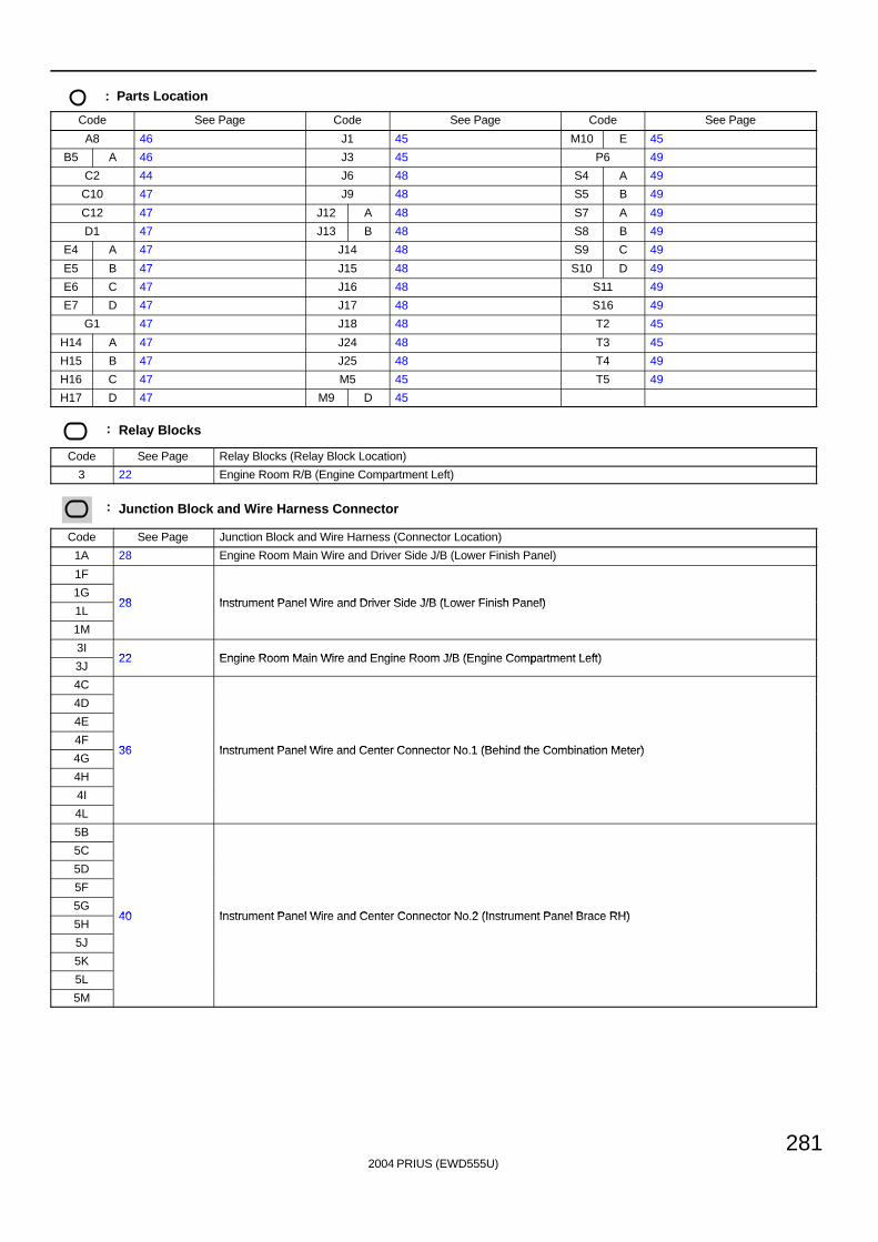
2004 PRIUS (EWD555U)
281
: Parts Location
Code See Page Code See Page Code See Page
A8 46 J1 45 M10 E 45
B5 A 46 J3 45 P6 49
C2 44 J6 48 S4 A 49
C10 47 J9 48 S5 B 49
C12 47 J12 A 48 S7 A 49
D1 47 J13 B 48 S8 B 49
E4 A 47 J14 48 S9 C 49
E5 B 47 J15 48 S10 D 49
E6 C 47 J16 48 S11 49
E7 D 47 J17 48 S16 49
G1 47 J18 48 T2 45
H14 A 47 J24 48 T3 45
H15 B 47 J25 48 T4 49
H16 C 47 M5 45 T5 49
H17 D 47 M9 D 45
: Relay Blocks
Code See Page Relay Blocks (Relay Block Location)
3 22 Engine Room R/B (Engine Compartment Left)
: Junction Block and Wire Harness Connector
Code See Page Junction Block and Wire Harness (Connector Location)
1A 28 Engine Room Main Wire and Driver Side J/B (Lower Finish Panel)
1F
1G28 Instrument Panel Wire and Driver Side J/B (Lower Finish Panel)
1L28 Instrument Panel Wire and Driver Side J/B (Lower Finish Panel)
1M
3I22 Engine Room Main Wire and Engine Room J/B (Engine Compartment Left)
3J22 Engine Room Main Wire and Engine Room J/B (Engine Compartment Left)
4C
4D
4E
4F36 Instrument Panel Wire and Center Connector No 1 (Behind the Combination Meter)
4G36 Instrument Panel Wire and Center Connector No.1 (Behind the Combination Meter)
4H
4I
4L
5B
5C
5D
5F
5G40 Instrument Panel Wire and Center Connector No 2 (Instrument Panel Brace RH)
5H40 Instrument Panel Wire and Center Connector No.2 (Instrument Panel Brace RH)
5J
5K
5L
5M
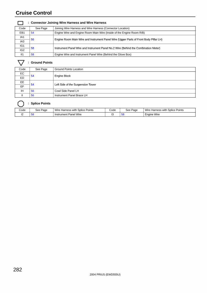
2004 PRIUS (EWD555U)
282
Cruise Control
: Connector Joining Wire Harness and Wire Harness
Code See Page Joining Wire Harness and Wire Harness (Connector Location)
EB1 54 Engine Wire and Engine Room Main Wire (Inside of the Engine Room R/B)
IA156 Engine Room Main Wire and Instrument Panel Wire (Upper Parts of Front Body Pillar LH)
IA356 Engine Room Main Wire and Instrument Panel Wire (Upper Parts of Front Body Pillar LH)
IG158 Instrument Panel Wire and Instrument Panel No 2 Wire (Behind the Combination Meter)
IG258 Instrument Panel Wire and Instrument Panel No.2 Wire (Behind the Combination Meter)
II1 58 Engine Wire and Instrument Panel Wire (Behind the Glove Box)
: Ground Points
Code See Page Ground Points Location
EC54 Engine Block
ED54 Engine Block
EE54 Left Side of the Suspension Tower
EF54 Left Side of the Suspension Tower
IH 56 Cowl Side Panel LH
II 56 Instrument Panel Brace LH
: Splice Points
Code See Page Wire Harness with Splice Points Code See Page Wire Harness with Splice Points
I2 58 Instrument Panel Wire I3 58 Engine Wire

2004 PRIUS (EWD555U)
283
Memo
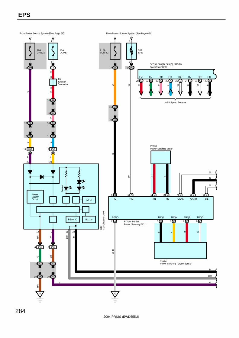
2004 PRIUS (EWD555U)
284
EPS
From Power Source System (See Page 66)
9 IG2
Y
4 IG1
B
II
B
14
21
PowerSupplyCircuit
GB
R
22
L
1M1
10AGAUGE
3
RR
5L16
5D7
IG211
Y
1A13
1L8
4C4
4H15
V
BR
11 5D
16 5H
P
C10
2
1
IG19
4C9
4I16
2425
BR
BGR
BEAN IC
9
V
V
7. 5AECU–IG
From Power Source System (See Page 66)
1L7
50AEPS
3C2
2
1
5H15
5C9
B6 A1 D1 D2
C5 C6 C7 8 C
B2
A2
IG
PGND TRQ1 TRQV TRQ2 TRQG
IG PIG M1 M2 SIL
1 B7 B
CANL CANH
P 7(A), P 8(B)
P10(C)
P 9(D)
OB
WW R B
W–B
B Y R W
B
GR
VV
15ADOME
Mas
ter
W
B
W
Buzzer
D28 D22 A32 A22 B35 B27 C31 C23
FL+ FL– FR+ FR– RL+ RL– RR+ RR–
R G P L W B W B
ABS Speed Sensors
S 7(A), S 8(B), S 9(C), S10(D)
(VFD)
Skid Control ECU
Com
bina
tion
Met
er
Power Steering ECU
Power Steering Torque Sensor
Power Steering Motor
JunctionConnector
J 6
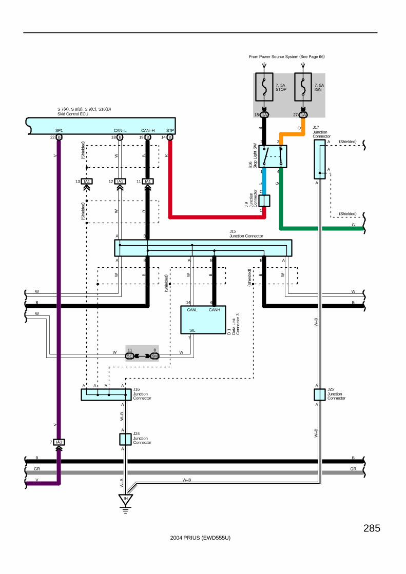
2004 PRIUS (EWD555U)
285
B
W–B
WW
CAN–L
A
A
A
A
CAN–H
A
A
AA
A
IH
W–B
W–B
( Shi
elde
d)
( Shi
elde
d)( S
hiel
ded)
BB
B W
J16
J24
J17
W–B
J25
W–B
W B
IA37
7
SIL
A
V
( Shi
elde
d)
IA113 IA112 IA111
D 1
CANL
14
A
A B
W B
W
B
B
GR
V
B
GR
J15
6
CANH
A B
5M
8
5C
11
W
WW
B A
A (Shielded)
A
(Shielded)
W
B
1
2
4
3
S16
7. 5ASTOP
From Power Source System (See Page 66)
1A18
BL
R
C
C
J 9
STP
7. 5AIGN
1A27
O
G
G
B18 B19 B14
V
SP1
B22
S 7(A), S 8(B), S 9(C), S10(D)Skid Control ECU
Dat
a Li
nkC
onne
ctor
3
Junc
tion
Con
nect
or
Junction Connector
JunctionConnector
JunctionConnector
JunctionConnector
JunctionConnector
Sto
p Li
ght
SW
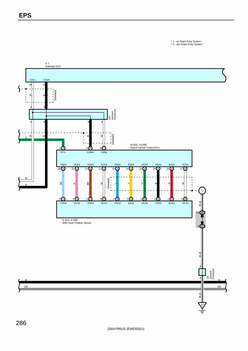
2004 PRIUS (EWD555U)
286
EPS
18
CA1H
G 1
CA1L
17
A
BA
B
( Shi
elde
d)
W B
J18
B
GR
* 2 : w/o Smart Entry System* 1 : w/ Smart Entry System
B
GR
A8 A6 A5 A3 B4 B5 B6 B1 B2 B3
I 2
4E14
4H4
SB P BR W L Y G B R W
W–B
W–B
( Shi
elde
d)
VSK4 VCK4 VSX3 VCX3 VSX2 E2X2 VCX2 VSX1 E2X1 VCX1
VSX4 VCX4 VSX3 VCX3 VSX2 E2X2 VCX2 VSX1 E2X1 VCX1
S 4(A), S 5(B)
J25
A
A
B A
B W
CANLCANH
( Shi
elde
d)
W
B
W B
G
ST1–
H14(A), H15(B)B2 A8 A9
A30 A31 A23 A21 A14 A16 A25 A15 A17A24
IH
W–B
Gateway ECU
Hybrid Vehicle Control ECU
Junc
tion
Con
nect
or
Junc
tion
Con
nect
or
Shift Lever Position Sensor
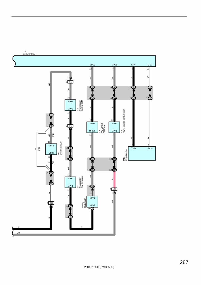
2004 PRIUS (EWD555U)
287
4F
S11
MPX1
B
11
MPX2
32
31
7 4L
7
4D
GR
4I
2 4C
GR
B
16 4L
W
BG
R
T 4
MPX1
MPX2
18
19
9 II1
8 II1
B
W
11
4I14
4D2
16
17
MPX1
MPX2
T 5
( *2)
( *1)
( *1)
GR
B
TX1–
6
GTX+
B
6 5E
6 5C
B
21
GTX–
W
7 5E
7 5C
WTX1+
GR
P
5G13
GR
5D13
P 6
5J8
5K8
MPX2+
11
MPX1
A 8
7
24
MPX2MPX+
3
5C4
GR
5C8
GR
5G8
3
MPD1
B
5J13
12
MPD2
B
3 IG2
MPX2
MPX1
GR
1G9
A15
GR
17
M13
B 5
( A)
4 5
B
GR
G 1
A/C
Con
trol
Ass
embl
y
Bod
y E
CU
Gateway ECU
Mul
ti–D
ispl
ay
Tran
spon
der
Key
Com
pute
rT
rans
mis
sion
Con
trol
EC
U
Sm
art
Key
EC
U
Pow
er S
ourc
e C
ontr
ol E
CU
IG12
B
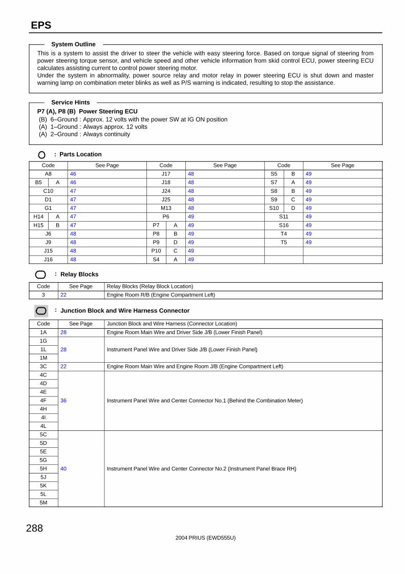
2004 PRIUS (EWD555U)
288
EPS
This is a system to assist the driver to steer the vehicle with easy steering force. Based on torque signal of steering frompower steering torque sensor, and vehicle speed and other vehicle information from skid control ECU, power steering ECUcalculates assisting current to control power steering motor.Under the system in abnormality, power source relay and motor relay in power steering ECU is shut down and masterwarning lamp on combination meter blinks as well as P/S warning is indicated, resulting to stop the assistance.
P7 (A), P8 (B) Power Steering ECU(B) 6–Ground : Approx. 12 volts with the power SW at IG ON position(A) 1–Ground : Always approx. 12 volts(A) 2–Ground : Always continuity
: Parts Location
Code See Page Code See Page Code See Page
A8 46 J17 48 S5 B 49
B5 A 46 J18 48 S7 A 49
C10 47 J24 48 S8 B 49
D1 47 J25 48 S9 C 49
G1 47 M13 48 S10 D 49
H14 A 47 P6 49 S11 49
H15 B 47 P7 A 49 S16 49
J6 48 P8 B 49 T4 49
J9 48 P9 D 49 T5 49
J15 48 P10 C 49
J16 48 S4 A 49
: Relay Blocks
Code See Page Relay Blocks (Relay Block Location)
3 22 Engine Room R/B (Engine Compartment Left)
: Junction Block and Wire Harness Connector
Code See Page Junction Block and Wire Harness (Connector Location)
1A 28 Engine Room Main Wire and Driver Side J/B (Lower Finish Panel)
1G
1L 28 Instrument Panel Wire and Driver Side J/B (Lower Finish Panel)
1M
( )
3C 22 Engine Room Main Wire and Engine Room J/B (Engine Compartment Left)
4C
4D
4E
4F 36 Instrument Panel Wire and Center Connector No.1 (Behind the Combination Meter)
4H
( )
4I
4L
5C
5D
5E
5G
5H 40 Instrument Panel Wire and Center Connector No.2 (Instrument Panel Brace RH)
5J
( )
5K
5L
5M
System Outline
Service Hints
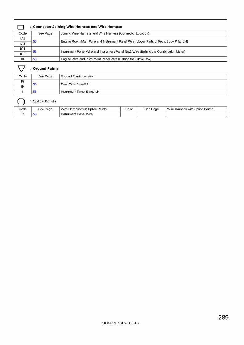
2004 PRIUS (EWD555U)
289
: Connector Joining Wire Harness and Wire Harness
Code See Page Joining Wire Harness and Wire Harness (Connector Location)
IA156 Engine Room Main Wire and Instrument Panel Wire (Upper Parts of Front Body Pillar LH)
IA356 Engine Room Main Wire and Instrument Panel Wire (Upper Parts of Front Body Pillar LH)
IG158 Instrument Panel Wire and Instrument Panel No 2 Wire (Behind the Combination Meter)
IG258 Instrument Panel Wire and Instrument Panel No.2 Wire (Behind the Combination Meter)
II1 58 Engine Wire and Instrument Panel Wire (Behind the Glove Box)
: Ground Points
Code See Page Ground Points Location
IG56 Cowl Side Panel LH
IH56 Cowl Side Panel LH
II 56 Instrument Panel Brace LH
: Splice Points
Code See Page Wire Harness with Splice Points Code See Page Wire Harness with Splice Points
I2 58 Instrument Panel Wire
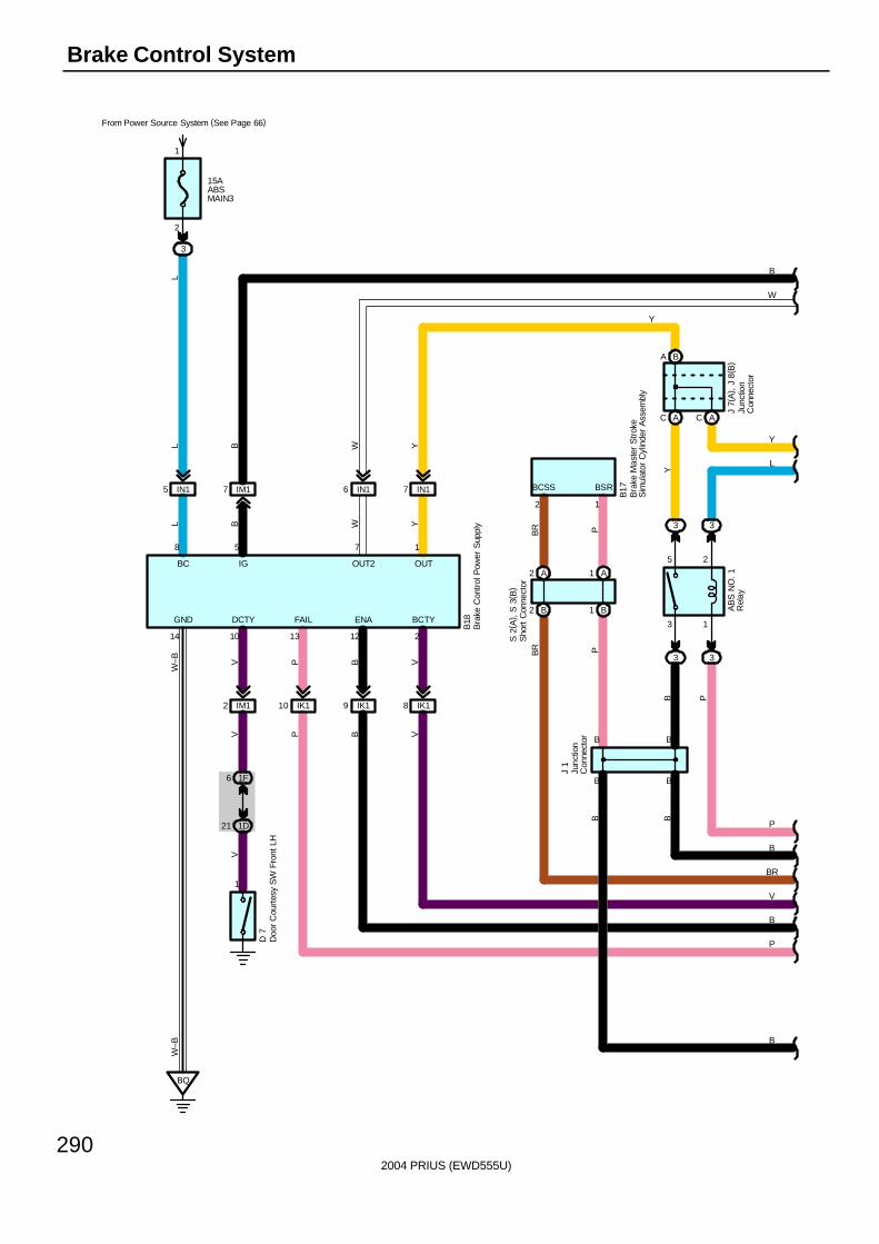
2004 PRIUS (EWD555U)
290
Brake Control System
IN17IN16IN15 IM17
IM12
1F6
1D21
1
BQ
15AABSMAIN3
From Power Source System (See Page 66)
3
2
1
AC AC
BA
3 1
5 2
3
3 3
3
B1B2
A1A2
L B W Y
L B W Y
P B VV
W–B
W–B
VV
P B V
BR P
BR P
B P
YBB
Y
L
W
B
P
B
BR
V
B
P
B
B18
B17
D 7
J 7(
A) ,
J 8
( B)
J 1
S 2
( A) ,
S 3
( B)
L
8 5 7 1
14 10 13 12 2
GND DCTY FAIL ENA BCTY
BC IG OUT2 OUT
Y
AB
S N
O. 1
Rel
ayB B
B B
2 1
BCSS BSR
Doo
r C
ourt
esy
SW
Fro
nt L
H
Junc
tion
Con
nect
or
Junc
tion
Con
nect
or
Bra
ke M
aste
r S
trok
eS
imul
ator
Cyl
inde
r A
ssem
bly
Sho
rt C
onne
ctor
Bra
ke C
ontr
ol P
ower
Sup
ply
IK110 IK19 IK18
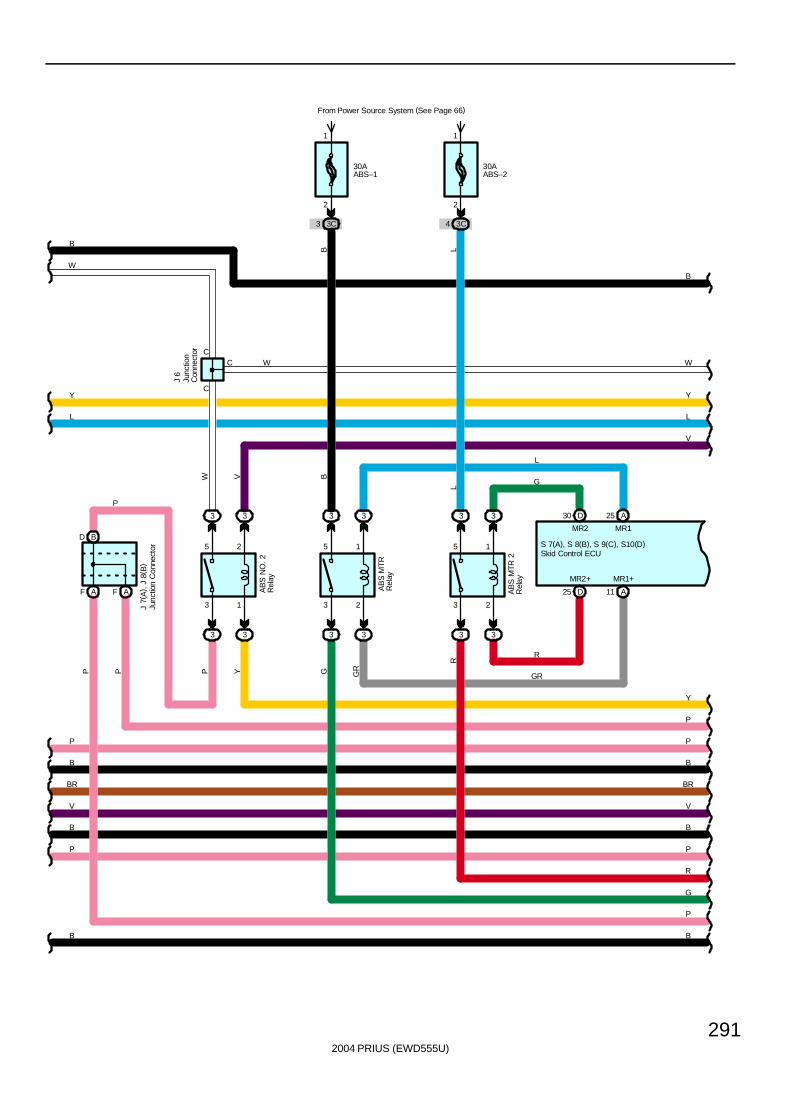
2004 PRIUS (EWD555U)
291
3 2
5 1
3 2
5 1
3 3 3 3
3 3
30AABS–1
From Power Source System (See Page 66)
3C3
2
1
30AABS–2
3C4
2
1
3 1
5 2
3
3 3
AF AF
BD
3 25 A
D25 A11
33
D30
B
W
Y
L
V
Y
P
P
B
BR
V
B
P
R
G
P
B
R
GR
G
L
B
P
B
V
BR
B
P
L
Y
W
B
P
W
P P P Y GR
BVW
J 7(
A) ,
J 8
( B)
J 6
S 7(A), S 8(B), S 9(C), S10(D)
MR2+ MR1+
MR2 MR1
B LL
AB
S M
TR 2
Rel
ay
AB
S M
TRR
elay
AB
S N
O.
2R
elay
G
R
C
C
C
Skid Control ECU
Junc
tion
Con
nect
or
Junc
tion
Con
nect
or
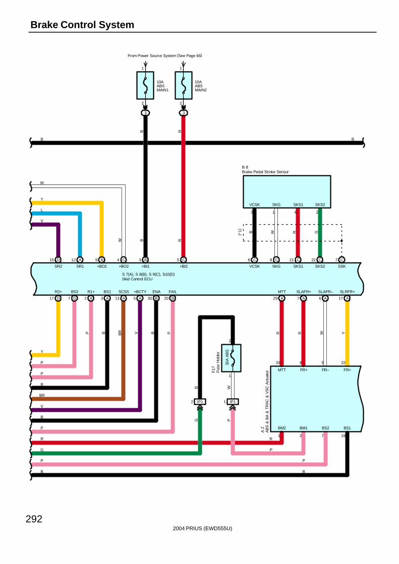
2004 PRIUS (EWD555U)
292
Brake Control System
D15 A12 B5 4 C 3 B 5 C
10AABSMAIN2
From Power Source System (See Page 66)
3
2
1
10AABSMAIN1
3
2
1
D17 D7 A2 A3 A13 A5 B30 B20 A29 A7 A6 A17
R2+ BS2 R1+ BS1 SCSS +BCTY ENA FAIL MTT SLAFR+ SLAFR– SLRFR+
33 8 5 22
R R W Y
C6 C8 C21 C22 C7
B
W
Y
L
V
Y
P
P
B
BR
V
B
P
R
G
P
B
B R
B R
S 7(A), S 8(B), S 9(C), S10(D)
SR2 SR1 +BO1 +BO2 +BI1 +BI2 VCSK SKG SKS1 SKS2 SSK
3 1 4 2
1 2 7 19
VCSK SKG SKS1 SKS2
BM2 BM1 BS2 BS1
MTT FR+ FR– FR+
B W R G
B
B 8
A 2
PBVBRB
W
P
R
P
P
B
( *1)
AB
S &
BA
& T
RA
C &
VS
C A
ctua
tor
Skid Control ECU
Brake Pedal Stroke Sensor
IP12 IP11
30A
AB
S
1
2
WBG P
Fuse
Hol
der
F17
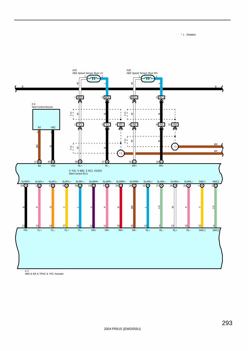
2004 PRIUS (EWD555U)
293
A34 D1 D2 D8
SLRFR– SLAFL+ SLAFL– SLRFL+
21 13 14 27
B P O Y
D26 D19 D9 D20
SLRFL– SLARR+ SLARR– SLRRR+
28 12 11 26
L V P R
D18 A15 A27 A16
SLRRR– SLARL+ SLARL– SLRRL+
25 10 9 24
BR L LG W
A26 A4 D3
SLRRL– SMC1 SMC2
23 20 6
P Y LG
B12 B33 B35 B27 C31 C33
I 1
I 1
BZ VBZ RL+ RL– RR+ RR–
1 2
FR– FL+ FL– FL+ FL– RR+ RR– RR+ RR– RL+ RL– RL+ RL– SMC1 SMC2
BR B
W B W B
W B
W B
BR
BR
BB
BZ VBZ
S 7(A), S 8(B), S 9(C), S10(D)
S 6
A25 A26
A 2
1 12 2
( *1)
( *1)
( *1)
( *1)
BD11 BD12 BL11 BL12
W L W L
ABS & BA & TRAC & VSC Actuator
Skid Control ECU
ABS Speed Sensor Rear LH ABS Speed Sensor Rear RH
Skid Control Buzzer
IF12 IF13 IF14 IN18 IN19 IN110
* 1 : Shielded
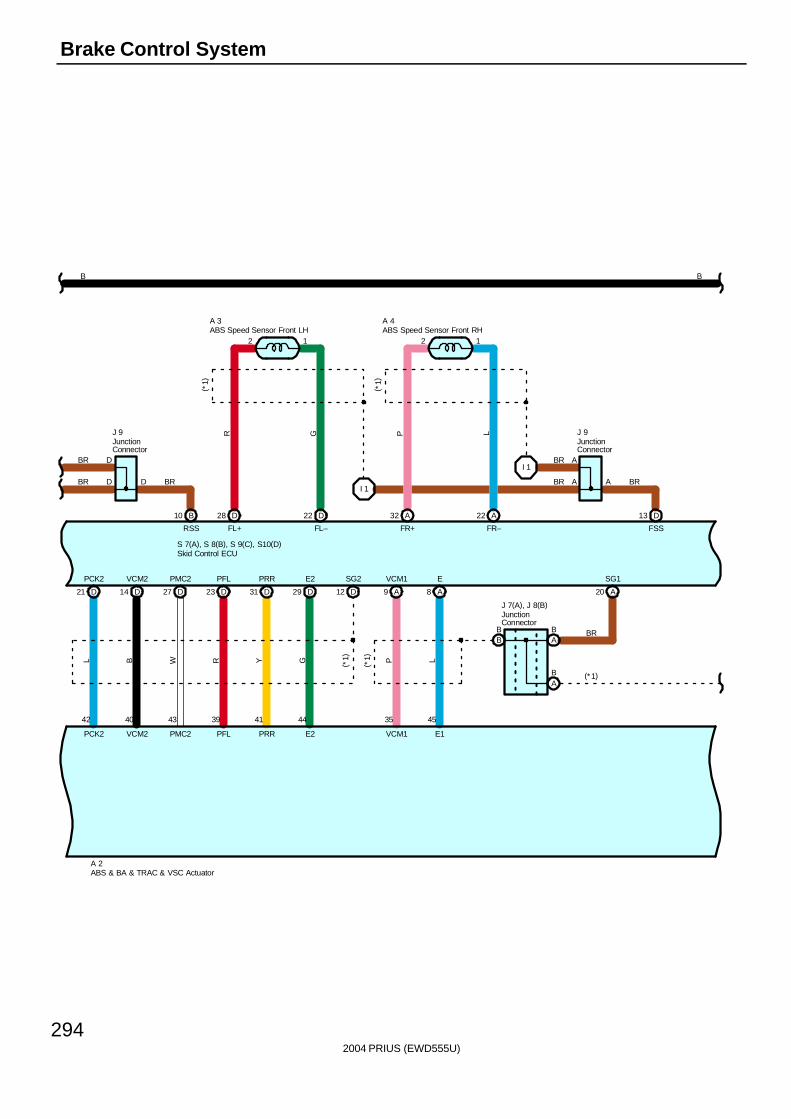
2004 PRIUS (EWD555U)
294
Brake Control System
D21 D14 D27 D23
PCK2 VCM2 PMC2 PFL
42 40 43 39
L B W R
D31 D29 D12 A9
PRR E2 SG2 VCM1
41 44 35
Y G ( *1) P
A8
E
45
L
B10
I 1
D28 D22 A32 A22 13 D
I 1
BB
AB
AB
A20
RSS FL+ FL– FR+ FR– FSS
PCK2 VCM2 PMC2 PFL PRR E2 VCM1 E1
BR
BR
B
A 2
S 7(A), S 8(B), S 9(C), S10(D)
J 9 J 9
J 7(A), J 8(B)
R G P L
B
BR
BR BR
BR
(*1)
D
D D BR
(*1)
2 21 1
A 3 A 4
( *1)
( *1)
A
A A
SG1
ABS Speed Sensor Front LH ABS Speed Sensor Front RH
ABS & BA & TRAC & VSC Actuator
Skid Control ECU
JunctionConnector
JunctionConnector
JunctionConnector
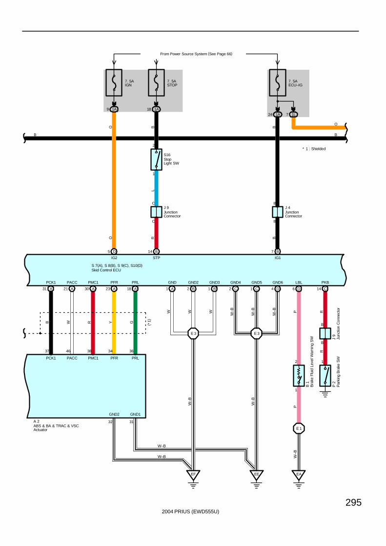
2004 PRIUS (EWD555U)
295
A31 A21
PCK1 PACC
37 46
B W
A30 A23 A18
PMC1 PFR PRL
38 34 36
R Y G
B2A1 B1
E 3
EF EE
E 3
4 D2 C 1 C
1
2 1
E 1
EA
D6 C14
D5
7. 5AIGN
From Power Source System (See Page 66)
1A9
7. 5AECU–IG
1A24 1L7
B7
IG2 IG1
PCK1 PACC PMC1 PRLPFR
GND2 GND1
32 31A 2
S 7(A), S 8(B), S 9(C), S10(D)
B
O B
O B
W W W
W–B
W–B
W–B
W–B
W–B
PW
–BP R
O
B
B 1
P 2
B
B
J 4
W–B
W–B
GND GND2 GND3 GND4 GND5 GND6 LBL PKB
B14
7. 5ASTOP
1A18
STP
BR
C
CJ 9
1
2
LS16
* 1 : Shielded
B
BR
J 9
ABS & BA & TRAC & VSCActuator
Skid Control ECU
Bra
ke F
luid
Lev
el W
arni
ng S
W
JunctionConnector
JunctionConnector
Junc
tion
Con
nect
orP
arki
ng B
rake
SW
StopLight SW
(*1)
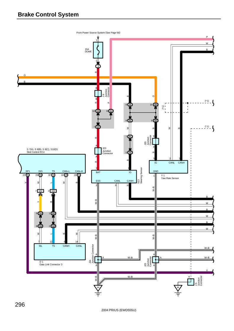
2004 PRIUS (EWD555U)
296
Brake Control System
B18 B19
5M8 5M2
5H6 5H1
B32B28
IA27 IA22
IH
1F7
1A13 1L8
5I8 5H15
5L7
5I5
5L8 5E9
15ADOME
3
2
1
B22
From Power Source System (See Page 66)
O
B
7 12 6 14
A
3
A
1
B
E
A
5 2 3
B
A
2 9 10
A A
1
E
RR P
RR
V W L W B
Y B
W L B W
BB
W BO
B
W B
W–B
W–B
W–B
W–B
W
B
W
W
B
B
W
V
W–B
P
W–B
( *1)
S13
Y 1
J 6
S 7(A), S 8(B), S 9(C), S10(D)
D 1
J23J2
0J2
5
SP1 D/G TS CAN–L CAN–H
ESS CANL CANH
GNDBAT IG
IG CANL CANH
SIL TS CANH CANL
B
(*1)
W–B
W–B
A A
J24
W–B
(*1)
IK
A
J 5
Skid Control ECU
Data Link Connector 3
Junc
tion
Con
nect
or
Junc
tion
Con
nect
or
Junc
tion
Con
nect
orJunctionConnector
Junc
tion
Con
nect
or
Junc
tion
Con
nect
or
Ste
erin
g S
enso
r
Yaw Rate Sensor
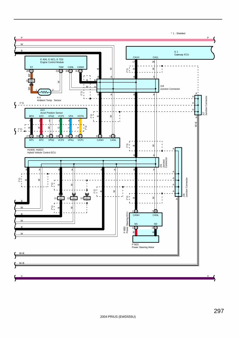
2004 PRIUS (EWD555U)
297
A
A
A
A
A
B A B A
17 28
B A
A
A
A
B W
B W
B W
V
W
B
W
B
W
B
W
P
(*1)
( *1)
( *1)
H14(A), H16(C)
J16
J17
P
V
W–B
G 1
CA1H CA1L
CANH CANL
J18
* 1 : Shielded
B
(*1)
IA111 IA112 IA113
A
B1 B7
D1 D2
A
AB
B W
AB
ABABABAB
B W
B W
B W
B W
B W
( *1)
( *1)
( *1)
( *1)
( *1)
J15
M1 M2
CANH CANL
P 9(D)
P 8
( B)
W–B
W–B
R B
CANHCANL
28 A 21 D 31 C30 C
BR
W
E2 TAM
EP1 EP2 VPA2 VCP2 VPA1 VCP1
A27 C35 C34 C33 C26 C25 A8 A9
5 2 3 1 6 4
BPA EP2 VPA2 VCP2 VPA VCPA
B R W G L Y ( *1)
(* 1)
21
A 6 A
B
A
B
W
EB13
BR
( *1)
Ambient Temp. Sensor
Gateway ECU
Hybrid Vehicle Control ECU
Junc
tion
Con
nect
or
Junc
tion
Con
nect
or
Junc
tion
Con
nect
or
Junction Connector
Pow
er S
teer
ing
EC
U
Power Steering Motor
A13Accel Position Sensor
E 4(A), E 6(C), E 7(D)Engine Control Module
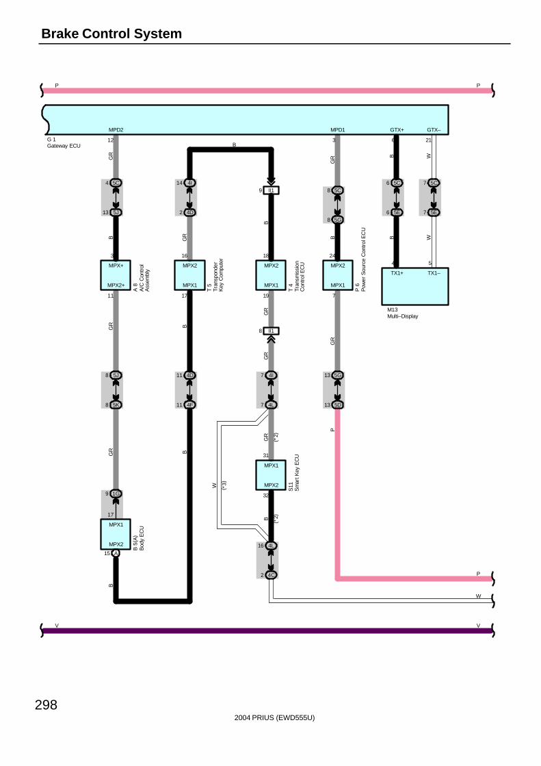
2004 PRIUS (EWD555U)
298
Brake Control System
MPX2
S11
MPX2 MPX2
MPX1
MPX1
P
W
GR
B
M13
B
GRB
GR
P 6
BGR
T 4
GR B
B 5
( A)
GR
GR
GR
B
BG
R
T 5
WB
WB
( *3)
( *2)
( *2)
A 8
8 II1
9 II1
7 4I
7 4L
15 A
11 4D
11 4F
2 4D
14 4I
9 1G
8 5J
12
8 5K
13 5J
4 5C
2 4C
16 4L
3
13 5G
216
13 5D
8 5G
8 5C
719
7 5C
1711
6 5C
32
7 5E
17
6 5E
31
241816354
MPD2 MPD1 GTX–GTX+
B
MPX1MPX1MPX1MPX2+
MPX2
MPX2
MPX+TX1–TX1+
P
V
P
P
W
V
G 1A
/C C
ontr
olA
ssem
bly
Bod
y E
CU
Gateway ECU
Multi–Display
Tran
spon
der
Key
Com
pute
r
Tran
smis
sion
Con
trol E
CU
Sm
art K
ey E
CU
Pow
er S
ourc
e C
ontr
ol E
CU
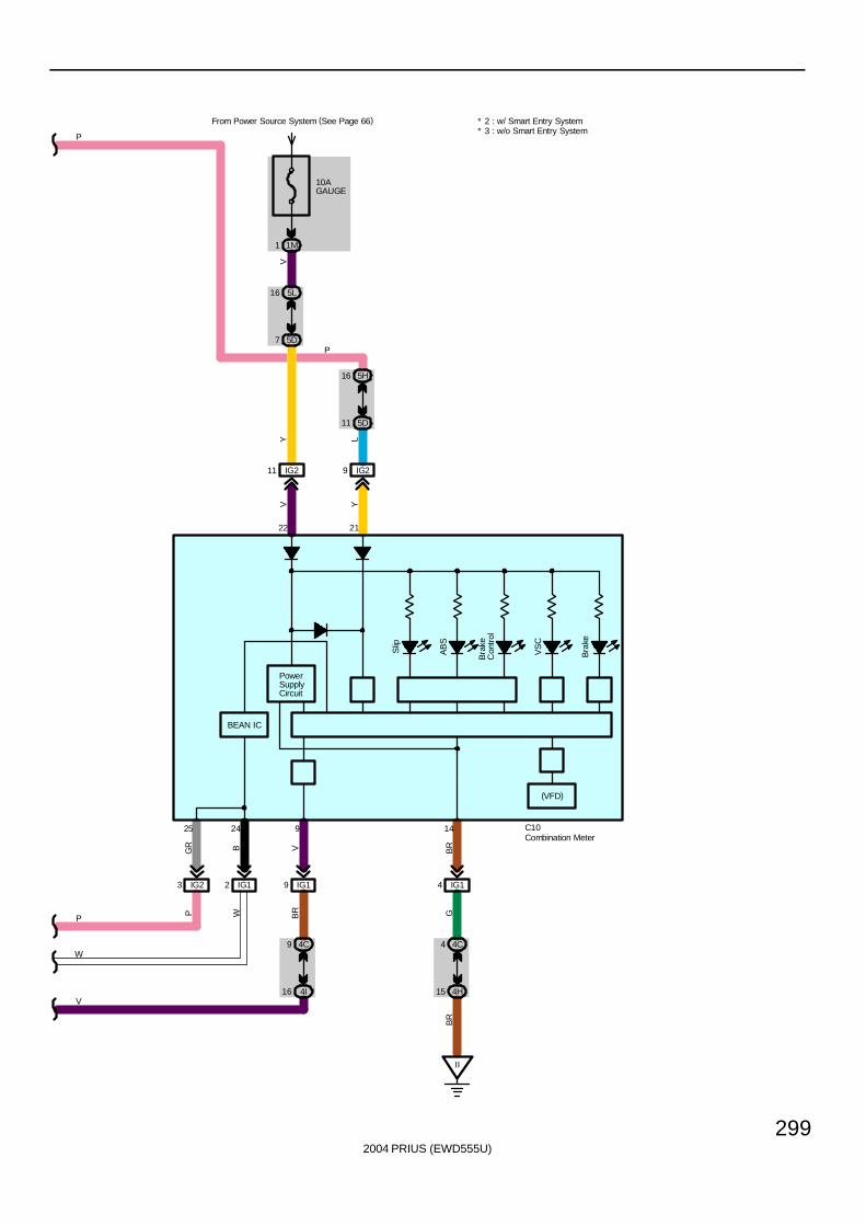
2004 PRIUS (EWD555U)
299
P
IG29IG211
10AGAUGE
From Power Source System (See Page 66)
1M1
5L16
5D7
22 21
IG14
4C4
4H15
II
(VFD)
IG12IG23
142425
V Y
Y L
V
BRBGR
GB
R
W
PowerSupplyCircuit
IG19
4C9
4I16
9
VB
R
5D11
5H16
P
W
V
P
BEAN IC
C10
* 3 : w/o Smart Entry System* 2 : w/ Smart Entry System
P
Combination Meter
Bra
ke
VS
C
Bra
keC
ontr
ol
AB
S
Slip
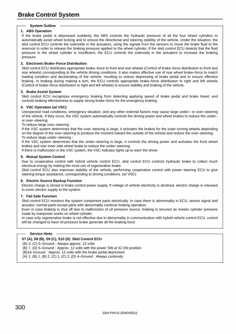
2004 PRIUS (EWD555U)
300
Brake Control System
1. ABS OperationIf the brake pedal is depressed suddenly, the ABS controls the hydraulic pressure of all the four wheel cylinders toautomatically avoid wheel locking and to ensure the directional and steering stability of the vehicle. Under the situation, theskid control ECU controls the solenoids in the actuators, using the signals from the sensors to move the brake fluid to thereservoir in order to release the braking pressure applied to the wheel cylinder. If the skid control ECU detects that the fluidpressure in the wheel cylinder is insufficient, the ECU controls the solenoids in the actuators to increase the brakingpressure.
2. Electronic Brake–Force DistributionSkid control ECU distributes appropriate brake–force to front and rear wheels (Control of brake–force distribution to front andrear wheels) corresponding to the vehicle driving conditions. It also makes effective use of rear wheel brake–force to matchloading condition and decelerating of the vehicle, resulting to reduce depressing of brake pedal and to ensure effectivebraking. In braking during making a turn, the ECU controls appropriate brake–force distribution to right and left wheels(Control of brake–force distribution to right and left wheels) to ensure stability and braking of the vehicle.
3. Brake Assist SystemSkid control ECU recognizes emergency braking from detecting applying speed of brake pedal and brake travel, andcontrols braking effectiveness to supply strong brake–force for the emergency braking.
4. VSC Operation (w/ VSC)Unexpected road conditions, emergency situation, and any other external factors may cause large under– or over–steeringof the vehicle. If they occur, the VSC system automatically controls the driving power and wheel brakes to reduce the under–or over–steering.To reduce large over–steering :If the VSC system determines that the over–steering is large, it activates the brakes for the outer turning wheels dependingon the degree of the over–steering to produce the moment toward the outside of the vehicle and reduce the over–steering.To reduce large under–steering :If the VSC system determines that the under–steering is large, it controls the driving power and activates the front wheelbrakes and rear inner side wheel brake to reduce the under–steering.If there is malfunction in the VSC system, the VSC indicator lights up to warn the driver.
5. Mutual System ControlDue to cooperative control with hybrid vehicle control ECU, skid control ECU controls hydraulic brake to collect muchelectrical energy by making the most use of regenerative brake.Skid control ECU also improves stability of the vehicle, performing cooperative control with power steering ECU to givesteering torque assistance, corresponding to driving conditions. (w/ VSC)
6. Electric Source Backup FunctionElectric charge is stored in brake control power supply. If voltage of vehicle electricity is declined, electric charge is releasedto cover electric supply to the system.
7. Fail Safe FunctionSkid control ECU monitors the system component parts electrically. In case there is abnormality in ECU, sensor signal andactuator, normal parts except parts with abnormality continue braking operation.Even in case braking is shut off due to malfunction of oil pressure source, braking is secured as master cylinder pressuremade by manpower works on wheel cylinder.In case only regenerative brake is not effective due to abnormality in communication with hybrid vehicle control ECU, controlwill be changed to have oil pressure brake generate all the braking force
S7 (A), S8 (B), S9 (C), S10 (D) Skid Control ECU(B) 3, (C) 5–Ground : Always approx. 12 volts(B) 7, (D) 5–Ground : Approx. 12 volts with the power SW at IG ON position(B)14–Ground : Approx. 12 volts with the brake pedal depressed(A) 1, (B) 1, (B) 2, (C) 1, (C) 2, (D) 4–Ground : Always continuity
System Outline
Service Hints
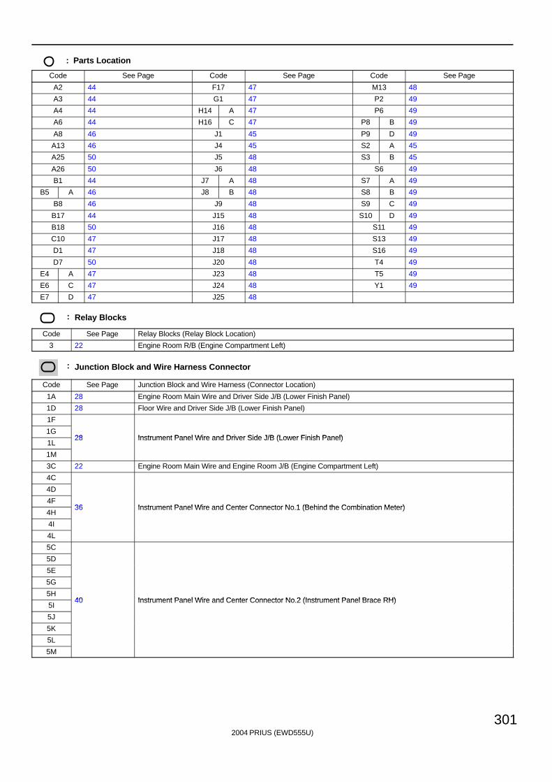
2004 PRIUS (EWD555U)
301
: Parts Location
Code See Page Code See Page Code See Page
A2 44 F17 47 M13 48
A3 44 G1 47 P2 49
A4 44 H14 A 47 P6 49
A6 44 H16 C 47 P8 B 49
A8 46 J1 45 P9 D 49
A13 46 J4 45 S2 A 45
A25 50 J5 48 S3 B 45
A26 50 J6 48 S6 49
B1 44 J7 A 48 S7 A 49
B5 A 46 J8 B 48 S8 B 49
B8 46 J9 48 S9 C 49
B17 44 J15 48 S10 D 49
B18 50 J16 48 S11 49
C10 47 J17 48 S13 49
D1 47 J18 48 S16 49
D7 50 J20 48 T4 49
E4 A 47 J23 48 T5 49
E6 C 47 J24 48 Y1 49
E7 D 47 J25 48
: Relay Blocks
Code See Page Relay Blocks (Relay Block Location)
3 22 Engine Room R/B (Engine Compartment Left)
: Junction Block and Wire Harness Connector
Code See Page Junction Block and Wire Harness (Connector Location)
1A 28 Engine Room Main Wire and Driver Side J/B (Lower Finish Panel)
1D 28 Floor Wire and Driver Side J/B (Lower Finish Panel)
1F
1G28 Instrument Panel Wire and Driver Side J/B (Lower Finish Panel)
1L28 Instrument Panel Wire and Driver Side J/B (Lower Finish Panel)
1M
3C 22 Engine Room Main Wire and Engine Room J/B (Engine Compartment Left)
4C
4D
4F36 Instrument Panel Wire and Center Connector No 1 (Behind the Combination Meter)
4H36 Instrument Panel Wire and Center Connector No.1 (Behind the Combination Meter)
4I
4L
5C
5D
5E
5G
5H40 Instrument Panel Wire and Center Connector No 2 (Instrument Panel Brace RH)
5I40 Instrument Panel Wire and Center Connector No.2 (Instrument Panel Brace RH)
5J
5K
5L
5M

2004 PRIUS (EWD555U)
302
Brake Control System
: Connector Joining Wire Harness and Wire Harness
Code See Page Joining Wire Harness and Wire Harness (Connector Location)
EB1 54 Engine Wire and Engine Room Main Wire (Inside of the Engine Room R/B)
IA156 Engine Room Main Wire and Instrument Panel Wire (Upper Parts of Front Body Pillar LH)
IA256 Engine Room Main Wire and Instrument Panel Wire (Upper Parts of Front Body Pillar LH)
IF1 56 Floor Wire and Engine Room Main Wire (Left Kick Panel)
IG158 Instrument Panel Wire and Instrument Panel No 2 Wire (Behind the Combination Meter)
IG258 Instrument Panel Wire and Instrument Panel No.2 Wire (Behind the Combination Meter)
II1 58 Engine Wire and Instrument Panel Wire (Behind the Glove Box)
IK1 58 Engine Room Main Wire and Floor No.2 Wire (Cowl Side Panel RH)
IM1 58 Instrument Panel Wire and Floor No.2 Wire (Right Kick Panel)
IN1 58 Floor No.2 Wire and Engine Room Main Wire (Right Kick Panel)
IP1 58 Engine Room No.2 Wire and Engine Room Main Wire (Upper Parts of Front Body Pillar LH)
BD1 60 Skid Control Sensor No.1 Wire and Floor Wire (Front Side of Left Quarter Panel)
BL1 62 Skid Control Sensor No.2 Wire and Floor No.2 Wire (Front Side of Right Quarter Panel)
: Ground Points
Code See Page Ground Points Location
EA 54 Right Side of the Fender Apron
EE54 Left Side of the Suspension Tower
EF54 Left Side of the Suspension Tower
IH 56 Cowl Side Panel LH
II 56 Instrument Panel Brace LH
IK 56 Cowl Side Panel RH
BQ 60 Rear Side of Right Quarter Panel
: Splice Points
Code See Page Wire Harness with Splice Points Code See Page Wire Harness with Splice Points
E154 Engine Room Main Wire
I1 58 Instrument Panel Wire
E354 Engine Room Main Wire
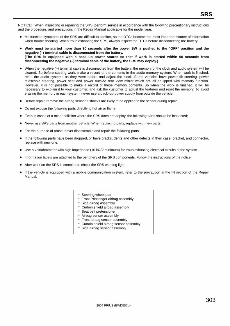
2004 PRIUS (EWD555U)
303
SRS
NOTICE: When inspecting or repairing the SRS, perform service in accordance with the following precautionary instructionsand the procedure, and precautions in the Repair Manual applicable for the model year.
Malfunction symptoms of the SRS are difficult to confirm, so the DTCs become the most important source of informationwhen troubleshooting. When troubleshooting the SRS, always inspect the DTCs before disconnecting the battery.
Work must be started more than 90 seconds after the power SW is pushed to the ”OFF” position and thenegative (–) terminal cable is disconnected from the battery.(The SRS is equipped with a back–up power source so that if work is started within 90 seconds fromdisconnecting the negative (–) terminal cable of the battery, the SRS may deploy.)
When the negative (–) terminal cable is disconnected from the battery, the memory of the clock and audio system will becleared. So before starting work, make a record of the contents in the audio memory system. When work is finished,reset the audio systems as they were before and adjust the clock. Some vehicles have power tilt steering, powertelescopic steering, power seat and power outside rear view mirror which are all equipped with memory function.However, it is not possible to make a record of these memory contents. So when the work is finished, it will benecessary to explain it to your customer, and ask the customer to adjust the features and reset the memory. To avoiderasing the memory in each system, never use a back–up power supply from outside the vehicle.
Before repair, remove the airbag sensor if shocks are likely to be applied to the sensor during repair.
Do not expose the following parts directly to hot air or flame;
Even in cases of a minor collision where the SRS does not deploy, the following parts should be inspected;
Never use SRS parts from another vehicle. When replacing parts, replace with new parts.
For the purpose of reuse, never disassemble and repair the following parts.
If the following parts have been dropped, or have cracks, dents and other defects in their case, bracket, and connector,replace with new one.
Use a volt/ohmmeter with high impedance (10 kΩ/V minimum) for troubleshooting electrical circuits of the system.
Information labels are attached to the periphery of the SRS components. Follow the instructions of the notice.
After work on the SRS is completed, check the SRS warning light.
If the vehicle is equipped with a mobile communication system, refer to the precaution in the IN section of the RepairManual.
∗ Steering wheel pad∗ Front Passenger airbag assembly∗ Side airbag assembly∗ Curtain shield airbag assembly∗ Seat belt pretensioner∗ Airbag sensor assembly∗ Front airbag sensor assembly∗ Curtain shield airbag sensor assembly∗ Side airbag sensor assembly
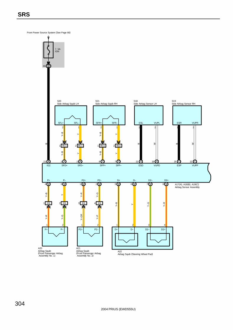
2004 PRIUS (EWD555U)
304
SRS
7. 5AIGN
From Power Source System (See Page 66)
1E16
B21 A1 A2
SFD+ SFD–
2 1
Y–B Y
S20
C8 C7
SFP+ SFP–
2 1
Y–B Y
S21 S18
WB
21
VUPLESL
VUPDESD
19 A21 A C20 C22
ESP VUPP
ESR VUPR
1 2
B W
S19
B4 B3 B1 B2
Y–R
Y–G
Y–G
R
Y–P
1 2 1 2
A20
B5 B6 B7 B8
Y–B Y
Y–G
Y–R
1 2 3 4
A22
A17(A), A18(B), A19(C)
B
IG2
P+ P– P2+ P2– D+ D– D2– D2+
BC11 BC12 BG11 BG12
Y–B Y
Y–B Y
SFL+ SFL– SFR+ SFR–
D+ D– D2– D2+
IH11 IH12 IH13 IH14
Y–G
Y–RY
Y–B
P2+ P2–P+ P–
A21
Airbag Squib (Steering Wheel Pad)
Airbag Sensor Assembly
Side Airbag Squib LH Side Airbag Squib RH Side Airbag Sensor LH Side Airbag Sensor RH
Airbag Squib(Front Passenger Airbag Assembly No. 2)
Airbag Squib(Front Passenger Airbag Assembly No. 1)
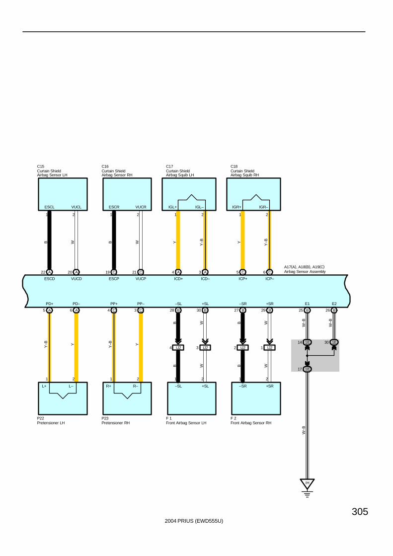
2004 PRIUS (EWD555U)
305
Y–B
A22 A20
ESCD VUCD
ESCL VUCL
1 2
B W
C18C15
Y
21
ICP–ICP+
6 C5 CA4 A3
ICD+ ICD–
1 2
Y
Y–B
C17C16
WB
21
VUCRESCR
VUCPESCP
21 C19 C
A5 A6
Y–B Y
1 2
P22
C4 C3
Y–B Y
1 2
R–
P23
B28 B30
B W
1 2
–SL +SL
F 1
B27 B29
B W
1 2
–SR +SR
F 2
B26B25
1E14 1E30
1E17
IH
A17(A), A18(B), A19(C)
W–B
W–B
W–B
PD+ PD– PP+ PP– –SL +SL –SR +SR E1 E2
IJ24 IJ23 IJ22 IJ21
B W B W
IGL+ IGL– IGR–IGR+
R+L–L+
Airbag Sensor Assembly
Curtain ShieldAirbag Sensor LH
Curtain ShieldAirbag Sensor RH
Curtain ShieldAirbag Squib LH
Curtain ShieldAirbag Squib RH
Front Airbag Sensor LH Front Airbag Sensor RHPretensioner LH Pretensioner RH
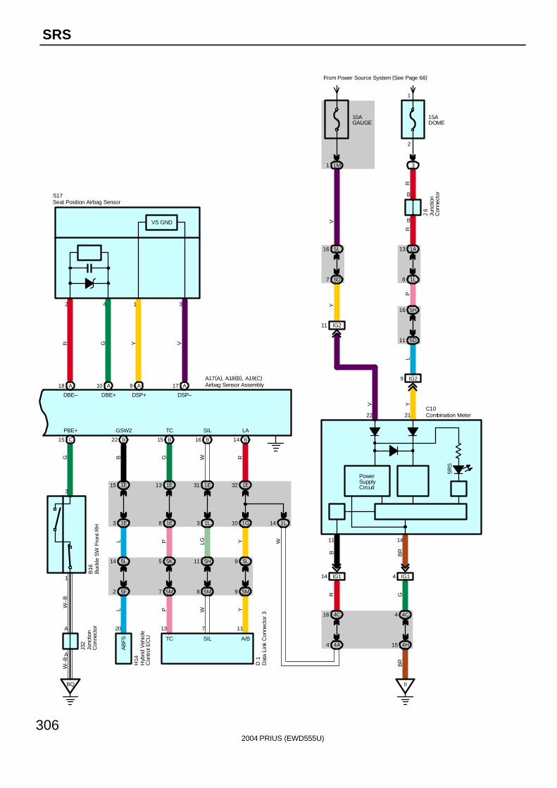
2004 PRIUS (EWD555U)
306
SRS
1E15
1E3
5F2
5L14
B22
13 1E
1E8
5M7
5K5
B15
31 1E
1L3
5M8
5H11
B16
32 1E
1G10
5M9
5L9
B14
L
9 IG2
YC10
4 IG1
B
II
B
14
21
SR
S
PowerSupplyCircuit
GB
R
22
10AGAUGE
From Power Source System (See Page 66)
1M1
15ADOME
3
RR
5L16
5D7
IG211V
Y
1A13
1L8
J 6
4C4
4H15
V
BR
5D11
5H16
P
14 IG1
11
RB
4C16
4A4
1L14
A18 A10
DBE– DBE+
2 4
R G
S17
VY
31
DSP–DSP+
17 A9 A
C15
BQ
PBE+ GSW2 TC SIL LA
B16
J32
H14
D 1
A17(A), A18(B), A19(C)
G B G W R
W–B
W–B
L P LG Y W
L P W Y
20 13 7 11
TC SIL A/B
AB
FS
3
A
1
A
VS GND
Airbag Sensor Assembly
Buc
kle
SW
Fro
nt R
H
Combination Meter
Dat
a Li
nk C
onne
ctor
3
Hyb
rid V
ehic
leC
ontr
ol E
CU
Junc
tion
Con
nect
or
Junc
tion
Con
nect
or
Seat Position Airbag Sensor
1
2
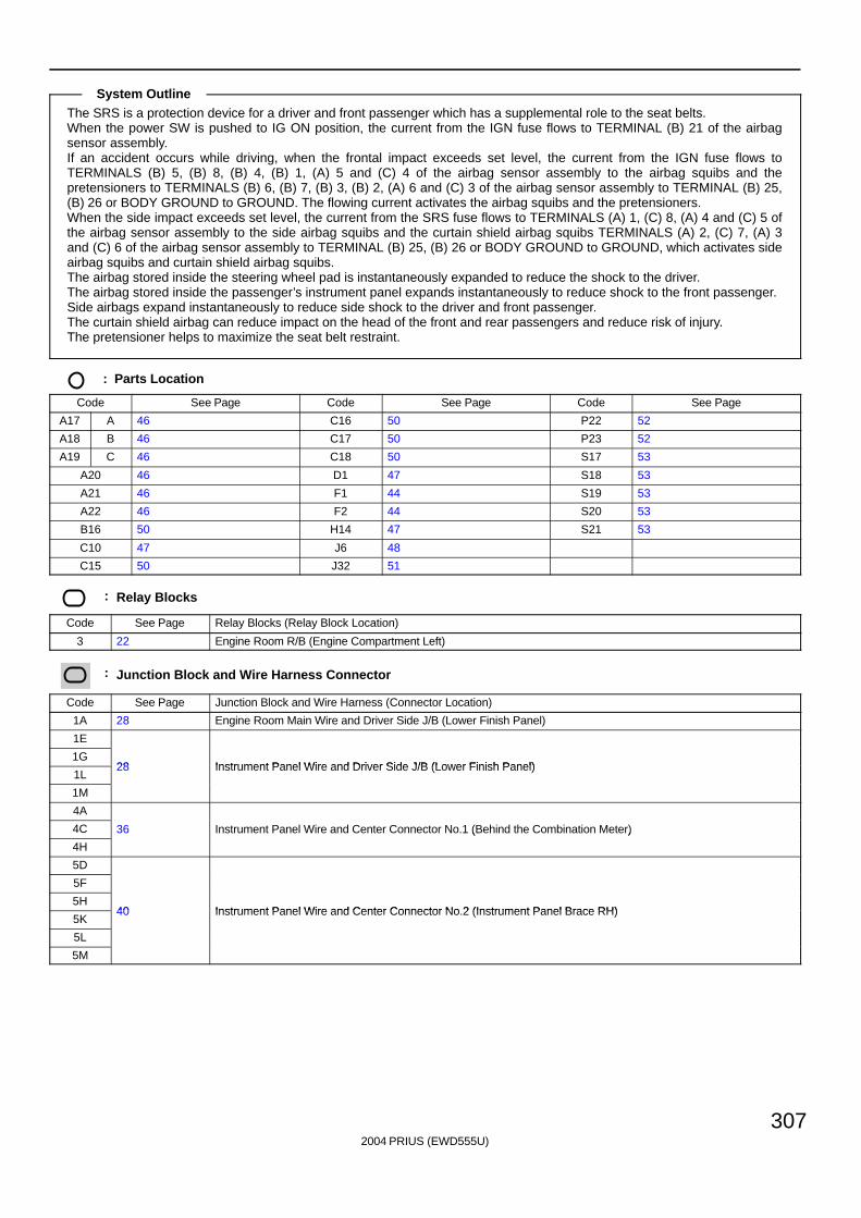
2004 PRIUS (EWD555U)
307
The SRS is a protection device for a driver and front passenger which has a supplemental role to the seat belts.When the power SW is pushed to IG ON position, the current from the IGN fuse flows to TERMINAL (B) 21 of the airbagsensor assembly.If an accident occurs while driving, when the frontal impact exceeds set level, the current from the IGN fuse flows toTERMINALS (B) 5, (B) 8, (B) 4, (B) 1, (A) 5 and (C) 4 of the airbag sensor assembly to the airbag squibs and thepretensioners to TERMINALS (B) 6, (B) 7, (B) 3, (B) 2, (A) 6 and (C) 3 of the airbag sensor assembly to TERMINAL (B) 25,(B) 26 or BODY GROUND to GROUND. The flowing current activates the airbag squibs and the pretensioners.When the side impact exceeds set level, the current from the SRS fuse flows to TERMINALS (A) 1, (C) 8, (A) 4 and (C) 5 ofthe airbag sensor assembly to the side airbag squibs and the curtain shield airbag squibs TERMINALS (A) 2, (C) 7, (A) 3and (C) 6 of the airbag sensor assembly to TERMINAL (B) 25, (B) 26 or BODY GROUND to GROUND, which activates sideairbag squibs and curtain shield airbag squibs.The airbag stored inside the steering wheel pad is instantaneously expanded to reduce the shock to the driver.The airbag stored inside the passenger’s instrument panel expands instantaneously to reduce shock to the front passenger.Side airbags expand instantaneously to reduce side shock to the driver and front passenger.The curtain shield airbag can reduce impact on the head of the front and rear passengers and reduce risk of injury.The pretensioner helps to maximize the seat belt restraint.
: Parts Location
Code See Page Code See Page Code See Page
A17 A 46 C16 50 P22 52
A18 B 46 C17 50 P23 52
A19 C 46 C18 50 S17 53
A20 46 D1 47 S18 53
A21 46 F1 44 S19 53
A22 46 F2 44 S20 53
B16 50 H14 47 S21 53
C10 47 J6 48
C15 50 J32 51
: Relay Blocks
Code See Page Relay Blocks (Relay Block Location)
3 22 Engine Room R/B (Engine Compartment Left)
: Junction Block and Wire Harness Connector
Code See Page Junction Block and Wire Harness (Connector Location)
1A 28 Engine Room Main Wire and Driver Side J/B (Lower Finish Panel)
1E
1G28 Instrument Panel Wire and Driver Side J/B (Lower Finish Panel)
1L28 Instrument Panel Wire and Driver Side J/B (Lower Finish Panel)
1M
4A
4C 36 Instrument Panel Wire and Center Connector No.1 (Behind the Combination Meter)
4H
( )
5D
5F
5H40 Instrument Panel Wire and Center Connector No 2 (Instrument Panel Brace RH)
5K40 Instrument Panel Wire and Center Connector No.2 (Instrument Panel Brace RH)
5L
5M
System Outline
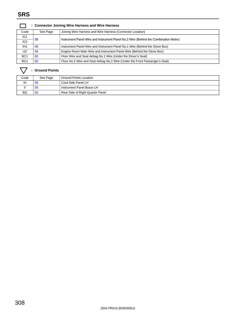
2004 PRIUS (EWD555U)
308
SRS
: Connector Joining Wire Harness and Wire Harness
Code See Page Joining Wire Harness and Wire Harness (Connector Location)
IG158 Instrument Panel Wire and Instrument Panel No 2 Wire (Behind the Combination Meter)
IG258 Instrument Panel Wire and Instrument Panel No.2 Wire (Behind the Combination Meter)
IH1 58 Instrument Panel Wire and Instrument Panel No.1 Wire (Behind the Glove Box)
IJ2 58 Engine Room Main Wire and Instrument Panel Wire (Behind the Glove Box)
BC1 60 Floor Wire and Seat Airbag No.1 Wire (Under the Driver’s Seat)
BG1 60 Floor No.2 Wire and Seat Airbag No.2 Wire (Under the Front Passenger’s Seat)
: Ground Points
Code See Page Ground Points Location
IH 56 Cowl Side Panel LH
II 56 Instrument Panel Brace LH
BQ 60 Rear Side of Right Quarter Panel

2004 PRIUS (EWD555U)
309
Memo
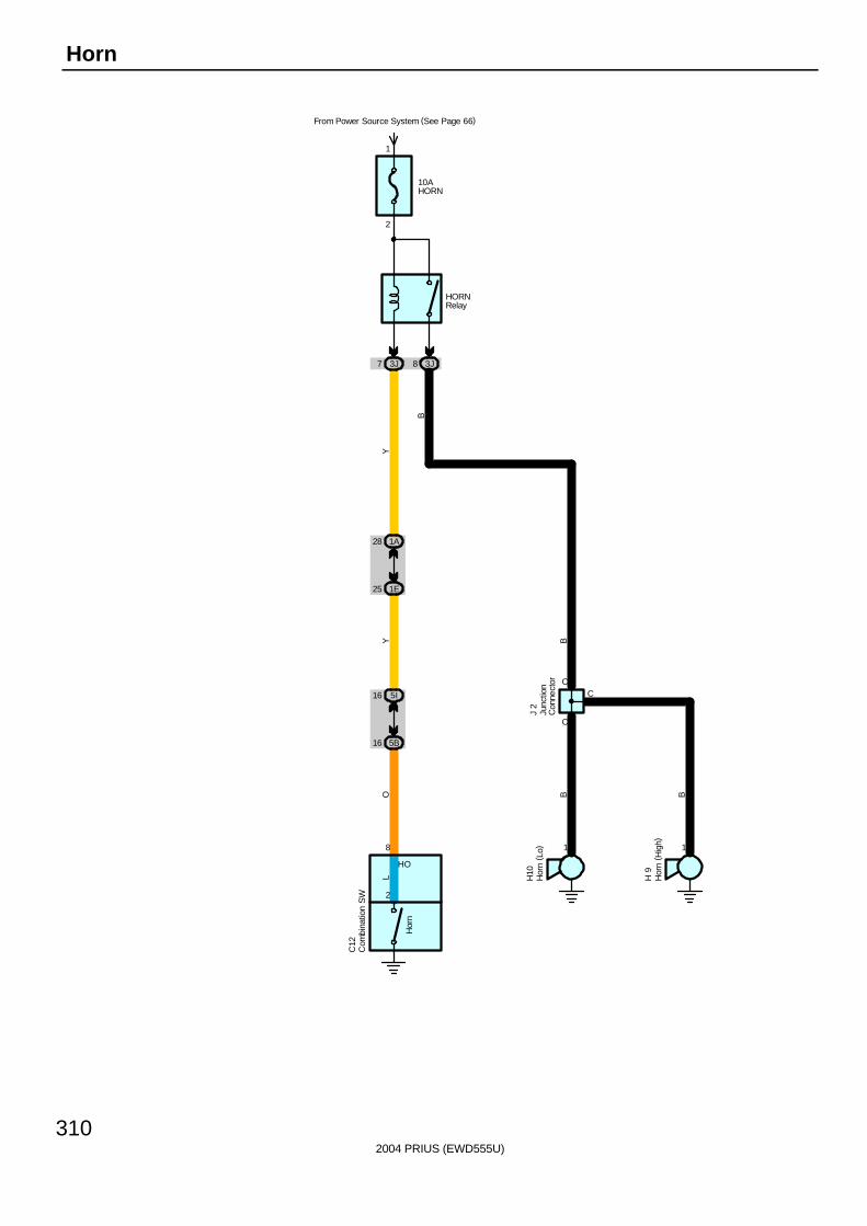
2004 PRIUS (EWD555U)
310
Horn
C
11
C
C
8
2
Hor
n
HO
10AHORN
From Power Source System (See Page 66)
3J7 3J8
1A28
1E25
5B16
5I16
O B B
BYY
L H10
H 9
C12
J 2
B
HORNRelay
Com
bina
tion
SW
Hor
n ( L
o)
Hor
n ( H
igh)
Junc
tion
Con
nect
or
1
2
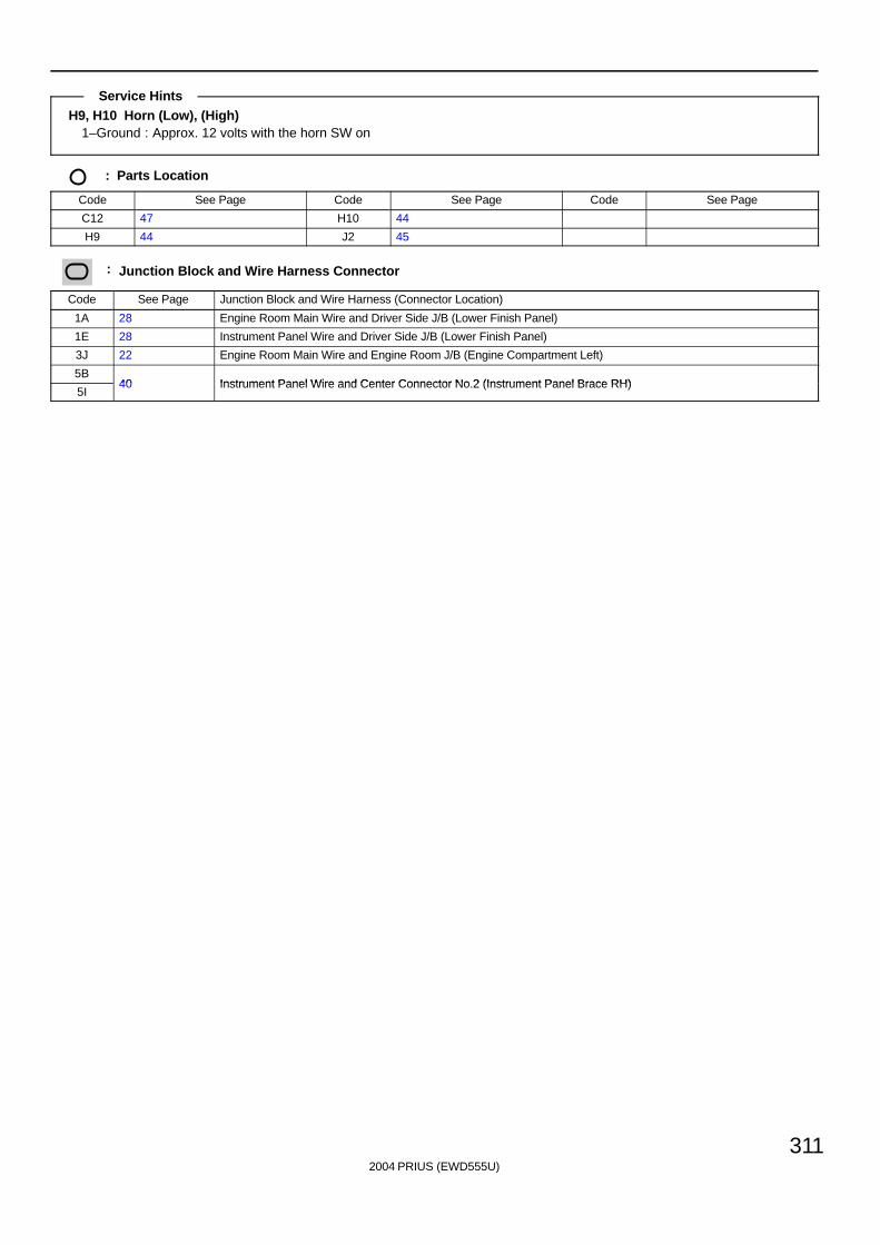
2004 PRIUS (EWD555U)
311
H9, H10 Horn (Low), (High)1–Ground : Approx. 12 volts with the horn SW on
: Parts Location
Code See Page Code See Page Code See Page
C12 47 H10 44
H9 44 J2 45
: Junction Block and Wire Harness Connector
Code See Page Junction Block and Wire Harness (Connector Location)
1A 28 Engine Room Main Wire and Driver Side J/B (Lower Finish Panel)
1E 28 Instrument Panel Wire and Driver Side J/B (Lower Finish Panel)
3J 22 Engine Room Main Wire and Engine Room J/B (Engine Compartment Left)
5B40 Instrument Panel Wire and Center Connector No 2 (Instrument Panel Brace RH)
5I40 Instrument Panel Wire and Center Connector No.2 (Instrument Panel Brace RH)
Service Hints
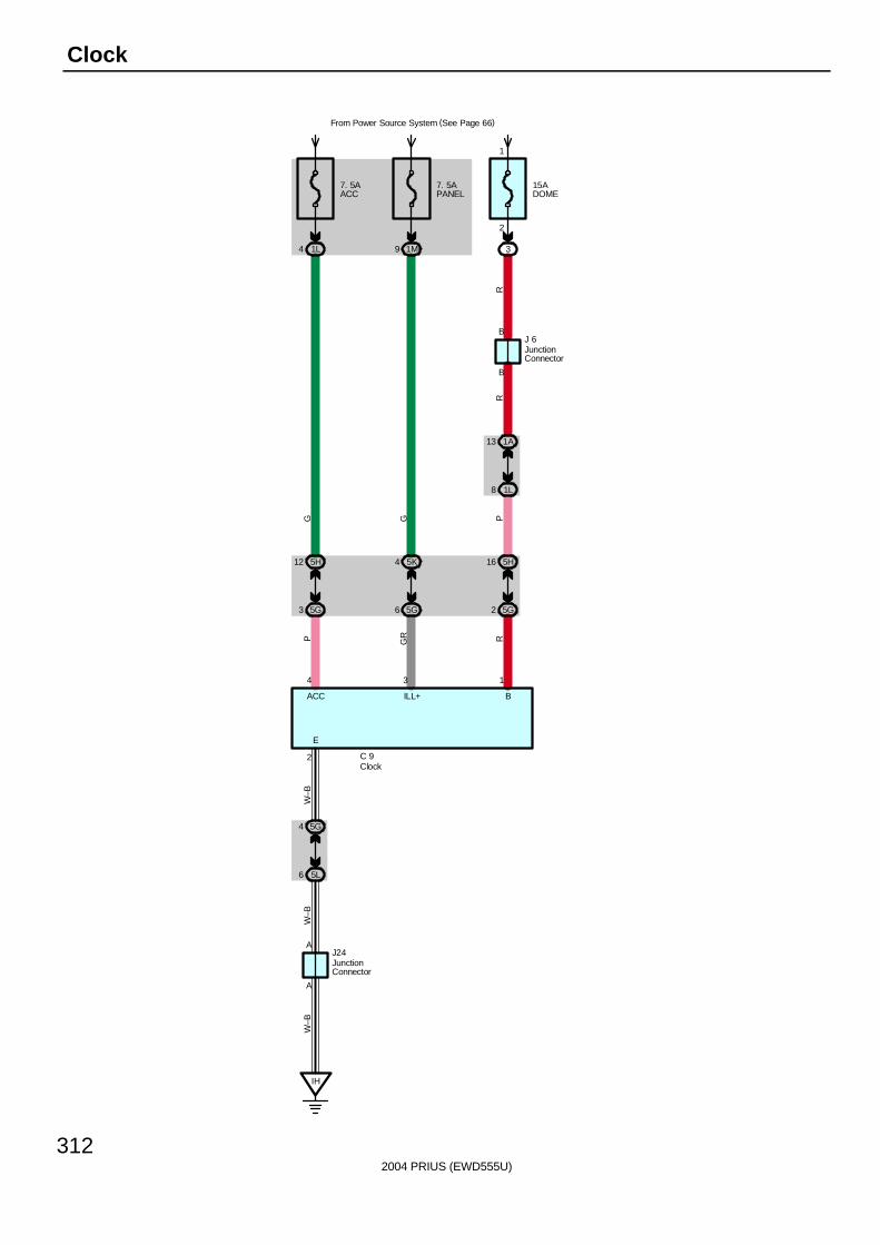
2004 PRIUS (EWD555U)
312
Clock
BILL+ACC
E
134
2
A
A
7. 5AACC
1L4
7. 5APANEL
From Power Source System (See Page 66)
1M9
15ADOME
3
1A13
1L8
5K4
5G6
5H12
5G3
5H16
5G2
RP
RGRP
GG
B
B
R
J 6
C 9
IH
5G4
5L6
J24
W–B
W–B
W–B
Clock
JunctionConnector
JunctionConnector
1
2
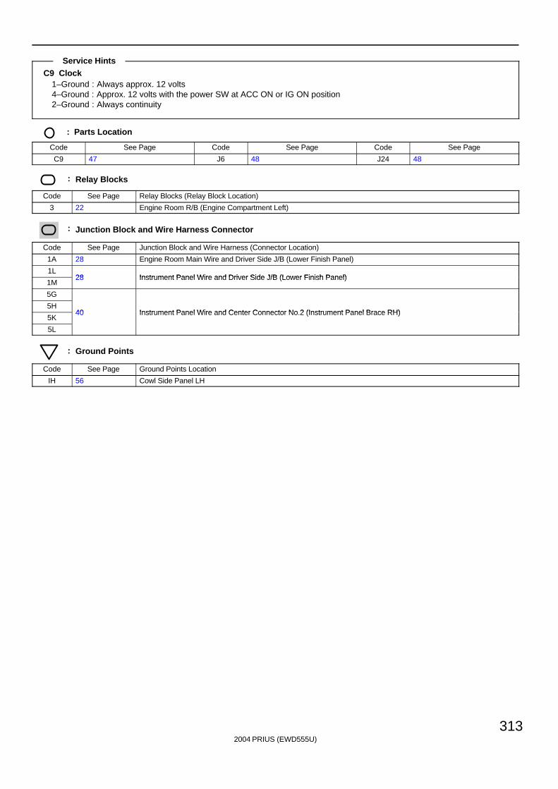
2004 PRIUS (EWD555U)
313
C9 Clock1–Ground : Always approx. 12 volts4–Ground : Approx. 12 volts with the power SW at ACC ON or IG ON position2–Ground : Always continuity
: Parts Location
Code See Page Code See Page Code See Page
C9 47 J6 48 J24 48
: Relay Blocks
Code See Page Relay Blocks (Relay Block Location)
3 22 Engine Room R/B (Engine Compartment Left)
: Junction Block and Wire Harness Connector
Code See Page Junction Block and Wire Harness (Connector Location)
1A 28 Engine Room Main Wire and Driver Side J/B (Lower Finish Panel)
1L28 Instrument Panel Wire and Driver Side J/B (Lower Finish Panel)
1M28 Instrument Panel Wire and Driver Side J/B (Lower Finish Panel)
5G
5H40 Instrument Panel Wire and Center Connector No 2 (Instrument Panel Brace RH)
5K40 Instrument Panel Wire and Center Connector No.2 (Instrument Panel Brace RH)
5L
: Ground Points
Code See Page Ground Points Location
IH 56 Cowl Side Panel LH
Service Hints
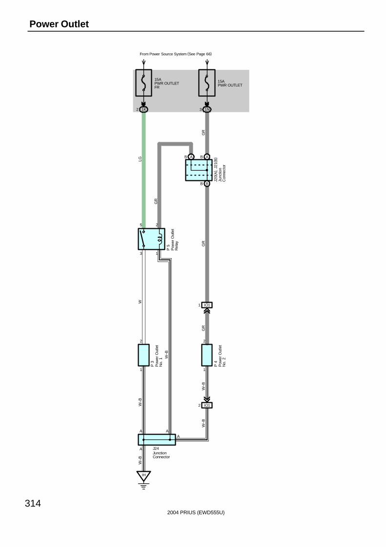
2004 PRIUS (EWD555U)
314
Power Outlet
A
2
11
A
AA
2
5
3
2
1
15APWR OUTLETFR
From Power Source System (See Page 66)
1K2
15APWR OUTLET
1N3
BB
ABAB
J20(
A) ,
J21
( B)
LG
GR
GR
IH
W
W–B
W–B
W–B
W–B
W–B
GR
GR
J24
P 4
P 3
P 5
IO12
IO11
Pow
er O
utle
tR
elay
Junc
tion
Con
nect
or
JunctionConnector
Pow
er O
utle
tN
o. 1
Pow
er O
utle
tN
o. 2
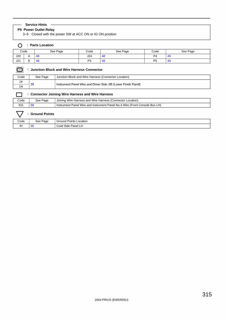
2004 PRIUS (EWD555U)
315
P5 Power Outlet Relay3–5 : Closed with the power SW at ACC ON or IG ON position
: Parts Location
Code See Page Code See Page Code See Page
J20 A 48 J24 48 P4 49
J21 B 48 P3 49 P5 49
: Junction Block and Wire Harness Connector
Code See Page Junction Block and Wire Harness (Connector Location)
1K28 Instrument Panel Wire and Driver Side J/B (Lower Finish Panel)
1N28 Instrument Panel Wire and Driver Side J/B (Lower Finish Panel)
: Connector Joining Wire Harness and Wire Harness
Code See Page Joining Wire Harness and Wire Harness (Connector Location)
IO1 58 Instrument Panel Wire and Instrument Panel No.4 Wire (Front Console Box LH)
: Ground Points
Code See Page Ground Points Location
IH 56 Cowl Side Panel LH
Service Hints
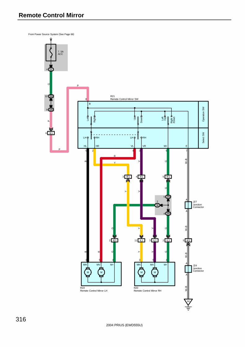
2004 PRIUS (EWD555U)
316
Remote Control Mirror
7635 2 4
EM+VLHL HR VR
Dow
n
Up
Rig
ht
Left
Rig
ht/D
own
Left
/Up
Sel
ect S
WO
pera
tion
SW
RHLHLH RH
8
B
A
A
53 4
M+MVMH
MM
5 4
M+MVMH
MM
3A
A
7. 5AACC
From Power Source System (See Page 66)
1L4
5H12
5N9
IE16
GP
IH
W–B
GVYGRB
G Y V G
W–B
G
VY
W–B
W–BGVB
IE12 IL111 IL13 IL12 IE25
IE15IE14IE13
5N5
5N4
5I
2
P
R
Y
R21
J27
J24
R20R19
P
JunctionConnector
JunctionConnector
Remote Control Mirror LH Remote Control Mirror RH
Remote Control Mirror SW
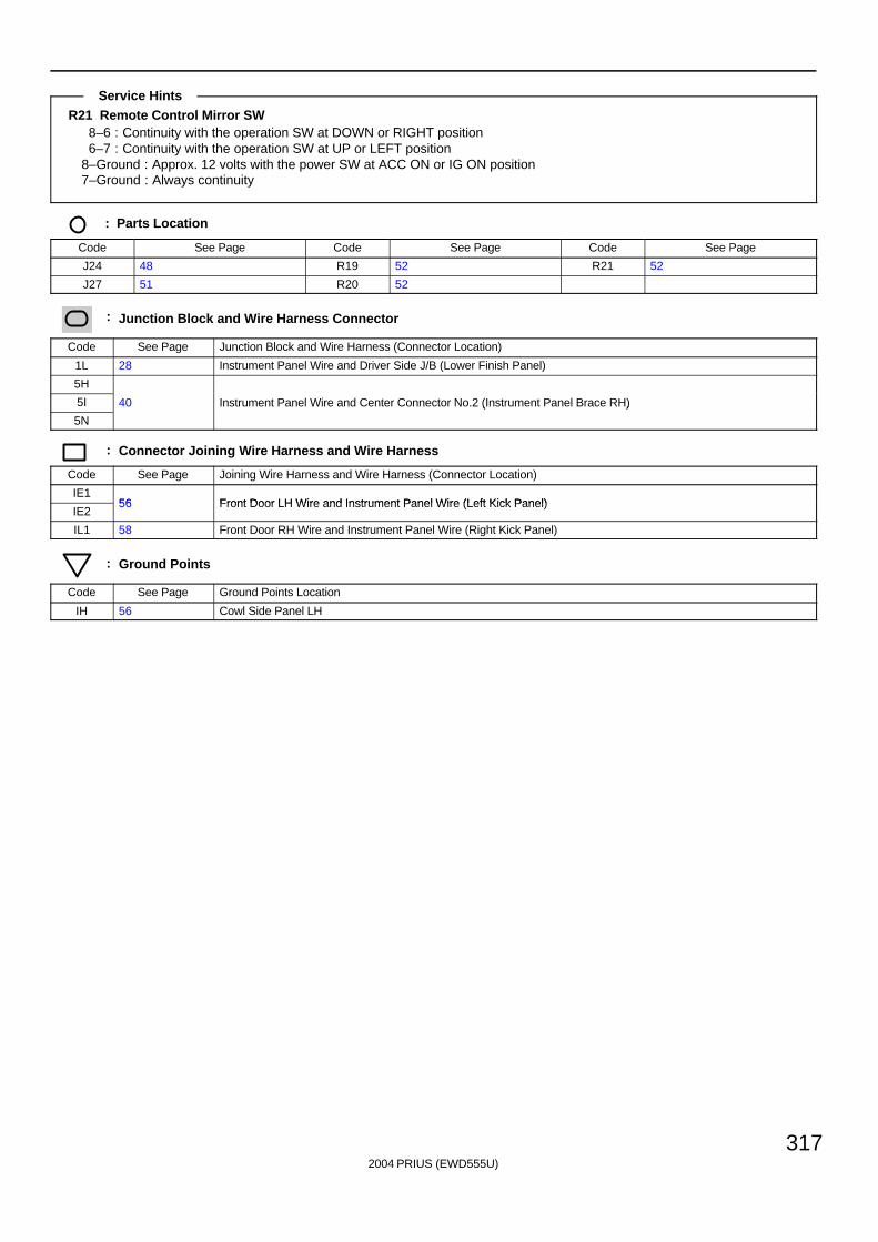
2004 PRIUS (EWD555U)
317
R21 Remote Control Mirror SW8–6 : Continuity with the operation SW at DOWN or RIGHT position6–7 : Continuity with the operation SW at UP or LEFT position
8–Ground : Approx. 12 volts with the power SW at ACC ON or IG ON position7–Ground : Always continuity
: Parts Location
Code See Page Code See Page Code See Page
J24 48 R19 52 R21 52
J27 51 R20 52
: Junction Block and Wire Harness Connector
Code See Page Junction Block and Wire Harness (Connector Location)
1L 28 Instrument Panel Wire and Driver Side J/B (Lower Finish Panel)
5H
5I 40 Instrument Panel Wire and Center Connector No.2 (Instrument Panel Brace RH)
5N
( )
: Connector Joining Wire Harness and Wire Harness
Code See Page Joining Wire Harness and Wire Harness (Connector Location)
IE156 Front Door LH Wire and Instrument Panel Wire (Left Kick Panel)
IE256 Front Door LH Wire and Instrument Panel Wire (Left Kick Panel)
IL1 58 Front Door RH Wire and Instrument Panel Wire (Right Kick Panel)
: Ground Points
Code See Page Ground Points Location
IH 56 Cowl Side Panel LH
Service Hints
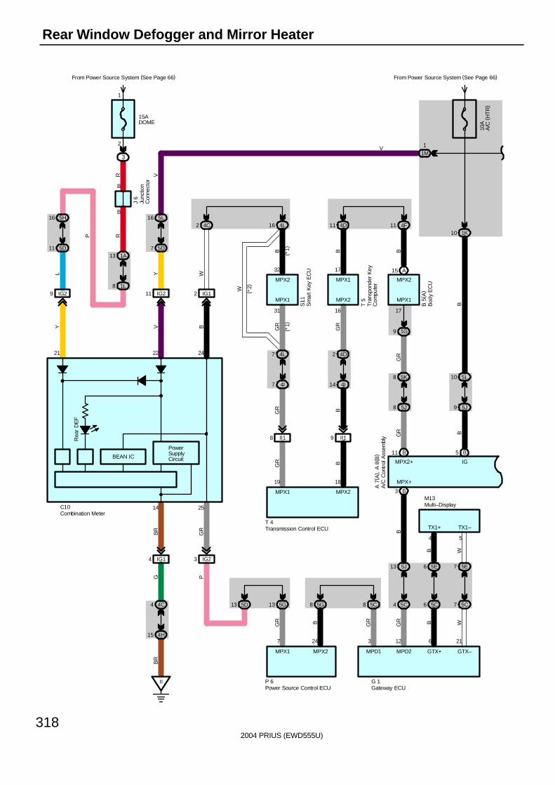
2004 PRIUS (EWD555U)
318
Rear Window Defogger and Mirror Heater
1M1
15ADOME
From Power Source System (See Page 66)
3
2
1
B
B
1A13
1L8
5H16
5D11 5D7
5L16
IG29 IG211
II
4H15
4C4
IG14
Rea
r D
EF
B3
MPX+
5J13
5C4
B11
5C85G8
IG23
5G13
5J8
5K8
1G9
17
A15
4F114D11
4D2
4I14
II19II18
4L7
4I7
4L164C2
IG12
5D13
A 7
( A) ,
A 8
( B)
B 5
( A)
T 5
S11
J 6
T 4
P 6 G 1
BG
R
GRBGR
BR
GB
R
PG
R
GR B
GR B
GR
GR
BBB
GR
GR
W
Y WBVY
R V
RP
L
MPX1MPX2MPX1
MPX1 MPX2MPX2
MPX1 MPX2
MPX1 MPX2 MPD1 MPD2
MPX2+
21 22 24
14 25
31 16
7 24 3 12
19 18
1732
V
C10
BEAN IC
PowerSupplyCircuit
( *1)
( *2)
( *1)
10 1K
10A
A/C
(H
TR
)
From Power Source System (See Page 66)
B5
9 5J
5L10
BIG
B
5E6
5C6
B
GTX+
6
5E7
5C7
W
GTX–
21
B W
4 5
TX1+ TX1–
M13
A/C
Con
trol
Ass
embl
y
Bod
y E
CU
Combination Meter
Gateway ECU
Junc
tion
Con
nect
or
Multi–Display
Tra
nspo
nder
Key
Com
pute
r
Transmission Control ECU
Sm
art
Key
EC
U
Power Source Control ECU
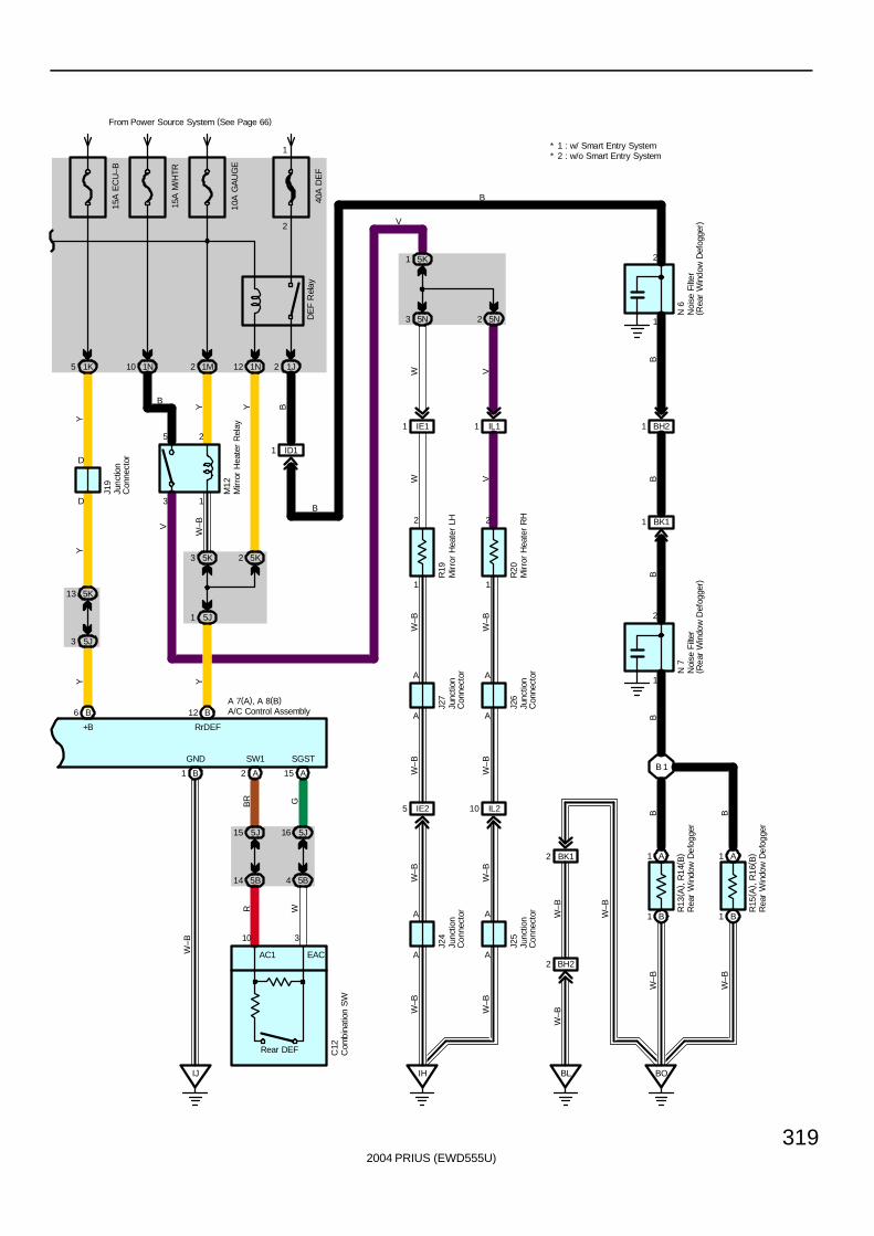
2004 PRIUS (EWD555U)
319
DE
F R
elay
1
2
1
2
A
A
A
A
1
2
A
A
A
A
1
2
15A
M/H
TR
From Power Source System (See Page 66)
1N10
10A
GA
UG
E
1M2
40A
DE
F
1N12 1J2
3 1
5 2
1
2
ID11
5K3 5K2
5J1
BOBLIH
B 1
IJ
B12
B1
GND
RrDEF
YW
–BY Y B
B
W–B
BH22
BK12
W–B
W–B
W–B
W–B
W–B
W–B
W–B
W–B
W–B
W–B
W–B
J24
J25
R13
( A) ,
R14
( B)
R15
( A) ,
R16
( B)
BB
B
B1 B1
A1 A1
IL210IE25
BK11
BH21IL11IE11
5N25N3
5K1
R20
R19
J27
J26
N 6
N 7
BB
B
VV
W–B
W–B
WW
B
V
B
V
M12
A15A2
5J15 5J16
5B14 5B4
AC1 EAC
10 3
BR G
WR
Rear DEF
A 7(A), A 8(B)
SW1 SGST
C12
* 1 : w/ Smart Entry System* 2 : w/o Smart Entry System
1K5
15A
EC
U–B
B6
3 5J
5K13
Y
+B
D
D
YY
J19
A/C Control Assembly
Com
bina
tion
SW
Junc
tion
Con
nect
or
Junc
tion
Con
nect
or
Junc
tion
Con
nect
orJu
nctio
nC
onne
ctor
Junc
tion
Con
nect
or
Mirr
or H
eate
r R
elay
Noi
se F
ilter
( Rea
r W
indo
w D
efog
ger)
Noi
se F
ilter
( Rea
r W
indo
w D
efog
ger)
Mirr
or H
eate
r LH
Mirr
or H
eate
r R
H
Rea
r W
indo
w D
efog
ger
Rea
r W
indo
w D
efog
ger
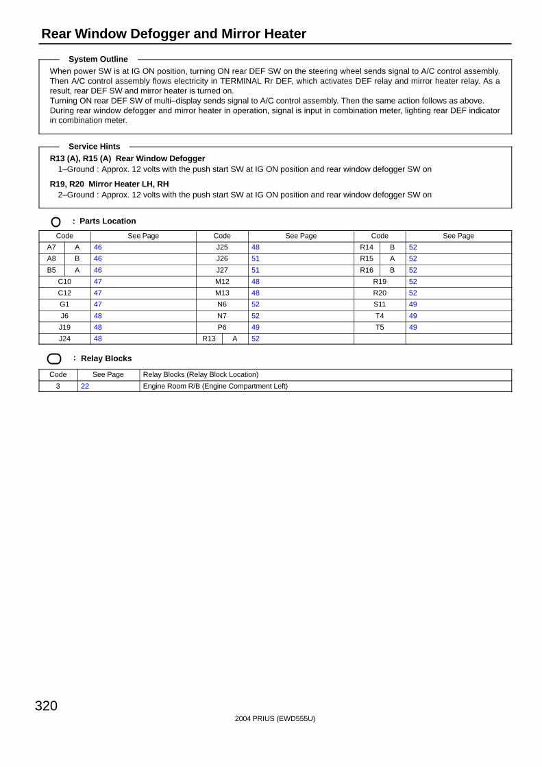
2004 PRIUS (EWD555U)
320
Rear Window Defogger and Mirror Heater
When power SW is at IG ON position, turning ON rear DEF SW on the steering wheel sends signal to A/C control assembly.Then A/C control assembly flows electricity in TERMINAL Rr DEF, which activates DEF relay and mirror heater relay. As aresult, rear DEF SW and mirror heater is turned on.Turning ON rear DEF SW of multi–display sends signal to A/C control assembly. Then the same action follows as above.During rear window defogger and mirror heater in operation, signal is input in combination meter, lighting rear DEF indicatorin combination meter.
R13 (A), R15 (A) Rear Window Defogger1–Ground : Approx. 12 volts with the push start SW at IG ON position and rear window defogger SW on
R19, R20 Mirror Heater LH, RH2–Ground : Approx. 12 volts with the push start SW at IG ON position and rear window defogger SW on
: Parts Location
Code See Page Code See Page Code See Page
A7 A 46 J25 48 R14 B 52
A8 B 46 J26 51 R15 A 52
B5 A 46 J27 51 R16 B 52
C10 47 M12 48 R19 52
C12 47 M13 48 R20 52
G1 47 N6 52 S11 49
J6 48 N7 52 T4 49
J19 48 P6 49 T5 49
J24 48 R13 A 52
: Relay Blocks
Code See Page Relay Blocks (Relay Block Location)
3 22 Engine Room R/B (Engine Compartment Left)
System Outline
Service Hints
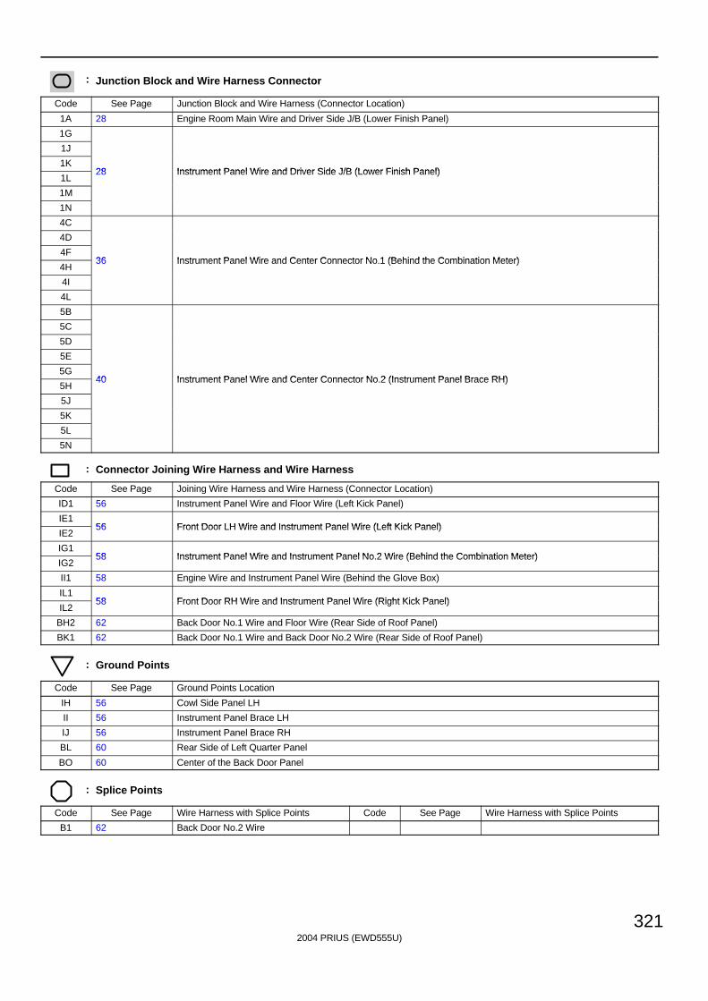
2004 PRIUS (EWD555U)
321
: Junction Block and Wire Harness Connector
Code See Page Junction Block and Wire Harness (Connector Location)
1A 28 Engine Room Main Wire and Driver Side J/B (Lower Finish Panel)
1G
1J
1K28 Instrument Panel Wire and Driver Side J/B (Lower Finish Panel)
1L28 Instrument Panel Wire and Driver Side J/B (Lower Finish Panel)
1M
1N
4C
4D
4F36 Instrument Panel Wire and Center Connector No 1 (Behind the Combination Meter)
4H36 Instrument Panel Wire and Center Connector No.1 (Behind the Combination Meter)
4I
4L
5B
5C
5D
5E
5G40 Instrument Panel Wire and Center Connector No 2 (Instrument Panel Brace RH)
5H40 Instrument Panel Wire and Center Connector No.2 (Instrument Panel Brace RH)
5J
5K
5L
5N
: Connector Joining Wire Harness and Wire Harness
Code See Page Joining Wire Harness and Wire Harness (Connector Location)
ID1 56 Instrument Panel Wire and Floor Wire (Left Kick Panel)
IE156 Front Door LH Wire and Instrument Panel Wire (Left Kick Panel)
IE256 Front Door LH Wire and Instrument Panel Wire (Left Kick Panel)
IG158 Instrument Panel Wire and Instrument Panel No 2 Wire (Behind the Combination Meter)
IG258 Instrument Panel Wire and Instrument Panel No.2 Wire (Behind the Combination Meter)
II1 58 Engine Wire and Instrument Panel Wire (Behind the Glove Box)
IL158 Front Door RH Wire and Instrument Panel Wire (Right Kick Panel)
IL258 Front Door RH Wire and Instrument Panel Wire (Right Kick Panel)
BH2 62 Back Door No.1 Wire and Floor Wire (Rear Side of Roof Panel)
BK1 62 Back Door No.1 Wire and Back Door No.2 Wire (Rear Side of Roof Panel)
: Ground Points
Code See Page Ground Points Location
IH 56 Cowl Side Panel LH
II 56 Instrument Panel Brace LH
IJ 56 Instrument Panel Brace RH
BL 60 Rear Side of Left Quarter Panel
BO 60 Center of the Back Door Panel
: Splice Points
Code See Page Wire Harness with Splice Points Code See Page Wire Harness with Splice Points
B1 62 Back Door No.2 Wire
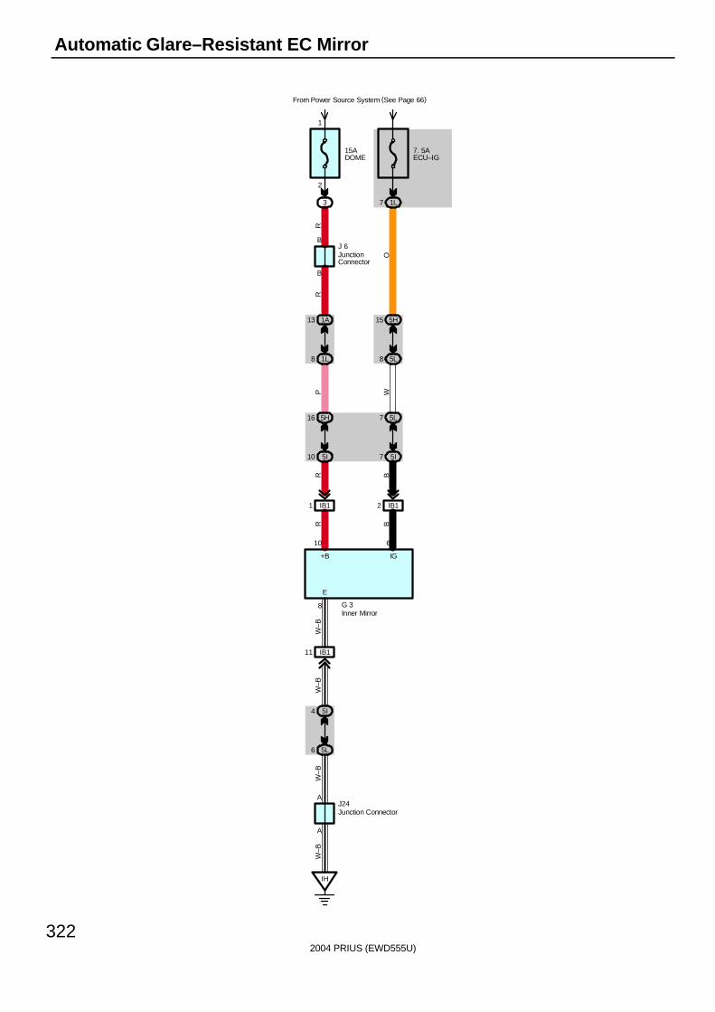
2004 PRIUS (EWD555U)
322
Automatic Glare–Resistant EC Mirror
IG+B
E
610
8
A
A
15ADOME
From Power Source System (See Page 66)
3
7. 5AECU–IG
1L7
1A13 5H15
5L81L8
5L7
5I7
5H16
5I10
R BBR
P WO
RW
–B
IB11 IB12
IB111
5I4
5L6
IH
J24
W–B
W–B
W–B
B
B
R
J 6
G 3Inner Mirror
JunctionConnector
Junction Connector
1
2

2004 PRIUS (EWD555U)
323
G3 Inner Mirror10–Ground : Always approx. 12 volts
8–Ground : Always continuity6–Ground : Approx. 12 volts with the power SW at IG ON position
: Parts Location
Code See Page Code See Page Code See Page
G3 51 J6 48 J24 48
: Relay Blocks
Code See Page Relay Blocks (Relay Block Location)
3 22 Engine Room R/B (Engine Compartment Left)
: Junction Block and Wire Harness Connector
Code See Page Junction Block and Wire Harness (Connector Location)
1A 28 Engine Room Main Wire and Driver Side J/B (Lower Finish Panel)
1L 28 Instrument Panel Wire and Driver Side J/B (Lower Finish Panel)
5H
5I 40 Instrument Panel Wire and Center Connector No.2 (Instrument Panel Brace RH)
5L
( )
: Connector Joining Wire Harness and Wire Harness
Code See Page Joining Wire Harness and Wire Harness (Connector Location)
IB1 56 Roof Wire and Instrument Panel Wire (Upper Parts of Front Body Pillar LH)
: Ground Points
Code See Page Ground Points Location
IH 56 Cowl Side Panel LH
Service Hints
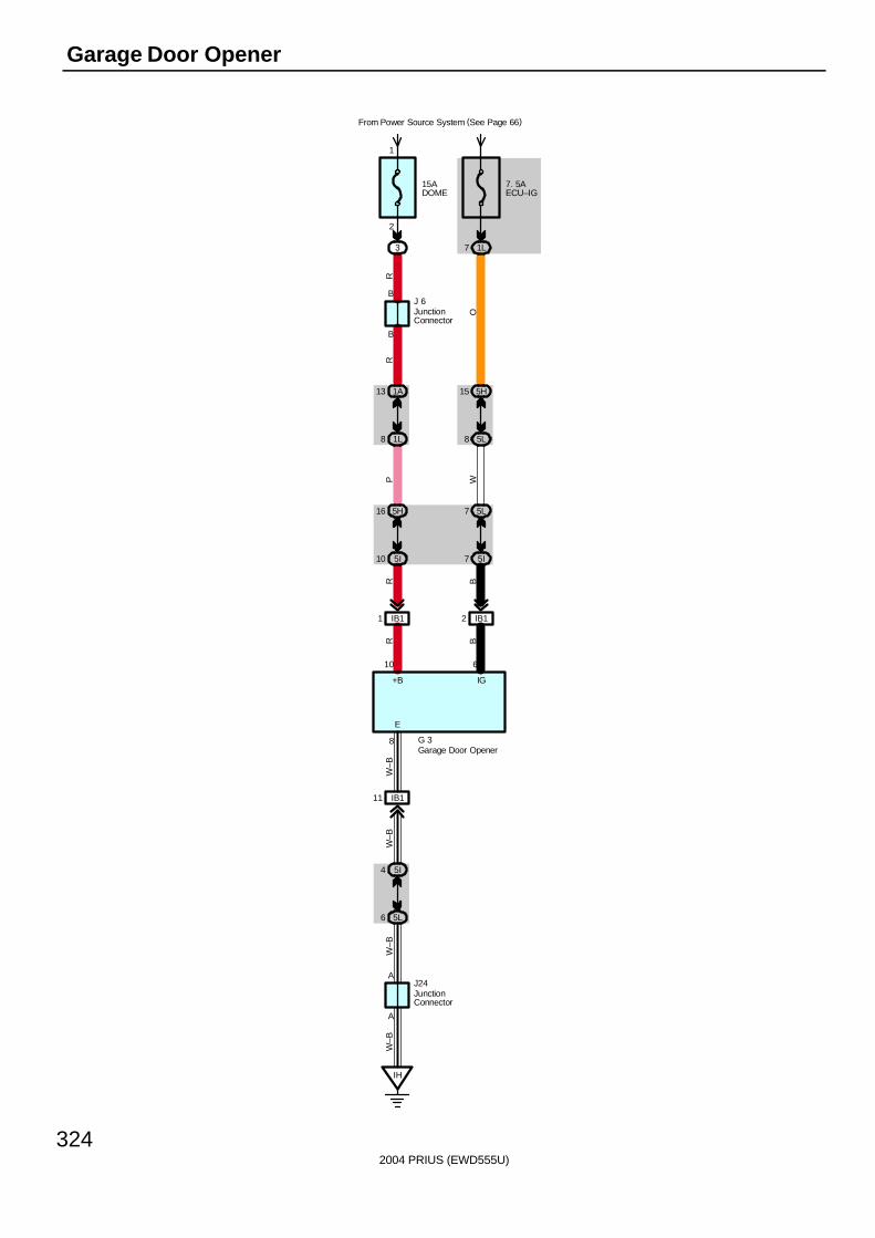
2004 PRIUS (EWD555U)
324
Garage Door Opener
IG+B
E
610
8
A
A
15ADOME
From Power Source System (See Page 66)
3
7. 5AECU–IG
1L7
1A13 5H15
5L81L8
5L7
5I7
5H16
5I10
R BBR
P WO
RW
–B
IB11 IB12
IB111
5I4
5L6
IH
J24
W–B
W–B
W–B
B
B
R
J 6
G 3Garage Door Opener
JunctionConnector
JunctionConnector
1
2
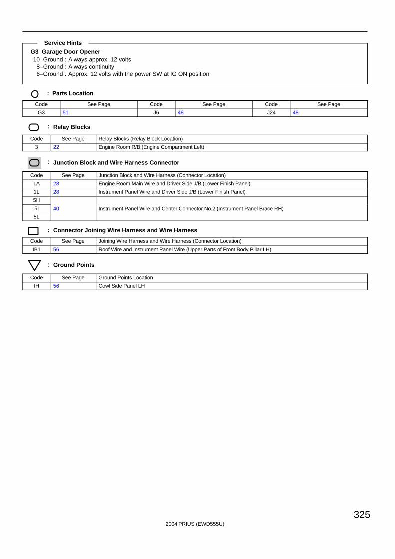
2004 PRIUS (EWD555U)
325
G3 Garage Door Opener10–Ground : Always approx. 12 volts
8–Ground : Always continuity6–Ground : Approx. 12 volts with the power SW at IG ON position
: Parts Location
Code See Page Code See Page Code See Page
G3 51 J6 48 J24 48
: Relay Blocks
Code See Page Relay Blocks (Relay Block Location)
3 22 Engine Room R/B (Engine Compartment Left)
: Junction Block and Wire Harness Connector
Code See Page Junction Block and Wire Harness (Connector Location)
1A 28 Engine Room Main Wire and Driver Side J/B (Lower Finish Panel)
1L 28 Instrument Panel Wire and Driver Side J/B (Lower Finish Panel)
5H
5I 40 Instrument Panel Wire and Center Connector No.2 (Instrument Panel Brace RH)
5L
( )
: Connector Joining Wire Harness and Wire Harness
Code See Page Joining Wire Harness and Wire Harness (Connector Location)
IB1 56 Roof Wire and Instrument Panel Wire (Upper Parts of Front Body Pillar LH)
: Ground Points
Code See Page Ground Points Location
IH 56 Cowl Side Panel LH
Service Hints
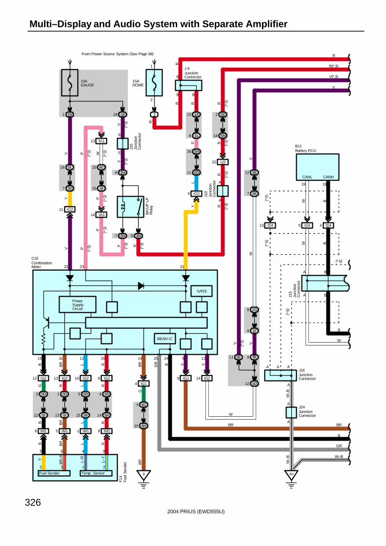
2004 PRIUS (EWD555U)
326
Multi–Display and Audio System with Separate Amplifier
From Power Source System (See Page 66)
9 IG2Y
14 IG24 IG1
B
II
B
14
21
PowerSupplyCircuit
GB
R
13
V
22
10AGAUGE
1M1
15ADOME
3
R
R
5L16
5D7
IG211
Y
1A13
1L8
4C4
4H15
V
BR
5K9
5D12
11 5D
16 5H
PL
8 1F
8 1G
W
7 5K
12 5E
V
W
R
A
A
A
A
B
CANH
18
ID44
AA
A
ID413
V
B
W
IH
W–B
W–B
( *5)
( *5)
( *5)
BB
J16
J24
B11
5 ID4
19
CANL
WW
B
W–B
IG19
2425
BGR
A
BEAN IC
(VFD)
V
9
V
3H6
3H7 3H8
E
4I15
4C15
IG113
IJ322
5E2
5N14
R
P R
PWP
RR
RR
1A19V
V
V E
A
AJ1
0
23
P
BK
/UP
LP
Rel
ay
R(*3)
V(*3)
5E11
V
( *3)
( *3)
( *3)
( *3)
( *3)
( *3) ( *
3)
( *3)
( *3)
( *3)
( *3)
( *3)
( *3)
B
GR
1
2
J15
IG212 IG213 IG210 IG28
R
5D6
5K14
L
5D5
5K15
R
5D1
5I13
G
5D2
5I12
IM18IM11IM15IM16
B BR
B BR L R
15 31 12 20
5 6 4 8
F14
C10
B BR L R
L R
(* 5)
BR BR
Battery ECU
CombinationMeter
Fuel
Sen
der
Junc
tion
Con
nect
or
Junc
tion
Con
nect
or
JunctionConnector
JunctionConnector
JunctionConnector
J 6
B
R
IA314
Junc
tion
Con
nect
or
J10
P ( *3)
Fuel Sender Temp. Sensor
2 3 1 2
Y
BR
–R
L–R
L–Y
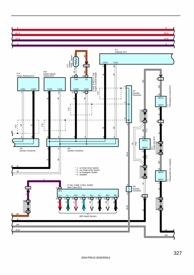
2004 PRIUS (EWD555U)
327
BG
R
T 4
MPX1
MPX2
18
19
9 II1
8 II1
GR
R
B
R
V V
GR
4D11
B
4F11
4I14
4D2
16
17
MPX1
MPX2
T 5
B
4L16
BG
R
4C2
4I7
4L7
31
32
MPX2
MPX1
S11
W ( *2)
( *1)
( *1)
W
G 1
17
CA1H
18
CA1L
98
CANLCANHCANLCANH
AB A B B A
A
A
A
A
A
A
( *5)
( *5)
( *5)
B
W
B W
B B WW
J18
H14
J17
AB
W–B
W–B
J25
W–B
GR
B W
B W
* 2 : w/o Smart Entry System* 1 : w/ Smart Entry System
P 8
W B
EB13
IA37
4I16
4C9
2
1
7 1
CANL CANH
A B
B
BR
BR
W
E 4
( A) ,
E 6
( C) ,
E 7
( D)
D21 A28
( *5)
A 6
TAM E2
C30C31
R(*3) R(*3)
V(*3) V(*3)
B
GR
J15
* 3 : w/ Navigation System* 5 : Shielded
V
D28 D22 A32 A22 B35 B27 C31 C23
FL+ FL– FR+ FR– RL+ RL– RR+ RR–
R G P L W B W B
ABS Speed Sensors
S 7(A), S 8(B), S 9(C), S10(D)B22
SP1
BR
V
Am
bien
tT
emp.
S
enso
r
Skid Control ECU
Eng
ine
Con
trol
Mod
ule
Gateway ECU
Hybrid VehicleControl ECU
Junction Connector
JunctionConnector
Junction Connector
JunctionConnector
Tran
spon
der
Key
Com
pute
rT
rans
mis
sion
Con
trol
EC
U
Sm
art
Key
EC
U
Power Steering ECU
IG12
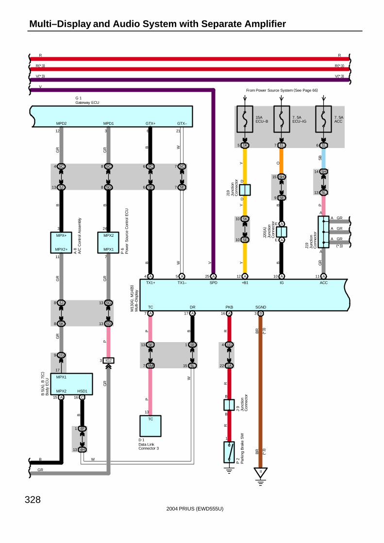
2004 PRIUS (EWD555U)
328
Multi–Display and Audio System with Separate Amplifier
5 1K
B
15AECU–B
D
D
Y
5K10
5E10
+B1 IG
P
A
A
13 5L
14 5H
SB
6 1L
7. 5AACC
J19
B
YY
J20(
A)
9 5E
15 5H
O
7 1L
7. 5AECU–IG
V
R
TC
P
7 5M
13 5E
D 1
P
1
SPD
TC
13 B
B
R
1G4
1A22
R
PKB
J 9
R
P 2
TX1–
6
GTX+
B
6 5E
6 5C
B
21
GTX–
W
7 5E
7 5C
W
TX1+
GR
P
5G13
GR
5D13
P 6
5J8
5K8
MPX2+
11
MPX1
A 8
7
R
GR
B
VFrom Power Source System (See Page 66)
24
MPX2MPX+
3
5C4
GR
G 1
5C8
GR
5G8
3
MPD1
B
5J13
12
MPD2
B
3 IG2
B
MPX2
MPX1
GR
1G9
A15
GR
17
DR
B
15 5L
1 5E
W
M13
( A) ,
M14
( B)
HSD1
C16
B 5
( A) ,
B 7
( C)
13 4H
1 4F
W
A10A12A25A5A4
A16A17A7
J19
GR
ACC
A11
GRA
A
A
GR
GR
R(*3)R(*3)
V(*3)V(*3)
SGND
B3
II
BR
BR
( *3)
( *3)
(* 3)
A/C
Con
trol
Ass
embl
y
Bod
y E
CU
Data LinkConnector 3
Gateway ECU
Junc
tion
Con
nect
or
Junc
tion
Con
nect
or
Junc
tion
Con
nect
or
Junc
tion
Con
nect
or
Mul
ti–D
ispl
ay
Par
king
Bra
ke S
W
Pow
er S
ourc
e C
ontr
ol E
CU
AE
AE
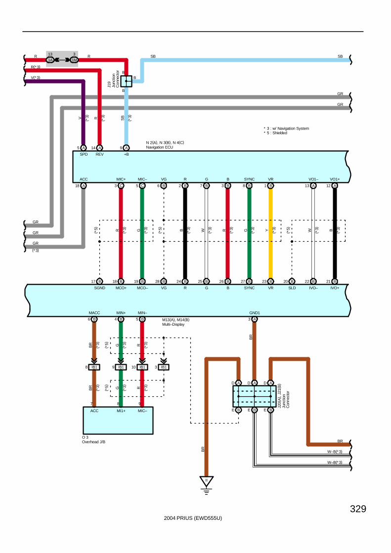
2004 PRIUS (EWD555U)
329
II
GND1
B
B
BR
BR
A18 C5 B6 B2 B7 B3 B8 B1 A13 A12
B18 B19 B28 B24 B25 B26 B27 B23 B20 B22 B21B17
A3
SBR1A
13
1M
3 R
J19
A9
B
SB
SB
( *3)
ACC MIC– VG R G B SYNC VR VO1– VO1+
+B
N 2(A), N 3(B), N 4(C)
GR
GR
C3
MIC+
GR
GR
GR
BE BE
AD AD D A
E B
IB18 IB19 IB110 IB13
B4 B5B6
BR
W–B(*3)
W–B(*3)
( *5)
( *5)
( *5) R G B W R G Y W B
SGND MCO+ MCO– VG R G B SYNC VR SLD IVO– IVO+
( *3)
( *3)
( *3)
( *3)
( *3)
( *3)
( *3)
( *3)
( *3)
BR
( *3)
BR
( *3) G ( *3) R ( *3)
G ( *3) R ( *3)
( *5)
( *5)
7 8 9
ACC MI1+ MIC–
O 3
J20(
A) ,
J21(
B)
MACC MIN+ MIN–
R(*3)
A14
REV
R
A5
SPD
VV(*3)
M13(A), M14(B)
(*3)
( *3)
( *3)
* 3 : w/ Navigation System* 5 : Shielded
Junc
tion
Con
nect
or
Junc
tion
Con
nect
or
Multi–Display
Navigation ECU
Overhead J/B
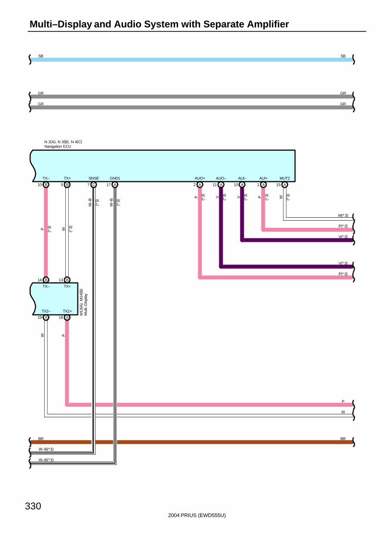
2004 PRIUS (EWD555U)
330
Multi–Display and Audio System with Separate Amplifier
TX2– TX2+
A1 A15B10 B5
B14 B13
A18A19
SBSB
TX– TX+ AUI+
N 2(A), N 3(B), N 4(C)
GR
GR
C7 A17
SNSE GND1
P
W
BR BR
W–B(*3)
W–B(*3)
PW
GR
GR
A10A112 A
AUO+ AUO– AUI–
P V V P W
W(*3)
P(*3)
V(*3)
V(*3)
P(*3)
( *3)
( *3)
( *3)
( *3)
( *3)
MUT2
P W
TX– TX+
( *3)
( *3)
W–B
W–B
( *3)
( *3)
M13
( A) ,
M14
( B)
Mul
ti–D
ispl
ay
Navigation ECU

2004 PRIUS (EWD555U)
331
BB1 11 BB1 10
8 IL2
WRYB
BJ1
WF1–WF1+WF2–WF2+
2121 1
31
2
24
WR
RR–RR+
B Y
1
31
2
24
YB
RL–RL+
R W
11 BJ1
A20A9A19A8 A14A5A13A4
10
R11 R12F12 F13
IL25IE24IE28
P V LG LLLGVP
T 9
T 8
B21
ID41 ID42 IM213 IM212B Y R W
12
WR
C 8
A12A3A1 A10
BA
AC AC
IA110
30AAMP
From Power Source System (See Page 66)
3
2
1
SB
SB
W
W
J20(
A) ,
J21
( B)
N–MU
+B +B2
S14(A), S15(B)
SBSB
B12
ACC
GR
GR
CTR+ CTR–
P
W
P
W
BRBR
GR
GR
V(*3)
P(*3)
V(*3)
P(*3)
W(*3)
( *4)
( *4)
* 4 : w/o Navigation System* 3 : w/ Navigation System
Center Speaker
Front Door Speaker LH Front Door Speaker RH
Junc
tion
Con
nect
or
Rear Door Speaker LH Rear Door Speaker RH
Stereo Component Amplifier
Twee
ter
Rea
r LH
Twee
ter
Rea
r R
H
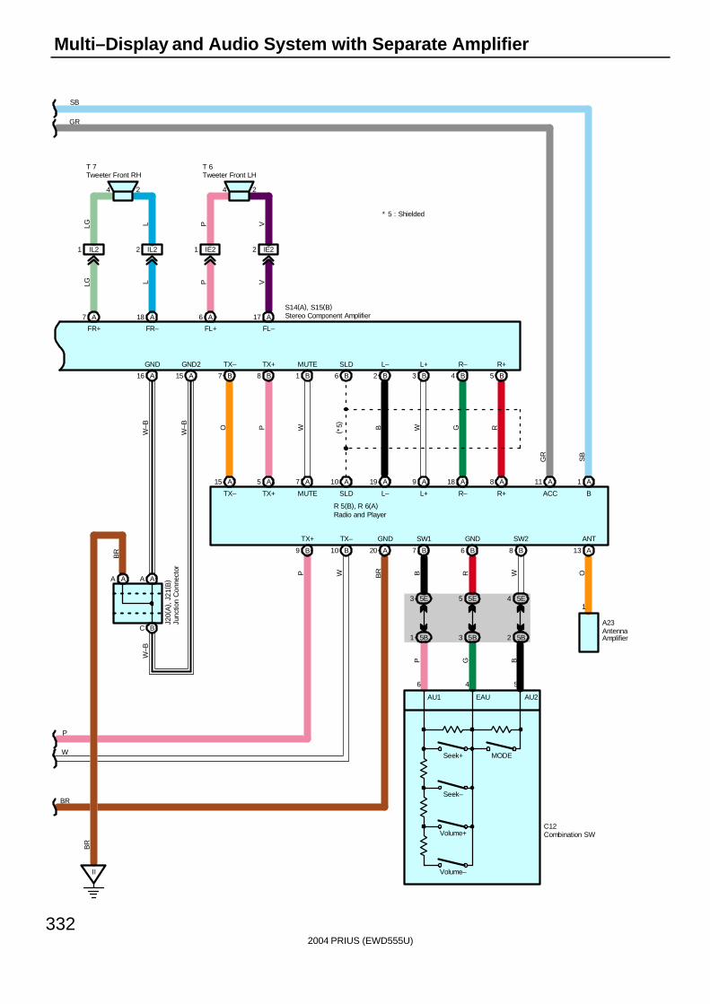
2004 PRIUS (EWD555U)
332
Multi–Display and Audio System with Separate Amplifier
SB
GR
1 A
C12
7 B 8 B6 B
GND SW2SW1
A23
B
BACC
TX–TX+
R W
GND
SB
A20B10B9
A11
P BG
R 5(B), R 6(A)
BR
Volume+
Volume–
Seek–
Seek+ MODE
A15
B7
O
TX–
TX–
5 A
B8
P
TX+
TX+
7 A
B1
W
MUTE
MUTE
10 A
B6
( *5)
SLD
SLD
19 A
B2B
L–
L–
9 A
B3
W
L+
L+
18 A
B4
G
R–
R–
8 A
B5
R
R+
R+
BC
AA AA
II
A16
GND
A15
GND2
J20(
A) ,
J21
( B)
W–B
W–B
BR
BR
W–B
GR
5E3 5E5 5E4
5B1 5B3 5B2
6 4 5
AU2EAUAU1
13 A
ANT
O
1
WP
P
W
BR
24
LLG
T 7
A18A7
FR+ FR–
24
VP
T 6
A17A6
FL+ FL–
IL21 IL22 IE21 IE22
S14(A), S15(B)
LLG VP
* 5 : Shielded
AntennaAmplifier
Combination SW
Junc
tion
Con
nect
or
Radio and Player
Stereo Component Amplifier
Tweeter Front LHTweeter Front RH
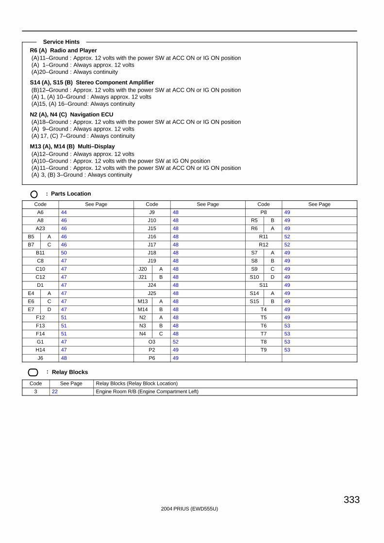
2004 PRIUS (EWD555U)
333
R6 (A) Radio and Player(A)11–Ground : Approx. 12 volts with the power SW at ACC ON or IG ON position(A) 1–Ground : Always approx. 12 volts(A)20–Ground : Always continuity
S14 (A), S15 (B) Stereo Component Amplifier(B)12–Ground : Approx. 12 volts with the power SW at ACC ON or IG ON position(A) 1, (A) 10–Ground : Always approx. 12 volts(A)15, (A) 16–Ground: Always continuity
N2 (A), N4 (C) Navigation ECU(A)18–Ground : Approx. 12 volts with the power SW at ACC ON or IG ON position(A) 9–Ground : Always approx. 12 volts(A) 17, (C) 7–Ground : Always continuity
M13 (A), M14 (B) Multi–Display(A)12–Ground : Always approx. 12 volts(A)10–Ground : Approx. 12 volts with the power SW at IG ON position(A)11–Ground : Approx. 12 volts with the power SW at ACC ON or IG ON position(A) 3, (B) 3–Ground : Always continuity
: Parts Location
Code See Page Code See Page Code See Page
A6 44 J9 48 P8 49
A8 46 J10 48 R5 B 49
A23 46 J15 48 R6 A 49
B5 A 46 J16 48 R11 52
B7 C 46 J17 48 R12 52
B11 50 J18 48 S7 A 49
C8 47 J19 48 S8 B 49
C10 47 J20 A 48 S9 C 49
C12 47 J21 B 48 S10 D 49
D1 47 J24 48 S11 49
E4 A 47 J25 48 S14 A 49
E6 C 47 M13 A 48 S15 B 49
E7 D 47 M14 B 48 T4 49
F12 51 N2 A 48 T5 49
F13 51 N3 B 48 T6 53
F14 51 N4 C 48 T7 53
G1 47 O3 52 T8 53
H14 47 P2 49 T9 53
J6 48 P6 49
: Relay Blocks
Code See Page Relay Blocks (Relay Block Location)
3 22 Engine Room R/B (Engine Compartment Left)
Service Hints
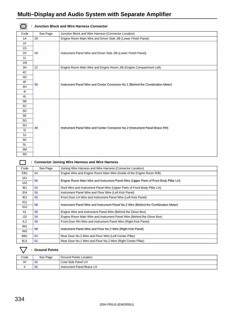
2004 PRIUS (EWD555U)
334
Multi–Display and Audio System with Separate Amplifier
: Junction Block and Wire Harness Connector
Code See Page Junction Block and Wire Harness (Connector Location)
1A 28 Engine Room Main Wire and Driver Side J/B (Lower Finish Panel)
1F
1G
1K 28 Instrument Panel Wire and Driver Side J/B (Lower Finish Panel)
1L
( )
1M
3H 22 Engine Room Main Wire and Engine Room J/B (Engine Compartment Left)
4C
4D
4F36 Instrument Panel Wire and Center Connector No 1 (Behind the Combination Meter)
4H36 Instrument Panel Wire and Center Connector No.1 (Behind the Combination Meter)
4I
4L
5B
5C
5D
5E
5G
5H40 Instrument Panel Wire and Center Connector No 2 (Instrument Panel Brace RH)
5I40 Instrument Panel Wire and Center Connector No.2 (Instrument Panel Brace RH)
5J
5K
5L
5M
5N
: Connector Joining Wire Harness and Wire Harness
Code See Page Joining Wire Harness and Wire Harness (Connector Location)
EB1 54 Engine Wire and Engine Room Main Wire (Inside of the Engine Room R/B)
IA156 Engine Room Main Wire and Instrument Panel Wire (Upper Parts of Front Body Pillar LH)
IA356 Engine Room Main Wire and Instrument Panel Wire (Upper Parts of Front Body Pillar LH)
IB1 56 Roof Wire and Instrument Panel Wire (Upper Parts of Front Body Pillar LH)
ID4 56 Instrument Panel Wire and Floor Wire (Left Kick Panel)
IE2 56 Front Door LH Wire and Instrument Panel Wire (Left Kick Panel)
IG158 Instrument Panel Wire and Instrument Panel No 2 Wire (Behind the Combination Meter)
IG258 Instrument Panel Wire and Instrument Panel No.2 Wire (Behind the Combination Meter)
II1 58 Engine Wire and Instrument Panel Wire (Behind the Glove Box)
IJ3 58 Engine Room Main Wire and Instrument Panel Wire (Behind the Glove Box)
IL2 58 Front Door RH Wire and Instrument Panel Wire (Right Kick Panel)
IM158 Instrument Panel Wire and Floor No 2 Wire (Right Kick Panel)
IM258 Instrument Panel Wire and Floor No.2 Wire (Right Kick Panel)
BB1 60 Rear Door No.2 Wire and Floor Wire (Left Center Pillar)
BJ1 62 Rear Door No.1 Wire and Floor No.2 Wire (Right Center Pillar)
: Ground Points
Code See Page Ground Points Location
IH 56 Cowl Side Panel LH
II 56 Instrument Panel Brace LH

2004 PRIUS (EWD555U)
335
Memo
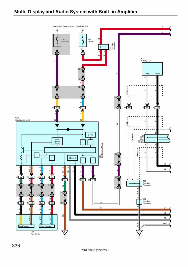
2004 PRIUS (EWD555U)
336
Multi–Display and Audio System with Built–in Amplifier
From Power Source System (See Page 66)
9 IG2
Y
14 IG24 IG1
B
II
B
14
21
PowerSupplyCircuit
GB
R
13
V
22
10AGAUGE
1M1
15ADOME
3
R
R
5L16
5D7
IG211
VY
1A13
1L8
4C4
4H15
V
BR
5K9
5D12
11 5D
16 5H
PL
8 1F
8 1G
W
7 5K
12 5E
V
R
A
A
A
A
B
CANH
18
ID44
AA
A
ID413
V
B
W
IH
W–B
W–B
( Shi
elde
d)
( Shi
elde
d)( S
hiel
ded)
BB
W B
J16
J24
B11
5 ID4
19
CANL
WW
B
W–B
C10
IG19
2425
BGR
A
BEAN IC
(VFD)
V
9
V
C10
GR
B
J15
W
BR
IG212 13 IG2 IG210 IG28
R
5D6
5K14
L
5D5
5K15
R
5D1
5I13
G
5D2
5I12
IM18IM11IM15IM16
B BR
B BR L
RR
15
L
31 12
R
20
5
L
6 4
BR
8
B
1
2
( Shi
elde
d)
BR
Battery ECU
Com
bina
tion
Met
er
Combination Meter
Junc
tion
Con
nect
or
JunctionConnector
JunctionConnector
Junc
tion
Con
nect
or
J 6
R
B
Fuel SenderF14
2 3 1 2
L–Y
L–R
BR
–RY
Fuel Sender Temp. Sensor
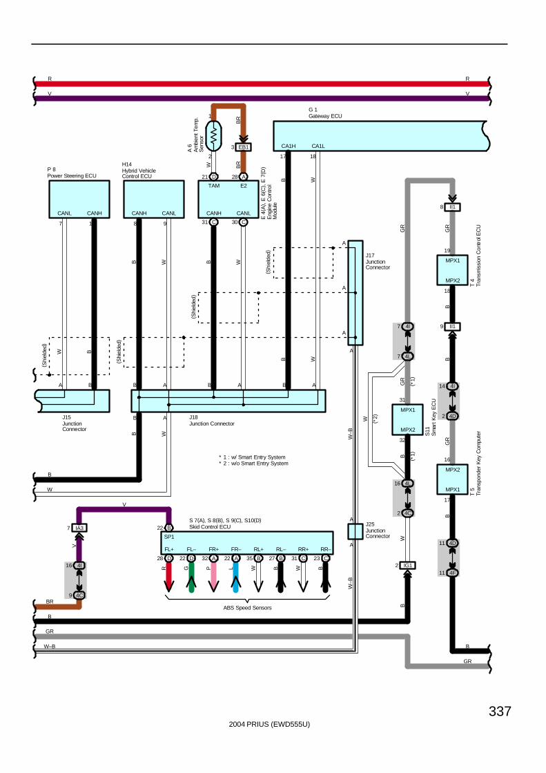
2004 PRIUS (EWD555U)
337
BG
R
T 4
MPX1
MPX2
18
19
9 II1
8 II1
GR
R
B
R
V V
GR
4D11
B
4F11
4I14
4D2
16
17
MPX1
MPX2T
5
B
4L16
BG
R
4C2
4I7
4L7
31
32
MPX2
MPX1
S11
W ( *2)
( *1)
( *1)
W
G 1
17
CA1H
18
CA1L
98
CANLCANHCANLCANH
AB A B B A
A
A
A
A
A
A
( Shi
elde
d)
( Shi
elde
d)
( Shi
elde
d)
B
W
B W
B B WW
J18
H14
J17
AB
W–B
W–B
J25
W–B
GR
B W
B W
* 2 : w/o Smart Entry System* 1 : w/ Smart Entry System
P 8
W B
EB13
2
1
7 1
CANL CANH
A B
B
BR
BR
W
E 4
( A) ,
E 6
( C) ,
E 7
( D)
D21 A28
( Shi
elde
d)
A 6
TAM E2
C30C31
GR
B
J15
BR
IA37
4I16
4C9
V
D28 D22 A32 A22 B35 B27 C31 C23
FL+ FL– FR+ FR– RL+ RL– RR+ RR–
R G P L W B W B
ABS Speed Sensors
S 7(A), S 8(B), S 9(C), S10(D)B22
SP1
V
Skid Control ECU
Eng
ine
Con
trol
Mod
ule
Gateway ECU
Hybrid VehicleControl ECU
JunctionConnector
JunctionConnector
Junction Connector
JunctionConnector
Tran
spon
der
Key
Com
pute
rTr
ansm
issi
on C
ontr
ol E
CU
Sm
art K
ey E
CU
Power Steering ECU
Am
bien
t Tem
p.
Sen
sor
IG12
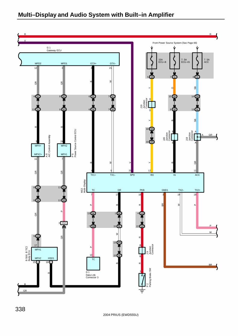
2004 PRIUS (EWD555U)
338
Multi–Display and Audio System with Built–in Amplifier
5 1K
B
15AECU–B
D
D
Y
5K10
5E10
GR
W
P
19 18
TX2– TX2+
12
+B1
11
ACC
GRA
10
IG
3
GND1
SB
J19
A
A
13 5L
14 5H
SB
6 1L
7. 5AACC
J19
B
YY
J20
E
E
9 5E
15 5H
O
7 1L
7. 5AECU–IG
V
R
BR W P
7
TC
P
7 5M
13 5E
D 1
P
1
SPD
25
TC
13 B
B
R
1G4
1A22
R
PKB
16
J 9
R
P 2
TX1–
5
6
GTX+
B
6 5E
6 5C
B
21
GTX–
W7 5E
7 5C
W
TX1+
4
GR
P
5G13
GR
5D13
P 6
5J8
5K8
MPX2+
11
MPX1
A 8
7
R
GR
B
VFrom Power Source System (See Page 66)
24
MPX2MPX+
3
5C4
GR
G 1
5C8
GR
5G8
3
MPD1B
5J13
12
MPD2
B
3 IG2
B
MPX2
MPX1
GR
1G9
A15
GR
17
17
DR
B
15 5L
1 5E
BW
15 4F
13 4H
M13
HSD1
C16
B 5
( A) ,
B 7
( C)
BR
A/C
Con
trol
Ass
embl
y
Bod
y E
CU
Data LinkConnector 3
Gateway ECU
Junc
tion
Con
nect
or
Junc
tion
Con
nect
or
Junc
tion
Con
nect
or
Junc
tion
Con
nect
or
Mul
ti–D
ispl
ay
Par
king
Bra
ke S
W
Pow
er S
ourc
e C
ontr
ol E
CU
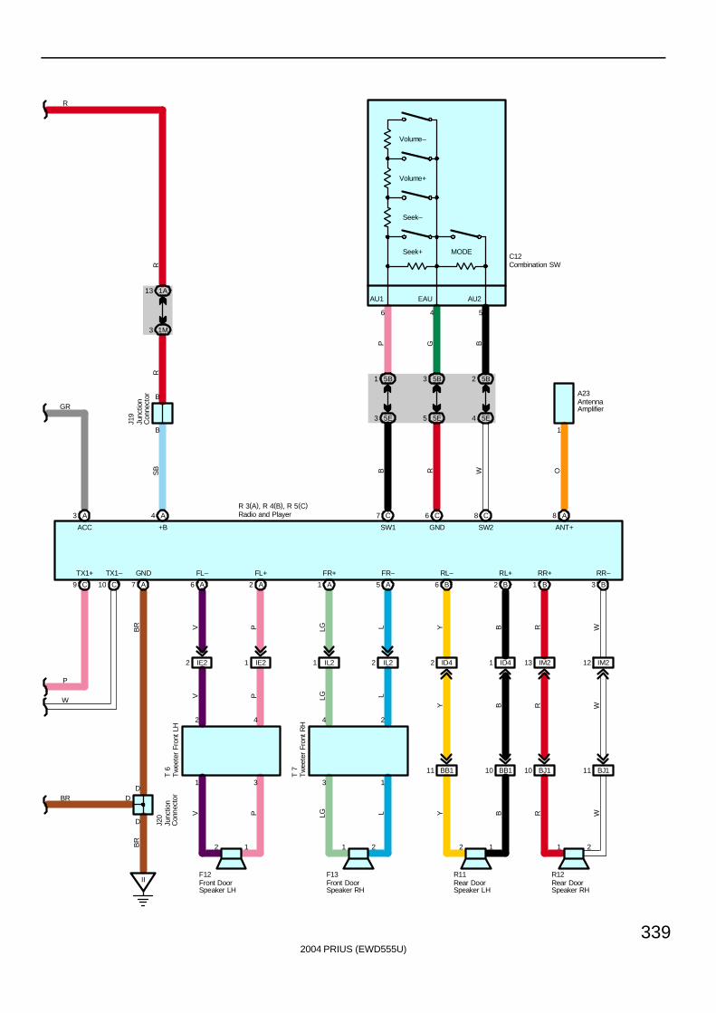
2004 PRIUS (EWD555U)
339
RS
B
IE2
4 A
1 IE2
C12
1
11 BJ1
LLGPV
IL2
7 C
II
RR–RR+
8
RL+RL–
C
21122
13
1
24
LLG
FR–FR+
V P
6 C
1
31
2
4
D
PV
FL+FL–
LG L
8
D
D
1
ANT+
4 56
EAU AU2AU1
GND SW2SW1
A23
OB
2 IL2
+BACC
TX1–TX1+
A
B
J19
R
W
P
GR
W
GND
B
3 1M
13 1A
R
R
A7 B3B1B2B6A5A1A2A6C10C9
A3
3 5E
1 5BP
4 5E
2 5B
B
5 5E
3 5B
G
2
R 3(A), R 4(B), R 5(C)
F12 F13 R11 R12
ID42 ID41 IM213 IM212
BJ110BB110BB111
Y B R WWR
WR
BR
BYY B
J20
T 7
T 6
Volume–
Volume+
Seek–
Seek+ MODE
BR
AntennaAmplifier
Combination SW
Front DoorSpeaker LH
Front DoorSpeaker RH
Junc
tion
Con
nect
or
Junc
tion
Con
nect
or
Radio and Player
Rear DoorSpeaker LH
Rear DoorSpeaker RH
Tw
eete
r Fr
ont
LH
Tw
eete
r Fr
ont
RH
BR
2
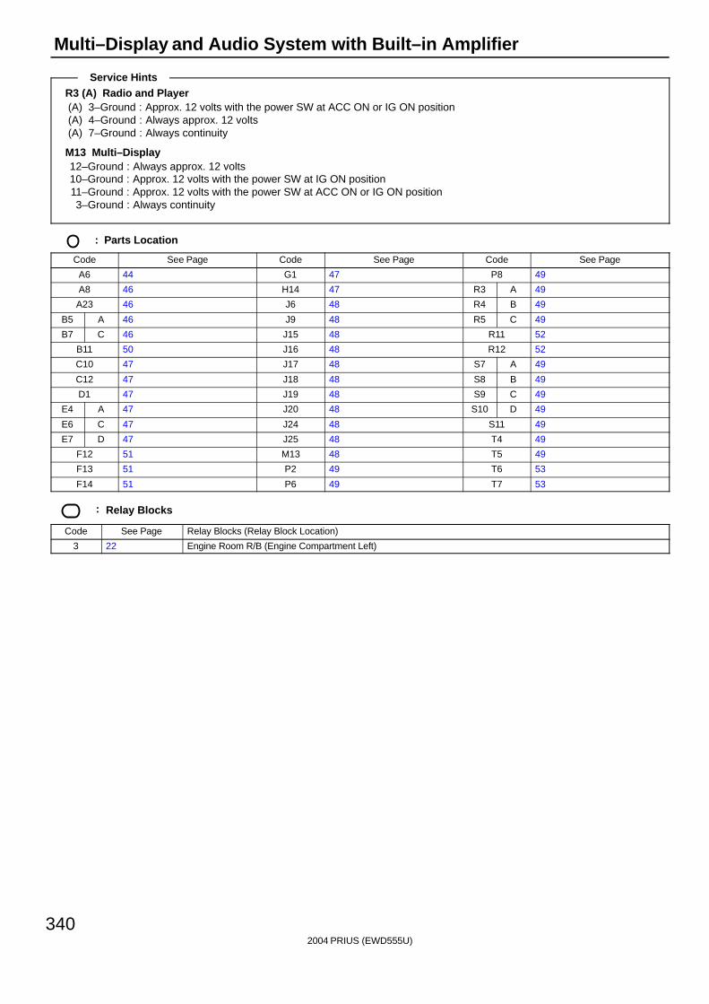
2004 PRIUS (EWD555U)
340
Multi–Display and Audio System with Built–in Amplifier
R3 (A) Radio and Player(A) 3–Ground : Approx. 12 volts with the power SW at ACC ON or IG ON position(A) 4–Ground : Always approx. 12 volts(A) 7–Ground : Always continuity
M13 Multi–Display12–Ground : Always approx. 12 volts10–Ground : Approx. 12 volts with the power SW at IG ON position11–Ground : Approx. 12 volts with the power SW at ACC ON or IG ON position3–Ground : Always continuity
: Parts Location
Code See Page Code See Page Code See Page
A6 44 G1 47 P8 49
A8 46 H14 47 R3 A 49
A23 46 J6 48 R4 B 49
B5 A 46 J9 48 R5 C 49
B7 C 46 J15 48 R11 52
B11 50 J16 48 R12 52
C10 47 J17 48 S7 A 49
C12 47 J18 48 S8 B 49
D1 47 J19 48 S9 C 49
E4 A 47 J20 48 S10 D 49
E6 C 47 J24 48 S11 49
E7 D 47 J25 48 T4 49
F12 51 M13 48 T5 49
F13 51 P2 49 T6 53
F14 51 P6 49 T7 53
: Relay Blocks
Code See Page Relay Blocks (Relay Block Location)
3 22 Engine Room R/B (Engine Compartment Left)
Service Hints
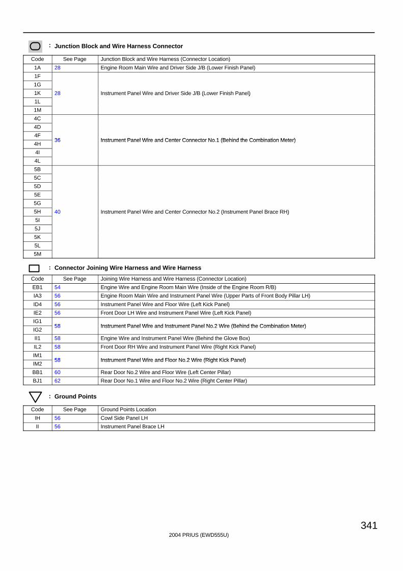
2004 PRIUS (EWD555U)
341
: Junction Block and Wire Harness Connector
Code See Page Junction Block and Wire Harness (Connector Location)
1A 28 Engine Room Main Wire and Driver Side J/B (Lower Finish Panel)
1F
1G
1K 28 Instrument Panel Wire and Driver Side J/B (Lower Finish Panel)
1L
( )
1M
4C
4D
4F36 Instrument Panel Wire and Center Connector No 1 (Behind the Combination Meter)
4H36 Instrument Panel Wire and Center Connector No.1 (Behind the Combination Meter)
4I
4L
5B
5C
5D
5E
5G
5H 40 Instrument Panel Wire and Center Connector No.2 (Instrument Panel Brace RH)
5I
( )
5J
5K
5L
5M
: Connector Joining Wire Harness and Wire Harness
Code See Page Joining Wire Harness and Wire Harness (Connector Location)
EB1 54 Engine Wire and Engine Room Main Wire (Inside of the Engine Room R/B)
IA3 56 Engine Room Main Wire and Instrument Panel Wire (Upper Parts of Front Body Pillar LH)
ID4 56 Instrument Panel Wire and Floor Wire (Left Kick Panel)
IE2 56 Front Door LH Wire and Instrument Panel Wire (Left Kick Panel)
IG158 Instrument Panel Wire and Instrument Panel No 2 Wire (Behind the Combination Meter)
IG258 Instrument Panel Wire and Instrument Panel No.2 Wire (Behind the Combination Meter)
II1 58 Engine Wire and Instrument Panel Wire (Behind the Glove Box)
IL2 58 Front Door RH Wire and Instrument Panel Wire (Right Kick Panel)
IM158 Instrument Panel Wire and Floor No 2 Wire (Right Kick Panel)
IM258 Instrument Panel Wire and Floor No.2 Wire (Right Kick Panel)
BB1 60 Rear Door No.2 Wire and Floor Wire (Left Center Pillar)
BJ1 62 Rear Door No.1 Wire and Floor No.2 Wire (Right Center Pillar)
: Ground Points
Code See Page Ground Points Location
IH 56 Cowl Side Panel LH
II 56 Instrument Panel Brace LH
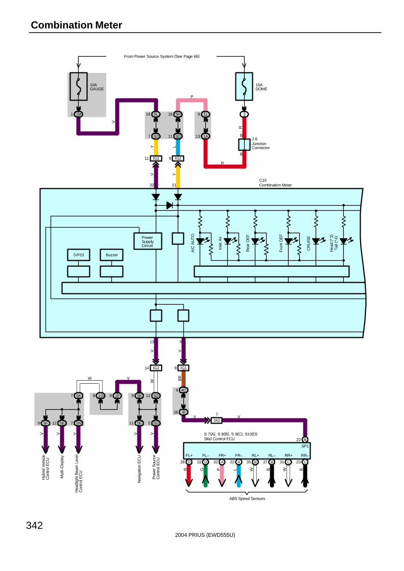
2004 PRIUS (EWD555U)
342
Combination Meter
13
A/C
AU
TO
Inle
t A
ir
Fron
t DE
F
CR
UIS
E
Tail
( *4)
9
PowerSupplyCircuit
Buzzer(VFD)
22 21
Pow
er S
ourc
eC
ontr
ol E
CU
Nav
igat
ion
EC
U
Hea
dlig
ht B
eam
Lev
elC
ontr
ol E
CU
Mul
ti–D
ispl
ay
Hyb
rid V
ehic
leC
ontro
l EC
U
5G55E115N75E125F9
5D125K91F81G85K7
W V
VVVVV
VW
IG214
10AGAUGE
From Power Source System (See Page 66)
1M1
IG211 IG29
5D7
5L16
5D11
5H16
1A13
1L8
15ADOME
3
B
BJ 6
R
P
R
LYV Y
V
Rea
r D
EF
C10B
R
IG19
4I16
4C9
V
Hea
d ( *
3)
IA3
7V V
D28 D22 A32 A22 B35 B27 C31 C23
FL+ FL– FR+ FR– RL+ RL– RR+ RR–
R G P L W B W B
ABS Speed Sensors
S 7(A), S 8(B), S 9(C), S10(D)B22
SP1
Skid Control ECU
Combination Meter
JunctionConnector

2004 PRIUS (EWD555U)
343
15 31 12 20 28 29
Rhe
osta
t
BB
GB
IG28IG210IG213IG212
IM18IM11IM15IM16
5D6
5K145K155I135I12
5D55D15D2
BR L R
RLRB
R L RRLBR
SB R
30
Ice
Roa
dC
ondi
tion
Slip
AB
S
Bra
ke C
ontr
ol
SR
S
Mas
ter
VS
C
Sm
art
Ent
ry
MA
INT
RE
QD
1176 23B
K/U
P L
P R
elay
Buc
kle
SW
Fro
ntLH B
uckl
e S
W F
ront
RH Fron
t Pas
seng
erS
eat
Bel
tW
arni
ng L
ight
LG R
B
Y P
C10
IG114
4C16
4A4
GR
B
A/B
11
Y5M
9
5L
9
D 1
5 6 4 8
* 3 : USA* 4 : Canada
Combination Meter
Data LinkConnector 3
Fuel
Sen
der
14 1L
1G10
Y
F14
2132
L–Y
L–R
BR
–RY
Temp. SensorFuel Sender
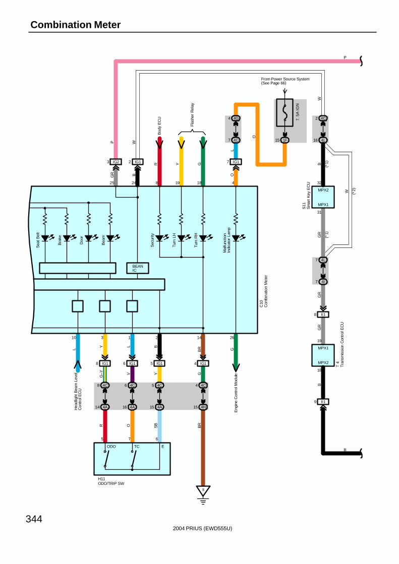
2004 PRIUS (EWD555U)
344
Combination Meter
IG1
4G4
7
L
L
BR
BR
II
Flas
her
Rel
ay
Sea
t Bel
t
Bra
ke
Doo
r
Bea
m
4
Mal
func
tion
Indi
cato
r La
mp
Sec
urity
Turn
LH
Turn
RH
8 19 18
14 2610
Bod
y E
CU
OE
ngin
e C
ontr
ol M
odul
e
Hea
dlig
ht B
eam
Lev
elC
ontr
ol E
CU
2425
BEANIC
C10
4C4
G
IG14
4H15
15 1F
From Power Source System(See Page 66)
7. 5
A IG
N
4C7
IG23 IG12 R Y G
BGR
WP
O
4L7
GR
G
B
4I7
4C2
4L16
32
31
MPX1
MPX2 W ( *2)
( *1)
( *1)
P
B
S11
BG
R
T 4
MPX1
MPX2
18
19
9 II1
8 II1G
RW
5 6
3
7
1 2
Y L BS
BOR
4C5
Y
IG15
4A15
4C6
V
IG16
4A16
4C8
G–Y
IG18
4A14
H11
ODO TC E
Com
bina
tion
Met
er
ODO/TRIP SW
Tran
smis
sion
Con
trol
EC
U
Sm
art K
ey E
CU
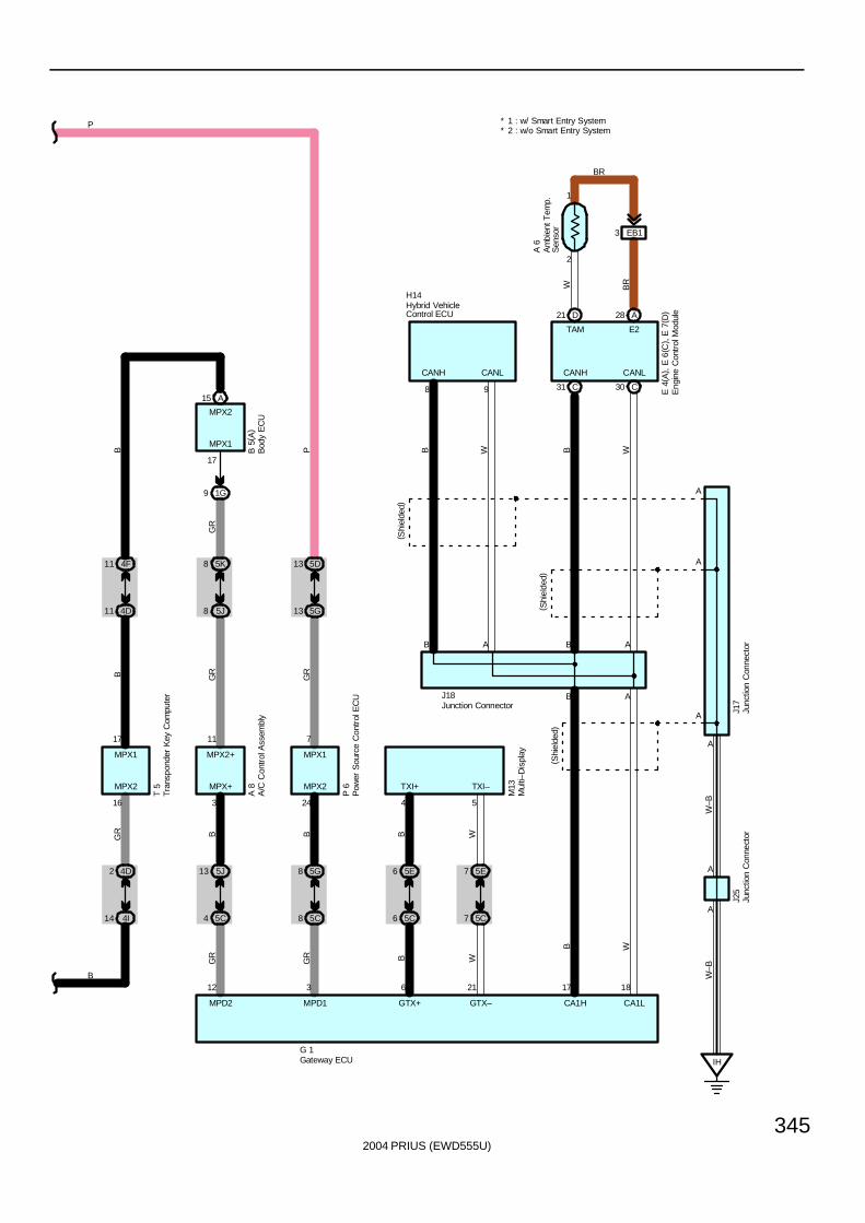
2004 PRIUS (EWD555U)
345
GR
MPD1
3
5G8
B
5C8
5D13
P
5G13
7
24
MPX2
MPX1
GR
P 6
P
B
G 1
17
MPX1
MPX2
B 5
( A)
1G9
GR
MPD2
A15
12
5J13
B
5C4
5K8
GR
5J8
11
3
MPX+
MPX2+
GR
A 8
GR
2 4D
B
4I14
4F11
B
4D11
17
16
MPX2
MPX1
T 5
7 5C
W
7 5E
21
GTX–
M13
B
TXI+
4
6 5C
B
6 5E
6
GTX+
5
TXI–
W
B
BAB A
A
A
A
CANH CANL CANH CANL
8 9
A
A
A(S
hiel
ded)
( Shi
elde
d)
IH
W–B
B B WW
J18
H14
W–B
B W
17
CA1H
18
CA1L
A
( Shi
elde
d)
J17
J25
* 2 : w/o Smart Entry System* 1 : w/ Smart Entry System
E 4
( A) ,
E 6
( C) ,
E 7
( D)D21 A28
C31 C30
TAM E2
2
1
EB13
W BR
A 6
Am
bien
t Tem
p.
Sen
sor
A/C
Con
trol
Ass
embl
yB
ody
EC
U
Eng
ine
Con
trol
Mod
ule
Gateway ECU
Hybrid VehicleControl ECU
Junc
tion
Con
nect
or
Junction Connector
Junc
tion
Con
nect
or
Mul
ti–D
ispl
ay
Tran
spon
der
Key
Com
pute
r
Pow
er S
ourc
e C
ontr
ol E
CU
BR
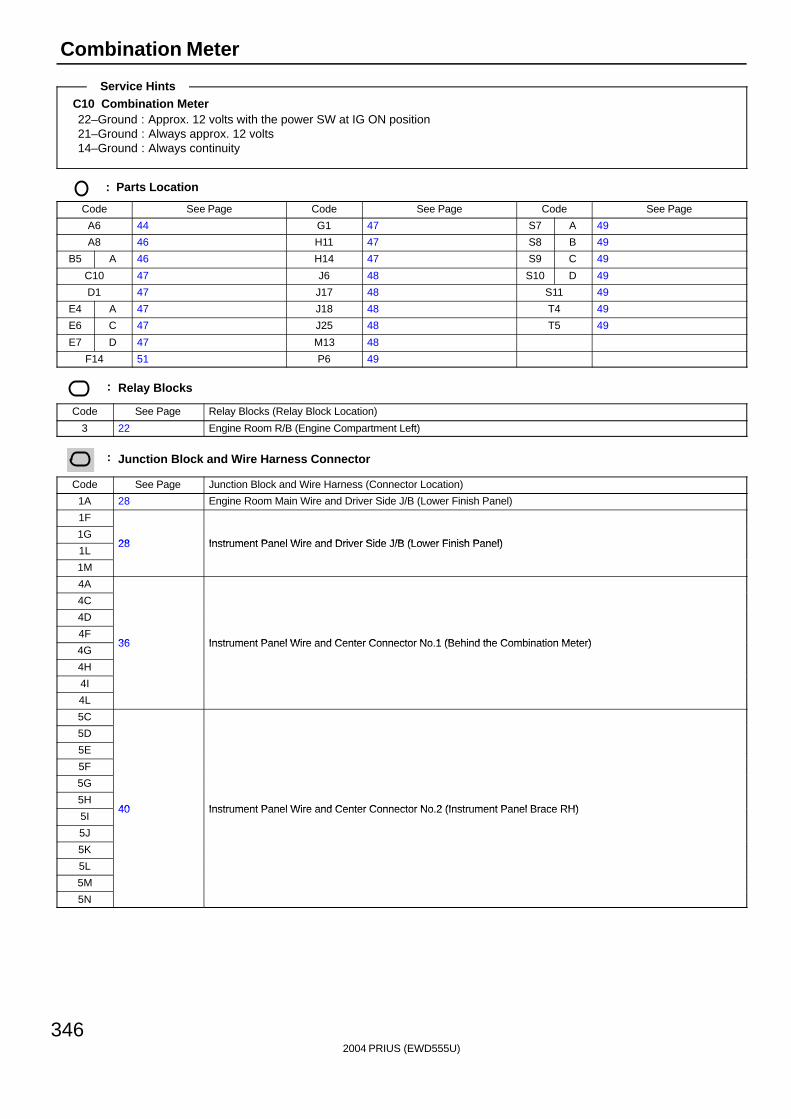
2004 PRIUS (EWD555U)
346
Combination Meter
C10 Combination Meter22–Ground : Approx. 12 volts with the power SW at IG ON position21–Ground : Always approx. 12 volts14–Ground : Always continuity
: Parts Location
Code See Page Code See Page Code See Page
A6 44 G1 47 S7 A 49
A8 46 H11 47 S8 B 49
B5 A 46 H14 47 S9 C 49
C10 47 J6 48 S10 D 49
D1 47 J17 48 S11 49
E4 A 47 J18 48 T4 49
E6 C 47 J25 48 T5 49
E7 D 47 M13 48
F14 51 P6 49
: Relay Blocks
Code See Page Relay Blocks (Relay Block Location)
3 22 Engine Room R/B (Engine Compartment Left)
: Junction Block and Wire Harness Connector
Code See Page Junction Block and Wire Harness (Connector Location)
1A 28 Engine Room Main Wire and Driver Side J/B (Lower Finish Panel)
1F
1G28 Instrument Panel Wire and Driver Side J/B (Lower Finish Panel)
1L28 Instrument Panel Wire and Driver Side J/B (Lower Finish Panel)
1M
4A
4C
4D
4F36 Instrument Panel Wire and Center Connector No 1 (Behind the Combination Meter)
4G36 Instrument Panel Wire and Center Connector No.1 (Behind the Combination Meter)
4H
4I
4L
5C
5D
5E
5F
5G
5H40 Instrument Panel Wire and Center Connector No 2 (Instrument Panel Brace RH)
5I40 Instrument Panel Wire and Center Connector No.2 (Instrument Panel Brace RH)
5J
5K
5L
5M
5N
Service Hints
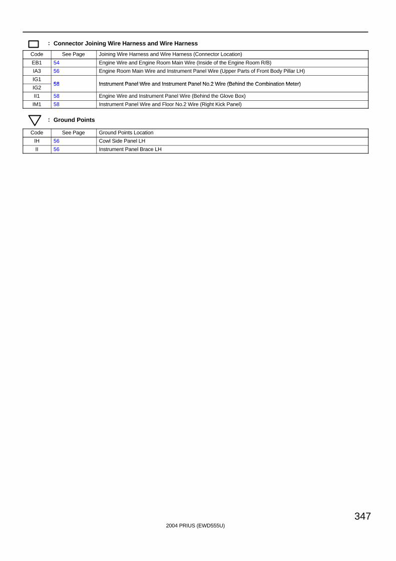
2004 PRIUS (EWD555U)
347
: Connector Joining Wire Harness and Wire Harness
Code See Page Joining Wire Harness and Wire Harness (Connector Location)
EB1 54 Engine Wire and Engine Room Main Wire (Inside of the Engine Room R/B)
IA3 56 Engine Room Main Wire and Instrument Panel Wire (Upper Parts of Front Body Pillar LH)
IG158 Instrument Panel Wire and Instrument Panel No 2 Wire (Behind the Combination Meter)
IG258 Instrument Panel Wire and Instrument Panel No.2 Wire (Behind the Combination Meter)
II1 58 Engine Wire and Instrument Panel Wire (Behind the Glove Box)
IM1 58 Instrument Panel Wire and Floor No.2 Wire (Right Kick Panel)
: Ground Points
Code See Page Ground Points Location
IH 56 Cowl Side Panel LH
II 56 Instrument Panel Brace LH
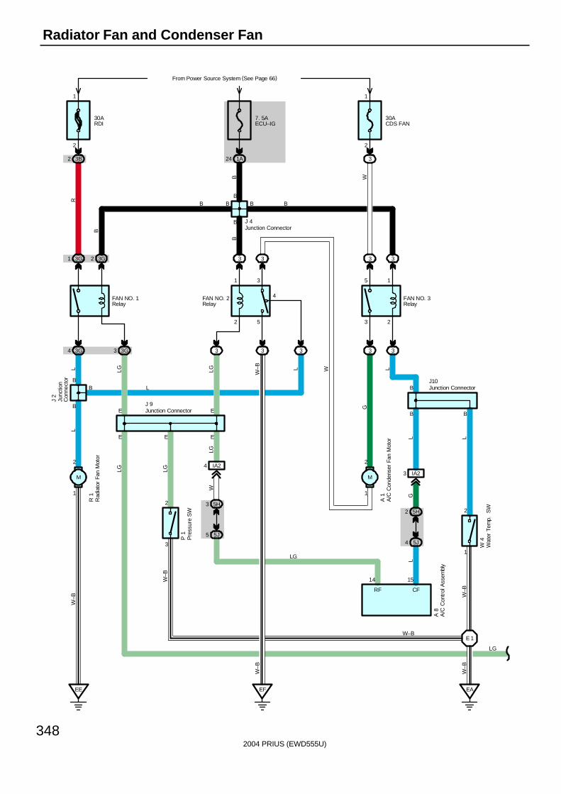
2004 PRIUS (EWD555U)
348
Radiator Fan and Condenser Fan
FAN NO. 3Relay
B
2
1
5
3
4
1
2
FAN NO. 2Relay
2
1
1
2
B
B
E
2
3
FAN NO. 1Relay
EE
E
B
B
B
BB B
30ARDI
From Power Source System (See Page 66)
3B2
2
1
EE EF
7. 5AECU–IG
1A24
3G1 3G2
3G4 3G3
3 3
3 33
E 1
5H3
5J5
IA24
3 2
5 1
33
3 3
30ACDS FAN
3
2
1
E
3 IA2
5H2
5J4
CF
1514
RF
A 8
EA
W–B
W–B
W–B
GL
W 4
A 1
L LG LG W–B L
G
L
L
LG LG
LGW
W–B
W–B
LL
P 1
R 1
J 2
J 9
J10B
B W
R
B
B
W
B B
L
J 4
LG
W–B
LG
A/C
Con
dens
er F
an M
otor
A/C
Con
trol
Ass
embl
y
Junc
tion
Con
nect
or
Junction Connector
Junction Connector
Junction Connector
Pre
ssur
e S
W
Rad
iato
r Fa
n M
otor
Wat
er T
emp.
S
W
MM
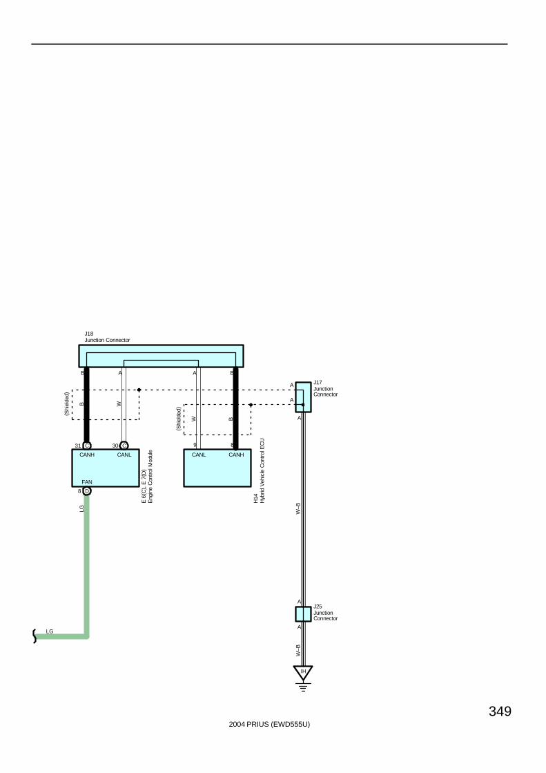
2004 PRIUS (EWD555U)
349
IH
A
A
9 8
B W
W B
LG W–B
W–B
LG
E 6
( C) ,
E 7
( D)
H14
C31 C30
D8
FAN
J18
J17
B A A B
A
CANH CANL CANL CANH
A
A
J25
Eng
ine
Con
trol
Mod
ule
Hyb
rid V
ehic
le C
ontr
ol E
CU
JunctionConnector
Junction Connector
JunctionConnector
( Shi
elde
d)
( Shi
elde
d)

2004 PRIUS (EWD555U)
350
Radiator Fan and Condenser Fan
The radiator fan motor and A/C condenser fan motor operate according to the water temp. SW (Inverter), A/C singlepressure SW, engine coolant temp. and the A/C system condition. The FAN NO.1 relay, FAN NO.2 relay, FAN NO.3 relay areturned on/off, to operate the fan motors at low speed (In series), or high speed (In parallel).
1. Low Speed operationWhen the water temp. SW (Inverter) is on and/or A/C control assembly is in operation, the radiator fan motor and A/Ccondenser fan motor operate at low speed.
2. High Speed OperationWhen the pressure SW (Single) is on, engine control module and/or A/C control assembly, the radiator fan motor operateand A/C condenser fan motor operates at high speed.
P1 Pressure SW3–2 : Close above approx. 1520 kpa (15.5 kgf/cm2. 220 psi)
Open below approx. 1230 kpa (12.5 kgf/cm2. 178 psi)
: Parts Location
Code See Page Code See Page Code See Page
A1 44 J2 45 J18 48
A8 46 J4 45 J25 48
E6 C 47 J9 48 P1 45
E7 D 47 J10 48 R1 45
H14 47 J17 48 W4 45
: Relay Blocks
Code See Page Relay Blocks (Relay Block Location)
3 22 Engine Room R/B (Engine Compartment Left)
: Junction Block and Wire Harness Connector
Code See Page Junction Block and Wire Harness (Connector Location)
1A 28 Engine Room Main Wire and Driver Side J/B (Lower Finish Panel)
3B22 Engine Room Main Wire and Engine Room J/B (Engine Compartment Left)
3G22 Engine Room Main Wire and Engine Room J/B (Engine Compartment Left)
5H40 Instrument Panel Wire and Center Connector No 2 (Instrument Panel Brace RH)
5J40 Instrument Panel Wire and Center Connector No.2 (Instrument Panel Brace RH)
: Connector Joining Wire Harness and Wire Harness
Code See Page Joining Wire Harness and Wire Harness (Connector Location)
IA2 56 Engine Room Main Wire and Instrument Panel Wire (Upper Parts of Front Body Pillar LH)
: Ground Points
Code See Page Ground Points Location
EA 54 Right Side of the Fender Apron
EE54 Left Side of the Suspension Tower
EF54 Left Side of the Suspension Tower
IH 56 Cowl Side Panel LH
: Splice Points
Code See Page Wire Harness with Splice Points Code See Page Wire Harness with Splice Points
E1 54 Engine Room Main Wire
System Outline
Service Hints

2004 PRIUS (EWD555U)
351
Memo
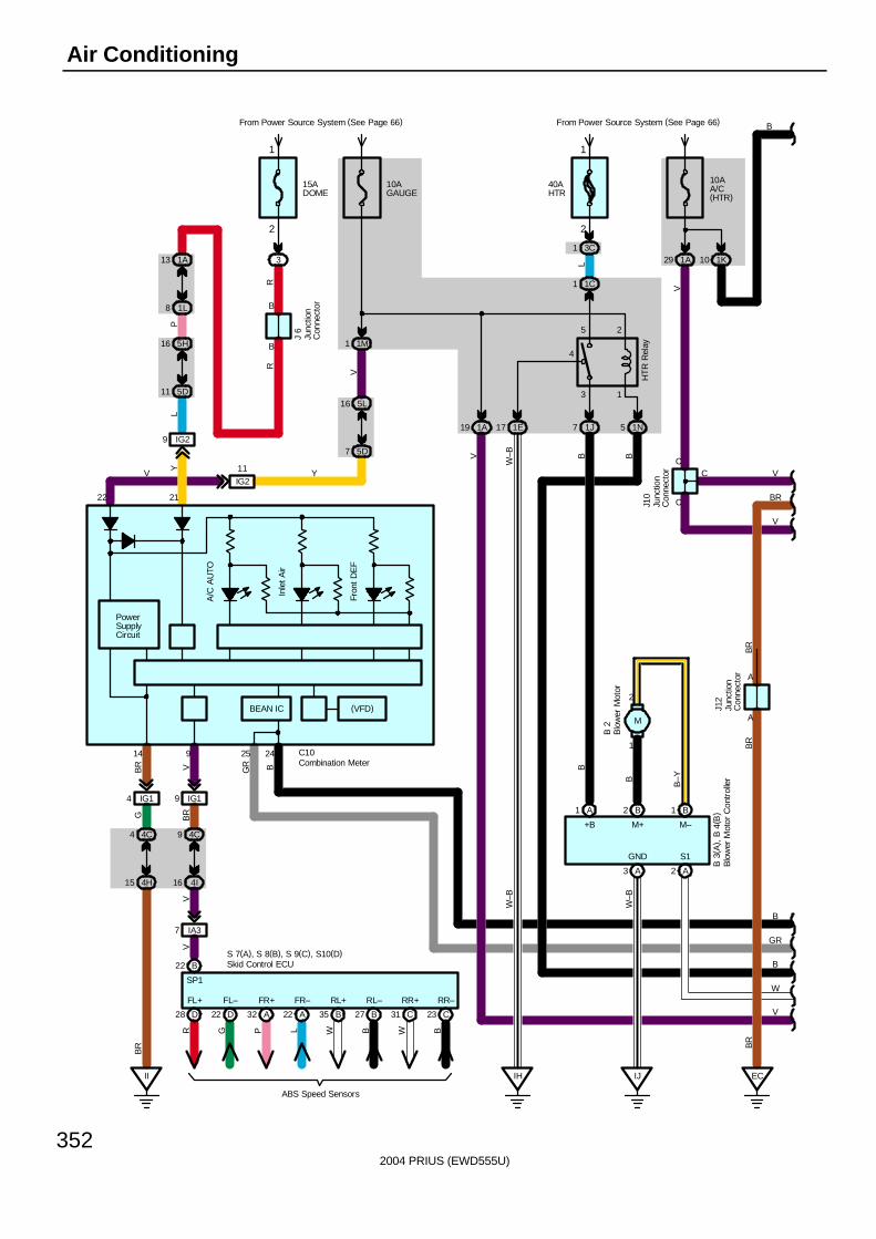
2004 PRIUS (EWD555U)
352
Air Conditioning
From Power Source System (See Page 66)
9 IG2
Y
4 IG1
B
II
B
14
21
PowerSupplyCircuit
GB
R
22
10AGAUGE
L
1M1
15ADOME
3R
R
5L16
5D7
1A13
1L8
4C4
4H15
BR
11 5D
16 5H
P
2
1
2425
BGR
BEAN IC
V
B
GR
A/C
AU
TO
Inle
t Air
Fron
t D
EF
10AA/C(HTR)
From Power Source System (See Page 66)
1A29
C10
V
1K10
J10
C
C
C
3 1
4
5 2
40AHTR
HT
R R
elay
IH
1E17 1J7 1N5
IJ
B
W
W–B B B
W–B
W–B
B
GND S1
+B
3C1
1C1
L
A3 A2
B2 B1A1
1
2
M–M+
B
B–Y
B 3
( A) ,
B 4
( B)
B 2
1A19
V
V
V
V
B
IG19
4C9
4I16
9
VB
R
D28 D22 A32 A22 B35 B27 C31 C23
FL+ FL– FR+ FR– RL+ RL– RR+ RR–
R G P L W B W B
ABS Speed Sensors
S 7(A), S 8(B), S 9(C), S10(D)B22
SP1
IA37
VV
IG2
11V Y
(VFD)
Skid Control ECU
Blo
wer
Mot
or C
ontr
olle
r
Combination Meter
Junc
tion
Con
nect
or
Blo
wer
Mot
or
Junc
tion
Con
nect
or
J 6
BR
A
A
BR
EC
BR
Junc
tion
Con
nect
or
J12
BR
M
2
1
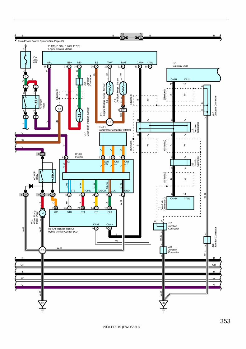
2004 PRIUS (EWD555U)
353
D 1
17
CA1L
G 1
CA1H
18
B
AB
W–B
A
A
A
A
A
A
A
A
A
(Shi
elde
d)
IH
W–B
W–B
( Shi
elde
d)
B W
J16
J24
W–B
B W
B W
CANH CANL
A
(Shi
elde
d)
J18
AB
B
GR
B
GR
6 14
B A
J15
B W
A
CANHCANL
CANH CANL
A
A
E 4(A), E 5(B), E 6(C), E 7(D)
( Shi
elde
d)
2
1
3H1
3H4 3H
B25C5 B24 C14 C17
EF
E 3
A8A9
W R Y G
W–BO
V
RW
–BW
–B
B
W
I11(C)
W 1
H14(A), H15(B), H16(C)
WP STB ET1 ITE CLK
AC
W/P
Rel
ay
W–B
B5L
10
5J
9B B
B
B A
WB
J25
J17
B
W
B
W
C6 F1 F2 F3
C5 C3 C2 C4 C1
IG OUT–W
OUT–V
OUT–U
STB TOINV TOECU CLK GND
R–W O O O
L–W
Y–W
G–W
BR
–W
B–W
C 4(F)
O O O
V V
C31 C30D21A19A28
1
2
1
2
I 3
E 1
A 6
WBR W
BR
E2 THW TAM
BR
CH
S W
/PR
elay
2
2 2
15 D
V
WPL
L
10ACHSW/P
From Power Source System (See Page 66)
3
2
1
G
V
V
B
2
1
A34A33
NE+ NE–
AG
GR
C 7
J14
A
I 3
( Shi
elde
d)
V
EB13
BR
Am
bien
t Tem
p.
Sen
sor
Cra
nksh
aft P
ositi
on S
enso
r
Dat
a Li
nkC
onne
ctor
3
Engine Control Module
Eng
ine
Coo
lant
Tem
p.
Sen
sor
Gateway ECU
Hybrid Vehicle Control ECU
Inverter
Junc
tion
Con
nect
or
Junc
tion
Con
nect
or
JunctionConnector
Junc
tion
Con
nect
or
Junc
tion
Con
nect
or
JunctionConnector
Junc
tion
Con
nect
or
Wat
er P
ump
Mot
or (
A/C
)
BR
BR
3H5
W–B
2
R
3 1
5 2
Compressor Assembly (Motor)
3
M
(Shi
elde
d)
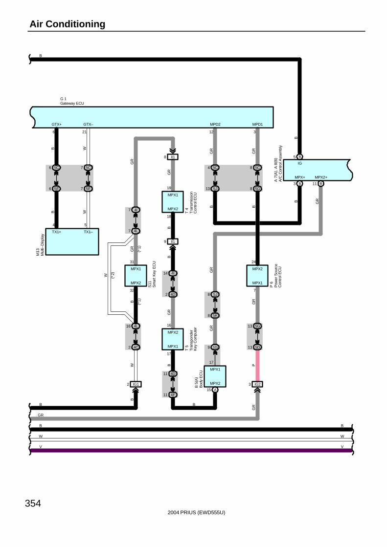
2004 PRIUS (EWD555U)
354
Air Conditioning
4F
S11
MPX1
B
11
MPX2
32
31
7 4L
7
4D
GR
4I
2 4C
GR
B
16 4L
W
BG
R
T 4
MPX1
MPX2
18
19
9 II1
8 II1
B
W
11
4I14
4D2
16
17
MPX1
MPX2
T 5
( *2)
( *1)
( *1)
GR
B
TX1–
6
GTX+
B
6 5E
6 5C
B
21
GTX–
W
7 5E
7 5C
W
TX1+
GR
P
5G13
GR
5D13
P 6
5J8
5K8
MPX1
7
24
MPX2
5C4
GR
5C8
GR
5G8
3
MPD1
B
5J13
12
MPD2
B
3 IG2MPX2
MPX1
GR
1G9
A15
GR
17
M13
B 5
( A)
4 5
G 1
B
GR
B
B
W
B5
MPX+ MPX2+
B3 B11
GRB
B
B
W
A 7
( A) ,
A 8
( B)
IG
V V
A/C
Con
trol A
ssem
bly
Bod
y E
CU
Gateway ECU
Mul
ti–D
ispl
ay
Tran
spon
der
Key
Com
pute
rT
rans
mis
sion
Con
trol
EC
U
Sm
art K
ey E
CU
Pow
er S
ourc
eC
ontro
l EC
U
IG12
B
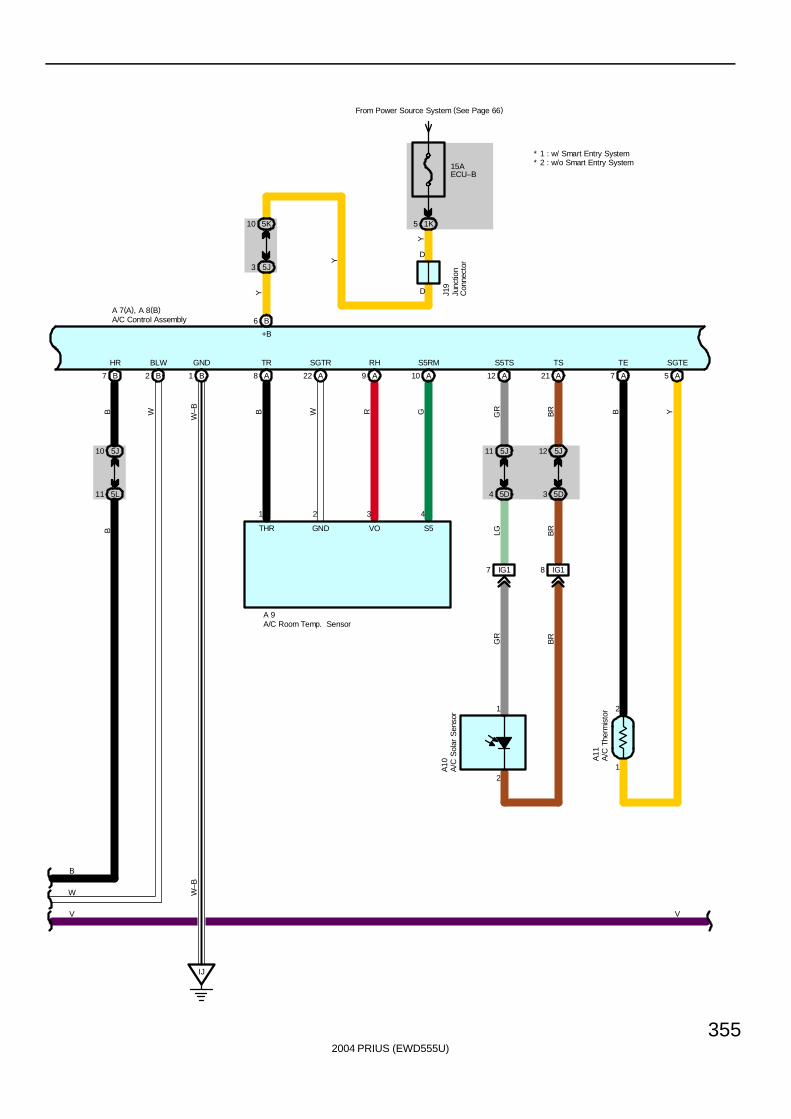
2004 PRIUS (EWD555U)
355
B6
B7 B2
5J10
5L11
B1
IJ
A8 A22 A9 A10 A12 A21 A7 A5
5J11 5J12
5D4 5D3
IG17 IG18
1
2
B
Y
B
W
W–B B W R G GR
BR
LG BR
GR
BR
B Y
W–B
B
W
A 7(A), A 8(B)
A 9
1 2 3 4
A11
A10
+B
HR BLW GND TR SGTR RH S5RM S5TS TS TE SGTE
THR GND VO S5
1
2
* 2 : w/o Smart Entry System* 1 : w/ Smart Entry System
V V
From Power Source System (See Page 66)
15AECU–B
1K5
D
D J19
5J3
5K10
Y
Y
A/C
The
rmis
tor
A/C Control Assembly
A/C Room Temp. Sensor
A/C
Sol
ar S
enso
rJu
nctio
nC
onne
ctor
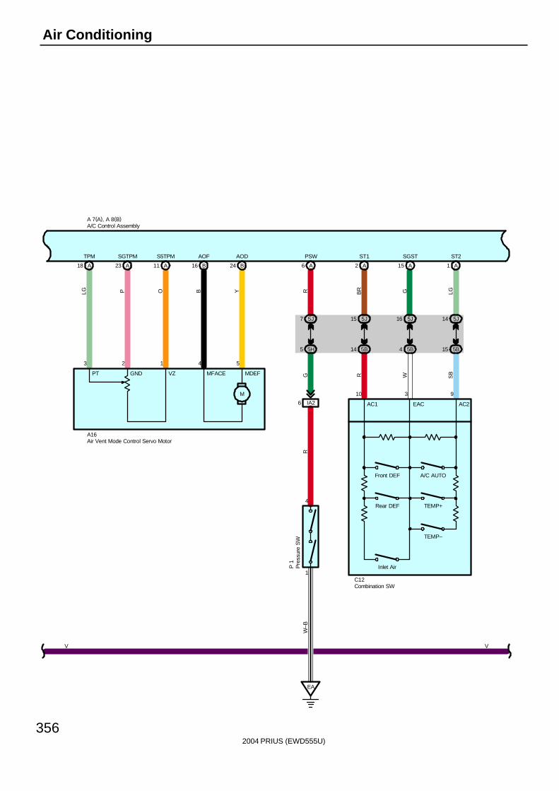
2004 PRIUS (EWD555U)
356
Air Conditioning
B1611 A23 A18 A B24 A6
5J7
5H5
IA26
4
1
EA
1 A2 A A15
LG P O B Y RR
GW
–B
BR G LG
A 7(A), A 8(B)
A16
3 2 1 4 5
10 3 9
C12
P 1
TPM SGTPM S5TPM AOF AOD PSW ST1 SGST ST2
AC1 EAC AC2
5J15
5B14
5J16
5B4
5J14
5B15
R W SB
A/C AUTO
TEMP+
TEMP–
Inlet Air
PT GND VZ MFACE MDEF
M
Front DEF
V V
A/C Control Assembly
Air Vent Mode Control Servo Motor
Combination SW
Pre
ssur
e S
W
Rear DEF
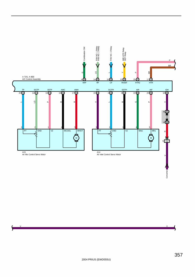
2004 PRIUS (EWD555U)
357
17 B13 A20 B14 AA 19 23 B3 A19 B4 AA 22 B18
5J6
5H4
IA25
B14 B15 A17B12 A25B4
L LG P B R V L B G P VR
V
LG L BRY PG
A 7(A), A 8(B)
A14A15
3 2 1 4 5 3 2 1 4 5
TP SGTP S5TP AMC AMH TP1 SGTPI S5TPI AIR AIF IDH
RF CF HTRRrDEF HTR2WIP
Con
vert
er
FAN
NO
. 1 R
elay
FAN
NO
. 3 R
elay
FAN
NO
. 2 R
elay
MIR
HT
R R
elay
DE
F R
elay
PT GND VZ MCOOL MHOT
M
PT GND VZ Mrec Mfrs
M
V V
BR
P
Air Inlet Control Servo Motor
A/C Control Assembly
Air Mix Control Servo Motor
Com
bina
tion
SW
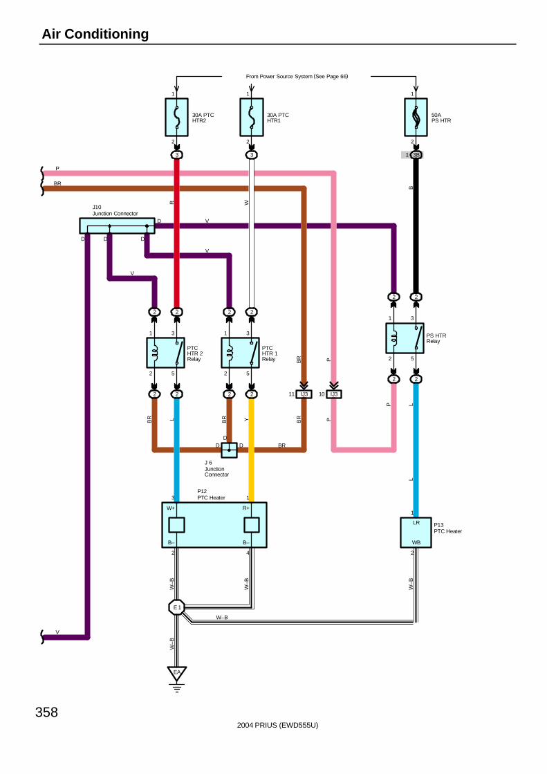
2004 PRIUS (EWD555U)
358
Air Conditioning
2
1
5
3
2
1
5
3
D
2
13
D
PTCHTR 1Relay
4
PTCHTR 2Relay
D
30A PTCHTR2
3
2
1
From Power Source System (See Page 66)
30A PTCHTR1
3
2
1
D D
EA
E 1
W–B
W–B
W–B
BR L BR Y
BR
J10
J 6
P12
2222
2222
R WV
V
B–B–
W+ R+
22
2
1
5
3
2
1
PS HTRRelay
2
50APS HTR
3B1
2
1
2
B
P LW
–B
P13
L
WB
LR
D
IJ311
D
IJ310
BR P
BR P
BR
P
V
JunctionConnector
Junction Connector
PTC Heater
PTC Heater
W–B
V
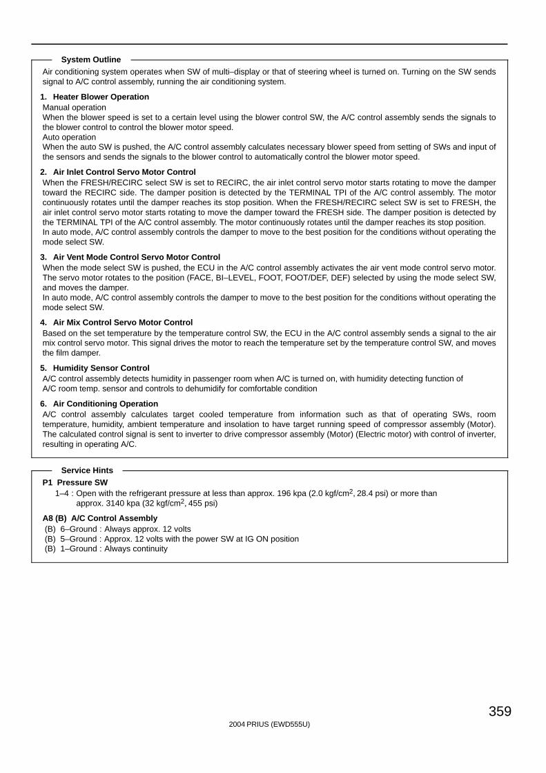
2004 PRIUS (EWD555U)
359
Air conditioning system operates when SW of multi–display or that of steering wheel is turned on. Turning on the SW sendssignal to A/C control assembly, running the air conditioning system.
1. Heater Blower OperationManual operationWhen the blower speed is set to a certain level using the blower control SW, the A/C control assembly sends the signals tothe blower control to control the blower motor speed.Auto operationWhen the auto SW is pushed, the A/C control assembly calculates necessary blower speed from setting of SWs and input ofthe sensors and sends the signals to the blower control to automatically control the blower motor speed.
2. Air Inlet Control Servo Motor ControlWhen the FRESH/RECIRC select SW is set to RECIRC, the air inlet control servo motor starts rotating to move the dampertoward the RECIRC side. The damper position is detected by the TERMINAL TPI of the A/C control assembly. The motorcontinuously rotates until the damper reaches its stop position. When the FRESH/RECIRC select SW is set to FRESH, theair inlet control servo motor starts rotating to move the damper toward the FRESH side. The damper position is detected bythe TERMINAL TPI of the A/C control assembly. The motor continuously rotates until the damper reaches its stop position.In auto mode, A/C control assembly controls the damper to move to the best position for the conditions without operating themode select SW.
3. Air Vent Mode Control Servo Motor ControlWhen the mode select SW is pushed, the ECU in the A/C control assembly activates the air vent mode control servo motor.The servo motor rotates to the position (FACE, BI–LEVEL, FOOT, FOOT/DEF, DEF) selected by using the mode select SW,and moves the damper.In auto mode, A/C control assembly controls the damper to move to the best position for the conditions without operating themode select SW.
4. Air Mix Control Servo Motor ControlBased on the set temperature by the temperature control SW, the ECU in the A/C control assembly sends a signal to the airmix control servo motor. This signal drives the motor to reach the temperature set by the temperature control SW, and movesthe film damper.
5. Humidity Sensor ControlA/C control assembly detects humidity in passenger room when A/C is turned on, with humidity detecting function of A/C room temp. sensor and controls to dehumidify for comfortable condition
6. Air Conditioning OperationA/C control assembly calculates target cooled temperature from information such as that of operating SWs, roomtemperature, humidity, ambient temperature and insolation to have target running speed of compressor assembly (Motor).The calculated control signal is sent to inverter to drive compressor assembly (Motor) (Electric motor) with control of inverter,resulting in operating A/C.
P1 Pressure SW1–4 : Open with the refrigerant pressure at less than approx. 196 kpa (2.0 kgf/cm2, 28.4 psi) or more than
approx. 3140 kpa (32 kgf/cm2, 455 psi)
A8 (B) A/C Control Assembly(B) 6–Ground : Always approx. 12 volts(B) 5–Ground : Approx. 12 volts with the power SW at IG ON position(B) 1–Ground : Always continuity
System Outline
Service Hints
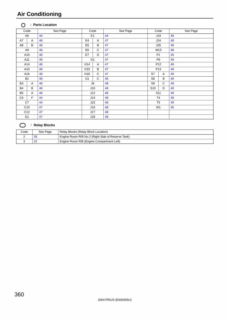
2004 PRIUS (EWD555U)
360
Air Conditioning
: Parts Location
Code See Page Code See Page Code See Page
A6 44 E1 44 J19 48
A7 A 46 E4 A 47 J24 48
A8 B 46 E5 B 47 J25 48
A9 46 E6 C 47 M13 48
A10 46 E7 D 47 P1 45
A11 46 G1 47 P6 49
A14 46 H14 A 47 P12 49
A15 46 H15 B 47 P13 49
A16 46 H16 C 47 S7 A 49
B2 46 I11 C 45 S8 B 49
B3 A 46 J6 48 S9 C 49
B4 B 46 J10 48 S10 D 49
B5 A 46 J12 48 S11 49
C4 F 44 J14 48 T4 49
C7 44 J15 48 T5 49
C10 47 J16 48 W1 45
C12 47 J17 48
D1 47 J18 48
: Relay Blocks
Code See Page Relay Blocks (Relay Block Location)
2 26 Engine Room R/B No.2 (Right Side of Reserve Tank)
3 22 Engine Room R/B (Engine Compartment Left)

2004 PRIUS (EWD555U)
361
: Junction Block and Wire Harness Connector
Code See Page Junction Block and Wire Harness (Connector Location)
1A28 Engine Room Main Wire and Driver Side J/B (Lower Finish Panel)
1C28 Engine Room Main Wire and Driver Side J/B (Lower Finish Panel)
1E
1G
1J
1K 28 Instrument Panel Wire and Driver Side J/B (Lower Finish Panel)
1L
( )
1M
1N
3B
3C 22 Engine Room Main Wire and Engine Room J/B (Engine Compartment Left)
3H
g g ( g )
4C
4D
4F36 Instrument Panel Wire and Center Connector No 1 (Behind the Combination Meter)
4H36 Instrument Panel Wire and Center Connector No.1 (Behind the Combination Meter)
4I
4L
5B
5C
5D
5E
5G 40 Instrument Panel Wire and Center Connector No.2 (Instrument Panel Brace RH)
5H
( )
5J
5K
5L
: Connector Joining Wire Harness and Wire Harness
Code See Page Joining Wire Harness and Wire Harness (Connector Location)
EB1 54 Engine Wire and Engine Room Main Wire (Inside of the Engine Room R/B)
IA256 Engine Room Main Wire and Instrument Panel Wire (Upper Parts of Front Body Pillar LH)
IA356 Engine Room Main Wire and Instrument Panel Wire (Upper Parts of Front Body Pillar LH)
IG158 Instrument Panel Wire and Instrument Panel No 2 Wire (Behind the Combination Meter)
IG258 Instrument Panel Wire and Instrument Panel No.2 Wire (Behind the Combination Meter)
II1 58 Engine Wire and Instrument Panel Wire (Behind the Glove Box)
IJ3 58 Engine Room Main Wire and Instrument Panel Wire (Behind the Glove Box)
: Ground Points
Code See Page Ground Points Location
EA 54 Right Side of the Fender Apron
EC 54 Engine Block
EF 54 Left Side of the Suspension Tower
IH 56 Cowl Side Panel LH
II 56 Instrument Panel Brace LH
IJ 56 Instrument Panel Brace RH
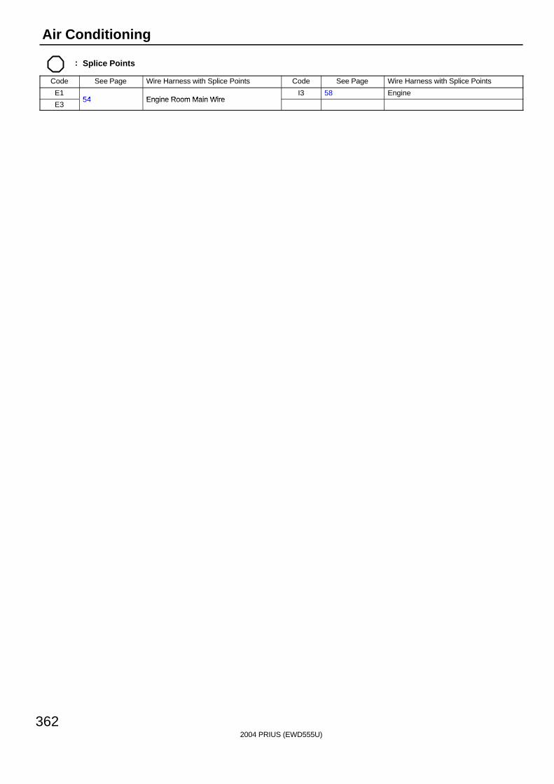
2004 PRIUS (EWD555U)
362
Air Conditioning
: Splice Points
Code See Page Wire Harness with Splice Points Code See Page Wire Harness with Splice Points
E154 Engine Room Main Wire
I3 58 Engine
E354 Engine Room Main Wire

2004 PRIUS (EWD555U)
363
Memo
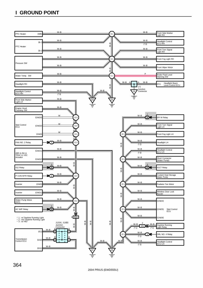
2004 PRIUS (EWD555U)
364
I GROUND POINT
IGCT Relay
Radiator Fan Motor
DRL NO. 4 Relay
P CON MTR Relay
EF EE
BB
BB
AB
AB
J12(A), J13(B)
EB18
E 3
E 3
3
(E1)
(E02)
(E01)
(GND2)
(GND1)
E 3 2
IA1
2
E 3
E 3
(GND)
(GND2)
(GND3)
3J3
E 3
E 3
EB EA
E 1
E 1
E 1W–B
W–B
W–B
W–B
W–B
W–B
W–B
W–B W–B
W–B
W–B
W–B
W–B
W–B
W–B
W–B
W–B
W–B
W–B
W–B
W–B
W–B
W–B
W–B
W–B
W–B
W–B
W–B
W–B
W–B
W–B
W–B
W–B
W–B
W–B
W–B
W–B
W–B
W–B
W–B
W–B W–B
W–B
W–BW–B
W–B W
–B
W–B
W–B W
–BW
–BW
–BW
–B
W–B
W–B
(* 3)
(*1)
(*1) (*1)
(*3)
(*3)
(*3)
* 1 : w/ Daytime Running Light* 2 : w/o Daytime Running Light* 3 : w/ HID
FAN NO. 2 Relay 3
(GND4)
(GND5)
(GND6)
E 3
W–B
W
W
W
W–B
W–B
IG2 Relay 3I3
(*2)
EFI M RelayW–B
3I
7
P
A A
IK
J 5
W–B
W–B
W–B
E 3
W–B
JunctionConnector
JunctionConnector
W–BAC W/P Relay 3H
5Skid ControlECU
Headlight BeamLevel Control ECU
PTC Heater
PTC Heater
Pressure SW
Water Temp. SW
Headlight RH
Headlight ControlECU RH
Front Side MarkerLight LH
Engine HoodCourtesy SW
ABS & BA &TRAC & VSCActuator
Skid ControlECU
Inverter
Inverter
Water Pump Motor(A/C)
TransmissionControl ECU
Front Side MarkerLight RH
Headlight ControlECU RH
Front Turn SignalLight RH
Front Fog Light RH
Front Wiper Motor
Brake Fluid LevelWarning SW
(E1)
Front Turn SignalLight LH
Front Fog Light LH
Headlight LH
Headlight ControlECU LH
Short Connector(Water Pump)
Coolant Heat StorageWater Pump
Wireless Door LockBuzzer
Headlight ControlECU LH
Daytime RunningLight Relay
(WB)
(B–)
(B–)
(GND)
(GND1)
E 3
E 3
W–B
W–B
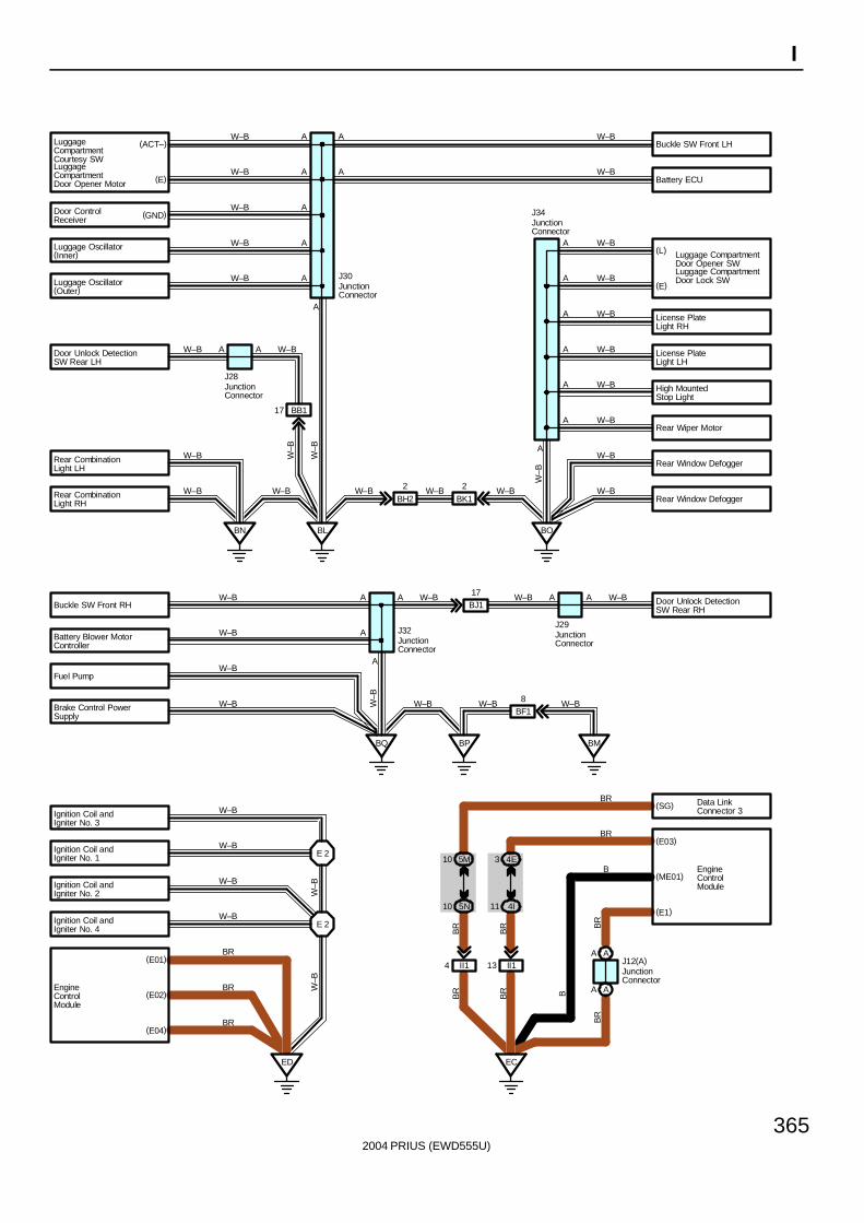
2004 PRIUS (EWD555U)
365
I
(L)
(E)
ED
E 2
E 2
(E01)
(E02)
(E04)BR
BR
BR
W–B
W–B
W–B
W–B
W–B
W–B
BL BO
BK1
2
BH2
2
BN
BB117
A A
A
A
A
A
A
A
A
A
A
A
A
A
A
A
A
W–B
W–B
W–B
W–B
W–B
W–B
W–B
W–B W–B
W–B
W–B W–B W–B
W–B
W–B
W–B
W–B
W–B
W–B
W–B
W–B
W–B
W–B
J28
J30
J34
W–B
W–B
W–B
(ACT–)
(E)
BQ BP BM
A
A
A ABJ117 A A
BF18
J32J29
W–B
W–B
W–B
W–B W–B W–B W–B
W–B W–B W–B
(SG)
(E03)
(E1)
II113II14
EC
B
BR
BR
BR B
W–B
4I115N10
BR
BR
BR
JunctionConnector
JunctionConnector
JunctionConnector
JunctionConnector
JunctionConnector
5M10 4E3
Luggage CompartmentDoor Opener SWLuggage CompartmentDoor Lock SW
Data LinkConnector 3
EngineControlModule
LuggageCompartmentDoor Opener Motor
Luggage Oscillator(Outer)
Luggage Oscillator(Inner)
Door ControlReceiver
LuggageCompartmentCourtesy SW
Door Unlock DetectionSW Rear LH
Rear CombinationLight LH
Rear CombinationLight RH
Buckle SW Front RH
Battery Blower MotorController
Fuel Pump
Brake Control PowerSupply
EngineControlModule
Ignition Coil andIgniter No. 4
Ignition Coil andIgniter No. 2
Ignition Coil andIgniter No. 1
Ignition Coil andIgniter No. 3
Rear Window Defogger
Rear Window Defogger
Rear Wiper Motor
High MountedStop Light
License PlateLight LH
License PlateLight RH
Battery ECU
Buckle SW Front LH
Door Unlock DetectionSW Rear RH
(ME01)
BR
BR
JunctionConnector
J12(A)AA
AA
(GND)
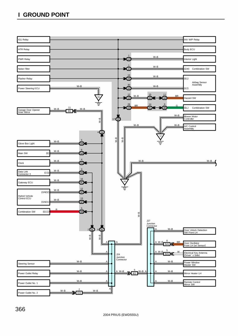
2004 PRIUS (EWD555U)
366
I GROUND POINT
Body ECU
(EW)
(E1)
(E2)
Hazard SW
(EL)
A/C ControlAssembly
Door OscillatorFront LH (w/ Sensor)
Electrical Key Antenna(Driver’ s Side)
IB1
11
IE2
5
IJ
IH
1E
28
1E
12
1E
30
1E
14
1I1
1O
1
1E17
IG
W–B
W–B
W–B
W–B
W–B
BR
G
W–B
BR
W–B
W–BW–B
W–BW–BW–B
W–B
W–B
W–B
W–B
W–B
A
A
A
A
A
A
A
A
A
A
A
A
A
W–B
R
W–B
W–B
W–B
W–B
W–B
W–B W–B
W–B
W–B
W–B
W–B
W–B
W–B
W–B
W–B
J24
J27
A
(GND1)
(GND2)
(CG)
(E)
4A
11
4B
9
4G
15
4G
14
5A5
5A
6
5G
4
5M
3
5B
5
5F12
5F
13
5L2 5L6
5I4
W–B
W–B5C
16
W–B
W–B
JunctionConnector
JunctionConnector
INV W/P Relay
Airbag SensorAssembly
Combination SW
Combination SW
Power Steering ECU
Inner MirrorGarage Door Opener
Glove Box Light
Main SW
Clock
Data LinkConnector 3
Gateway ECU
Combination SW
Hybrid VehicleControl ECU
Steering Sensor
Power Outlet Relay
Power Outlet No. 1
Interior Light
Blower MotorController
Door Unlock DetectionSW Front LH
Power WindowMaster SW
Mirror Heater LH
Remote ControlMirror SW
Flasher Relay
Noise Filter
PWR Relay
IG1 Relay
HTR Relay
BA18
BA1
5
BR
W
(ECC)
W–BPower Outlet No. 2
A
IO12 W–B
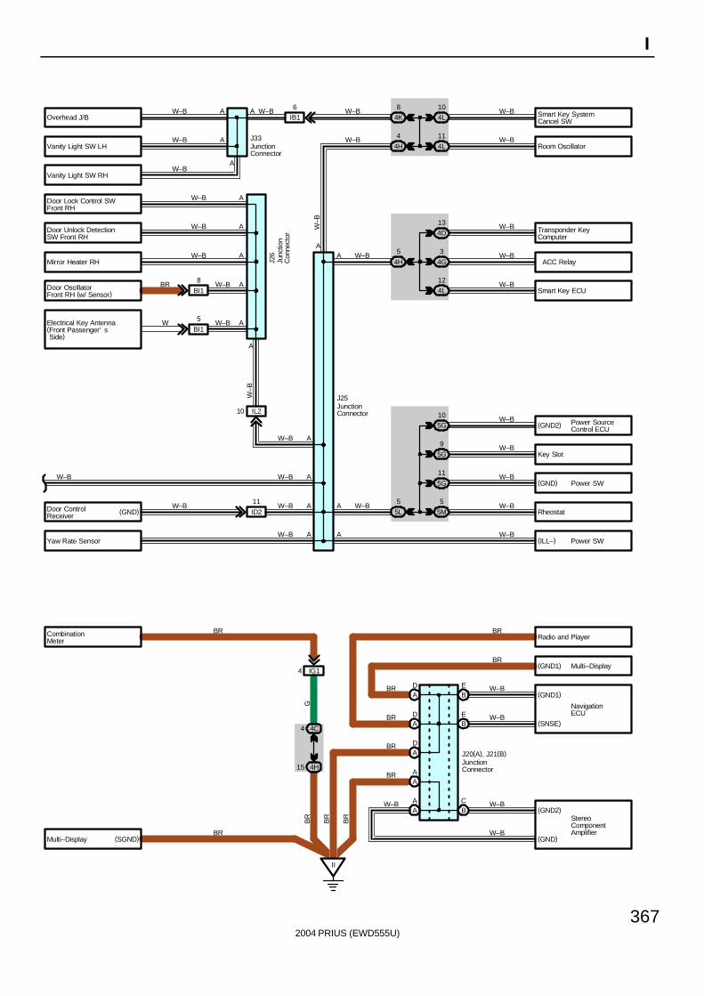
2004 PRIUS (EWD555U)
367
I
Transponder KeyComputer
Smart Key ECU
(GND2)
(GND)
Radio and Player
(GND1)
(GND1)
(SNSE)
(GND2)
(GND)
ID2
11
IL210
IB16
II
AA
AA
BC
BE
BE
AD
AD
AD
IG14
(SGND)
BR
BR
BR
G
BR
BR BR
BR
W–B
W–B
W–B
W–B
BR
BR
BR
BR
W–B
J20(A), J21(B)
W–B
W–B
W–B
W–B
W–B
W
BR
W–B
W–B
W–B
W–B
W–B
W–B W–B W–B
W–B
W–B
W–B
W–B
W–B
W–B
W–B
W–B
W–B
W–B
W–B
W–B
W–B
W–B
W–B
A
A
A
A
AA
A
AA
A
A
A
A
A
A
A
A
J33
J26
J25
4C4
4H15
4L10
4L
11
4D
13
4G
3
4L
12
5G10
5G
9
5G
11
5M
5
4K8
4H
4
4H
5
5L
5
JunctionConnector
JunctionConnector
Junc
tion
Con
nect
or
JunctionConnector
ACC Relay
Multi–Display
NavigationECU
StereoComponentAmplifier
Power SourceControl ECU
Power SW
Overhead J/B
Vanity Light SW LH
Vanity Light SW RH
Door Lock Control SWFront RH
Mirror Heater RH
Door OscillatorFront RH (w/ Sensor)
Door Unlock DetectionSW Front RH
CombinationMeter
Multi–Display
Yaw Rate Sensor
Door ControlReceiver
Smart Key SystemCancel SW
Room Oscillator
Key Slot
Rheostat
Electrical Key Antenna(Front Passenger’ s Side)
BI1
8
BI1
5 W–B
W–B
(GND)
W–BA(ILL–) Power SW
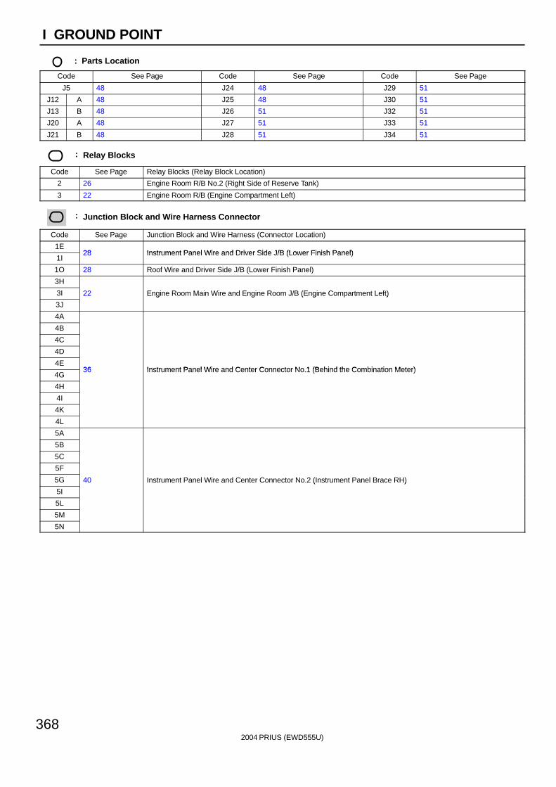
2004 PRIUS (EWD555U)
368
I GROUND POINT
: Parts Location
Code See Page Code See Page Code See Page
J5 48 J24 48 J29 51
J12 A 48 J25 48 J30 51
J13 B 48 J26 51 J32 51
J20 A 48 J27 51 J33 51
J21 B 48 J28 51 J34 51
: Relay Blocks
Code See Page Relay Blocks (Relay Block Location)
2 26 Engine Room R/B No.2 (Right Side of Reserve Tank)
3 22 Engine Room R/B (Engine Compartment Left)
: Junction Block and Wire Harness Connector
Code See Page Junction Block and Wire Harness (Connector Location)
1E28 Instrument Panel Wire and Driver Side J/B (Lower Finish Panel)
1I28 Instrument Panel Wire and Driver Side J/B (Lower Finish Panel)
1O 28 Roof Wire and Driver Side J/B (Lower Finish Panel)
3H
3I 22 Engine Room Main Wire and Engine Room J/B (Engine Compartment Left)
3J
g g ( g )
4A
4B
4C
4D
4E36 Instrument Panel Wire and Center Connector No 1 (Behind the Combination Meter)
4G36 Instrument Panel Wire and Center Connector No.1 (Behind the Combination Meter)
4H
4I
4K
4L
5A
5B
5C
5F
5G 40 Instrument Panel Wire and Center Connector No.2 (Instrument Panel Brace RH)
5I
( )
5L
5M
5N
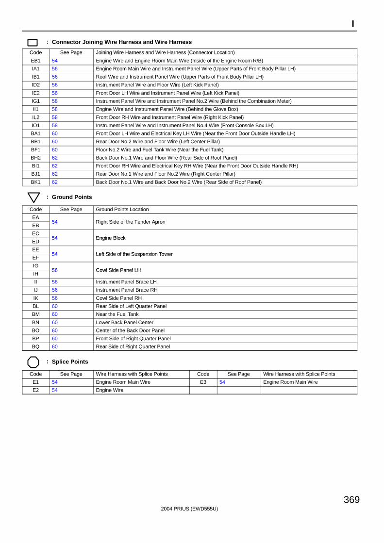
2004 PRIUS (EWD555U)
369
I
: Connector Joining Wire Harness and Wire Harness
Code See Page Joining Wire Harness and Wire Harness (Connector Location)
EB1 54 Engine Wire and Engine Room Main Wire (Inside of the Engine Room R/B)
IA1 56 Engine Room Main Wire and Instrument Panel Wire (Upper Parts of Front Body Pillar LH)
IB1 56 Roof Wire and Instrument Panel Wire (Upper Parts of Front Body Pillar LH)
ID2 56 Instrument Panel Wire and Floor Wire (Left Kick Panel)
IE2 56 Front Door LH Wire and Instrument Panel Wire (Left Kick Panel)
IG1 58 Instrument Panel Wire and Instrument Panel No.2 Wire (Behind the Combination Meter)
II1 58 Engine Wire and Instrument Panel Wire (Behind the Glove Box)
IL2 58 Front Door RH Wire and Instrument Panel Wire (Right Kick Panel)
IO1 58 Instrument Panel Wire and Instrument Panel No.4 Wire (Front Console Box LH)
BA1 60 Front Door LH Wire and Electrical Key LH Wire (Near the Front Door Outside Handle LH)
BB1 60 Rear Door No.2 Wire and Floor Wire (Left Center Pillar)
BF1 60 Floor No.2 Wire and Fuel Tank Wire (Near the Fuel Tank)
BH2 62 Back Door No.1 Wire and Floor Wire (Rear Side of Roof Panel)
BI1 62 Front Door RH Wire and Electrical Key RH Wire (Near the Front Door Outside Handle RH)
BJ1 62 Rear Door No.1 Wire and Floor No.2 Wire (Right Center Pillar)
BK1 62 Back Door No.1 Wire and Back Door No.2 Wire (Rear Side of Roof Panel)
: Ground Points
Code See Page Ground Points Location
EA54 Right Side of the Fender Apron
EB54 Right Side of the Fender Apron
EC54 Engine Block
ED54 Engine Block
EE54 Left Side of the Suspension Tower
EF54 Left Side of the Suspension Tower
IG56 Cowl Side Panel LH
IH56 Cowl Side Panel LH
II 56 Instrument Panel Brace LH
IJ 56 Instrument Panel Brace RH
IK 56 Cowl Side Panel RH
BL 60 Rear Side of Left Quarter Panel
BM 60 Near the Fuel Tank
BN 60 Lower Back Panel Center
BO 60 Center of the Back Door Panel
BP 60 Front Side of Right Quarter Panel
BQ 60 Rear Side of Right Quarter Panel
: Splice Points
Code See Page Wire Harness with Splice Points Code See Page Wire Harness with Splice Points
E1 54 Engine Room Main Wire E3 54 Engine Room Main Wire
E2 54 Engine Wire
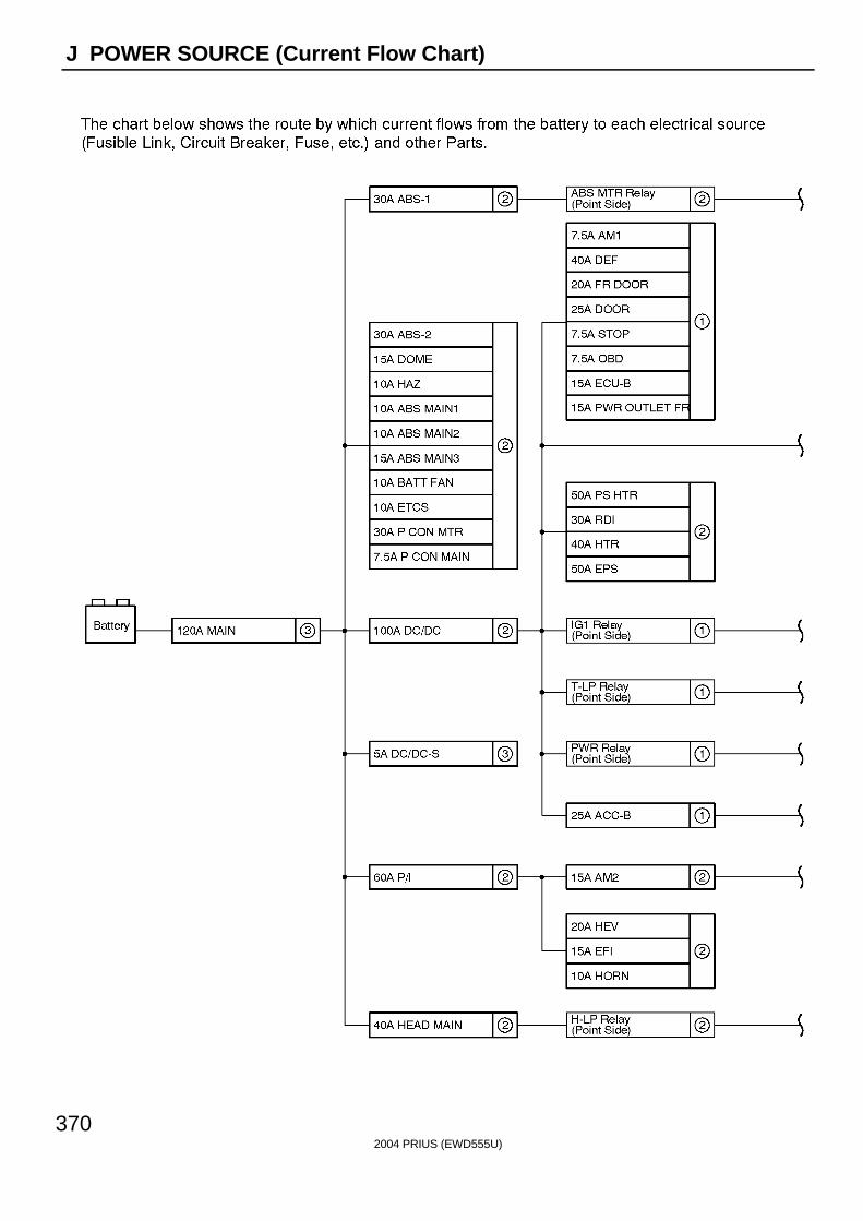
2004 PRIUS (EWD555U)
370
J POWER SOURCE (Current Flow Chart)
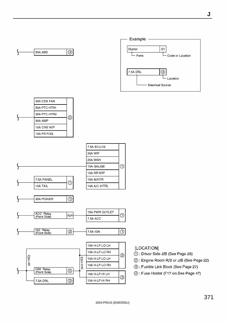
2004 PRIUS (EWD555U)
371
J
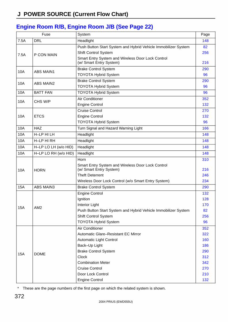
2004 PRIUS (EWD555U)
372
J POWER SOURCE (Current Flow Chart)
Engine Room R/B, Engine Room J/B (See Page 22)Fuse System Page
7.5A DRL Headlight 148
7.5A P CON MAIN
Push Button Start System and Hybrid Vehicle Immobilizer System
Shift Control System
Smart Entry System and Wireless Door Lock Control (w/ Smart Entry System)
82
256
216
10A ABS MAIN1Brake Control System
TOYOTA Hybrid System
290
96
10A ABS MAIN2Brake Control System
TOYOTA Hybrid System
290
96
10A BATT FAN TOYOTA Hybrid System 96
10A CHS W/PAir Conditioner
Engine Control
352
132
10A ETCS
Cruise Control
Engine Control
TOYOTA Hybrid System
270
132
96
10A HAZ Turn Signal and Hazard Warning Light 166
10A H–LP HI LH Headlight 148
10A H–LP HI RH Headlight 148
10A H–LP LO LH (w/o HID) Headlight 148
10A H–LP LO RH (w/o HID) Headlight 148
10A HORN
Horn
Smart Entry System and Wireless Door Lock Control (w/ Smart Entry System)
Theft Deterrent
Wireless Door Lock Control (w/o Smart Entry System)
310
216
246
234
15A ABS MAIN3 Brake Control System 290
15A AM2
Engine Control
Ignition
Interior Light
Push Button Start System and Hybrid Vehicle Immobilizer System
Shift Control System
TOYOTA Hybrid System
132
128
170
82
256
96
15A DOME
Air Conditioner
Automatic Glare–Resistant EC Mirror
Automatic Light Control
Back–Up Light
Brake Control System
Clock
Combination Meter
Cruise Control
Door Lock Control
Engine Control
352
322
160
186
290
312
342
270
210
132
∗ These are the page numbers of the first page on which the related system is shown.
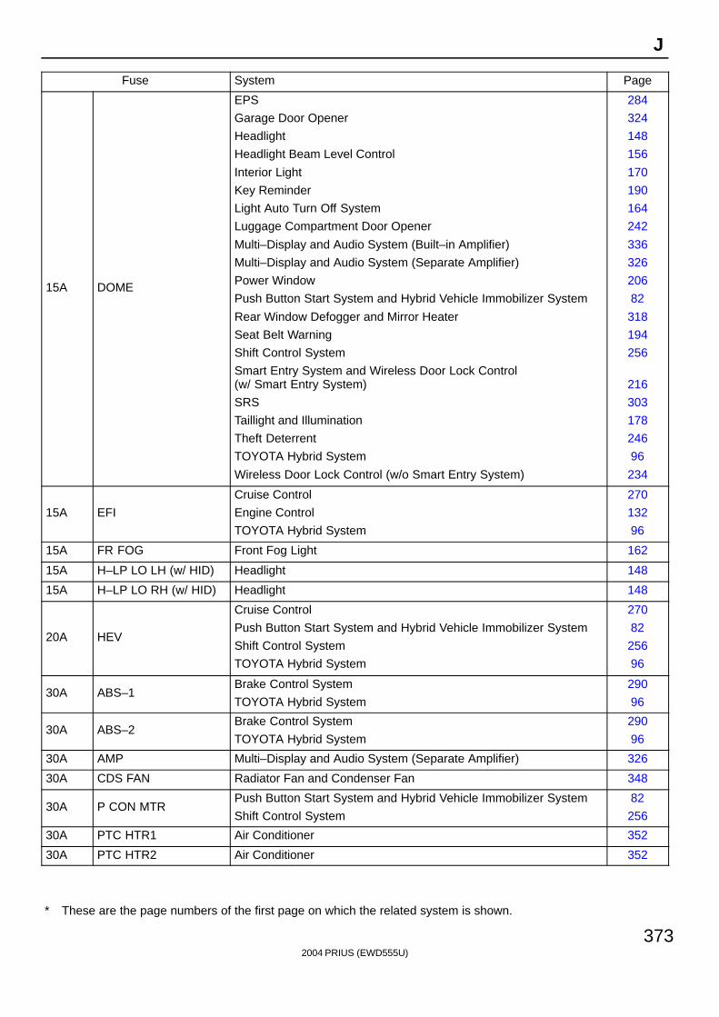
2004 PRIUS (EWD555U)
373
J
Fuse System Page
15A DOME
EPS
Garage Door Opener
Headlight
Headlight Beam Level Control
Interior Light
Key Reminder
Light Auto Turn Off System
Luggage Compartment Door Opener
Multi–Display and Audio System (Built–in Amplifier)
Multi–Display and Audio System (Separate Amplifier)
Power Window
Push Button Start System and Hybrid Vehicle Immobilizer System
Rear Window Defogger and Mirror Heater
Seat Belt Warning
Shift Control System
Smart Entry System and Wireless Door Lock Control (w/ Smart Entry System)
SRS
Taillight and Illumination
Theft Deterrent
TOYOTA Hybrid System
Wireless Door Lock Control (w/o Smart Entry System)
284
324
148
156
170
190
164
242
336
326
206
82
318
194
256
216
303
178
246
96
234
15A EFI
Cruise Control
Engine Control
TOYOTA Hybrid System
270
132
96
15A FR FOG Front Fog Light 162
15A H–LP LO LH (w/ HID) Headlight 148
15A H–LP LO RH (w/ HID) Headlight 148
20A HEV
Cruise Control
Push Button Start System and Hybrid Vehicle Immobilizer System
Shift Control System
TOYOTA Hybrid System
270
82
256
96
30A ABS–1Brake Control System
TOYOTA Hybrid System
290
96
30A ABS–2Brake Control System
TOYOTA Hybrid System
290
96
30A AMP Multi–Display and Audio System (Separate Amplifier) 326
30A CDS FAN Radiator Fan and Condenser Fan 348
30A P CON MTRPush Button Start System and Hybrid Vehicle Immobilizer System
Shift Control System
82
256
30A PTC HTR1 Air Conditioner 352
30A PTC HTR2 Air Conditioner 352
∗ These are the page numbers of the first page on which the related system is shown.
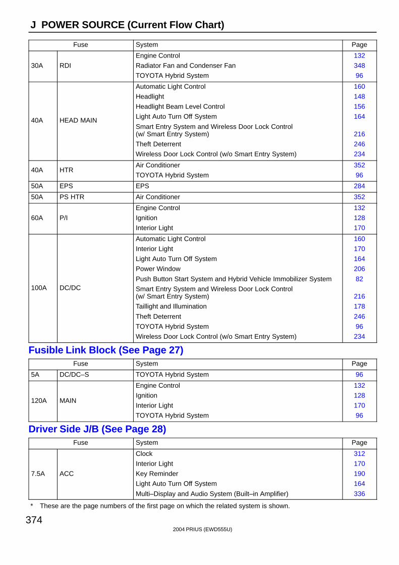
2004 PRIUS (EWD555U)
374
J POWER SOURCE (Current Flow Chart)
Fuse System Page
30A RDI
Engine Control
Radiator Fan and Condenser Fan
TOYOTA Hybrid System
132
348
96
40A HEAD MAIN
Automatic Light Control
Headlight
Headlight Beam Level Control
Light Auto Turn Off System
Smart Entry System and Wireless Door Lock Control (w/ Smart Entry System)
Theft Deterrent
Wireless Door Lock Control (w/o Smart Entry System)
160
148
156
164
216
246
234
40A HTRAir Conditioner
TOYOTA Hybrid System
352
96
50A EPS EPS 284
50A PS HTR Air Conditioner 352
60A P/I
Engine Control
Ignition
Interior Light
132
128
170
100A DC/DC
Automatic Light Control
Interior Light
Light Auto Turn Off System
Power Window
Push Button Start System and Hybrid Vehicle Immobilizer System
Smart Entry System and Wireless Door Lock Control (w/ Smart Entry System)
Taillight and Illumination
Theft Deterrent
TOYOTA Hybrid System
Wireless Door Lock Control (w/o Smart Entry System)
160
170
164
206
82
216
178
246
96
234
Fusible Link Block (See Page 27)Fuse System Page
5A DC/DC–S TOYOTA Hybrid System 96
120A MAIN
Engine Control
Ignition
Interior Light
TOYOTA Hybrid System
132
128
170
96
Driver Side J/B (See Page 28)Fuse System Page
7.5A ACC
Clock
Interior Light
Key Reminder
Light Auto Turn Off System
Multi–Display and Audio System (Built–in Amplifier)
312
170
190
164
336
∗ These are the page numbers of the first page on which the related system is shown.
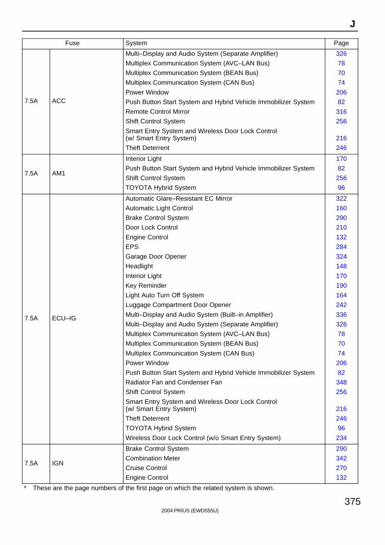
2004 PRIUS (EWD555U)
375
J
Fuse System Page
7.5A ACC
Multi–Display and Audio System (Separate Amplifier)
Multiplex Communication System (AVC–LAN Bus)
Multiplex Communication System (BEAN Bus)
Multiplex Communication System (CAN Bus)
Power Window
Push Button Start System and Hybrid Vehicle Immobilizer System
Remote Control Mirror
Shift Control System
Smart Entry System and Wireless Door Lock Control (w/ Smart Entry System)
Theft Deterrent
326
78
70
74
206
82
316
256
216
246
7.5A AM1
Interior Light
Push Button Start System and Hybrid Vehicle Immobilizer System
Shift Control System
TOYOTA Hybrid System
170
82
256
96
7.5A ECU–IG
Automatic Glare–Resistant EC Mirror
Automatic Light Control
Brake Control System
Door Lock Control
Engine Control
EPS
Garage Door Opener
Headlight
Interior Light
Key Reminder
Light Auto Turn Off System
Luggage Compartment Door Opener
Multi–Display and Audio System (Built–in Amplifier)
Multi–Display and Audio System (Separate Amplifier)
Multiplex Communication System (AVC–LAN Bus)
Multiplex Communication System (BEAN Bus)
Multiplex Communication System (CAN Bus)
Power Window
Push Button Start System and Hybrid Vehicle Immobilizer System
Radiator Fan and Condenser Fan
Shift Control System
Smart Entry System and Wireless Door Lock Control (w/ Smart Entry System)
Theft Deterrent
TOYOTA Hybrid System
Wireless Door Lock Control (w/o Smart Entry System)
322
160
290
210
132
284
324
148
170
190
164
242
336
326
78
70
74
206
82
348
256
216
246
96
234
7.5A IGN
Brake Control System
Combination Meter
Cruise Control
Engine Control
290
342
270
132
∗ These are the page numbers of the first page on which the related system is shown.
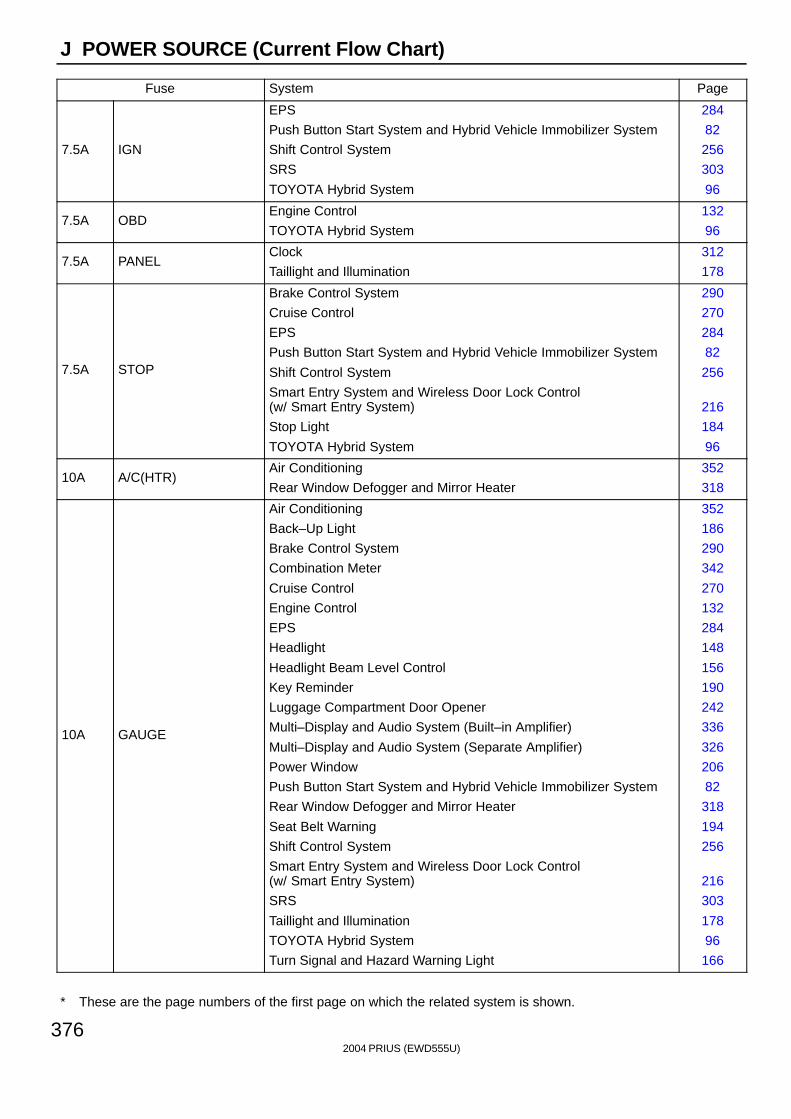
2004 PRIUS (EWD555U)
376
J POWER SOURCE (Current Flow Chart)
Fuse System Page
7.5A IGN
EPS
Push Button Start System and Hybrid Vehicle Immobilizer System
Shift Control System
SRS
TOYOTA Hybrid System
284
82
256
303
96
7.5A OBDEngine Control
TOYOTA Hybrid System
132
96
7.5A PANELClock
Taillight and Illumination
312
178
7.5A STOP
Brake Control System
Cruise Control
EPS
Push Button Start System and Hybrid Vehicle Immobilizer System
Shift Control System
Smart Entry System and Wireless Door Lock Control (w/ Smart Entry System)
Stop Light
TOYOTA Hybrid System
290
270
284
82
256
216
184
96
10A A/C(HTR)Air Conditioning
Rear Window Defogger and Mirror Heater
352
318
10A GAUGE
Air Conditioning
Back–Up Light
Brake Control System
Combination Meter
Cruise Control
Engine Control
EPS
Headlight
Headlight Beam Level Control
Key Reminder
Luggage Compartment Door Opener
Multi–Display and Audio System (Built–in Amplifier)
Multi–Display and Audio System (Separate Amplifier)
Power Window
Push Button Start System and Hybrid Vehicle Immobilizer System
Rear Window Defogger and Mirror Heater
Seat Belt Warning
Shift Control System
Smart Entry System and Wireless Door Lock Control (w/ Smart Entry System)
SRS
Taillight and Illumination
TOYOTA Hybrid System
Turn Signal and Hazard Warning Light
352
186
290
342
270
132
284
148
156
190
242
336
326
206
82
318
194
256
216
303
178
96
166
∗ These are the page numbers of the first page on which the related system is shown.

2004 PRIUS (EWD555U)
377
J
Fuse System Page
10A TAILFront Fog Light
Taillight and Illumination
162
178
15A ECU–B
Air Conditioning
Headlight
Multi–Display and Audio System (Built–in Amplifier)
Multi–Display and Audio System (Separate Amplifier)
Multiplex Communication System (AVC–LAN Bus)
Multiplex Communication System (BEAN Bus)
Multiplex Communication System (CAN Bus)
Rear Window Defogger and Mirror Heater
Theft Deterrent
352
148
336
326
78
70
74
318
246
15A M/HTR Rear Window Defogger and Mirror Heater 318
15A PWR OUTLET Power Outlet 314
15A PWR OUTLET FR Power Outlet 314
15A RR WIP Rear Wiper and Washer 202
20A FR DOOR Power Window 206
20A WSHFront Wiper and Washer
Rear Wiper and Washer
198
202
25A ACC–B Push Button Start System and Hybrid Vehicle Immobilizer System 82
25A DOOR
Door Lock Control
Luggage Compartment Door Opener
Smart Entry System and Wireless Door Lock Control (w/ Smart Entry System)
Theft Deterrent
Wireless Door Lock Control (w/o Smart Entry System)
210
242
216
246
234
30A POWER Power Window 206
30A WIP Front Wiper and Washer 198
40A DEF Rear Window Defogger and Mirror Heater 318
Fuse Holder (F17 on See Page 47)Fuse System Page
30A ABSBrake Control System
TOYOTA Hybrid System
290
96
∗ These are the page numbers of the first page on which the related system is shown.
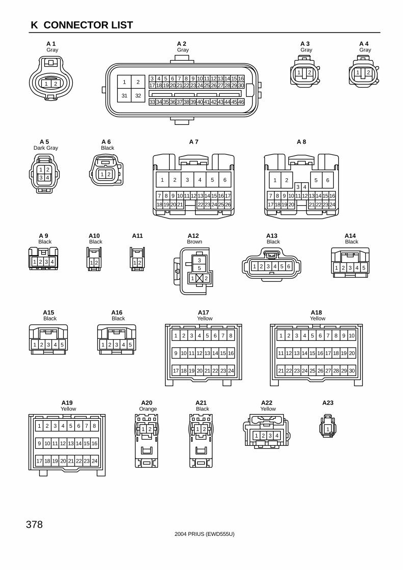
2004 PRIUS (EWD555U)
378
K CONNECTOR LIST
21
GrayA 1
31 32
213 4 5 6 7 8 9 10 11 12 13 14 15 1617 18 19 20 21 22 23 24 25 26 27 28 29 30
33 34 35 36 37 38 39 40 41 42 43 44 45 46
GrayA 2
1 2
GrayA 3
1 2
GrayA 4
1 2
3 4
Dark GrayA 5
1 2
BlackA 6
2322 2618
107
25
13 14 16 17
19
8
20
9 11 12 15
2421
1 2 3 4 5 6
A 7
18 2417
87 9 10
23
4
11 12 15
3
1613 14
19 20 2221
1 2 5 6
A 8
1 2 3 4
BlackA 9
21
BlackA10
21
A11
35
1 2
BrownA12
1 2 3 4 5 6
BlackA13
54321
BlackA14
54321
BlackA15
54321
BlackA16
9
1 2 3 4 5 6 7 8
10 11 12 13 14 15 16
17 18 19 20 21 22 23 24
YellowA17
11
1 3 4 5 6 7 8 9
13 14 15 16 17 18 19
21 23 24 25 26 27 28 29 30
20
10
22
12
2
YellowA18
9
1 2 3 4 5 6 7 8
10 11 12 13 14 15 16
17 18 19 20 21 22 23 24
YellowA19
21
OrangeA20
21
BlackA21
1 2 3 4
YellowA22
1
A23
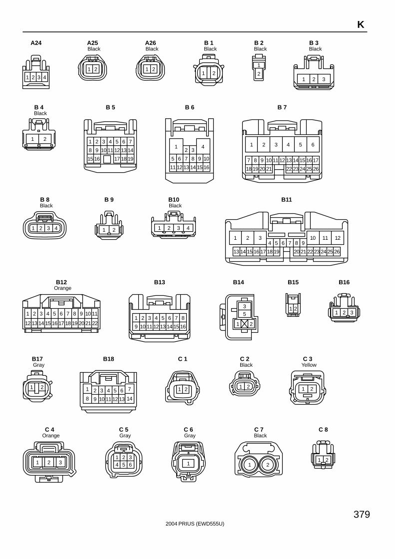
2004 PRIUS (EWD555U)
379
K
1 2 3 4
A24
1 2
BlackA25
1 2
BlackA26
1 2
BlackB 1
1
2
BlackB 2
1 2 3
BlackB 3
1 2
BlackB 4
1 2 3 4 5 6 7
8 9 10 11 12 13 14
15 16 17 18 19
B 5
1 4
5 7 8 10
11 13 14 16
6 9
12 15
2 3
B 6
2322 2618
107
25
13 14 16 17
19
8
20
9 11 12 15
2421
1 2 3 4 5 6
B 7
1 2 3 4
BlackB 8
1 2
B 9
1 2 3 4
BlackB10
111032 121
15 161413 17
4 5 6 7 8 9
18 19 20 21 22 23 24 25 26
B11
11
2221
109
2019
87
1817
65
1615
43
1413
1 2
12
OrangeB12
9
1 2 3
16
4 5 86 7
10 11 151412 13
B13
35
1 2
B14
21
B15
1 32
B16
1 2
GrayB17
1
14
7
9 1312
2 654
11108
3
B18
1 2
C 1
1 2
BlackC 2
21
YellowC 3
2 31
OrangeC 4
1 2 34 5 6
GrayC 5
1
GrayC 6
1 2
BlackC 7
1 2
C 8
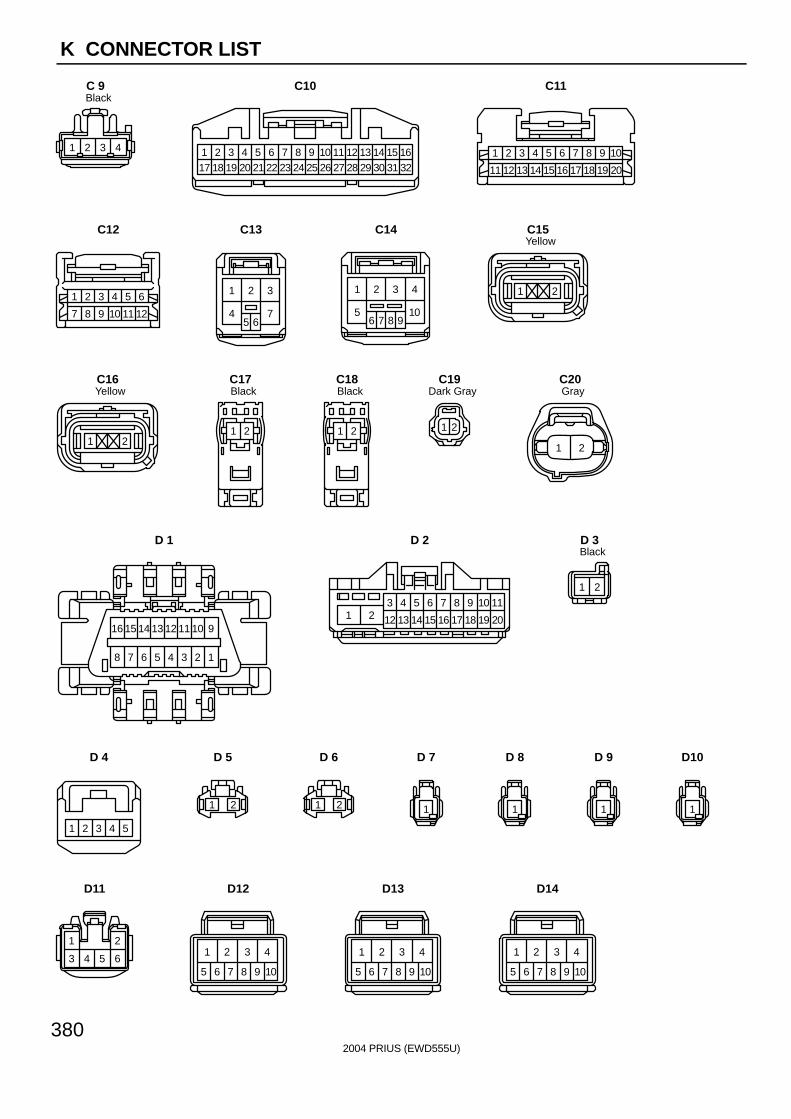
2004 PRIUS (EWD555U)
380
K CONNECTOR LIST
1 2 3 4
BlackC 9
418
317 201
211952
226
237
259
2610
2711
2812
2913
3014
3115
3216
248
C10
4 5 6 7
14 15 16 17
8
18
9
19
3
13
2
12
10
20
1
11
C11
2 3 4 5
8 9 10 11
1
7
6
12
C12
1 2 3
45 6
7
C13
1 2 3 4
56 7 8 9
10
C14
1 2
YellowC15
1 2
YellowC16
21
BlackC17
21
BlackC18
21
Dark GrayC19
1 2
GrayC20
16 15 14 13 12 11 10 9
8 7 6 5 4 3 2 1
D 1
1 23 4 5 6 7 8 9 10 11
12 13 14 15 16 17 18 19 20
D 2
1 2
BlackD 3
1 2 3 4 5
D 4
1 2
D 5
1 2
D 6
1
D 7
1
D 8
1
D 9
1
D10
1 2
3 4 5 6
D11
1 2 3 4
5 6 7 8 9 10
D12
1 2 3 4
5 6 7 8 9 10
D13
1 2 3 4
5 6 7 8 9 10
D14
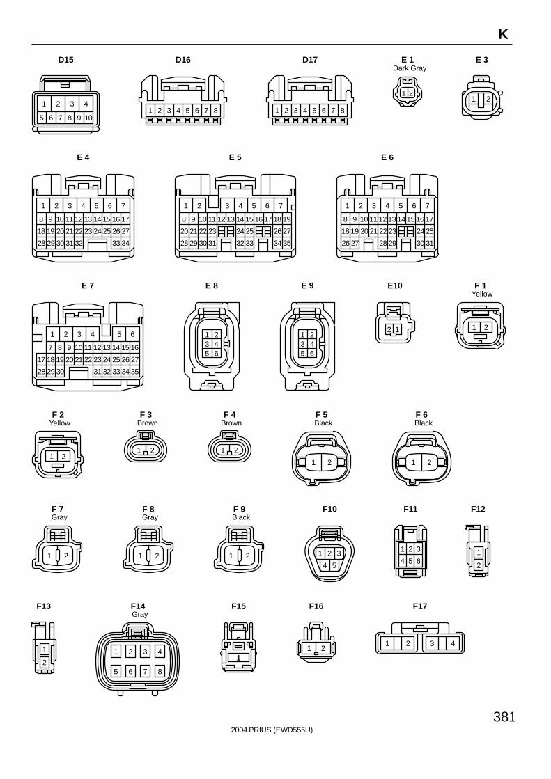
2004 PRIUS (EWD555U)
381
K
1 2 3 4
5 6 7 8 9 10
D15
1 2 3 4 5 6 7 8
D16
1 2 3 4 5 6 7 8
D17
21
Dark GrayE 1
1 2
E 3
1
17
29 3428
1918
98
20
10
21
33
11
76
13 14 15 16
22 23 26
12
432 5
2724 25
30 31 32
E 4
1
19
333231 3528
2320
118 12
34
13
76
15 16 17 18
24 25 26
14
432 5
27
29
21
9
30
22
10
E 5
1
17
292827 3126
1918
98
20
10
21
30
11
76
13 14 15 16
22 23 24
12
432 5
25
E 6
16
3231 3528
2017
9 10
34
11
65
13 14 15
23 24 26
12
321 4
27
29
18
7
30
19
8
21 22 25
33
E 7
1 23 45 6
E 8
1 23 45 6
E 9
2 1
E10
1 2
YellowF 1
1 2
YellowF 2
1 2
BrownF 3
1 2
BrownF 4
1 2
BlackF 5
1 2
BlackF 6
1 2
GrayF 7
1 2
GrayF 8
1 2
BlackF 9
1 2 3
4 5
F10
1 2 3
4 5 6
F11
1
2
F12
1
2
F13
1 2 3 4
5 6 7 8
GrayF14
11
F15
1 2
F16
1 2 3 4
F17
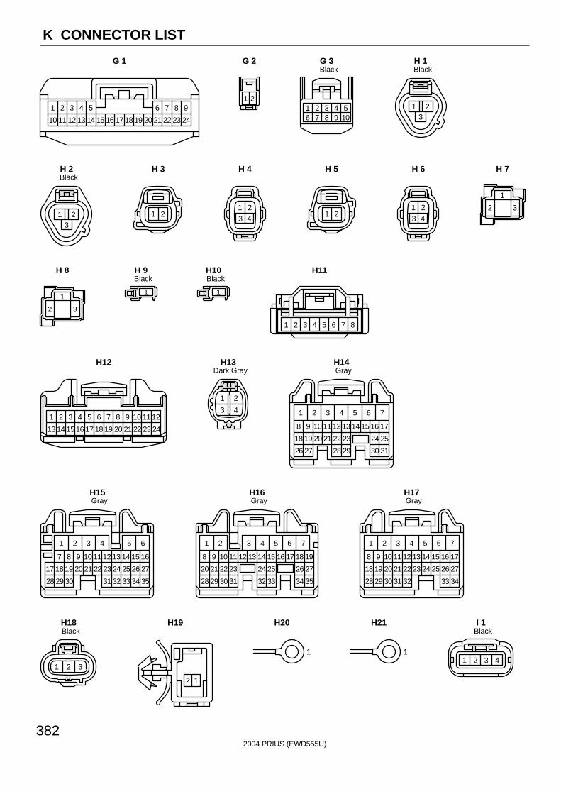
2004 PRIUS (EWD555U)
382
K CONNECTOR LIST
1
10
2
11
3
12
4
13
5
14 15 16 17 18 19 20
6
21
7
22
8
23
9
24
G 1
21
G 2
216 7
38
49
510
BlackG 3
213
BlackH 1
213
BlackH 2
1 2
H 3
1 2
3 4
H 4
1 2
H 5
1 2
3 4
H 6
1
2 3
H 7
1
2 3
H 8
1
BlackH 9
1
BlackH10
2 3 4 5 6 7 81
H11
21
13 14
3
15
4
16
5
17
6
18
7
19
8
20
9
21
10
22
11
23
12
24
H12
21
3 4
Dark GrayH13
7
31
25
14 1713
26
12
1
111098
2118
3 4 62
30
24
1615
2322
28
2019
5
27 29
GrayH14
6
3228 35
24 27
13 1612
29
11
1
10987
2118
3 4 52
17
34
26
15
33
25
14
2322
31
2019
30
GrayH15
1
19
333231 3528
2320
118 12
34
13
76
15 16 17 18
24 25 26
14
432 5
27
29
21
9
30
22
10
GrayH16
7
34
24 27
14 1713
28
12
1
111098
2118
3 4 62
33
26
16
25
15
2322
32
2019
5
29 30 31
GrayH17
1 2 3
BlackH18
2 1
H19
1
H20
1
H21
1 2 3 4
BlackI 1
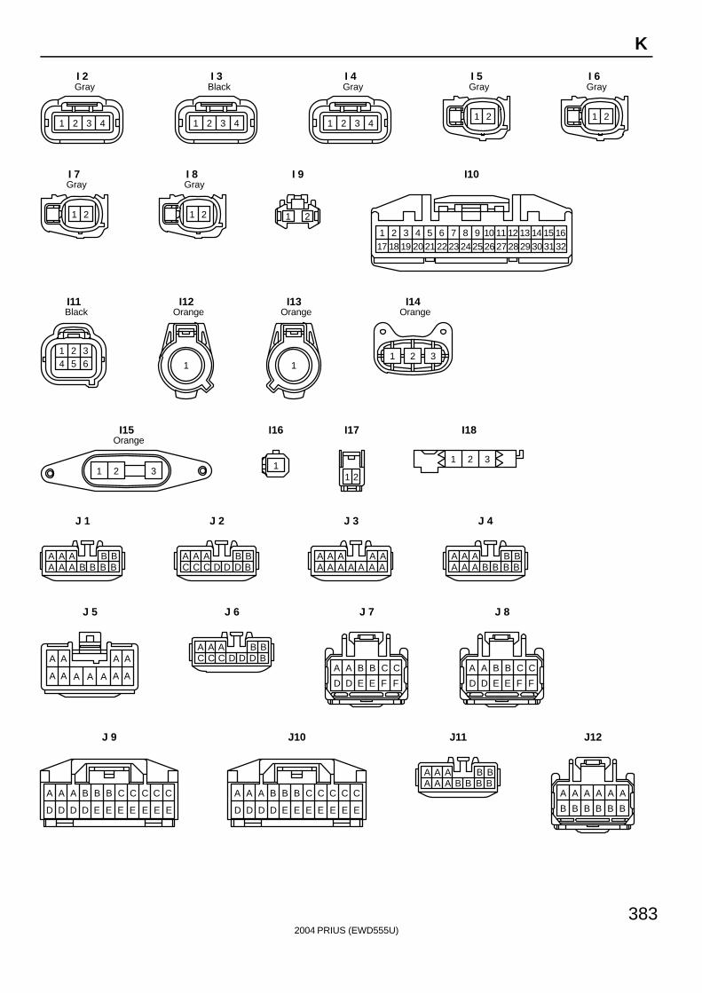
2004 PRIUS (EWD555U)
383
K
A A A A A A
B B B B B B
BBAAAA A A B B B B
BBAAAC C C D D D B
AAAAAA A A A A A A
BBAAAA A A B B B B
A A A A
A A A AA A A
BBAAAC C C D D D B
A A B B C C
D D E E F F
A A B B C C
D D E E F F
C
EE
CC
EE
CC
EE
BB
ED
BA
DD
A A
D
C
EE
CC
EE
CC
EE
BB
ED
BA
DD
A A
D
BBAAAA A A B B B B
1 2 3 4
GrayI 2
1 2 3 4
BlackI 3
1 2 3 4
GrayI 4
1 2
GrayI 5
1 2
GrayI 6
1 2
GrayI 7
1 2
GrayI 8
1 2
I 9
418
317 201
211952
226
237
259
2610
2711
2812
2913
3014
3115
3216
248
I10
1 2 34 5 6
BlackI11
1
OrangeI12
1
OrangeI13
1 2 3
OrangeI14
2 31
OrangeI15
1
I16
21
I17
1 2 3
I18
J 1 J 2 J 3 J 4
J 5 J 6 J 7 J 8
J 9 J10 J11 J12
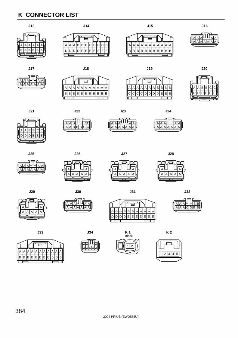
2004 PRIUS (EWD555U)
384
K CONNECTOR LIST
A
BB
AA
BB
AA
BB
AA
BB
AA
BB
A A
B
A A A A A A
B B B B B B
C
EE
CC
EE
CC
EE
BB
ED
BA
DD
A A
D
AAAAAA A A A A A A
A
BB
AA
BB
AA
BB
AA
BB
AA
BB
A A
B
BBAAAA A A C D B B
C
EE
CC
EE
CC
EE
BB
ED
BA
DD
A A
D
AAAAAA A A A A A A
AA
A A A A A
AA
A A A A A
AA
A A A A A
AAAAAA A A A A A A
AAAAAA A A A A A A
AAAAAA A A A A A A
CCBAAA A B B B C C
A A B B C C
D D D E E E
A A B B C C
D D D E E E
A
BB
AA
BB
AA
BB
AA
BB
AA
BB
A A
B
B
EE
BB
ED
BA
DD
AA
DC
AA
CC
A A
C
AAAAAA A A A A A A
AA
A A A A A
A A AA A A A A
J13 J14 J15 J16
J17 J18 J19 J20
J21 J22 J23 J24
J25 J26 J27 J28
J29 J30 J31 J32
J33 J34
1 2
BlackK 1
1 2 3 4 5
K 2
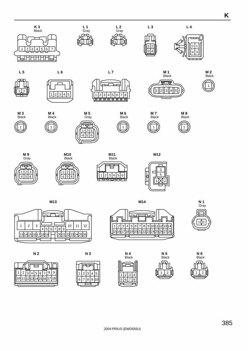
2004 PRIUS (EWD555U)
385
K
1 2 3 4 5 6 7
BlackK 3
1 2
GrayL 1
1 2
GrayL 2
23 41
L 3
4 3
12
L 4
1 2
L 5
1 2 3 4 5
L 6
1 2 3 4 5 6 7 8
L 7
54321
BlackM 1
1
BlackM 2
1
BlackM 3
1
BlackM 4
1 2 34 5 6
GrayM 5
1
BlackM 6
1
BlackM 7
1
BlackM 8
1 2 34 5 6
GrayM 9
1 2 34 5 6
BlackM10
1 2 3 4 5 6
BlackM11
35
1 2
M12
111032 121
15 161413 17
4 5 6 7 8 9
18 19 20 21 22 23 24 25 26
M13
21
15 16
4
18
5
19
6
20
7
21
8
22
9
23
10
24
11
25
13
27
14
28
3
17
12
26
M14
1 2
GrayN 1
1 2 3 4 5 6 7 8 9
10 11 12 13 14 15 16 17 18
N 2
109876
54321
N 3
8765431 2
BlackN 4
1 2
BlackN 5
1 2
BlackN 6
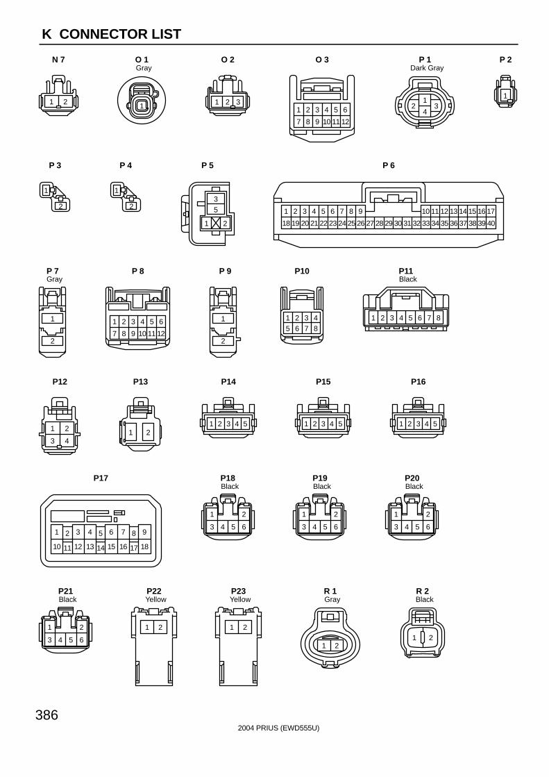
2004 PRIUS (EWD555U)
386
K CONNECTOR LIST
1 2
N 7
1
GrayO 1
1 32
O 2
7 8
1 2
12
4 5 6
9 1110
3
O 3
12 3
4
Dark GrayP 1
1
P 2
1
2
P 3
1
2
P 4
35
1 2
P 5
21
18 19
3
20
4
21
5
22
6
23
7
24
8
25
9
26 27 28 29 30 31 32
10
33
11
34
12
35
13
36
14
37
15
38
16
39
17
40
P 6
2
1
GrayP 7
1 2 3 4 5 6
7 8 9 10 11 12
P 8
2
1
P 9
8765431 2
P10
2 3 4 5 6 7 81
BlackP11
1 2
3 4
P12
1 2
P13
1 2 3 4 5
P14
1 2 3 4 5
P15
1 2 3 4 5
P16
6 95 8
14
7
15
4
17
21
1816
3
11 1310 12
P17
1 2
3 4 5 6
BlackP18
1 2
3 4 5 6
BlackP19
1 2
3 4 5 6
BlackP20
1 2
3 4 5 6
BlackP21
21
YellowP22
21
YellowP23
21
GrayR 1
1 2
BlackR 2
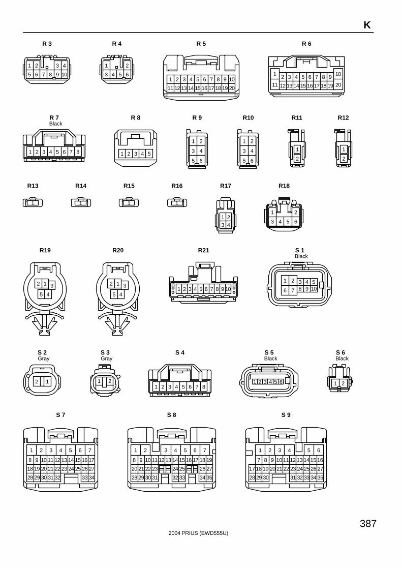
2004 PRIUS (EWD555U)
387
K
1 2 3 4
5 6 7 8 9 10
R 3
1 2
3 4 5 6
R 4
1 2 3 4 5 6 7 8 9 10
11 12 13 14 15 16 17 18 19 20
R 5
5 6 7 8 9 10
11 12 13 14
3 421
15 16 17 18 19 20
R 6
2 3 4 5 6 7 81
BlackR 7
1 2 3 4 5
R 8
1 2
3 4
5 6
R 9
1 2
3 4
5 6
R10
1
2
R11
1
2
R12
1
R13
1
R14
1
R15
1
R16
23 41
R17
1 2
3 4 5 6
R18
2 1 3
5 4
R19
2 1 3
5 4
R20
1 2 3 4 5 6 7 8 9 10
R21
1 2 3 4 5
6 7 8 9 10
BlackS 1
12
GrayS 2
1 2
GrayS 3
2 3 4 5 6 7 81
S 4
1 2 3 4 5 6
BlackS 5
1 2
BlackS 6
1
17
29 3428
1918
98
20
10
21
33
11
76
13 14 15 16
22 23 26
12
432 5
2724 25
30 31 32
S 7
1
19
333231 3528
2320
118 12
34
13
76
15 16 17 18
24 25 26
14
432 5
27
29
21
9
30
22
10
S 8
16
3231 3528
2017
9 10
34
11
65
13 14 15
23 24 26
12
321 4
27
29
18
7
30
19
8
21 22 25
33
S 9
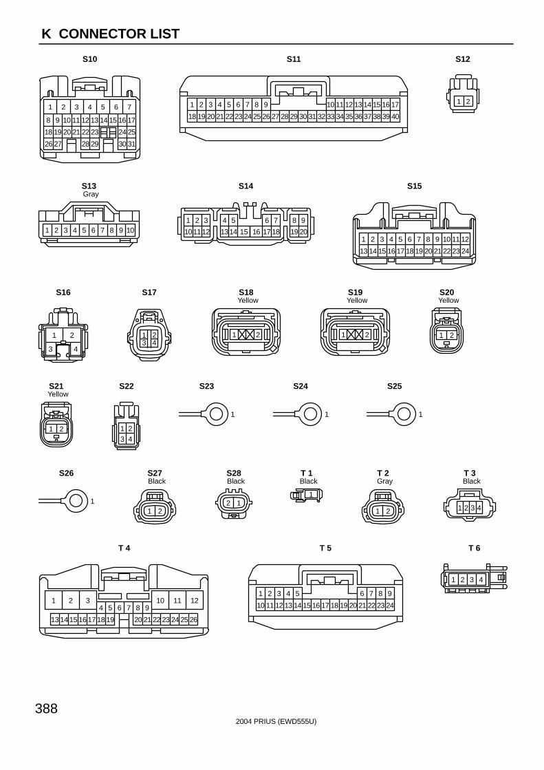
2004 PRIUS (EWD555U)
388
K CONNECTOR LIST
1
17
292827 3126
1918
98
20
10
21
30
11
76
13 14 15 16
22 23 24
12
432 5
25
S10
21
18 19
3
20
4
21
5
22
6
23
7
24
8
25
9
26 27 28 29 30 31 32
10
33
11
34
12
35
13
36
14
37
15
38
16
39
17
40
S11
1 2
S12
10987654321
GrayS13
1 32 4 5 6 7 8 9
101112 1314 15 16 17 18 19 20
S14
21
13 14
3
15
4
16
5
17
6
18
7
19
8
20
9
21
10
22
11
23
12
24
S15
1
3
2
4
S16
1 23 4
S17
1 2
YellowS18
1 2
YellowS19
1 2
YellowS20
1 2
YellowS21
23 41
S22
1
S23
1
S24
1
S25
1
S26
1 2
BlackS27
2 1
BlackS28
1
BlackT 1
1 2
GrayT 2
1 2 3 4
BlackT 3
111032 121
15 161413 17
4 5 6 7 8 9
18 19 20 21 22 23 24 25 26
T 4
1
10
2
11
3
12
4
13
5
14 15 16 17 18 19 20
6
21
7
22
8
23
9
24
T 5
1 2 3 4
T 6
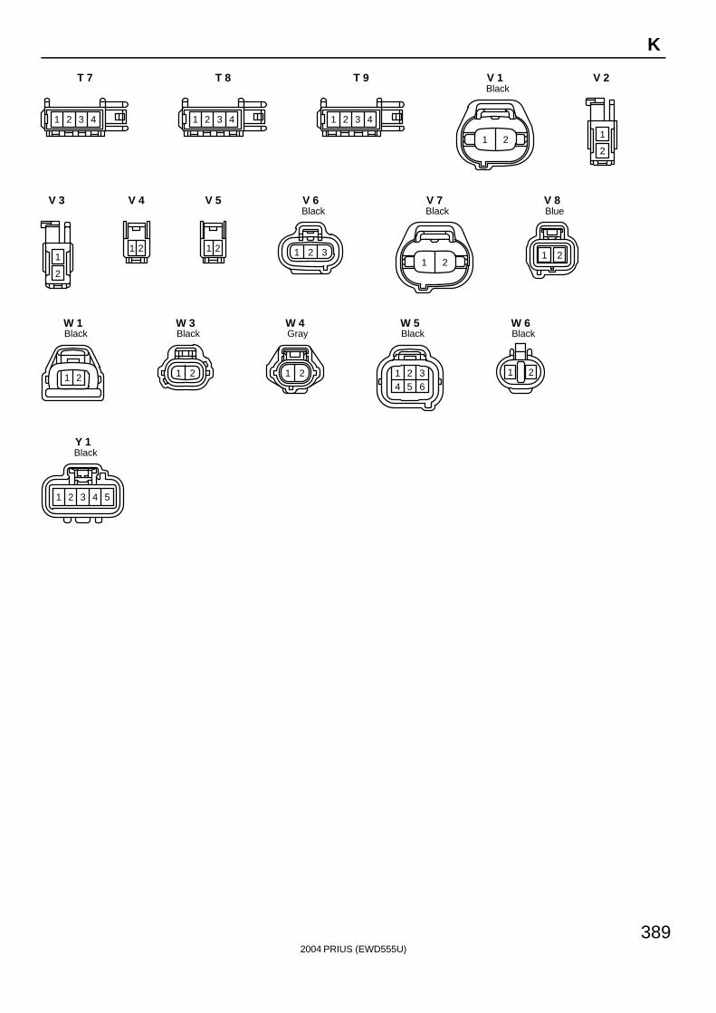
2004 PRIUS (EWD555U)
389
K
1 2 3 4
T 7
1 2 3 4
T 8
1 2 3 4
T 9
1 2
BlackV 1
1
2
V 2
1
2
V 3
21
V 4
21
V 5
1 2 3
BlackV 6
1 2
BlackV 7
1 2
BlueV 8
1 2
BlackW 1
1 2
BlackW 3
1 2
GrayW 4
1 2 34 5 6
BlackW 5
1 2
BlackW 6
54321
BlackY 1
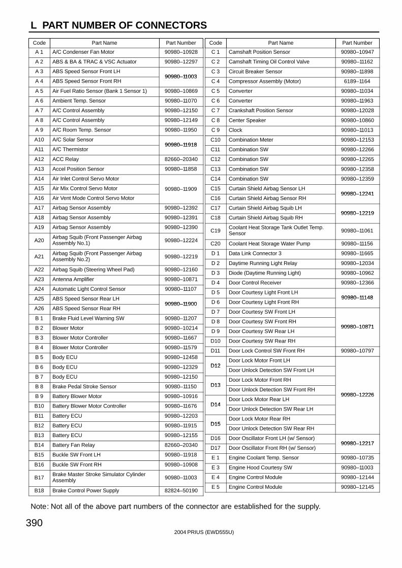
L PART NUMBER OF CONNECTORS
Code Part Name Part Number Code Part Name Part Number
Note: Not all of the above part numbers of the connector are established for the supply.
2004 PRIUS (EWD555U)390
A 1 A/C Condenser Fan Motor 90980–10928
A 2 ABS & BA & TRAC & VSC Actuator 90980–12297
A 3 ABS Speed Sensor Front LH90980–11003
A 4 ABS Speed Sensor Front RH90980–11003
A 5 Air Fuel Ratio Sensor (Bank 1 Sensor 1) 90980–10869
A 6 Ambient Temp. Sensor 90980–11070
A 7 A/C Control Assembly 90980–12150
A 8 A/C Control Assembly 90980–12149
A 9 A/C Room Temp. Sensor 90980–11950
A10 A/C Solar Sensor90980–11918
A11 A/C Thermistor90980–11918
A12 ACC Relay 82660–20340
A13 Accel Position Sensor 90980–11858
A14 Air Inlet Control Servo Motor
A15 Air Mix Control Servo Motor 90980–11909
A16 Air Vent Mode Control Servo Motor
A17 Airbag Sensor Assembly 90980–12392
A18 Airbag Sensor Assembly 90980–12391
A19 Airbag Sensor Assembly 90980–12390
A20Airbag Squib (Front Passenger AirbagAssembly No.1) 90980–12224
A21Airbag Squib (Front Passenger AirbagAssembly No.2) 90980–12219
A22 Airbag Squib (Steering Wheel Pad) 90980–12160
A23 Antenna Amplifier 90980–10871
A24 Automatic Light Control Sensor 90980–11107
A25 ABS Speed Sensor Rear LH90980–11900
A26 ABS Speed Sensor Rear RH90980–11900
B 1 Brake Fluid Level Warning SW 90980–11207
B 2 Blower Motor 90980–10214
B 3 Blower Motor Controller 90980–11667
B 4 Blower Motor Controller 90980–11579
B 5 Body ECU 90980–12458
B 6 Body ECU 90980–12329
B 7 Body ECU 90980–12150
B 8 Brake Pedal Stroke Sensor 90980–11150
B 9 Battery Blower Motor 90980–10916
B10 Battery Blower Motor Controller 90980–11676
B11 Battery ECU 90980–12203
B12 Battery ECU 90980–11915
B13 Battery ECU 90980–12155
B14 Battery Fan Relay 82660–20340
B15 Buckle SW Front LH 90980–11918
B16 Buckle SW Front RH 90980–10908
B17Brake Master Stroke Simulator CylinderAssembly 90980–11003
B18 Brake Control Power Supply 82824–50190
C 1 Camshaft Position Sensor 90980–10947
C 2 Camshaft Timing Oil Control Valve 90980–11162
C 3 Circuit Breaker Sensor 90980–11898
C 4 Compressor Assembly (Motor) 6189–1164
C 5 Converter 90980–11034
C 6 Converter 90980–11963
C 7 Crankshaft Position Sensor 90980–12028
C 8 Center Speaker 90980–10860
C 9 Clock 90980–11013
C10 Combination Meter 90980–12153
C11 Combination SW 90980–12266
C12 Combination SW 90980–12265
C13 Combination SW 90980–12358
C14 Combination SW 90980–12359
C15 Curtain Shield Airbag Sensor LH90980–12241
C16 Curtain Shield Airbag Sensor RH90980–12241
C17 Curtain Shield Airbag Squib LH90980–12219
C18 Curtain Shield Airbag Squib RH90980–12219
C19Coolant Heat Storage Tank Outlet Temp.Sensor 90980–11061
C20 Coolant Heat Storage Water Pump 90980–11156
D 1 Data Link Connector 3 90980–11665
D 2 Daytime Running Light Relay 90980–12034
D 3 Diode (Daytime Running Light) 90980–10962
D 4 Door Control Receiver 90980–12366
D 5 Door Courtesy Light Front LH90980–11148
D 6 Door Courtesy Light Front RH90980–11148
D 7 Door Courtesy SW Front LH
D 8 Door Courtesy SW Front RH90980–10871
D 9 Door Courtesy SW Rear LH90980–10871
D10 Door Courtesy SW Rear RH
D11 Door Lock Control SW Front RH 90980–10797
D12Door Lock Motor Front LH
D12Door Unlock Detection SW Front LH
D13Door Lock Motor Front RH
D13Door Unlock Detection SW Front RH
90980–12226
D14Door Lock Motor Rear LH
90980–12226
D14Door Unlock Detection SW Rear LH
D15Door Lock Motor Rear RH
D15Door Unlock Detection SW Rear RH
D16 Door Oscillator Front LH (w/ Sensor)90980–12217
D17 Door Oscillator Front RH (w/ Sensor)90980–12217
E 1 Engine Coolant Temp. Sensor 90980–10735
E 3 Engine Hood Courtesy SW 90980–11003
E 4 Engine Control Module 90980–12144
E 5 Engine Control Module 90980–12145
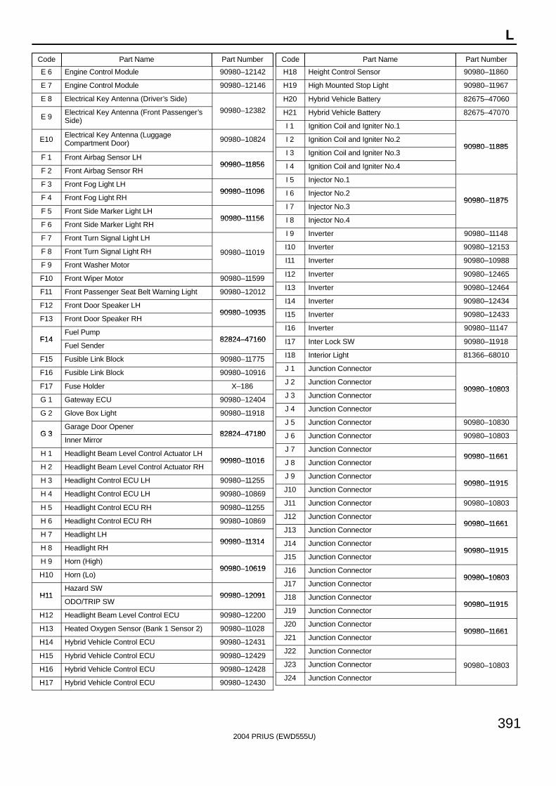
L
Code Part Name Part Number Code Part Name Part Number
2004 PRIUS (EWD555U)
391
E 6 Engine Control Module 90980–12142
E 7 Engine Control Module 90980–12146
E 8 Electrical Key Antenna (Driver’s Side)
E 9Electrical Key Antenna (Front Passenger’sSide)
90980–12382
E10Electrical Key Antenna (LuggageCompartment Door) 90980–10824
F 1 Front Airbag Sensor LH90980–11856
F 2 Front Airbag Sensor RH90980–11856
F 3 Front Fog Light LH90980–11096
F 4 Front Fog Light RH90980–11096
F 5 Front Side Marker Light LH90980–11156
F 6 Front Side Marker Light RH90980–11156
F 7 Front Turn Signal Light LH
F 8 Front Turn Signal Light RH 90980–11019
F 9 Front Washer Motor
F10 Front Wiper Motor 90980–11599
F11 Front Passenger Seat Belt Warning Light 90980–12012
F12 Front Door Speaker LH90980–10935
F13 Front Door Speaker RH90980–10935
F14Fuel Pump
82824–47160F14Fuel Sender
82824–47160
F15 Fusible Link Block 90980–11775
F16 Fusible Link Block 90980–10916
F17 Fuse Holder X–186
G 1 Gateway ECU 90980–12404
G 2 Glove Box Light 90980–11918
G 3Garage Door Opener
82824–47180G 3Inner Mirror
82824–47180
H 1 Headlight Beam Level Control Actuator LH90980–11016
H 2 Headlight Beam Level Control Actuator RH90980–11016
H 3 Headlight Control ECU LH 90980–11255
H 4 Headlight Control ECU LH 90980–10869
H 5 Headlight Control ECU RH 90980–11255
H 6 Headlight Control ECU RH 90980–10869
H 7 Headlight LH90980–11314
H 8 Headlight RH90980–11314
H 9 Horn (High)90980–10619
H10 Horn (Lo)90980–10619
H11Hazard SW
90980–12091H11ODO/TRIP SW
90980–12091
H12 Headlight Beam Level Control ECU 90980–12200
H13 Heated Oxygen Sensor (Bank 1 Sensor 2) 90980–11028
H14 Hybrid Vehicle Control ECU 90980–12431
H15 Hybrid Vehicle Control ECU 90980–12429
H16 Hybrid Vehicle Control ECU 90980–12428
H17 Hybrid Vehicle Control ECU 90980–12430
H18 Height Control Sensor 90980–11860
H19 High Mounted Stop Light 90980–11967
H20 Hybrid Vehicle Battery 82675–47060
H21 Hybrid Vehicle Battery 82675–47070
I 1 Ignition Coil and Igniter No.1
I 2 Ignition Coil and Igniter No.290980–11885
I 3 Ignition Coil and Igniter No.390980–11885
I 4 Ignition Coil and Igniter No.4
I 5 Injector No.1
I 6 Injector No.290980–11875
I 7 Injector No.390980–11875
I 8 Injector No.4
I 9 Inverter 90980–11148
I10 Inverter 90980–12153
I11 Inverter 90980–10988
I12 Inverter 90980–12465
I13 Inverter 90980–12464
I14 Inverter 90980–12434
I15 Inverter 90980–12433
I16 Inverter 90980–11147
I17 Inter Lock SW 90980–11918
I18 Interior Light 81366–68010
J 1 Junction Connector
J 2 Junction Connector90980–10803
J 3 Junction Connector90980–10803
J 4 Junction Connector
J 5 Junction Connector 90980–10830
J 6 Junction Connector 90980–10803
J 7 Junction Connector90980–11661
J 8 Junction Connector90980–11661
J 9 Junction Connector90980–11915
J10 Junction Connector90980–11915
J11 Junction Connector 90980–10803
J12 Junction Connector90980–11661
J13 Junction Connector90980–11661
J14 Junction Connector90980–11915
J15 Junction Connector90980–11915
J16 Junction Connector90980–10803
J17 Junction Connector90980–10803
J18 Junction Connector90980–11915
J19 Junction Connector90980–11915
J20 Junction Connector90980–11661
J21 Junction Connector90980–11661
J22 Junction Connector
J23 Junction Connector 90980–10803
J24 Junction Connector

L PART NUMBER OF CONNECTORS
Code Part Name Part Number Code Part Name Part Number
Note: Not all of the above part numbers of the connector are established for the supply.
2004 PRIUS (EWD555U)392
J25 Junction Connector 90980–10803
J26 Junction Connector
J27 Junction Connector90980–11529
J28 Junction Connector90980–11529
J29 Junction Connector
J30 Junction Connector 90980–10803
J31 Junction Connector 90980–11915
J32 Junction Connector 90980–10803
J33 Junction Connector 90980–11915
J34 Junction Connector 90980–10799
K 1 Knock Sensor 90980–11875
K 2 Key Slot 90980–12366
K 3 Key Slot 90980–12092
L 1 License Plate Light LH90980–11148
L 2 License Plate Light RH90980–11148
L 3Luggage Compartment Courtesy SW
90980–10795L 3Luggage Compartment Door Opener Motor
90980–10795
L 4Luggage Compartment Door Lock SW
90980–12212L 4Luggage Compartment Door Opener SW
90980–12212
L 5 Luggage Compartment Light 90980–10860
L 6 Luggage Oscillator (Inner) 90980–12366
L 7 Luggage Oscillator (Outer) 90980–12217
M 1 Mass Air Flow Meter 90980–11317
M 2 Motor Generator No.1
M 3 Motor Generator No.1 90980–12432
M 4 Motor Generator No.1
M 5 Motor Generator No.1 90980–11034
M 6 Motor Generator No.2
M 7 Motor Generator No.2 90980–12432
M 8 Motor Generator No.2
M 9 Motor Generator No.290980–11034
M10 Motor Generator No.290980–11034
M11 Main SW 90980–11986
M12 Mirror Heater Relay 82660–20340
M13 Multi–Display 90980–12203
M14 Multi–Display 90980–12410
N 1 Noise Filter (Ignition) 90980–10843
N 2 Navigation ECU 90980–11973
N 3 Navigation ECU 90980–11923
N 4 Navigation ECU 90980–12221
N 5 Noise Filter (High Mounted Stop Light)
N 6 Noise Filter (Rear Window Defogger) 90980–10916
N 7 Noise Filter (Rear Window Defogger)
O 1 Oil Pressure SW 90980–11363
O 2 Option Connector (Glass Breakage Sensor) 90980–10908
O 3 Overhead J/B 90980–12183
P 1 Pressure SW 90980–10943
P 2 Parking Brake SW 90980–10871
P 3 Power Outlet No.190980–10760
P 4 Power Outlet No.290980–10760
P 5 Power Outlet Relay 82660–20340
P 6 Power Source Control ECU 90980–12388
P 7 Power Steering ECU 90980–12300
P 8 Power Steering ECU 90980–12290
P 9 Power Steering Motor 90980–12299
P10 Power Steering Torque Sensor 90980–12221
P11 Power SW 90980–11989
P12 PTC Heater 90980–11136
P13 PTC Heater 90980–10903
P14 Power Window Control SW Front RH
P15 Power Window Control SW Rear LH 90980–10789
P16 Power Window Control SW Rear RH
P17 Power Window Master SW 90980–12122
P18 Power Window Motor Front LH
P19 Power Window Motor Front RH90980–10797
P20 Power Window Motor Rear LH90980–10797
P21 Power Window Motor Rear RH
P22 Pretensioner LH90980–12253
P23 Pretensioner RH90980–12253
R 1 Radiator Fan Motor 90980–10928
R 2 Rear Washer Motor 90980–11051
R 3 Radio and Player 90980–10997
R 4 Radio and Player 90980–10996
R 5 Radio and Player 90980–12259
R 6 Radio and Player 90980–12038
R 7 Rheostat 90980–11989
R 8 Room Oscillator 90980–12366
R 9 Rear Combination Light LH90980–11011
R10 Rear Combination Light RH90980–11011
R11 Rear Door Speaker LH90980–10935
R12 Rear Door Speaker RH90980–10935
R13 Rear Window Defogger 90980–10914
R14 Rear Window Defogger 90980–10913
R15 Rear Window Defogger 90980–10914
R16 Rear Window Defogger 90980–10913
R17 Rear Wiper Motor 90980–10795
R18 Rear Wiper Relay 90980–10797
R19Mirror Heater LH
R19Remote Control Mirror LH
90980–12189
R20Mirror Heater RH
90980–12189
R20Remote Control Mirror RH
R21 Remote Control Mirror SW 90980–11657
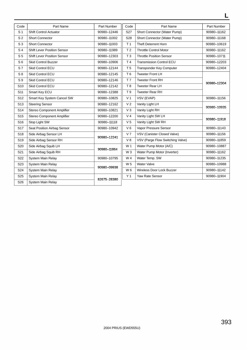
L
Code Part Name Part Number Code Part Name Part Number
2004 PRIUS (EWD555U)
393
S 1 Shift Control Actuator 90980–12446
S 2 Short Connector 90980–11002
S 3 Short Connector 90980–11003
S 4 Shift Lever Position Sensor 90980–11989
S 5 Shift Lever Position Sensor 90980–12303
S 6 Skid Control Buzzer 90980–10906
S 7 Skid Control ECU 90980–12144
S 8 Skid Control ECU 90980–12145
S 9 Skid Control ECU 90980–12146
S10 Skid Control ECU 90980–12142
S11 Smart Key ECU 90980–12388
S12 Smart Key System Cancel SW 90980–10825
S13 Steering Sensor 90980–12162
S14 Stereo Component Amplifier 90980–10821
S15 Stereo Component Amplifier 90980–12200
S16 Stop Light SW 90980–11118
S17 Seat Position Airbag Sensor 90980–10942
S18 Side Airbag Sensor LH90980–12241
S19 Side Airbag Sensor RH90980–12241
S20 Side Airbag Squib LH90980–11864
S21 Side Airbag Squib RH90980–11864
S22 System Main Relay 90980–10795
S23 System Main Relay90980–09938
S24 System Main Relay90980–09938
S25 System Main Relay82675–28380
S26 System Main Relay82675–28380
S27 Short Connector (Water Pump) 90980–11162
S28 Short Connector (Water Pump) 90980–11168
T 1 Theft Deterrent Horn 90980–10619
T 2 Throttle Control Motor 90980–11162
T 3 Throttle Position Sensor 90980–10711
T 4 Transmission Control ECU 90980–12203
T 5 Transponder Key Computer 90980–12404
T 6 Tweeter Front LH
T 7 Tweeter Front RH90980–12304
T 8 Tweeter Rear LH90980–12304
T 9 Tweeter Rear RH
V 1 VSV (EVAP) 90980–11156
V 2 Vanity Light LH90980–10935
V 3 Vanity Light RH90980–10935
V 4 Vanity Light SW LH90980–11918
V 5 Vanity Light SW RH90980–11918
V 6 Vapor Pressure Sensor 90980–11143
V 7 VSV (Canister Closed Valve) 90980–11156
V 8 VSV (Parge Flow Switching Valve) 90980–11859
W 1 Water Pump Motor (A/C) 90980–10887
W 3 Water Pump Motor (Inverter) 90980–11162
W 4 Water Temp. SW 90980–11235
W 5 Water Valve 90980–10988
W 6 Wireless Door Lock Buzzer 90980–11142
Y 1 Yaw Rate Sensor 90980–11904