flow structures and heat transfer on dimples in a staggered arrangement
TRANSCRIPT
International Journal of Heat and Fluid Flow 35 (2012) 168–175
Contents lists available at SciVerse ScienceDirect
International Journal of Heat and Fluid Flow
journal homepage: www.elsevier .com/ locate / i jhf f
Flow structures and heat transfer on dimples in a staggered arrangement
Johann Turnow a,⇑, Nikolai Kornev a, Valery Zhdanov b, Egon Hassel b
a Institute of Modeling and Simulation, University of Rostock, Albert-Einstein-Str. 2, 18059 Rostock, Germanyb Institute of Technical Thermodynamics, University of Rostock, Albert-Einstein-Str. 2, 18059 Rostock, Germany
a r t i c l e i n f o
Article history:Received 14 October 2011Received in revised form 11 January 2012Accepted 12 January 2012Available online 9 February 2012
Keywords:LESDimplesVortex structuresHeat transfer
0142-727X/$ - see front matter � 2012 Elsevier Inc. Adoi:10.1016/j.ijheatfluidflow.2012.01.002
⇑ Corresponding author.E-mail address: [email protected] (J.
a b s t r a c t
Vortex structures and heat transfer enhancement mechanism of turbulent flow over a staggered array ofdimples in a narrow channel have been investigated using Large Eddy Simulation (LES), Laser DopplerVelocimetry (LDV) and pressure measurements for Reynolds numbers ReH = 6521 and ReH = 13,042.
The flow and temperature fields are calculated by LES using dynamic mixed model applied both for thevelocity and temperature. Simulations have been validated with experimental data obtained for smoothand dimpled channels and empiric correlations. The flow structures determined by LES inside the dimpleare chaotic and consist of small eddies with a broad range of scales where coherent structures are hardlyto detect. Proper Orthogonal Decomposition (POD) method is applied on resolved LES fields of pressureand velocity to identify spatial–temporal structures hidden in the random fluctuations. For both Reynoldsnumbers it was found that the dimple package with a depth h to diameter D ratio of h/D = 0.26 providesthe maximum thermo-hydraulic performance. The heat transfer rate could be enhanced up to 201% com-pared to a smooth channel.
� 2012 Elsevier Inc. All rights reserved.
1. Introduction Chyu et al. (1997), who investigated the pressure drop and heat
Several methods of heat transfer enhancement like ribs, fins ordimples have been thoroughly investigated in the last decadeswith the aim to improve the heat transfer at a minimum hydraulicloss. In general, dimples are known already from golf ball aerody-namics. In this classical case applications of dimples are under-stood as a special form of surface roughness which shift thetypical drop down of the flow resistance for blunt bodies into thelow Reynolds number range. Initially, the idea was to use dimplesfor drag reduction. Wieghardt (1953) documented the influence ofdimples in terms of friction factor. Remarkably results obtained inDLR have been published by Wuest (2004). In this study the appli-cation of dimples on ICE trains reduces the forces from sidewindsup to 17%. Lienhardt et al. (2008) performed experimental andnumerical studies using dimples for drag reduction in a channel.No drastic reduction of drag has been documented for the investi-gated geometrical configurations of dimples. However, a high in-crease of drag resistance was also not observed which impliesthat dimples could be used to enhance heat transfer without a sig-nificant increase of the hydraulic losses. Afanasyev et al. (1993)investigated the pressure drop and heat transfer on a plate withdimples in the turbulent flow regime. The maximum of heat trans-fer augmentation of about 40% with only a low increase of thepressure drop. Most motivating results have been performed by
ll rights reserved.
Turnow).
transfer improvement for the surface roughened by an array ofhemisphere and tear-drop shaped cavities in the range of Reynoldsnumber ReDh = 10,000–50,000 based on the hydraulic diameter.The heat transfer coefficients on the roughened surface for bothconfigurations were determined to be 2.5 times higher than theseon the opposite smooth wall whereas the induced flow resistancewas twice as small as that of rib turbulators. The effect of the chan-nel height and dimple depth on heat transfer in the turbulent flowregimes has been studied by Moon et al. (2003) and Burgess andLigrani (2004). It was revealed that the heat transfer and frictionfactor increase for a decreasing channel height and a rising dimpledepth. Today a large number of experimental investigations havebeen performed for different dimple geometries (see e.g. Ligraniet al., 2003 and Ekkad and Nasir, 2003).
The results published in literature point out that concaveformed dimples in comparison to other conventional methodsshow the best thermo-hydraulic performance which is defined asthe ratio between the heat exchange and flow resistance.Depending on the geometrical configuration and on the flow prop-erties, the spatially averaged Nusselt number Num referred to thatof a smooth channel Num0 varies from Num/Num0 = 1.1 toNum/Num0 = 2.5 related to the literature. The relative flow resis-tance increase varies in a range of Cp/Cp0 = 1.05–3.5 which is fairlylow compared to other methods like rib turbulators.
High values of the thermo-hydraulic performance (Num/Num0)/(Cp/Cp0)1/3 are attained on dimples because of an efficient way ofvortex generation. The vortices on ribs and fins, which are neces-sary to mix the fluid, are created through the flow separation on
J. Turnow et al. / International Journal of Heat and Fluid Flow 35 (2012) 168–175 169
protruding elements what results in a high flow resistance. Thevortices on dimpled surfaces are created inside of concave cavitiespreventing a blockage of the channel and keeping the additionalresistance at a minimum. Its formation was in the focus of manystudies, but unfortunately, main attention has been paid to timeaveraged values whereas the flow structures within the cavitiesand their contribution to the heat transfer mechanism remain stillunclear and are not completely understood. Especially, in the tur-bulent range and at large ratio of dimple depth to dimple printdiameter h/D the flow is complicated. Since the form of the vortexhas a strong impact on the heat transfer, the deep understanding ofphysics inside the dimple becomes important for a furtherimprovement of heat exchanger efficiency.
The most detailed experimental study of unsteady flow charac-teristics on dimpled packages has been performed by Ligrani et al.(2003). Flow visualization by smoke patterns revealed a primaryvortex pair and additionally two secondary vortices arise at thespanwise edges of each dimple which enhance the mixing process.Unfortunately, these first valuable observations of flow physicshave never been quantified properly and analyzed using modernnon-intrusive measurement techniques and advanced numericaltechnologies like LES and DNS.
The objective of this investigation is to clarify the role of the vor-tex formations with respect to the heat transfer on a staggered dim-ple package using LES and measurements of pressure and velocity.In our previous work Turnow et al. (2010) vortex structures have al-ready been investigated for a single spherical dimple. LES simula-tions revealed the formation of asymmetric structures with anorientation switching between two extreme positions. The empha-sis of the present work is the identification of vortex structures ondimple package with a staggered arrangement. Since the maximalaugmentation of heat transfer is documented for dimples with adepth to diameter ratio of h/D P 0.22, the range of h/D between0.195 and 0.326 is investigated at Reynolds numbers ReH = 6521and ReH = 13,042 corresponding to the fully developed flow regime.The paper is organized as follows. The mathematical model and theexperimental setup are described in Sections 2 and 3. The numericalresults are validated using experimental data available for smoothand dimpled channels in Section 4.1. Unsteady flow structures are ana-lyzed in details in Section 4.2. Their impact on flow resistance and heattransfer is discussed in Section 4.3. Further in Section 4.4, the discreteProper Orthogonal Decomposition (POD) method is applied on re-solved LES fields to identify coherent structures hidden in the randomfluctuations. A section of conclusions completes the paper.
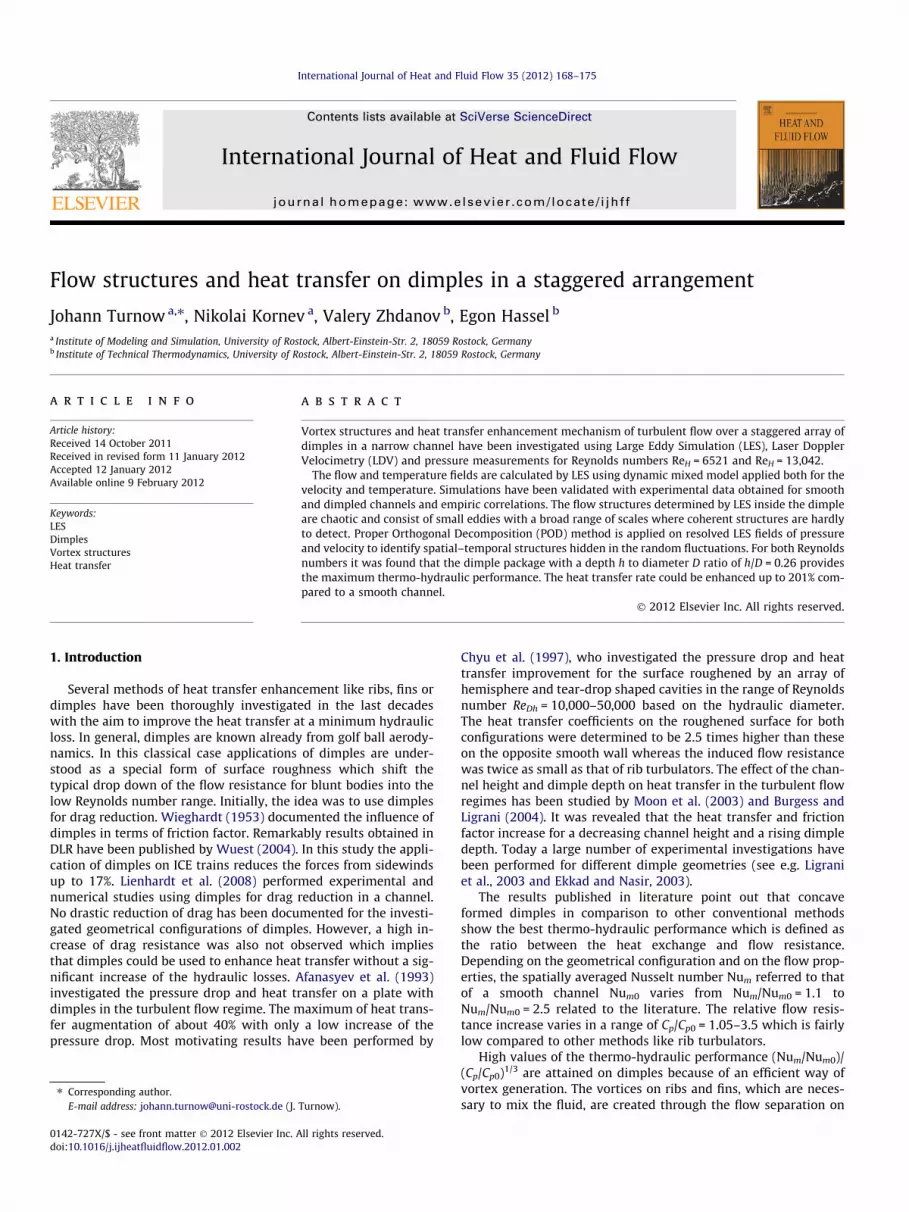
Fig. 1. Computational domain of the channel with dimples at the lower wall.
2. Computational methods
Large Eddy Simulations (LESs) have been performed based on a3-D finite volume method. The filtered transport equations aresolved on a non staggered Cartesian grid. The discretisation inspace and time of the quantities at the cell faces is of second orderusing central differencing scheme. The LES equations are obtainedby filtering the continuity equation, the Navier–Stokes equationsand the transport equation for the non-dimensional temperatureh at the filter width eD:
@~ui
@tþ @
~uj~ui
@xj¼ � 1
q@eP@xiþ @
@xjm@~ui
@xjþ @
~uj
@xi
� �� sij
� �ð1Þ
@~h@tþ @
~uj~h
@xj¼ @
@xj
mPr
@~h@xj� JSGS
j
" #: ð2Þ
The unclosed subgrid stress tensor sij ¼guiuj � ~ui~uj and the sub-grid contribution to the scalar dynamics JSGS
j ¼ fhuj � ~h~uj are mod-eled in terms of the filtered quantities ~ui and ~h, using the localizeddynamic mixed model (LDMM) on the basis of the dynamic model
proposed by Zang et al. (1993). In Eq. (2) the non-dimensional tem-perature h is defined as h = T � Tlowerwall/(Tlowerwall � Tupperwall) andfurther treated as a passive scalar without buoyancy effects. Themolecular Prandtl number Pr was set to Pr = 0.7, whereas the turbu-lent viscosity lt and the turbulent Prandtl number Prt are deter-mined dynamically using LDMM. Investigations revealed that thechosen SGS model (LDMM) shows fairly good agreement with mea-surements in respect to heat transfer and recirculating flows in con-trast to other SGS models (see Turnow, 2011).
Since the whole dimple package starting from the first row withan uniform inflow cannot be simulated using LES due to restrictedcomputer resources, only a part of dimples located within the fullydeveloped flow has been considered (Fig. 1). It should be noted thatthe domain size should be chosen carefully to capture typical flowstructures. In the most of the previous works, time resolved calcula-tions of heat exchangers with dimples or protrusions have been per-formed in a domain containing either a half or only one wholedimple using periodic conditions in streamwise and spanwise direc-tions. To our opinion this domain size is not sufficient because thetypical vortex structures can be larger than the dimple diameterwhat results in a significant degradation of accuracy of numericalsimulations even for the integral values. Therefore, an extended do-main (presented in Fig. 1) with a dimension 4.66H � H � 4.66H,where H is the channel height, including several dimples was cho-sen to guarantee capturing the largest flow structures. While thediameter D of the dimple with a sharp edge was kept constant atD = 23 mm, three dimple depths h of h/D = 0.196, h/D = 0.26 and h/D = 0.326 have been studied. Periodic boundary conditions havebeen applied in streamwise and spanwise directions. No slip wallconditions were enforced on the lower and the upper solid wallsfor the velocity. The temperature was fixed at the lower (hot surface,h = 1) and the upper (cold surface, h = 0) channel walls. To drive theflow with a constant massflow rate, the overall losses are calculatedwithin the domain and simply added as driving force to the momen-tum equation at every time instant.
3. Experimental setup
Experimental investigations have been performed in a closedwater loop channel for isothermal conditions presented in Fig. 2.
Main parts of the test rig are the head tank with an overflowweir inside, a settling chamber, the converging nozzle (contrac-tion) followed by the test section and a back tank with a meteringsystem. Further a water reservoir, main pump, pipelines and fourcontrolling valves are placed between each device to ensure stablewater levels. Water is pumped from the reservoir into the headtank by the main pump which can be additionally tuned to controlthe mass flow rate. A weir is installed inside the main tank to

Fig. 2. Flow chart and sketch of the experimental bench.
Table 1Different grid resolutions for LES of turbulent flow in aplane channel.
Mesh Nx � Ny � Nz
D1 128 � 64 � 128D2 256 � 80 � 256
170 J. Turnow et al. / International Journal of Heat and Fluid Flow 35 (2012) 168–175
reduce turbulence caused by the water pump. In addition, an over-flow pipe is placed at a predefined height into the head tank to pro-vide a constant water level. The advantage of this set-upconstruction is that a constant water level is ensured in the headtank providing flow with a constant flow rate and a low level ofturbulence inside the test section. The rectangular test channelsection behind the converging nozzle has the dimension in termsof channel width B, channel height H and total length L ofB � H � L = 200 mm � 15 mm � 1340 mm. The test section wasmade of acrylic glass to provide visual access. Thirty rows of dim-ples with a print diameter of D = 23 mm and depth of h = 6 mmhave been drilled in a staggered arrangement and then polishedby a CNC machine on the lower channel wall. The first row wasplaced at 500 mm behind the inlet of the test section.
Twelve bore holes have been drilled along the centerline of thetest section to measure the static pressure drop for the smooth anddimpled channel. The static pressure decrease have been measuredusing micro piezo-resistance electronic sensors of the membranetype. The resistance of the electronic elements brought on the mem-brane is changed due to mechanical stresses caused by the flow pres-sure and is transmitted from the pinhole on the dimpled surfacethrough a conducting rigid tube to the membrane with the innerdiameter of 0.8 mm. Hence, the sensor has a relatively high spatialresolution whereas the sensitivity is 1 mV/Pa with an error less than0.1%. Laser Doppler Velocimetry (LDV) technique as non-intrusivemethod is applied to measure the velocity profiles inside the test sec-tion. The 1D Neodym-YAG Laser with a wavelength of 532 nm,12 mW power and a focal length of 400 mm was mounted on a steer-ing unit for exact positioning with an accuracy of 0.1 mm. The LDVmeasurment unit is a beam forward scattering system with a com-bined counter and tracker signal processor. The recorded signal wassampled over 10,000 times (Bursts) at each measurement point in or-der to ensure a sufficient statistic. It has to be noted that the focalpoint of the two laser beams is about 5 mm3 which is found to befairly high especially when the measuring point is located near thewall. The finite size of the control volume effects the measurementsand is particularly important close to the wall since the velocity gra-dients reach its maximum in this part of the flow field. The interpo-lation uncertainty is estimated using methods described by Ruck(1987) as ±7.2% in the points of the largest velocity gradients.
4. Results
4.1. Validation
For validation, reference and for establishment of the grid inde-pendency a series of turbulent channel flow simulations with a
dimension of 4.66H � H � 4.66H and smooth walls have been car-ried out. Two Reynolds numbers ReD = UbulkD/m = 10,000 andReD = 20,000 have been considered which are equivalent to the Rey-nolds numbers ReH = UbulkH/m = 6521 (Res = 180) and ReH = 13,042(Res = 376) based on the channel height H. The total number of gridpoints are sketched in Table 1. A grid stretching normal to the wall isused where the first grid point is located at a distance of y+ = 0.4(case D1). A small stretching factor of 4.5 (from the largest to thesmallest edge length) normal to the wall was chosen for both casesto place several grid points into the viscous sublayer. The mesh ishomogeneous in spanwise and streamwise direction.
First the obtained results for the normal stresses are comparedto the well-known DNS data published by Moser et al. (1999) atReynolds number Res = 395. Fig. 3 represents all quantities show-ing a good agreement between the LES and DNS data. Second theTable 2 summarizes the results for the skin-friction coefficient Cf
obtained from numerical simulation (case D2) and pressure mea-surements for the smooth channel. The skin-friction coefficientCf ¼ sw=ð0:5qU2
bÞ for the plane channel can be calculated by thepressure gradient �Dpw/D x = sw/(H/2). The results show excellentagreement with the empirical correlation given by Dean (1978)Cf = 0.06138 Re�1/4. To evaluate the heat transfer rates, the presentLES data is compared to empiric correlations of Gnielinsky(VDI-organization, 2003)
Nu ¼ ðn=8ÞRePr1þ 12:7
ffiffiffiffiffiffiffiffin=8
pðPr2=3 � 1Þ
ð1þ ðDh=lÞ2=3Þ ð3Þ
and Dittuis-Boelter (VDI-organization, 2003)
Nu ¼ 0:023Re0:8Pr0:4 ð4Þ
summarized in Table 3. The discrepancy does not exceed 1% whichunderlines the accuracy of the present calculations.
A block structured curvilinear grid consisting of 13,196,000 cellswas chosen on the basis of the turbulent channel flow calculationsfor further investigations of the dimpled channel shown in Fig. 1.Several studies have been carried out (not presented here) toestablish the needed grid size for an accurate representation ofthe flow physics and heat transfer. The integral values for heat
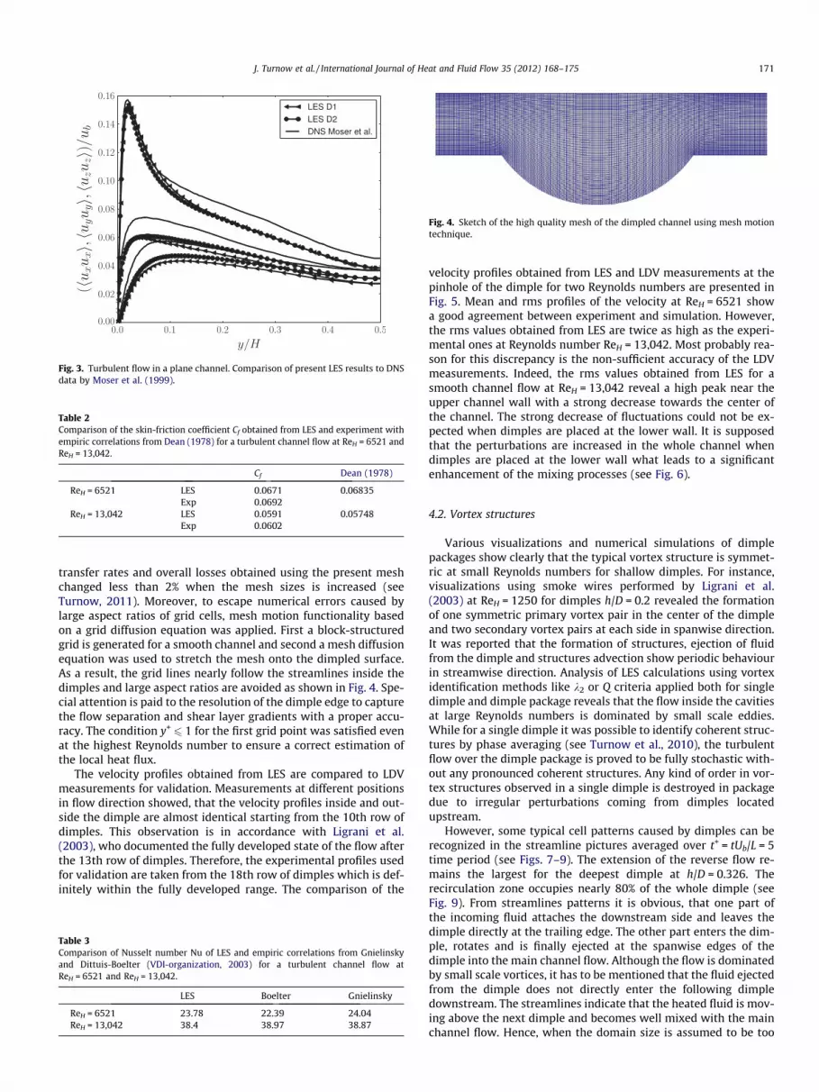
Fig. 3. Turbulent flow in a plane channel. Comparison of present LES results to DNSdata by Moser et al. (1999).
Table 2Comparison of the skin-friction coefficient Cf obtained from LES and experiment withempiric correlations from Dean (1978) for a turbulent channel flow at ReH = 6521 andReH = 13,042.
Cf Dean (1978)
ReH = 6521 LES 0.0671 0.06835Exp 0.0692
ReH = 13,042 LES 0.0591 0.05748Exp 0.0602
Fig. 4. Sketch of the high quality mesh of the dimpled channel using mesh motiontechnique.
J. Turnow et al. / International Journal of Heat and Fluid Flow 35 (2012) 168–175 171
transfer rates and overall losses obtained using the present meshchanged less than 2% when the mesh sizes is increased (seeTurnow, 2011). Moreover, to escape numerical errors caused bylarge aspect ratios of grid cells, mesh motion functionality basedon a grid diffusion equation was applied. First a block-structuredgrid is generated for a smooth channel and second a mesh diffusionequation was used to stretch the mesh onto the dimpled surface.As a result, the grid lines nearly follow the streamlines inside thedimples and large aspect ratios are avoided as shown in Fig. 4. Spe-cial attention is paid to the resolution of the dimple edge to capturethe flow separation and shear layer gradients with a proper accu-racy. The condition y+
6 1 for the first grid point was satisfied evenat the highest Reynolds number to ensure a correct estimation ofthe local heat flux.
The velocity profiles obtained from LES are compared to LDVmeasurements for validation. Measurements at different positionsin flow direction showed, that the velocity profiles inside and out-side the dimple are almost identical starting from the 10th row ofdimples. This observation is in accordance with Ligrani et al.(2003), who documented the fully developed state of the flow afterthe 13th row of dimples. Therefore, the experimental profiles usedfor validation are taken from the 18th row of dimples which is def-initely within the fully developed range. The comparison of the
Table 3Comparison of Nusselt number Nu of LES and empiric correlations from Gnielinskyand Dittuis-Boelter (VDI-organization, 2003) for a turbulent channel flow atReH = 6521 and ReH = 13,042.
LES Boelter Gnielinsky
ReH = 6521 23.78 22.39 24.04ReH = 13,042 38.4 38.97 38.87
velocity profiles obtained from LES and LDV measurements at thepinhole of the dimple for two Reynolds numbers are presented inFig. 5. Mean and rms profiles of the velocity at ReH = 6521 showa good agreement between experiment and simulation. However,the rms values obtained from LES are twice as high as the experi-mental ones at Reynolds number ReH = 13,042. Most probably rea-son for this discrepancy is the non-sufficient accuracy of the LDVmeasurements. Indeed, the rms values obtained from LES for asmooth channel flow at ReH = 13,042 reveal a high peak near theupper channel wall with a strong decrease towards the center ofthe channel. The strong decrease of fluctuations could not be ex-pected when dimples are placed at the lower wall. It is supposedthat the perturbations are increased in the whole channel whendimples are placed at the lower wall what leads to a significantenhancement of the mixing processes (see Fig. 6).
4.2. Vortex structures
Various visualizations and numerical simulations of dimplepackages show clearly that the typical vortex structure is symmet-ric at small Reynolds numbers for shallow dimples. For instance,visualizations using smoke wires performed by Ligrani et al.(2003) at ReH = 1250 for dimples h/D = 0.2 revealed the formationof one symmetric primary vortex pair in the center of the dimpleand two secondary vortex pairs at each side in spanwise direction.It was reported that the formation of structures, ejection of fluidfrom the dimple and structures advection show periodic behaviourin streamwise direction. Analysis of LES calculations using vortexidentification methods like k2 or Q criteria applied both for singledimple and dimple package reveals that the flow inside the cavitiesat large Reynolds numbers is dominated by small scale eddies.While for a single dimple it was possible to identify coherent struc-tures by phase averaging (see Turnow et al., 2010), the turbulentflow over the dimple package is proved to be fully stochastic with-out any pronounced coherent structures. Any kind of order in vor-tex structures observed in a single dimple is destroyed in packagedue to irregular perturbations coming from dimples locatedupstream.
However, some typical cell patterns caused by dimples can berecognized in the streamline pictures averaged over t+ = tUb/L = 5time period (see Figs. 7–9). The extension of the reverse flow re-mains the largest for the deepest dimple at h/D = 0.326. Therecirculation zone occupies nearly 80% of the whole dimple (seeFig. 9). From streamlines patterns it is obvious, that one part ofthe incoming fluid attaches the downstream side and leaves thedimple directly at the trailing edge. The other part enters the dim-ple, rotates and is finally ejected at the spanwise edges of thedimple into the main channel flow. Although the flow is dominatedby small scale vortices, it has to be mentioned that the fluid ejectedfrom the dimple does not directly enter the following dimpledownstream. The streamlines indicate that the heated fluid is mov-ing above the next dimple and becomes well mixed with the mainchannel flow. Hence, when the domain size is assumed to be too
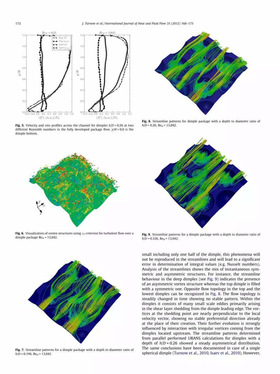
Fig. 5. Velocity and rms profiles across the channel for dimples h/D = 0.26 at twodifferent Reynolds numbers in the fully developed package flow. y/H = 0.0 is thedimple bottom.
Fig. 6. Visualization of vortex structures using k2-criterion for turbulent flow over adimple package ReH = 13,042.
Fig. 7. Streamline patterns for a dimple package with a depth to diameter ratio ofh/D = 0.196, ReH = 13,042.
Fig. 8. Streamline patterns for dimple package with a depth to diameter ratio ofh/D = 0.26, ReH = 13,042.
Fig. 9. Streamline patterns for a dimple package with a depth to diameter ratio ofh/D = 0.326, ReH = 13,042.
172 J. Turnow et al. / International Journal of Heat and Fluid Flow 35 (2012) 168–175
small including only one half of the dimple, this phenomena willnot be reproduced in the streamlines and will lead to a significanterror in determination of integral values (e.g. Nusselt numbers).Analysis of the streamlines shows the mix of instantaneous sym-metric and asymmetric structures. For instance, the streamlinebehaviour in the deep dimples (see Fig. 9) indicates the presenceof an asymmetric vortex structure whereas the top dimple is filledwith a symmetric one. Opposite flow topology in the top and thelowest dimples can be recognized in Fig. 8. The flow topology issteadily changed in time showing no stable pattern. Within thedimples it consists of many small scale eddies primarily arisingin the shear layer shedding from the dimple leading edge. The vor-tices at the shedding point are nearly perpendicular to the localvelocity vector, showing no stable preferential direction alreadyat the place of their creation. Their further evolution is stronglyinfluenced by interaction with irregular vortices coming from thedimples located upstream. The streamline patterns determinedfrom parallel performed URANS calculations for dimples with adepth of h/D = 0.26 showed a steady asymmetrical distribution.The same conclusions have been documented in case of a singlespherical dimple (Turnow et al., 2010, Isaev et al., 2010). However,

J. Turnow et al. / International Journal of Heat and Fluid Flow 35 (2012) 168–175 173
this finding has not been confirmed in LES computations for theflow over a dimple package. LES results reveal an unsteadystochastic flow behaviour which shows a fully symmetric charac-ter. The LES results sound to be more realistic. If any steady asym-metric structures would exists as predicted from URANScalculations, the velocity distribution should be also asymmetricin experiments and LES within each dimple. However, the meanprofiles obtained from LES and experiment show a symmetriccharacter. This fact is confirmed by a nearly symmetric distributionof time averaged velocity profiles at y/H = 0.5 in transversal direc-tion (see Fig. 10) obtained from LES and LDV measurements. Toconclude, no stable stationary symmetric or asymmetric vortexstructures could be found for turbulent flow over dimple packages.The symmetric primary vortex pair in the center of the dimple andtwo secondary vortex pairs at each side proposed by Ligrani et al.(2003) at ReH = 1250 for dimples with a ratio of h/D = 0.2 havenot been observed for the turbulent flow regime. In contrast toLES, the URANS technique predicts non realistic flow behaviour.
4.3. Flow resistance and heat transfer
Table 4 illustrates the influence of the relative dimple depth andReynolds number on the pressure coefficient Cp, friction coefficientCf and the overall heat transfer enhancement Num obtained fromLES. The pressure coefficient Cp is calculated by the mean pressuregradient in streamwise direction. It balances the overall losses. Forthe smooth channel it can be derived according to �dp/dx = sw/(H/2). The friction coefficient Cf summarizes the wall-shear stress sw
integrated over the dimpled surface. The coefficients Cp and Cf andas well the integral Nusselt number Num obtained for the dimpledsurface are normalized by the corresponding values of a smoothchannel denoted with the subscript 0. The heat transfer rates arecompared to measurements of Ligrani et al. (2003) to determinethe reliability of the obtained results. The integral Nusselt
Fig. 10. Time averaged velocity profiles at y/H = 0.4 in spanwise direction ath/D = 0.26 using LES method and experiment.
Table 4Pressure coefficient Cp, friction coefficient Cf and integral Nusselt number Num fordifferent dimple depths at ReH = 6521 and ReH = 13,042.
h/D 0.196 0.26 0.326
ReH = 6521 Num/Num0 1.62 1.93 1.46Cp/Cp0 2.4 2.89 3.41Cf/Cf0 0.94 0.86 0.82
ReH = 13,042 Num/Num0 1.75 2.01 1.52Cp/Cp0 2.83 3.03 3.81Cf/Cf0 0.79 0.67 0.61
number Num/Num0 = 1.93 at ReH = 13,042 for dimples with a ratioh/D = 0.26 from LES agrees well with the value of Num/Num0 = 1.83proposed by Ligrani et al. (2003) for a Reynolds numberReH = 10200 and a ratio h/D = 0.22. Pressure measurements haveonly been performed for dimples with a ratio h/D = 0.26 due to highmechanical effort to build up the test section for the dimple packageincluding 165 dimples. Measurements showed discrepancies to LESfor the pressure resistance coefficient Cp. The pressure coefficientreferred to the smooth channel is experimentally determined asCp/Cp0 = 3.49 for a Reynolds number ReH = 6521 and Cp/Cp0 = 3.69at ReH = 13,042. These values are higher than Cp/Cp0 = 2.89 atReH = 6521 and Cp/Cp0 = 3.03 at ReH = 13,042 obtained from LES.Table 5 summarizes the results.
While the results for the value Cp obtained from our measure-ments and numerical simulations are in the same range, the resultsreported by Ligrani et al. (2003) are significantly lower. Accordingto Ligrani et al. (2003), the ratio of flow resistance Cp/Cp0 is approx-imately 1.5 at a Reynolds number ReH = 10,200 and a ratioh/D = 0.22. Similar discrepancies with measurements performedby Ligrani et al. (2003) have been reported by Elyyan et al.(2007). Therefore, the good agreement of the heat transfer ratesand the large discrepancies for the flow resistance are somewhatcontradictory. However, the LES used in this work shows excellentagreement with empiric correlations both for the flow resistanceand for the heat transfer rates in a flat channel. Since our pressuremeasurements correlate with the LES simulations, they seem to bemore reliable than the measurements of Ligrani et al. (2003).
The results show that the resistance is approximately threetimes higher compared to a smooth channel at Reynolds numberReH = 13,042. The smallest resistance Cp/Cp0 = 2.83 is documentedfor the most shallow dimple at h/D = 0.196. When h/D increases,the resistance grows attaining the maximum value of Cp/Cp0 = 3.81 at h/D = 0.326. The same tendency is determined forthe lower Reynolds number ReH = 6521. In contrast to the overallresistance, the friction coefficient Cf is getting smaller when thedimple depth is increased. The reason for this decay can be foundin the formation of a recirculation zone which is fairly enlarged fora rising dimple depth. The velocity inside the recirculation zone islowered reducing the friction coefficient compared to the values ofan equivalent smooth wall.
The highest heat transfer rates can be found at the downstreamside of the dimple where the cold flow attaches the dimple surface(see Fig. 11). For the deep dimples it can be up to eight times higherthan that of a smooth channel at the trailing edge. Nevertheless,the effect of the dimple depth increase on the heat transfer is notstraightforward. The Nusselt number increases from Nu/Nu0 = 1.75 to Nu/Nu0 = 2.1 and then drops down to Nu/Nu0 = 1.52(see the Table 4) for an increasing dimple depth at ReH = 13,042.It attains its maximum of Num/Num0 = 2.01 at the ratio h/D = 0.26.The thermo-hydraulic performance Num/Num0/(Cp/Cp0)1/3 showsthe best results for dimples with a depth to diameter ratio ofh/D = 0.26 which is in accordance with that known from the liter-ature (see Ligrani et al., 2003). Thus, the overall heat transferenhancement can reach about 201% using an appropriate dimplepackage. The result can be explained using numerical simulationdata as follows. LES calculations showed that the vortices gener-ated in the shear layer between the recirculating flow and main
Table 5Comparison of pressure coefficients Cp obtained from measurements and LES fordimples with a ratio h/D = 0.26 at different Reynolds numbers ReH = 6521 andReH = 13,042.
LES Exp
ReH = 6521 Cp/Cp0 2.89 3.49ReH = 13,042 Cp/Cp0 3.03 3.69
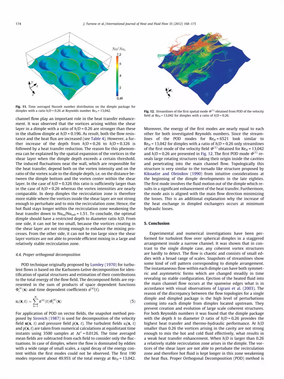
Fig. 12. Streamlines of the first spatial mode U(1) obtained from POD of the velocityfield at ReH = 13,042 for dimples with a ratio of h/D = 0.26.
Fig. 11. Time averaged Nusselt number distribution on the dimple package fordimples with a ratio h/D = 0.26 at Reynolds number ReH = 13,042.
174 J. Turnow et al. / International Journal of Heat and Fluid Flow 35 (2012) 168–175
channel flow play an important role in the heat transfer enhance-ment. It was observed that the vortices arising within the shearlayer in a dimple with a ratio of h/D = 0.26 are stronger than thesein the shallow dimple at h/D = 0.196. As result, both the flow resis-tance and the heat flux are increased (see Table 4). However, a fur-ther increase of the depth from h/D = 0.26 to h/D = 0.326 isfollowed by a heat transfer reduction. The reason for this phenom-ena can be explained by the spatial expansion of the vortices in theshear layer when the dimple depth exceeds a certain threshold.The induced fluctuations near the wall, which are responsible forthe heat transfer, depend both on the vortex intensity and on theratio of the vortex scale to the dimple depth, i.e. on the distance be-tween the dimple bottom and the vortex center within the shearlayer. In the case of h/D = 0.326 this ratio is sufficiently larger thanin the case of h/D = 0.26 whereas the vortex intensities are nearlycomparable. In deep dimples the recirculation zone is thereforemore stable where the vortices inside the shear layer are not strongenough to perturbate and to mix the recirculation zone. Hence, thehot fluid stays longer within the recirculation zone weakening theheat transfer down to Num/Num0 = 1.51. To conclude, the optimaldimple should have a restricted depth to diameter ratio h/D. Fromone side, it can not be too small, because the vortices creating inthe shear layer are not strong enough to enhance the mixing pro-cesses. From the other side, it can not be too large since the shearlayer vortices are not able to provide efficient mixing in a large andrelatively stable recirculation zone.
4.4. Proper orthogonal decomposition
POD technique originally proposed by Lumley (1970) for turbu-lent flows is based on the Karhunen-Leòve decomposition for iden-tification of spatial structures and estimation of their contributionsto the total energy of the flow field. The decomposed fields are rep-resented in the sum of products of space dependent functionsUðnÞi ðxÞ and time dependent coefficients a(n)(t).
uiðx; tÞ ¼XN
n¼1
aðnÞðtÞUðnÞi ðxÞ ð5Þ
For application of POD on vector fields, the snapshot method pro-posed by Sirovich (1987) is used for decomposition of the velocityfield u(x, t) and pressure field p(x, t). The turbulent fields ui(x, t)and p(x, t) are taken from numerical calculations at equidistant timeinstants using 3500 samples at Dt+ = 0.0126. The time averagedmean fields are subtracted from each field to consider only the fluc-tuations. In case of dimples, where the flow is dominated by eddieswith a wide range of small scales, a rapid decay of the energy con-tent within the first modes could not be observed. The first 190modes represent about 49.95% of the total energy at ReH = 13,042.
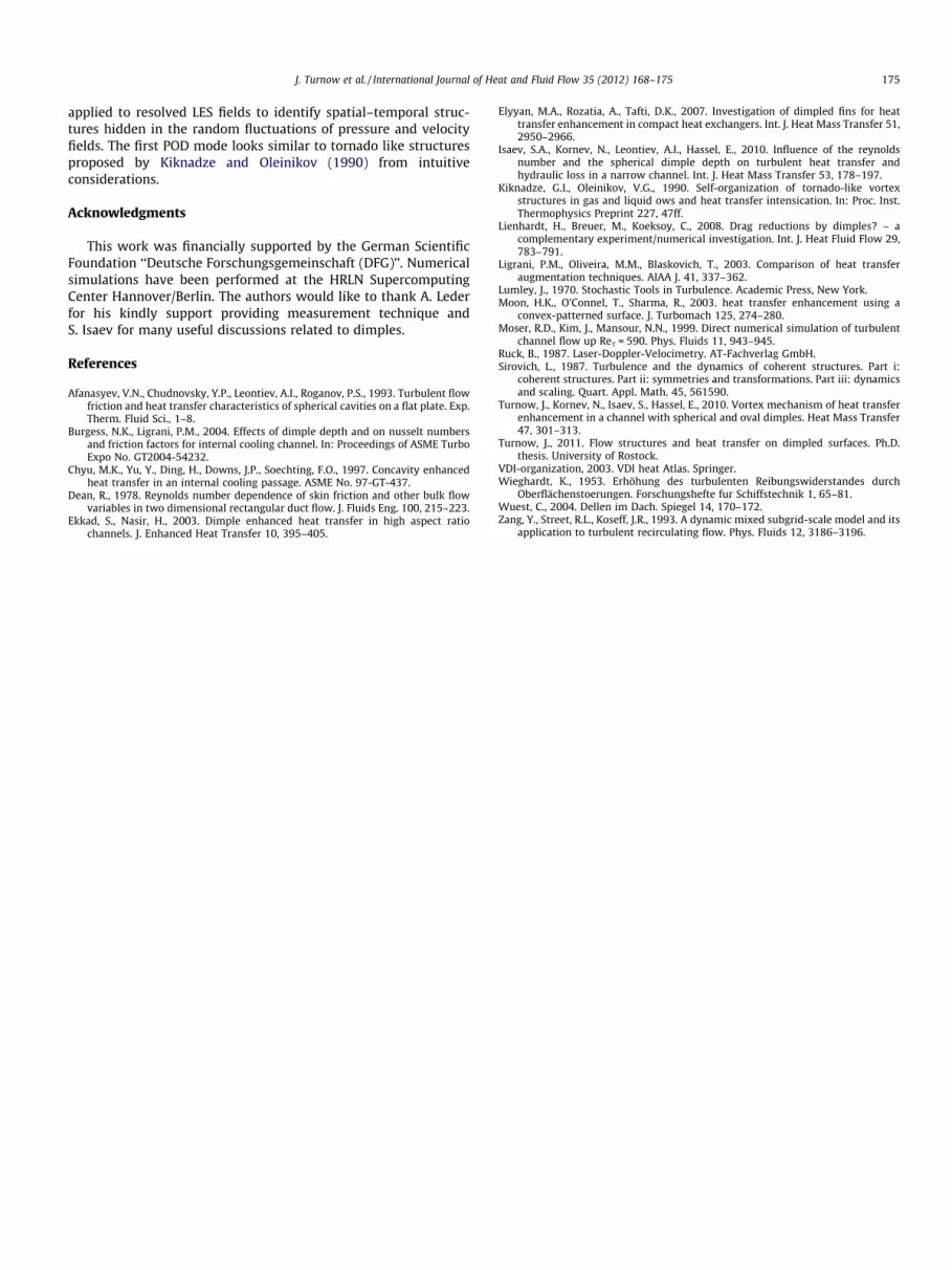
Moreover, the energy of the first modes are nearly equal to eachother for both investigated Reynolds numbers. Since the stream-lines of the POD modes for ReH = 6521 look similar toReH = 13,042 for dimples with a ratio of h/D = 0.26 only streamlinesof the first mode of the velocity field U(1) obtained for ReH = 13,042and h/D = 0.26 are presented in Fig. 12. The first POD mode U(1) re-veals large rotating structures taking their origin inside the cavitiesand penetrating into the main channel flow. Topologically thisstructure is very similar to the tornado like structure proposed byKiknadze and Oleinikov (1990) from intuitive considerations atthe beginning of the dimple developments in the late eighties.The first mode involves the fluid motion out of the dimple which re-sults in a significant enhancement of the heat transfer. Furthermore,the mode axis is aligned with the main flow direction minimizingthe losses. This is an additional explanation why the increase ofthe heat exchange in dimpled exchangers occurs at minimumhydraulic losses.
5. Conclusion
Experimental and numerical investigations have been per-formed for turbulent flow over spherical dimples in a staggeredarrangement inside a narrow channel. It was shown that in con-trast to the single dimple case, any coherent vortex structuresare hardly to detect. The flow is chaotic and consists of small ed-dies with a broad range of scales. Snapshots of streamlines showsome kind of cell pattern corresponding to dimple arrangement.The instantaneous flow within each dimple can have both symmet-ric and asymmetric forms which are changed steadily in timerevealing no stable configuration. Ejection of the heated fluid intothe main channel flow occurs at the spanwise edges what is inaccordance with visual observations of Ligrani et al. (2003). Thereason of the discrepancy between the flow topologies for a singledimple and dimpled package is the high level of perturbationscoming into each dimple from dimples located upstream. Theyprevent creation and evolution of large scale coherent structures.For both Reynolds numbers it was found that the dimple packagewith the depth h to diameter D ratio of h/D = 0.26 provides thehighest heat transfer and thermo-hydraulic performance. At h/Dsmaller than 0.26 the vortices arising in the cavity are not strongenough to mix the hot and cold fluid effectively, what results ina weak heat transfer enhancement. When h/D is larger than 0.26a relatively stable recirculation zone arises in the dimple. The vor-tices of the shear layer are not able to pertubate the recirculationzone and therefore hot fluid is kept longer in this zone weakeningthe heat flux. Proper Orthogonal Decomposition (POD) method is
J. Turnow et al. / International Journal of Heat and Fluid Flow 35 (2012) 168–175 175
applied to resolved LES fields to identify spatial–temporal struc-tures hidden in the random fluctuations of pressure and velocityfields. The first POD mode looks similar to tornado like structuresproposed by Kiknadze and Oleinikov (1990) from intuitiveconsiderations.
Acknowledgments
This work was financially supported by the German ScientificFoundation ‘‘Deutsche Forschungsgemeinschaft (DFG)’’. Numericalsimulations have been performed at the HRLN SupercomputingCenter Hannover/Berlin. The authors would like to thank A. Lederfor his kindly support providing measurement technique andS. Isaev for many useful discussions related to dimples.
References
Afanasyev, V.N., Chudnovsky, Y.P., Leontiev, A.I., Roganov, P.S., 1993. Turbulent flowfriction and heat transfer characteristics of spherical cavities on a flat plate. Exp.Therm. Fluid Sci., 1–8.
Burgess, N.K., Ligrani, P.M., 2004. Effects of dimple depth and on nusselt numbersand friction factors for internal cooling channel. In: Proceedings of ASME TurboExpo No. GT2004-54232.
Chyu, M.K., Yu, Y., Ding, H., Downs, J.P., Soechting, F.O., 1997. Concavity enhancedheat transfer in an internal cooling passage. ASME No. 97-GT-437.
Dean, R., 1978. Reynolds number dependence of skin friction and other bulk flowvariables in two dimensional rectangular duct flow. J. Fluids Eng. 100, 215–223.
Ekkad, S., Nasir, H., 2003. Dimple enhanced heat transfer in high aspect ratiochannels. J. Enhanced Heat Transfer 10, 395–405.
Elyyan, M.A., Rozatia, A., Tafti, D.K., 2007. Investigation of dimpled fins for heattransfer enhancement in compact heat exchangers. Int. J. Heat Mass Transfer 51,2950–2966.
Isaev, S.A., Kornev, N., Leontiev, A.I., Hassel, E., 2010. Influence of the reynoldsnumber and the spherical dimple depth on turbulent heat transfer andhydraulic loss in a narrow channel. Int. J. Heat Mass Transfer 53, 178–197.
Kiknadze, G.I., Oleinikov, V.G., 1990. Self-organization of tornado-like vortexstructures in gas and liquid ows and heat transfer intensication. In: Proc. Inst.Thermophysics Preprint 227, 47ff.
Lienhardt, H., Breuer, M., Koeksoy, C., 2008. Drag reductions by dimples? – acomplementary experiment/numerical investigation. Int. J. Heat Fluid Flow 29,783–791.
Ligrani, P.M., Oliveira, M.M., Blaskovich, T., 2003. Comparison of heat transferaugmentation techniques. AIAA J. 41, 337–362.
Lumley, J., 1970. Stochastic Tools in Turbulence. Academic Press, New York.Moon, H.K., O’Connel, T., Sharma, R., 2003. heat transfer enhancement using a
convex-patterned surface. J. Turbomach 125, 274–280.Moser, R.D., Kim, J., Mansour, N.N., 1999. Direct numerical simulation of turbulent
channel flow up Res = 590. Phys. Fluids 11, 943–945.Ruck, B., 1987. Laser-Doppler-Velocimetry. AT-Fachverlag GmbH.Sirovich, L., 1987. Turbulence and the dynamics of coherent structures. Part i:
coherent structures. Part ii: symmetries and transformations. Part iii: dynamicsand scaling. Quart. Appl. Math. 45, 561590.
Turnow, J., Kornev, N., Isaev, S., Hassel, E., 2010. Vortex mechanism of heat transferenhancement in a channel with spherical and oval dimples. Heat Mass Transfer47, 301–313.
Turnow, J., 2011. Flow structures and heat transfer on dimpled surfaces. Ph.D.thesis. University of Rostock.
VDI-organization, 2003. VDI heat Atlas. Springer.Wieghardt, K., 1953. Erhöhung des turbulenten Reibungswiderstandes durch
Oberflächenstoerungen. Forschungshefte fur Schiffstechnik 1, 65–81.Wuest, C., 2004. Dellen im Dach. Spiegel 14, 170–172.Zang, Y., Street, R.L., Koseff, J.R., 1993. A dynamic mixed subgrid-scale model and its
application to turbulent recirculating flow. Phys. Fluids 12, 3186–3196.