experimental investigation of bistable winglets to enhance wing lift takeoff capability
TRANSCRIPT
Experimental Investigation of Bistable Winglets to EnhanceWing Lift Takeoff Capability
A. Gatto∗
Brunel University, Uxbridge, Middlesex, England, UB8 3PH, United Kingdom
and
F. Mattioni† and M. I. Friswell‡
University of Bristol, Bristol, England, BS8 1TR, United Kingdom
DOI: 10.2514/1.39614
An experimental investigation into the use of a bistable winglet to enhance the lift characteristics of a wing
transitioning from lower to higher subsonicflow speeds is presented in this paper. The concept centers around the use
of a specifically designed composite winglet, manufactured with an unsymmetric layup, which, when increasingly
loaded, snaps between two stable states. Initially, during low-speed operation, the winglet is fixed in one stable state
that is specifically designed to be cambered, thus enhancing the lift capability of the wing. At higher dynamic
pressures, the winglet snaps to a configuration more intuitive and conventional to current winglet design. Results
presented in this paper show the concept to be viable at enhancing the lift produced by a swept wing as aerodynamic
loading increases before snap-through. During snap-through, however, the absence of anymethod of controlling the
snap-through process generated significant dynamic loading that was transmitted, unhindered, throughout the
entire test rig.
Nomenclature
b = wing span, mCD = drag coefficientCL = lift coefficientCY = side force coefficientCl = rolling moment coefficientCm = pitching moment coefficientCn = yawing moment coefficientcroot, ctip = root and tip chords, mh = winglet heightS = wing area, m2
V = freestream velocity, m � s�1� = angle of attack, deg� = cant angle, measured as dihedral angle relative to
wing plane, deg� = sweep angle, deg
Subscripts
bs = before snapmax = maximummin = minimumrms = root mean squaretip = tip spanwise locationwl = winglet
I. Introduction
A CONCERTED effort currently exists in the aerospacecommunity to develop morphing aircraft systems and
technologies [1–7]. Morphing may be broadly defined as the real-
time in-flight adaptability of aircraft systems to optimize andconfigure themselves to achieve maximum efficiency over a widerange of flight regimes. The primary impetus for this effort is theincreased cost-effectiveness that one platform brings to varioustheaters of operation: high-speed dash for ground and air attack,loiter for surveillance and reconnaissance, or high-lift for takeoff andlanding. With these desired but demanding characteristics formorphing aircraft and the use of composite materials firmlyembedded in modern aircraft structural design, it is of no greatsurprise that increasing trends toward developing synergeticsymbiotic applications of these two technologies currently exist.This combination of adaptability with high strength/weight aircraftstructures, if successful, clearly presents significant advancementsfor future aircraft configurations.
Unfortunately, however, the use of composite materials within thebroad application of morphing technologies presents significantchallenges to the aircraft designer and engineer. Althoughapplications do exist [4,8,9], various problems ranging fromacceptablemethods of actuation [5] and/or power consumption [8,9],achievable and reliable control [10], and substandard performancewhen compared with existing methods and/or tailorable structuralstiffness/compliancy [11,12] can be just some examples of limitingfactors. Another important aspect of integrating these technologies inmorphing aircraft is that morphing aircraft dynamically change statein flight. This particular characteristic does infer a degree ofstructural compliancy, which can also introduce significantsecondary aeroelastic challenges such as wing flutter.
One critical phase of flight for any aircraft, morphing or otherwise,is the initial takeoff configuration (principally considered in thispaper). In this state, the aircraft weight can be near its maximum,often requiring, particularly for large commercial aircraft, a runwayof substantial length to take off safely [13]. For this particularcategory of modern aircraft, assistance in this phase of the flightenvelope is generally provided through the use of deployable slatsand flaps that temporarily increase the camber of the wing, therebygenerating substantial lift augmentationwhen comparedwith normalcruising conditions [14–17]. Unfortunately, however, systems suchas these are intrinsically bulky and, due to the need for complexarrangements [18] and/or multiple redundancies, particularly heavy.In fact, the inclusion of one of these systems into a commercialaircraft can add up to 6–10% to the overall wing weight alone [19]. Itis for primarily these reasons that alternative methods for generating
Received 9 July 2008; accepted for publication 16 December 2008.Copyright © 2008 by A. Gatto. Published by the American Institute ofAeronautics andAstronautics, Inc., with permission. Copies of this papermaybe made for personal or internal use, on condition that the copier pay the$10.00 per-copy fee to the Copyright Clearance Center, Inc., 222 RosewoodDrive, Danvers, MA 01923; include the code 0021-8669/09 $10.00 incorrespondence with the CCC.
∗Lecturer in Aerospace Engineering, Department of MechanicalEngineering. Member AIAA.
†Marie Curie Research Assistant, Department of Aerospace Engineering.‡Sir George White Professor, Department of Aerospace Engineering.
JOURNAL OF AIRCRAFT
Vol. 46, No. 2, March–April 2009
647

this lift augmentation capability are eagerly sought by aircraftdesigners and manufacturers.
In this paper, the authors present a concept (Fig. 1) that seeks tomerge the two areas of composite materials and morphing aircraft.The concept involves the use of a bistable winglet for liftaugmentation at low flight speeds (before takeoff), which has theability to change to another, more intuitive, winglet configuration[20] at higher flight speeds (climb/cruise). In the transitional region,the winglet is designed to snap, passively, from the first stable state tothe second using only the increased aerodynamic loading on thewinglet as the dynamic pressure, and/or angle of attack, increases.Among the results presented are the real-time responses of the sweptwing and composite winglet to aerodynamic loading before, during,and after the snap process. Overall, these results show the concept’sviability and present a firm foundation for future consideration anddevelopment.
II. Design and Analysis of Selected CompositeWinglet Configurations
Fundamentally, bistable composites aremanufactured through theintroduction of a residual stress field into the internal structure of thelayup by two main mechanisms: prestressing the layup [21] orintroducing thermal stresses during manufacture [22]. In this paper,the latter method is employed using an unsymmetric orthotropic-lamina layup sequence. As a result of the unsymmetrical layupsequence and the laminas oriented either 0 or 90 deg, the dissimilarcoefficients of thermal expansion about the laminas’ principaldirections set up the internal structural stresses required forbistability during the cooldown phase of composite manufacture.Ultimately, the resultant laminate obtains multiple dissimilar stablestates, each having nonzero out-of-plane displacement.
Another characteristic of thermally induced bistable structures isthat the stable states set up from the manufacturing process can beengineered to be flexible and/or stiff, depending on the application.This is principally achieved through the careful and combinedselection of material properties, layup sequence, and structuralgeometry. Furthermore, bistable structures engineered in this waycan retain bistability even when constrained under certain conditions(restraining one edge, for example), giving a substantial scope ofengineering application. However, perhaps the most distinctadvantage of using bistable composites, when compared with othersmart structures, is that the required load to effect change is onlyrequired momentarily to initiate the transition (no continuous powerdrain).
The chosen planform for the desiredwinglet used in all subsequentanalysis and wind-tunnel testing is shown in Fig. 2 (bwl � 0:3 m,
croot;wl � 0:185 m, ctip;wl � 0:105 m, and �wl � 30 deg). Ulti-mately, this planform was selected to ensure seamless compatibilitywith the baseline swept-wing planform used and described inSec. III. As shown, the winglet was designed to have two separatesections: the first with bistability and the secondwithout. The secondsymmetric section was integrated into the winglet to allow ease oftransition into the baseline swept-wing-tip assembly. For the initialnumerical analysis, the three configurations shown in Fig. 2 wereconsidered before ultimately selecting and manufacturing the bestwinglet configuration for use with the wind-tunnel model. The firstconfiguration used fibers oriented parallel and perpendicular to thewinglet leading edge (LE), with the second incorporating fibersoriented parallel and perpendicular to a line bisecting the midpointsof the root and tip chord. The last, and final, configuration used fibersoriented parallel and perpendicular to a line intersecting thesymmetric and unsymmetric layup sections (Fig. 2c). To quantify theresulting shapes of these three configurations and predict subsequentbehavior, a nonlinear finite element package (ABAQUS)was used tomodel standard T300 carbon fiber prepreg, with Hexcel epoxy resin914 (properties in Table 1) selected as the default material.
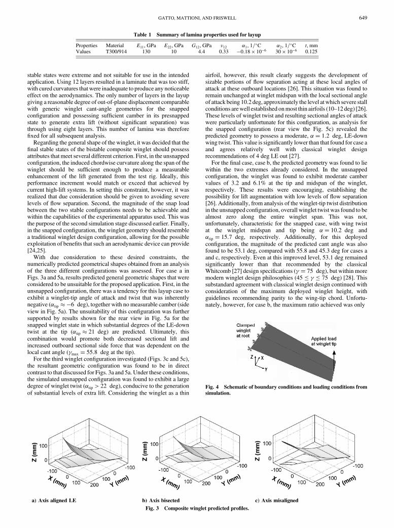
For the numerical analysis, a two-stage multistep nonlinearanalysis using standard built-in functions within ABAQUS wasapplied to all of the configurations shown in Fig. 2. For each of thesecases, the winglet panel was modeled using 336 double-curvatureshell elements (S8R) with a total of 1089 nodes. For the first stage ofthe analysis, the cooldown process of the laminate duringmanufacture was simulated, giving the predicted final geometricshapes. For this cooldown stage of the manufacturing process, thesimulation procedure involved applying a temperature difference of170�C (from nominal room temperature) with a heat-up rate of2–5�C=min to all nodes of the model. During this part of thesimulation, the plate was clamped at a point coincident with theorigin of the reference system (X � 0 and Y � 0 in Fig. 3) and at twoadditional nodes at the midpoint of the root and the tip chords, whichwere also restrained to move in the X–Y plane. These two additionalconstraints were only applied temporarily to aid in the convergenceof the numerical procedure to a stable solution. At the end of this step,the temperature field was allowed to dissipate naturally back to roomtemperature. To simulate the mechanics of the snap-through, aconcentrated force acting vertically up at the midpoint of the tipchordwas applied to the cured composite. For this second stage of theanalysis, all nodes at the root section were rigidly clamped,representing boundary conditions indicative of proposed wind-tunnel testing (Fig. 4). A vertical force was then applied at themidpoint of the tip chord, and to eliminate numerical inconsistencies,the same node was also constrained temporarily to move vertically.Before removal of this constraint, the concentrated load was rampedlinearly from 0 to 40 N to induce the snap-through, thereafter beingremoved to ensure convergence to a stable final result. Furtherinformation on the numerical procedure employed and an evaluationof this procedure using experimental results can be found in [23].
The first step taken in the numerical design of the winglet was todecide the number of lamina layers to use in the layup with thewinglet planform dimensions outlined. For this operation, theconfiguration shown in Fig. 2b was used. Layups comprising 2, 4, 8,and 12 laminas were investigated. For the 2- and 4-lamina layups,initial analysis showed that the out-of-plane displacements in both
Fig. 1 The bistable winglet concept.
Fig. 2 Composite winglet layup directions investigated.
648 GATTO, MATTIONI, AND FRISWELL
stable states were extreme and not suitable for use in the intendedapplication. Using 12 layers resulted in a laminate that was too stiff,with cured curvatures that were inadequate to produce any noticeableeffect on the aerodynamics. The only number of layers in the layupgiving a reasonable degree of out-of-plane displacement comparablewith generic winglet cant-angle geometries for the snappedconfiguration and possessing sufficient camber in its presnappedstate to generate extra lift (without significant separation) wasthrough using eight layers. This number of lamina was thereforefixed for all subsequent analysis.
Regarding the general shape of the winglet, it was decided that thefinal stable states of the bistable composite winglet should possessattributes that meet several different criterion. First, in the unsnappedconfiguration, the induced chordwise curvature along the span of thewinglet should be sufficient enough to produce a measurableenhancement of the lift generated from the test rig. Ideally, thisperformance increment would match or exceed that achieved bycurrent high-lift systems. In setting this constraint, however, it wasrealized that due consideration should be given to avoiding severelevels of flow separation. Second, the magnitude of the snap loadbetween the two stable configurations needs to be achievable andwithin the capabilities of the experimental apparatus used. This wasthe purpose of the second simulation stage discussed earlier. Finally,in the snapped configuration, the winglet geometry should resemblea traditional winglet design configuration, allowing for the possibleexploitation of benefits that such an aerodynamic device can provide[24,25].
With due consideration to these desired constraints, thenumerically predicted geometrical shapes obtained from an analysisof the three different configurations was assessed. For case a inFigs. 3a and 5a, results predicted general geometric shapes that wereconsidered to be unsuitable for the proposed application. First, in theunsnapped configuration, there was a tendency for this layup case toexhibit a winglet-tip angle of attack and twist that was inherentlynegative (�tip ��6 deg), together with no measurable camber (sideview in Fig. 5a). The unsuitability of this configuration was furthersupported by results shown for the rear view in Fig. 5a for thesnapped winglet state in which substantial degrees of the LE-downtwist at the tip (�tip � 21 deg) are predicted. Ultimately, thiscombination would promote both decreased sectional lift andincreased outboard sectional side force that was dependent on thelocal cant angle (�max � 55:8 deg at the tip).
For the third winglet configuration investigated (Figs. 3c and 5c),the resultant geometric configuration was found to be in directcontrast to that discussed for Figs. 3a and 5a. Under these conditions,the simulated unsnapped configuration was found to exhibit a largedegree of winglet twist (�tip > 22 deg), conducive to the generationof substantial levels of extra lift. Considering the winglet as a thin
airfoil, however, this result clearly suggests the development ofsizable portions of flow separation acting at these local angles ofattack at these outboard locations [26]. This situation was found toremain unchanged at winglet midspan with the local sectional angleof attack being 10.2 deg, approximately the level atwhich severe stallconditions arewell established onmost thin airfoils (10–12 deg) [26].These levels of winglet twist and resulting sectional angles of attackwere particularly unfortunate for this configuration, as analysis forthe snapped configuration (rear view the Fig. 5c) revealed thepredicted geometry to possess a moderate, �� 1:2 deg, LE-downwing twist. This value is significantly lower than that found for case aand agrees relatively well with classical winglet designrecommendations of 4 deg LE out [27].
For the final case, case b, the predicted geometry was found to liewithin the two extremes already considered. In the unsnappedconfiguration, the winglet was found to exhibit moderate cambervalues of 3.2 and 6.1% at the tip and midspan of the winglet,respectively. These results were encouraging, establishing thepossibility for lift augmentation with low levels of flow separation[26]. Additionally, from analysis of the winglet-tip twist distributionin the unsnapped configuration, overall winglet twist was found to bealmost zero along the entire winglet span. This was not,unfortunately, characteristic for the snapped case, with wing twistat the winglet midspan and tip being �� 10:2 deg and�tip � 15:7 deg, respectively. Additionally, for this deployedconfiguration, the magnitude of the predicted cant angle was alsofound to be 53.1 deg, compared with 55.8 and 45.3 deg for cases aand c, respectively. Even at this improved level, 53.1 deg remainedsignificantly lower than that recommended by the classicalWhitcomb [27] design specifications (� � 75 deg), but within moremodern winglet design philosophies (45 � � � 75 deg) [28]. Thissubstandard agreement with classical winglet design continued withconsideration of the maximum deployed winglet height, withguidelines recommending parity to the wing-tip chord. Unfortu-nately, however, for case b, the maximum ratio achieved was only
Table 1 Summary of lamina properties used for layup
Properties Material E11, GPa E22, GPa G12, GPa �12 �1, 1=�C �2, 1=
�C t, mmValues T300/914 130 10 4.4 0.33 �0:18 � 10�6 30 � 10�6 0.125
Fig. 3 Composite winglet predicted profiles.
Fig. 4 Schematic of boundary conditions and loading conditions from
simulation.
GATTO, MATTIONI, AND FRISWELL 649

hwlctip� 0:142
0:185� 0:76
(see Fig. 5b).Comparing results for the simulated reaction force vs displace-
ment for all three configurations, Fig. 6 indicates very little change inthe general behavior with changing fiber orientation. Four distinctregions of behavior are identifiable. Initially, with application of theexternal load, initial structural behavior resembles established linear-elastic structural characteristics (region i) before snap-though.Within this region, if the external load remains below a criticalloading condition, the winglet behaves like a normal linear-elasticstructure before nonlinear plastic deformation. However, withfurther increase in the loading condition, the composite entersregion ii, in which the behavior becomes increasingly nonlinear,reaching a critical snap load shortly thereafter. At this position, thecomposite initiates the change from one stable state to the other(region iii). Within this region, the magnitude of the reaction force
undergoes significant reduction and ultimately a change in sign. Atthis point, the composite now drives the change (negative structuralstiffness), rather than reacting to oppose it. Upon reaching the finalequilibrium condition at the end of region iii, further increase inapplied load results in the return of classical linear-elastic structuralbehavior, as shown in region iv.
Although similar in form, results in Fig. 6 do show subtledifferences with changes in fiber direction. For example, the reactionload required for snap-through was found to be 22.75, 25.20, and18.62 N for cases a, b, and c, respectively, representing substantialdecreases as the fiber direction is rotated both clockwise oranticlockwise from case b. Additionally, for cases a and b, theminimum reaction force was predicted at more than double thatpredicted for case c,whichwas substantial, given the small amount ofrelative fiber orientation imposed. Even so, if the maximum value of25.2 N is taken as the required snap load during wind-tunnel testing,and with the wind tunnel running at near-maximum capability(V � 40 m=s), the extra increment in lift required by the wingletplanform (Swl � 0:044 m2) to initiate the snap was calculated at�CLwl � 0:6. This value seemed reasonable and was considered tobe well within the capabilities of the test rig proposed (Sec. III).
From the preceding analysis for the three winglet configurationsinvestigated, the bistable winglet design with the fibers orientedparallel and perpendicular to a line bisecting the root and tip chords(case b) was chosen for manufacture and testing. Throughout theanalysis of all of the designs, this particular layup orientationsequence was thought to best meet the criterion imposed on thedifferent bistable geometrical configurations. Practically, thiscomposite design was the only one that gave confidence to theauthors that the efficient augmentation of lift in the unsnappedconfiguration was achievable, while still retaining some character-istics indicative of traditional winglet design in the snappedequilibrium condition. Although the predicted geometric displace-ments for the snapped case of this configurationwere found to be lessthan ideal when compared with current winglet design method-ologies, these inadequacies were tolerated to investigate the viabilityof the concept.
To manufacture the selected winglet configuration for the wind-tunnel testing phase, 8 rectangular laminas measuring 300 �
Fig. 5 Composite winglet predicted profiles; side and rear views.
Fig. 6 Details of the predicted snap dynamics.
650 GATTO, MATTIONI, AND FRISWELL
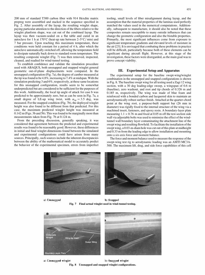
200 mm of standard T300 carbon fiber with 914 Hexdite matrixprepreg were assembled and stacked in the sequence specified inFig. 2. After assembly of the layup, the resulting winglet shape,paying particular attention to the direction of the fibers relative to thewinglet planform shape, was cut out of the combined layup. Thelayup was then vacuum-sealed on a flat table and cured in anautoclave for 1 h at 170�C (heat-up rate between 2–5�C=min) and7 bar pressure. Upon reaching this maximum temperature, theseconditions were held constant for a period of 4 h, after which theautoclave automatically switched off, allowing the temperature fieldto dissipate naturally back down to standard room temperature. Theresulting composite winglet (Fig. 7) was then removed, inspected,cleaned, and readied for wind-tunnel testing.
To establish confidence and validate the simulation procedureused with ABAQUS, both unsnapped and snapped winglet generalgeometric out-of-plane displacements were compared. In theunsnapped configuration (Fig. 7a), the degree of camber measured atthe tipwas found to be 4.8%, increasing to 7.4%atmidspan.With thesimulation predicting 3 and 6%, respectively, at these same locationsfor this unsnapped configuration, results seem to be somewhatunderpredicted but are considered to be sufficient for the purposes ofthis work. Additionally, the local tip angle of attack for case b waspredicted to be approximately zero, but as can be seen in Fig. 7a, asmall degree of LE-up wing twist, with �tip � 3:5 deg, wasmeasured. For the snapped condition (Fig. 7b), the deployed wingletheight was also found to be different from that predicted. For thiscase, the maximum predicted winglet height was measured at0.142m (Figs. 3b and 5b). Thiswas found to bemarginallymore thanmeasurements taken from Fig. 7b at 0.124 m.
From the preceding discussion, generally speaking, it wasconsidered that agreement between the predicted and experimentalresults was found to be reasonably good. However, these differencesin initial and final winglet dimensions found between the simulatedand experimental configurations could have arisen from manysources. Principally, such sources include the inherent discrepanciesbetween the ability of the mathematical model to accurately predictthe behavior of the experimental specimen, errors from imperfect
tooling, small levels of fiber misalignment during layup, and theassumption that the material properties of the laminas used perfectlymatched the values used in the numerical computations. Addition-ally, subsequent to manufacture, it should also be noted that thesecomposites remain susceptible to many outside influences that canchange the geometric configuration and also the bistable properties.Primarily, the most significant influences come from exposure tosignificant temperature gradients and elevated levels of moisture inthe air [23]. It is envisaged that combating these problems in practicewill be difficult, particularly because both of these elements can besignificant during aircraft flight. However, at this stage of theinvestigation, these factors were disregarded, as themain goal was toprove concept viability.
III. Experimental Setup and Apparatus
The experimental setup for the baseline swept-wing/wingletcombination in the unsnapped and snapped configurations is shownin Fig. 8. The baseline swept wing for all testing used a Zagi 12 wingsection, with a 30 deg leading-edge sweep, a wingspan of 0.6 m(baseline), zero washout, and root and tip chords of 0.326 m and0.185 m, respectively. The wing was made of blue foam andreinforced with a bonded carbon and lacquered skin to maintain anaerodynamically robust surface finish. Attached at the quarter-chordpoint at the wing root, a purpose-built support bar (26 mm indiameter) was rigidly fixed to the internal structure of the wing via amachined insert, fasteners, and epoxy resin. A boundary-layer platemeasuring 1:1 � 0:76 m and fixed at 0.05 m off the test-section sidewall via adjustable bolts was used to minimize the effect of the wind-tunnel wall boundary layer contaminating the attachment line of thesweptwing and resultingflowfield. To facilitate the installation of thesweptwing, a 0.03-m-diamholewas cut out of this plate atmidheightand 0.33 m from the leading edge to allow installation and mountingonto a six-axis force and moment balance.
The force andmoment balance used tomeasure the response of theswept-wing test rig to aerodynamic loading was an AMTI MC3A-500. The maximum lift, drag, and side force capabilities of this cell
Fig. 7 Final actual winglet used in wind-tunnel testing.
Fig. 8 Unsnapped and snapped winglet configurations.
GATTO, MATTIONI, AND FRISWELL 651
were rated at�1,�1, and�2 kN, with pitching, rolling, and yawingmoments specified at �56, �56, and �28 Nm, respectively. Aftercalibration, maximum errors for all six components returned beforethe wind-tunnel testing was less than �2:5%. Assessment of themaximum observed nonlinearity as well as zero drift after a rigorouspretesting program were found to be better than �0:5%. All dataobtained from the load cell was digitized through a 16-bit dSpacedata acquisition system at 1000 Hz over a period of 60 s and wasnondimensionalized with respect to the baseline (without winglet)swept-wing configuration.
The swept wing was installed at mid-test-section height inside aclosed test section (height� 1:5 m and width� 2:1 m), closed-circuit wind tunnel with amaximum operating freestream velocity of40 m=s� 1 m=s. The freestream turbulence level at the modelstation was approximately 0.2%. Under test conditions, measure-ments of all six forces and moments were taken before increasing thewind speed, which allowed the compensation of the final test resultsfor these initial conditions. To increase the aerodynamic loading onthe winglet, the wind tunnel was bought up to speed manually andsteadily by the operator until winglet snap was achieved. Thisprocess was repeated at several different angles of attack, rangingfrom 0–27.5 deg (position error�2 deg). For each of these angles ofattack, the freestream velocity at the point of winglet snap wasmeasured and recorded, giving a test Reynolds number rangebetween 2:8 � 105 and 4:8 � 105. No wind-tunnel blockagecorrections or artificial transition-inducing mechanisms were usedduring the test program.
To protect the exposed portion of the swept-wing support barbetween the wind-tunnel wall and the boundary-layer plate, a foamshroud, which encompassed the support bar completely, was fixed tothe boundary-layer plate and extended all the way across to the wind-tunnel wall. This ensured that the flow could not induce anysecondary loads on the swept-wing support bar. Upon exiting on theoutside of the wind-tunnel wall, the support bar was attached to apurpose-built manual rotation stage, which allowed adjustment ofthe angle of attack of the swept wing. This manual rotation stage wasalsomounted directly onto the force andmoment balance, whichwasconnected to a support frame fixed to the outside test-section wall(Fig. 9).
At the tip of the baseline swept wing, an insert was designed andbuilt to allow accurate and easy installation of the composite winglet.This insert was machined from nylon 6 and screwed into place usingan array of small countersunk screws. Facilitated in the design of theinsert was both a top and bottom half that used the mean camber lineof the swept-wing profile as the dividing line. Afterfixing thewingletbetween these two sections, the whole assembly was mounted insidean excavated cavity engineered into the swept-wing tip.
IV. Results and Discussion
A. Preliminary Comments
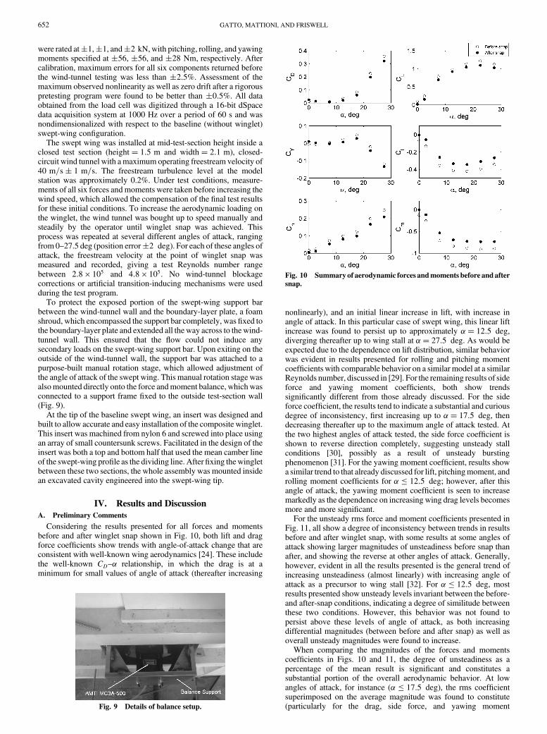
Considering the results presented for all forces and momentsbefore and after winglet snap shown in Fig. 10, both lift and dragforce coefficients show trends with angle-of-attack change that areconsistent with well-known wing aerodynamics [24]. These includethe well-known CD–� relationship, in which the drag is at aminimum for small values of angle of attack (thereafter increasing
nonlinearly), and an initial linear increase in lift, with increase inangle of attack. In this particular case of swept wing, this linear liftincrease was found to persist up to approximately �� 12:5 deg,diverging thereafter up to wing stall at �� 27:5 deg. As would beexpected due to the dependence on lift distribution, similar behaviorwas evident in results presented for rolling and pitching momentcoefficients with comparable behavior on a similar model at a similarReynolds number, discussed in [29]. For the remaining results of sideforce and yawing moment coefficients, both show trendssignificantly different from those already discussed. For the sideforce coefficient, the results tend to indicate a substantial and curiousdegree of inconsistency, first increasing up to �� 17:5 deg, thendecreasing thereafter up to the maximum angle of attack tested. Atthe two highest angles of attack tested, the side force coefficient isshown to reverse direction completely, suggesting unsteady stallconditions [30], possibly as a result of unsteady burstingphenomenon [31]. For the yawing moment coefficient, results showa similar trend to that already discussed for lift, pitchingmoment, androlling moment coefficients for � � 12:5 deg; however, after thisangle of attack, the yawing moment coefficient is seen to increasemarkedly as the dependence on increasing wing drag levels becomesmore and more significant.
For the unsteady rms force and moment coefficients presented inFig. 11, all show a degree of inconsistency between trends in resultsbefore and after winglet snap, with some results at some angles ofattack showing larger magnitudes of unsteadiness before snap thanafter, and showing the reverse at other angles of attack. Generally,however, evident in all the results presented is the general trend ofincreasing unsteadiness (almost linearly) with increasing angle ofattack as a precursor to wing stall [32]. For � � 12:5 deg, mostresults presented show unsteady levels invariant between the before-and after-snap conditions, indicating a degree of similitude betweenthese two conditions. However, this behavior was not found topersist above these levels of angle of attack, as both increasingdifferential magnitudes (between before and after snap) as well asoverall unsteady magnitudes were found to increase.
When comparing the magnitudes of the forces and momentscoefficients in Figs. 10 and 11, the degree of unsteadiness as apercentage of the mean result is significant and constitutes asubstantial portion of the overall aerodynamic behavior. At lowangles of attack, for instance (� � 17:5 deg), the rms coefficientsuperimposed on the average magnitude was found to constitute(particularly for the drag, side force, and yawing momentFig. 9 Details of balance setup.
Fig. 10 Summaryof aerodynamic forces andmoments before andafter
snap.
652 GATTO, MATTIONI, AND FRISWELL

coefficients), a component that was several times greater than themean magnitude. This result clearly outlines the unsteady nature ofthe flowfield/swept-wing combination at this Reynolds number. Athigher angles of attack (� 17:5 deg), whereas unsteadinessmagnitude increased further, this component as a percentage of theoverall magnitude was found to decrease to levels that wereapproximately 50% of the mean magnitude (Fig. 10).
B. Effect of Winglet Snap on Aerodynamic Performance
In Fig. 10, for all angles of attack tested, most aerodynamic forceand moment results show a measurable decrease in mean magnitudeafter winglet snap. From the results of lift force, the extra liftaugmentation generated by the composite winglet was found torange between 0:055 � �CL � 0:12 within the angle-of-attackrange presented (�CL � 0:12 at �� 22:5 deg). Unfortunately, atlow angles of attack of� � 7:5 degwith the change in lift coefficientbeing between 0:08 � �CL � 0:1, the performance of the bistablewinglet did not compare well with existing advanced high-liftsystems installed on swept-wing configurations (�CL � 0:6 for splitflaps and �CL � 1:5 for double-slotted flaps at low speeds and�� 0 deg) [24,26,33,34]. However, when considering the resultsfor the drag coefficient shown in Fig. 10, at low angles of attack(� � 2:5 deg), the mean drag coefficient measured after snap ismarginally more (�CD � 0:01) than that indicated before snap.Although the results clearly suggest that the winglet is outperformedby more traditional high-lift systems in the production of extra lift(not taking into account any relative weight savings from using thewinglet concept), for small angles of attack (� � 2:5 deg), resultsalso suggest that there is a small but measurable decrease in dragcoefficient (compared with the snapped configuration) before snap,most probably resulting from a combination of both the increase ineffective aspect ratio before snap (decreasing induced drag for thesame CL before and after snap) and/or an increase in winglet profiledrag after snap. Unfortunately, this trend did not persist for� 7:5 deg, with this difference in drag coefficient before and afterwinglet snap decreasing to approximately zero (�� 7:5 deg) andthereafter increasing almost linearly up to a maximum of �CD �0:028 at �� 27:5 deg.
Comparing the results for the aerodynamic moment coefficientspresented in Fig. 10 before and after snap, similar trends to thatalready described for the change in lift coefficient were evident forboth �Cl and �Cm, with almost a consistent change found for allangles of attack tested. This result was expected due to the inherent
dependency of these two moments on the lift distribution. For theserolling and pitching moment coefficients, the incremental differencein winglet performance between the unsnapped and snappedconfigurations was measured in the range of �0:076 � �Cl ��0:094 and �0:140 � �Cm � �0:178, respectively. Typicalincrements in pitching moment coefficient from the deployment ofmore traditional high-lift systems (on swept wings) can range from�Cm ��0:05 for split flaps [34] to �Cm ��0:29 for double-slotted flaps [34]. Using these results for comparison, it thereforeseems that the corrective measures required by the aircraft controlsystem during winglet deployment would be comparable with thecorrective measures required by the more advanced and complexhigh-lift systems in use today. This result, even at themoderate levelsof lift augmentation already discussed, is an unfortunateconsequence of the inherent increased moment arm when thewinglet is installed at the swept-wing tip.
Another interesting aspect of the winglet concept to consider wasthe magnitude of the freestream velocity measured at winglet snapwith increase in angle of attack (Table 2). At �� 0 deg, thefreestream velocity to snap the winglet was measured at 27 m=s.Under these conditions, the resultant aerodynamic force acts almostcoincident with a line perpendicular to the primary snapping axis ofthe winglet. As the angle of attack increased, the dynamic pressurerequired for winglet snap was shown to decrease rapidly, reaching aminimum of 16 m=s at �� 7:5 deg. At this angle of attack, therapidly increasing resultant aerodynamic force, together with the lineof action of this force remaining largely perpendicular to the primarysnap axis of the winglet, more easily generates the snapping momentrequired at a lower dynamic pressure. At higher angles of attack,however, the magnitude of the freestream velocity was found toremain constant within the region of 16–17 m=s for winglet snap,with the differential lift force generated by the winglet also showingconsistency (�CL � 0:1 in Fig. 10). This suggests conditions inwhich flow separation may have already occurred from the sharpleading edge of the winglet [26]. Ultimately, a constant value for thelift generated by the winglet would suggest that the snap velocitywould again increase from thisminimum; however, from�� 12:5 to27.5 deg, the drag force acting on the winglet increases rapidly(indicative from the results in Fig. 10), compensating somewhat forthe reduced contribution from �CLwl to snap the winglet.
C. Winglet-Snap Dynamics
To quantify the severity of this snap-through, Fig. 12 gives anexample of the dynamic responses of all six aerodynamic force andmoment coefficients of the swept-wing/composite wingletcombination as dynamic pressure increased. At first inspection, allresults show substantial degrees of increasing unsteadiness withincrease in dynamic pressure. Figure 11 quantifies this degree ofunsteadiness for the conditions just before and after snap. As can beseen from this figure, and when comparisons are made with Fig. 10,particularly for the drag and side force coefficients, the degree ofunsteadiness as a proportion of mean magnitude made thedetermination of mean values difficult and, in some cases(particularly at low angles of attack), unreliable. However, someinteresting and useful insight into the physics and mechanics of thewinglet-snap process at these levels of angle of attack could still begauged. For instance, in Fig. 12, for all results, after the initial linearincrease in aerodynamic loading (�10–40 s) after wind-onconditions, the extent of the maximum and minimum dynamicloads applied to the test rig and the speed of the transition between thetwo stable states were both found to be particularly severe. In mostcases, force and moment coefficient magnitudes at snap were morethan several hundred percent greater than the presnap or postsnap
Fig. 11 RMS aerodynamic forces and moments before and after snap.
Table 2 Summary of winglet-snap freestream velocity withangle of attack
Angle of attack, deg 0 2.5 7.5 12.5 17.5 22.5 27.5Snap velocity, m=s 27 23 16 16 17 17 16.5
GATTO, MATTIONI, AND FRISWELL 653

magnitudes. Figure 13 quantifies these results. Additionally, inFig. 13, there clearly exists an almost consistent offset between themaximum and minimum amplitudes at snap for the drag and sideforce coefficients as well as the yawing moment coefficient.However, results for the lift coefficient as well as the rolling andpitching moment coefficients indicate some variation in this offset,particularly at lower angles of attack, with values for the maximumand minimum dynamic loads (when compared with the mean result)showing asymmetry toward the maximum (i.e CLmax
� 1:575,CLmin
��0:578, and CLbs � 0:243 at �� 2:5 deg).Considering the real-time responses shown in Fig. 12 more
closely, amore detailed viewof thewinglet-snap dynamics for the liftforce coefficient and all three moment coefficients is presented inFig. 14. From these subfigures, all aerodynamic parameters
presented are shown to exhibit a reduction inmagnitude to levels thatare consistent with the postsnap magnitude just before winglet snap.For the case presented in Fig. 14, this reduction began atapproximately 40.45 s and lasted 0.06 s before the full dynamiceffects of the winglet snap were initiated (40.51 s). At this instant intime, the large-amplitude dynamic loads, discussed earlier, areinitiated as the winglet moves through the snap process. Typically,the maximum and minimum loading conditions are established for0.01 s each, representing increases and decreases of up to severalhundred percent, compared with the mean values during this timeframe. After this time period in which the maximum and minimumoccur, the dynamic loads undergo characteristic damped vibrationover a period of 0.2–0.4 s before the reestablishment of the postsnapsteady-state value. The entire dynamic snap process, from initiationto the reestablishment of steady-state conditions, was found to occurover a time period of 0.45–0.5 s.
As mentioned in Sec. IV.B, although being within the typicalcorrection range for modern elevator systems during deployment, itis conceivable that, due to this speed of snap transition, the demandson the frequency response of modern elevator control systems maybe unrealistic. If this is indeed the case, the integration of the bistablewinglets onto an aircraft wing in this pure form would clearlyrepresent an unacceptable degree of passenger discomfort as well assafe and achievable control. For the rolling and yawing moments, itwould be expected that these effects, if actuated simultaneously,would be less problematic, as the effects of a pair of winglets wouldcancel each other out. Having to correct a significant and sudden nosepitch-up moment just after takeoff, after winglet snap, poses a muchmore serious problem. Under these conditions, in which thepossibility of aircraft stall increases, it would be imperative, ifadopted, to develop system(s) that could slow, synchronize, and/orcontrol the snap process [35] as well as ensure stability after snap-through [36].
V. Conclusions
Anovel concept using a bistablewinglet to augment lift generationon a generic swept wing transitioning from lower to higher subsonicflow speeds is presented in this paper. The composite winglet, whichwas specifically designed using an unsymmetric layup sequence,was found to produce a measurable degree of lift augmentation at thefirst stable state with the span fully extended and the chordwiseprofile cambered, when comparedwith the final stable state, inwhichthe aerodynamic shape was more indicative of traditional wingletdesign. However, results also showed that during the snap-through
Fig. 12 Example of the response of the composite winglet and swept-
wing combination: �� 2:5 deg.
Fig. 13 Maximum and minimum aerodynamic forces and moments
during snap-through.
Fig. 14 Detailed response of lift force and all moments to composite
winglet snap: �� 2:5 deg.
654 GATTO, MATTIONI, AND FRISWELL

process, significant dynamic loads were produced and transmittedthroughout the entire wing structure, suggesting that additionalattenuation and/or control methodologies will be required to ensurepractical application to modern aircraft operations.
Acknowledgment
This work has been supported by a Marie-Curie excellenceresearch grant MEXT-CT-2003-002690 funded by the EuropeanCommission.
References
[1] Jha, A. K., and Kudvasmart, J. N., “Morphing Aircraft Concepts,Classifications, and Challenges,” Structures and Materials 2004:
Industrial and Commercial Applications of Smart Structures
Technologies, Proceedings of SPIE, Vol. 5388, Society of Photo-Optical Instrumentation Engineers, Bellingham, WA, Mar. 2004,pp. 213–224.
[2] Sanders, B., Eastep, F. E., and Forster, E., “Aerodynamic andAeroelastic Characteristics of Wings with Conformal Control Surfacesfor Morphing Aircraft,” Journal of Aircraft, Vol. 40, No. 1, 2003,pp. 94–99.doi:10.2514/2.3062
[3] Hall, J. M., “Executive Summary AFTI/F-111 Mission AdaptiveWing,” Wright Research and Development Center, TR-89-2083,Wright–Patterson AFB, OH, 1989.
[4] Knot, N. S., Zweber, J. V., Veley, D. E., Oz, H., and Eastep, F. E.,“Flexible Composite Wing with Internal Actuation for RollManoeuvre,” Journal of Aircraft, Vol. 39, No. 4, 2002, pp. 521–527.doi:10.2514/2.2971
[5] Johnston, C. O., Mason, W. H., Han, C., and Inman, D. J., “Actuator-Work Concepts Applied to Unconventional Aerodynamic ControlDevices,” Journal of Aircraft, Vol. 44, No. 5, 2007, pp. 1459–1468.doi:10.2514/1.26423
[6] Stanewsky, E., “Aerodynamic Benefits of Adaptive Wing Technol-ogy,”Aerospace Science and Technology, Vol. 4, No. 7, 2000, pp. 439–452.doi:10.1016/S1270-9638(00)01069-5
[7] Stanewsky, E., “Adaptive Wing and Flow Control Technology,”Progress in Aerospace Sciences, Vol. 37, No. 7, 2001, pp. 583–667.doi:10.1016/S0376-0421(01)00017-3
[8] Schultz, M. R., and Hyer, M. W., “A Morphing Concept Based onUnsymmetric Composite Laminates and Piezoceramic MFCActuators,” 45th AIAA/ASME/ASCE/AHS/ASC Structures, Struc-tural Dynamics and Materials Conference, Palm Springs, CA, AIAAPaper 2004-1806, Apr. 2004.
[9] Dano, M. L., and Hyer, M. W., “SMA-induced Snap-Through ofUnsymmetric Fiber-Reinforced Composite Laminates,” InternationalJournal of Solids and Structures, Vol. 40,No. 22,Nov. 2003, pp. 5949–5972.doi:10.1016/S0020-7683(03)00374-3
[10] Whitmer, C. E., and Kelkar, A. G., “Robust Control of a MorphingAirfoil Structure,”AmericanControl Conference, Inst. of Electrical andElectronics Engineers, Piscataway, NJ, June 2005, pp. 2863–2868.
[11] Campanile, L. F., “Lightweight Shape-Adaptable Airfoils: A NewChallenge for an Old Dream,” Adaptive Structures: Engineering
Applications, Wiley, Chicester, England, U.K., 2007.[12] Lu, K. J., and Kota, S., “Design of Compliant Mechanisms for
Morphing Structural Shapes,” Journal of Intelligent Material Systems
and Structures, Vol. 14, No. 6, 2003, pp. 379–391.doi:10.1177/1045389X03035563
[13] Crouch, T. D., Wings: A History of Aviation from Kites to the Space
Age, Norton, New York, 2004.[14] Williams, A. L., “ANew and Less Complex Alternative to the Handley
Page Slat,” Journal of Aircraft, Vol. 23, No. 3, 1986, pp. 200–206.doi:10.2514/3.45289
[15] Balaji, R., Bramkamp, F., Hesse,M., and Ballmannx, J., “Effect of Flapand Slat Riggings on 2-D High-Lift Aerodynamics,” Journal of
Aircraft, Vol. 43, No. 5, 2006, pp. 1259–1271.
doi:10.2514/1.19391[16] Heragu, S. S., “Prediction of Turbulent Flow Behavior over a Slotted
Flap,” Journal of Aircraft, Vol. 29, No. 1, 1992, pp. 52–62.doi:10.2514/3.46124
[17] Petz, R., and Nitsche, W., “Active Separation Control on the Flap of aTwo-Dimensional Generic High-Lift Configuration,” Journal of
Aircraft, Vol. 44, No. 3, 2007, pp. 865–874.doi:10.2514/1.25425
[18] Englar, R. J., Smith,M. J., Kelley, S.M., andRover, R. C., “ApplicationofCirculation Control toAdvanced Subsonic Transport Aircraft, Part 2:Transport Application,” Journal of Aircraft, Vol. 31, No. 5, 1994,pp. 1169–1177.doi:10.2514/3.46627
[19] Torenbeek, E., Synthesis of Subsonic Aeroplane Design, KluwerAcademic, Dordrecht, The Netherlands, 1982.
[20] de Mattos, B. S., Macedo, A. P., and da Silva Filho, D. H.,“Considerations about Winglet Design,” 21st Applied AerodynamicsConference, Orlando, FL, AIAA Paper 2003-3502, 23–26 June 2003.
[21] Schioler, T., and Pellegrino, S., “Multi-Configuration Space Frames,”45th AIAA/ASME/ASCE/AHS/ASC Structures, Structural DynamicsandMaterials Conference, Palm Springs, CA, AIAA Paper 2004-1529,Apr. 2004.
[22] Jun, W. J., and Hong, C. S., “Effect of Residual Shear Strain on theCured Shape of Unsymmetric Cross-Ply Thin Laminates,” CompositesScience and Technology, Vol. 38, No. 1, 1990, pp. 55–67.doi:10.1016/0266-3538(90)90071-C
[23] Mattioni, F.,Weaver, P.M., Potter, K. D., and Friswell,M. I., “Analysisof Thermally Induced Multistable Composites,” International Journalof Solids and Structures, Vol. 45, No. 2, Jan. 2008, Paper 657675.
[24] Stinton, D., The Design of the Airplane, Blackwell Science, London,2001.
[25] Raymer,D. P.,Aircraft Design: AConceptual Approach, 4th ed., AIAAEducation Series, New York, 2006.
[26] Abbott, I. H., and von Doenhoff, A. E., Theory of Wing Sections:
Including a Summary of Airfoil Data, Dover, New York, 1959.[27] Whitcomb, R. T., “A Design Approach and Selected Wind-Tunnel
Results at High Subsonic Speeds for Wing-Tip Mounted Winglets,”NASA TN D-8260, 1976.
[28] Aerodynamic Principles of Winglets, ESDU International, London,1998.
[29] Gerontakos, P., and Lee, T., “Near-Field Tip Vortex behind a SweptWing Model,” Experiments in Fluids, Vol. 40, No. 1, 2006, pp. 141–155.doi:10.1007/s00348-005-0056-y
[30] Orlik-Ruckemann, K., “Aerodynamic Aspects of Aircraft Dynamics atHigh Angles of Attack,” Journal of Aircraft, Vol. 20, No. 9, 1983,pp. 737–752.doi:10.2514/3.44938
[31] Johnson, J. L., Grafton, S. B., andYip, L. P., “Exploratory Investigationof the Effects of Vortex Bursting on the High Angle-of-Attack Lateral-Directional Stability Characteristics of Highly-Swept Wings,” 11thAerodynamic Testing Conference, Colorado Springs, CO, AIAAPaper 80-0463, Mar. 1980.
[32] Taylor, G. S., andGursul, I., “Buffeting Flows over a Low-SweepDeltaWing,” AIAA Journal, Vol. 42, No. 9, 2004, pp. 1737–1745.doi:10.2514/1.5391
[33] Gratzer, L. B., “Analysis of Transport Applications for High-liftSchemes,” Assessment of Lift Augmentation Devices, AGARDRept. LS-43-71, Neuilly-sur-Seine, France, 1971.
[34] Information on the Use of Data Items on High Lift Devices, ESDUInternational, London, 1997.
[35] Schultz, M. R., Hyer, M. W., Williams, R. B., Wilkie, W. K., andInman, D. J.,“Snap-Through of Unsymmetric Laminates UsingPiezocomposite Actuators,” Composites Science and Technology,Vol. 66, No. 14, Nov. 2006, pp. 2442–2448.doi:10.1016/j.compscitech.2006.01.027
[36] Canfield, R. A., Morgenstern, S. D., and Kunz, D. L., “Alleviation ofBuffet-Induced Vibration Using Piezoelectric Actuators,” Computersand Structures, Vol. 86, Nos. 3–5, Feb. 2008, pp. 281–291.doi:10.1016/j.compstruc.2007.02.027
GATTO, MATTIONI, AND FRISWELL 655