enhanced magneto-optical effects in magnetoplasmonic crystals
TRANSCRIPT
Enhanced magneto-optical effects inmagnetoplasmonic crystalsV. I. Belotelov1,2*, I. A. Akimov3,4*, M. Pohl3, V. A. Kotov1,5, S. Kasture6, A. S. Vengurlekar6,
Achanta Venu Gopal6, D. R. Yakovlev3,4, A. K. Zvezdin1 and M. Bayer3
Plasmonics allows light to be localized on length scales much shorter than its wavelength, which makes it possible tointegrate photonics and electronics on the nanoscale. Magneto-optical materials are appealing for applications inplasmonics because they open up the possibility of using external magnetic fields in plasmonic devices. Here, we fabricatea new magneto-optical material, a magnetoplasmonic crystal, that consists of a nanostructured noble-metal film on top ofa ferromagnetic dielectric, and we demonstrate an enhanced Kerr effect with this material. Such magnetoplasmoniccrystals could have applications in telecommunications, magnetic field sensing and all-optical magnetic data storage.
Surface plasmon polaritons (SPPs)—coupled oscillations ofthe electromagnetic field and the electron plasma in ametal—have an important role in plasmonics1–5 because they
allow electromagnetic energy to be concentrated in nanoscalevolumes near metal/dielectric interfaces, which leads to theenhancement of Raman scattering6,7 and other nonlinear opticaleffects. Including a magnetic material in a plasmonic structurewould provide another means of control over the plasmons andthe light in the device through magneto-optical effects8 such asthe Faraday effect (rotation of the polarization of transmittedlight) and the Kerr effect (rotation of the polarization of reflectedlight). In particular, if the applied magnetic field is perpendicularto the plane of incidence of the light, the transverse magneto-optical Kerr effect (TMOKE) leads to a change in the intensity ofthe reflected light8.
Magneto-optical effects in smooth films of ferromagnetic metalssuch as nickel are usually not large enough for device applications8.However, nanostructuring can increase the size of these effects byexploiting geometrical resonances rather than electronic ones9–12,and plasmonic effects can lead to further increase. An applied mag-netic field can alter the wave vector of an SPP on a smooth interface,but its transverse magnetic (TM) polarization will remainunchanged. An SPP-assisted increase in the TMOKE has beenobserved in smooth films of ferromagnetic metals such as nickelor iron13–18, in smooth or perforated noble-metal/ferromagnetic-metal multilayers19–23, in cobalt and iron gratings24,25, in metal/semiconductor films26, and in noble metals in high external mag-netic fields27. An increase of the polar Kerr effect owing to localizedsurface plasmons has also been predicted for granular ferromagneticcomposites28.
The main disadvantage of most of these approaches is that theoptical losses associated with the presence of a ferromagneticmetal are relatively high. Semiconductors and noble metals havethe disadvantage that huge external fields (exceeding several tesla)are needed to observe magneto-optical effects comparable in sizeto those seen in ferromagnets.
Here, we combine nanostructuring and plasmonics in a structurethat consists of a thin layer of a noble metal (gold) perforated with
subwavelength slits on top of a smooth ferromagnetic dielectric(bismith iron garnet; Fig. 1). This structure offers a combinationof a large Faraday rotation (owing to the ferromagnetic dielectric)and small optical losses for wavelengths longer than 650 nm (owingto the nanostructured noble metal). The cross-polarized transmissionand polar Kerr rotation of a similar structure were recently measuredas a function of external magnetic field29. Although the effects ofplasmons on these processes were observed, enhancement ofmagneto-optical effects through SPPs was not demonstrated29.
In previous theoretical work we have predicted that Faraday andKerr effects can be resonantly increased in these structures, in par-ticular near the Wood resonances30,31. Here, we confirm these pre-dictions by observing significant enhancement of the TMOKEin transmission.
Surface magnetoplasmons and Wood anomaliesThe TMOKE is usually characterized by the parameter d, which isthe relative change in the intensity of the light reflected by amedium when the magnetization M of the medium is reversed:
d = (R(M) − R(−M)/R(0) (1)
where R is the reflected light intensity. This change originates from amagnetic-field-induced change of the boundary conditions at thesurface of the magnetic layer, and reaches a maximum value foran oblique incidence of p-polarized light (electric field vector Eparallel to the plane of incidence), but almost vanishes fors-polarization (E perpendicular to the plane of incidence)8. Forsmooth ferromagnetic metals d≈ 1 × 10²³, which limits its useful-ness for applications8,32. The TMOKE can also be detected in thelight transmitted by a medium, but this effect is difficult toobserve because it has an intrinsically small value and becauselight is only weakly transmitted through ferromagnetic metals33.Here, we concentrate on the observation of the TMOKE in magne-toplasmonic crystals in transmission.
In the absence of an external magnetic field, the magnetization Mof the ferromagnetic film used in our experiments (see Methods) isperpendicular to the surface; an external magnetic field can be used
1A.M. Prokhorov General Physics Institute, Russian Academy of Sciences, 119991 Moscow, Russia, 2M.V. Lomonosov Moscow State University, 119992Moscow, Russia, 3Experimentelle Physik 2, Technische Universitat Dortmund, 44221 Dortmund, Germany, 4A.F. Ioffe Physical-Technical Institute, RussianAcademy of Sciences, 194021 St Petersburg, Russia, 5V.A. Kotelnikov Institute of Radio Engineering and Electronics, Russian Academy of Sciences, 125009Moscow, Russia, 6Tata Institute of Fundamental Research, Mumbai, 400005, India. *e-mail: [email protected]; [email protected]
ARTICLESPUBLISHED ONLINE: 24 APRIL 2011 | DOI: 10.1038/NNANO.2011.54
NATURE NANOTECHNOLOGY | VOL 6 | JUNE 2011 | www.nature.com/naturenanotechnology370
to orient it either parallel to the slits in the gold layer of our samples(Fig. 1a) or perpendicular to these slits (Fig. 1b) The incident light iseither p-polarized or s-polarized, and the plane of incidence isperpendicular to M.
Using a linear approximation for the dependence of the permit-tivity tensor describing the ferromagnetic film on the gyration (themagneto-optical parameter), this tensor is given by
1m =12 0 igy
0 12 −igx
−igy igx 12
⎛⎝
⎞⎠ (2)
where 12 is the dielectric function of the non-magnetized film, andgx and gy are the components of the gyration vector g¼ aM (ref. 8).The magnetic tensor m is taken to be unity, because the magneticdipole response at optical frequencies is very weak34.The gold met-allic layer is characterized by the dielectric function 11 (ref. 35).
There are several vectors that characterize the optical andmagneto-optical response of the system. These are the wave vectork and the electric field E of the incident light, and the latticevector L (Fig. 1a). Together, they determine the necessary conditionfor the excitation of SPPs in the slit grating system (E . L) = 0. Theyalso determine the quasi-momentum of the SPPs kSPP:
k = kSPP + (2p/d)mex (3)
where m is an integer and ex is a unit vector along the x-axis. SPPscan be generated by p-polarized light in the configuration shown inFig. 1a, and by s-polarized light in the configuration shown inFig. 1b.
The necessary condition for the occurrence of the TMOKE is[k × N] = 0 where N is the normal to the metal–dielectric interface.The cross product [M × N] is also very important. It is non-zeronear the surface of the magnetized film. The magnetic field breaksthe symmetry with respect to time reversal, whereas the interfacebreaks the space inversion, as does the N vector normal to it.Space–time symmetry breaking is characteristic of media with atoroidal moment t, which has transformation properties similarto those of the cross product [M × N] (ref. 36). Consequently, theproblem of SPP propagation along the interface of a transverselymagnetized medium is similar to that of electromagnetic wavepropagation in a bulk medium with a toroidal moment parallel tothis direction. In electrodynamics, a toroidal moment is known togive rise to optical non-reciprocity, as manifested by a differencebetween the wave vectors for waves propagating forward and back-ward with respect to the toroidal moment37. An expression for themagneto-optical non-reciprocity for a smooth metal/magnetic–
dielectric interface is given by21,31,38
kSPP = v
c
��������1112
11 + 12
√(1 + agy) (4)
where v is the incident light frequency, c is the light velocity invacuum, and a¼ (211 12)21/2 (1 2 12
2/112)21.
The non-reciprocity effect is a prominent inherent feature ofSPP-assisted TMOKE, as can clearly be seen for a smooth metal/dielectric interface. Far from the plasmonic resonance, one usuallyobserves a monotonic, featureless reflection spectrum, and theTMOKE signal is quite small, even for metal ferromagnets. In con-trast, at the SPP resonance, a pronounced dip appears in the reflec-tion spectrum. Because the SPP wave vector differs for oppositemagnetizations according to equation (4), the reflection dip shiftswith magnetic field to smaller or higher frequencies and theTMOKE signal becomes enhanced by about an order of magnitude.In fact, in the frequency range of SPP generation, the TMOKEparameter d is approximately equal to the product given by thefrequency derivative of the reflection spectrum and the magneticfield induced frequency shift. Thus, TMOKE enhancementthrough SPPs occurs even for a smooth interface. However, thereare drawbacks to this approach. First, to excite SPPs at the interfacebetween a metal and a magnetic film (in the Kretschmann geome-try), the refractive index of the prism must be larger than the refrac-tive index of the magnetic film, which is rather difficult to achieve.Second, sputtering of the opaque metal layer onto the dielectricreduces the transmission to almost zero, preventing operation intransmission. This is why it might be worth considering a hybridapproach that involves a perforated metal.
Ebbesen et al.39 demonstrated the phenomenon of extraordinaryoptical transmission in perforated metal films, where pronouncedpeaks appear in the transmission spectrum so that the structure ismuch more transparent than a smooth gold film. The SPPs in theperiodic system are characterized by their quasimomenta kSPP inthe first Brillouin zone. It was shown that the Wood anomalies40
(that is, the features in transmission and reflection spectra relatedto SPP excitation in metal gratings) are Fano resonances with acharacteristic asymmetric profile with a maximum followed by aminimum (or vice versa)41,42. At such a resonance, the SPP frequen-cies do not exactly match those of the maximum and the minimum.The origin of the Fano shape is interference between resonant pro-cesses in the excitation of eigenmodes of the structure (such asquasi-waveguide modes, SPPs, slit modes and so on), plus a non-resonant contribution from the radiation directly scattered by thegrating without excitation of eigenmodes.
Ferromagnetic dielectric
Non-magnetic substrate
M
E
a
kx
z
hΛ
d r
b
M
k
E
c
1 m
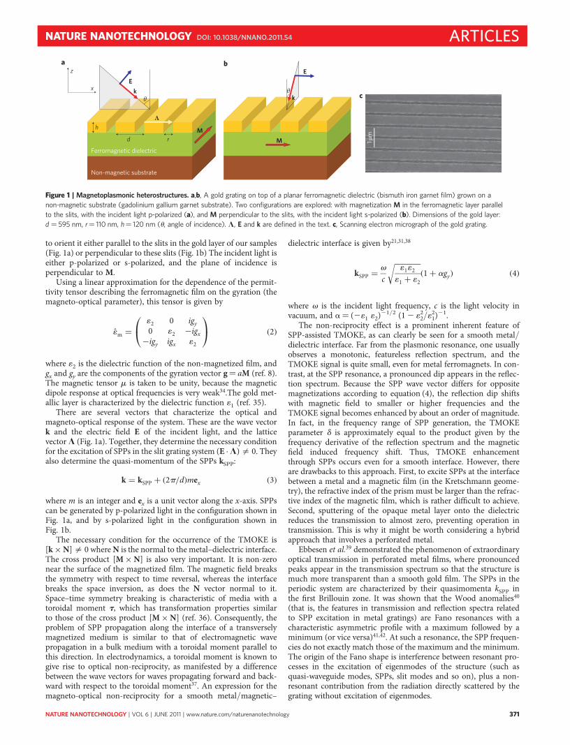
Figure 1 | Magnetoplasmonic heterostructures. a,b, A gold grating on top of a planar ferromagnetic dielectric (bismuth iron garnet film) grown on a
non-magnetic substrate (gadolinium gallium garnet substrate). Two configurations are explored: with magnetization M in the ferromagnetic layer parallel
to the slits, with the incident light p-polarized (a), and M perpendicular to the slits, with the incident light s-polarized (b). Dimensions of the gold layer:
d ¼ 595 nm, r¼ 110 nm, h¼ 120 nm (u, angle of incidence). L, E and k are defined in the text. c, Scanning electron micrograph of the gold grating.
NATURE NANOTECHNOLOGY DOI: 10.1038/NNANO.2011.54 ARTICLES
NATURE NANOTECHNOLOGY | VOL 6 | JUNE 2011 | www.nature.com/naturenanotechnology 371
Because SPPs can propagate along both surfaces of the perforatedmetal film, two types of Fano resonances can be observed. However,it is only the bottom metal surface adjacent to the ferromagneticlayer that contributes significantly to the TMOKE. Consequently,we can assume that TMOKE enhancement around the two reson-ances will be significantly different, exhibiting a much largerenhancement factor for the SPPs on the bottom interface.Furthermore, contrary to uniform films, the optical properties ofperforated metals are also governed by other eigenmodes andanomalies43,44. Indeed, transmission/reflection dips and peaksmight also be owing to Rayleigh anomalies or Fabry–Perot reson-ances. Such diversity of optical phenomena usually leads to consider-able difficulties in their interpretation. In this case, observation of theTMOKE can reveal the difference between various phenomena: forexample, Rayleigh anomalies (sharp maxima in the reflectionspectra of metallic gratings) are related to electromagnetic fieldsingularities when one of the diffracted orders becomes tangentialto the grating surface and are determined by the grating period, soit is not possible for the magnetization to have any influence onthem. Moreover, anomalies caused by Fabry–Perot resonancesinside the slits should not be very sensitive to the magnetization,because they are mainly determined by slit depth and width43.
Giant TMOKE in transmission modePreliminary numerical modelling enabled us to design the sample,that is, determine the gold grating period, gold thickness and slitwidth, and to adjust the main SPP resonances to the wavelengthrange 650–850 nm. This range is most suitable for magneto-optical experiments on bismuth iron garnets, because themagneto-optical figure of merit given by the ratio of the specific
Faraday rotation to the absorption is highest at �750 nm. (SeeMethods for a description of the numerical modelling procedure.)
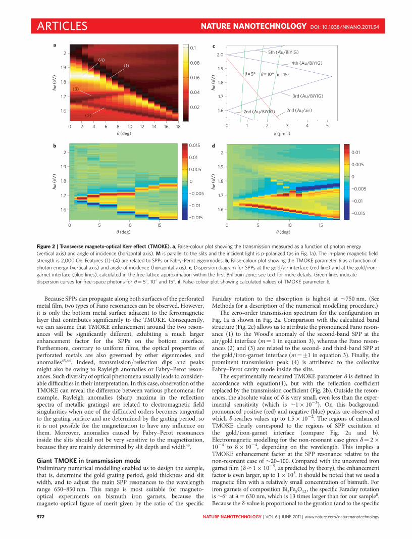
The zero-order transmission spectrum for the configuration inFig. 1a is shown in Fig. 2a. Comparison with the calculated bandstructure (Fig. 2c) allows us to attribute the pronounced Fano reson-ance (1) to the Wood’s anomaly of the second-band SPP at theair/gold interface (m¼ 1 in equation 3), whereas the Fano reson-ances (2) and (3) are related to the second- and third-band SPP atthe gold/iron-garnet interface (m¼+1 in equation 3). Finally, theprominent transmission peak (4) is attributed to the collectiveFabry–Perot cavity mode inside the slits.
The experimentally measured TMOKE parameter d is defined inaccordance with equation(1), but with the reflection coefficientreplaced by the transmission coefficient (Fig. 2b). Outside the reson-ances, the absolute value of d is very small, even less than the exper-imental sensitivity (which is �1 × 10²³). On this background,pronounced positive (red) and negative (blue) peaks are observed atwhich d reaches values up to 1.5 × 10²². The regions of enhancedTMOKE clearly correspond to the regions of SPP excitation atthe gold/iron-garnet interface (compare Fig. 2a and b).Electromagnetic modelling for the non-resonant case gives d¼ 2 ×1024 to 8 × 1024, depending on the wavelength. This implies aTMOKE enhancement factor at the SPP resonance relative to thenon-resonant case of �20–100. Compared with the uncovered irongarnet film (d≈ 1 × 1025, as predicted by theory), the enhancementfactor is even larger, up to 1 × 10³. It should be noted that we used amagnetic film with a relatively small concentration of bismuth. Foriron garnets of composition Bi3Fe5O12, the specific Faraday rotationis �68 at l¼ 630 nm, which is 13 times larger than for our sample8.Because the d-value is proportional to the gyration (and to the specific
a c
b d
0 2 4 6 8 10 12 14 16 18
1.6
1.7
1.8
1.9
2
θ (deg)
0.02
0.04
0.06
0.08
0.1
(3)
(2)
(1)(4)
0 5 10 15
1.6
1.7
1.8
1.9
2
θ (deg)
−0.015
−0.01
−0.005
0
0.005
0.01
0.015
0 1 2 3 4 5
1.6
1.7
1.8
1.9
2.0
2nd (Au/BiYIG)
5th (Au/BiYIG)
4th (Au/BiYIG)
3rd (Au/BiYIG)
θ = 15°θ = 10°θ = 5°
k (μm−1)
2nd (Au/air)
0 5 10 15θ (deg)
−0.015
−0.01
−0.005
0
0.005
0.01
1.6
1.7
1.8
1.9
2
ħω (e
V)
ħω (e
V)
ħω (e
V)
ħω (e
V)
Figure 2 | Transverse magneto-optical Kerr effect (TMOKE). a, False-colour plot showing the transmission measured as a function of photon energy
(vertical axis) and angle of incidence (horizontal axis). M is parallel to the slits and the incident light is p-polarized (as in Fig. 1a). The in-plane magnetic field
strength is 2,000 Oe. Features (1)–(4) are related to SPPs or Fabry–Perot eigenmodes. b, False-colour plot showing the TMOKE parameter d as a function of
photon energy (vertical axis) and angle of incidence (horizontal axis). c, Dispersion diagram for SPPs at the gold/air interface (red line) and at the gold/iron-
garnet interface (blue lines), calculated in the free lattice approximation within the first Brillouin zone; see text for more details. Green lines indicate
dispersion curves for free-space photons for u¼ 58, 108 and 158. d, False-colour plot showing calculated values of TMOKE parameter d.
ARTICLES NATURE NANOTECHNOLOGY DOI: 10.1038/NNANO.2011.54
NATURE NANOTECHNOLOGY | VOL 6 | JUNE 2011 | www.nature.com/naturenanotechnology372
Faraday rotation), d may exceed 0.2 by choosing an appropriateconcentration of bismuth.
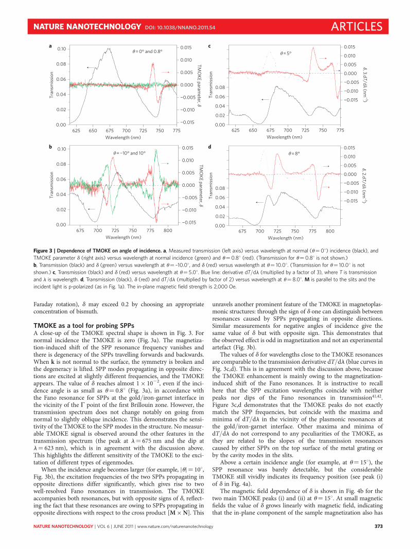
TMOKE as a tool for probing SPPsA close-up of the TMOKE spectral shape is shown in Fig. 3. Fornormal incidence the TMOKE is zero (Fig. 3a). The magnetiza-tion-induced shift of the SPP resonance frequency vanishes andthere is degeneracy of the SPPs travelling forwards and backwards.When k is not normal to the surface, the symmetry is broken andthe degeneracy is lifted. SPP modes propagating in opposite direc-tions are excited at slightly different frequencies, and the TMOKEappears. The value of d reaches almost 1 × 10²², even if the inci-dence angle is as small as u¼ 0.88 (Fig. 3a), in accordance withthe Fano resonance for SPPs at the gold/iron-garnet interface inthe vicinity of the G point of the first Brillouin zone. However, thetransmission spectrum does not change notably on going fromnormal to slightly oblique incidence. This demonstrates the sensi-tivity of the TMOKE to the SPP modes in the structure. No measur-able TMOKE signal is observed around the other features in thetransmission spectrum (the peak at l¼ 675 nm and the dip atl¼ 623 nm), which is in agreement with the discussion above.This highlights the different sensitivity of the TMOKE to the exci-tation of different types of eigenmodes.
When the incidence angle becomes larger (for example, |u|¼ 108,Fig. 3b), the excitation frequencies of the two SPPs propagating inopposite directions differ significantly, which gives rise to twowell-resolved Fano resonances in transmission. The TMOKEaccompanies both resonances, but with opposite signs of d, reflect-ing the fact that these resonances are owing to SPPs propagating inopposite directions with respect to the cross product [M × N]. This
unravels another prominent feature of the TMOKE in magnetoplas-monic structures: through the sign of d one can distinguish betweenresonances caused by SPPs propagating in opposite directions.Similar measurements for negative angles of incidence give thesame value of d but with opposite sign. This demonstrates thatthe observed effect is odd in magnetization and not an experimentalartefact (Fig. 3b).
The values of d for wavelengths close to the TMOKE resonancesare comparable to the transmission derivative dT/dl (blue curves inFig. 3c,d). This is in agreement with the discussion above, becausethe TMOKE enhancement is mainly owing to the magnetization-induced shift of the Fano resonances. It is instructive to recallhere that the SPP excitation wavelengths coincide with neitherpeaks nor dips of the Fano resonances in transmission41,42.Figure 3c,d demonstrates that the TMOKE peaks do not exactlymatch the SPP frequencies, but coincide with the maxima andminima of dT/dl in the vicinity of the plasmonic resonances atthe gold/iron-garnet interface. Other maxima and minima ofdT/dl do not correspond to any peculiarities of the TMOKE, asthey are related to the slopes of the transmission resonancescaused by either SPPs on the top surface of the metal grating orby the cavity modes in the slits.
Above a certain incidence angle (for example, at u¼ 158), theSPP resonance was barely detectable, but the considerableTMOKE still vividly indicates its frequency position (see peak (i)of d in Fig. 4a).
The magnetic field dependence of d is shown in Fig. 4b for thetwo main TMOKE peaks (i) and (ii) at u¼ 158. At small magneticfields the value of d grows linearly with magnetic field, indicatingthat the in-plane component of the sample magnetization also has
625 650 675 700 725 750 7750.00
0.02
0.04
0.06
0.08
0.10
−0.015
−0.010
−0.005
0.000
0.005
0.010
0.015
TMO
KE parameter, δ
Tran
smis
sion
Wavelength (nm)
θ = 0° and 0.8°
−0.015
−0.010
−0.005
0.000
0.005
0.010
0.015
TMO
KE parameter, δ
675 700 725 750 775 800Wavelength (nm)
0.00
0.02
0.04
0.06
0.08
0.10θ = −10° and 10°
Tran
smis
sion
δ, 3.dT/dλ (nm−1)
625 650 675 700 725 750 775Wavelength (nm)
0.00
0.02
0.04
0.06
0.08
0.10
0.12
0.14
0.16
−0.025
−0.020
−0.015
−0.010
−0.005
0.000
0.005
0.010
0.015θ = 5°
Tran
smis
sion
δ, 2.dT/dλ (nm−1)
675 700 725 750 775 800Wavelength (nm)
0.00
0.02
0.04
0.06
0.08
0.10
0.12
0.14
0.16
−0.025
−0.020
−0.015
−0.010
−0.005
0.000
0.005
0.010
0.015θ = 8°
Tran
smis
sion
a c
b d
Figure 3 | Dependence of TMOKE on angle of incidence. a, Measured transmission (left axis) versus wavelength at normal (u¼08) incidence (black), and
TMOKE parameter d (right axis) versus wavelength at normal incidence (green) and u¼0.88 (red). (Transmission for u¼0.88 is not shown.)
b, Transmission (black) and d (green) versus wavelength at u¼ –10.08, and d (red) versus wavelength at u¼ 10.08. (Transmission for u¼ 10.08 is not
shown.) c, Transmission (black) and d (red) versus wavelength at u¼ 5.08. Blue line: derivative dT/dl (multiplied by a factor of 3), where T is transmission
and l is wavelength. d, Transmission (black), d (red) and dT/dl (multiplied by factor of 2) versus wavelength at u¼ 8.08. M is parallel to the slits and the
incident light is p-polarized (as in Fig. 1a). The in-plane magnetic field strength is 2,000 Oe.
NATURE NANOTECHNOLOGY DOI: 10.1038/NNANO.2011.54 ARTICLES
NATURE NANOTECHNOLOGY | VOL 6 | JUNE 2011 | www.nature.com/naturenanotechnology 373
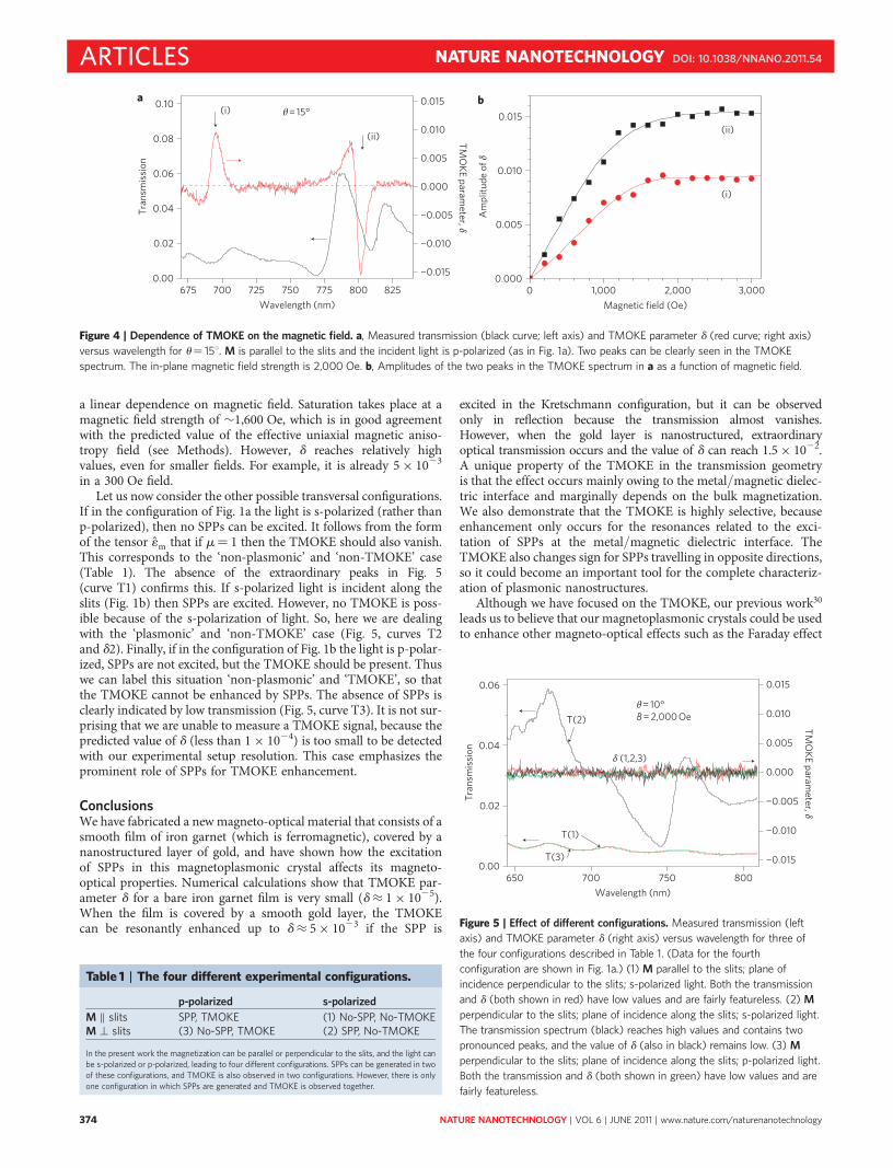
a linear dependence on magnetic field. Saturation takes place at amagnetic field strength of �1,600 Oe, which is in good agreementwith the predicted value of the effective uniaxial magnetic aniso-tropy field (see Methods). However, d reaches relatively highvalues, even for smaller fields. For example, it is already 5 × 10²³
in a 300 Oe field.Let us now consider the other possible transversal configurations.
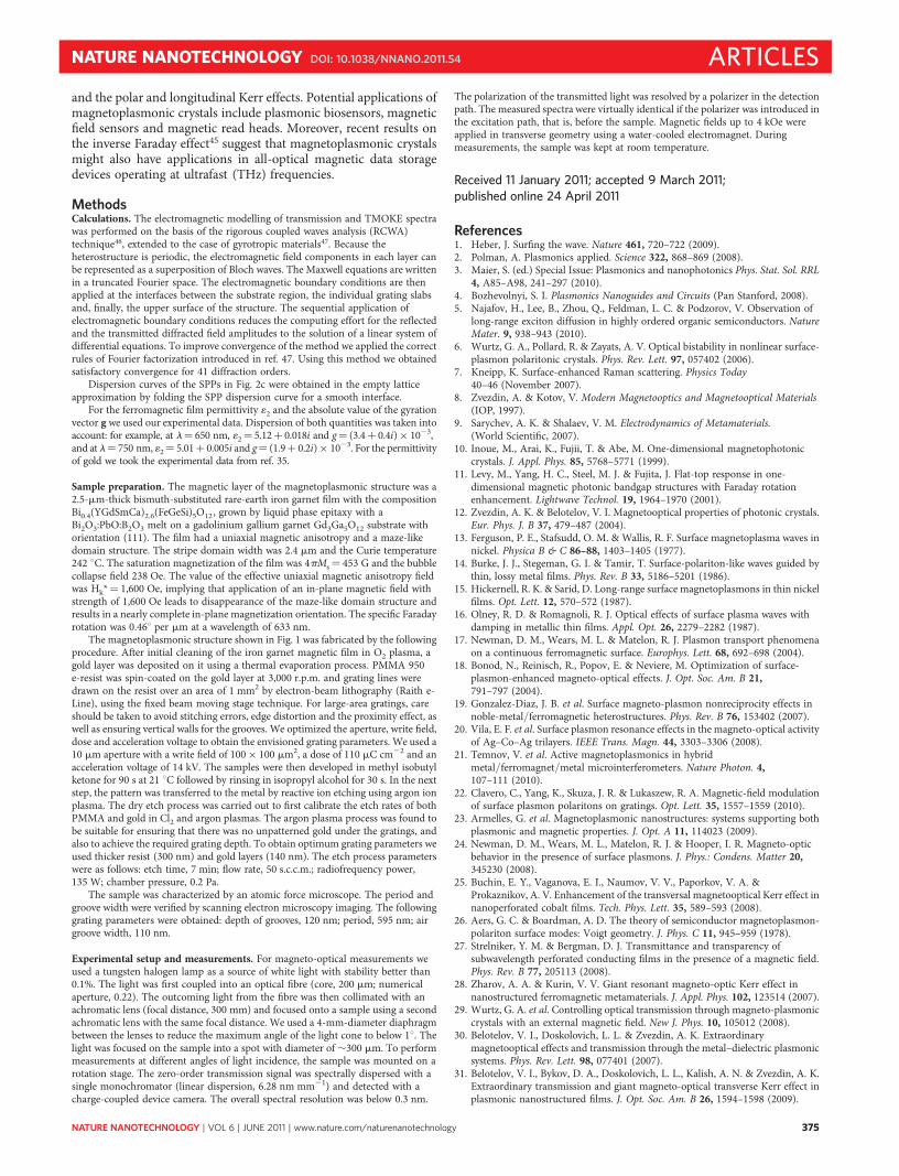
If in the configuration of Fig. 1a the light is s-polarized (rather thanp-polarized), then no SPPs can be excited. It follows from the formof the tensor 1m that if m¼ 1 then the TMOKE should also vanish.This corresponds to the ‘non-plasmonic’ and ‘non-TMOKE’ case(Table 1). The absence of the extraordinary peaks in Fig. 5(curve T1) confirms this. If s-polarized light is incident along theslits (Fig. 1b) then SPPs are excited. However, no TMOKE is poss-ible because of the s-polarization of light. So, here we are dealingwith the ‘plasmonic’ and ‘non-TMOKE’ case (Fig. 5, curves T2and d2). Finally, if in the configuration of Fig. 1b the light is p-polar-ized, SPPs are not excited, but the TMOKE should be present. Thuswe can label this situation ‘non-plasmonic’ and ‘TMOKE’, so thatthe TMOKE cannot be enhanced by SPPs. The absence of SPPs isclearly indicated by low transmission (Fig. 5, curve T3). It is not sur-prising that we are unable to measure a TMOKE signal, because thepredicted value of d (less than 1 × 1024) is too small to be detectedwith our experimental setup resolution. This case emphasizes theprominent role of SPPs for TMOKE enhancement.
ConclusionsWe have fabricated a new magneto-optical material that consists of asmooth film of iron garnet (which is ferromagnetic), covered by ananostructured layer of gold, and have shown how the excitationof SPPs in this magnetoplasmonic crystal affects its magneto-optical properties. Numerical calculations show that TMOKE par-ameter d for a bare iron garnet film is very small (d≈ 1 × 1025).When the film is covered by a smooth gold layer, the TMOKEcan be resonantly enhanced up to d≈ 5 × 10²³ if the SPP is
excited in the Kretschmann configuration, but it can be observedonly in reflection because the transmission almost vanishes.However, when the gold layer is nanostructured, extraordinaryoptical transmission occurs and the value of d can reach 1.5 × 1022.A unique property of the TMOKE in the transmission geometryis that the effect occurs mainly owing to the metal/magnetic dielec-tric interface and marginally depends on the bulk magnetization.We also demonstrate that the TMOKE is highly selective, becauseenhancement only occurs for the resonances related to the exci-tation of SPPs at the metal/magnetic dielectric interface. TheTMOKE also changes sign for SPPs travelling in opposite directions,so it could become an important tool for the complete characteriz-ation of plasmonic nanostructures.
Although we have focused on the TMOKE, our previous work30
leads us to believe that our magnetoplasmonic crystals could be usedto enhance other magneto-optical effects such as the Faraday effect
650 700 750 8000.00
0.02
0.04
0.06
−0.015
−0.010
−0.005
0.000
0.005
0.010
0.015
TMO
KE parameter, δ
Tran
smis
sion
Wavelength (nm)
δ (1,2,3)
θ = 10°B = 2,000 Oe
T(3)
T(1)
T(2)
Figure 5 | Effect of different configurations. Measured transmission (left
axis) and TMOKE parameter d (right axis) versus wavelength for three of
the four configurations described in Table 1. (Data for the fourth
configuration are shown in Fig. 1a.) (1) M parallel to the slits; plane of
incidence perpendicular to the slits; s-polarized light. Both the transmission
and d (both shown in red) have low values and are fairly featureless. (2) M
perpendicular to the slits; plane of incidence along the slits; s-polarized light.
The transmission spectrum (black) reaches high values and contains two
pronounced peaks, and the value of d (also in black) remains low. (3) M
perpendicular to the slits; plane of incidence along the slits; p-polarized light.
Both the transmission and d (both shown in green) have low values and are
fairly featureless.
675 700 725 750 775 800 8250.00
0.02
0.04
0.06
0.08
0.10
−0.015
−0.010
−0.005
0.000
0.005
0.010
0.015
Wavelength (nm)
TMO
KE parameter, δ
Tran
smis
sion
(ii)
θ = 15° a b
(i)
0 1,000 2,000 3,0000.000
0.005
0.010
0.015(ii)
Am
plitu
de o
f δ
Magnetic field (Oe)
(i)
Figure 4 | Dependence of TMOKE on the magnetic field. a, Measured transmission (black curve; left axis) and TMOKE parameter d (red curve; right axis)
versus wavelength for u¼ 158. M is parallel to the slits and the incident light is p-polarized (as in Fig. 1a). Two peaks can be clearly seen in the TMOKE
spectrum. The in-plane magnetic field strength is 2,000 Oe. b, Amplitudes of the two peaks in the TMOKE spectrum in a as a function of magnetic field.
Table 1 | The four different experimental configurations.
p-polarized s-polarized
M ‖ slits SPP, TMOKE (1) No-SPP, No-TMOKEM ⊥ slits (3) No-SPP, TMOKE (2) SPP, No-TMOKE
In the present work the magnetization can be parallel or perpendicular to the slits, and the light canbe s-polarized or p-polarized, leading to four different configurations. SPPs can be generated in twoof these configurations, and TMOKE is also observed in two configurations. However, there is onlyone configuration in which SPPs are generated and TMOKE is observed together.
ARTICLES NATURE NANOTECHNOLOGY DOI: 10.1038/NNANO.2011.54
NATURE NANOTECHNOLOGY | VOL 6 | JUNE 2011 | www.nature.com/naturenanotechnology374
and the polar and longitudinal Kerr effects. Potential applications ofmagnetoplasmonic crystals include plasmonic biosensors, magneticfield sensors and magnetic read heads. Moreover, recent results onthe inverse Faraday effect45 suggest that magnetoplasmonic crystalsmight also have applications in all-optical magnetic data storagedevices operating at ultrafast (THz) frequencies.
MethodsCalculations. The electromagnetic modelling of transmission and TMOKE spectrawas performed on the basis of the rigorous coupled waves analysis (RCWA)technique46, extended to the case of gyrotropic materials47. Because theheterostructure is periodic, the electromagnetic field components in each layer canbe represented as a superposition of Bloch waves. The Maxwell equations are writtenin a truncated Fourier space. The electromagnetic boundary conditions are thenapplied at the interfaces between the substrate region, the individual grating slabsand, finally, the upper surface of the structure. The sequential application ofelectromagnetic boundary conditions reduces the computing effort for the reflectedand the transmitted diffracted field amplitudes to the solution of a linear system ofdifferential equations. To improve convergence of the method we applied the correctrules of Fourier factorization introduced in ref. 47. Using this method we obtainedsatisfactory convergence for 41 diffraction orders.
Dispersion curves of the SPPs in Fig. 2c were obtained in the empty latticeapproximation by folding the SPP dispersion curve for a smooth interface.
For the ferromagnetic film permittivity 12 and the absolute value of the gyrationvector g we used our experimental data. Dispersion of both quantities was taken intoaccount: for example, at l¼ 650 nm, 12¼ 5.12þ 0.018i and g¼ (3.4þ 0.4i) × 1023,and at l¼ 750 nm, 12¼ 5.01þ 0.005i and g¼ (1.9þ 0.2i)× 1023. For the permittivityof gold we took the experimental data from ref. 35.
Sample preparation. The magnetic layer of the magnetoplasmonic structure was a2.5-mm-thick bismuth-substituted rare-earth iron garnet film with the compositionBi0.4(YGdSmCa)2.6(FeGeSi)5O12, grown by liquid phase epitaxy with aBi2O3:PbO:B2O3 melt on a gadolinium gallium garnet Gd3Ga5O12 substrate withorientation (111). The film had a uniaxial magnetic anisotropy and a maze-likedomain structure. The stripe domain width was 2.4 mm and the Curie temperature242 8C. The saturation magnetization of the film was 4pMs¼ 453 G and the bubblecollapse field 238 Oe. The value of the effective uniaxial magnetic anisotropy fieldwas Hk*¼ 1,600 Oe, implying that application of an in-plane magnetic field withstrength of 1,600 Oe leads to disappearance of the maze-like domain structure andresults in a nearly complete in-plane magnetization orientation. The specific Faradayrotation was 0.468 per mm at a wavelength of 633 nm.
The magnetoplasmonic structure shown in Fig. 1 was fabricated by the followingprocedure. After initial cleaning of the iron garnet magnetic film in O2 plasma, agold layer was deposited on it using a thermal evaporation process. PMMA 950e-resist was spin-coated on the gold layer at 3,000 r.p.m. and grating lines weredrawn on the resist over an area of 1 mm2 by electron-beam lithography (Raith e-Line), using the fixed beam moving stage technique. For large-area gratings, careshould be taken to avoid stitching errors, edge distortion and the proximity effect, aswell as ensuring vertical walls for the grooves. We optimized the aperture, write field,dose and acceleration voltage to obtain the envisioned grating parameters. We used a10 mm aperture with a write field of 100 × 100 mm2, a dose of 110 mC cm22 and anacceleration voltage of 14 kV. The samples were then developed in methyl isobutylketone for 90 s at 21 8C followed by rinsing in isopropyl alcohol for 30 s. In the nextstep, the pattern was transferred to the metal by reactive ion etching using argon ionplasma. The dry etch process was carried out to first calibrate the etch rates of bothPMMA and gold in Cl2 and argon plasmas. The argon plasma process was found tobe suitable for ensuring that there was no unpatterned gold under the gratings, andalso to achieve the required grating depth. To obtain optimum grating parameters weused thicker resist (300 nm) and gold layers (140 nm). The etch process parameterswere as follows: etch time, 7 min; flow rate, 50 s.c.c.m.; radiofrequency power,135 W; chamber pressure, 0.2 Pa.
The sample was characterized by an atomic force microscope. The period andgroove width were verified by scanning electron microscopy imaging. The followinggrating parameters were obtained: depth of grooves, 120 nm; period, 595 nm; airgroove width, 110 nm.
Experimental setup and measurements. For magneto-optical measurements weused a tungsten halogen lamp as a source of white light with stability better than0.1%. The light was first coupled into an optical fibre (core, 200 mm; numericalaperture, 0.22). The outcoming light from the fibre was then collimated with anachromatic lens (focal distance, 300 mm) and focused onto a sample using a secondachromatic lens with the same focal distance. We used a 4-mm-diameter diaphragmbetween the lenses to reduce the maximum angle of the light cone to below 18. Thelight was focused on the sample into a spot with diameter of �300 mm. To performmeasurements at different angles of light incidence, the sample was mounted on arotation stage. The zero-order transmission signal was spectrally dispersed with asingle monochromator (linear dispersion, 6.28 nm mm21) and detected with acharge-coupled device camera. The overall spectral resolution was below 0.3 nm.
The polarization of the transmitted light was resolved by a polarizer in the detectionpath. The measured spectra were virtually identical if the polarizer was introduced inthe excitation path, that is, before the sample. Magnetic fields up to 4 kOe wereapplied in transverse geometry using a water-cooled electromagnet. Duringmeasurements, the sample was kept at room temperature.
Received 11 January 2011; accepted 9 March 2011;published online 24 April 2011
References1. Heber, J. Surfing the wave. Nature 461, 720–722 (2009).2. Polman, A. Plasmonics applied. Science 322, 868–869 (2008).3. Maier, S. (ed.) Special Issue: Plasmonics and nanophotonics Phys. Stat. Sol. RRL
4, A85–A98, 241–297 (2010).4. Bozhevolnyi, S. I. Plasmonics Nanoguides and Circuits (Pan Stanford, 2008).5. Najafov, H., Lee, B., Zhou, Q., Feldman, L. C. & Podzorov, V. Observation of
long-range exciton diffusion in highly ordered organic semiconductors. NatureMater. 9, 938–943 (2010).
6. Wurtz, G. A., Pollard, R. & Zayats, A. V. Optical bistability in nonlinear surface-plasmon polaritonic crystals. Phys. Rev. Lett. 97, 057402 (2006).
7. Kneipp, K. Surface-enhanced Raman scattering. Physics Today40–46 (November 2007).
8. Zvezdin, A. & Kotov, V. Modern Magnetooptics and Magnetooptical Materials(IOP, 1997).
9. Sarychev, A. K. & Shalaev, V. M. Electrodynamics of Metamaterials.(World Scientific, 2007).
10. Inoue, M., Arai, K., Fujii, T. & Abe, M. One-dimensional magnetophotoniccrystals. J. Appl. Phys. 85, 5768–5771 (1999).
11. Levy, M., Yang, H. C., Steel, M. J. & Fujita, J. Flat-top response in one-dimensional magnetic photonic bandgap structures with Faraday rotationenhancement. Lightwave Technol. 19, 1964–1970 (2001).
12. Zvezdin, A. K. & Belotelov, V. I. Magnetooptical properties of photonic crystals.Eur. Phys. J. B 37, 479–487 (2004).
13. Ferguson, P. E., Stafsudd, O. M. & Wallis, R. F. Surface magnetoplasma waves innickel. Physica B & C 86–88, 1403–1405 (1977).
14. Burke, J. J., Stegeman, G. I. & Tamir, T. Surface-polariton-like waves guided bythin, lossy metal films. Phys. Rev. B 33, 5186–5201 (1986).
15. Hickernell, R. K. & Sarid, D. Long-range surface magnetoplasmons in thin nickelfilms. Opt. Lett. 12, 570–572 (1987).
16. Olney, R. D. & Romagnoli, R. J. Optical effects of surface plasma waves withdamping in metallic thin films. Appl. Opt. 26, 2279–2282 (1987).
17. Newman, D. M., Wears, M. L. & Matelon, R. J. Plasmon transport phenomenaon a continuous ferromagnetic surface. Europhys. Lett. 68, 692–698 (2004).
18. Bonod, N., Reinisch, R., Popov, E. & Neviere, M. Optimization of surface-plasmon-enhanced magneto-optical effects. J. Opt. Soc. Am. B 21,791–797 (2004).
19. Gonzalez-Diaz, J. B. et al. Surface magneto-plasmon nonreciprocity effects innoble-metal/ferromagnetic heterostructures. Phys. Rev. B 76, 153402 (2007).
20. Vila, E. F. et al. Surface plasmon resonance effects in the magneto-optical activityof Ag–Co–Ag trilayers. IEEE Trans. Magn. 44, 3303–3306 (2008).
21. Temnov, V. et al. Active magnetoplasmonics in hybridmetal/ferromagnet/metal microinterferometers. Nature Photon. 4,107–111 (2010).
22. Clavero, C., Yang, K., Skuza, J. R. & Lukaszew, R. A. Magnetic-field modulationof surface plasmon polaritons on gratings. Opt. Lett. 35, 1557–1559 (2010).
23. Armelles, G. et al. Magnetoplasmonic nanostructures: systems supporting bothplasmonic and magnetic properties. J. Opt. A 11, 114023 (2009).
24. Newman, D. M., Wears, M. L., Matelon, R. J. & Hooper, I. R. Magneto-opticbehavior in the presence of surface plasmons. J. Phys.: Condens. Matter 20,345230 (2008).
25. Buchin, E. Y., Vaganova, E. I., Naumov, V. V., Paporkov, V. A. &Prokaznikov, A. V. Enhancement of the transversal magnetooptical Kerr effect innanoperforated cobalt films. Tech. Phys. Lett. 35, 589–593 (2008).
26. Aers, G. C. & Boardman, A. D. The theory of semiconductor magnetoplasmon-polariton surface modes: Voigt geometry. J. Phys. C 11, 945–959 (1978).
27. Strelniker, Y. M. & Bergman, D. J. Transmittance and transparency ofsubwavelength perforated conducting films in the presence of a magnetic field.Phys. Rev. B 77, 205113 (2008).
28. Zharov, A. A. & Kurin, V. V. Giant resonant magneto-optic Kerr effect innanostructured ferromagnetic metamaterials. J. Appl. Phys. 102, 123514 (2007).
29. Wurtz, G. A. et al. Controlling optical transmission through magneto-plasmoniccrystals with an external magnetic field. New J. Phys. 10, 105012 (2008).
30. Belotelov, V. I., Doskolovich, L. L. & Zvezdin, A. K. Extraordinarymagnetooptical effects and transmission through the metal–dielectric plasmonicsystems. Phys. Rev. Lett. 98, 077401 (2007).
31. Belotelov, V. I., Bykov, D. A., Doskolovich, L. L., Kalish, A. N. & Zvezdin, A. K.Extraordinary transmission and giant magneto-optical transverse Kerr effect inplasmonic nanostructured films. J. Opt. Soc. Am. B 26, 1594–1598 (2009).
NATURE NANOTECHNOLOGY DOI: 10.1038/NNANO.2011.54 ARTICLES
NATURE NANOTECHNOLOGY | VOL 6 | JUNE 2011 | www.nature.com/naturenanotechnology 375
32. Krinchik, G. S. & Artem’ev, V. A. Magneto-optical properties of Ni, Co and Fe inultraviolet visible and infrared parts of spectrum. J. Exper. Theor. Phys. 26,1080–1085 (1968).
33. Druzhinin, A. V., Lobov, I. D., Mayevskiy, V. M. & Bolotin, G. Transversemagnetooptical Kerr effect in transmission. Phys. Met. Metallogr. 56,58–65 (1983).
34. Landau, L. D. & Lifshitz, E. M. Electrodynamics of Continuous Media(Pergamon, 1984).
35. Johnson, P. B. & Christy, R. W. Optical constants of the noble metals. Phys. Rev.B 6, 4370–4376 (1972).
36. Dubovik, V. M. & Tosunyan, L. A. Toroidal moments in the physics ofelectromagnetic and weak interactions. Sov. J. Part. Nucl. 14, 504–519 (1983).
37. Kalish, A. N., Belotelov, V. I. & Zvezdin, A. K. Optical properties of toroidalmedia. SPIE Conf. Proc. 6728, 67283D (2007).
38. Belotelov, V. I., Bykov, D. A., Doskolovich, L. L., Kalish, A. N. & Zvezdin, A. K.Giant transversal Kerr effect in magnetoplasmonic heterostructures. J. Exper.Theor. Phys. 137, 932–942 (2010).
39. Ebbesen, T. W., Lezec, H. J., Ghaemi, H. F., Thio, T. & Wolff, P. A. Extraordinaryoptical transmission through sub-wavelength hole arrays. Nature 391,667–669 (1998).
40. Wood, R. W. Anomalous diffraction gratings. Phys. Rev. 48, 928–936 (1935).41. Sarrazin, M. & Vigneron, J. P. Bounded modes to the rescue of optical
transmission. Europhys. News 38, 27–31 (2007).42. Luk’yanchuk B. et al. The Fano resonance in plasmonic nanostructures and
metamaterials. Nature Mater. 9, 707–715 (2010).43. Porto, J. A., Garcia-Vidal, F. J. & Pendry, J. B. Transmission resonances on
metallic gratings with very narrow slits. Phys. Rev. Lett. 83, 2845–2848 (1999).
44. Marquier, F., Greffet, J., Collin, S., Pardo, F. & Pelouard, J. Resonanttransmission through a metallic film due to coupled modes. Opt. Express 13,70–76 (2005).
45. Kimel, A. V., Kirilyuk, A., Tsvetkov, A., Pisarev, R. V. & Rasing, Th. Ultrafastnon-thermal control of magnetization by instantaneous photomagnetic pulses.Nature 435, 655–657 (2005).
46. Moharam, M. G., Pommet, D. A., Grann, E. B. & Gaylord, T. K. Stableimplementation of the rigorous coupled-wave analysis for surface-relief gratings:enhanced transmittance matrix approach. J. Opt. Soc. Am. A 12,1077–1086 (1995).
47. Li, L. Fourier modal method for crossed anisotropic gratings with arbitrarypermittivity and permeability tensors. J. Opt. A 5, 345–355 (2003).
AcknowledgementsThis work was supported by the Deutsche Forschungsgemeinschaft (DFG), the RussianFoundation for Basic Research (RFBR), the Indian Department of Science and Technology(DST) and Russia President’s grant (MK-3123.2011.2).
Author contributionsV.I.B. and A.K.Z. conceived and designed the experiments. V.A.K., A.V.G., A.S.V. and S.K.fabricated the sample. V.I.B., I.A.A. and M.P. performed the experiments. V.I.B., A.K.Z.and I.A.A. analysed the data. V.I.B., M.B., A.K.Z., I.A.A. and D.R.Y. co-wrote the paper. Allauthors discussed the results and commented on the manuscript.
Additional informationThe authors declare no competing financial interests. Reprints and permission information isavailable online at http://www.nature.com/reprints/. Correspondence and requests for materialsshould be addressed to V.I.B. and I.A.A.
ARTICLES NATURE NANOTECHNOLOGY DOI: 10.1038/NNANO.2011.54
NATURE NANOTECHNOLOGY | VOL 6 | JUNE 2011 | www.nature.com/naturenanotechnology376