engineering design of an rf vacuum window for the iter icrh antenna
TRANSCRIPT
E
CMU
a
AA
KIRWTB
1
Itts
aaa
doc(
cPmsaw
aa
0d
Fusion Engineering and Design 84 (2009) 887–894
Contents lists available at ScienceDirect
Fusion Engineering and Design
journa l homepage: www.e lsev ier .com/ locate / fusengdes
ngineering design of an RF vacuum window for the ITER ICRH antenna
raig Hamlyn-Harris ∗, Andrew Borthwick, John Fanthome, Chris Waldon,ark Nightingale, Neal Richardson
KAEA, Culham Science Centre, Abingdon, Oxfordshire, OX14 3DB, United Kingdom
r t i c l e i n f o
rticle history:vailable online 20 February 2009
a b s t r a c t
The RF vacuum window design proposed for ITER is similar to the one in operation on JET. It uses titaniumalloys for the outer and inner conductors and double conical ceramic insulators. However, unlike the
eywords:TERFindow
itanium
JET window, beryllia is the dielectric material. The design is complicated considerably by the need forcontinuous RF operation, which necessitates active cooling. Residual stress after manufacture has beenoptimised with particular attention given to subcritical crack growth in the ceramic. In addition, finiteelement methods were used to model the steady state temperature gradient from the combined effectsof volumetric heating of neutron irradiation, RF surface heating and dielectric loss heating. A scopingstudy is included in the modelling methodology of bonded joints and on the hydraulic requirements of
m.
erylliathe window cooling syste
. Introduction
The RF vacuum window is an integral part of the ITER antenna.t is the point where the RF feed crosses the vacuum boundary andhus forms part of the confinement barrier and a structural memberhat transfers disruption forces acting on the inner conductor to theurrounding structure.
It is a functional requirement of the antenna to have maintain-ble windows that do not require the removal of the antenna. Therere eight transmission lines and 16 vacuum windows in the presentntenna design. All windows are identical and maintainable.
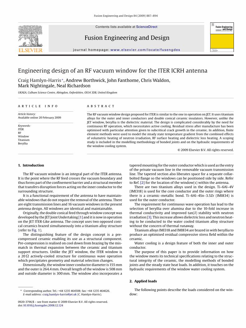
Originally, the double conical feed through window concept waseveloped by the JET Joint Undertaking [1] and it is now in operationn the JET ITER-Like antenna. The concept uses two opposed coni-al ceramics brazed simultaneously into a titanium alloy structurerefer to Fig. 1).
The distinguishing feature of the design concept is a pre-ompressed ceramic enabling its use as a structural component.re-compression is realised on cool down from brazing by the mis-atch in thermal expansion between the ceramic and titanium
upport structures. Unlike the JET window, the ITER window is20 � actively-cooled structure for continuous wave operation
hich precipitates geometry and material selection changes.Dimensionally, the window inner conductor diameter is 155 mmnd the outer is 264.4 mm. Overall length of the window is 508 mmnd outside diameter is 300 mm. The window also incorporates a
∗ Corresponding author. Tel.: +44 1235 464508; fax: +44 1235 464626.E-mail address: [email protected] (C. Hamlyn-Harris).
920-3796/$ – see front matter © 2009 Elsevier B.V. All rights reserved.oi:10.1016/j.fusengdes.2008.12.124
© 2009 Elsevier B.V. All rights reserved.
tapered mounting for the outer conductor which is used as the entryof the private vacuum line in the removable vacuum transmissionline. The tapered section also liberates space for a separate collar-bolted flange so the windows can be positioned side by side. Referto Ref. [2] for the location of the window(s) within the antenna.
There are two titanium alloys used in the design. Ti–6Al–4V(IMI318) is used for the core conductor and the outer rings wherethere is a ceramic–metallic bond. Ti–6Al–4Sn–3.5Zr (IMI834) isused for the outer conductor.
The requirement for continuous wave operation has lead to theselection of beryllia over alumina due to the 10-fold increase inthermal conductivity and improved tan(ı) stability with neutronirradiation [3]. This increase allows dielectric loss and neutron heat-ing to be conducted to the water cooled titanium alloy structurewithout the concern of thermal runaway.
Titanium alloys IMI318 and IMI834 are brazed in with beryllia toproduce an optimised residual compressive stress field within theceramic.
Water cooling is a design feature of both the inner and outerconductor.
The purpose of this paper is to provide information on howthe window meets its technical specifications relating to the struc-tural integrity of the ceramic, the modelling methods of bondedjoints and the steady state heat loads. In addition, it touches on thehydraulic requirements of the window water cooling system.
2. Applied loads
The following points describe the loads considered on the win-dow:
888 C. Hamlyn-Harris et al. / Fusion Engineering and Design 84 (2009) 887–894
n view with bill of material.
•
•
•
•
•
3
mcaitT
Table 1Physical properties of the window materials.
BeO IMI318 IMI834
Mean thermal expansion @20 ◦C,reference temperature: 600 ◦C(ppm/◦C)
7.96 9.6 11.02
Young’s modulus, @100 ◦C (GPa) 371 107 120Thermal conductivity, @100 ◦C 220 7.5 7.5
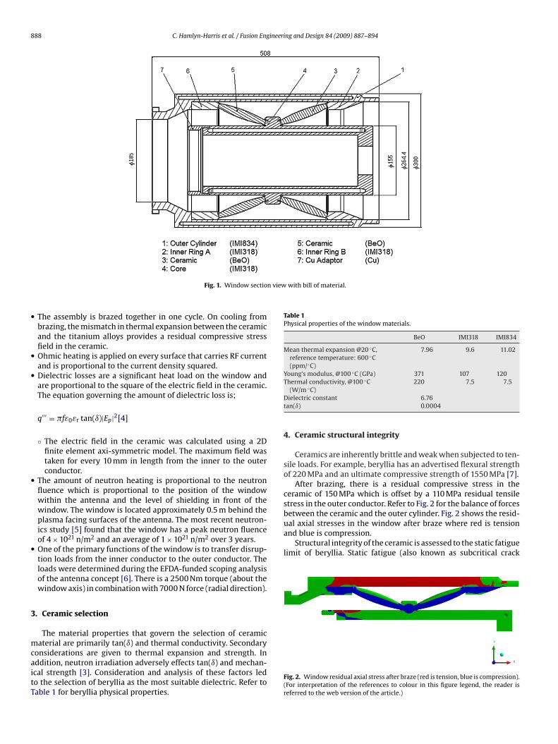
ual axial stresses in the window after braze where red is tensionand blue is compression.
Structural integrity of the ceramic is assessed to the static fatiguelimit of beryllia. Static fatigue (also known as subcritical crack
Fig. 1. Window sectio
The assembly is brazed together in one cycle. On cooling frombrazing, the mismatch in thermal expansion between the ceramicand the titanium alloys provides a residual compressive stressfield in the ceramic.Ohmic heating is applied on every surface that carries RF currentand is proportional to the current density squared.Dielectric losses are a significant heat load on the window andare proportional to the square of the electric field in the ceramic.The equation governing the amount of dielectric loss is;
q′′′ = �fε0εr tan(ı)|Ep|2[4]
◦ The electric field in the ceramic was calculated using a 2Dfinite element axi-symmetric model. The maximum field wastaken for every 10 mm in length from the inner to the outerconductor.
The amount of neutron heating is proportional to the neutronfluence which is proportional to the position of the windowwithin the antenna and the level of shielding in front of thewindow. The window is located approximately 0.5 m behind theplasma facing surfaces of the antenna. The most recent neutron-ics study [5] found that the window has a peak neutron fluenceof 4 × 10²¹ n/m2 and an average of 1 × 10²¹ n/m2 over 3 years.One of the primary functions of the window is to transfer disrup-tion loads from the inner conductor to the outer conductor. Theloads were determined during the EFDA-funded scoping analysisof the antenna concept [6]. There is a 2500 Nm torque (about thewindow axis) in combination with 7000 N force (radial direction).
. Ceramic selection
The material properties that govern the selection of ceramic
aterial are primarily tan(ı) and thermal conductivity. Secondaryonsiderations are given to thermal expansion and strength. Inddition, neutron irradiation adversely effects tan(ı) and mechan-cal strength [3]. Consideration and analysis of these factors ledo the selection of beryllia as the most suitable dielectric. Refer toable 1 for beryllia physical properties.
(W/m ◦C)Dielectric constant 6.76tan(ı) 0.0004
4. Ceramic structural integrity
Ceramics are inherently brittle and weak when subjected to ten-sile loads. For example, beryllia has an advertised flexural strengthof 220 MPa and an ultimate compressive strength of 1550 MPa [7].
After brazing, there is a residual compressive stress in theceramic of 150 MPa which is offset by a 110 MPa residual tensilestress in the outer conductor. Refer to Fig. 2 for the balance of forcesbetween the ceramic and the outer cylinder. Fig. 2 shows the resid-
Fig. 2. Window residual axial stress after braze (red is tension, blue is compression).(For interpretation of the references to colour in this figure legend, the reader isreferred to the web version of the article.)
ineeri
guaia
C. Hamlyn-Harris et al. / Fusion Eng
rowth) is a phenomenon where the flaw tips extend with time
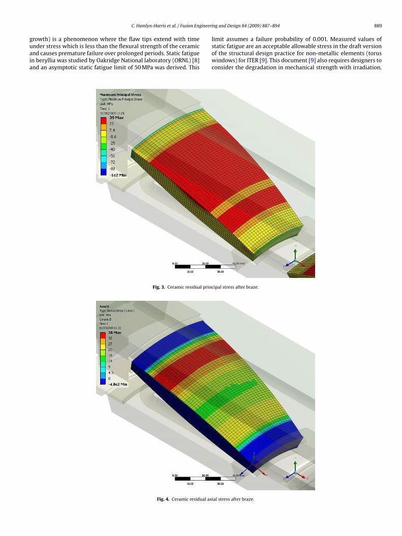
nder stress which is less than the flexural strength of the ceramicnd causes premature failure over prolonged periods. Static fatiguen beryllia was studied by Oakridge National laboratory (ORNL) [8]nd an asymptotic static fatigue limit of 50 MPa was derived. ThisFig. 3. Ceramic residual princ
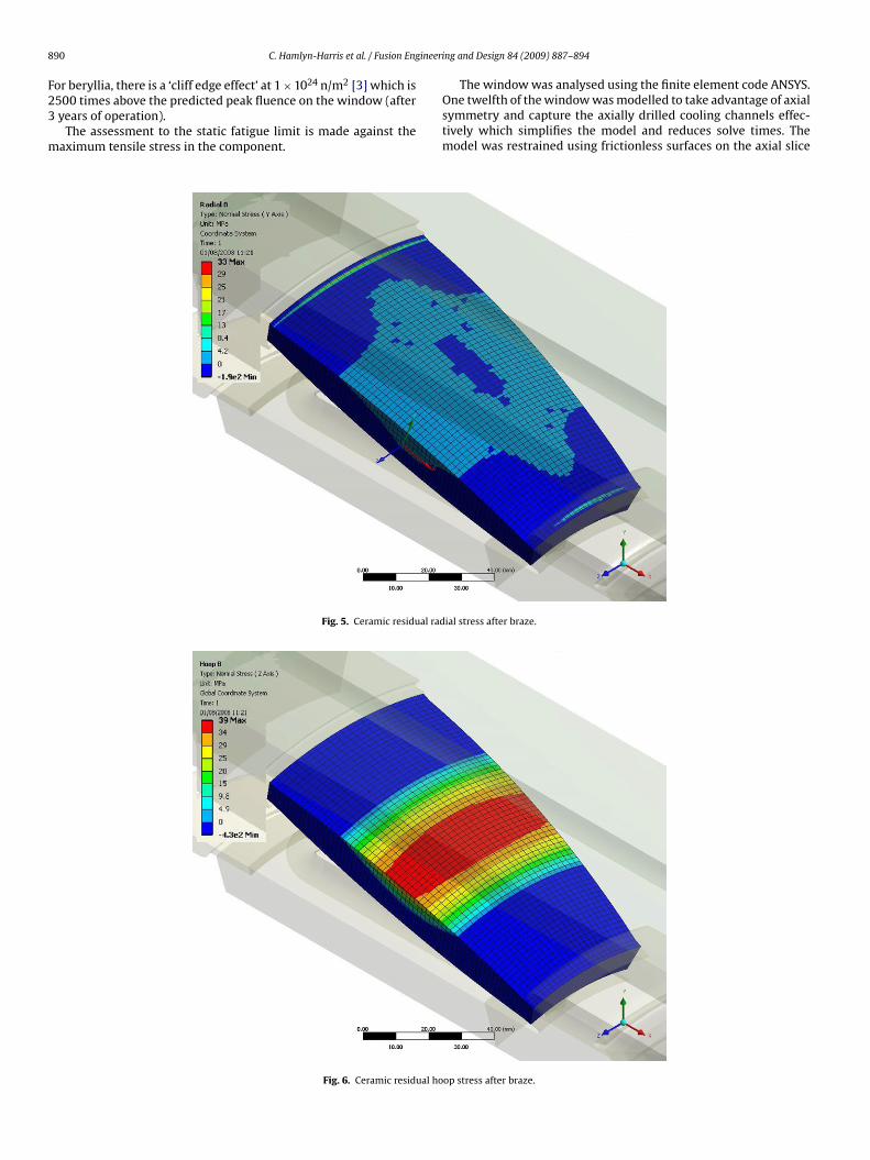
Fig. 4. Ceramic residual ax
ng and Design 84 (2009) 887–894 889
limit assumes a failure probability of 0.001. Measured values of
static fatigue are an acceptable allowable stress in the draft versionof the structural design practice for non-metallic elements (toruswindows) for ITER [9]. This document [9] also requires designers toconsider the degradation in mechanical strength with irradiation.ipal stress after braze.
ial stress after braze.
8 ineeri
F23
m
90 C. Hamlyn-Harris et al. / Fusion Eng
or beryllia, there is a ‘cliff edge effect’ at 1 × 1024 n/m2 [3] which is
500 times above the predicted peak fluence on the window (afteryears of operation).The assessment to the static fatigue limit is made against theaximum tensile stress in the component.
Fig. 5. Ceramic residual rad
Fig. 6. Ceramic residual ho
ng and Design 84 (2009) 887–894
The window was analysed using the finite element code ANSYS.
One twelfth of the window was modelled to take advantage of axialsymmetry and capture the axially drilled cooling channels effec-tively which simplifies the model and reduces solve times. Themodel was restrained using frictionless surfaces on the axial sliceial stress after braze.
op stress after braze.
ineeri
pfl
gadit
C. Hamlyn-Harris et al. / Fusion Eng
lanes and a planar axial restraint condition applied at collar-boltedange end.
Residual stress from brazing is significant and predominantly
enerates compressive stress within the ceramic. There is both anxial contraction and a radial contraction to consider in the coolown from brazing. The combination of these contractions resultsn the principal stress distribution shown in Fig. 3. The maximumensile stress is 39 MPa in the ceramic. This stress has been split
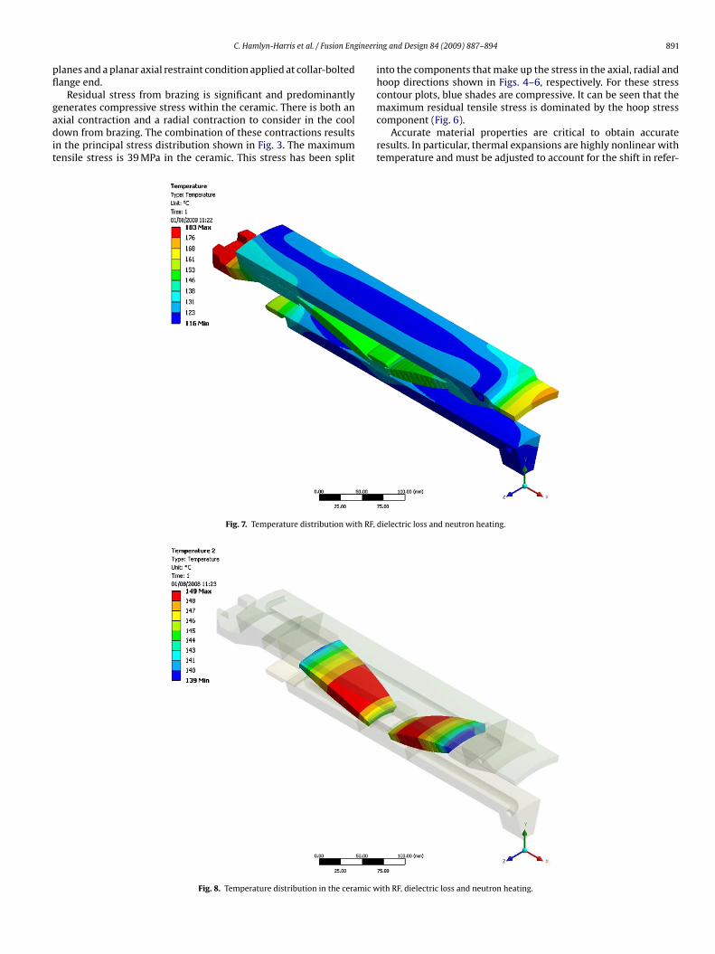
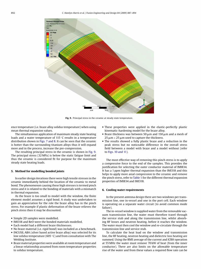
Fig. 7. Temperature distribution with RF,
Fig. 8. Temperature distribution in the ceramic w
ng and Design 84 (2009) 887–894 891
into the components that make up the stress in the axial, radial andhoop directions shown in Figs. 4–6, respectively. For these stresscontour plots, blue shades are compressive. It can be seen that the
maximum residual tensile stress is dominated by the hoop stresscomponent (Fig. 6).Accurate material properties are critical to obtain accurateresults. In particular, thermal expansions are highly nonlinear withtemperature and must be adjusted to account for the shift in refer-
dielectric loss and neutron heating.
ith RF, dielectric loss and neutron heating.
892 C. Hamlyn-Harris et al. / Fusion Engineering and Design 84 (2009) 887–894
erami
em
ldim
Tts
5
cbsi
egsp
•••••
•
Fig. 9. Principal stress in the c
nce temperature (i.e. braze alloy solidus temperature) when usingean thermal expansion values.The simultaneous application of maximum steady state heating
oads and a water temperature of 115 ◦C results in a temperatureistribution shown in Figs. 7 and 8. It can be seen that the ceramic
s hotter than the surrounding titanium alloys thus it will expandore and in the process, increase the pre-compression.The resulting principal stress in the ceramic is shown in Fig. 9.
he principal stress (32 MPa) is below the static fatigue limit andhus the ceramic is considered fit for purpose for the maximumteady state heating loads.
. Method for modelling bonded joints
In earlier design iterations there were high tensile stresses in theeramic immediately behind the location of the ceramic to metalond. The phenomenon causing these high stresses is termed pinchtress and it is related to the bonding of materials with a mismatchn thermal expansion.
As the braze is too small to model with the window, the finitelement model assumes a rigid bond. A study was undertaken toain an appreciation for the role the braze alloy has in the pinchtress. For example if plastic deformation of the braze relieves theinch stress then it may be discounted.
Simple 2D samples were modelled.IMI318 and BeO were the bonded materials modelled.Each model had a different braze thicknesses.No braze material (i.e. rigid bond) was included as a benchmark.
INCUSIL ABA (silver based active braze alloy) was selected for itslow solidus temperature (605 ◦C) and from consultation with TheWelding Institute.Braze material properties were available at room temperature anda linear relationship assumed from room temperature propertiesto solidus temperature.c at steady state temperature.
• These properties were applied in the elastic-perfectly plastickinematic-hardening model for the braze alloy.
• Braze thickness was between 50 �m and 150 �m and a mesh of25 �m × 25 �m used to capture the thickness.
• The results showed a fully plastic braze and a reduction in thepeak stress but no noticeable difference in the overall stressfield between a model with braze and a model without (referto Figs. 10 and 11).
The most effective way of removing this pinch stress is to applya compressive force to the end of the samples. This provides thejustification for selecting the outer conductor material of IMI834.It has a 1 ppm higher thermal expansion than the IMI318 and thishelps to apply more axial compression to the ceramic and removethe pinch stress, refer to Table 1 for the different thermal expansionproperties of IMI834 and IMI318.
6. Cooling water requirements
In the present antenna design there are two windows per trans-mission line, one in-vessel and one in the port cell. Each windowis operating on a separate water circuit (to avoid common modefailure).
The in-vessel window is supplied water from the removable vac-uum transmission line, the water must therefore travel throughthe service stub and along the transmission line, whilst absorb-ing RF losses and neutron heating, before it reaches the window.The water must then cool the window and re-circulate through thetransmission line and service stub.
To calculate the heat load on the window and transmission
line, the RF heating, neutron heating and dielectric loss heating aresummed. Using the RMS average of the current and ICRH operationat 55 MHz the water must remove 70 kW of heat (from the innerconductor). There are also limits on the allowable temperaturerise of the water and from these values a required flow rate can be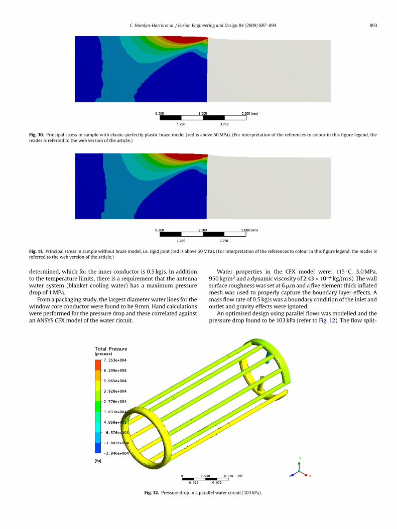
C. Hamlyn-Harris et al. / Fusion Engineering and Design 84 (2009) 887–894 893
Fig. 10. Principal stress in sample with elastic-perfectly plastic braze model (red is above 50 MPa). (For interpretation of the references to colour in this figure legend, thereader is referred to the web version of the article.)
F 50 MPr
dtwd
wwa
ig. 11. Principal stress in sample without braze model, i.e. rigid joint (red is aboveeferred to the web version of the article.)
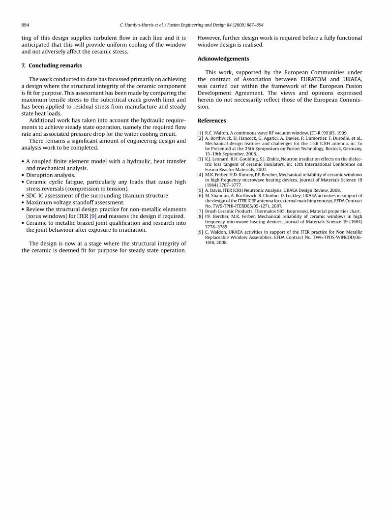
etermined, which for the inner conductor is 0.5 kg/s. In additiono the temperature limits, there is a requirement that the antennaater system (blanket cooling water) has a maximum pressurerop of 1 MPa.
From a packaging study, the largest diameter water lines for theindow core conductor were found to be 9 mm. Hand calculationsere performed for the pressure drop and these correlated against
n ANSYS CFX model of the water circuit.
Fig. 12. Pressure drop in a paral
a). (For interpretation of the references to colour in this figure legend, the reader is
Water properties in the CFX model were; 115 ◦C, 3.0 MPa,950 kg/m3 and a dynamic viscosity of 2.43 × 10⁻⁴ kg/(m s). The wallsurface roughness was set at 6 �m and a five element thick inflatedmesh was used to properly capture the boundary layer effects. A
mass flow rate of 0.5 kg/s was a boundary condition of the inlet andoutlet and gravity effects were ignored.An optimised design using parallel flows was modelled and thepressure drop found to be 103 kPa (refer to Fig. 12). The flow split-
lel water circuit (103 kPa).
8 ineeri
taa
7
aimhs
mr
a
•
••
•••
•
t
[[
[
[
[[
[[8] P.F. Bercher, M.K. Ferber, Mechanical reliability of ceramic windows in high
94 C. Hamlyn-Harris et al. / Fusion Eng
ing of this design supplies turbulent flow in each line and it isnticipated that this will provide uniform cooling of the windownd not adversely affect the ceramic stress.
. Concluding remarks
The work conducted to date has focussed primarily on achievingdesign where the structural integrity of the ceramic component
s fit for purpose. This assessment has been made by comparing theaximum tensile stress to the subcritical crack growth limit and
as been applied to residual stress from manufacture and steadytate heat loads.
Additional work has taken into account the hydraulic require-ents to achieve steady state operation, namely the required flow
ate and associated pressure drop for the water cooling circuit.There remains a significant amount of engineering design and
nalysis work to be completed.
A coupled finite element model with a hydraulic, heat transferand mechanical analysis.Disruption analysis.Ceramic cyclic fatigue, particularly any loads that cause highstress reversals (compression to tension).SDC-IC assessment of the surrounding titanium structure.Maximum voltage standoff assessment.Review the structural design practice for non-metallic elements(torus windows) for ITER [9] and reassess the design if required.
Ceramic to metallic brazed joint qualification and research intothe joint behaviour after exposure to irradiation.The design is now at a stage where the structural integrity ofhe ceramic is deemed fit for purpose for steady state operation.
[
ng and Design 84 (2009) 887–894
However, further design work is required before a fully functionalwindow design is realised.
Acknowledgements
This work, supported by the European Communities underthe contract of Association between EURATOM and UKAEA,was carried out within the framework of the European FusionDevelopment Agreement. The views and opinions expressedherein do not necessarily reflect those of the European Commis-sion.
References
1] R.C. Walton, A continuous wave RF vacuum window, JET-R (99)03, 1999.2] A. Borthwick, D. Hancock, G. Agarici, A. Davies, P. Dumortier, F. Durodie, et al.,
Mechanical design features and challenges for the ITER ICRH antenna, in: Tobe Presented at the 25th Symposium on Fusion Technology, Rostock, Germany,15–19th September, 2008.
3] K.J. Leonard, R.H. Goulding, S.J. Zinkle, Neutron irradiation effects on the dielec-tric loss tangent of ceramic insulators, in: 13th International Conference onFusion Reactor Materials, 2007.
4] M.K. Ferber, H.D. Kimrey, P.F. Bercher, Mechanical reliability of ceramic windowsin high frequency microwave heating devices, Journal of Materials Science 19(1984) 3767–3777.
5] A. Davis, ITER ICRH Neutronic Analysis, UKAEA Design Review, 2008.6] M. Shannon, A. Borthwick, B. Chuilon, D. Lockley, UKAEA activities in support of
the design of the ITER ICRF antenna for external matching concept, EFDA ContractNo. TW5-TPHI-ITERDES/05-1271, 2007.
7] Brush Ceramic Products, Thermalox 995, Isopressed, Material properties chart.
frequency microwave heating devices, Journal of Materials Science 19 (1984)3778–3785.
9] C. Waldon, UKAEA activities in support of the ITER practice for Non MetallicReplaceable Window Assemblies, EFDA Contract No. TW6-TPDS-WINCOD/06-1416, 2008.