electrode placement on the forearm for selective stimulation of
TRANSCRIPT
RESEARCH ARTICLE
Electrode placement on the forearm for
selective stimulation of finger extension/
flexion
Xueliang Bao1, Yuxuan Zhou1, Yunlong Wang1, Jianjun Zhang1, Xiaoying Lu1,2*,
Zhigong Wang2,3*
1 State Key Laboratory of Bioelectronics, Southeast University, Nanjing, People’s Republic of China, 2 Co-
innovation Center of Neuroregeneration, Nantong University, Nantong, People’s Republic of China,
3 Institute of RF- & OE-ICs, Southeast University, Nanjing, People’s Republic of China
* [email protected] (XL); [email protected] (ZW)
Abstract
It is still challenging to achieve a complex grasp or fine finger control by using surface func-
tional electrical stimulation (FES), which usually requires a precise electrode configuration
under laboratory or clinical settings. The goals of this study are as follows: 1) to study the
possibility of selectively activating individual fingers; 2) to investigate whether the current
activation threshold and selective range of individual fingers are affected by two factors:
changes in the electrode position and forearm rotation (pronation, neutral and supination);
and 3) to explore a theoretical model for guidance of the electrode placement used for selec-
tive activation of individual fingers. A coordinate system with more than 400 grid points was
established over the forearm skin surface. A searching procedure was used to traverse all
grid points to identify the stimulation points for finger extension/flexion by applying mono-
phasic stimulation pulses. Some of the stimulation points for finger extension and flexion
were selected and tested in their respective two different forearm postures according to the
number and the type of the activated fingers and the strength of finger action response to
the electrical stimulation at the stimulation point. The activation thresholds and current
ranges of the selectively activated finger at each stimulation point were determined by visual
analysis. The stimulation points were divided into three groups (“Low”, “Medium” and
“High”) according to the thresholds of the 1st activated fingers. The angles produced by the
selectively activated finger within selective current ranges were measured and analyzed.
Selective stimulation of extension/flexion is possible for most fingers. Small changes in elec-
trode position and forearm rotation have no significant effect on the threshold amplitude and
the current range for the selective activation of most fingers (p > 0.05). The current range is
the largest (more than 2 mA) for selective activation of the thumb, followed by those for the
index, ring, middle and little fingers. The stimulation points in the “Low” group for all five fin-
gers lead to noticeable finger angles at low current intensity, especially for the index, middle,
and ring fingers. The slopes of the finger angle variation in the “Low” group for digits 2~4 are
inversely proportional to the current intensity, whereas the slopes of the finger angle varia-
tion in other groups and in all groups for the thumb and little finger are proportional to the cur-
rent intensity. It is possible to selectively activate the extension/flexion of most fingers by
PLOS ONE | https://doi.org/10.1371/journal.pone.0190936 January 11, 2018 1 / 22
a1111111111
a1111111111
a1111111111
a1111111111
a1111111111
OPENACCESS
Citation: Bao X, Zhou Y, Wang Y, Zhang J, Lu X,
Wang Z (2018) Electrode placement on the
forearm for selective stimulation of finger
extension/flexion. PLoS ONE 13(1): e0190936.
https://doi.org/10.1371/journal.pone.0190936
Editor: Manabu Sakakibara, Tokai University,
JAPAN
Received: August 6, 2017
Accepted: December 22, 2017
Published: January 11, 2018
Copyright: © 2018 Bao et al. This is an open access
article distributed under the terms of the Creative
Commons Attribution License, which permits
unrestricted use, distribution, and reproduction in
any medium, provided the original author and
source are credited.
Data Availability Statement: All relevant data are
within the paper and its Supporting Information
files.
Funding: This paper was supported by the National
Natural Science Foundation of China (61534003)
and the Jiangsu Province Science and Technology
Project of China (BE2016738).
Competing interests: The authors have declared
that no competing interests exist.
stimulating the forearm muscles. The physiological characteristics of each finger should be
considered when placing the negative electrode for selective stimulation of individual fin-
gers. The electrode placement used for the selective activation of individual fingers should
not be confined to the location with the lowest activation threshold.
Introduction
Functional electrical stimulation (FES) is a clinical therapeutic technique that can help para-
lyzed patients to recover limb motor function lost due to stroke or spinal cord injury [1]. The
electrical stimulation pulses act on the nerve or the target muscle through surface [2–4] or
implanted electrodes [5] to induce artificial limb movements. Surface FES is widely accepted
by patients because it is noninvasive and convenient.
The therapeutic efficacy of FES on the muscle function rehabilitation of a paretic limb
depends on several factors, including the time point of interventional therapy, the intensity of
FES, and the amount of training [6]. However, many factors, such as muscle fatigue, discom-
fort, and poor muscle selectivity, limit the long-term use and effectiveness of FES. Previous
studies have shown that the size and location of the surface electrode are two of the factors
associated with discomfort and muscle selectivity [6–9]. The optimal electrode size depends on
the target muscle. Small electrodes are more precise than larger ones for the selective activation
of forearm muscles. However, accurate positioning of a small electrode may require more time
than a larger electrode to test over the skin surface of the target muscle [10]. The location of
the stimulating electrode is critical for eliciting the desired muscle contractile response. Posi-
tioning the electrode close to the sensory nerve may lead to activation of skin surface receptors
and cause discomfort. Consequently, patients may refuse such treatment [6]. Therefore, the
electrode location is an urgent issue in clinical applications of body surface electrical stimula-
tion [11–16]. The Handmaster™ system has multiple surface electrodes attached to the splint of
an FES device, allowing users to easily operate it. However, it is difficult to change the position
of the stimulating electrodes. For the ETHZ-ParaCare™ nerve prosthesis, it takes approximately
10 min to correct the electrodes to the right positions [17]. Problems associated with these
devices include the somewhat limited limb-action selectivity and the time-consuming posi-
tioning of the electrodes. Therefore, quickly and accurately positioning the surface electrodes
in the correct locations is an important prerequisite for the effective application of surface FES.
After effective treatments with the currently available FES, patients can perform some
simple functional tasks, including gripping and wrist extension [2, 4]. However, most current
electrical stimulators cannot enable patients to make the fine finger movements that are com-
monly lost in stroke patients. Achieving fine control of finger movements first requires the
identification of the stimulation points for each finger. Several groups have previously used
pen electrodes to locate muscle motor points [18–19]. Theoretically, the motor point is an
optimal stimulus position [20]. In previous studies, the stimulation (negative) electrodes were
placed on the optimal motor points [10] or in location(s) with the lowest activation thresholds
[21] to achieve the selective control of individual fingers. Here, we assumed that points with
higher thresholds than the motor point could also serve as options for negative electrode place-
ment if desired movements could be effectively caused without reports of discomfort during
the stimulation. Thus, it is highly meaningful to determine the locations of the stimulation
points at which the extension/flexion of individual fingers could be activated.
Electrode placement and selective stimulation of individual fingers
PLOS ONE | https://doi.org/10.1371/journal.pone.0190936 January 11, 2018 2 / 22
At the physiological level, there is positive theoretical support for fine finger movement con-
trol. The superficial multi-tendoned muscles, such as the extensor digitorum communis (EDC)
and flexor digitorum superficialis (FDS), can selectively activate digits 2–5. The single-tendoned
muscles, such as the extensor indicis (EI), extensor digiti minimi (EDM), and flexor pollicis
longus (FPL), also activate or assist in the extension or flexion of specific fingers [10, 21–23].
Several groups have attempted to selectively control individual fingers with surface FES.
Keller et al. observed that the flexion of the middle and ring fingers could be selectively stimu-
lated in all participants by applying FES to the finger flexor muscles [24]. By applying FES to
the EDC, FDS, and the thenar muscles, Westerveld et al. found that it was possible to selec-
tively stimulate 3 or 4 fingers, and the selective stimulation of extension of the middle, index,
and ring fingers and flexion of the thumb could be achieved in most participants [10]. These
studies confirmed the possibility of selective activation of individual fingers via the application
of FES to the forearm muscles.
To selectively stimulate a single finger, the distribution of stimulation points for each finger
should be determined first. However, there are currently no reports on the distribution of
stimulation point locations or maps for the selective stimulation of an individual finger. Wes-
terveld et al. sought stimulation points for a specific finger in a 4×6 grid drawn on the EDC
muscle [10]. However, that method could not be applied to everyone, because the position of
the EDC muscle is not easily identified. Then, the activation threshold and selective range of
each stimulation point to the finger were measured. Lawrence et al. found that the optimal
motor point shifted with forearm rotation (pronation and supination) [21].
A relative displacement of the stimulation point may result in a change in the activation
threshold. Thus, we attempted to explore whether small shifts in the position of the negative
electrode in a specific forearm posture and the displacement of the stimulation point in different
forearm postures affected the activation threshold and selective range of each individual finger.
The assumption that the points with high activation thresholds should be used to selectively
stimulate individual fingers was validated by dividing the stimulation points into three groups,
measuring the angle of the stimulated finger in the selective current range, and analyzing the
trend in angle variation. By validating this hypothesis, we may obtain a theoretical guide for the
placement of negative electrodes in order to selectively stimulate individual fingers.
The purpose of this study can be summarized as follows:
1. To determine the location of the stimulation points for finger extension and flexion by
applying a certain current intensity to the grid points in the forearm coordinate system and
to study the possibility and range of selective activation of individual fingers using surface
FES;
2. To investigate whether small changes in electrode placement in a forearm posture and the
relative displacement of the stimulation point (resulting from rotation of the forearm) influ-
ence the activation threshold and selective range of each individual finger;
3. To develop theoretical guidance for electrode placement used for the selective activation of
individual fingers by studying whether the finger activation threshold influences the trend
of finger angle variation.
Methods
Participants
Eight healthy young volunteers (7 male and 1 female, aged 23–30 years, right-handed) partici-
pated in this experiment. They gave written informed consent after the experiment was
Electrode placement and selective stimulation of individual fingers
PLOS ONE | https://doi.org/10.1371/journal.pone.0190936 January 11, 2018 3 / 22
approved by the Southeast University ethics committees. One week before the experiment,
each participant was instructed not to perform strenuous movements associated with the
upper limbs. The right forearm was stimulated during the tests.
Experimental setup
Electrical stimulation and electrodes. A Master-9™ programmer neuromuscular stimula-
tor (AMPI Company, Jerusalem, Israel) with an isolator was used to generate monophasic neg-
ative pulse trains with constant parameters (pulse width and frequency). The maximum
output current amplitude was 10 mA. Round hydrogel electrodes, 2.2 cm in diameter, were
used as the negative electrodes, and rectangular hydrogel electrodes of 4×4 cm were used as
the positive electrode.
Finger angle measurement. A self-developed data acquisition system, including a PC
with appropriate software and an inertial measurement unit (IMU) sensor module incorporat-
ing a micro-controller unit (MCU) chip (STM32F051K8U6) and an MPU9250 sensor, was
used to record and store the finger action angle data. Then, the 3D angle values, including
pitch, yaw and roll, were estimated by a quaternion-based Kalman filter algorithm in the MCU
and sent in real time through the serial port to the software on the PC. Generally, the angle
between the metacarpophalangeal joint (MCP) and the back of the hand is in the range of
70~90˚. The range of motion (ROM) of the proximal interphalangeal joint (PIP) is lower than
that of the distal interphalangeal joint (DIP) and greater than that of the MCP. It is more accu-
rate in response to the FES than the PIP and DIP joints. Therefore, the IMU sensor was
mounted using foam adhesive on the place between the PIP and DIP of the fingers to monitor
the PIP joint movement of the digits (extension and flexion). For the thumb, both angles of the
DIP and PIP were measured. The IMU modular sensor had an angular resolution of 0.01˚ and
a data sampling rate of 100 Hz. The sum of the movement angles of the finger in 3D space
were calculated as follows:
Angle ¼ffiffiffiffiffiffiffiffiffiffiffiffiffiffiffiffiffiffiffiffiffiffiffiffiffiffiffiffiffiffiffiffiffiffiffiffiffiffiffiffiroll2 þ pitch2 þ yaw2
pð1Þ
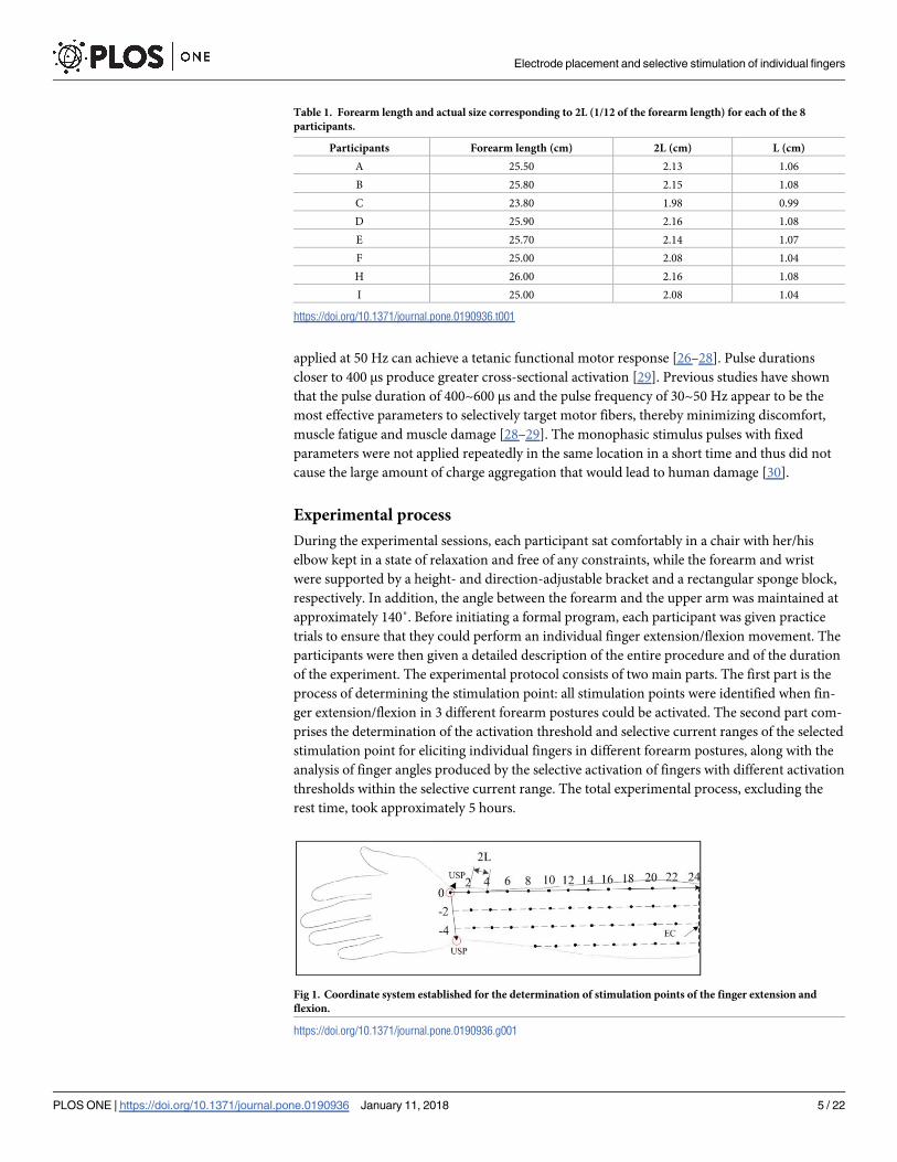
Coordinate system for electrode positioning. A coordinate system with more than 400
grid points was established over the forearm skin surface. The length of the forearm is divided
into 12 equally spaced segments from the elbow crease to the wrist crease. This cross-individ-
ual measurement method is similar to the bone proportional cun (B-cun) method used for
locating acupuncture points in Chinese medicine [25]. For each participant, the distance
between two adjacent grid points is scaled according to the length of the participant’s forearm,
as the points are defined and drawn relative to anatomical landmarks (as given in Table 1).
The inter-grid distance between points in different columns is equal to the distance between
two rows in order to make the coordinate system more standard, although the circumference
of the forearm decreases from the proximal to distal end. The end of the radial distal wrist
crease in the forearm in the supine posture has been defined as the origin, the medial distal
wrist crease has been defined as the positive x-axis, the dorsal wrist crease toward the ulna sty-
loid process (USP) has been defined as the negative x-axis, and the line connecting the wrist
crease and elbow crease (EC) that is perpendicular to the wrist crease has been defined as the
positive y-axis, as shown in Fig 1. The positive electrode was placed over the elbow olecranon,
while the negative electrode was placed at each grid point in order.
Stimulation parameters. For all participants, each grid point in a coordinate system was
electrically stimulated using current pulse trains with a train duration of 1 s. The pulse fre-
quency and the pulse width of a single pulse were 50 Hz and 400 μs, respectively. A stimulation
Electrode placement and selective stimulation of individual fingers
PLOS ONE | https://doi.org/10.1371/journal.pone.0190936 January 11, 2018 4 / 22
applied at 50 Hz can achieve a tetanic functional motor response [26–28]. Pulse durations
closer to 400 μs produce greater cross-sectional activation [29]. Previous studies have shown
that the pulse duration of 400~600 μs and the pulse frequency of 30~50 Hz appear to be the
most effective parameters to selectively target motor fibers, thereby minimizing discomfort,
muscle fatigue and muscle damage [28–29]. The monophasic stimulus pulses with fixed
parameters were not applied repeatedly in the same location in a short time and thus did not
cause the large amount of charge aggregation that would lead to human damage [30].
Experimental process
During the experimental sessions, each participant sat comfortably in a chair with her/his
elbow kept in a state of relaxation and free of any constraints, while the forearm and wrist
were supported by a height- and direction-adjustable bracket and a rectangular sponge block,
respectively. In addition, the angle between the forearm and the upper arm was maintained at
approximately 140˚. Before initiating a formal program, each participant was given practice
trials to ensure that they could perform an individual finger extension/flexion movement. The
participants were then given a detailed description of the entire procedure and of the duration
of the experiment. The experimental protocol consists of two main parts. The first part is the
process of determining the stimulation point: all stimulation points were identified when fin-
ger extension/flexion in 3 different forearm postures could be activated. The second part com-
prises the determination of the activation threshold and selective current ranges of the selected
stimulation point for eliciting individual fingers in different forearm postures, along with the
analysis of finger angles produced by the selective activation of fingers with different activation
thresholds within the selective current range. The total experimental process, excluding the
rest time, took approximately 5 hours.
Table 1. Forearm length and actual size corresponding to 2L (1/12 of the forearm length) for each of the 8
participants.
Participants Forearm length (cm) 2L (cm) L (cm)
A 25.50 2.13 1.06
B 25.80 2.15 1.08
C 23.80 1.98 0.99
D 25.90 2.16 1.08
E 25.70 2.14 1.07
F 25.00 2.08 1.04
H 26.00 2.16 1.08
I 25.00 2.08 1.04
https://doi.org/10.1371/journal.pone.0190936.t001
Fig 1. Coordinate system established for the determination of stimulation points of the finger extension and
flexion.
https://doi.org/10.1371/journal.pone.0190936.g001
Electrode placement and selective stimulation of individual fingers
PLOS ONE | https://doi.org/10.1371/journal.pone.0190936 January 11, 2018 5 / 22
When the forearm was pronated 180˚, the stimulation point identification for finger exten-
sion in the dorsal side of forearm was conducted. Then, the forearm was pronated 90˚ while
keeping the wrist at 0˚ (radial and ulnar) deviation, and stimulation points for finger extension
in the dorsal sides of the forearm and for finger flexion in the ventral side of the forearm were
determined. Finally, the stimulation points for finger flexion were identified in the ventral side
of the forearm while the forearm was pronated 0˚ (Fig 2A).
Scanning the grid points and marking the active stimulation points. The scanning pro-
cedure began at the coordinate origin in the forearm coordinate system and was performed
once in each forearm posture for each participant. The negative electrode was initiated with an
8-mA current intensity at each grid point. This current intensity was chosen to elicit more
digit movement after a pilot test across each participant, avoiding more discomfort resulting
from the use of a stronger current. As shown in Fig 2B, the negative electrode was moved over
the grid points. When the electrode was moved to the next adjacent grid point from one point
(e.g., from p1 to p2), there was partial overlap in the coverage regions of these two electrodes.
Each grid point was stimulated twice to confirm which fingers were in motion and which type
of motion was occurring. Each participant was asked to accurately report any uncomfortable
sensation in the testing process. The grid points without pricking, muscle pain, or discomfort
were finally marked as stimulation points.
Determination of activation thresholds and acquisition of finger movement angles.
After the completion of stimulation point identification, we selected some of the stimulation
points and tested in their respective two different forearm postures (e.g., stimulation points for
finger extension were examined in the forearm pronation and neutral postures) according to
the number and the type of the activated fingers and the strength of finger action response to
the electrical stimulation at the stimulation point, because it would be a time-consuming task,
if each stimulation point of finger extension/flexion identified in the coordination system was
used to be investigated. For each selected stimulation point, the activation thresholds of all
activated fingers in different forearm postures were determined. The threshold was deter-
mined by changing the current intensity applied to the stimulation point, which was first
decreased in steps of 1 mA and then adjusted in small steps of 0.1 mA if the finger angle
changed slightly with the varying current intensity. When visible finger twitching or minimal
movement was observed visually and verified by the PC software, the current intensity applied
to the stimulation point was defined as the activation threshold of the stimulated finger. The
current range between the activation thresholds of the 1st and 2nd activated fingers at each
stimulation point was considered the selective current range of the 1st activated finger (see
details in point 1 of section 2.4).
After determining the activation threshold and selective current threshold for the 1st acti-
vated finger at each stimulation point in different forearm postures, the stimulus points were
divided into 3 groups (“Low”, “Medium” and “High”) according to thresholds of the 1st acti-
vated fingers. Integer mA intensity electrical stimulation within the selective current range of
the 1st activated finger was applied to each stimulation point. During the testing process, in
addition to the complete relaxation of each participant, the stimulation was applied repeatedly
to exclude the voluntary and reflexive components of the movements. Each selected stimula-
tion point was repeatedly stimulated 8 times, with a relaxation period of� 5 s between con-
tractions (Fig 2C).
The angle data that the finger produced within the selective current range were recorded by
the IMU sensor module and transmitted through the serial port to the PC software.
A custom-written MATLAB script (The MathWorks, Natick, MA) was used to address the
angle data stored by the PC software. Three or four active angles were selected within 8
recorded finger angles, the mean value of which was calculated for further analysis.
Electrode placement and selective stimulation of individual fingers
PLOS ONE | https://doi.org/10.1371/journal.pone.0190936 January 11, 2018 6 / 22
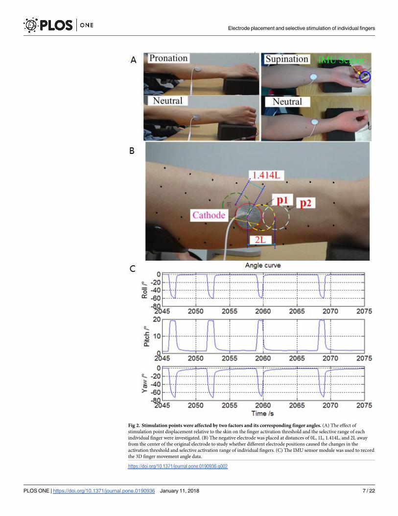
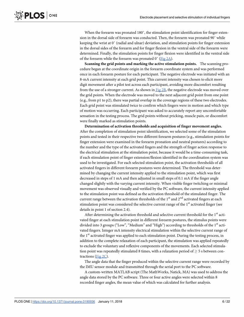
Fig 2. Stimulation points were affected by two factors and its corresponding finger angles. (A) The effect of
stimulation point displacement relative to the skin on the finger activation threshold and the selective range of each
individual finger were investigated. (B) The negative electrode was placed at distances of 0L, 1L, 1.414L, and 2L away
from the center of the original electrode to study whether different electrode positions caused the changes in the
activation threshold and selective activation range of individual fingers. (C) The IMU sensor module was used to record
the 3D finger movement angle data.
https://doi.org/10.1371/journal.pone.0190936.g002
Electrode placement and selective stimulation of individual fingers
PLOS ONE | https://doi.org/10.1371/journal.pone.0190936 January 11, 2018 7 / 22
Data analysis
Selective current ranges of individual fingers. The selective current range of each indi-
vidual finger was defined as the range of current intensity under which only one finger
responded to the FES. These ranges demonstrated how selectively a single finger could be
stimulated by adjusting the current intensity. Fig 3 shows an example of a stimulation point
for which finger A responded to the FES first (at Ia mA), followed by finger B (at Ib mA),
resulting in a selective stimulation current range for finger A of Ia~Ib mA. The value of I1 was
a current intensity equal to the result of function ceil (Ia) that rounded the threshold Ta to the
nearest integer toward infinity. The values of I2 and I3 were equal to I1+1 mA and I2+2 mA,
respectively. The Tb in Fig 3 was not available for the thumb because of its wide selective cur-
rent range. The definitions of A1, A2, and A2 are given in point 2 of this section.
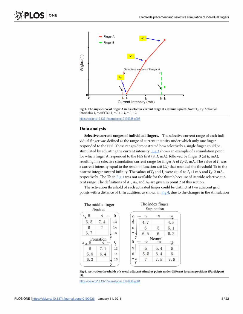
The activation threshold of each activated finger could be distinct at two adjacent grid
points with a distance of L. In addition, as shown in Fig 4, due to the changes in the stimulation
Fig 3. The angle curve of finger A in its selective current range at a stimulus point. Note: Ta, Tb: Activation
thresholds; I1 = ceil (Ta); I2 = I1+ 1; I3 = I1 + 2.
https://doi.org/10.1371/journal.pone.0190936.g003
Fig 4. Activation thresholds of several adjacent stimulus points under different forearm positions (Participant
D).
https://doi.org/10.1371/journal.pone.0190936.g004
Electrode placement and selective stimulation of individual fingers
PLOS ONE | https://doi.org/10.1371/journal.pone.0190936 January 11, 2018 8 / 22
point position caused by the relative displacement of the skin and muscles, forearm rotation
could change the activation threshold for a specific finger that was always activated at the same
grid point. The effects of small changes in the electrode placement and relative displacement of
the stimulation point (resulting from forearm rotation) on the threshold amplitude and selec-
tive range of each individual finger are described in Section 3.2.
The trend of finger angle variation in different sets of activation thresholds. On the
basis of the threshold measurements described above, we defined “Low” activation thresholds
as those with values of< 4 mA, “Medium” activation thresholds as those with values in the
range of 4–6 mA, and “High” activation thresholds as those with values� 6 mA. The angles of
each selectively stimulated finger were measured for stimulation points in each threshold
group at current intensities of I1, I2, and I3 mA. The trend of finger angle variation of each
stimulation point was deduced by observing the slope of each finger angle. As shown in Fig 3,
A1, A2 and A3 were the angles produced by finger A at 3 different current levels, I1 mA, I2 mA
and I3 mA, respectively.
Statistical analysis
A 4 × 2 (electrode position × forearm position) two-way ANOVA with Scheffe’s test (p< 0.05)
was performed to examine the effect of the electrode position change and relative shift of stim-
ulation points on the activation threshold and the selective range of each individual finger. A
Kruskal-Wallis one-way ANOVA was used to analyze the effect of the finger activation thresh-
old on the trend of angle variation of each finger at increasing current intensities.
Results
Determination of stimulation point distribution for finger extension and
flexion
The length of forearm can be divided into 12 equally spaced segments from the elbow crease to
the wrist crease. This method contributes to the location of stimulation point for the finger
extension/flexion. Fig 5 shows the positions of stimulation points for extension/flexion of each
finger (for participant D), which were identified using 8-mA electrical stimulation at each of
the grid points in the forearm coordinate system. When the forearm was rotated from prona-
tion or supination to the neutral position, the grid points that corresponded to the muscle
stimulation points in the original forearm position for finger extension or flexion moved
toward the radial side of the forearm. By contrast, the muscle stimulation points themselves
moved toward the ulnar side of the forearm. In the different forearm postures, both the num-
ber of stimulus points for each finger and the size of the stimulation point distribution were
changed. For digits 2 to 5, most of the stimulation points were in the same position on the
forearm.
Fig 6 shows the maps of distributions of stimulation points to selectively stimulate exten-
sion/flexion of individual fingers in two forearm positions (pronation and supination) for par-
ticipants D and F. Points in different colors indicate the positions of the stimulation points
that selectively stimulated each finger. There was inter-participant variation in the location of
the stimulus points for selective activation of the same finger, such as the stimulation point
positions for selective stimulation of ring finger extension and index finger flexion. The same
grid point among the participants could selectively stimulate different fingers, such as stimula-
tion of finger extension at position (5, 10). We measured the selective current range for several
stimulation points that selectively activated a single finger movement and used arrows and dif-
ferently sized black circles to mark these stimulation points in Fig 6. Different stimulation
Electrode placement and selective stimulation of individual fingers
PLOS ONE | https://doi.org/10.1371/journal.pone.0190936 January 11, 2018 9 / 22
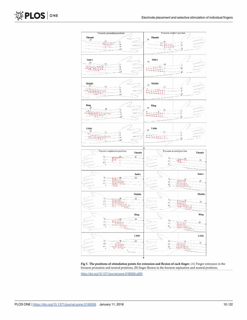
Fig 5. The positions of stimulation points for extension and flexion of each finger. (A) Finger extension in the
forearm pronation and neutral positions; (B) finger flexion in the forearm supination and neutral positions.
https://doi.org/10.1371/journal.pone.0190936.g005
Electrode placement and selective stimulation of individual fingers
PLOS ONE | https://doi.org/10.1371/journal.pone.0190936 January 11, 2018 10 / 22
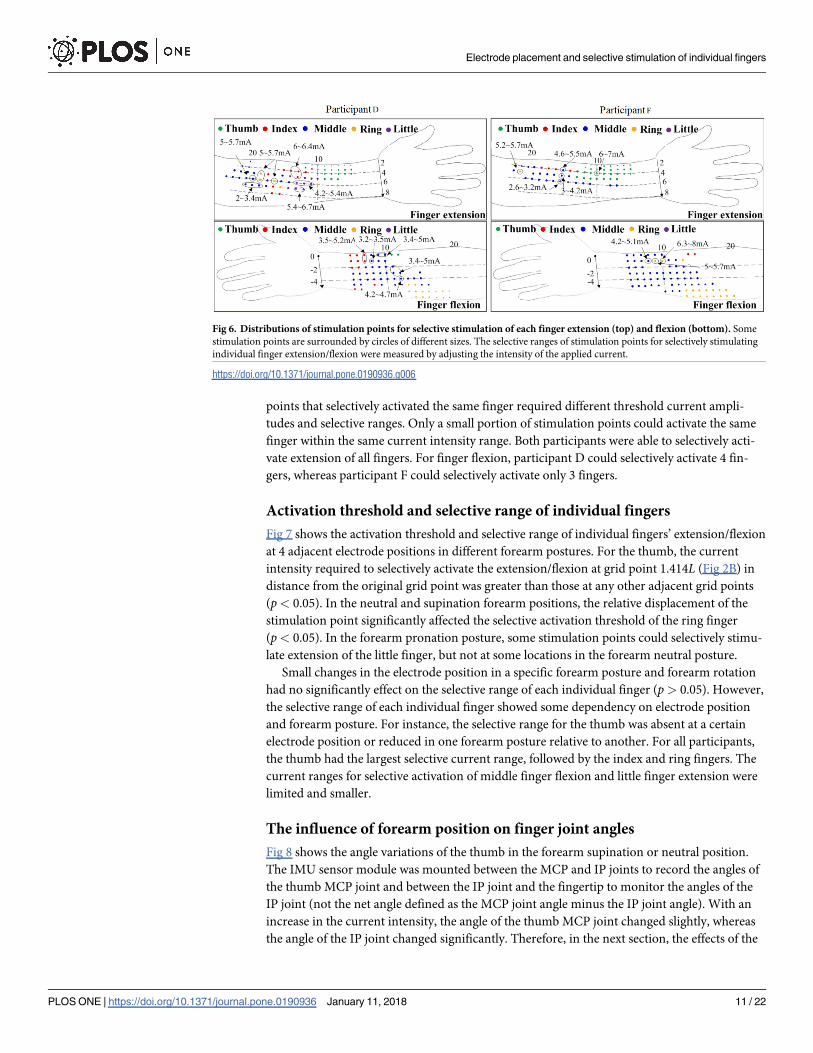
points that selectively activated the same finger required different threshold current ampli-
tudes and selective ranges. Only a small portion of stimulation points could activate the same
finger within the same current intensity range. Both participants were able to selectively acti-
vate extension of all fingers. For finger flexion, participant D could selectively activate 4 fin-
gers, whereas participant F could selectively activate only 3 fingers.
Activation threshold and selective range of individual fingers
Fig 7 shows the activation threshold and selective range of individual fingers’ extension/flexion
at 4 adjacent electrode positions in different forearm postures. For the thumb, the current
intensity required to selectively activate the extension/flexion at grid point 1.414L (Fig 2B) in
distance from the original grid point was greater than those at any other adjacent grid points
(p< 0.05). In the neutral and supination forearm positions, the relative displacement of the
stimulation point significantly affected the selective activation threshold of the ring finger
(p< 0.05). In the forearm pronation posture, some stimulation points could selectively stimu-
late extension of the little finger, but not at some locations in the forearm neutral posture.
Small changes in the electrode position in a specific forearm posture and forearm rotation
had no significantly effect on the selective range of each individual finger (p> 0.05). However,
the selective range of each individual finger showed some dependency on electrode position
and forearm posture. For instance, the selective range for the thumb was absent at a certain
electrode position or reduced in one forearm posture relative to another. For all participants,
the thumb had the largest selective current range, followed by the index and ring fingers. The
current ranges for selective activation of middle finger flexion and little finger extension were
limited and smaller.
The influence of forearm position on finger joint angles
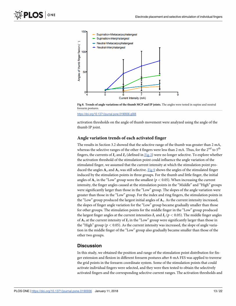
Fig 8 shows the angle variations of the thumb in the forearm supination or neutral position.
The IMU sensor module was mounted between the MCP and IP joints to record the angles of
the thumb MCP joint and between the IP joint and the fingertip to monitor the angles of the
IP joint (not the net angle defined as the MCP joint angle minus the IP joint angle). With an
increase in the current intensity, the angle of the thumb MCP joint changed slightly, whereas
the angle of the IP joint changed significantly. Therefore, in the next section, the effects of the
Fig 6. Distributions of stimulation points for selective stimulation of each finger extension (top) and flexion (bottom). Some
stimulation points are surrounded by circles of different sizes. The selective ranges of stimulation points for selectively stimulating
individual finger extension/flexion were measured by adjusting the intensity of the applied current.
https://doi.org/10.1371/journal.pone.0190936.g006
Electrode placement and selective stimulation of individual fingers
PLOS ONE | https://doi.org/10.1371/journal.pone.0190936 January 11, 2018 11 / 22
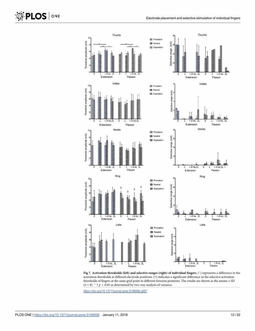
Fig 7. Activation thresholds (left) and selective ranges (right) of individual fingers. (�) represents a difference in the
activation thresholds at different electrode positions. (†) indicates a significant difference in the selective activation
thresholds of fingers at the same grid point in different forearm positions. The results are shown as the means ± SD
(n = 8). � , † p< 0.05 as determined by two-way analysis of variance.
https://doi.org/10.1371/journal.pone.0190936.g007
Electrode placement and selective stimulation of individual fingers
PLOS ONE | https://doi.org/10.1371/journal.pone.0190936 January 11, 2018 12 / 22
activation thresholds on the angle of thumb movement were analyzed using the angle of the
thumb IP joint.
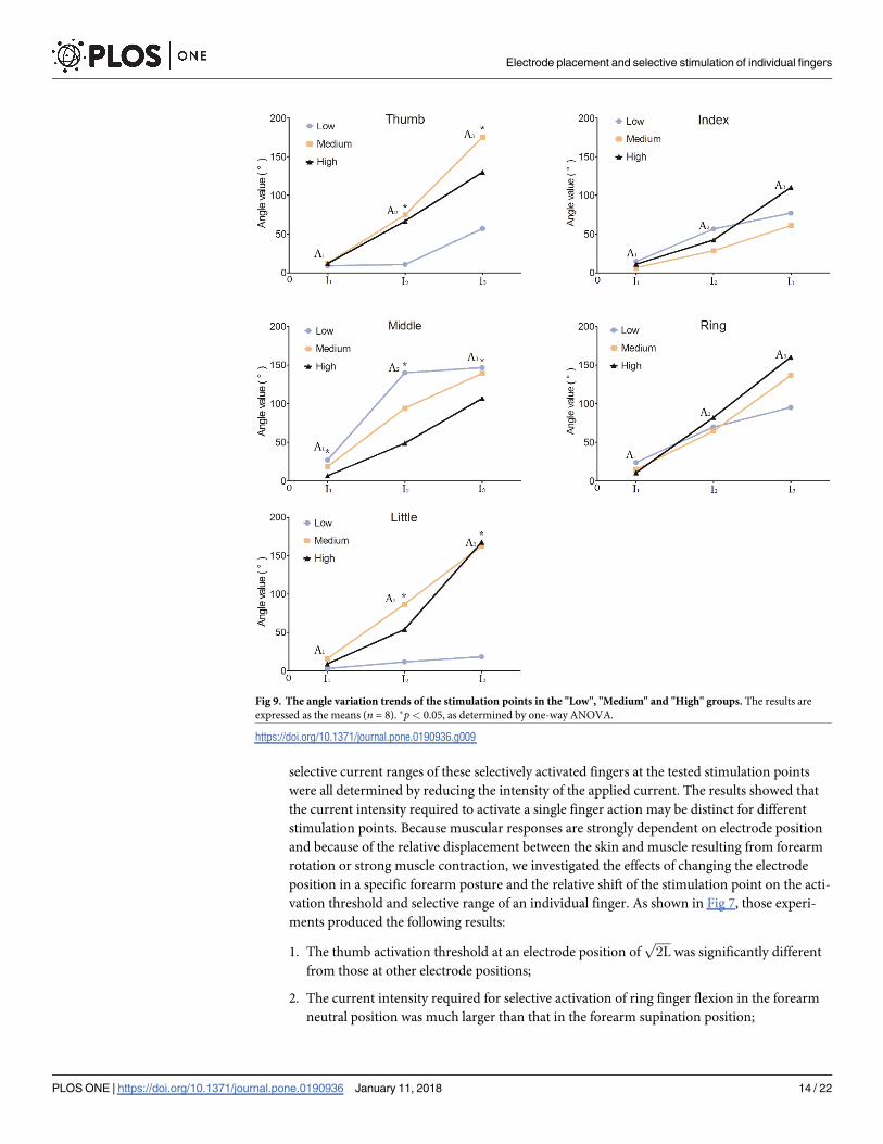
Angle variation trends of each activated finger
The results in Section 3.2 showed that the selective range of the thumb was greater than 2 mA,
whereas the selective ranges of the other 4 fingers were less than 2 mA. Thus, for the 2nd to 5th
fingers, the currents of I2 and I3 (defined in Fig 3) were no longer selective. To explore whether
the activation threshold of the stimulation point could influence the angle variation of the
stimulated finger, we assumed that the current intensity at which the stimulation point pro-
duced the angles A2 and A3 was still selective. Fig 9 shows the angles of the stimulated finger
induced by the stimulation points in three groups. For the thumb and little finger, the initial
angles of A1 in the “Low” group were the smallest (p< 0.05). When increasing the current
intensity, the finger angles caused at the stimulation points in the “Middle” and “High” groups
were significantly larger than those in the “Low” group. The slopes of the angle variation were
greater than those in the “Low” group. For the index and ring fingers, the stimulation points in
the “Low” group produced the largest initial angles of A1. As the current intensity increased,
the slopes of finger angle variation for the “Low” group became gradually smaller than those
for other groups. The stimulation points for the middle finger in the “Low” group produced
the largest finger angles at the current intensities I1 and I2 (p< 0.05). The middle finger angles
of A3 at the current intensity of I3 in the “Low” group were significantly larger than those in
the “High” group (p< 0.05). As the current intensity was increased, the slope of angle varia-
tion in the middle finger of the “Low” group also gradually became smaller than those of the
other two groups.
Discussion
In this study, we obtained the position and range of the stimulation point distribution for fin-
ger extension and flexion in different forearm postures after 8-mA FES was applied to traverse
the grid points in the forearm coordinate system. Some of the stimulation points that could
activate individual fingers were selected, and they were then tested to obtain the selectively
activated fingers and the corresponding selective current ranges. The activation thresholds and
Fig 8. Trends of angle variations of the thumb MCP and IP joints. The angles were tested in supine and neutral
forearm postures.
https://doi.org/10.1371/journal.pone.0190936.g008
Electrode placement and selective stimulation of individual fingers
PLOS ONE | https://doi.org/10.1371/journal.pone.0190936 January 11, 2018 13 / 22
selective current ranges of these selectively activated fingers at the tested stimulation points
were all determined by reducing the intensity of the applied current. The results showed that
the current intensity required to activate a single finger action may be distinct for different
stimulation points. Because muscular responses are strongly dependent on electrode position
and because of the relative displacement between the skin and muscle resulting from forearm
rotation or strong muscle contraction, we investigated the effects of changing the electrode
position in a specific forearm posture and the relative shift of the stimulation point on the acti-
vation threshold and selective range of an individual finger. As shown in Fig 7, those experi-
ments produced the following results:
1. The thumb activation threshold at an electrode position offfiffiffiffiffi2Lp
was significantly different
from those at other electrode positions;
2. The current intensity required for selective activation of ring finger flexion in the forearm
neutral position was much larger than that in the forearm supination position;
Fig 9. The angle variation trends of the stimulation points in the "Low", "Medium" and "High" groups. The results are
expressed as the means (n = 8). �p< 0.05, as determined by one-way ANOVA.
https://doi.org/10.1371/journal.pone.0190936.g009
Electrode placement and selective stimulation of individual fingers
PLOS ONE | https://doi.org/10.1371/journal.pone.0190936 January 11, 2018 14 / 22
3. The required current amplitude for activating a single-finger extension was slightly greater
than that required for finger flexion;
4. The selective activation ranges of each finger were different and limited, as the selective
ranges for thumb extension and flexion were> 2 mA, and those for the 2nd to 5th fingers
were< 2 mA;
5. The index finger had the second-largest activation range after the thumb. The selective
stimulation of middle finger extension and of little finger flexion was least achievable via
the application of surface FES to the forearm muscles.
It was possible to selectively activate the extension and flexion of most fingers by stimulat-
ing the forearm muscles. These results suggested that the use of high-resolution FES to stimu-
late the forearm muscles was likely to achieve selective activation of individual fingers. The
current threshold required to selectively activate most of the fingers varied slightly despite
changes in the electrode position and the forearm posture.
We conducted a further analysis (shown in Fig 9) based on the results described above. The
stimulation points that could selectively stimulate a single finger had different activation
thresholds and were found to have the following characteristics:
1. In the current range for selective activation of an individual finger, the slopes of the finger
angle variation in the “Low” group for digits 2~4 were inversely proportional to the current
intensity. Meanwhile, the slopes of the finger angle variation in the other groups for digits
2~4 and in all 3 groups for the thumb and little finger were proportional to the current
intensity.
2. For the selective activation of the thumb and little finger, the stimulation points with higher
activation thresholds resulted in higher finger angles when compared to the stimulation
points in the “Low” group (p< 0.05). Therefore, a stimulation point with a high activation
threshold may be more appropriate for the selective activation of the thumb or little finger
to achieve the target action.
3. For the index and ring fingers, as shown in Fig 9, there were no significant differences in
the finger angles generated by the stimulation points in the 3 groups at each current level
within the selective activation range.
4. The stimulation points for the middle finger in the “Low” group produced larger finger
angles than those in other 2 groups over the selective current range (p< 0.05).
In a previous study, the location at which a robust muscle contraction could be achieved
when the minimum current was injected was called the motor point [30]. As shown in Fig 9, at
the small injected current (I1), the stimulation points in the “Low” group for all 5 fingers pro-
duced noticeable movements, especially of the index, middle, and ring fingers. However, the
stimulation points in the “Low” groups for 3 or 4 fingers produced smaller finger angles than
those of the other 2 groups at the current intensities I2 and I3. Therefore, we believed that if the
electrode placement used for the selective activation of individual fingers was confined to the
location with the lowest activation threshold [19], it might reduce the possibility of achieving
the target action within the selective current range.
Physiological aspects
The selective stimulation of individual fingers may result from stimulating a single muscle
component through a single nerve branch [10]. The FPL muscle dominates thumb flexion,
whereas the extensor pollicis longus (EPL) and extensor pollicis brevis (EPB) muscles induce
Electrode placement and selective stimulation of individual fingers
PLOS ONE | https://doi.org/10.1371/journal.pone.0190936 January 11, 2018 15 / 22
thumb extension. Thumb extension and flexion are the most independent movements when
the thumb muscles are selectively stimulated. The FDS and EDC are superficial multi-tendoned
muscles with sub-compartments involved in the selective activation of digits 2~5 [21, 31]. The
FDS connects the PIP joint of the finger via tendons, the deeper stratum of which divides into
sub-compartments for the index and small fingers and the superficial stratum of which controls
the ring and middle fingers. The index finger can also be extended by contraction of the EI
muscle. The greater independence of the index finger relative to digits 3~5 can be attributed to
the selective stimulation of the EI muscle, and the selective range for index finger flexion may
result from the stimulation of the medial nerve innervating the lateral parts of the index finger
[22–23]. The coupling of nerves and additional connective tissues between the muscles and the
tendons is likely to result in a relatively small selective range of flexion for the middle, ring and
little fingers [32]. The middle finger had the smallest amount of independent movement [33].
Our result showed that the stimulation points for selective stimulation of the middle finger
were identified in participants D and F (Fig 6). The middle finger extension had the smallest
selectivity range (Fig 7), which is likely the result of the inter-participant variation in the stimu-
lation points for individual finger selective stimulation. Lang et al. observed that the neuromus-
cular coupling was greatest in the control of the ring and little fingers [32, 34]. Extension of the
little finger can be obtained by activation of the EDM muscle [18]. The flexion of the little fin-
ger has the smallest selectivity range, which was similar to that of middle finger extension. Our
study was consistent with the previous report that functional connection from the FDS muscle
to the little finger is missing in almost 60% of examined participants (Fig 6) [32].
No significant differences in the threshold amplitude and the selective ranges of most fin-
gers were observed, though the finger activation thresholds changed between adjacent elec-
trode positions, and stimulation points also shifted relative to the skin surface during forearm
rotation (Fig 7). For the thumb, the electrode position or the intensity of the current should be
adjusted to achieve the activation threshold, given that a relatively large displacement between
the muscle and the skin was observed during forearm rotation. For other fingers, when the
forearm posture was changed, only a slight increase in the current intensity was needed to acti-
vate the target finger.
Low levels of electrical stimulation can easily activate motor units (MUs) with lower stimu-
lation thresholds that are close to the stimulation electrode. These may be primarily the fatiga-
ble type II-B MUs. Then, the fatigue-resistant type I and II-A MUs with higher activation
thresholds and deep II-B MUs begin to be activated with increasing in FES intensity [20]. Fig 9
shows that the slopes of the finger angle variation in the “Low” group for digits 2~4 were
inversely proportional to the current intensity. This may be because a subset of activated MUs
of type II-B underwent fatigue. We speculated that the stimulation points with higher activa-
tion thresholds might activate more MUs of types I and II-A on the basis of the change in the
slope of the finger angle.
Due to the neuromuscular coupling of the nerves and muscles and the connections of the
tendons, the independent range of movement of a single finger is limited. Thus, the physiologi-
cal characteristics of each finger should be considered if the user wants to achieve the selective
stimulation of an individual finger through surface FES. For instance, it is suggested that the
locations with a lower activation threshold are more appropriate for selective stimulation of
the middle finger because it is the least independent [33].
Related works
Keller et al. succeeded in achieving selective flexion of most of the fingers but were unable to
selectively stimulate the little finger [24]. Our results on this point are nearly identical to those
Electrode placement and selective stimulation of individual fingers
PLOS ONE | https://doi.org/10.1371/journal.pone.0190936 January 11, 2018 16 / 22
of Keller’s study (Fig 7). Nathan [34] found that the thumb can be selectively stimulated by the
FPL and thenar muscles, whereas Westerveld et al. observed that selective stimulation of
thumb flexion and middle finger extension was possible. They also found that selective stimu-
lation of the index and ring finger was possible in most cases, and 3 or 4 fingers could be selec-
tively stimulated for most participants [10]. Our results showed that selective stimulation of
the forearm muscles can be used to induce extension and flexion of most of the fingers, with
the exceptions of middle finger extension and little finger flexion. The fact that the single-ten-
doned muscles that control thumb extension and flexion, such as the FPL, EPL, and EPB mus-
cles, are located in the forearm might explain the finding that the thumb possesses the largest
selective range.
Lawrence et al. investigated the movement trajectory of the motor points relative to the
skin surface during forearm rotation [21]. They observed that the change in position of the
optimal motor points for selective finger flexion was up to 4 cm, whereas the locations of opti-
mal motor points varied relatively little for finger extension, thumb flexion and thumb adduc-
tion. We investigated the changes of the activation threshold and selective current range of the
selectively activated finger for the same grid point that was stimulated during forearm rotation.
As shown in Fig 7, the shift of the stimulation point position relative to the skin surface did not
significantly affect the activation thresholds and selective ranges of the selectively activated fin-
ger. That is to say, once the activation threshold and selective current range of an individual
finger are determined at a certain location, it is not necessary to greatly adjust the intensity of
the applied stimulating current if there is a slight change in the forearm posture of the partici-
pant. This finding is favorable for the use of surface FES to achieve fine finger control. We
found that the current amplitude required for activating the extension of a single finger was
slightly greater than that required for flexion of a single finger. The positions and distributions
of the stimulation points for selective stimulation of individual fingers were similar among
participants, which would be helpful for rapid and accurate placement of the electrodes in lab-
oratory settings. The results in angle variation trends of stimulation points with different
activation thresholds provided us with theoretical guidance to successfully and selectively stim-
ulate a single finger.
De Marchis et al. utilized a surface array with fixed electrode positions, containing multi-
electrodes with stimulation (negative) and return (positive) contacts, to identify the optimal
stimulation point for hand opening [35]. They applied single pulses with a pulse width of
500 μs at three different amplitudes (9 mA, 10 mA and 11 mA) to the stimulation patterns
(defined as a pairs of negative and positive electrode) without inducing discomfort, while the
surface electromyography (sEMG) signal generated by the stimulated muscle during the pulse
was recorded. After removing lower-frequency movement artifacts, high-frequency noise, and
stimulation artifacts, sEMG signals contained only the muscular response to the applied stimu-
lation, corresponding to the evoked M-wave. The optimal stimulation pattern for a muscle was
determined by comparing the peak-to-peak length of the median M-wave. Then, a 5-s FES
burst with a frequency of 30 Hz and a pulse width of 500 μs was carried out to examine the
robustness of the optimal stimulation pattern during forearm rotation. This may indeed be a
novel method used for determining the optimal stimulation pattern. However, a series of com-
plex signal processing algorithms must be conducted to obtain the muscle response (M-wave).
It was not stated whether the frequency of the single pulse used was more than 20 Hz, because
FES below 20 Hz cannot induce a fusion contraction. Moreover, the authors also proposed
that the method used might be particularly useful for those severely affected patients who
show no residual hand movement at all, given that the muscle spasticity would limit the deter-
mination and detection of any muscle twitches. In our study, we used a 1-s FES pulse sequence
with a current level of 8 mA, a pulse width of 400 μs, and a frequency of 50 Hz to scan the grid
Electrode placement and selective stimulation of individual fingers
PLOS ONE | https://doi.org/10.1371/journal.pone.0190936 January 11, 2018 17 / 22
points in the forearm coordinate system. Our study provided the electrode placement position
for selective stimulation of individual fingers in different forearm postures. We further investi-
gated how the activation threshold and selective current range of the selectively activated fin-
ger varied due to changes in the electrode position and forearm rotation and whether the
stimulation points with different thresholds produced the same finger angle variation within
the selective current range. Compared to De Marchis’s study, we identified all the stimulation
points that induced individual fingers, rather than the optimal stimulus pattern. In addition,
the methodology used in our study did not involve complex processing algorithms, making it
easier to conduct.
Limitations
In this study, experiments were performed only in healthy human participants. We achieved
the purpose of selectively activating individual fingers by applying electrical stimulation to the
forearm muscles. During the experiments, we found that some stimulus points could elicit
both the finger and the wrist extension/flexion at higher current intensities, and some stimulus
points induced both the thumb extension and wrist abduction. However, the wrist joint kine-
matics were not recorded during the testing process because this point was out of the scope of
the study.
In the future, factors that affect muscle selectivity should be taken into account as much as
possible, and the experimental design should also be extended to stroke patients. Although
paralyzed patients show changes in muscle properties, the skin and the underlying muscles
that constitute the geometry of the forearm change only slightly [13, 15]. This geometry is an
important factor in the spatial selectivity of surface stimulation [10]. We believe that the results
of this study will be likely to provide guidance for future clinical trials.
An appropriate method is required to identify and locate the inter-participant variation in
the distribution of the stimulation points for the selective stimulation of finger extension and
flexion, resulting in a personalized stimulation. Future methods designed for fine finger con-
trol should include a high-density array of electrodes and should have the ability to locate the
appropriate stimulation points in participants with reference to the present results according
to the needs of the functional task to be completed.
There was no design to measure subjective comfort in our study. Stimulation was stopped
when participants reported unbearable discomfort. However, we found that most participants
were able to tolerate stimulation at 8 mA. In theory, a greater stimulation intensity would
result in a different distribution of stimulation points for finger extension/flexion, that is, each
stimulation point would activate more fingers than the lower current intensity. However, the
selective activation of a single finger at 8 mA of electrical stimulation was impossible in most
participants because multiple fingers were activated. Thus, 8 mA of electrical stimulation was
enough for most cases.
Practical applications
The results of this study show the positions at which we can place a negative electrode or an
electrode array for the selective stimulation of finger extension/flexion in different forearm
postures. The small differences in the activation threshold and selective range between differ-
ent selectively activated fingers indicate that a high-resolution stimulator for the fine control of
stimulus current and pulse duration, like the Master-9™ stimulator, should be designed. High-
resolution stimulation could enable stroke patients who have been able to achieve gross func-
tional hand opening to perform tasks requiring fine finger control. Fig 6 shows the stimulation
points that selectively activated single-finger extension/flexion for two participants. Although
Electrode placement and selective stimulation of individual fingers
PLOS ONE | https://doi.org/10.1371/journal.pone.0190936 January 11, 2018 18 / 22
the number and location of the stimulation points for selectively activating individual fingers
differed slightly, the positions of the stimulation points for finger extension/flexion were gen-
erally consistent relative to the length and width of the forearm.
FES induces muscle contraction in a non-physiological way, which may not follow the size
principle and may recruit motor units in a nonselective manner. Thus, in practical applica-
tions, early fatigue may still occur due to the stimulation to identical muscle fibers. As shown
in Fig 6, the stimulation points for selectively activating a single finger were not unique.
Changing the applied stimulus strategy [36] or providing asynchronous stimulus [37] of stim-
ulus points may be an effective way to alleviate muscle fatigue.
At present, a wearable multi-pad-based prototype for selective FES has been developed in
our group [38]. In future, we intend to develop a specific electrode array based on the shape
and distribution of stimulation points detected in this study for selective stimulation of finger
extension/flexion. Then, an iterative learning algorithm and sensor feedback may be used to
identify the stimulation points that selectively activate individual finger and to control stimu-
lating pulse output [39–40]. The frontend circuit of the stimulator should be further improved
on the basis of the multi-pad wearable selective FES so that the current output resolution could
be consistent with the research requirements.
Conclusions
The results of this study show that it is possible to selectively stimulate individual fingers. How-
ever, the current range of this selective stimulation varies among the fingers. A small change in
the position of the electrode in a specific forearm posture and the relative displacement of the
stimulus point affected the activation thresholds and selective range of most fingers, but this
effect was not significant. The high density of the electrode array and high-resolution stimula-
tion should be taken into account while applying electrical stimulation to the forearm muscle
for selective stimulation of a single finger. The electrode placement used for the selective acti-
vation of an individual finger should not be confined to the location with the lowest activation
threshold. The results presented here may contribute to the development of equipment for
implementing fine control of finger movement in clinical trials.
Supporting information
S1 Appendix. The raw dataset of finger extension and flexion angle for 8 subjects. The
Excel files are the raw data collected relating to the grid points’ response to surface FES and the
initial finger angle data analysis.
(RAR)
Acknowledgments
The authors would like to thank the AJE team for providing native English editing. The
authors would also like to thank the anonymous reviewers for helpful comments and sugges-
tions. This paper was supported by the National Natural Science Foundation of China
(61534003) and the Jiangsu Province Science and Technology Project of China (BE2016738).
Author Contributions
Conceptualization: Xueliang Bao.
Data curation: Xueliang Bao, Yunlong Wang.
Formal analysis: Xueliang Bao, Yuxuan Zhou, Yunlong Wang, Jianjun Zhang.
Electrode placement and selective stimulation of individual fingers
PLOS ONE | https://doi.org/10.1371/journal.pone.0190936 January 11, 2018 19 / 22
Funding acquisition: Xiaoying Lu, Zhigong Wang.
Investigation: Xueliang Bao, Jianjun Zhang.
Methodology: Xueliang Bao, Yuxuan Zhou, Yunlong Wang, Jianjun Zhang.
Project administration: Xiaoying Lu, Zhigong Wang.
Supervision: Xiaoying Lu, Zhigong Wang.
Validation: Xueliang Bao, Yuxuan Zhou, Yunlong Wang, Jianjun Zhang, Xiaoying Lu, Zhi-
gong Wang.
Writing – original draft: Xueliang Bao.
Writing – review & editing: Xueliang Bao, Yuxuan Zhou, Xiaoying Lu, Zhigong Wang.
References1. Koutsou AD, Summa S, Nasser B, Martinez JG, Thangaramanujam M. Upper Limb Neuroprostheses:
Recent Advances and Future Directions. Emerging Therapies in Neurorehabilitation: Springer; 2014.
p. 207–33.
2. Popovic-Maneski L, Kostic M, Bijelic G, Keller T, Mitrovic S, Konstantinovic L, et al. Multi-pad electrode
for effective grasping: design. Neural Systems and Rehabilitation Engineering, IEEE Transactions on.
2013; 21(4):648–54.
3. Koutsou AD, Moreno JC, Ama AJD, Rocon E, Pons JL. Advances in selective activation of muscles for
non-invasive motor neuroprostheses. Journal of Neuroengineering & Rehabilitation. 2016; 13(1):1–12.
4. Huang Z, Wang Z, Lv X, Zhou Y, Wang H, Zong S. A novel functional electrical stimulation-control sys-
tem for restoring motor function of post-stroke hemiplegic patients. Neural regeneration research. 2014;
9(23):2102. https://doi.org/10.4103/1673-5374.147938 PMID: 25657728
5. Knutson JS, Chae J, Hart RL, Keith MW, Hoyen HA, Harley MY, et al. Implanted neuroprosthesis for
assisting arm and hand function after stroke: a case study. Journal of rehabilitation research and devel-
opment. 2012; 49(10):1505. PMID: 23516054
6. Lyons G, Leane G, Clarke-Moloney M, O’brien J, Grace P. An investigation of the effect of electrode
size and electrode location on comfort during stimulation of the gastrocnemius muscle. Medical engi-
neering & physics. 2004; 26(10):873–8.
7. Gobbo M, Gaffurini P, Bissolotti L, Esposito F, Orizio C. Transcutaneous neuromuscular electrical stim-
ulation: influence of electrode positioning and stimulus amplitude settings on muscle response. Euro-
pean journal of applied physiology. 2011; 111(10):2451–9. https://doi.org/10.1007/s00421-011-2047-4
PMID: 21717122
8. Gomez-Tames JD, Gonzalez J, Yu W, editors. A simulation study: effect of the inter-electrode distance,
electrode size and shape in Transcutaneous Electrical Stimulation. 2012 Annual International Confer-
ence of the IEEE Engineering in Medicine and Biology Society; 2012: IEEE.
9. Kuhn A. Modeling transcutaneous electrical stimulation: ETH ZURICH; 2008.
10. Westerveld AJ, Schouten AC, Veltink PH, van der Kooij H. Selectivity and resolution of surface electrical
stimulation for grasp and release. IEEE transactions on neural systems and rehabilitation engineering.
2012; 20(1):94–101. https://doi.org/10.1109/TNSRE.2011.2178749 PMID: 22180518
11. O’Dwyer S, O’Keeffe D, Coote S, Lyons G. An electrode configuration technique using an electrode
matrix arrangement for FES-based upper arm rehabilitation systems. Medical engineering & physics.
2006; 28(2):166–76.
12. PopovićDB, PopovićMB. Automatic determination of the optimal shape of a surface electrode: selec-
tive stimulation. Journal of neuroscience methods. 2009; 178(1):174–81. https://doi.org/10.1016/j.
jneumeth.2008.12.003 PMID: 19109996
13. Schieber MH, Lang CE, Reilly KT, Mcnulty P, Sirigu A. Selective activation of human finger muscles
after stroke or amputation. Advances in Experimental Medicine & Biology. 2009; 629:559.
14. Kim Y, Kim W-S, Yoon B. The effect of stroke on motor selectivity for force control in single-and multi-
finger force production tasks. NeuroRehabilitation. 2014; 34(3):429–35. https://doi.org/10.3233/NRE-
141050 PMID: 24473243
15. Koutsou AD, Rocon E, Brunetti F, Moreno JC, Pons JL, editors. A novel method for the analysis of fore-
arm muscle activation by selective sFES. Ifess; 2013.
Electrode placement and selective stimulation of individual fingers
PLOS ONE | https://doi.org/10.1371/journal.pone.0190936 January 11, 2018 20 / 22
16. Koutsou AD, Moreno JC, del Ama AJ, Rocon E, Pons JL. Advances in selective activation of muscles
for non-invasive motor neuroprostheses. Journal of neuroengineering and rehabilitation. 2016; 13(1):1.
17. Popovic MR, Popovic DB, Keller T. Neuroprostheses for grasping. Neurological research. 2013.
18. Behringer M, Franz A, McCourt M, Mester J. Motor point map of upper body muscles. European journal
of applied physiology. 2014; 114(8):1605–17. https://doi.org/10.1007/s00421-014-2892-z PMID:
24777738
19. Botter A, Oprandi G, Lanfranco F, Allasia S, Maffiuletti NA, Minetto MA. Atlas of the muscle motor points
for the lower limb: implications for electrical stimulation procedures and electrode positioning. European
journal of applied physiology. 2011; 111(10):2461–71. https://doi.org/10.1007/s00421-011-2093-y
PMID: 21796408
20. Shalaby RE-S. Development of an electromyography detection system for the control of functional elec-
trical stimulation in neurological rehabilitation. 2011.
21. Lawrence M. Transcutaneous electrode technology for neuroprostheses: Lulu. com; 2015.
22. Leijnse J, Carter S, Gupta A, McCabe S. Anatomic basis for individuated surface EMG and homoge-
neous electrostimulation with neuroprostheses of the extensor digitorum communis. Journal of neuro-
physiology. 2008; 100(1):64–75. https://doi.org/10.1152/jn.00706.2007 PMID: 18463189
23. Agur AM, Dalley AF. Grant0s atlas of anatomy: Lippincott Williams & Wilkins; 2009.
24. Keller T, Hackl B, Lawrence M, Kuhn A, editors. Identification and control of hand grasp using multi-
channel transcutaneous electrical stimulation. International functional electrical stimulation society con-
ference; 2006.
25. Yin CS, Park H-J, Seo J-C, Lim S, Koh H-G. An evaluation of the cun measurement system of acupunc-
ture point location. The American journal of Chinese medicine. 2005; 33(05):729–35.
26. Doucet BM, Lam A, Griffin L. Neuromuscular electrical stimulation for skeletal muscle function. The
Yale journal of biology and medicine. 2012; 85(2):201. PMID: 22737049
27. Kilgore KL. Implantable Neuroprostheses for Restoring Function2015.
28. Chipchase LS, Schabrun SM, Hodges PW. Corticospinal excitability is dependent on the parameters of
peripheral electric stimulation: a preliminary study. Archives of Physical Medicine & Rehabilitation.
2011; 92(9):1423–30.
29. Glaviano NR, Saliba S. Can the Use of Neuromuscular Electrical Stimulation Be Improved to Optimize
Quadriceps Strengthening? Sports Health: A Multidisciplinary Approach. 2016; 8(1):79–85.
30. Gobbo M, Maffiuletti NA, Orizio C, Minetto MA. Muscle motor point identification is essential for optimiz-
ing neuromuscular electrical stimulation use. J Neuroeng Rehabil. 2014; 11(1):17.
31. Butler T, Kilbreath S, Gorman R, Gandevia S. Selective recruitment of single motor units in human
flexor digitorum superficialis muscle during flexion of individual fingers. The Journal of physiology. 2005;
567(1):301–9.
32. Lang CE, Schieber MH. Human finger independence: limitations due to passive mechanical coupling
versus active neuromuscular control. Journal of neurophysiology. 2004; 92(5):2802–10. https://doi.org/
10.1152/jn.00480.2004 PMID: 15212429
33. McIsaac TL, Fuglevand AJ. Motor-unit synchrony within and across compartments of the human flexor
digitorum superficialis. Journal of neurophysiology. 2007; 97(1):550–6. https://doi.org/10.1152/jn.
01071.2006 PMID: 17093112
34. Nathan R. FNS of the upper limb: targeting the forearm muscles for surface stimulation. Medical and
Biological Engineering and Computing. 1990; 28(3):249–56. PMID: 2377007
35. Cristiano DM, Thiago SM, Cristina SM, Silvia C, Alireza G. Multi-contact functional electrical stimulation
for hand opening: electrophysiologically driven identification of the optimal stimulation site. Journal of
Neuroengineering & Rehabilitation. 2016; 13(1):1–9.
36. Zhou Y-X, Wang H-P, Bao X-L, Lu X-Y, Wang Z-G. A frequency and pulse-width co-modulation strategy
for transcutaneous neuromuscular electrical stimulation based on sEMG time-domain features. Journal
of neural engineering. 2015; 13(1):016004. https://doi.org/10.1088/1741-2560/13/1/016004 PMID:
26644193
37. Popovic LZ, Malesevic NM, editors. Muscle fatigue of quadriceps in paraplegics: comparison between
single vs. multi-pad electrode surface stimulation. 2009 Annual International Conference of the IEEE
Engineering in Medicine and Biology Society; 2009: IEEE.
38. Wang HP, Guo AW, Bi ZY, Li F, Lu XY, Wang ZG, editors. A wearable multi-pad electrode prototype for
selective functional electrical stimulation of upper extremities. International Conference of the IEEE
Engineering in Medicine and Biology Society; 2017.
Electrode placement and selective stimulation of individual fingers
PLOS ONE | https://doi.org/10.1371/journal.pone.0190936 January 11, 2018 21 / 22

39. Malesević J, Dujović SD, Savić AM, Konstantinović L, Vidaković A, BijelićG, et al. A decision support
system for electrode shaping in multi-pad FES foot drop correction. Journal of Neuroengineering &
Rehabilitation. 2017; 14(1):66.
40. Loitz JC, Reinert A, Neumann AK, Quandt F, Schroeder D, Krautschneider WH. A flexible standalone
system with integrated sensor feedback for multi-pad electrode FES of the hand. Current Directions in
Biomedical Engineering. 2016; 2(1):391–4.
Electrode placement and selective stimulation of individual fingers
PLOS ONE | https://doi.org/10.1371/journal.pone.0190936 January 11, 2018 22 / 22