effects of variation of uranium enrichment on nuclear submarine reactor design
TRANSCRIPT
EFFECTS OF VARIATION OF URANIUM ENRICHMENT ON NUCLEAR SUBMARINE REACTOR DESIGN
by
Thomas Domini.c lppolito Jr.
B.S.N.E., University ofLowell, Lowell, Massachusetts (1987)
Ccrtified by
Certified by
SUBMI'ITED IN PARTIAL FULFILLMENT
OF THE REQUIREMENTS FOR THE
DEGREE OF MASTER OF
SCIENCE
atthe MASSACHUSETTS INSTITUTE OF TECHNOLOGY
May,1990
© Massachusetts Institute of Technology 1990
ay, 1990
is Cosupervisor
Dr. Marvin M. Miller, Thesis Cosapervisor
Accepted by Profêesor Allan F. Ftenry, Chairman, Committce on Graduate Students
MASSACHUSffTS INS11TliTE OF Trr, ·· · ·· ·'~V
NOV 1 :J 1990
LIBRARIES .AF~_ .. qVf:S'
Effects ofVariation of Uranium Enrichment on Nucleazo Submarine Reactor Design
by
Thomas D. Ippolito J r.
Submitted to the Department ofNuclear Engineering on May 18, 1990, in
partial fulfillment of the requirements for the degree of Mas ter of Science.
Abstract
Certain design tradeoffs exist between the use of highly-enriched uranium (HEU) ver&us the use of low enriched uranium (LEU) as a nuclear submarine reactor fuel with regard to such factors as core life and size, total pf'wer, and reactor safety. To evaluate these tradeoffs, three 50MWt reactor designa using uranium fuel enriched to 7%, 20% and 97.3% respectively are compared. The 7% and 20% designa are ar:~sumed to be fueled with uranium dioxide (U02) fuel in a "caramel configuration", while the 97.3% design is assumed to be of the dispersion type. (The designs are modeled using the EPRI-Cell computer code on the IBM 3033 at the Argonne National La.boratory. Access to thid facility from a DEC VT-100 terminal at M.I.T. was through the TYMNET Public Network System). It was concluded that the 20% euriched core could be designed to have the same lifetime ( 1200 full power days) as the 97.3% enriched core. The 7% enriched core could not m.aintain criticality for this period. However, a core life of600 full power days could be attained. The 7% and 20% cores are bt1th larger than the 97.3% core. However, the use of an integral design rather than a loop-type design could compensate for the larger core size.
Thesis Cosupervisor: David D. Lanning Title: Professor of Nuclear Engineering
Thesis Cosupervisor: Marvin M. Miller Title: Senior Research Scientist
2
TabJe ofConteuta
Par:e Abstract 2
List of Figures 6 List of Tables 8 Aeknowledgements 9 Disclaimer 10
Chapter 1. Introduction 11
1.1 Conventional Vs. Nuclear Propulsion 12 1.2 Submarine Pressurized Water Reactor Nuclear Power Plant 15 1.3 Design Cliteria and Objectives 17
1.4 Selection of Heactor Design Limita Z3
Chapter 2. Fuel Type Considerations al
2.1 Nuclear Fuel Considerations 3)
2.1.1 Fuel Selection Criteria 31
2.1.2 Review of Fuels Considered 33 2.1.2.1 Metallic Uranium Fuel 34 2.1.2.2 Metallic Uranium Rich Alloy Fuels 37 2.1.2.3 Uranium Aluminide- Aluminum Dispersion Fuel 41
2.1.2.4 Uranium Silicide - Aluminum Dispersion Fuel 42 2.1.2.5 Uranium Oxide- Aluminum Dispersion Fuel 43 2.1.2.6 Uranium Carbide and Uranium Nitride Fuels 45 2.1.2.7 Uranium Dioxide Fuel 46
2.2 Cladding Material Considerations 47 2.2.1 Cladding Material Selection Criteria 49 2.2.2 Selection of Cladding Material 51
2.3 Bumable Poison Material ffi
2.4 Reactor Coolant 59 2.5 Summary of Selected Materiais 00
Chapter 3. Fuel Element Design 61 3.1 Fuel Plate Design 62
3.3.1 LEU Fuel Plate: U02- Caram.el Fuel 63 3.3.2 HEU Fuel Plate: U02 - Zircaloy Cermet ffi
3
3.2 Fuel Element Design 71
Chapter 4. Analytic Methods 79
4.1 Reactor Physica Analyais 82
4.1.1 The EPRI-Cell Code 92 4.1.2 Reactor Core Model gr
4.1.2.1 Fuel Cell Model 00
4.1.2.2 Treatment of Extra Regions 103 4.1.2.8 TreatmE'nt of Burnable Poison Lump 100
4.1.2.4 Fuel Meat Material Volume Fractions 107 4.1.2.5 Number Densities 111
4.1.2.6 Simplified Overall Core Model 116
4.1.3 Reactor Core Design Procedure 122
4.1.4 Whole Core Materiais Calculations 12D
4.1.5 Safety Analysis 1.28
4.2 Thermal-Hydraulic Analysis tro
Chapter 5. Resulta of the Analysis 138
5.1 Excess Reactivity Curves 1.38
5.2 Potential for Excess Reactivity Curve Shape Adjustment 147
5.3 Mechanical Burnup Resulta 148
5.4 Reactor Safety Coefficients 151
5.5 Reactor Core Volvme and Power Density Resulta 151
5.6 Thermal Hydraulic Results 155
5.7 Whole Core Materiais 157
5.8 Correction for Coolant Water Number Density Error 164
Chapter 6. Conclusion and Recommendation 177
6.1 Conclusion 171 6.2 Recommendations 179
References 181
4
Appendix A. Non-Proliferation Treaty and Foreign Nuclear
Objectives
Appendix B. Nuclear Materiais Criticality
Appendix C. Reactivity Considerations
Appendix D. Fuel Bumup Considerations
187
191
194
Appendix E. EPRI··Cell lnput/Output Description ~
E.l lnput Description 1m
E.2 Variables U sed in the Calculations of this Study 2D5
E.3 EPRI-Cell Output Description and Interpretation 213
E.4 Sa.mple EPRI-Cell Output File 214
Appendix F. Detailed Summary of Calculated Resulta 251
Appendix G. Improved Retlector Savings Calculation Method 256
5
Ust ofFigures
FifDire PaEe
1.1 Typical PWR plant. 18 1,2 Typical nuclear submarine propulsion system. 19 1.3 Technicatome's integrated PWR which powers France's ID
SSNs. 2.1
3.1 3.2 3.3
3.4
3.5 3.6
3.7
4.1
4.2 4.3a 4.3b 4.4
4.5
4.6 4.7 4.8 4.9 4.10
4.11
4.12
5.1
5.2
5.3 5.4
5.5 5.6
5.7
Correlation between fission gas release and fu.el center temperatura for uo2 fuels.
Caramel fuel plate. Cermet fuel plate. Partial estima te of burnup Vs. U02 volume fraction.
Schematic cross-sections of cermet dispersion systems. Thick plate fuel element design. Assemblage of reactor fuel elements.
Fuel element design window. Interdependence of reactor design parameters.
Design space. Design variations for reactor core ( 1). Design variations for reactor cores (2,3,4,5),
EPRI~Cell data flow.
EPRI-Cell 3-D slab.
Fuel cell for reactor core (1).
Fuel cell for reactor cores (2,3,4,5).
Fuel element extra water. Thermal flux distribution for reflected reactor. Design procedure for reactor core (1).
Design procedure for reactor cores (2,3,4,5).
Fuel plate temperature profiles.
Reactor core (1), k-effVs. time.
Reactor core (2), k-effVs. time.
Reactor cors (3), k-effVs. time.
Reactor core (4), k-effVs. time.
Reactor core (5), k-eff Vs. time.
Effects of gadolinia distribution on k-effVs. time.
Reactor core fuel element grids.
6
48
Gl
ffi
ffi
70 'TJ
'TJ
75
85
00
00
91 95
00
100 101 105 118 1Z3 124 132
141
142 143 144 145 146 154
5.8 Reactor core (1), plutonium Vs. time. 159 5.9 Reactor core (2), plutonium Vs. time. 100
5.10 Reactor core (3), plutonium Vs. time. 161
5.11 Reactor core (4), plutonium Vs. time. 162 5.12 Reactor core (5), plutonium Vs. time. 163
B.1 Reflected criticai masses of uranium and plutonium Vs. 1.00
isotopic mix.
7
List ofTabJes
Tabl~ Pa.~
1.1 Submarine Power Requirements at 2670 tons displacement. 14 1.2 Design choices and limita for comparativa core neutron.
analysis studies. 28
2.1 Uranium bearing compounds. :Jj
2.2 Uranium rich alloys. :J:)
2.3 Possible cladding materiais. 52 2.4 Zircaloy alloy series. 54
2.5 Reactivity control materiais. fll 2.6 Isotopes of gadolinium. 58 2.7 Some properties of gadolinium. 58 2.8 lmportant physics properties of H20. m 3.1 Feasible dimensione of various parte of the caramel fuel plate. ffi
3.2 Fuel element characteristics. 78
4.1 Reactor designa. 8)
4.2 Reactor design data. 81
4.3 Energy break points. 9l
4.4 EPRI~Cell input variables for reactor design. m 5.1 Core bumup data. 150
5.2 Safety coefficients ofreactivity. 150
5.3 Core dimensione and power densities. 152
5.4 Thermal-hydraulic data. 156
5.5 Core materiais data. 158 5.6 Approximate correction factors. 176
8
Acknowledgments
The author wishes to express bis thanks to Dr. Marvin M. Miller who, through the sponsorship of the MIT Center for Intemational Studies, provided him with the opportunity to participate in this study and who also
provided valuable guidance throu~hout its duration. He also thanks Pt·ofessor David D. Le.nning for his expert advice,
guidance and instruction with the many aspects and technical details of nuclear reactor design and analysis encountered in this study.
A word of appreciation goes to Professor Ronald G. Ballinger with
whom the author consulted regarding the prolonged irradiation performance of the various nuclear fuels considered.
Special thanks to Dr. Rachei Morton for her invaluable assistance wi th setting up the computer link from MIT to Argonne National Laboratory.
The author expresses his sincere appreciation to Dr. William Woodruff of the Engineering Staff of Argonne National Laboratory for bis guidance
with the use of the EPRI-Cell code and his many suggestions for the application of EPRI-Cell to the reactor physics problems encountered. Dr. Woodruff also provided much assistance with the IBM Job Contrai Language needed to run EPRI-Cell. Also, thanks go to Fran Carneghi of Argonne's Computing Services Division for her administration of the computer account set. up to conduct this study.
The author must also thank those who provided him with much
encouragement and emotional support through this thesis and his three
years at MIT; his father, mother and grandmothers, and of course his brother and sisters.
Finally, the author must give thanks to, - the one who allowed him to come to MIT; - the one who provided him with endless motivation; - the one who was with him through the many sleepless nights
spent running EPRI-Cell, mak.ing figures and writing this
thesis;
- the one who made this thesis happen;
- the Eterna! God o f Heaven.
9
This study does not involve in any way, the use of classified material; rather, it is derived from material that is published in the open literature.
10
CHAPTERl Introduction
This study was motivated by the planned acquisition of nuclear
powered attack submarines (SSNs)t by three non-nuclear weapons states
(NNWS) India, Brazil and Canada. There is concem that posseesion of
SSN s by NNWS states might facilita te the proliferation of nuclear weapons
by providing either; (1) the opportunity for diversion ofthe fissile material
used as fu.el, or (2) a rationale for the development of indigenous uranium
enrichment ~apability.
U .S. and British nuclear submarine reactors are fueled with very
highly enriched uranium; typically 97.3% in the U.S. case.[l] France,
however, has deployed SSNs fueled with low enriched uranium (LEU);
typically lesa than 10%.[2] (By convention, weapons-grade uranium
(WGU), higbly enriched uranium (HEU) and low enriched uranium (LEU)
are defined to be uranium wbich has a (]235 content of greater than 90%,
greater than 20% and lesa than 20% respectively.) Since the {:ritical mass
increases rapidly below 20%, LEU is considered to be lesa of a p·roliferation
concem than HEU, although more plutonium is produced in an LEU fu.eled
reactor. For this reason, it is generally easier to purchase LEU on the
intemational market, reducing the argument for the need to develop
indigenous enrichment capability. Relevant here is the fact that more than
half of the separa tive work of the enrichment process required to produce
HEU has been done in producing LEU .[3]
t AB distinguished from SSBNs which are both nuclear powered andare also armed with nuclear-tipped ballistic missiles.
11
The purpose of this study is to assess the tradeoffs involved in the use of
HEU Vs. LEU as an SSN reactor fuel, with regard to such factors as core
life, core size, and reactor safety. This has been accomplished by modeling
one HEU and an two LEU reactor cores for comparison<
1.1 Conventional Vs. Nuclear Propulsion
Drag power requirements for a submarine are related to ita velocity by
the following correlated equation.[4]
where,
P = o.o6977 cd VUJ v3
P = propulsive power (MW)
cd = drag coefficient
V = volume displacement (m3)
v = forward speed (knots)
(1.1)
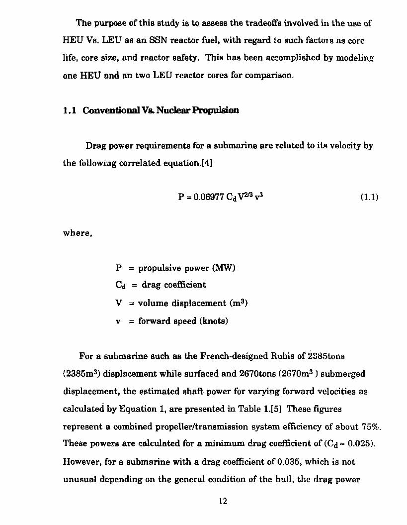
For a submarine such as the French-designed Rubis of 2385tons
(2385m3) displacement while surfaced and 2670tons (2670m3 ) submerged
displacement, the estimated ahaft power for varying forward veloti.ties as
calculated by Equation 1, are presented in Table 1.[5] These figm·es
representa comhined propeller/transmission system efficiency of about 75%.
These powers are calculated for a minimum drag coefficient of (Cd == 0.025).
However, for a submarine with a drag coefficient of 0.035, which is not
tmusual depending on the general condition of the hull, the drag power
12
requirement can increase by as much as 40%.[ 4]. One should note the
propulsive power increases with the cube of the forward velocity.
'.rhe Rubis can be considered to be an intermediate size submarina
whose volume displacement and total power requirements will serve as a
design basis. Submarine submerged volume displacements range from the
1070tons (1070m3 )West German Vastergotland class diesel powered
submarin~ or SSK, to the 8400tons (8400m3) ofthe British SSN, HMS
Resolution.[6]
Naval submarines must be able to take evasive action requiring high
speeds of25-30 knots or greater. Since an SSK runs submerged on
electricity produced by diesel generators and stored in batteries, this can
only be achieved for a short period of time; typically 1 hour maximum. This
is due to the tremendous propulsive power requirements which rapidly
deplete the batteriea.[5] SSKs can maintain an average speed of about 13
knots submerged.[6] The higher the average speed, the higher the
"indiscretion rate" or the percentage of time that the submarine must
surface to snorkel. In doing so, an SSK is highly vulnerable to radar
detection, visual detection and attack by surface ships, aircraft and other
submarines.
By contrast, most SSNs can maintain an average speed of25-35 knots
without approaching the surface. SSNs have an underwater endurance
which islimited only by the endurance ofthe crew. The SSN can thus
make high-speed, long distance undetected transite from one part of the
world to another. Only SSNs are capable of traveling under the Polar Ice
Cap, through the N orthwest Passage and in to the Arctic Ocean.
13

Table 1.1 Submarine power requirements at 2670 tons displacement [adapted from Reference E]
Forward Propulsive Hotel Total Speed (knots) Power(MW) Power(MW) Power(MW)
o o 0.150 0.150 2 0.004 0.150 0.154
4 0.029 0.150 0.179
6 0.096 0.150 0.246
8 0.229 0.150 0.379
10 0.448 0.150 0.598
12 0.773 0.150 0.923
. . . .
. . . . a> 3.581 0.150 3.731
25 6.994 0.150 7.144 :J) 12.085 0.150 12.235
33.2 16.350 0.150 16.500
35 19.191 0.150 19.341
By consequence, an SSN is a vehicle of maneuver since it's capabilities
and relative invulnerability provide much greater operating flexibility,
enabling it to redeploy quickly and often, in the wake of changing tactical
requirements. Clearly SSNs are more desirable as a military platform
than SSKs. However, they cost much more than SSKs. especially if one
takes into account the need for more sophisticated training and support.
14
1.2 8ubmar.IDe Pnaurized Water Reactor Nuclear Power Plant
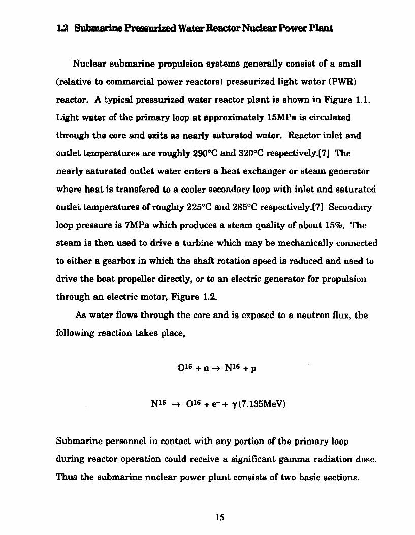
Nuclear submarine propulsion systems generally consist of a small
(relative to commercial power reactors) pressurized light water (PWR)
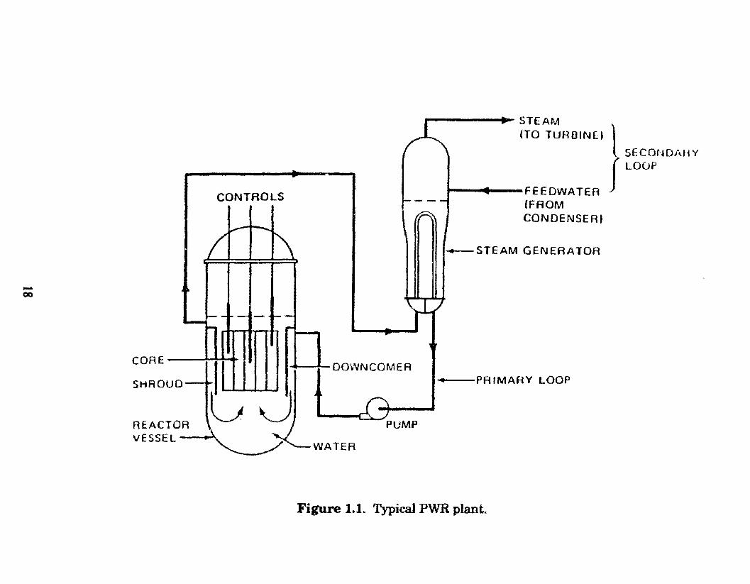
reactor. A typical pressurized water reactor plant is shown in Figure 1.1.
Light water of the primary loop at approximately 15MPa is circulated
through the core and exits as nearly saturated water. Reactor inlet and
outlet temperatures are roughly 290°C and 320°C respectively.[7] The
nearly saturated outlet water enters a heat exchanger or steam generator
where heat is transfered to a cooler secondary loop with inlet and saturated
outlet temperatures of roughly 225°C and 285°C respectively.[7] Secondary
loop pressure is 7MPa whith produces a steam quality of about 15%. The
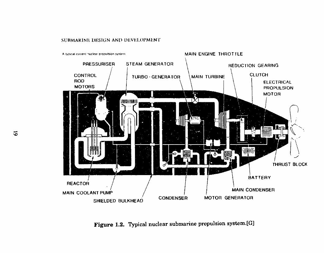
stewn is then used to drive a turbine which may be mechanically connected
to either a gearbox in which the shaft rotation speed is reduced and used to
drive the boat propeller directly, or to an electric generator for propulsion
through an electric motor, Figure 1.2.
As water flows through the core and is exposed to a neutron flux, the
following reaction takes place,
QIG + n --+ Nl6 + p
Nl6 --+ Ql6 + e- + y (7 .135Me V)
Submarine personnel in contact with any portion of the primary loop
during reactor operation could receive a significant gamm.a radiation dose.
Thus the submarine nuclear power plant consista of two basic sections.
15
1) A shielded radioactive compartment containing the reRctor, a
pressurizer, a steam generator anda primary coolant pump.
2) A nonradioactive machinery compartment containing the steam
turbinas, drive train and e0ndensers.
The steam generator serves as a banier preventing radioactivity from
leaving the shielded compartment. It should also be noted that since N16
has a half life of 7 .13s, personnel can enter the shielded compartment
roughly one minute after reactor shutdown.
During the lifetime of the reactor the fission products are prevented
from escaping to the environment by a total of five separa te ba:rriers. First,
the metallurgy of the fuel is optimized to retain the fission products within
the matrix of the fuel itself. Secondly, the individual fuel elements are
hennetically sealed in metal tubes or sandwitched between metal plates
known as cladding. Thirdly, the fuel in its entirety is encased in a high
integrity reactor pressure vessel. Fourthly, the nuclear propulsion eystem
is contained in an airlock compartment within the submarine. Finally, the
pressure hulJ. of the subm.arine itself servea as the fifth boundary to the
outside environment.
Due to volume and weight constraints in submarine design, the fmmer
which ia more constraining, it ia desirable to keep the power plantas small
and compact as possible. Since shielding accounts for a large percentage of
tota1 plant weight, it is especially desirable to keep the reactor core and
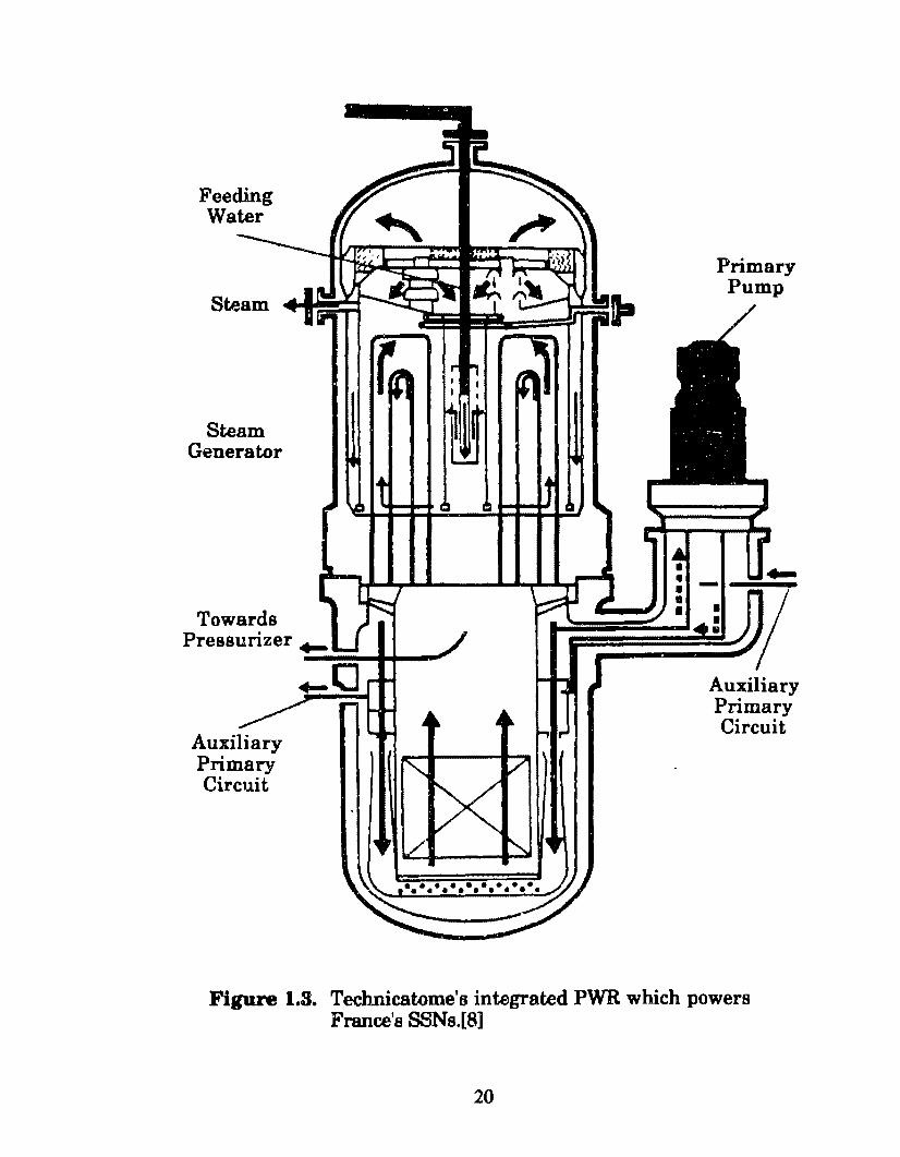
steam generator as small and compact as possible. This can be better
accomplished if toe componente in the shielded compartment are
constructed using an integral design such as that developed by the French
16
firm, Technicatome, and employed in alt ofFrance's SSNs, Figure 1.3. In
this design, the reactor, eteam generator, and primary coolant pump are
integrated into one steam producing unit eliminating component
separation and the large diameter interconnecting primary loop piping.
1.3 Design Criteria and ObjecUves
The following criteria have been employed in tbe nuclear reactor
designa of tlús study.
1) The over-all core design study can be simplified with a one
dimensional neutronics calculation of the fuel assembly for the
comparative purposes of this project. The EPRI-Cell Code (see
Appendix E.), which computes the space, energy, and bumup
dependence of the neutron spectrum wíthin light water reactor
fuel cells and which has been modified by Argonne National
Laboratory for use on plate-type research reactor fuels, is used for
this purpose.[9]
2) For this study the therm.al-hydraulie parameters of fuel
temperatures and required flow rates are assumed not to
be limiting within the simplifications which are discussed in
Section 1.4 and the fuel element design presented in Chapter 3.
This judgement is based on review of operating experiences with
the chosen meehanical arrangement of the fuel design (i. e. the
Engineering Test Reactor, ETR, of the National Reactor Testing
Station operated by Idaho National Engineering Laboratory)
17
-00
CONTAOLS
CORE ! 11 1 1
1 ~-11114 I
SHROUD-t: • • OOWNCOMER
REACTOR \ -- ~ VESSEL~ I --- PUMP
WATER
1 1111 STEAM
(TO TUHOINE~ l SECONDAHY f LOúP
I ._ FEEDWATER fFROM CONDENSERt
......,._STEAM GENEAATOA
---PAIMAAY LOOP
Figure 1.1. Typical PWR plant.
SllliMARINE LJESIGN AND DEVELOPMENT
A 1yJllr.11 currenl nuclear prorulsion sv~lem
PRESSUAISER
CONTAO L ROO
STEAM GENERA TOR
MAIN ENGINE THAOTTLE
GEARING
CLUTCH
ELECTRICAL PROPULSION
SHIELDED BULKHEAD CONDENSER MOTOR GENERATOR
Figure 1.2. Typical nuclear submarine propulsion system.[G]
Steam
Steam Generator
Auxiliary Primary Circuit
Primary Pump
Au:xiliary Primary Circuit
Figure 1.3. Technicatome'tJ integrated PWR which powers France's SSNs.[8]
20
3) It was assumed that no shuftling of the mel elements would take
place in order to extend fuel humup. At the end of core life, fuel
elements near the center of the core are depleted more than those
in the outer region of the core. In a fuel shuftling operation,
some of the fuel elements near the outer regions of the core are
switched with fuel elements near the core center. Consequently
the total available reactivity ofthe coreis increased. Reactivity is
defined in Appendix C. Fuel bumup ia discussed in Appendix D.
4) To conserve space, the reactor cores and components of Figure 1.1
were assumed to be constructed using the integral design of
Figure 1.3 thus permitting the use of a larger reactor core. This
applies to both the LEU and HEU reactors designa.
The objectives of the present calculations are to provide:
1) Comparisons of reactor core sizes for uranium enrichments of
7%, 20% and 97.3% with varying amounts and distributions of
burnable poison, gadolinium oxide (Gd203). A burnable poison
is a neutron absorbing material placed in certaiii locations of a
fuel element in order to reduce the excessive neutron
multiplication at the beginning-of-life, (BOC), of the reactor core.
As the fuel fiseions, the gadolinium (Gd) also burns out, thus
providing a longer core refueling interval.
21
2) Estim.ates o f the safety parameters such as the Doppler, void and
temperature coefficients of reactivity as a function of enrichment
and quantity ofburnable poison, Gd203, present in the reactor.
3) Fuel burnup information and plutonium buildup in the LEU
cores at comparable powers and operating cycles.
These results can be used as a basis for deciding if selected cases should
be calculated in more detail, inclucling distributed bumable poison and/or
enrichment for power flattening and better bumup; control movement
reactivity and power peaking effects, and thermal-hydraulic considerations.
Power flattening involves the reduction of the peaking factor which is
described in Section 1.4.
Upon reaching the above outlined objectives, conclusions can be drawn
about the effects, i f any, of using LEU as a fuel instead o f HEU, on
submarine design and operation. For example, if the LEU cores were
found to be significantly larger than the HEU core for a given reactor
power, a larger hull may be needed for the LEU fueled submarine
compared to the HEU fueled submarine . Based on the discussion of Section
1.2, this will reduce the submarines maximum forward velocity. Also, if
the unshu.tned LEU core lifetimes are shorter than that of the unshuffied
HEU core (the HEU core lifetime may, in some cases, be as longas the
submarine lifetime), the submarine must retum to port for fuel shuffiing
or refueling. These are major operations that for many submarine designs
require cutting open the hull, thus increasing the time the submarine will
be out of service. Submarine designers have generally avoided the use of
22
hatches dueto sealing problema at large depths.[lO] However, the French
Rubis does use large hatches to refuel.
1.4 Selection ofReactor Design Limita
In order for an SSN with a submerged volume displacement similar to
that of the Rubis to attain forward velocities of 25-35 knots, a reactor power
output of approximately 50 MWth is required. This is based on a typical
PWR plant thermodynamic efficiency of 33%, which yields a shaft power of
16.35MWe. As shown in Table 1.1, th.is corresponds to a forward velocity of
33.2 knots. For the unfavorable buli conditions described earlier, Equation 1
yields a maximum forward velocity of 29.6 knots, considering the propeller
/transmission efficiency. As a result o f these considerations, this study
focuses on SSN reactors of 50MWth power output.
For this study uraniu.m dioxide, U02 , was selected as the fuel and
Zircaloy was selected as the cladding material for reasons that will be
discussed in depth in Chapter 2. Use ofHEU permite a smaller
concentration or volume fraction of fuel in the fuel elements of a given
dimension than does use of LEU. In the HEU case the volume unoccupied
by fuel is occupied by zircaloy. Since U02 is a ceramic of po.or thermal
conductivity and zircaloy has a relatively high thermal conductivity, the
HEU fuel elements can be operated with a higher average volumetric heat
generation rate or average power density (q"'ave). This is because the
effective thermal conductivity of the mixture of uo2 and zircaloy present in
the HEU fuel elements is higher than that of the U02 present in the LEU
fuel elements. Based on a review of the operating experienccs of existing
HEU and LEU reactors. the maximum power density for the HEU reactor to
23
be analyzed here was set at IOOOkW/1 and for the LEU reactors was set at
about IOOkW/1. The 93% enriched, U02 fueled Advanced Test Reactor at the
National Reactor Testing Station operated by ldaho National Engineering
Laboratory has a maximum operating power density of about 2600kW/l.[ll]
Com.mercial PWRs fueled with LEU of about 3% ave:rage enrichment,
operate with a maxi.mum power density of al:-out 250kW/l. To be
conservative, the maximum power densities to be applied to these
calculations were reduced. For each reactor design to be considered for this
study, a minimum average power density limit (q"'ave) was set at 50kW/l in
order to ensure the ability ofthe reactor to produce steam. The average
power density in a commercial BWR is about 56kW/l.
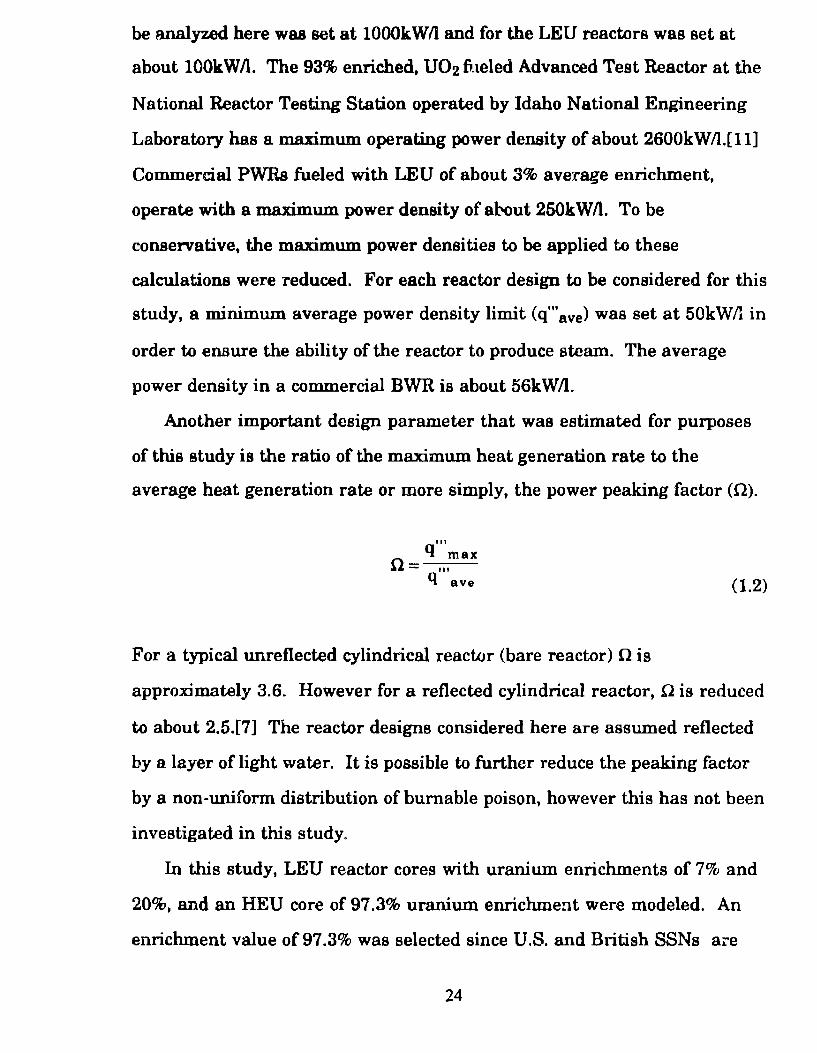
Another important dcsign parameter that was estimated for purposes
of this study is the ratio of the maximum heat generation rate to the
average heat generation rate or more simply, the power peaking factor (!l).
111
q max 0=-.. -,-
q ave (1.2)
For a typical unreflected cylindrical reactor (bare reactor) Q is
approximately 3.6. However for a reflected cylindrical reactor, .Q is reduced
to about 2.5.[7] The reactor designa considered here are assumed reflected
by a layer of light water. It is possible to further reduce the peaking factor
by a non-uniform distribution of bumable poison, however this has not been
investigated in this study.
In this study, LEU reactor cores with uranium enrichments of 7% and
20%, and an HEU core of 97.3% uranium enrichment were modeled. An
enrichment value of97.3% was selected since U.S. and British SSNs are
24
fueled with uranium of this enrichment. U.S. SSN reactor cores are reported
to have refueling httervals greater than 12 years, while future designa are
aimed at refueling intervals approaching 20 years, or the service lifetime of
the submarine.[2] Thus for the HEU core to be analyzed in this study, the
design operating lifetime without fuel shu.ffi.ing or refueling, was set at 20
years. These refueling intervals are based on a submarine service time of 240
days per year at sea while operating at an average o f 26% o f full power, or 60
full power days per year (60 FPD!Y). As deduced from Equation 1, this
representa about 63% of the maximu.m velocity.
(Percent of maximum velocity) = (0.25)113 = 0.63 (1.3)
It is known that the French designed Rubis is fueled with uranium of
three different enrichments whose average isless than 10%.[10] The value
of 7% was selected since the French have reported detailed designa of
"Caramel" fuel for research reactors with 7% enrichment.[12] This fuel
element design is discussed in detail in Chapter 3. lt was not possible to
attain a refueling interval of20 years for a 50MW reactor core fueled with
uraniu.m of 10% enrichment or lese without increasing the size of the core
and prohibitively lowering the average volumetric heat generation rate
(q"'ave). Too low a value of q"' will result in an insufficient coolant
temperature rise in the core. Thus a refueling interval of 10 years was
aelected as a design parameter for the 7% enriched LEU core. With fuel
shufiling, however, the operating lifetime of this core can be increased.
Newer U.S. SSN reactor core designa are being developed with refueling
intervals approaching 20 years and other nations seek.ing SSN s may desire
a similar capability. Our aim was to determine the possíble effects or
25
dífferences in submarine design and operation between submarines fueled
with HEU and those fueled with LEU. Thus an LEU core also with a
refueling intervaJ of 20 years needed to be modeled. As a result, feasibility
calculations were done for a reactor core of 20 year operating life and fueled
with uranium enriched to 20%.
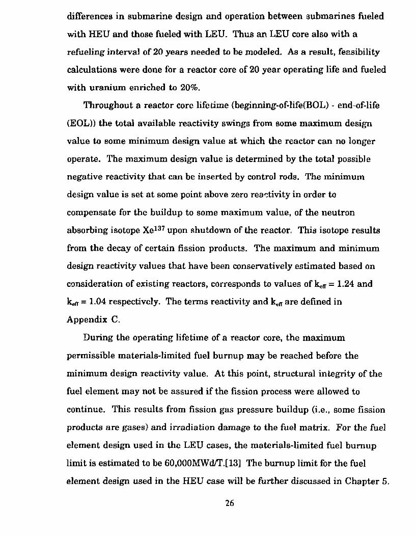
Throughout a reactor core lifetime (beginning-of-life(BOL)- endnof-life
(EOL)) the total available reactivity swings from some maximum design
value to some minimum design value at which the reactor can no longer
operate. The maximum design value is determined by the total possible
negative reactivity that can be inserted by control roda. The minimum
design value is set at some point above zero readivity in order to
compensate for the buildup to some maximum value, of the neutron
absorbing isotope Xel37 upon shutdown of the reactor. This isotope results
from the decay of certain fission products. The maximum and minimum
design reactivity values that have been conservatively estimated based on
consideration of existing reactors, corresponds to values of ~rr = 1.24 and
kerr = 1.04 respectively. The terms reactivity and kelf are defined in
Appendix C.
During the operating lifetime of a reactor core, the maximum
permissible materials-limited fuel burnup may be reached before the
minimum design reactivity value. At this point, structural integrity of the
fuel element may not be assured if the fission process were allowed to
continue. This results from fission gas pressure buildup (i.e., some fission
products are gases) and irradiation damage to the fuel matrix. For the fuel
element design used in the LEU cases, the materials-limited fuel bumup
limit is estimated to be 60,000MWd!r.[l3] The burnup limit for the fuel
element design used in the HEU case will be further discussed in Chapter 5.
26
neutronics data provided by the EPRI-Cell code, it will be possible to
calculate with accuracy sufficient for this study, the information outlined
in Section 1.3.
The design choices and assumed limita are summarized in Table 1.2.
27
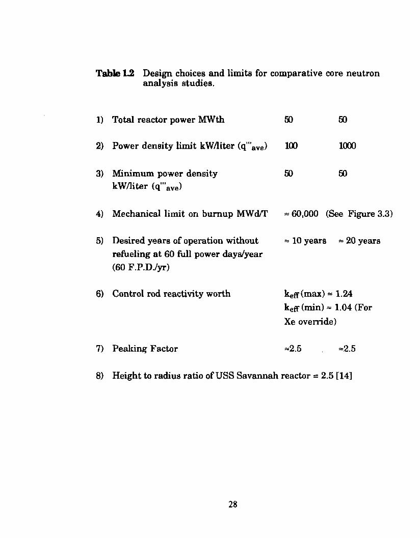
Table 1.2 Design choices and limits for comparative core neutron analysis studies.
1) Total reactor power MWth
2) Power density limit kW/liter (q'"ave)
3) Minimum power densit.y kW/liter (q"'ave)
100 1(XX)
4) Mechanical limit on bumup MWd!r = 60,000 (See Figure 3.3)
5) Desired years of operation without refueling at 60 full power dayslyear (60 F.P.DJyr)
6) Control rod reactivity worth
7) Peaking Factor
= 10 years = 20 years
ketr(max) = 1.24
keff (min) = 1.04 (For
Xe override)
=2.5 =2.5
8) Height to radius ratio ofUSS Savannah reactor = 2.5 [14]
28
Nuclear reactor fuel elements consist of a ayatem of interacting
materiais that includes the fuel material, clad material and and in moat
cases a reactivity control material (i.e., burnable poison). For the optimum
performance required of an SSN reactor as described in Chapter 1, small
size, high power density and marimum refueling lifetime, this system of
materiais must allow good neutron economy. maximum fuel bumup, and
corrosion resistance. This system must attain these goals while subject to
the environment encountered in the PWR core described in Section 1.2
which includes high neutron Ouxes (at high energies) as well as high
operating temperatures, system pressures, thermal gradiente and heat
flu.xes. Also of great importance ia the chemical compatibility of the fuel
element materiais with respect to each other and to the reactor coolant (i.e.,
H20). This taystem of materiais must also be capable of withstanding
transient and ofr-normal conditions without failure and muat retain
coolable geometry during accident conditions such as a LOCA (loss-of
cooling-accident) or LOF A (loss-of-flow-accident).
A fuel element composed of a given set of materiais may meet a given
set of performance objectives for a given set of reactor operating conditions.
However, the fuel element may be entirely inadequate when exposed to a
different reactor environment. For example, a particular fuel element may
perform satisfactorily in a low temperature research reactor used for the
production of neutrons but may melt or rapidly corrode when exposed to the
relatively high operating temperatures of a central station power
generating reactor or an SSN propulsion reactor. Thia fuel element may be
29
even lesa attractive for use or in a reactor cooled with a fluid other than
H20. The final materiais seleetion process ia more o r lesa a compromise
between the varioua in-reactor operating propertiea and characteriatica of
the fuel element materiais that resulta in a combination that most cl~Ge~J
meets the performance objectivea.
Tbe aame performance objectivea and reactor operating environment
mentioned above must be c:onsidered for the determination of thc size and
shape of the fuel elemente and the thicknesa of the cladding. Thia will be
discussed in detail in Chapter 3.
2.1 Nuclear Fuel CoDSlderafione
The central and moat important constituent of a nuclear reactor is the
fuel material in which energy ia produced from the nuclear fission process.
In most cases, the operating lifetime of the fuel element is limited by the
fuel material. For a reactor fueled with HEU, the operating lifetime of the
fuel element is often iimited by the mechanical behavior of the fuel when
irradiated in the reactor environment. For the reactor fueled with LEU, the
lifetime is often limited by the available reactivity supplied by the fuel
elements. The reactivity limitation of LEU fuel resulta from· two effects; the
concentration. of fissile materiai may be low compared to the HEU case, and
use ofLEU resulta in the addition ofneutron absorbing tJ238 (i.e., negative
reactivity).
30
2.1.1 Fuel Selectlon Criterta
The fuel material muat be carefully chosen in order fcr the fuel e!ement
to meet the SSN reactor fuel element deaign objectivea of maximum
bumup, JDllldmum operating lifetime, corrolion reaiatance and ability to I
withatand credible accident conditiona. In the folloW'ing eection, the
required fuel material characteristica that permit the fuel element to meet
theae objectives have been summarizecl.
1) In order to produce the reactor coolant outlet wmperature of
320°C nece8881"y for the production of eteam, high fuel
temparatures are required. Thus the melting point of the fuel
must be sufficiently above the maximum normal operating
temperature of the fuel element to provide a safety margin in thG
event of an accident that raiaea the fuel element temperature.
The combination of fuel conductivity and melting point must be
compatible to allow for this temperature margin. The maximum
fuel temperature calculation method and associated assumptions
are dhcussed in Section 4.2.
2) The fue! material should have only one crystal structure witlnn
the ope:rating temperature range of the reaetor (i.e .• room
temperatura to maximum operating temperature). Chang~s in
crystal structure are usually accompanied by a volume change
that can damage the fuel element.
31
3) To preserve fuel element integrity du.ring the attainable lifetime
of tbe fuel element (based on fuel mecbanical behavior fuel
material or available reactivity in the fbel elementa), the fuel
material ahould be chemically and metallurgieally inert 'llith
reapeet to the reactor coolant and fuel element cladding.
4) In order to conaene reactivity, the nonfiaaionable constituent of
tb.e fuel material ahould bave a relatively low macroacopic
neutron absorption c:roas-section (I.).
5) 'Ibe fuel muat exhibit good irradiation bebavior. Wben uranium
or ph .. tonium atoms fission, thy produce a wide range of fission
products. Among them, are the noble gases xenon and krypton
which are produced in approximately 30% of all fissions. Xenon
is also produced by the decay of other fission products or
precursora such as iodine. These gases can remain in the fuel
and form bubbles which cause the fuel to swell or the gasses can
d.iffuse to the surface and contact the cladding. In either case,
the cladding is subject to a pressure which rises steadily with
fuel burnup. At the limit, the internai fission gas pressure will
exceed the coolant pressure and cause the cladding to fail. Hence
fission gas behavior is a major factor with regard to the selection
of a particular reactor fuel. The ideal fuel material retains
fission gases within its structure and resists swelling.
32
6) The fuel material ahould permit maximum uranium loading per
unit volume of fuel. An enrichment limit impoaed on the
uraniu.m fuel producea two effects which muat be conaidered.
Lowering the uranium enrichment resulta in the addition of U238
which reducea the reactivity of the fuel element even if the
amount of 1J236 can be kept the same. Further. the added U238
reduces the allowable loading or concentration of U236 in the
reactor fuel el~~l:l~nta. For many reactor fu.el element designa,
use of LEU will aufficiently lower the initial reactivity so as to
render the use of the fuel element impractical. This will be
discussed further in Chapter 3. It should be noted that there are
three ways to regain reactivity lost by the use ofLEU: (1) the use
of higher uranium-loading fuel, (2) the use of a higher
performance reflector material, and (3) incí·ease the core size. Of
courae a combination of these approaches can be userl.[12.]
2.1.2 Review of the Fue1a CoDSidered.lor this Study
Generally, the many proven nuclear fuels in existence today consist of a
fissile material whir.h is mixed with a fertile material or difuent. In this
case, andas stated earlier, the fissile material is U235, and the ff!rtile
material ia U238. This fissile/fertile mixture is almost always combined
with some other element or elements in the form of a compoWld, alloy or
mixture. As a result, nuclear fuels may be grouped into three different
classes: metallic, ceramic and dispersion types; some examples of which
are considered in the proceeding diacussion.
33
The followi.ng aection review1 the fuel typea that have been considered
for use aa an SSN reactor fuel botb in the paat and for the purpoaea or this
study. The ceramic and metallic compounda of uranium. that were
considered are listed in Teble 2.1. The alloys ofuranium tbat were
considered Cor use aa nuclear fu.els are liated in Table 2.2. These tables are
by no meana emaustive.
2.1.2.1 MetaJHc Uraaium Fuel
The ideal uranium fuel ie the metal itself sínce it has th(: hlghest
uranium maes density or uranium loading possible, (18.9 glcm3). Its high
thermal conductivity oC 35 W/m4 °K allowa a fuel maximum temperature on
the order of 500°C for the fuel element designa considered for this study.
This offsets the relatively low melting point (1130°C) of uranium metal.
Other fuel types such as ceramic oxides may require maximum fuel
temperatures approaching 1000°C in order to achieve the necessary heat
flux required to produce a coolant outlet temperature of 320°C.
A major drawback to the use of uranium metal is that it has three
crystalline structures that are stable in the range of fuel temperaturee that
can be encountered in the reactor. This includes the normàl operating
temperature range and temperature increases that can occur in transient
or accident conditions. Uranium metal undergoes a phase change at 661°C
from alpha-uranium to beta-uranium and at 769°C from beta-uranium to
gamma-uranium. Alpha-uranium has an orthorhombic crystal structure;
beta-uranium a tetragonal crystal structure and gamma-uranium a body
centered-cubic crystal Gtructure. A volume increase accompanies the
34
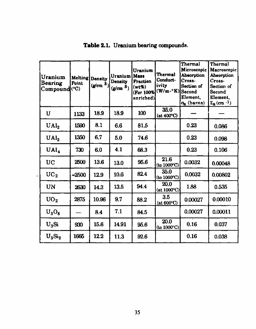
Table 2.1. Uranium bearing compounds.
Thermal Thermal Uranium Microscopic Macroscopic
Uranium Melting Ursmium Mua Thermal Abaorption Ahaorption
Bearing Point Denaity Denaity Fraction Conduct· Cross- C roas-
Compound (o C) (W'cm 3)
(glcm 3) (wt'f,) ivity Section of Seetion of (For lOO'f, (W/m-°K) Second Second enriched) Element, Element,
oa (barns) Ea (em ·1)
u 1133 18.9 18.9 100 35.0 (at4000C) - -
UAI2 1500 8.1 6.6 81.5 0.23 0.086
UAI3 1350 6.7 5.0 74.6 0.23 0.098
UA1 4 7:1) 6.0 4.1 68.3 0.23 0.106
uc 2500 13.6 13.0 95.6 21.6 0.0032 0.00048 (to 1 ()()(ffi)
uc2 =2500 12.9 10.6 82.4 35.0 0.0032 0.(X.l802 (to l()()()OC)
UN ~ 14.3 13.5 94.4 20.0 1.88 0.535 (at l()()()OC)
uo2 2875 10.96 9.7 88.2 3.5 0.00027 0.00010 (at 6000C)
UaOa -· 8.4 7.1 84.5 0.00027 0.00011
U3Si !D) 15.6 14.91 95.6 20.0 0.16 0.037 (to l()()(Y'C)
U3Si2 1665 12.2 11.3 92.6 0.16 0.038
35
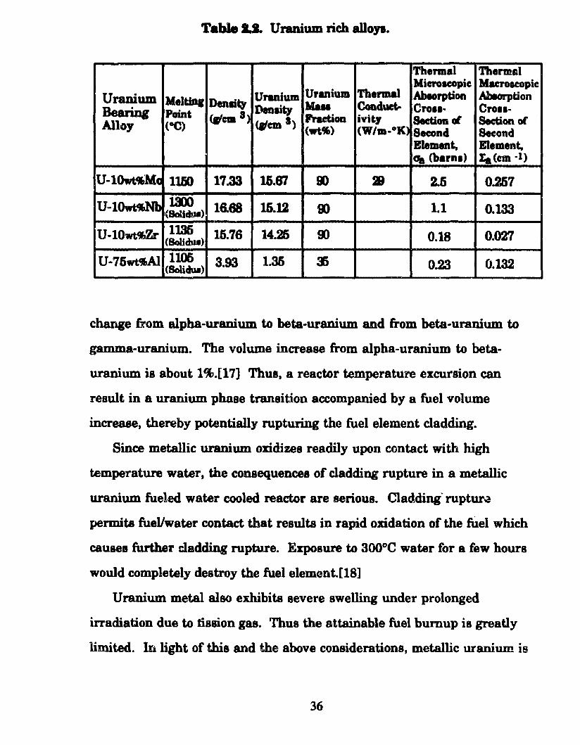
Table 1.1. Uranium rich alloya.
Thermal Thermal
Thermal Microacopic MacroDeOpic
Uranium Mel tini Uranium Uranium Abtorption Amorption
Beari.og Denlity Denlity Mau Coaduet- Cro11· CrOII· Point c.'em 8)
(Wcm a> Practioa ivity Section~ Section of Alloy (oC) (wt.11t) (W/m-•K) Second Second
Blement. Element, era (barna) :ta (em -1)
U -10wt.4MCl 11fJO 17.33 16.87 9) 28 2.6 0.267
uM 10wt.--,.,Nb J.3X) 16.68 1&.12 9) 1.1 0.133 (SoUdull)
U -10wt'~Zr 11.36 15.76 14.25 00 0.18 0.027 (Sol.ichu)
U-76wt.,Al 1106 3.93 1.36 3) 0.23 0.132 (Bolidul)
change from alpba-uranium to beta-uranium and from beta-uranium to
gamma-uranium. The volume increase from alpha-uranium to beta
uranium is about 1%.[17) Thus. a reactor temperature excursion can
result in a uranium phase transition accompanied by a fuel volume
increase, thereby potentially rupturing the fuel element cladding.
Since metallic uranium oxidizes readily upon contact with high
temperature water. the consequences of cladding rupture in a metallic
uranium fueled water cooled reactor are serious. Cladding· ruptur~
permita fueVwater contact that resulta in rapid oxidation of the fuel which
causes further cladding rupture. Exposure to 300°C water for a few hours
would completely destroy the fuel element.[18]
Uranium metal also exhibits severe swelling under prolonged
irradiation due to tission gas. Thus the attainable fuel bumup is greatly
limited. In light of this and the above considerations, metallic uraniu.m is
36
not a satisfactory fuel for use in tbe power produci.ng PWRs conaidered for
thie atudy.
2.1.2.2 Metallic Uranium. Rl.ch Alloy Fuel8
Various properties of metallic uranium C8Il be improved by the mddition
of non fissionable elements as a minor constituent. Alloying additions that
have been uaed in the past and that bave been considered for thia study are
molybdenum, niobium, zirconium and aluminum. As with metallic
uranium, uranium rich alloy fuels offer the desirable properties of high
thermal conductivity and high uranium loading. The general purposes
and specific goela of these alloying additions are summarized below.
1) To stabilize the gamma phase from 769°C down to room
temperature: Alloying additions of about ten weight percent
(lOwt%) molybdenum, zirconium or niobium can suppress the
formation ofbeta and then alpha uranium at room temperature.
These elements when added to molten uranium, result in the
retention of the gamma phase when the uranium is quenched to
room temperature. This eliminates the phase change related
volume increases in the fuel upon heat up ofthe fuel element
during reactor transients.
2) To raise the alphalbeta transformation temperatura in cases where
the gamma phase ia not stabilized to room temperature: It should
be noted that for relatively low temperature applications (i.e., below
thc beta/gamma transition temperature), alpha-uranium can be
37
ueecl where the alphalbeta tranaform.ation temperature has been
raieed by alloying additiona.
3) To i.mprove low and bigh temperatura mecbanical properties: For
nample, the alloying additiona mentionecl above increase the yield
strength wbich increuee th~ resistance to fission gas swelling.
4) To form higher meltiog point uranium. compounds: Molybdenum,
niobium and zirconium. additions nüse the melting point of
metallic uranium.
5) To i.mprove corrosion resistance: Although uranium rich alloy
fuels are more resistance to high temperature aqueous corrosion
than metallic uranium, uranium rich alloy fuels oxidize fairly
readily in high temperatura water. Thus the consequences of
cladding failure remain serious if metallic uranium rich alloys are
to be uaed in a water cooled reactor.
Uranium~molybdenum alloys, at temperatures up to 650°C, have
been used in the Dounreay and Enrico Fermi fast reactors With 9wt% and
lOwt% molybd0num respectively. Tbe later offers a uranium loading of
15.6g/cms. However, these fuel elements were lim.ited to a burnup of 2at%
due to the accompanying excessiva fission gas induced swelling that occurs
at temperatures greater than approximately 400°C. Since metallic
uranium rich alloys as employed in the chosE:n fuel element design require
a maximum operating fuel temperature of about 500°C, this fuel is
38
incapable of meeti.ng the performance objectives of the SSN reactor designa
conaidered in thia atudy .[ 12]
A disadvantage to the use ofmolybdenwn ia that it has a relatively high
macroscopic neutron abeorption croaa-eection (I.,) of 160 cm·l~ (see Table
2.4), that may sufliciently lawer the available reactivity of a fuel element
using LEU ao as to prohibit its use in a modem SSN reactor core.
The uranium-niobium and uraniwn-zirconium alloys described in
Table 2.2 provide uranium loadinga of 16.68glcm.S and 15. 76g!cm3
respectively. As with uraníum-molybdenu.m alloys, fission gas swelling at
2-4at% burnup are prohibitively high at temperatures greater than 400°C.
Thus these fuels are also incapable of meeting the performance objectives of
e modem SSN reactor. It should be noted that at lower temperatures
uranium-molybdenum alloya are more resistant to swelling than uranium
niobiu.m and uranium-zirconium alloys.
As in the case of malybdenum, niobiu.m has a relatively high l:a (60 cm-1)
and will also lower the reactivity of a fuel element using LEU. Zirconium,
however has the advantages of a relatively small I.a (9.8 cm-1) high melting
point ( 1845°C), excellent ductility and good resistance to aqueous corrosion.
It is interesting to note that uranium-zirconium alloy fuels were used in
the early nuclear submarine program.[l6] At that time submarines did not
require the refueling lifetimea of modem SSN s.
Although uranium rich alloy fuels appear to be unsuitable for use in
the plate type fuel elements considered for thls study, they can be used in
rod type fuel elementB where there exista a sufficiently large gap between
the outer fuel surface and the claddinc inner surface to accommodate the
excessive swelling. During operation, fission gas swelling increases the
original fuel volume by roughly 20% at which the fuel contacts the cladding.
39
At thia point, aufficient numben of fiaaion gas bubblea present on the fuel
grain bound.ariea 1ink together to form a continuous path which allowa for
fislrion gas relea.se and preventa additional swelliug. The released gasses
collect in a plenum or void element at the top of each fuei element.
A large fuellcladding gap requirea a highly conducting medium such
as liquid sodium in order to prevent escessive fuel temperatures. Due to the
violent aodiumlwater reaction that will OCC1n in the event of cladding
rupture, water can not be used as the reactor coolant. Thus the reactor
must be cooled by liquid sodiu.m. In the 1C50s U.S. Navy Admirai Hyman
Rickover prevented the liquid metal cooled reactor (LMR) from being
implemented on U.S. submarines because of concems of the possibility of
sea water contacting the sodiwn coolant.
Uranium-aluminum alloy fuels clad in alum.inum have been used
extensively in research reactors. The uraniwn loading must be less than
35wt% uranium in the fuel material. Above this 35wt% limit it is extremely
d.ifficult to maintain the specitied homogeneity of the uratúum throughout
the fu.el material that is required to prevent hot spots.[15] With the densities
of metallic uranium and aluminum taken as 18.8g!cm3 and 2.7g/cm3
respectively the following equation [12.],
Mu Pu --=--=--__..;.... __ _ Vmeat I+~( 100 -l)
PAI wt%U (2.1)
yielda a uraniu.m loading of 1.35glcm3 at 35wt%U. This is insufficient to
provide the reactivity required for a modem SSN reactor.
40
2.1.2.3 Unmium Alnmlnlde • A111minum Dilpendon Fuel (UAla • AI)
Dispersion type fuels are two phase alloys consisting of a fi asile isotope
bearing material that is uniformly dispersed in e matrix of nonfissile
material or diluent. These fuela are usually prepared by powder
metallurgy, a process in which fine powders of the fissile phase and
nonfissile phase are mixed, compacted, sintered, and rolled to form a
continuou& fuel material. The diapersion tecbtúque offers the following
advantages when the diluent predom.inates in volume.
1) Damage to the fuel material due to fission fragmenta is localized to
the each fuel particle and the region immediately surrounding it.[17]
2) The potential for reaction between the fuel and the coolant is
essentially eliminated in the event of cladding rupture. Only
parti eles on the surface of the fuel material can be exposed to the
coolant.[17]
3) The path for heat flow from the fissile particles is through a highly
conducting metallic nonfissile medium which lowers the required
operating fuel temperatura.
The uranium bearing intermetallic compounds formed by uranium
and aluminum, UAI2, UAla and UA14, can be dispersed in a continuous
matrix of aluminum to form uranium aluminide - aluminum (UAlx - Al)
diepersion type fuel. This fuel has been used extensively in research
reacto:rs not intended for power generation. Thus they can operate at a
41
relatively low temperature. Since alnminum metal melts at 660°C, a
temperatura wbich can easily be exceeded during transient or accident
conditiona, it should not be used u a fuel matris or cladding material for
PWR operating eonditions.
Uraniu:m alnminide ~ aluminum dispersion type fuel is used in the
Advanced Test Reactor operated by the Idaho National Engineering
Laboratory with an average uranium loading in the fuel plates of 42wt%
uranium or about 60wt% UAI •. As calculated from Equation 1.2, thi~;
corresponds to a uranium loading of about 2.0glcm3.[12.] lt has been
estimated tbat a uraniu.m loading of 2.6glcm3 could be achieved with this
type offuel.[l2] This fuelloading is not suffi.cient to provide adequate
reactivity for the LEU fuel elements of this study.
2.1.2.4 Unmium Sillcide • Alnmlnum Dispendon Fuel
Another more prom.ising fuel type is uranium silicide which has been
used to form a disparsion with aluminum. The uranium silicide
compounds of interest are UaSi which has a uranium density of 14.91g/cm3
and UaSi2 which has a uraniu.m. density of 11.3g/cm3. UaSi2 has a
moderately high melting point of l665°C while U3Si has a nielting point of
930°C. U ,Si2 was shown to more stable under irradiation than U aSi.[ 17]
Uranium silicide- aluminum dispersion type fuels (U3Sis- Al) offer
higher uranium. loadings than the UAlx- AI dispersion type fuels. Fuel
elements containing UsSix- AI dispersion type fuel of up to 45 volume
percent (45Vol%) UsSix, corresponds to a uranium loading of 4.75g/cm3,
have been succe&sfully irradiated in the Oak Ridge Research Reactor (ORR)
with maximum fuel temperatures of approximately 130°C.[ 17] Also, it has
42
been reported that U 3Si:.:- AI disperaion type fuela with a uranium loading
of 6glcm3 have been irradisted to a bumup of 50at'll.[21] However, this was
done with fuel maximum. operating temperaturf!ls at about low
temperature. At the operating temperatures of 500°C or greater required
for a power producing rsactor, uranium sUicide fuels exhibit excessive
swelling under irradiation. Furthermore, uranium silícide fuel undergoes
rapid and gN&B awelling at fuel temperaturea in exceBS of 900°C. Such fuel
temperatures can be reached quickly during a LOCA.{18] Thus, urarJum
silicide diaperaion type fuels are also not suitable for use in the power
producing reactors needed by SSNs.
2.1.2.1 Unmium O:d.de • Ab•minum Dispenion Fuel
Another dispersion type fuel that ia used in research reactors is
uranium oxide (UaOs), a ceramic fuel which ia dispersed in aluminum and
clad in aluminum. This is used as a fuel in the High Flux Isotope Reactor
(HFIR) operated by Oa.k Ridge National Laboratory. This type of fuel has
perfonned successfully in HFIR fuel elements up to a urani um loading o f
35wt% uranium (40wt% UsOs). Furthennore, at that time, as part of
development testa for UsOs- AI dispersion type fuel, samples were madep
and irradiated, evaluated, and deemed satisfactory up to a maximum
loading of 42wt% uranium (50wt% UaOs) in the fuel material. [12] With the
densities of the UaOa compound and aluminum taken as 8.4g/cm3 and
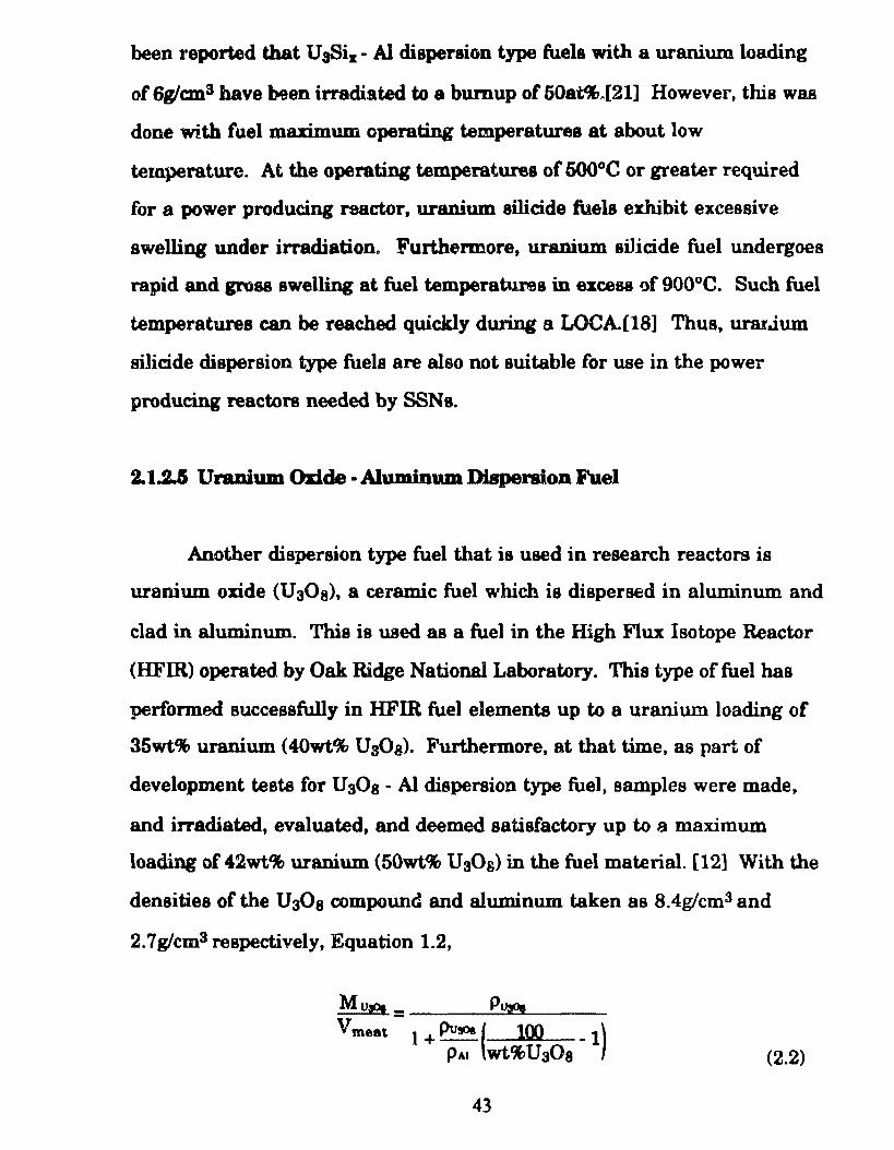
2.7glcm3 respectively, Equation 1.2,
Mue _ Pu,oe
V meat - I + PuA ( 100 _ 1) PAI wt%Us0s (2.2)
43
yields a UsOs compound loading of 2.04g/cm3 for 50wt% UaOa. Since the
uranium maas fraction in U30a is 84.5% as listed in Table 2.1, the uranium
loading is 1.73glcm3. lt has been estimated, however, that U30a- AI
dispersion type fuels with a uranium loading of2.8 to 3.7g/cm3 could be
fabricated.[12] Based on atomic geometry considerations, a uranium
loading ofabout 3.6 -3.7glcm3 (about 80wt% UsOs) ia thought to be the
theoretical limit at wbich the continuous aluminum phase can be
maintained. This is required in order to facilitate beat removal from the
fuel element through the highly conducting continuous aluminum
matrix.[12) Higher uraniwn loadings than those mentioned above are
required for SSN reactor fuel elements.
A major drawback to the use ofUaOa fuel is that it reverta to U02 at
approximately 1200°C. This is known a8 the thermite reaction. With the
concentration of the poorly conducting ceramic UaOs approaching 80wt% in
the fuel material, 1200°C can easily be reached during transient or accident
conditi.ons. When a higher oxide such &8 UO::. or U aOs, is reduced, the
conversion to uo2 is accompanied by a relatively large decrease in specific
volume (50% for UOs and 32% for U30 8). The specific volume change can
re8ult in fracture and size reduction of the higher oxide particles which can
destroy the fuel element.[17] As a result UaOs- AI dispersion type fuel can
not be used in the PWR reactor designs considered for this study.
44
2.1.2.8 Unmlum Carbide aod Uranium Nitride Fu.el.u
Uranium forms two carbides which are of practical interest as reactor
fuels, uranium carbide, uc. and uranium dicarbide, uc2. uc meits at
2780°C and UC2 at 2720°C. Basically, uraniu.m carbides have two desirable
properties: (1) tbese compounds provide relatively high uranium loadings
of 13.0glcm3 and 10.6glcm3 for uc and uc2 respectively, (2) the thermal
conductivity of these compounds are relatively high, 21.6W-mJ'OK for UC
and 35W -mfOK for UC2.
Uranium nitride fuel UN has a uranium loading of 13.5g/cm3 and has
a melting point of 2630°C and also has a relatively high thermal
conductivity. These properties lead to high available reacti\·ity and to lower
thermal gradients in the fuel elements.
Uranium carbide and uranium nitride fuels exhibit excessive swelling
upon irradiation due to fission gas retention. This is due to the high
densities of carbide and nitride ft1ela in which the volatile fission producta
are lesa mobile than in the other fuel typeslisted in Tables 2.1 and 2.2.[16]
Fission gas induced swelling in these fuels is greater than that of U02 by a
factor of two.[l6] Thus thc allowable bumup is lim.ited in order to prevent
excessive strain on the cladding.
As with metallic uranium fuel and uranium rich alloy fuels, the
chemical reactivity of UC, UC2 and UN with water and t.'te resulting
relesse of oxidizing gases make these fuels unsuitable for use in the power
producing PWR cores required by SSNs. As stated earlier, contact with
water will occur in the event of cladding rupture.
45
lt should be noted that these fuela are beat auited for the liquid sodium
cooled reactor deacribed in Section 2.1.2.2. where ezcessive swelling can be
accommodated and the fuellwater reaction ia eliminated.
2.1.2. 7 Uranlum Diodde Fuel
Uranium dioxide, a ceramic fuel, ia the most commonly uaed nuclear
fuel today. lt has a fe.brication density of 10.3glcmS. (95% o( i te theoreti.-..al
density), and offers a relatively high uranium loading of about 9.1g!cm.3.
This combined with the low macroacopic neutron abaorption cross-section
(l:.) ofoxygen in this fuel (0.00054cm-1), facilitates the use ofLEU. Thus
U02 has e.trong non-proliferation characteristica. Uranium dio:.Dde also
exhibits chemical inertness and has excellent resistance to corrosion when
expoeed to bigb temperatura and pressure water.
Use ofU02 necessitates a high marimum operating fuel temperature
dueto ite poor thermal conductivity. However, aince U02 has a high
melti.ng point of 2875°C, fuel mt!lting ia unlikely except is severe accident
situations. A disadvantage to a bigh fuel temperatura and fuel element
temperature grad.ient ia tbat during accident conditions such as a LOCA or
a LOFA, the cladding temperature will rise faster than in the case of a
lower operati:ng fuel temperature. Thus the available time before
emergency core cooling aetion must be etrective is decreased. As stated
earlier, zirealoy ia the chosen cladding material. lt has a melting point of
approxi.mately 1852°C but reacts with water at about 1200°C releasing
explosive hydrogen gaa.
As the operating temperature of uo2 fueled elements is increased, the
rate of fission gas relesse also increases. This will exert pressure on the
46
inner aurface of the cladding which will cause some awelling. Rod type
fuel elementa uaed in commercial reactors are comtructed with a plenu.m
at the top of each fuel rod where released fisaion guaes collect. In these
fuel roda, there is no fuellcladding bond, thus allowing fission gasses to
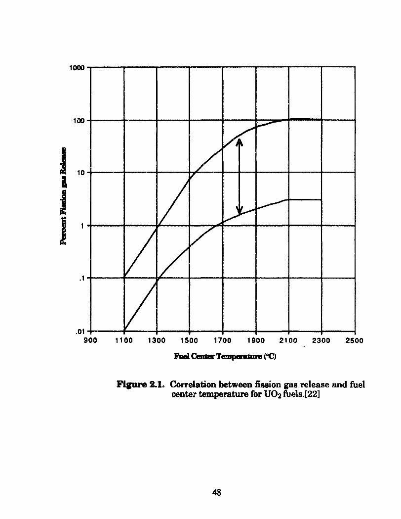
reach this plenum via tbe gap. Figure 2.1 sbowa the percentage of fission
gases released as a function of temperature. Although uo2 exhibits some
fission gas swelling it ia considerad to be one of the most stable under
irradiation and fission gas swelling reaistant fuels available.
Despite these limitations caused by poor thermal conductivity and
fission gas swelling, uo2 is considered to be the .fuel best suited for use in
the SSN PWR reactor design ofthis study. Furthermoret much operating
experience has been gained through the years with uo2 fuel clad in
zircaloy by itB use in commercial PWRs and to a lesser extent in research
rea~tors.
In nearly ali reactors, the fuel is covered with a protective material or
cladding which preventa the re)ease of radioactive fission products from the
fuel surface to the coolant channel. The claddíng alw prevénts corrosion of
the fuei and acta to retain the original shape of the fuel material during the
operating life time of the fuel element. The cladding must remain intact
both tbroughout the operation of the reacto? and following remova! of the
fuel element from the reactor core.
In high fuel bu.rnup power producing reactors, the cladding must
reaist swelling due to internai pressure buildup caused by fission gases.
Typical design limita are 1% cladding strain in com.mercial reactors. In
47
J i
~ J
1000
100
~ ~
/ , 10
'~ ~ ..... /
/ 1
.1 /
.01 900 1100 1300 1500 1700 1900 2100 2300 2500
Fipre 2.1 .. Correlation between fission gas relesse and fuel cente2' temperature for uo2 fuels.[22]
48
the case of weak or defective cladding, fission gas pressure can result in
failure of the cladding.
2.2.1 Clad Material SelectioD Criteria
A variety of material& e:Jiet that have been used or oould possibly be
used as a nuclear fuel cladding material, the most common of which are
listed in Table 2.3 along with aome i.mportant properties. None of these
materiais or any other material satisfies ali the requirements for an ideal
cladding. However, the material best suited for this puTi)Ose is the one that
forms the best compromise between the conflicting specifications for an
ideal cladding in a particular reactor environment. The characteristics of
the ideal cladding material are summarized below.
1) Low macroscopic neutron abaorption cross-section <L. cm·l):
Since cladding materiais add negative reactivity to the reactor, it
is desirable for I,.(clad) to be aslow as possible.
2) High thermal conductivity (k, W/m-°C): A high value for k for
the cladding material decreases the thermal resiàtance between
the fuel material and coolant. This decreases the maximum fuel
element center-line temperature needed to yield the heat tranefer
rate that producea the desired reactor power levei.
3) High me~ting point: Almost ali materiais that have been used as
nuclear fuel cladding materiais have a lower melting point than
U02 (•2800°C). During normal operation, the average
49
temperature of the fuel in a power producing PWR is about
l000°C and the average temperature of the cladding ia about
380°C. lf a loss-of-Oow-accident were to occur, in a brief time
period, the temperature profile through the fueVcladding system
would Oatten which can posaibly result in melting of the
cladding. Thus a cladding material with a high melting point
increases the safety margin for the reactor.
4) The material should have good irradiat.i.on stability (i.e., the
material should be resistant to irradiation induced swelling and
growth). Swelling is a cbange in shape and volume while growth
ia a change in shape with no change in volume. Poor irradiation
behavior can distort the shape of the fuel elements.
5) Low coefficient of thermal expansion(a, cmJ'OC): This is for
reasons similar to that stated in item (4).
6) The ideal nuclear fuel cladding material should have the
conflicting properties of high strength and ductility. Most high
strength materiais are also brittle and thus are subject to
catastrophic failure when their yield strength (oy) is exceeded.
7) The cladding material should be reoistant to corrosion as
influenced by contact with fuel material and coolant water at
higb temperaturee. Some of the more volatile fission products
such as iodine and cesium migra:ate to the cooler regions o f the
fuel element (i.e., the region in contact or closest to the cladding)
so
where they may induce stre88 corroaion cracking or other
d.egrading phenomena. Also, in PWRa, uceseive hydrogen
concentrations in the coolant water can react with some potential
cladding materiais to form hydrides. Hydrides are very brittle
materiais which can result in cladding failure if formed in
high atresses regiona.
The material with the lowest macroscopic neutron absorption cross~
section <I.>. and best combination of the ideal mechanical properties
described in the above discussion is zircaloy. lt has a I. of 10.7cm·l, has
good high temperatura strength, is ductile, has a relatively high thermal
conductivity of21W-mrK, anda high melti.ng point of 1852°0. Note that
temperature of zircaloy in a PWR system must remain below 1200°C at
which the following exothermic reaction can occur,
Zr + 2H2Ü -+ Zr02 + 4H
which resulta in the liberation of explosive hydrogen gas. ·
Magnesium and aluminum also have a low L. of 2.59cm·l and 13.8cm·l
respectively. However, magne&ium is highly reacti.ve to high wmperature
high pressure water and both have relati.vely low melting point.s of 648.8°C
and 660.4°C respectively. Thus, they are excluded from conaideration.
Stainless steel type 304 possesses excellent strength up to ..,600°C, is quite
ductile, and haB excellent corrosion resistance but its high L of 258cm·l
makes it less attractive for use in compact military reactors where good
51
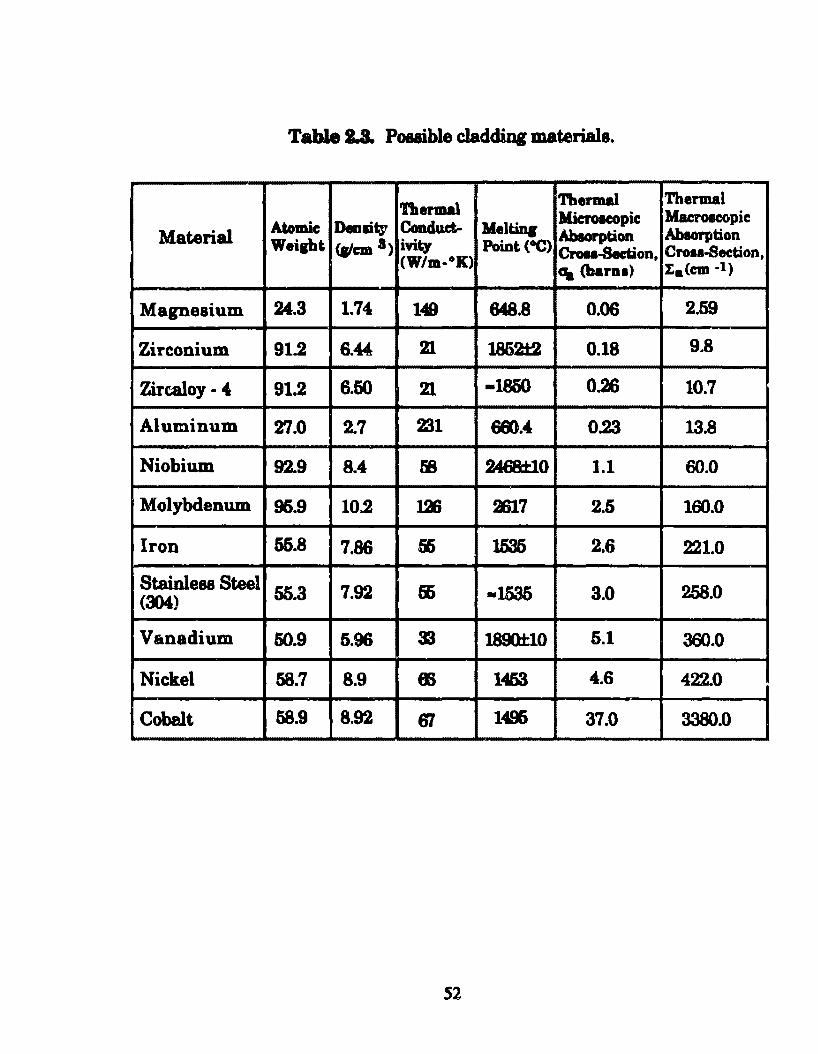
Table JJL Pouible cladding materiais.
'l'bermal Thermal Thermal Mic:Toacopic Macroacc;pic
Material Ato mie Denlity Coa.cluct- Mel tina lt.bsorption lt.bsorption Wei1ht {alem a) ivity Point (OC) Crou-Section, Cro••-Section, (W/m-°K) «<& <harn•) :ta(cm -1)
Magnesium 24.3 1.74 149 848.8 0.06 2.59
Zirconium 91.2 6.44 21 1862t2 0.18 9.8
Zircaloy- 4 91.2 6.50 21. -18ó0 0.26 10.7
Aluminum 27.0 2.7 ZJ1 681 . .& 0.23 13.8
Niobium 92.9 8 . .& 58 2468±10 1.1 60.0
Molybdenum 96.9 10.2 128 2617 2.5 160.0
Iron 55.8 7.86 56 1535 2.6 221.0
Stainle88 Steel 55.3 7.92 55 -1535 3.0 258.0 (304)
Vanadium 50.9 5.96 3J 1890±10 5.1 360.0
Nickel 58.7 8.9 m 1463 .&.6 422.0
Cobelt 58.9 8.92 61 1496 37.0 3380.0
52
neutron economy ia necessary.[16]
Although una11oyed zirconium (zireoniwn metal) haa a lower
I.C9.8cJn·l) than zircaloy {10.7cm-1), it ia not suitable as a cladd.ing material
since it emibits the following problema.
1) Inadequate corroaion resistance: Normal oxide filma that form
on the cladding au.rface fali of eaaily reault.ing in continuou&
uneheck.ec:l corroaion. Tbia occun rapidly in water over
300°C.[22]
2) Insufficient high temperature strength: Thia requires a thicker
clad which resulta in more material in the core and hence
increased neutron losses.
3) Pure zirconium ia susceptible to hydrogen absorption and
subsequent embrittlement. Excessive hydrogen in PWR coolant
water is absorbed by zirconium to form zirconium. hydride; a
brittle compound. If this occurs in high stress areas, cladding
failure can result.
To combat these problema, a series of zirconium alloys which are listed
in Table 2.4 and known as the zircaloys were developcd in the late 1950s.
Zircaloys are roughly 98% zirconium with minor additions of Tin (Sn), Iron
(Fe}, Chromium (Cr} and Nickel (Ni) not neceasarily including ali. Tin
additions improve the adherence of the oxide film wlúch acts as a protective
layer to slow further corrosion, however, some corrosion will continue to
S3
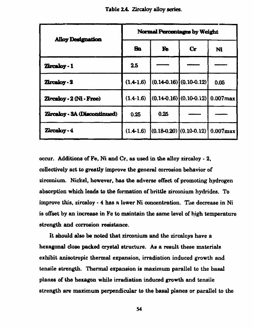
TabiE z.c. Zircaloy alloy series.
N'anDal Peft.wataa-by Weipt ADoy ........ doa
SD • Cr Ni
7..b:alo7-1 2.5
7..b:alo7·1 (1.4-1.6) (0.14-0.16) (0.10-0.12) 0.05
~y. 2 <Nl· Flee) (1.4-1.6) (0.1W.l6) (0.10-0.12) 0.007max
7..b:alo7. 8A. (l)i8ooDti.nued 0.25 0.25 -Zirealoy·4 (1.4-1.6) (0.18-0.20) (0.10-0.12) 0.007ma.x
occur. Additions ofFe, Ni and Cr, as used in the alloy zircaloy- 2,
collectively act to greatly improve the general corrosion behavior of
zirconium. Nickel, however, has the adverse effect of promoting hydrogen
absorption which leada to the formation of brittle zirconium hydrides. To
improve this, zircaloy • 4 has R. lower Ni concentration. The decrease in Ni
is offset by an increase in Fe to maintain the same level of high temperature
strength and corrosion resistance.
It should also be noted that zirconium and the zircaloys have a
hexagonal cloae pack.ed crystal structure. As a result these materiais
exhibit anisotropic thermal expansion, irradiation induced growth and
tensile strength. Thermal expansion is maximum parallel to the basal
planes of the hexagon while írradiation induced growth and tensile
strength are maximum perpendicular to the basa1 planes or parallel to the
54
C- axis. Such complicationa can be overcome with proper fahrication
techniques anel orientati.on of the hexagonal crystal otructure.[22]
As a means of controlling uceu reactivity at the beginning-of-cyde
(B.O.C.) and to provide a meana for power shaping and optimum core
burnup, commercial L WRs employ a control material or bumable puison.
These are solid neutron absorbing materiais that are placed in selected fuel
elements of the reactor. As they are subject to neutron irradiation, the
absorber material is gradually depleted, thus matching, ideally, the
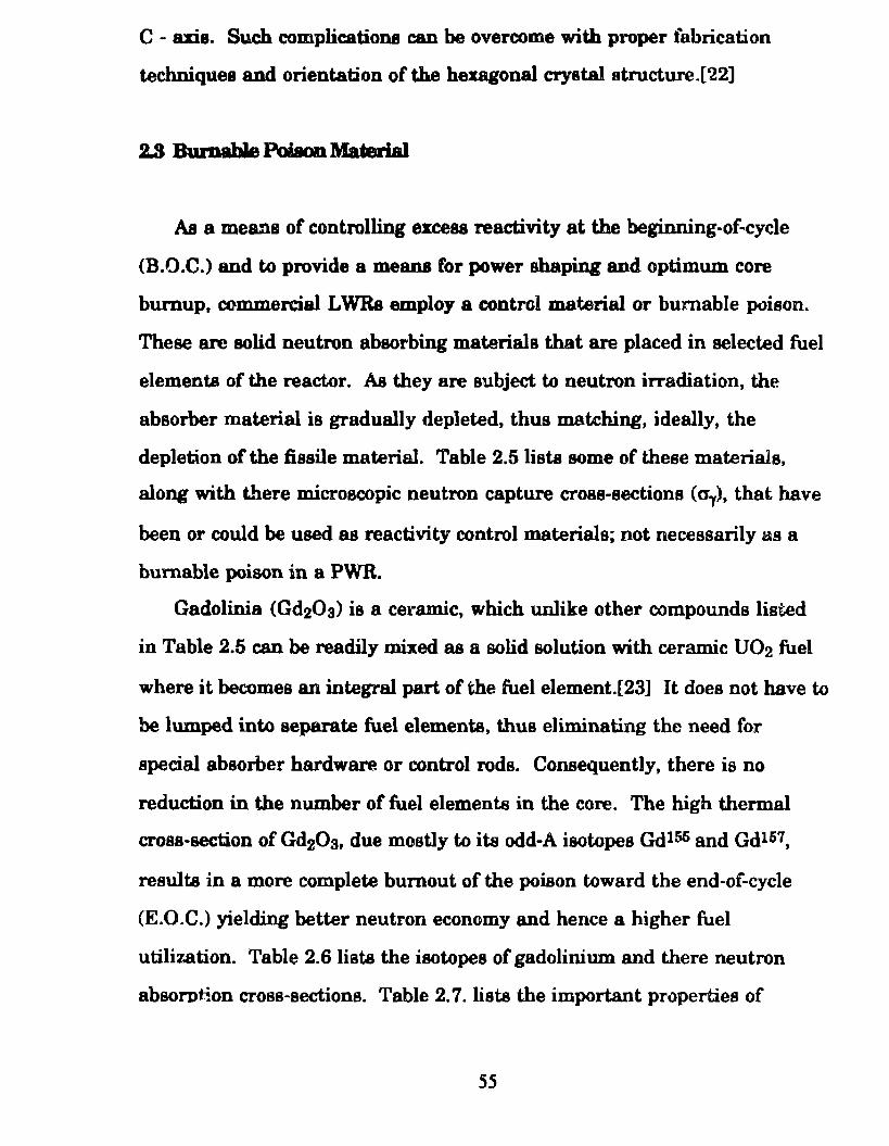
depletion of the fi.ssile material. Table 2.5 lista some of these materiais,
along with there microecopic neutron capture cross-sections (a1), that have
been or could be used as reactivity control materiais; not necessarily as a
bumable poison in a PWR.
Gadolinia (Gd20a) is a cei"amic, which unlike other compounds listed
in Table 2.5 can be readily mixed as a solid solution with ceramic U02 fuel
where it becomes an integral part of the fuel element.[23] It does not have to
be lumped into separate fuel elements, thus eliminating the need for
special absorber hardware or control roda. Consequently, there is no
reduction in the number of fuel elements in the core. The high thermal
cross-section of Gd20 3, due mostly to its odd-A isotopes Qd156 and Gdl57,
resulta in a more complete bumout of the poison toward the end-of-cycle
(E.O.C.) yield.ing better neutron economy and hence a higher fuel
utilization. Table 2.6 lista the isotopes of gadolinium and there neutron
absorotion cross-sections. Table 2. 7. lista the important properties o f
55
ga.dolinium. Witb proper design and distribution of Gd2Ús throughout the
reactor core, flatter power distributiona and low neutron leakage can be
achieved. A flatter power distribution resulta in a reduction of the reactor
power pealring factor which alao resulta in better fuel utilization.
Additional advantages to the uae of Gd20s u a solid aolution with U02 are
no displacement of water and little displacement of the fuel.
There are two potential diaadvantages to the use of Gd20s. Although
Gd:zOa ia physically compatible with uo2, the thermal conductivity and the
melting point ofthe fuel material islowered with its addition to uo2.[19]
However, for the reactor designa and fuel elements considered for this
study, this is nota problem. It was stated earlier that maximum uranium
fuel temperature heat would be encountered in the uo2 fuel elements
considered for this study ia 975°C and that the melting point ofU02 is
2875°C. Thus there is a wide ma.rgin to accommodate these undesirable
effects and gadolinium has been chose for this study.
It should be noted tbat for the 20% and 97.3% enriched reactor designa,
Gd20s is lumped into separate plates for reasooo that will be discussed in
detail in Chapter 5. In the 7% enriched reactor design, the Gd20a is
uniformly distributed throughout the reactoi" fuel elements.
56
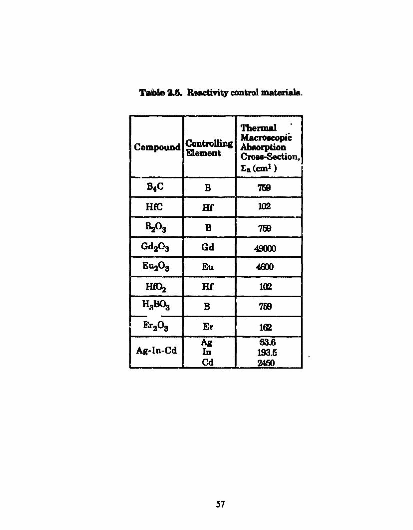
Table 2JL &actmty control materiais .
Tbermal .
Cont.rolliDg Macroaeopic Compound Ahaorption
Element Croaa-Section, I.a (cm1 )
s.c B 759
HfC Hf 102 ,,_
&.zOa B 759
Gd203 Gd 49(XX)
E~03 Eu 4.8X)
lltOz Hf lW
HaBOs B 7tiJ -Er20 3 E r 162
Ag 63.6 Ag-In-Cd In 193.5
Cd 2450
51
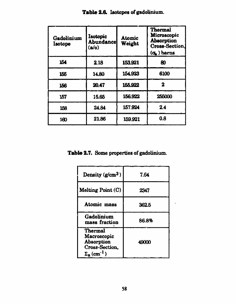
Table 2.8. Iaotopea of gadoUnium.
Thermal
GadoliDium llotopic Atomic Microacopic
I ao tope Abundance Weight Abaorption (alo) Croea-Section.
(q.) barns
1M 2.18 153.921 8)
156 14.80 l.M.923 6100
156 3).47 155.922 2
JD7 16.65 156.922 256000
1.58 24.84 157.924 2.4
18) 21.86 159.921 0.8
Table 2. 7. Some propertiea of gadolinium.
I Density (glcm3) 7.64
Melting Point (C) 2J47
Atomic mass 362.5
Gadolinium mass fraction 86.8% . Thermal Macroscopic Absorption 4900) Cross-Section, l:a (cm~l)
58
A. statecl in Chapter 1, H~ ia tbe coolant material by choice of the SSN
reactor type, the PWR. Water serves two functiona in this rea~M»r. It acts
aa a reactor coolant and aa a neutron moderator which elows down
neutrons to thermal energiea (..0.026eV) at which moet fiesion occur. Each
fi88ion releases an aversge of 2.4 neutrons with an average energy of about
2MeV.
With regard to reactor operation and contml, water haa two opposing
effects. lta neutron moderating characteristics contribute positive
reactivity to the reactor, while its neutron abeorpti.on characteristic~
contribute negative reactivity to the reactor. The degree to which each of
these characteristice, relative to each other, effect core reactivity, dependa
on the ratio of fuel element material to coolant water present in the core.
These effecta are of dire importance to reactor operation and safety and will
be discussed further in Chapter 3. Table 2.8 su.mmarizes the important
physics properties of H3Ü.
From the discussion of this chapter, our SSN reactors will consist of an
arra.ngement of uo2 fuel at some enrichment levelo zircaloy - 4 cladding
and structural material, Gd20s burnable poison material and H20 coolant.
The remainder of this study will consist of determining the quantity,
distribution and arrangement of these materiais that will result in the
optimum utilization of 7%, 20% and 97.3% enriched uranium.
59
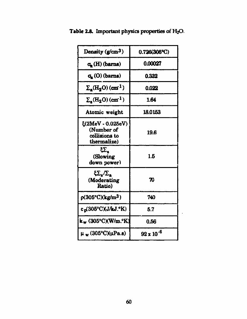
Table 2.8. lmportant physics properties of H:z().
Density (glcm3) o. 726(3060C)
a. (H) (bama) 0.00027
a. (0) (bama) 0.332
IaaitO> (car1) 0.022
I 1 <H20) (cm·1 ) 1.64
Atomic weight 18.0153
~(2MeV- 0.025eV) (Number of 19.6 collisions to thermalize) I
u:. (Slowing 1.5
down power)
~.li. (Moderating 'm
Ratio)
p(305°C)(kglm3) 740
c p(305°CXJikJ. °K) 5.7
kw (305°C)(W/m.°K 0.56
J1 w (305°CXJ!Pa.s) 92x 10-6
60
CBAPJERS Fuel tlement Deaip
At this point, the reader should be reminded that a reactor core is
assembled from a number of fuel elements or assemblies, each o f which
contains a number of fuel roda or fuel plates. In ordcr to maintain fuel
plate position and maintain coolant channel width, the fuel element must
contain side plates in addition to fuel plates. Rod type fuel elements or
assemblies must contain spacere to maintain rod position.
The general functions and purposes of solid nuclesr reactor fuel plates
or roda are to maintain a permanent space location of the fissile material in
the re&ctor core, retain fission products and fissile material, resist volume
changes due to internai or externai stresses (i.e., fission gas pressure) and
provide for the optimum transfer of heat with minimal thermal gradients.
AB discussed in the previous chapter, the reactor design objectives of eafety,
small size, high power density and maximu.m refueling lifetime are
mainly influenced by the materiais of which the fuel plates are composed.
However, the design o f the fuel plate and the fuel element also has some
effect on the ability ofthe reactor to meet these objectives by influencing
neutron economy, ability to remove heat from the reactor. attainable fuel
bumup, and ability to withstand transient and off-nonnal condi tions, and
in the PWR case, the void coefficient of reactivity (see Figure 3. 7 and
Appendix C).
Very crudely, reactor core design involves the solution to two problema:
that of maintaining controlled criticality in order to produce fission energy;
and that of removing the heat released in an orderly, useful fashion. In
relatively low-temperature low-power systems, fuel plate and fuel element
61
design geometry is determined primarily by physica considerations since
heat removei is not the major concem. In conti.Duous operation high
power ructon, especially those that muat operate at high temperatures,
fuel element design geometry ie determined primarily by heat removal or
thermal hydraulica conaiderationa. Since the reactor designa considered
for this study are high power density, relatively high temperature pcwer
produciog reactors, fuel elem.ent designa witb a high surface to fuel volume
ratio shouid be employed. Of the two baaic power reactor fuel element types,
those uaing clad fuel roda and clad fuel plates, plates o:ffer the highest
surface to volume ratio. Thus plate type fuel elements have been selected
for this study.
The structure ofthe fuel platc (i.e., cladding and fuel material) has a
direct influence on the ability of the reactor core in question to obtain high
fuel burnup and thus a long l'tifueling lifeti.me. For the fuel plates
considoered for this study, the volume of the fuel plates, exduding that of the
cladding, is not completely occupied by fuel material. The remaining
volume is occupied by plate structural material, which is uàed to form
structurea that are more resistant to fission gas swelling with respect to
fuel platea occupied by fuel material only. For the LEU case, a fuel
structure known as caramel type fuel haa been employed. For the HEU
reactor cores considered for this study, a lower fuel volume fraction ia
required in the fuel plates than for the fuel plateo of the LEU fueled reactor
cores. Thia lower fuel volume fraction enablos the use of a structure known
62
as a c:ermet that ia highly reaistant to fiaaion pa awelling enabling high
fuel bumup.
S.Ll LEU Fuel Plate: U()z Caramel Fui
In recent y~, the French have utilized 7'*' enriched uo2 caramel type
fuel in the Osiria reactor which islocated at the Saclay Nuclear Research
Center in France. A description of theae fuel platea and fuel element has
been published by the French as a part of the atudies for conversion of
research reactor fuels from HEU to LEU.[12] It should be noted that fuel
plates similar to the French caramel fuel plates have been used in the
Shippingport reactor core 11.[ 18]
The caramel fuel plate used in the Osiris reactor takes the form of two
thin sheeta of zircaloy cladding enclosing a regular array of rectangular
uo2 platelets or caramels which are separated by small pieces of zircaloy'
Figure 3.1.[ 12] Thia type of design allows a uo2 fuel bumup o f
approximately 60,000MWdll'.[13] Zircaloy separators which are each
bonded to tbe inner surfaces of both zircaloy cladding plates provide an
added restraining effect against fission gas swelling. Regular research
reactor fuel plates are composed
63
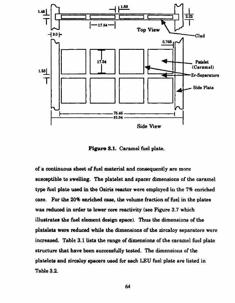
1.45.1_
T
1.~
T
IL
l-l1.s.&-J Top View
o.76ti I rJ
17.So& ......_ ..
1111 L
14
~ ..,.._ ______ ,_76.46 _______ _,.J
1-----------81.04 ----------t Side View
Fipre S. I. Caramel fuel plate.
_L 2.22
T
Patelet (C arame))
Zr·Separatora
-- Side Plate
of a continuous sheet of fuel material and consequently are more
susceptible to swelling. The platelet and spacer dimensione of the caramel
type fuel plate used in the Osiris reactor were employed in the 7% enriched
case. For the 20% enriched cue, the volume fraction of fuel in the plates
was reduced in order to lower core reactivity (see Figure 3. 7 which
illustrates tbe fuel element design space). Thua the dimensioDB of the
platelets were reduced while the dimensione of the zircaloy separa tora were
increased. Table 3.1 liste the range of dimensions of the caramel fuel plate
structure that bave been successfully tested. The dimensions of the
platelets and zircaloy spacers used for each LEU fuel plate are listed in
Table 3.2.
64
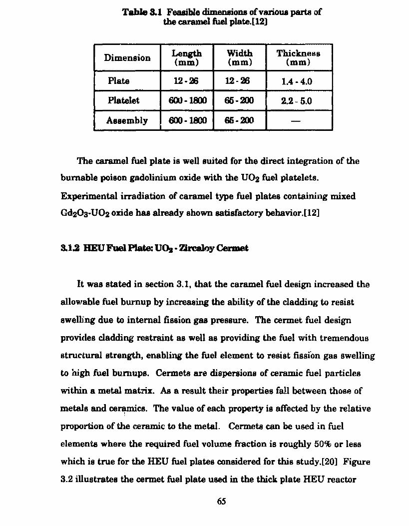
Table 8.1 Feaaible dimenaions ofvarioua parta of the caramel fuel plate.[12]
Dimension Length Width Thickness (mm) (mm) (mm)
Pia te 12-26 12-26 1.4 .. 4.0
Platelet 600-110) 65-201 2.2 ~ 5.0
Assembly 600-1800 66-200 -
The caramel fuel plate ia well suited for the direct integration of the
bumable poison gadolinium oxide with the uo2 fuel platelets.
Experimental irradiation of caramel type fuel plates containing mixed
Gd20a-U02 onde haa already shown satisfactory bebavior.[12]
3.1.2 BEU Fuel P1ate: UO. • Zirca1oy Cerm.et
It was stated. in section 3.1, that the caramel fuel design increased the
allowable fuel burnup by increaeing tbe ability of the cladding to resist
swelli'ng dueto internai fission gas pressure. The cermet fuel design
provides cladding restraint as well as providing the fuel with tremendous
structural strength, enabling the fuel element to resist fission gas swelling
to high fuel bumupe. Cenneta are dispersions of ceramic fuel particles
within a metal matrix. As a result their properties fali between thosB of
metais and ce~cs. The value of each property ia affected by the relative
proportion of the ceramic to the metal. Cermeta can be used in fuel
elements where the required fuel volume fraction is roughly 50% or less
which is true for the HEU fuel plates conaidered for this study.[20] Figure
3.2 illustrates the cermet fuel plate used in the thick plate HEU reactor
65
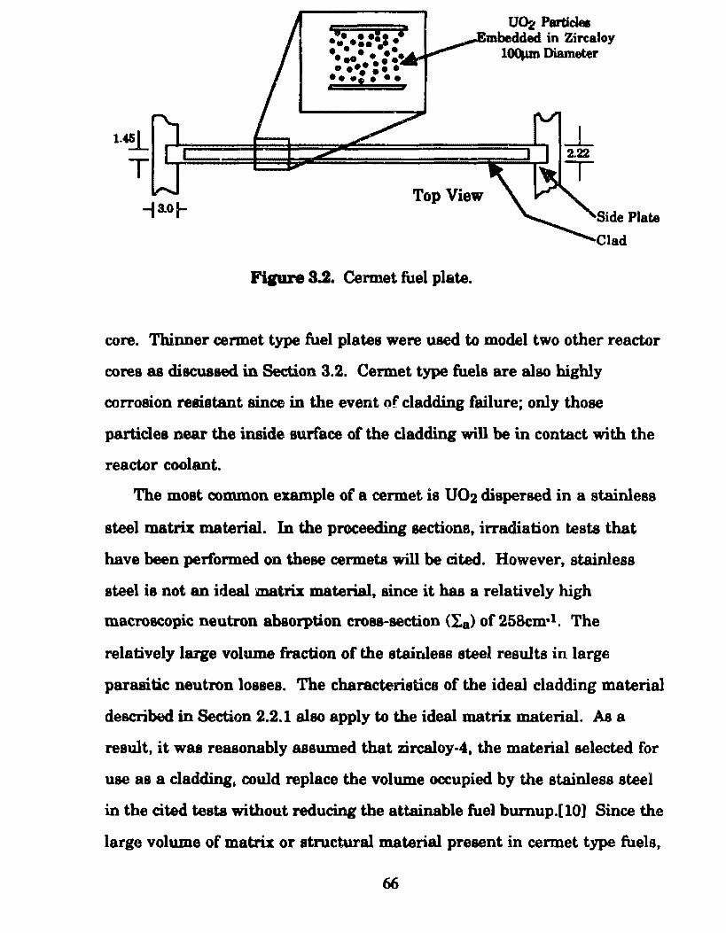
1.~
T
"ii • ··~ i ••••••• • • • • • ••• .. . . • ••• •• • • • ... , ...
Top View
Fipre 3.2. Cermet fuel plate.
UD2 Particlel mbedded in Zircaloy l~Diameter
Side Plate
Clad
core. Thinner cermet type fuel plates were used to model two other reactor
cores as discuased in Section 3.2. Cermet type fuels are also highly
corrosion reaistant since in the event of cladding failure; only those
particlea near the inside surface of the cladding will be in contact with the
reactor coolant.
The most common e:umple of a cermet is uo2 dispersed in a stainless
steel matrix material. In the proceeding sectione, irradiation testa that
have been perform.ed on these cermets will be cited. However, stainless
steel is not an ideal matrix material, since it has a relatively high
macroscopic neutron absorpti.on cross-section (I,8 ) of 258cm·t. The
relatively large volume fraction of the stainless steel resulta in large
parasitic neutron losees. The characteristics of the ideal cladding material
described in Section 2.2.1 also apply to tbe ideal matri.I material. As a
result, it was reasonably assumed that zircaloy-4, the material selected for
use as a cladding. could replace the volume occupied by the stainless steel
in the cited testa without reducing the attainable fuel burnup.[ 10] Since the
large volume of matrix or structural material present in cermet type fuels,
66
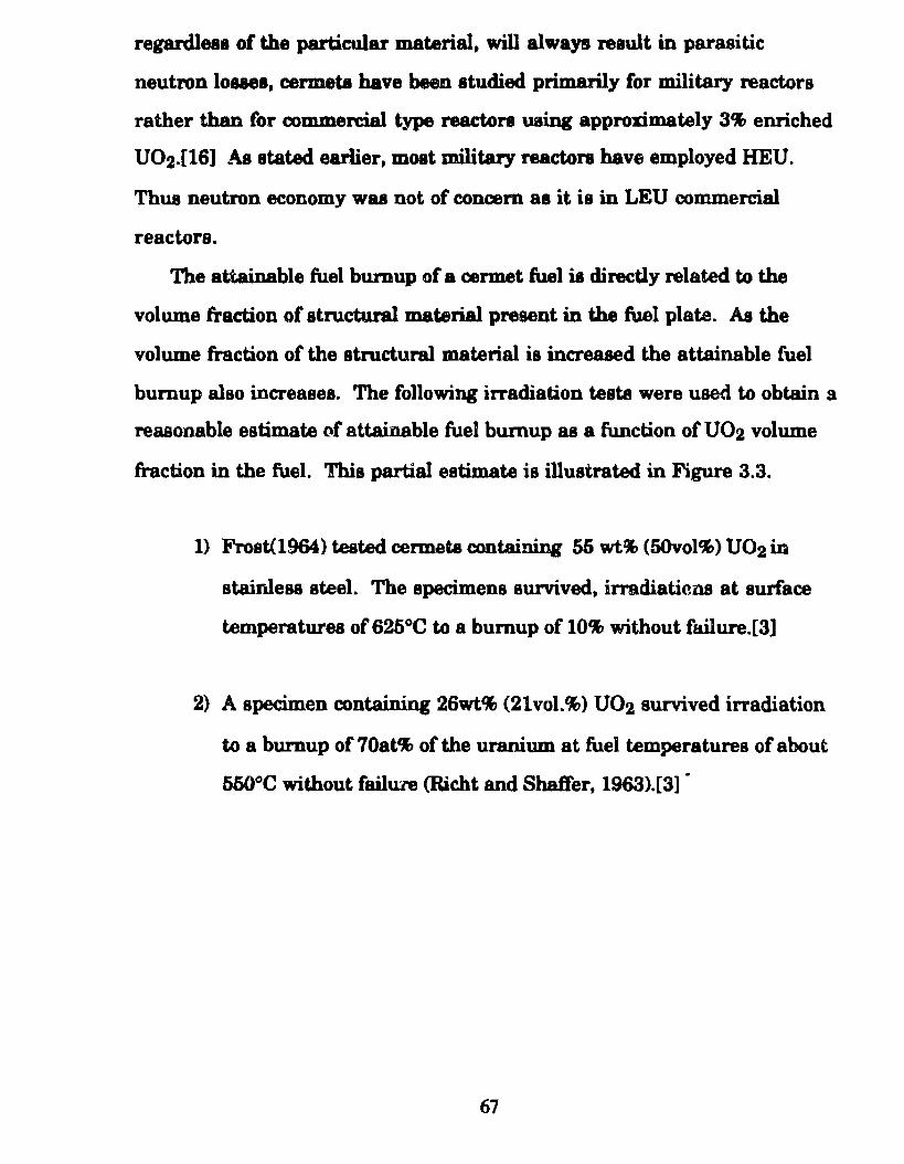
regardleae of the particular material, will always reault in parasitic
neutron louea, cermeta have been atudied primarily for military reactors
rather than Cor commercial type reactore uaing approximately 3% enriched
U02.[16] As atated earlier, moat military reactora have employed HEU.
Tbus neutron economy was not of concem as it ia in LEU commercial
reactors.
The attainable fuel burnup of a cermet fuel ia directly related to the
volume fraetion of structural material present in the fuel plate. As the
volume fraction of the atructural material is increased the attainable fuel
bumup also increasea. The following irradiation testa were used to obtain a
reaaonable estimate of attainable fuel bumup 88 a function of uo2 volume
fraction in the fuel. This partial estimate is illustrated in Figure 3.3.
1) Frost(1964) tested cermeta containing 55 wt% (50vol%) uo2 in
stainless steel. The apecimens survived, irradiatimts at surface
temperaturea of 625°C to a bumup of 10% without failure.[3]
2) A specimen containing 26wt% (21vol.%) U02 survived irradiation
to a burnup of 70at% of the uranium at fuel temperaturas of about
550°C without failU?e (Richt and Shalfer, 1963).[3] ·
67
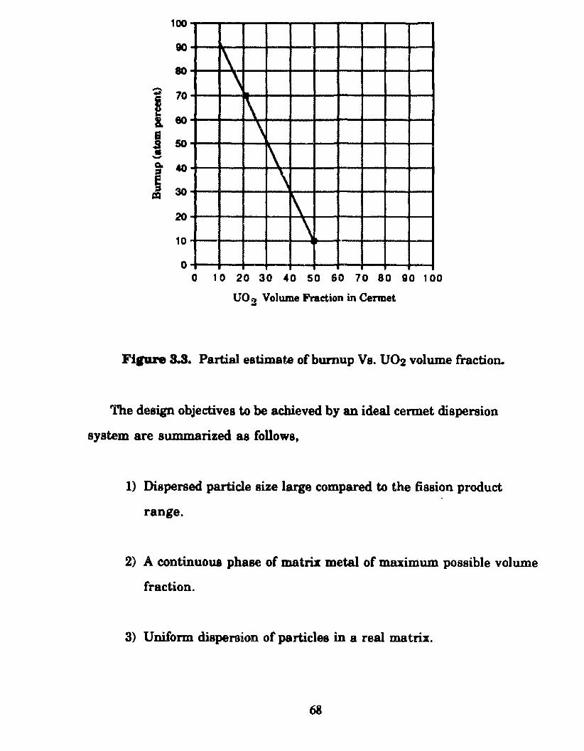
100
90
80
~ 70
I 80
I 50 -a. 40 ::s ; 30 = 20
10
\ \ \ \ 1\ \ \ \
o o 1 o 20 ao •o so so 10 ao 9o 1 oo
UO'l Volume Fraction in Cennet -FIJUI'8 S.S .. Partial estimate ofburnup Vs. U02 volume fraction.
The design objectives to be achieved by an ideal cermet dispersion
system are summarized as follows,
1) Dispersed particle size large compared to the fission product
range.
2) A continuoua phase of matrix metal of maximum possible volume
fraction.
3) Uniform dispersion of particles in a real matrix.
68
As a cermet fuel element is irradiated, damage to the fuel structure is
caused by a combination of the static and dynamic effecta o f the fission
products. At low fuel bumups the major damaging effect is due primarily
to the dynamic properties of the fission fragmente (i.e., fission product
recoil in the matrix). At high fuel bumups where higher concentrations of
fission products are approached the major damaging effect is due to the
static properties of the fission products (i.e., fission gas pressure).
In order to combat damage due t.he dynamic properties of fission
fragmenta, fuel particle diameter in a properly designed cermet should be
large compared to the range of the fission fragmenta. Thus fission
products released from the fuel during reactor operation are confined to
narrow regions or damage zones surrounding the fuel particles, while
most damage is concentrated in the fuel particles. Thus an undamaged
fission product free region of matrix metal exista around around each zone
of damage which surrounds each fuel particle. This objective cannot be
achieved in a homogeneous fissile metal or two ph.ase alloy systems where
both the fuel bearing compound and matrix may contain fissile atoms. For
a given volume fraction of fuel, the volume of damagcd matrix is
proportional to the surface area of the particles. Thus the fraction of the
matrix subject to recoil damage can be minimized by the use of smooth,
spherical particlea as large as can be tolerated. Most fuels designed to take
advantage of the cermet dispersion principie have particlea of a Ieast
1001Lm diameter.[20] Schematic cross sections of cermet dispersant
systems are shown in Figure 3.4. The dispersed particles are assumed to
be spheres in a cubically close-packed array. Two particle sizes are shown
with a spherical zone of damaged matrix metal surround.ing each particle.
Figure 3.4a illustrates a poorly designed cermet where damage zones
69
a
.b
Parti ele
.. age Zone
Figure 3.4. Schematic cross-sections 1Jf cermet dispersion systema.
overlap. Figure 3.4b illustrates a properly designed cermet where damage
zones do not overlap. Thus a continuou& web of undamaged matrix
material exista in the fuel plate providing good internai strength.
With increased fuel burnup, irradiation induced swelling arises due to
growth of the U02 particles. TbÍB ÍB C'lUSed by the static 8CCUmulation Of
fission products and the partia] escs.pe of fiasion gases from the uo2 fuel.
The ]ater effect is the moat significant. A gas filled void is created around
70
the fuel pvticles wbicb preuurizea the mat.rix ahell causing it to expand
as a tbick~walled veaael U.Dder preaaure. ThusD the matrix swelling that
can be allowed will determine the maximum fu.,l burnup. Swelling limits
are determined on the baaia of allowabl8 dimensional changea or a
maximum atrain baaed on reduced ductility limit of the neutron embrittled
matrix.[18] In effect, the matriz material acta u the atructural material in
the fuel element. The cermet of Fip:re 3.4b ia mcre resistant to ewelling
than the cermet of Figure 3.4a due to ita continuoWI web of undamaged
matrix material.
In order for the design principies deecriOOd above to be effective, the
particlea muat be uniform.ly diapersed throughout a m.atrix that
predominatea in volu.me.[20] lf the particlea are not unifonnly dispersed
some fiuion product damage zones will overlap thus weakening the
matrii. If the fuel material predomina te& in volume, it remains possible to
design a eermet aystem in which fission product damage :wnes do not
overlap. However, in this case the structural etrength of the matri:z:
materie.l is significantly reduced and the susceptibility to swelling
approachea that of a plate type fuel element utilizing a continuou.s sheet of
uo2 fuel.
Reacto&" cores fueled with 7%, 20% and 97.3% enrichcd uranium were
modeled using fuel element designa adopted from the original caramel fuel
element design of the Ooiris reactor. lt.R geometry ia similar to that of
current UAl MTR-type fuel elements ueed in some research reactors.
71
Figure 3.5 illuetratea the 17 plate caram.el fuel element used in the 7%
enriched core. Figure 3.6 showa how these fuel elements fit together as
building blocks to form a reactor core. As ín the case of the Osiris reactor
and many other research reactors using plate type fuel, the intra-.element
spacing ia set at lmm.
In order to facilitate the reactor core modeling process the following
mod.ifications were made to the original caramel fuel element,
1) Fuel element end spacings were decreased in order that the intra
element gap and the end-spacing of two acljacent fuel elementa
will equal the width of a water channel.
2) To allow for a square lattice pitch, the width of the fuel plates was
increased.
These modifications ware applied to identical fuel element geometries used
for the reactors fueled with 20% enriched caramel type fuel 8lld 97.3%
enriched tei'Dlet type fuel respectiveiy.
For the HEU case, due to high reactor power density and thus relatively
high fuel temperatures, two additional reactor cores were modeled
consisting of thinner ATR-type fuel plates (Advanced Test Reactor operated
by the Idaho National Engineering Laboratory). Use of a thinner plate in
the high power density core will reduce the relatively high fuel centerline
temperature by increasing the heat transfer ares. The thin plate HEU
reactor cases are described below.
72
End Spaci
0.8151
n~T 2.221
T 2.631
T Fuel Plate
Water Chan
Side Plate
ne~
1.~ T
... -
3~ I-1""'1 _......
I
I
I
I
I
I
I I I
I
I I 81.04
I
I J ._ .. I
I I - I I
"" I I I
I I
I I
,_ -~----------81.04---------t
Fipre 3.5. Thick. plate fuel element design.
I I
I
I
I
I
i
I .1
I
-;:::.:::: lv
I .I
_l I
I I
I
I
I 1
I I
I
L ... L ,
/
/
, ,
f L
Fuel Element
Intra-Element Gap
Fiau,re 3.8. Assemblage of reactor fuel elements.
73
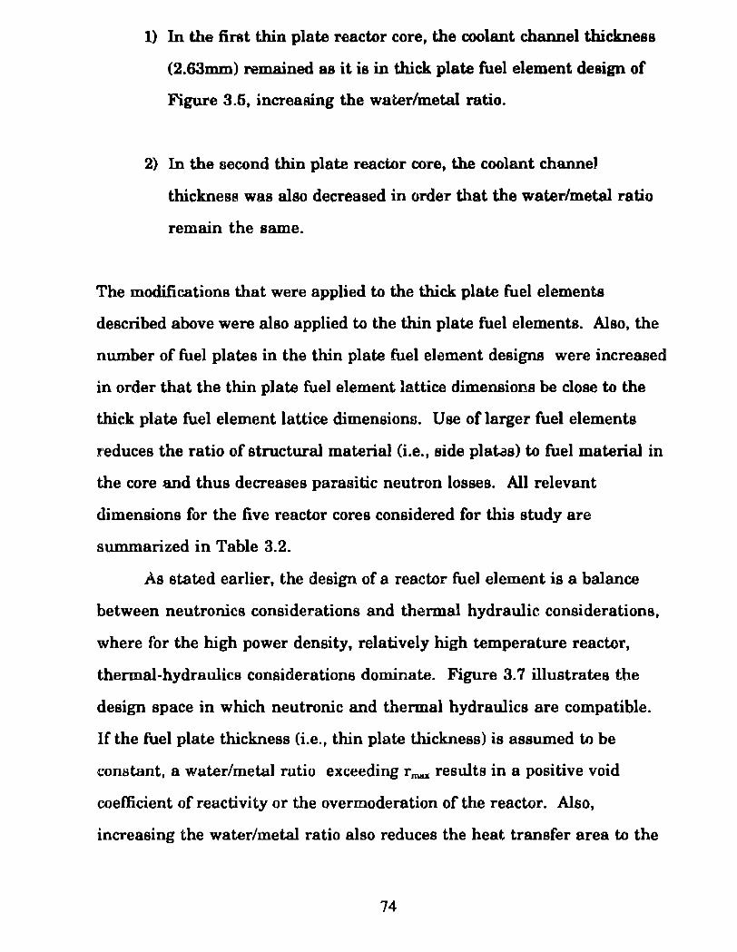
1) In the first thin plate reactor core, the coolant channel thickness
(2.63mm) remained as it ia in thick plate fuel element design of
Figure 3.5, increasing the water/metal ratio.
2) In the second thin plate reactor core, the coolant channel
thickness was also decreased in order that the water/metal ratio
remain the same.
The modifications that were applied to the thick plate fuel elements
described above were also applied to the thin plate fuel elements. Also, the
number of fuel plates in the thin plate fuel element designs were increased
in arder that the thin plate fuel element ]attice dimensions be dose to the
thick plate fuel element lattice dimensiona. Use of larger fuel elements
reduces the ratio of structural material (i.e., si de platas) to fuel material in
the core and thus decreases parasitic neutron losses. Ali relevant
dimensions for the five reactor cores considered for this study are
sum.marized in Table 3.2.
As stated earlier, the design of a reactor fuel element ia a balance
between neutronics considerations and thennal hydraulic considerations,
where for the high power density, relatively high temperature reactor,
thermal-hydraulics considerations domina te. Figure 3. 7 illustrates the
design space in which neutronic and thermal hydraulics are compatible.
If the fuel plate thickness (i.e., thin plate thickness) ia assumed to be
constant, a water/metal ratio exceeding r mu resulta in a positive void
coefficient of reactivity o r the overmoderation of the reactor. Also,
increasing the water/metal ratio also reduces the heat transfer area to the
74
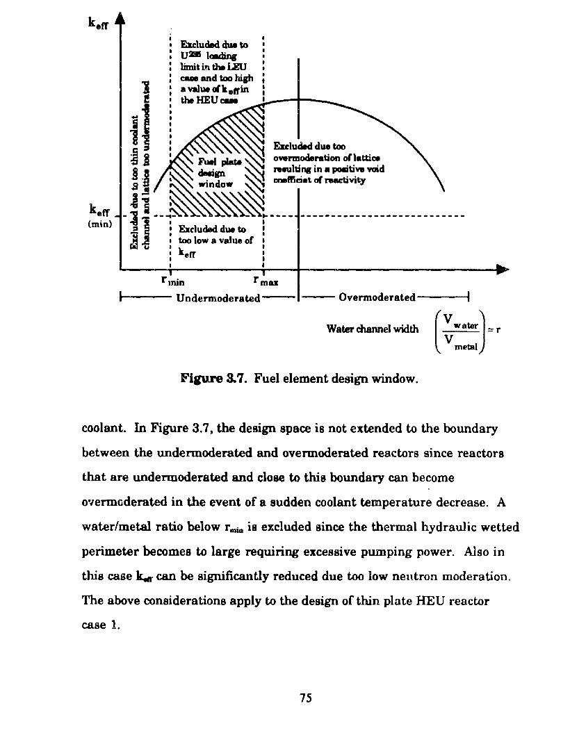
kefT (min)
E.uluded du. to u• bdin« limit m the LEU cue and too hilh a value olk eft'in theHEUcue
rmin
overmoderation oflattiae rHUltinc in a pomtivw wid c:oefticiet of reaetivity
rmu
t-1--- Undermoderated-- --Overmoderated----t
Water channel width ( ~ w •WJ ::: r metal
Figure 3. 7. Fuel element design window.
coolant. In Figure 3. 7, the design space is not extendcd to the boundary
between the undermoderated and overmoderated reactors since reactors
that are undermoderated and close to this boundary can become
o·1ermoderated in the event of a sudden coolant temperature decrease. A
water/metal ratio below rmia is excluded since the thermal hydraulic wetted
perimeter becomes to large requiring excessive pumping power. Also in
this case k..r can be significantly reduced due too low neutron moderation.
The above considerations apply to the design of thin plate HEU reactor
case 1.
75
For tbe aecond tbin plate HEU reactor cue, plate and coolant channel
dimenaiona were dflC!'eased in similar proportiona resulting in a constant
water/m~tal ratio. Tbia, however, increaaea the bomogeneity of the reactor
core and reduce8 k..,. Tbia can be compensated for by increasing the uo2 volume fraction in the cermet fuel. A disadvantage to decreasing the
coolant ebannel thiekneBS, as stated earlier, is the increase in the wetted
perimeter which increasea required pumping power. Thin fuel platea
provide the advantage of increaaed heat tranafer area and thua lower fuel
centerline temperatures. However factors exiat which prohibit fuel plates
from being made extremely thin. Some of these are listed below
1) The ratio of cladding to core becomes larger as the fuel plate
thickness decreases, leading to larger parasitic neutron losses.
2) Thin elementa have lesa rigidity andare more diffi.cult to support.
They are alao more prone to damage resulting from coolant Oow
induced vibrationa.
3) Coolant passages become smaller ~ leading to greater possibility of
obstruction of the passage, greater pressure drops and greater
pumptng power.
These considerationa as illustrated by Figure 3. 7 form the ba.sis for the
reactor designa whieh will be discussed in the proceeding chapters.
Chapters 1, 2 and 3 have covered the selection of the reactor operating
conditions and limita, materiais and fuel element design. Chapter 4 will
76
cover the metbods uaec:l to design and analye each reactor con considered
while Chapter & presente the resulta of the analysi1.
77
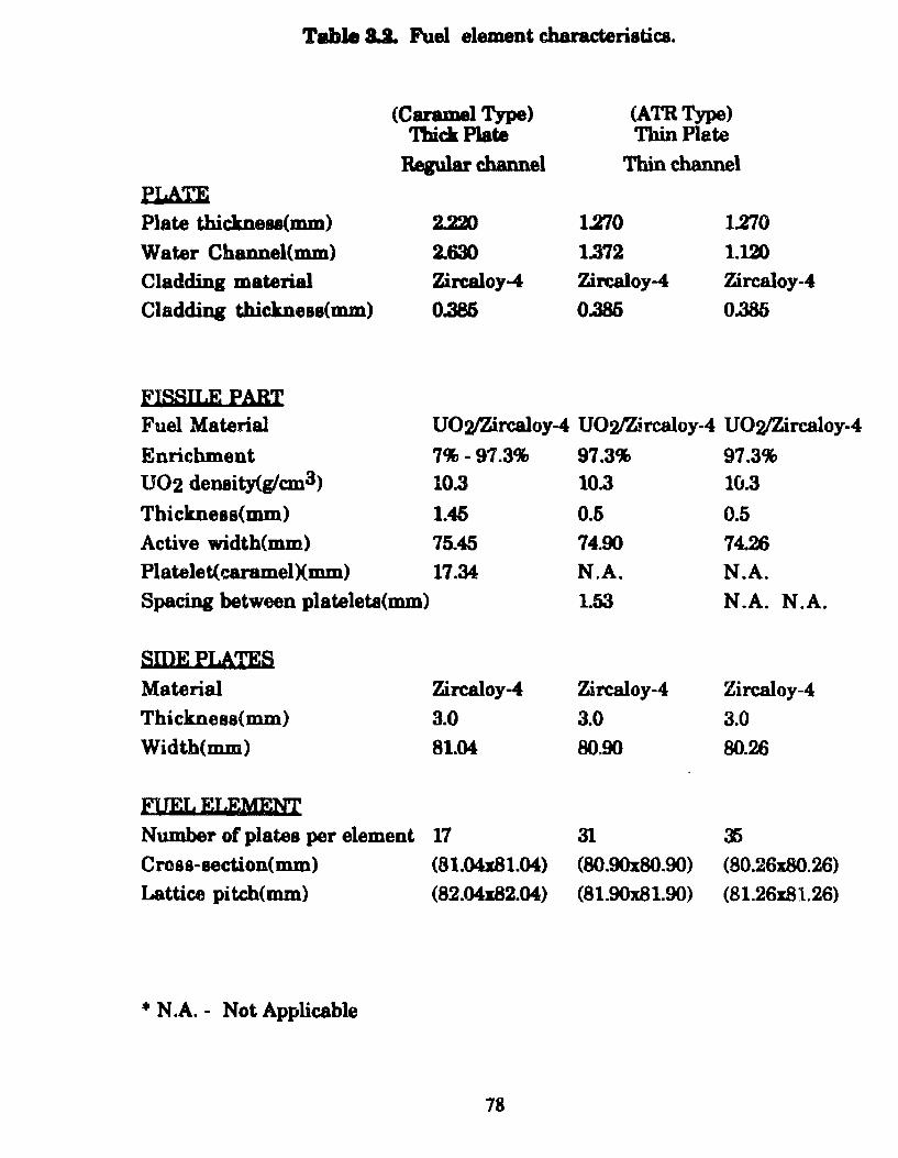
Tule 8.1. Fuel element ehanu:teristica.
(Caramel Type) (ATRType) 'lbickPiate Tbin Plate
Regular cbannel Thin channel PLATE
Plate thickneu(mm) 2.22D 1.270 1.270 Water Channel(mm) 2.630 1.372 1.120 Cladding material Zircaloy-4 Zircaloy-4 Zircaloy-4
Cladding tbicknese(mm) 0.386 0.385 0.385
FissU.E PABT Fuel Material U02/Zircaloy-4 U02)Z!rcaloy-4 U02/Zircaloy-4
Enrichment 7%-97.3% 97.3% 97.3% U02 denaity(glcm3) 10.3 10.3 10.3
Thickness(mm) 1.45 0.6 0.5 Active width(mm) 75.45 74.90 74.26
Platelet(caramelXmm) 17.34 N.A. N.A. Spacing between plateleta(mm) 1.53 N.A. N.A.
SIDEPI,ATES Material Zircaloy-4 Zircaloy-4 Zircaloy-4
Thickness(mm) 3.0 3.0 3.0 Width(mm) 81.04 80.90 80.26
FUEI. EI.EMEN'f Nu.mber of plates per element 17 31 :J)
Cross-section(m.m) (81.04x81.04) (80.90x80.90) (80.26x80.26)
Lattice pi tch(mm) (82.04x82.04) (81.90x81.90) (81.26x.81.26)
• N .A. - Not Applicable
78
In Chapter 1, certain operating characteristics and design
specificationa for a modem SSN reactor were selected as derived from the
performance requirementa of a modem SSN. Chapter 2 outlined the basis
for which the reactor fuel, cladding, coolant anel reactivity control material
(bumable poiaon) were aelected iD order to meet the required reactor
aperati.Dg characteriatica and deeip apeci6cationa. Chapter 3 descriood
the reactor fuel element designa chofien for this study, which are
conatructed baaed on the required reactor operating characteristics selected
in Chapter 1. This present chapter ia divided into two sections which cover
the reactor physica and the thermal hydraulic analysis methods used in
this atudy. However, as stated in Chapter 1, th.ermal-hydraulics
considerationa are assumed not to be limiting for the reactor designa
modeled in this study. Thus the design effort focwr;es on the reactor physics
{i.e., the a(ijustment of the reactor design to aatisfy ali relevant reactor
pbysica criteria). Following the reactor physics analysis, a simplified
thermal-hydraulic analyais ia however included to verify that fuel element
temperatures are within acceptable bounda and tbat the required coolant
flow ratee needed to remove héat are practical. All analytical methods
employed in thia study are covered in this chapter.
Table 4.1 aummarizes the reactor designa conaidered for this study.
Three reactor cores fueled with 7%, 20%, and 97.3% enriched urani um are
considered. For the HEU case (97.3%), two additional reactor core designa
are considered which use fuel oonta.ining thinner plates. AB stated in
Chapter 3, a thinner fuel plate reduces the required fuel center-line
79
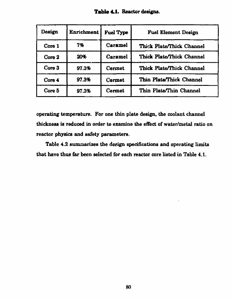
Table 4..1. Reactor deaip•.
Design Enrichmeot Fuel Type Fuel Element Design
Core 1 7% Caramel Tbi~ Platetrhick Channel
Core2 ~ Caramel Thick Platefl'hick Channel
Core3 97.3% Cermet Thick Platell'bick Channel
Core4 97.3~ Cennet Thin PlateiThick Channel
Core5 97.3% Cennet Thin Platetrhin Channel
operating temperature. For one thin plate design, the coolant channel
thickness is reduced in order to examine the eff'ect of water/metal ratio on
reactor physics and aafety parametera.
Table 4.2 aummarizes the de~ign specifications and operating limita
that have thus far been selected for each reactor core listed in Table 4.1.
80
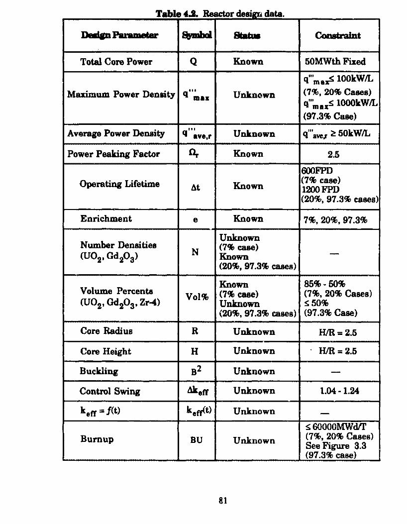
r tiJjpí. Table 4.1. Reacto de . data . Dadp Paramelar s,mbol .... Coostraint
Total Core Power Q Known 50MWth fued
q"'mazS lOOkWIL
Muimum Power Denaity q"• Unkn~wn (7%, 20% Cases) maz
q"' s lOOOkWIL maz (97 .3% Case)
Average Power Density 111
Unknown q"' ~ 50kWIL q ave,r IYel
Power Pealring Factor n.. Known 2.5
600FPD
Operating Lifetime At Known (7% case) 1200FPD (20%, 97.3% cases)
Enrichment e Known 7%, 20%, 97.3%
N umber Densities Unknown (7% case)
(U02, Gd203) N Known -(20%, 97.3% cases)
Volume Percenta Known 85%-50%
Vol% (7% case) (7%, 20% Cases) (U02, Gd20 3, Zr-4) Unknown S50%
(20%, 97.3% cases) (97 .3% Case)
Core Radius R Unknown H/R= 2.5
Core Height H Un.known HJR = 2.5
Buckling 82 Unknown -Control Swing Akeff Unknown 1.04- 1.24
keff =/(t) k 8 tr<t> Unk.nown -s 60000MWdlf
Burnup BU Unknown (7%, 20% Cases) See Figure 3.3 (97 .3% case)
81
For the comparative purpoaes of tb.ia atudy, a aimplified one
dimenaionalateacly-atate overall core reactor phyaica calculation ia used to
model the reactor corealisted in Table 4.1. With thia model, tb.e spatial
dependeoce of neutron fluz and fuel depletion (burnup) are neglected. (The
consumption of fuel ia treated as coDStant in alllocatioll.l of tbe reactor
core. In an actual reactor, the neutron fluz ia greateat in the center of the
core. Thua fuel depletion ia alao greateet in the center.) Tbia model also
does not eimulate the etrecta of control rod motion or atartup, shutdown and
transient behavior.
For the one-dimensional overall core model the entire reactor core is
characterized by each reactor physics parameter employed. For this
analysis, these parameters are,
1) Uranium enrichment (e).
2) Relative proportions or volume percents of U02 fuel, Zr-4
structural material and Gd20a burnable poison in the fuel meat
Vol%m(U02, Zr-4, Gd203). The subacript (m) refers to the volume
ftaction ofthe particular material in the fuel meat. (Note that
volume percenta are denoted by Vol~(l) while a volume
fractions are denoted by Volz{l). The aubscript, x, designates the
volume of concem and I refere to the material.
3) Total operating power (Q).
82
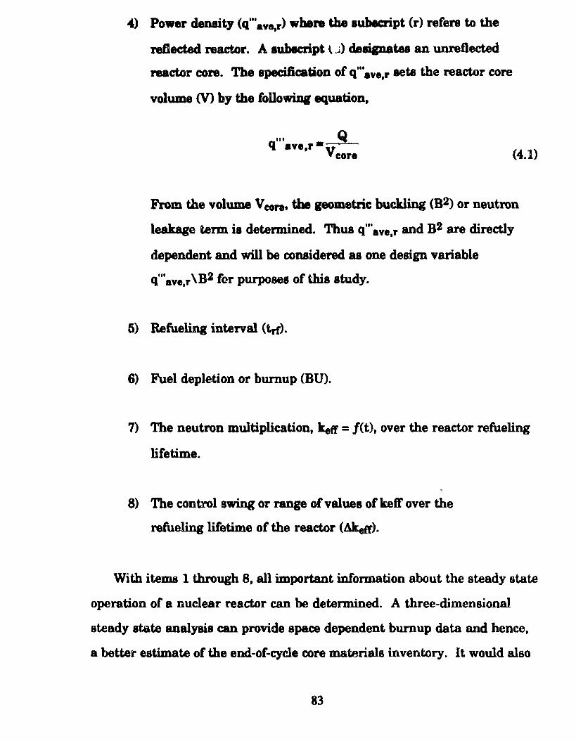
4) Power denaity (q"'ave,r> wbere the aubecript (r) refere to the
retleeted nactor. A sublcript \..i) deaignatee an unreflected
reactor core. The specification of q"'ave,r seta the reactor core
volume (V) by tbe following equation,
... Q q ave,r•v
core (4.1)
From the volume V conh tbe pometric buckling (B2) or neutron
leakage term ia determined. Thus q"·ave,r and B2 are directly
dependent and will be considered as one deaign variable
Q111ave,r \B2 for purposes of this study.
5) Refueling interval (trf).
6) Fuel depletion or burnup (BU).
7) The neutron multiplication, keft' = f(t), over the reactor refueling
lifetime.
8) The control awing or range of values of keff over the
refueling lüetime of the reactor (âkefr).
With items 1 through 8, all important information about the steady state
operation of a nuclear reactor can be determined. A three-dimensional
steady state analysis can provide space dependent burnup data and hence,
a better estimate of the end-of-cycle core materiais inventory. It would also
83
provide a more accurate estimation of keft"= j(t) and Akeff. However, as
stated in Chapter 1, it was decided that such refinement is unnecessary for
the comparative purpoaes of this study.
Figure 4.1 illustrates the relationship and interdependence of each of
these parameters which together describe the operating reactor system. A
certain percentage of the composition of this system is fuel material and a
certain percentage is non fuel material. The fuel is consumed in a nuclear
reaction to produce power for an operating time, after whlch the fuel has
reached a burnup levei (i.e., a certain percentage of fuel has been
consumed). At any particular time during the operating time span the
system h,11S excess reactivity or excess capability trt sustain the power
producing reaction. This excess capahility changes over the operating
time. The range of excess reactivity over the operating time determines the
amount of control capability that must be provided to this system. Some of
this capability is supplied the bumable poison (Gd203), a non fuel material.
An increase in the volume of control material in the system is accompanied
by a decrease in the volume of fuel material in the system. Thus as shown
by this figure, a change in any one o f these parameters affects ali the other
parameters, and thus the overall operation of the reactor system.
In Figure 4.1, to the left of the dashed line are the reactor physics
parameters that have been fixed according to the discussion of Chapter J..
To the right of the dashed line are the reactor physics parameters which have
not been fixed but are variable. These variable parameters are interdependent
andare constrained by the limits Bí)ecified in Table 4.2. Thus the design
window shown in Figure 4.2 for a reactor core of fixed total operating power
(Q), uranium enrichment (e), and refueling lifetime (lrf) is formed.
84
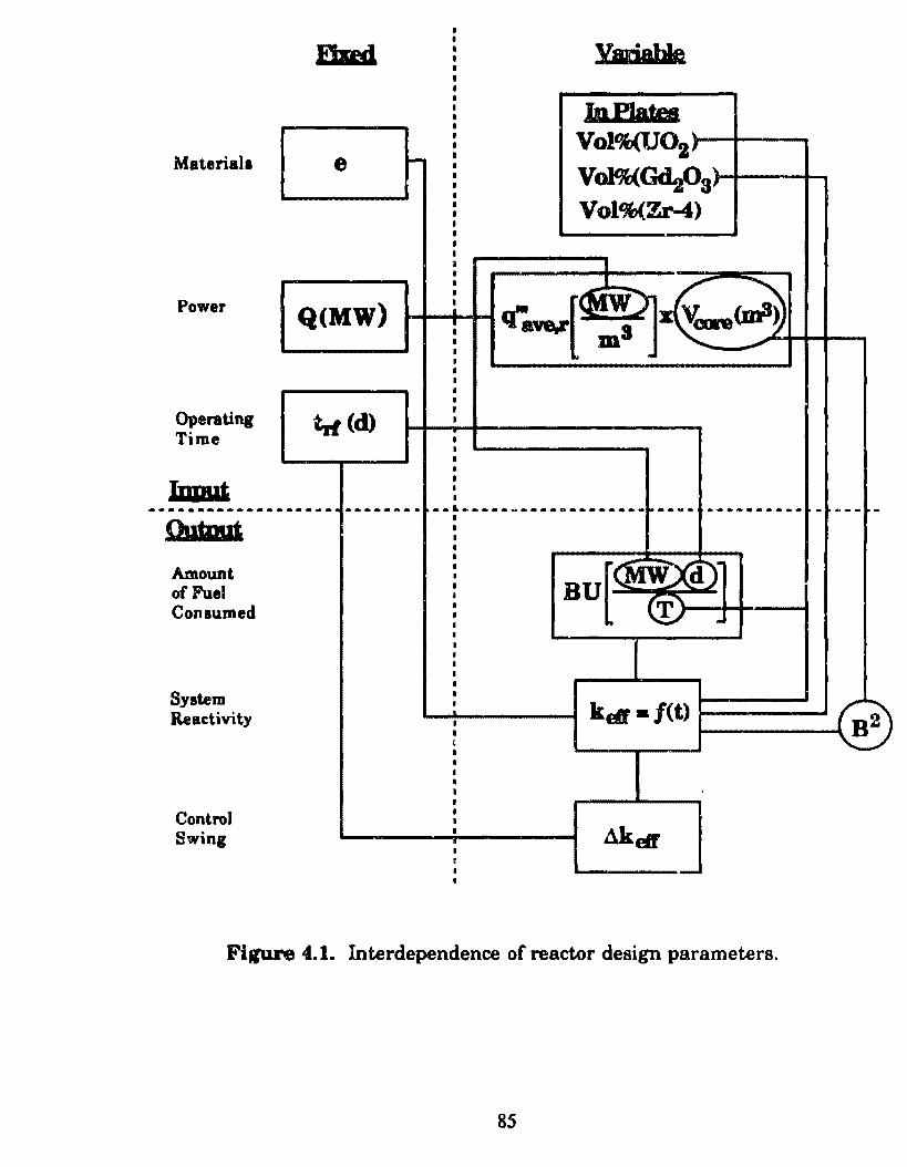
Material a
Power
Operating Time
lnpgt
fhed
e
Q(MW)
trt (d)
~
InPJatee
~
Vol%(U02 ~
Vol%(GdtOs> Vol%(Zr-4)
_L
q-~[~~~~~ I
I
--·-··---------·---·-----~-- --~·--·------~--------·---- ---··-··*· - ----Outwt Amount of Fuel Consumed
System Reactivity
Control Swing
.......... ·~-----~ k(§. /(t) ,__ __ _.... 2 t--------\ B
.
Figure 4.1. Interdependence of reactor design parameters.
85
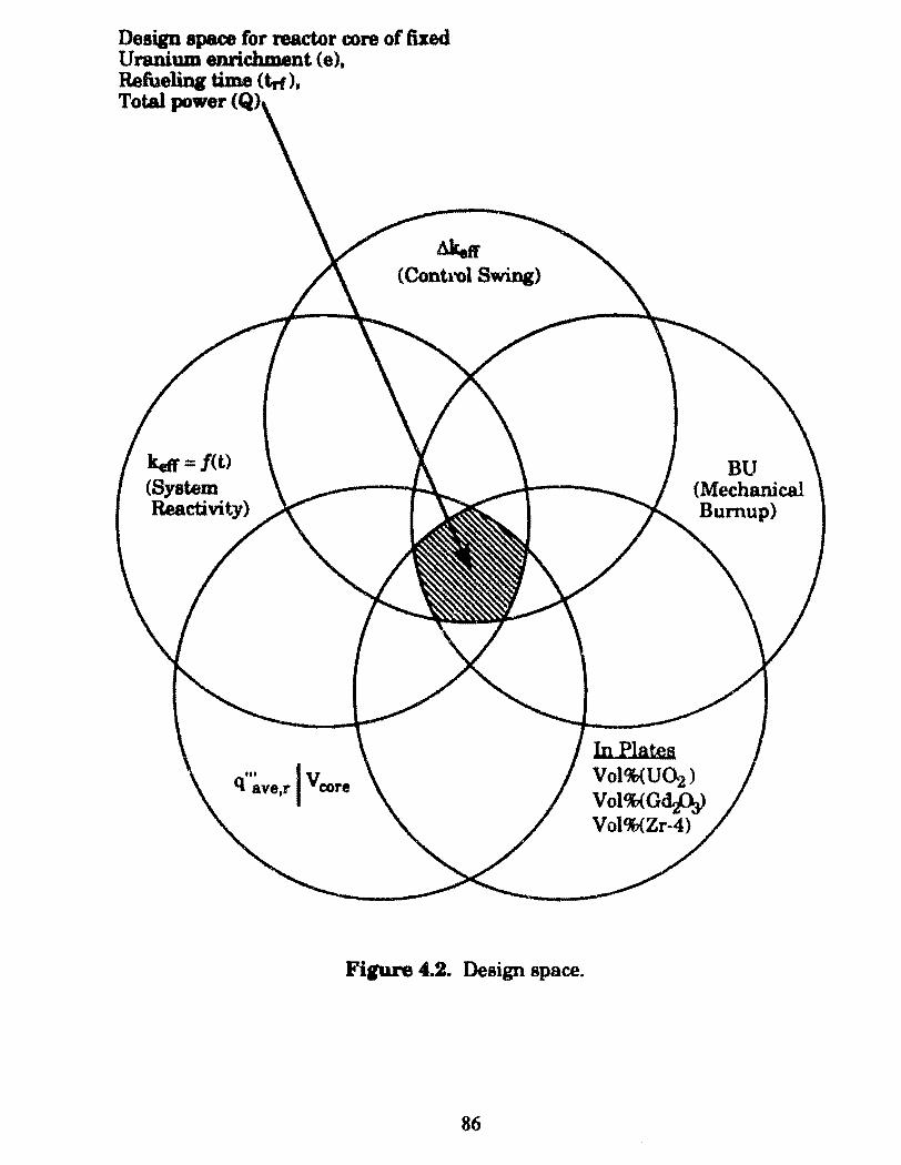
Design apace for reactor core of fixed Uranium enriehment (e). RefueliDg time (trf). Total power
ketJ = f(t) (System Reactivity)
Akeff ( Cont1'0l Swing)
Fipre 4.2. Design space.
86
BU (Mechanical Bumup)
In Plates Vol%(U~)
Vol%<Gd.JlJ) Vol%(Zr·4)
In tbia fipre each ci.rc:le representa ali poaeible valuea of each variable
parameter. The deaip apace or repon of overlap of the circlea repr0aents
the accept.ble range of valuee of each variable parameter in combination
with the ra.np ol acceptable valueo of tbe other variable param.etera. Thus
each reactor cora muat be deaipecl in order tbat the value of each of these
parametera lie in the deaip apace. ODe can aee by inapection ofFigures 4.1
and 4.2 that tbe one-dimeuaional calculation uaed for tbia atudy requires
iteration in orcler to acijuat tbe reactor phyaica deaip parameters to lie in
the design space.
To perform tbeae iterativa 1-D calculations the EPRI·Cell code ia
employed.(9] AB ahown in Fipre 4.1, tbe parameters above the horizontal
daahed 1ine are required aa input to EPRI-Cell while the parameters below
the dashed line are produced in the EPRI-Cell output. Tbus the valuea for
q"'ave,r \B2 and Vol%mCU02. Zr-4, Gd20a) are varied in the EPRI-Cell input
to cause the values of BU, kefr z f(t) and Akefr to satisfy the constraints listed
in Table 4.2. At thia point the value of q"'ave,r \B2, Vol%m(U02, Z'r-4,
Gd20s), BU, ketr and Akeft' will simultaneoualy lie in the design space of
Figure 4.2.
For each core deoign, Figure 4.3 illustrates the variable input design
parameten (physical reP~tor design acijustments) of q'"ave,r\B2 and
Vol%mCU02, Zr-4, Gd203) with regard to the complete core system. The
variable input design parameten (pbysical characteristics which are
variable) a.re contained in c:irclee while the physical characteristics which
are c,_ J&tant (pbysical characteristics which are not design variables) are
contained in rectangles. The physical basis for the variable input
parameters Q111
ave,r \B2 and Vol%mCU02, Zr_., Gd20a) for each reactor core
design is discuesed below.
87
CD.re (1)
For reactor core design 1 which utilizes 7% enriched caramel type fuel,
it is desirable for the uo2 volume percent in the fuel meat to be aslarge as
possible in order to maximize available reactivity. Thus for this core, the
UO?~Zr-4 volume percent ratio in the fuel meat ia fixed at what it is in the
original caramel fuel design. Note that the Zr-4 structural material in the
fuel meat ia structural material as described in Chapter 3. Also, for this
LEU design, the reactivity control material (Gd203) ia mixed directly with
the uo2 fuel material. Thus the variable input design parameters 88
íllustrated by Figure 4.3a are,
1) ratio ofvolu.me percents ofU02/Gd203, Vol%f(U02, Gd203)
within the fuel (i.e., the original dimensions of the fuel platelets
of the cara.mel fuel design); [The subscript (0 refers to the
volume percent of the particular material in the fuel (i.e., in this
case the fuel material is a mixture of U02 and Gd20a.>1
2) the values of q"'ave,r \B2 which are varied by a changes in the
core volume <Veore>· [Note that with each change in the core
volume, the height to radius ratio is constant as stated in table
4.2. This is discussed in detail in section 4.1.2.ô.]
These parameters are adjusted in the EPRI-Cell input to cause the values of
BU, keft' = f(t) and Akew to satísfy the constraints listed in Table 4.2.
88
Cores (2.3.4.5)
For reactor core designa 2,3,4 and 5, the U02 volume percent in the fuel
plate must be lower than that of eore 1 in order to reduce excess reactivity to
a controllable levei. Tbue for thie core, the UO:I{lr...f volume percent ratio
in tbe fuel meat ia a va.riable input deaign parameter. AB discusaed in
Chapter 3, a lumped gadolinia diatribution wu employed for these cores.
For theae cores the thickneu ofthe Gd2Üa plate lump was varied. Note that
as the lump thickneu decreaaea, the tbickne11 oC tbe cladding which
covera the lump muat increase proportionally. Tlús ia discussed in detail
in Section 4.1.2.3. Thua the variable input dcsign parameters for these
cores, as illustrated by Figure 4.3b are,
1) ratio ofvolume percent ofUO?/Zr-4, Vol%m(U02, Zr-4)
within the fuel plate&. For th .... 20% enriched case, this is
the ratio of the volume of the fuel platelets to the volume occupied
by the zircaloy epacera. [For the 97.3% enriched caseo, this is the
ratio of fuel particle volume to the volume of the cennet matrix
material. This ia discussed in detail in Section 4.1.2.4.]
2) the thick.ness of the Gd2Da plate lump, Vol%(Gd203). A change
in the thiclmess of this lump changes the relative proportione of
Gd2Üa to the UÜ2 and Zr-4 in the fuel meat.
3) the values of q"'@ve,r \B2 which are varied by a changes in V core·
These parameters are adjusted in the EPRI-Cell input to cause the values of
BU, ketr = j( t) and AkeK to satisfY the constraints liated in Table 4.2.
89
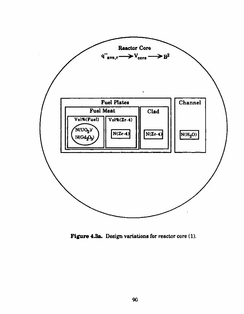
Reactor Core ... ~v ~ 2 q ave,r >' core -""""ly• B
Fuel Plates Channel
Fuel Meat Clad Voi.,(Fuel) VoiCJ11CZr-4)
N(U~)I {N(Zr-4~ (NcZr-4~ N<Gd..A>
Fip.re 4.Sa. Design variations for reactor core (1).
90
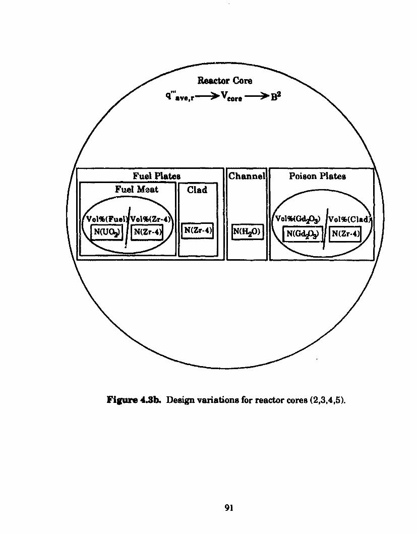
ReaetorCore
Fuel Platea Channel Poison Platea ---Fuel M0at Clad
Fipre 4.3b. Deaign variationa for reactor cores (2.3,4,5).
91
Sectiona 4.4.1.- 4.1.4. describe the methoda uaed to model the reactor cores
ofTable 4.1 using the EPRI-Cell code.
4.1.1 Tbe EPRI-Cell Code
A sophisticated computer code with thc capabilities to solve a
complicated problem can aometimea hinder the rapid completion of the
calculationa at hand. Sucb waa the caae with the computer code (EPRI
Cdl) chosen as the analytical tool for tlús study. Much time and effort was
devoted to the successful implementation and utilization of this code. This
would not have been possible without the aid of the administra tive and
engineering staff of Argonne National Laboratory.
The EPRI-Cell code was run on Argonne's IBM 3033 computer system
and was accessed from M.I.T. via the TYMNET public network system
with a DEC-VTIOO computer terminal anda Quibe modem. The TYMNET
public network system is a system of interoonnected communications
processors, called nodes, which transmit and receive computer data. It
offers local telephone access in hundreds of metropolitan areas around the
United States. Once a TYMNET COJmection was established with the ffiM
3033, user interface was accomplished using the OBS WYLBUR operating
system. OBS WYLBUR was aelecteõ. a.bove other available operating
systems since it permita on-line file viewing of lengthy EPRI-Cell output
data files. Thus the costJy and lengthy process ofhaving each output file
printed out and mailed to M.I.T. for data examination was eliminated. In
order to greatly reduce computer usage costa, the IBM 3033 was used in the
cheaper batch mode rather than in the in te. ,ictive mode. OBS WYLBUR
was used to set up batch files containing installati-:>n-dependant IBM Job
92
Control La.nguage (JCL) and accompanying EPRI-Cell input data. Job
Control La.nguage controla the data input proceaa to EPRI-Cell and the data
output proceaa from EPRI-Cell to appropriate memory locations and
retrieval quea. In order to further reduce computer usage costa, each batch
job waa aubmitted and nm during night and weekend hours and specified
as a low priority job. Low priority apecification, at times, :resulted in
signiticant time intervale between data aubmi88ion and output file
retrieval. Chargea per CPU hour were prohibitively high for full priority
batch joba regardless of the time period in which they were submitted.
As stated in Section 1.3, EPRI-Cell computes the space, energy, and
bumup dependence of the neutron spectrum in light water reactor fuel
cella. lta output consista mainly of broad group, macroscopic, exposure
deper,dent cross-sections for subsequent input into multidimensional
transport theory codes or diffusion theory codes such as DIF3D or REBUS-3
(this ia discussed further in Section 6.2). EPRI-Cell combines a GAM
resonance treatment in the fast and epithermal energy ranges with a
THERMOS, heterogeneous integral-transport treatment in the thermal
energy range. The original GAM and THERMOS codes have been modifi.ed
for use in EPRI-Cell; these modifications are fully described in the EPRI
Cell users manual. The GAM and THERMOS cross-aectiori libraries
coru;ist of 68 and 35 energy groups respectively. These cross-section sets are
collapsed by EPRI-Cell into 1, 2, 3, 4 or 5 energy groups, according to the
specificati.on of the user. The broad-group energy break points used by
EPRI-Cell are listed in Table 4.3.
A modified version of CINDER, which is a general 'point' program that
evaluates the time dependent concentrations of coupled nuclides following
irradiation in a specified time-dependent flux, is incorporated into the
93
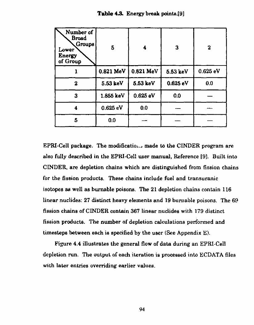
Table 4.3.. Energy break points.[9]
Numberof Broad
Groups 5 4 3 2 Lower
Energy ofGroup
1 0.821 MeV 0.821 MeV 5.53 keV 0.625 eV
2 5.53 keV 5.53 keV 0.625 e V 0.0
3 1.855 keV 0.625 eV 0.0 -4 0.625 eV 0.0 - -
5 0.0 - - -
EPRI-Cell package. The modificatim .... made to the CINDER program are
also fully described in the EPRI-Cell user manual, Reference [9]. Built into
CINDER, are depletion chains which are distinguished from fission chains
for the fission products. These chains include fuel and transuranic
isotopes as well as burnable poisons. The 21 depletion chains contain 116
linear nuclides: 27 distinct heavy elements and 19 bumable poisons. The 69
fission chains of CINDER cont.ain 367 linear nuclides with 179 distinct
fission products. The number of depletion calculations perfonned and
timesteps between each is specified by the user {See Appendix E).
Figure 4.4 illustrates the general flow of data during an EPRI-Cell
depletion run. The output of each iteration is processed into ECDATA files
with later entries overriding earlier values.
94
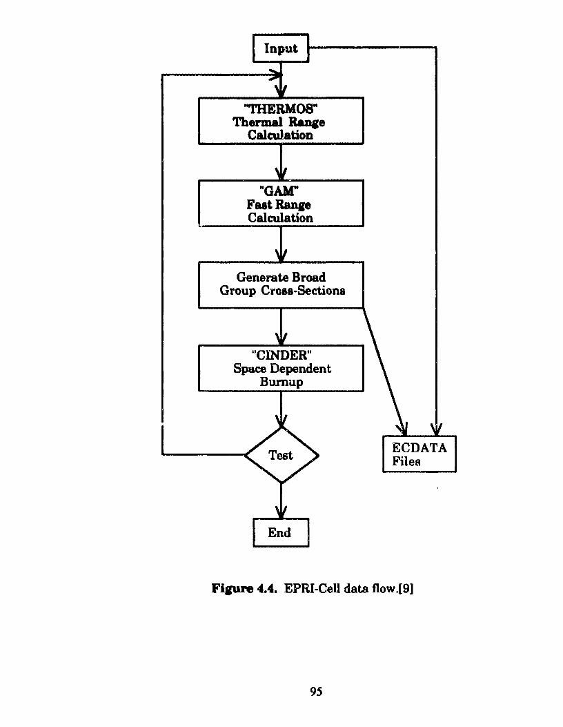
Input
"'IHERMOS" Thermal Raqe
Calculation
"GAM" FaatRanp Caleulation
Generate Broad Group Croaa-Sections
"ClNDER" Space Dependent
Bumup
End
'ECDATA Files
Fi,ure 4.4. EPRI-Cell data flow.[9]
95
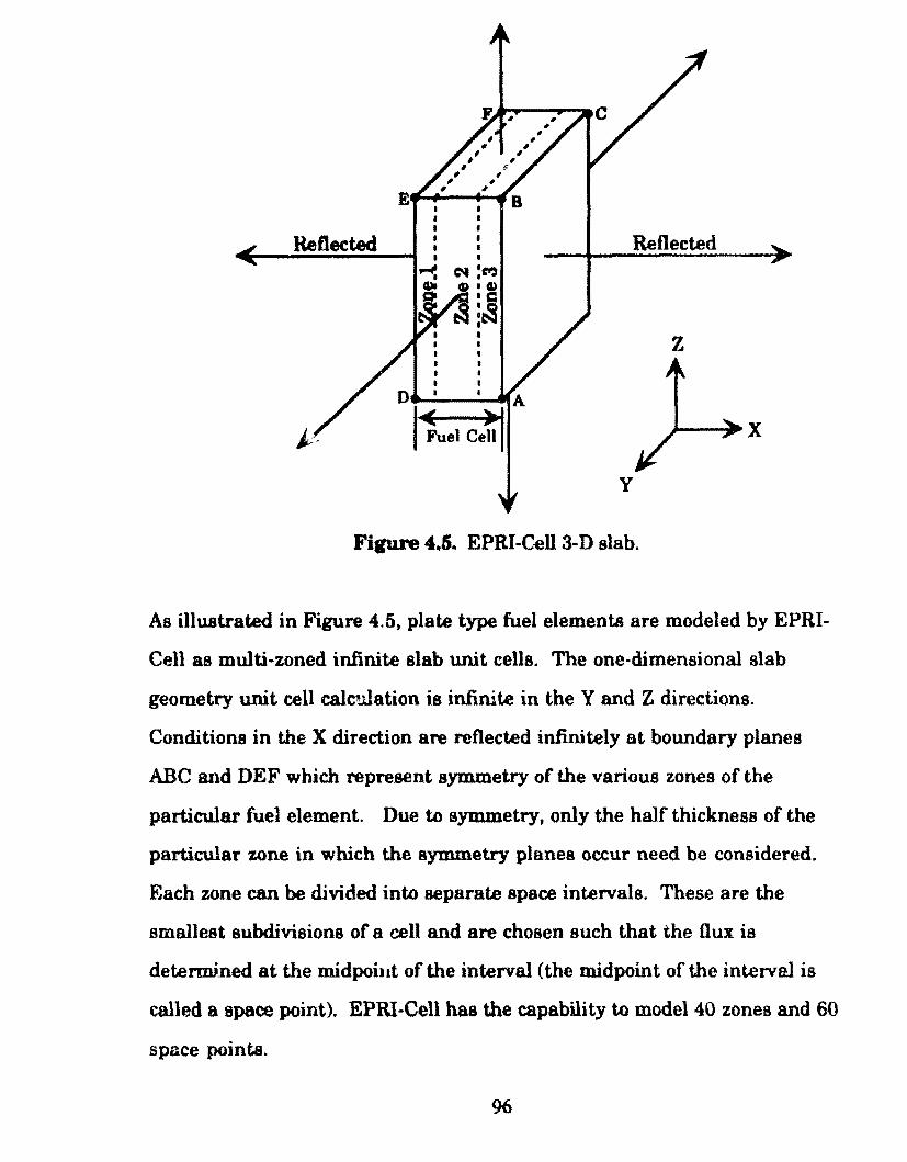
ReOected
I I
• I I I
C'l'e:C'r,) f»•CD •c ~:tS • • I
I I I
I I
D • I A
1-t •. Ce~
Reflected
z
y
Fipre 4.5. EPRI-Cell3-D slab.
As illu.strated in Figure 4.5, plate type fuel elements are modeled by EPRI
Cell as multi-zoned infinite slab unit cells. The one-dimensional slab
geometry unit cell cal~.llation is infinite in the Y and Z directions.
Conditions in the X direction are reflected infinitely at boundary planes
ABC and DEF which represent symmetry of the various zones of the
particular fuel element. Dueto symmetry, only the half thickness of the
particular zone in which the symmetry planes occur need be considered.
Each zone can be clivided into separate space intervals. These are the
smallest subdivisions of a eell andare chosen such that the flux is
deten:IV.ned at the midpoiut of the interval (the midpoint of the interval is
called a space point). EPRI-Cell has the capability to model40 zones and 60
space points.
96
Each zone in the fuel cell can represent fuel, cladding, coolant
channela, burnable poiaon of any other materi&l component o( the fuel
e1ement in queation. EPRI-Cell breab each zone into compositiona and
requirea input specifying the volume percent of each material composition
in each zone and the number .denaity of each nuclide in each composition.
EPRI-Cell haa the capability to treat 20 compositiona and 36 nuclides.
The EPRI-Cell code was used to mock up the reactor cores of this study
with one-dimenaional calculationa. In general, une-dimensional
calculations performed on high power denaity reactor cores are used only
for preliminary or survey type analysis.[12] Since the objectives of these
calculations are only to provide an estimate of reactor core aize, refueling
lifetime, reactivity coefficients, and plutoniwn buildup for comparativa
purpoaes, on~dimensional calculations were deemed appropriate. Other
reactor design considerations such as spatially dependant burnup, control
element motion and atartup, shutdown and transient behavior have been
neglected for the comparativa purposes of this study. Possibilities for
further, more detailed analysis are discussed in Chapter 6.
4.1.2 Reactnr Core Model
This section describes the methods used to model the reactor cores
considered for this study which are summ.arized in Table 4.1. Also
described in this section are the methods used to calculate the values of the
particular EPRI-Cell input parameters listed in Table 4.4 which represent
the reactor core design variables described in Figures 4.1 and 1.2. Each
calculation is baserl on the fixed and variable input data listed in Table 4.2
97
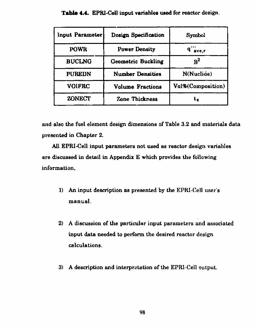
Table 4.4. EPRI-CeU input variahles uaed for reactor design.
Input Parameter Dosip Specification Symbol
POWR Power Density '" q ave,r
BUCLNG Geometric: Buclding B2
PUREDN N umber Densitiee N(Nuclide)
VOIFRC Volume Fractione Vol%(Composition)
WNECT Zone Thiclmess tx
and also the fuel element design dimensione of Table 3.2 and materiais data
presented in Chapter 2.
Ali EPRI-Cell input parameters not used as reactor design variables
are ruscussed in detail in Appendix E whlch provides the following
information,
1) An input description as presented by the EPRI-Cell user's
manual.
2) A discussion of the particular input parameters and associated
input data needed to perfonn the desired reactor design
calcula tio na.
3) A description and interpr~tation of the EPRI-Cell output.
98
4) The first and second depletion timesteps of the reactor core 3
EPRI·Cflll output file.
4.1.2.1 Fu.el Cell Treatment
A description of the fuel cells used to model each reactor core is
provided in this section. The geometry or thick.ness of each zone in each
fuel cell is specified in the EPRI·Cell input file by the parameter ZONECT.
Core (1)
As discussed earlier, for this core which is fueled with 7% enriched
uranium, a uniform bumable poison distribution was employed. A 1 umped
gadolinia distribution was not required for this enrichment as will be
discuased in Chapter 5.
Figure 4.6 illustrates the fuel cell considered this core. It consists of
fuel, cladding, and coolant water zones with planes of symmetry occurring
in the center of each fuel plate and coolant water channel. Consequently,
the zone thicknesses which must be specified by ZOl-..'ECT in O!'der to model
this fuel cell, are the half thickness of the fuel meat, the cladding thickness
and the half thickness of the water channel. As illustrated ·in Figure 4.5,
this cell is treated as infinite in the Y ·direction and also in the Z-direction
(extending into and out of the page).
Each zone contains material compositions which in turn are composed
of nuclides. The fuel zone consista of the compositions U02-Gd203 and
zircaloy4 structural material. The U02-Gd203 composition is a mixture of
U02 and Gd203, where Gd20a, as stated in Section 2.3, can be mixed
directly with uo2. The cladding and water zones consist of the
99
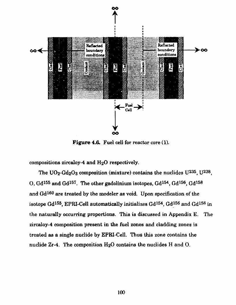
00
t
I
I FueJ I
r~~~~
00
Figure 4.6. Fuel cell for reactor core (1).
compositions zircaloy-4 and H20 respectively.
The U02-Gd20a composition (mixture) contains the nuclides U235, U238.
O, Gd 155 and Gd 157. The other gadolinium isotopes, Gd 154, Gd 156, Gd 158
and Qdl60 are treated by the modeler as void. Upon specification of the
isotope Qd155, EPRI-Cell automatically initializes Gd154, Gdl56 and Gdl58 in
the naturally occurring proportions. This is discussed in Appendix E. The
zircaloy-4 composition present in the fuel zones and cladding zones is
treated as a single nuclide by EPRinCell. Thus this zone contains the
nuclide Zr-4. The composition H20 contains the nuclides H andO.
100
Cores (2.3.4.5.)
For reactor core designa 2,3,4 and 5, a lumped gadolinia distribution
was employed in order to take advantage of self ahielding effects in the
gadolinia. As will be discussed further in Chapter 5, this preventa the
rapid depletion of gadolinia near B.O.C., thus providing reactivity control
towards E.O.C. Unlumped gadolinia depletes faster than the uranium fuel
since it has a larger absorption cross-section. For these designa, the
gadolinia waslumped into fuel plate locations and clad with Zr-4. This
requires an expanded fuel cell model.
Calculations were performed with burnabl~ poison plates occurring at
every fourth and sixth plate location as illustrated by Figures 4.7a and 4.7b.
As will he discussed in Chapter 5, the reactor core with burnable poison
plates distribut.ed every sixth plate exhibited a lower control swing, Akeff·
For these designa, the fuel element is modeled with four zone types, fuel,
cladding, coolant and burnable poison zones. The planes of symmetry for
this fuel cell occur in the center of the bumable poison zones and the center
of the middle fuel plate or zone with respect to the bumable poison zones.
However, the fuel cells shown in Figures 4.7a and 4.7b contain three planes
of sym.metry and not two as in the case of Figure 4.6. This was done in
order to verify, using t.he corresponding EPRI-Cell output, that the code was
performing a symmetric depletion calculation about the center planes of
symmetry. In other words, to verify the reflection of boundary conditions
across the symmetry planes.
In this case, the fuel zone consista of the compositions, uo2 and
zircaloy-4 structural material. The U02 consista o f the nuclides U235, U238
andO. No Gd20a is present since it is lumped into a solid sheets occupying
fuel plate locations. The zircaloy-4 in the fuel and cladding zones is treated
101
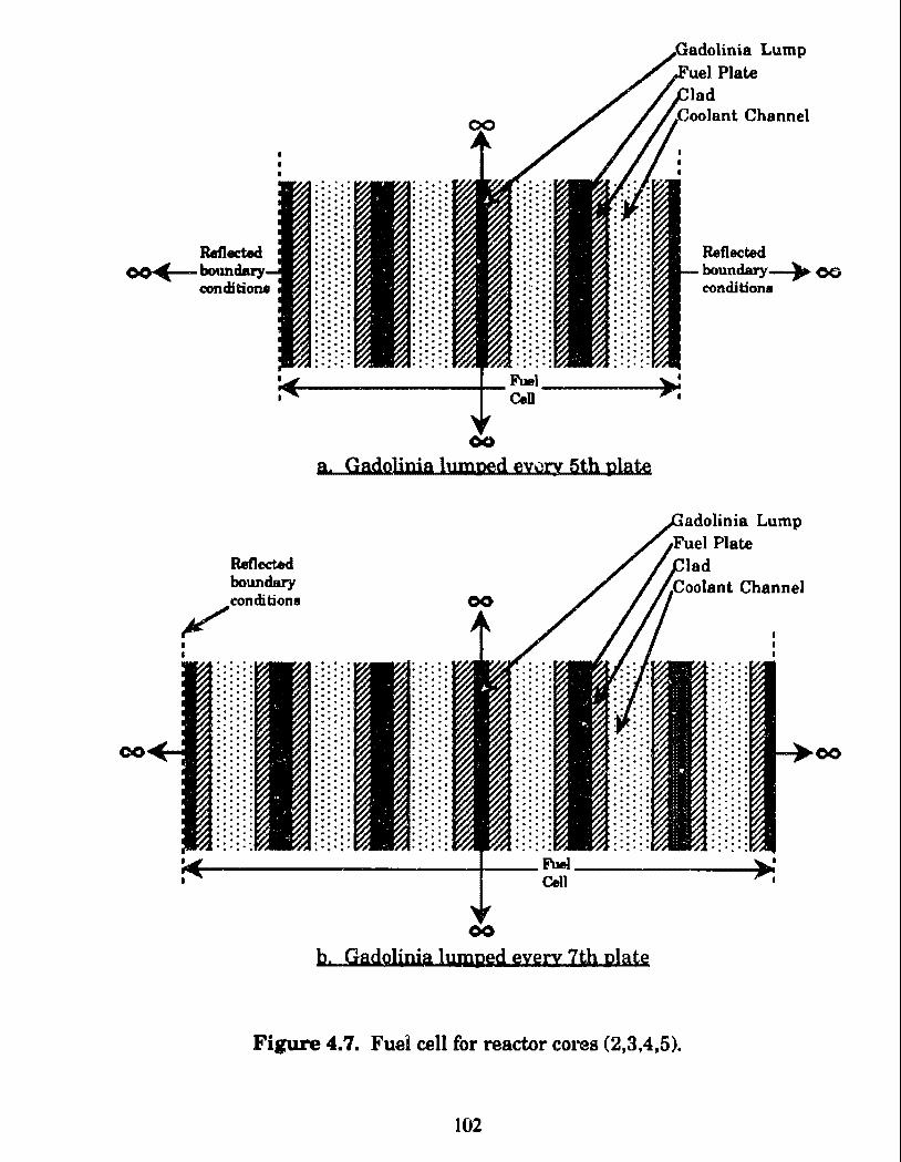
oo"C
co
cond:ition.1
Refled:ed boundary
~eondition1
a. Gadolinia lnm:ged eyvry 5th plate
00
b. Gadolinia lumped eyety 7th platg
Reflected ..,.,.-.__ boundary__.. O<;
condition1
adolinia Lump Pia te
lad
~ ....-i
00
Figure 4.7. Fuei cell for reactor cores (2,3,4,5).
102
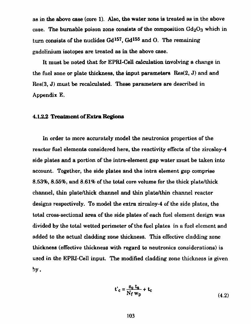
as in the above case (core 1). Also, the water zone is treated as in the above
case. The bumable poison zone consista of the composition Gd203 which in
turn consista of the nuclides Qd157, Qd155 andO. The remaining
gadolinium isotopes are treated as in the above case.
It must be noted that for EPRI-Cell calculation involving a change in
the fuel zone or plate thickness, the input parameters Res(2, J) and and
Res(3, J) must be recalculated. These parameters are described in
Append.ix E.
4.1..2.2 Treatm.ent ofExtra Regions
In order to more accurately model the neutronics properties of the
reactor fuel elements considered here, the reactivity effects of the zircaloy-4
side plates and a portion of the intra-element gap water mUBt be taken into
account. Together, the side plates and the intra element gap comprise
8.53%, 8.55%, and 8.61% ofthe total core volume for the thick plate/thlck
channel, thin plate/thick channel and thin platelthin channel reactor
designa respectively. To model the extra zircaloy-4 of the side plates, the
total cross-sectional area of the side plates of each fuel element design was
divided by the total wetted perimeter of the fuel plates in a fuel element and
added to the actual cladding zone thick.ness. This effective cladding zone
thickness (effective thickness with regard to neutronics considerations) is
used in the EPRI-Cell input. The modified cladd.ing zone thickness ia given
~y'
t'c= Beta +te Nrwp
103
(4.2)
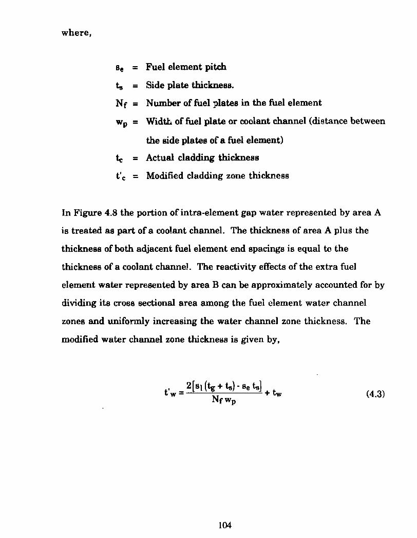
where,
Se = Fuel element pitch
ta = Side plate thickness.
Nr = N umber of fuel plates in the fuel element
Wp = Width of fuel plate or coolant channel (distance between
the side plates of a fuel element)
te = Actual cladding thickness
t'c: - Mod.ified cladding zone thickness -
In Figure 4.8 the portion o f intra-element gap water represented by area A
is treated as part of a coo!ant channel. The thickness of area A plus the
thickness of both adjacent fuel element end spacings is equal to the
thickness of a coolant channeJ. The reactivity effects o f the extra fuel
element water represented by area B can be appro:ximately accounted for by
dividing its cross sectional area among the fuel element wate:r channel
zones and uniformly increasing the water channel zone thlckness. The
modified water channel zone thickne~s is given by,
(4.3)
104
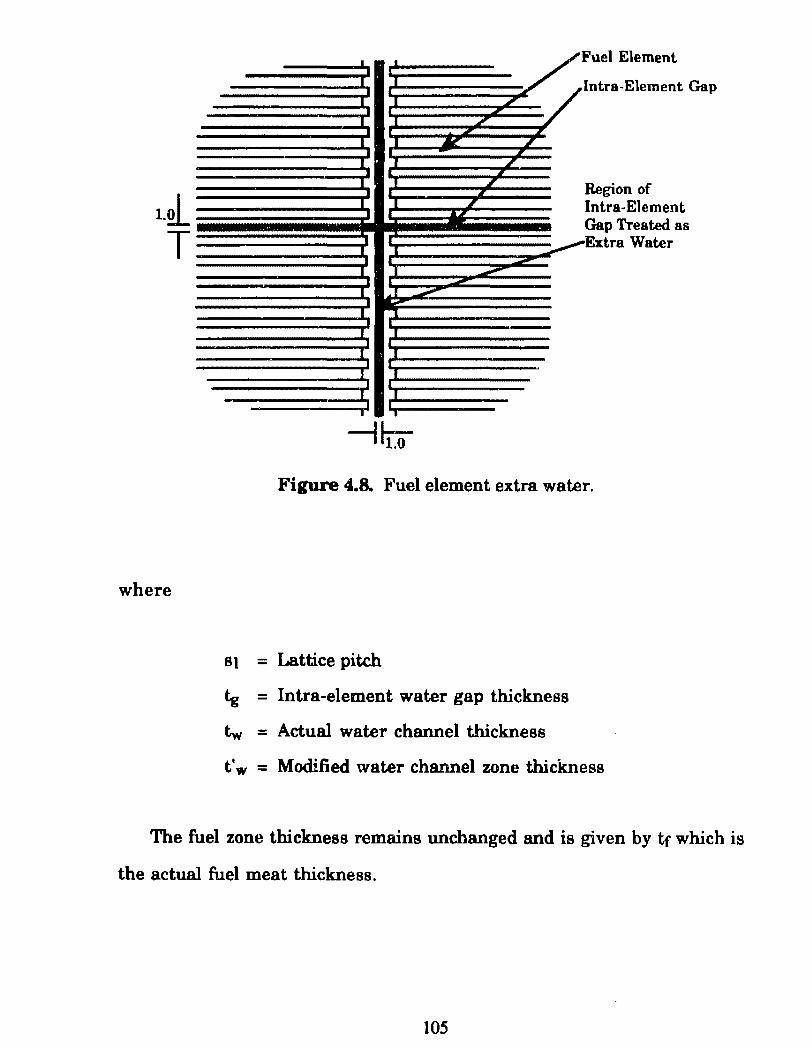
1.21_
T
where
I I Fuel Element
I I lntra-Element Gap l I L
I I _, I 1 ~ L
I
I I I
I I I Region of L I I , Intra-Eiement
I
Gap Treated as
_I I Extra Water
I I
I ! ,-,
-I I
I I
I I
I
I I
---1~
Figure 4.8. Fuel element extra water.
SJ = Lattice pitch
tg = Intra-element water gap thickness
tw = Actual water channel thickness
t'w = Modified water channel zone thickness
The fuel zone thickness remains unchanged and is given by tr which is
the actual fuel meat thickness.
105
According to the earlier discussion, the thickness of the gadolinia
lu.mps is a variable input design parameter for the cores utilizing 20% and
97.3% enriched uraniu.m, Vol%{Gd20a) in the fuel plate locations. This
section describes the method used to model these variations in lump
thickness.
Cores (2.3.4.5)
For reactor core designa 2,3,4 and 5 which employ a lumped gadolinia
distribution, the lu.mp thickness was used as a design variable (i.e., the
lump thickness was varied for the iterative design calculations).
Throughout theae calculations, the su.m thickness of the Gd203 lu.mp and
associated cladding must be equal to the regular fuel plate thickness. For
each lump thíckness variation, the corresponding cladd.ing thickness can
be calculated by the following relation,
where,
t1e = thickness of cladding for Gd203 lump
q = thickness of Gd203 lu.mp
The value of t1c is input in to EPRI·Cell by the parameter ZONECT.
106
(4.4)
4.1.2.4 Com.posltion Volume PerceiUB In tbe Fuel Meat
For each reactor core design, the volume fraction (volume percent
divided by 100) ofthe uo2 fuel and the Zr-4 structural material in the fuel
meat must be determined and input in to EPRI-Cell. As discussed earlier,
the the volume percent ratio of uo2 to Zr -4 structural material in the fuel
meat ia a design variable for reactor cores 2,3,4 and 5 which utilize the
lumped Gd203 distribution. For reactor core 1, this ratio is fixed. The
volume fraction of each composition is specified in the EPRI-Cell input file
by the parameter VOLFRC(K,L), where K refere to the particular material
composition and L specifies the particular zone. Note that for any changes
ofthe number densities ofthe nuclides Tfl35 and U238 or volwne percent
U02 which bears these nuclides, the values of the resonance input
parameters Res (4, tJ235) and Re~ (4, tJ238), (Res (5, U235), Res (5, U238) must
be recalculated. This is discussed in detail in Appendix E.
Core< I> For reactor core design 1 which utilizes 7% enriched caramel type fuel,
it is desirable for the uo2 volume fraction in the fuel meat to be as large as
possible in order to maximize available reactivity. Thus for·this core, the
Vol%m(U02) in the fuel meat is nota design variable. In thls case the U02
ia actually a mixture of uo2 and Gd20a. The following equation is used to
calculate the U02 volume fraction, Volm(U02), in the fuel meat of the
original caramel fuel plate design.
(4.5)
107
where,
w c = caramel o r platelet width
w 1 = spacing between platelets
The fixed uo2 volume percent in the fuel meat of the original caramel fuel
plate Vol%m(U02) is calculated to be 84.44%.
The corresponding fixed Zr-4 volume percent, Volm(Zr-4), in the fuel
meat is determined by the volume fraction relation,
(4.6)
where the resultirtg volume percent is calculated to be 15.56%
Core(2)
As calculated above the m.a:ximum uo2 volume percent allowed for this
study is 84.44% (Vol x 100), that of the original caramel fuel plate design.
Since a uranium enrichment of 20% is used in this core and as will be
shown in Chapter 5, the U02 volume percent Vol%m(U02) in the fuel meat
must be decreased in order to reduce the core excess reactivity to a
controllable levei. Th118, as discussed earlier, the uo2 volume percent in
the fuel meat is a design variable. Since t.he optimum Vol%m(U02) for this
design lies in the range,
108
a caramel fuel design was employed. As discussed in Chapter 3, fuel plates
with fuel zone uo2 volume per~nts lesa than 50% will employ cermet fuel
plate design. With each variation the corresponding Zr-4 volume percent in
the fuel meat was calculated by equation 4.6. (The calculated fuel meat
Vol%mU02 for each core design islisted in Table 5.1).
A reduction in the Vol%m(U02) requires a reduction in the fuei platelet
dimensione or caramels of the original design. This must be meet with a
corresponding increase in the thickness of the Zr-4 spacers, (Refer to
Figure 3.1). Upon detennination of the optimum U02 volume percent, the
caramel (platelet) and Zr-4 spacer widths are calculated by the following
equations. Defining the caramel width to Zr4 spacer width ratio as,
(4.7)
Equation 4.5 can be written as,
V= 4~ {Rcs + l)wp (4.8)
where Vis the U02 volume fraction, Volm(U02). Rearranging Equation 4.8
yields,
(4.9)
Solving the above equation by the quadratic formula and rearranging yields
(4.10)
109
Thus, solving Equation 4. 7 for w1 ,
and substituting into the constraint equation,
and rearranging. The value ofwc ia given by,
The value ofw8 can be found by substituting the value ofwc into the
constraint equation, Equation 4.11.
Cores (3.4.5)
(4.11)
(4.12)
(4.13)
For reactor core designa 3,4,and 5 which are fueled with 97.3% enriched
uranium (i.e., HEU), a low fuel meat U02 volume percent is required to
maintain controllable excess reactivity. Since the U02 volume percents for
these cores are lesa than 50% (this was initially assumed and later found to
be true) a cennet fuel design is employed. The uo2 volume fraction was
varied over the interval,
110
where 20% is the lower bound of the cermet uo2 volume percent, below
which irradiation behavior can not be estimated (see Figure 3.1 ). The
corresponding Zr-4 volume percents are determined by the volume fraction
relation,
(4.6)
4.1.2.5 Num.ber Densities
The nuclide number densities in each material composition U02, Gd20a,
Zr-4 and H20, which are used in each reactor core designare specified in the
EPRI-Cell input file via the input parameter PUREDN(J,K). The values J
and K specify the particular nuclide and material composition respectively.
As stated in Section 4.1.2.1., for any changes ofthe number densities ofthe
nuclides U235 and U238 or volume percent ofU02 which bears these nuclides,
the values ofthe resonance input parameters Res (4, U235) and Res (4, lJ238),
Res (5, IJ235), Res (5, U238) must be recalculated. This is discussed in detail
in Appendix E.
Core (1)
As shown in Figure 4.3a, for reactor core design 1 the Vol%m(U02-
Gd203 mixture)N ol%m(Zr-4 structural material) r a tio in the fuel meat is
constanc.. However, the fuel material consists of a mixture of U02 and
Gd20a where the UOvGd20a ratio is a design variable. Thus with each
variation of the wt%Gd203 in this mixture, the nuclide number densities in
the fuel/bumable poison mixture (U02-Gd20a mixture) must be
1 1 1
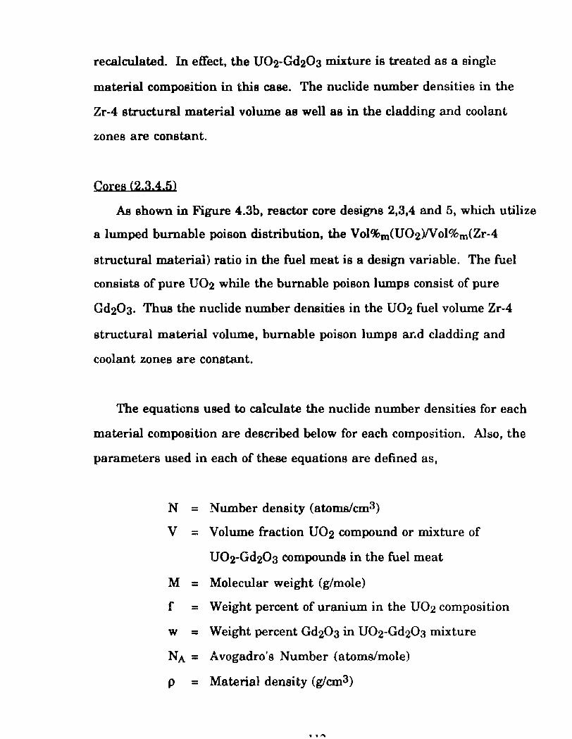
recalculated. In effect, the U02-Gd20a mixture is treated as a single
material composition in this case. The nuclide number densitiea in the
Zr-4 structural material volume as well as in the cladding and coolant
zones are constant.
Cores <2.3.4.5)
As shown in Figure 4.3b, reactor core designa 2,3,4 and 5, which utilize
a lumped burnable poison distribution, the Vol%m(U02Wol%m(Zr-4
structural material) ratio in the fuel meat is a design variable. The fuel
consista of pure uo2 while the bumable poison lumps consist of pure
Gd203. Thus the nuclide number densities in the U02 fuel volume Zr-4
structural material volume, bumable poison lumps ar .. d cladding and
coolant zones are constant.
The equations used to calculate the nuclide number densities for each
material composition are described below for each composition. Also, the
parameters used in each of these equations are defined as,
N = Number density (atoms/cm3)
v = Volume fraction U02 compound or mixture of
U02-Gd20a compounds in the fuel meat
M = Molecular weight (g/mole)
f = Weight percent of uranium in the U02 composition
w = Weight percent Gd203 in U02-Gdzüa mixture
NA= Avogadro's Number (atoms/mole)
p = Material density (g!cm3)
.....
uoa. Gib.Oa For tha U02 fuel of7%, 20% and 97.3% enrichment wlúch consista of a
mixture of 1J235 and U238 atoms, the average molecular weight of the
uranium atoms is given by the relation,
1 _ [ (1- e) + e ] Mave- M(U238) M(U235) (4.14)
The weigbt percent uranium in the uo2 compound is then given by,
f=- Mave Mave + 2M(O) (4.15)
The number density of the nuclides {]235 and {]238 can then be determined
by the following equations,
N(u2as) = (pXl- wXfl1- eXNAl M(u238X 1024bams/cm2)
(4.16)
(4.17)
The term (1- w) is the weight percent ofU02 in the U02-Gd203 mixture and
(0 is thc weigbt percent of uraniun:. in the U02 compound. For reactor
cores 2,3,4 and 5 which do not utilize the lumped bumable poison (Gd203)
distribution, (w) is set equal to -zero.
113
The number density o f the Gd20a molecule ia given by,
(4.18)
where M(Gd203) is the molecular weight of the Gd20a molecule (See Table
2.7). The number densities ofthe nuclides Gdl55 and Gd157 are the given by,
(4.19)
(4.20)
where a/o(Gd155) and a/o(Gd157) are the natural atomic abundances of the
respective nuclides (See Table 2.6). Note that the other gadolinium isotopes,
Gd154, Gd156, Gd158 and Gd160 must be treated as void. Upon specification of
the isotope Gd155, EPRI-Cell automatically initializes Gdl54, Gd156 and Gd158
in the naturally occurring proportions. This is discussed in
Appendix E.
For the oxygen number density can now be determined by,
where the first and second terma on the 1ight·hand-side are the
contributions from the U02 and Gd20a compositions respectively. The term
(1- w) is t.he weight percent U02 in the U02-Gd203 mixture and the term
114
( 1 - 0 is the weight percent oxygen in the U02 compound. For reactor co:-es
2,3,4 and 5 which do not utilize the lumped burnable poison (Gd203)
distribution, (w) is set equal to zero. For tha second term on the right-hand
side, the coefficient rt!sulta since 1.5 oxygen atoms ar e present for every
AP. stated in Section 4.1.2.1, the zircaloy-4 composition present in the
fuel zones and cladding zones is treated as a single nuclide by EPRI-Cell.
Thus this zone contains the nuclide Zr-4. The composition H20 contains
the nuclid~s H and O.
N(Zr-4) = p(Zr4XN_A)_---:-M(Zr-4( 1024barns/cm2) (4.22)
where the asso<:iated Zr-4 properties are listed in Table 2.3, Thus N(Zr-4) is
calculated to be 0.042518atomslb-cm.
H20 Coolanl-
'rhe number density of the H20 molecule is given by,
(4.23)
where the associeted H20 properties are listed in Table 2.8. Thus N(H20) is
calculated to be 0.02429atoms/b-cm. The number densities of the hydrogen
and oxygen constituents are given by,
115
(4.24)
(4.25)
For ali the calculational results given in this thesis, primarily Chapter 5,
the v alue of Proom temp<H20) = l.Oglcm3 was used A correction to P305°C
(i.e.,lower H20 density in core) is discussed in Section 5.8. Thus N(H) and
N(O) are 0.04840atoms/b-cm and 0.02420atoms/b-cm respectively, where
P305oc(H20) = 0.74glcm3.
4.1.2.8. Simplified Overall Core Calculati.on
As listed in Table 4.2 and discussed in Section 1.1, the total desired
reactor core power, Q, is 50MW, on which ali reactor core calculations are
based. The reactor core power is specified by the EPRI-Cell input
parameter POWR (W atts/cm of height). The value of POWR is given by the
relation,
POWR = (q"'ave,r><tcenXtunit) (4.26)
where q"'ave,r ia the reactor core average power density. The cell
thickness,tcelh is detennined by summing the thicknesses of the individual
fuel cell zones used to represent the fuel element o f the particular reactor
core under consideration. The unit thickness,tunit, is equal to lcm and
conserves dimensione. The reactor core average power density q"'ave,r is
given by the Equation 4.1,
116
'" Q q ave,r =V e ore (4.1)
where V coreis the reactor core volume. Since V core ia not known initially,
q"'ave,r can not be calculated and therefore must be guessed and is
therefore a variable design parameter. According to Table 4.1, this guess is
subject to the following constraints,
q"'ave,r ~ 50kWIL (4.27a)
... n ... s 11oookwiLI q max = r q ave,r lOOkWIL (4.27b)
where q'" mu: ia the maximum core power density and !lr. which is defined
below from Equation 1.2, is the power peaking factor for a finite cylindrical
reflected reactor.
111 a _q max r- "' q ave,r (4.28)
For a bare or unreflected cylindricru reactor, the power peaking facto r is
approximately 3. 75. For a reflected reactor core, the power peaking factor is
reduced by roughly 213.[7]
111 n _2,q max r- 3 "' q avc,u
117
(4.29)
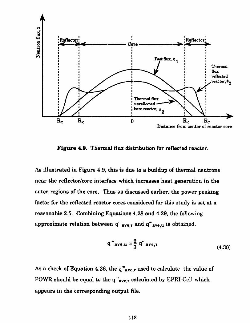
I I
•Retl~ :..c < I I
'Reflectori Core ------:i~>-..,.:.< >
FutOux, •t Thermal
' I I I I 1 'lllermal ftux : unreflec:t:ed ___ _,~~""'"
: baro reador, • 2
o Rc Rr Distance from center of reactor core
Figure 4.9. Thermal flux distribution for reflected reactor.
As illustrated in Figure 4.9, this is due to a buildup of thermal neutrons
near the retlector/core interface which increases heat generation in the
outer regions of the core. Thus as discussed earlier, the power peaking
factor for the reflected reactor coree considered for this study is set at a
reasonable 2.5. Combining Equations 4.28 and 4.29, the following
approximate relation between q"'ave,r and q"'ave,u is obtain.ed.
... - .2. '" Q ave,u -3
q ave,r
As a check of Equation 4.26, the q'"ave,r used to calcula te the value of
POWR should be equal to the q"'ave,r calculated by EPRI-Cell which
appears in the corresponding output file.
118
(4.30)
The volume in cm3 for tb.e reflected reactnr core for a particular total
power Q (SOMW) is given by rearranging Equation 4.1.
v - I Q Y 1 MWV__l__t_) core,r- \q11 'ave,r~1()(X) kW ~l(XX) cm3
As listed in Table 4.2, the height to radius ratio of the cylindrical
reactors considered for this study is assumed to be,
H=2.5 R
(4.31)
(4.32)
as in the case of the reactor which J)CJwers the USS Savannah. The ··olume
of a cylinder is given by,
V:: 1tR2H
Substituting Equation 4.32 into 4.33 yields,
V core r = 2.57tRr3 I
for the reflected reactor cores of this study. Solving for Rr gives,
Rr =~{V-;'Vi:Si
The value of H r is thcn given by rearranging Equation 4.32 to,
Hr = 2.5Rr
119
(4.33)
(4.34)
(4.35)
(4.36)
For a reactor core of finite dimensione, some neutrons are lost to
leakage. The term used to account for this loss for a bare unreflected
reactor core modeled in 1-D is known as the geometric buckling, B2, which
is a function of reactor geometry. The v alue of this term affects the value of
keff· The geometric buckling, B2, for an unreflected finite cylindrical
reactor is given by,
(4.37)
where Ru and Hu are the effective height and radius of the unreflected finite
cylindrical reactor and taken for this approximation to be equal to the
actual unreflected height and r8d.ius. For a constant total reactor power,
Q, Ru and Hu are larger than Rr and H r. Thus, if the values for Rr and H r,
as derived from the guess of q'"sve,r• are used in Equatíon 4.37, the neutron
leakage loss 88 represented by B2, will be overestimated. Since the reactor
cores considered for this study are reflected (i.e., surrounded by a water
shroud), neutron leakage is reduced, q"' ave is increased and the required
reactor volume to produce a total power of 50MW decreases. Thus for the
approximate comparative purposes of this study, it is 8ssumed that the
tenn B2, 88 calculated for the unreflected finite cylindrical reactor also
operating at a total power of 50MW, is representa tive of the neutron leakage
of the 50MW reflected reactor. Both reflected and unreflected reactors have
a height to radius ratio of 2.5. The volume of this unreflected counterpart is
determined by substituting q"'8 ve,u as defined by Equation 4.30 into
Equation 4.31. Thus,
120
V eore,u = (a .~ )1Jn ~:l~~ ~) 3
q ave,r em (4.38)
From Equation 4.34,
V core,u = 2.51tRu3 (4.39)
Rearranging Equation 4.39 yields,
(4.40)
Back substituting the value ofRu into Equation 4.36 for the unreflected
reactor gives,
Hu=2.5Ru (4.41)
Substituting the values of Ru and Hu in to Equation 4.37 yields B2 for the
50MW unrefl.ected counterpart reactor which is assumed to represent the
neutron leakage effects of the smaller 50MW reflected reactor. Thus, as
discussed previously, a guess of q"'ave,r is accompanied by a value of B2.
The value ofB2 is specified in the EPRI-Cell input file by the by the input
parameter BUCKLG. The calculated vaJues for B2 are listed in Tables F.l
and F.2 of Appendix F. This approxima.te method is chosen to be consistent
with the assu.m.ed (reasonahle for amall light water reactors, LWR's) power
peaking factor of 2.5. It should be noted that the reflector savings (i.e.,
reduction in core height and radius) calculated by this method is not
constant with variation in core volume as it is in reality. Appendix G
121
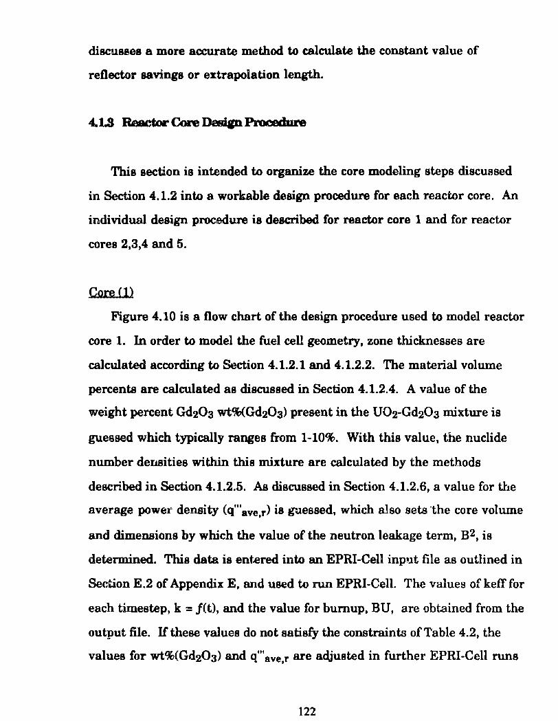
discusaes a more accurate method to calculate the constant value of
reflector savings or extrapolation length.
This section ia intended to organize the core modeling steps discussed
in Section 4.1.2 into a workable design procedure for each reactor core. An
individual design procedu.re is described for reactor core 1 and for reactor
cores 2,3,4 and 5.
Core <1>
Figure 4.10 is a flow chart of the design procedure used to model reactor
core 1. In order to model the fuel cell geometry, zone thicknesses are
calculated according to Section 4.1.2.1 and 4.1.2.2. The material volume
percents are calculated as discussed in Section 4.1.2.4. A value of the
weight percent Gd20a wt%<Gd20a) present in the U02-Gd20a mixture is
guessed which typically ranges from 1-10%. With this value, the nuclide
number deitBities within this mixture are calculated by the methods
described in Section 4.1.2.5. As discussed in Section 4.1.2.6, a value for the
average power density (q'"ave r> is g"..lessed, which also sets the core volume '
and dimensione by which the value ofthe neutron leakage term, B2, is
determined. This datais ent.ered into an EPRI-Cell input file as outlined in
Section E.2 of Appendix E, and used to run EPRI-Cell. The values of keff for
each timestep, k = j(t), and the value for burnup, BU, are obtained from the
output file. H these values do not satisfy the constraints of Table 4.2, the
values for wt%(Gd20a) snd q'"ave r are adjusted in further EPRI-Cell runs '
122
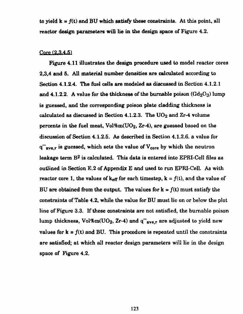
to yield k = /(t) and BU which satisfy these constraints. At this point, ali
reactor deaign parameten willlie in the design space of Figure 4.2.
Core (2.3.4.5)
Figure 4.11 illustrates the design procedure used to model reactor cores
2,3,4 and 5. Ali material number densities are calculated according to
Section 4.1.2.4. The fuel cells are modeled as discussed in Section 4.1.2.1
and 4.1.2.2. A velue for the thickneu ofthe burnable poison (Gd203) lump
is guessed, and the corresponding poison plate cladding thickness is
calculated as discussed in Section 4.1.2.3. The U02 and Zr-4 volume
percents in the fuel meat, Vol%m(U02, Zr-4), are guessed based on the
discussion of Section 4.1.2.5. AB described in Section 4.1.2.6. a. value for
q"' ave,r is guessed, which seta the v alue of V core by which the neutron
leakage tenn B2 is calculated. Thio data is entered into EPRI-Cell files as
outJined in Section E.2 of Appendix E and used to run 'EPRI-Cell. As with
reactor core 1, the values of keff for earh timestep, k = /(t), and the value of
BU are obtained from the output. The values for k = f(t) must satisfy the
constraints ofTable 4.2, while the value for BU must iie on or below the plot
line of Figure 3.3. If these constraints are not satisfied, the burnable poison
lump thickness, Vol%m(U02, Zr-4) and q"'ave,r are adjusted to yield new
values for k = f(t) and BU. This procedure is repeated until the constraints
are satisfied; at which ali reactor design parameters will lie in the design
space of Figure 4.2.
123
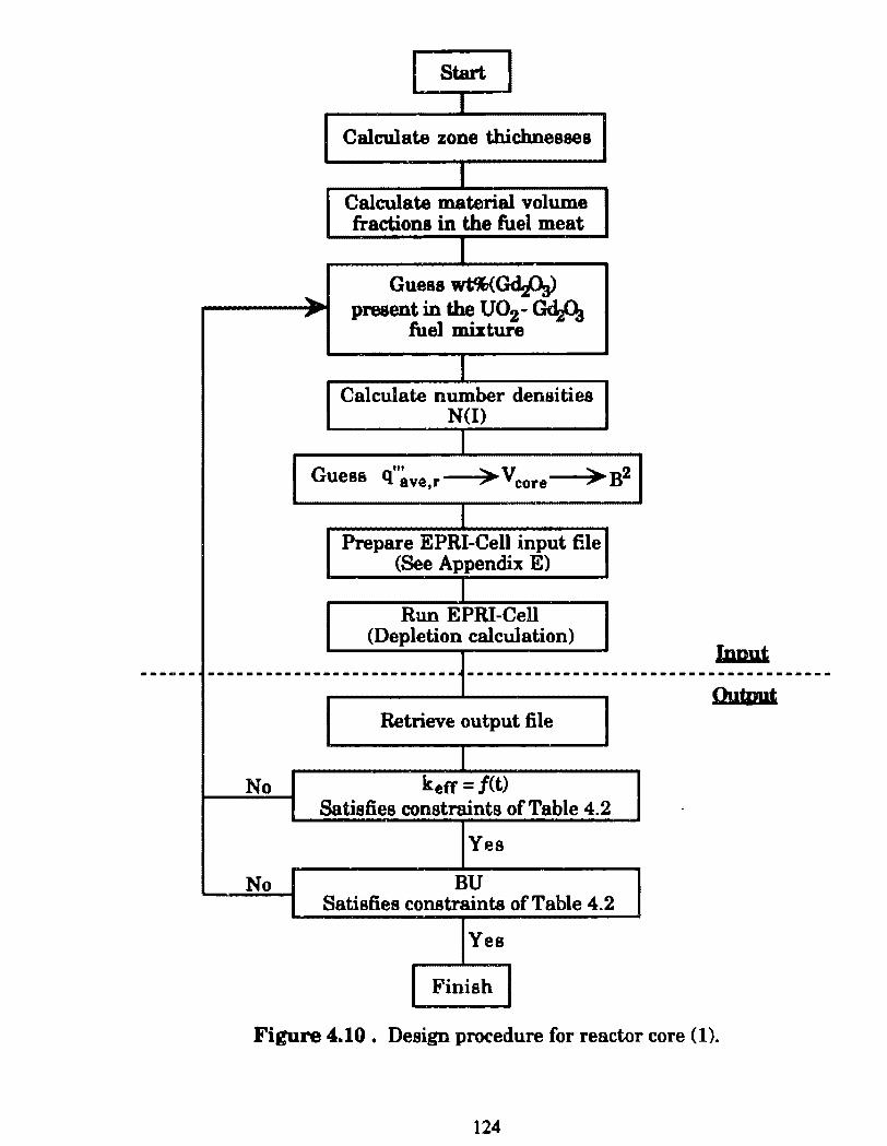
Start
Calculate zone thichnessea
Calculate material volume fractions in the fuel meat
""" Guess wt%<GdA)
,.. present in the uo2- Gd.A fuel mixture
Calculate number densities N(l)
Guess til
q ave,r ;.... vcore ,...B2
Prepare EPRI-Cell input file (See Appendix E)
Run EPRI -Cell (Depletion calculation)
Innut -------------------------- -------------------
Retrieve output file
No keff = j(t) Satisfies constraints of Table 4.2
Yes
No BU Satisfies constraints of Table 4.2
Yes
Finish
Figure 4.10. Design procedure for reactor core (1).
124
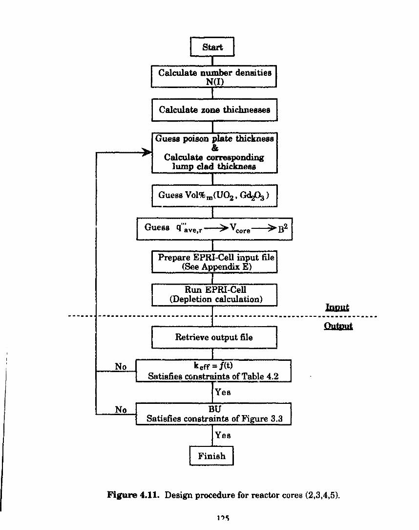
Start
Calculate number densities N(l)
Calculate zone thichnesses
Guess poison plate thickness ....... • , Calculate corresponding
lump clad thickness
Guess Vol%m<U02, GelA)
Guess 111
q ave,r ,.,. vcore ~B2
Prepare EPRI mCell input file (See Appendix E)
Run EPRI-Cell (Depletion calculation)
Iu.uut t-·----------~-----··-··*••• ···-·---------·---
Ouúmt Retrieve output file
No keff = j(t) Satisfies constraints ofTable 4.2
Yes
No BU Satisfies constraints of Figure 3.3
Yes
Finish
Firure 4.11. Design procedure for reactor cores (2,3,4,5).
4.1.4 WboJe Cme MateriaJa Calculaiiona
Upon completion of the reactor design analysis outlined in Section 4.3,
the net mass of a particular nuclide present in each core can be calculated
for any depletion step. This calculation is performed using the Editcell
Homogenized Concentrations of Nuclides for the particular depletion
timestep listed in the EPRI-Cell output file (See Appendix E, Sections E.3
and E.4). The units of the Editcell Homogenized Concentrations of Nuclides
or cell averaged number densities are atomslbam-cm. The total mass of
the particular nuclide present in the core is given by the following equation.
where,
N(l)M(l)Veore r (_l_- kg~ 1o2' hams_) = • l<XX> g ·~ c~
NA m(l)
m(l) = Total mass of nuclide in core
N(l) = Editcell homogenized concentration of particular
nuclide, cell averaged number de11sity
(atomslbarn-cm)
M(l) = Molecular weight of nuclide (gramslmole)
(4.42)
For additional information, the volume percent of U02 and Gd203 in
each reactor core can be ca.lculated.
l.?.n
Core Cll
As described in Section 4.1.2.5., for reactor core 1, the ratio o f thc U02-
Gd2Üs m:ixture to the Zr-4 atru.ctural material i e thed. However, the
U02f'Gd20a is a variable design parameter. Thua the wt%Gd203 in the
U02-Gd203 fuel mixture is known upon completion of the design procedure.
The volume fraction U02 within the U02-Gd203 fuel mi"tw~, Volf(U02), is
given by,
Volt(U02) = ------------1 + PU O! ( 100 _ l)
PGd20 3 1 - wt%Gd2ÜJ
(4.43)
The corresponding volume fraction within this fuel mixture is given by,
(4.44)
The whole core volume fraction~ àre given by the following equations,
Volc(U02,) = Vol~U02)Volm(fueli ~ , } 'tr + 2t c + t w (4.45)
Volc(Gd2Ü3) = Vol~Gd2ÜaJVolm(fueli 2 ~ -, )
'tr+ tc+Íw (4.46)
where the subocript (c) denotes a whole core volume fraction.
127
Cores (2.3.4.5)
For reactor cores 2,3,4 and 5 which utilize a lumped bumable poison
distribution, the ratio of U02 to Zr-4 structural material in the fuel meat
and the tbickneas of the bumable poiaon (Gd:a{)a) plate lumps are design
variables. Thus, upon completion of the design proeedure outline in Section
4.3, the uo2 volume fraction in the fuel meat and tbe bumable poison lump
thicknesa ~re known. The whole core volume fractions for U02 cmd Gd20a
are given by the following equations.
where,
N 1 = Number of burnable poison plate lumps in core
N r = Num.ber of fuel plates in core
4.1.5 Safety Analysia
Following a transient that resulta in a reactor power increase, the fuel
temperature will rise leading to an increase in the bulk coolar,t
temperature. As the coolant water temperature increases, the density
decreases. A fuel temperature increase or coolant density decrease is
accompanied by positive Ol' negative reactivity change (See Appendix C).
128
To estimate the reactivit1 cbange caused by an increase in fuel
temperature, EPRI-Cell was run with the fuel temperature specified by the
resonance data input parameter P.es(1,J) waa decreased to 293°C room
temperature (&e Appendii E.) As stated in this appendix, the fuel
operating temperature was set at U>00°C. For each reactor core, the
reactivity change for a fuel temperature increase at B.O.C. and E.O.C. ie
given by the following equation,
kett(~C) - 1 ken( 1()()()0C)- 1 PT = keft(293"C) - keft(1()()()0C)
where PT is the fuel temperature reactivity change.
(4.49)
To estim.ate the reactivity change caused by a coolant density decrease,
EPRl ali was run with the oxygen and hydrogen number density in the
coolant zone decreased by 10%. As stated in Section 4.1.2.5., number
densities are specified in the EPRI-Cell input files by the input parameter,
PUREDN. For each reactor core, the reactivity change for a coolant density
decrease of 10% at B.O.C. and E.O.C. is given by the following equation,
PM _ keft(puz<>100%)- 1 _ kefl(pu2o90%)- 1 - kefi(PH:z<>lOO%) ken(PH2<)90%) (4.50)
where PM is the moderator density reactivity change and PH2o(100%) was
taken to be l.Oglcm3 for these keff calculations.
129
As stated in Chapter 1, thermal-hydraulics considerations are
assumed not to be limiting for the reactor designe modeled in this study. A
simplified tbermal-bydraulic analyeis, however, haa been included to verify
that fuel element temperaturea are within acceptable bounds and that the
required coolant tlow ratea needed to remove heat are practical. Figure 4.12
illuatrates the fuel plate and CCM>lant channel geometry to which this
analyaia ia applied.. Below, each of the parameters used in the ensuing
discussion are defined.
'Ib = Bulk coolant temperature C'C)
Tin = Reactor core inlet temperature (°C)
Tout = Reactor core outlet temperature (°C)
T eo = Cladding ou ter surface temperatura (°C)
Tei = Cladding inner surface temperature (°C)
Tr1 = Fuel surface temperature (°C)
Trc = Maximum fuel center-line temperature (°C)
h = Coolant heat transfer coefficient (W/m.2.K)
kw = Coolant water thermal conductivity (W/m.K)
kc = Clad thermal conductivity, assumed constant (W/m.K)
kr = Fuel thennal conductivity, assumed constant (W/m.K)
kp = Cermet fuel particle conductivity (W/m.K)
km = Cermet matrix material conductivity (W/m.K)
u = Coolant water dynamic viscosity (uP8 .S)
Cp = Coolant water specific heat (kJ/kg.K)
p = Coolant water density at operating conditions (kglm3)
130
Wp = Width of fuel plate (m)
Ar = Fuel zone croa..;-oectional area (m2)
Aw = Flow area of coolant channel (m2)
Pt. :: Heated perimeter of coolant channel (m)
Pw = Wetted perimeter of coolant channel (m)
l>b = Hydraulic diameter of coolant cbannel (m)
De = Equivalent diam.eter
H = Heigbt of reactor core (m)
Re = Reynolds number (dimensionless)
Pr = Prandtl number (dimensionless)
Nu = Nusselt number (dimensionleas)
v = Coolant velocity (m/s2)
Marimum Fuel Center-LiDe Temperature
The fuel maximum center-line temperature is determined by
combining the heat transfer equations for the coolant bulklcladding outer
surface, cladding outer surface/inner surface, and fuel outer surface/fuel
center-line interfaces. These equations are,
'Ib = ~ (Tin + T out) (4.51)
T _ q'"max,m tr 'Ib co- h +
(4.52)
T . _ T q"'max,m te Íf c1- co+ kc
(4.53)
131
111 tr2 T T q mu.m
fc = fa + 4kr (4.54)
andare darived in &ference [7].
Combining Equationa 4.51, 4.52, 4.53 and 4.54, and assuming perfect
heat transfer across the fuel surfacelcladd.ing inner surface interface (i.e.,
T ci = Tra>. the following equation for the maximum fuel temperatura is
obtained.
(4.55)
The maximum power density in the fuel meat, q"1max,m is determ.ined by
the relation,
... q"' _ q ma][
ma][,m- Volc(meat)) (4.56)
where q"'mu ie detennined by Equation 4.27b and representa the fuel cell
averaged maximum power density. The value of the fuel meat volume
fraction, Volc(meat), ia given for reactor core 1 by,
Volc(meat) = ( 2
!;r , ) tr+ tc+tw (4.57)
while Volc(meat) for reactor cores 2, 3, 4 and 5 is given by,
Volc(meat) = ( 2 ~ , Y N NrN)
,tr+ te+ twA r+ t (4.58)
132
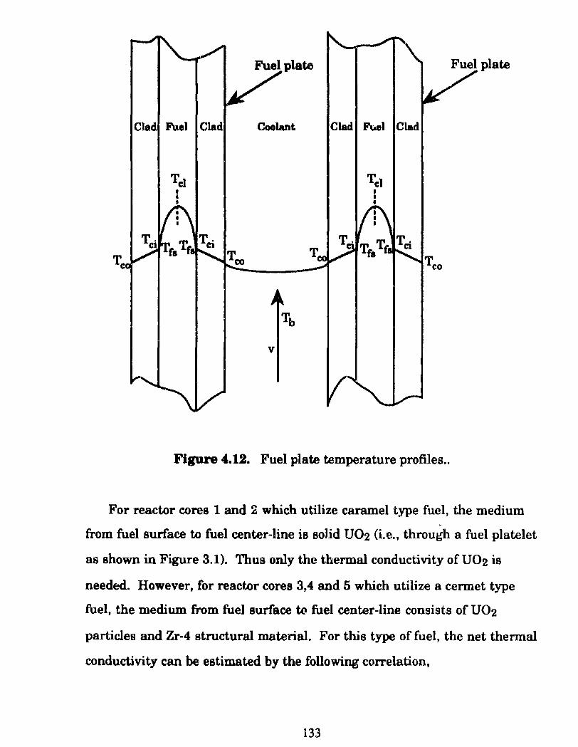
Clad F\J.el Clad Coolant Clad Ft.el Clad
v
Figure 4.12. Fuel plate temperature profiles ..
For reactor cores 1 and ~ which utilize caramel type fuel, the medium
from fuel surface to fuel center-line is solid uo2 (i.e., through a fuel platelet
as shown in Figure 3.1). Thus only the thermal conductivity o f U02 is
needed. However, for reactor cores 3,4 and 5 which utilize a cennet type
fuel, the medi um from fuel surface to fuel center-line consists of U02
particles and Zr-4 structural material. For this type of fuel, the net thennal
conductivity can be estimated by the following correlation,
133
(4.59)
where kp and lr.m are the thermal condu.cti.vitiea oC the U02 particlee and
Zr-4 structural material reepectively.[18] The valuea of (a) and (b) are
defined by the follo'Wing relationa.
a• 3km 2km+k.,
b= Vol%m(U<>2) Vol%m(Zr-4) + Vol%m(U<>2)
Muimnm Coolant Velocity
(4.60)
(4.61)
The maximum coolant velocity can be estimated by assuming the
entrance to each fuel elementis so orificed that the T out - Tin is the same in
every channel and hence the hottest channel need the highest coolant
velocity. The hot channel is surrounded by the fuel plates which operate at
the maximum linear power (q'mu:> ofthe reactor core. For the hot
channel,
q'(z) = q'mu:,m co~if) (4.62)
The linear heat generation rate is defined as,
I flt ... I'
q max = q max,m"' Wp (4.63)
134
subatitutiq Equation 4.63 into Equation 4.62 and integrating from H/2 to ..
H/2 yielda,
(4.64)
wherA q is tbe total heat rate tranaferred to the coolant in the hot channel.
The heat rate removed by the coolant is given by,
q =me, AT&t Cbmmel = mep (Tout- Ttn)uot Channel (4.65)
From continuity,
m=pAwv (4.66)
where,
Aw=twwp (4.67)
Substituting Equations 4.66 and 4.67 into 4.68 and rearranging yields the
required maximum coolant velocity for the reactor core.
V= q pAw Cp (T out - Tinluot Channel (4.68)
Coolant Heat Transfer Coeffident (h)
The heat transfer coefficient of the coolant water in the hot channel of
each reactor core can be determined by use of the familiar Dittus-Boelter
equation.
Nu= 0.023Re0·8 Pr0·3 (4.69)
135
where Nu, Re, and Pr are the Nuaaelt, Reynolds and Prandtl numbeTs
respectively which are defined below.
Nu=~ k
Pr = CpU k
Substituting Equationa 4. 70, 4. 71 and 4. 72 into Equation 4.69 and
rearranging yields,
(4.70)
(4.71)
(4.72)
(4.73)
where (v) ia the maximum coolant velocity and is determined by Equation
4.69. The term Dh is th.e hydraulic diameter of the coolant channel and is
defined as,
(4.74)
where the heated perimeter (Pb) is given by,
1\ = 2wp (4.75)
136
The tero~ De is the equivalent diameter of the coolant channel and is defi.ned
(4.76)
where the wetted perimeter CPw) ia given by,
Pw=2Wp+2tw (4.77)
137
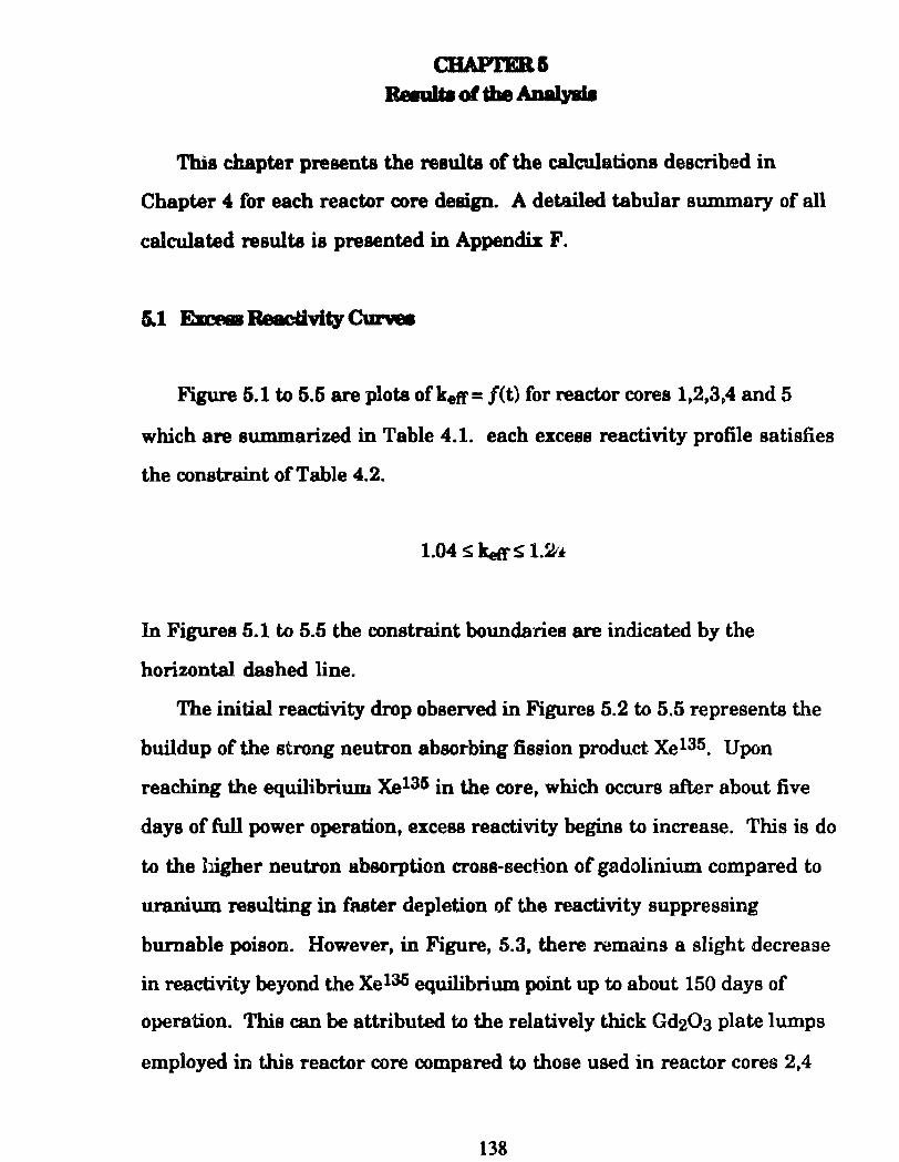
Thia chapter preaents the resulta of the calculationa described in
Chapter 4 for each reactor core design. A detailed tabular summary of all
calculated resulta ia presented in Appendix F.
Figure 5.1 to 5.5 are plots ofk.etr= f(t) for reactor cores 1,2,3,4 and 5
which are summarized in Table 4.1. each excess reactivity profile satisfies
the constraint o f Table 4.2.
1.04 s keft' ~ 1.2/~
In Figures 5.1 to 5.5 the constraint boundaries are indicated by the
horizontal dashed line.
The initial reactivity drop observed in Figures 5.2 to 5.5 representa the
buildup of the strong neutron absorbing fission product Xe135. Upon
reaching the equilibrium Xe135 in the core, which occurs after about five
days of full power operation, excess reactivity begins to increase. This is do
to the bigher neutron absorption cross-section of gadolinium compared to
uraniu.m resulting in faster depletion of the reactivity suppressing
burnable poison. However, in Figure, 5.3, there remains a slight decrease
in reactivity beyond the Xel3li equilibrium point up to about 150 days of
operation. This can be attributed to the relatively thick Gd203 plate lumps
employed in this reactor core compareci to those used in reactor cores 2,4
138
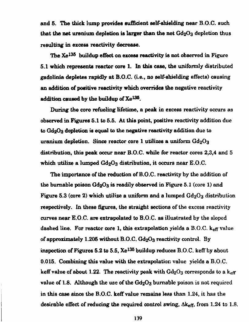
and 5. The tbiclt lump providea aufticient aelf-ahielding near B.O.C. such
tbat the net uranium depletion ia larger than the net Gd20a depletion thus
reaultiog in exce88 reactivity decreaae.
Tbe Xe135 buildup etreet on exce88 reactivity is not observed in Figure
5.1 which representa reactor core 1. In thia case, the uniformly distributed
gadolinia depletea rapidly at B.O.C. (i.e., no self-shielding effects) causing
an addition of positive reactivity which overridee the negative reactivity
addition caused by the buildup ofXel36.
During the core refuel:ing litetime, a peak in excess reactivity occurs as
observed in Figures 6.1 to 5.5. At this point, positive reactivity addition due
to Gd2Üs depletion ia equal to the negative reactivity addition due to
uranium depletion. Since reactor core 1 utilizes a uniform Gd203
distribution, this peak occur near B.O.C. while for reactor cores 2,3,4 and 5
which utilize a lumped Gd203 distribution, it occurs near E.O.C.
The importance ofthe reduction ofB.O.C. reactivity by the addition of
the burnable poison Gd203 is readily observed in Figure 5.1 (core 1) and
Figure 5.3 (core 2) which utilize a unüorm and a lumped Gd20a distribution
respectively. In these figures, the straight sections of the excess reactivity
curves near E.O.C. are extrapolated to B.O.C. as illustrated by the sloped
dashed line. For reactor core 1, thia extrapolation yields a B.O.C. keff value
of approximately 1.206 without B.O.C. Gd2<)3 reactivity control. By
inspection of Figures 5.2 to 5.5, Xel3li buildup reduces B.O.C. keffby about
0.015. Combining this value with the extrapolatior.. value yields a B.O.C.
keff value of about 1.22. The reactivity peak with Gd20a corresponds to a ketr
value of 1.8. Although the uae of the Gd203 bumable poison is not required
in this case since the B.O.C. ketrvalue remains less than 1.24, it has the
desirable effect of reducing the required control swing, Akeft', from 1.24 to 1.8.
139
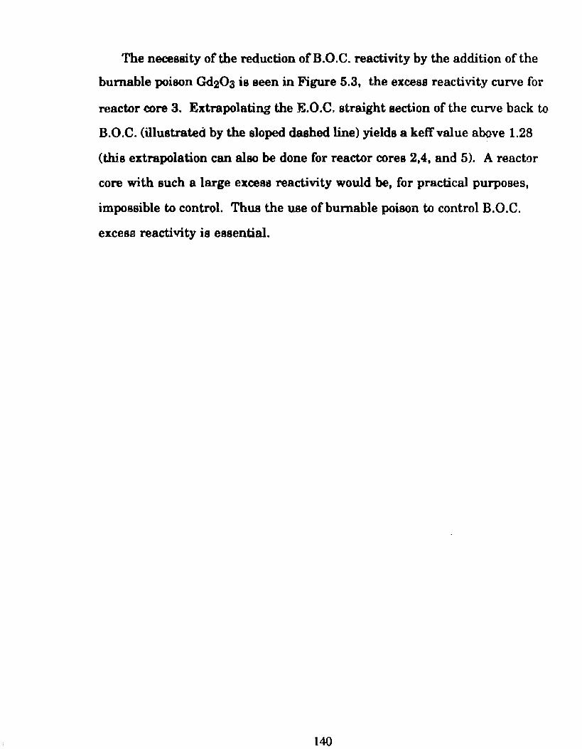
The necessity of the reduction of B.O.C. reactivity by the addition o f the
bumable poison Gd203 is seen in Figure 5.3, the excess reactivity curve for
reactor core 3. Extrapolating the E.O.C, straight section of the curve back to
B.O.C. (illustratecí by the sloped dashed line) yields a keff value aoove 1.28
(this extrapolation can also be done for reactor cores 2,4, and 5). A reactor
core with such a large excess reactivity would be, for practical purposes,
impossible to control. Thus the use ofbumable poison to control B.O.C.
excesa reactivity is essential.
140
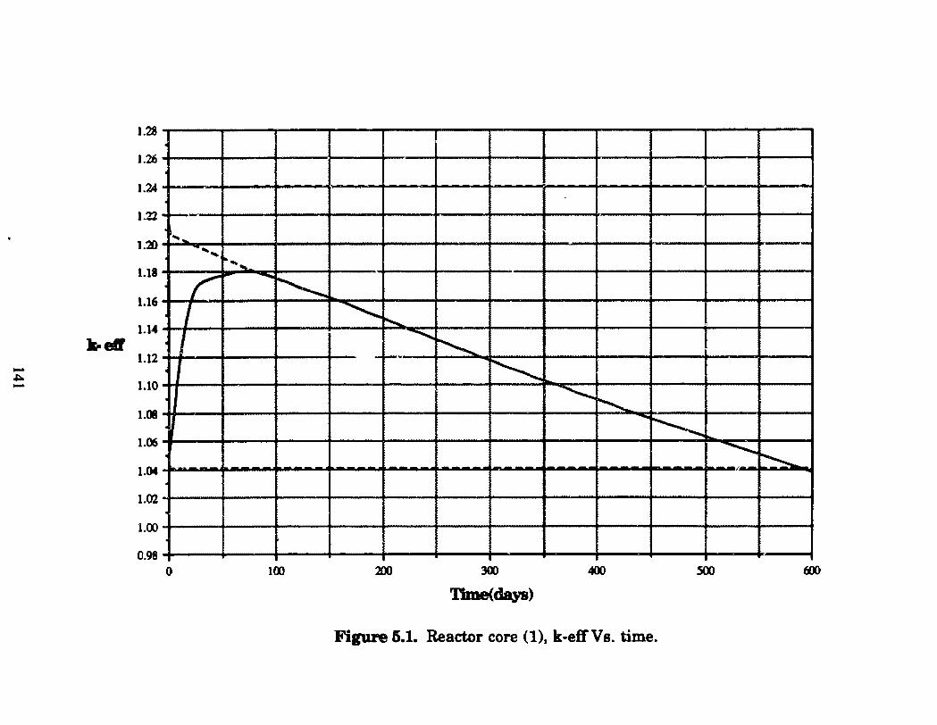
1.28
1.26
1.24
1.22 -1.20
1.11
1.16
1.14
k-eff 1.12 -~ 1.10 -1.01
1.06
1.()4
1, .. ... ,
~ .... ~
1 r - --... ~
I L ~ r--.... -...... ~ ~
-........... ~ -~
-.......... ~ h
1.02
1.00
0.98 o 100 200 300 400 soo tiOO
'11me(da,a)
Figure 5.1. Reactor core (1), k-effVs. time.
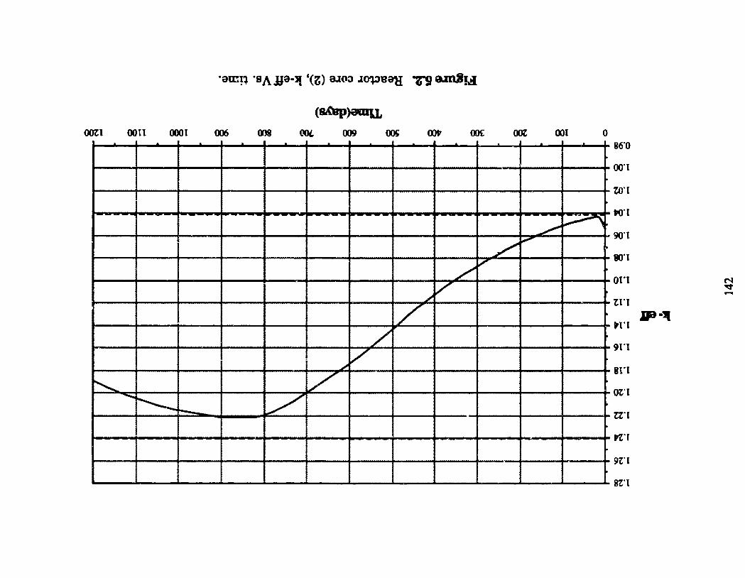
ootl 0011 0001 006 OOL 009 001 o 86"0
00"1
un
~ ~
L ~
/ v
/ /
/
t()"[
9(rt
tcn
on ~ "'11:7' -tn
JP•l( tl'l
/ _., /
~ v -!'--- v --91"1
sn ot"l
t:Z"I
n·r
9t"l
St"l
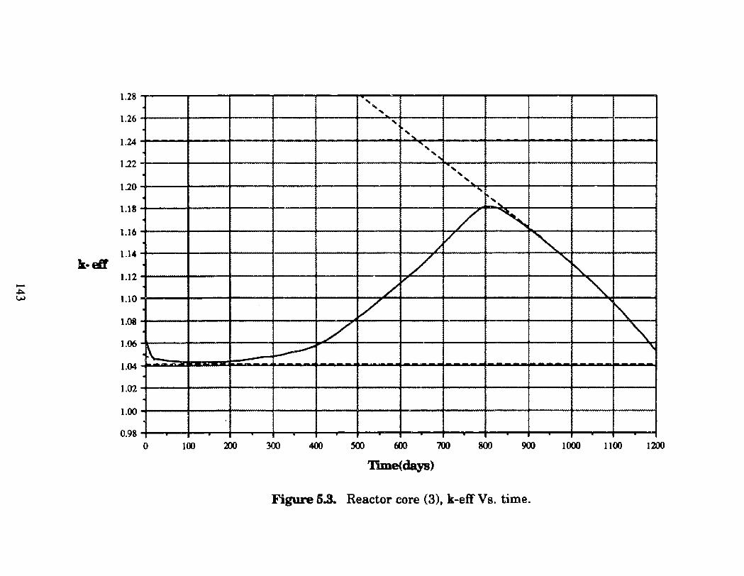
1.28 ' ' ' 1.26
' 1.24 '~
.... , 1.22
' ...
' ' 1.20 ' .. ....
1.18
1.16
1.14 k·eít
1.12 -~ ~ 1.10
1.08
1.06
1.04
!", ~ ....
L ~ / .~ /
/ "' ' / "" " v ~ / ·"' k. ~ ~
.i I
1.02
1.00
0.98
o 100 200 300 400 soo 600 100 800 900 1 ()()() 1100 1200
Thne(days)
Figure 5.3. Reactor core (3)t k-eff Vs. time.
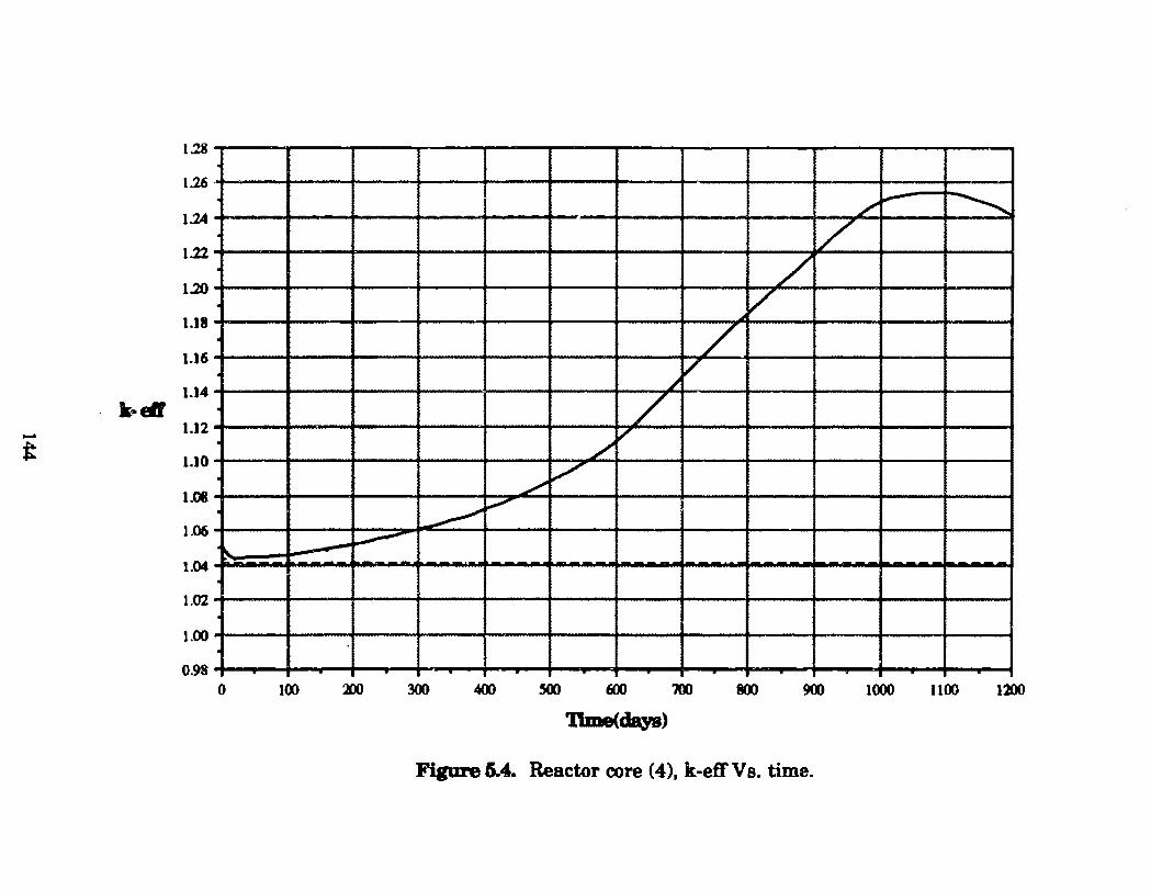
1.28
1.26
1.24
1.22
1.20
L ~ ~
/ /
v 1.18
1.16
1.14 )(. ....
1.12 -t 1.10
1.08
1.06
/ ~ v
/ /
~
L /
~ V"
\... -~ 1.04
1.02
1.00
0.98 o 100 :.m 300 400 ~ 600 700 800 900 1000 1100 lnt
'Itme(daya)
Figure 6.4. Reactor core (4), k-efi'Vs. time.
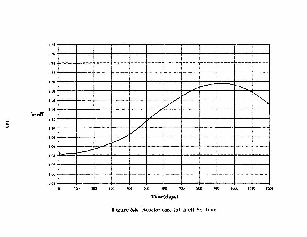
1.28
1.26
1.24
1.22
1.20
1.18
1.16
1.14 k-Eif
i.12 -.. VI 1.10
1.08
1.06
/ ~ -~
/ v ~' v ' / i
/ 'ti'
/ v ..,..,. ~
____., V'
1.04
1.02 -1.00
0.98
o 100 Dl 300 400 500 600 700 800 900 1000 1100 1200
'11me(days)
Figure 5.5. Reactor core (5), k-eff Vs. time.
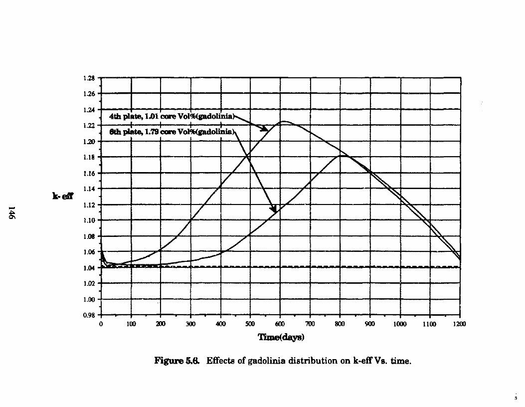
1.28
1.26 . 1.24
1.22
1.20
UfJ
1.16
1.14 k·efr
1.12 -~ 1.10
1.08
1.06
4th plate, 1.01 core Vol'f,(gadollnia' I--I I I I
. 8th pláte, t.79 C:on v~olinia\ "Y " "-\ v "" ~ 7' ~ / " . v \ ~
/ ~ / \ / ~ ~
. 7 -, ~ ~ 7 v ' ~ . v / ~
l. - _,/" ~ ~ 1.04
1.02
1.00 . 0.98 .
o 100 3X) 300 400 500 600 700 800 900 1000 1100 1200
'Dme(days)
Figure 5.8. Effects of gadolinia distribution on k~effVs. time.
5.2 PoC;entiaJ for~ Reactivity Curve Shape Adjustment
As discussed earlier, the excess reactivity profile for reactor core 4
(Figure 5.4) peaks at a value greater than 1.24 which does not satisfy the
reactivity constraint. For this core which utilizes a lumped gadolinia
distribution, Gd203 plates were distributed in every sixth fuel plate location.
The excess reactivity peaking effect for this core can be further suppressed
by decreasing the number of Gd20a lumps and increasing the thickness of
the índividuallumps (i.e., lumping Gd203 into every 8th or 10th fuel plate
location). Figure 5.6 illustrates the effect of changing the amonnt of
lumping from every 4th fuel plate location to every fifth fuel plate location.
The reactivity profiles of this figure are for the design of reactor core 3
utilizing the fuel cell d~signs of Figures 4.7a and 4.7b. (Note that the
reactivity profile for reactor core 3 using the fuel cell ofFigure 4.7b is also
plotted in Figure 5.3). The change in the amount oflumping from every 4th
to every 5th fuel plate location has two effects. First and most important,
the reactivity peak is suppressed and also pushed closer to E.O.C. The
increased self-shielding effect causes the net amount of bumable poison in
the core to deplete more slowly. Second, the net amount of bumable poison
in the coreis increased without suppressing the B.O.C. keff value (excess
reactivity) below the minimum allowed value of 1.04. (The value of 1.04 is
set to allow for Xe135 override capability). As with the first effect, the
increase in the net mass of Gd203 is possible due to the increased self
shielding effect which resulta in a slower Gd203 depletion rate. Thus with
the conclusions derived from Figure 5.6, it is obvious that the reactivity peak
of Figure 5.2 can be suppressed with increased lumping. For purposes of
147
this study, however, this was not possible due to the limit in the number o f
space point and zonea tbat can be modeled by the EPRI-Cell code.
With a more sophisticated distribution or/and the use of other burnable
poisons it may be possible to levei the excess reactivity curve of F!gures 5.1 to
5.5. In such a case, the rate of poliitive reactivity addition caused by Gd203
depleüon and the rate of negaüve reactivity addition caused by uranium
depletion are equal throughout the refueling lifetime of the reactor core.
This is what is done in an actual reactor.
5.3 Mechanical Burnup Resulta
The values for mechanical burnup as calculated by EPRI-Cell for each
reactor core are in units ofMWc:Vr. These burnup values are converted to
units of a tom percent (at%) by the equation,
BU(at%) = Bu(MWd Y 1 T.Y 1 _.L_) T ~ 1 x 10⁶ g~o.948 MWd (5.1)
where the maximum possible burnup per unit mass of uranium is
0.948MWd/T.[24] For each reactor core the calculated burnup values in uníts
of MWd/T and at% are listed in Table 5.1.
For reactor core 1 which utilizes the caramel fuel design, a burnup of
28,290 MWd/T was obtained. As listed in Table 4.2, the mechanical
limitations of this fuel design allow a maximum burnup of 60,000MWd/T.
However, inspection of the excess reactivity curve for this core (Figure 5.1)
shows that at E.O.C. keff has dropped to its minimum allowable value. Thus
148
the mechanically allowable bumup of 60,000MWd/T can not be obtained.
The core refueling lifetime for this core (600FPD) is thus reactivity limited. Reactor
core 2 also uses the caramel fuel design and is thus allowed a maximum
bumup of 60,000MWd/T as liste'-' in Table 4.2. A calculated bumup value of
62J20MWd/T was obtained. The excess reactivity curve for this core (Figure
5.2) shows an E.O.C. value of ketf =1.19 where the minimum value for keff is
1.04. Thus the refueling lifetime for this oore is not reactivity limited, rather
it is limited by the structural mechanics of the fuel. As discussed in Section
3.1.1, internai fission gas pressure will cause fuel failure ata burnup greater
than approximately 60,000MWd/T.
The maximum allowed bumup values for reactor cores 3,4 and 5 which
utilize the cermet fuel design, are listed in Table 5.1. These values, in at%,
have been estimated from Figure 3.3 by using the cermet Vol%m(UO.z) values
also listed in Table 5.1. The calculated burnup values, in at%, for reactor cores
3,4 and 5 are below there respective maximum allowed burnup values in at%
as required. As can be seen from the excess reactivity curves for reactor cores
3,4 and 5 (Figures 5.3 to 5.5), the E.O.C. keff values are above the minimurr&
allowed keff value of 1.04. Thus as with reactor core 2, the refueling lifetimes
of these reactor cores 3,4 and 5 are limited by the structura.l mechanical of the
fuel.
149
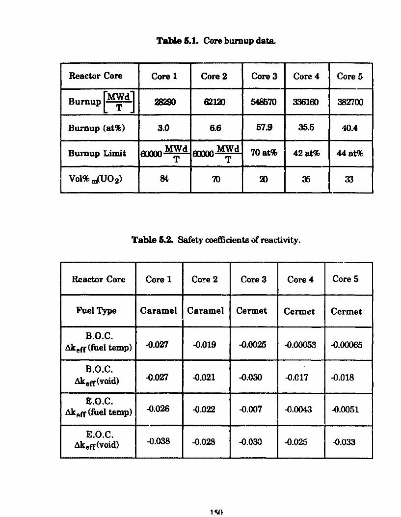
Table 5.1. Core bumup data
Reactor Core Core 1 Core2 Core3 Core4 CoreS
Bumupf~d] 28290 6200 54B570 336160 38Z700
Bumup (at%) 3.0 6.6 57.9 35.5 40.4
Bumup Limit flXXXl MWd T
fiXX)() MWd T
70 at% 42at% 44at%
Vol%.JU02) 84 70 a> :f) 3J
Table &.2. Safety coetlicients ofreactivity.
Reactor Core Core 1 Core 2 Core3 Core4 Core 5
Fuel Type C arame] C arame] Cennet Cermet Cermet
B.O.C. Akeff (fuel temp) ~.027 -0.019 -0.0025 ~.00053 -0.00065
B.O.C. âk.8rr(void) -0.027 -~).021 -0.030 -0.017 -0.018
E.O.C. Akeff (fuel temp) -0.026 -{).022 -0.007 -0.0043 -0.0051
E.O.C. -0.038 Ak8 rr(void) -0.028 -0.030 -0.025 -0.033
lq)
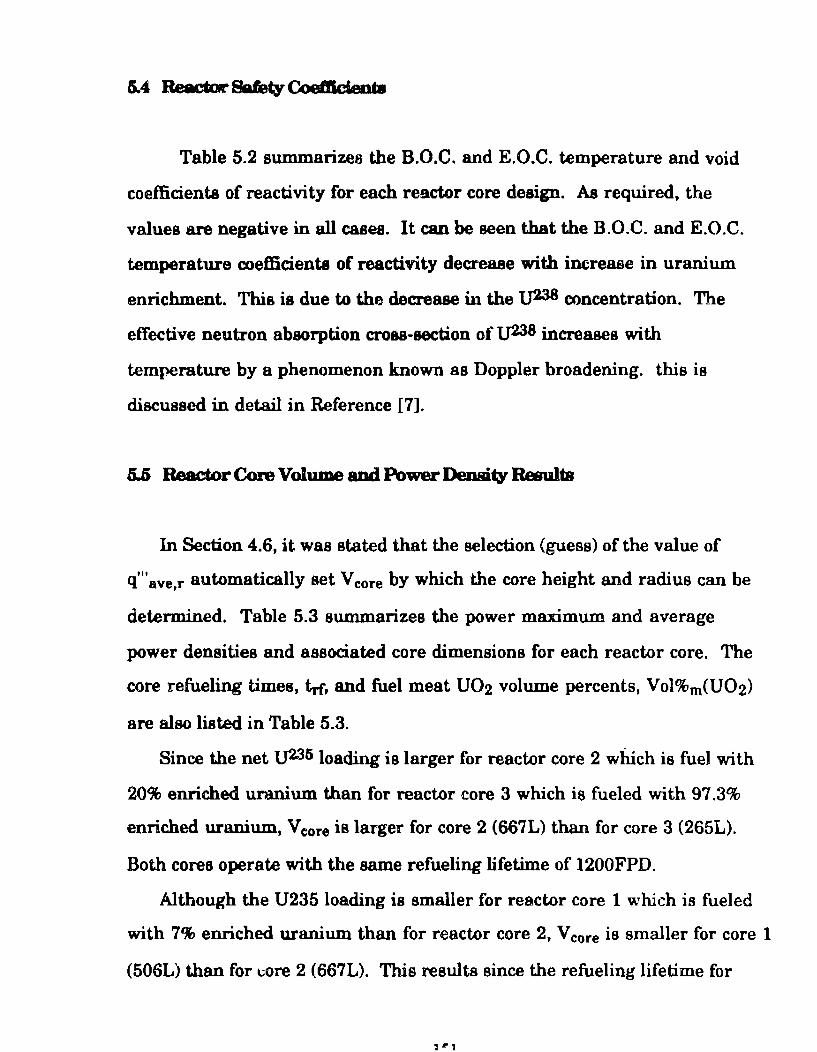
Table 5.2 summarizes the B.O.C. and E.O.C. temperature and void
coefficients of reactivity for each rea.ctor core deaign. AB required, the
values are negative in ali cases. lt can be seen that the B.O.C. and E.O.C.
temperatura coefficients of reactivity decrease with increase in uranium
enrichment. This is due to the decrease in the lJ238 concentration. The
effective neutron absorption cro88-section of lJ238 increases with
temperature by a phenomenon known as Doppler broadening. this is
discussed in detail in Reference [7].
5.5 Reactor Core Volume aod Power Density Resulta
In Section 4.6, it was stated that the selection {guess) of the value of
q'"avetr automatically set Vcore by which the core height and radius can be
determined. Table 5.3 summarizes the power maximum and average
power densities and associated core dimensione for each reactor core. The
core refueling times, tn, and fuel meat U02 volume percents, Vol%m(U02)
are also listed in Table 5.3.
Since the net lJ235loading islarger for reactor core 2 whlch is fuel with
20% enriched unmiwn than for reactor core 3 which ia fueled with 97.3%
enriched uranium, Vc:ore is larger for core 2 (667L) than for core 3 (265L).
Both cores operate with the same refueling lifetime of 1200FPD.
Although the U235 loading is smaller for reactor core 1 which is fueled
with 7% enriched uranium than for reactor core 2, V core ia smaller for core 1
(506L) than for l:Ore 2 (667L). This resulta since the refueling lifetime for
,..,.1
Table LS. Core dimenaiona and power densities.
Reactor Core Core 1 Core2 Core3 Core4 Core 5
Fuel Type C arame I Caramel Cermet Cermet Cermet
Full Power Daya 8X) :um um :em 12)0
Diameter(m) 0.81 0.88 0.66 0.74 0.70
Height(m) 0.98 LOS 0.79 0.90 0.86
Volume(l) ra; fB1 :&; :135 333
q"' avg,r(kW/1) 00 75 1B9 131 tro
qmm &I (kW /1) 240 182 535 368 425
reactor coi'E!l is 600FPD while for reactor core 2 it is 1200FPD. Thus reactor
core 1 consumes ha1f as much uranium as reactor core 2.
For reactor cores 4 md 5 which are fueled with 97.3% enriched uranium
and which also operate with refueling lifetimes of 1200FPD, the calculated
values for V core are 385L and 333L respectJ.vely. These values for V core are
larger than Vcore for reactor core 3 which io al90 fueled fueled with 97.3%
enriched uranium and operated with a refueling lifetime of 1200FPD. The
larger volumes of reactor cores 4 and 5 compareci to core 3 is caused by the ia
caused by the thinner fuel plates used by these cores. For a reactor core of
constant ura:nium mass inventory, as the thickness o f the fuel plates ia
decreased, a more homogeneous system is obtained. This resulta in a core
reactivity decrease which, in thia case, ia compensated for by an increase in
V core· This topic ia discuued in detail in Reference [25].
The associated reactor core dimensions range from 88cm to 65cm and
108cm to 79cm for the core diameters and heights respectively. This
representa net differences of 29cm in height and 23cm in diameter.
Based on the calculated reactor core diameter values liated in Table 5.3,
and the associated fuel element lattice cross-sectional areaa listed in Table
3.2, the fuel element core grid layouta of Figure 5. 7 were estimated. Figures
5.la, 5.lb, 5.lcp 5.ld and 5.1e represent the esti:mated core grids for reactor
cores 1, 2, 3, 4, and 5 respectively. Each square in the figures representa a
fuel element
For reactor core 2 which ia fueled with 20% enriched uranium, a mass
of 193kg U23S i5 required while a mass of 106kg U235 is required for reactor
core 3, where both operate with trf of 1200FPD. Reactor core 2 requires the
larger U236 in order to provide sufficient positive reactivity in order to
override the negativa reactivity added by the increased UZJS mass.
The calculated values of q"'ave,r for each reactor core satisfy the
conatraints liated in Table 4.2.
I '1
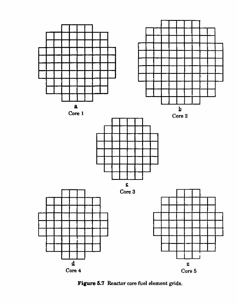
&
Core 1
d. Core4
" Core3
h Core 2
~
Core 5
Figure 5. 7 Reactor core fuel element grids.
I
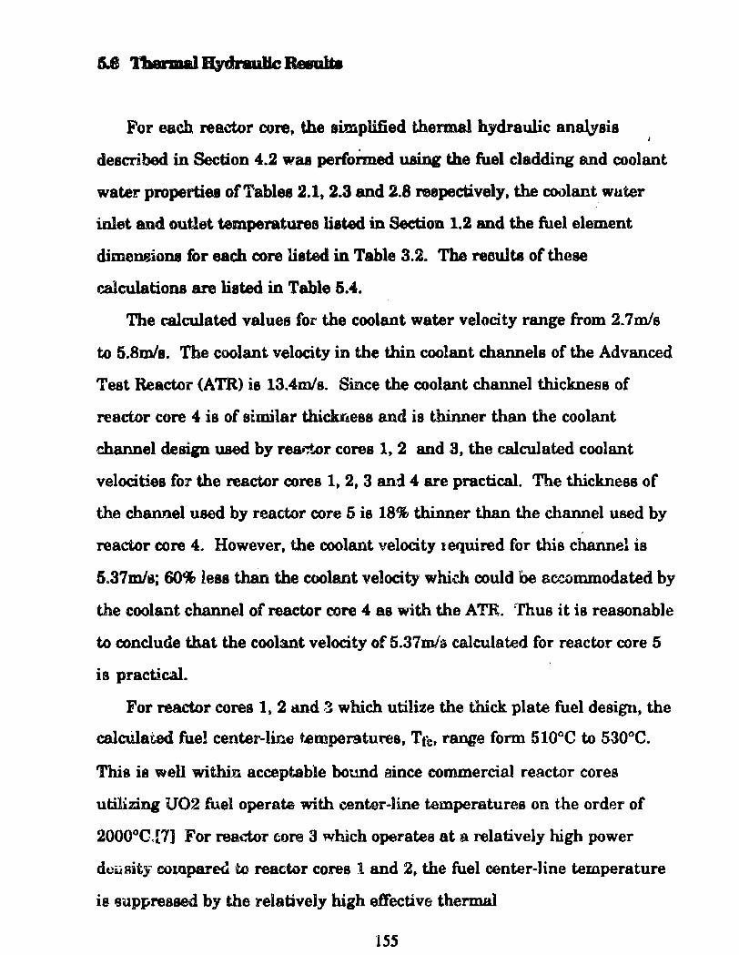
For each reactor core, the simplified thermal hydraulic anazysis
described in Section 4.2 waa perfoimed nsing the fuel cladding and coolant
water propertiea ofTablee 2.1. 2.3 and 2.8 reepectively. the coolant wuter
inlet and outlet temperatures listed in Section 1.2 and the fuel element
dimeneiona for each core listed in Table 3.2. The reaults of these
calculations are liated in Table 5.4.
The calculated values for the coolant water velocity range from 2. 7m/s
to 5.8m/s. Tbe coolant velocity in the thin coolant channels of the Advanced
Test Reactor (A TR) is 13.4m/s. Since the coolant channel thickness of
reactor core 4 is of similar thickrJess and ia thinner than the coolant
channel deaign used by rear,t..or cores 1, 2 and 3, the calculated coolant
velocities fo:r the reactor cores 1, 2, 3 and 4 are practical. The thickness of
the channel used by reactor core 5 is 18% tbinner than the channel used by
reactor core 4. However, the coolant velocity tequired for this channel ia
5.37mls; 60% lesa than the coolant velocity whidt could be sccommodated by
the coolant channel of reactor core 4 e.s with the ATR. rfhus it is reasonable
to conclude that the coolant velocity of 5.37mla calculated for reactor core 5
is practical.
For reactor cores 1, 2 tllld 3 which utilize the thick. plate fuel design, the
calcUlat.ed fue! center-line temperatu.-es, Tte. range form 510°C to 530°C.
This ia well within acceptable bound eince commercial reactor cores
utilizing U02 fuel operate with center-line temperatures on the order of
2000°C .. [7] For reador core 3 which operatea at a relatively high power
dcusity coropared to reactor cores 1 and 2, the fuel center-line temperature
is suppreased by the relatively bigh e.ffective thermal
155
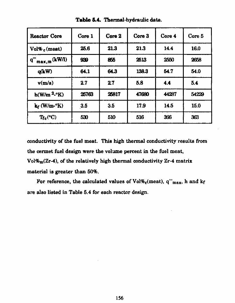
Table 5.4. '11lermal-hydraulic data.
Reactor Core Corel Core2 Core3 Core4 Core5
Vol% c (meat) 25.6 21.3 21.3 14.4 16.0
q ... max m (kWil) D 865 2513 2550 28)8 ,
q(kW) 64.1 &&.3 138.3 54.7 54.0
v(mls) 2.7 2.7 5.8 4.4 5.4
b(WJm2_oK) 257SJ 2li817 47681 44287 54229
k,- {W/m-oK) 3.5 3.5 17.9 14.5 15.0
Trc(°C) 5.'J) 510 516 356 3m
conductivity of the fuel meat. This high thermal conductivity resulte from
the cermet fuel design were the volume percent in the fuel meat~
Vol%m(Zr-4). of the relatively high thermal conductivity Zr-4 matrix
material is greater than 50%.
For reference, the calculated values of Vol%c(meat.), q'" max. h and kr
are also listed in Table 5.4 for each reactor design.
156
Table 5.5 enmmarizea the whole core B.O.C. and E.O.C. materiais data.
calculated by the methods described in Section 4. 1.4. which have been
calculated for raference p\li"))Ollea. The E.O.C. enriehment ia the
percentap of tJ236 which ia contained in the total E.O.C. uranium mass
(i.e, the aum ofthe E.O.C. mauea oflJ233, tJ236 and 1J238).
Figurea 6.8 to 5.12 are plota over the refuel.ing lifetime ofthe plutonium.
mass contained in reactor cores 1, 2, 3, 4 and 5 reapectively. Plutonium
buildup resulta from the conversion ofU238 to Pu239, which in turn is
converted to Pu240, Pu241 and Pu242. Reactor core 1 which utilizes 7%
enriched uranium contains lesa plutonium than reactor core 2 which is
fueled with 20% enriched uranium since it haa a refueling lifetime half
that of core 2. For reactor core 3, Figure 5.10 indicates that the total mas a of
plutonium in the core decreases near E.O.C. Thia results since the U238
concent.ration has been depleted to an extent that Pu 239 production is lesa
than the consumption cf Pu isotopes by fiBSion or conversion to higher
actinides.
157
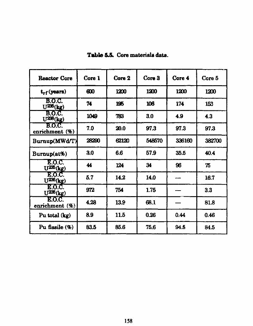
Table U Core materiais data.
Reactor Core Corel Core2 Core3 Core4 CoreS
trr(Jears> mo 1D) 12)0 12X) mx> ~.o.c.
lJB(q) 74 196 106 174 153
B.O.C. 1049 7Si 3.0 4.9 4.3 tJ298(b) B.O.C. 7.0 3>.0 97.3 97.3 97.3 enrichment (9&)
Burnup(MWdlr) 28200 6213) 548570 336100 382700
Burnup(at%) 3.0 6.6 57.9 35.5 40.4
E.O.C. 44 124 M 96 75 UDi(kg) E.O.C. 5.7 14.2 14.0 - 16.7 l]B(kg) E!Q.C.
lJB(kg) 972 754 1.75 - 3.3
E.O.C. 4.28 13.9 68.1 - 81.8 enrichment (%)
Pu total (kg) 8.9 11.5 0.26 0.44 0.46
Pu fissile (%) 83.5 85.6 75.6 94.5 84.5
158
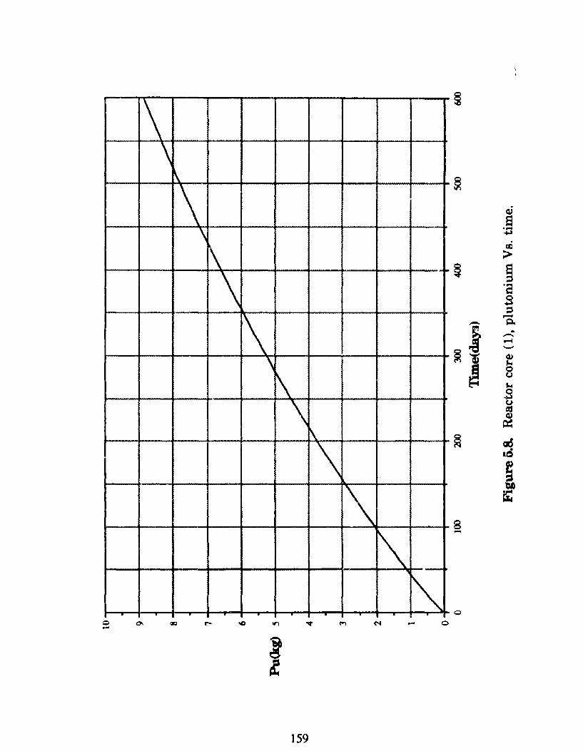
\ \
\
\ ~
~
8 \
.... ~
~
\ 12:
;>
~ ~ ·a 3 ::1
!\ \
~
,_ - 0..
i --.....t '-"
~li G:l ~
~ o (.)
.... .s \
\
\ \
t) ~ cu ~
~ aõ lÓ
! fZ
8
\ -
, __
""' . . . . Q
159
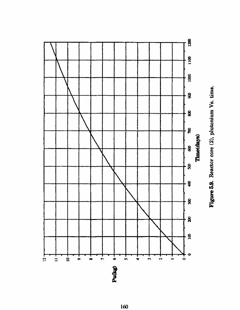
\ ~ -8
1\ \
.... ...
§ - . \
\ \
\ ' \
'
G,)
!j e '.::3 a:i >
i 9 ·a 3
~ = 'a -§I
.. -C'l1 ........
f 8 ...
~ ~ «:~
\ '
"' 1\ '\
~ §
. ~
~ j ~
~
" 8 -
" . . . .
160
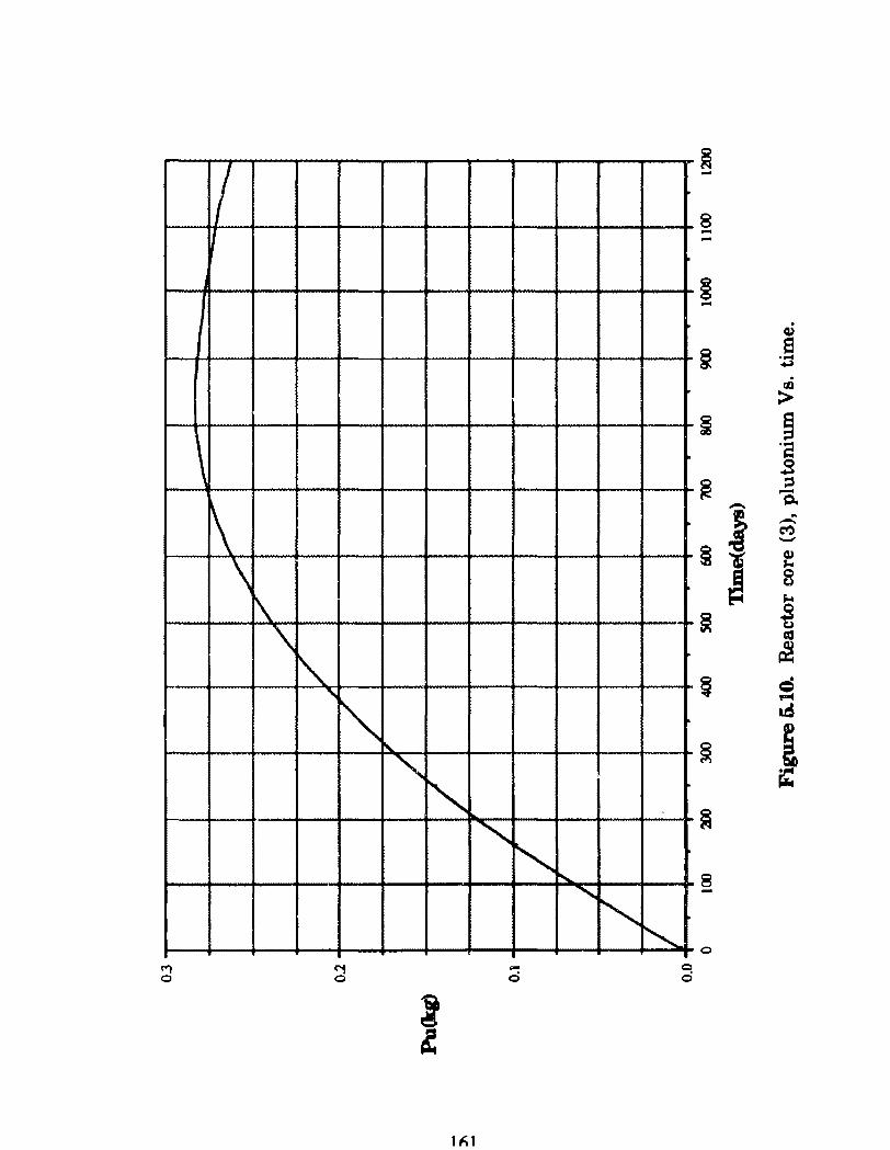
1/ 1/
\ ~ \
\ \ ~
' "~
C"1 o
" ~ "' ~ "" ' "' -c::i
1 h1
~ -8 -.... § - .
Q)
~ 8 ·.o . 11)
> r; §
·a .s
~ ::s -- t:l.
§i A -C'f':) --Q) J.o
~ o CJ
lo-4
~ ~ Cl
~ ~
. = '1""4
at5
~ 1 ~
~
8 -~ o
c o
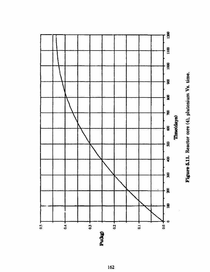
• -8 --
\ \
§ -~
i 8 :0 ..; >
~
\ \
\
\ 1\
1\ ~ .
~ [\._
"
~ ~ ·a s ~
:::1 -a
~ I --' • -f 8 ...
~ .s u CXJ
~
~ • .... ,... ~
~ j ~
8 -~ o
V"l ~ a C"1 - C! o o o d o
f 162
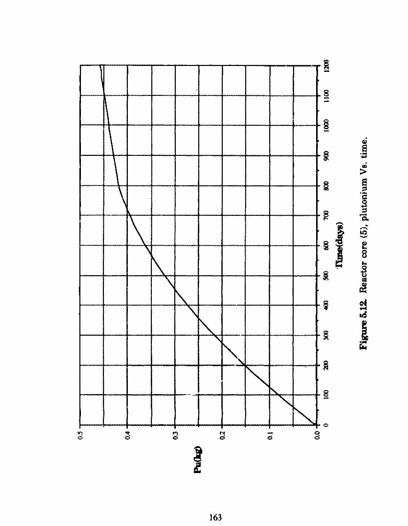
~ -- 8 --
§ -\ \
. (I)
~ e
"""" ~ Cll
> \
\ § ~ ·a
.s
\ ~
\
\ \ ~
'\
~ ~ 'a - ...
§I ..-.. 1.0 -f 8 ... .s
~ u ca
~
~ c4 .-4
at5
~ " i',
""' ~ ! r:: ~
~
" 8 -
~ o .,..,
d C"'' N - ~ o c:i o d
~ ~
163
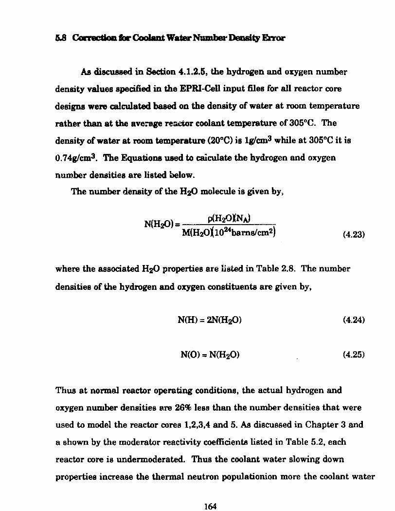
AB di8CU.81Jed in Section 4.1.2.5, the hydrogen nnd oxygen number
density values specified in the EPRI-Cell input files for ali reactor core
designa were calculated baaed on the density of water at room temperature
rather than at the ave:age reocior coolant temperature of 305°C. The
density ofwater at room temperature (20°C) is lglcm3 while at 305°C it is
O. 7 4g/cm3. The Equationa uaed to caiculate the hydrogen and oxygen
number densities are listed below.
The number density ofthe H2<) molecule is given by)
N(H2Ü) = p(H:tJXNA) M(H2Ül102-fbams/cm2) (4.23)
where the associated H2Ü properties are listed in Table 2.8. The number
densities ofthe hydrogen and oxygen constituents are given by,
(4.24)
(4.25)
Thua at normal reactor operating conditions, the actual hydrogen and
oxygen number densities are 26% less than the number densities that were
used to model the reactor cores 1,2,3,4 and 5. As discussed in Chapter 3 and
a shown by the moderator reactivity coeffi.cients listed in Table 5.2, each
reactor core ia undennoderated. Thus the coolant water slowing down
properties increase the thermal neutron populationion more the coolant water
164
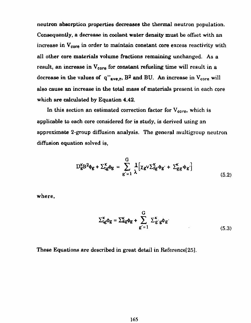
neutron absorption properties decreases the thermal neutron population.
Consequently, a decrease in coolant water density must be offset with an
increase in Vcore in arder to maintain constant core excess reactivity with
ali other core materiais volume fractions remaining nnchanged. As a
reault, an increase in Vcore for constant refueling time will result in a
decrease in the values of q"'ave,r• B2 and BU. Ao increase in Vcore will
also cause an increase in the total mass of materiais present in each core
which are calculated by Equation 4.42.
In this section an estimated correction factor for V core. which ia
applicable to each core considered for ia study, is derived using an
approximate 2-group diffusion analysis. The general multigroup neutron
diffusion equation solved is,
(5.2)
where,
G
~g = L~~g + L L~·~g' g'=l (5.3)
These Equations are described in great detail in Reference[25].
165
The terma used in Equations 5.2 and 5.3 are defined below.
Dg = Neutron diffusion coefticient
B2 = Geometric buckliog
Iag = Neutron absorption crosa-section
I 1·1 = N eutron scatteri.ng CI"'88-aection from group g to group g'
I.11· = Neutron ecattering CI'088·aection from group g' to group g
Irg' = Neutron fission cross-section in group g'
v = Average neutron yield per fission event
Xg = Probability a fission neutron will be bom in group g
À = Eigenvalue to set the RHS and LHS of Equation 5.2 equal
4»1 = Neutron flu.x in group g
JC = Region of reactor core to which Equatian 5.2 ia applied
Solving Equation 5.2 for À with À = keff for two neutron energy groups
yields,
k ff = VI.f2Í:21 + VÍ:,fl
e (DtB2 + Iat + IuXD2B2 + :Ea2) (DtB2 + I.at + I:u) (5.4)
For purposes of this analysie it ia assumed that Í:12 (scattering from the
thermal to the fast energy group) is equal to zero since it is sufficiently
small. Also since most fission neutrons are bom into the fast energy
group, it is assumed that 11 = 1 and 12 =O. These considerations are
further explained in Reference [Henry]. The diffusion coefficient D is
defined by the following relation,
166
Dr=a~ (5.5)
where,
I:tr = Neutron transport cross-section
Each macroscopic crose-section used in Equations 5.2 and 5.3 are the
sum of the contributions of the macroecopic cross section cf water and the
macroscopic cross-section of ali non-coolant materiais present in the
reactor. Thus Itrt, Ur2• Lat, La2 and l:21 are defined as,
(5.6a)
(5.6b)
(5.6c)
(5.6d)
(5.6e)
The para.meter m refers to ali non-coolant materials present in the
reactor while (w) refers to the coolant water. For simplifying purposes of
this analysis, it is assumed that L2t(m) = O since it is small compared to
L2t(w). This concept is further discussed in Reference [25]. Substituting
11\7
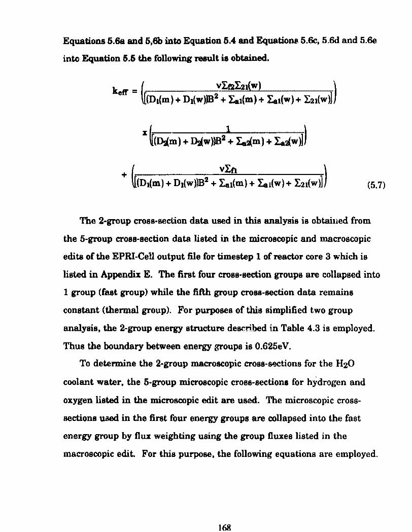
Equations 5.6a and 5,6b into Equation 5.4 and Equations 5.6c, 5.6d and 5.6e
into Equation 5.6 the followi.ng result is obtained.
"~(Dám) + Dáw))B2 + I,dm) + ld'w~)
(5.7)
Thc 2-group cross-section data used in this analysis is obtained from
the 5-group cross-section data listed in the microscopic and macroscopic
edita of the EPRI-Cell output file for timestep 1 of reactor core 3 which is
listed in Appendix E. Tbe first four cross-section groups are c;:ollapsed into
1 group (fast group) while the fifth group cross-section data remains
constant (thermal group). For purposes of this simpli.fied two group
analysis, the 2-group energy structure described in Table 4.3 is employed.
Thus the boWldary between energy groups is 0.625eV.
To determine the 2-group macroacopic cross-scx:tions for the H20
coolant water, the 5-group m.icroscopic croes-sectiona for hydrogen and
oxygen listed in the microscopic edit are used. The microscopic cross
oections uaed in the first four energy groups are colJapsed into the fast
energy group by flUI weighting using the group O.uxes listed in the
macroscopic edit. For this purpose, the following equations are employed.
168
4
I, ~I) ~I) (H) 11'1=1
Oxt(H) ~ ..;..-~-4----I, ~I) pl (5.8)
4
l: q,) Ox{e) (O)
( ) pl
0':.:1 o = ..;..._-.----
L~~> pl (5.9)
The subscripted numbers in parenthesis indicate the energy group of the
cross-secticm a~ it is listed in the 5-energy group structure of the EPRI-Cell
output file listed in Appendix E. The subacripted numbers not in
parenthesis indieate the energy group of the new 2-group structure where 1
designatea the fast group and 2 designutes the thermal group. In each
equation used in this rmalysis, the subscript, x, refer to any arbitrary cross
section.
The thennal group microscopic cross sections for hydrogen and oxygen
are given by,
(5.10)
(5.11)
The core averaged macroocopic cross-sections for oxygen and hydrogen are
then determined by the follcwing equatiom.
169
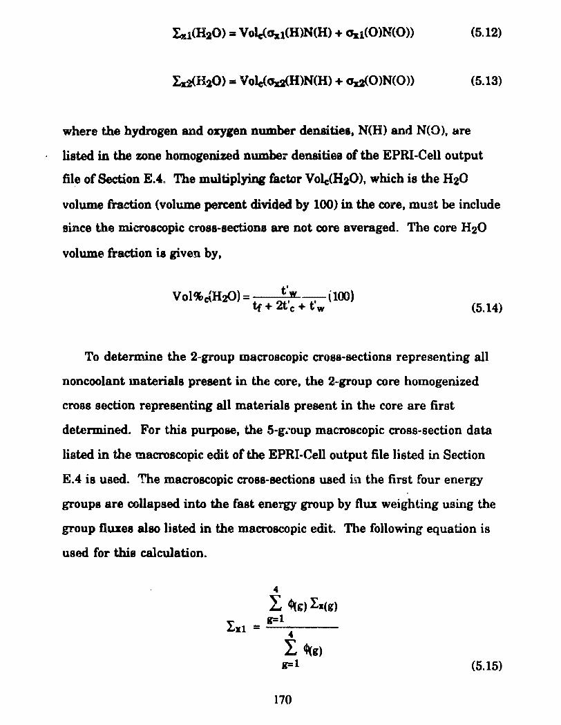
Id<H2Ü) = Volc(<Jd{H)N(H) + <Jd{O)N(O)) (5.13)
where the hydrogen and oxygen number denaities. N(H) and N(O), are
listed in the zone homogenized numbeT densitiea of the EPRI·Cell output
file ofSection E.4. The multiplying factor Volc(H20), which is the H20
volume fraction (volume percent divided by 100) in the core, muBt be include
since the microscopic cross·sectiona are not core averaged. The core H20
volume fraction is given by,
Vol%c:{H2<)) = ~.w , \100) tr+ c+tw (5.14)
To determine the 2-group macroscopic cross-sections representing ali
noncoolant materiais present in the core, the 2-group core homogenized
croos section representing ali materiais present in th~ core are first
determined. For this purpose, the 5-gÀ .. oup macroscopic cross-section data
listed in t.he macroscopic edit of the EPRI-Cell output file listed in Section
E.4 is used. The macroscopic cross-sections used in the first four energy
groups are collapsed into the fast energy group by fha weíghting using the
group Duxes also listed in the macroscopic edit. Th.e following equation is
used for this calculation.
4
L ~g) l:x(g) ~ g=l Loz.l = --.---
L ~g) g=l (5.15)
170
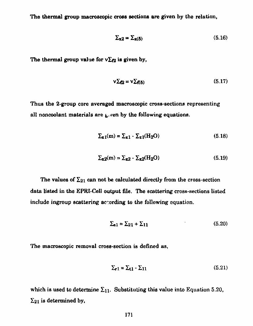
The thermal group macroscopic cross sections are given by the relation,
Iz2 = L:C6) (5.16)
The thennal group val,~e for vi.n is given by,
(5.17)
Thus the 2-group core averaged macroscopic cross-sections representing
ali noncoolant materiais are i»·· ven by the following equations.
(5.18)
(5.19)
The values of I.21 can not be calculated directly from the cross-section
data listed in the EPRI-Cell output file. The scattering cross-sections listed
include ingroup scattering acr::ording to the following equation.
(5.20)
The macroscopic remova! cross-section ia de.fined as.
L.-1 = Iu- In (5.21)
which is used to determine l:u. Subatituting this value into Equation 5.20,
I21 ia determined by,
171
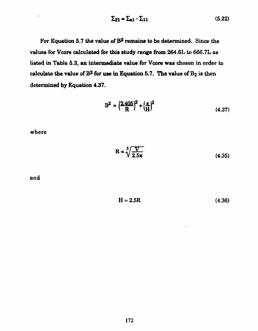
Ia1 • I.1 .. I.u (5.22)
For Equation 5. 7 the v alue of B2 rem ai na to be determined. Since the
valuea for V core ealcclated for thia atudy range &om 264.6L to 666.7L as
listed in Table 5.3, an intermediate value for V core wu chosen in order to
ealcu.late the value ofB2 for uae in Equation 5.7. The value ofB2 ia then
determined by Equation 4.37.
where
and
R-~~ -v 2.5i
H=2.5R
172
(4.37)
(4.35)
(4.36)
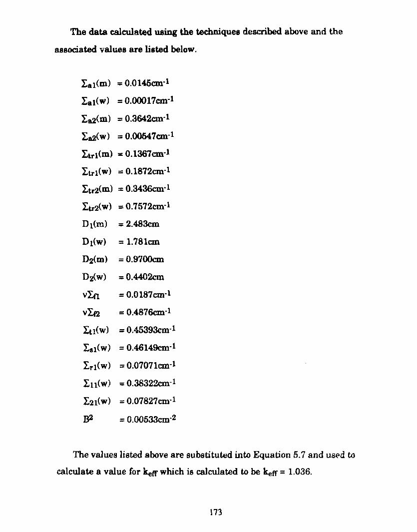
The data calculated uaing the techniques deacribed above and the
associated values are listed below.
Lal(m) = 0.0145cm·1
l:8 t(W) = 0.00017cm-1
l:a2(m) = 0.3642cm-l
l:a2(w) = 0.00547cm-l
Ltrt<m) = 0.1367cm-1
~trl(w) = 0.1872cm-l
Ltr2(m) = 0.3436cnrl
I:triw) = 0.7572cnrl
D1(m) = 2.483cm
Dt(W) = 1.781cm
D2(m) =0.9700cm
D:l{w) =0.4402cm
VLfl = 0.0187cm·l
v In = 0.4876cnrl
l:u(w) = 0.45393cm-l
I.at(w) = 0.46149cnrl
Lri(W) = 0.07071cm.-l
I.n(w) = 0.38322cnrl
l:2t(W) = 0.07827cnrl
B2 = 0.00533cm·2
The values liated above are substituwd in to Equation 5. 7 and us(ld to
calculate a value for ketr which is calculated to be ketr = 1.036.
173
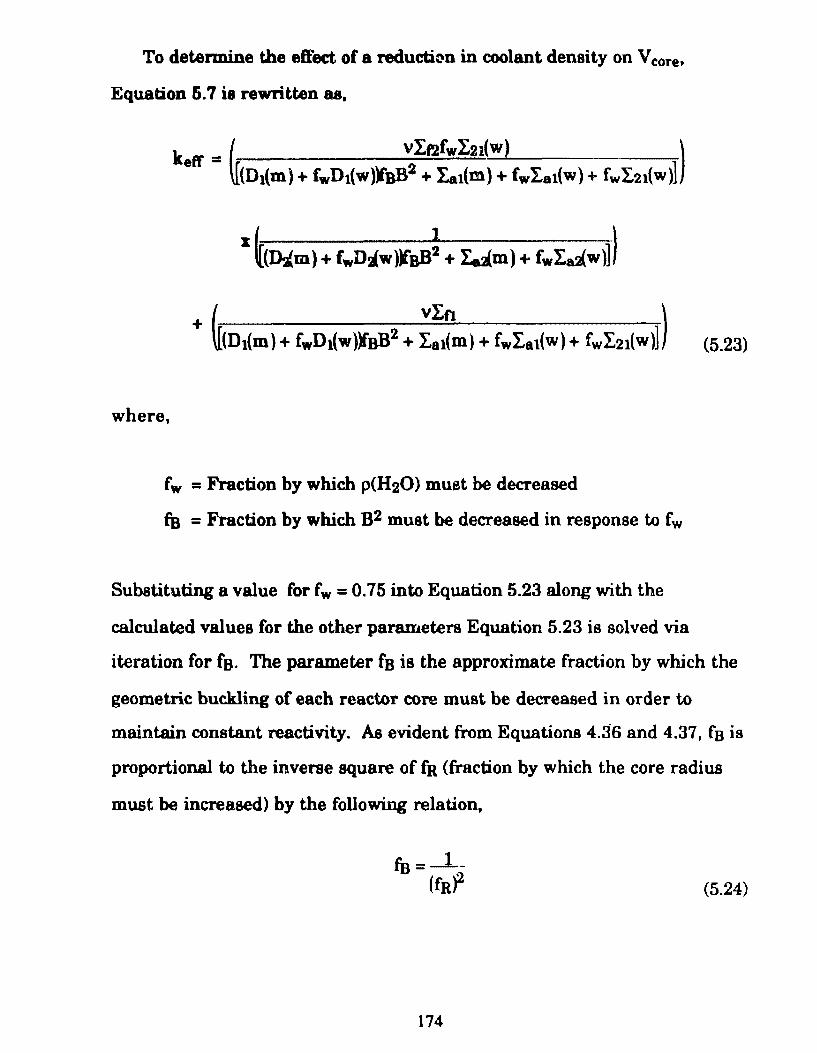
To determine the effect of a reductit~~n in coolant density on V core,
Equation 5. 7 ie rewritten as,
where,
fw = Fraction by which p(H20) must be decreased
fB = Fraction by which B2 must be decreased in response to fw
(5.23)
Substituting a value for fw = 0.75 into Equation 5.23 along with the
calculated values for the other parameters Equation 5.23 is solved via
iteration for fs. The para.meter fa is the approximate fraction by which the
geometric buckling of each reactor core must be decreased in order to
maintain constant reactivity. As evident from Equations 4.36 and 4.37, f ais
proportional to the in verse square of fR (fraction by which the core radius
must be increased) by the following relation,
(5.24)
174
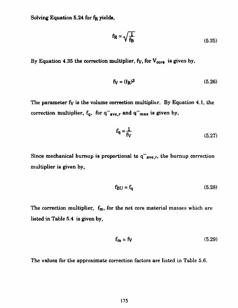
Solving Equation 5.24 for fa yielda,
fa={& (5.25)
By Equation 4.35 the correction multiplier, fv, for V core is given by,
fv = (fa)3 (5.26)
The parameter fv ia the volume correction multiplibr. By Equation 4.1, the
correction multiplier, fq, for q'"ave,r and q"'max ia given by,
fq =_l_ fv (5.27)
Since mechanical bumup is proportional to q"' ave,r, the bumup correction
multiplier is given by,
(5.28)
The correction multiplier, fm, for the net core material masses which are
listed in Table 5.4 ia given by,
(5.29)
The values for the approximate correction factors are listed in Table 5.6.
175
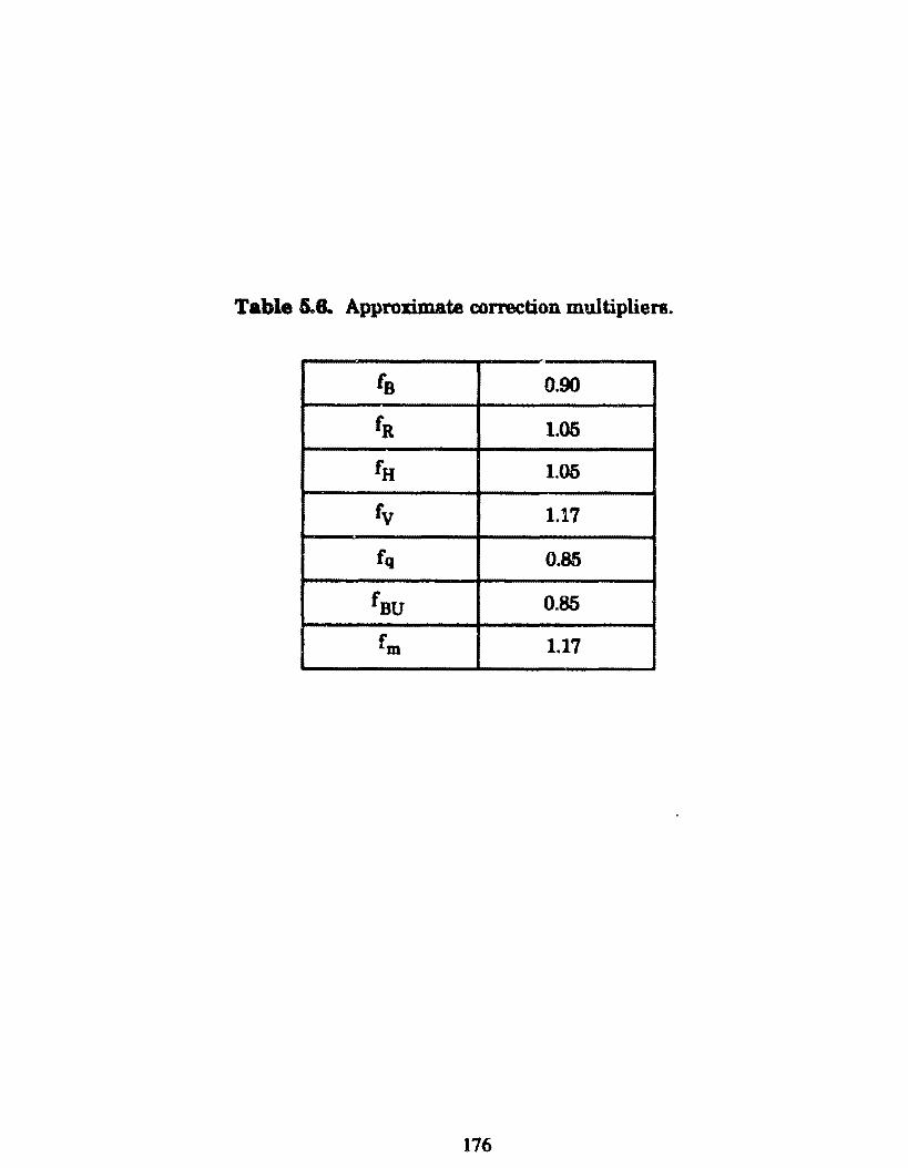
Table 5..8. Approximate correction multipliers.
fs 0.90
f R 1.05
f H 1.05
f v 1.17
fq 0.85
fsu 0.85
fm 1.17
176
6.1 CoDclutdon
CB.API.'ER 8 CoacJwdon aad BecommendGtiODI
AB stated earlier, it is known that modem U.S. are fueled with very
highly enriched uranium; greater than 90111. In this study, a reactor core
using plate type fuel elementa fueled with 97.3% enriched uranium which
operates with a refueli.ng lifetime oi 1200FPD, waa m.odeled. The safety
coeffi.cienta of reactivity and thermal hydraulics resulta calculated are
acceptable.
The French have proved that the use of LEU (i.e., approx:imately 7%
enriched uraniu.m) as a nuclear submarine fuel is feasible. In this study a
reactor core uaing plate type fuel elementa fueled with 7% was enriched
hl'BDium was modeled. However, it was not possible for this core to
maintain criticality beyond a refueling lifetime of approx:imately 600FPD.
Also for thia case, the aafety coefficient o f reactivity and thermal hydraulics
are acceptable. Tbe volume of tbis core is roughly twice the size of the core
fueled with 97.35 enriched uranium. This corresponds to a 17cm and 20cm
increase in diameter and height respectively (these dimensione are
corre,:ted using correction facton of Table 5.6) .
A reador core using plate type fuel elements fueled with 20% enriched
uranium which operates with a refueling lifetime of 1200FPD, was
modeled. The safety coefticient of reactivity and thermal hydraulics differ
very little compared to the core fueled with 97.3% enriched uranium. AB
discussed in Chapter 1, low enriched uranium, LEU, is intcmationally
regarded to be u.ranium with enrichment in the range0%- 20%. Thus it is
177
demonstrated that a reactor core using LEU and with operating
performance similar to the 97.3% enriched core, can be designed. The core
fuel with 20% enriched uranium is, however, about two and one half times
largar than the core fueled with 97.3% enriched uranium. This
corresponds to a 24cm and 30cm inaease in diameter and height
respectively (these dimensions are corrected using correction factors of
Table 5.6). Thua as maintained in Chapter 1, these dimensional increases
are sufficiently amall that they can eaaily be compensated for by the use of
an integral reactor design.
178
For each reactor core modeled in this study using one dimensional
calculations, a more detailed analysis can be done which accounts for
spatial dependence of fuel depleü.on, control rod motion and startup,
shutdown and transient bebavior.
The DIF3D code developed by Argonne National Laboratory can be used
to model, with 3AD di..ffusion theory, the steady-stat.e behavior of each reactor
core. DIF3D solves multigroup diffusion theory eigenvalue, adjoint, fixed
source and criticality (concentration search) problema in 1-, 2- and 3-space
dimensions for for orthogonal (rectangular and cylindrical), triangular
and hexagonal geometries.[26] The reactor core fuel element grids
illustrated in Figure 5,1 and dimensions ofTable 3.2 can be used in
preparation of a DIF3D input file. The core heights listed in Table 5.5 can
aloo be used. (Note that these dimensions must be corrected using the
correction factors listed in Table 5.6). The EPRI-Cell input files used for
this study are set up to produce 5-group cross-section data in ISOTXS data
seta (see Appendix E) which can be input directly into DIF3D.
To model the time dependant aspecta of the fuel cycle of each reactor
core, the REBUS-3 fuel cycle analysis code, also developed by Argonne
National Laboratory, can be used. AB in the above case the corrected
dimensional data deucribed above can be used in preparation of a REBUS-3
input file. There are four types of of search procedures thRt may be carried
out in order to satisfy user supplied constraints.[27]
179
1) Adjustment of the reaetor refueling lifetime in order to achleve a
apeci.fied E.O.C. fuel bumup.
2) Adjustment of the B.O.C. uranium enrichment in order to
achieve a speci.fied E.O.C. kefr at any speci.fied point during the
refueling lifetime.
3) Adjustment of the bu.rnable poison density (i.e., coolant water
boron concentration) in order to maintain a specified value af kew
throughout the reactor refueling lifetime.
4) Adjustment of t.he reactor refueling lifetime to achieve a specified
value of kefr at E.O.C.
Also, for REBUS.3, the 5-group cross-section data listed in the ISOTXS
data seta can be input directly.
For thennal hydraulic transient analysis, the P ARET code developed by
the Phillips Petroleu.m Company, can be used. PARET is a digital
computer program designed for use in predicting the course and
consequences of nondestructive reactivity accidents in smail reactor cores.
This code couples neutronics and thermal hydraulics and uses point
kinetics, 1-D hydrodynamics and 1-D heat tnmsfer.[28]
1RO
[1] Cochran, Thomas B., Arlrin, William M., Norris, Robert S., Hoenig,
Milton M., Nuclear Weapona Data Book, Volume 11, U.S. Nuclear
Warhead Production, Ballinger Publishing Company, Cambridge,
Massachusetts, 1987.
[2] Girarei, Yves, Technicatome of France, Presentation at tha
Conference on The Implication of the Aquisition of Nuclear-Powered
Submarinas (SSN) by Non .. Nuclear Weapons States, MIT, March
?:1- 28, 1989.
[3] Nuclear Theft: Risks and Safeguards, A Report to the Energy Policy
Project of the Ford Fot' iation, Manson Willrich, Theodore B.
Taylor, Ballinger Publishing Company, Cambridge, Mass, 1974,
Pg. 228.
[4] An Analysis of Air Independent Power Planta for Adaption to
Conventional Submarinas; Prapared for the Department o f National
Defanse, DMEE-6, GasTops Ltd., GTL-7-47-TR.l, Glo~cester, July,
1987.
[5) Fact Sheet, Rubie/Trafalgar Class SSN's, Canadian National
Defeme, Ottawa, Ontario.
[6] Freidman, Norman, Submarine Design and Development, Naval
Institute Presa, Annapolis, Mary~and, 1984.
181
[7] Lamarsh, John R., Introduction to Nuclear Engineering (2nd
Edition), Addison-Wealey publishing Company, Reading,
Maasachusetts, 1983.
[8] Wings Magazine, Canadian Submarine Acquisition Program
(CASAP), Nuclear Propulsion, Tbomas Lynch, April1988, Pgs 64-68.
[91 EPRIMCELL Code Description, Prepared by: Nuclear Associates
International Corporation, 6003 Executive Boulevard,
Rockville, Md, 20852, Prepared for: Electric Power Research
Institute, 3412 Hillview Avenue, Paio Alto, Ca, 94304,
October 29, 1975.
[10] Personal Com..munication
[11] Directory of Nuclear Reactors, Research and Test Reactors, Vol. V,
Intemational Atomic Energy Agency. Vienna, 1964, Pg 107.
[12] Research Reactor Core Conversion From the Use of Highly
Enriched Uranium to the Use of Low Enriched Uranium J.,uels
Guidebook, A Technical Document Issued by the International
Atomic Energy Agency, Vienna, 1980.
I R?.
[13] Barnier, M., Baylot,J.P., Oeiria, A M.TR Adopted and Well Fitted to
LEU Utilization, Qualifieation and Development, Experimental
Reacton Department, Saclay Nuclear Center, France, As Presented
in, JAERI-M 80-073, Proceed.ings of the Intemational Meeting on
Reduced Enrichment for Reaearch and Teat Reactors, October
24-27, 1983, Tokai, ,lapan, May 1984.
[14] Reactore of the World, Second Series, Simmona .. Boardman
Publishing C\lrporation, New York.
[15] Robertson, J.A.L., lrradiation Effects in Nuclear Fue]s, Atomic
Energy of Canada, Ltd., American Nuclear Society, Gordon and
Breach, N.Y., 1969.
[16] Frost, Brian T., Nuclear Fuel Elements, (Argonne National
Laboratory), Pergamon Press, N.Y., 1982.
[17] Kauünan, Albert F., Nuclear Reactor Fuel Elemcnts, Metallurgy and
F~brication, John Wiley & Sons, N.Y., 1962.
[18] Tong, L.S., Weisman, J., Thermal Analysis of Pressurized Water
Reactors, 2nd Edition, American Nuclear Society,LaGrange Pary,
Dlinois, 1979.
183
[19] Copeland, G.L., Hohba, R.W., Hofman. G.L., Snelgrov, J.L.,
Performance of Low-Enriched U3Si2- Aluminum Dispersion Fuel in
t...'te Oak Ridge Rasean:h Reactor, Argonne National Laboratory,
ANl/RERTIVI'M-10, October, 1987.
[20] Finnieton, H.M., Howe, J.P., Progreaa in Nuclear Energy, Seri.:,s V,
Metallurgy and Fuels, Pergmnon Presa, N.Y., 1956.
[21] Travelli, A., Semiar Presented at M.I.T., The Reduced Enrichment
Re&ctor Program, March, 1989.
[22] Claae Notes, Course 22.70, Nuclear Mateials, Massachusetta
Institute ofTechnology, Spring 1989.
[23] Rahn, Frank J., Adamantiades, Achilles G., Kenton, John E.,
Braun, Chaim, (of the Electric Power Research of California), A
Guide to Nuclear Power Technology, A resource for Decision
Making, John Wiley & Sons, N.Y.» 1984, Pg 437.
[24] Benedict, Manson, Pigford, Thomas H., Levi, Hans Wolfgang,
Nuclear Chamical Engineering, McGraw Hill Book Company, New
York., 1981.
[25] Henry, Allan F., Nuclear-Reactor Analysis, MIT Presa, Cambridge,
Massachusett.s, 1975.
184
[26] ANJ..,..82-64, DIF3D: ACode to Solve One-, Two-, and Three~
Dimensional Diffusion Theory Problema, K.L. Derstine, Applied
Physics Division, Argonne National Laboratory, 9700 South
Casa Avenue, Argonne Dlinois, 60439, April, 1984, Prepared
for the U.S. Departu.tent of Energy.
[27] A.NL-83-2, A U ser's Guide for the REBUS-3 Fuel Cycle Analysis
Capability, B.J. Toppel, Applied Physics Division, Argonne
National Laboratory, 9700 South Cass Avenue, Argonne
Dlinois, 60439, March, 1983, Prepared for the U.S. Department
ofEnergy.
[28] P&~'r- A Program for the Anaysis of Reactor Transients,
C.F. Obenchain, Phillips Petroleum Company, Atomic Energy
Division, Contract AT(10-1)-205, Idaho Operations Office,
U.S. Atomic Energy Commision, (100-17282, AEC Research and
Developement Report, Reactor Technology, Issued: January
1969).
[29) Desjardins, Marie France, Rauf, Tariq, Opening Pandora· Box,
Nuclear Powered Submarines and the Spread of Nuclear Weapons,
Aurora Papers 8,The Canadian Center for Anns Control and
Disannament, June, 1988.
[30] Desjardins, Marie France, Rauf, Tariq, Canada's Nuclear
Submarine Program: A New Proliferation Concern, Arms Control
Today, December, 1988,
185
[31] Nero, Anthony B. Jr., A Guidebook to Nuclear Resctors, Fuel Cycles,
The Iaauea of Nuclear Power, Univeraity of Califomia Presa, Los
Angeles, 1979.
[32] India Gets Soviet Nuclear-Powered Sub, The Waahington Post9
Wedneaday, Janua.ry 6, 1988, Pg A8.
[33] Manchanda, Rita, (New Delhi)~ Nuclear Ambitiono: Soviet
Submarine Deal Comes to Surface, Far Eastem Review, Defence
Section, December 24, 1987.
[34] Plutonium, Power and Politics, lntemational Arrangements for the
Diapoaition of Spent Fuel, Gene I. Rochlin, University of Califomia
Preas, Los Angeles, 1979.
186

AppendixA
Non-Proliferati.on Treaty and Fornign Nuclear Objectives
Modem day concerns are not only with the continued diffusíon of
information related to he design of nuclear weapona, but also with the
increasing availability of the technology to produce weapons usable
materiais. To date there are five "official" nuclear weapons states (NWS),
the U.S., the U.S.S.R., the U.K., France and China. However, Israel, South
Mrica and Pakistan are widely believed to have the capability to produce
nuclear weapons, while lndia detonated a peaceful nuclear exploaion (PNE)
in 1974.
Relatively early on in the nuclear age, pressure began to develop for an
inter-national agreement to thwart both the vertical and especia1ly ·~ he
hori7ontal proliferation of nuclear weapons. (Horizontal proliferation refers
to an increase in the number of states possessing nuclear weapons, while
vertical proliferation refers to the growth in the nuclear arsenais of the five
nuclear weapons states.)
Consequently, in June 1958, lreland submitted to the UN General
Assembly, a resolution.-requesting the establishment of a committee to
study the dangers inherent in the further dissemination of nuclear
weapons. This resolution did not deal specifically with horizontal
proliferation; however it recognized the possibility that an increase in the
nurnber of nuclear weapons states may occur. Following mount.ing
concern by the international community, the title Non-Proliferation of
Nuclear Weapons was adopted in 1965 by the UN General Assembly in a
resolution calling on the Eighteen Nation Disarmament Committee (ENDC)
to lay the foundation for such a treaty. After intense negotiations between
187
the US and the USSR, final draft.a of a treaty were aubm.itted at the UN .[29]
Upon further reviaiona by the ENDC the Non-Proliferation of Nuclear
Weaponat Treaty waa aigned in June 1968. A central element of the Treaty
is a syatem of safeguarda to be administered by the Vienna based
Intemational Atomic Energy Agency (IAEA), which waa established in
1957. The objective of the safeguards ayatem ia to verify that nuclear
materiais used for peaceful activitiea in NNWS ia not diverted to the
production of nuclear weapons.
Since it eu~i-ed into force in March of 1970, 135 natione have signed the
treaty, including three of the five nuclear weapons states. France and China
refused to aign, along with a number of NNWS auch as Argentina, Brazil,
India, Israel, Pakistan and South Africa. Thia brings to light an inherent
weakness in the non-prolifemtion regime; not ali of the significant NNWS
are members.[30] Thia waa further demonstrated by the indigenous
acquisition of a nuclear explosive by lndia in 1974 as evidenced by its so called
"peaceful nuclear explosion". In ita attainment of a nuclear explosive
capability, India aet a precedent; none of the other NWS had reached this
status via commercial nuclear development, rather the converse is true:
commercial nuclear development was based, in part. on previoua military
work.[31] Since lndia is not an NPI' signatory, it could clairn to have violated
neither the Treaty'a prohibition of ali nuclear explosive devices or explosive
use of nuclear material supplied by other nations. However, Canada did
claim that India violated its pledge not use a Canadian supplied research
reactor to produce the plutonium for the PNE.
Another perceived weakness of the NPr is the nonrequirement of
safeguards for nuclear material used for maritime nuclear propulsion,
including its military application. This was intended by the Treaty's
188
draftera. In the 1960&, aeveral NATO membera, including ltaly and the
Netherlanda, were activeJy conaidering the acquisition of nuclear powered
shlps and demanded an ezclu&ion for nuclear propulsion.[29] As a result,
it ia penniaaible under Paragraph 14 of the IAEA model safeguards
agreement INFCIRCL153 • 10 to withdraw from IAEA safeguards, nuclear
fuel when it is uaed in non--e.zploaive military applications such as fuel for
submarina reactora.[30] Tbe NPI' only uaigna the IAEA the obligation of
applying aafeguards to nuclear materiais in use for peaceful activities such
as that used in research or commercial reactora. However, to date, no
NNWS has availed itaelf to this ezemption to the rule that all nuclear
material in NPr NNWS is subjected to safeguards.
To date, only the five members of the official nuclear weapons club have
developed the technology to build nuclear powered submarines (SSN s).
However, in December 1987, lndia "leased" an SSN o f the Charlie class
from the Soviet Union, making it the first ever NNWS to opera te this type of
submarine.[32] The NPT and associated IAEA system of safeguards did
not prohibit this transfer on either the part of the Soviets or India.[33] A
related development occurred in June 1987, when Canada, a long time
supporter of non-proliferation, announced planes to acquire a fleet on 10-12
SSNs•. Since Canada has impeccable non-proliferation crédentials, there
was little concem that it would utilize the safeguards exemption to divert
enriched uranium for weapons. However, some analysts thought that it
would set an unfortunate precedent in this regard. However, Canada
sought to alloy these concems by decla.ring that it would enter into a
bilateral monitoring arrangement with its supplier w cover the period
during which the material is not subject to IAEA safeguards•.
Another problem is that st.ates such aa Brazil may seek to justify the
189
development of an indigenous uranium enrichment eapability by the
requirement for enriched uranium for nuclear submarine reactor fuel.
The potential for nuclear weapona development existe if such a capability
were achieved.
• In April 1989, Canada hu since cancelled its SSN acquisition program due to budgetary conatraint&.
190
AppmdizB Nuclear MateriaJe Crifblity
N atu.rally occurring uranium eDate in the following isotopes, U234, U235
and lJ138 where for our purposea, tJl34 ia negligible. The enrichment of
natural uranium or UNat ia 0.711% where enrichment is defined as,
maae of fi.saile material e= masa of fi88ile material + maB8 of fissionable material (B.l)
or for thia case,
235 mass (U ) E=---------------------235 238
mass (U ) + masa ~U ) (B.2)
Fissile iaotopea (0233, {]235, Pu239, Pu241) have alarge fission tToss-section at
thermal neutron energies (i.e., 500b at 0.025eV), while fissionable isotopes
such as Pu241 and U238 have a very low crose-section at such energies. In
fact, the fission cross-section o f lJ238 is essentially zero below a neutron
energy of lMeV.
The principal fissile isotopes used in nuclear weapons are lJ235 and
Pu239. Weapons grade uranium and plutoniwn contain greater than 90% of
these isotopes respectively. The actual amounts required for weapons use
depend on the details of a number of factors which are not available to the
general public. However, it is known that the criticai mass (minimum
mass required fcr criticality based on prompt neutrons) of the fissile metal
as a reflected sphere is roughly 5kg for Pu239. and 18kg for lJ235. A possible
reflector in this case is beryllium.
191
About 8q of typical LWR plutonium constitutea a criticai mass when
fab:icated int.o a reOected. sphere.[31] Use of an o:Dde reduces the fissile
atom denaity and increases the criticai masa by appro:a:imately 50%. Such
quMtitiea of theae material& are not very large; i.e., a 4kg sphere of
plutonium ia amaller than a baaeball.[l]
When tbe concentration or enrichment of lJ23S drops below 20%, the
refleeted criticai ma88 becomea prohibitively high, becoming infinite below
about 6%. For Pu239, tbe re0ect4:td criticai mau ia 20kg at 0% fi asile content.
This is illustrated in Figure B.l. Bare unreflected criticai masses are a
factor of three to four times higher.[34].
192
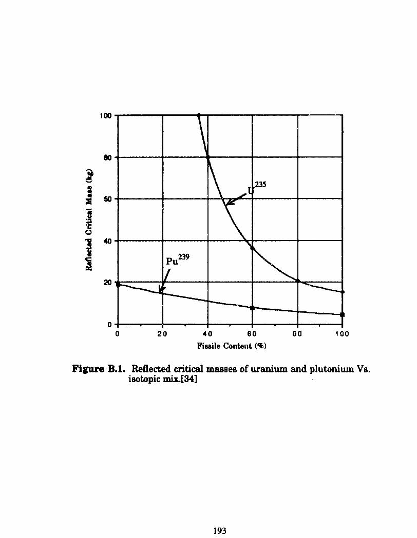
100
\ 80
\ .,t 23!i
\ ~
~ Pu239
[/ ·~r ~
20
---... -o .
o 20 40 60 00 100
Fisaile Content (%)
Fipre 8.1.. Reflected criticai masses of uranium and plutonium Vs. isotopic Dli.I.[34]
193
The nuclear fiuion cbain reaction can be deacribecl quantitatively in
terma of the neutron multiplication faetor (k). Tbia ia defined as the ratio of
the number of ftsaiona (or fiaaion neutrona) in in one generation to the
number of fiaaiona (or 688ion neutronl) in tbe prec:eding generation.
number of fiaaiona in one pneration k·----------------------~---------number of fiasio11.1 in precec:ling generation (C.1)
H k ia equal to 1, the reactor ia said to be criticai and is operating in a steady
state.. If k ia greater than or lese than 1, the reactor is said to be
supercritical and subcritical respectively. The in6nite mt..ltiplication
factor, kmr. is used to describe a reactor of in.finite dimensione (i.e., no
neutron leakage from the reactor surface). The effective mwtiplication
factor, ketr, is useci to descrioo a reactor of finite dimensione (i.e., accounts
for neutron leakage).
The neutron multiplication faetor is used to define a term known as
reactivity, p.
k -1 • p= k efr (C.2)
H a reactor is criticai, keft'iS equal ~ 1 and the reactivity is equal to O. If keõ
were reduced, for example, by the insertion of a neutron &bSGrber in to the
reactor, the reactivity would be negative. Thus the insertion of a neutron
absorber or control rod corresponds to the insertion of nega tive reactivity. A
194
poaitive reactivity inlertion correeponda to the a chaqe that inc:reaaea the
neutron population auch u replaciq a fuel element with one containing
uranium fuel of a higher enrichment. There are many other changea that
can take placa in a reactor that correapond to the inlertion ofnegative
reac:tivity or poaitive reactivity.
19Cf
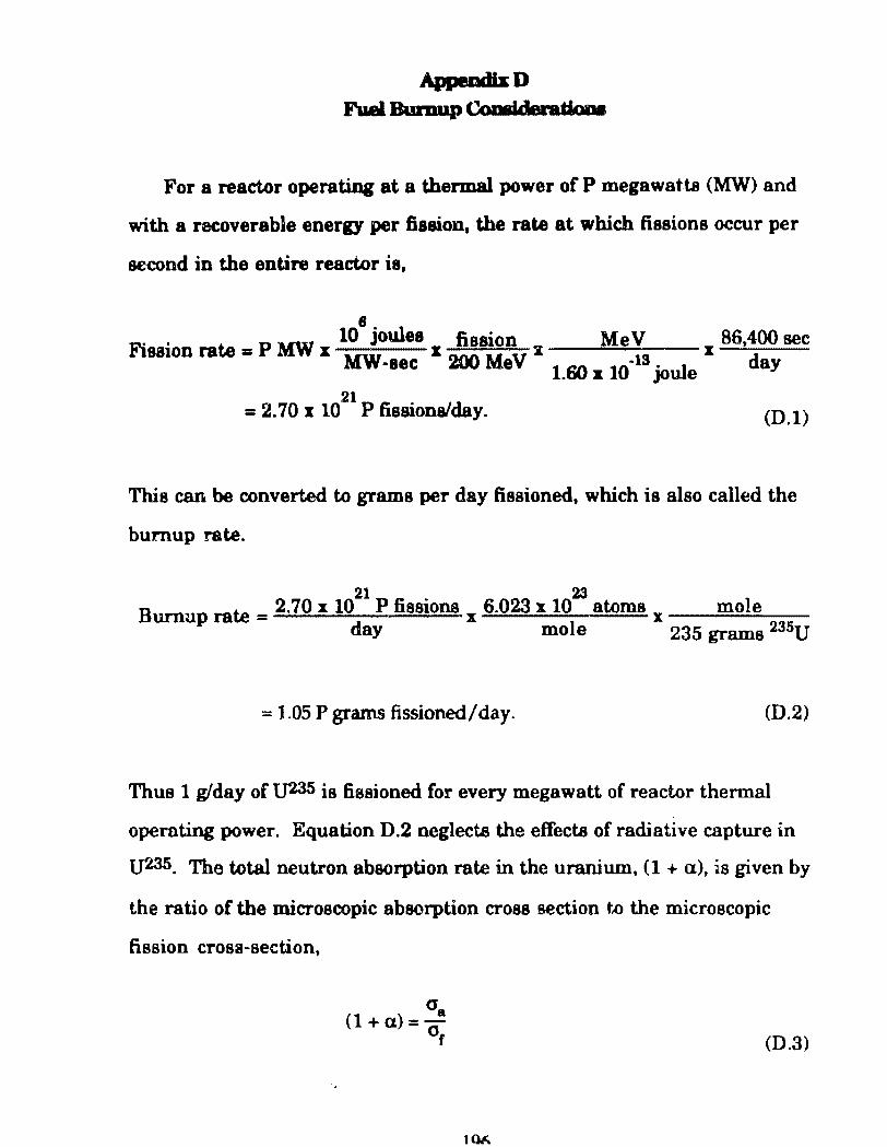
For a reactor operating at a tbermal power of P megawatts (MW) and
with a recoverable energy per fission, the rate at which fiasions occur per
second in the entire reactor ia,
8. ul . . 10 JO ee fiaaion Me V 86,400 sec
Fiaston rate = P MW I MW I 200 M " x 13 x d -eec ev 1.60:.: 10. joule ay
= 2.70 I 1021
P fissionalday. (D.l)
This can be converted. to grama per day fissioned, which ia also called the
bumup rate.
Burnup rate = 2.70 x 10²¹
P fissions x 6.023 x 10²³
atoms x mole day mole 235 grama 235U
= 1.05 P grams fissioned/day. (0.2)
Thus 1 g/day o f lJ235 ia fiaaioned for every megawatt of reactor thermal
operating power. Equation D.2 neglects the effects of radiative capture in
U235. The total neutron absorption rate in the uranium, (1 +a), ia given by
the ratio of the microscopic absorption cross section t.o the microscopic
fission crosa-section,
o. (1 + a)=o
r (D.3)
IOF..
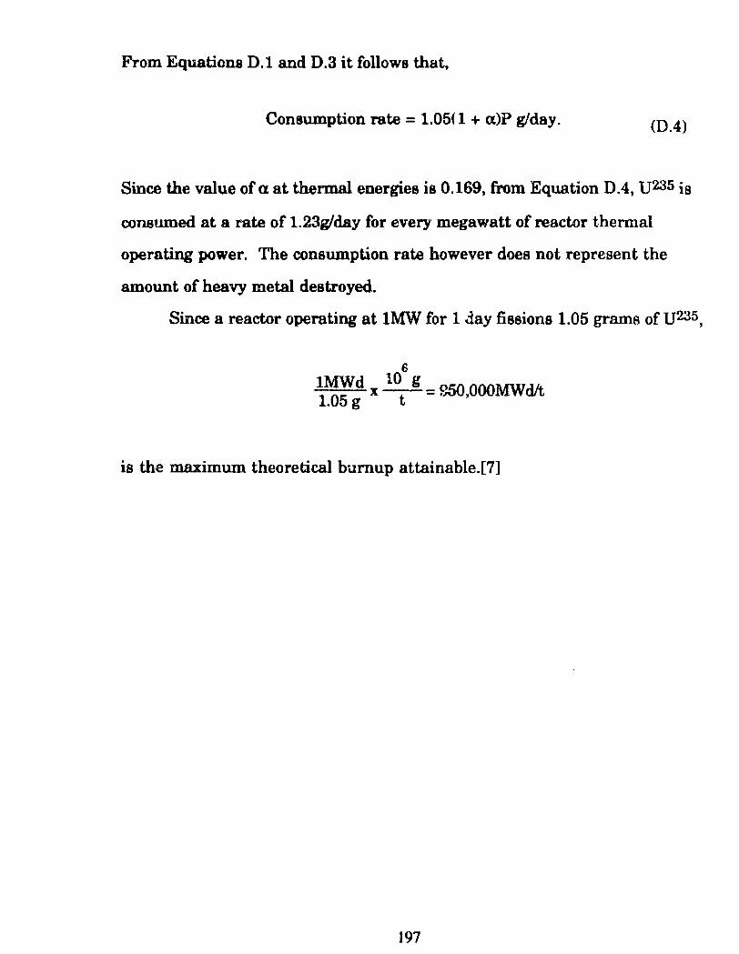
From Equations D.l and D.3 it follows that,
Consumption rate = 1.05( 1 + a)P g!day. (0.4)
Since the value of a at thermal energies is 0.169, from Equation D.4, U235 is
consumed at a rate of 1.23g/day for every megawatt of reactor thermal
operating power. The consumption rate however does not represent the
amount of heavy metal destroyed.
Since a reactor operating at lMW for 1 d.ay fissions 1.05 grams of U235,
6 lMWd 10 g 1.05 g X t = S50.000MWdlt
is the maximum theoretical burnup attainable.[7]
197
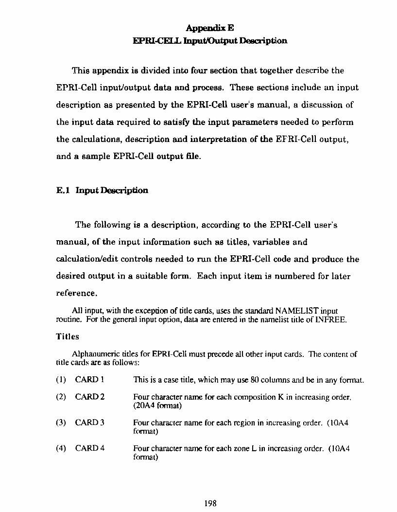
AppendixE
EPRI-CELL IDputJOutput Descripti.on
This appendix is divided into four section that together describe the
EPRI-Cell inputJoutput data and process. These sections include an input
description as presented by the EPRI-Cell user's manual, a discussion of
the input data required to satisfy the input parameters needed to perform
the calculations, description and interpretation of the EFRI-Cell output,
and a sample EPRI-Cell output file.
E.l lnput Description
The following is a description, according to the EPRI-Cell user's
manual, of the input information such as titles, variables and
calculation/edit controla needed to run the EPRI-Cell code and produce the
desired output in a suitable form. Each input item is nwnbered for later
reference.
All input, with the exception of title cards, uses the standard NAMELIST input routine. For the general input option, data are entered in the narnelist títle of INFREE.
Titles
Alphanwneric titles for EPRI-Cell must precede ali other input cards. The contem of title cards are as follows:
(1) CARD 1
(2) CARD2
(3) CARD 3
(4) CARD4
This is a case title, which may use 80 columns and be in any fonnat.
Four character name for each composition K in increasing order. (20A4 formal)
Four character name for each region in increasing order. ( 1 OA4 formar)
Four character name for each rone L in increasing order. ( 1 OA4 format)
198
Nuclides and Number Densities
The NAMELIST input rcquired to describe lhe initial number densities are listed below.
(5) NCOM (6) ID
(7) NUCLID(J)
(8) TEMPID(I)
Number of Comoositions in the cell N umber of nuclides in lhe problem (max=25).
ZAS LD. for each nuclide present in lhe problem, entered in increuina onier. The ZAS I.D. for an isotope is detennined from:
where Z = Atomic Number A = Atomic Weight S = Any I.D. from O to 9 to distinguish different sources of
çross-section sets for lhe same isotope.
Table 3.3 of (he EPRI-Cell user's manuallists the nuclides in the GAM/THERMOS library. Also, an attached memo by E. M. Pennington, April 4, 1984, lists the ZAS I.D.'s of the nuclides in lhe EPRI-Celllibrary. Note that for depletion calculations, nuclides 999999 and 999998 (fission products are lumped into these dummy nuclides) must be included in this list as well as the isotopes of plutonium, Xe135 and Sm149 (as 1Q-2Dif zero).
Temperature lD. for scattering kemel of each nuclide. Allowable values of ZAS I.D. and temperature I.D. for the current library are listed in Ta.ble 3.3 of the EPRI-Cell user's manual. eK)
(9) PUREDN(J,K) Pure number density of nuclide J in composition K. (atoms/bam-cm)
(10) VOLFRC(K,L) Volwne fraction of composition K in zone L. (DEF AUL T=400*0.0)
(11) DENFRC(K,L) Density fraction of composition K in zone L. (DEFAUL T=400*1.0)
Calculation and Edit Controls
Optional calculational paths and edits are specified via the input array OPTION (1). In general, if OPTION(O= 1, the option is selected and if it is entered as O it is not selected. The default values are zero unless specified.
(12) OPTION(l)
(13) OPTION(2)
(14) OPTION(3)
(15) OPTION(4)
Not Used (N.U.)
N.U.
Group dependent buckling will be used. Array AL2(J) also required as input
Heavy scatterer present.
199
(16) OPTION(5)
(17) OPTION(6)
(18) OJ7fi0N(7)
(19) OJ7fi0N(8)
(20) OPTION(9)
(21) OPTION(lO)
(22) OP110N(ll)
(23) OPTION(12)
(24) ornoN(l3)
(25) OPTION(14)
(26) OPTION ( 15)
(27) OPTION ( 16)
(28) OPTION ( 17)
(29) OPTION(18)
(30) OPTION(19)
(31) OPTION(20)
(32) OPTION(21)
(33) OPTION(22)
(34) OPTION(23)
Resoo.ance overlap can:ction applicd. Appropriale for mixed oxide fuel only.
Equal volume space poini:S within each zone.
Buckling search: With this option, group constants edited reflect converged buckling. Note that opnons 7 and 3 may nol be selected sim~~~sly.
Analytic isotropic boundary condition.
N.U.
N.U.
Edit fast and thennal microgroup cross-sections.
Edit fast and therrnal microgroup fluxes (thennaJ fluxes are ~ôu).
CINDER numbcr densities printed for each depletable point (intended only as debug output). Note that only main chain Xe1JS
and Sm1.t9 are printed.
Shon libraries are supplied
Heterogeneous fast effect correction applied. Use~ if the three innermost zones are fuel, clad and moderator.
If OYilON( 16)=N is entered, macroscopic conventiona15 group cross-sections are punched in PDQ fonnat for table set N. If OPTION(l6)=-N, the same cross-sections are punched except the thennal group is MND. ( 1 :s; N S 99)
Enter OPTION ( 17)=2,3 or 4 indicating the number of collapsed broad groups to be edited. Table 3.2 of the EPRI~Cell user's manual defines the energy break:points for lhe standard collapsed edits. Set=5 for standard 5 group edit.
IfOPTION(l8)=1, the collapsed macroscopic cros~~sections wiU be punched for input to PDQ. OPTION(l6) and OPTION(l7) must be set abo.
N.U.
If 0Yn0N(20)=6, is entered, an Sn ~ compaóble broadgroup edit will be done in the standard 5 group structure. Note that this option has not been thoroughly evaluated.
N.U.
N.U.
N.U.
200
(35) OPTION(2.4) Enter O if timestep lengths input in MWD(fONNE, or l if input in hou;s.
(36) OPTION(25)
Other Parameters Controlling the Calculation
(37) NTS Number ofGAMJTHERMOS calculations. (max=30, DEFAULT=l)
(38) TlMSTP(N) Duration in hours fcx timestep N for CINDER calcularion. (max=29, DEI<AULT=lOO.O, 400.0, 1500.0, 26•2()()().0)
(39) POWR Power in WattsJ&.:m of height (DEFAULT=l.O)
(40) R.EJ..PWR(N) Re1ative poweroftimesttp N. (DEFAULT::::30•I.O; use l.OE-7 for a zero power timestep)
(41) BUCKLG Total buckling in cm·2• This is the grO\!p independent buckling when OPTION(3)=0. When OPTION(3)=1, see below.
(42) AL2(J) Group dependent buckling for 68 fast groups. U!;e v:hen OPTION(3)=1, in which case BUCKLG is used as a single value- of buckling for the thennal group.
(43) THERMG Numberof groups in thermal calculation (D&"AULT=3S for t ... e current library).
(44) ISPEC lndex of fission spectrum (9 for U(h or 10 for M~ is recom.rocnded). (J)EFAUL T=9)
( 45) PHITYP Ent~r 1.0 for P··1 or 0.0 for B-1 fast calculation.
( 46) IEDIT(L) Emt indicator for each zone L. Each zone L w'losc edit indicator is 1 is included in the ''edit cell". Extra zooes in a supercell calculation supercell calculation, IEDIT for the extra region should be O. For a supercell edi~ IEDIT for the extra regíon shauld be l.
( 47) LBG(I) First fme group in broad fast group !. The standard 5 group structure is obtained by inputtin,6 LBG-=1,11,31,63. (DEfAUL TS)
( 48) I5GT(I) The thennal broad group for each fine thennal gmup. The ~.t.andfu""d 5 group structure is obwbed by inputting ISGT-:~21 *5, 14~~. (DEFAULTS)
(49) DSIRDK Value ofkcn sought ifthis is a xarch run. {DEFAULT=l.O)
(50) EPSILN Con':lergence critcria for scru-ch calcuJations. (DEFAULT=O.OOOl)
201
(51) TEMP(L)
Geometry Data
Temperature (°K): lf a nuclide is entered whose thennal crosssections are determined from doppler-broadened resonance parameters, (e.g.,Pul<IO, Gd 155), TEMP(l) is required. TEMP(3), required for the 5 or collapsed group edits, Is the moderator temperature (utilized in the generatioo of the MND diffusion coefficient).
The input required to describe the genc::ral geometry is listed below.
(52) NGEOM
(53) WNEPT(I)
(54) WNETK(I)
(55) ZONECf(l)
(56) XTREG
Resonance Data
Set this equal to 1 to invoke slab geometry. Absence of this flag invokes the stand.ard cylindrical geometry.
N umber of space points in zone I.
Thickness of zooe I in em.
Depletion indicator for zone I. Use 1 if zone I is depletable or zero if zone I is depletable.
Region number or scattering ring, if any. This signals the code that region number "XTREG" has no physical signi.ficance and is not to be induded in the thermal flux nonnalization, etc. (DEFAULT=())
The resonance treannent in EPRI-Cell is based on equivalence relations which employ tables of groupwise resonance integrais as a function of temperature and excess potential scattering cross-sections. In the cu.nent library, um, U231 , Pu239 and Pu240 h ave resonance data. !f a noclide is.requested in the cell calculation and no resonance date are entered, then the iniinite clilute cross-sections are used. Therefore, entries for Pu:n9 and Pu :MO should be made for depletion calculations even though initial atom densities are 10'20• The input describing the resonance date is as follows:
(57) NUCRE
(58) IDRES(J)
(59) RES(l ,1)
(60) RES(2,J)
Number of nuclides for which resonance data are entered.
ZAS I.D. number of nuclides for which resonance calculations are to be done. For each of the nudides listed in IDRES(J), five input values are required. ·
Resonance temperature in °K for the Jlh resonance nuclide.
The mean chord length Lave. for the absorbing lump where the Jth nuclide exists. For Lhe fuel cell problem,
whcre,
4V Lave =s (E,l)
V = Volume of fuel (i.e., material between cladding plates). S = Swface area of fuel.
202
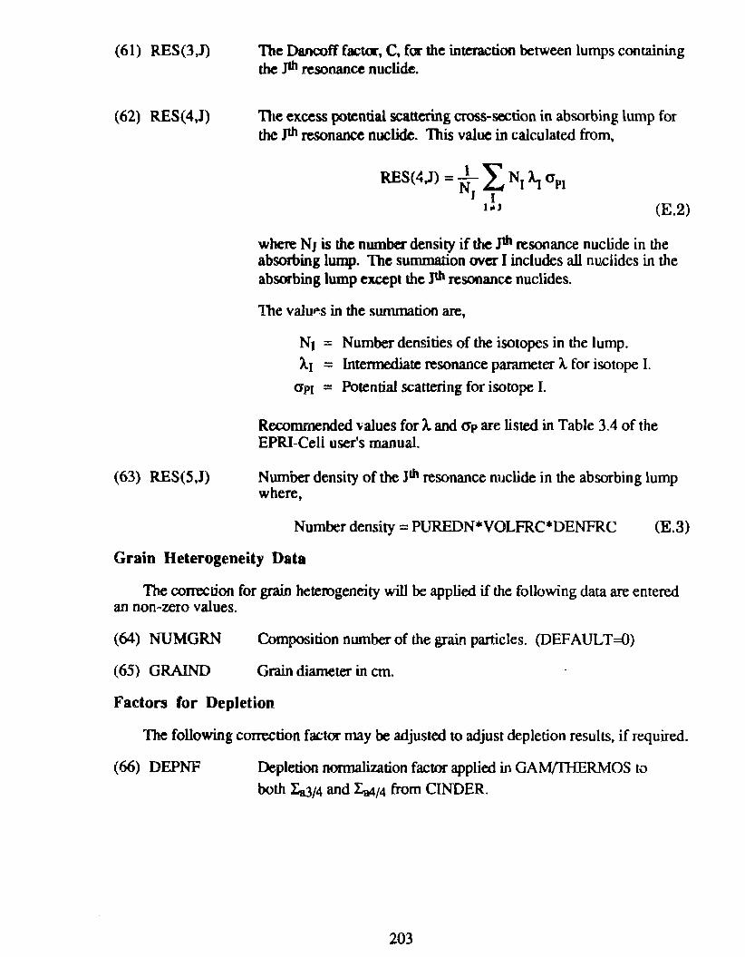
(61) RES(3,J)
(62) RES(4))
(63) RES(5,J)
The Dancoff factor, C, for the interaction between lumps containing the .J1h resonance nuclide.
Tite excess potential scattering cross-section in absorbing lump for the J1h resonance nuclide. This value in calculated from,
(E.2)
where NJ is the numbcr density if the Jlh resonance nuclide in lhe absorbing lump. The summation ovcr I includes all nuclides in the absorbing lump except the Jth resonance nuclides.
1lte valu~s in the swnmation are,
Nt = Number densities of the isotopes in the lump. Ãr = Intennediate resonance parameter Â. for isotope I.
apJ = Potential scattering for isotope I.
Recommended values for Â. and <Jp are listed in Table 3.4 of the EPRI-Cell user's manual.
Number density of the Jth resonance nuclide in the absorbing lump where,
Number density = PUREDN*VOLFRC*DENFRC (E.3)
Grain Heterogeneity Data
The com:ction for grain heterogeneity will be applied if lhe following data are emered an non~zero values.
(64) NUMGRN
(65) GRAIND
Composition nwnber of the grain particles. (DEFAULT=O)
Grain diarneter in em.
Factors for Depletion
The following correction factor may be adjusted to adjust depletion results, if required.
(66) DEPNF Depletion normalization factor applied in GAM/THERMOS to
both l:u/4 and l:a4t4 from CINDER.
203
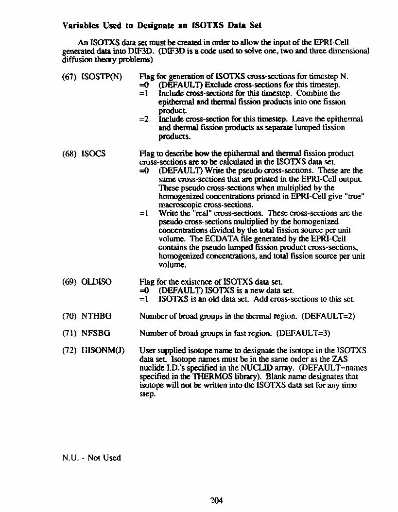
Variables Used to Designate an ISOTXS Data Set
An ISOIXS data sct must bc cn:atcd in ordcr to allow the input of the EPRI-Cell generatcd data into DIF3D. (DIF3D is acode usal to solve one, two and three dimensional diffusion theory problems)
(67) ISOSTP(N) Flag for generation of ISOTXS cross-scctions for timestep N. =O (DEFAUL n Exclude cross-sections for this timestep. = 1 lnclude aoss-sections for this timestep. Combine the
epithermal and thermal fission products in to one fission product
=2 lnclude cross-section for this timestep. l.eave the epithermal and thennal ftsSion products as se.parate lumped fission products.
( 68) ISOCS flag to describe bow the epithennal and thermal fission product cross-sectioos are to be calculated in the ISOTXS data set. =O (DEFAULT) Write the pseudo cross-sections. These are the
same cross-sections that are printed in the EPRI-Cell output These pseudo cross-sectioos when multiplied by the horoogenized concentrations printed in EPRI-Cell give "true" macroscopic cross-scctions.
= 1 Write the "real" cross-sections. These cross-sections are the pseudo cross-sections multiplied by the homogenized concentrations divided by the total fission source per unit volume. The ECOA TA file generated by the EPRI-Cell contains the pseudo lumped fission product cross-sections, homogenized concenttations, and total fission source per unit volume.
(69) OlDISO Flag for the existence of ISOfXS data set =O (DEFAULT) ISOTXS is a new data set. = 1 ISOTXS is an old data set. Add cross-sections to this set.
(70) NTHBG Number of broad groups in the thennal region. (DEFAUL T=2)
(71) NFSBG Number of broad groups in fast region. (DEFAUL T=3)
(72) HISONM(J) User supplied isotope name to designate lhe isotope in the ISOTXS data set Isotope names must be in the same order as the Z-\S nuclide I.D.'s specified in the NUCLID array. (DEFAULT=names specified in the 111ERMOS library). Blank name designates that isotope will not be written into the ISOI'XS data set for any time step.
N.U. - Not Used
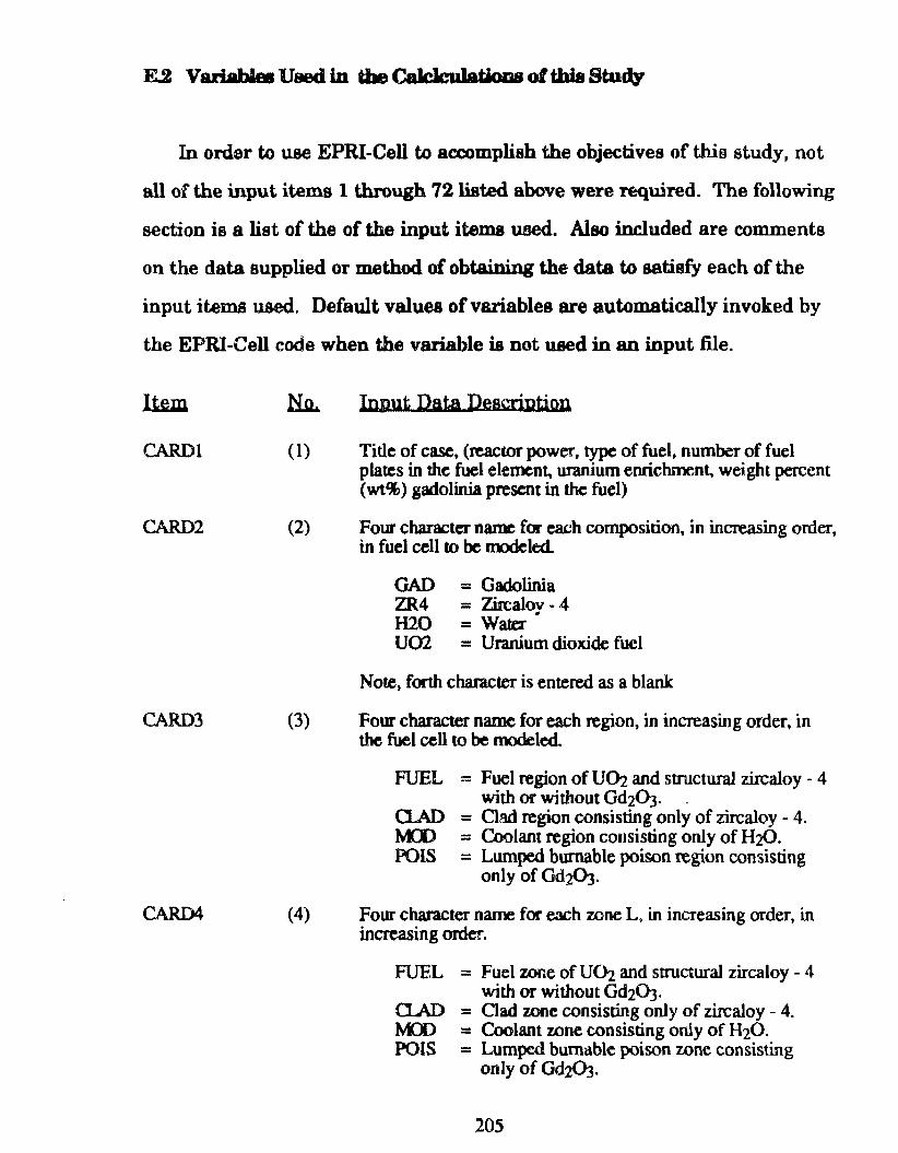
F...2 Variablee Uaed in the Calclculatioas oftbia Study
In order to use EPRI-Cell to accomplish the objectives of this study, not
ali o f the input items 1 th.rough 72 listed above were required. The following
section is a list of the of the input i tema uood. Also included are comments
on the data supplied or method of obtainin.g the data to satisfy each of the
input items used. Default values of variables are automatically ínvoked by
the EPRI-Cell code when the variable ia not used in an input file.
Item
CARDl (1)
CARD2 (2)
CARD3 (3)
CARD4 (4)
In,nut Data Descril)tion
Ti de of case, (reactor power, type of fuel, number of fuel platcs in the fuel elemen~ uranium enrichrnent., weight percent (wt%) gadolinia present in the fuel)
Fow- character name for each composition, in increasing order, in fuel cell to be roodeled.
GAD = Gadolinia ZR4 = Zirealov - 4 H20 = Water .. U02 = Uranium dioxide fucl
Note, forth character is entered as a blank
Four character name for each region, in increasi.ng order, in the fuel cell to be modeled.
FUEL
a.AD MD POIS
= Fuel region of UD2 and sbllctural zircaloy - 4 with or without Gd2ÜJ·
= Clad region consisting only of zircaloy - 4. = Coolant region cortsisting only of H:z(). = Lumped bumable poison region consisting
only of Gd:PJ.
Four character name for each wne L, in increasing order, in increasing order.
FUEL
Q.AD MD POIS
= Fuel zooe of U(h and s011ctural zircaloy - 4 with or without Gd203.
= Clad zone consisting only of zircaloy - 4. = Coolant zone consisting only of H20. = Lumpcd bum"ble poison zone consisting
onJy of Gdz03.
205
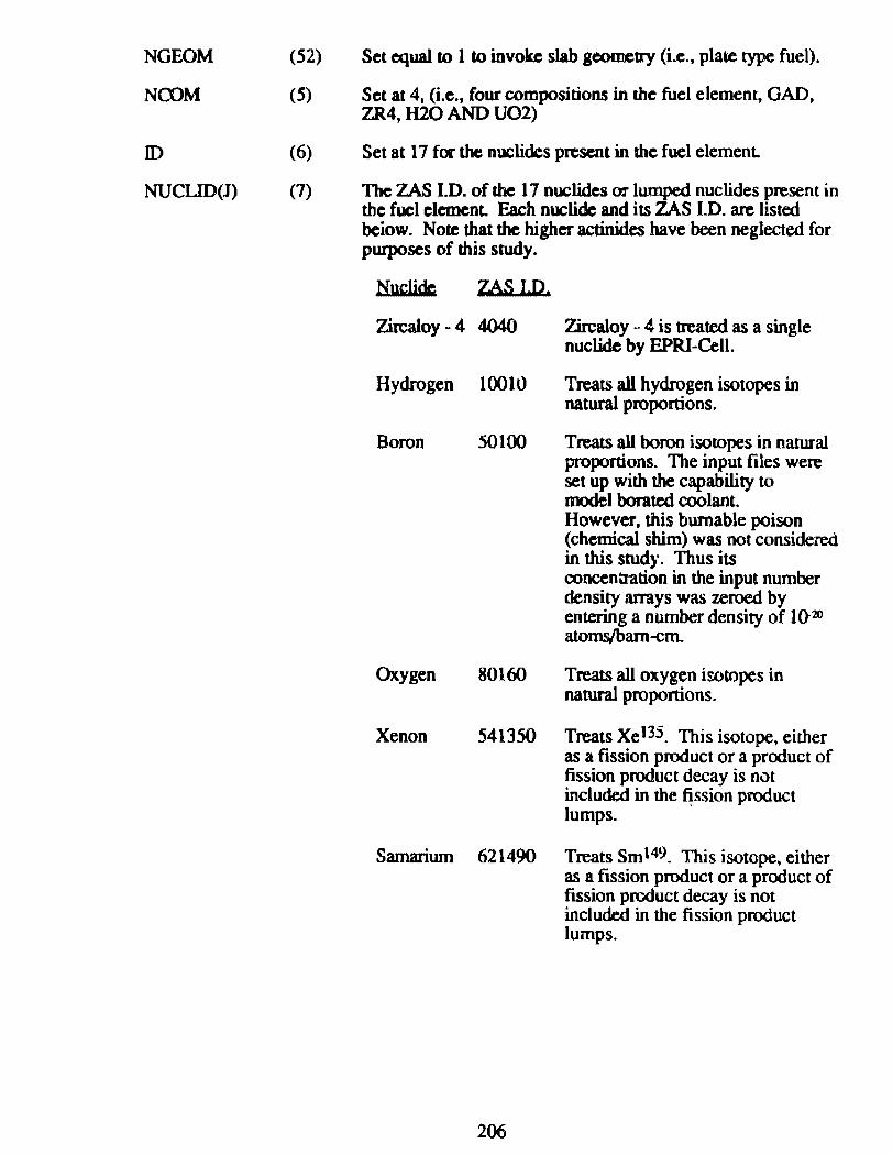
NGEOM
NCOM
ID
NUCLID(J)
(52)
(.5)
(6)
(7)
Set equal to 1 to invok.c slab gCOilletry (i.e., plate type fuel).
Set at 4, (i.e .• four compositions in the fuel elemenr, GAD, ZR4, H20 ANO U02)
Set at 17 for the nuclides present in the fuel elemenl
Thc ZAS I.D. of the 17 nuclides or lumped nuclides present in the fuel element Each nuclide and its ZAS I.D. are listed beiow. Note that lhe higher actinides have been neglected for purposes of this study.
Nuclidc; ZAS ID.
Zircaloy - 4 4040 Zircaloy ·· 4 is treated as a single nuclide by EPRI-Cell.
Hydrogen 10010 Treats ali hydrogen isotopes in natural proportions.
Boron 50100 Treats ali boron isotopes in natural proportions. The input files were set up with the capability to model borated coolant. However, this bumable poison (chemical shim) was not considered in this study. Thus its concentration in the input number density arrays was zeroed by entering a number density of 1(}20 atoms,lbam-cm.
Oxygen 80160 Treats ali oxygen iwtopes in natural proportions.
Xenon 541350 Treats Xel35. This isotope, either as a fission product or a product of fission product decay is n0t included in the ~ssion product lumps.
Samarium 621490 Treats Sm149. This isotope, either as a fission product ora product of fission product decay is not included in the fission product lumps.
206
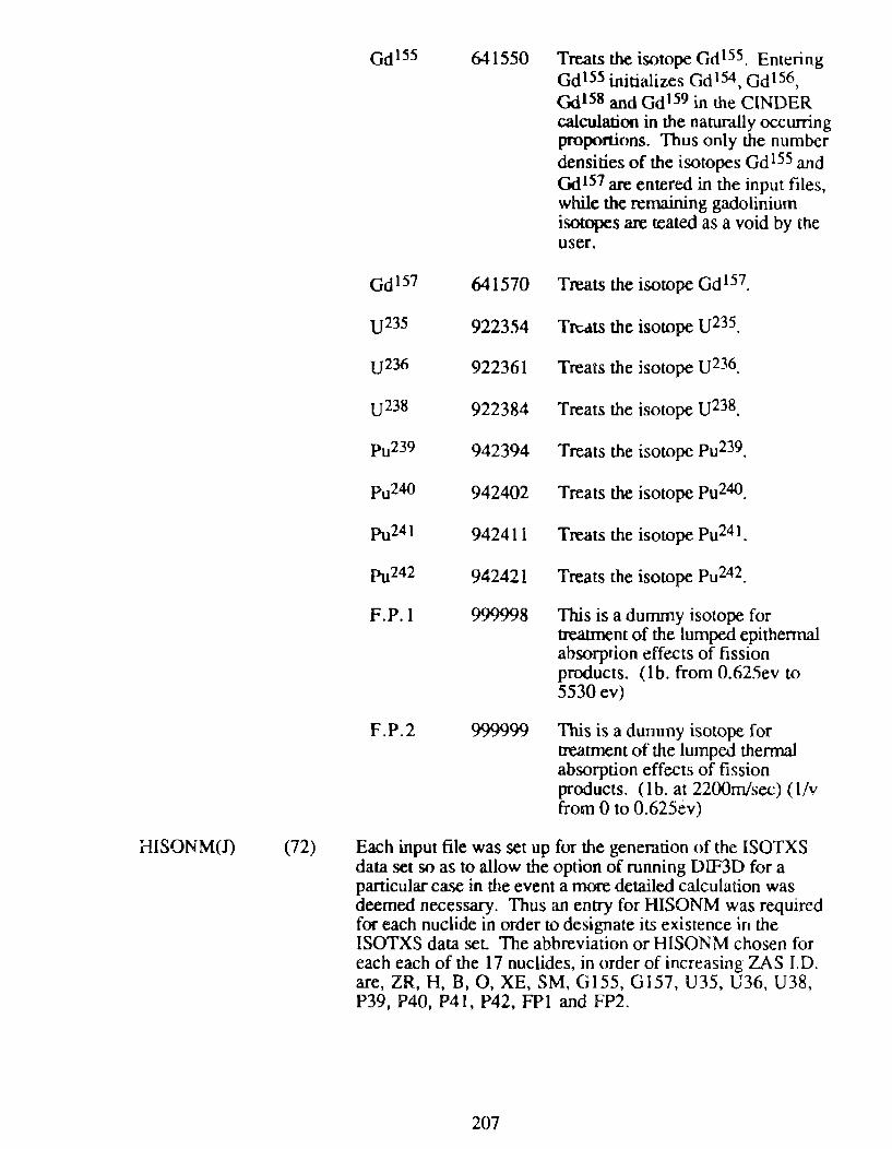
i-IISONM(n (72)
Gdl55
Gdl57
uz3s
U236
uz3s
Pu239
Pu240
Pu241
Pu242
F.P.l
641550 Treats lhe isotope GdlSS. Entering Gctl55 initializes Gdl54, Gdl56, Qdl58 and Gdl59 in the CINDER calculation in the natura.lly occwring proponions. Thus on1y the number
641570
922354
922361
922384
942394
942402
942411
942421
999998
densities of the isotopes Gd ISS and Gd 157 are entered in the input files, while the remaining gadolinium isotopes are teated as a void by the user.
Treats the isowpe Gdl57.
Tn;4ts the isotope U235.
Trea~s the isotope U236.
Treats the isotope U238.
Treats the isotope Pu239.
Treats the isotope Pu240.
Treats the isotope Pu241_
Treats the isotope Pu242.
This is a durnmy isotope for treatment of the lumped epithennal absorprion effects of fission products. (1b. from 0.625ev to 5530 ev)
F. P. 2 999999 lbis is a dummy isotope for treatment o f the lumped thennal absorption effects of fission products. (1 b. at 2200m/sec) (1/v from O to 0.625év)
Each input file was set up for the generation o f the ISOTXS data set soas to allow the option of running DIF3D for a particular case in the event a more detailed calculation was deemed necessary. Thus an entry for HISONM was required for each nuclide in order to designare its existence in the ISOTXS data set The abbreviation or HISONM chosen for each each of the 17 nuclides, in order of increasing ZAS I. O. are, ZR, H, B, O, XE, SM, 0155, G157, U35, U36, U38, P39, P40, P41, P42, FPI and FP2.
207
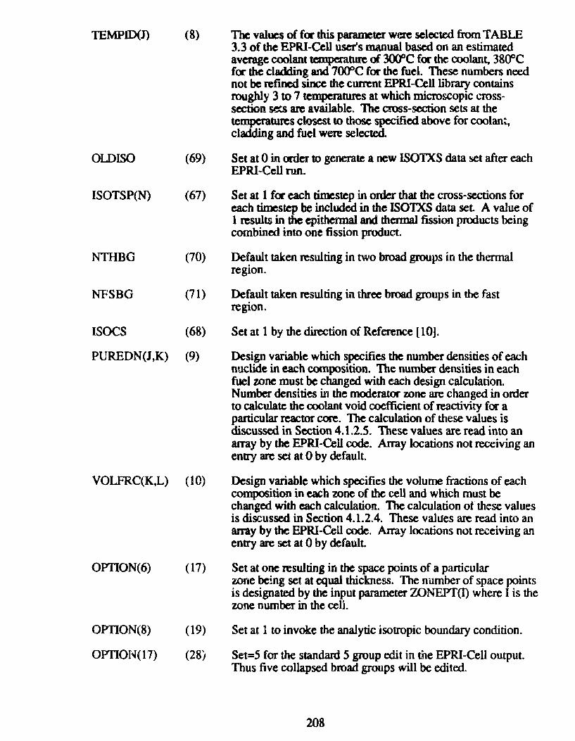
TEMPID(J) (8) The values of fc:r this paramcter were selected from TABLE 3.3 of the EPRI-Cell user's manual based on an estimated average coolant tcmperature d. JO()DC for the coolant, 3800C for the cladding and 7000C for the fuel. These numbers need not bc refincd si.nce the current EPRI-Celllibrary contains roughly 3 to 7 temperatures at which microscopic cross-section sets are available. The cross·section sets at the temperatmes closest to those specified above for coolan~, cladding and fuel were selected.
OlDISO (69) Set at O in mier to generate a new ISOTXS data set after each EPRI-CeU run.
ISOTSP(N) (67) Set at 1 for each timestep in order that the cross-sections for each timestep be included in the ISOTXS data set A value of l results in the epithennal and thermal fission products being combined into one fission product.
NTIIBG (70) Default taken resulting in two broad groups in the thennal region.
NFSBG (71) Default taken resulting in three broad groups in d.e fast region.
ISOCS (68) Set at 1 by me diiection of Reference [10].
PUREDN(J,K) (9) Design variable which specifies the number densities of each nuclide in each composition. The number densities in each fuel zone must be changed with each design calculation. Number densiti~ in the moderator wne are changed in order to calculate thc coolant void coefficient of reactivity for a particular reactor core. 1be calculation of these values is discusscd in Section 4.1.2.5. These values are read into an array by the EPRI-Cell code. Array locations not receiving an entty are set at O by default.
VOLFRC(K,L) (10) Design variable which specifies the volume fractions of each composition in each zone of the cell and which must be changed with each calculation. The calculation of these values is discussed in Section 4.1.2.4. These values are read into an array by the EPRI-Cell code. Array locations not receiving an entry are set at O by default.
OPTION(6) (17) Set at one resulting in lhe space points of a particular zone be!ng set at equal thickness. The number of space points is designated by the input parameter ZONEPT(I) where I is the wne number in the ceU.
OPTION(8) (19) Set at 1 to invoke the analytic isotropic boundary condition.
OPTION(17) (28) Set=S for the standard 5 group edit in the EPRI-Cell output. Thus tive collapsed broad groups will be edited.
208
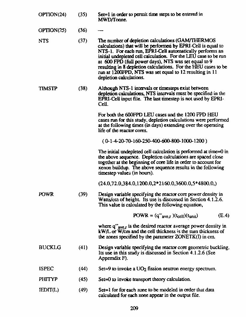
OP110N(24) (35)
OPTION(25) (36)
NTS
TIMSTP
POWR
BUCKLG
ISPEC
PHITYP
IEDIT(L)
(37)
(38)
(39)
(41)
(44)
(45)
(49)
Set=l in order to permit rime steps to be entered in MWD/fonne.
The numbtr c:A depletion calculations (GA.M/IHERMOS cak:ulatioos) that will be perlonned by EPRI-Cell is equal to NTS-1. For eacb run, EPRI-Cell automatica11y performs an initial undepleted cell calculation. For the LEU case to be run at 600 FPD (full power days), NTS was set equal to 9 resulting m 8 depletion calculations. For the HEU cases to be ruo at 1200FPD, NTS was set equal to 12 resulting in 11 depletion calculations.
Although NTS-1 in:crvals or timesteps exist between depletion cakulatioos, NTS intervals must be specified in the EPRI-CeU inp~t file. The last timestep is not used by EPRICell.
For both the 600FPD LEU cases and the 1200 FPD HEU cases run for this study. depletion calculations were perfonned at the following times (in days) extending over the operating 1ife of the reactor cores.
( 0-1-4-20-70-160-250-400-600-800-1000-1200 )
The initial undepleted ccll calculation is performed at t.ime=O in the above sequence. Depletirn calculations are spaced closc tog-:ther at the beginning of core life in order to account for xenon buildup. The above sequence resuhs in the following timestep values (in hours).
(24.0,72.0,384.0, 1200.0,2*2160.0,3600.0,5*4800.0,)
Design variable specifying the reactor core power density in Watts/crn of height lts use is discussed in Section 4.1.2.6. This \'alue is calculated by the following equation,
POWR = (q"'ave.r )(tcen)(tuni0 (E.4)
wherc q"'ave,r is the desired reactor average power density in kW/1... or W/cm and the cell thickness js the swn thickness of the zones specifiod by the pamneter WNETK(I) in em
Design variable specifying the reactor core geometric buckling. Its use in this study is discussed in Section 4.1.2.6 (See Appemdix F).
Set=9 to invoke a U(h fission neutron energy spectrum.
Set=O to invoke transport theory calculation.
Set= 1 for for each zone to be modelcd in order that dara calculated for each :wne appear in the output file.
209
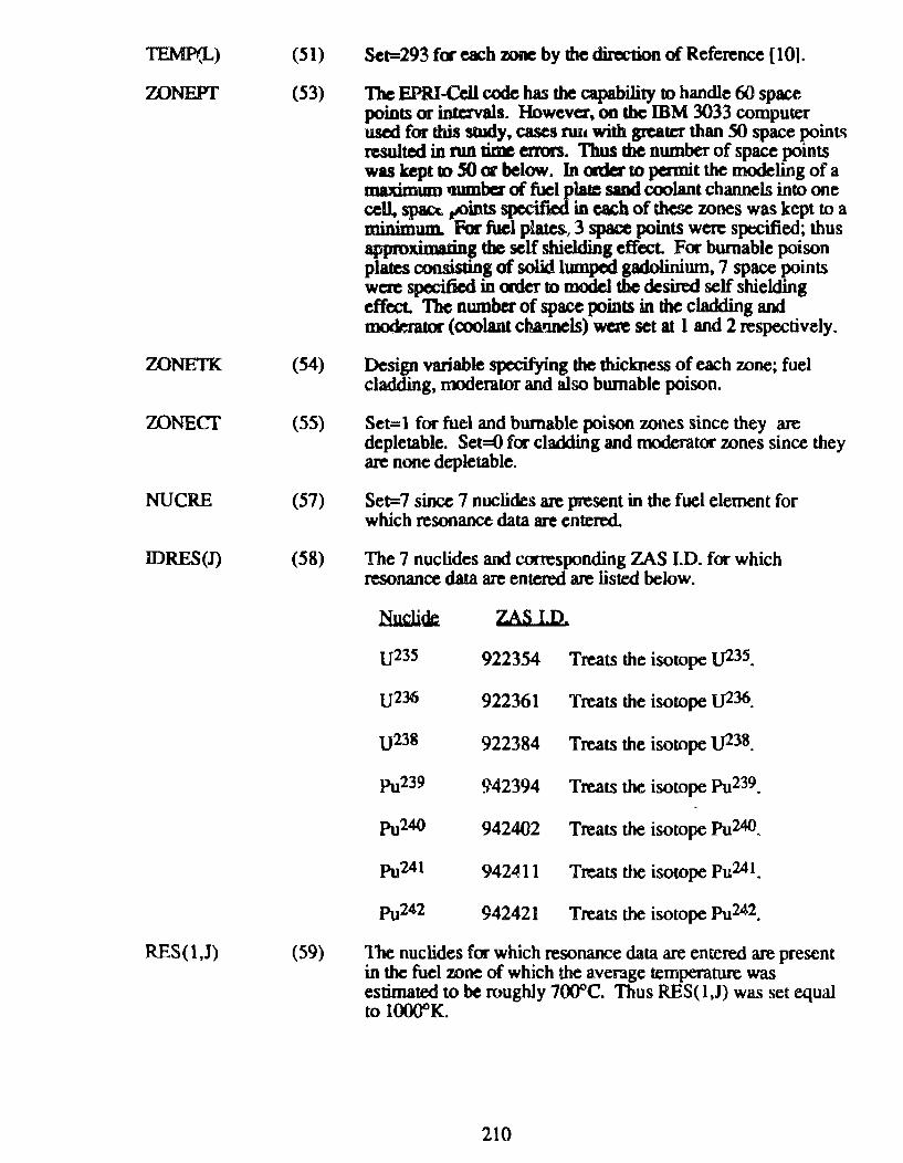
TEMP(L) (51) Set=293 f<r each zonc by thc dircction of Reference [10].
WNEPT (53) Tbe EPRI-Cell oode has the capability to handle 6() space points or intervals. Howevez, on the mM 3033 computer used for tbis study, cases rwa with greater than 50 space pointl\ resulted in run time errors. Thus tbe number of space points was kept to SO or below. In mler to pennit lhe modeling of a maximum IJIDDbcr ~late sand coolant channels into one ce~ spacc. ,...oints · in cacb of tbese zones was kept to a minimum. For fuel p~atcs., 3 space points w~ spxified; thus approximating the self shielding effect. For burnable poison plates consisting of solid lumped gadolinium. 7 space points wc:re specified in mler to modcl the desired self shielding effect. 1be number of space points in the cladding and DIOdlerator (coolant cha.rmels) WCR set at l and 2 respectively.
WNETK (54) Design variable specifying the thickness of each zone; fuel cladding, moderator and also bumable poison.
ZONECI' (55) Set= 1 for fuel and bumable poison wnes since they are depletable. Set=O for cladding and moderator zones since they are none depletable.
NUCRE (57) Set=7 since 7 nuclides are present in the fuel element for which resonance data are entered.
IDRES(J) (58) The 7 nuclides and corresponding ZAS I.D. for which resonance data are entered are listed below.
NlldiW: ZAS I.D.
U23S 922354 Treats the isotope lJ23S.
lJ236 922361 Treats the isotope IJ236.
u238 922384 Treats the isotope 1]238.
pg239 942394 Treats the isotope Pu239.
Pu240 942402 Treats the isotope Pu240.
Pu241 942411 Treats the isotope Pu241.
Pu242 942421 Treats the isotope Pu242.
RES(l,J) (59) The nuclides for which resonance data are entered are present in the fuel mne of which the average temperature was estimated to be roughly 7000C. Thus RES( l,J) was set equal to l()()()OK.
210
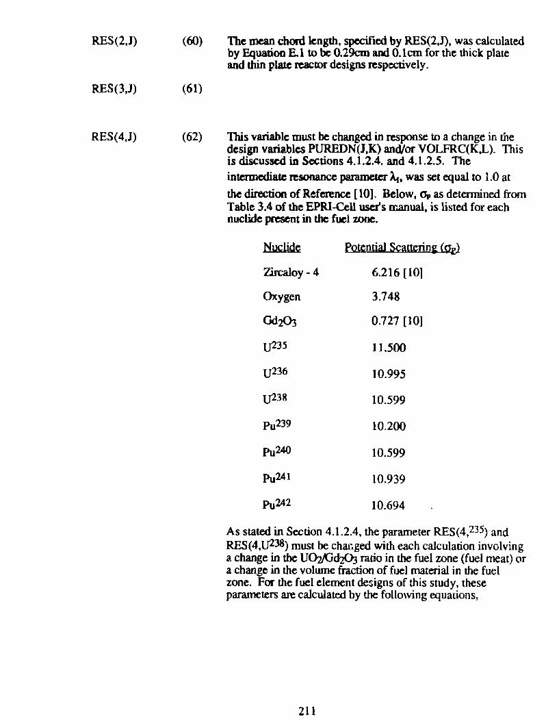
RES(2,J) (60)
RES(3,J) (61)
RES(4,J) (62)
The mean choni length, specificd by RES(2,J), was calculated by Equatioo E. I to be 0.29cm and O.lcm for the thick plate and thin plale reactor designs respectively.
This variable must hc changed in response to a change in lhe dcsign variables PUREDN(J,K) and/or VOLFRC(K,L). This is discussed in Soctions 4.1.2.4. and 4.1.2.5. The
intermediatc n:sonance paramet:er A.. was set equal to 1.0 at the direction ofReference [10]. Below, a, as detemúned from Table 3.4 of the EPRI-Cell user's manual, is listed for each nuclide present in the fuel zone.
~ Potential Scatterini (Qf}
Zircaloy- 4 6.216 (lO]
Oxygen 3.748
Gd203 0.727 [10]
U235 11.500
u236 10.995
1)238 10.599
Pu239 10.200
Pu240 10.599
Pu241 10.939
Pu242 10.694
As stated in Section 4.1.2.4, the parameter RES( 4, 235) and RES(4,t.J238) must be char.ged with each calculation involving a change in the UO;z/Cid2ÜJ rario in the fuel zone (fuel meat) or a change in the volwne fraction of fuel material in the fuel zone. For the fuel element designs of this study, these parameters are calculated by the following equations,
211

REs{4, u23S) = Vol%(UDI)[N38oJ~ + rP0p0 + ~CJp 0] + (1- Vol% (UOz)) Nu4<Jpzr4
Vol% (U~) N38 (E.5)
REs(4, u238) = Vol%{U~)(N38op3S + N<>opO + ~opo] + (1- Vol%(UOz)) N<T4opzr4
Voi%(UQ,} N33 (E.6)
RES(5,J) (63)
Also for each change that requires a recalculation o f RES( 4)), RES(S, lJ23S) and RES(5, t.J238) must also be recalculated. These panuneters are calculated by the following equations,
RES(5, lJ235) = Vol%(UD2) N35 (E.7)
RES(5, tJ238) = Vol%(UÜ2) N38 (E.8)
By Equation E.3, this variable must be changed in response ro a change in the design variables PUREDN(J,K) and/or VOLFRC(K,L). This is discussed in Section 4.1.2.4 and 4.1.2.5.
212
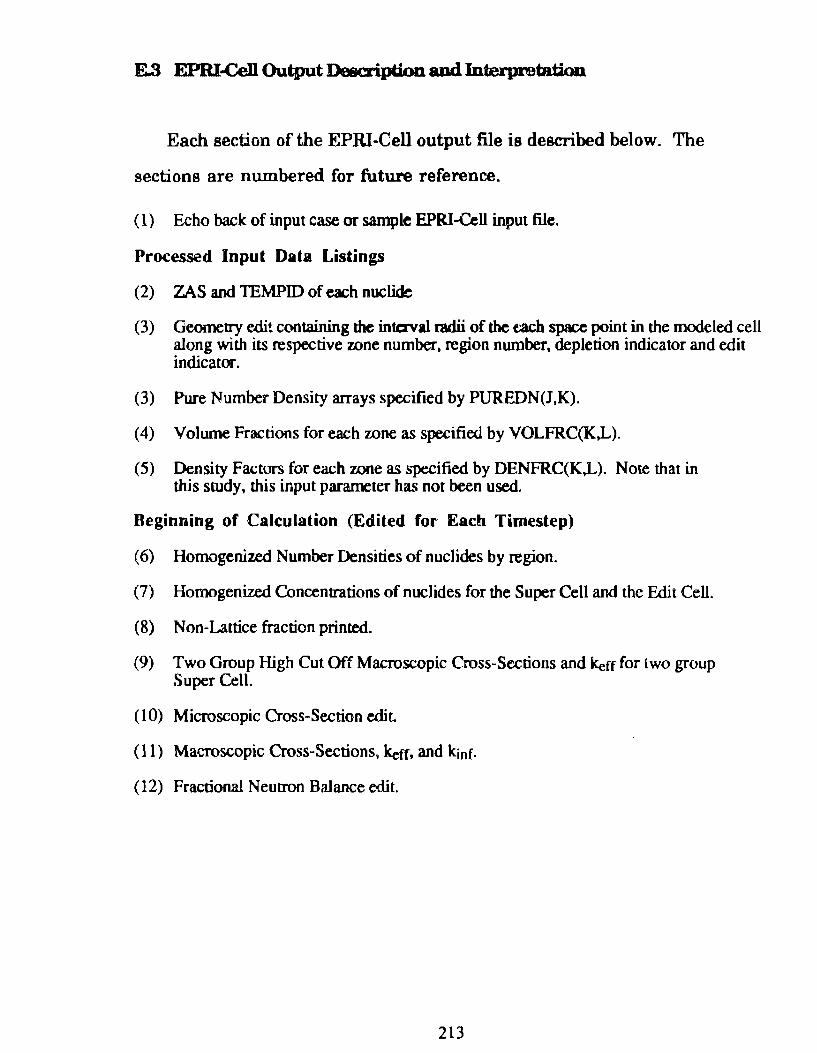
E.3 EPRI-CeD. Output Deecription aod Interpretation
Each section o f the EPRI -Cell output file is described below. The
sections are numbered for future reference.
( 1) Echo back of input case or sample EPRI-Cell input file.
Processed Input Data Listings
(2) ZAS and TE~ID of each nuclide
(3) Geometry edit containing the intaval radii of the t:ach space point in the m<Xleled cell along with its respective zone number, region number, depletion indicator and edit indicator.
(3) Pure Number Density arrays specified by PUREDN(J,K).
(4) Volume Fractions for each zone as specified by VOLFRC(K,L).
(5) Density Factors for each zone as specified by DENFRC(K,L). Note that in this study, this input parameter h as not been used.
Beginning of Calculation (Edited for Each Timestep)
(6) Homogenized Number Densities of nuclides by region.
(7) Homogenized Concentrations of nuclides for the Super Cell and the Edit Cell.
(8) Non-Lattice fraction printed.
(9) Two Group High Cut Off Macroscopic Cross-Sections and kerr for lwo group Super Cell.
(lO) Microscopic Cross-Section edit
( 11) Macroscopic Cross-Sections, ketr, and kinf·
(12) Fractional Neutron Balance edit.
213
E.4 SampJe EPRI-Cell Output File
This appendix contains two sample time steps printed with the EPRI
Cell output file for the thick plate 97.3% enriched HEU case. The edit for
timestep 1 containa the data for the initial undepleted fuel cell calculation,
while the edit for timestep 2 contains the data for the second depletion
calculation. Also included are tbe preceding input echo back and processed
input data listings.
214
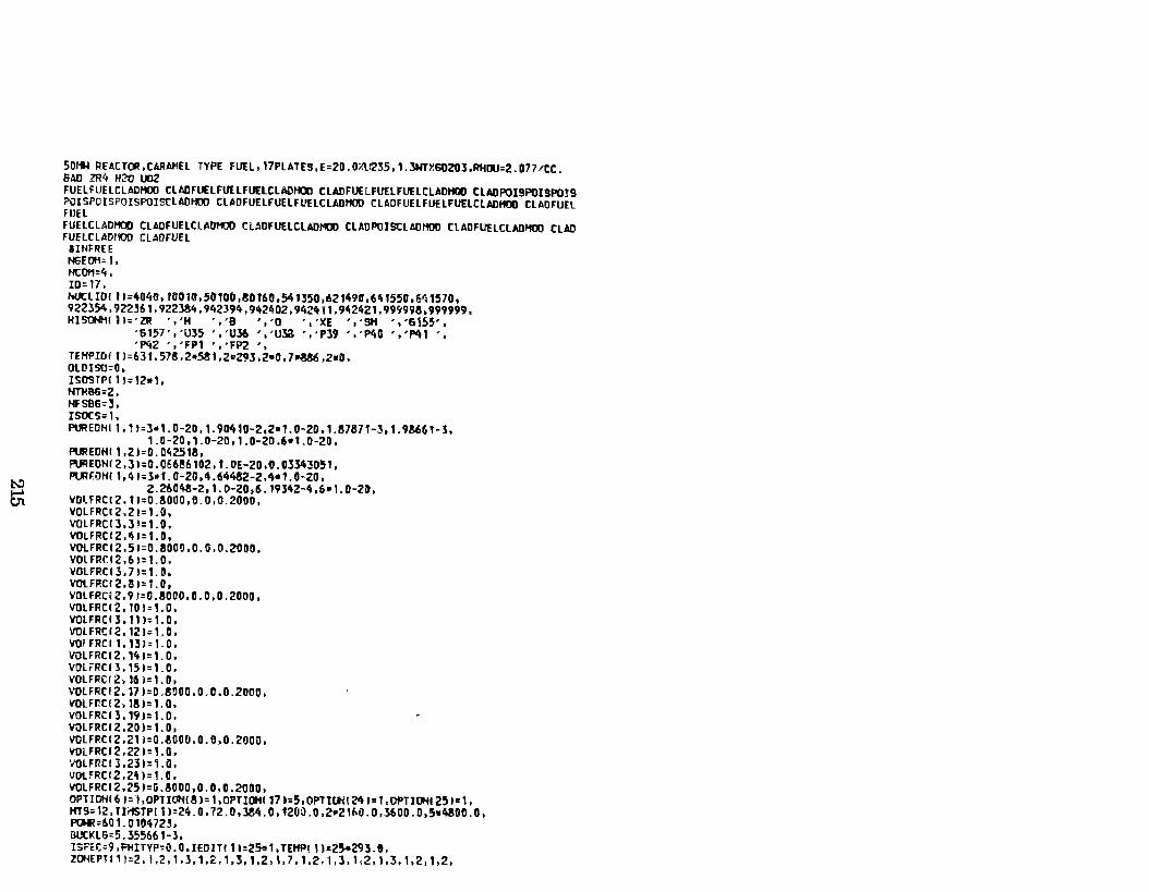
1:'-' ~
50~ RE~CTOR,CARAMEL TYPE FutL,J7PLATES,E=20.0%l~35,1.3NTY.60203,RHOU=2.077/CC. SAD ZR4 H2'0 IAl2 FUELFUELCLADHOD CLADFUELFutLFUELCLADHOD CLADFUELFUElFUELCLADHOO CLADPOISPOISPOJS POISPOISPOISPOISCLADHOD CLADFUELFUELFUELCLAOHOD CLAOFUELFUELFUELCLAOHOO CLAOFUEL FUEL FUELCLAOHOD CLADFUELCLAOMOO CtAOFUElCLAOHOO CLADPOISCLADHOO CLADFUELCLADHOD CLAD fUHCLADHOO CL~OFUEL
UHFREE NGEOH= 1, Ht0?1=4. ID= 17, hOCliDI 11=4040, 10010,501UU,SD160,54135D,621490,6~1550,~~1570, 922354.922361,922~4,942394,942402,9424V1.9~2421,99999!,999999, HISOHHI ll='ZR ','H ','8 ·,·o ·,·XE ·,·SH •,·&~55',
'6157','U35 ','U36 ','Ula ','P39 ','P40 ','P41 ' 'P42 ','FPI ','F?Z •,
TEHPIOI fl=63t,578,2•5!1,2D29J,2•0,7~,2•0, OLDISO::O, ISOSTPI11:12•1, HnlBG=Z, HFSB6=3, ISOCS:1, PUREDHI 1,11=3•1.0~20,1.90410·2,2•1.0~20,1.87871-3,1.9!661-3,
1.0-20,1.0-20,1.0-20.6•1.0-20, PUREDHI 1,21=0.042518, PUREOHI2,31=0.066!6102,t.DE-20,0.03343051, PURF.DHI 1,41=3•1.0~20,4.64482-2.4•1.0-ZO,
Z.Z6D~-2,1.D-20,6. 19342~4,6•1.0-20, VDlFRCI2,11=0.8000,0.0,0.2000, VOLFRCl2,21=1.0, VOLFRCI3,31=1.0, VOLfRCI2,41=1.0, VOlFRCI2,51=0.80D0,0.0,0.2000, VOlFRCI2,61=1.0, VOlfRCI3,7J:1.D, VOtFRCI2,!1=1.0, VOlfRC~2.91=0.80D0,0.0,0.2000, VOLFRCI2,101=1.0, VOlFRCI3,11l=1.0, VOLFRCI2,121=1.0, VQ[ F RC I 1 , 13 I= 1. O , VOLFRCI2,141=1.0, VOlFRCIJ,151=1.0, VOLFRCI2, 16l=1.0, >1)LFRCI2.17l=0.!000,0.0.0.2000, V!OtFr.C!2,18l=1.0, VOLFRCI3,19l=l.O, VQLFRCI2,2DI=1.0, VOLFRCI2,21l=0.300b,0.0,0.2000, ~FRC12,221=1.0, '10lfP.CI3,231=1.Q, VOlfRCI2,241=1.C, VOLFRCI2,251=G.8000,0.C,0.2000, OPTIOH161=I,OPTIOHI!I=1,0PTIOH1171:5,0PTtOHt24l=1,0PTIOHI251=1, HT9=12,TI.MSTPI11=24.0,72.D,J84.0,120~.0.Z•Z1~0.0,l600.0,5•4800.0, PDWR=&01.01C472~. BUCKL5=5.355661-3, lS~EC=9,FHITYP•O.O,IEDITt11=2S.1,TEHPl llc25-29l.G, ZOHEPH 1 1=2, 1,2, 1, J ,1, 2., 1, 3, 1,2, 1, 7, 1,2, i, 3, 1,2, 1, 3, 1, 2, 1, 2,
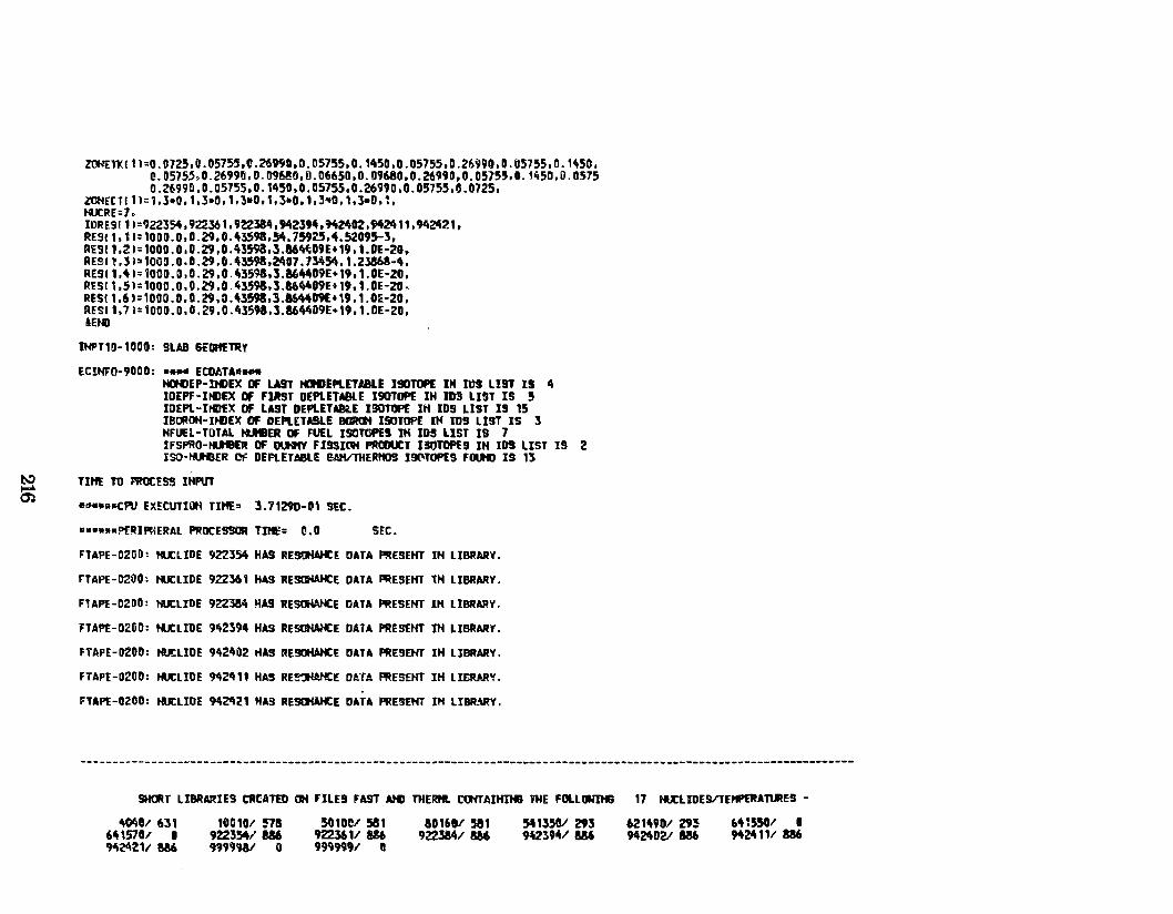
~
~
~rKI11=0.0725,0.05755,0.26ttD,O.D5755,0.1450,0.05755,D.26990,0.05755,D.1~5D, C.D5755,0.2699D,O.D96!~,0.D6650,D.n968D,0.26990,0.05755,0.1450,0.0575 0.2699D,0.05755,D.1~50,0.05755,0.2699D,D.05755,G.0725,
lOHECTI11=1,l•0,1,3•0,1,3wD,1,3•D,1,3•0,1,leD,~, IURE:7, IORE91 11 =922354, 9l2361, 922384, ~2l94,9ltM02, 942411,9112421, RE911.11=10DD.D,D.29,0.43598,54.759Z5,4.52095-l, RE911,21=1000.0,D.Z9,0.43598,3.864~09E+19,1.0E-20, AES1l,]l21Q09.0,8.29,0.4l598,~07.73454,1.23868-4, RE511,41=iOOD.O,D.29,0.4359&,l.864409E•19,1.0E-20, RES11,51=1000.0,0.Z9,0.4l59&,3.864't9E~19,1.0E-20, AESI1,61=1000.D,D.29,0.43598,].8644D9E+19,1.0E-20, RESI 1,71:100D.O,D.29,0.4359a,l.86~09E•19,1.0E-2D, &Et«l
IHPT1!1-10DO: SUB 6EOifETJl'f
EClHF0-9000: .... ECO~TA• ... t«HHEP-DI)EX Of LAIT HDIIIEPLEllaLE I90TOPE IH 11)9 LIST IS 4 IDEPF-J~EX Of Fllt9T DEPLETABLE 190TOPE IH ID!I LJST IS 5 ltlEPL-ItllfX OF U9T DEPLEU8U J90TIJP( IH IDS LIST IS 15 JBCROH·I~EX DF DEPLETMLE BCJRt!ol ISOTOPt IH ms LIST IS 3 HF~l-TOTAL N.leER DF FUEL JSQTOPES JK ID!I LJST 19 7 IFSPRO-~~ DF IJI.HfY FJ9SillH PROJOCT ISOTOPES IH IDS UST IS 2 ISO·I'Uf3ER OI= DEFlETABLIE SAK/THEAtt09 J9(1oTOP(9 FOUtJ IS 1]
TlftE ro I"RRCESS lHPUT
e-.ooootf'V EX~CUTIOH TI~" 3.71291HU SEC.
••••••PERIPHERAL PROCESSOR T!Hf: 0.0 SEC.
FTAPE-0200: HUtLIDE 922354 HA9 RESOHAHCE DATA PRE9EHT IH LJBRARY.
rUPE-0200: tU:LIDE 922361 HAS JIESIIWICE DATA ~ESEHT IH LIBRARY.
F1APE-02DD: HUtLIDE 922381\ ~A9 RESCJWiCE DATA ~ESEHT IH LIBRARY.
fTAPE-0200: HUCLIDE 9~2394 HAS RESOHAHCE DATA PRESEHT IH LJBRARY.
FTAPE-UZOO: HUtllDE 9~2~D2 ~AS AESOHAHCE DATA PRE9EHT IH LIBRARY.
FTAPE-0200: HUCLIDE 9~2411 HA9 RE~E D!Y! PRESEHT IH LIERAR~.
FTAPE-02:00: tU:LIDE 94~21 HAS RESOHAHCE DATA PREStHT IH liBR.\RY.
SHCJlT LIBRARIE9 CRtATtO ~ FILE!I FAST AMI THEIM. COfTAIHDIJ iHE FOLLONIHB 17 ~LIM!VTEP'ftRA'MES -
lt04tll 6l1 6415701 o ~24211 w
100101 ~s 922354/ 886 99999&1 o
501oe1 581 9223611 au 9999991 11
&0160/ 581 922384/ 8M
541350/ 293 9~2394/ w 6214901 29!
9424021 w 61H5501 I 91t24111 186
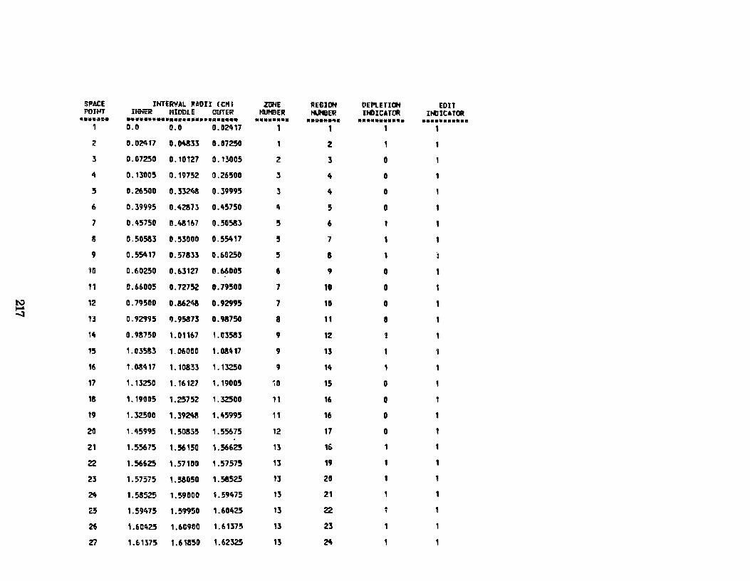
SPACE IHTERVAL RADII (CHt ZOHE REGI OH OEPUTIOH EDIT POIHT ItiER HIDOLE l!üTER I'UIIER tUIIER Jti:IICATI:Jt ItlliCATQR ............ .. .......... R••••••••••••• ......... ............ . ............. • ••••••••••
0.0 0.0 0.02417 1 1
2 0.02i\17 o. Dlt311 0.07250 1 2
3 0.07250 o. 10127 0.13005 2 3 o 4 0.1300~ 0.19752 0.26500 3 4 o 1
5 0.26500 0.33248 0.39995 J 4 o 6 0.39995 o .42!73 0.45750 " 5 o 7 0.45750 1!.43167 0.50533 5 6
s 0.50583 0.53000 0.55417 ' 7
9 0.551117 0.57831 0.60250 5 a 1
1!l 0.60250 0.63127 1!.660í)5 6 9 o 11 0.66005 0.72752 0.79500 1 10 o
to.:) 12 0.7~500 0.86N ...... 0.92995 7 10 o ....;J
13 0.92995 11.95873 0.93750 a 11 o 14 0.9!750 L01167 1.03581 9 12
15 1.035!3 1.060110 1.08~17 9 1l
16 1.03417 1.10833 1. 13250 9 14
17 1.13250 1.16127 1.19005 10 15 o
1! 1.19005 1.Z5752 1.32500 11 16 o 19 1.32500 1.392'\3 1.4591J5 11 16 o 20 1.45995 1.50855 1.55675 12 17 o 21 1.55675 1.56150 1.56625 1l 1& 1
22 1.56625 ,.57100 1.57575 13 " 23 1.57575 1.!5!050 1.58525 13 20 1
~ 1.5!525 1.59000 1.59475 13 21
2.5 1.59475 1.S99!i0 1.60425 13 22
26 1.6042.5 1.60900 1.61375 13 23
Z7 1.61375 1.611150 1.6232S 13 24
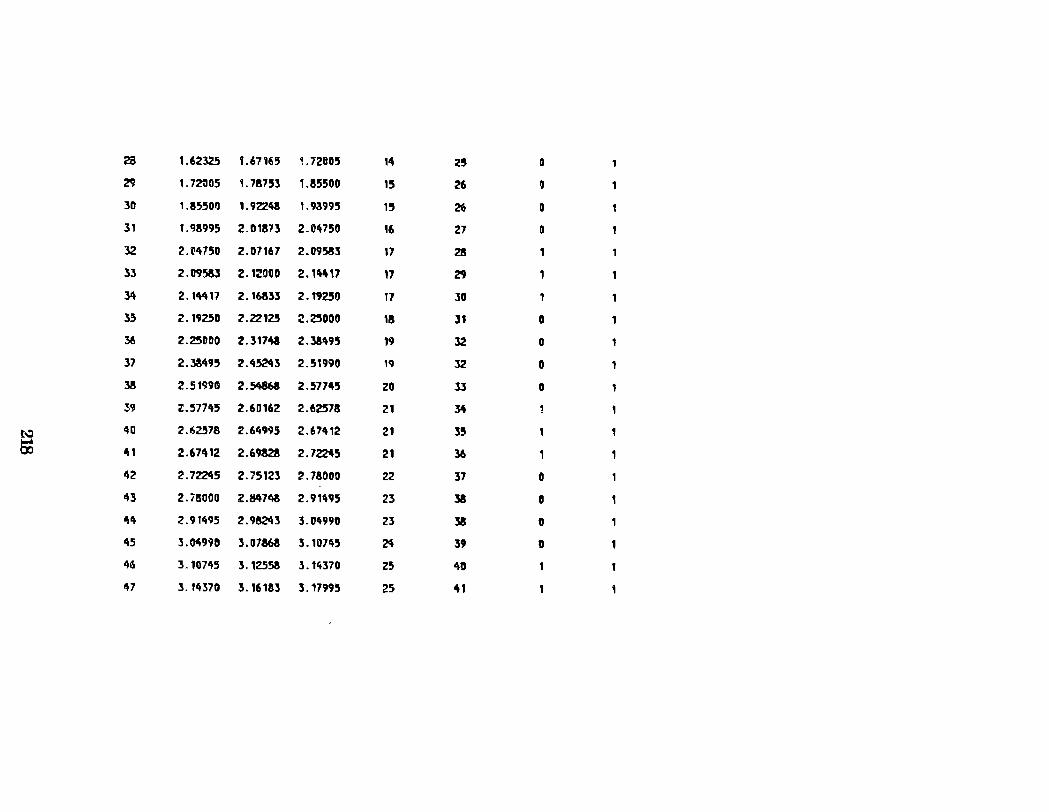
~ t .62325 1.67165 1.72C05 14 25 D
29 1.7~05 1. 78753 1.!5500 15 26 o 30 1.85500 1.92248 1.93995 15 26 o 31 1. CJ!995 2.01871 2.04750 16 27 o 32 2.il475D 2.07167 2.095!!3 " 28
33 2.119583 2. 1:!000 2.1"17 17 29
~ 2. 1lt417 2.16835 2.1925!) 17 lO 1
3.5 2.19Z50 2.22125 2.~000 18 lt o 36 2.25000 2.31748 2.3!495 19 l2 o 37 2.38495 2.45243 2.51990 19 32 o 1
3ll 2.51990 2.54868 2.57745 20 3l o 39 2.577'\5 2.60162 2.62578 21 34
l\:1 40 2.6Z578 2.64995 2.67412 21 35
s 41 2.67412 2.6982! 2.72245 21 36
1\2 2.7~5 2.75123 2.7!000 22 37 o ~3 Z.ii!OOO 2.8471\3 2.91495 23 38 o 44 2.91495 2.9!2Ci3 3.04990 23 38 o 45 J.04no 3.07!68 3.10745 24 39 o 46 l. 10745 3.12558 3.14370 25 40
tt7 J. 14370 3. 16183 3.17995 25 41
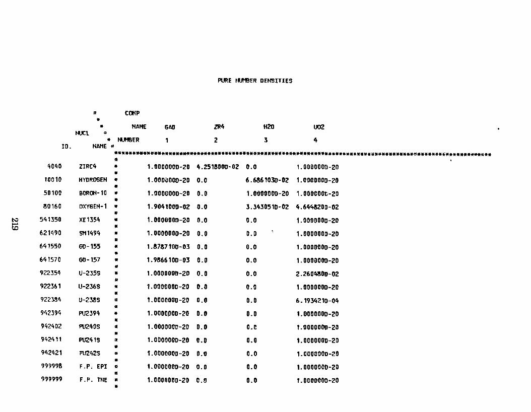
PURE t~ER OEHSITIES
1:1 COtiP • • HAHE GAD ZR4 H20 U02
tU: L 11
• ti.IHBER 1 2 3 4 ro. HAHE *
······---·~·······~**·**······~··**•••*************••·················~··········~······~············· • 4040 ZIRC4 • 1.0000000-20 4.2518000-02 0.0 1.0000000-20
• 10010 HYUROGEH li! 1.000i:J000-20 0.0 6.6861030-02 1.(t!)0000D-20
• 50100 BOROH-10 • 1.0000000-20 0.0 1.0000000-20 1.000COOt-20
• S0160 OXYSEH-1 • 1.9041000-02 0.0 3.3430510-02 4.6448200-02
• t...:l 541350 XE1354 • 1.0000000-20 a.o 0.0 1.0000000-20 EC •
621490 SH1494 • 1.0000000-20 0.0 0.0 1.0000000-20 • 641550 GD-155 • 1.8737100-03 0.0 0.0 1.0000000-20 •
64t570 G0-157 • 1.9866100-03 0.1) 0.0 1.0000000-20 • 922354 U-235S • 1.0000000-20 0.0 0.0 2.260~00-02 !!!
922361 U-2369 • 1.0000000-20 0.0 0.0 1.0000000-20 •
922}84 U-23139 l:t 1.0000000-20 0.0 0.0 6. 1934210-0I't !il
942394 PU239!\ • 1.0000D00-20 0.0 0.0 1.0000000-20 • 942't02 PU21't0S !f 1.0000000-20 o. o o.c 1. 0000000-20 • 942411 PU241S ~ 1.0000000-20 0.0 0.0 1.0000000-20 I!
942421 FU2'iZS • 1.0000000-20 0.0 0.0 1.0000000-20 •
99999B F .P. EPI a 1.0000000-20 0.0 0.0 1.0000000-20 • 999999 F.P. nlE • 1.0000000-20 0.6 0.0 1.0000000-20 •
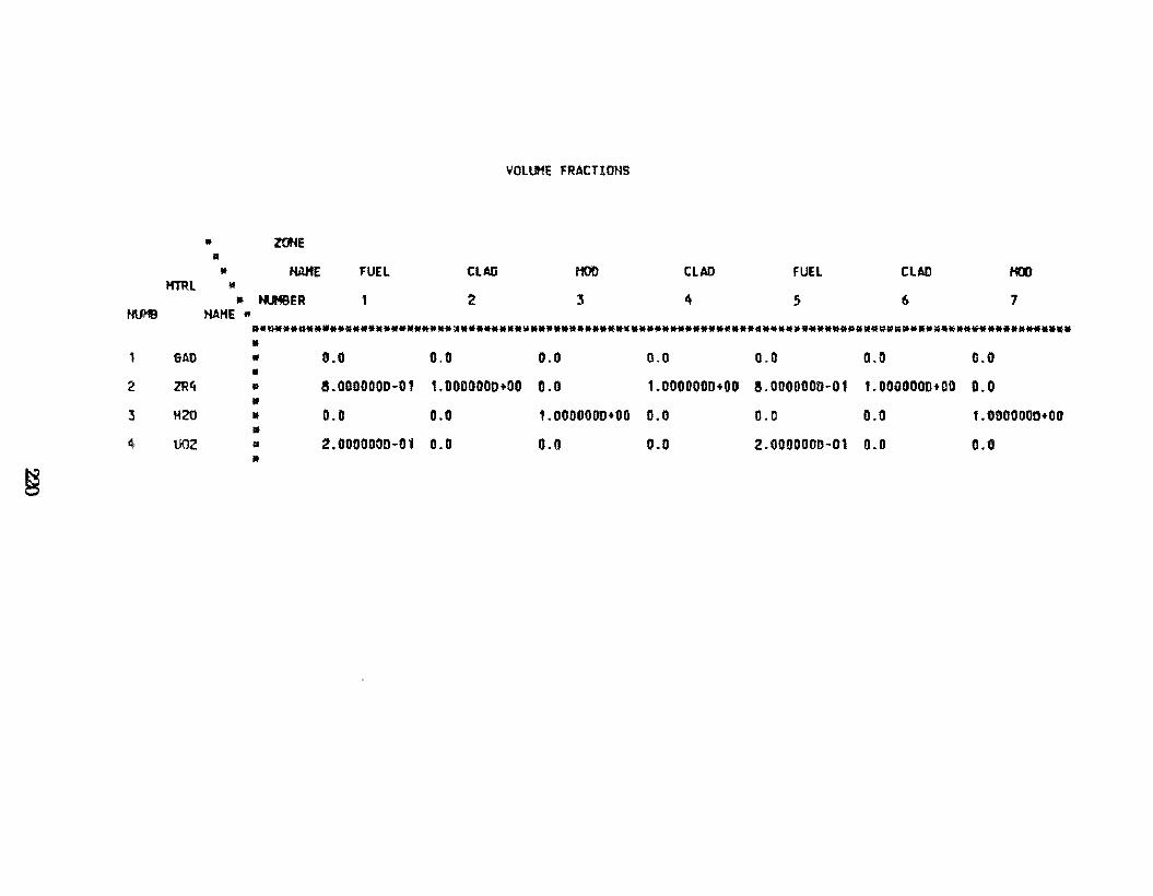
• • *
HTRL • • HUI1B HAHE "
1 GAD
2 ZR4
3 H20
~, U02
~
ZOHE
NAHE FUEL CLAD
HUHB~R 1 2
VOLUHE FRACTIONS
HOD
3
CLAD
4
FUEL
5
CUD
6
HOO
7
••~•••••************W****~********~********************************************************************** • • 0.0 0.0 0.0 0.0 0.0 0.0 D.O • • S.OOOOOOD-01 1.0000000+00 0.0 1.0000000+00 5.0000000-01 1.0000000+00 0.0 • • 0.0 0.0 1.0000000+00 0.0 0.0 0.0 1.0DOOOOD+OO • • Z.OOOOOQD-01 0.0 0.0 0.0 2.0000000-01 0.0 0.0 lf
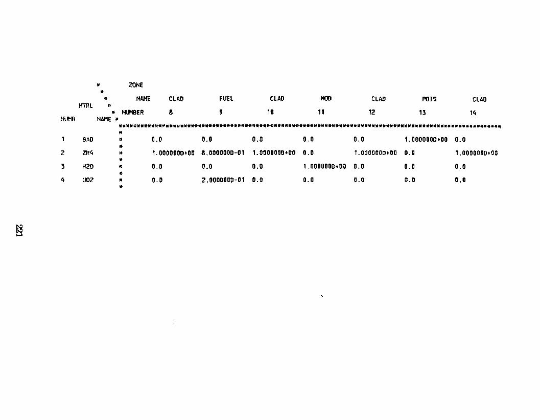
HUH8
1
2
3
4
~ """"
* ZONE •
tt NAHE Krnl tt
• t«..eER HAHE *
CUD FUEL
8 9
CLAD
10
1100
11
CLAD
12
POIS CUJJ
13 14
••••a••**•~•~•••~•••***•••••••••••******************************************************•• .. •••••••••••••• " 6AO ~ 0.0 0.0 0.0 0.0 0.0 1.0000000+00 0.0 •
ZR4 lt 1.0000000+00 8.0000000-01 1. OOOOOOD+OO 0.0 1.0000000+00 0.0 1.0000000+00 •
H20 10 0.0 0.0 0.0 1.0000000•00 0.0 0.0 0.0 •
U02 • 0.0 2.0000000-01 0.0 0.0 0.0 D.O D.O •
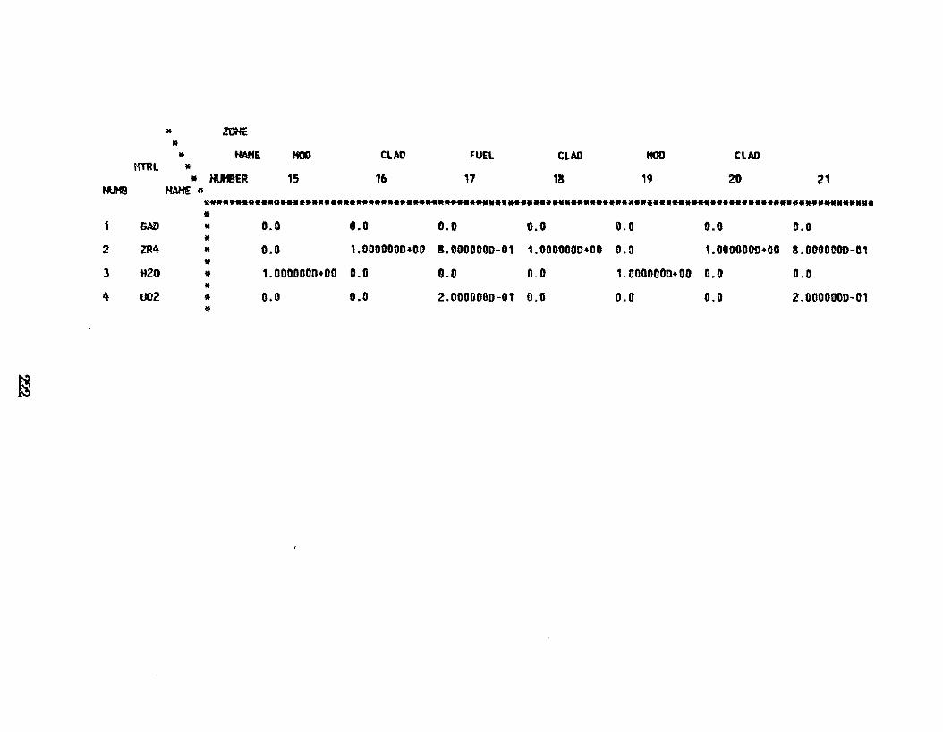
NI..Jitm
1
2
3
4
f§
J1 ztlHE
• lf
tff'Rl • MAME
• l'lJ'EER HAHE o
KOD
15
CLAO
16
FUEl
17
CLAD
18
HOO
19
CLAD
20 21
~·----•••a .. •••••••••• .. •••••••••*** ... ****••••••••••••••••••••••••••••• .. ****•••••••••••••••••• .... •••• •
6AD • 0.0 0.0 o. o o. o 0.0 0.0 0.0 •
ZR4 li 0.0 1.0000000+00 8.0000000-01 1.0000000+00 0.0 1.0000000+00 8.0000DOD-01 •
H20 • 1.0000000+00 0.0 0.0 0.0 1.0000000+00 0.0 0.0 •
U02 • o.o 0.0 2.0000000-01 O.G 0.0 0.0 2.0000DOD-01 !11
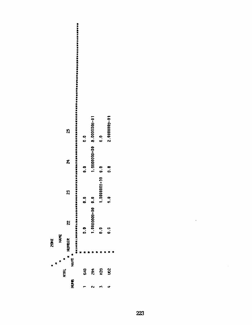
• • • • • "' • • * * * • • • llt • • • • • : • 11 • • .. * • • • • * • * :111
* • * • • = " .... .... • C) C)
• I I
* c o • C) C)
• o o ~ • C) o • o o
* o o • o C) o o • .. o 10 Cl N
* .. • o
i o + o • o • C)
~ "' c 1!11 Cl
• o • o Cl o o • .. c c o • • • o • C)
lll +
: c g
• o ,.., : Cl N Q
* o : C) o o o . • c Cl C'l
• • * o • o .. + * g • • o
~ • o ;;: o • o • o o o .::1
= . . . .
o - o o
~ l w a:: ~ ~
Uol
I • t • • o • • • • • • • • • • "' ~ • • <1:
• :z:. ~ Cl ~ c N
~ <E !?;i N s 1,1) :r
; ..- N ,.., ~
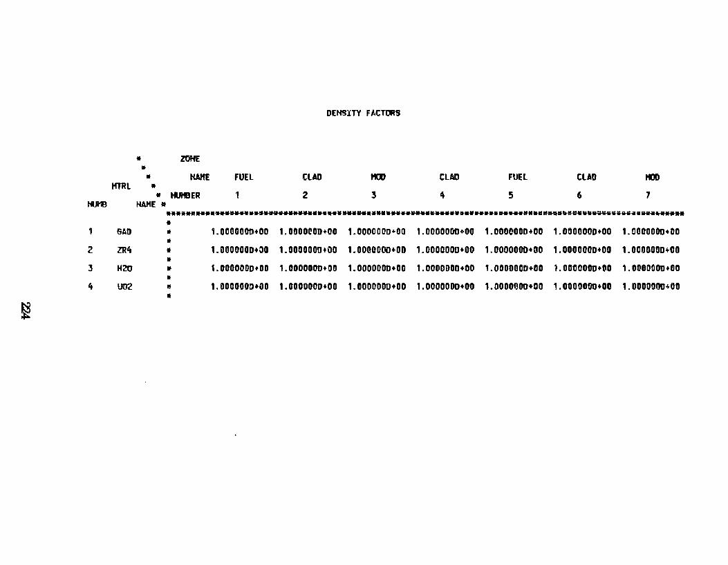
* • *
HTRL • *
tuB HAHE •
6AD
2 ZR4
J H20
4 U02
~
ZOKE
KAHE
IUitER
FUEL
1
CLAD
2
DEHS:nY FI.CTOR9
..00
3
CLAD
4
FUEL
5
CLAD
6
t«:lD
7
****** .. •••••w••••**•••••••• .. ****** ..... *************~********************•••-.•~~ow~••~••~~·---~••••• • • 1.0000000+00 1.0000rOD+OO 1.0000000+00 1.0000000+00 1.0000000+00 1.0000000+00 1.0000000+DD • * 1.0000000+00 1.0000000+00 1.0000000+00 1.0000000+00 1.0000000+1:10 1.0000000+00 1.0000000•00 • • t.OCOOODD+OO 1.0000000+00 1.0000000+00 1.0000000+00 1.0000000+80 1.0000000+00 1.0000000+00 • lt 1.0000GOD+UO 1. COOOOOO+OO 1.0000000+00 1.0000000+00 1.0000000+00 1.0000000+00 1.0000000+00 •
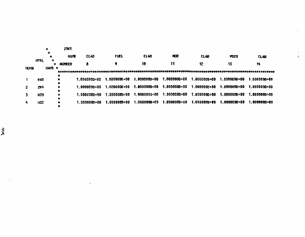
·~ ..... ,.71
~
1
2
3
4
HTRL
6AD
lR4
H20
lMl2
• lf».."l
" • HAME •
11 ti.HtER HAHE 11
ClAD
8
fUEL
9
CUD
18
til)
t1
tLAD
,~
POIS
13
CLAD
,,. ....... .w••····~ .. ······~·····~··~············· .... ····························~·~··········~·····~ a • 1.0000000+00 1.0000000+00 1.0000000+00 1.aOOOOOD+CO 1.0000000•00 1.00000GO+OO 1.DOOOODD+OO • • • R
• • •
1.0000000+00 1.0000000+00 1.0000000+00 1.0000000+00 1.000000D+OO 1.0000000+00 1.DOOOOSO+OG
1.000e30D+90 1.0000000+00 1.~000800,00 1.0000000+00 1.0000000+00 1.0000000+00 1.0000000+00
1.0000000+00 1.0000000+00 1.0GDOOOD+eO 1.000000DoaO 1.COOODOD+OO 1.0GOOOOD+OO 1.0000000+10
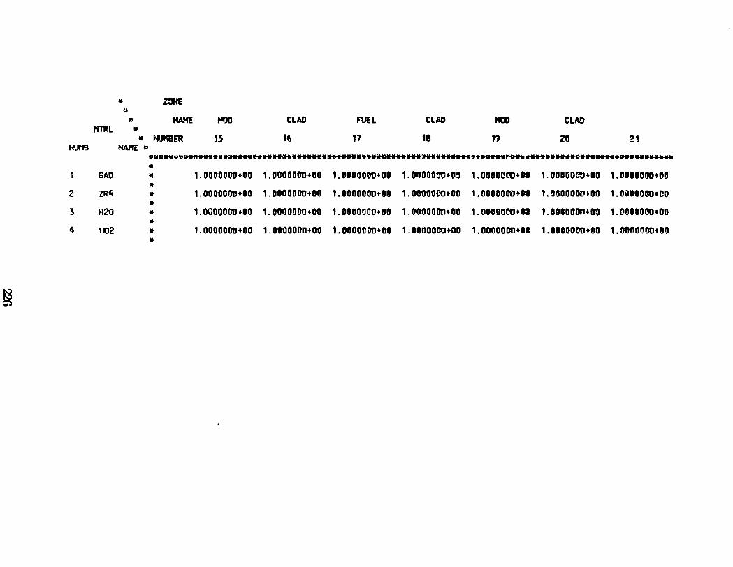
a ZOHE ~
" MAME HOD CLAD fUEL CUD HOD CUD HTRL •
• tuiBER 15 16 17 18 19 20 21 HIJ1B HAHE o
•••---•~**••~*** .. ******•******•••••••••••~••••**•~**v•****-•••••••~---~•••••••**..._• .. •**•****-•
1 6AD li 1. 0000000•00 1.0000000+00 1.0000000+00 1.0000000•09 1.0000~DO•OO 1. 00000~1J•OO 1. OOOOOOD+DrJ 11'1
2 ZR4 • 1. OOOOODC•OO 1.0000000•00 1.01)00000•00 1.0000000•00 1.0000000•00 1.00000~-tOO 1. OCOODDO•OO 11
J H20 • 1. OOOOOOIHOO 1.001l000D+OO 1.0000000+00 t.OOOOOOO•OO 1.0000000+1}3 1. ODODDDihDO 1.000UOOO•OO •
4 002 • 1.0000000•00 1.000000D•OO 1.0000000•00 1.00000CD+DD 1.DOODODD•DO 1.0DODDOD•DO 1.DDDOOOD+GO •
~
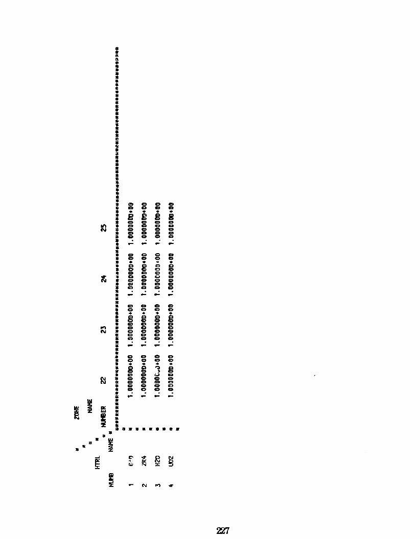
10
lt
,., N
lil
I ~ 11' ..... ; ,.
• 111 IX • ....
~
• ~
I
i 1!1
i • • ! • * • • !
:
I I • • : I • .. * .. • * i : • • i • • : : • • • • * • .. • : .. Ql
: i • * 111 .. • i
a c c c c o c o • • • • g g 8 g c c c c Ct c o D o o c c c c c Cl o o c c . - - - -o o C) c c c o c • • .. + Q 8 c D o c o c c c Cl o c o c Cl o g o o o c o c c o c . . . - - - -c o Cl c o o c c • • ... ... 8 B 8 8 c o o o c c o o c o o Cl c o o o c c o o . . . - - - -c o c o c o o o • ... • • g g ~ 8 c , c o li;,) o o o G o Cl o c o Cl o o C)
c o o o . . - - - -• • • • • * • 8 •
1:'1 .,. ~ g ~
~ UJ %
N .., ~

BESIH TIMESTEP 1
REGIOH HOHOGEHIZED NUHBER OEHSITIES
" REG. • * HAHE FUEL FUEL CLAD HOD ClAD FUEL FUEL
HL'Cl • • tUeER 1 2 3 4 5 6 7
ID. HÃHE • .................................................................................................... ~····· •
40140 ZIRC4 • 3.4014400-02 3.4014400-02 4.2518000-02 0.0 4.2518000-02 3.4014400-02 3. 4014400-02 •
10010 HYDROGEN • 2.0000000-21 2. 0000000-21 0.0 6.6861030-02 0.0 2.0000000-21 2.0000eD0-21 •
50100 BORON-10 .. 2.0000000-21 2. 0000000··2 1 0.0 1. ODOOODD-20 0.0 2.0000000-21 2.0000000-21 • 8\l16ll OXYG'EH-1 • 9.2896400-03 9.2896400-03 0.0 3.Yt3051D-02 0.0 9.2896400-tl3 9.2896400-03
~ * 51\1350 :<EB54 • 2.0000000-21 2.0000000-21 0.0 D.D 0.0 2.0000000-21 2. 0000000-21 •
621490 SHl494 * 2.0000000-21 2.0000000-21 0.0 0.0 0.0 2.0000000-~1 2.0000000-21 .. 641550 60-15~ • 2.0000000-21 2.0000000-21 0.0 0.0 0.0 2.0000000-21 2. 0000000-21
• 641570 60-157 • 2.000000D-C!1 2.0000000-21 0.0 0.0 0.0 2.00000®-21 2.0000000-21
• 922354 U-235S " 4. 5209600-0'3 4.5209600-(13 0.0 0.0 D.O 4.5209600-03 4.5209600-03 •
922361 U-236S • 2.0000000-21 2.0000000-21 0.0 0.0 0.0 2.0000000-21 2.0000000-21 •
922:5.84 U-2~S • 1. 23.!6!40-04 1.23!6MD-04 0.0 0.0 0.0 1. 2386!40-0~ 1.2386840-04 !f
942394 P\.12394 • 2.0000000-21 2.0000000-21 0.0 0.0 0.0 2.0000000-21 2.0000000-21 •
942402 PU240S • 2.0000000-21 2.0000000-21 0.0 0.0 0.0 2.0000000-21 2.0000000-21 •
942411 PU2419 • 2.DOOOOO!l-21 2.0000000-21 0.0 0.0 0.0 2. 0000000-21 2.0000000-21 •
9~2421 PU242S • 2.00001!00-21 2.0000000-21 0.0 0.0 0.0 Z.OIJODOQ0-21 2.0000QOD-21 ll
999998 F. P. EPI • 2.0000000-21 2.0000000-21 0.0 0.0 0.0 2.0000000-21 2.00000~0-21 tf
999Çi99 F .P. ~E • 2.0000000-21 Z.OUOOOOD-21 0.0 G.O 0.0 2.CO~\I000-21 2.000000D-21 •
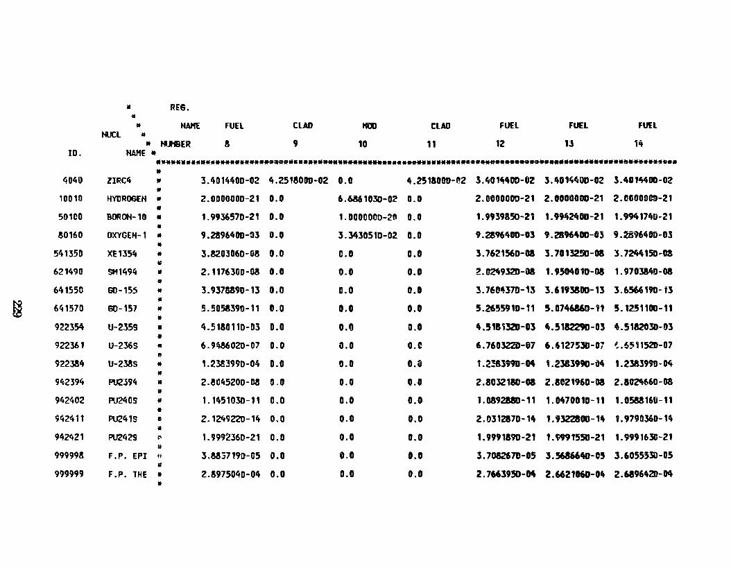
• RE6 • .. tlf HAHE FUH CLAD ttOD CLAD FUEL FUEL FUU
ti..ICl • • N..tiBER 8 9 10 11 12 13 1'\
10. tw1E * ••••••••••••• .. •••••********••••••***•*** .. ***••••• .... •• ......... ...-...... ~ ... ••••••••••••a•••••••o•• •
4040 ZIRC4 • 3.4014400-02 4.2518000-02 0.0 4.2518000-1?2 l."i01440D-02 3.4014~00-02 3.4014400-02 •
10010 HYDR06EH • 2.0000000-21 0.0 6.6861030-02 0.0 2.0000000-21 2.0000000-21 2.COOOOC9-21 •
501CO BOROH-10 • 1. 9936570-21 0.0 1.DOOOOOD-2f' 0.0 1. 9939850-21 1. 9942'100-21 1.99417ftD-21 •
80160 DXYGEH-1 • 9. 289M00-03 0.0 3.1430510-02 0.0 9.2896400-Dl 9.2896400-03 9.2896400-03 •
541350 XE1JS4 • 3.8203060-08 !J.O c.o 0.0 3. 7621560-Ga 3. 7D132!.iD-08 :s. 724415D-oa 11
621490 SH1494 • 2. 1176300-08 0.0 0.0 0.0 2.~9321Hl8 1.9504010-08 1. 9703840-08 •
641550 S0-155 • 3.937M9D-1J 0.0 a.o 0.0 3.7604370-13 3.619!800-13 3.6566190-il
!§ • 641570 G0-157 • 5. 5058390-11 0.0 0.0 0.0 5.2655910-11 5.0746860-11 5.1251100-11
• 922354 U-2359 • 4.5180110-03 0.0 0.0 0.0 4.511~32D-Dl lt.518229D-05 4.5182030-Dl
• 922361 U-236S • 6. 9486020-07 0.0 0.0 o.e 6.7603220-87 6.6127530-07 ~. 5~ 11520-07 e
922384 U-238S • 1.23!3990-04 0.0 0.0 O.i 1.2:!83990-04 1.2383990-att 1 . 2383990-04 •
942394 P\.12394 • 2.8045200-08 0.0 0.0 0.0 2.8032180-08 2.8021960-03 2.802ft66D-08 •
942402 PU240S * 1. 1ft51030-11 0.0 0.0 0.0 1. 0892880-11 1.0470010-11 1. 0588160-11 •
942411 PU241S 11 2. 124922D-14 o. o 0.0 0.0 2.D31287D-14 1. 9322800-14 1.9790360-1ft * 942421 PU2429 ~ 1.999~360-21 O.D 0.0 0.0 1.9991890-21 1."'1550-21 1.9991630-21 li
999998 F .P. EPI fi 3.883719D-G5 0.0 0.0 D.O 3.7082670-05 3.5686640-05 3.6055530-05 lf
9?9999 F.P. lHE • 2.5975040-04 0.0 0.0 0.0 2. 7663950-04 2.6621060-0lt 2.6896lt21HM •
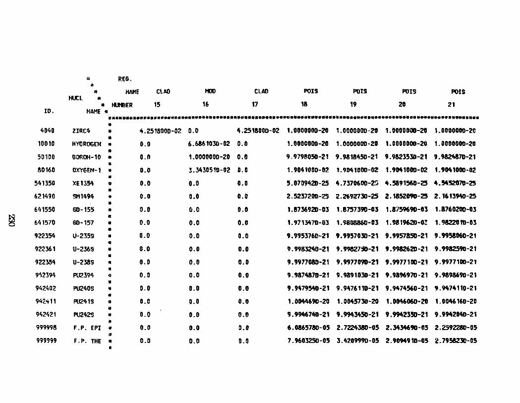
~ RE6. 111
11 HAHE ClAD HOD CLAD POIS POIS POIS POIS HUCL •
• tl.leER 15 16 17 18 19 20 21 10. HAHE • ••§•..w.-e••••******•*****••••••**•••-*•••••**••****...._ ................. ~••a••••• ....................
• 4040 ZIRC~ • 4.2516000-02 0.0 4.2518000-02 1. 0000000-20 1. 0000000-20 1.0000000-20 1.0000000-21! • 10010 HYUROSEH • 0.0 6.686103CJ-02 0.0 1.0DOC000-20 1.0000000-20 1.0000000-20 1.1000000-20 •
501DC BOROH-10 • o.n 1.0000000-20 0.0 9.9798.050-21 9.9318450-21 9.9823530-21 9.~70-21
• 80160 OXYGEH-1 • 0.0 3.3430510-02 0.0 1.9041000-!)2 1. 904 UIOD-02 1. 9041000-02 1. 9041000-02 •
541350 XE1354 • 0.0 o.o 0.0 5. 07 09le2b -25 4. 7370600-Z!j 4.5891560-25 4.54m7D-25 •
621490 SH1494 • 0.0 0.0 0.0 2.5237200-25 2. 2692730-25 2.1852090-25 2.16139~-25
• 641550 G0-15.S • 0.0 0.0 0.0 1.8736920-03 1.8757390-03 1.8759690-03 1.1760200-Gl
~ • 641570 60-157 • 0.0 0.0 0.0 1. 971~10-03 1. 980886U-n 1. 9819620-D:! 1. 9322010-03 •
922354 U-2359 • 0.0 0.0 0.0 9.9953760-21 9.995703D-21 9. 9957850-21 9.9953060-21 •
922361 U-2369 • 0.0 0.0 0.0 9.9983240-21 9.99827~-21 9.9912620-21 9.9912590-21 •
922~4 U-2389 • 0.0 0.0 0.0 9.9917G8D-21 9.9977090-21 9.9977100-21 9.9977100-21 •
9'\2394 PU239~ ~ 0.0 0.0 0.0 9.9874870-21 9.9391030-21 9.9896970-21 9.9893690-21 •
942402 PU240S .. 0.0 0.0 0.0 9.9479540-21 9.9476110-21 9.«74560-21 9.M7411D-21 li
942.'t 11 PU2419 • 0.0 0.0 0.0 1.001t469C-20 1. 0045730-20 1.0M606D-20 1.0046160-20 if
942421 PU2429 .. 0.0 0.0 !LO 9.9946740-21 9. 9943450-21 9.9942350-21 9.994204D-2t • 999998 F.P. EPI lf 0.0 0.0 D.O 6.0865780-05 2.7224380-05 2.3434690-05 2.2592280-05 ;J
999999 F.P. THE • O.D 0.0 0.0 7.9603250-05 3.4209990-05 2.9094910-05 2. 7958230-05 ..
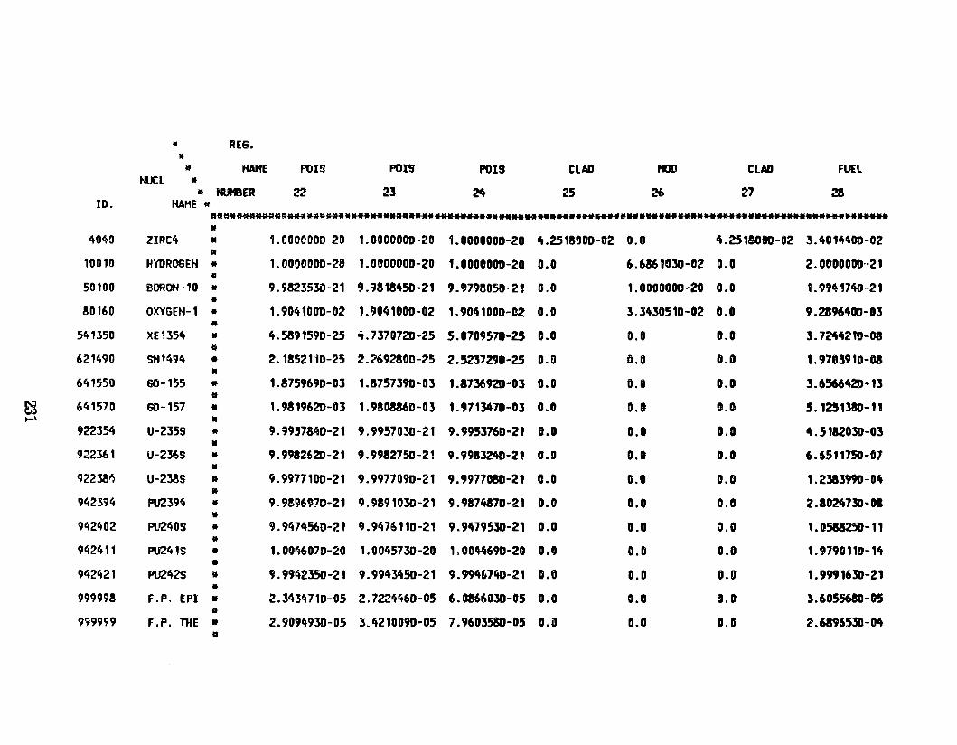
• REG •
* • HAHE POIS POIS POIS CLAD til) CLAD FUEL tU: L •
11 ti.I'SER 22 21 24 25 26 27 28 ID. HA.HE *
111111*~~-~ ..............................................................................................
• 4MO ZIRC4 • 1.0000000-20 1.0000000-20 1.DOOOOOD-20 lt.2518DDD-02 0.0 4.2515000-02 3.4014400-02
• 10010 HYDROGEH • l.OODOODD-20 1.000000D-20 1.0000DOD-20 0.0 6.6861030-02 0.0 2. 0000000··21 •
50100 BOROH-10 • 9.982J5lD-21 9.9818450-21 9 o 9798050-21 G.O 1.0000000-20 0.0 1.99~1740-21
• ~0160 OXYGEH-1 • 1.9041000-02 1.9041000-02 1.904100D-D2 0.0 3.3430510-02 0.0 9.2396400-03
• 541350 XE1l54 • 4.5891590-25 4.7370720-25 5.0709570-25 D.O 0.0 G.O ]. 72442tD-08
111
621490 Stt1494 • 2. 1852110-25 2.2692800-25 2. 5257290-25 O.D 0.0 0.0 1. 9703910-08 •
641550 60-155 • 1.8759690-03 1.8757390-03 1.87~920-03 O.D 0.0 0.0 3.6566420-13 •
EZ 641570 60-157 • 1. 9819620-03 1. 9SDM6D-03 1.9713470-03 0.0 0.0 0.0 5.1251380-11 ~ •
922354 U-2359 • 9.9957340-21 9.9957030-21 9.9953760-21 D.D 0.0 0.0 4.5182030-03 • 922361 U-2369 • 9.9982620-21 9.9982750-21 9.99832itD-2' O.D 0.0 0.0 6.6511750-07 •
9223M U-238S • 9.9977100-21 9.9977090-21 9.9977080-21 0.0 0.0 0.0 1. 2383990-04 •
942394 PU239~ • 9.9896970-21 9.9891030-21 9.9874870-21 0.0 0.0 0.0 2 .8024730-DI •
942402 PU240S • 9.9474560-21 9.9476110-21 9.9479530-21 0.0 0.0 0.0 1. 0588250-11 •
942411 PU241S • 1.0046070-20 1. 0045730-20 1.00"690-20 0.0 0.0 0.0 1. 979011D- 14 •
942421 PU2~2S • 9.9942350-21 9.9943450-21 9.99467't0-21 0.0 0.0 O.D 1.9991630-21 •
999998 F.P. EPI • 2.3434710-05 2.7224460-05 6.0866030-05 0.0 O.D ,,0 :5.605.5680-05 •
999999 F.P. Til E • 2.9094930-05 3.4210090-05 7.9603580-05 0.0 0.0 0.0 2.6896530-04 •
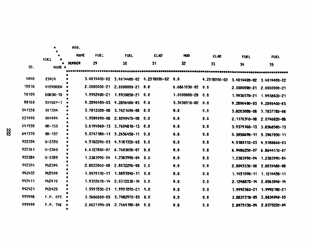
• ~EG . lf
~ HAHE FUEl FUEL CLAD HOD CLAD FUEL FUEL ~1JCL •
• tf.I'IBER 29 30 31 32 33 ~ 35 ID. HAHE • •••~•-**** .. ••••••v .. ***••••e ... •••••••••••••••••••••••R*W ... --. .... ..w••••••***-..... •••••••••••--• .... • 4040 ZIRC4 11 3.4014400-02 3.4014400-02 4.2518000-02 0.0 4.2518000-02 3.4014400-02 3.401"00-02 •
10010 HVDROGEH • 2.0000000-21 2.00000C!J-21 0.0 6.6861030-02 0.0 2.0000000-21 2.0000000-21 •
50101) SORON-10 • 1. 9942q00-21 1.9939850-21 0.0 1.0000000-20 0.0 1. 9936570-21 1. 9938020-21 • 80160 OXY6H'-1 • 9.2!961\0D-03 9.28961'100-03 CI.O 3.3430510-02 0.0 9.28964DD-03 9.2396400-03 • 541350 XE1354 • 3.701330D-08 3. 7621690-08 0.0 0.0 0.0 3.8203CBD-08 3. 7837780-03 I!
621490 SH1494 • 1.9504D9o-oa 2. 0249470-08 0.0 G.O 0.0 2.117631~-oa 2.0746820-oa ti
641550 Ei0-155 • 3.6194060-13 3.7604810-13 0.0 0.0 o.a 3.9379160-13 3.8568500-13
~ 11
641570 Ei0-157 • 5.0n718D-11 5. 2656450-11 0.0 o.a 0.0 5.5058690-11 5.3967050-11 v
922354 U-235S • 4.51&2290-03 4.5181320-03 0.0 0.0 11.8 4.5~0110-03 4.5180660-03 ~
922361 U-2365 il 6.6127800-07 6.7603650-07 0.0 G.D 0.8 6.9W25D-07 6 .86ltlt 11»-07 •
92238tt U-2389 • 1.2383990-04 1.2383990-04 0.0 0.0 o.a 1. 2383990-M 1.2383990-0~ •
942394 PU2394 ~ 2.8022060-08 2.8032290-08 0.0 0.0 0.0 2.3045330-08 2.8039480-0S •
Cll4~02 PU24DS • 1.047011D-11 1.03930~-11 0.0 0.0 0.0 1.1451090-11 1.121"50-11 • 942411 PU241S • 1.9322670-iif 2.0312330-14 0.0 0.0 0.0 2.124887D-14 2.0.563040-14 • 942421 PU242S R 1.4i991550-21 1. 9991390-2, ll.D 0.0 a.o ~.9992360-21 1.9992180-21 • 999998 F. P. EPI • 3.5686800-05 3.7052970-05 0.0 0.0 0.0 3.8137310-05 3.3034040-05 •
999999 F .P. THE lli 2.6621190-0t\ 2. 76641SD-O~ D.O O.D 0.0 2.8975130-Cit 2.8375220-0it •
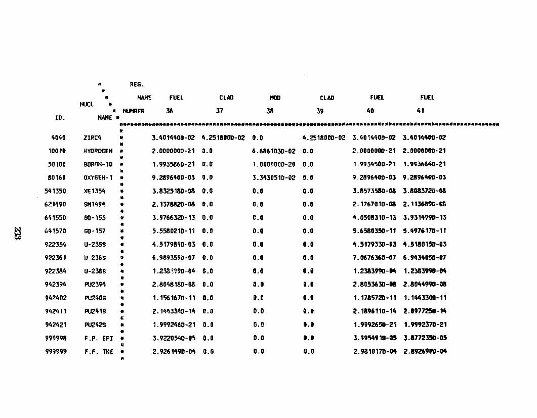
~ REG. • • ~ FUEL CLAD t10D CLAD fUEL ~un
ti.JCL • • tutBER 36 37 38 39 40 41 ID. HAHE •
.. .... ~ ............................. ***** ............................................................. • 4040 ZIRC4 • 3.4014400-02 4.2518000-02 0.0 4.2518000~02 3.~014400-02 3.401"00-02 • 10010 HYDROGEH 11 2.000000D-Z1 0.0 6.6861030-02 0.0 2.0000000-21 2.0000000-21 •
50100 BOROH-10 • 1.9935860-21 D.O 1.00D0000-20 0.0 1. 993't50D-21 1. 9936640-21 •
80160 OXYSEH-1 • 9.2896400-0l 0.0 l."'3051D-Q2 0.0 9.28961t00-0l 9.2896400-03 .. 541350 XE1354 • 3.8325180-08 0.0 0.0 0.0 3.8573580-08 3 .8Ga372D-08
• 621490 SH149~ • 2. 1378820-08 0.0 0.0 o.o 2. 1767010-0& 2. 1 136890-06
• 641550 60-155 • 3.9766320-13 0.0 0.0 0.0 4. 0508310-13 3.9314990-13
• ~ 641570 60-157 • 5.5580210-11 0.0 0.0 0.0 5.6580350-11 5.4976170-11
• 922354 U-2359 • 4.517984D~D3 0.0 0.0 0.0 't.517933D-D3 4.5180150-03 •
922361 U-236S • 6.9.!93590-117 0.0 0.0 0.0 7. 067636D-07 6.9434050-07 •
922lM U-238S • , .2~~~?90-04 G.O 0.0 o.e 1. 2383990-04 1. 2383990-04 •
942394 PU2394 • 2.80431SD-08 0.0 0.0 0.0 2.8053630-0S 2.8044990-08 •
942402 PU2409 • 1.1561670-11 0.0 0.0 0.0 1.1785720-11 1.1443300-11 •
942411 F\12419 • 2. 1~43340-1~ 0.0 0.0 ~.0 2.1896110-14 2. 0977250-14 J:
942421 PU242S • 1.9992463-21 0.0 G.O 0.0 1.fl926SIJ-21 1."92370-21 •
99999& F .P. EPI • 3. 9220540-05 0.0 0.0 0.0 3.'1954910-05 3.8772350-05 li
999'!199 F.P. THE • 2.926f49D-04 0.0 0.0 0.0 2.9310170-04 2.8926900-04 •
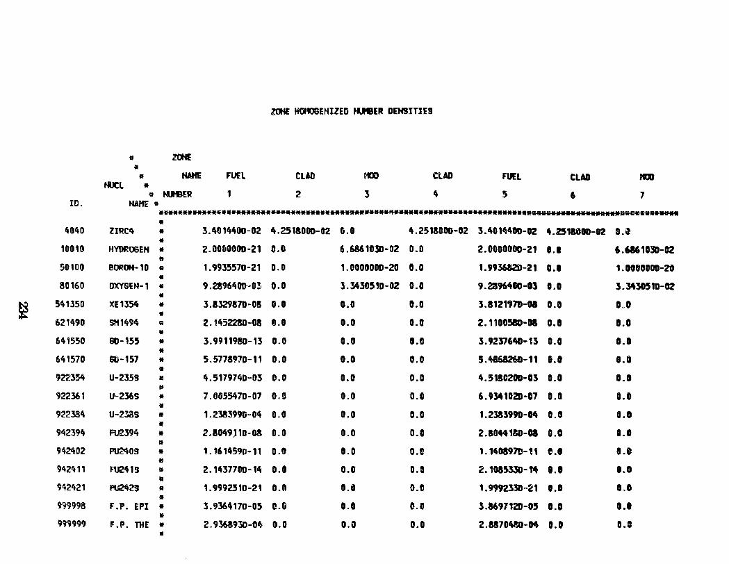
ZOHE HOHOGEHIZED HUHBER DEH91TIE9
11 ztM
* • HAHE FUEL CUD fG) CLAD FUEL CLAD JGJ tiJCl •
e N.leER 1 2 3 4 5 6 7 ID. HAHE tt
•a•••••....w~••..._• ... •••••N•....w .. ww..w•••••M•••••• ........ •••••••• ..... m••••••••••••••a•••••s•K••••••• •
~MO ZIRC~ • 3.4014400-02 ,.,251&000-02 G.O 4.2511000-02 3.4014400-02 4.2518010-12 G.t • 10010 HVDROGEH • 2.0060000-21 c.o 6.6861030-02 0.0 2.0000000-21 0.1 6.6861030-02 •
50100 BOROH-10 R 1. 9935570-21 0.0 1.0000000-20 0.0 1. 993682D-21 0.0 1. 0080000-20 • 80160 OXYSEN-1 !!i 9.2896400-0! o.o l.3430.5,D-02 0.0 9.2396,.00-0l O.D 3. 3430510-02 •
~ 5tt1350 XE1354 • 3.8329870-08 0.0 0.0 0.0 3.1121970-01 0.0 D~O
• 621490 SH1494 Q 2. 1452280-08 o.a 0.0 0.0 2.1100.58D-D8 O.D D.O
• 641550 60-155 • 3.9911980-13 0.0 a.o O.G 3. 923761tD-U 0.0 0.0
• 641570 00-157 • 5.577S97D-11 0.0 0.0 0.0 5.W8260-11 8.0 1.0 •
922354 U-2359 11 4.5179740-03 e.o 0.0 0.0 4.51SC20D-03 O.D 0.0 ~
922361 U-2l6S • 7. 005547D-07 0.0 0.0 0.0 6.9341020-07 O.D D.O •
922384 U-2?t.8S • 1.2383990-04 0.0 0.0 O.G 1.2333990-14 0.0 a.o • 942394 FU2394 • 2.1049,10-03 0.0 0.0 O.C! 2.10441!0-DI 0.0 ••• • 942402 PU2409 • 1.1614590-11 0.0 0.0 0.8 1 . 14DI97D- t1 C.l e.e 11
9~2411 FU241S a 2.1437700-14 o. o 0.0 o.~ 2. 1015330-M ••• 1.0 •
~42421 Pti242'S • 1. 99925 10-21 0.0 O.IJ 0.0 1.9992330 .. ~1 O.D 0,0 11
9!19998 F .P. EPI • 3.9364170-05 0.0 0.0 0.0 3.8697120-0.5 0.0 0.1 • 999999 F.P. 114E • 2. 9368930-0~ 0.0 0.0 O.G 2.SS70W»-04 0.1 o.= •
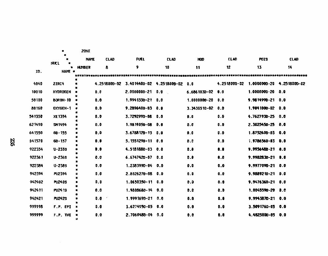
• ZONE • • HAtiE CLAD FUU CLAD HOO tLAD POIS CUD
tiJCL • • tOe ER a 9 10 li 12 13 14
ID. HAHE • ~-~ ............. ~ ...................................................... r. ..............................
• 4040 ZIRC4 * ~.2518000-02 3.4014400-02 4.2518000-02 0.0 4.2518000-02 1.0000000-20 4.2518000-02
• 10010 HYDROGEH • O.tl 2.0000000-21 0.0 6.6861030-02 o.o 1.0000000-ZO 0.0
111
50100 BORmf-10 • 0.0 1. 9941330-21 0.0 1.0000000-20 0.0 9.9814990-21 0.0
* aot60 OXYSEH-1 • 0.0 9.2896400-0] 0.0 3.Yt3G51D-02 0.0 I. 90411011-02 D.D •
541350 XE1354 • 0.0 3. 7292t90-08 0.0 0.0 0.6 4.7627930-25 o.e • 621490 SH1494 • 0.0 1. 9819050-08 0.0 0.0 o.o 2.30254SD-Z5 D.l • 641550 EiG-155 • o. o 3.6788120-13 0.0 0.0 o.o 1.8752600-03 o.o •
~ S41570 60-157 • 0.0 5.1551290-1 t 0.0 O.IJ 0.0 ·j. 9786560-03 O.D •
922354 U-235S • 0.0 4.5181880-03 0.0 0.8 0.1 9.M56W-21 O.D •
922361 U-2J6S • 0.0 6.6747420-07 0.0 0.0 0.0 9.991ZalD-21 0.0 •
922384 U-Z38S • 0.0 1. 2383990-04 0.0 o.o 0.0 9.9977090-21 o.o •
942394 F\.12394 • 0.0 2.8026270-08 0.0 0.0 0.0 9.91&9210-21 0.0 •
942402 PU240S • 0.0 1.0650350-11 0.0 o.a o.a 9.9476360-21 0.0 • 9ft2411 PI.J241S • D.D 1.MOSUD-14 0.0 0.0 0.0 I. OK559D-20 a.e • 942421 PU242S • 0.0 1.9991690-21 0.0 o.o 0.0 9.9M381D-21 0.0 •
99999S F.P. EPI 1!1 0.0 3.6274950-05 0.0 0.0 o.o 3.5091760-05 0.0 •
999999 F.P. THE 'li 0.0 2.7060ft80-0~ 0.0 0.0 0.0 ~.48250110-05 0.0 g
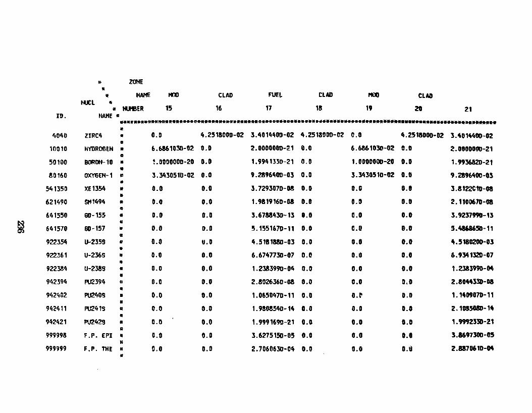
~ Z\M: !I
• HAHE HOO CLAD FUEL CLAD PQI CUD ti.JCL 5
• tueER 15 16 17 18 19 20 21 ID. twtE •
.. •••••• ~.-~.._ .... ~ ............. ~..._._ ••••• N..._ ............ .._ ................................
I!
4040 ZIRC4 • 0.0 lt.25180DD-02 3.4014400-02 4.2513000-02 0.0 4.2518000-02 3 .40 11tlt00-02 •
10010 HVDROGEH • 6.6861030-02 0.0 2.0000000-21 0.0 6.6861030-02 c.c 2.000DO!l0-21 e
5011)0 BOR00-10 • ~.OOOOOOD-20 0.0 1. 994 13:50-21 0.0 1.0000000-20 o. o 1 . 993682D-21 •
80160 OXYEiEH-1 ., 3.34305111-02 0.0 9.2896400-03 0.0 3.3430510-02 0.0 9.2896400-03 •
541350 XE13S4 • 0.0 0.0 3.7293070-08 0.0 o.c 0.1 3.8 122C10-DI •
621490 SH1494 • 0.0 O.G 1. 9819160-03 0.0 G.~ D.D 2.1100610-Da •
~41550 GD-155 • 0.0 0.0 3.67&8430-13 0.0 0.0 0.0 3.9237990-13 •
641570 60-157 • 0.0 0.0 5.1551670-11 0.0 6.0 e.o 5.48686!5D-11 •
922J~ U-2359 • 0.0 u.o 4.5181880-03 0.0 0.0 0.0 4. 5180201HI:S •
922361 U-2J6S • 0.0 0.0 6.6747730-07 0.0 0.0 0.0 6.9341320-07 •
9223.84 U-2389 • 0.0 0.0 1.2383990-0~ 0.0 0.0 0.0 1.2383HD-04 •
942:594 PU2394 Q 0.0 0.0 2.8026360-08 0.0 c.o 0,0 2.1044330-Da • 942402 PIJ2lt0S • 0.0 0.0 1.0650470-11 0.0 o.~ 0.0 1.11t0907D-11 •
942411 PU241S • 0.0 O.D 1. 9!0351W-11t 0.0 0.0 0.0 2. 10S501D-14 • 942421 PU2429 • 0.0 0.0 , . 9991690-21 0.0 0.0 0.0 1.9992330-21 •
999998 F .P. EPI • 0.0 0.0 3.6275150-05 0.0 0.0 0.1 3.8697300-05 M
999999 F.P. THE • 0.0 0.0 2.7060630-0~ 0.0 0.0 0.@ 2.8170610-04 11
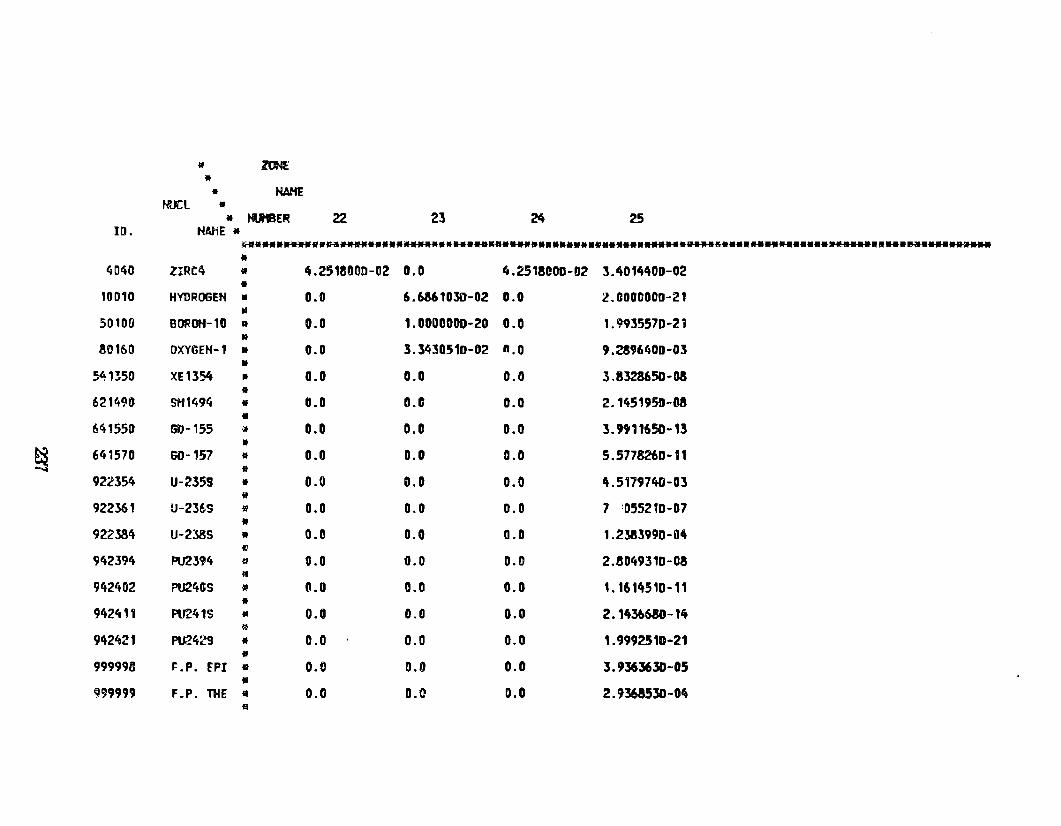
lll ltH • • tWfE
NUCL • • tOe ER 22 23 ~ 25 ID. HAHE •
~ .......... ***********************.a• ... ···············•******~5···· .............................. ~··· •
40~0 ZIRC4 • 4.2518000-02 0.0 4.2518COD-IJ2 3.4014400-02 •
10010 HYDROGEH • 0.0 6.6861030-02 D.O 2.0000000-21
"' 50100 BOROH-10 a 0.0 1.0000000-20 0.0 1 . 9935570-2 i •
80160 OXYSEH-1 • 0.0 3.3430510-02 n.o 9.2896400-0l •
.54B50 XE1354 • 0.0 0.0 0.0 3.8328650-0S •
621490 SH1494 • ti.O o.c 0.0 2. 145 '95D-M •
641550 GD-155 '» 0.0 0.0 0.0 3. 9911650-13 •
~ 641570 60-157 • 0.0 0.0 0.0 5. 5778260-11 •
922354 U-2359 • 0.0 0.0 0.0 4.5179740-03 * 922361 U-2:56S I' 0.0 0.0 0.0 7 '055210-07 •
922384 U-238S • 0.0 0.0 0.0 1.2383990-114 11
942394 PU2394 ~ 0.0 0.0 0.0 2.8049310-03 lf
9ft2402 PU24GS • l1.0 0.0 0.0 1.1614510-11 •
942411 PU241S • 0.0 0.0 0.0 2. 143b680-1ft I&
942421 PU2429 • 0.0 0.0 0.0 1.9992510-21 • 999998 ~ .P. EPI 111 o. o 0.0 0.0 3.9363630-05 • 999999 F.P. lHE • 0.0 o.c 0.0 2.9363530-04 ~
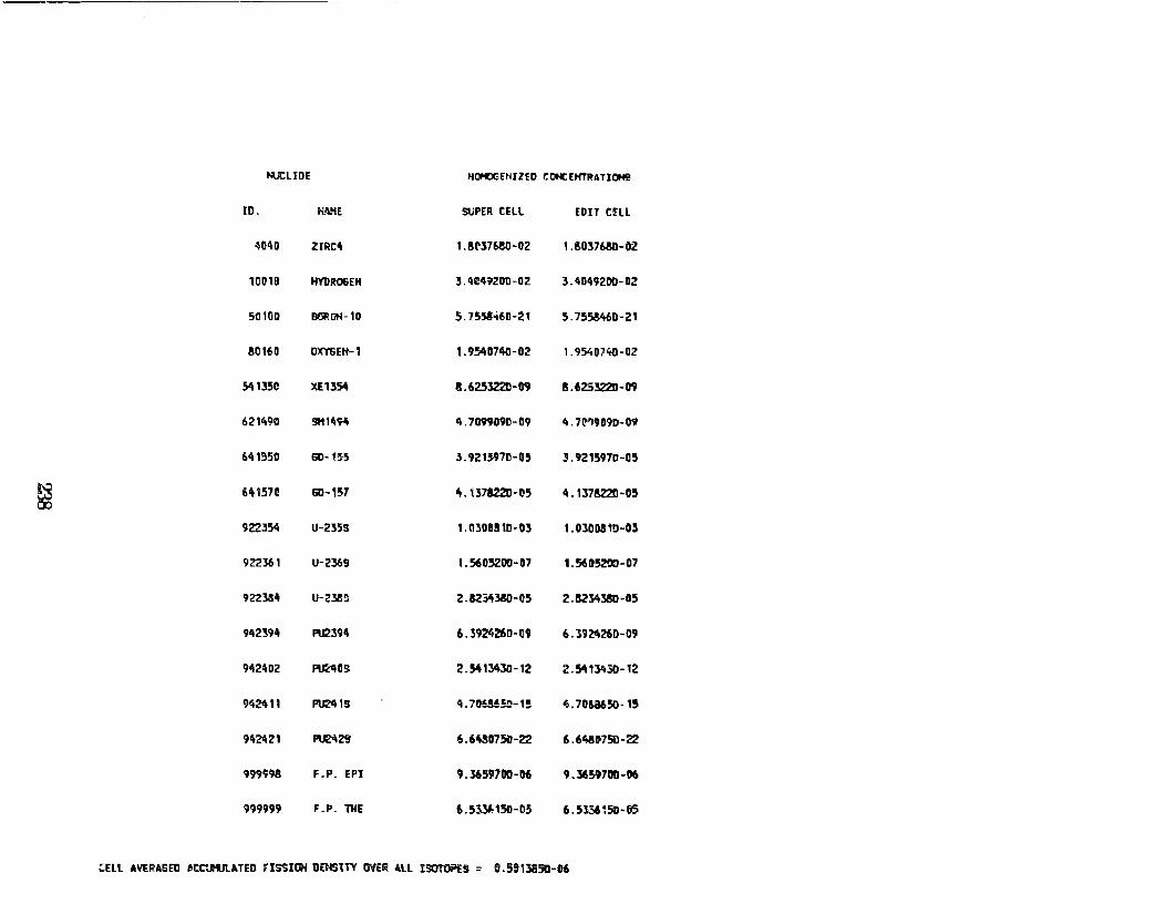
~liDE HOHOGEHJlED CONCEHTRATJOHS
ID. H. ~\ME SUPER CHL EDJT C!Ell
~040 ZIRCI\ 1.8l'37680-02 1.80376.80-0l
10010 HYDRO&EH l.ttC492DD-02 3.4049200-02
50100 OORütl-10 5.755!-+60-21 5. 752460-21
80160 OXYSEH-1 1. 95407411-02 1. 9540740-02
51t1l5D XE1354 8.625322D-09 8.62532211-09
621490 SHWil\ 4.7099090-09 4.7t''I9D9D-09
6411350 60-'.~5 3.9215970-05 ]. 9215970-05
~ 6'11571! 61)-157 lt. 137822D-1!5 4. 1l782'2D-05
9223511 U-235S UI301151D-Dl I. 03008 1!:1-03
922361 U-236S I. 560~00- 07 1.5605200-07
922334 u-238!1 2.8234380-05 2 .1!.23-l3oi!O-O 5
942394 P\12394 6.3924260-09 6 .19~260-09
9424D2 ~os 2. 54134JII-12 2. 5lt 13430-12
942411 PU241S 4.70M!5!1-1! 4.70t.a65o-15
942421 1'\121\2! 6. 61t!075D-22 6.6~li75D-22
999998 F.P. EPI 9.3659700-06 9.36~700-06
999999 F.P. TIIE 6. 5331.-150-05 6.5l3615D-65
CELL AVE~AGED ~CC'..HJI..A.TED FlS'SIIil DENStTY üo/EI< 4ll iSüiOi"U = G.551:58511-06
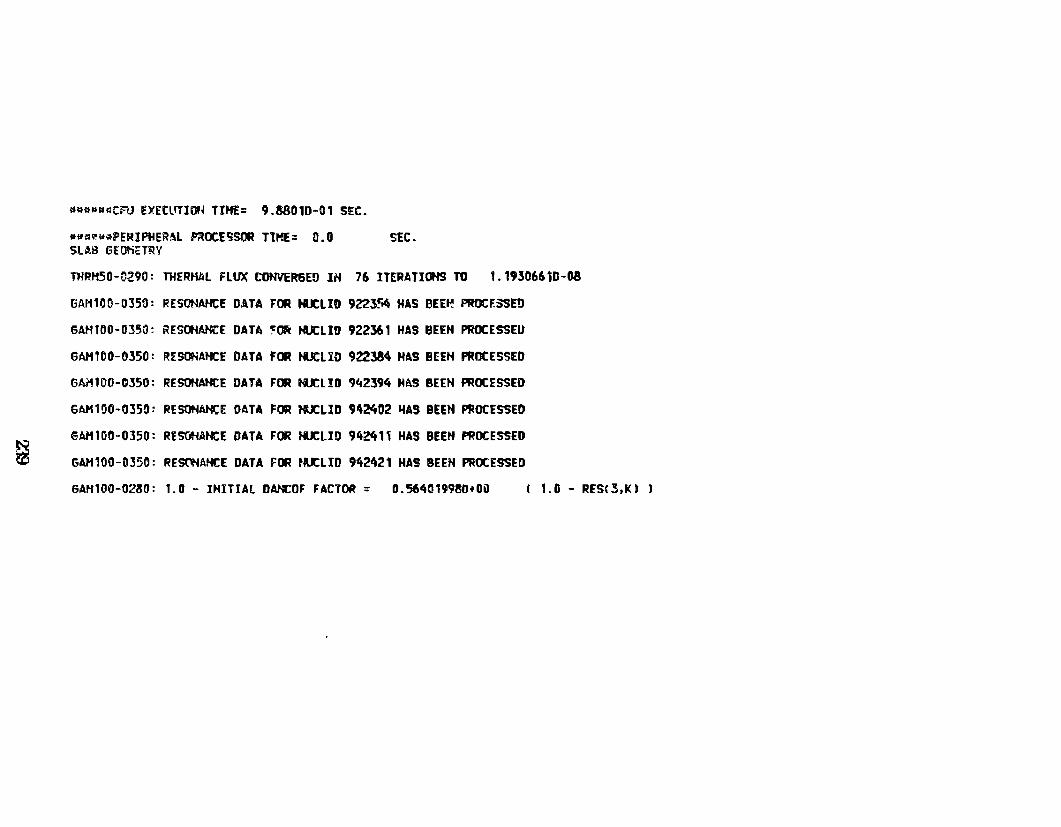
~
~~oPa~c~ EXECL~l~~ TI~= 9.38010-01 SEC.
•~~~~~PERIPHER~L ~OCESSOR TtHE= 0.0 SEC. SUB GEOtiH~V
THRH50-0290: THERHAL fLUX COHVERGEO IH 76 ITERATIOHS TO 1.19306610-08
GAH100-0J53: RESONAHCE DATA FOR HUCLID 922354 HAS BEE~ PROCF.SSED
GAHl00-0350: ~ESOHANCE DATA ~Ok HUCLID 922361 HAS BEEH PROCESSEU
GAHt00-0350: RrSONAHCE DATA FOR HUCLlO 922384 H~9 BEEH PROCESSEO
6AH100-C350: RESOHAHCE DATA FOR HUCLID ?42394 HAS BEEH PROCfSSEO
6AH100-035~: RESOHAHCE DATA FOR HUCLID 9~2402 ~AS BEEH PROCESSED
6AH100-0l50: RESOHAHCE DATA FOR HUCLID 942411 HAS BEEH PROCESSED
GAH100-0350: RE~AHCE DATA FOR t~LID 942421 HAS BEEH PROCESSED
GAHl00-0230: 1.0 - IHITIAL DAHCOF FACTOR = 0.564019980+0ü 1.0 - RESC3,K) J
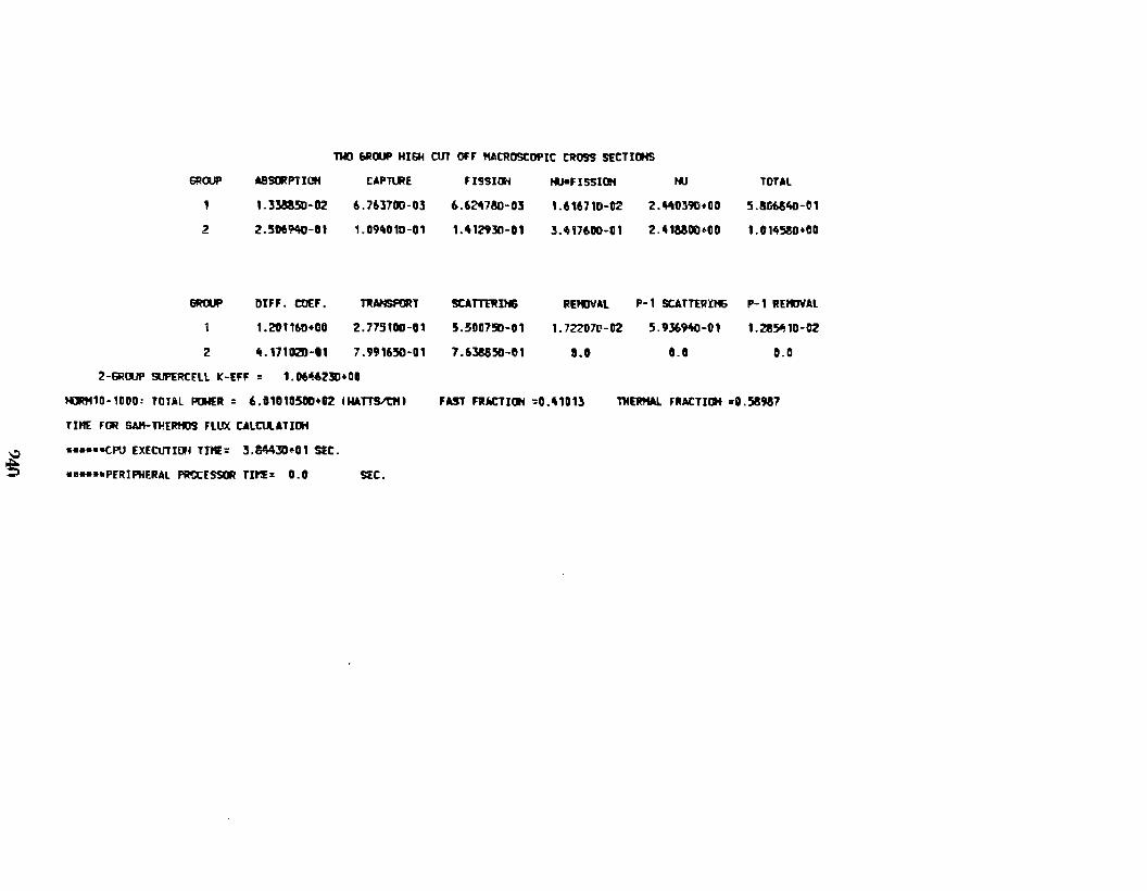
~
1l«l 6ROOP HISH OIT OH ttACROSCDPIC CROSS stCTICifS
SROUP
2
GRruP
z
AB43C:RPTIOH
1. 33885l:HJ2
2. 506'!'40-01
OIFF. COU.
1.201160+00
tt. 171020-01
CAPT\.RE
6.763700-03
1. D9ft0 1D-0 1
TRAHSRJRT
2. 7751DIH, 1
?.991650-01
Z-GRruP StMRCEll K-EFF = 1.06~231:1•00
HORH10-1DOO: TOTAL PONER : 6.01010500•02 IWATT~)
TlttE FOR SAtt-TllERmS FLUX CALC\A.ATIOH
•••••-<:PU EXECUTI!J~ TtltE= 3.844~~01 S!C.
•• .. ••PERIPHERAL PRtCESSOR TIME= 0.0 SEC.
J'J5Sitli
6.6247&>-03
1.-\12930-01
SCA TT'EJ! IH&
5.500750-01
7. 638850-01
t«JJIFI S'Sl 1:14
L61671D-02
3.1f1176DO-D 1
RE'IJVAL
1. 72207t'-02
li.O
tlJ
2.440l91:1+DO
2.ft1MOD•OD
P-1 SCATTER:tH6
5.9l691t0-01
0.0
TOTAL
5.SG654D-01
1.0145mJ•OO
P-1 REKJVAL
1. 2851! 10-02
0.0
J'AST FRJCTIDH =0.,101) ntERMAL FRACTUif =ll. 58987
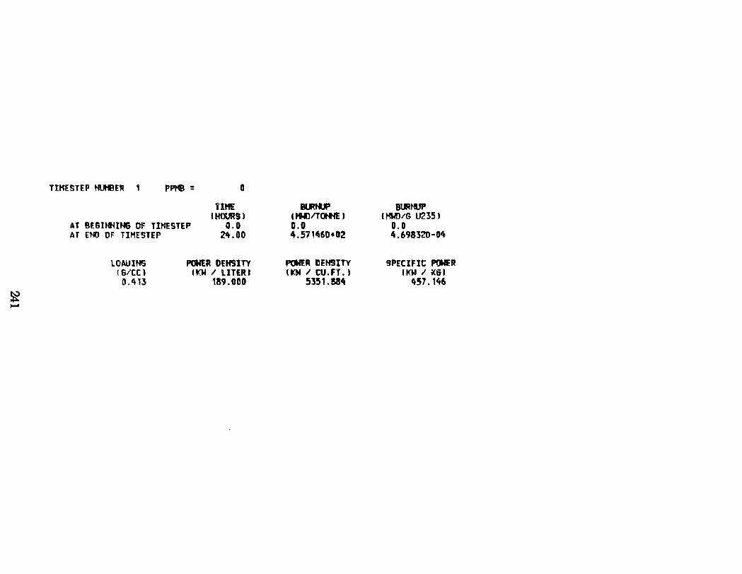
~ ~
TIHfSTEP HUHBER 1 PPtE = o
AT BE6INHIH6 0F TIHESTEP AT EHO OF TIMESTEP
1'lttE t~Sl
0.0 2't.OO
LOWIHG !6/CC l 0.4U
POWER DEHSlTY IKW I LITERI
189.000
IUtlJP l fti)ITOtflE ) 0.0 4.571460+02
miER DEHSITY tKN I tu.FT. J
5351.!84
PHUP tHWDIG U2351
0.0 4.698320-04
9PECIFIC PONER f KW I ;(IH
tt57. 146
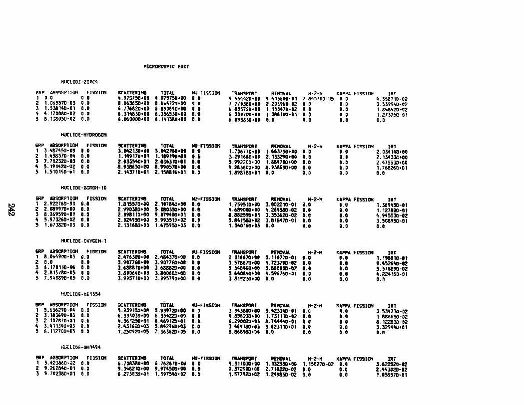
"ICROSCOPIC EDIT
HUttiDE-ZilfCit
GIIP ABSOOPTIOH FISSIIJ4 sunEJtJH& TOTll. NJ-FISSIOH 11l AHSF'(JI f RHfl\IAL H-2-H KAPPA FISSIOH IR f 1 0.0 0.0 0\.975-750•00 4.975750•00 0.11 4.4~420•00 ~.415600-01 7 .!45700-05 D.O 4. ~!71[1-02 2 1. 065570-03 o.o a. o&l65D•lJO 11.0&1\72::1•00 0.0 7 .179J8D•OD 2 .ZOl96D-D2 0.0 D.D J.5J994D-OZ l 1. 538140- o' 0.0 6.7l6&2D•IIO 6.11')06~D•OO o.o 6.8557,0+01 1.15:M7D-02 0.0 0.0 1. !434ZD • 02
"' 4.170080-02 0.0 6.]1<\alO•DII 6.l~5lll~oa o.o 6 .309700•110 1.l86HI0-01 0.0 0.0 1.27.3750-01
!5 a. 12oso-oz 0.0 6.06000Dtll0 6.1't1J8Dt00 D.D 6. 0938.3G•OD O.D 0.11 D.D 0.0
HUCLIDE-HYDR06EH
6RP ABSOIIPTIOH FISSic.l !!ICA TTEJIJMi TOTAl 111-FI 'JS lctl TRAHSPORT IIEtCJVAL H-2-H kAPPA F I!35ID'i IRT 1 l.tti7450-D5 1.0 3.M213D•il 3.042160•11 ••• 1. 706 71D • DI 1.66l750oDI 0.0 D.O 2.034140•10 2 1.45êSl7D-O'i C.l 1. 189170&1~ I. 109t9D•t1 ••• 3.291660611 2. 133290•00 O.D D.l 2. 13-'tlJC•DO 3 7.702320-13 c.o 2.1ll540•11 Z.t34lJD•I1 t.D 5.992200•00 1.884700•011 I.D D.D 2.•H353D•OD 4 5. 19 1it2D--OZ UI a. tlii6':50•DD 1.99057D•Dt 1.1 9.21l60D•DO a.9Ja650•0D 0.0 O.D 1. 763260•0 1 5 L51014D-ii1 0.0 2.10710•11 2. 153110•01 I.D 1.89!7M•D1 11.11 0.0 0.!1 0.11
HUtliDE-BORDH-10
SRP A35a'P1IOH FIS5ICI4 ~TTDIIIII TOTAL tiJ-FISSIOH TWAHSf'G'T IIEtCJVAL H-2-H UPPA F JSSII»> illf
~ 1 2.'122760-!1 fi.t t.a1557D•OO 2.117MO•DI 0.1 1 .759510•00 1.102210-01 iJ.I 0.0 1 . .369450-01 Z 2.1189970•00 0.11 2.990380•00 5.11&0350•00 11.1 4.689000•00 4.26\510-02 ••• o.o 1. 1271iXl-ot l a.369590•81 0.0 2.191110+00 9.11MDD•D1 t.D 1.882590•11 3.35.3620-02 0.1 D.l ~. 9455l!Hl2 4 5.973260•02 0.0 2.024950+00 5.99]511.1•02 0.1 5.a~15BD•II2 3.818470-01 1.11 D.O 3.5G8950-0t 5 1.67382D•Ol 0.0 2. 131680•00 1.675950•03 O.D 1 .340160•03 0.0 O.D 0.0 11.0
HUtl!DE-OXYGEH-1
&RP ~PTlc.l FI5'31DH SCATTEIUH8 TOTAL ~FI'JSII»t TRAHP'ORT ltEtCVAL H-2-H t:'"""A FISSICJH UIT 1 a. 0649!10-DJ 0.0 2.476.JOD+OI 2.'\1431D•DU 0.0 2.116670•11 :S. 11D77D-11 o,o o.e 1. 191010-11 2 11.0 ~ .. 3. 9D776U+iJI 3.9071~•01 D.l l.571S67Dt00 4.723190-12 1.0 1.0 9.4526~-12 J 6. 170 110-M 11.0 :S.63N1D•Ol J.68&&2D•OO 1.0 3.54D~•OO 3.16DODD-12 1.1 I. O 5.57&890-112 4 2.a 151ao-o5 0.0 3.80D64D+08 3.!1ti066D•DO !1. o 3.64081t0•lll 4.596760-01 1.0 0.1 4. 224160-0 I 5 7. 94Dõ9D-05 0.11 3.995710+00 .3.995790•00 11.0 3.81~230•00 0.11 0.0 11.0 O.D
tU:L IDE-XE 15~
&RP AntlRPTIOM FISSIOH oc.t.nrRIHB TOTAl 1«.1-FISSICJH TWAN!JPORT ltEtCJVAL lt-2-H KAPPA FIS!Il»> IIIT 1 5.6.36290-tl~ 0.0 5.U91!0•0~ 5.9397211•00 D.D 3 .lltliDD•OO 5.4Z3340-11 0.0 IJ.O 3.53973D-D2 2 3. 183690-0l 0.0 6.331030•1111 6.31422Dtll0 O.D "-!5623Dt00 1. 731ttD-02 D.l 11.0 1.886650-02 ! z. 107!170•01 D.fl 4.3612511•01 6.~91211•01 D.O 6.29D02D•Q1 a. 7'"-"D-Ot 0.1 o.o a. 122.SlD-D2
" l.'t1134b•Ol ~-D 2.•\316211•03 5.&429&D+Ol 0.0 3.4691SD•Il ].i23110•01 0.0 0.1 3.329440•01 5 f,, 1 12700+05 !1. o 1. 2.50920•05 7.36.36211•05 0.0 a.mtao•M 11.0 0.11 0.0 0.11
iü:t I!IE-$W;9:0
I!IIIP DSORPT IOH FI!I'SIOH SCATTDIIHS TOTAL tti-FIS910H Tl.t.HSPOIIT IIIDIWAL lt-2-H Kii'PA Fl991~ IRT 1 5 .• 2:>860-;)2 0.0 6.704380•00 i.76Z610•til ••• •. 311UD•GO 1. ll2550•DG 1. 150270-02 O.G 3. 6Z252D-12 z 9.2628~-01 0.0 9.00i821D•OD 9.97-\5CO•DI ••• 9.l129aD•DD 2.71122J1-DZ 0.0 O.D 2."3020-12 l '. 702380•0 1 0.0 6. 27303lltllt 1. ~75-WJ• Dl D.lt 1. 57792D•D2 1.249850-02 !1.11 o.c 1.t5&57D-Ii1
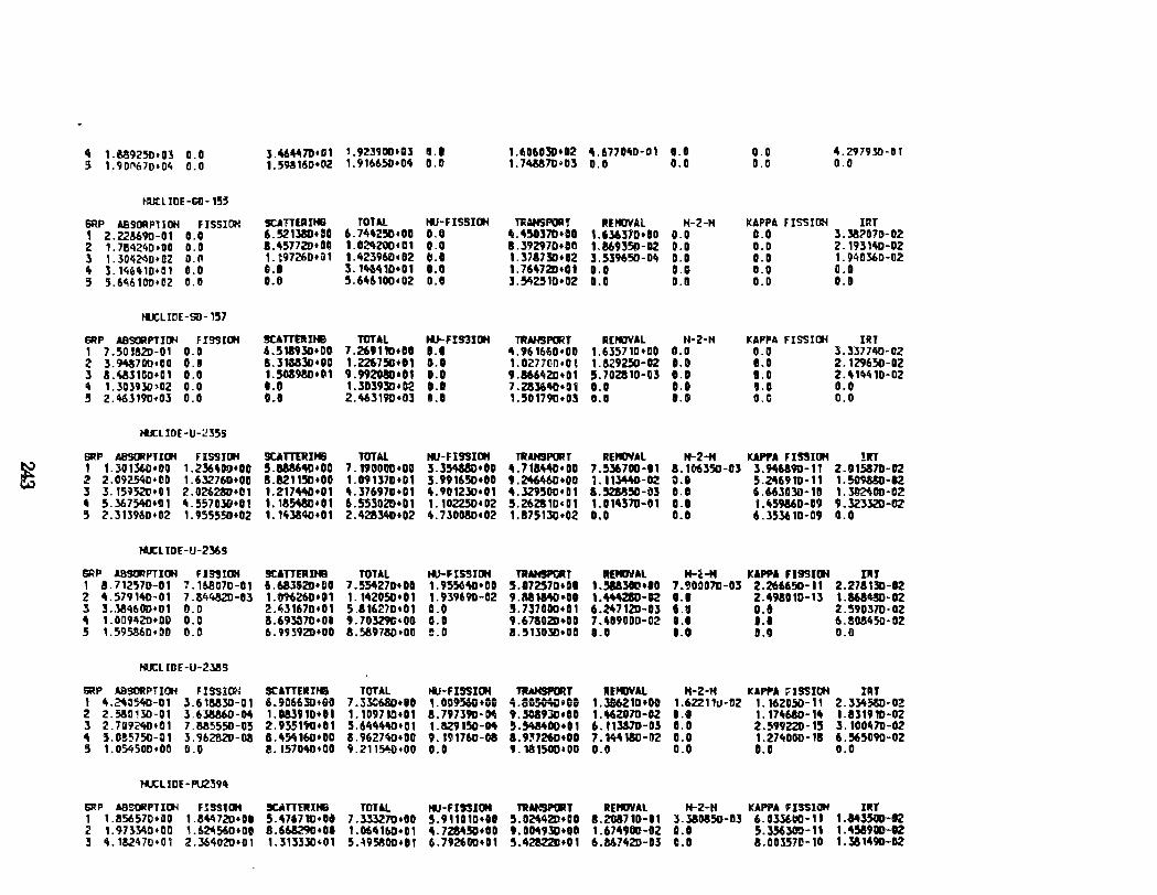
4 1.U925tJ•03 0.0 3.~4111D•D1 '. 92'3900•03 l!l.t 1.6060!0•02 4.6770~0-01 1.0 0.0 4. Z979l0-D I 5 1. 901'670•04 0.0 1.598160•02 1. 91665:1•04 11. o 1. 74M7D•b3 D.D 0.0 0.0 0.0
1-IUtllOE-G0-15~
&RP ASstWtPT I ()I FJSSIC!tt !ICA'ITEIIINB TOTM. ttJ-FlSSI()I TliAHSPORl' RlP«JVAl H-2-H KAPPA FISSIDH lRT , 2.228690-01 e.o 6.521380taD 6.744250•110 0.0 4.~~37D•et 1.636370•80 0.0 0.0 3.382070-02 2 1.784240•00 0.0 8.~57720•011 1. 02tt2'0D• 01 a.o 8.392970•011 1.869350-0Z 0.0 0.0 2. 193 1"0-02 l 1.304~0•02 0.11 1. t97260trt1 1.423960•112 tLO 1. 3787311•12 3.539650-0't 0.0 a.o 1.940360-02 4 3. 146"'0+CU 11.0 D.l 3. 1~410•01 1.11 1. 7647211•0 1 0.0 0.0 0.0 D.O 5 5.6~6100•02 0.0 0.6 5.646100•02 0.0 l. Yt251D•II2 0.0 0.0 0.0 0.0
~LIOE-60-157
IIIIP A9S(JIPTIIJ'I FISSUJH !CATTtiUtll TOTAL NJ- FIS31114 TRAH9PORJ R[PIOYAL H-2-H I(APPA FISSICtl IRT 1 7 .501!J2D-01 O.D 6.518930•00 7.269110•01 ••• 4.961660•00 1. 635710 •DO 0.0 0.0 3.337740-DZ 2 3.943700•110 0.!1 S.31MlD•DD 1 .226751l•Ot 0.0 1.027700•0 ~ 1. 8292.50-02 e.o 11.0 2.129650-02 3 S.~31GD•OI 0.0 1.508980•01 9.992080•11 o.e 9.866'tZD•D1 5.702810-03 O.D 11. o 2.414410-0Z 4 1. 303930>0Z 0.0 1.0 1. 303930. B2 lU 7 .283640•111 0.1 D.D ••• 0.0 5 2.463190•03 O.D 11.1 2.46J19D•Dl D.ll ,.501790•03 o.a e.o 0.0 0.0
IU:LIOE-U-:!355
1111 P A89(J! I'TICJI Fl~JCJI !ltA T'TtRJNB TOTAL ttJ-FlSSI~ TRAHSPORT REtiOYAL H-2-f4 KAPPA FI~IOH !RT
~ 1 1. :so !360•00 1.236400•00 5.888640•00 7. 1900110•00 ].354880•00 ~.718~•00 7.536700-11 8. 106350-03 3.946190-11 2.1115870-02 2 2.09ZS4D•DII 1.632760+00 8.821150•00 1.09137D•D1 ].991650+00 9.2tt6'+60•DO 1. 111440-02 0.1 5.N91D-11 1.50MSU-12 3 J. 15~SZD•01 2.02628D•ll1 1.217""D+D1 4.37697D•D1 4.901230•01 4.329500•01 1.52M50-i:l3 o.o 6. 66JDJI1·111 1.~00-0Z 4 5.367~•!11 ~-~57030•01 1. 185480• OI 6.553020•01 1. 10225DtOZ 5.262S1D•Dt 1.114570-111 O.G t .rt5986D-D9 9.323320-02 5 2.3B96D•D2 1. 955550•02 1. 11i3840•01 2.428340•02 4.730080•02 1.875130•02 0.0 11.0 6.353610-09 0.0
tU:LTDE -U-2369
G!P .I.SSORPT ICJI FI"IOit !IUTTERIHB TOTAL ttJ- FISSIOH TRAMSPIJII r lltiHAL lf-~-M KAPPA FI9SI!Ji Ptr 1 8. 712'HD-0 1 7. 16aG7D-01 6.68lG2D•DO 7 . .554270•00 1. 95!56411•01 5.172570•111 1. !118300 •tO 7.900070-113 2.266650-11 2.278,311-12 z 4.579140-01 7.1S4432D-Dl 1.M6260•n 1. 142050•01 1. 939690-112 9.a81MO•DD 1.444280-R ••• 2.498010-13 1.868Wl-OZ l 3..~1\600•01 0.0 2.ltJ167D•Ot 5.81li21'0•D1 a.o 5.737000+01 6 .24712D-03 1.1 o.a 2.590370-02 4 1.0G9ttZD•DD 0.0 a.69l37D•Oií 9.70329G•OO 0.0 9.67802D•DO 7.409000-02 0.0 ••• 6.!SM1t50-0Z 5 , .59.5360•00 0.0 6.99~92D•OO 8.589780•00 ~.0 8.51JOlD•DD 1.0 1.0 e.o 0.0
t«JCLIDE-U-23115
6RP ABSORPH~ FISSION SCATTEIIIINS TOTAL 'i.I-FISSICII TlbHSPORT REPIJVAl H·2·H KAF'f'A ;: I SSIOH IRJ I ~-~il5'40-01 3.61MlD-01 6. 906630+00 7 .31.."680•110 1. D095®•lUI ~.;~•CD 1.316210•00 1.622111J-02 1. 16Z050-11 2. 3l458D-OZ z Z.58liHD-01 l.63&6D-04 1.W910t01 1. 10971Qt01 8.797391HM 9.l089lD•DO 1.462070-DZ l.t 1. 17~680-14 1. 831910-0Z J Z.7U'i'240•01 7.M555D-C5 2.9351"'+01 5.6"'t4D•D1 1.!SZ9150-D4 5.54M00•11 6. 113&70-03 11.0 2.599Z2D-15 l. 1001t7D-OZ ~ 5.11!5750-111 l. 962alD-08 8.4~160•00 8.9627%0•00 9. 1~1760-08 1.9,726D•ID 7. 144180-112 0.0 1.27~000-13 6.565090-02 5 1. OS45DD•OD 0.0 e. IS704D•OO 9.2115o'!D+OD 11.0 9.181500•00 0.11 0.0 0.0 0.0
tu:LIOE-PU239'
GJ:P ABSORPTICtl FlSSI~ SUTTlRlH8 fDTAl ttJ-FIS!IOH TRA~m'URT REPIJVAL H-2-H KAPPA FISSIOH DIT 1 1. 856570•110 1.8'"720•~1 5.47671D•Ocl 7 .ln27D•OO 5.911010•11 5 . 02t\42ll• DO I.Z0871D-11 3. 380850-113 6.U~t~a-11 1.143500-02 2 1.9H~D•DO 1.62'11560•00 8.668290•01 1. 061\160•0 1 4-72M!iD+OD 9.0049lD•U 1. 6749110-0Z 0.1 5.3.56300-11 1 . 458900-02 3 4. 1!2470•0, 2. 361\0ZD•O 1 1.31:53:~~01 5. -\9!5800•0 1 6 .792600•0 1 5.428Z2D•01 6.M7~2D-D3 c.o 8. 00l57D-10 1. 3& 1490-02
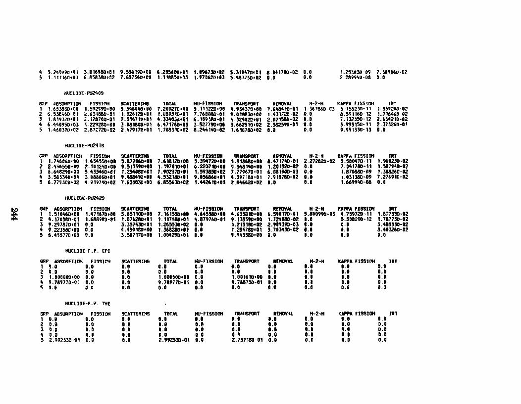
4 5. ztl~99il•G 1 3.1t69M•01 9.5.56190•00 6.211,.00•11 t.HI7lD•02 5.31947D•Dt 8.141700-02 0.0 1.~3830·09 7 .l!I986D·02 s 1. 111160+0] ê.a~.w~~cz 7.M7!w.)•CO 1. 111!1850+03 1.97062D+IIl 5.41J375o•D2 11.0 0.0 2. 2!99,.0·03 0.0
N'XLIDE·PU24G9
~p ABSORPTIOH FISSI~ SUTTERIHII TOTAL 1«.1· FI SSHif ntAHSPORJ REIIJVAI.. H-2-H klPPA FISSJOH IR f 1 L65l!lD•DD 1. 592990•00 !I.W440+~11 7.20027D+OQ !1. 1 11221! • DO 4. 9~37o•OD 7.6~410·01 t.l67MD·Ol 5. 155230-11 1 .!59200·02 2 6.5le'f60-01 l::.6318!.0·01 1.02'\1lD+01 1. 0895tD+01 7.760MD-01 9.0158.50+00 1.431720·02 11.0 8.591160-12 L 7161t6D-02 3 1.8111l2D•Dt 2.123700-01 2.51U10+11 4.3.YtD3it•Gt 6. 109180-01 4.l21tOZD+111 2.021580-02 11.0 7. ll2l50-12 2. 6lii21D-G2 4 6 .lt40950•03 ~ • 2Z9Z8D •1111 3.05'1100•01 6 .47176D+O:S 3. 527790•01 3.662910•02 2.582590-01 0.1 3.9951511-11 2.373260-01 5 1.%0:590•02 2.87~720-0l 2.479170+111 1.70531D•C2 1.2"4140-02 1.6 16780•02 l.t 0.0 9.4913]ll-13 0.0
HUCliDE-~IS
~p lli!SORPTIO"tf FI,IOH !ICATTOINI TOTAL 161-FIS91Cif T1t1H91'0111T RE110'ill H-2-H KAPf"' FISSIDii IIIJ t t. 746060•00 1.654550+11 5.17206C•t• 7.618 1211+01 5.3947~•01 ~-9~+11 1.~717~-11 2. 2728211-02 !1.500470·11 1.960250-02 2 2.456550+00 l. 101~•CI 9.513590+10 1. 1t701Dtlt ~.223710•01 'L54&11\D+Dt 1.2015211-R 0.1 7 .041780-U 1.5&79~-02 3 6.6~+01 5.43546a+Of 1. 254080•11 7.f0ZJ7D•I1 ,_ 59315D•t2 7.779670•01 6.031900-03 0.1 I. 870850-09 1.3118260-12 4 3.58!Yta+Oi 3.1.1&8660•01 1.4884'10•11 4.512111•11 9.156860•01 4.397180•01 7. 918710-02 ••• í.Olt:JSG-H 7.276910-02 5 6. 719l01J•02 ,. .9197'NJ•02 7.6330~+00 6 .85,.30+12 1.44Z. 111+03 l.M662D•D2 1.0 0.1 1.6699~-oa 0.0
tU:liGE-PU2429
! 6RP MSGIPTIOH FI !!I IOH ICAnEJn. TOTAL MJ-FJUJCit nt....,..T ltfiiJVAL tt-2-N F.IPI'I F ISSII:Jf nn 1 L510't6D•OO 1.471671)+00 5.t.5110D+O!I 7. 161550•11 4.645SBD•II ~.695810•01 6.590170-01 5.19ot90-D5 4.7597211-11 1.8173!ICI-02 2 4. 1711~1-01 1.6889!!1-11 1.076280+01 1. 117WID•01 4.879760-11 9. 135590•10 1. 7291180-12 1.1 5 . .508200-12 !.717750·12 3 9.ZV757D•01 0.0 3.357ot3Do01 1. 265530•112 ••• 1.215100•02 2.9t939D-t3 ••• o.e 3 • "i55:5D-02 4 f.2Zl58D•OO o.e 4.4591Stt+Gt 1.3632a0•11 ••• 1.214780•01 3.7113450-0Z •.• lt.l 3.403260-02 5 6.455770•00 lJ.D 3.5&717D~oo 1.0042911•01 D.l 9. 90!180• to 0.0 a.o 1.0 0.0
HUCllDE-f.P. EPI
&aP .taSORFT lt!t FI!'JIN SCAn~Il-16 TOlA!. ..,_ nss IOH TUHSPC!RT JIEMIJVAL tt-2-H UPPA FISSI~ IIIT t lJ.O 0.1 O.t ••• e.o • •• 0.1 ••• 1.1 11.0 z a.o 0.0 11.1 t.O D.l o.e 1.1 1.1 1.1 0.1
' 1 .IIDDOOD•OO 0.0 0.0 1. DD0500•00 O.G 1.001610+10 ••• 1.1 ••• O.t 4 9.7&n7o-o1 C.ll 1.1 9. 789770-0~ e.o 9.7&5730-01 ••• 1.1 0.1 0.1 5 a.G G.U 0.1 Cl.O o.o 0.0 l.tl 0.0 0.0 0.0
HUtliOE-F.P. THE
&RP AB'lCJ'PTtOH FISSICIH SCAmlfJNS TOTAL t«J-FIS!IICtl T11D!Sf'OR T Jlt1'GV1ll H-2-M ICAJIPA. FISSIOH I'IT t o.a 0.0 1.0 1.0 ••• • •• J.O 1.0 t.l 1.0 2 0.0 a.o o.a .. , 0,, 0.0 ••• lt.a o.e D.D l ti.O B.D CI.O 0.0 1.1 ••• ••• 1.1 0.1 (i.D
4 0.0 1.0 I.J o.o o.o 0.0 ·-~ ••• 0.1 0.0 5 2. 992330-01 a.a O.D 2.992530-01 0.0 2.757180-01 0.0 e.o 0.0 O.D
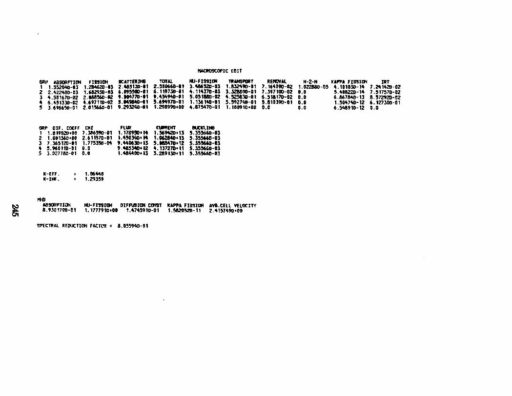
~
SRil I.BSORPTI~ FISSICtt ICATIERM 1 1. 552040-ll 1.21462D-13 2.'151lD-11 2 2.42248!>-U 1.6&2950-ll i.D95510-11 l 4.50167D-D2 2.188560-tz 9.~77D·II
" 6.451l31HI:! 4.697itD-G2 5.149840-11 !l 1.696650-01 2.111!5WI-111
5RP OIF. C'O(Ff DII 1 1.319020•110 7.316590-01 2 1.G01360•00 2.611570-01 J 7.365121:1-111 1. 775350-04 4 ,.9611HD-01 O.G 5 l.92778il-lt1 0.0
k-EFF. K-INf.
= 1.1Xt~O : 1.29359
PHJ
9. 29l24iH11
Fllllt 1. T789Sl* 14 l.l\50l!t0• M 9. 'KD6JII+Il 9.'153411•12 1.484400•13
HICR09COPIC ED IT
TOTAL tll-FISSICIH lltAHSPORT 2.5110660-11 l.W5.2D·t3 1.!321190-11 i\.1191JII-11 4.114370-0l 3 .l28801Ht1 9.45'i940-fll 5.051&SD-02 4.5258JD-01 5.694971-111 1.136140-11 5.5927~-01 1.291990•1111 4.57547tHH 1. 1110910•08
aJif!EtlT NICI.INB 1.569420•11 5.355660-03 1. 062140•13 5.355HD-03 5.18847D•12 5.155660-13 4. 137271•11 5 • .»5KO-Ol l.2.8913D•11 5.355661HJl
AS!ImPTt~ IIJ-FIS910f DIFFU9IOH Cllf!T ~A Fl!I'JIOH AYI.CELl vtlOClTY 8.9}g1711D-01 1.1777910•00 1.4745910-01 1.582052D-11 2.4157490•00
Sl'ECTRAL REDUCTiott FACTC'Jt : 8.1155940-01
REJIJYAL H-2-N KAPPA FISSIOH IRT 7. 16~090-02 1.02288D-05 4.101030-14 7.2414211-02 7.397100-02 1.11 5.4118221H4 7.517570-02 6.~H817D-02 D.O 6.86784D-1l 8.5729211-Gl 5.810190-01 O.D 1.S047ft0-12 6.127300-01 II.C o.c 6.~910-12 11.0
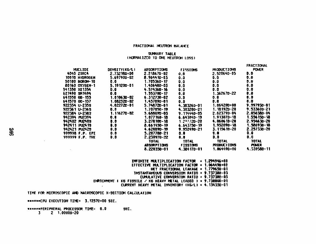
~
!=RACTIOHAL l'fEUTROH BALAt«:E
SlH1.ARY TAB!.E I HlMHALilrD TO 0HE HEUTROH LOSS I
HUtliDE DENSITYI K&/1. I ABSORPTIOHS FlliSIOHS PROOUCTIOHS ltOitO ZIRC4 2.732180•00 2.213670-02 i). o 2.520640-05
100 10 HYORCGEH 5.697900-02 8.964410-0l 0.0 G.O 50100 Bc.(lf-10 0.0 t. 705360-17 0.0 o.o 80160 OXY&EH-1 5.191200-01 1.1tC6480-03 0.0 o.o
54 1350 XE 1354 0.0 ft. 571t36D -16 0.0 o.o 6211t90 Stt1494 o.o 1.553700-17 0.0 1.362670-22 641550 G0-155 1.010610-0~ 6.312730-02 0.0 0.0 6~1570 60-137 1 . 08252D -02 1.457!90-01 0.0 o.o 92235&\ U-235S 4.02272D-01 5.748720-01 lt.l!S3Z6D-01 1. 064200+00 922361 U-236S 0.0 1.707050-19 ft.3Cl20D-21 1.181920-20 9223M U-2383 1.116270-02 5.688890-03 9. 11444D-05 2.623790-04 9lt2391t M394 0.1 1. 077160-18 6. 6~13~0-19 1. 913070-18 94~02 ~09 0.0 3.271100-18 1.2.-:17/20-20 4.060610-20 M~11 f!U2lt1S 0.0 a. 661~50-19 6.64l750-19 1.9SZ09D-14 94~21 ~2S 0.0 4.620390-19 9.952490-21 3. 11561P-20 999998 F .P. EPI o.o 5.207180-21 0.0 0.0 999999 F. P. lHE 0.0 2.230970-22 0.0 0.0
TOTAl TOTAL TOTAl .IBSORPTIIIG FISSIDHS PROOUCli<If.l 1.220350-01 4.314170-01 1. 06ltlí9D~OG
IHFIHITE PU..Tirt.ICATic.t FACTIR :a: 1.2949411•00 EFFECTivt tU.. TlPLlCATIOM FACTOR = 1. 064490•n
HU FRACTICJIAl LUKA&E :a: 1. 779650-01 lHSTAHTAHfOUS CONVERSIOH RATIO : 9.737310-0l
CUHULATIYE COHYERSIOH RATIO : 9.737380-03 EtiUCHHEHT I K6 FISSILE I' K& HEAVY HETAL lOAOED J :a: 9.7341000-01
C\JlREHT HEAVY METAL IHVfNTORY I KSIU .: 4. 1~350-0 1
TIHE FOR HICROSCOPIC AHD MACROSCOPIC X-SECTIOH CALCUlATIOH
••••••CPU EXECUTIOH TIHE= 3.12570•00 SEC.
••••••PER!PHERAl PROCESSOR TIHE~ 0.0 SEC. 3 2 1.00~00-20
FRACT!OHAL POWER
0.0 0.0 o ... 11.0 a.o ii.O 0.0 o.o 9.997950-0t 9.533600-21 2.050J80-04 1 . 556150-11 2.9~30-20 , . 586930-18 2.257l30-20 0.0 O.fJ
TOTAL POWER
4.539580-11
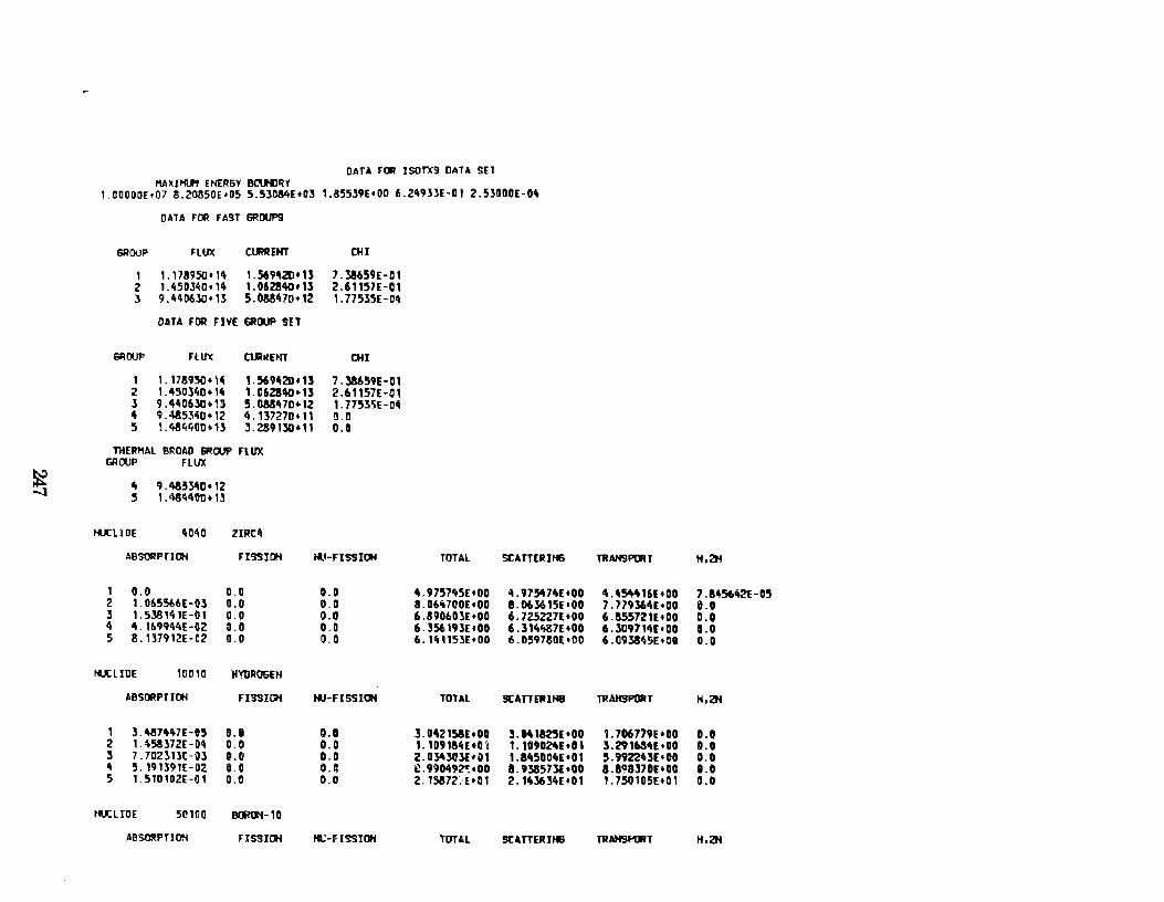
DATA l'llR JSOTX9 DATA SET I1A X I HI.J'9 ENE JIGY BC.Uil R Y
I.GOOOOE•07 !.2085DE•05 5.5Jn84E+0] 1.85539E+DO 6.249lJE-01 2.5300DE-D4
DATA FOR F~9T SRCM'S
GROUP FlllX CtMEHT OH
, 1.178950•14 1.56942Dt15 7 .38659E-ll1 z 1. 45DJ~o· 14 LD6Z!I40t1l Z.61157E-01 l 9.4"06JO+B 5.MM7D•12 1.77535E-IItt
OATA FOR Fivt: 6Ril.IP SET
6111JUP FUN CtlhlENT CHI
1 1. 178950. \4 1.5691112D•U 7.38659(-01 z 1. 450340• llt 1.C6ZS40•1l 2.61157HJ1 J 9.4406JD+U 5.GMI't7D+12 1. 77535E -OI! 4 9.485340+12 li. 137270• 11 lU! 5 1.4M400+1l 3.289130+11 0.0
ntERHAL BROAO EiROUP FlUX GROUP FLUX
~ 4 9 .483l-'D•12 -l 5 1.4aii40D•B
tUCllDf 1\040 liRCtt
ABSOIIPTIOH FI9SIIJN 1«.1-FISSIOH TOTAL SCAITERJH6 TRAH9P()RJ N,Ztl
I 0.0 0.0 0.0 4.9757't5E•OO ~.975474[•00 4.1115tt416l•OO 7 . 845642(-05 2 1. 0655b6t-Ol 11.0 0.0 8.06ít700Et00 !.063615E•OO 7. "179364(•00 0.0 J I. 53814 TE -0 I 0.0 0.0 6.89D60JE+OO 6. 7Z5Z27E+OO 6.a5572U•OO o.a 4 ". lt.9944E -oz ~1.0 0.0 6.J~I9Jt•OO 6. J 14ft87f +DO 6. JD9114E •00 a.o 5 8. B7912E-02 0.0 0.0 6.14115lE+OO 6.D59780E•OD 6. 093845E • 00 0.0
tU!: LIDE 101110 H'!'DR06EH
ABSDRPTIDH FI9SiõH IIJ-FISSIOH TOTAL StAITEIIlH8 TRAHSPOIIT ~.ZH
1 3. 4874't7E-e5 1!1. o 0.1 J.042158Et00 ~.041mt•OO 1. 706 779E +00 o.o 2 1.~5Sl72E-Djj 0.0 0.0 1. 109184[ +O '1 1. 109024(•0 1 J.29163Ut00 0.0 3 7. 702li:U -QJ IUI 0.0 2.D~lOlE•i11 1.8lt5004E•D1 5.9922'13E•CO o.o ~ '. l91391f.-IJZ 0.0 O.tl t1.99D49~•00 8. 9:5857Jl •DO 8.84!18370E•OC O.D 5 1.510102Hl1 0.0 0.0 2. 15372.cE•01 2. 14l6JU•01 , 750105[•01 D.D
tU:LIOE ~1!1011 BOROi-10
A"BSORPHOH FXSSJCJi Hl:-FI!SIOH TOTAL 9ClTTEIIJH8 TRAHSP'IJIT H.ZH
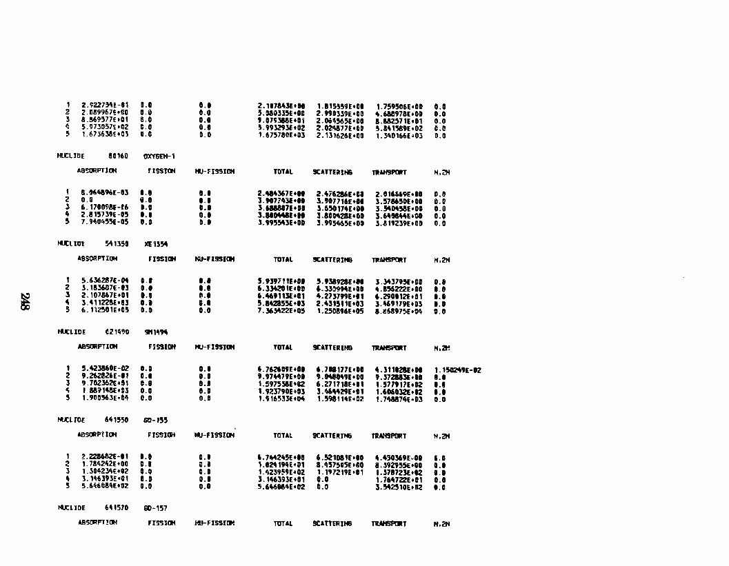
1 Z.\lZ27~E-01 1.0 0.1 2. 107MlE•II 1.115~~9E•OI 1. 759~06E•DD 0.0 2 2.0!!9967f•ll0 0.0 0.0 5.G80335f•DO 2.99D339E•DO 4.68897BE•OD 0.0 3 8.!69577Et01 tU 0.1 9.07BNE+Iti 2.0i~56~•110 1.112571E•01 CI.O ~ 5.973D57E•02 c.a 0.1 ~- 993293lt02 2.0N17E•III ~.141589(•02 c.e 5 1.67l638E•03 11.0 D.O 1.675730Et0l 2. 1l1t.26E•DO 1. YtD 166E •Ol D.O
HUCLIDE !0161) OXYSfH-1
ABSORPT l D'f FISSI1»4 ti.H' I!t9IOH TOTAL 9CATUiHH& T1UoH9f'(JIT H,2H
1 a.M4BHE-lll 1.1 0.1 VY4367E •H 2.476286E+CI 2.016169E•DD O.IJ 2 0.0 8.0 I.D 3.9t711\31•H J.907716E+II !.578650E•DD 0.0 3 6. 17DMN-r6 ••• 0.1 3.MU07E•DI J.65017U•OI 3.541145SE•OD 0.0 4 2.815739(-05 1.1 0.1 l.IIKUE•H J.IOM28E+IID 3.640M4E•OD 0.0 5 7.H0455(-05 D.O D.l 3. 99554lE+DD l. 995465Et DO 3.ll192l9E•DD 0.0
IU:liDt 541350 XE1!54
ABstii!PTI~ FISSIOH IQJ-FI9!110H TOTAL !ICATTfRIHB TJIAH5f'(I!T M,ZH
1 5.6l6Z37E-04 0.1 ••• 5.9J97f1E+DI 5.t!l921f•ll l.:Ml795E•OD 0.1 2 3. 18:!6ll7E-13 ••• 0.1 6.ll4201E•tl 6.l39994E•OI 4.856222[•00 ••• J 2.107867E•Dt 1.1 l!.l 6.46911)(+11 4.273799E•t1 6.290112!•01 D.l
" 3.41122!1•!13 D.l ••• 5.842155E•Il 2.4l1511E•03 ].469U~EtDS D.D 5 6.11Z501E•D5 0.0 D.O 7 .]6]4Z2E +05 1. 250896( •05 1.116897~•04 0.0
tU: liDE ~2WJO St'l111'M
ABSORPTIOH F2SSIIJf ttJ-FI9911»4 TOTAl 9CI\TTE111ttl TRioHSAIIT H,2t!
1 5.423UIE-CZ O.D D.l 6. 762tiHE+II 6.7DI177E•DI 4. 311t2U•H 1. 15112'49E-D2 2 9.Z6ZU6E-11 0.1 t.l 9.97~79E•OI 9.1MN49(•0D 9.372113E•DD 1.1 3 9 . 7G2J62E • !H e.e lU 1. 597536[ •12 6.271718E•I1 t.577t11E+D2 1.1 ~ 1.389148E•II3 o.a e.o 1. 9ie3790E til] ].'tl4\29E•I1 1.6060l2E•12 1.1 5 1.9DnUE·D~ 0.0 O.D 1.9165331•04 1.598114[+02 !.748&711if•Ol 0.0
I'U:LIDE 6ftU~O G!H55
A8SORPTIOH FISSIIJI'tl tll-Fl!SIDH TOTAL SCATTUJMi TJI~T H,2H
1 2. 228682(-G 1 ••• 0.1 6. 71t4~5E •lO 6.521DIU•IO 4.4!J0369hll li.D 2 1. 7842ft2E •DD 0.1 ll.il 1.0ZCI 11HE•;t 1.111575D5E•OO 8.392955E•OI 0.1 l 1.lD42YlE•02 o.o 0.1 1.ft2~9!õ9E•D2 1.1972191:•11 1.37172lf.•IZ 0.1 4 ]. 1~6393E•01 1.1 0.1 ].1463931:•111 ••• t.764722f•01 0.0 5 S.6ft603ftE•OZ D.O 0.0 5.6460ME•02 D.O ].!M2510E•02 0.0
tU: LIDE 6f!1570 60-157
lBSORPT!OH FISSIOH t«.J-FISSJ!Jo! TOTAl 9CAnERIII& TUtt!iPOIT H,2N
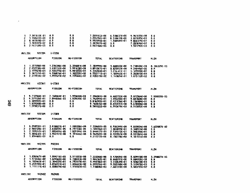
I 1. 501!1 nr-e 1 o.a 0.0 7.269103E•DO 6. !'H8UIE•00 .,,961655E•DO 0.0 2 3. 9<\.8691( •00 0.0 O.D 1.221l7~E+01 8.318611E•OO 1.D27695E•01 0.0 3 8.~3078E•D1 0.0 O.D 9.99201\f!t•Of 1.~08404E•01 9 .&66l74E •O 1 o.o 4 1. JQ 3907E • 02 0.0 O.D 1.l039:17E•02 !1.0 7.Z!3646E•01 o.o 5 2.4631b8E•D3 0.0 0.0 2.4631~E+03 11.0 1.501792E•03 1!.0
ti.Jr.LIOE 922354 u-~35s
AB s:JR P TI O!i FISSIOH KJ-FISS!tl4 TOTAL SCAnE;:!lHIB TUHSf'tiRT H,ZH
I 1.30 1358E+DD t.236396t•OO 3.l!Yt88,e•OCI 7.189J99E+OO ~.W40lf•DO 4.71M~r•DO 8. 106J29E-03 2 2.092538E•OD I.U2753Et00 3. 9"63!!'. •DO 1.091367E•01 8.8Z0953E•DD 9.246't46E+OO 0.1! 3 3. 15?~DE+ill 2.D~27U•Of 4.901222t•01 4.376964E+01 1.216~J[•01 4 .l2941ê!E •0 1 a.a " 5.l67374E•01 4.5S6376E•OI t.102220E+02 6.552771E+D1 1. 185463E tO I 5.26Z!1DE•D 1 0.0 5 2.3B9.HE•02 1. 955521E+02 4. 729868E•02 2.42!J15E•D2 1. 143824Etbl 1.8751l2E+02 0.0
IH: LIDE 1122361 U-236S
ASSORPT ICJl FISSION tfJ-FIS9ION TOTAL SCATT[QIN& TRAHSPORT H,2H
1 !1.712~6(-01 7. 16806411!-01 1. 95564DE+OD 7.554269E•DD 6.6U7!1lt•OD !1.0725641'•00 7.900055E-Ol 2 4.579128E-P1 7.844306E-113 1. tl9690E-02 1. 1420<\U • O f 1. 09625'1:•0 1 9.U1828h00 0.0
~ 3 l.l84592E+Ot 0.0 0.0 5.81~5Et01 2.431036E+01 5.7369341•01 o.a " 1.0D9398E~oo ••• a.o 9.702&76E•IO 8.69~~7E•9D 9.678026[+08 0.0 5 1. 595837E•OO D.D O.D 8.589522E•OD 6.993679E•OO 8.~13t152E•OO 0.0
tU: liDE 9223!4 Ll-2.589
ABSORFTIGI Fl9'5IOH tfJ-FISSIOH TOTAl SCATIERIHB TRAttSf'(IIT H,2H
1 4.24.,36E-01 3.618821E-01 1.00955oSE•DD 7.l30680E•Dil 6. 906349E •DI 4.50583U•DO 1.622087E-D2 2 2.5o30128E-01 3.6lM59E-M 8.797338E-01\ 1. 109706E•O, 1.C83595l•DI 9.3G8t1.,f:+OC 0.0 3 2. 709241E•01 7. 8S~9U-O!I 1. 829144( -01\ ~- 64.,'t 17E• O 1 2.934572l+GI !1. 54&390t:+O 1 a.a " 5. 03SU2E -O 1 l.962761E-03 9. 191666E-08 8.962522(•00 &.4~3961E+OO 8.937264E•DO 0.0 !I 1. 05411j8Q[ •1111 0.0 0.0 9.21 127lt•DO a. t5ttnae•oo 9.18151JE•DD D.D
tu:LIDE 942394 PUZ39~
ABSO!! PT IOH FIS!IIOH tli-FIS910N TOTAl 9CATIERIHB TIIAHSPORT H,2H
1 1.S56!167E•I!O L&\4716E~Itli 5.911D03l•OD 7. S3326M•ID 5.47M5ftE•DD 5.024411f:•OO :S.l!OS271'-0l 2 1.973ll6E•IID 1.62456DE•DO 4.728443E•OO 1. 06"621' •11 1.661097E•OD 9.01M920E•OO 11.1 3 4. 182tt63l •O t 2.l6411Z0Et01 6.79257SE•01 !1.495786E•01 1.312639E •O 1 5.~18E+01 D.O
' !.Z49789E•01 :S.8169lfl+iH 1. D 966t5E • OZ 6.2053»E•01 9.55576aE•06 5.31M78E•01 0.1 5 1. t 11111E•03 6. BS8079E • Ol 1.'n0~5Etll3 1. 118806E •03 7.68731DE•OO 5.~3755(•02 0.11
tU:l11lE t'i~ez PU2ft09
ABSORPTIOH F!SSIOH tfJ-FISSI1114 TOUl SCAntJIIHB TRAH!!PORT ... 2N
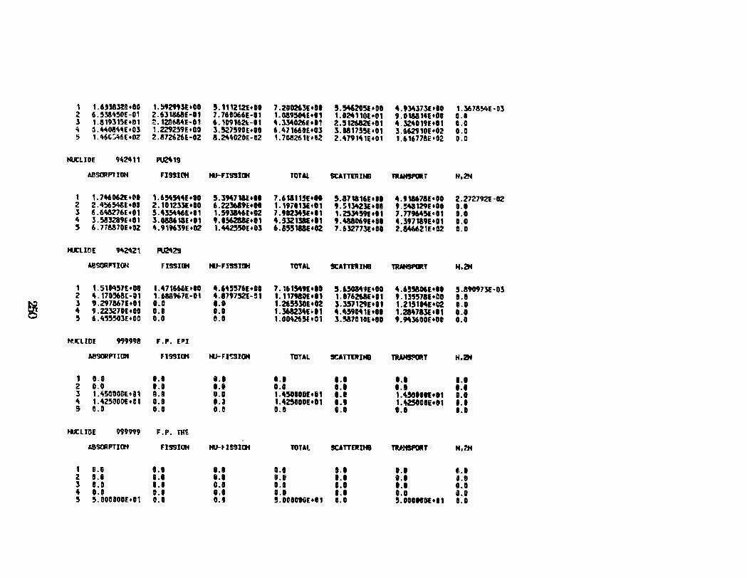
1 1 .6518-R!•IO 1.!;92tUE+CI S. 11121ZE+IO 7.210263(+11 S.!M6205l•OI 4.9~3731+10 1. 367!~E-D3 2 6.S3M5DE-01 2 .631368E-11 7.76GD66E-11 1.089504[+11 1.824110l+D1 9.01M14E+OD !I.D l 1.!193151:+01 ~. 128M4E-O! 6.1091621:-11 4.3340261+11 2.512682€+01 4.~0191+11 0.0 ~ O. "08\,.E +03 1.2292S9E•OO 3.52759DE+OD 6.471660E+Dl l. D8175!H: •0 1 3.662910E+02 0.0 5 1.46(;:;~6(+02 2.!72&26(-112 ll. 24"0211E -112 1. 708261E.fiJ2 VU9141E+Ot 1.6167781:•02 0.0
NUCLIDE 9i!241 1 PIJ2\1!J
ABSORFTIOH FJ!IS([tf tii-FIS!ltll TOTAL SCATTUIHB nAHSf'Uii r H,2N
1 1. 746062E+C!D 1.654544E+011 5.3947111+11 7.61111!f+H 5.171a16E+II 4.911678E•DO 2.2727921-02 2 2. 4~548E +1111 2. 1012llE+IO 6.22l61ti+H 1.19ilt3Et01 9.St~23E+II 9."'129E•OI D.O l 6.6ft8276E•G1 5.4354~E+I1 1.59li46E+G2 7.9123451+11 t. 2534'591•11 J.nM51•01 0.0 4 3. 583289( •OI l. 0886'11l+01 9.1562&1E+I1 4.532t31E+It 9.4aa069E+DI 4.397119E+01 0.0 5 6. 77e!70Et02 4.9196l9E+D2 1.~E+Dl 6.85518Mt02 J.632773E+DO 2.846621E.f02 0.0
t«n.IOE M2'\21 P\J2'1129
~SORPTIOH FISSJ(If tiJ-FISSJtlf TOTAL StAnRIHII nwtSPORr H,2H
1 t. 51Gq5JE •00 t.47t666E•IO 4.6455761•11 7. 1615491. li 5.6501411+011 4.65!106E•II 5.190973E-D3 2 4. t70,.8E-Ot 1.6MK7E-01 4.1797-'21-51 1.11Jtaof.+l1 1 . t76261E •11 9.t3'J571E+OD e.e
~ l 9.2978671+11 1.0 1.1 1.265!50E+I2 S.l57129E•D1 1.2t51ME+02 o.o 4 9.22lZ7DE+OO 0.0 0.1 '. 3612l4E •11 4.~59~1E•tl 1.214713(+11 0.0 5 6.4,5503E+OO 0.0 8.0 1.0042UI•C1 l.!I&701CE+fJO 9.943600E+Dt 0.0
t6:LfDE 9')9998 F.P. EPI
A8'lORPT Illtl nssiai I'IJ- F I C:SIOH TOTAL !CA T"TER IHD TIAH!FmT H,2tt
1 0.8 ••• 1.1 1.1 1.1 1.1 1.1 2 0.0 ••• ••• 0.0 0.1 1.1 1.1 3 1.~5COOOE+iH e.a I). O 1.4500101+81 l.t 1.4540111•11 1.1 4 1.425000E+C1 11.8
··~ 1. 425800[. 01 1.1 1.~DIE+D1 t.l
!j G.D O.D cu 0.0 0.1 ••• 1.0
tU: LIDE 999999 F.P. llCE
t.BStiiPT I OH FI99JIJH 111-H!SICif TOTAL ttAlTERJHI l'IWISPOitT H,?J4
' B.G ••• • •• 0.1 t.l 1.1 ,,,I 2. 11.1 D.l 8.1 1.1 1.1 t.l l).t ] D.D D.l C.ll 1.1 ••• 1.1 1.11 't 0.11 t.l ••• 0.1 ••• o.o ••• 5 5.oooaooE•Dt 0.0 0.1 5. DODDIHIE+et t.CI 5.0DOtcH+I1 D.O
Appeadh:F Tabular Summ.ary ol Calculated Be!JUlâJ
Thil3 a appenilix summarizes in detail ali calculated resulta for this
study. Table F.l summarizes the deeign resulta for reactor cores 1, 2 and 3.
Table F.2 summarizes the design resulta for reactor cores 4 and 5. In these
tables, isotopic number densities in the fuel far the uranium and plutonium
nuclides at B.O.C. and E.O.C. are listed.
251
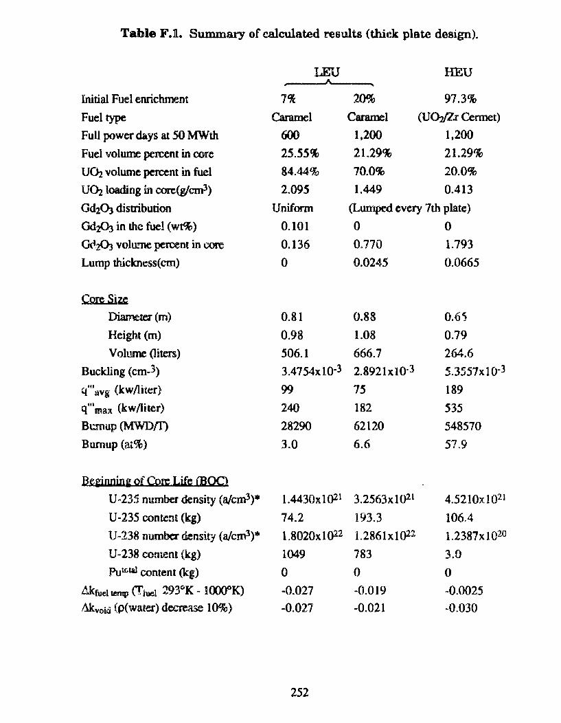
Table F.n.. Summary of calculated results (thick plate design).
LEU HEU
Initial FLJel enrichment 7'l 20% 97.3%
Fuel type Caramel C arame I (UQYZ.r Cennet)
Full power days at 50 MWth 600 1,200 1,200
Fuel volw:ne percent in core 25.55% 21.29% 21.29%
U(h volume percent in fuel 84.44% 70.0% 20.0%
UÜlloading in corc(g/cm3) 2.095 1.449 0.413
Gd20:J disnibution Uniform (Lumped every 7th plate)
Gd20J in thc fuel (wt%) 0.101 o o 0<12.03 volmne percent in core 0.136 0.770 1.793
Lump th.ickness(cm) o 0.0245 0.0665
Core Size
Diameter (m) 0.81 0.88 0.65
Height (m) 0.98 1.08 0.79
Voll!llle (liters) 506.1 666.7 264.6
Buckling (cm-3) 3.4754xl0-3 2.8921xt0·3 5.3557x 1 o-3 q"'~vg (kw/Jiter} 99 75 189
q"'max (kw/liter) 240 182 535
Bcmup(MWDm 28290 62120 548570
Burnup (at%) 3.0 6.6 57.9
a,~Wlin& Qf eo~ LiCc woc) U -235 number density (a/cm3)* 1.4430x. 1 ()21 3.2563x10²¹ 4.5210x!021
U-235 contcn~ (kg) 74.2 193.3 106.4
U~138 number densit-t (a/cm3)* 1.8020x 1 ()22 1.2861x1Q22 l.2387xl020
U-238 coment (kg) 1049 783 3.0 Put(,lal content (kg) o o o
Aktue11m1p <Ttue~ 293"K- lOOOOK) -0.027 -0.019 -0.0025
Mcvoiâ (p(water) decrease 10%) -0.027 -0.021 -0.030
252
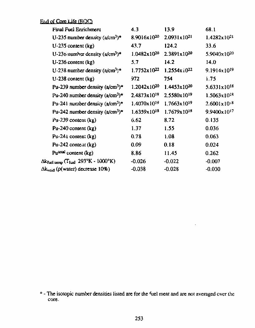
Eud of Core Ufe (E,QQ
Final Fuel Enrichoxnt 4.3 13.9 68.1
U-235 number den:\ity (a/cm3)• 8.9016x 10²° 2.093lx1021 1.4282xi()21
U-235 content (kg) 43.7 124.2 33.6
U-23ti numn.:z. <k.nsity (a!cm3)* l. 0482x 1 ()2° 2.3891x1()20 5.9040xt02°
U-236 content (kg) 3.1 14.2 14.0
U·238 number density (aicm3~• l.7752xl()22 1.2SS4 X i ()22 9.1914x10l9
U-238 content (kg) ~72 754 L75
Pu-239 number density (aJcm3)* 1.2042xl()20 1.4453xt()20 5.6331x1Q18
Pu-240 number density (afcm3)"' 2.4873x10¹⁹ 2,5580xl019 1.5063x10¹⁸
llu~241 number densiiy (afcm3)• l.4070x1Ql~ l.7663xiQ19 2.6001x10 18
Pu-242 number density (afcm3)• 1.6359xl018 1.7679x 10¹⁸ 9.9400x 10¹⁷
Pu-239 contem (kg) 6.62 8.72 0.135
Pu-240 content (kg) 1.37 1.55 0.036
Pu-241 conten' (kg) 0.78 l.08 0.063
Pu-242 conteat (kg) 0.09 0.18 0.024
Puialll contem (kg) 8.86 11.45 0.262
&kfucl Lr:mp (T fud 293°K - 1000°K) -0.026 -0.022 -0.007 Llkvoid (p(water) decrease 10%) -0.038 -0.028 -0.030
"' - The isotopic number densities lísred are for the fuel meat and are not averaged over lhe core.
253
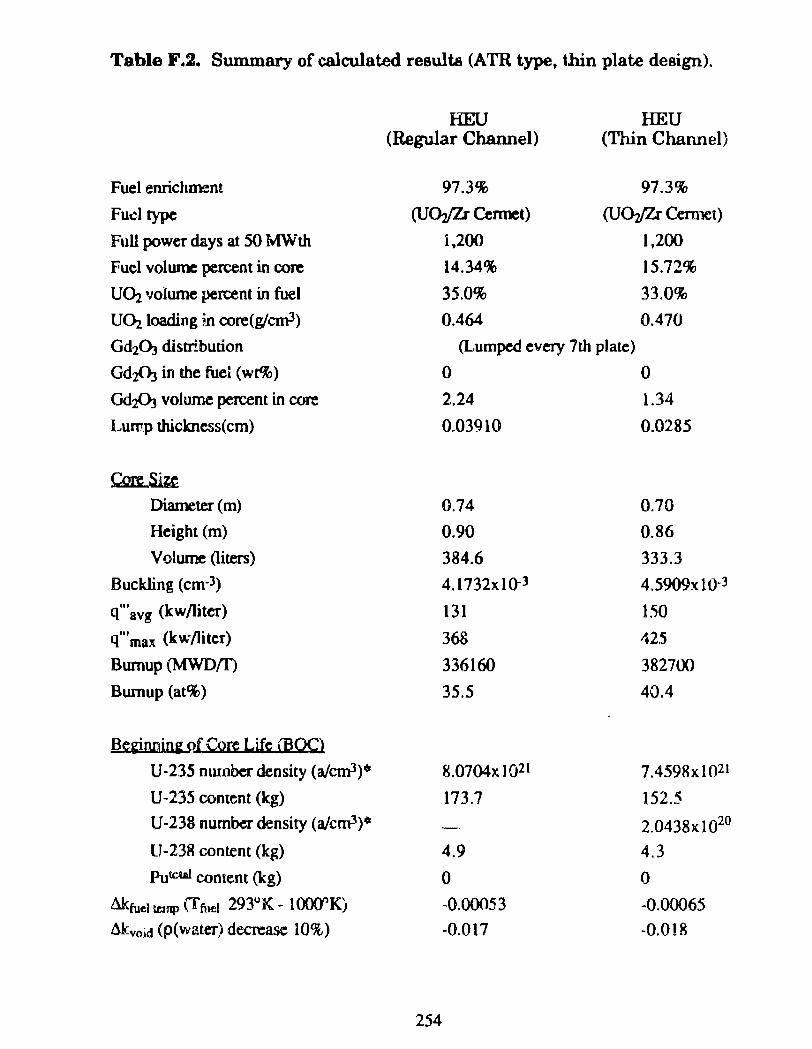
Table F.2. Sum.mary of calculated resulta (ATR type, thin plate design).
HEU HEU (Regular Channel) (Thin Channel)
Fuel enrichm:nt 97.3% 97.3%
Fud type (U(}p:r ~nnet) (U(}p:r Cermet)
Full power days at 50 MWth 1,200 1,200
Fuel volume percent in core 14.34% 15.72%
UÜ! volume percent in fuel 35.0% 33.0%
UOz loading in core(glcm3) 0.464 0.470
Gd2ÜJ distri.burion (Lumped every 7th plate)
Gd:z03 in lhe fuei (wt%) o o GdA volume percent in core 2.24 1.34
Lump thickness(cm) 0.03910 0.0285
Core Sizst Diameter (m) 0.74 0.70 Height (m) 0.90 0.86
Volume (liters) 384.6 333.3
Buckling (cm-3) 4.1732xiQ-3 4 .5909x 10-3
q"'avg (kw/liter) 131 150
q"'max (kw/liter) 368 425
Bwnup (MWDnJ 336160 382700
Bwnup (at%) 35.5 40.4
Beginnin~ of Core Life lBOC}
U-235 nmober density (alcml)" 8.0704x 1 Q21 7.4598xl02l
U-235 coment (kg) 173.7 152.5
U-238 number density (a/cm3)6 2.0438x 10²⁰
U-238 content (kg) 4.9 4.3
Putctal content (kg) o o &fuel ~np (f fu~l 293°K- 1 (){)(')"K) -0.00053 -0.00065
ókvoid (p(water) decrease lO%) -0.017 -0.018
254
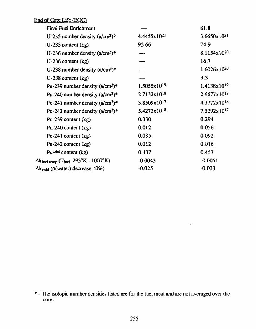
End of Core Lif~ CEQC
Final Fuel Enrichment 81.8
U-235 numbc:r density (a/cm3)0 4.4455x 10²¹ 3.6650xJ()21
U-235 content (kg) 95.66 74.9
U-236 number density (a/cm1)• 8.1154xi02°
U-236 content (kg) 16.7
U-238 number density (a/cm3)• 1.6026x 10²°
U-238 contem (kg) 3.3
Pu-239 number density (a/cm3)• 1.5055x 10¹⁹ 1.4138xl019
Pu-240 number density (aJcm3)• 2.7132x101R 2.6677x tQ18
Pu·241 numberdensity (aJcm3)• 3.8509x 10¹⁷ 4.3772xt018
Pu-242 number density (a/cm3)• 5.4273x 10¹⁸ 7.5292xt017
Pu-239 contem (kg) 0.330 0.294
Pu-240 content (kg) 0.012 0.056
Pu-241 content (k.g) 0.085 0.092
Pu-242 content (kg) 0.012 0.016
Putolal content (k.g) 0.437 0.457
Mc:ruc1 ternp (f fuel 293°K- l()(X)°K) -0.0043 -0.0051
Akvoid (p(water) decrease 10%) -0.025 -0.033
* -'The isotopic number densities listed are for the fuel meat and are not averaged over lhe core.
255
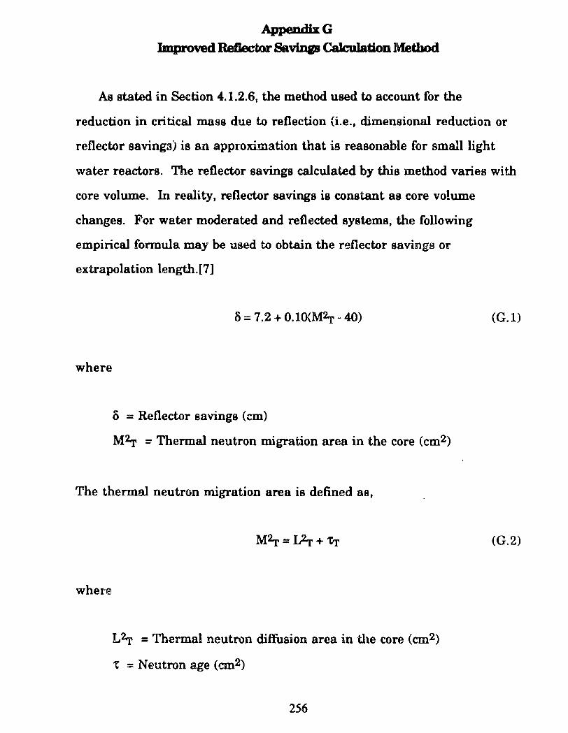
AppendixG
lmproved Reflector Savillp CaJculation l~thod
As stated in Section 4.1.2.6~ the method used to account for the
reduction in cri tical mass due to reflection (i. e .• dimensional reduction o r
reflector savinga) is an approximation that ia reasonable for smalllight
water reactors. The reflector savings calculated by thia method varies with
core volume. In reality, reflector savings is constant as core volume
changes. For water moderated and reflected systems, the following
empirical formula may be used to obtain the reflector savings or
extrapolation length.[7]
~ = 7.2 + O.lO{W,.- 40)
where
ó = Reflector savings (em)
M2.r = Thermal neutron migration area in the core (cm2)
The thermal neutron migration areais defined as,
whe:te
L2rr = Thennal neutron diffusion area in the core (cm2)
t = Neutron age (cm2)
256
(G.l)
(G.2)
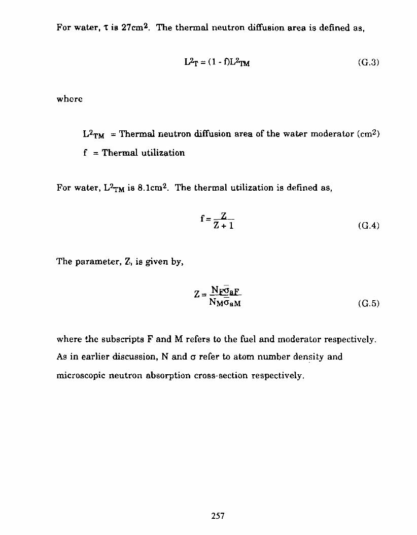
For water, tis 27cm2. The thennal neutron diffusion areais defined as,
L2r = (1 - f)L2nf (G.3)
where
L2TM = Thermal neutron díffusion area of the water moderator (cm2)
f = Thermal utilization
For water, L,_M is 8.1cm2. The thermal utilization is defined as,
The parameter, Z, ia given by,
f= z Z+l
z = N.r2aF NMO"aM
(G.4)
(G.5)
where the subscripts F and M refers to the fuel and modera to r respectively.
As in earlier discussion, N and a refer to atom number density and
m.icroscopic neutron absorption cross-section respectively.
257