effect of tuned mass damper on the interaction of a quarter car model with a damaged bridge
TRANSCRIPT
PLEASE SCROLL DOWN FOR ARTICLE
This article was downloaded by: [O'Connor, Alan]On: 13 April 2010Access details: Access Details: [subscription number 921291590]Publisher Taylor & FrancisInforma Ltd Registered in England and Wales Registered Number: 1072954 Registered office: Mortimer House, 37-41 Mortimer Street, London W1T 3JH, UK
Structure and Infrastructure EngineeringPublication details, including instructions for authors and subscription information:http://www.informaworld.com/smpp/title~content=t713683556
Effect of tuned mass damper on the interaction of a quarter car model witha damaged bridgeVikram Pakrashi a; Alan O'Connor a;Biswajit Basu a
a Department of Civil, Structural and Environmental Engineering, Trinity College Dublin, Dublin 2,Ireland
First published on: 30 April 2008
To cite this Article Pakrashi, Vikram , O'Connor, Alan andBasu, Biswajit(2010) 'Effect of tuned mass damper on theinteraction of a quarter car model with a damaged bridge', Structure and Infrastructure Engineering, 6: 4, 409 — 421,First published on: 30 April 2008 (iFirst)To link to this Article: DOI: 10.1080/15732470701816850URL: http://dx.doi.org/10.1080/15732470701816850
Full terms and conditions of use: http://www.informaworld.com/terms-and-conditions-of-access.pdf
This article may be used for research, teaching and private study purposes. Any substantial orsystematic reproduction, re-distribution, re-selling, loan or sub-licensing, systematic supply ordistribution in any form to anyone is expressly forbidden.
The publisher does not give any warranty express or implied or make any representation that the contentswill be complete or accurate or up to date. The accuracy of any instructions, formulae and drug dosesshould be independently verified with primary sources. The publisher shall not be liable for any loss,actions, claims, proceedings, demand or costs or damages whatsoever or howsoever caused arising directlyor indirectly in connection with or arising out of the use of this material.
Effect of tuned mass damper on the interaction of a quarter car model
with a damaged bridge
Vikram Pakrashi, Alan O’ Connor* and Biswajit Basu
Department of Civil, Structural and Environmental Engineering, Trinity College Dublin, Dublin 2, Ireland
(Received 21 February 2007; final version received 20 November 2007)
This paper considers the effects of a tuned mass damper (TMD) on damaged bridge–accelerating quarter car vehicleinteraction. The damage of the bridge is considered to be an open crack. The incorporation of a TMD to control thevibration response of the bridge and the quarter car vehicle model has been investigated from different aspects. Asimplified form for the tuning ratio of the TMD is proposed. The vibration mitigation of the peak displacement,velocity and acceleration of the damaged bridge and the accelerating quarter car vehicle model using such a tuning isobserved, along with the effects of possible detuning of the TMD due to the progressive deterioration of the bridge.A detailed parametric study is performed on the system with the TMD, considering the effects of quarter car vehiclemodel velocity, acceleration and the severity of the damage of the bridge.
Keywords: tuned mass dampers; open crack; vibration control; tuning ratio; bridge–vehicle interaction
1. Introduction
The interaction between bridges and the vehiclestraversing them can give rise to dynamic magnificationof static effects. The magnified displacement due tovibration may be unacceptable in terms of service-ability, or alternatively, the consequences of amplifiedloading can lead to excess cracking, thereby violating apossible limit state criterion. Thus, both the vehicleand the bridge experience magnified stresses due todynamic effects. In addition, a bridge–vehicle interac-tion generally increases the vertical acceleration of thevehicle. This becomes a source of discomfort for thepassengers since the human body is sensitive to a rateof change in velocity. Installation of a proper vibrationcontrol mechanism such as a tuned mass damper(TMD) can lower the dynamic response of the bridgeand the vehicle, and, as a direct consequence, thestructure demonstrates a relative improvement interms of serviceability. The frequency and dampingratio of the TMD is adjusted or tuned with that of thebridge in such a way that the TMD absorbs the majorpart of the excitation and controls the bridge–vehicleinteraction, thus providing possible solutions related tothe excess stress on the vehicles and the passengerdiscomfort due to unwanted and excessive verticalacceleration.
A huge amount of literature of varying complexityand details (both theoretical and experimental) isavailable on the vehicle–bridge interaction technique
(Abdel-Rohman and Al-Duaij 1996, Delgado and dosSantos 1997, Pesterev and Bergman 1997, Song et al.2003, da Silva 2004). Genin et al. (1975), Hayashikawaand Watanabe (1981), Klasztorny and Langer (1990),Cai et al. (1994) and Fryba (1999) have discussed theproblem of a quarter car model of a vehicle movingover a flexible guideway modelled as an EulerBernoulli beam element in detail.
Hartog (1985) showed the efficiency of a TMD tosuppress vibrations of a single degree of freedomsystem (SDOF) system under harmonic loading. Withdamping included, the tuning frequency and thedamping become outputs of an optimisation problem.The TMDs perform satisfactorily when the excitingfrequency has a narrow window (Inman 2001),which is often the case for a vehicle–bridge interactionprocess. Igusa and Xu (1992) have examined bothsingle and multiple TMDs with the natural frequencydistributed over a range and have found multipleTMDs to be more effective and robust than a singleone. Park and Reed (2000) have found uniformlydistributed TMDs to perform better than linearlydistributed ones. Yamaguchi and Harnpornchai(1993), Abe and Fujino (1994), Kareem and Kline(1995) and Wang et al. (2003) have discussed theadvantages of multiple TMDs over a single TMD.Kwon et al. (1998) and Jo et al. (2001) have consideredthe interaction of high-speed vehicles with three spansteel box girder bridges and have advocated the use of
*Corresponding author. Email: [email protected]
Structure and Infrastructure Engineering
Vol. 6, No. 4, August 2010, 409–421
ISSN 1573-2479 print/ISSN 1744-8980 online
� 2010 Taylor & Francis
DOI: 10.1080/15732470701816850
http://www.informaworld.com
Downloaded By: [O'Connor, Alan] At: 19:26 13 April 2010
a critical damping value in a TMD, suggested by Tsai(1993), to avoid the beating phenomenon due toinadequate damper tuning. Warburton and Ayorinde(1980), however, have previously shown that, for aTMD with small mass ratio with respect to the bridge,exact tuning may turn out to be rewarding. It isobserved from the literature that the improvement dueto the presence of multiple TMDs are often quite smallin terms of the peak response, as in many of the cases,the first vibration mode of the beam contributes almostentirely to the dynamic response of a beam (Law andZhu 2004, Yang and Lin 2005).
However, the interaction of a damaged beam and amoving load traversing over the beam has beenconsidered quite recently, mostly for the purposes ofstructural health monitoring process. Majumdar andManohar (2003) have considered a bridge system withpartially immobile bearings and have identified the lossof local stiffness by proposing a time domain damagedescriptor. Lee et al. (2002) have experimentallyinvestigated the possible application of bridge–vehicleinteraction data for identifying the loss of bendingrigidity by continuously monitoring the operationalmodal parameters. Law and Zhu (2004) have con-sidered a simply supported beam with open andbreathing cracks and discussed the dynamic behaviourof the bridge–vehicle interaction from both theory andexperiment.
It is observed that the effects of a TMD on adeteriorating bridge traversed by an acceleratingvehicle have not been dealt with. Since the naturalfrequency of a deteriorating bridge changes with time,it is important to observe the corresponding effects onthe tuning criteria, the possibility of detuning and theconsequent malfunction of a TMD device due to suchdeterioration in terms of vibration control of both thebridge and vehicle. Also, most of the existing literatureconsiders a constant velocity for the traversing vehicleand hence the investigation of the effects of variousvehicle accelerations for a deteriorating bridge–vehi-cle–TMD interaction is deemed important. This paperformulates a damaged beam with an open crack fittedwith TMDs. A quarter car model of an acceleratingvehicle consisting of two degrees of freedom isconsidered to traverse the beam. Optimised tuningparameters for the TMD following Ghosh and Basu(2006) have been computed. The modification in thetuning parameters due the presence of damage is alsoinvestigated. The effectiveness of the TMDs is con-sidered in terms of the peak responses of the bridgeand the vehicle. The efficiency of the TMD for each ofsuch criteria is parametrically investigated for a rangeof velocities and crack depth ratios (CDR). The effectsof an accelerating vehicle are investigated for the samecriteria of vibration control. The study forms a basis to
identify and emphasise the importance of damage andthe acceleration of a vehicle traversing a bridge withrespect to the efficiency of peak vibration reductionthrough the implementation of a passive TMD.
2. Damage model
A simply supported Euler Bernoulli beam with an opencrack is modelled as two uncracked sub-beamsconnected through a rotational spring at the locationof a crack in the lumped crack formulation. The lengthof the beam is L, with the damage located at a distancea from the left hand support of the beam. The crackdepth is taken as c and the overall depth of the beam ish. The free vibration equation for both the beams oneither side of the crack can be written as
EI@4y
@x4þ rA
@2y
@t2¼ 0; ð1Þ
where E, I, A and r are the Young’s modulus, themoment of inertia, the cross sectional area and thedensity of the material of the beam on either side ofthe crack, respectively. The displacement of the beamfrom its static equilibrium position is y(x,t), at adistance of x from the left hand support along thelength of the beam at time t. The strains and stressesare concentrated at the crack tip and decay inverselyproportional to the square root of the radial distanceaway from the crack tip (Carneiro and Inman 2000). Itis assumed that the effects of the crack are applicable inthe immediate neighbourhood of the crack locationand are represented by a rotational spring of equiva-lent local stiffness. Through the separation of variablesin Equation (1) and solving the characteristic equation,a general solution of the modeshapes is found to be(Narkis 1994):
FLðxÞ ¼ C1Lsin ðlxÞ þ C2Lcos ðlxÞ þ C3L sinhðlxÞþ C4L coshðlxÞ; 0 � x < a ð2Þ
and
FRðxÞ ¼ C1Rsin ðlxÞ þ C2Rcos ðlxÞ þ C3R sinhðlxÞþ C4R coshðlxÞ; a � x � L ð3Þ
for the sub-beams on the left (L) and the right (R) sideof the rotational spring respectively. The terms C(.)
are integration constants arising from the solution ofthe separated fourth order differential equation inspace. The term l is expressed as:
l ¼ rAo2
EI
� �1=4
; ð4Þ
410 V. Pakrashi et al.
Downloaded By: [O'Connor, Alan] At: 19:26 13 April 2010
where the natural frequency of the cracked beam is o.The displacement and the moment at the two supportsof the beam are zero. Hence,
FLð0Þ ¼ 0; F00Lð0Þ ¼ 0; FRðLÞ ¼ 0 and F00RðLÞ ¼ 0:
ð5Þ
Continuity in displacement, moment and shear areassumed at the location of crack. These conditions canbe expressed as:
FLðaÞ ¼ FRðaÞ; F00LðaÞ ¼ F00RðaÞ and F000L ðaÞ ¼ F000RðaÞ:ð6Þ
A slope discontinuity is present at the crack location.The slope condition is modelled as:
F0RðaÞ � F0LðaÞ ¼ yLF00RðaÞ: ð7Þ
In Equation (7), the term y is the non-dimensionalcrack section flexibility dependent on the crack depthratio. As in Narkis (1994), the function is considered tobe a polynomial of the crack depth ratio in a non-dimensional form as:
y ¼ 6pd2ðh=LÞð0:5033� 0:9022dþ 3:412d2 � 3:181d3
þ 5:793d4Þ: ð8Þ
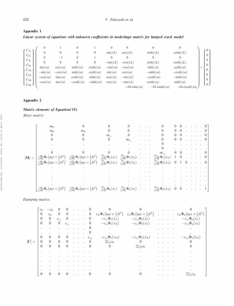
The term d (¼c/h) is the crack depth ratio (CDR). Therelationship between the equivalent spring stiffness andthe crack depth ratio can be found in Douka et al.(2004). The boundary conditions are substituted in thegeneral modeshape equation and a system of eightlinear equations is formed. The natural frequency ofthe cracked beam may be found by setting thedeterminant of the matrix derived from the system ofequations to zero, expanding it and solving for theroots of l numerically. In this paper, the roots werefound using Brent’s method in MATLAB (1994). Thematrix is presented in Appendix 1. The coefficient C1L
is normalised to unity; this is consistent with the factthat, for an undamaged beam, the maxima of the firstmodeshape is equal to unity. The other coefficients arethen found with respect to C1L.
3. Bridge–vehicle–TMD interaction
3.1. Description of the problem
The bridge is modelled as a simply supported EulerBernoulli beam with an open crack as the damage. Thevehicle is modelled as a quarter car element consistingof two degrees of freedom representing the verticalmotions of the wheel and the body. The quarter car isassumed to traverse the damaged beam with an
acceleration f and an initial velocity u0. The massesof the lower and the upper degrees of freedom of thequarter car model are mw and mb respectively. Anassembly consisting of two sets of springs (kb, kw) anddampers (cb, cw) represents the suspension system ofvehicle. Angular movements of the vehicle areneglected.
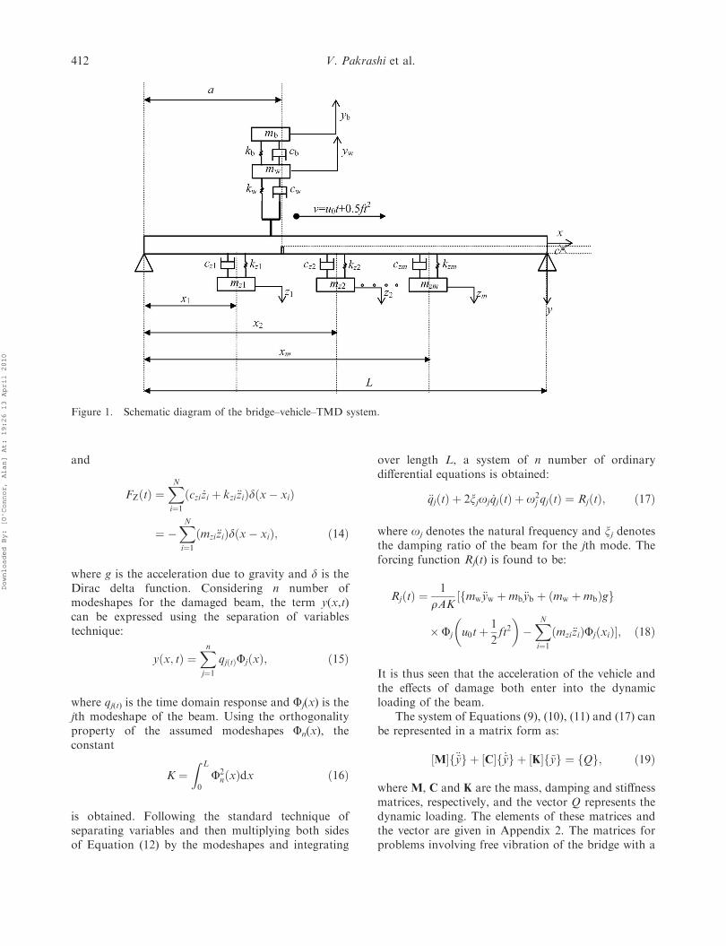
Tuned mass dampers are modelled to be connectedto the beam with a parallel spring and damper system.For the case of multiple tuned mass dampers, the ithTMD is assumed to have a spring stiffness kzi and adamping of czi. The location of the ith TMD on thebeam from the left hand support is taken as xi. Thevehicle is assumed to be moving on a surface withoutlosing contact with it. Bouncing, impact effects andsurface roughness of the bridge pavement are notconsidered. The mass of the ith TMD is given as mzi.Figure 1 shows the model of a quarter car vehiclebridge interaction (hereinafter termed vehicle bridgeinteraction) with a TMD installed as described in thissection.
3.2. Equations of motion
Considering the dynamic equilibrium conditions forthe degrees of freedom along the displacement direc-tions yb, yw and zi (for the ith TMD) the followingequations are obtained:
mb€yb þ cbð _yb � _ywÞ þ kbðyb � ywÞ ¼ 0; ð9Þ
mb€yb þmw€yw þ cwð _yw þ _yÞ þ kwðyw þ yÞ ¼ 0 ð10Þ
and
m€zi þ czið _zi � _yÞ þ kziðzi � yÞ ¼ 0 ð11Þ
respectively. The overdots represent derivatives withrespect to time. The displacement of the beam at aninstant of time t at a location x from the extreme lefthand support is given by y(x,t). Considering thedynamic loading factors and N number of TMDs atlocations x1 ,. . . , xN, the partial differential equationfor the forced vibration of the beam is:
EI@4yðx; tÞ@x4
þ c@yðx; tÞ@t
þ rA@2yðx; tÞ@t2
¼ FPðtÞ þ FZðtÞ;
ð12Þ
where
FPðtÞ ¼ ðmb€ybðtÞ þmw€ywðtÞ þ ðmb þmwÞgÞd�x�
�u0tþ
1
2ft2��
ð13Þ
Structure and Infrastructure Engineering 411
Downloaded By: [O'Connor, Alan] At: 19:26 13 April 2010
and
FZðtÞ ¼XNi¼1ðczi _zi þ kzi€ziÞdðx� xiÞ
¼ �XNi¼1ðmzi€ziÞdðx� xiÞ; ð14Þ
where g is the acceleration due to gravity and d is theDirac delta function. Considering n number ofmodeshapes for the damaged beam, the term y(x,t)can be expressed using the separation of variablestechnique:
yðx; tÞ ¼Xnj¼1
qjðtÞFjðxÞ; ð15Þ
where qj(t) is the time domain response and Fj(x) is thejth modeshape of the beam. Using the orthogonalityproperty of the assumed modeshapes Fn(x), theconstant
K ¼Z L
0
F2nðxÞdx ð16Þ
is obtained. Following the standard technique ofseparating variables and then multiplying both sidesof Equation (12) by the modeshapes and integrating
over length L, a system of n number of ordinarydifferential equations is obtained:
€qjðtÞ þ 2xjoj _qjðtÞ þ o2j qjðtÞ ¼ RjðtÞ; ð17Þ
where oj denotes the natural frequency and xj denotesthe damping ratio of the beam for the jth mode. Theforcing function Rj(t) is found to be:
RjðtÞ ¼1
rAK½fmw€yw þmb€yb þ ðmw þmbÞgg
� Fj
�u0tþ
1
2ft2��XNi¼1ðmzi€ziÞFjðxiÞ�; ð18Þ
It is thus seen that the acceleration of the vehicle andthe effects of damage both enter into the dynamicloading of the beam.
The system of Equations (9), (10), (11) and (17) canbe represented in a matrix form as:
½M�f€~yg þ ½C�f _~yg þ ½K�f~yg ¼ fQg; ð19Þ
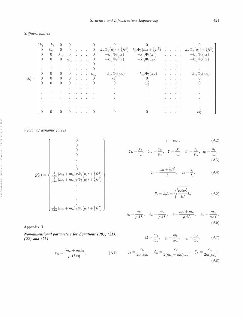
where M, C and K are the mass, damping and stiffnessmatrices, respectively, and the vector Q represents thedynamic loading. The elements of these matrices andthe vector are given in Appendix 2. The matrices forproblems involving free vibration of the bridge with a
Figure 1. Schematic diagram of the bridge–vehicle–TMD system.
412 V. Pakrashi et al.
Downloaded By: [O'Connor, Alan] At: 19:26 13 April 2010
TMD and the forced and free vibration of the bridgewithout a TMD can be obtained by suppressing therows and columns corresponding to the degrees offreedom that are not present for the particularproblem. The governing Equations (9), (10), (11) and(17) can be normalised to:
O2 €Yb þ 2zbOgfð _Yb � _YwÞ þ g2f ðYb � YwÞ ¼ 0; ð20Þ
ebew
O2 €YbþO2 €Ywþ 2zweew
Oð _Ywþ _YÞþ eewðYwþYÞ ¼ 0;
ð21Þ
O2 €Zi þ 2zZiOgZð _Zi � _YÞ þ g2ZðZi � YÞ ¼ 0 ð22Þ
and
€uj þ 2zjoj
o1_uj þ
oj
o1
� �2
uj
¼ 1
K
�ðeb €Yb þ ew €YwÞ þ
egymo2
1
� �FjðbjxvÞ
�XNi¼1
ezigymo2
1
FjðbjxiÞ�; ð23Þ
where the non-dimensional terms are given inAppendix 3.
3.3. Importance of the first modeshape
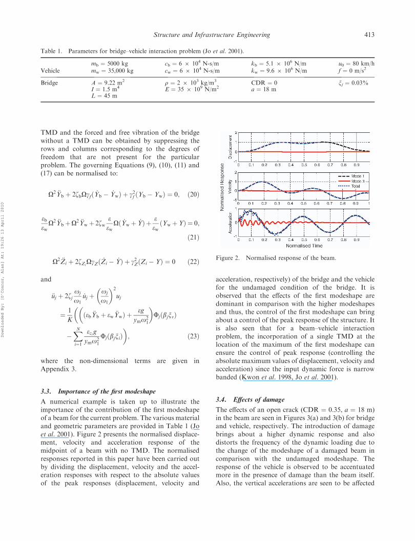
A numerical example is taken up to illustrate theimportance of the contribution of the first modeshapeof a beam for the current problem. The various materialand geometric parameters are provided in Table 1 (Joet al. 2001). Figure 2 presents the normalised displace-ment, velocity and acceleration response of themidpoint of a beam with no TMD. The normalisedresponses reported in this paper have been carried outby dividing the displacement, velocity and the accel-eration responses with respect to the absolute valuesof the peak responses (displacement, velocity and
acceleration, respectively) of the bridge and the vehiclefor the undamaged condition of the bridge. It isobserved that the effects of the first modeshape aredominant in comparison with the higher modeshapesand thus, the control of the first modeshape can bringabout a control of the peak response of the structure. Itis also seen that for a beam–vehicle interactionproblem, the incorporation of a single TMD at thelocation of the maximum of the first modeshape canensure the control of peak response (controlling theabsolute maximum values of displacement, velocity andacceleration) since the input dynamic force is narrowbanded (Kwon et al. 1998, Jo et al. 2001).
3.4. Effects of damage
The effects of an open crack (CDR ¼ 0.35, a ¼ 18 m)in the beam are seen in Figures 3(a) and 3(b) for bridgeand vehicle, respectively. The introduction of damagebrings about a higher dynamic response and alsodistorts the frequency of the dynamic loading due tothe change of the modeshape of a damaged beam incomparison with the undamaged modeshape. Theresponse of the vehicle is observed to be accentuatedmore in the presence of damage than the beam itself.Also, the vertical accelerations are seen to be affected
Table 1. Parameters for bridge–vehicle interaction problem (Jo et al. 2001).
mb ¼ 5000 kg cb ¼ 6 6 104 N-s/m kb ¼ 5.1 6 106 N/m u0 ¼ 80 km/hVehicle mw ¼ 35,000 kg cw ¼ 6 6 104 N-s/m kw ¼ 9.6 6 106 N/m f ¼ 0 m/s2
Bridge A ¼ 9.22 m2 r ¼ 2 6 103 kg/m3 CDR ¼ 0 xj ¼ 0.03%I ¼ 1.5 m4 E ¼ 35 6 109 N/m2 a ¼ 18 mL ¼ 45 m
Figure 2. Normalised response of the beam.
Structure and Infrastructure Engineering 413
Downloaded By: [O'Connor, Alan] At: 19:26 13 April 2010
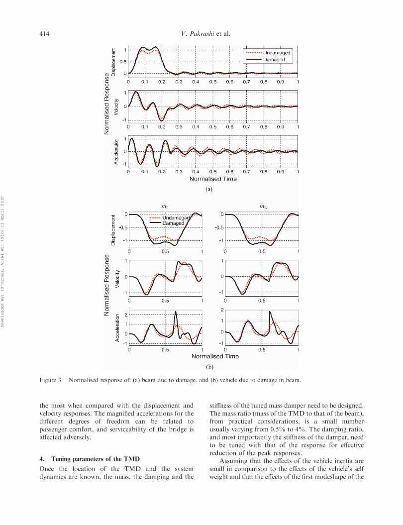
the most when compared with the displacement andvelocity responses. The magnified accelerations for thedifferent degrees of freedom can be related topassenger comfort, and serviceability of the bridge isaffected adversely.
4. Tuning parameters of the TMD
Once the location of the TMD and the systemdynamics are known, the mass, the damping and the
stiffness of the tuned mass damper need to be designed.The mass ratio (mass of the TMD to that of the beam),from practical considerations, is a small numberusually varying from 0.5% to 4%. The damping ratio,and most importantly the stiffness of the damper, needto be tuned with that of the response for effectivereduction of the peak responses.
Assuming that the effects of the vehicle inertia aresmall in comparison to the effects of the vehicle’s selfweight and that the effects of the first modeshape of the
Figure 3. Normalised response of: (a) beam due to damage, and (b) vehicle due to damage in beam.
414 V. Pakrashi et al.
Downloaded By: [O'Connor, Alan] At: 19:26 13 April 2010
beam dominate, the governing system of Equations(9), (10), (11) and (17) can be reduced to the form:
€q1ðtÞ þ 2z1o1 _q1ðtÞ þ o21q1ðtÞ
¼ mz1
rAK2zz1oz1 _uðtÞ þ o2
z1uðtÞ
� �þPF1 u0tþ 1
2 ft2
� �rAK
ð24Þand
€u1ðtÞ þ 2zz1oz1 _u1ðtÞ þ o2z1u1ðtÞ ¼ �€q1ðtÞ; ð25Þ
where
u1ðtÞ ¼ z1ðtÞ � yðtÞ ð26Þ
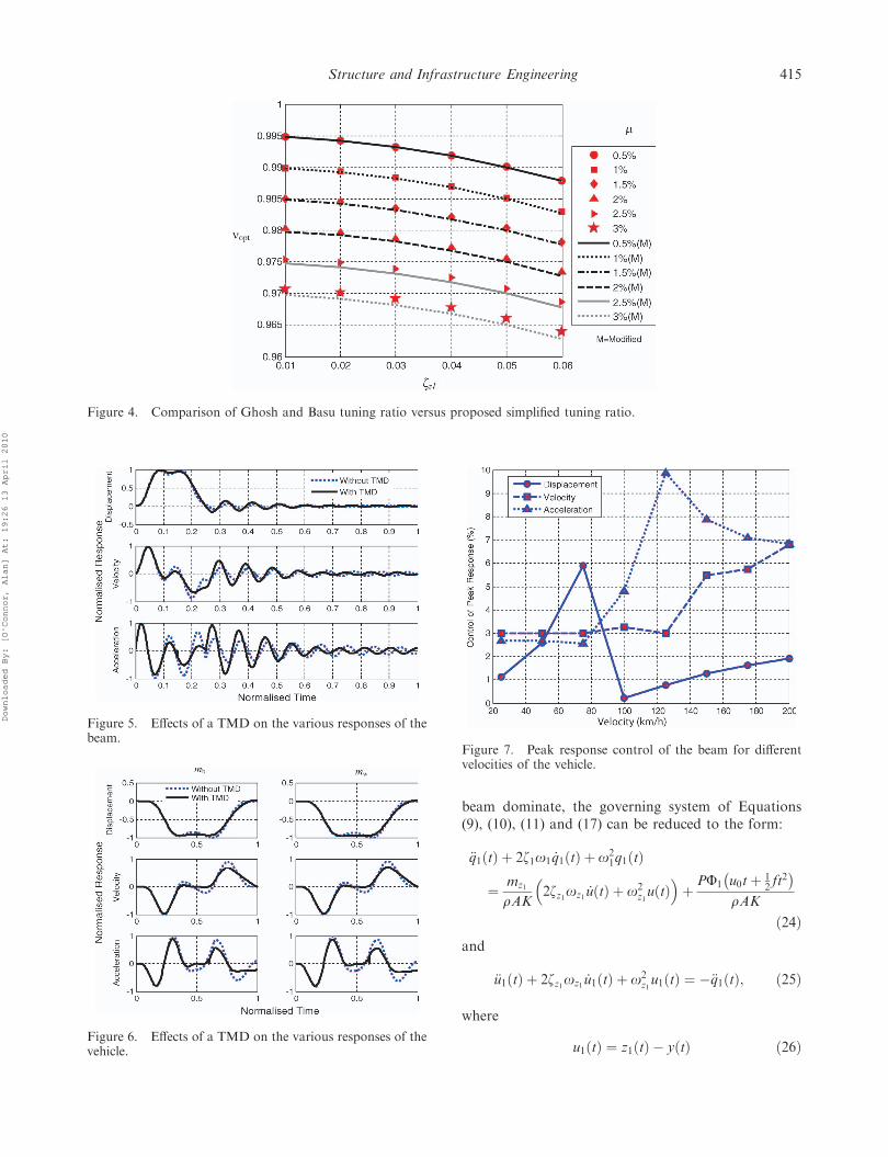
Figure 4. Comparison of Ghosh and Basu tuning ratio versus proposed simplified tuning ratio.
Figure 5. Effects of a TMD on the various responses of thebeam.
Figure 6. Effects of a TMD on the various responses of thevehicle.
Figure 7. Peak response control of the beam for differentvelocities of the vehicle.
Structure and Infrastructure Engineering 415
Downloaded By: [O'Connor, Alan] At: 19:26 13 April 2010
and
P ¼ ðmw þmbÞg: ð27Þ
By choosing
m ¼ mz1
rAK; z2 ¼ zz1 ; o2 ¼ oz1 ; m1 ¼ rAK ð28Þ
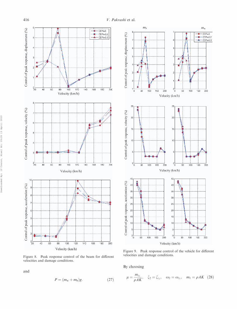
Figure 8. Peak response control of the beam for differentvelocities and damage conditions.
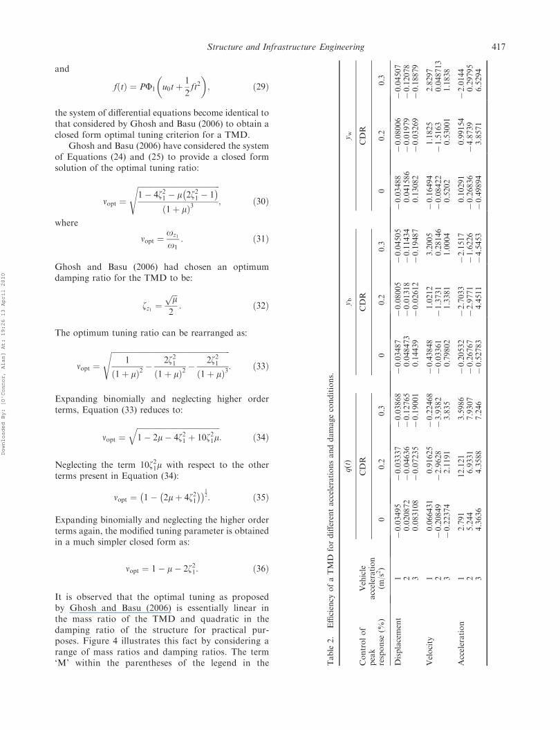
Figure 9. Peak response control of the vehicle for differentvelocities and damage conditions.
416 V. Pakrashi et al.
Downloaded By: [O'Connor, Alan] At: 19:26 13 April 2010
and
fðtÞ ¼ PF1
�u0tþ
1
2ft2�; ð29Þ
the system of differential equations become identical tothat considered by Ghosh and Basu (2006) to obtain aclosed form optimal tuning criterion for a TMD.
Ghosh and Basu (2006) have considered the systemof Equations (24) and (25) to provide a closed formsolution of the optimal tuning ratio:
nopt ¼
ffiffiffiffiffiffiffiffiffiffiffiffiffiffiffiffiffiffiffiffiffiffiffiffiffiffiffiffiffiffiffiffiffiffiffiffiffiffiffiffiffiffiffi1� 4z21 � m 2z21 � 1
� �ð1þ mÞ3
s; ð30Þ
where
nopt ¼oz1
o1: ð31Þ
Ghosh and Basu (2006) had chosen an optimumdamping ratio for the TMD to be:
zz1 ¼ffiffiffimp
2: ð32Þ
The optimum tuning ratio can be rearranged as:
nopt ¼
ffiffiffiffiffiffiffiffiffiffiffiffiffiffiffiffiffiffiffiffiffiffiffiffiffiffiffiffiffiffiffiffiffiffiffiffiffiffiffiffiffiffiffiffiffiffiffiffiffiffiffiffiffiffiffiffiffiffiffiffiffiffi1
ð1þ mÞ2� 2z21ð1þ mÞ2
� 2z21ð1þ mÞ3
s: ð33Þ
Expanding binomially and neglecting higher orderterms, Equation (33) reduces to:
nopt ¼ffiffiffiffiffiffiffiffiffiffiffiffiffiffiffiffiffiffiffiffiffiffiffiffiffiffiffiffiffiffiffiffiffiffiffiffiffiffiffiffiffiffiffi1� 2m� 4z21 þ 10z21m
q: ð34Þ
Neglecting the term 10z21m with respect to the otherterms present in Equation (34):
nopt ¼ 1� 2mþ 4z21� �� �1
2: ð35Þ
Expanding binomially and neglecting the higher orderterms again, the modified tuning parameter is obtainedin a much simpler closed form as:
nopt ¼ 1� m� 2z21: ð36Þ
It is observed that the optimal tuning as proposedby Ghosh and Basu (2006) is essentially linear inthe mass ratio of the TMD and quadratic in thedamping ratio of the structure for practical pur-poses. Figure 4 illustrates this fact by considering arange of mass ratios and damping ratios. The term‘M’ within the parentheses of the legend in the T
able
2.
Efficiency
ofaTMD
fordifferentaccelerationsanddamageconditions.
q(t)
yb
yw
Controlof
peak
response
(%)
Vehicle
acceleration
(m/s2)
CDR
CDR
CDR
00.2
0.3
00.2
0.3
00.2
0.3
Displacement
170.03495
70.03337
70.03868
70.03487
70.08005
70.04505
70.03488
70.08006
70.04507
20.020872
70.04636
70.12765
0.048473
70.01318
70.11434
0.041586
70.01979
70.12078
30.083108
70.07235
70.19001
0.14439
70.02612
70.19487
0.13082
70.03269
70.18879
Velocity
10.066431
0.91625
70.22468
70.43848
1.0212
3.2005
70.16494
1.1825
2.8297
270.20849
72.9628
73.9382
70.03361
71.3731
0.28146
70.08422
71.5163
0.048713
370.22374
2.1191
3.835
0.79802
1.3381
1.0004
0.5202
0.53001
1.1838
Acceleration
12.791
12.121
3.5986
70.20532
72.7033
72.1517
0.10291
0.99154
72.0144
25.244
6.9331
7.9307
70.26767
72.9771
71.6226
70.26836
74.8739
0.29795
34.3636
4.3588
7.246
70.52783
4.4511
74.5453
70.49894
3.8571
6.5294
Structure and Infrastructure Engineering 417
Downloaded By: [O'Connor, Alan] At: 19:26 13 April 2010
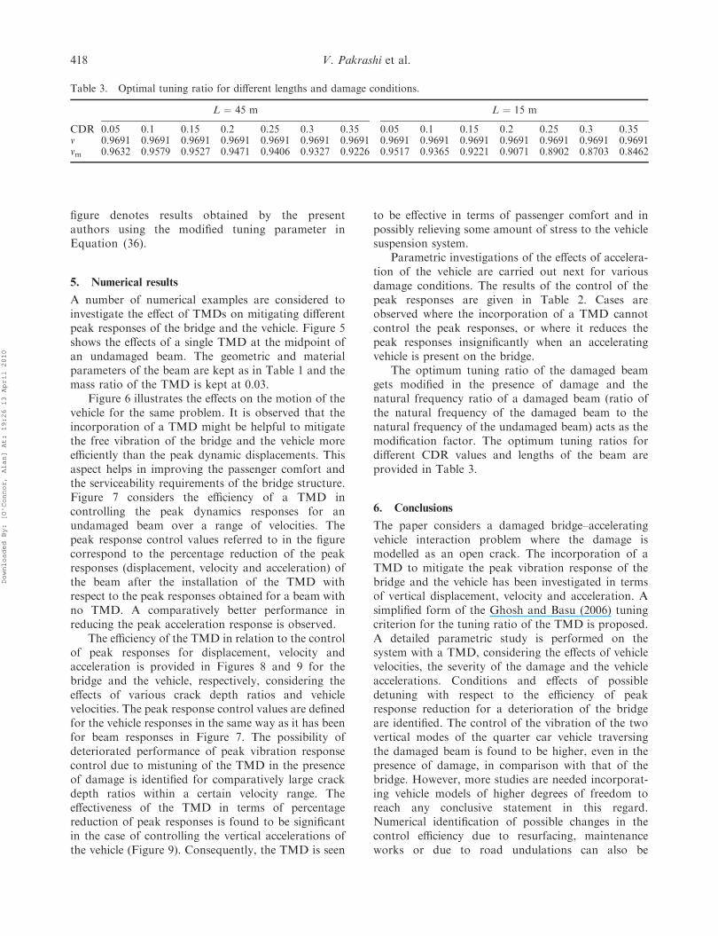
figure denotes results obtained by the presentauthors using the modified tuning parameter inEquation (36).
5. Numerical results
A number of numerical examples are considered toinvestigate the effect of TMDs on mitigating differentpeak responses of the bridge and the vehicle. Figure 5shows the effects of a single TMD at the midpoint ofan undamaged beam. The geometric and materialparameters of the beam are kept as in Table 1 and themass ratio of the TMD is kept at 0.03.
Figure 6 illustrates the effects on the motion of thevehicle for the same problem. It is observed that theincorporation of a TMD might be helpful to mitigatethe free vibration of the bridge and the vehicle moreefficiently than the peak dynamic displacements. Thisaspect helps in improving the passenger comfort andthe serviceability requirements of the bridge structure.Figure 7 considers the efficiency of a TMD incontrolling the peak dynamics responses for anundamaged beam over a range of velocities. Thepeak response control values referred to in the figurecorrespond to the percentage reduction of the peakresponses (displacement, velocity and acceleration) ofthe beam after the installation of the TMD withrespect to the peak responses obtained for a beam withno TMD. A comparatively better performance inreducing the peak acceleration response is observed.
The efficiency of the TMD in relation to the controlof peak responses for displacement, velocity andacceleration is provided in Figures 8 and 9 for thebridge and the vehicle, respectively, considering theeffects of various crack depth ratios and vehiclevelocities. The peak response control values are definedfor the vehicle responses in the same way as it has beenfor beam responses in Figure 7. The possibility ofdeteriorated performance of peak vibration responsecontrol due to mistuning of the TMD in the presenceof damage is identified for comparatively large crackdepth ratios within a certain velocity range. Theeffectiveness of the TMD in terms of percentagereduction of peak responses is found to be significantin the case of controlling the vertical accelerations ofthe vehicle (Figure 9). Consequently, the TMD is seen
to be effective in terms of passenger comfort and inpossibly relieving some amount of stress to the vehiclesuspension system.
Parametric investigations of the effects of accelera-tion of the vehicle are carried out next for variousdamage conditions. The results of the control of thepeak responses are given in Table 2. Cases areobserved where the incorporation of a TMD cannotcontrol the peak responses, or where it reduces thepeak responses insignificantly when an acceleratingvehicle is present on the bridge.
The optimum tuning ratio of the damaged beamgets modified in the presence of damage and thenatural frequency ratio of a damaged beam (ratio ofthe natural frequency of the damaged beam to thenatural frequency of the undamaged beam) acts as themodification factor. The optimum tuning ratios fordifferent CDR values and lengths of the beam areprovided in Table 3.
6. Conclusions
The paper considers a damaged bridge–acceleratingvehicle interaction problem where the damage ismodelled as an open crack. The incorporation of aTMD to mitigate the peak vibration response of thebridge and the vehicle has been investigated in termsof vertical displacement, velocity and acceleration. Asimplified form of the Ghosh and Basu (2006) tuningcriterion for the tuning ratio of the TMD is proposed.A detailed parametric study is performed on thesystem with a TMD, considering the effects of vehiclevelocities, the severity of the damage and the vehicleaccelerations. Conditions and effects of possibledetuning with respect to the efficiency of peakresponse reduction for a deterioration of the bridgeare identified. The control of the vibration of the twovertical modes of the quarter car vehicle traversingthe damaged beam is found to be higher, even in thepresence of damage, in comparison with that of thebridge. However, more studies are needed incorporat-ing vehicle models of higher degrees of freedom toreach any conclusive statement in this regard.Numerical identification of possible changes in thecontrol efficiency due to resurfacing, maintenanceworks or due to road undulations can also be
Table 3. Optimal tuning ratio for different lengths and damage conditions.
L ¼ 45 m L ¼ 15 m
CDR 0.05 0.1 0.15 0.2 0.25 0.3 0.35 0.05 0.1 0.15 0.2 0.25 0.3 0.35n 0.9691 0.9691 0.9691 0.9691 0.9691 0.9691 0.9691 0.9691 0.9691 0.9691 0.9691 0.9691 0.9691 0.9691nm 0.9632 0.9579 0.9527 0.9471 0.9406 0.9327 0.9226 0.9517 0.9365 0.9221 0.9071 0.8902 0.8703 0.8462
418 V. Pakrashi et al.
Downloaded By: [O'Connor, Alan] At: 19:26 13 April 2010
beneficial as a future study. The presence of vehicleacceleration is observed to affect the performance ofthe TMD significantly.
References
Abdel-Rohman, M. and Al-Duaij, J., 1996. Dynamic
response of a hinged–hinged single span bridgewith uneven deck. Computers and Structures, 59, 291–299.
Abe, M. and Fujino, Y., 1994. Dynamic characterization of
multiple tuned mass dampers and some design formulas.Earthquake Engineering and Structural Dynamics, 23,813–835.
Cai, Y., Chen, S.S., Rote, D.M., and Coffey, H.T., 1994.Vehicle/guideway interaction for high speed vehicles on aflexible guideway. Journal of Sound and Vibration, 175(5), 625–646.
Carneiro, S.H.S. and Inman, D.J., 2002. Continuous modelfor the transverse vibration of cracked timoshenkobeams. Transactions of ASME, Journal of Vibration and
Acoustics, 24, 310–320.da Silva, J.G.S., 2004. Dynamical performance of highway
bridge decks with irregular pavement surface. Computers
and Structures, 82, 871–881.Delgado, R.M. and dos Santos, S.M., 1997. Modelling of
railway bridge–vehicle interaction on high speed tracks.
Computers and Structures, 63, 511–523.Douka, E., Bamnios, G., and Trochidis, A., 2004. A method
of determining the location and depth of cracks in doublecracked beams. Applied Acoustics, 65, 997–1008.
Fryba, L., 1999. Vibrations of solids and structures undermoving loads. London: Thomas Telford.
Genin, J., Ginsberg, J.H., and Ting, E.C., 1975. A complete
formulation of inertial effects in the guideway vehicleinteraction problem. Journal of Sound and Vibration, 38,15–26.
Ghosh, A. and Basu, B., 2006. A closed form optimal tuningcriterion for TMD in damped structures. StructuralControl and Health Monitoring, 14 (4), 681–692.
Hartog, D., 1985. Mechanical vibration. New York: Dover
Publications.Hayashikawa, T. and Watanabe, N., 1981. Dynamic
behaviour of continuous beams with moving loads.
Journal of Engineering Mechanics Division, ASCE, 107(EMI), 229–246.
Igusa, T. and Xu, K., 1992. Dynamic characteristics of
multiple tuned mass substructures with closely spacedfrequencies. Earthquake Engineering and StructuralDynamics, 21, 1050–1070.
Inman, D.J., 2001. Engineering vibration. New Jersey:Prentice Hall.
Jo, B.W., Tae, G.H., and Lee, D.W., 2001. Structuralvibration of tuned mass damper installed in a three span
steel box bridge. International Journal of Pressure Vesselsand Piping, 78, 667–675.
Kareem, A. and Kline, S., 1995. Performance of multiple
mass dampers under random loading. Journal ofStructural Engineering, 121, 348–361.
Klasztorny, M. and Langer, J., 1990. Dynamic response of
single span bridges to a series of moving loads. Earth-quake Engineering and Structural Dynamics, 19 (8), 1107–1124.
Kwon, H.C., Kim, M.C., and Lee, I.W., 1998. Vibrationcontrol of bridges under moving loads. Computers andStructures, 66 (4), 473–480.
Law, S.S. and Zhu, X.Q., 2004. Dynamic behaviour
of damaged concrete bridge structures under movingvehicular loads. Engineering Structures, 26, 1279–1293.
Lee, J.W., Kim, J.D., Yun, C.B., Yi, J.H., and Shim, J.M.,2002. Health monitoring method for bridges underordinary traffic loadings. Journal of Sound and Vibration,
257 (2), 247–264.Majumdar, L. and Manohar, C.S., 2003. A time-domain
approach for damage detection in beam structuresusing vibration data with a moving oscillator as an
excitation source. Journal of Sound and Vibration, 268,699–716.
MATLAB, 1994. User manual. Mathworks Inc., 3 Apple Hill
Drive, Natick, MA, USA.Narkis, Y., 1994. Identification of crack location in vibrating
simply supported beams. Journal of Sound and Vibration,
172 (4), 549–558.Park, J. and Reed, D., 2001. Analysis of uniformly and
linearly distributed mass dampers under harmonic
excitation. Engineering Structures, 23, 802–814.Pesterev, A.V. and Bergman, L.A., 1997. Vibration of elastic
continuum carrying accelerating oscillator. ASCEJournal of Engineering Mechanics, 123, 886–889.
Song, M.K., Noh, H.C., and Choi, C.K., 2003. A new threedimensional finite element analysis model of high-speedtrain–bridge interactions. Engineering Structures, 25,
1611–1626.Tsai, H.C., 1993. Green’s function of support excited
structures with tuned mass dampers derived by a
perturbation method. Earthquake Engineering andStructural Dynamics, 22 (11), 975–990.
Wang, J.F., Lin, C.C., and Chen, B.L., 2003. Vibration
suppression for high-speed railway bridges using tunedmass dampers. International Journal of Solids andStructures, 40, 465–491.
Warburton, G.B. and Ayorinde, E.O., 1980. Optimal
dynamic vibration absorbers for general beam systems.Earthquake Engineering and Structural Dynamics, 8, 197–217.
Yamaguchi, H. and Harnpornchai, N., 1993. Fundamentalcharacteristics of multiple tuned mass dampers forsuppressing harmonically forced oscillations. Earth-
quake Engineering and Structural Dynamics, 22, 51–62.
Yang, Y.B. and Lin, C.W., 2005. Vehicle–bridge interactiondynamics and potential applications. Journal of Sound
and Vibration, 284, 205–226.
Structure and Infrastructure Engineering 419
Downloaded By: [O'Connor, Alan] At: 19:26 13 April 2010
Appendix 1
Linear system of equations with unknown coefficients in modeshape matrix for lumped crack model
C1L
C2L
C3L
C4L
C1R
C2R
C3R
C4R
8>>>>>>>>>>>>><>>>>>>>>>>>>>:
9>>>>>>>>>>>>>=>>>>>>>>>>>>>;
0 1 0 1 0 0 0 0
0 0 0 0 sinðlLÞ cosðlLÞ sinhðlLÞ coshðlLÞ0 �1 0 1 0 0 0 0
0 0 0 0 �sinðlLÞ �cosðlLÞ sinhðlLÞ coshðlLÞsinðlaÞ cosðlaÞ sinhðlaÞ coshðlaÞ �sinðlaÞ �cosðlaÞ sinhðlaÞ coshðlaÞ�sinðlaÞ �cosðlaÞ sinhðlaÞ coshðlaÞ sinðlaÞ cosðlaÞ �sinhðlaÞ �coshðlaÞ�cosðlaÞ sinðlaÞ coshðlaÞ sinhðlaÞ cosðlaÞ �sinðlaÞ �coshðlaÞ �sinhðlaÞ�cosðlaÞ sinðlaÞ �coshðlaÞ �sinhðlaÞ cosðlaÞ �sinðlaÞ coshðlaÞ sinhðlaÞ
þyLlsinðlaÞ �yLlsinhðlaÞ �yLlcoshðlaÞ
0BBBBBBBBBBBBBBBB@
1CCCCCCCCCCCCCCCCA
¼
0
0
0
0
0
0
0
0
8>>>>>>>>>>>>><>>>>>>>>>>>>>:
9>>>>>>>>>>>>>=>>>>>>>>>>>>>;
Appendix 2
Matrix elements of Equation(19)
Mass matrix
½M� ¼
mb 0 0 0 : : : 0 0 0 : : : : 0mb mw 0 0 : : : 0 0 0 : : : : 00 0 mz1 0 : : : 0 0 0 : : : : 00 0 0 mz2 : : : 0 0 0 : : : : 0: : : : : : : 0 : : : : : : :: : : : : : : 0 : : : : : : :0 0 0 0 : : : mzN 0 0 : : : : 0
�mb
rAKF1 u0tþ 12 ft
2� � �mw
rAK F1 u0tþ 12 ft
2� � mz1
rAKF1ðx1Þmz2
rAKF1ðx2Þ : : :mzN
rAKF1ðxNÞ 1 0 : : : : 0�mb
rAKF2 u0tþ 12 ft
2� � �mw
rAK F2 u0tþ 12 ft
2� � mz1
rAKF2ðx1Þmz2
rAKF2ðx2Þ : : :mzN
rAKF2ðxNÞ 0 1 0 : : : 0: : : : : : : : : : : : : : :: : : : : : : : : : : : : : :: : : : : : : : : : : : : : :: : : : : : : : : : : : : : :: : : : : : : : : : : : : : :
�mb
rAKFn u0tþ 12 ft
2� � �mw
rAK Fn u0tþ 12 ft
2� � mz1
rAKFnðx1Þmz2
rAKFnðx2Þ : : :mzN
rAKFnðxNÞ 0 0 : : : : 1
266666666666666666666666664
377777777777777777777777775
Damping matrix
½C� ¼
cb �cb 0 0 : : : 0 0 0 : : : : 00 cw 0 0 : : : 0 cwF1 u0tþ 1
2 ft2
� �cwF2 u0tþ 1
2 ft2
� �: : : : cwFn u0tþ 1
2 ft2
� �0 0 cz1 0 : : : 0 �cz1F1ðx1Þ �cz1F2ðx1Þ : : : : �cz1Fnðx1Þ0 0 0 cz2 : : : 0 �cz2F1ðx2Þ �cz2F2ðx2Þ : : : : �cz2Fnðx2Þ: : : : : : : 0 : : : : : : :: : : : : : : 0 : : : : : : :0 0 0 0 : : : czN �czNF1ðxNÞ �czNF2ðxNÞ : : : : �czNFnðxNÞ0 0 0 0 : : : 0 2x1o1 0 : : : : 00 0 0 0 : : : 0 0 2x2o2 : : : : 0: : : : : : : : : : : : : : :: : : : : : : : : : : : : : :: : : : : : : : : : : : : : :: : : : : : : : : : : : : : :: : : : : : : : : : : : : : :0 0 0 0 : : : 0 0 0 : : : : 2xnon
26666666666666666666666664
37777777777777777777777775
420 V. Pakrashi et al.
Downloaded By: [O'Connor, Alan] At: 19:26 13 April 2010
Stiffness matrix
½K� ¼
kb �kb 0 0 : : : 0 0 0 : : : : 00 kw 0 0 : : : 0 kwF1 u0tþ 1
2 ft2
� �kwF2 u0tþ 1
2 ft2
� �: : : : kwFn u0tþ 1
2 ft2
� �0 0 kz1 0 : : : 0 �kz1F1ðx1Þ �kz1F2ðx1Þ : : : : �kz1Fnðx1Þ0 0 0 kz2 : : : 0 �kz2F1ðx2Þ �kz2F2ðx2Þ : : : : �kz2Fnðx2Þ: : : : : : : 0 : : : : : : :: : : : : : : 0 : : : : : : :0 0 0 0 : : : kzN �kzNF1ðxNÞ �kzNF2ðxNÞ : : : : �kzNFnðxNÞ0 0 0 0 : : : 0 o2
1 0 : : : : 00 0 0 0 : : : 0 0 o2
2 : : : : 0: : : : : : : : : : : : : : :: : : : : : : : : : : : : : :: : : : : : : : : : : : : : :: : : : : : : : : : : : : : :: : : : : : : : : : : : : : :0 0 0 0 : : : 0 0 0 : : : : o2
n
26666666666666666666666664
37777777777777777777777775
Vector of dynamic forces
QðtÞ ¼
0000::0
1rAK ðmb þmwÞgF1 u0tþ 1
2 ft2
� �1
rAK ðmb þmwÞgF2 u0tþ 12 ft
2� �
:::::
1rAK ðmb þmwÞgFn u0tþ 1
2 ft2
� �
8>>>>>>>>>>>>>>>>>>>>>>>>><>>>>>>>>>>>>>>>>>>>>>>>>>:
9>>>>>>>>>>>>>>>>>>>>>>>>>=>>>>>>>>>>>>>>>>>>>>>>>>>;
Appendix 3
Non-dimensional parameters for Equations (20), (21),(22) and (23)
ym ¼ðmw þmbÞgrALo2
1
; ðA1Þ
t ¼ to1; ðA2Þ
Yb ¼ybym
; Yw ¼ywym
; Y ¼ y
ym; Zi ¼
ziym
; uj ¼qjym
;
ðA3Þ
xv ¼u0tþ 1
2 ft2
L; xi ¼
xiL; ðA4Þ
bj ¼ ljL ¼
ffiffiffiffiffiffiffiffiffiffiffiffirAo2
j
EI
4
sL; ðA5Þ
eb ¼mb
rAL; ew ¼
mw
rAL; e ¼ mb þmw
rAL; ezi ¼
mzi
rAL;
ðA6Þ
O ¼ o1
ow; gf ¼
ob
ow; gzi ¼
ozi
ow; ðA7Þ
zb ¼cb
2mbob; zw ¼
cw2ðmw þmbÞow
; zzi ¼czi
2mziozi
:
ðA8Þ
Structure and Infrastructure Engineering 421
Downloaded By: [O'Connor, Alan] At: 19:26 13 April 2010