ee 4755—digital design using hardware description ... - lsu
TRANSCRIPT

EE 4755—Digital Design Using Hardware Description Languages
Basic Information
URL: http://www.ece.lsu.edu/v
Offered by:
David M. Koppelman, Room 3316R P. F. Taylor Hall
578-5482.
[email protected], http://www.ece.lsu.edu/koppel/koppel.html
Tentative office hours: M-F 15:00-16:00.
011 LSU EE 4755 Lecture Transparency. Formatted 14:53, 21 August 2017 from lsli01. 011
Formal Prerequisite
EE 3755 (Computer Organization).
Informal Prerequisites (What you really need to know.)
C (The computer language.)
Digital hardware design: Should be able to answer these:
Is a ripple adder something to get excited about?
What does it mean to clock a register?
Your part of the design carries the critical path: your fault or your forte?
012 LSU EE 4755 Lecture Transparency. Formatted 14:53, 21 August 2017 from lsli01. 012
Graded Material
Midterm Exam, 35%
Fifty minutes, open notes.
Final Exam, 35%
Two hours, open notes.
Yes, it’s cumulative.
Homework/Projects, 30%
Written and computer assignments.
Lowest grade or unsubmitted assignment dropped.
013 LSU EE 4755 Lecture Transparency. Formatted 14:53, 21 August 2017 from lsli01. 013
Electronic Design Automation (EDA)
Electronic Design Automation (EDA) (Short Definition)
The use of software to automate electronic (digital and analog) design.
Electronic Design Automation (EDA) (Longer Definition)
Electronic design in which
the design is written in a hardware description language
possibly consisting of components from a vendor’s IP library
the functionality of the design is verified by simulation
the correctness, testability, and compliance of a design is evaluated by software
and the design is converted to a manufactureable form using synthesis tools.
014 LSU EE 4755 Lecture Transparency. Formatted 14:53, 21 August 2017 from lsli01. 014
Hardware Description Languages
Hardware Description Language:
A language used for describing the structure of hardware and how the hardware should behave.Examples include SystemVerilog and VHDL.
Kinds of Digital Hardware Built Using HDL’s:
Anything worth selling.
015 LSU EE 4755 Lecture Transparency. Formatted 14:53, 21 August 2017 from lsli01. 015

The Most Popular Hardware Description Languages
Verilog and SystemVerilog
(Verilog was replaced by SystemVerilog in 2009.)
C-Like and C++-Like Syntax
Originated in industry in 1984, now IEEE standard.
VHDL
Ada-Like Syntax
Originated as a DoD project, now an IEEE standard.
Verilog vs. VHDL
Good News: Many tools support both.
SystemVerilog covered in this course.
016 LSU EE 4755 Lecture Transparency. Formatted 14:53, 21 August 2017 from lsli01. 016

History of Verilog and SystemVerilog
Verilog developed by Gateway Design Automation in 1984, later bought by Cadence.
Became an IEEE standard 1995: IEEE 1364-1995.
Major update in 2001: IEEE 1364-2001.
Minor update in 2005.
Also in 2005, related language SystemVerilog was standardized as IEEE 1800-2005.
In 2009 Verilog and SystemVerilog merged: IEEE 1800-2009.
Minor update in 2013: IEEE 1800-2012.
017 LSU EE 4755 Lecture Transparency. Formatted 14:53, 21 August 2017 from lsli01. 017

VHSIC Hardware Description Language (VHDL)
Ada-like syntax. (Ada is a DoD-developed language for large embedded systems.)
Developed as part of U.S. Department of Defense (DoD) VHSIC program in 1983
Became IEEE standard 1076 in 1987.
Some believe that VHDL is harder to learn than Verilog.
At most one or two lectures on VHDL.
018 LSU EE 4755 Lecture Transparency. Formatted 14:53, 21 August 2017 from lsli01. 018
Design Flow
Design Flow:
The steps used to produce a design, from initial design entry to the generation of the finalmanufacureable form. Describes which programs will be used, when they will be used, andhow they will be used.
EDA tool vendors usually provide design flows that show how their products can be used.
Companies develop design flows that are used to produce their designs.
A simple design flow is described below.
019 LSU EE 4755 Lecture Transparency. Formatted 14:53, 21 August 2017 from lsli01. 019

Informal Design Flow
♦ Enter design. (Use your favorite text editor and HDL.)
♦ Enter testbench for design.
The testbench checks correctness.
This is very important—you never want to say “I thought it worked.”
♦ Run simulation to verify correctness.
♦ Use waveform viewer and other tools to find bugs. (If any.)
♦ Run synthesis program.
Synthesis reports indicate area and timing.
Not satisfied? Go to Step 1.
Otherwise, tape out, download to FPGA, etc.
0110 LSU EE 4755 Lecture Transparency. Formatted 14:53, 21 August 2017 from lsli01. 0110
Demonstration
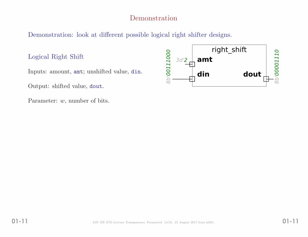
Demonstration: look at different possible logical right shifter designs.
amt
dout
right_shift
din
8b'00111000
8b'00001110
3d'2Logical Right Shift
Inputs: amount, amt; unshifted value, din.
Output: shifted value, dout.
Parameter: w, number of bits.
0111 LSU EE 4755 Lecture Transparency. Formatted 14:53, 21 August 2017 from lsli01. 0111
What makes the shifter interesting.
It’s used in many applications.
It’s easy to describe behaviorally (by what it does).
A naıve implementation costs 3w2 gates.
A good implementation costs 6w lgw gates.
Should we rely on the synthesis program to get it right?
0112 LSU EE 4755 Lecture Transparency. Formatted 14:53, 21 August 2017 from lsli01. 0112
Simple Design Flow
Simple Design Flow (Simple Flow, for short)
Three easy steps (not counting step zero).
Used to describe the major steps in a typical design flow.
List of Steps in Simple Design Flow
Simple Flow Step 0: Goal Determination.
Simple Flow Step 1: Design Capture
Simple Flow Step 2: Behavioral Verification
Simple Flow Step 3: Synthesis and Timing Verification
0113 LSU EE 4755 Lecture Transparency. Formatted 14:53, 21 August 2017 from lsli01. 0113

Simple Flow Step 0:
Start with: an idea for a new chip.
Goal: a box full of the new chips.
0114 LSU EE 4755 Lecture Transparency. Formatted 14:53, 21 August 2017 from lsli01. 0114

Simple Flow Step 1: Design Capture
Using the back of an envelope or some other suitable medium . . .
. . . develop a rough draft of the design.
Using a text editor . . .
. . . write a Verilog description of the design.
Using a text editor . . .
. . . write a Verilog description of a testbench used to test the design.
The testbench generates inputs for the design and verifies the design’s outputs.
0115 LSU EE 4755 Lecture Transparency. Formatted 14:53, 21 August 2017 from lsli01. 0115

Simple Flow Step 2: Behavioral Verification
Using a simulator and waveform viewer . . .
. . . check if design passes testbench tests . . .
. . . and if not, debug.
Waveform viewer is sort of a virtual logic analyzer, can view signals on any part of design.
Simulator output includes messages generated by behavioral code . . .
. . . including “pass” or “fail” message produced by testbench.
Using text editor . . .
. . . fix bugs, and tune performance.
0116 LSU EE 4755 Lecture Transparency. Formatted 14:53, 21 August 2017 from lsli01. 0116

Simple Flow Step 3: Synthesis and Timing Verification
Using synthesis programs . . .
. . . generate design database.
Design database has information needed to fabricate the chip . . .
. . . and to perform simulations with accurate timing.
Simulate using design database to verify that timing is acceptable . . .
. . . if timing is not acceptable edit the Verilog structural description and repeat steps above.
Using the Internet, E-mail design database and credit card number to fab.
After a few weeks, get parts back in mail.
0117 LSU EE 4755 Lecture Transparency. Formatted 14:53, 21 August 2017 from lsli01. 0117
Topics Covered in This Course
• Coding in SystemVerilog.
• Writing structural and synthesizable descriptions.
• Writing testbench code.
• Using simulation, waveform viewers and similar tools.
• Synthesis.
• Using synthesis tools.
0118 LSU EE 4755 Lecture Transparency. Formatted 14:53, 21 August 2017 from lsli01. 0118
EDA (Electronic Design Automation) Tools
Programs to support design automation.
These include SystemVerilog simulators, synthesis programs, design rule checkers, etc., etc.,etc.
Major EDA Vendors
◦ Synopsis
◦ Cadence Design Systems
◦ Mentor Graphics
0119 LSU EE 4755 Lecture Transparency. Formatted 14:53, 21 August 2017 from lsli01. 0119

Course Will Use Products of Cadence Design Systems
ECE is a member of Cadence’s University Software Program.
Software would normally cost well over 100 k$ . . .
. . . which helps explain why you can’t have your own copies (unless you’re rich).
0120 LSU EE 4755 Lecture Transparency. Formatted 14:53, 21 August 2017 from lsli01. 0120

For Simulation: Cadence Incisive Enterprise Simulator Package
A collection of programs including:
◦ ncvlog – Verilog simulator.
◦ simvision – Waveform viewer (to view sim results).
◦ irun – Convenient front end to other programs.
0121 LSU EE 4755 Lecture Transparency. Formatted 14:53, 21 August 2017 from lsli01. 0121

For Synthesis: Encounter RTL Compiler
◦ rc – Front end for synthesis tools.
0122 LSU EE 4755 Lecture Transparency. Formatted 14:53, 21 August 2017 from lsli01. 0122
Design Capture
Design Capture:
Entering a design in electronic form.
Start: Idea in engineer’s head, scribbles on back of envelope.
Finish: Design in electronic form readable by some EDA tools.
0123 LSU EE 4755 Lecture Transparency. Formatted 14:53, 21 August 2017 from lsli01. 0123

Design Capture Methods
◦ Schematic Capture
Enter design using GUI (graphical user interface) schematic editor.
Fun and easy for beginners but tedious for all but small designs.
◦ Finite-State Machine Editors
Programs meant for designing FSM, to be part of larger design.
◦ Hardware Description Languages
Like any programming language . . .
. . . design entered using standard or specialized text editor.
0124 LSU EE 4755 Lecture Transparency. Formatted 14:53, 21 August 2017 from lsli01. 0124
HDL Descriptive Styles
Descriptive style refers to a set of rules that a description adheres to.
HDL’s are used to write a hardware description or model (don’t call it a program).
Descriptive Styles
Structural: how parts are connected together, like a schematic.
Behavioral: what hardware is supposed to do.
Register Transfer Language (RTL): a form in which registers are explicit. Covered later insemester.
Intent of structural code is the description of hardware.
Intent of behavioral code can be
description of hardware, for use by a synthesis program
testbench, used to verify correctness of other descriptions
simulate a part not yet designed in detail
0125 LSU EE 4755 Lecture Transparency. Formatted 14:53, 21 August 2017 from lsli01. 0125

Synthesis Design Target
Design Target:
The type of device to be manufactured or programmed. Synthesis programs generate outputfor a particular design target.
0126 LSU EE 4755 Lecture Transparency. Formatted 14:53, 21 August 2017 from lsli01. 0126
Design Targets
◦ Programmable Logic Array (PLA)
Chip that can be programmed (once) to implement a logic function.
Usually programmed at the factory.
PLAs might be used in prototypes or when only a few parts are needed.
◦ Application-Specific Integrated Circuit (ASIC)
A fully custom chip.
Usually the fastest design target, can have the most components.
0127 LSU EE 4755 Lecture Transparency. Formatted 14:53, 21 August 2017 from lsli01. 0127

◦ Gate Array
A chip full of gates manufactured in two steps:
First generic layers containing gates are fabricated . . .
. . . but gates are not connected to each other.
Later, metal layers connecting gates are added.
Designer using gate arrays specifies only metal layer.
Since gates fabricated in advance time is saved.
◦ Field-Programmable Gate Array (FPGA)
A chip full of logic whose connection and function can be programmed and later re-programmed.
Many FPGA vendors provide EDA tools for their products.
0128 LSU EE 4755 Lecture Transparency. Formatted 14:53, 21 August 2017 from lsli01. 0128

Typical Synthesis Steps
Start With:
Choice of Design Target
Type of target: FPGA, ASIC, etc.
Manufacturer and family.
A synthesis program or programs.
Behavioral or Structural Description
Functionality has been verified by simulation.
Behavioral description (if used) follows synthesizebility rules specified for synthesis program.
0129 LSU EE 4755 Lecture Transparency. Formatted 14:53, 21 August 2017 from lsli01. 0129
Major Synthesis Steps (Summary)
Synthesis of technology-independent gate-level description.
Map gates and modules to technology-specific versions.
Place and route.
0130 LSU EE 4755 Lecture Transparency. Formatted 14:53, 21 August 2017 from lsli01. 0130
Major Synthesis Steps (Details)
Synthesis of technology-independent gate-level description.
Synthesis program infers registers and minimizes logic.
Registers aren’t explicitly declared (even though it will appear otherwise) . . .
. . . so synthesis program must determine (infer) where they are needed.
Because (most) synthesis programs minimize combinational logic . . .
. . . descriptions should be written for clarity.
Output of this step is purely structural code . . .
. . . consisting of gates and standard modules (e.g., for arithmetic), and library modules.
Based on output, designer might tweak design or give hints to synthesis program.
Place and Route
Placement is the determination of the physical location of a part.
Routing is the determination of paths for wires interconnecting parts.
0131 LSU EE 4755 Lecture Transparency. Formatted 14:53, 21 August 2017 from lsli01. 0131

Output of place-and-route step:
Timing information (since technology and wire lengths are known) which may be . . .
. . . backannotated (written into) the original behavioral description.
Behavioral descriptions re-simulated to see if they meet timing criteria.
For FPGAs, code to program the devices.
For ASICS and gate arrays, . . .
. . . a design database to tape-out and send to a fab.
Fabrication facilities apply additional steps, not covered here.
0132 LSU EE 4755 Lecture Transparency. Formatted 14:53, 21 August 2017 from lsli01. 0132