ec series - adelaide hot water
TRANSCRIPT
970-289 Revised 05-12
Table of ContentsModel Nomenclature ..................................................................................................................1Introduction....................................................................................................................................2Initial Inspection............................................................................................................................2General Description.....................................................................................................................2Moving and Storage ....................................................................................................................2Safety Considerations .................................................................................................................2Location............................................................................................................................................2Installation.......................................................................................................................................2Condensate Drain.........................................................................................................................3Duct System....................................................................................................................................3Electrical ...........................................................................................................................................4Thermostat Connections ..........................................................................................................4Safety Devices and the UPM Controller ...............................................................................4Piping ................................................................................................................................................4Sequence of Operation ..............................................................................................................6Unit Options ...................................................................................................................................7Well Water Systems .....................................................................................................................8Cooling Tower / Boiler Application........................................................................................9Earth Coupled Systems ............................................................................................................10System Checkout........................................................................................................................11Unit Start-Up ................................................................................................................................11Maintenance ................................................................................................................................11Wiring Diagrams.........................................................................................................................12Operating Pressures & Temperatures.................................................................................43Unit Check-Out............................................................................................................................50Trouble Shooting .......................................................................................................................51
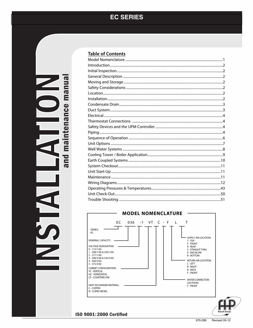
MODEL NOMENCLATURE
SERIES:EC
NOMINAL CAPACITY:
VOLTAGE DESIGNATION:0 - 115/1/601 - 208/1/60 & 230/1/602 - 277/1/603 - 208/3/60 & 230/3/604 - 460/3/605 - 575/3/60
CABINET CONFIGURATION:VT - VERTICALHZ - HORIZONTALCF - COUNTERFLOW
HEAT EXCHANGER MATERIAL:C - COPPERN - CUPRO-NICKEL
SUPPLY AIR LOCATION:T - TOPF - FRONTR - REARS - STRAIGHT THRUE - END BLOWB - BOTTOM
RETURN AIR LOCATION:L - LEFTR - RIGHTB - BACKF - FRONT
WATER CONNECTIONLOCATION:F - FRONT
EC 036 -1 VT C - F L T
EC SERIES
970-289 Revised 05-12
INTRODUCTION:
The EC Series uses scroll and reciprocating compressorsand refrigerant R-410A to achieve high efficiency levels,quiet operation and reliable performance.
The new refrigerant provides performance similar to that ofR-22 with one major advantage. Refrigerant R-410A is anHFC so it does not contain any ozone depleting HCFCs orCFCs.
INITIAL INSPECTION:
Be certain to inspect all cartons or crates on each unit asreceived at the job site before signing the freight bill. Verifythat all items have been received and that there are novisible damages; note any shortages or damages on allcopies of the freight bill. In the event of damage orshortage, remember that the purchaser is responsible forfiling the necessary claims with the carrier. Concealeddamages not discovered until after removing the units fromthe packaging must be reported to the carrier within 24hours of receipt.
GENERAL DESCRIPTION:
The EC Water-to-Air Heat Pumps provide the bestcombination of performance and efficiency available.Safety devices are built into each unit to provide themaximum system protection possible when properlyinstalled and maintained.
The EC Water-to-Air Heat Pumps are UnderwritersLaboratories (UL), (CE) and (CUL) listed for safety. The ECWater-to-Air Heat Pumps are designed to operate withentering liquid temperature between 50° F and 100° F. Withthe extended range option, the heat pump can operate withentering liquid temperatures between 25° F and 110° F.
NOTE: 50° F Min. EWT for well water applications withsufficient water flow to prevent freezing. Antifreezesolution is required for all closed lop applications.
Cooling Tower/ Boiler and Earth Coupled (GeoThermal)applications should have sufficient antifreeze solution toprotect against extreme conditions and equipment failure.Frozen water coils are not covered under warranty.
WARNING: This product should not be used fortemporarily heating/cooling during construction. Doing somay effect the units warranty.
MOVING AND STORAGE:
If the equipment is not needed for immediate installationupon its arrival at the job site, it should be left in itsshipping carton and stored in a clean, dry area. Units mustonly be stored or moved in the normal upright position asindicated by the “UP” arrows on each carton at all times. Ifunit stacking is required, stack units as follows: Verticalunits less than 6 tons, no more than two high. Horizontalunits less than 6 tons, no more than three high. “Do notstack units larger than 6 tons.”
SAFETY CONSIDERATIONS:
CAUTION: R-410A systems operate at higher pressuresthan standard R-22 systems. Do not use R-22 serviceequipment or components on R-410A equipment.
Installation and servicing of this equipment can behazardous due to system pressure and electricalcomponents. Only trained and qualified personnel shouldinstall, repair, or service the equipment. Untrainedpersonnel can perform basic functions of maintenancesuch as cleaning coils and replacing filters.
WARNING: Before performing service or maintenanceoperations on the system, turn off main power to the unit.Electrical shock could cause personal injury or death.
When working on equipment, always observe precautionsdescribed in the literature, tags, and labels attached to theunit. Follow all safety codes. Wear safety glasses and workgloves. Use a quenching cloth for brazing, and place a fireextinguisher close to the work area.
LOCATION:
Locate the unit in an indoor area that allows easy removalof the filter and access panels, and has enough room forservice personnel to perform maintenance or repair.Provide sufficient room to make water, electrical, and ductconnection(s). If the unit is located in a confined space suchas a closet, provisions must be made for return air to freelyenter the space. On horizontal units, allow adequate roombelow the unit for a condensate drain trap and do notlocate the unit above supply piping. These units are notapproved for outdoor installation; therefore, they must beinstalled inside the structure being conditioned. Do notlocate in areas that are subject to freezing.
INSTALLATION:
WARNING: Remove all shipping blocks under blowerhousing. Loosen compressor mounting bolts.
MOUNTING VERTICAL UNITS:
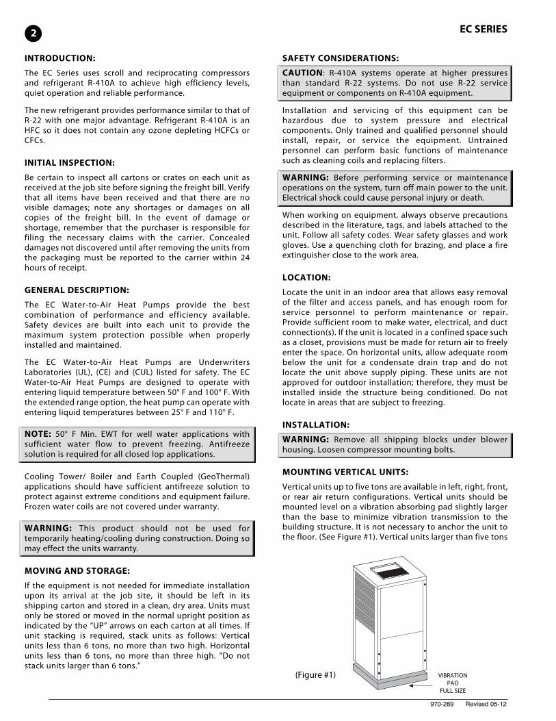
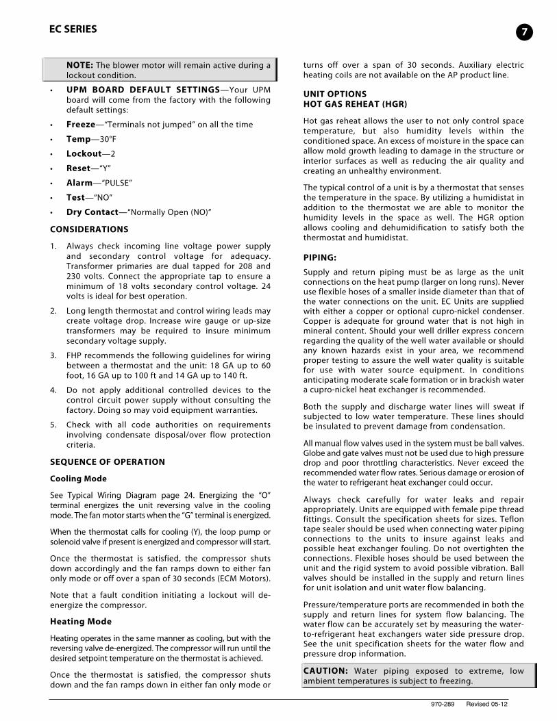
Vertical units up to five tons are available in left, right, front,or rear air return configurations. Vertical units should bemounted level on a vibration absorbing pad slightly largerthan the base to minimize vibration transmission to thebuilding structure. It is not necessary to anchor the unit tothe floor. (See Figure #1). Vertical units larger than five tons
(Figure #1) VIBRATIONPAD
FULL SIZE
2 EC SERIES
970-289 Revised 05-12
should be vibration isolated according to the designengineers specifications.
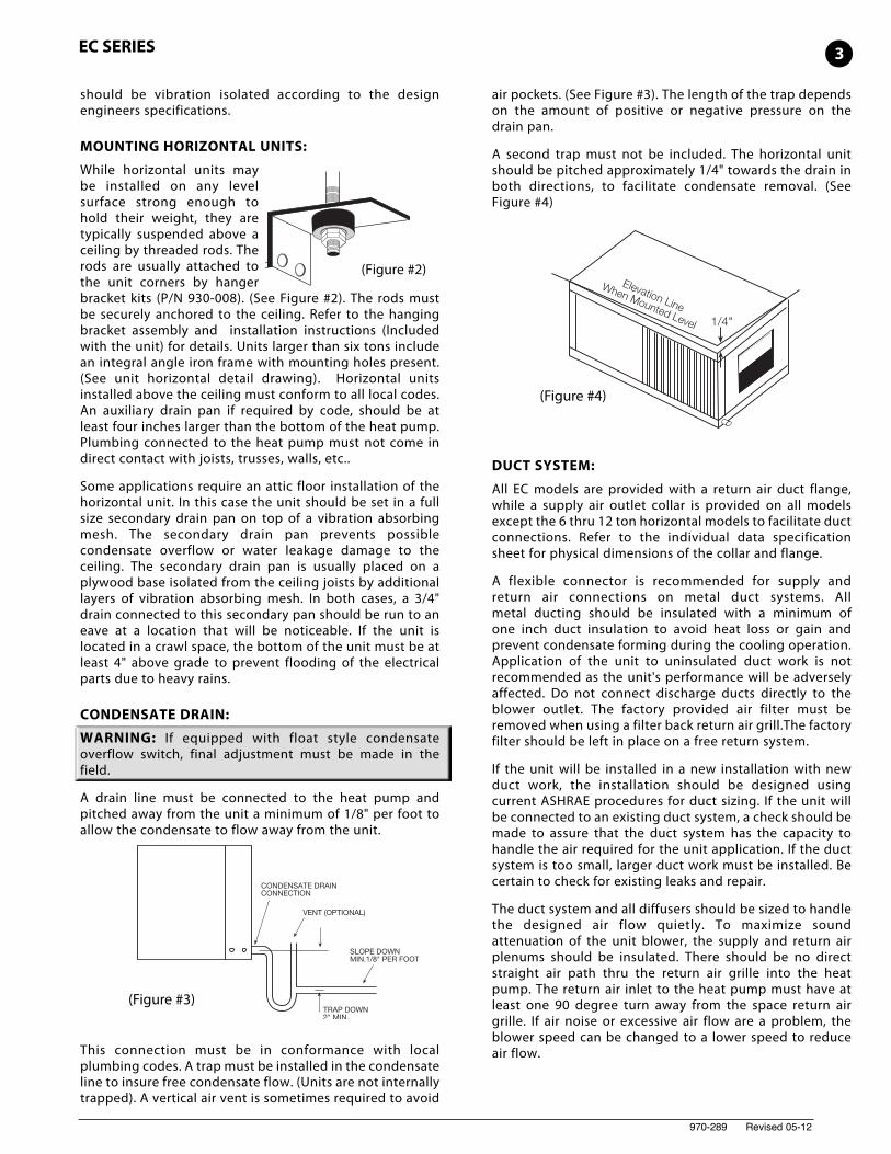
MOUNTING HORIZONTAL UNITS:
While horizontal units maybe installed on any levelsurface strong enough tohold their weight, they aretypically suspended above aceiling by threaded rods. Therods are usually attached tothe unit corners by hangerbracket kits (P/N 930-008). (See Figure #2). The rods mustbe securely anchored to the ceiling. Refer to the hangingbracket assembly and installation instructions (Includedwith the unit) for details. Units larger than six tons includean integral angle iron frame with mounting holes present.(See unit horizontal detail drawing). Horizontal unitsinstalled above the ceiling must conform to all local codes.An auxiliary drain pan if required by code, should be atleast four inches larger than the bottom of the heat pump.Plumbing connected to the heat pump must not come indirect contact with joists, trusses, walls, etc..
Some applications require an attic floor installation of thehorizontal unit. In this case the unit should be set in a fullsize secondary drain pan on top of a vibration absorbingmesh. The secondary drain pan prevents possiblecondensate overflow or water leakage damage to theceiling. The secondary drain pan is usually placed on aplywood base isolated from the ceiling joists by additionallayers of vibration absorbing mesh. In both cases, a 3/4"drain connected to this secondary pan should be run to aneave at a location that will be noticeable. If the unit islocated in a crawl space, the bottom of the unit must be atleast 4" above grade to prevent flooding of the electricalparts due to heavy rains.
CONDENSATE DRAIN:
WARNING: If equipped with float style condensateoverflow switch, final adjustment must be made in thefield.
A drain line must be connected to the heat pump andpitched away from the unit a minimum of 1/8" per foot toallow the condensate to flow away from the unit.
This connection must be in conformance with localplumbing codes. A trap must be installed in the condensateline to insure free condensate flow. (Units are not internallytrapped). A vertical air vent is sometimes required to avoid
air pockets. (See Figure #3). The length of the trap dependson the amount of positive or negative pressure on thedrain pan.
A second trap must not be included. The horizontal unitshould be pitched approximately 1/4" towards the drain inboth directions, to facilitate condensate removal. (SeeFigure #4)
DUCT SYSTEM:
All EC models are provided with a return air duct flange,while a supply air outlet collar is provided on all modelsexcept the 6 thru 12 ton horizontal models to facilitate ductconnections. Refer to the individual data specificationsheet for physical dimensions of the collar and flange.
A flexible connector is recommended for supply andreturn air connections on metal duct systems. Allmetal ducting should be insulated with a minimum ofone inch duct insulation to avoid heat loss or gain andprevent condensate forming during the cooling operation.Application of the unit to uninsulated duct work is notrecommended as the unit's performance will be adverselyaffected. Do not connect discharge ducts directly to theblower outlet. The factory provided air filter must beremoved when using a filter back return air grill.The factoryfilter should be left in place on a free return system.
If the unit will be installed in a new installation with newduct work, the installation should be designed usingcurrent ASHRAE procedures for duct sizing. If the unit willbe connected to an existing duct system, a check should bemade to assure that the duct system has the capacity tohandle the air required for the unit application. If the ductsystem is too small, larger duct work must be installed. Becertain to check for existing leaks and repair.
The duct system and all diffusers should be sized to handlethe designed air flow quietly. To maximize soundattenuation of the unit blower, the supply and return airplenums should be insulated. There should be no directstraight air path thru the return air grille into the heatpump. The return air inlet to the heat pump must have atleast one 90 degree turn away from the space return airgrille. If air noise or excessive air flow are a problem, theblower speed can be changed to a lower speed to reduceair flow.
(Figure #3)
3
(Figure #2)
(Figure #4)
EC SERIES
970-289 Revised 05-12
ELECTRICAL:
All field wiring must comply with local and national fire,safety and electrical codes. Power to the unit must bewithin the operating voltage range indicated on the unit'snameplate. On three phase units, phases must be balancedwithin 2%.
Properly sized fuses or HACR circuit breakers must beinstalled for branch circuit protection. See equipmentrating plate for maximum size. The unit is supplied with anopening for attaching conduit. Be certain to connect theground lead to the ground lug in the control box. Connectthe power leads as indicated on the unit wiring diagram.
THERMOSTAT CONNECTIONS:
Thermostat wiring is connected to the 5-position (6-position on dual compressor models) low voltage terminalblock located in the upper portion of the electrical box. Thethermostat connections and their functions are as follows:
C Transformer 24 VAC CommonO Reversing Valve (energized in cooling)Y Compressor contactorY1 1ST stage compressor contractor (dual-
compressor unit)Y2 2ND stage compressor contractor (dual-
compressor unit)R Transformer 24 VAC HotG Fan
SAFETY DEVICES AND THE UPM CONTROLLER
Each unit is factory provided with a Unit Protection Module(UPM) that controls the compressor operation andmonitors the safety controls that protect the unit.
Safety controls include the following:
• High pressure switch located in the refrigerant dischargeline and wired across the HPC terminals on the UPM
• Low pressure switch located in the unit refrigerant suctionline and wired across terminals LPC1 and LPC2 on the UPM.
• Optional freeze protection sensor, mounted close tocondensing water coil, monitors refrigeranttemperature between condensing water coil andthermal expansion valve. If temperature drops belowor remains at freeze limit trip for 30 seconds, thecontroller will shut down the compressor and enter intoa soft lockout condition. The default freeze limit trip is30°F, however this can be changed to 15°F by cuttingthe R42 resistor located on top of DIP switch SW1.
• The optional condensate overflow protection sensor(standard on horizontal units) is located in the drainpan of the unit and connected to the ‘COND’ terminalon the UPM board.
• Units with two compressors will be equipped withUPM II.
• UPM II provides the same protection for eachcompressor.
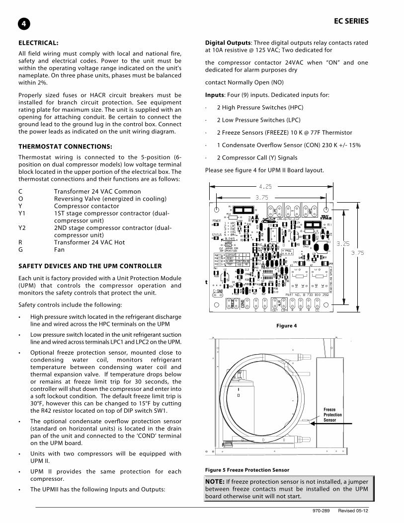
• The UPMII has the following Inputs and Outputs:
Digital Outputs: Three digital outputs relay contacts ratedat 10A resistive @ 125 VAC; Two dedicated for
the compressor contactor 24VAC when “ON” and onededicated for alarm purposes dry
contact Normally Open (NO)
Inputs: Four (9) inputs. Dedicated inputs for:
· 2 High Pressure Switches (HPC)
· 2 Low Pressure Switches (LPC)
· 2 Freeze Sensors (FREEZE) 10 K @ 77F Thermistor
· 1 Condensate Overflow Sensor (CON) 230 K +/- 15%
· 2 Compressor Call (Y) Signals
Please see figure 4 for UPM II Board layout.
t
Figure 4
Figure 5 Freeze Protection Sensor
NOTE: If freeze protection sensor is not installed, a jumperbetween freeze contacts must be installed on the UPMboard otherwise unit will not start.
Freeze Protection Sensor
4 EC SERIES
970-289 Revised 05-12
The UPM includes the following features:
• ANTI-SHORT CYCLE TIME—5 minute delay on breaktimer to prevent compressor short cycling.
• RANDOM START—Each controller has a uniquerandom start delay ranging from 270 to 300 seconds toreduce the chances of multiple units simultaneouslystarting after initial power up or after a powerinterruption, creating a large electrical spike.
• LOW PRESSURE BYPASS TIMER—If the compressoris running and the low pressure switch opens, then thecontrol will keep the compressor on for 120 seconds.After 2 minutes if the low pressure switch remainsopen, the control will shut down the compressor andenter a soft lockout. The compressor will not beenergized until the low pressure switch closes and theanti-short cycle time delay expires. If the low pressureswitch opens 2–4 times in 1 hour, the unit will enter ahard lock out and need to be reset.
• BROWNOUT/SURGE/POWER INTERRUPTIONPROTECTION— The brownout protection in the UPMboard will shut down the compressor if the incomingpower falls below 18 VAC. The compressor will remainoff till the voltage goes above 18 VAC and the antishort cycle timer (300 seconds) times out. The unit willnot go into a hard lockout.
• MALFUNCTION OUTPUT—Alarm output is NormallyOpen (NO) dry contact. If 24 VAC output is needed R mustbe wired to the ALR-COM terminal; 24VAC will be availableon the ALR-OUT terminal when the unit is in alarmcondition. If pulse is selected the alarm output will bepulsed. The fault output will depend on the dip switchsetting for “ALARM”. If it set to “CONST’, a constant signalwill be produced to indicate a fault has occurred and theunit requires inspection to determine the type of fault. If itis set to “PULSE”, a pulse signal is produced and a faultcode is detected by a remote device indicating the fault.See L.E.D. Fault Indication below for blink codeexplanations. The remote device must have a malfunctiondetection capability when the UPM board is set to “PULSE”.
• TEST DIP SWITCH—A test dip switch is provided to reduceall time delay settings to 10 seconds during troubleshootingor verification of unit operation. Note that operation of theunit while in test mode can lead to accelerated wear andpremature failure of the unit. The “TEST” switch must be setback to “NO” for normal operation.
• FREEZE SENSOR—The freeze sensor input is activeall the time, if a freeze option is not selected the freezeterminals will need a jumper. There are 2 configurablefreeze points, 30°F & 15°F. The unit will enter a soft lockout until the temperature climbs above the set pointand the anti-short cycle time delay has expired. Thefreeze sensor will shut the compressor output downafter 90 seconds of water flow loss and report a freezecondition. It is recommended to have a flow switch toprevent the unit from running if water flow is lost.
NOTE: If unit is employing a fresh water system (no anti-freezeprotection), it is extremely important to have the “Freeze”jumper R42 resistor set to 30°F in order to shut down the unitat the appropriate leaving water temperature and protect yourheat pump from freezing if a freeze sensor is included.
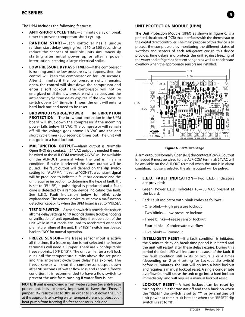
UNIT PROTECTION MODULE (UPM)
The Unit Protection Module (UPM) as shown in figure 6, is aprinted circuit board (PCB) that interfaces with the thermostat orthe digital direct controller. The main purpose of this device is toprotect the compressors by monitoring the different states ofswitches and sensors of each refrigerant circuit, this deviceprovides time delays and protects the unit against freezing ofthe water and refrigerant heat exchangers as well as condensateoverflow when the appropriate sensors are installed.
Figure 6 - UPM Two Stage
Alarm output is Normally Open (NO) dry contact. If 24 VAC outputis needed R must be wired to the ALR-COM terminal; 24VAC willbe available on the ALR-OUT terminal when the unit is in alarmcondition. If pulse is selected the alarm output will be pulsed.
• L.E.D. FAULT INDICATION—Two L.E.D. indicatorsare provided:
• Green: Power L.E.D. indicates 18—30 VAC present atthe board.
• Red: Fault indicator with blink codes as follows:
- One blink—High pressure lockout
- Two blinks—Low pressure lockout
- Three blinks—Freeze sensor lockout
- Four blinks—Condensate overflow
- Five blinks—Brownout
• INTELLIGENT RESET—If a fault condition is initiated,the 5 minute delay on break time period is initiated andthe unit will restart after these delays expire. During thisperiod the fault LED will indicate the cause of the fault. Ifthe fault condition still exists or occurs 2 or 4 times(depending on 2 or 4 setting for Lockout dip switch)before 60 minutes, the unit will go into a hard lockoutand requires a manual lockout reset. A single condensateoverflow fault will cause the unit to go into a hard lockoutimmediately, and will require a manual lockout reset.
• LOCKOUT RESET—A hard lockout can be reset byturning the unit thermostat off and then back on whenthe “RESET” dip switch is set to “Y” or by shutting offunit power at the circuit breaker when the “RESET” dipswitch is set to “R”.
5EC SERIES
970-289 Revised 05-12
6 EC SERIES
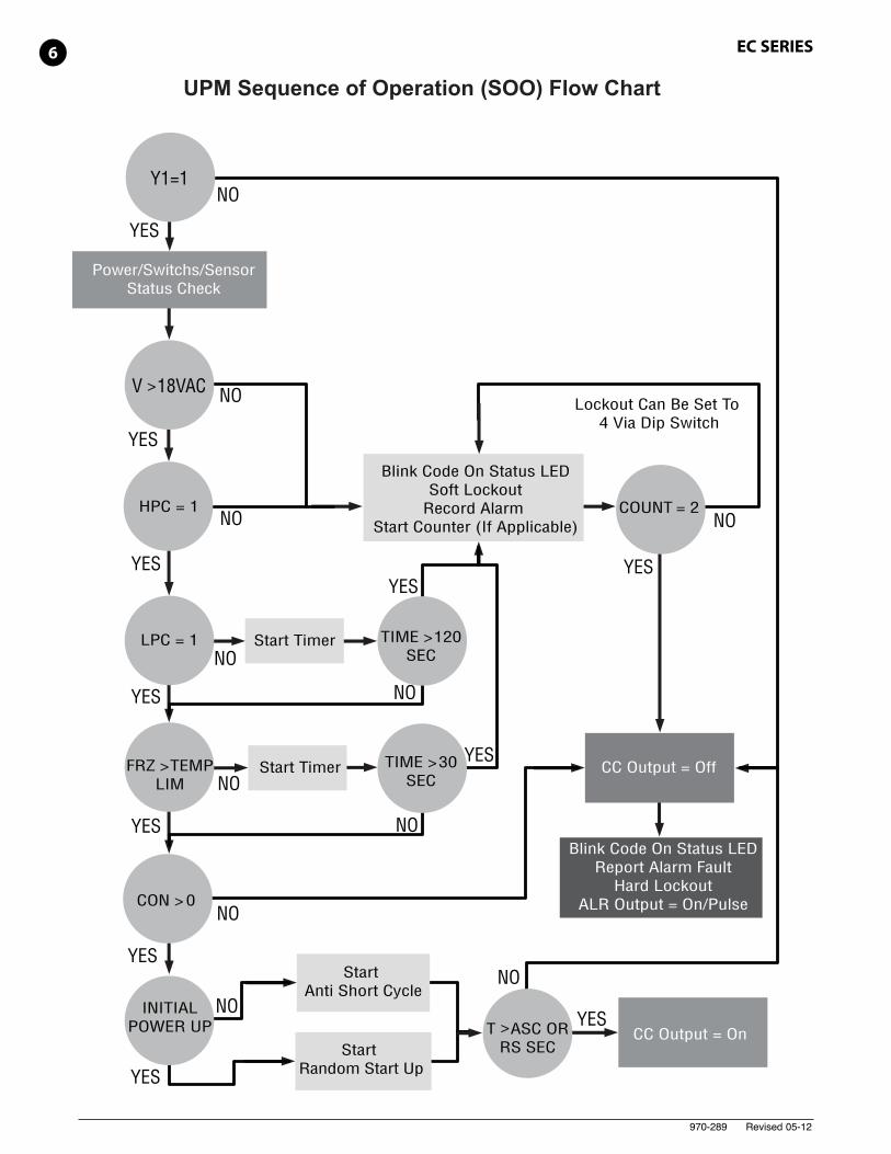
UPM Sequence of Operation (SOO) Flow Chart
YES
YES
YES
YES
YES
YES
YES
YES
YES
YES YES
NO
NO
NO
NO
NO
NO
NO
NO
NO
NO
NO
Y1=1
V > 18VAC
HPC = 1
LPC = 1
FRZ > TEMPLIM
CON > 0
INITIALPOWER UP T > ASC OR
RS SEC
TIME > 30SEC
TIME > 120SEC
COUNT = 2
Start Timer
Start Timer
CC Output = On
CC Output = Off
Blink Code On Status LEDReport Alarm Fault
Hard LockoutALR Output = On/Pulse
Blink Code On Status LEDSoft Lockout
Record Alarm Start Counter (If Applicable)
Start Anti Short Cycle
Start Random Start Up
Lockout Can Be Set To 4 Via Dip Switch
Power/Switchs/SensorStatus Check
970-289 Revised 05-12
NOTE: The blower motor will remain active during alockout condition.
• UPM BOARD DEFAULT SETTINGS—Your UPMboard will come from the factory with the followingdefault settings:
• Freeze—“Terminals not jumped” on all the time
• Temp—30°F
• Lockout—2
• Reset—“Y”
• Alarm—“PULSE”
• Test—“NO”
• Dry Contact—“Normally Open (NO)”
CONSIDERATIONS
1. Always check incoming line voltage power supplyand secondary control voltage for adequacy.Transformer primaries are dual tapped for 208 and230 volts. Connect the appropriate tap to ensure aminimum of 18 volts secondary control voltage. 24volts is ideal for best operation.
2. Long length thermostat and control wiring leads maycreate voltage drop. Increase wire gauge or up-sizetransformers may be required to insure minimumsecondary voltage supply.
3. FHP recommends the following guidelines for wiringbetween a thermostat and the unit: 18 GA up to 60foot, 16 GA up to 100 ft and 14 GA up to 140 ft.
4. Do not apply additional controlled devices to thecontrol circuit power supply without consulting thefactory. Doing so may void equipment warranties.
5. Check with all code authorities on requirementsinvolving condensate disposal/over flow protectioncriteria.
SEQUENCE OF OPERATION
Cooling Mode
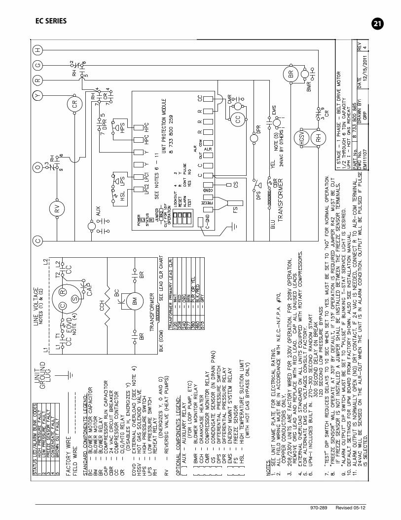
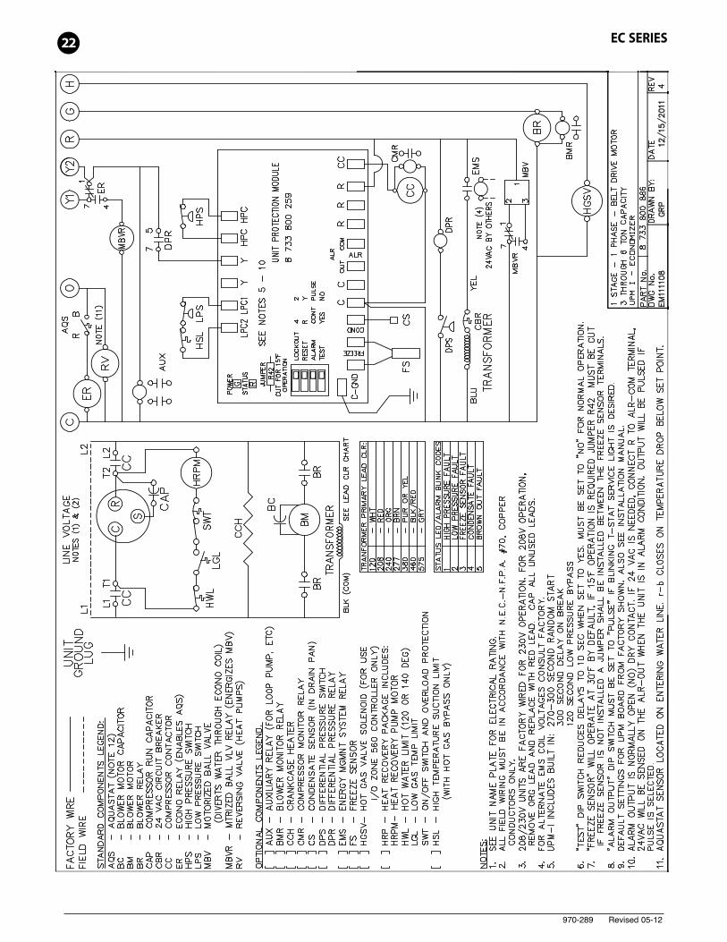
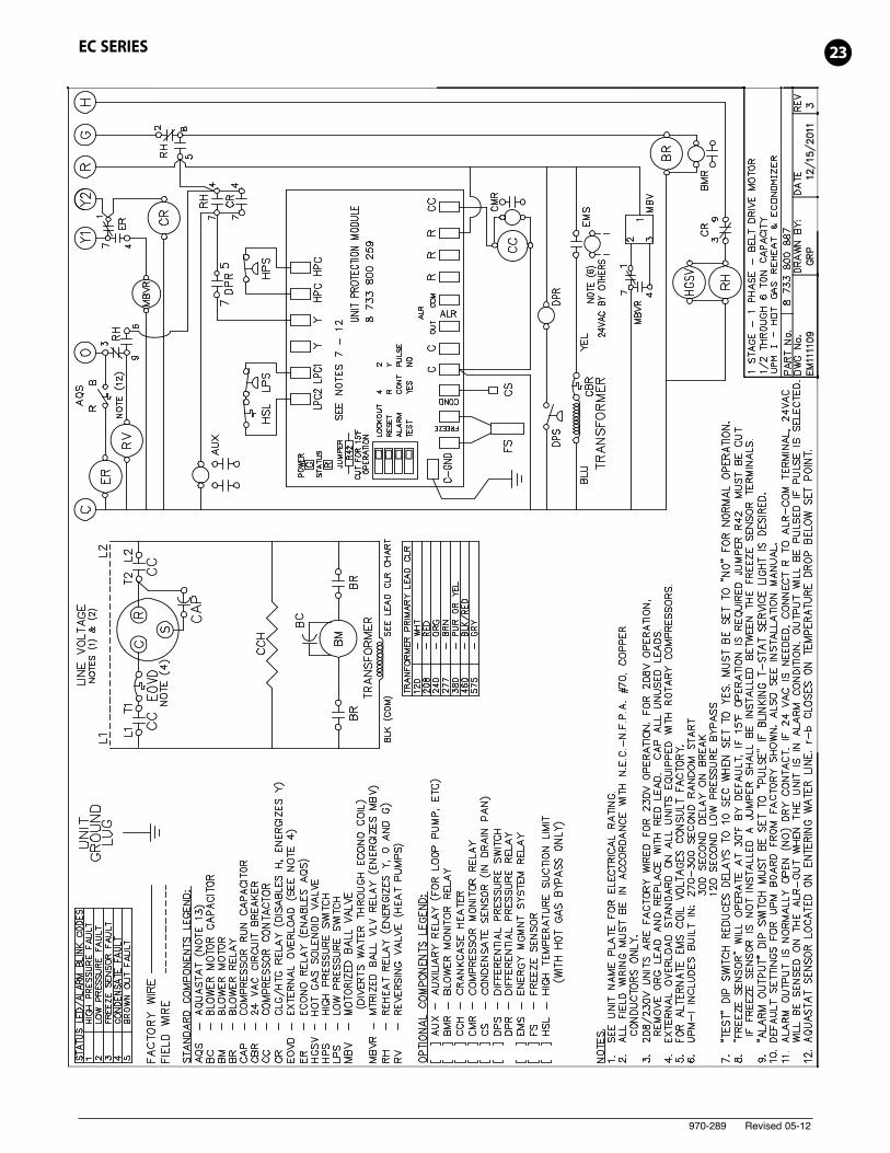
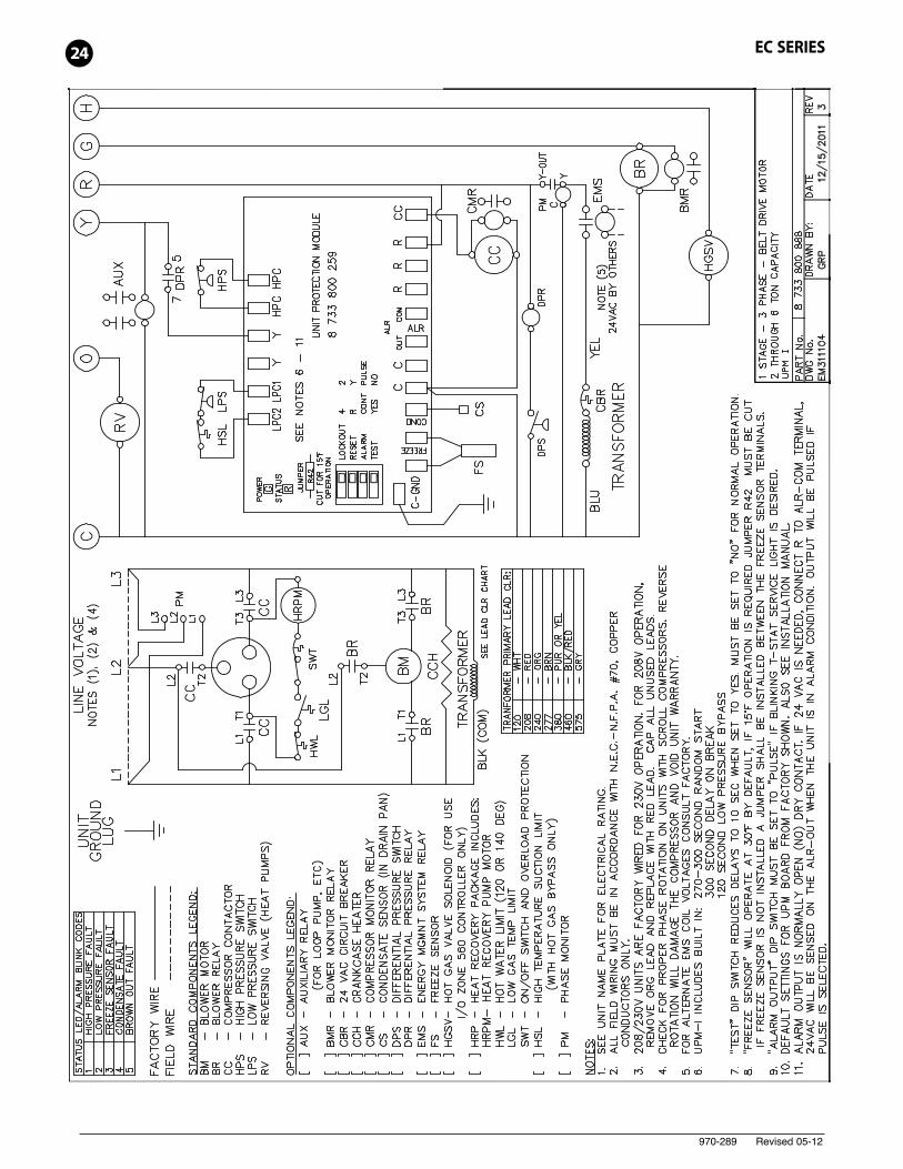
See Typical Wiring Diagram page 24. Energizing the “O”terminal energizes the unit reversing valve in the coolingmode. The fan motor starts when the “G” terminal is energized.
When the thermostat calls for cooling (Y), the loop pump orsolenoid valve if present is energized and compressor will start.
Once the thermostat is satisfied, the compressor shutsdown accordingly and the fan ramps down to either fanonly mode or off over a span of 30 seconds (ECM Motors).
Note that a fault condition initiating a lockout will de-energize the compressor.
Heating Mode
Heating operates in the same manner as cooling, but with thereversing valve de-energized. The compressor will run until thedesired setpoint temperature on the thermostat is achieved.
Once the thermostat is satisfied, the compressor shutsdown and the fan ramps down in either fan only mode or
turns off over a span of 30 seconds. Auxiliary electricheating coils are not available on the AP product line.
UNIT OPTIONS HOT GAS REHEAT (HGR)
Hot gas reheat allows the user to not only control spacetemperature, but also humidity levels within theconditioned space. An excess of moisture in the space canallow mold growth leading to damage in the structure orinterior surfaces as well as reducing the air quality andcreating an unhealthy environment.
The typical control of a unit is by a thermostat that sensesthe temperature in the space. By utilizing a humidistat inaddition to the thermostat we are able to monitor thehumidity levels in the space as well. The HGR optionallows cooling and dehumidification to satisfy both thethermostat and humidistat.
PIPING:
Supply and return piping must be as large as the unitconnections on the heat pump (larger on long runs). Neveruse flexible hoses of a smaller inside diameter than that ofthe water connections on the unit. EC Units are suppliedwith either a copper or optional cupro-nickel condenser.Copper is adequate for ground water that is not high inmineral content. Should your well driller express concernregarding the quality of the well water available or shouldany known hazards exist in your area, we recommendproper testing to assure the well water quality is suitablefor use with water source equipment. In conditionsanticipating moderate scale formation or in brackish watera cupro-nickel heat exchanger is recommended.
Both the supply and discharge water lines will sweat ifsubjected to low water temperature. These lines shouldbe insulated to prevent damage from condensation.
All manual flow valves used in the system must be ball valves.Globe and gate valves must not be used due to high pressuredrop and poor throttling characteristics. Never exceed therecommended water flow rates. Serious damage or erosion ofthe water to refrigerant heat exchanger could occur.
Always check carefully for water leaks and repairappropriately. Units are equipped with female pipe threadfittings. Consult the specification sheets for sizes. Teflontape sealer should be used when connecting water pipingconnections to the units to insure against leaks andpossible heat exchanger fouling. Do not overtighten theconnections. Flexible hoses should be used between theunit and the rigid system to avoid possible vibration. Ballvalves should be installed in the supply and return linesfor unit isolation and unit water flow balancing.
Pressure/temperature ports are recommended in both thesupply and return lines for system flow balancing. Thewater flow can be accurately set by measuring the water-to-refrigerant heat exchangers water side pressure drop.See the unit specification sheets for the water flow andpressure drop information.
CAUTION: Water piping exposed to extreme, lowambient temperatures is subject to freezing.
7EC SERIES
970-289 Revised 05-12
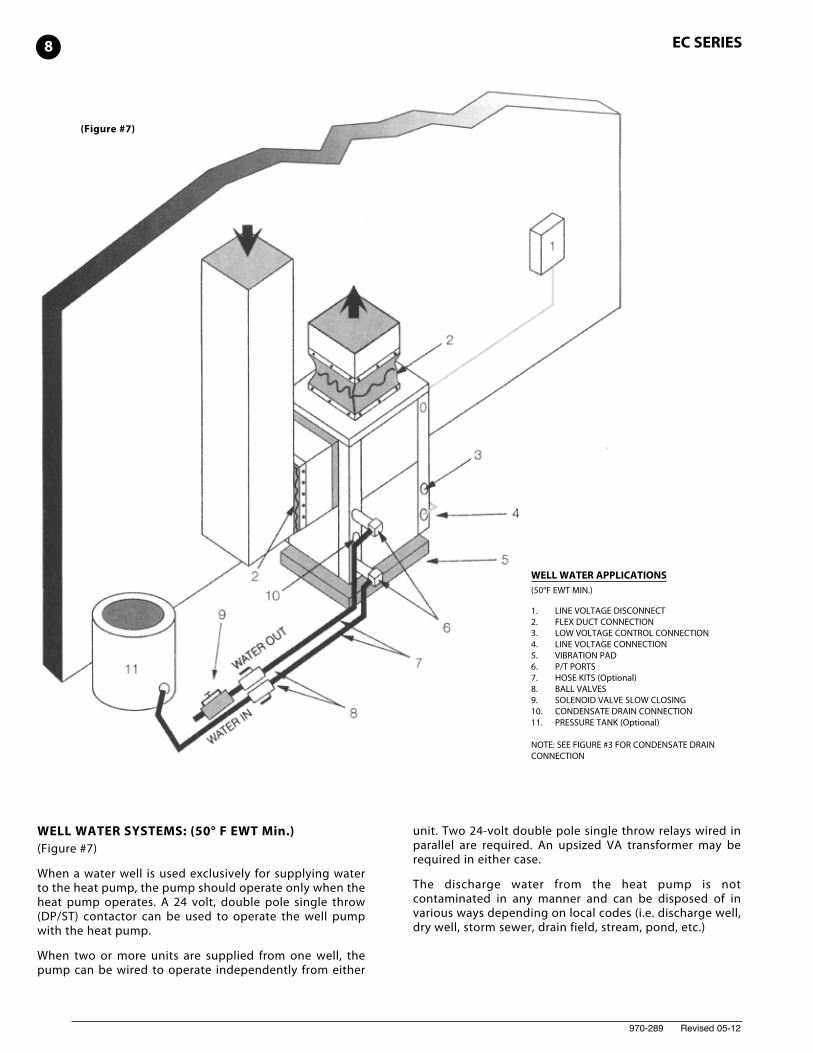
(Figure #7)
WELL WATER APPLICATIONS(50°F EWT MIN.)
1. LINE VOLTAGE DISCONNECT2. FLEX DUCT CONNECTION3. LOW VOLTAGE CONTROL CONNECTION4. LINE VOLTAGE CONNECTION5. VIBRATION PAD6. P/T PORTS7. HOSE KITS (Optional)8. BALL VALVES9. SOLENOID VALVE SLOW CLOSING10. CONDENSATE DRAIN CONNECTION11. PRESSURE TANK (Optional)
NOTE: SEE FIGURE #3 FOR CONDENSATE DRAINCONNECTION
8 EC SERIES
WELL WATER SYSTEMS: (50° F EWT Min.)(Figure #7)
When a water well is used exclusively for supplying waterto the heat pump, the pump should operate only when theheat pump operates. A 24 volt, double pole single throw(DP/ST) contactor can be used to operate the well pumpwith the heat pump.
When two or more units are supplied from one well, thepump can be wired to operate independently from either
unit. Two 24-volt double pole single throw relays wired inparallel are required. An upsized VA transformer may berequired in either case.
The discharge water from the heat pump is notcontaminated in any manner and can be disposed of invarious ways depending on local codes (i.e. discharge well,dry well, storm sewer, drain field, stream, pond, etc.)
970-289 Revised 05-12
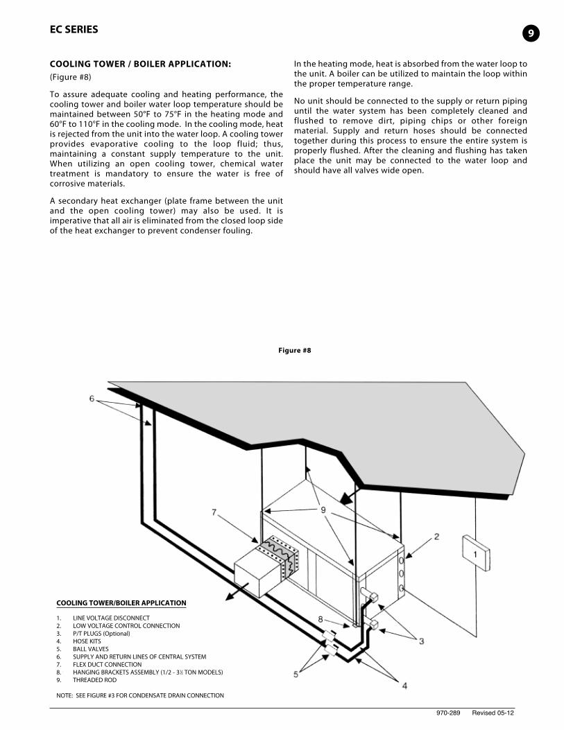
COOLING TOWER/BOILER APPLICATION
1. LINE VOLTAGE DISCONNECT2. LOW VOLTAGE CONTROL CONNECTION3. P/T PLUGS (Optional)4. HOSE KITS5. BALL VALVES6. SUPPLY AND RETURN LINES OF CENTRAL SYSTEM7. FLEX DUCT CONNECTION8. HANGING BRACKETS ASSEMBLY (1/2 - 31⁄2 TON MODELS)9. THREADED ROD
NOTE: SEE FIGURE #3 FOR CONDENSATE DRAIN CONNECTION
Figure #8
EC SERIES
COOLING TOWER / BOILER APPLICATION:(Figure #8)
To assure adequate cooling and heating performance, thecooling tower and boiler water loop temperature should bemaintained between 50°F to 75°F in the heating mode and60°F to 110°F in the cooling mode. In the cooling mode, heatis rejected from the unit into the water loop. A cooling towerprovides evaporative cooling to the loop fluid; thus,maintaining a constant supply temperature to the unit.When utilizing an open cooling tower, chemical watertreatment is mandatory to ensure the water is free ofcorrosive materials.
A secondary heat exchanger (plate frame between the unitand the open cooling tower) may also be used. It isimperative that all air is eliminated from the closed loop sideof the heat exchanger to prevent condenser fouling.
In the heating mode, heat is absorbed from the water loop tothe unit. A boiler can be utilized to maintain the loop withinthe proper temperature range.
No unit should be connected to the supply or return pipinguntil the water system has been completely cleaned andflushed to remove dirt, piping chips or other foreignmaterial. Supply and return hoses should be connectedtogether during this process to ensure the entire system isproperly flushed. After the cleaning and flushing has takenplace the unit may be connected to the water loop andshould have all valves wide open.
9
970-289 Revised 05-12
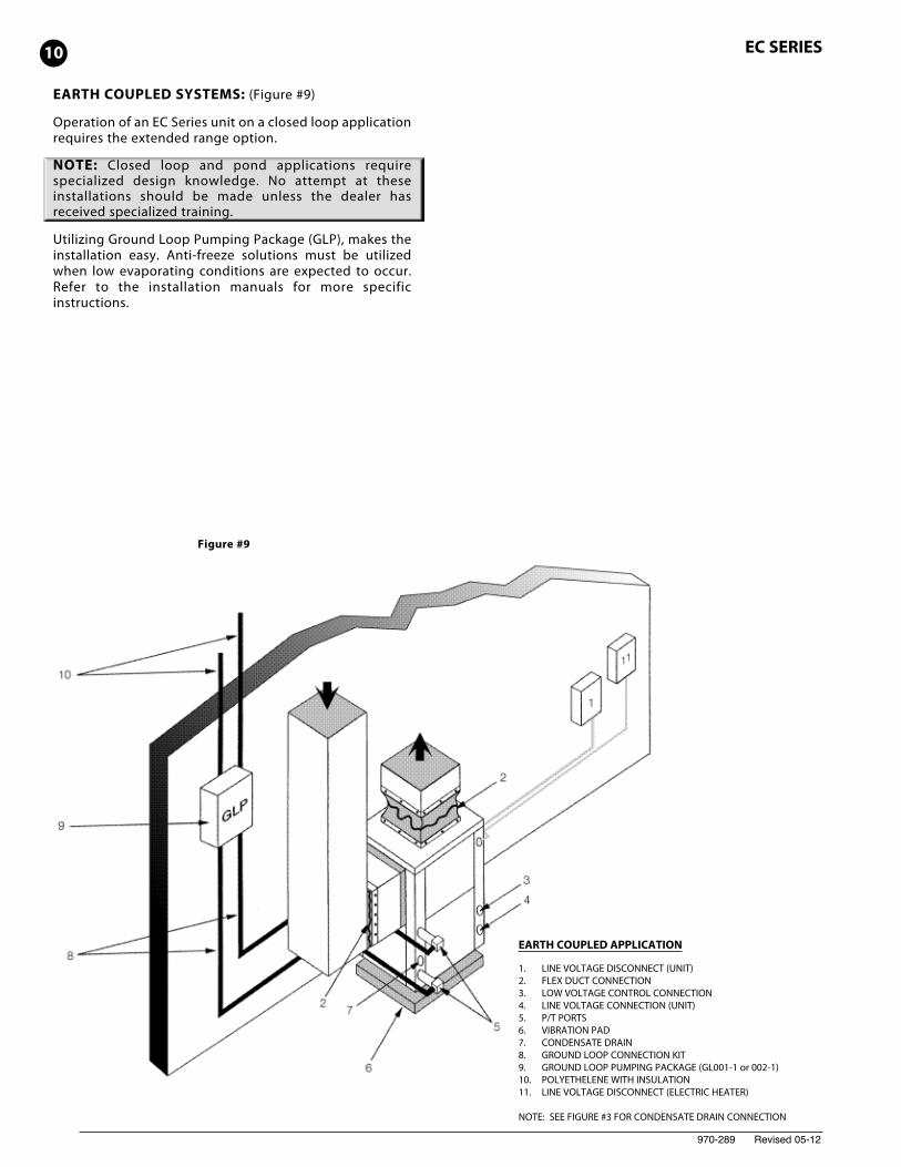
EARTH COUPLED SYSTEMS: (Figure #9)
Operation of an EC Series unit on a closed loop applicationrequires the extended range option.
NOTE: Closed loop and pond applications requirespecialized design knowledge. No attempt at theseinstallations should be made unless the dealer hasreceived specialized training.
Utilizing Ground Loop Pumping Package (GLP), makes theinstallation easy. Anti-freeze solutions must be utilizedwhen low evaporating conditions are expected to occur.Refer to the installation manuals for more specificinstructions.
EARTH COUPLED APPLICATION
1. LINE VOLTAGE DISCONNECT (UNIT)2. FLEX DUCT CONNECTION3. LOW VOLTAGE CONTROL CONNECTION4. LINE VOLTAGE CONNECTION (UNIT)5. P/T PORTS6. VIBRATION PAD7. CONDENSATE DRAIN8. GROUND LOOP CONNECTION KIT9. GROUND LOOP PUMPING PACKAGE (GL001-1 or 002-1)10. POLYETHELENE WITH INSULATION11. LINE VOLTAGE DISCONNECT (ELECTRIC HEATER)
NOTE: SEE FIGURE #3 FOR CONDENSATE DRAIN CONNECTION
Figure #9
10 EC SERIES
970-289 Revised 05-12
IN-WARRANTY MATERIAL RETURN:
When contacting your FHP Representative for service orreplacement parts, refer to the model and serial number ofthe unit as stamped on the data plate attached to the unit.
All warranty material returned to the factory for creditmust be accompanied by a material return material tag.Enter the information as called for on the tag in order toexpedite handling and insure prompt issuance of credits.
Freight charges for all items returned to the factory shallbe prepaid.The return of the part does not constitute anorder for a replacement. Therefore, a purchase order mustbe entered through your nearest representative. The ordershall include the part number, model number, and serialnumber of the unit involved. If the part is within thewarranty period, and after our inspection of the returnedpart proves that the failure is due to faulty material orworkmanship a credit or replacement part will be issued.
All warranty parts shall be returned freight prepaid to:
FHP Manufacturing Company601 N.W. 65TH Court • Fort Lauderdale, FL 33309
SYSTEM CHECKOUT:
• After completing the installation, and beforeenergizing the unit, the following system checksshould be made:
• Verify that the supply voltage to the heat pump is inaccordance with the nameplate ratings.
• Make sure that all electrical connections are tight andsecure.
• Check the electrical fusing and wiring for the correctsize.
• Verify that the low voltage wiring between thethermostat and the unit is correct.
• Verify that the water piping is complete and correct.
• Check that the water flow is correct, and adjust ifnecessary.
• Check the blower for free rotation, and that it issecured to the shaft.
• Verify that vibration isolation has been provided.
• Unit is serviceable. Be certain that all access panels aresecured in place.
UNIT START-UP:
1. Set the thermostat to the highest setting.
2. Set the thermostat system switch to "COOL", and thefan switch to the "AUTO" position. The reversing valvesolenoid should energize. The compressor and fanshould not run.
3. Reduce the thermostat setting approximately 5degrees below the room temperature.
4. Verify the heat pump is operating in the coolingmode.
5. Turn the thermostat system switch to the "OFF"position. The unit should stop running and thereversing valve should deenergize.
6. Leave the unit off for approximately (5) minutes toallow for system equalization.
7. Turn the thermostat to the lowest setting.
8. Set the thermostat switch to "HEAT".
9. Increase the thermostat setting approximately 5degrees above the room temperature.
10. Verify the heat pump is operating in the heatingmode.
11. Set the thermostat to maintain the desired spacetemperature.
12. Check for vibrations, leaks, etc...
13. Instruct the owner on the unit and thermostatoperation.
MAINTENANCE:
1. Filter changes or cleanings are required at regularintervals. The time period between filter changes willdepend upon type of environment the equipment isused in. In a single family home, that is not underconstruction, changing or cleaning the filter every 60days is sufficient. In other applications, such as motels,where daily vacuuming produces a large amount oflint, filter changes may need to be as frequent asbiweekly.
2. An annual ”checkup” is recommended by a licensedrefrigeration mechanic. Recording the performancemeasurements of volts, amps, and water temperaturedifferences (both heating and cooling) isrecommended. This data should be compared to theinformation on the unit’s data plate and the datataken at the original startup of the equipment.
3. Lubrication of the blower motor is not required,however, may be performed on some motors toextend motor life. Use SAE-20 non-detergent electricmotor oil.
4. The condensate drain should be checked annually bycleaning and flushing to insure proper drainage.
5. Periodic lockouts almost always are caused by air orwater flow problems. The lockout (shutdown) of theunit is a normal protective measure in the design ofthe equipment. If continual lockouts occur call amechanic immediately and have them check for:water flow problems, water temperature problems, airflow problems or air temperature problems. Use ofthe pressure and temperature charts for the unit maybe required to properly determine the cause.
11EC SERIES
970-289 Revised 05-12
12 EC SERIES
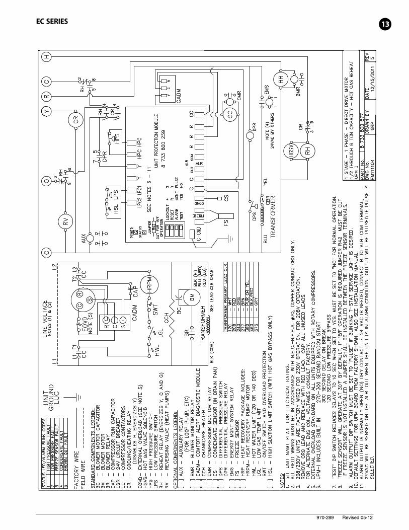
970-289 Revised 05-12
13EC SERIES
970-289 Revised 05-12
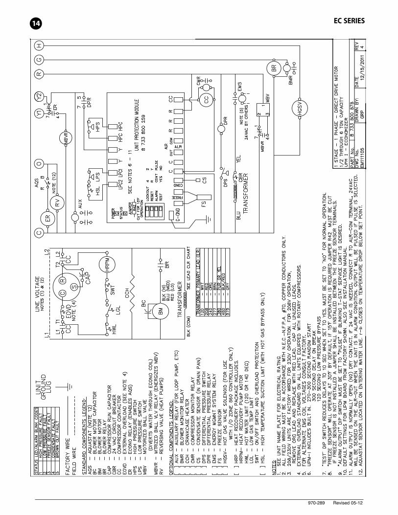
14 EC SERIES
970-289 Revised 05-12
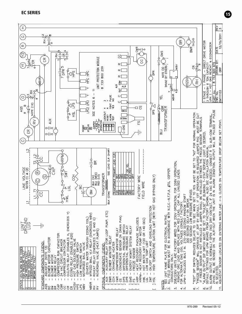
15EC SERIES
970-289 Revised 05-12
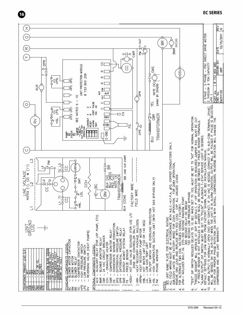
16 EC SERIES
970-289 Revised 05-12
17EC SERIES
970-289 Revised 05-12
18 EC SERIES
970-289 Revised 05-12
19EC SERIES
970-289 Revised 05-12
20 EC SERIES
970-289 Revised 05-12
21EC SERIES
970-289 Revised 05-12
22 EC SERIES
970-289 Revised 05-12
23EC SERIES
970-289 Revised 05-12
24 EC SERIES
970-289 Revised 05-12
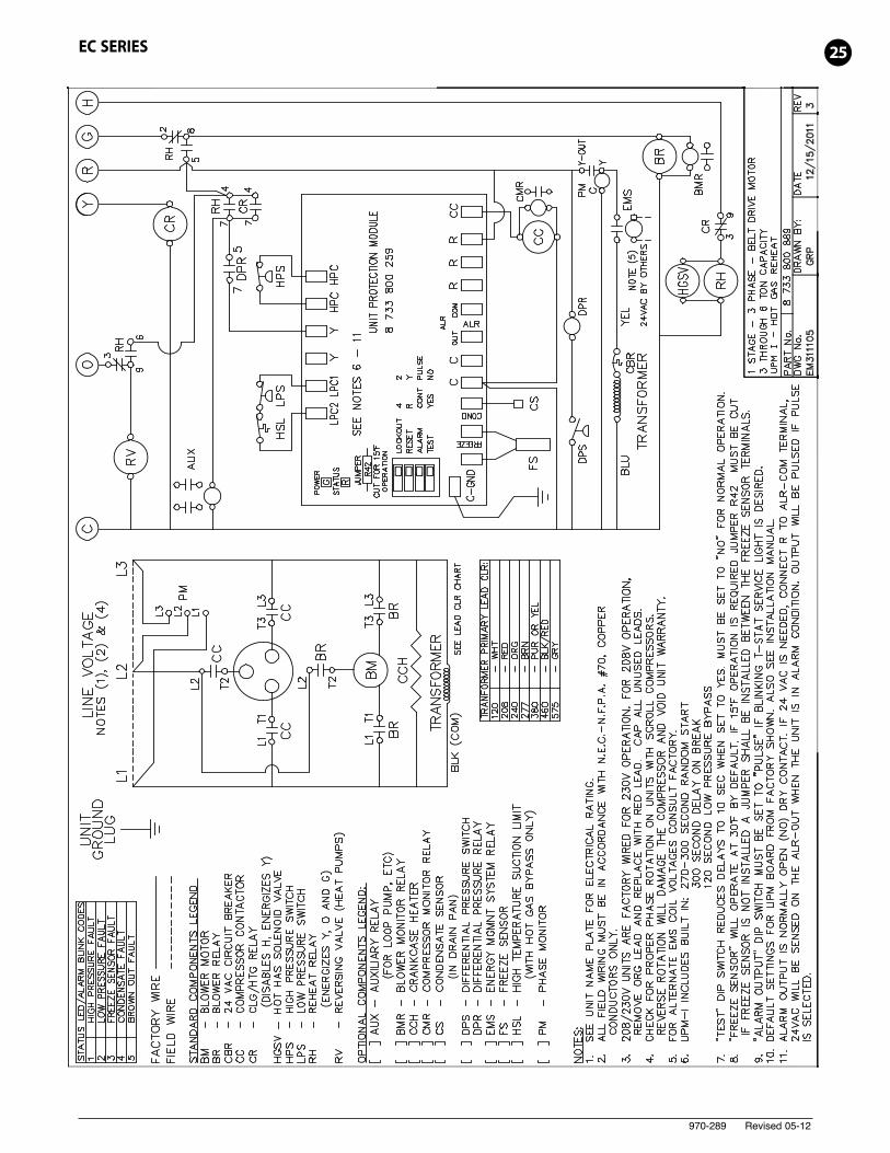
25EC SERIES
970-289 Revised 05-12
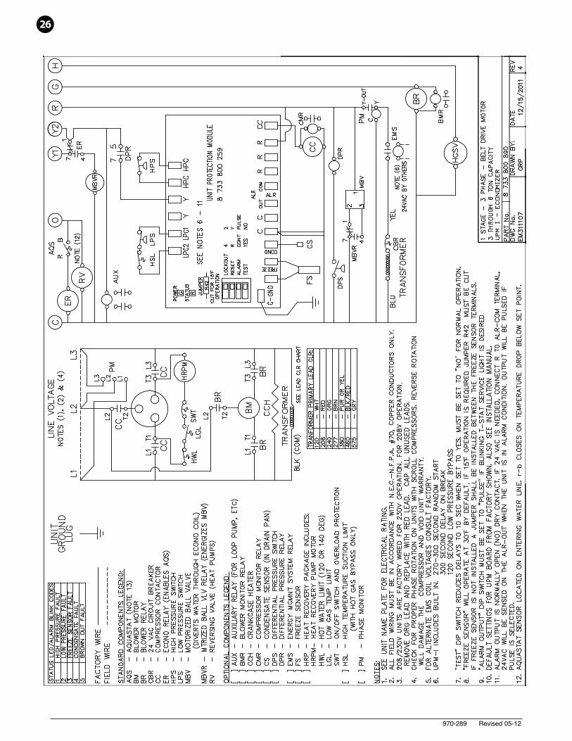
26
970-289 Revised 05-12
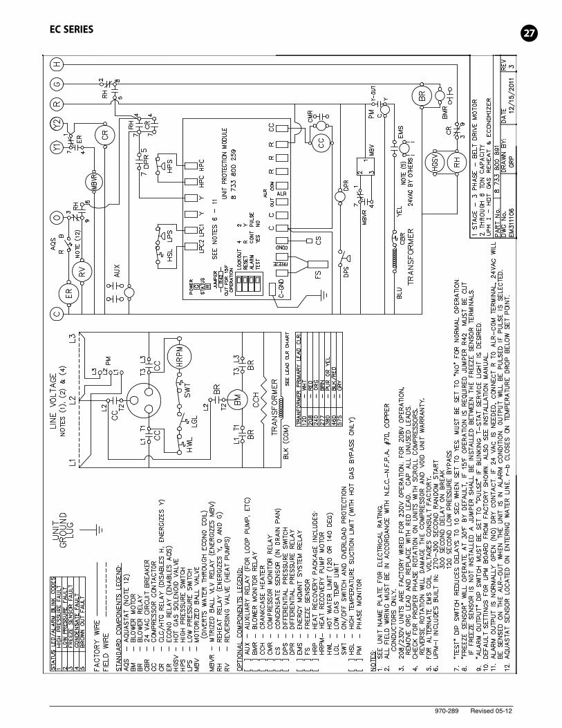
27EC SERIES
970-289 Revised 05-12
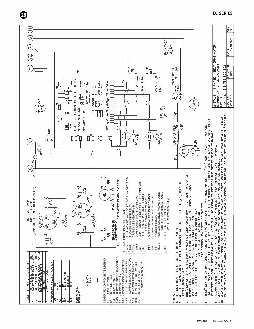
28 EC SERIES
970-289 Revised 05-12
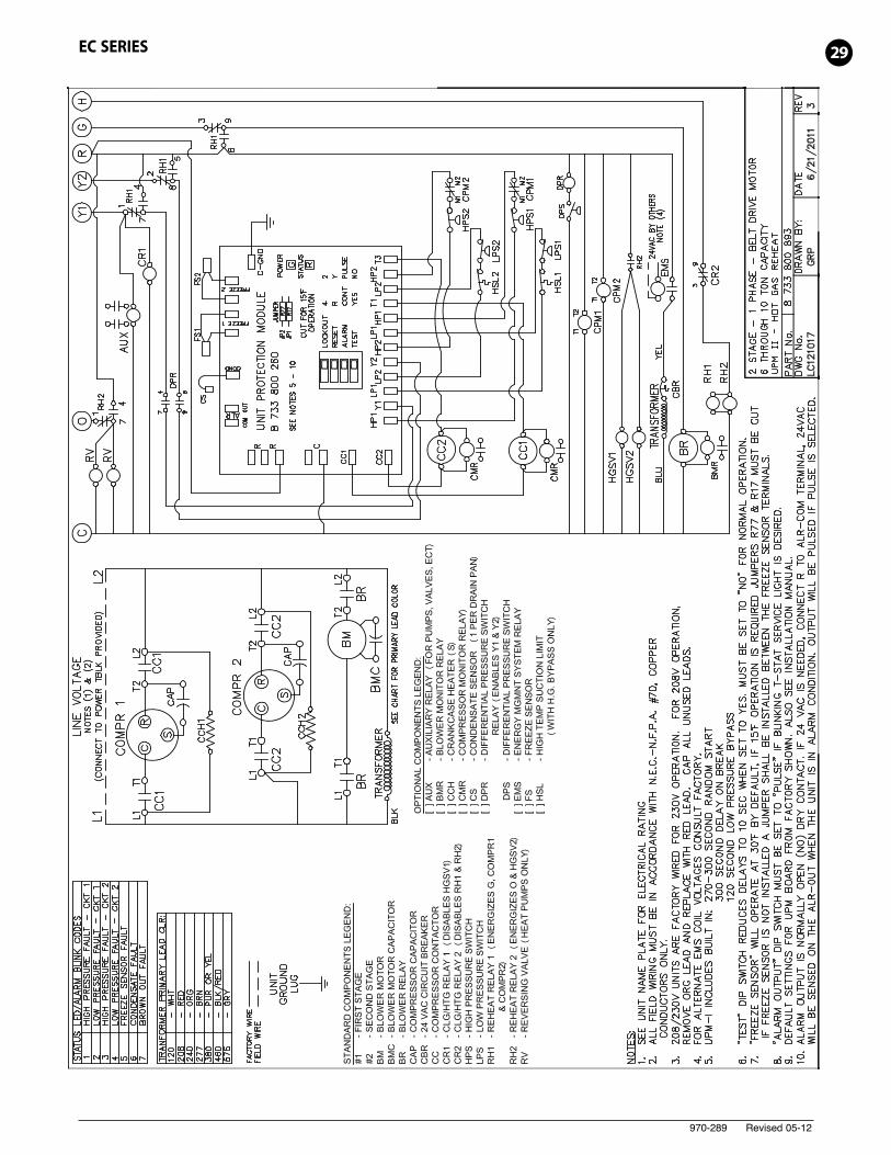
29EC SERIES
970-289 Revised 05-12
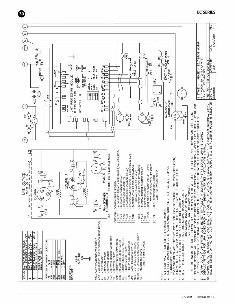
30 EC SERIES
970-289 Revised 05-12
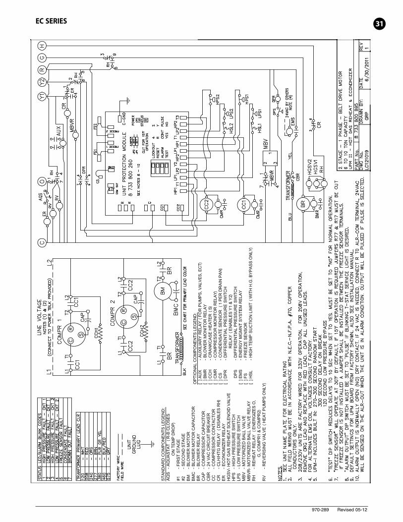
31EC SERIES
970-289 Revised 05-12
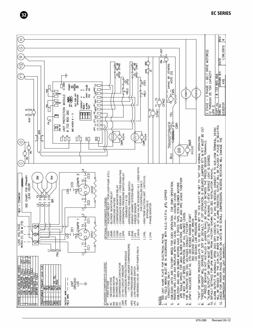
32 EC SERIES
970-289 Revised 05-12
33EC SERIES
970-289 Revised 05-12
34 EC SERIES
970-289 Revised 05-12
35EC SERIES
970-289 Revised 05-12
36 EC SERIES
970-289 Revised 05-12
37EC SERIES
970-289 Revised 05-12
38 EC SERIES
970-289 Revised 05-12
39EC SERIES
970-289 Revised 05-12
40 EC SERIES
970-289 Revised 05-12
41EC SERIES
970-289 Revised 05-12
42 EC SERIES
970-289 Revised 05-12
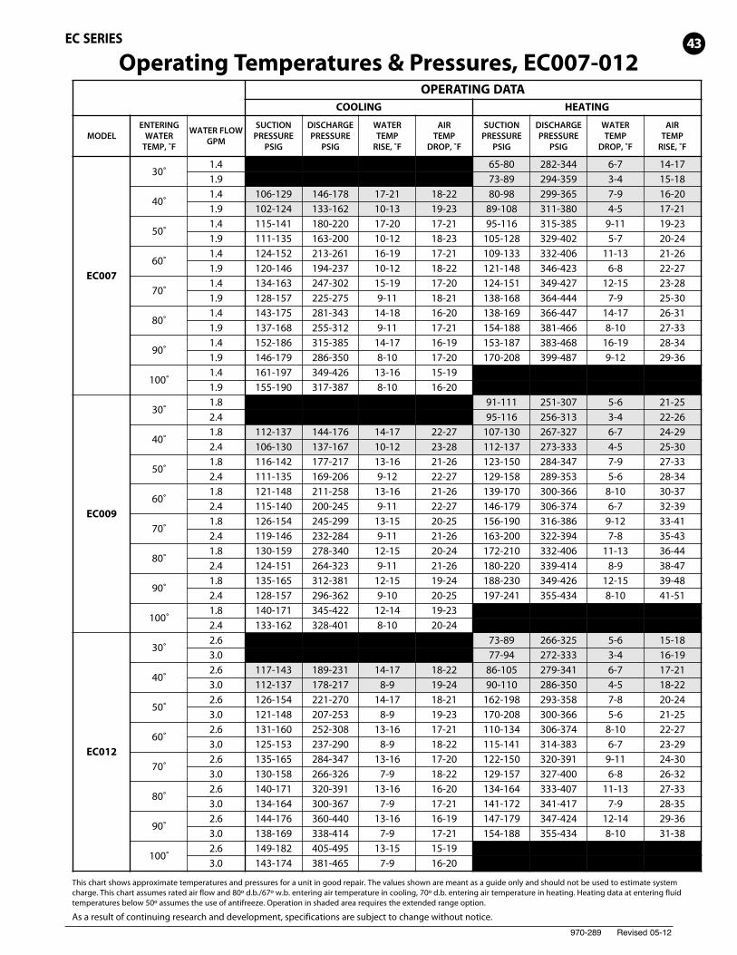
Operating Temperatures & Pressures, EC007-012
This chart shows approximate temperatures and pressures for a unit in good repair. The values shown are meant as a guide only and should not be used to estimate systemcharge. This chart assumes rated air flow and 80º d.b./67º w.b. entering air temperature in cooling, 70º d.b. entering air temperature in heating. Heating data at entering fluidtemperatures below 50º assumes the use of antifreeze. Operation in shaded area requires the extended range option.
As a result of continuing research and development, specifications are subject to change without notice.
OPERATING DATACOOLING HEATING
MODELENTERING
WATERTEMP, ˚F
WATER FLOWGPM
SUCTIONPRESSURE
PSIG
DISCHARGEPRESSURE
PSIG
WATERTEMP
RISE, ˚F
AIRTEMP
DROP, ˚F
SUCTIONPRESSURE
PSIG
DISCHARGEPRESSURE
PSIG
WATERTEMP
DROP, ˚F
AIRTEMP
RISE, ˚F
EC007
30˚1.4 65-80 282-344 6-7 14-171.9 73-89 294-359 3-4 15-18
40˚1.4 106-129 146-178 17-21 18-22 80-98 299-365 7-9 16-201.9 102-124 133-162 10-13 19-23 89-108 311-380 4-5 17-21
50˚1.4 115-141 180-220 17-20 17-21 95-116 315-385 9-11 19-231.9 111-135 163-200 10-12 18-23 105-128 329-402 5-7 20-24
60˚1.4 124-152 213-261 16-19 17-21 109-133 332-406 11-13 21-261.9 120-146 194-237 10-12 18-22 121-148 346-423 6-8 22-27
70˚1.4 134-163 247-302 15-19 17-20 124-151 349-427 12-15 23-281.9 128-157 225-275 9-11 18-21 138-168 364-444 7-9 25-30
80˚1.4 143-175 281-343 14-18 16-20 138-169 366-447 14-17 26-311.9 137-168 255-312 9-11 17-21 154-188 381-466 8-10 27-33
90˚1.4 152-186 315-385 14-17 16-19 153-187 383-468 16-19 28-341.9 146-179 286-350 8-10 17-20 170-208 399-487 9-12 29-36
100˚1.4 161-197 349-426 13-16 15-191.9 155-190 317-387 8-10 16-20
EC009
30˚1.8 91-111 251-307 5-6 21-252.4 95-116 256-313 3-4 22-26
40˚1.8 112-137 144-176 14-17 22-27 107-130 267-327 6-7 24-292.4 106-130 137-167 10-12 23-28 112-137 273-333 4-5 25-30
50˚1.8 116-142 177-217 13-16 21-26 123-150 284-347 7-9 27-332.4 111-135 169-206 9-12 22-27 129-158 289-353 5-6 28-34
60˚1.8 121-148 211-258 13-16 21-26 139-170 300-366 8-10 30-372.4 115-140 200-245 9-11 22-27 146-179 306-374 6-7 32-39
70˚1.8 126-154 245-299 13-15 20-25 156-190 316-386 9-12 33-412.4 119-146 232-284 9-11 21-26 163-200 322-394 7-8 35-43
80˚1.8 130-159 278-340 12-15 20-24 172-210 332-406 11-13 36-442.4 124-151 264-323 9-11 21-26 180-220 339-414 8-9 38-47
90˚1.8 135-165 312-381 12-15 19-24 188-230 349-426 12-15 39-482.4 128-157 296-362 9-10 20-25 197-241 355-434 8-10 41-51
100˚1.8 140-171 345-422 12-14 19-232.4 133-162 328-401 8-10 20-24
EC012
30˚2.6 73-89 266-325 5-6 15-183.0 77-94 272-333 3-4 16-19
40˚2.6 117-143 189-231 14-17 18-22 86-105 279-341 6-7 17-213.0 112-137 178-217 8-9 19-24 90-110 286-350 4-5 18-22
50˚2.6 126-154 221-270 14-17 18-21 162-198 293-358 7-8 20-243.0 121-148 207-253 8-9 19-23 170-208 300-366 5-6 21-25
60˚2.6 131-160 252-308 13-16 17-21 110-134 306-374 8-10 22-273.0 125-153 237-290 8-9 18-22 115-141 314-383 6-7 23-29
70˚2.6 135-165 284-347 13-16 17-20 122-150 320-391 9-11 24-303.0 130-158 266-326 7-9 18-22 129-157 327-400 6-8 26-32
80˚2.6 140-171 320-391 13-16 16-20 134-164 333-407 11-13 27-333.0 134-164 300-367 7-9 17-21 141-172 341-417 7-9 28-35
90˚2.6 144-176 360-440 13-16 16-19 147-179 347-424 12-14 29-363.0 138-169 338-414 7-9 17-21 154-188 355-434 8-10 31-38
100˚2.6 149-182 405-495 13-15 15-193.0 143-174 381-465 7-9 16-20
43EC SERIES
970-289 Revised 05-12
OPERATING DATACOOLING HEATING
MODELENTERING
WATERTEMP, ˚F
WATER FLOWGPM
SUCTIONPRESSURE
PSIG
DISCHARGEPRESSURE
PSIG
WATERTEMP
RISE, ˚F
AIRTEMP
DROP, ˚F
SUCTIONPRESSURE
PSIG
DISCHARGEPRESSURE
PSIG
WATERTEMP
DROP, ˚F
AIRTEMP
RISE, ˚F
EC015
30˚2.8 74-90 244-299 3-4 13-153.8 78-95 251-306 2-3 13-16
40˚2.8 122-149 183-224 14-18 19-23 87-106 257-314 4-5 15-183.8 117-143 172-210 8-10 20-24 91-111 263-322 3-3 16-19
50˚2.8 131-160 214-261 14-18 18-22 164-201 269-329 5-6 17-203.8 126-154 201-245 8-10 19-24 173-211 276-337 3-4 18-22
60˚2.8 136-166 244-298 14-17 18-22 111-136 282-344 6-7 19-233.8 131-160 230-281 8-10 19-23 117-143 289-353 4-5 20-24
70˚2.8 141-172 275-336 14-17 17-21 124-152 294-360 7-8 21-253.8 135-165 258-316 8-10 18-22 131-160 302-369 5-6 22-27
80˚2.8 145-178 310-378 14-17 17-20 136-166 307-375 8-9 23-283.8 140-171 291-356 8-10 18-22 143-175 314-384 5-6 24-30
90˚2.8 150-183 349-426 14-17 16-20 149-182 319-390 8-10 25-303.8 144-176 328-401 8-9 17-21 156-191 327-400 6-7 26-32
100˚2.8 155-189 392-480 13-16 16-193.8 149-182 369-451 8-9 17-21
EC018
30˚3.0 65-80 282-344 6-7 14-175.0 73-89 294-359 3-4 15-18
40˚3.0 121-148 184-225 17-21 18-22 80-98 299-365 7-9 16-205.0 117-143 167-204 10-13 19-23 89-108 311-380 4-5 17-21
50˚3.0 123-151 222-271 17-20 17-21 95-116 315-385 9-11 19-235.0 119-145 202-247 10-12 18-23 105-128 329-402 5-7 20-24
60˚3.0 125-153 260-318 16-19 17-21 109-133 332-406 11-13 21-265.0 120-147 237-289 10-12 18-22 121-148 346-423 6-8 22-27
70˚3.0 127-155 298-365 15-19 17-20 124-151 349-427 12-15 23-285.0 122-149 271-331 9-11 18-21 138-168 364-444 7-9 25-30
80˚3.0 129-158 336-411 14-18 16-20 138-169 366-447 14-17 26-315.0 124-152 306-374 9-11 17-21 154-188 381-466 8-10 27-33
90˚3.0 131-160 374-458 14-17 16-19 153-187 383-468 16-16 28-345.0 126-154 340-416 8-10 17-20 170-208 399-487 9-12 29-36
100˚3.0 133-162 413-504 13-16 15-195.0 128-156 375-458 8-10 16-20
EC024
30˚5.0 72-87 296-361 5-6 21-257.0 75-92 301-368 3-4 22-26
40˚5.0 114-139 155-190 14-17 22-27 88-107 314-384 6-7 24-297.0 108-132 147-180 10-12 23-28 92-112 321-392 4-5 25-30
50˚5.0 116-142 192-234 13-16 21-26 104-127 333-407 7-9 27-337.0 111-135 182-222 9-12 22-27 109-133 340-415 5-6 28-34
60˚5.0 119-146 228-279 13-16 21-26 120-146 352-430 8-10 30-377.0 113-138 217-265 9-11 22-27 125-153 359-439 6-7 32-39
70˚5.0 122-149 264-323 13-15 20-25 136-166 371-453 9-12 33-417.0 116-142 251-307 9-11 21-26 142-174 378-462 7-8 35-43
80˚5.0 125-152 301-368 12-15 20-24 152-185 389-476 11-13 36-447.0 118-145 286-349 9-11 21-26 159-194 397-485 8-9 38-47
90˚5.0 127-156 337-412 12-15 19-24 168-205 408-499 12-15 39-487.0 121-148 320-392 9-10 20-25 176-215 416-509 8-10 41-51
100˚5.0 130-159 374-457 12-14 19-237.0 124-151 355-434 8-10 20-24
EC SERIES
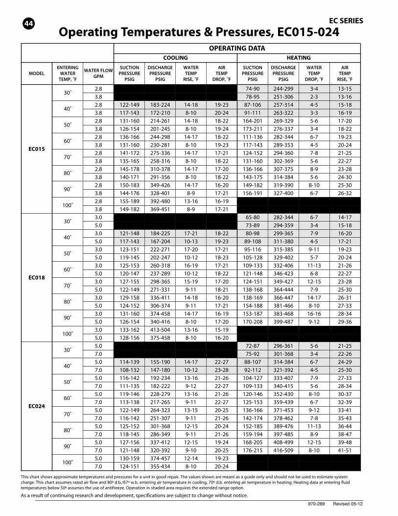
Operating Temperatures & Pressures, EC015-024
This chart shows approximate temperatures and pressures for a unit in good repair. The values shown are meant as a guide only and should not be used to estimate systemcharge. This chart assumes rated air flow and 80º d.b./67º w.b. entering air temperature in cooling, 70º d.b. entering air temperature in heating. Heating data at entering fluidtemperatures below 50º assumes the use of antifreeze. Operation in shaded area requires the extended range option.
As a result of continuing research and development, specifications are subject to change without notice.
44
970-289 Revised 05-12
OPERATING DATACOOLING HEATING
MODELENTERING
WATERTEMP, ˚F
WATER FLOWGPM
SUCTIONPRESSURE
PSIG
DISCHARGEPRESSURE
PSIG
WATERTEMP
RISE, ˚F
AIRTEMP
DROP, ˚F
SUCTIONPRESSURE
PSIG
DISCHARGEPRESSURE
PSIG
WATERTEMP
DROP, ˚F
AIRTEMP
RISE, ˚F
EC030
30˚3.5 73-89 266-325 5-6 15-187.5 77-94 272-333 3-4 16-19
40˚3.5 117-143 189-231 14-17 18-22 86-105 279-341 6-7 17-217.5 112-137 178-217 8-9 19-24 90-110 286-350 4-5 18-22
50˚3.5 126-154 221-270 14-17 18-21 162-198 293-358 7-8 20-247.5 121-148 207-253 8-9 19-23 170-208 300-366 5-6 21-25
60˚3.5 131-160 252-308 13-16 17-21 110-134 306-374 8-10 22-27 7.5 125-153 237-290 8-9 18-22 115-141 314-383 6-7 23-29
70˚3.5 135-165 284-347 13-16 17-20 122-150 320-391 9-11 24-307.5 130-158 266-326 7-9 18-22 129-157 327-400 6-8 26-32
80˚3.5 140-171 320-391 13-16 16-20 134-164 333-407 11-13 27-337.5 134-164 300-367 7-9 17-21 141-172 341-417 7-9 28-35
90˚3.5 144-176 360-440 13-16 16-19 147-179 347-424 12-14 29-367.5 138-169 338-414 7-9 17-21 154-188 355-434 8-10 31-38
100˚3.5 149-182 405-495 13-15 15-197.5 143-174 381-465 7-9 16-20
EC036
30˚4.5 74-90 244-299 3-4 13-159.0 78-95 251-306 2-3 13-16
40˚4.5 122-149 183-224 14-18 19-23 87-106 257-314 4-5 15-189.0 117-143 172-210 8-10 20-24 91-111 263-322 3-3 16-19
50˚4.5 131-160 214-261 14-18 18-22 164-201 269-329 5-6 17-209.0 126-154 201-245 8-10 19-24 173-211 276-337 3-4 18-22
60˚4.5 136-166 244-298 14-17 18-22 111-136 282-344 6-7 19-239.0 131-160 230-281 8-10 19-23 117-143 289-353 4-5 20-24
70˚4.5 141-172 275-336 14-17 17-21 124-152 294-360 7-8 21-259.0 135-165 258-316 8-10 18-22 131-160 302-369 5-6 22-27
80˚4.5 145-178 310-378 14-17 17-20 136-166 307-375 8-9 23-289.0 140-171 291-356 8-10 18-22 143-175 314-384 5-6 24-30
90˚4.5 150-183 349-426 14-17 16-20 149-182 319-390 8-10 25-309.0 144-176 328-401 8-9 17-21 156-191 327-400 6-7 26-32
100˚4.5 155-189 392-480 13-16 16-199.0 149-182 369-451 8-9 17-21
EC041EC042
30˚6.0 64-78 248-303 5-6 15-1810.0 67-82 254-311 3-4 16-19
40˚6.0 109-134 183-224 18-22 19-23 75-91 261-319 6-8 17-2110.0 105-128 172-210 10-12 20-25 79-96 267-327 4-5 18-23
50˚6.0 118-144 214-261 18-22 19-23 142-173 273-334 8-10 20-2410.0 113-138 201-245 10-12 20-24 149-182 280-342 5-7 21-26
60˚6.0 122-149 244-298 17-21 18-22 96-117 286-349 9-11 22-2710.0 117-143 230-281 10-12 19-24 101-123 293-358 6-8 24-29
70˚6.0 126-154 275-336 17-21 18-22 107-131 299-365 11-13 25-3010.0 121-148 258-316 10-12 19-23 113-138 306-374 7-9 26-32
80˚6.0 130-159 310-378 17-21 17-21 117-143 311-380 12-15 27-3310.0 125-153 291-356 10-12 18-22 123-151 319-390 8-10 29-35
90˚6.0 134-164 349-426 17-20 17-20 128-157 324-396 13-16 29-3610.0 129-158 328-401 9-12 18-22 135-165 332-406 9-11 31-38
100˚6.0 139-170 392-480 16-20 16-2010.0 133-163 369-451 9-11 17-21
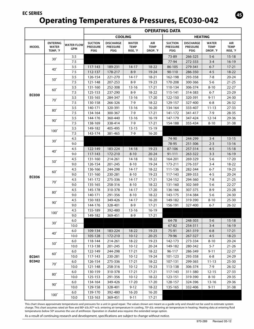
Operating Temperatures & Pressures, EC030-042
This chart shows approximate temperatures and pressures for a unit in good repair. The values shown are meant as a guide only and should not be used to estimate systemcharge. This chart assumes rated air flow and 80º d.b./67º w.b. entering air temperature in cooling, 70º d.b. entering air temperature in heating. Heating data at entering fluidtemperatures below 50º assumes the use of antifreeze. Operation in shaded area requires the extended range option.
As a result of continuing research and development, specifications are subject to change without notice.
45EC SERIES
970-289 Revised 05-12
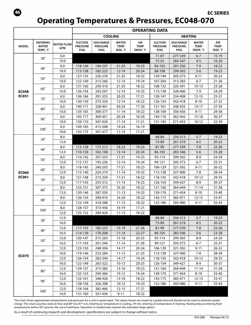
Operating Temperatures & Pressures, EC048-070
This chart shows approximate temperatures and pressures for a unit in good repair. The values shown are meant as a guide only and should not be used to estimate systemcharge. This chart assumes rated air flow and 80º d.b./67º w.b. entering air temperature in cooling, 70º d.b. entering air temperature in heating. Heating data at entering fluidtemperatures below 50º assumes the use of antifreeze. Operation in shaded area requires the extended range option.
As a result of continuing research and development, specifications are subject to change without notice.
OPERATING DATACOOLING HEATING
MODELENTERING
WATERTEMP, ˚F
WATER FLOWGPM
SUCTIONPRESSURE
PSIG
DISCHARGEPRESSURE
PSIG
WATERTEMP
RISE, ˚F
AIRTEMP
DROP, ˚F
SUCTIONPRESSURE
PSIG
DISCHARGEPRESSURE
PSIG
WATERTEMP
DROP, ˚F
AIRTEMP
RISE, ˚F
EC048EC051
30˚6.0 71-87 277-339 6-7 15-1910.0 75-92 284-347 4-5 16-20
40˚6.0 118-144 194-237 21-25 19-23 84-102 291-356 7-9 18-2210.0 113-138 182-223 12-14 20-24 88-108 299-365 5-6 19-23
50˚6.0 127-155 226-276 21-25 18-22 159-194 305-373 9-11 20-2510.0 122-149 213-260 12-14 19-24 167-204 313-383 6-7 21-26
60˚6.0 131-160 259-316 21-25 18-22 108-132 320-391 10-13 23-2810.0 126-154 243-297 12-14 19-23 113-138 328-400 7-9 24-29
70˚6.0 136-166 291-355 20-25 17-21 120-147 334-408 12-15 25-3110.0 130-159 273-334 12-14 18-22 126-154 342-418 8-10 27-32
80˚6.0 140-171 328-401 20-24 17-20 131-161 348-425 14-17 27-3410.0 135-165 308-377 11-14 18-22 138-169 356-436 9-11 29-36
90˚6.0 145-177 369-451 20-24 16-20 144-176 362-442 15-18 30-3710.0 139-170 347-424 11-14 17-21 151-185 371-453 10-12 32-39
100˚6.0 149-183 415-508 19-24 16-1910.0 143-175 391-477 11-14 17-21
EC060EC061
30˚8.0 68-84 256-313 5-7 19-2312.0 73-89 261-319 4-5 20-25
40˚8.0 113-138 173-212 18-22 19-23 81-99 277-339 7-8 22-2612.0 110-134 162-198 12-14 20-24 86-105 283-346 5-6 23-28
50˚8.0 116-142 207-253 17-21 19-23 93-114 299-365 8-9 24-2912.0 112-137 193-236 12-14 19-24 99-121 305-373 6-7 25-31
60˚8.0 118-145 240-293 17-21 18-23 106-129 321-392 9-11 26-3212.0 115-140 224-274 11-14 19-23 113-138 327-400 7-8 28-34
70˚8.0 121-148 273-334 17-21 18-22 118-145 342-418 10-12 29-3512.0 117-143 255-312 11-14 19-23 126-154 349-427 8-9 30-37
80˚8.0 123-151 307-375 16-20 18-22 131-160 364-444 11-14 31-3812.0 120-146 287-350 11-13 19-23 139-170 371-454 8-10 33-40
90˚8.0 126-154 340-416 16-20 18-22 143-175 385-471 12-15 33-4112.0 122-149 318-388 11-13 18-22 152-186 393-480 9-11 35-43
100˚8.0 128-157 373-456 16-19 17-2112.0 125-152 349-426 11-13 18-22
EC070
30˚12.0 68-84 256-313 5-7 19-2316.0 73-89 261-319 4-5 20-25
40˚12.0 117-143 182-222 15-19 21-26 81-99 277-339 7-8 22-2616.0 114-139 170-208 11-14 22-27 86-105 283-346 5-6 23-28
50˚12.0 120-147 215-263 15-18 20-25 93-114 299-365 8-9 24-2916.0 117-143 201-246 11-14 21-26 99-121 305-373 6-7 25-31
60˚12.0 123-150 248-304 14-17 20-24 106-129 321-392 9-11 26-3216.0 119-146 232-284 11-13 21-25 113-138 327-400 7-8 28-34
70˚12.0 126-154 282-344 14-17 19-24 118-145 342-418 10-12 29-3516.0 122-149 263-322 10-13 20-25 126-154 349-427 8-9 30-37
80˚12.0 129-157 315-385 13-16 19-23 131-160 364-444 11-14 31-3816.0 125-153 294-360 10-12 19-24 139-170 371-454 8-10 33-40
90˚12.0 132-161 348-426 13-16 18-22 143-175 385-471 12-15 33-4116.0 128-156 326-398 10-12 19-23 152-186 393-480 9-11 35-43
100˚12.0 134-164 382-466 12-15 17-2116.0 131-160 357-436 9-11 18-22
EC SERIES46
970-289 Revised 05-12
OPERATING DATACOOLING HEATING
MODELENTERING
WATERTEMP, ˚F
WATER FLOWGPM
SUCTIONPRESSURE
PSIG
DISCHARGEPRESSURE
PSIG
WATERTEMP
RISE, ˚F
AIRTEMP
DROP, ˚F
SUCTIONPRESSURE
PSIG
DISCHARGEPRESSURE
PSIG
WATERTEMP
DROP, ˚F
AIRTEMP
RISE, ˚F
EC072
30˚10.0 65-80 282-344 6-7 14-1716.0 73-89 294-359 3-4 15-18
40˚10.0 121-148 184-225 17-21 18-22 80-98 299-365 7-9 16-2016.0 117-143 167-204 10-13 19-23 89-108 311-380 4-5 17-21
50˚10.0 123-151 222-271 17-20 17-21 95-116 315-385 9-11 19-2316.0 119-145 202-247 10-12 18-23 105-128 329-402 5-7 20-24
60˚10.0 125-153 260-318 16-19 17-21 109-133 332-406 11-13 21-2616.0 120-147 237-289 10-12 18-22 121-148 346-423 6-8 22-27
70˚10.0 127-155 298-365 15-19 17-20 124-151 349-427 12-15 23-2816.0 122-149 271-331 9-11 18-21 138-168 364-444 7-9 25-30
80˚10.0 129-158 336-411 14-18 16-20 138-169 366-447 14-17 26-3116.0 124-152 306-374 9-11 17-21 154-188 381-466 8-10 27-33
90˚10.0 131-160 374-458 14-17 16-19 153-187 383-468 16-19 28-3416.0 126-154 340-416 8-10 17-20 170-208 399-487 9-12 29-36
100˚10.0 133-162 413-504 13-16 15-1916.0 128-156 375-458 8-10 16-20
EC096
30˚13.0 72-87 296-361 5-6 21-2522.0 75-92 301-368 3-4 22-26
40˚13.0 114-139 155-190 14-17 22-27 88-107 314-384 6-7 24-2922.0 108-132 147-180 10-12 23-28 92-112 321-392 4-5 25-30
50˚13.0 116-142 192-234 13-16 21-26 104-127 333-407 7-9 27-3322.0 111-135 182-222 9-12 22-27 109-133 340-415 5-6 28-34
60˚13.0 119-146 228-279 13-16 21-26 120-146 352-430 8-10 30-3722.0 113-138 217-265 9-11 22-27 125-153 359-439 6-7 32-39
70˚13.0 122-149 264-323 13-15 20-25 136-166 371-453 9-12 33-4122.0 116-142 251-307 9-11 21-26 142-174 378-462 7-8 35-43
80˚13.0 125-152 301-368 12-15 20-24 152-185 389-476 11-13 36-4422.0 118-145 286-349 9-11 21-26 159-194 397-485 8-9 38-47
90˚13.0 127-156 337-412 12-15 19-24 168-205 408-499 12-15 39-4822.0 121-148 320-392 9-10 20-25 176-215 416-509 8-10 41-51
100˚13.0 130-159 374-457 12-14 19-2322.0 124-151 355-434 8-10 20-24
EC120
30˚16.0 73-89 266-325 5-6 15-1832.0 77-94 272-333 3-4 16-19
40˚16.0 117-143 189-231 14-17 18-22 86-105 279-341 6-7 17-2132.0 112-137 178-217 8-9 19-24 90-110 286-350 4-5 18-22
50˚16.0 126-154 221-270 14-17 18-21 162-198 293-358 7-8 20-2432.0 121-148 207-253 8-9 19-23 170-208 300-366 5-6 21-25
60˚16.0 131-160 252-308 13-16 17-21 110-134 306-374 8-10 22-2732.0 125-153 237-290 8-9 18-22 115-141 314-383 6-7 23-29
70˚16.0 135-165 284-347 13-16 17-20 122-150 320-391 9-11 24-3032.0 130-158 266-326 7-9 18-22 129-157 327-400 6-8 26-32
80˚16.0 140-171 320-391 13-16 16-20 134-164 333-407 11-13 27-3332.0 134-164 300-367 7-9 17-21 141-172 341-417 7-9 28-35
90˚16.0 144-176 360-440 13-16 16-19 147-179 347-424 12-14 29-3632.0 138-169 338-414 7-9 17-21 154-188 355-434 8-10 31-38
100˚16.0 149-182 405-495 13-15 15-1932.0 143-174 381-465 7-9 16-20
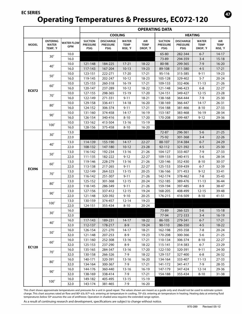
Operating Temperatures & Pressures, EC072-120
This chart shows approximate temperatures and pressures for a unit in good repair. The values shown are meant as a guide only and should not be used to estimate systemcharge. This chart assumes rated air flow and 80º d.b./67º w.b. entering air temperature in cooling, 70º d.b. entering air temperature in heating. Heating data at entering fluidtemperatures below 50º assumes the use of antifreeze. Operation in shaded area requires the extended range option.
As a result of continuing research and development, specifications are subject to change without notice.
47EC SERIES
970-289 Revised 05-12
OPERATING DATACOOLING HEATING
MODELENTERING
WATERTEMP, ˚F
WATER FLOWGPM
SUCTIONPRESSURE
PSIG
DISCHARGEPRESSURE
PSIG
WATERTEMP
RISE, ˚F
AIRTEMP
DROP, ˚F
SUCTIONPRESSURE
PSIG
DISCHARGEPRESSURE
PSIG
WATERTEMP
DROP, ˚F
AIRTEMP
RISE, ˚F
EC150
30˚22.0 74-90 244-299 3-4 13-1538.0 78-95 251-306 2-3 13-16
40˚22.0 122-149 183-224 14-18 19-23 87-106 257-314 4-5 15-1838.0 117-143 172-210 8-10 20-24 91-111 263-322 3-3 16-19
50˚22.0 131-160 214-261 14-18 18-22 164-201 269-329 5-6 17-2038.0 126-154 201-245 8-10 19-24 173-211 276-337 3-4 18-22
60˚22.0 136-166 244-298 14-17 18-22 111-136 282-344 6-7 19-2338.0 131-160 230-281 8-10 19-23 117-143 289-353 4-5 20-24
70˚22.0 141-172 275-336 14-17 17-21 124-152 294-360 7-8 21-2538.0 135-165 258-316 8-10 18-22 131-160 302-369 5-6 22-27
80˚22.0 145-178 310-378 14-17 17-20 136-166 307-375 8-9 23-2838.0 140-171 291-356 8-10 18-22 143-175 314-384 5-6 24-30
90˚22.0 150-183 349-426 14-17 16-19 149-182 319-390 8-10 25-3038.0 144-176 328-401 8-9 17-21 156-191 327-400 6-7 26-32
100˚22.0 155-189 392-480 13-16 16-1938.0 149-182 369-451 8-9 17-21
EC180
30˚25.0 64-78 248-303 5-6 15-1845.0 67-82 254-311 3-4 16-19
40˚25.0 109-134 183-224 18-22 19-23 75-91 261-319 6-8 17-2145.0 105-128 172-210 10-12 20-25 79-96 267-327 4-5 18-23
50˚25.0 118-144 214-261 18-22 19-23 142-173 273-334 8-10 20-2445.0 113-138 201-245 10-12 20-24 149-182 280-342 5-7 21-26
60˚25.0 122-149 244-298 17-21 18-22 96-117 286-349 9-11 22-2745.0 117-143 230-281 10-12 19-24 101-123 293-358 6-8 24-29
70˚25.0 126-154 275-336 17-21 18-22 107-131 299-365 11-13 25-3045.0 121-148 258-316 10-12 19-23 113-138 306-374 7-9 26-32
80˚25.0 130-159 310-378 17-21 17-21 117-143 311-380 12-15 27-3345.0 125-153 291-356 10-12 18-22 123-151 319-390 8-10 29-35
90˚25.0 134-164 349-426 17-20 17-20 128-157 324-396 13-16 29-3645.0 129-158 328-401 9-12 18-22 135-165 332-406 9-11 31-38
100˚25.0 139-170 392-480 16-20 16-2045.0 133-163 369-451 9-11 17-21
EC210
30˚28.0 71-87 277-339 6-7 15-1952.0 75-92 284-347 4-5 16-20
40˚28.0 118-144 194-237 21-25 19-23 84-102 291-356 7-9 18-2252.0 113-138 182-223 12-14 20-24 88-108 299-365 5-6 19-23
50˚28.0 127-155 226-276 21-25 18-22 159-194 305-373 9-11 20-2552.0 122-149 213-260 12-14 19-24 167-204 313-383 6-7 21-26
60˚28.0 131-160 259-316 21-25 18-22 108-132 320-391 10-13 23-2852.0 126-154 243-297 12-14 19-23 113-138 328-400 7-9 24-29
70˚28.0 136-166 291-355 20-25 17-21 120-147 334-408 12-15 25-3152.0 130-159 273-334 12-14 18-22 126-154 342-418 8-10 27-32
80˚28.0 140-171 328-401 20-24 17-20 131-161 348-425 14-17 27-3452.0 135-165 308-377 11-14 18-22 138-169 356-436 9-11 29-36
90˚28.0 145-177 369-451 20-24 16-20 144-176 362-442 15-18 30-3752.0 139-170 347-424 11-14 17-21 151-185 371-453 10-12 32-39
100˚28.0 149-183 415-508 19-24 16-1952.0 143-175 391-477 11-14 17-21
EC SERIES
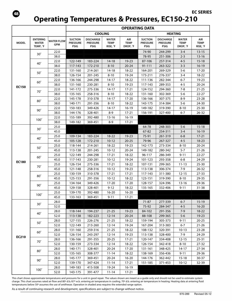
This chart shows approximate temperatures and pressures for a unit in good repair. The values shown are meant as a guide only and should not be used to estimate systemcharge. This chart assumes rated air flow and 80º d.b./67º w.b. entering air temperature in cooling, 70º d.b. entering air temperature in heating. Heating data at entering fluidtemperatures below 50º assumes the use of antifreeze. Operation in shaded area requires the extended range option.
As a result of continuing research and development, specifications are subject to change without notice.
Operating Temperatures & Pressures, EC150-21048
970-289 Revised 05-12
OPERATING DATACOOLING HEATING
MODELENTERING
WATERTEMP, ˚F
WATER FLOWGPM
SUCTIONPRESSURE
PSIG
DISCHARGEPRESSURE
PSIG
WATERTEMP
RISE, ˚F
AIRTEMP
DROP, ˚F
SUCTIONPRESSURE
PSIG
DISCHARGEPRESSURE
PSIG
WATERTEMP
DROP, ˚F
AIRTEMP
RISE, ˚F
EC240
30˚32.0 68-84 256-313 5-7 19-2364.0 73-89 261-319 4-5 20-25
40˚32.0 113-138 172-210 18-22 19-23 81-99 277-339 7-8 22-2664.0 110-134 161-196 12-14 20-24 86-105 283-346 5-6 23-28
50˚32.0 116-142 206-252 17-21 19-23 93-114 299-365 8-9 24-2964.0 112-137 193-236 12-14 19-24 99-121 305-373 6-7 25-31
60˚32.0 118-145 241-294 17-21 18-23 106-129 321-392 9-11 26-3264.0 115-140 225-275 11-14 19-23 113-138 327-400 7-8 28-34
70˚32.0 121-148 275-336 17-21 18-22 118-145 342-418 10-12 29-3564.0 117-143 257-314 11-14 19-23 126-154 349-427 8-9 30-37
80˚32.0 123-151 309-378 16-20 18-22 131-160 364-444 11-14 31-3864.0 120-146 289-353 11-13 19-23 139-170 371-454 8-10 33-40
90˚32.0 126-154 344-420 16-20 18-22 143-175 385-471 12-15 33-4164.0 122-149 321-392 11-13 18-22 152-186 393-480 9-11 35-43
100˚32.0 128-157 378-462 16-19 17-2164.0 125-152 353-432 11-13 18-22
EC300
30˚45.0 68-84 256-313 5-7 19-2375.0 73-89 261-319 4-5 20-25
40˚45.0 117-143 210-256 15-19 21-26 81-99 277-339 7-8 22-2675.0 114-139 196-239 11-14 22-27 86-105 283-346 5-6 23-28
50˚45.0 120-147 243-297 15-18 20-25 93-114 299-365 8-9 24-2975.0 117-143 227-277 11-14 21-26 99-121 305-373 6-7 25-31
60˚45.0 123-150 276-337 14-17 20-24 106-129 321-392 9-11 26-3275.0 119-146 258-315 11-13 21-25 113-138 327-400 7-8 28-34
70˚45.0 126-154 309-378 14-17 19-24 118-145 342-418 10-12 29-3575.0 122-149 289-353 10-13 20-25 126-154 349-427 8-9 30-37
80˚45.0 129-157 343-419 13-16 19-23 131-160 364-444 11-14 31-3875.0 125-153 320-391 10-12 19-24 139-170 371-454 8-10 33-40
90˚45.0 132-161 376-459 13-16 18-22 143-175 385-471 12-15 33-4175.0 128-156 351-429 10-12 19-23 152-186 393-480 9-11 35-43
100˚45.0 134-164 409-500 12-15 17-2175.0 131-160 382-467 9-11 18-22
EC360
30˚50.0 65-80 282-344 6-7 14-1790.0 73-89 294-359 3-4 15-18
40˚50.0 121-148 184-225 17-21 18-22 80-98 299-365 7-9 16-2090.0 117-143 167-204 10-13 19-23 89-108 311-380 4-5 17-21
50˚50.0 123-151 222-271 17-20 17-21 95-116 315-385 9-11 19-2390.0 119-145 202-247 10-12 18-23 105-128 329-402 5-7 20-24
60˚50.0 125-153 260-318 16-19 17-21 109-133 332-406 11-13 21-2690.0 120-147 237-289 10-12 18-22 121-148 346-423 6-8 22-27
70˚50.0 127-155 298-365 15-19 17-20 124-151 349-427 12-15 23-2890.0 122-149 271-331 9-11 18-21 138-168 364-444 7-9 25-30
80˚50.0 129-158 336-411 14-18 16-20 138-169 366-447 14-17 26-3190.0 124-152 306-374 9-11 17-21 154-188 381-466 8-10 27-33
90˚50.0 131-160 374-458 14-17 16-19 153-187 383-468 16-19 28-3490.0 126-154 340-416 8-10 17-20 170-208 399-487 9-12 29-36
100˚50.0 133-162 413-504 13-16 15-1990.0 128-156 375-458 8-10 16-20
EC SERIES
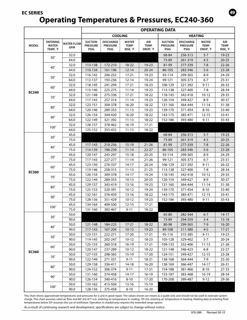
This chart shows approximate temperatures and pressures for a unit in good repair. The values shown are meant as a guide only and should not be used to estimate systemcharge. This chart assumes rated air flow and 80º d.b./67º w.b. entering air temperature in cooling, 70º d.b. entering air temperature in heating. Heating data at entering fluidtemperatures below 50º assumes the use of antifreeze. Operation in shaded area requires the extended range option.
As a result of continuing research and development, specifications are subject to change without notice.
Operating Temperatures & Pressures, EC240-36049
970-289 Revised 05-12
EC SERIES
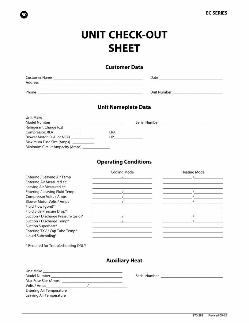
UNIT CHECK-OUTSHEETCustomer Data
Customer Name ______________________________________________ Date _________________________________Address _____________________________________________________
_____________________________________________________Phone ______________________________________________________ Unit Number __________________________
Unit Nameplate Data
Unit Make _________________________________________Model Number_____________________________________ Serial Number_________________________________Refrigerant Charge (oz) ________Compressor: RLA _____________ LRA______________Blower Motor: FLA (or NPA) ____________ HP_______________Maximum Fuse Size (Amps) ___________Minimum Circuit Ampacity (Amps) ______________
Operating Conditions
Cooling Mode Heating ModeEntering / Leaving Air Temp _______________ /_______________ _______________ /_______________Entering Air Measured at: _______________________________ _______________________________Leaving Air Measured at: _______________________________ _______________________________Entering / Leaving Fluid Temp _______________ /_______________ _______________ /_______________Compressor Volts / Amps _______________ /_______________ _______________ /_______________Blower Motor Volts / Amps _______________ /_______________ _______________ /_______________Fluid Flow (gpm)* _______________________________ _______________________________Fluid Side Pressure Drop* _______________________________ _______________________________Suction / Discharge Pressure (psig)* _______________ /_______________ _______________ /_______________Suction / Discharge Temp* _______________ /_______________ _______________ /_______________Suction Superheat* _______________________________ _______________________________Entering TXV / Cap Tube Temp* _______________________________ _______________________________Liquid Subcooling* _______________________________ _______________________________
* Required for Troubleshooting ONLY
Auxiliary Heat
Unit Make _________________________________________Model Number _____________________________________ Serial Number ________________________________Max Fuse Size (Amps) _______________________________Volts / Amps_____________________ /____________________Entering Air Temperature ____________________________Leaving Air Temperature_____________________________
50
970-289 Revised 05-12
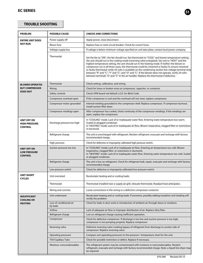
TROUBLE SHOOTING
PROBLEM POSSIBLE CAUSE CHECKS AND CORRECTIONS
ENTIRE UNIT DOESNOT RUN
Power supply off Apply power, close disconnect
Blown fuse Replace fuse or reset circuit breaker. Check for correct fuses.
Voltage supply low If voltage is below minimum voltage specified on unit data plate, contact local power company.
Thermostat Set the fan to "ON", the fan should run. Set thermostat to "COOL" and lowest temperature setting,the unit should run in the cooling mode (reversing valve energized). Set unit to "HEAT" and thehighest temperature setting, the unit should run in the heating mode. If neither the blower orcompressor run in all three cases, the thermostat could be miswired or faulty.To ensure miswiredor faulty thermostat verify 24 volts is available on the condensing section low voltage terminal stripbetween "R" and "C", "Y" and "C", and "O" and "C". If the blower does not operate, verify 24 voltsbetween terminals "G" and "C" in the air handler. Replace the thermostat if defective.
BLOWER OPERATESBUT COMPRESSORDOES NOT
Thermostat Check setting, calibration, and wiring.
Wiring Check for loose or broken wires at compressor, capacitor, or contactor.
Safety controls Check UPM board red default L.E.D. for Blink Code
Compressor overload open If the compressor is cool and the overload will not reset, replace compressor.
Compressor motor grounded Internal winding grounded to the compressor shell. Replace compressor. If compressor burnout,install suction filter dryer.
Compressor windings open After compressor has cooled, check continuity of the compressor windings. If the windings areopen, replace the compressor.
UNIT OFF ONHIGH PRESSURECONTROL
Discharge pressure too highIn "COOLING" mode: Lack of or inadequate water flow. Entering water temperature too warm.Scaled or plugged condenser.In "HEATING" mode: Lack of or inadequate air flow. Blower inoperative, clogged filter or restrictionsin ductwork.
Refrigerant charge The unit is overcharged with refrigerant. Reclaim refrigerant, evacuate and recharge with factoryrecommended charge.
High pressure Check for defective or improperly calibrated high pressure switch.
UNIT OFF ONLOW PRESSURECONTROL
Suction pressure too low In "COOLING" mode: Lack of or inadequate air flow. Entering air temperature too cold. Blowerinoperative, clogged filter, or restrictions in ductwork.In "HEATING" mode: Lack of or inadequate water flow. Entering water temperature too cold. Scaledor plugged condenser.
Refrigerant charge The unit is low on refrigerant. Check for refrigerant leak, repair, evacuate and recharge with factoryrecommended charge.
Low pressure switch Check for defective or improperly calibrated low pressure switch.
UNIT SHORTCYCLES
Unit oversized Recalculate heating and or cooling loads.
Thermostat Thermostat installed near a supply air grill, relocate thermostat. Readjust heat anticipator.
Wiring and controls Loose connections in the wiring or a defective compressor contactor.
INSUFFICIENTCOOLING ORHEATING
Unit undersized Recalculate heating and or cooling loads. If excessive, possibly adding insulation and shading willrectify the problem.
Loss of conditioned airby leaks
Check for leaks in duct work or introduction of ambient air through doors or windows.
Airflow Lack of adequate air flow or improper distribution of air. Replace dirty filter.
Refrigerant charge Low on refrigerant charge causing inefficient operation.
Compressor Check for defective compressor. If discharge is too low and suction pressure is too high,compressor is not pumping properly. Replace compressor.
Reversing valve Defective reversing valve creating bypass of refrigerant from discharge to suction side ofcompressor. Replace reversing valve.
Operating pressures Compare unit operating pressures to the pressure / temperature chart for the unit.
TXV/Capillary Tube Check for possible restriction or defect. Replace if necessary.
Moisture, noncondensables The refrigerant system may be contaminated with moisture or noncondensables. Reclaimrefrigerant, evacuate and recharge with factory recommended charge. Note: a liquid line dryer maybe required.
EC SERIES 51
970-289 Revised 05-12
601 N.W. 65th Court, Ft. Lauderdale, FL 33309Phone: 954-776-5471 | Fax: 954-776-5529www.boschtaxcredit.com | www.fhp-mfg.com