draft uganda standard
TRANSCRIPT
DRAFT UGANDA STANDARD
DUS 1836
First Edition 2017-mm-dd
ThisFinal Draft Uganda Standard, DUS 1836:2017, is based on ASTM C138/C138M – 17a, Standard Test Method for Density (Unit Weight), Yield, and Air Content (Gravimetric) of Concrete, Copyright ASTM International, 100 Barr Harbor Drive, West Conshohocken, PA 19428, USA, pursuant to license with ASTM International.
Reference number DUS 1836: 2017
© UNBS 2017
Standard Test Method for Density (Unit Weight), Yield, and Air Content (Gravimetric) of Concrete
C138/C138M – 17a DUS 1836: 2017
© UNBS 2017 – All rights reserved ii
Compliance with this standard does not, of itself confer immunity from legal obligations
A Uganda Standard does not purport to include all necessary provisions of a contract. Users are responsible for its correct application
© UNBS 2017
All rights reserved. Unless otherwise specified, no part of this publication may be reproduced or utilised in any form or by any means, electronic or mechanical, including photocopying and microfilm, without prior written permission from UNBS.
Requests for permission to reproduce this document should be addressed to
The Executive Director Uganda National Bureau of Standards P.O. Box 6329 Kampala Uganda Tel: +256 417 333 250/1/2/3 Fax:+ 256 414 286 123 E-mail: [email protected] Web: www.unbs.go.ug
C138/C138M – 17a DUS 1836: 2017
© UNBS 2017 – All rights reserved iii
Foreword
Uganda National Bureau of Standards (UNBS) is a parastatal under the Ministry of Trade, Industry and Cooperatives established under Cap 327, of the Laws of Uganda, as amended. UNBS is mandated to co-ordinate the elaboration of standards and is
(a) a member of International Organisation for Standardisation (ISO) and
(b) a contact point for the WHO/FAO Codex Alimentarius Commission on Food Standards, and
(c) the National Enquiry Point on TBT Agreement of the World Trade Organisation (WTO).
The work of preparing Uganda Standards is carried out through Technical Committees. A Technical Committee is established to deliberate on standards in a given field or area and consists of key stakeholders including government, academia, consumer groups, private sector and other interested parties.
Draft Uganda Standards adopted by the Technical Committee are widely circulated to stakeholders and the general public for comments. The committee reviews the comments before recommending the draft standards for approval and declaration as Uganda Standards by the National Standards Council.
This standard was developed by the Building and Construction Standards Technical Committee (UNBS/TC 3).
Wherever the words, “ASTM Standard" appear, they should be replaced by "Uganda Standard."
DRAFT UGANDA STANDARD DUS 1836: 2017
Designation: C138/C138M – 17a This Final Draft Uganda Standard, FDUS 1836:2017, is based on ASTM C138/C138M – 17a, Standard Test Method for Density (Unit Weight), Yield, and Air Content (Gravimetric) of Concrete, Copyright ASTM International, 100 Barr Harbor Drive, West Conshohocken, PA 19428, USA, pursuant to license with ASTM International.
© UNBS 2017 – All rights reserved 1
Standard Test Method for
Density (Unit Weight), Yield, and Air Content (Gravimetric) of Concrete1 American Association State Highway and Transportation Officials Standard AASHTO No.: T121
This standard is issued under the fixed designation C138/C138M; the number immediately following the designation indicates the year of original adoption
or, in the case of revision, the year of last revision. A number in parentheses indicates the year of last reapproval. A superscript epsilon (ε) indicates an
editorial change since the last revision or reapproval.
This standard has been approved for use by agencies of the U.S. Department of Defense.
1. Scope *
1.1 This test method covers determination of the density (see Note 1) of freshly mixed concrete and gives formulas for
calculating the yield, cement content, and air content of the concrete. Yield is defined as the volume of concrete produced
from a mixture of known quantities of the component materials.
1.2 The values stated in either SI units or inch-pound units are to be regarded separately as standard. The values stated in
each system may not be exact equivalents; therefore, each system shall be used independently of the other. Combining values
from the two systems may result in non-conformance with the standard.
NOTE 1—Unit weight was the previous terminology used to describe the property determined by this test method, which is mass per unit
volume.
1.3 The text of this test method references notes and footnotes that provide explanatory information. These notes and
footnotes (excluding those in tables) shall not be considered as requirements of this test method.
1.4 This standard does not purport to address all of the safety concerns, if any, associated with its use. It is the
responsibility of the user of this standard to establish appropriate safety and health practices and determine the applicability
of regulatory limitations prior to use. (Warning—Fresh hydraulic cementitious mixtures are caustic and may cause chemical
burns to skin and tissue upon prolonged exposure.2 )
1.5 This international standard was developed in accordance with internationally recognized principles on standardization
established in the Decision on Principles for the Development of International Standards, Guides and Recommendations
issued by the World Trade Organization Technical Barriers to Trade (TBT) Committee.
2. Referenced Documents
1 This test method is under the jurisdiction of ASTM Committee C09 on Concrete and Concrete Aggregates and is the direct responsibility of Subcommittee
C09.60 on Testing Fresh Concrete. Current edition approved March 15, 2017. Published May 2017. Originally approved in 1938. Last previous edition approved in 2017 as C138/C138M – 17.
DOI: 10.1520/C0138_C0138M-17A.
*A Summary of Changes section appears at the end of this standard. 2 See section on Safety Precautions, Manual of Aggregate and Concrete Testing, Annual Book of ASTM Standards, Vol 04.02.
C138/C138M – 17a DUS 1836: 2017
© UNBS 2017 – All rights reserved 2
2.1 ASTM Standards:3
C29/C29M
C31/C31M
C143/C143M
C150/C150M
C172/C172M
C173/C173M
C188
C231/C231M
C1758/C1758M
3. Terminology
3.1 Symbols:
A = air content (percentage of voids) in the concrete
C = actual cement content, kg/m3 [lb/yd3]
Cb = mass of cement in the batch, kg [lb]
D = density (unit weight) of concrete, kg/m3 [lb/ft3]
M = total mass of all materials batched, kg [lb] (see Note 3)
Mc = mass of the measure filled with concrete, kg [lb] or
Mm = mass of the measure, kg [lb]
Ry = relative yield
T = theoretical density of the concrete computed on an airfree basis, kg/m3 [lb/ft3]
(see Note 2)
Y = yield, volume of concrete produced per batch, m3 [yd3]
Yd = volume of concrete which the batch was designed to produce, m3 [yd3]
Yf = volume of concrete produced per batch, m3 [ft3]
V = total absolute volume of the component ingredients in the batch, m3 [ft3]
Vm = volume of the measure, m3 [ft3]
NOTE 2—The theoretical density is, customarily, a laboratory determination, the value for which is assumed to remain constant for all
batches made using identical component ingredients and proportions.
NOTE 3—The total mass of all materials batched is the sum of the masses of the cement, the fine aggregate in the condition used, the
coarse aggregate in the condition used, the mixing water added to the batch, and any other solid or liquid materials used.
4. Apparatus
4.1 Balance—A balance or scale accurate to 45 g [0.1 lb] or to within 0.3 % of the test load, whichever is greater, at any
point within the range of use. The range of use shall be considered to extend from the mass of the measure empty to the mass
of the measure plus its contents at 2600 kg/m3 [160 lb/ft3].
4.2 Tamping Rod—A round, smooth, straight steel rod, with a 16 mm [5/8 in.] ± 2 mm [1/16 in.] diameter. The length of the
tamping rod shall be at least 100 mm [4 in.] greater than the depth of the measure in which rodding is being performed, but
3 For referenced ASTM standards, visit the ASTM website, www.astm.org, or contact ASTM Customer Service at [email protected]. For Annual Book of
ASTM Standards volume information, refer to the standard's Document Summary page on the ASTM website.
C138/C138M – 17a DUS 1836: 2017
© UNBS 2017 – All rights reserved 3
not greater than 600 mm [24 in.] in overall length (see Note 4). The rod shall have the tamping end or both ends rounded to a
hemispherical tip of the same diameter as the rod.
NOTE 4—A rod length of 400 mm [16 in.] to 600 mm [24 in.] meets the requirements of the following: Practice C31/C31M, Test Method
C138/C138M, Test Method C143/C143M, Test Method C173/C173M and Test Method C231/C231M.
4.3 Internal Vibrator—The vibrator frequency shall be at least 9000 vibrations per minute [150 Hz] while the vibrator is
operating in the concrete. The outside diameter or the side dimension of the vibrating element shall be at least 19 mm [0.75
in.] and not greater than 38 mm [1.50 in.]. The combined length of the vibrator shaft and vibrating element shall exceed the
depth of the section being vibrated by at least 75 mm [3 in.]. The vibrator frequency shall be checked with a vibrating reed
tachometer at an interval not to exceed two years. If the vibrator manufacturer recommends a shorter verification interval, a
verification procedure, or other verification device, the manufacturer’s recommendation shall be followed.
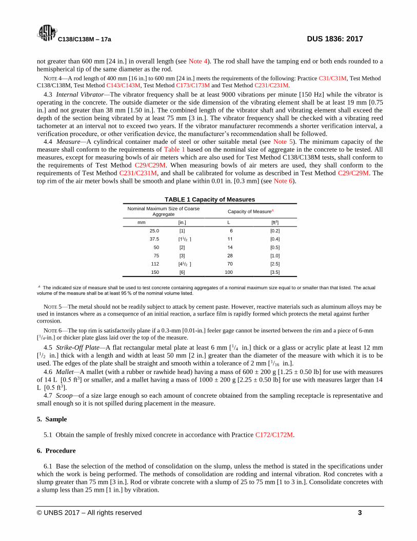
4.4 Measure—A cylindrical container made of steel or other suitable metal (see Note 5). The minimum capacity of the
measure shall conform to the requirements of Table 1 based on the nominal size of aggregate in the concrete to be tested. All
measures, except for measuring bowls of air meters which are also used for Test Method C138/C138M tests, shall conform to
the requirements of Test Method C29/C29M. When measuring bowls of air meters are used, they shall conform to the
requirements of Test Method C231/C231M, and shall be calibrated for volume as described in Test Method C29/C29M. The
top rim of the air meter bowls shall be smooth and plane within 0.01 in. [0.3 mm] (see Note 6).
TABLE 1 Capacity of Measures
Nominal Maximum Size of Coarse Aggregate
Capacity of MeasureA
mm [in.] L [ft3]
25.0 [1] 6 [0.2]
37.5 [11/2 ] 11 [0.4]
50 [2] 14 [0.5]
75 [3] 28 [1.0]
112 [41/2 ] 70 [2.5]
150 [6] 100 [3.5]
A The indicated size of measure shall be used to test concrete containing aggregates of a nominal maximum size equal to or smaller than that listed. The actual volume of the measure shall be at least 95 % of the nominal volume listed.
NOTE 5—The metal should not be readily subject to attack by cement paste. However, reactive materials such as aluminum alloys may be
used in instances where as a consequence of an initial reaction, a surface film is rapidly formed which protects the metal against further
corrosion.
NOTE 6—The top rim is satisfactorily plane if a 0.3-mm [0.01-in.] feeler gage cannot be inserted between the rim and a piece of 6-mm
[1/4-in.] or thicker plate glass laid over the top of the measure.
4.5 Strike-Off Plate—A flat rectangular metal plate at least 6 mm [1/4 in.] thick or a glass or acrylic plate at least 12 mm
[1/2 in.] thick with a length and width at least 50 mm [2 in.] greater than the diameter of the measure with which it is to be
used. The edges of the plate shall be straight and smooth within a tolerance of 2 mm [1/16 in.].
4.6 Mallet—A mallet (with a rubber or rawhide head) having a mass of 600 ± 200 g [1.25 ± 0.50 lb] for use with measures
of 14 L [0.5 ft3] or smaller, and a mallet having a mass of 1000 ± 200 g [2.25 ± 0.50 lb] for use with measures larger than 14
L [0.5 ft3].
4.7 Scoop—of a size large enough so each amount of concrete obtained from the sampling receptacle is representative and
small enough so it is not spilled during placement in the measure.
5. Sample
5.1 Obtain the sample of freshly mixed concrete in accordance with Practice C172/C172M.
6. Procedure
6.1 Base the selection of the method of consolidation on the slump, unless the method is stated in the specifications under
which the work is being performed. The methods of consolidation are rodding and internal vibration. Rod concretes with a
slump greater than 75 mm [3 in.]. Rod or vibrate concrete with a slump of 25 to 75 mm [1 to 3 in.]. Consolidate concretes with
a slump less than 25 mm [1 in.] by vibration.
C138/C138M – 17a DUS 1836: 2017
© UNBS 2017 – All rights reserved 4
NOTE 7—Nonplastic concrete, such as is commonly used in the manufacture of pipe and unit masonry, is not covered by this test method.
6.2 Dampen the interior of the measure and remove any standing water from the bottom. Determine the mass of the empty
measure to an accuracy consistent with the requirements of 4.1. Place the measure on a flat, level, firm surface. Place the
concrete in the measure using the scoop described in 4.7. Move the scoop around the perimeter of the measure opening to
ensure an even distribution of the concrete with minimal segregation. Fill the measure in the number of layers required by the
consolidation method (6.3 or 6.4).
6.2.1 Follow the procedures in Practice C1758/C1758M for filling the measure, if self-consolidating concrete is being
tested. Upon completion of the filling process, proceed to 6.6.
6.3 Rodding—Place the concrete in the measure in three layers of approximately equal volume. Rod each layer with 25
strokes of the tamping rod when nominal 14-L [0.5-ft3] or smaller measures are used, 50 strokes when nominal 28-L [1-ft3]
measures are used, and one stroke per 20 cm2 [3 in.2] of surface for larger measures. Rod each layer uniformly over the cross
section with the rounded end of the rod using the required number of strokes. Rod the bottom layer throughout its depth. In
rodding this layer, use care not to damage the bottom of the measure. For each upper layer, allow the rod to penetrate through
the layer being rodded and into the layer below approximately 25 mm [1 in.]. After each layer is rodded, tap the sides of the
measure 10 to 15 times with the appropriate mallet (see 4.6) using such force so as to close any voids left by the tamping rod
and to release any large bubbles of air that may have been trapped. Add the final layer so as to avoid overfilling.
6.4 Internal Vibration—Fill and vibrate the measure in two approximately equal layers. Place all of the concrete for each
layer in the measure before starting vibration of that layer. Insert the vibrator at three different points for each layer. In
compacting the bottom layer, do not allow the vibrator to rest on or touch the bottom or sides of the measure. In compacting
the final layer, the vibrator shall penetrate into the underlying layer approximately 25 mm [1 in.] . Take care that the vibrator
is withdrawn in such a manner that no air pockets are left in the specimen. The duration of vibration required will depend
upon the workability of the concrete and the effectiveness of the vibrator (see Note 8). Continue vibration only long enough to
achieve proper consolidation of the concrete (see Note 9). Observe a constant duration of vibration for the particular kind of
concrete, vibrator, and measure involved.
NOTE 8—Usually, sufficient vibration has been applied as soon as the surface of the concrete becomes relatively smooth.
NOTE 9—Overvibration may cause segregation and loss of appreciable quantities of intentionally entrained air.
6.5 On completion of consolidation the measure must not contain a substantial excess or deficiency of concrete. An excess
of concrete protruding approximately 3 mm [1/8 in.] above the top of the mold is optimum. A small quantity of concrete may
be added to correct a deficiency. If the measure contains a great excess of concrete at completion of consolidation, remove a
representative portion of the excess concrete with a trowel or scoop immediately following completion of consolidation and
before the measure is struck-off.
6.6 Strike-Off—After consolidation, strike-off the top surface of the concrete and finish it smoothly using the flat strike-off
plate so that the measure is level full. Strike-off the measure by pressing the strike-off plate on the top surface of the measure
to cover about two thirds of the surface and withdraw the plate with a sawing motion to finish only the area originally covered.
Then place the plate on the top of the measure to cover the original two thirds of the surface and advance it with a vertical
pressure and a sawing motion to cover the whole surface of the measure and continue to advance it until it slides completely
off the measure. Incline the plate and perform final strokes with the edge of the plate to produce a smooth surface.
6.7 Cleaning and Weighing—After strike-off, clean all excess concrete from the exterior of the measure and determine the
mass of the concrete and measure to an accuracy consistent with the requirements of 4.1.
7. Calculation
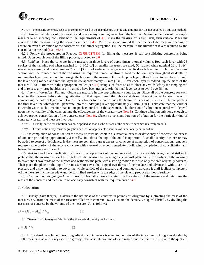
7.1 Density (Unit Weight)—Calculate the net mass of the concrete in pounds or kilograms by subtracting the mass of the
measure, Mm, from the mass of the measure filled with concrete, Mc. Calculate the density, D, kg/m3 [lb/ft3] , by dividing the
net mass of concrete by the volume of the measure, Vm as follows:
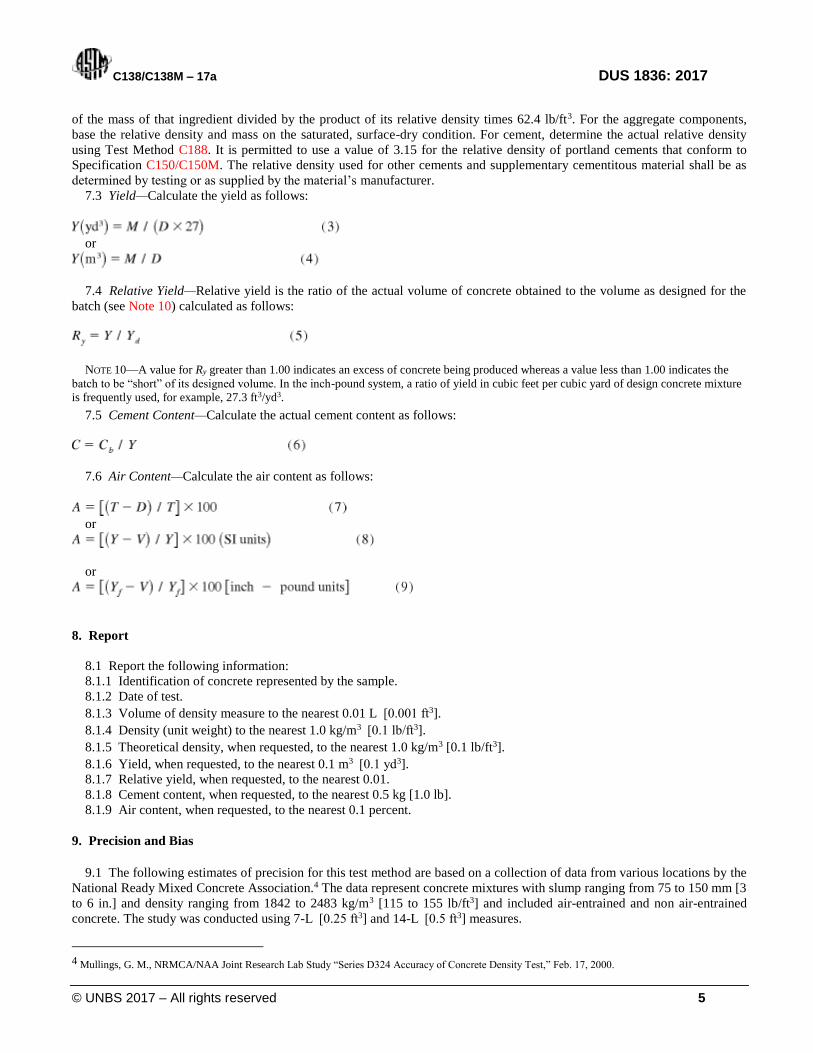
7.2 Theoretical Density—Calculate the theoretical density as follows:
7.2.1 The absolute volume of each ingredient in cubic meters is equal to the mass of the ingredient in kilograms divided by
1000 times its relative density (specific gravity). The absolute volume of each ingredient in cubic feet is equal to the quotient
C138/C138M – 17a DUS 1836: 2017
© UNBS 2017 – All rights reserved 5
of the mass of that ingredient divided by the product of its relative density times 62.4 lb/ft3. For the aggregate components,
base the relative density and mass on the saturated, surface-dry condition. For cement, determine the actual relative density
using Test Method C188. It is permitted to use a value of 3.15 for the relative density of portland cements that conform to
Specification C150/C150M. The relative density used for other cements and supplementary cementitous material shall be as
determined by testing or as supplied by the material’s manufacturer.
7.3 Yield—Calculate the yield as follows:
or
7.4 Relative Yield—Relative yield is the ratio of the actual volume of concrete obtained to the volume as designed for the
batch (see Note 10) calculated as follows:
NOTE 10—A value for Ry greater than 1.00 indicates an excess of concrete being produced whereas a value less than 1.00 indicates the
batch to be “short” of its designed volume. In the inch-pound system, a ratio of yield in cubic feet per cubic yard of design concrete mixture
is frequently used, for example, 27.3 ft3/yd3.
7.5 Cement Content—Calculate the actual cement content as follows:
7.6 Air Content—Calculate the air content as follows:
or
or
8. Report
8.1 Report the following information:
8.1.1 Identification of concrete represented by the sample.
8.1.2 Date of test.
8.1.3 Volume of density measure to the nearest 0.01 L [0.001 ft3].
8.1.4 Density (unit weight) to the nearest 1.0 kg/m3 [0.1 lb/ft3].
8.1.5 Theoretical density, when requested, to the nearest 1.0 kg/m3 [0.1 lb/ft3].
8.1.6 Yield, when requested, to the nearest 0.1 m3 [0.1 yd3].
8.1.7 Relative yield, when requested, to the nearest 0.01.
8.1.8 Cement content, when requested, to the nearest 0.5 kg [1.0 lb].
8.1.9 Air content, when requested, to the nearest 0.1 percent.
9. Precision and Bias
9.1 The following estimates of precision for this test method are based on a collection of data from various locations by the
National Ready Mixed Concrete Association.4 The data represent concrete mixtures with slump ranging from 75 to 150 mm [3
to 6 in.] and density ranging from 1842 to 2483 kg/m3 [115 to 155 lb/ft3] and included air-entrained and non air-entrained
concrete. The study was conducted using 7-L [0.25 ft3] and 14-L [0.5 ft3] measures.
4 Mullings, G. M., NRMCA/NAA Joint Research Lab Study “Series D324 Accuracy of Concrete Density Test,” Feb. 17, 2000.
C138/C138M – 17a DUS 1836: 2017
© UNBS 2017 – All rights reserved 6
9.1.1 Single-Operator Precision—The single operator standard deviation of density of freshly mixed concrete has been
found to be 0.65 lb/ft3 [10.4 kg/m3] (1s). Therefore, results of two properly conducted by the same operator on the same
sample of concrete should not differ by more than 1.85 lb/ft3 [29.6 kg/m3] (d2s).
9.1.2 Multi-Operator Precision—The multi-operator standard deviation of density of freshly mixed concrete has been
found to be 13.1 kg/m3 [0.82 lb/ft3] (1s). Therefore, results of two properly conducted tests by the two operators on the same
sample of concrete should not differ by more than 37.0 kg/m3 [2.31 lb/ft 3] (d2s).
9.2 Bias—This test method has no bias since the density is defined only in terms of this test method.
10. Keywords
10.1 air content; cement content; concrete; relative yield; unit weight; yield
APPENDIXES
(Nonmandatory Information)
X1. SAMPLE CALCULATIONS (SI UNITS)
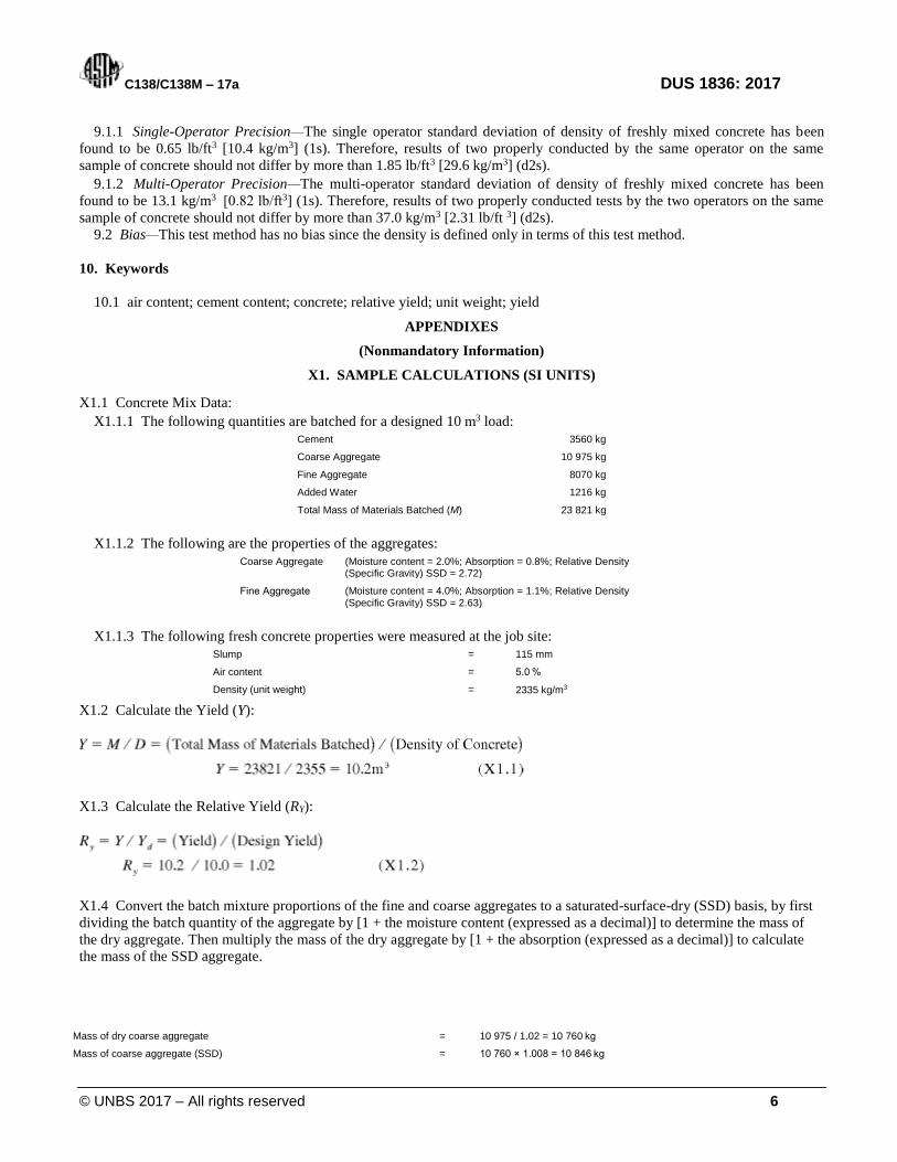
X1.1 Concrete Mix Data:
X1.1.1 The following quantities are batched for a designed 10 m3 load:
Cement 3560 kg
Coarse Aggregate 10 975 kg
Fine Aggregate 8070 kg
Added Water 1216 kg
Total Mass of Materials Batched (M) 23 821 kg
X1.1.2 The following are the properties of the aggregates:
Coarse Aggregate (Moisture content = 2.0%; Absorption = 0.8%; Relative Density (Specific Gravity) SSD = 2.72)
Fine Aggregate (Moisture content = 4.0%; Absorption = 1.1%; Relative Density (Specific Gravity) SSD = 2.63)
X1.1.3 The following fresh concrete properties were measured at the job site:
Slump = 115 mm
Air content = 5.0 %
Density (unit weight) = 2335 kg/m3
X1.2 Calculate the Yield (Y):
X1.3 Calculate the Relative Yield (RY):
X1.4 Convert the batch mixture proportions of the fine and coarse aggregates to a saturated-surface-dry (SSD) basis, by first
dividing the batch quantity of the aggregate by [1 + the moisture content (expressed as a decimal)] to determine the mass of
the dry aggregate. Then multiply the mass of the dry aggregate by [1 + the absorption (expressed as a decimal)] to calculate
the mass of the SSD aggregate.
Mass of dry coarse aggregate = 10 975 / 1.02 = 10 760 kg
Mass of coarse aggregate (SSD) = 10 760 × 1.008 = 10 846 kg
C138/C138M – 17a DUS 1836: 2017
© UNBS 2017 – All rights reserved 7
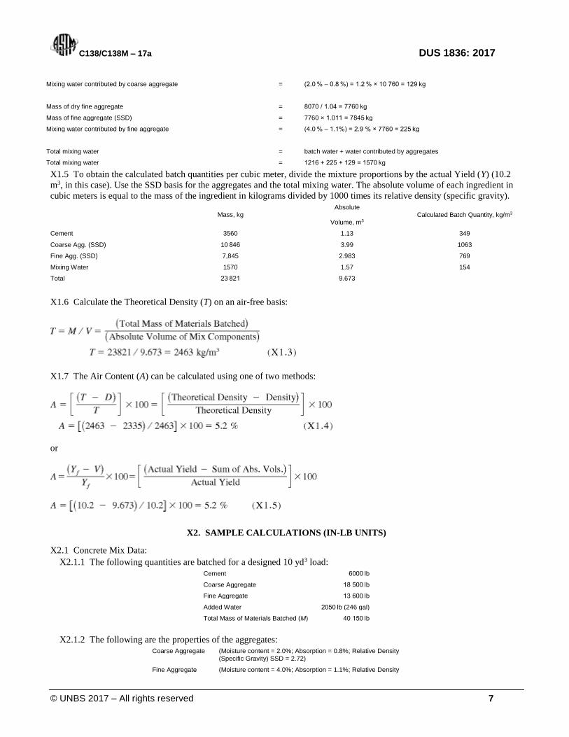
Mixing water contributed by coarse aggregate = (2.0 % – 0.8 %) = 1.2 % × 10 760 = 129 kg
Mass of dry fine aggregate = 8070 / 1.04 = 7760 kg
Mass of fine aggregate (SSD) = 7760 × 1.011 = 7845 kg
Mixing water contributed by fine aggregate = (4.0 % – 1.1%) = 2.9 % × 7760 = 225 kg
Total mixing water = batch water + water contributed by aggregates
Total mixing water = 1216 + 225 + 129 = 1570 kg
X1.5 To obtain the calculated batch quantities per cubic meter, divide the mixture proportions by the actual Yield (Y) (10.2
m3, in this case). Use the SSD basis for the aggregates and the total mixing water. The absolute volume of each ingredient in
cubic meters is equal to the mass of the ingredient in kilograms divided by 1000 times its relative density (specific gravity).
Mass, kg
Absolute
Volume, m3 Calculated Batch Quantity, kg/m3
Cement 3560 1.13 349
Coarse Agg. (SSD) 10 846 3.99 1063
Fine Agg. (SSD) 7,845 2.983 769
Mixing Water 1570 1.57 154
Total 23 821 9.673
X1.6 Calculate the Theoretical Density (T) on an air-free basis:
X1.7 The Air Content (A) can be calculated using one of two methods:
or
X2. SAMPLE CALCULATIONS (IN-LB UNITS)
X2.1 Concrete Mix Data:
X2.1.1 The following quantities are batched for a designed 10 yd3 load:
Cement 6000 lb
Coarse Aggregate 18 500 lb
Fine Aggregate 13 600 lb
Added Water 2050 lb (246 gal)
Total Mass of Materials Batched (M) 40 150 lb
X2.1.2 The following are the properties of the aggregates:
Coarse Aggregate (Moisture content = 2.0%; Absorption = 0.8%; Relative Density (Specific Gravity) SSD = 2.72)
Fine Aggregate (Moisture content = 4.0%; Absorption = 1.1%; Relative Density
C138/C138M – 17a DUS 1836: 2017
© UNBS 2017 – All rights reserved 8
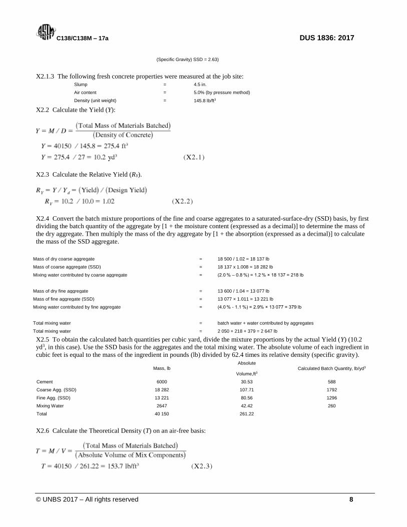
(Specific Gravity) SSD = 2.63)
X2.1.3 The following fresh concrete properties were measured at the job site:
Slump = 4.5 in.
Air content = 5.0% (by pressure method)
Density (unit weight) = 145.8 lb/ft3
X2.2 Calculate the Yield (Y):
X2.3 Calculate the Relative Yield (RY).
X2.4 Convert the batch mixture proportions of the fine and coarse aggregates to a saturated-surface-dry (SSD) basis, by first
dividing the batch quantity of the aggregate by [1 + the moisture content (expressed as a decimal)] to determine the mass of
the dry aggregate. Then multiply the mass of the dry aggregate by [1 + the absorption (expressed as a decimal)] to calculate
the mass of the SSD aggregate.
Mass of dry coarse aggregate = 18 500 / 1.02 = 18 137 lb
Mass of coarse aggregate (SSD) = 18 137 x 1.008 = 18 282 lb
Mixing water contributed by coarse aggregate = (2.0 % – 0.8 %) = 1.2 % × 18 137 = 218 lb
Mass of dry fine aggregate = 13 600 / 1.04 = 13 077 lb
Mass of fine aggregate (SSD) = 13 077 × 1.011 = 13 221 lb
Mixing water contributed by fine aggregate = (4.0 % - 1.1 %) = 2.9% × 13 077 = 379 lb
Total mixing water = batch water + water contributed by aggregates
Total mixing water = 2 050 + 218 + 379 = 2 647 lb
X2.5 To obtain the calculated batch quantities per cubic yard, divide the mixture proportions by the actual Yield (Y) (10.2
yd3, in this case). Use the SSD basis for the aggregates and the total mixing water. The absolute volume of each ingredient in
cubic feet is equal to the mass of the ingredient in pounds (lb) divided by 62.4 times its relative density (specific gravity).
Mass, lb
Absolute
Volume,ft3 Calculated Batch Quantity, lb/yd3
Cement 6000 30.53 588
Coarse Agg. (SSD) 18 282 107.71 1792
Fine Agg. (SSD) 13 221 80.56 1296
Mixing Water 2647 42.42 260
Total 40 150 261.22
X2.6 Calculate the Theoretical Density (T) on an air-free basis:
C138/C138M – 17a DUS 1836: 2017
© UNBS 2017 – All rights reserved 9
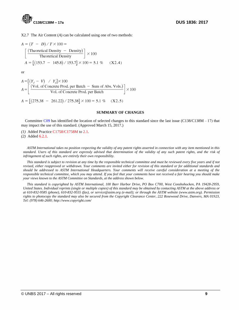
X2.7 The Air Content (A) can be calculated using one of two methods:
or
SUMMARY OF CHANGES
Committee C09 has identified the location of selected changes to this standard since the last issue (C138/C138M – 17) that
may impact the use of this standard. (Approved March 15, 2017.)
(1) Added Practice C1758/C1758M to 2.1.
(2) Added 6.2.1.
ASTM International takes no position respecting the validity of any patent rights asserted in connection with any item mentioned in this
standard. Users of this standard are expressly advised that determination of the validity of any such patent rights, and the risk of
infringement of such rights, are entirely their own responsibility.
This standard is subject to revision at any time by the responsible technical committee and must be reviewed every five years and if not
revised, either reapproved or withdrawn. Your comments are invited either for revision of this standard or for additional standards and
should be addressed to ASTM International Headquarters. Your comments will receive careful consideration at a meeting of the
responsible technical committee, which you may attend. If you feel that your comments have not received a fair hearing you should make
your views known to the ASTM Committee on Standards, at the address shown below.
This standard is copyrighted by ASTM International, 100 Barr Harbor Drive, PO Box C700, West Conshohocken, PA 19428-2959,
United States. Individual reprints (single or multiple copies) of this standard may be obtained by contacting ASTM at the above address or
at 610-832-9585 (phone), 610-832-9555 (fax), or [email protected] (e-mail); or through the ASTM website (www.astm.org). Permission
rights to photocopy the standard may also be secured from the Copyright Clearance Center, 222 Rosewood Drive, Danvers, MA 01923,
Tel: (978) 646-2600; http://www.copyright.com/
C138/C138M – 17a DUS 1836: 2017
© UNBS 2017 – All rights reserved 10
Certification marking
Products that conform to Uganda standards may be marked with Uganda National Bureau of Standards (UNBS) Certification Mark shown in the figure below.
The use of the UNBS Certification Mark is governed by the Standards Act, and the Regulations made thereunder. This mark can be used only by those licensed under the certification mark scheme operated by the Uganda National Bureau of Standards and in conjunction with the relevant Uganda Standard. The presence of this mark on a product or in relation to a product is an assurance that the goods comply with the requirements of that standard under a system of supervision, control and testing in accordance with the certification mark scheme of the Uganda National Bureau of Standards. UNBS marked products are continually checked by UNBS for conformity to that standard.
Further particulars of the terms and conditions of licensing may be obtained from the Director, Uganda National Bureau of Standards.

C138/C138M – 17a FDUS 1836: 2017
ICS nn.nnn.nn
Price based on nn pages
© UNBS 2017 – All rights reserved