distributed i/o - honeywell ecc
TRANSCRIPT
® U.S. Registered Trademark Copyright © 2006 Honeywell Inc. • All Rights Reserved EN0B-0090GE51 R0906
74-2145-6
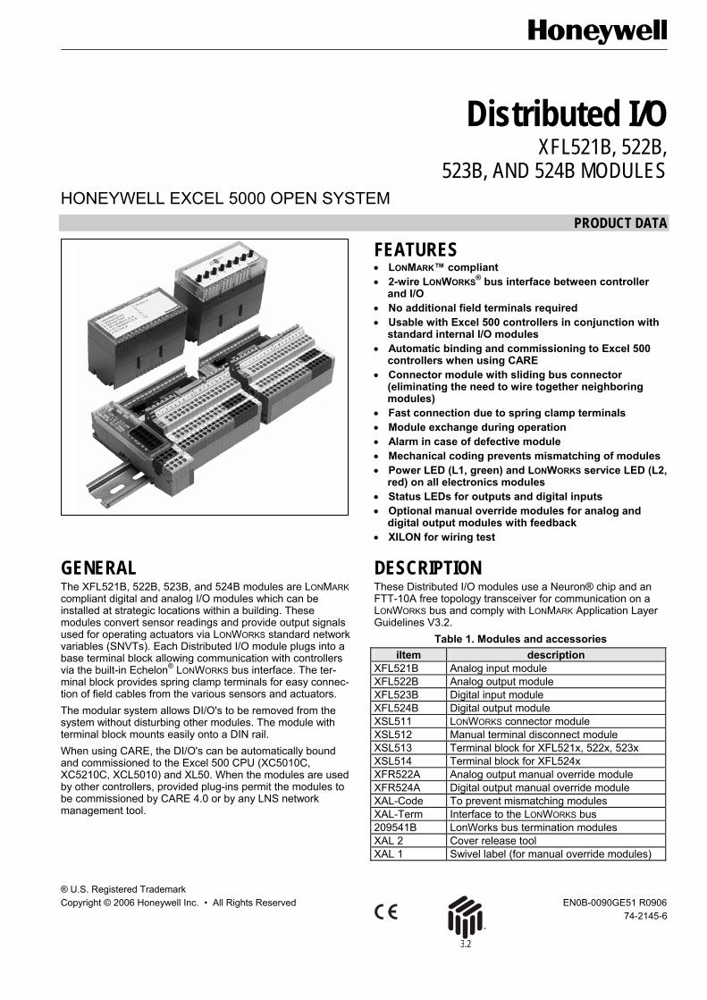
Distributed I/O XFL521B, 522B,
523B, AND 524B MODULES HONEYWELL EXCEL 5000 OPEN SYSTEM
PRODUCT DATA
FEATURES • LONMARK™ compliant • 2-wire LONWORKS® bus interface between controller
and I/O • No additional field terminals required • Usable with Excel 500 controllers in conjunction with
standard internal I/O modules • Automatic binding and commissioning to Excel 500
controllers when using CARE • Connector module with sliding bus connector
(eliminating the need to wire together neighboring modules)
• Fast connection due to spring clamp terminals • Module exchange during operation • Alarm in case of defective module • Mechanical coding prevents mismatching of modules • Power LED (L1, green) and LONWORKS service LED (L2,
red) on all electronics modules • Status LEDs for outputs and digital inputs • Optional manual override modules for analog and
digital output modules with feedback • XILON for wiring test
GENERAL The XFL521B, 522B, 523B, and 524B modules are LONMARK compliant digital and analog I/O modules which can be installed at strategic locations within a building. These modules convert sensor readings and provide output signals used for operating actuators via LONWORKS standard network variables (SNVTs). Each Distributed I/O module plugs into a base terminal block allowing communication with controllers via the built-in Echelon® LONWORKS bus interface. The ter-minal block provides spring clamp terminals for easy connec-tion of field cables from the various sensors and actuators. The modular system allows DI/O's to be removed from the system without disturbing other modules. The module with terminal block mounts easily onto a DIN rail. When using CARE, the DI/O's can be automatically bound and commissioned to the Excel 500 CPU (XC5010C, XC5210C, XCL5010) and XL50. When the modules are used by other controllers, provided plug-ins permit the modules to be commissioned by CARE 4.0 or by any LNS network management tool.
DESCRIPTION These Distributed I/O modules use a Neuron® chip and an FTT-10A free topology transceiver for communication on a LONWORKS bus and comply with LONMARK Application Layer Guidelines V3.2.
Table 1. Modules and accessories iItem description
XFL521B Analog input module XFL522B Analog output module XFL523B Digital input module XFL524B Digital output module XSL511 LONWORKS connector module XSL512 Manual terminal disconnect module XSL513 Terminal block for XFL521x, 522x, 523x XSL514 Terminal block for XFL524x XFR522A Analog output manual override module XFR524A Digital output manual override module XAL-Code To prevent mismatching modules XAL-Term Interface to the LONWORKS bus 209541B LonWorks bus termination modules XAL 2 Cover release tool XAL 1 Swivel label (for manual override modules)
DISTRIBUTED I/O
EN0B-0090GE51 R0906 2
INTEROPERABILITY The Distributed I/O modules are compliant to the LONMARK Application Layer Interface Guidelines, version 3.2. The modules contain a LONMARK Node Object to allow monitoring and setting the status of the various Sensor / Actuator Ob-jects, as well as a LONMARK Sensor Object for each input or an Actuator Object for each individual output. Upon receiving an update to the NViRequest network vari-able, the NVoStatus network variable is updated. The defini-tion of SNVT_obj_request includes an object ID field to allow the Node Object to report status conditions for all objects on a node. All network variables have the NV names in their self-docu-mentation strings. This allows a network management node or tool to display meaningful information on a Distributed I/O module even if it is installed by an EXCEL 500 controller and not by the tool itself. The Distributed I/O modules use the standard 6-byte location string (see Table 2) in the Neuron® chip’s EEPROM to store the module address (0...15 as set using the rotary HEX switch in the case of applications prior to CARE 4.0) and the module type.
Location String ‘0’ Y Y
Mod
ule
type
Set
to '0
'
Mod
ule
addr
ess
Module Type: 0 = XFL521B Analog Input 1 = XFL522B Analog Output 2 = XFL523B Digital Input 3 = XFL524B Digital Output
Table 2. Location string for storing module address The node self-documentation string contains the module type and revision in the optional part after the semicolon. Example:
#pragma set_node_sd_string &3.2@0,3[6;XDO2_2_00 In this example, the module type is "XDO2" ("2" means that the 3120E5 chip is used) and the revision is "2.00".
LONMARK Node Object Setting the Node Object to “DISABLE” via nviRequest suppresses updating of all output NVs and handling of input NVs. Setting the Node Object to “ENABLE” via nviRequest returns the module to normal operation. The Node Object also contains the optional NV nciNetConfig which is initialized to “CFG_LOCAL” by default. This allows
the Distributed I/O module to set its location string. If a network management node commands this nci to “CFG_EXTERNAL”, then the module will no longer modify its Location String. This nci is stored in EEPROM and remains there even in the event of a power failure.
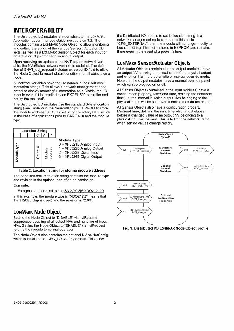
LONMARK Sensor/Actuator Objects All Actuator Objects (contained in the output modules) have an output NV showing the actual state of the physical output and whether it is in the automatic or manual override mode. Note that the output modules have a manual override panel which can be plugged on or off. All Sensor Objects (contained in the input modules) have a configuration property, MaxSendTime, defining the heartbeat time, i.e. the interval in which output NVs belonging to the physical inputs will be sent even if their values do not change. All Sensor Objects also have a configuration property, MinSendTime, defining the min. time which must elapse before a changed value of an output NV belonging to a physical input will be sent. This is to limit the network traffic when sensor values change rapidly.
Node ObjectType #0
MandatoryNetworkVariables
inputNV 1
nviRequestSNVT_obj_requestnv1 nviRequest
SNVT_obj_requestinputNV 1
nviRequestSNVT_obj_requestnv2 nvoStatus
SNVT_obj_status
inputNV 1
nviRequestSNVT_obj_requestnv8 nvoFileDirectory
SNVT_addressOptionalNetworkVariables
OptionalConfiguration
Properties
inputNV 1
nviRequestSNVT_obj_requestnc25 nciNetConfig
SNVT_config_src
inputNV 1
nviRequestSNVT_obj_requestnc49 SCPTMaxSendTime
SNVT_time_sec
inputNV 1
nviRequestSNVT_obj_requestnc52 SCPTMinSendTime
SNVT_time_sec
Fig. 1. Distributed I/O LONMARK Node Object profile
DISTRIBUTED I/O
3 EN0B-0090GE51 R0906
Table 3. Node Object network variables NV name type range description
nviRequest SNVT_obj_request
RQ_NORMAL RQ_DISABLE RQ_ENABLE RQ_UPDATE_STATUSRQ_REPOPRT_MASK RQ_SELF_TEST
Upon receiving an update to nviRequest, nvoStatus is updated. RQ_SELF_TEST is used only in the XFL522B analog output module for outputs configured as a motor. In this case, a synchronization is performed to set the actuator in the 0% position.
nvoStatus SNVT_obj_status Reports the status of the node upon request through nviRequest.
nciNetConfig SNVT_config_src CFG_LOCAL (default) CFG_EXTERNAL
This configuration variable is set to CFG_LOCAL at the factory and whenever the rotary HEX switch is reset. If it is set to CFG_EXTERNAL, a network manager will assign a network address for the node. In this case, the module will not modify its location string as long as the rotary HEX switch is not reset.
nvoFileDirectory SNVT_address
Points to a file directory in the address space of the Neuron® chip containing descriptors for the files in the module. It is used to access the configuration pro-perties stored in configuration parameter files accessed by network management read/write messages.
SCPTMinSendTime SNVT_time_sec 1.0 to 10.0 sec (default = 1.0 sec)
Defines the min. period of time between output variable transitions. This configuration property is applicable only to output NVs of the input modules.
SCPTMaxSendTime SNVT_time_sec 1.0 to 6553.4 sec (default = 60.0 sec)
Defines the max. time period of time before output NVs are automatically updated. It must be set to a higher number than SCPTminSendTime. This configuration property is applicable only to output NVs of the input modules.
XFL52xB Module Response Times The response time of Distributed I/O modules is defined as the period of time between the updating of the physical signal and the updating of the NV (or vice versa). The response time varies somewhat due to certain factors and is also dependent upon the module type (see also Table 4).
Table 4. Response time (RT)
module typical RT (sec)
max. RT (sec)
min. time between 2 updates
XFL521B 0.8 1.6 SNVTMinSendTime (default: 1 sec)
XFL522B 0.2 0.4 n.a.
XFL523B 0.3 0.5 SNVTMinSendTime (default: 1 sec)
XFL524B 0.2 0.4 not applicable
XSL511 Connector Module Power Supply NOTE: When connecting XFL52xB modules to the power
supply, the same side of the transformer must always be connected to the same side of the XSL511 (see also Fig. 11 on page 9)!
Cable Lengths and Cross Sectional Areas Distribute I/O cables must meet the same requirements specified for Excel 500 and Excel 600 I/O as specified in Table 5.
Table 5. Cable sizing. cross sectional area
type of signal ≤ 300 ft (100 m)
≤ 550 ft (170 m)
≤ 1300 ft (400 m)
24 Vac power supply
≤ 16 AWG (≥ 1.5 mm2)
≤ 14 AWG (≥ 2.5 mm2)
-
Low voltage signals1
≤ 20 AWG (≥ 0.5 mm2)
1 0...10 V sensors, totalizers, digital inputs, 0...10 V signals for actuators, etc.
IMPORTANT
The max. length of a signal cable with 24 Vac supply is 550 ft (170 m). The max. length of a two-wire, 0 to 10 Vdc signal cable is 1300 ft (400 m). The secondary side of the transformer must not be connected to earth ground.
DISTRIBUTED I/O
EN0B-0090GE51 R0906 4
TRANSFORMER
MAX. 550 ft (170 m)MIN. 14 AWG (2.5 mm )2
PRIMARYVOLTAGE
YGND
24 Vac
2
24 V 24 V
~
1
0000
056a
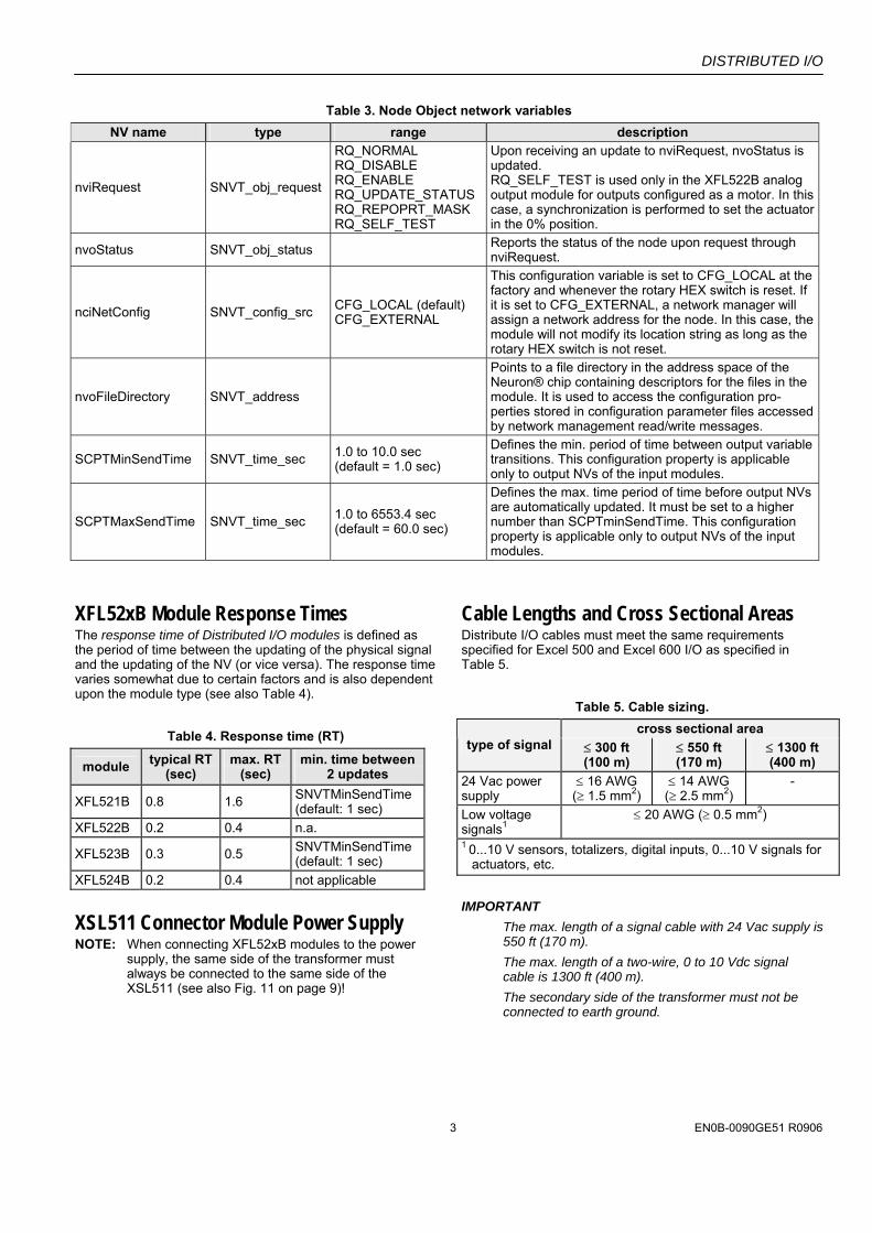
Fig. 2. Cabling of actuator with 24 Vac supply and max.
550 ft (170 m). IMPORTANT
It is recommend to install a fuse on the secondary side of the transformer in order to protect the devices from miswiring.
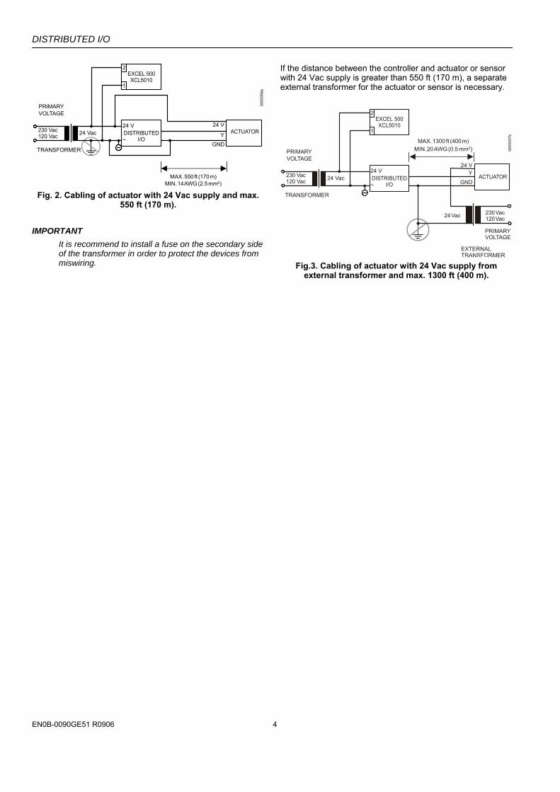
If the distance between the controller and actuator or sensor with 24 Vac supply is greater than 550 ft (170 m), a separate external transformer for the actuator or sensor is necessary.
Fig.3. Cabling of actuator with 24 Vac supply from
external transformer and max. 1300 ft (400 m).
DISTRIBUTED I/O
5 EN0B-0090GE51 R0906
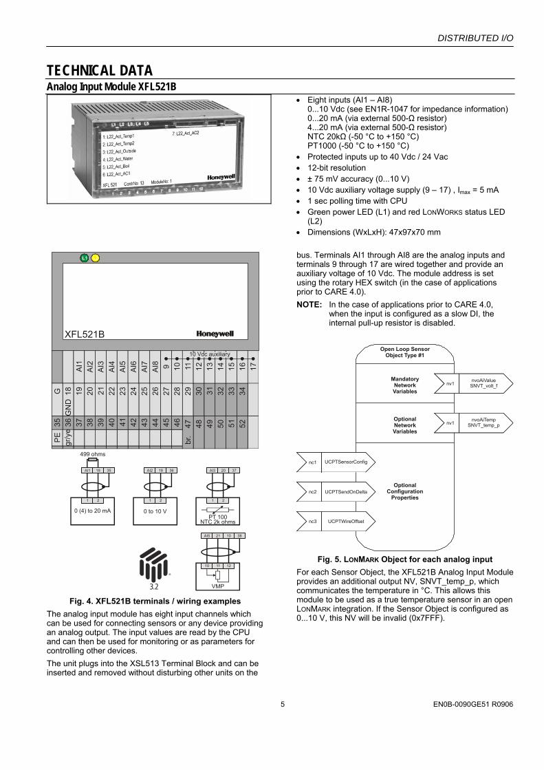
TECHNICAL DATA Analog Input Module XFL521B
• Eight inputs (AI1 – AI8) 0...10 Vdc (see EN1R-1047 for impedance information) 0...20 mA (via external 500-Ω resistor) 4...20 mA (via external 500-Ω resistor) NTC 20kΩ (-50 °C to +150 °C) PT1000 (-50 °C to +150 °C)
• Protected inputs up to 40 Vdc / 24 Vac • 12-bit resolution • ± 75 mV accuracy (0...10 V) • 10 Vdc auxiliary voltage supply (9 – 17) , Imax = 5 mA • 1 sec polling time with CPU • Green power LED (L1) and red LONWORKS status LED
(L2) • Dimensions (WxLxH): 47x97x70 mm
XFL521B
AI1
AI2
AI3
AI4
AI5 AI6
AI7
AI8 9 10
292827262524232221201918G
ND
G 30 31 32 33 34525150494847
br.
464544434241403938373635P
Egr
/ye
11 12 13 14 15 16 17
10 Vdc auxiliary
0 (4) to 20 mA
AI1
1 2
18 35
499 ohms
VMP
AI5
1110 12
21 10 38
0 to 10 V
AI2
1 2
19 36
PT 100NTC 2k ohms
AI3
1 2
20 37
Fig. 4. XFL521B terminals / wiring examples
The analog input module has eight input channels which can be used for connecting sensors or any device providing an analog output. The input values are read by the CPU and can then be used for monitoring or as parameters for controlling other devices. The unit plugs into the XSL513 Terminal Block and can be inserted and removed without disturbing other units on the
bus. Terminals AI1 through AI8 are the analog inputs and terminals 9 through 17 are wired together and provide an auxiliary voltage of 10 Vdc. The module address is set using the rotary HEX switch (in the case of applications prior to CARE 4.0). NOTE: In the case of applications prior to CARE 4.0,
when the input is configured as a slow DI, the internal pull-up resistor is disabled.
Open Loop Sensor
Object Type #1
MandatoryNetworkVariables
inputNV 1
nviRequestSNVT_obj_requestnv1
nvoAiValueSNVT_volt_f
inputNV 1
nviRequestSNVT_obj_requestnv1
nvoAiTempSNVT_temp_p
OptionalNetworkVariables
OptionalConfiguration
Properties
inputNV 1
nviRequestSNVT_obj_requestnc1 UCPTSensorConfig
inputNV 1
nviRequestSNVT_obj_requestnc2 UCPTSendOnDelta
inputNV 1
nviRequestSNVT_obj_requestnc3 UCPTWireOffset
Fig. 5. LONMARK Object for each analog input
For each Sensor Object, the XFL521B Analog Input Module provides an additional output NV, SNVT_temp_p, which communicates the temperature in °C. This allows this module to be used as a true temperature sensor in an open LONMARK integration. If the Sensor Object is configured as 0...10 V, this NV will be invalid (0x7FFF).
DISTRIBUTED I/O
EN0B-0090GE51 R0906 6
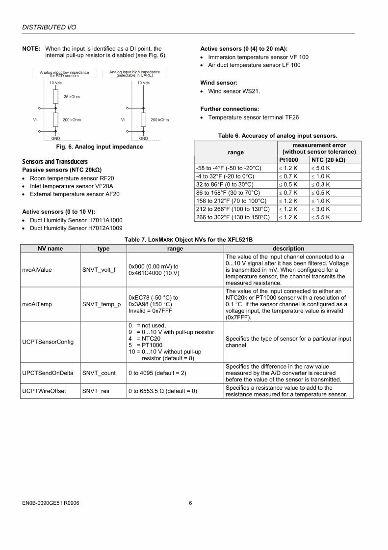
NOTE: When the input is identified as a DI point, the internal pull-up resistor is disabled (see Fig. 6).
10 Vdc
GND
25 kOhm
200 kOhmVi
10 Vdc
GND
200 kOhmVi
Analog input low impedancefor RTD sensors
Analog input high impedance(selectable in CARE)
Fig. 6. Analog input impedance
Sensors and Transducers Passive sensors (NTC 20kΩ) • Room temperature sensor RF20 • Inlet temperature sensor VF20A • External temperature sensor AF20 Active sensors (0 to 10 V): • Duct Humidity Sensor H7011A1000 • Duct Humidity Sensor H7012A1009
Active sensors (0 (4) to 20 mA): • Immersion temperature sensor VF 100 • Air duct temperature sensor LF 100 Wind sensor: • Wind sensor WS21. Further connections: • Temperature sensor terminal TF26
Table 6. Accuracy of analog input sensors. measurement error
(without sensor tolerance) range Pt1000 NTC (20 kΩ)
-58 to -4°F (-50 to -20°C) ≤ 1.2 K ≤ 5.0 K -4 to 32°F (-20 to 0°C) ≤ 0.7 K ≤ 1.0 K 32 to 86°F (0 to 30°C) ≤ 0.5 K ≤ 0.3 K 86 to 158°F (30 to 70°C) ≤ 0.7 K ≤ 0.5 K 158 to 212°F (70 to 100°C) ≤ 1.2 K ≤ 1.0 K 212 to 266°F (100 to 130°C) ≤ 1.2 K ≤ 3.0 K 266 to 302°F (130 to 150°C) ≤ 1.2 K ≤ 5.5 K
Table 7. LONMARK Object NVs for the XFL521B NV name type range description
nvoAiValue SNVT_volt_f 0x000 (0.00 mV) to 0x461C4000 (10 V)
The value of the input channel connected to a 0...10 V signal after it has been filtered. Voltage is transmitted in mV. When configured for a temperature sensor, the channel transmits the measured resistance.
nvoAiTemp SNVT_temp_p 0xEC78 (-50 °C) to 0x3A98 (150 °C) Invalid = 0x7FFF
The value of the input connected to either an NTC20k or PT1000 sensor with a resolution of 0.1 °C. If the sensor channel is configured as a voltage input, the temperature value is invalid (0x7FFF).
UCPTSensorConfig
0 = not used, 9 = 0...10 V with pull-up resistor 4 = NTC20 5 = PT1000 10 = 0...10 V without pull-up resistor (default = 8)
Specifies the type of sensor for a particular input channel.
UPCTSendOnDelta SNVT_count 0 to 4095 (default = 2) Specifies the difference in the raw value measured by the A/D converter is required before the value of the sensor is transmitted.
UCPTWireOffset SNVT_res 0 to 6553.5 Ω (default = 0) Specifies a resistance value to add to the resistance measured for a temperature sensor.
DISTRIBUTED I/O
7 EN0B-0090GE51 R0906
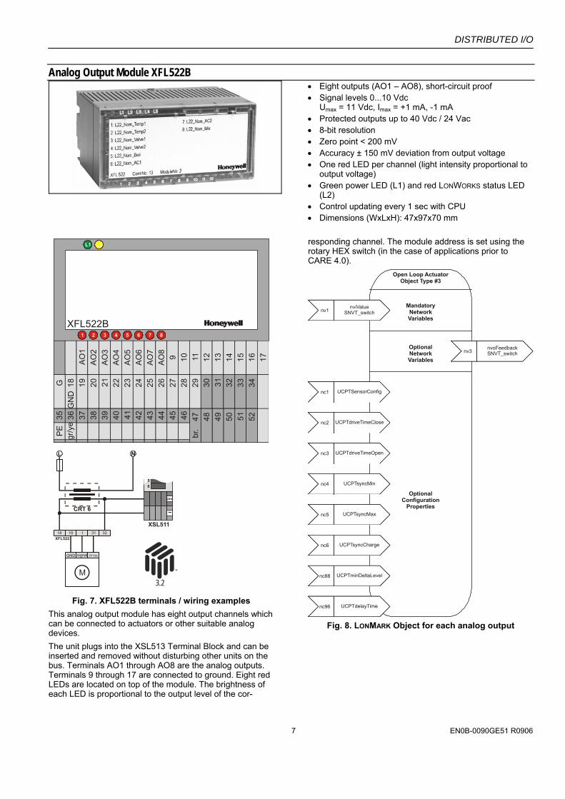
Analog Output Module XFL522B
• Eight outputs (AO1 – AO8), short-circuit proof • Signal levels 0...10 Vdc
Umax = 11 Vdc, Imax = +1 mA, -1 mA • Protected outputs up to 40 Vdc / 24 Vac • 8-bit resolution • Zero point < 200 mV • Accuracy ± 150 mV deviation from output voltage • One red LED per channel (light intensity proportional to
output voltage) • Green power LED (L1) and red LONWORKS status LED
(L2) • Control updating every 1 sec with CPU • Dimensions (WxLxH): 47x97x70 mm
XFL522
XSL511
XFL522B
CRT 6
18 19
GND signal 24 Vac
1 31 32
AO
1A
O2
AO
3A
O4
AO
5A
O6
AO
7A
O8
9 10292827262524232221201918
GN
DG 30 31 32 33 34
525150494847br
.464544434241403938373635
PE
gr/y
e
11 12 13 14 15 16 17
L N
M
6
~
24V
5
Fig. 7. XFL522B terminals / wiring examples
This analog output module has eight output channels which can be connected to actuators or other suitable analog devices. The unit plugs into the XSL513 Terminal Block and can be inserted and removed without disturbing other units on the bus. Terminals AO1 through AO8 are the analog outputs. Terminals 9 through 17 are connected to ground. Eight red LEDs are located on top of the module. The brightness of each LED is proportional to the output level of the cor-
responding channel. The module address is set using the rotary HEX switch (in the case of applications prior to CARE 4.0).
Open Loop ActuatorObject Type #3
MandatoryNetworkVariables
inputNV 1
nviRequestSNVT_obj_requestnv1
nviValueSNVT_switch
inputNV 1
nviRequestSNVT_obj_requestnv3 nvoFeedback
SNVT_switchOptionalNetworkVariables
OptionalConfiguration
Properties
inputNV 1
nviRequestSNVT_obj_requestnc1 UCPTSensorConfig
inputNV 1
nviRequestSNVT_obj_requestnc2 UCPTdriveTimeClose
inputNV 1
nviRequestSNVT_obj_requestnc3 UCPTdriveTimeOpen
inputNV 1
nviRequestSNVT_obj_requestnc4 UCPTsyncMin
inputNV 1
nviRequestSNVT_obj_requestnc5 UCPTsyncMax
inputNV 1
nviRequestSNVT_obj_requestnc6 UCPTsyncCharge
inputNV 1
nviRequestSNVT_obj_requestnc88 UCPTminDeltaLevel
inputNV 1
nviRequestSNVT_obj_requestnc96 UCPTdelayTime
Fig. 8. LONMARK Object for each analog output
DISTRIBUTED I/O
EN0B-0090GE51 R0906 8
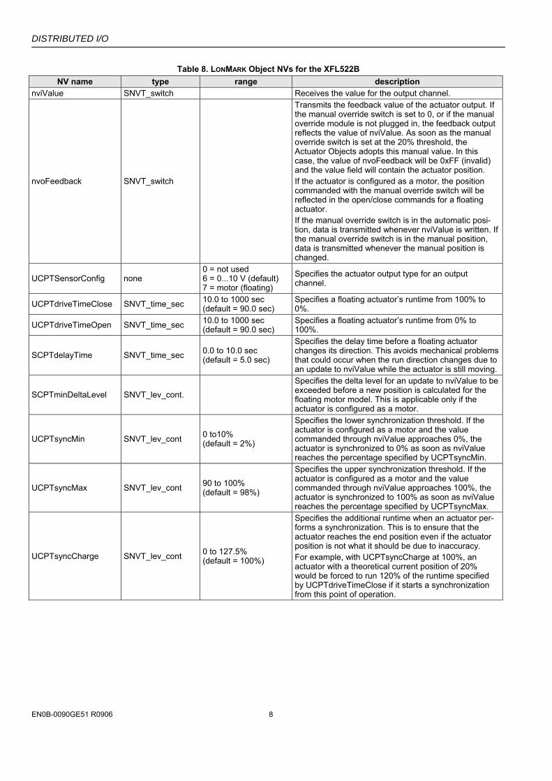
Table 8. LONMARK Object NVs for the XFL522B NV name type range description
nviValue SNVT_switch Receives the value for the output channel.
nvoFeedback SNVT_switch
Transmits the feedback value of the actuator output. If the manual override switch is set to 0, or if the manual override module is not plugged in, the feedback output reflects the value of nviValue. As soon as the manual override switch is set at the 20% threshold, the Actuator Objects adopts this manual value. In this case, the value of nvoFeedback will be 0xFF (invalid) and the value field will contain the actuator position. If the actuator is configured as a motor, the position commanded with the manual override switch will be reflected in the open/close commands for a floating actuator. If the manual override switch is in the automatic posi-tion, data is transmitted whenever nviValue is written. If the manual override switch is in the manual position, data is transmitted whenever the manual position is changed.
UCPTSensorConfig none 0 = not used 6 = 0...10 V (default) 7 = motor (floating)
Specifies the actuator output type for an output channel.
UCPTdriveTimeClose SNVT_time_sec 10.0 to 1000 sec (default = 90.0 sec)
Specifies a floating actuator’s runtime from 100% to 0%.
UCPTdriveTimeOpen SNVT_time_sec 10.0 to 1000 sec (default = 90.0 sec)
Specifies a floating actuator’s runtime from 0% to 100%.
SCPTdelayTime SNVT_time_sec 0.0 to 10.0 sec (default = 5.0 sec)
Specifies the delay time before a floating actuator changes its direction. This avoids mechanical problems that could occur when the run direction changes due to an update to nviValue while the actuator is still moving.
SCPTminDeltaLevel SNVT_lev_cont.
Specifies the delta level for an update to nviValue to be exceeded before a new position is calculated for the floating motor model. This is applicable only if the actuator is configured as a motor.
UCPTsyncMin SNVT_lev_cont 0 to10% (default = 2%)
Specifies the lower synchronization threshold. If the actuator is configured as a motor and the value commanded through nviValue approaches 0%, the actuator is synchronized to 0% as soon as nviValue reaches the percentage specified by UCPTsyncMin.
UCPTsyncMax SNVT_lev_cont 90 to 100% (default = 98%)
Specifies the upper synchronization threshold. If the actuator is configured as a motor and the value commanded through nviValue approaches 100%, the actuator is synchronized to 100% as soon as nviValue reaches the percentage specified by UCPTsyncMax.
UCPTsyncCharge SNVT_lev_cont 0 to 127.5% (default = 100%)
Specifies the additional runtime when an actuator per-forms a synchronization. This is to ensure that the actuator reaches the end position even if the actuator position is not what it should be due to inaccuracy. For example, with UCPTsyncCharge at 100%, an actuator with a theoretical current position of 20% would be forced to run 120% of the runtime specified by UCPTdriveTimeClose if it starts a synchronization from this point of operation.
DISTRIBUTED I/O
9 EN0B-0090GE51 R0906
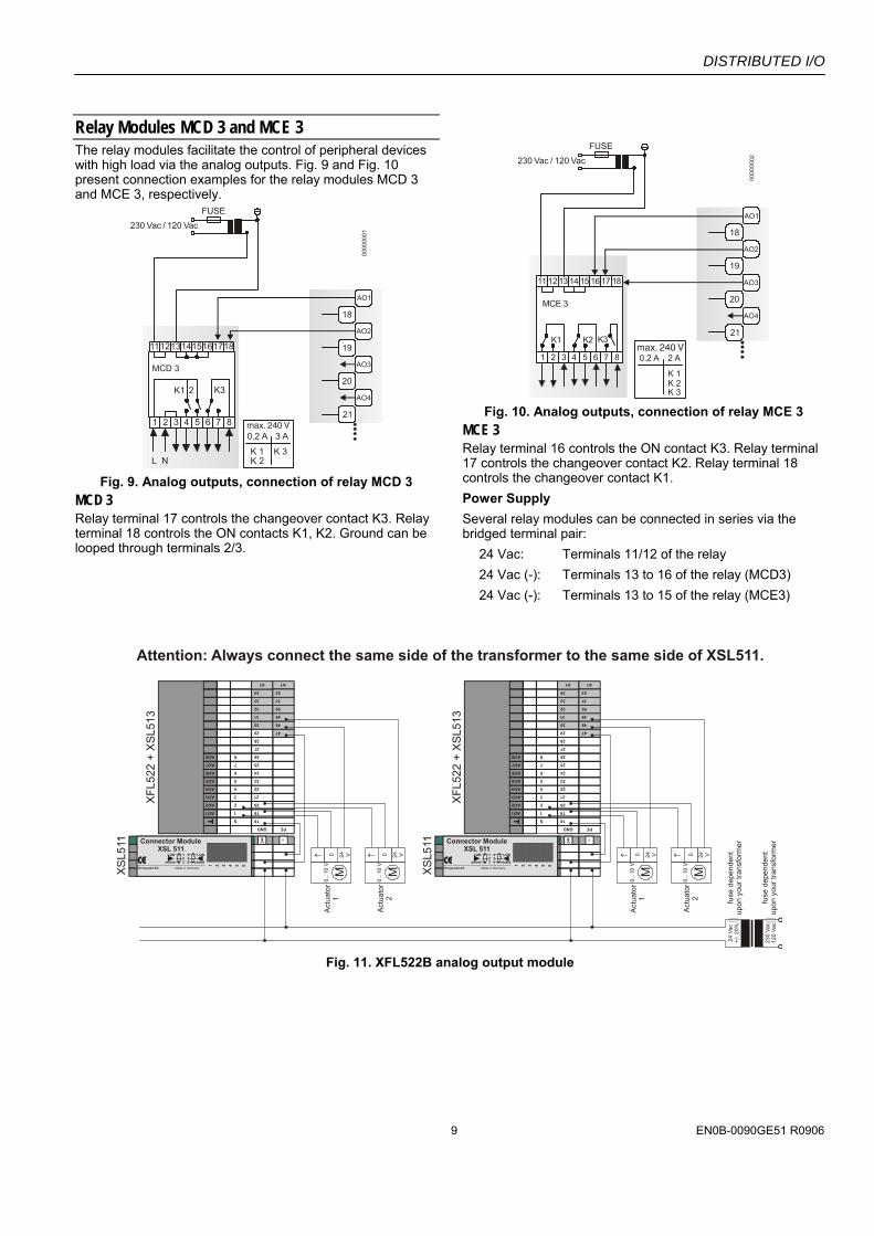
Relay Modules MCD 3 and MCE 3 The relay modules facilitate the control of peripheral devices with high load via the analog outputs. Fig. 9 and Fig. 10 present connection examples for the relay modules MCD 3 and MCE 3, respectively.
230 Vac / 120 VacFUSE
0.2 A
K 1K 2
K 3
3 A
1112131415161718
1 2
2
3
K3
4 5
K1
L N
6 7 8
MCD 3
AO1
18
AO2
19
AO3
20
AO4
21
0000
0001
Fig. 9. Analog outputs, connection of relay MCD 3
MCD 3 Relay terminal 17 controls the changeover contact K3. Relay terminal 18 controls the ON contacts K1, K2. Ground can be looped through terminals 2/3.
230 Vac / 120 VacFUSE
AO1
18
AO2
19
AO3
20
AO4
21
0000
0002
11 12 13 14 15 16 17 18
1 2 3
K1 K2 K3
4 5 6 7 8
MCE 3
0.2 A
K 1K 2
2 A
K 3 Fig. 10. Analog outputs, connection of relay MCE 3
MCE 3 Relay terminal 16 controls the ON contact K3. Relay terminal 17 controls the changeover contact K2. Relay terminal 18 controls the changeover contact K1. Power Supply Several relay modules can be connected in series via the bridged terminal pair:
24 Vac: Terminals 11/12 of the relay 24 Vac (-): Terminals 13 to 16 of the relay (MCD3) 24 Vac (-): Terminals 13 to 15 of the relay (MCE3)
Attention: Always connect the same side of the transformer to the same side of XSL511.
24 V
ac+/
- 20%
230
Vac
120
Vac
fuse
dep
ende
ntup
on y
our t
rans
form
er
fuse
dep
ende
ntup
on y
our t
rans
form
er
XFL
522
+ X
SL51
3
XSL5
11
18
20
21
22
23
24
25
26
27
28
GND
Act
uato
r2
Act
uato
r1
19AO1
AO2
AO3
AO4
AO5
AO6
AO7
AO8
1
2
3
4
5
6
S
8
7
PE
24V PE~
1 2 3 4 5 6
Connector Module XSL 511
Honeywell AG Made in Germany
123
LON
shield
456
LON
shield
30
31
32
33
34
A1 A1
47
48
49
50
51
52
0...1
0 V
M24 V↑ 0
0...1
0 V
M24 V↑ 0
XFL
522
+ X
SL51
3
XSL5
1118
20
21
22
23
24
25
26
27
28
GND
Act
uato
r2
Act
uato
r1
19AO1
AO2
AO3
AO4
AO5
AO6
AO7
AO8
1
2
3
4
5
6
S
8
7
PE
24V PE~
1 2 3 4 5 6
Connector Module XSL 511
Honeywell AG Made in Germany
123
LON
shield
456
LON
shield
30
31
32
33
34
A1 A1
47
48
49
50
51
52
0...1
0 V
M24 V↑ 0
0...1
0 V
M24 V↑ 0
2929
Fig. 11. XFL522B analog output module
DISTRIBUTED I/O
EN0B-0090GE51 R0906 10
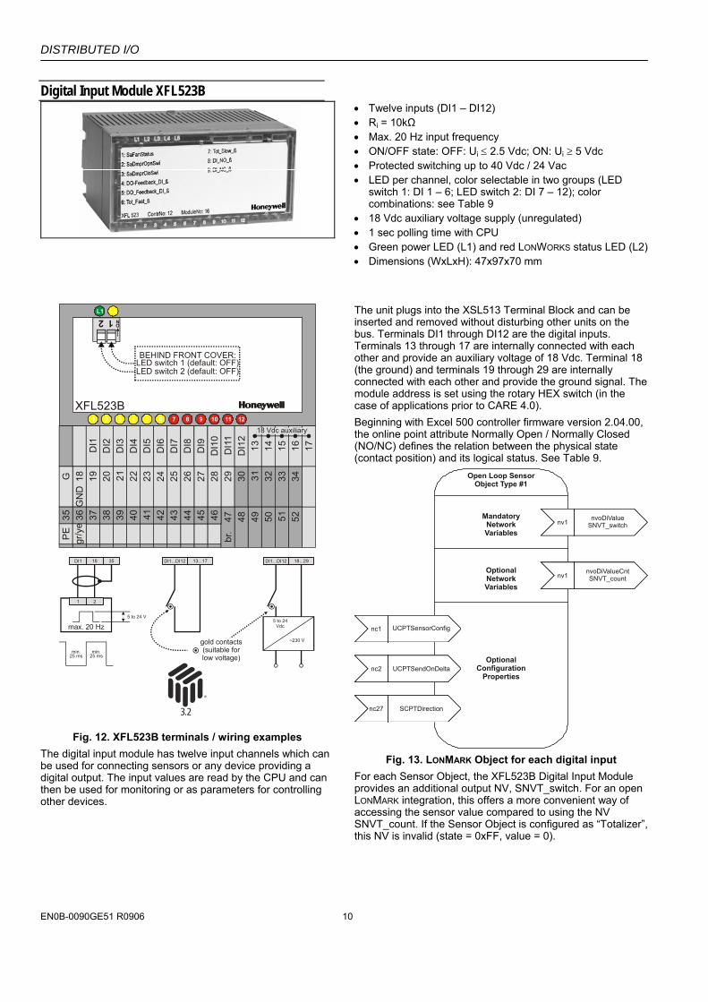
Digital Input Module XFL523B
• Twelve inputs (DI1 – DI12) • Ri = 10kΩ • Max. 20 Hz input frequency • ON/OFF state: OFF: Ui ≤ 2.5 Vdc; ON: Ui ≥ 5 Vdc • Protected switching up to 40 Vdc / 24 Vac • LED per channel, color selectable in two groups (LED
switch 1: DI 1 – 6; LED switch 2: DI 7 – 12); color combinations: see Table 9
• 18 Vdc auxiliary voltage supply (unregulated) • 1 sec polling time with CPU • Green power LED (L1) and red LONWORKS status LED (L2) • Dimensions (WxLxH): 47x97x70 mm
XFL523B
DI1
DI2
DI3
DI4
DI5
DI6
DI7
DI8
DI9
DI1
0292827262524232221201918
GN
DG 30 31 32 33 34
525150494847br
.464544434241403938373635
PE
gr/y
e
DI1
1D
I12
13 14 15 16 17
18 Vdc auxiliary
max. 20 Hz
DI1
1 2
18 35 13...17 18...29DI1...DI12 DI1...DI12
5 to 24 V
min.25 ms
min.25 ms
5 to 24Vdc
~230 Vgold contacts(suitable forlow voltage)
2 1ON
BEHIND FRONT COVER:LED switch 1 (default: OFF)LED switch 2 (default: OFF)
Fig. 12. XFL523B terminals / wiring examples
The digital input module has twelve input channels which can be used for connecting sensors or any device providing a digital output. The input values are read by the CPU and can then be used for monitoring or as parameters for controlling other devices.
The unit plugs into the XSL513 Terminal Block and can be inserted and removed without disturbing other units on the bus. Terminals DI1 through DI12 are the digital inputs. Terminals 13 through 17 are internally connected with each other and provide an auxiliary voltage of 18 Vdc. Terminal 18 (the ground) and terminals 19 through 29 are internally connected with each other and provide the ground signal. The module address is set using the rotary HEX switch (in the case of applications prior to CARE 4.0). Beginning with Excel 500 controller firmware version 2.04.00, the online point attribute Normally Open / Normally Closed (NO/NC) defines the relation between the physical state (contact position) and its logical status. See Table 9.
Open Loop SensorObject Type #1
MandatoryNetworkVariables
inputNV 1
nviRequestSNVT_obj_requestnv1 nvoDiValue
SNVT_switch
inputNV 1
nviRequestSNVT_obj_requestnv1 nvoDiValueCnt
SNVT_countOptionalNetworkVariables
OptionalConfiguration
Properties
inputNV 1
nviRequestSNVT_obj_requestnc1 UCPTSensorConfig
inputNV 1
nviRequestSNVT_obj_requestnc2 UCPTSendOnDelta
inputNV 1
nviRequestSNVT_obj_requestnc27 SCPTDirection
Fig. 13. LONMARK Object for each digital input
For each Sensor Object, the XFL523B Digital Input Module provides an additional output NV, SNVT_switch. For an open LONMARK integration, this offers a more convenient way of accessing the sensor value compared to using the NV SNVT_count. If the Sensor Object is configured as “Totalizer”, this NV is invalid (state = 0xFF, value = 0).
DISTRIBUTED I/O
11 EN0B-0090GE51 R0906
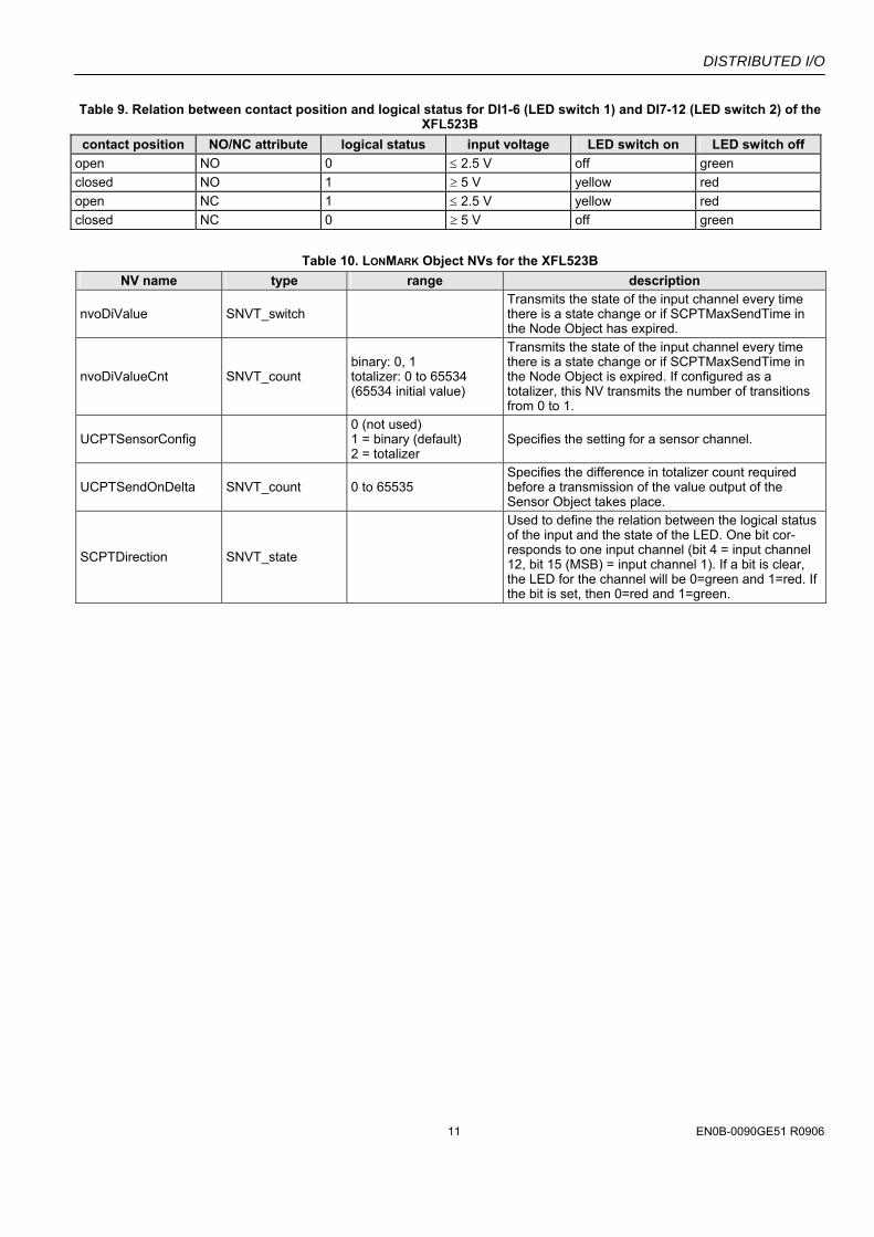
Table 9. Relation between contact position and logical status for DI1-6 (LED switch 1) and DI7-12 (LED switch 2) of the XFL523B
contact position NO/NC attribute logical status input voltage LED switch on LED switch off open NO 0 ≤ 2.5 V off green closed NO 1 ≥ 5 V yellow red open NC 1 ≤ 2.5 V yellow red closed NC 0 ≥ 5 V off green
Table 10. LONMARK Object NVs for the XFL523B NV name type range description
nvoDiValue SNVT_switch Transmits the state of the input channel every time there is a state change or if SCPTMaxSendTime in the Node Object has expired.
nvoDiValueCnt SNVT_count binary: 0, 1 totalizer: 0 to 65534 (65534 initial value)
Transmits the state of the input channel every time there is a state change or if SCPTMaxSendTime in the Node Object is expired. If configured as a totalizer, this NV transmits the number of transitions from 0 to 1.
UCPTSensorConfig 0 (not used) 1 = binary (default) 2 = totalizer
Specifies the setting for a sensor channel.
UCPTSendOnDelta SNVT_count 0 to 65535 Specifies the difference in totalizer count required before a transmission of the value output of the Sensor Object takes place.
SCPTDirection SNVT_state
Used to define the relation between the logical status of the input and the state of the LED. One bit cor-responds to one input channel (bit 4 = input channel 12, bit 15 (MSB) = input channel 1). If a bit is clear, the LED for the channel will be 0=green and 1=red. If the bit is set, then 0=red and 1=green.
DISTRIBUTED I/O
EN0B-0090GE51 R0906 12
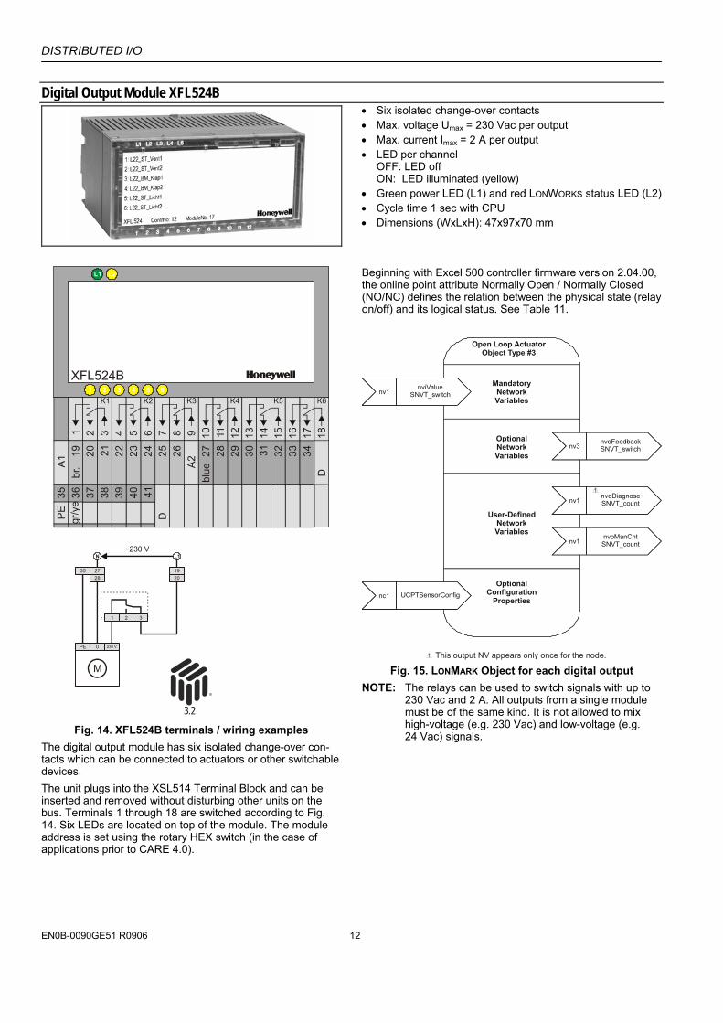
Digital Output Module XFL524B
• Six isolated change-over contacts • Max. voltage Umax = 230 Vac per output • Max. current Imax = 2 A per output • LED per channel
OFF: LED off ON: LED illuminated (yellow)
• Green power LED (L1) and red LONWORKS status LED (L2) • Cycle time 1 sec with CPU • Dimensions (WxLxH): 47x97x70 mm
XFL524B
21
29282625242322212019A1 A2
30 31 32 33 34
D
D
27bl
uebr.
41403938373635PE gr/y
e
13 14 15 16 17 183 4 5 6 7 8 9 10 11 12
K1 K2 K3 K4 K5 K6
L1N
35 2728 20
19
1 2 3
~230 V
PE 0 230 V
M
Fig. 14. XFL524B terminals / wiring examples
The digital output module has six isolated change-over con-tacts which can be connected to actuators or other switchable devices. The unit plugs into the XSL514 Terminal Block and can be inserted and removed without disturbing other units on the bus. Terminals 1 through 18 are switched according to Fig. 14. Six LEDs are located on top of the module. The module address is set using the rotary HEX switch (in the case of applications prior to CARE 4.0).
Beginning with Excel 500 controller firmware version 2.04.00, the online point attribute Normally Open / Normally Closed (NO/NC) defines the relation between the physical state (relay on/off) and its logical status. See Table 11.
Open Loop ActuatorObject Type #3
MandatoryNetworkVariables
inputNV 1
nviRequestSNVT_obj_requestnv1
nviValueSNVT_switch
OptionalNetworkVariables
inputNV 1
nviRequestSNVT_obj_requestnv1
nvoDiagnoseSNVT_count
1
1
inputNV 1
nviRequestSNVT_obj_requestnv3
nvoFeedbackSNVT_switch
inputNV 1
nviRequestSNVT_obj_requestnv1
nvoManCntSNVT_count
User-DefinedNetworkVariables
inputNV 1
nviRequestSNVT_obj_requestnc1 UCPTSensorConfig
OptionalConfiguration
Properties
This output NV appears only once for the node. Fig. 15. LONMARK Object for each digital output
NOTE: The relays can be used to switch signals with up to 230 Vac and 2 A. All outputs from a single module must be of the same kind. It is not allowed to mix high-voltage (e.g. 230 Vac) and low-voltage (e.g. 24 Vac) signals.
DISTRIBUTED I/O
13 EN0B-0090GE51 R0906
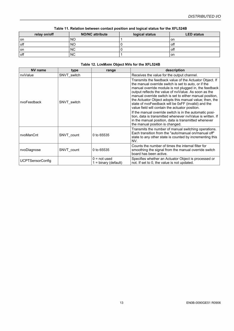
Table 11. Relation between contact position and logical status for the XFL524B relay on/off NO/NC attribute logical status LED status
on NO 1 on off NO 0 off on NC 0 off off NC 1 on
Table 12. LONMARK Object NVs for the XFL524B NV name type range description
nviValue SNVT_switch Receives the value for the output channel.
nvoFeedback SNVT_switch
Transmits the feedback value of the Actuator Object. If the manual override switch is set to auto, or if the manual override module is not plugged in, the feedback output reflects the value of nviValue. As soon as the manual override switch is set to either manual position, the Actuator Object adopts this manual value; then, the state of nvoFeedback will be 0xFF (invalid) and the value field will contain the actuator position. If the manual override switch is in the automatic posi-tion, data is transmitted whenever nviValue is written. If in the manual position, data is transmitted whenever the manual position is changed.
nvoManCnt SNVT_count 0 to 65535
Transmits the number of manual switching operations. Each transition from the "auto/manual on/manual off" state to any other state is counted by incrementing this NV.
nvoDiagnose SNVT_count 0 to 65535 Counts the number of times the internal filter for smoothing the signal from the manual override switch board has been active.
UCPTSensorConfig 0 = not used 1 = binary (default)
Specifies whether an Actuator Object is processed or not. If set to 0, the value is not updated.
DISTRIBUTED I/O
EN0B-0090GE51 R0906 14
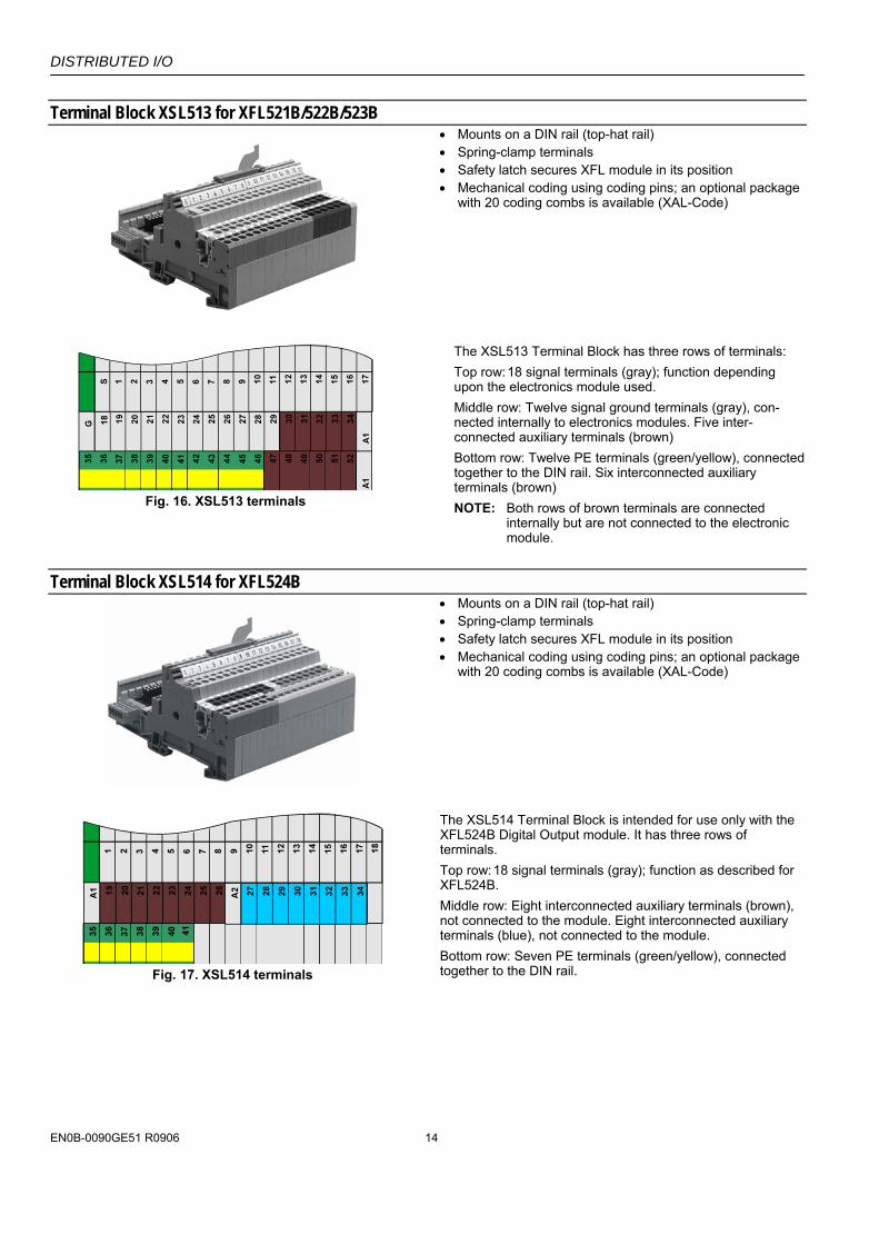
Terminal Block XSL513 for XFL521B/522B/523B
• Mounts on a DIN rail (top-hat rail) • Spring-clamp terminals • Safety latch secures XFL module in its position • Mechanical coding using coding pins; an optional package
with 20 coding combs is available (XAL-Code)
Fig. 16. XSL513 terminals
The XSL513 Terminal Block has three rows of terminals: Top row: 18 signal terminals (gray); function depending upon the electronics module used. Middle row: Twelve signal ground terminals (gray), con-nected internally to electronics modules. Five inter-connected auxiliary terminals (brown) Bottom row: Twelve PE terminals (green/yellow), connected together to the DIN rail. Six interconnected auxiliary terminals (brown) NOTE: Both rows of brown terminals are connected
internally but are not connected to the electronic module.
Terminal Block XSL514 for XFL524B
• Mounts on a DIN rail (top-hat rail) • Spring-clamp terminals • Safety latch secures XFL module in its position • Mechanical coding using coding pins; an optional package
with 20 coding combs is available (XAL-Code)
Fig. 17. XSL514 terminals
The XSL514 Terminal Block is intended for use only with the XFL524B Digital Output module. It has three rows of terminals. Top row: 18 signal terminals (gray); function as described for XFL524B. Middle row: Eight interconnected auxiliary terminals (brown), not connected to the module. Eight interconnected auxiliary terminals (blue), not connected to the module. Bottom row: Seven PE terminals (green/yellow), connected together to the DIN rail.
DISTRIBUTED I/O
15 EN0B-0090GE51 R0906
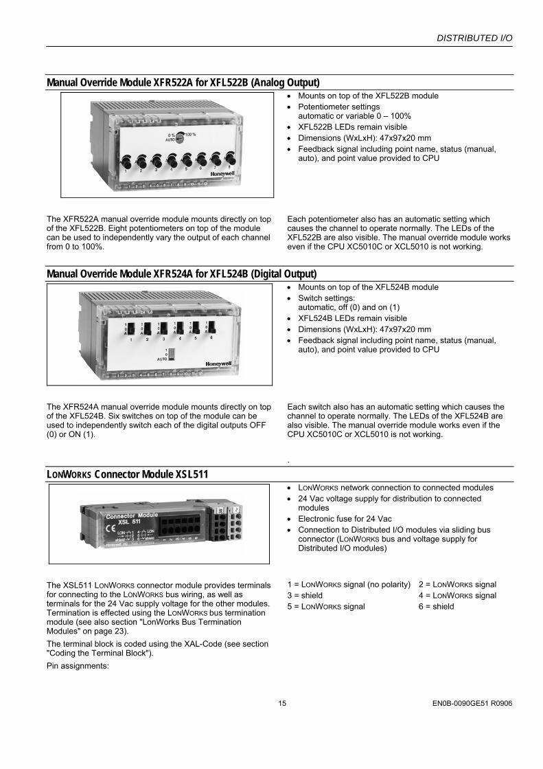
Manual Override Module XFR522A for XFL522B (Analog Output)
• Mounts on top of the XFL522B module • Potentiometer settings
automatic or variable 0 – 100% • XFL522B LEDs remain visible • Dimensions (WxLxH): 47x97x20 mm • Feedback signal including point name, status (manual,
auto), and point value provided to CPU
The XFR522A manual override module mounts directly on top of the XFL522B. Eight potentiometers on top of the module can be used to independently vary the output of each channel from 0 to 100%.
Each potentiometer also has an automatic setting which causes the channel to operate normally. The LEDs of the XFL522B are also visible. The manual override module works even if the CPU XC5010C or XCL5010 is not working.
Manual Override Module XFR524A for XFL524B (Digital Output)
• Mounts on top of the XFL524B module • Switch settings:
automatic, off (0) and on (1) • XFL524B LEDs remain visible • Dimensions (WxLxH): 47x97x20 mm • Feedback signal including point name, status (manual,
auto), and point value provided to CPU
The XFR524A manual override module mounts directly on top of the XFL524B. Six switches on top of the module can be used to independently switch each of the digital outputs OFF (0) or ON (1).
Each switch also has an automatic setting which causes the channel to operate normally. The LEDs of the XFL524B are also visible. The manual override module works even if the CPU XC5010C or XCL5010 is not working. .
LONWORKS Connector Module XSL511
• LONWORKS network connection to connected modules • 24 Vac voltage supply for distribution to connected
modules • Electronic fuse for 24 Vac • Connection to Distributed I/O modules via sliding bus
connector (LONWORKS bus and voltage supply for Distributed I/O modules)
The XSL511 LONWORKS connector module provides terminals for connecting to the LONWORKS bus wiring, as well as terminals for the 24 Vac supply voltage for the other modules. Termination is effected using the LONWORKS bus termination module (see also section "LonWorks Bus Termination Modules" on page 23). The terminal block is coded using the XAL-Code (see section "Coding the Terminal Block"). Pin assignments:
1 = LONWORKS signal (no polarity) 2 = LONWORKS signal 3 = shield 4 = LONWORKS signal 5 = LONWORKS signal 6 = shield
DISTRIBUTED I/O
EN0B-0090GE51 R0906 16
Terminal Block Connection NOTE: The terminal blocks are to be mounted on 1.5-inch
(35-mm) DIN rails (DIN/EN 50 022 35x15). The mounting panel should have a min. thickness of 0.08 inch (2 mm) to provide reference potential for proper grounding and shielding. The max. distance between the fastening points of the rail should be 5.9 inches (150 mm).
The LONWORKS connector module (see section "LONWORKS Connector Module XSL511") can be used as an interface between the LONWORKS bus and the Distributed I/O modules. The terminal blocks may be fitted alongside one another. Depending upon the configuration, either one or two termination modules are required for terminating a LONWORKS bus with FTT devices on it. See also section "LonWorks Bus Termination Modules" on page 23 for more information on termination.
Mounting with the LonWorks Connector Module IMPORTANT
When mounting the terminal blocks using the XSL511 LonWorks Connector Module, the following worst-case power consumption analysis must be performed to determine the required transformer.
Select the worst-case max. current rating for the XSL511 based upon the max. temperature of the installation as stated in Table 13. The electronic fuse RXE160 is applied in XSL511 with date code 9916 and higher. Ratings are as follows:
Table 13. Max. current ratings for XSL511 max.current rating at: module/
fuse 32°F (0°C)
68°F (20°C)
104°F (40°C)
122°F (50°C)
140°F (60°C)
158°F(70°C)
XSL511/ RXE090 1.07 A 0.9 A 0.73 A 0.65 A 0.57 A 0.49 A
XSL511 RXE160 1.9 A 1.6 A 1.3 A 1.15 A 1.01 A 0.86 A
Calculate the worst-case current draw for the Distributed I/O modules and the Excel 500-XCL5010 controller to be connected to the transformer based on the input voltage stated in Table 14:
Table 14. Max. current ratings for other modules max. current rating at: module
19.2 Vac 28.8 Vac 19.2 Vdc 28.8 Vdc XFL521B1 130 mA 90 mA 90 mA 65 mA XFL522B2 120 mA 90 mA 85 mA 60 mA XFL523B3 155 mA 105 mA 110 mA 75 mA XFL524B4 165 mA 115 mA 120 mA 80 mA 1 All inputs shorted to GND. 10 V loaded with 5 mA. 2 All outputs loaded with 1 mA. XFR522A mounted and set to
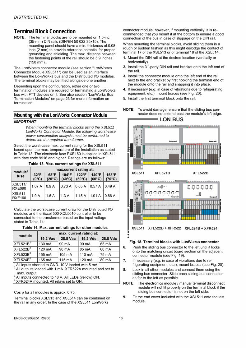
max. output. 3 All inputs connected to 18 V. All LEDs (yellow) ON. 4 XFR524A mounted. All relays set to ON. Cos ϕ for all modules is approx. 0.75. Terminal blocks XSL513 and XSL514 can be combined on the rail in any order. In the case of the XSL511 LonWorks
connector module, however, if mounting vertically, it is re-commended that you mount it at the bottom to ensure a good connection of the bus in case of slippage on the DIN rail. When mounting the terminal blocks, avoid sliding them in a rough or sudden fashion as this might dislodge the contact of terminal 17 of the XSL513 or of terminal 18 of the XSL514. 1. Mount the DIN rail at the desired location (vertically or
horizontally). 2. Install the 3rd-party DIN rail end bracket onto the left end of
the rail. 3. Install the connector module onto the left end of the rail
next to the end bracket by first hooking the terminal end of the module onto the rail and snapping it into place.
4. If necessary (e.g. in case of vibrations due to refrigerating equipment, etc.), mount braces (see Fig. 20).
5. Install the first terminal block onto the rail. NOTE: To avoid damage, ensure that the sliding bus con-
nector does not extend past the module's left edge.
Fig. 18. Terminal blocks with LONWORKS connector
6. Push the sliding bus connector to the left until it locks onto the matching circuit board section on the adjacent connector module (see Fig. 19).
7. If necessary (e.g. in case of vibrations due to re-frigerating equipment, etc.), mount braces (see Fig. 20).
8. Lock in all other modules and connect them using the sliding bus connector. Slide each sliding bus connector as far to the left as possible.
NOTE: The electronics module / manual terminal disconnect module will not fit properly on the terminal block if the sliding bus connector is not on the left side.
9. Fit the end cover included with the XSL511 onto the last module.
DISTRIBUTED I/O
17 EN0B-0090GE51 R0906
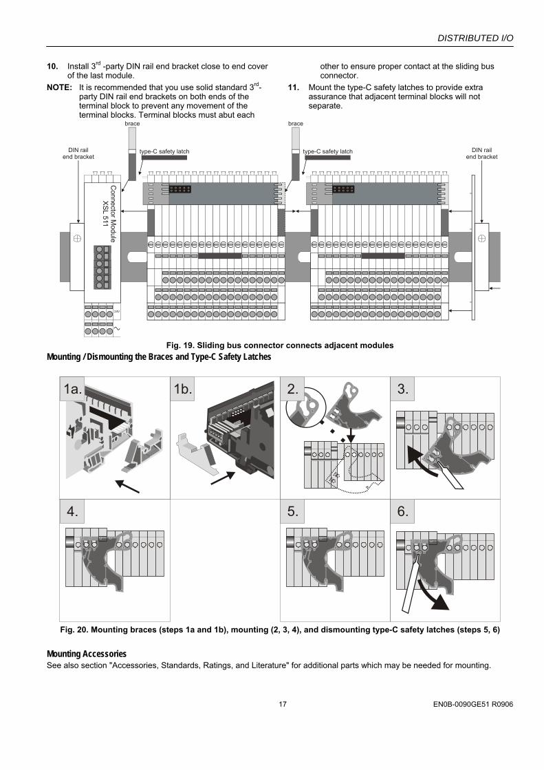
10. Install 3rd -party DIN rail end bracket close to end cover of the last module.
NOTE: It is recommended that you use solid standard 3rd-party DIN rail end brackets on both ends of the terminal block to prevent any movement of the terminal blocks. Terminal blocks must abut each
other to ensure proper contact at the sliding bus connector.
11. Mount the type-C safety latches to provide extra assurance that adjacent terminal blocks will not separate.
type-C safety latch
brace
type-C safety latch
brace
24V
Connector M
oduleX
SL 511
DIN railend bracket
DIN railend bracket
Fig. 19. Sliding bus connector connects adjacent modules
Mounting / Dismounting the Braces and Type-C Safety Latches
1a.
4. 5. 6.
1b. 2. 3.
Fig. 20. Mounting braces (steps 1a and 1b), mounting (2, 3, 4), and dismounting type-C safety latches (steps 5, 6)
Mounting Accessories See also section "Accessories, Standards, Ratings, and Literature" for additional parts which may be needed for mounting.
DISTRIBUTED I/O
EN0B-0090GE51 R0906 18
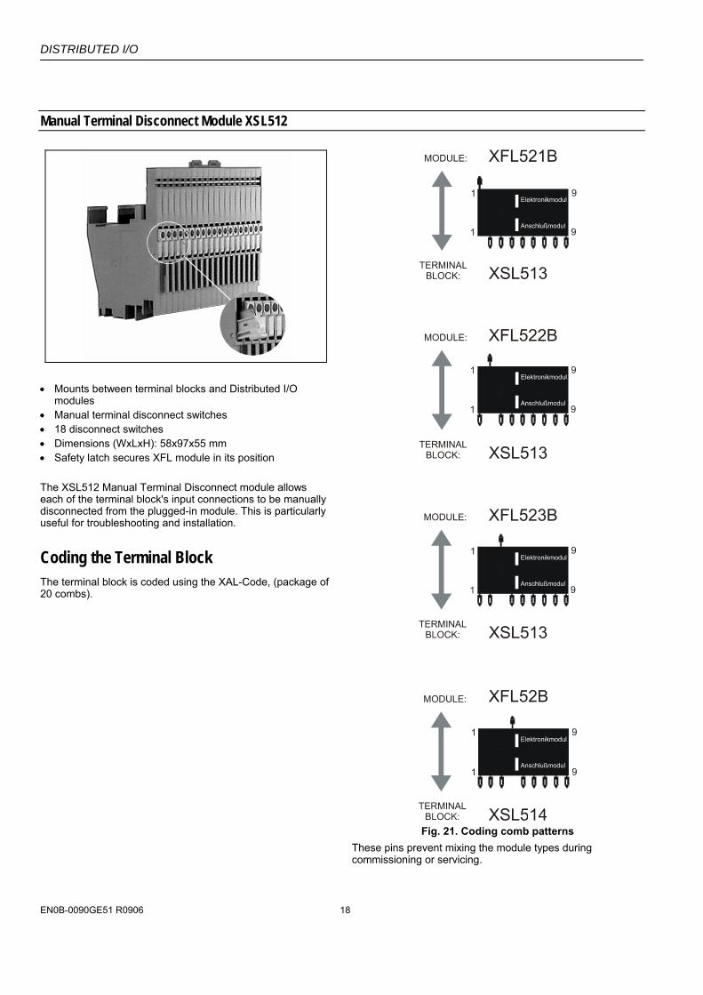
Manual Terminal Disconnect Module XSL512
• Mounts between terminal blocks and Distributed I/O
modules • Manual terminal disconnect switches • 18 disconnect switches • Dimensions (WxLxH): 58x97x55 mm • Safety latch secures XFL module in its position The XSL512 Manual Terminal Disconnect module allows each of the terminal block's input connections to be manually disconnected from the plugged-in module. This is particularly useful for troubleshooting and installation.
Coding the Terminal Block The terminal block is coded using the XAL-Code, (package of 20 combs).
Fig. 21. Coding comb patterns
These pins prevent mixing the module types during commissioning or servicing.
DISTRIBUTED I/O
19 EN0B-0090GE51 R0906
CAUTION Mixing the modules can destroy them.
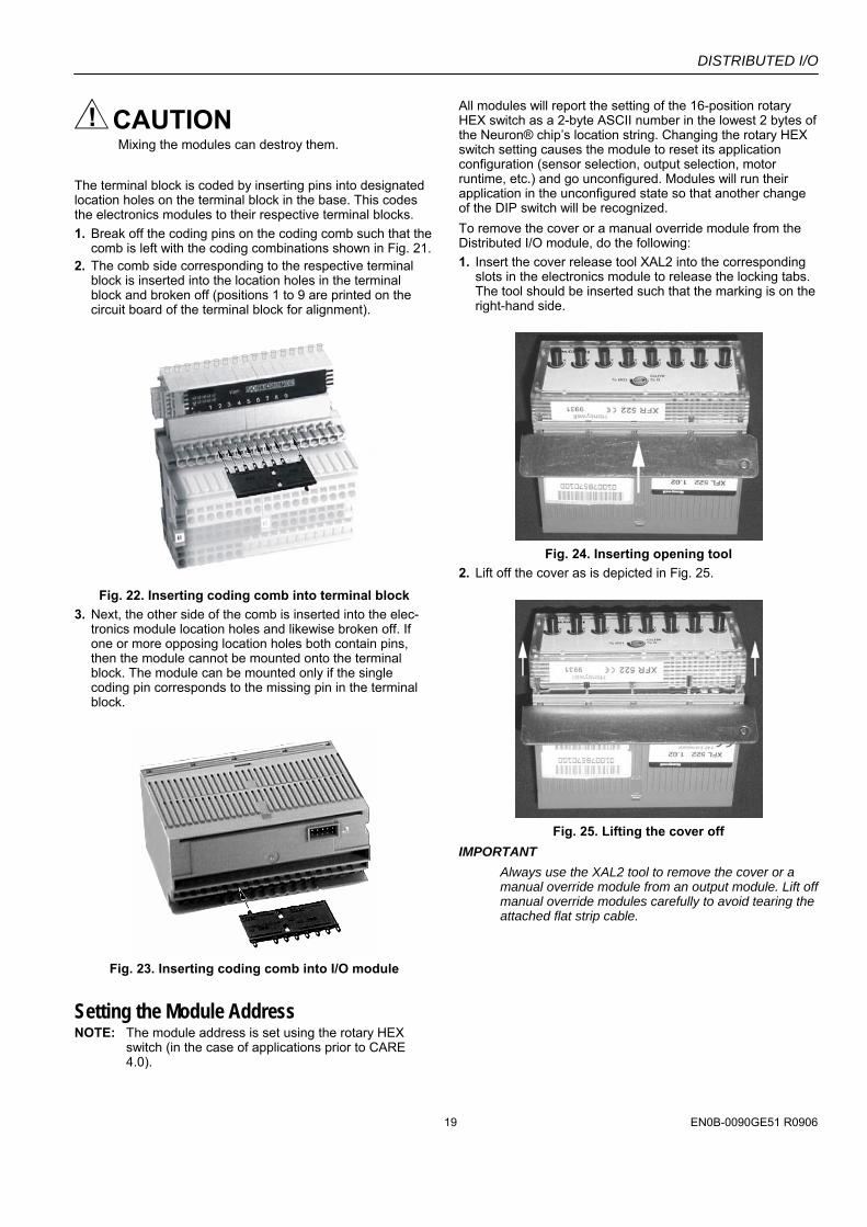
The terminal block is coded by inserting pins into designated location holes on the terminal block in the base. This codes the electronics modules to their respective terminal blocks. 1. Break off the coding pins on the coding comb such that the
comb is left with the coding combinations shown in Fig. 21. 2. The comb side corresponding to the respective terminal
block is inserted into the location holes in the terminal block and broken off (positions 1 to 9 are printed on the circuit board of the terminal block for alignment).
Fig. 22. Inserting coding comb into terminal block
3. Next, the other side of the comb is inserted into the elec-tronics module location holes and likewise broken off. If one or more opposing location holes both contain pins, then the module cannot be mounted onto the terminal block. The module can be mounted only if the single coding pin corresponds to the missing pin in the terminal block.
Fig. 23. Inserting coding comb into I/O module
Setting the Module Address NOTE: The module address is set using the rotary HEX
switch (in the case of applications prior to CARE 4.0).
All modules will report the setting of the 16-position rotary HEX switch as a 2-byte ASCII number in the lowest 2 bytes of the Neuron® chip’s location string. Changing the rotary HEX switch setting causes the module to reset its application configuration (sensor selection, output selection, motor runtime, etc.) and go unconfigured. Modules will run their application in the unconfigured state so that another change of the DIP switch will be recognized. To remove the cover or a manual override module from the Distributed I/O module, do the following: 1. Insert the cover release tool XAL2 into the corresponding
slots in the electronics module to release the locking tabs. The tool should be inserted such that the marking is on the right-hand side.
Fig. 24. Inserting opening tool
2. Lift off the cover as is depicted in Fig. 25.
Fig. 25. Lifting the cover off
IMPORTANT Always use the XAL2 tool to remove the cover or a manual override module from an output module. Lift off manual override modules carefully to avoid tearing the attached flat strip cable.
DISTRIBUTED I/O
EN0B-0090GE51 R0906 20
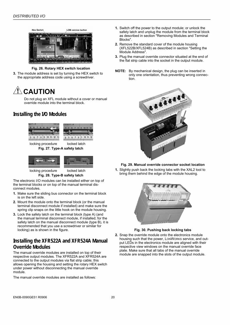
Fig. 26. Rotary HEX switch location
3. The module address is set by turning the HEX switch to the appropriate address code using a screwdriver.
CAUTION Do not plug an XFL module without a cover or manual override module into the terminal block.
Installing the I/O Modules
locking procedure locked latch
Fig. 27. Type-A safety latch
locking procedure locked latch
Fig. 28. Type-B safety latch The electronic I/O modules can be installed either on top of the terminal blocks or on top of the manual terminal dis-connect modules. 1. Make sure the sliding bus connector on the terminal block
is on the left side. 2. Mount the module onto the terminal block (or the manual
terminal disconnect module if installed) and make sure the spring clip snaps on the little hook on the module housing.
3. Lock the safety latch on the terminal block (type A) (and the manual terminal disconnect module, if installed; for the safety latch on the manual disconnect module (type B), it is recommended that you use a screwdriver or similar for locking) as is shown in the figure.
Installing the XFR522A and XFR524A Manual Override Modules The manual override modules are installed on top of their respective output modules. The XFR522A and XFR524A are connected to the output modules via flat strip cable; this allows opening the housing and setting the rotary HEX switch under power without disconnecting the manual override module. The manual override modules are installed as follows:
1. Switch off the power to the output module; or unlock the safety latch and unplug the module from the terminal block as described in section "Removing Modules and Terminal Blocks".
2. Remove the standard cover of the module housing (XFL522B/XFL524B) as described in section "Setting the Module Address".
3. Plug the manual override connector situated at the end of the flat strip cable into the socket in the output module.
NOTE: By mechanical design, the plug can be inserted in
only one orientation, thus preventing wrong connec-tion.
Fig. 29. Manual override connector socket location
1. Slightly push back the locking tabs with the XAL2 tool to bring them behind the edge of the module housing.
Fig. 30. Pushing back locking tabs
2. Snap the override module onto the electronics module housing such that the power, LONWORKS service, and out-put LEDs in the electronics module are aligned with their respective view windows on the manual override face plate. Make sure that all tabs of the manual override module are snapped into the slots of the output module.
DISTRIBUTED I/O
21 EN0B-0090GE51 R0906
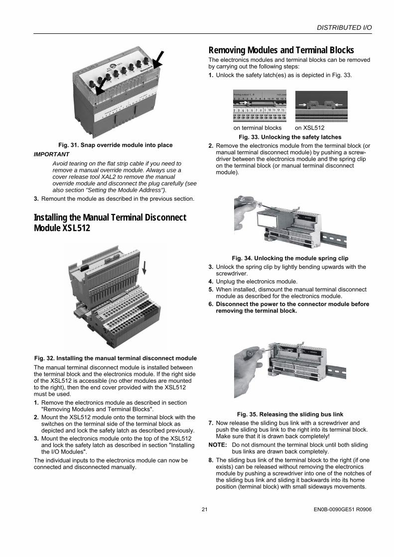
Fig. 31. Snap override module into place
IMPORTANT Avoid tearing on the flat strip cable if you need to remove a manual override module. Always use a cover release tool XAL2 to remove the manual override module and disconnect the plug carefully (see also section "Setting the Module Address").
3. Remount the module as described in the previous section.
Installing the Manual Terminal Disconnect Module XSL512
Fig. 32. Installing the manual terminal disconnect module The manual terminal disconnect module is installed between the terminal block and the electronics module. If the right side of the XSL512 is accessible (no other modules are mounted to the right), then the end cover provided with the XSL512 must be used. 1. Remove the electronics module as described in section
"Removing Modules and Terminal Blocks". 2. Mount the XSL512 module onto the terminal block with the
switches on the terminal side of the terminal block as depicted and lock the safety latch as described previously.
3. Mount the electronics module onto the top of the XSL512 and lock the safety latch as described in section "Installing the I/O Modules".
The individual inputs to the electronics module can now be connected and disconnected manually.
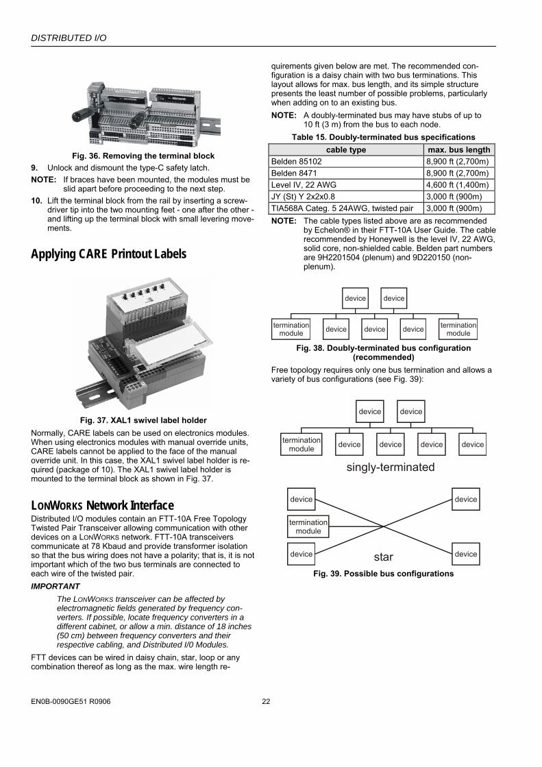
Removing Modules and Terminal Blocks The electronics modules and terminal blocks can be removed by carrying out the following steps: 1. Unlock the safety latch(es) as is depicted in Fig. 33.
on terminal blocks on XSL512
Fig. 33. Unlocking the safety latches 2. Remove the electronics module from the terminal block (or
manual terminal disconnect module) by pushing a screw-driver between the electronics module and the spring clip on the terminal block (or manual terminal disconnect module).
Fig. 34. Unlocking the module spring clip
3. Unlock the spring clip by lightly bending upwards with the screwdriver.
4. Unplug the electronics module. 5. When installed, dismount the manual terminal disconnect
module as described for the electronics module. 6. Disconnect the power to the connector module before
removing the terminal block.
Fig. 35. Releasing the sliding bus link
7. Now release the sliding bus link with a screwdriver and push the sliding bus link to the right into its terminal block. Make sure that it is drawn back completely!
NOTE: Do not dismount the terminal block until both sliding bus links are drawn back completely.
8. The sliding bus link of the terminal block to the right (if one exists) can be released without removing the electronics module by pushing a screwdriver into one of the notches of the sliding bus link and sliding it backwards into its home position (terminal block) with small sideways movements.
DISTRIBUTED I/O
EN0B-0090GE51 R0906 22
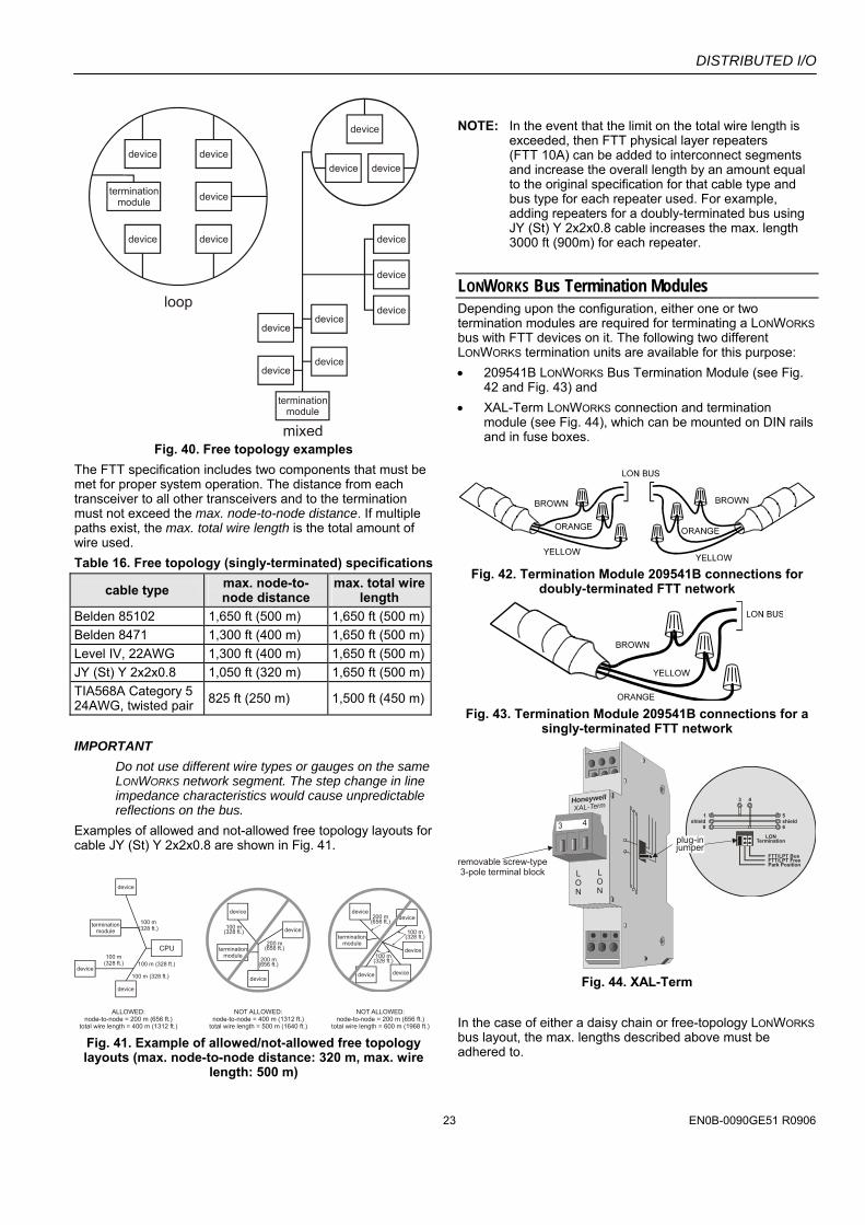
Fig. 36. Removing the terminal block
9. Unlock and dismount the type-C safety latch. NOTE: If braces have been mounted, the modules must be
slid apart before proceeding to the next step. 10. Lift the terminal block from the rail by inserting a screw-
driver tip into the two mounting feet - one after the other - and lifting up the terminal block with small levering move-ments.
Applying CARE Printout Labels
Fig. 37. XAL1 swivel label holder
Normally, CARE labels can be used on electronics modules. When using electronics modules with manual override units, CARE labels cannot be applied to the face of the manual override unit. In this case, the XAL1 swivel label holder is re-quired (package of 10). The XAL1 swivel label holder is mounted to the terminal block as shown in Fig. 37.
LONWORKS Network Interface Distributed I/O modules contain an FTT-10A Free Topology Twisted Pair Transceiver allowing communication with other devices on a LONWORKS network. FTT-10A transceivers communicate at 78 Kbaud and provide transformer isolation so that the bus wiring does not have a polarity; that is, it is not important which of the two bus terminals are connected to each wire of the twisted pair. IMPORTANT
The LONWORKS transceiver can be affected by electromagnetic fields generated by frequency con-verters. If possible, locate frequency converters in a different cabinet, or allow a min. distance of 18 inches (50 cm) between frequency converters and their respective cabling, and Distributed I/0 Modules.
FTT devices can be wired in daisy chain, star, loop or any combination thereof as long as the max. wire length re-
quirements given below are met. The recommended con-figuration is a daisy chain with two bus terminations. This layout allows for max. bus length, and its simple structure presents the least number of possible problems, particularly when adding on to an existing bus. NOTE: A doubly-terminated bus may have stubs of up to
10 ft (3 m) from the bus to each node. Table 15. Doubly-terminated bus specifications
cable type max. bus lengthBelden 85102 8,900 ft (2,700m) Belden 8471 8,900 ft (2,700m) Level IV, 22 AWG 4,600 ft (1,400m) JY (St) Y 2x2x0.8 3,000 ft (900m) TIA568A Categ. 5 24AWG, twisted pair 3,000 ft (900m) NOTE: The cable types listed above are as recommended
by Echelon® in their FTT-10A User Guide. The cable recommended by Honeywell is the level IV, 22 AWG, solid core, non-shielded cable. Belden part numbers are 9H2201504 (plenum) and 9D220150 (non-plenum).
terminationmodule
terminationmoduledevice
device device
device device
Fig. 38. Doubly-terminated bus configuration (recommended)
Free topology requires only one bus termination and allows a variety of bus configurations (see Fig. 39):
terminationmodule device
device device
device device device
singly-terminated
device
device device
device
star
terminationmodule
Fig. 39. Possible bus configurations
DISTRIBUTED I/O
23 EN0B-0090GE51 R0906
device
device
device
device
device
terminationmodule
terminationmodule
device
device
device
device
devicedevice
device
device
device
device
loop
mixed Fig. 40. Free topology examples
The FTT specification includes two components that must be met for proper system operation. The distance from each transceiver to all other transceivers and to the termination must not exceed the max. node-to-node distance. If multiple paths exist, the max. total wire length is the total amount of wire used. Table 16. Free topology (singly-terminated) specifications
cable type max. node-to-node distance
max. total wire length
Belden 85102 1,650 ft (500 m) 1,650 ft (500 m)Belden 8471 1,300 ft (400 m) 1,650 ft (500 m)Level IV, 22AWG 1,300 ft (400 m) 1,650 ft (500 m)JY (St) Y 2x2x0.8 1,050 ft (320 m) 1,650 ft (500 m)TIA568A Category 5 24AWG, twisted pair 825 ft (250 m) 1,500 ft (450 m)
IMPORTANT
Do not use different wire types or gauges on the same LONWORKS network segment. The step change in line impedance characteristics would cause unpredictable reflections on the bus.
Examples of allowed and not-allowed free topology layouts for cable JY (St) Y 2x2x0.8 are shown in Fig. 41.
device
device
terminationmodule
CPU
device
terminationmodule
device
device
device
100 m(328 ft.)
100 m(328 ft.) 100 m (328 ft.)
100 m (328 ft.)
100 m(328 ft.)
200 m(656 ft.)
200 m(656 ft.)
ALLOWED:node-to-node = 200 m (656 ft.)
total wire length = 400 m (1312 ft.)
NOT ALLOWED:node-to-node = 400 m (1312 ft.)
total wire length = 500 m (1640 ft.)
NOT ALLOWED:node-to-node = 200 m (656 ft.)
total wire length = 600 m (1968 ft.)
terminationmodule
device
device
device
devicedevice
100 m(328 ft.)
100 m(328 ft.)
200 m(656 ft.)
Fig. 41. Example of allowed/not-allowed free topology layouts (max. node-to-node distance: 320 m, max. wire
length: 500 m)
NOTE: In the event that the limit on the total wire length is
exceeded, then FTT physical layer repeaters (FTT 10A) can be added to interconnect segments and increase the overall length by an amount equal to the original specification for that cable type and bus type for each repeater used. For example, adding repeaters for a doubly-terminated bus using JY (St) Y 2x2x0.8 cable increases the max. length 3000 ft (900m) for each repeater.
LONWORKS Bus Termination Modules Depending upon the configuration, either one or two termination modules are required for terminating a LONWORKS bus with FTT devices on it. The following two different LONWORKS termination units are available for this purpose: • 209541B LONWORKS Bus Termination Module (see Fig.
42 and Fig. 43) and • XAL-Term LONWORKS connection and termination
module (see Fig. 44), which can be mounted on DIN rails and in fuse boxes.
Fig. 42. Termination Module 209541B connections for
doubly-terminated FTT network
Fig. 43. Termination Module 209541B connections for a
singly-terminated FTT network
3 4
LON
HoneywellXAL-Term
LON
removable screw-type3-pole terminal block
1 5
3 4
0 6shield shield
LONTermination
FTT/LPT BusFTT/LPT FreePark Position
plug-injumper
Fig. 44. XAL-Term
In the case of either a daisy chain or free-topology LONWORKS bus layout, the max. lengths described above must be adhered to.
DISTRIBUTED I/O
EN0B-0090GE51 R0906 24
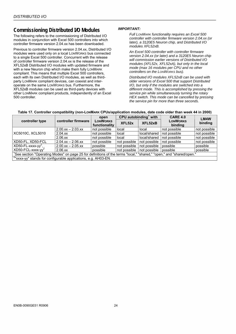
Commissioning Distributed I/O Modules The following refers to the commissioning of Distributed I/O modules in conjunction with Excel 500 controllers into which controller firmware version 2.04.xx has been downloaded. Previous to controller firmware version 2.04.xx, Distributed I/O modules were used only on a local LONWORKS bus connected to a single Excel 500 controller. Concurrent with the release of controller firmware version 2.04.xx is the release of the XFL52xB Distributed I/O modules with updated firmware and with a new Neuron chip which make them fully LONMARK compliant. This means that multiple Excel 500 controllers, each with its own Distributed I/O modules, as well as third-party LONMARK compliant devices, can coexist and inter-operate on the same LONWORKS bus. Furthermore, the XFL52xB modules can be used as third-party devices with other LONMARK compliant products, independently of an Excel 500 controller.
IMPORTANT: Full LONMARK functionality requires an Excel 500 controller with controller firmware version 2.04.xx (or later), a 3120E5 Neuron chip, and Distributed I/O modules XFL52xB. An Excel 500 controller with controller firmware version 2.04.xx (or later) and a 3120E5 Neuron chip will commission earlier versions of Distributed I/O modules (XFL52x, XFL52xA), but only in the local mode (max 16 modules per CPU and no other controllers on the LONWORKS bus). Distributed I/O modules XFL52xB can be used with older versions of Excel 500 that support Distributed I/O, but only if the modules are switched into a different mode. This is accomplished by pressing the service pin while simultaneously turning the rotary HEX switch. This mode can be cancelled by pressing the service pin for more than three seconds.
Table 17. Controller compatibility (non-LONMARK CPUs/application modules, date code older than week 44 in 2000)
CPU autobinding1 with controller type controller firmware
open LONWORKS
functionality XFL52x XFL52xB CARE 4.0 LONWORKS
binding LM4W
binding
2.00.xx – 2.03.xx not possible local local not possible not possible 2.04.xx not possible local local/shared not possible not possible XC5010C, XCL5010 2.06.xx not possible local local/shared not possible not possible
XD50-FL, XD50-FCL 2.04.xx – 2.06.xx not possible not possible not possible not possible not possible 2.00.xx – 2.05.xx possible not possible not possible possible possible XD50-FL-xxxx-yy2,
XD50-FCL-xxxx-yy2 2.06.xx possible not possible not possible possible possible 1See section "Operating Modes" on page 25 for definitions of the terms "local," "shared," "open," and "shared/open." 2"xxxx-yy" stands for configurable applications, e.g. AH03-EN.
DISTRIBUTED I/O
25 EN0B-0090GE51 R0906
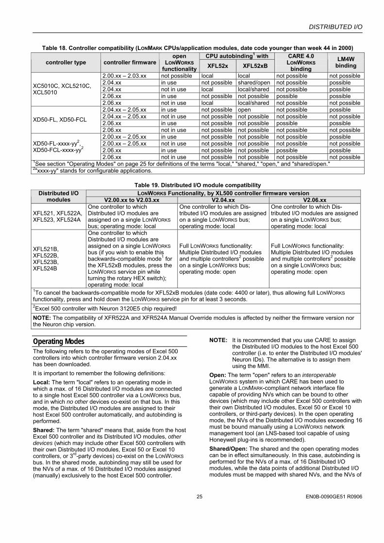
Table 18. Controller compatibility (LONMARK CPUs/application modules, date code younger than week 44 in 2000) CPU autobinding1 with
controller type controller firmware open
LONWORKS functionality XFL52x XFL52xB
CARE 4.0 LONWORKS
binding LM4W
binding
2.00.xx – 2.03.xx not possible local local not possible not possible 2.04.xx in use not possible shared/open not possible possible 2.04.xx not in use local local/shared not possible possible 2.06.xx in use not possible not possible possible possible
XC5010C, XCL5210C, XCL5010
2.06.xx not in use local local/shared not possible not possible 2.04.xx – 2.05.xx in use not possible open not possible possible 2.04.xx – 2.05.xx not in use not possible not possible not possible not possible 2.06.xx in use not possible not possible possible possible XD50-FL, XD50-FCL
2.06.xx not in use not possible not possible not possible not possible 2.00.xx – 2.05.xx in use not possible not possible not possible possible 2.00.xx – 2.05.xx not in use not possible not possible not possible not possible 2.06.xx in use not possible not possible possible possible
XD50-FL-xxxx-yy2, XD50-FCL-xxxx-yy2
2.06.xx not in use not possible not possible not possible not possible 1See section "Operating Modes" on page 25 for definitions of the terms "local," "shared," "open," and "shared/open." 2"xxxx-yy" stands for configurable applications.
Table 19. Distributed I/O module compatibility LONWORKS Functionality, by XL500 controller firmware version Distributed I/O
modules V2.00.xx to V2.03.xx V2.04.xx V2.06.xx
XFL521, XFL522A, XFL523, XFL524A
One controller to which Distributed I/O modules are assigned on a single LONWORKS bus; operating mode: local
One controller to which Dis-tributed I/O modules are assigned on a single LONWORKS bus; operating mode: local
One controller to which Dis-tributed I/O modules are assigned on a single LONWORKS bus; operating mode: local
XFL521B, XFL522B, XFL523B, XFL524B
One controller to which Distributed I/O modules are assigned on a single LONWORKS bus (if you wish to enable this backwards-compatible mode1 for the XFL52xB modules, press the LONWORKS service pin while turning the rotary HEX switch); operating mode: local
Full LONWORKS functionality: Multiple Distributed I/O modules and multiple controllers2 possible on a single LONWORKS bus; operating mode: open
Full LONWORKS functionality: Multiple Distributed I/O modules and multiple controllers2 possible on a single LONWORKS bus; operating mode: open
1To cancel the backwards-compatible mode for XFL52xB modules (date code: 4400 or later), thus allowing full LONWORKS functionality, press and hold down the LONWORKS service pin for at least 3 seconds. 2Excel 500 controller with Neuron 3120E5 chip required! NOTE: The compatibility of XFR522A and XFR524A Manual Override modules is affected by neither the firmware version nor the Neuron chip version.
Operating Modes The following refers to the operating modes of Excel 500 controllers into which controller firmware version 2.04.xx has been downloaded. It is important to remember the following definitions: Local: The term "local" refers to an operating mode in which a max. of 16 Distributed I/O modules are connected to a single host Excel 500 controller via a LONWORKS bus, and in which no other devices co-exist on that bus. In this mode, the Distributed I/O modules are assigned to their host Excel 500 controller automatically, and autobinding is performed. Shared: The term "shared" means that, aside from the host Excel 500 controller and its Distributed I/O modules, other devices (which may include other Excel 500 controllers with their own Distributed I/O modules, Excel 50 or Excel 10 controllers, or 3rd-party devices) co-exist on the LONWORKS bus. In the shared mode, autobinding may still be used for the NVs of a max. of 16 Distributed I/O modules assigned (manually) exclusively to the host Excel 500 controller.
NOTE: It is recommended that you use CARE to assign the Distributed I/O modules to the host Excel 500 controller (i.e. to enter the Distributed I/O modules' Neuron IDs). The alternative is to assign them using the MMI.
Open: The term "open" refers to an interoperable LONWORKS system in which CARE has been used to generate a LONMARK-compliant network interface file capable of providing NVs which can be bound to other devices (which may include other Excel 500 controllers with their own Distributed I/O modules, Excel 50 or Excel 10 controllers, or third-party devices). In the open operating mode, the NVs of the Distributed I/O modules exceeding 16 must be bound manually using a LONWORKS network management tool (an LNS-based tool capable of using Honeywell plug-ins is recommended). Shared/Open: The shared and the open operating modes can be in effect simultaneously. In this case, autobinding is performed for the NVs of a max. of 16 Distributed I/O modules, while the data points of additional Distributed I/O modules must be mapped with shared NVs, and the NVs of
DISTRIBUTED I/O
EN0B-0090GE51 R0906 26
the additional Distributed I/O modules must be bound manually (e.g. using an LNS-based tool).
Autobinding The following refers to the autobinding of the NVs of Distributed I/O modules to Excel 500 controllers into which controller firmware version 2.04.xx has been downloaded. When Distributed I/O modules are used exclusively by Honeywell Excel 500 controllers, it is possible to auto-matically bind their NVs to the controller. This is referred to as "autobinding." In autobinding, each controller on the bus finds the Distributed I/O modules assigned to it and binds the required NVs. IMPORTANT:
Autobinding does not work across routers. Dis-tributed I/O modules must be located within the same router segment as the controller to which their NVs are to be bound. However, autobinding is possible across repeaters.
IMPORTANT: The autobound NVs of a controller are not visible to a LONWORKS network management tool, and there is hence no danger that a careless user will attempt to re-bind them. However, the NVs of the Distributed I/O modules are visible to a LONWORKS network management tool. Any attempt to re-bind the auto-bound NVs of Distributed I/O modules will corrupt the autobindings. In such a case, the Excel 500 con-troller will restore the autobindings automatically, but there will be numerous system and application alarms as a result. If, prior to autobinding, the Distributed I/O modules have been accessed by a LONWORKS network management tool, the modules will remain in the “configured” mode. In this state, they cannot be found by the controller during autobinding, and they do not appear in the list of modules on the controller MMI. Such modules must be decommissioned using the LONWORKS network management tool, or the LONWORKS service pin must be pressed for at least three seconds.
If an Excel 500 controller in the shared/open mode is deleted from the LonMaker project, all of its bindings will also be deleted. In this case, the deleted Excel 500 controller will restore all of the autobindings (if any) auto-matically after 3 minutes (provided no bindings are per-formed or changed in LonMaker in the meantime), but there will be numerous system and application alarms as a result.
Assignment The following refers to the assignment of Distributed I/O modules to Excel 500 controllers into which controller firmware version 2.04.xx has been downloaded. There are two methods of assigning Distributed I/O modules to a particular Excel 500 controller. Regardless of which of these two assignment methods is employed, assignment requires that the modules' rotary HEX switches be set according to the CARE terminal assignment.
Recommended Assignment Method The Ideal approach is to know the Neuron IDs of the Dis-tributed I/O modules when engineering the application using CARE, thus enabling you to enter the Neuron ID during the CARE terminal assignment. When this is done, every module will be fully identified and assigned auto-matically by the Excel 500 controller after the application is downloaded. Alternate Assignment Method If the Neuron ID is not available when engineering the application using CARE, it will be possible to correctly assign the Distributed I/O modules to their controller(s) only after having downloaded the application. In this case, assignment is performed via the MMI as described in detail in the XI581/XI582 User Guide, EN2B-0126. IMPORTANT:
It is essential that Distributed I/O modules not be assigned simultaneously via different MMIs. When using the alternative assignment method, work on only one MMI at a time so as to avoid competing network accesses. Disregarding this will result in contradictory and unreliable assignments. There will be incomplete Distributed I/O module lists displayed, and there is the danger that one controller will take away an existent assignment from another controller.
Priority of Distributed I/O Module Assignments Assignments made via an MMI always have priority over assignments made using CARE. Thus, in the event of a conflict (e.g. when the Neuron ID entered using CARE differs from the Neuron ID entered via the MMI), the assignment carried out via the MMI will have priority. Flashing of Distributed I/O Module Assignment The Distributed I/O module assignment that was made in CARE or via the controller MMI must be manually saved to Flash memory. When Distributed I/O module assignment has been made during the test mode, the assignments are automatically saved in Flash memory. These assignments can be reused for the application after the application has been downloaded (the MMI's assignment dialog will offer the option of keeping the existing assignment). Controller Reset IMPORTANT:
Resetting a controller will erase the Distributed I/O module assignment. After a reset, one of the following procedures must be performed.
• Restore the application (including the assignments) from Flash (this is the simplest method).
• Restore the assignments during the "start-up" sequence (this requires somewhat more effort because all of the modules are searched on the LonWorks network automatically).
• Download the application and re-assign the Distributed I/O modules (this method requires the most effort because it must be done manually).
DISTRIBUTED I/O
27 EN0B-0090GE51 R0906
Manual Binding The following refers to the manual binding of the NVs of Distributed I/O modules to Excel 500 controllers into which controller firmware version 2.04.xx has been downloaded. There are several cases in which it is necessary to manually bind the NVs of the Distributed I/O modules to their respective controller(s). This is done using a LONWORKS network management tool (e.g. LonMaker). More than 16 Modules per Excel 500 Autobinding can be used to bind the NVs of a max. of 16 Distributed I/O modules per controller, only. If the application requires more than 16 Distributed I/O modules per controller, you must use CARE to allocate those additional NVs requiring mapping with the data points, and you will also have to use a LONWORKS network management tool to bind the NVs of the additional modules to the controller. Double-Mapping a Data Point It is possible to preserve the autobinding by mapping the data point with a second NV. However, the second NV must then be bound (using a LONWORKS network manage-ment tool) to another LONWORKS device. While this method preserves autobinding, it does require one controller NV more than if all binding is performed using a LONWORKS network management tool (e.g. LonMaker).
Binding to Other Devices If you wish to bind the NVs of Distributed I/O modules to other devices (i.e. other than the host Excel 500 controller), autobinding cannot be used. Instead, you will have to employ a LONWORKS network management tool (e.g. LonMaker) to (manually) bind all of the Distributed I/O modules' NVs.
Troubleshooting (Controller Autobinding) Wiring Check NOTE: In the case of CARE 4.0, the controller cannot be
used to perform autobinding. However, you can use XILON to perform the wiring test.
In the case of Excel 500 controllers with controller firmware version 2.04.xx, Distributed I/O modules can be checked out without even having an application loaded in the controller. This is possible using a special test mode previously active only for internal I/O modules. This test mode, accessible through the “Data Point Wiring Check” option on the second screen of the start-up sequence, allows manually setting outputs and reading inputs to verify the I/O wiring. The procedure is described in detail in the XI581/582 User Guide, EN2B-0126.
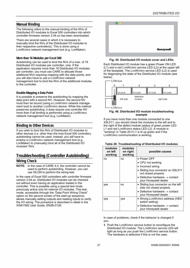
Fig. 45. Distributed I/O module cover and LEDs
Each Distributed I/O module has a green Power ON LED (L1) and a red LONWORKS service LED (L2) at the upper left of the faceplate. The LONWORKS service LED (L2) is used for diagnosing the state of the Distributed I/O module (see below).
Fig. 46. Distributed I/O module troubleshooting
example If you have more than one module connected to one XSL511, you should check the modules to the left and to the right of the defect module (status of green power LED L1 and red LONWORKS status LED L2). A module is "working" in Table 20 if L1 is lit up green and if the LONWORKS communication is working. Table 20. Troubleshooting of Distributed I/O modules modules on left
working
modules on right working
possible causes
no no • Power OFF • CPU not working • Incorrect wiring • Sliding bus connector on XSL511
not closed properly • Defective hardware → contact
your Honeywell dealer yes no • Sliding bus connector on the left
side not closed properly • Defective hardware → contact
your Honeywell dealer yes yes • Wrong LONWORKS address (HEX
switch setting) • Defective hardware → contact
your Honeywell dealer In case of problems, check if the behavior is changed if you: 1. Push the LONWORKS service button to reconfigure the
Distributed I/O module. The LONWORKS service LED will light as long as you push the LONWORKS service button. The hardware is defective if this is not the case.
DISTRIBUTED I/O
EN0B-0090GE51 R0906 28
2. Switch the power ON / OFF. 3. Set the rotary HEX switch to an unused address for a
few seconds and then select the correct address. This will reset the Distributed I/O module.
Please contact Honeywell if the above actions do not solve the problem.
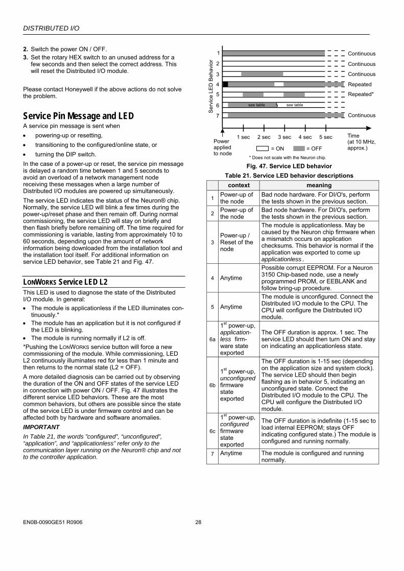
Service Pin Message and LED A service pin message is sent when • powering-up or resetting, • transitioning to the configured/online state, or • turning the DIP switch. In the case of a power-up or reset, the service pin message is delayed a random time between 1 and 5 seconds to avoid an overload of a network management node receiving these messages when a large number of Distributed I/O modules are powered up simultaneously. The service LED indicates the status of the Neuron® chip. Normally, the service LED will blink a few times during the power-up/reset phase and then remain off. During normal commissioning, the service LED will stay on briefly and then flash briefly before remaining off. The time required for commissioning is variable, lasting from approximately 10 to 60 seconds, depending upon the amount of network information being downloaded from the installation tool and the installation tool itself. For additional information on service LED behavior, see Table 21 and Fig. 47.
LONWORKS Service LED L2 This LED is used to diagnose the state of the Distributed I/O module. In general: • The module is applicationless if the LED illuminates con-
tinuously.* • The module has an application but it is not configured if
the LED is blinking. • The module is running normally if L2 is off. *Pushing the LONWORKS service button will force a new commissioning of the module. While commissioning, LED L2 continuously illuminates red for less than 1 minute and then returns to the normal state (L2 = OFF). A more detailed diagnosis can be carried out by observing the duration of the ON and OFF states of the service LED in connection with power ON / OFF. Fig. 47 illustrates the different service LED behaviors. These are the most common behaviors, but others are possible since the state of the service LED is under firmware control and can be affected both by hardware and software anomalies. IMPORTANT In Table 21, the words ”configured”, “unconfigured”, “application”, and “applicationless” refer only to the communication layer running on the Neuron® chip and not to the controller application.
1 sec
1
2
3
4
5
6
7
Serv
ice
LED
Beh
avio
r
2 sec 3 sec 4 sec 5 sec Time(at 10 MHz,approx.)
Powerappliedto node
Continuous
* Does not scale with the Neuron chip.
Continuous
Continuous
Continuous
Repeated
Repeated*
see table
= ON = OFF
see table
Fig. 47. Service LED behavior
Table 21. Service LED behavior descriptions context meaning
1 Power-up of the node
Bad node hardware. For DI/O's, perform the tests shown in the previous section.
2 Power-up of the node
Bad node hardware. For DI/O's, perform the tests shown in the previous section.
3 Power-up / Reset of the node
The module is applicationless. May be caused by the Neuron chip firmware when a mismatch occurs on application checksums. This behavior is normal if the application was exported to come up applicationless.
4 Anytime
Possible corrupt EEPROM. For a Neuron 3150 Chip-based node, use a newly programmed PROM, or EEBLANK and follow bring-up procedure.
5 Anytime
The module is unconfigured. Connect the Distributed I/O module to the CPU. The CPU will configure the Distributed I/O module.
6a
1st power-up, application-less firm-ware state exported
The OFF duration is approx. 1 sec. The service LED should then turn ON and stay on indicating an applicationless state.
6b
1st power-up, unconfigured firmware state exported
The OFF duration is 1-15 sec (depending on the application size and system clock). The service LED should then begin flashing as in behavior 5, indicating an unconfigured state. Connect the Distributed I/O module to the CPU. The CPU will configure the Distributed I/O module.
6c
1st power-up, configured firmware state exported
The OFF duration is indefinite (1-15 sec to load internal EEPROM; stays OFF indicating configured state.) The module is configured and running normally.
7 Anytime The module is configured and running normally.

DISTRIBUTED I/O
29 EN0B-0090GE51 R0906
Accessories, Standards, Ratings, and Literature Accessories — XAL 1 Swivel Label Holder (required for Manual
Override Modules, package includes 10 XAL 1 swivel labels).
— XAL 2 Cover Release Tool (required for opening the module housing e.g. to set the module address using the rotary HEX switch; package includes 20 XAL 2 Cover Release Tools).
— 209541B Termination Module (one or two required, depending on LONWORKS bus layout; see section "LonWorks Bus Termination Modules" on page 23).
— XAL-Term LONWORKS Connection and Termination module (see Fig. 44 on page 23).
Approvals and Standards • CE and EN 50082-1
Environmental Ratings • Operating temperature: 32° to 122°F (0° to 50°C) • Shipping/storage temperature: -13° to 150°F (-25° to
65°C) • Relative humidity (operation and storage): 5% to 90%,
non-condensing
Applicable Literature • EN0B-091 Excel 100/500/600 System Overview • EN1R-1047 Excel 500/600 Installation Instructions • EN0B-270 Excel 50/500 LONWORKS Mechanisms
Fig. 48. Dimensions of XSL511 LONWORKS connector
module in inches (mm)
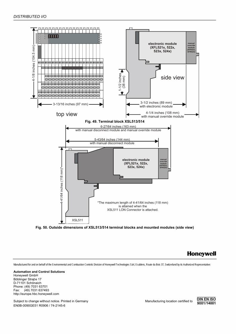
DISTRIBUTED I/O
Manufactured for and on behalf of the Environmental and Combustion Controls Division of Honeywell Technologies Sàrl, Ecublens, Route du Bois 37, Switzerland by its Authorized Representative: Automation and Control Solutions Honeywell GmbH Böblinger Straβe 17 D-71101 Schönaich Phone: (49) 7031 63701 Fax: (49) 7031 637493 http://europe.hbc.honeywell.com Subject to change without notice. Printed in Germany Manufacturing location certified to EN0B-0090GE51 R0906 / 74-2145-6
electronic module(XFL521x, 522x,
523x, 524x)
manualoverridemodule
(XFR522,XFR524)
3-13/16 inches (97 mm)
4-1/
8 in
ches
(104
.5 m
m)
top view
side view
3-1/2 inches (89 mm)with electronic module
4-1/4 inches (108 mm)with manual override module
1-1/
2 in
ches
(38
mm
)
Fig. 49. Terminal block XSL513/514
electronic module(XFL521x, 522x,
523x, 524x)
manualoverridemodule
(XFR522,XFR524)
6-27/64 inches (163 mm)with manual disconnect module and manual override module
5-43/64 inches (144 mm)with manual disconnect module
4-41
/64
inch
es (1
18 m
m)*
XSL511
*The maximum length of 4-41/64 inches (118 mm)is attained when the
XSL511 LON Connector is attached.
Fig. 50. Outside dimensions of XSL513/514 terminal blocks and mounted modules (side view)