honeywell ssec - magnetic sensors data sheets - steven
TRANSCRIPT

Magnetic Sensors Product Catalog
Sensing Earth’s magnetic field
COMPASSING, MAGNETOMETRY AND DEADRECKONING SOLUTIONS
Courtesy of Steven Engineering, Inc.-230 Ryan Way, South San Francisco, CA 94080-6370-Main Office: (650) 588-9200-Outside Local Area: (800) 258-9200-www.stevenengineering.com

Honeywell delivers real sensorsolutions you can count on
Honeywell’s Magnetic Sensors are
among the most sensitive and reliable
low-field sensors in the industry. Our
magnetic sensors are designed to accu-
rately detect the direction and magnitude
of external magnetic fields for compass-
ing and magnetometry applications.
From discrete sensors for low-cost, high
volume applications, to high perform-
ance solid-state compasses and magne-
tometers, Honeywell magnetic sensor
products operate on nearly any platform.
Honeywell combines the time-tested reli-
ability of these products with new and
innovative solid-state magnetic sensor
solutions. Our integrated circuits and
sensors are ruggedly designed to func-
tion optimally in a wide variety of environ-
ments and products.
Honeywell products are developed and
manufactured following Six Sigma princi-
ples, which means we do more than just
supply products for your needs—we
understand customer needs and aim to
exceed expectations. Plus, all our prod-
ucts are backed by Honeywell, a global
leader in sensor manufacturing, technol-
ogy and quality.
Courtesy of Steven Engineering, Inc.-230 Ryan Way, South San Francisco, CA 94080-6370-Main Office: (650) 588-9200-Outside Local Area: (800) 258-9200-www.stevenengineering.com

Honeywell magnetic sensors utilize world class technology
Attributes of Honeywell’s magnetic sen-
sors designed with Anisotropic
Magnetoresistive (AMR) technology pro-
vides significant advantages over tradi-
tional sensors. They are extremely sensi-
tive, low field, solid state magnetic sen-
sors designed to measure direction and
magnitude of Earth’s magnetic fields,
from 27 micro-gauss to 6 gauss (0.6
milli-Tesla).
Our magnetoresistive sensors are sensi-
tive enough to determine the change in
magnetic fields due to the presence of
nearby ferromagnetic objects. With a
bandwidth up to 5MHz, our sensors
detect vehicles and other ferrous
objects, even at high speeds.
Honeywell recently added a new line of
dead reckoning products to its Magnetic
Sensors family. These new products pro-
vide accurate navigation in challenging
environments and offer solutions where
GPS is not available. The advanced
dead reckoning technology further
strengthens our position as a leader in
personal navigation electronics technolo-
gy for GPS applications.
Honeywell’s magnetic sensor-based
products are excellent solutions in many
applications other than simple magnetic
field compassing, such as platform level-
ing or proximity detection.
Applications include:
• Compassing
– Automotive, GPS and dead
reckoning, mobile phones,
PDAs, & watches, irrigation
systems
• Attitude reference
– Aircraft systems, UAVs,
magnetic field detection
• Dead reckoning
– Backup for GPS receivers
• Position sensing
– Valve controls, measuring
equipment, displacement sensing
• Vehicle detection
– Parking meters, RR signaling
devices, electronic traffic signals
• Security
– Metal detectors, magnetic anomaly
detectors
• Others
– Medical, current sensors,
non-contact switches
Courtesy of Steven Engineering, Inc.-230 Ryan Way, South San Francisco, CA 94080-6370-Main Office: (650) 588-9200-Outside Local Area: (800) 258-9200-www.stevenengineering.com
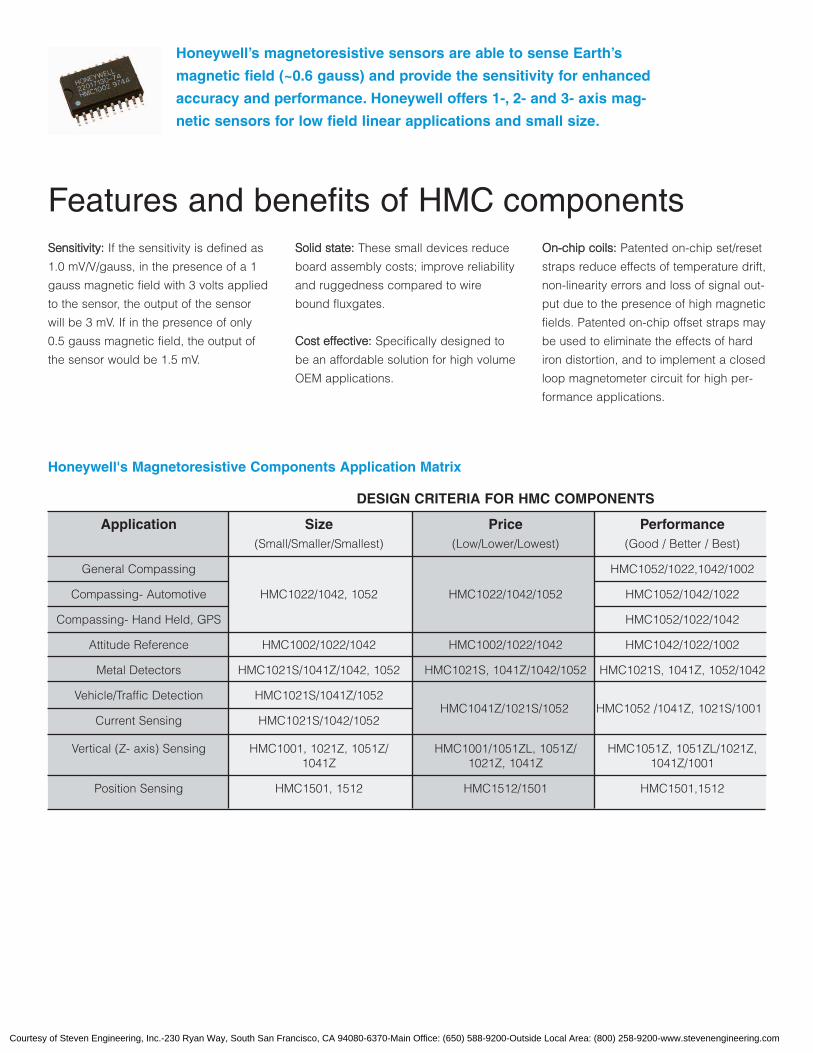
Honeywell’s magnetoresistive sensors are able to sense Earth’s
magnetic field (~0.6 gauss) and provide the sensitivity for enhanced
accuracy and performance. Honeywell offers 1-, 2- and 3- axis mag-
netic sensors for low field linear applications and small size.
SSeennssiittiivviittyy:: If the sensitivity is defined as
1.0 mV/V/gauss, in the presence of a 1
gauss magnetic field with 3 volts applied
to the sensor, the output of the sensor
will be 3 mV. If in the presence of only
0.5 gauss magnetic field, the output of
the sensor would be 1.5 mV.
DESIGN CRITERIA FOR HMC COMPONENTS
Application Size Price Performance(Small/Smaller/Smallest) (Low/Lower/Lowest) (Good / Better / Best)
General Compassing HMC1052/1022,1042/1002
Compassing- Automotive HMC1022/1042, 1052 HMC1022/1042/1052 HMC1052/1042/1022
Compassing- Hand Held, GPS HMC1052/1022/1042
Attitude Reference HMC1002/1022/1042 HMC1002/1022/1042 HMC1042/1022/1002
Metal Detectors HMC1021S/1041Z/1042, 1052 HMC1021S, 1041Z/1042/1052 HMC1021S, 1041Z, 1052/1042
Vehicle/Traffic Detection HMC1021S/1041Z/1052
Current Sensing HMC1021S/1042/1052
Vertical (Z- axis) Sensing HMC1001, 1021Z, 1051Z/ HMC1001/1051ZL, 1051Z/ HMC1051Z, 1051ZL/1021Z,1041Z 1021Z, 1041Z 1041Z/1001
Position Sensing HMC1501, 1512 HMC1512/1501 HMC1501,1512
Honeywell's Magnetoresistive Components Application Matrix
Features and benefits of HMC componentsSSoolliidd ssttaattee:: These small devices reduce
board assembly costs; improve reliability
and ruggedness compared to wire
bound fluxgates.
CCoosstt eeffffeeccttiivvee:: Specifically designed to
be an affordable solution for high volume
OEM applications.
OOnn--cchhiipp ccooiillss:: Patented on-chip set/reset
straps reduce effects of temperature drift,
non-linearity errors and loss of signal out-
put due to the presence of high magnetic
fields. Patented on-chip offset straps may
be used to eliminate the effects of hard
iron distortion, and to implement a closed
loop magnetometer circuit for high per-
formance applications.
HMC1041Z/1021S/1052 HMC1052 /1041Z, 1021S/1001
Courtesy of Steven Engineering, Inc.-230 Ryan Way, South San Francisco, CA 94080-6370-Main Office: (650) 588-9200-Outside Local Area: (800) 258-9200-www.stevenengineering.com

HMR2300 Smart DigitalMagnetometer
With extremely low magnetic field sensi-
tivity (<70 micro-gauss, <7 nano-Tesla)
capability and a user configurable com-
mand set, the HMR2300 solves a variety
of problems in custom applications.
Honeywell’s three-axis smart digital mag-
netometer detects the strength and
direction of the external magnetic field
and interfaces with computer/controller
digital ports. Three independent magnet-
ic sensors are oriented orthogonally to
sense the x, y and z-axis magnitudes of
the magnetic field. The bridge outputs
are then converted to a 16-bit digital
value using an internal A/D converter.
Features and benefits
FFiieelldd rraannggee:: ±2 Gauss
FFlleexxiibbllee:: Microcontroller-based sensor
system with RS232 or RS485 interfaces.
SSiimmppllee ttoo uussee:: Just plug and play
FFiieelldd rreessoolluuttiioonn:: <70 µGauss
AAccccuurraaccyy oovveerr ±±11 GGaauussss:: <0.5% FS out-
put rate selectable: 10 to 154
Samples/Sec.
DDeemmoo KKiittss - A Development Kit is avail-
able which includes one magnetometer
module in an aluminum enclosure,
cabling with power supply, Windows™
demonstration software for a remote PC,
and a user’s guide.
HMR2300R Three AxisStrapdown Magnetometer
The HMR2300R detects the direction and
strength of Earth’s magnetic field and
communicates the x, y and z compo-
nents directly via serial bus. Due to
Honeywell’s round strapdown design as
opposed to a gimbaled fluxvalve, it has
no moving parts to damage or wear out
during severe flight conditions. The
HMR2300R offers an ideal replacement
for flux valve sensors in avionics sys-
tems. Also includes 55 bytes of EE prom
locations available for data storage.
Features and benefits
FFlleexxiibbiilliittyy: RS422 or RS485 interface
choices
AAccccuurraaccyy:: <70 micro-gauss resolution
HMC2003 Three-Axis AnalogMagnetometer
The HMC2003 is a complete, three-axis
magnetometer with analog output in a
20-pin hybrid DIP package. With
Honeywell’s sensitive HMC1001 and
HMC1002 MR sensors, and precision
instrumentation amplifiers, it measures x,
y and z-axis magnetic fields. In addition,
Honeywell’s patented on-chip offset and
set/reset straps are accessible for con-
sistent and advanced processing appli-
cations.
Features and benefits
SSmmaallll ssiizzee:: DIP-20 footprint (1 in. x 75 in.)
allows easy insertion into system-level
boards, reducing development costs.
SSoolliidd ssttaattee:: All components are solid
state and DC operated, improving relia-
bility, EMI performance, and ruggedness
compared to fluxgate sensors.
DDyynnaammiicc rraannggee:: Accurately measures
field from 40 microgauss to ±2 gauss
with factory calibrated 1V/gauss outputs.
LLooww nnooiissee:: Instrumentation amplifiers
with 1kHz low pass filters rejects unwant-
ed noise.
IInntteerrnnaall vvoollttaaggee rreeffeerreennccee:: An externally
accessible +2.5V (zero gauss) reference
improves measurement accuracy and
stability. An on-board excitation current
source reduces temperature errors for
consistent performance.
Courtesy of Steven Engineering, Inc.-230 Ryan Way, South San Francisco, CA 94080-6370-Main Office: (650) 588-9200-Outside Local Area: (800) 258-9200-www.stevenengineering.com

Small Size Precision thin film resistors with 2500 Ω/sq provide high value resistors in a small area.
High Value Resistors 5M, 10M, 20M and 40M Ω resistors available as standard products.
Network of Resistors Standard resistor networks including voltage divider 1000:1, bussed resistors (100kΩeach) and a resistor with variable value of 10KΩ – 1.1MΩ, by different pinouts. Customnetwork solutions also available.
High Precision Resistors are laser trimmed with tolerance <1%.
High Quality Manufactured on solid state semiconductor process line providing high stability andrepeatability with demonstrated reliability.
Assembly Surface mount dual-line package, surface mount ballgrid or die form are optional.
Temperature Less than 300 ppm/°C temperature tracking of <2 ppm/°C.
FEATURES AND BENEFITS
RESISTORSAdvanced Information
Precision ResistorNetworks
APPLICATIONS
Implantable Medical Devices
Cellular Telephones
Avionics
Satellites hin film resistors
manufactured with
chromium silicon
provide a smaller
solution for applica-
tions where space is at
a premium; laser
trimmed high precision
resistors are available
as standard values or
custom arrays with
tolerance <1%.
T
Coefficients
Courtesy of Steven Engineering, Inc.-230 Ryan Way, South San Francisco, CA 94080-6370-Main Office: (650) 588-9200-Outside Local Area: (800) 258-9200-www.stevenengineering.com
Honeywell reserves the right to make changes to any products or technology herein to improve reliability, function or design. Honeywell does not assume any liabilityarising out of the application or use of any product or circuit described herein; neither does it convey any license under its patent rights nor the rights of others.
Solid State Electronics Center12001 State Highway 55Plymouth, MN 55441http://www.ssec.honeywell.com
900254 9-99
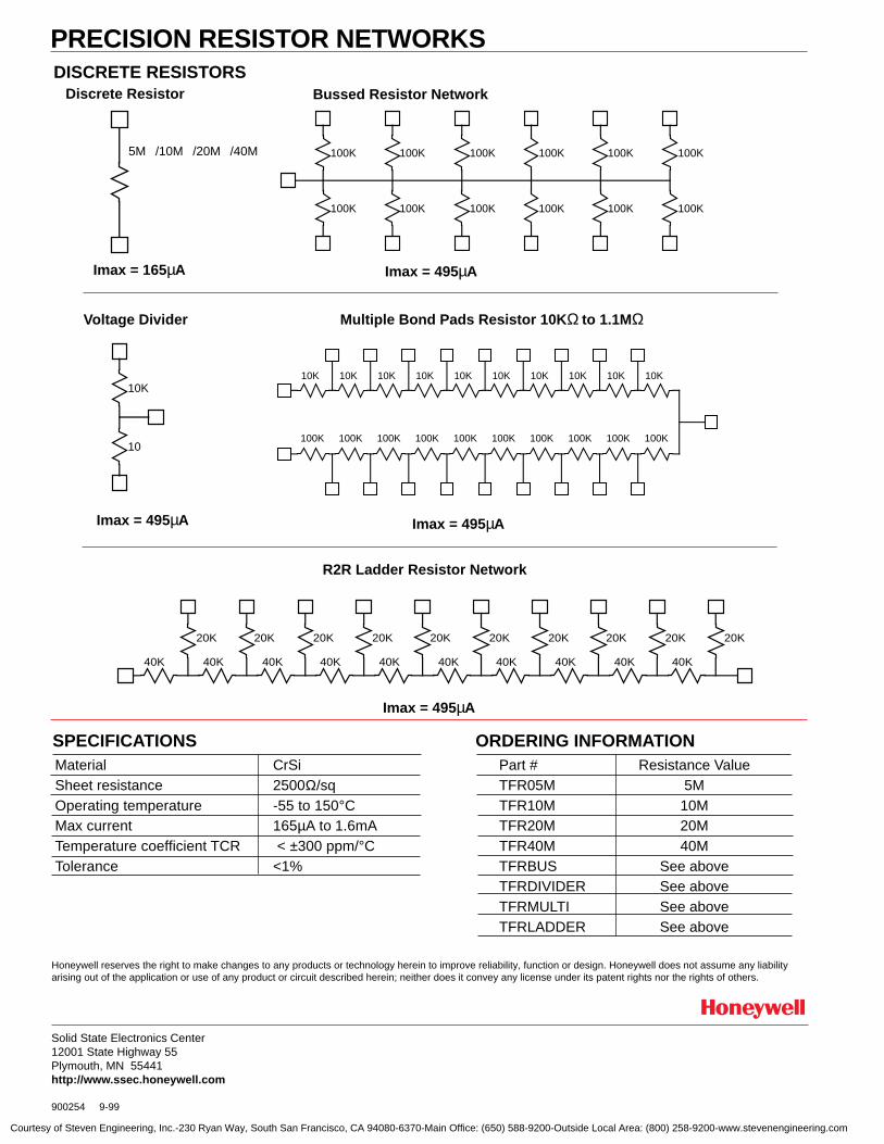
DISCRETE RESISTORS
40K
20K
40K
20K
40K
20K
40K
20K
40K
20K
40K 40K
20K
40K
20K
40K
20K
40K
20K20K
10K 10K 10K 10K 10K 10K 10K 10K 10K 10K
100K 100K 100K 100K 100K 100K 100K 100K 100K 100K
100K
100K
100K
100K
100K
100K
100K
100K
100K
100K
100K
100K
Discrete Resistor
Voltage Divider Multiple Bond Pads Resistor 10K Ω to 1.1MΩ
Imax = 495µAImax = 495µA
Bussed Resistor Network
Imax = 495µAImax = 165µA
R2R Ladder Resistor Network
Imax = 495µA
10
10K
PRECISION RESISTOR NETWORKS
SPECIFICATIONS
5M /10M /20M /40M
Material CrSiSheet resistance 2500Ω/sqOperating temperature -55 to 150°CMax current 165µA to 1.6mATemperature coefficient TCR < ±300 ppm/°CTolerance <1%
ORDERING INFORMATIONPart # Resistance ValueTFR05M 5MTFR10M 10MTFR20M 20MTFR40M 40MTFRBUS See aboveTFRDIVIDER See aboveTFRMULTI See aboveTFRLADDER See above
Courtesy of Steven Engineering, Inc.-230 Ryan Way, South San Francisco, CA 94080-6370-Main Office: (650) 588-9200-Outside Local Area: (800) 258-9200-www.stevenengineering.com

SENSOR PRODUCTS
1- and 2-Axis MagneticSensors
HMC1001 / 1002HMC1021 / 1022
Compassing
Navigation Systems
Attitude Reference
Traffic Detection
Medical Devices
Non-Contact Switch
APPLICATIONS
Wide Field Range Field range up to ±6 gauss, (earth’s field = 0.5 gauss)
Small Package • Designed for 1- and 2-axis to work together to provide 3-axis (x, y, z) sensing
• 1-axis part in an 8-pin SIP or an 8-pin SOIC or a ceramic 8-pin DIP package
• 2-axis part in a 16-pin or 20-pin SOIC package
Solid State These small devices reduce board assembly costs, improve reliability and ruggedness com-
pared to mechanical fluxgates.
On-Chip Coils Patented on-chip set/reset straps to reduce effects of temperature drift, non-linearity errors and
loss of signal output due to the presence of high magnetic fields
Patented on-chip offset straps for elimination of the effects of hard iron distortion
Cost Effective The sensors were specifically designed to be affordable for high volume OEM applications.
onfigured as a 4-elementwheatstone bridge, thesemagnetoresistive sensorsconvert magnetic fields to
a differential output volt-age, capable of sensing
magnetic fields as low as30 µgauss. These MRsoffer a small, low cost,
high sensitivity and highreliability solution for low
field magnetic sensing.
C
FEATURES AND BENEFITS
Not actual size
Courtesy of Steven Engineering, Inc.-230 Ryan Way, South San Francisco, CA 94080-6370-Main Office: (650) 588-9200-Outside Local Area: (800) 258-9200-www.stevenengineering.com
LINEAR MAGNETIC FIELD SENSORS
2
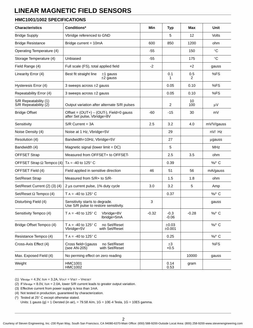
HMC1001/1002 SPECIFICATIONS
Characteristics Conditions* Min Typ Max Unit
Bridge Supply Vbridge referenced to GND 5 12 Volts
Bridge Resistance Bridge current = 10mA 600 850 1200 ohm
Operating Temperature (4) -55 150 °C
Storage Temperature (4) Unbiased -55 175 °C
Field Range (4) Full scale (FS), total applied field -2 +2 gauss
Linearity Error (4) Best fit straight line ±1 gauss 0.1 0.5 %FS±2 gauss 1 2
Hysteresis Error (4) 3 sweeps across ±2 gauss 0.05 0.10 %FS
Repeatability Error (4) 3 sweeps across ±2 gauss 0.05 0.10 %FS
S/R Repeatability (1) 10S/R Repeatability (2) Output variation after alternate S/R pulses 2 100 µV
Bridge Offset Offset = (OUT+) – (OUT-), Field=0 gauss -60 -15 30 mVafter Set pulse, Vbridge=8V
Sensitivity S/R Current = 3A 2.5 3.2 4.0 mV/V/gauss
Noise Density (4) Noise at 1 Hz, Vbridge=5V 29 nV/ Hz
Resolution (4) Bandwidth=10Hz, Vbridge=5V 27 µgauss
Bandwidth (4) Magnetic signal (lower limit = DC) 5 MHz
OFFSET Strap Measured from OFFSET+ to OFFSET- 2.5 3.5 ohm
OFFSET Strap Ω Tempco (4) TA = -40 to 125° C 0.39 %/° C
OFFSET Field (4) Field applied in sensitive direction 46 51 56 mA/gauss
Set/Reset Strap Measured from S/R+ to S/R- 1.5 1.8 ohm
Set/Reset Current (2) (3) (4) 2 µs current pulse, 1% duty cycle 3.0 3.2 5 Amp
Set/Reset Ω Tempco (4) T A = -40 to 125° C 0.37 %/° C
Disturbing Field (4) Sensitivity starts to degrade. 3 gaussUse S/R pulse to restore sensitivity.
Sensitivity Tempco (4) T A = -40 to 125° C Vbridge=8V -0.32 -0.3 -0.28 %/° C Ibridge=5mA -0.06
Bridge Offset Tempco (4) T A = -40 to 125° C no Set/Reset ±0.03 %/° CVbridge=5V with Set/Reset ±0.001
Resistance Tempco (4) T A = -40 to 125° C 0.25 %/° C
Cross-Axis Effect (4) Cross field=1gauss no Set/Reset ±3 %FS(see AN-205) with Set/Reset +0.5
Max. Exposed Field (4) No perming effect on zero reading 10000 gauss
Weight HMC1001 0.14 gramHMC1002 0.53
(1) VBridge = 4.3V, IS/R = 3.2A, VOUT = VSET – VRESET
(2) If VBridge = 8.0V, IS/R = 2.0A, lower S/R current leads to greater output variation.(3) Effective current from power supply is less than 1mA.(4) Not tested in production, guaranteed by characterization.(*) Tested at 25° C except otherwise stated.
Units: 1 gauss (g) = 1 Oersted (in air), = 79.58 A/m, 1G = 10E-4 Tesla, 1G = 10E5 gamma.
Courtesy of Steven Engineering, Inc.-230 Ryan Way, South San Francisco, CA 94080-6370-Main Office: (650) 588-9200-Outside Local Area: (800) 258-9200-www.stevenengineering.com
LINEAR MAGNETIC FIELD SENSORS
3
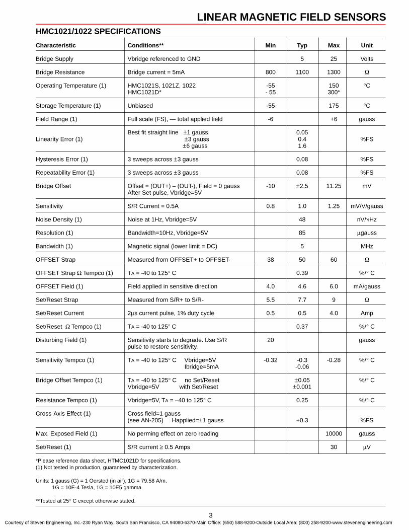
HMC1021/1022 SPECIFICATIONS
Characteristic Conditions** Min Typ Max Unit
Bridge Supply Vbridge referenced to GND 5 25 Volts
Bridge Resistance Bridge current = 5mA 800 1100 1300 Ω
Operating Temperature (1) HMC1021S, 1021Z, 1022 -55 150 °CHMC1021D* - 55 300*
Storage Temperature (1) Unbiased -55 175 °C
Field Range (1) Full scale (FS), — total applied field -6 +6 gauss
Best fit straight line ±1 gauss 0.05Linearity Error (1) ±3 gauss 0.4 %FS
±6 gauss 1.6
Hysteresis Error (1) 3 sweeps across ±3 gauss 0.08 %FS
Repeatability Error (1) 3 sweeps across ±3 gauss 0.08 %FS
Bridge Offset Offset = (OUT+) – (OUT-), Field = 0 gauss -10 ±2.5 11.25 mVAfter Set pulse, Vbridge=5V
Sensitivity S/R Current = 0.5A 0.8 1.0 1.25 mV/V/gauss
Noise Density (1) Noise at 1Hz, Vbridge=5V 48 nV/√Hz
Resolution (1) Bandwidth=10Hz, Vbridge=5V 85 µgauss
Bandwidth (1) Magnetic signal (lower limit = DC) 5 MHz
OFFSET Strap Measured from OFFSET+ to OFFSET- 38 50 60 Ω
OFFSET Strap Ω Tempco (1) TA = -40 to 125° C 0.39 %/° C
OFFSET Field (1) Field applied in sensitive direction 4.0 4.6 6.0 mA/gauss
Set/Reset Strap Measured from S/R+ to S/R- 5.5 7.7 9 Ω
Set/Reset Current 2µs current pulse, 1% duty cycle 0.5 0.5 4.0 Amp
Set/Reset Ω Tempco (1) TA = -40 to 125° C 0.37 %/° C
Disturbing Field (1) Sensitivity starts to degrade. Use S/R 20 gausspulse to restore sensitivity.
Sensitivity Tempco (1) TA = -40 to 125° C Vbridge=5V -0.32 -0.3 -0.28 %/° C Ibridge=5mA -0.06
Bridge Offset Tempco (1) TA = -40 to 125° C no Set/Reset ±0.05 %/° CVbridge=5V with Set/Reset ±0.001
Resistance Tempco (1) Vbridge=5V, TA = –40 to 125° C 0.25 %/° C
Cross-Axis Effect (1) Cross field=1 gauss(see AN-205) Happlied=±1 gauss +0.3 %FS
Max. Exposed Field (1) No perming effect on zero reading 10000 gauss
Set/Reset (1) S/R current ≥ 0.5 Amps 30 µV
*Please reference data sheet, HTMC1021D for specifications.(1) Not tested in production, guaranteed by characterization.
Units: 1 gauss (G) = 1 Oersted (in air), 1G = 79.58 A/m, 1G = 10E-4 Tesla, 1G = 10E5 gamma
**Tested at 25° C except otherwise stated.
Courtesy of Steven Engineering, Inc.-230 Ryan Way, South San Francisco, CA 94080-6370-Main Office: (650) 588-9200-Outside Local Area: (800) 258-9200-www.stevenengineering.com
LINEAR MAGNETIC FIELD SENSORS
4
0
0.2
0.4
0.6
0.8
1
0 1 2 3 4 5
Null Voltage (mV) (Set)
Null Voltage (mV) (Reset)
Sensitivity (mV/V/Oe) (Set)
Sensitivity (mV/V/Oe) (Reset) no set/reset in t
region
900
1000
1100
1200
1300
1400
-50 -25 0 25 50 75 100 125
1
10
100
1000
0.1 1 10 100 1000
0.6
0.7
0.8
0.9
1
1.1
1.2
1.3
-50 -25 0 25 50 75 100 125
-60
-40
-20
0
20
40
60
-20 -15 -10 -5 0 5 10 15 20-20
-15
-10
-5
0
5
10
15
-2 -1 0 1 2
Reset
Set
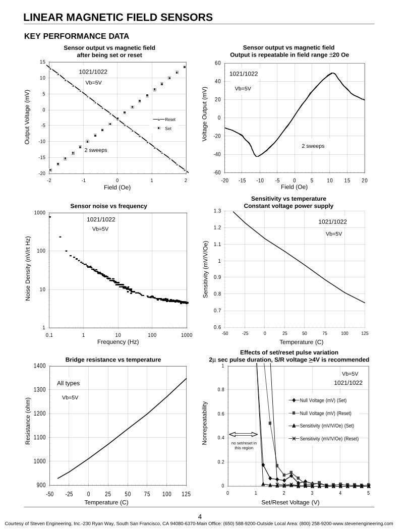
KEY PERFORMANCE DATASensor output vs magnetic field
after being set or reset
Vb=5V
2 sweeps
Sensor output vs magnetic field Output is repeatable in field range ±20 Oe
Sensitivity vs temperatureConstant voltage power supply
Vb=5V
Sen
sitiv
ity (
mV
/V/O
e)Sensor noise vs frequency
Vb=5V
Frequency (Hz)
Effects of set/reset pulse variation2µ sec pulse duration, S/R voltage >4V is recommended
Vb=5V
Bridge resistance vs temperature
Noi
se D
ensi
ty (
nV/r
t Hz)
Vol
tage
Out
put (
mV
)
Temperature (C)
Field (Oe)
Res
ista
nce
(ohm
)
Non
repe
atab
ility
Set/Reset Voltage (V)
Temperature (C)
Field (Oe)
Out
put V
olta
ge (
mV
)
2 sweeps
Vb=5V
Vb=5V
1021/1022
1021/1022 1021/1022
1021/1022
All types 1021/1022
no set/reset inthis region
Courtesy of Steven Engineering, Inc.-230 Ryan Way, South San Francisco, CA 94080-6370-Main Office: (650) 588-9200-Outside Local Area: (800) 258-9200-www.stevenengineering.com
LINEAR MAGNETIC FIELD SENSORS
5
OUT+ 1VBRIDGE 2
GND 3OUT- 4
Die• 8 OFFSET-7 OFFSET+6 S/R-5 S/R+
HMC1021S
OFFSET- (A) 1OUT+ (A) 2
VBRIDGE (A) 3OUT- (A) 4OUT- (B) 5
VBRIDGE (B) 6GND (A) 7S/R+ (B) 8
Die A•
Die B
16 OFFSET+ (A)15 S/R- (A)14 S/R+ (A)13 GND (B)12 OUT+ (B)11 OFFSET- (B)10 OFFSET+ (B)9 S/R- (B)
OUT- 1VBRIDGE 2
S/R+ 3GND 4S/R- 5
OFFSET+ 6OFFSET- 7
OUT+ 8
Die
•
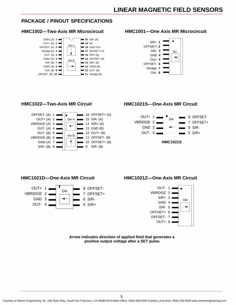
HMC1002—Two-Axis MR Microcircuit
GND1 (A) 1
OUT+ (A) 2
OFFSET- (A) 3
Vbridge (A) 4
OUT- (A) 5
GND2 (A) 6
S/R- (B) 7
GND1 (B) 8
Out+ (B) 9
OFFSET- (B) 10
20 S/R- (A)
19 NC
18 GND PLN
17 OFFSET (+A)
16 S/R+ (A)
15 OFFSET+ (B)
14 S/R+ (B)
13 GND2 (B)
12 OUT- (B)
11 Vbridge (B)
Die B
Die A
Arrow indicates direction of applied field that generates a positive output voltage after a SET pulse.
HMC1001—One Axis MR Microcircuit
S/R+ 1OFFSET+ 2
S/R- 3GND 4Out+ 5
OFFSET- 6Vbridge 7
Out- 8
Die
•
PACKAGE / PINOUT SPECIFICATIONS
HMC1022—Two-Axis MR Circuit HMC1021S—One-Axis MR Circuit
HMC1021Z—One-Axis MR CircuitHMC1021D—One-Axis MR Circuit
OUT+ 1VBRIDGE 2
GND 3OUT- 4
Die8 OFFSET-7 OFFSET+6 S/R-5 S/R+
Courtesy of Steven Engineering, Inc.-230 Ryan Way, South San Francisco, CA 94080-6370-Main Office: (650) 588-9200-Outside Local Area: (800) 258-9200-www.stevenengineering.com
LINEAR MAGNETIC FIELD SENSORS
6
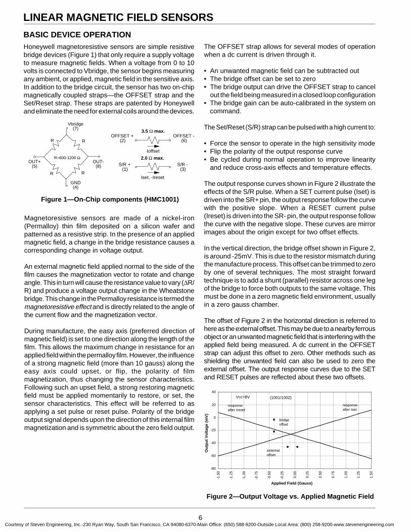
Honeywell magnetoresistive sensors are simple resistivebridge devices (Figure 1) that only require a supply voltageto measure magnetic fields. When a voltage from 0 to 10volts is connected to Vbridge, the sensor begins measuringany ambient, or applied, magnetic field in the sensitive axis.In addition to the bridge circuit, the sensor has two on-chipmagnetically coupled straps—the OFFSET strap and theSet/Reset strap. These straps are patented by Honeywelland eliminate the need for external coils around the devices.
-80
-60
-40
-20
0
20
40
-1.5
0
-1.2
5
-1.0
0
-0.7
5
-0.5
0
-0.2
5
0.00
0.25
0.50
0.75
1.00
1.25
1.50
Applied Field (Gauss)
Ou
tpu
t V
olt
age
(mV
)
bridgeoffset
externaloffset
responseafter Ireset
responseafter Iset
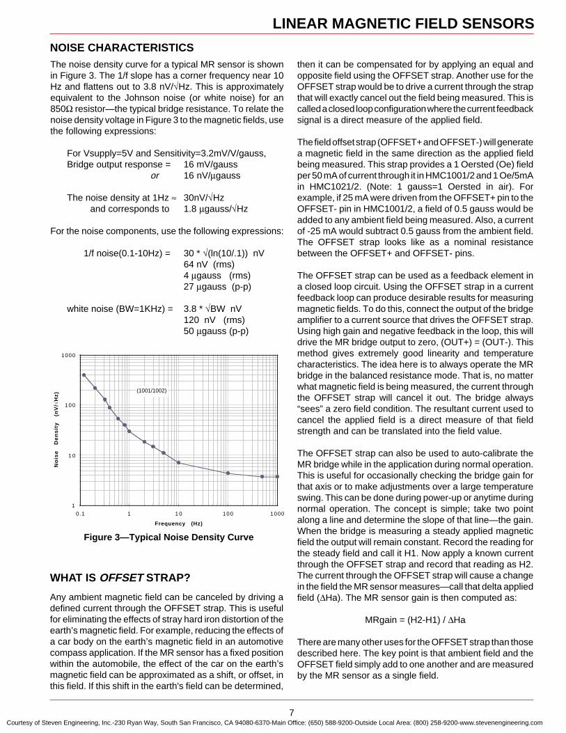
Vcc=8V
Figure 2—Output Voltage vs. Applied Magnetic Field
Figure 1—On-Chip components (HMC1001)
OUT+(5)
OUT-(8)
Vbridge(7)
GND(4)
R=600-1200 Ω
R R
R R
OFFSET +(2)
S/R +(1)
OFFSET -(6)
S/R -(3)
2.0 Ω max.
3.5 Ω max.
Iset, -Ireset
Ioffset
Magnetoresistive sensors are made of a nickel-iron(Permalloy) thin film deposited on a silicon wafer andpatterned as a resistive strip. In the presence of an appliedmagnetic field, a change in the bridge resistance causes acorresponding change in voltage output.
An external magnetic field applied normal to the side of thefilm causes the magnetization vector to rotate and changeangle. This in turn will cause the resistance value to vary (∆R/R) and produce a voltage output change in the Wheatstonebridge. This change in the Permalloy resistance is termed themagnetoresistive effect and is directly related to the angle ofthe current flow and the magnetization vector.
During manufacture, the easy axis (preferred direction ofmagnetic field) is set to one direction along the length of thefilm. This allows the maximum change in resistance for anapplied field within the permalloy film. However, the influenceof a strong magnetic field (more than 10 gauss) along theeasy axis could upset, or flip, the polarity of filmmagnetization, thus changing the sensor characteristics.Following such an upset field, a strong restoring magneticfield must be applied momentarily to restore, or set, thesensor characteristics. This effect will be referred to asapplying a set pulse or reset pulse. Polarity of the bridgeoutput signal depends upon the direction of this internal filmmagnetization and is symmetric about the zero field output.
The OFFSET strap allows for several modes of operationwhen a dc current is driven through it.
• An unwanted magnetic field can be subtracted out• The bridge offset can be set to zero• The bridge output can drive the OFFSET strap to cancel
out the field being measured in a closed loop configuration• The bridge gain can be auto-calibrated in the system on
command.
The Set/Reset (S/R) strap can be pulsed with a high current to:
• Force the sensor to operate in the high sensitivity mode• Flip the polarity of the output response curve• Be cycled during normal operation to improve linearity
and reduce cross-axis effects and temperature effects.
The output response curves shown in Figure 2 illustrate theeffects of the S/R pulse. When a SET current pulse (Iset) isdriven into the SR+ pin, the output response follow the curvewith the positive slope. When a RESET current pulse(Ireset) is driven into the SR- pin, the output response followthe curve with the negative slope. These curves are mirrorimages about the origin except for two offset effects.
In the vertical direction, the bridge offset shown in Figure 2,is around -25mV. This is due to the resistor mismatch duringthe manufacture process. This offset can be trimmed to zeroby one of several techniques. The most straight forwardtechnique is to add a shunt (parallel) resistor across one legof the bridge to force both outputs to the same voltage. Thismust be done in a zero magnetic field environment, usuallyin a zero gauss chamber.
The offset of Figure 2 in the horizontal direction is referred tohere as the external offset. This may be due to a nearby ferrousobject or an unwanted magnetic field that is interfering with theapplied field being measured. A dc current in the OFFSETstrap can adjust this offset to zero. Other methods such asshielding the unwanted field can also be used to zero theexternal offset. The output response curves due to the SETand RESET pulses are reflected about these two offsets.
BASIC DEVICE OPERATION
(1001/1002)
Courtesy of Steven Engineering, Inc.-230 Ryan Way, South San Francisco, CA 94080-6370-Main Office: (650) 588-9200-Outside Local Area: (800) 258-9200-www.stevenengineering.com
LINEAR MAGNETIC FIELD SENSORS
7
Any ambient magnetic field can be canceled by driving adefined current through the OFFSET strap. This is usefulfor eliminating the effects of stray hard iron distortion of theearth’s magnetic field. For example, reducing the effects ofa car body on the earth’s magnetic field in an automotivecompass application. If the MR sensor has a fixed positionwithin the automobile, the effect of the car on the earth’smagnetic field can be approximated as a shift, or offset, inthis field. If this shift in the earth's field can be determined,
The noise density curve for a typical MR sensor is shownin Figure 3. The 1/f slope has a corner frequency near 10Hz and flattens out to 3.8 nV/√Hz. This is approximatelyequivalent to the Johnson noise (or white noise) for an850Ω resistor—the typical bridge resistance. To relate thenoise density voltage in Figure 3 to the magnetic fields, usethe following expressions:
For Vsupply=5V and Sensitivity=3.2mV/V/gauss,Bridge output response = 16 mV/gauss
or 16 nV/µgauss
The noise density at 1Hz ≈ 30nV/√Hz and corresponds to 1.8 µgauss/√Hz
For the noise components, use the following expressions:
1/f noise(0.1-10Hz) = 30 * √(ln(10/.1)) nV64 nV (rms)4 µgauss (rms)27 µgauss (p-p)
white noise (BW=1KHz) = 3.8 * √BW nV120 nV (rms)50 µgauss (p-p)
Figure 3—Typical Noise Density Curve
WHAT IS OFFSET STRAP?
1
1 0
100
1000
0.1 1 1 0 100 1000
Frequency (Hz)
No
ise
D
en
sit
y
(nV
/√H
z)
(1001/1002)
then it can be compensated for by applying an equal andopposite field using the OFFSET strap. Another use for theOFFSET strap would be to drive a current through the strapthat will exactly cancel out the field being measured. This iscalled a closed loop configuration where the current feedbacksignal is a direct measure of the applied field.
The field offset strap (OFFSET+ and OFFSET-) will generatea magnetic field in the same direction as the applied fieldbeing measured. This strap provides a 1 Oersted (Oe) fieldper 50 mA of current through it in HMC1001/2 and 1 Oe/5mAin HMC1021/2. (Note: 1 gauss=1 Oersted in air). Forexample, if 25 mA were driven from the OFFSET+ pin to theOFFSET- pin in HMC1001/2, a field of 0.5 gauss would beadded to any ambient field being measured. Also, a currentof -25 mA would subtract 0.5 gauss from the ambient field.The OFFSET strap looks like as a nominal resistancebetween the OFFSET+ and OFFSET- pins.
The OFFSET strap can be used as a feedback element ina closed loop circuit. Using the OFFSET strap in a currentfeedback loop can produce desirable results for measuringmagnetic fields. To do this, connect the output of the bridgeamplifier to a current source that drives the OFFSET strap.Using high gain and negative feedback in the loop, this willdrive the MR bridge output to zero, (OUT+) = (OUT-). Thismethod gives extremely good linearity and temperaturecharacteristics. The idea here is to always operate the MRbridge in the balanced resistance mode. That is, no matterwhat magnetic field is being measured, the current throughthe OFFSET strap will cancel it out. The bridge always“sees” a zero field condition. The resultant current used tocancel the applied field is a direct measure of that fieldstrength and can be translated into the field value.
The OFFSET strap can also be used to auto-calibrate theMR bridge while in the application during normal operation.This is useful for occasionally checking the bridge gain forthat axis or to make adjustments over a large temperatureswing. This can be done during power-up or anytime duringnormal operation. The concept is simple; take two pointalong a line and determine the slope of that line—the gain.When the bridge is measuring a steady applied magneticfield the output will remain constant. Record the reading forthe steady field and call it H1. Now apply a known currentthrough the OFFSET strap and record that reading as H2.The current through the OFFSET strap will cause a changein the field the MR sensor measures—call that delta appliedfield (∆Ha). The MR sensor gain is then computed as:
MRgain = (H2-H1) / ∆Ha
There are many other uses for the OFFSET strap than thosedescribed here. The key point is that ambient field and theOFFSET field simply add to one another and are measuredby the MR sensor as a single field.
NOISE CHARACTERISTICS
Courtesy of Steven Engineering, Inc.-230 Ryan Way, South San Francisco, CA 94080-6370-Main Office: (650) 588-9200-Outside Local Area: (800) 258-9200-www.stevenengineering.com
LINEAR MAGNETIC FIELD SENSORS
8
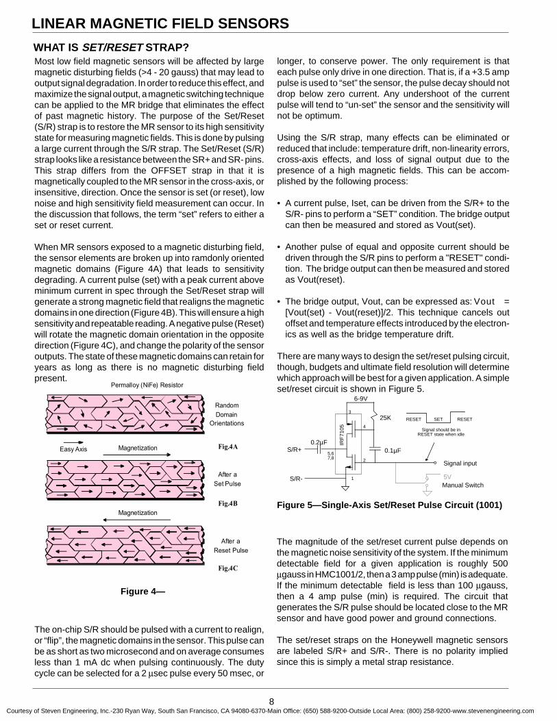
Most low field magnetic sensors will be affected by largemagnetic disturbing fields (>4 - 20 gauss) that may lead tooutput signal degradation. In order to reduce this effect, andmaximize the signal output, a magnetic switching techniquecan be applied to the MR bridge that eliminates the effectof past magnetic history. The purpose of the Set/Reset(S/R) strap is to restore the MR sensor to its high sensitivitystate for measuring magnetic fields. This is done by pulsinga large current through the S/R strap. The Set/Reset (S/R)strap looks like a resistance between the SR+ and SR- pins.This strap differs from the OFFSET strap in that it ismagnetically coupled to the MR sensor in the cross-axis, orinsensitive, direction. Once the sensor is set (or reset), lownoise and high sensitivity field measurement can occur. Inthe discussion that follows, the term “set” refers to either aset or reset current.
When MR sensors exposed to a magnetic disturbing field,the sensor elements are broken up into ramdonly orientedmagnetic domains (Figure 4A) that leads to sensitivitydegrading. A current pulse (set) with a peak current aboveminimum current in spec through the Set/Reset strap willgenerate a strong magnetic field that realigns the magneticdomains in one direction (Figure 4B). This will ensure a highsensitivity and repeatable reading. A negative pulse (Reset)will rotate the magnetic domain orientation in the oppositedirection (Figure 4C), and change the polarity of the sensoroutputs. The state of these magnetic domains can retain foryears as long as there is no magnetic disturbing fieldpresent.
The on-chip S/R should be pulsed with a current to realign,or “flip”, the magnetic domains in the sensor. This pulse canbe as short as two microsecond and on average consumesless than 1 mA dc when pulsing continuously. The dutycycle can be selected for a 2 µsec pulse every 50 msec, or
longer, to conserve power. The only requirement is thateach pulse only drive in one direction. That is, if a +3.5 amppulse is used to “set” the sensor, the pulse decay should notdrop below zero current. Any undershoot of the currentpulse will tend to “un-set” the sensor and the sensitivity willnot be optimum.
Using the S/R strap, many effects can be eliminated orreduced that include: temperature drift, non-linearity errors,cross-axis effects, and loss of signal output due to thepresence of a high magnetic fields. This can be accom-plished by the following process:
• A current pulse, Iset, can be driven from the S/R+ to theS/R- pins to perform a “SET” condition. The bridge outputcan then be measured and stored as Vout(set).
• Another pulse of equal and opposite current should bedriven through the S/R pins to perform a "RESET" condi-tion. The bridge output can then be measured and storedas Vout(reset).
• The bridge output, Vout, can be expressed as: Vout =[Vout(set) - Vout(reset)]/2. This technique cancels outoffset and temperature effects introduced by the electron-ics as well as the bridge temperature drift.
There are many ways to design the set/reset pulsing circuit,though, budgets and ultimate field resolution will determinewhich approach will be best for a given application. A simpleset/reset circuit is shown in Figure 5.
WHAT IS SET/RESET STRAP?
The magnitude of the set/reset current pulse depends onthe magnetic noise sensitivity of the system. If the minimumdetectable field for a given application is roughly 500µgauss in HMC1001/2, then a 3 amp pulse (min) is adequate.If the minimum detectable field is less than 100 µgauss,then a 4 amp pulse (min) is required. The circuit thatgenerates the S/R pulse should be located close to the MRsensor and have good power and ground connections.
The set/reset straps on the Honeywell magnetic sensorsare labeled S/R+ and S/R-. There is no polarity impliedsince this is simply a metal strap resistance.
Figure 5—Single-Axis Set/Reset Pulse Circuit (1001)
5V
S/R+
IRF
7105
0.2µF
25K3
4
2
1
5,67,8
0.1µF
SET RESETRESET
Signal should be in RESET state when idle
Signal input
Manual Switch
6-9V
S/R-
Easy Axis
Permalloy (NiFe) Resistor
Random
Domain
Orientations
After a
Set Pulse
Magnetization
After a
Reset Pulse
Magnetization
Fig.4A
Fig.4B
Fig.4C
Figure 4—
Courtesy of Steven Engineering, Inc.-230 Ryan Way, South San Francisco, CA 94080-6370-Main Office: (650) 588-9200-Outside Local Area: (800) 258-9200-www.stevenengineering.com
LINEAR MAGNETIC FIELD SENSORS
9
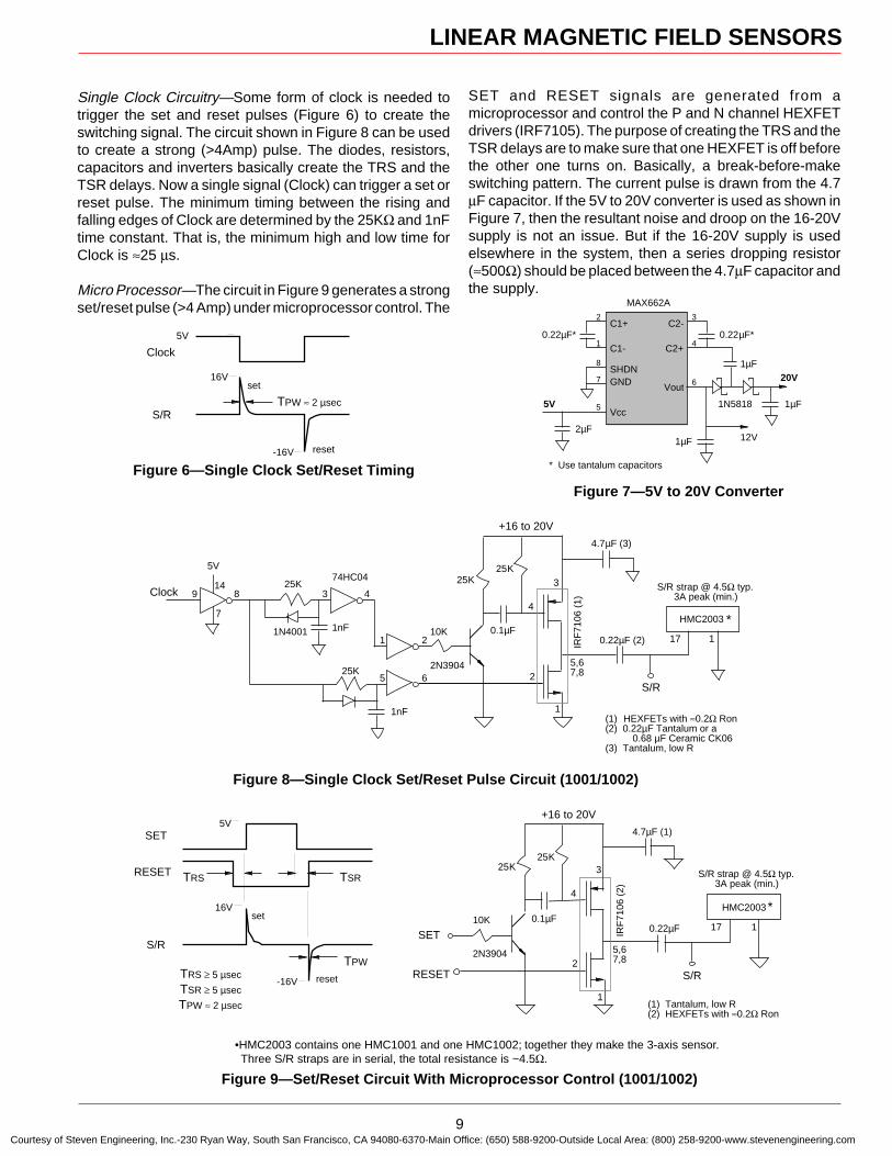
Single Clock Circuitry—Some form of clock is needed totrigger the set and reset pulses (Figure 6) to create theswitching signal. The circuit shown in Figure 8 can be usedto create a strong (>4Amp) pulse. The diodes, resistors,capacitors and inverters basically create the TRS and theTSR delays. Now a single signal (Clock) can trigger a set orreset pulse. The minimum timing between the rising andfalling edges of Clock are determined by the 25KΩ and 1nFtime constant. That is, the minimum high and low time forClock is ≈25 µs.
Micro Processor—The circuit in Figure 9 generates a strongset/reset pulse (>4 Amp) under microprocessor control. The
TSRTRS
SET
RESET
S/R
16V
-16VTRS ≥ 5 µsec
TSR ≥ 5 µsec
TPW ≈ 2 µsec
5V
TPW
set
reset
S/R strap @ 4.5Ω typ.3A peak (min.)
SET10K
10.22µF
4.7µF (1)
25K
+16 to 20V
17
HMC2003
2N3904
RESET S/R
IRF
7106
(2)
1
2
4
3
5,67,8
(1) Tantalum, low R(2) HEXFETs with ≈0.2Ω Ron
25K
0.1µF
Figure 9—Set/Reset Circuit With Microprocessor Control (1001/1002)
SET and RESET signals are generated from amicroprocessor and control the P and N channel HEXFETdrivers (IRF7105). The purpose of creating the TRS and theTSR delays are to make sure that one HEXFET is off beforethe other one turns on. Basically, a break-before-makeswitching pattern. The current pulse is drawn from the 4.7µF capacitor. If the 5V to 20V converter is used as shown inFigure 7, then the resultant noise and droop on the 16-20Vsupply is not an issue. But if the 16-20V supply is usedelsewhere in the system, then a series dropping resistor(≈500Ω) should be placed between the 4.7µF capacitor andthe supply.
Clock
S/R
16V
-16V
TPW ≈ 2 µsec
5V
set
reset
Figure 6—Single Clock Set/Reset TimingFigure 7—5V to 20V Converter
0.22µF*1
2
8
7
5
SHDN
Vcc
GND
C1-
C1+
1µF
Vout
4
3
C2+
C2-0.22µF*
1µF
1N5818
20V6
5V
MAX662A
* Use tantalum capacitors
12V2µF
1µF
10K
25K
+16 to 20V
2N3904
25K
0.1µF
S/R strap @ 4.5Ω typ.3A peak (min.)Clock
10.22µF (2)
4.7µF (3)
17
HMC2003
S/R
(1) HEXFETs with ≈0.2Ω Ron(2) 0.22µF Tantalum or a 0.68 µF Ceramic CK06(3) Tantalum, low R
25K
25K
1nF
1nF
89 43
21
65
7
14
5V74HC04
1N4001
IRF
7106
(1)
1
2
4
3
5,67,8
Figure 8—Single Clock Set/Reset Pulse Circuit (1001/1002)
*
*
•HMC2003 contains one HMC1001 and one HMC1002; together they make the 3-axis sensor. Three S/R straps are in serial, the total resistance is ~4.5Ω.
Courtesy of Steven Engineering, Inc.-230 Ryan Way, South San Francisco, CA 94080-6370-Main Office: (650) 588-9200-Outside Local Area: (800) 258-9200-www.stevenengineering.com
LINEAR MAGNETIC FIELD SENSORS
10
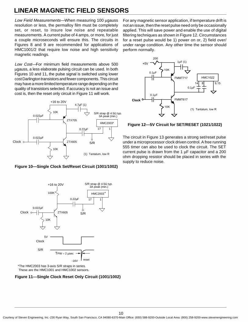
Figure 10—Single Clock Set/Reset Circuit (1001/1002)
Figure 11—Single Clock Reset Only Circuit (1001/1002)
Low Field Measurements—When measuring 100 µgaussresolution or less, the permalloy film must be completelyset, or reset, to insure low noise and repeatablemeasurements. A current pulse of 4 amps, or more, for justa couple microseconds will ensure this. The circuits inFigures 8 and 9 are recommended for applications ofHMC1001/2 that require low noise and high sensitivitymagnetic readings.
Low Cost—For minimum field measurements above 500µgauss, a less elaborate pulsing circuit can be used. In bothFigures 10 and 11, the pulse signal is switched using lowercost Darlington transistors and fewer components. This circuitmay have a more limited temperature range depending on thequality of transistors selected. If accuracy is not an issue andcost is, then the reset only circuit in Figure 11 will work.
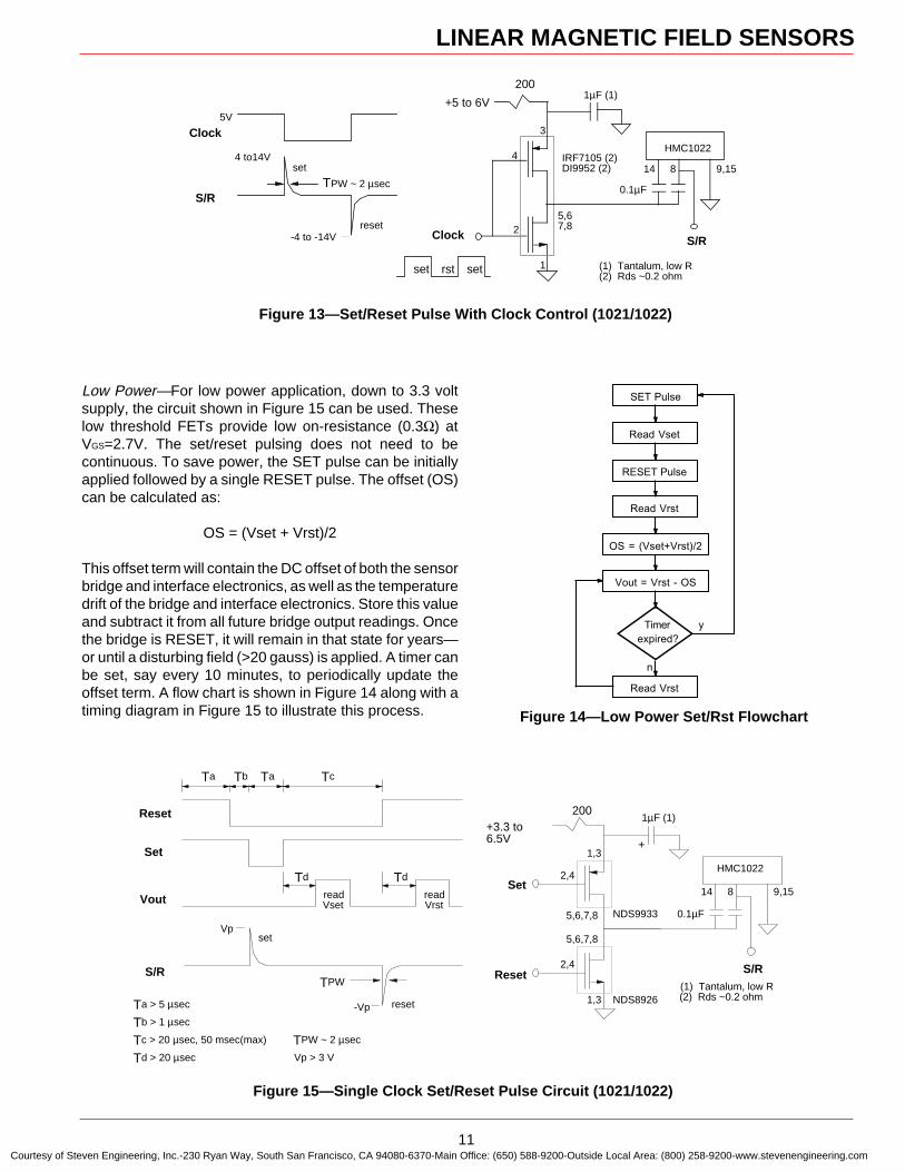
The circuit in Figure 13 generates a strong set/reset pulseunder a microprocessor clock driven control. A free running555 timer can also be used to clock the circuit. The SETcurrent pulse is drawn from the 1 µF capacitor and a 200ohm dropping resistor should be placed in series with thesupply to reduce noise.
For any magnetic sensor application, if temperature drift isnot an issue, then the reset pulse need only be occasionallyapplied. This will save power and enable the use of digitalfiltering techniques as shown in Figure 12. Circumstancesfor a reset pulse would be 1) power on or, 2) field over/under range condition. Any other time the sensor shouldperform normally.
*The HMC2003 has 3-axis S/R straps in series. These are the HMC1001 and HMC1002 sensors.
Figure 12—5V Circuit for SET/RESET (1021/1022)
S/R strap @ 4.5Ω typ.3A peak (min.)
10K
10.22µF
4.7µF (1)+16 to 20V
17
HMC2003*
Clock S/R
(1) Tantalum, low R
0.022µF
0.022µF10K
ZTX605
ZTX705
10K
0.1µF
1µF (1)+5V
Clock
(1) Tantalum, low R
0.1µF
0.1µF10K
FMMT617
FMMT717
200
9,1514
HMC1022
8
S/R strap @ 4.5Ω typ.3A peak (min.)
10K
10.22µF
+16 to 20V
17
HMC2003
Clock S/R
0.022µF
100K
ZTX605
Clock
S/R
-16V
TPW ≈ 2 µsec
5V
reset
*
1µF (1)
0.1µF
0.1µF
0.1µF
Courtesy of Steven Engineering, Inc.-230 Ryan Way, South San Francisco, CA 94080-6370-Main Office: (650) 588-9200-Outside Local Area: (800) 258-9200-www.stevenengineering.com
LINEAR MAGNETIC FIELD SENSORS
11
Low Power—For low power application, down to 3.3 voltsupply, the circuit shown in Figure 15 can be used. Theselow threshold FETs provide low on-resistance (0.3Ω) atVGS=2.7V. The set/reset pulsing does not need to becontinuous. To save power, the SET pulse can be initiallyapplied followed by a single RESET pulse. The offset (OS)can be calculated as:
OS = (Vset + Vrst)/2
This offset term will contain the DC offset of both the sensorbridge and interface electronics, as well as the temperaturedrift of the bridge and interface electronics. Store this valueand subtract it from all future bridge output readings. Oncethe bridge is RESET, it will remain in that state for years—or until a disturbing field (>20 gauss) is applied. A timer canbe set, say every 10 minutes, to periodically update theoffset term. A flow chart is shown in Figure 14 along with atiming diagram in Figure 15 to illustrate this process.
Figure 13—Set/Reset Pulse With Clock Control (1021/1022)
Figure 15—Single Clock Set/Reset Pulse Circuit (1021/1022)
Figure 14—Low Power Set/Rst Flowchart
SET Pulse
Read Vset
RESET Pulse
Read Vrst
OS = (Vset+Vrst)/2
Vout = Vrst - OS
Timer
expired?
Read Vrst
y
n
9,15
1µF (1)+5 to 6V
14
HMC1022
Clock S/R
1
2
4
3
5,67,8
(1) Tantalum, low R(2) Rds ~0.2 ohm
200
8
set rst set
Clock
S/R
4 to14V
-4 to -14V
TPW ~ 2 µsec
5V
set
reset
IRF7105 (2)DI9952 (2)
0.1µF
Ta
Reset
Set
S/R
Vp
-VpTa > 5 µsec
Tb > 1 µsec
Tc > 20 µsec, 50 msec(max) TPW ~ 2 µsec
Td > 20 µsec Vp > 3 V
TPW
set
reset
Tb Ta Tc
readVset
readVrst
Td Td
Vout
1µF (1)+3.3 to 6.5V
Reset
NDS9933
2,4
1,3
5,6,7,8
(1) Tantalum, low R(2) Rds ~0.2 ohm
Set
200
5,6,7,8
1,3
2,4
NDS8926
9,1514
HMC1022
S/R
8
0.1µF
+
Courtesy of Steven Engineering, Inc.-230 Ryan Way, South San Francisco, CA 94080-6370-Main Office: (650) 588-9200-Outside Local Area: (800) 258-9200-www.stevenengineering.com
LINEAR MAGNETIC FIELD SENSORS
12
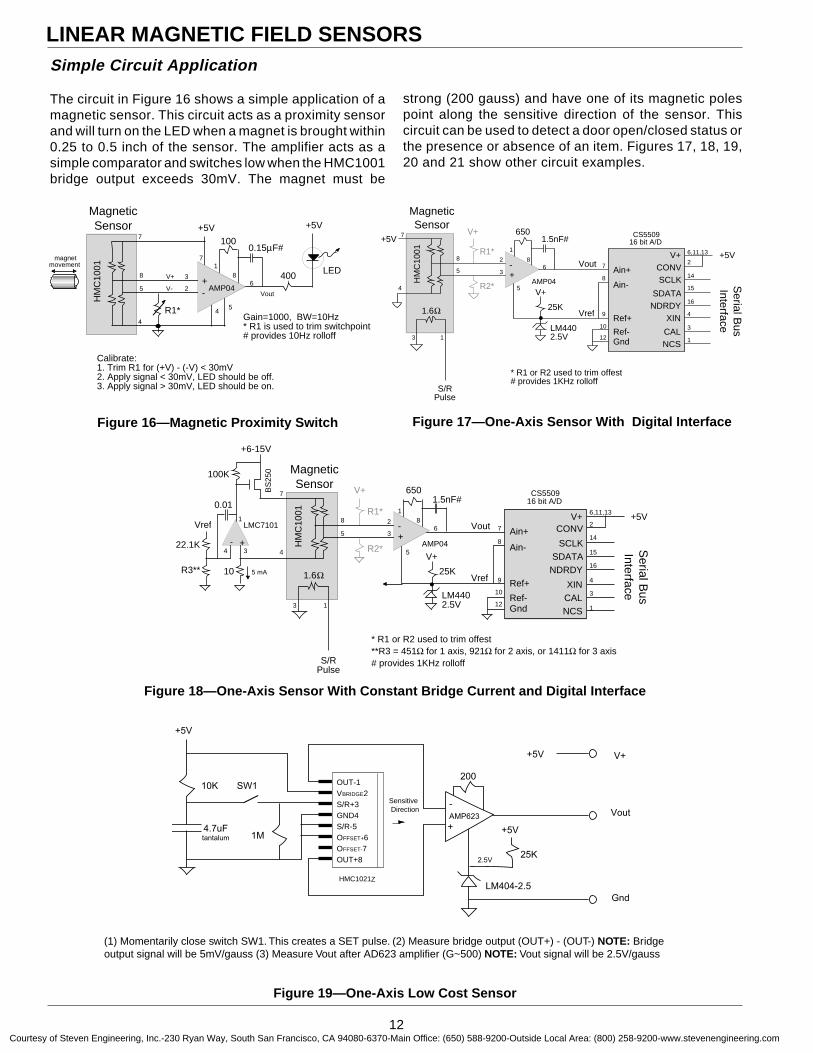
Simple Circuit Application
The circuit in Figure 16 shows a simple application of amagnetic sensor. This circuit acts as a proximity sensorand will turn on the LED when a magnet is brought within0.25 to 0.5 inch of the sensor. The amplifier acts as asimple comparator and switches low when the HMC1001bridge output exceeds 30mV. The magnet must be
* R1 or R2 used to trim offest**R3 = 451Ω for 1 axis, 921Ω for 2 axis, or 1411Ω for 3 axis# provides 1KHz rolloff
Vref
MagneticSensor
1.5nF#650
R1*
R2*
-+
25K
LM4402.5V
V+AMP04H
MC
1001
Vout
18
6
5
2
3 Ain+
Ain-
Ref+
Ref-
CONV
SCLKSDATA
NDRDY
XINCALNCS
1.6Ω
V+7
4
8
5
13
7
8
9
10
2
14
15
16
4
3
1
CS550916 bit A/D
12 Gnd
V+ 6,11,13 +5V
Serial B
usInterface
+6-15V
S/RPulse
10
- +
Vref
22.1K
R3**
BS
250100K
LMC7101
5 mA
0.011
34
Figure 18—One-Axis Sensor With Constant Bridge Current and Digital Interface
strong (200 gauss) and have one of its magnetic polespoint along the sensitive direction of the sensor. Thiscircuit can be used to detect a door open/closed status orthe presence or absence of an item. Figures 17, 18, 19,20 and 21 show other circuit examples.
4Gain=1000, BW=10Hz* R1 is used to trim switchpoint# provides 10Hz rolloff
MagneticSensor
0.15µF#100
R1*
+- AMP04
HM
C10
01 18
6
5
3
2
7
4
8
5
+5V
7
400
+5V
Calibrate:1. Trim R1 for (+V) - (-V) < 30mV2. Apply signal < 30mV, LED should be off.3. Apply signal > 30mV, LED should be on.
V-
V+
Vout
LEDmagnet
movement
Figure 16—Magnetic Proximity Switch
* R1 or R2 used to trim offest# provides 1KHz rolloff
Vref
MagneticSensor
1.5nF#650
R1*
R2*
-+
25K
LM4402.5V
V+AMP04H
MC
1001
Vout
1
86
5
2
3 Ain+
Ain-
Ref+
Ref-
CONVSCLK
SDATANDRDY
XIN
CALNCS
1.6Ω
V+7
4
8
5
13
7
8
9
10
2
14
15
16
4
3
1
CS550916 bit A/D
12 Gnd
V+ 6,11,13 +5V
Serial B
usInterface
+5V
S/RPulse
Figure 17—One-Axis Sensor With Digital Interface
Figure 19—One-Axis Low Cost Sensor
(1) Momentarily close switch SW1. This creates a SET pulse. (2) Measure bridge output (OUT+) - (OUT-) NOTE: Bridgeoutput signal will be 5mV/gauss (3) Measure Vout after AD623 amplifier (G~500) NOTE: Vout signal will be 2.5V/gauss
Sensitive Direction
OUT-1VBRIDGE2S/R+3GND4S/R-5OFFSET+6OFFSET-7OUT+8
HMC1021S
10K
4.7uFtantalum
SW1
Vout
+5V
1M
-
+AMP623
200
+5V
2.5V25K
LM404-2.5
+5V
Gnd
V+
Z
Courtesy of Steven Engineering, Inc.-230 Ryan Way, South San Francisco, CA 94080-6370-Main Office: (650) 588-9200-Outside Local Area: (800) 258-9200-www.stevenengineering.com
LINEAR MAGNETIC FIELD SENSORS
13
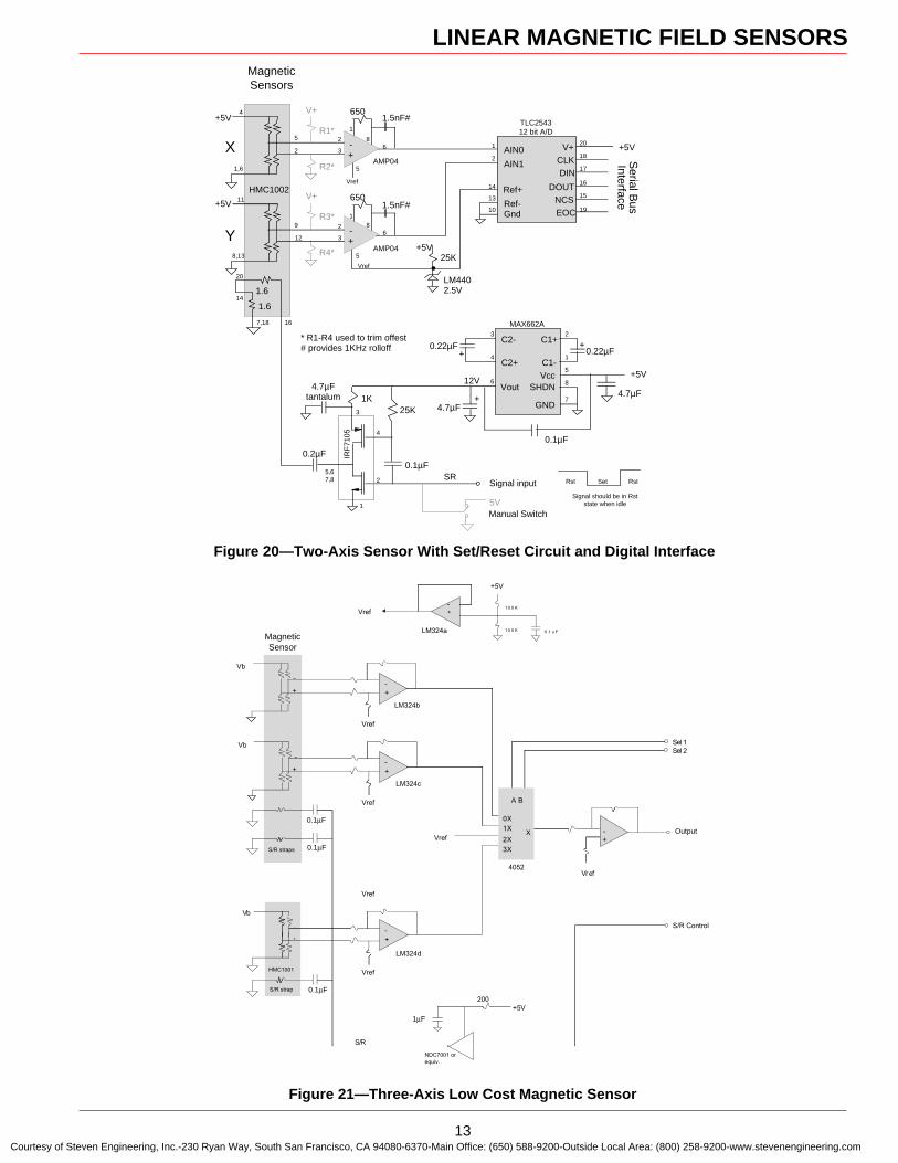
Figure 20—Two-Axis Sensor With Set/Reset Circuit and Digital Interface
* R1-R4 used to trim offest# provides 1KHz rolloff
MagneticSensorS
25K
LM4402.5V
+5V
1.6
16
20
SR
IRF
7105
0.2µF
4.7µF tantalum 1K
25K3
4
2
1
5,67,8
0.1µF
Set RstRst
Signal should be in Rst state when idle5V
Signal input
Manual Switch
23
12V
0.22µF1
7
5Vcc
SHDN
GND
C1-
C1+
Vout
4C2+
C2-0.22µF
6+5V
8
MAX662A
++
4.7µF
0.1µF
4.7µF+
1.5nF#650
R3*
R4*
-+
AMP04
18
6
5
2
3
V+11
8,13
9
12
+5V
14
7,18
1.6
1.5nF#650
R1*
R2*
-+
AMP04
HMC1002
1
86
5
2
3
V+4
1,6
5
2
+5V
Vref
Vref
AIN0
AIN1
Ref+
Ref-
CLKDIN
DOUTNCSEOC
1
2
14
13
18
17
16
15
19
TLC254312 bit A/D
10 Gnd
V+ 20 +5V
Serial B
usInterface
X
Y
Figure 21—Three-Axis Low Cost Magnetic Sensor
0.1 F
Vb
S/R strap
NDC7001 or equiv.
-+
Vref
+5V
1 F
200
+5V
-+ 10 0 K
10 0 K 0 .1 u F
-
+
MagneticSensors
S/R straps
0.1 F
0.1 F
4052
0X 1X
2X 3X
X Output
Sel 2Sel 1
S/R
A B
S/R Control
HMC1001
-
+
Vb
Vref
-
+
+-
Vref
LM324c
Vref
LM324b
Vb
+-
Vref
LM324a
+-
Vref
LM324d
Vref
MagneticSensors
MagneticSensor
0.1µF
0.1µF
0.1µF
1µF
Output
Courtesy of Steven Engineering, Inc.-230 Ryan Way, South San Francisco, CA 94080-6370-Main Office: (650) 588-9200-Outside Local Area: (800) 258-9200-www.stevenengineering.com

LINEAR MAGNETIC FIELD SENSORS
14
1 8
D
H E
e B
h × 45°
A
A1
HMC1001—8-Pin SIP and
HMC1002—Package Outline
PACKAGE OUTLINES
HMC1021S—8-Pin SOIC
HMC1022—16-Pin SOIC
D
E
B
1
h x 45°e
A
•H
A1
D
E
B
1 8
h x 45°e
A
•H
A1
916
SymbolA
A1BDEeHh
Min1.3710.1010.3554.8003.810
1.270 ref5.8160.381
Max1.7280.2490.4834.9793.988
6.1980.762
Min.054.004.014.189.150
.050 ref.229.015
Max.068.010.019.196.157
.244
.030
Millimeters Inches
SymbolA
A1BDEeHh
Min1.3710.1010.3559.8293.810
1.270 ref5.8160.381
Max1.7280.2490.483
11.2533.988
6.1980.762
Min.054.004.014.387.150
.050 ref.229.015
Max.068.010.019.443.157
.244
.030
Millimeters Inches
HMC1021Z—8-Pin SIP
D
E
8 7 6 5
1 2 3 4
LQ
A
b
E1
A1
e
HMC1021D—8-Pin Ceramic DIP
D
E
B
1 10
20 11
h
H
e A
A1
SymbolA
A1BDEeHh
Min 2.489 0.127 0.457
12.675 7.264
1.270 ref 1.270 0.381
Max2.6420.2790.483
12.9297.417
10.566ref
Min .098 .005 .014 .499 .286
.050 ref .396 .015
Max.104.011.019.509.292ref
.416
.030
Millimeters Inches
SymbolA
A1BDEeHh
Min 1.371 0.101 0.355 9.829 3.810
1.270 ref 5.014 0.381
Max1.7280.2490.483
11.2533.988
5.3140.762
Min .054 .004 .014 .387 .150
.050 ref .197 .015
Max.068.010.019.443.157
.209
.030
Millimeters Inches
SymbolA
A1bDE
E1eQL
Min 0.107 ref
0.009 0.016
— 0.282 0.290 0.100 ref
0.015 0.125
Max
0.0120.0200.4050.2980.310
0.0600.175
Millimeters Inches
Min Max 2.718 ref
0.229 0.406
— 7.163 7.366 2.54 ref
0.381 3.175
0.3050.508
10.2877.5697.874
1.5244.445
6.850 7.300 0.270 0.287
ref
Courtesy of Steven Engineering, Inc.-230 Ryan Way, South San Francisco, CA 94080-6370-Main Office: (650) 588-9200-Outside Local Area: (800) 258-9200-www.stevenengineering.com
LINEAR MAGNETIC FIELD SENSORS
15
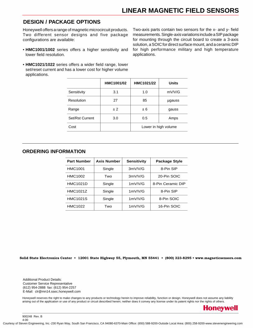
DESIGN / PACKAGE OPTIONSTwo-axis parts contain two sensors for the x- and y- fieldmeasurements. Single-axis variations include a SIP packagefor mounting through the circuit board to create a 3-axissolution, a SOIC for direct surface mount, and a ceramic DIPfor high performance military and high temperatureapplications.
Honeywell offers a range of magnetic microcircuit products.Two different sensor designs and five packageconfigurations are available:
• HMC1001/1002 series offers a higher sensitivity andlower field resolution.
• HMC1021/1022 series offers a wider field range, lowerset/reset current and has a lower cost for higher volumeapplications.
ORDERING INFORMATION
900248 Rev. B4-00
Honeywell reserves the right to make changes to any products or technology herein to improve reliability, function or design. Honeywell does not assume any liabilityarising out of the application or use of any product or circuit described herein; neither does it convey any license under its patent rights nor the rights of others.
Solid State Electronics Center • 12001 State Highway 55, Plymouth, MN 55441 • (800) 323-8295 • www.magneticsensors.com
Additional Product Details:Customer Service Representative(612) 954-2888 fax: (612) 954-2257E-Mail: [email protected]
rebmuNtraP rebmuNsixA ytivitisneS elytSegakcaP
1001CMH elgniS G/V/Vm3 PISniP-8
2001CMH owT G/V/Vm3 CIOSniP-02
D1201CMH elgniS G/V/Vm1 PIDcimareCniP-8
Z1201CMH elgniS G/V/Vm1 PISniP-8
S1201CMH elgniS G/V/Vm1 CIOSniP-8
2201CMH owT G/V/Vm1 CIOSniP-61
20/1001CMH 22/1201CMH stinU
ytivitisneS 1.3 0.1 G/V/Vm
noituloseR 72 58 ssuagµ
egnaR 2± 6± ssuag
tnerruCtsR/teS 0.3 5.0 spmA
tsoC emulovhgihnirewoL
Courtesy of Steven Engineering, Inc.-230 Ryan Way, South San Francisco, CA 94080-6370-Main Office: (650) 588-9200-Outside Local Area: (800) 258-9200-www.stevenengineering.com

Single-Axis Magnetic Sensor HMC1021D
The Honeywell HMC1021D is a single-axis magneto-resistive
sensor design in an 8-pin ceramic DIP package. The
advantages of the HMC1021D include high-temperature
operation, low magnetic field detection range, and a non-
magnetic package.
Honeywell’s Anisotropic Magneto-Resistive (AMR) sensor
technology provides the HMC1021D advantages over other
magnetic sensors with a wheatstone bridge to convert magnetic
fields to differential output voltage. Capable of sensing
magnetic field strength and direction down to 85 micro-gauss,
this sensor offers a compact and highly reliable solution for low
field magnetic sensing.
Honeywell continues to maintain product excellence and performance by introducing innovative solid-state magnetic
sensor solutions. These are highly reliable, top performance products that are delivered when promised. Honeywell’s
magnetic sensor solutions provide real solutions you can count on.
FEATURES BENEFITS
4 High Temperature Operating Range 4 From -55°C to +225°C, Perfect for Downhole Applications
4 Single-Axis DIP Package 4 Easy to Assemble Component.
4 On-Chip Set/Reset Straps 4 Reduces Temperature Effects, High Field Upset Resistance
4 On-Chip Offset Straps 4 Counters Hard-Iron Distortion
4 High Sensitivity 4 Low-Noise Signals for Amplification and Detection
4 High Reliability 4 Compact Solid State Design with Repeatable Results.
4 Available in High Volumes 4 Easy Transition to Production
Advanced Information
Courtesy of Steven Engineering, Inc.-230 Ryan Way, South San Francisco, CA 94080-6370-Main Office: (650) 588-9200-Outside Local Area: (800) 258-9200-www.stevenengineering.com
HMC1021D
2 www.honeywell.com
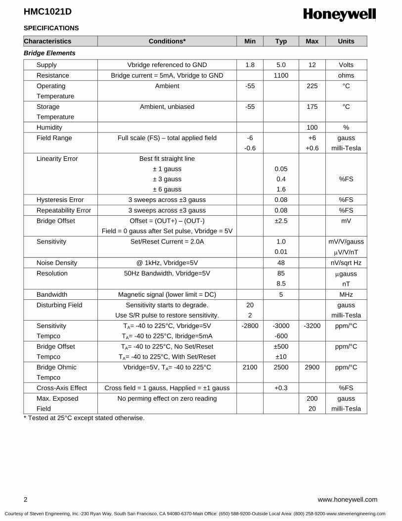
SPECIFICATIONS
Characteristics Conditions* Min Typ Max Units
Bridge Elements
Supply Vbridge referenced to GND 1.8 5.0 12 Volts Resistance Bridge current = 5mA, Vbridge to GND 1100 ohms Operating Temperature
Ambient -55 225 °C
Storage Temperature
Ambient, unbiased -55 175 °C
Humidity 100 % Field Range Full scale (FS) – total applied field -6
-0.6 +6
+0.6 gauss
milli-Tesla Linearity Error Best fit straight line
± 1 gauss ± 3 gauss ± 6 gauss
0.05 0.4 1.6
%FS
Hysteresis Error 3 sweeps across ±3 gauss 0.08 %FS Repeatability Error 3 sweeps across ±3 gauss 0.08 %FS Bridge Offset Offset = (OUT+) – (OUT-)
Field = 0 gauss after Set pulse, Vbridge = 5V ±2.5 mV
Sensitivity Set/Reset Current = 2.0A 1.0 0.01
mV/V/gaussµV/V/nT
Noise Density @ 1kHz, Vbridge=5V 48 nV/sqrt Hz Resolution 50Hz Bandwidth, Vbridge=5V 85
8.5 µgauss
nT Bandwidth Magnetic signal (lower limit = DC) 5 MHz Disturbing Field Sensitivity starts to degrade.
Use S/R pulse to restore sensitivity. 20 2
gauss milli-Tesla
Sensitivity Tempco
TA= -40 to 225°C, Vbridge=5V TA= -40 to 225°C, Ibridge=5mA
-2800 -3000 -600
-3200 ppm/°C
Bridge Offset Tempco
TA= -40 to 225°C, No Set/Reset TA= -40 to 225°C, With Set/Reset
±500 ±10
ppm/°C
Bridge Ohmic Tempco
Vbridge=5V, TA= -40 to 225°C 2100 2500 2900 ppm/°C
Cross-Axis Effect Cross field = 1 gauss, Happlied = ±1 gauss +0.3 %FS Max. Exposed Field
No perming effect on zero reading 200 20
gauss milli-Tesla
* Tested at 25°C except stated otherwise.
Courtesy of Steven Engineering, Inc.-230 Ryan Way, South San Francisco, CA 94080-6370-Main Office: (650) 588-9200-Outside Local Area: (800) 258-9200-www.stevenengineering.com
HMC1021D
www.honeywell.com 3
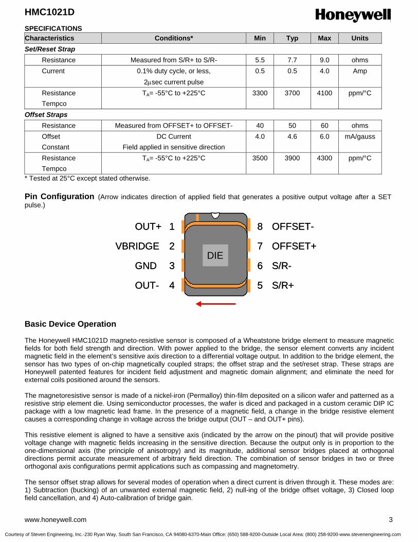
SPECIFICATIONS Characteristics Conditions* Min Typ Max Units Set/Reset Strap Resistance Measured from S/R+ to S/R- 5.5 7.7 9.0 ohms Current 0.1% duty cycle, or less,
2µsec current pulse 0.5 0.5 4.0 Amp
Resistance Tempco
TA= -55°C to +225°C 3300 3700 4100 ppm/°C
Offset Straps Resistance Measured from OFFSET+ to OFFSET- 40 50 60 ohms Offset Constant
DC Current Field applied in sensitive direction
4.0 4.6 6.0 mA/gauss
Resistance Tempco
TA= -55°C to +225°C 3500 3900 4300 ppm/°C
* Tested at 25°C except stated otherwise. Pin Configuration (Arrow indicates direction of applied field that generates a positive output voltage after a SET pulse.) Basic Device Operation The Honeywell HMC1021D magneto-resistive sensor is composed of a Wheatstone bridge element to measure magnetic fields for both field strength and direction. With power applied to the bridge, the sensor element converts any incident magnetic field in the element’s sensitive axis direction to a differential voltage output. In addition to the bridge element, the sensor has two types of on-chip magnetically coupled straps; the offset strap and the set/reset strap. These straps are Honeywell patented features for incident field adjustment and magnetic domain alignment; and eliminate the need for external coils positioned around the sensors. The magnetoresistive sensor is made of a nickel-iron (Permalloy) thin-film deposited on a silicon wafer and patterned as a resistive strip element die. Using semiconductor processes, the wafer is diced and packaged in a custom ceramic DIP IC package with a low magnetic lead frame. In the presence of a magnetic field, a change in the bridge resistive element causes a corresponding change in voltage across the bridge output (OUT – and OUT+ pins). This resistive element is aligned to have a sensitive axis (indicated by the arrow on the pinout) that will provide positive voltage change with magnetic fields increasing in the sensitive direction. Because the output only is in proportion to the one-dimensional axis (the principle of anisotropy) and its magnitude, additional sensor bridges placed at orthogonal directions permit accurate measurement of arbitrary field direction. The combination of sensor bridges in two or three orthogonal axis configurations permit applications such as compassing and magnetometry. The sensor offset strap allows for several modes of operation when a direct current is driven through it. These modes are: 1) Subtraction (bucking) of an unwanted external magnetic field, 2) null-ing of the bridge offset voltage, 3) Closed loop field cancellation, and 4) Auto-calibration of bridge gain.
OUT+ 1
2
3
4 5
6
7
8
VBRIDGE
GND
OUT- S/R+
S/R-
OFFSET+
OFFSET-
DIE
OUT+ 1
2
3
4 5
6
7
8
VBRIDGE
GND
OUT- S/R+
S/R-
OFFSET+
OFFSET-
DIEDIEDIE
Courtesy of Steven Engineering, Inc.-230 Ryan Way, South San Francisco, CA 94080-6370-Main Office: (650) 588-9200-Outside Local Area: (800) 258-9200-www.stevenengineering.com

HMC1021D
4 www.honeywell.com
The set/reset strap can be pulsed with high currents for the following benefits: 1) Enable the sensor to perform high sensitivity measurements, 2) Flip the polarity of the bridge output voltage, and 3) Periodically used to improve linearity, lower cross-axis effects, and temperature effects. Noise Characteristics The noise density for the HMR1021D is around 50nV/sqrt Hz at the 1 Hz corner, and drops below 10nV/sqrt Hz at 20Hz and begins to fit the Johnson Noise value at around 5nV/sqrt Hz beyond 100Hz. The 10Hz noise voltage averages around 0.58 micro-volts with a 0.16 micro-volts standard deviation. These values are provided with a 5-volt supply. Offset Strap The offset strap is a spiral of metallization that couples in the sensor element’s sensitive axis. The offset strap measures nominally 50 ohms, and requires about 4.6mA for each gauss of induced field. The strap will easily handle currents to buck or boost fields through the ±6 gauss linear measurement range, but designers should note the extreme thermal heating on the sensor die when doing so. With most applications, the offset strap is not utilized and can be ignored. Designers can leave one or both strap connections (Off- and Off+) open circuited, or ground one connection node. Do not tie positive and negative strap connections together of the same strap to avoid shorted turn magnetic circuits. Set/Reset Strap The set/reset strap is another spiral of metallization that couples to the sensor element’s easy axis (perpendicular to the sensitive axis on the sensor die). The set/reset strap connections have a nominal resistance of 7.7 ohms with a minimum required peak current of 0.5A for reset or set pulses. With rare exception, the set/reset strap must be used to periodically condition the magnetic domains of the magneto-resistive elements for best and reliable performance. A set pulse is defined as a positive pulse current entering the S/R+ strap connection. The successful result would be the magnetic domains aligned in a forward easy-axis direction so that the sensor bridge’s polarity is a positive slope with positive fields on the sensitive axis result in positive voltages across the bridge output connections. A reset pulse is defined as a negative pulse current entering the S/R+ strap connection. The successful result would be the magnetic domains aligned in a reverse easy-axis direction so that sensor bridge’s polarity is a negative slope with positive fields on the sensitive axis result in negative voltages across the bridge output connections. Ordering Information
Ordering Number Product HMC1021D
Single-Axis Magnetic Sensor
Find out more For more information on Honeywell’s Magnetic Sensors visit us online at www.magneticsensors.com or contact us at 800-323-8295 (763-954-2474 internationally). The application circuits herein constitute typical usage and interface of Honeywell product. Honeywell does not warranty or assume liability of customer-designed circuits derived from this description or depiction. Honeywell reserves the right to make changes to improve reliability, function or design. Honeywell does not assume any liability arising out of the application or use of any product or circuit described herein; neither does it convey any license under its patent rights nor the rights of others. U.S. Patents 4,441,072, 4,533,872, 4,569,742, 4,681,812, 4,847,584 and 6,529,114 apply to the technology described
Honeywell International Inc. 12001 Highway 55 Plymouth, MN 55441 Tel: 800-323-8295 www.honeywell.com
Form #900333 October 2005 ©2005 Honeywell International Inc.
Courtesy of Steven Engineering, Inc.-230 Ryan Way, South San Francisco, CA 94080-6370-Main Office: (650) 588-9200-Outside Local Area: (800) 258-9200-www.stevenengineering.com

HMC1023SENSOR PRODUCTS
3-AXIS MAGNETIC SENSOR Features
Ball Grid Array (BGA) Surface-Mount PackageThree Orthogonal Magneto-Resistive SensorsWide Field Range of ± 6 Gauss1.0 mV/V/gauss SensitivityMinimum Detectable Field to 85 gaussPatented On-Chip Set/Reset and Offset Straps
Product Description
The Honeywell HMC1023 is a high performance three-axis magneto-resistive sensor design in a singlepackage. The advantages of the HMC1023 includeorthogonal three-axis sensing, small size and a 16-contact BGA surface mount package.
Each of the magneto-resistive sensors are configuredas 4-element Wheatstone bridges to convert magneticfields to differential output voltages. Capable of sensingfields down to 85 micro-gauss, these sensors offer acompact, high sensitivity and highly reliable solution forlow field magnetic sensing.
APPLICATIONS
HMC1023 Circuit DiagramCompassing
Navigation Systems
Attitude Reference
Traffic Detection
Medical Devices
Solid State Electronics Center • www.magneticsensors.com • (800) 323-8295 • Page 1
Courtesy of Steven Engineering, Inc.-230 Ryan Way, South San Francisco, CA 94080-6370-Main Office: (650) 588-9200-Outside Local Area: (800) 258-9200-www.stevenengineering.com
HMC1023SENSOR PRODUCTS
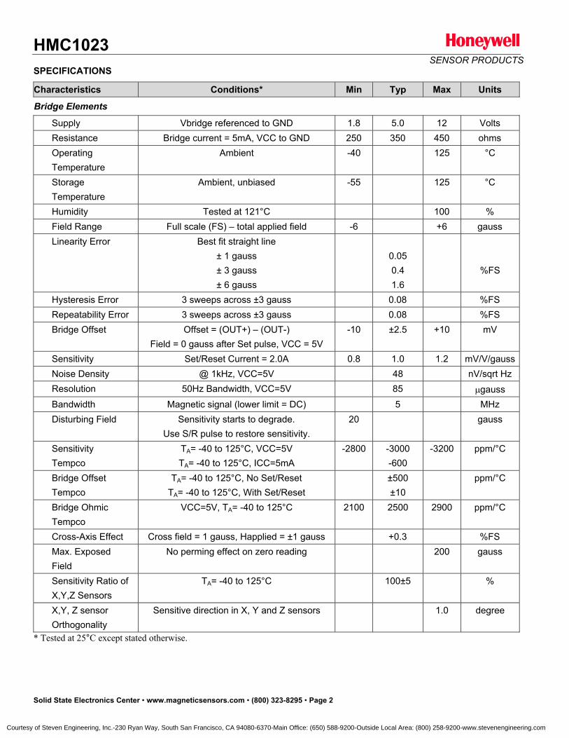
SPECIFICATIONS
Characteristics Conditions* Min Typ Max Units
Bridge Elements
Supply Vbridge referenced to GND 1.8 5.0 12 Volts Resistance Bridge current = 5mA, VCC to GND 250 350 450 ohms Operating Temperature
Ambient -40 125 °C
Storage Temperature
Ambient, unbiased -55 125 °C
Humidity Tested at 121°C 100 % Field Range Full scale (FS) – total applied field -6 +6 gauss Linearity Error Best fit straight line
± 1 gauss± 3 gauss± 6 gauss
0.050.41.6
%FS
Hysteresis Error 3 sweeps across ±3 gauss 0.08 %FS Repeatability Error 3 sweeps across ±3 gauss 0.08 %FS Bridge Offset Offset = (OUT+) – (OUT-)
Field = 0 gauss after Set pulse, VCC = 5V-10 ±2.5 +10 mV
Sensitivity Set/Reset Current = 2.0A 0.8 1.0 1.2 mV/V/gauss Noise Density @ 1kHz, VCC=5V 48 nV/sqrt Hz Resolution 50Hz Bandwidth, VCC=5V 85 gauss Bandwidth Magnetic signal (lower limit = DC) 5 MHz Disturbing Field Sensitivity starts to degrade.
Use S/R pulse to restore sensitivity. 20 gauss
Sensitivity Tempco
TA= -40 to 125°C, VCC=5VTA= -40 to 125°C, ICC=5mA
-2800 -3000-600
-3200 ppm/°C
Bridge Offset Tempco
TA= -40 to 125°C, No Set/ResetTA= -40 to 125°C, With Set/Reset
±500±10
ppm/°C
Bridge Ohmic Tempco
VCC=5V, TA= -40 to 125°C 2100 2500 2900 ppm/°C
Cross-Axis Effect Cross field = 1 gauss, Happlied = ±1 gauss +0.3 %FS Max. Exposed Field
No perming effect on zero reading 200 gauss
Sensitivity Ratio of X,Y,Z Sensors
TA= -40 to 125°C 100±5 %
X,Y, Z sensor Orthogonality
Sensitive direction in X, Y and Z sensors 1.0 degree
* Tested at 25°C except stated otherwise.
Solid State Electronics Center • www.magneticsensors.com • (800) 323-8295 • Page 2
Courtesy of Steven Engineering, Inc.-230 Ryan Way, South San Francisco, CA 94080-6370-Main Office: (650) 588-9200-Outside Local Area: (800) 258-9200-www.stevenengineering.com
HMC1023SENSOR PRODUCTS
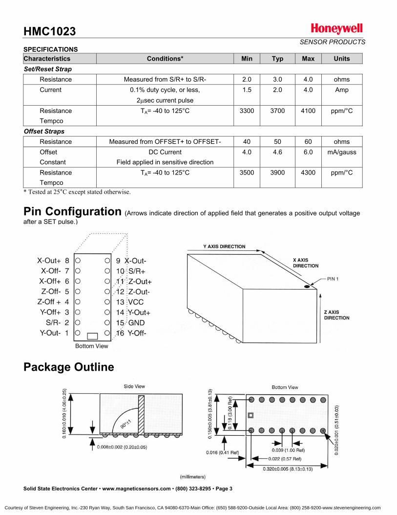
SPECIFICATIONSCharacteristics Conditions* Min Typ Max UnitsSet/Reset Strap
Resistance Measured from S/R+ to S/R- 2.0 3.0 4.0 ohms Current 0.1% duty cycle, or less,
2 sec current pulse 1.5 2.0 4.0 Amp
Resistance Tempco
TA= -40 to 125°C 3300 3700 4100 ppm/°C
Offset Straps Resistance Measured from OFFSET+ to OFFSET- 40 50 60 ohms Offset Constant
DC CurrentField applied in sensitive direction
4.0 4.6 6.0 mA/gauss
Resistance Tempco
TA= -40 to 125°C 3500 3900 4300 ppm/°C
* Tested at 25°C except stated otherwise.
Pin Configuration (Arrows indicate direction of applied field that generates a positive output voltageafter a SET pulse.)
Package Outline
Solid State Electronics Center • www.magneticsensors.com • (800) 323-8295 • Page 3
Courtesy of Steven Engineering, Inc.-230 Ryan Way, South San Francisco, CA 94080-6370-Main Office: (650) 588-9200-Outside Local Area: (800) 258-9200-www.stevenengineering.com

HMC1023SENSOR PRODUCTS
Mounting Considerations When mounting the Honeywell HMC1023 on a circuit board, please consider the following advice for ball grid arraycomponent attachment.
Ball Grid Array attachment/removal to printed circuit boards is precisely controlled thermal solder reflow process. Toprevent internal electrical damage and package cracking, do not use conventional soldering iron/solder station tools. If you do not have experience and the reflow oven, please have a qualified BGA rework technician do the work for you.
The reflow profile show below is the recommended profile for HMC1023 package attachment.
Melting temperature for the HMC1023 balls is at 180°C. The recommended rise and fall temperatures should be nogreater than 3°C/sec to prevent mechnical stresses or “popcorning”. Peak external temperature the part should beexposed to is between 200 to 210°C. When exposed a high temperature, such as the solder reflow process, theinternal connections in the package could sustain permanent damage, leaving open connections. 225°C is the meltingpoint of solder inside the HMC1023 Ball Grid Array package. Do not expose the part to this level of temperature.
If using solder paste, we recommend Kester SN62 solder paste with water soluble flux R560. This has a melting pointaround 180°C. Kester recommends a pre-heating zone from ambient temperature to 180°C for 2 to 4 minutesmaximum. The first part of this pre-heating zone ramps up from ambient to 150°C in 90 seconds with a ramp rate of less than 2.5 degrees C per second. The soak zone should last from 60 to 90 seconds (2 minutes maximum) andramp up in temperature from 150 to 180°C at 0.5 to 0.6 °C/ sec. The reflow zone should last for 30 to 90 secondsmaximum (40 to 60 seconds is ideal) and peak in temperature between 200 and 210°C with a ramp of 1.3 to1.6°C/sec.
Solid State Electronics Center • www.magneticsensors.com • (800) 323-8295 • Page 4
The reflow parameters can vary significantly and excellent reflow results can still be achieved. A thin layer of paste flux or a 2 to 3 mil layer of solder paste applied to the mother-board prior to placing the HMC1023 is helpful. Theprofile can be verified by placing a thermocouple between the HMC1023 and motherboard.
Courtesy of Steven Engineering, Inc.-230 Ryan Way, South San Francisco, CA 94080-6370-Main Office: (650) 588-9200-Outside Local Area: (800) 258-9200-www.stevenengineering.com

HMC1023SENSOR PRODUCTS
Basic Device Operation The Honeywell HMC1023 magneto-resistive sensor is composed of three Wheatstone bridge elements to measuremagnetic fields for both field strength and direction. With power applied to the bridges, the sensors elements convertany incident magnetic field in each element’s sensitive axis direction to a differential voltage output. In addition to the bridge elements, these sensors have two types of on-chip magnetically coupled straps; the offset straps and theset/reset strap. These straps are Honeywell patented features for incident field adjustment and magnetic domainalignment; and eliminate the need for external coils positioned around the sensors.
The magnetoresistive sensors are made of a nickel-iron (Permalloy) thin-film deposited on a silicon wafer andpatterned as a resistive strip element. In the presence of a magnetic field, a change in the bridge resistive elementscauses a corresponding change in voltage across the bridge outputs.
These resistive elements are aligned together to have a common sensitive axis (indicated by arrows on the pinouts)that will provide positive voltage change with magnetic fields increasing in the sensitive direction. Because the outputonly is in proportion to the one-dimensional axis (the principle of anisotropy) and its magnitude, additional sensorbridges placed at orthogonal directions permit accurate measurement of arbitrary field direction. The combination ofsensor bridges in this three orthogonal axis configuration permit applications such as compassing and magnetometry.
The individual sensor offset straps allow for several modes of operation when a direct current is driven through it. These modes are: 1) Subtraction (bucking) of an unwanted external magnetic field, 2) null-ing of the bridge offset voltage, 3) Closed loop field cancellation, and 4) Auto-calibration of bridge gain.
The set/reset strap can be pulsed with high currents for the following benefits: 1) Enable the sensor to perform highsensitivity measurements, 2) Flip the polarity of the bridge output voltage, and 3) Periodically used to improve linearity, lower cross-axis effects, and temperature effects.
Noise Characteristics
The noise density for the HMR1023 series is around 50nV/sqrt Hz at the 1 Hz corner, and drops below 10nV/sqrt Hz at 20Hz and begins to fit the Johnson Noise value at around 5nV/sqrt Hz beyond 100Hz. The 10Hz noise voltageaverages around 0.58 micro-volts with a 0.16 micro-volts standard deviation. These values are provided with a 5-voltsupply.
Offset Strap
The offset strap is a spiral of metalization that couples in the sensor element’s sensitive axis. In the HMC1023 design,there is one strap per bridge with both ends brought out externally. Each offset strap measures nominally 50 ohms,and requires about 4.6mA for each gauss of induced field. The straps will easily handle currents to buck or boostfields through the ±6 gauss linear measurement range, but designers should note the extreme thermal heating on thesensor die when doing so.
With most applications, the offset strap is not utilized and can be ignored. Designers can leave one or both strapconnections (Off- and Off+) open circuited, or ground one connection node. Do not tie positive and negative strapconnections together of the same strap to avoid shorted turn magnetic circuits.
Set/Reset Strap
The set/reset strap is another spiral of metalization that couples to the sensor elements easy axis (perpendicular tothe sensitive axis on the sensor die). The HMC1023 set/reset strap circuit has three straps (one per sensor) paralleledtogether for operation at low voltages. The set/reset strap connections have a nominal resistance of 3.0 ohms with a minimum required peak current of 1.5A for reset or set pulses. With rare exception, the set/reset strap must be usedto periodically condition the magnetic domains of the magneto-resistive elements for best and reliable performance.
A set pulse is defined as a positive pulse current entering the S/R+ strap connection. The successful result would bethe magnetic domains aligned in a forward easy-axis direction so that the sensor bridge’s polarity is a positive slopewith positive fields on the sensitive axis result in positive voltages across the bridge output connections.
Solid State Electronics Center • www.magneticsensors.com • (800) 323-8295 • Page 5
Courtesy of Steven Engineering, Inc.-230 Ryan Way, South San Francisco, CA 94080-6370-Main Office: (650) 588-9200-Outside Local Area: (800) 258-9200-www.stevenengineering.com
HMC1023SENSOR PRODUCTS
A reset pulse is defined as a negative pulse current entering the S/R+ strap connection. The successful result wouldbe the magnetic domains aligned in a reverse easy-axis direction so that sensor bridge’s polarity is a negative slopewith positive fields on the sensitive axis result in negative voltages across the bridge output connections.
Typically a reset pulse is sent first, followed by a set pulsea few milliseconds later. By shoving the magnetic domainsin completely opposite directions, any prior magneticdisturbances are likely to be completely erased by the duet of pulses. For simpler circuits with less criticalrequirements for noise and accuracy, a single polaritypulse circuit may be employed (all sets or all resets). Withthese uni-polar pulses, several pulses together becomeclose in performance to a set/reset pulse circuit. Figure 1shows a quick and dirty manual pulse circuit for uni-polarapplication of pulses to the set/reset strap.
Rsr3.0Rsr3.0
Iset
5 volts
Iset
5 volts
Figure 1 Set Pulse Circuit
Application NotesThree Axis Compassing with Tilt Compensation
For full three-axis compassing, the circuit depicted in Figure 2 shows HMC1023 used for sensing the magnetic field in three axes. A two-axis accelerometer with digital (PWM) outputs is also shown to provide pitch and roll (tilt)sensing, to correct the three-axis magnetic sensors outputs into to the tilt-compensated two-axis heading. Theaccelerometer can be substituted with a fluidic 2-axis tilt sensor if desired. For lower voltage operation with Lithium battery supplies (2.5 to 3.6Vdc), the Set/Reset circuit should be upgraded from a single IRF7509 to the dual IRF7509implementation (H-bridge) to permit a minimum 1.5-ampere pulse (500mA per set/reset strap resistance) to the sensors.
Figure 7 Three Axis Compass
HMC1023
U1Vcc
set/reset
.33uf
IRF7509
set/reset
Vcc/2
Vcc/2
5.00k
5.00k
500k
500k
5.00k
5.00k
500k
500k
LMV324
LMV324
1nf
1nf
U3
U4
3.3 to 5.0v
U2Vcc
Vcc/2
5.00k
5.00k
500k
500k
LMV324
.1 f
+
-
Cwith
MultiplexedA/D Conv.
AN0
AN1
AN2
AN3Vcc/2
U6
U5
xout
yout
Two-axisaccelerometer
Vcc
Vcc
DO0
DI0
DI1
HMC1023
U1Vcc
set/reset
.33uf
IRF7509
set/reset
Vcc/2
Vcc/2
5.00k
5.00k
500k
500k
5.00k
5.00k
500k
500k
LMV324
LMV324
1nf
1nf
U3
U4
3.3 to 5.0v
U2Vcc
Vcc/2
5.00k
5.00k
500k
500k
LMV324
.1 f
+
-
Cwith
MultiplexedA/D Conv.
AN0
AN1
AN2
AN3Vcc/2
U6
U5
xout
yout
Two-axisaccelerometer
Vcc
Vcc
DO0
DI0
DI1
Solid State Electronics Center • www.magneticsensors.com • (800) 323-8295 • Page 6
Courtesy of Steven Engineering, Inc.-230 Ryan Way, South San Francisco, CA 94080-6370-Main Office: (650) 588-9200-Outside Local Area: (800) 258-9200-www.stevenengineering.com
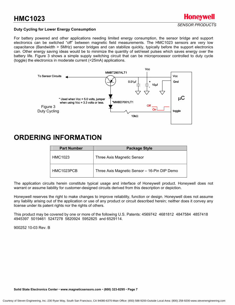
HMC1023SENSOR PRODUCTS
Duty Cycling for Lower Energy Consumption
For battery powered and other applications needing limited energy consumption, the sensor bridge and supportelectronics can be switched “off” between magnetic field measurements. The HMC1023 sensors are very lowcapacitance (Bandwidth > 5MHz) sensor bridges and can stabilize quickly, typically before the support electronicscan. Other energy saving ideas would be to minimize the quantity of set/reset pulses which saves energy over thebattery life. Figure 3 shows a simple supply switching circuit that can be microprocessor controlled to duty cycle (toggle) the electronics in moderate current (<25mA) applications.
MMBT2907ALT1
C
To Sensor Circuits
toggle
10k
+
-10 f
0.01 f
Vcc
Vcc
Gnd
*MMBD7001LT1* Used when Vcc = 5.0 volts, jumperwhen using Vcc = 3.3 volts or less.
MMBT2907ALT1
C
To Sensor Circuits
toggle
10k
+
-10 f
0.01 f
Vcc
Vcc
Gnd
*MMBD7001LT1* Used when Vcc = 5.0 volts, jumperwhen using Vcc = 3.3 volts or less.
OffOn
OffOn
Figure 3 Duty Cycling
ORDERING INFORMATION Part Number Package Style
HMC1023 Three Axis Magnetic Sensor
HMC1023PCB Three Axis Magnetic Sensor – 16-Pin DIP Demo
The application circuits herein constitute typical usage and interface of Honeywell product. Honeywell does notwarrant or assume liability for customer-designed circuits derived from this description or depiction.
Honeywell reserves the right to make changes to improve reliability, function or design. Honeywell does not assumeany liability arising out of the application or use of any product or circuit described herein; neither does it convey anylicense under its patent rights nor the rights of others.
This product may be covered by one or more of the following U.S. Patents: 4569742 4681812 4847584 48574184945397 5019461 5247278 5820924 5952825 and 6529114.
900252 10-03 Rev. B
Solid State Electronics Center • www.magneticsensors.com • (800) 323-8295 • Page 7
Courtesy of Steven Engineering, Inc.-230 Ryan Way, South San Francisco, CA 94080-6370-Main Office: (650) 588-9200-Outside Local Area: (800) 258-9200-www.stevenengineering.com

1-Axis Magnetic Sensor HMC1041Z
The Honeywell HMC1041Z is a z-axis surface mount option
designed for low field magnetic sensing. By adding the
HMC1041Z to other 2-axis magneto-resistive sensors, a cost
effective and space-efficient 3-axis magnetometer or
compassing solution is enabled. This compact, low cost
solution is easy to assemble for high volume, cost effective
OEM designs. Applications for the HMC1041Z include
Compassing, Navigation Systems, Magnetometry, and
Current Sensing.
The HMC1041Z utilizes Honeywell’s Anisotropic Magnetoresistive (AMR) technology that provides advantages over coil
based magnetic sensors. They are extremely sensitive, low field, solid-state magnetic sensors designed to measure
direction and magnitude of Earth’s magnetic fields, from tens of micro-gauss to 6 gauss. Honeywell’s Magnetic Sensors
are among the most sensitive and reliable low-field sensors in the industry.
Honeywell continues to maintain product excellence and performance by introducing innovative solid-state magnetic
sensor solutions. These are highly reliable, top performance products that are delivered when promised. Honeywell’s
magnetic sensor solutions provide real solutions you can count on.
FEATURES BENEFITS
4 Low Height Magnetic Sensors (1.05mm) 4 Narrow Dimensions and Small Size for Low Profile Vertical Sensing
Applications and Mounting, No Layout Constraints
4 Surface Mount Z-Axis Sensor 4 Easy to Assemble & Compatible with High Speed SMT Assembly
4 Low Voltage Operations (2.0V) 4 Compatible for Battery Powered Applications
4 Low Cost 4 Designed for High Volume, Cost Effective OEM Designs
4 Available in Tape & Reel Packaging 4 High Volume OEM Assembly
4 Lead Free Package Construction 4 Complies with Current Environmental Standards
4 4-Element Wheatstone Bridge 4 Low Noise Passive Element Design
4 Wide Magnetic Field Range (+/-6 Oe) 4 Sensor Can Be Used in Strong Magnetic Field Environments
4 Patented Offset and Set/Reset Straps 4 Stray Magnetic Field Compensation
Advanced Information
Courtesy of Steven Engineering, Inc.-230 Ryan Way, South San Francisco, CA 94080-6370-Main Office: (650) 588-9200-Outside Local Area: (800) 258-9200-www.stevenengineering.com
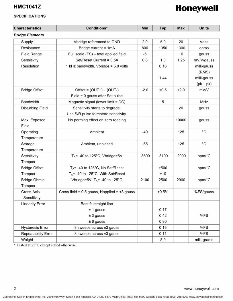
HMC1041Z
2 www.honeywell.com
SPECIFICATIONS
Characteristics Conditions* Min Typ Max Units
Bridge Elements
Supply Vbridge referenced to GND 2.0 5.0 20 Volts Resistance Bridge current = 1mA 800 1050 1300 ohms Field Range Full scale (FS) – total applied field -6 +6 gauss Sensitivity Set/Reset Current = 0.5A 0.8 1.0 1.25 mV/V/gauss Resolution 1 kHz bandwidth, Vbridge = 5.0 volts 0.16
1.44
milli-gauss (RMS)
milli-gauss (pk – pk)
Bridge Offset Offset = (OUT+) – (OUT-) Field = 0 gauss after Set pulse
-2.0 ±0.5 +2.0 mV/V
Bandwidth Magnetic signal (lower limit = DC) 5 MHz Disturbing Field Sensitivity starts to degrade.
Use S/R pulse to restore sensitivity. 20 gauss
Max. Exposed Field
No perming effect on zero reading 10000 gauss
Operating Temperature
Ambient -40 125 °C
Storage Temperature
Ambient, unbiased -55 125 °C
Sensitivity Tempco
TA= -40 to 125°C, Vbridge=5V -3500 -3100 -2000 ppm/°C
Bridge Offset Tempco
TA= -40 to 125°C, No Set/Reset TA= -40 to 125°C, With Set/Reset
±500 ±10
ppm/°C
Bridge Ohmic Tempco
Vbridge=5V, TA= -40 to 125°C 2100 2500 2900 ppm/°C
Cross-Axis Sensitivity
Cross field = 0.5 gauss, Happlied = ±3 gauss ±0.5% %FS/gauss
Linearity Error Best fit straight line ± 1 gauss ± 3 gauss ± 6 gauss
0.17 0.42 0.80
%FS
Hysteresis Error 3 sweeps across ±3 gauss 0.15 %FS Repeatability Error 3 sweeps across ±3 gauss 0.11 %FS Weight 8.9 milli-grams * Tested at 25°C except stated otherwise.
Courtesy of Steven Engineering, Inc.-230 Ryan Way, South San Francisco, CA 94080-6370-Main Office: (650) 588-9200-Outside Local Area: (800) 258-9200-www.stevenengineering.com
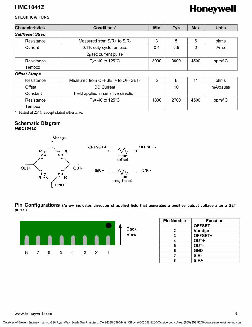
HMC1041Z
www.honeywell.com 3
SPECIFICATIONS Characteristics Conditions* Min Typ Max Units Set/Reset Strap Resistance Measured from S/R+ to S/R- 3 5 6 ohms Current 0.1% duty cycle, or less,
2µsec current pulse 0.4 0.5 2 Amp
Resistance Tempco
TA=-40 to 125°C 3000 3900 4500 ppm/°C
Offset Straps Resistance Measured from OFFSET+ to OFFSET- 5 8 11 ohms Offset Constant
DC Current Field applied in sensitive direction
10 mA/gauss
Resistance Tempco
TA=-40 to 125°C 1800 2700 4500 ppm/°C
* Tested at 25°C except stated otherwise. Schematic Diagram HMC1041Z Pin Configurations (Arrow indicates direction of applied field that generates a positive output voltage after a SET pulse.)
Pin Number Function 1 OFFSET- 2 Vbridge 3 OFFSET+ 4 OUT+ 5 OUT- 6 GND 7 S/R- 8 S/R+
BackView
12345678
BackView
12345678
Courtesy of Steven Engineering, Inc.-230 Ryan Way, South San Francisco, CA 94080-6370-Main Office: (650) 588-9200-Outside Local Area: (800) 258-9200-www.stevenengineering.com
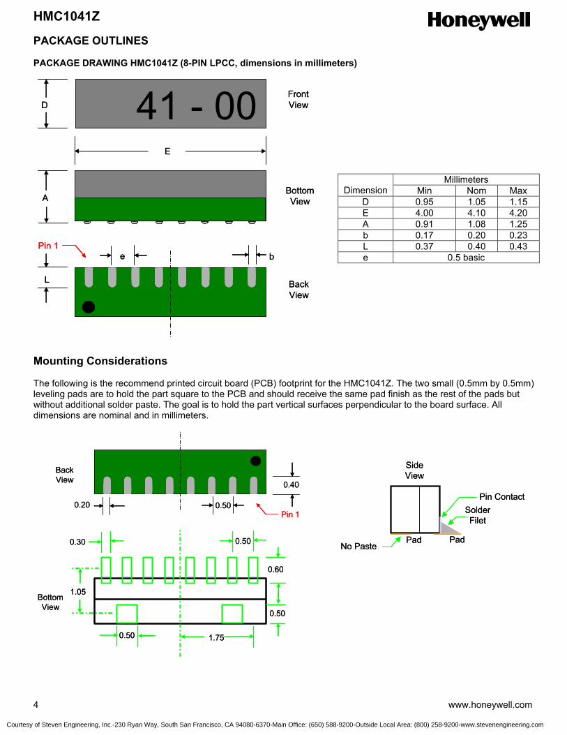
HMC1041Z
4 www.honeywell.com
PACKAGE OUTLINES PACKAGE DRAWING HMC1041Z (8-PIN LPCC, dimensions in millimeters) Mounting Considerations The following is the recommend printed circuit board (PCB) footprint for the HMC1041Z. The two small (0.5mm by 0.5mm) leveling pads are to hold the part square to the PCB and should receive the same pad finish as the rest of the pads but without additional solder paste. The goal is to hold the part vertical surfaces perpendicular to the board surface. All dimensions are nominal and in millimeters.
Millimeters Dimension Min Nom Max
D 0.95 1.05 1.15 E 4.00 4.10 4.20 A 0.91 1.08 1.25 b 0.17 0.20 0.23 L 0.37 0.40 0.43 e 0.5 basic
No Paste
SideView
SolderFilet
Pad Pad
Pin Contact
No Paste
SideView
SolderFilet
Pad Pad
Pin Contact
BottomView
0.50
0.60
0.30
1.75
0.20 0.50
0.40
Pin 1
BackView
0.50
0.50
1.05BottomView
0.50
0.60
0.30
1.75
0.20 0.50
0.40
Pin 1
BackView
0.50
0.50
1.05
41 - 00D
A
E
be
L
Pin 1
FrontView
BottomView
BackView
41 - 00D
A
E
be
L
Pin 1
FrontView
BottomView
BackView
Courtesy of Steven Engineering, Inc.-230 Ryan Way, South San Francisco, CA 94080-6370-Main Office: (650) 588-9200-Outside Local Area: (800) 258-9200-www.stevenengineering.com

HMC1041Z
www.honeywell.com 5
Stencil Design and Solder Paste A 4 mil stencil and 100% paste coverage is recommended for the eight electrical contact pads. Do not apply paste on the leveling pads. The HMC1041Z has been tested successfully with no-clean solder paste. Pick and Place Placement is machine dependant and no restrictions are recommended, and have be tested with mechanical centering. Placement force should be equivalent 1206 SMT resistors and enough force should be used to squeeze the paste out from the package/contact pad overlap and to keep the package pin contacts vertical. The low mass of the HMC1041Z ensures that very little paste is required to hold the part until reflow. Reflow and Rework No special profile is required for the HMC1041Z, and compatible with lead eutectic and lead-free solder paste reflow profiles. Honeywell recommends the adherence to solder paste manufacturer’s guidelines. The HMC1041Z may be reworked with soldering irons, but extreme care must be taken not to overheat the copper pads from the part’s fiberglass substrate. Irons with a tip temperature no greater than 315°C should be used. Excessive rework risks the copper pads pulling away into the molten solder. Basic Device Operation The Honeywell HMC1041Z magnetoresistive sensor is a Wheatstone bridge device to measure magnetic fields. With power supply applied to a bridge, the sensor converts any incident magnetic field in the sensitive axis direction to a differential voltage output. In addition to the bridge circuit, the sensor has two on-chip magnetically coupled straps; the offset strap and the set/reset strap. These straps are Honeywell patented features for incident field adjustment and magnetic domain alignment; and eliminate the need for external coils positioned around the sensors. The magnetoresistive sensors are made of a nickel-iron (Permalloy) thin-film deposited on a silicon wafer and patterned as a resistive strip element. In the presence of a magnetic field, a change in the bridge resistive elements causes a corresponding change in voltage across the bridge outputs. These resistive elements are aligned together to have a common sensitive axis (indicated by arrows on the pinouts) that will provide positive voltage change with magnetic fields increasing in the sensitive direction. Because the output only is in proportion to the one-dimensional axis (the principle of anisotropy) and its magnitude, additional sensor bridges placed at orthogonal directions permit accurate measurement of arbitrary field direction. The combination of sensor bridges in two and three orthogonal axis permit applications such as compassing and magnetometry. The offset strap allows for several modes of operation when a direct current is driven through it. These modes are: 1) Subtraction (bucking) of an unwanted external magnetic field, 2) null-ing of the bridge offset voltage, 3) Closed loop field cancellation, and 4) Auto-calibration of bridge gain. The set/reset strap can be pulsed with high currents for the following benefits: 1) Enable the sensor to perform high sensitivity measurements, 2) Flip the polarity of the bridge output voltage, and 3) Periodically used to improve linearity, lower cross-axis effects, and temperature effects. Offset Strap The offset strap is a spiral of metallization that couples in the sensor element’s sensitive axis. The offset strap measures nominally 8 ohms, and requires 10mA for each gauss of induced field. The straps will easily handle currents to buck or boost fields through the ±6 gauss linear measurement range, but designers should note the extreme thermal heating on the die when doing so. With most applications, the offset strap is not utilized and can be ignored. Designers can leave one or both strap connections (Off- and Off+) open circuited, or ground one connection node. Do not tie both strap connections together to avoid shorted turn magnetic circuits. Set/Reset Strap The set/reset strap is another spiral of metallization that couples to the sensor elements easy axis (perpendicular to the sensitive axis on the sensor die. Each set/reset strap has a nominal resistance of 5 ohms with a nominal required peak
Courtesy of Steven Engineering, Inc.-230 Ryan Way, South San Francisco, CA 94080-6370-Main Office: (650) 588-9200-Outside Local Area: (800) 258-9200-www.stevenengineering.com
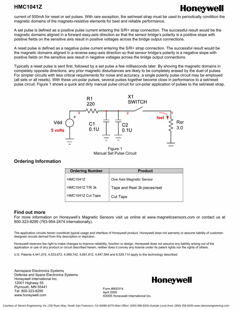
HMC1041Z
6 www.honeywell.com
Iset
5 volts
Rsr3.0
Iset
5 volts
Rsr3.0
current of 500mA for reset or set pulses. With rare exception, the set/reset strap must be used to periodically condition the magnetic domains of the magneto-resistive elements for best and reliable performance. A set pulse is defined as a positive pulse current entering the S/R+ strap connection. The successful result would be the magnetic domains aligned in a forward easy-axis direction so that the sensor bridge’s polarity is a positive slope with positive fields on the sensitive axis result in positive voltages across the bridge output connections. A reset pulse is defined as a negative pulse current entering the S/R+ strap connection. The successful result would be the magnetic domains aligned in a reverse easy-axis direction so that sensor bridge’s polarity is a negative slope with positive fields on the sensitive axis result in negative voltages across the bridge output connections. Typically a reset pulse is sent first, followed by a set pulse a few milliseconds later. By shoving the magnetic domains in completely opposite directions, any prior magnetic disturbances are likely to be completely erased by the duet of pulses. For simpler circuits with less critical requirements for noise and accuracy, a single polarity pulse circuit may be employed (all sets or all resets). With these uni-polar pulses, several pulses together become close in performance to a set/reset pulse circuit. Figure 1 shows a quick and dirty manual pulse circuit for uni-polar application of pulses to the set/reset strap. Ordering Information
Ordering Number Product HMC1041Z HMC1041Z T/R 3k HMC1041Z Cut Tape
One Axis Magnetic Sensor
Tape and Reel 3k pieces/reel Cut Tape
Find out more For more information on Honeywell’s Magnetic Sensors visit us online at www.magneticsensors.com or contact us at 800-323-8295 (763-954-2474 internationally). The application circuits herein constitute typical usage and interface of Honeywell product. Honeywell does not warranty or assume liability of customer-designed circuits derived from this description or depiction. Honeywell reserves the right to make changes to improve reliability, function or design. Honeywell does not assume any liability arising out of the application or use of any product or circuit described herein; neither does it convey any license under its patent rights nor the rights of others. U.S. Patents 4,441,072, 4,533,872, 4,569,742, 4,681,812, 4,847,584 and 6,529,114 apply to the technology described
Figure 1 Manual Set Pulse Circuit
Aerospace Electronics Systems Defense and Space Electronics Systems Honeywell International Inc. 12001 Highway 55 Plymouth, MN 55441 Tel: 800-323-8295 www.honeywell.com
Form #900314 April 2005 ©2005 Honeywell International Inc.
Courtesy of Steven Engineering, Inc.-230 Ryan Way, South San Francisco, CA 94080-6370-Main Office: (650) 588-9200-Outside Local Area: (800) 258-9200-www.stevenengineering.com

2-Axis Magnetic Sensor HMC1042L
The Honeywell HMC1042L is a high-performance, two-axis
magneto-resistive sensor. It is designed for magnetic compass
applications with capability of 0.2 degree accuracy. Stand alone or
by adding the companion HMC1041Z sensor, precision two and
three-axis magnetometry or compassing solutions are enabled. Pin
compatible with the HMC1052L; this miniature, low cost solution is
easy to assemble for high volume, cost effective OEM designs.
Applications for the HMC1042L include Compassing, Navigation
Systems, Magnetometry, and Magnetic Anomaly Detection.
The HMC1042L utilizes Honeywell’s Anisotropic Magnetoresistive
(AMR) technology that provides advantages over coil based
magnetic sensors. They are extremely sensitive, low field, low hysteresis, solid-state magnetic sensors designed to
measure direction and magnitude of Earth’s magnetic fields, from tens of micro-gauss to 6 gauss. Honeywell’s Magnetic
Sensors are among the most sensitive and reliable low-field sensors in the industry.
Honeywell continues to maintain product excellence and performance by introducing innovative solid-state magnetic
sensor solutions. These are highly reliable, top performance products that are delivered when promised. Honeywell’s
magnetic sensor solutions provide real solutions you can count on.
FEATURES BENEFITS
4 Two-Axis Precision Sensors 4 Near-Perfect Orthogonality and ±0.2%FS/gauss Cross Axis
Performance
4 Miniature Surface Mount Two-Axis Magnetic Sensors (3mm x 3mm QFN)
4 Small Size for Low Profile Sensing Applications and Mounting, Compatible with High Speed SMT Assembly
4 Low Voltage Operations (1.8V) 4 Compatible for Battery Powered Applications
4 Low Cost 4 Designed for High Volume, Cost Effective OEM Designs
4 Available in Tape & Reel Packaging 4 High Volume OEM Assembly
4 Lead Free Package Construction 4 Complies with Current Environmental Standards
4 4-Element Wheatstone Bridge 4 Low Noise Passive Element Design
4 Wide Magnetic Field Range (+/-6 Oe) 4 Sensor Can Be Used in Strong Magnetic Field Environments
4 Patented Offset and Set/Reset Straps 4 Stray Magnetic Field Compensation
Advanced Information
Courtesy of Steven Engineering, Inc.-230 Ryan Way, South San Francisco, CA 94080-6370-Main Office: (650) 588-9200-Outside Local Area: (800) 258-9200-www.stevenengineering.com
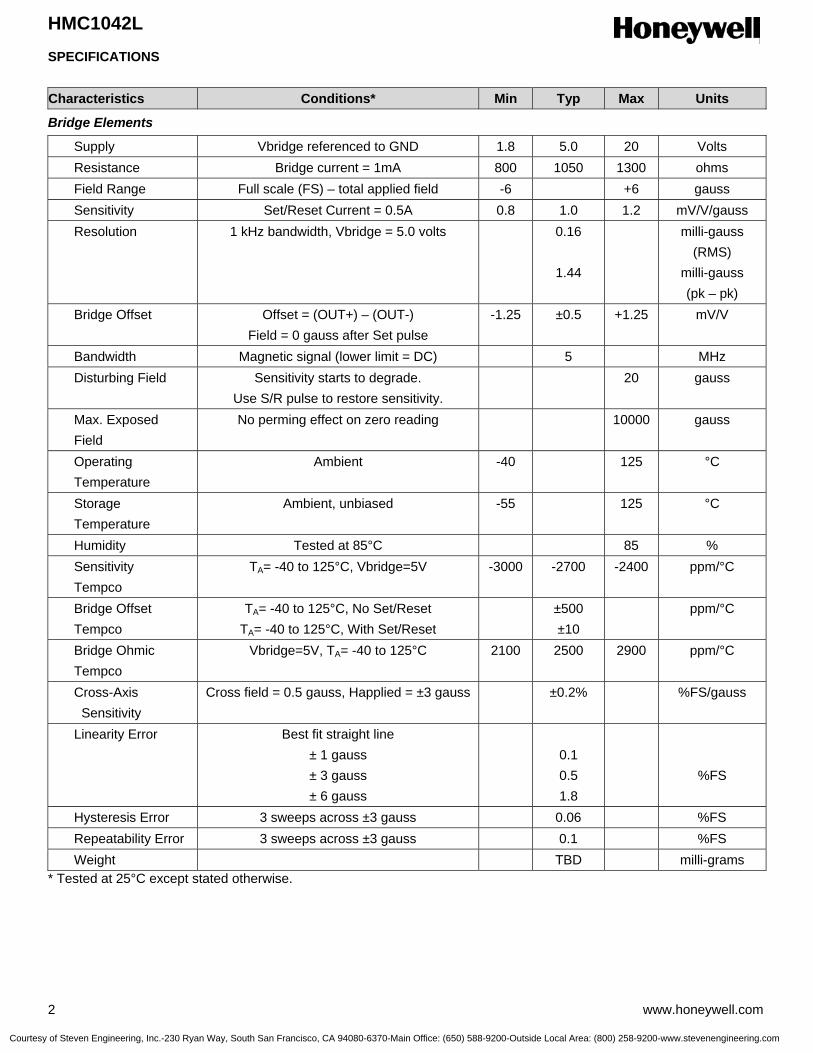
HMC1042L
2 www.honeywell.com
SPECIFICATIONS
Characteristics Conditions* Min Typ Max Units
Bridge Elements
Supply Vbridge referenced to GND 1.8 5.0 20 Volts Resistance Bridge current = 1mA 800 1050 1300 ohms Field Range Full scale (FS) – total applied field -6 +6 gauss Sensitivity Set/Reset Current = 0.5A 0.8 1.0 1.2 mV/V/gauss Resolution 1 kHz bandwidth, Vbridge = 5.0 volts 0.16
1.44
milli-gauss (RMS)
milli-gauss (pk – pk)
Bridge Offset Offset = (OUT+) – (OUT-) Field = 0 gauss after Set pulse
-1.25 ±0.5 +1.25 mV/V
Bandwidth Magnetic signal (lower limit = DC) 5 MHz Disturbing Field Sensitivity starts to degrade.
Use S/R pulse to restore sensitivity. 20 gauss
Max. Exposed Field
No perming effect on zero reading 10000 gauss
Operating Temperature
Ambient -40 125 °C
Storage Temperature
Ambient, unbiased -55 125 °C
Humidity Tested at 85°C 85 % Sensitivity Tempco
TA= -40 to 125°C, Vbridge=5V -3000 -2700 -2400 ppm/°C
Bridge Offset Tempco
TA= -40 to 125°C, No Set/Reset TA= -40 to 125°C, With Set/Reset
±500 ±10
ppm/°C
Bridge Ohmic Tempco
Vbridge=5V, TA= -40 to 125°C 2100 2500 2900 ppm/°C
Cross-Axis Sensitivity
Cross field = 0.5 gauss, Happlied = ±3 gauss ±0.2% %FS/gauss
Linearity Error Best fit straight line ± 1 gauss ± 3 gauss ± 6 gauss
0.1 0.5 1.8
%FS
Hysteresis Error 3 sweeps across ±3 gauss 0.06 %FS Repeatability Error 3 sweeps across ±3 gauss 0.1 %FS Weight TBD milli-grams * Tested at 25°C except stated otherwise.
Courtesy of Steven Engineering, Inc.-230 Ryan Way, South San Francisco, CA 94080-6370-Main Office: (650) 588-9200-Outside Local Area: (800) 258-9200-www.stevenengineering.com
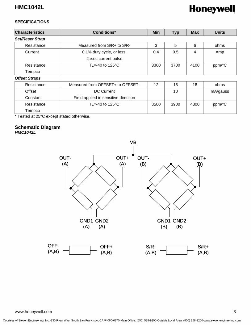
HMC1042L
www.honeywell.com 3
SPECIFICATIONS Characteristics Conditions* Min Typ Max Units Set/Reset Strap Resistance Measured from S/R+ to S/R- 3 5 6 ohms Current 0.1% duty cycle, or less,
2µsec current pulse 0.4 0.5 4 Amp
Resistance Tempco
TA=-40 to 125°C 3300 3700 4100 ppm/°C
Offset Straps Resistance Measured from OFFSET+ to OFFSET- 12 15 18 ohms Offset Constant
DC Current Field applied in sensitive direction
10 mA/gauss
Resistance Tempco
TA=-40 to 125°C 3500 3900 4300 ppm/°C
* Tested at 25°C except stated otherwise. Schematic Diagram HMC1042L
VB
GND1(A)
GND1(B)
OUT-(A)
OUT+(A)
OUT-(B)
OUT+(B)
OFF-(A,B)
OFF+(A,B)
S/R-(A,B)
S/R+(A,B)
GND2(A)
GND2(B)
VB
GND1(A)
GND1(B)
OUT-(A)
OUT+(A)
OUT-(B)
OUT+(B)
OFF-(A,B)
OFF+(A,B)
S/R-(A,B)
S/R+(A,B)
GND2(A)
GND2(B)
Courtesy of Steven Engineering, Inc.-230 Ryan Way, South San Francisco, CA 94080-6370-Main Office: (650) 588-9200-Outside Local Area: (800) 258-9200-www.stevenengineering.com

HMC1042L
4 www.honeywell.com
Pin Configurations (Arrow indicates direction of applied field that generates a positive output voltage after a SET pulse.)
PACKAGE OUTLINES PACKAGE DRAWING HMC1042L (16-PIN LCC, dimensions in millimeters)
Pin Number Function 1 GND2 (A) 2 OFF+ 3 OUT+ (A) 4 VB 5 NC 6 OFF- 7 GND2 (B) 8 S/R+ 9 NC 10 OUT- (B) 11 S/R- 12 NC 13 GND1 (A) 14 OUT- (A) 15 GND1 (B) 16 OUT+ (B)
1234
5
6
7
8
9 10 11 12
13
14
15
16
GND2(A)
OFF+OUT+(A)
VB
NC
NC
OFF-
GND2(B)
S/R+
OUT-(B) S/R- NC
GND1(A)
OUT-(A)
GND1(B)
OUT+(B)
B
A
BOTTOM VIEW
1234
5
6
7
8
9 10 11 12
13
14
15
16
GND2(A)
OFF+OUT+(A)
VB
NC
NC
OFF-
GND2(B)
S/R+
OUT-(B) S/R- NC
GND1(A)
OUT-(A)
GND1(B)
OUT+(B)
B
A
BOTTOM VIEW
Millimeters Symbol min max
A 0.80 1.00 A1 0 0.05 A3 0.20 REF b 0.18 0.30 D 3.00 BSC D2 1.55 1.80 E 3.00 BSC E2 1.55 1.80 e 0.50 BSC L 0.30 0.50 N 16
ND 4 NE 4 r B(min)/2
aaa 0.15 bbb 0.10 ccc 0.10
Courtesy of Steven Engineering, Inc.-230 Ryan Way, South San Francisco, CA 94080-6370-Main Office: (650) 588-9200-Outside Local Area: (800) 258-9200-www.stevenengineering.com
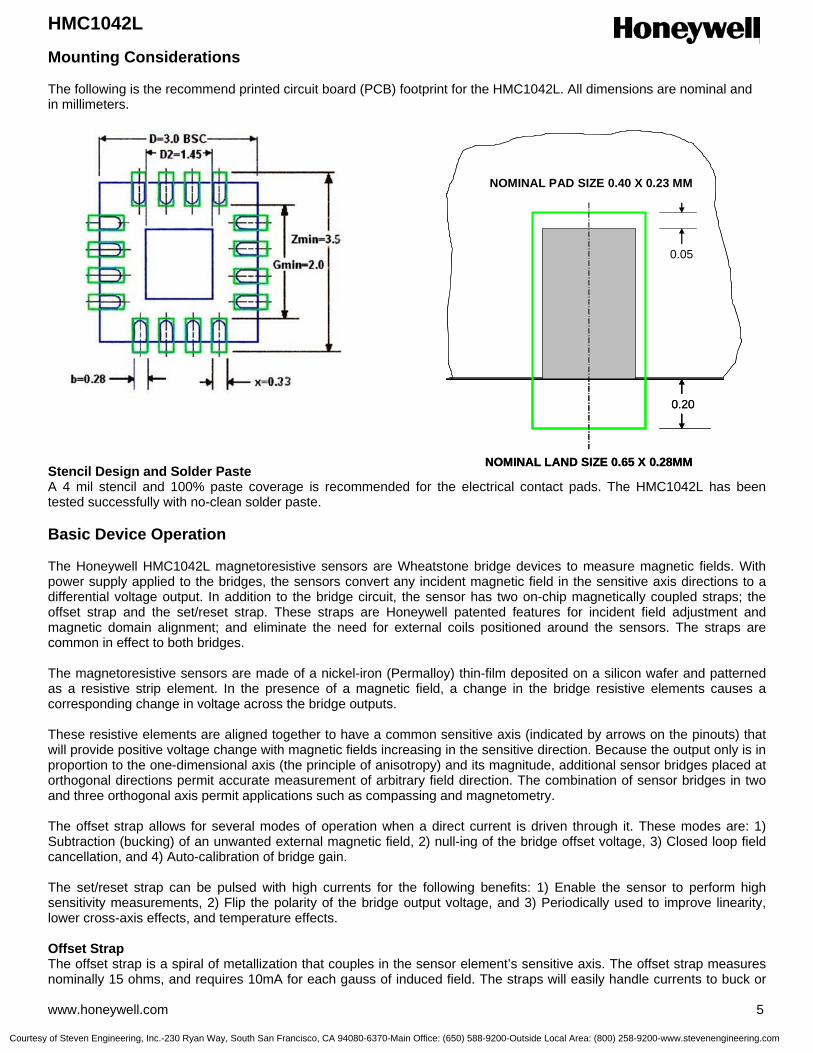
HMC1042L
www.honeywell.com 5
Mounting Considerations The following is the recommend printed circuit board (PCB) footprint for the HMC1042L. All dimensions are nominal and in millimeters.
Stencil Design and Solder Paste A 4 mil stencil and 100% paste coverage is recommended for the electrical contact pads. The HMC1042L has been tested successfully with no-clean solder paste. Basic Device Operation The Honeywell HMC1042L magnetoresistive sensors are Wheatstone bridge devices to measure magnetic fields. With power supply applied to the bridges, the sensors convert any incident magnetic field in the sensitive axis directions to a differential voltage output. In addition to the bridge circuit, the sensor has two on-chip magnetically coupled straps; the offset strap and the set/reset strap. These straps are Honeywell patented features for incident field adjustment and magnetic domain alignment; and eliminate the need for external coils positioned around the sensors. The straps are common in effect to both bridges. The magnetoresistive sensors are made of a nickel-iron (Permalloy) thin-film deposited on a silicon wafer and patterned as a resistive strip element. In the presence of a magnetic field, a change in the bridge resistive elements causes a corresponding change in voltage across the bridge outputs. These resistive elements are aligned together to have a common sensitive axis (indicated by arrows on the pinouts) that will provide positive voltage change with magnetic fields increasing in the sensitive direction. Because the output only is in proportion to the one-dimensional axis (the principle of anisotropy) and its magnitude, additional sensor bridges placed at orthogonal directions permit accurate measurement of arbitrary field direction. The combination of sensor bridges in two and three orthogonal axis permit applications such as compassing and magnetometry. The offset strap allows for several modes of operation when a direct current is driven through it. These modes are: 1) Subtraction (bucking) of an unwanted external magnetic field, 2) null-ing of the bridge offset voltage, 3) Closed loop field cancellation, and 4) Auto-calibration of bridge gain. The set/reset strap can be pulsed with high currents for the following benefits: 1) Enable the sensor to perform high sensitivity measurements, 2) Flip the polarity of the bridge output voltage, and 3) Periodically used to improve linearity, lower cross-axis effects, and temperature effects. Offset Strap The offset strap is a spiral of metallization that couples in the sensor element’s sensitive axis. The offset strap measures nominally 15 ohms, and requires 10mA for each gauss of induced field. The straps will easily handle currents to buck or
NOMINAL PAD SIZE 0.40 X 0.23 MM
NOMINAL LAND SIZE 0.65 X 0.28MM
0.20
0.05
NOMINAL PAD SIZE 0.40 X 0.23 MM
NOMINAL LAND SIZE 0.65 X 0.28MM
0.20
0.05
Courtesy of Steven Engineering, Inc.-230 Ryan Way, South San Francisco, CA 94080-6370-Main Office: (650) 588-9200-Outside Local Area: (800) 258-9200-www.stevenengineering.com

HMC1042L
6 www.honeywell.com
boost fields through the ±6 gauss linear measurement range, but designers should note the extreme thermal heating on the die when doing so. With most applications, the offset strap is not utilized and can be ignored. Designers can leave one or both strap connections (Off- and Off+) open circuited, or ground one connection node. Do not tie both strap connections together to avoid shorted turn magnetic circuits. Set/Reset Strap The set/reset strap is another spiral of metallization that couples to the sensor elements easy axis (perpendicular to the sensitive axis on the sensor die. Each set/reset strap has a nominal resistance of 4.5 ohms with a nominal required peak current of 500mA for reset or set pulses. With rare exception, the set/reset strap must be used to periodically condition the magnetic domains of the magneto-resistive elements for best and reliable performance. A set pulse is defined as a positive pulse current entering the S/R+ strap connection. The successful result would be the magnetic domains aligned in a forward easy-axis direction so that the sensor bridge’s polarity is a positive slope with positive fields on the sensitive axis result in positive voltages across the bridge output connections. A reset pulse is defined as a negative pulse current entering the S/R+ strap connection. The successful result would be the magnetic domains aligned in a reverse easy-axis direction so that bridge’s polarity is a negative slope with positive fields on the sensitive axis result in negative voltages across the bridge output connections. Typically a reset pulse is sent first, followed by a set pulse a few milliseconds later. By shoving the magnetic domains in completely opposite directions, any prior magnetic disturbances are likely to be completely erased by the duet of pulses. For simpler circuits with less critical requirements for noise and accuracy, a single polarity pulse circuit may be employed (all sets or all resets). With these uni-polar pulses, several pulses together become close in performance to a set/reset pulse circuit. Figure 1 shows a quick and dirty manual pulse circuit for uni-polar application of pulses to the set/reset strap. Ordering Information
Ordering Number Product HMC1042L HMC1042L T/R 3k HMC1042L Cut Tape
Two Axis Magnetic Sensor
Tape and Reel 3k pieces/reel Cut Tape
Find out more For more information on Honeywell’s Magnetic Sensors visit us online at www.magneticsensors.com or contact us at 800-323-8295 (763-954-2474 internationally). The application circuits herein constitute typical usage and interface of Honeywell product. Honeywell does not warranty or assume liability of customer-designed circuits derived from this description or depiction. Honeywell reserves the right to make changes to improve reliability, function or design. Honeywell does not assume any liability arising out of the application or use of any product or circuit described herein; neither does it convey any license under its patent rights nor the rights of others. U.S. Patents 4,441,072, 4,533,872, 4,569,742, 4,681,812, 4,847,584 and 6,529,114 apply to the technology described
Iset
5 volts
Rsr3.0
Iset
5 volts
Rsr3.0
Honeywell International Inc. 12001 Highway 55 Plymouth, MN 55441 Tel: 800-323-8295 www.honeywell.com/magnetic
Form #900340 January 2006 ©2006 Honeywell International Inc.
Figure 1 Manual Set Pulse Circuit
Courtesy of Steven Engineering, Inc.-230 Ryan Way, South San Francisco, CA 94080-6370-Main Office: (650) 588-9200-Outside Local Area: (800) 258-9200-www.stevenengineering.com

3-Axis Magnetic Sensor HMC1043
The Honeywell HMC1043 is a miniature three-axis surface mount
sensor array designed for low field magnetic sensing. By adding the
HMC1043 with supporting signal processing, a cost effective and
space-efficient 3-axis magnetometer or compassing solution is enabled.
This ultra-compact, low cost solution is easy to assemble for high
volume OEM designs. Applications for the HMC1043 include
Compassing, Navigation Systems, Magnetometry, and Current Sensing.
The HMC1043 utilizes Honeywell’s Anisotropic Magnetoresistive (AMR)
technology that provides advantages over coil based magnetic sensors.
They are extremely sensitive, low field, solid-state magnetic sensors
designed to measure direction and magnitude of Earth’s magnetic
fields, from tens of micro-gauss to 6 gauss. Honeywell’s Magnetic Sensors are among the most sensitive and reliable low-
field sensors in the industry.
Honeywell continues to maintain product excellence and performance by introducing innovative solid-state magnetic
sensor solutions. These are highly reliable, top performance products that are delivered when promised. Honeywell’s
magnetic sensor solutions provide real solutions you can count on.
FEATURES BENEFITS
4 Low Height Magnetic Sensors (1.40mm) 4 Narrow Dimensions and Small Size for Low Profile Vertical Sensing
Applications and Mounting, No Layout Constraints
4 Surface Mount Three-Axis Sensors 4 Easy to Assemble & Compatible with High Speed SMT Assembly
4 Low Voltage Operations (2.0V) 4 Compatible for Battery Powered Applications
4 Low Cost 4 Designed for High Volume, Cost Effective OEM Designs
4 Available in Tape & Reel Packaging 4 High Volume OEM Assembly
4 Lead Free Package Construction 4 Complies with Current Environmental Standards
4 4-Element Wheatstone Bridges 4 Low Noise Passive Element Design
4 Wide Magnetic Field Range (+/-6 Oe) 4 Sensor Can Be Used in Strong Magnetic Field Environments
4 Patented Offset and Set/Reset Straps 4 Stray Magnetic Field Compensation
Advanced Information
Courtesy of Steven Engineering, Inc.-230 Ryan Way, South San Francisco, CA 94080-6370-Main Office: (650) 588-9200-Outside Local Area: (800) 258-9200-www.stevenengineering.com
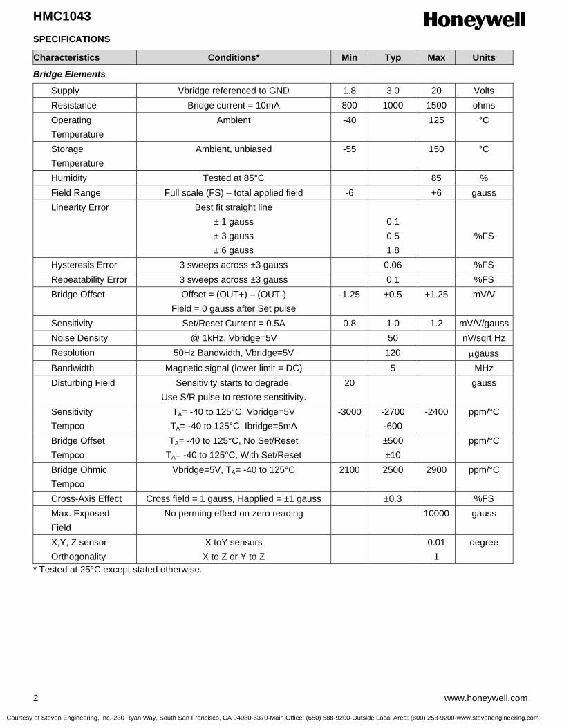
HMC1043
2 www.honeywell.com
SPECIFICATIONS
Characteristics Conditions* Min Typ Max Units
Bridge Elements
Supply Vbridge referenced to GND 1.8 3.0 20 Volts Resistance Bridge current = 10mA 800 1000 1500 ohms Operating Temperature
Ambient -40 125 °C
Storage Temperature
Ambient, unbiased -55 150 °C
Humidity Tested at 85°C 85 % Field Range Full scale (FS) – total applied field -6 +6 gauss Linearity Error Best fit straight line
± 1 gauss ± 3 gauss ± 6 gauss
0.1 0.5 1.8
%FS
Hysteresis Error 3 sweeps across ±3 gauss 0.06 %FS Repeatability Error 3 sweeps across ±3 gauss 0.1 %FS Bridge Offset Offset = (OUT+) – (OUT-)
Field = 0 gauss after Set pulse -1.25 ±0.5 +1.25 mV/V
Sensitivity Set/Reset Current = 0.5A 0.8 1.0 1.2 mV/V/gauss Noise Density @ 1kHz, Vbridge=5V 50 nV/sqrt Hz Resolution 50Hz Bandwidth, Vbridge=5V 120 µgauss Bandwidth Magnetic signal (lower limit = DC) 5 MHz Disturbing Field Sensitivity starts to degrade.
Use S/R pulse to restore sensitivity. 20 gauss
Sensitivity Tempco
TA= -40 to 125°C, Vbridge=5V TA= -40 to 125°C, Ibridge=5mA
-3000 -2700 -600
-2400 ppm/°C
Bridge Offset Tempco
TA= -40 to 125°C, No Set/Reset TA= -40 to 125°C, With Set/Reset
±500 ±10
ppm/°C
Bridge Ohmic Tempco
Vbridge=5V, TA= -40 to 125°C 2100 2500 2900 ppm/°C
Cross-Axis Effect Cross field = 1 gauss, Happlied = ±1 gauss ±0.3 %FS Max. Exposed Field
No perming effect on zero reading 10000 gauss
X,Y, Z sensor Orthogonality
X toY sensors X to Z or Y to Z
0.01 1
degree
* Tested at 25°C except stated otherwise.
Courtesy of Steven Engineering, Inc.-230 Ryan Way, South San Francisco, CA 94080-6370-Main Office: (650) 588-9200-Outside Local Area: (800) 258-9200-www.stevenengineering.com
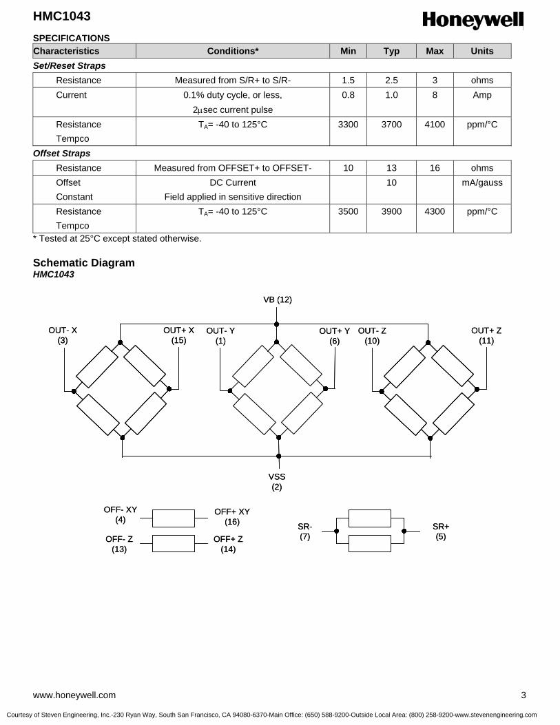
HMC1043
www.honeywell.com 3
SPECIFICATIONS Characteristics Conditions* Min Typ Max Units Set/Reset Straps Resistance Measured from S/R+ to S/R- 1.5 2.5 3 ohms Current 0.1% duty cycle, or less,
2µsec current pulse 0.8 1.0 8 Amp
Resistance Tempco
TA= -40 to 125°C 3300 3700 4100 ppm/°C
Offset Straps Resistance Measured from OFFSET+ to OFFSET- 10 13 16 ohms Offset Constant
DC Current Field applied in sensitive direction
10 mA/gauss
Resistance Tempco
TA= -40 to 125°C 3500 3900 4300 ppm/°C
* Tested at 25°C except stated otherwise. Schematic Diagram HMC1043
VB (12)
VSS(2)
OUT- X(3)
OUT+ X(15)
OUT- Y(1)
OUT+ Y(6)
OUT- Z(10)
OUT+ Z(11)
OFF- XY(4)
OFF- Z(13)
SR-(7)
SR+(5)
OFF+ XY(16)
OFF+ Z(14)
VB (12)
VSS(2)
OUT- X(3)
OUT+ X(15)
OUT- Y(1)
OUT+ Y(6)
OUT- Z(10)
OUT+ Z(11)
OFF- XY(4)
OFF- Z(13)
SR-(7)
SR+(5)
OFF+ XY(16)
OFF+ Z(14)
Courtesy of Steven Engineering, Inc.-230 Ryan Way, South San Francisco, CA 94080-6370-Main Office: (650) 588-9200-Outside Local Area: (800) 258-9200-www.stevenengineering.com
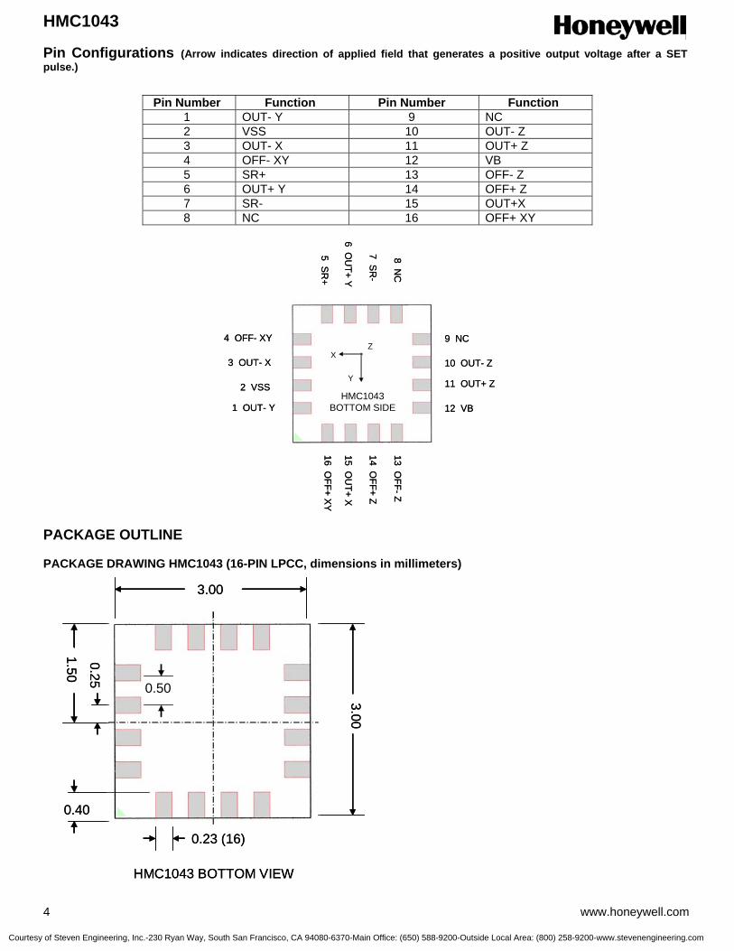
HMC1043
4 www.honeywell.com
Pin Configurations (Arrow indicates direction of applied field that generates a positive output voltage after a SET pulse.) PACKAGE OUTLINE PACKAGE DRAWING HMC1043 (16-PIN LPCC, dimensions in millimeters)
Pin Number Function Pin Number Function 1 OUT- Y 9 NC 2 VSS 10 OUT- Z 3 OUT- X 11 OUT+ Z 4 OFF- XY 12 VB 5 SR+ 13 OFF- Z 6 OUT+ Y 14 OFF+ Z 7 SR- 15 OUT+X 8 NC 16 OFF+ XY
3.00
3.00
1.50
0.25
0.50
0.40
0.23 (16)
HMC1043 BOTTOM VIEW
3.00
3.00
1.50
0.25
0.50
0.40
0.23 (16)
HMC1043 BOTTOM VIEW
9 NC
10 OUT- Z
11 OUT+ Z
12 VB
13 OFF-Z
14 OFF+ Z
15 OU
T+ X
16 OFF+ X
Y1 OUT- Y
2 VSS
3 OUT- X
4 OFF- XY
5 SR
+
6 OU
T+ Y
7 SR
-
8 NC
HMC1043BOTTOM SIDE
X
Y
Z9 NC
10 OUT- Z
11 OUT+ Z
12 VB
13 OFF-Z
14 OFF+ Z
15 OU
T+ X
16 OFF+ X
Y1 OUT- Y
2 VSS
3 OUT- X
4 OFF- XY
5 SR
+
6 OU
T+ Y
7 SR
-
8 NC
HMC1043BOTTOM SIDE
X
Y
Z
Courtesy of Steven Engineering, Inc.-230 Ryan Way, South San Francisco, CA 94080-6370-Main Office: (650) 588-9200-Outside Local Area: (800) 258-9200-www.stevenengineering.com

HMC1043
www.honeywell.com 5
Mounting Considerations The following is the recommend printed circuit board (PCB) footprint for the HMC1043. Each of the sixteen pads on the HMC1043 is spaced on 0.5mm centers with 4 pads per side. Each pad is nominally 0.23mm by 0.40mm with a tin over copper finish. Recommended PCB lands for the HMC1043 are outsized to 0.28mm by 0.65mm for 0.025mm sides plus 0.05mm inside and 0.20mm outside areas. The extra area is for good reflow attachment and enough pad contact exposure for test probing if necessary. Stencil Design and Solder Paste A 4 mil stencil and 100% paste coverage is recommended for the eight electrical contact pads. Do not apply paste on the leveling pads. The HMC1053L has been tested successfully with no-clean solder paste. Pick and Place Placement is machine dependant and no restrictions are recommended. Reflow and Rework No special profile is required for the HMC1043. The product is compatible with lead eutectic and lead-free solder paste reflow profiles. Honeywell recommends the adherence to solder paste manufacturer’s guidelines. The HMC1043 may be reworked with soldering irons, but extreme care must be taken not to overheat the copper pads from the part’s fiberglass substrate. Irons with a tip temperature no greater than 315°C should be used. Excessive rework risks the copper pads pulling away into the molten solder. Basic Device Operation The Honeywell HMC1043 magnetoresistive sensors are Wheatstone bridges to measure magnetic fields. With power supply applied to the bridges, the sensors convert any incident magnetic field in the sensitive axis directions to a differential voltage outputs. In addition to the bridge circuits, each sensor has two on-chip magnetically coupled straps; the offset strap and the set/reset strap. These straps are Honeywell patented features for incident field adjustment and magnetic domain alignment; and eliminate the need for external coils positioned around the sensors. The magnetoresistive sensors are made of a nickel-iron (Permalloy) thin-film deposited on a silicon wafer and patterned as a resistive strip element. In the presence of a magnetic field, a change in the bridge resistive elements causes a corresponding change in voltage across the bridge outputs.
NOMINAL PAD SIZE 0.40 X 0.23 MM
NOMINAL LAND SIZE 0.65 X 0.28MM
0.20
0.05
NOMINAL PAD SIZE 0.40 X 0.23 MM
NOMINAL LAND SIZE 0.65 X 0.28MM
0.20
0.05
Courtesy of Steven Engineering, Inc.-230 Ryan Way, South San Francisco, CA 94080-6370-Main Office: (650) 588-9200-Outside Local Area: (800) 258-9200-www.stevenengineering.com

HMC1043
6 www.honeywell.com
Iset
5 volts
Rsr3.0
Iset
5 volts
Rsr3.0
These resistive elements are aligned together to have a common sensitive axis (indicated by arrows on the pinouts) that will provide positive voltage change with magnetic fields increasing in the sensitive direction. Because the output only is in proportion to the one-dimensional axis (the principle of anisotropy) and its magnitude, additional sensor bridges placed at orthogonal directions permit accurate measurement of arbitrary field direction. The combination of sensor bridges in two and three orthogonal axis permit applications such as compassing and magnetometry. The offset strap allows for several modes of operation when a direct current is driven through it. These modes are: 1) Subtraction (bucking) of an unwanted external magnetic field, 2) null-ing of the bridge offset voltage, 3) Closed loop field cancellation, and 4) Auto-calibration of bridge gain. The set/reset strap can be pulsed with high currents for the following benefits: 1) Enable the sensor to perform high sensitivity measurements, 2) Flip the polarity of the bridge output voltage, and 3) Periodically used to improve linearity, lower cross-axis effects, and temperature effects. Offset Straps The offset strap is a spiral of metallization that couples in the sensor element’s sensitive axis. The offset strap measures nominally 8 ohms, and requires 10mA for each gauss of induced field. The straps will easily handle currents to buck or boost fields through the ±6 gauss linear measurement range, but designers should note the extreme thermal heating on the die when doing so. With most applications, the offset strap is not utilized and can be ignored. Designers can leave one or both strap connections (Off- and Off+) open circuited, or ground one connection node. Do not tie both strap connections together to avoid shorted turn magnetic circuits. Set/Reset Straps The set/reset strap is another spiral of metallization that couples to the sensor elements easy axis (perpendicular to the sensitive axis on the sensor die. Each set/reset strap has a nominal resistance of 5 ohms with a nominal required peak current of 500mA for reset or set pulses. With rare exception, the set/reset strap must be used to periodically condition the magnetic domains of the magneto-resistive elements for best and reliable performance. A set pulse is defined as a positive pulse current entering the S/R+ strap connection. The successful result would be the magnetic domains aligned in a forward easy-axis direction so that the sensor bridge’s polarity is a positive slope with positive fields on the sensitive axis result in positive voltages across the bridge output connections. A reset pulse is defined as a negative pulse current entering the S/R+ strap connection. The successful result would be the magnetic domains aligned in a reverse easy-axis direction so that sensor bridge’s polarity is a negative slope with positive fields on the sensitive axis result in negative voltages across the bridge output connections. Typically a reset pulse is sent first, followed by a set pulse a few milliseconds later. By shoving the magnetic domains in completely opposite directions, any prior magnetic disturbances are likely to be completely erased by the duet of pulses. For simpler circuits with less critical requirements for noise and accuracy, a single polarity pulse circuit may be employed (all sets or all resets). With these uni-polar pulses, several pulses together become close in performance to a set/reset pulse circuit. Figure 1 shows a quick and dirty manual pulse circuit for uni-polar application of pulses to the set/reset strap.
Figure 1 Manual Set Pulse Circuit
Courtesy of Steven Engineering, Inc.-230 Ryan Way, South San Francisco, CA 94080-6370-Main Office: (650) 588-9200-Outside Local Area: (800) 258-9200-www.stevenengineering.com

HMC1043
www.honeywell.com 7
Ordering Information
Ordering Number Product HMC1043 HMC1043 T/R HMC1043 Cut Tape
One Axis Magnetic Sensor
Tape and Reel with 3k pieces/reel Cut Tape
Find out more For more information on Honeywell’s Magnetic Sensors visit us online at www.magneticsensors.com or contact us at 800-323-8295 (763-954-2474 internationally). The application circuits herein constitute typical usage and interface of Honeywell product. Honeywell does not warranty or assume liability of customer-designed circuits derived from this description or depiction. Honeywell reserves the right to make changes to improve reliability, function or design. Honeywell does not assume any liability arising out of the application or use of any product or circuit described herein; neither does it convey any license under its patent rights nor the rights of others. U.S. Patents 4,441,072, 4,533,872, 4,569,742, 4,681,812, 4,847,584 and 6,529,114 apply to the technology described
Honeywell International Inc. 12001 Highway 55 Plymouth, Minnesota 55441 USA Tel: 800-323-8295 www.honeywell.com
Form #900341 Rev A March 2006 ©2006 Honeywell International Inc.
Courtesy of Steven Engineering, Inc.-230 Ryan Way, South San Francisco, CA 94080-6370-Main Office: (650) 588-9200-Outside Local Area: (800) 258-9200-www.stevenengineering.com

1, 2 and 3 Axis Magnetic Sensors HMC1051/HMC1052/HMC1053
The Honeywell HMC1051, HMC1052 and HMC1053 are
magnetoresistive sensors designed for low field magnetic sensing.
Various packaging options have been created from the basic
HMC1052 sensor chip to create 1, 2 and 3-axis magneto-resistive
sensors for cost effective and small size solutions. The advantage
of the HMC105X family of sensors is in the near-perfectly
orthogonal dual sensor on a single chip with shared set/reset and
offset coils/straps included.
The HMC105X family utilizes Honeywell’s Anisotropic
Magnetoresistive (AMR) technology that provides advantages over
coil based magnetic sensors. They are extremely sensitive, low
field, solid-state magnetic sensors designed to measure direction
and magnitude of Earth’s magnetic fields, from 120 micro-gauss to
6 gauss. Honeywell’s Magnetic Sensors are among the most
sensitive and reliable low-field sensors in the industry. Applications
for the HMC105X family of sensors include low cost Compassing,
Magnetometry, and Current Sensing.
Honeywell continues to maintain product excellence and performance by introducing innovative solid-state magnetic
sensor solutions. These are highly reliable, top performance products that are delivered when promised. Honeywell’s
magnetic sensor solutions provide real solutions you can count on.
FEATURES BENEFITS
4 Miniature Surface-Mount Packages 4 Small Sizes for Compact Applications
4 Leaded and Leadless Packages 4 Compatible with High Speed SMT Assembly and Prototyping
4 Low Voltage Operations (1.8V) 4 Compatible for Battery Powered Applications
4 Low Cost 4 Designed for High Volume, Cost Effective OEM Designs
4 Tape & Reel Packaging Options 4 High Volume OEM Assembly
4 4-Element Wheatstone Bridge 4 Low Noise Passive Element Design
4 Wide Magnetic Field Range (+/-6 Oe) 4 Sensor Can Be Used in Strong Magnetic Field Environments
4 Patented Offset and Set/Reset Straps 4 Stray Magnetic Field Compensation
Courtesy of Steven Engineering, Inc.-230 Ryan Way, South San Francisco, CA 94080-6370-Main Office: (650) 588-9200-Outside Local Area: (800) 258-9200-www.stevenengineering.com
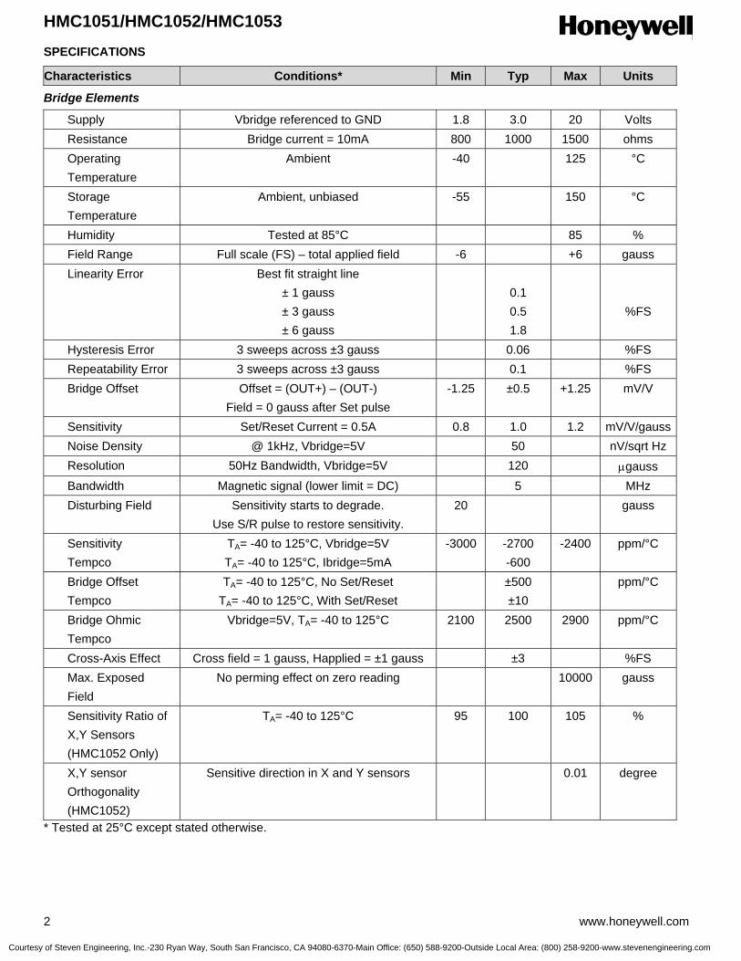
HMC1051/HMC1052/HMC1053
2 www.honeywell.com
SPECIFICATIONS
Characteristics Conditions* Min Typ Max Units
Bridge Elements
Supply Vbridge referenced to GND 1.8 3.0 20 Volts Resistance Bridge current = 10mA 800 1000 1500 ohms Operating Temperature
Ambient -40 125 °C
Storage Temperature
Ambient, unbiased -55 150 °C
Humidity Tested at 85°C 85 % Field Range Full scale (FS) – total applied field -6 +6 gauss Linearity Error Best fit straight line
± 1 gauss ± 3 gauss ± 6 gauss
0.1 0.5 1.8
%FS
Hysteresis Error 3 sweeps across ±3 gauss 0.06 %FS Repeatability Error 3 sweeps across ±3 gauss 0.1 %FS Bridge Offset Offset = (OUT+) – (OUT-)
Field = 0 gauss after Set pulse -1.25 ±0.5 +1.25 mV/V
Sensitivity Set/Reset Current = 0.5A 0.8 1.0 1.2 mV/V/gauss Noise Density @ 1kHz, Vbridge=5V 50 nV/sqrt Hz Resolution 50Hz Bandwidth, Vbridge=5V 120 µgauss Bandwidth Magnetic signal (lower limit = DC) 5 MHz Disturbing Field Sensitivity starts to degrade.
Use S/R pulse to restore sensitivity. 20 gauss
Sensitivity Tempco
TA= -40 to 125°C, Vbridge=5V TA= -40 to 125°C, Ibridge=5mA
-3000 -2700 -600
-2400 ppm/°C
Bridge Offset Tempco
TA= -40 to 125°C, No Set/Reset TA= -40 to 125°C, With Set/Reset
±500 ±10
ppm/°C
Bridge Ohmic Tempco
Vbridge=5V, TA= -40 to 125°C 2100 2500 2900 ppm/°C
Cross-Axis Effect Cross field = 1 gauss, Happlied = ±1 gauss ±3 %FS Max. Exposed Field
No perming effect on zero reading 10000 gauss
Sensitivity Ratio of X,Y Sensors (HMC1052 Only)
TA= -40 to 125°C 95 100 105 %
X,Y sensor Orthogonality (HMC1052)
Sensitive direction in X and Y sensors 0.01 degree
* Tested at 25°C except stated otherwise.
Courtesy of Steven Engineering, Inc.-230 Ryan Way, South San Francisco, CA 94080-6370-Main Office: (650) 588-9200-Outside Local Area: (800) 258-9200-www.stevenengineering.com
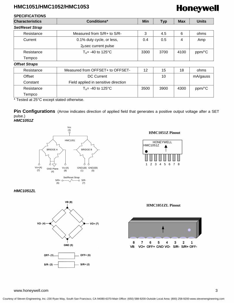
HMC1051/HMC1052/HMC1053
www.honeywell.com 3
SPECIFICATIONS Characteristics Conditions* Min Typ Max Units Set/Reset Strap Resistance Measured from S/R+ to S/R- 3 4.5 6 ohms Current 0.1% duty cycle, or less,
2µsec current pulse 0.4 0.5 4 Amp
Resistance Tempco
TA= -40 to 125°C 3300 3700 4100 ppm/°C
Offset Straps Resistance Measured from OFFSET+ to OFFSET- 12 15 18 ohms Offset Constant
DC Current Field applied in sensitive direction
10 mA/gauss
Resistance Tempco
TA= -40 to 125°C 3500 3900 4300 ppm/°C
* Tested at 25°C except stated otherwise.
Pin Configurations (Arrow indicates direction of applied field that generates a positive output voltage after a SET pulse.) HMC1051Z HMC1051ZL
HMC1051
Vcc(3)
GND Plane(4)
Vo+(A)(2)
Vo-(A)(8)
GND1(B)(1)
GND2(B)(5)
BRIDGE A BRIDGE B
S/R+(6)
S/R-(7)
Set/Reset Strap
HMC1051Z Pinout
HONEYWELLHMC1051Z
1 2 3 4 5 6 7 8
HMC1051ZL Pinout
12345678OFF-S/R+S/R-VO-GNDOFF+VO+VB12345678
OFF-S/R+S/R-VO-GNDOFF+VO+VB12345678
OFF-S/R+S/R-VO-GNDOFF+VO+VB
Courtesy of Steven Engineering, Inc.-230 Ryan Way, South San Francisco, CA 94080-6370-Main Office: (650) 588-9200-Outside Local Area: (800) 258-9200-www.stevenengineering.com
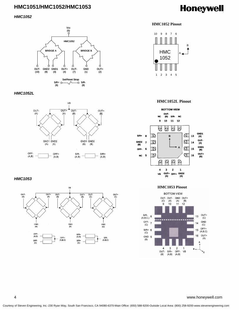
HMC1051/HMC1052/HMC1053
4 www.honeywell.com
HMC1052 HMC1052L HMC1053
HMC1052 Pinout
HMC1052
1 2 3 4 5
678910
A
B
HMC1052
Vcc(5)
GND2(9)
OUT-(10)
OUT+(4)
GND(1)
BRIDGE A BRIDGE B
S/R+(6)
S/R-(8)
Set/Reset Strap
GND1(3)
OUT-(7)
OUT+(2)
HMC1052
Vcc(5)
GND2(9)
OUT-(10)
OUT+(4)
GND(1)
BRIDGE A BRIDGE B
S/R+(6)
S/R-(8)
Set/Reset Strap
GND1(3)
OUT-(7)
OUT+(2)
HMC1052L Pinout
HMC1053 Pinout
1234
5
6
7
8
9 10 11 12
13
14
15
16
GND2(A)
OFF+OUT+(A)
VB
NC
NC
OFF-
GND2(B)
S/R+
OUT-(B) S/R- NC
GND1(A)
OUT-(A)
GND1(B)
OUT+(B)
B
A
BOTTOM VIEW
1234
5
6
7
8
9 10 11 12
13
14
15
16
GND2(A)
OFF+OUT+(A)
VB
NC
NC
OFF-
GND2(B)
S/R+
OUT-(B) S/R- NC
GND1(A)
OUT-(A)
GND1(B)
OUT+(B)
B
A
BOTTOM VIEW
Courtesy of Steven Engineering, Inc.-230 Ryan Way, South San Francisco, CA 94080-6370-Main Office: (650) 588-9200-Outside Local Area: (800) 258-9200-www.stevenengineering.com
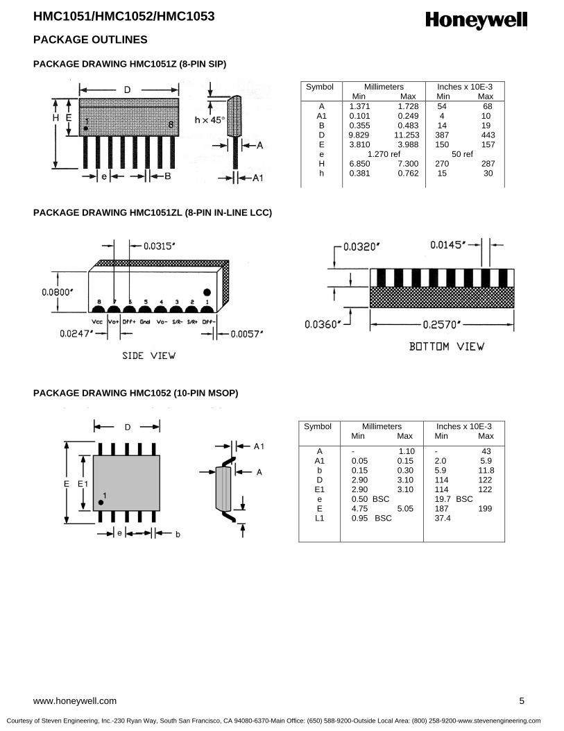
HMC1051/HMC1052/HMC1053
www.honeywell.com 5
PACKAGE OUTLINES PACKAGE DRAWING HMC1051Z (8-PIN SIP) PACKAGE DRAWING HMC1051ZL (8-PIN IN-LINE LCC) PACKAGE DRAWING HMC1052 (10-PIN MSOP)
Symbol Millimeters Min Max
Inches x 10E-3 Min Max
A A1 b D E1 e E L1
- 1.10 0.05 0.15 0.15 0.30 2.90 3.10 2.90 3.10 0.50 BSC 4.75 5.05 0.95 BSC
- 43 2.0 5.9 5.9 11.8 114 122 114 122 19.7 BSC 187 199 37.4
Symbol Millimeters Min Max
Inches x 10E-3 Min Max
A A1 B D E e H h
1.371 1.728 0.101 0.249 0.355 0.483 9.829 11.253 3.810 3.988
1.270 ref 6.850 7.300 0.381 0.762
54 68 4 10
14 19 387 443 150 157
50 ref 270 287 15 30
Courtesy of Steven Engineering, Inc.-230 Ryan Way, South San Francisco, CA 94080-6370-Main Office: (650) 588-9200-Outside Local Area: (800) 258-9200-www.stevenengineering.com
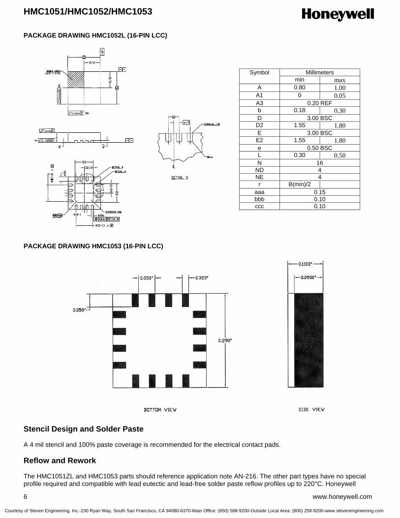
HMC1051/HMC1052/HMC1053
6 www.honeywell.com
PACKAGE DRAWING HMC1052L (16-PIN LCC) PACKAGE DRAWING HMC1053 (16-PIN LCC)
Stencil Design and Solder Paste A 4 mil stencil and 100% paste coverage is recommended for the electrical contact pads. Reflow and Rework The HMC1051ZL and HMC1053 parts should reference application note AN-216. The other part types have no special profile required and compatible with lead eutectic and lead-free solder paste reflow profiles up to 220°C. Honeywell
Millimeters Symbol min max
A 0.80 1.00 A1 0 0.05 A3 0.20 REF b 0.18 0.30 D 3.00 BSC
D2 1.55 1.80 E 3.00 BSC
E2 1.55 1.80 e 0.50 BSC L 0.30 0.50 N 16
ND 4 NE 4 r B(min)/2
aaa 0.15 bbb 0.10 ccc 0.10
Courtesy of Steven Engineering, Inc.-230 Ryan Way, South San Francisco, CA 94080-6370-Main Office: (650) 588-9200-Outside Local Area: (800) 258-9200-www.stevenengineering.com

HMC1051/HMC1052/HMC1053
www.honeywell.com 7
recommends the adherence to solder paste manufacturer’s guidelines. The HMC105X parts may be reworked with soldering irons, but extreme care must be taken not to overheat the copper pads from the part’s fiberglass substrate. Irons with a tip temperature no greater than 315°C should be used. Excessive rework risks the copper pads pulling away into the molten solder. Device Operation The Honeywell HMC105X family of magnetoresistive sensors are Wheatstone bridge devices to measure magnetic fields. With power supply applied to a bridge, the sensor converts any incident magnetic field in the sensitive axis direction to a differential voltage output. In addition to the bridge circuit, the sensor has two on-chip magnetically coupled straps; the offset strap and the set/reset strap. These straps are Honeywell patented features for incident field adjustment and magnetic domain alignment; and eliminate the need for external coils positioned around the sensors. The magnetoresistive sensors are made of a nickel-iron (Permalloy) thin-film deposited on a silicon wafer and patterned as a resistive strip element. In the presence of a magnetic field, a change in the bridge resistive elements causes a corresponding change in voltage across the bridge outputs. These resistive elements are aligned together to have a common sensitive axis (indicated by arrows on the pinouts) that will provide positive voltage change with magnetic fields increasing in the sensitive direction. Because the output only is in proportion to the one-dimensional axis (the principle of anisotropy) and its magnitude, additional sensor bridges placed at orthogonal directions permit accurate measurement of arbitrary field direction. The combination of sensor bridges in two and three orthogonal axis permit applications such as compassing and magnetometry. The offset strap allows for several modes of operation when a direct current is driven through it. These modes are: 1) Subtraction (bucking) of an unwanted external magnetic field, 2) null-ing of the bridge offset voltage, 3) Closed loop field cancellation, and 4) Auto-calibration of bridge gain. The set/reset strap can be pulsed with high currents for the following benefits: 1) Enable the sensor to perform high sensitivity measurements, 2) Flip the polarity of the bridge output voltage, and 3) Periodically used to improve linearity, lower cross-axis effects, and temperature effects. Noise Characteristics The noise density for the HMR105X series is around 50nV/sqrt Hz at the 1 Hz corner, and quickly drops below 10nV/sqrt Hz at 5Hz and begins to fit the Johnson Noise value at just below 5nV/sqrt Hz beyond 50Hz. The 10Hz noise voltage averages around 1.4 micro-volts with a 0.8 micro-volts standard deviation. Cross-Axis Effect Cross-Axis effect for the HMR105X series is typically specified at ±3% of full scale to 1 gauss. See application note AN215 regarding this effect and methods for nulling. Offset Strap The offset strap is a spiral of metalization that couples in the sensor element’s sensitive axis. In two-axis designs, the strap is common to both bridges and must be multiplexed if each bridge requires a different strap current. In three-axis designs, the A and B bridges are together with the C bridge sharing a common node for series driving all three bridges’ offset straps. Each offset strap measures nominally 15 ohms, and requires 10mA for each gauss of induced field. The straps will easily handle currents to buck or boost fields through the ±6 gauss linear measurement range, but designers should note the extreme thermal heating on the die when doing so. With most applications, the offset strap is not utilized and can be ignored. Designers can leave one or both strap connections (Off- and Off+) open circuited, or ground one connection node. Do not tie both strap connections together to avoid shorted turn magnetic circuits. Set/Reset Strap The set/reset strap is another spiral of metalization that couples to the sensor elements easy axis (perpendicular to the sensitive axis on the sensor die). Like the offset strap, the set/reset strap runs through a pair of bridge elements to keep the overall die size compact. Each set/reset strap has a nominal resistance of 3 to 6 ohms with a minimum required peak
Courtesy of Steven Engineering, Inc.-230 Ryan Way, South San Francisco, CA 94080-6370-Main Office: (650) 588-9200-Outside Local Area: (800) 258-9200-www.stevenengineering.com
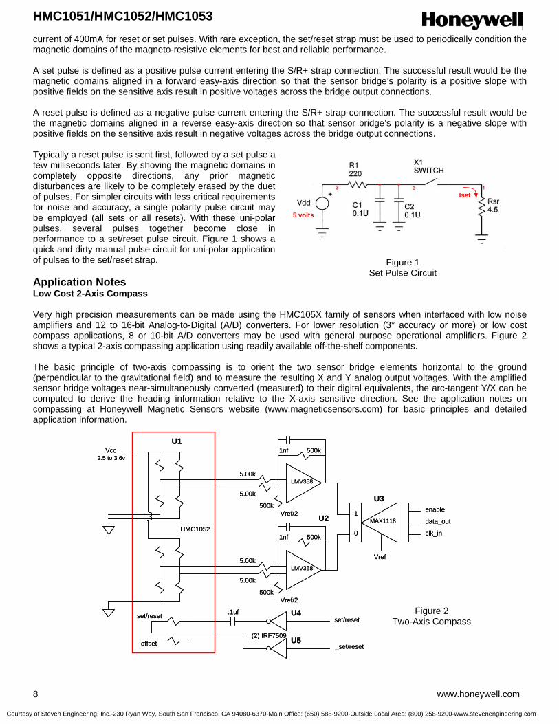
HMC1051/HMC1052/HMC1053
8 www.honeywell.com
current of 400mA for reset or set pulses. With rare exception, the set/reset strap must be used to periodically condition the magnetic domains of the magneto-resistive elements for best and reliable performance. A set pulse is defined as a positive pulse current entering the S/R+ strap connection. The successful result would be the magnetic domains aligned in a forward easy-axis direction so that the sensor bridge’s polarity is a positive slope with positive fields on the sensitive axis result in positive voltages across the bridge output connections. A reset pulse is defined as a negative pulse current entering the S/R+ strap connection. The successful result would be the magnetic domains aligned in a reverse easy-axis direction so that sensor bridge’s polarity is a negative slope with positive fields on the sensitive axis result in negative voltages across the bridge output connections. Typically a reset pulse is sent first, followed by a set pulse a few milliseconds later. By shoving the magnetic domains in completely opposite directions, any prior magnetic disturbances are likely to be completely erased by the duet of pulses. For simpler circuits with less critical requirements for noise and accuracy, a single polarity pulse circuit may be employed (all sets or all resets). With these uni-polar pulses, several pulses together become close in performance to a set/reset pulse circuit. Figure 1 shows a quick and dirty manual pulse circuit for uni-polar application of pulses to the set/reset strap. Application Notes Low Cost 2-Axis Compass Very high precision measurements can be made using the HMC105X family of sensors when interfaced with low noise amplifiers and 12 to 16-bit Analog-to-Digital (A/D) converters. For lower resolution (3° accuracy or more) or low cost compass applications, 8 or 10-bit A/D converters may be used with general purpose operational amplifiers. Figure 2 shows a typical 2-axis compassing application using readily available off-the-shelf components. The basic principle of two-axis compassing is to orient the two sensor bridge elements horizontal to the ground (perpendicular to the gravitational field) and to measure the resulting X and Y analog output voltages. With the amplified sensor bridge voltages near-simultaneously converted (measured) to their digital equivalents, the arc-tangent Y/X can be computed to derive the heading information relative to the X-axis sensitive direction. See the application notes on compassing at Honeywell Magnetic Sensors website (www.magneticsensors.com) for basic principles and detailed application information.
Figure 1 Set Pulse Circuit
HMC1052
U1Vcc
offset
set/reset .1uf
(2) IRF7509
set/reset
_set/reset
Vref/2
Vref/2
5.00k
5.00k
500k
500k
5.00k
5.00k
500k
500k
LMV358
LMV358
1nf
1nf
MAX11181
0
Vref
U2
U3
U4
U5
enable
data_out
clk_in
2.5 to 3.6v
HMC1052
U1Vcc
offset
set/reset .1uf
(2) IRF7509
set/reset
_set/reset
Vref/2
Vref/2
5.00k
5.00k
500k
500k
5.00k
5.00k
500k
500k
LMV358
LMV358
1nf
1nf
MAX11181
0
Vref
U2
U3
U4
U5
enable
data_out
clk_in
2.5 to 3.6v
Figure 2 Two-Axis Compass
Iset
5 volts
Iset
5 volts
Courtesy of Steven Engineering, Inc.-230 Ryan Way, South San Francisco, CA 94080-6370-Main Office: (650) 588-9200-Outside Local Area: (800) 258-9200-www.stevenengineering.com

HMC1051/HMC1052/HMC1053
www.honeywell.com 9
Set/Reset Circuit Notes The above set/reset circuit in Figure 1using the IRF7507 dual complementary MOSFETs is shown in detail by Figure 2 in its H-bridge driven configuration. This configuration is used primarily in battery operated applications were the 500mA nominal set/reset pulsed currents can be best obtained under low voltage conditions. The 200-ohm resistor trickle charges the 1uf supply reservoir capacitor to the Vcc level, and isolates the battery from the high current action of the capacitors and MOSFET switches. Under conventional logic states one totem pole switch holds one node of the 0.1uf capacitor low, while the other switch charges Vcc into the capacitors opposite node. At the first logic change, the capacitor exhibits almost a twice Vcc flip of polarity, giving the series set/reset strap load plenty of pulse current. A restoring logic state flip uses the 0.1uf capacitors stored energy to create a second nearly equal but opposite polarity current pulse through the set/reset strap. For operation at normal 3.3 or 5-volt logic levels, a single complementary MOSFET pair can be used in a single ended circuit shown in Figure 4. Other complementary MOSFET pairs can be used with the caution that the chosen devices should have less than 0.5 ohms ON resistance and be able to handle the needed supply voltages and set/reset currents. Note that even a 1Hz rate of set/reset function draws an average current of less than 2 microamperes. Magnetic Field Detection For simple magnetic field sensing applications such Magnetic Anomaly Detectors (MADs) and Magnetometers, a similar circuit to the compass application can be implemented using one, two, or three magnetic sensors. In the example circuit in Figure 5, a HMC1051Z sensor bridge is used with a low voltage capable dual op-amp to detect sufficient intensity of a magnetic field in a single direction. Uses of the circuit include ferrous object detection such as vehicle detection, a “sniffer” for currents in nearby conductors, and magnetic proximity switching. By using two or three sensor circuits with HMC1051, HMC1052, or HMC1053 parts, a more omni-directional sensing pattern can be implemented. There is nothing special in choosing the resistors for the differential op-amp gain stages other than having like values (e.g. the two 5kΩ and the 500kΩ resistors) matched at 1% tolerance or better to reject common-mode interference signals (EMI, RFI). The ratio of the 500kΩ/5kΩ resistors sets the stage gain and can be optimized for a specific purpose. Typical gain ratios for compass and magnetometer circuits using the HMC105X family, range from 50 to 500. The choice of the 5kΩ value sets impedance loading seen by the sensor bridge network and should be about 4 kilo-ohms or higher for best voltage transfer or matching. Note that Figure 5 also shows an alternative set/reset strap driver circuit using two darlington complentary paired BJTs as electronic switches.
D
D
S
S
G
G
IRF7509(P)
IRF7509(N)
Vcc200Ω
1µf +
-
Vsr
D
D
S
S
G
G
IRF7509(P)
IRF7509(N)
Vsr
set/reset
_set/reset
4Ω
.1µf
Rset/reset
D
D
S
S
G
G
IRF7509(P)
IRF7509(N)
Vcc200Ω
1µf +
-
Vsr
D
D
S
S
G
G
IRF7509(P)
IRF7509(N)
Vsr
set/reset
_set/reset
4Ω
.1µf
Rset/reset
Figure 3 H-Bridge Driver
D
D
S
S
G
G
IRF7509(P)
IRF7509(N)
Vcc200Ω
1µf +
-
Vsr
set/reset
4Ω
.1µf
Rset/reset
D
D
S
S
G
G
IRF7509(P)
IRF7509(N)
Vcc200Ω
1µf +
-
Vsr
set/reset
4Ω
.1µf
Rset/reset
Figure 4 Single-Ended Driver
Courtesy of Steven Engineering, Inc.-230 Ryan Way, South San Francisco, CA 94080-6370-Main Office: (650) 588-9200-Outside Local Area: (800) 258-9200-www.stevenengineering.com
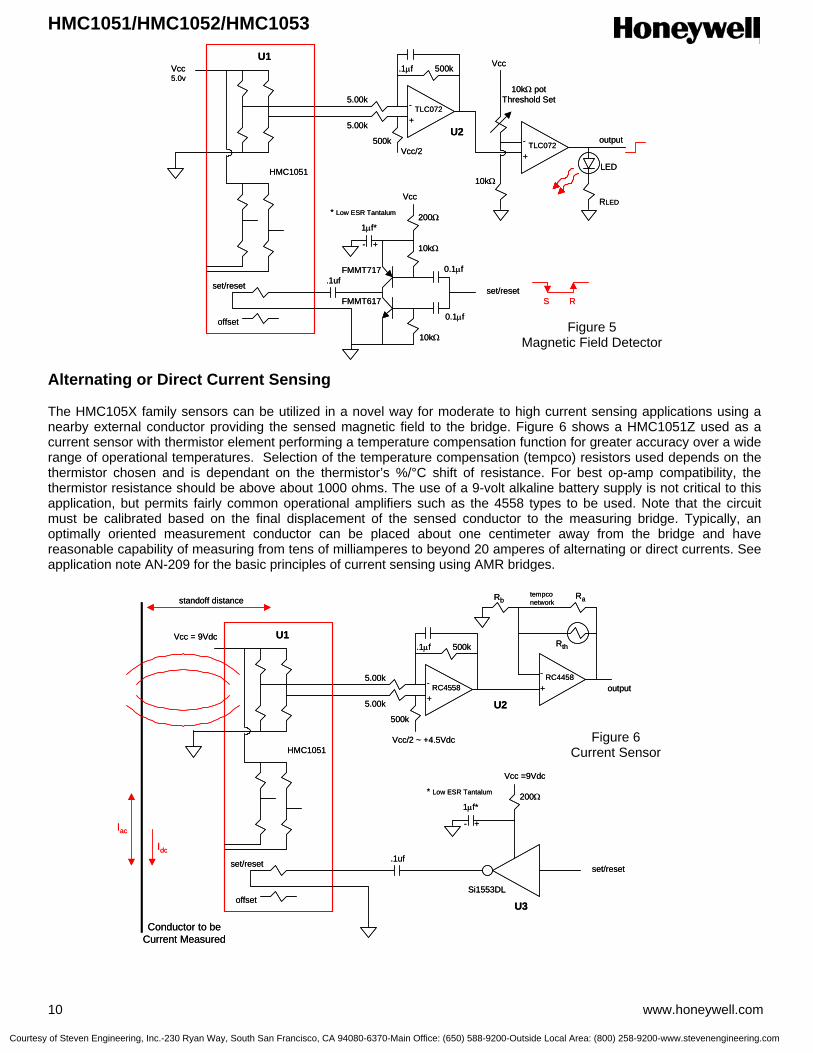
HMC1051/HMC1052/HMC1053
10 www.honeywell.com
Alternating or Direct Current Sensing The HMC105X family sensors can be utilized in a novel way for moderate to high current sensing applications using a nearby external conductor providing the sensed magnetic field to the bridge. Figure 6 shows a HMC1051Z used as a current sensor with thermistor element performing a temperature compensation function for greater accuracy over a wide range of operational temperatures. Selection of the temperature compensation (tempco) resistors used depends on the thermistor chosen and is dependant on the thermistor’s %/°C shift of resistance. For best op-amp compatibility, the thermistor resistance should be above about 1000 ohms. The use of a 9-volt alkaline battery supply is not critical to this application, but permits fairly common operational amplifiers such as the 4558 types to be used. Note that the circuit must be calibrated based on the final displacement of the sensed conductor to the measuring bridge. Typically, an optimally oriented measurement conductor can be placed about one centimeter away from the bridge and have reasonable capability of measuring from tens of milliamperes to beyond 20 amperes of alternating or direct currents. See application note AN-209 for the basic principles of current sensing using AMR bridges.
HMC1051
U1Vcc
offset
set/reset .1ufset/reset
Vcc/2
5.00k
5.00k
500k
500k
TLC072
TLC072
.1µf
U2
5.0v
+
-
+
-
Vcc
10kΩ
10kΩ potThreshold Set
RLED
LED
output
+-
1µf*
* Low ESR Tantalum
FMMT717
FMMT617
10kΩ
10kΩ
Vcc
200Ω
0.1µf
0.1µf
RS
HMC1051
U1Vcc
offset
set/reset .1ufset/reset
Vcc/2
5.00k
5.00k
500k
500k
TLC072
TLC072
.1µf
U2
5.0v
+
-
+
-
Vcc
10kΩ
10kΩ potThreshold Set
RLED
LED
output
+-
1µf*
* Low ESR Tantalum
FMMT717
FMMT617
10kΩ
10kΩ
Vcc
200Ω
0.1µf
0.1µf
RS
Figure 5 Magnetic Field Detector
HMC1051
U1Vcc = 9Vdc
offset
set/reset .1ufset/reset
Vcc/2 ~ +4.5Vdc
5.00k
5.00k
500k
500k
RC4558RC4458
.1µf
U2+
- +
-
+-
1µf*
* Low ESR Tantalum
Vcc =9Vdc
200Ω
Conductor to beCurrent Measured
Idc
Iac
Rb Ra
Rth
tempconetworkstandoff distance
output
Si1553DL
U3
HMC1051
U1Vcc = 9Vdc
offset
set/reset .1ufset/reset
Vcc/2 ~ +4.5Vdc
5.00k
5.00k
500k
500k
RC4558RC4458
.1µf
U2+
- +
-
+-
1µf*
* Low ESR Tantalum
Vcc =9Vdc
200Ω
Conductor to beCurrent Measured
Idc
Iac
Rb Ra
Rth
tempconetworkstandoff distance
output
Si1553DL
U3
Figure 6 Current Sensor
Courtesy of Steven Engineering, Inc.-230 Ryan Way, South San Francisco, CA 94080-6370-Main Office: (650) 588-9200-Outside Local Area: (800) 258-9200-www.stevenengineering.com
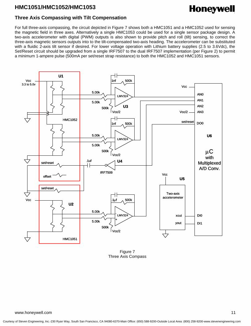
HMC1051/HMC1052/HMC1053
www.honeywell.com 11
Three Axis Compassing with Tilt Compensation For full three-axis compassing, the circuit depicted in Figure 7 shows both a HMC1051 and a HMC1052 used for sensing the magnetic field in three axes. Alternatively a single HMC1053 could be used for a single sensor package design. A two-axis accelerometer with digital (PWM) outputs is also shown to provide pitch and roll (tilt) sensing, to correct the three-axis magnetic sensors outputs into to the tilt-compensated two-axis heading. The accelerometer can be substituted with a fluidic 2-axis tilt sensor if desired. For lower voltage operation with Lithium battery supplies (2.5 to 3.6Vdc), the Set/Reset circuit should be upgraded from a single IRF7507 to the dual IRF7507 implementation (per Figure 2) to permit a minimum 1-ampere pulse (500mA per set/reset strap resistance) to both the HMC1052 and HMC1051 sensors.
HMC1052
U1Vcc
offset
set/reset .1uf
IRF7509
set/reset
Vcc/2
Vcc/2
5.00k
5.00k
500k
500k
5.00k
5.00k
500k
500k
LMV324
LMV324
1nf
1nf
U3
U4
3.3 to 5.0v
HMC1051
U2Vcc
Vcc/2
5.00k
5.00k
500k
500k
LMV324
.1µf
+
-
set/reset
µCwith
MultiplexedA/D Conv.
AN0
AN1
AN2
AN3Vcc/2
U6
U5
xout
yout
Two-axisaccelerometer
Vcc
Vcc
DO0
DI0
DI1
Figure 7 Three Axis Compass
Courtesy of Steven Engineering, Inc.-230 Ryan Way, South San Francisco, CA 94080-6370-Main Office: (650) 588-9200-Outside Local Area: (800) 258-9200-www.stevenengineering.com

HMC1051/HMC1052/HMC1053
12 www.honeywell.com
Duty Cycling for Lower Energy Consumption For battery powered and other applications needing limited energy consumption, the sensor bridge and support electronics can be switched “off” between magnetic field measurements. The HMC105X family of magnetic sensors are very low capacitance (Bandwidth > 5MHz) sensor bridges and can stabilize quickly, typically before the support electronics can. Other energy saving ideas would be to minimize the quantity of set/reset pulses which saves energy over the battery life. Figure 8 shows a simple supply switching circuit that can be microprocessor controlled to duty cycle (toggle) the electronics in moderate current (<25mA) applications.
Ordering Information
Part Number Package Style HMC1051Z
One Axis Magnetic Sensor – SIP8
HMC1051ZL
One Axis Magnetic Sensor – 8-PIN IN-LINE LCC
HMC1052
Two Axis Magnetic Sensors – MSOP10
HMC1052L
Two Axis Magnetic Sensors – 16-PIN LCC
HMC1053
Three Axis Magnetic Sensors – 16-PIN LCC
Find out more For more information on Honeywell’s Magnetic Sensors visit us online at www.magneticsensors.com or contact us at 800-323-8295 (763-954-2474 internationally). The application circuits herein constitute typical usage and interface of Honeywell product. Honeywell does not warranty or assume liability of customer-designed circuits derived from this description or depiction. Honeywell reserves the right to make changes to improve reliability, function or design. Honeywell does not assume any liability arising out of the application or use of any product or circuit described herein; neither does it convey any license under its patent rights nor the rights of others. U.S. Patents 4,441,072, 4,533,872, 4,569,742, 4,681,812, 4,847,584 and 6,529,114 apply to the technology described
Honeywell International Inc. 12001 Highway 55 Plymouth, MN 55441 Tel: 800-323-8295 www.honeywell.com/magneticsensors
Form #900308 Rev B March 2006 ©2006 Honeywell International Inc.
MMBT2907ALT1
µC
To Sensor Circuits
toggle
10kΩ
+
-10µf
0.01µf
Vcc
Vcc
Gnd
OffOn
*MMBD7001LT1* Used when Vcc = 5.0 volts, jumperwhen using Vcc = 3.3 volts or less.
MMBT2907ALT1
µC
To Sensor Circuits
toggle
10kΩ
+
-10µf
0.01µf
Vcc
Vcc
Gnd
OffOn
*MMBD7001LT1* Used when Vcc = 5.0 volts, jumperwhen using Vcc = 3.3 volts or less.
Figure 8 Duty Cycling
Courtesy of Steven Engineering, Inc.-230 Ryan Way, South San Francisco, CA 94080-6370-Main Office: (650) 588-9200-Outside Local Area: (800) 258-9200-www.stevenengineering.com

3-Axis Compass Sensor Set HMC1055
The Honeywell HMC1055 is a 3-axis compass sensor chipset
that combines the HMC1051Z single-axis and the HMC1052
two-axis magneto-resistive sensors, plus a two-axis MEMSIC
MXS3334UL accelerometer in a single kit. By combining
these three sensor packages, OEM compass system
designers will have the building blocks needed to create their
own tilt compensated compass designs using these proven
components.
The HMC1055 chip set includes the three sensor integrated
circuits and this datasheet describes the application notes for
sensor function, a reference design, and design tips for integrating the compass feature into other product platforms.
Honeywell’s Magnetoresistive (AMR) sensor technology provides advantages over coil based magnetic sensors and are
among the most sensitive and reliable low-field sensors in the industry. The MEMSIC accelerometer offers a low cost,
high performance tilt sensor (inclinometer) function using its unique thermal chimney effect.
Honeywell continues to maintain product excellence and performance by introducing innovative solid-state magnetic
sensor solutions. These are highly reliable, top performance products that are delivered when promised. Honeywell’s
magnetic sensor solutions provide real solutions you can count on.
FEATURES BENEFITS
4 Three Precision Sensor Components 4 An Easy Way to Acquire the Critical Tilt Compensated Compass
Sensors in One Purchase
4 Single Z-Axis AMR Sensor (HMC1051Z) 4 Easy to Assemble Component
4 Two-Axis AMR Sensor (HMC1052) 4 Leaded MSOP-10 Package for Small Size
4 Two-Axis MEMS Accelerometer (MXS3334UL)
4 Low Cost, High Performance Tilt Sensor
4 Low Cost Chipset 4 Affordable Chipset for Designers, Low Volume Designs
4 Reference Design Included 4 Aimed for Moderate Accuracy Compassing
4 Available in Tape & Reel Packaging 4 Easy Transition to Production
Courtesy of Steven Engineering, Inc.-230 Ryan Way, South San Francisco, CA 94080-6370-Main Office: (650) 588-9200-Outside Local Area: (800) 258-9200-www.stevenengineering.com
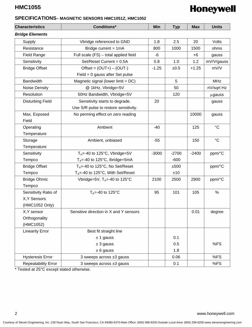
HMC1055
2 www.honeywell.com
SPECIFICATIONS– MAGNETIC SENSORS HMC1051Z, HMC1052
Characteristics Conditions* Min Typ Max Units
Bridge Elements
Supply Vbridge referenced to GND 1.8 2.5 20 Volts Resistance Bridge current = 1mA 800 1000 1500 ohms Field Range Full scale (FS) – total applied field -6 +6 gauss Sensitivity Set/Reset Current = 0.5A 0.8 1.0 1.2 mV/V/gauss Bridge Offset Offset = (OUT+) – (OUT-)
Field = 0 gauss after Set pulse -1.25 ±0.5 +1.25 mV/V
Bandwidth Magnetic signal (lower limit = DC) 5 MHz Noise Density @ 1kHz, Vbridge=5V 50 nV/sqrt Hz Resolution 50Hz Bandwidth, Vbridge=5V 120 µgauss Disturbing Field Sensitivity starts to degrade.
Use S/R pulse to restore sensitivity. 20 gauss
Max. Exposed Field
No perming effect on zero reading 10000 gauss
Operating Temperature
Ambient -40 125 °C
Storage Temperature
Ambient, unbiased -55 150 °C
Sensitivity Tempco
TA=-40 to 125°C, Vbridge=5V TA=-40 to 125°C, Ibridge=5mA
-3000 -2700 -600
-2400 ppm/°C
Bridge Offset Tempco
TA=-40 to 125°C, No Set/Reset TA=-40 to 125°C, With Set/Reset
±500 ±10
ppm/°C
Bridge Ohmic Tempco
Vbridge=5V, TA=-40 to 125°C 2100 2500 2900 ppm/°C
Sensitivity Ratio of X,Y Sensors (HMC1052 Only)
TA=-40 to 125°C 95 101 105 %
X,Y sensor Orthogonality (HMC1052)
Sensitive direction in X and Y sensors 0.01 degree
Linearity Error Best fit straight line ± 1 gauss ± 3 gauss ± 6 gauss
0.1 0.5 1.8
%FS
Hysteresis Error 3 sweeps across ±3 gauss 0.06 %FS Repeatability Error 3 sweeps across ±3 gauss 0.1 %FS * Tested at 25°C except stated otherwise.
Courtesy of Steven Engineering, Inc.-230 Ryan Way, South San Francisco, CA 94080-6370-Main Office: (650) 588-9200-Outside Local Area: (800) 258-9200-www.stevenengineering.com
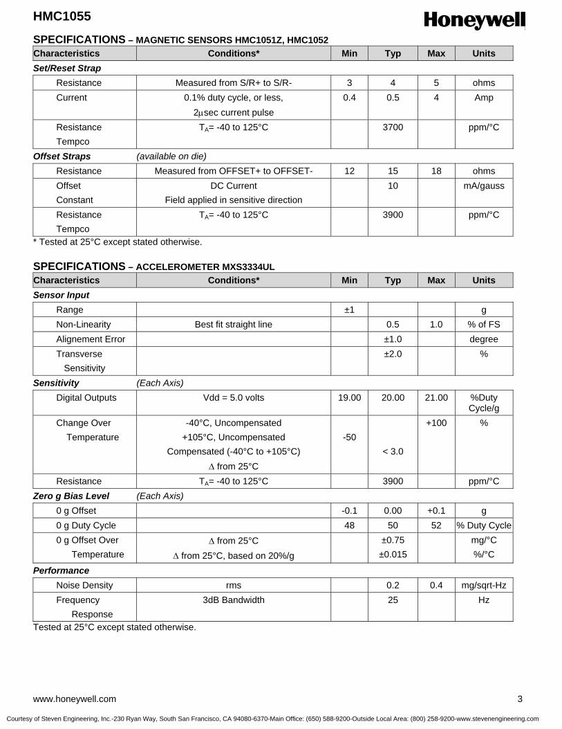
HMC1055
www.honeywell.com 3
SPECIFICATIONS – MAGNETIC SENSORS HMC1051Z, HMC1052 Characteristics Conditions* Min Typ Max Units Set/Reset Strap Resistance Measured from S/R+ to S/R- 3 4 5 ohms Current 0.1% duty cycle, or less,
2µsec current pulse 0.4 0.5 4 Amp
Resistance Tempco
TA= -40 to 125°C 3700 ppm/°C
Offset Straps (available on die) Resistance Measured from OFFSET+ to OFFSET- 12 15 18 ohms Offset Constant
DC Current Field applied in sensitive direction
10 mA/gauss
Resistance Tempco
TA= -40 to 125°C 3900 ppm/°C
* Tested at 25°C except stated otherwise.
SPECIFICATIONS – ACCELEROMETER MXS3334UL Characteristics Conditions* Min Typ Max Units Sensor Input Range ±1 g Non-Linearity Best fit straight line 0.5 1.0 % of FS Alignement Error ±1.0 degree Transverse Sensitivity
±2.0 %
Sensitivity (Each Axis) Digital Outputs Vdd = 5.0 volts 19.00 20.00 21.00 %Duty
Cycle/g Change Over Temperature
-40°C, Uncompensated +105°C, Uncompensated
Compensated (-40°C to +105°C) ∆ from 25°C
-50
< 3.0
+100 %
Resistance TA= -40 to 125°C 3900 ppm/°C Zero g Bias Level (Each Axis) 0 g Offset -0.1 0.00 +0.1 g 0 g Duty Cycle 48 50 52 % Duty Cycle 0 g Offset Over Temperature
∆ from 25°C ∆ from 25°C, based on 20%/g
±0.75 ±0.015
mg/°C %/°C
Performance Noise Density rms 0.2 0.4 mg/sqrt-Hz Frequency Response
3dB Bandwidth 25 Hz
Tested at 25°C except stated otherwise.
Courtesy of Steven Engineering, Inc.-230 Ryan Way, South San Francisco, CA 94080-6370-Main Office: (650) 588-9200-Outside Local Area: (800) 258-9200-www.stevenengineering.com
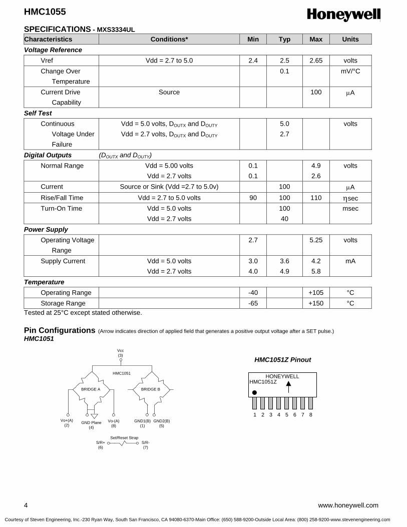
HMC1055
4 www.honeywell.com
SPECIFICATIONS - MXS3334UL Characteristics Conditions* Min Typ Max Units Voltage Reference Vref Vdd = 2.7 to 5.0 2.4 2.5 2.65 volts Change Over Temperature
0.1 mV/°C
Current Drive Capability
Source 100 µA
Self Test Continuous Voltage Under Failure
Vdd = 5.0 volts, DOUTX and DOUTY
Vdd = 2.7 volts, DOUTX and DOUTY 5.0
2.7 volts
Digital Outputs (DOUTX and DOUTY) Normal Range Vdd = 5.00 volts
Vdd = 2.7 volts 0.1 0.1
4.9 2.6
volts
Current Source or Sink (Vdd =2.7 to 5.0v) 100 µA Rise/Fall Time Vdd = 2.7 to 5.0 volts 90 100 110 ηsec Turn-On Time Vdd = 5.0 volts
Vdd = 2.7 volts 100
40 msec
Power Supply Operating Voltage Range
2.7 5.25 volts
Supply Current Vdd = 5.0 volts Vdd = 2.7 volts
3.0 4.0
3.6 4.9
4.2 5.8
mA
Temperature Operating Range -40 +105 °C Storage Range -65 +150 °C Tested at 25°C except stated otherwise. Pin Configurations (Arrow indicates direction of applied field that generates a positive output voltage after a SET pulse.) HMC1051
HMC1051
Vcc(3)
GND Plane(4)
Vo+(A)(2)
Vo-(A)(8)
GND1(B)(1)
GND2(B)(5)
BRIDGE A BRIDGE B
S/R+(6)
S/R-(7)
Set/Reset Strap
HMC1051Z Pinout
HONEYWELLHMC1051Z
1 2 3 4 5 6 7 8
Courtesy of Steven Engineering, Inc.-230 Ryan Way, South San Francisco, CA 94080-6370-Main Office: (650) 588-9200-Outside Local Area: (800) 258-9200-www.stevenengineering.com

HMC1055
www.honeywell.com 5
HMC1052
MXS3334UL Pin Descriptions HMC1051Z
Pin Name Description 1 GND1(B) Bridge B Ground 1 (normally left open) 2 Vo+(A) Bridge Output Positive 3 Vcc Bridge Positive Supply 4 GND Plane Bridge Ground (substrate) 5 GND2(B) Bridge B Ground 2 (normally left open) 6 S/R+ Set/Reset Strap Positive 7 S/R- Set/Reset Strap Negative 8 Vo-(A) Bridge Output Negative
HMC1052 Pinout
HMC1052
1 2 3 4 5
678910
A
B
HMC1052
Vcc(5)
GND2(9)
OUT-(10)
OUT+(4)
GND(1)
BRIDGE A BRIDGE B
S/R+(6)
S/R-(8)
Set/Reset Strap
GND1(3)
OUT-(7)
OUT+(2)
HMC1052
Vcc(5)
GND2(9)
OUT-(10)
OUT+(4)
GND(1)
BRIDGE A BRIDGE B
S/R+(6)
S/R-(8)
Set/Reset Strap
GND1(3)
OUT-(7)
OUT+(2)
InternalOscillator
Sck(optional)
CLK
HeaterControl
X axis
Y axis
Factory AdjustOffset & Gain
Low PassFilter
Low PassFilter
TemperatureSensor
VoltageReference VREF
DOUTX
VDD VDAGnd
2-AXISSENSOR
DOUTY
TOUT
ContinousSelf Test
(7) (1)
(6)
(5)
(2)
(4)(3)(8)
InternalOscillator
Sck(optional)
CLK
HeaterControl
X axis
Y axis
Factory AdjustOffset & Gain
Low PassFilter
Low PassFilter
TemperatureSensor
VoltageReference VREF
DOUTX
VDD VDAGnd
2-AXISSENSOR
DOUTY
TOUT
ContinousSelf Test
(7) (1)
(6)
(5)
(2)
(4)(3)(8)
8
4
1
2
3
7
6
5
Top ViewM
EM
SIC X +g
Y +g
Courtesy of Steven Engineering, Inc.-230 Ryan Way, South San Francisco, CA 94080-6370-Main Office: (650) 588-9200-Outside Local Area: (800) 258-9200-www.stevenengineering.com
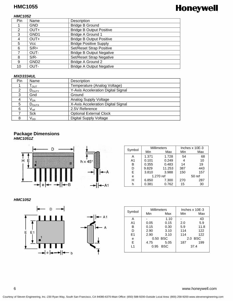
HMC1055
6 www.honeywell.com
HMC1052 Pin Name Description 1 GND Bridge B Ground 2 OUT+ Bridge B Output Positive 3 GND1 Bridge A Ground 1 4 OUT+ Bridge B Output Positive 5 Vcc Bridge Positive Supply 6 S/R+ Set/Reset Strap Positive 7 OUT- Bridge B Output Negative 8 S/R- Set/Reset Strap Negative 9 GND2 Bridge A Ground 2 10 OUT- Bridge A Output Negative
MXD3334UL
Pin Name Description 1 TOUT Temperature (Analog Voltage) 2 DOUTY Y-Axis Acceleration Digital Signal 3 Gnd Ground 4 VDA Analog Supply Voltage 5 DOUTX X-Axis Acceleration Digital Signal 6 Vref 2.5V Reference 7 Sck Optional External Clock 8 VDD Digital Supply Voltage
Package Dimensions HMC1051Z HMC1052
Symbol Millimeters Min Max
Inches x 10E-3 Min Max
A A1 B D E1 e E L1
- 1.10 0.05 0.15 0.15 0.30 2.90 3.10 2.90 3.10
0.50 BSC 4.75 5.05
0.95 BSC
- 43 2.0 5.9 5.9 11.8 114 122 114 122
2.0 BSC 187 199
37.4
Symbol Millimeters Min Max
Inches x 10E-3 Min Max
A A1 B D E e H h
1.371 1.728 0.101 0.249 0.355 0.483 9.829 11.253 3.810 3.988
1.270 ref 6.850 7.300 0.381 0.762
54 68 4 10
14 19 387 443 150 157
50 ref 270 287 15 30
Courtesy of Steven Engineering, Inc.-230 Ryan Way, South San Francisco, CA 94080-6370-Main Office: (650) 588-9200-Outside Local Area: (800) 258-9200-www.stevenengineering.com

HMC1055
www.honeywell.com 7
MXS3334UL Application Notes The HMC1055 Chipset is composed of three sensors packaged as integrated circuits for tilt compensated electronic compass development. These three sensors are composed of a Honeywell HMC1052 two-axis magnetic field sensor, a Honeywell HMC1051Z one-axis magnetic sensor, and the Memsic MXS3334UL two-axis accelerometer. Traditionally, compassing is done with a two-axis magnetic sensor held level (perpendicular to the gravitational axis) to sense the horizontal vector components of the earth’s magnetic field from the south pole to the north pole. By incorporating a third axis magnetic sensor and the two-axis accelerometer to measure pitch and roll (tilt), the compass is able to be electronically “gimbaled” and can point to the north pole regardless of level. The HMC1052 two-axis magnetic sensor contains two Anisotropic Magneto-Resistive (AMR) sensor elements in a single MSOP-10 package. Each element is a full wheatstone bridge sensor that varies the resistance of the bridge magneto-resistors in proportion to the vector magnetic field component on its sensitive axis. The two bridges on the HMC1052 are orientated orthogonal to each other so that a two-dimensional representation of an magnetic field can be measured. The bridges have a common positive bridge power supply connection (Vb); and with all the bridge ground connections tied together, form the complete two-axis magnetic sensor. Each bridge has about an 1100-ohm load resistance, so each bridge will draw several milli-amperes of current from typical digital power supplies. The bridge output pins will present a differential output voltage in proportion to the exposed magnetic field strength and the amount of voltage supply across the bridge. Because the total earth’s magnetic field strength is very small (~0.6 gauss), each bridge’s vector component of the earth’s field will even be smaller and yield only a couple milli-volts with nominal bridge supply values. An instrumentation amplifier circuit; to interface with the differential bridge outputs, and to amplify the sensor signal by hundreds of times, will then follow each bridge voltage output. The HMC1051Z is an additional magnetic sensor in an 8-pin SIP package to place the sensor silicon die in a vertical orientation relative to a Printed Circuit Board (PCB) position. By having the HMC1052 placed flat (horizontal) on the PCB and the HMC1051Z vertical, all three vector components of the earth’s magnetic field (X, Y, and Z) are sensed. By having the Z-axis component of the field, the electronic compass can be oriented arbitrarily; and with a tilt sensor, perform tilt-compensated compass heading measurements as if the PCB where perfectly level.
Courtesy of Steven Engineering, Inc.-230 Ryan Way, South San Francisco, CA 94080-6370-Main Office: (650) 588-9200-Outside Local Area: (800) 258-9200-www.stevenengineering.com
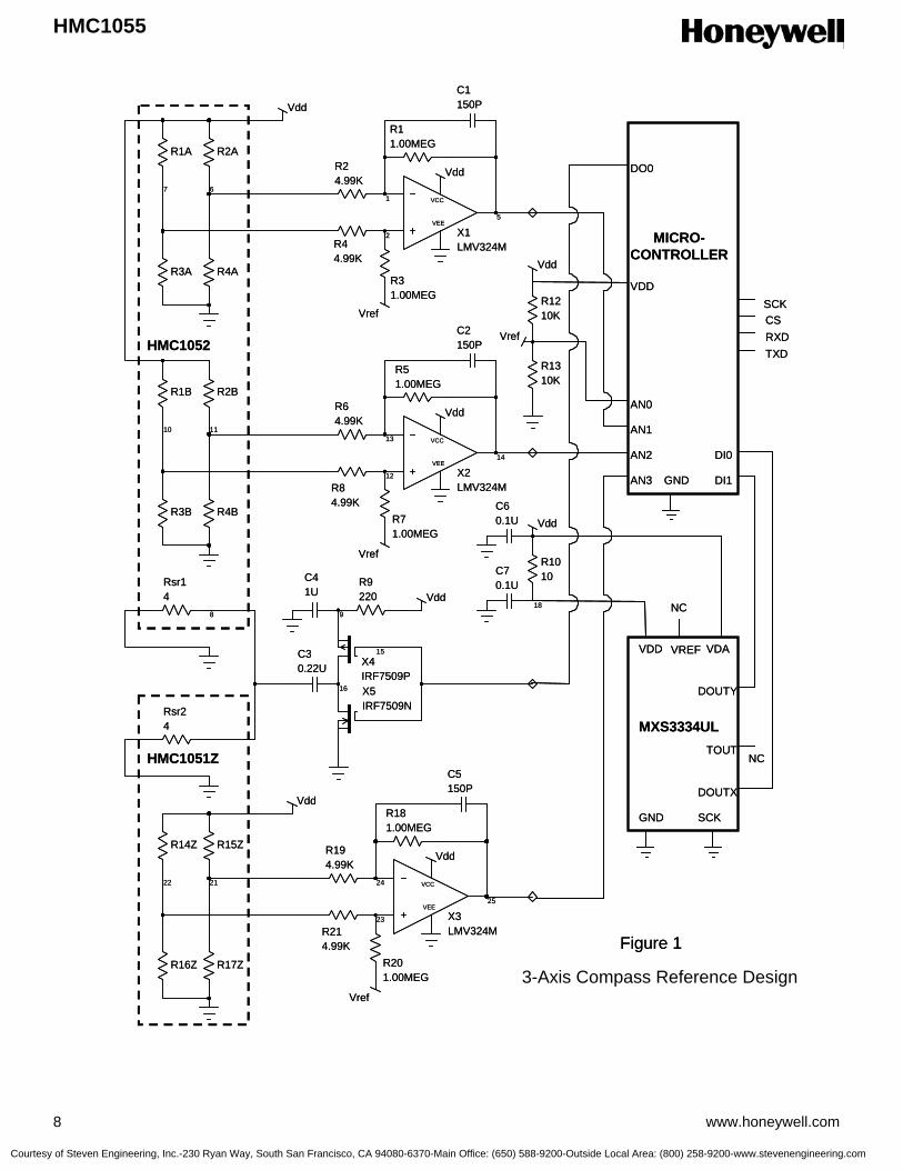
HMC1055
8 www.honeywell.com
7
R1A
6
R2A
R3A R4A
VCC
VEE
2
1
5
X1LMV324M
R24.99K
R44.99K
R31.00MEG
Vref
Vdd
R11.00MEG
C1150P
10
R1B
11
R2B
R3B R4B
VCC
VEE
12
13
14
X2LMV324M
R64.99K
R84.99K
R71.00MEG
Vref
Vdd
R51.00MEG
C2150P
Vdd
8
Rsr14
16
C30.22U
9
R9220 Vdd
18
R1010C4
1U
R1210K
R1310K
Vdd
Vref
22
R14Z
21
R15Z
R16Z R17Z
VCC
VEE
23
24
25
X3LMV324M
R194.99K
R214.99K
R201.00MEG
Vref
Vdd
R181.00MEG
C5150P
Rsr24
Vdd
15X4IRF7509PX5IRF7509N
C60.1U
C70.1U
Vdd
MXS3334UL
HMC1052
HMC1051Z
VDAVDD
GND
GND
DOUTX
DOUTY
SCK
VREF
NC
AN3
AN2
AN1
AN0
DO0
DI0
DI1
TXDRXDCSSCK
MICRO-CONTROLLER
VDD
Figure 1
TOUTNC
3-Axis Compass Reference Design
Courtesy of Steven Engineering, Inc.-230 Ryan Way, South San Francisco, CA 94080-6370-Main Office: (650) 588-9200-Outside Local Area: (800) 258-9200-www.stevenengineering.com

HMC1055
www.honeywell.com 9
The MXS3334UL is a two-axis accelerometer in an 8-pin LCC package that provides a digital representation of the earth’s gravitational field. When the MXS3334UL is held level and placed horizontally on a PCB, both digital outputs provide a 100 Hz Pulse Width Modulated (PWM) square wave with a 50 percent duty cycle. As the accelerometer is pitched or rolled from horizontal to vertical, the Doutx and Douty duty cycles will shift plus or minus 20% of its duty from the 50% center point. The reference design in Figure 1 shows a reference design incorporating all three sensor elements of the HMC1055 chipset for a tilt compensated electronic compass operating from a 5.0 volt regulated power supply described as Vdd. The HMC1052 sensor bridge elements A and B are called out as R1A, R2A, R3A, R4A, and R1B, R2B, R3B, R4B respectively; and create a voltage dividing networks that place nominally 2.5 volts into the succeeding amplifier stages. The HMC1051Z sensor bridge elements R14Z, R15Z, R16Z, and R17Z also do a similar voltage dividing method to its amplifier stage. In this design each amplifier stage uses a single operational amplifier (op-amp) from a common LMV324M quad op-amp Integrated Circuit (IC). For example, resistors R1, R2, R3, and R4 plus capacitor C1 configure op-amp X1 into an instrumentation amplifier with a voltage gain of about 200. These instrumentation amplifier circuits take the voltage differences in the sensor bridges, and amplify the signals for presentation at the micro-controller Analog to Digital Converter (ADC) inputs, denoted as AN1, AN2, and AN3. Because the zero magnetic field reference level is at 2.5 volts, each instrumentation amplifier circuit receives a 2.5 volt reference voltage (Vref) from a resistor divider circuit composed of R12 and R13. For example, a +500 milli-gauss earth’s field on bridge A of the HMC1052 will create a 2.5 milli-volt difference voltage at the sensor bridge output pins (0.5 gauss multiplied by the 1.0mV/V/gauss sensitivity rating). This 2.5mV then is multiplied by 200 for 0.5 volt offset that is referenced to the 2.5 volt Vref for a total of +3.0 volts at AN1. Likewise any positive and or negative magnetic field vectors from bridge B and the HMC1051Z bridge are converted to voltage representations at AN2 and AN3. The micro-controller also receives the sensor inputs from the MXS3334UL accelerometer directly from Doutx and Douty into two digital inputs denoted as DI0 and DI1. Optionally, the MXS3334UL temperature output pin (Tout) can routed to another microcontroller ADC input for further temperature compensation of sensor inputs. Power is supplied to the MXS3334UL from the 5.0 volt Vdd source directly to the accelerometer VDA pin and on to the VDD pin via a ten ohm resistor (R10) for modest digital noise decoupling. Capacitors C6 and C7 provide noise filtering locally at the accelerometer and throughout the compass circuit. The set/reset circuit for this electronic compass is composed of MOSFETs X4 and X5, capacitors C3 and C4, and resistor R9. The purpose of the set/reset circuit is to re-align the magnetic moments in the magnetic sensor bridges when they exposed to intense magnetic fields such as speaker magnets, magnetized hand tools, or high current conductors such as welding cables or power service feeders. The set/reset circuit is toggled by the microcontroller and each logic state transition creates a high current pulse in the set/reset straps for both HMC1052 and the HMC1051Z. Operational Details With the compass circuitry fully powered up, sensor bridge A creates a voltage difference across OUTA- and OUTA+ that is then amplified 200 times and presented to microcontroller analog input AN1. Similarly, bridges B and C create a voltage difference that is amplified 200 times and presented to microcontroller analog inputs AN2 and AN3. These analog voltages at AN1 and AN2 can be thought of as “X” and “Y” vector representations of the magnetic field. The third analog voltage (AN3) plus the tilt information from accelerometer, is added to the X and Y values to create tilt compensated X and Y values, sometimes designated X’ and Y’. To get these X, Y, and Z values extracted, the voltages at AN1 through AN3 are to be digitized by the microcontroller’s onboard Analog-to-Digital Converter (ADC). Depending on the resolution of the ADC, the resolution of the Compass is set. Typically compasses with one degree increment displays will have 10-bit or greater ADCs, with 8-bit ADCs more appropriate for basic 8-cardinal point (North, South, East, West, and the diagonal points) compassing. Individual microcontroller choices have a great amount of differing ADC implementations, and there may be instances where the ADC reference voltage and the compass reference voltage can be shared. The point to remember is that the analog voltage outputs are referenced to half the supplied bridge voltage and amplified with a similar reference. The most often asked question on AMR compass circuits is how frequent the set/reset strap must be pulsed. The answer for most low cost compasses is fairly infrequently; from a range of once per second, to once per compass menu selection by the user. While the set circuit draws little energy on a per pulse basis, a constant one pulse per second rate could draw down a fresh watch battery in less than a year. In the other extreme of one “set” pulse upon the user manually requesting
Courtesy of Steven Engineering, Inc.-230 Ryan Way, South San Francisco, CA 94080-6370-Main Office: (650) 588-9200-Outside Local Area: (800) 258-9200-www.stevenengineering.com

HMC1055
10 www.honeywell.com
a compass heading, negligible battery life impact could be expected. From a common sense standpoint, the set pulse interval should be chosen as the shortest time a user could withstand an inaccurate compass heading after exposing the compass circuit to nearby large magnetic sources. Typical automatic set intervals for low cost compasses could be once per 10 seconds to one per hour depending on battery energy capacity. Provision for a user commanded “set” function may be a handy alternative to periodic or automatic set routines. In portable consumer electronic applications like compass-watches, PDAs, and wireless phones; choosing the appropriate compass heading data flow has a large impact on circuit energy consumption. For example, a one heading per second update rate on a sport watch could permit the compass circuit to remain off to nearly 99 percent of the life of the watch, with just 10 millisecond measurement snapshots per second and a one per minute set pulses for perming correction. The HMC1052 and HMC1051Z sensors have a 5 MHz bandwidth in magnetic field sensing, so the minimum snapshot measurement time is derived principally by the settling time of the op-amps plus the sample-and-hold time of the microcontroller’s ADCs. In some “gaming” applications in wireless phones and PDAs, more frequent heading updates permits virtual reality sensor inputs for software reaction. Typically these update rates follow the precedent set more than a century ago by the motion picture industry (“Movies”) at 20 updates or more per second. While there is still some value in creating off periods in between these frequent updates, some users may choose to only switch power on the sensor bridges exclusively and optimize the remainder of the circuitry for low power consumption. Compass Firmware Development To implement an electronic compass with tilt compensation, the microcontroller firmware must be developed to gather the sensor inputs and to interpret them into meaningful data to the end user system. Typically the firmware can be broken into logical routines such as initialization, sensor output collection and raw data manipulation, heading computation, calibration routines, and output formatting. For the sensor output data collection, the analog voltages at microcontroller inputs AN0 through AN3 are digitized and a “count” number representing the measured voltage is the result. For compassing, the absolute meaning of the ADC counts scaled back to the sensor’s milli-gauss measurement is not necessary, however it is important to reference the zero-gauss ADC count level. For example, an 8-bit ADC has 512 counts (0 to 511 binary), then count 255 would be the zero offset and zero-gauss value. In reality errors will creep in due to the tolerances of the sensor bridge (bridge offset voltage), multiplied by the amplifier gain stages plus any offset errors the amplifiers contribute; and magnetic errors from hard iron effects (nearby magnetized materials). Usually a factory or user calibration routine in a clean magnetic environment will obtain a correction value of counts from mid ADC scale. Further tweaking of the correction value for each magnetic sensor axis once the compass assembly is in its final user location, is highly desired to remove the magnetic environment offsets. For example, the result of measuring AN0 (Vref) is about count 255, and the measuring of AN1, AN2, and AN3 results in 331, 262, and 205 counts respectively. Next calibration values of 31, -5, and 20 counts would be subtracted to result in corrected values of 301, 267, and 205 respectively. If the pitch and roll were known to be zero; then the AN3 (Z-axis output) value could be ignored and the tilt corrected X and Y-axis values would be the corrected values of AN1 and AN2 minus the voltage reference value of AN0. Doing the math yields arctan [y/x] or arctan [(267-255)/(301-255)] or 14.6 degrees east of magnetic north. Heading Computation Once the magnetic sensor axis outputs are gathered and the calibration corrections subtracted, the next step toward heading computation is to gather the pitch and roll (tilt) data from the MEMSIC MXS3334UL accelerometer outputs. The MXS3334UL in perfectly horizontal (zero tilt) condition produces a 100Hz, 50 percent duty cycle Pulse Width Modulated (PWM) digital waveform from its Doutx and Douty pins corresponding to the X and Y sensitive axis. These output pins will change their duty cycle from 30% to 70% when tilted fully in each axis (±1g). The scaling of the PWM outputs is strictly gravitational, so that a 45 degree tilt results in 707 milli-g’s or a slew of ±14.1% from the 50% center point duty cycle. With the MXS3334UL’s positive X-axis direction oriented towards the front of the user’s platform, a pitch downward will result in a reduced PWM duty cycle, with a pitch upward increasing in duty cycle. Likewise, the Y-axis arrow is 90 degrees counter-clockwise which results in a roll left corresponding to a decreasing duty cycle, and roll right to an increasing duty cycle.
Courtesy of Steven Engineering, Inc.-230 Ryan Way, South San Francisco, CA 94080-6370-Main Office: (650) 588-9200-Outside Local Area: (800) 258-9200-www.stevenengineering.com

HMC1055
www.honeywell.com 11
Measuring the pitch and roll data for a microcontroller is reasonably simple in that the Doutx and Douty logic signals can be sent to microcontroller digital input pins for duty cycle measurement. At firmware development or factory calibration, the total microcontroller clock cycles between Doutx or Douty rising edges should be accrued using an interrupt or watchdog timer feature to scale the 100Hz (10 millisecond) edges. Then measuring the Doutx and Douty falling edges from the rising edge (duty cycle computation) should be a process of clock cycle counting. For example, a 1MHz clocked microcontroller should count about 10,000 cycles per rising edge, and 5,000 cycle counts from rising to falling edge would represent a 50% duty cycle or zero degree pitch or roll. Once the duty cycle is measured for each axis output and mathematically converted to a gravitational value, these values can be compared to a memory mapped table, if the user desires the true pitch and roll angles. For example, if the pitch and roll data is to be known in one degree increments, a 91-point map can be created to match up gravitational values (sign independent) with corresponding degree indications. Because tilt-compensated compassing requires sine and cosine of the pitch and roll angles, the gravitational data is already formatted between zero and one and does not require further memory maps of trigonometric functions. The gravity angles for pitch and roll already fit the sine of the angles, and the cosines are just one minus the sine values (cosine = 1 – sine). The equations: X’ = X * cos(φ) + Y * sin(θ) * sin(φ) – Z * cos(θ) * sin(φ) Y’ = Y * cos(θ) + Z * sin(θ) Create tilt compensated X and Y magnetic vectors (X’, Y’) from the raw X, Y, and Y magnetic sensor inputs plus the pitch (φ) and roll (θ) angles. Once X’ and Y’ are computed, the compass heading can be computed by equation: Azimuth (Heading) = arctan (Y’ / X’) To perform the arc-tangent trigonometric function, a memory map needs to be implemented. Thankfully the pattern repeats in each 90° quadrant, so with a one-degree compass resolution requirement, 90 mapped quotients of the arc-tangent function can be used. If 0.1° resolution is needed then 900 locations are needed and only 180 locations with 0.5° resolution. Also, special case quotient detections are needed for the zero and inifinity situations at 0°, 90, 180°, and 270° prior to the quotient computation. After the heading is computed, two heading correction factors may be added to handle declination angle and platform angle error. Declination angle is the difference between the magnetic north pole and the geometric north pole, and varies depending on the latitude and longitude (global location) of the user compass platform. If you have access to Global Positioning Satellite (GPS) information resulting in a latitude and longitude computation, then the declination angle can be computed or memory mapped for heading correction. Platform angle error may occur if the sensors are not aligned perfectly with the mechanical characteristics of the user platform. These angular errors can be inserted in firmware development and or in factory calibration. Compass Calibration In the paragraphs describing raw magnetic sensor data, the count values of X, Y, and Z are found from inputs AN0 to AN3. A firmware calibration routine will create Xoff, Yoff and Xsf, and Ysf for calibration factors for “hard-iron” distortions of the earth’s magnetic field at the sensors. Typically these distortions come from nearby magnetized components. Soft-iron distortions are more complex to factor out of heading values and are generally left out for low cost compassing applications. Soft-iron distortion arises from magnetic fields bent by un-magnetized ferrous materials either very close to the sensors or large in size. Locating the compass away from ferrous materials provides the best error reduction. The amount of benefit is dependant on the amount of ferrous material and its proximity to the compass platform. To derive the calibration factors, the sensor assembly (platform) and its affixed end-platform (e.g. watch/human, boat, auto, etc.) are turned at least one complete rotation as the compass electronics collects many continuous readings. The speed and rate of turn are based on how quickly the microcontroller can collect and process X, Y, and Z data during the calibration routine. A good rule of thumb is to collect readings every few degrees by either asking the user to make a couple rotations or by keeping in the rotation(s) slow enough to collect readings of the correct rate of turn. The Xh and Yh readings during calibration are done with Xoff and Yoff at zero values, and axis scale factors (Xsf and Ysf) at unity values. The collected calibration X and Y values are then tabulated to find the min and max of both X and Y. At the end of the calibration session, the Xmax, Ymax, Xmin, and Ymin values are converted to the following:
Courtesy of Steven Engineering, Inc.-230 Ryan Way, South San Francisco, CA 94080-6370-Main Office: (650) 588-9200-Outside Local Area: (800) 258-9200-www.stevenengineering.com

HMC1055
12 www.honeywell.com
Xsf = 1 or (Ymax –Ymin) / (Xmax – Xmin) , whichever is greater Ysf = 1 or (Xmax –Xmin) / (Ymax – Ymin) , whichever is greater Xoff = [(Xmax – Xmin)/2 – Xmax] * Xsf Yoff = [(Ymax –Ymin)/2 –Ymax] * Ysf Z-axis data is generally not corrected if the end-platform can not turned upside-down. In portable or hand-held applications, then the compass assembly can be tipped upside down and Zoff can be computed like Xoff and Yoff, but with only two reference points (upright and upside down). Factory values for Zoff maybe the only values possible. Creating corrected X, Y, and Z count values are done as previously mentioned by subtracting the offsets. The scale factor values are used only after the Vref counts are subtracted form the offset corrected axis counts. For more details on calibration for iron effects, see the white paper “Applications of Magnetoresistive Sensors in Navigation Systems” located on the magneticsensors.com website. Offsets due to sensor bridge offset voltage of each sensor axis are part of the Xoff, Yoff, and Zoff computation. These offsets are present even with no magnetic field disturbances. To find their true values, the set and reset drive circuits can be toggled while taking measurements shortly after each transition. After a reset pulse, the magnetic field portion of the sensor bridge will have flipped polarity while the offset remains the same. Thus two measurements, after a reset and a set pulse can be summed together. The magnetic portions of the sum will cancel, leaving just a double value of the offset. The result can then be divide by two to derive the bridge offset. The reason for knowing the bridge offset, is that the offset will drift with temperature. Should the user desire the best accuracy in heading, a new calibration should be performed with each encounter with a new temperature environment. See application notes AN-212, AN-213, and AN-214 for further compass design considerations. Ordering Information
Ordering Number Product HMC1055
3-Axis Compass Sensor Set
Find out more For more information on Honeywell’s Magnetic Sensors visit us online at www.magneticsensors.com or contact us at 800-323-8295 (763-954-2474 internationally). The application circuits herein constitute typical usage and interface of Honeywell product. Honeywell does not warranty or assume liability of customer-designed circuits derived from this description or depiction. Honeywell reserves the right to make changes to improve reliability, function or design. Honeywell does not assume any liability arising out of the application or use of any product or circuit described herein; neither does it convey any license under its patent rights nor the rights of others. U.S. Patents 4,441,072, 4,533,872, 4,569,742, 4,681,812, 4,847,584 and 6,529,114 apply to the technology described
Honeywell International Inc. Defense and Space 12001 Highway 55 Plymouth, MN 55441 Tel: 800-323-8295 www.honeywell.com
Form #900302 Rev A September 2005 ©2005 Honeywell International Inc.
Courtesy of Steven Engineering, Inc.-230 Ryan Way, South San Francisco, CA 94080-6370-Main Office: (650) 588-9200-Outside Local Area: (800) 258-9200-www.stevenengineering.com

FEATURES AND BENEFITS
SENSOR PRODUCTS
Linear / Angular / RotaryDisplacement Sensors
HMC1501 / HMC1512
APPLICATIONS
igh resolution, low power MR sensor
capable of measuring the angle
direction of a magnetic field from a
magnet with <0.07° resolution.
Advantages of measuring field
direction versus field strength include:
insensitivity to the tempco of the
magnet, less sensitivity to shock and
vibration, and the ability to withstand
large variations in the gap between
the sensor and magnet. These
sensors may be operated on 3 volts
with bandwidth response of 0-5 MHz.
Output is typical Wheatstone bridge.
No Rare Earth Magnets Unlike Hall effect devices which may require samarium cobalt or similar “rare earth”
magnets, the HMC1501 and HMC1512 can function with Alnico or ceramic type magnets.
Wide Angular Range HMC1501—Angular range of ±45° with <0.07° resolution.
HMC1512—Angular range of ±90° with <0.05° resolution.
Effective Linear Range Linear range of 8mm with two sensors mounted on two ends; range may be increased
through multiple sensor arrays operating together.
Absolute Sensing Unlike incremental “encoding” devices, sensors know the exact position and require no
indexing for proper positional output.
Non-Contact Sensing No moving parts to wear out; no dropped signals from worn tracks as in conventional
contact based rotary sensors.
Small Package Available in an 8-pin surface mount package with case dimensions (exclusive of pins), of
5mm x 4mm x 1.2mm total mounting envelope, with pins of less than 6mm square.
Large Signal Output Full Scale output range of 120mV with 5V of power supply.
Linear Displacement
Angular Displacement
Motor Control
Valve Position
Proximity Detection
Current Spike Detection
Not actual size
H
Courtesy of Steven Engineering, Inc.-230 Ryan Way, South San Francisco, CA 94080-6370-Main Office: (650) 588-9200-Outside Local Area: (800) 258-9200-www.stevenengineering.com

2
HMC1501 / HMC1512 SENSOR PRODUCTS
Anisotropic magnetoresistance (AMR) occurs in ferrousmaterials. It is a change in resistance when a magneticfield is applied in a thin strip of ferrous material. The mag-netoresistance is a function of cos2θ where θ is the anglebetween magnetization M and current flow in the thin strip.When an applied magnetic field is larger than 80 Oe, themagnetization aligns in the same direction of the appliedfield; this is called saturation mode. In this mode, θ is theangle between the direction of applied field and the currentflow; the MR sensor is only sensitive to the direction ofapplied field.
The sensor is in the form of a Wheatstone bridge (Figure 1).The resistance R of all four resistors is the same. The bridgepower supply VS causes current to flow through the resistors,the direction as indicated in the figure for each resistor.
Both HMC1501 and HMC1512 are designed to be used insaturation mode. HMC1501 contains one MR bridge andHMC1512 has two identical MR bridges, coexisting on asingle die. Bridge B physically rotates 45° from bridge A.The HMC1501 has sensor output ∆V=-V
SS sin (2θ) and
the HMC1512 has sensor output ∆V=VSS sin (2θ) for sen-
sor A and sensor B output ∆VS=-V
SS cos (2θ), where V
S is
supply voltage, S is a constant, determined by materials.For Honeywell sensors, S is typically 12mV/V.
PRINCIPLES OF OPERATION
MR SENSOR CIRCUITS
Figure 1
CurrentFlow
PermalloyThin Film
(NiFe)
Metal Contact
M
AppliedField
θ
PINOUT DRAWINGS
OUT+ 1GND 1 2
34
• 8 OUT-7 GND 265 VBRIDGE
θ • 8765
θ
1234
OUT- AOUT- B
VBRIDGEBVBRIDGEA
GNDAGNDBOUT+ BOUT+ A
HMC1501 HMC1512
Caution: Do not connect GND or Power to Pin 3,4 &6.
OUT+A
OUT-A
VBRIDGE A
GND A
Bridge A
R R
R R
OUT+ OUT-
VBRIDGE
GND 1
R R
R R
GND 2
VBRIDGE BOUT +B
OUT -BGND B
Bridge B
R
RR
R
+ -
∆V
R+∆R
M M
R-∆R
R+∆RR-∆R
M M
Applied Field Direction
VsI
Courtesy of Steven Engineering, Inc.-230 Ryan Way, South San Francisco, CA 94080-6370-Main Office: (650) 588-9200-Outside Local Area: (800) 258-9200-www.stevenengineering.com
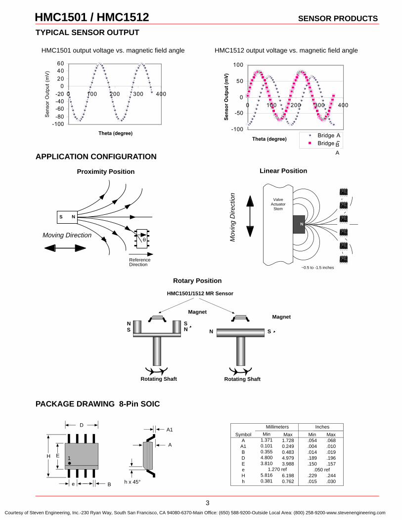
3
TYPICAL SENSOR OUTPUT
HMC1501 / HMC1512 SENSOR PRODUCTS
Rotating ShaftRotating Shaft
NS
SN
Magnet
N S
Magnet
HMC1501/1512 MR Sensor
APPLICATION CONFIGURATION
N
~0.5 to -1.5 inches
ValveActuator
Stem
Proximity Position
Rotary Position
Linear Position
HMC1501 output voltage vs. magnetic field angle HMC1512 output voltage vs. magnetic field angle
-100-80-60-40-20
0204060
0 100 200 300 400
Theta (degree)
Sen
sor
Out
put
(mV
)
-100
-50
0
50
100
0 100 200 300 400
Theta (degree)
Sen
sor
Ou
tpu
t (m
V)
Bridge ABridge BB
A
ReferenceDirection
θ
NS
Moving DirectionM
ovin
g D
irect
ion
PACKAGE DRAWING 8-Pin SOIC
D
E
B
1
h x 45°e
A
•H
A1Symbol
AA1BDEeHh
Min1.3710.1010.3554.8003.810
1.270 ref5.8160.381
Max1.7280.2490.4834.9793.988
6.1980.762
Min.054.004.014.189.150
.050 ref.229.015
Max.068.010.019.196.157
.244
.030
Millimeters Inches
Courtesy of Steven Engineering, Inc.-230 Ryan Way, South San Francisco, CA 94080-6370-Main Office: (650) 588-9200-Outside Local Area: (800) 258-9200-www.stevenengineering.com
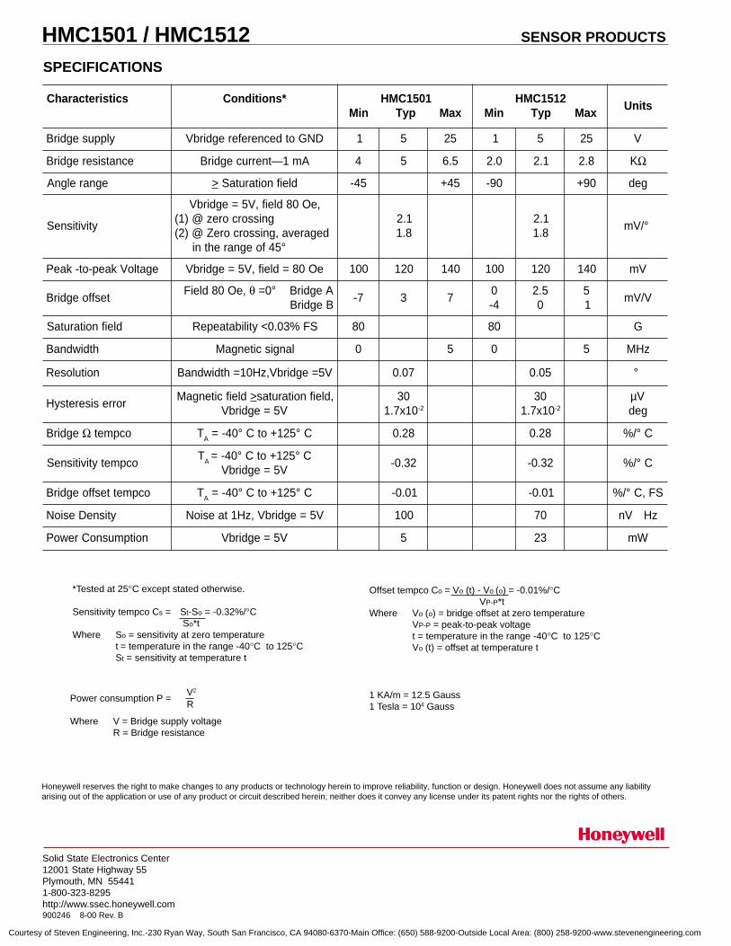
4
Honeywell reserves the right to make changes to any products or technology herein to improve reliability, function or design. Honeywell does not assume any liabilityarising out of the application or use of any product or circuit described herein; neither does it convey any license under its patent rights nor the rights of others.
SPECIFICATIONS
HMC1501 / HMC1512 SENSOR PRODUCTS
Solid State Electronics Center12001 State Highway 55Plymouth, MN 554411-800-323-8295http://www.ssec.honeywell.com900246 8-00 Rev. B
1 KA/m = 12.5 Gauss1 Tesla = 104 Gauss
Offset tempco Co = Vo (t) - Vo (o) = -0.01%/°C VP-P*t
Where Vo (o) = bridge offset at zero temperatureVP-P = peak-to-peak voltaget = temperature in the range -40°C to 125°CVo (t) = offset at temperature t
Power consumption P =
Where V = Bridge supply voltageR = Bridge resistance
V2
R
*Tested at 25°C except stated otherwise.
Sensitivity tempco Cs = St-So = -0.32%/°C So*t
Where So = sensitivity at zero temperaturet = temperature in the range -40°C to 125°CSt = sensitivity at temperature t
scitsiretcarahC *snoitidnoC 1051CMHxaMpyTniM
2151CMHxaMpyTniM
stinU
ylppusegdirB DNGotdecnereferegdirbV 1 5 52 1 5 52 V
ecnatsiseregdirB Am1—tnerrucegdirB 4 5 5.6 0.2 1.2 8.2 KΩ
egnarelgnA > dleifnoitarutaS 54- 54+ 09- 09+ ged
ytivitisneS
,eO08dleif,V5=egdirbVgnissorcorez@)1(
degareva,gnissorcoreZ@)2(°54foegnarehtni
1.28.1
1.28.1
°/Vm
egatloVkaep-ot-kaeP eO08=dleif,V5=egdirbV 001 021 041 001 021 041 Vm
tesffoegdirB,eO08dleiF θ AegdirB°0=
BegdirB7- 3 7
04-
5.20
51
V/Vm
dleifnoitarutaS SF%30.0<ytilibataepeR 08 08 G
htdiwdnaB langiscitengaM 0 5 0 5 zHM
noituloseR V5=egdirbV,zH01=htdiwdnaB 70.0 50.0 °
rorresiseretsyHdleifcitengaM > ,dleifnoitarutas
V5=egdirbV03
01x7.1 2-
0301x7.1 2-
Vµged
egdirB Ω ocpmet TA C°521+otC°04-= 82.0 82.0 C°/%
ocpmetytivitisneSTA C°521+otC°04-=
V5=egdirbV23.0- 23.0- C°/%
ocpmettesffoegdirB TA C°521+otC°04-= 10.0- 10.0- SF,C°/%
ytisneDesioN V5=egdirbV,zH1taesioN 001 07 zHVn
noitpmusnoCrewoP V5=egdirbV 5 32 Wm
Courtesy of Steven Engineering, Inc.-230 Ryan Way, South San Francisco, CA 94080-6370-Main Office: (650) 588-9200-Outside Local Area: (800) 258-9200-www.stevenengineering.com

HMC2003 SENSOR PRODUCTS
Solid State Electronics Center • www.magneticsensors.com • (800) 323-8295 • Page 1
THREE-AXIS MAGNETIC SENSOR HYBRID Features • 20-pin Wide DIP Footprint (1” by 0.75”) • Precision 3-axis Capability • Factory Calibrated Analog Outputs • 40 micro-gauss to ±2 gauss Dynamic Range • Analog Output at 1 Volt/gauss (2.5V @ 0 gauss) • Onboard +2.5 Volt Reference • +6 to +15 Volt DC Single Supply Operation • Very Low Magnetic Material Content • -40° to 85°C Operating Temperature Range General Description The Honeywell HMC2003 is a high sensitivity, three-axis magnetic sensor hybrid assembly used to measure low magnetic field strengths. Honeywell’s most sensitive magneto-resistive sensors (HMC1001 and HMC1002) are utilized to provide the reliability and precision of this magnetometer design. The HMC2003 interface is all analog with critical nodes brought out to the pin interfaces for maximum user flexibility. The internal excitation current source and selected gain and offset resistors, reduces temperature errors plus gain and offset drift. Three precision low-noise instrumentation amplifiers with 1kHz low pass filters provide accurate measurements while rejecting unwanted noise.
• Precision Compassing
• Navigation Systems
• Attitude Reference
• Traffic Detection
• Proximity Detection
• Medical Devices
APPLICATIONS
BLOCK DIAGRAM
Courtesy of Steven Engineering, Inc.-230 Ryan Way, South San Francisco, CA 94080-6370-Main Office: (650) 588-9200-Outside Local Area: (800) 258-9200-www.stevenengineering.com
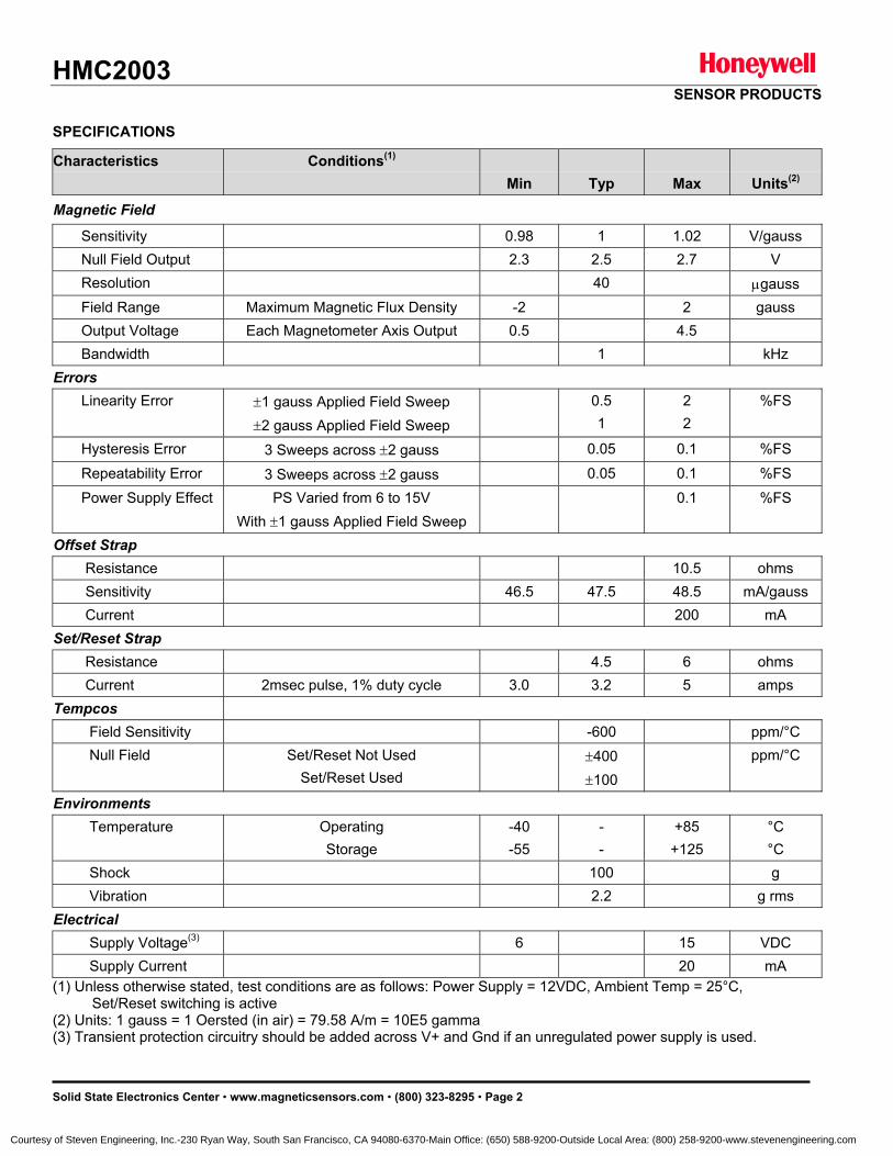
HMC2003 SENSOR PRODUCTS
Solid State Electronics Center • www.magneticsensors.com • (800) 323-8295 • Page 2
SPECIFICATIONS
Characteristics Conditions(1) Min
Typ
Max
Units(2)
Magnetic Field
Sensitivity 0.98 1 1.02 V/gauss Null Field Output 2.3 2.5 2.7 V Resolution 40 µgauss Field Range Maximum Magnetic Flux Density -2 2 gauss Output Voltage Each Magnetometer Axis Output 0.5 4.5 Bandwidth 1 kHz Errors Linearity Error ±1 gauss Applied Field Sweep
±2 gauss Applied Field Sweep
0.5 1
2 2
%FS
Hysteresis Error 3 Sweeps across ±2 gauss 0.05 0.1 %FS
Repeatability Error 3 Sweeps across ±2 gauss 0.05 0.1 %FS
Power Supply Effect PS Varied from 6 to 15V With ±1 gauss Applied Field Sweep
0.1 %FS
Offset Strap Resistance 10.5 ohms Sensitivity 46.5 47.5 48.5 mA/gauss Current 200 mA Set/Reset Strap Resistance 4.5 6 ohms Current 2msec pulse, 1% duty cycle 3.0 3.2 5 amps Tempcos Field Sensitivity -600 ppm/°C Null Field Set/Reset Not Used
Set/Reset Used ±400
±100
ppm/°C
Environments Temperature Operating
Storage -40 -55
- -
+85 +125
°C °C
Shock 100 g Vibration 2.2 g rms Electrical Supply Voltage(3) 6 15 VDC Supply Current 20 mA (1) Unless otherwise stated, test conditions are as follows: Power Supply = 12VDC, Ambient Temp = 25°C,
Set/Reset switching is active (2) Units: 1 gauss = 1 Oersted (in air) = 79.58 A/m = 10E5 gamma (3) Transient protection circuitry should be added across V+ and Gnd if an unregulated power supply is used.
Courtesy of Steven Engineering, Inc.-230 Ryan Way, South San Francisco, CA 94080-6370-Main Office: (650) 588-9200-Outside Local Area: (800) 258-9200-www.stevenengineering.com
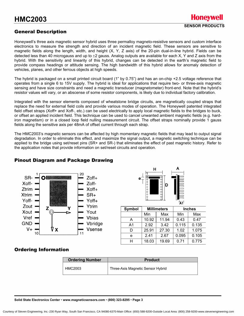
HMC2003 SENSOR PRODUCTS
Solid State Electronics Center • www.magneticsensors.com • (800) 323-8295 • Page 3
General Description Honeywell’s three axis magnetic sensor hybrid uses three permalloy magneto-resistive sensors and custom interface electronics to measure the strength and direction of an incident magnetic field. These sensors are sensitive to magnetic fields along the length, width, and height (X, Y, Z axis) of the 20-pin dual-in-line hybrid. Fields can be detected less than 40 microgauss and up to ±2 gauss. Analog outputs are available for each X, Y and Z axis from the hybrid. With the sensitivity and linearity of this hybrid, changes can be detected in the earth’s magnetic field to provide compass headings or attitude sensing. The high bandwidth of this hybrid allows for anomaly detection of vehicles, planes, and other ferrous objects at high speeds. The hybrid is packaged on a small printed circuit board (1” by 0.75”) and has an on-chip +2.5 voltage reference that operates from a single 6 to 15V supply. The hybrid is ideal for applications that require two- or three-axis magnetic sensing and have size constraints and need a magnetic transducer (magnetometer) front-end. Note that the hybrid’s resistor values will vary, or an abscense of some resistor components, is likely due to individual factory calibration. Integrated with the sensor elements composed of wheatstone bridge circuits, are magnetically coupled straps that replace the need for external field coils and provide various modes of operation. The Honeywell patented integrated field offset straps (Xoff+ and Xoff-, etc.) can be used electrically to apply local magnetic fields to the bridges to buck, or offset an applied incident field. This technique can be used to cancel unwanted ambient magnetic fields (e.g. hard-iron magnetism) or in a closed loop field nulling measurement circuit. The offset straps nominally provide 1 gauss fields along the sensitive axis per 48mA of offset current through each strap. The HMC2003’s magnetic sensors can be affected by high momentary magnetic fields that may lead to output signal degradation. In order to eliminate this effect, and maximize the signal output, a magnetic switching technique can be applied to the bridge using set/reset pins (SR+ and SR-) that eliminates the effect of past magnetic history. Refer to the application notes that provide information on set/reset circuits and operation. Pinout Diagram and Package Drawing Ordering Information
Ordering Number Product HMC2003
Three-Axis Magnetic Sensor Hybrid
Symbol Millimeters Inches
Min Max Min Max A 10.92 11.94 0.43 0.47 A1 2.92 3.42 0.115 0.135 D 25.91 27.30 1.02 1.075 e 2.41 2.67 0.095 0.105 H 18.03 19.69 0.71 0.775
Courtesy of Steven Engineering, Inc.-230 Ryan Way, South San Francisco, CA 94080-6370-Main Office: (650) 588-9200-Outside Local Area: (800) 258-9200-www.stevenengineering.com
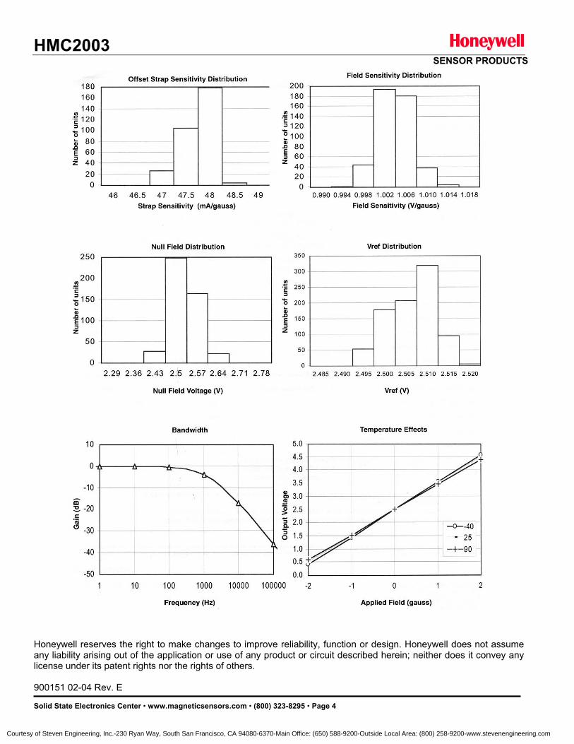
HMC2003 SENSOR PRODUCTS
Solid State Electronics Center • www.magneticsensors.com • (800) 323-8295 • Page 4
Honeywell reserves the right to make changes to improve reliability, function or design. Honeywell does not assume any liability arising out of the application or use of any product or circuit described herein; neither does it convey any license under its patent rights nor the rights of others. 900151 02-04 Rev. E
Courtesy of Steven Engineering, Inc.-230 Ryan Way, South San Francisco, CA 94080-6370-Main Office: (650) 588-9200-Outside Local Area: (800) 258-9200-www.stevenengineering.com

Integrated Compass Sensor HMC6052
The Honeywell HMC6052 is a 2-axis Magneto-Resistive sensor
plus amplifiers and analog support features essential for
compassing and low magnetic field sensing. The product is
offered in a 14-pin surface mount 3.5mm by 3.5mm LCC
package. Two channels of amplified sensor signals with a set
switch function allow compass system designers to have a
compact, easy to implement solution. Applications for the
HMC6052 include electronic compassing, and magnetometry.
Honeywell continues to maintain product excellence and
performance by introducing innovative solid-state magnetic
sensor solutions. These are highly reliable, top performance
products that are delivered when promised. Honeywell’s magnetic
sensor products provide real solutions you can count on.
FEATURES BENEFITS
4 2 Axis AMR Magnetic Sensor (HMC1052)
w/ Integrated Amplifiers & Set Circuit 4 Complete Analog Solution Optimized for Compassing. Eliminates
Need for External Amplifiers and Most Discrete Components
4 Single Die in a Surface Mount Package (3.5 x 3.5 x 0.8 mm 14-pin LCC)
4 Optimized for Smallest Footprint and Easy Integration
4 Minimal Support Components 4 Only Two Capacitors to Complete the Analog Signal Processing
4 Field Range +/- 2 gauss 4 Optimized for Compass Applications in Hand-Held or Hard Iron Environment
4 Low Voltage Operation (2.5 to 3.6 V) 4 Compatible for Battery Powered Applications
4 Precision Magnetic Field Measurement 4 User’s ADC Resolution Limits the Accuracy of the Outputs
4 Minimal Detectable Field (80 micro-gauss) 4 Permits Accurate Compassing and Magnetic Field Measurement
4 Lead Free Package Construction 4 Complies with Current Environmental Standards (RoHS)
Preliminary Information
Courtesy of Steven Engineering, Inc.-230 Ryan Way, South San Francisco, CA 94080-6370-Main Office: (650) 588-9200-Outside Local Area: (800) 258-9200-www.stevenengineering.com
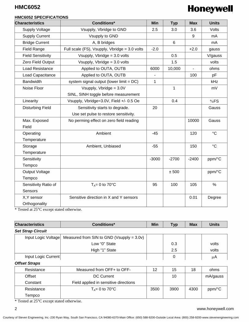
HMC6052
2 www.honeywell.com
HMC6052 SPECIFICATIONS Characteristics Conditions* Min Typ Max Units Supply Voltage Vsupply, Vbridge to GND 2.5 3.0 3.6 Volts Supply Current Vsupply to GND 9 mA Bridge Current A, B bridges 6 mA Field Range Full scale (FS), Vsupply, Vbridge = 3.0 volts -2.0 +2.0 gauss Field Sensitivity Vsupply, Vbridge = 3.0 volts 0.5 V/gauss Zero Field Output Vsupply, Vbridge = 3.0 volts 1.5 volts Load Resistance Applied to OUTA, OUTB 6000 10,000 - ohms Load Capacitance Applied to OUTA, OUTB - 100 pF Bandwidth system signal output (lower limit = DC) 1 kHz Noise Floor Vsupply, Vbridge = 3.0V
SINL, SINH toggle before measurement 1 mV
Linearity Vsupply, Vbridge=3.0V, Field +/- 0.5 Oe 0.4 %FS Disturbing Field Sensitivity starts to degrade.
Use set pulse to restore sensitivity. 20 Gauss
Max. Exposed Field
No perming effect on zero field reading 10000 Gauss
Operating Temperature
Ambient -45 120 °C
Storage Temperature
Ambient, Unbiased -55 150 °C
Sensitivity Tempco
-3000 -2700 -2400 ppm/°C
Output Voltage Tempco
± 500 ppm/°C
Sensitivity Ratio of Sensors
TA= 0 to 70°C 95 100 105 %
X,Y sensor Orthogonality
Sensitive direction in X and Y sensors 0.01 Degree
* Tested at 25°C except stated otherwise. Characteristics Conditions* Min Typ Max Units Set Strap Circuit Input Logic Voltage Measured from SIN to GND (Vsupply = 3.0v)
Low “0” State High “1” State
0.3 2.5
volts volts
Input Logic Current 0 µA Offset Straps Resistance Measured from OFF+ to OFF- 12 15 18 ohms Offset Constant
DC Current Field applied in sensitive directions
10 mA/gauss
Resistance Tempco
TA= 0 to 70°C 3500 3900 4300 ppm/°C
* Tested at 25°C except stated otherwise.
Courtesy of Steven Engineering, Inc.-230 Ryan Way, South San Francisco, CA 94080-6370-Main Office: (650) 588-9200-Outside Local Area: (800) 258-9200-www.stevenengineering.com
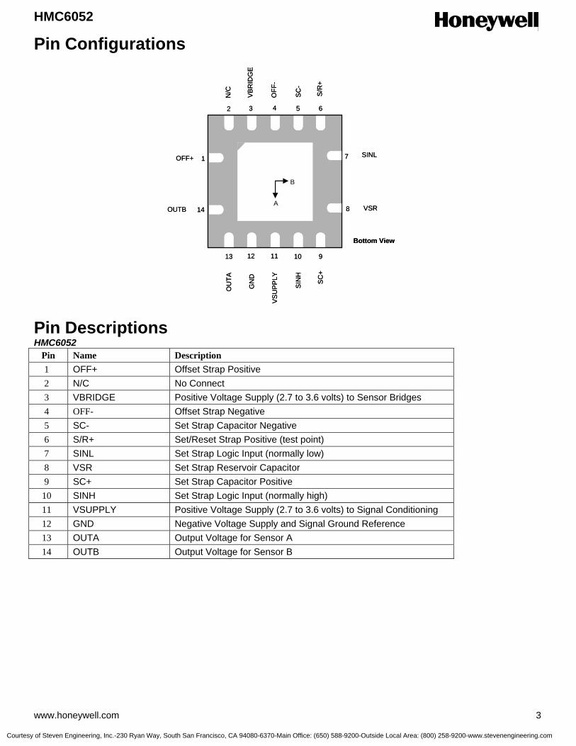
HMC6052
www.honeywell.com 3
Pin Configurations Pin Descriptions HMC6052
Pin Name Description 1 OFF+ Offset Strap Positive 2 N/C No Connect 3 VBRIDGE Positive Voltage Supply (2.7 to 3.6 volts) to Sensor Bridges 4 OFF- Offset Strap Negative 5 SC- Set Strap Capacitor Negative 6 S/R+ Set/Reset Strap Positive (test point) 7 SINL Set Strap Logic Input (normally low) 8 VSR Set Strap Reservoir Capacitor 9 SC+ Set Strap Capacitor Positive
10 SINH Set Strap Logic Input (normally high) 11 VSUPPLY Positive Voltage Supply (2.7 to 3.6 volts) to Signal Conditioning 12 GND Negative Voltage Supply and Signal Ground Reference 13 OUTA Output Voltage for Sensor A 14 OUTB Output Voltage for Sensor B
1
2 3 4 5 6
7
8
910111213
14A
B
Bottom View
OFF+
N/C
VB
RID
GE
OFF
-
SC-
S/R
+
VSR
SINL
OUTB
SC
+
SIN
H
VSU
PPLY
GN
D
OU
TA
1
2 3 4 5 6
7
8
910111213
14A
B
Bottom View
OFF+
N/C
VB
RID
GE
OFF
-
SC-
S/R
+
VSR
SINL
OUTB
SC
+
SIN
H
VSU
PPLY
GN
D
OU
TA
Courtesy of Steven Engineering, Inc.-230 Ryan Way, South San Francisco, CA 94080-6370-Main Office: (650) 588-9200-Outside Local Area: (800) 258-9200-www.stevenengineering.com

HMC6052
4 www.honeywell.com
Package Dimensions
Millimeters Symbol Min Nom Max
A 0.80 0.90 1.00 A1 0 0.02 0.05 A3 0.20 BSC b 0.18 0.23 0.30 D 3.50 BSC
D2 1.90 2.05 2.15 E 3.50 BSC
E2 1.90 2.05 2.15 e 0.50 BSC L 0.30 0.40 0.50 N 14
ND 5 NE 2 r b(min)/2
aaa 0.15 bbb 0.10 ccc 0.10
Mounting Considerations Stencil Design and Solder Paste A 4 mil stencil and 100% paste coverage is recommended electrical contact pads. The HMC6052 has been tested successfully with no-clean solder paste. Pick and Place Placement is machine dependant and no restrictions are recommended, and have been tested with mechanical centering. Placement force should be equivalent 1206 SMT components. Reflow and Rework No special profile is required for the HMC6052 and compatible with lead eutectic and lead-free solder paste reflow profiles. Honeywell recommends the adherence to solder paste manufacturer’s guidelines. Irons with a tip temperature no greater than 315°C should be used.
Application Notes The HMC6052 Integrated Compass Sensor circuit is composed of two Magneto-Resistive (MR) sensors that sense external magnetic fields and additional analog support circuits for electronic compass functions. Two instrumentation amplifiers follow the sensor wheatstone bridges to measure the differential output signals and provide substantial voltage amplification. A voltage reference is used to center the amplifiers for common zero field bias point. A pair of electronic switch circuits is included, to create a set pulse function using an external capacitor connected to the SC- and SC+ pins. In a quiescent state, the capacitor will be charged to the full supply voltage potential and suddenly discharged in reverse polarity when both SINL and SINH pins flip logic states. The resulting set pulse current flows through the set strap near the sensor bridge re-aligning the magnetic moments on the bridge magneto-resistive elements. This toggling of the set strap circuit is on user demand, or periodically to remove any potential magnetic upsets to the sensors.
Courtesy of Steven Engineering, Inc.-230 Ryan Way, South San Francisco, CA 94080-6370-Main Office: (650) 588-9200-Outside Local Area: (800) 258-9200-www.stevenengineering.com
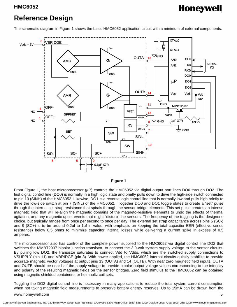
HMC6052
www.honeywell.com 5
Reference Design The schematic diagram in Figure 1 shows the basic HMC6052 application circuit with a minimum of external components.
Figure 1
From Figure 1, the host microprocessor (µP) controls the HMC6052 via digital output port lines DO0 through DO2. The first digital control line (DO0) is normally in a high logic state and briefly pulls down to drive the high-side switch connected to pin 10 (SINH) of the HMC6052. Likewise, DO1 is a reverse logic control line that is normally low and pulls high briefly to drive the low-side switch at pin 7 (SINL) of the HMC6052. Together DO0 and DO1 toggle states to create a “set” pulse through the internal set strap resistance that spirals through the sensor bridge elements. This set pulse creates an intense magnetic field that will re-align the magnetic domains of the magneto-resistive elements to undo the effects of thermal agitation, and any magnetic upset events that might “disturb” the sensors. The frequency of the toggling is the designer’s choice, but typically ranges from once per second to once per day. The external set strap capacitance across pins 5 (SC-) and 9 (SC+) is to be around 0.2uf to 1uf in value, with emphasis on keeping the total capacitor ESR (effective series resistance) below 0.5 ohms to minimize capacitor internal losses while delivering a current spike in excess of 0.5 amperes. The microprocessor also has control of the complete power supplied to the HMC6052 via digital control line DO2 that switches the MMBT2907 bipolar junction transistor, to connect the 3.0-volt system supply voltage to the sensor circuits. By pulling low DO2, the transistor saturates to connect Vdd to Vdds, which are the switched supply connections to VSUPPLY (pin 11) and VBRIDGE (pin 3). With power applied, the HMC6052 internal circuits quickly stabilize to provide accurate magnetic vector voltages at output pins 13 (OUTA) and 14 (OUTB). With near zero magnetic field inputs, OUTA and OUTB should be near half the supply voltage to provide bipolar output voltage values corresponding to the intensity and polarity of the resulting magnetic fields on the sensor bridges. Zero field stimulus to the HMC6052 can be obtained using magnetic shielded containers, or helmholtz coil sets. Toggling the DO2 digital control line is necessary in many applications to reduce the total system current consumption when not taking magnetic field measurements to preserve battery energy reserves. Up to 15mA can be drawn from the
G
GAMR
AMR
SW
SW
SET
OFFSETVref
GND
GND
GND
GND
GND
V+
V+
V+
V+
V+
GND
GNDGND
SINL
SINHSC+SC-
OUTA
OUTB
OFF+
OFF-
VBRIDGEVdds = 3V
0.1µF X7R(2)
AN0
AN1
µP
Vss
GND
Vdd
MMBT2907
DO2
DO1
DO0
10k Ω
TXD
CLKGND
XTAL0
XTAL1
Vdd
10
7
12
11
14
13
3
Vdds
+3V
4
1
5 9
RXD
SERIALI/O
NC
NC
GNDVSR
1µF X7R+RS
8
6
S/R+
GG
GGAMR
AMR
SW
SW
SET
OFFSETVref
GND
GND
GND
GND
GND
V+
V+
V+
V+
V+
GND
GNDGND
SINL
SINHSC+SC-
OUTA
OUTB
OFF+
OFF-
VBRIDGEVdds = 3V
0.1µF X7R(2)
AN0
AN1
µP
Vss
GND
Vdd
MMBT2907
DO2
DO1
DO0
10k Ω
TXD
CLKGND
XTAL0
XTAL1
Vdd
10
7
12
11
14
13
3
Vdds
+3V
4
1
5 9
RXD
SERIALI/O
NC
NC
GNDVSR
1µF X7R+RS
8
6
S/R+
Courtesy of Steven Engineering, Inc.-230 Ryan Way, South San Francisco, CA 94080-6370-Main Office: (650) 588-9200-Outside Local Area: (800) 258-9200-www.stevenengineering.com

HMC6052
6 www.honeywell.com
supply during the sensor circuit’s operation. The supply current can be effectively reduced by “duty cycling” DO2 and making “snapshot” measurements during the sensor’s on time. For example, a 3.0-volt lithium watch battery may have a typical 150mA-hour energy capacity rating. With the reference design drawing about 15mA continuously, only 10 hours of operational time results. By placing the microcontroller and HMC6052 into sleep mode 99% of the time, the total battery life extends to 1000 hours. Even greater efficiencies can be had if the host microprocessor only toggles on DO2 for a few milliseconds, makes the analog to digital conversions of outputs OUTA and OUTB, and then pulls DO2 high to sleep the HMC6052 until the next required measurement update. The analog outputs of the HMC6052 circuit (OUTA, OUTB) are representative voltages proportional to the magnetic field imposed on sensor bridges A and B. The sensor bridges have orthogonal axis of sensitivity and create a two dimensional representation of the magnetic field’s strength and direction. When oriented nearly level with the ground, the outputs can then be used for electronic compassing by sensing the horizontal components of the earth’s magnetic field. Using onboard Analog-to-Digital Converters (ADCs) within the host microprocessor, the digital representations of north-pole magnetic field direction can be related to the host platform (watch, phone, PDA, vehicle, ship, aircraft, etc.). The outputs of the HMC6052 are referenced to approximately half of the supply voltage applied across pins 11 (VSUPPLY) and 12 (GND). With no other errors accounted for, OUTA (pin 13) and OUTB (pin 14) would be close to 1.5 volts with no magnetic field applied (completely shielded) and a supply voltage of 3-volts. If the shielding were removed and a nominal earth’s magnetic field applied of 300 milli-gauss and –100 milli-gauss to sensor bridges A and B respectively, OUTA would move positively from 1.5 volts and OUTB would move negatively from 1.5 volts. Neglecting offset errors and using a nominal sensitivity of 0.5 volts per gauss, OUTA would be at about 1.65 volts and OUTB would be at about 1.45 volts. Using the above example values of earth’s field excitation, a host microprocessor with onboard 10-bit ADCs could provide 1024 increments (or counts) across the nominal zero to 3-volt supply voltage. If count 512 (about 1.5 volts) is referenced as the zero gauss point, the 1.65 and 1.45 volt OUTA and OUTB levels convert to counts 563 and 495 respectively. Without compensating for offset errors and calibration factors, the magnetic vectors for outputs A and B would be 51 and –17 counts with respect to the zero field level count. In electronic compassing, the arctangent (B/A) is computed by the microprocessor, resulting in a heading of about 341 degrees (19 degrees west of magnetic north). For details on offset correction, calibration, and electronic compass heading computation using microprocessors, please visit www.magneticsensors.com, and browse the technical papers and application notes in the applications section.
ORDERING INFORMATION
Ordering Number Product HMC6052
Integrated Compass Sensor
Find out more For more information on Honeywell’s Magnetic Sensors visit us online at www.magneticsensors.com or contact us at 800-323-8295 (763-954-2474 internationally). The application circuits herein constitute typical usage and interface of Honeywell product. Honeywell does not warranty or assume liability of customer-designed circuits derived from this description or depiction. Honeywell reserves the right to make changes to improve reliability, function or design. Honeywell does not assume any liability arising out of the application or use of any product or circuit described herein; neither does it convey any license under its patent rights nor the rights of others. U.S. Patents 4,441,072, 4,533,872, 4,569,742, 4,681,812, 4,847,584 and 6,529,114 apply to the technology described
Aerospace Electronics Systems Defense and Space Electronics Systems Honeywell International Inc. 12001 Highway 55 Plymouth, MN 55441 Tel: 800-323-8295 www.honeywell.com
Form #900306 April 2005 ©2005 Honeywell International Inc.
Courtesy of Steven Engineering, Inc.-230 Ryan Way, South San Francisco, CA 94080-6370-Main Office: (650) 588-9200-Outside Local Area: (800) 258-9200-www.stevenengineering.com

3-Axis Compass with Algorithms HMC6343
The Honeywell HMC6343 is a fully integrated compass module that includes
firmware for heading computation and calibration for magnetic distortions.
The module combines 3-axis magneto-resistive sensors and 3-axis MEMS
accelerometers, analog and digital support circuits, microprocessor and
algorithms required for heading computation. By combining the sensor
elements, processing electronics, and firmware into a 9.0mm by 9.0mm by
1.9mm LCC package, Honeywell offers a complete, ready to use tilt-
compensated electronic compass. This provides design engineers with the
simplest solution to integrate high volume, cost effective compasses into
binoculars, cameras, night vision optics, laser ranger finders, antenna
positioning, and other industrial compassing applications.
The HMC6343 utilizes Honeywell’s Anisotropic Magnetoresistive (AMR) technology that provides advantages over other
magnetic sensor technologies. The sensors feature precision sensitivity and linearity, solid-state construction with very
low cross-axis sensitivity designed to measure both direction and magnitude of Earth’s magnetic fields. Honeywell’s
Magnetic Sensors are among the most sensitive and reliable low-field sensors in the industry.
Honeywell continues to maintain product excellence and performance by introducing innovative solid-state magnetic
sensor solutions. Honeywell’s magnetic sensor solutions provide real solutions you can count on.
FEATURES BENEFITS
4 Compass with Heading/Tilt Outputs 4 A complete compass solution including compass firmware
4 3-axis MR Sensors, Accelerometers and a Microprocessor in a Single Package
4 A digital compass solution with heading and tilt angle outputs in a chip-scale package
4 Compass Algorithms 4 For computation of heading, and magnetic calibration for hard-iron
4 9 x 9 x 1.9mm LCC Surface Mount Package
4 Small size, easy to assemble and compatible with high speed surface mount technology assembly
4 Low Voltage Operations 4 Compatible with battery powered applications
4 EEPROM Memory 4 To store compass data for processor routines
4 Digital Serial Data Interface 4 I2C Interface, easy to use 2-wire communication for heading output
4 Moderate Precision Outputs 4 Typical 2° Heading Accuracy with 1° Pitch and Roll Accuracy
4 Lead Free Package Construction 4 Complies with RoHS environmental standards
4 Flexible Mounting 4 Can be mounted on horizontal or vertical circuit boards
Courtesy of Steven Engineering, Inc.-230 Ryan Way, South San Francisco, CA 94080-6370-Main Office: (650) 588-9200-Outside Local Area: (800) 258-9200-www.stevenengineering.com
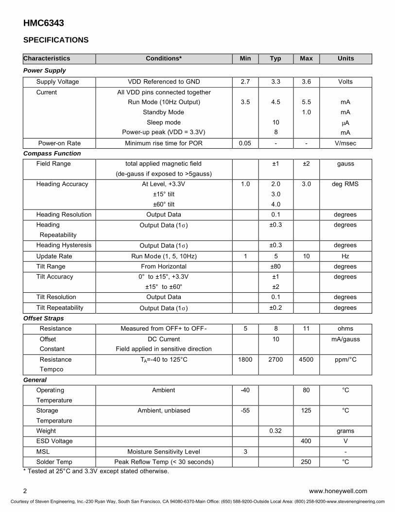
HMC6343
2 www.honeywell.com
SPECIFICATIONS Characteristics Conditions* Min Typ Max Units
Power Supply
Supply Voltage VDD Referenced to GND 2.7 3.3 3.6 Volts
Current All VDD pins connected together Run Mode (10Hz Output)
Standby Mode Sleep mode
Power-up peak (VDD = 3.3V)
3.5
4.5
10 8
5.5 1.0
mA mA
µA mA
Power-on Rate Minimum rise time for POR 0.05 - - V/msec Compass Function Field Range total applied magnetic field
(de-gauss if exposed to >5gauss) ±1 ±2 gauss
Heading Accuracy At Level, +3.3V ±15° tilt ±60° tilt
1.0 2.0 3.0 4.0
3.0 deg RMS
Heading Resolution Output Data 0.1 degrees Heading Repeatability
Output Data (1σ) ±0.3 degrees
Heading Hysteresis Output Data (1σ) ±0.3 degrees
Update Rate Run Mode (1, 5, 10Hz) 1 5 10 Hz Tilt Range From Horizontal ±80 degrees Tilt Accuracy 0° to ±15°, +3.3V
±15° to ±60° ±1
±2 degrees
Tilt Resolution Output Data 0.1 degrees
Tilt Repeatability Output Data (1σ) ±0.2 degrees
Offset Straps Resistance Measured from OFF+ to OFF- 5 8 11 ohms
Offset Constant
DC Current Field applied in sensitive direction
10 mA/gauss
Resistance Tempco
TA=-40 to 125°C 1800 2700 4500 ppm/°C
General Operating Temperature
Ambient -40 80 °C
Storage Temperature
Ambient, unbiased -55 125 °C
Weight 0.32 grams ESD Voltage 400 V
MSL Moisture Sensitivity Level 3 - Solder Temp Peak Reflow Temp (< 30 seconds) 250 °C * Tested at 25°C and 3.3V except stated otherwise.
Courtesy of Steven Engineering, Inc.-230 Ryan Way, South San Francisco, CA 94080-6370-Main Office: (650) 588-9200-Outside Local Area: (800) 258-9200-www.stevenengineering.com
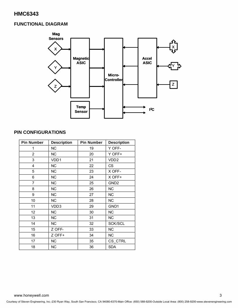
HMC6343
www.honeywell.com 3
FUNCTIONAL DIAGRAM PIN CONFIGURATIONS
Pin Number Description Pin Number Description
1 NC 19 Y OFF- 2 NC 20 Y OFF+ 3 VDD1 21 VDD2 4 NC 22 CS 5 NC 23 X OFF- 6 NC 24 X OFF+ 7 NC 25 GND2 8 NC 26 NC 9 NC 27 NC
10 NC 28 NC 11 VDD3 29 GND1 12 NC 30 NC 13 NC 31 NC 14 NC 32 SCK/SCL 15 Z OFF- 33 NC 16 Z OFF+ 34 NC 17 NC 35 CS_CTRL 18 NC 36 SDA
MagSensors
MagneticASIC
Micro-Controller
TempSensor
X
Y
Z
AccelASIC
X
Y
Z
I2C
MagSensors
MagneticASIC
Micro-Controller
TempSensor
X
Y
Z
AccelASIC
X
Y
Z
I2C
Courtesy of Steven Engineering, Inc.-230 Ryan Way, South San Francisco, CA 94080-6370-Main Office: (650) 588-9200-Outside Local Area: (800) 258-9200-www.stevenengineering.com
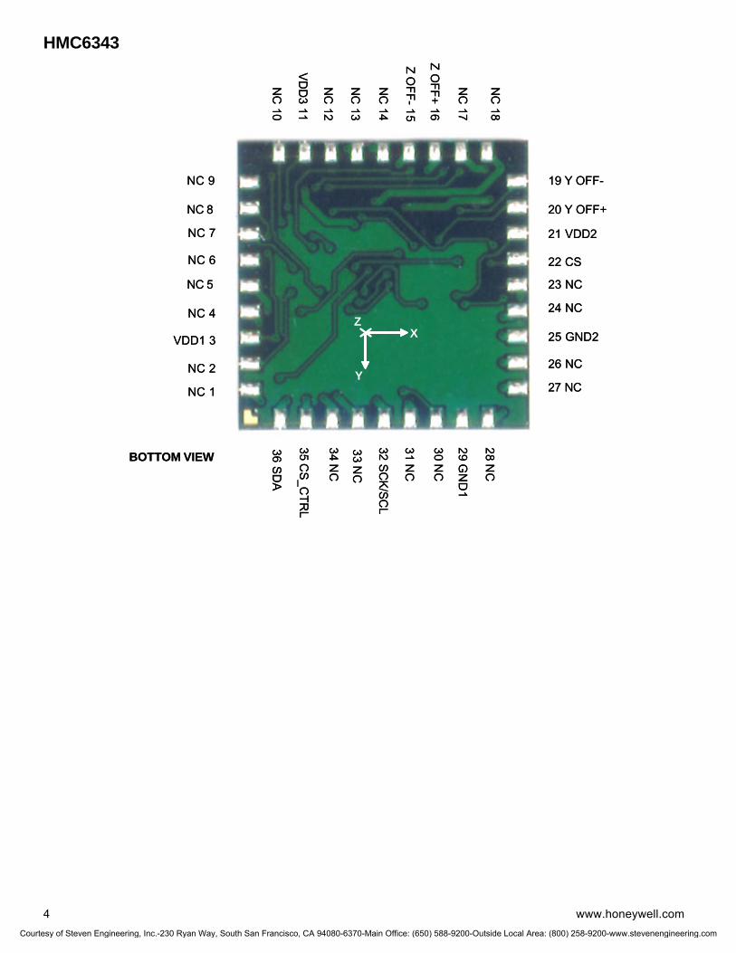
HMC6343
4 www.honeywell.com
NC 1
NC 2
VDD1 3
NC 4
NC 5
NC 6
NC 7
NC 8
NC 9
NC
10
VDD
3 11
NC
12
NC
13
NC
14
Z OFF-15
Z OFF+ 16
NC
17
NC
18
19 Y OFF-
20 Y OFF+
21 VDD2
22 CS
23 NC
24 NC
25 GND2
26 NC
27 NC
28 NC
29 GN
D1
30 NC
31 NC
32 SCK/SC
L
33 NC
34 NC
35 CS_C
TRL
36 SD
ABOTTOM VIEW
X
Y
Z
NC 1
NC 2
VDD1 3
NC 4
NC 5
NC 6
NC 7
NC 8
NC 9
NC
10
VDD
3 11
NC
12
NC
13
NC
14
Z OFF-15
Z OFF+ 16
NC
17
NC
18
19 Y OFF-
20 Y OFF+
21 VDD2
22 CS
23 NC
24 NC
25 GND2
26 NC
27 NC
28 NC
29 GN
D1
30 NC
31 NC
32 SCK/SC
L
33 NC
34 NC
35 CS_C
TRL
36 SD
ABOTTOM VIEW
X
Y
Z
Courtesy of Steven Engineering, Inc.-230 Ryan Way, South San Francisco, CA 94080-6370-Main Office: (650) 588-9200-Outside Local Area: (800) 258-9200-www.stevenengineering.com
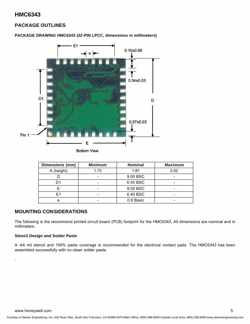
HMC6343
www.honeywell.com 5
PACKAGE OUTLINES PACKAGE DRAWING HMC6343 (32-PIN LPCC, dimensions in millimeters)
Dimensions (mm) Minimum Nominal Maximum
A (height) 1.73 1.87 2.02 D - 9.00 BSC -
D1 - 6.40 BSC - E - 9.00 BSC - E1 - 6.40 BSC - e - 0.8 Basic -
MOUNTING CONSIDERATIONS The following is the recommend printed circuit board (PCB) footprint for the HMC6343. All dimensions are nominal and in millimeters. Stencil Design and Solder Paste A 4-6 mil stencil and 100% paste coverage is recommended for the electrical contact pads. The HMC6343 has been assembled successfully with no-clean solder paste. .
0.34±0.03
D
0.57±0.03
0.10±0.08
E
e
E1
D1
Pin 1
Bottom View
0.34±0.03
D
0.57±0.03
0.10±0.08
E
e
E1
D1
Pin 1
Bottom View
Courtesy of Steven Engineering, Inc.-230 Ryan Way, South San Francisco, CA 94080-6370-Main Office: (650) 588-9200-Outside Local Area: (800) 258-9200-www.stevenengineering.com
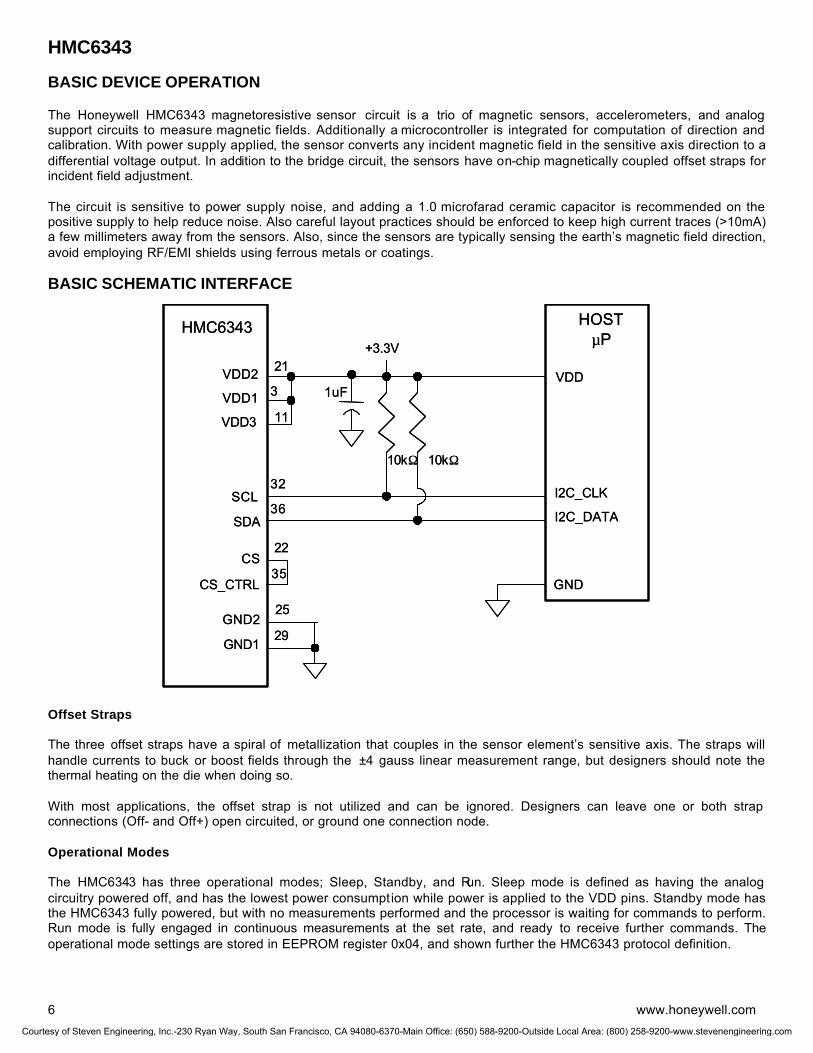
HMC6343
6 www.honeywell.com
BASIC DEVICE OPERATION The Honeywell HMC6343 magnetoresistive sensor circuit is a trio of magnetic sensors, accelerometers, and analog support circuits to measure magnetic fields. Additionally a microcontroller is integrated for computation of direction and calibration. With power supply applied, the sensor converts any incident magnetic field in the sensitive axis direction to a differential voltage output. In addition to the bridge circuit, the sensors have on-chip magnetically coupled offset straps for incident field adjustment. The circuit is sensitive to power supply noise, and adding a 1.0 microfarad ceramic capacitor is recommended on the positive supply to help reduce noise. Also careful layout practices should be enforced to keep high current traces (>10mA) a few millimeters away from the sensors. Also, since the sensors are typically sensing the earth’s magnetic field direction, avoid employing RF/EMI shields using ferrous metals or coatings. BASIC SCHEMATIC INTERFACE Offset Straps The three offset straps have a spiral of metallization that couples in the sensor element’s sensitive axis. The straps will handle currents to buck or boost fields through the ±4 gauss linear measurement range, but designers should note the thermal heating on the die when doing so. With most applications, the offset strap is not utilized and can be ignored. Designers can leave one or both strap connections (Off- and Off+) open circuited, or ground one connection node. Operational Modes The HMC6343 has three operational modes; Sleep, Standby, and Run. Sleep mode is defined as having the analog circuitry powered off, and has the lowest power consumption while power is applied to the VDD pins. Standby mode has the HMC6343 fully powered, but with no measurements performed and the processor is waiting for commands to perform. Run mode is fully engaged in continuous measurements at the set rate, and ready to receive further commands. The operational mode settings are stored in EEPROM register 0x04, and shown further the HMC6343 protocol definition.
HMC6343
VDD2
GND1
VDD1
VDD3
HOSTµP
SCL
SDA
21
29
32
36
3
11
+3.3V
10kΩ 10kΩ
I2C_CLK
I2C_DATA
VDD
GND
CS
CS_CTRL
22
35
1uF
25GND2
HMC6343
VDD2
GND1
VDD1
VDD3
HOSTµP
SCL
SDA
21
29
32
36
3
11
+3.3V
10kΩ 10kΩ
I2C_CLK
I2C_DATA
VDD
GND
CS
CS_CTRL
22
35
1uF
25GND2
Courtesy of Steven Engineering, Inc.-230 Ryan Way, South San Francisco, CA 94080-6370-Main Office: (650) 588-9200-Outside Local Area: (800) 258-9200-www.stevenengineering.com
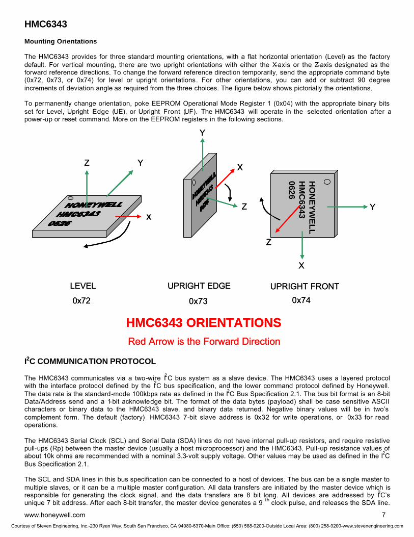
HMC6343
www.honeywell.com 7
Mounting Orientations The HMC6343 provides for three standard mounting orientations, with a flat horizontal orientation (Level) as the factory default. For vertical mounting, there are two upright orientations with either the X-axis or the Z-axis designated as the forward reference directions. To change the forward reference direction temporarily, send the appropriate command byte (0x72, 0x73, or 0x74) for level or upright orientations. For other orientations, you can add or subtract 90 degree increments of deviation angle as required from the three choices. The figure below shows pictorially the orientations. To permanently change orientation, poke EEPROM Operational Mode Register 1 (0x04) with the appropriate binary bits set for Level, Upright Edge (UE), or Upright Front (UF). The HMC6343 will operate in the selected orientation after a power-up or reset command. More on the EEPROM registers in the following sections. I2C COMMUNICATION PROTOCOL
The HMC6343 communicates via a two-wire I2C bus system as a slave device. The HMC6343 uses a layered protocol with the interface protocol defined by the I2C bus specification, and the lower command protocol defined by Honeywell. The data rate is the standard-mode 100kbps rate as defined in the I2C Bus Specification 2.1. The bus bit format is an 8-bit Data/Address send and a 1-bit acknowledge bit. The format of the data bytes (payload) shall be case sensitive ASCII characters or binary data to the HMC6343 slave, and binary data returned. Negative binary values will be in two’s complement form. The default (factory) HMC6343 7-bit slave address is 0x32 for write operations, or 0x33 for read operations. The HMC6343 Serial Clock (SCL) and Serial Data (SDA) lines do not have internal pull-up resistors, and require resistive pull-ups (Rp) between the master device (usually a host microprocessor) and the HMC6343. Pull-up resistance values of about 10k ohms are recommended with a nominal 3.3-volt supply voltage. Other values may be used as defined in the I2C Bus Specification 2.1. The SCL and SDA lines in this bus specification can be connected to a host of devices. The bus can be a single master to multiple slaves, or it can be a multiple master configuration. All data transfers are initiated by the master device which is responsible for generating the clock signal, and the data transfers are 8 bit long. All devices are addressed by I2C’s unique 7 bit address. After each 8-bit transfer, the master device generates a 9 th clock pulse, and releases the SDA line.
HO
NE
YW
EL
LH
MC
63430626
x
YZ
LEVEL
Y
X
Z
UPRIGHT EDGE
Y
UPRIGHT FRONT
X
Z
0x72 0x73 0x74
HMC6343 ORIENTATIONSRed Arrow is the Forward Direction
HO
NE
YW
EL
LH
MC
63430626
x
YZ
LEVEL
Y
X
Z
UPRIGHT EDGE
Y
UPRIGHT FRONT
X
Z
0x72 0x73 0x74
HMC6343 ORIENTATIONSRed Arrow is the Forward Direction
Courtesy of Steven Engineering, Inc.-230 Ryan Way, South San Francisco, CA 94080-6370-Main Office: (650) 588-9200-Outside Local Area: (800) 258-9200-www.stevenengineering.com

HMC6343
8 www.honeywell.com
The receiving device (addressed slave) will pull the SDA line low to acknowledge (ACK) the successful transfer or leave the SDA high to negative acknowledge (NACK). Per the I2C spec, all transitions in the SDA line must occur when SCL is low. This requirement leads to two unique conditions on the bus associated with the SDA transitions when SCL is high. Master device pulling the SDA line low while the SCL line is high indicates the Start (S) condition, and the Stop (P) condition is when the SDA line is pulled high while the SCL line is high. The I2C protocol also allows for the Restart condition in which the master device issues a second start condition without issuing a stop. All bus transactions begin with the master device issuing the start sequence followed by the slave address byte. The address byte contains the slave address; the upper 7 bits (bits7-1), and the Least Significant bit (LSb). The LSb of the address byte designates if the operation is a read (LSb=1) or a write (LSb=0). At the 9 th clock pulse, the receiving slave device will issue the ACK (or NACK). Following these bus events, the master will send data bytes for a write operation, or the slave will clock out data with a read operation. All bus transactions are terminated with the master issuing a stop sequence. I2C bus control can be implemented with either hardware logic or in software. Typical hardware designs will release the SDA and SCL lines as appropriate to allow the slave device to manipulate these lines. In a software implementation, care must be taken to perform these tasks in code. I2C Slave Address The I2C slave address byte consists of the 7 most significant bits with the least significant bit zero filled. As described earlier, the default (factory) value is 0x32 and the legal I2C bounded values are between 0x10 and 0xF6. This slave address is in EEPROM address 0x00. Users can change the slave address by writing to this location. Any address updates will become effective after the next power up or after a reset command. Software Version This EEPROM software version number byte contains the binary value of the programmed software. Values of 0x05 and beyond are considered production software. Deviation Angle Correction Typically the HMC6343 X-axis (or Z-axis) is designated the forward direction of the compass, and is placed mechanically towards the forward direction of the end user product. The deviation angle is used to correct for mechanical angle errors in package orientation by adding the deviation angle to the internal compass heading before the result is placed as the computed heading. Two EEPROM Bytes are used to store the deviation angle, and the binary value is in tenths of a degree and in two’s complement form for a ±1800 representation. The deviation angle MSB is located in EEPROM register 0x0B and the LSB in 0x0A. Variation Angle Correction The variation angle or declination angle of the HMC6343 is the number of degree that must be added to the internal compass heading to convert the magnetic north reference direction to the geographic (true) north reference direction. This angle information is provided to the HMC6343 from external latitude and longitude data processed through a World Magnetic Model equation to compute variation angle, or by lookup table. Two EEPROM Bytes are used to store the variation angle, and the binary value is in tenths of a degree and in two’s complement form for a ±1800 representation. The deviation angle MSB is located in EEPROM register 0x0D and the LSB in 0x0C. Magnetometer Offsets The Magnetometer Offset bytes are the values stored after the completion of the last factory or user hard-iron calibration routine. Additional value changes are possible, but will be overwritten when the next calibration routine is completed. Note that these offset values are added to the sensor offset values computed by the set/reset routine to convert the raw magnetometer data to the compensated magnetometer data. These values are written into EEPROM addresses 0x0E to 0x13 and loaded to RAM on the power up.
Courtesy of Steven Engineering, Inc.-230 Ryan Way, South San Francisco, CA 94080-6370-Main Office: (650) 588-9200-Outside Local Area: (800) 258-9200-www.stevenengineering.com
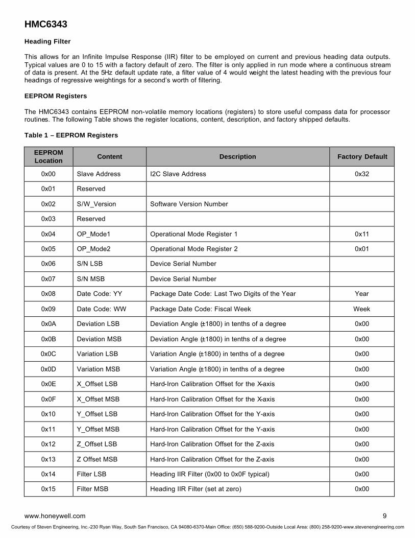
HMC6343
www.honeywell.com 9
Heading Filter This allows for an Infinite Impulse Response (IIR) filter to be employed on current and previous heading data outputs. Typical values are 0 to 15 with a factory default of zero. The filter is only applied in run mode where a continuous stream of data is present. At the 5Hz default update rate, a filter value of 4 would weight the latest heading with the previous four headings of regressive weightings for a second’s worth of filtering. EEPROM Registers The HMC6343 contains EEPROM non-volatile memory locations (registers) to store useful compass data for processor routines. The following Table shows the register locations, content, description, and factory shipped defaults. Table 1 – EEPROM Registers
EEPROM Location Content Description Factory Default
0x00 Slave Address I2C Slave Address 0x32
0x01 Reserved
0x02 S/W_Version Software Version Number
0x03 Reserved
0x04 OP_Mode1 Operational Mode Register 1 0x11
0x05 OP_Mode2 Operational Mode Register 2 0x01
0x06 S/N LSB Device Serial Number
0x07 S/N MSB Device Serial Number
0x08 Date Code: YY Package Date Code: Last Two Digits of the Year Year
0x09 Date Code: WW Package Date Code: Fiscal Week Week
0x0A Deviation LSB Deviation Angle (±1800) in tenths of a degree 0x00
0x0B Deviation MSB Deviation Angle (±1800) in tenths of a degree 0x00
0x0C Variation LSB Variation Angle (±1800) in tenths of a degree 0x00
0x0D Variation MSB Variation Angle (±1800) in tenths of a degree 0x00
0x0E X_Offset LSB Hard-Iron Calibration Offset for the X-axis 0x00
0x0F X_Offset MSB Hard-Iron Calibration Offset for the X-axis 0x00
0x10 Y_Offset LSB Hard-Iron Calibration Offset for the Y-axis 0x00
0x11 Y_Offset MSB Hard-Iron Calibration Offset for the Y-axis 0x00
0x12 Z_Offset LSB Hard-Iron Calibration Offset for the Z-axis 0x00
0x13 Z Offset MSB Hard-Iron Calibration Offset for the Z-axis 0x00
0x14 Filter LSB Heading IIR Filter (0x00 to 0x0F typical) 0x00
0x15 Filter MSB Heading IIR Filter (set at zero) 0x00
Courtesy of Steven Engineering, Inc.-230 Ryan Way, South San Francisco, CA 94080-6370-Main Office: (650) 588-9200-Outside Local Area: (800) 258-9200-www.stevenengineering.com

HMC6343
10 www.honeywell.com
Command Protocol The command protocol defines the content of the data (payload) bytes of I2C protocol sent by the master, and the slave device (HMC6343). Note that angular outputs are in tenths of a degree (0-3600 heading, ±0-900 tilt). After the master device sends the 7-bit slave address, the 1-bit Read/Write, and gets the 1-bit slave device acknowledge bit returned; the next one to three sent data bytes are defined as the input command and argument bytes. To conserve data traffic, all response data (Reads) will be context sensitive to the last command (Write) sent. All write commands shall have the address byte least significant bit cleared (factory default 0x32). These commands then follow with the command byte and command specific binary formatted argument bytes in the general form of: (Command Byte) (Argument Binary MS Byte) (Argument Binary LS Byte) The slave (HMC6343) shall provide the acknowledge bits between each data byte per the I2C protocol. Response byte reads are done by sending the address byte (factory default 0x33) with the least significant bit set, and then clocking back response bytes, last command dependant. Table 2 shows the HMC6343 command and response data flow. Table 2 – HMC6343 Interface Commands/Responses
Command Byte (hex)
Argument 1 Byte (Binary)
Argument 2 Byte (Binary)
Response Bytes (Binary)
Command Description
(0x40) MSB/LSB Data (6 Bytes)
Post Accel Data. AxMSB, AxLSB, AyMSB, AyLSB, AzMSB, AzLSB
(0x45) MSB/LSB Data (6 Bytes)
Post Mag Data. MxMSB, MxLSB, MyMSB, MyLSB, MzMSB, MzLSB
(0x50) MSB/LSB Data (6 Bytes)
Post Heading Data. HeadMSB, HeadLSB, PitchMSB, PitchLSB, RollMSB, RollLSB
(0x55) MSB/LSB Data (6 Bytes)
Post Tilt Data. PitchMSB, PitchLSB, RollMSB, RollLSB, TempMSB, TempLSB
(0x65) Post OP Mode 1 Read the current value of OP Mode 1
(0x71) Enter User Calibration Mode
(0x72) Level Orientation (X=forward, +Z=up) (default)
(0x73) Upright Sideways Orientation (X=forward, Y=up)
(0x74) Upright Flat Front Orientation (Z=forward, -X=up)
(0x75) Enter Run Mode (from Standby Mode)
(0x76) Enter Standby Mode (from Run Mode)
(0x7E) Exit User Calibration Mode
(0x82) Reset the Processor
(0x83) Enter Sleep Mode (from Run Mode)
(0x84) Exit Sleep Mode (to Standby Mode)
(0xE1) EEPROM Address Data (1 Byte) Read from EEPROM
(0xF1) EEPROM Address Data Write to EEPROM
Courtesy of Steven Engineering, Inc.-230 Ryan Way, South San Francisco, CA 94080-6370-Main Office: (650) 588-9200-Outside Local Area: (800) 258-9200-www.stevenengineering.com
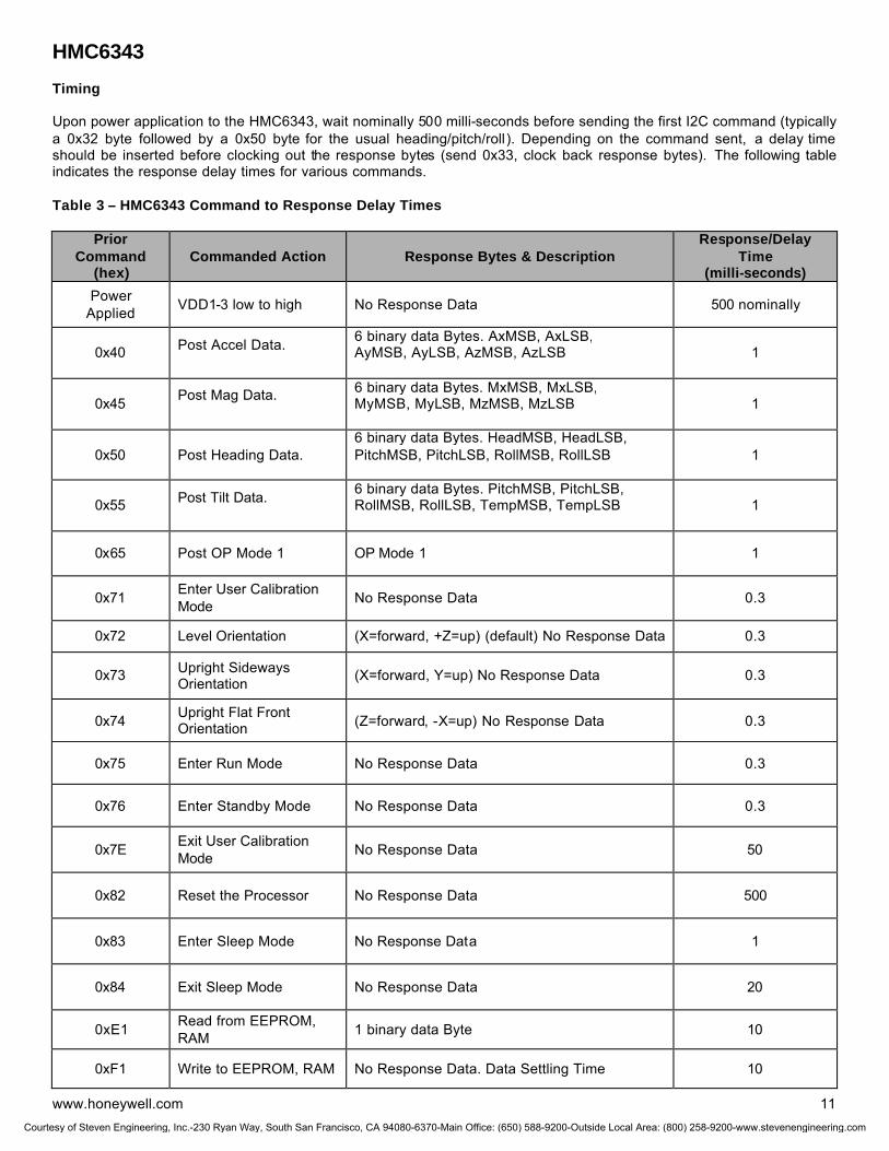
HMC6343
www.honeywell.com 11
Timing Upon power application to the HMC6343, wait nominally 500 milli-seconds before sending the first I2C command (typically a 0x32 byte followed by a 0x50 byte for the usual heading/pitch/roll). Depending on the command sent, a delay time should be inserted before clocking out the response bytes (send 0x33, clock back response bytes). The following table indicates the response delay times for various commands. Table 3 – HMC6343 Command to Response Delay Times
Prior Command
(hex) Commanded Action Response Bytes & Description
Response/Delay Time
(milli-seconds)
Power Applied VDD1-3 low to high No Response Data 500 nominally
0x40 Post Accel Data.
6 binary data Bytes. AxMSB, AxLSB, AyMSB, AyLSB, AzMSB, AzLSB
1
0x45 Post Mag Data.
6 binary data Bytes. MxMSB, MxLSB, MyMSB, MyLSB, MzMSB, MzLSB
1
0x50 Post Heading Data. 6 binary data Bytes. HeadMSB, HeadLSB, PitchMSB, PitchLSB, RollMSB, RollLSB
1
0x55 Post Tilt Data.
6 binary data Bytes. PitchMSB, PitchLSB, RollMSB, RollLSB, TempMSB, TempLSB
1
0x65 Post OP Mode 1 OP Mode 1 1
0x71 Enter User Calibration Mode No Response Data 0.3
0x72 Level Orientation (X=forward, +Z=up) (default) No Response Data 0.3
0x73 Upright Sideways Orientation (X=forward, Y=up) No Response Data 0.3
0x74 Upright Flat Front Orientation (Z=forward, -X=up) No Response Data 0.3
0x75 Enter Run Mode No Response Data 0.3
0x76 Enter Standby Mode No Response Data 0.3
0x7E Exit User Calibration Mode No Response Data 50
0x82 Reset the Processor No Response Data 500
0x83 Enter Sleep Mode No Response Data 1
0x84 Exit Sleep Mode No Response Data 20
0xE1 Read from EEPROM, RAM 1 binary data Byte 10
0xF1 Write to EEPROM, RAM No Response Data. Data Settling Time 10
Courtesy of Steven Engineering, Inc.-230 Ryan Way, South San Francisco, CA 94080-6370-Main Office: (650) 588-9200-Outside Local Area: (800) 258-9200-www.stevenengineering.com
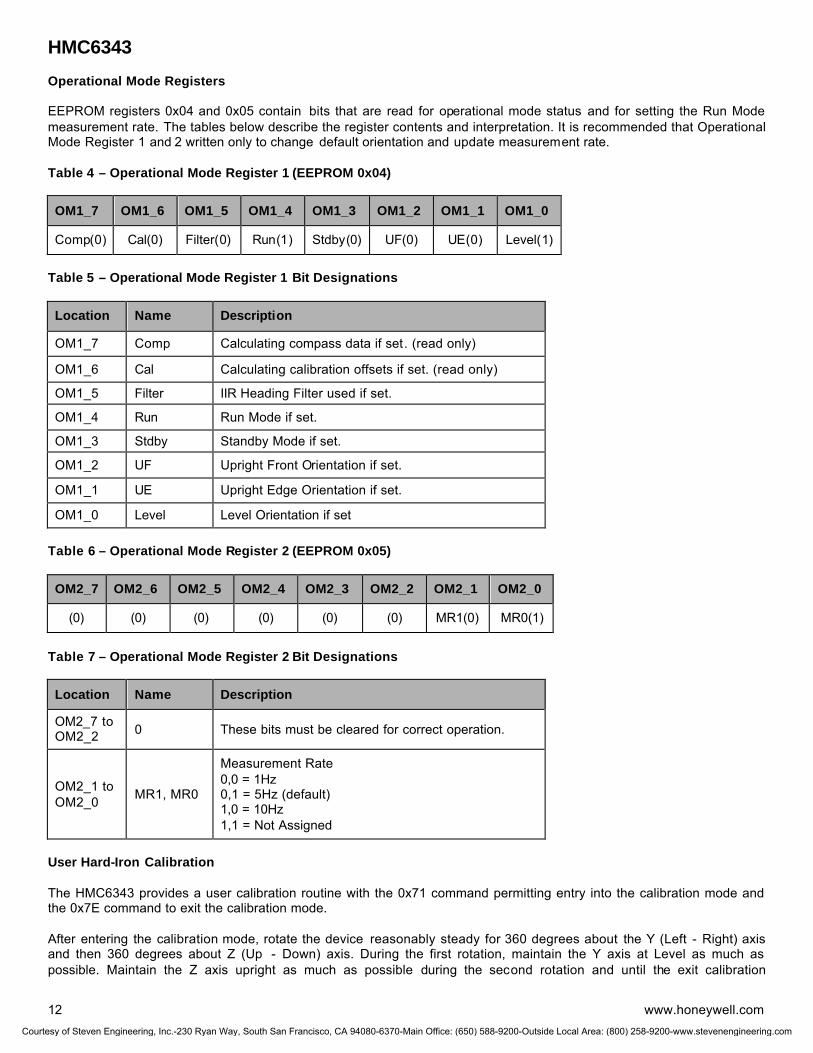
HMC6343
12 www.honeywell.com
Operational Mode Registers EEPROM registers 0x04 and 0x05 contain bits that are read for operational mode status and for setting the Run Mode measurement rate. The tables below describe the register contents and interpretation. It is recommended that Operational Mode Register 1 and 2 written only to change default orientation and update measurement rate. Table 4 – Operational Mode Register 1 (EEPROM 0x04)
OM1_7 OM1_6 OM1_5 OM1_4 OM1_3 OM1_2 OM1_1 OM1_0
Comp(0) Cal(0) Filter(0) Run(1) Stdby(0) UF(0) UE(0) Level(1)
Table 5 – Operational Mode Register 1 Bit Designations
Location Name Description
OM1_7 Comp Calculating compass data if set. (read only)
OM1_6 Cal Calculating calibration offsets if set. (read only)
OM1_5 Filter IIR Heading Filter used if set.
OM1_4 Run Run Mode if set.
OM1_3 Stdby Standby Mode if set.
OM1_2 UF Upright Front Orientation if set.
OM1_1 UE Upright Edge Orientation if set.
OM1_0 Level Level Orientation if set
Table 6 – Operational Mode Register 2 (EEPROM 0x05)
OM2_7 OM2_6 OM2_5 OM2_4 OM2_3 OM2_2 OM2_1 OM2_0
(0) (0) (0) (0) (0) (0) MR1(0) MR0(1)
Table 7 – Operational Mode Register 2 Bit Designations
Location Name Description
OM2_7 to OM2_2 0 These bits must be cleared for correct operation.
OM2_1 to OM2_0 MR1, MR0
Measurement Rate 0,0 = 1Hz 0,1 = 5Hz (default) 1,0 = 10Hz 1,1 = Not Assigned
User Hard-Iron Calibration The HMC6343 provides a user calibration routine with the 0x71 command permitting entry into the calibration mode and the 0x7E command to exit the calibration mode. After entering the calibration mode, rotate the device reasonably steady for 360 degrees about the Y (Left - Right) axis and then 360 degrees about Z (Up - Down) axis. During the first rotation, maintain the Y axis at Level as much as possible. Maintain the Z axis upright as much as possible during the second rotation and until the exit calibration
Courtesy of Steven Engineering, Inc.-230 Ryan Way, South San Francisco, CA 94080-6370-Main Office: (650) 588-9200-Outside Local Area: (800) 258-9200-www.stevenengineering.com

HMC6343
www.honeywell.com 13
command is issued. The first rotation can also be done by rotating 360 degrees about X (Fore -Aft) axis. Then exit calibration. The calibration routine collects these readings to correct for hard-iron distortions of the magnetic field. These hard-iron effects are due to magnetized materials nearby the HMC6343 part that in a fixed position with respect to the end user platform. An example would be the magnetized chassis or engine block of a vehicle in which the compass is mounted onto. Upon exiting the calibration mode, the resulting magnetometer offsets are updated. Example Communication For basic power up and compassing using the defaults, the flowing order of operations is recommended:
1. Apply power to the VDD pins (nominally +3.3 volts)
2. Wait at least 500 milli-seconds for device initialization. The HMC6343 is in the default Run Mode.
3. Send 0x32 and 0x50 to command the Heading and Tilt Data to be clocked out next.
4. Wait at least 1 milli-second to allow the HMC6343 to process the command.
5. Send 0x33 and clock back six more response Bytes from the HMC6343. These will be the Heading, Pitch and Roll Byte pairs; binary format in tenths of a degree with 2’s compliment on pitch and roll angles. (0 to 3600 heading, ±900 pitch, and ±900 roll)
6. Repeat steps 3 - 5 every 200 milli-seconds or longer to get fresh data from the default 5Hz update rate.
ORDERING INFORMATION
Ordering Number Product Packaging HMC6343 HMC6343-demo HMC6343-eval
3 axis Compass with Algorithms Development Kit Evaluation Board
Tubes
Demo Board, USB Cable and Demo Software
Board
FIND OUT MORE For more information on Honeywell’s Magnetic Sensors visit us online at www.magneticsensors.com or contact us at 800-323-8295 (763-954-2474 internationally). The application circuits herein constitute typical usage and interface of Honeywell product. Honeywell does not warranty or assume liability of customer-designed circuits derived from this description or depiction. Honeywell reserves the right to make changes to improve reliability, function or design. Honeywell does not assume any liability arising out of the application or use of any product or circuit described herein; neither does it convey any license under its patent rights nor the rights of others. U.S. Patents 4,441,072, 4,533,872, 4,569,742, 4,681,812, 4,847,584 and 6,529,114 apply to the technology described
Honeywell 12001 Highway 55 Plymouth, MN 55441 Tel: 800-323-8295 www.honeywell.com
Form #900357 October 2008 ©2008 Honeywell International Inc.
CautionThis part is sensitive to damageby electrostatic discharge. Use ESDprecautionary procedures whentouching, removing or inserting.
CAUTION: ESDS CAT. 1A
CautionThis part is sensitive to damageby electrostatic discharge. Use ESDprecautionary procedures whentouching, removing or inserting.
CautionThis part is sensitive to damageby electrostatic discharge. Use ESDprecautionary procedures whentouching, removing or inserting.
CAUTION: ESDS CAT. 1A
Courtesy of Steven Engineering, Inc.-230 Ryan Way, South San Francisco, CA 94080-6370-Main Office: (650) 588-9200-Outside Local Area: (800) 258-9200-www.stevenengineering.com

Digital Compass Solution HMC6352
The Honeywell HMC6352 is a fully integrated compass
module that combines 2-axis magneto-resistive sensors
with the required analog and digital support circuits, and
algorithms for heading computation. By combining the
sensor elements, processing electronics, and firmware in
to a 6.5mm by 6.5mm by 1.5mm LCC package,
Honeywell offers a complete, ready to use electronic
compass. This provides design engineers with the
simplest solution to integrate high volume, cost effective
compasses into wireless phones, consumer electronics,
vehicle compassing, and antenna positioning.
Honeywell continues to maintain product excellence and
performance by introducing innovative solid-state
magnetic sensor solutions. These are highly reliable, top
performance products that are delivered when promised.
Honeywell’s magnetic sensor products provide real
solutions you can count on.
FEATURES BENEFITS
4 Compass with Heading Output 4 A Complete Compass. Everything is Done.
4 Full Integration of 2-Axis Magnetic Sensors and Electronics
4 A Complete Digital Solution with Heading Output to Avoid Design of Hardware and Compassing Firmware Routines.
4 Firmware Included 4 Data Acquisition, Calibration, and Heading Computation Routines Included for Quick-to-Market Designs.
4 Small Surface Mount Package (6.5 x 6.5 x 1.5mm, 24-pin LCC)
4 Easy to Assemble & Compatible with High Speed SMT Assembly
4 Low Voltage Operation (2.7 to 5.2V) 4 Compatible for Battery Powered Applications
4 I2C 2-Wire Serial Interface 4 Works as a Slave to Customer’s Master Processor (100kHz).
4 Lead Free Package Construction 4 Complies with Current Environmental Standards (RoHS)
4 Wide Magnetic Field Range (± 2 Oe) 4 Sensor Can Be Used in Strong Magnetic Field Environments
4 Set/Reset Strap Drive 4 Stray Magnetic Field Protection and Temperature Compensation
4 RoHS Compliant 4 Lead Free and No Banned Substances
Courtesy of Steven Engineering, Inc.-230 Ryan Way, South San Francisco, CA 94080-6370-Main Office: (650) 588-9200-Outside Local Area: (800) 258-9200-www.stevenengineering.com
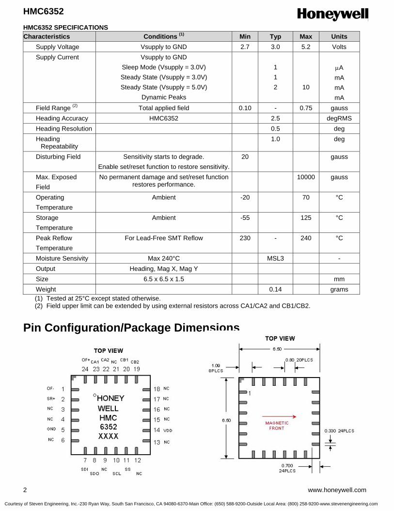
HMC6352
2 www.honeywell.com
HMC6352 SPECIFICATIONS Characteristics Conditions (1) Min Typ Max Units Supply Voltage Vsupply to GND 2.7 3.0 5.2 Volts Supply Current Vsupply to GND
Sleep Mode (Vsupply = 3.0V) Steady State (Vsupply = 3.0V) Steady State (Vsupply = 5.0V)
Dynamic Peaks
1 1 2
10
µA mA mA mA
Field Range (2) Total applied field 0.10 - 0.75 gauss Heading Accuracy HMC6352 2.5 degRMS Heading Resolution 0.5 deg Heading
Repeatability 1.0 deg
Disturbing Field Sensitivity starts to degrade. Enable set/reset function to restore sensitivity.
20 gauss
Max. Exposed Field
No permanent damage and set/reset function restores performance.
10000 gauss
Operating Temperature
Ambient -20 70 °C
Storage Temperature
Ambient -55 125 °C
Peak Reflow Temperature
For Lead-Free SMT Reflow 230 - 240 °C
Moisture Sensivity Max 240°C MSL3 - Output Heading, Mag X, Mag Y Size 6.5 x 6.5 x 1.5 mm Weight 0.14 grams
(1) Tested at 25°C except stated otherwise. (2) Field upper limit can be extended by using external resistors across CA1/CA2 and CB1/CB2.
Pin Configuration/Package Dimensions
Courtesy of Steven Engineering, Inc.-230 Ryan Way, South San Francisco, CA 94080-6370-Main Office: (650) 588-9200-Outside Local Area: (800) 258-9200-www.stevenengineering.com

HMC6352
www.honeywell.com 3
Pin Descriptions HMC6352
Pin Name Description 1 OF- No User Connection (Offset Strap Negative) 2 SR+ No User Connection (Set/Reset Strap Positive) 3 NC No User Connection 4 NC No User Connection 5 GND Supply/System Ground 6 NC No User Connection 7 SDI I2C Data Output (SPI Data In) 8 SDO No User Connection (SPI Data Out) 9 PGM No User Connection (Program Enable) 10 SCL I2C Clock (SPI Clock) 11 SS No User Connection (Slave Select) 12 NC No User Connection 13 NC No User Connection 14 VDD Supply Voltage Positive Input (+2.7VDC to +5.0VDC) 15 NC No User Connection 16 NC No User Connection 17 NC No User Connection 18 NC No User Connection 19 CB2 Amplifier B Filter Capacitor Connection 20 CB1 Amplifier B Filter Capacitor Connection 21 NC No User Connection 22 CA2 Amplifier A Filter Capacitor Connection 23 CA1 Amplifier A Filter Capacitor Connection 24 OF+ No User Connection (Offset Strap Positive)
I2C Communication Protocol
The HMC6352 communicates via a two-wire I2C bus system as a slave device. The HMC6352 uses a layered protocol with the interface protocol defined by the I2C bus specification, and the lower command protocol defined by Honeywell. The data rate is the standard-mode 100kbps rate as defined in the I2C Bus Specification 2.1. The bus bit format is an 8-bit Data/Address send and a 1-bit acknowledge bit. The format of the data bytes (payload) shall be case sensitive ASCII characters or binary data to the HMC6352 slave, and binary data returned. Negative binary values will be in two’s complement form. The default (factory) HMC6352 7-bit slave address is 42(hex) for write operations, or 43(hex) for read operations. The HMC6352 Serial Clock (SCL) and Serial Data (SDA) lines do not have internal pull-up resistors, and require resistive pull-ups (Rp) between the master device (usually a host microprocessor) and the HMC6352. Pull-up resistance values of about 10k ohms are recommended with a nominal 3.0-volt supply voltage. Other values may be used as defined in the I2C Bus Specification 2.1. The SCL and SDA lines in this bus specification can be connected to a host of devices. The bus can be a single master to multiple slaves, or it can be a multiple master configuration. All data transfers are initiated by the master device which is responsible for generating the clock signal, and the data transfers are 8 bit long. All devices are addressed by I2C’s unique 7 bit address. After each 8-bit transfer, the master device generates a 9 th clock pulse, and releases the SDA line. The receiving device (addressed slave) will pull the SDA line low to acknowledge (ACK) the successful transfer or leave the SDA high to negative acknowledge (NACK). Per the I2C spec, all transitions in the SDA line must occur when SCL is low. This requirement leads to two unique conditions on the bus associated with the SDA transitions when SCL is high. Master device pulling the SDA line low while the SCL line is high indicates the Start (S) condition, and the Stop (P) condition is when the SDA line is pulled high while the SCL line is high. The I2C protocol also allows for the Restart condition in which the master device issues a second start condition without issuing a stop. All bus transactions begin with the master device issuing the start sequence followed by the slave address byte. The address byte contains the slave address; the upper 7 bits (bits7-1), and the Least Significant bit (LSb). The LSb of the
Courtesy of Steven Engineering, Inc.-230 Ryan Way, South San Francisco, CA 94080-6370-Main Office: (650) 588-9200-Outside Local Area: (800) 258-9200-www.stevenengineering.com

HMC6352
4 www.honeywell.com
address byte designates if the operation is a read (LSb=1) or a write (LSb=0). At the 9 th clock pulse, the recieving slave device will issue the ACK (or NACK). Following these bus events, the master will send data bytes for a write operation, or the slave will transmit back data for a read operation. All bus transactions are terminated with the master issuing a stop sequence. The following timing diagram shows an example of a master commanding a HMC6352 (slave) into sleep mode by sending the “S” command. The bottom two traces show which device is pulling the SDA line low.
I2C bus control can be implemented with either hardware logic or in software. Typical hardware designs will release the SDA and SCL lines as appropriate to allow the slave device to manipulate these lines. In a software implementation, care must be taken to perform these tasks in code. Command Protocol The command protocol defines the content of the data (payload) bytes of I2C protocol sent by the master, and the slave device (HMC6352). After the master device sends the 7-bit slave address, the 1-bit Read/Write, and gets the 1-bit slave device acknowledge bit returned; the next one to three sent data bytes are defined as the input command and argument bytes. To conserve data traffic, all response data (Reads) will be context sensitive to the last command (Write) sent. All write commands shall have the address byte least significant bit cleared (factory default 42(hex)). These commands then follow with the ASCII command byte and command specific binary formatted argument bytes in the general form of: (Command ASCII Byte) (Argument Binary MS Byte) (Argument Binary LS Byte) The slave (HMC6352) shall provide the acknowledge bits between each data byte per the I2C protocol. Response byte reads are done by sending the address byte (factory default 43(hex)) with the least significant bit set, and then clocking back one or two response bytes, last command dependant. For example, an “A” command prompts the HMC6352 to make a sensor measurement and to route all reads for a two byte compass heading or magnetometer data response. Then all successive reads shall clock out two response bytes after sending the slave address byte. Table 1 shows the HMC6352 command and response data flow.
0 1 0 0 0 0 1 0START ACK ACK STOP0 1 0 1 0 0 1 1
SDA
SCL
M_SDAS_SDA
0 1 0 0 0 0 1 0START ACK ACK STOP0 1 0 1 0 0 1 10 1 0 0 0 0 1 0START ACK ACK STOP0 1 0 1 0 0 1 1
SDA
SCL
M_SDAS_SDA
42(hex) Write to This I2C Address
“S” Command
Courtesy of Steven Engineering, Inc.-230 Ryan Way, South San Francisco, CA 94080-6370-Main Office: (650) 588-9200-Outside Local Area: (800) 258-9200-www.stevenengineering.com
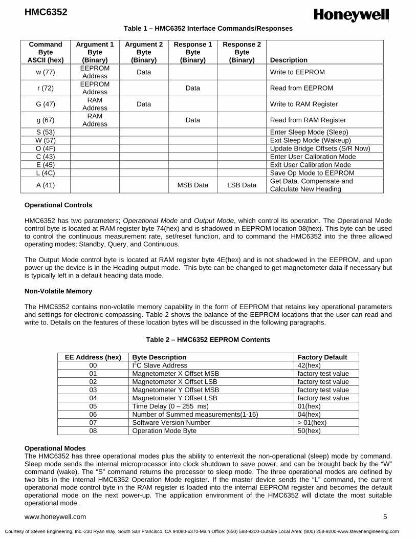
HMC6352
www.honeywell.com 5
Table 1 – HMC6352 Interface Commands/Responses
Command Byte
ASCII (hex)
Argument 1 Byte
(Binary)
Argument 2 Byte
(Binary)
Response 1 Byte
(Binary)
Response 2 Byte
(Binary)
Description
w (77) EEPROM Address Data Write to EEPROM
r (72) EEPROM Address Data Read from EEPROM
G (47) RAM Address Data Write to RAM Register
g (67) RAM Address Data Read from RAM Register
S (53) Enter Sleep Mode (Sleep) W (57) Exit Sleep Mode (Wakeup) O (4F) Update Bridge Offsets (S/R Now) C (43) Enter User Calibration Mode E (45) Exit User Calibration Mode L (4C) Save Op Mode to EEPROM
A (41) MSB Data LSB Data Get Data. Compensate and Calculate New Heading
Operational Controls HMC6352 has two parameters; Operational Mode and Output Mode, which control its operation. The Operational Mode control byte is located at RAM register byte 74(hex) and is shadowed in EEPROM location 08(hex). This byte can be used to control the continuous measurement rate, set/reset function, and to command the HMC6352 into the three allowed operating modes; Standby, Query, and Continuous. The Output Mode control byte is located at RAM register byte 4E(hex) and is not shadowed in the EEPROM, and upon power up the device is in the Heading output mode. This byte can be changed to get magnetometer data if necessary but is typically left in a default heading data mode. Non-Volatile Memory The HMC6352 contains non-volatile memory capability in the form of EEPROM that retains key operational parameters and settings for electronic compassing. Table 2 shows the balance of the EEPROM locations that the user can read and write to. Details on the features of these location bytes will be discussed in the following paragraphs.
Table 2 – HMC6352 EEPROM Contents
EE Address (hex) Byte Description Factory Default 00 I2C Slave Address 42(hex) 01 Magnetometer X Offset MSB factory test value 02 Magnetometer X Offset LSB factory test value 03 Magnetometer Y Offset MSB factory test value 04 Magnetometer Y Offset LSB factory test value 05 Time Delay (0 – 255 ms) 01(hex) 06 Number of Summed measurements(1-16) 04(hex) 07 Software Version Number > 01(hex) 08 Operation Mode Byte 50(hex)
Operational Modes The HMC6352 has three operational modes plus the ability to enter/exit the non-operational (sleep) mode by command. Sleep mode sends the internal microprocessor into clock shutdown to save power, and can be brought back by the “W” command (wake). The “S” command returns the processor to sleep mode. The three operational modes are defined by two bits in the internal HMC6352 Operation Mode register. If the master device sends the “L” command, the current operational mode control byte in the RAM register is loaded into the internal EEPROM register and becomes the default operational mode on the next power-up. The application environment of the HMC6352 will dictate the most suitable operational mode.
Courtesy of Steven Engineering, Inc.-230 Ryan Way, South San Francisco, CA 94080-6370-Main Office: (650) 588-9200-Outside Local Area: (800) 258-9200-www.stevenengineering.com

HMC6352
6 www.honeywell.com
Standby Mode: (Operational Mode=0) This is the factory default mode. The HMC6352 waits for master device commands or change in operational mode. Receiving an “A” command (get data) will make the HMC6352 perform a measurement of sensors (magnetometers), compute the compensated magnetometer and heading data, and wait for the next read or command. No new measurements are done until another “A” command is sent. This mode is useful to get data on demand or at random intervals as long as the application can withstand the time delay in getting the data. Query Mode: (Operational Mode=1) In this mode the internal processor waits for “A” commands (get data), makes the measurements and computations, and waits for the next read command to output the data. After each read command, the HMC6352 automatically performs another get data routine and updates the data registers. This mode is designed to get data on demand without repeating “A” commands, and with the master device controlling the timing and data throughput. The tradeoff in this mode is the previous query latency for the advantage of an immediate read of data. The above two modes are the most power conserving readout modes. Continuous Mode: (Operational Mode=2) The HMC6352 performs continuous sensor measurements and data computations at selectable rates of 1Hz, 5Hz, 10Hz, or 20Hz, and updates the output data bytes. Subsequent “A” commands are un-necessary unless re-synchronization to the command is desired. Data reads automatically get the most recent updates. This mode is useful for data demanding applications. The continuous mode measurement rate is selected by two bits in the operational mode selection byte, along with the mode selection and the periodic Set/Reset bit. The periodic Set/Reset function performs a re-alignment of the sensors magnetic domains in case of sensor perming (magnetic upset event), operating temperature shifts, and normal thermal agitation of the domains. Exposure of the HMC6352 to magnetic fields above 20 gauss (disturbing field threshold) leads to possible measurement inaccuracy or “stuck” sensor readings until the set/reset function is performed. With the periodic Set/Reset bit set, the set/reset function occurs every few minutes. Operational Mode Control Byte Syntax As described above, the HMC6352 operation mode, measurement rate, and periodic set/reset are selected and stored both in a processor RAM register and in EEPROM. Upon power-up the EEPROM will transfer the saved operational mode control byte into register address 74(hex). The following is the byte format: Bit 7 =0 Bits 6 and 5 (Continuous Mode Measurement Rate)
Bit 6 Bit 5 Description 0 0 1 Hz Measurement Rate 0 1 5 Hz Measurement Rate 1 0 10 Hz Measurement Rate 1 1 20 Hz Measurement Rate
Bit 4 (Periodic Set/Reset), 0 = Off, 1 = On Bit 3 = 0 Bit 2 = 0 Bits 1 and 0 (Operational Mode Value)
Bit 1 Bit 0 Description 0 0 Standby Mode 0 1 Query Mode 1 0 Continuous Mode 1 1 Not Allowed
The total bit format for the Operational Mode Byte is shown below: Bit 7 (MSB) Bit 6 Bit 5 Bit 4 Bit 3 Bit 2 Bit 1 Bit 0 (LSB)
0 M. Rate_H M. Rate_L Per. S/R 0 0 Op Mode_H Op Mode_L
Courtesy of Steven Engineering, Inc.-230 Ryan Way, South San Francisco, CA 94080-6370-Main Office: (650) 588-9200-Outside Local Area: (800) 258-9200-www.stevenengineering.com

HMC6352
www.honeywell.com 7
Output Data Modes The read response bytes after an “A” command, will cause the HMC6352 will return two bytes with binary formatted data. Either heading or magnetometer data can be retrieved depending on the output data selection byte value. Negative signed magnetometer data will be returned in two’s complement form. This output data control byte is located in RAM register location 4E(hex) and defaults to value zero (heading) at power up. The following is the byte format: Bits 7 through 3 = 0 Bits 0, 1, 2 (Output Mode Value)
Bit 2 Bit 1 Bit 0 Description 0 0 0 Heading Mode 0 0 1 Raw Magnetometer X Mode 0 1 0 Raw Magnetometer Y Mode 0 1 1 Magnetometer X Mode 1 0 0 Magnetometer Y Mode
The total bit format for the Output Mode Byte is shown below: Bit 7 (MSB) Bit 6 Bit 5 Bit 4 Bit 3 Bit 2 Bit 1 Bit 0 (LSB)
0 0 0 0 0 Mode Mode Mode Heading Mode: The heading output data will be the value in tenths of degrees from zero to 3599 and provided in binary format over the two bytes. Raw Magnetometer Modes: These X and Y raw magnetometer data readings are the internal sensor values measured at the output of amplifiers A and B respectively and are 10-bit 2’s complement binary ADC counts of the analog voltages at pins CA1 and CB1. The leading 6-bits on the MSB are zero filled or complemented for negative values. The zero count value will be about half of the supply voltage. If measurement averaging is implemented, the most significant bits may contain values of the summed readings. Magnetometer Modes: These X and Y magnetometer data readings are the raw magnetometer readings plus offset and scaling factors applied. The data format is the same as the raw magnetometer data. These compensated data values come from the calibration routine factors plus additional offset factors provided by the set/reset routine. User Calibration The HMC6352 provides a user calibration routine with the “C” command permitting entry into the calibration mode and the “E” command to exit the calibration mode. Once in calibration mode, the user is requested to rotate the compass on a flat surface at least one full circular rotation while the HMC6352 collects several readings per second at various headings with the emphasis on rotation smoothness to gather uniformly spaced readings. Optimally two rotations over 20 seconds duration would provide an accurate calibration. The calibration time window is recommended to be from 6 seconds up to 3 minutes depending on the end user’s platform. The calibration routine collects these readings to correct for hard-iron distortions of the earth’s magnetic field. These hard-iron effects are due to magnetized materials nearby the HMC6352 part that in a fixed position with respect to the end user platform. An example would be the magnetized chassis or engine block of a vehicle in which the compass is mounted onto. Upon exiting the calibration mode, the resulting magnetometer offsets and scaling factors are updated I2C Slave Address The I2C slave address byte consists of the 7 most significant bits with the least siginificant bit zero filled. A described earlier, the default (factory) value is 42(hex) and the legal I2C bounded values are between 10(hex) and F6(hex). This slave address is written into EEPROM address 00(hex) and changed on the power up. Magnetometer Offsets The Magnetometer Offset bytes are the values stored after the completion of the last factory or user calibration routine. Additional value changes are possible, but will be overwritten when the next calibration routine is completed. Note that
Courtesy of Steven Engineering, Inc.-230 Ryan Way, South San Francisco, CA 94080-6370-Main Office: (650) 588-9200-Outside Local Area: (800) 258-9200-www.stevenengineering.com

HMC6352
8 www.honeywell.com
these offset values are added to the sensor offset values computed by the set/reset routine to convert the raw magnetometer data to the compensated magnetometer data. These values are written into EEPROM addresses 01(hex) to 04 (hex) and loaded to RAM on the power up. These offsets are in ADC counts applied to the 10-bit ADC raw magnetometer data. Most offset MSB values will likely be zero filled or complemented. Time Delay The EEPROM time delay byte is the binary value of the number of milliseconds from the time a measurement request was commanded and the time the actual measurements are made. The default value is 01(hex) for no delay. Extra measurement delays maybe desired to allow for amplifier stabilization from immediate HMC6352 power-up or for external filter capacitor selection that limits the bandwidth and time response of the amplifier stages. This value is written into EEPROM address 05(hex) and loaded to RAM on the power up. Measurement Summing This EEPROM summed measurement byte permits designers/users to back average or data smooth the output data (heading, magnetometer values) to reduce the amount of jitter in the data presentation. The default value is 04(hex) which is four measurements summed. A value of 00(hex) would be no summing. Up to 16 sets of magnetometer data may be selected for averaging. This slave address is written into EEPROM address 06(hex) and loaded to RAM on the power up. Software Version This EEPROM software version number byte contains the binary value of the programmed software. Values of 01(hex) and beyond are considered production software. Timing Requirements Table 3 contains the time delays required by HMC6352 upon receipt of the command to either perform the commanded task or to have the response available on the I2C bus.
Table 3 – Interface Command Delays
Command Byte
ASCII (hex)
Description
Time Delay (µsec) w (77) Write to EEPROM 70 r (72) Read from EEPROM 70 G (47) Write to RAM Register 70 g (67) Read from RAM Register 70 S (53) Enter Sleep Mode (Sleep) 10 W (57) Exit Sleep Mode (Wakeup) 100 O (4F) Update Bridge Offsets (S/R Now) 6000 C (43) Enter User Calibration Mode 10 E (45) Exit User Calibration Mode 14000 L (4C) Save Op Mode to EEPROM 125
A (41) Get Data. Compensate and Calculate New Heading 6000
Command and Operation Mode Interactions All commands are accepted in the standby mode. Honeywell strongly recommends using this mode during the initial setup stage. Setting up of the HMC6352 operation mode and its slave address are typical set up examples. Although execution of all commands in the Query and Continuous Modes is acceptable, the completion outcome is not guaranteed. Q: How to Read Data from HMC6352? A: In Standby Mode - Use “A” command.
In Query Mode - Send 43(hex) slave address to read data and clock out the two register data bytes for heading. An initial “A” command is needed to update the heading after each read.
Courtesy of Steven Engineering, Inc.-230 Ryan Way, South San Francisco, CA 94080-6370-Main Office: (650) 588-9200-Outside Local Area: (800) 258-9200-www.stevenengineering.com
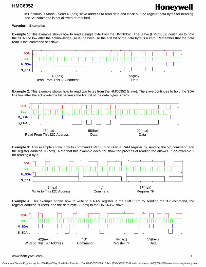
HMC6352
www.honeywell.com 9
In Continuous Mode - Send 43(hex) slave address to read data and clock out the register data bytes for heading. The “A” command is not allowed or required.
Waveform Examples Example 1: This example shows how to read a single byte from the HMC6352. The Slave (HMC6352) continues to hold the SDA line low after the acknowledge (ACK) bit because the first bit of the data byte is a zero. Remember that the data read is last command sensitive.
Example 2: This example shows how to read two bytes from the HMC6352 (slave). The slave continues to hold the SDA line low after the acknowledge bit because the first bit of the data bytes is zero. Example 3: This example shows how to command HMC6352 to read a RAM register by sending the “g” command and the register address 7F(hex). Note that this example does not show the process of reading the answer. See example 1 for reading a byte.
Example 4: This example shows how to write to a RAM register in the HMC6352 by sending the “G” command, the register address 7F(hex), and the data byte 55(hex) to the HMC6352 slave.
SDA
SCL
M_SDA
S_SDA
SDA
SCL
M_SDA
S_SDA
SDA
SCL
M_SDA
S_SDA
43(hex) Read From This I2C Address
55(hex) Data
SDA
SCL
M_SDA
S_SDA
SDA
SCL
M_SDA
S_SDA
SDA
SCL
M_SDA
S_SDA
43(hex) Read From This I2C Address
55(hex) Data
00(hex) Data
SDA
SCL
M_SDA
S_SDA
SDA
SCL
M_SDA
S_SDA
SDA
SCL
M_SDA
S_SDA
42(hex) Write to This I2C Address
“g” Command
7F(hex) Register 7F
SDA
SCL
M_SDA
S_SDA
SDA
SCL
M_SDA
S_SDA
SDA
SCL
M_SDA
S_SDA
42(hex) Write to This I2C Address
“G” Command
7F(hex) Register 7F
55(hex) Data
Courtesy of Steven Engineering, Inc.-230 Ryan Way, South San Francisco, CA 94080-6370-Main Office: (650) 588-9200-Outside Local Area: (800) 258-9200-www.stevenengineering.com

HMC6352
10 www.honeywell.com
Example 5: The final example shows how to read RAM register 7F(hex). First perform a write operation to command the HMC6352 to read a RAM register and define which register to read (Example 3). The sensor puts the answer in the data buffer. Then perform a read operation to clock out the answer (Example 1). There is a Stop/Start event in between the write operation and the read operation. This example is just a combination of Examples 3 and 1, but it is provided to show that reading a register involves both a write and a read operation.
Application Notes The HMC6352 Integrated Compass Sensor circuit is composed of two magneto-resistive (MR) sensors with orthogonal orientation for sensing the horizontal components of the earth’s magnetic field (0 to 630 milli-gauss), plus two amplifiers, a set/reset drive circuit, and a microprocessor (µP). Best accuracy is obtained in clean magnetic environments (free air) and held level, or perpendicular to the gravitational direction. At worst case, each degree of tilt from a level orientation could add two degrees of compass heading error. Magnetic errors can be introduced if operated near strong magnetic sources such as microphone or speaker magnets, transformers in test equipment, and CRT deflection yokes in video displays/monitors. These magnetic errors can typically be reduced or eliminated by performing the calibration routine. When locating the HMC6352 in dense printed circuit board designs, take precautions in location of this magnetic field sensing device for soft-iron effects that bend the earth’s magnetic field. These soft-iron effects are from ferrous materials without residual magnetization and tend to be items like nickel-plating on SMT component contacts and RFI/EMI shielding materials. The amount of stand-off of the HMC6352 from these soft-irons is heuristic and dependant on the amount of material, material shape, and proximity. A user calibration mode is available in the HMC6352 to diminish hard-iron effects of the end-user’s (customer’s) location of the product. Hard-iron effects come from nearby ferrous materials with residual magnetism that buck or boost the intensity of the earth’s magnetic field, leading to heading errors. Such hard-iron effects come from vehicle chassis, speaker magnets, and high current conductors or circuit traces.
PCB Pad Definition (Dimensions in Millimeters) The HMC6352 is a fine pitch LCC package with a 0.80mm pin pitch (spacing), with the pin pads defined as 0.70mm by 0.33mm in size. PCB pads are recommended to be oversized by 0.025mm from each pad for a short dimension oversize of 0.05mm. The interior PCB pad is recommended to be 0.05mm oversized per pin with an exterior oversize of 0.20mm for proper package centering and to permit test probing. Lead finish is SnAgCu. Soldering attachment shall be done by SMT lead-free reflow methods with standard preheating, soaking, reflow, and cooling profiles for large body parts. Caution, excessive temperature exposure beyond the profiles may result in internal damage to the HMC6352 circuits.
STOP START
SDA
SCL
M_SDA
S_SDA
STOP STARTSTOP START
SDA
SCL
M_SDA
S_SDA
SDA
SCL
M_SDA
S_SDA
42(hex) Write to This I2C Address
“g” Command
7F(hex) Register 7F
43(hex) Read From This
I2C Address
55(hex) Data
Courtesy of Steven Engineering, Inc.-230 Ryan Way, South San Francisco, CA 94080-6370-Main Office: (650) 588-9200-Outside Local Area: (800) 258-9200-www.stevenengineering.com

HMC6352
www.honeywell.com 11
MECHANICAL DIMENSIONS (In millimeters)
Dimension Minimum Nominal Maximum D - 6.50 BSC -
D1 - 4.00 BSC - E - 6.50 BSC -
E1 - 4.00 BSC - e - 0.8 Basic - A 1.37 1.52 1.67
SOLDERING GUIDELINES Most LCC packages have no special requirements beyond normal procedures for attaching SMT components to printed circuit boards. The exception to this process is the Honeywell HMC6352 that has a FR4 substrate package with epoxy top encapsulation.
TOP VIEW
24
1
6.90
5.00
0.380.80
TOP VIEW
24
1
6.90
5.00
0.380.80
D
E
A
e
E1
e
D1
D
E
A
e
E1
e
D1
Courtesy of Steven Engineering, Inc.-230 Ryan Way, South San Francisco, CA 94080-6370-Main Office: (650) 588-9200-Outside Local Area: (800) 258-9200-www.stevenengineering.com

HMC6352
12 www.honeywell.com
If the HMC6352 is stored in an uncontrolled humidity environment (>10% RH) beyond one week, a 24-hour bakeout period should be implemented before solder reflow. This bakeout should be in accordance with JEDEC J-STD-033A at 125°C for MSL3 devices. Three heating zones are defined in SMT reflow soldering process; the preheating zone, the soaking zone, and the reflow zone. The preheating zone includes the soaking zone, and nominally ranges from 2 to 4 minutes depending on temperature rise to arrive in the 160°C to 180°C soaking plateau to active the flux and remove any remaining moisture in the assembly. Preheat rise times must not exceed 3°C per second to avoid moisture and mechanical stresses that result in “popcorning” the package encapsulation. The soaking zone is a one to two minute temperature stabilization time to bring the all the PCB assembly to an even temperature. Typically this zone has a 0.5 to 0.6°C rise in temperature heading towards the main reflow heating elements. The reflow zone is 30 to 90 second bump in temperature over the 180°C point to reflow the screened solder paste before a gradual cooling. The peak temperature is typically in the 230°C to 240°C range. It should be noted that lead-free solders tend to require higher peak reflow temperatures and longer reflow times. Cooling zone temperature fall should decrease not more than 6°C per second to avoid mechanical stresses in the PCB assembly.
REFERENCE DESIGN The schematic diagram in Figure 1 shows the basic HMC6352 application circuit with a minimum of external components. From Figure 1, the host microprocessor (µP) controls the HMC6352 via I2C serial data interface lines for data (SDA) and clock (SCL). Two external 10k-ohm pull-up resistors to the nominal +3 volt DC supply create normally high logic states when the interface lines are not in use. The host initiates use of the interface by creating the 100kHz clock and pulling low the data line to indicate the start condition. The data line logic state transitions are only allowed during the clock low states and require the data line to be stable in the high states, with the exception of the start and stop conditions. The 0.01µF supply decoupling capacitor in this reference can be omitted if another supply filter capacitor is already included in the overall circuit design. If the supply traces extend beyond a couple inches to the HMC6352, it is advisable to add a local supply decoupling capacitor near the HMC6352 to retain optimum circuit stability. Additional masters and slaves can be added to the I2C bus traces without interface trouble to the HMC6352. There are no periodic maintenance commands required, and even HMC6352 sleep mode or power shutdown can be accomplished without harm to the data or clock lines.
Figure 1 Reference Design Schematic
Courtesy of Steven Engineering, Inc.-230 Ryan Way, South San Francisco, CA 94080-6370-Main Office: (650) 588-9200-Outside Local Area: (800) 258-9200-www.stevenengineering.com

HMC6352
www.honeywell.com 13
Amplifier Filter Connections The HMC6352 design has provisions for the feedback loop of each amplifier stage to be accessible via the CA1, CA2, CB1, and CB2 pin contacts. Across the contacts and internal to the HMC6352 is the amplifier section plus a 1200k-ohm feedback resistance to set the voltage gain. By placing small value ceramic capacitors across CA1 to CA2 (or CB1 to CB2), the designer can set the –3dB bandwidth of the amplified magnetometer signals to drop spurious magnetic interference in the system. For example a 120 pico-Farad capacitor (Cext) in the amplifier feedback loop would limit the bandwidth to about 1kHz. Be aware that larger values of capacitance begin to slow the amplifier response to where the measurement delay time EEPROM byte may have to be increased in value to let the signal settle before making a measurement. Figure 2 shows the partial schematic of the amplifier feedback loop. An optional gain reducing resistor (Rext) could also place across the feedback loop of the amplifier stages. With the amplifier set with the internal 1200 k-ohm feedback for ±750 milli-gauss maximum magnetic field flux density, a second 1200k-ohm external resistor would halve the gain and permit ±1.5 gauss capability if desired. Gain can be reduced for up to ±6 gauss capability for magnetometry-only applications or compassing with significant magnetic stray fields nearby.
ORDERING INFORMATION
Ordering Number Product HMC6352
Digital Compass Solution, I2C
Find out more For more information on Honeywell’s Magnetic Sensors visit us online at www.magneticsensors.com or contact us at 800-323-8295 (763-954-2474 internationally). The application circuits herein constitute typical usage and interface of Honeywell product. Honeywell does not warranty or assume liability of customer-designed circuits derived from this description or depiction. Honeywell reserves the right to make changes to improve reliability, function or design. Honeywell does not assume any liability arising out of the application or use of any product or circuit described herein; neither does it convey any license under its patent rights nor the rights of others. U.S. Patents 4,441,072, 4,533,872, 4,569,742, 4,681,812, 4,847,584 and 6,529,114 apply to the technology described
Honeywell International Inc. 12001 Highway 55 Plymouth, MN 55441 Tel: 800-323-8295 www.honeywell.com
Form #900307 Rev D January 2006 ©2006 Honeywell International Inc.
Figure 2 Amplifier Filter Connections
Courtesy of Steven Engineering, Inc.-230 Ryan Way, South San Francisco, CA 94080-6370-Main Office: (650) 588-9200-Outside Local Area: (800) 258-9200-www.stevenengineering.com

HMC6352 2-Axis Digital Compass Module
Device Operational Overview HMC6352 HMC6352 has two parameters; Operational Mode and Output Mode, which control its operation. The Operational Mode is a RAM byte (0x74) and is shadowed in EEPROM location 0x08. This byte can be used to control the Measurement rate, Set/reset function, and to command the device into the three allowed operating modes; Standby, Query, and Continuous. The current Op Mode RAM value can be saved in the EEPROM using the “L” command, and will become the default mode on subsequent power up. Also, HMC6352 can be put in to Sleep mode for the lowest power consumption. The Output Mode Byte is located in RAM 0x4E and is not shadowed in the EEPROM, and upon power up the device is in the Heading output mode. This byte can be changed to get magnetometer data if necessary. The application environment of the HMC6352 will dictate the most suitable operational mode. In the Standby Mode the HMC6352 is not performing measurements and is waiting for a command, and can be commanded in to making a heading measurement by issuing the “A” command. This mode is useful to get data on demand or at random intervals as long as the application can withstand the time delay in getting the data. With the Query Mode, the HMC6352 will make a fresh measurement after it is read by the host processor. In this mode the data are available for immediate read. The above two modes are the most power efficient readout modes. In the Continuous Mode the user can choose 1,5,10,or 20 Hz output rate and the HMC6352 will make continuous measurements and update the output registers. This mode is useful for data demanding applications. In this mode the output can be read by writing 0x43 to the HMC6352 I2C bus.
Courtesy of S
teven Engineering, Inc.-230 R
yan Way, S
outh San F
rancisco, CA
94080-6370-Main O
ffice: (650) 588-9200-Outside Local A
rea: (800) 258-9200-ww
w.stevenengineering.com

HMC6352 2-Axis Digital Compass Module
I2C Bus Overview HMC6352 employs the 2-wire I2C bus protocol (http://www.semiconductors.philips.com/acrobat/literature/9398/39340011.pdf) in the 100 Kb/s data rate, 7 bit addressing mode. There is a clock line (SCL) and a data SDA line in this bus specification and a host of devices can be connected. The bus can be a single Master – multi Slave or it can be a Multi-Master configuration. All data transfers are initiated by the Master device which is responsible for generating the clock signal, and the transfers are 8 bit long. All devices are addressed by its unique 7 bit Address. After each 8-bit transfer, the Master generates a 9 th clock pulse, and the transmitting device releases the SDA line. The receiving device will pull the SDA line low to acknowledge (ACK) the successful transfer or leave the SDA high to NACK. All transitions in the SDA line must occur when SCL is low. This requirement leads to two unique conditions on the bus associated with the SDA transitions when SCL is high. Master device pulling the SDA low while SCL high is the Start (S) condition, and the Stop(P) condition when the SDA is pulled high while SCL is high. The I2C protocol also allows for the Restart condition in which the master device issues a second Start condition without issuing a Stop. All bus transactions begin with the Master issuing the Start sequence followed by the slave address-byte. The address-byte contains the slave address; the upper 7 bits (bits7-1), and the LSb. The LSb of the address-byte designates if the operation is read (LSb=1) or write (LSb=0). At the 9 th clock pulse, the transmitting device will issue the ACK (or NACK). Following these bus events, the master will send data bytes for a write operation, and the slave will transmit data for a read operation. All bus transactions are terminated with the Master issuing a Stop sequence.
Courtesy of S
teven Engineering, Inc.-230 R
yan Way, S
outh San F
rancisco, CA
94080-6370-Main O
ffice: (650) 588-9200-Outside Local A
rea: (800) 258-9200-ww
w.stevenengineering.com
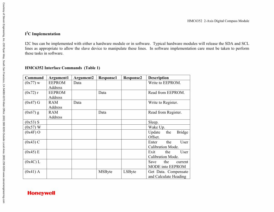
HMC6352 2-Axis Digital Compass Module
I2C Implementation I2C bus can be implemented with either a hardware module or in software. Typical hardware modules will release the SDA and SCL lines as appropriate to allow the slave device to manipulate these lines. In software implementation care must be taken to perform these tasks in software. HMC6352 Interface Commands (Table 1) Command Argument1 Argument2 Response1 Response2 Description (0x77) w
EEPROM Address
Data Write to EEPROM.
(0x72) r
EEPROM Address
Data Read from EEPROM.
(0x47) G RAM Address
Data Write to Register.
(0x67) g RAM Address
Data Read from Register.
(0x53) S Sleep. (0x57) W Wake Up. (0x4F) O Update the Bridge
Offset. (0x43) C Enter the User
Calibration Mode. (0x45) E Exit the User
Calibration Mode. (0x4C) L Save the current
MODE into EEPROM (0x41) A
MSByte LSByte Get Data. Compensate and Calculate Heading
Courtesy of S
teven Engineering, Inc.-230 R
yan Way, S
outh San F
rancisco, CA
94080-6370-Main O
ffice: (650) 588-9200-Outside Local A
rea: (800) 258-9200-ww
w.stevenengineering.com
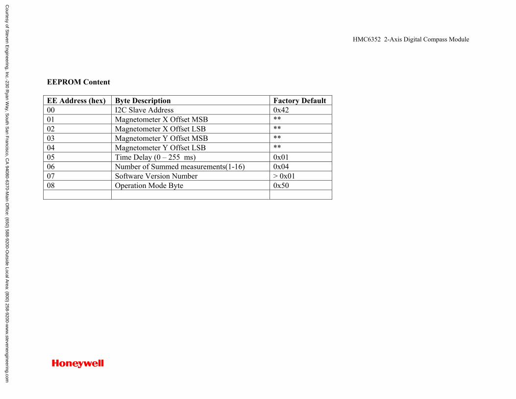
HMC6352 2-Axis Digital Compass Module
EEPROM Content EE Address (hex) Byte Description Factory Default 00 I2C Slave Address 0x42 01 Magnetometer X Offset MSB ** 02 Magnetometer X Offset LSB ** 03 Magnetometer Y Offset MSB ** 04 Magnetometer Y Offset LSB ** 05 Time Delay (0 – 255 ms) 0x01 06 Number of Summed measurements(1-16) 0x04 07 Software Version Number > 0x01 08 Operation Mode Byte 0x50
Courtesy of S
teven Engineering, Inc.-230 R
yan Way, S
outh San F
rancisco, CA
94080-6370-Main O
ffice: (650) 588-9200-Outside Local A
rea: (800) 258-9200-ww
w.stevenengineering.com
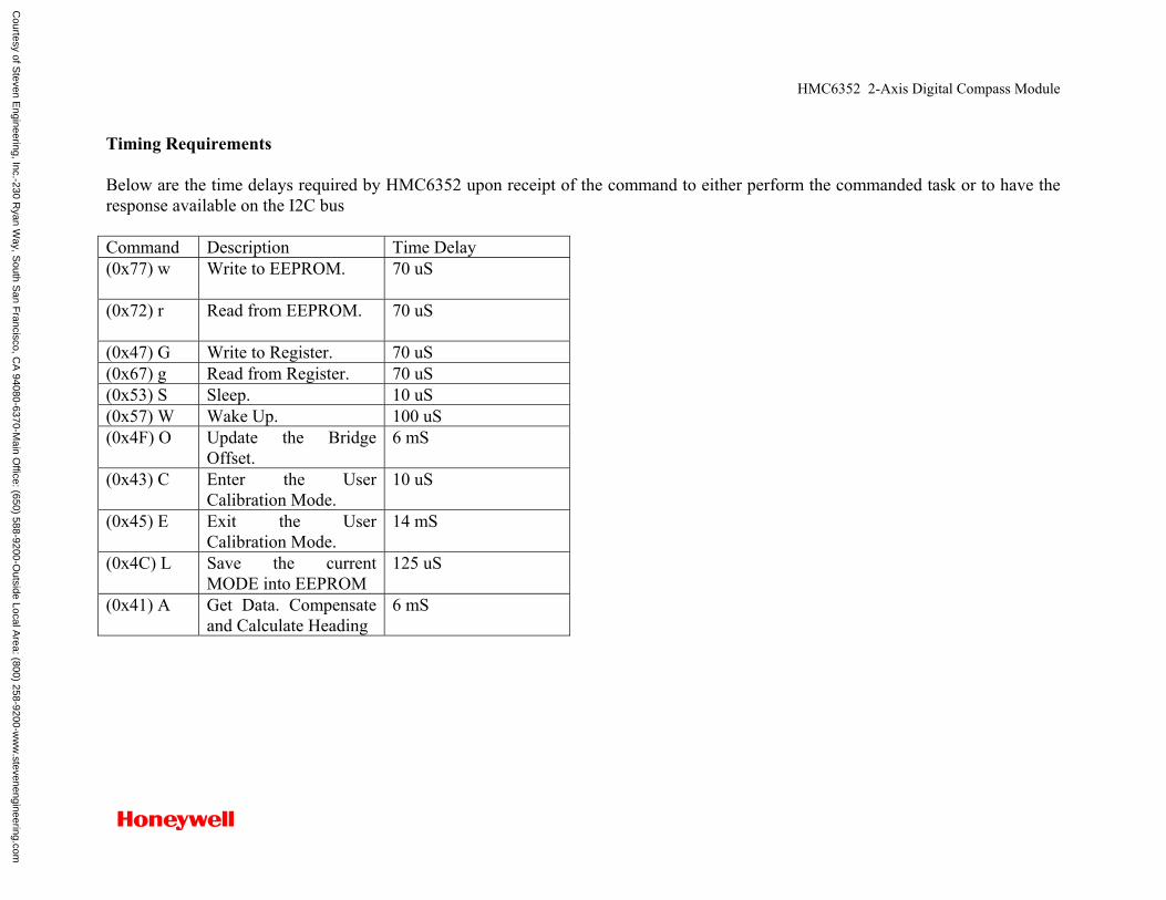
HMC6352 2-Axis Digital Compass Module
Timing Requirements Below are the time delays required by HMC6352 upon receipt of the command to either perform the commanded task or to have the response available on the I2C bus Command Description Time Delay (0x77) w
Write to EEPROM. 70 uS
(0x72) r
Read from EEPROM. 70 uS
(0x47) G Write to Register. 70 uS (0x67) g Read from Register. 70 uS (0x53) S Sleep. 10 uS (0x57) W Wake Up. 100 uS (0x4F) O Update the Bridge
Offset. 6 mS
(0x43) C Enter the User Calibration Mode.
10 uS
(0x45) E Exit the User Calibration Mode.
14 mS
(0x4C) L Save the current MODE into EEPROM
125 uS
(0x41) A
Get Data. Compensate and Calculate Heading
6 mS
Courtesy of S
teven Engineering, Inc.-230 R
yan Way, S
outh San F
rancisco, CA
94080-6370-Main O
ffice: (650) 588-9200-Outside Local A
rea: (800) 258-9200-ww
w.stevenengineering.com

HMC6352 2-Axis Digital Compass Module
Command and Operation Mode Interactions All commands are acceptable in the Standby Mode. Honeywell strongly recommends using this mode during initial setup stage. Setting up of the HMC6352 operation mode and its slave address are set up examples. Although execution of all commands in the Query and Continuous Modes is acceptable, the outcome is not guaranteed. How to Read Data from HMC6352
1) In Standby Mode Use “A” command
2) In Query Mode Send 0x43 and clock out data (See Example 5)
3) In Continuous Mode Send 0x43 and clock out data (See Example 5) A is not allowed
Courtesy of S
teven Engineering, Inc.-230 R
yan Way, S
outh San F
rancisco, CA
94080-6370-Main O
ffice: (650) 588-9200-Outside Local A
rea: (800) 258-9200-ww
w.stevenengineering.com
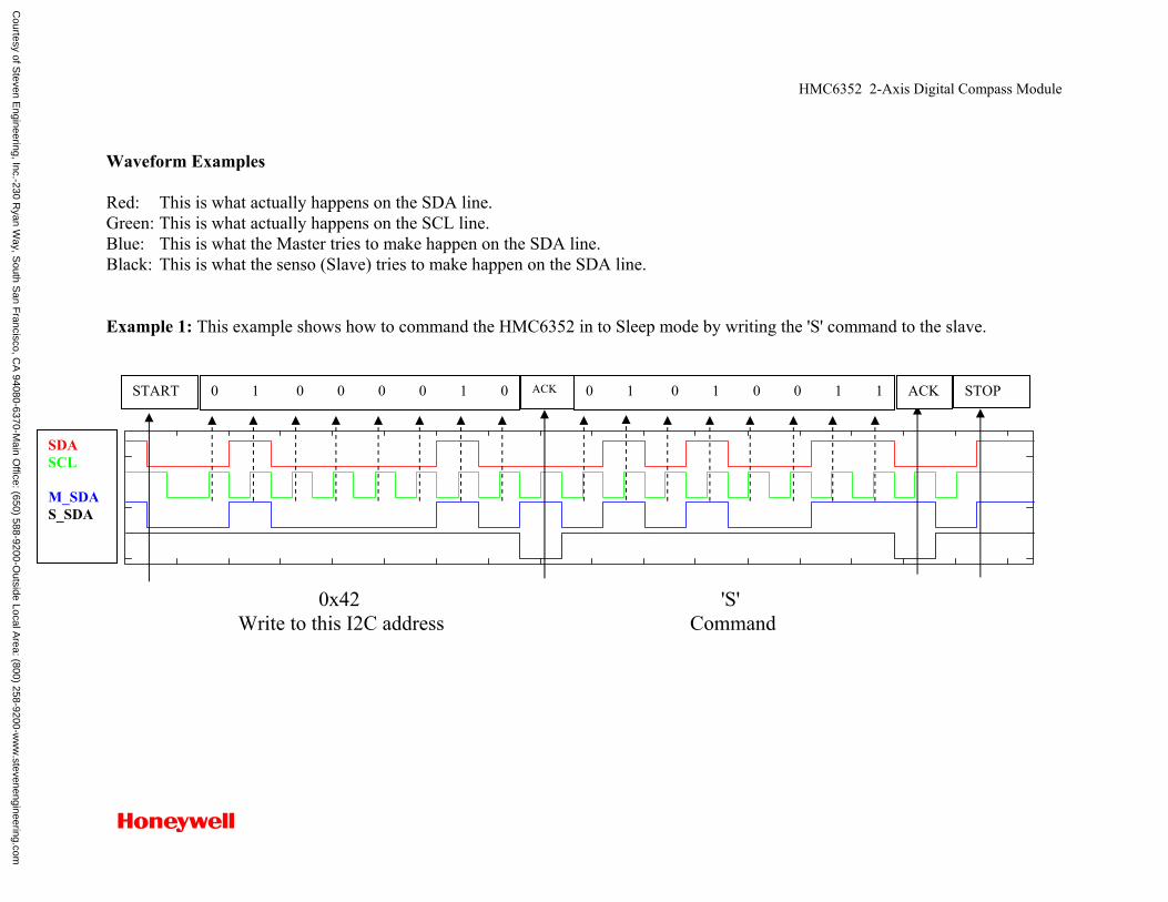
HMC6352 2-Axis Digital Compass Module
Waveform Examples Red: This is what actually happens on the SDA line. Green: This is what actually happens on the SCL line. Blue: This is what the Master tries to make happen on the SDA line. Black: This is what the senso (Slave) tries to make happen on the SDA line. Example 1: This example shows how to command the HMC6352 in to Sleep mode by writing the 'S' command to the slave.
0x42 'S' Write to this I2C address Command
SDA SCL M_SDA S_SDA
0 1 0 0 0 0 1 0 START ACK ACK STOP 0 1 0 1 0 0 1 1
Courtesy of S
teven Engineering, Inc.-230 R
yan Way, S
outh San F
rancisco, CA
94080-6370-Main O
ffice: (650) 588-9200-Outside Local A
rea: (800) 258-9200-ww
w.stevenengineering.com
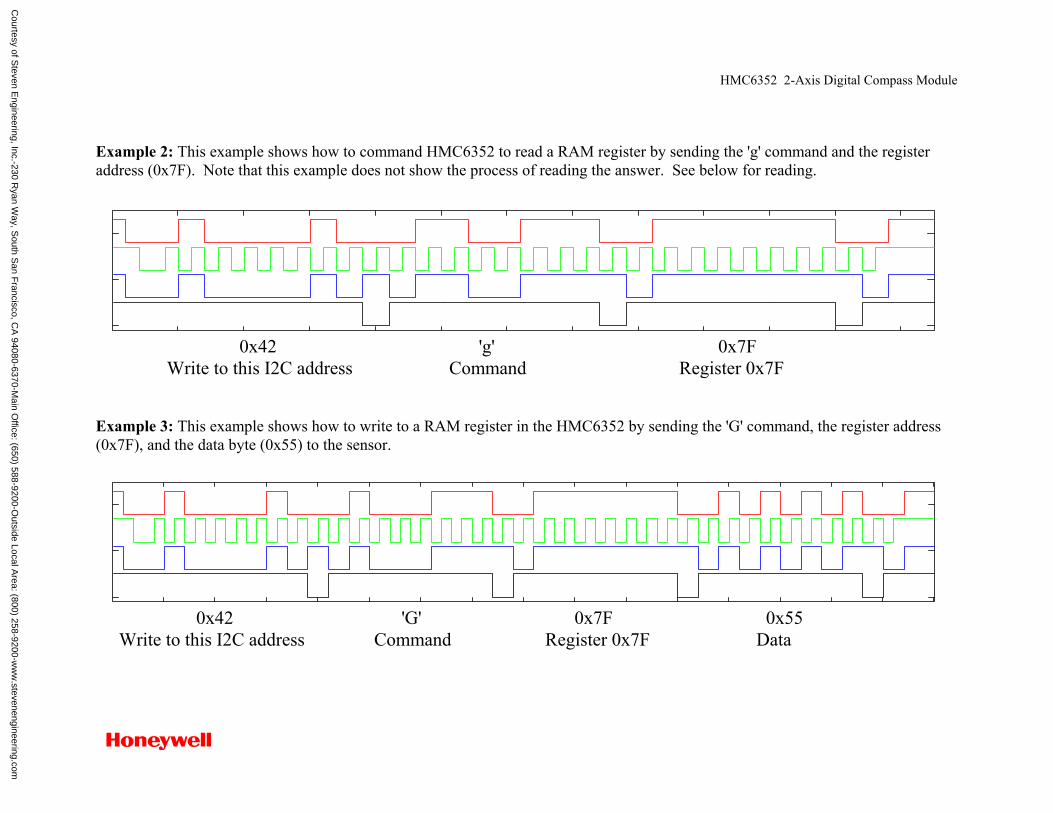
HMC6352 2-Axis Digital Compass Module
Example 2: This example shows how to command HMC6352 to read a RAM register by sending the 'g' command and the register address (0x7F). Note that this example does not show the process of reading the answer. See below for reading.
0x42 'g' 0x7F Write to this I2C address Command Register 0x7F Example 3: This example shows how to write to a RAM register in the HMC6352 by sending the 'G' command, the register address (0x7F), and the data byte (0x55) to the sensor.
0x42 'G' 0x7F 0x55 Write to this I2C address Command Register 0x7F Data
Courtesy of S
teven Engineering, Inc.-230 R
yan Way, S
outh San F
rancisco, CA
94080-6370-Main O
ffice: (650) 588-9200-Outside Local A
rea: (800) 258-9200-ww
w.stevenengineering.com
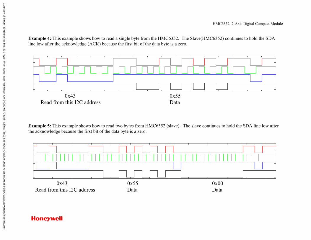
HMC6352 2-Axis Digital Compass Module
Example 4: This example shows how to read a single byte from the HMC6352. The Slave(HMC6352) continues to hold the SDA line low after the acknowledge (ACK) because the first bit of the data byte is a zero.
0x43 0x55 Read from this I2C address Data Example 5: This example shows how to read two bytes from HMC6352 (slave). The slave continues to hold the SDA line low after the acknowledge because the first bit of the data byte is a zero.
0x43 0x55 0x00 Read from this I2C address Data Data
Courtesy of S
teven Engineering, Inc.-230 R
yan Way, S
outh San F
rancisco, CA
94080-6370-Main O
ffice: (650) 588-9200-Outside Local A
rea: (800) 258-9200-ww
w.stevenengineering.com
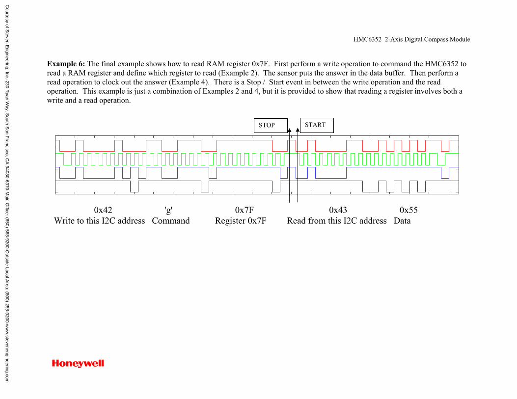
HMC6352 2-Axis Digital Compass Module
Example 6: The final example shows how to read RAM register 0x7F. First perform a write operation to command the HMC6352 to read a RAM register and define which register to read (Example 2). The sensor puts the answer in the data buffer. Then perform a read operation to clock out the answer (Example 4). There is a Stop / Start event in between the write operation and the read operation. This example is just a combination of Examples 2 and 4, but it is provided to show that reading a register involves both a write and a read operation.
0x42 'g' 0x7F 0x43 0x55 Write to this I2C address Command Register 0x7F Read from this I2C address Data
STOP START
Courtesy of S
teven Engineering, Inc.-230 R
yan Way, S
outh San F
rancisco, CA
94080-6370-Main O
ffice: (650) 588-9200-Outside Local A
rea: (800) 258-9200-ww
w.stevenengineering.com

HMR2300 SENSOR PRODUCTS
Solid State Electronics Center • www.magneticsensors.com • (800) 323-8295 • Page 1
SMART DIGITAL MAGNETOMETER Features • High Accuracy Over ±1 gauss, <0.5% Full Scale • Range of ±2 gauss, <70 µgauss Resolution • Three Axis (X, Y, Z) Digital Outputs • 10 to 154 Samples Per Second, Selectable • RS-232 or RS-485 Serial Data Interfaces • PCB or Aluminum Enclosure Options • 6-15 volt DC Unregulated Power Supply Interface
General Description The Honeywell HMR2300 is a three-axis smart digital magnetometer to detect the strength and direction of an incident magnetic field. The three of Honeywell’s magneto-resistive sensors are oriented in orthogonal directions to measure the X, Y and Z vector components of a magnetic field. These sensor outputs are converted to 16-bit digital values using an internal delta-sigma A/D converter. An onboard EEPROM stores the magnetometer’s configuration for consistent operation. The data output is serial full-duplex RS-232 or half-duplex RS-485 with 9600 or 19,200 data rates. A RS-232 development kit version is available that includes a windows compatible demo program, interface cable, AC adapter, and carrying case.
Block Diagram
APPLICATIONS
• Attitude Reference
• Compassing & Navigation
• Traffic and Vehicle Detection
• Anomaly Detection
• Laboratory Instrumentation
• Security Systems
µC
HMC2003
HMC1002
HMC1001
PwrCond
V+
EEPROM
TX
RX
UA
RT
ADC
Gnd
µC
HMC2003
HMC1002
HMC1001
PwrCond
V+
EEPROM
TX
RX
UA
RT
ADC
Gnd
Courtesy of Steven Engineering, Inc.-230 Ryan Way, South San Francisco, CA 94080-6370-Main Office: (650) 588-9200-Outside Local Area: (800) 258-9200-www.stevenengineering.com
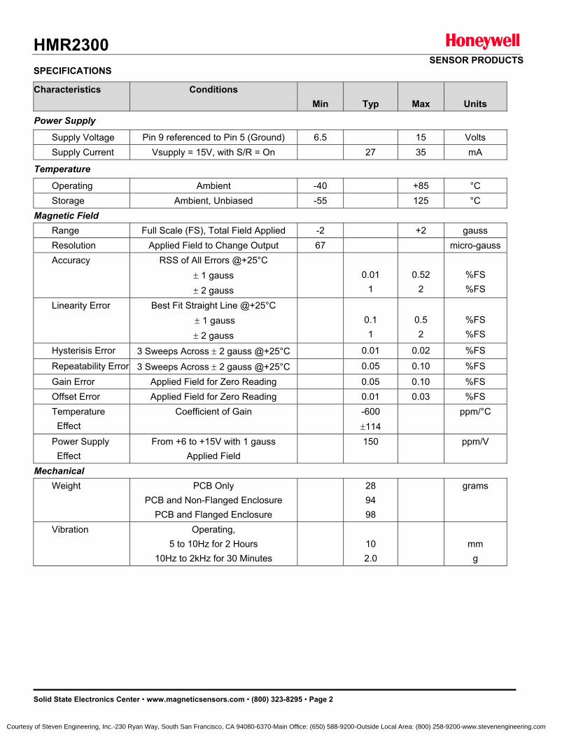
HMR2300 SENSOR PRODUCTS
Solid State Electronics Center • www.magneticsensors.com • (800) 323-8295 • Page 2
SPECIFICATIONS
Characteristics Conditions Min
Typ
Max
Units
Power Supply
Supply Voltage Pin 9 referenced to Pin 5 (Ground) 6.5 15 Volts Supply Current Vsupply = 15V, with S/R = On 27 35 mA
Temperature
Operating Ambient -40 +85 °C Storage Ambient, Unbiased -55 125 °C Magnetic Field Range Full Scale (FS), Total Field Applied -2 +2 gauss Resolution Applied Field to Change Output 67 micro-gauss Accuracy RSS of All Errors @+25°C
± 1 gauss ± 2 gauss
0.01
1
0.52
2
%FS %FS
Linearity Error Best Fit Straight Line @+25°C ± 1 gauss ± 2 gauss
0.1 1
0.5 2
%FS %FS
Hysterisis Error 3 Sweeps Across ± 2 gauss @+25°C 0.01 0.02 %FS
Repeatability Error 3 Sweeps Across ± 2 gauss @+25°C 0.05 0.10 %FS
Gain Error Applied Field for Zero Reading 0.05 0.10 %FS Offset Error Applied Field for Zero Reading 0.01 0.03 %FS Temperature Effect
Coefficient of Gain -600 ±114
ppm/°C
Power Supply Effect
From +6 to +15V with 1 gauss Applied Field
150 ppm/V
Mechanical Weight PCB Only
PCB and Non-Flanged Enclosure PCB and Flanged Enclosure
28 94 98
grams
Vibration Operating, 5 to 10Hz for 2 Hours
10Hz to 2kHz for 30 Minutes
10 2.0
mm
g
Courtesy of Steven Engineering, Inc.-230 Ryan Way, South San Francisco, CA 94080-6370-Main Office: (650) 588-9200-Outside Local Area: (800) 258-9200-www.stevenengineering.com
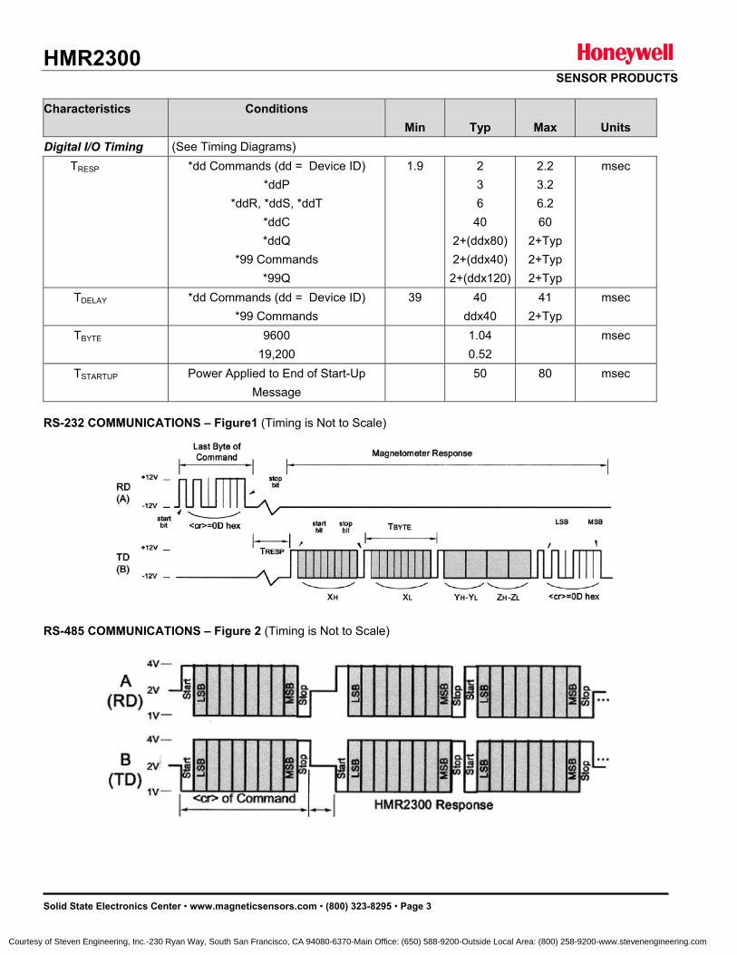
HMR2300 SENSOR PRODUCTS
Solid State Electronics Center • www.magneticsensors.com • (800) 323-8295 • Page 3
Characteristics Conditions
Min
Typ
Max
Units Digital I/O Timing (See Timing Diagrams) TRESP *dd Commands (dd = Device ID)
*ddP *ddR, *ddS, *ddT
*ddC *ddQ
*99 Commands *99Q
1.9 2 3 6
40 2+(ddx80) 2+(ddx40) 2+(ddx120)
2.2 3.2 6.2 60
2+Typ 2+Typ 2+Typ
msec
TDELAY *dd Commands (dd = Device ID) *99 Commands
39 40 ddx40
41 2+Typ
msec
TBYTE 9600 19,200
1.04 0.52
msec
TSTARTUP Power Applied to End of Start-Up Message
50 80 msec
RS-232 COMMUNICATIONS – Figure1 (Timing is Not to Scale) RS-485 COMMUNICATIONS – Figure 2 (Timing is Not to Scale)
Courtesy of Steven Engineering, Inc.-230 Ryan Way, South San Francisco, CA 94080-6370-Main Office: (650) 588-9200-Outside Local Area: (800) 258-9200-www.stevenengineering.com
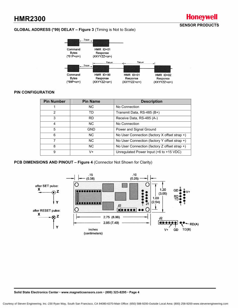
HMR2300 SENSOR PRODUCTS
Solid State Electronics Center • www.magneticsensors.com • (800) 323-8295 • Page 4
GLOBAL ADDRESS (*99) DELAY – Figure 3 (Timing is Not to Scale) PIN CONFIGURATION
Pin Number Pin Name Description
1 NC No Connection 2 TD Transmit Data, RS-485 (B+) 3 RD Receive Data, RS-485 (A-) 4 NC No Connection 5 GND Power and Signal Ground 6 NC No User Connection (factory X offset strap +) 7 NC No User Connection (factory Y offset strap +) 8 NC No User Connection (factory Z offset strap +) 9 V+ Unregulated Power Input (+6 to +15 VDC)
PCB DIMENSIONS AND PINOUT – Figure 4 (Connector Not Shown for Clarity)
Courtesy of Steven Engineering, Inc.-230 Ryan Way, South San Francisco, CA 94080-6370-Main Office: (650) 588-9200-Outside Local Area: (800) 258-9200-www.stevenengineering.com
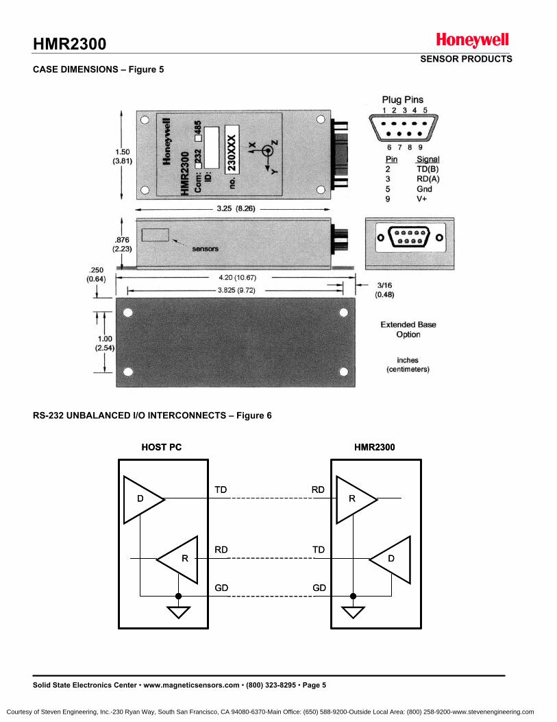
HMR2300 SENSOR PRODUCTS
Solid State Electronics Center • www.magneticsensors.com • (800) 323-8295 • Page 5
CASE DIMENSIONS – Figure 5 RS-232 UNBALANCED I/O INTERCONNECTS – Figure 6
HMR2300HOST PC
D
DR
RTD
TDRD
RD
GD GD
HMR2300HOST PC
D
DR
RTD
TDRD
RD
GD GD
Courtesy of Steven Engineering, Inc.-230 Ryan Way, South San Francisco, CA 94080-6370-Main Office: (650) 588-9200-Outside Local Area: (800) 258-9200-www.stevenengineering.com
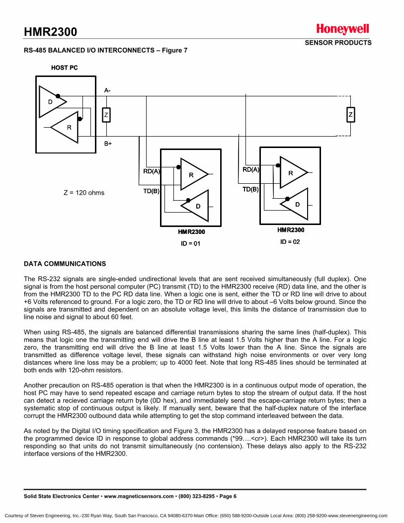
HMR2300 SENSOR PRODUCTS
Solid State Electronics Center • www.magneticsensors.com • (800) 323-8295 • Page 6
RS-485 BALANCED I/O INTERCONNECTS – Figure 7
DATA COMMUNICATIONS The RS-232 signals are single-ended undirectional levels that are sent received simultaneously (full duplex). One signal is from the host personal computer (PC) transmit (TD) to the HMR2300 receive (RD) data line, and the other is from the HMR2300 TD to the PC RD data line. When a logic one is sent, either the TD or RD line will drive to about +6 Volts referenced to ground. For a logic zero, the TD or RD line will drive to about –6 Volts below ground. Since the signals are transmitted and dependent on an absolute voltage level, this limits the distance of transmission due to line noise and signal to about 60 feet. When using RS-485, the signals are balanced differential transmissions sharing the same lines (half-duplex). This means that logic one the transmitting end will drive the B line at least 1.5 Volts higher than the A line. For a logic zero, the transmitting end will drive the B line at least 1.5 Volts lower than the A line. Since the signals are transmitted as difference voltage level, these signals can withstand high noise environments or over very long distances where line loss may be a problem; up to 4000 feet. Note that long RS-485 lines should be terminated at both ends with 120-ohm resistors. Another precaution on RS-485 operation is that when the HMR2300 is in a continuous output mode of operation, the host PC may have to send repeated escape and carriage return bytes to stop the stream of output data. If the host can detect a recieved carriage return byte (0D hex), and immediately send the escape-carriage return bytes; then a systematic stop of continuous output is likely. If manually sent, beware that the half-duplex nature of the interface corrupt the HMR2300 outbound data while attempting to get the stop command interleaved between the data. As noted by the Digital I/O timing specification and Figure 3, the HMR2300 has a delayed response feature based on the programmed device ID in response to global address commands (*99….<cr>). Each HMR2300 will take its turn responding so that units do not transmit simultaneously (no contension). These delays also apply to the RS-232 interface versions of the HMR2300.
HOST PC
D
R Z Z
A -
B+
HMR2300
R
D
RD(A)
TD(B)
ID = 01
HMR2300
R
D
RD(A)
TD(B)
ID = 02
HOST PC
D
R Z
A -
B+
HMR2300
R
D
RD(A)
TD(B)
ID = 01
HMR2300
R
D
RD(A)
TD(B)
ID = 01
HMR2300
R
D
RD(A)
TD(B)
ID = 02 HMR2300
R
D
RD(A)
TD(B)
ID = 02
Z = 120 ohms
Courtesy of Steven Engineering, Inc.-230 Ryan Way, South San Francisco, CA 94080-6370-Main Office: (650) 588-9200-Outside Local Area: (800) 258-9200-www.stevenengineering.com
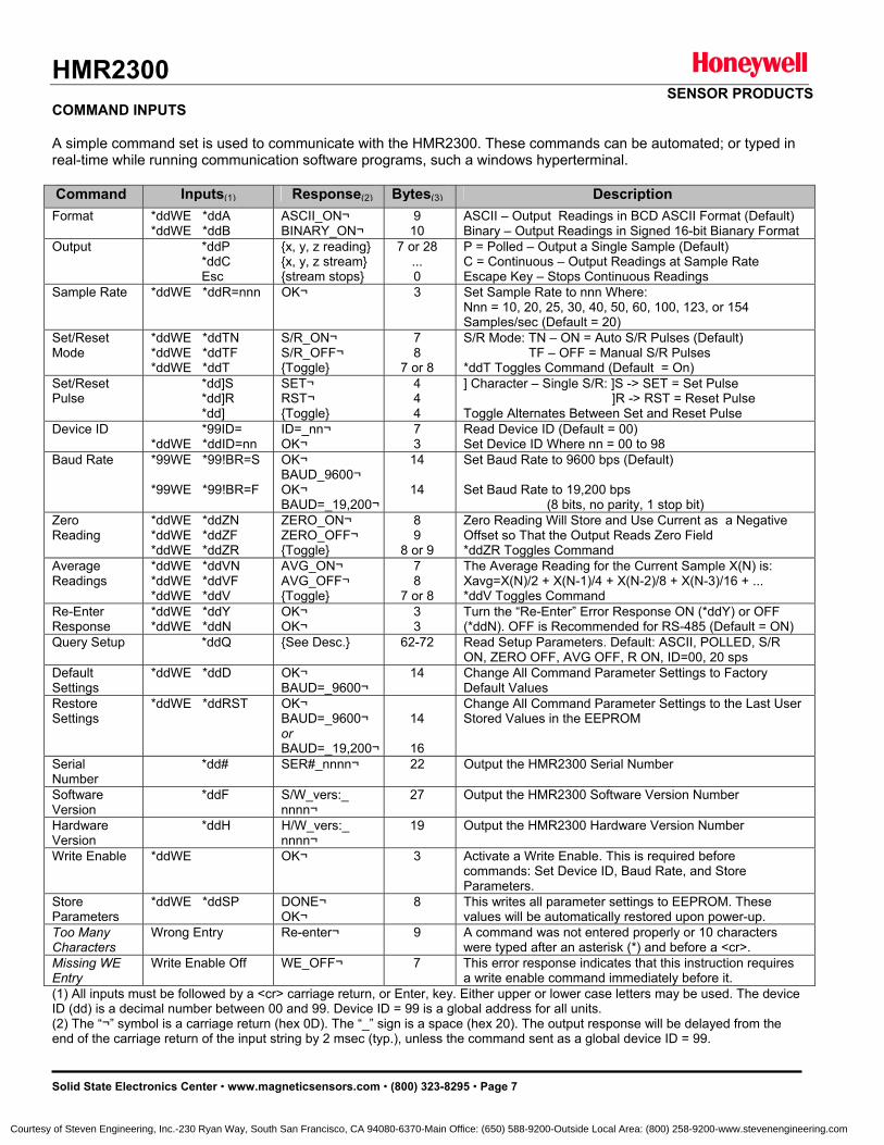
HMR2300 SENSOR PRODUCTS
Solid State Electronics Center • www.magneticsensors.com • (800) 323-8295 • Page 7
COMMAND INPUTS A simple command set is used to communicate with the HMR2300. These commands can be automated; or typed in real-time while running communication software programs, such a windows hyperterminal. Command Inputs(1) Response(2) Bytes(3) Description
Format *ddWE *ddA *ddWE *ddB
ASCII_ON¬ BINARY_ON¬
9 10
ASCII – Output Readings in BCD ASCII Format (Default) Binary – Output Readings in Signed 16-bit Bianary Format
Output *ddP *ddC Esc
x, y, z reading x, y, z stream stream stops
7 or 28 ... 0
P = Polled – Output a Single Sample (Default) C = Continuous – Output Readings at Sample Rate Escape Key – Stops Continuous Readings
Sample Rate *ddWE *ddR=nnn OK¬ 3 Set Sample Rate to nnn Where: Nnn = 10, 20, 25, 30, 40, 50, 60, 100, 123, or 154 Samples/sec (Default = 20)
Set/Reset Mode
*ddWE *ddTN *ddWE *ddTF *ddWE *ddT
S/R_ON¬ S/R_OFF¬ Toggle
7 8
7 or 8
S/R Mode: TN – ON = Auto S/R Pulses (Default) TF – OFF = Manual S/R Pulses *ddT Toggles Command (Default = On)
Set/Reset Pulse
*dd]S *dd]R *dd]
SET¬ RST¬ Toggle
4 4 4
] Character – Single S/R: ]S -> SET = Set Pulse ]R -> RST = Reset Pulse Toggle Alternates Between Set and Reset Pulse
Device ID *99ID= *ddWE *ddID=nn
ID=_nn¬ OK¬
7 3
Read Device ID (Default = 00) Set Device ID Where nn = 00 to 98
Baud Rate *99WE *99!BR=S *99WE *99!BR=F
OK¬ BAUD_9600¬ OK¬ BAUD=_19,200¬
14
14
Set Baud Rate to 9600 bps (Default) Set Baud Rate to 19,200 bps (8 bits, no parity, 1 stop bit)
Zero Reading
*ddWE *ddZN *ddWE *ddZF *ddWE *ddZR
ZERO_ON¬ ZERO_OFF¬ Toggle
8 9
8 or 9
Zero Reading Will Store and Use Current as a Negative Offset so That the Output Reads Zero Field *ddZR Toggles Command
Average Readings
*ddWE *ddVN *ddWE *ddVF *ddWE *ddV
AVG_ON¬ AVG_OFF¬ Toggle
7 8
7 or 8
The Average Reading for the Current Sample X(N) is: Xavg=X(N)/2 + X(N-1)/4 + X(N-2)/8 + X(N-3)/16 + ... *ddV Toggles Command
Re-Enter Response
*ddWE *ddY *ddWE *ddN
OK¬ OK¬
3 3
Turn the “Re-Enter” Error Response ON (*ddY) or OFF (*ddN). OFF is Recommended for RS-485 (Default = ON)
Query Setup *ddQ See Desc. 62-72 Read Setup Parameters. Default: ASCII, POLLED, S/R ON, ZERO OFF, AVG OFF, R ON, ID=00, 20 sps
Default Settings
*ddWE *ddD OK¬ BAUD=_9600¬
14 Change All Command Parameter Settings to Factory Default Values
Restore Settings
*ddWE *ddRST OK¬ BAUD=_9600¬ or BAUD=_19,200¬
14
16
Change All Command Parameter Settings to the Last User Stored Values in the EEPROM
Serial Number
*dd# SER#_nnnn¬ 22 Output the HMR2300 Serial Number
Software Version
*ddF S/W_vers:_ nnnn¬
27 Output the HMR2300 Software Version Number
Hardware Version
*ddH H/W_vers:_ nnnn¬
19 Output the HMR2300 Hardware Version Number
Write Enable *ddWE OK¬ 3 Activate a Write Enable. This is required before commands: Set Device ID, Baud Rate, and Store Parameters.
Store Parameters
*ddWE *ddSP DONE¬ OK¬
8 This writes all parameter settings to EEPROM. These values will be automatically restored upon power-up.
Too Many Characters
Wrong Entry Re-enter¬ 9 A command was not entered properly or 10 characters were typed after an asterisk (*) and before a <cr>.
Missing WE Entry
Write Enable Off WE_OFF¬ 7 This error response indicates that this instruction requires a write enable command immediately before it.
(1) All inputs must be followed by a <cr> carriage return, or Enter, key. Either upper or lower case letters may be used. The device ID (dd) is a decimal number between 00 and 99. Device ID = 99 is a global address for all units. (2) The “¬” symbol is a carriage return (hex 0D). The “_” sign is a space (hex 20). The output response will be delayed from the end of the carriage return of the input string by 2 msec (typ.), unless the command sent as a global device ID = 99.
Courtesy of Steven Engineering, Inc.-230 Ryan Way, South San Francisco, CA 94080-6370-Main Office: (650) 588-9200-Outside Local Area: (800) 258-9200-www.stevenengineering.com
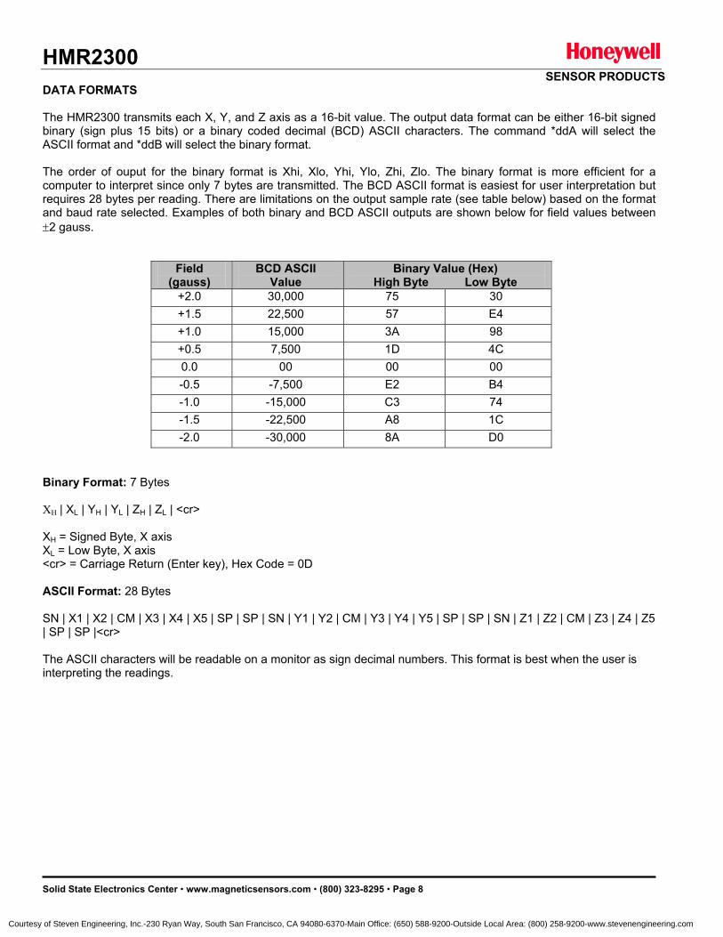
HMR2300 SENSOR PRODUCTS
Solid State Electronics Center • www.magneticsensors.com • (800) 323-8295 • Page 8
DATA FORMATS The HMR2300 transmits each X, Y, and Z axis as a 16-bit value. The output data format can be either 16-bit signed binary (sign plus 15 bits) or a binary coded decimal (BCD) ASCII characters. The command *ddA will select the ASCII format and *ddB will select the binary format. The order of ouput for the binary format is Xhi, Xlo, Yhi, Ylo, Zhi, Zlo. The binary format is more efficient for a computer to interpret since only 7 bytes are transmitted. The BCD ASCII format is easiest for user interpretation but requires 28 bytes per reading. There are limitations on the output sample rate (see table below) based on the format and baud rate selected. Examples of both binary and BCD ASCII outputs are shown below for field values between ±2 gauss.
Field (gauss)
BCD ASCII Value
Binary Value (Hex) High Byte Low Byte
+2.0 30,000 75 30 +1.5 22,500 57 E4 +1.0 15,000 3A 98 +0.5 7,500 1D 4C 0.0 00 00 00 -0.5 -7,500 E2 B4 -1.0 -15,000 C3 74 -1.5 -22,500 A8 1C -2.0 -30,000 8A D0
Binary Format: 7 Bytes XH | XL | YH | YL | ZH | ZL | <cr> XH = Signed Byte, X axis XL = Low Byte, X axis <cr> = Carriage Return (Enter key), Hex Code = 0D ASCII Format: 28 Bytes SN | X1 | X2 | CM | X3 | X4 | X5 | SP | SP | SN | Y1 | Y2 | CM | Y3 | Y4 | Y5 | SP | SP | SN | Z1 | Z2 | CM | Z3 | Z4 | Z5 | SP | SP |<cr> The ASCII characters will be readable on a monitor as sign decimal numbers. This format is best when the user is interpreting the readings.
Courtesy of Steven Engineering, Inc.-230 Ryan Way, South San Francisco, CA 94080-6370-Main Office: (650) 588-9200-Outside Local Area: (800) 258-9200-www.stevenengineering.com
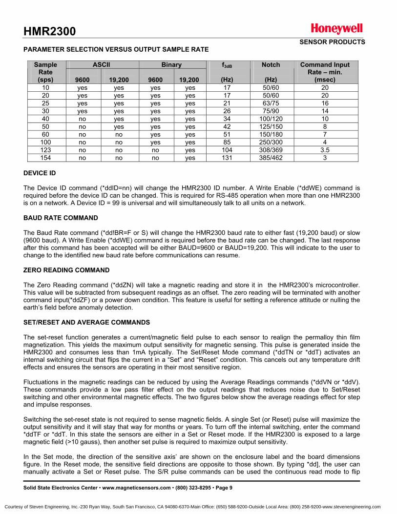
HMR2300 SENSOR PRODUCTS
Solid State Electronics Center • www.magneticsensors.com • (800) 323-8295 • Page 9
PARAMETER SELECTION VERSUS OUTPUT SAMPLE RATE
ASCII Binary Sample Rate (sps)
9600
19,200
9600
19,200
f3dB
(Hz)
Notch
(Hz)
Command Input Rate – min.
(msec) 10 yes yes yes yes 17 50/60 20 20 yes yes yes yes 17 50/60 20 25 yes yes yes yes 21 63/75 16 30 yes yes yes yes 26 75/90 14 40 no yes yes yes 34 100/120 10 50 no yes yes yes 42 125/150 8 60 no no yes yes 51 150/180 7
100 no no yes yes 85 250/300 4 123 no no no yes 104 308/369 3.5 154 no no no yes 131 385/462 3
DEVICE ID The Device ID command (*ddID=nn) will change the HMR2300 ID number. A Write Enable (*ddWE) command is required before the device ID can be changed. This is required for RS-485 operation when more than one HMR2300 is on a network. A Device ID = 99 is universal and will simultaneously talk to all units on a network. BAUD RATE COMMAND The Baud Rate command (*dd!BR=F or S) will change the HMR2300 baud rate to either fast (19,200 baud) or slow (9600 baud). A Write Enable (*ddWE) command is required before the baud rate can be changed. The last response after this command has been accepted will be either BAUD=9600 or BAUD=19,200. This will indicate to the user to change to the identified new baud rate before communications can resume. ZERO READING COMMAND The Zero Reading command (*ddZN) will take a magnetic reading and store it in the HMR2300’s microcontroller. This value will be subtracted from subsequent readings as an offset. The zero reading will be terminated with another command input(*ddZF) or a power down condition. This feature is useful for setting a reference attitude or nulling the earth’s field before anomaly detection. SET/RESET AND AVERAGE COMMANDS The set-reset function generates a current/magnetic field pulse to each sensor to realign the permalloy thin film magnetization. This yields the maximum output sensitivity for magnetic sensing. This pulse is generated inside the HMR2300 and consumes less than 1mA typically. The Set/Reset Mode command (*ddTN or *ddT) activates an internal switching circuit that flips the current in a “Set” and “Reset” condition. This cancels out any temperature drift effects and ensures the sensors are operating in their most sensitive region. Fluctuations in the magnetic readings can be reduced by using the Average Readings commands (*ddVN or *ddV). These commands provide a low pass filter effect on the output readings that reduces noise due to Set/Reset switching and other environmental magnetic effects. The two figures below show the average readings effect for step and impulse responses. Switching the set-reset state is not required to sense magnetic fields. A single Set (or Reset) pulse will maximize the output sensitivity and it will stay that way for months or years. To turn off the internal switching, enter the command *ddTF or *ddT. In this state the sensors are either in a Set or Reset mode. If the HMR2300 is exposed to a large magnetic field (>10 gauss), then another set pulse is required to maximize output sensitivity. In the Set mode, the direction of the sensitive axis’ are shown on the enclosure label and the board dimensions figure. In the Reset mode, the sensitive field directions are opposite to those shown. By typing *dd], the user can manually activate a Set or Reset pulse. The S/R pulse commands can be used the continuous read mode to flip
Courtesy of Steven Engineering, Inc.-230 Ryan Way, South San Francisco, CA 94080-6370-Main Office: (650) 588-9200-Outside Local Area: (800) 258-9200-www.stevenengineering.com
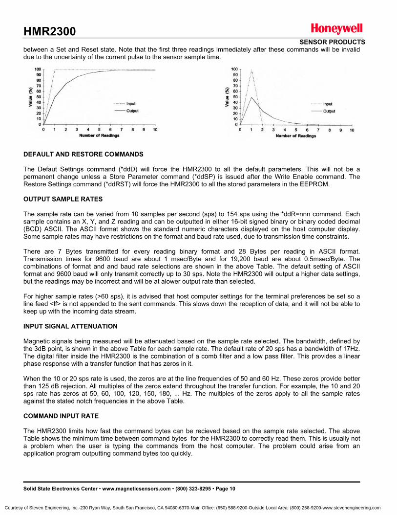
HMR2300 SENSOR PRODUCTS
Solid State Electronics Center • www.magneticsensors.com • (800) 323-8295 • Page 10
between a Set and Reset state. Note that the first three readings immediately after these commands will be invalid due to the uncertainty of the current pulse to the sensor sample time.
DEFAULT AND RESTORE COMMANDS The Defaut Settings command (*ddD) will force the HMR2300 to all the default parameters. This will not be a permanent change unless a Store Parameter command (*ddSP) is issued after the Write Enable command. The Restore Settings command (*ddRST) will force the HMR2300 to all the stored parameters in the EEPROM. OUTPUT SAMPLE RATES The sample rate can be varied from 10 samples per second (sps) to 154 sps using the *ddR=nnn command. Each sample contains an X, Y, and Z reading and can be outputted in either 16-bit signed binary or binary coded decimal (BCD) ASCII. The ASCII format shows the standard numeric characters displayed on the host computer display. Some sample rates may have restrictions on the format and baud rate used, due to transmission time constraints. There are 7 Bytes transmitted for every reading binary format and 28 Bytes per reading in ASCII format. Transmission times for 9600 baud are about 1 msec/Byte and for 19,200 baud are about 0.5msec/Byte. The combinations of format and and baud rate selections are shown in the above Table. The default setting of ASCII format and 9600 baud will only transmit correctly up to 30 sps. Note the HMR2300 will output a higher data settings, but the readings may be incorrect and will be at alower output rate than selected. For higher sample rates (>60 sps), it is advised that host computer settings for the terminal preferences be set so a line feed <lf> is not appended to the sent commands. This slows down the reception of data, and it will not be able to keep up with the incoming data stream. INPUT SIGNAL ATTENUATION Magnetic signals being measured will be attenuated based on the sample rate selected. The bandwidth, defined by the 3dB point, is shown in the above Table for each sample rate. The default rate of 20 sps has a bandwidth of 17Hz. The digital filter inside the HMR2300 is the combination of a comb filter and a low pass filter. This provides a linear phase response with a transfer function that has zeros in it. When the 10 or 20 sps rate is used, the zeros are at the line frequencies of 50 and 60 Hz. These zeros provide better than 125 dB rejection. All multiples of the zeros extend throughout the transfer function. For example, the 10 and 20 sps rate has zeros at 50, 60, 100, 120, 150, 180, ... Hz. The multiples of the zeros apply to all the sample rates against the stated notch frequencies in the above Table. COMMAND INPUT RATE The HMR2300 limits how fast the command bytes can be recieved based on the sample rate selected. The above Table shows the minimum time between command bytes for the HMR2300 to correctly read them. This is usually not a problem when the user is typing the commands from the host computer. The problem could arise from an application program outputting command bytes too quickly.
Courtesy of Steven Engineering, Inc.-230 Ryan Way, South San Francisco, CA 94080-6370-Main Office: (650) 588-9200-Outside Local Area: (800) 258-9200-www.stevenengineering.com
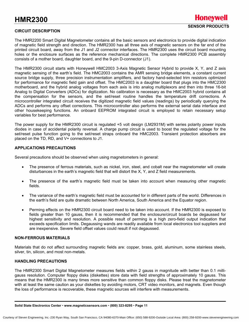
HMR2300 SENSOR PRODUCTS
Solid State Electronics Center • www.magneticsensors.com • (800) 323-8295 • Page 11
CIRCUIT DESCRIPTION The HMR2200 Smart Digital Magnetometer contains all the basic sensors and electronics to provide digital indication of magnetic field strength and direction. The HMR2300 has all three axis of magnetic sensors on the far end of the printed circuit board, away from the J1 and J2 connector interfaces. The HMR2300 uses the circuit board mounting holes or the enclosure surfaces as the reference mechanical directions. The complete HMR2300 PCB assembly consists of a mother board, daughter board, and the 9-pin D-connector (J1). The HMR2300 circuit starts with Honeywell HMC2003 3-Axis Magnetic Sensor Hybrid to provide X, Y, and Z axis magnetic sensing of the earth’s field. The HMC2003 contains the AMR sensing bridge elements, a constant current source bridge supply, three precision instrumentation amplifiers, and factory hand-selected trim resistors optimized for performance for magnetic field gain and offset. The HMC2003 is a daughter board that plugs into the HMC2300 motherboard, and the hybrid analog voltages from each axis is into analog multiplexors and then into three 16-bit Analog to Digital Converters (ADCs) for digitization. No calibration is necessary as the HMC2003 hybrid contains all the compensation for the sensors, and the set/reset routine handles the temperature drift corrections. A microcontroller integrated circuit receives the digitized magnetic field values (readings) by periodically querying the ADCs and performs any offset corrections. This microcontroller also performs the external serial data interface and other housekeeping functions. An onboard EEPROM integrated circuit is employed to retain necessary setup variables for best performance. The power supply for the HMR2300 circuit is regulated +5 volt design (LM2931M) with series polarity power inputs diodes in case of accidental polarity reversal. A charge pump circuit is used to boost the regulated voltage for the set/reset pulse function going to the set/reset straps onboard the HMC2003. Transient protection absorbers are placed on the TD, RD, and V+ connections to J1. APPLICATIONS PRECAUTIONS Several precautions should be observed when using magnetometers in general:
• The presence of ferrous materials, such as nickel, iron, steel, and cobalt near the magnetometer will create disturbances in the earth’s magnetic field that will distort the X, Y, and Z field measurements.
• The presence of the earth’s magnetic field must be taken into account when measuring other magnetic
fields.
• The variance of the earth’s magnetic field must be accounted for in different parts of the world. Differences in the earth’s field are quite dramatic between North America, South America and the Equator region.
• Perming effects on the HMR2300 circuit board need to be taken into account. If the HMR2300 is exposed to
fields greater than 10 gauss, then it is recommended that the enclosure/circuit boards be degaussed for highest sensitivity and resolution. A possible result of perming is a high zero-field output indication that exceeds specification limits. Degaussing wands are readily available from local electronics tool suppliers and are inexpensive. Severe field offset values could result if not degaussed.
NON-FERROUS MATERIALS Materials that do not affect surrounding magnetic fields are: copper, brass, gold, aluminum, some stainless steels, silver, tin, silicon, and most non-metals. HANDLING PRECAUTIONS The HMR2300 Smart Digital Magnetometer measures fields within 2 gauss in magnitude with better than 0.1 milli-gauss resolution. Computer floppy disks (diskettes) store data with field strengths of approximately 10 gauss. This means that the HMR2300 is many times more sensitive than common floppy disks. Please treat the magnetometer with at least the same caution as your diskettes by avoiding motors, CRT video monitors, and magnets. Even though the loss of performance is recoverable, these magnetic sources will interfere with measurements.
Courtesy of Steven Engineering, Inc.-230 Ryan Way, South San Francisco, CA 94080-6370-Main Office: (650) 588-9200-Outside Local Area: (800) 258-9200-www.stevenengineering.com
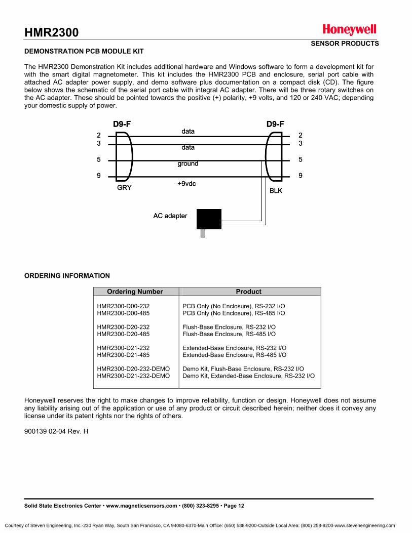
HMR2300 SENSOR PRODUCTS
Solid State Electronics Center • www.magneticsensors.com • (800) 323-8295 • Page 12
DEMONSTRATION PCB MODULE KIT The HMR2300 Demonstration Kit includes additional hardware and Windows software to form a development kit for with the smart digital magnetometer. This kit includes the HMR2300 PCB and enclosure, serial port cable with attached AC adapter power supply, and demo software plus documentation on a compact disk (CD). The figure below shows the schematic of the serial port cable with integral AC adapter. There will be three rotary switches on the AC adapter. These should be pointed towards the positive (+) polarity, +9 volts, and 120 or 240 VAC; depending your domestic supply of power. ORDERING INFORMATION
Ordering Number Product HMR2300-D00-232 HMR2300-D00-485 HMR2300-D20-232 HMR2300-D20-485 HMR2300-D21-232 HMR2300-D21-485 HMR2300-D20-232-DEMO HMR2300-D21-232-DEMO
PCB Only (No Enclosure), RS-232 I/O PCB Only (No Enclosure), RS-485 I/O Flush-Base Enclosure, RS-232 I/O Flush-Base Enclosure, RS-485 I/O
Extended-Base Enclosure, RS-232 I/O Extended-Base Enclosure, RS-485 I/O Demo Kit, Flush-Base Enclosure, RS-232 I/O Demo Kit, Extended-Base Enclosure, RS-232 I/O
Honeywell reserves the right to make changes to improve reliability, function or design. Honeywell does not assume any liability arising out of the application or use of any product or circuit described herein; neither does it convey any license under its patent rights nor the rights of others. 900139 02-04 Rev. H
D9-F D9-F
BLKGRY
23
5
9
23
5
9
data
data
ground
+9vdc
AC adapter
D9-F D9-F
BLKGRY
23
5
9
23
5
9
data
data
ground
+9vdc
AC adapter
Courtesy of Steven Engineering, Inc.-230 Ryan Way, South San Francisco, CA 94080-6370-Main Office: (650) 588-9200-Outside Local Area: (800) 258-9200-www.stevenengineering.com
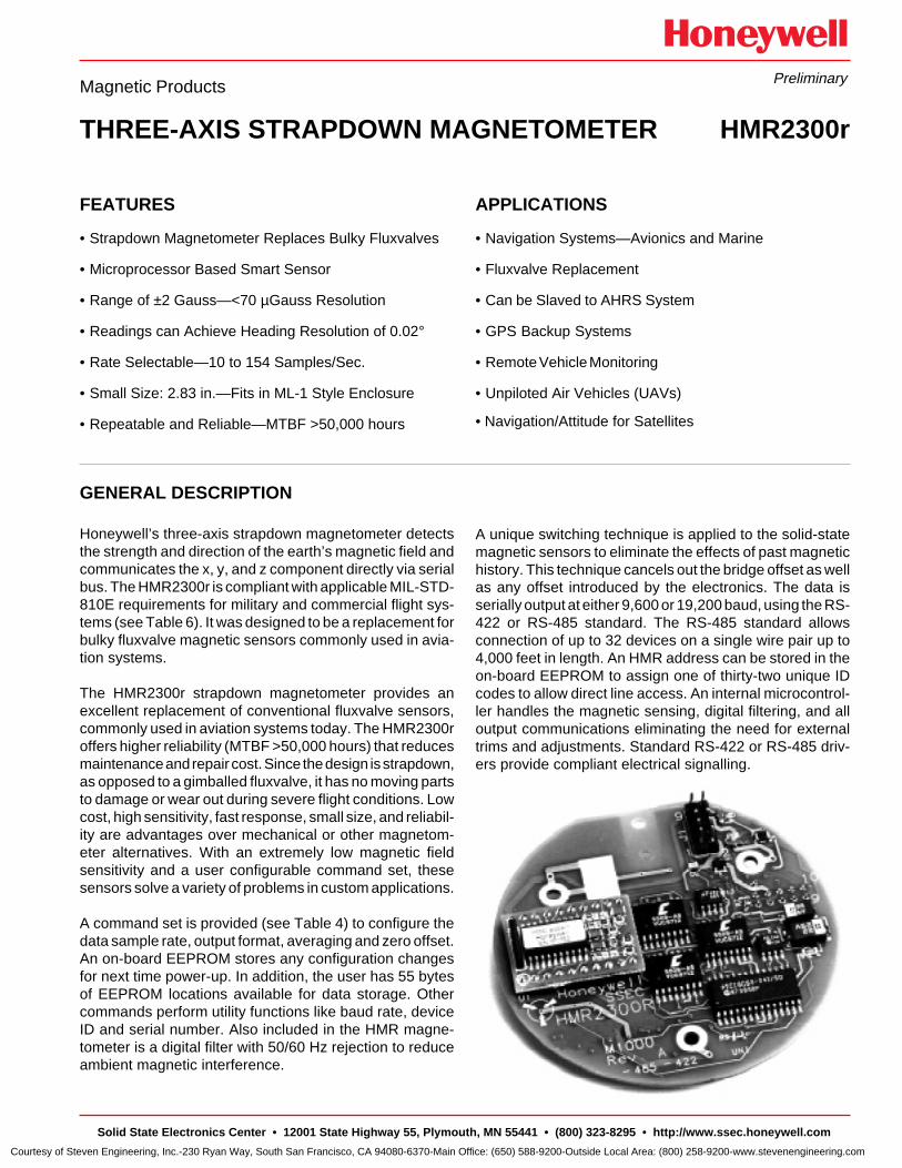
APPLICATIONS
• Navigation Systems—Avionics and Marine
• Fluxvalve Replacement
• Can be Slaved to AHRS System
• GPS Backup Systems
• Remote Vehicle Monitoring
• Unpiloted Air Vehicles (UAVs)
• Navigation/Attitude for Satellites
FEATURES
• Strapdown Magnetometer Replaces Bulky Fluxvalves
• Microprocessor Based Smart Sensor
• Range of ±2 Gauss—<70 µGauss Resolution
• Readings can Achieve Heading Resolution of 0.02°
• Rate Selectable—10 to 154 Samples/Sec.
• Small Size: 2.83 in.—Fits in ML-1 Style Enclosure
• Repeatable and Reliable—MTBF >50,000 hours
Magnetic Products
THREE-AXIS STRAPDOWN MAGNETOMETER HMR2300r
GENERAL DESCRIPTION
Honeywell’s three-axis strapdown magnetometer detectsthe strength and direction of the earth’s magnetic field andcommunicates the x, y, and z component directly via serialbus. The HMR2300r is compliant with applicable MIL-STD-810E requirements for military and commercial flight sys-tems (see Table 6). It was designed to be a replacement forbulky fluxvalve magnetic sensors commonly used in avia-tion systems.
The HMR2300r strapdown magnetometer provides anexcellent replacement of conventional fluxvalve sensors,commonly used in aviation systems today. The HMR2300roffers higher reliability (MTBF >50,000 hours) that reducesmaintenance and repair cost. Since the design is strapdown,as opposed to a gimballed fluxvalve, it has no moving partsto damage or wear out during severe flight conditions. Lowcost, high sensitivity, fast response, small size, and reliabil-ity are advantages over mechanical or other magnetom-eter alternatives. With an extremely low magnetic fieldsensitivity and a user configurable command set, thesesensors solve a variety of problems in custom applications.
A command set is provided (see Table 4) to configure thedata sample rate, output format, averaging and zero offset.An on-board EEPROM stores any configuration changesfor next time power-up. In addition, the user has 55 bytesof EEPROM locations available for data storage. Othercommands perform utility functions like baud rate, deviceID and serial number. Also included in the HMR magne-tometer is a digital filter with 50/60 Hz rejection to reduceambient magnetic interference.
Preliminary
A unique switching technique is applied to the solid-statemagnetic sensors to eliminate the effects of past magnetichistory. This technique cancels out the bridge offset as wellas any offset introduced by the electronics. The data isserially output at either 9,600 or 19,200 baud, using the RS-422 or RS-485 standard. The RS-485 standard allowsconnection of up to 32 devices on a single wire pair up to4,000 feet in length. An HMR address can be stored in theon-board EEPROM to assign one of thirty-two unique IDcodes to allow direct line access. An internal microcontrol-ler handles the magnetic sensing, digital filtering, and alloutput communications eliminating the need for externaltrims and adjustments. Standard RS-422 or RS-485 driv-ers provide compliant electrical signalling.
Solid State Electronics Center • 12001 State Highway 55, Plymouth, MN 55441 • (800) 323-8295 • http://www.ssec.honeywell. com
Courtesy of Steven Engineering, Inc.-230 Ryan Way, South San Francisco, CA 94080-6370-Main Office: (650) 588-9200-Outside Local Area: (800) 258-9200-www.stevenengineering.com
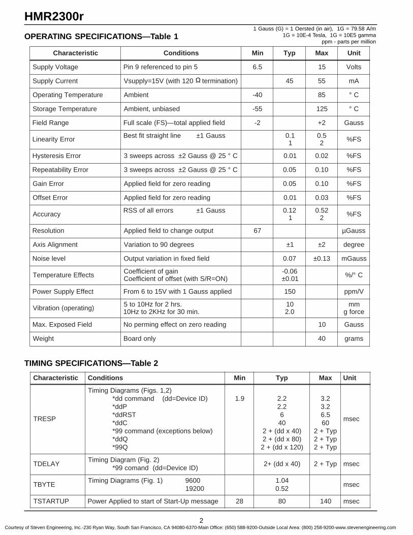
2
HMR2300r
OPERATING SPECIFICATIONS—Table 11 Gauss (G) = 1 Oersted (in air), 1G = 79.58 A/m
1G = 10E-4 Tesla, 1G = 10E5 gammappm - parts per million
TIMING SPECIFICATIONS—Table 2
Ω
citsiretcarahC snoitidnoC niM pyT xaM tinU
egatloVylppuS 5nipotdecnerefer9niP 5.6 51 stloV
tnerruCylppuS )noitanimret021htiw(V51=ylppusV 54 55 Am
erutarepmeTgnitarepO tneibmA 04- 58 C°
erutarepmeTegarotS desaibnu,tneibmA 55- 521 C°
egnaRdleiF dleifdeilppalatot—)SF(elacslluF 2- 2+ ssuaG
rorrEytiraeniL ssuaG1±enilthgiartstiftseB 1.01
5.02 SF%
rorrEsiseretsyH C°52@ssuaG2±ssorcaspeews3 10.0 20.0 SF%
rorrEytilibataepeR C°52@ssuaG2±ssorcaspeews3 50.0 01.0 SF%
rorrEniaG gnidaerorezrofdleifdeilppA 50.0 01.0 SF%
rorrEtesffO gnidaerorezrofdleifdeilppA 10.0 30.0 SF%
ycaruccA ssuaG1±srorrellafoSSR 21.01
25.02 SF%
noituloseR tuptuoegnahcotdleifdeilppA 76 µ ssuaG
tnemngilAsixA seerged09otnoitairaV 1± 2± eerged
levelesioN dleifdexifninoitairavtuptuO 70.0 31.0± ssuaGm
stceffEerutarepmeT niagfotneiciffeoC)NO=R/Shtiw(tesffofotneiciffeoC
60.0-10.0± C°/%
tceffEylppuSrewoP deilppassuaG1htiwV51ot6morF 051 V/mpp
)gnitarepo(noitarbiV .srh2rofzH01ot5.nim03rofzHK2otzH01
010.2
mmecrofg
dleiFdesopxE.xaM gnidaeroreznotceffegnimrepoN 01 ssuaG
thgieW ylnodraoB 04 smarg
citsiretcarahC snoitidnoC niM pyT xaM tinU
PSERT
)2,1.sgiF(smargaiDgnimiT)DIeciveD=dd(dnammocdd*
Pdd*TSRdd*
Cdd*)wolebsnoitpecxe(dnammoc99*
Qdd*Q99*
9.1 2.22.2
604
)04xdd(+2)08xdd(+2)021xdd(+2
2.32.35.606
pyT+2pyT+2pyT+2
cesm
YALEDT)2.giF(margaiDgnimiT
)DIeciveD=dd(dnamoc99*)04xdd(+2 pyT+2 cesm
ETYBT0069)1.giF(smargaiDgnimiT
0029140.125.0
cesm
PUTRATST egassempU-tratSfotratsotdeilppArewoP 82 08 041 cesm
Courtesy of Steven Engineering, Inc.-230 Ryan Way, South San Francisco, CA 94080-6370-Main Office: (650) 588-9200-Outside Local Area: (800) 258-9200-www.stevenengineering.com
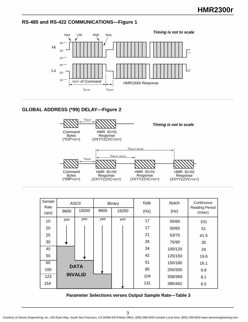
3
HMR2300r
Timing is not to scale
RS-485 and RS-422 COMMUNICATIONS—Figure 1
GLOBAL ADDRESS (*99) DELAY—Figure 2
Timing is not to scale
Parameter Selections verses Output Sample Rate—Table 3
Lo
Hi
<cr> of Command HMR2300r Response
4V
2V
1V
4V
2V
1V
TBYTE TRESP
...
...
Start LSB MSB Stop
TRESP
AAAAAA
AAACommand
Bytes(*01P<cr>)
HMR ID=01Response
(XXYYZZVC<cr>)
AAAAAA
CommandBytes
(*99P<cr>)
HMR ID=00Response
(XXYYZZVC<cr>)
HMR ID=02Response
(XXYYZZVC<cr>)
TDELAY (ID=01)
AAAAAA
AAAAAA
AAAAAA
HMR ID=01Response
(XXYYZZVC<cr>)
TDELAY (ID=02)
TRESP
Continuous Reading Period
(msec)
101
51
41.5
35
24
19.6
16.1
9.8
8.1
6.5
17
17
21
26
34
42
51
85
104
131
50/60
50/60
63/75
75/90
100/120
125/150
150/180
250/300
308/369
385/462
Sample
Rate
(sps) 9600
yes
19200
yes
9600
yes
19200
yes
ASCII Notch
(Hz)
f3dB
(Hz)
10
20
25
30
40
50
60
100
123
154
Binary
DATA
INVALID
Courtesy of Steven Engineering, Inc.-230 Ryan Way, South San Francisco, CA 94080-6370-Main Office: (650) 588-9200-Outside Local Area: (800) 258-9200-www.stevenengineering.com
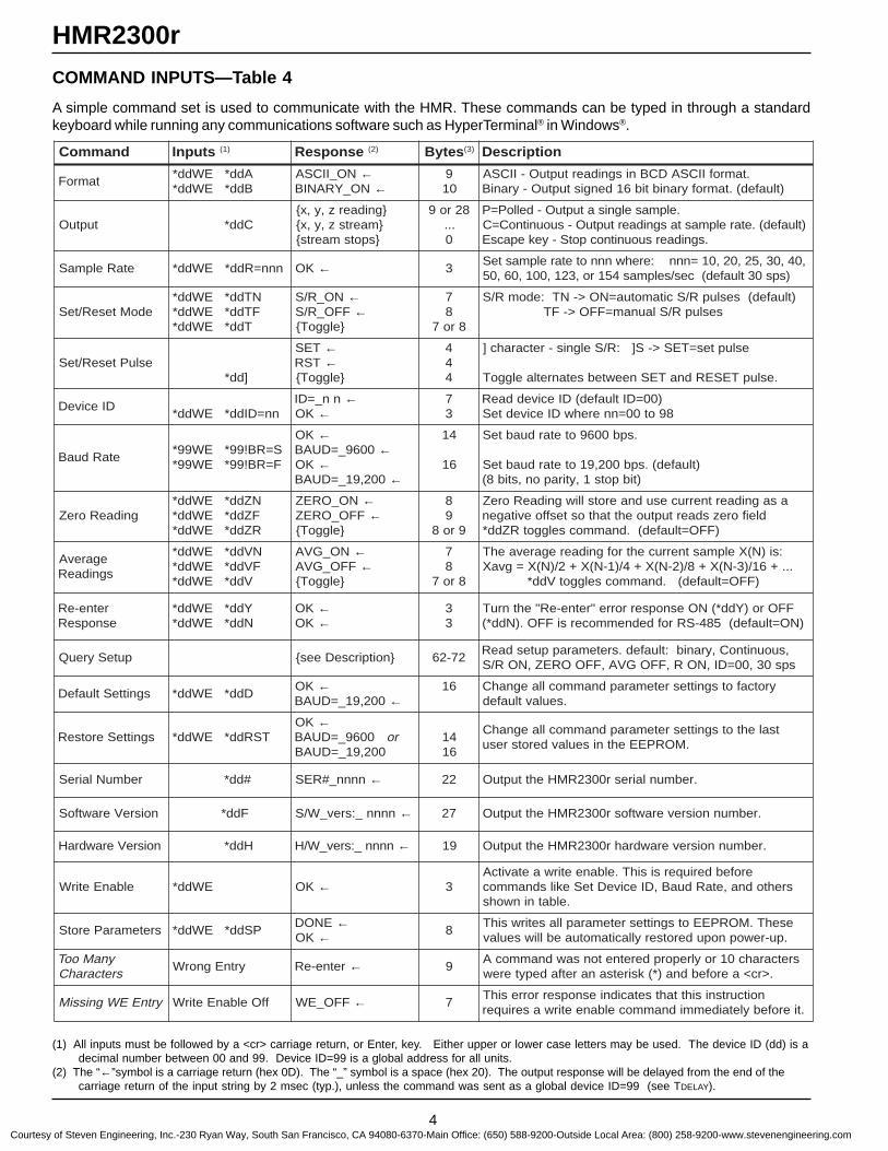
4
HMR2300r
(1) All inputs must be followed by a <cr> carriage return, or Enter, key. Either upper or lower case letters may be used. The device ID (dd) is adecimal number between 00 and 99. Device ID=99 is a global address for all units.
(2) The “←”symbol is a carriage return (hex 0D). The “_” symbol is a space (hex 20). The output response will be delayed from the end of thecarriage return of the input string by 2 msec (typ.), unless the command was sent as a global device ID=99 (see TDELAY).
COMMAND INPUTS—Table 4
A simple command set is used to communicate with the HMR. These commands can be typed in through a standardkeyboard while running any communications software such as HyperTerminal® in Windows®.
dnammoC stupnI )1( esnopseR )2( setyB )3( noitpircseD
tamroFAdd*EWdd*Bdd*EWdd*
NO_IICSA ←NO_YRANIB ←
901
.tamrofIICSADCBnisgnidaertuptuO-IICSA)tluafed(.tamrofyranibtib61dengistuptuO-yraniB
tuptuO Cdd*gnidaerz,y,x
maertsz,y,xspotsmaerts
82ro9...
0
.elpmaselgnisatuptuO-delloP=P)tluafed(.etarelpmastasgnidaertuptuO-suounitnoC=C
.sgnidaersuounitnocpotS-yekepacsE
etaRelpmaS nnn=Rdd*EWdd* KO ← 3,04,03,52,02,01=nnn:erehwnnnotetarelpmasteS
)sps03tluafed(ces/selpmas451ro,321,001,06,05
edoMteseR/teSNTdd*EWdd*FTdd*EWdd*
Tdd*EWdd*
NO_R/S ←FFO_R/S ←elggoT
78
8ro7
)tluafed(seslupR/Scitamotua=NO>-NT:edomR/SseslupR/Slaunam=FFO>-FT
esluPteseR/teS]dd*
TES ←TSR ←
elggoT
444
esluptes=TES>-S]:R/Selgnis-retcarahc]
.eslupTESERdnaTESneewtebsetanretlaelggoT
DIeciveDnn=DIdd*EWdd*
nn_=DI ←KO ←
73
)00=DItluafed(DIeciveddaeR89ot00=nnerehwDIecivedteS
etaRduaBS=RB!99*EW99*F=RB!99*EW99*
KO ←0069_=DUAB ←
KO ←002,91_=DUAB ←
41
61
.spb0069otetarduabteS
)tluafed(.spb002,91otetarduabteS)tibpots1,ytirapon,stib8(
gnidaeRoreZNZdd*EWdd*FZdd*EWdd*RZdd*EWdd*
NO_OREZ ←FFO_OREZ ←
elggoT
89
9ro8
asagnidaertnerrucesudnaerotslliwgnidaeRoreZdleiforezsdaertuptuoehttahtostesffoevitagen
)FFO=tluafed(.dnammocselggotRZdd*
egarevAsgnidaeR
NVdd*EWdd*FVdd*EWdd*
Vdd*EWdd*
NO_GVA ←FFO_GVA ←
elggoT
78
8ro7
:si)N(XelpmastnerrucehtrofgnidaeregarevaehT...+61/)3-N(X+8/)2-N(X+4/)1-N(X+2/)N(X=gvaX
)FFO=tluafed(.dnammocselggotVdd*
retne-eResnopseR
Ydd*EWdd*Ndd*EWdd*
KO ←KO ←
33
FFOro)Ydd*(NOesnopserrorre"retne-eR"ehtnruT)NO=tluafed(584-SRrofdednemmocersiFFO.)Ndd*(
puteSyreuQ ees noitpircseD 27-26,suounitnoC,yranib:tluafed.sretemarapputesdaeRsps03,00=DI,NOR,FFOGVA,FFOOREZ,NOR/S
sgnitteStluafeD Ddd*EWdd*KO ←
002,91_=DUAB ←61 yrotcafotsgnittesretemarapdnammocllaegnahC
.seulavtluafed
sgnitteSerotseR TSRdd*EWdd*KO ←
0069_=DUAB ro002,91_=DUAB
4161
tsalehtotsgnittesretemarapdnammocllaegnahC.MORPEEehtniseulavderotsresu
rebmuNlaireS #dd* nnnn_#RES ← 22 .rebmunlairesr0032RMHehttuptuO
noisreVerawtfoS Fdd* nnnn_:srev_W/S ← 72 .rebmunnoisreverawtfosr0032RMHehttuptuO
noisreVerawdraH Hdd* nnnn_:srev_W/H ← 91 .rebmunnoisreverawdrahr0032RMHehttuptuO
elbanEetirW EWdd* KO ← 3erofebderiuqersisihT.elbaneetirwaetavitcA
srehtodna,etaRduaB,DIeciveDteSekilsdnammoc.elbatninwohs
sretemaraPerotS PSdd*EWdd*ENOD ←
KO ← 8esehT.MORPEEotsgnittesretemarapllasetirwsihT.pu-rewopnopuderotseryllacitamotuaeblliwseulav
ynaMooTsretcarahC
yrtnEgnorW retne-eR ← 9sretcarahc01roylreporpderetnetonsawdnammocA
.>rc<aerofebdna)*(ksiretsanaretfadepyterew
yrtnEEWgnissiM ffOelbanEetirW FFO_EW ← 7noitcurtsnisihttahtsetacidniesnopserrorresihT
.tierofebyletaidemmidnammocelbaneetirwaseriuqer
Courtesy of Steven Engineering, Inc.-230 Ryan Way, South San Francisco, CA 94080-6370-Main Office: (650) 588-9200-Outside Local Area: (800) 258-9200-www.stevenengineering.com
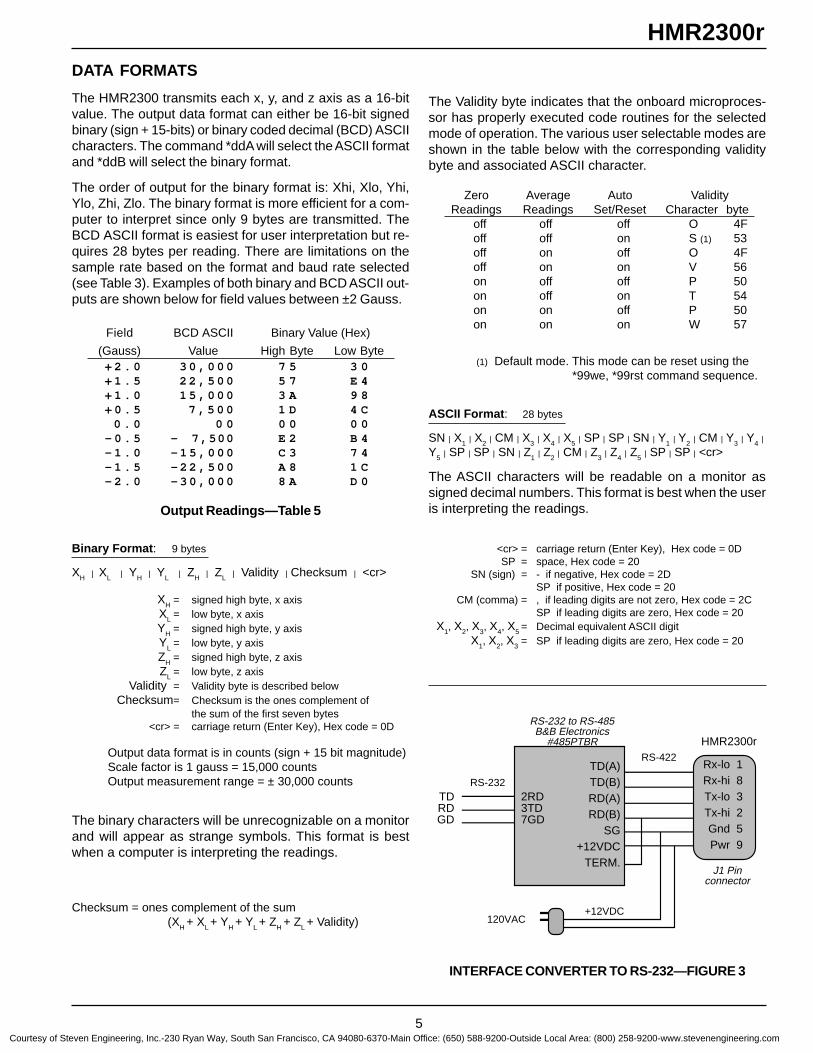
5
HMR2300rDATA FORMATS
The HMR2300 transmits each x, y, and z axis as a 16-bitvalue. The output data format can either be 16-bit signedbinary (sign + 15-bits) or binary coded decimal (BCD) ASCIIcharacters. The command *ddA will select the ASCII formatand *ddB will select the binary format.
The order of output for the binary format is: Xhi, Xlo, Yhi,Ylo, Zhi, Zlo. The binary format is more efficient for a com-puter to interpret since only 9 bytes are transmitted. TheBCD ASCII format is easiest for user interpretation but re-quires 28 bytes per reading. There are limitations on thesample rate based on the format and baud rate selected(see Table 3). Examples of both binary and BCD ASCII out-puts are shown below for field values between ±2 Gauss.
Field BCD ASCII Binary Value (Hex)
(Gauss) Value High Byte Low Byte+ 2 . 0 3 0 , 0 0 0 7 5 3 0+ 1 . 5 2 2 , 5 0 0 5 7 E 4+ 1 . 0 1 5 , 0 0 0 3 A 9 8+ 0 . 5 7 , 5 0 0 1 D 4 C
0 . 0 0 0 0 0 0 0- 0 . 5 - 7 ,500 E 2 B 4- 1 . 0 - 1 5 , 0 0 0 C 3 7 4- 1 . 5 - 2 2 , 5 0 0 A 8 1 C- 2 . 0 - 3 0 , 0 0 0 8 A D 0
Output Readings—Table 5
Binary Format : 9 bytes
XH | XL | YH | YL | ZH | ZL | Validity | Checksum | <cr>
XH = signed high byte, x axisXL = low byte, x axisYH = signed high byte, y axisYL = low byte, y axisZH = signed high byte, z axisZL = low byte, z axis
Validity = Validity byte is described belowChecksum= Checksum is the ones complement of
the sum of the first seven bytes<cr> = carriage return (Enter Key), Hex code = 0D
Output data format is in counts (sign + 15 bit magnitude)Scale factor is 1 gauss = 15,000 countsOutput measurement range = ± 30,000 counts
The binary characters will be unrecognizable on a monitorand will appear as strange symbols. This format is bestwhen a computer is interpreting the readings.
Checksum = ones complement of the sum(XH + XL + YH + YL + ZH + ZL + Validity)
The Validity byte indicates that the onboard microproces-sor has properly executed code routines for the selectedmode of operation. The various user selectable modes areshown in the table below with the corresponding validitybyte and associated ASCII character.
Zero Average Auto ValidityReadings Readings Set/Reset Character byte
off off off O 4Foff off on S (1) 53off on off O 4Foff on on V 56on off off P 50on off on T 54on on off P 50on on on W 57
(1) Default mode. This mode can be reset using the*99we, *99rst command sequence.
ASCII Format : 28 bytes
SN | X1 | X2 | CM | X3 | X4 | X5 | SP | SP | SN | Y1 | Y2 | CM | Y3 | Y4 |Y5 | SP | SP | SN | Z1 | Z2 | CM | Z3 | Z4 | Z5 | SP | SP | <cr>
The ASCII characters will be readable on a monitor assigned decimal numbers. This format is best when the useris interpreting the readings.
<cr> = carriage return (Enter Key), Hex code = 0DSP = space, Hex code = 20
SN (sign) = - if negative, Hex code = 2DSP if positive, Hex code = 20
CM (comma) = , if leading digits are not zero, Hex code = 2CSP if leading digits are zero, Hex code = 20
X1, X2, X3, X4, X5 = Decimal equivalent ASCII digitX1, X2, X3 = SP if leading digits are zero, Hex code = 20
INTERFACE CONVERTER TO RS-232—FIGURE 3
HMR2300r
TD(A)TD(B)RD(A)RD(B)
SG+12VDC
TERM.
RS-232 to RS-485B&B Electronics
#485PTBR
RS-422 Rx-lo 1
Rx-hi 8Tx-lo 3Tx-hi 2 Gnd 5 Pwr 9
J1 Pinconnector
+12VDC120VAC
2RD3TD7GD
TDRDGD
RS-232
Courtesy of Steven Engineering, Inc.-230 Ryan Way, South San Francisco, CA 94080-6370-Main Office: (650) 588-9200-Outside Local Area: (800) 258-9200-www.stevenengineering.com
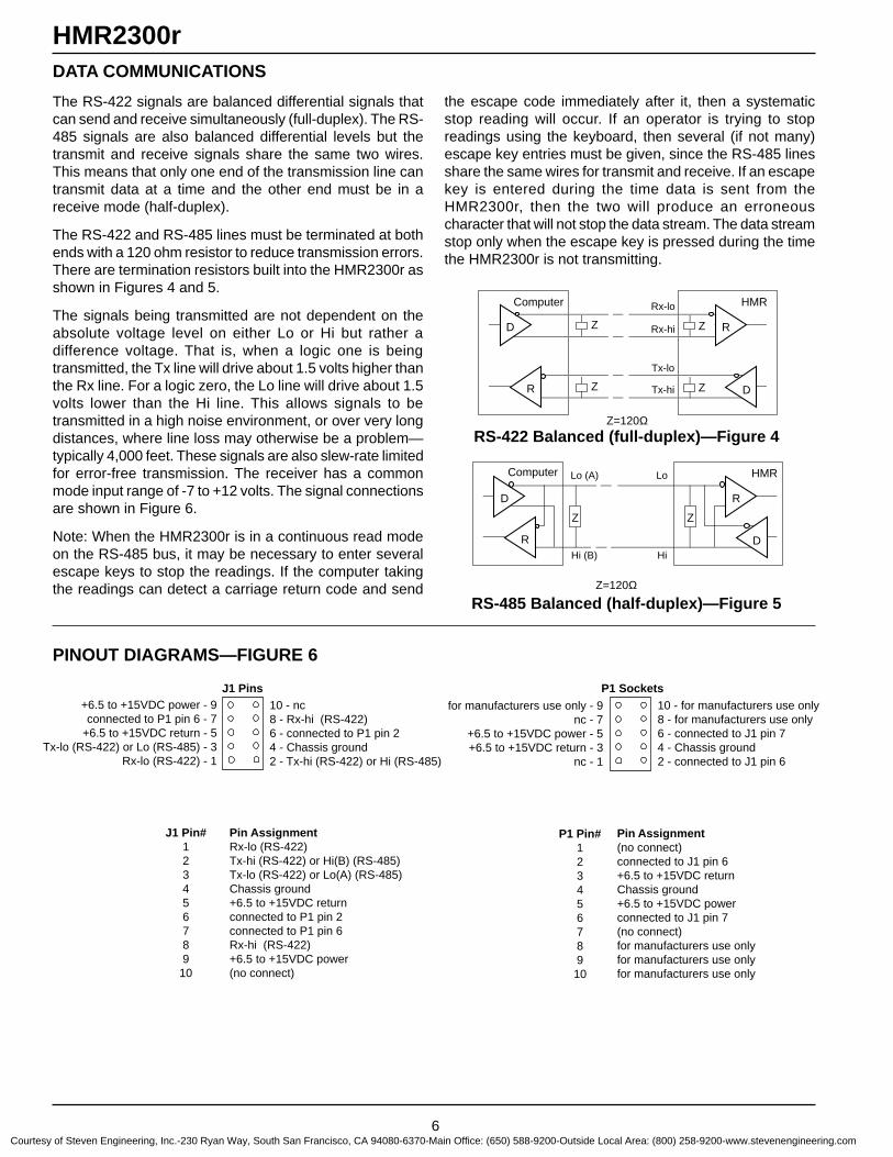
6
HMR2300rDATA COMMUNICATIONS
The RS-422 signals are balanced differential signals thatcan send and receive simultaneously (full-duplex). The RS-485 signals are also balanced differential levels but thetransmit and receive signals share the same two wires.This means that only one end of the transmission line cantransmit data at a time and the other end must be in areceive mode (half-duplex).
The RS-422 and RS-485 lines must be terminated at bothends with a 120 ohm resistor to reduce transmission errors.There are termination resistors built into the HMR2300r asshown in Figures 4 and 5.
The signals being transmitted are not dependent on theabsolute voltage level on either Lo or Hi but rather adifference voltage. That is, when a logic one is beingtransmitted, the Tx line will drive about 1.5 volts higher thanthe Rx line. For a logic zero, the Lo line will drive about 1.5volts lower than the Hi line. This allows signals to betransmitted in a high noise environment, or over very longdistances, where line loss may otherwise be a problem—typically 4,000 feet. These signals are also slew-rate limitedfor error-free transmission. The receiver has a commonmode input range of -7 to +12 volts. The signal connectionsare shown in Figure 6.
Note: When the HMR2300r is in a continuous read modeon the RS-485 bus, it may be necessary to enter severalescape keys to stop the readings. If the computer takingthe readings can detect a carriage return code and send
the escape code immediately after it, then a systematicstop reading will occur. If an operator is trying to stopreadings using the keyboard, then several (if not many)escape key entries must be given, since the RS-485 linesshare the same wires for transmit and receive. If an escapekey is entered during the time data is sent from theHMR2300r, then the two will produce an erroneouscharacter that will not stop the data stream. The data streamstop only when the escape key is pressed during the timethe HMR2300r is not transmitting.
PINOUT DIAGRAMS—FIGURE 6
RS-422 Balanced (full-duplex)—Figure 4
RS-485 Balanced (half-duplex)—Figure 5
+6.5 to +15VDC power - 9connected to P1 pin 6 - 7
+6.5 to +15VDC return - 5Tx-lo (RS-422) or Lo (RS-485) - 3
Rx-lo (RS-422) - 1
10 - nc8 - Rx-hi (RS-422)6 - connected to P1 pin 24 - Chassis ground2 - Tx-hi (RS-422) or Hi (RS-485)
J1 Pinsfor manufacturers use only - 9
nc - 7+6.5 to +15VDC power - 5+6.5 to +15VDC return - 3
nc - 1
10 - for manufacturers use only8 - for manufacturers use only6 - connected to J1 pin 74 - Chassis ground2 - connected to J1 pin 6
P1 Sockets
Pin Assignment(no connect)connected to J1 pin 6+6.5 to +15VDC returnChassis ground+6.5 to +15VDC powerconnected to J1 pin 7(no connect)for manufacturers use onlyfor manufacturers use onlyfor manufacturers use only
P1 Pin#12345678910
Pin AssignmentRx-lo (RS-422)Tx-hi (RS-422) or Hi(B) (RS-485)Tx-lo (RS-422) or Lo(A) (RS-485)Chassis ground+6.5 to +15VDC returnconnected to P1 pin 2connected to P1 pin 6Rx-hi (RS-422)+6.5 to +15VDC power(no connect)
J1 Pin#123456789
10
HMR
D
DR
R
Computer Lo
Hi
Z
Z=120Ω
Lo (A)
Hi (B)
Z
HMR
D
DR
R
Computer Rx-lo
Z
Z=120Ω
ZZ Rx-hi
Tx-lo
Tx-hiZ
Courtesy of Steven Engineering, Inc.-230 Ryan Way, South San Francisco, CA 94080-6370-Main Office: (650) 588-9200-Outside Local Area: (800) 258-9200-www.stevenengineering.com

7
HMR2300rBOARD DIMENSIONS—FIGURE 7
All Dimensions in inches
P1
TOP-SIDE OF CIRCUIT BOARD ASSEMBLY
BACK-SIDE OF CIRCUIT BOARD ASSEMBLY
P1SAMTEC SSQ-105-01-S-D10-SOCKET HEADER
AAAAAAAAAAAAAAAAAAAAAAAAAAAAAA
AAAAAAAAAA
J1SAMTEC TSW-105-06-T-D10-PIN HEADER
+Z axis(Down)
.060
.39 MAXCOMPONENTHEIGHT
.12 MAXCOMPONENTHEIGHT
+X(FWD)
+Y
J1
Courtesy of Steven Engineering, Inc.-230 Ryan Way, South San Francisco, CA 94080-6370-Main Office: (650) 588-9200-Outside Local Area: (800) 258-9200-www.stevenengineering.com
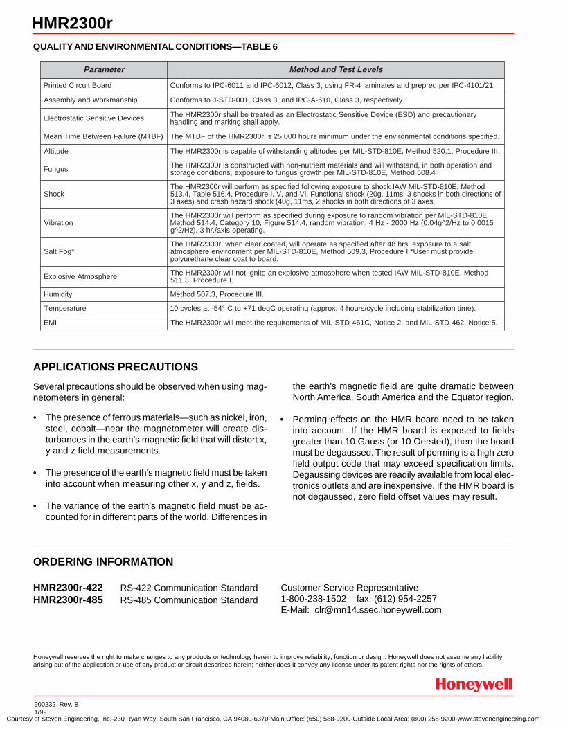
900232 Rev. B1/99
Honeywell reserves the right to make changes to any products or technology herein to improve reliability, function or design. Honeywell does not assume any liabilityarising out of the application or use of any product or circuit described herein; neither does it convey any license under its patent rights nor the rights of others.
HMR2300r-422 RS-422 Communication StandardHMR2300r-485 RS-485 Communication Standard
Several precautions should be observed when using mag-netometers in general:
• The presence of ferrous materials—such as nickel, iron,steel, cobalt—near the magnetometer will create dis-turbances in the earth’s magnetic field that will distort x,y and z field measurements.
• The presence of the earth’s magnetic field must be takeninto account when measuring other x, y and z, fields.
• The variance of the earth’s magnetic field must be ac-counted for in different parts of the world. Differences in
ORDERING INFORMATION
the earth’s magnetic field are quite dramatic betweenNorth America, South America and the Equator region.
• Perming effects on the HMR board need to be takeninto account. If the HMR board is exposed to fieldsgreater than 10 Gauss (or 10 Oersted), then the boardmust be degaussed. The result of perming is a high zerofield output code that may exceed specification limits.Degaussing devices are readily available from local elec-tronics outlets and are inexpensive. If the HMR board isnot degaussed, zero field offset values may result.
QUALITY AND ENVIRONMENTAL CONDITIONS—TABLE 6
HMR2300r
Customer Service Representative1-800-238-1502 fax: (612) 954-2257E-Mail: [email protected]
APPLICATIONS PRECAUTIONS
retemaraP sleveLtseTdnadohteM
draoBtiucriCdetnirP .12/1014-CPIrepgerperpdnasetanimal4-RFgnisu,3ssalC,2106-CPIdna1106-CPIotsmrofnoC
pihsnamkroWdnaylbmessA .ylevitcepser,3ssalC,016-A-CPIdna,3ssalC,100-DTS-JotsmrofnoC
seciveDevitisneScitatsortcelE yranoituacerpdna)DSE(eciveDevitisneScitatsortcelEnasadetaertebllahsr0032RMHehT.ylppallahsgnikramdnagnildnah
)FBTM(eruliaFneewteBemiTnaeM .deificepssnoitidnoclatnemnorivneehtrednumuminimsruoh000,52sir0032RMHehtfoFBTMehT
edutitlA .IIIerudecorP,1.025dohteM,E018-DTS-LIMrepsedutitlagnidnatshtiwfoelbapacsir0032RMHehT
sugnuF dnanoitarepohtobni,dnatshtiwlliwdnaslairetamtneirtun-nonhtiwdetcurtsnocsir0032RMHehT4.805dohteM,E018-DTS-LIMrephtworgsugnufoterusopxe,snoitidnocegarots
kcohSdohteM,E018-DTS-LIMWAIkcohsoterusopxegniwollofdeificepssamrofreplliwr0032RMHehT
fosnoitceridhtobniskcohs3,sm11,g02(kcohslanoitcnuF.IVdna,V,IerudecorP,4.615elbaT,4.315.sexa3fosnoitceridhtobniskcohs2,sm11,g04(kcohsdrazahhsarcdna)sexa3
noitarbiVE018-DTS-LIMrepnoitarbivmodnaroterusopxegniruddeificepssamrofreplliwr0032RMHehT
5100.0otzH/2^g40.0(zH0002-zH4,noitarbivmodnar,4.415erugiF,01yrogetaC,4.415dohteM.gnitareposixa/.rh3,)zH/2^g
*goFtlaStlasaoterusopxe.srh84retfadeificepssaetarepolliw,detaocraelcnehw,r0032RMHehTedivorptsumresU*IerudecorP,3.905dohteM,E018-DTS-LIMreptnemnorivneerehpsomta
.draobottaocraelcenahteruylop
erehpsomtAevisolpxE dohteM,E018-DTS-LIMWAIdetsetnehwerehpsomtaevisolpxenaetingitonlliwr0032RMHehT.IerudecorP,3.115
ytidimuH .IIIerudecorP,3.705dohteM
erutarepmeT .)emitnoitazilibatsgnidulcnielcyc/sruoh4.xorppa(gnitarepoCged17+otC°45-taselcyc01
IME .5ecitoN,264-DTS-LIMdna,2ecitoN,C164-DTS-LIMfostnemeriuqerehtteemlliwr0032RMHehT
Courtesy of Steven Engineering, Inc.-230 Ryan Way, South San Francisco, CA 94080-6370-Main Office: (650) 588-9200-Outside Local Area: (800) 258-9200-www.stevenengineering.com

FEATURES AND BENEFITS
SENSOR PRODUCTS
Digital Compass ModuleHMR3000
APPLICATIONS
lectronic compass module thatprovides heading, pitch and rolloutput for navigation and guid-
ance systems. Honeywell’ssolid state magnetoresistive
sensors make this strapdowncompass both rugged and reli-
able. This compass providesfast response time up to 20
Hertz and high heading accu-racy of 0.5° with 0.1° resolution.
E
Fast Response Time Built with solid state magnetic sensors and no moving parts improves response time,
allowing faster updates compared to gimballed fluxgates.
Small Size Available as a circuit board 1.2 x 2.95 inches, weighing less than one ounce, or in an
aluminum enclosure.
Low Power Operates with less than 35 mA, allowing for long operation with a battery.
High Accuracy Accuracy better than 0.5° with 0.1° resolution for critical positioning applications.
Wide Tilt Range Tilt range of ±40° for both the roll and pitch allows operation for most applications.
Hard Iron Compensation Calibration routines to compensate for distortion due to nearby ferrous objects and
stray fields, such as vehicles.
User Configurable Features User settings of baud rate, update rate, output format, units, filter settings, deviation
angles, alarms and warnings are stored internally in non-volitile memory.
Oceanographic– Marine Compassing– Positioning of Buoys,
Underwater Structures
Drilling– Down Hole and Directional
Attitude Reference
Heading– Navigation of Unmanned
Vehicles– Avionic Compassing
Integration with GPS– Dead Reckoning
Satellite Antenna Positioning
Laser Range Finders– Surveying Applications
Courtesy of Steven Engineering, Inc.-230 Ryan Way, South San Francisco, CA 94080-6370-Main Office: (650) 588-9200-Outside Local Area: (800) 258-9200-www.stevenengineering.com
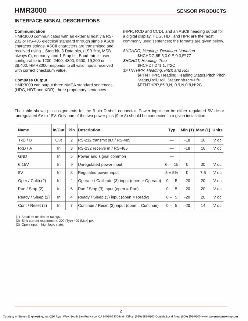
2
HMR3000 SENSOR PRODUCTS
The table shows pin assignments for the 9-pin D-shell connector. Power input can be either regulated 5V dc or unregulated 6V to 15V. Only one of the two power pins (9 or 8) should be connected in a given installation.
INTERFACE SIGNAL DESCRIPTIONS
(1) Absolute maximum ratings.(2) Sink current requirement; 200 (Typ) 400 (Max) µA.(3) Open input = high logic state.
CommunicationHMR3000 communicates with an external host via RS-232 or RS-485 electrical standard through simple ASCIIcharacter strings. ASCII characters are transmitted andreceived using 1 Start bit, 8 Data bits, (LSB first, MSBalways 0), no parity, and 1 Stop bit. Baud rate is userconfigurable to 1200, 2400, 4800, 9600, 19,200 or38,400. HMR3000 responds to all valid inputs receivedwith correct checksum value.
Compass OutputHMR3000 can output three NMEA standard sentences,(HDG, HDT and XDR), three proprietary sentences
(HPR, RCD and CCD), and an ASCII heading output fora digital display. HDG, HDT and HPR are the mostcommonly used sentences; the formats are given below.
$HCHDG, Heading, Deviation, Variation$HCHDG,85.5,0.0,E,0.0,E*77
$HCHDT, Heading, True$HCHDT,271.1,T*2C
$PTNTHPR, Heading, Pitch and Roll$PTNTHPR, Heading,Heading Status,Pitch,PitchStatus,Roll,Roll Status*hh<cr><lf>$PTNTHPR,85.9,N,-0.9,N,0.8,N*2C
emaN tuO/nI niP noitpircseD pyT )1(niM )1(xaM stinU
B/DxT tuO 2 584-SR/tuotimsnart232-SR — 81- 81 cdV
A/DxR nI 3 584-SR/nieviecer232-SR — 81- 81 cdV
DNG nI 5 nommoclangisdnarewoP —
V51-6 nI 9 tupnirewopdetalugernU 51–6 0 03 cdV
V5 nI 8 tupnirewopdetalugeR %5±5 0 5.7 cdV
)2(bilaC/repO nI 1 )etarepO=nepo(tupni)3(etarbilaC/etarepO 5–0 02- 02 cdV
)2(potS/nuR nI 6 )nuR=nepo(tupni)3(potS/nuR 5–0 02- 02 cdV
)2(peelS/ydaeR nI 4 )ydaeR=nepo(tupni)3(peelS/ydaeR 5–0 02- 02 cdV
)2(teseR/tnoC nI 7 )eunitnoC=nepo(tupni)3(teseR/eunitnoC 5–0 02- 41 cdV
Courtesy of Steven Engineering, Inc.-230 Ryan Way, South San Francisco, CA 94080-6370-Main Office: (650) 588-9200-Outside Local Area: (800) 258-9200-www.stevenengineering.com
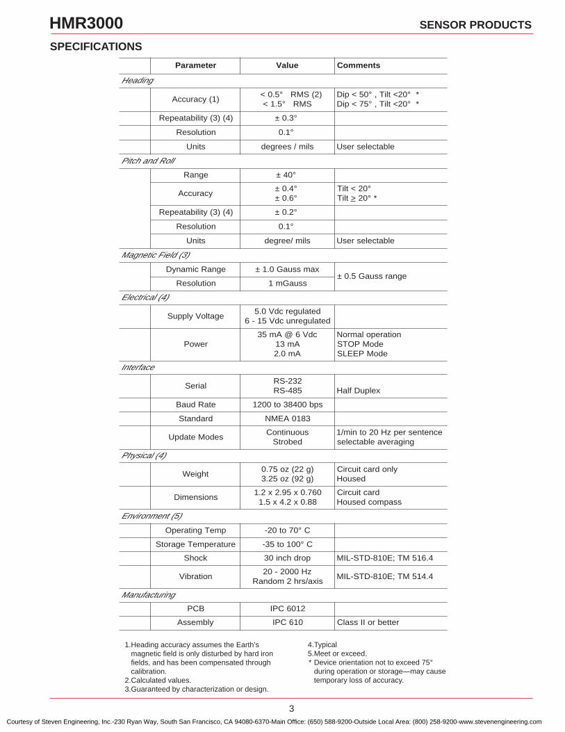
3
HMR3000 SENSOR PRODUCTS
SPECIFICATIONS
4.Typical5.Meet or exceed.* Device orientation not to exceed 75°
during operation or storage—may causetemporary loss of accuracy.
retemaraP eulaV stnemmoC
gnidaeH
)1(ycaruccA)2(SMR°5.0<
SMR°5.1<°02<tliT,°05<piD *°02<tliT,°57<piD *
)4()3(ytilibataepeR °3.0±
noituloseR °1.0
stinU slim/seerged elbatcelesresU
lloRdnahctiP
egnaR °04±
ycaruccA°4.0±°6.0±
°02<tliTtliT > °02 *
)4()3(ytilibataepeR °2.0±
noituloseR °1.0
stinU slim/eerged elbatcelesresU
)3(dleiFcitengaM
egnaRcimanyD xamssuaG0.1±egnarssuaG5.0±
noituloseR ssuaGm1
)4(lacirtcelE
egatloVylppuSdetalugercdV0.5
detalugernucdV51-6
rewoPcdV6@Am53
Am31Am0.2
noitarepolamroNedoMPOTSedoMPEELS
ecafretnI
laireS232-SR584-SR xelpuDflaH
etaRduaB spb00483ot0021
dradnatS 3810AEMN
sedoMetadpUsuounitnoC
debortSecnetnesrepzH02otnim/1
gnigarevaelbatceles
)4(lacisyhP
thgieW)g22(zo57.0)g29(zo52.3
ylnodractiucriCdesuoH
snoisnemiD067.0x59.2x2.1
88.0x2.4x5.1dractiucriC
ssapmocdesuoH
)5(tnemnorivnE
pmeTgnitarepO C°07ot02-
erutarepmeTegarotS C°001ot53-
kcohS pordhcni03 4.615MT;E018-DTS-LIM
noitarbiVzH0002-02
sixa/srh2modnaR4.415MT;E018-DTS-LIM
gnirutcafunaM
BCP 2106CPI
ylbmessA 016CPI rettebroIIssalC
1.Heading accuracy assumes the Earth’smagnetic field is only disturbed by hard ironfields, and has been compensated throughcalibration.
2.Calculated values.3.Guaranteed by characterization or design.
Courtesy of Steven Engineering, Inc.-230 Ryan Way, South San Francisco, CA 94080-6370-Main Office: (650) 588-9200-Outside Local Area: (800) 258-9200-www.stevenengineering.com
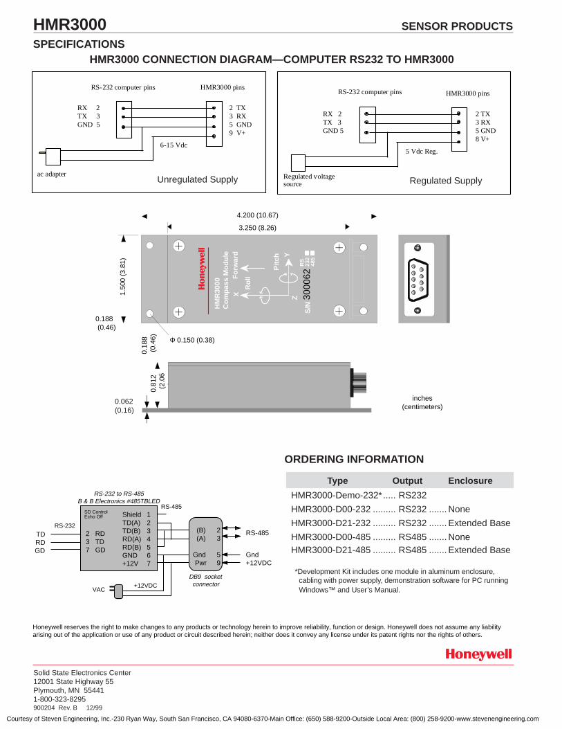
Honeywell reserves the right to make changes to any products or technology herein to improve reliability, function or design. Honeywell does not assume any liabilityarising out of the application or use of any product or circuit described herein; neither does it convey any license under its patent rights nor the rights of others.
Solid State Electronics Center12001 State Highway 55Plymouth, MN 554411-800-323-8295900204 Rev. B 12/99
HMR3000 SENSOR PRODUCTS
SPECIFICATIONS
2 TX3 RX5 GND8 V+
Regulated voltagesource
RS-232 computer pins HMR3000 pins
RX 2TX 3GND 5
5 Vdc Reg.
RS-232 computer pins HMR3000 pins
RX 2TX 3GND 5
2 TX3 RX5 GND9 V+
ac adapter
6-15 Vdc
Unregulated Supply Regulated Supply
HMR3000 CONNECTION DIAGRAM—COMPUTER RS232 TO HMR3000
Type Output Enclosure
HMR3000-Demo-232*..... RS232
HMR3000-D00-232 ......... RS232 ....... None
HMR3000-D21-232 ......... RS232 ....... Extended Base
HMR3000-D00-485 ......... RS485 ....... NoneHMR3000-D21-485 ......... RS485 ....... Extended Base
ORDERING INFORMATION
*Development Kit includes one module in aluminum enclosure,cabling with power supply, demonstration software for PC runningWindows™ and User’s Manual.
Shield 1TD(A) 2TD(B) 3RD(A) 4RD(B) 5GND 6+12V 7
RS-232 to RS-485B & B Electronics #485TBLED
RS-485
Gnd+12VDC
RS-485
(B) 2 (A) 3
Gnd 5 Pwr 9
DB9 socketconnector+12VDC
VAC
2 RD3 TD7 GD
TDRDGD
RS-232
SD ControlEcho Off
4.200 (10.67)
3.250 (8.26)
1.50
0 (3
.81)
0.18
8(0
.46) Φ 0.150 (0.38)
0.188(0.46)
HM
R30
00C
om
pas
s M
od
ule
X
Y
Fo
rwar
d
Ro
ll
Pit
ch
Z
S/N
RS
232
485
3000
62AAAAAA
AAAAA
AAAA
AA
inches(centimeters)0.062 (
0.16)
0.81
2(2
.06
)
0.062(0.16)
Courtesy of Steven Engineering, Inc.-230 Ryan Way, South San Francisco, CA 94080-6370-Main Office: (650) 588-9200-Outside Local Area: (800) 258-9200-www.stevenengineering.com

Honeywell Magnetic Sensor Products
HMR3000 Digital Compass Solution User’s Guide
Courtesy of Steven Engineering, Inc.-230 Ryan Way, South San Francisco, CA 94080-6370-Main Office: (650) 588-9200-Outside Local Area: (800) 258-9200-www.stevenengineering.com

HMR3000 User’s Guide
2 www.honeywell.com
Packing List
Part Number Items included
HMR3000-D00-232 HMR3000 RS-232 Circuit Card
HMR3000-D00-485 HMR3000 RS-485 Circuit Card
HMR3000-D21-232 Housed Compass Module RS-232
HMR3000-D21-485 Housed Compass Module RS-485
HMR3000-D21-232-DEMO Housed Compass Module RS-232 Windows Demo Software CD Power supply and interface cable
Factory Default Settings
Parameter or Condition Default Settings
Baud Rate 19200 Operation Mode Run Output Sentences None TC1 (filter 1 time constant) 4 Heading filter L value 0 Heading filter S value 0
How to Set Up and Install HMR3000 Demo Unit Software 1) Connect the interface cable between the HMR3000 and serial port of a PC. Check and select the line voltage input (110 or 220 V), turn the voltage selector to 9 volt DC mark with positive polarity, and plug in the adapter to an
electrical outlet. 2) Install PC Demo Interface software on the PC by running setup.exe from the CD. In Windows, click start, then run and browse CD to find setup.exe in the HMR3000 PC DEMO folder. 3) Double click on PC Demo Interface icon (PCDEMO.EXE).
Select the correct COM port and 19200 baud rate (The serial port is usually COM1).
Courtesy of Steven Engineering, Inc.-230 Ryan Way, South San Francisco, CA 94080-6370-Main Office: (650) 588-9200-Outside Local Area: (800) 258-9200-www.stevenengineering.com

HMR3000 User’s Guide
www.honeywell.com 3
4) Click the musical note button
5) Go to Serial Output tab and change the message rate on HPR sentence to 825. Click on the attitude display button
Note: You should have received PC Demo Interface Ver. 2.03 or higher. If you have an older version please update to the latest version. Please call Honeywell Magnetic Sensors Technical Support at 763-954-2474 if you need this new version of the software. Computer Requirements Minimum: PC 486/33MHz Windows 3.1, Windows 95 or NT Operating System VGA 2 Mb disk space (more for log file and captured data) RS-232 serial port Recommended: Pentium/120MHz Windows 95 or newer Operating System SVGA 1024 x 768 Microsoft Excel (5.0 or greater) for capture and export of data (if desired) Note: The Graphical output of the HMR3000 on PC Demo software may become sluggish if the PC has slow graphic capability or if other applications are running in the background.
How to Set the Baud Rate Using the PC DEMO software interface: 1) Connect the device and run PC Demo 2) Go to Tune Parameters / Serial Output page through the main menu of the program 3) Select the baud rate 4) Power down the device 5) Power up the device and communicate with the new baud rate Through Direct Commands 1) Set up normal communications with the current baud rate 2) Issue the commands (see Section 4.4 of the User's Guide and Baud Rate) 3) Power down the device 4) Power up the device and communicate with the new baud rate
Courtesy of Steven Engineering, Inc.-230 Ryan Way, South San Francisco, CA 94080-6370-Main Office: (650) 588-9200-Outside Local Area: (800) 258-9200-www.stevenengineering.com

HMR3000 User’s Guide
4 www.honeywell.com
1.0 INTRODUCTION The HMR3000 uses Honeywell magnetic sensors with proven MR technology and a two-axis tilt sensor to bring you the heading information. This electronically gimbaled compass gives accurate heading even when the compass is tilted up to 45 degrees. This low power, small device is housed in a non-magnetic metallic enclosure that can be easily installed on any platform. The HMR3000 allows the user to configure compass output to include any combination of six NMEA standard messages and to change measurement parameters for the magnetometer to suit the application. The sophisticated auto compass calibration routines will correct for the hard-iron magnetic effects of the platform. The wide dynamic range of the magnetometer (±1 G or 100 µT) allows the HMR3000 to be useful in applications with moderate local magnetic fields.
2.0 GETTING TO KNOW THE HMR3000 PRODUCT 2.1 Identifying the HMR3000 The HMR3000 Compass module comes in three different options: (1) Bare circuit board with RS-232 or RS-485 electrical interface (2) Housed Compass Module with RS-232 or RS-485 electrical interface (3) Demonstration Kit (Housing and RS-232 only) The electrical interface of the compass module is clearly marked on the circuit board in option (1) and on the product label in option (2). Option (3) only comes with RS-232 electrical interface. 2.2 Setting Up the HMR3000 Interface and power cables—Interface and power supply should be included in the Demonstration Kit (see Electrical Connections in Section 2.4). For other HMR3000 product options, a cable having a standard 9-pin D shell female connector should be wired according to the pin-out defined below. Power should only be connected to either pin 9 or pin 8. It is sufficient to connect the pins listed in Table 1 for most applications. However, pins 1, 4, 6 and 7 serve specific purposes in the operation of HMR3000 and should be kept open (high logic state) in normal operation (see Table 2 for complete pin out description). See Figures below for suggested cabling diagram for connection between HMR3000 and serial port of a personal computer.
Name In/Out Pin Description
TxD / A Out 2 RS-232 transmit out / RS-485 transmit-receive signal
RxD / B In 3 RS-232 receive in / RS-485 transmit-receive return
GND In 5 Power and signal common 6-15V In 9 Unregulated power input 5V In 8 Regulated power input
Pin Assignment for Typical Operation of HMR3000 Caution: Do NOT exceed +5.5V at regulated power input (pin 8). Higher voltages will damage components.
Courtesy of Steven Engineering, Inc.-230 Ryan Way, South San Francisco, CA 94080-6370-Main Office: (650) 588-9200-Outside Local Area: (800) 258-9200-www.stevenengineering.com
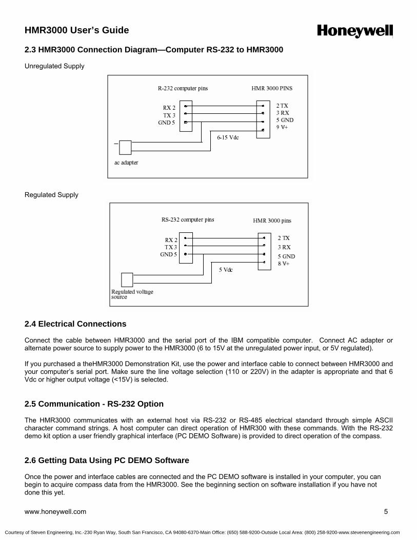
HMR3000 User’s Guide
www.honeywell.com 5
2.3 HMR3000 Connection Diagram—Computer RS-232 to HMR3000 Unregulated Supply
Regulated Supply
2.4 Electrical Connections Connect the cable between HMR3000 and the serial port of the IBM compatible computer. Connect AC adapter or alternate power source to supply power to the HMR3000 (6 to 15V at the unregulated power input, or 5V regulated). If you purchased a theHMR3000 Demonstration Kit, use the power and interface cable to connect between HMR3000 and your computer’s serial port. Make sure the line voltage selection (110 or 220V) in the adapter is appropriate and that 6 Vdc or higher output voltage (<15V) is selected. 2.5 Communication - RS-232 Option The HMR3000 communicates with an external host via RS-232 or RS-485 electrical standard through simple ASCII character command strings. A host computer can direct operation of HMR300 with these commands. With the RS-232 demo kit option a user friendly graphical interface (PC DEMO Software) is provided to direct operation of the compass. 2.6 Getting Data Using PC DEMO Software Once the power and interface cables are connected and the PC DEMO software is installed in your computer, you can begin to acquire compass data from the HMR3000. See the beginning section on software installation if you have not done this yet.
Courtesy of Steven Engineering, Inc.-230 Ryan Way, South San Francisco, CA 94080-6370-Main Office: (650) 588-9200-Outside Local Area: (800) 258-9200-www.stevenengineering.com

HMR3000 User’s Guide
6 www.honeywell.com
1. Double click on PC Demo Interface icon (PCDEMO.EXE).
2. Select the correct COM port and 19200 baud rate (The serial port is usually COM1).
3. Message box, identifying the Firmware Version, should appear, and confirms good interface connections. 4. Click the musical note button (tune parameters).
5. Go to Serial Output tab and change the message rate on HPR sentence to 825. Now the compass should output heading, pitch and roll data at 825 sentences/min rate.
6. Note that the message rates for all the output sentences are set to 0 at the factory. Click on the View Interface, or Monitor NMEA Sentences selections on the Display menu (or left two buttons) to see the result of the HPR sentence output. The View Log selection under the Diagnostics menu is another option to inspect compass data. Make sure the Log all messages (logging page in Diagnostics menu) option is activated. A non-zero HPR message rate should be chosen to view the displays to be active.
The HMR3000 output can be changed to include all or any of the six NMEA sentences each with its own rate. Users can capture the output messages to a file using the Capture Mode by selecting the message to be captured.
Courtesy of Steven Engineering, Inc.-230 Ryan Way, South San Francisco, CA 94080-6370-Main Office: (650) 588-9200-Outside Local Area: (800) 258-9200-www.stevenengineering.com

HMR3000 User’s Guide
www.honeywell.com 7
2.8 Configuring the HMR3000 with PC DEMO Software Following is a list of basic parameters that would be accessed routinely and at installation. Advanced parameters that control the operation of the magnetometer, heading output, and warning levels are described in the Configuration Parameters section. Activate the Tune Parameters button to configure.
Function Parameter / Description Located Under Range
Declination
Declination Angle Angle between magnetic north and the geographic north. Add a declination angle to magnetic heading to obtain a true north heading.
General page 0-180 deg 0- 3200 mils
Output Messages and Rate
HDG, HDT, XDR, HPR, RCD, CCD NMEA sentence outputs Rates in sentences per minute
Serial Output page None or All
0-1200 updates/min
Data Filter TC1 Time constant for IIR filter 0-255
1=72 ms
Heading Output L and S Smoothing factors for non linear filter
0<S<1 L= integer >1 L=0 disable L<256
Deviation
Deviation Angle The angle between compass forward direction and that of the platform. Add deviation to get platform heading
General page 0-180 deg 0- 3200 mils
2.9 Communication—RS485 Option The HMR3000 Compass module’s RS-485 interface is half duplex, i.e. transmit and receive circuits share the same physical pair of wires. The HMR3000 must disable its transmitter to allow characters to be received from a host system. If the unit is operating in the Run mode, i.e. generating repetitive output; then the Run/Stop pin (pin 6) should be forced low before the host attempts to transmit a command. See details in Description of hardware interrupt section. 2.10 Digital Compass Installation To get optimum performance when installing the HMR3000, follow the guidelines listed below for your vehicle or platform: Location—Install the HMR3000 as far as possible from any source generating a magnetic field and far from ferrous metal objects. Honeywell magnetic sensors used in HMR3000 have a large field range of 2 gauss (200 µT), compared to 0.65 gauss (65 µT); the maximum of earth’s total magnetic field, and therefore would not saturate in most platforms. Calibration and compensation routines in the compass can effectively compensate for static magnetic fields superimposed on the earth’s field components, which are used for heading calculations. However, compasses can not compensate for the effects of varying fields produced by dc and ac currents in nearby wires. Level—The HMR3000 is electronically gimbaled and it is not necessary to mount the compass perfectly level. However, to get the maximum possible tilt range, the compass should be mounted level (flanges down) when the vehicle or platform is in normal operation.
Courtesy of Steven Engineering, Inc.-230 Ryan Way, South San Francisco, CA 94080-6370-Main Office: (650) 588-9200-Outside Local Area: (800) 258-9200-www.stevenengineering.com

HMR3000 User’s Guide
8 www.honeywell.com
Orientation—Forward direction of the compass can be oriented at any angle from that of the platform. Use Deviation Angle parameter to convert the compasses magnetic heading to the true or magnetic heading of the vehicle/platform. 2.11 HMR3000 Hard-Iron Calibration All magnetic compasses have to be calibrated in order to compensate for magnetic fields other than the earth’s field components to get accurate heading. These additional magnetic fields (hard-iron effects) are generated by the near environment and therefore depend on the compass mounting location. By performing a simple procedure, the HMR3000 can compensate for these steady, static magnetic fields. Field components found after a calibration are only valid for the particular orientation and location of the compass. A re-calibration is necessary after a relocation of the compass or if the platform has changed its magnetic character. Typically hard-iron calibration is performed by following a calibration procedure specified by the manufacturer. During this procedure the compass collects data required for the compensation algorithms. The goal of the calibration procedure is to sample the magnetic field components for many possible orientations of the host system. Rotating the host system through 360 degrees or driving in a circle (in the case of a vehicle) will enable the compass to sample its magnetic environment and derive the magnetic offset and scaling numbers to null out the hard-iron effects. The HMR3000 can be calibrated by either using the built in calibration method or by using the PC Demo Interface software program. The calibration procedure for both these methods is the same. 2.11.1 Built-in Calibration Method
This method uses an iterative procedure to calculate the hard iron offsets. In most situations 275 iterations would produce good results. The calibration procedure has to continue until this iteration count is reached. To put the HMR3000 into calibration mode issue the calibration command #F33.4=0*51<cr><lf>. Slowly rotate the host system through a full circle in a gentle motion while changing roll and pitch as much as the host will allow. Generally this procedure will take over two minutes. You may check the iteration count periodically during the rotation by issuing #I26C?*31<cr><lf>. HMR3000 will reply with a #nnnn*hh<cr><lf> message, where nnnn is the value of the iteration count. If this value is less than 275 continue with the calibration procedure until that number reaches 275. At the end of this procedure issue a command to save the results in the HMR3000’s EEPROM (#F2FE.2=1*67<cr><lf>). Put the compass back into operate mode by issuing a #F33.4=1*50<cr><lf> command. This method works when the hard iron field effects are small. 2.11.2 PC DEMO Calibration Method This method is recommended when the hard iron field effects are large. The PC DEMO software interface will collect the raw magnetic vector information and analyze the data to find the hard iron offsets. 1. In PC Demo, go to Diagnostics menu, and then to the Perform 3D Calibration selection. 2. On calibration page, activate Read Data button. You should see the Total Valid Readings number (# of data points collected) go up with motion. 3. Slowly rotate the platform through a full circle in a gentle motion while changing roll and pitch as much as the platform will allow. Generally this procedure will take over two minutes. 4. At the end of this procedure click the Stop button. The magnetic vector offsets will display as results. Click the Apply button to put the Hard Iron offsets values into effect. In clean magnetic environments, the offsets will be only a few hundred counts away from zero.
Courtesy of Steven Engineering, Inc.-230 Ryan Way, South San Francisco, CA 94080-6370-Main Office: (650) 588-9200-Outside Local Area: (800) 258-9200-www.stevenengineering.com

HMR3000 User’s Guide
www.honeywell.com 9
5. If sufficient tilt change were not encountered during the calibration procedure, then the calculated Zoffset value may not be reliable. In such a case the Z offset would likely will appear in red, and the corresponding check box empty. User has the option to accept this Z offset value by checking the box. At the end of each calibration, PC DEMO software calculates and reports a variation number as a sign of magnetic environment change/goodness; the lower the number the better the calibration. The compass should be relocated if the variation number is greater than 40. 2.11.3 PC DEMO Z Reference Calibration Method In applications which changing the tilt of the host is not possible, an approximate value of the Zoffset can be found by using the Z Reference Method. This method directly compares the Z component of the earth’s magnetic field in an undisturbed location to that of the host. This procedure involves two steps: Step 1. Collect Z reference value near the calibration site, away from large metal objects that will distort the earth’s field by: 1 Select the Diagnostics menu, and then select Capture/Clear Z Reference. 2. Hit Read Data, and hold the compass approximately level. 3. Hit the Stop button after capturing 10-20 readings, and hit the Apply New button to save the new Z Reference value in the EEPROM of HMR3000. Step 2. Install the compass on the vehicle/mount and follow the normal 3D Calibration described above in 2.11.2. Mag Z offset will be computed from the Z Reference method as well as the normal method. 1. At the end of the calibration, between the Stop and Apply button selections, ensure the MagZ check box is un-checked, and the Z Reference check box is checked. 2. Select the Apply button to save the new offset values. 3.0 OPERATION OF THE HMR3000 IN DETAIL 3.1 GENERAL The HMR3000 digital compass consists of three magnetoresistive magnetic sensors, and a liquid filled two-axis tilt sensor to produce tilt compensated heading data. A microprocessor controls the measurement sequence of the sensors, and all the parameters that control the operation are stored in an EEPROM. The output sentences of the HMR3000 conform to the NMEA 0813 standard for Marine communication (NMEA = National Marine Electronics Association). The HMR3000 has four operational modes: Continuous Mode Output unsolicited NMEA standard message(s) at a configurable rate Strobe Mode Active Strobe Mode- Measurement is continuous and message output on request Passive Strobe Mode- Measurement and output upon request Sleep Mode (requires an interrupt signal at the connector)
Courtesy of Steven Engineering, Inc.-230 Ryan Way, South San Francisco, CA 94080-6370-Main Office: (650) 588-9200-Outside Local Area: (800) 258-9200-www.stevenengineering.com
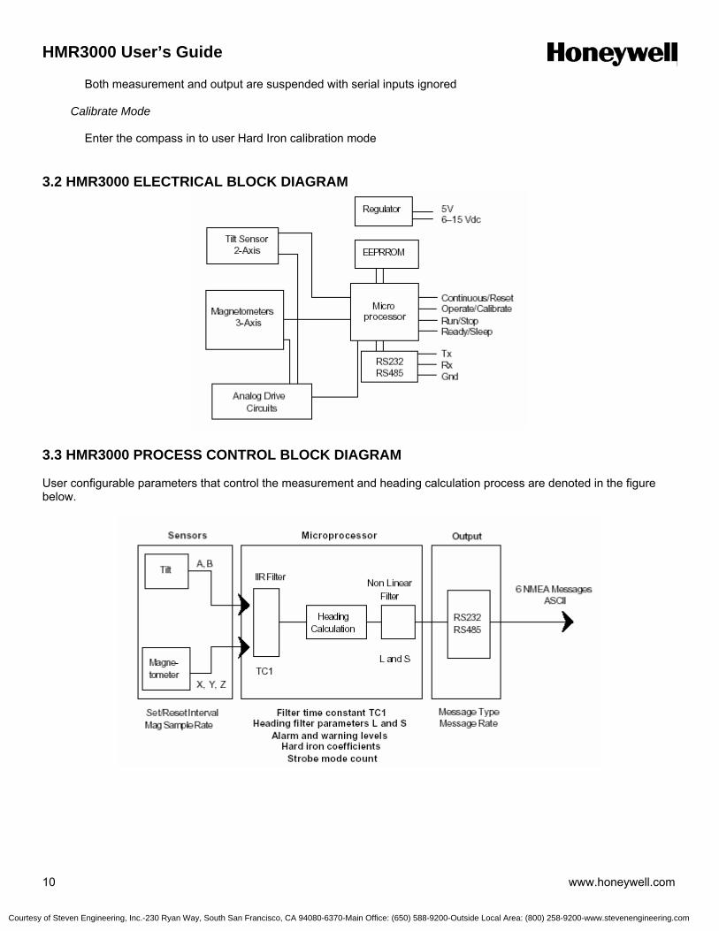
HMR3000 User’s Guide
10 www.honeywell.com
Both measurement and output are suspended with serial inputs ignored Calibrate Mode Enter the compass in to user Hard Iron calibration mode 3.2 HMR3000 ELECTRICAL BLOCK DIAGRAM
3.3 HMR3000 PROCESS CONTROL BLOCK DIAGRAM User configurable parameters that control the measurement and heading calculation process are denoted in the figure below.
Courtesy of Steven Engineering, Inc.-230 Ryan Way, South San Francisco, CA 94080-6370-Main Office: (650) 588-9200-Outside Local Area: (800) 258-9200-www.stevenengineering.com

HMR3000 User’s Guide
www.honeywell.com 11
3.4 HMR3000 Measurement Sequence In normal operation, the microprocessor takes a set of seven measurements, four tilt and three magnetic, that are combined to produce heading, roll, and pitch data. A set of magnetic measurements can be taken at 110, 55, 27.5, or 13.75 Hz rates. The fluidic ilt sensor is driven with a constant 55 Hz pulse. Raw data are normalized, linearized, and filtered at the 13.75 Hz rate. Normalization includes gain matching, offset nulling, and hard-iron compensation offsets for the three magnetic measurements; and the gain and offset compensation for tilt measurements. Tilt measurements are linearized to account for the non-linear characteristics of the inclinometer function. All five measurements, TiltX, TiltY, MagX, MagY, and MagZ, are low-pass filtered, using an IIR filter (Infinite Impulse Response), depending on the setting for the TC1. This filter may be disabled by setting the time constant to zero. Magnetic sensor operation includes a Set/Reset pulse routine to achieve high sensitivity magnetic measurements. The active area of the MR element is Set and Reset periodically by 3 amp current pulses through the magnetic sensor set/reset straps. The periodicity of this Set/Reset operation can be changed to achieve high heading accuracy or to conserve power. Compass heading is calculated 13.75 times per second from the 5 filtered measurements. A form of non-linear smoothing can be applied to the current heading to produce a smooth heading. The transfer function of the algorithm is a high degree of smoothing applied for small changes in heading, i.e. noise, while little or no smoothing is applied to larger, more significant changes by setting the parameters of this non linear filter. In may not make sense to use the IIR filter and the non-linear smoothing for a given application. If the compass is mounted on a vessel that cannot change direction quickly, then it is probably better to use the IIR filter and disable smoothing. On the other hand, smoothing works well for hand-held applications or where noise is a problem. 3.5 HMR3000 Interface Pin Descriptions The table below shows pin assignments for the 9-pin D-shell connector. Different pins are used to supply either regulated 5Vdc or unregulated 6V to 15V power. Only one of the two power pins (9 or 8) should be connected in a given installation.
Name In/Out Pin Description
TxD / A Out 2 RS-232 transmit out / RS-485 transmit-receive signal
RxD / B In 3 RS-232 receive in / RS-485 transmit-receive return GND In 5 Power and signal common 6-15V In 9 Unregulated power input 5V In 8 Regulated power input Oper / Calib * In 1 Operate / Calibrate-* input (open = Operate) Run / Stop * In 6 Run / Stop- input (open = Run) Ready / Sleep * In 4 Ready / Sleep- input (open = Ready) Cont / Reset * In 7 Continue / Reset- input (open = Continue)
*A dash following a signal name is used to denote that the signal is asserted active low. In this case, when pin 1 is low the Calibrate function is selected. 3.6 HMR3000 Serial Data Communication The HMR3000 serial communications are governed by a simple, asynchronous, ASCII protocol modeled after the NMEA 0183 standard. Either an RS-232 or an RS-485 electrical interface can be used. ASCII characters are transmitted and received using 1 start bit, 8 data bits (LSB first), no parity (MSB always 0), and 1 stop bit; 10 bits total per character. Baud rate can be any one of 1200, 2400, 4800, 9600, 19200, 38400.
Courtesy of Steven Engineering, Inc.-230 Ryan Way, South San Francisco, CA 94080-6370-Main Office: (650) 588-9200-Outside Local Area: (800) 258-9200-www.stevenengineering.com

HMR3000 User’s Guide
12 www.honeywell.com
The HMR3000 supports both standard NMEA 0183 and proprietary messages. Unsolicited NMEA messages are sent by the HMR3000 in Continuous Mode at the rates programmed in EEPROM. HMR3000 also responds to all input messages from the host. An HMR3000 response to a command input may be delayed due to transmission of an unsolicited output. The host processor must wait for HMR3000 to respond to the last command input before sending another command message. All communication from and to HMR3000 contain a two-character Checksum Field at the end of the data fields, and are denoted in the following sentences by ‘hh’. The checksum assures the accuracy of the message transmitted. This checksum is calculated per NMEA 0183 Standard, and is outlined in section 3.11. 3.7 HMR3000 Input Data There are two kinds of serial data input to the HMR3000; either a request for output sentence, or a setting of a configuration parameter. HMR3000 sends a response to all valid inputs with a correct checksum value. 1. Response to a Request for output sentence is the appropriate sentence. 2. Response to parameter input will be #!0000*21 to indicate the command and the parameter was accepted. 3.8 HMR3000 Output Data There are six possible NMEA messages, three standard and three proprietary, that can be automatically sent from the HMR3000 in Continuous Mode by selecting their Update Rates. Additionally, there is a seventh, non-conforming ASCII display message that can also be sent. The ASCII display message is not expected to commingle with the other six NMEA messages. It is intended for simpler systems where the HMR3000 is connected to a numerical readout device instead of a host processor. The update rate for each message can be set independently to one of the following: 0, 1, 2, 3, 6, 12, 20, 30, 60, 120, 180,300, 413, 600, 825, or 1200 sentences per minute. If the output channel, due to its programmed baud rate, cannot accommodate the total number of sentences selected, then the channel will operate at full speed and highest priority will be given to responses to input, followed by sentences with update rates from lowest to highest. Fairness will be implemented in the priority scheme so that each sentence ready for output is transmitted at least once before higher priority sentences are repeated. 3.9 Query for NMEA Sentences The three NMEA standard sentences (HDG, HDT, and XDR) and three proprietary (HPR, RCD, and CCD) messages can be queried as follows. The three standard query messages accepted are: $TNHCQ,HDG*27<cr><lf> $TNHCQ,HDT*34<cr><lf> $TNHCQ,XDR*22<cr><lf> The three proprietary query messages accepted are: $PTNT,HPR*78<cr><lf> $PTNT,RCD*67<cr><lf> $PTNT,CCD*76<cr><lf>
Courtesy of Steven Engineering, Inc.-230 Ryan Way, South San Francisco, CA 94080-6370-Main Office: (650) 588-9200-Outside Local Area: (800) 258-9200-www.stevenengineering.com

HMR3000 User’s Guide
www.honeywell.com 13
3.10 Format of NMEA Sentence Outputs HDG Heading, Deviation, & Variation $HCHDG,x.x,x.x,a,x.x,a*hh<cr><lf> If either the deviation or variation parameter has not been programmed, the corresponding field will be null (per NMEA 0183 version 2.1, section 5.2.2.3). Parameters have not been programmed if their absolute values are greater than 3200 mils or 180.0 degrees. Positive deviation and variation is indicated by a = E; negative values by a = W. Heading field will be null if it cannot be calculated (see HPR proprietary sentence). NMEA requires that units for heading measurement be degrees. Eg. In Degree Mode $HCHDG,85.8,0.0,E,0.0,E*77 $HCHDG,271.2,0.0,E,0.0,E*44 $HCHDG,271.1,10.7,E,12.2,W*52 $HCHDG,0.0,10.7,E,12.2,W*57 Mil Mode is not allowed by NMEA standard HDT Heading, True $HCHDT,x.x,T*hh<cr><lf> The heading field will be null if variation has not been programmed (see HDG and Definitions), or if heading cannot be calculated. If deviation has not been programmed, it is assumed to be zero, otherwise it is added to measured heading and variation to express true heading of compass board. Eg. In Degree Mode $HCHDT,86.2,T*15 $HCHDT,271.1,T*2C $HCHDT,0.9,T*20 Mil Mode not allowed by NMEA standard XDR Transducer Measurements $HCXDR,A,x.x,D,PITCH,A,x.x,D,ROLL,G,x.x,,MAGX,G,x.x,,MAGY, G,x.x,,MAGZ,G,x.x,,MAGT*hh<cr><lf> Each of the six possible measurements - pitch; roll; and magnetic x, y, z, and total—can be individually included in or excluded from the message (see “XDR has …” parameters). See NMEA 0183 for a detailed description of the “Type-Data-Units-ID” field encoding. The “Data” field of an included measurement will be null if its contents cannot be determined due to saturated measurements. Only units of degrees are allowed by NMEA for pitch and roll measurements. Magnetic measurements are transmitted in engineering units (milli Gauss) determined by a tunable conversion factor. MAGX aligns with the compass board north-south axis, and MAGZ is perpendicular to the plane of the compass board. MAGT is the total magnetic field strength determined by calculating the square root of the sum of the squares of MAGX, MAGY, and MAGZ. Eg. In Degree Mode $HCXDR,A,-0.8,D,PITCH,A,0.8,D,ROLL,G,122,,MAGX,G,1838,,MAGY,G,- 667,,MAGZ,G,1959,,MAGT*11
Courtesy of Steven Engineering, Inc.-230 Ryan Way, South San Francisco, CA 94080-6370-Main Office: (650) 588-9200-Outside Local Area: (800) 258-9200-www.stevenengineering.com
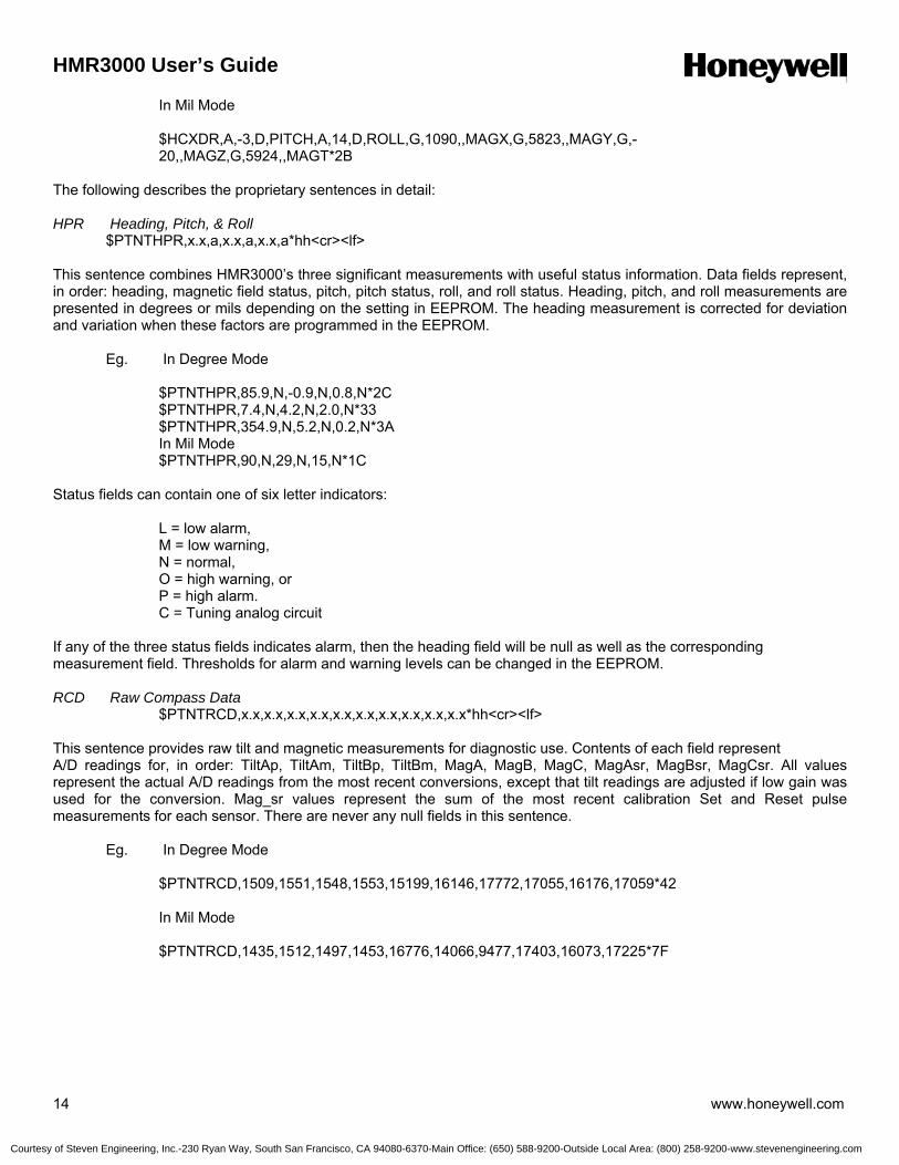
HMR3000 User’s Guide
14 www.honeywell.com
In Mil Mode $HCXDR,A,-3,D,PITCH,A,14,D,ROLL,G,1090,,MAGX,G,5823,,MAGY,G,- 20,,MAGZ,G,5924,,MAGT*2B The following describes the proprietary sentences in detail: HPR Heading, Pitch, & Roll $PTNTHPR,x.x,a,x.x,a,x.x,a*hh<cr><lf> This sentence combines HMR3000’s three significant measurements with useful status information. Data fields represent, in order: heading, magnetic field status, pitch, pitch status, roll, and roll status. Heading, pitch, and roll measurements are presented in degrees or mils depending on the setting in EEPROM. The heading measurement is corrected for deviation and variation when these factors are programmed in the EEPROM. Eg. In Degree Mode $PTNTHPR,85.9,N,-0.9,N,0.8,N*2C $PTNTHPR,7.4,N,4.2,N,2.0,N*33 $PTNTHPR,354.9,N,5.2,N,0.2,N*3A In Mil Mode $PTNTHPR,90,N,29,N,15,N*1C Status fields can contain one of six letter indicators:
L = low alarm, M = low warning, N = normal, O = high warning, or P = high alarm. C = Tuning analog circuit
If any of the three status fields indicates alarm, then the heading field will be null as well as the corresponding measurement field. Thresholds for alarm and warning levels can be changed in the EEPROM.
RCD Raw Compass Data
$PTNTRCD,x.x,x.x,x.x,x.x,x.x,x.x,x.x,x.x,x.x,x.x*hh<cr><lf> This sentence provides raw tilt and magnetic measurements for diagnostic use. Contents of each field represent A/D readings for, in order: TiltAp, TiltAm, TiltBp, TiltBm, MagA, MagB, MagC, MagAsr, MagBsr, MagCsr. All values represent the actual A/D readings from the most recent conversions, except that tilt readings are adjusted if low gain was used for the conversion. Mag_sr values represent the sum of the most recent calibration Set and Reset pulse measurements for each sensor. There are never any null fields in this sentence. Eg. In Degree Mode $PTNTRCD,1509,1551,1548,1553,15199,16146,17772,17055,16176,17059*42
In Mil Mode
$PTNTRCD,1435,1512,1497,1453,16776,14066,9477,17403,16073,17225*7F
Courtesy of Steven Engineering, Inc.-230 Ryan Way, South San Francisco, CA 94080-6370-Main Office: (650) 588-9200-Outside Local Area: (800) 258-9200-www.stevenengineering.com

HMR3000 User’s Guide
www.honeywell.com 15
CCD Conditioned Compass Data $PTNTCCD,x.x,x.x,x.x,x.x,x.x,x.x,x.x*hh<cr><lf> This sentence provides conditioned tilt and magnetic measurements for diagnostic use. The fields are, in order: TiltX 32768 times tangent of angle, between compass board north-south axis and level plane. This value is the
difference between the raw tilt measurements normalized, linearized, and filtered according to parameter settings. The pitch measurement is determined by taking the arctan of TiltX/32768.
TiltY Same as TiltX but for the compass board east-west axis (roll). MagX normalized and filtered magnetic field strength along the north-south axis of the compass board. This value has been adjusted for any hard-iron offset determined during calibration (or tuned manually). MagY same as MagX but along the compass board east-west axis. MagZ same as MagX and MagY, but along the axis perpendicular to the plane of the board. This value has been adjusted both for gain variation with the X-Y sensor pair and for hard-iron. MagT Total magnetic field strength Heading calculated heading based on the magnetometer and inclinometer data in this sentence. Presented in degrees or mils depending on the setting in EEPROM. This field will be null if the heading cannot be calculated. Eg. In Degree Mode $PTNTCCD,522,-472,109,1841,677,1964,86.3*44 In Mil Mode $PTNTCCD,-25187,351,-3909,1899,-4394,6180,1838*58 ASCII Message The special ASCII display message normally consists of a string of 4 digits that represent the heading in degrees and tenths, followed by a terminating carriage return character. Heading is corrected for deviation and variation when these factors are programmed in the EEPROM. When the heading cannot be transmitted due to a magnetometer or tilt signal out of range, then 4 minus signs are transmitted instead. Eg. In Degree Mode 3.11 NMEA Checksum Field This absolute value is calculated by exclusive OR operation on the 8 data bits (ASCII code) (no start or stop bits) of each character in the message, between, but excluding “$” and “*” (or between “#” and “*”) characters. The hexadecimal value of the most significant and the least significant 4 bits of the result is converted to two ASCII characters (0-9, A-F) for transmission of the. The most significant character is transmitted first. These characters fill the “hh” positions in the commands and command responses described within this user’s guide.
Courtesy of Steven Engineering, Inc.-230 Ryan Way, South San Francisco, CA 94080-6370-Main Office: (650) 588-9200-Outside Local Area: (800) 258-9200-www.stevenengineering.com
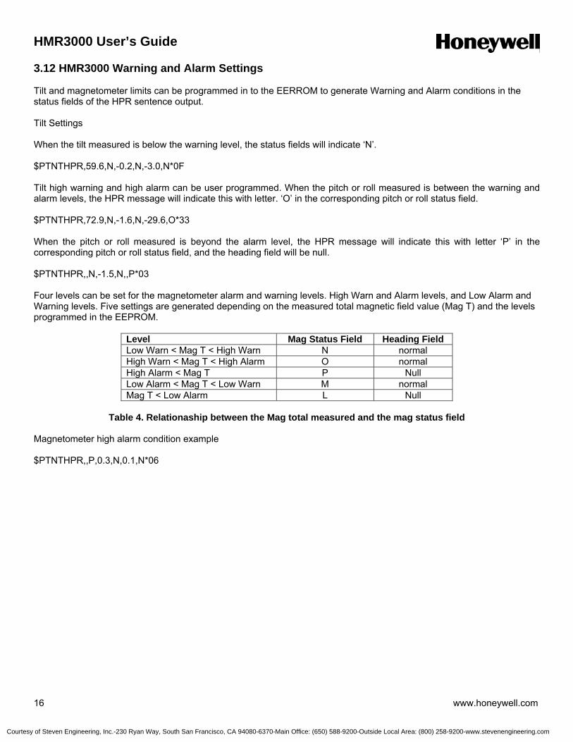
HMR3000 User’s Guide
16 www.honeywell.com
3.12 HMR3000 Warning and Alarm Settings Tilt and magnetometer limits can be programmed in to the EERROM to generate Warning and Alarm conditions in the status fields of the HPR sentence output. Tilt Settings When the tilt measured is below the warning level, the status fields will indicate ‘N’. $PTNTHPR,59.6,N,-0.2,N,-3.0,N*0F Tilt high warning and high alarm can be user programmed. When the pitch or roll measured is between the warning and alarm levels, the HPR message will indicate this with letter. ‘O’ in the corresponding pitch or roll status field. $PTNTHPR,72.9,N,-1.6,N,-29.6,O*33 When the pitch or roll measured is beyond the alarm level, the HPR message will indicate this with letter ‘P’ in the corresponding pitch or roll status field, and the heading field will be null. $PTNTHPR,,N,-1.5,N,,P*03 Four levels can be set for the magnetometer alarm and warning levels. High Warn and Alarm levels, and Low Alarm and Warning levels. Five settings are generated depending on the measured total magnetic field value (Mag T) and the levels programmed in the EEPROM.
Level Mag Status Field Heading Field Low Warn < Mag T < High Warn N normal High Warn < Mag T < High Alarm O normal High Alarm < Mag T P Null Low Alarm < Mag T < Low Warn M normal Mag T < Low Alarm L Null
Table 4. Relationaship between the Mag total measured and the mag status field
Magnetometer high alarm condition example $PTNTHPR,,P,0.3,N,0.1,N*06
Courtesy of Steven Engineering, Inc.-230 Ryan Way, South San Francisco, CA 94080-6370-Main Office: (650) 588-9200-Outside Local Area: (800) 258-9200-www.stevenengineering.com
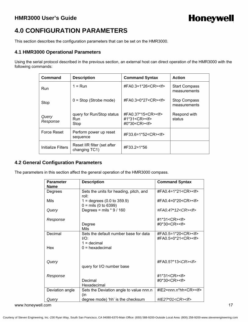
HMR3000 User’s Guide
www.honeywell.com 17
4.0 CONFIGURATION PARAMETERS This section describes the configuration parameters that can be set on the HMR3000. 4.1 HMR3000 Operational Parameters Using the serial protocol described in the previous section, an external host can direct operation of the HMR3000 with the following commands:
Command Description Command Syntax Action
Run Stop Query Response
1 = Run 0 = Stop (Strobe mode) query for Run/Stop status Run Stop
#FA0.3=1*26<CR><lf> #FA0.3=0*27<CR><lf> #FA0.3?*15<CR><lf> #1*31<CR><lf> #0*30<CR><lf>
Start Compass measurements Stop Compass measurements Respond with status
Force Reset
Perform power up reset sequence #F33.6=1*52<CR><lf>
Initialize Filters Reset IIR filter (set after changing TC1) #F33.2=1*56
4.2 General Configuration Parameters The parameters in this section affect the general operation of the HMR3000 compass.
Parameter Name
Description Command Syntax
Degrees Mils Query Response
Sets the units for heading, pitch, and roll: 1 = degrees (0.0 to 359.9) 0 = mils (0 to 6399) Degrees = mils * 9 / 160 Degree Mils
#FA0.4=1*21<CR><lf> #FA0.4=0*20<CR><lf> #FA0.4?*12<CR><lf> #1*31<CR><lf> #0*30<CR><lf>
Decimal Hex Query Response
Sets the default number base for data I/O: 1 = decimal 0 = hexadecimal query for I/O number base Decimal Hexadecimal
#FA0.5=1*20<CR><lf> #FA0.5=0*21<CR><lf> #FA0.5?*13<CR><lf> #1*31<CR><lf> #0*30<CR><lf>
Deviation angle Query
Sets the Deviation angle to value nnn.n (in degree mode) ‘hh’ is the checksum
#IE2=nnn.n*hh<CR><lf> #IE2?*01<CR><lf>
Courtesy of Steven Engineering, Inc.-230 Ryan Way, South San Francisco, CA 94080-6370-Main Office: (650) 588-9200-Outside Local Area: (800) 258-9200-www.stevenengineering.com
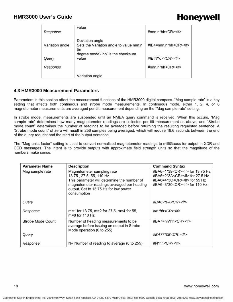
HMR3000 User’s Guide
18 www.honeywell.com
Response
value Deviation angle
#nnn.n*hh<CR><lf>
Variation angle Query Response
Sets the Variation angle to value nnn.n (in degree mode) ‘hh’ is the checksum value Variation angle
#IE4=nnn.n*hh<CR><lf> #IE4?*07<CR><lf> #nnn.n*hh<CR><lf>
4.3 HMR3000 Measurement Parameters Parameters in this section affect the measurement functions of the HMR3000 digital compass. “Mag sample rate” is a key setting that affects both continuous and strobe mode measurements. In continuous mode, either 1, 2, 4, or 8 magnetometer measurements are averaged per tilt measurement depending on the “Mag sample rate” setting. In strobe mode, measurements are suspended until an NMEA query command is received. When this occurs, “Mag sample rate” determines how many magnetometer readings are collected per tilt measurement as above, and “Strobe mode count” determines the number of readings to be averaged before returning the resulting requested sentence. A “Strobe mode count” of zero will result in 256 samples being averaged, which will require 18.6 seconds between the end of the query request and the start of the output sentence. The “Mag units factor” setting is used to convert normalized magnetometer readings to milliGauss for output in XDR and CCD messages. The intent is to provide outputs with approximate field strength units so that the magnitude of the numbers make sense.
Parameter Name Description Command Syntax Mag sample rate Query Response
Magnetometer sampling rate 13.75 , 27.5, 55, 110 Hz This parameter will determine the number of magnetometer readings averaged per heading output. Set to 13.75 Hz for low power consumption m=1 for 13.75, m=2 for 27.5, m=4 for 55, m=8 for 110 Hz
#BA6=1*39<CR><lf> for 13.75 Hz #BA6=2*3A<CR><lf> for 27.5 Hz #BA6=4*3C<CR><lf> for 55 Hz #BA6=8*30<CR><lf> for 110 Hz #BA6?*0A<CR><lf> #m*hh<CR><lf>
Strobe Mode Count Query Response
Number of heading measurements to be average before issuing an output in Strobe Mode operation (0 to 255) N= Number of reading to average (0 to 255)
#BA7=nn*hh<CR><lf> #BA7?*0B<CR><lf> #N*hh<CR><lf>
Courtesy of Steven Engineering, Inc.-230 Ryan Way, South San Francisco, CA 94080-6370-Main Office: (650) 588-9200-Outside Local Area: (800) 258-9200-www.stevenengineering.com
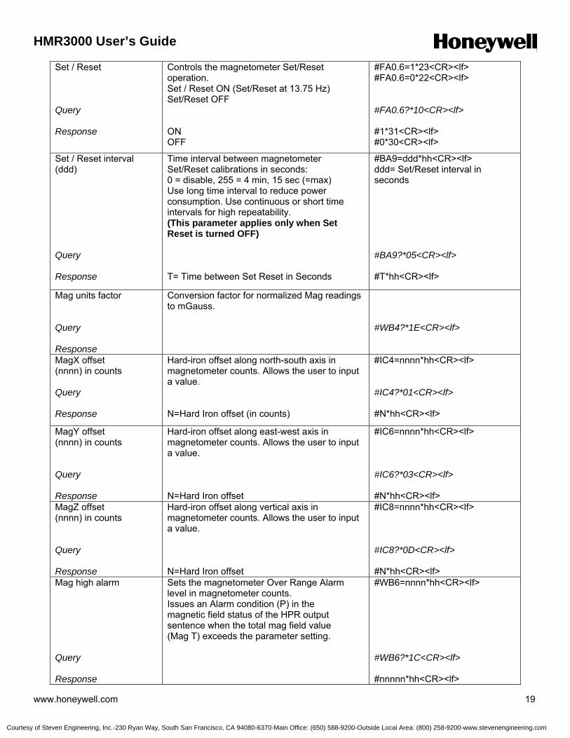
HMR3000 User’s Guide
www.honeywell.com 19
Set / Reset Query Response
Controls the magnetometer Set/Reset operation. Set / Reset ON (Set/Reset at 13.75 Hz) Set/Reset OFF ON OFF
#FA0.6=1*23<CR><lf> #FA0.6=0*22<CR><lf> #FA0.6?*10<CR><lf> #1*31<CR><lf> #0*30<CR><lf>
Set / Reset interval (ddd) Query Response
Time interval between magnetometer Set/Reset calibrations in seconds: 0 = disable, 255 = 4 min, 15 sec (=max) Use long time interval to reduce power consumption. Use continuous or short time intervals for high repeatability. (This parameter applies only when Set Reset is turned OFF) T= Time between Set Reset in Seconds
#BA9=ddd*hh<CR><lf> ddd= Set/Reset interval in seconds #BA9?*05<CR><lf> #T*hh<CR><lf>
Mag units factor Query Response
Conversion factor for normalized Mag readings to mGauss.
#WB4?*1E<CR><lf>
MagX offset (nnnn) in counts Query Response
Hard-iron offset along north-south axis in magnetometer counts. Allows the user to input a value. N=Hard Iron offset (in counts)
#IC4=nnnn*hh<CR><lf> #IC4?*01<CR><lf> #N*hh<CR><lf>
MagY offset (nnnn) in counts Query Response
Hard-iron offset along east-west axis in magnetometer counts. Allows the user to input a value. N=Hard Iron offset
#IC6=nnnn*hh<CR><lf> #IC6?*03<CR><lf> #N*hh<CR><lf>
MagZ offset (nnnn) in counts Query Response
Hard-iron offset along vertical axis in magnetometer counts. Allows the user to input a value. N=Hard Iron offset
#IC8=nnnn*hh<CR><lf> #IC8?*0D<CR><lf> #N*hh<CR><lf>
Mag high alarm Query Response
Sets the magnetometer Over Range Alarm level in magnetometer counts. Issues an Alarm condition (P) in the magnetic field status of the HPR output sentence when the total mag field value (Mag T) exceeds the parameter setting.
#WB6=nnnn*hh<CR><lf> #WB6?*1C<CR><lf> #nnnnn*hh<CR><lf>
Courtesy of Steven Engineering, Inc.-230 Ryan Way, South San Francisco, CA 94080-6370-Main Office: (650) 588-9200-Outside Local Area: (800) 258-9200-www.stevenengineering.com
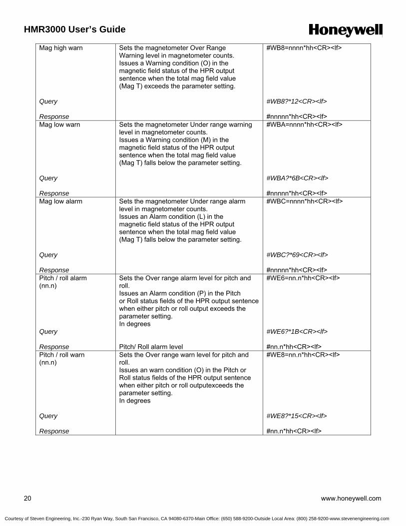
HMR3000 User’s Guide
20 www.honeywell.com
Mag high warn Query Response
Sets the magnetometer Over Range Warning level in magnetometer counts. Issues a Warning condition (O) in the magnetic field status of the HPR output sentence when the total mag field value (Mag T) exceeds the parameter setting.
#WB8=nnnn*hh<CR><lf> #WB8?*12<CR><lf> #nnnnn*hh<CR><lf>
Mag low warn Query Response
Sets the magnetometer Under range warning level in magnetometer counts. Issues a Warning condition (M) in the magnetic field status of the HPR output sentence when the total mag field value (Mag T) falls below the parameter setting.
#WBA=nnnn*hh<CR><lf> #WBA?*6B<CR><lf> #nnnnn*hh<CR><lf>
Mag low alarm Query Response
Sets the magnetometer Under range alarm level in magnetometer counts. Issues an Alarm condition (L) in the magnetic field status of the HPR output sentence when the total mag field value (Mag T) falls below the parameter setting.
#WBC=nnnn*hh<CR><lf> #WBC?*69<CR><lf> #nnnnn*hh<CR><lf>
Pitch / roll alarm (nn.n) Query Response
Sets the Over range alarm level for pitch and roll. Issues an Alarm condition (P) in the Pitch or Roll status fields of the HPR output sentence when either pitch or roll output exceeds the parameter setting. In degrees Pitch/ Roll alarm level
#WE6=nn.n*hh<CR><lf> #WE6?*1B<CR><lf> #nn.n*hh<CR><lf>
Pitch / roll warn (nn.n) Query Response
Sets the Over range warn level for pitch and roll. Issues an warn condition (O) in the Pitch or Roll status fields of the HPR output sentence when either pitch or roll outputexceeds the parameter setting. In degrees
#WE8=nn.n*hh<CR><lf> #WE8?*15<CR><lf> #nn.n*hh<CR><lf>
Courtesy of Steven Engineering, Inc.-230 Ryan Way, South San Francisco, CA 94080-6370-Main Office: (650) 588-9200-Outside Local Area: (800) 258-9200-www.stevenengineering.com
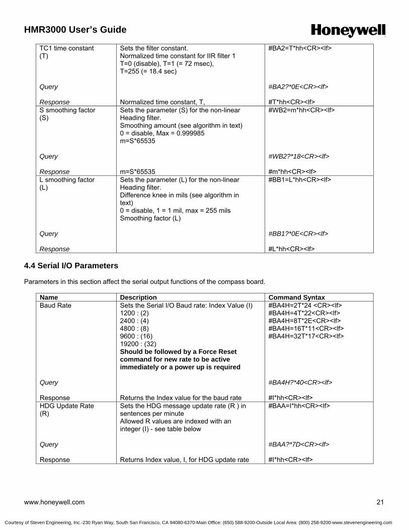
HMR3000 User’s Guide
www.honeywell.com 21
TC1 time constant (T) Query Response
Sets the filter constant. Normalized time constant for IIR filter 1 T=0 (disable), T=1 (= 72 msec), T=255 (= 18.4 sec) Normalized time constant, T,
#BA2=T*hh<CR><lf> #BA2?*0E<CR><lf> #T*hh<CR><lf>
S smoothing factor (S) Query Response
Sets the parameter (S) for the non-linear Heading filter. Smoothing amount (see algorithm in text) 0 = disable, Max = 0.999985 m=S*65535 m=S*65535
#WB2=m*hh<CR><lf> #WB2?*18<CR><lf> #m*hh<CR><lf>
L smoothing factor (L) Query Response
Sets the parameter (L) for the non-linear Heading filter. Difference knee in mils (see algorithm in text) 0 = disable, 1 = 1 mil, max = 255 mils Smoothing factor (L)
#BB1=L*hh<CR><lf> #BB1?*0E<CR><lf> #L*hh<CR><lf>
4.4 Serial I/O Parameters Parameters in this section affect the serial output functions of the compass board.
Name Description Command Syntax Baud Rate Query Response
Sets the Serial I/O Baud rate: Index Value (I) 1200 : (2) 2400 : (4) 4800 : (8) 9600 : (16) 19200 : (32) Should be followed by a Force Reset command for new rate to be active immediately or a power up is required Returns the Index value for the baud rate
#BA4H=2T*24 <CR><lf> #BA4H=4T*22<CR><lf> #BA4H=8T*2E<CR><lf> #BA4H=16T*11<CR><lf> #BA4H=32T*17<CR><lf> #BA4H?*40<CR><lf> #I*hh<CR><lf>
HDG Update Rate (R) Query Response
Sets the HDG message update rate (R ) in sentences per minute Allowed R values are indexed with an integer (I) - see table below Returns Index value, I, for HDG update rate
#BAA=I*hh<CR><lf> #BAA?*7D<CR><lf> #I*hh<CR><lf>
Courtesy of Steven Engineering, Inc.-230 Ryan Way, South San Francisco, CA 94080-6370-Main Office: (650) 588-9200-Outside Local Area: (800) 258-9200-www.stevenengineering.com
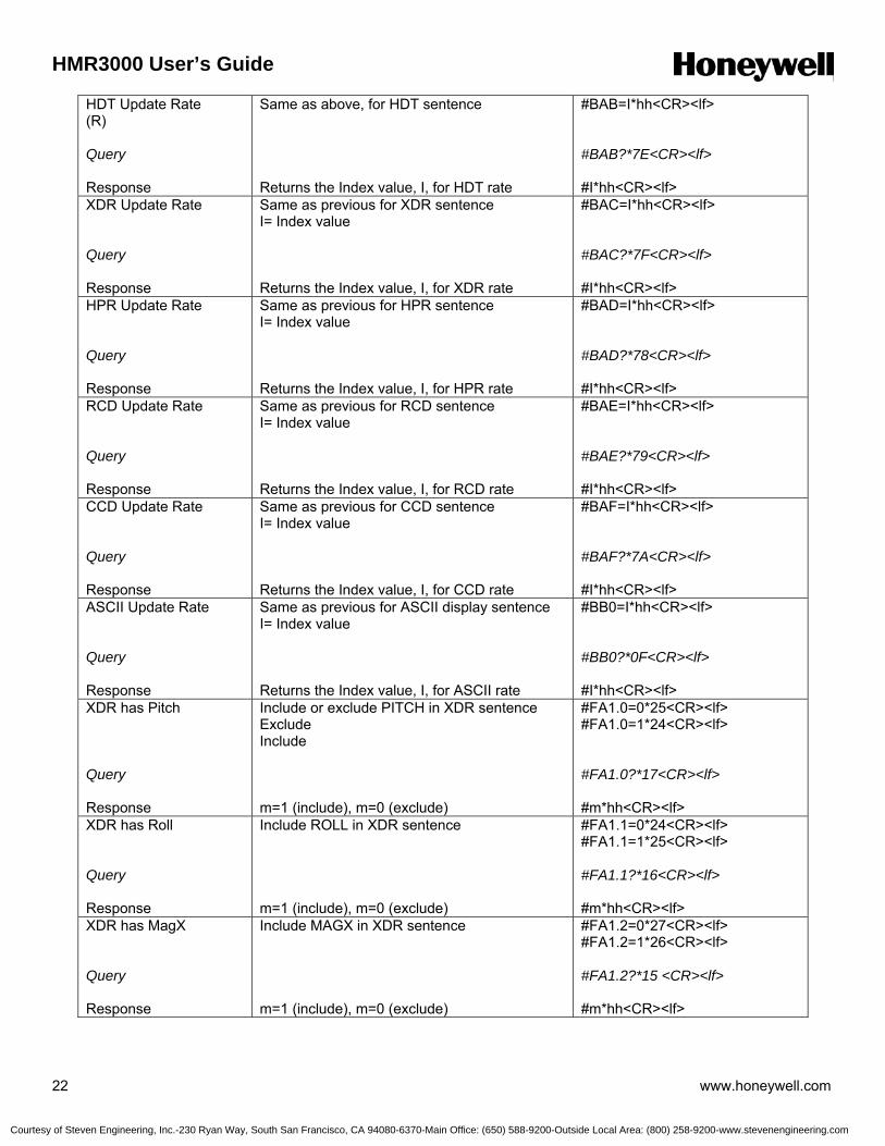
HMR3000 User’s Guide
22 www.honeywell.com
HDT Update Rate (R) Query Response
Same as above, for HDT sentence Returns the Index value, I, for HDT rate
#BAB=I*hh<CR><lf> #BAB?*7E<CR><lf> #I*hh<CR><lf>
XDR Update Rate Query Response
Same as previous for XDR sentence I= Index value Returns the Index value, I, for XDR rate
#BAC=I*hh<CR><lf> #BAC?*7F<CR><lf> #I*hh<CR><lf>
HPR Update Rate Query Response
Same as previous for HPR sentence I= Index value Returns the Index value, I, for HPR rate
#BAD=I*hh<CR><lf> #BAD?*78<CR><lf> #I*hh<CR><lf>
RCD Update Rate Query Response
Same as previous for RCD sentence I= Index value Returns the Index value, I, for RCD rate
#BAE=I*hh<CR><lf> #BAE?*79<CR><lf> #I*hh<CR><lf>
CCD Update Rate Query Response
Same as previous for CCD sentence I= Index value Returns the Index value, I, for CCD rate
#BAF=I*hh<CR><lf> #BAF?*7A<CR><lf> #I*hh<CR><lf>
ASCII Update Rate Query Response
Same as previous for ASCII display sentence I= Index value Returns the Index value, I, for ASCII rate
#BB0=I*hh<CR><lf> #BB0?*0F<CR><lf> #I*hh<CR><lf>
XDR has Pitch Query Response
Include or exclude PITCH in XDR sentence Exclude Include m=1 (include), m=0 (exclude)
#FA1.0=0*25<CR><lf> #FA1.0=1*24<CR><lf> #FA1.0?*17<CR><lf> #m*hh<CR><lf>
XDR has Roll Query Response
Include ROLL in XDR sentence m=1 (include), m=0 (exclude)
#FA1.1=0*24<CR><lf> #FA1.1=1*25<CR><lf> #FA1.1?*16<CR><lf> #m*hh<CR><lf>
XDR has MagX Query Response
Include MAGX in XDR sentence m=1 (include), m=0 (exclude)
#FA1.2=0*27<CR><lf> #FA1.2=1*26<CR><lf> #FA1.2?*15 <CR><lf> #m*hh<CR><lf>
Courtesy of Steven Engineering, Inc.-230 Ryan Way, South San Francisco, CA 94080-6370-Main Office: (650) 588-9200-Outside Local Area: (800) 258-9200-www.stevenengineering.com

HMR3000 User’s Guide
www.honeywell.com 23
XDR has MagY Query Response
Include MAGY in XDR sentence m=1 (include), m=0 (exclude)
#FA1.3=0*26<CR><lf> #FA1.3=1*27<CR><lf> #FA1.3?*14 <CR><lf> #m*hh<CR><lf>
XDR has MagZ Query Response
Include MAGZ in XDR sentence m=1 (include), m=0 (exclude)
#FA1.4=0*21<CR><lf> #FA1.4=1*20<CR><lf> #FA1.4?*13 <CR><lf> #m*hh<CR><lf>
XDR has MagT Query Response
Include MAGT in XDR sentence m=1 (include), m=0 (exclude)
#FA1.5=0*20<CR><lf> #FA1.5=1*21<CR><lf> #FA1.5?*12 <CR><lf> #m*hh<CR><lf>
In the current configuration software, when the baud rate is changed, the new rate will not take effect until a “Force Reset” command is issued or until the unit is powered off then on. When any output sentence rate is changed, the current interval will expire before the new rate takes effect.
Index(I) Rate(R) Index Rate Index Rate Index Rate 0 0 4 6 8 60 12 413 1 1 5 12 9 120 13 600 2 2 6 20 10 180 14 825 3 3 7 30 11 300 15 1200
Courtesy of Steven Engineering, Inc.-230 Ryan Way, South San Francisco, CA 94080-6370-Main Office: (650) 588-9200-Outside Local Area: (800) 258-9200-www.stevenengineering.com

HMR3000 User’s Guide
24 www.honeywell.com
5.0 HMR3000 HARDWARE INTERRUPT PINS The following is the detail description of the Cont./Reset, Operate/Calibrate, Ready/Sleep, Run/Stop pins. The order of precedence for operation of the switch input pins is as follows: 1. Setting "Cont. / Reset" low unconditionally holds the HMR3000 processor in its reset state. No other functions can be performed until the switch is returned to the "Continue" position. 2. Setting "Operate / Calibrate" low (Calibrate) forces the processor into Calibrate mode. The "Run / Stop" and "Ready / Sleep" switches are ignored in this mode. When the switch is set to the Operate position, the unit can be in either mode depending on the "Select Mode" command bit that can be changed via the serial interface. The "Select Mode" command bit is initialized to the Operate state on power up. 3. Setting "Ready / Sleep" low while the unit is not in Calibrate mode forces the unit into a low power state with measurements and outputs suspended, and with serial inputs ignored. This switch must be returned to the "Ready" position before a host processor can send a serial command. When momentarily placed in the "Ready" position, the processor will run a complete measurement and output cycle (if in Run mode) before suspending operation. Mechanical switch bounce on this input can be tolerated in the firmware.
4. Setting "Run / Stop" low stops any output in progress within one character time and prevents further output. When the switch is in the Run position, the state of the internal Run/Stop command bit controls the unsolicited output. The internal Run/Stop command bit is initialized to the settings saved in the EEPROM. 6.0 ALGORITHM FOR THE NON-LINEAR HEADING FILTER The algorithm for the non-linear heading filter is: Assume CH = current heading SH = smoothed output L = tuned setting (integer > 0, 0 = disable) S = tuned setting (0 < fraction < 1, 0 = disable, max = 0.999985) Calculate D = CH - SH (difference) G = S + S * (D/L)**2 (saturate G as D/L gets large, S <= G <= 1) SH = SH + D * G (note that SH = CH for G = 1) These calculations are iterated at the 13.75 Hz rate.
Courtesy of Steven Engineering, Inc.-230 Ryan Way, South San Francisco, CA 94080-6370-Main Office: (650) 588-9200-Outside Local Area: (800) 258-9200-www.stevenengineering.com

HMR3000 User’s Guide
www.honeywell.com 25
7.0 PHYSICAL DIMENSIONS Enclosure Dimensions
PCB Dimensions
Aerospace Electronics Systems Defense and Space Electronics Systems Honeywell International Inc. 12001 Highway 55 Plymouth, MN 55441 Tel: 800-323-8295 www.honeywell.com
Form #900240 Rev C August 2005 ©2005 Honeywell International Inc.
Courtesy of Steven Engineering, Inc.-230 Ryan Way, South San Francisco, CA 94080-6370-Main Office: (650) 588-9200-Outside Local Area: (800) 258-9200-www.stevenengineering.com

HMR3100 SENSOR PRODUCTS
Solid State Electronics Center • www.magneticsensors.com • (800) 323-8295 • Page 1
DIGITAL COMPASS SOLUTION Features • 5° Heading Accuracy, 0.5° Resolution • 2-axis Capability • Small Size (19mm x 19mm x 4.5mm), Light Weight • Advanced Hard Iron Calibration Routine for Stray
Fields and Ferrous Objects • 0° to 70°C Operating Temperature Range • 2.6 to 5 volt DC Single Supply Operation
General Description The Honeywell HMR3100 is a low cost, two-axis electronic compassing solution used to derive heading output. Honeywell’s magnetoresistive sensors are utilized to provide the reliability and accuracy of these small, solid state compass designs. The HMR3100 communicates through binary data and ASCII characters at four selectable baud rates of 2400, 4800, 9600, or 19200. This compass solution is easily integrated into systems using a simple USART interface.
Block Diagram• Vehicle Compassing
• Hand-Held Electronics
• Telescope Positioning
• Navigation Systems
APPLICATIONS
HMC1022
VCC
RXD
TXD
RTS
GND
CPU
Top Side
Bottom Side
Courtesy of Steven Engineering, Inc.-230 Ryan Way, South San Francisco, CA 94080-6370-Main Office: (650) 588-9200-Outside Local Area: (800) 258-9200-www.stevenengineering.com
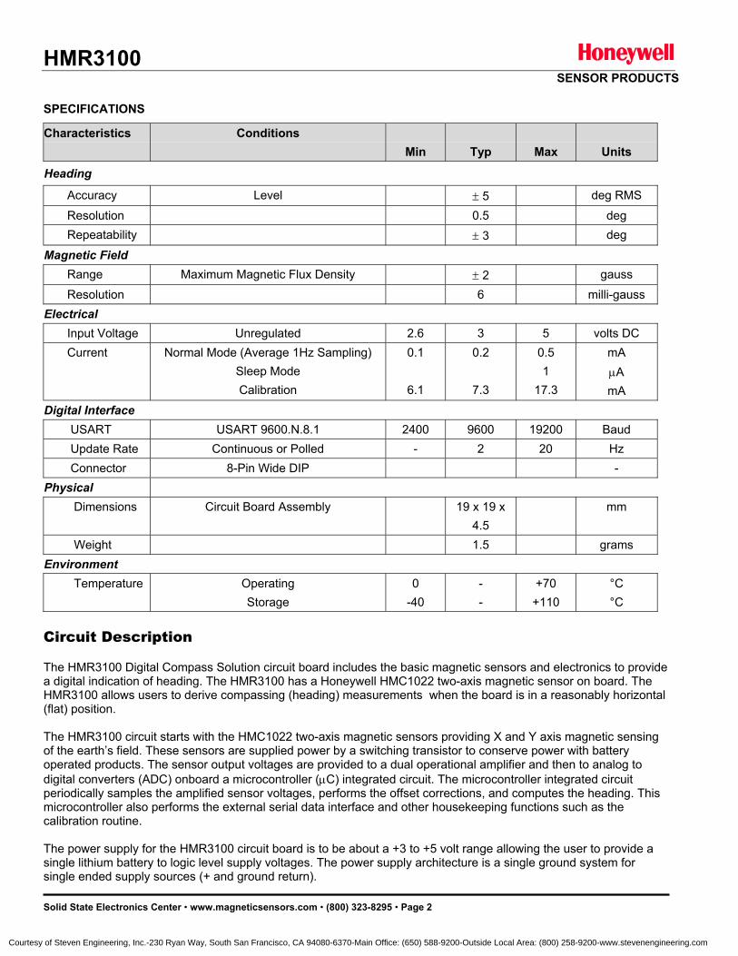
HMR3100 SENSOR PRODUCTS
Solid State Electronics Center • www.magneticsensors.com • (800) 323-8295 • Page 2
SPECIFICATIONS
Characteristics Conditions Min
Typ
Max
Units
Heading
Accuracy Level ± 5 deg RMS
Resolution 0.5 deg Repeatability ± 3 deg
Magnetic Field Range Maximum Magnetic Flux Density ± 2 gauss
Resolution 6 milli-gauss Electrical Input Voltage Unregulated 2.6 3 5 volts DC Current Normal Mode (Average 1Hz Sampling)
Sleep Mode Calibration
0.1
6.1
0.2
7.3
0.5 1
17.3
mA µA mA
Digital Interface USART USART 9600.N.8.1 2400 9600 19200 Baud Update Rate Continuous or Polled - 2 20 Hz Connector 8-Pin Wide DIP - Physical Dimensions Circuit Board Assembly 19 x 19 x
4.5 mm
Weight 1.5 grams Environment Temperature Operating
Storage 0
-40 - -
+70 +110
°C °C
Circuit Description The HMR3100 Digital Compass Solution circuit board includes the basic magnetic sensors and electronics to provide a digital indication of heading. The HMR3100 has a Honeywell HMC1022 two-axis magnetic sensor on board. The HMR3100 allows users to derive compassing (heading) measurements when the board is in a reasonably horizontal (flat) position. The HMR3100 circuit starts with the HMC1022 two-axis magnetic sensors providing X and Y axis magnetic sensing of the earth’s field. These sensors are supplied power by a switching transistor to conserve power with battery operated products. The sensor output voltages are provided to a dual operational amplifier and then to analog to digital converters (ADC) onboard a microcontroller (µC) integrated circuit. The microcontroller integrated circuit periodically samples the amplified sensor voltages, performs the offset corrections, and computes the heading. This microcontroller also performs the external serial data interface and other housekeeping functions such as the calibration routine. The power supply for the HMR3100 circuit board is to be about a +3 to +5 volt range allowing the user to provide a single lithium battery to logic level supply voltages. The power supply architecture is a single ground system for single ended supply sources (+ and ground return).
Courtesy of Steven Engineering, Inc.-230 Ryan Way, South San Francisco, CA 94080-6370-Main Office: (650) 588-9200-Outside Local Area: (800) 258-9200-www.stevenengineering.com
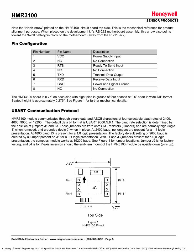
HMR3100 SENSOR PRODUCTS
Solid State Electronics Center • www.magneticsensors.com • (800) 323-8295 • Page 3
Note the “North Arrow” printed on the HMR3100 circuit board top side. This is the mechanical reference for product alignment purposes. When placed on the development kit’s RS-232 motherboard assembly, this arrow also points toward the 9-volt batterypin block on the motherboard (away from the RJ-11 jack). Pin Configuration
Pin Number Pin Name Description 1 VCC Power Supply Input 2 NC No Connection 3 RTS Ready To Send Input 4 NC No Connection 5 TXD Transmit Data Output 6 RXD Receive Data Input 7 GND Power and Signal Ground 8 NC No Connection
The HMR3100 board is 0.77” on each side with eight pins in groups of four spaced at 0.6” apart in wide-DIP format. Seated height is approximately 0.275”. See Figure 1 for further mechanical details. USART Communication Protocol
HMR3100 module communicates through binary data and ASCII characters at four selectable baud rates of 2400, 4800, 9600, or 19200. The default data bit format is USART 9600.N.8.1. The baud rate selection is determined by the position of jumpers J1 and J3. These jumpers are zero ohm SMT resistors (jumpers) and are normally high (logic 1) when removed, and grounded (logic 0) when in place. At 2400 baud, no jumpers are present for a 1,1 logic presentation. At 4800 baud J3 is present for a 1,0 logic presentation. The factory default setting of 9600 baud is created by a jumper present on J1 for a 0,1 logic presentation. With J1 and J3 jumpers present for a 0,0 logic presentation, the compass module works at 19200 baud. See Figure 1 for jumper locations. Jumper J2 is for factory testing, and J4 is for Y-axis inversion should the end-item mount of the HMR3100 module be upside down (pins up).
Figure 1HMR3100 Pinout
0.77”
0.77”
µ C
xtal
Pin 1
Pin 4
Top Side
Pin 5
Pin 8
J1 J2 J3 J4
Courtesy of Steven Engineering, Inc.-230 Ryan Way, South San Francisco, CA 94080-6370-Main Office: (650) 588-9200-Outside Local Area: (800) 258-9200-www.stevenengineering.com
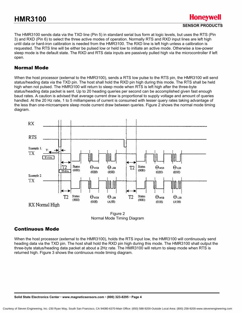
HMR3100 SENSOR PRODUCTS
Solid State Electronics Center • www.magneticsensors.com • (800) 323-8295 • Page 4
The HMR3100 sends data via the TXD line (Pin 5) in standard serial bus form at logic levels, but uses the RTS (Pin 3) and RXD (Pin 6) to select the three active modes of operation. Normally RTS and RXD input lines are left high until data or hard-iron calibration is needed from the HMR3100. The RXD line is left high unless a calibration is requested. The RTS line will be either be pulsed low or held low to initiate an active mode. Otherwise a low-power sleep mode is the default state. The RXD and RTS data inputs are passively pulled high via the microcontroller if left open. Normal Mode When the host processor (external to the HMR3100), sends a RTS low pulse to the RTS pin, the HMR3100 will send status/heading data via the TXD pin. The host shall hold the RXD pin high during this mode. The RTS shall be held high when not pulsed. The HMR3100 will return to sleep mode when RTS is left high after the three-byte status/heading data packet is sent. Up to 20 heading queries per second can be accomplished given fast enough baud rates. A caution is advised that average current draw is proportional to supply voltage and amount of queries handled. At the 20 Hz rate, 1 to 5 milliamperes of current is consumed with lesser query rates taking advantage of the less than one-microampere sleep mode current draw between queries. Figure 2 shows the normal mode timing diagram. Continuous Mode When the host processor (external to the HMR3100), holds the RTS input low, the HMR3100 will continuously send heading data via the TXD pin. The host shall hold the RXD pin high during this mode. The HMR3100 shall output the three-byte status/heading data packet at about a 2Hz rate. The HMR3100 will return to sleep mode when RTS is returned high. Figure 3 shows the continuous mode timing diagram.
Figure 2 Normal Mode Timing Diagram
Courtesy of Steven Engineering, Inc.-230 Ryan Way, South San Francisco, CA 94080-6370-Main Office: (650) 588-9200-Outside Local Area: (800) 258-9200-www.stevenengineering.com
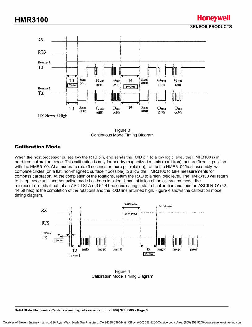
HMR3100 SENSOR PRODUCTS
Solid State Electronics Center • www.magneticsensors.com • (800) 323-8295 • Page 5
Calibration Mode When the host processor pulses low the RTS pin, and sends the RXD pin to a low logic level, the HMR3100 is in hard-iron calibration mode. This calibration is only for nearby magnetized metals (hard-iron) that are fixed in position with the HMR3100. At a moderate rate (5 seconds or more per rotation), rotate the HMR3100/host assembly two complete circles (on a flat, non-magnetic surface if possible) to allow the HMR3100 to take measurements for compass calibration. At the completion of the rotations, return the RXD to a high logic level. The HMR3100 will return to sleep mode until another active mode has been initiated. Upon initiation of the calibration mode, the microcontroller shall output an ASCII STA (53 54 41 hex) indicating a start of calibration and then an ASCII RDY (52 44 59 hex) at the completion of the rotations and the RXD line returned high. Figure 4 shows the calibration mode timing diagram.
Figure 3 Continuous Mode Timing Diagram
Figure 4 Calibration Mode Timing Diagram
Figure 4 Calibration Mode Timing Diagram
Courtesy of Steven Engineering, Inc.-230 Ryan Way, South San Francisco, CA 94080-6370-Main Office: (650) 588-9200-Outside Local Area: (800) 258-9200-www.stevenengineering.com
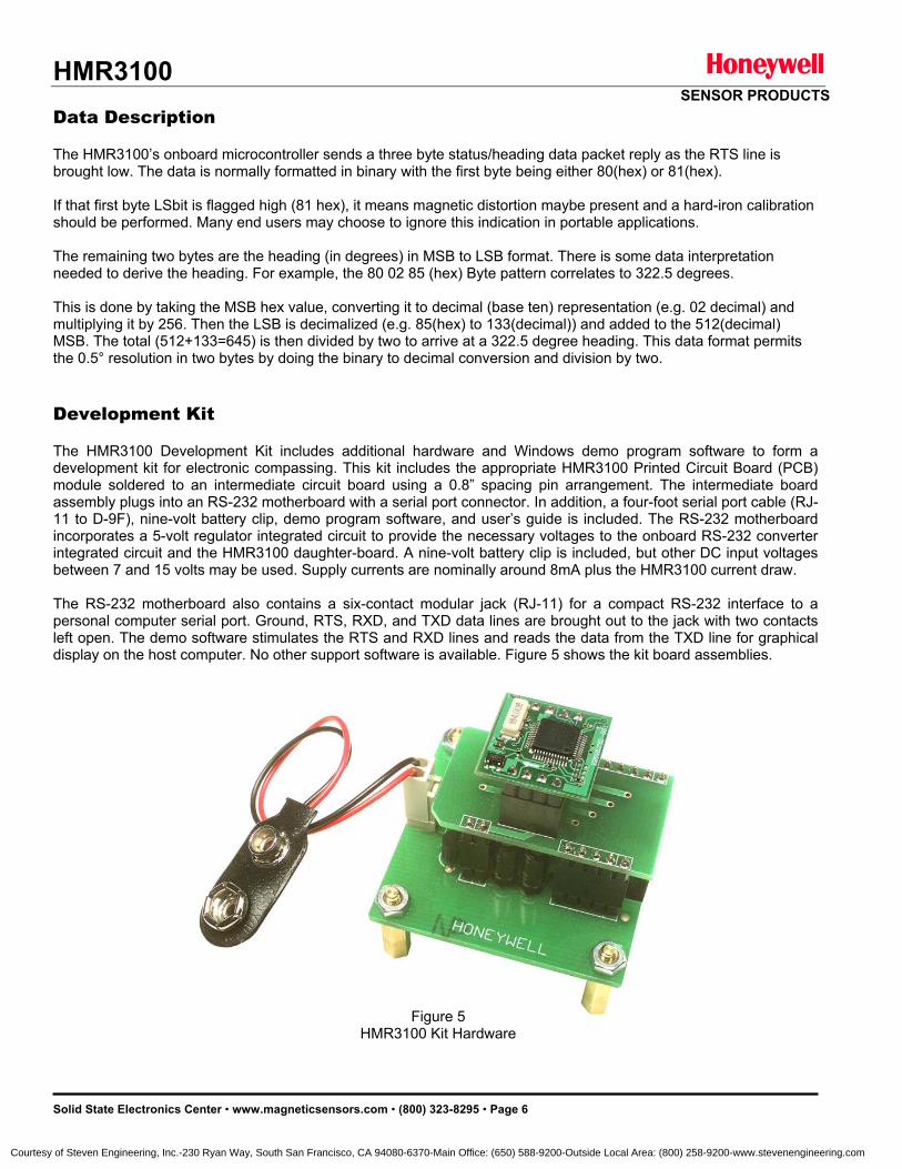
HMR3100 SENSOR PRODUCTS
Solid State Electronics Center • www.magneticsensors.com • (800) 323-8295 • Page 6
Data Description The HMR3100’s onboard microcontroller sends a three byte status/heading data packet reply as the RTS line is brought low. The data is normally formatted in binary with the first byte being either 80(hex) or 81(hex). If that first byte LSbit is flagged high (81 hex), it means magnetic distortion maybe present and a hard-iron calibration should be performed. Many end users may choose to ignore this indication in portable applications. The remaining two bytes are the heading (in degrees) in MSB to LSB format. There is some data interpretation needed to derive the heading. For example, the 80 02 85 (hex) Byte pattern correlates to 322.5 degrees. This is done by taking the MSB hex value, converting it to decimal (base ten) representation (e.g. 02 decimal) and multiplying it by 256. Then the LSB is decimalized (e.g. 85(hex) to 133(decimal)) and added to the 512(decimal) MSB. The total (512+133=645) is then divided by two to arrive at a 322.5 degree heading. This data format permits the 0.5° resolution in two bytes by doing the binary to decimal conversion and division by two. Development Kit The HMR3100 Development Kit includes additional hardware and Windows demo program software to form a development kit for electronic compassing. This kit includes the appropriate HMR3100 Printed Circuit Board (PCB) module soldered to an intermediate circuit board using a 0.8” spacing pin arrangement. The intermediate board assembly plugs into an RS-232 motherboard with a serial port connector. In addition, a four-foot serial port cable (RJ-11 to D-9F), nine-volt battery clip, demo program software, and user’s guide is included. The RS-232 motherboard incorporates a 5-volt regulator integrated circuit to provide the necessary voltages to the onboard RS-232 converter integrated circuit and the HMR3100 daughter-board. A nine-volt battery clip is included, but other DC input voltages between 7 and 15 volts may be used. Supply currents are nominally around 8mA plus the HMR3100 current draw. The RS-232 motherboard also contains a six-contact modular jack (RJ-11) for a compact RS-232 interface to a personal computer serial port. Ground, RTS, RXD, and TXD data lines are brought out to the jack with two contacts left open. The demo software stimulates the RTS and RXD lines and reads the data from the TXD line for graphical display on the host computer. No other support software is available. Figure 5 shows the kit board assemblies.
Figure 5
HMR3100 Kit Hardware
Courtesy of Steven Engineering, Inc.-230 Ryan Way, South San Francisco, CA 94080-6370-Main Office: (650) 588-9200-Outside Local Area: (800) 258-9200-www.stevenengineering.com

HMR3100 SENSOR PRODUCTS
Solid State Electronics Center • www.magneticsensors.com • (800) 323-8295 • Page 7
Ordering Information
Ordering Number Product HMR3100 HMR3100-Demo-232
PCB Module Only PCB Module with Development Kit
Honeywell reserves the right to make changes to improve reliability, function or design. Honeywell does not assume any liability arising out of the application or use of any product or circuit described herein; neither does it convey any license under its patent rights nor the rights of others. 900268 02-04 Rev. A
Courtesy of Steven Engineering, Inc.-230 Ryan Way, South San Francisco, CA 94080-6370-Main Office: (650) 588-9200-Outside Local Area: (800) 258-9200-www.stevenengineering.com

HMR3100 SENSOR PRODUCTS
Solid State Electronics Center • www.magneticsensors.com • (800) 323-8295 • Page 1
HMR3100
Digital Compass Solution
User’s Guide
Courtesy of Steven Engineering, Inc.-230 Ryan Way, South San Francisco, CA 94080-6370-Main Office: (650) 588-9200-Outside Local Area: (800) 258-9200-www.stevenengineering.com
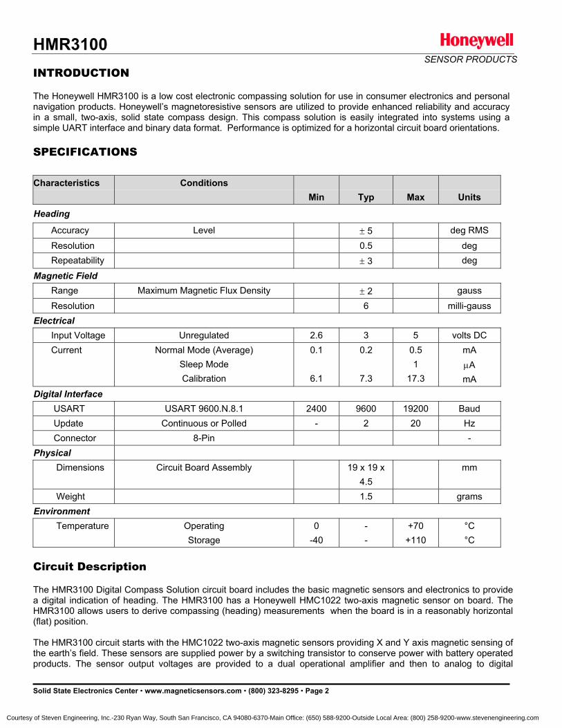
HMR3100 SENSOR PRODUCTS
Solid State Electronics Center • www.magneticsensors.com • (800) 323-8295 • Page 2
INTRODUCTION The Honeywell HMR3100 is a low cost electronic compassing solution for use in consumer electronics and personal navigation products. Honeywell’s magnetoresistive sensors are utilized to provide enhanced reliability and accuracy in a small, two-axis, solid state compass design. This compass solution is easily integrated into systems using a simple UART interface and binary data format. Performance is optimized for a horizontal circuit board orientations. SPECIFICATIONS
Characteristics Conditions Min
Typ
Max
Units
Heading
Accuracy Level ± 5 deg RMS
Resolution 0.5 deg Repeatability ± 3 deg
Magnetic Field Range Maximum Magnetic Flux Density ± 2 gauss
Resolution 6 milli-gauss Electrical Input Voltage Unregulated 2.6 3 5 volts DC Current Normal Mode (Average)
Sleep Mode Calibration
0.1
6.1
0.2
7.3
0.5 1
17.3
mA µA mA
Digital Interface USART USART 9600.N.8.1 2400 9600 19200 Baud Update Continuous or Polled - 2 20 Hz Connector 8-Pin - Physical Dimensions Circuit Board Assembly 19 x 19 x
4.5 mm
Weight 1.5 grams Environment Temperature Operating
Storage 0
-40 - -
+70 +110
°C °C
Circuit Description The HMR3100 Digital Compass Solution circuit board includes the basic magnetic sensors and electronics to provide a digital indication of heading. The HMR3100 has a Honeywell HMC1022 two-axis magnetic sensor on board. The HMR3100 allows users to derive compassing (heading) measurements when the board is in a reasonably horizontal (flat) position. The HMR3100 circuit starts with the HMC1022 two-axis magnetic sensors providing X and Y axis magnetic sensing of the earth’s field. These sensors are supplied power by a switching transistor to conserve power with battery operated products. The sensor output voltages are provided to a dual operational amplifier and then to analog to digital
Courtesy of Steven Engineering, Inc.-230 Ryan Way, South San Francisco, CA 94080-6370-Main Office: (650) 588-9200-Outside Local Area: (800) 258-9200-www.stevenengineering.com
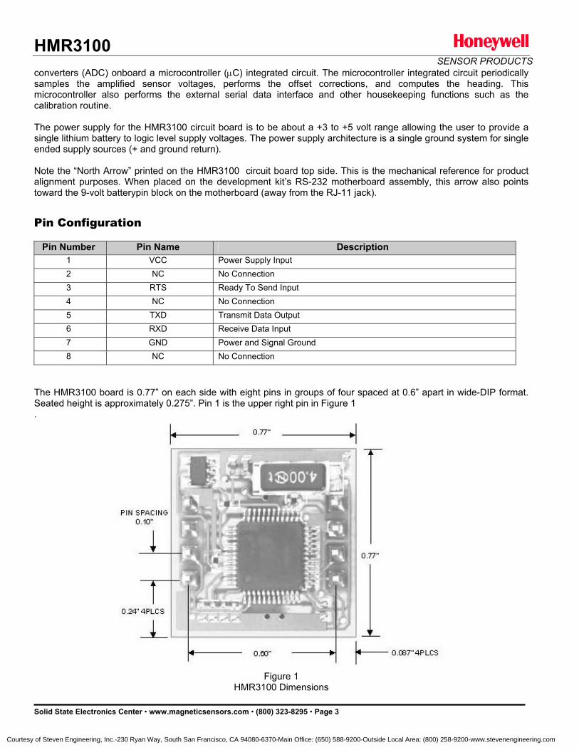
HMR3100 SENSOR PRODUCTS
Solid State Electronics Center • www.magneticsensors.com • (800) 323-8295 • Page 3
converters (ADC) onboard a microcontroller (µC) integrated circuit. The microcontroller integrated circuit periodically samples the amplified sensor voltages, performs the offset corrections, and computes the heading. This microcontroller also performs the external serial data interface and other housekeeping functions such as the calibration routine. The power supply for the HMR3100 circuit board is to be about a +3 to +5 volt range allowing the user to provide a single lithium battery to logic level supply voltages. The power supply architecture is a single ground system for single ended supply sources (+ and ground return). Note the “North Arrow” printed on the HMR3100 circuit board top side. This is the mechanical reference for product alignment purposes. When placed on the development kit’s RS-232 motherboard assembly, this arrow also points toward the 9-volt batterypin block on the motherboard (away from the RJ-11 jack). Pin Configuration
Pin Number Pin Name Description
1 VCC Power Supply Input 2 NC No Connection 3 RTS Ready To Send Input 4 NC No Connection 5 TXD Transmit Data Output 6 RXD Receive Data Input 7 GND Power and Signal Ground 8 NC No Connection
The HMR3100 board is 0.77” on each side with eight pins in groups of four spaced at 0.6” apart in wide-DIP format. Seated height is approximately 0.275”. Pin 1 is the upper right pin in Figure 1 .
Figure 1 HMR3100 Dimensions
Courtesy of Steven Engineering, Inc.-230 Ryan Way, South San Francisco, CA 94080-6370-Main Office: (650) 588-9200-Outside Local Area: (800) 258-9200-www.stevenengineering.com

HMR3100 SENSOR PRODUCTS
Solid State Electronics Center • www.magneticsensors.com • (800) 323-8295 • Page 4
USART Communication Protocol HMR3100 module communicates through binary data and ASCII characters at four selectable baud rates of 2400, 4800, 9600, or 19200. The default data bit format is USART 9600.N.8.1. The baud rate selection is determined by the position of jumpers J1 and J3. These jumpers are zero ohm SMT resistors (jumpers) and are normally high (logic 1) when removed, and grounded (logic 0) when in place. At 2400 baud, no jumpers are present for a 1,1 logic presentation. At 4800 baud J3 is present for a 1,0 logic presentation. The factory default setting of 9600 baud is created by a jumper present on J1 for a 0,1 logic presentation. With J1 and J3 jumpers present for a 0,0 logic presentation, the compass module works at 19200 baud. See Figure 1 for jumper locations. Jumper J2 is for factory testing, and J4 is for Y-axis inversion should the end-item mount of the HMR3100 module be upside down (pins up). The HMR3100 sends data via the TXD line (Pin 5) in standard serial bus form at logic levels, but uses the RTS (Pin 3) and RXD (Pin 6) to select the three active modes of operation. Normally RTS and RXD input lines are left high until data or hard-iron calibration is needed from the HMR3100. The RXD line is left high unless a calibration is requested. The RTS line will be either be pulsed low or held low to initiate an active mode. Otherwise a low-power sleep mode is the default state. The RXD and RTS data inputs are passively pulled high via the microcontroller if left open. Normal Mode When the host processor (external to the HMR3100), sends a RTS low pulse to the RTS pin, the HMR3100 will send status/heading data via the TXD pin. The host shall hold the RXD pin high during this mode. The RTS shall be held high when not pulsed. The HMR3100 will return to sleep mode when RTS is left high after the three-byte status/heading data packet is sent. Up to 20 heading queries per second can be accomplished given fast enough baud rates. A caution is advised that average current draw is proportional to supply voltage and amount of queries handled. At the 20 Hz rate, 1 to 5 milliamperes of current is consumed with lesser query rates taking advantage of the less than one-microampere sleep mode current draw between queries. Figure 2 shows the normal mode timing diagram.
Figure 2 Normal Mode Timing Diagram
Figure 2 Normal Mode Timing Diagram
Courtesy of Steven Engineering, Inc.-230 Ryan Way, South San Francisco, CA 94080-6370-Main Office: (650) 588-9200-Outside Local Area: (800) 258-9200-www.stevenengineering.com
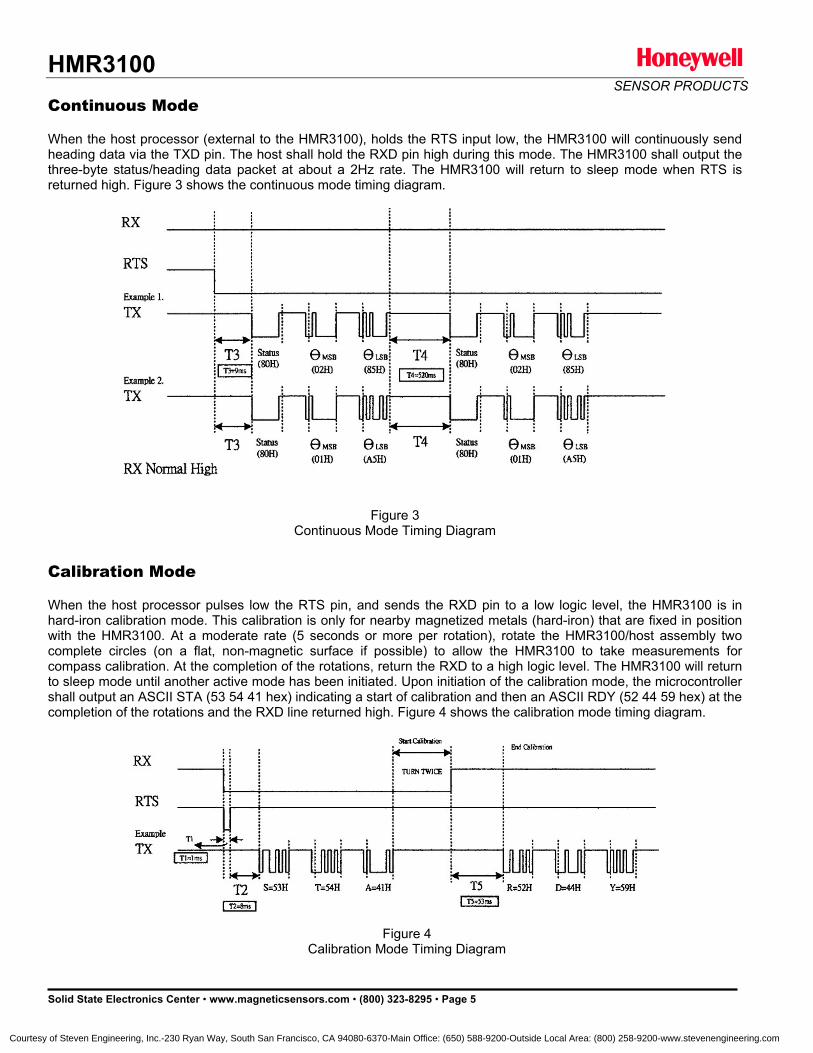
HMR3100 SENSOR PRODUCTS
Solid State Electronics Center • www.magneticsensors.com • (800) 323-8295 • Page 5
Continuous Mode When the host processor (external to the HMR3100), holds the RTS input low, the HMR3100 will continuously send heading data via the TXD pin. The host shall hold the RXD pin high during this mode. The HMR3100 shall output the three-byte status/heading data packet at about a 2Hz rate. The HMR3100 will return to sleep mode when RTS is returned high. Figure 3 shows the continuous mode timing diagram. Calibration Mode When the host processor pulses low the RTS pin, and sends the RXD pin to a low logic level, the HMR3100 is in hard-iron calibration mode. This calibration is only for nearby magnetized metals (hard-iron) that are fixed in position with the HMR3100. At a moderate rate (5 seconds or more per rotation), rotate the HMR3100/host assembly two complete circles (on a flat, non-magnetic surface if possible) to allow the HMR3100 to take measurements for compass calibration. At the completion of the rotations, return the RXD to a high logic level. The HMR3100 will return to sleep mode until another active mode has been initiated. Upon initiation of the calibration mode, the microcontroller shall output an ASCII STA (53 54 41 hex) indicating a start of calibration and then an ASCII RDY (52 44 59 hex) at the completion of the rotations and the RXD line returned high. Figure 4 shows the calibration mode timing diagram.
Figure 3 Continuous Mode Timing Diagram
Figure 4 Calibration Mode Timing Diagram
Courtesy of Steven Engineering, Inc.-230 Ryan Way, South San Francisco, CA 94080-6370-Main Office: (650) 588-9200-Outside Local Area: (800) 258-9200-www.stevenengineering.com
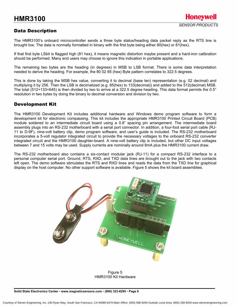
HMR3100 SENSOR PRODUCTS
Solid State Electronics Center • www.magneticsensors.com • (800) 323-8295 • Page 6
Data Description The HMR3100’s onboard microcontroller sends a three byte status/heading data packet reply as the RTS line is brought low. The data is normally formatted in binary with the first byte being either 80(hex) or 81(hex). If that first byte LSbit is flagged high (81 hex), it means magnetic distortion maybe present and a hard-iron calibration should be performed. Many end users may choose to ignore this indication in portable applications. The remaining two bytes are the heading (in degrees) in MSB to LSB format. There is some data interpretation needed to derive the heading. For example, the 80 02 85 (hex) Byte pattern correlates to 322.5 degrees. This is done by taking the MSB hex value, converting it to decimal (base ten) representation (e.g. 02 decimal) and multiplying it by 256. Then the LSB is decimalized (e.g. 85(hex) to 133(decimal)) and added to the 512(decimal) MSB. The total (512+133=645) is then divided by two to arrive at a 322.5 degree heading. This data format permits the 0.5° resolution in two bytes by doing the binary to decimal conversion and division by two. Development Kit The HMR3100 Development Kit includes additional hardware and Windows demo program software to form a development kit for electronic compassing. This kit includes the appropriate HMR3100 Printed Circuit Board (PCB) module soldered to an intermediate circuit board using a 0.8” spacing pin arrangement. The intermediate board assembly plugs into an RS-232 motherboard with a serial port connector. In addition, a four-foot serial port cable (RJ-11 to D-9F), nine-volt battery clip, demo program software, and user’s guide is included. The RS-232 motherboard incorporates a 5-volt regulator integrated circuit to provide the necessary voltages to the onboard RS-232 converter integrated circuit and the HMR3100 daughter-board. A nine-volt battery clip is included, but other DC input voltages between 7 and 15 volts may be used. Supply currents are nominally around 8mA plus the HMR3100 current draw. The RS-232 motherboard also contains a six-contact modular jack (RJ-11) for a compact RS-232 interface to a personal computer serial port. Ground, RTS, RXD, and TXD data lines are brought out to the jack with two contacts left open. The demo software stimulates the RTS and RXD lines and reads the data from the TXD line for graphical display on the host computer. No other support software is available. Figure 5 shows the kit board assemblies.
Figure 5 HMR3100 Kit Hardware
Courtesy of Steven Engineering, Inc.-230 Ryan Way, South San Francisco, CA 94080-6370-Main Office: (650) 588-9200-Outside Local Area: (800) 258-9200-www.stevenengineering.com

HMR3100 SENSOR PRODUCTS
Solid State Electronics Center • www.magneticsensors.com • (800) 323-8295 • Page 7
Honeywell reserves the right to make changes to improve reliability, function or design. Honeywell does not assume any liability arising out of the application or use of any product or circuit described herein; neither does it convey any license under its patent rights nor the rights of others. 900284 02–04 Rev A
Courtesy of Steven Engineering, Inc.-230 Ryan Way, South San Francisco, CA 94080-6370-Main Office: (650) 588-9200-Outside Local Area: (800) 258-9200-www.stevenengineering.com

Digital Compass Solutions HMR3200/HMR3300
The Honeywell HMR3200/HMR3300 are digital compass
solutions for use in precision heading applications.
Honeywell’s magnetoresistive sensors are utilized to
provide the reliability and accuracy of these small, solid
state compass designs. These compass solutions are
designed for generic precision compass integration into
customer systems using a 5-voltage logic level serial data
interface with commands in ASCII format.
The HMR3200 is a two-axis precision compass with three
orthogonal magnetoresistive sensors, and can be used in
either vertical or horizontal orientations.
The HMR3300 includes a MEMS accelerometer for a horizontal three-axis, tilt compensated precision compass for
performance up to a ±60° tilt range.
Honeywell continues to maintain product excellence and performance by introducing innovative solid-state magnetic
sensor solutions. These are highly reliable, top performance products that are delivered when promised. Honeywell’s
magnetic sensor solutions provide real solutions you can count on.
FEATURES BENEFITS
4 Compact Solution on a 1.0” by 1.5” PCB 4 Small Size and Pin Interface for Daughter/Motherboard Integration
4 Precision Compass Accuracy 4 ±1° at Level Heading Accuracy, ±0.1° Resolution
4 Tilt-Compensated (HMR3300 only) 4 Up to ±60° of Pitch and Roll Angles Using a MEMS Accelerometer
4 0.5° Repeatability 4 Magnetoresistive Sensor Technology for Consistency
4 8 Hz Continuous Update Rate 4 Rapid Heading Computations for Control System Applications
4 Hard-Iron Compensation Routine 4 User Driven Calibration to Null Stray Fields
4 -40° to +85°C Operating Temp Range 4 Consumer and Industrial Environment Uses
4 Demonstration Kit Available 4 Includes RS-232 Motherboard PCB, Cable, 9-volt power supply, PC Demo Software, and a Carrying Case
4 UART and SPI Communication 4 Intuitive Command Language
Courtesy of Steven Engineering, Inc.-230 Ryan Way, South San Francisco, CA 94080-6370-Main Office: (650) 588-9200-Outside Local Area: (800) 258-9200-www.stevenengineering.com
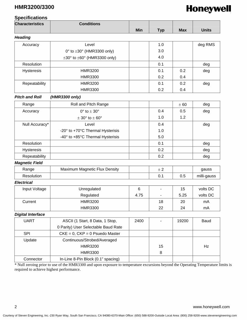
HMR3200/3300
2 www.honeywell.com
Specifications Characteristics Conditions
Min
Typ
Max
Units
Heading
Accuracy Level 0° to ±30° (HMR3300 only)
±30° to ±60° (HMR3300 only)
1.0 3.0 4.0
deg RMS
Resolution 0.1 deg Hysteresis HMR3200
HMR3300 0.1
0.2 0.2 0.4
deg
Repeatability HMR3200 HMR3300
0.1 0.2
0.2 0.4
deg
Pitch and Roll (HMR3300 only)
Range Roll and Pitch Range ± 60 deg
Accuracy 0° to ± 30° ± 30° to ± 60°
0.4 1.0
0.5 1.2
deg
Null Accuracy* Level -20° to +70°C Thermal Hysterisis -40° to +85°C Thermal Hysterisis
0.4 1.0 5.0
deg
Resolution 0.1 deg Hysteresis 0.2 deg Repeatability 0.2 deg Magnetic Field Range Maximum Magnetic Flux Density ± 2 gauss
Resolution 0.1 0.5 milli-gauss Electrical Input Voltage Unregulated
Regulated 6
4.75 - -
15 5.25
volts DC volts DC
Current HMR3200 HMR3300
18 22
20 24
mA mA
Digital Interface UART ASCII (1 Start, 8 Data, 1 Stop,
0 Parity) User Selectable Baud Rate 2400 - 19200 Baud
SPI CKE = 0, CKP = 0 Psuedo Master Update Continuous/Strobed/Averaged
HMR3200 HMR3300
15 8
Hz
Connector In-Line 8-Pin Block (0.1” spacing) * Null zeroing prior to use of the HMR3300 and upon exposure to temperature excursions beyond the Operating Temperature limits is required to achieve highest performance.
Courtesy of Steven Engineering, Inc.-230 Ryan Way, South San Francisco, CA 94080-6370-Main Office: (650) 588-9200-Outside Local Area: (800) 258-9200-www.stevenengineering.com
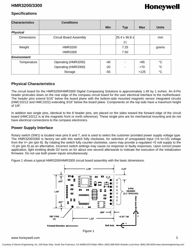
HMR3200/3300
www.honeywell.com 3
Specifications Characteristics Conditions
Min
Typ
Max
Units Physical Dimensions Circuit Board Assembly 25.4 x 36.8 x
11 mm
Weight HMR3200 HMR3300
7.25 7.50
grams
Environment Temperature Operating (HMR3200)
Operating (HMR3300) Storage
-40 -20 -55
- -
+85 +70 +125
°C °C °C
Physical Characteristics The circuit board for the HMR3200/HMR3300 Digital Compassing Solutions is approximately 1.45 by 1 inches. An 8-Pin header protrudes down on the rear edge of the compass circuit board for the user electrical interface to the motherboard. The header pins extend 5/16” below the board plane with the bottom-side mounted magnetic sensor integrated circuits (HMC1021Z and HMC1022) extending 3/16” below the board plane. Components on the top-side have a maximum height of 1/8”. In addition two single pins, identical to the 8 header pins, are placed on the sides toward the forward edge of the circuit board (HMC1021Z is at the magnetic front or north reference). These single pins are for mechanical mounting and do not have electrical connections to the compass electronics. Power Supply Interface Rotary switch (SW1) is located near pins 6 and 7, and is used to select the customer provided power supply voltage type. The HMR3200/3300 is factory set with this switch fully clockwise, for selection of unregulated input (+6 to+15) voltage from the V+ pin (pin 8). By rotating the switch fully counter-clockwise, users may provide a regulated +5 volt supply to the +5 pin (pin 6) as an alternative. Incorrect switch settings may cause no response or faulty responses. Upon correct power application, light emitting diode D2 turns on for about one second afterwards to indicate the execution of the initialization firmware. Do not use both power inputs simultaneously. Figure 1 shows a typical HMR3200/HMR3300 circuit board assembly with the basic dimensions. Figure 1
1.00”
1.45”
1.22”REF PINS
(2)
1
2
3
4
5
6
7
8
8-PINHEADER
(0.1” SPACING)
.037”
0.15”
.094”
.037”SW1
~0.30” Tall
Forward Direction-
+
- +
Roll Axis
Pitch Axis
1.00”
1.45”
1.22”REF PINS
(2)
1
2
3
4
5
6
7
8
8-PINHEADER
(0.1” SPACING)
.037”
0.15”
.094”
.037”SW1
~0.30” Tall
1.00”
1.45”
1.22”REF PINS
(2)
1
2
3
4
5
6
7
8
8-PINHEADER
(0.1” SPACING)
.037”
0.15”
.094”
.037”SW1
~0.30” Tall
Forward Direction-
+
-
+
- +- +
Roll Axis
Pitch Axis
Courtesy of Steven Engineering, Inc.-230 Ryan Way, South San Francisco, CA 94080-6370-Main Office: (650) 588-9200-Outside Local Area: (800) 258-9200-www.stevenengineering.com

HMR3200/3300
4 www.honeywell.com
Mounting Considerations The HMR3200/HMR3300 precision compasses use the ten integrated circuit style pins to plug into compatible motherboards for electrical interface, and to be orientated mechanically. The pins are nominally 0.030” in diameter and 0.200 in length. Trimming the pin lengths or removing the pins voids the warranty, as Honeywell can not retest the modified compasses (socketized test fixtures). Wires can be substituted for the pins, but caution should be used in soldering to not damage the pin solder pads. The HMC1021Z part is an 8-pin SIP device that is shipped carefully in a nearly perfectly vertical orientation with respect to the horizontal referenced circuit board. Do not bend or reposition this part, or the factory magnetic calibration will be no longer valid. Should the part be accidentally bent, return for recalibration is possible or align the part vertical to recapture most of the accuracy. Correct flat orientation of the compass modules is with the pins pointing downward. Circuit Description The HMR3200/HMR3300 Digital Compass Solutions include all the basic sensors and electronics to provide a digital indication of heading. The HMR3200 has all three axis of magnetic sensors on board, but allows the user to select which pair of sensors for compassing (flat or upright). The HMR3300 uses all three magnetic sensors plus includes an accelerometer to provide tilt (pitch and roll) sensing relative to the board’s horizontal (flat) position. The HMR3200/HMR3300 circuit starts with Honeywell HMC1021Z and HMC1022 single and two-axis magnetic sensors providing X, Y, and Z axis magnetic sensing of the earth’s field. The HMC1022 provides the horizontal components (X and Y), and HMC1021Z provides the vertical (Z) axis component of the incident magnetic field into cartesian magnitudes at orthognal angles. These sensors are supplied power by a constant current source to maintain best accuracy over temperature. The sensor output voltages and constant current sensor supply voltage are provided to a multiplexed 16-bit Analog to Digital Converter (ADC) integrated circuit. A microcontroller integrated circuit periodically queries the multiplexed ADC and performs the offset corrections and computes the heading. This microcontroller also performs the external serial data interface and other housekeeping functions such as the calibration routine. An onboard EEPROM integrated circuit is employed to retain necessary data variables for best performance. For the HMR3200, the three magnetic sensors (XYZ) are included and no accelerometer is present. The *L (level) and *U (upright) are available for horizontal and vertical circuit board orientations respectively. At level, the XY sensors are used to compute heading; and upright, the YZ sensors are used to compute heading. For the HMR3300, an additional pair of data inputs from the ±2g accelerometer (Analog Devices ADXL213) is received by the microcontroller. These tilt inputs (pitch and roll) are added to sensor data inputs to form a complete data set for a three dimensional computation of heading. If the board is held horizontal, the pitch and roll angles are zero and the X and Y sensor inputs dominate the heading equation. When tilted, the Z magnetic sensor plus the accelerometer’s pitch and roll angles enter into heading computation. The power supply for the HMR3200/HMR3300 circuit is regulated +5 volt design allowing the user to directly provide the regulated supply voltage or a +6 to +15 volt unregulated supply voltage. If the unregulated supply voltage is provided, then the linear voltage regulator integrated circuit drops the excess supply voltage to a stable +5 volts. The power supply is a dual ground (analog and digital) system to control internal noise and maximize measurment accuracy. Electrical Interface Pinout
Pin Number Pin Name Description
1 SCK Synchronous Data Clock (Pulled high in UART mode and left open) 2 RX Recieve Data, 5V CMOS Input 3 TX Transmit Data, 5V CMOS Output 4 CS Chip Select (Pulled high in UART mode and left open) 5 Cal Calibration Input (No connection normally, consult for details) 6 +5 +5 Volt Regulated Power Input (SW1 must be fully CCW) 7 GD Logic and Power Return (Ground) 8 V+ Unregulated Power Input (+6 to +15 volts, factory default, SW1 must be CW)
Courtesy of Steven Engineering, Inc.-230 Ryan Way, South San Francisco, CA 94080-6370-Main Office: (650) 588-9200-Outside Local Area: (800) 258-9200-www.stevenengineering.com

HMR3200/3300
www.honeywell.com 5
Application Notes When To Calibrate The HMR3200/HMR3300 comes with an optional user hard-iron calibration routine to null modest intensity hard-iron distortion. For many users in cleaner magnetic environments, the factory calibration will be better and yield more accurate readings than after a user calibration. The calibration routine is not cure-all for nasty magnetic environments. If a needle compass is thrown off from true readings, then it is very likely the HMR3200 and HMR3300 will have poor accuracy too. Most compass error sources come from ferrous metals (steel, iron, nickel, cobalt, etc.) located too close to the compass location and are known as soft-irons creating soft-iron distortion. Soft-iron distortion will change the intensity and direction of the magnetic fields on any nearby compass, and the calibration routine can not remove these flux concentration and bending errors. A good rule of thumb is to keep soft-irons at least two largest dimensions away from the compass. For example, a half-inch stainless steel panhead bolt should be at least an inch away from the HMC1021Z and HMC1022 sensor locations. Other nasty magnetic environments are man-made AC and DC magnetic fields created from nearby motors and high current conductors. These fields should also require compass or source relocation when possible. In some cases, ferrous metal shielding may help if the shield material is thin and far enough away from the compass. Hard-iron distortion can be calibrated out, and is composed of soft-irons that are also magnetized and create remnant (stray) magnetic flux. Classic hard-iron distortion typically comes from large vehicle chassis components and engine blocks that have up to ±2 gauss on the parts. Locating the compass away from hard and soft-irons is the first line of defense to preserve accuracy, and the calibration routine will null out the remaining hard-iron influences. Calibration Procedure For the HMR3200, one complete turn in a level plane is the best way to expose the sensors to all headings to compute the calibration offsets. Since the compass collects data at a 15 samples per second rate, a sample per degree of rotation or slower is a good guideline. If slow turns are not possible, multiple faster turns are a good substitute. The goodness of the calibration or the amount of hard-iron present is found by checking the Xof, Yof, and Zof values after the calibration routine is complete. In known clean magnetic environments, the horizontal values (XY = level, YZ = upright) should be ±200 ADC counts or less in these offset variables. Sending these Xof, Yof, and Zof values back to zero returns the compass to the factory calibration state. The vertical axis values can be zero set or ignored for the HMR3200. For the HMR3300, the above described level turns will calibrate the XY axis’, but the Z-axis must also be calibrated as well One full rotation with as much pitch and roll variation included as application allows. If only mild pitch and roll variations are possible, complete the level rotations, exit the calibration routine, and force the Zof value to zero. Some accuracy maybe lost in this zeroing, but the mild tilt would likely never cause serious tilt-compensation heading error. UART Communication Protocol
HMR3200/HMR3300 modules communicate through ASCII characters with the * or # characters as start bytes. The data bit format is 1 Start, 8 Data, 1 Stop, and No parity bits. Factory baud rate is set to 19,200. Asynchronous communication has the complete menu of commands. Synchronous communication is limited to direct heading queries and no other commands. Power-On/Reset The compasses require a hard power-on transition on the power supply voltage to serve as an internal hardware reset and clock-start. Some bench power supplies may create a soft-start condition and the HMR3200/HMR3300 my react with a constant-on LED illumination if not reset suddenly. An in-line power supply switch (mechanical or electrical) may be required when prototyping to avoid soft-starts. Upon application of power or after a Reset Command, the HMR3200/HMR3300 will run about an 800 milli-second initialization routine to set the onboard hardware and grab EEPROM variables and shadow them in controller RAM locations for operation. The LED will illuminate during the routine and extinguish upon completion.
Courtesy of Steven Engineering, Inc.-230 Ryan Way, South San Francisco, CA 94080-6370-Main Office: (650) 588-9200-Outside Local Area: (800) 258-9200-www.stevenengineering.com

HMR3200/3300
6 www.honeywell.com
Initial Status Output The HMR3200/HMR3300 will begin sending ASCII characters immediately after the initialization routine ends and the LED extinguishes. The first line of text will be the model number of the compass and the internal firmware revision number. For the HMR3300, a second response string will be sent, starting with a # character and either the N, W or A characters. The #N response indicates normal operation and is the always expected response from the HMR3200. The #W and #A responses are only for the HMR3300, and indicate the low temperature warning and alarm environments had been encountered. These responses will be reset to normal when the user sends the pitch and roll re-zero commands to re-calibrate the MEMS accelerometer for best tilt-compensation performance and accurate tilt indications. After initialization, the compasses automatically begin streaming heading or magnetometer output data at 15Hz (HMR3200) or 8Hz (HMR3300). Users must send a start/stop command (*S) to exit continuous streaming data, and to get the controller’s full attention to the next commands. Operational Commands Syntax: *X<cr><lf> Sends command for an operational mode change. The * prefix indicates command type. A #I response indicates an invalid command was sent. Heading Output Command
*H<cr><lf> Selects the Heading output mode (factory set default). This configuration is saved in non-volatile memory. All data are in decimal degrees. Response Format: Heading<cr><lf> (HMR3200 only and 15 times per second) Eg: 235.6<cr><lf> Response Format: Heading, Pitch, Roll<cr><lf> (HMR3300 only and 8 times per second) Eg: 123.4, 18.6, -0.5<cr><lf>
Magnetometer Output Command
*M<cr><lf> Selects the magnetometer output mode. This configuration is saved in non-volatile memory. All data are in signed decimal values with user calibration offsets included. Response Format: MagX, MagY, MagZ<cr><lf> Eg: 1256, -234, -1894<cr><lf>
Compass Orientation (HMR3200 only)
*L<cr><lf> Heading calculation is done assuming the compass is level (XY). *U<cr><lf> Heading calculation is done assuming the compass is upright (connector end down) (YZ). These orientation commands are saved in non-volatile memory.
Courtesy of Steven Engineering, Inc.-230 Ryan Way, South San Francisco, CA 94080-6370-Main Office: (650) 588-9200-Outside Local Area: (800) 258-9200-www.stevenengineering.com

HMR3200/3300
www.honeywell.com 7
Operational Commands (continued) Starting and Stopping Data Output
*S<cr><lf> The data output will toggle between Start and Stop each time this command is issued (factory set default is Start, first Start/Stop command will stop data output). Continuous data streaming control. Most commands require the compass to be in a stop condition for the controller to immediately execute the desired command.
Query Output *Q<cr><lf> Query for a single output response string in the currently selected mode (Magnetometer/Heading). The *Q commands are allowed only in Stop data mode. Query commands allow the user to slow the data flow by requesting each response string.
Roll Axis Re-Zero (HMR3300 only)
*O<cr><lf> Allows the user to zero the roll output. This command should only be issued when the roll axis is leveled (±0.3°). Clears Alarm or Warning status after command receipt.
Pitch Axis Re-Zero (HMR3300 only) *P<cr><lf> Allows the user to zero the pitch output. This command should only be used when the pitch axis is leveled (±0.3°). Clears Alarm or Warning status after command receipt.
Averaged Output *A<cr><lf> Same result as the query command except that the data are the result of an averaging of 20 readings. The *A commands are allowed only in Stop data mode. The command response will not occur until the 20 readings accrue (8 per second for the HMR3300, 15 per second for the HMR3200).
Split Filter Toggle (HMR3300 only) *F<cr><lf> This command toggles the split filter bit in the configuration status bytes. The parameter setting is saved in the EEPROM immediately, but not in shadowed in RAM. Requires power cycling or a reset command (*R) to activate. A set bit indicates the System Filter only smoothes the accelerometer data (Tilt Filter), and the Magnetic Filter is now active to smooth magnetic sensor data. A cleared filter bit resumes the same smoothing for both the tilt and magnetometer data.
Reset
*R<cr><lf> Resets compass to power-up condition. A one second initialization routine starts and EEPROM data (non-volatile memory) is uploaded (shadowed) into RAM. Continuous streaming data begins after initialization and status output.
Courtesy of Steven Engineering, Inc.-230 Ryan Way, South San Francisco, CA 94080-6370-Main Office: (650) 588-9200-Outside Local Area: (800) 258-9200-www.stevenengineering.com

HMR3200/3300
8 www.honeywell.com
Operational Commands (continued) User Calibration
*C<cr><lf> The command to be issued to enter and exit the calibration mode. Once in the calibration mode, the device will send one or more magnetometer data strings appended by a “C” character to indicate the Calibration Mode operation. Eg. 123,834,1489,C<cr><lf> See the calibration procedure notes earlier in this datasheet. At the completion of the calibration movements, issue another *C<cr><lf> to exit the calibration mode.
Configuration Commands
Syntax: #Dev=±xxxx<cr><lf> Sets parameter value
#Dev?<cr><lf> Queries for the parameter value
Variation Input (Declination Angle Correction)
#Var=±nnnn<cr><lf> where the variation is ± nnn.n degrees Sets the declination angle between magnetic north and geographic north. The declination angle is subtracted from the magnetic north heading computed to create a geographic north heading. Values typically range in the ±25 degree area. For example New York has a -14 degree declination angle, and Los Angles has a +14 degree declination angle. Eg: #Var=-203<cr><lf> sets the declination angle to –20.3 degrees. Eg: #Var=?<cr><lf>returns the declination angle; –20.3
Deviation Input (Platform Angle Correction)
#Dev=±nnnn<cr><lf> where the angle is ± nnn.n degrees Sets or returns the angle between compass forward direction and that of the mounting platform. The Deviation angle is subtracted from the predicted heading to compensate for mechanical misalignment. Eg: #Dev=23<cr><lf> sets the deviation angle to +2.3 degrees. Eg: #Dev=?<cr><lf>returns the deviation angle; +2.3
User Magnetic Offset Values (X, Y and Z)
#Xof, #Yof, #Zof Sets or returns the user offset values for each magnetic axis. These values are recomputed after a calibration routine. Also fixed offsets can be inserted to correct for known magnetic shifts. Values are in ADC counts. Eg: #Xof=+47<cr><lf> sets the x offset value to +47. Eg: #Xof=?<cr><lf> returns the x offset value; +47.
Courtesy of Steven Engineering, Inc.-230 Ryan Way, South San Francisco, CA 94080-6370-Main Office: (650) 588-9200-Outside Local Area: (800) 258-9200-www.stevenengineering.com
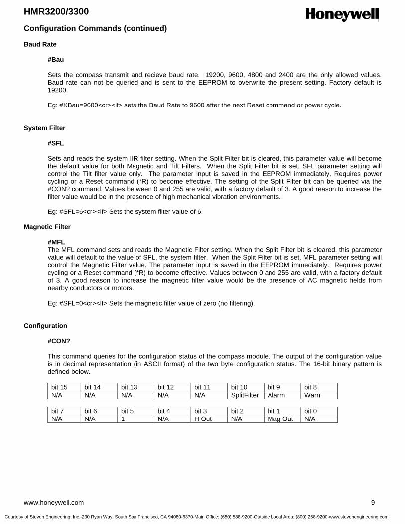
HMR3200/3300
www.honeywell.com 9
Configuration Commands (continued) Baud Rate
#Bau Sets the compass transmit and recieve baud rate. 19200, 9600, 4800 and 2400 are the only allowed values. Baud rate can not be queried and is sent to the EEPROM to overwrite the present setting. Factory default is 19200. Eg: #XBau=9600<cr><lf> sets the Baud Rate to 9600 after the next Reset command or power cycle.
System Filter
#SFL Sets and reads the system IIR filter setting. When the Split Filter bit is cleared, this parameter value will become the default value for both Magnetic and Tilt Filters. When the Split Filter bit is set, SFL parameter setting will control the Tilt filter value only. The parameter input is saved in the EEPROM immediately. Requires power cycling or a Reset command (*R) to become effective. The setting of the Split Filter bit can be queried via the #CON? command. Values between 0 and 255 are valid, with a factory default of 3. A good reason to increase the filter value would be in the presence of high mechanical vibration environments.
Eg: #SFL=6<cr><lf> Sets the system filter value of 6.
Magnetic Filter
#MFL The MFL command sets and reads the Magnetic Filter setting. When the Split Filter bit is cleared, this parameter value will default to the value of SFL, the system filter. When the Split Filter bit is set, MFL parameter setting will control the Magnetic Filter value. The parameter input is saved in the EEPROM immediately. Requires power cycling or a Reset command (*R) to become effective. Values between 0 and 255 are valid, with a factory default of 3. A good reason to increase the magnetic filter value would be the presence of AC magnetic fields from nearby conductors or motors. Eg: #SFL=0<cr><lf> Sets the magnetic filter value of zero (no filtering).
Configuration
#CON?
This command queries for the configuration status of the compass module. The output of the configuration value is in decimal representation (in ASCII format) of the two byte configuration status. The 16-bit binary pattern is defined below.
bit 15 bit 14 bit 13 bit 12 bit 11 bit 10 bit 9 bit 8 N/A N/A N/A N/A N/A SplitFilter Alarm Warn
bit 7 bit 6 bit 5 bit 4 bit 3 bit 2 bit 1 bit 0 N/A N/A 1 N/A H Out N/A Mag Out N/A
Courtesy of Steven Engineering, Inc.-230 Ryan Way, South San Francisco, CA 94080-6370-Main Office: (650) 588-9200-Outside Local Area: (800) 258-9200-www.stevenengineering.com
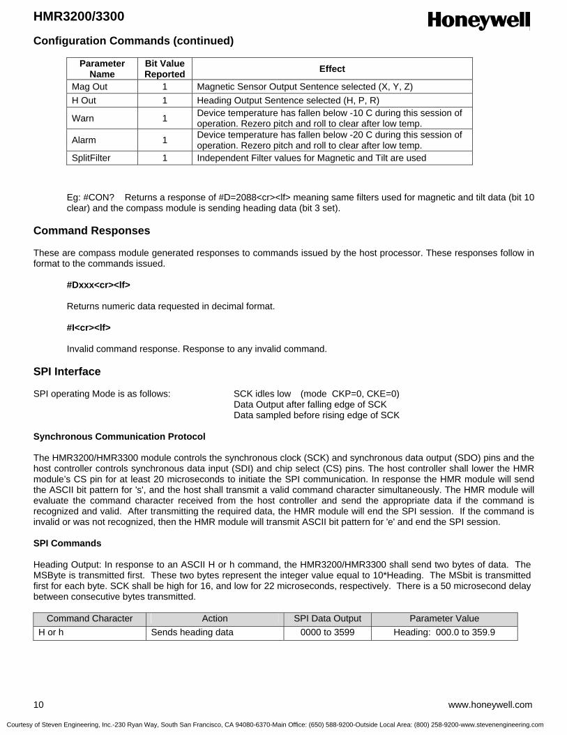
HMR3200/3300
10 www.honeywell.com
Configuration Commands (continued)
Parameter Name
Bit Value Reported Effect
Mag Out 1 Magnetic Sensor Output Sentence selected (X, Y, Z) H Out 1 Heading Output Sentence selected (H, P, R)
Warn 1 Device temperature has fallen below -10 C during this session of operation. Rezero pitch and roll to clear after low temp.
Alarm 1 Device temperature has fallen below -20 C during this session of operation. Rezero pitch and roll to clear after low temp.
SplitFilter 1 Independent Filter values for Magnetic and Tilt are used
Eg: #CON? Returns a response of #D=2088<cr><lf> meaning same filters used for magnetic and tilt data (bit 10 clear) and the compass module is sending heading data (bit 3 set).
Command Responses These are compass module generated responses to commands issued by the host processor. These responses follow in format to the commands issued.
#Dxxx<cr><lf> Returns numeric data requested in decimal format.
#I<cr><lf> Invalid command response. Response to any invalid command.
SPI Interface SPI operating Mode is as follows: SCK idles low (mode CKP=0, CKE=0)
Data Output after falling edge of SCK Data sampled before rising edge of SCK
Synchronous Communication Protocol The HMR3200/HMR3300 module controls the synchronous clock (SCK) and synchronous data output (SDO) pins and the host controller controls synchronous data input (SDI) and chip select (CS) pins. The host controller shall lower the HMR module’s CS pin for at least 20 microseconds to initiate the SPI communication. In response the HMR module will send the ASCII bit pattern for 's', and the host shall transmit a valid command character simultaneously. The HMR module will evaluate the command character received from the host controller and send the appropriate data if the command is recognized and valid. After transmitting the required data, the HMR module will end the SPI session. If the command is invalid or was not recognized, then the HMR module will transmit ASCII bit pattern for 'e' and end the SPI session. SPI Commands Heading Output: In response to an ASCII H or h command, the HMR3200/HMR3300 shall send two bytes of data. The MSByte is transmitted first. These two bytes represent the integer value equal to 10*Heading. The MSbit is transmitted first for each byte. SCK shall be high for 16, and low for 22 microseconds, respectively. There is a 50 microsecond delay between consecutive bytes transmitted.
Command Character Action SPI Data Output Parameter Value H or h Sends heading data 0000 to 3599 Heading: 000.0 to 359.9
Courtesy of Steven Engineering, Inc.-230 Ryan Way, South San Francisco, CA 94080-6370-Main Office: (650) 588-9200-Outside Local Area: (800) 258-9200-www.stevenengineering.com
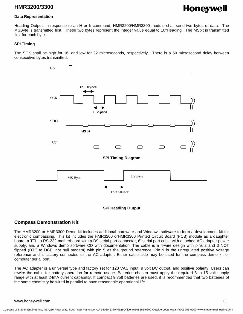
HMR3200/3300
www.honeywell.com 11
Data Representation Heading Output: In response to an H or h command, HMR3200/HMR3300 module shall send two bytes of data. The MSByte is transmitted first. These two bytes represent the integer value equal to 10*Heading. The MSbit is transmitted first for each byte. SPI Timing The SCK shall be high for 16, and low for 22 microseconds, respectively. There is a 50 microsecond delay between consecutive bytes transmitted.
SPI Timing Diagram
SPI Heading Output
Compass Demonstration Kit The HMR3200 or HMR3300 Demo kit includes additional hardware and Windows software to form a development kit for electronic compassing. This kit includes the HMR3200 orHMR3300 Printed Circuit Board (PCB) module as a daughter board, a TTL to RS-232 motherboard with a D9 serial port connector, 6’ serial port cable with attached AC adapter power supply, and a Windows demo software CD with documentation. The cable is a 4-wire design with pins 2 and 3 NOT flipped (DTE to DCE, not null modem) with pin 5 as the ground reference. Pin 9 is the unregulated positive voltage reference and is factory connected to the AC adapter. Either cable side may be used for the compass demo kit or computer serial port. The AC adapter is a universal type and factory set for 120 VAC input, 9 volt DC output, and positive polarity. Users can rewire the cable for battery operation for remote usage. Batteries chosen must apply the required 6 to 15 volt supply range with at least 24mA current capability. If compact 9 volt batteries are used, it is recommended that two batteries of the same chemistry be wired in parallel to have reasonable operational life.
MS Byte LS Byte
Tb = 50µsec
CS
SCK
SDO
SDI
MS bit
Th ~ 16µsec
Tl ~ 22µsec
CS
SCK
SDO
SDI
MS bit
Th ~ 16µsec
Tl ~ 22µsec
Courtesy of Steven Engineering, Inc.-230 Ryan Way, South San Francisco, CA 94080-6370-Main Office: (650) 588-9200-Outside Local Area: (800) 258-9200-www.stevenengineering.com

HMR3200/3300
12 www.honeywell.com
The TTL to RS-232 motherboard is designed to handle only unregulated power supply voltages and routes the supply directly to the V+ pin of the HMR3200 or HMR3300 daughterboard. The electronics on the motherboard convert the RX and TX 5 volt logic to the ±6 volt RS-232 drive logic for computer serial ports. Ordering Information
Ordering Number Product HMR3200 HMR3200-Demo-232 HMR3300 HMR3300-D00-232 HMR3300-Demo-232
PCB Module Only PCB Module with Development Kit PCB Module Only PCB Module and RS-232 Motherboard PCB Module with Development Kit
Find out more For more information on Honeywell’s Magnetic Sensors visit us online at www.magneticsensors.com or contact us at 800-323-8295 (763-954-2474 internationally). The application circuits herein constitute typical usage and interface of Honeywell product. Honeywell does not warranty or assume liability of customer-designed circuits derived from this description or depiction. Honeywell reserves the right to make changes to improve reliability, function or design. Honeywell does not assume any liability arising out of the application or use of any product or circuit described herein; neither does it convey any license under its patent rights nor the rights of others. U.S. Patents 4,441,072, 4,533,872, 4,569,742, 4,681,812, 4,847,584 and 6,529,114 apply to the technology described
Honeywell International Inc. 12001 Highway 55 Plymouth, MN 55441 Tel: 800-323-8295 www.honeywell.com/magnetic
Form #900266 Rev F December 2005 ©2005 Honeywell International Inc.
Courtesy of Steven Engineering, Inc.-230 Ryan Way, South San Francisco, CA 94080-6370-Main Office: (650) 588-9200-Outside Local Area: (800) 258-9200-www.stevenengineering.com

Digital Compass Solution HMR3400
The Honeywell HMR3400 is a digital compass solution designed for use in navigation
and precision pointing applications. Honeywell’s magnetoresistive sensor technology is
coupled with a MEMS accelerometer to provide a miniature, reliable tilt-compensated
electronic compass. Using a common set of commands from the legacy HMR3300
digital compass solution, the HMR3400 is designed to be easily integrated into host
systems with a regulated 5 volt supply and a UART serial data interface.
Honeywell continues to maintain product excellence and performance by introducing
innovative solid-state magnetic sensor solutions. These are highly reliable, top
performance products that are delivered when promised. Honeywell’s magnetic sensor
products provide real solutions you can count on.
FEATURES BENEFITS
4 Compact Solution on a 0.6 by 1.5” PCB 4 Narrow Dimensions and Small Size for Tight Mounting Conditions,
Minimal Layout Constraints
4 Precision Compass Accuracy 4 ±1° at Level Heading Accuracy
4 Tilt-Compensated 4 Up to ±60° of Pitch and Roll Angles Using a MEMS Accelerometer
4 Cost Effective 4 Designed for High Volume, Commercial OEM Designs
4 Available in Tape & Reel Packaging 4 High Volume OEM Assembly
4 -40° to +85°C Operating Temp Range 4 Consumer and Industrial Environment Uses
4 8 Hz Continuous Update Rate 4 Rapid Heading Computations for Guidance Applications
4 Hard-Iron Compensation Routine 4 User Driven Calibration to Null Stray Fields
4 0.5° Repeatability 4 Magnetoresistive Sensor Technology for Consistency
Advanced Information
Courtesy of Steven Engineering, Inc.-230 Ryan Way, South San Francisco, CA 94080-6370-Main Office: (650) 588-9200-Outside Local Area: (800) 258-9200-www.stevenengineering.com
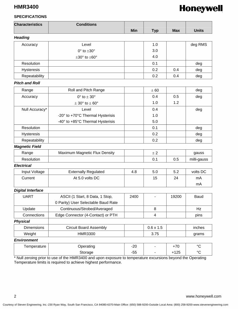
HMR3400
2 www.honeywell.com
SPECIFICATIONS
Characteristics Conditions Min
Typ
Max
Units
Heading
Accuracy Level 0° to ±30°
±30° to ±60°
1.0 3.0 4.0
deg RMS
Resolution 0.1 deg Hysteresis 0.2 0.4 deg Repeatability 0.2 0.4 deg
Pitch and Roll
Range Roll and Pitch Range ± 60 deg
Accuracy 0° to ± 30° ± 30° to ± 60°
0.4 1.0
0.5 1.2
deg
Null Accuracy* Level -20° to +70°C Thermal Hysterisis -40° to +85°C Thermal Hysterisis
0.4 1.0 5.0
deg
Resolution 0.1 deg Hysteresis 0.2 deg Repeatability 0.2 deg Magnetic Field Range Maximum Magnetic Flux Density ± 2 gauss
Resolution 0.1 0.5 milli-gauss Electrical Input Voltage Externally Regulated 4.8 5.0 5.2 volts DC Current At 5.0 volts DC 15 24 mA
mA Digital Interface UART ASCII (1 Start, 8 Data, 1 Stop,
0 Parity) User Selectable Baud Rate 2400 - 19200 Baud
Update Continuous/Strobed/Averaged 8 Hz Connections Edge Connector (4-Contact) or PTH 4 pins Physical Dimensions Circuit Board Assembly 0.6 x 1.5 inches Weight HMR3300 3.75 grams Environment Temperature Operating
Storage -20 -55
- -
+70 +125
°C °C
* Null zeroing prior to use of the HMR3400 and upon exposure to temperature excursions beyond the Operating Temperature limits is required to achieve highest performance.
Courtesy of Steven Engineering, Inc.-230 Ryan Way, South San Francisco, CA 94080-6370-Main Office: (650) 588-9200-Outside Local Area: (800) 258-9200-www.stevenengineering.com

HMR3400
www.honeywell.com 3
Pin Configuration
Pin Number Pin Name Description
1 GND Power and Signal Ground 2 RXD UART Receive Data/SPI Data Output 3 TXD UART Transmit Data/SPI Data Input 4 +5VDC +5 VDC Regulated Power Input
BASIC DEVICE OPERATION The HMR3400 Digital Compass Solution includes all the basic sensors and electronics to provide a digital indication of heading. The HMR3400 uses three magnetic sensors plus a MEMS accelerometer to provide tilt (pitch and roll) sensing relative to the board’s horizontal (flat) position. The HMR3400 circuit starts with Honeywell HMC1022 and HMC1021Z magnetic sensors providing X, Y, and Z axis magnetic sensing of the earth’s field. These sensors are supplied power by a constant current source to maintain best accuracy over temperature. The sensor output voltages and constant current sensor supply voltage are provided to multiplexed Analog to Digital Converter (ADC) integrated circuit. A microcontroller integrated circuit periodically queries the multiplexed ADC and performs the offset corrections and computes the heading. This microcontroller also performs the external serial data interface and other housekeeping functions such as the calibration routine. An onboard EEPROM integrated circuit is employed to retain necessary data variables for best performance. An additional pair of data inputs from the ±2g accelerometer is received by the microcontroller. These tilt inputs (pitch and roll) are added to sensor data inputs to form a complete data set for a three dimensional computation of heading. The power supply for the HMR3400 circuits is regulated +5 volts allowing the user to directly provide the regulated supply voltage to minimize PCB size. The power supply distrbution is a dual ground (analog and digital) system to control internal noise and maximize measurment accuracy.
PHYSICAL CHARACTERISTICS The circuit board for the HMR3400 Digital Compassing Solution is approximately 0.6 by 1.5 inches. An 4-Pin header may optionally be placed at the edge connector plated through holes for pinned user interface. Figure 1 shows the typical circuit board with dimensions.
Figure 1
1.501.00
0.60
0.30
0.065
0.055 (2 places)Dimensions in inches0.076 DIA (3 places)
1.501.00
0.60
0.30
0.065
0.055 (2 places)Dimensions in inches0.076 DIA (3 places)
Courtesy of Steven Engineering, Inc.-230 Ryan Way, South San Francisco, CA 94080-6370-Main Office: (650) 588-9200-Outside Local Area: (800) 258-9200-www.stevenengineering.com

HMR3400
4 www.honeywell.com
Mounting Considerations The following is the recommend printed circuit board (PCB) footprint for the HMR3400. Three small mounting holes are provided to hold the HMR3400 mechanically to the host PCB or chassis. The goal is to hold the part horizontal and parallel with the forward and side surfaces of the end product. The HMC1021Z part is an 8-pin SIP device that is shipped carefully in a nearly perfectly vertical orientation with respect to the horizontal referenced circuit board. Do not bend or reposition this part, or the factory magnetic calibration will be no longer valid. Should the part be accidentally bent, return for recalibration is possible or align the part vertical to recapture most of the accuracy. Correct flat orientation of the compass modules is with the pins pointing downward. Circuit Description The HMR3400 Digital Compass Solution includes all the basic sensors and electronics to provide a digital indication of heading. The HMR3400 uses three magnetic sensors and includes an accelerometer to provide tilt (pitch and roll) sensing relative to the board’s horizontal (flat) position. HMR3400 is derived from the HMR3300 product baseline, and is a shrink in terms of size and flexibility of power supplied. The HMR3400 circuit starts with Honeywell HMC1021Z and HMC1022 single and two-axis magnetic sensors providing X, Y, and Z axis magnetic sensing of the earth’s field. The HMC1022 provides the horizontal components (X and Y), and HMC1021Z provides the vertical (Z) axis component of the incident magnetic field into cartesian magnitudes at orthognal angles. These sensors are supplied power by a constant current source to maintain best accuracy over temperature. The sensor output voltages and constant current sensor supply voltage are provided to a multiplexed 16-bit Analog to Digital Converter (ADC) integrated circuit. A microcontroller integrated circuit periodically queries the multiplexed ADC and performs the offset corrections and computes the heading. This microcontroller also performs the external serial data interface and other housekeeping functions such as the calibration routine. An onboard EEPROM integrated circuit is employed to retain necessary data variables for best performance. The HMR3400 contains an additional pair of data inputs from the ±2g accelerometer (Analog Devices ADXL213) is received by the microcontroller. These tilt inputs (pitch and roll) are added to sensor data inputs to form a complete data set for a three dimensional computation of heading. If the board is held horizontal, the pitch and roll angles are zero and the X and Y sensor inputs dominate the heading equation. When tilted, the Z magnetic sensor plus the accelerometer’s pitch and roll angles enter into heading computation. The power supply for the HMR3400 circuit is designed for regulated +5 volt provision from a regulated supply source. The power supply is a dual ground (analog and digital) system to control internal noise and maximize measurment accuracy. Application Notes When To Calibrate The HMR3400 comes with an optional user hard-iron calibration routine to null modest intensity hard-iron distortion. For many users in cleaner magnetic environments, the factory calibration will be better and yield more accurate readings than after a user calibration. The calibration routine is not cure-all for nasty magnetic environments. If a needle compass is thrown off from true readings, then it is very likely the HMR3400 will have poor accuracy too. Most compass error sources come from ferrous metals (steel, iron, nickel, cobalt, etc.) located too close to the compass location and are known as soft-irons creating soft-iron distortion. Soft-iron distortion will change the intensity and direction of the magnetic fields on any nearby compass, and the calibration routine can not remove these flux concentration and bending errors. A good rule of thumb is to keep soft-irons at least two largest dimensions away from the compass. For example, a half-inch stainless steel panhead bolt should be at least an inch away from the HMC1021Z and HMC1022 sensor locations. Other nasty magnetic environments are man-made AC and DC magnetic fields created from nearby motors and high current conductors. These fields should also require compass or source relocation when possible. In some cases, ferrous metal shielding may help if the shield material is thin and far enough away from the compass. Hard-iron distortion can be calibrated out, and is composed of soft-irons that are also magnetized and create remnant (stray) magnetic flux. Classic hard-iron distortion typically comes from large vehicle chassis components and engine blocks that have up to ±2 gauss on the parts. Locating the compass away from hard and soft-irons is the first line of defense to preserve accuracy, and the calibration routine will null out the remaining hard-iron influences.
Courtesy of Steven Engineering, Inc.-230 Ryan Way, South San Francisco, CA 94080-6370-Main Office: (650) 588-9200-Outside Local Area: (800) 258-9200-www.stevenengineering.com

HMR3400
www.honeywell.com 5
Calibration Procedure For the HMR3400, one complete turn in a level plane is the starting point to expose the XY sensors to all headings to compute the calibration offsets. Since the compass collects data at a 8 samples per second rate, a sample per degree of rotation or slower is a good guideline. If slow turns are not possible, multiple faster turns are a good substitute. The goodness of the calibration or the amount of hard-iron present is found by checking the Xof, Yof, and Zof values after the calibration routine is complete. In known clean magnetic environments, the horizontal values (XY = level, YZ = upright) should be ±200 ADC counts or less in these offset variables. Sending these Xof, Yof, and Zof values back to zero returns the compass to the factory calibration state. For the HMR3400, the above described level turns will calibrate the XY axis’, but the Z-axis should also be calibrated as well One full rotation with as much pitch and roll variation included as application allows. If only mild pitch and roll variations are possible, complete the level rotations, exit the calibration routine, and force the Zof value to zero. Some accuracy maybe lost in this zeroing, but the mild tilt would likely never cause serious tilt-compensation heading error. UART Communication Protocol
HMR3400 module communicates through ASCII characters with the * or # characters as start bytes. The data bit format is 1 Start, 8 Data, 1 Stop, and No parity bits. Factory baud rate is set to 19,200. Asynchronous communication has the complete menu of commands. Synchronous communication is limited to direct heading queries and no other commands. Power-On/Reset The compasses require a hard power-on transition on the power supply voltage to serve as an internal hardware reset and clock-start. Some bench power supplies may create a soft-start condition and the HMR3400 my not react if not reset suddenly. An in-line power supply switch (mechanical or electrical) may be required when prototyping to avoid soft-starts. Upon application of power or after a Reset Command, the HMR3400 will run about an 800 milli-second initialization routine to set the onboard hardware and grab EEPROM variables and shadow them in controller RAM locations for operation. Initial Status Output The HMR3400 will begin sending ASCII characters immediately after the initialization routine ends. The first line of text will be the model number of the compass and the internal firmware revision number. A second response string will be sent, starting with a # character and either the N, W or A characters. The #N response indicates normal operation and is the always expected response from the HMR3200. The #W and #A responses indicate the low temperature warning and alarm environments had been encountered. These responses will be reset to normal when the user sends the pitch and roll re-zero commands to re-calibrate the MEMS accelerometer for best tilt-compensation performance and accurate tilt indications. After initialization, the compasses automatically begin streaming heading or magnetometer output data at 8Hz. Users must send a start/stop command (*S) to exit continuous streaming data, and to get the controller’s full attention to the next commands.
Courtesy of Steven Engineering, Inc.-230 Ryan Way, South San Francisco, CA 94080-6370-Main Office: (650) 588-9200-Outside Local Area: (800) 258-9200-www.stevenengineering.com
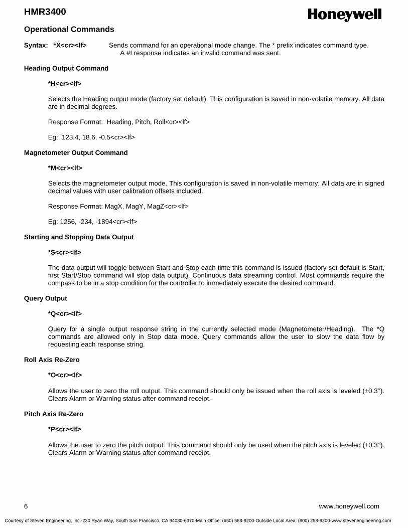
HMR3400
6 www.honeywell.com
Operational Commands Syntax: *X<cr><lf> Sends command for an operational mode change. The * prefix indicates command type. A #I response indicates an invalid command was sent. Heading Output Command
*H<cr><lf> Selects the Heading output mode (factory set default). This configuration is saved in non-volatile memory. All data are in decimal degrees. Response Format: Heading, Pitch, Roll<cr><lf> Eg: 123.4, 18.6, -0.5<cr><lf>
Magnetometer Output Command
*M<cr><lf> Selects the magnetometer output mode. This configuration is saved in non-volatile memory. All data are in signed decimal values with user calibration offsets included. Response Format: MagX, MagY, MagZ<cr><lf> Eg: 1256, -234, -1894<cr><lf>
Starting and Stopping Data Output
*S<cr><lf> The data output will toggle between Start and Stop each time this command is issued (factory set default is Start, first Start/Stop command will stop data output). Continuous data streaming control. Most commands require the compass to be in a stop condition for the controller to immediately execute the desired command.
Query Output *Q<cr><lf> Query for a single output response string in the currently selected mode (Magnetometer/Heading). The *Q commands are allowed only in Stop data mode. Query commands allow the user to slow the data flow by requesting each response string.
Roll Axis Re-Zero
*O<cr><lf> Allows the user to zero the roll output. This command should only be issued when the roll axis is leveled (±0.3°). Clears Alarm or Warning status after command receipt.
Pitch Axis Re-Zero *P<cr><lf> Allows the user to zero the pitch output. This command should only be used when the pitch axis is leveled (±0.3°). Clears Alarm or Warning status after command receipt.
Courtesy of Steven Engineering, Inc.-230 Ryan Way, South San Francisco, CA 94080-6370-Main Office: (650) 588-9200-Outside Local Area: (800) 258-9200-www.stevenengineering.com

HMR3400
www.honeywell.com 7
Operational Commands (continued) Averaged Output
*A<cr><lf> Same result as the query command except that the data are the result of an averaging of 20 readings. The *A commands are allowed only in Stop data mode. The command response will not occur until the 20 readings accrue.
Split Filter Toggle *F<cr><lf> This command toggles the split filter bit in the configuration status bytes. The parameter setting is saved in the EEPROM immediately, but not in shadowed in RAM. Requires power cycling or a reset command (*R) to activate. A set bit indicates the System Filter only smoothes the accelerometer data (Tilt Filter), and the Magnetic Filter is now active to smooth magnetic sensor data. A cleared filter bit resumes the same smoothing for both the tilt and magnetometer data.
Reset
*R<cr><lf> Resets compass to power-up condition. A one second initialization routine starts and EEPROM data (non-volatile memory) is uploaded (shadowed) into RAM. Continuous streaming data begins after initialization and status output.
User Calibration *C<cr><lf> The command to be issued to enter and exit the calibration mode. Once in the calibration mode, the device will send one or more magnetometer data strings appended by a “C” character to indicate the Calibration Mode operation. Eg. 123,834,1489,C<cr><lf> See the calibration procedure notes earlier in this datasheet. At the completion of the calibration movements, issue another *C<cr><lf> to exit the calibration mode.
Configuration Commands
Syntax: #Dev=±xxxx<cr><lf> Sets parameter value
#Dev?<cr><lf> Queries for the parameter value
Variation Input (Declination Angle Correction)
#Var=±nnnn<cr><lf> where the variation is ± nnn.n degrees Sets the declination angle between magnetic north and geographic north. The declination angle is subtracted from the magnetic north heading computed to create a geographic north heading. Values typically range in the ±25 degree area. For example New York has a -14 degree declination angle, and Los Angles has a +14 degree declination angle. Eg: #Var=-203<cr><lf> sets the declination angle to –20.3 degrees. Eg: #Var=?<cr><lf>returns the declination angle; –20.3
Courtesy of Steven Engineering, Inc.-230 Ryan Way, South San Francisco, CA 94080-6370-Main Office: (650) 588-9200-Outside Local Area: (800) 258-9200-www.stevenengineering.com

HMR3400
8 www.honeywell.com
Configuration Commands (continued) Deviation Input (Platform Angle Correction)
#Dev=±nnnn<cr><lf> where the angle is ± nnn.n degrees Sets or returns the angle between compass forward direction and that of the mounting platform. The Deviation angle is subtracted from the predicted heading to compensate for mechanical misalignment. Eg: #Dev=23<cr><lf> sets the deviation angle to +2.3 degrees. Eg: #Dev=?<cr><lf>returns the deviation angle; +2.3
User Magnetic Offset Values (X, Y and Z)
#Xof, #Yof, #Zof Sets or returns the user offset values for each magnetic axis. These values are recomputed after a calibration routine. Also fixed offsets can be inserted to correct for known magnetic shifts. Values are in ADC counts. Eg: #Xof=+47<cr><lf> sets the x offset value to +47. Eg: #Xof=?<cr><lf> returns the x offset value; +47.
Baud Rate
#Bau Sets the compass transmit and recieve baud rate. 19200, 9600, 4800 and 2400 are the only allowed values. Baud rate can not be queried and is sent to the EEPROM to overwrite the present setting. Factory default is 19200. Eg: #XBau=9600<cr><lf> sets the Baud Rate to 9600 after the next Reset command or power cycle.
System Filter
#SFL Sets and reads the system IIR filter setting. When the Split Filter bit is cleared, this parameter value will become the default value for both Magnetic and Tilt Filters. When the Split Filter bit is set, SFL parameter setting will control the Tilt filter value only. The parameter input is saved in the EEPROM immediately. Requires power cycling or a Reset command (*R) to become effective. The setting of the Split Filter bit can be queried via the #CON? command. Values between 0 and 255 are valid, with a factory default of 3. A good reason to increase the filter value would be in the presence of high mechanical vibration environments.
Eg: #SFL=6<cr><lf> Sets the system filter value of 6.
Magnetic Filter
#MFL The MFL command sets and reads the Magnetic Filter setting. When the Split Filter bit is cleared, this parameter value will default to the value of SFL, the system filter. When the Split Filter bit is set, MFL parameter setting will control the Magnetic Filter value. The parameter input is saved in the EEPROM immediately. Requires power cycling or a Reset command (*R) to become effective. Values between 0 and 255 are valid, with a factory default of 3. A good reason to increase the magnetic filter value would be the presence of AC magnetic fields from nearby conductors or motors. Eg: #SFL=0<cr><lf> Sets the magnetic filter value of zero (no filtering).
Courtesy of Steven Engineering, Inc.-230 Ryan Way, South San Francisco, CA 94080-6370-Main Office: (650) 588-9200-Outside Local Area: (800) 258-9200-www.stevenengineering.com
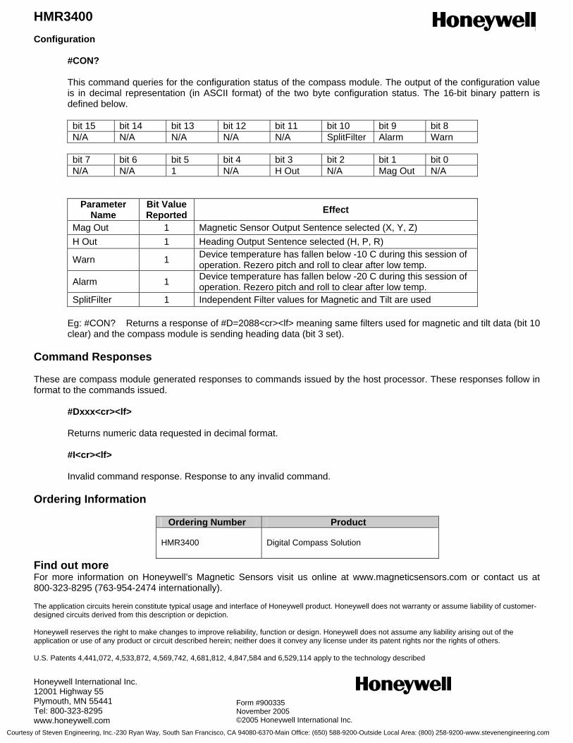
HMR3400
www.honeywell.com 9
Configuration
#CON?
This command queries for the configuration status of the compass module. The output of the configuration value is in decimal representation (in ASCII format) of the two byte configuration status. The 16-bit binary pattern is defined below.
bit 15 bit 14 bit 13 bit 12 bit 11 bit 10 bit 9 bit 8 N/A N/A N/A N/A N/A SplitFilter Alarm Warn
bit 7 bit 6 bit 5 bit 4 bit 3 bit 2 bit 1 bit 0 N/A N/A 1 N/A H Out N/A Mag Out N/A
Parameter Name
Bit Value Reported Effect
Mag Out 1 Magnetic Sensor Output Sentence selected (X, Y, Z) H Out 1 Heading Output Sentence selected (H, P, R)
Warn 1 Device temperature has fallen below -10 C during this session of operation. Rezero pitch and roll to clear after low temp.
Alarm 1 Device temperature has fallen below -20 C during this session of operation. Rezero pitch and roll to clear after low temp.
SplitFilter 1 Independent Filter values for Magnetic and Tilt are used Eg: #CON? Returns a response of #D=2088<cr><lf> meaning same filters used for magnetic and tilt data (bit 10 clear) and the compass module is sending heading data (bit 3 set).
Command Responses These are compass module generated responses to commands issued by the host processor. These responses follow in format to the commands issued.
#Dxxx<cr><lf> Returns numeric data requested in decimal format.
#I<cr><lf> Invalid command response. Response to any invalid command.
Ordering Information
Ordering Number Product HMR3400
Digital Compass Solution
Find out more For more information on Honeywell’s Magnetic Sensors visit us online at www.magneticsensors.com or contact us at 800-323-8295 (763-954-2474 internationally). The application circuits herein constitute typical usage and interface of Honeywell product. Honeywell does not warranty or assume liability of customer-designed circuits derived from this description or depiction. Honeywell reserves the right to make changes to improve reliability, function or design. Honeywell does not assume any liability arising out of the application or use of any product or circuit described herein; neither does it convey any license under its patent rights nor the rights of others. U.S. Patents 4,441,072, 4,533,872, 4,569,742, 4,681,812, 4,847,584 and 6,529,114 apply to the technology described Honeywell International Inc. 12001 Highway 55 Plymouth, MN 55441 Tel: 800-323-8295 www.honeywell.com
Form #900335 November 2005 ©2005 Honeywell International Inc.
Courtesy of Steven Engineering, Inc.-230 Ryan Way, South San Francisco, CA 94080-6370-Main Office: (650) 588-9200-Outside Local Area: (800) 258-9200-www.stevenengineering.com

HMR3200/HMR3300SENSOR PRODUCTS
HMR3200/HMR3300Digital Compass Solutions
User’s Guide
Solid State Electronics Center • www.magneticsensors.com • (800) 323-8295 • Page 1
Courtesy of Steven Engineering, Inc.-230 Ryan Way, South San Francisco, CA 94080-6370-Main Office: (650) 588-9200-Outside Local Area: (800) 258-9200-www.stevenengineering.com
HMR3200/HMR3300SENSOR PRODUCTS
TABLE OF CONTENTS
INTRODUCTION ............................................................................................................................................................................3
SPECIFICATIONS ..........................................................................................................................................................................3
PIN CONFIGURATION..................................................................................................................................................................4
CIRCUIT DESCRIPTION ..............................................................................................................................................................4
PHYSICAL CHARACTERISTICS ................................................................................................................................................5
APPLICATION NOTES..................................................................................................................................................................6UART Communication Protocol ....................................................................................................................................................6Operational Commands ..................................................................................................................................................................6Configuration Commands...............................................................................................................................................................7Magnetic Filter................................................................................................................................................................................8Command RESPONSES.................................................................................................................................................................8Data Representation ........................................................................................................................................................................9SPI Timing......................................................................................................................................................................................9
Demonstration PCB Module Kit ...................................................................................................................................................10Development Kit Communication ................................................................................................................................................10Development Kit Setup.................................................................................................................................................................10HMR3200 Demo Program Operation ...........................................................................................................................................11HMR3300 Demo Program Operation ...........................................................................................................................................11
Solid State Electronics Center • www.magneticsensors.com • (800) 323-8295 • Page 2
Courtesy of Steven Engineering, Inc.-230 Ryan Way, South San Francisco, CA 94080-6370-Main Office: (650) 588-9200-Outside Local Area: (800) 258-9200-www.stevenengineering.com
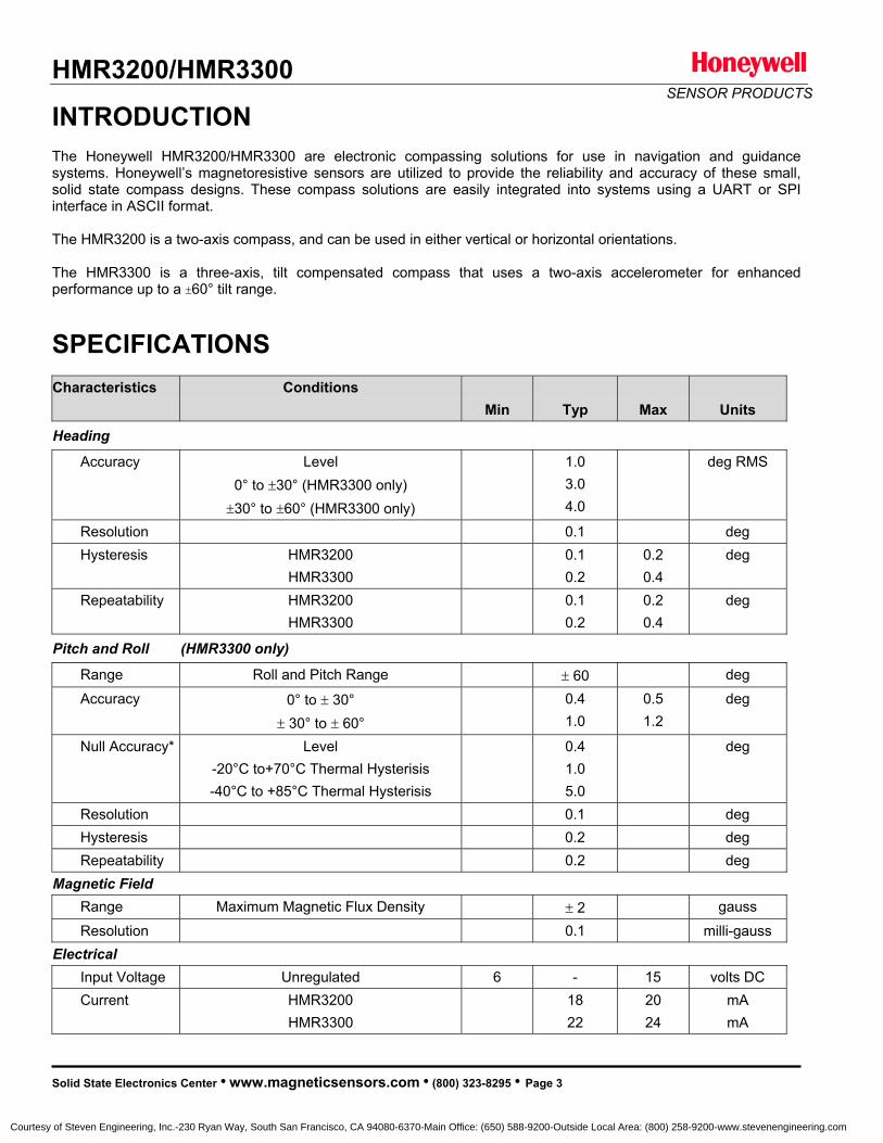
HMR3200/HMR3300SENSOR PRODUCTS
INTRODUCTIONThe Honeywell HMR3200/HMR3300 are electronic compassing solutions for use in navigation and guidancesystems. Honeywell’s magnetoresistive sensors are utilized to provide the reliability and accuracy of these small,solid state compass designs. These compass solutions are easily integrated into systems using a UART or SPIinterface in ASCII format.
The HMR3200 is a two-axis compass, and can be used in either vertical or horizontal orientations.
The HMR3300 is a three-axis, tilt compensated compass that uses a two-axis accelerometer for enhancedperformance up to a 60° tilt range.
SPECIFICATIONSCharacteristics Conditions
Min Typ Max Units
Heading
Accuracy Level0° to 30° (HMR3300 only)30° to 60° (HMR3300 only)
1.03.04.0
deg RMS
Resolution 0.1 deg Hysteresis HMR3200
HMR33000.10.2
0.20.4
deg
Repeatability HMR3200HMR3300
0.10.2
0.20.4
deg
Pitch and Roll (HMR3300 only)
Range Roll and Pitch Range 60 deg Accuracy 0° to 30°
30° to 60°0.41.0
0.51.2
deg
Null Accuracy* Level-20°C to+70°C Thermal Hysterisis-40°C to +85°C Thermal Hysterisis
0.41.05.0
deg
Resolution 0.1 deg Hysteresis 0.2 deg Repeatability 0.2 deg
Magnetic Field Range Maximum Magnetic Flux Density 2 gauss Resolution 0.1 milli-gauss
Electrical Input Voltage Unregulated 6 - 15 volts DC Current HMR3200
HMR33001822
2024
mAmA
Solid State Electronics Center • www.magneticsensors.com • (800) 323-8295 • Page 3
Courtesy of Steven Engineering, Inc.-230 Ryan Way, South San Francisco, CA 94080-6370-Main Office: (650) 588-9200-Outside Local Area: (800) 258-9200-www.stevenengineering.com
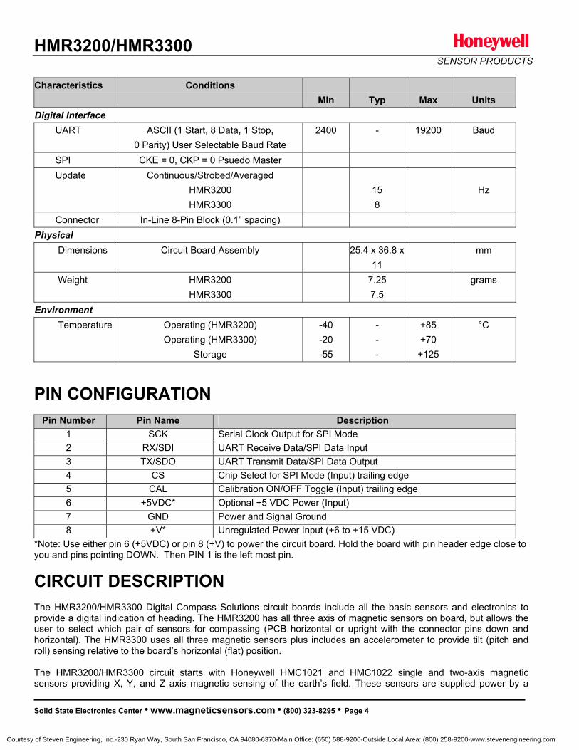
HMR3200/HMR3300SENSOR PRODUCTS
Characteristics ConditionsMin Typ Max Units
Digital Interface UART ASCII (1 Start, 8 Data, 1 Stop,
0 Parity) User Selectable Baud Rate 2400 - 19200 Baud
SPI CKE = 0, CKP = 0 Psuedo Master Update Continuous/Strobed/Averaged
HMR3200HMR3300
158
Hz
Connector In-Line 8-Pin Block (0.1” spacing)Physical
Dimensions Circuit Board Assembly 25.4 x 36.8 x11
mm
Weight HMR3200HMR3300
7.257.5
grams
Environment Temperature Operating (HMR3200)
Operating (HMR3300)Storage
-40-20-55
---
+85+70+125
°C
PIN CONFIGURATION Pin Number Pin Name Description
1 SCK Serial Clock Output for SPI Mode 2 RX/SDI UART Receive Data/SPI Data Input 3 TX/SDO UART Transmit Data/SPI Data Output 4 CS Chip Select for SPI Mode (Input) trailing edge 5 CAL Calibration ON/OFF Toggle (Input) trailing edge6 +5VDC* Optional +5 VDC Power (Input)7 GND Power and Signal Ground8 +V* Unregulated Power Input (+6 to +15 VDC)
*Note: Use either pin 6 (+5VDC) or pin 8 (+V) to power the circuit board. Hold the board with pin header edge close to you and pins pointing DOWN. Then PIN 1 is the left most pin.
CIRCUIT DESCRIPTION The HMR3200/HMR3300 Digital Compass Solutions circuit boards include all the basic sensors and electronics toprovide a digital indication of heading. The HMR3200 has all three axis of magnetic sensors on board, but allows theuser to select which pair of sensors for compassing (PCB horizontal or upright with the connector pins down andhorizontal). The HMR3300 uses all three magnetic sensors plus includes an accelerometer to provide tilt (pitch and roll) sensing relative to the board’s horizontal (flat) position.
The HMR3200/HMR3300 circuit starts with Honeywell HMC1021 and HMC1022 single and two-axis magneticsensors providing X, Y, and Z axis magnetic sensing of the earth’s field. These sensors are supplied power by a
Solid State Electronics Center • www.magneticsensors.com • (800) 323-8295 • Page 4
Courtesy of Steven Engineering, Inc.-230 Ryan Way, South San Francisco, CA 94080-6370-Main Office: (650) 588-9200-Outside Local Area: (800) 258-9200-www.stevenengineering.com
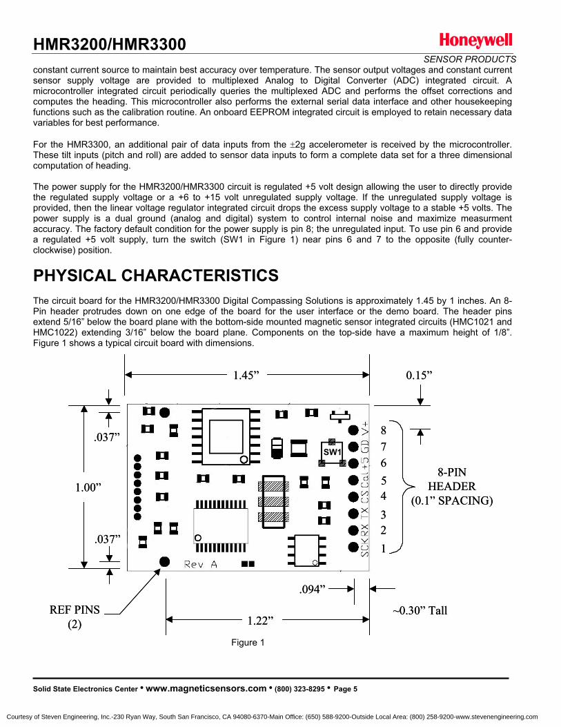
HMR3200/HMR3300SENSOR PRODUCTS
constant current source to maintain best accuracy over temperature. The sensor output voltages and constant currentsensor supply voltage are provided to multiplexed Analog to Digital Converter (ADC) integrated circuit. A microcontroller integrated circuit periodically queries the multiplexed ADC and performs the offset corrections andcomputes the heading. This microcontroller also performs the external serial data interface and other housekeepingfunctions such as the calibration routine. An onboard EEPROM integrated circuit is employed to retain necessary data variables for best performance.
For the HMR3300, an additional pair of data inputs from the 2g accelerometer is received by the microcontroller.These tilt inputs (pitch and roll) are added to sensor data inputs to form a complete data set for a three dimensionalcomputation of heading.
The power supply for the HMR3200/HMR3300 circuit is regulated +5 volt design allowing the user to directly providethe regulated supply voltage or a +6 to +15 volt unregulated supply voltage. If the unregulated supply voltage is provided, then the linear voltage regulator integrated circuit drops the excess supply voltage to a stable +5 volts. Thepower supply is a dual ground (analog and digital) system to control internal noise and maximize measurmentaccuracy. The factory default condition for the power supply is pin 8; the unregulated input. To use pin 6 and provide a regulated +5 volt supply, turn the switch (SW1 in Figure 1) near pins 6 and 7 to the opposite (fully counter-clockwise) position.
PHYSICAL CHARACTERISTICS The circuit board for the HMR3200/HMR3300 Digital Compassing Solutions is approximately 1.45 by 1 inches. An 8-Pin header protrudes down on one edge of the board for the user interface or the demo board. The header pinsextend 5/16” below the board plane with the bottom-side mounted magnetic sensor integrated circuits (HMC1021 andHMC1022) extending 3/16” below the board plane. Components on the top-side have a maximum height of 1/8”.Figure 1 shows a typical circuit board with dimensions.
Figure 1
1.00”
1.45”
1.22”REF PINS
(2)
12345678
8-PINHEADER
(0.1” SPACING)
.037”
0.15”
.094”
.037”SW1
~0.30” Tall
1.00”
1.45”
1.22”REF PINS
(2)
12345678
8-PINHEADER
(0.1” SPACING)
.037”
0.15”
.094”
.037”SW1
~0.30” Tall
Solid State Electronics Center • www.magneticsensors.com • (800) 323-8295 • Page 5
Courtesy of Steven Engineering, Inc.-230 Ryan Way, South San Francisco, CA 94080-6370-Main Office: (650) 588-9200-Outside Local Area: (800) 258-9200-www.stevenengineering.com

HMR3200/HMR3300SENSOR PRODUCTS
APPLICATION NOTES UART COMMUNICATION PROTOCOL
HMR3200/HMR3300 modules communicate through ASCII characters. The data bit format is 1 Start, 8 Data, 1 Stop, and No parity bits. Asynchronous communication has the complete menu of commands.
Operational Commands
Syntax: *X<cr><lf> Sends command for an operational mode change
Heading Output Command*H<cr><lf>Selects the Heading output mode (factory set default). This configuration is saved in non-volatile memory. Format: Heading, Pitch, Roll (Heading Only for HMR3200) in degreesEg: 235.6,-0.3,2.8 (HMR3300)Eg: 127.5 (HMR3200)
Magnetometer Output Command*M<cr><lf>Selects the magnetometer output mode. This configuration is saved in non-volatile memory. Format: MagX, MagY, MagZ in counts
Eg: 1256,-234,1894
Compass Orientation (HMR3200 only)*L<cr><lf>Heading calculation is done assuming the compass is level. *U<cr><lf>Heading calculation is done assuming the compass is upright (connector end down).These orientation commands are saved in non-volatile memory.
Starting and Stopping Data Output*S<cr><lf>The data output will toggle between Start and Stop each time this command is issued (factory set default is Start, first Start/Stop command will stop data output).
Query*Q<cr><lf>Query for an output in the currently selected mode (Mag/Head). Allowed only in Stop data mode.
Roll Axis Re-Zero *O<cr><lf>Allows the user to zero the roll output. This command should only be issued when the roll axis is leveled( 0.3°).
Pitch Axis Re-Zero*P<cr><lf>Allows the user to zero the pitch output. This command should only be used when the pitch axis is leveled( 0.3°).
Averaged Output*A<cr><lf>Same result as the query command except that the data is the result of an averaging of the last 20 readings.Allowed only in Stop data mode.
Solid State Electronics Center • www.magneticsensors.com • (800) 323-8295 • Page 6
Courtesy of Steven Engineering, Inc.-230 Ryan Way, South San Francisco, CA 94080-6370-Main Office: (650) 588-9200-Outside Local Area: (800) 258-9200-www.stevenengineering.com
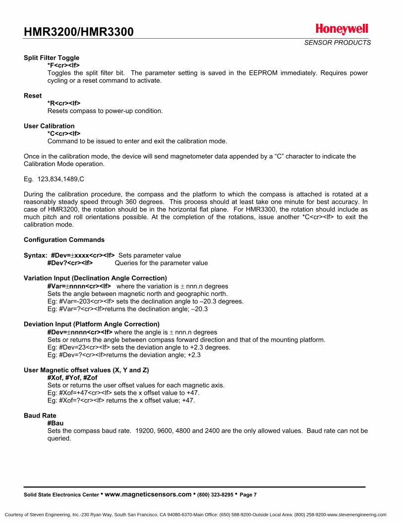
HMR3200/HMR3300SENSOR PRODUCTS
Split Filter Toggle *F<cr><lf>Toggles the split filter bit. The parameter setting is saved in the EEPROM immediately. Requires powercycling or a reset command to activate.
Reset*R<cr><lf>Resets compass to power-up condition.
User Calibration*C<cr><lf>Command to be issued to enter and exit the calibration mode.
Once in the calibration mode, the device will send magnetometer data appended by a “C” character to indicate the Calibration Mode operation.
Eg. 123,834,1489,C
During the calibration procedure, the compass and the platform to which the compass is attached is rotated at areasonably steady speed through 360 degrees. This process should at least take one minute for best accuracy. In case of HMR3200, the rotation should be in the horizontal flat plane. For HMR3300, the rotation should include asmuch pitch and roll orientations possible. At the completion of the rotations, issue another *C<cr><lf> to exit the calibration mode.
Configuration Commands
Syntax: #Dev= xxxx<cr><lf> Sets parameter value#Dev?<cr><lf> Queries for the parameter value
Variation Input (Declination Angle Correction)#Var= nnnn<cr><lf> where the variation is nnn.n degreesSets the angle between magnetic north and geographic north.Eg: #Var=-203<cr><lf> sets the declination angle to –20.3 degrees.Eg: #Var=?<cr><lf>returns the declination angle; –20.3
Deviation Input (Platform Angle Correction)#Dev= nnnn<cr><lf> where the angle is nnn.n degreesSets or returns the angle between compass forward direction and that of the mounting platform. Eg: #Dev=23<cr><lf> sets the deviation angle to +2.3 degrees.Eg: #Dev=?<cr><lf>returns the deviation angle; +2.3
User Magnetic offset values (X, Y and Z) #Xof, #Yof, #ZofSets or returns the user offset values for each magnetic axis. Eg: #Xof=+47<cr><lf> sets the x offset value to +47.Eg: #Xof=?<cr><lf> returns the x offset value; +47.
Baud Rate#BauSets the compass baud rate. 19200, 9600, 4800 and 2400 are the only allowed values. Baud rate can not bequeried.
Solid State Electronics Center • www.magneticsensors.com • (800) 323-8295 • Page 7
Courtesy of Steven Engineering, Inc.-230 Ryan Way, South San Francisco, CA 94080-6370-Main Office: (650) 588-9200-Outside Local Area: (800) 258-9200-www.stevenengineering.com
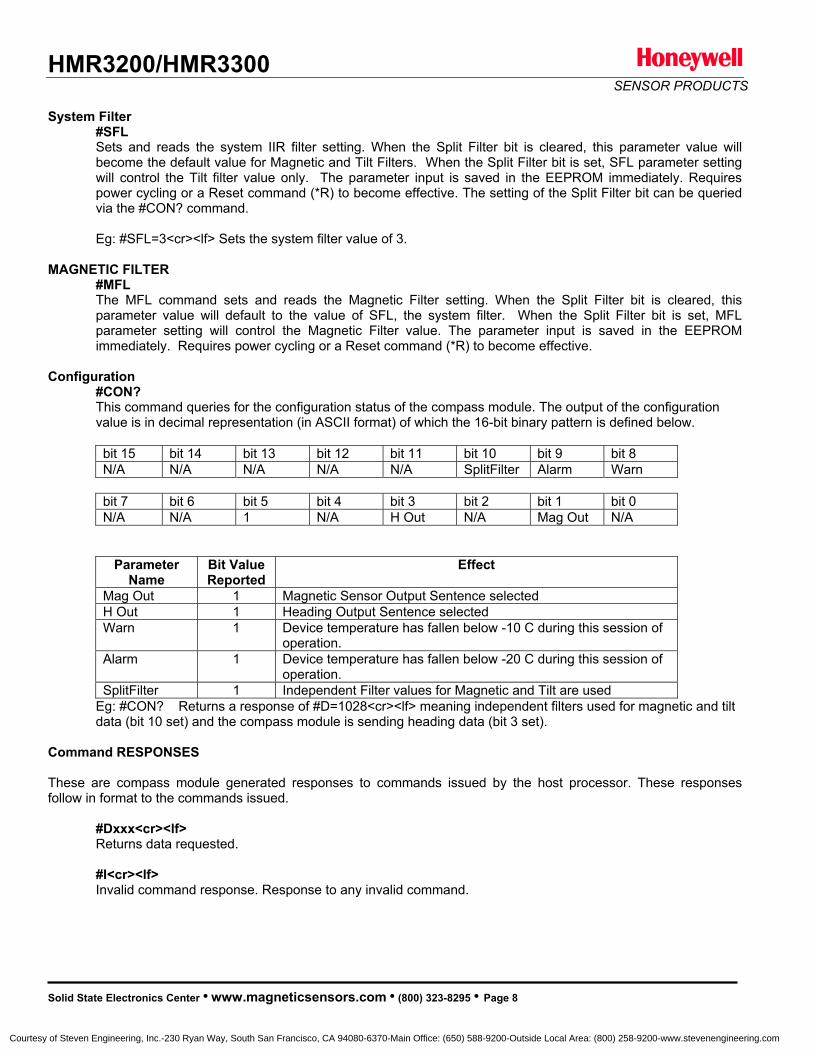
HMR3200/HMR3300SENSOR PRODUCTS
System Filter #SFLSets and reads the system IIR filter setting. When the Split Filter bit is cleared, this parameter value will become the default value for Magnetic and Tilt Filters. When the Split Filter bit is set, SFL parameter settingwill control the Tilt filter value only. The parameter input is saved in the EEPROM immediately. Requirespower cycling or a Reset command (*R) to become effective. The setting of the Split Filter bit can be queriedvia the #CON? command.
Eg: #SFL=3<cr><lf> Sets the system filter value of 3.
MAGNETIC FILTER #MFLThe MFL command sets and reads the Magnetic Filter setting. When the Split Filter bit is cleared, this parameter value will default to the value of SFL, the system filter. When the Split Filter bit is set, MFLparameter setting will control the Magnetic Filter value. The parameter input is saved in the EEPROM immediately. Requires power cycling or a Reset command (*R) to become effective.
Configuration#CON?This command queries for the configuration status of the compass module. The output of the configurationvalue is in decimal representation (in ASCII format) of which the 16-bit binary pattern is defined below.
bit 15 bit 14 bit 13 bit 12 bit 11 bit 10 bit 9 bit 8 N/A N/A N/A N/A N/A SplitFilter Alarm Warn
bit 7 bit 6 bit 5 bit 4 bit 3 bit 2 bit 1 bit 0 N/A N/A 1 N/A H Out N/A Mag Out N/A
ParameterName
Bit Value Reported
Effect
Mag Out 1 Magnetic Sensor Output Sentence selectedH Out 1 Heading Output Sentence selectedWarn 1 Device temperature has fallen below -10 C during this session of
operation.Alarm 1 Device temperature has fallen below -20 C during this session of
operation.SplitFilter 1 Independent Filter values for Magnetic and Tilt are used
Eg: #CON? Returns a response of #D=1028<cr><lf> meaning independent filters used for magnetic and tilt data (bit 10 set) and the compass module is sending heading data (bit 3 set).
Command RESPONSES
These are compass module generated responses to commands issued by the host processor. These responsesfollow in format to the commands issued.
#Dxxx<cr><lf>Returns data requested.
#I<cr><lf>Invalid command response. Response to any invalid command.
Solid State Electronics Center • www.magneticsensors.com • (800) 323-8295 • Page 8
Courtesy of Steven Engineering, Inc.-230 Ryan Way, South San Francisco, CA 94080-6370-Main Office: (650) 588-9200-Outside Local Area: (800) 258-9200-www.stevenengineering.com

HMR3200/HMR3300SENSOR PRODUCTS
SPI Interface
SPI operating Mode is as follows: SCK idles lowData Output after falling edge of SCK Data sampled before rising edge of SCK
(MODE CKP=0, CKE=0)
Synchronous Communication Protocol
The HMR3200/HMR3300 module controls the synchronous clock (SCK) and synchronous data output (SDO) pins andthe host controller controls synchronous data input (SDI) and chip select (CS) pins. The host controller shall lower the HMR module’s CS pin for at least 20 microseconds to initiate the SPI communication. In response the HMR modulewill send the ASCII bit pattern for 's', and the host shall transmit a valid command character simultaneously. The HMR module will evaluate the command character received from the host controller and send the appropriate data if thecommand is recognized and valid. After transmitting the required data, the HMR module will end the SPI session. If the command is invalid or was not recognized, then the HMR module will transmit ASCII bit pattern for 'e' and end theSPI session.
SPI Commands
Heading Output: In response to an ASCII H or h command, the HMR3200/HMR3300 shall send two bytes of data.The MSByte is transmitted first. These two bytes represent the integer value equal to 10*Heading. The MSbit istransmitted first for each byte. SCK shall be high for 16, and low for 22 microseconds, respectively. There is a 50microsecond delay between consecutive bytes transmitted.
Command Character Action SPI Data Output Parameter Value H or h Sends heading data 0000 to 3599 Heading: 000.0 to 359.9
Data Representation
Heading Output: In response to an H or h command, HMR3200/HMR3300 module shall send two bytes of data. TheMSByte is transmitted first. These two bytes represent the integer value equal to 10*Heading. The MSbit istransmitted first for each byte.SPI Timing
The SCK shall be high for 16, and low for 22 microseconds, respectively. There is a 50 microsecond delay betweenconsecutive bytes transmitted.
Solid State Electronics Center • www.magneticsensors.com • (800) 323-8295 • Page 9
Courtesy of Steven Engineering, Inc.-230 Ryan Way, South San Francisco, CA 94080-6370-Main Office: (650) 588-9200-Outside Local Area: (800) 258-9200-www.stevenengineering.com

HMR3200/HMR3300SENSOR PRODUCTS
CS
SCK
SDO
SDI
MS bit
Th ~ 16 sec
Tl ~ 22 sec
CS
SCK
SDO
SDI
MS bit
Th ~ 16 sec
Tl ~ 22 sec
SPI Timing Diagram
SPI Heading Output
MS Byte LS Byte
Tb = 50 sec
Demonstration PCB Module Kit Development Kit Communication
The HMR3200 (HMR3300) Demo Module when purchased as part of a development kit, includes additional hardwareand Windows software to form development kit for electronic compassing. This kit includes the HMR3200 (HMR3300)Printed Circuit Board (PCB) module, a RS-232 motherboard with D9 serial port connector, serial port cable withattached AC adapter power supply, interface demo software, and documentation. The table below shows the D9connector interface pinout.
Pin Number Pin Name Description2 TX USART transmit Out (output) 3 RX USART receive In (input) 5 GND Power and Signal ground9 +V Unregulated 6 -15 Vdc (input)
Development Kit Setup
The following steps are to be performed for setup of the development kit:
1. Load and install demo Windows software provided within the kit on your PC.
Solid State Electronics Center • www.magneticsensors.com • (800) 323-8295 • Page 10
2. Insert the HMR3200 or HMR3300 header pins into the 8-pin connector provided on the motherboard. Make sure the two alignment pins at the opposite end of the HMR PCB fit into the sockets on the motherboard aswell.
Courtesy of Steven Engineering, Inc.-230 Ryan Way, South San Francisco, CA 94080-6370-Main Office: (650) 588-9200-Outside Local Area: (800) 258-9200-www.stevenengineering.com

HMR3200/HMR3300SENSOR PRODUCTS
3. Connect the motherboard to the serial port cable and complete the cable connection at the serial port on yourPC. Ensure that the PC serial port is setup as COM 1. For ease of use, choose the serial port cable endwhere the AC adapter cable interfaces, for insertion to your PC.
4. If you substitute the AC adapter for an alternate DC supply source for the HMR/motherboard circuits, ensurea +6 to +15 volt supply is applied to pin 9 of the connectors on the serial port cable.
HMR3200 Demo Program Operation
The following steps are to be performed for HMR3200 demonstration program operation:
1. Close down other programs on your PC that would potentially interfere with rapid serial port communication of the compass. Typically, most program hangs will occur in servicing the port and necessitate a power downreset to resume compass communication.
2. From the Windows Start Menu, go to Programs and select HMR3200 Demo. Alternately, you could browse the directories for Program Files\HMR3200 and run HMR3200.exe at that directory location.
3. Click on the green Start button to begin data flow, and click on the yellow Quit button to end.
4. Choose the Heading (default) or the Magnetic data selections as desired.
HMR3300 Demo Program Operation
The following steps are to be performed for HMR3300 demonstration program operation:
1. Close down other programs on your PC that would potentially interfere with rapid serial port communication of the compass. Typically, most program hangs will occur in servicing the port and necessitate a power downreset to resume compass communication.
2. From the Windows Start Menu, go to Programs and select HMR3300 Compass Demo. Alternately, you couldbrowse the directories for Program Files\HMR3300 and run HMR3300.exe at that directory location.
3. Choose COM1 and 19200 as the default port and baud rate selections for communication. Press OK.
3. Click on the Run button to begin data flow, and click on the same button to Stop.
4. Choose the aviation Gauges (default) or the Text Output screens as desired.
5. On the Text Output screen you have HPR (heading, pitch, roll) or MAG (XYZ magnetometer vectors) asselectable options. Data can be cleared and stored into text files (*.txt) as desired.
Thank you for your purchase. For additional information and datasheets, visit our website at: www.magneticsensors.com
Or contact us at: [email protected]
1-800-323-8295
Solid State Electronics Center, 12001 Highway 55, Plymouth MN 55441
Honeywell reserves the right to make changes to improve reliability, function or design. Honeywell does not assumeany liability arising out of the application or use of any product or circuit described herein; neither does it convey any license under its patent rights nor the rights of others.
02-03 Rev. D
Solid State Electronics Center • www.magneticsensors.com • (800) 323-8295 • Page 11
Courtesy of Steven Engineering, Inc.-230 Ryan Way, South San Francisco, CA 94080-6370-Main Office: (650) 588-9200-Outside Local Area: (800) 258-9200-www.stevenengineering.com

HMR4001SENSOR PRODUCTS
Advance Information
Web Site: www.magneticsensors.com HoneywellEmail: [email protected] Solid State Electronics Center
12001 State Highway 552001 HMR4001 Published Jun 2001 Page 1 Plymouth, Minnesota 55441-4799
1-800-323-8295
LINEAR POSITION SENSOR MODULEFeatures 0-10 mm Magnetic Travel (Magnet Dependent) Continuous PWM and Analog Voltage Outputs 0.2mm Accuracy (Magnet Dependent) 0.05mm Repeatability -40° to +85°C Operating Temperature Range 1%/100°C Temperature Effect Small PCB Package 6 to 20 volt DC Single Supply Required
General Description
The Honeywell HMR4001 is a high-resolution singlesensor module capable of measuring linear or angularposition. Advantages include high sensitivity so lowercost magnets such as alnico or ceramic can be used,insensitivity to shock and vibration, and ability towithstand large variations in the gap between thesensor and the magnet.
The HMR4001 is manufactured with Honeywell'sHMC1512 Magnetic Displacement Sensor IC, whichprovides better performance than Hall Effect devicesand only needs a magnetic field source greater than 80gauss. Dual frequency PWM and analog outputs plus asleep mode function are included on board
Block Diagram
Linear Displacement
Shaft Position
Angular Displacement
Proximity Detection
APPLICATIONS
Courtesy of Steven Engineering, Inc.-230 Ryan Way, South San Francisco, CA 94080-6370-Main Office: (650) 588-9200-Outside Local Area: (800) 258-9200-www.stevenengineering.com
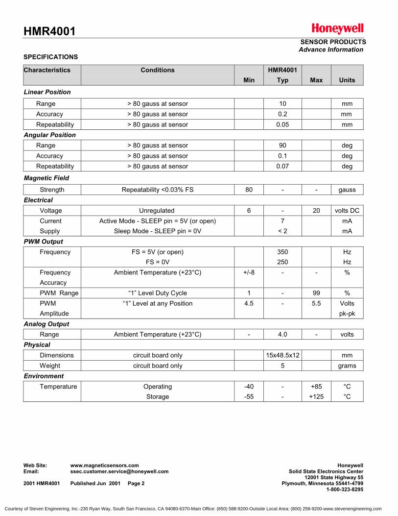
HMR4001SENSOR PRODUCTS
Advance Information
Web Site: www.magneticsensors.com HoneywellEmail: [email protected] Solid State Electronics Center
12001 State Highway 552001 HMR4001 Published Jun 2001 Page 2 Plymouth, Minnesota 55441-4799
1-800-323-8295
SPECIFICATIONS
Characteristics ConditionsMin
HMR4001Typ Max Units
Linear Position
Range > 80 gauss at sensor 10 mm Accuracy > 80 gauss at sensor 0.2 mm Repeatability > 80 gauss at sensor 0.05 mmAngular Position Range > 80 gauss at sensor 90 deg Accuracy > 80 gauss at sensor 0.1 deg Repeatability > 80 gauss at sensor 0.07 deg
Magnetic Field
Strength Repeatability <0.03% FS 80 - - gaussElectrical Voltage Unregulated 6 - 20 volts DC Current Supply
Active Mode - SLEEP pin = 5V (or open)Sleep Mode - SLEEP pin = 0V
7< 2
mAmA
PWM Output Frequency FS = 5V (or open)
FS = 0V350250
HzHz
Frequency Accuracy
Ambient Temperature (+23°C) +/-8 - - %
PWM Range “1” Level Duty Cycle 1 - 99 % PWM Amplitude
“1” Level at any Position 4.5 - 5.5 Voltspk-pk
Analog Output Range Ambient Temperature (+23°C) - 4.0 - voltsPhysical Dimensions circuit board only 15x48.5x12 mm Weight circuit board only 5 gramsEnvironment Temperature Operating
Storage-40-55
--
+85+125
°C°C
Courtesy of Steven Engineering, Inc.-230 Ryan Way, South San Francisco, CA 94080-6370-Main Office: (650) 588-9200-Outside Local Area: (800) 258-9200-www.stevenengineering.com
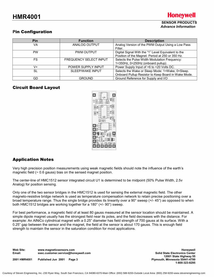
HMR4001SENSOR PRODUCTS
Advance Information
Web Site: www.magneticsensors.com HoneywellEmail: [email protected] Solid State Electronics Center
12001 State Highway 552001 HMR4001 Published Jun 2001 Page 3 Plymouth, Minnesota 55441-4799
1-800-323-8295
Pin Configuration
Pin Function DescriptionVA ANALOG OUTPUT Analog Version of the PWM Output Using a Low Pass
Filter.PW PWM OUTPUT Digital Signal With the “1” Level Equivalent to the
Position of the Magnet. Period at 250 or 350 Hz.FS FREQUENCY SELECT INPUT Selects the Pulse Width Modulation Frequency:
1=350Hz, 0=250Hz (onboard pullup)V+ POWER SUPPLY INPUT Power Supply Input of +6 to +20 Volts DC.SL SLEEP/WAKE INPUT Selects the Wake or Sleep Mode: 1=Wake, 0=Sleep.
Onboard Pullup Resistor to Keep Board in Wake Mode.GD GROUND Ground Reference for Supply and I/O
Circuit Board Layout
Application Notes
Very high precision position measurements using weak magnetic fields should note the influence of the earth’smagnetic field (~ 0.6 gauss) bias on the sensed magnet position.
The center-line of HMC1512 sensor integrated circuit U1 is determined to be midpoint (50% Pulse Width, 2.5vAnalog) for position sensing.
Only one of the two sensor bridges in the HMC1512 is used for sensing the external magnetic field. The othermagneto-resistive bridge network is used as temperature compensation network to retain precise positioning over abroad temperature range. Thus the single bridge provides its linearity over a 90° sweep (+/- 45°) as opposed to whenboth HMC1512 bridges are working together for a 180° (+/- 90°) sweep.
For best performance, a magnetic field of at least 80 gauss measured at the sensor location should be maintained. Asimple dipole magnet usually has the strongest field near its poles, and the field decreases with the distance. Forexample: An AlNiCo cylindrical magnet with a 0.25” diameter has field strength of 700 gauss at its surface. With a0.25” gap between the sensor and the magnet, the field at the sensor is about 170 gauss. This is enough fieldstrength to maintain the sensor in the saturation condition for most applications.
Courtesy of Steven Engineering, Inc.-230 Ryan Way, South San Francisco, CA 94080-6370-Main Office: (650) 588-9200-Outside Local Area: (800) 258-9200-www.stevenengineering.com
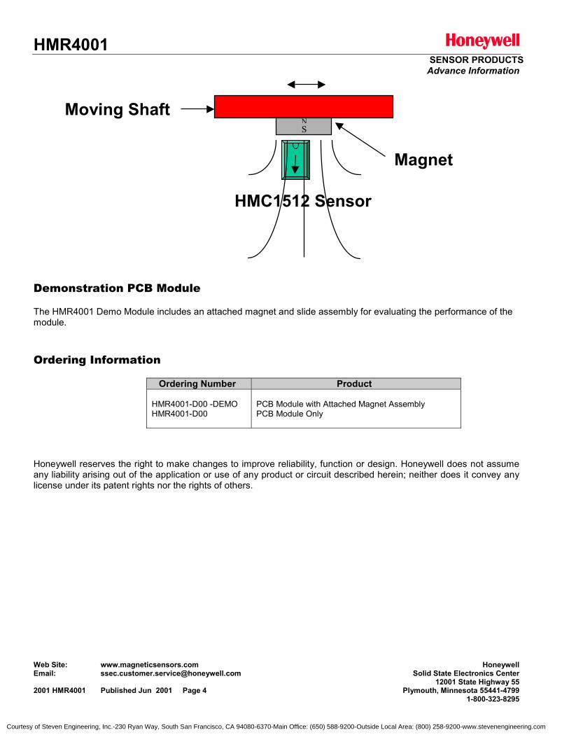
HMR4001SENSOR PRODUCTS
Advance Information
Web Site: www.magneticsensors.com HoneywellEmail: [email protected] Solid State Electronics Center
12001 State Highway 552001 HMR4001 Published Jun 2001 Page 4 Plymouth, Minnesota 55441-4799
1-800-323-8295
Demonstration PCB Module
The HMR4001 Demo Module includes an attached magnet and slide assembly for evaluating the performance of themodule.
Ordering Information
Ordering Number Product
HMR4001-D00 -DEMOHMR4001-D00
PCB Module with Attached Magnet AssemblyPCB Module Only
Honeywell reserves the right to make changes to improve reliability, function or design. Honeywell does not assumeany liability arising out of the application or use of any product or circuit described herein; neither does it convey anylicense under its patent rights nor the rights of others.
HMC1512 Sensor
Magnet
Moving ShaftNS
Courtesy of Steven Engineering, Inc.-230 Ryan Way, South San Francisco, CA 94080-6370-Main Office: (650) 588-9200-Outside Local Area: (800) 258-9200-www.stevenengineering.com

Courtesy of Steven Engineering, Inc.-230 Ryan Way, South San Francisco, CA 94080-6370-Main Office: (650) 588-9200-Outside Local Area: (800) 258-9200-www.stevenengineering.com
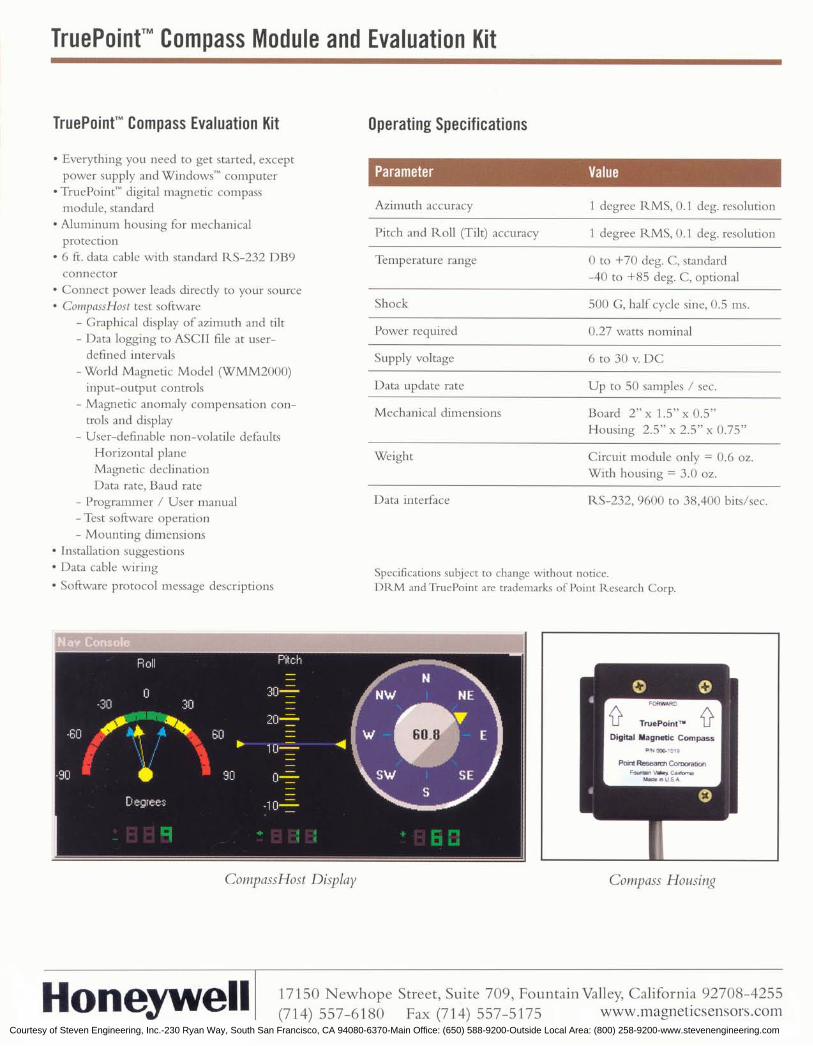
Courtesy of Steven Engineering, Inc.-230 Ryan Way, South San Francisco, CA 94080-6370-Main Office: (650) 588-9200-Outside Local Area: (800) 258-9200-www.stevenengineering.com

Courtesy of Steven Engineering, Inc.-230 Ryan Way, South San Francisco, CA 94080-6370-Main Office: (650) 588-9200-Outside Local Area: (800) 258-9200-www.stevenengineering.com
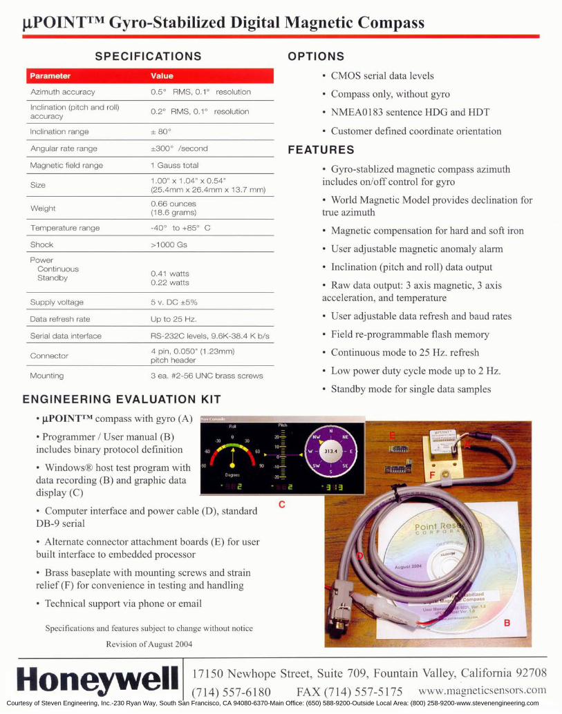
Courtesy of Steven Engineering, Inc.-230 Ryan Way, South San Francisco, CA 94080-6370-Main Office: (650) 588-9200-Outside Local Area: (800) 258-9200-www.stevenengineering.com

Courtesy of Steven Engineering, Inc.-230 Ryan Way, South San Francisco, CA 94080-6370-Main Office: (650) 588-9200-Outside Local Area: (800) 258-9200-www.stevenengineering.com
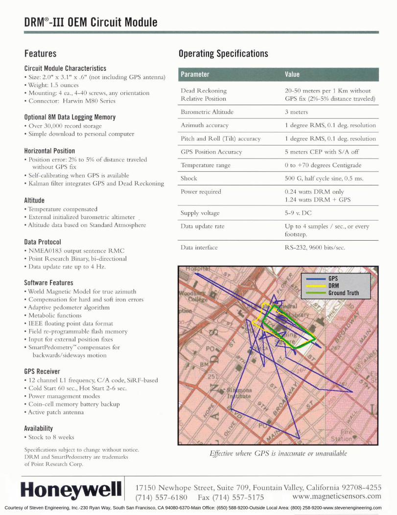
Courtesy of Steven Engineering, Inc.-230 Ryan Way, South San Francisco, CA 94080-6370-Main Office: (650) 588-9200-Outside Local Area: (800) 258-9200-www.stevenengineering.com

Courtesy of Steven Engineering, Inc.-230 Ryan Way, South San Francisco, CA 94080-6370-Main Office: (650) 588-9200-Outside Local Area: (800) 258-9200-www.stevenengineering.com
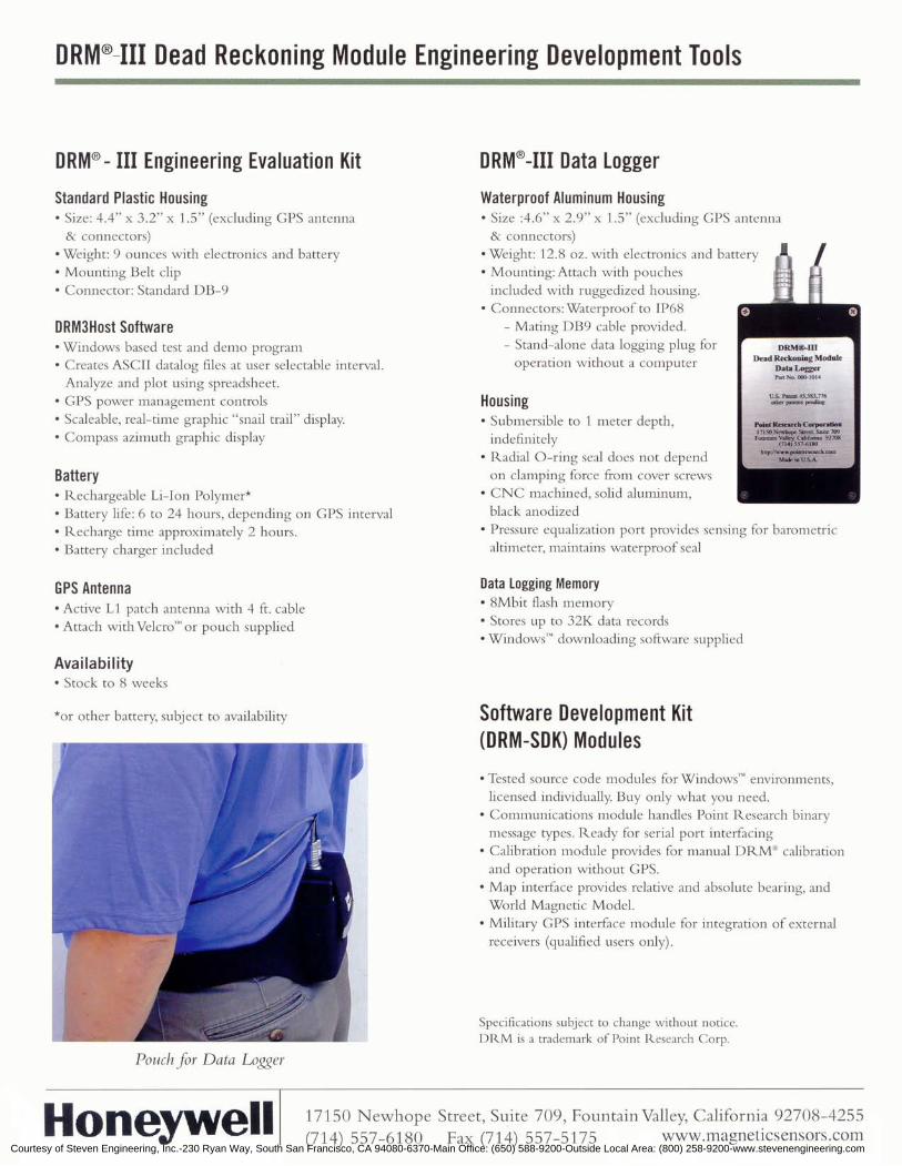
Courtesy of Steven Engineering, Inc.-230 Ryan Way, South San Francisco, CA 94080-6370-Main Office: (650) 588-9200-Outside Local Area: (800) 258-9200-www.stevenengineering.com
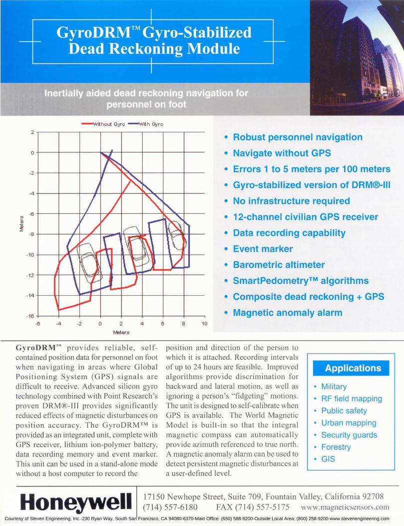
Courtesy of Steven Engineering, Inc.-230 Ryan Way, South San Francisco, CA 94080-6370-Main Office: (650) 588-9200-Outside Local Area: (800) 258-9200-www.stevenengineering.com

Courtesy of Steven Engineering, Inc.-230 Ryan Way, South San Francisco, CA 94080-6370-Main Office: (650) 588-9200-Outside Local Area: (800) 258-9200-www.stevenengineering.com
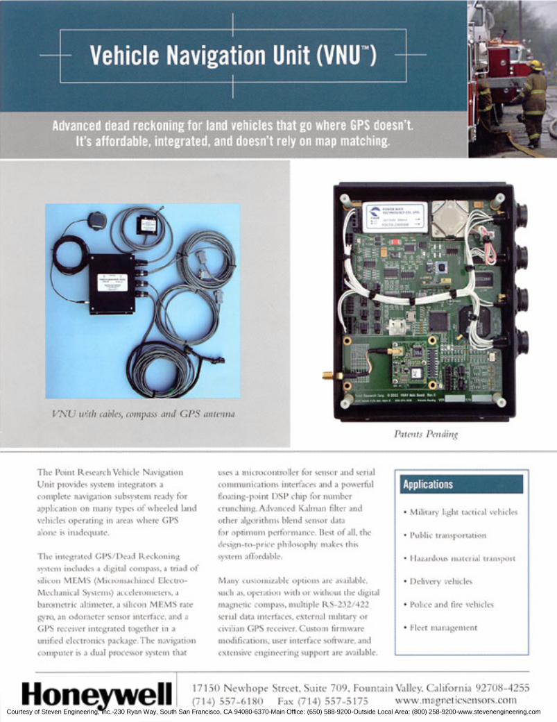
Courtesy of Steven Engineering, Inc.-230 Ryan Way, South San Francisco, CA 94080-6370-Main Office: (650) 588-9200-Outside Local Area: (800) 258-9200-www.stevenengineering.com
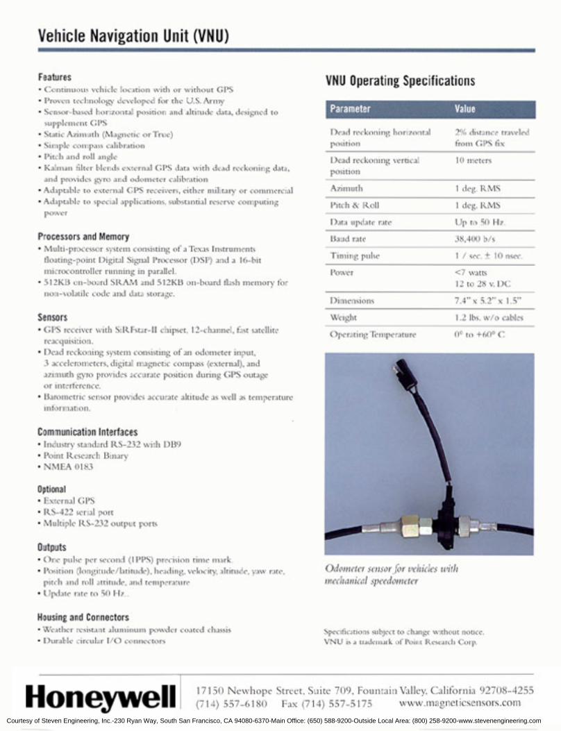
Courtesy of Steven Engineering, Inc.-230 Ryan Way, South San Francisco, CA 94080-6370-Main Office: (650) 588-9200-Outside Local Area: (800) 258-9200-www.stevenengineering.com